Adobe InDesign CS4 Products Programming Guide In Design En
User Manual: adobe InDesign - CS4 - Programming Guide Free User Guide for Adobe InDesign Software, Manual
Open the PDF directly: View PDF ![]() .
.
Page Count: 862 [warning: Documents this large are best viewed by clicking the View PDF Link!]
- Introduction
- Persistent Data and Data Conversion
- Commands
- Concepts
- Commands
- Command managers, databases, and undo support
- The command processor
- Scheduled commands
- Snapshots and interface implementation types
- Command history
- Undo and redo
- Notification within commands
- Error handling
- Key client APIs
- Extension patterns
- Notification
- Concepts
- Observers
- Responders
- Key client APIs
- Extension patterns
- Selection
- Layout Fundamentals
- Terminology
- Concepts
- Documents and the layout hierarchy
- Spreads and pages
- Layers
- Master spreads and master pages
- Page items
- Guides and grids
- Layout-related preferences
- Coordinate systems
- The layout presentation and view
- Key client APIs
- Extension patterns
- Commands that manipulate page items
- Graphics Fundamentals
- Paths
- Graphic page items
- Colors and swatches
- Color management
- Graphic attributes
- Rendering attributes
- Stroke effects
- Transparency effects
- Data model for drawing
- Dynamics of drawing
- Client APIs
- Extension patterns
- Swatch-list state
- Catalog of graphic attributes
- Mappings between attribute domains
- Spread-drawing sequence
- Controlling the settings in a graphics port
- Drawing sequence for a page item
- Text Fundamentals
- Concepts
- Text content
- Text presentation
- Text composition
- Phases of text composition
- Damage
- Recomposition
- Wax strand
- Paragraph composers
- Shuffling
- Vertical justification
- Background composition
- Recomposition transactional model
- Recomposition notification
- Implementation notes for paragraph composers
- Fonts
- Tables
- Printing
- Concepts
- Printing data model
- Utility APIs
- The print action sequence
- Print user interface
- Printing extension patterns
- Printing solutions
- Getting started
- Working with print-preset styles
- Getting information about print-preset styles
- Adding a print-preset style
- Duplicating a print-preset style
- Modifying the name of a print-preset style
- Modifying the settings of a print-preset style
- Deleting a print-preset style
- Exporting a set of print-preset styles to a file
- Importing a set of print-preset styles from a file
- Getting notified when a print-preset style is imported to/exported from a file
- Working with trap styles
- Getting information about trap styles
- Adding a trap style
- Duplicating a trap style
- Modifying a trap style
- Deleting a trap style
- Exporting a set of trap styles to another trap-style list
- Importing a set of trap styles from another trap-style list
- Determining which trap style is associated with a page on a document
- Associating a trap style with a page on a document
- Participating in the print process
- Participating in the stages of the print-action sequence
- Specifying which page items should be printed
- Specifying which layer(s) of a document should be printed
- Adding a custom watermark during the printing process
- Injecting PostScript comments or extra data into the print stream during the print action sequence
- Adding custom print settings so they are managed like other print settings
- Adding your own panel to the Print and Print Presets dialog boxes
- Specifying which parts of the Print and Print Presets dialog boxes are relevant or locked
- Writing printing data to a custom stream
- Bosses that aggregate IPrintData
- Print-action and supporting commands
- Japanese page-mark files
- Exporting to EPS and PDF
- PDF Import and Export
- PDF import
- PDF export
- PDF-style import and export
- Frequently asked questions
- How does the PDF export provider determine whether it should start the viewer after the export?
- How do I set the PDF clipboard setting as seen in the File Handling preferences?
- How do I control which layer of a document should be exported?
- How do I make the two-page spreads in my document export as two separate PDF pages?
- Why does kPDFExportCmdBoss give me an assert after the command is processed (ASSERT 'db != nil' in PDFExportController.cpp)?
- How do I set up line ranges for output in InCopy Galley or Story mode?
- Is it possible to export only selected text from an InDesign document?
- Implementing Preflight Rules
- XML Fundamentals
- Introduction
- Terminology
- XML features at a glance
- The user interface for XML
- XML model
- Importing XML
- Import architecture
- Importing a minimal XML file
- Unplaced content versus placed content
- XML template
- Matching against an XML template
- Importing repeating elements
- Throwing away unmatched existing elements on import (delete unmatched right)
- Throwing away unmatched incoming elements on XML import
- Attribute-style mapping
- Creating links on XML import
- Sparse import
- Importing a CALS table as an InDesign table
- Support table and cell styles when importing an InDesign table
- Exporting XML
- Tags
- Elements and content
- XML-related preferences
- Key client API
- Extension patterns
- Commands and notification
- Entities supported
- Assets from XSLT example
- Limitations of the InDesign XML architecture
- Scriptable Plug-in Fundamentals
- Terminology
- Overview
- Scripting architecture
- How to make your plug-in scriptable
- Prerequisites
- Defining IDs
- Adding a new property to an existing script object
- Adding a new event to an existing script object
- Adding a new script object to make preferences scriptable
- Adding a new singleton script object
- Adding a new script object to make a boss with a UID scriptable
- Adding a new script object to make a boss with no UID scriptable
- Adding a new script object to make a C++ object with no boss scriptable
- Adding a new script object to make a panel scriptable
- Adding an error-string service
- Handling multiple concurrent requests
- Reviewing scripting resources
- Running versioned scripts
- Supporting IDML
- Maintaining IDML forward and backward compatibility
- Verifying your plug-in’s data is round-tripped through IDML
- Tips for debugging the scripting architecture
- Scripting resources
- VersionedScriptElementInfo resource
- Object element
- Event element
- Property element
- Struct element
- TypeDef element
- Enum element
- Enumerator element
- Metadata element
- Provider element
- Suite element
- ScriptElementIDs, ScriptIDs, names, descriptions, and GUIDs
- ScriptID/name registration
- Scripting data types
- Script-object inheritance
- Overloading an existing event or property
- Versioning of scripting resources
- Client-specific scripting resources
- Elements that are not applicable to a particular object
- Key scripting APIs
- Scripting DOM reference
- Snippet Fundamentals
- Conceptual overview
- User interface for snippets
- Snippet model
- Snippet examples
- Client API
- Extension patterns
- Frequently asked questions
- What is a snippet, and how do I create one?
- What happens if I export a snippet of a placed image?
- What features are based on snippets?
- How accurately is data round-tripped through snippets?
- When do I have to care about snippets?
- Can I export spreads or pages as snippets?
- Should we generate snippet files from scratch?
- Can I import a snippet directly into a library?
- Can I import a snippet into the scrap database?
- Can we add our own new snippet types?
- Shared Application Resources
- Introduction
- Terminology
- Architecture
- Working with snippet APIs: frequently asked questions
- How do I create streams for reading and writing snippets?
- How do I limit my export to those items in the preference panel?
- How do I export all text styles, object styles, XML tags, or swatches in the application workspace?
- How do I import a snippet into the application?
- How do I control whether existing objects like paragraph styles are replaced or deleted on import.
- How do I determine the correct ScriptID to use for a preference I’m trying to include or exclude?
- How do I know which list element types will be exported by default?
- User-Interface Fundamentals
- Suppressed User Interface
- Using Adobe File Library
- Introduction
- Terminology
- Adobe File Library architecture
- Porting guidelines
- Frequently asked questions
- Why should I use Adobe file library?
- Does Adobe file library support cross-platform path conversion?
- Should I still use the ICoreFileName interface?
- Why was the GetSysFile method renamed GetIDFile in SDKFileHelper?
- How do I navigate between IDFile and IDPath?
- What are the differences between a file and a directory?
- What are the relationships between IDPath and IDFile?
- Why should IDFile not be treated as PMString?
- How do an invalid path and a nonexistent path differ?
- Can I construct an AString from PMString?
- How can I convert a relative path to an absolute path?
- Performance Tuning
- Tools
- Key concepts
- Custom tools
- Working with tools
- Catching a mouse click or mouse drag on a document
- Implementing a custom tool
- Displaying a Tool Options dialog box
- Finding the spread nearest the mouse position
- Changing spreads
- Performing a page-item hit test
- Setting or getting the active tool
- Observing when the active tool changes
- Changing the toolbox appearance from normal to skinny
- Using default implementations for trackers
- Suppressing the application's default tracker for a custom toolbox
- Tool-category information
- Default implementations of tool-related interfaces
- Tracker listings
- Diagnostics
- Introduction
- Using the diagnostics plug-in
- Diagnostics menu
- Diagnostics > Command menu
- Diagnostics > Document Structure menu
- Diagnostics > INX DTD menu
- Diagnostics > Object Model menu
- Diagnostics > Scripting DOM menu
- Running the Diagnostics plug-in in indesign/incopy with a script
- Running the Diagnostics plug-in in InDesign Server on Windows with a script
- Running the Diagnostics plug-in in InDesign Server on Mac OS with a script
- Frequently asked questions
- InCopy: Getting Started
- InCopy: Notes
- Concepts
- Working with notes
- Adding a note at the current insertion-point position
- Inserting text into a note
- Converting text to a new note
- Converting note content to text
- Navigating among notes
- Splitting a note
- Expanding and collapsing notes
- Selecting a note
- Getting kNoteDataBoss, given a text index whose position is anchored to note
- Deleting notes
- Changing notes-palette content to reflect particular note data
- Checking note spelling
- Observing a note that is being modified
- Using notes in InDesign
- InCopy: Track Changes
- Concepts
- Data model for Track Changes
- Key client APIs
- Useful commands and associated notification protocols
- kSetRedlineTrackingCmdBoss
- kSetTrackChangesPrefsCmdBoss
- kActivateRedlineCmdBoss
- kDeactivateRedlineCmdBoss
- kRejectAllRedlineCmdBoss
- kRejectRangeRedlineCmdBoss
- kRejectRedlineCmdBoss
- kAcceptAllRedlineCmdBoss
- kAcceptRangeRedlineCmdBoss
- kAcceptRedlineCmdBoss
- kMoveRedlineChangeCmdBoss
- kRedlinePreserveDeletionCmdBoss
- Working with Track Changes
- Navigating tracked changes
- Accepting and rejecting tracked changes
- Understanding multiple change records in one location
- Avoid insignificant tracked changes
- Undoing accepted deleted text
- Determining whether a location in a story is in deleted text
- Determining whether a primary story-thread location is at a deleted-text anchor
- Getting kDeletedTextBoss, given a text index having deleted text
- Removing deleted text
- Moving a change record from one story to another
- Maintaining kRedlineStrandBoss text-run information
- InCopy: Assignments
- Glossary

ADOBE® INDESIGN® CS4
ADOBE INDESIGN CS4 PRODUCTS
PROGRAMMING GUIDE
© 2008 Adobe Systems Incorporated. All rights reserved.
Adobe InDesign CS4 Products Programming Guide
If this guide is distributed with software that includes an end user agreement, this guide, as well as the software described in it, is furnished under license and may be
used or copied only in accordance with the terms of such license. Except as permitted by any such license, no part of this guide may be reproduced, stored in a retrieval
system, or transmitted, in any form or by any means, electronic, mechanical, recording, or otherwise, without the prior written permission of Adobe Systems
Incorporated. Please note that the content in this guide is protected under copyright law even if it is not distributed with software that includes an end user license
agreement.
The content of this guide is furnished for informational use only, is subject to change without notice, and should not be construed as a commitment by Adobe Systems
Incorporated. Adobe Systems Incorporated assumes no responsibility or liability for any errors or inaccuracies that may appear in the informational content
contained in this guide.
Please remember that existing artwork or images that you may want to include in your project may be protected under copyright law. The unauthorized incorporation
of such material into your new work could be a violation of the rights of the copyright owner. Please be sure to obtain any permission required from the copyright
owner.
Any references to company names in sample templates are for demonstration purposes only and are not intended to refer to any actual organization.
Adobe, the Adobe logo, Acrobat, Bridge, Creative Suite, Illustrator, InCopy, InDesign, Photoshop, and Reader are either registered trademarks or trademarks of
Adobe Systems Incorporated in the United States and/or other countries. Microsoft and Windows are either registered trademarks or trademarks of Microsoft
Corporation in the United States and/or other countries. Apple and Mac OS are trademarks of Apple Computer, Incorporated, registered in the United States and
other countries. Java is a trademark of Sun Microsystems, Incorporated in the United States and other countries.All other trademarks are the property of their
respective owners.
Adobe Systems Incorporated, 345 Park Avenue, San Jose, California 95110, USA. Notice to U.S. Government End Users. The Software and Documentation are
“Commercial Items,” as that term is defined at 48 C.F.R. §2.101, consisting of “Commercial Computer Software” and “Commercial Computer Software
Documentation,” as such terms are used in 48 C.F.R. §12.212 or 48 C.F.R. §227.7202, as applicable. Consistent with 48 C.F.R. §12.212 or 48 C.F.R. §§227.7202-1
through 227.7202-4, as applicable, the Commercial Computer Software and Commercial Computer Software Documentation are being licensed to U.S. Government
end users (a) only as Commercial Items and (b) with only those rights as are granted to all other end users pursuant to the terms and conditions herein.
Unpublished-rights reserved under the copyright laws of the United States. Adobe Systems Incorporated, 345 Park Avenue, San Jose, CA 95110-2704, USA. For U.S.
Government End Users, Adobe agrees to comply with all applicable equal opportunity laws including, if appropriate, the provisions of Executive Order 11246, as
amended, Section 402 of the Vietnam Era Veterans Readjustment Assistance Act of 1974 (38 USC 4212), and Section 503 of the Rehabilitation Act of 1973, as
amended, and the regulations at 41 CFR Parts 60-1 through 60-60, 60-250, and 60-741. The affirmative action clause and regulations contained in the preceding
sentence shall be incorporated by reference.

3
Introduction . . . . . . . . . . . . . . . . . . . . . . . . . . . . . . . . . . . . . . 27
For experienced InDesign developers . . . . . . . . . . . . . . . . . . . . . . . . . . . . . . . . . . . . . . . 27
For new InDesign developers . . . . . . . . . . . . . . . . . . . . . . . . . . . . . . . . . . . . . . . . . . . . 27
Persistent Data and Data Conversion . . . . . . . . . . . . . . . . . . . . . . . . 29
Concepts . . . . . . . . . . . . . . . . . . . . . . . . . . . . . . . . . . . . . . . . . . . . . . . . . . . . . . . . . 29
Persistence . . . . . . . . . . . . . . . . . . . . . . . . . . . . . . . . . . . . . . . . . . . . . . . . . . . . . 29
Databases. . . . . . . . . . . . . . . . . . . . . . . . . . . . . . . . . . . . . . . . . . . . . . . . . . . . . . 29
Persistent objects . . . . . . . . . . . . . . . . . . . . . . . . . . . . . . . . . . . . . . . . . . . . . . . . . . . . 30
Using persistent objects. . . . . . . . . . . . . . . . . . . . . . . . . . . . . . . . . . . . . . . . . . . . . 30
Implementing persistent objects . . . . . . . . . . . . . . . . . . . . . . . . . . . . . . . . . . . . . . . 33
Streams . . . . . . . . . . . . . . . . . . . . . . . . . . . . . . . . . . . . . . . . . . . . . . . . . . . . . . . . . . 34
IPMStream methods . . . . . . . . . . . . . . . . . . . . . . . . . . . . . . . . . . . . . . . . . . . . . . . 34
Implementing a new stream . . . . . . . . . . . . . . . . . . . . . . . . . . . . . . . . . . . . . . . . . . 35
Missing plug-ins . . . . . . . . . . . . . . . . . . . . . . . . . . . . . . . . . . . . . . . . . . . . . . . . . . . . 36
Warning levels . . . . . . . . . . . . . . . . . . . . . . . . . . . . . . . . . . . . . . . . . . . . . . . . . . . 36
Missing plug-in alert . . . . . . . . . . . . . . . . . . . . . . . . . . . . . . . . . . . . . . . . . . . . . . . 38
Guidelines for handling a missing plug-in . . . . . . . . . . . . . . . . . . . . . . . . . . . . . . . . . 38
Data handling for missing plug-ins . . . . . . . . . . . . . . . . . . . . . . . . . . . . . . . . . . . . . . 39
Conversion of persistent data . . . . . . . . . . . . . . . . . . . . . . . . . . . . . . . . . . . . . . . . . . . . 40
When to convert persistent data . . . . . . . . . . . . . . . . . . . . . . . . . . . . . . . . . . . . . . . 41
Converting data with the conversion manager . . . . . . . . . . . . . . . . . . . . . . . . . . . . . . 42
Converting data without the conversion manager . . . . . . . . . . . . . . . . . . . . . . . . . . . . 52
Resources. . . . . . . . . . . . . . . . . . . . . . . . . . . . . . . . . . . . . . . . . . . . . . . . . . . . . . . . . 53
PluginVersion resource, format numbers, and their macros . . . . . . . . . . . . . . . . . . . . . . 53
Setting up resources . . . . . . . . . . . . . . . . . . . . . . . . . . . . . . . . . . . . . . . . . . . . . . . 54
Schemas. . . . . . . . . . . . . . . . . . . . . . . . . . . . . . . . . . . . . . . . . . . . . . . . . . . . . . . 54
SchemaList . . . . . . . . . . . . . . . . . . . . . . . . . . . . . . . . . . . . . . . . . . . . . . . . . . . . . 56
DirectiveList . . . . . . . . . . . . . . . . . . . . . . . . . . . . . . . . . . . . . . . . . . . . . . . . . . . . 58
Advanced schema topics . . . . . . . . . . . . . . . . . . . . . . . . . . . . . . . . . . . . . . . . . . . . . . . 59
Arrays of values . . . . . . . . . . . . . . . . . . . . . . . . . . . . . . . . . . . . . . . . . . . . . . . . . . 59
FieldArray . . . . . . . . . . . . . . . . . . . . . . . . . . . . . . . . . . . . . . . . . . . . . . . . . . . . . . 60
Conditional-field inclusion . . . . . . . . . . . . . . . . . . . . . . . . . . . . . . . . . . . . . . . . . . . 60
Contents

Contents
4Adobe InDesign CS4 Products Programming Guide
Commands . . . . . . . . . . . . . . . . . . . . . . . . . . . . . . . . . . . . . . 63
Concepts . . . . . . . . . . . . . . . . . . . . . . . . . . . . . . . . . . . . . . . . . . . . . . . . . . . . . . . . . 63
Command pattern . . . . . . . . . . . . . . . . . . . . . . . . . . . . . . . . . . . . . . . . . . . . . . . . 63
Databases and undoability . . . . . . . . . . . . . . . . . . . . . . . . . . . . . . . . . . . . . . . . . . . 64
Models. . . . . . . . . . . . . . . . . . . . . . . . . . . . . . . . . . . . . . . . . . . . . . . . . . . . . . . . 64
Commands. . . . . . . . . . . . . . . . . . . . . . . . . . . . . . . . . . . . . . . . . . . . . . . . . . . . . . . . 68
Command parameters. . . . . . . . . . . . . . . . . . . . . . . . . . . . . . . . . . . . . . . . . . . . . . 69
Command undoability. . . . . . . . . . . . . . . . . . . . . . . . . . . . . . . . . . . . . . . . . . . . . . 70
Command processing and the CmdUtils class . . . . . . . . . . . . . . . . . . . . . . . . . . . . . . . 70
Command sequences . . . . . . . . . . . . . . . . . . . . . . . . . . . . . . . . . . . . . . . . . . . . . . 71
Command managers, databases, and undo support. . . . . . . . . . . . . . . . . . . . . . . . . . . . . . 73
The command processor . . . . . . . . . . . . . . . . . . . . . . . . . . . . . . . . . . . . . . . . . . . . . . . 76
Scheduled commands. . . . . . . . . . . . . . . . . . . . . . . . . . . . . . . . . . . . . . . . . . . . . . . . . 78
Snapshots and interface implementation types . . . . . . . . . . . . . . . . . . . . . . . . . . . . . . . . 79
Command history . . . . . . . . . . . . . . . . . . . . . . . . . . . . . . . . . . . . . . . . . . . . . . . . . . . 80
Merging changes with an existing step in the command history . . . . . . . . . . . . . . . . . . . 81
Undo and redo . . . . . . . . . . . . . . . . . . . . . . . . . . . . . . . . . . . . . . . . . . . . . . . . . . . . . 81
Extension patterns involved in undo and redo . . . . . . . . . . . . . . . . . . . . . . . . . . . . . . 83
Notification within commands . . . . . . . . . . . . . . . . . . . . . . . . . . . . . . . . . . . . . . . . . . . 83
Error handling . . . . . . . . . . . . . . . . . . . . . . . . . . . . . . . . . . . . . . . . . . . . . . . . . . . . . . 83
Protective shutdown . . . . . . . . . . . . . . . . . . . . . . . . . . . . . . . . . . . . . . . . . . . . . . . 84
Key client APIs . . . . . . . . . . . . . . . . . . . . . . . . . . . . . . . . . . . . . . . . . . . . . . . . . . . . . . 84
Command facades and utilities . . . . . . . . . . . . . . . . . . . . . . . . . . . . . . . . . . . . . . . . 84
Command-processing APIs . . . . . . . . . . . . . . . . . . . . . . . . . . . . . . . . . . . . . . . . . . . 86
Extension patterns . . . . . . . . . . . . . . . . . . . . . . . . . . . . . . . . . . . . . . . . . . . . . . . . . . . 86
Command . . . . . . . . . . . . . . . . . . . . . . . . . . . . . . . . . . . . . . . . . . . . . . . . . . . . . 86
Error string service . . . . . . . . . . . . . . . . . . . . . . . . . . . . . . . . . . . . . . . . . . . . . . . . 88
Persistent interface . . . . . . . . . . . . . . . . . . . . . . . . . . . . . . . . . . . . . . . . . . . . . . . . 89
Persistent boss. . . . . . . . . . . . . . . . . . . . . . . . . . . . . . . . . . . . . . . . . . . . . . . . . . . 91
Snapshot interface . . . . . . . . . . . . . . . . . . . . . . . . . . . . . . . . . . . . . . . . . . . . . . . . 92
Inval handler . . . . . . . . . . . . . . . . . . . . . . . . . . . . . . . . . . . . . . . . . . . . . . . . . . . . 94
Snapshot view interface. . . . . . . . . . . . . . . . . . . . . . . . . . . . . . . . . . . . . . . . . . . . . 99

Adobe InDesign CS4 Products Programming Guide 5
Contents
Notification . . . . . . . . . . . . . . . . . . . . . . . . . . . . . . . . . . . . . 101
Concepts . . . . . . . . . . . . . . . . . . . . . . . . . . . . . . . . . . . . . . . . . . . . . . . . . . . . . . . . .101
Observer pattern . . . . . . . . . . . . . . . . . . . . . . . . . . . . . . . . . . . . . . . . . . . . . . . . .101
Responder pattern . . . . . . . . . . . . . . . . . . . . . . . . . . . . . . . . . . . . . . . . . . . . . . . .102
Observers. . . . . . . . . . . . . . . . . . . . . . . . . . . . . . . . . . . . . . . . . . . . . . . . . . . . . . . . .102
Subjects . . . . . . . . . . . . . . . . . . . . . . . . . . . . . . . . . . . . . . . . . . . . . . . . . . . . . . .103
Observers . . . . . . . . . . . . . . . . . . . . . . . . . . . . . . . . . . . . . . . . . . . . . . . . . . . . . .104
Message protocols . . . . . . . . . . . . . . . . . . . . . . . . . . . . . . . . . . . . . . . . . . . . . . . .104
Subject and observer types . . . . . . . . . . . . . . . . . . . . . . . . . . . . . . . . . . . . . . . . . .105
Regular and lazy notification. . . . . . . . . . . . . . . . . . . . . . . . . . . . . . . . . . . . . . . . . .106
Observers and undo . . . . . . . . . . . . . . . . . . . . . . . . . . . . . . . . . . . . . . . . . . . . . . .111
Relating observers to subjects. . . . . . . . . . . . . . . . . . . . . . . . . . . . . . . . . . . . . . . . .112
Document notification . . . . . . . . . . . . . . . . . . . . . . . . . . . . . . . . . . . . . . . . . . . . .113
Observers and the model . . . . . . . . . . . . . . . . . . . . . . . . . . . . . . . . . . . . . . . . . . . .113
Responders. . . . . . . . . . . . . . . . . . . . . . . . . . . . . . . . . . . . . . . . . . . . . . . . . . . . . . . .115
Signal manager . . . . . . . . . . . . . . . . . . . . . . . . . . . . . . . . . . . . . . . . . . . . . . . . . .116
Responder . . . . . . . . . . . . . . . . . . . . . . . . . . . . . . . . . . . . . . . . . . . . . . . . . . . . .117
Responders and the model . . . . . . . . . . . . . . . . . . . . . . . . . . . . . . . . . . . . . . . . . . .117
Responders and global error state . . . . . . . . . . . . . . . . . . . . . . . . . . . . . . . . . . . . . .118
Ordering of responders . . . . . . . . . . . . . . . . . . . . . . . . . . . . . . . . . . . . . . . . . . . . .118
Responders and undo . . . . . . . . . . . . . . . . . . . . . . . . . . . . . . . . . . . . . . . . . . . . . .119
Key client APIs . . . . . . . . . . . . . . . . . . . . . . . . . . . . . . . . . . . . . . . . . . . . . . . . . . . . . .119
Extension patterns . . . . . . . . . . . . . . . . . . . . . . . . . . . . . . . . . . . . . . . . . . . . . . . . . . .120
User-interface widget observer . . . . . . . . . . . . . . . . . . . . . . . . . . . . . . . . . . . . . . . .120
Model observer . . . . . . . . . . . . . . . . . . . . . . . . . . . . . . . . . . . . . . . . . . . . . . . . . .120
Selection observer . . . . . . . . . . . . . . . . . . . . . . . . . . . . . . . . . . . . . . . . . . . . . . . .122
Document observer . . . . . . . . . . . . . . . . . . . . . . . . . . . . . . . . . . . . . . . . . . . . . . .122
Active context observer . . . . . . . . . . . . . . . . . . . . . . . . . . . . . . . . . . . . . . . . . . . . .122
Subject . . . . . . . . . . . . . . . . . . . . . . . . . . . . . . . . . . . . . . . . . . . . . . . . . . . . . . .124
Responder . . . . . . . . . . . . . . . . . . . . . . . . . . . . . . . . . . . . . . . . . . . . . . . . . . . . .124
Selection . . . . . . . . . . . . . . . . . . . . . . . . . . . . . . . . . . . . . 125
Concepts . . . . . . . . . . . . . . . . . . . . . . . . . . . . . . . . . . . . . . . . . . . . . . . . . . . . . . . . .125
Selection . . . . . . . . . . . . . . . . . . . . . . . . . . . . . . . . . . . . . . . . . . . . . . . . . . . . . .125
Selection format and target . . . . . . . . . . . . . . . . . . . . . . . . . . . . . . . . . . . . . . . . . .125
Design patterns . . . . . . . . . . . . . . . . . . . . . . . . . . . . . . . . . . . . . . . . . . . . . . . . . .126
Selection architecture . . . . . . . . . . . . . . . . . . . . . . . . . . . . . . . . . . . . . . . . . . . . . . . . .127
Abstract selection bosses and suites. . . . . . . . . . . . . . . . . . . . . . . . . . . . . . . . . . . . . . . .130

Contents
6Adobe InDesign CS4 Products Programming Guide
Concrete selection bosses . . . . . . . . . . . . . . . . . . . . . . . . . . . . . . . . . . . . . . . . . . . . . .131
Layout selection. . . . . . . . . . . . . . . . . . . . . . . . . . . . . . . . . . . . . . . . . . . . . . . . . .132
Table selection. . . . . . . . . . . . . . . . . . . . . . . . . . . . . . . . . . . . . . . . . . . . . . . . . . .133
Text selection . . . . . . . . . . . . . . . . . . . . . . . . . . . . . . . . . . . . . . . . . . . . . . . . . . .134
Galley text selection . . . . . . . . . . . . . . . . . . . . . . . . . . . . . . . . . . . . . . . . . . . . . . .135
Story-editor text selection . . . . . . . . . . . . . . . . . . . . . . . . . . . . . . . . . . . . . . . . . . .136
Note text selection . . . . . . . . . . . . . . . . . . . . . . . . . . . . . . . . . . . . . . . . . . . . . . . .137
XML selection . . . . . . . . . . . . . . . . . . . . . . . . . . . . . . . . . . . . . . . . . . . . . . . . . . .138
Document defaults . . . . . . . . . . . . . . . . . . . . . . . . . . . . . . . . . . . . . . . . . . . . . . . .140
Application defaults . . . . . . . . . . . . . . . . . . . . . . . . . . . . . . . . . . . . . . . . . . . . . . .141
Integrator suites. . . . . . . . . . . . . . . . . . . . . . . . . . . . . . . . . . . . . . . . . . . . . . . . . . . . .142
CSB suites. . . . . . . . . . . . . . . . . . . . . . . . . . . . . . . . . . . . . . . . . . . . . . . . . . . . . . . . .142
Encapsulation . . . . . . . . . . . . . . . . . . . . . . . . . . . . . . . . . . . . . . . . . . . . . . . . . . . . . .143
Suites and the user interface: an example . . . . . . . . . . . . . . . . . . . . . . . . . . . . . . . . . . . .143
Responsibilities . . . . . . . . . . . . . . . . . . . . . . . . . . . . . . . . . . . . . . . . . . . . . . . . . . . . .144
Basic client-code responsibilities . . . . . . . . . . . . . . . . . . . . . . . . . . . . . . . . . . . . . . .144
Selection-observer responsibilities . . . . . . . . . . . . . . . . . . . . . . . . . . . . . . . . . . . . . .144
Custom-suite responsibilities . . . . . . . . . . . . . . . . . . . . . . . . . . . . . . . . . . . . . . . . .144
Custom suites . . . . . . . . . . . . . . . . . . . . . . . . . . . . . . . . . . . . . . . . . . . . . . . . . . . . . .145
Selection extensions . . . . . . . . . . . . . . . . . . . . . . . . . . . . . . . . . . . . . . . . . . . . . . . . . .146
Caches . . . . . . . . . . . . . . . . . . . . . . . . . . . . . . . . . . . . . . . . . . . . . . . . . . . . . . . .146
Selection change notification . . . . . . . . . . . . . . . . . . . . . . . . . . . . . . . . . . . . . . . . .146
Initialization . . . . . . . . . . . . . . . . . . . . . . . . . . . . . . . . . . . . . . . . . . . . . . . . . . . .147
Communication with Integrator suite . . . . . . . . . . . . . . . . . . . . . . . . . . . . . . . . . . . .147
Selection observers . . . . . . . . . . . . . . . . . . . . . . . . . . . . . . . . . . . . . . . . . . . . . . . . . .147
Selection-utility interface (ISelectionUtils) . . . . . . . . . . . . . . . . . . . . . . . . . . . . . . . . . . . .148
Layout Fundamentals . . . . . . . . . . . . . . . . . . . . . . . . . . . . . . . . 149
Terminology . . . . . . . . . . . . . . . . . . . . . . . . . . . . . . . . . . . . . . . . . . . . . . . . . . . . . . .149
Concepts . . . . . . . . . . . . . . . . . . . . . . . . . . . . . . . . . . . . . . . . . . . . . . . . . . . . . . . . .150
Documents and the layout hierarchy . . . . . . . . . . . . . . . . . . . . . . . . . . . . . . . . . . . . . . .152
Architecture . . . . . . . . . . . . . . . . . . . . . . . . . . . . . . . . . . . . . . . . . . . . . . . . . . . .152
Parent and child objects and IHierarchy. . . . . . . . . . . . . . . . . . . . . . . . . . . . . . . . . . .155
Spreads and pages . . . . . . . . . . . . . . . . . . . . . . . . . . . . . . . . . . . . . . . . . . . . . . . . . . .157
Layers . . . . . . . . . . . . . . . . . . . . . . . . . . . . . . . . . . . . . . . . . . . . . . . . . . . . . . . . . . .161
Layers in a basic document. . . . . . . . . . . . . . . . . . . . . . . . . . . . . . . . . . . . . . . . . . .162
Layer options. . . . . . . . . . . . . . . . . . . . . . . . . . . . . . . . . . . . . . . . . . . . . . . . . . . .165
Navigating spread content using ISpread. . . . . . . . . . . . . . . . . . . . . . . . . . . . . . . . . .166

Adobe InDesign CS4 Products Programming Guide 7
Contents
Master spreads and master pages . . . . . . . . . . . . . . . . . . . . . . . . . . . . . . . . . . . . . . . . .168
Master spreads and master pages in a basic document . . . . . . . . . . . . . . . . . . . . . . . . .169
Master-page item overrides . . . . . . . . . . . . . . . . . . . . . . . . . . . . . . . . . . . . . . . . . .172
Basing one master page on another . . . . . . . . . . . . . . . . . . . . . . . . . . . . . . . . . . . . .172
Page items . . . . . . . . . . . . . . . . . . . . . . . . . . . . . . . . . . . . . . . . . . . . . . . . . . . . . . . .173
Frames and paths . . . . . . . . . . . . . . . . . . . . . . . . . . . . . . . . . . . . . . . . . . . . . . . . .173
Graphic page items. . . . . . . . . . . . . . . . . . . . . . . . . . . . . . . . . . . . . . . . . . . . . . . .177
Text page items . . . . . . . . . . . . . . . . . . . . . . . . . . . . . . . . . . . . . . . . . . . . . . . . . .177
Interactive page items . . . . . . . . . . . . . . . . . . . . . . . . . . . . . . . . . . . . . . . . . . . . . .178
Groups. . . . . . . . . . . . . . . . . . . . . . . . . . . . . . . . . . . . . . . . . . . . . . . . . . . . . . . .178
Abstract page items and kPageItemBoss . . . . . . . . . . . . . . . . . . . . . . . . . . . . . . . . . .179
Guides and grids . . . . . . . . . . . . . . . . . . . . . . . . . . . . . . . . . . . . . . . . . . . . . . . . . . . .180
Ruler guides . . . . . . . . . . . . . . . . . . . . . . . . . . . . . . . . . . . . . . . . . . . . . . . . . . . .180
Margin and column guides . . . . . . . . . . . . . . . . . . . . . . . . . . . . . . . . . . . . . . . . . . .180
Document grid . . . . . . . . . . . . . . . . . . . . . . . . . . . . . . . . . . . . . . . . . . . . . . . . . .181
Baseline grid . . . . . . . . . . . . . . . . . . . . . . . . . . . . . . . . . . . . . . . . . . . . . . . . . . . .181
Snap . . . . . . . . . . . . . . . . . . . . . . . . . . . . . . . . . . . . . . . . . . . . . . . . . . . . . . . . .181
Layout-related preferences. . . . . . . . . . . . . . . . . . . . . . . . . . . . . . . . . . . . . . . . . . . . . .182
Coordinate systems . . . . . . . . . . . . . . . . . . . . . . . . . . . . . . . . . . . . . . . . . . . . . . . . . .183
Transformation matrices . . . . . . . . . . . . . . . . . . . . . . . . . . . . . . . . . . . . . . . . . . . .183
Pasteboard coordinate space . . . . . . . . . . . . . . . . . . . . . . . . . . . . . . . . . . . . . . . . .184
Inner coordinate space and parent coordinate space . . . . . . . . . . . . . . . . . . . . . . . . . .185
Spread coordinate space . . . . . . . . . . . . . . . . . . . . . . . . . . . . . . . . . . . . . . . . . . . .188
Page coordinate space. . . . . . . . . . . . . . . . . . . . . . . . . . . . . . . . . . . . . . . . . . . . . .189
Page-item coordinate space . . . . . . . . . . . . . . . . . . . . . . . . . . . . . . . . . . . . . . . . . .190
Bounding box and IGeometry . . . . . . . . . . . . . . . . . . . . . . . . . . . . . . . . . . . . . . . . .190
Transformation and ITransform . . . . . . . . . . . . . . . . . . . . . . . . . . . . . . . . . . . . . . . .191
Measurement units. . . . . . . . . . . . . . . . . . . . . . . . . . . . . . . . . . . . . . . . . . . . . . . .192
Geometrical data types . . . . . . . . . . . . . . . . . . . . . . . . . . . . . . . . . . . . . . . . . . . . .194
The layout presentation and view . . . . . . . . . . . . . . . . . . . . . . . . . . . . . . . . . . . . . . . . .194
Layout presentation . . . . . . . . . . . . . . . . . . . . . . . . . . . . . . . . . . . . . . . . . . . . . . .194
Layout view. . . . . . . . . . . . . . . . . . . . . . . . . . . . . . . . . . . . . . . . . . . . . . . . . . . . .196
Current spread and active layer . . . . . . . . . . . . . . . . . . . . . . . . . . . . . . . . . . . . . . . .197
Layout-presentation and layout-view coordinate spaces . . . . . . . . . . . . . . . . . . . . . . . .198
Key client APIs . . . . . . . . . . . . . . . . . . . . . . . . . . . . . . . . . . . . . . . . . . . . . . . . . . . . . .199
Extension patterns . . . . . . . . . . . . . . . . . . . . . . . . . . . . . . . . . . . . . . . . . . . . . . . . . . .202
New-page-item responder . . . . . . . . . . . . . . . . . . . . . . . . . . . . . . . . . . . . . . . . . . .202
Custom page item . . . . . . . . . . . . . . . . . . . . . . . . . . . . . . . . . . . . . . . . . . . . . . . .203
Custom unit-of-measure service . . . . . . . . . . . . . . . . . . . . . . . . . . . . . . . . . . . . . . .203

Contents
8Adobe InDesign CS4 Products Programming Guide
Commands that manipulate page items . . . . . . . . . . . . . . . . . . . . . . . . . . . . . . . . . . . . .204
Page-item creation commands . . . . . . . . . . . . . . . . . . . . . . . . . . . . . . . . . . . . . . . .204
Page-item update commands . . . . . . . . . . . . . . . . . . . . . . . . . . . . . . . . . . . . . . . . .205
Page-item deletion commands . . . . . . . . . . . . . . . . . . . . . . . . . . . . . . . . . . . . . . . .209
Graphics Fundamentals . . . . . . . . . . . . . . . . . . . . . . . . . . . . . . . 211
Paths. . . . . . . . . . . . . . . . . . . . . . . . . . . . . . . . . . . . . . . . . . . . . . . . . . . . . . . . . . . .211
Path concepts . . . . . . . . . . . . . . . . . . . . . . . . . . . . . . . . . . . . . . . . . . . . . . . . . . .211
Paths data model . . . . . . . . . . . . . . . . . . . . . . . . . . . . . . . . . . . . . . . . . . . . . . . . .213
Path operations . . . . . . . . . . . . . . . . . . . . . . . . . . . . . . . . . . . . . . . . . . . . . . . . . .215
Graphic page items . . . . . . . . . . . . . . . . . . . . . . . . . . . . . . . . . . . . . . . . . . . . . . . . . .217
Graphic page-item types . . . . . . . . . . . . . . . . . . . . . . . . . . . . . . . . . . . . . . . . . . . .217
Graphic page-item settings . . . . . . . . . . . . . . . . . . . . . . . . . . . . . . . . . . . . . . . . . .219
Graphic page-item data model . . . . . . . . . . . . . . . . . . . . . . . . . . . . . . . . . . . . . . . .223
Graphic page-item examples . . . . . . . . . . . . . . . . . . . . . . . . . . . . . . . . . . . . . . . . .226
Graphics import . . . . . . . . . . . . . . . . . . . . . . . . . . . . . . . . . . . . . . . . . . . . . . . . . .238
Export to graphics file format . . . . . . . . . . . . . . . . . . . . . . . . . . . . . . . . . . . . . . . . .243
Colors and swatches . . . . . . . . . . . . . . . . . . . . . . . . . . . . . . . . . . . . . . . . . . . . . . . . . .246
Architecture . . . . . . . . . . . . . . . . . . . . . . . . . . . . . . . . . . . . . . . . . . . . . . . . . . . .246
Swatches . . . . . . . . . . . . . . . . . . . . . . . . . . . . . . . . . . . . . . . . . . . . . . . . . . . . . .250
Solid colors . . . . . . . . . . . . . . . . . . . . . . . . . . . . . . . . . . . . . . . . . . . . . . . . . . . . .250
Gradients . . . . . . . . . . . . . . . . . . . . . . . . . . . . . . . . . . . . . . . . . . . . . . . . . . . . . .251
Swatch lists . . . . . . . . . . . . . . . . . . . . . . . . . . . . . . . . . . . . . . . . . . . . . . . . . . . . .251
Inks . . . . . . . . . . . . . . . . . . . . . . . . . . . . . . . . . . . . . . . . . . . . . . . . . . . . . . . . . .251
Color management . . . . . . . . . . . . . . . . . . . . . . . . . . . . . . . . . . . . . . . . . . . . . . . . . .252
ICC profiles . . . . . . . . . . . . . . . . . . . . . . . . . . . . . . . . . . . . . . . . . . . . . . . . . . . . .253
Color-management workflow . . . . . . . . . . . . . . . . . . . . . . . . . . . . . . . . . . . . . . . . .253
Data model for color management. . . . . . . . . . . . . . . . . . . . . . . . . . . . . . . . . . . . . .253
Graphic attributes . . . . . . . . . . . . . . . . . . . . . . . . . . . . . . . . . . . . . . . . . . . . . . . . . . .256
Graphic-attribute data model . . . . . . . . . . . . . . . . . . . . . . . . . . . . . . . . . . . . . . . . .256
Representation of graphic attributes. . . . . . . . . . . . . . . . . . . . . . . . . . . . . . . . . . . . .258
Graphic styles . . . . . . . . . . . . . . . . . . . . . . . . . . . . . . . . . . . . . . . . . . . . . . . . . . .258
Graphic state . . . . . . . . . . . . . . . . . . . . . . . . . . . . . . . . . . . . . . . . . . . . . . . . . . . .259
Mapping graphic attributes between domains . . . . . . . . . . . . . . . . . . . . . . . . . . . . . .260
Rendering attributes. . . . . . . . . . . . . . . . . . . . . . . . . . . . . . . . . . . . . . . . . . . . . . . . . .261
Color-rendering attributes . . . . . . . . . . . . . . . . . . . . . . . . . . . . . . . . . . . . . . . . . . .261
Gradient attributes . . . . . . . . . . . . . . . . . . . . . . . . . . . . . . . . . . . . . . . . . . . . . . . .262

Adobe InDesign CS4 Products Programming Guide 9
Contents
Stroke effects . . . . . . . . . . . . . . . . . . . . . . . . . . . . . . . . . . . . . . . . . . . . . . . . . . . . . .262
Path stroker. . . . . . . . . . . . . . . . . . . . . . . . . . . . . . . . . . . . . . . . . . . . . . . . . . . . .262
Path corners . . . . . . . . . . . . . . . . . . . . . . . . . . . . . . . . . . . . . . . . . . . . . . . . . . . .263
Path-end strokers . . . . . . . . . . . . . . . . . . . . . . . . . . . . . . . . . . . . . . . . . . . . . . . . .263
Transparency effects . . . . . . . . . . . . . . . . . . . . . . . . . . . . . . . . . . . . . . . . . . . . . . . . . .263
Concepts . . . . . . . . . . . . . . . . . . . . . . . . . . . . . . . . . . . . . . . . . . . . . . . . . . . . . .263
Flattening . . . . . . . . . . . . . . . . . . . . . . . . . . . . . . . . . . . . . . . . . . . . . . . . . . . . . .272
Transparency data model . . . . . . . . . . . . . . . . . . . . . . . . . . . . . . . . . . . . . . . . . . . .272
Data model for drawing. . . . . . . . . . . . . . . . . . . . . . . . . . . . . . . . . . . . . . . . . . . . . . . .276
Presentation views . . . . . . . . . . . . . . . . . . . . . . . . . . . . . . . . . . . . . . . . . . . . . . . .276
Graphics context . . . . . . . . . . . . . . . . . . . . . . . . . . . . . . . . . . . . . . . . . . . . . . . . .277
Viewport . . . . . . . . . . . . . . . . . . . . . . . . . . . . . . . . . . . . . . . . . . . . . . . . . . . . . .277
Dynamics of drawing . . . . . . . . . . . . . . . . . . . . . . . . . . . . . . . . . . . . . . . . . . . . . . . . .278
Drawing the layout . . . . . . . . . . . . . . . . . . . . . . . . . . . . . . . . . . . . . . . . . . . . . . . .278
Drawing page items . . . . . . . . . . . . . . . . . . . . . . . . . . . . . . . . . . . . . . . . . . . . . . .281
Drawing in user-interface widget windows . . . . . . . . . . . . . . . . . . . . . . . . . . . . . . . .283
Offscreen drawing . . . . . . . . . . . . . . . . . . . . . . . . . . . . . . . . . . . . . . . . . . . . . . . .284
Client APIs . . . . . . . . . . . . . . . . . . . . . . . . . . . . . . . . . . . . . . . . . . . . . . . . . . . . . . . .285
Path-related client APIs . . . . . . . . . . . . . . . . . . . . . . . . . . . . . . . . . . . . . . . . . . . . .285
Graphic page-item client APIs . . . . . . . . . . . . . . . . . . . . . . . . . . . . . . . . . . . . . . . . .286
Key color-related client APIs . . . . . . . . . . . . . . . . . . . . . . . . . . . . . . . . . . . . . . . . . .287
Graphic-attribute client APIs . . . . . . . . . . . . . . . . . . . . . . . . . . . . . . . . . . . . . . . . . .288
Extension patterns . . . . . . . . . . . . . . . . . . . . . . . . . . . . . . . . . . . . . . . . . . . . . . . . . . .289
Custom graphic attributes . . . . . . . . . . . . . . . . . . . . . . . . . . . . . . . . . . . . . . . . . . .289
Custom path-stroker effects . . . . . . . . . . . . . . . . . . . . . . . . . . . . . . . . . . . . . . . . . .289
Custom corner effects . . . . . . . . . . . . . . . . . . . . . . . . . . . . . . . . . . . . . . . . . . . . . .290
Custom path-end effects . . . . . . . . . . . . . . . . . . . . . . . . . . . . . . . . . . . . . . . . . . . .290
Custom page-item adornments . . . . . . . . . . . . . . . . . . . . . . . . . . . . . . . . . . . . . . . .291
Custom drawing-event handler . . . . . . . . . . . . . . . . . . . . . . . . . . . . . . . . . . . . . . . .294
Swatch-list state. . . . . . . . . . . . . . . . . . . . . . . . . . . . . . . . . . . . . . . . . . . . . . . . . . . . .296
Initial state of swatch list and ink list . . . . . . . . . . . . . . . . . . . . . . . . . . . . . . . . . . . . .296
State of swatch list and ink list after adding a custom stop color . . . . . . . . . . . . . . . . . . .297
Swatch list and ink list after adding a gradient swatch. . . . . . . . . . . . . . . . . . . . . . . . . .299
Swatch list and ink list after applying an unnamed color to an object . . . . . . . . . . . . . . . .300
Color spaces . . . . . . . . . . . . . . . . . . . . . . . . . . . . . . . . . . . . . . . . . . . . . . . . . . . .300
Catalog of graphic attributes . . . . . . . . . . . . . . . . . . . . . . . . . . . . . . . . . . . . . . . . . . . .301
Mappings between attribute domains . . . . . . . . . . . . . . . . . . . . . . . . . . . . . . . . . . . . . .306
Spread-drawing sequence . . . . . . . . . . . . . . . . . . . . . . . . . . . . . . . . . . . . . . . . . . . . . .307

Contents
10 Adobe InDesign CS4 Products Programming Guide
Controlling the settings in a graphics port . . . . . . . . . . . . . . . . . . . . . . . . . . . . . . . . . . . .309
Drawing sequence for a page item. . . . . . . . . . . . . . . . . . . . . . . . . . . . . . . . . . . . . . . . .310
Text Fundamentals . . . . . . . . . . . . . . . . . . . . . . . . . . . . . . . . . . 313
Concepts . . . . . . . . . . . . . . . . . . . . . . . . . . . . . . . . . . . . . . . . . . . . . . . . . . . . . . . . .313
Text content . . . . . . . . . . . . . . . . . . . . . . . . . . . . . . . . . . . . . . . . . . . . . . . . . . . . . . .315
Stories . . . . . . . . . . . . . . . . . . . . . . . . . . . . . . . . . . . . . . . . . . . . . . . . . . . . . . . .315
Text formatting . . . . . . . . . . . . . . . . . . . . . . . . . . . . . . . . . . . . . . . . . . . . . . . . . .324
Class associations . . . . . . . . . . . . . . . . . . . . . . . . . . . . . . . . . . . . . . . . . . . . . . . . .330
Text presentation . . . . . . . . . . . . . . . . . . . . . . . . . . . . . . . . . . . . . . . . . . . . . . . . . . . .331
Text layout . . . . . . . . . . . . . . . . . . . . . . . . . . . . . . . . . . . . . . . . . . . . . . . . . . . . .331
Text frame . . . . . . . . . . . . . . . . . . . . . . . . . . . . . . . . . . . . . . . . . . . . . . . . . . . . .331
Frame list . . . . . . . . . . . . . . . . . . . . . . . . . . . . . . . . . . . . . . . . . . . . . . . . . . . . . .333
Threading and text frames . . . . . . . . . . . . . . . . . . . . . . . . . . . . . . . . . . . . . . . . . . .336
Parcels . . . . . . . . . . . . . . . . . . . . . . . . . . . . . . . . . . . . . . . . . . . . . . . . . . . . . . . .339
Span . . . . . . . . . . . . . . . . . . . . . . . . . . . . . . . . . . . . . . . . . . . . . . . . . . . . . . . . .342
Text frames and the wax . . . . . . . . . . . . . . . . . . . . . . . . . . . . . . . . . . . . . . . . . . . .343
Text-frame options . . . . . . . . . . . . . . . . . . . . . . . . . . . . . . . . . . . . . . . . . . . . . . . .345
Text-frame geometry. . . . . . . . . . . . . . . . . . . . . . . . . . . . . . . . . . . . . . . . . . . . . . .345
Text Inset . . . . . . . . . . . . . . . . . . . . . . . . . . . . . . . . . . . . . . . . . . . . . . . . . . . . . .346
Text wrap . . . . . . . . . . . . . . . . . . . . . . . . . . . . . . . . . . . . . . . . . . . . . . . . . . . . . .347
Text on a path . . . . . . . . . . . . . . . . . . . . . . . . . . . . . . . . . . . . . . . . . . . . . . . . . . .350
The wax . . . . . . . . . . . . . . . . . . . . . . . . . . . . . . . . . . . . . . . . . . . . . . . . . . . . . . .354
Wax strand, wax line, and wax run . . . . . . . . . . . . . . . . . . . . . . . . . . . . . . . . . . . . . .354
Examples of the wax . . . . . . . . . . . . . . . . . . . . . . . . . . . . . . . . . . . . . . . . . . . . . . .355
Text adornments . . . . . . . . . . . . . . . . . . . . . . . . . . . . . . . . . . . . . . . . . . . . . . . . .358
Text composition . . . . . . . . . . . . . . . . . . . . . . . . . . . . . . . . . . . . . . . . . . . . . . . . . . . .364
Phases of text composition. . . . . . . . . . . . . . . . . . . . . . . . . . . . . . . . . . . . . . . . . . .366
Damage . . . . . . . . . . . . . . . . . . . . . . . . . . . . . . . . . . . . . . . . . . . . . . . . . . . . . . .367
Recomposition . . . . . . . . . . . . . . . . . . . . . . . . . . . . . . . . . . . . . . . . . . . . . . . . . .369
Wax strand . . . . . . . . . . . . . . . . . . . . . . . . . . . . . . . . . . . . . . . . . . . . . . . . . . . . .370
Paragraph composers . . . . . . . . . . . . . . . . . . . . . . . . . . . . . . . . . . . . . . . . . . . . . .371
Shuffling . . . . . . . . . . . . . . . . . . . . . . . . . . . . . . . . . . . . . . . . . . . . . . . . . . . . . .371
Vertical justification . . . . . . . . . . . . . . . . . . . . . . . . . . . . . . . . . . . . . . . . . . . . . . .371
Background composition . . . . . . . . . . . . . . . . . . . . . . . . . . . . . . . . . . . . . . . . . . . .371
Recomposition transactional model . . . . . . . . . . . . . . . . . . . . . . . . . . . . . . . . . . . . .372
Recomposition notification. . . . . . . . . . . . . . . . . . . . . . . . . . . . . . . . . . . . . . . . . . .372
Implementation notes for paragraph composers . . . . . . . . . . . . . . . . . . . . . . . . . . . . .372

Adobe InDesign CS4 Products Programming Guide 11
Contents
Fonts . . . . . . . . . . . . . . . . . . . . . . . . . . . . . . . . . . . . . . . . . . . . . . . . . . . . . . . . . . . .389
Font-subsystem architecture. . . . . . . . . . . . . . . . . . . . . . . . . . . . . . . . . . . . . . . . . .390
Fonts within the document. . . . . . . . . . . . . . . . . . . . . . . . . . . . . . . . . . . . . . . . . . .392
Composite fonts and international-font issues . . . . . . . . . . . . . . . . . . . . . . . . . . . . . .395
Tables . . . . . . . . . . . . . . . . . . . . . . . . . . . . . . . . . . . . . 397
Concepts . . . . . . . . . . . . . . . . . . . . . . . . . . . . . . . . . . . . . . . . . . . . . . . . . . . . . . . . .397
Table structure. . . . . . . . . . . . . . . . . . . . . . . . . . . . . . . . . . . . . . . . . . . . . . . . . . .397
Design and architecture. . . . . . . . . . . . . . . . . . . . . . . . . . . . . . . . . . . . . . . . . . . . . . . .402
Table model versus text model . . . . . . . . . . . . . . . . . . . . . . . . . . . . . . . . . . . . . . . .402
Table data model . . . . . . . . . . . . . . . . . . . . . . . . . . . . . . . . . . . . . . . . . . . . . . . . .404
Cell data model . . . . . . . . . . . . . . . . . . . . . . . . . . . . . . . . . . . . . . . . . . . . . . . . . .406
Table attributes . . . . . . . . . . . . . . . . . . . . . . . . . . . . . . . . . . . . . . . . . . . . . . . . . .407
Table and cell styles . . . . . . . . . . . . . . . . . . . . . . . . . . . . . . . . . . . . . . . . . . . . . . .409
Formatting tables, cells, and table text . . . . . . . . . . . . . . . . . . . . . . . . . . . . . . . . . . .413
Essential APIs . . . . . . . . . . . . . . . . . . . . . . . . . . . . . . . . . . . . . . . . . . . . . . . . . . . . . .414
Table commands . . . . . . . . . . . . . . . . . . . . . . . . . . . . . . . . . . . . . . . . . . . . . . . . .414
ITableSuite . . . . . . . . . . . . . . . . . . . . . . . . . . . . . . . . . . . . . . . . . . . . . . . . . . . . .414
ITableStyleSuite and ITableStylesFacade . . . . . . . . . . . . . . . . . . . . . . . . . . . . . . . . . .415
ICellStyleSuite and ICellStylesFacade. . . . . . . . . . . . . . . . . . . . . . . . . . . . . . . . . . . . .415
Printing . . . . . . . . . . . . . . . . . . . . . . . . . . . . . . . . . . . . . 417
Concepts . . . . . . . . . . . . . . . . . . . . . . . . . . . . . . . . . . . . . . . . . . . . . . . . . . . . . . . . .417
Printing is simply drawing to the printer . . . . . . . . . . . . . . . . . . . . . . . . . . . . . . . . . .417
Control can be shared . . . . . . . . . . . . . . . . . . . . . . . . . . . . . . . . . . . . . . . . . . . . . .417
Inks and colors. . . . . . . . . . . . . . . . . . . . . . . . . . . . . . . . . . . . . . . . . . . . . . . . . . .417
Overprinting . . . . . . . . . . . . . . . . . . . . . . . . . . . . . . . . . . . . . . . . . . . . . . . . . . . .418
Trapping . . . . . . . . . . . . . . . . . . . . . . . . . . . . . . . . . . . . . . . . . . . . . . . . . . . . . .418
Color management and proofing . . . . . . . . . . . . . . . . . . . . . . . . . . . . . . . . . . . . . . .418
Preflight and packaging. . . . . . . . . . . . . . . . . . . . . . . . . . . . . . . . . . . . . . . . . . . . .418
Exporting to EPS and PDF. . . . . . . . . . . . . . . . . . . . . . . . . . . . . . . . . . . . . . . . . . . .419
Printing data model . . . . . . . . . . . . . . . . . . . . . . . . . . . . . . . . . . . . . . . . . . . . . . . . . .419
Print settings . . . . . . . . . . . . . . . . . . . . . . . . . . . . . . . . . . . . . . . . . . . . . . . . . . . .419
Print preset styles . . . . . . . . . . . . . . . . . . . . . . . . . . . . . . . . . . . . . . . . . . . . . . . . .420
Trap styles . . . . . . . . . . . . . . . . . . . . . . . . . . . . . . . . . . . . . . . . . . . . . . . . . . . . .420
Utility APIs . . . . . . . . . . . . . . . . . . . . . . . . . . . . . . . . . . . . . . . . . . . . . . . . . . . . . . . .420
The print action sequence . . . . . . . . . . . . . . . . . . . . . . . . . . . . . . . . . . . . . . . . . . . . . .421
Common print interfaces . . . . . . . . . . . . . . . . . . . . . . . . . . . . . . . . . . . . . . . . . . . .422

Contents
12 Adobe InDesign CS4 Products Programming Guide
Print user interface . . . . . . . . . . . . . . . . . . . . . . . . . . . . . . . . . . . . . . . . . . . . . . . . . . .423
Print dialog box . . . . . . . . . . . . . . . . . . . . . . . . . . . . . . . . . . . . . . . . . . . . . . . . . .423
Print Presets dialog box . . . . . . . . . . . . . . . . . . . . . . . . . . . . . . . . . . . . . . . . . . . . .435
Extending the Print dialog box or the Print Presets selectable dialog box . . . . . . . . . . . . .435
Printing extension patterns . . . . . . . . . . . . . . . . . . . . . . . . . . . . . . . . . . . . . . . . . . . . .435
Print-setup provider . . . . . . . . . . . . . . . . . . . . . . . . . . . . . . . . . . . . . . . . . . . . . . .435
Print-insert-PostScript proc provider. . . . . . . . . . . . . . . . . . . . . . . . . . . . . . . . . . . . .436
Print-data helper-strategy provider . . . . . . . . . . . . . . . . . . . . . . . . . . . . . . . . . . . . .437
Draw-event handlers. . . . . . . . . . . . . . . . . . . . . . . . . . . . . . . . . . . . . . . . . . . . . . .438
Printing solutions. . . . . . . . . . . . . . . . . . . . . . . . . . . . . . . . . . . . . . . . . . . . . . . . . . . .438
Getting started . . . . . . . . . . . . . . . . . . . . . . . . . . . . . . . . . . . . . . . . . . . . . . . . . .438
Working with print-preset styles . . . . . . . . . . . . . . . . . . . . . . . . . . . . . . . . . . . . . . .439
Working with trap styles . . . . . . . . . . . . . . . . . . . . . . . . . . . . . . . . . . . . . . . . . . . .441
Participating in the print process . . . . . . . . . . . . . . . . . . . . . . . . . . . . . . . . . . . . . . .443
Bosses that aggregate IPrintData . . . . . . . . . . . . . . . . . . . . . . . . . . . . . . . . . . . . . . . . . .448
Print-action and supporting commands . . . . . . . . . . . . . . . . . . . . . . . . . . . . . . . . . . . . .448
Japanese page-mark files. . . . . . . . . . . . . . . . . . . . . . . . . . . . . . . . . . . . . . . . . . . . . . .449
Exporting to EPS and PDF . . . . . . . . . . . . . . . . . . . . . . . . . . . . . . . . . . . . . . . . . . . . . .450
Exporting to EPS . . . . . . . . . . . . . . . . . . . . . . . . . . . . . . . . . . . . . . . . . . . . . . . . .450
Exporting to PDF . . . . . . . . . . . . . . . . . . . . . . . . . . . . . . . . . . . . . . . . . . . . . . . . .453
PDF Import and Export . . . . . . . . . . . . . . . . . . . . . . . . . . . . . . . 455
PDF import . . . . . . . . . . . . . . . . . . . . . . . . . . . . . . . . . . . . . . . . . . . . . . . . . . . . . . . .455
PDF export . . . . . . . . . . . . . . . . . . . . . . . . . . . . . . . . . . . . . . . . . . . . . . . . . . . . . . . .459
InDesign/InCopy document export . . . . . . . . . . . . . . . . . . . . . . . . . . . . . . . . . . . . .459
InDesign book export . . . . . . . . . . . . . . . . . . . . . . . . . . . . . . . . . . . . . . . . . . . . . .468
Selected page-items export . . . . . . . . . . . . . . . . . . . . . . . . . . . . . . . . . . . . . . . . . .469
PDF-style import and export. . . . . . . . . . . . . . . . . . . . . . . . . . . . . . . . . . . . . . . . . . . . .470
Adding, deleting, and editing styles . . . . . . . . . . . . . . . . . . . . . . . . . . . . . . . . . . . . .471
Frequently asked questions . . . . . . . . . . . . . . . . . . . . . . . . . . . . . . . . . . . . . . . . . . . . .472
How does the PDF export provider determine whether it should start the viewer
after the export? . . . . . . . . . . . . . . . . . . . . . . . . . . . . . . . . . . . . . . . . . . . . . . . . .472
How do I set the PDF clipboard setting as seen in the File Handling preferences? . . . . . . . .472
How do I control which layer of a document should be exported? . . . . . . . . . . . . . . . . . .472
How do I make the two-page spreads in my document export as two separate PDF pages? .473
Why does kPDFExportCmdBoss give me an assert after the command is processed
(ASSERT 'db != nil' in PDFExportController.cpp)? . . . . . . . . . . . . . . . . . . . . . . . . . . . . .473
How do I set up line ranges for output in InCopy Galley or Story mode? . . . . . . . . . . . . . .473
Is it possible to export only selected text from an InDesign document? . . . . . . . . . . . . . .473

Adobe InDesign CS4 Products Programming Guide 13
Contents
Implementing Preflight Rules . . . . . . . . . . . . . . . . . . . . . . . . . . . 475
Introduction . . . . . . . . . . . . . . . . . . . . . . . . . . . . . . . . . . . . . . . . . . . . . . . . . . . . . . .475
About preflight in InDesign CS4 . . . . . . . . . . . . . . . . . . . . . . . . . . . . . . . . . . . . . . . . . .475
About rules. . . . . . . . . . . . . . . . . . . . . . . . . . . . . . . . . . . . . . . . . . . . . . . . . . . . . . . .475
Rule IDs . . . . . . . . . . . . . . . . . . . . . . . . . . . . . . . . . . . . . . . . . . . . . . . . . . . . . . . . . .476
Rule service . . . . . . . . . . . . . . . . . . . . . . . . . . . . . . . . . . . . . . . . . . . . . . . . . . . . . . .476
IPreflightRuleService example . . . . . . . . . . . . . . . . . . . . . . . . . . . . . . . . . . . . . . . . .477
Rule bosses. . . . . . . . . . . . . . . . . . . . . . . . . . . . . . . . . . . . . . . . . . . . . . . . . . . . . . . .478
IPreflightRuleVisitor interface . . . . . . . . . . . . . . . . . . . . . . . . . . . . . . . . . . . . . . . . .479
IPreflightRuleVisitor method examples . . . . . . . . . . . . . . . . . . . . . . . . . . . . . . . . . . . . . .480
IPreflightRuleVisitor::GetClassesToVisit . . . . . . . . . . . . . . . . . . . . . . . . . . . . . . . . . . .480
IPreflightRuleVisitor::Visit . . . . . . . . . . . . . . . . . . . . . . . . . . . . . . . . . . . . . . . . . . . .481
IPreflightRuleVisitor::AggregateResults . . . . . . . . . . . . . . . . . . . . . . . . . . . . . . . . . . .483
IPreflightRuleVisitor::UpdateRuleData . . . . . . . . . . . . . . . . . . . . . . . . . . . . . . . . . . . .490
IPreflightRuleVisitor::ValidateRuleData . . . . . . . . . . . . . . . . . . . . . . . . . . . . . . . . . . .490
More on specific objects . . . . . . . . . . . . . . . . . . . . . . . . . . . . . . . . . . . . . . . . . . . . . . .491
Native, UID-based objects . . . . . . . . . . . . . . . . . . . . . . . . . . . . . . . . . . . . . . . . . . .491
Artwork . . . . . . . . . . . . . . . . . . . . . . . . . . . . . . . . . . . . . . . . . . . . . . . . . . . . . . .492
Text runs and ranges . . . . . . . . . . . . . . . . . . . . . . . . . . . . . . . . . . . . . . . . . . . . . . .494
Tables, rows, columns, and cells . . . . . . . . . . . . . . . . . . . . . . . . . . . . . . . . . . . . . . . .495
XML Fundamentals . . . . . . . . . . . . . . . . . . . . . . . . . . . . . . . . . . 497
Introduction . . . . . . . . . . . . . . . . . . . . . . . . . . . . . . . . . . . . . . . . . . . . . . . . . . . . . . .497
XML-based workflow. . . . . . . . . . . . . . . . . . . . . . . . . . . . . . . . . . . . . . . . . . . . . . .497
Using XML with InDesign . . . . . . . . . . . . . . . . . . . . . . . . . . . . . . . . . . . . . . . . . . . .498
Terminology . . . . . . . . . . . . . . . . . . . . . . . . . . . . . . . . . . . . . . . . . . . . . . . . . . . . . . .498
XML features at a glance . . . . . . . . . . . . . . . . . . . . . . . . . . . . . . . . . . . . . . . . . . . . . . .499
XML extension patterns . . . . . . . . . . . . . . . . . . . . . . . . . . . . . . . . . . . . . . . . . . . . .499
Tagging in tables and inline graphics . . . . . . . . . . . . . . . . . . . . . . . . . . . . . . . . . . . .499
Throw away unmatched existing (right). . . . . . . . . . . . . . . . . . . . . . . . . . . . . . . . . . .499
Throw away unmatched incoming (left). . . . . . . . . . . . . . . . . . . . . . . . . . . . . . . . . . .500
Importing repeating elements. . . . . . . . . . . . . . . . . . . . . . . . . . . . . . . . . . . . . . . . .500
Importing CALS table . . . . . . . . . . . . . . . . . . . . . . . . . . . . . . . . . . . . . . . . . . . . . .500
Support for DOM core level 2 . . . . . . . . . . . . . . . . . . . . . . . . . . . . . . . . . . . . . . . . .500
Support table- and cell-styles import . . . . . . . . . . . . . . . . . . . . . . . . . . . . . . . . . . . .500
Support XML-rules processing. . . . . . . . . . . . . . . . . . . . . . . . . . . . . . . . . . . . . . . . .500
Snippets. . . . . . . . . . . . . . . . . . . . . . . . . . . . . . . . . . . . . . . . . . . . . . . . . . . . . . .500

Contents
14 Adobe InDesign CS4 Products Programming Guide
The user interface for XML . . . . . . . . . . . . . . . . . . . . . . . . . . . . . . . . . . . . . . . . . . . . . .501
Structure view . . . . . . . . . . . . . . . . . . . . . . . . . . . . . . . . . . . . . . . . . . . . . . . . . . .501
Tags in layout view and story view . . . . . . . . . . . . . . . . . . . . . . . . . . . . . . . . . . . . . .501
Tags panel . . . . . . . . . . . . . . . . . . . . . . . . . . . . . . . . . . . . . . . . . . . . . . . . . . . . .502
Mapping between tags and styles . . . . . . . . . . . . . . . . . . . . . . . . . . . . . . . . . . . . . .503
Validation window . . . . . . . . . . . . . . . . . . . . . . . . . . . . . . . . . . . . . . . . . . . . . . . .504
Other. . . . . . . . . . . . . . . . . . . . . . . . . . . . . . . . . . . . . . . . . . . . . . . . . . . . . . . . .504
XML model . . . . . . . . . . . . . . . . . . . . . . . . . . . . . . . . . . . . . . . . . . . . . . . . . . . . . . . .505
Native document model and logical structure. . . . . . . . . . . . . . . . . . . . . . . . . . . . . . .505
Elements and attributes . . . . . . . . . . . . . . . . . . . . . . . . . . . . . . . . . . . . . . . . . . . . .505
Content items . . . . . . . . . . . . . . . . . . . . . . . . . . . . . . . . . . . . . . . . . . . . . . . . . . .506
References to elements and content items . . . . . . . . . . . . . . . . . . . . . . . . . . . . . . . . .507
Document element and root element . . . . . . . . . . . . . . . . . . . . . . . . . . . . . . . . . . . .508
Backing store. . . . . . . . . . . . . . . . . . . . . . . . . . . . . . . . . . . . . . . . . . . . . . . . . . . .509
Persistence and the backing store . . . . . . . . . . . . . . . . . . . . . . . . . . . . . . . . . . . . . .510
Importing XML . . . . . . . . . . . . . . . . . . . . . . . . . . . . . . . . . . . . . . . . . . . . . . . . . . . . .511
Import architecture. . . . . . . . . . . . . . . . . . . . . . . . . . . . . . . . . . . . . . . . . . . . . . . .512
Importing a minimal XML file . . . . . . . . . . . . . . . . . . . . . . . . . . . . . . . . . . . . . . . . .515
Unplaced content versus placed content . . . . . . . . . . . . . . . . . . . . . . . . . . . . . . . . . .518
XML template . . . . . . . . . . . . . . . . . . . . . . . . . . . . . . . . . . . . . . . . . . . . . . . . . . .519
Matching against an XML template . . . . . . . . . . . . . . . . . . . . . . . . . . . . . . . . . . . . .519
Importing repeating elements. . . . . . . . . . . . . . . . . . . . . . . . . . . . . . . . . . . . . . . . .519
Throwing away unmatched existing elements on import (delete unmatched right). . . . . . .520
Throwing away unmatched incoming elements on XML import . . . . . . . . . . . . . . . . . . .522
Attribute-style mapping . . . . . . . . . . . . . . . . . . . . . . . . . . . . . . . . . . . . . . . . . . . .522
Creating links on XML import . . . . . . . . . . . . . . . . . . . . . . . . . . . . . . . . . . . . . . . . .523
Sparse import . . . . . . . . . . . . . . . . . . . . . . . . . . . . . . . . . . . . . . . . . . . . . . . . . . .523
Importing a CALS table as an InDesign table. . . . . . . . . . . . . . . . . . . . . . . . . . . . . . . .524
Support table and cell styles when importing an InDesign table . . . . . . . . . . . . . . . . . . .524
Exporting XML. . . . . . . . . . . . . . . . . . . . . . . . . . . . . . . . . . . . . . . . . . . . . . . . . . . . . .524
Export architecture . . . . . . . . . . . . . . . . . . . . . . . . . . . . . . . . . . . . . . . . . . . . . . . .525
Document order . . . . . . . . . . . . . . . . . . . . . . . . . . . . . . . . . . . . . . . . . . . . . . . . .526
Tagged graphic placeholder, exported . . . . . . . . . . . . . . . . . . . . . . . . . . . . . . . . . . .527
Tagged text range, exported . . . . . . . . . . . . . . . . . . . . . . . . . . . . . . . . . . . . . . . . . .528
Tags . . . . . . . . . . . . . . . . . . . . . . . . . . . . . . . . . . . . . . . . . . . . . . . . . . . . . . . . . . . .529
Architecture . . . . . . . . . . . . . . . . . . . . . . . . . . . . . . . . . . . . . . . . . . . . . . . . . . . .530
Tag-to-style mapping . . . . . . . . . . . . . . . . . . . . . . . . . . . . . . . . . . . . . . . . . . . . . .531
Style-to-tag mapping . . . . . . . . . . . . . . . . . . . . . . . . . . . . . . . . . . . . . . . . . . . . . .532

Adobe InDesign CS4 Products Programming Guide 15
Contents
Elements and content . . . . . . . . . . . . . . . . . . . . . . . . . . . . . . . . . . . . . . . . . . . . . . . . .534
Tagged graphic placeholder . . . . . . . . . . . . . . . . . . . . . . . . . . . . . . . . . . . . . . . . . .534
Tagged images . . . . . . . . . . . . . . . . . . . . . . . . . . . . . . . . . . . . . . . . . . . . . . . . . .536
Tagged stories . . . . . . . . . . . . . . . . . . . . . . . . . . . . . . . . . . . . . . . . . . . . . . . . . . .537
Tagged text ranges . . . . . . . . . . . . . . . . . . . . . . . . . . . . . . . . . . . . . . . . . . . . . . . .538
Tagged inline graphics. . . . . . . . . . . . . . . . . . . . . . . . . . . . . . . . . . . . . . . . . . . . . .542
Tagged tables . . . . . . . . . . . . . . . . . . . . . . . . . . . . . . . . . . . . . . . . . . . . . . . . . . .543
DTD. . . . . . . . . . . . . . . . . . . . . . . . . . . . . . . . . . . . . . . . . . . . . . . . . . . . . . . . . .545
Processing instructions and comments . . . . . . . . . . . . . . . . . . . . . . . . . . . . . . . . . . .547
Structural (container) elements . . . . . . . . . . . . . . . . . . . . . . . . . . . . . . . . . . . . . . . .549
XML-related preferences . . . . . . . . . . . . . . . . . . . . . . . . . . . . . . . . . . . . . . . . . . . . . . .549
Workspace-level XML preferences . . . . . . . . . . . . . . . . . . . . . . . . . . . . . . . . . . . . . .549
Service-level XML preferences . . . . . . . . . . . . . . . . . . . . . . . . . . . . . . . . . . . . . . . . .551
Key client API . . . . . . . . . . . . . . . . . . . . . . . . . . . . . . . . . . . . . . . . . . . . . . . . . . . . . .552
XML suites . . . . . . . . . . . . . . . . . . . . . . . . . . . . . . . . . . . . . . . . . . . . . . . . . . . . .552
Command facades and utilities . . . . . . . . . . . . . . . . . . . . . . . . . . . . . . . . . . . . . . . .553
Extension patterns . . . . . . . . . . . . . . . . . . . . . . . . . . . . . . . . . . . . . . . . . . . . . . . . . . .553
XML acquirer . . . . . . . . . . . . . . . . . . . . . . . . . . . . . . . . . . . . . . . . . . . . . . . . . . . .553
XML transformer . . . . . . . . . . . . . . . . . . . . . . . . . . . . . . . . . . . . . . . . . . . . . . . . .554
XMl-import matchmaker . . . . . . . . . . . . . . . . . . . . . . . . . . . . . . . . . . . . . . . . . . . .555
Post-import responder . . . . . . . . . . . . . . . . . . . . . . . . . . . . . . . . . . . . . . . . . . . . .555
Custom suite for the structure view . . . . . . . . . . . . . . . . . . . . . . . . . . . . . . . . . . . . .556
SAX-content handler . . . . . . . . . . . . . . . . . . . . . . . . . . . . . . . . . . . . . . . . . . . . . . .556
SAX DOM serializer handler . . . . . . . . . . . . . . . . . . . . . . . . . . . . . . . . . . . . . . . . . .557
Custom-tag service . . . . . . . . . . . . . . . . . . . . . . . . . . . . . . . . . . . . . . . . . . . . . . . .557
SAX-entity resolver . . . . . . . . . . . . . . . . . . . . . . . . . . . . . . . . . . . . . . . . . . . . . . . .557
XML-export handler . . . . . . . . . . . . . . . . . . . . . . . . . . . . . . . . . . . . . . . . . . . . . . .558
Commands and notification . . . . . . . . . . . . . . . . . . . . . . . . . . . . . . . . . . . . . . . . . . . . .558
Backing store and notification of changes in logical structure. . . . . . . . . . . . . . . . . . . . .558
Entities supported . . . . . . . . . . . . . . . . . . . . . . . . . . . . . . . . . . . . . . . . . . . . . . . . . . .559
Assets from XSLT example . . . . . . . . . . . . . . . . . . . . . . . . . . . . . . . . . . . . . . . . . . . . . .560
Limitations of the InDesign XML architecture . . . . . . . . . . . . . . . . . . . . . . . . . . . . . . . . . .561

Contents
16 Adobe InDesign CS4 Products Programming Guide
Scriptable Plug-in Fundamentals . . . . . . . . . . . . . . . . . . . . . . . . . 563
Terminology . . . . . . . . . . . . . . . . . . . . . . . . . . . . . . . . . . . . . . . . . . . . . . . . . . . . . . .563
Overview . . . . . . . . . . . . . . . . . . . . . . . . . . . . . . . . . . . . . . . . . . . . . . . . . . . . . . . . .565
Scripting . . . . . . . . . . . . . . . . . . . . . . . . . . . . . . . . . . . . . . . . . . . . . . . . . . . . . .565
Benefits of making a plug-in scriptable . . . . . . . . . . . . . . . . . . . . . . . . . . . . . . . . . . .565
Scripting and IDML . . . . . . . . . . . . . . . . . . . . . . . . . . . . . . . . . . . . . . . . . . . . . . . .566
Making a plug-in scriptable . . . . . . . . . . . . . . . . . . . . . . . . . . . . . . . . . . . . . . . . . .566
Tools for making a plug-in scriptable . . . . . . . . . . . . . . . . . . . . . . . . . . . . . . . . . . . .567
Scripting architecture . . . . . . . . . . . . . . . . . . . . . . . . . . . . . . . . . . . . . . . . . . . . . . . . .567
Scripting DOM . . . . . . . . . . . . . . . . . . . . . . . . . . . . . . . . . . . . . . . . . . . . . . . . . . .568
Versioning the scripting DOM . . . . . . . . . . . . . . . . . . . . . . . . . . . . . . . . . . . . . . . . .569
Scripting plug-in . . . . . . . . . . . . . . . . . . . . . . . . . . . . . . . . . . . . . . . . . . . . . . . . .570
Script interaction with the scripting DOM . . . . . . . . . . . . . . . . . . . . . . . . . . . . . . . . .571
Scripting process overview . . . . . . . . . . . . . . . . . . . . . . . . . . . . . . . . . . . . . . . . . . .572
Script managers . . . . . . . . . . . . . . . . . . . . . . . . . . . . . . . . . . . . . . . . . . . . . . . . . .573
Scriptable plug-ins . . . . . . . . . . . . . . . . . . . . . . . . . . . . . . . . . . . . . . . . . . . . . . . .573
Scripting resources . . . . . . . . . . . . . . . . . . . . . . . . . . . . . . . . . . . . . . . . . . . . . . . .574
Script providers . . . . . . . . . . . . . . . . . . . . . . . . . . . . . . . . . . . . . . . . . . . . . . . . . .574
Scriptable boss classes. . . . . . . . . . . . . . . . . . . . . . . . . . . . . . . . . . . . . . . . . . . . . .574
How to make your plug-in scriptable . . . . . . . . . . . . . . . . . . . . . . . . . . . . . . . . . . . . . . .575
Prerequisites . . . . . . . . . . . . . . . . . . . . . . . . . . . . . . . . . . . . . . . . . . . . . . . . . . . .575
Defining IDs . . . . . . . . . . . . . . . . . . . . . . . . . . . . . . . . . . . . . . . . . . . . . . . . . . . .576
Adding a new property to an existing script object . . . . . . . . . . . . . . . . . . . . . . . . . . .576
Adding a new event to an existing script object . . . . . . . . . . . . . . . . . . . . . . . . . . . . .576
Adding a new script object to make preferences scriptable . . . . . . . . . . . . . . . . . . . . . .577
Adding a new singleton script object . . . . . . . . . . . . . . . . . . . . . . . . . . . . . . . . . . . .578
Adding a new script object to make a boss with a UID scriptable. . . . . . . . . . . . . . . . . . .578
Adding a new script object to make a boss with no UID scriptable. . . . . . . . . . . . . . . . . .579
Adding a new script object to make a C++ object with no boss scriptable . . . . . . . . . . . . .580
Adding a new script object to make a panel scriptable . . . . . . . . . . . . . . . . . . . . . . . . .581
Adding an error-string service . . . . . . . . . . . . . . . . . . . . . . . . . . . . . . . . . . . . . . . . .582
Handling multiple concurrent requests . . . . . . . . . . . . . . . . . . . . . . . . . . . . . . . . . . .582
Reviewing scripting resources . . . . . . . . . . . . . . . . . . . . . . . . . . . . . . . . . . . . . . . . .583
Running versioned scripts . . . . . . . . . . . . . . . . . . . . . . . . . . . . . . . . . . . . . . . . . . .586
Supporting IDML . . . . . . . . . . . . . . . . . . . . . . . . . . . . . . . . . . . . . . . . . . . . . . . . .588
Maintaining IDML forward and backward compatibility . . . . . . . . . . . . . . . . . . . . . . . .589
Verifying your plug-in’s data is round-tripped through IDML . . . . . . . . . . . . . . . . . . . . .590
Tips for debugging the scripting architecture . . . . . . . . . . . . . . . . . . . . . . . . . . . . . . .591

Adobe InDesign CS4 Products Programming Guide 17
Contents
Scripting resources . . . . . . . . . . . . . . . . . . . . . . . . . . . . . . . . . . . . . . . . . . . . . . . . . . .591
VersionedScriptElementInfo resource . . . . . . . . . . . . . . . . . . . . . . . . . . . . . . . . . . . .592
Object element . . . . . . . . . . . . . . . . . . . . . . . . . . . . . . . . . . . . . . . . . . . . . . . . . .593
Event element . . . . . . . . . . . . . . . . . . . . . . . . . . . . . . . . . . . . . . . . . . . . . . . . . . .595
Property element . . . . . . . . . . . . . . . . . . . . . . . . . . . . . . . . . . . . . . . . . . . . . . . . .597
Struct element. . . . . . . . . . . . . . . . . . . . . . . . . . . . . . . . . . . . . . . . . . . . . . . . . . .601
TypeDef element . . . . . . . . . . . . . . . . . . . . . . . . . . . . . . . . . . . . . . . . . . . . . . . . .602
Enum element . . . . . . . . . . . . . . . . . . . . . . . . . . . . . . . . . . . . . . . . . . . . . . . . . . .603
Enumerator element . . . . . . . . . . . . . . . . . . . . . . . . . . . . . . . . . . . . . . . . . . . . . . .604
Metadata element . . . . . . . . . . . . . . . . . . . . . . . . . . . . . . . . . . . . . . . . . . . . . . . .604
Provider element . . . . . . . . . . . . . . . . . . . . . . . . . . . . . . . . . . . . . . . . . . . . . . . . .606
Suite element . . . . . . . . . . . . . . . . . . . . . . . . . . . . . . . . . . . . . . . . . . . . . . . . . . .609
ScriptElementIDs, ScriptIDs, names, descriptions, and GUIDs . . . . . . . . . . . . . . . . . . . . .610
ScriptID/name registration . . . . . . . . . . . . . . . . . . . . . . . . . . . . . . . . . . . . . . . . . . .612
Scripting data types . . . . . . . . . . . . . . . . . . . . . . . . . . . . . . . . . . . . . . . . . . . . . . .615
Script-object inheritance . . . . . . . . . . . . . . . . . . . . . . . . . . . . . . . . . . . . . . . . . . . .619
Overloading an existing event or property . . . . . . . . . . . . . . . . . . . . . . . . . . . . . . . . .621
Versioning of scripting resources . . . . . . . . . . . . . . . . . . . . . . . . . . . . . . . . . . . . . . .621
Client-specific scripting resources . . . . . . . . . . . . . . . . . . . . . . . . . . . . . . . . . . . . . .632
Elements that are not applicable to a particular object . . . . . . . . . . . . . . . . . . . . . . . . .638
Key scripting APIs. . . . . . . . . . . . . . . . . . . . . . . . . . . . . . . . . . . . . . . . . . . . . . . . . . . .639
Scripting DOM reference . . . . . . . . . . . . . . . . . . . . . . . . . . . . . . . . . . . . . . . . . . . . . . .641
Scripting DOM versioning . . . . . . . . . . . . . . . . . . . . . . . . . . . . . . . . . . . . . . . . . . .641
Dumping the scripting DOM . . . . . . . . . . . . . . . . . . . . . . . . . . . . . . . . . . . . . . . . . .642
Snippet Fundamentals . . . . . . . . . . . . . . . . . . . . . . . . . . . . . . . . 643
Conceptual overview . . . . . . . . . . . . . . . . . . . . . . . . . . . . . . . . . . . . . . . . . . . . . . . . .643
Snippets as self-contained assets . . . . . . . . . . . . . . . . . . . . . . . . . . . . . . . . . . . . . . .643
Snippet types . . . . . . . . . . . . . . . . . . . . . . . . . . . . . . . . . . . . . . . . . . . . . . . . . . .644
Features that depend on snippets . . . . . . . . . . . . . . . . . . . . . . . . . . . . . . . . . . . . . .644
User interface for snippets . . . . . . . . . . . . . . . . . . . . . . . . . . . . . . . . . . . . . . . . . . . . . .644
Drag and drop . . . . . . . . . . . . . . . . . . . . . . . . . . . . . . . . . . . . . . . . . . . . . . . . . . .644
Asset library . . . . . . . . . . . . . . . . . . . . . . . . . . . . . . . . . . . . . . . . . . . . . . . . . . . .645
Export snippet from selection . . . . . . . . . . . . . . . . . . . . . . . . . . . . . . . . . . . . . . . . .645
Snippet model. . . . . . . . . . . . . . . . . . . . . . . . . . . . . . . . . . . . . . . . . . . . . . . . . . . . . .645
INX, IDML, and snippets . . . . . . . . . . . . . . . . . . . . . . . . . . . . . . . . . . . . . . . . . . . . .645
Boss DOM overview . . . . . . . . . . . . . . . . . . . . . . . . . . . . . . . . . . . . . . . . . . . . . . .646
Scripting DOM overview . . . . . . . . . . . . . . . . . . . . . . . . . . . . . . . . . . . . . . . . . . . .647
From boss DOM to scripting DOM . . . . . . . . . . . . . . . . . . . . . . . . . . . . . . . . . . . . . .647

Contents
18 Adobe InDesign CS4 Products Programming Guide
Snippet types and policies . . . . . . . . . . . . . . . . . . . . . . . . . . . . . . . . . . . . . . . . . . .648
Export . . . . . . . . . . . . . . . . . . . . . . . . . . . . . . . . . . . . . . . . . . . . . . . . . . . . . . . .648
Import . . . . . . . . . . . . . . . . . . . . . . . . . . . . . . . . . . . . . . . . . . . . . . . . . . . . . . . .650
Snippet examples . . . . . . . . . . . . . . . . . . . . . . . . . . . . . . . . . . . . . . . . . . . . . . . . . . .652
Filled-rectangle snippet . . . . . . . . . . . . . . . . . . . . . . . . . . . . . . . . . . . . . . . . . . . . .652
Image-item snippet . . . . . . . . . . . . . . . . . . . . . . . . . . . . . . . . . . . . . . . . . . . . . . .657
XML element snippet, tagged placeholder . . . . . . . . . . . . . . . . . . . . . . . . . . . . . . . . .660
Client API . . . . . . . . . . . . . . . . . . . . . . . . . . . . . . . . . . . . . . . . . . . . . . . . . . . . . . . . .663
Suites . . . . . . . . . . . . . . . . . . . . . . . . . . . . . . . . . . . . . . . . . . . . . . . . . . . . . . . .663
Utilities . . . . . . . . . . . . . . . . . . . . . . . . . . . . . . . . . . . . . . . . . . . . . . . . . . . . . . .663
Extension patterns . . . . . . . . . . . . . . . . . . . . . . . . . . . . . . . . . . . . . . . . . . . . . . . . . . .664
Adding persistent data to snippet files . . . . . . . . . . . . . . . . . . . . . . . . . . . . . . . . . . .664
Frequently asked questions . . . . . . . . . . . . . . . . . . . . . . . . . . . . . . . . . . . . . . . . . . . . .664
What is a snippet, and how do I create one? . . . . . . . . . . . . . . . . . . . . . . . . . . . . . . . .664
What happens if I export a snippet of a placed image? . . . . . . . . . . . . . . . . . . . . . . . . .664
What features are based on snippets? . . . . . . . . . . . . . . . . . . . . . . . . . . . . . . . . . . . .665
How accurately is data round-tripped through snippets?. . . . . . . . . . . . . . . . . . . . . . . .665
When do I have to care about snippets?. . . . . . . . . . . . . . . . . . . . . . . . . . . . . . . . . . .665
Can I export spreads or pages as snippets?. . . . . . . . . . . . . . . . . . . . . . . . . . . . . . . . .665
Should we generate snippet files from scratch? . . . . . . . . . . . . . . . . . . . . . . . . . . . . . .665
Can I import a snippet directly into a library? . . . . . . . . . . . . . . . . . . . . . . . . . . . . . . .666
Can I import a snippet into the scrap database? . . . . . . . . . . . . . . . . . . . . . . . . . . . . .666
Can we add our own new snippet types? . . . . . . . . . . . . . . . . . . . . . . . . . . . . . . . . . .666
Shared Application Resources . . . . . . . . . . . . . . . . . . . . . . . . . . . 667
Introduction . . . . . . . . . . . . . . . . . . . . . . . . . . . . . . . . . . . . . . . . . . . . . . . . . . . . . . .667
Terminology . . . . . . . . . . . . . . . . . . . . . . . . . . . . . . . . . . . . . . . . . . . . . . . . . . . . . . .667
Architecture . . . . . . . . . . . . . . . . . . . . . . . . . . . . . . . . . . . . . . . . . . . . . . . . . . . . . . .667
How it works . . . . . . . . . . . . . . . . . . . . . . . . . . . . . . . . . . . . . . . . . . . . . . . . . . . .668
ISnippetExport. . . . . . . . . . . . . . . . . . . . . . . . . . . . . . . . . . . . . . . . . . . . . . . . . . .668
IAppPrefsExportDelegate . . . . . . . . . . . . . . . . . . . . . . . . . . . . . . . . . . . . . . . . . . . .669
ISnippetImport . . . . . . . . . . . . . . . . . . . . . . . . . . . . . . . . . . . . . . . . . . . . . . . . . .669
IAppPrefsImportOptions . . . . . . . . . . . . . . . . . . . . . . . . . . . . . . . . . . . . . . . . . . . .669
IAppPrefsImportDelegate. . . . . . . . . . . . . . . . . . . . . . . . . . . . . . . . . . . . . . . . . . . .670

Adobe InDesign CS4 Products Programming Guide 19
Contents
Working with snippet APIs: frequently asked questions . . . . . . . . . . . . . . . . . . . . . . . . . . .670
How do I create streams for reading and writing snippets?. . . . . . . . . . . . . . . . . . . . . . .670
How do I limit my export to those items in the preference panel? . . . . . . . . . . . . . . . . . .670
How do I export all text styles, object styles, XML tags, or swatches in the
application workspace? . . . . . . . . . . . . . . . . . . . . . . . . . . . . . . . . . . . . . . . . . . . . .671
How do I import a snippet into the application? . . . . . . . . . . . . . . . . . . . . . . . . . . . . .671
How do I control whether existing objects like paragraph styles are replaced or
deleted on import. . . . . . . . . . . . . . . . . . . . . . . . . . . . . . . . . . . . . . . . . . . . . . . . .671
How do I determine the correct ScriptID to use for a preference I’m trying to include
or exclude? . . . . . . . . . . . . . . . . . . . . . . . . . . . . . . . . . . . . . . . . . . . . . . . . . . . . .671
How do I know which list element types will be exported by default?. . . . . . . . . . . . . . . .671
User-Interface Fundamentals . . . . . . . . . . . . . . . . . . . . . . . . . . . . 673
Introduction . . . . . . . . . . . . . . . . . . . . . . . . . . . . . . . . . . . . . . . . . . . . . . . . . . . . . . .673
Key concepts. . . . . . . . . . . . . . . . . . . . . . . . . . . . . . . . . . . . . . . . . . . . . . . . . . . . . . .674
Design objectives for user-interface API. . . . . . . . . . . . . . . . . . . . . . . . . . . . . . . . . . .674
Idioms and naming conventions . . . . . . . . . . . . . . . . . . . . . . . . . . . . . . . . . . . . . . .674
Abstractions and re-use . . . . . . . . . . . . . . . . . . . . . . . . . . . . . . . . . . . . . . . . . . . . .675
Widgets versus platform controls . . . . . . . . . . . . . . . . . . . . . . . . . . . . . . . . . . . . . . .676
Commands, model plug-ins, and user-interface plug-ins . . . . . . . . . . . . . . . . . . . . . . .676
Suites and the user interface . . . . . . . . . . . . . . . . . . . . . . . . . . . . . . . . . . . . . . . . . .677
Finding widgets in the API . . . . . . . . . . . . . . . . . . . . . . . . . . . . . . . . . . . . . . . . . . .678
Notifications about control events or changes . . . . . . . . . . . . . . . . . . . . . . . . . . . . . .678
Sample user interface . . . . . . . . . . . . . . . . . . . . . . . . . . . . . . . . . . . . . . . . . . . . . . . . .679
Type binding . . . . . . . . . . . . . . . . . . . . . . . . . . . . . . . . . . . . . . . . . . . . . . . . . . . .680
Factorization of the user-interface model . . . . . . . . . . . . . . . . . . . . . . . . . . . . . . . . . . . .683
Architecture . . . . . . . . . . . . . . . . . . . . . . . . . . . . . . . . . . . . . . . . . . . . . . . . . . . .683
Control views . . . . . . . . . . . . . . . . . . . . . . . . . . . . . . . . . . . . . . . . . . . . . . . . . . .684
Control data models . . . . . . . . . . . . . . . . . . . . . . . . . . . . . . . . . . . . . . . . . . . . . . .684
Event handlers . . . . . . . . . . . . . . . . . . . . . . . . . . . . . . . . . . . . . . . . . . . . . . . . . . .685
Attributes . . . . . . . . . . . . . . . . . . . . . . . . . . . . . . . . . . . . . . . . . . . . . . . . . . . . . .685
Relevant design patterns . . . . . . . . . . . . . . . . . . . . . . . . . . . . . . . . . . . . . . . . . . . . . . .686
Observer pattern . . . . . . . . . . . . . . . . . . . . . . . . . . . . . . . . . . . . . . . . . . . . . . . . .686
How event handlers implement controllers . . . . . . . . . . . . . . . . . . . . . . . . . . . . . . . .687
The role of MVC in the user-interface model . . . . . . . . . . . . . . . . . . . . . . . . . . . . . . . .688
Chain of responsibility . . . . . . . . . . . . . . . . . . . . . . . . . . . . . . . . . . . . . . . . . . . . . .689
Facade . . . . . . . . . . . . . . . . . . . . . . . . . . . . . . . . . . . . . . . . . . . . . . . . . . . . . . . .689
Command . . . . . . . . . . . . . . . . . . . . . . . . . . . . . . . . . . . . . . . . . . . . . . . . . . . . .690
Widget-observer pattern . . . . . . . . . . . . . . . . . . . . . . . . . . . . . . . . . . . . . . . . . . . .690
Persistence and widgets . . . . . . . . . . . . . . . . . . . . . . . . . . . . . . . . . . . . . . . . . . . . . . .691

Contents
20 Adobe InDesign CS4 Products Programming Guide
Resource roadmap . . . . . . . . . . . . . . . . . . . . . . . . . . . . . . . . . . . . . . . . . . . . . . . . . . .692
Architecture . . . . . . . . . . . . . . . . . . . . . . . . . . . . . . . . . . . . . . . . . . . . . . . . . . . .692
OpenDoc framework (ODF) resources . . . . . . . . . . . . . . . . . . . . . . . . . . . . . . . . . . . .693
Top-level framework resources . . . . . . . . . . . . . . . . . . . . . . . . . . . . . . . . . . . . . . . .694
Localizing framework resources. . . . . . . . . . . . . . . . . . . . . . . . . . . . . . . . . . . . . . . .694
Resource compilers. . . . . . . . . . . . . . . . . . . . . . . . . . . . . . . . . . . . . . . . . . . . . . . .695
Customizing a widget . . . . . . . . . . . . . . . . . . . . . . . . . . . . . . . . . . . . . . . . . . . . . . . . .696
Advanced event handling . . . . . . . . . . . . . . . . . . . . . . . . . . . . . . . . . . . . . . . . . . . . . .696
Writing a proxy event handler . . . . . . . . . . . . . . . . . . . . . . . . . . . . . . . . . . . . . . . . .696
Watching events . . . . . . . . . . . . . . . . . . . . . . . . . . . . . . . . . . . . . . . . . . . . . . . . .697
Key abstractions in the API . . . . . . . . . . . . . . . . . . . . . . . . . . . . . . . . . . . . . . . . . . . . . .697
Suppressed User Interface . . . . . . . . . . . . . . . . . . . . . . . . . . . . . 699
Introduction . . . . . . . . . . . . . . . . . . . . . . . . . . . . . . . . . . . . . . . . . . . . . . . . . . . . . . .699
Architecture . . . . . . . . . . . . . . . . . . . . . . . . . . . . . . . . . . . . . . . . . . . . . . . . . . . . . . .699
XML-based implementation . . . . . . . . . . . . . . . . . . . . . . . . . . . . . . . . . . . . . . . . . . . . .700
XML file format . . . . . . . . . . . . . . . . . . . . . . . . . . . . . . . . . . . . . . . . . . . . . . . . . . . . .701
SuppressedWidget . . . . . . . . . . . . . . . . . . . . . . . . . . . . . . . . . . . . . . . . . . . . . . . .702
SuppressedAction . . . . . . . . . . . . . . . . . . . . . . . . . . . . . . . . . . . . . . . . . . . . . . . .702
SuppressedMenu . . . . . . . . . . . . . . . . . . . . . . . . . . . . . . . . . . . . . . . . . . . . . . . . .703
SuppressedDragDrop . . . . . . . . . . . . . . . . . . . . . . . . . . . . . . . . . . . . . . . . . . . . . .703
SuppressPlatformDialogControl. . . . . . . . . . . . . . . . . . . . . . . . . . . . . . . . . . . . . . . .704
SuppressedUI tool . . . . . . . . . . . . . . . . . . . . . . . . . . . . . . . . . . . . . . . . . . . . . . . . . . .704
SuppressedUI tool limitations . . . . . . . . . . . . . . . . . . . . . . . . . . . . . . . . . . . . . . . . .706
Working with the ISuppressedUI API. . . . . . . . . . . . . . . . . . . . . . . . . . . . . . . . . . . . . . . .706
Other user-interface “suppression” mechanisms . . . . . . . . . . . . . . . . . . . . . . . . . . . . . . . .707
Using Adobe File Library . . . . . . . . . . . . . . . . . . . . . . . . . . . . . . 709
Introduction . . . . . . . . . . . . . . . . . . . . . . . . . . . . . . . . . . . . . . . . . . . . . . . . . . . . . . .709
Terminology . . . . . . . . . . . . . . . . . . . . . . . . . . . . . . . . . . . . . . . . . . . . . . . . . . . . . . .709
Adobe File Library architecture . . . . . . . . . . . . . . . . . . . . . . . . . . . . . . . . . . . . . . . . . . .711
Adobe File Library classes and utilities. . . . . . . . . . . . . . . . . . . . . . . . . . . . . . . . . . . .711
Common file API . . . . . . . . . . . . . . . . . . . . . . . . . . . . . . . . . . . . . . . . . . . . . . . . .713
File API specific to InDesign . . . . . . . . . . . . . . . . . . . . . . . . . . . . . . . . . . . . . . . . . .714
Debugging IDFile . . . . . . . . . . . . . . . . . . . . . . . . . . . . . . . . . . . . . . . . . . . . . . . . .716
Porting guidelines . . . . . . . . . . . . . . . . . . . . . . . . . . . . . . . . . . . . . . . . . . . . . . . . . . .716
Creative Suite 2 porting concerns. . . . . . . . . . . . . . . . . . . . . . . . . . . . . . . . . . . . . . .716
Creative Suite 3 porting concerns. . . . . . . . . . . . . . . . . . . . . . . . . . . . . . . . . . . . . . .716

Adobe InDesign CS4 Products Programming Guide 21
Contents
Frequently asked questions . . . . . . . . . . . . . . . . . . . . . . . . . . . . . . . . . . . . . . . . . . . . .717
Why should I use Adobe file library? . . . . . . . . . . . . . . . . . . . . . . . . . . . . . . . . . . . . .717
Does Adobe file library support cross-platform path conversion? . . . . . . . . . . . . . . . . . .717
Should I still use the ICoreFileName interface? . . . . . . . . . . . . . . . . . . . . . . . . . . . . . .717
Why was the GetSysFile method renamed GetIDFile in SDKFileHelper? . . . . . . . . . . . . . . .717
How do I navigate between IDFile and IDPath? . . . . . . . . . . . . . . . . . . . . . . . . . . . . . .717
What are the differences between a file and a directory? . . . . . . . . . . . . . . . . . . . . . . . .718
What are the relationships between IDPath and IDFile? . . . . . . . . . . . . . . . . . . . . . . . . .718
Why should IDFile not be treated as PMString? . . . . . . . . . . . . . . . . . . . . . . . . . . . . . .718
How do an invalid path and a nonexistent path differ? . . . . . . . . . . . . . . . . . . . . . . . . .718
Can I construct an AString from PMString? . . . . . . . . . . . . . . . . . . . . . . . . . . . . . . . . .718
How can I convert a relative path to an absolute path? . . . . . . . . . . . . . . . . . . . . . . . . .719
Performance Tuning . . . . . . . . . . . . . . . . . . . . . . . . . . . . . . . . . 721
Use profiling tools . . . . . . . . . . . . . . . . . . . . . . . . . . . . . . . . . . . . . . . . . . . . . . . . . . .721
Windows . . . . . . . . . . . . . . . . . . . . . . . . . . . . . . . . . . . . . . . . . . . . . . . . . . . . . .721
Mac OS . . . . . . . . . . . . . . . . . . . . . . . . . . . . . . . . . . . . . . . . . . . . . . . . . . . . . . .721
Commands. . . . . . . . . . . . . . . . . . . . . . . . . . . . . . . . . . . . . . . . . . . . . . . . . . . . . . . .722
Commands should operate on lists of inputs . . . . . . . . . . . . . . . . . . . . . . . . . . . . . . .722
Notify on the document subject instead of the page item object . . . . . . . . . . . . . . . . . .722
Mark commands that do not require undo support . . . . . . . . . . . . . . . . . . . . . . . . . . .723
Observers. . . . . . . . . . . . . . . . . . . . . . . . . . . . . . . . . . . . . . . . . . . . . . . . . . . . . . . . .723
Attach to documents, not page items . . . . . . . . . . . . . . . . . . . . . . . . . . . . . . . . . . . .723
Do work only when the command is done . . . . . . . . . . . . . . . . . . . . . . . . . . . . . . . . .723
Do not update the user interface from an observer . . . . . . . . . . . . . . . . . . . . . . . . . . .724
Watch for lazy notification whenever possible. . . . . . . . . . . . . . . . . . . . . . . . . . . . . . .724
File input/output . . . . . . . . . . . . . . . . . . . . . . . . . . . . . . . . . . . . . . . . . . . . . . . . . . . .724
Memory . . . . . . . . . . . . . . . . . . . . . . . . . . . . . . . . . . . . . . . . . . . . . . . . . . . . . . . . . .724
Use memory caches for items accessed often . . . . . . . . . . . . . . . . . . . . . . . . . . . . . . .724
Avoid allocating too much memory . . . . . . . . . . . . . . . . . . . . . . . . . . . . . . . . . . . . .725
Idle tasks . . . . . . . . . . . . . . . . . . . . . . . . . . . . . . . . . . . . . . . . . . . . . . . . . . . . . . . . .725
Honor the RunTask flags. . . . . . . . . . . . . . . . . . . . . . . . . . . . . . . . . . . . . . . . . . . . .725
Do a small amount of work during each RunTask call . . . . . . . . . . . . . . . . . . . . . . . . . .725

Contents
22 Adobe InDesign CS4 Products Programming Guide
Tools . . . . . . . . . . . . . . . . . . . . . . . . . . . . . . . . . . . . . 727
Key concepts. . . . . . . . . . . . . . . . . . . . . . . . . . . . . . . . . . . . . . . . . . . . . . . . . . . . . . .727
The toolbox and the layout view . . . . . . . . . . . . . . . . . . . . . . . . . . . . . . . . . . . . . . .727
Tools . . . . . . . . . . . . . . . . . . . . . . . . . . . . . . . . . . . . . . . . . . . . . . . . . . . . . . . . .728
Cursors . . . . . . . . . . . . . . . . . . . . . . . . . . . . . . . . . . . . . . . . . . . . . . . . . . . . . . .728
Tool tips . . . . . . . . . . . . . . . . . . . . . . . . . . . . . . . . . . . . . . . . . . . . . . . . . . . . . . .729
Trackers . . . . . . . . . . . . . . . . . . . . . . . . . . . . . . . . . . . . . . . . . . . . . . . . . . . . . . .729
Tracker factory, tracking, and event handling . . . . . . . . . . . . . . . . . . . . . . . . . . . . . . .729
Beyond the toolbox . . . . . . . . . . . . . . . . . . . . . . . . . . . . . . . . . . . . . . . . . . . . . . .730
Drawing and sprites . . . . . . . . . . . . . . . . . . . . . . . . . . . . . . . . . . . . . . . . . . . . . . .730
Documents, page items, and commands . . . . . . . . . . . . . . . . . . . . . . . . . . . . . . . . . .731
Line-tool use scenario . . . . . . . . . . . . . . . . . . . . . . . . . . . . . . . . . . . . . . . . . . . . . .731
Trackers with multiple behaviors . . . . . . . . . . . . . . . . . . . . . . . . . . . . . . . . . . . . . . .734
Tool manager . . . . . . . . . . . . . . . . . . . . . . . . . . . . . . . . . . . . . . . . . . . . . . . . . . .735
Toolbox utilities . . . . . . . . . . . . . . . . . . . . . . . . . . . . . . . . . . . . . . . . . . . . . . . . . .735
Tool type . . . . . . . . . . . . . . . . . . . . . . . . . . . . . . . . . . . . . . . . . . . . . . . . . . . . . .735
Custom tools. . . . . . . . . . . . . . . . . . . . . . . . . . . . . . . . . . . . . . . . . . . . . . . . . . . . . . .736
Architecture . . . . . . . . . . . . . . . . . . . . . . . . . . . . . . . . . . . . . . . . . . . . . . . . . . . .736
Class diagram . . . . . . . . . . . . . . . . . . . . . . . . . . . . . . . . . . . . . . . . . . . . . . . . . . .736
Partial implementation classes . . . . . . . . . . . . . . . . . . . . . . . . . . . . . . . . . . . . . . . .737
Default implementations . . . . . . . . . . . . . . . . . . . . . . . . . . . . . . . . . . . . . . . . . . . .737
ToolDef ODFRez type . . . . . . . . . . . . . . . . . . . . . . . . . . . . . . . . . . . . . . . . . . . . . .738
Icons and cursors . . . . . . . . . . . . . . . . . . . . . . . . . . . . . . . . . . . . . . . . . . . . . . . . .738
InDesign trackers . . . . . . . . . . . . . . . . . . . . . . . . . . . . . . . . . . . . . . . . . . . . . . . . .739
Working with tools . . . . . . . . . . . . . . . . . . . . . . . . . . . . . . . . . . . . . . . . . . . . . . . . . . .740
Catching a mouse click or mouse drag on a document . . . . . . . . . . . . . . . . . . . . . . . . .740
Implementing a custom tool . . . . . . . . . . . . . . . . . . . . . . . . . . . . . . . . . . . . . . . . . .740
Displaying a Tool Options dialog box . . . . . . . . . . . . . . . . . . . . . . . . . . . . . . . . . . . .740
Finding the spread nearest the mouse position . . . . . . . . . . . . . . . . . . . . . . . . . . . . . .740
Changing spreads. . . . . . . . . . . . . . . . . . . . . . . . . . . . . . . . . . . . . . . . . . . . . . . . .740
Performing a page-item hit test . . . . . . . . . . . . . . . . . . . . . . . . . . . . . . . . . . . . . . . .740
Setting or getting the active tool . . . . . . . . . . . . . . . . . . . . . . . . . . . . . . . . . . . . . . .741
Observing when the active tool changes . . . . . . . . . . . . . . . . . . . . . . . . . . . . . . . . . .741
Changing the toolbox appearance from normal to skinny . . . . . . . . . . . . . . . . . . . . . . .741
Using default implementations for trackers . . . . . . . . . . . . . . . . . . . . . . . . . . . . . . . .741
Suppressing the application's default tracker for a custom toolbox . . . . . . . . . . . . . . . . .741
Tool-category information . . . . . . . . . . . . . . . . . . . . . . . . . . . . . . . . . . . . . . . . . . . . . .742
Default implementations of tool-related interfaces . . . . . . . . . . . . . . . . . . . . . . . . . . . . . .745
Tracker listings. . . . . . . . . . . . . . . . . . . . . . . . . . . . . . . . . . . . . . . . . . . . . . . . . . . . . .746

Adobe InDesign CS4 Products Programming Guide 23
Contents
Diagnostics . . . . . . . . . . . . . . . . . . . . . . . . . . . . . . . . . . . . . 751
Introduction . . . . . . . . . . . . . . . . . . . . . . . . . . . . . . . . . . . . . . . . . . . . . . . . . . . . . . .751
Using the diagnostics plug-in . . . . . . . . . . . . . . . . . . . . . . . . . . . . . . . . . . . . . . . . . . . .751
Diagnostics menu. . . . . . . . . . . . . . . . . . . . . . . . . . . . . . . . . . . . . . . . . . . . . . . . .752
Diagnostics > Command menu . . . . . . . . . . . . . . . . . . . . . . . . . . . . . . . . . . . . . . . .752
Diagnostics > Document Structure menu . . . . . . . . . . . . . . . . . . . . . . . . . . . . . . . . .753
Diagnostics > INX DTD menu . . . . . . . . . . . . . . . . . . . . . . . . . . . . . . . . . . . . . . . . .754
Diagnostics > Object Model menu . . . . . . . . . . . . . . . . . . . . . . . . . . . . . . . . . . . . . .755
Diagnostics > Scripting DOM menu . . . . . . . . . . . . . . . . . . . . . . . . . . . . . . . . . . . . .756
Running the Diagnostics plug-in in indesign/incopy with a script . . . . . . . . . . . . . . . . . .756
Running the Diagnostics plug-in in InDesign Server on Windows with a script . . . . . . . . . .757
Running the Diagnostics plug-in in InDesign Server on Mac OS with a script . . . . . . . . . . .757
Frequently asked questions . . . . . . . . . . . . . . . . . . . . . . . . . . . . . . . . . . . . . . . . . . . . .758
Where is the Diagnostics panel?. . . . . . . . . . . . . . . . . . . . . . . . . . . . . . . . . . . . . . . .758
What is trace? . . . . . . . . . . . . . . . . . . . . . . . . . . . . . . . . . . . . . . . . . . . . . . . . . . .758
Why don’t I get trace messages? . . . . . . . . . . . . . . . . . . . . . . . . . . . . . . . . . . . . . . .758
InCopy: Getting Started . . . . . . . . . . . . . . . . . . . . . . . . . . . . . . . 759
About InCopy . . . . . . . . . . . . . . . . . . . . . . . . . . . . . . . . . . . . . . . . . . . . . . . . . . . . . .759
Developing for InCopy. . . . . . . . . . . . . . . . . . . . . . . . . . . . . . . . . . . . . . . . . . . . . .759
Using the combined InDesign/InCopy SDK . . . . . . . . . . . . . . . . . . . . . . . . . . . . . . . . . . .759
The InCopy API . . . . . . . . . . . . . . . . . . . . . . . . . . . . . . . . . . . . . . . . . . . . . . . . . .760
Compiler settings . . . . . . . . . . . . . . . . . . . . . . . . . . . . . . . . . . . . . . . . . . . . . . . . .760
Resources . . . . . . . . . . . . . . . . . . . . . . . . . . . . . . . . . . . . . . . . . . . . . . . . . . . . . .760
Synchronization of design and architecture . . . . . . . . . . . . . . . . . . . . . . . . . . . . . . . . . . .760
File relationships . . . . . . . . . . . . . . . . . . . . . . . . . . . . . . . . . . . . . . . . . . . . . . . . . . . .761
Stories . . . . . . . . . . . . . . . . . . . . . . . . . . . . . . . . . . . . . . . . . . . . . . . . . . . . . . . .762
Page geometry . . . . . . . . . . . . . . . . . . . . . . . . . . . . . . . . . . . . . . . . . . . . . . . . . .762
Metadata . . . . . . . . . . . . . . . . . . . . . . . . . . . . . . . . . . . . . . . . . . . . . . . . . . . . . .762
The document model . . . . . . . . . . . . . . . . . . . . . . . . . . . . . . . . . . . . . . . . . . . . . .763
User-interface differences. . . . . . . . . . . . . . . . . . . . . . . . . . . . . . . . . . . . . . . . . . . .763
Checking the feature set . . . . . . . . . . . . . . . . . . . . . . . . . . . . . . . . . . . . . . . . . . . .763
Workflow . . . . . . . . . . . . . . . . . . . . . . . . . . . . . . . . . . . . . . . . . . . . . . . . . . . . . . . . .764
Design and architecture. . . . . . . . . . . . . . . . . . . . . . . . . . . . . . . . . . . . . . . . . . . . .764
InCopyBridge plug-in . . . . . . . . . . . . . . . . . . . . . . . . . . . . . . . . . . . . . . . . . . . . . . . . .766
InCopyBridge . . . . . . . . . . . . . . . . . . . . . . . . . . . . . . . . . . . . . . . . . . . . . . . . . . .766
InCopyBridgeUI . . . . . . . . . . . . . . . . . . . . . . . . . . . . . . . . . . . . . . . . . . . . . . . . . .767

Contents
24 Adobe InDesign CS4 Products Programming Guide
InCopy: Notes . . . . . . . . . . . . . . . . . . . . . . . . . . . . . . . . . . . . . 769
Concepts . . . . . . . . . . . . . . . . . . . . . . . . . . . . . . . . . . . . . . . . . . . . . . . . . . . . . . . . .769
End-user requirements . . . . . . . . . . . . . . . . . . . . . . . . . . . . . . . . . . . . . . . . . . . . .769
Capabilities . . . . . . . . . . . . . . . . . . . . . . . . . . . . . . . . . . . . . . . . . . . . . . . . . . . . .771
Data model for notes. . . . . . . . . . . . . . . . . . . . . . . . . . . . . . . . . . . . . . . . . . . . . . .773
Essential APIs. . . . . . . . . . . . . . . . . . . . . . . . . . . . . . . . . . . . . . . . . . . . . . . . . . . .779
Useful commands and associated notification protocols . . . . . . . . . . . . . . . . . . . . . . . .783
Working with notes . . . . . . . . . . . . . . . . . . . . . . . . . . . . . . . . . . . . . . . . . . . . . . . . . .786
Adding a note at the current insertion-point position . . . . . . . . . . . . . . . . . . . . . . . . . .786
Inserting text into a note . . . . . . . . . . . . . . . . . . . . . . . . . . . . . . . . . . . . . . . . . . . .787
Converting text to a new note . . . . . . . . . . . . . . . . . . . . . . . . . . . . . . . . . . . . . . . . .787
Converting note content to text. . . . . . . . . . . . . . . . . . . . . . . . . . . . . . . . . . . . . . . .787
Navigating among notes . . . . . . . . . . . . . . . . . . . . . . . . . . . . . . . . . . . . . . . . . . . .788
Splitting a note . . . . . . . . . . . . . . . . . . . . . . . . . . . . . . . . . . . . . . . . . . . . . . . . . .788
Expanding and collapsing notes . . . . . . . . . . . . . . . . . . . . . . . . . . . . . . . . . . . . . . .788
Selecting a note . . . . . . . . . . . . . . . . . . . . . . . . . . . . . . . . . . . . . . . . . . . . . . . . . .789
Getting kNoteDataBoss, given a text index whose position is anchored to note . . . . . . . . .789
Deleting notes . . . . . . . . . . . . . . . . . . . . . . . . . . . . . . . . . . . . . . . . . . . . . . . . . . .790
Changing notes-palette content to reflect particular note data . . . . . . . . . . . . . . . . . . . .790
Checking note spelling . . . . . . . . . . . . . . . . . . . . . . . . . . . . . . . . . . . . . . . . . . . . .790
Observing a note that is being modified . . . . . . . . . . . . . . . . . . . . . . . . . . . . . . . . . .790
Using notes in InDesign . . . . . . . . . . . . . . . . . . . . . . . . . . . . . . . . . . . . . . . . . . . . .790
InCopy: Track Changes . . . . . . . . . . . . . . . . . . . . . . . . . . . . . . . . 791
Concepts . . . . . . . . . . . . . . . . . . . . . . . . . . . . . . . . . . . . . . . . . . . . . . . . . . . . . . . . .791
User interface for Track Changes feature . . . . . . . . . . . . . . . . . . . . . . . . . . . . . . . . . .791
Data model for Track Changes. . . . . . . . . . . . . . . . . . . . . . . . . . . . . . . . . . . . . . . . . . . .794
Redline strand . . . . . . . . . . . . . . . . . . . . . . . . . . . . . . . . . . . . . . . . . . . . . . . . . . .794
Tracking text insertion and deletion . . . . . . . . . . . . . . . . . . . . . . . . . . . . . . . . . . . . .795
Example: Track Changes in action. . . . . . . . . . . . . . . . . . . . . . . . . . . . . . . . . . . . . . .799
Track Changes preferences . . . . . . . . . . . . . . . . . . . . . . . . . . . . . . . . . . . . . . . . . . .809
Key client APIs . . . . . . . . . . . . . . . . . . . . . . . . . . . . . . . . . . . . . . . . . . . . . . . . . . . . . .809
Track Changes utilities . . . . . . . . . . . . . . . . . . . . . . . . . . . . . . . . . . . . . . . . . . . . . .809
Suite interfaces . . . . . . . . . . . . . . . . . . . . . . . . . . . . . . . . . . . . . . . . . . . . . . . . . .809
RedlineIterator. . . . . . . . . . . . . . . . . . . . . . . . . . . . . . . . . . . . . . . . . . . . . . . . . . .811
kDeletedTextBoss . . . . . . . . . . . . . . . . . . . . . . . . . . . . . . . . . . . . . . . . . . . . . . . . .812

Adobe InDesign CS4 Products Programming Guide 25
Contents
Useful commands and associated notification protocols . . . . . . . . . . . . . . . . . . . . . . . . . . .814
kSetRedlineTrackingCmdBoss . . . . . . . . . . . . . . . . . . . . . . . . . . . . . . . . . . . . . . . . .814
kSetTrackChangesPrefsCmdBoss . . . . . . . . . . . . . . . . . . . . . . . . . . . . . . . . . . . . . . .814
kActivateRedlineCmdBoss . . . . . . . . . . . . . . . . . . . . . . . . . . . . . . . . . . . . . . . . . . .816
kDeactivateRedlineCmdBoss. . . . . . . . . . . . . . . . . . . . . . . . . . . . . . . . . . . . . . . . . .816
kRejectAllRedlineCmdBoss . . . . . . . . . . . . . . . . . . . . . . . . . . . . . . . . . . . . . . . . . . .816
kRejectRangeRedlineCmdBoss . . . . . . . . . . . . . . . . . . . . . . . . . . . . . . . . . . . . . . . .817
kRejectRedlineCmdBoss. . . . . . . . . . . . . . . . . . . . . . . . . . . . . . . . . . . . . . . . . . . . .817
kAcceptAllRedlineCmdBoss . . . . . . . . . . . . . . . . . . . . . . . . . . . . . . . . . . . . . . . . . .818
kAcceptRangeRedlineCmdBoss . . . . . . . . . . . . . . . . . . . . . . . . . . . . . . . . . . . . . . . .819
kAcceptRedlineCmdBoss . . . . . . . . . . . . . . . . . . . . . . . . . . . . . . . . . . . . . . . . . . . .819
kMoveRedlineChangeCmdBoss . . . . . . . . . . . . . . . . . . . . . . . . . . . . . . . . . . . . . . . .820
kRedlinePreserveDeletionCmdBoss . . . . . . . . . . . . . . . . . . . . . . . . . . . . . . . . . . . . .821
Working with Track Changes. . . . . . . . . . . . . . . . . . . . . . . . . . . . . . . . . . . . . . . . . . . . .821
Navigating tracked changes . . . . . . . . . . . . . . . . . . . . . . . . . . . . . . . . . . . . . . . . . .821
Accepting and rejecting tracked changes . . . . . . . . . . . . . . . . . . . . . . . . . . . . . . . . .821
Understanding multiple change records in one location . . . . . . . . . . . . . . . . . . . . . . . .822
Avoid insignificant tracked changes . . . . . . . . . . . . . . . . . . . . . . . . . . . . . . . . . . . . .822
Undoing accepted deleted text . . . . . . . . . . . . . . . . . . . . . . . . . . . . . . . . . . . . . . . .822
Determining whether a location in a story is in deleted text . . . . . . . . . . . . . . . . . . . . . .822
Determining whether a primary story-thread location is at a deleted-text anchor . . . . . . . .822
Getting kDeletedTextBoss, given a text index having deleted text . . . . . . . . . . . . . . . . . .823
Removing deleted text . . . . . . . . . . . . . . . . . . . . . . . . . . . . . . . . . . . . . . . . . . . . .823
Moving a change record from one story to another . . . . . . . . . . . . . . . . . . . . . . . . . . .823
Maintaining kRedlineStrandBoss text-run information . . . . . . . . . . . . . . . . . . . . . . . . .823
InCopy: Assignments . . . . . . . . . . . . . . . . . . . . . . . . . . . . . . . . . 825
Concepts . . . . . . . . . . . . . . . . . . . . . . . . . . . . . . . . . . . . . . . . . . . . . . . . . . . . . . . . .825
Assignment workflow . . . . . . . . . . . . . . . . . . . . . . . . . . . . . . . . . . . . . . . . . . . . . . . . .826
Assignment-export options . . . . . . . . . . . . . . . . . . . . . . . . . . . . . . . . . . . . . . . . . . . . .826
Assignment . . . . . . . . . . . . . . . . . . . . . . . . . . . . . . . . . . . . . . . . . . . . . . . . . . . . . . .827
Assignment data model. . . . . . . . . . . . . . . . . . . . . . . . . . . . . . . . . . . . . . . . . . . . . . . .829
Assignment hierarchy . . . . . . . . . . . . . . . . . . . . . . . . . . . . . . . . . . . . . . . . . . . . . .829
Object structure of an assignment . . . . . . . . . . . . . . . . . . . . . . . . . . . . . . . . . . . . . .830
Moving assignment content . . . . . . . . . . . . . . . . . . . . . . . . . . . . . . . . . . . . . . . . . .832
Assignment files and links . . . . . . . . . . . . . . . . . . . . . . . . . . . . . . . . . . . . . . . . . . .834
Assignment files . . . . . . . . . . . . . . . . . . . . . . . . . . . . . . . . . . . . . . . . . . . . . . . . . . . .834
Comparing assignment files to InDesign and InCopy files . . . . . . . . . . . . . . . . . . . . . . .835
Assignment-file format . . . . . . . . . . . . . . . . . . . . . . . . . . . . . . . . . . . . . . . . . . . . .835

Contents
26 Adobe InDesign CS4 Products Programming Guide
The assignment API . . . . . . . . . . . . . . . . . . . . . . . . . . . . . . . . . . . . . . . . . . . . . . . . . .838
IAssignmentMgr. . . . . . . . . . . . . . . . . . . . . . . . . . . . . . . . . . . . . . . . . . . . . . . . . .838
IAssignedDocument . . . . . . . . . . . . . . . . . . . . . . . . . . . . . . . . . . . . . . . . . . . . . . .838
IAssignment . . . . . . . . . . . . . . . . . . . . . . . . . . . . . . . . . . . . . . . . . . . . . . . . . . . .838
IAssignedStory. . . . . . . . . . . . . . . . . . . . . . . . . . . . . . . . . . . . . . . . . . . . . . . . . . .838
IAssignmentSelectionSuite . . . . . . . . . . . . . . . . . . . . . . . . . . . . . . . . . . . . . . . . . . .839
IAssignmentUtils . . . . . . . . . . . . . . . . . . . . . . . . . . . . . . . . . . . . . . . . . . . . . . . . .839
IAssignmentUIUtils . . . . . . . . . . . . . . . . . . . . . . . . . . . . . . . . . . . . . . . . . . . . . . . .839
IAssignmentPreferences. . . . . . . . . . . . . . . . . . . . . . . . . . . . . . . . . . . . . . . . . . . . .839
Common commands. . . . . . . . . . . . . . . . . . . . . . . . . . . . . . . . . . . . . . . . . . . . . . .839
Glossary . . . . . . . . . . . . . . . . . . . . . . . . . . . . . . . . . . . . . 841

Introduction 27
Introduction
For experienced InDesign developers
Introduction
This guide provides detailed information on the Adobe® InDesign® CS4 plug-in architecture.
This C++-based SDK can be used for creating plug-ins compatible with the CS4 versions of
InDesign, InDesign Server, and Adobe InCopy®.
This guide contains the most detailed information on plug-in development for InDesign prod-
ucts. It is not designed to be a starting point. It picks up where Learning Adobe InDesign CS4
Plug-in Development leaves off, and it is more commonly used to understand particular sub-
jects deeply.
For experienced InDesign developers
If you are an experienced InDesign plug-in developer, we recommend starting with Adobe
InDesign CS4 Porting Guide.
For new InDesign developers
If you are new to InDesign development, we recommend approaching the documentation as
follows:
1. Getting Started With the Adobe InDesign CS4 Products SDK provides an overview of the
SDK, as well as a tutorial that takes you through the tools and steps to build your first plug-
in.
2. Learning Adobe InDesign CS4 Plug-in Development introduces the most common program-
ming constructs for InDesign development. This includes an introduction to the InDesign
object model and basic information on user-interface options, scripting, localization, and
best practices for structuring your plug-in.
3. The SDK itself includes several sample projects. All samples are described in the “Samples”
section of the API reference. This is a great opportunity to find sample code that does some-
thing similar to what you want to do, and study it.
4. Adobe InDesign CS4 Solutions provides step-by-step instructions (or “recipes”) for accom-
plishing various tasks. If your particular task is covered by the Solutions guide, reading it
can save you a lot of time.
5. This manual provides the most complete, in-depth information on plug-in development for
InDesign CS4 products.

Introduction
For new InDesign developers
28

Persistent Data and Data Conversion 29
Persistent Data and Data Conversion
Concepts
Persistent Data and Data Conversion
This chapter describes how an application stores and refers to persistent data as objects and
streams. The chapter also provides background information and implementation guidelines
related to data conversion.
This chapter has the following objectives:
zDescribe how Adobe InDesign® stores data.
zExplain how an object is made persistent.
zShow how to refer to a persistent object.
zDefine a stream and explain how to create a new stream.
zIdentify when data conversion is used.
zDescribe the types of conversion providers.
zShow how conversion providers are defined.
zDescribe schemas and their use.
For common procedures and troubleshooting related to converting persistent data, see the
“Versioning Persistent Data” chapter of Adobe InDesign CS4 Solutions.
Concepts
Persistence
A persistent object can be removed from main memory and returned again, unchanged. A per-
sistent object can be part of a document (like a spread or page item) or part of the application
(like a dialog box, menu item, or default setting). Persistent objects can be stored in a database,
to last beyond the end of a session. Non-persistent objects last only until memory is freed,
when the destructor for the object is called. Only persistent objects are stored in databases.
Databases
The application uses lightweight databases to store persistent objects. The host creates a data-
base for each document created. The host also creates a database for the clipboard storage
space, the object model information (the InDesign SavedData or Adobe InCopy® SavedData
file), and the workspace information (the InDesign Defaults or InCopy Defaults file).
Each document is contained in its own database. Each persistent object in the database has a
UID, a ClassID, and a stream of persistent data.
The stream with the persistent object data contains a series of records that correspond to the
persistent object. The object’s UID is stored with the object, as a key for the record. The vari-

Persistent Data and Data Conversion
Persistent objects
30
able-length records have one segment for each persistent interface. Every segment has the same
structure:
ImplementationID tag
int32 length
<data>
Figure 1 is a conceptual diagram of this structure. The figure is a conceptual diagram of the
database contents, and does not represent the actual contents of any database. The format and
content of the data are determined by the implementation of the interface. See “Reading and
writing persistent data” on page 34.
FIGURE 1Conceptual diagram of an object’s data
For each object, the ClassID value is stored in the table, and the ImplementationID values are
stored in the stream, but the InterfaceID value is not stored with either. Adding an existing
implementation (i.e., an implementation supplied by the SDK) to an existing class can cause
problems if another software developer adds the same implementation to the class: one of the
two plug-ins will fail on start-up. To avoid this collision, create a new implementation for any
persistent interface to be added to a class, using ImplementationAlias. For an example, see
<SDK>/source/sdksamples/dynamicpanel/DynPn.fr.
Persistent objects
This section discusses how persistent objects are created, deleted, and manipulated.
The application stores persistent objects in a database, and each object has a unique identifier
within the database. The methods for creating, instantiating, and using a persistent object are
different from the methods for non-persistent objects.
Using persistent objects
When a persistent object is created, its record exists in memory. Certain events, like a user’s
request to save a document, trigger the writing of the record to storage. (See Figure 2) A count
is maintained of the number of references to each persistent object. Any object with a reference
count greater than zero remains active in memory. If the reference count for a persistent object
reaches zero, the object may be asked to write itself to its database and be moved to the instance
cache, which makes the object a candidate for deletion from memory. Events that require
access to the object, like drawing or manipulating it, trigger the host to read the object back
ImplID Length Data ImplID Length Data ImplID Length
k<Foo>Boss object persistent data record
UID
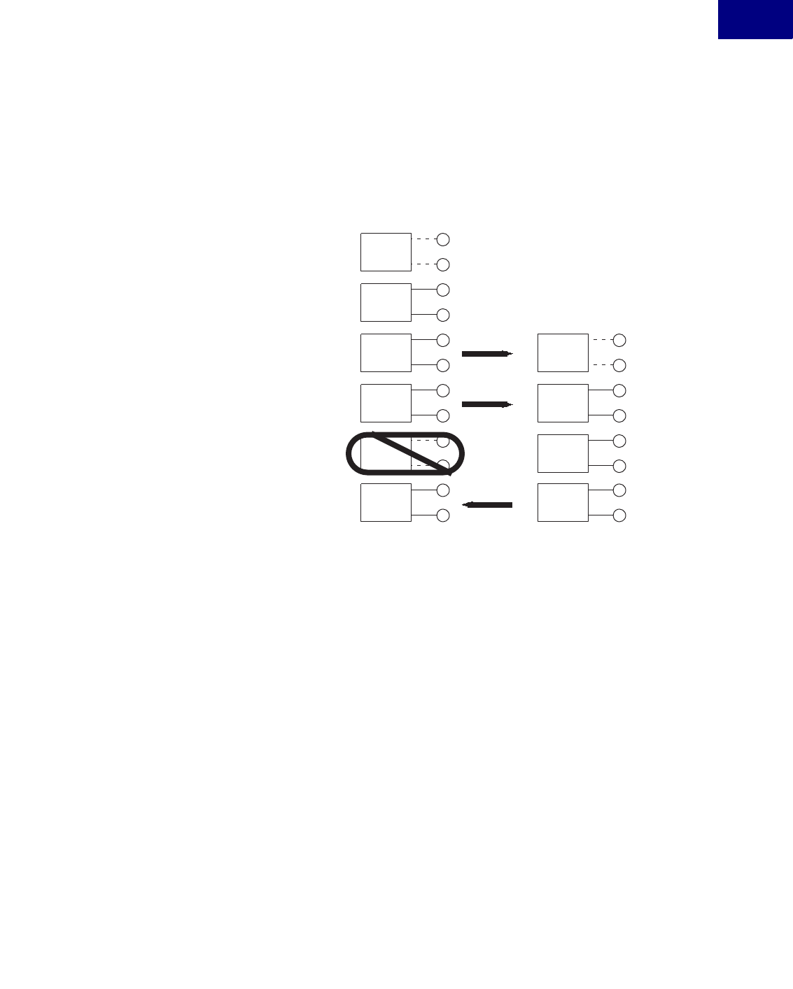
Persistent Data and Data Conversion 31
Persistent Data and Data Conversion
Persistent objects
into memory. Because individual objects can be saved and loaded, the host does not have to
load the entire document into memory at once.
FIGURE 2Creating and storing persistent objects
Creating a persistent object
Creating a new instance of a persistent object differs from creating a non-persistent object,
because it requires a unique identifier to associate the object with its record in the database. For
the CreateObject and CreateObject2 methods used to create persistent objects, see
<SDK>/source/public/includes/CreateObject.h.
For examples of the creation of persistent objects, see the CreateWidgetForNode method in
<SDK>/source/sdksamples/paneltreeview/PnlTrvTVWidgetMgr.cpp or the StartupSomePal-
ette method in <SDK>/source/sdksamples/dynamicpanel/DynPnPanelManager.cpp.
You also can call IDataBase::NewUID method to create a new UID in the database. It adds an
entry to the database relating the UID to the class of the object being created; however, the
object is not instantiated yet, and no other information about it exists in the database.
Instantiating a persistent object
Before you instantiate a new object, use the InterfacePtr template to retrieve one of the object’s
interfaces. Pass the returned InterfacePtr to the IDatabase::Instantiate method, which calls the
database to instantiate the object.
There is only one object in memory for any UID and database. This method checks whether
the object already is in memory and, if so, returns a reference to that object. If the object is
Host Main memory Storage
Instantiate
(no storage)
Dirty
ReadWrite
Instantiate
(with storage)
NewUID
Reference count
reaches zero

Persistent Data and Data Conversion
Persistent objects
32
marked as changed, it is written to the database. For more information, see “Reading and writ-
ing persistent data” on page 34. If the object is not in memory, the method checks for previ-
ously stored data in the database. If data is found, the method instantiates the object from this
data. Otherwise, the method instantiates the object from the object’s constructor. Each imple-
mentation has a constructor, so the boss and all its implementations are instantiated.
An object is stored to the database only if it is changed, making the default object data invalid.
A single object could exist and be used in several user sessions without ever being written to
the database. A persistent object whose data is not stored in the database is constructed from
the object’s constructor.
Whether it instantiates a new object or returns a reference to an object previously instantiated,
IDatabase::Instantiate increments the reference count on the object and returns an IPMUn-
known* to the requested interface, if the interface is available.
Using commands and wrappers
There are commands for creating new objects of many of the existing classes (e.g., kNewDocC-
mdBoss, kNewPageItemCmdBoss, kNewStoryCmdBoss, and kNewUIDCmdBoss). When you
need to create an object, first look for a suite interface, utility interface, or facade interface to
make creating your object safe and easy. If no such interface exists, use a command if one is
available, rather than creating the object with general functions.
Using a command to create an object protects the database. Commands are transaction based;
if you use a command when the application already is in an error state, the command performs
a protective shut-down, which quits the application rather than permitting a potentially cor-
rupting change to be made to the document. Commands also provide notification for changes
to the model, allowing observers to be updated when the change is made, including changes
made with undo and redo operations.
When you implement a new type of persistent object, also implement a command to create
objects of that type, using methods outlined in “Implementing persistent objects” on page 33.
Types of references to objects
There are four types of reference to a persistent object: UID, UIDRef, InterfacePtr, and
UIDList. Each type of reference serves a different purpose. Understanding these reference
types makes working with persistent objects easier.
zUID is the type used for a unique identifier within the scope of a database. The UID value
by itself is not sufficient to identify the object outside the scope of the database. Like a
record number, a UID value has meaning only within a given database. UID values are use-
ful for storing, passing, and otherwise referring to boss objects, because UID values have no
run-time dependencies, and there is an instance cache ensuring fast access to the instanti-
ated objects. kInvalidUID is a value used to identify a UID that does not point at a valid
object. Any time a UID is retrieved and needs to be tested to see if it points at a valid object,
the UID should be compared to kInvalidUID.
zA UIDRef object contains two pieces of information: a pointer to a database and the UID of
an object within this database. A UIDRef is useful for referring to objects, because it identi-
fies both the database and the object. Using a UIDRef object is a common means of refer-
ring to a persistent object, especially when the persistent object is to be passed around or

Persistent Data and Data Conversion 33
Persistent Data and Data Conversion
Persistent objects
stored, since a UIDRef does not require the referenced object to be instantiated. A UIDRef
object cannot itself be persistent data, because it has a run-time dependency, the database
pointer. An empty or invalid UIDRef object has kInvalidUID as its UID and a nil pointer as
its database pointer.
zA InterfacePtr object contains a pointer to an interface (on any type of boss object) and
identify an instantiated object in main memory. While an InterfacePtr object on the boss is
necessary for working with the boss, it should not be used to track a reference to a persistent
object, because this forces the object to stay in memory. In many cases, a nil pointer
returned from InterfacePtr does not indicate an error state but simply means the requested
interface does not exist on the specified boss.
zA UIDList object contains a list of UIDs and a single pointer to a database. This means all
objects identified by a UIDList must be within the same database. A UIDList is a class
object and should be used any time a list of objects is needed for a selection or a command.
Destroying an object
There are commands for deleting persistent objects. Use the command rather than calling the
DeleteUID method directly, to be sure of cleaning up all references to the object or item refer-
ences contained in the object.
When you implement a command to delete a persistent object, after you remove the references
to the object, use DeleteUID to delete the object from the database, as follows:
IDataBase::DBResultCode dbResult = database->DeleteUID(uid);
Implementing persistent objects
To make a boss object persistent, add the IPMPersist interface. Any boss with this interface is
persistent and, when an object of the boss is created, it is assigned a UID. Even though the
object has a UID, and the UID has an entry in the (ClassID, UID) pairings in a database, the
object does not automatically store data. It is up to the interface to store the data it needs. To
implement this, add the ReadWrite method to the interface (see “Reading and writing persis-
tent data” on page 34), and make sure the PreDirty method is called before information is
changed (see “Marking changed data” on page 34).
NOTE:If you add an interface to an existing persistent boss, the interface also may be made
persistent. If so, you must obey the following implementation rules for it.
Adding the IPMPersist interface to a boss
All instances of IPMPersist must use the kPMPersistImpl implementation. For an example, see
the kPstLstDataBoss boss class definition in <SDK>/source/sdksamples/persistentlist/PstLst.fr
Creating an interface factory for a persistent interface
For a persistent implementation, use the CREATE_PERSIST_PMINTERFACE macro.

Persistent Data and Data Conversion
Streams
34
Reading and writing persistent data
To store data, your interface must support the ReadWrite method. This method does the actual
reading and writing of persistent data in the database. The method takes a stream argument
containing the data to be transferred. Read and write stream methods are generalized, so one
ReadWrite method handles transfers in both directions. For example, XferBool reads a boolean
value for a read stream and writes a boolean value for a write stream. For an example, see the
BPIDataPersist::ReadWrite method in <SDK>/source/sdksamples/basicpersistinterface/BPI-
DataPersist.cpp.
Marking changed data
When data changes for a persistent object that resides in memory, there is a difference between
the current version of the object and the object as it exists in the database’s storage. When this
happens, the object in memory is said to be dirty, meaning it does not match the version in
storage. Before a persistent object is modified, you must call the PreDirty method to mark the
object as being changed, so it is written to the database. For an example, see the BPIDataPer-
sist::Set method in <SDK>/source/sdksamples/basicpersistinterface/BPIDataPersist.cpp.
The PreDirty method called from within BPIDataPersist::Set is implementation-independent,
so you can rely on the version provided by HELPER_METHODS macros defined in Helper-
Interface.h (DECLARE_HELPER_METHODS, DEFINE_HELPER_METHODS, and
HELPER_METHODS_INIT).
Streams
This section discusses how streams are used to move information into and out of a document.
Streams are used by persistent objects to store their information to a database. Streams also are
used by the host application, to move data like placed images, information copied to the clip-
board, and objects stored in the database. IPMStream is the public interface to streams. Imple-
mentations of IPMStream typically use the IXferBytes interface to move data.
Stream utility methods (in StreamUtil.h) are helpers for creating all the common types of
streams used to move information within or between InDesign databases. The stream utility
methods and general read, write, and copy methods are needed any time you work with a
stream.
IPMStream methods
IPMStream is a generalized class for both reading and writing streams. Any particular stream
implementation is either a reading stream or a writing stream, and the type of stream can be
determined with the IPMStream::IsReading and IPMStream::IsWriting methods.
Any persistent implementation has a ReadWrite method, which uses a set of data-transferring
methods on the stream to read and write its data. (See “Reading and writing persistent data” on
page 34.) The IPMStream methods starting with the Xfer prefix are used for transferring the

Persistent Data and Data Conversion 35
Persistent Data and Data Conversion
Streams
data type identified in the method name. For example, XferByte transfers a byte, XferInt16
transfers a 16-bit integer, XferBool transfers a boolean value, and so on. All transferring meth-
ods are overloaded, so they can take a single item or an array of items. (The XferByte(uchar,
int32) version typically is used for buffers.) Streams also handle byte swapping, if required. If
swapping is not set (SetSwapping(bool16)), the default is to not do byte-order swapping.
Additional IPMStream methods, XferObject and XferReference, transfer boss objects and ref-
erences to objects. XferObject transfers an owned object, and XferReference transfers a refer-
ence to an object not owned by the object using the stream. To decide which method to use,
think about what should happen to the object if the owning object were deleted. If the object
should still be available (as, for example, the color a page item refers to), use XferReference. If
the item is owned by the object and should be deleted with the owner (as, for example, the page
a document refers to), use XferObject.
Implementing a new stream
If you must read from or write to a location the host application does not recognize, you must
create a new type of stream. For example, you might need to create a new stream type to import
and export files stored on an FTP site or in a database.
Stream boss
The first step in implementing a new stream is to define the boss. Typically, a stream boss con-
tains IPMStream and any interface required to identify the type of information in the stream,
the target or source of the stream, or both. Example 1creates a pointer-based read-stream boss:
EXAMPLE 1 kExtLinkPointerStreamWriteBoss, a pointer based stream boss
Class
{
kExtLinkPointerStreamWriteBoss,
kInvalidClass,
{
IID_IPMSTREAM, kExtLinkPointerStreamWriteImpl,
IID_IPOINTERSTREAMDATA, kPointerStreamDataImpl,
}
};
IPMStream is the only interface all stream bosses have in common. In Example 1, the IPointer-
StreamData controls a stream that writes out to memory; it contains a buffer and a length.

Persistent Data and Data Conversion
Missing plug-ins
36
Example 2 is another example.
EXAMPLE 2 kFileStreamReadBoss, a stream commonly used in importing
Class
{
kFileStreamReadBoss,
kInvalidClass,
{
IID_IPMSTREAM, kFileStreamReadLazyImpl,
IID_IFILESTREAMDATA, kFileStreamDataImpl,
}
};
IPMStream interface and the IXferBytes class
When implementing your own stream, take advantage of the default implementations of IPM-
Stream, CStreamRead, and CStreamWrite. These default implementations use an abstract base
class, IXferBytes, to do the actual reading and writing. To implement a stream for a new data
source, you must create an IXferBytes subclass that can read and write to that data source.
Missing plug-ins
This section discusses how to open a document that contains data saved by a plug-in that is no
longer available.
Plug-ins you create can add data to the document. When your plug-in is present and loaded, it
can open and interpret the data; however, if the user removes the plug-in and then opens the
document, or gives the document to someone who does not have the plug-in, the plug-in is not
available to interpret the data.
You have two ways to handle such situations:
zControl what warning is shown when the document is opened without the plug-in.
zImplement code to update the data the next time the document is opened with the plug-in.
The rest of this section describes these options.
Warning levels
The application can give a warning when it opens a document that contains data created by a
plug-in that is not available. There are three warning levels: critical, default, and ignore. By set-
ting the warning level, the plug-in can specify the relative importance of its data. Data created
by the plug-in has the “default” warning level unless you override the setting and identify the
data as more important (critical) or less important (ignored). This importance settings can be
modified by adding resources to the plug-in’s boss definition file:
zCriticalTags — A “critical” warning tells the user the document contains data from missing
plug-ins and strongly advises the user not to open the document. If the user continues the

Persistent Data and Data Conversion 37
Persistent Data and Data Conversion
Missing plug-ins
open operation, the application opens an untitled document that is a copy of the original, to
preserve the original document. Use this level when the data is visible in the document or
contributes objects owned by another object in the database, like text attributes, owned by
the text model.
zDefaultTags — A “default” warning tells the user the document contains data from missing
plug-ins and asks whether to continue the open operation. If the user continues the open
operation, the application opens the original document. Use this level when the data is self-
contained and invisible to the user, but the user might encounter missing function that
would have been provided by the plug-in.
zIgnoreTags — An “ignore” warning provides no warning message at all; the application pro-
ceeds with the open operation as if there were no missing plug-ins. Use this level when the
data is invisible to the user and completely self-contained. In this case, the user does not
need to know the plug-in was involved in the construction of this document. If the plug-in
stored data in the document, but that data is used only by this plug-in and does not refer-
ence objects supplied by other plug-ins, the user sees no difference in the document when
the plug-in is missing. For example, the plug-in might store preferences information in
every document for its own use.
You can set these warnings to use ClassID (when the plug-in creates new bosses) or Implemen-
tationID (when the plug-in adds interfaces to existing bosses) values as triggers. Use kImple-
mentationIDSpace to specify a list of ImplementationID values, and kClassIDSpace for
ClassID values. You can put any number of IDs in the list, but all the IDs must be of the same
type. Use a second resource to mark IDs of another type. Example 3 and Example 4 set the
warning level to ignore data stored by the PersistentList plug-in in the SDK by adding two
resources to PstLst.fr:
EXAMPLE 3 Marking implementation IDs as ignored
resource IgnoreTags(1)
{
kImplementationIDSpace,
{
kPstLstDataPersistImpl,
kPstLstUIDListImpl,
}
};
EXAMPLE 4 Marking boss classes as ignored
resource IgnoreTags(2)
{
kClassIDSpace,
{
kPstLstDataBoss,
}
};
You do not need to mark any IDs that do not appear in the document (for example, data that
was written out to saved data) or implementations that are not persistent.
You do not need to mark IDs if you want the default behavior.

Persistent Data and Data Conversion
Missing plug-ins
38
Missing plug-in alert
This alert is activated when a document is opened and contains data from one or more missing
plug-ins that cannot be ignored. The document contains a list of the plug-ins that added data to
it. Each piece of data added has an importance attached to it; this may be critical, default, or
ignorable. Data marked as ignorable does not cause the alert to be activated. Data marked as
critical or default causes the alert to be activated. In the case of critical data, the alert works
more strongly; this is the only difference between critical and default data.
The alert tells the user data is missing, presents a list of missing plug-ins, and allows the user to
continue or cancel the open operation. Each missing plug-in has the chance to add a string to
the alert that specifies additional useful information (e.g., a URL for purchasing or download-
ing the plug-in). The alert is modeled on the missing-font alert.
The “Don’t Warn Again For These Plug-ins” option is de-selected by default. If this option is
selected, the alert is not activated the next time a document is opened and any subset of the
listed plug-ins is missing (and no other plug-ins are missing). This allows users accustomed to
seeing (and ignoring) alerts concerning specific plug-ins to automatically bypass the alert,
while still getting warned about data from any plug-ins newly found to be missing. The alert is
activated again if a document is opened that uses other missing plug-ins. The alert is activated
again if the “Don’t Warn Again For These Plug-ins” option is de-selected.
Guidelines for handling a missing plug-in
If a plug-in creates persistent data in a document, these guidelines ensure the document
behaves gracefully if a user tries to open it when the plug-in is missing or if the document is
edited by a user who did not have the plug-in:
If your plug-in does not store data in documents, you do not need to take any special precau-
tions.
If the data stored by your plug-in does not reference other data in the document and does not
appear visually in the document, mark the data as ignorable.
If editing the document without your plug-in could corrupt the document, mark the data as
critical. You can specify a string that is displayed when the plug-in is missing and the user
opens a document that contains data added by the plug-in. See the ExtraPluginInfo resource,
which may provide information like the URL of a site from which the missing plug-in can be
obtained. See an example of the use of this resource in <SDK>/source/sdksamples/transparen-
cyeffect/TranFx.fr.
If there are checks your plug-in can do to restore the data’s integrity on opening a document
edited without the plug-in, supply a FixUpData method. For an example, see
<SDK>/source/sdksamples/persistentlist/PstLstPlugIn.cpp.
If you want your plug-in to handle the storage of its own data, use the application-supplied
mechanism that treats the plug-in’s data like a black box. (See “Black-box data storage” on
page 39.)

Persistent Data and Data Conversion 39
Persistent Data and Data Conversion
Missing plug-ins
Data handling for missing plug-ins
If a document contains data placed there by a plug-in that is not available, the user can choose
to open the document anyway. If the data is completely self-contained, there may be no prob-
lem; however, if the plug-in’s data depends on anything else in the document, undesirable
things can happen.
Missing data not copied
InDesign maintains most data in a centrally managed model in which the core-content man-
ager keeps track of what information is added to the document, handles conversion of the data,
and provides a convenient mechanism for instantiating objects based on the data. This
approach does not allow the data to be copied when the plug-in is missing, however, because
the content manager would not be able to provide these services for the missing plug-in’s cop-
ied data, and that potentially can leave the document in an invalid state. With the exception of
those objects that hold onto only ClassID values, InDesign blocks copying data associated with
missing plug-ins.
This means no attribute is copied if the plug-in that supplies the attribute is missing. This
applies to all attributes: text, graphics, table, cjk, etc. Furthermore, if a plug-in attached a data
interface to an existing attribute, and the plug-in is missing, the attribute is copied but the add-
in data interface is not. This is consistent with how InDesign handles UID-based objects.
Likewise, if a data interface is added to an XML element, the data interface is not copied if the
plug-in that supplied it is missing.
There are several features based on an object from a required plug-in holding a ClassID from
an optional plug-in, including adornments, text composer, pair-kern algorithm, section num-
bers, and unit defaults. In these cases, the consequences of losing track of the plug-in that sup-
plied the data is much less severe. Conversion of these ClassIDs is quite unusual and could be
handled if necessary by issuing new ClassIDs. Error handling in the user interface when the
plug-in is missing is much more graceful.
Black-box data storage
A second, simpler data-model storage mechanism was added for software developers requiring
that data (like text attributes) is copied with the text, and for developers who want to attach
data to other ID objects, such that it gets copied even when the source plug-in is missing. This
mechanism is black-box data storage.
In the simplest case, the black box is just a new persistent interface that sits on the object. A
plug-in can store data in the box or fetch data out of the box. The data is keyed by a ClassID,
which is supplied by the plug-in. Multiple plug-ins can store their data in the same black box,
and each plug-in gets its own, unique, streamed access to its data. The black box just keeps
track of the key, the length of the data, and the data stream. The software developer is responsi-
ble for handling everything else—conversion, swapping, etc. Users do not get a missing plug-in
alert for data placed in a black box.
Any UID-based object could have a black box. In addition, attributes and small bosses (used
for XML elements) also can have black boxes.

Persistent Data and Data Conversion
Conversion of persistent data
40
The following objects support black boxes:
zkDocBoss — The root object of the document does not get copied.
zkPageItemBoss — This includes all page item objects, including spreads, master pages,
splines, frames, images, and text frames.
zAttributes — This includes text, graphic, table, cjk, etc. (i.e., everything that appears in an
AttributeBossList).
For more information on the black-box mechanism, see IBlackBoxCommands, IBlackBoxCm-
dData, and IBlackBoxData in the API reference documentation.
FixUpData
Suppose a hyperlink attribute is linked to another frame, and the user can double-click the link
to go to the frame. A plug-in supplies an observer, so if the frame is deleted, the link is severed.
Now suppose you give the document containing the hyperlinks to someone who does not have
the hyperlink plug-in. This person edits the document, deletes the frame, saves the document,
then returns the document to you. The document is now corrupted, because your plug-in was
unable to delete the associated link, which now points to an undefined frame.
To restore the integrity of a document in this case, the plug-in can override the IPlugIn::FixUp-
Data method. This method is called when the document is opened, if the plug-in was used to
store data in the document and the document was edited and saved without the plug-in. In this
case, the hyperlinks plug-in could override FixUpData to scan all its objects, checking whether
the linked frame UIDs were deleted; when the document is opened with the plug-in, the
method correctly severs the links.
Conversion of persistent data
This section describes types of conversion providers and the advantages of each type.
Converting persistent data from an old document to a new one is complex, because each plug-
in can store data independently in the document. When the host opens a document created
with an older version of the application or an older version of any plug-in used in the docu-
ment, you must convert and update the older data to match the new format.
Versioning persistent data is the process of converting persistent data in a database from one
format to another. The data in different formats usually resides in different databases; for
example, data in a database (document) from a previous version of InDesign versus that in a
database (document) from a newer version of InDesign. Just as each plug-in having a persistent
data implementation is responsible for the order of reading and writing its own data (thus
implicitly defining a data format), each plug-in also is responsible for converting its own data
from one format to another. Whether data in a database requires conversion usually is deter-
mined when the database is opened.

Persistent Data and Data Conversion 41
Persistent Data and Data Conversion
Conversion of persistent data
There are two approaches to converting persistent data:
zYou can use the host’s conversion manager to manage the conversion process. This
approach is the most common. See “Converting data with the conversion manager” on
page 42.
zThe plug-in that owns the data can manage when and how data is converted, using version
information or other data embedded with the object data. See “Converting data without the
conversion manager” on page 52.
When to convert persistent data
As a plug-in developer, you want to ensure your users can open documents with persistent data
from an older version of your plug-in. To do this, your plug-in must provide data conversion
function. The best time to consider your data-conversion strategy is when you realize your
plug-in will store some data to a database. You need to implement data-conversion utilities in
the following cases:
zYou change the order of IPMStream::Xfer* calls in the ReadWrite method.
zYou change a persistent object’s definition.
zYou re-number (change the value of) an ImplementationID or ClassID identifier.
zYou remove a plug-in and data from the removed plug-in might be in a document a user
wants to open.
In any of these cases, the conversion manager needs to be notified how to convert the persistent
data for use by the loaded plug-in.
Specifying how the persistent data format changed is somewhat different from adding persis-
tent data to or removing it from a document. Besides telling the conversion manager to add or
delete any obsolete data, the conversion provider has to be able to tell the conversion manager
about every implementation in the plug-in that was ever removed, to keep the content manager
up to date about the various persistent data formats.
NOTE:To provide a document for use with an earlier version of InDesign, use the InDesign
Interchange file format.
At the very least, the resources required to support data conversion can help you keep a log of
how your persistent data format has changed. Such a log can be useful.
Sample conversion scenario
Consider a plug-in with two released versions, 1 and 2, which use the same data format; in this
case, both versions of the plug-in have the same format version number, 1. The new release of
the plug-in, version 3, stores additional data, such as a time stamp. You must update the format
version number to match the current plug-in version number; so, for plug-in version 3, the for-
mat version also would be 3. Because you changed the format version number, you must create
a converter that converts from version 1 to version 3. See Table 1.

Persistent Data and Data Conversion
Conversion of persistent data
42
TABLE 1 Version changes example
For a fourth version of the plug-in, you again change the format, allowing a date stamp to be
signed. Change the plug-in and format version numbers to 4, and add an additional converter
to convert from version 3 to version 4. Conversions from version 1 to version 4 are done by the
conversion manager, which chains the converters together; the first converts from format ver-
sion 1 to format version 3, and the second converts from format version 3 to format version 4).
Converting data with the conversion manager
Each document contains header information about the content, which includes a list of all
plug-ins that wrote data to the document and the version number of the plug-in last used to
write that data. When a document is opened, the application checks whether any plug-ins are
missing or out of date. If a plug-in is missing, it might provide an alert embedded in the docu-
ment. (See “Missing plug-ins” on page 36.)
If a plug-in is out of date, data written by the old plug-in must be updated to match the format
required by the loaded plug-in. A plug-in can register a conversion service to do the update.
The InDesign conversion manager (IConversionMgr) determines which conversions are
required for opening the document and calls the appropriate plug-in to do the conversion.
When the persistent data for any plug-in changes, this is a document format change. Any of the
following can change the document format:
zChanges to the ReadWrite method — If the ReadWrite method is used to stream data to the
document, changing the ReadWrite method might change the document format; however,
an implementation might have a ReadWrite method that works with some other database
or other data source, not with the document itself. For example, a widget has a ReadWrite
method used for streaming to and from resources and to and from the SavedData file.
Changes to a method that does not work with the document database do not require any
special conversion.
zChanges to an object’s definition — If you add an implementation to (or remove an imple-
mentation from) the definition of a persistent boss in the framework resource (.fr) file, you
change how the object is streamed. If you add a new implementation, an old version of the
object will stream, but it will not contain the data normally appearing for the implementa-
tion you added. This is fine if the data can be initialized adequately from the implementa-
tion’s constructor; otherwise, you may need to add a converter. If you change the
implementation of an interface from one ImplementationID to another, you must convert
the data. If you remove an ImplementationID from a class, you should add a converter to
Plug-in version Format change Format version
1N/A (new plug-in) 1.0
2No1.1
3Yes 3
4Yes4

Persistent Data and Data Conversion 43
Persistent Data and Data Conversion
Conversion of persistent data
strip the old data from the object; otherwise, the obsolete data is carried around with the
object indefinitely.
zRe-numbering an ImplementationID or ClassID — If an ImplementationID or ClassID
changes, you must register a converter so occurrences of the ImplementationID or ClassID
in old documents can be updated. In practice, re-numbering a ClassID or Implementa-
tionID is a source of many bugs and typically leads to corrupt documents, so we strongly
recommend you not re-number an ImplementationID or ClassID.
When you make a format change, you must do two things to maintain backward compatibility:
zUpdate the version number of the plug-in whose data format you changed.
zProvide a converter that can convert between the previous format and the new format.
Updating version numbers
Each plug-in has a plug-in version resource of type PluginVersion. The PluginVersion resource
appears in the boss definition file. The first entry of this resource describes the application's
build number; on the release build, this entry is the final-release version number. The second
entry of the resource is the plug-in's ID, followed by three sets of version numbers, followed by
an array of feature-set IDs. If any of the IDs in this list matches the current feature-set ID, the
plug-in is loaded. To see an example, open any example .fr file in the SDK.
Each version number has a major number and a minor number. The first version number is the
version of the plug-in, which gets updated for every release of the plug-in. The second version
number is the version of the application with which the plug-in expects to run. This ensures
the user does not drop a plug-in compiled for one version of the application into an installation
of another version of the application. The last number is the format version number, which
indicates the version of the plug-in that last changed the file format; this is the version number
written into the document, and it is the number the conversion manager checks to see whether
conversion is required.
The format version number does not always match the plug-in’s version number. The format
version number does not generally change as often as the plug-in version number. The plug-in
version number changes for every release of a plug-in, but the format version number changes
only if the format for the data the plug-in stores in the document has changed and the conver-
sion manager is required to convert the data.
Adding a converter
Converters can be implemented as conversion services. InDesign supports two types of ser-
vice-provider-based data conversion:
zSchema-based provider — Schema-based converters are configured through resources, are
easier to use than code-based converters, and cover most format-change needs. Use this
type of converter unless it cannot handle the special needs of your plug-in.
zCode-based provider — If your implementation uses a special data-compression algorithm
or other storage optimizations, involves data of variable length, or uses virtual object store
(VOS) objects, schema-based converters cannot handle the necessary data format conver-
sions. In this case, you must implement your own custom conversion provider.

Persistent Data and Data Conversion
Conversion of persistent data
44
A conversion service is responsible for all conversions done by the plug-in. A converter might
at first handle only a single conversion, from the first format to the second. Later, if you change
the format again, you can add another conversion to the converter, to convert from the second
format to the third.
Suppose you market a plug-in that supplies a date stamp. You had released two versions (ver-
sion 1.0 and version 2.0) of the plug-in without changing the persistent data created by the
plug-in; so both releases have the same format version number (1.0). For the third released ver-
sion of the plug-in, you add a time stamp. You must update the format version number to
match the current plug-in version number; i.e., for plug-in version 3.0, the format version also
must be 3.0.
Suppose for the fourth released version of the plug-in (version 4.0), you again change the for-
mat, allowing a date stamp to be signed. You then change the format version number to 4.0 and
add an additional converter, capable of converting from format version 3.0 to format version
4.0. Conversions from format version 1.0 to format version 4.0 can be done by the conversion
manager, which chains the two converters together, using the first converter to convert from
format version 1.0 to format version 3.0, and using the second converter to convert format ver-
sion 3.0 to format version 4.0.)
Adding a converter (either schema-based or code-based) to your plug-in means adding a new
boss with two interfaces, IK2ServiceProvider and IConversionProvider. The
IK2ServiceProvider implementation, kConversionServiceImpl, is provided by the application.
You need to supply the IConversionProvider implementation. Here is a sample boss:
/**
This boss provides a conversion service to the conversion manager
to use the schema-based implementation.
*/
Class
{
kMyConversionProviderBoss,
kInvalidClass,
{
IID_ICONVERSIONPROVIDER, kMySchemaBasedConversionImpl,
IID_IK2SERVICEPROVIDER, kConversionServiceImpl,
}
},
Most of the work is done in the conversion provider supplied with the SDK.
The default implementation of IConversionMgr calls IConversionProvider::CountConversions
and IConversionProvider::GetNthConversion to determine which conversions are supported
by the converter. When you implement a new converter, CountConversions returns 1, and Get-
NthConversion returns fromVersion set to the version number before your change and toVer-
sion set to the version number having your change in it. VersionID is a data type in the Public
library; it consists of the PluginID value, the major format version number, and the minor for-
mat version number.
For a new converter, fromVersion should be VersionID(yourPluginID, kOldPersistMajorVer-
sionNumber, kOldPersistMinorVersionNumber). The toVersion should be the new format ver-
sion number.

Persistent Data and Data Conversion 45
Persistent Data and Data Conversion
Conversion of persistent data
Your new conversion is added as conversion index 0. For a new converter, it looks like this:
int32 TextConversionProvider::CountConversions() const
{
return 1;
}
void TextConversionProvider::GetNthConversion(
int32 i, VersionID* fromVersion, VersionID* toVersion) const
{
*fromVersion = VersionID(kTextPluginID, kOldPersistMajorVersionNumber,
kOldPersistMinorVersionNumber);
*toVersion = VersionID(kTextPluginID, kNewPersistMajorVersionNumber,
kNewPersistMinorVersionNumber);
}
When adding another change after a changed version already exists, the change numbers
should chain together so the conversion manager can do changes across multiple formats. So, if
your plug-in used three formats—starting with version 1, then changed in version 3, and
changed again in version 4—your plug-in should register one converter that handles the con-
version from format version 1 to format version 3 and another converter that handles the con-
version from format version 3 to format version 4. If necessary, the conversion manager can
chain them together to convert a document from version 1 to version 4. The methods would
look like this:
const int32 kFirstFormatVersion = 1;
const int32 kSecondFormatVersion = 3;
const int32 kThirdFormatVersion = 4;
const int32 kFirstChange = 0;
const int32 kNewChange = 1;
int32 TextConversionProvider::CountConversions() const
{
return 2;
}
void TextConversionProvider::GetNthConversion(
int32 i, VersionID* fromVersion, VersionID* toVersion) const
{
if (i == kFirstChange)
{
*fromVersion = VersionID(kTextPluginID, kMajorVersionNumber,
kFirstPersistMinorVersionNumber);
*toVersion = VersionID(kTextPluginID, kMajorVersionNumber,
kSecondPersistMinorVersionNumber);
}
else if (i == kNewChange)
{
*fromVersion = VersionID(kTextPluginID, kMajorVersionNumber,
kSecondPersistMinorVersionNumber);
*toVersion = VersionID(kTextPluginID, kMajorVersionNumber,
kThirdPersistMinorVersionNumber);
}
}

Persistent Data and Data Conversion
Conversion of persistent data
46
Next, tell the conversion manager which information you changed. The default implementa-
tion of IConversionMgr calls IConversionProvider::ShouldConvertImplementation with each
implementation in the document supplied by the plug-in. Depending on the data status of the
implementation, the plug-in must return kMustConvert when the content must be modified,
kMustRemove when the data is obsolete and must be removed, kMustStrip when the content
must be stripped, or kNothingToConvert for all other cases.
Using kTextFrameImpl as an example, define a method for IConversionProvider::ShouldCon-
vertImplementation, returning kMustConvert when the tag is kTextFrameImpl and kNothing-
ToConvert in all other cases. The plug-in should do this when the conversion manager is
converting that plug-in’s data and not performing another conversion, so check the conversion
index and make sure it is the one that you added. It might look like the following:
IConversionProvider::ConversionStatus
TextConversionProvider::ShouldConvertImplementation(
ImplementationID tag, ClassID context, int32 conversionIndex) const
{
IConversionProvider::ConversionStatus status =
IConversionProvider::kNothingToConvert;
switch (conversionIndex)
{
case 0:
if (tag == kTextFrameImpl)
status = IConversionProvider::kMustConvert;
break;
default:
break;
}
return status;
}
Next, implement ConvertTag to do the actual conversion. Suppose the TextFrame ReadWrite
method writes an integer value and a real value, and you are adding a boolean. The ConvertTag
implementation might look like the following, which illustrates what most converters look like:
ImplementationID TextConversionProvider::ConvertTag(
ImplementationID tag, ClassID forClass, int32 conversionIndex, int32 inLength,
IPMStream* inStream, IPMStream* outStream, IterationStatus whichIteration)
{
ImplementationID outTag = tag;
switch (conversionIndex)
{
case 0:
if (tag == kTextFrameImpl)
{
if (inLength > 0)
{
int32 passThruInt; inStream->XferInt32(passThruInt);
outStream->XferInt32(passThruInt);
int32 passThruReal; inStream->XferInt32(passThruReal);
outStream->XferInt32(passThruReal); // Adding new field bool16 smartQuotes =
kTrue;
outStream->XferInt32(smartQuotes);

Persistent Data and Data Conversion 47
Persistent Data and Data Conversion
Conversion of persistent data
}
} break;
default:
break;
} return outTag;
}
If the converter needs to convert a class, it implements ShouldConvertClass and ConvertClass.
This is necessary only if the class is being deleted or is a container for some other data. (See
“Containers and embedded data” on page 48.)
Removing classes or implementations
If you remove a ClassID or an ImplementationID from a version of your plug-in, the identifier
also must be removed from documents as they are converted. The conversion manager
removes an identifier for you if you implement your converter to return invalid status. For
example, to remove a tag, implement ConvertTag as follows:
ImplementationID TextConversionProvider::ConvertTag(
ImplementationID tag, ClassID forClass, int32 conversionIndex, int32 inLength,
IPMStream* inStream, IPMStream* outStream, IterationStatus whichIteration)
{
ImplementationID outTag = tag;
switch (conversionIndex)
{
case 0:
if (tag == kTagToRemove)
outTag = kInvalidImpl;
break;
default:
break;
}
return outTag;
}
Deleting a class is similar: implement ConvertClass to return kInvalidClass.
Changing an implementation in one class
Suppose a boss is defined with an IBoolData interface, implemented as kPersistBoolTrue,
meaning it defaults to true. Suppose you change this to kPersistBoolFalse. When you read an
old document with the new boss, you want it to use the new implementation. You would then
write a converter to take the data stored as kPersistBoolTrue and switch it to be stored as kPer-
sistBoolFalse. When you first access the boss, it has the old value. If you do not make a con-
verter, the boss will not read the old data, because there is no interface in the new boss using
the kPersistBoolTrue ImplementationID. Instead, the boss looks for kPersistBoolFalse but does
not find it, because the old boss did not have it; therefore, the value is false, because it is the
default value instead of the old value.
To change the ImplementationID of the data in the document, make a conversion method to
catch the old ImplementationID and change it to the new one. Do this only for your boss; do
not change other bosses using kPersistBoolTrue. Your method might look like this:

Persistent Data and Data Conversion
Conversion of persistent data
48
ImplementationID TextConversionProvider::ConvertTag(
ImplementationID tag, ClassID forClass, int32 conversionIndex, int32 inLength,
IPMStream* inStream, IPMStream* outStream, IterationStatus whichIteration)
{
ImplementationID outTag = tag;
switch (conversionIndex)
{
case 0:
if (tag == kPersistBoolTrue && forClass == kMyBoss)
outTag = kPersistBoolFalse;
bool16 theBool;
inStream->XferBool(theBool);
outStream->XferBool(theBool);
break;
default:
break;
}
return outTag;
}
forClass is the boss in which the data was found. The conversion should be done only if
forClass is the one you want changed.
Also implement ShouldConvertImplementation. forClass is either the class in which the data
was found or kInvalidClass if any class should match. The implementation of ShouldCon-
vertImplementation looks like this:
IConversionProvider::ConversionStatus
TextConversionProvider::ShouldConvertImplementation (
ImplementationID tag, ClassID forClass, int32 conversionIndex) const
{
IConversionProvider::ConversionStatus status =
IConversionProvider::kNothingToConvert;
switch (conversionIndex){
case 0:
if (tag == kTextFrameImpl &&
(forClass == kMyBoss || forClass == kInvalidClass))
status = IConversionProvider::kMustConvert;
break;
default:
break;
}
return status;
}
Containers and embedded data
InDesign does not have many instances of containers. One example is in the text attribute code.
A text style is a UID-based boss object containing an implementation, TextAttributeList, that
contains a list of attribute bosses (Bold, Point Size, Leading, and so on). These attribute bosses
are not UID-based bosses; instead, TextAttributeList streams the ClassID for a boss, followed
by the boss’s data, then streams the next boss in the list. TextAttributeList, therefore, must call
the stream’s content tracker to notify the content manager that a new class was added to the
document.

Persistent Data and Data Conversion 49
Persistent Data and Data Conversion
Conversion of persistent data
The following example illustrates why this is important.
Suppose a new Red-Line plug-in adds an attribute to the style and the text does not compose
correctly if the Red-Line plug-in is removed. Red-Line can list the attribute as critical, so the
host provides a strongly worded warning when the user tries to open the document without the
Red-Line plug-in. However, if TextAttributeList does not register the attribute boss with the
content manager, the application never knows the attribute is in the document and cannot
warn the user. Suppose the Red-Line plug-in is updated, and the attribute boss in particular is
updated to store its data differently. The Red-Line plug-in registers a converter handling the
format change. If the host does not know the attribute appears in the document, the Red-Line
converter is never called to perform the conversion. The document appears to open correctly,
but it crashes on the attribute’s ReadWrite method the first time the style is read.
For the Red-Line attribute to be converted, TextAttributeList must register a converter. If the
content manager was notified when the attribute was streamed, the conversion manager knows
the attribute needs to be converted. It even knows the attribute was streamed by TextAt-
tributeList. But the conversion manager has no way of knowing where the attribute is inside the
data streamed by TextAttributeList; therefore, TextAttributeList should register a converter that
calls back to the conversion manager to convert each piece of embedded data. Otherwise, the
embedded data is not converted.
Content manager
The host has a content manager that tracks what data is stored in the document, which plug-in
stored it, and the format version number of the plug-in last used to write the data.
Think of this as a table attached to the root of the document: every ImplementationID part of
the document appears in the table. This table also includes all ClassID values in the document.
Table 2 and Table 3 are an example.
TABLE 2 Version information
ImplementationID PluginID Format version number (only
minor number)
kSpreadImpl kSpreadPluginID 0
kSpreadLayerImpl kLayerPluginID 0
kTextAttrAlignJustImpl kTextAttrPluginID 1
kCMSProfileListImpl kColorMgmtPluginID 3
...

Persistent Data and Data Conversion
Conversion of persistent data
50
TABLE 3 Class IDs in the document
When an object is streamed to a document, the document receives the ClassID of the object
and the data streamed by each of the object’s ReadWrite methods. The data written by a Read-
Write method is marked with the ImplementationID of the ReadWrite implementation; this
way, when the data is read later, the system knows which C++ class to instantiate to read the
data. IContentMgr maintains an overall list of the ClassID and ImplementationID values used
in the document. When a new ClassID or ImplementationID is added to the document, ICon-
tentMgr checks which plug-in supplied the ClassID or ImplementationID, notes the plug-in ID
and the format version number, and adds the new entry to the table.
The plug-in supplying a ClassID is the one supplying the class definition. Only the plug-in sup-
plying the original class definitions is considered; add-in classes do not count. The plug-in sup-
plying an ImplementationID is the one that registered a factory for the ImplementationID.
This data is used to detect missing plug-ins and manage document conversion. When the user
opens a document containing data supplied by a missing plug-in, the host alerts the user that
the document contains data from a missing plug-in. The host detects missing plug-ins by look-
ing in the content manager to see which plug-ins supplied data to the document and checking
this list against the list of loaded plug-ins to see whether any are missing.
This data also is used for document conversion. When the user opens a document, the default
implementation of IConversionMgr checks the format version number of the plug-ins supply-
ing data to the document and compares it with the format version number of loaded plug-ins.
Any mismatch means a conversion is required before the document can be opened. If there is a
format version change without a supplied data converter, the document will not open.
Conversion manager
When a document is opened, the conversion manager is called to check whether any data in
the document requires conversion. If the data requires conversion and a converter is available,
the document is converted and opens as an untitled document. If a converter cannot be found,
the host displays an alert message that warns the user the document cannot be opened because
it cannot be converted.
This initial check, implemented in IConversionMgr::GetStatus, happens very early in the pro-
cess of trying to open the document, before any objects in the document are accessed (i.e.,
before any of their ReadWrite methods are called). This is critical, because a ReadWrite
method will not succeed if the object needs to be converted. The conversion manager accesses
the content manager (converting it if necessary), and uses the content manager to find out what
ClassID Plug-in ID Format version number (only
minor number)
kSpreadBoss kSpreadPluginID 1
kSpreadLayerBoss kLayerPluginID 1
kTextAttrAlignBodyBoss kTextAttrPluginID 3
kDocBoss kDocFrameworkPluginID 1

Persistent Data and Data Conversion 51
Persistent Data and Data Conversion
Conversion of persistent data
plug-ins supplied data to the document. If any plug-ins used in the document have different
formats than the formats of the loaded plug-ins, conversion is necessary. Next, the conversion
manager sees whether there is a converter to convert from the format in the document to the
format associated with the loaded plug-in. If such a converter is available, conversion is possi-
ble; the document may be closed and opened again as an untitled document.
If the GetStatus method returns with a result indicating conversion is not necessary, the open
operation proceeds without calling the conversion manager again. If the GetStatus method
returns with a result indicating conversion is necessary but impossible, the open operation is
aborted. If the GetStatus method returns with a result indicating conversion is required and a
converter is available, the conversion manager’s ConvertDocument method is called to per-
form the conversion.
The first thing ConvertDocument does is compile a list of the classes and implementations in
the document that must be converted. A plug-in may have many different implementations
that wrote data to the document, but only one of these implementations might require conver-
sion. The conversion manager uses the content manager to iterate over classes and implemen-
tations supplied by the plug-in, and the conversion manager calls the converter to find out
which classes and implementations require conversion. Each class or implementation in the
document that the converter says must be converted is added to the list of classes or list of
implementations to be converted. Other data written by the plug-in is ignored by the converter;
it is not converted.
The next step is to iterate over the UIDs in the document. For each UID, the conversion man-
ager gets the class of the UID. If the class is on the list of classes to be converted, the conversion
manager calls a converter for the class. If, as is more common, the class contains an implemen-
tation needing to be converted, the conversion manager opens an input stream on the UID and
iterates through the implementations in the UID. If any implementation in the UID requires
conversion, an output stream is opened on the UID. Any implementation not requiring con-
version is copied to the output stream. If an implementation requires conversion, its converter
is called. The converter gets passed the input stream and the output stream. The converter
reads from the input stream in the old format and writes to the output stream in the new for-
mat.
After the UID iteration is completed, the content manager is called to update the format num-
bers for all plug-ins that were outdated, to show their data was converted and is up to date.
After this, it is safe for ReadWrite methods to be called on objects in the document.
If any converter requires access to another object to do its conversion, it is called in the last
phase of conversion. For example, suppose there was one document-wide preference setting for
whether text in frames has smart quotes turned on, but you want to make this a per-frame set-
ting. The text frame must store a new flag that indicates whether smart quotes are on or off.
The converter adds a new flag in the first phase of conversion, but the converter cannot set the
correct value for the flag until the preferences are converted. So, the converter needs to be
called once again, after the first phase is complete and it is safe to instantiate the preferences, to
get the value of the document-wide smart-quotes setting so the converter can set the frame’s
new smart-quotes setting accordingly.

Persistent Data and Data Conversion
Conversion of persistent data
52
Converting data without the conversion manager
To perform format conversion without the conversion manager, the persistent data itself must
identify the version of the plug-in that originally wrote the information. To use this method,
add a version number to the implementation classes, and implement the ReadWrite method to
write the version number first whenever the method writes data, as shown in Figure 3. This
method has the advantage of forward compatibility.
FIGURE 3Persistent data with version number
For example, suppose the first version of your plug-in stores two-byte values, fOne and fTwo,
and uses a byte value to store the data’s version number. The ReadWrite method for this imple-
mentation would be something like Example 5:
EXAMPLE 5 ReadWrite method supporting multiple versions (version 1 of the plug-in)
FooStuff::ReadWrite(IPMStream* stream, ImplementationID implementation)
{
stream->XferByte(0x01);
stream->XferByte(fOne);
stream->XferByte(fTwo);
}
The second version of this plug-in modifies the data format by adding a 16-bit integer value,
fThree. In this version, your ReadWrite method must be able to read data in either format, but
it always must write data back in the new format. See Example 6:
EXAMPLE 6 ReadWrite method supporting multiple versions (version 2 of the plug-in)
FooStuff::ReadWrite(IPMStream* stream, ImplementationID implementation)
{
uchar version = 0x02; //Always *write* version 2 data
stream->XferByte(version);
if (version == 0x01)
{
stream->XferByte(fOne);
stream->XferByte(fTwo);
}
else
{
stream->XferByte(fOne);
stream->XferByte(fTwo);
stream->XferInt16(fThree);
}
}
ID Length ID Length
Data
k<Foo>Boss persistent data record
Vers. | Other
Data
Vers. | Other

Persistent Data and Data Conversion 53
Persistent Data and Data Conversion
Resources
This code both reads and writes all data for this implementation. It could check whether the
stream is a reading or writing stream and perform only the needed operation, but the dual-pur-
pose code actually is simpler and accomplishes the same thing. If the stream is a ReadStream,
the version is initialized as 0x02 but immediately replaced by the contents of the first byte in
the stream, and the rest of the stream is processed according to the version number found. If
this plug-in encounters data claiming a version number greater than 2, only the data it under-
stands (processed by the else clause) is read. This method allows the version 2 plug-in to work
with data from both earlier and later versions. Each new version of the plug-in using this
method must preserve the portion of the stream previous versions created and add new infor-
mation only to the end.
When using this approach, the plug-in’s data version number must not change between ver-
sions of the plug-in, but only when a data converter is being supplied to convert the data from
one version to another.
Resources
This section explains the fundamental elements and ODFRez resources you need when incor-
porating a converter in your plug-in.
PluginVersion resource, format numbers, and their macros
PluginVersion is a resource included in every InDesign and InCopy plug-in. Part of the
resource is the declaration of a persistent data format number, like the following:
kSDKDefPersistMajorVersionNumber, kSDKDefPersistMinorVersionNumber,
For an example, see the resource definition in <SDK>/source/sdksamples/basicdia-
log/BscDlg.fr.
Each plug-in specifies a different format number. These format numbers are stored in docu-
ments, so when a document is opened, the content manager can determine whether data con-
version is needed. This determination is made by comparing the format numbers stored in the
document for each plug-in with the format numbers declared by loaded plug-ins. If the format
numbers are different, the conversion manager is called upon to do a data conversion.
Format number values must meet the following criteria:
zBe greater than or equal to zero.
zIncrease with each format change.
zIncrement if the data format of any persistent class in a plug-in changes.
NOTE:If multiple persistent classes in a plug-in change their data formats at the same time, the
data-format version number needs to increment only once. How much you increment
data format version numbers is up to you.
Format-number values are just numbers; however, you might find it easier to use #define mac-
ros for format numbers instead of using their values directly.

Persistent Data and Data Conversion
Resources
54
Table 4 lists format-number macros and their values from previous InDesign SDKs. See
<SDK>/source/sdksamples/common/SDKDef.h.
TABLE 4 Format number macros from prior InDesign SDKs
Setting up resources
With the first format change for a plug-in, you must add a converter (either schema-based or
code-based) to your plug-in (only one converter per plug-in). See “Adding a converter” on
page 43.
Schemas
The schema resource defines which formats of which implementations the converter should
handle. The schema resource is defined in your .fr file and compiled using the ODFRC (Open
Document Framework Resource Compiler). See Example 7 and <SDK>/pub-
lic/includes/Schema.fh.
EXAMPLE 7 Schema resource
resource Schema(uniqueResourceID)
{
ImplementationID,
{ schemaFormatMajorNumber, schemaFormatMinorNumber },
{ // [0..n] SchemaFields go here (see SchemaFields.fh) }
};
Examples
When you define a schema resource, you explicitly state which format number of which imple-
mentation it defines. It knows which plug-in contains the implementation, because it is defined
implicitly to be the plug-in that contains the schema resource. In other words, all schemas
defined in plug-in A are for implementations provided by plug-in A. The schema-based con-
verter uses the information in this resource (or the SchemaList resource) to determine how to
map persistent data from one format to another.
Version Macro: Major Macro: Minor Tuple
1.0 kSDKDef_10_PersistMajorVersionNumber kSDKDef_10_PersistMinorVersionNumber {0, 307}
1.5 kSDKDef_15_PersistMajorVersionNumber kSDKDef_15_PersistMinorVersionNumber {1, 0}
1.0J kSDKDef_1J_PersistMajorVersionNumber kSDKDef_1J_PersistMinorVersionNumber {2, 1}
2.0 / 2.0J kSDKDef_20_PersistMajorVersionNumber kSDKDef_20_PersistMinorVersionNumber {4, 1}
CS / CS
Japanese
(3.0 /
3.0J)
kSDKDef_30_PersistMajorVersionNumber kSDKDef_30_PersistMinorVersionNumber {5, 1}

Persistent Data and Data Conversion 55
Persistent Data and Data Conversion
Resources
In Example 8, (1) identifies the schema resource ID. The value does not matter, as long as it is
unique among all schema resources compiled into the plug-in. The first item in the schema
specifies the implementation ID, and the second item specifies the format number as a tuple {1,
0}. Next comes the schema field list. Curly brackets ( { } ) delimit the list, and commas separate
the individual fields. Each field has a type, name, and default value. It is extremely important
each field name is unique and these values are not re-used when a field is deleted. Field names
must be unique among the schemas that describe different formats of the same implementa-
tion, because this is what allows data mapping between different format numbers.
NOTE:Although it is not done in the example below, we recommend you use #define macros
for each field name, to enhance readability.
EXAMPLE 8 Schema resource from <SDK>/sdksamples/snapshot/Snap.fr
resource Schema(1)
{
kSnapPrefsDataPersistImpl, // ImplementationID
{RezLong(1), RezLong(0)}, // format number
{
{PMString {0x0001, ""}}, // dialog default file name
{ClassID {0x0002, 0}}, // format class ID, fFormatClassID
{Real {0x0003, 1.0}}, // fScale
{Real {0x0004, 72.0}}, // fResolution
{Real {0x0005, 72.0}}, // fMinimumResolution
{Real {0x0006, 0.0}}, // fBleed
{Bool16 {0x0007, 0}}, // fDrawArea
{Bool16 {0x0008, 0}}, // fFullResolutionGraphics
{Bool16 {0x0009, 0}}, // fDrawGray
{Bool16 {0x000a, 0}}, // fAddAlpha
{Int32 {0x000b, 512}}, // fDrawingFlags, set default to IShape::kPrinting == 512
{Bool16 {0x000c, 0}}, // fIndexedColour
}
};
In Example 9 (based on the preceding Snap.fr example), there is a new schema resource ID (2).
Inside the schema, the following changes occurred:
zThe implementation ID has not changed, but the format number is specified as a tuple {1,
1}.
zschemaFormatMinorNumber changed from 0 to 1.
zIn the schema field list, the fifth field (0x0005, fMinimumResolution) was deleted. During
conversion, the fifth field (Real) is stripped from the existing data.
zThe seventh field changed its type. It uses the same name but is now of type Bool8. This
requires an implicit conversion. (For a table of valid and invalid type conversions, see the
“Versioning Persistent Data” chapter of Adobe InDesign CS4 Solutions.)
zA new field (0x000d, fMaximumResolution) was added. On conversion, an element of type
Int32 (with a value of 3) is appended to the end of the existing data.

Persistent Data and Data Conversion
Resources
56
EXAMPLE 9 Hypothetical schema resource
resource Schema(2)
{
kSnapPrefsDataPersistImpl, // implementation ID
{RezLong(1), RezLong(1)}, // format number
{
{PMString {0x0001, ""}}, // dialog default file name
{ClassID {0x0002, 0}}, // format class ID, fFormatClassID
{Real {0x0003, 1.0}}, // fScale
{Real {0x0004, 72.0}}, // fResolution
{Real {0x0006, 0.0}}, // fBleed
{Bool8 {0x0007, 0}}, // fDrawArea
{Bool16 {0x0008, 0}}, // fFullResolutionGraphics
{Bool16 {0x0009, 0}}, // fDrawGray
{Bool16 {0x000a, 0}}, // fAddAlpha
{Int32 {0x000b, 512}}, // fDrawingFlags, set default IShape::kPrinting == 512
{Bool16 {0x000c, 0}}, // fIndexedColour
{Int32 {0x000d, 3}}, // minimum resolution enum
}
};
Default values
Default values in a schema are used only when the associated field is added to the data stream
by conversion. For example, if an implementation originally contained only one int32 value but
now also needs a bool16 value, the first schema lists only the int32 and the second schema lists
both the int32 and the bool16. When the conversion runs, the schema converter writes a
bool16 into the output stream, using the value specified as the default. Because the int32
already existed, the default value specified by the schema is not used.
Suppose you have an implementation with two int32 values. In your constructor, you give them
values of 11 and 52. The schema should reflect this. If you later decide 53 is a better default
value for the second one, change the schema to match. In this case, however, you do not need a
new schema.
SchemaList
The SchemaList resource allows you to specify several schemas in one resource, for conve-
nience. Example 10 shows the two previous schema resources combined in one SchemaList.
Even if initially you have only one Schema inside your SchemaList, it is a good idea to create
this resource because, over the course of development, this SchemaList resource acts as a per-
sistent data format log.

Persistent Data and Data Conversion 57
Persistent Data and Data Conversion
Resources
EXAMPLE 10 Hypothetical SchemaList resource
resource SchemaList(uniqueResourceID)
{{
Schema // schemaTypeIdentifier
{
kSnapPrefsDataPersistImpl,
{RezLong(1), RezLong(0)},
{
{PMString {0x0001, ""}},
{ClassID {0x0002, 0}},
{Real {0x0003, 1.0}},
{Real {0x0004, 72.0}},
{Real {0x0005, 72.0}},
{Real {0x0006, 0.0}},
{Bool16 {0x0007, 0}},
{Bool16 {0x0008, 0}},
{Bool16 {0x0009, 0}},
{Bool16 {0x000a, 0}},
{Int32 {0x000b, 512}},
{Bool16 {0x000c, 0}},
}
};
Schema // schemaTypeIdentifier
{
kSnapPrefsDataPersistImpl,
{RezLong(1), RezLong(1)},
{
{PMString {0x0001, ""}},
{ClassID {0x0002, 0}},
{Real {0x0003, 1.0}},
{Real {0x0004, 72.0}},
{Real {0x0006, 0.0}},
{Bool8 {0x0007, 0}},
{Bool16 {0x0008, 0}},
{Bool16 {0x0009, 0}},
{Bool16 {0x000a, 0}},
{Int32 {0x000b, 512}},
{Bool16 {0x000c, 0}},
{Int32 {0x000d, 3}},
}
};
}}
The possible types for schemaTypeIdentifier (see Example 10) are listed below. See Schema.fh
for their definitions.
zClassSchema — Schema for classes in the current plug-in.
zOtherClassSchema — Like ClassSchema, but you can specify it for another plug-in by an
additional PluginID field.
zImplementationSchema — Schema for implementations in the current plug-in.

Persistent Data and Data Conversion
Resources
58
zSchema — Another name for ImplementationSchema, because this is the most common
type.
zOtherImplementationSchema — Like ImplementationSchema, but you can specify it for
another plug-in by an additional PluginID field.
DirectiveList
To instruct the schema-based converter to add or remove implementations or an entire boss,
specify a DirectiveList resource to your resource file, as shown in Example 11. (The Direc-
tiveList resource formerly was known as BossDirective.) The DirectiveList resource is defined
in your .fr file and compiled using ODFRC.
EXAMPLE 11 DirectiveList syntax
resource DirectiveList(uniqueResourceID)
{
{ // [0..n] Directives go here }
};
A DirectiveList resource is required each time you do any of the following:
zAdd a new boss or remove an existing one.
zAdd an implementation to a boss or remove one from a boss.
zChange the ID of a boss or implementation.
The DirectiveList resource serves several purposes:
zHelps the conversion manager delete unnecessary data from a document when a boss or
implementation is removed.
zKeeps the content manager up to date regarding a document’s contents.
zAllows the conversion manager to do its job correctly, even when a boss or implementation
moves to a different plug-in.
The possible list of directives is in Table 5.
TABLE 5 Possible list of directives
Directive Description
IgnorePlugin Mark a plug-in as ignorable.
MoveClass Moves a boss class from one plug-in to another.
MoveClassToPlugin A boss was moved from one plug-in to another.
MoveImplementation Moves an implementation from one plug-in to another.
MoveImplementationToPlugin An implementation was moved from one plug-in to another.
RemoveAllImplementation Removes an implementation from all boss classes.
RemoveAllOtherImplementation Removes an implementation from all boss classes.

Persistent Data and Data Conversion 59
Persistent Data and Data Conversion
Advanced schema topics
NOTE:See Schema.fh. Fields vary by type of directive.
Advanced schema topics
Arrays of values
Suppose an implementation contains three boolean flags followed by four uint32 values. The
schema could contain seven separate fields, or it could define two array fields, as in
Example 12:
EXAMPLE 12 Schema resource with array fields
#define kBarOptions 1
#define kBarValues 2
resource Schema(2)
{
kBarImpl,
{1, 0},
{
{Bool16Array{kBarOptions, {kTrue, kFalse, kTrue}}},
{Uint32Array{kBarValues, {0, 0, 0, 0}}}
}
};
The number of default values statically determines the number of elements in each array. Note
that the set of default values is enclosed in braces.
RemoveClass Removes a boss class from a plug-in.
RemoveImplementation Removes an implementation from a boss class.
RemoveOtherClass Removes a boss class from another plug-in.
RemoveOtherImplementation Removes an implementation from a boss class.
RemovePlugin Removes an entire plug-in.
RenumberPlugin Re-numbers an entire plug-in.
ReplaceAllImplementation Replaces one implementation with another in all plug-ins.
ReplaceClass Replaces one boss class with another.
ReplaceImplementation Replaces one implementation with another in a specific plug-in.
Directive Description

Persistent Data and Data Conversion
Advanced schema topics
60
FieldArray
If the quantity of array elements is dynamic or an array consists of structures rather than single
elements, use a FieldArray, which is a type of field, like Bool16, Uint32Array, or any of the
other types in Schema.fh.
In the following example, the Bar implementation differs slightly from the previous example.
Instead of having three flags followed by four values, it has a value associated with each flag,
and the number of (flag, value) pairs is dynamic:
EXAMPLE 13
#define kBarPairs 1
#define kBarOption 2
#define kBarValue 3
resource Schema(3)
{
kBarImpl,
{1, 0},
{
{FieldArray{kBarPairs, {Uint16{0}}, {{Bool16{kBarOption, kFalse}},
{Uint32{kBarValue, 0}}}}}
}
};
The syntax looks slightly complicated because of ODFRC limitations, but it is fairly straightfor-
ward. The schema contains only one field; its type is FieldArray, and its name is kBarPairs.
Following the field's name is its iteration count. Because this is an attribute of the FieldArray, it
has a type but not a name. It also has a default value, which usually is zero. The counter might
be a signed or unsigned integer that is 8, 16, or 32 bits wide.
NOTE:The iteration count immediately precedes the iterated values. (If your implementation's
persistent data requires the count be elsewhere, you must write your own conversion
provider.)
Following the iteration count is the list of iterated fields. Each has a type, name, and default
value, like any other field. The default value is not used unless the iteration count has a nonzero
default. In the preceding example, the output stream would simply be “0.” If the default itera-
tion count were 2, the output would be “2, kFalse, 0, kFalse, 0.”
FieldArrays can be nested up to three levels deep.
Conditional-field inclusion
An important variant of the FieldArray type is the FieldIf type. Use this construct to include a
block of fields zero times if a condition is not met or once if the condition is met. The condi-
tional value can be of type Bool8, Bool16, ClassID, or ImplementationID. If the conditional
value is of type ClassID or ImplementationID, the fields are included if the ID is valid.

Persistent Data and Data Conversion 61
Persistent Data and Data Conversion
Advanced schema topics
Example 14 is a slight variant of Example 13:
EXAMPLE 14
resource Schema(4)
{
kBarImpl,
{1, 0},
{
{FieldIf{kBarPairs, {Bool16{kFalse}}, {{Bool16{kBarOption, kFalse}},
{Uint32{kBarValue, 0}}}}}
}
};
In this case, kBarOption and kBarValue are included zero or one times, depending on the
Bool16 value.
FieldIf constructs can be nested up to three levels deep.

Persistent Data and Data Conversion
Advanced schema topics
62
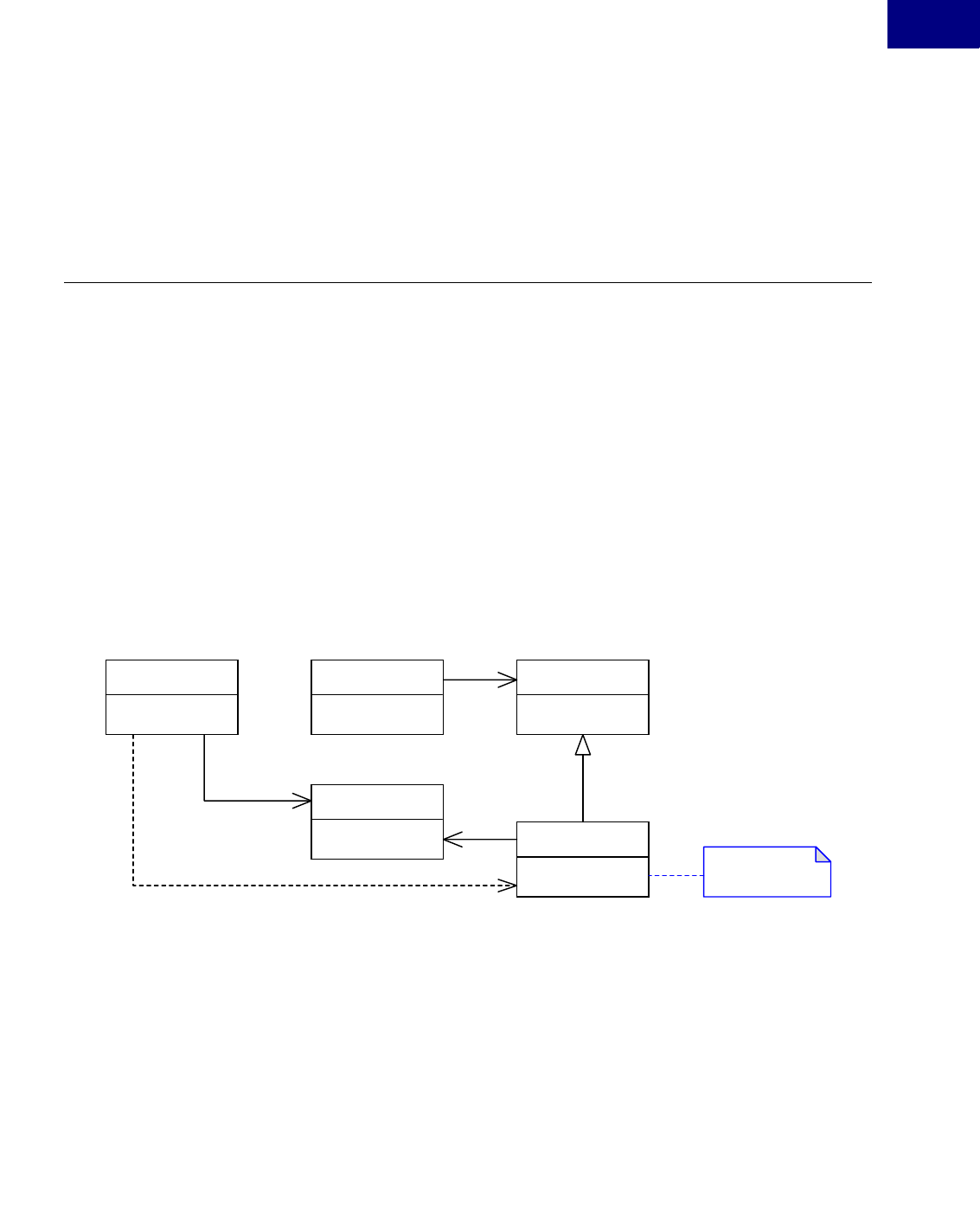
Commands 63
Commands
Concepts
Commands
This chapter describes InDesign’s command architecture. It also outlines how to find and use
the commands provided by the InDesign API, how to implement new commands of your own,
and other extension patterns associated with commands.
Concepts
This section introduces the generic command pattern, databases that provide persistence to the
application’s objects, and models that represent the application’s objects in memory.
Command pattern
The intent of the command pattern is as follows: “Encapsulate a request as an object, thereby
letting you parameterize clients with different requests, queue or log requests and support
undoable operations.” (This is described in Gamma, Helm, Johnson, and Vlissides, Design Pat-
terns, Addison-Wesley, 1995.) The structure of this pattern is shown in Figure 4.
FIGURE 4Command Pattern Structure
This pattern decouples the object that invokes an operation from the object that implements it.
The client wants an operation to be performed, the receiver knows how to perform the opera-
tion, and the two are decoupled by this pattern. The command declares an interface for execut-
ing an operation. The client does not send messages directly to the receiver; rather, the client
creates a concrete command object and sets its receiver. The concrete command implements
execute by calling the corresponding operation on the receiver. The invoker asks the command
to carry out the request, which causes the receiver to perform the operation.
Within the InDesign API, an implementation of the command pattern is used in situations
where preventing data corruption is paramount and users must be able to undo or redo
changes. See “Commands” on page 68.
Client Invoker Command
+ Execute() : void
Receiver
+ Action() : void ConcreteCommand
+ Execute() : void receiver->Action();

Commands
Concepts
64
Databases and undoability
A persistent object has its state maintained outside the application runtime. It can be removed
from main memory and returned again, unchanged. The application maintains persistent
objects in a database. A database on disk is an opaque binary file in the operating system’s file
system. This database file stores the serialized state of a collection of objects. The set of objects
stored in a particular database is collectively known as a model. For example, an InDesign doc-
ument file like Untitled-1.indd is a database file that represents the state of an instance of a doc-
ument model. See “Models” on page 64.
Objects are stored in a database in the following format:
zObjects that persist are stored as a tree of objects, each of which is associated with and per-
sisted by a database.
zEach persistent object has a identifier, the UID, that identifies it uniquely within its data-
base.
zEach persistent object (except the root object) is owned and referred to by another object,
the parent. A persistent object also can be referenced by other objects, though this does not
indicate any form of ownership.
The class that represents a database is IDataBase.
For more detail, see the “Persistent Data and Data Conversion” chapter.
Databases must be consistent and stable. Some databases also need to support undoability—the
ability for a user to undo or redo changes. For example, the ability to undo changes made to a
document is required; however, there is no requirement to undo changes made to the database
that persists the user interface state.
Table 6 shows the databases that exist and their support for undoability. If a database supports
undoability, that support cannot be turned off. All changes to objects that persist in the data-
base must be undo-able. Turning off undo support is not allowed, because it would disable
error handling and increase the risk of document corruption.
NOTE:To change objects that persist in a database that supports undo, we recommend using
commands. If, however, you need to change data without showing something in the Edit >
Undo menu, you can bypass commands and wrap your changes in calls to
CmdUtils::BeginAutoUndoSequence and CmdUtils::EndAutoUndoSequence.
Models
A model is a collection of objects backed by a database for persistent storage. A model is a tree-
structured graph of objects. The ownership relationships between objects in a model defines
this tree structure. Ownership relationships are just parent-child relationships within the tree.
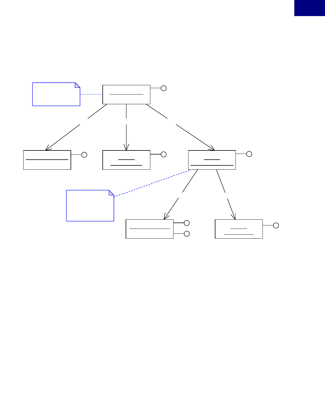
Commands 65
Commands
Concepts
Document model
Documents are represented by the document model. Figure 5 shows an example.
FIGURE 5Objects in a document model (instance diagram)
The document (kDocBoss) is the root object in the document model. It owns a collection of
spreads (kSpreadBoss), stories (kTextStoryBoss), a workspace (kDocWorkspaceBoss), and so
on. These objects may own further objects specific to their domain. The document’s workspace
owns objects like styles and swatches, which can be used throughout the document.
The database file that provides persistence for a document model is an end-user document file;
for example, a file Untitled-1.indd saved from InDesign.
UID 75 :
kDocWorkspaceBoss IWorkspace
UID 91 :
kPMColorBoss IColorData
UID 125 :kStyleBoss IStyleInfo
ITextAttributes
UID 1 :kDocBoss IDocument
UID 60 :kSpreadBoss ISpread UID 41 :
kTextStoryBoss ITextModel
Document content
such as layout and
text.
Document
preference settings
such as styles and
swatches.
IStyleGroupManager
IDocument::GetDocWorkSpace
ISwatchList
ISpreadList IStoryList
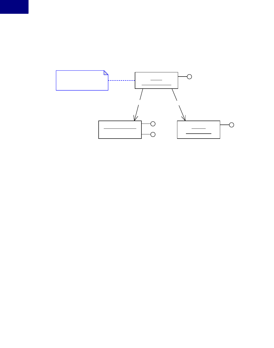
Commands
Concepts
66
Defaults model
Global preference settings are represented by the defaults model. Figure 6 shows an example.
FIGURE 6Objects in the defaults model (instance diagram)
The workspace (kWorkspaceBoss) is the root object in a defaults model. It owns the objects
that represent default preference settings like styles, swatches and so on. The defaults model is
global and is accessed from the session (kSessionBoss) via the ISession interface. When a new
document is created, preference settings can be copied from the defaults model into the docu-
ment’s workspace (kDocWorkspaceBoss).
The database file that provides persistence for this model is an application defaults file. For
example, the file named InDesign Defaults is the database file used by InDesign to persist the
defaults model.
UID 1 :
kWorkspaceBoss IWorkspace
UID 27 :kStyleBoss IStyleInfo
ITextAttributes
UID 42 :
kPMColorBoss IColorData
Global default preference
settings such as styles and
swatches.
ISwatchList
IStyleGroupManager

Commands 67
Commands
Concepts
Session model
A session of an application is represented by the session model. Figure 7 shows an example.
FIGURE 7Objects in the session model (instance diagram)
The session (kSessionBoss) is the root object in the session model. This model owns applica-
tion-related objects that must persist from session to session. For instance, user interface
objects are found here, together with other objects that store the application’s type system (the
boss classes provided by all registered plug-ins).
The database file that persists objects in this model is the application’s saved data file. For
example, the file named InDesign SavedData is the database file used by InDesign to persist the
session model.
NOTE:Objects in the session model can be modified by calling mutator methods on their
interfaces directly. There is no need to modify them using commands. The database that
persists this model does not support undo.
Books, asset libraries, and other models
Several other features in an application have their own dedicated model, together with a data-
base that provides that model with persistence. Prominent examples are books, asset libraries,
and the scrap. See Table 6 for the level of undo support provided by their databases.
UID 2 :kAppBoss
UID 3 :
kActionManagerBoss
UID 4 :
kPanelManagerBoss
UID 5 :
kToolManagerBoss
UID 6 :
kDocumentListBoss
UID 1 :kSessionBoss
ISession
IApplication

Commands
Commands
68
Commands
This section describes how commands are used in the application. It includes sections on the
CmdUtils class, which is fundamental to the processing of commands, and how to use com-
mand sequences to group multiple commands into one logical unit.
Within the application, the most prevalent use of commands by client code is to modify persis-
tent objects in the document model or defaults model. For example, plug-ins use commands to
create frames in a document or modify the default text style.
Commands encapsulate the changes made to persistent objects into a database transaction.
Encapsulating changes in this way helps prevent corruption. Furthermore, any change to the
state of persistent objects that needs to support undo must be made using a command.
Commands change persistent objects by doing the following:
zCalling mutator methods on interfaces that exist on persistent objects.
zProcessing other commands (that call mutator methods on interfaces that exist on persis-
tent objects).
zCalling utilities that process commands (that call mutator methods on interfaces that exist
on persistent objects).
zA mixture of the above.
A command is processed by the application; this means an instance of the command is passed
to the application to be executed. A command can change persistent data within only one data-
base each time it is processed. The processing of a command moves the database from one con-
sistent state to another.
When a command is used to modify objects that persist in a database that supports undo, that
command can manifest on the undo and redo menu items, and the database automatically
reverts the state of affected objects on undo and restore the changed state on redo.
NOTE:Before InDesign CS4, commands were directly responsible for reverting or restoring
the changes they made to persistent objects on undo and redo. The application has
taken over this responsibility.
The InDesign API provides commands for plug-ins to use. See “Command processing and the
CmdUtils class” on page 70 and “Key client APIs” on page 84.
Plug-ins also can introduce new commands using the command extension pattern. See “Com-
mand” on page 86. This is required when a plug-in adds custom persistent data to a document,
defaults, or other objects that persist in a database that supports undo. The extension patterns
named persistent interface and persistent boss are ways in which custom persistent data can be
added to a database. See “Persistent interface” on page 89 and “Persistent boss” on page 91.

Commands 69
Commands
Commands
Command parameters
Commands implement the protocol used to modify objects that persist in a database that sup-
ports undo. A client initiates this protocol by instantiating a command and passing it off to the
application for processing. The client also is responsible for initializing the state of the com-
mand, including the setting of parameters. In general, the command pattern supports two
mechanisms for parameter passing:
1. The UIDList in the ICommand interface (the “item list”), which identifies a set of persistent
objects; see ICommand::SetItemList. On input, this might identify the set of page items on
which the command operates. For example, a page item move command (kMoveAbso-
luteCmdBoss) would use this to identify the set of items to be moved. On output, the item
list might identify the set of object manipulated by a command. For example, a page item
create command (kNewPageItemCmdBoss) would provide the UIDs of the objects created
as a result of the command being processed. The use of the command’s item list is specific to
each command; a command is not required to use the item list.
2. Data-carrying interfaces on the command’s boss class. For example, the command used to
apply a particular text style aggregates an IBoolData interface to define whether character
styles should be overridden, and an IRangeData interface to indicate the range of text that
should be updated by the command.
These two approaches for passing parameters are shown in Figure 8. There is a command boss
class showing two aggregated interfaces, ICommand and a data-carrying interface (ISome-
Data). Parameters can be passed through the item list in ICommand, the data-carrying inter-
face, or both.
FIGURE 8Passing parameters to commands
«boss»
kSomeCommandBoss
«interface»
ICommand
+ GetItemList() : const UIDList*
+ SetItemList(const UIDList&) : void
«interface»
ISomeData
+ GetData()
+ SetData()

Commands
Commands
70
Command undoability
Each command has a property called undoability (see ICommand::Undoability), which deter-
mines whether the command name can appear in undo and redo menu items (i.e., whether the
changes made by the command can be undone or redone in a distinct step).
zAn undoability of kRegularUndo is used by commands whose changes need to appear as a
separate named step in undo and redo menu items. This is the default behavior.
zAn undoability of kAutoUndo is used by commands whose changes do not appear as a sep-
arate named step; for example, commands whose changes should be undone or redone with
an existing step.
Changes made to objects that persist in a database that supports undo must be undoable. To
achieve this, the various extension patterns involved, such as commands and persistent inter-
faces, must be implemented following the rules described in this chapter. The database then
automatically reverts the state of affected objects on undo and restores the changed state on
redo. The undoability of a command (kRegularUndo / kAutoUndo) has no effect on this behavior.
It affects only whether the command appears as a distinct step in undo and redo menu items.
Command processing and the CmdUtils class
Client code uses commands when changing objects that persist state in any database that sup-
ports undo. For example, commands are used to change objects in the document model or the
defaults model. The level of support for undo of each database is given in Table 6.
To change the objects, client code creates instances of one or more commands and submits
these instances to the application for execution. For example, to create frames in a document, a
plug-in either creates commands to be processed and passes them to the application or calls a
helper class that encapsulates both the creation and request for processing. The helper classes
provided by the InDesign API are introduced in “Command facades and utilities” on page 84.
Client code that must create commands uses the CmdUtils class. CmdUtils::CreateCommand
creates an instance of a specific command. The client code parameterizes the command, using
the command’s item list and data interfaces. The client code submits the command to the appli-
cation for execution, by calling CmdUtils::ProcessCommand. Client code can group the com-
mands it processes into command sequences, using methods and classes provided by
CmdUtils. Guidance on processing commands and command sequences is in “Command-pro-
cessing APIs” on page 86 and the “Commands” chapter of Adobe InDesign CS4 Solutions.
The sequence of calls involved in processing a command is shown in Figure 9. The client code
creates the command, populates the item list and other data interfaces, then passes the com-
mand off for processing.
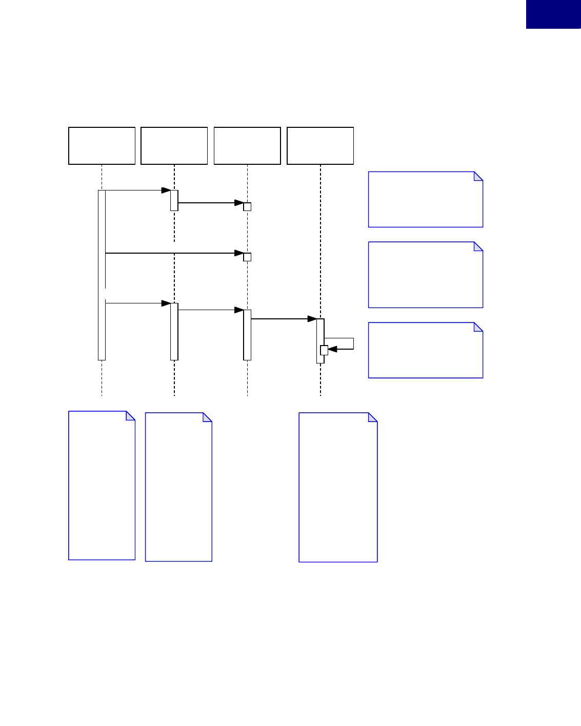
Commands 71
Commands
Commands
FIGURE 9Client processing a command
Command sequences
A command sequence (see ICommandSequence) groups a set of commands into a single
undoable step that changes the model from one consistent state into another. The command
sequence manifests on the undo and redo menu items as a single item.
Client code CmdUtils A Command A Persistent
Interface
Some client code creates an
instance of a command using
CmdUtils::CreateCommand
The client sets the command
parameters, both through the
item list (shown here) or
through data carrying
interfaces.
The processing of the
command is initiated through
the client calling
CmdUtils::ProcessCommand.
Client code
creates
command, sets
parameters and
passes it for
processing. The
client should
also test error
state on return,
before
processing
further
commands.
CmdUtils should
be used for all
client
interactions with
the commands
sub-system. The
rest of the
internals are not
shown in this
diagram.
The update to some
interface on a (UID
based) boss object.
The call to PreDirty
allows the
application to track
the changes made
so that the
application can
undo or redo the
changes
automatically.
CreateCommand
construct
SetItemList
ProcessCommand
Do Set
PreDirty
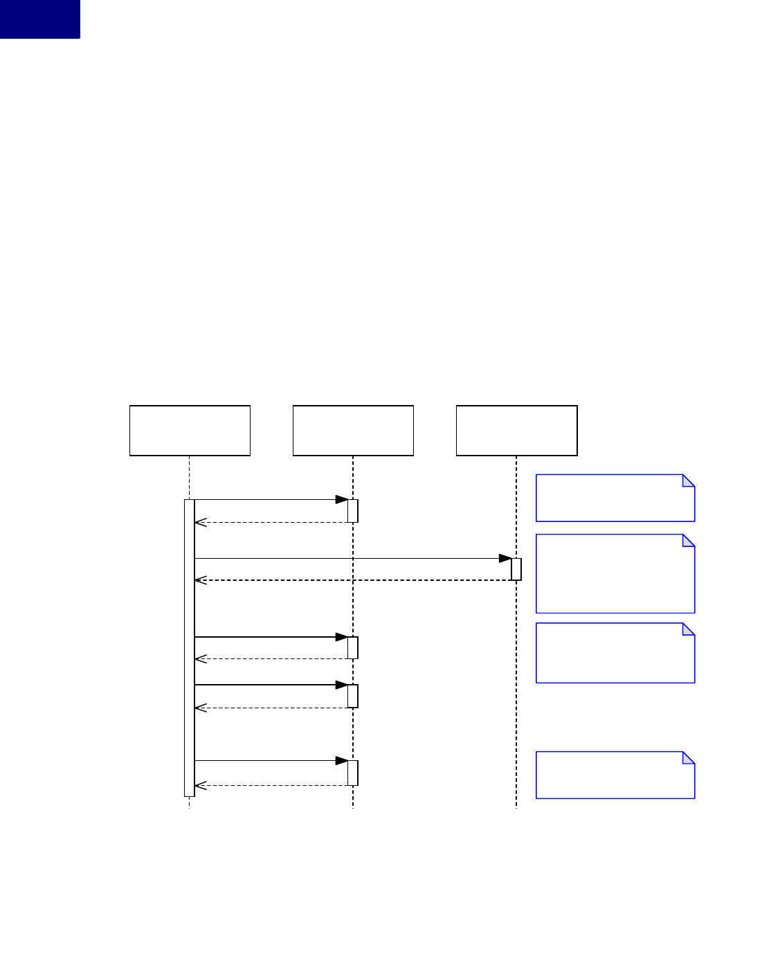
Commands
Commands
72
Command sequences can be nested. For example, say you begin a sequence in one method,
then call a second method that begins a second sequence. The second sequence is said to be
nested within the first. When sequences are nested, only one sequence—the outermost one—
appears on undo and redo menu items.
Command sequences assimilate all commands are processed within their scope, whether the
command is processed directly from within the sequence or indirectly through subcommands
(commands processed by a command). See the “Commands” chapter of Adobe InDesign CS4
Solutions for how to write code that uses command sequences.
A typical scenario for a command sequence is shown in Figure 10. Between the BeginCom-
mandSequence and EndCommandSequence calls, all commands processed act as a single set of
changes; only one element will appear on undo and redo menu items.
FIGURE 10 Calls made for a command sequence
A command sequence can change persistent objects in more that one database. (A command,
on the other hand, can change objects only in one database each time it is processed.) Opera-
tions that change objects in two or more documents can be implemented using a command
sequence. Such a set of modifications manifests in undo and redo menu items for all affected
documents.
Client code CmdUtilsICommandSequence
The client creates a new
command sequence.
The client gives the sequence
a name, otherwise the
sequence uses the name of
the first command processed.
Multiple commands are
processed within the scope of
a sequence.
The client indicates the
sequence is complete.
BeginCommandSequence
ICommandSequence*=
SetName
ProcessCommand
ProcessCommand
EndCommandSequence

Commands 73
Commands
Command managers, databases, and undo support
A command sequence has limited support for error handling: the sequence either succeeds
entirely or fails. An abortable command sequence (see IAbortableCmdSeq) allows more
sophisticated error handling, to allow for fail/retry semantics. Abortable command sequences
incur a significant performance overhead and should be used only where absolutely necessary.
Guidance on using these types of sequence is in the “Commands” chapter of Adobe InDesign
CS4 Solutions.
Command managers, databases, and undo support
This section describes how command managers relate to the application’s databases.
The application object model realizes a tree-structured graph of boss objects. Within this tree
are several distinct models, notably the session model, the defaults model, and one or more
document models (see “Models” on page 64). Each model has a distinct database that provides
persistence for its objects (see “Databases and undoability” on page 64). Each database has an
associated boss, called a command manager. When commands are used to change objects in a
model, the command manager is responsible for executing the commands.
Figure 11 shows that the application object model has several distinct databases that provide
persistence for its objects. The diagram shows some of the objects in an InDesign session (with
two open documents) and the databases with which these objects are associated. Each UID-
based object refers to its associated database through its IPMPersist interface. The defaults
model, represented by an instance of kWorkspaceBoss, persists in the InDesign Defaults data-
base file. Each document model, represented by an instance of kDocBoss, persists in an InDe-
sign document database file. The session model, represented by the instance of kSessionBoss
and the child objects that do not belong to any other model, persists in the InDesign SavedData
database file.
Each database has an associated command manager (see objects in Figure 11 that have an
ICommandMgr interface). The command manager is responsible for managing database
transactions and executing the commands that change the objects that persist in the database.
If an object has an ICommandMgr interface, it is the root object of its associated database. This is
shown in Figure 11. Key objects that are command managers are listed in Table 6; for the com-
plete list, see ICommandMgr in the API Reference.
NOTE:The class that represents a database is IDataBase. This class is an abstract C++ class, but
it is not an IPMUnknown interface.
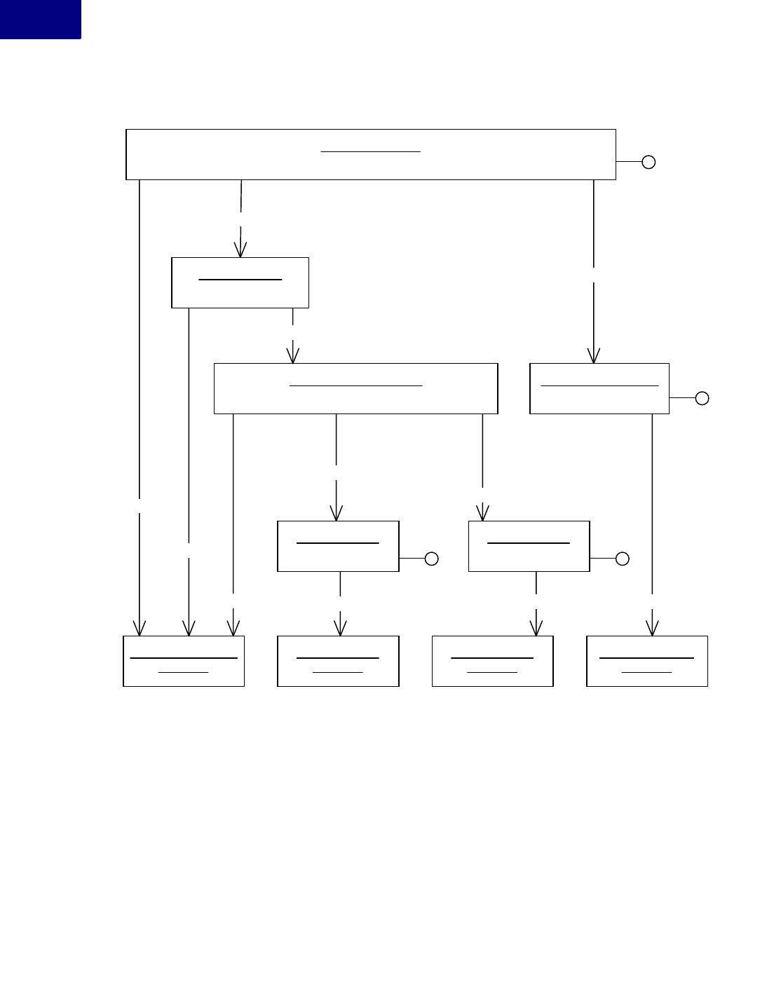
Commands
Command managers, databases, and undo support
74
FIGURE 11 Models and databases in an indesign session (object diagram)
UID 1 :kSessionBoss
ICommandMgr
UID 2 :kAppBoss
UID 3 :kDocumentListBoss UID 1 :kWorkspaceBoss
ICommandMgr
UID 1 :kDocBoss
ICommandMgr
UID 1 :kDocBoss
ICommandMgr
InDesign SavedData :
IDataBase
Untitled-1.indd :
IDataBase
Untitled-2.indd :
IDataBase
InDesign Defaults :
IDataBase
IPMPersist
IPMPersist
IPMPersist IPMPersist IPMPersist IPMPersist
IDocumentList::GetNthDoc(1)
IDocumentList::GetNthDoc(0)
ISession::QueryWorkspace
IApplication::QueryDocumentList
ISession::QueryApplication
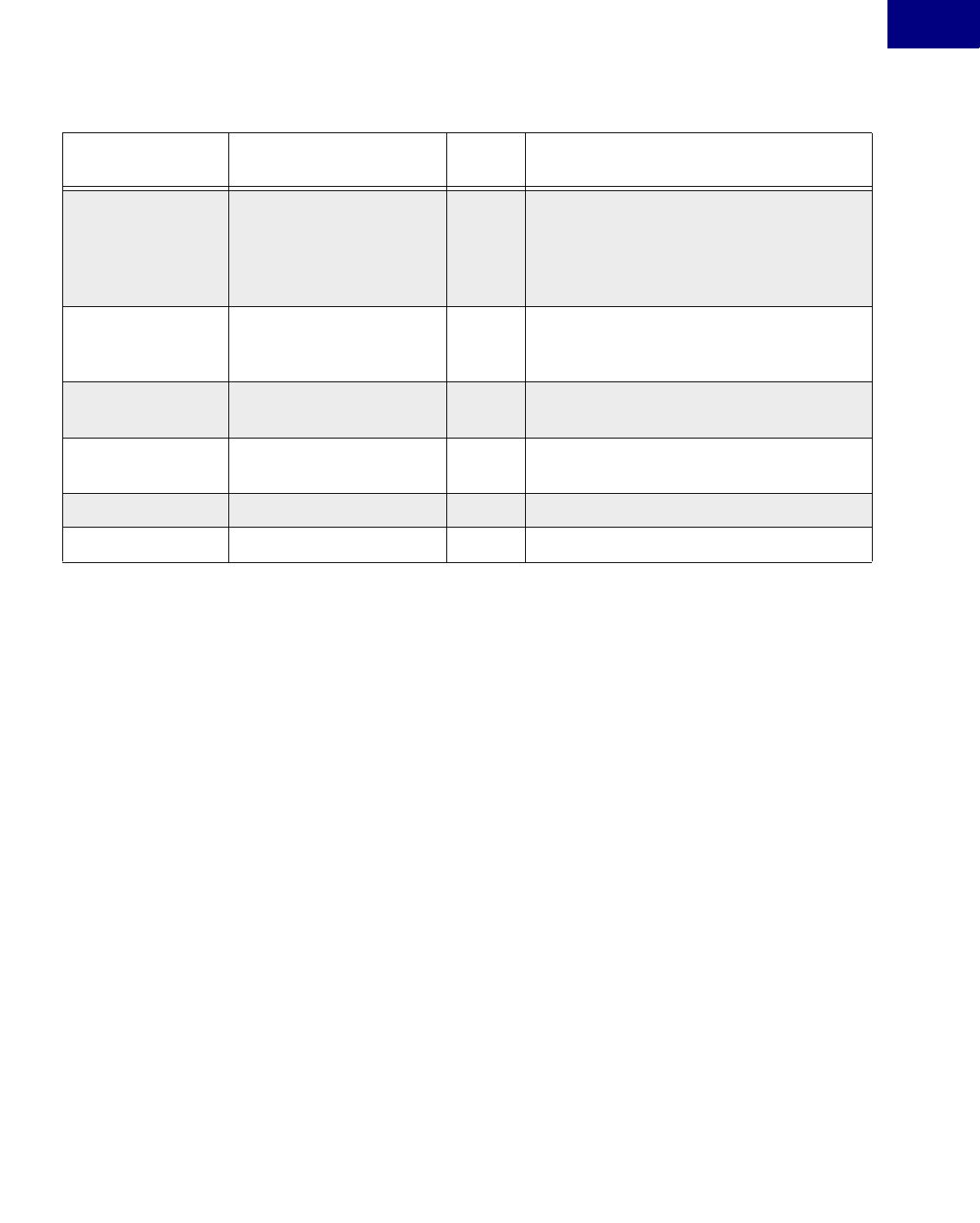
Commands 75
Commands
Command managers, databases, and undo support
TABLE 6 Frequently Used Databases and their Support for Undoability
Each database has a level of support for undo which is fixed when the database is created and
can be one of the following:
zFull — The database fully supports undoable operations. The changes made by a transac-
tion can be reversed automatically on undo and restored on redo. Undo and redo menu
items are fully supported.
zPartial — The database can undo only the most recent operation. If an error occurs, the
database is rolled back to its state before the transaction began; however, once a transaction
is committed, it is irreversible. There is no support for undo and redo menu items.
zNone — The database does not support undoable operations. There is no support for error
handling, abortable command sequences, or undo and redo menu items.
NOTE:Undo support varies by product. In InDesign and InCopy, full undo support is
provided for documents and defaults. In InDesign Server, only partial undo support is
provided for these databases; the server has no concept of user undo and redo.
Objects that persist in a database with full or partial support for undo must be modified using
commands. For example, a plug-in must process commands to change document content such
as spreads, pages, or page items.
Objects that persist in a database without support for undo can be modified by calling mutator
methods on persistent interfaces directly. Commands are not required. For example, a plug-in
can call interfaces on user interface objects, such as widgets, that set state directly.
Command manager /
root boss class
Database Undo
support
Example filename and use
kSessionBoss Application SavedData None InDesign SavedData User interface objects like
tools, menus, panels, dialogs, controls, and
string translations. Objects that define the
application object model, like plug-ins and boss
classes.
kWorkspaceBoss Application Defaults Full InDesign Defaults Default resources like
swatches, fonts, and styles inherited by new
documents.
kDocBoss InDesign Document Full Your.indd Document content like spreads,
pages, page items, and text.
kBookBoss InDesign Book Partial Your.indb A collection of InDesign documents
and associated resources.
kCatalogBoss InDesign Asset Library Partial Your.indl A collection of page items.
Clipboard/scrap Application ClipboardScrap Partial

Commands
The command processor
76
The command processor
This section describes how a command is passed through the application until it is processed.
The session (see the ISession interface) has a singleton instance of the command processor (see
kCommandProcessorBoss and the ICommandProcessor interface). The command processor is
the core application component to which all commands are submitted via CmdUtils.
The command processor’s structure is shown in Figure 12. A command targets one or more
objects for change, and these objects persist in a particular database. Normally, client code cre-
ates a command instance and sets this target by passing parameters to the command (see
“Command parameters” on page 69). The client code submits the command instance for pro-
cessing using CmdUtils. Figure 13 shows the internal collaboration between the objects
involved.
FIGURE 12 Command processor (class diagram)
The command processor examines the command and determines which database contains the
objects the command changes. Each database has an associated command manager boss (see
ICommandMgr interface), shown in Figure 12 as the boss class named kSomeModelRootBoss.
For example, the root of the document model is kDocBoss, and kDocBoss is a command man-
ager. The command processor calls the associated command manager to execute the com-
mand.
«boss»
kSessionBoss
«boss»
kCommandProcessorBoss ICommandProcessor
«boss»
kSomeCommandBoss ICommand «boss»
kSomeModelRootBoss ICommandMgr
IDataBase
IDataBase::GetRootUID 1
IPMPersist::GetDataBase 1
changes objects that persist in
1
1..*
1
ISession::QueryCommandProcessor
1
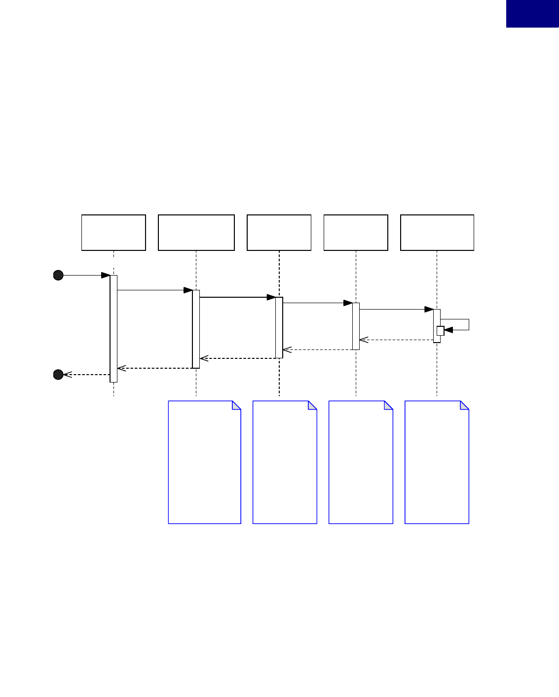
Commands 77
Commands
The command processor
Figure 13 shows the internal processing of a command. The call to process a command is
passed to the session-wide command processor. This determines which database is targeted by
the command, and the command is passed to the command manager for the specified data-
base. The command manager processes the command, and the command updates an interface
on a persistent (UID based) boss object. On completion, control returns to the client that initi-
ated the process.
FIGURE 13 Internals of command processing (sequence diagram)
NOTE:Third party plug-ins should not interact directly with the command processor or
command manager interfaces. CmdUtils provides all methods needed by third parties
for processing commands.
A CommandCmdUtils A Command
Manager
CommandProcessor A Persistent
Interface
The command is
passed to the
session wide
command
processor which
determines the
target database
and calls
ICmdManager::Do
for that database.
The command
manager
invokes the
command.
The command
updates the
persistent
interface.
Generally the
command will
derive from the
Command class,
providing an
implementation
of Do().
The persistent
interface calls
PreDirty before
making any
update to the
data.
ProcessCommand
ProcessCommand
Do DoImmediate Set
PreDirty
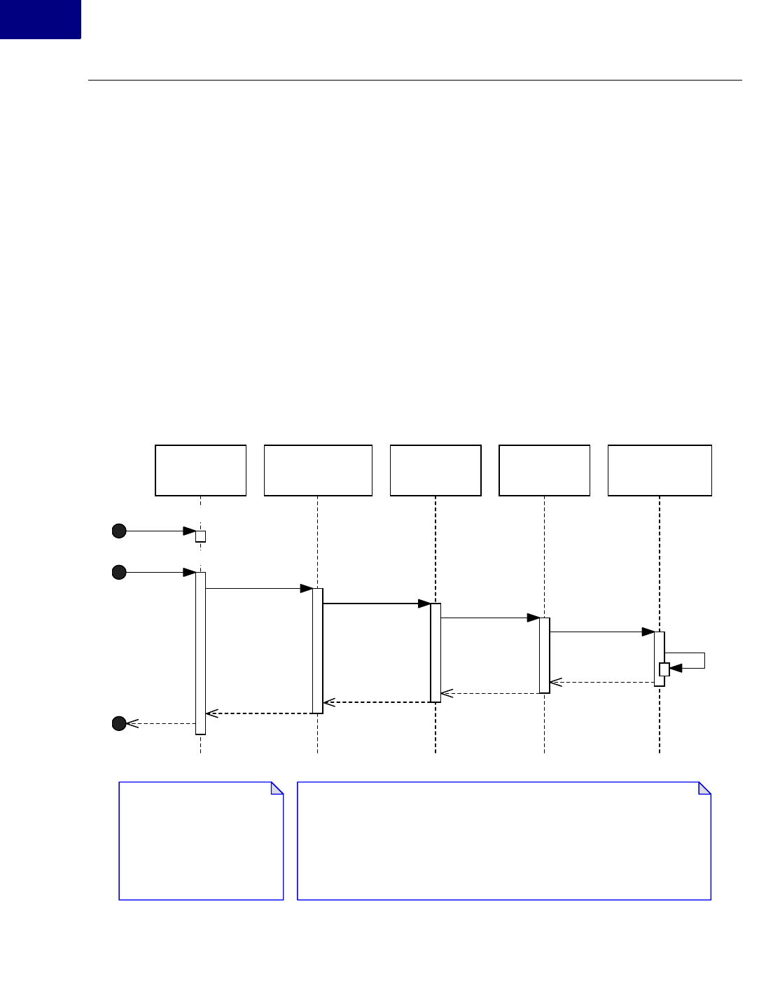
Commands
Scheduled commands
78
Scheduled commands
Commands can be scheduled for later processing, using CmdUtils::ScheduleCommand. The
command is placed in a queue and processed when the application is idle as part of the main
event loop, before idle tasks are processed. The sequence of calls involved in processing a
scheduled command is shown in Figure 14. Compare this with the more normal case of imme-
diately processing a command, shown in Figure 13. In Figure 14, the scheduled command is
passed to the command processor (through the CmdUtils::ScheduleCommand call). At some
later time, after all other processing is complete and control is returned to the main application
event loop, all scheduled commands are processed.
Guidance on using scheduled commands is in the “Commands” chapter of Adobe InDesign CS4
Solutions.
FIGURE 14 Processing a scheduled command
A CommandA CmdManagerCommandProcessorCmdUtils A Persistent
Interface
Some client code schedules the
command. The command is
processed as part of the main
event loop after all other
processing has completed, and
before idle tasks are processed.
Processing of a scheduled command is identical to that of a non-scheduled
command. The only difference is with a non-scheduled command, client code is
responsible for the initiation, upon completion, control returns to the client. With
a scheduled command the event loop initiates processing, upon completion
control returns to the main event loop. If a scheduled command returns an error,
it is reported to the user, the error condition is cleared and processing resumes.
ScheduleCommand
ProcessScheduledCmds
ProcessCommand
Do
DoImmediate
Set
PreDirty

Commands 79
Commands
Snapshots and interface implementation types
Snapshots and interface implementation types
A snapshot is a copy of the state of an interface at a particular time. Undo and redo are achieved
automatically by the application, which keeps snapshots of the interfaces changed within an
undoable transaction. The snapshots are kept in the command history (see “Command his-
tory” on page 80) of the database with which the interface is associated.
The way in which an IPMUnknown interface is implemented determines whether its data is
persistent and/or needs a snapshot to support undo or redo:
zRegular interfaces store transient data that is not maintained on undo or redo. They are
declared to the object model using CREATE_PMINTERFACE, and their state is lost if they
are removed from memory. Data in a regular interface is not persistent, and no snapshot is
taken.
zPersistent interfaces are declared to the object model using the
CREATE_PERSIST_PMINTERFACE macro. They serialize their state to their associated
database via the ReadWrite method and can be removed from memory and returned again
unchanged. Persistent interfaces that are part of a database that supports undo also are
called to serialize their state (again via their ReadWrite method) to a snapshot. This mecha-
nism is required to support undo and redo. See “Persistent interface” on page 89.
zSnapshot interfaces store transient data that must be maintained on undo and redo. They
are declared to the object model using the CREATE_SNAPSHOT_PMINTERFACE macro,
and they serialize their state in a snapshot via the SnapshotReadWrite method. Snapshot
interfaces are aggregated on a boss that persists in a database that supports undo; however,
their data is not persistent. Data maintained by a snapshot interface is lost whenever the
associated database is closed or when the command history for the database is cleared. See
“Snapshot interface” on page 92.
zSnapshot view interfaces are similar to snapshot interfaces, which also store transient data
that must be maintained on undo and redo. The distinction is that a snapshot view interface
depends on model objects that persist in another database. A snapshot view interface is part
of a user interface object and must explicitly identify the database containing the model of
interest. Also, the database on which a snapshot view interface depends can change. For
example, a widget that tracks some state in the front document must change the database on
which its snapshot view interface depends when the front document changes. Snapshot
view interfaces are declared to the object model using the
CREATE_VIEW_PMINTERFACE macro. See “Snapshot view interface” on page 99.
zIt also is possible to create a hybrid interface to allow the data that persists in the database to
differ from the data of which a snapshot is taken for undo and redo. This can be used by
complex data structures, like collections that need to optimize performance. Such an inter-
face is declared to the object model using the
CREATE_PERSIST_SNAPSHOT_PMINTERFACE macro. Data is serialized to the data-
base via the ReadWrite method and to the snapshot via the SnapshotReadWrite method.
For example, consider this approach if you have a collection of some sort and want to serial-
ize only those objects that changed relative to the snapshot (rather than the entire collec-
tion).

Commands
Command history
80
Command history
Consider a database to be the state of the persistent object model. For example, a document
database is the state of the document object model (kDocBoss and all its dependents) at a par-
ticular time. Persistent interfaces (on dependent objects) are called to serialize their state to the
database when necessary, via their ReadWrite method.
The command history (ICmdHistory) provides a history of the undoable operations that were
performed on each database. It records the state changes made by a particular command or
command sequence, for the purposes of undo and redo. The name of the first command or
command sequence processed to perform an operation on the model appears as a named step
in the command history. These steps manifest as undo and redo menu items. The command
history is used to automatically revert the state of affected objects on undo and to restore the
changed state on redo.
The database and its command history are related but distinct states.
To maintain the command history, the database monitors which of its objects change when
commands are processed. It tracks the UIDs that are deleted, created, or un-deleted. It tracks
persistent interfaces, snapshot interfaces and snapshot view interfaces that are modified, and it
takes snapshots of them. This information is kept in the command history as a set of CmdStac-
kItem objects. (CmdStackItem is opaque on the SDK; third parties cannot access its data.)
When undo is invoked, the application automatically reverts the database state to its previous
revision, using this information. When redo is invoked, the application automatically restores
the database state to its next revision.
See Figure 15. The command processor (kCommandProcessorBoss) aggregates the command
history (interface ICmdHistory), which is responsible for maintaining the state changes made
by a particular command or command sequence (which manifests on the undo and redo
menu). This state, represented as CmdStackItems, is used to move the model to previous and
next states on undo and redo. The CmdStackItem encapsulates all data required for an undo
and redo that occurred while processing a command or command sequence.

Commands 81
Commands
Undo and redo
FIGURE 15 Command history
Merging changes with an existing step in the command history
Sometimes it is desirable to extend the scope of an existing step shown in the undo/redo menu
to include functionality that occurs after the step finished. This can be done using either of the
following:
zA command with undoability of kAutoUndo.
zA command sequence with undoability of kAutoUndo.
Undo and redo
To enable a user to undo or redo a change, the objects changed must:
zPersist in a database that supports undo (see Table 6).
zBe modified by processing commands.
The application maintains the state required for undo/redo of changes made to persistent
objects, as commands are processed. Each database that supports undo has a command history
in which the necessary information is recorded, as described in “Command history” on
page 80. Each persistent interface on a UID-based boss object has its ReadWrite method called
to add the state to the command history (for undo and redo) and to the database (to persist its
«boss»
kCommandProcessorBoss
«interface»
ICmdHistory
CmdStackItem
The command
processor
aggregates a
command history
interface.
The command history maintains a set of
CmdStackItems (opaque in the SDK). These items
represent the set of UIDs added, deleted and modified.
For the modified persistent interfaces, the changes are
captured through a call to ReadWrite.
Any UID based object that has an associated snapshot
interface that has been modified, will have its state
captured through a call to its SnapshotReadWrite.
On undo/redo, the state that is maintained in the
CmdStackItem (opaque in the SDK), which is used to
reset the UID based objects (through calls to
ReadWrite and SnapshotReadWrite).
0..*
1
1
1
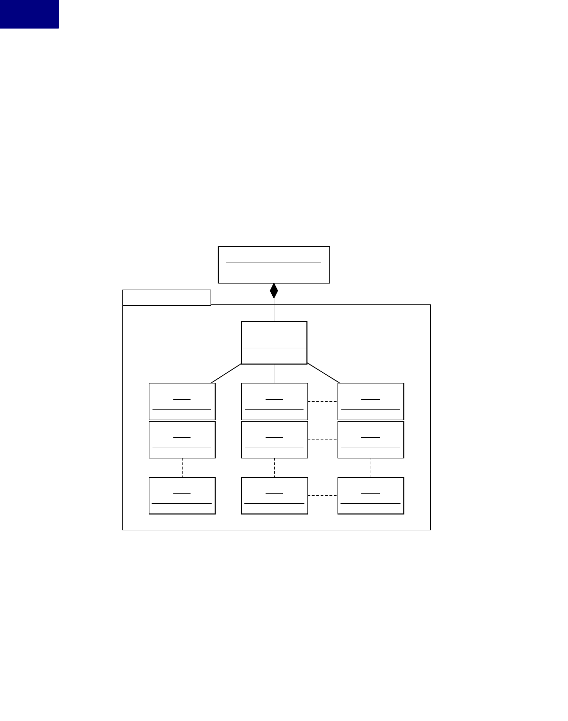
Commands
Undo and redo
82
state). On undo, the ReadWrite method is called to reset the state back to that from before the
action, and on Redo, the ReadWrite method is called again to set the state back to that from the
initial action. The sequence of calls to a persistent interface is shown in Figure 17. Snapshot
interfaces are called on their SnapshotReadWrite method using a similar approach; see
Figure 18.
The command processor records in the command history the set of undoable operations it has
performed (see the ICmdHistory interface on kCommandProcessorBoss). The steps in the
command history appear in undo and redo menu items and are modelled internally using
CmdStackItems. (These are internal only. Discussion is provided here to give some notion of
how the command processor works.) This is shown in Figure 16.
FIGURE 16 Command history internals (instance diagram)
The command history maintains a stack of CmdStackItem objects for each database that sup-
ports undo; see Figure 16. A CmdStackItem (opaque in the SDK) represents the set of changes
made by the sequence or command that manifests on the undo/redo menu. It contains data
gathered during a database transaction for the purposes of undo and redo. On undo/redo, the
“current” CmdStackItem is used to revert the state of the model. The CmdStackItem encapsu-
lates all data required for an undo/redo that occurred while processing a command or com-
mand sequence. This includes all changes to persistent interface and snapshot interface data
that were pre-dirtied. The CmdStackItem also maintains any inval handler cookies (see “Inval
handler” on page 94) created as part of the sequence.
CmdHistory Internals
«interface»
ICmdHistory
DB1:
CmdStackItem1
DB1:
CmdStackItem2
DB1:
CmdStackItemN
DB2:
CmdStackItem1
DB2:
CmdStackItem2
DB2:
CmdStackItemN
DBN:
CmdStackItem1
DBN:
CmdStackItem2
DBN:
CmdStackItemN
kCommandProcessorBoss
1
1

Commands 83
Commands
Notification within commands
Each step has a name of either a command or a command sequence that performed the opera-
tion. On undo, the application automatically reverts the database to its state before the opera-
tion was performed. On redo, the application automatically restores the database to its state
after the operation was performed.
Extension patterns involved in undo and redo
The following extension patterns are called at undo or redo:
zPersistent interfaces; see “Persistent interface” on page 89.
zSnapshot interfaces; see “Snapshot interface” on page 92 (introduced in InDesign CS4).
zSnapshot view interfaces; see “Snapshot view interface” on page 99 (introduced in InDesign
CS4).
zInval cookies; see “Inval handler” on page 94 (introduced in InDesign CS4).
zObservers, via their LazyUpdate method (introduced in InDesign CS4); see the “Notifica-
tion” chapter.
Notification within commands
A command can initiate notification, so observers interested in changes to the objects it modi-
fies are notified. See the “Notification” chapter.
Commands also can be processed within observers and responders. Take care with commands
that modify the model in this way. See the “Notification” chapter for further discussion of
model changes within the context of notification.
If you are implementing your own command, see “Command” on page 86 for additional infor-
mation on notification in the command extension pattern.
Error handling
In response to a user gesture or another event, the application calls a plug-in to carry out an
action. For example, the user creates a text frame. In this case, the plug-in creates and processes
the commands that perform the action. On detecting an error, a plug-in normally sets the glo-
bal error code (see ErrorUtils) to something other than kSuccess and returns. When control
returns to the application, the global error code is checked. If it is set, the database is reverted to
the state it had before the modifications began. Extension patterns that participated in the
transaction being rolled back are called as follows:

Commands
Key client APIs
84
1. Persistent interfaces, snapshot interfaces, and snapshot view interfaces modified by the
transaction are called to revert their state. See “Persistent interface” on page 89, “Snapshot
interface” on page 92, and “Snapshot view interface” on page 99.
2. Inval cookies created during the transaction are called to undo. See “Inval handler” on
page 94).
When the application returns to its main event loop, it informs the user through an alert, using
the string associated with the error code that is set (see “Error string service” on page 88). The
global error code is then cleared, and the application continues.
Plug-in code that processes commands or command sequences must check for errors. CmdU-
tils::ProcessCommand returns an error code that should be checked for kSuccess before con-
tinuing. Alternatively, you can check the global error code using ErrorUtils. Details are in the
“Commands” chapter of Adobe InDesign CS4 Solutions. If a plug-in tries to process a command
while the global error code is set, protective shutdown occurs to protect the integrity of the
document or defaults databases (see “Protective shutdown” on page 84).
Command implementation code also must check for errors. If a command encounters an error
condition within the scope of its Command::Do method, it should set the global error code
using ErrorUtils and return. Details on error handling is in the command extension pattern;
see “Command” on page 86.
Plug-in code that requires more sophisticated error handling, to allow for fail/retry semantics,
must use an abortable command sequence. For information on using abortable command
sequences, see the “Commands” chapter of Adobe InDesign CS4 Solutions.
Protective shutdown
Protective shutdown is a mechanism that helps prevent document corruption. Any attempt to
process a command when the global error code is set (to something other than kSuccess)
causes a protective shutdown. The application creates a log file describing the problem it
encountered and then exits.
Key client APIs
This section summarizes the APIs a plug-in can use to interact with commands.
Command facades and utilities
There are many command-related boss classes named k<whatever>CmdBoss, but in many
cases you do not need to instantiate these commands, as there are command facades and utili-
ties in the API that encapsulate parameterizing and processing these commands.
Interfaces like those in Table 7 are examples of command facades and utilities. These encapsu-
late processing of many commands required by plug-in code. These interfaces are aggregated
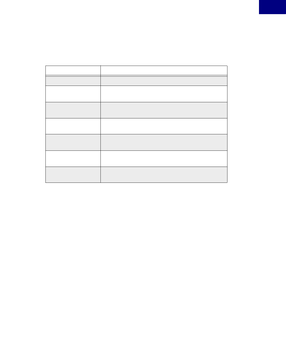
Commands 85
Commands
Key client APIs
on kUtilsBoss; the smart pointer class Utils makes it straightforward to acquire and call meth-
ods on these interfaces. You can call their methods by writing code that follows this pattern:
Utils<IDocumentCommands>()->MethodName(...)
TABLE 7 Useful command facades and utilities
These utility classes abstract over low-level commands. Before using commands, always look
for such a utility to see if there is a method that serves your purpose on one of these interfaces.
By doing so, you avoid the increased chance of confusion and error that comes with processing
commands. Your use case may require you to process some commands, if the utilities do not
provide all of the functionality you require.
As used in the application, command “facade” and “utility” are just different names for the
same thing, a class that reduces and simplifies the amount of client code you need to write to
change objects in the model. They decouple client code from command creation, initialization,
and processing.
When implementing custom commands, it is advisable to provide your own command facade
or utility. If you want to share your class with other plug-ins, implement it as an add-in inter-
face on kUtilsBoss; for example, see XDocBkFacade. If the class is used only by one plug-in, a
C++ class is sufficient; for example, see BPIHelper.
API Used for manipulating...
IDocumentCommands Documents.
IPathUtils Frames and splines. See the “Layout Fundamentals” chapter
for other APIs that help with layout.
IGraphicAttributeUtils Graphic attributes. See the “Graphics Fundamentals”
chapter for other APIs that help with graphics.
ITextModelCmds Text. See the “Text Fundamentals” chapter for other APIs
that help with text.
ITableCommands Tables. See the “Tables” chapter for other APIs that help
with tables.
IXMLUtils XML. See the “XML Fundamentals” chapter for other APIs
that help with XML.
kUtilsBoss See kUtilsBoss in the API Reference for a complete list of
command facades and utilities.

Commands
Extension patterns
86
Command-processing APIs
The classes used when writing client code to process commands are listed in Table 8.
TABLE 8 Useful classes for processing commands
NOTE:You must use CmdUtils to process commands. Do not use the ICommandProcessor or
ICommandMgr interfaces for this. Misuse of these interfaces can easily cause
document corruption.
For information on finding and processing the commands provided by the API, see the “Com-
mands” chapter of Adobe InDesign CS4 Solutions.
Extension patterns
This section summarizes the mechanisms a plug-in can use to extend the command subsystem.
Command
Description
Suppose:
zYou added a new persistent boss to a document or a persistent interface to an object in a
document, and you need to set custom data in these objects.
zThe API does not provide a command that sets the model data you need to change.
zYou want do some processing, and you concluded that a command provides the best pattern
in which to encapsulate it.
Architecture
To implement a command, follow these steps:
zDefine a new boss class in your plug-in that aggregates IID_ICOMMAND. If you require
input parameters over and above the command’s item list, aggregate further data interfaces
to the boss through which the parameters can be passed.
zProvide an implementation of ICommand using Command as a base class.
API Description
CmdUtils Provides methods that create, process, or schedule commands and
manage command sequences.
PersistUtils Provides methods like GetDataBase, GetUID, and GetUIDRef, which
are used to identify the objects to be operated on by a command.
ErrorUtils Provides access to the global error code.

Commands 87
Commands
Extension patterns
zAdd client code that processes your new command. See the “Commands” chapter of Adobe
InDesign CS4 Solutions.
zFor more guidance, see the Command page in the API Reference and “Best Practice” below.
Best practices
zThe Do method contains the code that modifies the model. The model is changed by calling
mutator methods on model interfaces, processing commands, processing commands in a
command sequence, or calling utilities that process commands for you.
zIf you encounter an error condition within your Do method, set the global error code
(ErrorUtils::PMSetGlobalErrorCode) and return. The application is responsible for revert-
ing the model back to its state before the Do method was called and informing the user of
the error.
zIf you need more sophisticated flow control that allows for fail/retry semantics, use an
abortable command sequence (see IAbortableCmdSeq).
zThe Do method can change objects in only one database each time it is called. To change
objects in more than one database in one undoable step, use a command sequence (ICom-
mandSequence).
zNormally, the database containing the objects to be changed is passed using the command’s
item list. Alternatively, a command can target a predetermined database, by calling Com-
mand::SetTarget in its constructor. It also can override Command::SetUpTarget and deter-
mine the database containing the objects to be changed when the command is processed.
zNormally, the DoNotify method contains the code that initiates notification, should you
require it. Initiate notification by calling ISubject::ModelChange (not ISubject::Change).
Calling ISubject::ModelChange when model objects are changed broadcasts regular and
lazy notification (see the “Notification” chapter). The application calls DoNotify after the
Do method of the command is called; however, notification need not be restricted to this
method.
zNotification can be performed for each object that was modified using the ISubject inter-
face of affected objects. Notification also can be performed centrally. For example, many
commands that modify the document model notify change using the ISubject interface of
the document (kDocBoss). Sometimes commands use both these approaches. The benefit
of using a centralized approach is that an observer needs to attach to only one subject to
receive the notification.
zIf you need to pre-notify observers before the model is changed, call your DoNotify method
from your Do method before making any changes to the model.
zNotification can result in the processing of further commands, which can result in global
error code being set. If further commands are processed, application shutdown occurs. If
multiple subjects are notified by a command, the global error code should be tested between
notifications. If the error code is set, the DoNotify method should return without calling
further subjects, or it should consume the error and reset the global error code.
zThe undoability of a command should be fixed at command construction (see ICom-
mand::GetUndoability). Its default value is kRegularUndo. If a different undoability is

Commands
Extension patterns
88
required, it should be set in the command’s constructor. See ICommand::Undoability in the
API Reference.
zA command must have a name (see Command::CreateName), if it has an undoability of
kRegularUndo and it returns kTrue for IsNameRequired. Such commands can appear in
undo and redo menu items. The name must have a translation, so it can be displayed in
undo and redo menu items in a localized form. Commands with an undoability of kRegu-
larUndo that override IsNameRequired to return kFalse must pick up their name from a
subcommand. Some commands create and process other commands (subcommands) to
make their changes and want to pick up the name of the first subcommand called within
their scope instead of providing their own name.
zCommands with undoability of kAutoUndo do not need a name, because their changes
merge with an existing step in the undo and redo menu items.
zThe destructor of a command normally is empty. Do not change the model within the
destructor.
See also
zFor documentation on commands: Command and ICommand in the API Reference.
zFor documentation on notification: ISubject and IObserver in the API Reference.
zIf you need error codes set by your command to map onto strings that describe the error
condition: “Error string service” on page 88.
zFor sample code: kBPISetDataCmdBoss, BPISetDataCmd, and BPIHelper from the
BasicPersistInterface plug-in.
Error string service
Description
Suppose error conditions can occur in your plug-in, and you need to inform the user of these
errors.
Architecture
Sometimes, error conditions can occur in your plug-in, often within commands or command
sequences. When control is returned to the application by your plug-in, and the global error
code is set to something other than kSuccess, the user is informed and the model is reverted
back to the last consistent state. An error string service provides the ability to map error codes
onto error strings. To handle this, follow these steps:
zYou Provide an error string service. This service allows ODFRez resources in your plug-in
to map error codes onto strings that describe the error. Detailed documentation on how to
define the error codes, resources, and implementations involved is the API Reference for
IErrorStringService.
zOn detecting the error condition, call ErrorUtils::PMSetGlobalErrorCode to set your error
and return control to the application. The application informs the user of the error.

Commands 89
Commands
Extension patterns
See also
For sample code: BPIErrorStringService from the BasicPersistInterface plug-in.
Persistent interface
Description
Suppose you need to add custom data to an existing object in the model and have that persist.
For example, you want frames in a document to have a set of custom properties that you con-
trol.
Architecture
The state of a persistent interface that is associated with a database that supports undo is cap-
tured by the application before it is changed; its state is reverted on undo and restored on redo.
The state is saved in the command history (see “Command history” on page 80) for undo and
redo, and in the database for persistence. Figure 17 shows the typical sequence of calls made to
modify persistent interface, and when that modification subsequently is undone or redone.
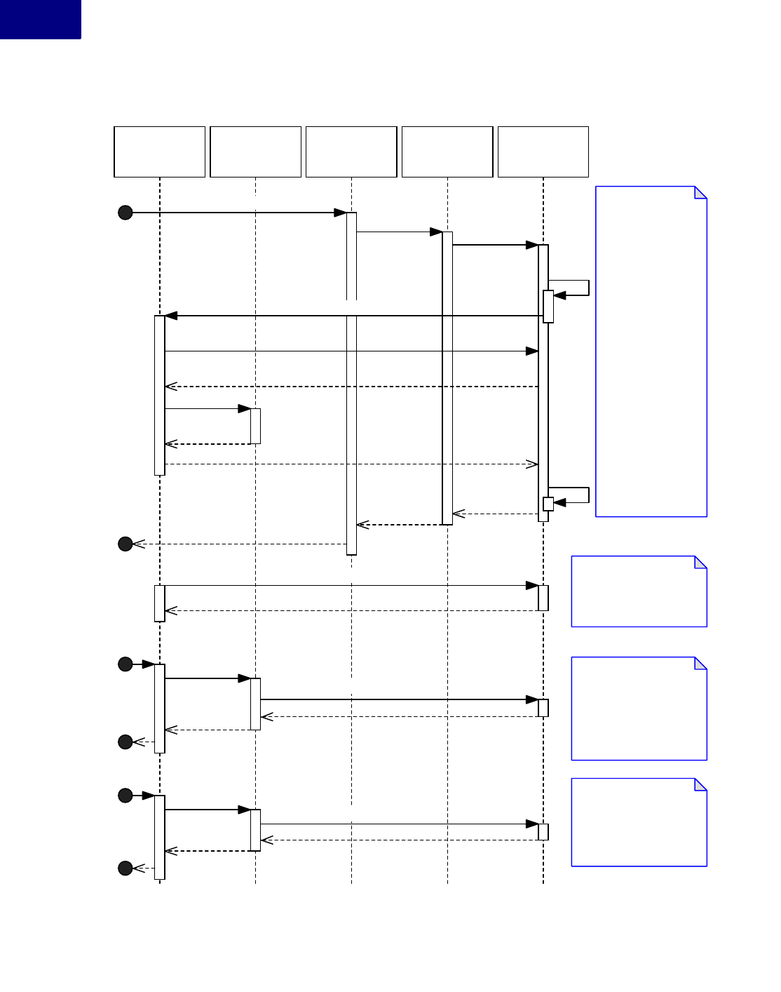
Commands
Extension patterns
90
FIGURE 17 Sequence of calls to a persistent interface
Application core ICmdHistory CmdUtils A Command A Persistent
Interface
Some entity
processes a
command which
results in a
persistent interface
being modified. The
persistent interface
calls PreDirty before
mutating the data,
which allows the
application core to
snapshot the state of
the interface for the
command history
before it is changed
(to allow the
modification to be
undone), and to
require it to be
streamed to the
database afterwards.
The application calls on
the persistent interface to
stream its data to the
database.
On undo, the command
history reverts the
persistent interface to the
state it had before the
modification was made.
On redo, the command
history restores the
persistent interface to the
state it had after the
modification was made.
ProcessCommand
DoImmediate
Set
PreDirty
PreDirty
ReadWrite
Push
Modify
ReadWrite
Undo
ReadWrite
Redo
ReadWrite

Commands 91
Commands
Extension patterns
To implement a persistent interface, follow these steps:
1. Aggregate your interface on the boss class in the model to which you want to add custom
data that persists. Use an add-in interface (an ODFRez AddIn statement) if you are adding
the interface to an existing boss class. To define a new type of persistent boss, see “Persistent
boss” on page 91.
2. Provide an abstract interface that uses IPMUnknown as a base class.
3. Provide an implementation of this abstract interface.
4. Use CREATE_PERSIST_PMINTERFACE to make your implementation class available to
the application (instead of CREATE_PMINTERFACE).
5. Define a ReadWrite method for your implementation class. It gets called to serialize your
data when needed.
6. Call PreDirty within mutator methods before changing member variables that need to be
serialized. This gives the application the ability to recognize that this interface is about to
change.
7. Call mutator methods to update the state of your interface. The application calls your Read-
Write method to serialize your data when needed.
NOTE:If your interface persists in a document, you must consider what should happen when
users who do not have your plug-in open documents that contain your plug-in’s data.
See the section on missing plug-ins in the “Persistent Data and Data Conversion”
chapter.
See also
z“Command” on page 86.
zFor sample code: IBPIData, BPIDataPersist and BPISetDataCmd from the BasicPersistInt-
erface plug-in.
zFor documentation on persistence: the “Persistent Data and Data Conversion” chapter.
Persistent boss
Description
Suppose you need to add a new type of persistent object to the model. For example, you need to
add a list of custom style objects to defaults.
Architecture
To implement a persistent boss that has a UID, follow these steps:
1. Define a new boss class.
2. Aggregate IID_IPMPERSIST, and use the kPMPersistImpl implementation provided by the
API.

Commands
Extension patterns
92
3. Add persistent interfaces to the boss to store your custom data. See “Persistent interface” on
page 89.
4. Choose a boss class to own the instances of your new persistent boss. Add a persistent inter-
face into the boss class you have chosen that stores the UIDs of the new persistent boss. For
example, to add custom styles to defaults, add this interface into kWorkspaceBoss.
NOTE:If your boss persists within a database that supports undo, such as a document or
defaults, you must create, modify, and delete the persistent boss using commands.
Implement a create command to allocate a new UID for each new instance of the
peristent boss, and store this UID in an interface on boss that owns it. The delete
command deletes all child UIDs owned by the persistent boss, removes all references to
the persistent boss from the model, then deletes the UID.
See also
zFor sample code: kPstLstDataBoss and PstLstUIDList from the PersistentList plug-in.
zFor documentation on persistence: the “Persistent Data and Data Conversion” chapter.
z“Command” on page 86.
Snapshot interface
Description
Suppose you have an object containing transient data, which depends on model objects that
persist in a database that supports undo, and:
zYour object needs to be updated when the model objects are modified initially and on any
subsequent undo or redo.
zYou cannot use lazy notification to update your object, because it must be kept up to date
with changes to the model at all times.
zYour object must be updated on undo or redo, before observers get called.
For example, the text state (see the ITextState interface) caches the text attributes that are
applied to the “text caret”; the next text insertion uses these attributes. This cache is imple-
mented as a snapshot interface and maintained on undo and redo.
Architecture
The state of an snapshot interface is captured by the application before it is changed; its state is
reverted on undo and restored on redo. The state is saved in the command history (see “Com-
mand history” on page 80) for undo and redo. Figure 18 shows a typical sequence of calls for a
snapshot interface when it is modified, and when that modification is subsequently undone or
redone.
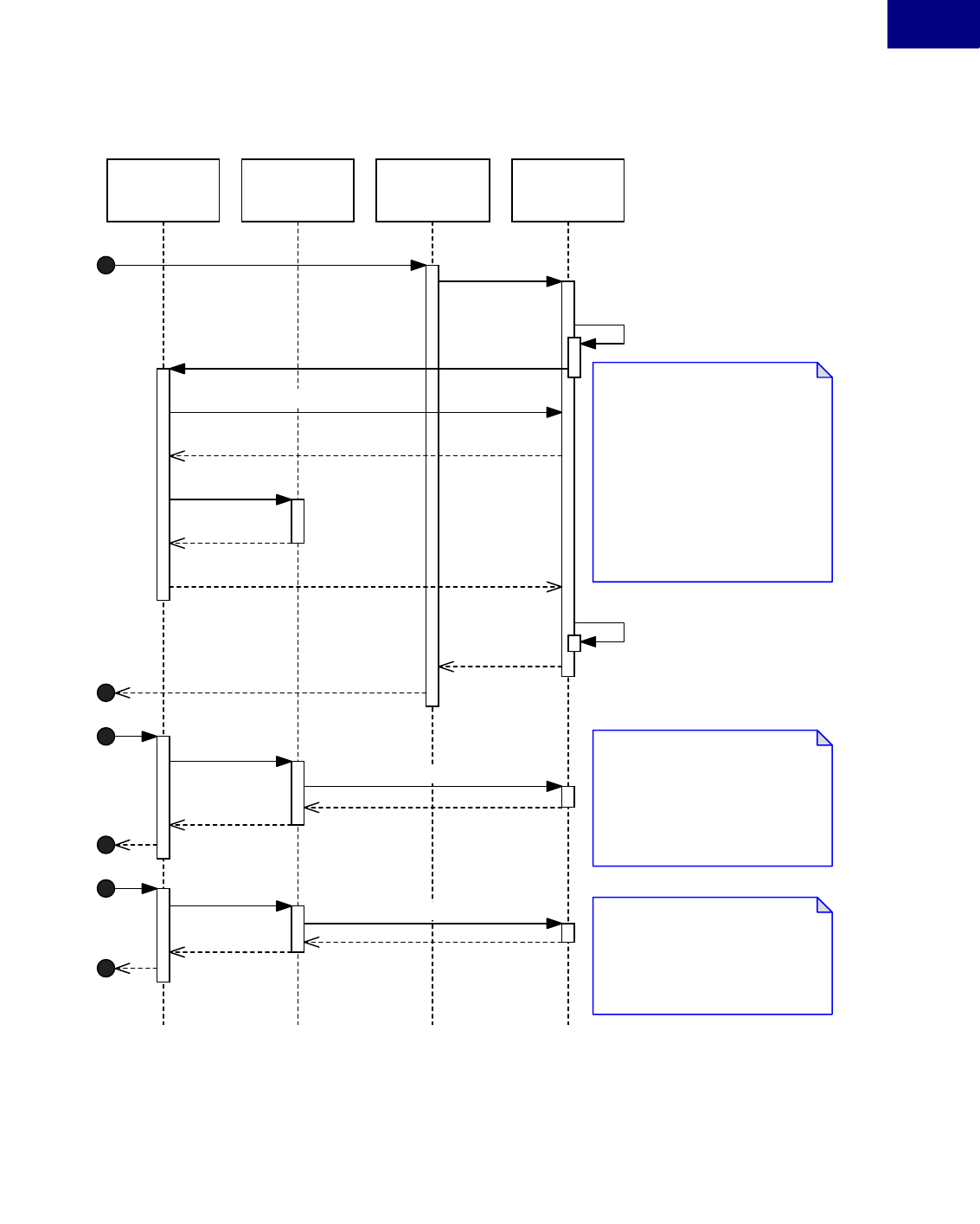
Commands 93
Commands
Extension patterns
FIGURE 18 Sequence of calls for a snapshot interface
Often, an observer or responder is used to modify a snapshot interface, as shown in Figure 18.
Before changing any data, the snapshot interface implementation calls PreDirty, indicating to
the application that the SnapshotReadWrite method should be called to capture the state of the
interface (this state is associated with the CmdStackItem for the current sequence)). On undo
Application core ICmdHistory An Observer A Snapshot
Interface
Some change causes an observer to
be called which results in a snapshot
interface being modified. The
snapshot interface calls PreDirty
before mutating the data, which
allows the application core to
capture the state of the interface for
the command history before it is
changed (to allow the modification
to be undone).
On undo, the command history is
invoked. This leads to a
SnapshotReadWrite call on the
snapshot interface, to revert the state
of the interface back to the was it
was before the modification.
Similarly, on redo, the snapshot
interface has the SnapshotReadWrite
method called to restore the state to
the way it was after the modification.
Update
Set
PreDirty
PreDirty
SnapshotReadWrite
Push
Modify
Undo
Undo
SnapshotReadWrite
Redo
Redo
SnapshotReadWrite

Commands
Extension patterns
94
or redo, the SnapshotReadWrite method is invoked with the data associated with that particu-
lar sequence on the undo/redo menu.
To implement a snapshot interface, follow these steps:
1. Add your interface to a persistent boss class that is part of the model on whose state your
interface depends. Check that this class aggregates IPMPersist, since the boss must have a
UID to support a snapshot interface. For example, if your object depends on objects in a
document, you might choose kDocBoss.
2. Provide an abstract interface that uses IPMUnknown as a base class.
3. Provide an implementation of this abstract interface.
4. Use CREATE_SNAPSHOT_PMINTERFACE to make your implementation class available
to the application (instead of CREATE_PMINTERFACE).
5. Define a SnapshotReadWrite method for your implementation class. It gets called to serial-
ize snapshots of your data when needed.
6. Call PreDirty within mutator methods before changing member variables you serialize in
SnapshotReadWrite.
7. When the model objects you depend on are changed, call mutator methods to modify the
state of your interface. You might need to track the change to the object using regular notifi-
cation. The application takes a snapshot of your interface, reverts the state on undo, and
restores it on redo.
NOTE:Even though this extension pattern is very similar in its implementation to a persistent
interface, its effect is very different. The information in your snapshot interface is
transient and not saved persistently with a document, defaults, or whatever other model
it is associated.
See also
zFor sample code: LnkWtchCache in the LinkWatcher plug-in and GTTxtEdtSnapshotInter-
face in the GoToL astTextEdit plug-in.
zThe “Notification” chapter.
Inval handler
Description
Suppose you have an object that depends on model objects that persist in a database that sup-
ports undo, and:
zYour object must be updated at undo and at redo when the model objects it depends on
change.
zYou cannot use lazy notification (see the “Notification” chapter) to update your object,
because you need it to be kept up to date with changes to the model at all times.

Commands 95
Commands
Extension patterns
zYou cannot use a snapshot interface (see “Snapshot interface” on page 92) because you need
to do more than restore the state of an object within the application.
zYou need to program behavior that runs at undo and redo.
NOTE:This extension pattern is very rare. This is an advanced pattern and should be used only
if absolutely necessary.
For example, an observer might watch a subject that can be deleted from the model. Typically,
such observers are attached to the subject when it is created and detached just before it gets
deleted. If an object is created, the observer is attached. If there is an undo at this point, the
observer should be detached; a subsequent redo should result in the observer being re-
attached. Similarly, if an object is deleted, the observer is detached. At this point, an undo
should result in the observer being attached; a subsequent redo should result in the observer
being detached.
Consider an observer that attaches to a spread (see kSpreadBoss). When a spread is created, the
observer gets attached to the new spread. If the creation of the spread is undone, this observer
must be detached before the undo takes place. If the creation of the spread is redone, the
observer must be re-attached after the redo takes place. The inval handler extension pattern
allows for this. The GoToLastTextExit plug-in provides sample code that shows how to use an
inval handler to manage the attachment and detachment of an observer that watches stories in
a document.
Architecture
Inval handlers allow plug-in code to be called at undo and redo. There are two parts to the
mechanism:
zAn inval handler (see IInvalHandler) that registers interest in a database that supports
undo.
zAn inval cookie that gets called on undo and redo. The inval cookie is created by the inval
handler at the end of a transaction that contained changes in which the plug-in was inter-
ested.
Inval handlers are used in situations where a plug-in needs to achieve more than the restoration
of the state (through persistent interfaces and snapshot interfaces), and the lazy notification
broadcast occurs too late to meet this need. The plug-in has code that must be called immedi-
ately at undo or redo.
To implement an inval handler, follow these steps:
zProvide an implementation of an inval handler (see the IInvalHandler class in the API Ref-
erence for details. See GTTxtEdtInvalHandler for sample code).
zProvide an implementation of an inval cookie (see the IInvalCookie class in the API Refer-
ence for details. See GTTxtEdtInvalCookie for sample code).
zCreate an instance of the inval handler, and call DBUtils::AttachInvalHandler to associate
this instance with the database that persists the objects in which you are interested. The
scope of this association can be defined by the lifetime of the database or the enabling of
particular functionality. For example, an inval handler might be attached to a database
when a document is opened.

Commands
Extension patterns
96
zOnce an inval handler is attached to a database, call DBUtils::StartCollectingInvals to indi-
cate the inval handler is interested in participating in undo and redo. This usually occurs on
some event (through an observer or some other means). The StartCollectingInvals call
informs the database that the inval handler should be called at the end of the current trans-
action. If an undoable transaction is ongoing, the inval handler is said to be “collecting
invals.”
zThe plug-in code records the semantics of the change. Where this is recorded is implemen-
tation-dependent: it could be in the state associated with the inval handler (recommended),
an inval handler cookie, or elsewhere.
zFurther changes of interest can occur within the same transaction. The plug-in code should
record the semantics of the changes; for example, by adding state to a list within the inval
handler.
zAt the completion of the transaction, the IInvalHandler::EndCollectingInvals method is
called. The inval handler can return an instance of an inval cookie representing the
change(s) of interest that occurred. This inval cookie is kept in the command history for
this database transaction. The inval handler is now said to be “not collecting invals.”
zThe inval cookie is called on undo and redo of the transaction.
zWhen the lifetime of an inval handler is over, call DBUtils::DetachInvalHandler to detach
the inval handler from the database. For example, an inval handler might be detached from
a document database when a document is closed.
Figure 19 shows the lifetime of a typical inval handler. Figure 20 shows the typical sequence of
calls made to an inval cookie on undo. On undo, any inval cookies that were previously associ-
ated with the CmdStackItem are called. The inval cookie setting the error state aborts the undo
(the model is reset to the state from before the undo).
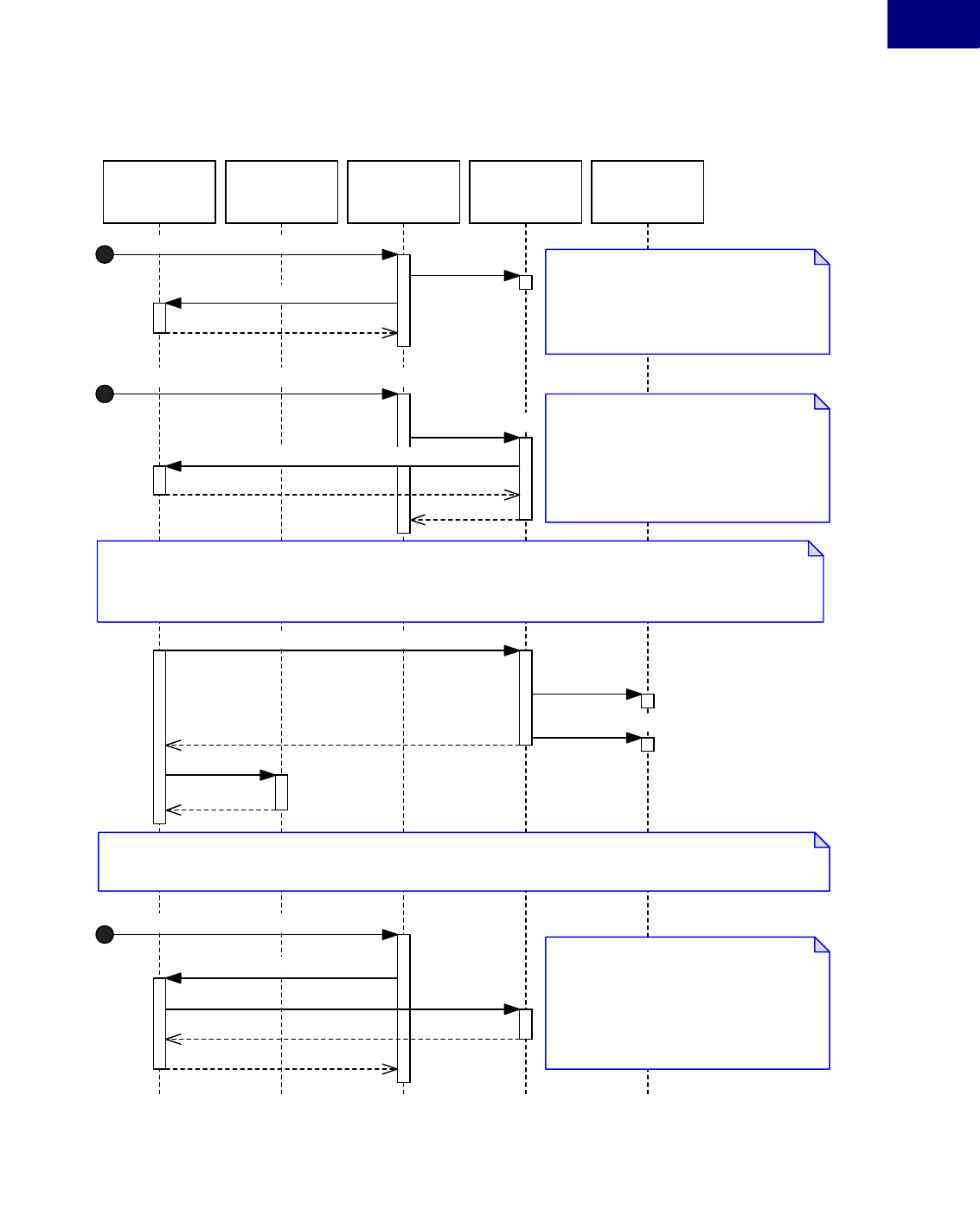
Commands 97
Commands
Extension patterns
FIGURE 19 Typicalinval handler calls (sequence diagram)
Observer (or
other type of
object)
An Inval HandlerApplication core An Inval CookieICmdHistory
New events in the model of interest for undo / redo cause the above sequence to be repeated and a new inval
cookie to be associated with the transaction.
An inval handler is created and associated
with the database that persists the objects
of interest. For example, an inval handler
might be attached when a document is
opened.
More events of interest for undo / redo can occur within the same transaction. The inval handler must be called to
record each event. At the end of the transaction, EndCollectingInvals is called. The inval handler returns the cookie
to be called on undo and redo of the transaction. See sequence diagram showing inval cookie calls.
When the lifetime of an inval handler is over,
DetachInvalHandler is called to detach the
inval handler from the database. For
example, an inval handler might be
detached when a document is closed.
StartCollectingInvals is called to indicate
that the inval handler is interested in
participating in undo and redo of a
transaction. This usually occurs on some
event (through an observer, or some other
means).
Event that causes attach to the model
new
DBUtils::AttachInvalHandler
Event in the model of interest for undo / redo
AddInvalInfo(info)
bool16= DBUtils::StartCollectingInvals
IInvalCookie*= EndCollectingInvals
new
AddInvalInfo(vector of info)
Push
Event that causes detach from the model
DBUtils::DetachInvalHandler
delete
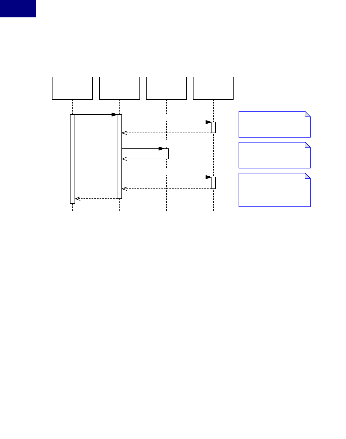
Commands
Extension patterns
98
FIGURE 20 Inval cookie calls on undo
There are times where the lifetime of an inval handler does not match that of the command his-
tory. Inval handlers can be attached and detached at any time, asynchronously with anything
else happening in the model. This means there are entries in the command history that do not
have corresponding inval cookies for a particular inval handler. In this situation, the inval han-
dler’s BeforeRevert_InvalAll and AfterRevert_InvalAll methods are used to provide the oppor-
tunity to rebuild the required state directly.
There are times when an inval cookie instance can be asked to merge another instance. This
causes the IInvalCookie::Merge method to be called, to merge cookies that were returned by
each call to IInvalHander::EndCollectingInvals within one undoable transaction. For example,
this can happen at the end of an abortable command sequence.
See also
zIInvalHandler, IInvalCookie, DBUtils::AttachInvalHandler, DBUtils::StartCollectingInvals,
and DBUtils::DetachInvalHandler in the API Reference.
zFor sample code: GTTxtEdtInvalHandler in the GoToLastTextEdit plug-in.
zFor documentation on how to detect change in other objects using observers and respond-
ers: the “Notification” chapter.
Application core ICmdHistory An Inval CookieModel
Prior to the model state being
reverted, all inval cookies are
called.
After all inval cookies are
called, the model is reverted
(assuming no error).
After the model has been
reverted, all inval cookies are
called. Setting error here will
undo the "Undo".
Undo
ErrorCode= InvalBeforeUndo
ReadWrite / SnapshotReadWrite
ErrorCode= InvalAfterUndo

Commands 99
Commands
Extension patterns
Snapshot view interface
Description
Suppose you have a user interface object like a widget, which has data that depends on model
objects that persist in a database that supports undo, and:
zYour data needs to be updated when the model objects it depends on are modified or when
modifications are undone or redone.
zYou cannot use lazy notification to update your data, because it must be kept up to date with
changes to the model at all times.
NOTE:Use of this pattern is extremely rare in the application codebase. For example, it is used
by interface ILayoutControlData on the layout widget. The data in this interface is
depended on by many other objects and always must be kept in tight synchronzsation
with the database. This is an advanced pattern and should be used only if absolutely
necessary.
Architecture
A snapshot is taken of the state of a snapshot view interface, before it is changed, reverted on
undo, and restored on redo. It is very similar to a snapshot interface (see “Snapshot interface”
on page 92). The distinction is that the database with which a snapshot interface is associated is
fixed and implicitly defined by the persistent boss on which it is aggregated. A snapshot view
interface, on the other hand, is part of a user interface object and must explicitly identify the
database containing the model objects on which it depends. Also, it is not one specific data-
base. For example, a widget that tracks some state in the front document must change the data-
base on which its snapshot view interface depends, when the front document changes.
To implement a snapshot view interface, follow the steps described under CViewInterface in
the API Reference.
See also
The CViewInterface template class in the API Reference.

Commands
Extension patterns
100

Notification 101
Notification
Concepts
Notification
Notification patterns inform interested parties of certain changes. This chapter describes the
prevalent notification patterns used by products in the InDesign family.
Concepts
Notification is a mechanism by which an interested object can be made aware of changes in
other components or subsystems. This section focusses on two prevalent notification patterns,
the observer and the responder.
Observer pattern
The observer pattern is described in [Design Patterns] by Gamma et al. The intent of the pat-
tern is to “Define a one to many dependency between objects so that when one object changes
state, all its dependents are notified and updated automatically.” Figure 21 shows the structure.
FIGURE 21 Abstract representation of the observer pattern
The pattern consists of a subject and one or more observers. A subject is an object that needs to
inform other objects that are interested in changes to the subject’s state. An observer is an object
that needs to keep its state consistent with the state of a subject. A subject can have an associa-
tion with multiple observers. An observer can observe multiple subjects.
The association between observers and subjects is managed through Attach and Detach calls.
Any change to the subject is declared through a call to the Notify method, which in turn calls
Update on any associated observers.
The subject supports three operations:
zAttach — Associates a specific observer with a subject.
zDetach — Detaches a specific observer from a subject.
zNotify — Notifies all associated observers of some change to the subject.
Subject
Attach(Observer) : void
Detach(Observer) : void
Notify() : void
Observer
Update() : void
Notify()
for all o in observers {
o->Update()
}
0..*
has observers
0..*
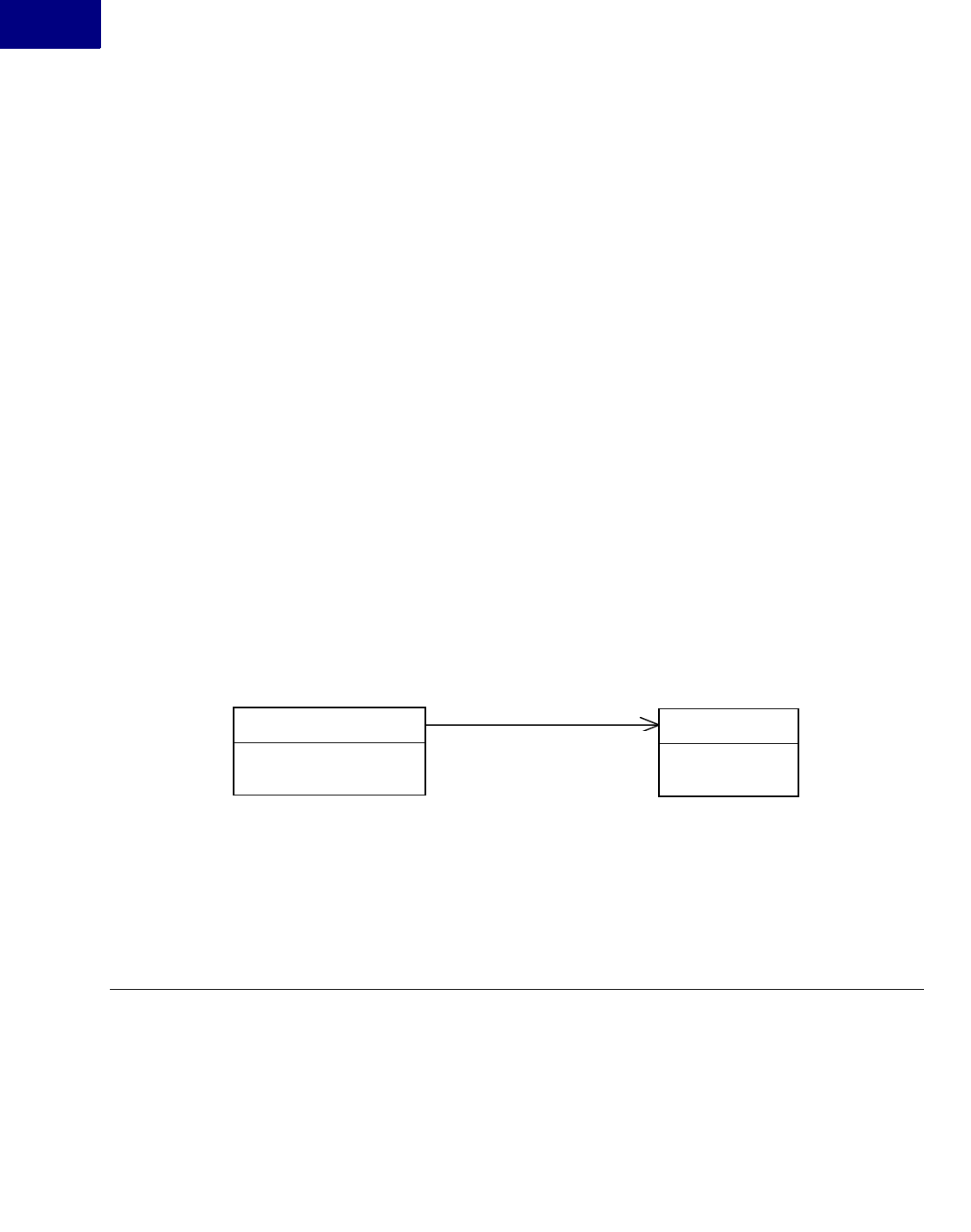
Notification
Observers
102
The observer supports one operation:
zUpdate — Keeps the observer’s state consistent with the subject’s state.
Typically, when a client wants to be notified of changes in a subject, it calls Attach, passing an
observer that will be the recipient of update messages.
Any update to the subject that could be of interest to observers results in a call to the subject’s
Notify method. The subject, in turn, iterates through all attached observers, calling their
Update operations.
At any point, a client can remove the observer from the subject, using Detach. The observer no
longer receives update events from that subject.
For more information, see “Observers” on page 102.
Responder pattern
With the observer pattern, notification is provided when an object is modified. The responder
pattern provides notification on an event. Notification consists of a signal sent from one party
to a responder that can react to the event. The application predefines a set of events and corre-
sponding signals in which responders can register interest. For example, signals are associated
with document events like create, open, save, and close. A responder that registers interest in
the document open event is called each time a document is opened. Figure 22 shows the struc-
ture.
FIGURE 22 Responder pattern
The pattern consists of a signal manager and responders. The signal manager is the object
responsible for notifying responders of some event. A responder is an object that is called as a
result of that event. A responder registers its interest in a particular event using the service pro-
vider extension pattern. A responder is a service provider, although this is not shown explicitly
in Figure 22. For more information, see “Responders” on page 115.
Observers
This section describes the implementation of the observer pattern (see “Observer pattern” on
page 101) within the application. The implementation consists of two interfaces, a subject (see
the ISubject interface) and an observer (see the IObserver interface), as shown in Figure 23.
SignalManager
+ SignalResponder() : void
Responder
+ Respond() : void
1
has responders
0..*

Notification 103
Notification
Observers
FIGURE 23 Subject and observer interfaces (class diagram)
Subjects
A subject is an object potentially of interest to other objects. Within the application, any object
that maintains state of interest to other objects is a candidate for being a subject. An object with
an ISubject interface is a subject. The interface supports the following key operations:
zAttachObserver — Associates a particular observer with the subject.
zDetachObserver — Detached a particular observer from the subject.
zChange — Notifies observers of a change to the subject. Observers get called on their IOb-
server::Update method. See “Regular and lazy notification” on page 106.
zModelChange — Notifies observers of a change to a subject. Observers get called on their
IObserver::Update method and/or their IObserver::LazyUpdate method. See “Regular and
lazy notification” on page 106.
Change manager
Subjects within the application defer the functionality required to track the subject and
observer dependencies to the change manager (the IChangeManager signature interface). The
ISubject interface forms a facade over the change manager. It is unlikely third-party developers
need to interact with the change manager directly. It is not considered further here.
«interface»
ISubject
+ AttachObserver() : void
+ Change() : void
+ DetachObserver() : void
+ ModelChange() : void
«interface»
IObserver
+ AutoAttach() : void
+ AutoDetach() : void
+ LazyUpdate() : void
+ Update() : void
CSubject
+ AttachObserver() : void
+ Change() : void
+ DetachObserver() : void
+ ModelChange() : void
CObserver
+ AutoAttach() : void
+ AutoDetach() : void
+ LazyUpdate() : void
SomeObserver
+ Update() : void
A default implementation,
kCSubjectImpl, is provided. It is
unlikely that you would need
to specialise it.
«realize» «realize»
0..*0..*

Notification
Observers
104
Observers
An observer is an object interested in changes to a subject. Any object within the application
object model can be an observer by aggregating the IObserver interface. The interface supports
the following key operations:
zAutoAttach and AutoDetach — Provided when the observer knows the subject with which
it should be associated. A client would then delegate the association of subject and observer
to the observer. See “Relating observers to subjects” on page 112 for a description of how to
associate an observer with a subject.
zUpdate and LazyUpdate — Receives notification when a subject changes. An observer can
get called via its Update or LazyUpdate method, depending on how it chooses to receive
notifications from the subject. See “Regular and lazy notification” on page 106.
Message protocols
Normally, an observer attaching to a subject indicates a protocol of interest. This protocol
(identified by type PMIID) allows the observer to be called only for a subset of the total set of
messages being broadcast by the subject. Generally, the protocol is synonymous with a data
interface on the subject. Observers interested in changes to a specific data interface on the sub-
ject attach using the PMIID of the data interface.
Figure 24 shows a subject, kSomeSubjectBoss, that aggregates a data interface, ISomeData. The
observer, kSomeObserverBoss, is interested in changes to this data interface. The observer
attaches to the subject, specifying IID_ISOMEDATA as the protocol of interest. This corre-
sponds to the PMIID of the data interface. After the data interface is modified, the ISub-
ject::ModelChange or ISubject::Change method is called to broadcast notification. Observers
are called via their Update or LazyUpdate methods, with a message protocol of
IID_ISOMEDATA.
The object that actually modifies the data interface and calls the ISubject interface to broadcast
notification is not shown in Figure 24. If the subject object is part of a document or defaults,
the object that calls the mutator method on the data interface normally is a command (see the
“Commands” chapter). The command calls ISubject::ModelChange if it performs notification.
If the subject object is a user interface object, mutator methods on the data interface itself nor-
mally call ISubject::Change to broadcast notification.

Notification 105
Notification
Observers
FIGURE 24 A subject and an observer boss class (class diagram)
Subject and observer types
Within the application, subjects are split into distinct “types.” The type of object a subject is
determines the method on ISubject that is called to perform notification. The types of subject
are as follows:
zModel — An object that is part of the document model (see kDocBoss), the defaults model
(see kWorkspaceBoss), or another model that supports undo. The ISubject::ModelChange
method is used to broadcast notification when model objects change.
zUser interface — An object that is part of the user interface; for example a checkbox or but-
ton This is distinct from an element in the user interface that is interested in model data.
The ISubject::Change method is used to broadcast notification when user interface objects
change.
Within the application, observers are split into distinct “types.” The type of subject object an
observer is watching determines the type of observer. The types of observers are as follows:
«boss»
kSomeBoss
«interface»
ISubject
+ AttachObserver() : void
+ Change() : void
+ DetachObserver() : void
+ ModelChange() : void
CSubject
+ AttachObserver() : void
+ Change() : void
+ DetachObserver() : void
+ ModelChange() : void
«interface»
IObserver
+ AutoAttach() : void
+ AutoDetach() : void
+ LazyUpdate() : void
+ Update() : void
CObserver
+ AutoAttach() : void
+ AutoDetach() : void
+ LazyUpdate() : void
«boss»
kSomeObserverBoss
«interface»
ISomeData
+ Get() : void
+ Set() : void
SomeData
+ Get() : void
+ Set() : void
SomeObserver
+ Update() : void
«realize» «realize» «realize»
0..*0..*

Notification
Observers
106
zModel — An observer attached to objects that persist in a document (see kDocBoss),
defaults (see kWorkspaceBoss), or another model that supports undo. Notification of model
observers is done through a call to ISubject::ModelChange.
zUser interface — An observer attached to a user interface object; for example a checkbox or
button.
zSelection — An observer watching an artifact of the current application selection.
zContext — An observer watching some context, such as the active document.
zHybrid — An observer watching multiple types of subjects. A particular observer may
attach to any set of objects; however we do not consider what requirements observers that
attach to multiple types of subjects might have.
Regular and lazy notification
The application supports two types of notification, regular and lazy. If an observer needs to be
called as soon as a subject broadcasts the change message, it should request regular notification.
If the observer can afford to wait until idle time before being notified that a change of interest
occurred, it can register for lazy notification. When an observer attaches to a subject, it defines
whether it wants to attach for regular notification, lazy notification, or both.
Regular notification
Regular notification is passed to an observer via the IObserver::Update method.
With regular notification, an observer is called within the scope of the call to a subject’s ISub-
ject::Change (or ISubject::ModelChange) method. Figure 25 shows the typical sequence of calls
made when a subject notifies an observer using regular notification.

Notification 107
Notification
Observers
FIGURE 25 Regular notification
A client object is called and modifies some data interface, then broadcasts notification about
the changes it makes. It mutates the state of a data interface and then calls ISubject::Model-
Change. Observers get called via IObserver::Update and can retrieve the state of the data inter-
face. The subject and the data interface are most often on the same boss object, but not always.
If a change is undone or redone, the observer is not notified. That is, the Update message is not
re-broadcast. See Figure 27 for the sequence of calls made on undo.
Lazy notification
Lazy notification is passed to observers via the IObserver::LazyUpdate method. Lazy notifica-
tion is available only to observers of subject objects associated with persistent databases sup-
porting undo.
Lazy notification is used when observers do not need to be in tight synchronization with
changes being made to the subject objects they observe. Rather than participating in each
change that occurs on a subject object, observers using lazy notification are notified after all
updates are made and the application is idle.
When the state of an object in the model is changed (for instance, by a command), and notifi-
cation is required, the notification always is broadcast by calling ISubject::ModelChange. The
ISubject::ModelChange method queues a message to be broadcast later. Once the application is
idle, observers get called with this message via the IObserver::LazyUpdate method, as shown in
Figure 26.
An ObserverA Data InterfaceA Client Object A Subject
Set
Change
Update
Get
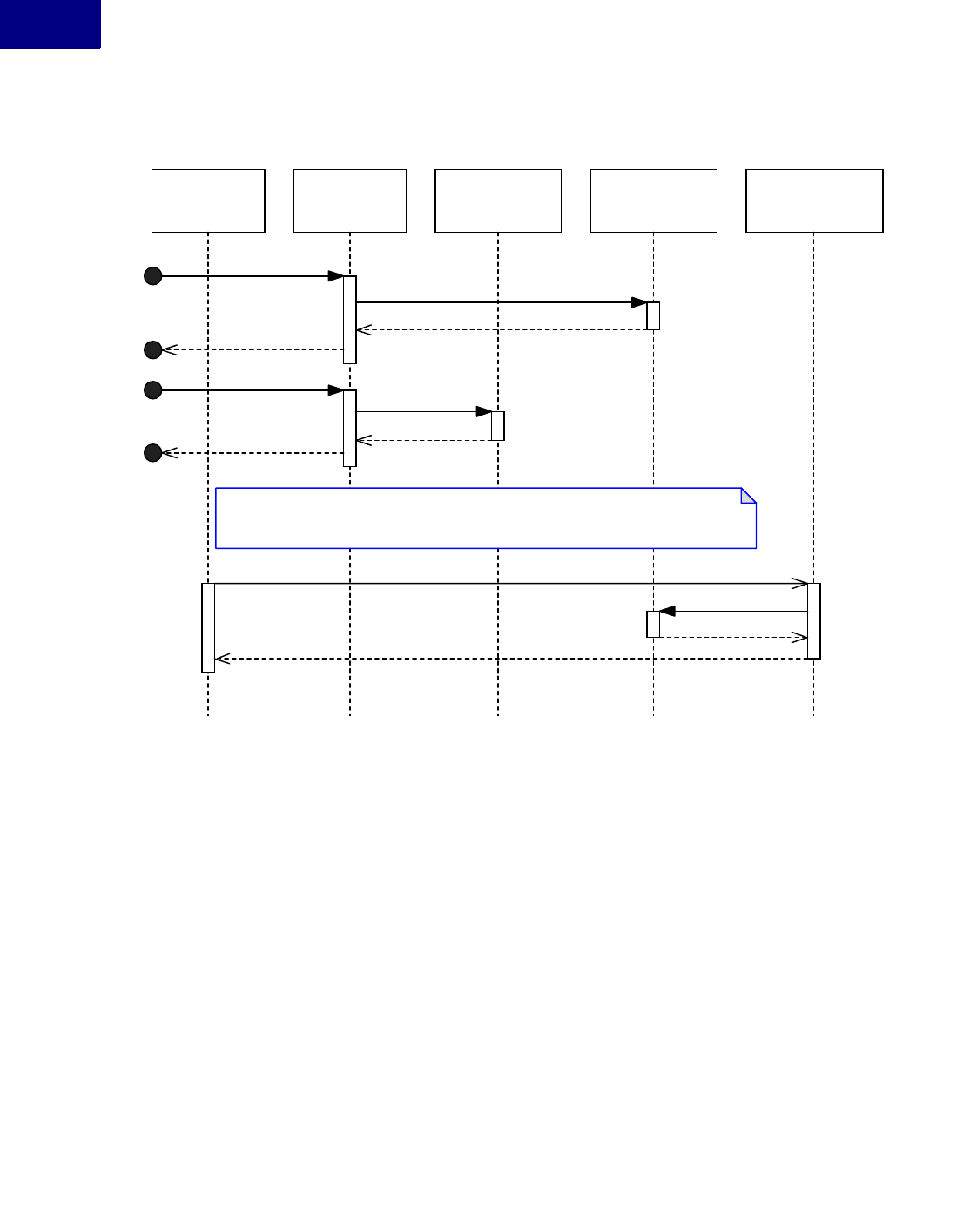
Notification
Observers
108
FIGURE 26 Lazy notification
NOTE:The approach above holds for subject objects in the document model, the defaults
model, or, in general, any subject object that persists in a database that supports undo.
Only subject objects which persist in a database that supports undo can use lazy
notification.
Regardless of the number of changes made to the persistent interface, only one LazyUpdate call
is made per sequence for a given message protocol.
An implication of this is that ordering of lazy notification with respect to other lazy notification
messages cannot be guaranteed. Lazy notification can be thought of as a message indicating a
change was applied to an object some time in the past. The observer is responsible for deter-
mining the nature of the change.
An observer that registers for lazy notification is not guaranteed to receive all messages. For
example, suppose an observer is attached to a page item and is watching for the page item to
move. If a sequence moves the page item and then deletes it, a lazy update message for the
move is not sent to the observer. If a subject object is deleted, any lazy notification messages
being queued for that object are purged.
We recommend any model observer used to keep some user interface component synchro-
nized with the model should use lazy notification. This eliminates any unnecessary refresh of
Application Idle
Task
A Command A Persistent
Interface
A Model Subject An Observer
Observers using lazy notification are notified later on when the application is idle.
Do
Set
DoNotify
ModelChange
LazyUpdate
Get
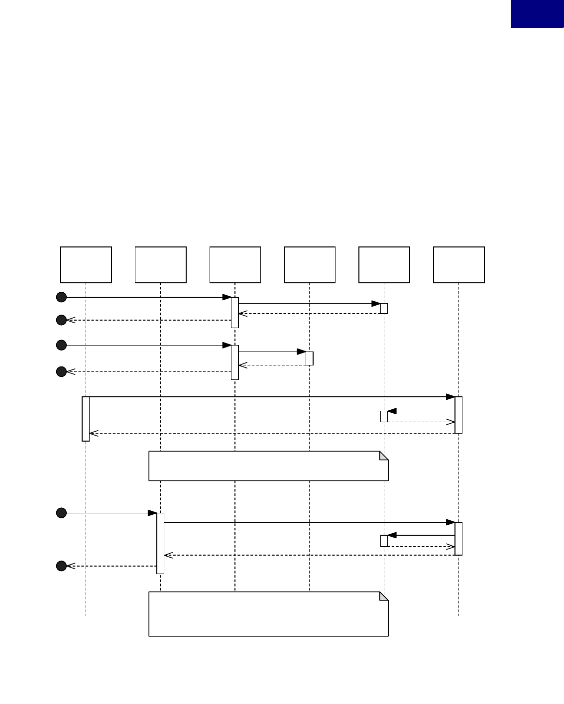
Notification 109
Notification
Observers
user interface data. An example use of lazy notification is a user interface panel that reports
information about the set of text frames in a document. The user interface panel is associated
with a model observer watching for textual changes or the addition or removal of text frames.
These operations result in the panel being updated. There is no real requirement for the panel
to be updated in real time as these changes are made; the panel should be updated when the
text updates are complete (and the application is idle). Lazy notification enables this by sending
a single IObserver::LazyUpdate message to the observer when the move is complete.
If a change is undone or redone, the observer is notified; that is, the LazyUpdate message is re-
broadcast. The sequence of calls made to an observer’s LazyUpdate method on undo is shown
in Figure 27.
FIGURE 27 Sequence of calls made to an observer on undo
A Command A Persistent
Interface
A Model
Subject
An ObserverApplication
Core
ICmdHistory
The lazy update on do is discussed elsewhere
On undo (and redo) the LazyUpdate method of the observer is
invoked. Note, the command is no longer in existence when
undo or redo is processed.
Do Set
DoNotify ModelChange
LazyUpdate
Get
Undo
LazyUpdate
Get
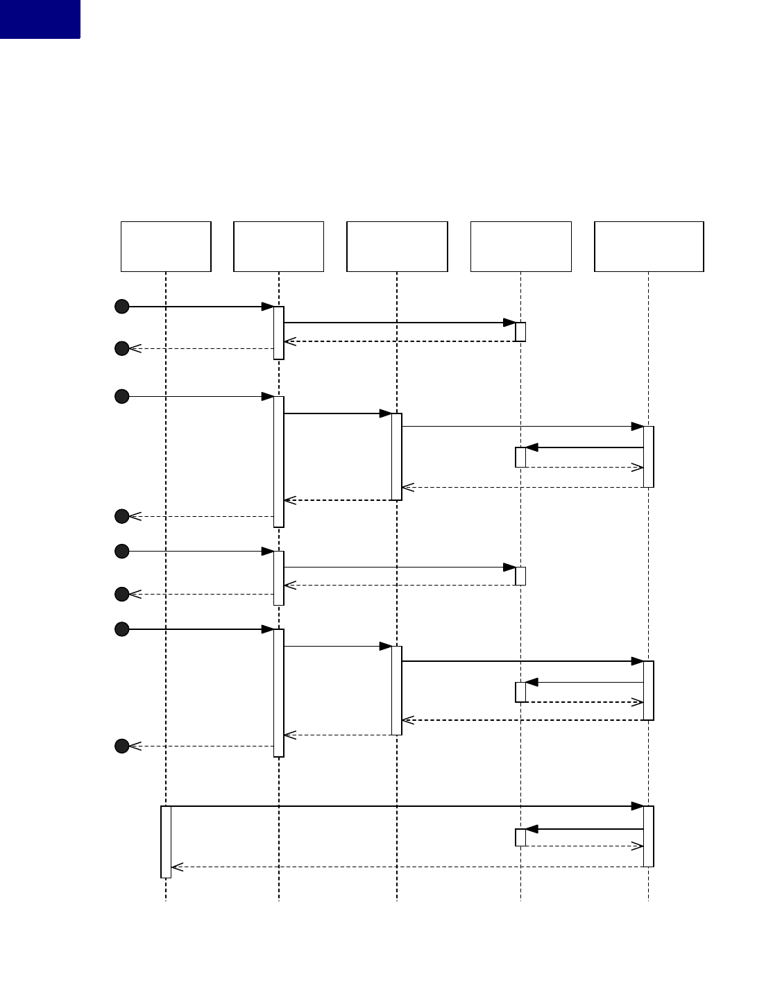
Notification
Observers
110
Both notifications
An observer can register for both regular and lazy notification. Figure 28 shows the sequence of
calls this might involve.
FIGURE 28 Regular and lazy notification
Application Idle
Task
A Persistent
Interface
A Model Subject An ObserverA Command
Do
Set
DoNotify
ModelChange
Update
Get
Do
Set
DoNotify
ModelChange
Update
Get
LazyUpdate
Get

Notification 111
Notification
Observers
While every ISubject::ModelChange message sent to the subject is propagated to the observer
via IObserver::Update, only one IObserver::LazyUpdate call is made, regardless of the number
of changes made in a single transaction. For example, if multiple updates are made on an
object, the update messages being transmitted using a single protocol identifier, and the lazy
update method is called only once.
On undo or redo, only the LazyUpdate messages are re-broadcast.
Registering for both notifications allows an observer to have the rich context of the Update
message and have to re-build their view of the model only on rarer undo/redo events.
Lazy notification data
With regular notification, the observer (IObserver::Update) method is passed a context about
what caused the change (usually, the command that initiated the notification). With lazy notifi-
cation (IObserver::LazyUpdate), the observer gets notified only that something changed. The
observer must be capable (for instance, by examining the model) of deducing or otherwise
rebuilding the set of information it requires. In some cases, the time this takes causes perfor-
mance issues; therefore, the API provides lazy notification data as an optimization.
Lazy notification data objects are data-carrying (C++) objects created by the message origina-
tor. For example, a command that deletes a document page object (kPageBoss) might create a
lazy notification data object and populate it with the UID of the deleted page. Generally, this
lazy notification data object is passed to observers via IObserver::LazyUpdate. There are situa-
tions where the lazy notification data objects associated with a change are purged (for example,
in low memory condition), and the observer is called with a nil-pointer; therefore it is impor-
tant that observers be designed to deal with this.
The lazy notification data objects used within the application are not documented in the public
API.
NOTE:Use of lazy notification data objects is not pervasive in the application. They exist only
as an optimization, and the types of data they consist of varies. We recommend you
avoid using them if possible and refresh the observer’s state entirely when
IObserver::LazyUpdate is called.
Observers and undo
Only observers registered for lazy notification are signalled when an object they are associated
with is modified through an undo or redo action. For each undo or redo, the observer receives
one call (per message protocol), regardless of the number of changes made to the subject
object.
If the observer performs model modifications using commands (see “Model modifications” on
page 114), on undo or redo these are automatically undone or re-done as required. For observ-
ers watching the model to update some aspect of the user interface, lazy notification should
give the required update. If there are more exotic requirements for notification on undo and
redo, two other patterns exist: see the Snapshot interface and Inval Handler extension patterns
in the “Commands” chapter.

Notification
Observers
112
Relating observers to subjects
This section discusses how observers are attached to particular subjects.
Determining the subject
Before being able to attach and detach observers, an understanding of both the subject to
attach to and the protocol to listen along is required. The sample code provided as part of the
SDK has examples for many key events of interest. Similarly, Adobe InDesign CS4 Solutions has
advice on detecting when events occur for domains like layout, text, XML, and so on.
If neither of these resources provide the answer, the debug version of the application can be
used. Under the test menu is an item called Test > Spy. It can be configured to log all executing
commands, along with the subjects that are notified, the protocol used for notification, and the
change that occurs. Perform the action of interest, and Spy provides the information required
to observe the action.
Attaching and detaching subjects
In most situations, an observer understands the subjects in which it is interested and how to
attach to them. Such an observer attaches to the subjects in the IObserver::AutoAttach call and
detaches in IObserver::AutoDetach. For example, an observer on a panel can discover the wid-
gets it contains (see the IPanelControlData interface) and attach to their subject interface.
NOTE:The IObserver::AutoAttach and IObserver::AutoDetach methods still need to be called
by another object.
There are other situations where the observer does not know the subject(s) with which it
should be associated. Given a subject and an observer, a client object can directly attach or
detach the observer using ISubject::AttachObserver and ISubject::DetachObserver calls.
Using a responder to attach and detach an observer
Sometimes, an observer is required based on an action within the application. Responders (see
“Responders” on page 115) are called on different application events and can be used to man-
age the association between an observer and a subject. For example, a responder can be called
when documents are created, opened, or closed. On create or open, the responder can attach an
observer to the document. On close, the responder can detach the observer.
Using an observer to attach and detach another observer
Sometimes, an observer attaches and detaches a second observer based on notification received
by the first observer. This pattern commonly is seen in user interface objects that view objects
in the front most document. The active context (see kActiveContextBoss, the IActiveContext
interface, and the IID_IACTIVECONTEXT protocol) is the subject that is updated when the
user chooses the document on which to work. The user interface object has a first observer that
watches the active context. This observer attaches and detaches a second observer to the sub-
jects of interest in the front-most document.

Notification 113
Notification
Observers
Observing a subject that can be deleted
Sometimes, a client object needs to observe a subject created as part of an undoable action. To
do this, a pattern involving two observers and an inval handler can be used (inval handlers are
described in the “Commands” chapter). The first observer watches for create events for the
subject and attaches the second observer to the newly created subject. To ensure this second
observer gets detached if the create action is undone, the first observer also must set up an
inval handler. The inval handler provides a mechanism to detach the observer on undo and
reattach it on redo.
Observing a subject that can be deleted as part of an undoable action is similar. On undo, the
observer must be reattached; on redo, it must be detached. Again, this requires the use of an
inval handler.
Document notification
The application supports a large object model. Any object is a candidate for becoming a subject
(and thousands of subjects exist). Management of observers interested in the set of messages
broadcast from a subject can be difficult, if many instances of a subject can exist. For example,
consider objects in the page item hierarchy (which can be deleted and recreated, undone and
redone, as a consequence of user actions). It is difficult and undesirable to maintain an
observer on each page item. To solve this problem, as well as the actual subject object broad-
casting the change message, the document’s subject also broadcasts the change. This means any
observer associated with the ISubject interface on the document (kDocBoss) subject is noti-
fied, without the overhead of managing the association with finer-grained objects within the
document.
Notification of changes to page items are broadcast on the document subject using IPageIte-
mUtils::NotifyDocumentObservers. Some other types of object use the ISubject interface of the
document (see kDocBoss) directly to notify of a change.
Observers and the model
This section details some considerations around the use of model observers within the applica-
tion.
Observers “watch” model data for two primary reasons:
1. To update a user interface element to reflect the state of the model. (This type of observer is
distinct from user interface observers, which watch for changes in user interface elements
like checkboxes.)
2. To provide a point where existing functionality can be extended. For example, an observer
can be used to set custom data in a story object (kTextStoryBoss), on story creation. There
are side effects for both the error state and model modifications that should be considered
when using observers to extend the model.

Notification
Observers
114
Error state
Model observers that extend functionality can set the global error state either directly (using
ErrorUtils::PMSetGlobalErrorCode) or indirectly (through processing of commands). Gener-
ally, observers are notified during the processing of a command or sequence of commands. If
the application tries to process a command when the global error state indicates anything but
success (kSuccess), a protective shutdown is invoked to protect the integrity of open docu-
ments.
An observer setting the global error state either aborts the current change (that is, the current
change is undone) or causes the shutdown of the application. The behavior is determined on a
per-use basis and can be complicated by the use of commands in different scenarios. For exam-
ple, the creation of a text story object (kTextStoryBoss) can occur through the type text tool or
from an import and place operation. The type text tool is straightforward, and an observer set-
ting global error state causes the change to be undone. For import and place, however, the story
creation occurs as part of a longer sequence of commands. A similar observer setting global
error state causes an application shutdown as further commands are processed.
Unless it is explicitly suggested that it is appropriate to set error state in an observer of a partic-
ular subject change, an observer should not set error state. Also, an observer that uses objects
that potentially set error state (such as commands) should test for and consume any errors, tak-
ing appropriate remedial action.
Model modifications
A common pattern involves calling commands within an observer to make further modifica-
tions to the model. This can lead to problems. If the observer is notified as part of a sequence of
commands, and the commands that are due to be processed after the current notification phase
ends make any assumptions about the state of the model, instability and document corruption
can result.
For example, consider a sequence of two commands. The first inserts text into a text story
object (kTextStoryBoss). The second changes the color of the newly inserted text to blue.
Pseudo-code for this sequence is in Example 15
EXAMPLE 15 Pseudo-code showing dependencies between commands
void MyTextUtils::AddNote(string str, ITextModel* story, TextIndex position)
{
int32 stringLen = str.Length();
BeginSequence("AddNote");
MyTextUtils::AddToStory(story,position,str,stringLen);
MyTextUtils::SetTextColor(story,position,stringLen,BLUE);
EndSequence("AddNote");
}
At some point, a third party decides to extend the text functionality by writing a macro
expander, the purpose of which is to expand known acronyms as text is entered into stories.
The third party uses an observer that is notified when text is added to a story. If the observer
modifies the model, specifically changing the number of characters entered into the story, it
breaks the sequence in Example 15. The stringLen value is no longer valid.

Notification 115
Notification
Responders
If there is no risk of side effects from the model change within an observer (for example, the
observer modifies custom data, not the core application data on the object), it is safe to proceed
with the change. If there is a need to perform further modifications on the core application
data, consider factoring the change to execute as a separate task (possibly on application idle).
In Example 15, the observer might mark some custom, persistent data in the story, indicating it
needs to be processed, and schedule a custom command. The custom command examines the
story, determines whether the macro expansion operation is still valid, and updates the story if
required. No assumptions can be made about what might occur between marking the story in
the observer and the follow-on processing (for example, the document could close, further
updates could occur, or the application could terminate).
Commands that delete objects generally pre-notify, so subject observers get an opportunity to
tidy up associated objects before the object is deleted. Observers called in this context should
ensure the command state is CommandState::kNotDone.
Responders
This section describes the implementation of the responder pattern (see “Responder pattern”
on page 102) within the application. The responder pattern provides notification that a specific
event has occurred. For example, a responder can be called when a document is created,
opened, or closed. Figure 29 shows the general structure.
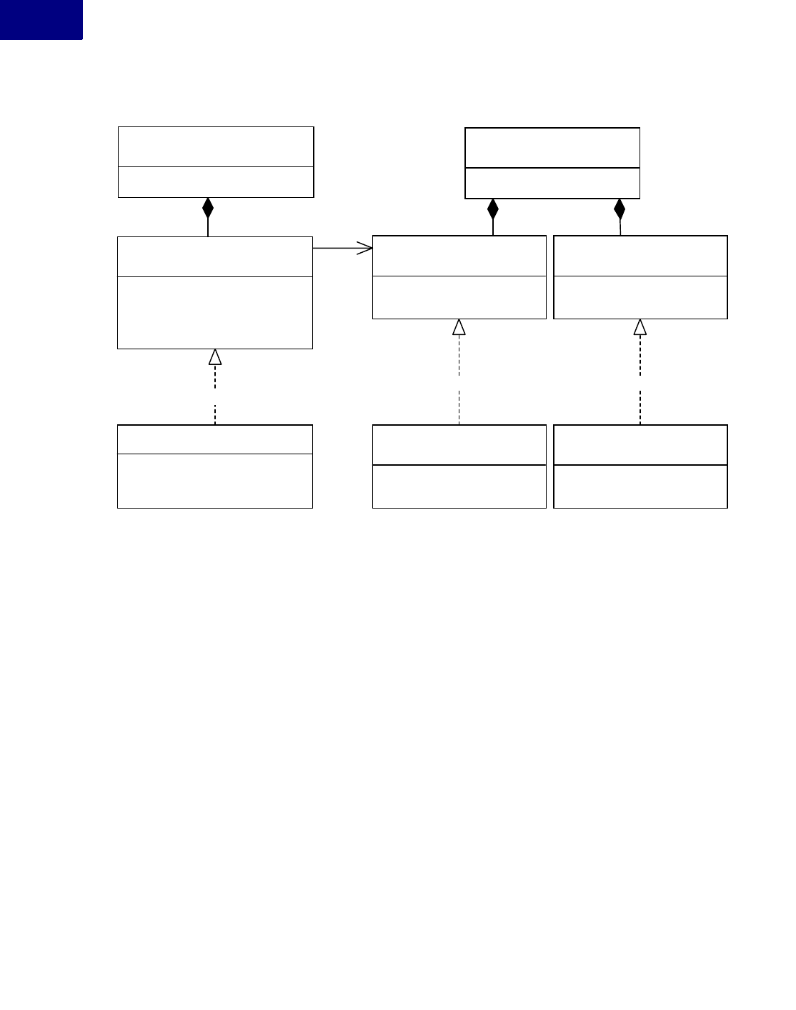
Notification
Responders
116
FIGURE 29 Pattern used for responders
The components to the responder pattern shown in Figure 29 are as follows:
zSignal manager (signature interface ISignalMgr) — The entity responsible for notifying
responders of an event.
zService provider (interface IK2ServiceProvider) — The entity that identifies the object as a
responder and indicates the events of interest.
zResponder (signature interface IResponder) — The entity invoked as a result of some event.
Signal manager
A signal manager is an object that controls the calling of responders. A boss class that has an
ISignalMgr interface is a signal manager. A signal manager is called by some other object that
wants responders to be notified when an event of interest has occurred. The object that calls a
signal manager is often a command (see interface ICommand). For example, the command
that opens a document calls the signal manager to notify responders which have registered an
interest in this event.
Responders are service providers. Each event for which a responder can be notified has a corre-
sponding ServiceID. The application predefines a set of events and corresponding ServiceIDs
in which responders can register interest. For example, the open document event has a Servi-
ceID of kOpenDocSignalResponderService. See the “Notification” chapter of Adobe InDesign
CS4 Solutions.
«interface»
ISignalMgr
CountResponders() : int32
Init(ServiceID) : void
SignalNextResponder() : ErrorCode
Terminate() : void
SignalMgr
ServiceID: = kARespServiceID
«interface»
IResponder
Respond(ISignalMgr*) : void
SignalFailed(ISignalMgr*) : void
CResponder
AResponder
Respond(ISignalMgr*) : void
«interface»
IK2ServiceProvider
GetServiceID() : ServiceID
CServiceProvider
AResponderServiceProvider
ServiceID: = kARespServiceID
«boss»
kAResponderBoss
«boss»
kASignalMgrBoss
«realize»
10..*
«realize» «realize»

Notification 117
Notification
Responders
When a particular event occurs the signal manager is called to signal all responders that have
registered interest. The signal manager uses the service registry (not shown in Figure 29) to
find the responders that need to be called for the event.
If a responder sets the global error state, the signal manager is responsible for calling previously
signalled responders indicating there was an error condition (allowing the responder to take
whatever action might be necessary) and the action is aborted.
Responder
A responder is a boss class that supports two specific interfaces, the service provider interface
(IK2ServiceProvider) that identifies the events the responder is interested in, and the
responder interface (signature interface IResponder) that is called for a particular event.
Responder registration
Each event for which a responder can be called has a corresponding ServiceID. A responder
registers for one or more of these events by returning the ServiceIDs for the events of interest
via its IK2ServiceProvider implementation. See the “Notification” chapter of Adobe InDesign
CS4 Solutions for details on the predefined events the application makes available. For sample
code, see the DocWchServiceProvider class in the DocWatch plug-in.
Responder implementation
The responder is called via IResponder::Respond on an event of interest. The Respond method
performs whatever functionality is required and returns.
If the global error state is set (ErrorUtils::PMSetGlobalErrorCode) by a responder, any previ-
ously signalled responders have their IRespond::SignalFailed method called to indicate failure.
The SignalFailed method performs the function needed to recover. For example, if the
Respond method attached an observer to an object, the SignalFailed method detaches that
observer.
Both methods receive a pointer to a signal manager interface, so they can find out information
about the event. Typically, the Respond and SignalFailed methods query the signal manager
interface for other contextual interfaces. For example, the document signal manager (see kDoc-
umentSignalMgrBoss) provides context in the IDocumentSignalData data interface. Respond-
ers that register for document signals like kAfterOpenDocSignalResponderService use this
data interface to access the document being opened.
The Respond and SignalFailed methods often call the service manager using the ISig-
nalMgr::GetServiceID method, to verify the ID of the service that occurred. This allows one
responder implementation to be handle more than one type of event
For sample code, see the DocWchResponder class in the DocWatch plug-in.
Responders and the model
Responder implementations can perform follow-on modifications to the model. For example, a
responder called as the result of a command modifying the model can make further changes to
the model by calling other commands.

Notification
Responders
118
Take care that these modifications do not interfere with the model data on which the signal is
based. For example, if a responder signalled on a create story signal (kNewStorySignalRe-
sponderService) deletes or otherwise modifies the created story, commands, observers, and
responders that might follow the errant responder could make assumptions about the state of
the story. Avoid direct modifications that interfere with the data on which a responder is based.
If such a change is required, consider using the responder to set an associated, independent
state that can be used by an idle task (or similar) to perform the actual modification on the
model. This technique guarantees the model is in a consistent state before modifications are
made.
NOTE:A responder should check the global error state is kSuccess
(ErrorUtils::PMGetGlobalErrorCode), before modifying the model.
Responders and global error state
Responders are designed to accommodate error; however, in practice, how a particular signal
service deals with error state is implementation dependent.
NOTE:If you set global error state in the IResponder::Respond method, thoroughly test all areas in
the domain in which you are working.
If a responder sets global error state, the signal manager calls all previously signalled respond-
ers via IResponder::SignalFailed and aborts the action. The ability to clean up a failed action is
implementation and context dependent. For example, the creation of a text story object (kText-
StoryBoss) can occur as a result of using the type text tool or importing a file. In the case of
importing a file, the responder is called from a much deeper stack than in the case of using the
type text tool. The implementation in the latter case does not handle aborting the import from
a responder.
Another implication of the IResponder::SignalFailed method being called on error is the
method must be able to consume and take remedial action for any errors caused within the
method. There is nothing the application core can do if an IResponder::SignalFailed method
itself fails; the condition is indeterminate.
Ordering of responders
No guarantees can be made about the order in which responders are called to react to an event.
If a client requires a particular responder to be called before another, the implementation of the
second responder should call ISignalMgr::SignalResponder (identifying the first responder) at
the start of its respond method. Even though the signal manager’s iteration of the responders
has been short-circuited by calling one of the responders directly, no responder is called more
than once.
Notification 119
Notification
Key client APIs
Responders and undo
Responders for the predefined events made available by the application are not called at undo
or redo of an operation.
If a responder processes commands to make follow-on changes to the model, these changes are
undone automatically as part of an undo operation; the client code need to manage this. The
same is true for redo of an operation.
If a responder is being used to attach an observer to a newly created model object, that
observer must be detached on undo and reattached on redo. Similarly, if a responder is being
used to detach an observer from a model object about to be deleted, that observer must be reat-
tached on undo and detached on redo. To achieve this, the undo or redo actions need to be
tracked using an inval handler. See the “Commands” chapter for a description of the inval han-
dler extension pattern.
If the responder is being used for a non-model based activity (for example, keeping a log of
specific operations), and the undo or redo actions need to be tracked, an inval handler again is
required.
Key client APIs
Table 9 shows key client APIs for observers and responders
TABLE 9 Key client APIs for observers and responders
API Note
Observers IObserver Client code mainly calls AutoAttach and
AutoDetach to have an observer attach or detach
automatically to or from the subject(s) of interest.
ISubject Client code mainly calls AttachObserver and
DetachObserver methods to attach or detach an
observer.
Responders ISignalManager If you are extending the application and need to
signal new types of events to responders you will call
the signal manager to perform the notification.
Often this notification is performed by a custom
command that you provide. Signal managers in the
application use the default implementation,
kSignalMgrImpl, provided by the API. This default
implementation provides all functionality for the
signal manager, it is unlikely that a third party
developer would need to further specialize it.

Notification
Extension patterns
120
Extension patterns
This section describes the mechanisms a plug-in can use to receive notification.
User-interface widget observer
Description
This observer is attached to the subject object for a user interface artifact and called on a user
interface event, such as selection of a checkbox or activation of a button.
Architecture
To implement a user interface observer, follow these steps:
zSubclass the widget type you are creating (for example, kDialogBoss for dialogs), as
described in the “User Interfaces” chapter of Adobe InDesign CS4 Solutions.
zProvide an implementation for IObserver. The AutoAttach and AutoDetach methods
should attach the observer to any sub-widgets (for example, all buttons on a dialog). Partial
implementations exist; for example CDialogObserver for dialogs and CWidgetObserver for
widgets.
zUser interface widget observers register for regular notification. Implement the IOb-
server::Update method to react to the user interface state change.
See also
zThe “User-Interface Fundamentals” chapter.
zThe “User Interfaces” chapter of Adobe InDesign CS4 Solutions.
zFor sample code: PictureIcon/PicIcoRollOverButtonObserver and WListBoxCompos-
ite/WLBCmpListBoxObserver.
Model observer
Description
A model observer provides an extension point for when a persistent object supported by an
application database supporting undo is updated.
Architecture
To implement a model observer, follow these steps:
zDetermine the subject that is to be observed, the protocol to listen on, and the change of
interest. See the “Notification” chapter of Adobe InDesign CS4 Solutions.
zDetermine which boss class in the object model will aggregate the observer. Commonly, the
boss class that represents the object being observed is a good candidate (for example, aggre-
gating the observer on the document if you are interested in changes to the document). If

Notification 121
Notification
Extension patterns
the observer relates to multiple subjects (for example, attaching to all open documents),
place the observer somewhere accessible from client code.
zProvide the implementation of IObserver, deriving from the CObserver partial implemen-
tation.
zDetermine whether it is appropriate to implement the AutoAttach and AutoDetach meth-
ods. Generally, these methods can be used if the subject object to be observed is known
within the scope of the observer (for example, if the subject is on the same boss object as the
observer). If the AutoAttach and AutoDetach methods are implemented, client code still
needs to call them to create the dependency between subject and observer. If these methods
are not provided, client code needs to manage the dependency between subject and
observer directly (through the ISubject::AttachObserver and ISubject::DetachObserver
calls).
zDetermine whether the subject object is maintained in a database that supports undo. If so,
lazy notification is available.
zIf lazy notification is available, determine the type of notification required. If the subject
object represents a UID-based object from a database that supports undo/redo, lazy notifi-
cation is available. If the observer does not need to track every change to an object within a
sequence of changes (for example, the observer is used to keep information in a user inter-
face panel up to date, and the panel needs to be updated just once, after all changes are
applied), lazy notification can be used. If the observer needs to be aware of all changes to the
object as they occur, use regular notification. When attaching the observer to the subject
(either in the AutoAttach/AutoDetach methods or through client code), specify the notifi-
cation type.
zIf lazy notification is not available, register for regular notification.
zProvide implementations of the IObserver::Update and/or IObserver::LazyUpdate meth-
ods, as required.
See also
z“Relating observers to subjects” on page 112
z“Determining the subject” on page 112
z“Regular and lazy notification” on page 106
zFor sample code showing a model observer using lazy notification: CustomDataLink / Cus-
DtLnkUITreeObserver, LinkWatcher / LnkWtchActiveContextObserver, PanelTreeView /
PnlTrvTreeObserver.
zFor sample code showing a model observer using regular notification: CustomDataLink/
CusDtLnkDocObserver, GoToLastTextEdit/GTTxtEdtNewDeleteStoryObserver, Link-
Watcher/LnkWtchCacheManager, and PersistentList/PstLstDocObserver.

Notification
Extension patterns
122
Selection observer
Description
Selection observers provide an opportunity for client code to be called when there is a change
in the active selection. For details, see the “Selection Observers” section in the “Selection” chap-
ter.
See also
z“Selection Observers” section in the “Selection” chapter.
zFor sample code: TableAttributes/TblAttSelectionObserver, StrokeWeightMutator/StrMut-
SelectionObserver, BasicPersistInterface/BPISelectionObserver, and Persistent List/PstL-
stUISelectionObserver.
Document observer
Description
As well as notifying a change on a subject, often the notification is repeated on the document
for a subject. This allows observers to watch for a change of interest on a document (rather
than attach/detach from every object within the document). For example, an observer inter-
ested in page items being moved around the layout does not need to attach to each page item
(and detach if the page item is deleted, re-attaching if it is un-deleted, and so on), but attaches
to the document instead.
A document observer is a special example of a model observer, using the document object
(kDocBoss) as the subject.
See also
z“Model observer” on page 120
zFor sample code: CustomDataLink/CusDtLnkDocObserver, LinkWatcher LnkWtchCache-
Manager, and PersistentList/PstLstDocObserver.
Active context observer
Description
A context observer is an observer that watches the active context.
Architecture
The active context object (kActiveContextBoss) is session wide and available from the session
object (kSessionBoss) through the ISession::GetActiveContext call. An active context observer
is an observer attached to the subject interface on the active context object. Active context noti-
fications always are broadcast on the IID_IACTIVECONTEXT protocol. Only regular notifi-
cation is available. The change context provided is another IID, indicating the type of

Notification 123
Notification
Extension patterns
contextual change that occurred. The common contextual changes of interest are shown in
Table 10.
TABLE 10 Types of context changes
To implement a context observer, follow these steps:
zAggregate an observer on a boss class accessible from client code.
zProvide implementations of IObserver::AutoAttach and IObserver::AutoDetach (attaching
to the ISubject interface on the kActiveContextBoss accessible from the GetExecutionCon-
textSession()->GetActiveContext() call).
zProvide an implementation of the IObserver::Update method. The protocol ID is
IID_IACTIVECONTEXT.
Example 16 shows how to detect when the active document has changed.
EXAMPLE 16 How to detect the active document has changed
void MyObs::Update(const ClassID& theChange, ISubject* iSubj, const PMMID&
protocol, void* changedBy)
{
if (protocol == IID_IACTIVECONTEXT){
InterfacePtr<IActiveContext> context(iSubj, UseDefaultIID());
IActiveContext::ContextInfo* info=
(IActiveContext::ContextInfo*)changedBy;
if(info->Key() == IID_IDOCUMENT){
HandleDocumentChange(context);
}
}
}
See also
zFor sample code: LinkWatcher/LnkWtchActiveContextObserver.
changedBy Note
IID_IDOCUMENT The active document changed.
IID_ICONTROLVIEW The active layout view changed (for example, when
the document has multiple layout views open).
IID_ISPREAD The current spread changed.
IID_ISELECTIONMANAGER The type of selection changed.

Notification
Extension patterns
124
Subject
Description
If there is a need for a boss class to be observable, it needs to be a subject.
Architecture
To turn a boss class into a subject, follow these steps:
zAggregate the ISubject interface onto the boss class.
zProvide the implementation for the interface. Generally, re-using the API-supplied imple-
mentation (kCSubjectImpl) is sufficient, and there should be no need for further specializa-
tion of this interface.
See also
zFor sample code: PersistentList/kPstLstDataBoss.
Responder
Description
A responder provides notification of an event, such as document open.
Architecture
To implement a responder, follow these steps:
zDetermine the event of interest (as described in the “Notification” chapter of Adobe InDe-
sign CS4 Solutions).
zAggregate the service provider interface (IK2ServiceProvider) on a boss class. Either re-use
an existing implementation (see the “Notification” chapter of Adobe InDesign CS4 Solu-
tions), or provide an implementation that defines the set of ServiceIDs for the events of
interest.
zAggregate the responder (IResponder) on the same boss class.
zProvide an implementation for the responder, derived from the CResponder partial imple-
mentation.
See also
zThe “Notification” chapter of Adobe InDesign CS4 Solutions
zFor sample code: DocWatch/DocWchResponder, CustomDataLink/CusDtLnkDocRe-
sponder, and BasicPersistInterface/BPIDefaultResponder.

Selection 125
Selection
Concepts
Selection
This chapter describes the InDesign/InCopy selection architecture. The selection architecture
is based on the concept of suites—abstract interfaces that allow client code to interact with an
abstract selection. A suite remains neutral to the underlying format of the objects that are
selected.
Concepts
Selection
A selection is whatever is chosen or picked out. For instance, when a user selects a range of text
with the Text tool, the user chooses a range of characters. In this case, the selection is a choice
of characters from the text model. Highlighting in the user interface is incidental feedback that
helps the user make the intended selection. Usually, making a choice using selection is a pre-
cursor to modifying the properties of the model underlying the selection. Selection primarily is
about targeting objects on which to perform some action, and the selection subsystem exists to
mediate changes to those objects.
Selection format and target
It is necessary to distinguish between the format of a selection and its content, the selection tar-
get. A selection format describes the model format of a selectable object, like the layout
(frames), text, table cells, or XML structure. Each of these has a distinct arrangement of objects
that represents its model. A selection target specifies a set of selected objects of a given selec-
tion format, like particular frames or a specific range of text.
The principal goal of the selection subsystem is to hide all details about formats and targets
from client code. Client code needs ask only, “Can this client code do this operation to the
selection?” If yes, the client code can try to change the properties of the selection target. This
encapsulation is achieved by means of the facade pattern discussed in “Design patterns” on
page 126.
InDesign 2.0 included support for a handful of selection formats, including layout objects
(frames), text, table cells, and XML-structure items. InCopy CS added support for other selec-
tion formats, like notes. See Table 11.
Selection
Concepts
126
TABLE 11 Selection formats and their targets
Design patterns
A key task for a plug-in developer is writing model code that extends some aspect of the docu-
ment model. For instance, if your principal requirement is adding private data to the layout
model (see the BasicPersistInterface sample plug-in), the data added extends the layout model
and persists with document contents. The command pattern, used in the application API to
support undo and preserve document integrity, requires you to write further code to change
your model. The API already uses the facade pattern, like ITableCommands and IXMLEle-
mentCommands, to hide the complexity of parameterizing and processing low-level com-
mands.
The selection architecture is an instance of the facade pattern, in that it makes client code easier
to write by defining a high-level interface on top of the selection subsystem. The selection
architecture shields client code from requiring detailed knowledge of what was selected in the
selection subsystem. A facade also makes software maintenance easier, because a facade weak-
ens the coupling between a subsystem and its clients. This weak coupling allows the subsystem
components to be varied without necessarily affecting its clients.
Selection format When obtained Selection target
Application defaults No documents are open. Global preferences
Document defaults Document is open with nothing selected. Document preferences
Galley text Insertion position is in text, or text range is chosen
in Galley view.
Range of characters in a text model
(ITextTarget)
Layout One or more page items are chosen in a layout view. Layout objects (see ILayoutTarget)
Note Insertion position or text range is chosen in a note
view.
Range of characters in note text
(ITextTarget)
Story editor text Insertion position is in text, or text range is chosen
in a story-editor view.
Range of characters in a text model
(ITextTarget)
Table (table cells) One or more table cells are chosen in a layout view. Table cells in a table model
(ITableTarget)
Text Insertion position is in text, or text range is chosen
in a layout view.
Range of characters in a text model
(ITextTarget)
XML structure One or more nodes are chosen in an XML-structure
view.
Elements/attributes in the XML
structure (IXMLNodeTarget)

Selection 127
Selection
Selection architecture
Selection architecture
The most important objective of the selection architecture is to ensure that new selection for-
mats can be added easily.
To support new selection formats without rewriting large parts of the application, client code
must be de-coupled from the selection format. Client code must not need to know the selec-
tion’s subject identifier, meaning client code must not need to know which objects are selected
or any boss object associations in the underlying model (for example, the architecture of a text
frame). Client code also must not need to know any commands that manipulate the objects.
To achieve this goal, the selection architecture makes extensive use of suites that are neutral to
selection format. A suite provides a high-level, model-independent API that encapsulates the
details of the boss classes, interfaces, and commands in the underlying model. Clients interact
with suites instead of directly with the selected objects. In programming terms, a suite is a layer
of abstraction that sits on top of the selection and provides a narrow API through which client
code communicates its intent with respect to the portion of the model selected. In design-pat-
tern terms, a suite represents a facade that makes it easier to write client code. Writing code
that sits on the model-manipulation side requires an understanding of the selection architec-
ture and the model.
Figure 30 shows the layers of encapsulation in the selection architecture. Client code commu-
nicates through suites on an abstract selection boss (ASB) class. In turn, these suites communi-
cate with concrete selection boss (CSB) suites on one or more CSB classes. The CSB suites deal
with the selection format of only their CSB, and they know how to access and change objects
only in the part of the model the CSB manipulates.
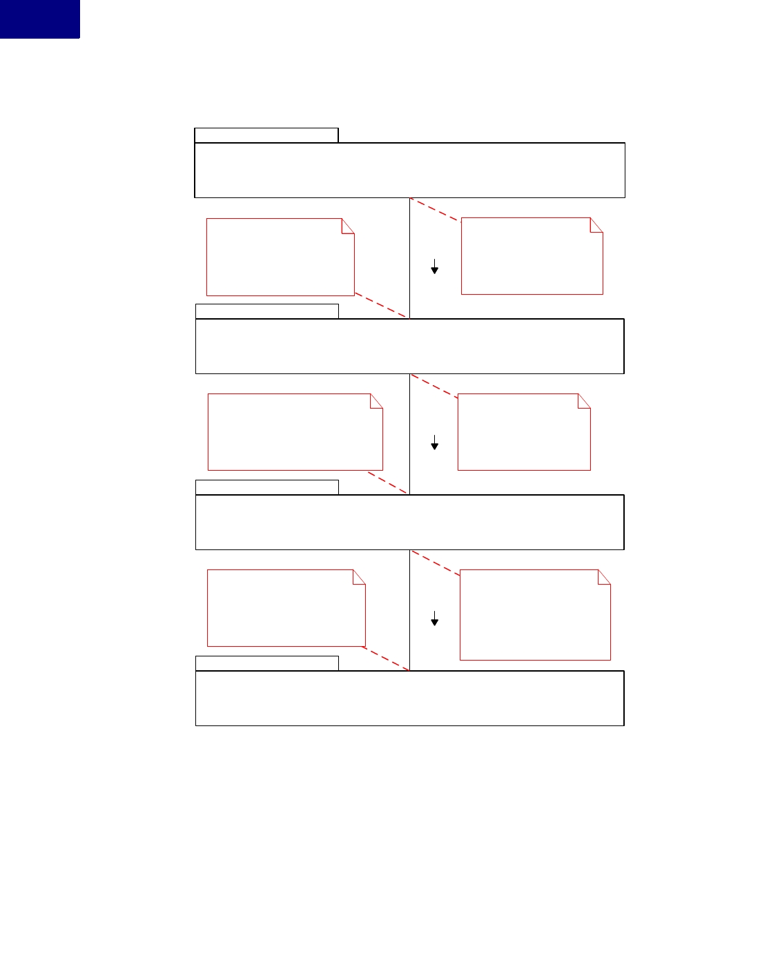
Selection
Selection architecture
128
FIGURE 30 Layers of encapsulation
A window can have one or more views that can support selection. Each view that uses selection
instantiates a selection subsystem. In general, client code can remain unaware of what selection
subsystem is in operation. While software developers need to be concerned about selection for-
mats if they are writing code that manipulates the model, there is less need to be concerned
about selection subsystems. For more information about selection subsystems, see “Selection
architecture” on page 127.
To write code that uses selection to choose attributes of the model to be displayed or changed,
it is important to understand the structure that owns the selection format. To illustrate this, a
schematic diagram of the selection subsystem used by the layout view (kLayoutWidgetBoss) to
Selection subsystem::
Abstract selection
Selection subsystem::
Concrete selection
Client
Model
Client code uses the selection
manager (ISelectionManager)
to acquire a suite, and then calls
one of its methods.
Integrator suite
forwards the method
call to the corresponding
CSB suite method on
enabled CSBs.
CSB suite accesses interfaces
on boss objects in the model
or processes commands to
change the model to do what
this suite method does.
Concrete selection
comprises one or more CSBs,
each of which target the part
of the model that underlies its
selection format.
Abstract selection:
Client code is decoupled
from the model by accessing
attributes of the selection
through an ASB.
Model stores attributes in
interfaces on boss objects. The
attributes targeted by selection
are selection attributes.
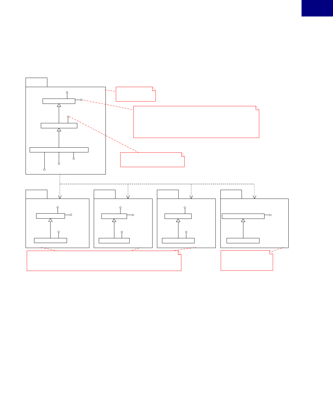
Selection 129
Selection
Selection architecture
edit design documents is shown in Figure 31. It presents the static structure and highlights
important boss classes and interfaces.
FIGURE 31 Selection subsystem used by layout view
The ASB provides the suites called by client code. In Figure 31, interface IXxxxSuite illustrates
such a capability. The suite implementation on the ASB is an integrator suite; its responsibilities
are described in detail in “Integrator suites” on page 142. For now, think of these suites as for-
warding any calls they receive to corresponding suites on the CSBs. Further implementations
of IXxxxSuite are provided on each CSB that supports the capability. These implementations
are CSB suites; their role is discussed further in “CSB suites” on page 142
In Figure 31, you can see that IXxxxSuite is implemented on the layout CSB and the text CSB.
This means layout and text selections have its capability. Also, when nothing is selected, client
code still has the capability represented by IXxxxSuite, because the ASB then targets defaults
and finds an implementation of the suite on kDocumentDefaultSuiteBoss. For more informa-
tion on how to use suites to manage preferences, see “Selection architecture” on page 127. Table
selections do not have the capability represented by IXxxxSuite, because there is no implemen-
tation of the suite on the table CSB.
kNewLayoutSelectionBoss
kLayoutSuiteBoss
ILayoutTarget
IConcreteSelection
kTextSuiteBoss
kTextSelectionBoss
ITextTarget
kTableSuiteBoss
kTableSelectionBoss
ITableTarget
IConcreteSelection IConcreteSelection
IXxxxSuite IXxxSuite
kDocumentDefaultSuiteBoss
kDocWorkspaceBoss
IXxxxSuite
Defaults:
Defaults are targeted
when nothing is selected
.
Suite:
interface that provides clients with a capability to access or change
attributes of the selection. More generically, a suite acts on or
reports information about the target. In the future, there may be
subclasses of kIntegratorSuiteBoss that are not selection related.
CSBs:
concrete selection boss classes that join this selection subsystem. Each CSB targets
its selection format(layout, text, or tables).
ASB:
abstract selection
Layout CSB DefaultsTable CSBText CSB
ILayoutSelectionSuite
ITextSelectionSuite
ITableSelectionSuite
IXxxxSuite
ISelectionManager
IIntegratorTarget
kIntegratorSuiteBoss
kAbstractSelectionBoss
kAbstractLayoutDocumentSelectionBoss
ASB
Selection manager:
Manages a selection subsystem.

Selection
Abstract selection bosses and suites
130
ISelectionManager is the signature interface that identifies a boss class as an ASB. To obtain a
suite, client code queries an ISelectionManager interface for the suite of interest. If the suite is
available, its interface is returned; otherwise, nil is returned. The ASB is not a normal boss
class; all suite interfaces are aggregated on the ASB, but an interface pointer is returned to client
code only when an active CSB (or the default CSB) that supports the suite exists. The ASB uses
a special implementation of IPMUnknown to control whether a query for an interface returns
the interface or nil.
Suite implementations get added to suite boss classes. The following suite boss classes are in
Figure 31:
zkDocumentDefaultSuiteBoss for defaults
zkIntegratorSuiteBoss for the ASB
zkLayoutSuiteBoss for the layout CSB
zkTableSuiteBoss for the table CSB
zkTextSuiteBoss for the text CSB
A suite boss class has a target (like IIntegratorTarget or ILayoutTarget) and a collection of suite
implementations. Figure 31 shows how the selection extends the suite boss classes. Other boss
classes extend the suite boss classes in different ways. For example, scripting uses the suite boss
kTextSuiteBoss to manipulate text content.
Each box in Figure 31 is a self-contained, portable unit. This is one reason why the selection
architecture is not coupled to a view, and CSBs do not have pointers to their ASB. This design
allows re-use of suite boss classes by other features in the future. A catalogue of suite boss
classes is provided in Table 22, in “Suite boss classes” on page 145.
Each selection format has a CSB that extends its suite boss class. IConcreteSelection is the sig-
nature interface that identifies a boss class as a CSB. Only those CSBs that join the selection
subsystem used by the layout view are shown in the Figure 31. Other CSBs exist and are used
by other subsystems. For a complete list of all CSBs, see the API reference documentation for
IConcreteSelection. To understand more about the responsibilities of a CSB, see “Concrete
selection bosses” on page 131.
Also, the ASB supports a set of interfaces that allows the selection content to be set program-
matically. ISelectionManager provides the ability to select/deselect all objects. Each selection
format provides an interface to allow the selection target to be varied. In Figure 31, for exam-
ple, ILayoutSelectionSuite allows page items to be selected, and ITextSelectionSuite allows text
to be selected.
Abstract selection bosses and suites
The selection architecture isolates client code from model code by means of an ASB. The ASB
provides suite interfaces, which are collections of capabilities, as well as other interfaces needed
for managing the selection. The main point to understand about the ASB is that it implements
the facade for the selection subsystem. Client code interacts with the facade (a suite on the

Selection 131
Selection
Concrete selection bosses
ASB). Writing client code to take advantage of the selection architecture is straightforward; you
need to understand only the facade. To write model code and code to change your model or the
existing document model, however, it is important to understand how to interact fully within
the selection subsystem, and this is less straightforward.
The client code in Example 17 uses a parameter to determine the selection manager (ISelec-
tionManager) to use by calling IActiveContext::GetContextSelection. The client code then que-
ries for the suite of interest, IFooSuite. If the suite is available, the client checks to see if the
capability it wants is enabled by calling IFooSuite::CanDoSomething. If so, the client uses the
capability on the selection by calling IFooSuite::DoSomething. If someone were to create a new
selection format and add support for IFooSuite, this client code would work. It does not need
to know any details of how IFooSuite is implemented on any specific selection format.
EXAMPLE 17 Client code using the selection architecture
void FooActionComponent::DoAction(IActiveContext* ac, ActionID actionID...)
{
...
InterfacePtr<IFooSuite> iFooSuite(ac->GetContextSelection(), UseDefaultIID());
if (iFooSuite != nil && iFooSuite->CanDoSomething()) {
iFooSuite->DoSomething();
}
...
}
In most cases, either client code is passed a parameter that identifies the selection manager to
query for a suite, or the selection manager is implied by the kind of code being written.
Concrete selection bosses
A CDB is a boss class that encapsulates a selection format. It supports the manipulation and
observation of the selected objects in the part of the model where the objects are located.
This section describes the available selection formats and their associated CSB. The key prop-
erties of each CSB are tabulated. Table 12 describes the label for each field.
TABLE 12 CSB description legend
Label Specifies
CSB The boss class that represents this concrete selection.
CSB name The name of the CSB that represents this concrete selection.
Description A general description of this concrete selection.
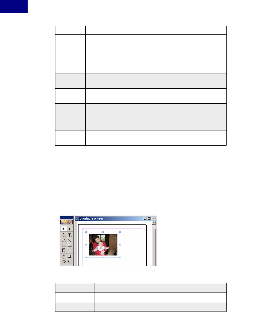
Selection
Concrete selection bosses
132
Layout selection
Layout selections—made with the Selection tool or programmatically—are represented by the
layout CSB. For examples of the suites available, see IGeometrySuite, ITransformSuite, and
IGraphicAttributeSuite. For a complete list of available suites, see the API reference documen-
tation for kLayoutSuiteBoss. Also see Figure 32 and Table 13.
FIGURE 32 Layout selection containing a page item
TABLE 13 Layout-selection CSB
Selection
attribute
extensibility
Indicates whether this concrete selection can be extended to notify of
changes to new selection attributes introduced by third-party software
developers. Each CSB is responsible for defining the mechanism used
to call selection extensions when selection attributes change. Some
CSBs allow the mechanism to be extended. See “Selection extensions”
on page 146 and “Selection observers” on page 147.
Selection
format
The format of the objects this concrete selection makes selectable.
Selection
suite
The interface that can specify the set of objects selected for this concrete
selection.
Suite boss
class
The boss class to which suites get added that extend the attributes that
can be manipulated by this concrete selection. A list of all suites
supported by the CSB is in the documentation for this boss class.
Custom suites get added to the suite boss class.
Target The interface that identifies the set of objects selected for this concrete
selection.
CSB Name Layout CSB
Selection format Layout objects like frames and other kinds of page items.
CSB kNewLayoutSelectionBoss.
Label Specifies
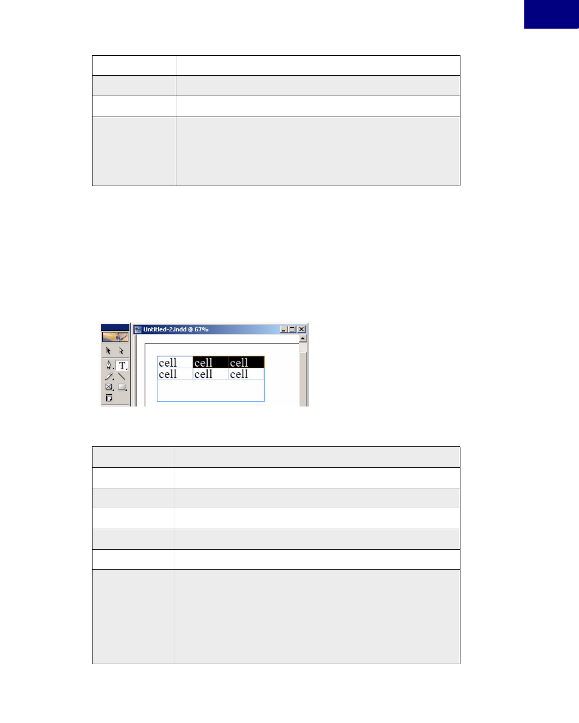
Selection 133
Selection
Concrete selection bosses
Table selection
Table selections—made with the Type tool or programmatically—are represented by the table
CSB. For an example of a suite, see ITableSuite. For a complete list of available suites, see the
API reference documentation for kTableSuiteBoss. Also see Figure 33 and Table 14.
FIGURE 33 Table selection containing table cells
TABLE 14 Table-selection CSB
Suite boss class kLayoutSuiteBoss.
Target ILayoutTarget.
Selection suite ILayoutSelectionSuite.
Selection
attribute
extensibility
Extensible. The CSB has a shared observer attached to the
document’s subject (kDocBoss). Selection extensions define
CreateObserverProtocolCollection to extend the protocols that are
attached. Selection extensions define SelectionAttributeChanged
to handle change broadcasts.
CSB Name Table CSB
Selection format Table cells.
CSB kTableSelectionBoss.
Suite boss class kTableSuiteBoss.
Target ITableTarget.
Selection suite ITableSelectionSuite.
Selection
attribute
extensibility
Extensible. The CSB has a cell focus (ICellFocus) that monitors
table-attribute changes in the selection. Changes to custom table
attributes also are detected by this CSB. Also, the CSB has a shared
observer attached to the document’s subject (kDocBoss). Selection
extensions define CreateObserverProtocolCollection to extend the
protocols that are attached. Selection extensions define
SelectionAttributeChanged to handle change broadcasts.
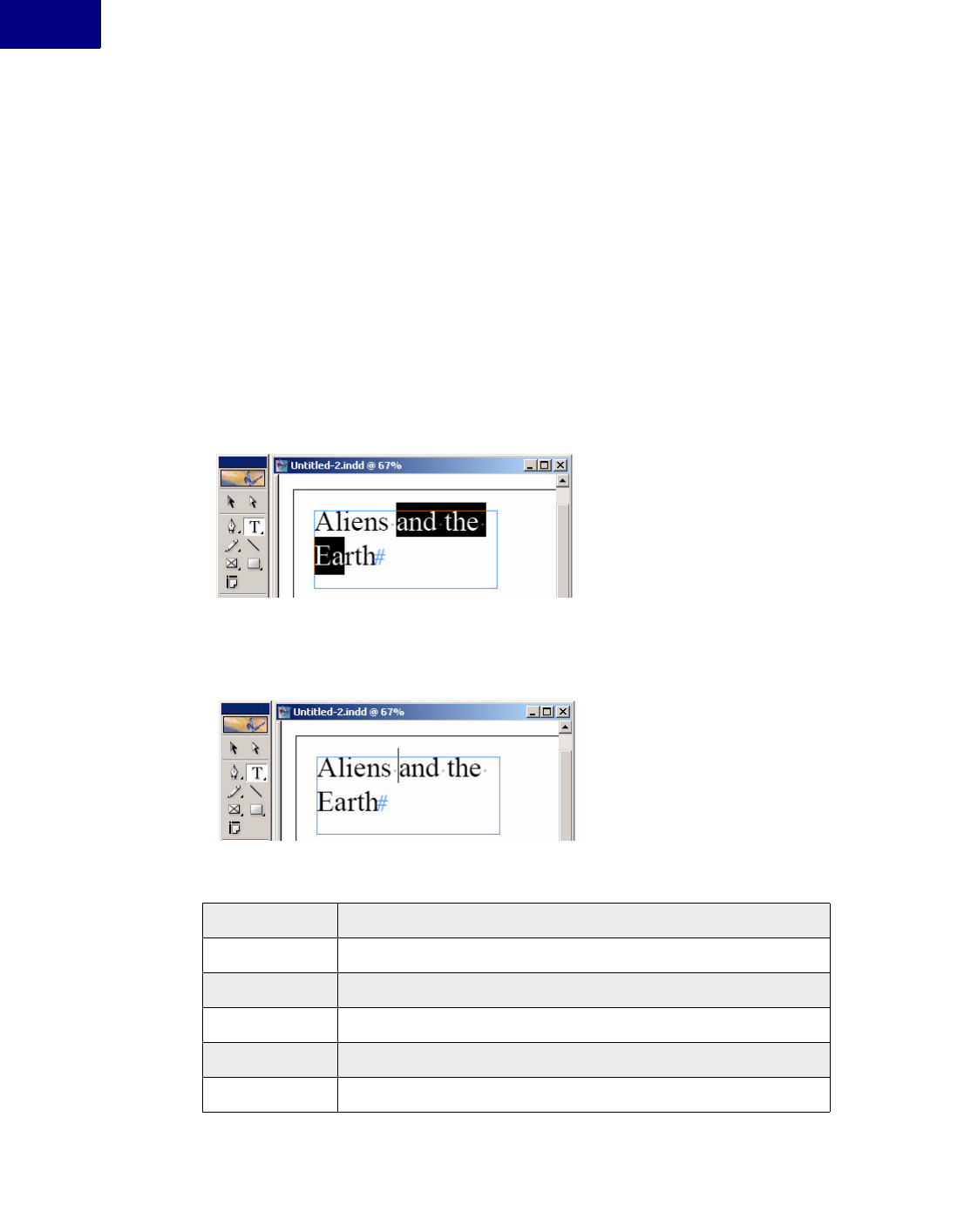
Selection
Concrete selection bosses
134
Text selection
Text selections in the Layout view—made with the Type tool or programmatically—are repre-
sented by the text CSB. Text selection take one of two principal forms, a selected range of char-
acters in a story (TextRange) or an insertion point within a story (represented by a TextRange
with zero span). Although it may not seem intuitive that an insertion point is considered a text
selection, it is considered a selection from the viewpoint of selection management.
NOTE:Other views use other CSBs to represent text selection.
For examples of the suites available, see ITextEditSuite and ITextAttributeSuite. For a complete
list of available suites, see the API reference documentation for kTextSuiteBoss. Also see
Figure 34, Figure 35, and Table 15.
FIGURE 34 Text selection containing a tange of characters
FIGURE 35 Text selection containing an insertion point
TABLE 15 Text-selection CSB
CSB name Text CSB.
Selection format Text.
CSB kTextSelectionBoss.
Suite boss class kTextSuiteBoss.
Target ITextTarget.
Selection suite ITextSelectionSuite.
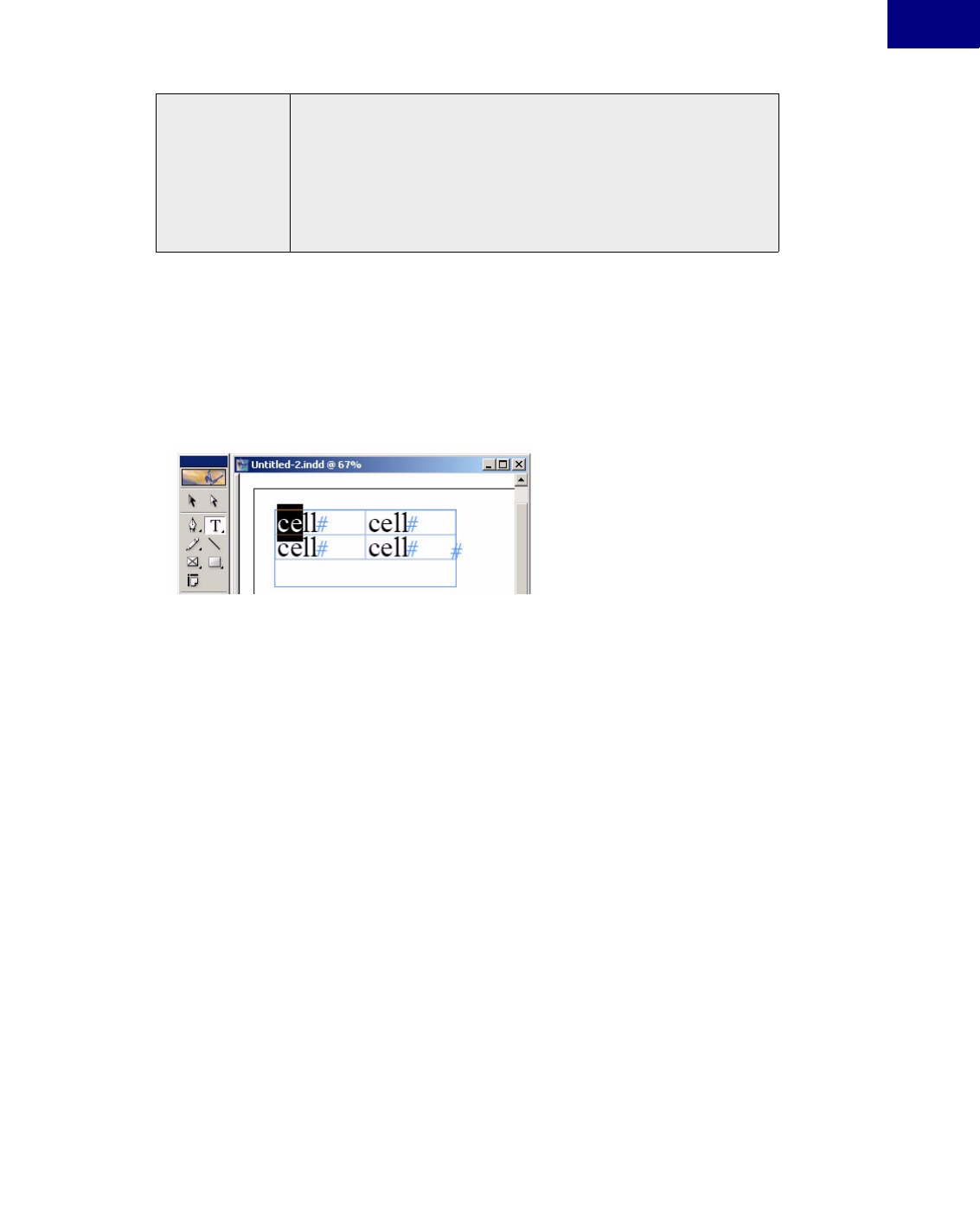
Selection 135
Selection
Concrete selection bosses
Figure 36 shows a text selection in a table cell. Although the selection is inside a table, this is a
text selection and not a table selection. The selected text is indicated by the ITextTarget target
interface. The table implied by this selection is indicated by ITableTarget, a secondary targeting
interface provided by text selection.
FIGURE 36 Text selection in a table cell
Galley text selection
Text selections in the galley view—made with the Type tool or programmatically—are repre-
sented by the galley-text CSB. The galley-text CSB represents text selection made in a galley
view window.
Text selection uses many subsystems. For the most part, client code can remain unaware of
what subsystem is in operation, but suite developers need to know, because the CSB that sup-
ports text selection in the galley view is different than the one that supports it in the layout
view. If you do not add your suite to the appropriate suite boss class, your suite might not be
available when you want it. In most cases, the same suite implementation can be re-used. For
an example of a suite that is available, see ITextEditSuite. For a complete list of available suites,
see the API reference documentation for kGalleyTextSuiteBoss. Also see Figure 37 and
Table 16.
Selection
attribute
extensibility
Extensible. The CSB has a text focus (ITextFocus) on
kTextSelectionFocusBoss that monitors text-attribute changes; this
picks up changes to custom text attributes. Also, the CSB has a
shared observer attached to the document’s subject (kDocBoss).
Selection extensions define CreateObserverProtocolCollection to
extend the protocols that are attached. Selection extensions define
SelectionAttributeChanged to handle change broadcasts.
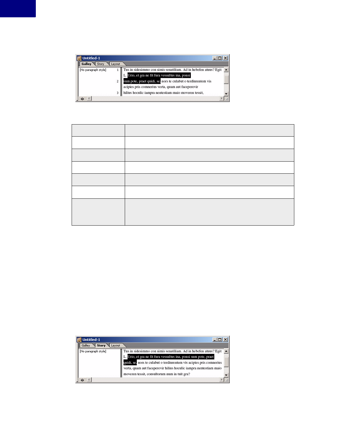
Selection
Concrete selection bosses
136
FIGURE 37 Galley text selection containing a range of characters
TABLE 16 Galley text-selection CSB
Story-editor text selection
The story editor is available in InDesign and InCopy.
Text selections by the story editor are similar to galley text selection. The story-editor CSB
extends the galley-text CSB, and both share the same suite boss class, kGalleyTextSuiteBoss.
For an example of a suite that is available, see ITextEditSuite. For a complete list of available
suites, see the API reference documentation for kGalleyTextSuiteBoss. Also see Figure 38,
Figure 39, and Table 17.
FIGURE 38 Story-editor text selection in InCopy
CSB name Galley text CSB.
Selection format Galley text.
CSB kGalleyTextSelectionBoss.
Suite boss class kGalleyTextSuiteBoss.
Target ITextTarget.
Selection suite ITextSelectionSuite.
Selection attribute
extensibility
Limited extensibility. The CSB has a text focus (ITextFocus) on
kTextSelectionFocusBoss, which monitors text-attribute changes.
Changes to custom text attributes are picked up by this.
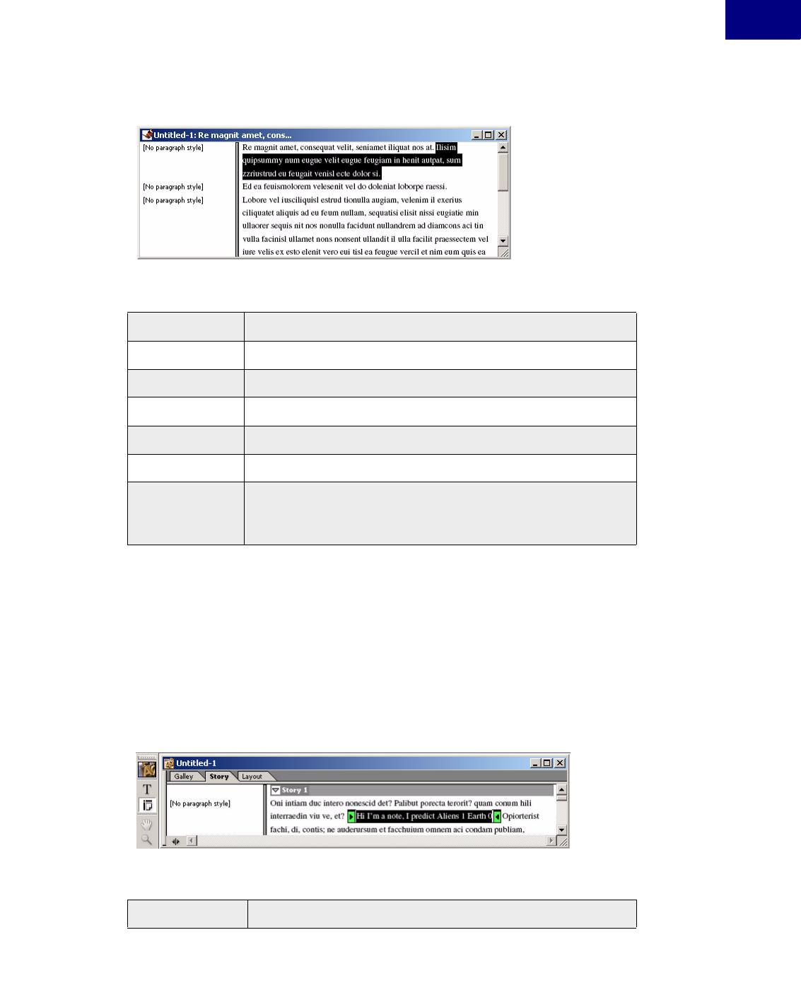
Selection 137
Selection
Concrete selection bosses
FIGURE 39 Story-editor text selection in InDesign
TABLE 17 Story-editor text-selection CSB
Note text selection
When text is selected in a note, the CSB involved is not the same as the one used for normal
text selection. The note-text CSB represents text selection made in a note. For an example of a
suite that is available, see INoteSuite. For the complete list of available suites, see the API refer-
ence documentation for kNoteTextSuiteBoss. Also see Figure 40 and Table 18.
FIGURE 40 Note selection
TABLE 18 Note text-selection CSB
CSB name Story-editor text CSB.
Selection format Story editor text.
CSB kStoryEditorSelectionBoss.
Suite boss class kGalleyTextSuiteBoss.
Target ITextTarget.
Selection suite ITextSelectionSuite.
Selection
attribute
extensibility
Limited extensibility. The CSB has a text focus (ITextFocus) on
kTextSelectionFocusBoss, which monitors text attribute changes.
Changes to custom text attributes are also picked up by this.
CSB name Note text CSB.
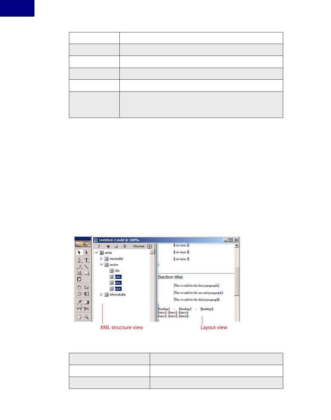
Selection
Concrete selection bosses
138
XML selection
XML selections in the structure view (the left panel of Figure 41)—made with the Selection
tool or programmatically—are represented by the XML CSB. There is a selection subsystem
associated with the XML structure view that is distinct from the selection subsystem associated
with the layout view, even though both views are displayed in the same window. Do not con-
fuse XML selection with the XML tags shown in the layout view (the right panel of Figure 41).
For examples of suites that are available, see IXMLStructureSuite and IXMLTagSuite. For a
complete list of available suites, see the documentation for kXMLStructureSuiteBoss. Also see
Figure 41 and Table 19.
FIGURE 41 XML node selections in XML-structure view
TABLE 19 XML-selection CSB
Selection format Note text.
CSB kNoteTextSelectionBoss.
Suite boss class kNoteTextSuiteBoss.
Target ITextTarget.
Selection suite ITextSelectionSuite.
Selection attribute
extensibility
Limited extensibility. The CSB has a text focus (ITextFocus) on
kTextSelectionFocusBoss, which monitors text attribute changes.
Changes to custom text attributes are also picked up by this.
CSB name XML CSB
Selection format XML node (element, attribute, or both)
CSB kXMLStructureSelectionBoss

Selection 139
Selection
Concrete selection bosses
Suite boss class kXMLStructureSuiteBoss
Target IXMLNodeTarget
Selection suite IXMLNodeSelectionSuite
Selection attribute extensibility Not extensible.
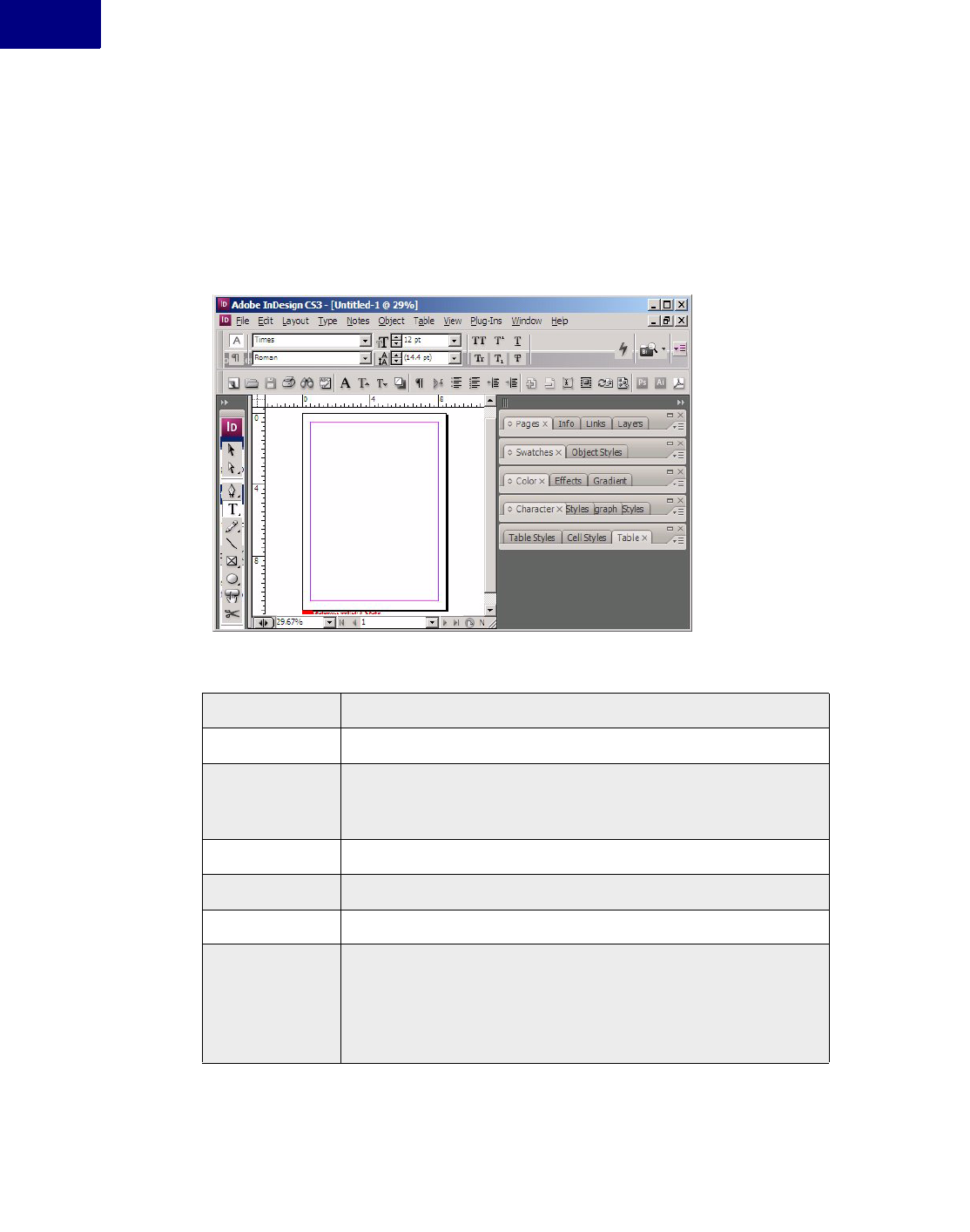
Selection
Concrete selection bosses
140
Document defaults
When a document is open but nothing is selected, the document workspace (kDocWorkspace-
Boss) becomes the selection subsystem’s target. For more information, see “Selection architec-
ture” on page 127. Also see Figure 42 and Table 20.
FIGURE 42 Document defaults: open document with no selection
TABLE 20 Document-defaults CSB
CSB name Defaults.
Selection format Preferences maintained as data interfaces on kDocWorkspaceBoss.
CSB kDocWorkspaceBoss. (Strictly speaking, this is not a CSB, because
it does not aggregate IConcreteSelection; however,
kDocWorkspaceBoss often is referred to as the defaults CSB.)
Suite boss class kDocumentDefaultSuiteBoss.
Target NA
Selection suite NA
Selection
attribute
extensibility
Extensible. The CSB has a shared observer attached to the
document workspace’s subject (kDocWorkspaceBoss). Selection
extensions define CreateObserverProtocolCollection to extend the
protocols that are attached. Selection extensions define
SelectionAttributeChanged to handle change broadcasts.
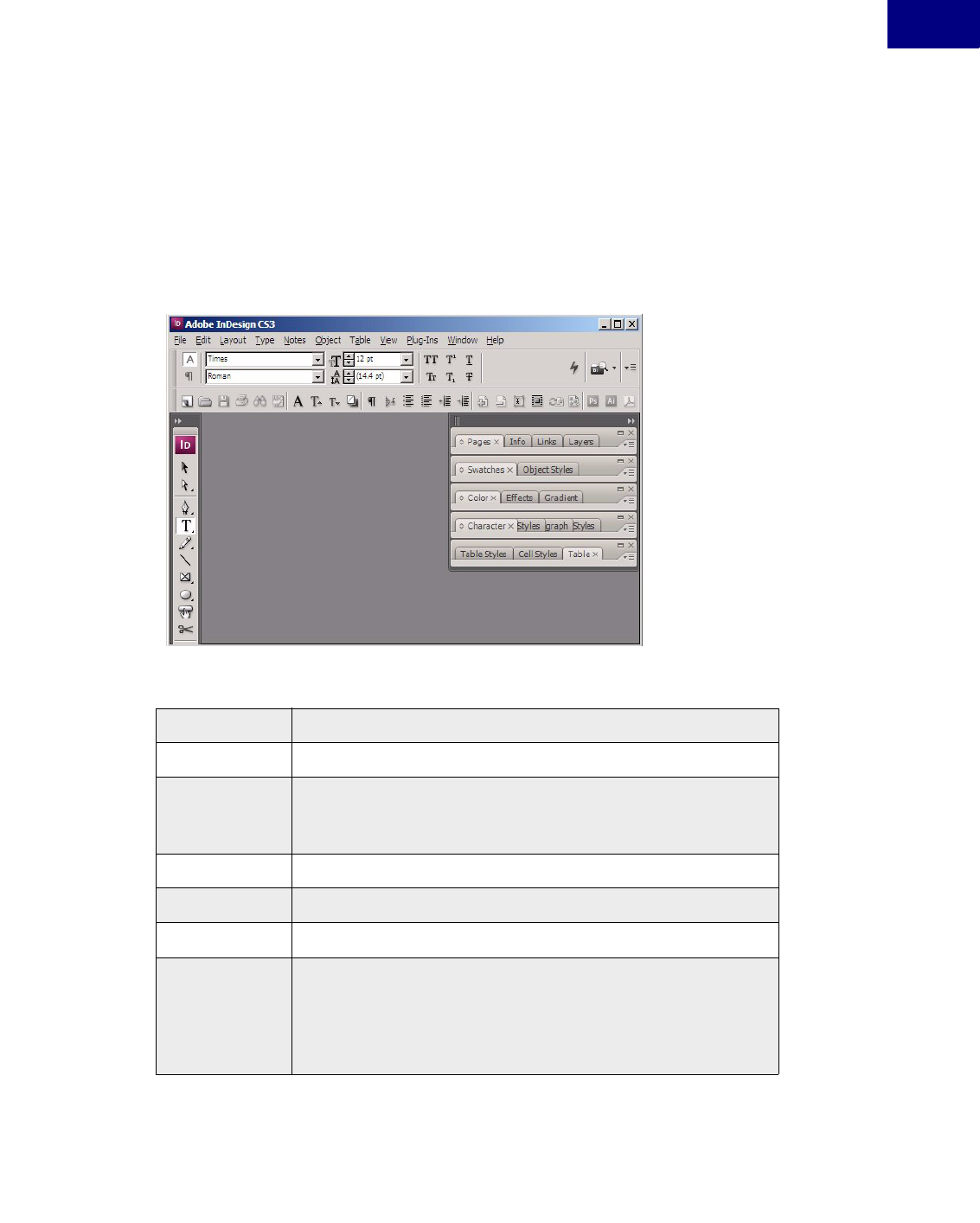
Selection 141
Selection
Concrete selection bosses
Application defaults
When no document is open, a special selection subsystem (the workspace selection, kAbstract-
WorkspaceSelectionBoss) is activated. It targets application-wide defaults on kWorkspaceBoss.
For more information, see “Selection architecture” on page 127. Also see Figure 43 and
Table 21.
FIGURE 43 Application defaults: no document open
TABLE 21 Application-defaults CSB
CSB name Defaults.
Selection format Preferences maintained as data interfaces on kWorkspaceBoss.
CSB kWorkspaceBoss. (Strictly speaking, kWorkspaceBoss is not a CSB,
because it does not aggregate IConcreteSelection; however,
kWorkspaceBoss often is referred to as the defaults CSB.)
Suite boss class kApplicationDefaultSuiteBoss.
Target NA
Selection suite NA
Selection
attribute
extensibility
Extensible. The CSB has a shared observer attached to the session
workspace’s subject (kWorkspaceBoss). Selection extensions define
CreateObserverProtocolCollection to extend the protocols that are
attached. Selection extensions define SelectionAttributeChanged to
handle change broadcasts.

Selection
Integrator suites
142
Integrator suites
An integrator suite is an implementation of a suite that was added to kIntegratorSuiteBoss,
which is part of an ASB. Consequently, an integrator suite sometimes is known as an ASB suite.
All communication between client code and the selection is performed using the integrator
suite. A properly designed suite API is neutral to selection format, meaning there are no refer-
ences to a specific selection format. This is essential to avoid tight coupling between the client
code and the model.
The purpose of an integrator suite is to iterate over the concrete-selection formats supported by
the suite or, more formally, to integrate over the integrator target (represented by IIntegrator-
Target). Although it may seem that “iterator” may be a more appropriate name, “integrator” is
correct in this context, because it means “to join together.” In the mathematical sense, “inte-
grate” also can refer to summation, and the integrator suite performs a summation over the
capabilities of individual selection-format-specific suites.
The implementation of an integrator suite is very stereotypical; it delegates any call to CSB
suites on CSBs that are active (i.e., on CSBs that have a selection). Integrator-suite implementa-
tions should be based on templates provided by the SDK. The templates reduce the amount of
code you need to write.
An example of an integrator suite is the kTableSuiteIntegratorImpl implementation of ITable-
Suite on kIntegratorSuiteBoss. Both text (kTextSuiteBoss) and table selections (kTableSuite-
Boss) provide support for ITableSuite. The client code is shielded from the selection format
that is providing the implementation. Integrator suite calls are forwarded to the selection-for-
mat–specific implementations on the CSB suites.
CSB suites
A CSB suite is a suite implementation on a CSB. CSB suites receive calls forwarded from inte-
grator suites when they are called by client code.
CSB suites exist to do model-specific work, like navigating relationships between objects in the
model and processing of commands. When you manipulate the model from within a CSB suite,
you interact with objects in a specific selection format (e.g., by means of target interfaces like
ITextTarget or ILayoutTarget). There are several CSBs that extend suite-boss classes; for exam-
ple, kTextSelectionBoss subclasses kTextSuiteBoss. For a complete list of CSBs, see the API ref-
erence documentation for the IConcreteSelection interface, from which you can examine the
documentation page for each CSB to see which suite boss it extends.

Selection 143
Selection
Encapsulation
Encapsulation
A key concept in the selection architecture is that client code should be insulated from code
that accesses and modifies the model (both the document and associated data). Code that
works in terms of UID, UIDRef, or UIDList values that relate to stories (kTextStoryBoss
objects) or layout objects (for example, something that exposes an IGraphicFrameData inter-
face) interacts with a portion of the document model.
A selection of objects that is represented, for example, as a UIDList (as would have been the
case in the old selection architecture) is tightly coupled to the model. Such tight coupling
makes it very difficult to add new selection formats, because client code already has detailed
knowledge about what is in a selection. Also, with such tight coupling, you cannot change the
way in which the model is represented without breaking client code, because the client code
has detailed model knowledge.
To add new selection formats, the client code needs to be de-coupled from the selection for-
mats. This means client code should be neutral with respect to selection format when dealing
with the selection. The client code communicates by means of ASB suites. These suites, in turn,
communicate with CSB suites. The CSB suites deal only with the model format of their CSB;
they do not even know about the ASB. This is necessary because an alternative use for suites is
scripting, which most likely does not have an analog to the ASB.
Suites and the user interface: an example
In the StrokeWeightMutator sample plug-in, the stroke-weight drop-down widget is enabled
when the stroke weight of whatever is selected can be changed. These steps are followed:
1. The widget looks for the API’s stroke attribute suite (IStrokeAttributeSuite).
2. If the suite is available, a CSB (the one with something selected or the defaults, if nothing is
selected) has an implementation of the suite.
3. The widget asks the integrator suite on the ASB whether the stroke-weight attribute is avail-
able, by calling IStrokeAttributeSuite::GetStrokeWeightCount.
4. The integrator-suite implementation on the ASB forwards the call to the CSB-suite imple-
mentations.
5. The CSB implementation accesses the model for the selection format it supports and
returns the answer.
6. The widget then calls IStrokeAttributeSuite::GetStrokeWeight to retrieve the value if appli-
cable.
When the widget handles a user click to change the stroke weight, the widget calls IStrokeAt-
tributeSuite::ApplyStrokeWeight on the integrator suite to dispatch to the CSB suites, which
change the value stored in the model. The widget synchronizes what it displays with any

Selection
Responsibilities
144
changes to the selection using a selection observer. It is sent a message when the stroke weights
displayed in the widget need to be refreshed. (See “Selection observers” on page 147.)
Responsibilities
Basic client-code responsibilities
If you are writing client code that modifies the properties of an abstract selection and can use a
pre-existing suite, your responsibilities are minor. Query the selection manager (ISelection-
Manager) that represents the abstract selection for the suite you want (like ITextAttributeSuite
to change properties of text in a selection) and, if you get the suite, use it. Look for a code frag-
ment showing these responsibilities for the ITextMiscellanySuite suite.
You must understand how to query the abstract selection for a particular capability. To under-
stand what suites are provided by the API, see the API reference documentation and examine
the boss classes that aggregate ITextMiscellanySuite, to see the selection formats that support
this particular capability.
Selection-observer responsibilities
If you are writing code that needs to update when the selection changes, implement a selection
observer (see “Selection observers” on page 147). If there is a pre-existing suite that informs
your client code of the changes you are interested in, your selection observer looks for mes-
sages from this suite. For example, ITextAttributeSuite notifies clients when a text-attribute
change happens to the selection. Otherwise, implement a custom suite to inform client code
about the changes of interest (see “Custom suites” on page 145).
Custom-suite responsibilities
If you have any client code that depends on the state of the selection, write a custom suite to
access that state. For example, the BasicMenu sample implements a custom suite because it has
menu items that need to know whether a page item is selected. A suite is required because the
client code needs to access a selection target interface to determine whether a page item is
selected.
If you are writing code that changes the existing document model (for example, you are imple-
menting or processing commands that change this model), and you want to use selection to
target the objects, you must create a suite.
If you are writing code that extends the document model (for example, you are adding a cus-
tom data interface to the layout model, like BasicPersistInterface), and you want to use selec-
tion to target the manipulation of this data, you must create a suite.
The model also extends to default preferences; changes to the application’s default preferences
and the document default preferences can be mediated by the selection subsystem.

Selection 145
Selection
Custom suites
Custom suites
When writing a custom suite that you want to make available to client code in one or more
selection formats, provide two implementations, one relating to abstract selections and another
to concrete selections. The former (see “Integrator suites” on page 142) is added to the kInte-
gratorSuiteBoss suite boss class, and the latter (see “CSB suites” on page 142) is added to the
selection-format-specific suite boss classes. For details about the selection formats that can be
of interest to client code, see “Concrete selection bosses” on page 131. Table 22 lists suite boss
classes.
TABLE 22 Suite boss classes
Suite boss class Selection format Rationale
kApplicationDefaultSuiteBoss Application defaults If you want your suite to be available to client
code when no documents are open, add the
suite to this boss class.
kDocumentDefaultSuiteBoss Document defaults If you want your suite to be available to client
code when a document is open but nothing is
selected, add the suite to this boss class.
kGalleyTextSuiteBoss Text in InCopy Galley
or Story Editor views
(ITextTarget)
If you want your suite to be available to client
code during galley- or story-editor-view text
selections, add the suite to this boss class.
kIntegratorSuiteBoss Abstract
(IIntegratorTarget)
Required for any custom suite.
kLayoutSuiteBoss Layout (ILayoutTarget) If you want your suite to be available to client
code during layout selections, add the suite to
this boss class.
kNoteTextSuiteBoss Text in InCopy Note
(ITextTarget)
If you want your suite to be available to client
code during note selections, add the suite to
this boss class.
kSelectionInterfaceAlwaysActiveBoss If you want your suite to be available to client
code regardless of the kind of concrete
selection that exists, add the suite to this boss
class.
kStoryEditorSuiteBoss Text in Story Editor
view (ITextTarget)
(Not supported.) If you want the story editor
suite to be different from that for InCopy
Galley view, add the suite to this boss class.
kTableSuiteBoss Tables (ITableTarget) If you want your suite to be available to client
code during table selections, add the suite to
this boss class.

Selection
Selection extensions
146
Selection extensions
A selection extension (ISelectionExtension) is a bridge between a suite implementation with an
unknown interface and the selection architecture. A suite that requires advanced function reg-
isters a selection extension with the selection subsystem. The selection subsystem then com-
municates with the extension, which in turn forwards a message to the suite implementation. If
your suite requires one or more of the services described in this section, you must implement a
selection extension.
Caches
A suite may need to cache data to improve performance. You can add caches to suite imple-
mentations. In general, caches are added to CSB suite implementations. Cache validation
should be delayed as long as possible. Rather than updating the cache every time a model
change occurs, declare a Boolean cacheValid flag. When the model changes, set the flag to
kFalse. Before accessing the cache, rebuild it if it is invalid. Thus, if your suite provides data to a
user-interface panel and that panel is not visible, your suite does not needlessly consume CPU
cycles recalculating cache values the user does not need.
Furthermore, caches should be enabled only on CSB boss classes, not suite boss classes.
Because the scripting architecture extends suite boss classes, no caching should be done on
them. If you are implementing a custom suite that needs a cache, add your cache interface only
to the CSB. IConcreteSelection is the signature interface that identifies a boss class as a CSB.
Your custom suite implementation can then perform a run-time check to see if your cache
interface is available. If not, it can handle this situation gracefully and carry on without using
the cache.
Selection change notification
The design of some suites requires notification of selection changes. A selection extension
allows your suite to be called by a CSB whenever the selection changes. A selection extension
allows you to control whether clients of your suite—in the form of selection observers—get
notified. (See section “Selection observers” on page 147.)
kTextSuiteBoss Text (ITextTarget) If you want your suite to be available to client
code during text selections, add the suite to
this boss class.
kXMLStructureSuiteBoss XML structure,
(IXMLNodeTarget)
If you want your suite to be available to client
code during XML selections, add the suite to
this boss class.
Suite boss class Selection format Rationale

Selection 147
Selection
Selection observers
There are two kinds of selection change events:
zAn object is added to or removed from the selection (that is, the selection changes); for
example, a user Shift-clicks to add a frame to the selection.
zAn attribute of an object in the selection changes (that is, a selection attribute changes); for
example, the stroke color of selected frames changes.
A suite that has a cache must mark its cache as invalid when notified the selection has changed.
A suite needs to invalidate its cache when notified that a selection attribute changed only if the
specific selection-attribute change affects this suite's cache. Many selection-attribute changes
may not affect a particular cache.
NOTE:Selection-attribute change notification is not supported on all CSBs. For information on
each CSB, see “Concrete selection bosses” on page 131.
Initialization
Some suites need to perform an action on start-up or shut-down of a selection subsystem. Any
such initialization is done by implementing a selection extension. Do not confuse this kind of
start-up and shut-down with application services, like IStartupShutdownService, which are
called for the application session. Selection subsystems get created and destroyed as the views
that own them open and close.
Communication with Integrator suite
Rarely, a CSB implementation needs to communicate with its integrator. Because there is no
pointer on the CSB back to the integrator, a messaging system was created: IConcreteSelec-
tion::BroadcastToIntegratorSuite.
Selection observers
As described in “Selection change notification” on page 146, there are two kinds of selection
change event: selection-changed event and selection-attribute-changed event. A selection
observer (ActiveSelectionObserver) is the abstraction that allows client code to be called when
a selection-changed event occurs. For more information, see the SelectionObserver.h header
file.
Suites that need to communicate extra data to selection observers during the selection-changed
event implement a selection extension. Suites that need to include information about a selec-
tion-attribute–changed event also implement a selection extension. (See “Selection extensions”
on page 146.)
When a selection-changed event occurs, a selection observer’s ActiveSelectionObserver::Han-
dleSelectionChanged member method is called. On receiving this call, an observer can take
action. For example, the observer can update some data displayed in a user-interface widget.

Selection
Selection-utility interface (ISelectionUtils)
148
Optionally, before taking action, the observer can examine the message parameter (ISelection-
Message) and look for extra data placed there by a suite.
When a selection-attribute–changed event occurs, a selection observer’s ActiveSelectionOb-
server::HandleSelectionAttributeChanged member method is called. On receiving this call, an
observer must call ISelectionMessage::WasSuiteAffected before taking action. There are many
kinds of selection attributes, and they can be given meaning only by the CSB suite. It examines
the broadcast from the selection format that changed (originating from a command notifica-
tion that the model was updated), then passes a model-independent message about the change
to selection observers. A selection observer may be called when any attribute of the selected
objects changes, so a selection observer can receive messages that do not affect it. The selection
observer must filter these calls, so it does not needlessly take action and waste CPU cycles. For
sample code, see BasicPersistInterface.
Selection-utility interface (ISelectionUtils)
A utility interface for selection (ISelectionUtils) is provided on kUtilsBoss. For detailed infor-
mation on the member methods, see the API reference documentation for ISelectionUtils.
Some member methods provided by ISelectionUtils allow you to access the active selection.
Most client code does not need to depend on the active selection, because client code normally is
given access to the selection manager to use. If you want the active selection, ISelection-
Utils::GetActiveSelection returns the selection manager from the active context. There also are
other member methods, like QueryActiveLayoutSelectionSuite and QueryActiveTextSelec-
tionSuite, that depend on the active selection manager; these should be used only by client
code that needs to work with the active selection.

Layout Fundamentals 149
Layout Fundamentals
Terminology
Layout Fundamentals
This chapter describes the features and supporting architecture of the layout subsystem, as well
as how a client can use these features and the layout-related extension patterns in the InDesign
API.
For use cases related to layout, see the “Layout” chapter of Adobe InDesign CS4 Solutions.
Terminology
See the “Glossary” for definitions of terms. Table 23 lists terms used in this chapter and sec-
tions that relate to them.
TABLE 23 Terminology
Term See ...
Bounding box “Bounding box and IGeometry” on page 190
Child “Parent and child objects and IHierarchy” on page 155
Content page item “Page items” on page 173
Current spread “Current spread and active layer” on page 197
Document “Documents and the layout hierarchy” on page 152 and
“Spreads and pages” on page 157
Document layer “Layers” on page 161
Frame “Frames and paths” on page 173
Front document “The layout presentation and view” on page 194
Front view “The layout presentation and view” on page 194
Geometric page item “Coordinate systems” on page 183
Graphic frame “Frames and paths” on page 173
Graphic page item “Graphic page items” on page 177
Group “Groups” on page 178
Guide “Guides and grids” on page 180
Layer “Documents and the layout hierarchy” on page 152 and
“Layers” on page 161
Layout hierarchy “Spreads and pages” on page 157
Layout view “Layout view” on page 196

Layout Fundamentals
Concepts
150
Concepts
Figure 44 shows a facing-pages publication with three pages arranged over two spreads. The
document is presented for edit in the layout presentation. The Pages panel is used to edit the
spreads and pages, including the master spreads and master pages. The Layers panel is used to
edit the layers.
Layout presentation “The layout presentation and view” on page 194
Master page, Master
spread
“Documents and the layout hierarchy” on page 152 and
“Master spreads and master pages” on page 168
Page “Documents and the layout hierarchy” on page 152 and
“Master spreads and master pages” on page 168
Page item “Documents and the layout hierarchy” on page 152 and
“Page items” on page 173
Pages layer “Spreads and pages” on page 157
Parent “Parent and child objects and IHierarchy” on page 155
Path “Frames and paths” on page 173
Publication “Spreads and pages” on page 157
Spread “Documents and the layout hierarchy” on page 152 and
“Spreads and pages” on page 157
Spread layer “Layers” on page 161
Text frame “Frames and paths” on page 173
Text page item “Text page items” on page 177
Transformation matrix “Transformation matrices” on page 183
Term See ...
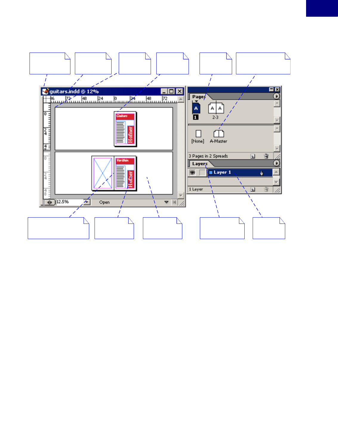
Layout Fundamentals 151
Layout Fundamentals
Concepts
FIGURE 44 Layout concepts
Some basic terms are given below. A full layout-related glossary is in “Terminology” on
page 149.
zDocument — An InDesign document, unless otherwise stated.
zLayer — The abstraction that controls whether objects in a document are displayed and
printed and whether they can be edited. A layer can be shown or hidden, locked or
unlocked, arranged in front-to-back drawing order, etc. A page item is assigned to a layer. If
a layer is shown, its associated page items are drawn; if a layer is hidden, its associated page
items are not drawn. Layers affect an entire document: if you alter a layer, the change applies
across all spreads.
zLayers panel —The user interface for creating, deleting, and arranging layers.
zLayout presentation — The user-interface window in which the layout of a document is pre-
sented for viewing and editing. The layout presentation contains the layout view and other
widgets that control the presentation of the document within the view.
zMaster page — A page that provides background content for another page. When a page is
based on a master page, the page items that lie on the master page also appear on the page.
A master page eliminates the need for repetitive page formatting and typically contains page
numbers, headers and footers, and background pictures.
Document Spread Page
Pasteboard
Pages
palette
Layer
Page item
(text frame)
Page item
(empty graphic frame) Layers palette
Layout
presentation
Master spread and
master pages

Layout Fundamentals
Documents and the layout hierarchy
152
zMaster spread — A special kind of spread that contains a set of master pages.
zPage — The object in a spread on which page items are arranged.
zPage item — Represents content the user creates and edits on a spread, like a path, a group,
or a frame and its content.
zPages panel — The user interface for creating, deleting, and arranging pages and masters.
zSpread — The primary container for layout data. A spread contains a set of pages on which
page items that represent pictures, text, and other content are arranged. The pages can be
kept together to form an island spread, a layout that spans more than one page.
Documents and the layout hierarchy
This section introduces the data model on which the layout subsystem is based. The boss
classes and interfaces that represent spreads, pages, and page items in a document are
described in general.
Architecture
This section shows how the items introduced in “Concepts” on page 150 are represented by
boss classes and interfaces in a document. Figure 45 shows the overall arrangement.
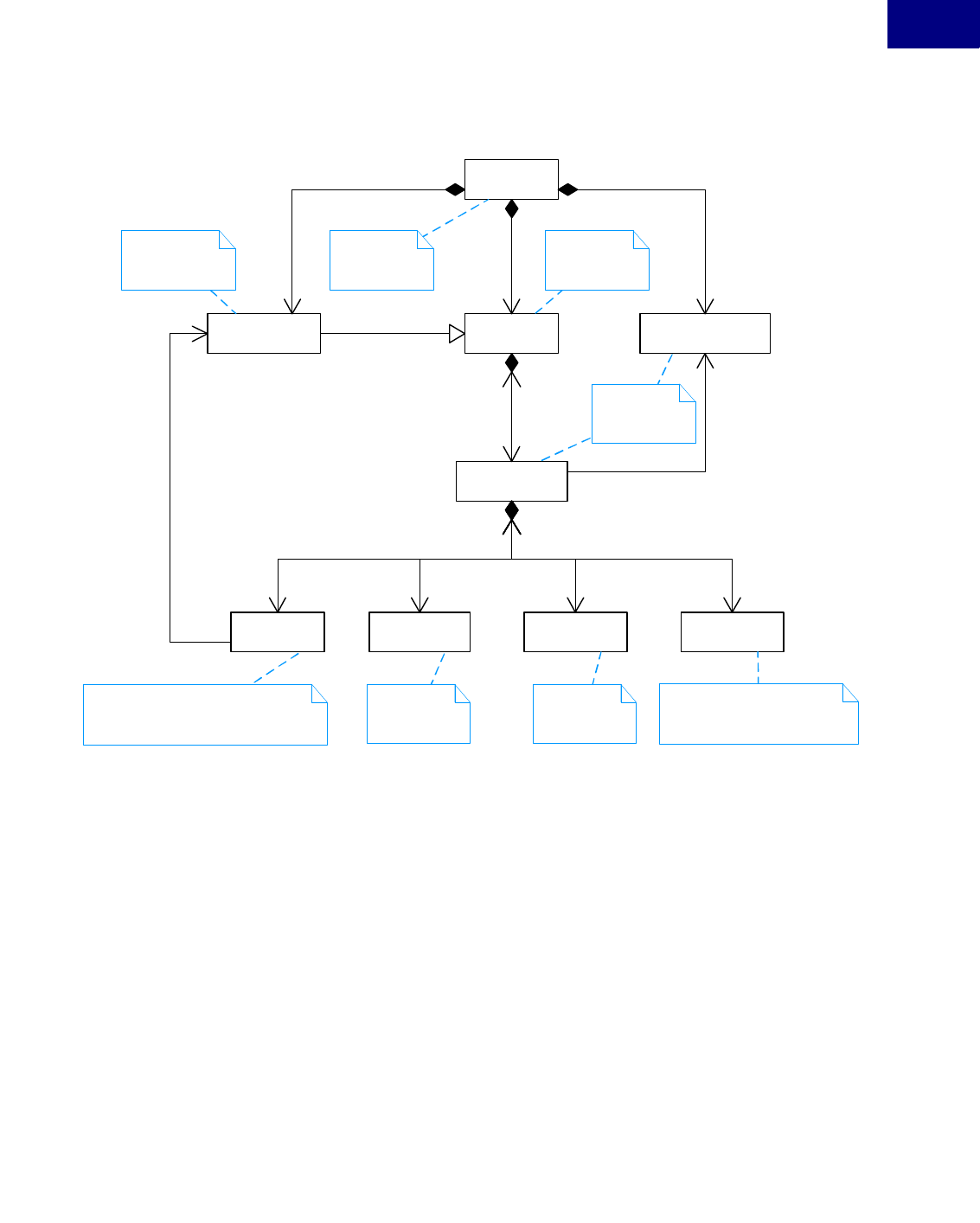
Layout Fundamentals 153
Layout Fundamentals
Documents and the layout hierarchy
FIGURE 45 Layout-hierarchy class diagram
A document (kDocBoss) comprises one or more spreads (kSpreadBoss) and master spreads
(kMasterPagesBoss). The ISpreadList interface lists the spreads. The IMasterSpreadList inter-
face lists the master spreads. Each spread contains one or more pages (kPageBoss), ruler guides
(kGuideItemBoss), frames (kSplineItemBoss), paths (kSplineItemBoss), or groups (kGroupI-
temBoss). These objects are arranged in a spread in a tree represented by the interface IHierar-
chy. Frames and groups have additional page items nested within them. The objects in a layout
are layered, and this layering is reflected within each spread. A layer is represented by a docu-
ment layer (kDocumentLayerBoss) that has two corresponding spread layers (kSpreadLayer-
Boss) in each spread. The document layers are listed by the ILayerList interface; the spread
layers are the immediate children of a spread on the IHierarchy interface. A spread (kSpread-
Boss) contains 2n spread layers as children, where n is the number of document layers. All the
immediate children of a spread must be spread layers (kSpreadLayerBoss).
Figure 45 showed a document has at least two layers:
zThe pages layer — Pages (kPageBoss) always are associated with the pages layer. The pages
layer is represented by the document layer (kDocumentLayerBoss) found at index 0 in the
ILayerList interface. It has two corresponding spread layers (kSpreadLayerBoss) in each
«boss»
kSpreadLayerBoss
«boss»
kDocBoss
«boss»
kSpreadBoss
1
IHierarchy4..*
1
1..*
ISpreadList
«boss»
kSplineItemBoss
0..*
IHierarchy
«boss»
kGroupItemBoss
0..*
«boss»
kGuideItemBoss
0..*
«boss»
kPageBoss
1..10
IHierarchy
«boss»
kDocumentLayerBoss
2
1
ISpreadLayer
1
2..*
ILayerList
«boss»
kMasterPagesBoss
1
1..*
IMasterSpreadList
<<extends>>
1
0..1
IMasterPage
Represents a
master spread.
Represents a
document.
Represents a
spread.
Represents a page or master page. Note:
A page doesn't own the content that lies
upon it; the spread owns the content.
Represents a
layer.
Represents a
ruler guide.
Represents a
group.
Represents a frame or path.
Graphics or text page items can
be nested inside a frame.
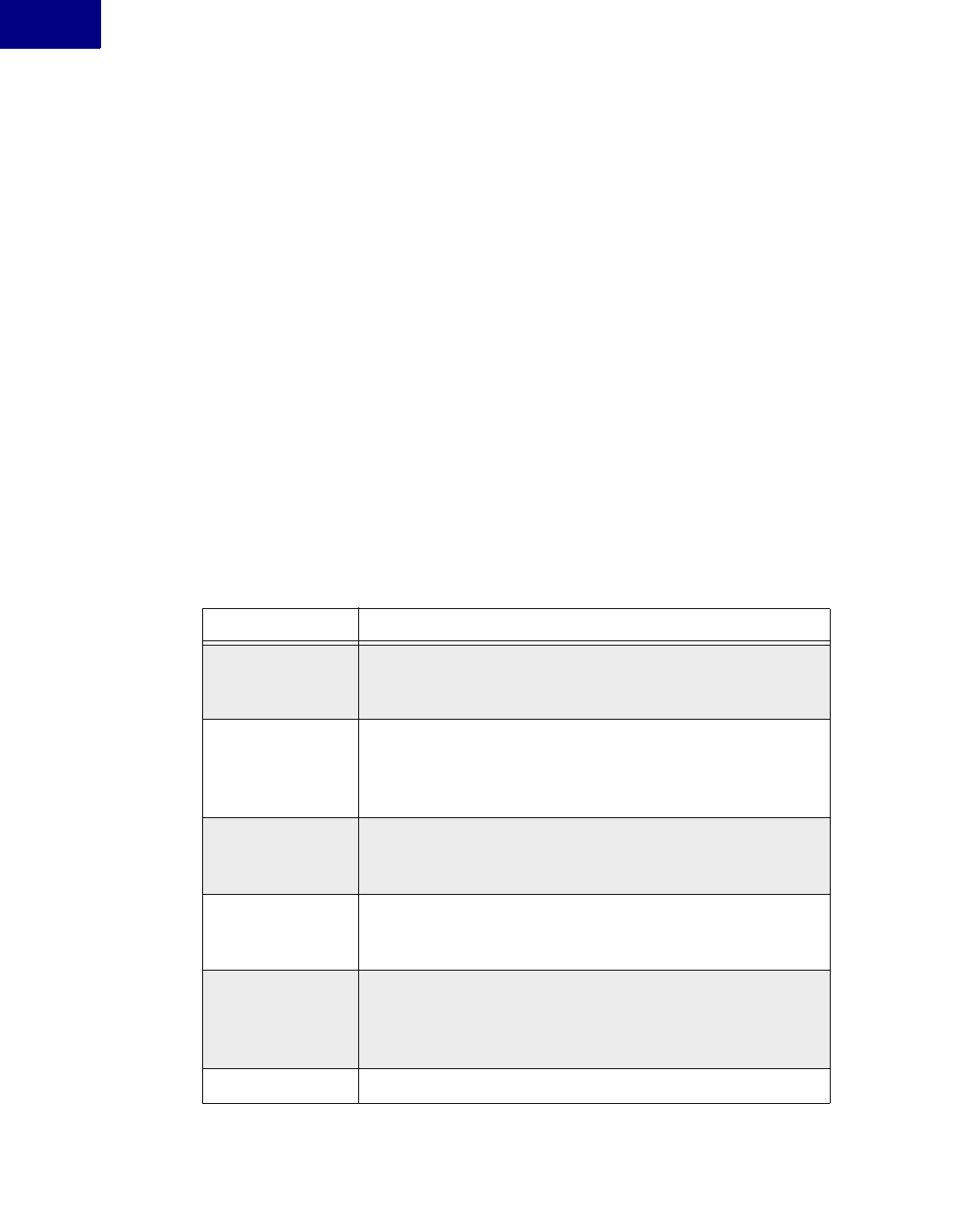
Layout Fundamentals
Documents and the layout hierarchy
154
spread. The spread layer that owns the spread’s pages (kPageBoss) is found at child index 0
in the spread’s hierarchy (IHierarchy); the other spread layer, which is always empty, is
found at child index 1.
zA layer for content.
The remaining layers—and there always is at least one other layer in the ILayerList interface—
are the layers to which guides (kGuideItemBoss), frames (kSplineItemBoss), paths (kSpli-
neItemBoss), and groups (kGroupItemBoss) can be assigned. Each of theses layers is repre-
sented by a document layer that has two corresponding spread layers. When a page item is
assigned to belong to a particular layer, the object becomes owned by the corresponding spread
layer through IHierarchy. Changes to document layers are document-wide, meaning changes
to document layers affect all spreads, including master spreads in the document. For more
information about layers, see “Spreads and pages” on page 157 and “Layers” on page 161.
Figure 45 also shows that master spreads (kMasterPagesBoss) have the same organization as
spreads. A master spread (kMasterPagesBoss) contains master pages (kPageBoss), which pro-
vide background content for other pages. Master spreads form their own hierarchy, and each
page connects to its master by the interface IMasterPage. For more information, see “Master
spreads and master pages” on page 168.
The key interfaces involved in the layout data model are summarized in Table 24. For more
information, see the API reference documentation for these interfaces.
TABLE 24 Key interfaces in the layout data model
Interface Note
IDocumentLayer Signature interface for a document layer
(kDocumentLayerBoss). Stores a document layer’s properties.
Has an associated content-spread layer and guide-spread layer.
IHierarchy Connects boss objects in a tree that represents a layout hierarchy.
Provides a mechanism to find parent and child objects and
interfaces. See “Parent and child objects and IHierarchy” on
page 155.
ILayerList List of document layers (kDocumentLayerBoss) in a document.
A layer is represented by a kDocumentLayerBoss object that has
two associated kSpreadLayerBoss objects in each spread.
IMasterPage Stores the master spread (kMasterPagesBoss) associated with a
page (kPageBoss) and the index of the master page within the
master spread on which this page is based.
IMasterSpread Signature interface for a master spread (kMasterPagesBoss).
Stores the name of a master spread and contains the incremental
information that defines a master spread. This information is
beyond what is contained in a spread.
IMasterSpreadList List of the master spreads (kMasterPagesBoss) in a document.
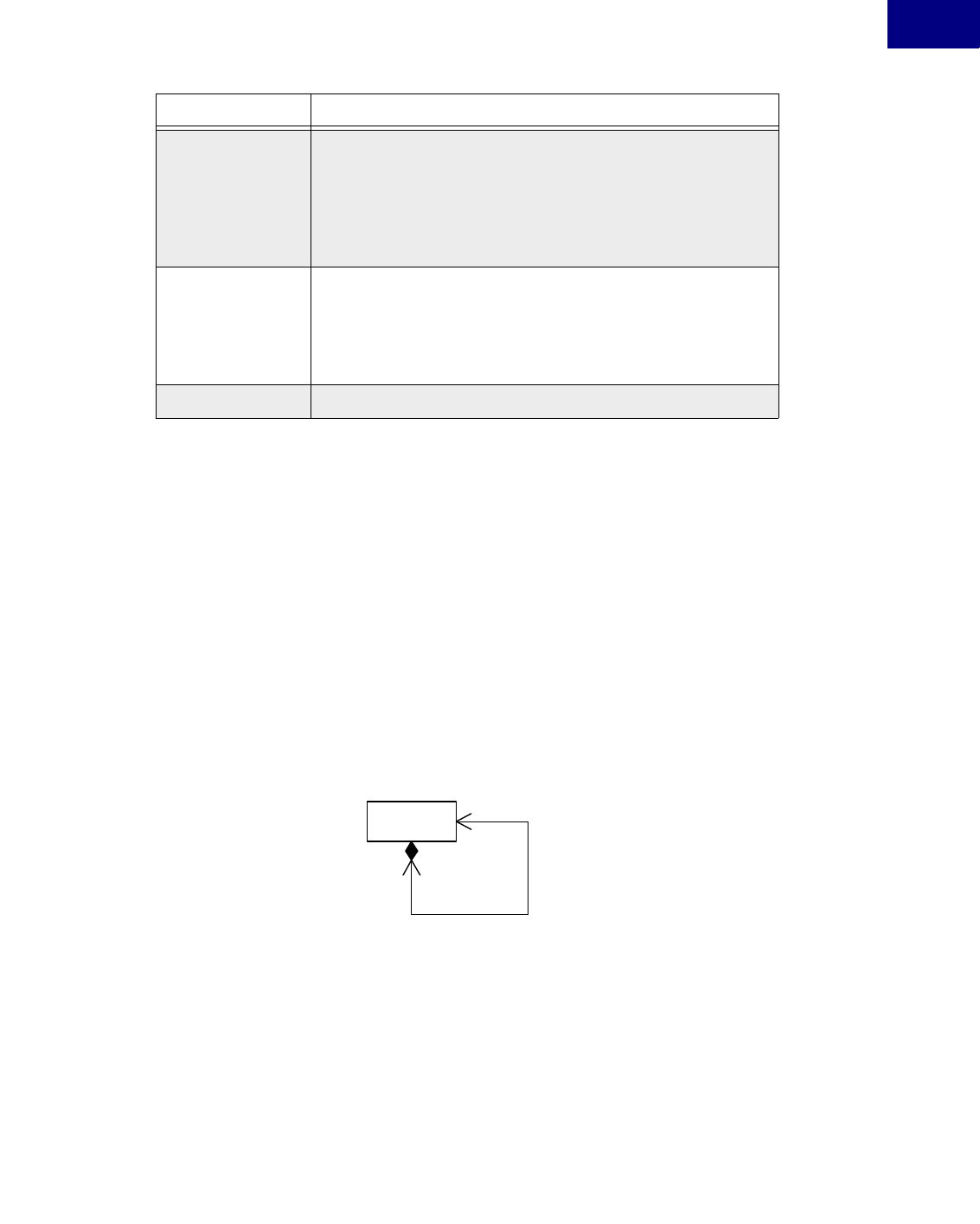
Layout Fundamentals 155
Layout Fundamentals
Documents and the layout hierarchy
The SnpInspectLayoutModel code snippet can inspect the layout hierarchy. Run the snippet in
SnippetRunner to create a textual report for a document. See SnpInspectLayoutModel for sam-
ple code that examines the layout hierarchy in various ways.
Parent and child objects and IHierarchy
A page item can contain other page items. The containing object is the parent; the contained
objects are the children. Child index order defines z-order, the order in which objects draw; the
child with index 0 draws first (behind), and the child with index n-1 draws last (in front). This
association between page items is implemented by the IHierarchy interface, as shown in
Figure 46.
FIGURE 46 Page Item parent-child composition (class diagram)
kPageItemBoss is the abstract base class for objects that participate in the layout hierarchy. IHi-
erarchy is a required interface. Subclasses of kPageItemBoss include spreads (kSpreadBoss),
spread layers (kSpreadLayerBoss), and frames (kSplineItemBoss). To see all subclasses, see the
API reference documentation for kPageItemBoss. Each subclass of kPageItemBoss may have
different constraints on the number and type (boss class) of children it can contain.
The child objects contained within the parent are said to be nested. Figure 47 shows an exam-
ple. The object diagram is an example of how the internal representation changes when a circle
is nested inside a square using cut and paste. The parent-child association between boss objects
in a layout is realized by the IHierarchy interface. When the circle is cut, the association with its
ISpread Signature interface for a spread (kSpreadBoss). Contains useful
methods for discovering the page items that lie on a page or
spread and for navigating between document layers
(kDocumentLayerBoss) and spread layers (kSpreadLayerBoss).
A document is laid out as a set of spreads in which each spread
contains one or more pages and other page items.
ISpreadLayer Signature interface for a spread layer (kSpreadLayerBoss). A
spread layer is the container for the page items in a layer through
the IHierarchy interface on the kSpreadLayerBoss. The
ISpreadLayer interface maintains a relationship back to the
corresponding document layer boss (kDocumentLayerBoss).
ISpreadList List of the spreads (kSpreadBoss) in a document.
Interface Note
«boss»
kPageItemBoss
parent1
children
0..*
IHierarchy
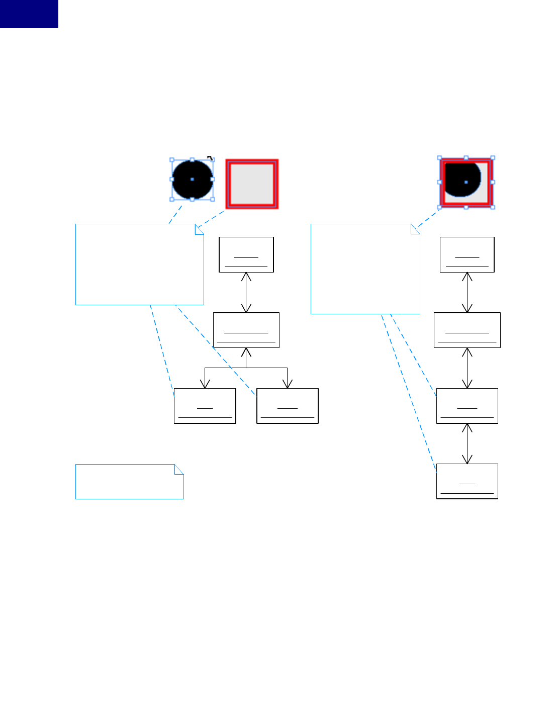
Layout Fundamentals
Documents and the layout hierarchy
156
initial parent, the spread layer, is broken. When the circle is pasted, it is associated with its new
parent, the square. The square becomes a frame, because it now contains the circle. The draw-
ing of the circle is then clipped to its frame.
FIGURE 47 Change in parent-child relationships when a circle is nested in a square
The low-level commands used to edit the hierarchy programmatically are kAddToHierarchyC-
mdBoss and kRemoveFromHierarchyCmdBoss. A utility interface, IHierarchyUtils, provides a
facade that processes these commands. For more information, see the API reference documen-
tation.
The boss objects in the hierarchy illustrated above can be visited using a recursive function, as
shown in Example 18:
«boss»
spread1
: kSpreadBoss
«boss»
layer1-content
: kSpreadLayerBoss
«boss»
circle
: kSplineItemBoss
«boss»
square
: kSplineItemBoss
parent
child
parent
child child
«boss»
spread1
: kSpreadBoss
«boss»
layer1-content
: kSpreadLayerBoss
«boss»
square
: kSplineItemBoss
«boss»
circle
: kSplineItemBoss
parent
child
parent
child
parent
child
Above:
The original circle and square paths.
Below:
The parent-child relationships
between the boss objects that
represent these paths on a
spread.
Above:
The circle cut and pasted into
the square.
Below:
The changed parent-child
relationships. The square is
the parent of the circle.
gg
The parent-child associations
are represented by the
IHierarchy interface.

Layout Fundamentals 157
Layout Fundamentals
Spreads and pages
EXAMPLE 18 Recursive function that visits each child boss object in a hierarchy
void VisitChildren(IHierarchy* parent)
{
int32 childCount = parent->GetChildCount();
for (int32 childIndex = 0; childIndex < childCount; childIndex++)
{
InterfacePtr<IHierarchy> child(parent->QueryChild(childIndex));
#ifdef DEBUG
// Trace the boss class name of the child.
DebugClassUtilsBuffer className;
DebugClassUtils::GetIDName(&className, ::GetClass(child));
TRACEFLOW("LayoutFundamentals", "%s\n", className);
#endif
// Add code to examine other interfaces on the boss object.
VisitChildren(child);
}
}
Spreads and pages
A spread is the primary container for layout data. A spread contains a set of pages on which the
page items that represent pictures, text, or content of another format are arranged. A spread
owns all the objects it contains, including its pages, ruler guides, frames, paths, groups, and any
nested content. The objects in a spread are organized into layers, so the user can control
whether the objects assigned to a layer should be displayed or editable. See Figure 48 for the
user’s perspective. The publication shown is a facing-pages document with one spread, one
page, and one layer.
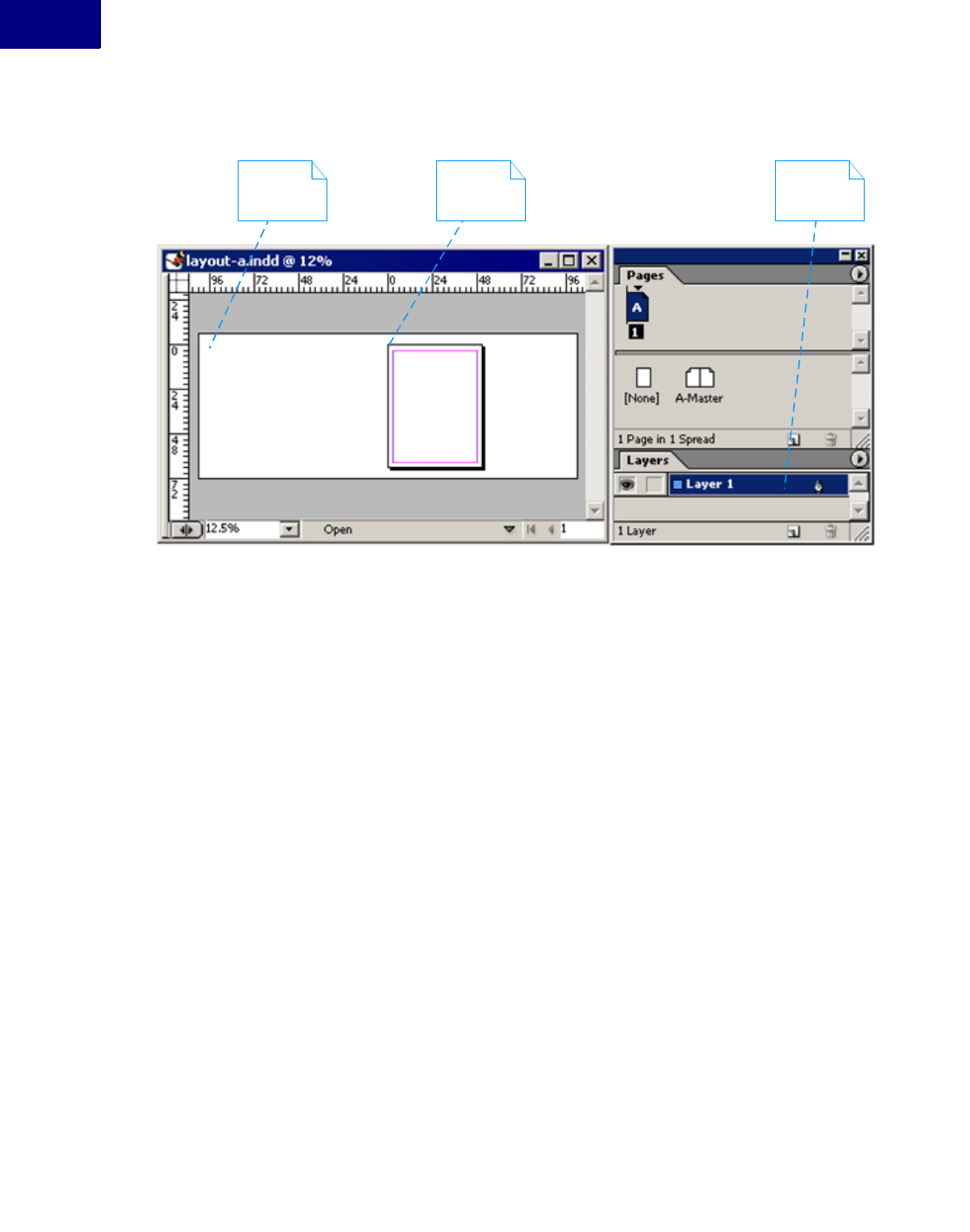
Layout Fundamentals
Spreads and pages
158
FIGURE 48 User’s perspective of a sample spread and page
Figure 49 is an object diagram showing the layout-related boss objects that exist in a publica-
tion containing a ruler guide and graphic frame on a page. The sample document (kDocBoss)
contains a spread (kSpreadBoss), page (kPageBoss), graphic frame (kSplineItemBoss), and
ruler guide (kGuideItemBoss). The content of the spread is layered on spread layers (kSpread-
LayerBoss) that map onto corresponding document layers (kDocumentLayerBoss). There are
two document layers (kDocumentLayerBoss), the pages layer and layer 1. The page, graphic
frame, and ruler guide are arranged on spread layers (kSpreadLayerBoss) under the spread’s
IHierarchy interface.
Spread Page Layer
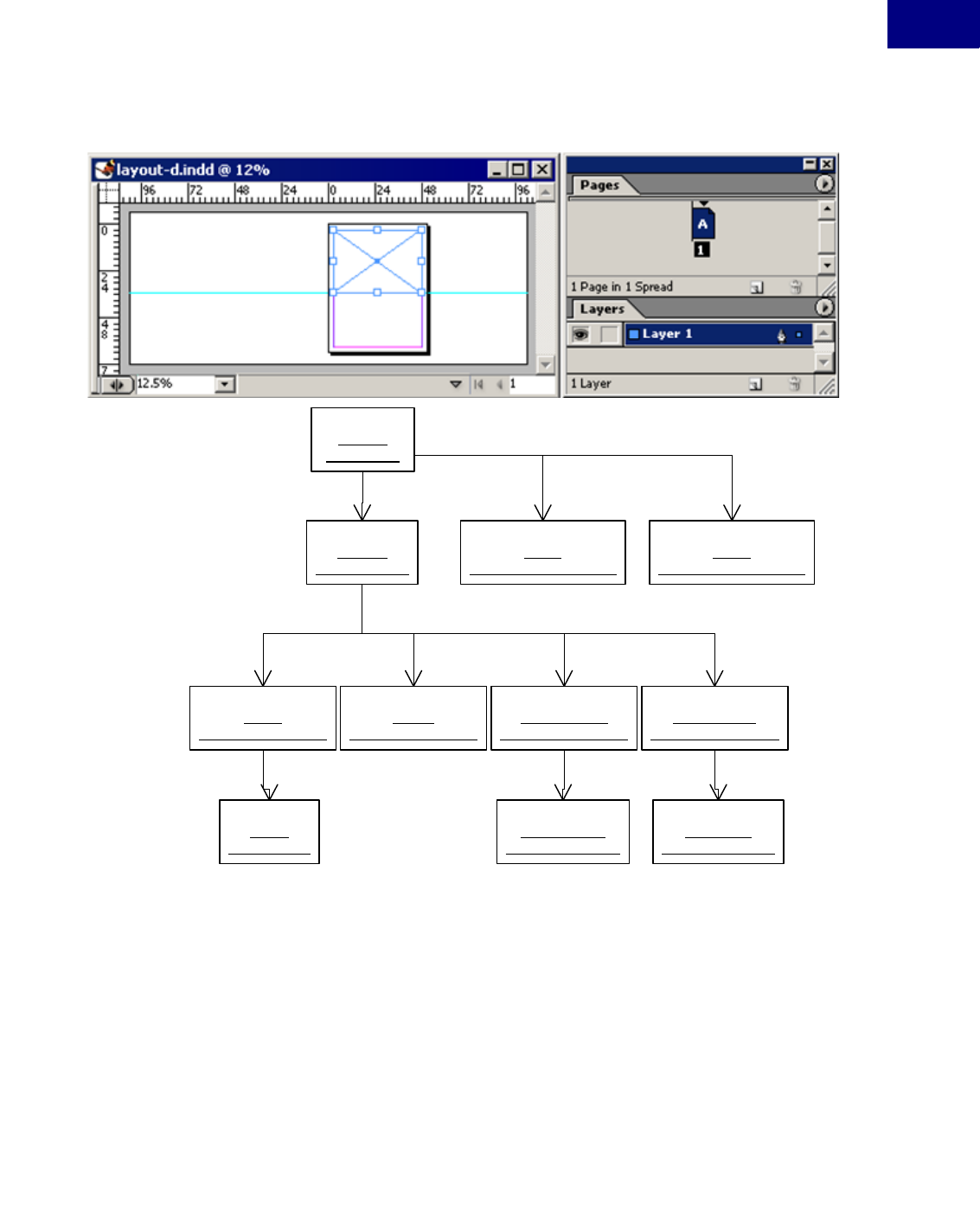
Layout Fundamentals 159
Layout Fundamentals
Spreads and pages
FIGURE 49 Document containing a frame and ruler guide on a page
A layer is represented by a kDocumentLayerBoss object with two corresponding kSpreadLay-
erBoss objects in each spread.
The pages layer is the layer to which pages (kPageBoss) are assigned. In Figure 49, the pages
layer is represented by the kDocumentLayerBoss object named “pages” and the kSpreadLayer-
Boss objects named “pages” and “private.” The pages document layer (kDocumentLayerBoss)
always is at index 0 in the layer list (ILayerList). The first child on the spread’s hierarchy always
is the associated page’s spread layer and contains the spread’s pages (kPageBoss). The second
child of the spread is a private spread layer that always is empty. Pages are drawn behind all
other objects, because they always are stored on the spread’s hierarchy at child index 0. Note the
pages layer is not shown in the Layers panel.
«boss»
layout-d
: kDocBoss
«boss»
spread1
: kSpreadBoss
«boss»
pages
: kSpreadLayerBoss
«boss»
private
: kSpreadLayerBoss
«boss»
layer1-content
: kSpreadLayerBoss
«boss»
layer1-guides
: kSpreadLayerBoss
ISpreadList::GetNthSpreadUID(0)
IHierarchy::QueryChild(0)
IHierarchy::QueryChild(1)
IHierarchy::QueryChild(2)
IHierarchy::QueryChild(3)
«boss»
graphic-frame
: kSplineItemBoss
IHierarchy::QueryChild(0)
«boss»
ruler-guide
: kGuideItemBoss
«boss»
page1
: kPageBoss
IHierarchy::QueryChild(0)IHierarchy::QueryChild(0)
«boss»
pages
: kDocumentLayerBoss
«boss»
layer1
: kDocumentLayerBoss
ILayerList::QueryLayer(0) ILayerList::QueryLayer(1)

Layout Fundamentals
Spreads and pages
160
In Figure 49, Layer 1 is represented by the kDocumentLayerBoss object layer1. It has two cor-
responding spread layers (kSpreadLayerBoss) on the spread’s hierarchy, one for content
(layer1-content, which stores the graphic frame (kSplineItemBoss)) and one for ruler guides
(layer1-guides, which stores the ruler guide). The order of these spread layers can vary,
depending on whether guides are being drawn behind or in front of content. Figure 49 illus-
trates the order when guides are drawn in front of content.
NOTE:Child index order in IHierarchy defines z-order, the order in which objects on those
spread layers (kSpreadLayerBoss) draw. The child with index 0 draws first (behind); the
child with index n-1, last (in front).
The code shown in Example 19 visits each child boss object of the spread shown in Figure 49.
(For the implementation of VisitChildren, see Example 18.) All boss objects on the spread’s
hierarchy are visited by the code in Example 19, including spread layer and page boss objects.
EXAMPLE 19 Code that iterates spreads and visits their children using IHierarchy
void VisitSpreadChildren(UIDRef& documentUIDRef)
{
InterfacePtr<IDocument> document(documentUIDRef, UseDefaultIID());
InterfacePtr<ISpreadList> spreadList(document, UseDefaultIID());
IDataBase* database = documentUIDRef.GetDataBase();
int32 spreadCount = spreadList->GetSpreadCount();
for ( int32 spreadIndex = 0; spreadIndex < spreadCount; spreadIndex++ )
{
UIDRef spreadUIDRef(database, spreadList->GetNthSpreadUID(spreadIndex));
InterfacePtr<IHierarchy> spreadHierarchy(spreadUIDRef, UseDefaultIID());
VisitChildren(spreadHierarchy);
}
}
In contrast, the code shown in Example 20 filters the objects by the pages on which they lie.
The method ISpread::GetItemsOnPage calculates which items lie on a page. Since pages do not
own the items that lie on them (spreads own the items), the calculation of which items lie on a
page is geometrical, comparing the intersection of the bounding box of each item with the
bounding box of the page. (For details, see ISpread::GetItemsOnPage.) If this code is run on the
spread shown in Figure 49, the only object that appears in the list itemsOnPage is the graphic
frame. The ruler guide is not returned as an item, because it is a pasteboard-ruler guide; if the
ruler guide were a page-ruler guide, the code in Example 20 would list it.

Layout Fundamentals 161
Layout Fundamentals
Layers
EXAMPLE 20 Code that iterates spreads and filters items by the page on which they lie using
ISpread
void FilterItemsByPage(UIDRef& documentUIDRef)
{
InterfacePtr<IDocument> document(documentUIDRef, UseDefaultIID());
InterfacePtr<ISpreadList> spreadList(document, UseDefaultIID());
IDataBase* database = documentUIDRef.GetDataBase();
int32 spreadCount = spreadList->GetSpreadCount();
for ( int32 spreadIndex = 0; spreadIndex < spreadCount; spreadIndex++ )
{
UIDRef spreadUIDRef(database, spreadList->GetNthSpreadUID(spreadIndex));
InterfacePtr<ISpread> spread(spreadUIDRef, UseDefaultIID());
for (int32 pageIndex = 0; pageIndex < spread->GetNumPages(); pageIndex++)
{
UIDList itemsOnPage(database);
const bool16 bIncludePage = kFalse;
const bool16 bIncludePasteboard = kFalse;
spread->GetItemsOnPage(pageIndex, &itemsOnPage, bIncludePage,
bIncludePasteboard);
// Add code to manipulate itemsOnPage.
}
}
}
The SnpInspectLayoutModel code snippet can inspect the spreads in a document and their
associated hierarchy. Run the snippet in SnippetRunner to create a textual report. For sample
code, see SnpInspectLayoutModel::ReportDocumentByHierarchy.
Layers
Layers are presented to the user and edited with the Layers panel. Layers can be shown or hid-
den, locked or unlocked. By re-arranging the order of layers, the user can control the front-to-
back order in which page items assigned to those layers draw. The user also can change the
layer to which a selected page item is assigned, by dragging and dropping in the Layers panel.
Figure 50 shows the user’s perspective of a layer. The document shown is a facing-pages docu-
ment with one spread, one page, and one layer.

Layout Fundamentals
Layers
162
FIGURE 50 User’s perspective of a layer
Layers in a basic document
Figure 51 is an object diagram showing the layout hierarchy that results when a new layer is
added to the document in Figure 49. The diagram shows a document (kDocBoss) containing
one spread (kSpreadBoss), one page (kPageBoss) and three layers. Each layer is represented by
one kDocumentLayerBoss object that has two corresponding kSpreadLayerBoss objects in
each spread. The pages layer that stores the page (kPageBoss) is represented by the kDocu-
mentLayerBoss object named “pages” and the kSpreadLayerBoss objects named “pages” and
“private.” Layer 1 is represented by the objects layer1, layer1-content, and layer1-guides. Layer 2
is represented by the objects layer2, layer2-content, and layer2-guides. A graphic frame (kSpli-
neItemBoss) and a ruler guide (kGuideItemBoss) are assigned to Layer 1. Layer 2 is empty.
Spread Page Layer
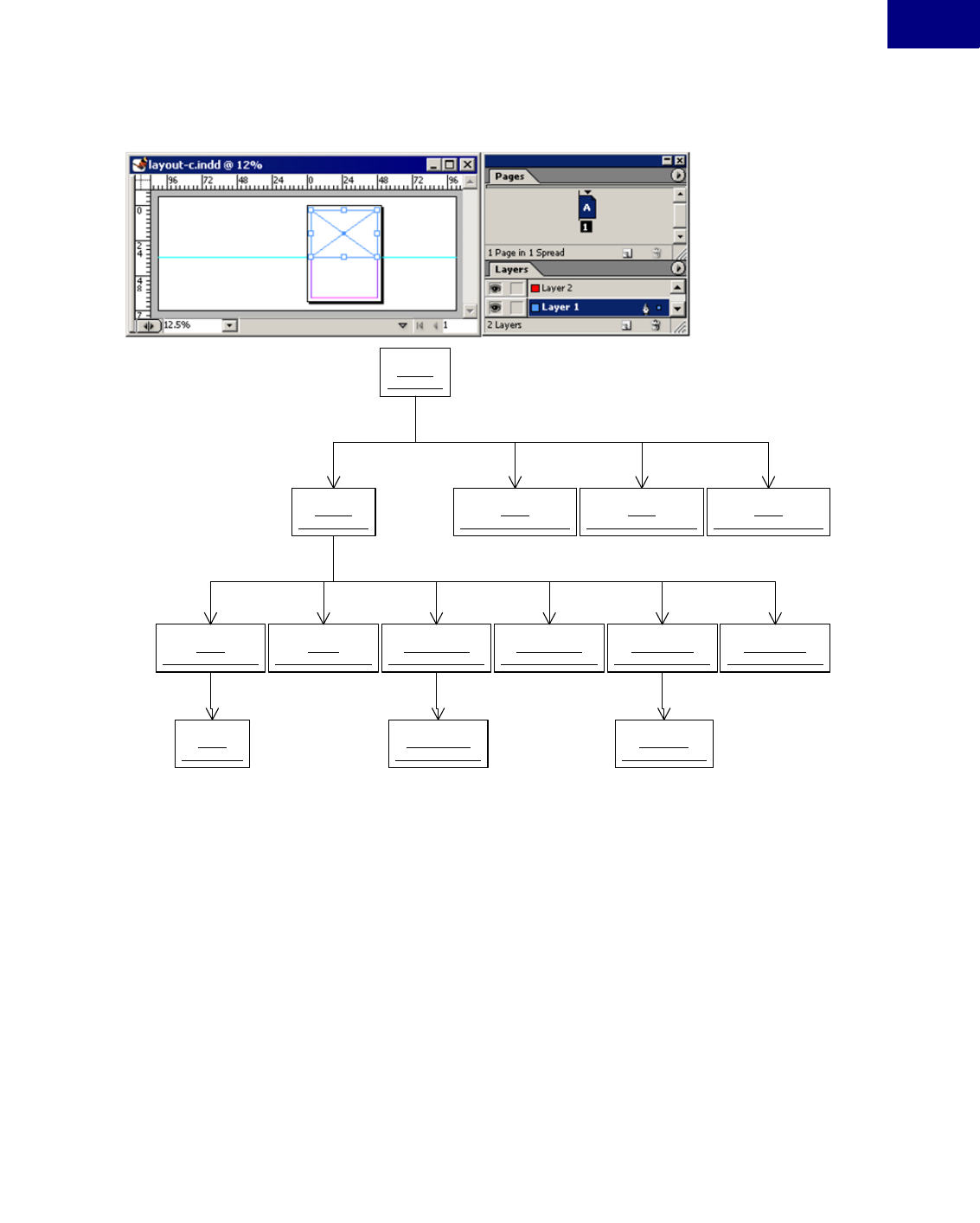
Layout Fundamentals 163
Layout Fundamentals
Layers
FIGURE 51 Document with two layers
When a new layer is added, three new objects are created:
zA new document layer is added to the layer list (ILayerList). This is the kDocumentLayer-
Boss object layer2.
zTwo corresponding spread layers are added to the spread. One new spread layer is added to
contain paths, frames, or groups; the other new spread layer is added to contain ruler
guides. These are the kSpreadLayerBoss objects layer2-content and layer2-guides.
Figure 51 shows that when a document layer is created, two corresponding spread layers are
added to each spread. When a document layer is deleted, its corresponding spread layers are
removed from each spread. Document-layer edits are document-wide; i.e., they affect all
spreads in a document.
Content-spread layers are stored contiguously in the spread’s hierarchy (IHierarchy). Guide-
spread layers also are stored contiguously. For example, the layer1-content and layer2-content
objects in Figure 51 are contiguous content-spread layers, and layer1-guides and layer2-guides
are contiguous guide-spread layers.
«boss»
layout-c
: kDocBoss
«boss»
spread1
: kSpreadBoss
«boss»
pages
: kSpreadLayerBoss
«boss»
private
: kSpreadLayerBoss
«boss»
layer1-content
: kSpreadLayerBoss
«boss»
layer2-content
: kSpreadLayerBoss
ISpreadList::GetNthSpreadUID(0)
IHierarchy::QueryChild(0)
IHierarchy::QueryChild(1)
IHierarchy::QueryChild(2)
IHierarchy::QueryChild(3)
«boss»
page1
: kPageBoss
IHierarchy::QueryChild(0)
«boss»
pages
: kDocumentLayerBoss
«boss»
layer1
: kDocumentLayerBoss
«boss»
layer2
: kDocumentLayerBoss
«boss»
layer1-guides
: kSpreadLayerBoss
«boss»
layer2-guides
: kSpreadLayerBoss
IHierarchy::QueryChild(4)
IHierarchy::QueryChild(5)
ILayerList::QueryLayer(0) ILayerList::QueryLayer(1) ILayerList::QueryLayer(2)
«boss»
graphic-frame
: kSplineItemBoss
«boss»
ruler-guide
: kGuideItemBoss
IHierarchy::QueryChild(0) IHierarchy::QueryChild(0)

Layout Fundamentals
Layers
164
The order of content-spread layers and guide-spread layers as child objects of the spread’s hier-
archy (IHierarchy) varies, depending on whether guides are being drawn in front or in back of
content. Ruler guides are kept in a distinct spread layer, to allow them to be drawn in front of or
behind other content, or even to turn them off completely, as determined by a preference set-
ting. (See “Guides and grids” on page 180.) Figure 51 shows the order when guides are drawn
in front of content. The corresponding index order is as follows:
index[0] pages spread layer
index[1] private spread layer
index[2] layer1-content spread layer
index[3] layer2-content spread layer
index[4] layer1-guides spread layer
index[5] layer2-guides spread layer
If guides are drawn behind other content, the index order of spread layers in the spread’s hier-
archy (IHierarchy) is as follows:
index[0] pages spread layer
index[1] private spread layer
index[2] layer1-guides spread layer
index[3] layer2-guides spread layer
index[4] layer1-content spread layer
index[5] layer2-content spread layer
NOTE:Child-index order in IHierarchy defines z-order, the order in which objects on those
spread layers (kSpreadLayerBoss) draw. The child with index 0 draws first (behind); the
child wth index n-1, last (in front).
The spread’s ISpread interface has methods that return the spread layer associated with a given
document layer. (See “Navigating spread content using ISpread” on page 166.) The associations
are calculated using the following algorithm.
The indices of the pages-spread layer and private-spread layer are fixed:
zPages-spread layer IHierarchy child index = 0.
zPrivate-spread layer IHierarchy child index = 1.
Variable definitions:
zi = index of document layer (kDocumentLayerBoss) in ILayerList whose associated spread
layer (kSpreadlayerBoss) is wanted.
zc = number of document layers in ILayerList.
If guides are displayed in front of content, the following calculations are used:
zContent-spread layer IHierarchy child index = i + 1.
zGuide-spread layer IHierarchy child index = i + c.
If guides are displayed behind content, the following calculations are used:
zContent-spread layer IHierarchy child index = i +c.
zGuide-spread layer IHierarchy child index = i + 1.
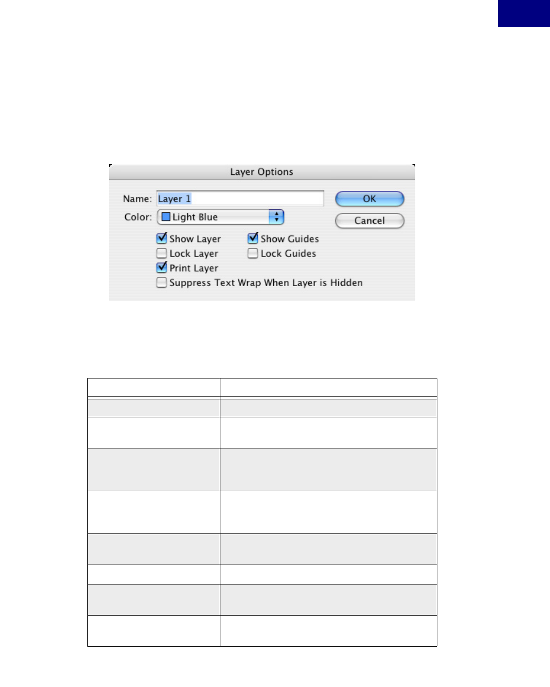
Layout Fundamentals 165
Layout Fundamentals
Layers
Layer options
There are layer options that can be controlled via the Layers Options dialog. User can double
click on a layer name in the Layers palette to bring up the Layer Options dialog, as shown in
Figure 52.
FIGURE 52 Layer Options dialog
The attributes in the Layer Options dialog are managed by the IDocumentLayer interface,
which is aggregated on the kDocumentLayerBoss. Table 25 lists some of the commands that
can be used to modify layer options.
TABLE 25 Layer Options-related commands
Command Note
kChangeLayerNameCmdBoss Changes the name of the layer.
kIgnoreHiddenTextWrapCmd
Boss
Sets text-wrap options for a document layer.
kLockGuideLayerCmdBoss Locks or unlocks a guide layer. A “locked” layer
means nothing in that layer (only guides) can be
selected.
kLockLayerCmdBoss Locks or unlocks a layer. A “locked” layer means
nothing in that layer can be selected. Layers are
unlocked by default.
kPrintLayerCmdBoss Sets the printability of the layer. A non-printable
layer does not print or export.
kSetLayerColorCmdBoss Changes the layer color.
kShowGuideLayerCmdBoss Sets the guide visibility of the layer. An “invisible”
layer is not displayed on the screen.
kShowLayerCmdBoss Sets the visibility of the layer. An “invisible” layer is
not displayed on the screen.

Layout Fundamentals
Layers
166
Use the commands in Table 25 whenever possible to modify layer options.
The SnpPrintDocument.cpp SDK snippet allows the user to select which layer to print. It uses
kPrintLayerCmdBoss to set the printability for each layer. For more information, see the snip-
pet source code.
NOTE:A similar set of attributes also exists in the ISpreadLayer. “Layers in a basic document”
on page 162 explains the relationship between IDocumentLayer and ISpreadLayer in a
document. The ISpreadLayer interface primarily provides “getter” methods that
forward the request for information to the corresponding IDocumentLayer interface
Navigating spread content using ISpread
“Layers in a basic document” on page 162 shows the content of a spread is stored on its IHierar-
chy interface. Locating content using IHierarchy can be laborious. Alternately, the ISpread
interface makes it easy to examine the content of a spread, as shown in the object diagram in
Figure 53.
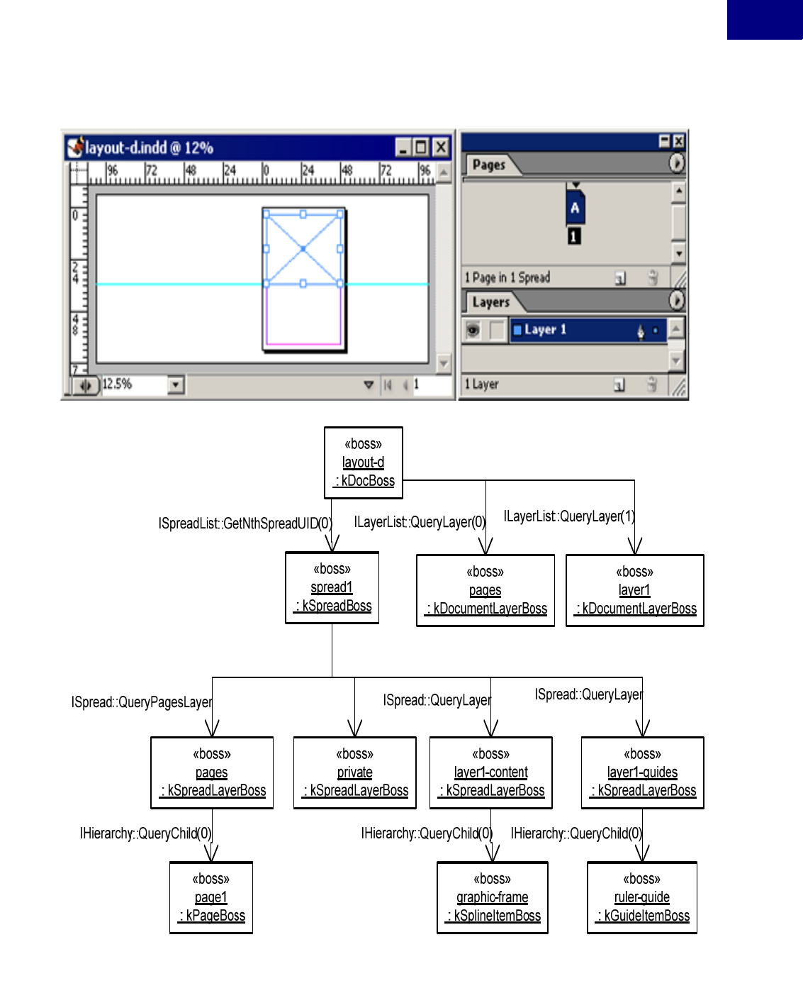
Layout Fundamentals 167
Layout Fundamentals
Layers
FIGURE 53 Spread layer navigation using ISpread

Layout Fundamentals
Master spreads and master pages
168
Figure 53 shows you can use the ISpread interface on a spread (kSpreadBoss) to find the guide
or content spread layer associated with a document layer. (For more information, see
ISpread::QueryLayer.) You also can discover which page items lie on a given page. (For more
information, see ISpread::GetItemsOnPage.)
Using ISpread to discover the content of a spread is much easier than using IHierarchy.
When run on the document shown in Figure 53, the code in Example 21 visits the content of
spread layer layer1-content if parameter wantGuideLayer is kFalse. The code visits the content
of spread layer layer1-guides if parameter wantGuideLayer is kTrue.
EXAMPLE 21 Code that iterates over spreads in a document, then iterates over document layers to
visitiitems on the spread layer associated with each document layer
void FilterItemsByLayer(UIDRef& documentUIDRef, bool16 wantGuideLayer)
{
InterfacePtr<IDocument> document(documentUIDRef, UseDefaultIID());
InterfacePtr<ISpreadList> spreadList(document, UseDefaultIID());
InterfacePtr<ILayerList> layerList(document, UseDefaultIID());
IDataBase* database = documentUIDRef.GetDataBase();
int32 spreadCount = spreadList->GetSpreadCount();
for ( int32 spreadIndex = 0; spreadIndex < spreadCount; spreadIndex++ )
{
UIDRef spreadUIDRef(database, spreadList->GetNthSpreadUID(spreadIndex));
InterfacePtr<ISpread> spread(spreadUIDRef, UseDefaultIID());
int32 layerCount = layerList->GetCount();
// Skip the pages layer (layer 0).
for (int32 layerIndex = 1; layerIndex < layerCount; layerIndex++)
{
IDocumentLayer* documentLayer = layerList->QueryLayer(layerIndex);
int32 pPos;
// Visit the content spread layer associated with the document layer
// if wantGuideLayer is kFalse, the guide spread layer otherwise.
InterfacePtr<ISpreadLayer> contentSpreadLayer
(
spread->QueryLayer(documentLayer, &pPos, wantGuideLayer)
);
InterfacePtr<IHierarchy> hierarchy(contentSpreadLayer, UseDefaultIID());
VisitChildren(hierarchy);
}
}
}
NOTE:For an implementation of VisitChildren, see Example 18.
Master spreads and master pages
A master spread is a special kind of spread that contains master pages. A master page is a page
designed to contain background content for another page. When a page is based on a master
page, the page items that lie on the master page also appear on the page. A master page elimi-
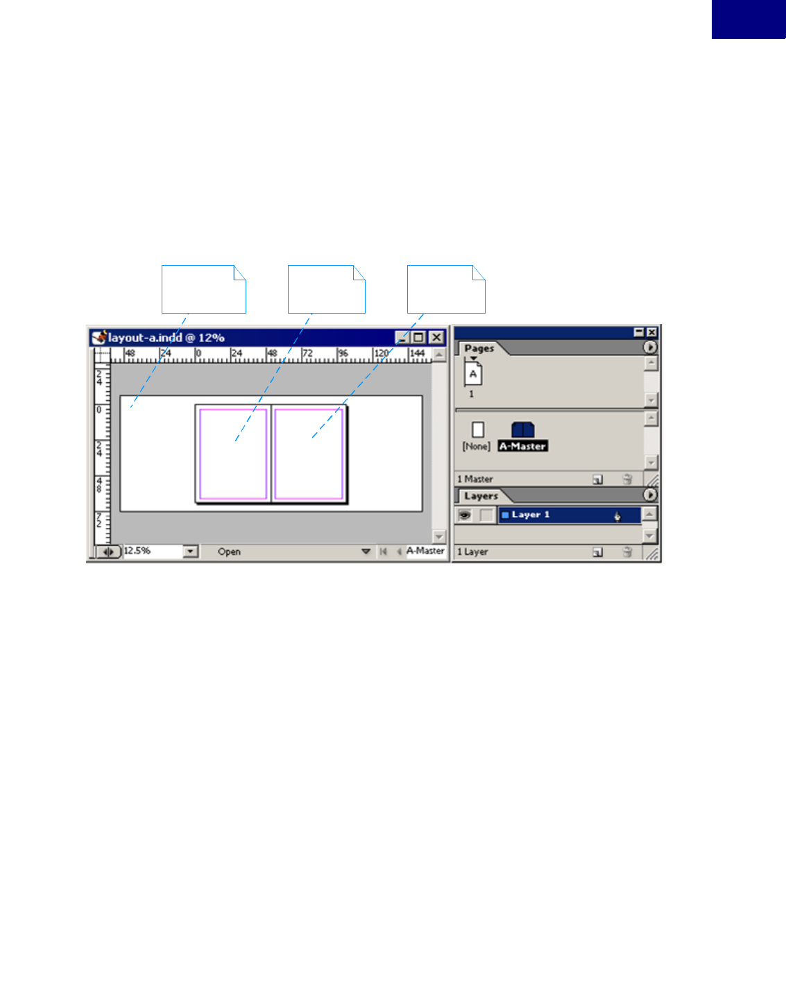
Layout Fundamentals 169
Layout Fundamentals
Master spreads and master pages
nates the need for repetitive page formatting and typically contains page numbers, headers and
footers, and background pictures. The layout presentation is used to edit the content of master
spreads. The Pages panel is used to arrange the pages in a master spread and assign a master
page to a page.
See Figure 54 for the user’s perspective on master spreads and master pages. The publication
shown is a facing-pages document with a master spread containing two master pages.
FIGURE 54 User’s perspective of master spreads and master pages
Master spreads and master pages in a basic document
A master spread (kMasterPagesBoss) is a special kind of spread; it extends the spread boss class
(kSpreadBoss). The content of a master spread is organized the same way as a spread: each has
a hierarchy (IHierarchy) with spread layers acting as parent objects for content. Compare the
spread shown in Figure 49 to the master spread shown in Figure 55. The document (kDocBoss)
shown contains a master spread (kMasterPagesBoss), with two pages (kPageBoss), and two
paths (kSplineItemBoss) in the form of a square and a circle.
NOTE:Pages (kPageBoss) that are part of a master spread are master pages. This name clashes
with the name of the master-spread boss class, kMasterPagesBoss, so the distinction
between the two is worth repeating: a master page is a page (kPageBoss) owned by a
master spread (kMasterPagesBoss).
Master spread Master page Master page
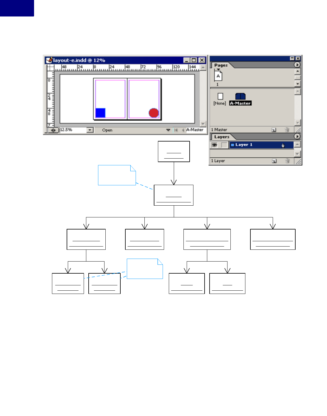
Layout Fundamentals
Master spreads and master pages
170
FIGURE 55 Facing-pages master spread
When a page is based on a master page, the page items that lie on the master page also appear
on the page. When the master spread in Figure 55 is applied to page 1 of the facing-pages doc-
ument in Figure 49, page items from the master page appear on page 1. The circle in the
screenshot of page 1 in Figure 56 is an object from the master spread.
Figure 56 is an object diagram showing a one-page document that has a master (A-Master)
applied. The circle drawn on page 1 is an object inherited from the associated master page. The
boss objects that represent the spread and the master spread it is based on are shown. The asso-
ciation between a page (kPageBoss) and its master page is implemented by the IMasterPage
interface. The screenshot shows that filtering of the objects on the master spread is being per-
formed. Objects that intersect the bounding box of the master page associated with the page
are drawn, other objects on the master spread are filtered out. The circle is the only object from
«boss»
A-Master
: kMasterPagesBoss
«boss»
A-Master-layer1-content
: kSpreadLayerBoss
«boss»
A-Master-layer1-guides
: kSpreadLayerBoss
«boss»
A-Master-private
: kSpreadLayerBoss
«boss»
A-Master-pages
: kSpreadLayerBoss
«boss»
master-page-2
: kPageBoss
«boss»
circle
: kSplineItemBoss
«boss»
square
: kSplineItemBoss
IMasterSpreadList
IHierarchy
«boss»
master-page-1
: kPageBoss
IHierarchy IHierarchy
«boss»
layout-e
: kDocBoss
Master spread
Master pages
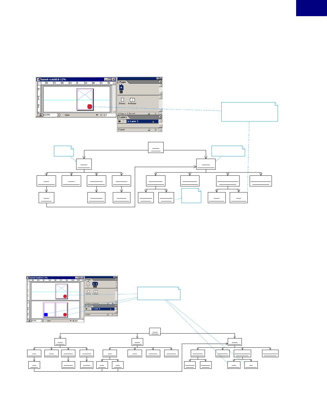
Layout Fundamentals 171
Layout Fundamentals
Master spreads and master pages
the master spread to draw, because it is the only object that intersects the bounding box of the
master page associated with page 1.
FIGURE 56 Spread based on a master spread
When two new pages based on the master shown in Figure 55 are added to the document, the
layout hierarchy is as shown in Figure 57. The object diagram shows the boss objects that rep-
resent three pages in a facing-pages document based on the same master spread. The circle and
square objects drawn on pages 1, 2, and 3 come from the master.
FIGURE 57 Two spreads based on a facing-pages master spread
«boss»
A-Master
: kMasterPagesBoss
«boss»
A-Master -layer1-content
: kSpreadLayerBoss
«boss»
A-Master -layer1-guides
: kSpreadLayerBoss
«boss»
A-Master -private
: kSpreadLayerBoss
«boss»
A-Master -pages
: kSpreadLayerBoss
«boss»
mas ter-page-2
: kPageBoss
«boss»
circle
: kSplineItemBoss
«boss»
square
: kSplineItemBoss
IMasterSpreadList
«boss»
mas ter-page-1
: kPageBoss
«boss»
spread1
: kSpreadBoss
«boss»
pages
: kSpreadLayerBoss
«boss»
pri vate
: kSpreadLayerBoss
«boss»
layer1-content
: kSpreadLayerBoss
«boss»
layer1-guides
: kSpreadLayerBoss
«boss»
graphic-frame
: kSplineItemBoss
«boss»
ruler-guide
: kGuideItemBoss
«boss»
page1
: kPageBoss
ISpreadList
IMasterPage
«boss»
layout-e
: kDocBoss
Spread Master spread
Master
page
Page item inherited
from master
«boss»
A-Master
: kMasterPagesBoss
«boss»
A-Master-layer1-content
: kSpreadLayer Bo ss
«boss»
A-Master-layer1-guides
: kSpreadLayer Bo ss
«boss»
A-Master-privat e
: kSpreadLayer Bo ss
«boss»
A-Master-pages
: kSpreadLayer Bo ss
«boss»
master-page-2
: kPageB oss
«boss»
circle
: kSpli neItem Boss
«boss»
squar e
: kSpli neItem Boss
IMasterSpreadList
«boss»
master-page-1
: kPageB oss
«boss»
spread1
: kSpreadBo ss
«boss»
pages
: kSpreadLayer Bo ss
«boss»
privat e
: kSpreadLayer Bo ss
«boss»
layer1-conten t
: kSpreadLayer Bo ss
«boss»
layer1-gu ide s
: kSpreadLayer Bo ss
«boss»
graphi c-frame
: kSpli neItem Bos s
«boss»
ruler -guide
: kGuideItem Boss
«boss»
page1
: kPageB oss
«boss»
spread2
: kSpreadBo ss
«boss»
pages
: kSpreadLayer Bo ss
«boss»
privat e
: kSpreadLayer Bo ss
«boss»
layer1-conten t
: kSpreadLayer Bo ss
«boss»
layer1-gu ide s
: kSpreadLayer Bo ss
«boss»
page2
: kPageB oss
«boss»
page3
: kPageB oss
ISpreadList
IMasterPage
«boss»
layout-f
: kDocBoss
Page items inherited
from master

Layout Fundamentals
Master spreads and master pages
172
The master spread (kMasterPagesBoss) associated with a page (kPageBoss) is found by calling
IMasterPage::GetMasterPageUID. The associated master page (kPageBoss) within that master
spread is calculated by calling IMasterPage::GetMasterIndex. The calculation depends on the
index position (0, 1, 2, ...) of the page within its spread and the document set-up. Given the
result returned by IMasterPage::GetMasterIndex, ISpread::GetNthPageUID can be called to get
a reference to the master page (kPageBoss), or ISpread::GetItemsOnPage can be called to calcu-
late the objects on the master spread that intersect the bounding box of the master page.
To base a page or set of pages on a master spread, process the kApplyMasterSpreadCmdBoss
command.
Master-page item overrides
Page items from a master spread can be overridden. For example, to change the fill color of the
circle on page 1 in the Figure 57, a master page item override is created. A record of the over-
ride is kept by the page (kPageBoss) in the IMasterOverrideList interface.
Overrides to master-page items are applied programmatically with kOverrideMasterPageItem-
CmdBoss.
Even when a master-page item is overridden, changes made to its counterpart on the master
still can effect page items. An overridden page item continues to inherit all properties of its
master counterpart that are not overridden. For example, if the only property that was overrid-
den on page 1 is the fill color of the circle, modifying the position of the circle in the master
causes the position of the circle to be updated on the pages based on that master (pages 1 and
3). The application of the initial fill-color override creates a copy of the circle (kSplineItem-
Boss) object on spread 1; a record of the override is kept in IMasterOverrideList on page 1. The
circle on spread 1 is a controlled page item; the circle on the master spread is the controlling
page item. Master page items maintain a list of controlled page items in the IControlledPage-
Items interface, which represents the page items for which overrides were made. An overridden
master-page item on a spread maintains a reference to its controlling master-page item, in the
IControllingPageItem interface.
Basing one master page on another
A master page can be based on another master page. The association is maintained by the
IMasterPage interface as it is for a normal page (kPageBoss) owned by a spread (kSpreadBoss).
For example, consider two masters, A and B, with different sets of page items. When you drag
master A onto master B in the Pages panel, master B becomes based on master A. Master page
items on master A appear on master B; however, the page items on master B inherited from
master A remain owned by master A. If you alter the page items on master A, the change is
inherited by master B. Master B can override page items from master A for individual proper-
ties, just as the master-page items on a spread can be overridden.

Layout Fundamentals 173
Layout Fundamentals
Page items
Page items
A page item is a path, frame, group, picture, text frame, or page-item type that represents con-
tent the user creates and edits on a spread. For general information about the organization of
page items in a spread, see “Spreads and pages” on page 157.
Frames and paths
A path represents a straight line, curved line, or closed shape like a rectangle, ellipse, or poly-
gon. A path comprises one or more segments, each of which may be straight or curved. Each
path is open (the default) or closed. Graphic attributes are properties that control how the path
is formatted when drawn, like stroke weight and color. For more information about paths, see
the “Paths” section of the “Graphics Fundamentals” chapter. A frame is simply a path that con-
tains—or is designated to contain—other objects, like a graphic page item, text page item, or
page item that represents another type of content.
Frames and paths are represented by the same boss class, kSplineItemBoss.
A path can become a frame, and a frame can become a path. The difference between a path and
a frame is the state of the interfaces on kSplineItemBoss. A path is a kSplineItemBoss object
that contains no children in its IHierarchy interface. A graphic frame is a kSplineItemBoss
object that contains a graphic page item in its IHierarchy interface. (For more information
about graphic page items, see the “Graphic Page Items” section of the “Graphics Fundamentals”
chapter.) A text frame is a kSplineItemBoss object that contains a text page item (kMultiCol-
umnItemBoss). (For more information on text page items, see the “Text” chapter.)
Figure 58 shows a square path, an empty graphic frame, a graphic frame displaying a picture,
an empty text frame, and a text frame containing text. The object diagram shows a square being
used as a path and as a frame.
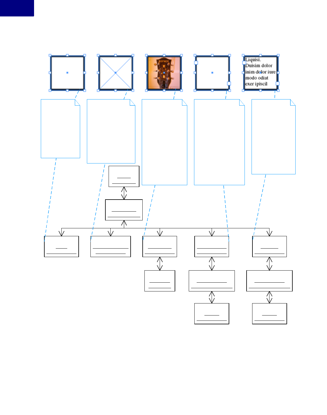
Layout Fundamentals
Page items
174
FIGURE 58 Square used as a path and a frame
The toolbox palette provides the user with several path-drawing tools. The Rectangle, Ellipse,
Polygon, and Line tools create basic shapes. The Rectangle Frame, Ellipse Frame, and Polygon
Frame tools create basic graphic-frame shapes. The Pen and Pencil tools create free-form
shapes. When one of these tools is used to draw a path, a spline item (kSplineItemBoss) is cre-
ated to represent the path. The IPathGeometry interface on kSplineItemBoss describes the
points in the path. Other interfaces on kSplineItemBoss provide properties like stroke weight
«boss»
spread1
: kSpreadBoss
«boss»
layer1-content
: kSpreadLayerBoss
«boss»
square
: kSplineItemBoss
«boss»
empty-graphic-frame
: kSplineItemBoss
«boss»
graphic-frame
: kSplineItemBoss
«boss»
empty-text-frame
: kSplineItemBoss
«boss»
text-frame
: kSplineItemBoss
«boss»
jpeg-picture
: kImageItem
«boss»
column-controller
: kMultiColumnItemBoss
«boss»
column1
: kFrameItemBoss
«boss»
column-controller
: kMultiColumnItemBoss
«boss»
column1
: kFrameItemBoss
IHierarchy
Above:
Square.
Below:
Representation
as a spline,
a path-based
object. Any
spline can be
used as a frame.
Above:
Empty graphic frame.
Below:
Representation
as a spline
designated for
graphics content.
IGraphicFrameData::
IsGraphicFrame
returns kTrue.
Above:
Graphic frame
displaying JPEG
picture.
Below:
Representation
as a spline
containing an
image in its
IHierarchy
interface. The
content of the
frame is clipped
by the frame's path.
Above:
Empty text frame.
Below:
Representation
as a spline
containing a
column controller
in its IHierarchy
interface that in
turn contains a
column. The
story (not shown)
associated with
these objects is empty.
Above:
Text frame
displaying text.
Below:
Representation
is the same as
the empty text
frame. The
difference is
that the associated
story (not shown)
contains text.

Layout Fundamentals 175
Layout Fundamentals
Page items
and stroke color that control how the path is drawn. When a path is used as a frame, the con-
tent is clipped by the frame’s path.
IGraphicFrameData is a frame’s signature interface. IGraphicFrameData stores data that distin-
guishes whether the boss object represents a frame or a path. IFrameType is an alternative sig-
nature interface. It provides an easy-to-use interface that indicates whether the object
represents a path or a frame. Major interfaces on kSplineItemBoss, the boss class representing
paths and frames, are shown in the class diagram in Figure 59 and summarized in Table 26. For
more information on the interfaces noted and details of the other interfaces on kSplineItem-
Boss, see the API reference documentation.
FIGURE 59 kSplineItemBoss
TABLE 26 Key kSplineItemBoss interfaces
Interface Note
IFrameType Indicates whether the boss object is a path or frame.
IGeometry Stores the bounding box of the boss object in inner
coordinates. See “Bounding box and IGeometry” on
page 190.
IGraphicFrameData Stores whether the boss object is a graphic frame and
provides other helper methods to determine the content
of a frame.
IHandleShape Draws selection handles on the boss object’s bounding
box. These selection handles are used to move and resize
the object.
IHandleShape
(IID_IPATHHANDLESH
APE)
Draws selection handles on the points in the boss object’s
path. These selection handles are used to edit the path
points.
IGraphicFrameData
IHierarchy
IPathGeometry
IGeometry
ITransform
IShape
«boss»
kSplineItemBoss
IFrameType
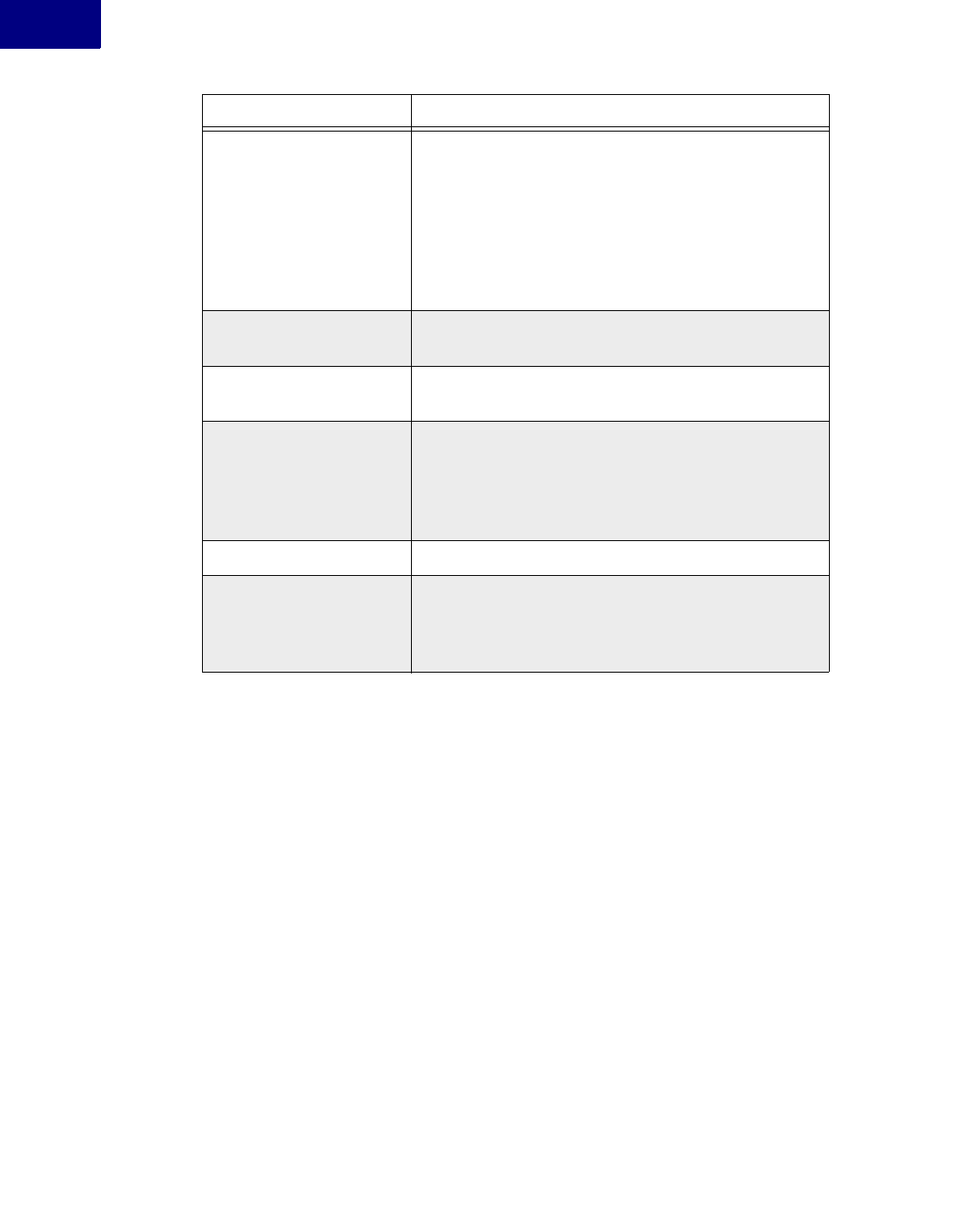
Layout Fundamentals
Page items
176
A frame can contain at most one child in its hierarchy (IHierarchy). The child boss object is the
content of the frame. The child may be one of the following boss classes: kSplineItemBoss,
kGroupItemBoss, a graphics page item (e.g., kImageItem, kSVGItem, kPlacedPDFItemBoss,
and kEPSItem), a text page item (kMultiColumnItemBoss), or another content page item.
NOTE:The child object can be a group (kGroupItemBoss). To put several objects in a frame,
first group them.
A frame can be owned by one parent using its hierarchy (IHierarchy) interface. Typically, a
frame on a spread is owned by a spread layer (kSpreadLayerBoss), but a frame also can be
owned by other boss objects. For example, a frame that is part of a group is owned by the
kGroupItemBoss, a frame nested inside a frame is owned by a kSplineItemBoss, and an inline
frame is owned by a kInlineBoss.
Paths and frames are created programmatically using IPathUtils. For sample code, see SDKLay-
outHelper::CreateRectangleGraphic, SDKLayoutHelper::CreateSplineGraphic, SDKLay-
outHelper::CreateRectangleFrame, and SDKLayoutHelper::CreateTextFrame. The frame for a
page item can be created when a file is placed.
For sample code that can be used to examine the content of a frame, see Example 18. For sam-
ple code that can be used to discover frames in a document, see Example 19 and Example 20.
IHierarchy Connects the boss object into a tree that represents a
layout hierarchy. Provides mechanism to find parent and
child objects and interfaces. The objects the boss object
contains are the children of the IHierarchy interface. The
object in which the boss object is contained is its parent.
The child-index order in IHierarchy defines the z-order
of child objects. See “Parent and child objects and
IHierarchy” on page 155.
IPageItemAdornmentList A list of adornments that the page item object may have.
For details, see the “Graphics Fundamentals” chapter.
IPathGeometry Stores the points in the boss object’s path in inner
coordinates. The interface can describe multiple paths.
IScrapItem Creates commands that can copy and paste the boss
object. Different types of page items need to transfer
different kinds of data. For example, a path transfers a
description of its shape, and a text frame transfers text as
well as a description of the frame.
IShape Draws the boss object.
ITransform Represents any transformation applied to the boss object
(e.g., translation, rotation, scaling) in a transformation
matrix (PMMatrix). See “Transformation and
ITransform” on page 191.
Interface Note
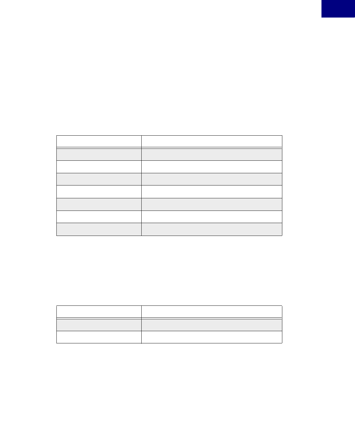
Layout Fundamentals 177
Layout Fundamentals
Page items
The SnpInspectLayoutModel code snippet can inspect the spreads in a document and their
associated hierarchy, including their frames. To create a textual report, run the snippet in Snip-
petRunner. For sample code, see SnpInspectLayoutModel::ReportDocumentByHierarchy.
Graphic page items
A graphic page item represents a picture. Table 27 shows the boss classes that represent graph-
ics-format files that are imported and placed in a document. Graphic page items are contained
in frames (kSplineItemBoss) when placed on a spread. For more information, see “Graphic
Page Items” in the “Graphics Fundamentals” chapter.
TABLE 27 Graphic page-item boss classes
Text page items
A text page item represents a visual container that displays text. Table 28 shows the boss classes
that participate in the display of text. Text page items are contained in frames (kSplineItem-
Boss) when placed on a spread. For more information, see the “Text Fundamentals” chapter.
TABLE 28 Text page-item boss classes
Boss class Represented graphics format
kDCSItemBoss DCS
kEPSItem EPS
kImageItem Raster image formats (e.g., TIFF, JPEG, PNG, GIF)
kPICTItem PICT
kPlacedPDFItemBoss PDF
kSVGItem SVG
kWMFItem WMF
Boss class Represents
kFrameItemBoss Column
kMultiColumnItemBoss Column controller
Layout Fundamentals
Page items
178
Interactive page items
An interactive page item represents an item in a multimedia format. Table 29 shows the boss
classes that represent interactive page items. Interactive page items are contained in frames
(kSplineItemBoss) when placed on a spread.
TABLE 29 Interactive item boss classes
Groups
Grouping is a way to combine two or more objects so they can be worked with as a single
object. The objects in a group move, transform, copy, and paste as a unit. Grouping boss objects
results in the creation of a kGroupItemBoss to represent the group. The grouped objects
become the children of the group in its IHierarchy interface. Unlike a frame, a group does not
have a path that clips its content when drawn. The geometry and shape of the group is defined
by the objects in the group.
The object diagram in Figure 60 shows an example of how the internal representation changes
when two objects are grouped.
Boss class Represents
kMoviePageItemBoss Movie
kPushButtonItemBoss Button
kSoundPageItemBoss Audio
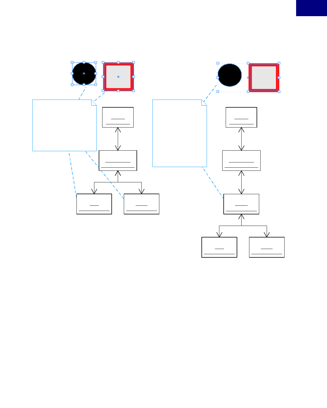
Layout Fundamentals 179
Layout Fundamentals
Page items
FIGURE 60 Grouping of two kSplineItemBoss path objects
A group must contain at least two children in its IHierarchy. The only boss classes that can be
part of a group are kSplineItemBoss and kGroupItemBoss. In other words, only frames, paths,
and groups can be grouped. To put a graphic page item—such as an image (kImageItem)—into
a group, that item must be contained in a frame (kSplineItemBoss).
There is no signature interface on kGroupItemBoss that identifies a boss object uniquely as a
group. To test for a group, call IPageItemTypeUtils::IsGroup.
Objects are grouped using the kGroupCmdBoss command and ungrouped using the kUn-
groupCmdBoss command. Selected objects can be grouped and ungrouped using IGroupItem-
Suite.
Abstract page items and kPageItemBoss
The kPageItemBoss boss class is the abstract base class for page items. The kDrawablePage-
ItemBoss boss class is the abstract base class for page items that can be selected and edited on a
«boss»
spread1
: kSpreadBoss
«boss»
layer1-content
: kSpreadLayerBoss
«boss»
group1
: kGroupItemBoss
«boss»
circle
: kSplineItemBoss
IHierarchy
Above:
The circle and square
combined in agroup.
Below:
The new group boss
object, kGroupItemBoss,
and the changed
IHierarchy associations.
The circle and square
become children of the
group.
«boss»
square
: kSplineItemBoss
«boss»
spread1
: kSpreadBoss
«boss»
layer1-content
: kSpreadLayerBoss
«boss»
circle
: kSplineItemBoss
«boss»
square
: kSplineItemBoss
IHierarchy
Above:
The original circle and
square paths.
Below:
The IHierarchy associations
between the boss objects that
represent these paths on a
spread.
Before grouping After grouping

Layout Fundamentals
Guides and grids
180
spread. These abstract classes are subclassed and implemented by the set of page items that can
be created and edited on a spread, such as kSplineItemBoss, kGroupItemBoss, and kImageItem.
In general terms, a page item is any object that can participate in a hierarchy (IHierarchy). This
perspective is valid and includes spreads (kSpreadBoss) and pages (kPageBoss) as page items.
There is an alternative, more advanced definition of page item. To see all subclasses of kPage-
ItemBoss, see the API reference documentation for kPageItemBoss.
Guides and grids
Guides and grids are used to align and position objects. Some, like ruler guides, can be dynam-
ically created and changed. Others, like the margins of a page, are static properties of an object.
Ruler guides
A ruler guide is a horizontal or vertical guide line used to align and position objects on a
spread. Ruler guides are represented by the kGuideItemBoss boss class and are a type of page
item. Ruler guides are represented as page items, because ruler guides share many behaviors of
page items. Ruler guides can be associated with a layer, moved around on a spread, and copied
and pasted. The signature interface that identifies a boss object as a ruler guide is IGuideData,
which stores the properties of the guide. There are two kinds of ruler guides: page guides span
a specific page, and pasteboard guides span the pasteboard of a spread.
Ruler guides are kept in their own spread layer (kSpreadLayerBoss) in the spread hierarchy
(IHierarchy), so ruler guides can be drawn in front or back of other content or completely hid-
den. For a description of this organization, see “Layers” on page 161.
Ruler guides are created by the kNewGuideCmdBoss command. They can be changed by the
kMoveGuideRelativeCmdBoss, kMoveGuideAbsoluteCmdBoss, kSetGuideViewThresholdC-
mdBoss, kChangeGuideColorCmdBoss, kSetGuidesBackCmdBoss, kSetGuideOrientationC-
mdBoss, and kSetGuideFitToPageCmdBoss commands.
Guide preferences are stored in the IGuidePrefs interface on the document workspace (kDoc-
WorkspaceBoss). A distinct set of preferences that are inherited by new documents is main-
tained on the session workspace (kWorkspaceBoss). The kSetGuidePrefsCmdBoss command is
used to manipulate these preferences.
Margin and column guides
Margin guides represent the margins of a page. Column guides represent columns on a page.
Each page (kPageBoss) has its own margin and column settings stored in IMargins and ICol-
umns interfaces, respectively.
The margins for a page can be changed using kSetPageMarginsCmdBoss. The columns for a
page can be changed using kSetPageColumnsCmdBoss and kSetColumnGutterCmdBoss.

Layout Fundamentals 181
Layout Fundamentals
Guides and grids
Document grid
The document grid is a grid (like graph paper) across a spread, on which page items can be
aligned.
Grid preferences are stored in the IGridPrefs interface on the document workspace (kDoc-
WorkspaceBoss). A distinct set of preferences that are inherited by new documents is main-
tained on the session workspace (kWorkspaceBoss). The kSetGridPrefsCmdBoss command is
used to manipulate these preferences.
Baseline grid
The baseline grid is used to align the baseline of text across multiple columns on a spread.
Baseline-grid preferences are stored in the IBaselineGridPrefs interface on a story (kTextStory-
Boss), the document workspace (kDocWorkspaceBoss), and the session workspace (kWork-
spaceBoss). When a new story is created, the preferences in the document workspace are
inherited by the story. New documents inherit preferences from the session workspace. The
kSetBaselineGridPrefsCmdBoss command is used to manipulate these preferences. Each story
can override its baseline-grid preference settings.
Snap
If snapping is on, when the user drags an object within a certain distance of a guide or grid, the
object’s position is snapped to the guide or grid. If snapping is off, an object can be moved
freely. Snapping is implemented by interaction between three main objects:
zThe object on which other objects are being moved around; for example, a spread (kSpread-
Boss). This object supports snapping by instantiating the ISnapTo interface.
zAn object that can be snapped onto, like a guide or grid. The snapping is performed by a
snap-to service. The signature interface is ISnapToService, and the ServiceID is kSnap-
ToS er vice.
zThe object handling the user interaction. Normally, this is a tracker created by a tool of
some sort. See the API reference documentation for the ITracker interface.
Snap preferences are stored in the ISnapToPrefs interface on the document workspace (kDoc-
WorkspaceBoss). A distinct set of preferences that are inherited by new documents is main-
tained on the session workspace (kWorkspaceBoss). The kSetSnapToPrefsCmdBoss command
is used to manipulate these preferences.
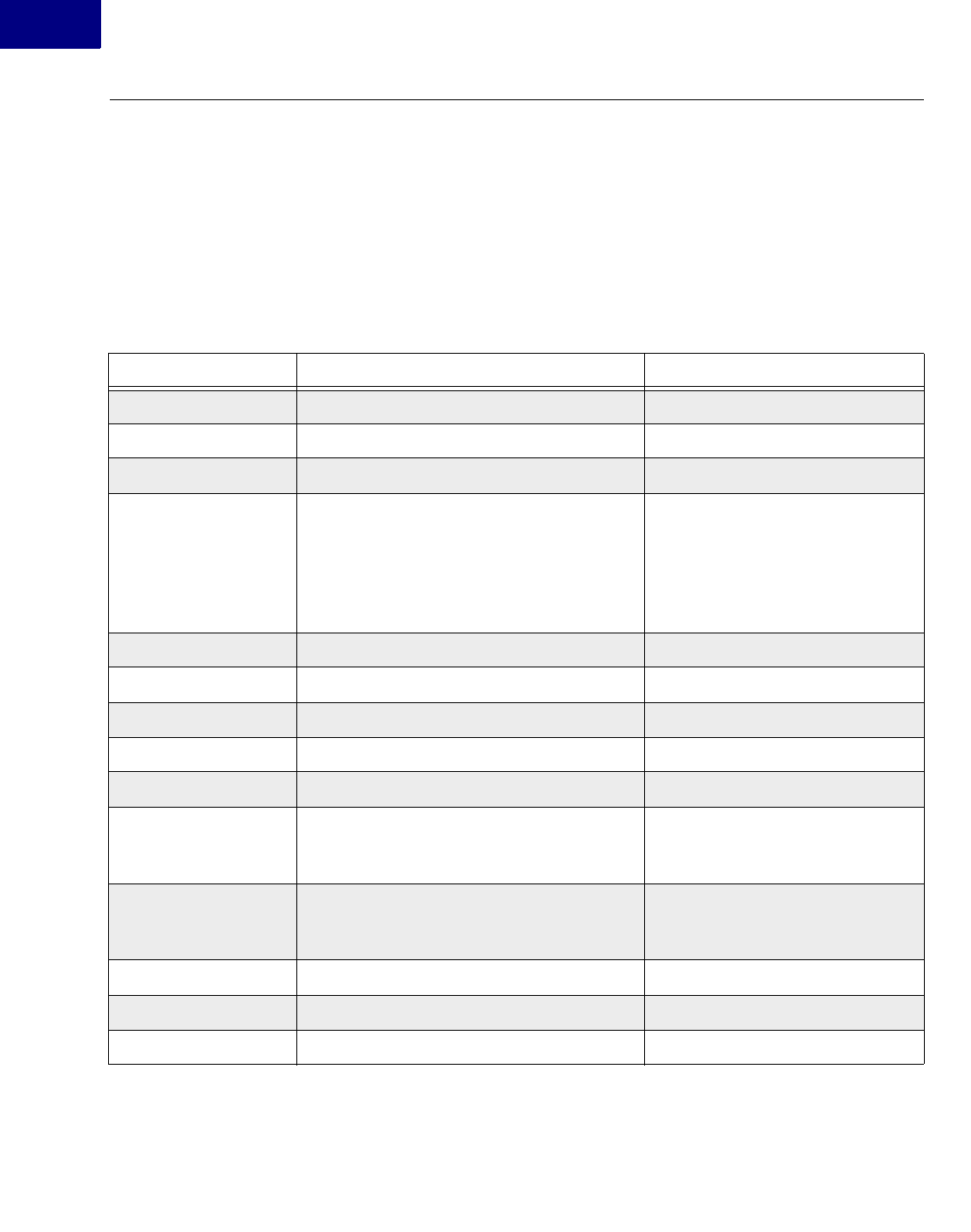
Layout Fundamentals
Layout-related preferences
182
Layout-related preferences
The interfaces that store the major preference settings related to layout are summarized in
Table 30. Unless noted otherwise, each interface is present on the session workspace (kWork-
spaceBoss) and document workspace (kDocWorkspaceBoss). kWorkspaceBoss contains the
settings inherited when a new document is created. kDocWorkspaceBoss contains the settings
for the document. For more information about the interfaces and commands listed, see the API
reference documentation.
TABLE 30 Layout-related preferences
Interface Note Mutator
IAutoTextFramePrefs kSetAutoTextFramePrefsCmdBoss
IBaselineGridPrefs kSetBaselineGridPrefsCmdBoss
IColumnPrefs kSetColumnPrefsCmdBoss
IDocStyleListMgr Stores a list of InDesign document presets
(kDocStyleBoss). The Save Preset button in the
New Document dialog box saves entries into
this list. Present only on the session workspace
(kWorkspaceBoss).
kDocAddStyleCmdBoss,
kDocDeleteStyleCmdBoss,
kDocEditStyleCmdBoss,
kDocSetStyleNameCmdBoss,
kSaveDocumentStyleDataCmdBoss,
kDocSetDefaultStyleNameCmdBoss
IFrameEdgePrefs kSetFrameEdgePrefsCmdBoss
IGridPrefs kSetGridPrefsCmdBoss
IGuidePrefs kSetGuidePrefsCmdBoss
ILayerPrefs kSetLayerPrefsCmdBoss
IMarginPrefs kSetMarginPrefsCmdBoss
IPageLayoutPrefs Stores the default shuffling behavior
preferences for pages (between spreads) when
pages are added, deleted, or moved.
kSetPageLayoutPrefsCmdBoss
IPageSetupPrefs Stores the default set-up of an InDesign
document (number of pages, page size,
orientation, etc.).
kSetPageSetupPrefsCmdBoss
IPasteboardPrefs kSetPasteboardPrefsCmdBoss
ISnapToPrefs kSetSnapToPrefsCmdBoss
IZeroPointPrefs kSetZeroPointPrefCmdBoss

Layout Fundamentals 183
Layout Fundamentals
Coordinate systems
Coordinate systems
This section describes the coordinate spaces used by layout, and the arrangement of the layout-
related interfaces that store geometric data.
Coordinate systems define the geometrical location of objects in a document and the canvas on
which drawing occurs. Coordinate systems determine the position, orientation, and size of the
text, graphics, and images that appear on a page.
InDesign uses two-dimensional graphics. Position is defined in terms of coordinates on a two-
dimensional surface (a Cartesian plane). A coordinate is a pair of real numbers, x and y, that
locate a point horizontally and vertically within a two-dimensional coordinate space. A coordi-
nate space is determined by the location of the origin, the orientation of the x and y axes, and
the lengths of the units along each axis.
InDesign defines several coordinate spaces in which the coordinates that specify objects are
interpreted. The following sections describe these spaces and the relationships among them.
Transformations among coordinate spaces are defined by transformation matrices, which can
specify any linear mapping of two-dimensional coordinates, including translation, scaling,
rotation, reflection, and skewing. Matrices are used to move from one coordinate space to
another.
The approach used by InDesign aligns with PostScript and Adobe PDF. for more information,
see the Adobe PDF Reference (http://partners.adobe.com/public/devel-
oper/pdf/index_reference.html). Computer Graphics Principles and Practice (Foley, James D., et
al., Addison-Wesley, 1990) also provides useful theory on two-dimensional geometrical trans-
formation.
Transformation matrices
A transformation matrix specifies the relationship between two coordinate spaces as a linear
mapping of one coordinate space to another. By modifying a transformation matrix, objects
can be scaled, rotated, translated, or transformed in other ways.
In InDesign, a transformation matrix is specified by six numbers in the form of a PMMatrix. In
its most general form, this PMMatrix is denoted [a b c d e f]; it can represent any linear trans-
formation from one coordinate system to another.
The PMMatrix patterns that specify the most common transformations are as follows:
zTranslation is specified by [1 0 0 1 Tx Ty], where Tx and Ty are the distances to translate the
origin of the coordinate system in the horizontal and vertical dimensions, respectively.
zScaling is specified by [Sx 0 0 Sy 0 0]. This scales the coordinates so one unit in the horizon-
tal and vertical dimensions of the new coordinate system is the same size as Sx and Sy units,
respectively, in the previous coordinate system.
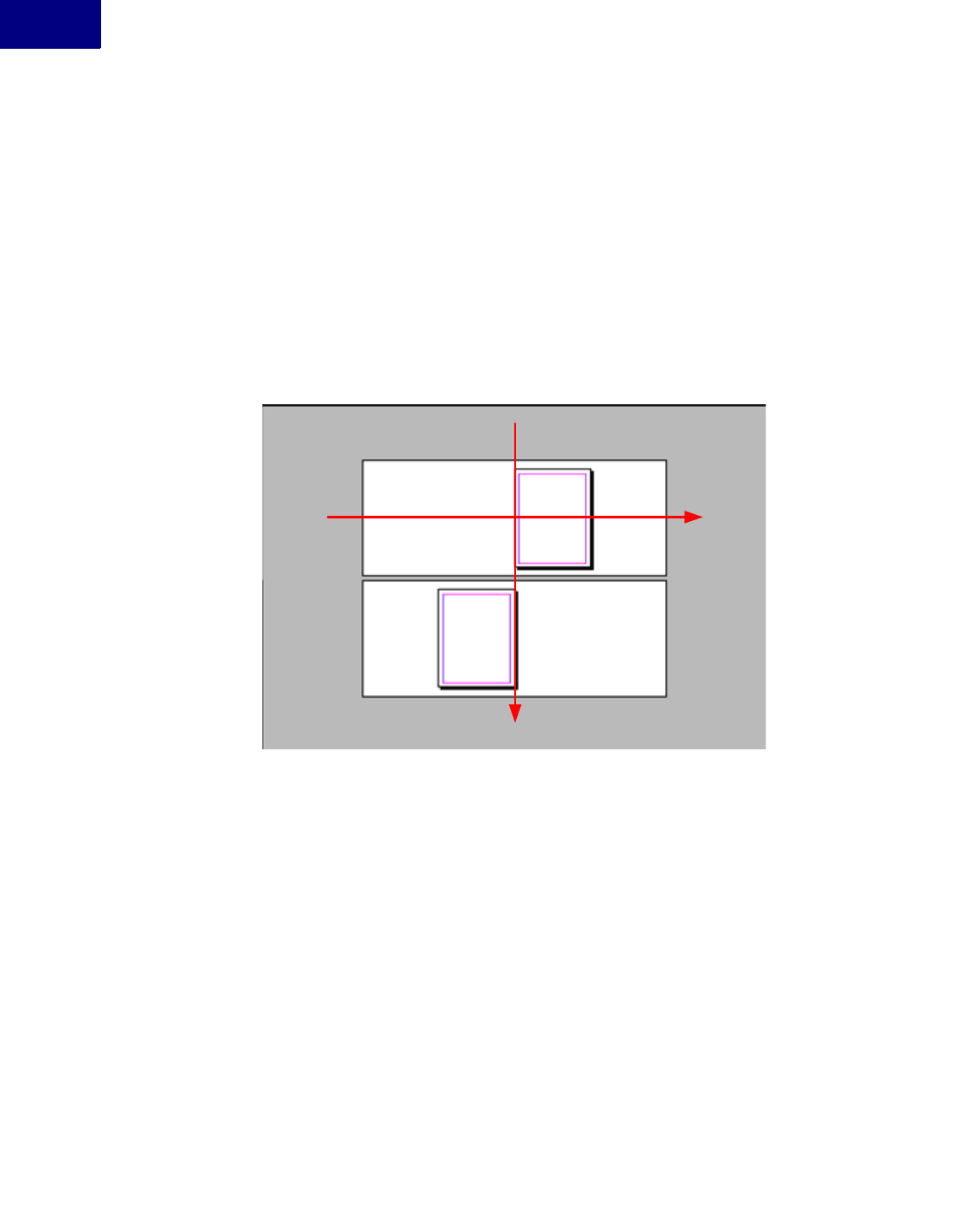
Layout Fundamentals
Coordinate systems
184
zRotation is specified by [cos(A) sin(A) -sin(A) cos(A) 0 0], which has the effect of rotating
the coordinate system axes by an angle A counterclockwise.
zSkew is specified by [1 tan(A) tan(B) 1 0 0], which skews the x axis by angle A and the y axis
by angle B.
Pasteboard coordinate space
The pasteboard coordinate space is the global coordinate system that encloses all objects in a
document, as shown in Figure 61.
FIGURE 61 Pasteboard coordinate space
All objects in a layout can have their coordinates expressed in pasteboard coordinates. The ori-
gin is the center of the first spread. The x axis increases from left to right; the y axis decreases
from up to down. The length along each axis is measured in the PostScript unit of points. For
example, Figure 62 shows the pasteboard coordinates of the bounding boxes for the spreads
and pages in a basic document. The figure shows the pasteboard coordinates of the bounding
box of each spread and page in a facing-page document with letter-sized pages of width 612
points and height 792 points. All values shown are in PostScript points.
Xpasteboard
Ypasteboard
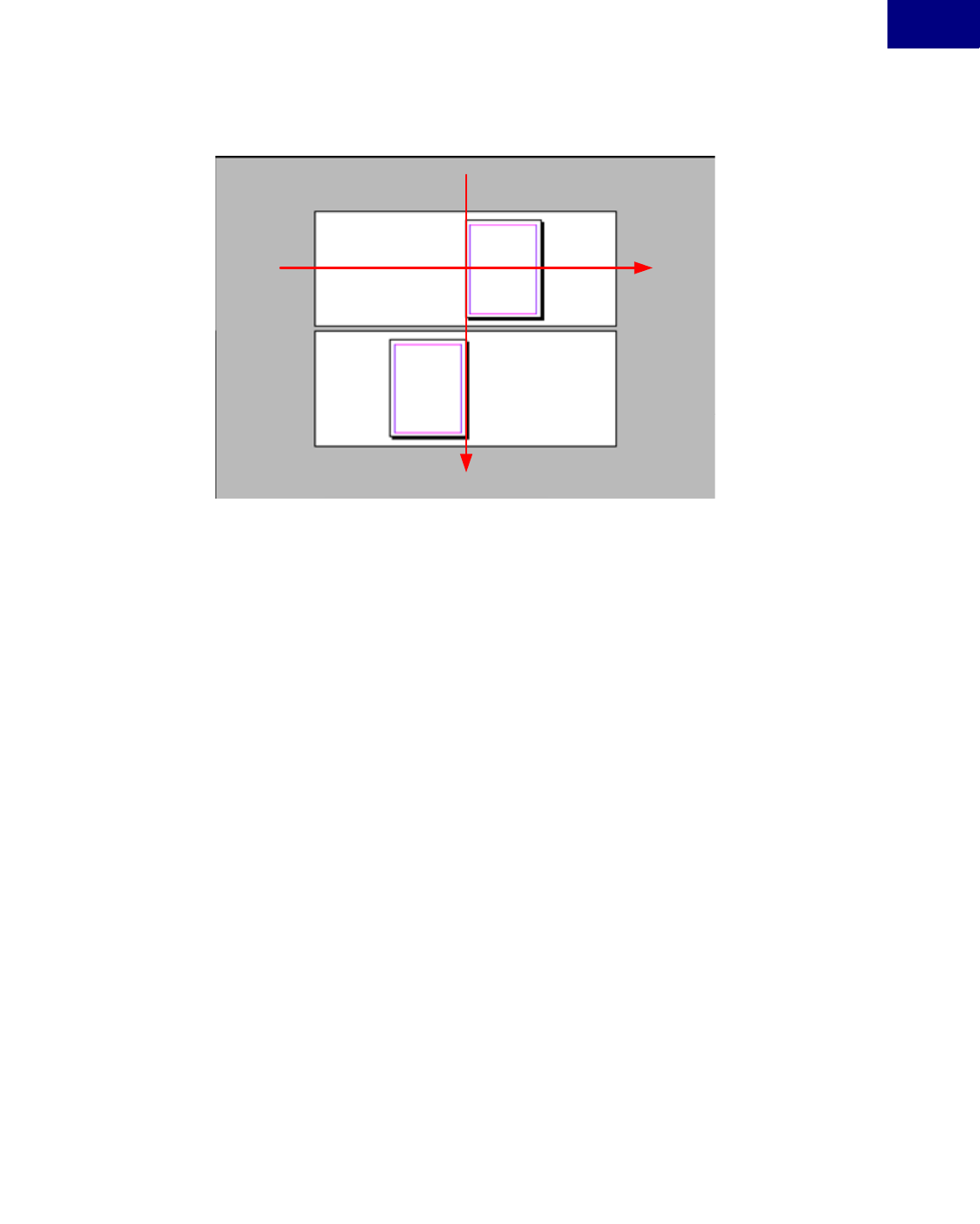
Layout Fundamentals 185
Layout Fundamentals
Coordinate systems
FIGURE 62 Pasteboard coordinates of spread and page bounding boxes
The unit in which all measurements are stored in a document is the PostScript point. The unit
in which measurements are shown in the user interface is controlled by a preference (see “Mea-
surement units” on page 192).
Inner coordinate space and parent coordinate space
Each page item has its own coordinate system, known as its inner coordinate space. Each page
item has an associated parent coordinate space. The inner coordinate space and its relationship
with its parent coordinate space are defined by three interfaces:
zIHierarchy defines the parent association. The parent coordinate space is the first ancestor
boss object on IHierarchy that has an IGeometry interface. This may not be the boss object’s
immediate parent. For example, many objects are owned by a spread layer (kSpreadLayer-
Boss). Spread layers are not geometrical objects; they do not have an IGeometry interface;
therefore, the parent coordinate space for a boss object owned by a spread layer is the spread
(kSpreadBoss).
zIGeometry defines the bounding box, which implies the origin and orientation of the x and
y axes.
zITransform defines the transformation matrix that maps from the inner coordinate space to
the parent coordinate space.
Figure 63 shows a square containing a rectangular child page item as an example of a parent
page item. The inner coordinate system of the parent as defined by its IGeometry interface is
shown.
-1224,-468
1224,468
-1224,504
1224,1440
Xpasteboard
Ypasteboard
1224,-468
-1224,468
1224,504
-1224,1440
0,-396
612,396
612,-396
0,396
-612,576
0,1368
0,576
-612,1368
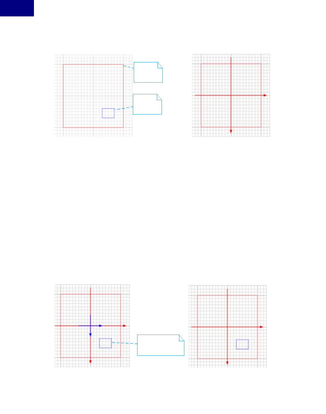
Layout Fundamentals
Coordinate systems
186
FIGURE 63 Parent coordinates
In the A part of Figure 63, the parent is a square (kSplineItemBoss), 200 points wide. The child
is a rectangle (kSplineItemBoss), 40 points wide and 30 points high. The square is used as a
frame for the rectangle; this association is defined by the IHierarchy interface. The objects are
shown on a document grid with a grid line every 100 points and subdivisions every 10 points.
In the B part of Figure 63, the bounding box stored by the square’s IGeometry interface defines
the origin of the object’s inner coordinate space and the orientation of its x and y axes. The
coordinates of the bounding box of the square in its inner coordinate space are shown, together
with the x and y axes these coordinates imply. For a parent object, this is known as the parent
coordinate space.
The IGeometry and ITransform interfaces on the child object express the coordinate system
relationship to the parent. There is more than one way to arrange this data. In Figure 64, the
child’s coordinate system (the rectangle) is coincident with the parent’s coordinate system (the
square).
FIGURE 64 Coincident inner coordinates and parent coordinates
A. Parent and child page items B. Inner coordinates of parent
xparent
yparent
-100,-100 100,-100
-100,100 100,100
Parent
Child
C. Inner coordinates of child
xparent
yparent
30,40 70,40
30,70 70,70
xchild
ychild
D. After transformation of C to parent
xparent
yparent
30,40 70,40
30,70 70,70
Transformation matrix
[1 0 0 1 0 0]
(the identity matrix)
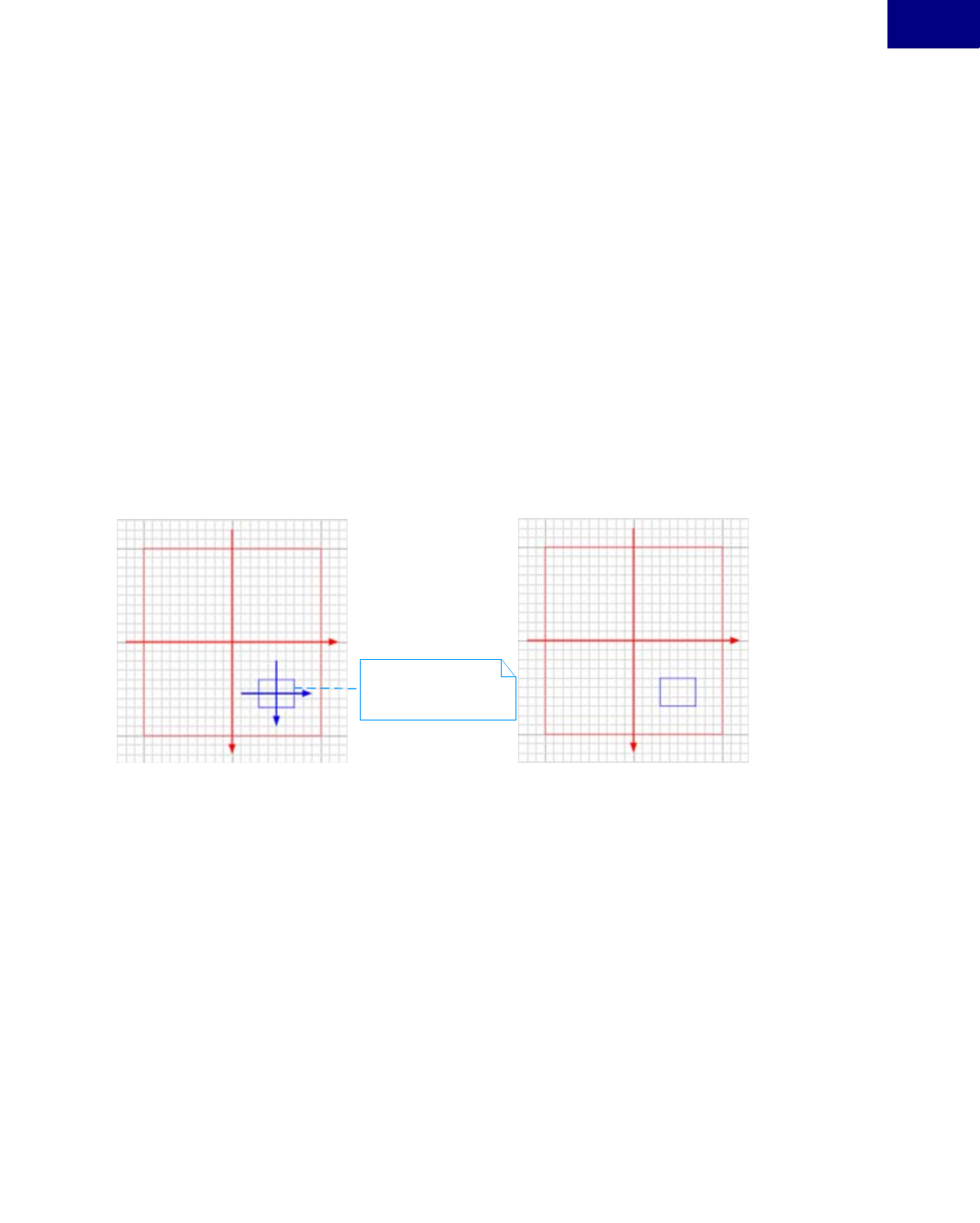
Layout Fundamentals 187
Layout Fundamentals
Coordinate systems
In the C part of Figure 64, the rectangle has its own inner coordinate space. The bounding box
stored by the rectangle’s IGeometry interface is shown. This bounding box defines the origin of
the object’s inner coordinate space and the orientation of its x and y axes, labeled xchild and
ychild. The transformation matrix defined by the rectangle’s ITransform interface maps the
rectangle’s inner coordinate space (the child coordinate space) into the square’s coordinate
space (the parent coordinate space). In the arrangement shown, the parent and child coordi-
nate systems are coincident; therefore, the transformation matrix in ITransform is the identity
matrix.
In the D part of Figure 64, when the bounding box of the child (the rectangle) is transformed
using the child’s transformation matrix to the parent coordinate space (the square), the coordi-
nates are expressed in the parent coordinate space as shown.
In the arrangement shown in Figure 65, the child coordinate space is not coincident with its
parent coordinate space. Instead, the origin of the rectangle’s coordinate space is located at the
rectangle’s center.
FIGURE 65 Non-coincident Inner coordinates and parent coordinates
In the E part of Figure 65, the origin of the rectangle’s inner coordinate space is located at its
center. The coordinates of the bounding box defined by the rectangle’s IGeometry interface, are
shown together with the x and y axes these coordinates imply, labeled xchild and ychild. The
transformation matrix defined by the child’s ITransform interface specifies the translation
required to map to the parent coordinate space.
In the F part of Figure 65, when the bounding box of the child (the rectangle) is transformed
using the child’s transformation matrix to the parent coordinate space (the square), the coordi-
nates are expressed in the parent coordinate space as shown.
A comparison of Figure 64 and Figure 65 shows that, after transformation, the bounding box of
the rectangle in its parent’s coordinate space is the same.
NOTE:To transform any point from inner coordinate space to any other coordinate space, the
page item’s transformation matrix (ITransform) must be applied. For utilities to help
with the calculations, see TransformUtils.
E. Inner coordinates of child
xparent
yparent
-20,-15 20,-15
-20,15 20,15
xchild
ychild
F. After transformation of E to parent
xparent
yparent
30,40 70,40
30,70 70,70
Transformation matrix
[1 0 0 1 50 55]
(translation Tx=50, Ty=55)
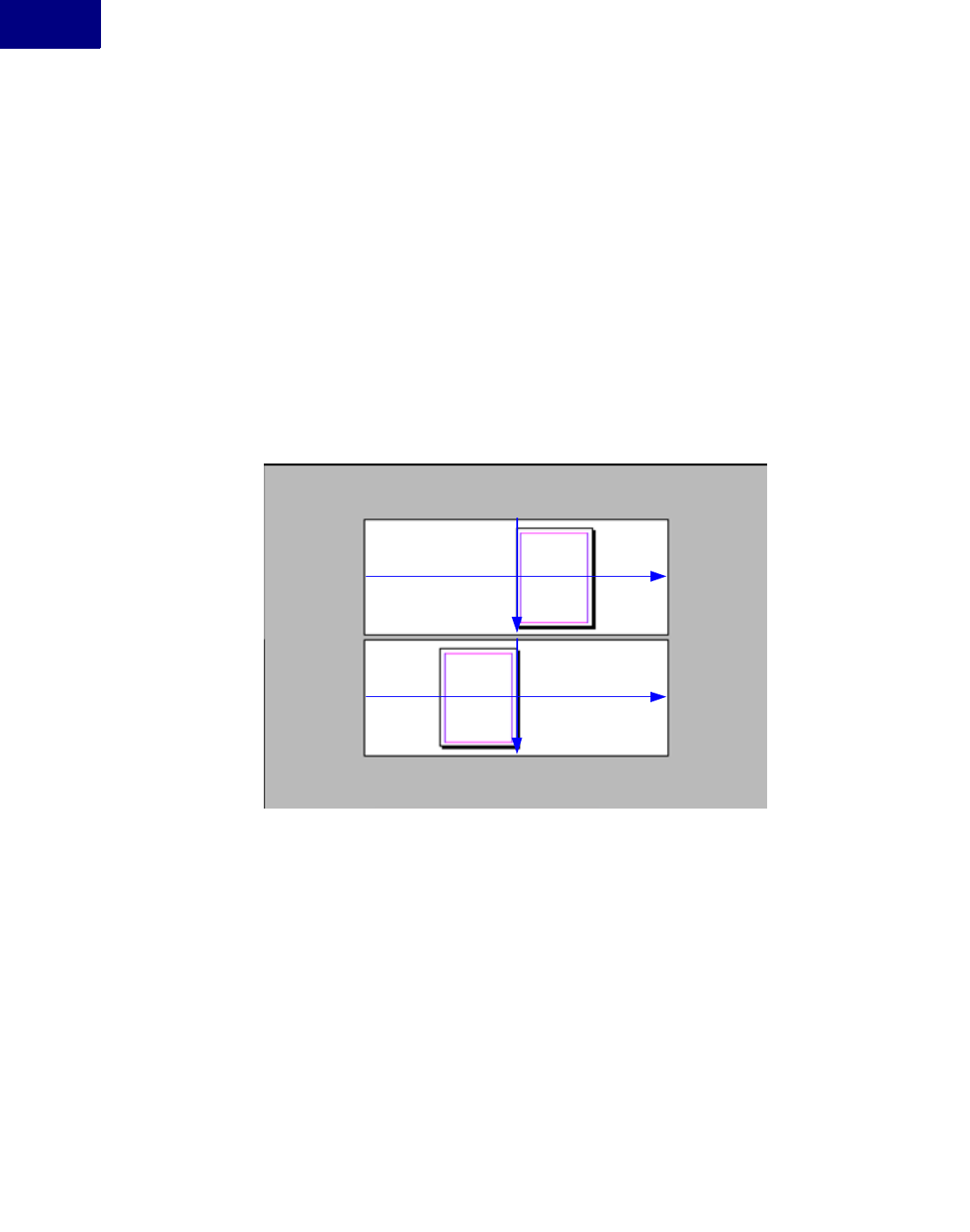
Layout Fundamentals
Coordinate systems
188
Tools like the Rectangle tool use a tracker (CPathCreationTracker) to create a path (kSpli-
neItemBoss) whose coordinate system is coincident with their parent coordinate system as
shown in Figure 64. Facades like IPathUtils often are used to create a path (kSplineItemBoss)
arranged as shown in Figure 65.
Spread coordinate space
Spread coordinate space is the coordinate system of a spread (kSpreadBoss). Each spread has its
own coordinate space, also known as the inner coordinate space for a spread. The origin of the
spread coordinate space is the center of the spread. The parent coordinate space is pasteboard
coordinate space. Unlike other page items, the parent of a spread is not defined by IHierarchy;
the parent of a spread is fixed as the document (kDocBoss). See Figure 66.
FIGURE 66 Spread coordinate space
In spread coordinates, the bounding box of each spread is identical. It is returned by IGeome-
try::GetStrokeBoundingBox. The spread’s (kSpreadBoss) implementation of IGeometry deter-
mines the bounding box using the IPasteboard interface. The spread’s ITransform interface
stores a transformation matrix that translates the spread coordinate space to pasteboard coor-
dinate space. This matrix is a translation matrix [1 0 0 1 0 Ty], where Ty specifies the spread’s
offset in the vertical dimension.
Figure 67 shows the spread coordinates of the bounding box of each spread and page in a fac-
ing-page document with letter-sized pages 612 points wide and 792 points high.
Xspread1
Yspread1
Xspread2
Yspread2
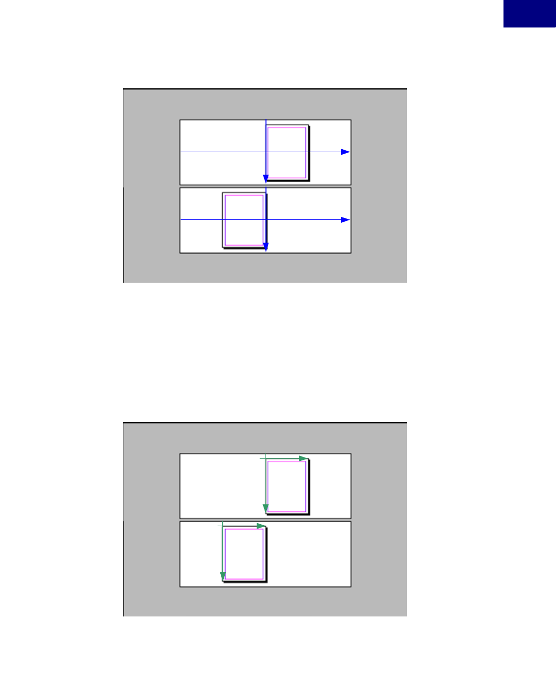
Layout Fundamentals 189
Layout Fundamentals
Coordinate systems
FIGURE 67 Spread coordinates of spread and page bounding boxes in a basic document
Page coordinate space
Each page has its own coordinate space, also known as the inner coordinate space for a page
(kPageBoss). The parent coordinate space for page coordinate space is spread coordinate space.
The origin of page coordinate space is the top-left corner of the page. See Figure 68.
FIGURE 68 Page coordinate space
-1224,-468
1224,468
-1224,-468
1224,468
Xspread1
Yspread1
1224,-468
-1224,468
1224,-468
-1224,468
Xspread2
Yspread2
0,-396
612,396
612,-396
0,396
-612,-396
0,396
0,-396
-612,396
Xpage1
Ypage1
Xpage2
Ypage2
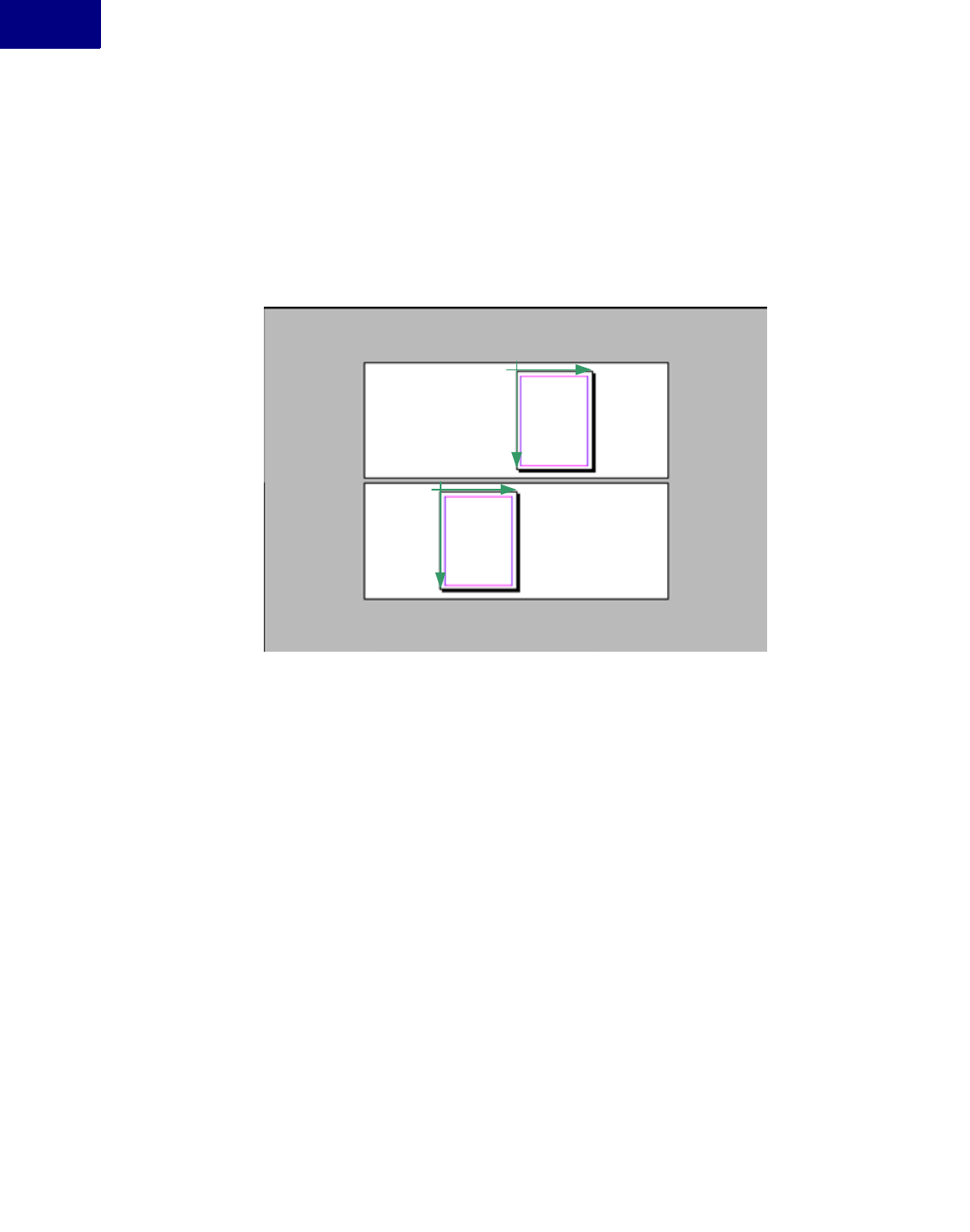
Layout Fundamentals
Coordinate systems
190
In page coordinates, the bounding box of each page (kPageBoss) in a document is identical. It
is returned by IGeometry::GetStrokeBoundingBox. The page’s ITransform interface stores a
transformation matrix that translates the page coordinate space to spread coordinate space.
Figure 69 shows the page coordinates of the bounding box of each page in a facing-page docu-
ment with letter-sized pages 612 points wide and 792 points high.
FIGURE 69 Page coordinates of page bounding boxes in a basic document
Page-item coordinate space
Each page item has its own coordinate space, known as its inner coordinate space. The page
item’s bounding box is stored in interface IGeometry. The geometrical data stored in IGeome-
try and other data interfaces specific to the page item type are in the inner coordinate space of
the page item. For example, the points that describe a path in interface IPathGeometry are
stored in the inner coordinate space. A transformation matrix that transforms from inner coor-
dinate space to parent coordinate space is stored in the ITransform interface. The parent coor-
dinate system is defined by the IHierarchy interface.
For more information, see “Inner coordinate space and parent coordinate space” on page 185.
Bounding box and IGeometry
The bounding box (IGeometry::GetStrokeBoundingBox) is the smallest rectangle (PMRect)
that encloses a geometric page item:
zThe bounding box of an image (kImageItem) encloses the pixels that define its raster data.
zThe bounding box of a group (kGroupItemBoss) is the union of the bounding boxes of the
objects in the group.
0,0
612,792
Xpage1
Ypage1
612,0
0,792
Xpage2
Ypage2
0,0
612,792
612,0
0,792

Layout Fundamentals 191
Layout Fundamentals
Coordinate systems
zThe bounding box of a path (kSplineItemBoss) encloses all points in the path (IPathGeom-
etry) and includes the effect of the properties that control how the path is stroked, such as
stroke weight and corner style.
zThe bounding box of a page (kPageBoss) or spread (kSpreadBoss) encloses the objects that
lie on it.
For illustrations, see “Spread coordinate space” on page 188 and “Page coordinate space” on
page 189.
A page item stores the data that describes its geometry in its inner coordinate space. For exam-
ple, the bounding box in IGeometry and the points that describe a path in interface IPathGe-
ometry are stored in inner coordinate space (see “Inner coordinate space and parent coordinate
space” on page 185). This stored data is independent of any transformation that may be in
effect. Transformation (e.g., scaling and rotation) is described by the page item’s ITransform
interface.
The IGeometry::GetPathBoundingBox method gives the path bounding box, the bounding
box of a path excluding the effects of adornments.
NOTE:Paths (kSplineItemBoss) have path bounding boxes; page items of other types may not.
The IShape::GetPaintedBBox method gives the painted bounding box, the bounding box of the
page item including the effect of adornments.
Table 31 lists some useful geometry-related APIs.
TABLE 31 Useful geometry-related APIs
Transformation and ITransform
A page item has its own coordinate space, its inner coordinate space. (See “Inner coordinate
space and parent coordinate space” on page 185.) The coordinates of the points that describe
the page item are stored in this inner coordinate space. A transformation matrix (PMMatrix)
that maps from inner coordinate space to the parent coordinate space is stored in the ITrans-
form interface. Scaling, rotation, and other transformations that may be in effect are repre-
sented in this matrix. Points in inner coordinate space are mapped to the parent coordinate
space using the matrix obtained from ITransform::GetInnerToParentMatrix. There are useful
functions in TransformUtils.h that help to get the transform matrix (InnerToParentMatrix) and
perform transform calculations. For details, see the API reference documentation.
For example, to calculate the bounding box of a page item in its parent coordinate space, get the
bounding box from the page item (IGeometry::GetStrokeBoundingBox), and apply its trans-
formation matrix (ITransform::GetInnerToParentMatrix). The calculated bounding box takes
into account all scaling, rotation, and other transformations that are applied. The parent could
API Note
IGeometry Stores the bounding box of a page item.
IGeometryFacade Positions and resizes page items.
IGeometrySuite Positions and resizes objects currently selected.

Layout Fundamentals
Coordinate systems
192
be a group (kGroupItemBoss), frame (kSplineItemBoss), spread (kSpreadBoss), or other kind
of page item.
A transformation matrix can be inverted (PMMatrix::Invert) to create a matrix that performs
the inverse transformation. For example, if you have a matrix that transforms from inner coor-
dinate space to parent coordinate space (InnerToParentMatrix), the inverse matrix can be used
to transform points from parent coordinate space to inner coordinate space.
The matrix that transforms from inner coordinate space to pasteboard coordinate space is
returned by ITransform::GetInnerToRootMatrix. To access it, we recommend you use a helper
function, InnerToPasteboardMatrix. This code walks up the hierarchy (IHierarchy) and con-
catenates the transformation matrix (ITransform::GetInnerToParentMatrix) of each page item.
The end result is a matrix that maps from the inner coordinates of the page item it started from
into pasteboard coordinates.
To compare the coordinates of two or more page items, the coordinates first should be trans-
formed to a common coordinate space. The pasteboard coordinate space often is used for this
purpose.
When creating a path (kSplineItemBoss), it often is useful to specify its position in pasteboard
coordinates. You often position new page items relative to an existing boss object, like a spread,
page, or frame. For example, to determine a position relative to a page, you first need the IGe-
ometry interface of the page (kPageBoss); then you can call InnerToPasteboard to transform
points on that page into pasteboard coordinates. When you have the points described in paste-
board coordinates, you can use IPathUtils to create the path. Alternately, you can describe the
points in the parent coordinate space as shown by the sample code in SnpCreateFrame and
SDKLayoutHelper.
Table 32 lists some useful transformation-related APIs.
TABLE 32 Useful transformation-related APIs
Measurement units
The internal unit of measurement used by the application is PostScript points. All measure-
ments in a document are stored in the internal measurement unit as PMReal values. The user
can choose to work in other measurement units, like centimeters, inches, picas, or ciceros. The
user’s preferred measurement unit is converted to and from the standard internal unit (Post-
Script points) at the boundary between the user interface and the document model.
API Note
ITransform Stores the page item’s transformation matrix.
TransformUtils Utility functions for transform calculations. See methods like
InnerToPasteboard and PasteboardToInner in
TransformUtils.h.
ITransformFacade Scale, rotate, skew, or move page items.
ITransformSuite Scale, rotate, skew, or move objects currently selected.

Layout Fundamentals 193
Layout Fundamentals
Coordinate systems
Unit-of-measure service
The conversion from a specific measurement unit to the internal measurement unit is per-
formed by a unit-of-measure service.
A unit-of-measure service is a boss class that aggregates the IUnitOfMeasure and
IK2ServiceProvider interfaces. IUnitOfMeasure is the interface responsible for converting
between the unit of measure and the internal unit of measure. IUnitOfMeasure also has meth-
ods for producing a formatted string representation from units and tokenizing a string to pro-
duce a formatted number from the string. The measurement units supported by the application
can be extended. For more information, see “Custom unit-of-measure service” on page 203.
Common unit-of-measure services include kPointsBoss, kInchesBoss, kInchesDecimalBoss,
kMillimetersBoss, kPicasBoss, kCicerosBoss, and kCentimetersBoss.
Measurement-unit preferences
The user’s preferred measurement unit is stored in the IUnitOfMeasureSettings interface. The
session workspace (kWorkspaceBoss) stores the measurement-unit preferences inherited by
new documents. The document workspace (kDocWorkspaceBoss) stores the document’s pref-
erences. The user changes these preferences by choosing Edit > Preferences > Units & Incre-
ments and using the resulting dialog box. To change these preferences programmatically, use
the kSetMeasureUnitsCmdBoss command.
Figure 70 is a class diagram of IUnitOfMeasureSettings.
FIGURE 70 Measurement-unit preferences (IUnitOfMeasureSettings)
The measurement system, IMeasurementSystem, is an interface aggregated on kSessionBoss
that is used to help locate and use a unit-of-measure service. Unit-of-measure services can be
referred to by either their ClassID or an index the measurement system assigns. The index
assigned by the measurement system is used while referring to a unit of measure in memory,
but this index should be converted to a ClassID when writing or reading from a stream.
Figure 71 is a class diagram of IMeasurementSystem.
FIGURE 71 Measurement system (IMeasurementSystem)
kWorkspaceBoss
IUnitOfMeasureSettings
kDocWorkspaceBoss
IUnitOfMeasureSettings
kSessionBoss
IMeasurementSystem

Layout Fundamentals
The layout presentation and view
194
Geometrical data types
The core geometrical data types are as follows:
zPMPoint — (x, y) coordinates expressed as real (PMReal) numbers.
zPMRect — Rectangle represented by points that designate the top-left and bottom-right
corners.
zPMMatrix — Two-dimensional transformation matrix that maps from one coordinate
space to another.
The core geometrical-collection data types are as follows:
zPMPointList
zPMRectCollection
zPMMatrixCollection
The layout presentation and view
This section describes the objects that present the layout to the user and allow the content to be
edited interactively.
Layout presentation
The layout of a document is presented within a layout presentation. A document has a layout
presentation (kLayoutPresentationBoss) for each view of the publication’s layout. A layout pre-
sentation is implemented by kLayoutPresentationBoss and its associated widgets. The pages
and spreads are presented by the layout view (kLayoutWidgetBoss). The general arrangement
is shown in the class diagram in Figure 72.
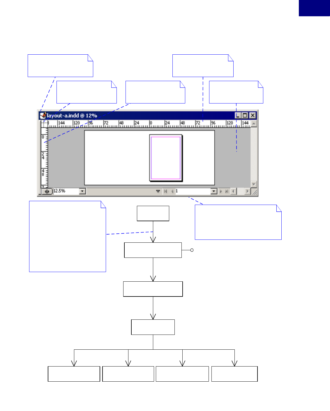
Layout Fundamentals 195
Layout Fundamentals
The layout presentation and view
FIGURE 72 Layout presentation
«boss»
kDocBoss
«boss»
kLayoutPresentationBoss
«boss»
kLayoutPanelBoss
«boss»
kLayoutGenericPanelBoss
«boss»
kLayoutWidgetBoss
«boss»
kVertRulerWidgetBoss
«boss»
kHorzRulerWidgetBoss
«boss»
kZeroPointWidgetBoss
1IPresentationList0..*
1
IPanelControlData1
1IPanelControlData1
0..* 0..1
1
0..1
1
IPanelControlData1
IDocumentPresentation
Layout presentation
kLayoutPresentationBoss
Zero point
kZeroPointWidgetBoss
Vertical ruler
kVertRulerWidgetBoss
Horizontal ruler
kHorzRulerWidgetBoss
Layout view
kLayoutWidgetBoss
The other widgets provided by the
layout presentation have not been
modelled; e.g., the widgets that
control the magnification of the
view, page navigation, and scrolling.
A document can be presented
in one or more presentation
views. Layout presentations
present pages and spreads.
Note: Presentations returned
by IPresentationList are not
always layout presentations.
Other types of presentation
may be open on a document;
e.g., story windows.
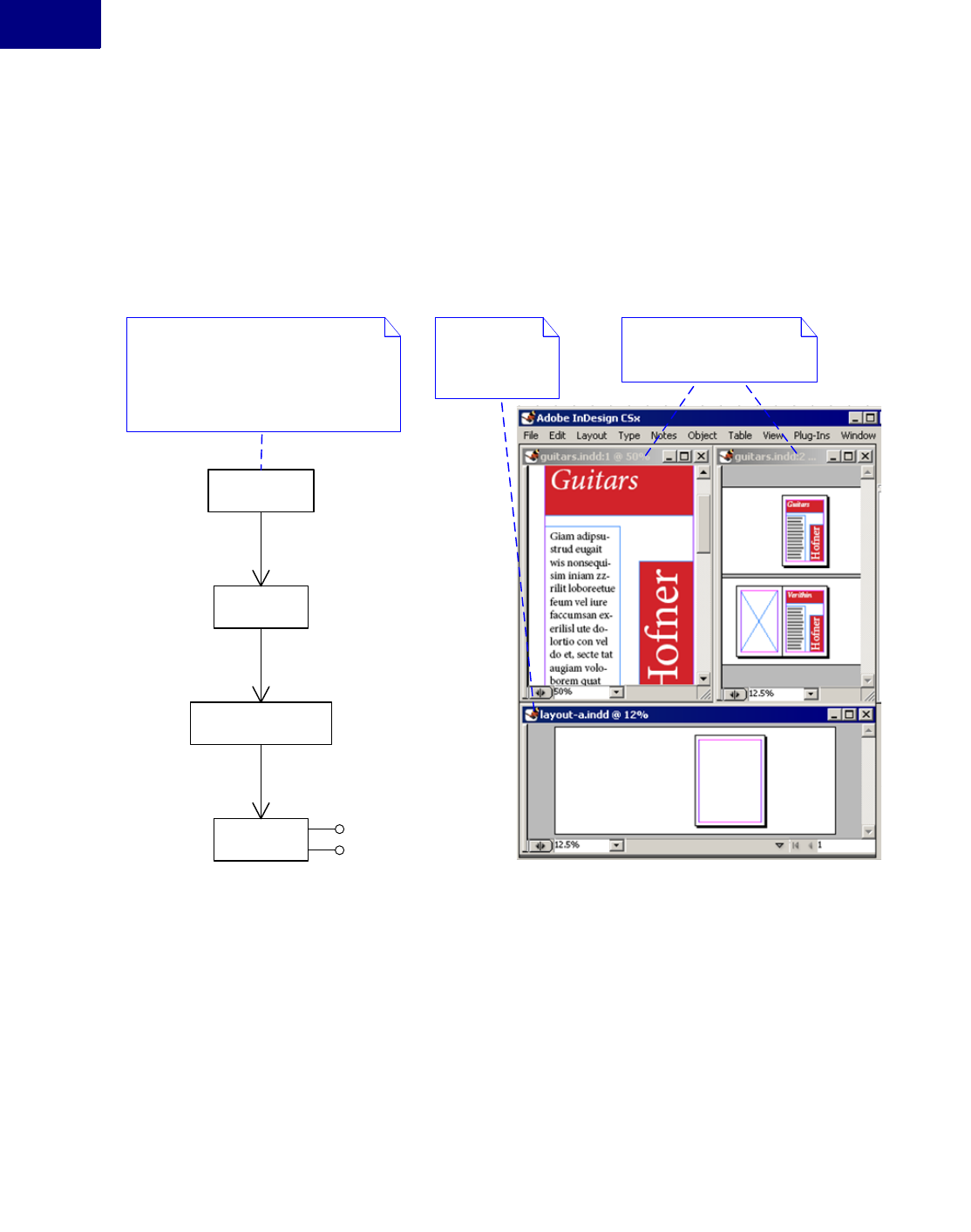
Layout Fundamentals
The layout presentation and view
196
The application may have several layout presentations open at once, each displaying different
documents or different views of the same document, as shown in the class diagram in
Figure 73. The figure shows a screenshot of the application with three layout presentations
open. The boss classes and interfaces required to discover the documents open under the cur-
rent session also are also shown. Each document knows the windows that are open on it by
means of the IPresentationList interface on kDocBoss.
FIGURE 73 Multiple layout presentations
A document does not need to have a presentation view. Documents that do not have a presen-
tation view can be edited programmatically. Sometimes this called editing a headless docu-
ment.
Layout view
The layout view presents the layout of a document and is represented by the kLayoutWidget-
Boss boss class. Documents can contain a variety of objects, like spreads, pages, frames, text,
and graphics. The document stores these objects; the layout view displays them and allows
them to be edited interactively. The layout view is part of a layout presentation (see Figure 72).
«boss»
kSessionBoss
«boss»
kAppBoss
«boss»
kDocumentListBoss
«boss»
kDocBoss
1
ISession::QueryApplication1
1
IApplication::QueryDocumentList1
1
IDocumentList::GetNthDoc0..*
Layout presentations
showing different views
of the same document.
Layout
presentation
of a second
document
To discover the layout presentations
that are open, iterate the
IPresentationList interface on
each document. Documents
opened by the current session
can be discovered as shown.
IPresentationList
IDocument
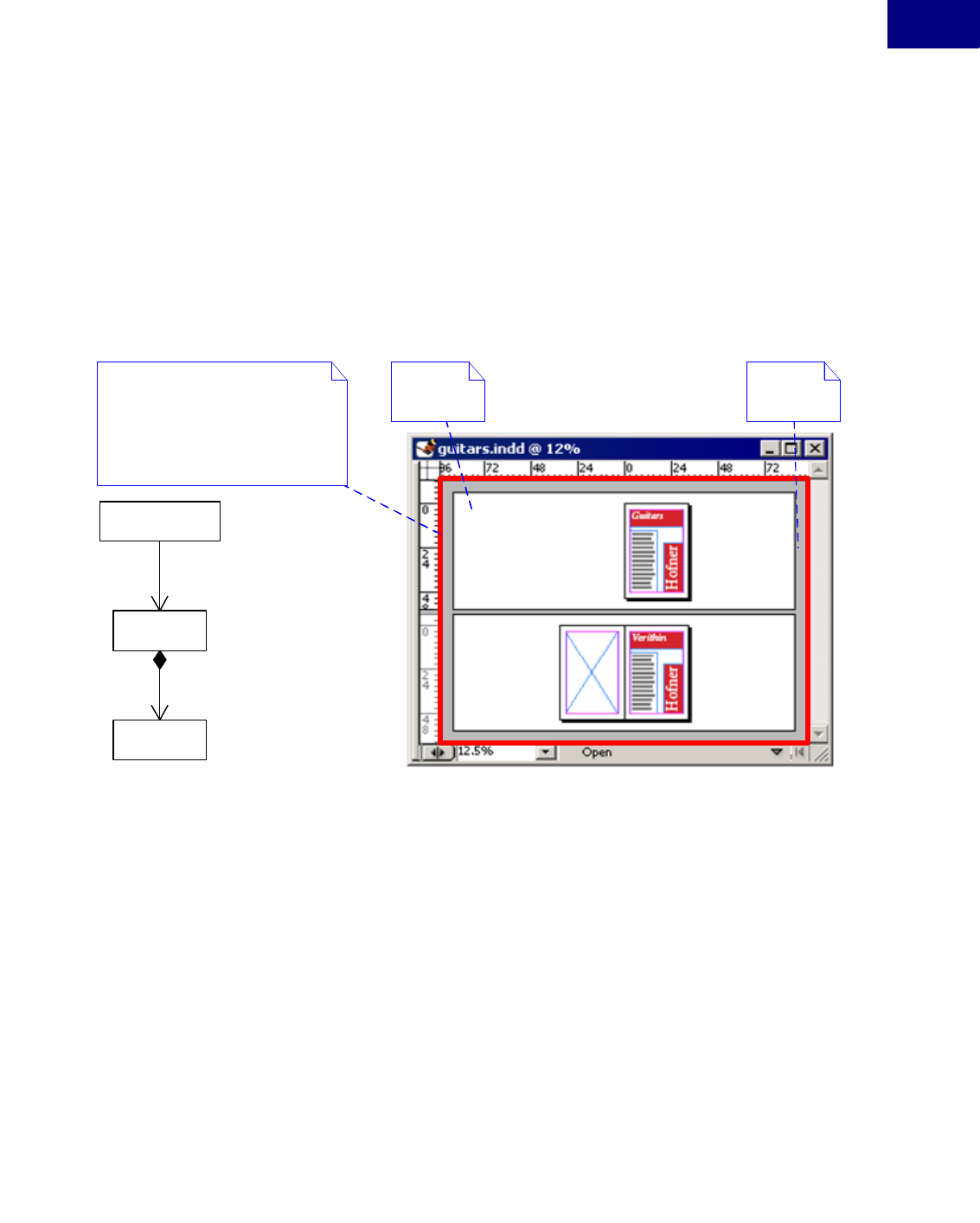
Layout Fundamentals 197
Layout Fundamentals
The layout presentation and view
Only the visible part of a document is presented in layout view. The layout presentation con-
trols which part of a document is visible using magnification and page navigation widgets, etc.
Other panels, like the Pages and Navigation panels, also may adjust the view.
The layout view sometimes is known as the layout widget.
The layout view causes the visible objects to draw by discovering the spreads that are visible
and calling each spread to draw. The general arrangement is shown in the class diagram in
Figure 74.
FIGURE 74 Layout view and its associated document
The layout view uses its ILayoutControlData interface to get to its associated document. The
ISpreadList interface on the document provides access to any particular spread. The IHierarchy
interface can be used to access children of the spread. For reasons of efficiency, navigation of
the layout hierarchy during a window draw is somewhat more selective than shown in
Figure 74. Portions of spreads that are not visible in a window are not called to draw. The layout
view also discriminates between redrawing an entire window and drawing only the region that
changed. These two strategies mean page items are not guaranteed to be called to draw during
every window draw.
Current spread and active layer
The current spread is the spread (kSpreadBoss) targeted for edit operations. Normally, new
page items created by the tools that handle user actions in the layout view are created in the
current spread. Each view (kLayoutWidgetBoss) stores a reference to its current spread in ILay-
outControlData::GetSpreadRef. The current spread is set in the user interface by clicking on a
«boss»
kLayoutWidgetBoss
«boss»
kDocBoss
«boss»
kSpreadBoss
1
ISpreadList1..*
1
ILayoutControlData1
The layout widget draws the area
within the red highlight. Interface
ILayoutControlData provides access
to the document being presented.
Additionally ILayoutControlData provides
access to the spread, page,
and layer being edited.
Spread Floor

Layout Fundamentals
The layout presentation and view
198
spread in the layout view. The tool that handles the click processes the kSetSpreadCmdBoss
command. A reference to the current spread of the view that most recently edited the docu-
ment (kDocBoss) is stored in the IPersistUIDData interface with PMIID
IID_ICURRENTSPREAD.
The active layer is the layer targeted for edit operations. New page items created by the tools
that handle user actions in the layout view are assigned to the active layer. Each view (kLayout-
WidgetBoss) has a reference to its active layer (kDocumentLayerBoss) given by ILayoutCon-
trolData::GetActiveDocLayerUID. The active layer is set in the user interface by clicking on a
layer in the Layers panel, which then processes the kSetActiveLayerCmdBoss command. A ref-
erence to the active layer of the view that most recently edited the document can be found by
calling ILayerUtils::QueryDocumentActiveLayer.
When creating a page item programmatically, choose its parent boss object. Normally, this is a
spread layer (kSpreadLayerBoss). If you have access to a layout view, ILayoutControl-
Data::QueryActiveLayer returns the hierarchy of the spread layer to use.
NOTE:The current page is not stored anywhere in a document (in contrast, the current spread
and active layer are stored as described above). ILayoutControlData::GetPage returns
the visible page. This is calculated by means of ILayoutUIUtils::GetVisiblePageUID, by
finding the page whose center point is closest to the center of the layout view.
Layout-presentation and layout-view coordinate spaces
The relationship between layout-presentation coordinates and layout-view coordinates is rela-
tively static and is described by the respective IControlView implementations. When the user
hides the rulers, the layout-view coordinate space is coincident with the layout-presentation
coordinate space. The relationship between pasteboard coordinates and layout-view coordi-
nates is stored in the layout view’s IControlView interface. The layout view’s IControl-
View::GetContentToWindowTransform method returns the transform that maps from
pasteboard coordinates to layout-view coordinates. See Figure 75.
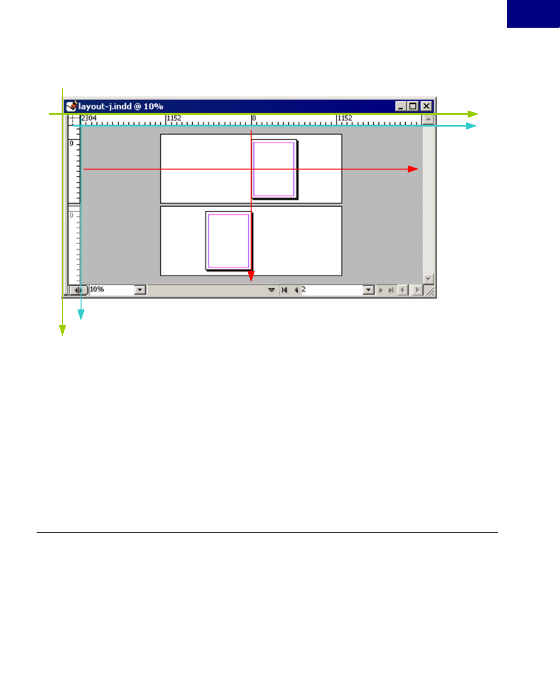
Layout Fundamentals 199
Layout Fundamentals
Key client APIs
FIGURE 75 Layout-presentation and layout-view coordinate spaces
As the user zooms and scrolls the view, the relationship between layout-view coordinates and
pasteboard coordinates changes. The layout view (kLayoutWidgetBoss) has an IPanorama
interface to track the scroll and zoom changes. The relationship between the pasteboard and
layout-view coordinate systems is stored in the layout view’s IControlView interface. The lay-
out view’s IControlView::GetContentToWindowTransform method returns the transform that
maps from pasteboard coordinates to window coordinates. By using the known coordinate
relationships in the layout hierarchy, a region described in a page item’s inner coordinate space
can be mapped to the window coordinates.
Global-screen coordinates can be converted to pasteboard coordinates using ILayoutU-
IUtils::ComputePasteboardPoint. Event handlers often return mouse locations in global-screen
coordinates.
Key client APIs
This section summarizes the APIs provided to manipulate layout-related objects. For more
information, see the API reference documentation.
The layout view (kLayoutWidgetBoss) displays a document for editing and provides some
important data interfaces, summarized in Table 33. The layout view can be obtained in several
ways, one of which is calling ILayoutUIUtils::QueryFrontLayoutData.
Y layout-presentation
X layout-
presentation
Y layout-widget
X layout-
widget
Xpasteboard
Ypasteboard
Layout Fundamentals
Key client APIs
200
TABLE 33 Layout user-interface APIs
Table 34 summarizes the suite interfaces that manipulate layout-related objects that are
selected. To obtain a suite, client code can query a selection manager interface (ISelectionMan-
ager) for the suite of interest. If the suite is available, its interface is returned; otherwise, a nil
pointer is returned. For details of how to obtain the selection manager, see the “Selection” chap-
ter of Learning the Adobe InDesign CS4 Architecture. Given a selection manager, you can call
suite methods using code that follows this pattern:
InterfacePtr<IGeometrySuite> suite(selectionManager,UseDefaultIID());
if (suite) suite->MethodName();
TABLE 34 Layout suites
API Note
ILayoutControlData Data interface that refers to the document being viewed
and the spread, page, and layer currently selected
ILayoutControlViewHelper Helper routines for performing page item hit-testing
API Description
IAlignAndDistributeSuite Aligns and distributes objects that are selected.
IArrangeSuite Brings forward, sends backward, or performs other z-
order-related operations on objects that are selected.
IFrameContentSuite Content-fitting operations and frame conversion
operations on objects that are selected.
IGeometrySuite Positions and resizes objects that are selected.
IGroupItemSuite Groups and ungroups objects that are selected.
IGuideDataSuite Manipulates the properties of guides that are selected.
ILayerSuite Manipulates document layers.
ILayoutHitTestSuite Hit-tests objects that are selected.
ILayoutSelectionSuite Sets the page items that are selected.
IMasterPageSuite Manipulates master page item overrides.
IPageItemLockSuite Locks or unlocks objects that are selected.
IPathOperationSuite Performs path operations of selected page items.
IPathSelectionSuite Performs path selections.
IReferencePointSuite Manipulates reference point.
ITransformSuite Scales, rotates, skews, or moves objects that are currently
selected.
Layout Fundamentals 201
Layout Fundamentals
Key client APIs
There are many command boss classes related to layout, as summarized in “Commands that
manipulate page items” on page 204. When possible, try to avoid to avoid processing low-level
commands when possible; instead, look for a facade or utility, to see if there is a method that
serves your purpose on one of these interfaces. Facades encapsulate parameterizing and pro-
cessing the low-level commands. For example, to add an item to a page-item hierarchy, you
could process kAddToHierarchyCmdBoss, but instead you should use IHierar-
chyUtils::AddToHierarchy, which provides a ready-made facade.
The facades and utilities related to layout are listed in Table 35 and Table 36. These interfaces
are aggregated on kUtilsBoss. The Utils smart pointer class makes it straightforward to acquire
and call methods on these interfaces. You can call their methods by writing code that follows
this pattern:
Utils<IPathUtils>()->MethodName(...)
TABLE 35 Layout facades and utilities
API Description
IGeometryFacade Positions and resizes page items.
ITransformFacade Scales, rotates, skews, or moves page items.
IPathUtils Creates and works with paths (kSplineItemBoss).
IFrameContentUtils Helps work with text or graphic-frame content.
IHierarchyUtils Adds and removes page items from a hierarchy
(IHierarchy).
IImageUtils Helper functions to get image information.
ILayoutUIUtils Helper functions related to the layout user interface. Most of
these are related to the active or front document.
ILayoutUtils Helper functions related to layout. Most of these are related
to pages or the page-item hierarchy.
IMasterSpreadUtils Helper functions for master spreads and master page items.
IPageItemUtils Page-item helper functions, like cache and change
notifications.
IPageItemTypeUtils Helps determine the type of a page item (e.g., path, frame,
and image).
IPasteboardUtils Helps determine the spread by location or gets the location
of page items.
IPathInfoUtils Helps get path information.
IPathPointUtils Stores path points during path-point transformation.
IPathUtils Creates and manipulates path page items.
IRefPointUtils Utility interface for functions that compute reference points.

Layout Fundamentals
Extension patterns
202
TABLE 36 Layout helper classes
Extension patterns
This section summarizes the mechanisms a plug-in can use to extend the layout subsystem.
New-page-item responder
A new-page-item responder lets a plug-in receive notification when a new page item (e.g.,
frame, path, group, or image) is created by kNewPageItemCmdBoss. For the complete list of
page item types, see “Page items” on page 173.
A new-page-item responder often is used to detect the creation of a specific type of page item.
For example, to detect the creation of a graphic frame, implement a new-page-item responder
that gets a reference to the new page item (INewPISignalData::GetPageItem) and then checks
whether it is a graphic frame (IPageItemTypeUtils::IsGraphicFrame).
Another common use of a new-page-item responder is initializing a custom data interface on a
page item from defaults.
Consider the case where you defined a custom data interface and added this data interface to
the document workspace (kDocWorkspaceBoss) to store default data. You also added this data
interface to kDrawablePageItemBoss to store the settings per page item, and you want the
default data to be inherited when new page items are created. In this case, you can implement a
new-page-item responder that copies the data from defaults into the new page item. For an
implementation of this pattern, see BasicPersistInterface.
ITransformUpdateUtils Helps determine values relative to the zero point.
IValidateGeometryUtils Validates transformation data.
API Note
Arranger Brings to front, sends to back, and performs other z-order-
related operations. See ArrangeUtils.h.
TransformUtils Utility functions for transform calculations. See methods in
TransformUtils.h, such as such as InnerToPasteboard and
PasteboardToInner.
API Description

Layout Fundamentals 203
Layout Fundamentals
Extension patterns
A new-page-item responder is a service provider characterized by the following:
zThe responder interface IResponder — The implementation can expect to be able to acquire
an INewPISignalData interface from the signal manager (ISignalMgr) that it is passed.
zThe signature interface IK2ServiceProvider — The ServiceID must be of type kNewPISignal-
ResponderService. You can re-use the API implementation kNewPISignalRespServiceImpl
for this.
Sample code
BasicPersistInterface copies data from defaults into new page items.
Custom page item
A custom page item lets a plug-in extend the set of objects that can be laid out on a page. A cus-
tom page item gives the plug-in control of how the object is drawn and how it behaves when
selected and manipulated by the user. A common use of a custom page item is adding support
for a graphics format for which the application provides no native support. In this case, the cus-
tom page item also requires a custom import provider (IImportProvider), to allow files of that
graphics format to be placed. Some custom page items also may require custom tools to be
implemented to create and manipulate the custom page items.
Implementing a custom page item can be complex. Before beginning development of a custom
page item, evaluate whether another type of extension pattern—like a page-item adornment or
draw-event handler—might meet your needs. If you do need to implement a custom page item,
study the subclasses of kPageItemBoss to see if there is an existing page item that is a close
match to what you need. (See kPageItemBoss in the API reference documentation.) If an exist-
ing page item comes close to meeting your needs, use this boss class as the base class for your
implementation. The examples provided in the SDK show only the basics of what is involved.
Sample code
zBasicShape specializes kSplineItemBoss and shows how to implement the interfaces
involved in drawing a page item.
zCandleChart specializes kSplineItemBoss to show how to draw some data as a chart.
Custom unit-of-measure service
Plug-ins can extend the set of measurement units supported by the application by defining a
unit-of-measure service. The following steps outline what a plug-in needs to do to make a cus-
tom unit of measure appear in the Edit > Preferences > Units & Increments dialog box:
1. Define a unit-of-measure service boss class.
2. Implement the C++ code for IUnitOfMeasure, using CUnitOfMeasure as a base.

Layout Fundamentals
Commands that manipulate page items
204
3. Implement IK2ServiceProvider using the default kUnitOfMeasureService provided by the
API, which registers the custom unit with the application-measurement system.
4. Include a ruler-resource description of the ODFRez type RulerDataType for your custom
unit of measure in the .fr resource file.
Rulers
Rulers are displayed by the ruler widgets (kHorzRulerWidgetBoss and kVertRulerWidgetBoss).
The presentation of the ruler is described by the data defined in the ODFRez resource type,
RulerDataType. This type describes the font, associated unit-of-measure service ClassID, and
tick-mark layout. For more details, see RulerType.fh.
Typically, a ruler is associated with a particular unit-of-measure service. The resource descrip-
tion for the ruler is in the same plug-in as the unit-of-measure service. The unit-of-measure
service returns the resource ID of its ruler description in its implementation of IUnitOfMea-
sure::GetRulerSpecRsrcSpec.
When a new view is created on a document, the preferred measurement unit is determined.
Then, the associated unit-of-measure service is queried for the resource ID of its ruler descrip-
tion. If one exists, that description is used to create a new ruler as part of the new view of the
document.
Sample code
CustomUnits creates a custom unit. In addition, it provides a resource description of how the
ruler tick markers are specified for the custom units. CstUniRuler.fr from the sample shows a
sample ruler resource.
Commands that manipulate page items
Page-item creation commands
TABLE 37 Commands that create page items
Command Description
kCreateMultiColumnItemCmdB
oss
Creates a new text frame.
kImportAndLoadPlaceGunCmd
Boss
Combination of kImportPIFromFileCmdBoss and kLoadPlaceGunCmdBoss.
kImportAndPlaceCmdBoss Combination of kImportPIFromFileCmdBoss and kPlacePICmdBoss.
Layout Fundamentals 205
Layout Fundamentals
Commands that manipulate page items
Page-item update commands
TABLE 38 Commands that add/remove a page item to/from a hierarchy
kImportPIFromFileCmdBoss First, this command imports a file. If what is imported is a story, a
multicolumn item is created. If what is imported is not in a graphic frame, a
new graphic frame is created and the imported file is put into the frame. The
UID of the new item is returned on the command’s item list.
kLoadPlaceGunCmdBoss Loads the item specified on the command’s item list into the place gun. Only
one item can be loaded by this command.
kNewPageItemCmdBoss Used to create a new page item. You will need to use this command only if you
are creating a custom page item. Do not use this command to create a page-
item type supplied by the API, a kSplineItemBoss, kImageItem, or
kMultiColumnItemBoss. Each page-item type provides a command to create
it. The newly created page item can be any simple page item that supports the
IGeometry interface. All attributes for the new page item are stored in the
INewPageItemCmdData interface. The UID of the new page item is returned
in the command’s item list. If the parent is supplied, the new page item is
added to the hierarchy.
kPlaceGraphicFrameCmdBoss Creates a graphic frame and places an image item into it. The item to be placed
can be passed through the command’s item list or placed from the place gun.
To use the place gun, set the usePlaceGunContents parameter on the
IPlacePIData interface to kTrue, and do not set the command's item list. When
passing the UID of the placed item using the command's item list, set the
usePlaceGunContents parameter to kFalse.
kPlaceItemInGraphicFrameCmd
Boss
Places a page item into an existing graphic frame. The page item can be passed
into the command’s item list, or it can be placed from the place gun. The UID
of the graphic frame is returned on the command’s item list.
kPlacePICmdBoss Places a page item. This command does not create a new page item. It
command takes an existing page item from the command’s item list or the
place gun, then places the page item into the page item hierarchy.
kReplaceCmdBoss Replaces one page item with another. Both the old page item and the new page
item are specified in the IReplaceCmdData interface.
Command Description
kAddToHierarchyCmdBoss Adds the page item in the command’s item list to the parent specified in the
IHierarchyCmdData interface. The index position for the page item also is
specified on the IHierarchyCmdData interface. For example, when a new
page item is created, it calls this command if the new item’s parent was
supplied.
kRemoveFromHierarchyCmdBoss Removes a page item from its parent when deleting a page item or detaching
the imported content from the imported frame.
Command Description
Layout Fundamentals
Commands that manipulate page items
206
TABLE 39 Commands that position page items
TABLE 40 Commands for content fitting
NOTE:Sometimes, after replace or paste operations, the graphic frame content (e.g., the placed
image, PDF, or EPS item) does not fit into the frame or is not at the position you want
inside the frame. Unfortunately, there is no graphic attribute or helper function that can
determine the fitting mode for a page item. You can compare the bounding boxes for
the content (for example, the image item) and the parent (the frame), to decide whether
Command Description
kAlignCmdBoss Aligns the page items in the command’s item list to the alignment type
specified in the IIntData interface. The command itself is a compound
command made up of a set of move-relative commands. Since the move
commands are undoable, the align command also is undoable.
kCenterItemsInViewCmdBoss Moves a set of page items so they appear centered in the current view. This
command is not undoable.
kFitPageItemInWindowCmdBoss Used to make the current selected page items fit in a window. This command
is not undoable.
kMoveToLayerCmdBoss Moves the page items specified on the command’s item list to the document
layer specified on the IUIDData interface. The page items appear in the same
z-order relative to each other as before in front of the new layer. This
command does not move the items that are children of a group or a graphic
frame, nor does it move standoffs.
kMoveToSpreadCmdBoss Like kMoveToLayerCmdBoss, except kMoveToSpreadCmdBoss moves the
page items from one spread to another.
Command Description
kAlignContentInFrameCmdBoss Aligns the contents in the command’s item list to the specified corners of
their respective frames. The corner, which is the same for all items, is
specified on the IAlignContentInFrameCmdData interface. This command
ignores frames without content. The command’s item list holds the UIDs of
the contents, not the UIDs of the frames that contain the contents. This
command sends out a notification that the content’s subject has changed.
kCenterContentInFrameCmdBoss Positions the contents at the centers of their respective frames. The content
UIDs are stored in the command’s item list.
kFitContentPropCmdBoss Takes a list of frame content and modifies the content size and
transformation to fit the frames and maintain the content’s proportions.
kFitFrameToContentCmdBoss Resizes each frame in the command’s item list to fit its content’s path
bounding box. This command takes a list of page items, filters out the empty
frame and non-graphical frame, and transforms the frame's path geometry.
The text frames are still in the command’s item list, even though they are not
affected by this and other commands.
Layout Fundamentals 207
Layout Fundamentals
Commands that manipulate page items
the content should be positioned in the center, fit into the frame, or aligned to the
corner of the frame using a content-fitting command. Because these commands are
one-time actions and not attributes, however, these commands must be executed again
if the page items are resized.
TABLE 41 Commands that designate the type of a frame
TABLE 42 Commands that copy and paste page items
Command Description
kConvertFrameToItemCmdBoss Takes a list of graphic frames and text frames with no content and converts
them to graphic items (unassigned), which are neither text frames nor
graphic frames. This command sets the graphic-frame attribute of the
specified page items to kFalse.
kConvertItemToFrameCmdBoss The opposite of kConvertFrameToItemCmdBoss.
kConvertItemToFrameCmdBoss sets the graphic-frame attribute of the
specified page items to kTrue and converts unassigned graphic items to
graphic frames. It command also converts empty text frames to empty
graphic frames.
kConvertItemToTextCmdBoss Converts unassigned page items and empty graphic frames to empty text
frames.
Command Description
kCopyCmdBoss A generic command for copying page items from one document to another. This
command applies to any page item that supports the IScrapItem interface.
kCopyImageItemCmdBoss Copies the specified image item to the specified target. Both the image item and
the target are specified in the ICopyCmdData interface.
kCopyPageItemCmdBoss Copies one or more page items to the specified parent object, if any. A UIDList of
the page items created is returned in the command’s item list.
kDuplicateCmdBoss Duplicates the items specified in the command’s item list. The page items in the
command's item list are duplicated if the command is prepared successfully.
kPasteCmdBoss Pastes one or more page items to the specified database in the command’s
ICopyCmdData interface. The UIDList of the items to paste are passed to the
command in the ICopyCmdData interface.
kPasteGraphicItemCmdBoss Used for pasting EPS, image, and PDF items into the destination database. The
difference between kPasteGraphicItemCmdBoss and kCopyPageItemCmdBoss is
that if the specified parent is a graphic frame, the graphic item (EPS, image, PDF)
is created as a child of the frame. If no frame is specified as the parent,
kPasteGraphicItemCmdBoss creates a new rectangular frame as its parent and
applies all its transformation values to the frame, so it appears in the correct
location.
kPasteInsideCmdBoss Pastes the specified content into a frame and, if necessary, deletes previous content.
The pasted content is aligned to the top left.
Layout Fundamentals
Commands that manipulate page items
208
TABLE 43 Commands that transform page items
NOTE:We strongly recommend using ITransformFacade and ITransformSuite for your
transformation needs.
NOTE:Although other transform commands are still available, they may be removed in the
future, so we strongly recommend you use only the two commands in Table 43.
TABLE 44 Commands that group page items
TABLE 45 Commands that lock page items
Command Description
kTransformPageItemsCmd
Boss
Performs various page-item transformations, such as move, rotate, scale, and skew.
The caller needs to pass in appropriate data.
kTransformPathPointsCmd
Boss
Transforms path points of page items. The transformation could be move, rotate,
scale, skew, etc. The caller needs to pass in appropriate data.
Command Description
kGroupCmdBoss Groups selected items in the list and creates a new page item consisting of the group. The
parent for the group is the same as the parent of the last item in the sorted selected-item list.
The UID of the new group page item is returned in the command’s item list. This command
requires that the items to be grouped have valid parents, because only items at the same
level in the hierarchy can form a group. For example, it is invalid to try to group an image
with the spline item that contains it (or any other splines not at the same level as the image
of the document hierarchy).
kUngroupCmdBoss Ungroups the items specified in the command’s item list. The parent of the group becomes
the parent of all ungrouped items.
Command Description
kSetLockPositionCmdBoss Used to lock/unlock the page items. (See the ILockPosition interface.)
Layout Fundamentals 209
Layout Fundamentals
Commands that manipulate page items
Page-item deletion commands
TABLE 46 Commands that delete page items
Command Description
kDeleteCmdBoss Deletes the page items specified in the command’s item list. Any groups left empty
by the deletions also are deleted.
kDeleteFrameCmdBoss Deletes both the frame and its contents. In general, you should avoid directly
calling this command. Instead, use the GetDeleteCmd method of the IScrapItem
interface to delete the frame.
kDeletePageItemCmdBoss Deletes the page items specified in the command’s item list and removes the items
from the hierarchy. In general, you should avoid directly calling this command.
Instead, use the GetDeleteCmd method of the IScrapItem interface to delete the
page item.
kDeleteImageItemCmdBoss kDeleteImageItemCmdBoss is a subclass of kDeletePageItemCmdBoss. The
purpose of kDeleteImageItemCmdBoss is to release an image object when the page
item is deleted. This command deletes the image items on the command’s item list.
If the ClassID of any item is not kImageItem, that item is not deleted.
kDeleteLayerCmdBoss Deletes the layer specified on the command’s item list. The layers in the item list
must be in the same document. After this operation, all page items on the layer list
also are deleted.
kDeletePageCmdBoss Deletes the pages specified on the command’s item list. Page items on the pages
also are deleted. If the spread is left without pages by this command, the spread also
is deleted. If page reshuffling is specified on the IBoolData interface, the remaining
pages in the affected spread and pages in the spreads that follow are reallocated so
each spread has the number of pages specified in the page set-up preferences for
the document.
kDeleteSpreadCmdBoss Deletes one or more spreads and all their pages and page items. If the deletion
would leave the document without spreads, the command is aborted and nothing is
deleted. The list of spreads to delete is specified in the command’s item list.
kDeleteUIDsCmdBoss Deletes the UIDs specified on the command’s item list.
kRemoveInternalCmdBoss Used when you delete a page item with embedded data. This command removes
the embedded data from the publication.

Layout Fundamentals
Commands that manipulate page items
210

Graphics Fundamentals 211
Graphics Fundamentals
Paths
Graphics Fundamentals
This chapter explains how the appearance of page items is specified, how page items are drawn,
and how you can customize how page items are drawn.
The objectives of this chapter are as follows:
zShow how paths are defined and manipulated.
zIllustrate graphic page-item structure and how to import and export graphics files.
zExamine how colors and related properties of graphics are represented.
zIntroduce graphic attributes.
zDescribe stroke-related effects, like custom path strokers.
zIntroduce transparency and transparency effects.
zOutline how spreads and page items are drawn to the screen and printed.
zDescribe extension patterns to let you customize how page items are drawn.
For definitions of terms, see the “Glossary.”
Paths
This section shows how a path is defined and drawn according to its control points.
Path concepts
Paths
Paths can be created using various tools in InDesign. Shape tools and Frame tools create closed
paths, the Pencil tool creates continuous smooth paths with lots of anchor points, and the Pen
tool allows you create paths with great precision.
A path page item may have one or more paths. For example, a line, a rectangle, or an oval con-
sists of one path; a compound path, two or more paths.
Path points
A path is defined by its path points. A path may have one or more path points. Path points are
represented by PMPathPoint objects. There are three types of path points:
zkL, line point — Used to form a straight line. These (and kCK path points) are called corner
points.
zkCS, continuous smooth point — Used to form a continuous smooth curve. These are called
smooth points.
zkCK, continuous unsmooth point — The point’s left and right tangents are not on the same
line. These (and kL path points) are called corner points.
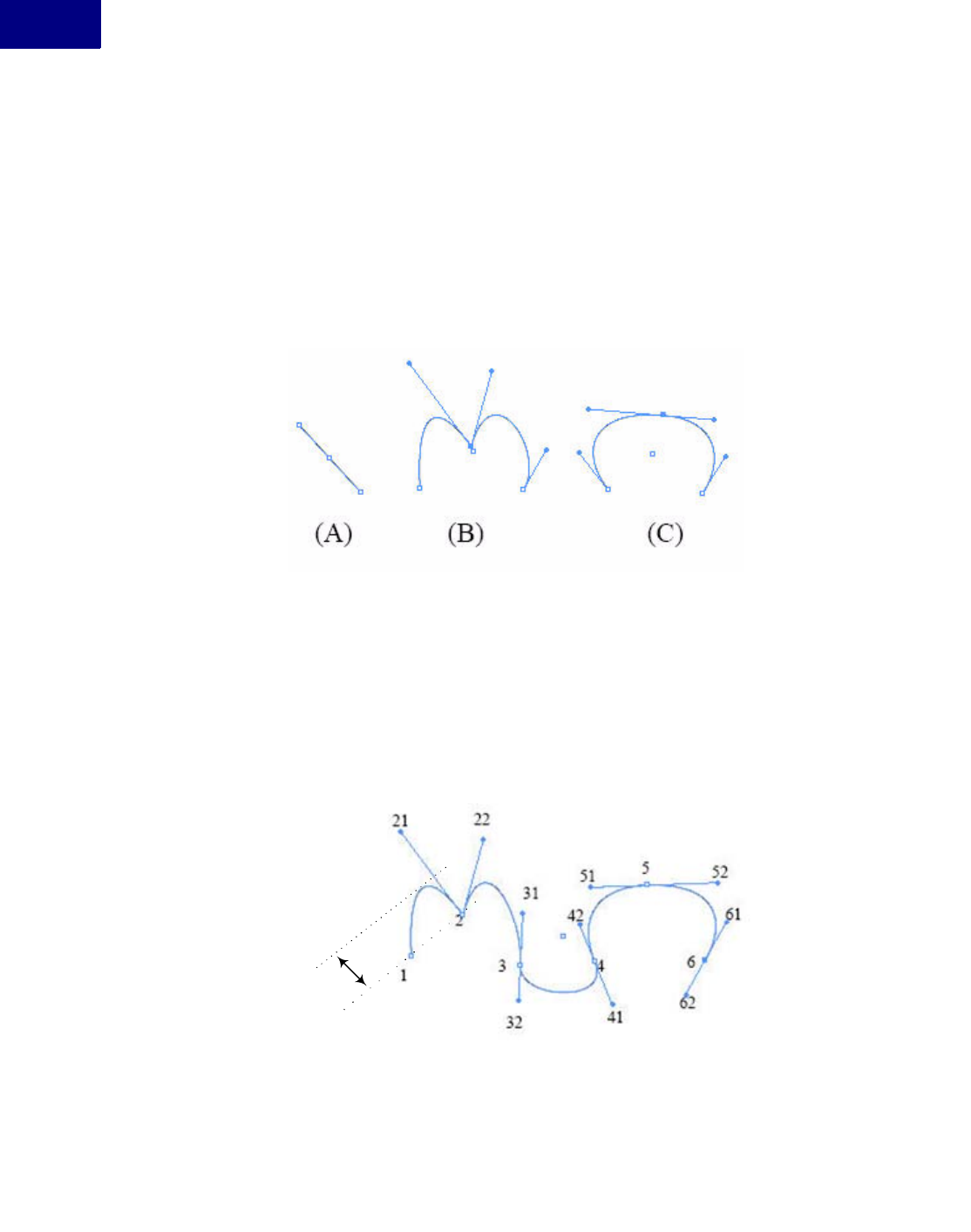
Graphics Fundamentals
Paths
212
A PMPathPoint object stores three PMPoint objects, represented as pairs of (x,y) coordinates.
These PMPoint objects represent the anchor point, the left-direction point, and the right-direc-
tion point, respectively (see Figure 77). For a kL path point, the left- and right-direction points
are the same as the anchor point.
Figure 76 shows examples of path points. In part A, the line consists of two kL points. In part B,
the middle kCK point has two direction points that are not on a line with the anchor point. In
part, the middle kCS point’s anchor point and two direction points form a line.
FIGURE 76 Path-point types
Path drawing
A path is controlled by its path points. InDesign draws Bezier curves based on the path points.
Figure 77 shows an open path with six path points.
FIGURE 77 Path with six path points
Depth
of
curve

Graphics Fundamentals 213
Graphics Fundamentals
Paths
In the figure, note the following:
zEvery anchor point (1, 2, 3, 4, 5, and 6) is on the path.
zPoints 21, 31, 41, 51, and 61 are left-direction points. Points 22, 32, 42, 52, and 62 are right-
direction points.
zDirection lines (from anchor point to direction point) always are tangent to (perpendicular
to the radius of) the curve at the anchor points.
zThe angle of each direction line determines the slope of the curve, and the length of each
direction line determines the height, or depth, of the curve.
zA path is drawn segment by segment. The shape of each segment is determined by its two
end anchor points and their direction points. For example, curve (1,2) is determined by
anchor points 1 and 2 and left-direction point 21; curve (2,3) is determined by anchor
points 2 and 3, right-direction point 22, and left-direction point 31.
If a path is closed, the last segment is controlled by the last and first path points.
For more details, see PMBezierCurve.h.
Winding rule
The winding rule determines whether a given point is inside or outside the area defined by a
path. InDesign supports both even-odd and non-zero winding rules:
zEven-odd winding rule — If a ray drawn from a point in any direction crosses the path an
odd number of times, the point is inside; otherwise, the point is outside.
zNon-zero winding rule — The crossing count for a ray is the total number of times the ray
crosses a left-to-right portion of the path minus the total number of times the ray crosses a
right-to-left portion of the path. If a ray drawn from a point in any direction has a crossing
count of zero, the point is outside; otherwise, the point is inside.
For details, see the book PostScript Language Reference, available on the Adobe Web site.
The winding rule of an object is stored as a graphic attribute of the kGraphicStyleEvenOddAt-
trBoss page item; therefore, you can get or set the winding rules through IGraphicsAttribu-
teUtils the same way as other graphic attributes. For more information, see “Graphic attributes”
on page 256.
Paths data model
Path page-item structure
Paths can exist on any page item that defines an IPathGeometry interface. Figure 78 show the
relationship among page item, path, path point, and point. A path can be viewed as connected
path segments or connected path points.
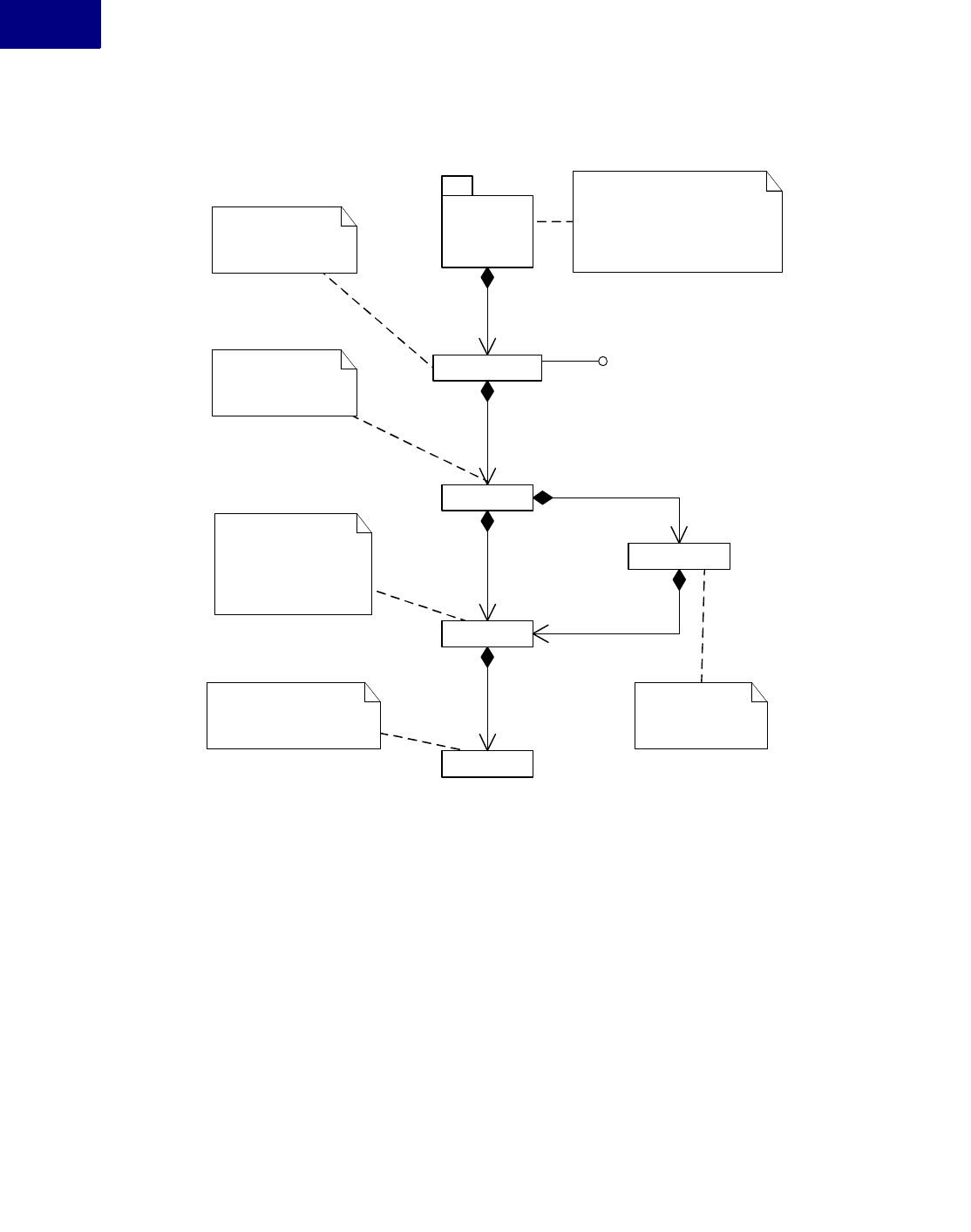
Graphics Fundamentals
Paths
214
FIGURE 78 Path page-item structure
Path geometry
There is no object in the InDesign object model that maps to a single path directly; instead, all
path points of all paths of a page item are stored using the interface defined by the IPathGeom-
etry class. IPathGeometry is the signature interface of a path page item. It has methods to
access path information of a page item, like the number of paths the page item has and whether
a path is open or closed.
Paths are differentiated using a path index. Methods for accessing path points normally require
a path index parameter.
The PMPathPointList type is defined as K2Vector<PMPathPoint>. An item of this type stores a
list of path points; for example, all path points of a path. Unlike with IPathGeometry, path
points stored in an item of type PMPathPointList are not divided into paths by path index.
The most common path page item is the spline item, represented by kSplineItemBoss. Spline
items include paths (lines, curves, frames) like those shown in Figure 76 and Figure 77. There
Path page item
Path
Path point
Point
1
1..*
owns
1
1..*
owns
A page item has
at least one path
associated with it.
A path consists of
straight or curved
line segments.
A point mathematically
defines coordinates of
a position.
A path point defines
an anchor point and
the directions of the
path at the anchor
point.
1
3
owns
Path segment
1
2defined by
10..*
owns
A path segment
connects two
path points.
Document
hierarchy
This package includes all
ancestors of a page item.
See details in "Layout
fundamentals" for information
on navigating to page items.
1
1..*
owns
IPathGeometry

Graphics Fundamentals 215
Graphics Fundamentals
Paths
are several other kinds of paths, including image-clipping paths, text-wrap paths, and text out-
lines. All paths use IPathGeometry to store paths.
Path operations
You can access paths of a page item through the interface defined by the IPathGeometry class.
InDesign also encapsulates some complex manipulations into several high-level path opera-
tions, which are provided as commands and selection suites.
Compound paths
You can combine two or more paths, compound paths, grouped page items, text outlines, text
frames, or other shapes that interact with and intercept one another to create a new compound
path. The advantage of a compound path over individual paths is that a compound path is a
single object, so you can apply attributes to the compound path as a whole.
Use kMakeCompoundPathCmdBoss to create a new compound path and kReleasePathsCmd-
Boss to split a compound path into individual paths.
NOTE:A compound path does not connect or join any two points of existing paths; it only puts
two paths together in one page item.
Comparing compound paths and groups
Both compound paths and groups involve combining multiple page items as a whole. The main
difference between compound paths and groups is that making compound paths combines all
items together into one page item (all other original page items are deleted), whereas grouping
does not delete the original page items; they are just moved into the new group item. See
Figure 79. The steps in the figure are explained below.
FIGURE 79 Compound path contrasted with group
(1) original red
rectangle and
yellow oval
(2) result of
compound path
(3) result of
group with 50%
opacity applied
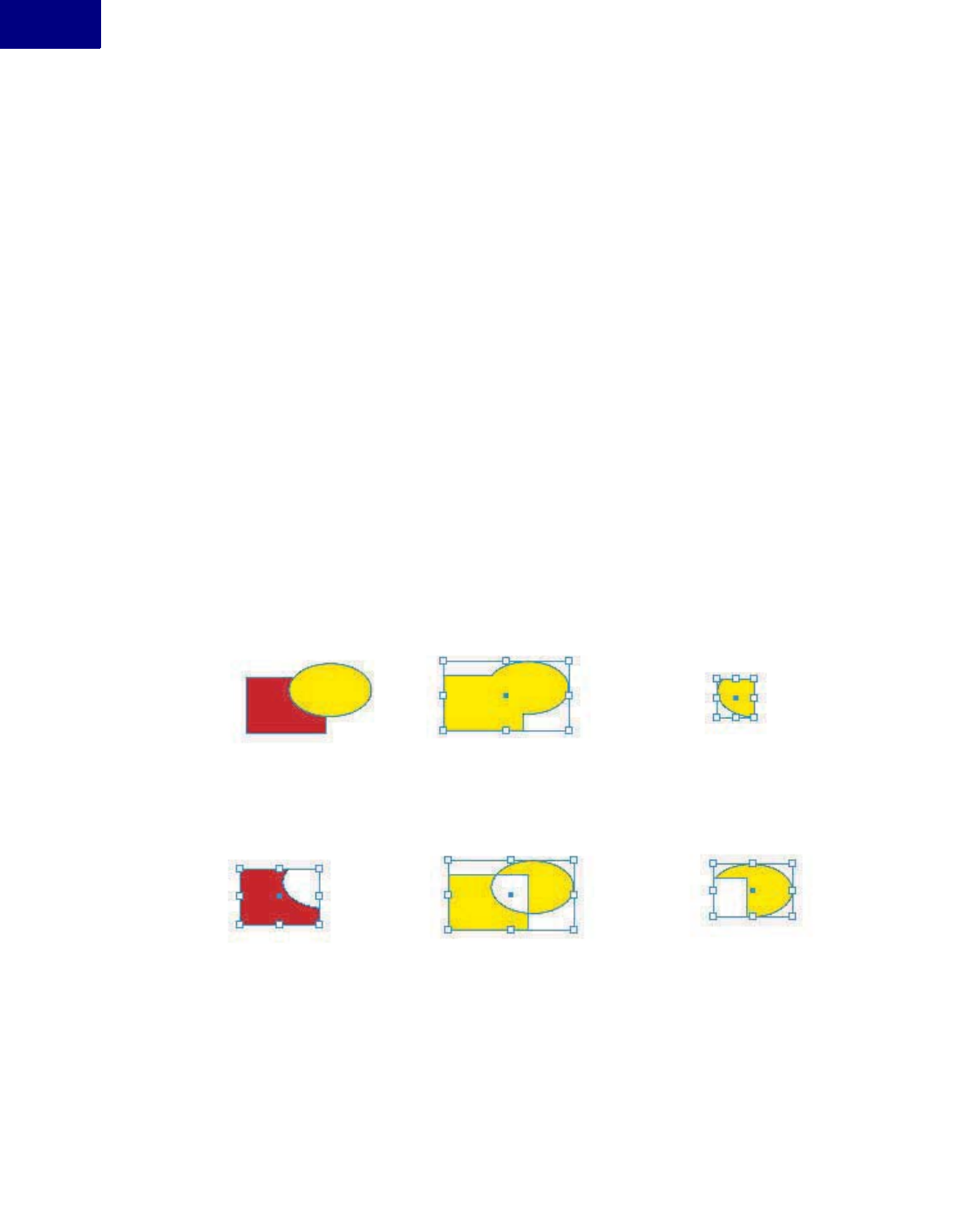
Graphics Fundamentals
Paths
216
In Figure 79:
1. The original page items are a red rectangle and a yellow oval, represented by kSplineItem-
Boss object A and kSplineItemBoss object B, respectively.
2. To make a compound path out of these two objects, to take the path points from kSpli-
neItemBoss object B and add them to kSplineItemBoss object A through the IPathGeome-
try interface, then delete kSplineItemBoss object B. The result is only one kSplineItemBoss
object, A, with new path points. The new item retains the first item’s graphic attributes,
including fill color. All path operations use the even-odd winding rule, resulting in the hole
in the compound path.
3. To group the two page items instead, InDesign first creates a kGroupItemBoss object, then
removes both kSplineItemBoss object A and kSplineItemBoss object B from their current
hierarchical parents and adds them as hierarchical children to kGroupItemBoss. The result
is three different boss objects. The graphic attributes of the original items are retained. You
can apply graphic attributes to a group page item or its children independently.
Path-finder operations
Path-finder operations, also referred to as compound-shape operations, combine shapes
enclosed by the paths. InDesign supports adding, subtracting, intersecting, excluding-overlap,
and minus-back operations. Figure 80 illustrates the results of these path finder operations.
FIGURE 80 Path-finder operations
You can use kMergePathCmdBoss or IPathOperationSuite to achieve the effect.
Path-finder operations require exactly two input objects. The attributes of the front object are
retained by the result object, except in the case of the subtract operation.
(1) original red
rectangle and
yellow oval
(2) result of path
fi nder add operation
(3) result of path
fi nder intersect
(4) result of path
fi nder subtract
(5) result of path
fi nder exclude
overlap operation
(6) result of path
fi nder minus back
operation
operation
operation

Graphics Fundamentals 217
Graphics Fundamentals
Graphic page items
Shape conversion
Shape conversion changes the current shape to a new shape. InDesign can convert to various
shapes, including lines, triangles, rectangles with corner effects, ovals, and polygons. Figure 81
shows the result of converting a rectangle and an oval to inverse-rounded rectangles.
FIGURE 81 Convert shape
The command to achieve this effect is kConvertShapeCmdBoss. It gets the bounding box of the
current shape, then inserts or changes path points in the IPathGeometry object to represent the
desired shape, so the resulting page item maintains the same bounding box as the original
shape.
IConvertShapeSuite takes shape type, corner effects, and several other parameters. You can use
this method to convert a shape to a new shape with a new combination of attributes, like shape
type, corner effects, and number of polygon sides.
NOTE:If you convert a page item from shape A to shape B, then convert from shape B back to
shape A again, the number of path points and their coordinates may be different than
for your original shape A.
Graphic page items
This section discusses the concepts and data model for graphic page items, as well as graphic
page-item special operations, like setting clipping paths and text-wrap contours. This section
also covers importing and exporting graphics files.
Graphic page-item types
Computer graphics fall into two main categories, vector graphics and raster images.
InDesign can import raster images, vector graphics, or a combination of both, depending on
the graphics-file format.
(1) original red
rectangle and
yellow oval
(2) result of converting
shape to inverse-
rounded rectangle

Graphics Fundamentals
Graphic page items
218
Raster images
Raster images, or bitmap images, are the most common electronic medium for such continu-
ous-tone images as photographs or images created in painting programs like Adobe Photo-
shop®. Raster images are resolution dependent.
InDesign supports almost all popular raster-image formats, including PSD, JPEG, TIFF, GIF,
PNG, BMP, and Scitex, all of which are represented by kImageItem boss, which is discussed in
more detail in “Graphic page-item boss-class inheritances” on page 223.
An alpha channel is an invisible channel that defines transparent areas of a graphic. The alpha
channel is stored in a graphic with the RGB or CMYK channels. A user can create alpha chan-
nels using background-removal features in Photoshop.
Vector graphics
Vector graphics use geometrical formulas to represent images. Paths created using the drawing
tools in the InDesign Toolbox are examples of vector graphics.
Vector graphics are more flexible than bitmaps, because vector graphics can be resized without
losing resolution. Another advantage of vector graphics is that their representations often
require less memory than representations of bitmap images.
NOTE:Since most output devices are raster devices, vector objects must be translated into
bitmaps before being printed or displayed. For example, PostScript printers have a
raster image processor (RIP) that performs the translation within the printer.
Vector-graphic formats can differ dramatically. InDesign supports import and export of most
common vector graphics (see Table 47).
TABLE 47 InDesign-supported vector-graphics formats
For more information on importing vector graphics, see “Graphics import” on page 238. For
more information on exporting vector graphics, see “Export to graphics file format” on
page 243.
File format Import Export Related page-item boss
DCS Yes No kEPSItem
EPS Yes Yes kEPSItem
PDF Yes Yes kPlacedPDFItemBoss
PICT Yes No kPICTItem
SVG No Ye s N/A. You can export various content or
documents to SVG file format, but there is no
page item for SVG format.
WMF Yes No kWMFItem

Graphics Fundamentals 219
Graphics Fundamentals
Graphic page items
Graphic page-item settings
Content fitting
Sometimes the size of the graphic page item is not the same as the size of the parent graphics
frame, causing the graphic to be displayed incorrectly. Usually, end users can move, resize, or
rotate the graphic page item or the graphics frame in the same way as any other page item.
Taking advantage of the relationship between the graphic page item and the graphics frame,
InDesign has several content-fitting options:
zFit content to frame — Resizes the graphic page item to the same size as the graphics frame.
zFit frame to content — Resizes the graphics frame to the same size as the graphic page item.
zCenter content in frame — Moves the graphic page item to the center of the graphics frame.
No resizing is involved.
zFit content proportionally — Resizes the graphic page item to barely fit the frame (i.e., the
graphic page-item edge touches the frame vertically or horizontally), while maintaining the
aspect ratio of the graphic page item.
zFill frame proportionally — Resizes the graphic page item while maintaining its aspect ratio
until all white space in the frame is filled.
If there is a selection, we recommend you use IFrameContentSuite or IFrameContentFacade
where possible to perform these operations, though individual commands for these operations
do exist.
NOTE:These transformations of graphic page items and frames change only the IGeometry or
ITransform objects. These transformations do not alter the structure of the graphic
page item and frame objects.
Clipping paths
A clipping path crops part of the image so only part image appears through the shape you cre-
ate. The clipping path is stored separately from its graphics frame, so you can freely modify one
without affecting the other. The clipping path does not change the image; the clipping path
affects only how the image is drawn.
Clipping paths can be created in the following ways:
zUse existing paths or alpha channels. You can add paths and alpha channels in Photoshop
files.
zLet InDesign generate a clipping path with Detect Edges.
zDraw a path in the shape you want, and paste the graphic into the path.
When you set or generate a clipping path, the clipping path is attached to the image, resulting
in an image that is drawn clipped by the path and cropped by the frame.
IPathGeometry aggregated on the graphic page-item bosses stores the clipping path. For more
information on how a path is defined, see “Path geometry” on page 214.

Graphics Fundamentals
Graphic page items
220
The IClipSettings interface is aggregated on kWorkspaceBoss, kDocWorkspaceBoss, and each
graphic page-item boss, to define preferences or individual graphic page items’ clipping-path
settings. For more details on IClipSettings, see the API reference documentation.
Not all settings in IClipSettings are required to determine a clipping path. For example, if you
choose the kClipEmbeddedPath type, you need to know only the embedded path index. Set-
tings like threshold, tolerance, and inset are required only to detect edges. We highly recom-
mend you use the IClippingPathSuite selection-suite interface.
Text wrap
You can wrap text around the frame of any page-item object.
The text-wrap data model is discussed in detail in the “Text Fundamentals” chapter. The path
the text wraps around is defined by a separate page item, kStandOffPageItemBoss, which is
accessible through IStandOffData, aggregated both on the graphic-frame boss (kSplineItem-
Boss) and graphic page-item boss (See Figure 83). Whenever the text-wrap object changes, the
path is copied to the IID_ITEXTWRAPPATH interface (same implementation as IPathGeom-
etry) of the graphic page-item boss; this improves the performance of text composition and
screen redrawing.
What makes the graphic page item special in text wrapping is that you can specify the contour
options when the text-wrap mode is set to Wrap Around Object Shape. In addition to setting
the text-wrap contour to the stroke bounding box of the graphics frame that owns a graphic
page item, you also can specify that text wrap around any of the following:
zThe rectangle formed by the graphic's height and width (the stroke bounding box of the
graphic page item).
zPaths generated by edge detection. You can adjust edge detection manually, using a clipping
path (“Clipping paths” on page 219).
zThe image’s alpha channel.
zThe image’s embedded Photoshop path.
zThe image’s clipping path.
As with the clipping path setting, contour options for text wraps are specified by IStandOffC-
ontourWrapSettings aggregated on kWorkspaceBoss, kDocWorkspaceBoss, and individual
graphic page-item bosses. We highly recommend you use ITextWrapFacade to manipulate text
wraps, including setting contour options.
Display performance
Display performance is used to set the balance between graphic display speed and quality. You
can specify the quality of how raster images, vector graphics, and transparencies are drawn to
the screen. A display performance group is a set of values for these categories.
NOTE:Graphics display performance options do not affect output resolution when exporting
or printing images in an InDesign document. When printing to a PostScript device,
packaging for GoLive, or exporting to EPS or PDF, the final image resolution depends
on the output options you choose when you print or export the file.

Graphics Fundamentals 221
Graphics Fundamentals
Graphic page items
The following display performance groups are available:
zFast — The highest display speed but the lowest display quality. In the standard setting for
this group, InDesign draws a raster image or vector graphic as a gray box.
zTypical — The default option for graphic page items. In the standard setting for this group,
InDesign draws a low-resolution proxy image appropriate for identifying and positioning a
graphic.
zHigh Quality — The highest quality but the lowest display speed. In the standard setting for
this group, InDesign draws a raster image or vector graphic at high resolution (i.e., uses the
file provided by the graphic page item’s link).
NOTE:Standard settings of display performance groups can be modified through the Display
Performance area of the Preferences dialog box or programmatically. See the “Graphics”
chapter of Adobe InDesign CS4 Solutions.
These display performance groups are session preferences, represented by IDrawOptions,
aggregated on kWorkspaceBoss (see Figure 82). The interface stores an array of DrawOptions-
Set (also defined in IDrawOptions.h), corresponding to the fast, typical, and high-quality
groups, respectively. Each group itself, represented by a DrawOptionsSet, has a set identifier
and defines the qualities for each category, including vector, raster, and transparency. (For
details, see the API reference documentation.) The array of DrawOptionsSet defines a two-
dimensional map that indicates whether the graphic page item should be displayed as a gray
box, proxy image, or a high-resolution graphic, given a display group (such as fast) and a cate-
gory (such as raster). You can contain the current active group by calling IDrawOp-
tions::GetActiveSetID, and can set groups through the Edit > Preferences > Display
Performance menu.
Display-performance settings are not document-level preferences; instead, they are set as view
preferences. IDrawOptionsSetID, aggregated on kLayoutWidgetBoss (see Figure 82), allows
each layout presentation to have different default settings, even if they are of the same docu-
ment. IDrawOptionsSetID stores a DrawOptionsSet as default settings when importing
graphic page items. These settings can be set through the View > Display Performance menu.
Individual graphic page items can have their own display-performance overrides. IDrawOp-
tionOverrides, aggregated on kDrawablePageItemBoss—which is inherited by all graphic page
item bosses (see Figure 82)—stores a display-performance group (DrawOptionsSet) for each
graphic page item. Display performance overrides can be set through the Object > Display Per-
formance menu. The IDisplayPerformanceSuite selection-suite interface facilitates the manip-
ulation of display-performance settings.
NOTE:To let page item overrides take effect, the IDrawOptions::GetIgnoreOverrides
preferences flag must be kFalse. You can set this flag through the View > Display
Performance menu.
The display-performance object model is summarized in the class diagram in Figure 82.
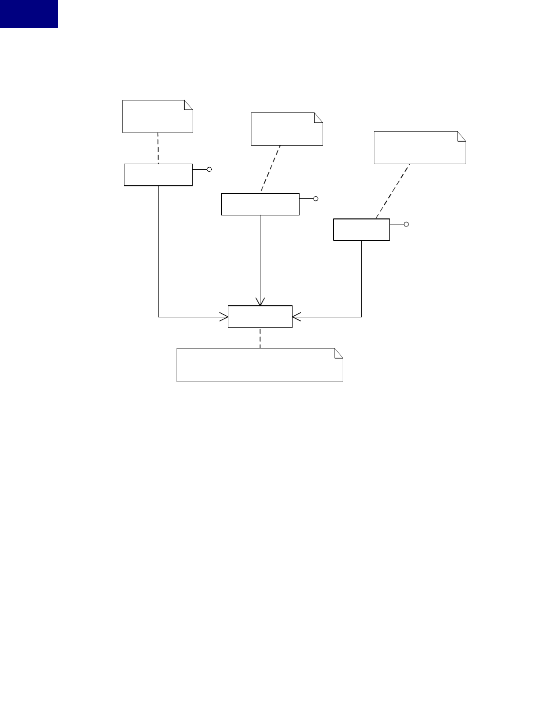
Graphics Fundamentals
Graphic page items
222
FIGURE 82 Display-performance object model
Drawing a graphic page item
Changing display performance from typical to fast does not replace a proxy image with a gray
box directly. In fact, changing display performance does not change the instance of the graphic
page item at all. The effect is achieved by invalidating the layout and letting the page-item
drawing process take care of displaying.
Drawing a layout containing graphic page items follows a generic drawing process detailed in
“Dynamics of drawing” on page 278. A graphic page item is drawn in the following steps:
1. Set the crop rectangle. This involves calculating the graphic page item’s bounding box,
cropped by the frame bounding box and view bounding box.
2. Clip the graphics with their clipping paths.
3. Determine drawing options and draw the graphics.
You can participate in the graphic page-item drawing process by implementing the custom,
drawing event-handler extension pattern, described in “Extension patterns” on page 289.
«boss»
kLayoutWidgetBoss
«boss»
kWorkspaceBoss
1
1..*
IDrawOptionsSetID::GetID
The individual graphic
page item
The application
preferences
1
1..*
IDrawOptionOverrides::GetDrawOptions
«struct»
DrawOptionsSet
Represents a display performance group,
which stores settings for raster images, vector
graphics, transparency, etc.
1
1..*
IDrawOptions::GetActiveSetID
The layout view
«boss»
kImageItem/...
IDrawOptions
IDrawOptionsSetID
IDrawOptionOverrides

Graphics Fundamentals 223
Graphics Fundamentals
Graphic page items
Graphic page-item data model
This section illustrates the data model and common interfaces for graphic page items.
Graphic page-item boss-class inheritances
Although graphic page items are represented by various boss classes (kImageBoss and bosses
for vector graphics in Table 47), they share similar interfaces and demonstrate similar proper-
ties.
kImageItem (the boss representing raster images), kPlacedPDFItemBoss, kEPSItem, kPIC-
TItem, and kWMFItem directly or indirectly inherit from kDrawablePageItemBoss, which
aggregates interfaces necessary for page-item drawing. For the complete inheritance graph for
the bosses, see the API reference documentation; search for kDrawablePageItemBoss.
Graphic page-item class hierarchy
Graphic page-item boss classes have the following characteristics:
zAre wrapped in a spline item (kSplineItemBoss).
zHave text wrap around their contour or frame (represented as kStandOffPageItemBoss).
zStore low-resolution proxy images as kImageInDB.
zStore a link object (ILinkObject) which keeps the UIDRef(s) of link boss(es). A link boss,
like kImportLinkBoss, links the link object (page item) and external graphic files.
zMay embed link resources internally as kPMPersistDataBlobBoss.
Figure 83 is a simplified view of the graphic page items in the class hierarchy of an InDesign
document. ILinkObject provides access to the link object, which can be used to access the
linked graphic resource. If the link is embedded, IStoreInternal provides access to kPMPersist-
DataBlobBoss, which stores the bitmap of the image. IImageDataAccess provides access to the
proxy image, and the bitmap of the images also are stored as kPMPersistDataBlobBoss, which
is accessible through IPersistUIDData on kImageInDB. Navigation from the document root to
the kSplineItemBoss is wrapped into a package, which is discussed in the “Layout Fundamen-
tals” chapter.
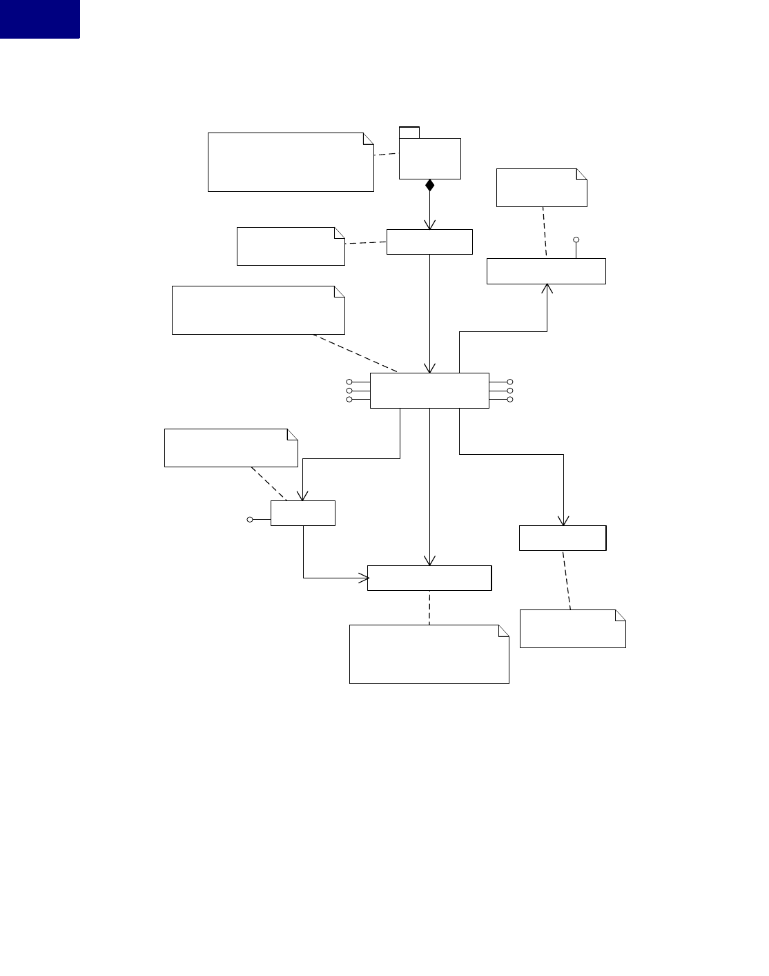
Graphics Fundamentals
Graphic page items
224
FIGURE 83 Graphic page-item class hierarchy
Graphic page-item interfaces
Several common interfaces are aggregated on graphic page-item bosses to provide features spe-
cific to graphic page items. These interfaces are either aggregated directly on the boss (e.g.,
kPlacedPDFItemBoss), or aggregated by way of their parent bosses (e.g., kImageBaseItem, the
parent of kImageItem, or kDisplayListPageItemBoss, the parent of all other vector graphic page
item bosses). Table 48 summarizes these important interfaces and their uses.
«boss»
kSplineItemBoss
«boss»
Any
graphic page item boss
«boss»
kImageInDB
«boss»
kImportLinkBoss
1
1
IHierarchy::QueryChild(0)
1
0..1
IStoreInternal::GetStoredUID()
The graphic frame
wrapping the image
page item.
The graphic page items such as
kImageItem, kPlacedPDFItemBoss,
kEPSItem, kPICTItem, kWMFItem,
or other graphic page item bosses.
Stores the link of
an external graphic
file.
kImageInDB stores a low-
resolution image (of a
high-resolution image)
1
0..*
ILinkObject::GetLinks
«boss»
kPMPersistDataBlobBoss
1
0..1
IImageDataAccess::
GetLowResImageUID()
Stores whole image internally
as a blob. Could be either proxy
image (from IPersistUIDData)
or embedded image (from
IStoreInternal).
1
0..1
IPersistUIDData::GetUID()
«boss»
kStandOffPageItemBoss
Stores the path
geometry of
text wrap.
1
0..1
IStandOffData::GetStandOffUID()
Document
hierarchy
This package includes all
ancestors of a spline page item.
See details in the "Layout
Fundamentals" section about how
to navigate to the page item.
1
0..*
owns
IGraphicItem
IImageItem(kImageItem only)IPathGeometry
IGeometry
IImageAttributes(kImageItem only)IID_ITEXTWRAPPATH(IPathGeometry)
IPathGeometry
IImageAttributes
Graphics Fundamentals 225
Graphics Fundamentals
Graphic page items
TABLE 48 Graphics-interface summary
Proxy images
When a graphic is placed, the contents of the original file are not actually copied into the docu-
ment. Instead, InDesign creates a link to the original file on the disk and adds a screen-resolu-
tion bitmap image (the proxy image) to the layout, so you can view and move the graphic.
When you export or print, InDesign uses the link to retrieve the original graphic, creating the
final, desired, full-resolution output. Although end users can set preferences to tell InDesign to
show high-resolution images (see “Display performance” on page 220), by default InDesign
shows a low-resolution proxy image for performance reasons; the proxy image is created by
processing kCreateLowResImageCmdBoss during the import process.
A proxy image is represented by the boss kImageInDB, which is accessible from the graphic
page item through IImageDataAccess::GetLowResImageUID. The connection is established
during the image-import process. For the data model of the proxy image in relation to the
graphic page items, see “Graphic page-item class hierarchy” on page 224 and “Graphic page-
item examples” on page 226.
One of the most important interfaces on kImageInDB is IPersistUIDData, which holds a UID
pointing to an instance of kPMPersistDataBlobBoss, which stores the bitmap of the proxy
image.
Interface ID Interface Description
IID_IGRAPHICITEM IIntData This is the signature interface for all graphic types (raster,
EPS, etc.). The integer data is never used.
IID_IIMAGEITEM IImageItem Aggregated onto kImageBaseItem, this interface provides
access to the embedded color profile of the image. More
importantly, testing the presence of this interface verifies that
a page item boss is a raster image.
IID_IGEOMETRY IGeometry This interface defines the geometry (position, size, etc.) of a
graphic page item. It is used for calculating cropping during
the graphic page-item drawing process.
IID_IPATHGEOMETRY IPathGeometry This interface stores the clipping path of a graphic page item
(see “Clipping paths” on page 219).
IID_ITEXTWRAPPATH IPathGeometry This interface stores the text-wrap path; however, this path is
only a cache (or mirror) of the text-wrap path. The real path
is stored at IPathGeometry on kStandOffPageItemBoss. Every
time the real text-wrap path is changed, this path is updated.
(See “Text wrap” on page 220.)
IID_IIMAGEATTRIBUTES IImageAttributes This interface stores a set of tags to describe the attributes of a
raster image. Predefined tags are defined as enumerators,
each of which describes the type, length, and data of a raster
image. These tags are crucial in defining image item
properties, such as alpha channel, clipping path, and color
profile.

Graphics Fundamentals
Graphic page items
226
The proxy image is not always created by asking the image-import filter for the data. For raster
images, if image auto-embedding is allowed in the image-import preferences, and the image is
smaller than a predefined amount (defaults to 48 KB, accessible through ILinkState::GetEm-
bedSize), the original high-resolution image is embedded directly.
Creating a proxy image is aided by the IImageStreamManager interface, which provides a
mechanism to convert the source-image format to a destination-image format according to the
image attributes.
Graphic page items and links
Every graphic page item that was placed from a file has an associated link. End users can
choose the Embed Link menu in the Links panel’s fly-out menu to embed the link manually.
The file remains in the Links panel, marked with an embedded link icon.
NOTE:This behavior differs from link for a text file. You can create a link when placing a text
file; however, since text is inheritently part of the InDesign document, you cannot really
“embed” the link. If you create a link when placing a text file, you can choose to unlink
the file from the Links panel. Once it is unlinked, the link is removed from the Links
panel.
As a software developer, you also can use ILinkFacade::EmbedLinks to embed the image link
(ILinkFacade is aggregated on kUtilsBoss). kStoreInternalCmdBoss, processed internally, reads
the original high-resolution file and stores the image data as a data blob, referenced by the
IStoreInternal interface on the graphic page item.
Embedding a link is not the same as embedding the small image to create a proxy image, dis-
cussed in “Proxy images” on page 225:
zThe image data is stored in a different place. Embedding a link stores a data blob referenced
by IStoreInternal on the graphic page item. Embedding an image as a proxy stores the data
blob referenced by IPersistUIDData on kImageInDB boss.
zEmbedding a link does not cause a check for the size of the image.Embedding an image as a
proxy requires the image file to be smaller than a predefined size.
Graphic page-item examples
New graphics can be placed into a layout with or without an existing graphics frame. This sec-
tion illustrates how instances of graphics objects evolve as you place a PDF file, replace it with
an image, move the image around, embed a link, and set clipping-path and text-wrap contour
options.
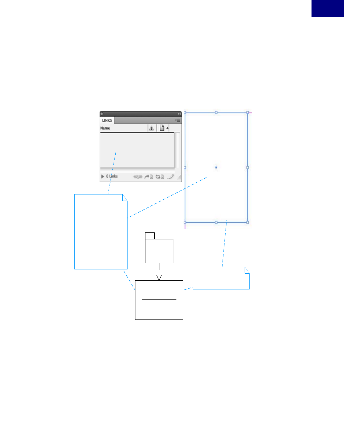
Graphics Fundamentals 227
Graphics Fundamentals
Graphic page items
Begin with an empty graphics frame
We start exploring the graphics object model by examining an empty graphics frame. Figure 84
shows a screenshot and the object model when only an empty graphics frame is created. The
graphics frame is represented by kSplineItemBoss, and it does not have any hierarchical chil-
dren.
FIGURE 84 Empty graphics frame
Above:
Empty links panel.
Right:
Empty graphic frame.
Below:
A graphic frame
represented as
kSplineItemBoss.
No child object.
LeftTop = (36, -360)
RightBottom = (276, 0)
«boss»
graphic-frame
: kSplineItemBoss
The graphic frame. Its
pasteboard coordinates
are shown.
Document
hierarchy

Graphics Fundamentals
Graphic page items
228
Place a PDF item in a graphics frame
Next, we place a PDF file into the graphics frame. During import, InDesign creates a kPlacedP-
DFItemBoss object to represent the PDF item and adds it as a child of the graphics frame.
Figure 85 shows the object model of the graphics frame with a PDF item. A few other objects
are created to represent information of the PDF item. New objects are marked in yellow.
Comparing Figure 85 to Figure 84, notice the Links panel shows a link to the external PDF file.
The link is represented by kImportLinkBoss through ILinkObject, aggregated on kPlacedPD-
FItemBoss.
A proxy image is created for the PDF item as kImageInDB boss (UID 0xcd), and the proxy
image bitmap is represented by kPMPersistDataBlobBoss (UID 0xce).
By default, a graphic page item is put into the graphics frame with an offset of (0,0) in inner
coordinate space, so the PDF item has the same PMRect::LeftTop position (obtained from IGe-
ometry::GetPathBoundingBox) on the pasteboard as the graphics frame. Although the PDF
item is slightly wider than the frame (PMRect::RightBottom member), InDesign does not draw
that part, because it is cropped by the frame.
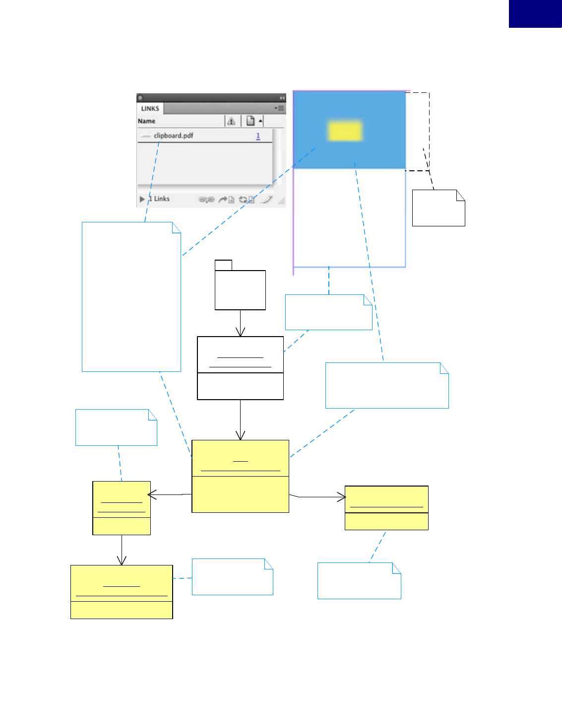
Graphics Fundamentals 229
Graphics Fundamentals
Graphic page items
FIGURE 85 PDF item in graphics frame
UID = 0xcf
«boss»
link : kImportLinkBoss
UID = 0xcd
«boss»
proxy image
: kImageInDB
UID = 0xcb
LeftTop = (36, -360)
RightBottom = (298, -200)
«boss»
PDF
: kPlacedPDFItemBoss
Above:
A PDF file appears
in the Links panel.
Right:
PDF item placed in
the graphic frame.
Below:
The graphic frame
now has a PDF item
represented by
kPlacedPDFItemBoss.
LeftTop = (36, -360)
RightBottom = (276, 0)
«boss»
graphic-frame
: kSplineItemBoss
UID = 0xce
«boss»
image blob
: kPMPersistDataBlobBoss
The graphic frame
is not changed.
The PDF item is the only child
of the graphic frame. It is
wider than, but shorter than
the graphic frame.
A proxy image is
created for the
PDF file.
Link maintains a
connection to
external PDF file.
A proxy image is
stored as a data
blob.
Document
hierarchy
Area not
cropped
by frame

Graphics Fundamentals
Graphic page items
230
Replace a PDF item with an image
Next, we import an image file to replace the PDF item and examine the changes to the object
model. Figure 86 shows the screenshot and object model after the change. Again, new objects
are marked in yellow. Note the following:
zThe Links panel shows a link to the new image file (PalmTreeCMYK.tif).
zThe overall structure of the object model did not change, but a new boss object kImageItem
replaced kPlacedPDFItemBoss.
zThe UID of the link, proxy image, and proxy image data blob also changed. These objects
were created during the import process—and the old objects were deleted.
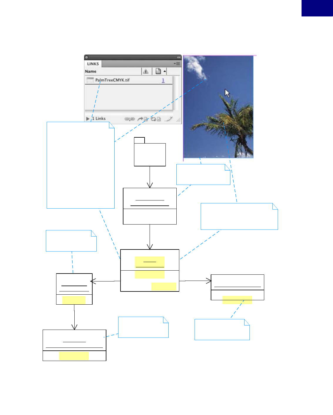
Graphics Fundamentals 231
Graphics Fundamentals
Graphic page items
FIGURE 86 Imported image
UID = 0xb4
«boss»
proxy image
: kImageInDB
UID = 0xb5
«boss»
image blob
: kPMPersistDataBlobBoss
Above:
New image appears
in the Links panel.
Right:
Image replaced PDF item
in the graphic frame.
Below:
The graphic frame
now has an image
represented by
kImageItem.
The graphic frame
is not changed.
The image is the only child
of the graphic frame. It is
larger than the graphic frame,
thus only a portion is shown.
A proxy image is
created for the
the image file.
Link maintains a
connection to
external image file.
A proxy image is
stored as a data
blob.
LeftTop = (36, -360)
RightBottom = (276, 0)
«boss»
graphic-frame
: kSplineItemBoss
UID = 0xb7
«boss»
link : kImportLinkBoss
Document
hierarchy
UID = 0xb3
LeftTop = (36, -360)
RightBottom = (418, 302)
«boss»
image
: kImageItem

Graphics Fundamentals
Graphic page items
232
Move an image within a frame
You may have noticed the palm tree image is large, and we can only see a small part of the tree.
Now we move the image a little bit within the graphics frame, using the Direct Selection tool.
Figure 87 shows the resulting object model. Everything is the same, except the pasteboard
coordinates of the image item. The changed object is marked by a red circle; changed values are
marked in yellow. The coordinates represent the bounding box of the image item.
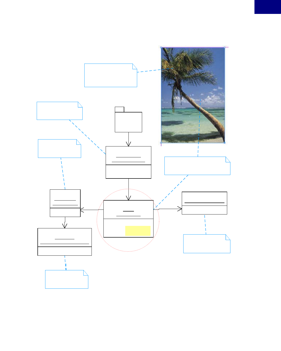
Graphics Fundamentals 233
Graphics Fundamentals
Graphic page items
FIGURE 87 Image moved within a frame
Right:
The image is moved to
a new location within
the graphic frame.
The graphic frame
is not changed.
After the move, the image has
new pasteboard coordinates.
A proxy image is
created for the
the image file.
Link maintains a
connection to
external image file.
A proxy image is
stored as a data
blob.
LeftTop = (36, -360)
RightBottom = (276, 0)
«boss»
graphic-frame
: kSplineItemBoss
UID = 0xb3
LeftTop = (-84, -528)
RightBottom = (298, 134)
«boss»
image
: kImageItem
UID = 0xb7
«boss»
link : kImportLinkBoss
UID = 0xb4
«boss»
proxy image
: kImageInDB
UID = 0xb5
«boss»
image blob
: kPMPersistDataBlobBoss
Document
hierarchy

Graphics Fundamentals
Graphic page items
234
Embed an image’s datalink
Next, we manually embed the image into the document by choosing Embed Link on the Links
panel fly-out menu. Figure 88 shows the changed object model after the image is embedded.
The new object is within the red circle, marked in yellow. A new kPMPersistDataBlobBoss is
created to store the embedded image information. Other bosses—including the link object
(kImportLinkBoss)—do not change.
There are two kPMPersistDataBlobBoss objects in the object model, but they represent differ-
ent things. The one accessible through IPersistUIDData on the proxy image:kImageInDB boss
represents the proxy image; the other—accessible through IStoreInternal on the image:kImage-
Item boss—represents the embedded image data.
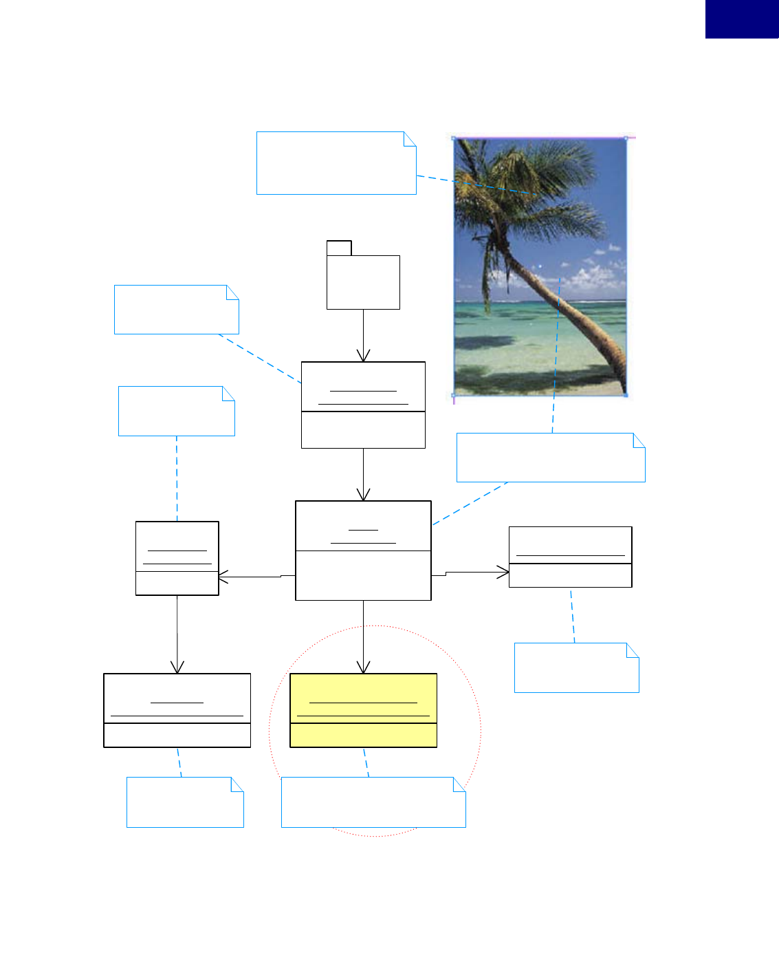
Graphics Fundamentals 235
Graphics Fundamentals
Graphic page items
FIGURE 88 Embedded image
The image is embedded
into the InDesign file. The
look and feel of the image
does not change.
The graphic frame
is not changed.
Embedding the image does not
change pasteboard coordinates.
A proxy image is
created for the
the image file.
Link maintains
a connection to
external image file.
A proxy image is
stored as a data
blob.
UID = 0xb3
LeftTop = (-84, -528)
RightBottom = (298, 134)
«boss»
image
: kImageItem
UID = 0xb7
«boss»
link : kImportLinkBoss
UID = 0xb4
«boss»
proxy image
: kImageInDB
UID = 0xb5
«boss»
image blob
: kPMPersistDataBlobBoss
LeftTop = (36, -360)
RightBottom = (276, 0)
«boss»
graphic-frame
: kSplineItemBoss
UID = 0xd8
«boss»
embedded image blob
: kPMPersistDataBlobBoss
Embedded image blob (orignal
graphic file data), accessible
through IStoreInternal.
Document
hierarchy
1
1
IPersistUIDData::GetUID() 1
1
IStoreInternal::GetStoredUID()
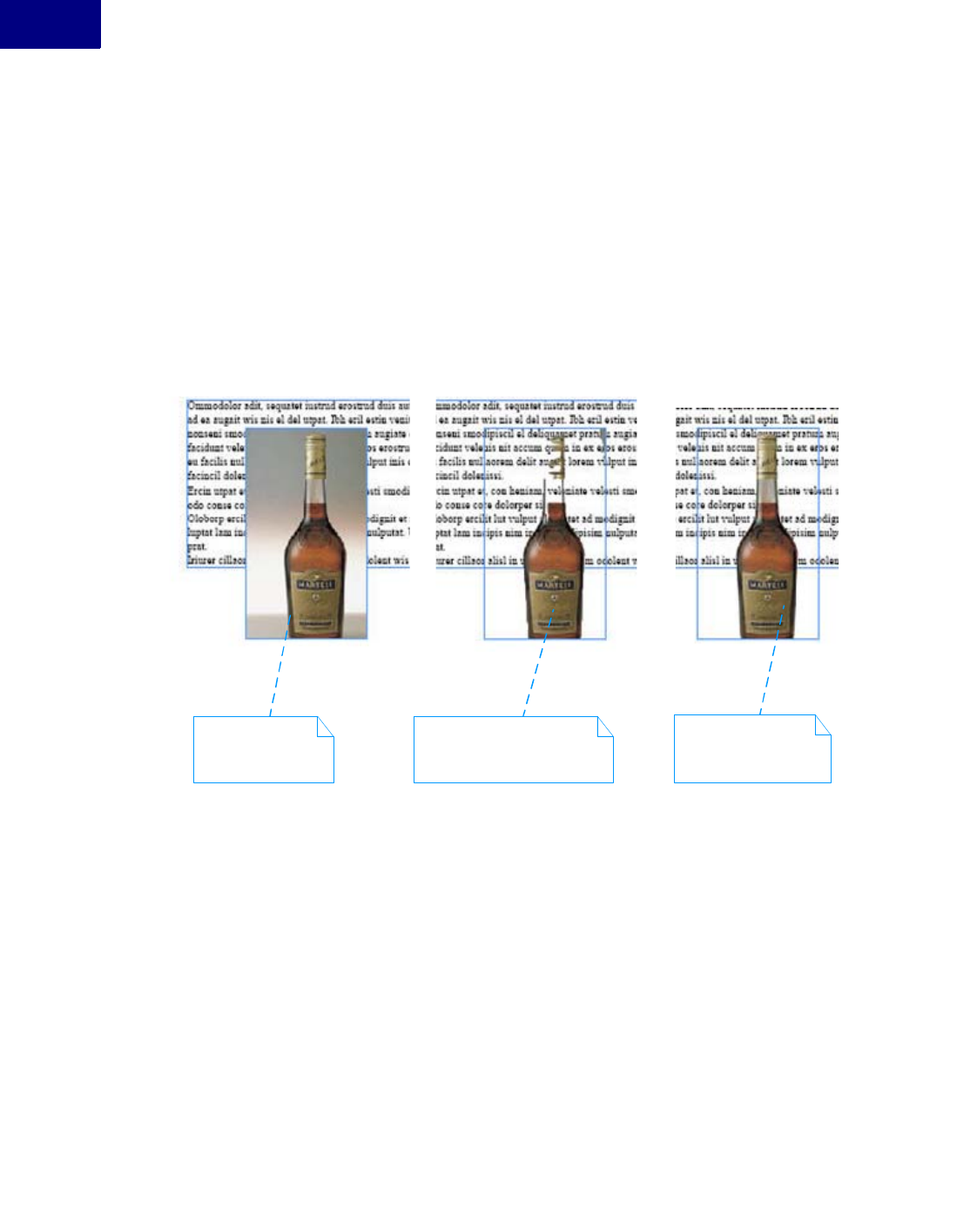
Graphics Fundamentals
Graphic page items
236
Setting clipping path and text wrap
Let’s use a different image to set clipping-path and text-wrap options. In this section, we place a
linked image, overlap it on top of a text frame, and examine how the image and text frame
change when you set clipping-path and text-wrap options.
Figure 89 shows examples of clipping-path options. In the left screenshot, no clipping path was
set, so the image overlaps the background text. The center screenshot shows the result of the
clipping-path Detect Edges option (with the Threshold parameter set to 150). Although Detect
Edges can detect most of the contours of the bottle, the result looks even better if you use the
existing Photoshop paths, as shown in the right screenshot.
FIGURE 89 Clipping-path options
Reminder: The clipping path is stored with the IPathGeometry interface of the graphic page
item, so no extra object is created. For the graphic page item’s class diagram, see Figure 83; for
descriptions, see “Clipping paths” on page 219.
Now we set the text wrap of the image item, shown in Figure 90. All three screenshots were
taken with the text wrap set to wrap around the graphic page item’s object shape. The left
screenshot shows the result when the text-wrap contour option is set to Same As Clipping, with
clipping-path type set to Detect Edges. The top-right corner of the bottle frame does not have
text, because a small part of the image is there. You can set the contour option to use existing
Photoshop paths independent of the clipping path, shown in the center screenshot. You also
can set both the clipping path and text-wrap contour options to use the Photoshop path, which
produces the best result, as shown in the right screenshot.
Object model changes after setting the text-wrap options are shown in the lower part of
Figure 90. A new kStandOffPageItemBoss object—within the red circle, marked in yellow—is
created to hold the text-wrap path. For information on how this affects text composition, see
the “Text Fundamentals” chapter.
Image clipping
path set to None
Clipping path is generated
by detecting edges.
Clipping path set to
existing Photoshop
path.
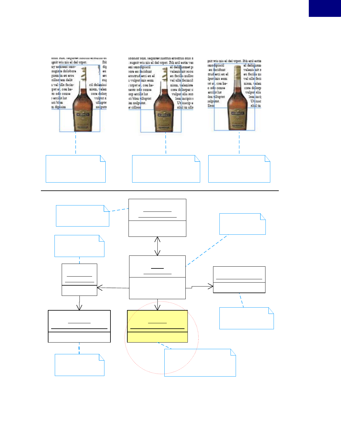
Graphics Fundamentals 237
Graphics Fundamentals
Graphic page items
FIGURE 90 Text-wrap options
Clipping path is set to
detect edges, and
text wrap is set to
Same As Clipping
Clipping path is generated
by detecting edges.
Text wrap is set to use
Photoshop path
Both clipping path and
text wrap are set to
use existing Photoshop
path.
The graphic frame
The image item
A proxy image is
created for the
the image file.
Link maintains
a connection to
external image file.
A proxy image is
stored as a data
blob.
LeftTop = (156, 123)
RightBottom = (288, 336)
«boss»
graphic-frame
: kSplineItemBoss
UID = 0xd1
LeftTop = (156, 123)
RightBottom = (308,350)
«boss»
image
: kImageItem
UID = 0xd4
«boss»
link : kImportLinkBoss
UID = 0xd2
«boss»
proxy image
: kImageInDB
UID = 0xd3
«boss»
image blob
: kPMPersistDataBlobBoss
UID = 0xd7
«boss»
text wrap
: kStandOffPageItemBoss
The standoff object, which
stores the path geometry of
the text wrap.

Graphics Fundamentals
Graphic page items
238
Graphics import
Overview of the import process
When a user chooses to place a graphic into a document, InDesign performs a sequence of
steps to import the graphics file as a graphic page item. Figure 91 shows the steps involved in
importing PDF, EPS, and image files.
You also can import another InDesign document to a document. The import process works
like PDF import. The only difference is importing InDesign document also imports swatches,
inks, fonts and links, etc. and creates secondary links if the document being imported also con-
tains links. You can set InDesign document-import options like other graphic file types; see
“InDesign document-import preferences” on page 242.
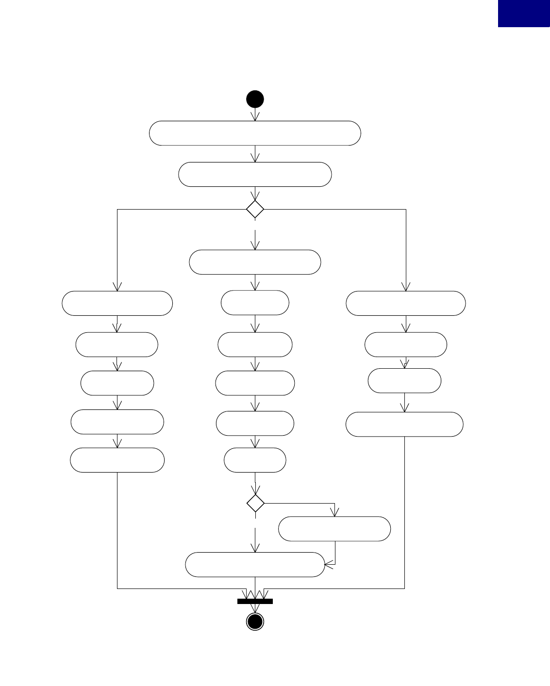
Graphics Fundamentals 239
Graphics Fundamentals
Graphic page items
FIGURE 91 Graphics-import process
Create a link that connects the page item and link resource
Choose import provider based on file type
Create kPlacedPDFItemBoss
Choose image read format provider
Create EPS, DICT or WMF item
New kImageItem
Set image IO prefs
Set Image attributes
Sample high-resolution image
Read and set proxy image's data blob
Create kImageInDB
Set PDF import prefs
Set PDF attributes
Generate raster preview
Stream into kImageInDB
Set EPS import prefs
Set EPS attributes
Create TIFF proxy kImageInDB
[Raster Images]
[PDF] [Vectors (except PDF)]
[no]
[yes]
Embed image?

Graphics Fundamentals
Graphic page items
240
At a high level, the process involves the following steps:
1. Create a kImportLinkBoss that connects the link resource and the page item.
2. Query for an import provider that provides kImportProviderService for the graphic. This
service also is used for importing other types of files, like plain-text files. For graphics files,
one of four providers is called: kPDFPlaceProviderBoss, kImagePlaceProviderBoss,
kEPSPlaceProviderBoss or kNativeImportServiceBoss. See Table 49 for details on file for-
mats supported by these providers.
3. Create the appropriate new page item according to the type of the graphics file. See
Table 49.
4. Import the file and set new page-item attributes, like IPDFAttributes, IEPSAttributes, and
IImageAttributes. This may involve searching for an appropriate image import filter
(“Image-import filters” on page 242) and setting import options (“Import options” on
page 240).
5. Create and set a low-resolution proxy image for the new page item, which is accessible
through IImageAccess on the new page item.
TABLE 49 Supported graphic-file formats for import
Import options
To control how the file should be imported, end users can choose Show Import Options in the
Place dialog box, which allows the user to set import options through an Import Options dia-
log box. The specific options depend on the file type and graphics data in the file.
PDF-import preferences
The IPDFPlacePrefs (IID_IPDFPLACEPREFS) interface allows you to set various PDF import
options, like how to crop the graphic and which pages to import. If the PDF file contains layers,
you can set up layer information on the dialog using IGraphicLayerInfo.
Both interfaces are aggregated on kWorkspaceBoss. IGraphicLayerInfo can be initialized by the
imported file before bringing up the Import Options dialog. Table 50 lists some default settings
of IPDFPlacePrefs.
Import provider Filename extension Page-item boss
kEPSPlaceProviderBoss AI, EPS, DCS kEPSItem
kEPSPlaceProviderBoss PCT, PIC kPICTItem
kEPSPlaceProviderBoss WMF, EMF kWMFItem
kImagePlaceProviderBoss TIF, TIFF, SCT, PSD, PNG,
PCX, JPEG, JPG, GIF, DIB
kImageItem
kPDFPlaceProviderBoss PDF kPlacedPDFItemBoss
kNativeImportServiceBoss INDD kInDesignPageItemBoss
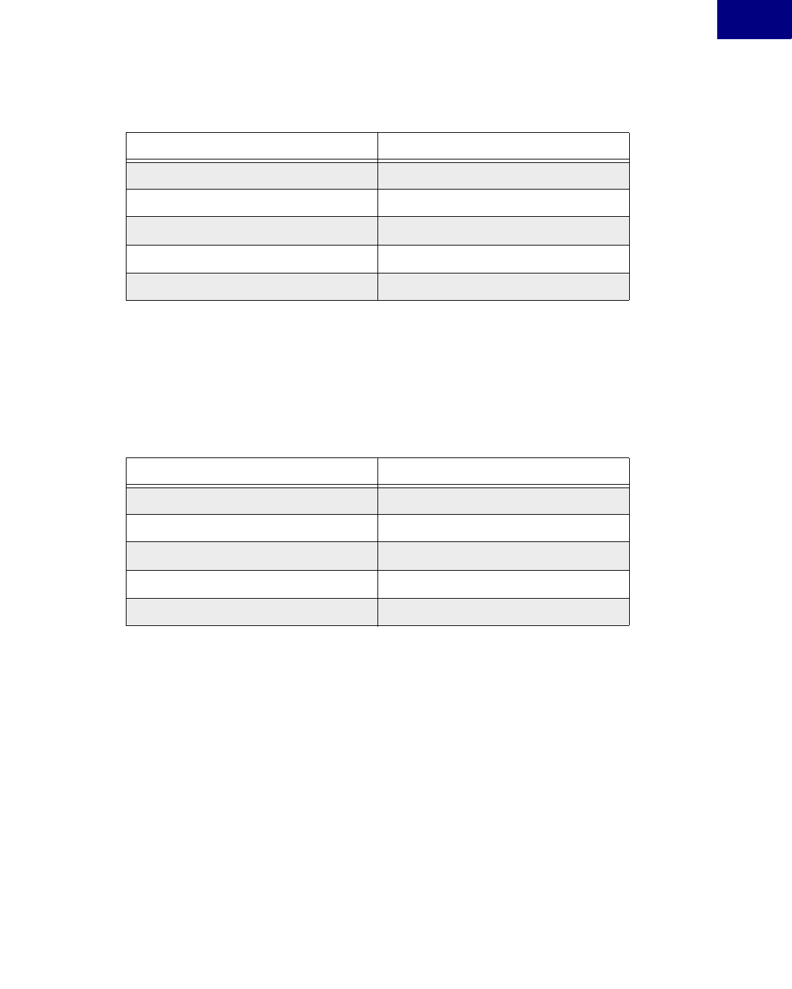
Graphics Fundamentals 241
Graphics Fundamentals
Graphic page items
For details, see the “PDF Import and Export” chapter.
TABLE 50 Selected default PDF-import preferences
EPS-import preferences
IEPSPreferences (IID_IEPSPREFERENCES) also is aggregated on kWorkspaceBoss. Some set-
tings are set programmatically; for example, importing an EPS graphic from a file (not from
the clipboard) automatically sets the import mode to “import whole” (kImportWhole).
Table 51 lists some default settings of IEPSPreferences.
TABLE 51 Selected default EPS-import preferences
NOTE:“Create frame” corresponds to the Apply Photoshop Clipping Path checkbox, and
kAlwaysCreate corresponds to the Rasterize The PostScript radio button in the EPS
Import Options dialog box.
Image-import preferences
The Raster Image Import Options dialog box uses separate panels to set raster image-specific
import options, like color profile and clipping path. Usually, InDesign uses session preferences
(IImageIOPreferences on kWorkspaceBoss) to import an image file. Table 52 lists some of the
default settings.
Preference Default value
Crop kCropToContent
Page number 1
Proxy resolution 72
Show preview kTrue
Transparent background kTrue
Preference Default value
Import mode kImportWhole
Display resolution 72
Read OPI comments kDontReadOPIComments
Create frame kDontCreateFrameFromClipPath
Create proxy kCreateIfNeeded
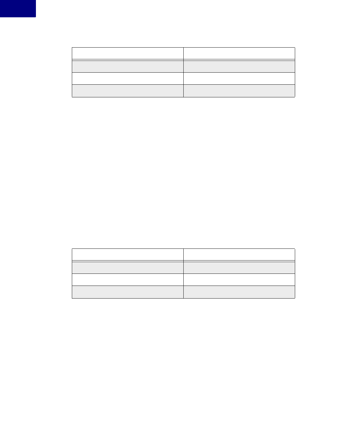
Graphics Fundamentals
Graphic page items
242
TABLE 52 Selected default image-import preferences
When auto-embedding is allowed and the image size is small, InDesign automatically embeds
the high-resolution image as the proxy image, so the data and the interfaces of kImageInDB
reflect the high-resolution image rather than a new, low-resolution image.
InDesign document-import preferences
Placing InDesign document directly into an InDesign document has advantages in the publish-
ing workflow, including automatically maintained links, fonts, swatches, links and so on. The
IImportDocOptions (IID_IIMPORTDOCOPTIONS) interface allows you to set various InDe-
sign document-import options, like how to crop the pages, which pages to import, and where
to display previews. IGraphicLayerInfo let you set up layer information on the dialog to choose
which layer to import.
Both IImportDocOptions and IGraphicLayerInfo are session preferences aggregated on
kWorkspaceBoss. They also store information to pass to kImportDocCmdBoss, if you want to
use the command directly to place InDesign files. Table 53 lists some default settings of IIm-
portDocOptions.
TABLE 53 Selected default InDesign document-import preferences
Image-import filters
You may have noticed in Table 49 that the same kImagePlaceProviderBoss is used for import-
ing various kinds of raster images. These raster images have different file formats and, there-
fore, they need different ways to read data. InDesign provides another level of abstraction: the
image-import provider queries for service providers that support kImageReadFormatService.
This mechanism also serves as another extension pattern software developers may implement
to support new raster-image formats.
InDesign implements a set of providers to read various image formats, to import TIF (TIFF),
SCT, PSD, PNG, PCX, JPEG (JPG), GIF, and DIB files. These providers serve as the image-
import filters. When InDesign is instructed to place an image, it iterates over all the providers
until it finds one that can import the image. See Table 54 for a list of these providers.
Preference Default value
Allow auto-embedding kTrue
Create clip frame kTrue
Preview resolution 72
Preference Default value
Crop kCropToPage
Page number 1
Show preview kTrue
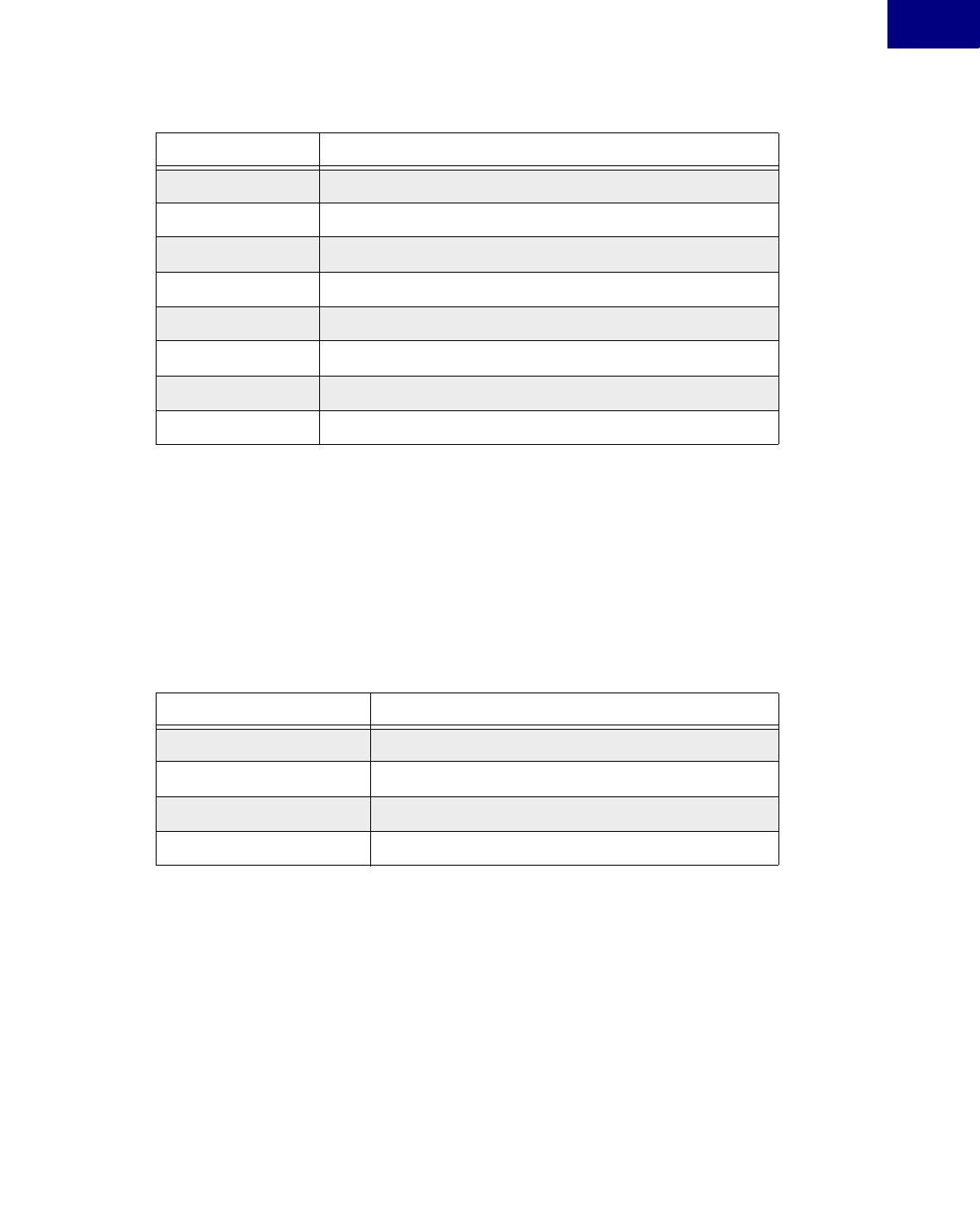
Graphics Fundamentals 243
Graphics Fundamentals
Graphic page items
TABLE 54 Image read-format providers
Export to graphics file format
InDesign supports exporting all or part of a document to PDF, EPS, SVG, and JPEG formats.
All the export processes are alike at a high level: exports are implemented using the IExport-
Provider service-provider mechanism (see the “Service Providers” chapter of Learning the
Adobe InDesign CS4 Architecture). Each type of export destination format provides export ser-
vices. Table 55 lists export providers that export to a graphics file format.
TABLE 55 Graphic-export providers
For examples of export provider implementations, see SDK samples like CHMLFilter, TextEx-
portFilter, and XDocBookWorkflow.
Each export provider has a corresponding command that exports content to a desired file for-
mat in the following two stages:
1. Drawing — Drawing page items to an intermediate entity, such as a viewport.
2. Streaming — Writing the content to the provided file stream.
Export to PDF and EPS are discussed in detail in the “Exporting to EPS and PDF” section of
the “Printing” chapter. PDF import and export also are discussed in the “PDF Import and
Export” chapter.
File type Image read-format provider
TIF kTIFFImageReadFormatBoss
SCT kSCTImageReadFormatBoss
PSD kPSImageReadFormatBoss
PNG kPNGImageReadFormatBoss
PCX kPCXImageReadFormatBoss
JPEG kJPEGImageReadFormatBoss
GIF kGIFImageReadFormatBoss
DIB kDIBImageReadFormatBoss
Export destination Export provider
PDF kPDFExportBoss
EPS kEPSExportBoss
SVG kSVGExportProviderBoss
JPEG kJPEGExportProviderBoss
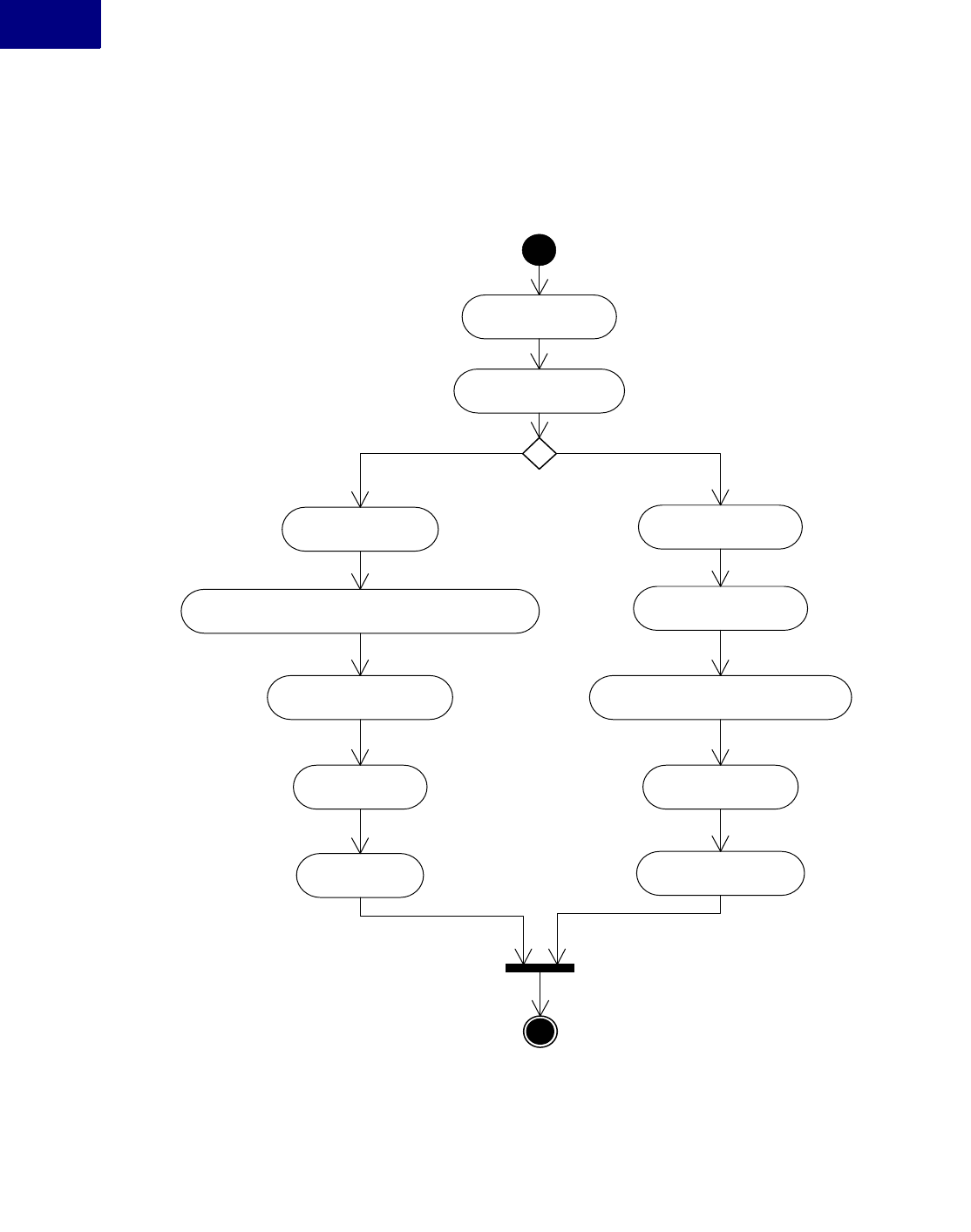
Graphics Fundamentals
Graphic page items
244
Only SVG and JPEG export are discussed in this section. Figure 92 shows high-level activities
of SVG and JPEG export.
FIGURE 92 SVG and JPEG export process
Get export file format
Choose export provider
Set SVG export prefs Set JPEG export prefs
Export to JPEG stream
Create kSVGExportViewPortBoss and set attributes
Install draw event handler
Set up SVGWriter
Draw page items
Create SnapshotUtilsEx
Draw page items on SnapshotUtilsEx
Create output stream
[SVG] [JPEG]
Graphics Fundamentals 245
Graphics Fundamentals
Graphic page items
SVG export
SVG export preferences
Settings for SVG export are stored with the ISVGExportPreferences interface on kWorkspace-
Boss. For details, see the API reference documentation.
End users can modify the preferences through the SVG Export Options dialog box. You also
can change the preferences programmatically, with the kSVGExportSetPrefsCommandBoss
command. Table 56 lists some of the default SVG-export preferences.
TABLE 56 Selected default SVG-export preferences
Exporting to SVG format
InDesign exports to SVG format by drawing page items and documents to a special viewport,
kSVGExportViewPortBoss. For more information about viewports, see “Data model for draw-
ing” on page 276. kSVGExportCommandBoss aggregates ISVGExportController, which con-
trols the drawing process and hides much of the complexity involved in SVG export.
kSVGExportViewPortBoss aggregates ISVGWriterAccess, which helps in writing contents to
an SVG file stream.
JPEG export
JPEG export preferences
Settings for JPEG export are stored with the IJPEGExportPreferences interface on kWorkspa-
ceBoss. For details, see the API reference documentation.
End users can modify the preferences through the JPEG Export Options dialog box. You also
can change the preferences programmatically, with the kJPEGExportSetPrefsCommandBoss
command. Table 57 lists some of the default JPEG-export preferences.
Preference Description Default value
Embed fonts Whether to embed fonts in
the SVG file
kTrue
Embed image Whether the image should be
embedded in the SVG file
kTrue
Export bitmap sampling Sampling quality kHiResSampling
Image format Image format kDefaultImageFormat,
which is set to the same as
kPNGImageFormat
JPEG quality Image quality kJPEGQualityMed
Page item export Whether to export the
selected page item only
kFalse
Range format The range of pages to export kAllPages

Graphics Fundamentals
Colors and swatches
246
TABLE 57 Selected default JPEG-export preferences
Exporting to JPEG format
kJPEGExportCommandBoss creates a SnapshotUtilsEx object and draws document contents
on it. kJPEGExportCommandBoss then calls SnapshotUtilsEx::ExportImageToJPEG to write
to the file stream. SnapshotUtilsEx also has methods to export to TIFF and GIF formats, so you
can export to TIFF and GIF if you write your own export command, though you may need to
provide your own image-write format boss. In the case of JPEG, the write-format boss pro-
vided is kJPEGImageWriteFormatBoss. For more information on SnapshotUtilsEx, see “Snap-
shots” on page 285. For use of SnapshotUtils (the older version of SnapshotUtilsEx, see the
Snapshot SDK sample plug-in).
NOTE:Multiple JPEG files are created for documents with multiple pages.
Colors and swatches
This section examines the data model for swatches, colors, and gradients.
Architecture
This section covers the representation of color, a fundamental graphic property, in the InDe-
sign API. When we talk about color in the context of InDesign, we refer to the following:
zA color system refers to how colors and gradients are represented and printed and how to
achieve consistent color throughout different applications and different devices. See “Color
management” on page 252.
zA rendering attribute of a page item refers to how a color or gradient can be used to render
a page item’s graphic attributes, like stroke and fill. See “Graphic attributes” on page 256.
Preference Description Default value
Export bitmap sampling Sampling quality kHiResSampling
JPEG quality Image quality kJPEGQualityMed
Range format The range of pages to export kAllPages
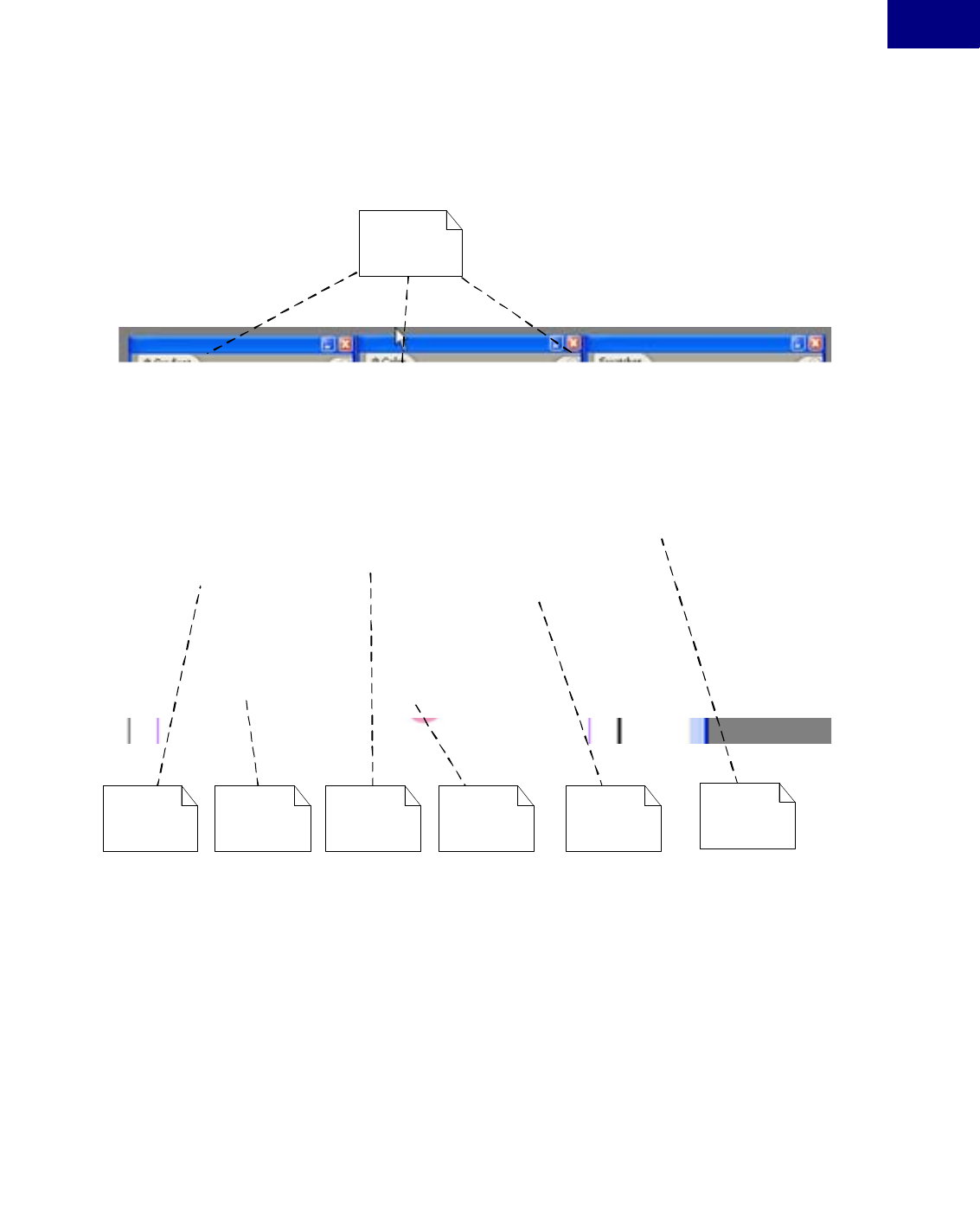
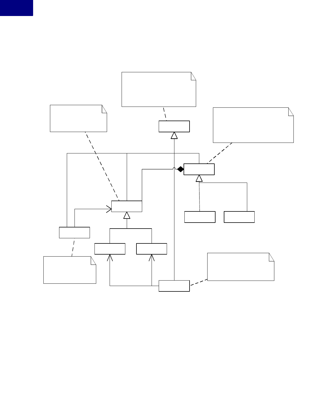
Graphics Fundamentals
Colors and swatches
248
Figure 94 shows some of the key color-related concepts and the relationships among them.
FIGURE 94 Conceptual model for color
Figure 95 is a UML class diagram involving color-related boss classes. It shows the relationship
among color and swatch–related boss classes. The relationships also apply if you replace kDoc-
WorkspaceBoss with kWorkspaceBoss.
swatch
gradient
11
based on
A swatch is a rendering object
that can render document
objects. It can be normal color,
tint, mixed ink, or gradient.
Gradients are continuous, smooth
color transitions along a vector
from one color to another. It could
be linear or radial type.
A mixed ink consists of at
least one process color ink
and at least one spot color.
«subtype»
color
process
mixed ink
tint
radial linear
spot
«subtype»
«subtype»
1
1..*
based on 1
1..*
based on
«subtype»
«subtype»
«subtype»«subtype»
1
-Composite1..*
Tint is a percentage
of a color.
Color could be of type
process or spot.

Graphics Fundamentals 249
Graphics Fundamentals
Colors and swatches
FIGURE 95 Color-related boss-class diagram
Comparing Figure 95 to the to the conceptual diagrams, note the following:
zThe kDocWorkspaceBoss is used here to show where these boss classes belong. These inter-
faces also exist on kWorkspaceBoss.
zThe boss objects of type kPMColorBoss and kGradientRenderingObjectBoss and other
classes represent swatches directly. IRenderingObject is the signature interface.
zkPMColorBoss implements solid color, tint, mixed ink, process color, and spot color.
When swatches are created, modified, or deleted, the state of the swatch list changes. For a
detailed discussion of these changes, see “Swatch-list state” on page 296.
«bos s»
kDocWorkspaceBoss
«bos s»
kPMColorBoss
«bos s»
kPMInkDataBoss
1
*IGradientFill::GetNthGradientColorUID()
1
0..*
IID_IUICOLORLIST,
IID_ISWATCHLIST
1
*
IID_IINKLIST
«bos s»
kGradientRenderingObjectBoss
«bos s»
kAGMBlackBoxRenderingObjectBoss
«bos s»
kGraphicStateNoneRenderingObjectBoss
1
0..*
1
0..*
IID_ISWATCHLIST
1
0..*
1
*
1
*
1
*
1
*IInkResources::GetUsedInks().
The document workspace
IID_ISWATCHLIST and IID_IUICOLORLIST share
the same interface ISwatchList, but have different
implementations (kSwatchListImpl and
kUIColorListImpl respectively).
kPMColorBoss from IID_ISWATCHLIST is a swatch,
kPMColorBoss from IID_IUICOLORLIST is a UI color.
These four bosses
represent swatches.

Graphics Fundamentals
Colors and swatches
250
Swatches
A swatch is an abstraction that can represent a color, gradient, tint or mixed ink.
A rendering object implements the IRenderingObject interface. IRenderingObject represents
information about a color or gradient and exposes capabilities to render this information to a
device. The following are some of the boss classes that expose the IRenderingObject interface:
zkPMColorBoss represents colors (including tint and mixed ink)
zkGradientRenderingObjectBoss represents gradient.
zkGraphicStateNoneRenderingObjectBoss represents the absence of rendering information;
for example, this boss can represent no-fill or no-stroke attributes. This boss is used inter-
nally.
zkAGMBlackBoxRenderingObjectBoss is used for special page items created from Adobe
Illustrator® clipboard format. It is only for internal use.
Some methods of IRenderingObject take an IGraphicsPort item as an argument. IGraphicsPort
is an interface with methods that parallel PostScript operators like setcolorspace. The key
responsibility of the rendering object implementation is to set up the color space, tint, and
color components to draw to the graphics port. IRenderingObjectApplyAction is another
required interface on rendering objects. For more details on IRenderingObject, IRenderingOb-
jectApplyAction, IGraphicsPort, and the other interfaces on rendering object boss classes, see
the API reference documentation.
Solid colors
Color is represented by the kPMColorBoss class, responsible for representing solid colors,
including tints and mixed inks. In addition to the signature interface for a rendering object,
IRenderingObject, kPMColorBoss aggregates several other interfaces, including the following:
zIColorOverrides — Stores tint and color remarks so the kPMColorBoss also can represent
tint and special color types (e.g., reserved color). For details, see the API reference docu-
mentation.
zIInkData — Stores the ink information used by the color. InkType represents color type
(process or spot).
zIColorData — Represents color coordinates in a ColorArray vector and a color space.
There are three color spaces of interest:
zCMYK defines a color with four components: cyan, magenta, yellow, and black. Typically,
these components are represented by percentages.
zRGB represents colors with three components: red, green, and blue. Typically, these compo-
nents are represented by values between 0 and 255.
zLAB (more precisely, L*a*b*) is a device-independent color space
See “Color management” on page 252.

Graphics Fundamentals 251
Graphics Fundamentals
Colors and swatches
Gradients
Gradients are represented by the kGradientRenderingObjectBoss boss class, which aggregates
IRenderingObject as well as IGradientFill, representing gradient-specific properties. For
details, see the API reference documentation.
Gradients can be linear or radial; see the enum declaration of GradientType in GraphicTypes.h.
A gradient consists of one or more ranges of color, which are smooth interpolations between
gradient stop positions. The color is defined only at the gradient stop positions, with calculated
color values at intermediate positions. For more detail on working with gradients, see “Gradi-
ents” in InDesign Help.
Swatch lists
Rendering objects (IRenderingObject) are referenced in a swatch list (ISwatchList). The swatch
list (ISwatchList) is exposed on workspaces (IWorkspace). For examples of the swatch list (and
ink list) when an end user creates and applies swatches to page items in a document, see
“Swatch-list state” on page 296.
If you create a color through the Color panel, or create a new gradient through the Gradient
panel and then apply the gradient to a page item without creating a swatch beforehand, an
unnamed (or local) swatch is created in the swatch list. The unnamed swatches do not appear
in the Swatches panel, but they can be used for the strokes and fills of document objects by cli-
ent code.
User-interface color list
Colors and color names that appear in the application user interface in places like the Layers
panel and Tags panel are not the same ones used in representing color in the document. User-
interface colors also are stored in an ISwatchList interface on workspaces (IWorkspace), but
with the interface identifier IID_IUICOLORLIST.
User-interface colors are normally RGB only. A key utility interface for working with user-
interface colors is IUIColorUtils. User-interface colors are represented by kUIColorDataBoss
rather than a rendering-object boss class.
Inks
Colors are ultimately printed by means of inks; for example, CMYK color separation is per-
formed before printing to a four-color press. Inks are represented by the kPMInkDataBoss boss
class.
The rendering object classes like kPMColorBoss or kGradientRenderingObjectBoss aggregate
the IInkResources interface, with which you can refer to the inks used in a color (or other page
item) by using the IInkResources::GetUsedInks method, then querying for IPMInkDataBoss.
IInkData::GetInkUIDList returns an empty list when the color type is process. IInkData is an
interface on kPMColorBoss.
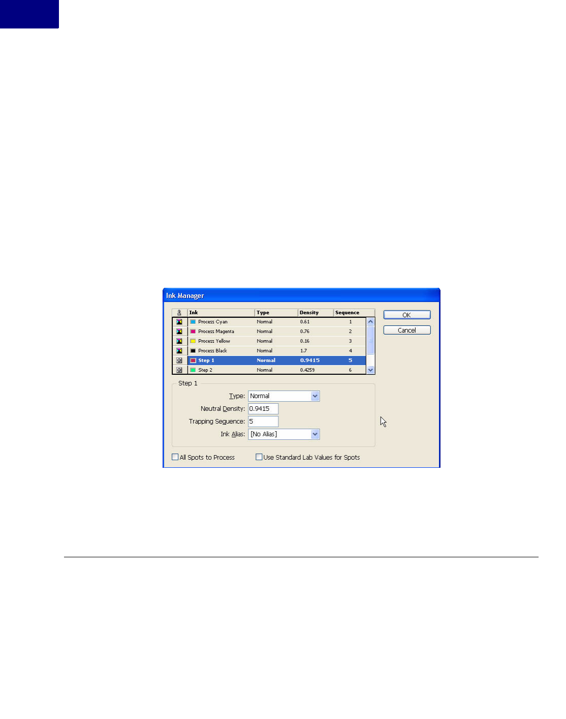
Graphics Fundamentals
Color management
252
There is an IInkList interface on the workspace boss classes that specifies the inks needed for
all swatches in the document and application. The ink list contains process inks and zero or
more spot inks.
The relation between inks and the swatch list is fairly direct: adding a new spot color to the
swatch list and applying it to a document object results in a new entry in the ink list. However,
creating another swatch that is a process color and applying it does not necessarily change the
entries in the ink list, if the process inks needed to print this new color already are in the ink
list.
The ink-manager feature (Ink Manager in the Swatches panel menu) shows the inks associated
with the contents of the swatch list. For example, if the swatches in the document were defined
in terms of four process colors and two spot colors, the ink-manager user interface is similar to
that shown in Figure 96. For information on how to work with the ink manager and iterate
through the ink list, see the “Graphics” chapter of Adobe InDesign CS4 Solutions.
FIGURE 96 Ink Manager dialog box
It is necessary to preflight documents to ensure they print correctly when submitted to the
press. As far as color is concerned, it is necessary to identify the inks that must be loaded in the
press for a job to print correctly.
Color management
The purpose of color management is to get accurate color on all kinds of devices. Color-man-
agement modules provide color-conversion calculations from one device’s color space to
another, based on ICC device profiles. For detailed descriptions of the color spaces used by
InDesign, see “Color spaces” on page 300.

Graphics Fundamentals 253
Graphics Fundamentals
Color management
ICC profiles
An ICC profile is a record of the unique color characteristics of a color input or output device.
An ICC profile contains data for the translation of device-dependent color to L*a*b* color. The
following illustrates the concept of translation from the L*a*b* color space to RGB and CMYK
color spaces using ICC profiles:
zL*a*b* = RGB + ICC profile
zL*a*b* = CMYK + ICC profile
With an ICC profile, color-management systems can do the following:
zTranslate a user-defined, device-specific color to a device-independent, L*a*b* color. For
example, if the user creates an RGB color for a specific computer monitor, that color could
be translated to L*a*b*.
zTranslate a L*a*b* color to a device-specific color. For example, when printing to a printer,
the L*a*b* color is translated to a CMYK color.
Color-management workflow
Color management within InDesign is relatively complex because of the following:
zInDesign supports multiple color spaces per document. For example, a user could assign
text in one paragraph an RGB color, another paragraph a CMYK color, and so on.
zInDesign supports external links (by means of ILink) to assets that can have different color
settings than those used in the document.
There are three levels of ICC profile sets involved in InDesign:
zImage ICC profile — This is embedded in the image file when the image is created.
zDocument ICC profile — This is associated with a particular InDesign document.
zApplication ICC profile preference — This is the default profile of the application. The
default profile is assigned to any new document.
InDesign features relating to color management are described comprehensively in “Color Man-
agement” in InDesign Help.
Data model for color management
The implementation of color management is somewhat complex. The class diagram in
Figure 97 illustrates some color management-related boss class relationships in InDesign.
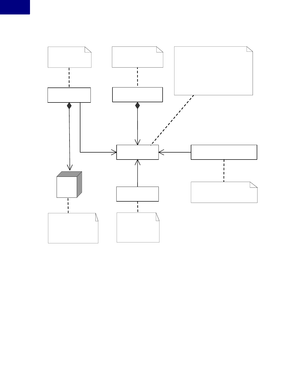
Graphics Fundamentals
Color management
254
FIGURE 97 Color management
Color presets
Outside the application, predefined Adobe color-management settings are stored in color pre-
set files, which are saved at the following location:
Windows:
Program Files\Common Files\Adobe\Color\Settings\
Mac OS:
Library/Application Support/Adobe/Color/Settings
These presets are shared among all Adobe Creative Suite® applications, to make it easier to
achieve consistent color across the suite. The kWorkspaceBoss boss class aggregates the IColor-
PresetsManager interface, which is responsible for managing the presets, like loading color pre-
Color
preset
files
<<boss>>
kWorkspaceBoss
<<boss>>
kDocWorkspaceBoss
<<boss>>
kCMSProfileBoss
<<boss>>
kDocumentPresentationBoss
<<boss>>
kImageBaseBoss
Application
preferences
Color preset files are
installed during
InDesign installation
and shared with other
Adobe applications.
Images may
each have their
own color
profile.
The document
workspace
Document window for
proofing
ICMSProfileList
11
1..*
1
1..*
ICMSProfileUID
1..* 1
1
0..*
IColorPresetManager
IColorPresetSettings ICMSProofing
The color profile. Note: although
both application-preference and
document-side bosses
(kDocumentPresentationBoss and
kImageBaseItem) can refer to a
profile by UIDRef, they are pointing
to different objects, because they
are at different databases.

Graphics Fundamentals 255
Graphics Fundamentals
Color management
set files and saving customized presets. The settings of the current preset are populated into the
IColorPresetsSettings interface on kWorkspaceBoss.
The IColorPresetsSettings interface stores the working color-management settings of the appli-
cation, like RGB and CMYK, the ICC profile, and color-management policies. In the user
interface, the color-management settings are accessed through the Color Settings dialog box.
Color profile
The kCMSProfileBoss boss class represents a color profile. The ICMSProfile interface on kCM-
SProfileBoss stores information about the type and category of the profile. This interface has a
method for getting and setting profile data by accessing the IACESpecificProfileData interface
on the same boss.
The ICMSProfileList interface, exposed on workspaces (IWorkspace), indicates which profiles
are used, as either document profiles or image profiles, and which are assigned to specific doc-
ument categories (e.g., document CMYK and document RGB). A profile can be assigned to
each category of a document through Edit > Assign Profiles.
Image settings
Any imported image can have either an embedded profile or a profile already assigned to it.
(See Object > Image Color Settings.) The ICMSItemProfileSource interface aggregated on the
kImageBaseItem boss class stores the basic profile-assignment type (see the enumeration ICM-
SItemProfileSource::ProfileSourceType) and the name of the image's embedded profile, if any.
If an image uses an external profile or an embedded profile, an interface IPersistUIDData (with
interface identifier IID_ICMSPROFILEUID) stores the UID of an instance of kCMSProfile-
Boss, so you will be able to instantiate an interface on kCMSProfileBoss from this UID and get
the profile data needed.
There is no link from a specific profile to the images that use that profile. To find the images
that use a specific profile in the profile list, you need to iterate through all images using the
links manager (ILinksManager).
Rendering intent
The ICMSSettings interface is aggregated on docworkspace (kDocWorkspaceBoss) and the
kImageBaseItem boss class, a superclass for image boss classes, which stores rendering-intent
information for document and image page item. Please use the ICMSUtils interface to set ren-
dering intent, rather than manipulating the ICMSSettings interface directly.
For application defaults, rendering intent are determined by IColorPresetsSettings interface
aggregated on kWorkspaceBoss. You can use GetIntent and SetIntent methods to manipulate
rendering intent.
Proofing
The ICMSProofing interface is aggregated on kWorkspaceBoss, kDocumentPresentationBoss,
and several user-interface panels. The implementation on kWorkspaceBoss is a proofing pref-
erence, and the implementation on kDocumentPresentationBoss is responsible for setting up
drawing when users choose to proof their design using the Proof Setup dialog box. This ICM-
SProofing interface stores the proofing settings as well as a proofing profile.
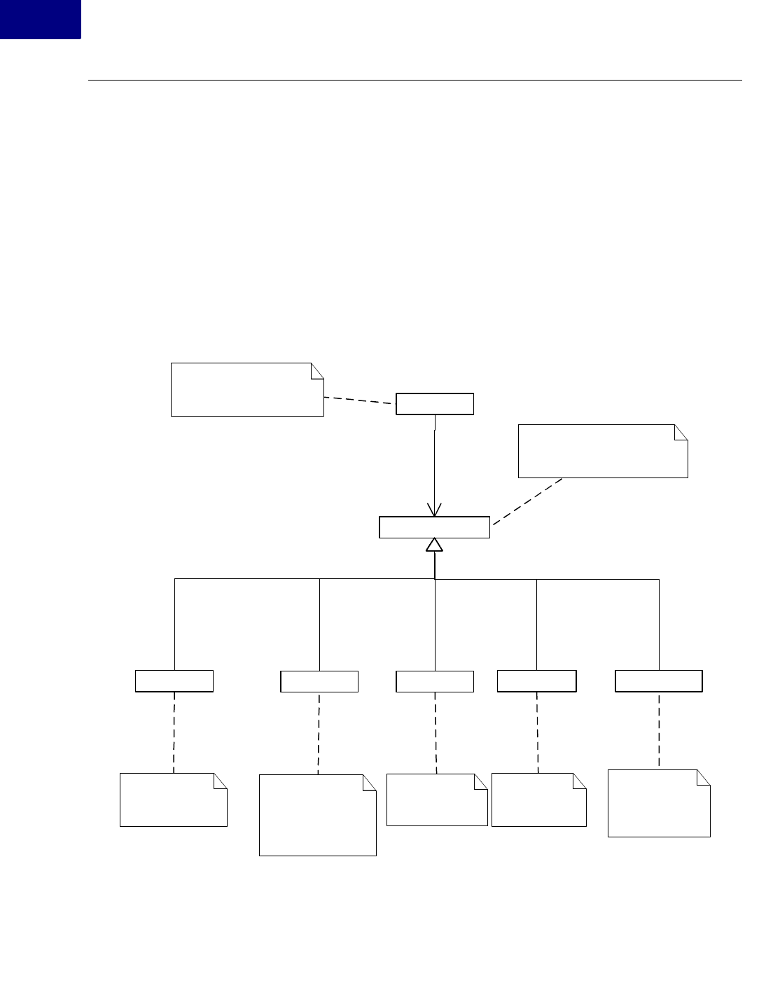
Graphics Fundamentals
Graphic attributes
256
Graphic attributes
A graphic attribute describes an aspect of how a page item should be drawn. There are many
kinds of graphic attribute for properties like stroke color, fill color, stroke type, and stroke
weight. This section introduces the concepts involved and describes specific sets of graphic
attributes for features like page-item rendering.
Graphic-attribute data model
Figure 98 is a conceptual model of the graphic attributes associated with a page item.
FIGURE 98 Graphic-attribute conceptual model
A page item owns a collection of graphic attributes, specifying properties that control how the
page item is drawn, like stroke color, stroke style, and transparency. Each attribute is responsi-
Graphic attributes
Page item
A graphic attribute controls
one aspect of the drawing of
an object.
A page item that carries
a various number of
graphic attributes
Other various
attributes
Stroke style ...
Stroke color Gradient fill Transparency
«subtype»
«subtype»
«subtype»
«subtype»
Stroke color
controls the
color of stroke.
Stroke style
attribute controls
the style of
stroke (dotted
line, etc.).
1
0..*
owns
Gradient fill
controlls fill
of the object.
Transparency
controls the
transparecy
effect.

Graphics Fundamentals 257
Graphics Fundamentals
Graphic attributes
ble for a single aspect of how the page item is drawn. A list of graphic attributes is represented
by IGraphicStyleAttributeBossList.
Figure 99 shows the graphic-attribute UML class model of a drawable page item.
FIGURE 99 Graphic attributes on a page item
There are several important interfaces on a page item responsible for managing graphic
attributes:
zIGraphicStateIsApplicable.
zIGraphicStyleAttributeBossList (IID_IGRAPHICSTYLE_OVERRIDES), which stores a list
of graphic attributes that override those stored in a graphic style.
«boss»
kDrawablePageItemBoss
«boss»
kGraphicStyleBoss
«partial-implementation»
IGraphicStyleAttributeBossList
1
1
IID_IGRAPHICSTYLE_DESCRIPTOR
IGraphicStyleDescriptor
1
1
IID_IGRAPHICSTYLE_OVERRIDES
IGraphicStyleAttributeBossList
1
1
IID_IGRAPHICSTYLE_DEFINITION
IGraphicStyleAttributeBossList
1
1
IID_IGRAPHICSTYLE_REFERENCE
IGraphicStyleReference
1
1
IID_IGRAPHICSTYLE_IS_APPLICABLE
IGraphicStateIsApplicable
IGraphicStyleAttributeBossList
is a list of individual graphic
attribute boss objects.
«boss»
Individual kGraphicsAttrBoss
1
0..*
Iterating method
Drawable page items such as
Spline, Group, and Image have
graphic attributes applied.
IID_IGRAPHICSTYLE_IS_APPLICABLE
can answer whether an attribute is
applicable to the page item.
IID_IGRAPHICSTYLE_DESCRIPTOR
can be used to query an attribute
or return a list of attributes applied
to the page item.
Every individual attribute
class inherits from
kGraphicsAttrBoss.

Graphics Fundamentals
Graphic attributes
258
zIGraphicStyleAttributeBossList.
zIGraphicStyleDescriptor.
zIGraphicStyleReference.
For details on each interface’s responsibilities, see the API reference documentation.
Representation of graphic attributes
Graphic attributes are represented by boss classes with the signature interface IGraphicAt-
tributeInfo. The graphic attributes in the application appear in the API reference documenta-
tion for IGraphicAttributeInfo. Typically, they derive from the kGraphicsAttrBoss boss class.
The IGraphicAttributeInfo interface stores the name and type of the attribute. Some graphic
attributes have corresponding text and table attributes. See “Mapping graphic attributes
between domains” on page 260.
Graphic attributes have additional data interfaces that specify their values. Because there are
many graphic attributes, sometimes it is a challenge to determine which attribute boss corre-
sponds to which attribute. For a description of attributes, see “Catalog of graphic attributes” on
page 301.
Most of the attributes represent a single value, like a boolean, int16, int32, PMPoint, or
PMReal. These simple attributes generally are backed by interfaces like IGraphicAttrBoolean,
IGraphicAttrInt16, IGraphicAttrInt32, IGraphicAttrPoint, and IGraphicAttrRealNumber. For
example, kGraphicStyleEvenOddAttrBoss (IGraphicAttrBoolean) corresponds to the even-odd
fill rule when you have a compound path; set it to kTrue to use the even-odd rule or to kFalse
to use the default InDesign fill rule (non-zero winding fill rule).
Some other attributes have UID values. For example, attributes related to object rendering refer
to a rendering object through the IPersistUIDData interface. For more information, see “Ren-
dering attributes” on page 261.
Some other attributes have ClassID values, which are all stored with IGraphicAttrClassID.
These attributes are used to specify stroke effects of a page item. See “Stroke effects” on
page 262.
Graphic styles
A graphic style (kGraphicStyleBoss, UID-based) is a collection of graphic attributes. The
IGraphicStyleNameTable interface exposed on workspaces (IWorkspace) stores the names and
UIDs of graphic styles.
There are two key interfaces on kGraphicStyleBoss:
zIGraphicStyleInfo stores the name and UID for the style on which this style is based (the
style from which this style inherits).
zIGraphicStyleAttributeBossList (IID_IGRAPHICSTYLE_DEFINITION) stores the list of
graphic attributes this graphic style owns.
Only [No Style] is used in the InDesign CS4 and InCopy CS4 implementations. kGraphicStyle-
NoneBoss implements the default [No Style], which is set up during application start-up (for

Graphics Fundamentals 259
Graphics Fundamentals
Graphic attributes
the session workspace) and document creation (for document workspace). This style stores
default settings of various graphic attributes, like stroke weight as 1.0 and stroke type as solid
line.
Although there still is a public API to work with user-named graphic styles, these are depre-
cated since the introduction of object styles. Adobe applications do not define user-named
styles using graphic styles as the container. We recommend you avoid using graphic styles for
this purpose in your plug-ins. User-named styles are supported by the object styles feature.
An object style is a style that defines the appearance of a page-item object. An object style con-
tains settings of a set of attributes, including graphic attributes and text attributes. An object
style is a superset of graphic style.
Graphic state
Graphic state is the representation of the current state of things related to the graphic
attributes. Usually this is a collection of graphic attributes for the current selection or, if there is
no selection, the current defaults. The graphic state is represented by kGraphicStateBoss.
An active graphic state refers to the graphic state at the current context. Active graphic state can
be accessed through IGraphicStateAccessor, aggregated on kDocWorkspaceBoss or kWorkspa-
ceBoss. A reference to an interface of the active graphic state also can be acquired through
IGraphicStateUtils::QueryActiveGraphicState, aggregated on kUtilsBoss.
The kGraphicStateBoss boss class aggregates interfaces like IGraphicStateRenderObjects and
IGraphicStateData.
IGraphicStateRenderObjects
This interface is key to the graphic state. It can be acquired from the IGraphicStateUtils utility
interface by querying active graphic state or the graphic state of a specific database. For sample
code that shows how to acquire the interface, see the “Graphics” chapter of Adobe InDesign CS4
Solutions.
Given this interface, you can query the current IRenderingObject interface for the specified
rendering class or the active rendering class in the graphic state. The active rendering could be
fill or stroke.
Changing the graphic state
Changing any graphic attributes changes the graphic state. Virtually every user-interface
action—like selecting a new swatch, picking a color in the Color Picker panel, switching fill and
stroke, selecting a different stroke style, changing selection, or changing the front document—
causes a change to current active graphic state. You can use methods on IGraphicAttributeUtils
or IGraphicStateUtils to acquire appropriate commands.
kGraphicStateBoss also aggregates an ISubject interface. Changes to the graphic state can be
observed by listening along the IID_IGRAPHICSTATE_RENDEROBJECTS and
IID_IGRAPHICSTATE_DATA protocols.
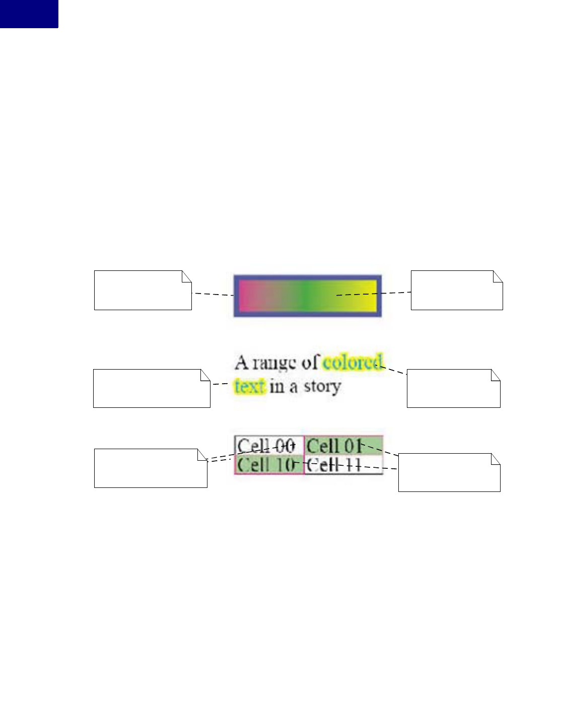
Graphics Fundamentals
Graphic attributes
260
Creating new page items using default attributes
When a new page item is created, default attributes in the graphic-state boss objects are copied
and applied to new page items when you specify INewPageitemCmdData::kDefaultGraphicAt-
tributes as attrType parameter on spline creation methods on IPathUtils.
Mapping graphic attributes between domains
Some graphic attributes also can be applied to text or tables. For example, Figure 100 shows
stroke and fill colors and gradients applied to text, table cells, and a spline item. Although the
intent is the same in each case, the attributes differ in each case. Text and tables have some
attributes corresponding to the graphic attributes.
FIGURE 100 Stroke and fill attributes
There are independent attributes for each of these domains. For example, an attribute repre-
sented by kGraphicStyleFillRenderingAttrBoss on a spline page item is represented by the
kCellAttrFillColorBoss type when the attribute is applied to a table cell, and it is represented by
the kTextAttrColorBoss type when the attribute is applied to a text run.
When a graphic attribute is applied to a text run, there is a conversion process in which a new
text attribute is applied as an override to the run. The same applies when trying to apply a
graphic attribute to a table; the graphic attribute can be converted to a corresponding table
attribute.
Not all graphic attributes apply to text or tables. The IGraphicAttributeInfo::IsTextAttribute
and IGraphicAttributeInfo::IsTableAttribute methods return kTrue if the corresponding
attribute in the respective domain exists. IGraphicAttributeInfo::CreateTextAttribute returns a
kGraphicStyleFill
RenderingAttrBoss
(Gradient)
kTextAttrColorBoss
(Cyan)
kCellAttrFillColorBoss
(green)
kGraphicStyleStroke
RenderingAttrBoss
(blue)
kTextAttrStrokeColorBoss
(yellow)
kCellStrokeAttrDataBoss
(red)

Graphics Fundamentals 261
Graphics Fundamentals
Rendering attributes
text attribute that maps onto the equivalent graphic attribute. Similarly, IGraphicAt-
tributeInfo::CreateTableAttribute returns a table attribute that maps onto the equivalent
graphic attribute. Each of these methods is expected to return a non-zero value if the
Is<XXX>Attribute method returns kTrue.
The selection suites (e.g., IGraphicAttributeSuite and IGradientAttributeSuite) make it
straightforward for client code to change the properties of a selection; the client code needs to
work with only the graphic attributes. There is no need to worry about whether the selection is
text, choosing the specific text attribute, and whether the selection is text, table, or layout.
The mapping between different domains is hard-coded. New graphic attributes added by third-
party software developers may provide their own mapping by overriding the default imple-
mentations of IGraphicAttributeInfo. The mappings between graphic attributes and text
attributes are shown in Table 85. The mappings between graphic attributes and table attributes
are shown in Table 86. Note that the mapping between graphic attributes and table attributes is
many-to-one rather than one-to-one because; for example, the kCellStrokeAttrDataBoss boss
class can represent information about multiple stroke parameters, whereas each of the corre-
sponding graphic attributes refers to one parameter.
Rendering attributes
A rendering attribute refers to a swatch to be used when drawing an aspect of a page item. Ren-
dering attributes are a special kind of graphic attribute that refer to their associated swatch by
UID. The swatch can be a color, gradient, tint, etc.
Color-rendering attributes
A page item’s stroke, fill, or gap can be rendered independently. Table 58 lists color-rendering
attributes.
TABLE 58 Color-rendering attributes
Rendering-attribute class Description
kGraphicStyleFillRenderingAttrBoss Fill rendering object
kGraphicStyleFillTintAttrBoss Fill tint
kGraphicStyleGapRenderingAttrBoss Gap rendering object
kGraphicStyleGapTintAttrBoss Gap tint
kGraphicStyleStrokeRenderingAttrBoss Stroke rendering object
kGraphicStyleStrokeTintAttrBoss Stroke tint

Graphics Fundamentals
Stroke effects
262
Gradient attributes
Page items also can be rendered using gradients; however, multiple graphic attributes are
needed to represent a gradient. For example, you need to specify gradient fill angle, center, and
length. There is no characteristic signature for a gradient attribute other than the boss class
name; for the canonical graphic attributes, the boss-class name is of the following form:
kGraphicStyleGradient<graphic_attribute>AttrBoss.
A list of these boss classes is in the master attributes list in “Catalog of graphic attributes” on
page 301.
You can use the same color-rendering attributes class name to apply gradient attributes to page
items. IRenderingObjectApplyAction::PreGraphicApply automatically forwards the attributes
to appropriate gradient attributes. For example, if you are supplying kGraphicStyleFillRender-
ingAttrBoss, the method adds attributes including the following:
zkGraphicStyleGradientFillAngleAttrBoss
zkGraphicStyleGradientFillGradCenterAttrBoss
zkGraphicStyleGradientFillHiliteAngleAttrBoss
zkGraphicStyleGradientFillHiliteLengthAttrBoss
zkGraphicStyleGradientFillLengthAttrBoss
zkGraphicStyleGradientFillRadiusAttrBoss
The situation gets more complicated by the possibility of applying gradients to table cells; when
a gradient is applied to a table cell, additional cell-specific attributes are involved. For example,
kCellAttrGradientFillBoss and kCellAttrGradientStrokeBoss are table-cell attributes represent-
ing properties of gradients.
Stroke effects
There are several graphic attributes that define the look and feel of the stroke of a page item.
Some of these attributes are straightforward, like kGraphicStyleStrokeWeightAttrBoss, which
defines stroke weight.
Path stroker
A path stroker is responsible for the basic drawing of a path. To find existing path-stroker boss
classes, see the API reference documentation for IPathStroker. For information on how to add
custom path strokers, see “Custom path-stroker effects” on page 289.
IPathStrokerList allows you to access the list of available path strokers. IPathStrokerUtils pro-
vides utility methods to do the same thing.
The kGraphicStyleStrokeLineImplAttrBoss boss class specifies the class ID of a path stroker
that applies to a particular path.

Graphics Fundamentals 263
Graphics Fundamentals
Transparency effects
Path corners
A path-corner effect draws the corners of a stroked path. For a list of path-corner-effect boss
classes, see the API reference documentation for IPathCorner. For information on how to add
custom path corners, see “Custom corner effects” on page 290.
The kGraphicStyleCornerImplAttrBoss boss class specifies the class ID of the corner effect.
Path-end strokers
A path-end stroker (IPathEndStroker) draws the start and end of a stroked path. To find path-
end strokers, see the API reference documentation for IPathEndStroker. For information on
how to add custom path ends, see “Custom path-end effects” on page 290.
The kGraphicStyleLineEndStartAttrBoss boss class specifies the class ID of the line-end (for
example, arrow) style at the starting side of a line. The kGraphicStyleLineEndEndAttrBoss boss
class specifies the class ID of the line-end style at the terminating side of a line.
Transparency effects
Concepts
Transparency effects are a set of graphic attributes that define color blending for overlapped
page items and backgrounds. Common transparency effects include basic transparency, drop
shadow, and feather. Figure 101 shows examples of transparency effects supported in InDesign.
Graphics Fundamentals
Transparency effects
264
FIGURE 101 Transparency effects supported in InDesign
No effect
Outer glow
Satin
Gradient feather
Drop shadow
Inner glow
Basic feather
Inner shadow
Bevel & emboss
Directional feather

Graphics Fundamentals 265
Graphics Fundamentals
Transparency effects
These transparency effects can be divided into two classes:
zOuter effects include drop shadow, outer glow, and outer bevel, and emboss. In this class of
effects, a copy of the artwork is converted to raster; the raster has the effects applied and is
then drawn first, the artwork is then drawn on top of the effect. (The exception is emboss,
in which artwork is dean first then the effect is drawn on top)
zInner (clipped) effects include inner shadow, inner glow, inner bevel, satin, and feathers. The
artwork fill and shape is combined with the effect parameters, and the result is a new fill for
the artwork. Because the fill is clipped to the artwork shape, this class of effect is highly
dependent on the type of artwork involved.
Common controlling parameters
Different transparency effects are controlled by different sets of parameters, Some of these
parameters are used commonly in defining different transparency effects.
Opacity
Opacity is the converse of transparency. It represented by the following formula:
opacity = (1.0 - transparency)
Opacity is expressed as a percentage, where 0% is completely clear and 100% is completely
opaque. Page items can have individual opacities assigned to them. Items can be grouped and
have a group opacity assigned, which is combined with the individual opacities to calculate the
resultant color on the backdrop.
Blending mode
Blending mode defines how the background (backdrop) and foreground (source) colors inter-
act. In the physical world, transparency is the result of light passing through translucent mate-
rials. Blending modes are somewhat different: they do not try to model the complex physics of
transparency; rather, they are analytic expressions that produce interesting visual effects. The
following blending modes are encountered often: normal, multiply, and screen. There also are
blending modes related to color spaces, like hue, saturation, and color-blending modes.
Blending modes are vector functions that take as input the object source color and backdrop
color and produce a resulting color that is the new color of the backdrop. This is not pixel-
based blending; rather, this is in terms of points with no dimension. The colors that are the
input for a blending function need to be specified in a common blending-color space (docu-
ment CMYK or RGB). This is specified document-wide through the Edit menu.
A blending mode is described by an analytic expression that specifies how to calculate the
resultant backdrop color given the mode, current backdrop color, foreground color, and opaci-
ties of the background and foreground. Ordinarily, a blending function is a vector function:
C_r = F(Mode, C_b, C_f, O_b, O_f)
where C_r is the resultant backdrop color, Mode is the blending mode, C_b is the current back-
drop color, O_b is the opacity of the backdrop, and O_f is the opacity of the foreground (source
object).

Graphics Fundamentals
Transparency effects
266
In general, the blending function gives the resulting color at a point. The two-dimensional
coordinates in the backdrop plane also can be specified in the expression above, to give an
exhaustive expression for a blending function.
Normal blending mode is a trivial blending mode, which specifies that the resulting blend is the
value of the source color. The result of a normal blend is given by the following formula:
B(C_b, C_s) = C_s
where B is the blending function, C_b is the backdrop color, and C_s the source-object color.
Multiply-blending mode is the scalar product of the backdrop color and the source object color.
For an additive color space like RGB, the multiply-blending mode is calculated by taking the
component-wise product of the two vectors. The multiply blending mode is given by the fol-
lowing formula:
B(C_b,C_s) = C_b•C_s
With an additive color space, the resulting blend color is darker than either of the two inputs,
so the multiply-blending mode also is referred to as shadow mode.
For a subtractive color space like CMYK, it is necessary to take the reciprocal of the colors. The
expression for the blending mode is identical to the above, but with the substitution of (1-c) for
the color.
Screen-blending mode often is referred to as highlight mode. The analytic expression for screen
blending mode is given by the following formula:
B(C_b, C_s) = 1 - (1-C_s)•(1-C_b)
This can be thought of as the reciprocal of multiply mode, in the sense that it is multiplying the
reciprocal input colors and using the reciprocal of the result. The resulting components are
larger than the corresponding input components, so the net effect is a highlight of the two col-
ors.
Position
Position determines the location of a transparency effect. It could be specified as an X offset-Y
offset pair or a distance-angle pair. They can be used to calculate each other. InDesign also have
a concept of global light, which is the angle of the light and is maintained the same for every
object of a document.
Size
Size refers to the size of a transparency effect. It is specified in number of points. For example, a
drop shadow with size of 0p5 mains the shadow width is 5 points.
Spread
Adding spread outsets the object's outline before blurring, so the effect seems bolder. Spread is
expressed as a percentage of the blur width. Typically, spread is for outer effects, Spread is the
percentage of the size or blur width that is simply outset rather than tapered off. For example,
for a drop shadow with a blur width of 10 points and a spread of 0%, you get 10 points of blur.
If the spread is 50%, however, you get 5 points of outset and 5 points of blur. If the spread is
100% you get 10 points of outset and no blur.

Graphics Fundamentals 267
Graphics Fundamentals
Transparency effects
Noise
Random noise can be added to the transparency effect, to give it a rougher appearance.
Choke
Choke is conceptually the same as spread, but for effects that go “inward,” like inner glow. For
example, an inner glow with size 10 points and spread 50%, you get 5 points of inset and 5
points of blur.
Feather width
Feather width is conceptually the same as size, simply the total amount of inset applied. For
example, if you have 10 points of width, the feather extends from the edge of the object to 10
points inside the object. For directional feather, you can specify width in four directions.
Basic transparency
Basic transparency is an effect that lets the viewer see through an object. The Transparency
panel in the user interface allows end users to specify the transparency attributes of selected
page items, including blending mode, opacity, whether these should be isolated, and whether
knockout is required.
Transparency in group items
A group item is a collection of one or more page items. Transparency can be applied to a page
item or a group item. Transparency groups are constructs to work around real-world problems
involving grouped transparent objects. The application allows the assignment of opacity,
knockout, and isolation properties to transparency groups (i.e., collections of page items).
These group properties determine how a group of page items interact transparently with the
backdrop. It also is possible to specify knockout and isolation properties for one page item.
Group attributes combine with those of the objects in the group. For example, if objects have
50% opacity and the group has 50% opacity, the resulting opacity of the composited objects is
equivalent to an object with 25% opacity.
These group properties are independent of, and in addition to, the opacities and blending
modes of the individual objects. The objects interact with each other and the backdrop using
their individual opacity and blending modes. The group opacity and group-blending mode do
not affect the interaction of the individual objects with each other, but they do affect the inter-
action of these objects with the backdrop.
Knockout groups
A knockout group is a group whose individual elements do not interact with each other but do
interact with the backdrop. The objects within the group paint opaquely over each other, but
compositing occurs with the initial backdrop data. An example in which this is useful is a
group that consists of the fill and the stroke of a path. If the group is not a knockout group,
there is an interaction of the fill and stroke in the region they have in common, which often is
undesirable. Instead, the desired effect is to have the stroke opaquely cover the fill in the com-
mon overlap, and to have each interact with the backdrop with respect to their individual opac-
ities and blending modes. Figure 102 shows a comparison of transparency effects with and
without knockout groups.
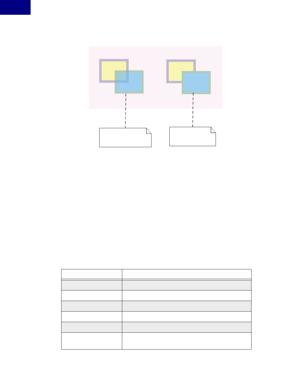
Graphics Fundamentals
Transparency effects
268
FIGURE 102 Knockout groups
Isolated groups
An isolated group is a group whose individual elements do not blend with the backdrop inde-
pendently but do blend with the backdrop as a group. An isolated group can be represented by
its group object of color and opacity values. By definition, an isolated group can be represented
by color and opacity values that are independent of the backdrop into which it is to be compos-
ited.
Drop shadow
In the real world, drop shadow is generated when light is blocked by an object. As represented
in graphics, drop shadow is a blurred representation of the shape of an object, offset by a user-
specified distance and drawn below the object.
The parameters that control a drop shadow include the ones listed in Table 59.
TABLE 59 Drop-shadow parameters
Parameter Description
Blending mode See “Blending mode” on page 265.
Noise See “Noise” on page 267.
Object-knockout shadow Object does not interact with shadow.
Opacity See “Opacity” on page 265.
Position See “Position” on page 266.
Shadow honors other
effects
Shadow can be the result together with other transparency
effects.
Transparency without
knockout group
Transparency with
knockout group
Graphics Fundamentals 269
Graphics Fundamentals
Transparency effects
Inner shadow
Inner shadow is very similar to drop shadow. It adds a shadow that falls just inside the edges of
the object, giving the object a recessed appearance. The parameters that control an inner
shadow effect are like those of drop shadows (see Table 60).
TABLE 60 Inner-shadow parameters
Outer and inner glow
Glow is a graphic effect that makes an object appear to shine as if with intense heat. Outer glow
refers to the glow effect applied to the outside edges of the object; inner glow refers to the glow
effect applied to the inside edges. The parameters that control outer glow are listed in Table 61.
TABLE 61 Outer-glow parameters
The parameters that control inner glow are listed in Table 62.
Size See “Size” on page 266.
Spread See “Spread” on page 266.
Parameter Description
Blending mode See “Blending mode” on page 265.
Opacity See “Opacity” on page 265.
Position See “Position” on page 266.
Size See “Size” on page 266.
Noise See “Noise” on page 267.
Choke See “Choke” on page 267.
Parameter Description
Blending mode See “Blending mode” on page 265.
Opacity See “Opacity” on page 265.
Technique The method to produce angled corners. You can get a
smooth/rounded effect (softer) or a mitered effect (precise).
Size See “Size” on page 266.
Noise See “Noise” on page 267.
Spread See “Spread” on page 266.
Parameter Description
Graphics Fundamentals
Transparency effects
270
TABLE 62 Inner-glow controlling parameters
Bevel and emboss
The bevel and emboss effect is a kind of simulation of how an object would look if it were
“puffed up” into the third dimension. The parameters that control bevel and emboss are listed
in Table 63.
TABLE 63 Bevel and emboss parameters
Parameter Description
Blending mode See “Blending mode” on page 265.
Choke See “Choke” on page 267.
Noise See “Noise” on page 267.
Opacity See “Opacity” on page 265.
Size See “Size” on page 266.
Source Indicates the “polarity” of the glow. “Center” means the center of
the object glows and the edges do not. “Edge” means the opposite.
Technique The method to produce angled corners. You can get a
smooth/rounded effect (softer) or a mitered effect (precise).
Parameter Description
Style A choice of inner bevel, outer bevel, emboss and pillow emboss.
Direction Indicates whether the object appears to be “sunken” or “raised.”
Technique Simulate effect made with smooth, chisel hard and chisel soft.
Soften The amount of blurring, more or less, that is applied to the
beveled result. This softens the effect so your bevel is not so harsh.
Size Width of the effect. See “Size” on page 266.
Depth Determines the intensity or sharpness of the bevel.
Angle The direction in the page-plane of the light source.
Altitude The angular distance above the page plane.
Highlight-
blending mode
See “Blending mode” on page 265.
Highlight opacity See “Opacity” on page 265.
Shadow-blending
mode
See “Blending mode” on page 265.
Shadow opacity See “Opacity” on page 265.
Graphics Fundamentals 271
Graphics Fundamentals
Transparency effects
Satin
Satin applies interior shading that creates a satiny finish. Table 64 lists its controlling parame-
ters.
TABLE 64 Satin parameters
Feather effects
Feather is a graphic effect that allows designers to create a smooth edge around a frame. InDe-
sign support three types of feathers: basic, directional, and gradient. The parameters that con-
trol a basic feather effect are listed in Table 65. Directional-feather effect feathers only on
selected sides of an object and takes additional parameters, listed in Table 66. Gradient effect
creates a linear or radial gradient of opacity around an object and allows parameters to define a
gradient, like gradient stops, gradient type and angle,; see Table 67.
TABLE 65 Basic feather parameters
TABLE 66 Directional-feather parameters
Parameter Description
Blending mode See “Blending mode” on page 265.
Opacity See “Opacity” on page 265.
Angle The direction of the light to create effect.
Distance The distance of the light to satin effect.
Size See “Size” on page 266.
Parameter Description
Feather width See “Feather width” on page 267.
Corners Diffused, sharp, or rounded.
Choke See “Choke” on page 267.
Noise See “Noise” on page 267. Feather noise is added only to the
feather region.
Parameter Description
Angle The direction of the feather.
Choke See “Choke” on page 267
Feather widths See “Feather width” on page 267.
Noise See “Noise” on page 267.
Shape First edge only, leading edges, or all edges.

Graphics Fundamentals
Transparency effects
272
TABLE 67 Gradient-feather parameters
Flattening
PostScript and PDF 1.3 have no representation of transparency information. To print or export
spreads with transparent information, it is necessary to generate nontransparent representa-
tions of the effects of transparency; this is known as flattening. In some cases, the interactions
may be among areas of solid color, in which case they can be replaced by a solid color in each
region of interaction. If images are involved, a composite image must be calculated that reflects
the contributions of the objects being composited, including any solid-color areas.
Dealing with text and gradients requires the application of additional rules. If a section of the
page is particularly complex, it can be faster to rasterize the area than to try to calculate all the
interactions; the flattener user interface supports this feature.
The flattener is an Adobe core technology. Its implementation comes from the Adobe Graphics
Manager (AGM) library, and it is used in other Adobe applications that support transparency
within vector graphics, such as Illustrator.
The end user has a degree of control over how the flattener is used. The Print dialog box has an
option to parameterize the flattener. The user may choose flattener presets and specify, for
example, that high quality is preferred over high speed. There is a trade-off between precision
of results and resources used. The lower the resolution, the quicker and less memory-intensive
the calculation.
Flattening is a complex and potentially resource-expensive process. Various optimizations are
required to implement transparency effectively, such as caching high-resolution images to file,
to ensure that the memory requirements are minimized. There also are complexities intro-
duced by OPI image substitution, because printing with transparency requires that embedded
files write graphic primitives into the output stream.
Transparency data model
Transparency features are complicated, but the principles of their implementation are not.
Basically, transparency implementation involves the following related aspects:
zGraphic attributes used to specify states and parameters of transparency effects
zPage-item adornments used to draw transparency effects
zService providers and drawing-event handler to participate in the printing process that flat-
tens the transparency before printing
Parameter Description
Gradient stops Defines the gradient
Gradient type Linear or radial gradient
Angle The direction of the gradient

Graphics Fundamentals 273
Graphics Fundamentals
Transparency effects
The boss classes responsible for transparency behavior are delivered mainly by the Transpar-
ency plug-in. The user interface to the effects is supplied by the TransparencyUI plug-in.
Transparency information is represented by graphic attributes, and transparency is rendered to
a device through page-item adornments.
Defining transparency: graphic-attribute bosses
Transparency effects are defined programmatically as a set of graphic attributes. These
attribute boss classes derive from kGraphicsAttrBoss and aggregate a collection of interfaces
that set and get a variety of graphic-attribute data types. For general information about graphic
attributes, see “Graphic attributes” on page 256. For a summary of the transparency=attribute
boss structure, see “Transparency-attribute boss structure” on page 273.
Transparency-attribute targets
Transparency effects can be applied to the object, stroke, fill, or content. They are called trans-
parency targets. Accordingly, transparency attributes can be categorized into different targets.
Attribute targets are defined as enums in IXPAttributeSuite::AttributeTarget.
Transparency-attribute groups
Each transparency effect has a set of attributes to represent the parameters that control the
effect. Accordingly, transparency attributes can also be categorized into groups. Each group
corresponds to each transparency effect. Transparency-attribute groups are defined as enums
in IXPAttributeSuite::AttributeGroup.
Transparency-attribute data types and values
Different transparency attributes hold different types of data. The IXPAttributeSuite::Attribute-
DataType enum defines all possible data types a transparency attribute can have.
IXPAttributeSuite::AttributeValue is a class that can hold values for any of the attributes. It
serves as a generic container for get and set functions.
Transparency-attribute boss structure
Transparency-attribute bosses are organized as a three-level inheritance. The most generic level
is the kGraphicsAttrBoss. This implies transparency attributes work and can be manipulated
the same way as any other graphic attributes.
The next level is attribute groups. These attribute group bosses inherit from kGraphicsAttrBoss
and aggregate the IID_IOBJECTSTYLEATTRINFO interface with the kXPAttrInfoImpl imple-
mentation. These groups correspond to the transparency effects; see Table 68.
TABLE 68 Transparency-attribute groups
Group-attribute boss Transparency effect
kDropShadowAttrBoss Drop shadow
kVignetteAttrBoss Basic feather
kXPAttrBoss Basic transparency

Graphics Fundamentals
Transparency effects
274
The bottom level has the real transparency attributes that define every transparency. For exam-
ple, kXPBasicOpacityAttrBoss, kXPStrokeBlendingOpacityAttrBoss, kXPFillBlendingOpac-
ityAttrBoss, and kXPContentBlendingOpacityAttrBoss inherit from kXPAttrBoss and
aggregate the IID_IGRAPHICATTR_REALNUMBER interface. They define the opacity
attribute of basic transparency for object, stroke, fill, and content targets, respectively.
Transparency-attribute types
There are about 400 transparency attributes. You may still access them in the general graphic-
attribute way; however, the InDesign API also provides utility functions in IXPAttributeUtils to
manipulate transparency attributes more effectively. Part of that is the concept of transparency-
attribute types.
Transparency-attribute types are defined as enums in IXPAttributeSuite::AttributeType. These
enums are divided into segments according to transparency targets and transparency groups.
The BASE_XP_ATTR(t,x) macro generates the base index of the segment. For example, if you
want to know the enum value of the first transparency attribute for controlling inner shadow
on the stroke of an object, use kStrokeInnerShadowBaseID + 1. kStrokeInnerShadowBaseID is
calculated as BASE_XP_ATTR(kTargetStroke, kGroupInnerShadow).
A transparency-attribute type has a one-to-one mapping to transparency-attribute boss. You
can translate between AttributeTypes and attribute-boss ClassIDs using the GetAttribute-
ClassID and GetAttributeFromClassID methods on IXPAttributeUtils.
Drawing transparency: adornment bosses
To create a transparent rendering for an object, add an IAdornmentShape implementation to
the adornment boss class that provides the behavior for the object. The kBeforeShape and kAf-
terShape flags specify when to draw in response to the IAdornmentShape::GetDrawOrderBits
method. The IAdornmentShape::GetPaintedBBox method specifies the adornment bounding
box. Bound of the outer effects are larger than the object’s bounds.
Table 69 lists the adornment bosses responsible for drawing transparency effects. One adorn-
ment boss can draw multiple effects. The primary reason we do not have one adornment for
every effect is to limit the total number of adornments of a page item, for performance reasons.
kXPBevelEmbossAttrBoss Bevel and emboss
kXPDirectionalFeatherAttrBoss Directional feather
kXPGradientFeatherAttrBoss Gradient feather
kXPInnerGlowAttrBoss Inner glow
kXPInnerShadowAttrBoss Inner shadow
kXPOuterGlowAttrBoss Outer glow
kXPSatinAttrBoss Satin
Group-attribute boss Transparency effect
Graphics Fundamentals 275
Graphics Fundamentals
Transparency effects
TABLE 69 Boss classes that aggregate IAdornmentShape
Printing transparency: flattening
Before transparency is printed, transparency effects must be flattened. You can choose different
flattener presets to represent transparency using non-transparency representation, then print
the result as normal page items.
Managing flattener presets
Flattener presets are represented by kXPFlattenerStyleBoss. The key interface is IFlattenerSet-
tings, which defines settings of presets, directly corresponding to the Flattener Preset Options
dialog box.
The flattener preset is an application-wide preference. The IFlattenerStyleListMgr interface is
aggregated on kWorkspaceBoss and is responsible for managing all flattener presets. As with
other general presets, like print presets, the IFlattenerStyleListMgr implementation hooks flat-
tener presets into the generic presets dialog and provides an entry point for adding, deleting,
and editing flattener presets with respective commands.
The kSpreadBoss also aggregates IFlattenerSettings, which allows the spread to override the
flattener settings for a specific spread.
Printing-related bosses
Transparency participates in the printing process by iterating spreads for pages containing
transparency effects that require flattening. With these bosses, the print command can examine
transparency use, setting up viewport attributes and so on. Together with drawing in the spread
and page item, InDesign can achieve results that appear as if there are transparency interac-
tions, even though these are accomplished through flattened, opaque, drawing instructions.
See Table 70.
Boss-class name Description
kXPDropShadowAdornmentBoss Draws knockout drop shadows and outer glow.
kXPPageitemAdornmentBoss Draws blending and non-knockout drop
shadows.
kXPVignetteAdornmentBoss Draws basic feather, directional feather, and
gradient feather.
kXPInnerEffectsAdornmentBoss Draws inner effects, like inner shadow, inner
glow, bevel and emboss, and satin.

Graphics Fundamentals
Data model for drawing
276
TABLE 70 Printing-related boss classes
Data model for drawing
Presentation views
Drawing documents to the screen really means drawing to an application-layout presentation,
which is a platform-independent construct containing layout widgets that display the contents
of the document. Layout presentation is represented by kLayoutPresentationBoss, with the key
interface IDocumentPresentation. Note that kLayoutPresentationBoss is inherited from kWin-
dowBoss; however, it is very important not to use the IWindow interface for any layout-presen-
tation operation. Instead, always use IDocumentPresentation for operations like minimizing
the view. The IWindow on a kLayoutPresentationBoss is only for internal use. There may be
several layout presentations open at the same time; these can be hosted in one operating-sys-
tem window as tabbed document presentation views, or each layout presentation can be hosted
inside its own operating-system window.
In addition to the layout presentation, there are other windows/view containers in InDesign.
Dialog boxes and pop-up tips are application windows and are represented by the platform-
independent kWindowBoss object. The panel container, often referred to as palette, is repre-
sented by a PaletteRef. For more detail on these interfaces and their responsibilities, see the API
reference documentation.
To summarize, the application manages two main categories of views:
zDocument presentations have a document associated with them and display the content of
the document. They also are referred to as layout presentations. A document presentation
may not always correspond to a standalone operating-system window, because an operat-
ing-system window can have many document presentations in it. Note, however, that “win-
dow” is still being referred to throughout this document, because that is still a commonly
accepted term for the view to a document.
zUser-interface windows/palettes are used for dialog boxes, panels, and other types of win-
dows that do not have documents associated with them.
Most of the detail in the remainder of this section concerns drawing a layout.
Boss-class name Description
kXPGatherProviderBoss A document iterator provider that gathers
document-wide use of transparency.
kXPPrintSetupServiceBoss Implements print services to set up global color
profiles.
kXPDrwEvtHandlerBoss Transparency start-up and shut-down. Hooks
transparency into the draw manager.

Graphics Fundamentals 277
Graphics Fundamentals
Data model for drawing
Graphics context
Drawing requires a graphics context. When page items are called to draw, they are provided
with a GraphicsData object, which contains a pointer to an InDesign graphics context. Using
the application’s graphics context, page items can perform platform-independent drawing to
several of device contexts: screen, print, or PDF.
The graphics context for application drawing is described by an object derived from IGraphics-
Context, an abstract-data container interface. This interface is not aggregated on boss classes,
nor is it derived from IPMUnknown. Instead, implementations of IGraphicsContext are spe-
cialized for different drawing devices.
A graphics context is instantiated based on a viewport boss object (see “Viewport” on
page 277), IControlView interface pointer, and update region. Several important pieces of
information are stored in the graphics context object, including the following:
zThe current rectangular clip region for the drawing port.
zThe transform for mapping content to drawing device coordinates.
The transform describes the relationship of the content coordinates to the drawing-device
coordinates. For screen drawing, the drawing device is a window. The transform is based on
the IControlView implementation supplied at the time of the graphics-context instantiation.
During a normal screen-drawing sequence, this is the IControlView implementation on the
kLayoutWidgetBoss that instantiates the graphics context, so the transform is initialized to be
pasteboard to the application-window coordinates. During the drawing sequence, this trans-
form is modified to represent parent-window coordinates. For a description of coordinate sys-
tems related to drawing, see the “Layout Fundamentals” chapter.
Screen draws do not paint the entire document and then copy only a portion of it to the win-
dow. Instead, only the region of the window marked invalid is redrawn. The clip region stored
in the graphics context is applied like a mask, discarding any drawing outside the clip bounds.
During a drawing sequence, the clip represents the update region in the window and is stored
in window coordinates.
For drawing to the screen, AGM is used to provide the graphics context. An offscreen context
is used for drawing, to facilitate a smooth, flicker-free screen update. The drawing code renders
off-screen, and the result of the completed drawing is subsequently copied to the screen. For
more details, see “Offscreen drawing” on page 284. The use of off-screen contexts is transpar-
ent to page items when they draw. The graphics context provided to the page item hides these
implementation details.
Viewport
The application’s platform-independent API for drawing is provided by the viewport. Page
items use the IGraphicsPort interface on the viewport boss object for drawing. The viewport
boss object does not draw directly to the platform window; instead, the viewport boss object
draws through the AGM, which is specialized for the type of drawing device (for example,
PostScript printing or the screen). The specialization is transparent to clients of the graphics
context and the viewport boss object.

Graphics Fundamentals
Dynamics of drawing
278
A viewport boss object operates as a wrapper between the drawing client (often a page item)
and the underlying AGM code that defines the graphics context for the output device. There
are several different types of viewport boss classes, each tailored to a particular type of drawing
output. For a list of relevant boss classes and the responsibilities of the interfaces on the boss
classes, see the API reference documentation for IViewPort. For example, kWindowViewPort-
Boss is used for drawing to application windows.
Dynamics of drawing
Drawing the layout
Layout drawing is the process of drawing page items to the layout presentation. Layout is
described in depth in the “Layout Fundamentals” chapter. For more detail on how individual
page items are drawn, see “Drawing page items” on page 281.
Invalidating a view
InDesign drawing occurs in response to invalidation of a view, or region. Although InDesign
provides platform-independent APIs for invalidating a view, the APIs simply forward the inval-
idation to the operating system. The invalidation state is maintained by the operating system,
which generates update events to the application.
Invalidation can be caused by changes to the model (persistent data in a document) or direct
invalidation. Both use the same mechanism to invalidate a view.
Changes to the model are broadcast to interested observers with regular or lazy notification.
For example, the application uses an observer on the layout widget to monitor changes to page
items in the layout. When the observer receives notification of a change, it asks the subject of
the change to invalidate a region based on its bounding box.
Views can be directly invalidated by using the ILayoutUtils::InvalidateViews method. The col-
laboration of boss objects is shown in Figure 103.

Graphics Fundamentals 279
Graphics Fundamentals
Dynamics of drawing
FIGURE 103 Boss collaboration when invalidating a view
The ILayoutUtils::InvalidateViews method uses a document pointer to locate the views for a
document. For each view, the method gets the ILayoutController interface on the kLayoutWid-
getBoss and calls ILayoutController::InvalidateContent, which creates an invalidation region
equal to the view’s window. The invalidation region is passed to the IWindowPort::InvalRgn
method on the IWindowPort interface of the kWindowViewPortBoss corresponding to the
window. This method then passes the invalidation region to the operating system.
The invalidation region is then accumulated by the operating system, which generates a paint
message. The operating system sends an update message (event) to the InDesign event dis-
patcher, where the message is wrapped in a platform-independent class and routed to the event
handler on the appropriate window.
The window’s event handler calls indirectly the IControlView::Draw method. At that point, the
drawing sequence begins following the pattern for drawing a widget hierarchy; Draw uses the
IPanelControlData interface to locate each of its children and call Draw on the child’s IControl-
View interface. This means the kLayoutPanelBoss is called to draw, and it iterates each of its
child widgets (scroll bars, the layout widget, rulers, etc.).
The drawing sequence concludes with validating the contents of the window. This completes
the update cycle, from invalidation to redraw.
Layout drawing order
Layout presentations are updated in several steps that allow better performance and the oppor-
tunity to interrupt the drawing. Good performance is achieved by specializing the drawing
«boss»
kWindowViewportBoss
ILayoutUIUtils
«boss»
kLayoutWidgetBoss
Platform invalidation
*
*
InvalidateViews
*
*
ILayoutController::InvalidateContent
*
*
IWindowPort::InvalRgn

Graphics Fundamentals
Dynamics of drawing
280
operations according to the view’s z-order, whether the invalidation is due to a selection change
or because all objects changed.
At the level of the kLayoutWidgetBoss, several decisions are made behind the scenes for the
sake of drawing performance. The IControlView implementation on the kLayoutWidgetBoss
chooses what to draw based on the window’s z-order, the selection, and the update region.
Foreground and background drawing
If the window is the front view, two views may be drawn: a background view containing all
objects and a foreground view containing only the decorations for the selection. Offscreen
graphics contexts are created and cached for both views (see “Offscreen drawing” on page 284).
If the update region overlaps the window or the current front view was not the last view to have
been drawn, the background view is redrawn. If the selection is not empty, the foreground view
also is redrawn.
Based on the above rules, the kLayoutWidgetBoss IControlView filters the visible spreads and
calls their IShape::Draw methods through the InDesign draw manager. This filtering means
page items are not guaranteed to be called for a screen draw. The background draw then prop-
agates through the layout hierarchy, as described in “Spread-drawing sequence” on page 307.
After the background draw is complete, if the selection is empty, the background image is cop-
ied to the window and the draw is complete. If the selection is not empty, the foreground draw
starts by copying the background image to the foreground offscreen context. The selection is
drawn to the foreground, then the foreground image is copied to the window.
The use of foreground and background draws means a page item could be called twice during a
redraw: the first call to IShape::Draw in the order of the layout hierarchy for the background
draw, and the second call to IHandleShape::Draw in the order of the selection list for the fore-
ground draw.
If the window is not the front view, a more abbreviated drawing sequence takes place. Both the
document items and the selection are drawn to a foreground offscreen context, and it is copied
to the screen.
Z-order
Z-order is the order (depth) of page item objects in the direction perpendicular to the screen.
Z-order determines which object or part of an object is visible to the user. InDesign handles
three levels of z-order:
1. Window z-order — InDesign windows may overlap.
2. Layer order — InDesign documents are layered. InDesign draws page layers first, then other
document layers. For more information, see the “Layers” section of the “Layout Fundamen-
tals” chapter.
3. Page item z-order — On the same layer, page items are ordered according to their positions
in the parent object’s hierarchy. The child with index 0 is drawn first; the child with the
greatest index is drawn last. For more information, see the “Documents and the Layout
Hierarchy” section of the “Layout Fundamentals” chapter.

Graphics Fundamentals 281
Graphics Fundamentals
Dynamics of drawing
NOTE:Do not confuse z-order with foreground and background drawing. Z-order controls
what is visible to the viewer, whereas foreground and background are just bitmaps for
speeding up rendering.
Draw manager
Conceptually, kLayoutWidgetBoss calls each spread to draw. In reality, kLayoutWidgetBoss
calls through the InDesign draw manager. The draw manager is an interface that exists on each
viewport and is used to set clipping areas and initiate the drawing of any page element and its
children to that viewport. The draw manager can be used for drawing to the screen, PDF, and
print. Drawing in InDesign occurs on a spread-by-spread basis and is hierarchical. Without a
service like the draw manager, it would be hard to change the behavior of drawing in a sub-
hierarchy. Optionally, you can create a kDrawMgrBoss and use the IterateDrawOrder method,
which allows clients to iterate the document in the same manner as drawing, calling a client-
provided callback routine for every page item in the hierarchy, but without a graphics context.
Funneling all drawing activity through the draw manager provides three important features for
changing the behavior of drawing operations:
zClipping of areas to be drawn.
zFiltering of items to be drawn.
zInterrupting a drawing sequence.
Clipping and filtering provide a means to select items for the draw based on regions. The draw
manager maintains the current values for the clip and filter regions. Interruption of the draw-
ing sequence relies on the broader mechanism of drawing events. As items draw, they broad-
cast standard messages that announce the beginning and end of discrete drawing operations.
Drawing events are received by special handlers that register interest in particular types of mes-
sages, and each drawing-event handler has the opportunity to abort the draw at that point. Cli-
ents of the draw manager (like the layout widget) install a default drawing-event handler.
The draw manager provides services for hit testing, iterating the drawing order, and drawing.
Detail about how spreads are drawn is described in “Spread-drawing sequence” on page 307.
Drawing page items
When page items are called to draw, they are passed information about their drawing context,
including a GraphicsData object and IShape drawing flags (e.g., kPatientUser). For more infor-
mation, see the API reference documentation for these types. Page items use this information
to perform their drawing operations.
The IGraphicsPort interface is the InDesign interface for drawing and is aggregated on all
viewport boss classes. The IGraphicsPort interface is used by all drawing interfaces on a page
item, regardless of the output device.
The viewport settings can be modified using IGraphicsPort methods. The IGraphicsPort::gsave
and IGraphicsPort::grestore methods effectively push the current port settings onto a stack and
pop the old settings when desired. These methods are used to save the current port settings
when setting the port’s transform to a new space. For example, when a page item is called to
Graphics Fundamentals
Dynamics of drawing
282
draw, it should save the port settings, set the port to its inner coordinate space, draw, and
restore the port before returning.
The IGraphicsPort implementations provide methods very similar to PostScript graphics oper-
ators. These methods support drawing primitives, port-transformation manipulation, and
changing port-clip settings. For a complete list of the methods, see the API reference documen-
tation for IGraphicsPort.h. Line-drawing methods like IGraphicsPort::lineto, IGraphic-
sPort::moveto, IGraphicsPort::curveto, IGraphicsPort::closepath, IGraphicsPort::fill, and
IGraphicsPort::stroke are available. If a path is defined in the port, it can be discarded using the
IGraphicsPort::newpath method. These methods are demonstrated in the “Graphics” chapter
of Adobe InDesign CS4 Solutions. Control over the color space, color values, gradient, and
blending modes also is available through IGraphicsPort methods.
See Table 71 for a list of interfaces for drawing page items.
TABLE 71 Interfaces for basic page-item drawing
IShape, IPathPageItem, and IHandleShape are directly involved in drawing a page item. IShape
is the main interface for drawing the page item and is called when the entire page item needs to
be rendered. Path-based items like spline bosses also have the IPathPageItem interface to han-
dle the details of drawing their paths. IHandleShape is called when a page item is in the selected
state and is used for drawing the decorations that denote selection. PathHandleShape is
responsible for drawing path-selection handles.
IGraphicStyleDescriptor maintains the graphic attributes for the page item. The drawing pro-
cess sets graphics port settings based on various graphic attributes.
IPageItemAdornmentList maintains a list of adornments for the page item. Adornments are
drawn with the page item. This interface provides a means to enhance or decorate a page item’s
appearance. For more detail, see “Extension patterns” on page 289.
IShape is responsible for providing the drawing, hit testing, drawing-order iteration, and inval-
idation functions for page items. This interface is responsible for rendering a page item and is
used during background draws to create the path, fill, and stroke of an object. For details, see
its API reference documentation.
There are partial implementation classes like CShape and CGraphicFrameShape in the public
API. For details, see the API reference documentation.
Interface Function
IGraphicStyleDescriptor Renders graphic attributes.
IHandleShape Renders selection handles. Called during foreground
drawing.
IPageItemAdornmentList Lists adornments for a page item.
IPathPageItem Renders low-level draws for path, fill, and stroke.
IShape Renders path, fill, and stroke. Called during
background drawing.

Graphics Fundamentals 283
Graphics Fundamentals
Dynamics of drawing
For details on the drawing sequence for a page item, see “Drawing sequence for a page item” on
page 310.
The IHandleShape interface
The IHandleShape interface is responsible for drawing and hit testing for a page item’s selection
handles. This interface is defined in the abstract base class in IHandleShape.h.
As with the IShape class, the IHandleShape drawing sequence includes extensibility points in
the form of adornment calls. For more detail, see “Extension patterns” on page 289. For more
detail on its responsibilities, see the API reference documentation on IHandleShape.
Most page items (such as kSplineItemBoss) that aggregate IHandleShape (with the ID
IID_IHandleShape interface) also have another implementation of IHandleShape which is
based on PathHandleShape (with the ID IID_IPATHHANDLESHAPE interface). The imple-
mentation based on PathHandleShape inherits from the same superclass as IHandleShape;
therefore, it has exactly the same public interface. The purpose of this interface is to draw path-
selection handles. Observe the difference in the user interface by switching between the Selec-
tion and Direct Selection tools.
The IPathPageItem interface
The IPathPageItem interface encapsulates the specialized drawing functions for path-based
page items. This class provides methods for operations like stroke, fill, clip, and copying a path
to the graphics port. The CGraphicFrameShape class delegates these specific draw operations
to the IPathPageItem class.
In this class, graphic attributes are used to control the appearance. The IPathPageItem::Stroke
method first calls IPathPageItem::Setup, which initializes a set of default stroke properties and
then tries to get the stroke graphic attributes, like stroke weight and a ClassID for a path stro-
ker. The path stroker is a service provider that delivers the kPathStrokerService. The
IPathPageitem::Stroke method then uses the stroke graphic attributes and path stroker to actu-
ally create the stroke.
Drawing in user-interface widget windows
A user-interface widget is any descendant of kBaseWidgetBoss. Drawing in a user-interface
widget window—such as a palette, dialog box, or panel—is like drawing to the layout presenta-
tion. Instead of calling the draw method of the layout-control view, palette drawing calls ICon-
trolView::Draw methods of various IControlView implementations.
The first stage in creating an owner-drawn panel is constructing an AGMGraphicsContext
object from the IControlView::Draw parameters and obtaining an IGraphicsPort from the
graphic context.
Next, set colors and draw the items. This can be done through the IInterfaceColors interface,
aggregated on kSessionBoss. There are a few standard interface colors common to drawing
items in user-interface windows. User-interface colors are defined in InterfaceColorDefines.h.
Next, set the color of the graphics port and draw items.

Graphics Fundamentals
Dynamics of drawing
284
Each each widget actually is a window, so the PMRect value from IControlView::GetFrame
represents the coordinates of the widget in its parent widget. An IControlView::MoveTo(0,0)
call is convenient for transforming the coordinates.
You can draw lines, boxes, and so on as you normally draw in the layout presentation, using the
methods of IGraphicsPort. For drawing PMString, InDesign provides utility methods on the
StringUtils class (DrawStringUtils.h) that let you measure a PMString and draw strings directly.
For more details, see the API reference documentation.
For an example of an owner-drawn panel, with a custom IControlView::Draw implementation,
see the SDK sample PanelTreeView in <SDK>/source/sdksamples/paneltreeview, and inspect
PnlTrvCustomView.cpp.
Offscreen drawing
Purpose of offscreen drawing
An offscreen drawing is simply a bitmap. The technique of offscreen drawing has been used for
years by various applications to reduce screen flicker and improve performance when drawing
to the screen. Mac OS X actually creates a separate offscreen buffer for each window, such that
when an application tries to draw to a window, it actually is drawing to the offscreen buffer.
The operating system then periodically transfers its offscreen buffer to the actual screen. This
process is done at the operating-system level and decreases the number of cases in which InDe-
sign needs to draw offscreen on Mac OS X.
Drawing layout offscreen
Offscreen drawing is used just about any time the layout presentation needs to update. InDe-
sign maintains an offscreen representation of the layout presentation with everything except
the current selection highlighting. Hence, when the selection changes, InDesign can very
quickly redraw the screen from the offscreen buffer, followed by drawing the new selection.
The biggest area where offscreen drawing is used is the layout-control view. Drawing back-
ground and foreground in layout-control view is discussed in “Layout drawing order” on
page 279. What must be emphasized here is that drawing the layout does not really draw to the
screen directly; instead, drawing the layout actually draws offscreen.
Corresponding to background and foreground drawing, there are background offscreen buff-
ers and foreground offscreen buffers. The background offscreen representation in InDesign is
the offscreen buffer maintained by each layout view, containing everything except current
selection highlighting. Each layout view has its own offscreen buffer. The background offscreen
buffer is invalidated by querying for the ILayoutController of the IControlView interface for
the layout and calling ILayoutController::InvalidateContent.
InDesign can be told to update a layout without dirtying the background offscreen buffer, by
querying for the ILayoutController of the IControlView interface for the layout and calling
ILayoutController::InvalidateSelection.
Palettes and dialog boxes are responsible for their own offscreen representations. In general,
most panels do not use offscreen drawing; however, a few user-interface windows, like the Nav-
igator panel, maintain their own offscreen representations. As mentioned above, Mac OS X

Graphics Fundamentals 285
Graphics Fundamentals
Client APIs
provides offscreen buffers for all windows, so offscreen drawing on Mac OS X is not necessary
if the goal is simply to avoid flicker.
Offscreen data
Drawing offscreen is drawing to the kOffscreenViewPortBoss. Besides other interfaces that are
involved in drawing, one of the most important interfaces on kOffscreenViewPortBoss is IOff-
screenPortData. This is the interface that stores a reference to the offscreen bitmap and distin-
guishes kOffscreenViewPortBoss from other viewports.
An offscreen bitmap is wrapped in the platform-independent IPlatformOffscreen. You can get
and set bitmaps with IOffscreenPortData; however, you are not allowed to create bitmaps
directly. Instead, you may want to aggregate an IOffscreenViewPortCache interface on the con-
trol-view boss class, so you can query background and foreground viewport data.
For more information, see the API reference documentation for IPlatformOffscreen, IOff-
screenPortData, and IOffscreenViewPortCache.
Snapshots
A snapshot is a record of a part of the document view at a specific instant. SnapshotUtilsEx
draws items into a memory-based graphics context, creating a bitmap (snapshot) that can be
exported to a stream in several formats, like JPEG, TIFF, or GIF.
SnapshotUtilsEx also creates its own offscreen bitmap and uses an IDrawMgr to walk the IHi-
erarchy and draw specific page items to the offscreen buffer; however, the internal implementa-
tion is different. Like layout offscreen, the viewport SnapshotUtilsEx interacts with is
kAGMImageViewportBoss, the bitmap it draws to is of type AGMImageRecord defined in
GraphicsExternal.h, and it uses IAGMImageViewPort to manipulate the bitmap. SnapshotUtil-
sEx does not interact with the layout's offscreen representation in any way.
SnapshotUtilsEx is very useful for creating proxy images of documents, since it uses the same
draw manager to draw page items in memory, a much faster way. Sample code in the Snapshot
sample plug-in and in SnpCreateInddPreview.cpp demonstrates the use.
The sample code in the SDK still uses SnapshotUtils. We recommend using the more recent
SnapshotUtilsEx.
Client APIs
Path-related client APIs
High-level APIs provided to manipulate paths are summarized in Table 72. For details about
them, see the API reference documentation.
Graphics Fundamentals
Client APIs
286
TABLE 72 Path and graphic page-item APIs
Graphic page-item client APIs
APIs provided to manipulate graphics are summarized in Table 73. For details about them, see
the API reference documentation.
TABLE 73 Graphic page-item APIs
API Description
IPathPointScriptUtils Utility methods related to path point scripting (called by script
providers).
IPageItemTypeUtils Utilities to get the type of a page item.
IPathUtils Path manipulations.
ISplineUtils Utilities for spline-item manipulations.
IPathInfoUtils Analyzes whether a list of PathInfo object forms a point or
straight line.
IPathPointUtils Utility methods related to path point transformations.
IPathOperationSuite Manipulates paths on selected page items, including
compound paths. Includes path-finder operations.
IConvertShapeSuite Converts selected page items to a new shape.
API Description
IFrameContentSuite Selection suite interface for content fitting and frame-
content conversion.
IFrameContentFacade Facade for content fitting and frame-content conversion.
IFrameContentUtils Utility interface for determining various aspects of frame
contents.
IClippingPathSuite Gets and sets clipping path for selected graphics items.
ITextWrapFacade Facade for manipulating text wrap.
IDisplayPerformanceSuite Changes display performance settings for selection.
IImageObjectSuite Accesses image layers.
IImageFacade Facade for getting image information.
IJPEGExportSuite Exports selection to JPEG file format.
ISVGExportSuite Exports selection to SVG file format.
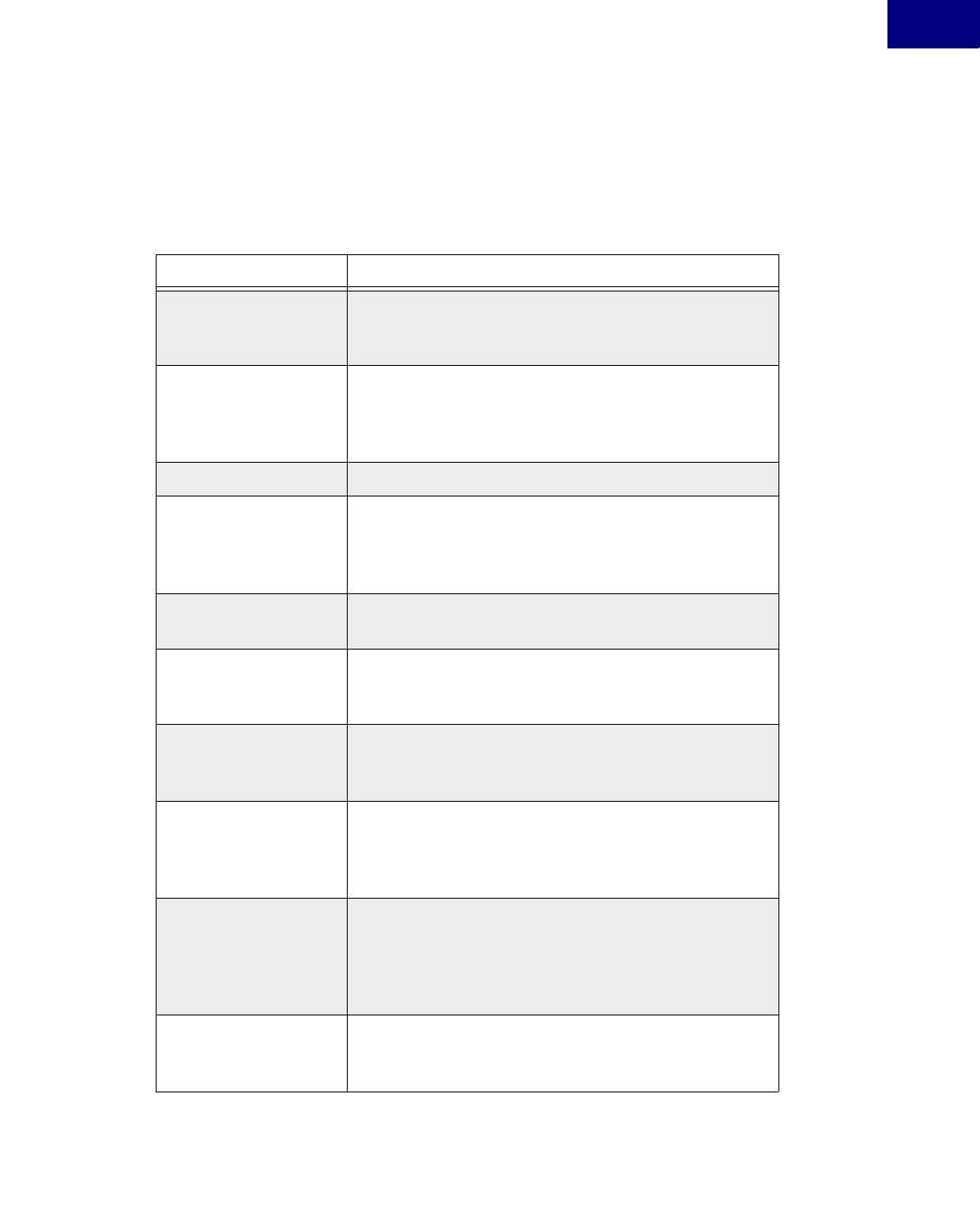
Graphics Fundamentals 287
Graphics Fundamentals
Client APIs
Key color-related client APIs
Interfaces provided to manipulate color, swatch, ink, and color management objects are sum-
marized in “Color-related APIs” on page 287. For details about them, see the API reference
documentation.
TABLE 74 Color-related APIs
API Description
IGradientAttributeSuite A selection suite interface. Provides gradient attribute–
related operations that apply to the application defaults,
document defaults, text, layout, and tables.
ISwatchUtils Utility interface to manipulate swatches. For example, this
interface can be used to acquire the active swatch list,
retrieve or instantiate new, persistent, rendering boss
objects, and modify the properties of the swatch list.
IUIColorUtils Utility interface for dealing with user-interface colors.
IInkMgrUtils Utility interface for managing inks. For example, this
interface can be used to acquire the active ink list and
retrieve information about name, type, ink alias, and
corresponding swatches of a spot ink.
IInkMgrUIUtils Utility interface, mainly for calling the ink-manager dialog
box.
IColorSystemUtils Utility interface for color-rendering objects. For example,
this interface can be used to get color space and color
components of a given color swatch.
ICMSAttributeSuite A selection suite interface. Provides color-management
functionality for the selected image page item, like getting
or applying color profile or rendering intent.
ICMSUtils Utility interface for the color-management system. For
example, this interface can be used to obtain CMSSettings
and ProfileList. Provides wrappers for color-management
commands.
ICMSManager A manager interface that provides a generic wrapper
around a color-management system (CMS). Access to the
CMS typically is done by coordinating between this
interface and a data interface for the specific CMS
implementation.
IColorPresetsManager A manager interface that manages a set of color preset files.
For example, load or save a color preset, and get or set
working RGB/CMYK profile and CMS policy.

Graphics Fundamentals
Client APIs
288
Since color-related objects like colors, swatches, inks, and color profiles are stored in the docu-
ment or application database, you will need commands to manipulate them. The utility inter-
faces described above provide a higher-level abstraction that wrap the required commands. For
a list of commands, see the API reference documentation.
Graphic-attribute client APIs
APIs provided to manipulate graphic attributes are summarized in “Graphic-attribute APIs” on
page 288. For details about them, see the API reference documentation.
TABLE 75 Graphic-attribute APIs
API Description
IGraphicAttributeUtils Exposes methods that can be used to create lists of
attribute overrides and create commands to apply
attribute overrides. It also exposes methods to read the
graphic attributes of document objects.
IGraphicStateUtils Exposes methods to create or process commands to apply
overrides, swap stroke and fill, and so on. It also exposes a
key method to acquire a reference to the active graphic
state, which is discussed in detail in the “Graphics”
chapter of Adobe InDesign CS4 Solutions.
IGraphicAttributeSuite Selection suite that can be queried for through an abstract
selection (kAbstractSelectionBoss). It is aggregated on the
concrete selection boss classes connected with application
defaults, document defaults, layout, tables, and text.
IGraphicAttrProxySuite Selection suite that switches graphic attributes between
layout objects and text.
IStrokeAttributeSuite High-level attribute suite interface specifically to get and
set various stroke attributes. It uses
IGraphicAttributeSuite to get and set appropriate data.
IXPAttributeSuite Accesses or changes transparency attributes on the
selected page items or group items. This header file also
defines all transparency-attribute-related enums such as
attribute types.
IXPAttributeUtils Transparency-attribute-related utility functions
IXPAttributeFacade High-level transparency-attribute facade. Defines
methods to get and set all transparency attributes.
IXPUtils Transparency utility functions. Mainly for flattening.
IXPManager Transparency helper functions.

Graphics Fundamentals 289
Graphics Fundamentals
Extension patterns
There are command boss classes used to manipulate graphic attributes, graphic style, and
graphic state. The utility interfaces described in Table 75 provide a higher-level abstraction that
wraps the common commands. For a complete list of provided commands, see the API refer-
ence documentation.
Extension patterns
Custom graphic attributes
You can provide custom graphic attributes that extend InDesign function for end users. As
explained in “Representation of graphic attributes” on page 258, graphic attributes are applied
to page items by adding to a list of attribute boss objects associated with the page item.
To define a customized graphic attribute, follow these steps:
1. Create a new boss class for the attribute. The boss class should inherit from kGraphicsAttr-
Boss.
2. Provide an implementation of the IGraphicAttributeInfo interface.
3. If the graphic attribute value could be stored in an existing data interface, like IGraphicAttr-
Boolean or IGraphicAttrClassID, add it to the attribute class; otherwise, implement an
interface of your own.
4. Provide your own code to initialize and set your attribute data when the attribute is applied
to a page item. Code to apply the attribute to a page item also is required.
If you implemented a custom graphic attribute, you are likely to use a page-item adornment to
decorate the page item based on your graphic-attribute value. For an example, see the Trans-
parencyEffect and TransparencyEffectUI sample SDK plug-ins.
Custom path-stroker effects
You can provide custom path strokers with your own stroke implementation through a kPath-
StrokerService. The service provider should provide an implementation of IPathStroker, with
IStrokeParameters used for storing parameters for the stroke. See “Path stroker” on page 262.
To implement a custom path stroker, follow these steps:
1. Create a new boss class for the service provider (for example k<XXX>PathStrokerBoss).
Add a service provider to the boss class (the application-provided kPathStrokerServicePro-
viderImpl can be re-used), and define your implementation of IPathStroker.
2. Create your implementation of IPathStroker. The interface basically provides methods on
how to draw the path on the specific graphic port and hit testing (stroke bounding box,
etc.).

Graphics Fundamentals
Extension patterns
290
3. If the implementation of the stroker is complicated, you may aggregate additional interfaces
on the boss. InDesign CS4/InCopy CS4 provides a common stroke-parameter implementa-
tion of the IStrokeParameters interface. The interface stores information like where a path
segment starts and the length of the segment. For details, see the API reference documenta-
tion.
To change only the dash and gap of a stroke, you do not need a custom stroke implementation.
Instead, just apply the appropriate kDashedAttributeValuesBoss attribute.
Custom corner effects
You can provide a custom corner path with your own corner path implementation through a
kPathCornerService. The service provider should provide an implementation of IPathCorner.
See “Path corners” on page 263. To implement a custom corner effect, follow these steps:
1. Create a new boss class for the service provider (for example k<XXX>CornerBoss). Add a
service provider to the boss class (the application-provided kPathCornerServiceProvider-
Impl can be re-used), and define your own implementation of IPathCorner.
2. Create your implementation of IPathCorner. The interface basically provides drawing
methods from three points on the corner. For detailed definitions of the pointers, see the
API reference documentation of the interface. The three points are calculated by a private
method not included in the SDK from the stroke path and corner size. You need to provide
only the method for creating the corner effect using these points.
3. Determine the size of the corner, and apply kGraphicStyleCornerRadiusAttrBoss to the
path page item. The corner-size attribute is decoupled from the corner-path implementa-
tion, so you could set and change corner size independently and use this setting with other
corner implementations.
Custom path-end effects
You can provide a custom path-end effect with your own path-end implementation through a
kPathEndStrokerService. The service provider should provide an implementation of IPathEnd-
Stroker. See “Path-end strokers” on page 263. To implement a custom path-end effect, follow
these steps:
1. Create a new boss class for the service provider (for example k<XXX>ArrowHeadBoss).
Add a service provider to the boss class (the application-provided kPathEndStrokerService-
ProviderImpl can be re-used), and define your own implementation of IPathEndStroker.
2. Create your implementation of IPathEndStroker. The interface basically provides drawing
and hit testing methods for a stroke end. A page item’s stroke bounding box includes both
the stroke and stroke-end bounding box returned from the method on this interface.
3. Set the implementation ID to the appropriate line-end attribute, and apply the attribute to
the page item.
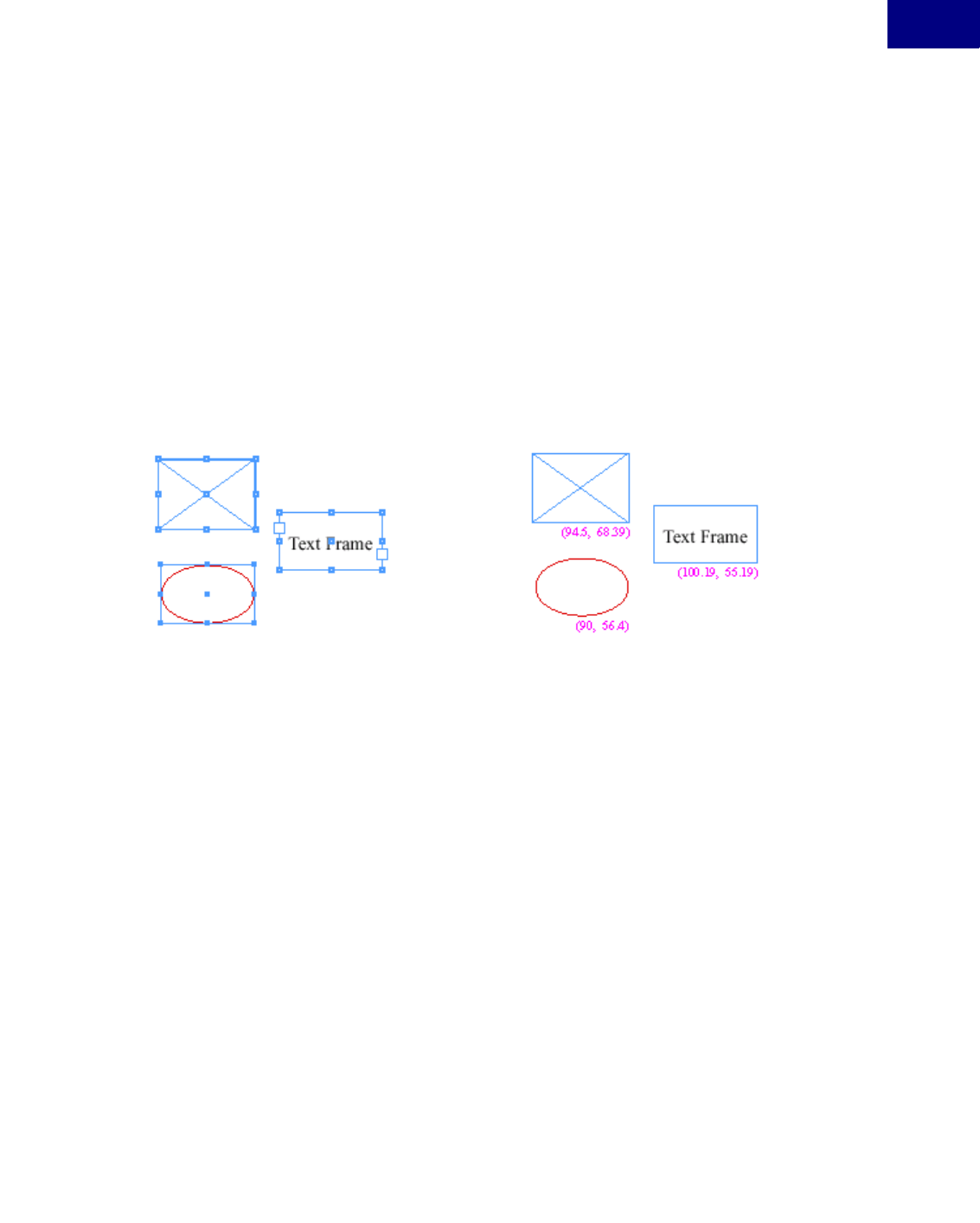
Graphics Fundamentals 291
Graphics Fundamentals
Extension patterns
Custom page-item adornments
Page-item adornments customize the appearance of a page item, giving a plug-in the chance to
add drawing when the page item is rendered. For example, if you want to add a drop shadow or
label for a specific page item, a page-item adornment is one way to add these extra drawings.
Examples of page-item adornments in InDesign are the transparency drop shadow and feather
effects, the graphics-frame outline path, and the empty-graphics frame indicator (the X inside
the frame).
You can participate in page-item drawing by creating a custom page-item adornment. For
example, you could provide an adornment to show in magenta type the width and height of
each selected page item, as shown in Figure 104.
FIGURE 104 Adding adornments to selected page items
Architecture
Page-item adornments are represented by boss objects. There are two main types of page-item
adornments:
zIAdornmentShape implementations, drawn during execution of IShape::Draw.
zIAdornmentHandleShape implementations, drawn during execution of IHandle-
Shape::Draw.
The Draw methods on their implementations determine the appearance of the adornment.
Page-item adornments are connected to page items through the IPageItemAdornmentList
interface aggregated on the kPageItemBoss boss class. Figure 105 illustrates the basic data
model for adornments. A page item aggregates the IPageItemAdornmentList interface, which
stores a list of adornments the page item has.
Before adding adornments After adding adornments
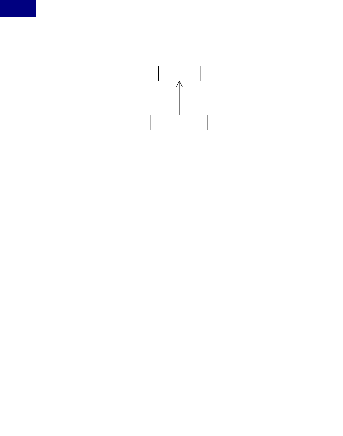
Graphics Fundamentals
Extension patterns
292
FIGURE 105 Adornment data model
IPageItemAdornmentList
The IPageItemAdornmentList interface manages a list of the adornments for a page item. Each
adornment in the list is drawn in an order determined by the value of its AdornmentDra-
wOrder. For page-item adornments, there are several opportunities within the drawing cycle to
draw.
Each adornment can be drawn at one or more phases within the drawing cycle if you AND
together the flags defined in the AdornmentDrawOrder enumeration (defined in IAdornment-
Shape.h and IAdornmentHandleShape). These values indicate when the adornment is to be
drawn. Upon calling the command kAddPageitemAdornmentCmdBoss, the adornment is
inserted into the list based on drawing order.
When adding an adornment to a page item, define the adornment as a new boss class that
aggregates the IAdornmentShape or IAdornmentHandleShape interface. In a more complex
case, you can use more than one adornment for a single page item.
IAdornmentShape
When implementing IAdornmentShape, you can choose to provide hit testing and invalidation
of the view, if needed. At a minimum, your implementation must draw the adornment.
When a page item is drawn, each attached adornment is called to draw through the IAdorn-
mentShape interface. A page-item shape tells the drawing manager at which of the following
times it should be drawn:
zAfter the frame shape (kAfterShape).
zBefore the text foreground (kBeforeTextForeground).
zAt one of the other events defined in the adornment objects.
The drawing order controls when the adornment is called to draw. Figure 106 shows the draw-
ing sequences for one rectangle spline item. When the adornments’ drawing methods get called
depends on the drawing order. For detailed information on page item drawing, see “Drawing
page items” on page 281.
«boss»
kYourAdornmentBoss
«boss»
kPageItemBoss
1
*
IPageItemAdornmentList

Graphics Fundamentals 293
Graphics Fundamentals
Extension patterns
FIGURE 106 Drawing sequences for a rectangle page item
IAdornmentHandleShape
Implementing IAdornmentHandleShape lets you decorate the selection handles associated
with a page item. This decoration can be drawn with IAdornmentHandleShape::kBeforeShape
or IAdornmentHandleShape::kAfterShape; that is, before or after IHandleShape calls
DrawHandlesImmediate.
Implementation hints
To implement a custom page-item adornment, you need to do at least the following:
1. Define an adornment boss class. Depending on the nature of your adornment, you need to
implement IAdornmentShape or IAdornmentHandleShape. This determines how and
when your adornment is drawn. In providing the implementation aggregated on the adorn-
ment boss class, you specify how the adornment is drawn and how the painted bounding
box is calculated.
2. Determine when you will connect your adornment to the page-item adornment list, most
likely by processing a low-level command.
For a sample showing how to implement a custom page-item adornment, see FrameLabel in
the SDK; also see other samples that provide an implementation of IAdornmentShape, such as
TransparencyEffect and CustomDataLink.
Fill shape by calling
IPathPageItem::Fill.
Set fill path by calling
IPathPageItem::CopyPath.
Draw kAfterFill adornments. Draw kAfterStroke adornments.
Stroke by calling
IPathPageItem::Stroke.
Draw kAfterShape adornments.
Draw kBeforeShape adornments.
Set port’s clip to fill path.
Draw children by calling
IShape::Draw for each child.
Draw kBeforeStroke adornments.
DrawMgr
Continue other drawings.
Graphics Fundamentals
Extension patterns
294
Custom drawing-event handler
You can use a custom drawing-event handler to take control when a page item is being drawn
at some point in the drawing cycle, to modify how the item draws or cancel it being drawn.
Architecture
Drawing events are messages that are broadcast at specific points in the drawing order. Each
drawing event signals the beginning or end of a phase of drawing. Drawing events provide
extensibility points in that drawing operations can be modified or cancelled in response to the
event.
Drawing-event types are defined in DocumentContextID.h. Some of the generic drawing event
types associated with shape drawing are shown in Table 76.
TABLE 76 Generic drawing events
In addition, there are other, more specific event types that signal the beginning and end of
spread, layer, and page drawing. Drawing events are generated for each Draw method in the
hierarchy: kBegin<XXX>Message, kEnd<XXX>Message, and kDraw<XXX>Message.
kBegin<XXX>Message is generated just before a call to the next level of the hierarchy (after
any transformation is applied to the object). kEnd<XXX>Message is generated just after execu-
tion returns from a lower level of the hierarchy.
Registering and unregistering
There are two ways a plug-in can register or unregister for drawing events: as a service provider
or using direct registration through the IDrwEvtDispatcher interface.
zDrawing-event handlers can be a type of service provider. If so, they are automatically regis-
tered at start-up. A boss can register as a service provider using the IK2ServiceProvider
interface and the kDrawEventService service ID. The boss must provide an implementation
of the IDrwEvtHandler interface. When the application starts, the Register method in the
drawing-event handler registers for the drawing events it wants to receive.
zA second method of registering for events is to instantiate the IDrwEvtDispatcher interface
and call IDrwEvtDispatcher::RegisterHandler directly. This requires parameters including
the event being registered for, a pointer to the event handler, and the priority of the event
handler.
Drawing event Use
kAbortCheckMessage Opportunity to abort drawing of an entire item.
kBeginShapeMessage Start of shape drawing.
kDrawShapeMessage Shape drawing is about to begin.
kEndShapeMessage End of shape drawing.
kFilterCheckMessage Opportunity to filter drawing based on object type.

Graphics Fundamentals 295
Graphics Fundamentals
Extension patterns
In the PrintSelection SDK sample, the kPrnSelDrawServicesBoss boss class does not provide an
implementation for IK2ServiceProvider. This is because this particular sample uses the direct
registration method; see the AfterPrintUI method in PrnSelPrintSetupProvider.cpp.
Unregistering is similar to registering, except the call to UnRegisterHandler is on the IDrwEvt-
Dispatcher interface.
Drawing event-handling priorities
Drawing event handlers register their prioritized interest in particular types of drawing events.
Priorities are defined in IDrwEvtDispatcher.h. When a handler registers for an event, it must
pass a priority to RegisterHandler. The priorities include the following:
zkDEHPostProcess
zkDEHLowestPriority
zkDEHLowPriority
zkDEHMediumPriority
zkDEHHighPriority
zkDEHInitialization
As each event is processed, handlers are called in order, from the kDEHInitialization priority
down to kDEHPostProcess. If two handlers have the same priority for the same event, the han-
dler registered first is called first. The return code for handlers registered using the kDEHIni-
tialization priority is ignored. For additional information about return codes for the other
priorities, see “Handling drawing events” on page 295.
Handling drawing events
The drawing-event handler’s HandleEvent method takes two parameters: a ClassID that is the
eventID (see DocumentContextID.h) and a void pointer to a class containing the event data.
For drawing events, this pointer must be cast to the DrawEventData class (see IDrw-
EvtHandler.h) to access the data.
In the HandleEvent method of the drawing-event handler, if the method returns kTrue, it is
assumed the event was properly handled and no other event handlers are called for the event;
therefore, the drawing at that step ceases. If the method returns kFalse, the drawing event is
considered not handled, and the drawing step proceeds. A drawing-event handler that modi-
fies or decorates the drawing of an object but does not replace it returns kFalse. Also,
kEnd<XXX>Message does not look at the return code from the event handler, because the
draw operation already completed.
Implementation
A custom drawing-event handler is an extension pattern to let third-party code participate in
drawing or printing or interrupt the drawing or printing of a page item. The following steps
summarize how to implement a custom drawing-event handler. The signature interface of the
pattern is IDrwEvtHandler.

Graphics Fundamentals
Swatch-list state
296
1. Define your own drawing-event handler boss class.
2. Depending on how you want to register and unregister your event handler, you also may
need to implement the IK2ServiceProvider interface, returning a ServiceID of kDrawEvent-
Service.
3. Provide an implementation of IDrwEvtHandler.
4. In your IDrwEvtHandler::HandleEvent implementation, you will get an event ID and a void
pointer to a class containing the event data. You should cast to the DrawEventData and
obtain the GraphicsData pointer; then you can do your custom drawing in the same context
of page-item drawing.
For sample code, see BasicDrwEvtHandler and other samples that implement IDrwEvtHandler
in the SDK.
Swatch-list state
Initial state of swatch list and ink list
When the application starts, it initializes a swatch list by creating several default swatches (ren-
dering objects). There are reserved swatches: None, Paper, Black, and Registration. Table 77
lists the initial state of swatch list, and Table 78 illustrates initial ink list. (UIDs are not neces-
sarily the same for different workspaces.)
TABLE 77 Initial state of swatches
Index UID Rendering object Swatch name Color or gradient information
011 kPMColorBoss Black (reserved) kPMCsCalCMYK(0,0,0,1)
1 18 kPMColorBoss C=0 M=0 Y=100 K=0 kPMCsCalCMYK(0,0,1,0)
219 kPMColorBoss C=0 M=100 Y=0 K=0 kPMCsCalCMYK(0,1,0,0)
3 20 kPMColorBoss C=100 M=0 Y=0 K=0 kPMCsCalCMYK(1,0,0,0)
421 kPMColorBoss C=100 M=90 Y=10 K=0 kPMCsCalCMYK(1,0.9,0.1,0)
5 22 kPMColorBoss C=15 M=100 Y=100 K=0 kPMCsCalCMYK(0.15,1,1,0)
623 kPMColorBoss C=75 M=5 Y=100 K=0 kPMCsCalCMYK(0.75,0.05,1,0)
7 12 kPMColorBoss Cyan kPMCsCalCMYK(1,0,0,0)
813 kPMColorBoss Magenta kPMCsCalCMYK(0,1,0,0)
9 14 kGraphicStateNoneRenderingO
bjectBoss
None (reserved) N/A
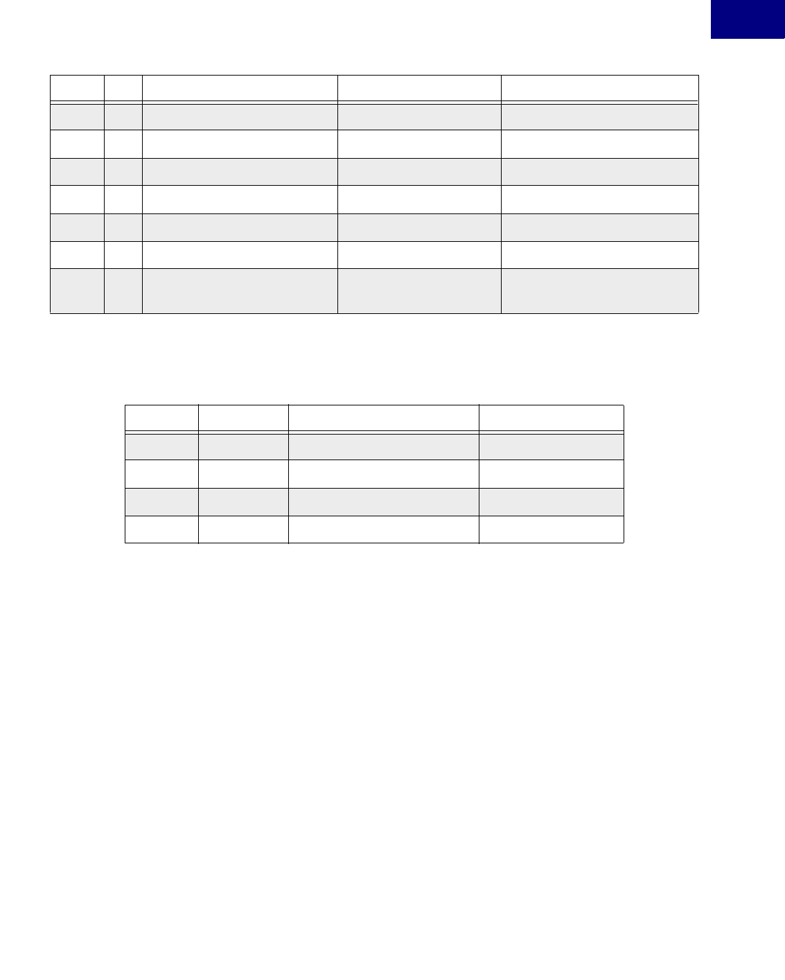
Graphics Fundamentals 297
Graphics Fundamentals
Swatch-list state
Notice there are several invisible, unnamed swatches that are created but do not show up in the
Swatches panel.
TABLE 78 Initial ink list
State of swatch list and ink list after adding a custom stop color
Adding a custom color swatch, PANTONE 368 C, causes an additional swatch-list entry to be
created. For information on how to add a color swatch, see the “Graphics” chapter of Adobe
InDesign CS4 Solutions. Table 79 illustrates the new state of the swatch list, and Table 80 illus-
trates the new state of the ink list. Note the following:
zThe swatch is sorted by swatch name. Since the new swatch’s name is between index 9 and
10, the new color is inserted into position 10. The following row is added: 10, 167, kPMCol-
orBoss, PANTONE 368 C, kPMCsCalCMYK (0.57,0,1,0), Spot.
zThe swatch list is reordered, so entries 10 and after are shifted down. The UIDs of the exist-
ing swatches do not change.
zA new spot ink is added to the ink list.
10 15 kPMColorBoss Paper (reserved) kPMCsCalCMYK(0,0,0,0)
11 16 kPMColorBoss Registration (reserved) kPMCsCalCMYK(1,1,1,1)
12 17 kPMColorBoss Ye l l o w kPMCsCalCMYK(0,0,1,0)
13 97 kPMColorBoss (invisible) kPMCsCalCMYK(0,0,0,1)
14 99 kPMColorBoss (invisible) kPMCsCalCMYK(0,0,0,0)
15 98 kGradientRenderingObjectBoss (invisible) Stop 0 UID=99, Stop 1 UID=11
16 100 kAGMBlackBoxRenderingObje
ctBoss
(invisible) N/A
Index UID Name Type
0 7 Process Cyan Process
1 8 Process Magenta Process
2 9 Process Yellow Process
3 10 Process Black Process
Index UID Rendering object Swatch name Color or gradient information
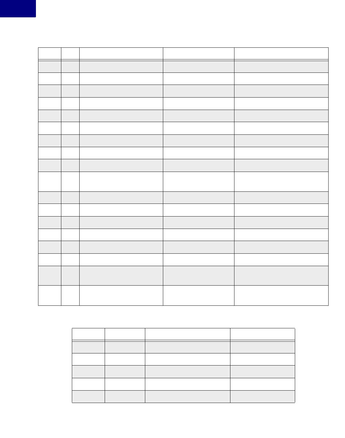
Graphics Fundamentals
Swatch-list state
298
TABLE 79 Swatches after adding a custom color
TABLE 80 Ink list after a stop color is added to swatch
Index UID Rendering object Swatch name Color or gradient information
011 kPMColorBoss Black (reserved) kPMCsCalCMYK(0,0,0,1)
1 18 kPMColorBoss C=0 M=0 Y=100 K=0 kPMCsCalCMYK(0,0,1,0)
219 kPMColorBoss C=0 M=100 Y=0 K=0 kPMCsCalCMYK(0,1,0,0)
3 20 kPMColorBoss C=100 M=0 Y=0 K=0 kPMCsCalCMYK(1,0,0,0)
421 kPMColorBoss C=100 M=90 Y=10 K=0 kPMCsCalCMYK(1,0.9,0.1,0)
5 22 kPMColorBoss C=15 M=100 Y=100 K=0 kPMCsCalCMYK(0.15,1,1,0)
623 kPMColorBoss C=75 M=5 Y=100 K=0 kPMCsCalCMYK(0.75,0.05,1,0)
7 12 kPMColorBoss Cyan kPMCsCalCMYK(1,0,0,0)
813 kPMColorBoss Magenta kPMCsCalCMYK(0,1,0,0)
9 14 kGraphicStateNoneRendering
ObjectBoss
None (reserved) N/A
10 167 kPMColorBoss PANTONE 368 C kPMCsCalCMYK(0.57,0,1,0), Spot
11 15 kPMColorBoss Paper (reserved) kPMCsCalCMYK(0,0,0,0)
12 16 kPMColorBoss Registration (reserved) kPMCsCalCMYK(1,1,1,1)
13 17 kPMColorBoss Yellow kPMCsCalCMYK(0,0,1,0)
14 97 kPMColorBoss (invisible) kPMCsCalCMYK(0,0,0,1)
15 99 kPMColorBoss (invisible) kPMCsCalCMYK(0,0,0,0)
16 98 kGradientRenderingObjectBo
ss
(invisible) Stop 0 UID=99, Stop 1UID=11
17 100 kAGMBlackBoxRenderingObj
ectBoss
(invisible) N/A
Index UID Name Type
0 7 Process Cyan Process
1 8 Process Magenta Process
2 9 Process Yellow Process
3 10 Process Black Process
4166 PANTONE 368 C Spot
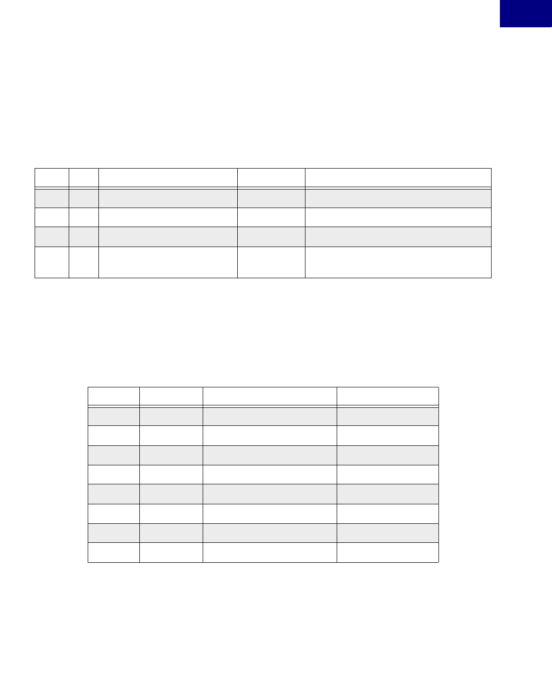
Graphics Fundamentals 299
Graphics Fundamentals
Swatch-list state
Swatch list and ink list after adding a gradient swatch
The user also may add a custom gradient. Adding a gradient may add additional colors for a
gradient stop. Similar to what occurs when adding a custom color swatch, new entries are cre-
ated for these added colors and gradients. For information on adding a gradient swatch, see the
“Graphics” chapter of Adobe InDesign CS4 Solutions. Table 81 lists only the new entries for the
swatch list, and Table 82 illustrates the updated ink list.
TABLE 81 New entries in swatch list after adding a custom gradient
The new gradient, Tie-dye, has three stops, so these three color swatches (Stop 1, Stop 2, and
Stop 3) also are inserted into the swatch list.
For the existing swatches we did not list here, the swatch data did not change, but their indices
were changed to make room for new swatches. The new swatches are inserted continuously,
because these new swatch names happened to be in continuous position with existing names.
TABLE 82 Ink list after a gradient with three-stop colors is added toswatch
Since the gradient stop colors are spot colors, they also are added to the ink list.
Index UID Rendering object Swatch name Color or gradient information
13 169 kPMColorBoss Stop 1 kPMCsCalCMYK(0.2,1,0.5,0)
14 171 kPMColorBoss Stop 2 kPMCsCalRGB(0,1,0.5)
15 173 kPMColorBoss Stop 3 kPMCsCalCMYK(0,0.3,0.9,0)
16 174 kGradientRenderingObjectBoss Tie-dye Stop 0 UID=169, Stop 1UID=171, Stop 2
UID =173
Index UID Name Type
0 7 Process Cyan Process
1 8 Process Magenta Process
2 9 Process Yellow Process
3 10 Process Black Process
4166 PANTONE 368 C Spot
5 168 Stop 1 Spot
6170 Stop 2 Spot
7 172 Stop 3 Spot

Graphics Fundamentals
Swatch-list state
300
Swatch list and ink list after applying an unnamed color to an object
When an instance of a color is chosen with the Color Picker panel and applied to a page item, a
new, unnamed swatch entry is added to the end of the swatch list. See Table 83.
TABLE 83 New swatch entry added after picking a color from color picker
Unnamed swatches are not sorted, so a new unnamed swatch is appended at the end. After the
previous step (adding a gradient), there were 22 swatches total in the list, so this step adds the
swatch at index 22.
Unnamed swatches do not appear in the Swatches panel, but they can be used for the strokes
and fills of document objects by client code. When a color is chosen through the Color panel,
the active graphic state changes, and a new swatch may be created. A new swatch is created in
the swatch list only if the new color is applied to a document object; i.e., if there is an active
selection when the color is created or the color is applied to an object like a spline page item.
Because the added unnamed color is a process color, the inks this color uses to print (i.e., Pro-
cess Cyan, Process Magenta, Process Yellow, and Process Black) already are in the ink list, so
the ink list does not change. Applying a new gradient to a page-item object through the Gradi-
ent panel results in a similar state.
Color spaces
There are three common color spaces: RGB, CMYK, and L*a*b*.
RGB color spaces
RGB is a device-dependent color model. It is the native color model of monitors, scanners and
digital cameras.
The kPMCsCalRGB space denotes calibrated RGB. Although the space is device-dependent,
coordinates within this space are not arbitrary. There are several, slightly different color spaces
that use the RGB color model:
zAdobe RGB (1998) — Previously referred to as SMPTE-240M.
zApple® RGB — The default color space for Photoshop 3 and 4.
zColorMatch RGB — Based on the Radius PressView display. This has a smaller gamut than
Adobe RGB (1998) and other color spaces for print production jobs.
zsRGB (IEC61966-2.1) — The default color space for Photoshop 5. This reflects the color
properties of the average computer monitor. It was proposed in 1996 by Hewlett-Packard
and Microsoft® for representing color on the Internet, as described at
http://www.w3.org/Graphics/Color/sRGB.html. sRGB also is the color space used to repre-
sent color in SVG documents. For more information about SVG, go to
http://www.w3.org/TR/SVG.
Index UID Rendering object Swatch name Color or gradient information
22 177 kPMColorBoss (invisible) kPMCsCalCMYK(0.4715,0,0.75,0)

Graphics Fundamentals 301
Graphics Fundamentals
Catalog of graphic attributes
CMYK
Like RGB, CMYK is a device-dependent color model. It is the native color model of most print-
ers. Many color spaces use the CMYK color model. For example, the InDesign color-manage-
ment user interface lets the end user specify any of the following:
zEuroscale Coated v2
zEuroscale Uncoated v2
zJapan Standard v2
zU.S. Sheetfed Coated v2
zU.S. Sheetfed Uncoated v2
zU.S. Web Coated (SWOP) v2
zU.S. Web Uncoated v2
The choice of color space is governed by expectations about the properties of the press on
which the job will be printed.
LAB
L*a*b* (1976 CIE L*a*b* Space) is device-independent and is the basic color model in Post-
Script. L*a*b* is used for color management as the device-independent model of the ICC
device profiles.
L*a*b* was standardized in 1976 to provide a space that is perceptually uniform. L*a*b* has its
basis in the CIE standard observer, derived by analysis of the physiology of the retina and the
early visual pathways.
The terms L*, a*, and b* refer to coordinate axes within the space. L is a function of luminance,
the physical correlate of brightness. The other coordinates are less easily understood in physical
terms and better regarded as mathematical abstractions.
Catalog of graphic attributes
There are many graphic attributes in the application. Sometimes several attributes collaborate
to implement a feature, like transparency; sometimes the values of some attributes are impor-
tant, like color and stroke-line implementations.
Figure 107 is a master list of graphic attributes. The attribute boss class, name, and interface
that store the attribute value are listed. Other information is provided in the boolean matrix on
the right of the table.
The list can be obtained from the API reference documentation in two ways:
zLook for IGraphicAttributeInfo and see which boss classes aggregate this interface.
zLook at the kGraphicsAttrBoss boss class and examine the list of subclasses of this class.
Note this list is not a complete list of graphic attributes and is not updated for each release.

Graphics Fundamentals
Catalog of graphic attributes
302
FIGURE 107 Master list of graphic attributes
className
attributeName
value interfaces
affectsPageItemGeometry?
isRequiredGraphicAttribute?
isTableAttribute?
isTextAttribute?
isObservedByGraphicState?
isObservedByTransparencyAttrSuite?
isFormFieldAttribute?
kCheckDefaultCheckedAttrBoss Default Is Checked IGraphicAttrBoolean no no no no yes no yes
kCheckExportValueAttrBoss Export Value IStringAttr no no no no yes no yes
kChoiceAllowMultiSelAttrBoss Allow Multiple Selection IGraphicAttrBoolean no no no no yes no yes
kChoiceEditableAttrBoss Editable IGraphicAttrBoolean no no no no yes no yes
kChoiceListAttrBoss Choice List IChoiceListAttr (private) no no no no yes no yes
kChoiceSortAttrBoss Sort Items IGraphicAttrBoolean no no no no yes no yes
kDashedAttributeValuesBoss Dash settings IDashedAttributeValues no yes no no yes no no
kFormDefaultValueAttrBoss Form Field Default Value IStringAttr no no no no yes no yes
kFormDescriptionAttrBoss Form Field Description IStringAttr no no no no yes no yes
kFormExportAttrBoss Form Field Export IGraphicAttrBoolean no no no no yes no yes
kFormExportMappingAttrBoss Form Field Export Mapping Name IStringAttr no no no no yes no yes
kFormExportRequiredAttrBoss Form Field Required For Export IGraphicAttrBoolean no no no no yes no yes
kFormFontColorAttrBoss Form Field Font Color ITextAttrUID no no no no yes no yes
kFormFontOverprintAttrBoss Form Field Font Color Overprint IGraphicAttrBoolean no no no no yes no yes
kFormFontSizeAttrBoss Form Field Font Size IGraphicAttrRealNumber no no no no yes no yes
kFormFontStrokeColorAttrBoss Form Field Font Stroke Color ITextAttrUID no no no no yes no yes
kFormFontStrokeOverprintAttrBoss Form Field Font Stroke Color Overprint IGraphicAttrBoolean no no no no yes no yes
kFormFontStrokeTintAttrBoss Form Field Font Stroke Tint IGraphicAttrRealNumber no no no no yes no yes
kFormFontStrokeWeightAttrBoss Form Field Font Stroke Weight IGraphicAttrRealNumber no no no no yes no yes
kFormFontStyleAttrBoss Form Field Font Style ITextAttrFont no no no no yes no yes
kFormFontTintAttrBoss Form Field Font Tint IGraphicAttrRealNumber no no no no yes no yes
kFormFontUIDAttrBoss Form Field Font Family ITextAttrUID no no no no yes no yes
kFormNameAttrBoss Form Field Name IStringAttr yes no no no yes no yes
kFormPrintVisibleAttrBoss Form Field Visible When Printed IGraphicAttrBoolean no no no no yes no yes
kFormReadOnlyAttrBoss Form Field Read Only IGraphicAttrBoolean no no no no yes no yes
kFormScreenVisibleAttrBoss Form Field Visible On Screen IGraphicAttrBoolean no no no no yes no yes
kFormSpellCheckAttrBoss Spell Check IGraphicAttrBoolean no no no no yes no yes
kFormStyleAttrBoss Form Field Style IStringAttr yes no no no yes no yes
kFormTypeAttrBoss Form Field Type IGraphicAttrInt32 yes no no no yes no yes
kFormValueAttrBoss Form Field Value IStringAttr no no no no yes no yes
kGraphicStyleCornerImplAttrBoss Effect IGraphicAttrClassID yes yes no no yes no no
kGraphicStyleCornerRadiusAttrBoss Size IGraphicAttrRealNumber yes yes no no yes no no
kGraphicStyleEvenOddAttrBoss Even-Odd IGraphicAttrBoolean no yes no no yes no no
kGraphicStyleFillRenderingAttrBoss Color IPersistUIDData no yes yes yes yes no no

Graphics Fundamentals 303
Graphics Fundamentals
Catalog of graphic attributes
className
attributeName
value interfaces
affectsPageItemGeometry?
isRequiredGraphicAttribute?
isTableAttribute?
isTextAttribute?
isObservedByGraphicState?
isObservedByTransparencyAttrSuite?
isFormFieldAttribute?
kGraphicStyleFillTintAttrBoss Tint IGraphicAttrRealNumber no no yes yes yes no no
kGraphicStyleGapRenderingAttrBoss Gap color IPersistUIDData no no yes no yes no no
kGraphicStyleGapTintAttrBoss Gap tint IGraphicAttrRealNumber no no yes no yes no no
kGraphicStyleGradientFillAngleAttrBoss Gradient fill angle IGraphicAttrRealNumber no no no yes no no no
kGraphicStyleGradientFillGradCenterAttrBoss Gradient fill center IGraphicAttrPoint no no no yes no no no
kGraphicStyleGradientFillHiliteAngleAttrBoss Gradient fill hilight angle IGraphicAttrRealNumber no no no no no no no
kGraphicStyleGradientFillHiliteLengthAttrBoss Gradient fill hilight length IGraphicAttrRealNumber no no no no no no no
kGraphicStyleGradientFillLengthAttrBoss Gradient fill length IGraphicAttrRealNumber no no no yes no no no
kGraphicStyleGradientFillRadiusAttrBoss Gradient fill radius IGraphicAttrRealNumber no no no no no no no
kGraphicStyleGradientStrokeAngleAttrBoss Gradient angle IGraphicAttrRealNumber no no no yes no no no
kGraphicStyleGradientStrokeGradCenterAttrBos
s
Gradient stroke center IGraphicAttrPoint no no no yes no no no
kGraphicStyleGradientStrokeHiliteAngleAttrBoss Gradient stroke hilight angle IGraphicAttrRealNumber no no no no no no no
kGraphicStyleGradientStrokeHiliteLengthAttrBos
s
Gradient stroke hilight length IGraphicAttrRealNumber no no no no no no no
kGraphicStyleGradientStrokeLengthAttrBoss Gradient stroke length IGraphicAttrRealNumber no no no yes no no no
kGraphicStyleGradientStrokeRadiusAttrBoss Gradient stroke radius IGraphicAttrRealNumber no no no no no no no
kGraphicStyleJoinTypeAttrBoss Join IGraphicAttrInt32 yes yes no no yes no no
kGraphicStyleLineCapAttrBoss End cap IGraphicAttrInt32 yes yes no no yes no no
kGraphicStyleLineEndEndAttrBoss Line end IGraphicAttrClassID yes yes no no yes no no
kGraphicStyleLineEndStartAttrBoss Line start IGraphicAttrClassID yes yes no no yes no no
kGraphicStyleMiterLimitAttrBoss Miter limit IGraphicAttrRealNumber yes yes no no yes no no
kGraphicStyleNonPrintAttrBoss Non print IGraphicAttrBoolean no yes no yes yes no no
kGraphicStyleOverprintFillAttrBoss Overprint fill IGraphicAttrBoolean no yes yes yes yes no no
kGraphicStyleOverprintGapAttrBoss Overprint gap IGraphicAttrBoolean no no no no yes no no
kGraphicStyleOverprintStrokeAttrBoss Overprint stroke IGraphicAttrBoolean no yes yes yes yes no no
kGraphicStyleStrokeAlignmentAttrBoss Stroke alignment IGraphicAttrInt32 yes no no no yes no no
kGraphicStyleStrokeLineImplAttrBoss Stroke type IPersistUIDData IGraphicAttrClassI
D
yes yes yes no yes no no
kGraphicStyleStrokeRenderingAttrBoss Color IPersistUIDData no yes yes yes yes no no
kGraphicStyleStrokeTintAttrBoss Tint IGraphicAttrRealNumber no no yes yes yes no no
kGraphicStyleStrokeWeightAttrBoss Stroke weight IGraphicAttrRealNumber yes yes yes yes yes no no
kStrokeParametersBoss Stroke parameters IStrokeParameters no no no no yes no no
kTextAlignmentAttrBoss TextAlignment (form field) IGraphicAttrInt32 no no no no yes no yes
kTextHasMaxLengthAttrBoss Has Maximum Field Length IGraphicAttrBoolean no no no no yes no yes
kTextMaxLengthAttrBoss Maximum Field Length IGraphicAttrInt32 no no no no yes no yes
kTextMultilineAttrBoss Multiline IGraphicAttrBoolean no no no no yes no yes
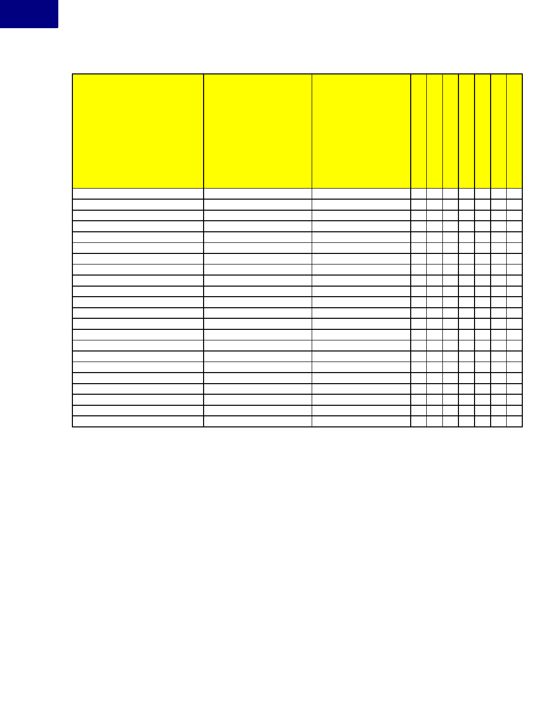
Graphics Fundamentals
Catalog of graphic attributes
304
Some boss classes inherit from kGraphicsAttrBoss and implement IGraphicAttributeInfo. They
are the base classes for graphic attributes, but they do not represent standalone attributes.
These bosses are excluded from the master attributes list and are listed in Table 84 for refer-
ence.
className
attributeName
value interfaces
affectsPageItemGeometry?
isRequiredGraphicAttribute?
isTableAttribute?
isTextAttribute?
isObservedByGraphicState?
isObservedByTransparencyAttrSuite?
isFormFieldAttribute?
kTextPasswordAttrBoss Password IGraphicAttrBoolean no no no no yes no yes
kTextScrollAttrBoss Scroll IGraphicAttrBoolean no no no no yes no yes
kTextUseForFileSelAttrBoss Used For File Selection IGraphicAttrBoolean no no no no yes no yes
kXPBasicBlendModeAttrBoss Mode IGraphicAttrInt32 no yes no no no yes no
kXPBasicIsolationGroupAttrBoss Isolate blending IGraphicAttrBoolean no no no no no yes no
kXPBasicKnockoutGroupAttrBoss Knockout group IGraphicAttrBoolean no no no no no yes no
kXPBasicOpacityAttrBoss Opacity IGraphicAttrRealNumber no yes no no no yes no
kXPDropShadowBlendModeAttrBoss Mode IGraphicAttrInt32 no no no no no yes no
kXPDropShadowBlurRadiusAttrBoss Blur radius IGraphicAttrRealNumber no no no no no yes no
kXPDropShadowColorAttrBoss Color IPersistUIDData no no no no no yes no
kXPDropShadowModeAttrBoss Drop shadow IGraphicAttrInt32 no no no no no yes no
kXPDropShadowNoiseAttrBoss Noise IGraphicAttrRealNumber no no no no no yes no
kXPDropShadowOffsetXAttrBoss X offset IGraphicAttrRealNumber no no no no no yes no
kXPDropShadowOffsetYAttrBoss Y offset IGraphicAttrRealNumber no no no no no yes no
kXPDropShadowOpacityAttrBoss Opacity IGraphicAttrRealNumber no no no no no yes no
kXPDropShadowSpreadAttrBoss Spread IGraphicAttrRealNumber no no bo no no yes no
kXPVignetteCornersAttrBoss Corners IGraphicAttrInt32 no no no no no yes no
kXPVignetteInnerOpacityAttrBoss Inner opacity IGraphicAttrRealNumber no no no no no yes no
kXPVignetteModeAttrBoss Feather IGraphicAttrInt32 no no no no no yes no
kXPVignetteNoiseAttrBoss Noise IGraphicAttrRealNumber no no no no no yes no
kXPVignetteOuterOpacityAttrBoss Outer opacity IGraphicAttrRealNumber no no no no no yes no
kXPVignetteWidthAttrBoss Feather width IGraphicAttrRealNumber no no no no no yes no
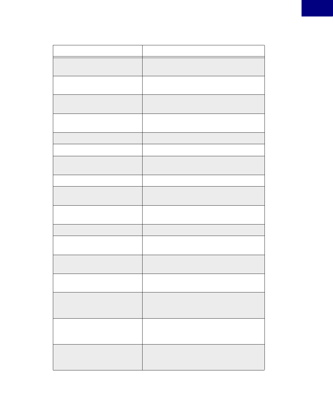
Graphics Fundamentals 305
Graphics Fundamentals
Catalog of graphic attributes
TABLE 84 Parent boss class of attributes
Boss ID Description
kVignetteAttrBoss Parent attribute boss for all basic feather
attributes.
kDropShadowAttrBoss Parent attribute boss for all drop-shadow
attributes.
kXPAttrBoss Parent attribute boss for all basic-transparency
attributes.
kXPInnerShadowAttrBoss Parent attribute boss for all inner-shadow
attributes.
kXPOuterGlowAttrBoss Parent attribute boss for all outer-glow attributes.
kXPInnerGlowAttrBoss Parent attribute boss for all inner-glow attributes.
kXPBevelEmbossAttrBoss Parent attribute boss for all bevel and emboss
attributes.
kXPSatinAttrBoss Parent attribute boss for all satin attributes.
kXPDirectionalFeatherAttrBoss Parent attribute boss for all directional-feather
attributes.
kXPGradientFeatherAttrBoss Parent attribute boss for all gradient-feather
attributes.
kDefaultGraphicsAttrBoss Parent of kGraphicStyleNonPrintAttrBoss.
kStrokeEffectGraphicsAttrBoss Parent of all stroke-effect attributes (line cap, join
type, etc.).
kCornerEffectGraphicsAttrBoss Parent of all corner-effect attributes (corner
implementation, size).
kFillGraphicsAttrBoss Parent of all fill attributes (gradient fill, gradient
fill angle, fill color, overprint, etc.).
kStrokeGraphicsAttrBoss Parent of all stroke attributes (gradient stroke,
gradient-stroke angle, stroke color, stroke weight,
etc.).
kGradientStrokeGraphicsAttrBoss Gradient stroke itself is parent of all gradient-
stroke attributes (length, gradient center, radius,
etc.).
kGradientFillGraphicsAttrBoss Gradient fill stroke itself is parent of all gradient
fill attributes (length, gradient center, radius,
etc.)

Graphics Fundamentals
Mappings between attribute domains
306
Mappings between attribute domains
TABLE 85 Graphic-attribute-to-text-attribute mapping
TABLE 86 Graphic-attribute-to-table-attribute mapping
Graphic-attribute class Text-attribute class
kGraphicStyleFillRenderingAttrBoss kTextAttrColorBoss
kGraphicStyleFillTintAttrBoss kTextAttrStrokeTintBoss
kGraphicStyleGradientFillAngleAttrBoss kTextAttrGradLengthBoss
kGraphicStyleGradientFillGradCenterAttrBoss kTextAttrGradCenterBoss
kGraphicStyleGradientStrokeAngleAttrBoss kTextAttrStrokeGradAngleBoss
kGraphicStyleGradientStrokeGradCenterAttrBoss kTextAttrStrokeGradCenterBoss
kGraphicStyleGradientStrokeLengthAttrBoss kTextAttrStrokeGradLengthBoss
kGraphicStyleOverprintFillAttrBoss kTextAttrOverprintBoss
kGraphicStyleOverprintStrokeAttrBoss kTextAttrStrokeOverprintBoss
kGraphicStyleStrokeRenderingAttrBoss kTextAttrStrokeColorBoss
kGraphicStyleStrokeWeightAttrBoss kTextAttrOutlineBoss
Graphic-attribute class Table-attribute class
kGraphicStyleFillRenderingAttrBoss kCellAttrFillColorBoss
kGraphicStyleFillTintAttrBoss kCellAttrFillTintBoss
kGraphicStyleOverprintFillAttrBoss kCellAttrFillOverprintBoss
kGraphicStyleOverprintStrokeAttrBoss kCellStrokeAttrDataBoss
kGraphicStyleStrokeLineImplAttrBoss kCellStrokeAttrDataBoss
kGraphicStyleStrokeRenderingAttrBoss kCellStrokeAttrDataBoss
kGraphicStyleStrokeWeightAttrBoss kCellStrokeAttrDataBoss

Graphics Fundamentals 307
Graphics Fundamentals
Spread-drawing sequence
Spread-drawing sequence
Once the kLayoutWidgetBoss IControlView implementation obtains a list of the visible
spreads, it has to ask each spread to draw through the InDesign draw manager. This section
describes the overall sequence for drawing the layout hierarchy.
The collaboration for drawing the layout hierarchy is shown in Figure 108. The IControlView
implementation on the kLayoutWidgetBoss calls the draw manager once for each visible
spread in the window’s view. The draw manager is responsible for creating a GraphicsData
object that describes the graphics context for the spread’s drawing. Specifically, it sets the trans-
formation matrix in the graphics port to support drawing in the spread’s parent coordinate sys-
tem, which is the pasteboard. The draw manager then calls the spread’s IShape::Draw method
to initiate the sequence of drawing that spread.
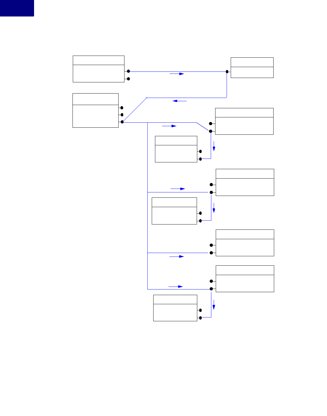
Graphics Fundamentals
Spread-drawing sequence
308
FIGURE 108 Boss collaboration for drawing the layout
When an item’s IShape::Draw method is called, it must draw itself, then its children. This
action is analogous to the mechanism used for the IControlView interface on widgets. The
IShape implementation provides methods for drawing an object and iterating over the object’s
children, asking each of them to draw. Before drawing, the IShape implementation sets the
transformation matrix in the graphics port to the item’s inner coordinates. This establishes the
following conventions:
kViewPortBoss
IDrawMgr
kLayoutWidgetBoss
IControlView
ILayoutControlData
kSpreadBoss
IGeometry
IHierarchy
IShape
kSpreadLayerBoss
IHierarchy
IShape
kPageBoss
IHierarchy
IShape
kSpreadLayerBoss
IHierarchy
IShape
kSplineItemBoss
IHierarchy
IShape
kSpreadLayerBoss
IHierarchy
IShape
kSpreadLayerBoss
IHierarchy
IShape
kGuideItemBoss
IHierarchy
IShape
1. : DrawWithTimedUpdate()
2 : Draw()
2.1 : Draw()
2.1.1 : Draw()
2.2 : Draw()
2.3 : Draw()
2.2.1 : Draw()
2.4.1 : Draw()
2.4 : Draw()

Graphics Fundamentals 309
Graphics Fundamentals
Controlling the settings in a graphics port
zEach drawing object expects to receive the graphics port set to its parent’s coordinate sys-
tem.
zEach drawing object sets the graphics port to its inner coordinates before drawing itself or
calling its children to draw.
zEach drawing object reverts the graphics port to its parent’s coordinate system before
returning to the caller.
Iterating over the object’s children is accomplished by using the IHierarchy interface on each
page item. This interface provides methods for iterating over the layout hierarchy. For more
information about the IHierarchy interface, see the “Layout Fundamentals” chapter.
After being called by the draw manager, spread drawing always follows the layout hierarchy.
Users can control whether the guides appear in front of the content or behind it, and this affects
the hierarchy. Assuming guides are behind the content, page layers are drawn first, followed by
the content layers, then the guide layers. If the guide layers appear in front of the content, the
guides draw before the content. All content on a given layer is drawn before proceeding to the
next layer. Embedded children of a page item are called to draw before that item completes its
drawing. For example, when the kSplineItemBoss is called to draw in step 2.2.1 of Figure 108, if
it had children, they would be called to draw as step 2.2.1.1 and 2.2.1.2. before returning to the
kSpreadLayerBoss.
Controlling the settings in a graphics port
The port’s transform can be modified by translations, scale factors, and rotations, and a new
transform can be concatenated to the existing port. Concatenation is most often used when
page items draw; it is how a page item sets the port to draw to its inner coordinates. Example 22
shows sample code demonstrating this operation. For more information on the application
coordinate systems, see the “Layout Fundamentals” chapter.
EXAMPLE 22 Manipulating the graphics-port settings
// Get the graphics port from gd, a GraphicsData*.
IGraphicsPort* gPort = gd->GetGraphicsPort();
if (gPort == nil) return;
// Save the current port settings.
gPort->gsave();
// Get this page item's ITransform interface.
InterfacePtr<ITransform> xform(this, IID_ITRANSFORM);
// Concatenate the inner to parent matrix to the port.
gPort->concat(xform->CurrentMatrix());

Graphics Fundamentals
Drawing sequence for a page item
310
// Draw a rectangle around the item.
InterfacePtr<IGeometry> geo (this, IID_IGEOMETRY);
const PMRect r = geo->GetStrokeBoundingBox();
gPort->rectpath(r);
gPort->stroke();
// Restore the previous port settings.
gPort->grestore();
Drawing sequence for a page item
The drawing sequence for a page item that implements IShape involves more than just the
drawing instructions. Extensibility points are built into the sequence, in the form of drawing
events and adornments. Extensibility points are described in “Extension patterns” on page 289.
Although each IShape implementation may have its own specific drawing sequence, all imple-
mentations follow these steps as guidelines:
1. When a page item begins drawing, three drawing events are broadcast (kAbortCheckMes-
sage, kFilterCheckMessage, and kDrawShapeMessage). No IShape drawing activities occur
between the broadcasts.
2. Save the graphics port state by calling IGraphicsPort::gsave. The graphics port is set to draw
in the page item’s inner coordinate system.
3. A kBeginShapeMessage drawing event is broadcast. If any drawing-event handler returns
kTrue, the drawing activity ends.
4. Draw kBeforeShape page item adornments.
5. Draw the page item’s own shape by calling the protected method CShape::DrawShape. This
method varies depending on the nature of the page item. The following is a list of common
tasks the DrawShape method may accomplish:
zDefine the item’s path.
zFill the path.
zSet the port to clip to the path.
zDraw the item’s children.
zStroke the path.
6. Draw kAfterShape page-item adornments.
There are types of page-item adornments other than kBeforeShape and kAfterShape. These
may be called to draw at other points in the sequence. The use of graphics-port save and restore
operations allows the adornments and child drawing routines to modify the port as needed and
return it to a known state for the next drawing step.

Graphics Fundamentals 311
Graphics Fundamentals
Drawing sequence for a page item
For details of the code responsible for drawing, see the CShape.cpp and CGraphicFrame-
Shape.cpp source code in the SDK, under <SDK>/source/public/pageitems/basicinterfaces. For
examples of how to create your own shapes, also see the BasicShape and CandleChart sample
plug-ins.

Graphics Fundamentals
Drawing sequence for a page item
312

Text Fundamentals 313
Text Fundamentals
Concepts
Text Fundamentals
This chapter provides background on the fundamental concepts used in the text architecture
and describes the major subsystems that implement text features. It has the following objec-
tives:
zIdentify the core subsystems that implement the text architecture.
zDescribe the model for text content—how raw text and formatting information is managed.
zDescribe how the presentation of text (i.e., the actual rendered text) is modeled within the
application, including both the glyphs that represent the text and the objects that manage
the placement of glyphs on a spread.
zDescribe text composition, the process of taking the content model and incomplete presen-
tation model to generate the final appearance of text in the presentation model.
zDescribe fonts and how they relate to the InDesign text subsystem.
Table 87 lists resources for more information on relevant topics.
TABLE 87 For more information
Concepts
This section introduces the subsystems that implement the text architecture. The core text
architecture can be divided into the following core subsystems: text content, text presentation,
and text composition. Subsystems that extend the core include import and export, text styles,
editors, and text search/replace. See Figure 109.
For ... Go to ...
More information on
digital typography topics
http://store.adobe.com/type/topics/main.html
A glossary of typographic
terms
http://store.adobe.com/type/topics/glossary.html
An overview of Adobe
type technology
http://partners.adobe.com/asn/developer/type/main.html
The PostScript language
FAQ list
http://www.postscript.org/FAQs/language/FAQ.html
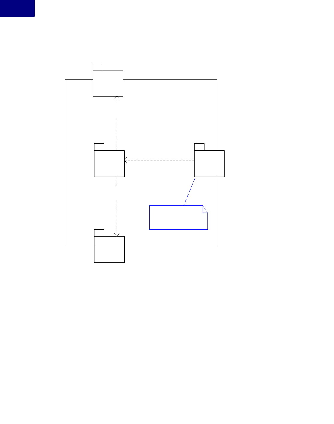
Text Fundamentals
Concepts
314
FIGURE 109 Overview of core text architecture
The text-content subsystem manages the content of a story. The text-content subsystem stores
the characters and attributes that control the styled appearance of text.
The text-presentation subsystem deals with where the text glyphs appear on the page. Text is
composed into frames that display a story. A frame is a visual container for text. Visually, a
story is displayed through a linked set of one or more frames. The frames have properties—
such as the number of columns, column width, and text inset—that control where text flows.
Text-wrap settings on overlapping frames may affect this flow. Once text is composed, it has a
visual appearance and exhibits many of the same geometry traits as other page items.
The text-composition subsystem manages the process that flows text into a set of specified con-
tainers. Fonts provide the text-composition subsystem with the glyph dimensions it needs to
arrange glyphs into lines of a given width.
The text
model
Text
composition
«uses»
Content (story thread, character and text attributes)
«uses»
Visual container (parcel and text frame)
is created by
Content
Visual container
has
Visual container
Wax line
Displays / is displayed by
Wax strand
Content
has
Represents composed text
Text layout
The wax
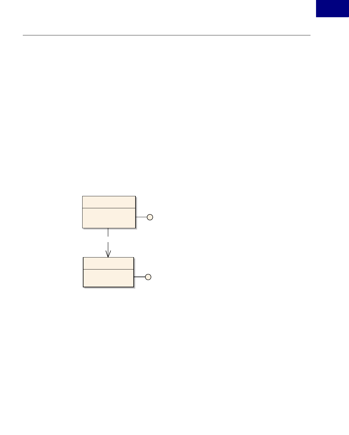
Text Fundamentals 315
Text Fundamentals
Text content
Text content
This section describes how the raw character and formatting information for a story is main-
tained within the application. Text content represents the information required to render a set
of characters. This information includes the Unicode character values, along with any format-
ting information that defines the look of text, contents of footnotes and tables, inline graphics,
and styles that can be applied to text.
Stories
Text content within a document is represented by a story (signature interface ITextModel). A
single, related set of text is maintained within a single story. The document can contain multi-
ple stories. All stories within the document can be accessed through the IStoryList interface on
the kDocBoss class. Figure 110 shows this relationship.
FIGURE 110 Stories: maintained on the kdocboss, accessed by means of IStoryList.
A document can contain private, feature-dependent stories, which are defined not to be user-
accessible. Other features (like find/replace and spelling) ignore these stories. Programmati-
cally, they can be accessed through the IStoryList interface, as with any other story.
Generally, stories are not directly created or deleted. The life-cycle of a story is controlled as a
side effect of another operation. For example, creating a text frame using the Type tool causes a
text story to be created, whereas linking two text frames together causes a story to be deleted. It
is possible to control the lifetime of a story directly, though the story is still subject to the side
effects of manipulating an associated text frame.
A story has a length, which can be accessed using ITextModel::TotalLength. A story has a min-
imum length of one character: a terminating kTextChar_CR, which is inserted into the story
when the story is created. This character should not be deleted.
kDocBoss
IStoryList
kTextStoryBoss
ITextModel
1
IStoryList::GetNthUserAccessibleStoryUID
1..*
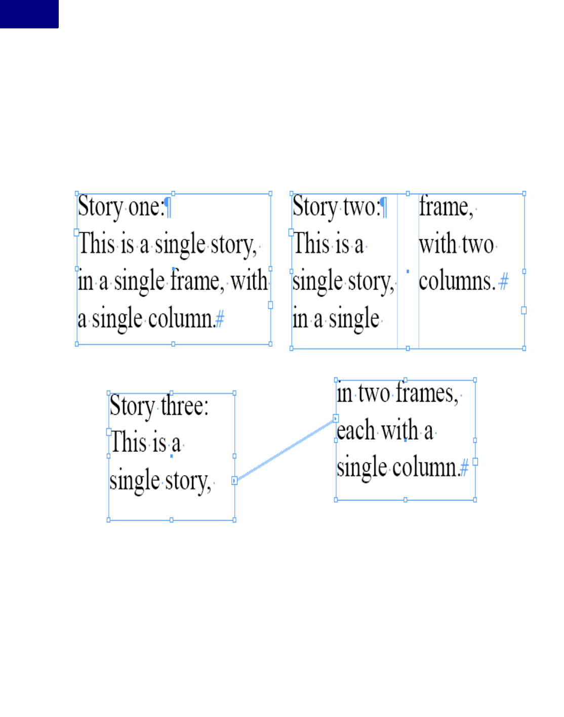
Text Fundamentals
Text content
316
The textual content of a story is maintained independently from the visual containers in which
it is contained; i.e., its layout on the page. The text content from a story can be contained within
one frame, flow between columns within a frame, or even flow between multiple frames. For
example, Figure 111 shows three stories, each flowing through different sets of containers. The
model used in maintaining the text content for each is the same. Determining where a particu-
lar glyph is rendered is the responsibility of the composer.
FIGURE 111 Three text stories flowing through text frames in a spread
Information related to the text in a story is maintained by a set of strands. Strands represent
parallel sets of information, each of which holds a component of the story. The strands inter-
twine to give a complete description of the story. Strands are identified using the IStrand signa-
ture interface. Some common strands are shown in Figure 112.
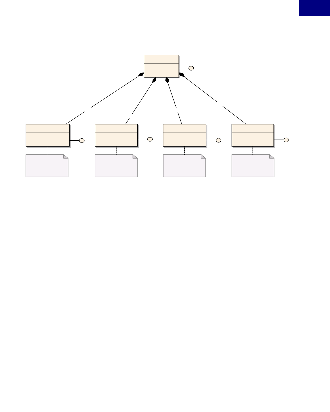
Text Fundamentals 317
Text Fundamentals
Text content
FIGURE 112 The text story aggregates the strands representing the content.
Strands
Strands (signature interface IStrand) model the linear behavior of text. Each strand represents a
different aspect of textual information. A story can be thought of as the composition of the set
of strands that contain information for a particular aspect of the story. Figure 112 shows a story
with associated text, paragraph-attribute, and character-attribute strands. It also shows the
owned item strand used to maintain objects within the text, like inline graphics.
Each strand has the same virtual length, equal to the value returned by ITextModel::Total-
Length. Each position within a strand refers to the same logical position within the other
strands and the story as a whole. For example, position 10 on the kTextDataStrandBoss relates
to a particular character—the character at position 10 within the kCharAttrStrandBoss refers
to formatting information applicable to this character. Any modification of the text length is
reflected in each strand.
Figure 113 shows some text and how it might be represented on two strands. While the actual
storage mechanism for the strands is of little interest, both strands have the same virtual length.
A story (kTextStoryBoss) comprises a set of strands, each with the same length. The figure
shows only the data (kTextDataStrandBoss) and paragraph-attribute (kParaAttrStrandBoss)
strands.
kCharAttrStrandBoss
IStrand
kParaAttrStrandBoss
IStrand
kTextDataStrandBoss
IStrand
kTextStoryBoss
ITextModel
kOwnedItemStrandBoss
IStrand
Holds Unicode character
code data for the text in the
story.
Maintains formatting
information applicable to
paragraphs.
Maintains formatting
information applicable to a
range of characters.
Maintains a link to objects
anchored into the text,
such as inline images, table
frames, and footnotes.
1
ITextModel::QueryStrand(kOwnedItemStrandBoss,...)
1
1
ITextModel::QueryStrand(kCharAttrStrandBoss,...)
1
1
ITextModel::QueryStrand(kParaAttrStrandBoss,...)
1
1
ITextModel::QueryStrand(kTextDataStrandBoss,...)
1
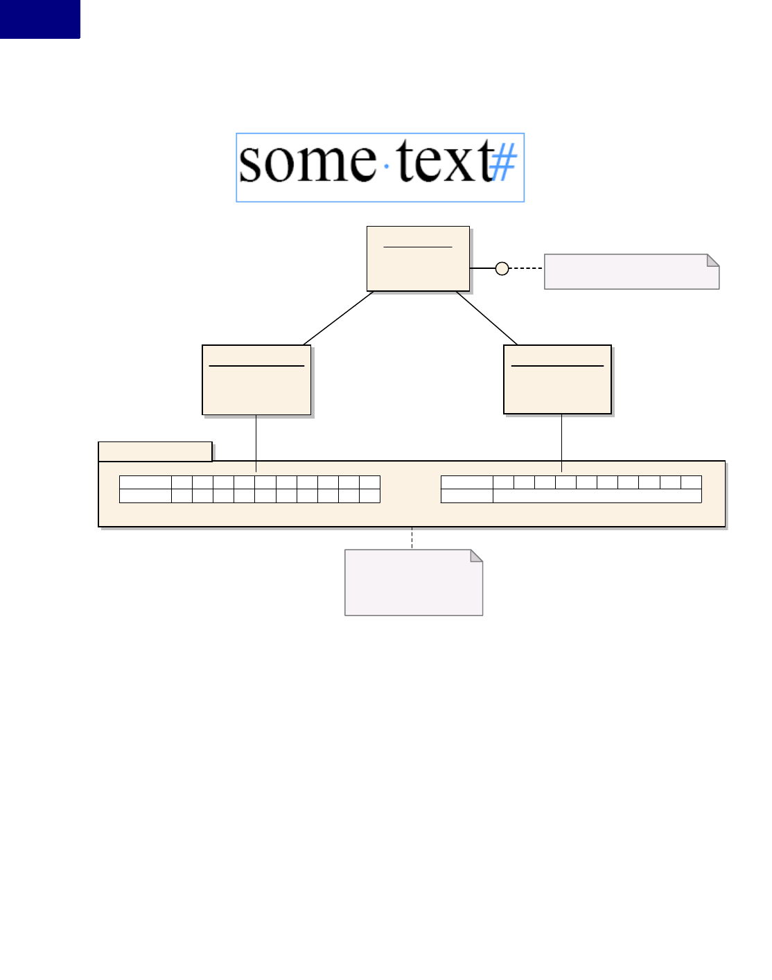
Text Fundamentals
Text content
318
FIGURE 113 A story and two of its associated strands
Formatting is defined in “Text formatting” on page 324.
Runs
Strands are further divided into runs. A run represents something about the content of a partic-
ular strand. For the kTextDataStrandBoss, a run is a manageable-sized chunk of text data. For
the kParaAttrStrandBoss, a run exists for each paragraph in the story. For the kCharAttr-
StrandBoss, a run represents a sequence of characters that share the same formatting informa-
tion. The semantics of a run is defined by its strand.
Owned items
Owned items (signature interface IOwnedItem) exist to allow some object to be associated with
a particular TextIndex position in the text strand. Generally, features anchor the owned item
into the text by placing a special character into the kTextDataStrandBoss; however, there is no
requirement for associating an owned item with a special character in the data strand.
Figure 114 shows an instance diagram associated with a story that contains an inline image.
:kTextStoryBoss
ITextModel
:kTextDataStrandBoss :kParaAttrStrandBoss
Strands abstract over the raw
data. Developers should not need
to interact directly with the
storage model below strands.
ITextModel::TotalLength() == 10
Text storage subsystem
Index 012345678
Data s o m e t e x t
9
#
Data strand
Index 0123456789
Data Format t i n g def i n ed by r oot st yl e
Paragraph attribute strand
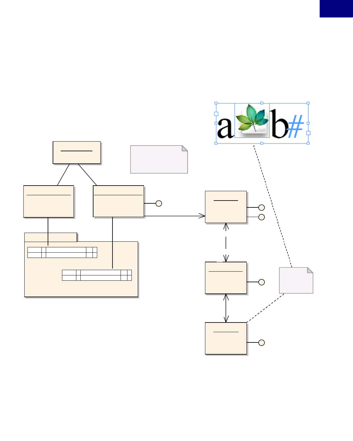
Text Fundamentals 319
Text Fundamentals
Text content
The story has the character “a” followed by an inline image, then the character “b.” The owned
item strand (kOwnedItemStrandBoss) maintains the UID of the inline object (kInlineBoss).
The actual image (kImageItem—note the nonstandard name) is associated through the hierar-
chy (IHierarchy).
FIGURE 114 Instance diagram showing an owned item
Anchored-item positioning
The positioning of an inline object relative to its anchor position in the text is controlled
through the IAnchoredObjectData interface. The default behavior is defined by the IAnchore-
dObjectData on the session and document-workspace boss classes. Object styles also can
:kTextStoryBoss
:kTextDataStrandBoss :kOwnedItemStrandBoss
IItemStrand
:kInlineBoss
IHierarchy
IOwnedItem
:kSplineItemBoss
IHierarchy
:kImageItem
IHierarchy
IItemStrand::GetOwnedUID
for TextIndex 0, 2, and 3
would return kInvalidUID.
Text storage subsystem
I ndex 0 1 2 3
Data akTextChar_I nline b #
Data Strand
I ndex 0 1 2 3
Data UI D for kI nl i neBoss #
Owned item strand
Inline graphic
represented by
kImageItem
1
IItemStrand::GetOwnedUID(1)
1
1
+IHiearchy::QueryChild
0..*
+IHierarchy::QueryParent
1
+IHierarchy::QueryChild
0..*
+IHierarchy::QueryParent

Text Fundamentals
Text content
320
define how an inline object is positioned (IAnchoredObjectData on kObjectStyleBoss). Spe-
cific inline objects can be modified (IAnchoredObjectData on kInlineBoss).
The placement of inline objects can be specified as any of the following:
zWithin the text flow (with variable offset on the y axis).
zAbove the line, aligned to the center, right, or left of the text or spline. A variable amount of
space before and after the inline object can be specified.
zA custom position on the page, relative to the anchor point, text frame, page, or spline.
As the content that contains the anchor is manipulated (by either adding text that causes the
anchor to flow out of the initial frame or manipulating the frames in which the text is con-
tained), the position of the inline object is updated automatically.
Story threads
Strands model the linear nature of text; however, not all text within a story is linear. For exam-
ple, an embedded table can have cells with textual content that flows independently from the
main text in the story. Story threads (signature interface ITextStoryThread) represent these dis-
tinct flows of text.
Each story has at least one story thread, the primary story thread, which represents the main
text of the story. Other text elements (like footnotes) contained within a story are anchored off
the primary story thread using owned items, as described in “Owned items” on page 318.
The interface that models story threads (ITextStoryThread) is maintained on the boss class
related to the text it represents. For the primary story thread, the interface is found on the
kTextStoryBoss. For footnotes, the interface is on kFootnoteReferenceBoss. The story thread
maintains text indices that identify the range of text within the story that relates to the particu-
lar strands.
Figure 115 shows a story with only text within the primary story thread (i.e., the story uses no
features requiring other story threads). The story instance (kTextStoryBoss) has four associated
strands. There is one story thread (ITextStoryThread) in this story.
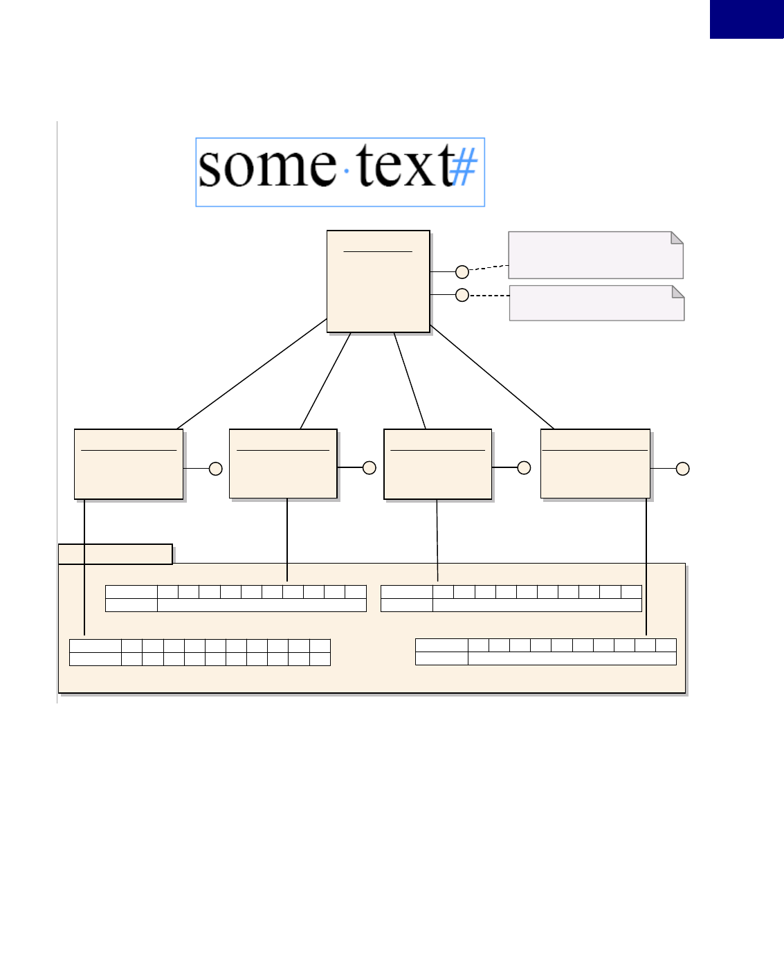
Text Fundamentals 321
Text Fundamentals
Text content
FIGURE 115 Story with only primary story thread
The primary story thread always begins at TextIndex 0. Other features, like footnotes and
tables, use story threads to maintain the feature text as a distinct entity. Figure 116 shows an
instance diagram of a story with a footnote. In the figure, a text-story thread (ITextStoryTh-
read) maintains a relationship with some part of the text in a story. In this example, the primary
story thread (on kTextStoryBoss) ranges between TextIndex 0 and 3, and the footnote (kFoot-
noteReferenceBoss) ranges between TextIndex 4 and 8.
:kTextStoryBoss
ITextStoryThread
ITextModel
:kTextDataStrandBoss
IStrand
:kParaAttrStrandBoss
IStrand
:kCharAttrStrandBoss
IStrand
:kOwnedItemStrandBoss
IStrand
ITextStoryThread::GetTextStart() == 0
ITextStoryThread::GetTextEnd() == 9
ITextModel::TotalLength() == 10
Text storage subsystem
Index 012345678
Data s o m e t e x t
9
#
Data strand
Index 0 1 2 3 4 5 6 7 8 9
Data Format t i n g def i n ed by r oot st yl e
Paragraph attribute strand
Index 0 1 2 3 4 5 6 7 8 9
Data No formatting defined
Character attribute strand
Index 0 1 2 3 4 5 6 7 8 9
Data No inline objects in stream
Owned item strand
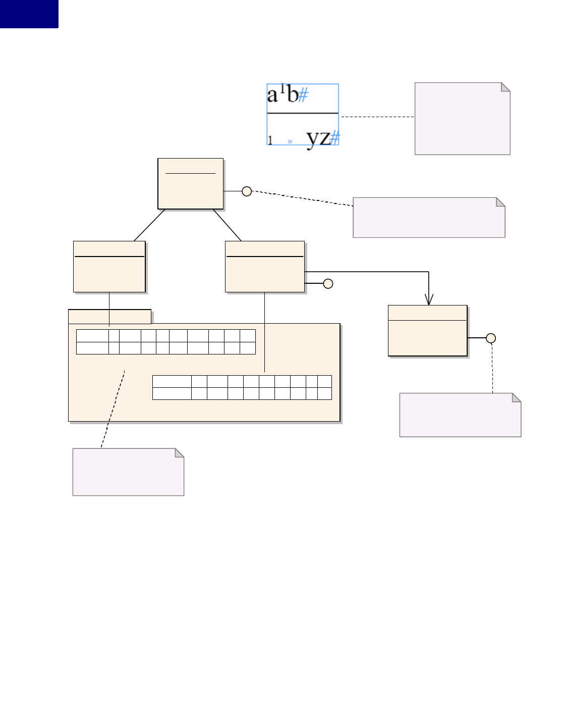
Text Fundamentals
Text content
322
FIGURE 116 A story containing a footnote
Story-thread dictionaries and hierarchies
Each distinct instance of a text feature within a story has a distinct text-story thread (ITextSto-
ryThread), including the main story text (the primary story thread). Text-story threads are
associated with a particular TextIndex, known as the anchor, obtainable with ITextStoryThre-
adDict::GetAnchorTextRange. This does not apply to the primary story thread, which is the
only thread that always returns an anchor position of zero. An anchor for a footnote appears to
the users in the user interface as the footnote-reference character. The anchor for a table
appears as the table itself.
A text-story thread can contain anchors for other text story threads, subject to some restric-
tions; for example, footnotes can contain tables but not other footnotes. A feature does not
Text storage subsystem
:kTextStoryBoss
ITextStoryThread
:kTextDataStrandBoss :kOwnedItemStrandBoss
IItemStrand
:kFootnoteReferenceBoss
ITextStoryThread
I ndex 0 1 2 3 4 5 6 7
Data a0x4 b # 0x4 0x9 y z
8
#
Data strand
Index 0 1 2 3 4 5 6 7
Data UI D
8
Owned item strand
0x4 == kTextChar_FootnoteMarker
0x09 == kTextChar_Tab
See TextChar.h.
ITextStoryThread::GetTextStart() returns 0
ITextStoryThread::GetTextEnd() returns 3
ITextStoryThread::GetTextSpan() returns 4
ITextStoryThread::GetTextStart() returns 4
ITextStoryThread::GetTextEnd() returns 8
ITextStoryThread::GetTextSpan() returns 5
The footnote number and tab
are inserted into the footnote
automatically. The data strand
indicates where the number
should be placed using
kTextChar_FootnoteMarker.
IItemStrand::GetOwnedUID(1)
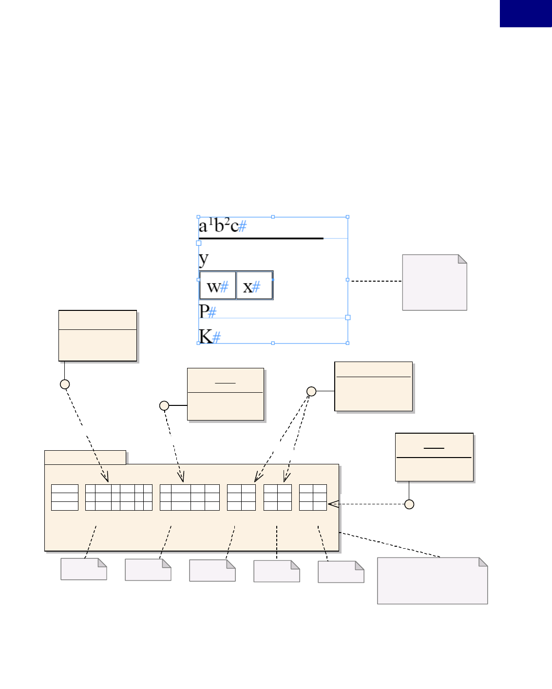
Text Fundamentals 323
Text Fundamentals
Text content
need to associate the story thread with a particular TextIndex, in which case it is associated
with the end of story marker for the primary text-story thread (these are unanchored threads).
A thread block is a contiguous text range (TextRange) that contains the contents for one text-
story thread. If a text-story thread contains a set of anchors, the thread blocks associated with
these anchors directly follow the thread block for this story thread. This is depicted in
Figure 117. Note how the thread blocks for the table directly follows the thread block for the
footnote into which it is anchored. In the figure, ITextStoryThreadDict manages the story
threads for a particular use of a feature. There is one story thread for the primary story, one for
each footnote, and two for the embedded table.
FIGURE 117 A story with two footnotes, one containing a two-cell table
Text storage subsystem
Index
Data
Inlines
1 2 3 4
0x4 b0x4 c
UID1 UI D2
0
a
5
#
Primary story thread
6 7 8 9
y0x16 P #
UID3
Footnote 1 thread
10
w
11
#
Table
thread 1
14
K
15
#
Footnote
2
thread
UID1 :
kFootnoteReferenceBoss
ITextStoryThreadDict
UID2 :
kFootnoteReferenceBoss
ITextStoryThreadDict
UID3 :kTableModelBoss
ITextStoryThreadDict
kTextStoryBoss
ITextStoryThreadDict
On data strand:
0x4 == kTextChar_FootnoteMarker
0x16 == kTextChar_Table
See TextChar.h.
Thread block 0 Thread block 1 Thread block 2 Thread block 4
12
x
13
#
Table
thread 2
Thread block 3
The auto-numbering
characters have been
edited out of the
footnotes.
QueryStoryThread
QueryStoryThread QueryStoryThread
QueryStoryThread
QueryStoryThread

Text Fundamentals
Text content
324
The text-story thread dictionary (ITextStoryThreadDict) maintains the set of story threads
associated with a particular use of a feature. In Figure 117, each feature has one associated story
thread, apart from the table. Each cell in the table has a distinct story thread. ITextStoryThre-
adDict is responsible for managing the set of threads in the table.
Text story threads have a hierarchical relationship (the root being the primary story thread).
Individual features are responsible for managing a set of one or more story threads using the
story-thread dictionary (ITextStoryThreadDict). In Figure 117, kFootnoteReferenceBoss
(UID1) manages one text-story thread, while kTableModelBoss (UID3) manages two story
threads, one for each cell. The story maintains a dictionary hierarchy (ITextStoryThreadDictH-
ier), which provides the ability to iterate across all objects that contain a dictionary associated
with the story.
Text formatting
This section describes how the style information that controls the look of text is maintained
within the application.
Text attributes
The fundamental component for formatting text is the text attribute (signature interface IAttr-
Report). This is a lightweight, non-persistent set of boss objects, each of which describes one
text property; for example, the color or point size of text. Attributes are interpreted by the text-
composition subsystem, to define how the text appears when composed.
Attributes target either arbitrary ranges of characters (like the color or point size of a set of
characters) or a paragraph (like applying a drop cap or setting paragraph alignment).
Attributes are managed in an AttributeBossList list, a persistent container class. Consider an
AttributeBossList list to be a hash table of attributes, the key being the ClassID. One implica-
tion of this is there can be only one instance of any particular attribute within an Attribute-
BossList list (for example, no conflicting text-color attribute within an AttributeBossList).
Attributes can be applied directly (within an AttributeBossList list) to the appropriate para-
graph or character-attribute strand, or they can be applied to a text style. An example of apply-
ing the attribute directly to the strand would be italicizing text directly using the text editor.
Such changes are local to the text being formatted and known as local overrides to the current
style.
An attribute boss class that supports the IAttrImportExport interface can participate in the
import and export of InDesign tagged text files.
Default attributes
The application provides a set of default attributes. These attributes are maintained within an
AttributeBossList on both the session and document workspace. Default attributes define a set
of overrides that are applied to any new stories created. These AttributeBossList lists reflect the
state of the Character and Paragraph panels when no documents are open (session workspace)
or new stories are created (document workspace). When a new document is created, the docu-
ment workspace inherits the value of the default attributes from the session. The default

Text Fundamentals 325
Text Fundamentals
Text content
attributes can be updated directly through the Paragraph and Character panels or by selecting
styles in the styles panels; the defaults are updated to match the style.
Text styles
A text style (signature interface IStyleInfo) provides a mechanism to name and persist a partic-
ular set of text attributes with particular values. The application supports two kinds of styles for
text, paragraph styles and character styles. Each style has an AttributeBossList list that main-
tains the set of attributes that apply to that style. Access to the attributes in a style is achieved
through the ITextAttributes wrapper interface. Character styles are associated with character
attributes; however, paragraph styles can be associated with both paragraph and character
attributes. Paragraph styles are applied to whole paragraphs; character styles can be applied to
arbitrary ranges of text.
All text must be associated with both a paragraph style and character style. To support this, the
application defines two default styles: the root character style and root paragraph style (known
in the application user interface as [No Paragraph Style]). The root paragraph style contains a
complete set of paragraph-based and character-based attributes. This defines the default look
of text with no further formatting applied. The root character style is empty; it exists purely to
provide a root for character styles.
Styles form a hierarchy rooted at the root style. Each style (except the root style) is based on a
style. The AttributeBossList list for a particular style record only the differences from the style
on which it is based; that is, the set of attributes the particular style overrides. This is shown in
Figure 118. In the figure, the kStyleBoss for the root paragraph style defines all attributes with a
default value. The kStyleBoss for the new style (Yellow Text) contains only the attributes that
differ from the root style. The root character style contains no attributes; it exists to provide a
root to the character-style hierarchy.
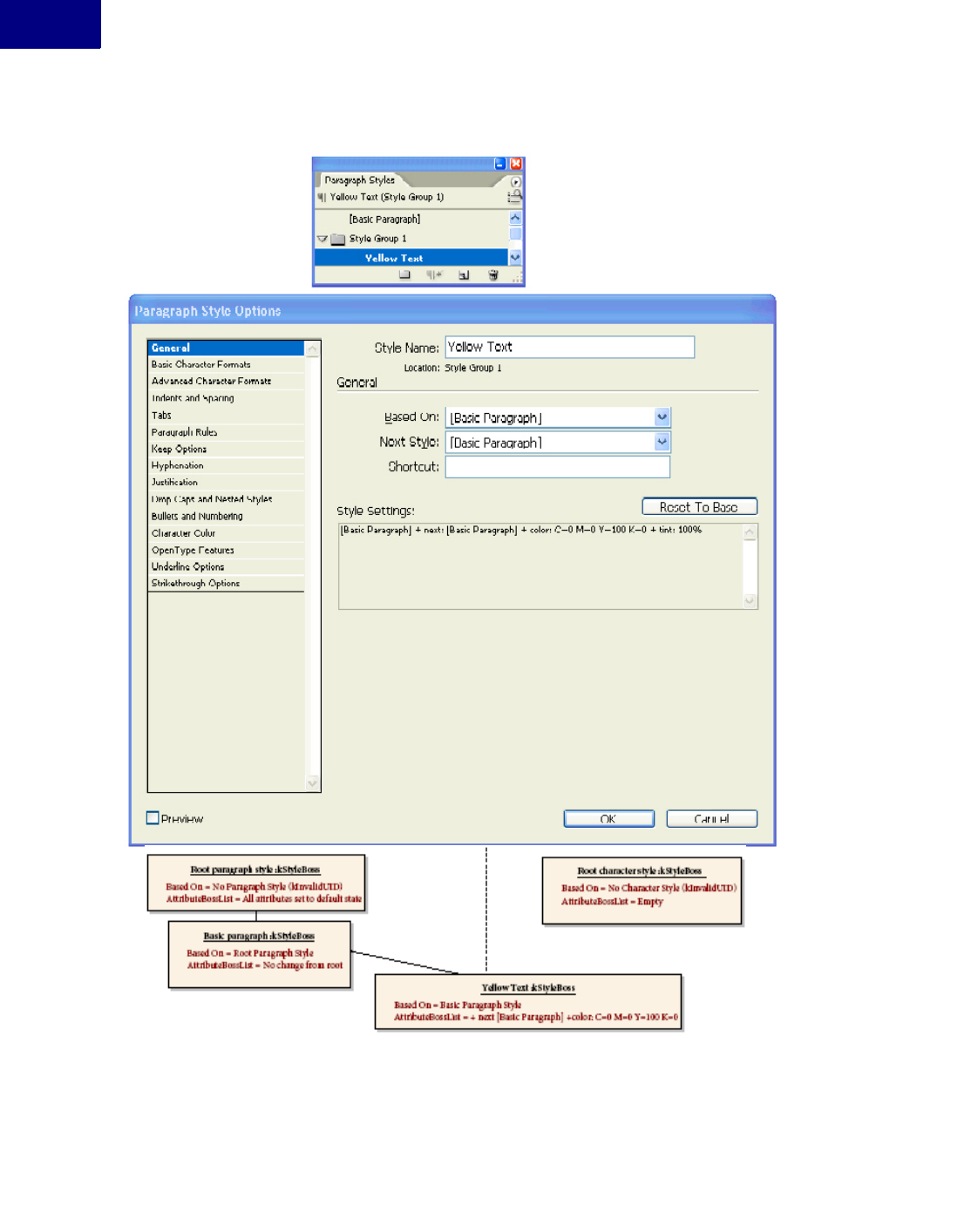
Text Fundamentals
Text content
326
FIGURE 118 Paragraph-style example
The application provides two basic styles, for character attributes and paragraph attributes.
These are the default styles applied to new stories (assuming no other style is selected in a styles
panel). The basic styles cannot be deleted, but you can modify them with plug-ins. Initially, the
basic styles are based on the root styles; however, the parent styles can be changed.

Text Fundamentals 327
Text Fundamentals
Text content
Users can create, edit and delete folders, called Groups, in the Character, Paragraph, and Object
Styles palettes. Style group is a collection of styles or groups. The user also can nest groups
inside groups and drag styles within the palette to edit the contents of a group. Styles do not
need to be inside a group and can exist at the root level of the palette. The group concept also is
available in the object style palette.
Character and paragraph styles are not required to have unique names across groups; however,
sibling styles and groups must have unique names within a parent (i.e., at the same level in the
hierarchy). Style names are case-sensitive, so the user can have both “heading” and “Heading”
in the same folder. A group and a style cannot have the same name. Since style names are not
unique, they are displayed in the user interface as full paths.
The alphabetical sort is an action applied to the entire list of styles. Users can rearrange the
styles and groups arbitrarily at any time; to view the list alphabetically, they can resort the list
with the Sort By Name command. Styles are intermixed with groups for sorting. Sorting is
undo-able. The sorting is language specific, based on the user-interface language. Reserved
styles like [Basic Paragraph] or [Basic Graphics Frame] are not reordered by this command.
Styles are accessible through the style group manager (signature interface IStyleGroupMan-
ager) on the document (kDocWorkspaceBoss) and session (kWorkspaceBoss) workspace boss
classes. When a document is created, its style group manager inherits the existing set of styles
from the session workspace. There are multiple style group managers supported by the work-
spaces, each identified by a distinct interface identifier; for example,
IID_IPARASTYLEGROUPMANAGER and IID_ICHARSTYLEGROUPMANAGER. IStyle-
GroupManager has one automatically created object of type IStyleGroupHierarchy called
“Root Hierarchy,” represented by the kStyleGroupHierarchyBoss. IStyleGroupManager pro-
vides access to kStyleGroupHierarchyBoss through its GetRootHierarchy() method.
This Root Hierarchy is created on the first call to the GetRootHierarchy method. The kStyle-
GroupHierarchyBoss holds all the styles (kStyleBoss) and style groups (kStyleGroupBoss) at
root level. The key interface on the kStyleGroupHierarchyBoss is IStyleGroupHierarchy, which
stores the persistent UID-based style tree hierarchy so you can query information like par-
ent/child node information. All children of this root hierarchy must support the IStyle-
GroupHierarchy interface; therefore, IStyleGroupHierarchy also is aggregated on the
kStyleBoss and kStyleGroupBoss, so access to the style hierarchy also is available if you have
access to the UID of any style or style group in the hierarchy. With IStyleGroupHierarchy, you
gain access to the style-tree hierarchy the user sees in the style panel. IStyleGroupHierarchy has
a method to traverse the style hierarchy, which should be used to iterate through all styles.
IStyleGroupManager also provides two overloaded FindByName() methods that return the
UID of a style or style group.
Figure 119 shows how to navigate the styles, given a particular workspace. The style group
manager (IStyleGroupManager on document and session workspaces) provides access to all
paragraph and character styles (kStyleBoss) through the GetRootHierarchy() method, which
returns an IStyleGroupHierarchy on the kStyleGroupHierarchyBoss. kStyleGroupHierarchy-
Boss holds all the styles (kStyleBoss) and style groups (kStyleGroupBoss) at root level. Styles
can be iterated over using IStyleGroupHierarchy::GetDescendents or accessed by name using
IStyleGroupManager::FindByName. Given a particular style, the style it is based on can be
accessed using IStyleInfo::GetBasedOn.
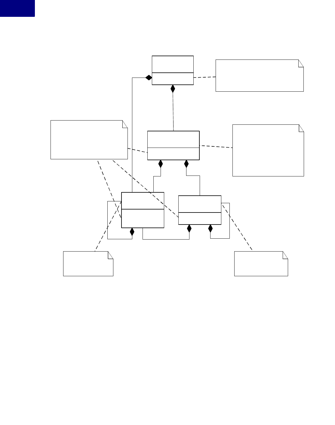
Text Fundamentals
Text content
328
FIGURE 119 Navigating styles in a document
Sorting the style hierarchy is done through the IStyleGroupHierarchy::Sort() method, when it
is invoked, it sorts its children and calls its children’s Sort method. The call to Sort() on the root
hierarchy recursively sorts all styles. This methods takes a flag to indicate whether to sort in
descending/ascending order, all child or immediate child, etc.
Text formatting and stories
All text has an associated character- and paragraph-attribute style. This style is either the root
style (which defines a default value for the complete set of attributes used in composition) or a
style that records differences from the root style. Styles form a hierarchy in which the values of
attributes in child nodes override those in parent nodes. As well as having the character and
paragraph styles defined on the attribute strands, local overrides can be applied. This occurs
when a formatting change is made without modifying a style; for example, selecting a word and
making it bold.
+IStyleGroupManager
«boss»
kDocWorkspaceBoss
+IStyleGroupHierarchy
«boss»
kStyleGroupBoss
+IStyleGroupHierarchy
«boss»
kStyleGroupHierarchyBoss
1
1
1
0..*
1
0..*
1
0..*
1
0..*
+IStyleGroupHierarchy
+IStyleInfo
«boss»
kStyleBoss
Holds all the styles (kStyleBoss)
and style groups (kStyleGroupBoss)
at root level.
IStyleGroupHierarchy can be
used to access its styles and
groups.
IStyleGroupHierarchy is aggregated
on kStyleGroupHierarchyBoss,
kStyleBoss, and kStyleGroupBoss, it is
used to access kStyleBoss/kStyleGroupBoss
current object may have.
1
0..1
IStyleInfo::GetBasedOn
IStyleGroupHierarchy::QueryChild
IStyleGroupHierarchy::QueryChild
IStyleGroupHierarchy::QueryChild
IStyleGroupHierarchy::QueryChild
1
1
IStyleGroupManager::GetRootStyleUID
IStyleGroupManager::GetRootHierarchy
Represents a text style Represents a style group
The IStyleGroupManager is the access point
for style set management. It gives access
to the root IStyleGroupHierarchy from where
you can get the full style set hierarchy
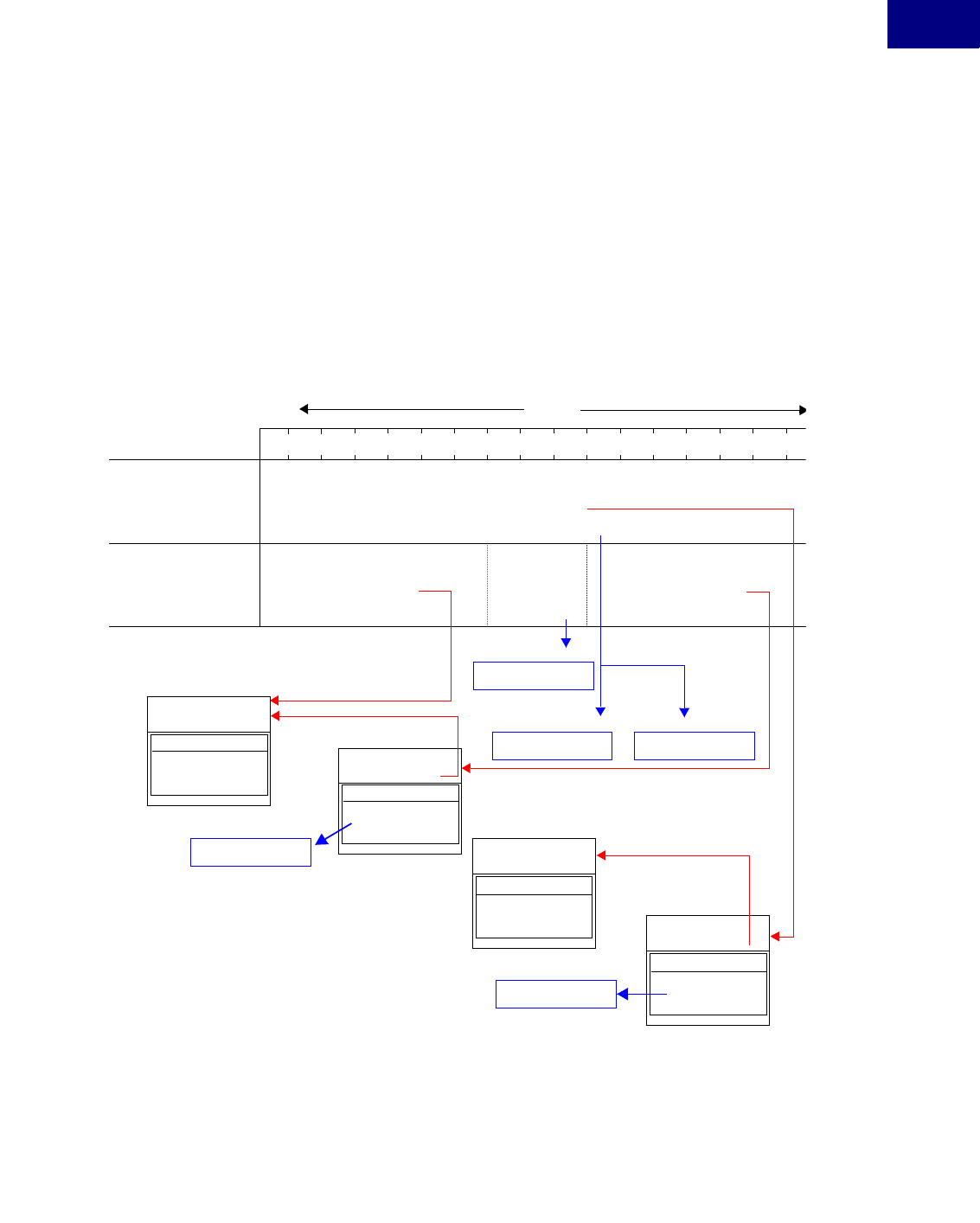
Text Fundamentals 329
Text Fundamentals
Text content
Attributes describe one of the text’s appearance and are used by the composition engine when
rendering the associated glyphs. IComposeScanner (on the kTextStoryBoss) provides APIs that
allow the value of any attribute to be deduced for any TextIndex. Figure 120 shows an example
of how styles and local attribute overrides combine to describe the exact look of text. The para-
graph-attribute strand specifies the text will use the custom style pStyle and two local over-
rides. The overrides specify the body and last line of the paragraph are to be centered. The
character-attribute strand specifies the root style for the word “Aliens,” a local +bold override
for the word “and,” and the word “Earth” to use the custom style cStyle.
FIGURE 120 Formatting and strands
kTextAttrPointSizeBoss
+size: 24 pt
01234567891011121314
kTextDataStrandBoss
kParaAttrStrandBoss
kCharAttrStrandBoss
Start: 10
End: 16
UID: cStyle
Overrides: None
Start: 0
End: 6
UID: root
Overrides: None
Start: 7
End: 9
UID: root
Overrides: +bold
length = 17
Story
15 16
Al i ans nd Ear th#e
Start: 0
End: 16
UID: pStyle
Overrides: + last: centered + body: centered
name: root
based on: none
AttributeBossList
all attributes
described here
kStyleBoss
name:
pStyle
based on: root
AttributeBossList
kStyleBoss
kTextAttrFontStyleBoss
+bold
kTextAttrUnderlineBoss
+underline
name:
cStyle
based on: root
AttributeBossList
kStyleBoss
name: root
based on: none
AttributeBossList
kStyleBoss
always empty
kTextAttrAlignBodyBoss kTextAttrAlignLastBoss
+ body: centered + last: centered
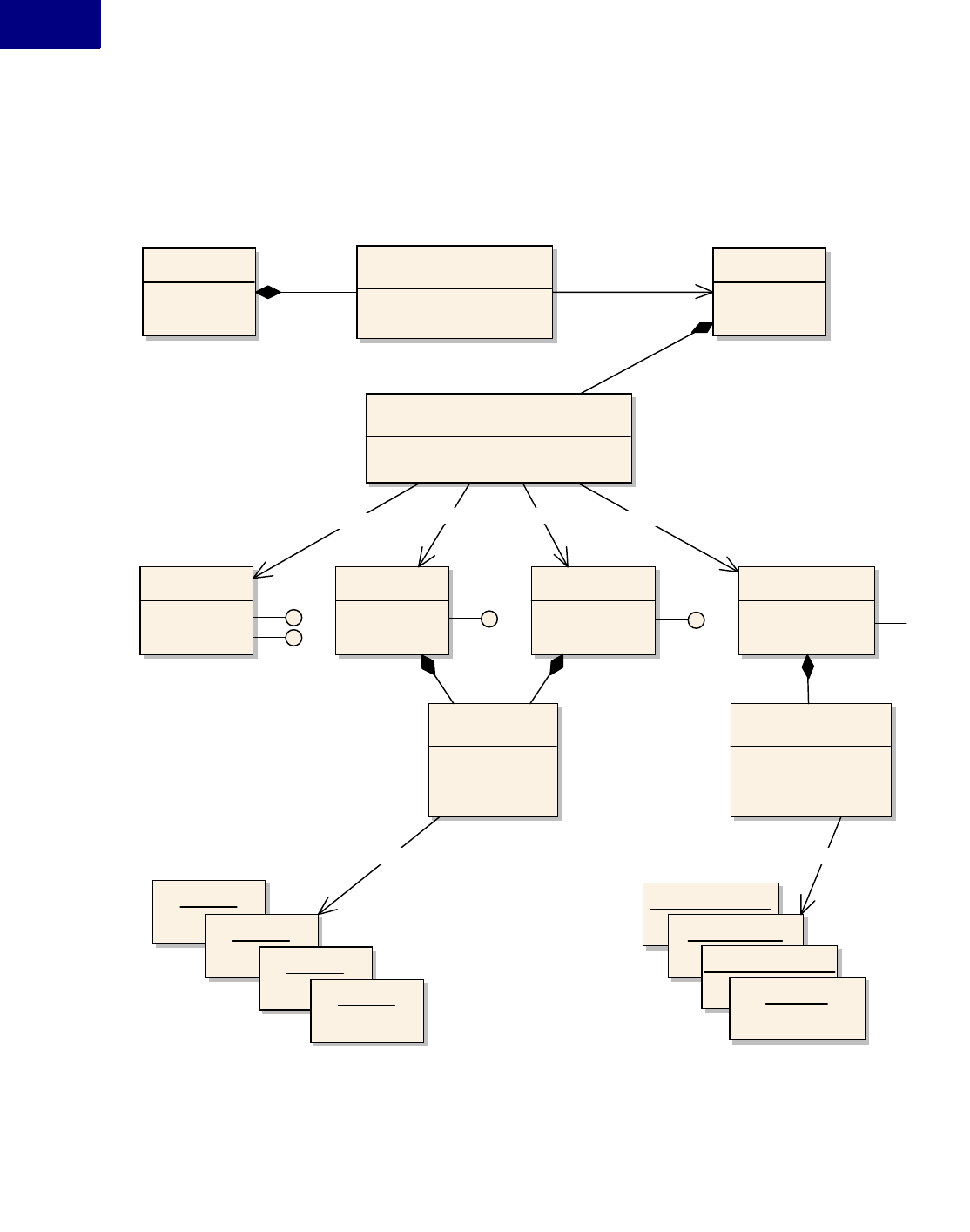
Text Fundamentals
Text content
330
Class associations
Figure 121 shows the major classes and associations for text content.
FIGURE 121 Major classes and associations for text content
Other owned item boss
kDocBoss «interface»
IStoryList
+ GetNthTextModelUID() : UIDRef
kTextStoryBoss
«interface»
ITextModel
+ QueryStrand(PMIID, ClassID) : IPMUnknown *
kTextDataStrandBoss
IStrand
ITextStrand
kParaAttrStrandBoss
IStrand
kCharAttrStrandBoss
IStrand
«interface»
IAttributeStrand
+ GetStyleUID() : UID
«interface»
IItemStrand
+ GetNthOwnedUID() : UID
kTableFrameBoss
kFootnoteReferenceBoss
kInlineBoss
kOwnedItemStrandBoss
IStrand
kStyleBoss
kStyleBoss
kStyleBoss
kStyleBoss
GetNthTextModelUID
QueryStrand QueryStrand QueryStrand QueryStrand
GetNthOwnedUIDGetStyleUID

Text Fundamentals 331
Text Fundamentals
Text presentation
Text presentation
This section describes the presentation model responsible for managing the final look of text.
The layout factors (such as the types of containers with which text can be associated) are
described before the representation of the rendered text (the wax) is presented.
The text-presentation model represents both the information required to place a set of glyphs
on a spread and the management of those glyphs within the application. In Figure 109, this is
represented by the text layout and wax components. Text layout is concerned with the contain-
ers for text and the attributes of a container that can affect how text is placed in respect to that
container. The wax models the actual glyphs rendered into the layout.
Text layout
Text layout defines the shape and form of the visual containers in which text is composed and
displayed. The textual content is maintained in the text model of the story associated with the
layout. This content is divided into one or more story threads, each representing an indepen-
dent flow of text. See “Story threads” on page 320.
In text composition, text flows from the story thread into its associated visual containers to cre-
ate wax that fits the layout. Text layout, in turn, displays the wax. When the layout is updated,
text is recomposed to reflect the change.
Text frame
The text frame is the fundamental container used to place and display text. Text frames have
properties, like the number of columns, column width, gutter width, and text inset, that control
where text flows. A text frame is represented by several associated boss classes.
Figure 122 shows a text frame containing two columns, with one line of text displayed in each
column. Figure 123 shows how this instance of a text frame is represented internally.
FIGURE 122 Text frame
TEXTFRAME
-POINTINSET -POINTGUTTER
INPORT
OUTPORT
COLUMN COLUMN
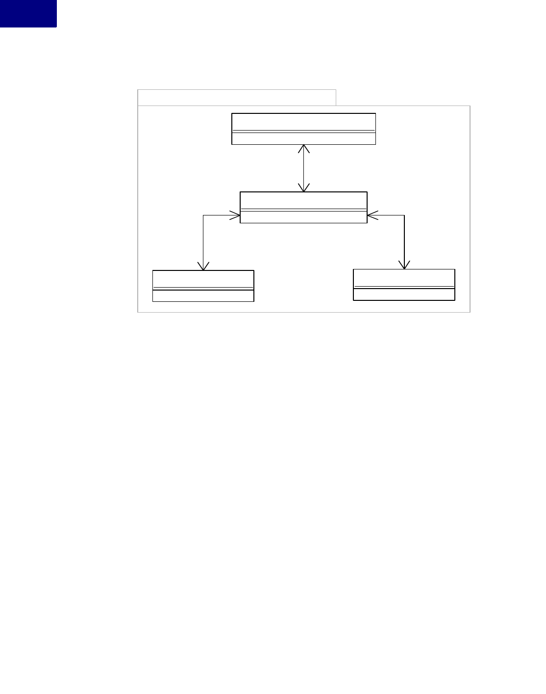
Text Fundamentals
Text presentation
332
FIGURE 123 Instance diagram of text frame
As shown in Figure 124, a text frame consists of a graphic frame (kSplineItemBoss) containing
one multicolumn item (kMultiColumnItemBoss). The multicolumn item (kMultiColum-
nItemBoss) is the controller for the text frame and contains one or more columns
(kFrameItemBoss). The ITextColumnSizer interface stores the major properties of the text
frame, such as the number of columns. IMultiColumnTextFrame provides access to the associ-
ated story, frame list, and the range of text displayed.
Text frame
UID = 176
«boss class»
graphic frame : layout::kSplineItemBoss
UID = 177
«boss class»
controller : kMultiColumnItemBoss
UID = 179
«boss class»
column 1 : kFrameItemBoss
UID = 180
«boss class»
column 2 : kFrameItemBoss
IHierarchy::QueryParent
IHierarchy::QueryChild(1)
IHierarchy::QueryParent
IHierarchy::QueryChild(0)
IHierarchy::QueryChild(0)
IHierarchy::QueryParent
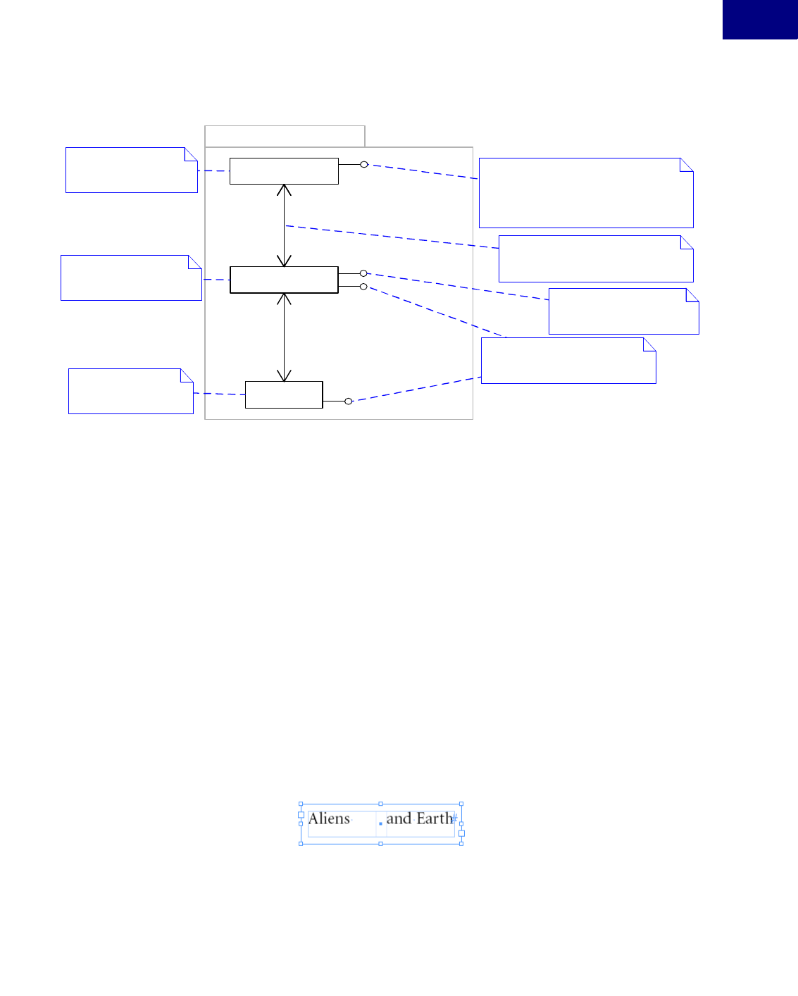
Text Fundamentals 333
Text Fundamentals
Text presentation
FIGURE 124 Structure of a text frame
The relationship between the graphic frame (kSplineItemBoss) and its content is maintained by
the IHierarchy interface. Use IHierarchy::QueryChild to navigate from the graphic frame to its
associated multicolumn item, then onto individual columns. Conversely, use IHierarchy::Que-
ryParent to navigate up from a column to the multicolumn item and on up to the graphic
frame.
Frame list
A story (kTextStoryBoss) associates the text frames that display its content through the frame
list (kFrameListBoss). Conversely, a text frame associates the story whose text it displays
through the frame list. Figure 125 and Figure 126shows the story and frame list objects for the
example introduced in Figure 122 and Figure 123. Figure 127 shows the general structure of
the frame list (IFrameList) for a story.
FIGURE 125 Frame list
Text frame
«boss class»
kMultiColumnItemBoss
«boss class»
kFrameItemBoss
IGraphicFrameData
IHierarchy::QueryParent1
IHierarchy::QueryChild
1..*
IMultiColumnTextFrame
ITextColumnSizer
ITextFrameColumn
IGraphicFrameData::GetTextContentUID
is a helper method that returns the UID
of the associated kMultiColumnItemBoss
or kInvalidUID if the frame does not have
textual content.
Stores the major properties
of a text frame, such as the
number of columns
«boss class»
layout::
kSplineItemBoss
1
1
IHierarchy::QueryParent1
IHierarchy::QueryChild1
Represents the graphic
frame
Represents a column
within the text frame
Represents the controller
for the text frame
Provides access to the associated
story, frame list, and the range of
text displayed
The relationship between the graphic
frame and its content is maintained
by the IHierarchy interface.
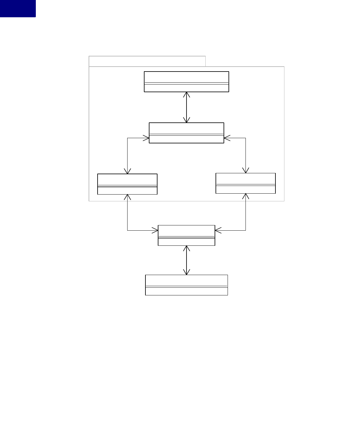
Text Fundamentals
Text presentation
334
FIGURE 126 Instance diagram of frame list
Text frame
UID = 176
«boss class»
graphic frame : layout::kSplineItemBoss
UID = 177
«boss class»
controller : kMultiColumnItemBoss
UID = 179
«boss class»
column 1 : kFrameItemBoss
UID = 180
«boss class»
column 2 : kFrameItemBoss
IHierarchy::QueryParent
IHierarchy::QueryChild(1)
IHierarchy::QueryParent
IHierarchy::QueryChild(0)
UID = 174
«boss class»
frame list : kFrameListBoss
UID = 158
«boss class»
story : The Text Model::kTextStoryBoss
IHierarchy::QueryChild(0)
IHierarchy::QueryParent
ITextFrameColumn::QueryFrameList
IFrameList::QueryNthFrame(0) IFrameList::QueryNthFrame(1)
ITextFrameColumn::QueryFrameList
ITextModel::QueryFrameList
IFrameList::QueryTextModel

Text Fundamentals 335
Text Fundamentals
Text presentation
FIGURE 127 Structure of the frame list (IFrameList) for a story
«boss class»
layout::
kSplineItemBoss
«boss class»
kMultiColumnItemBoss
1
1
IHierarchy
«boss class»
kFrameItemBoss
1
1..*
IHierarchy
«boss class»
kFrameListBoss
«boss class»
The Text Model::
kTextStoryBoss
IFrameList::QueryNthFrame1..*
ITextFrameColumn::QueryFrameList1
ITextModel::QueryFrameList1
IFrameList::QueryTextModel1
IMultiColumnTextFrame::QueryFrameList
IMultiColumnTextFrame::QueryTextModel
ITextFrameColumn::QueryTextModel
IFrameList
ITextFrameColumn
IMultiColumnTextFrame
ITextModel
Text frame
IGraphicFrameData
Associates the story and the
frames that display its text
Represents text content
Provides access to the
story's text content
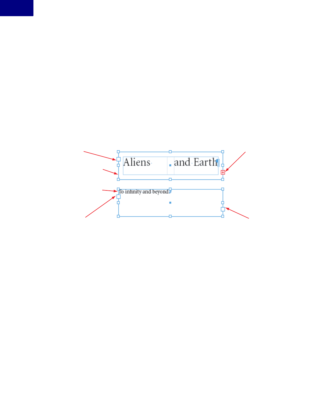
Text Fundamentals
Text presentation
336
Threading and text frames
The text in a frame can be independent of other frames, or it can flow between threaded
frames. Threading of text is the process of connecting the flow of text between frames. Do not
confuse threading text between frames with text-story threads. The connections can be visual-
ized by selecting a text frame and choosing View > Show Text Threads, as shown in Figure 130.
Threaded frames share a common underlying story (kTextStoryBoss) and can be on the same
spread or different spreads in the same document.
Figure 128 shows two unthreaded text frames. Because each text frame is associated with a dis-
tinct story, editing the text in one of the frames does not affect the text in the other frame (see
Figure 129).
FIGURE 128 Unthreaded text frames
OUTPORTINDICATINGOVERSETTEXTINPORTATBEGINNINGOFSTORY
4WO-COLUMNFRAME
/NE-COLUMNFRAME
INPORTATBEGINNINGOFSTORY OUTPORTATENDOFSTORY
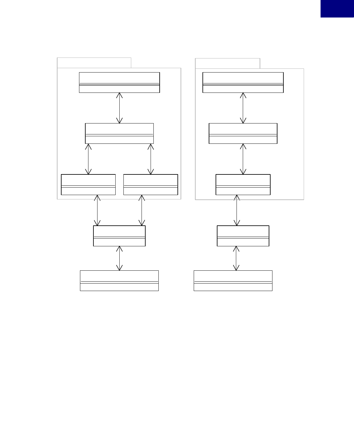
Text Fundamentals 337
Text Fundamentals
Text presentation
FIGURE 129 Instance diagram of unthreaded text frames
When the text frames that display a story cannot display all the text, the unseen text is called
“overset text.” A red plus sign (+) on the outport of the two-column frame indicates the story
has overset text.
If the user clicks the outport of the two-column frame with the Selection tool and then clicks
the inport of the one-column frame, the frames become threaded. In Figure 130, the text from
the two-column frame that was overset now flows through the one-column frame. During this
process, the text from the story underlying the one-column frame is appended to the story
underlying the two-column frame. The frame list (kFrameListBoss) and story (kTextStory-
Boss) underlying the one-column frame are deleted. Once threaded, the two frames share the
same underlying story (see Figure 131).
UID = 176
«boss class»
graphic frame 1 : layout::kSplineItemBoss
UID = 177
«boss class»
controller : kMultiColumnItemBoss
UID = 179
«boss class»
column 1 : kFrameItemBoss
UID = 180
«boss class»
column 2 : kFrameItemBoss
IHierarchy
IHierarchy
UID = 174
«boss class»
frame list : kFrameListBoss
UID = 158
«boss class»
story 1 : The Text Model::kTextStoryBoss
IHierarchy
ITextFrameColumn::QueryFrameList
IFrameList::QueryNthFrame(0) IFrameList::QueryNthFrame(1)
ITextFrameColumn::QueryFrameList
ITextModel::QueryFrameList
IFrameList::QueryTextModel
UID = 262
«boss class»
graphic frame 2 : layout::kSplineItemBoss
UID = 264
«boss class»
controller : kMultiColumnItemBoss
UID = 281
«boss class»
column 1 : kFrameItemBoss
IHierarchy
IHierarchy
UID = 335
«boss class»
frame list : kFrameListBoss
UID = 319
«boss class»
story 2 : The Text Model::kTextStoryBoss
-IFrameList::QueryNthFrame(0)
-ITextFrameColumn::QueryFrameList
-ITextModel::QueryFrameList
-IFrameList::QueryTextModel
Two-column text frame
One-column text frame
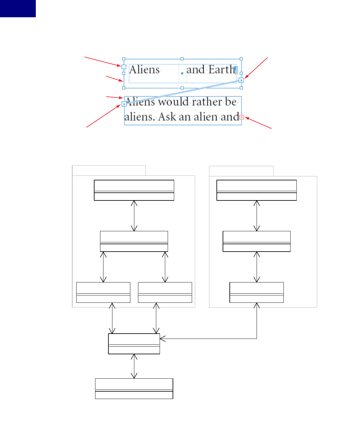
Text Fundamentals
Text presentation
338
FIGURE 130 Threaded text frames
FIGURE 131 Instance diagram of threaded text frames
OUTPORTINDICATINGOVERSETTEXT
INPORTATBEGINNINGOFSTORY OUTPORTINDICATINGLINKTONEXTFRAME
INPORTINDICATINGLINKFROMPREVIOUSFRAME
4WO-COLUMNFRAME
/NE-COLUMNFRAME
UID = 176
«boss class»
graphic frame 1 : layout::kSplineItemBoss
UID = 177
«boss class»
controller : kMultiColumnItemBoss
UID = 179
«boss class»
column 1 : kFrameItemBoss
UID = 180
«boss class»
column 2 : kFrameItemBoss
IHierarchy
IHierarchy
UID = 174
«boss class»
frame list : kFrameListBoss
UID = 158
«boss class»
story 1 : The Text Model::kTextStoryBoss
IHierarchy
ITextFrameColumn::QueryFrameList
IFrameList::QueryNthFrame(0) IFrameList::QueryNthFrame(1)
ITextFrameColumn::QueryFrameList
ITextModel::QueryFrameList
IFrameList::QueryTextModel
UID = 262
«boss class»
graphic frame 2 : layout::kSplineItemBoss
UID = 264
«boss class»
controller : kMultiColumnItemBoss
UID = 281
«boss class»
column 1 : kFrameItemBoss
IHierarchy
IHierarchy
IFrameList::QueryNthFrame(2)
ITextFrameColumn::QueryFrameList
Two-column text frame
One-column text frame

Text Fundamentals 339
Text Fundamentals
Text presentation
Parcels
A flow of text content within a story is a story thread, is represented by a boss class with an
ITextStoryThread interface. A parcel is a visual container into which the text of a story thread is
flowed for layout and display. A parcel is represented by a boss class with an IParcel interface.
The text of a story thread (ITextStoryThread) can be composed into a list of parcels (IParcel) in
a parcel list (IParcelList).
Examples of application-provided parcels are as follows:
zText frame item (kFrameItemBoss)
zTable cell parcel (kTextCellParcelBoss)
zFootnote parcel (kFootnoteParcelBoss)
Figure 132 shows how text frames support story threads and parcels. The text in the primary
story thread is displayed through parcels given by the parcel list on the frame list. These parcels
are the frame items of the text frames that display the story.
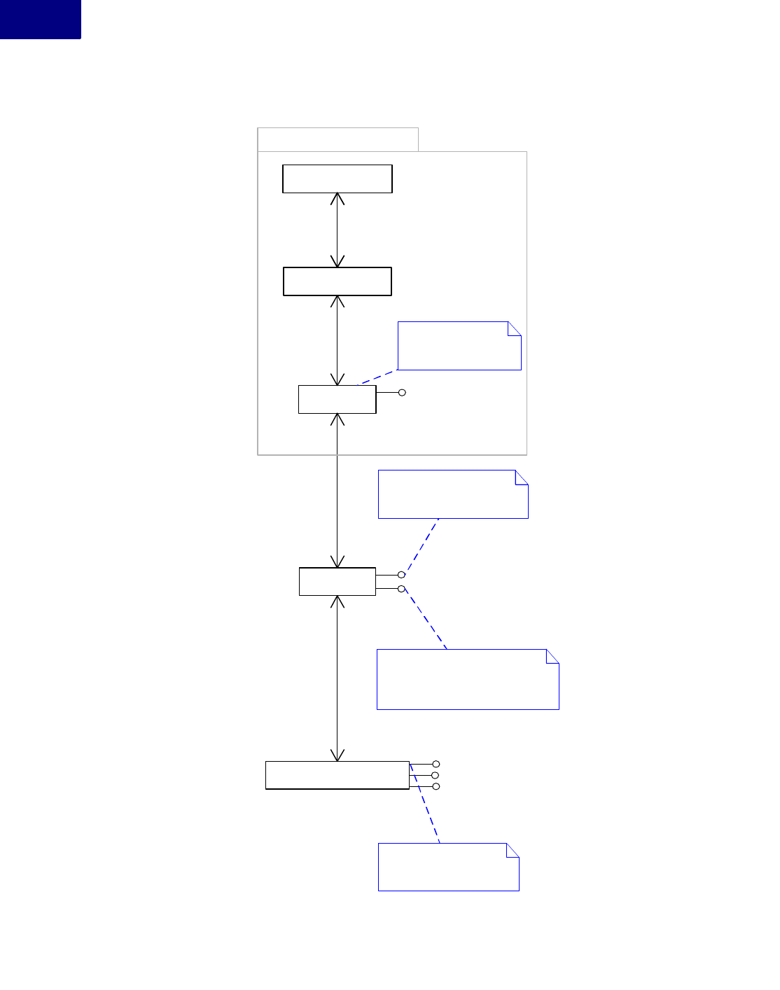
Text Fundamentals
Text presentation
340
FIGURE 132 Structure of the parcel implementation for text frames
«boss class»
The Text Model::
kTextStoryBoss
ITextStoryThread
«boss class»
kFrameListBoss
IParcelList
ITextParcelList
«boss class»
kFrameItemBoss
IParcel
IParcelList::QueryParcel1..*
IParcel::QueryParcelList1
ITextStoryThread::QueryParcelList1
ITextParcelList::QueryStoryThread1
«boss class»
kMultiColumnItemBoss
«boss class»
layout::
kSplineItemBoss
1
1
1
1..*
Displays a range of
text from the
primary story thread
Text in the primary story thread
flows into parcels in this parcel list.
Effectively, this flows the content
through the text frames.
ITextStoryThreadDict
The range of text displayed
in the parcels can be found
in ITextParcelList.
Text frame
ITextModel
The primary story thread
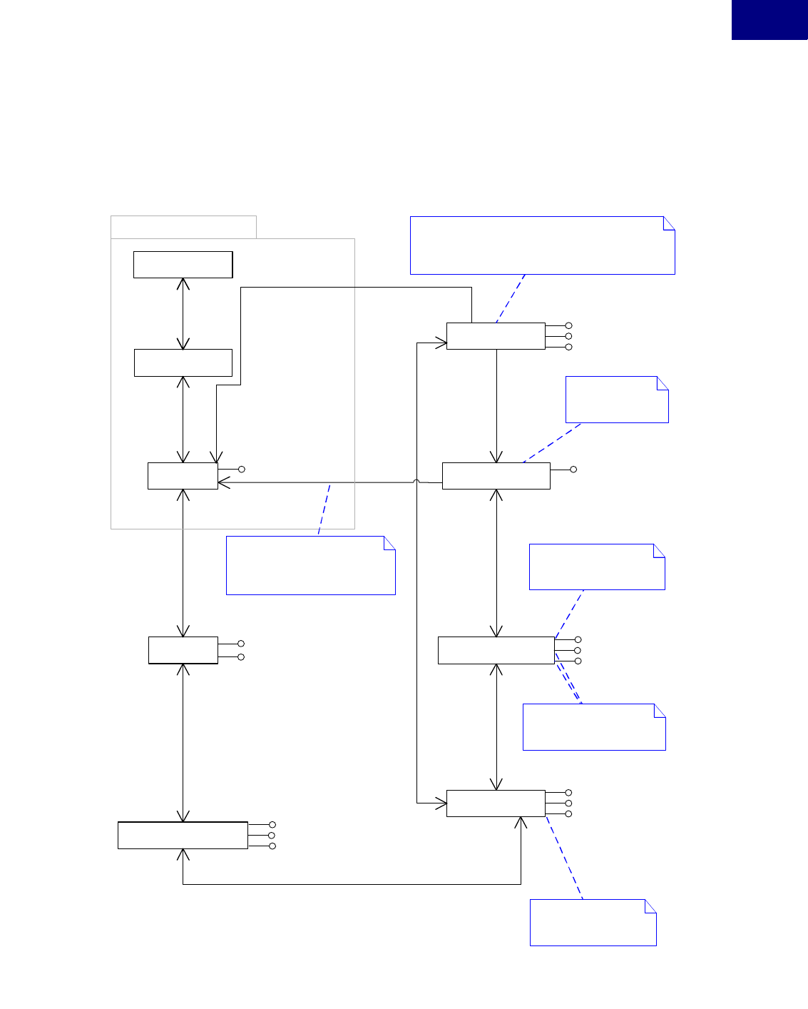
Text Fundamentals 341
Text Fundamentals
Text presentation
Figure 133 shows how tables support story threads and parcels. The text for the story thread of
a table cell (kTextCellContentBoss) is displayed through the parcels given by its parcel list.
These parcels are text cell parcels (kTextCellParcelBoss). For more information, see the
“Tables” chapter.
FIGURE 133 Structure of the parcel implementation for tables
«boss class»
The Text Model::
kTextStoryBoss
ITextStoryThread
«boss class»
kFrameListBoss
IParcelList
ITextParcelList
«boss class»
kFrameItemBoss
IParcel
IParcelList::QueryParcel1..*
IParcel::QueryParcelList1
ITextStoryThread::QueryParcelList1
ITextParcelList::QueryStoryThread1«boss class»
table::
kTableModelBoss
«boss class»
table::
kTextCellContentBoss
ITextStoryThread
IParcelList
ITextParcelList
«boss class»
table::
kTextCellParcelBoss
IParcel
ITextStoryThreadDict
ITableTextContainer
ITableModel
ITableTextContainer::QueryTextModel1
lTableModelList::QueryNthModel 0..*
ITextStoryThreadDict::QueryThread1..*
ITextStoryThread::GetDictUID1
IParcelList::QueryParcel1..*
IParcel::QueryParcelList1
«boss class»
kMultiColumnItemBoss
«boss class»
layout::
kSplineItemBoss
1
1
1
1..*
Each cell has a story thread
whose text flows into parcels
in the cell's parcel list.
Displays a range of
text from the cell's
story thread
ITextStoryThreadDict
«boss class»
table::
kTableFrameBoss
ITableFrame
IOwnedItem
IWaxAnchorPt
IParcel::GetFrameUID
Text frame
ITextModel
A table frame (kTableFrameBoss) represents the rows
of a table that lie in a frame item (kFrameItemBoss).
The rows of a table can flow across one or more frame items
(kFrameItemBoss).
A table model exists for
each table embedded in
the story.
Each text cell in a table knows the
frame item (kFrameItemBoss)
in which it lies; unless it is overset, in
which case the cell is not displayed.
The range of text displayed
in the parcels can be found
in ITextParcelList.
ITableLayout::frame_iterator::QueryFrame
0..*
ITableFrame::QueryModel
1
1
ITableFrame::const_parcel_iterator1..*
1
ITableFrame::QueryFrame1
Text Fundamentals
Text presentation
342
Span
Each object that displays text is associated with a story thread. After composition, the object
stores the index (TextIndex) into the text model of the first character it displays and the total
number of characters it shows. This text range is the span. The span is available on several
interfaces (see Table 88 and Table 89). Table 88 lists the APIs that indicate the range of text dis-
played. Table 89 lists the APIs that find the parcel or frame displaying a specific TextIndex.
NOTE:The ranges returned from these APIs are accurate only if the text in the object is fully
composed. Before relying on these methods, you must check for damage and for the
object to recompose, if necessary.
TABLE 88 APIs that indicate the range of text displayed
TABLE 89 APIs that find the parcel or frame displaying a specific TextIndex
Figure 134 shows a story displayed in a two-column frame. The range of text displayed in both
columns is available in the IMultiColumnTextFrame interface on the multicolumn item (kMul-
tiColumnItemBoss). The range of text available in each frame item (kFrameItemBoss) is avail-
able in both ITextFrameColumn and ITextParcelList.
API Description
IFrameList Gives the range of text displayed by each frame item (kFrameItemBoss).
ITextFrameColumn Gives the range of text displayed by the frame item (kFrameItemBoss).
IMultiColumnTextFrame Gives the range of text displayed by the multicolumn item
(kMultiColumnItemBoss).
ITextParcelList Gives the range of text displayed by a parcel. All objects that display composed text
are a kind of parcel (IParcel).
API Description
IFrameList::QueryFrameContaining Use this method to find the frame item (kFrameItemBoss) that displays
the character at a specific index (TextIndex) in the text model.
ITextModel::QueryTextParcelList Call this to find the text parcel list associated with a given TextIndex. After
you have the ITextParcelList, use ITextParcelList::GetParcelContaining,
then IParcelList::QueryParcel. All objects that display composed text are a
kind of parcel (IParcel). As a result, this approach finds parcels for text
frames, table cells, or other new kinds of parcels. Note, however, that some
text embedded in the text model may not be composed or displayed in a
parcel.
IWaxIterator After you know the text model (ITextModel) and the range of text you
want, use this class to get the wax data.
TextIterator After you know the text model (ITextModel) and the range of text that you
want, use this class to get the character data.
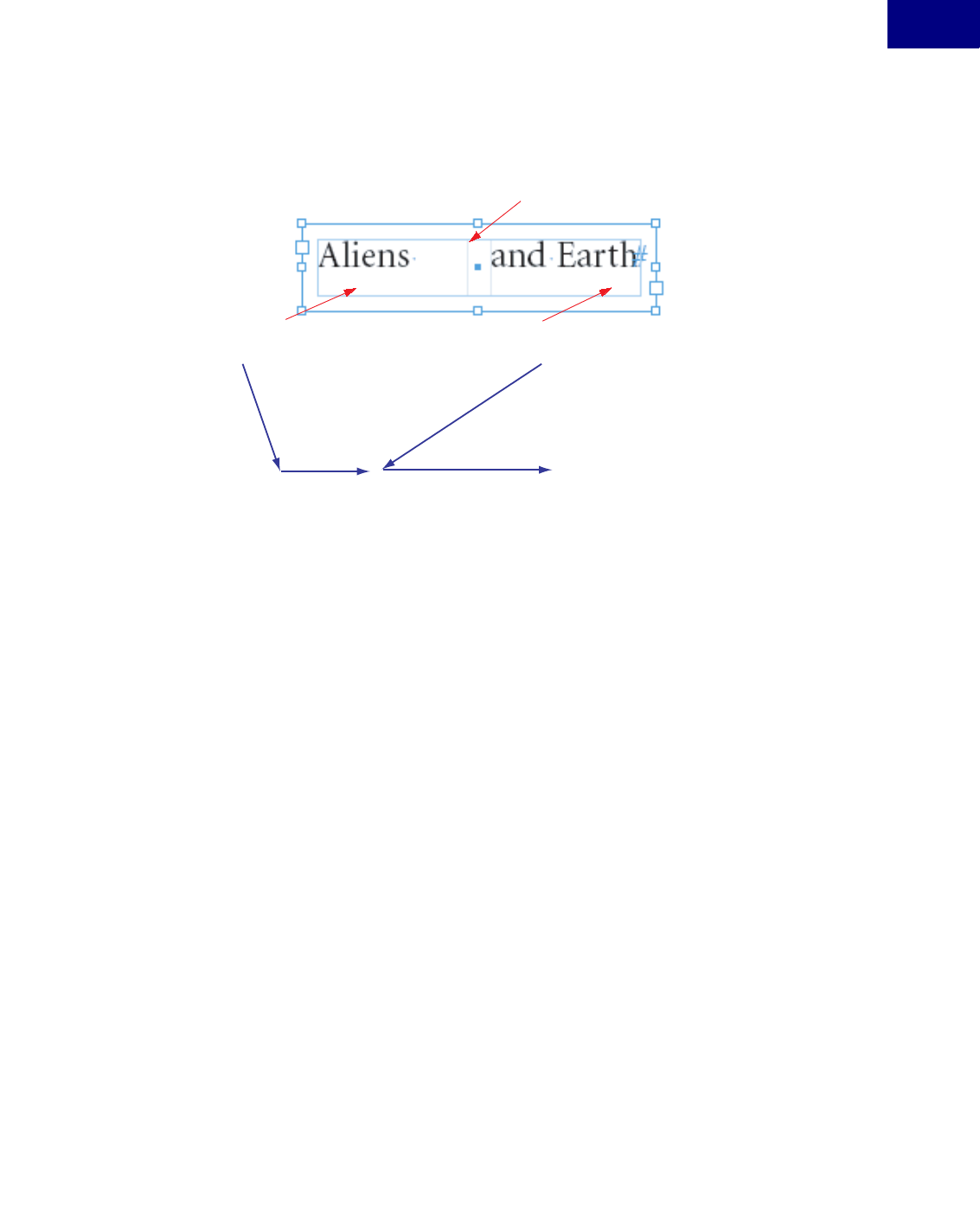
Text Fundamentals 343
Text Fundamentals
Text presentation
FIGURE 134 Finding the range of text displayed in a frame or parcel
Conversely, you can discover the parcel (IParcel) displaying the character at a specific index
(TextIndex) in the text model. It is possible the TextIndex of interest is overset text that is not
displayed. The kind of parcel returned depends on the kind of story thread (ITextStoryThread)
that owns the range of text in which the TextIndex lies.
For example, if the TextIndex lies in the primary story thread, it is in the range 0 to (IText-
Model::GetPrimaryStoryThreadSpan - 1). The primary story thread is displayed by the text
frames associated with the story. In this case, the frame item (kFrameItemBoss) that displays
the desired TextIndex is determined. Alternately, the desired TextIndex can be in the range
ITextModel::GetPrimaryStoryThreadSpan to (ITextModel::TotalLength - 1). Text in this range
is associated with a table or other feature that embeds text in stories, like notes, footnotes, or
tracked changes. If the feature displays composed text, the parcel displaying a specific TextIn-
dex can be determined.
Text frames and the wax
After text is composed, each line is represented by a wax line (kWaxLineBoss). The wax for a
story is owned by the wax strand. A text frame is associated with its wax lines by the range of
text displayed, which is obtained from ITextFrameColumn or ITextParcelList. The range of text
displayed by the frame is maintained when text is recomposed. Wax lines are accessed using a
wax iterator, IWaxIterator, which is a C++ helper class created by calling IWaxStrand::New-
WaxIterator.
Consider the wax for a text frame with two columns, each displaying one line of text. See
Figure 135. Here, the wax line (kWaxLineBoss) objects do not have UIDs. They are managed
by the wax strand (IWaxStrand on kFrameListBoss) that persists some wax data and regener-
ates the rest by recomposing the text when required.
K-ULTI#OLUMN)TEM"OSS
3TART3PAN
K&RAME)TEM"OSS
3TART3PAN
K&RAME)TEM"OSS
3TART3PAN
K4EXT3TORY"OSS
)4EXT-ODEL
4EXT)NDEX
#HARACTER!LIENSAND%ARTHr
4HETEXTCONTENTISSTOREDin THEASSOCIATED
STORYgSTEXTMODEL$ETERMINETHERANGE
YOUWANT, andTHENUSETHE4EXT)TERATOR
class TOACCESSTHECHARACTERDATA
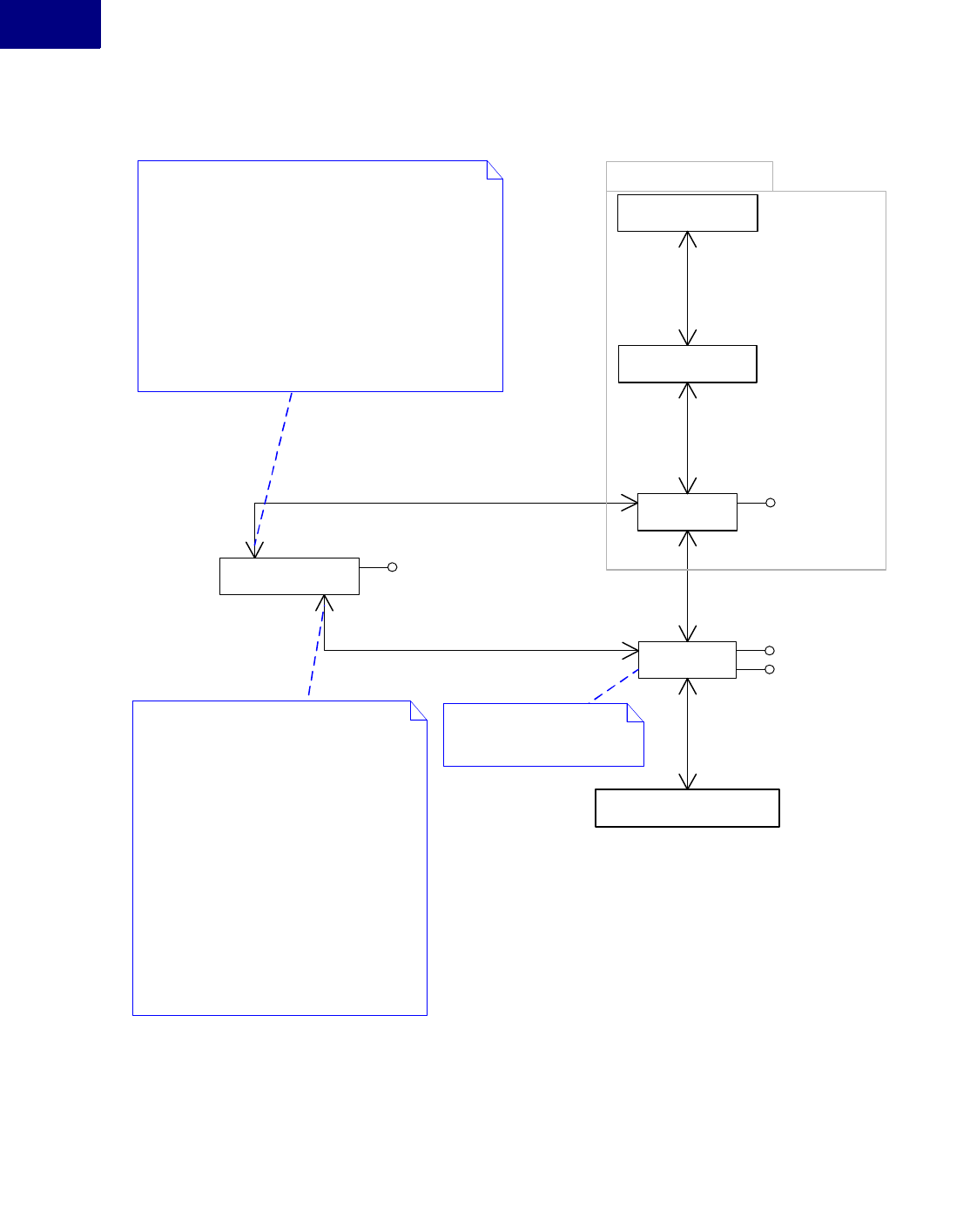
Text Fundamentals
Text presentation
344
FIGURE 135 Structure of the wax for a text frame
«boss class»
The Text Model::
kTextStoryBoss
«boss class»
kFrameListBoss
«boss class»
kFrameItemBoss
«boss class»
kMultiColumnItemBoss
«boss class»
layout::
kSplineItemBoss
IWaxStrand
«boss class»
The Wax::
kWaxLineBoss
ITextFrameColumn
IWaxLine::GetParcelKey
0..1
IWaxIterator::GetFirstWaxLine0..*
IWaxLine::QueryWaxStrand
1
IWaxIterator::GetFirstWaxLine 0..*
IWaxLine
IHierarchy::QueryParent1
IHierarchy::QueryChild1
IHierarchy::QueryParent1
IHierarchy::QueryChild1..*
IFrameList::QueryNthFrame1..*
ITextFrameColumn::QueryFrameList1
ITextModel::QueryFrameList1
IFrameList::QueryTextModel1
IFrameList
Text frame
The wax associated with a text frame can be discovered
by using a wax iterator (IWaxIterator) to find the wax lines
(IWaxLine) for the the range of text displayed by the frame
(see ITextFrameColumn).
IWaxStrand::NewWaxIterator is called to create an
IWaxIterator.
IWaxIterator is a helper class that can access the wax lines
associated with a given TextIndex.
IWaxIterator is not a descendant of IPMUnknown.
It should not be used in conjunction with InterfacePtr.
The wax lines associated with a story
can be found by using a wax iterator
(IWaxIterator) for the range of text
of interest.
A wax line for text in the range
0..(ITextModel::GetPrimaryStoryThreadSpan-1)
will be associated with a frame item
(kFrameItemBoss), unless the wax line
represents overset text (in which case it
is not displayed).
A wax line for text in the range
ITextModel::GetPrimaryStoryThreadSpan..
(ITextModel::TotalLength-1) may be associated
with other kinds of parcel, such as table
text cells (kTextCellParcelBoss). This is not
shown on the diagram.
Manages the wax for a story
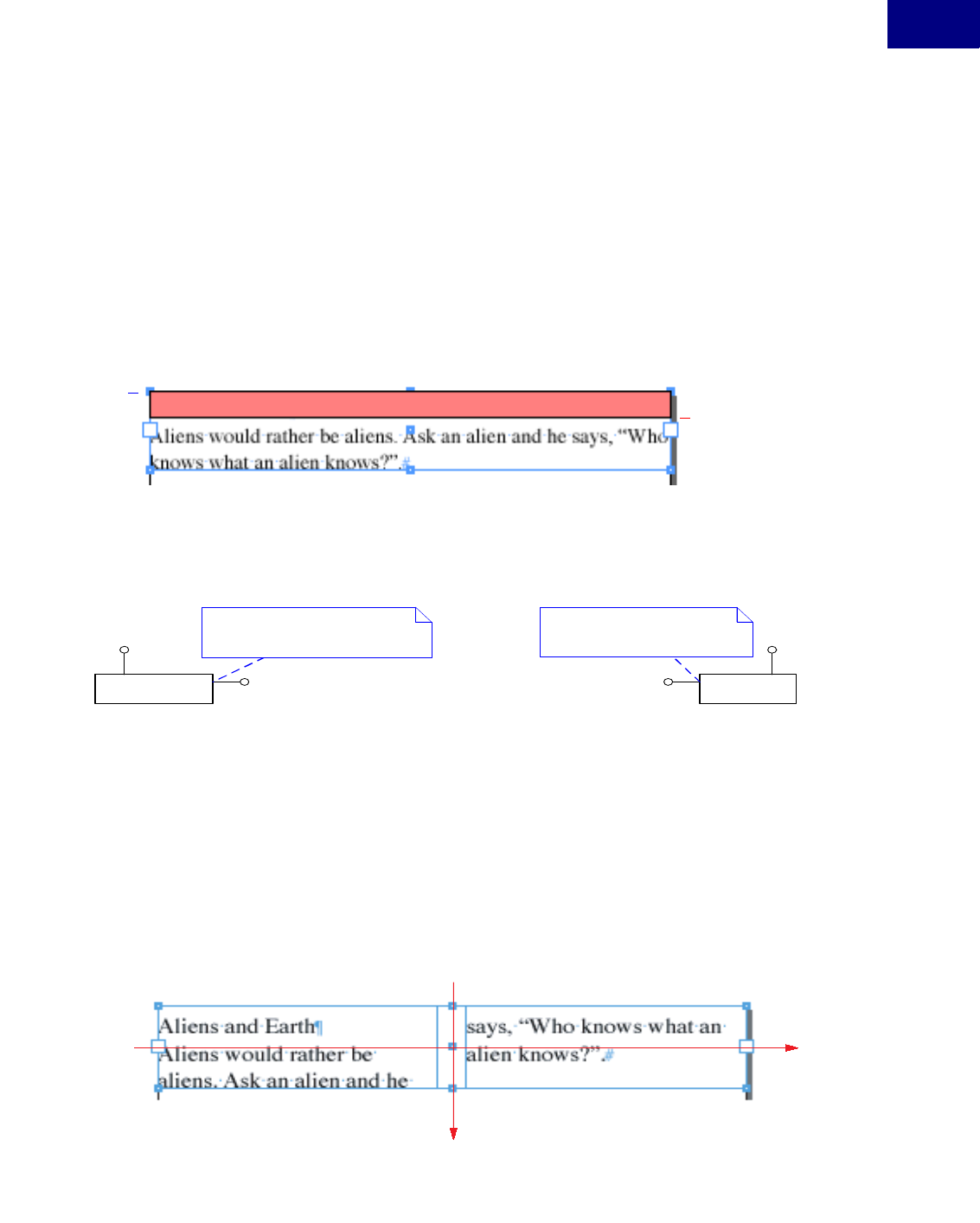
Text Fundamentals 345
Text Fundamentals
Text presentation
Text-frame options
You manipulate text-frame options from the dialog box invoked by choosing Object > Text
Frame Options. Default text-frame options store the properties inherited when a new text
frame is created. The text-frame options are stored in the ITextOptions interface on the docu-
ment workspace. A distinct set of defaults are maintained on the session workspace and are
inherited. Figure 136 and Figure 137 show the boss classes and interfaces involved.
FIGURE 136 Interfaces storing text-frame options on a text frame
FIGURE 137 Interfaces storing default text-frame options
Text-frame geometry
In Figure 138, the bounds of the page items that make up the text frame are tabulated in the
inner coordinates of the spline. In Table 90, the geometries of the multicolumn and column
items are expressed in the coordinate space of their parent, the spline. Effectively, they share a
common coordinate space.
FIGURE 138 Text-frame geometry
yPosition Baseline
-15
-5
Tile for line 1
«boss class»
kDocWorkspaceBoss
«boss class»
kWorkspaceBoss
ITextOptionsITextOptions
Session-specific defaults that are
inherited by new documents
Document-specific defaults that are
inherited by new text frames
IWorkspace IWorkspace
-100,-15
100,15
0,0
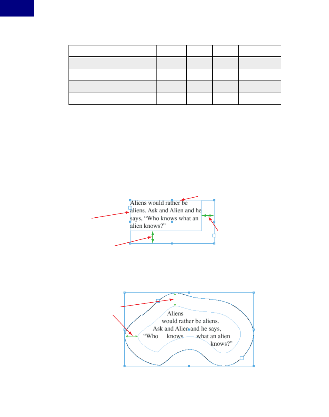
Text Fundamentals
Text presentation
346
TABLE 90 Text-frame geometry
Text Inset
Text inset, a property of a text frame, is an area between the edge of the frame and the area
where text flows. If the text frame is regular in shape, you can specify the inset independently
for each side (see Figure 139). With irregularly shaped frames, the inset follows the contour of
the text frame, and there is only one inset value (see Figure 140).
FIGURE 139 Text Inset
FIGURE 140 Irregular text inset
Item Left Top Right Bottom
kFrameItemBoss (left column) -100.00 -15.00 -5.00 15.00
kFrameItemBoss (right column) 5.00 -15.00 100.00 15.00
kMultiColumnItemBoss -100.00 -15.00 100.00 15.00
kSplineItemBoss -100.00 -15.00 100.00 15.00
TOPINSET POINTS
BOTTOMINSET POINTS
LEFTINSET POINTS
RIGHTINSET POINTS
INSETPOINTS
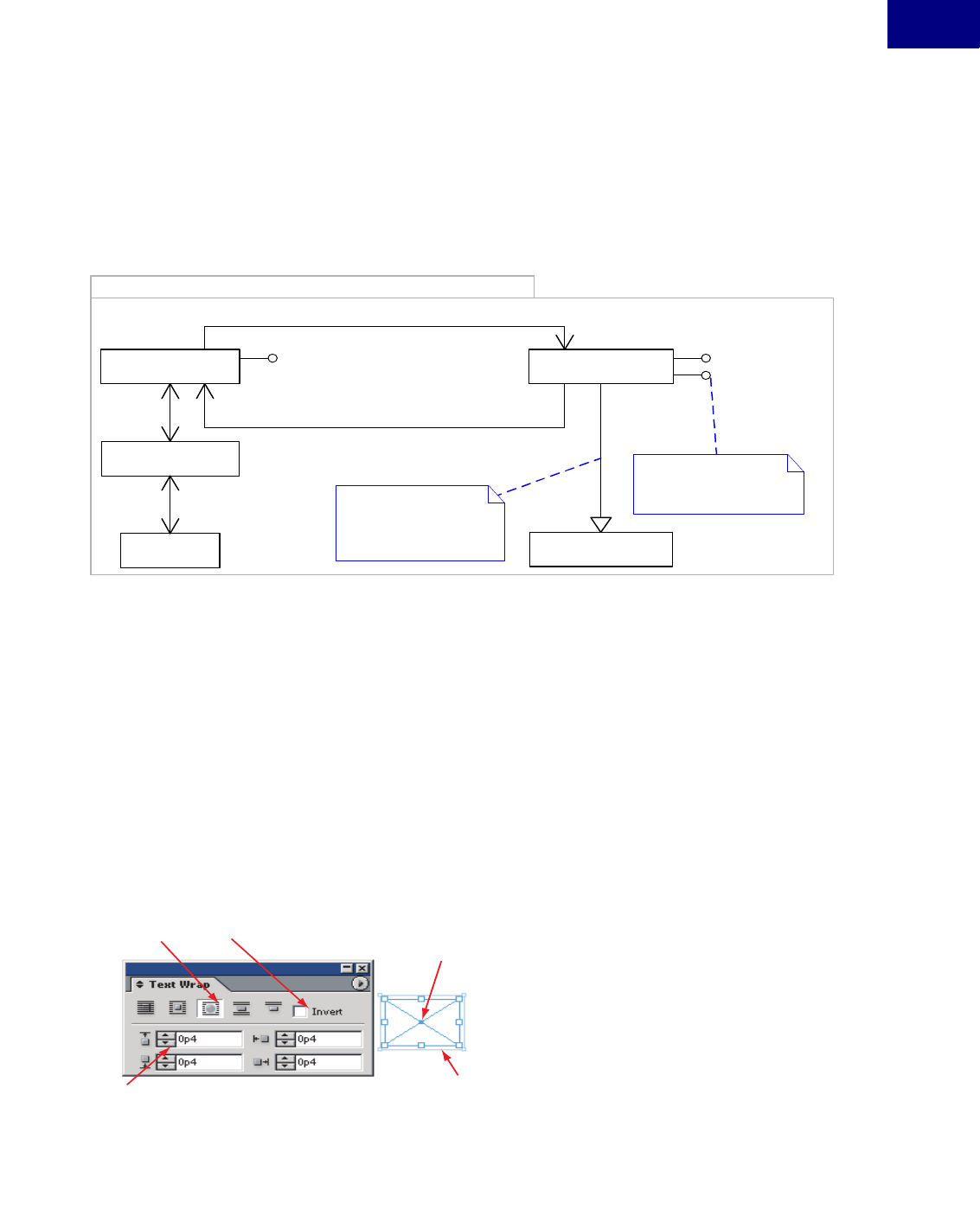
Text Fundamentals 347
Text Fundamentals
Text presentation
Figure 141 shows the structure of a text inset. The properties of the text inset are found in the
ITextInset interface on the text frame’s kSplineItemBoss. Even when there is no text inset in
effect (all insets have a value of 0 points), a kTextInsetPageItemBoss is associated with the text
frame and describes the contour of the text inset.
FIGURE 141 Structure of text inset
Text wrap
Text in a text frame is affected by other page items that have text wrap applied. Text wrap is rep-
resented by a standoff abstraction. A standoff describes whether there should be text wrap and,
if so, the contour around which the text should be wrapped.
Figure 142 shows an empty graphic frame with text wrap set at a 4-point offset around the
frame’s path. Figure 143 shows that if there is no intersection between the boundary of the
standoff and the boundary of the text frame, then the text in the text frame is not affected.
FIGURE 142 Text-wrap properties applied to empty frame
«boss class»
kFrameItemBoss
«boss class»
kMultiColumnItemBoss
«boss class»
layout::
kSplineItemBoss
«boss class»
kTextInsetPageItemBoss
IPathGeometry
1
1
ITextInset::QueryInsetGeometry
11 IStandOffItemData::QueryPageItem
Represents the contour
of the inset associated
with the text frame
Text frame
«boss class»
kStandOffPageItemBoss
Text inset is a special
kind of standoff, which
is the abstraction that
represents text wrap.
ITextInset IStandOffItemData
MODE Form
MARGIN
EMPTYGRAPHICFRAME
K3PLINE)TEM"OSS
STANDOFF
K3TAND/FF0AGE)TEM"OSS
4HEMODEMARGIN,ANDFORMPROPERTIES
ARESTOREDININTERFACE)3TAND/FF$ATA.
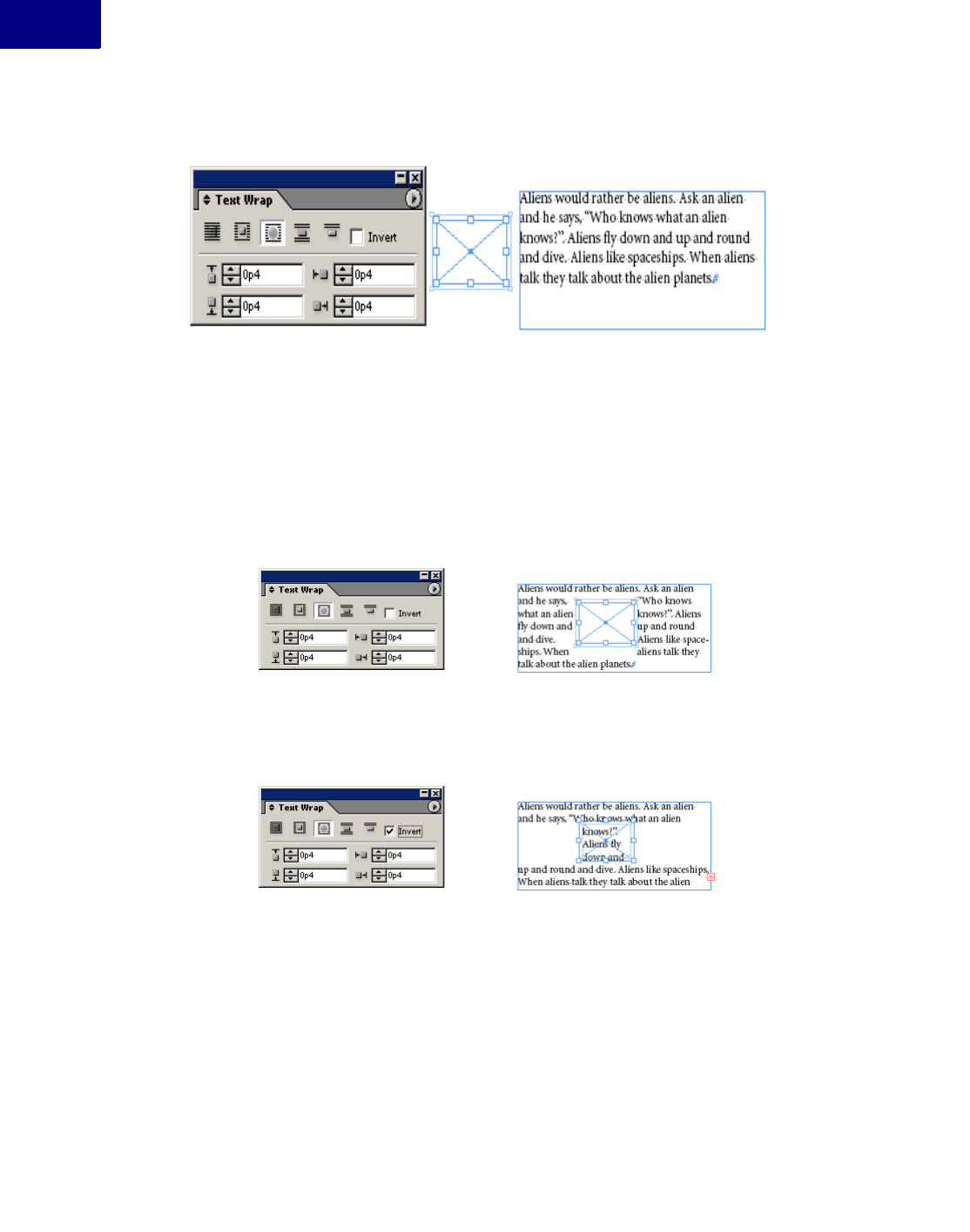
Text Fundamentals
Text presentation
348
FIGURE 143 Text wrap: empty frame with text wrap alongside text frame
Figure 144 shows what happens when the empty graphic frame overlaps the text frame. The
text within that frame is forced to wrap around the empty frame, which is said to repel the text.
By inverting the text wrap, a page item can indicate it is to be used to attract text within its
boundary rather than repel it. Figure 145 shows how this causes text to flow within the set
boundaries.
FIGURE 144 Text wrap: empty frame with text wrap overlapping text frame
FIGURE 145 Text wrap: empty frame with inverted text wrap overlapping text frame
The objects representing the text wrap for the sample are shown in Figure 146. The general
structure of text wrap is shown in Figure 147.
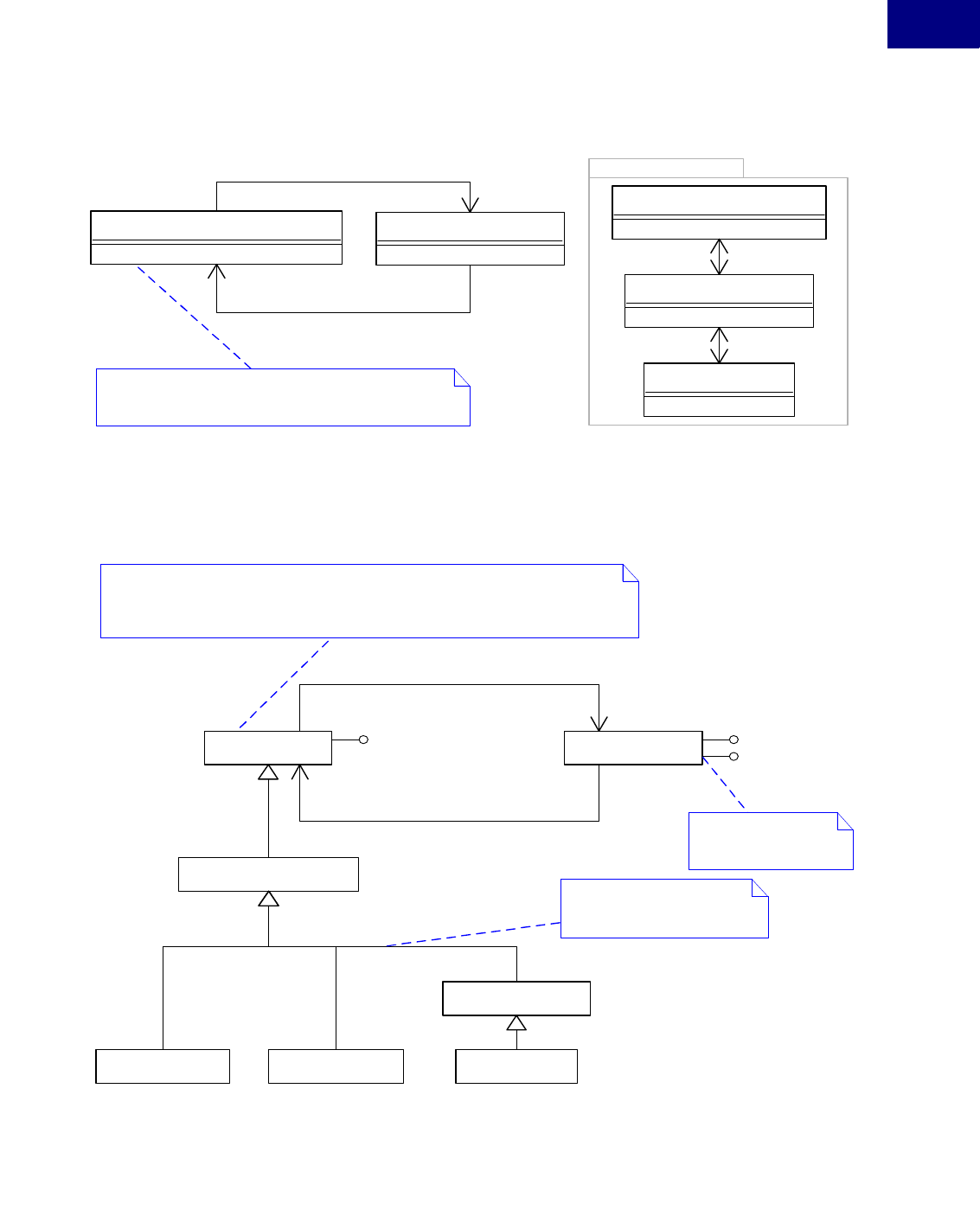
Text Fundamentals 349
Text Fundamentals
Text presentation
FIGURE 146 Instance diagram for text wrap
FIGURE 147 Structure of text wrap
Text frame
UID = 176
«boss class»
graphic frame : layout::kSplineItemBoss
UID = 177
«boss class»
controller : kMultiColumnItemBoss
UID = 179
«boss class»
column 1 : kFrameItemBoss
UID = 200
«boss class»
empty graphic frame : layout::kSplineItemBoss
UID = 201
«boss class»
stand off : kStandOffPageItemBoss
IStandOffData::QueryStandOffGeometry
IStandOffItemData::QueryPageItem
Empty graphic frame with standoff to represent the text wrap
«boss class»
kStandOffPageItemBoss
IPathGeometry
1
0..1
IStandOffData::QueryStandOffGeometry
11 IStandOffItemData::QueryPageItem
«boss class»
layout::
kPageItemBoss
Text wrap is represented by a standoff. A standoff can be associated with various
kinds of page items such as graphic frames (kSplineItemBoss), pictures (kImageItemBoss,
etc.), and groups (kGroupItemBoss). They can each have distinct standoff
properties.
Represents the contour
of the text wrap
«boss class»
layout::
kSplineItemBoss
«boss class»
layout::
kDrawablePageItemBoss
«boss class»
layout::
kGroupItemBoss
«boss class»
graphics::
kImageBaseItem
«boss class»
graphics::
kImageItem
Other kinds of page items not
shown on this diagram can also
have a standoff.
IStandOffData IStandOffItemData
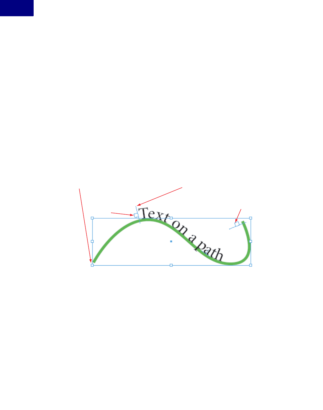
Text Fundamentals
Text presentation
350
Properties of a standoff are found in IStandOffData on the page item with the standoff. Use
IStandOffData::GetMode to obtain the kind of text wrap and IStandOffData::GetMargin to get
the offsets. Each page item has distinct standoff applied, so the page item can be a graphic
frame (kSplineItemBoss), a group (kGroupItemBoss), or another type.
When a text wrap is applied, a standoff boss class kStandOffPageItemBoss is associated with
the owning page item. The standoff boss class is not part of the page item instance hierarchy;
you do not navigate to it using IHierarchy. Instead, use IStandOffData::QueryStandOffGeome-
try to access the standoff boss class. The kStandOffPageItemBoss boss class has a path geome-
try that represents the contour of the standoff, and text in a text frame wraps to this contour.
Text on a path
Text on a path allows text to flow along the contour of a spline (kSplineItemBoss). Text on a
path frame has an inport and an outport. As a result, you can thread text in other frames to and
from it. Figure 148, Figure 149, and Figure 150 show the objects involved in text on a path.
FIGURE 148 Text on a path
kSplineItemBoss kTOPSplineItemBoss
kMultiColumnItemBoss
kTOPFrameItemBoss
Inport Outport
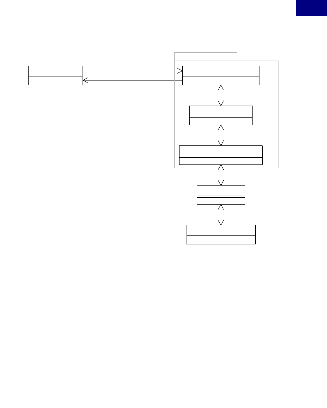
Text Fundamentals 351
Text Fundamentals
Text presentation
FIGURE 149 Instance diagram for text on a path
UID = 184
«boss class»
text on a path spline : kTOPSplineItemBoss
UID = 185
«boss class»
controller : kMultiColumnItemBoss
UID = 186
«boss class»
text on path frame item : kTOPFrameItemBoss
IHierarchy::QueryParent
IHierarchy::QueryChild(0)
IHierarchy::QueryParent
IHierarchy::QueryChild(0)
UID = 182
«boss class»
frame list : kFrameListBoss
UID = 166
«boss class»
story : The Text Model::kTextStoryBoss
IFrameList::QueryNthFrame(0)
ITextFrameColumn::QueryFrameList
ITextModel::QueryFrameList
IFrameList::QueryTextModel
UID = 144
«boss class»
path : layout::kSplineItemBoss
IMainItemTOPData::GetTOPSplineItemUID
ITOPSplineData::GetMainSplineItemUID
Text on a path frame
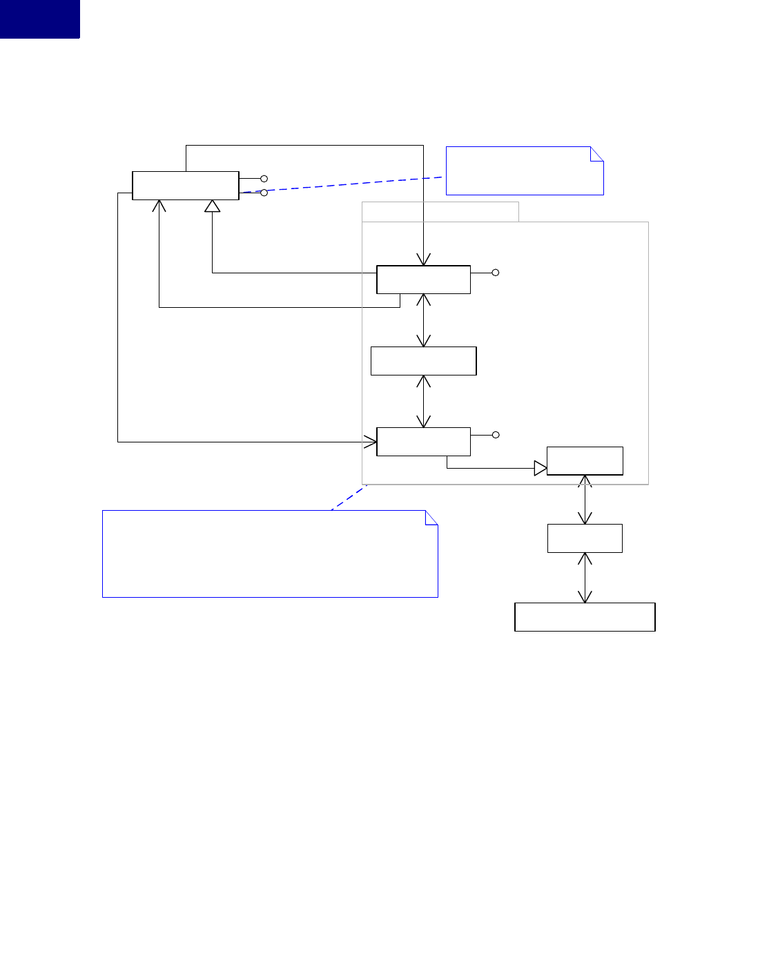
Text Fundamentals
Text presentation
352
FIGURE 150 Structure of text on a path frame
Text on a path can be associated with any spline (kSplineItemBoss). The structure of text on a
path frame parallels that of a normal text frame. It is represented by three associated boss
classes: kTOPSplineItemBoss, kMultiColumnItemBoss, and kTOPFrameItemBoss. You can
navigate from a spline (kSplineItemBoss) to any associated text on a path (kTOPSplineItem-
Boss) using the IMainItemTOPData interface. You can navigate back using the ITOPSpline-
Data interface. After you have an interface on the kTOPSplineItemBoss, you can navigate up
and down the text on a path frame using IHierarchy.
Figure 151 and Figure 152 show a text frame that also has text on a path running along its con-
tour. In this example, the text displayed inside the frame and the text that runs its contour have
distinct underlying stories. If they were threaded, they would be associated with the same story.
«boss class»
kTOPSplineItemBoss
«boss class»
kMultiColumnItemBoss
«boss class»
kTOPFrameItemBoss
«boss class»
layout::
kSplineItemBoss
«boss class»
kFrameItemBoss
IHierarchy::QueryParent1
IHierarchy::QueryChild
1
IHierarchy::QueryParent1
IHierarchy::QueryChild1
IMainItemTOPData
ITOPSplineData
1
owns text on path0..1
IMainItemTOPData::GetTOPSplineItemUID
1
1
ITOPSplineData::GetMainSplineItemUID
1
-IMainItemTOPData::GetTOPTextContentUID
1
Text on a path frame is a special kind of text frame. It is represented
by three associated boss classes: kTOPSplineItemBoss,
kMultiColumnItemBoss, and kTOPFrameItemBoss.
Note that you will not find these boss classes on the hierarchy
(IHierarchy) that owns the kSplineItemBoss. Instead, they
can be accessed by interface IMainItemTOPData on the owning spline.
Represents the contour along
which the text flows
«boss class»
kFrameListBoss
IFrameList::QueryNthFrame1..* ITextFrameColumn::QueryFrame1
«boss class»
The Text Model::
kTextStoryBoss
ITextModel::QueryFrameList1
IFrameList::QueryTextModel1
Text on a path frame
IPathGeometry
ITOPFrameData
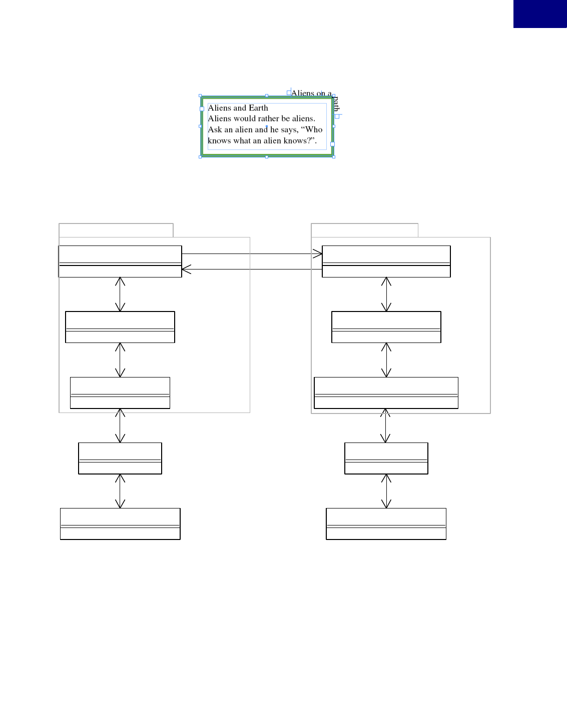
Text Fundamentals 353
Text Fundamentals
Text presentation
FIGURE 151 Text frame with text on a path
FIGURE 152 Instance diagram for text frame with text on a path
UID = 205
«boss class»
text on path spline : kTOPSplineItemBoss
UID = 206
«boss class»
controller : kMultiColumnItemBoss
UID = 207
«boss class»
text on path frame item : kTOPFrameItemBoss
IHierarchy::QueryParent
IHierarchy::QueryChild(0)
IHierarchy::QueryParent
IHierarchy::QueryChild(0)
UID = 203
«boss class»
frame list : kFrameListBoss
UID = 187
«boss class»
story : The Text Model::kTextStoryBoss
IFrameList::QueryNthFrame(0)
ITextFrameColumn::QueryFrameList
ITextModel::QueryFrameList
IFrameList::QueryTextModel
UID = 183
«boss class»
graphic frame : layout::kSplineItemBoss
IMainItemTOPData::GetTOPSplineItemUID
ITOPSplineData::GetMainSplineItemUID
Text on a path frame
UID = 184
«boss class»
controller : kMultiColumnItemBoss
UID = 186
«boss class»
column 1 : kTOPFrameItemBoss
IHierarchy::QueryParent
IHierarchy::QueryChild(0)
IHierarchy::QueryParent
IHierarchy::QueryChild(0)
UID = 181
«boss class»
frame list : kFrameListBoss
UID = 165
«boss class»
story : The Text Model::kTextStoryBoss
IFrameList::QueryNthFrame(0)
ITextFrameColumn::QueryFrameList
ITextModel::QueryFrameList
IFrameList::QueryTextModel
Text frame
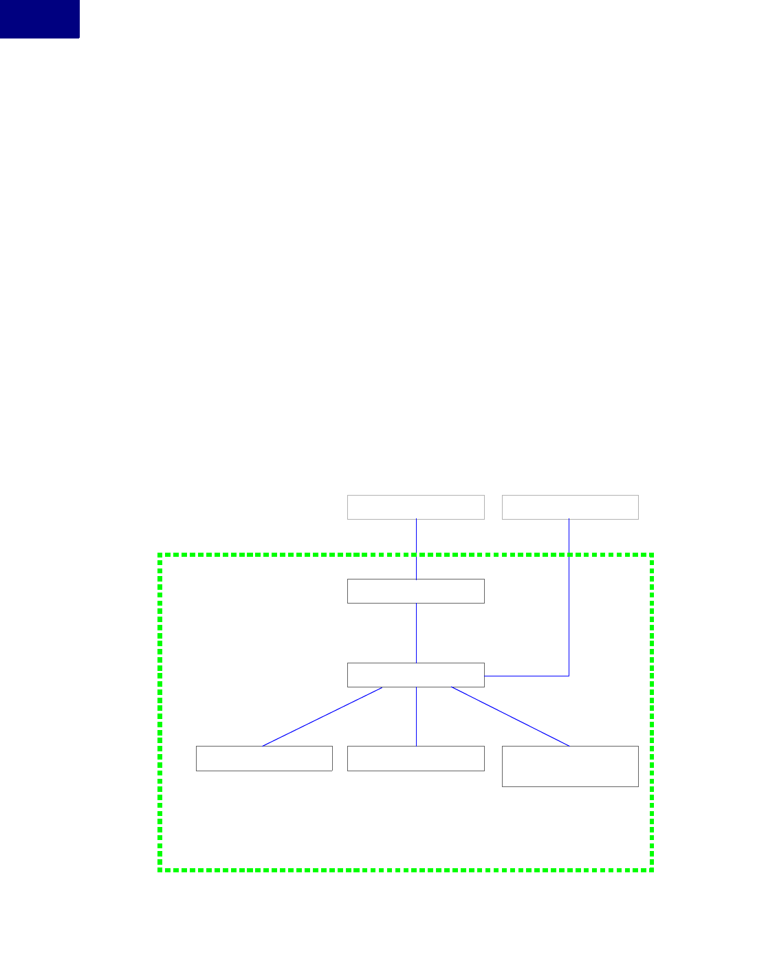
Text Fundamentals
Text presentation
354
The wax
The output of text composition is called the wax. The wax is responsible for drawing and hit
testing the text of a story.
The term “wax” comes from the manual paste-up process conventionally used to create maga-
zine and newspaper pages before the advent of interactive pagination software. In the old pro-
cess, typeset columns of text (galleys) were received from the typesetter. The galleys were run
through a waxer, cut into sections, and positioned on an art board. Wax was used as an adhe-
sive to stick the sections on the art board.
The art board in InDesign is a spread, and you can think of the galleys as text frames. The type-
set columns of text are the wax generated by text composition. The wax adheres—fixes—the
position of a line of text within a frame.
Wax strand, wax line, and wax run
The frame list (kFrameListBoss) manages the wax for a story by means of the wax strand
(IWaxStrand interface). The wax strand owns a collection of wax lines that contain wax runs, as
shown in Figure 153.
FIGURE 153 Class diagram of the wax
1
0..m
1
0..m
1
0..m
kTextStoryBoss
kFrameListBoss
kWaxTextRunBoss Collection
(TCY, WarichuuSet, etc.)
Collection (kWaxLineBoss)
kFrameItemBoss
1
0..1
1
0..m
The wax
IWaxStrand
0..m
kWaxILGRunBoss
1

Text Fundamentals 355
Text Fundamentals
Text presentation
The wax is organized as a hierarchy of collections and leaf runs. The most common case is a
series of wax lines, each with a collection of wax runs. A wax line is created for each line of text
in a frame. A wax run is created each time the appearance of the text changes within the line.
Examples of this include changes in point size, changes in font, and the interruption of the flow
of text in a line because text wrap causes text to flow around another frame.
The IWaxStrand interface on kFrameListBoss owns all wax lines for a story and is the root of
the wax tree. The IWaxIterator and IWaxRunIterator iterator classes provide access to wax lines
and wax runs.
kWaxLineBoss typically represents the wax for one line of text. (Warichuu is an exception to
this, where the Warichuu set contains multiple lines; all lines in the Warichuu set relate to one
kWaxLineBoss object.) Each line owns its wax runs, collections of wax runs, or combination of
runs and collections of runs. kWaxLineBoss provides access to its children through the IWaxC-
ollection interface.
Any boss that supports the IWaxCollection interface is a parent in the wax hierarchy to boss
objects that support the IWaxRun interface. A boss can support both the IWaxCollection and
IWaxRun interfaces, creating levels in the hierarchy.
kWaxTextRunBoss is the object that represents the wax for ordinary text. This object stores the
information needed to render the glyphs and provides the interfaces that draw, hit test, and
select the text.
kWaxILGRunBoss represents the wax for inline frames. Inline frames allow frames to be
embedded in the text flow. An inline frame behaves as if it were one character of text and
moves along with the text flow when the text is recomposed. kWaxILGRunBoss provides the
drawing, hit testing, and selection behavior for inline frames.
For a complete list of wax-run boss classes, see the API reference documentation for IWaxRun.
Examples of the wax
This section describes the wax generated for some sample text frames. To recreate these exam-
ples, use the Text tool to create the frames. If you use another tool, like the place gun or a
graphic frame tool, the inner coordinate spaces for the frames will be different from those illus-
trated. For simplicity, use a sample page size 200 points wide and 100 points deep, and format
text using 8-point type, the Times Regular font, and 10-point leading. All text is composed by
the Adobe Paragraph Composer in a horizontal text frame.
Single line with no format changes
The wax generated for a single line of text with no format changes is shown in Figure 154. This
example has a frame 200 points wide and 30 points deep, containing one line of 8-point Times
Regular text with 10-point leading. The first baseline offset setting for the frame is set to lead-
ing. This forces the baseline of the first line of text in the frame to be offset from the top of the
frame by a distance equal to the leading value for the text (10 points).

Text Fundamentals
Text presentation
356
FIGURE 154 Wax for single line with no format changes
Each node in the wax tree records its position, its width, and a reference to the characters in the
text model it describes. The origin records the index into the text model to the first character in
the node. The span records the number of characters in the node.
Wax lines record their position in the inner coordinate space of the frame in which they are
displayed. Wax runs record their position as an offset relative to the position of the wax line.
Additional information is stored specific to the type of node—wax line or wax run.
Figure 155 exposes some additional data in the wax. A wax line stores the leading for the line.
A wax run stores font name, a font-transformation matrix, glyph information, and other data
necessary to describe how the text is to be drawn. A glyph is an element of a font.
WaxLine
X=-100
Y=-5
Width=55.76
Origin=0
Span=17
WaxRun
X=0
Y=0
Width=55.76
Origin=0
Span=17
left=-100, top=-15
right=100, bottom= 15
-5
Leading
Width
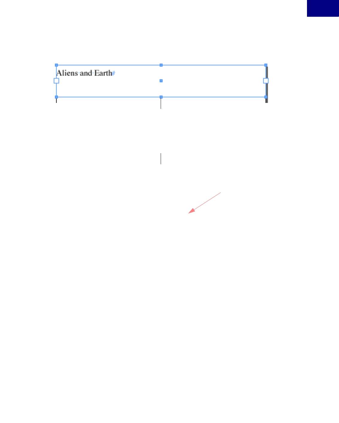
Text Fundamentals 357
Text Fundamentals
Text presentation
FIGURE 155 Information stored in the wax
When a character is composed, its character code is mapped to its corresponding GlyphID
from the font being used to display the character. The font provides the initial width of a glyph
at a particular point size. This width may be adjusted by composition to account for letter spac-
ing, word spacing, and kerning. The GlyphID values and their widths after composition are
stored in the wax run, as shown in Figure 155.
Generation of wax runs
Wax runs are generated for each set of format changes or line breaks that occur in the rendered
text. Figure 156 illustrates the effect of applying text attributes that change text format.
WaxLine
X=-100
Y=-5
Width=55.76
Origin=0
Span=17
Leading=10
WaxRun
X=0
Y=0
Width=55.76
Origin=0
Span=17
FontName=Times-Roman
FontMatrix=[8 0 0 8 0 0]
GlyphIDs=[0x24 0x4f 0x4c 0x48 0x51 0x56 0x3 0x44 0x51 0x47 0x3 0x28 0x44 0x55 0x57 0x4b 0xffffffff ]
GlyphWidths=[5.78 2.22 2.22 3.55 4.00 3.11 2.00 3.55 4.00 4.00 2.00 4.89 3.55 2.66 2.22 4.00 2.00]
-100,-15
100,15
Transformation matrix
for 8-point text
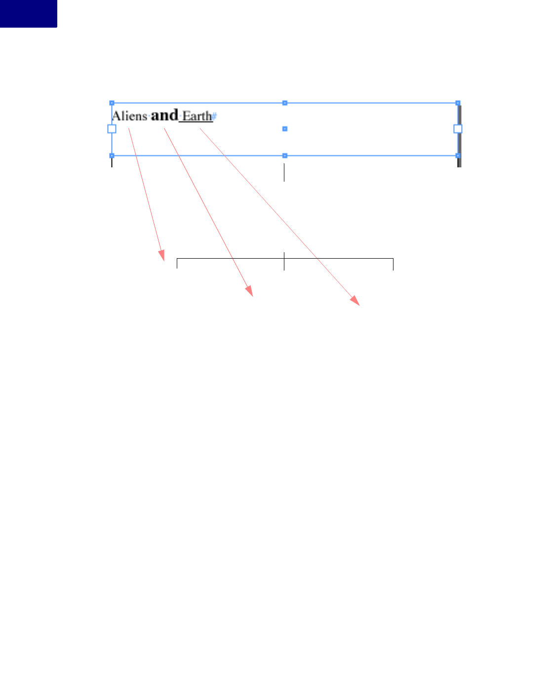
Text Fundamentals
Text presentation
358
FIGURE 156 Wax for single line with format changes
Figure 156 shows how a wax run is created each time the text attributes specify the appearance
of the text is to change. The arrows show the correspondence between the text drawn in the
frame and the wax run that describes its appearance and location. A distinct wax run would be
required for the following:
zEach time the appearance of the text changes within the line.
zEach line of text that appears in the parcel list for a story.
zEach side of a line that is interrupted, either by using an irregular-shaped frame or by over-
lapping a page item with wrap turned on within the frame.
Text adornments
Text adornments provide a way for plug-ins to adorn the wax (composed text). Text adorn-
ments give plug-ins the opportunity to do additional drawing when the wax in a frame is
drawn. The wax draws the text and calls the text adornments it is aware of to draw. For this to
occur, the adornment must be attached to the wax.
Text adornments are boss objects attached by ClassID to an individual wax run. When the run
is drawn, text adornments are given control using the ITextAdornment interface.
WaxLine
X=-100
Y=-5
Width=60.33
Origin=0
Span=17
-100,-15
100,15
WaxRun
X=0
Y=0
Width=22.89
Origin=0
Span=7
FontName=Times-Roman
FontMatrix=[8 0 0 8 0 0]
WaxRun
X=22.89
Y=0
Width=16.12
Origin=7
Span=3
FontName=Times-Bold
FontMatrix=[10 0 0 10 0 0]
WaxRun
X=39.01
Y=0
Width=21.32
Origin=10
Span=7
FontName=Times-Roman
FontMatrix=[8 0 0 8 0 0]
UnderlineMode=kUnderlineSingle

Text Fundamentals 359
Text Fundamentals
Text presentation
Calls to the ITextAdornment::Draw method are ordered by the priority value returned by the
ITextAdornment::GetDrawPriority method. Higher-priority adornments (smaller numbers)
are called before lower-priority adornments (larger numbers).
Text adornments cannot influence how text is composed; for example, they cannot influence
how characters are built into wax lines and wax runs by the text-composition subsystem.
Instead, text adornments augment the appearance of the text. A text adornment controls
whether the adornment is drawn in front of or behind the text.
There are two types of text adornments: local and global.
Local text adornments
A local text adornment is controlled by one or more text attributes. A local text adornment
provides visual feedback of the text the text attributes control. For example, an adornment can
highlight the background on which the text is drawn or strike out text by drawing a line in the
foreground.
The text attribute controls the process by interacting with text composition and associating the
adornment with a drawing style (see IDrawingStyle and kComposeStyleBoss). This causes the
text composer to attach the adornment to a wax run (see IWaxRenderData in “The wax” on
page 354).
Table 91 shows the main text adornments used by the application and the text attributes that
control them.
TABLE 91 Text adornments and associated text attributes
To add a local text adornment, first add a new text attribute. In more complex situations, use
multiple text attributes to control one text adornment. For example, kTAKentenSizeBoss,
kTAKentenRelatedSizeBoss, kTAKentenFontFamilyBoss, and kTAKentenFontStyleBoss collec-
tively control the kenten adornment implemented by the kTextAdornmentKentenBoss.
Local text adornments are attached to a drawing style and subsequently to an individual wax
run. These adornments always are called to draw, although they can choose not to draw any-
thing.
Figure 157 shows the sequence of calls that result in an adornment being associated with a par-
ticular wax run.
Adornment classID Attribute classID Description
kTextAdornmentIndexMarkBoss kTAIndexMarkBoss Index mark
kTextAdornmentKentenBoss kTAKentenSizeBoss, etc. Adorns text for emphasis
kTextAdornmentRubyBoss kTARubyPointSizeBoss, etc. Annotates base text
kTextAdornmentStrikethruBoss kTextAttrStrikethruBoss Strikes through text
kTextAdornmentUnderlineBoss kTextAttrUnderlineBoss Underlines text
kTextHyperlinkAdornmentBoss kHyperlinkAttributeBoss Hyperlink mark
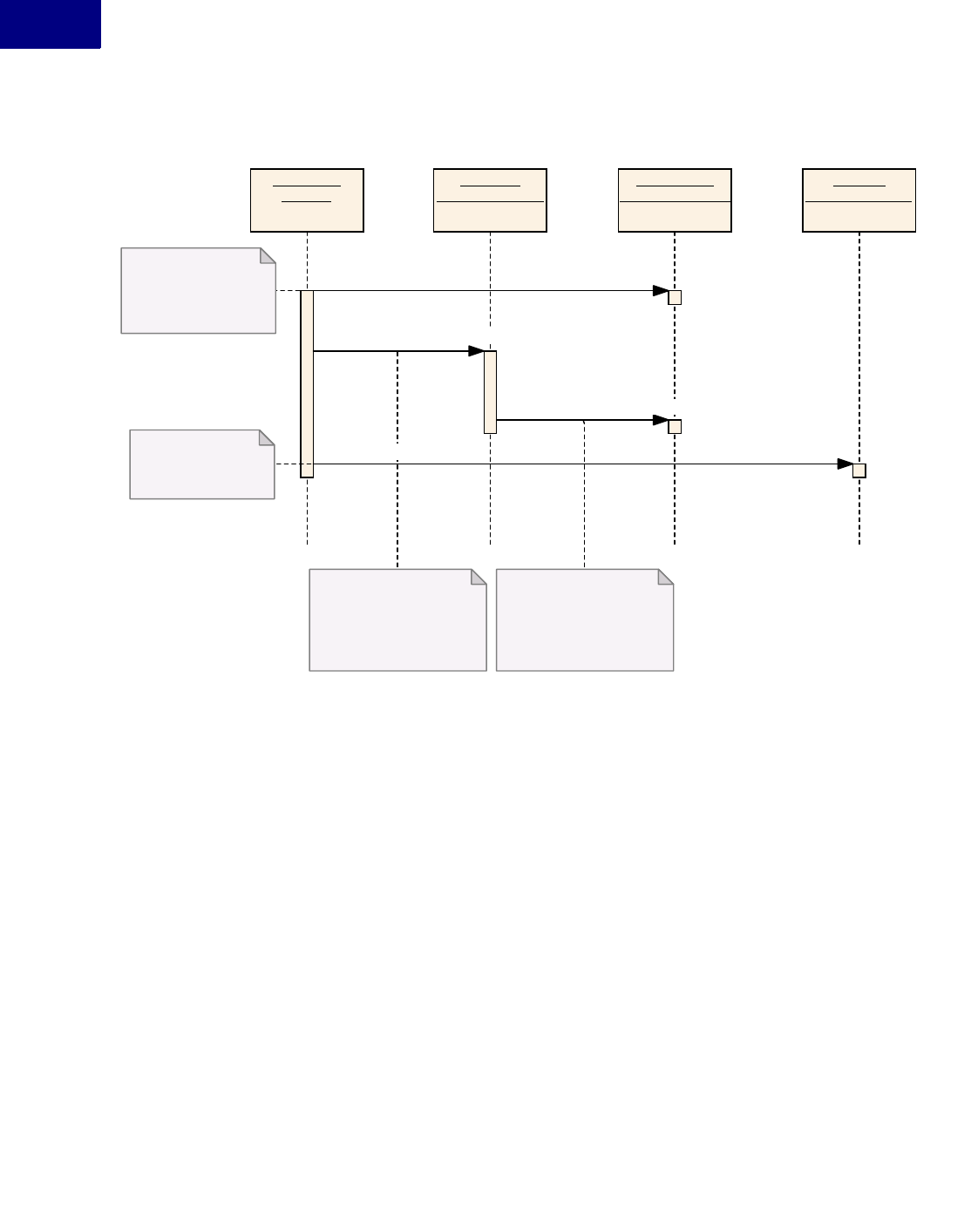
Text Fundamentals
Text presentation
360
FIGURE 157 Sequence for adding an adornment to a specific wax run
The composition subsystem calls the IAttrReport::TellComposition method of each attribute
that applies to a particular range of text. This gives the attribute a chance to interact with the
composition subsystem. This interaction includes the registering of adornments that are to be
associated with the wax and called when the wax is drawn (IDrawingStyle::AddTextAdorn-
ment). The adornments are attached to the wax as ClassIDs (IWaxRun::AddAdornment); i.e.,
the adornments are not instantiated at this point.
Figure 158 shows how adornments associated with a wax run are instantiated and called to
draw.
Composition
(abstract)
IAttrReport
(kSomeTextAttrBoss)
IDrawingStyle
(kComposeStyleBoss)
Creates kComposeStyleBoss
to hold the exact value of all
attributes as they apply to an
individual run of text
The composition subsystem
invokes each attribute active for
the run of text, allowing the
attribute to p articipate in the
composition process.
e attribute can specify
adornments to be added to the
drawing style. These adornments
will be given the opportunity to
participate in the drawing process.
IWaxRun
(kWaxTextRunBoss)
Adornment ClassID added
to the wax run
create
TellComposition(ICompositionStyle* style, IDrawingStyle* draw)
AddTextAdornment(ClassID attrID, ClassID adornmentID)
AddAdornment(ClassID id)
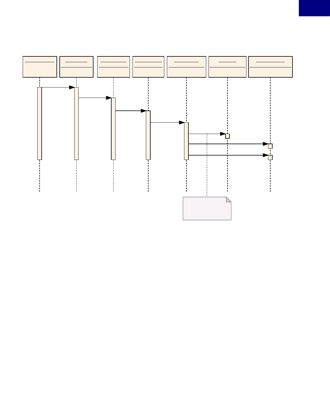
Text Fundamentals 361
Text Fundamentals
Text presentation
FIGURE 158 Sequence for local-adornment drawing
The Draw signal propagates to the wax run (IWaxRunText on kWaxTextRunBoss). The wax
run (IWaxRun on kWaxTextRunBoss) is interrogated for the set of adornments registered
through composition, as shown in Figure 157. Each adornment (ITextAdornment) is created
on whichever boss class it is represented on, and the Draw method is called.
It is possible to associate a data interface (ITextAdornmentData) during registration (IAttrRe-
port::TellComposition). This interface allows control over whether the adornment is associated
with wax runs.
Global text adornments
Global text adornments are attached to all wax runs, though they never have run-specific
adornment data. Global text adornments provide the ability to draw something without requir-
ing the text to be recomposed. Unlike local text adornments, global text adornments do not
need to be attached to individual wax runs to draw; however, global text adornments are asked
if they are active before they are called to draw.
For example, the Show Hidden Characters feature is implemented using a global text adorn-
ment, kTextAdornmentShowInvisiblesBoss. The adornment behaves as if it is attached to all
runs, but is called only when the adornment requests draw.
Draw Subsystem ITextParcelList
(kFrameListBoss)
IWaxLineShape
(kWaxLineBoss)
IWaxRunText
(kWaxTextRunBoss)
ITextAdornment
(kSomeAdornmentBoss)
IParcelShape
(kFrameItemBoss)
IWaxRun
(kWaxTextRunBoss)
Gets the list of adornments
(classID) held by the wax
run
Draw
Draw
Draw
Draw
GetAdornments
create
Draw

Text Fundamentals
Text presentation
362
Table 92 lists global text adornments.
TABLE 92 Global text adornments
Global text adornments are service providers. The ServiceID is kGlobalTextAdornmentSer-
vice. Global text adornments aggregate the IK2ServiceProvider interface and use the default
implementation kGlobalTextAdornmentServiceImpl.
Global adornments have the opportunity to participate in drawing if they are enabled. Figure
Figure 159 shows the sequence of events that cause IGlobalTextAdornment::Draw to be called.
For brevity, the calls to the adornment to determine whether it is enabled (IGlobalTextAdorb-
ment::GetIsActive) and to access the ink bounds of the adornment (IGlobalTextAdorn-
ment::GetInkBounds) are not shown.
Adornment boss Description
kTextAdornmentHJKeepsVBoss Highlights keeps violations.
kTextAdornmentMissingFontBoss Highlights missing fonts.
kTextAdornmentMissingGlyphsBoss Highlights missing glyphs.
kDynamicSpellCheckAdornmentBoss Squiggle line to mark spell checks.
kTextAdornmentShowInvisiblesBoss Shows hidden characters.
kPositionMarkerLayoutAdornmentBoss Draws position marker.
kTextAdornmentShowKinsokuBoss Shows Japanese character line break.
kTextAdornmentShowCustomCharWidthsBoss Marks character width as a filled rectangle.
kXMLMarkerAdornmentBoss XML marker.
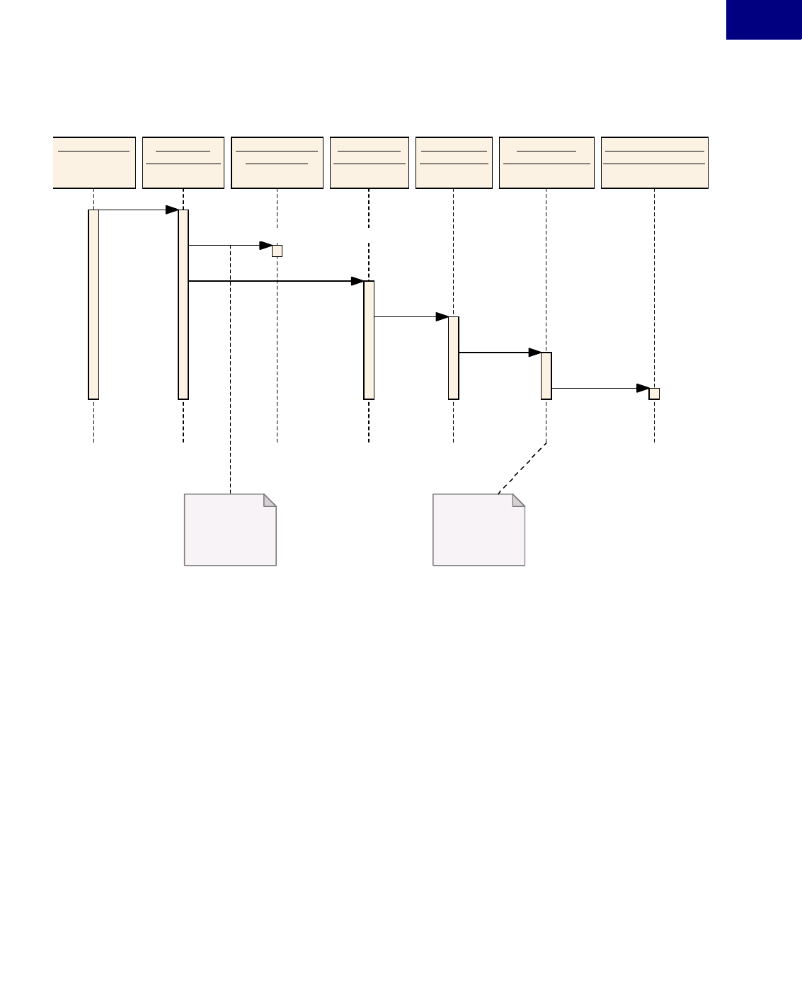
Text Fundamentals 363
Text Fundamentals
Text presentation
FIGURE 159 Sequence diagram for drawing of global adornments
When a frame (IParcelShape on kFrameItemBoss) is instructed to draw, it queries the service
registry (IK2ServiceRegistry on kSessionBoss) for the set of global text adornments that are
enabled (IGlobalTextAdornment::GetIsActive). The frame calls Draw on the parcel list (IText-
ParcelList on kFrameListBoss), which causes the wax line (IWaxLineShape on kWaxLineBoss)
and wax run (IWaxRunText on kWaxTextRunBoss) Draw methods to be called. During the
drawing of the wax run, the global adornments built up previously (Draw from IParcelShape
on kFrameItemBoss) have their Draw method called. Compare Figure 159 with Figure 158.
The set of global adornments are global to the document (maintained by the service registry),
whereas local adornments are local to a specific wax run.
Draw Subsystem ITextParcelList
(kFrameListBoss)
IWaxLineShape
(kWaxLineBoss)
IWaxRunText
(kWaxTextRunBoss)
IGlobalTextAdornment
(kSomeAdornmentBoss)
IParcelShape
(kFrameItemBoss)
IK2ServiceReg istry
(kSessionBoss)
Builds a list of global
adornments
requesting to be
drawn
Invokes Draw on all
adornments on the
list previously
constructed
Draw
GetNthServiceProviderID(kGlobalTextAdornmentServiceID)
Draw
Draw
Draw
Draw
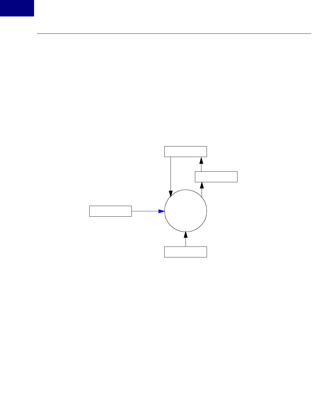
Text Fundamentals
Text composition
364
Text composition
This section describes the process of creating the final rendered text. It includes information
for software developers who want to develop custom composition engines.
Text composition is the process of converting text content into its composed representation,
the wax. The text-composition subsystem flows text content from a story thread maintained by
a story into a layout represented by parcels in a parcel list. Story threads are described in “Story
threads” on page 320; parcels and the wax, in “Text presentation” on page 331. Figure 160 is an
overview of text composition.
FIGURE 160 Text composition
Figure 161 shows a sample text frame with no format changes. The figure shows the objects
representing the story, the frame, and the composed text; it does not show the details of how
the text actually gets composed.
The wax
The text model
Text layout
Text composition
Story thread
characters and text attributes
Frames/
parcels
Wax lines
Fonts
Glyphs
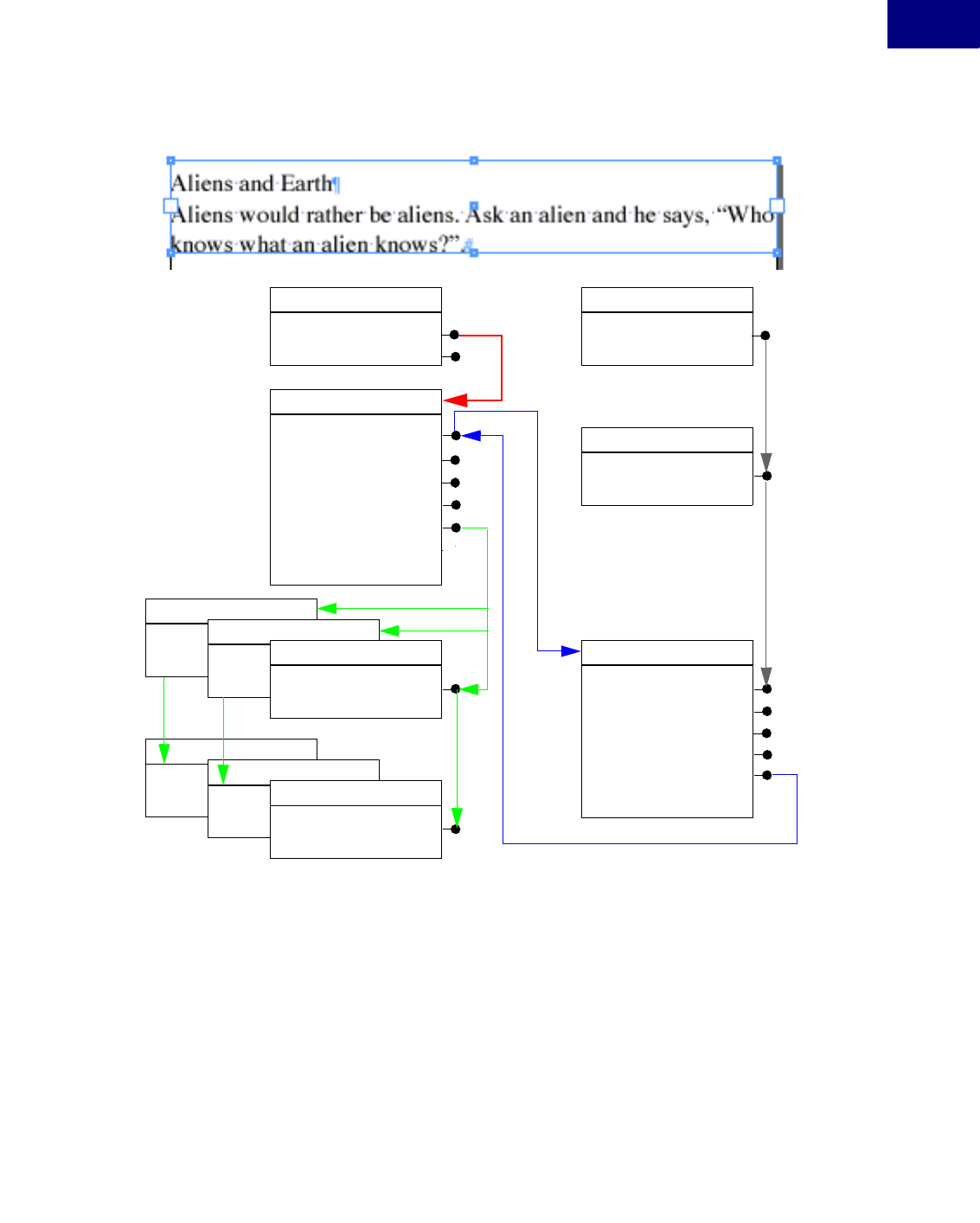
Text Fundamentals 365
Text Fundamentals
Text composition
FIGURE 161 Sample text frame with no formatting changes
Text composition creates the wax lines (kWaxLineBoss) and their associated wax runs (kWax-
TextRunBoss) using the primary story thread’s content and layout as input.
Wax lines are added to the wax strand (IWaxStrand). Text composition also maintains the
range of characters displayed in each parcel/frame (see “Span” on page 342).
kWaxTextRunBoss
kWaxLineBoss
IWaxLine
kWaxLineBoss
IWaxLine kFrameItemBoss
IHierarchy
IParcel
ITextTiler
ITextGrid
ITextFrameColumn
kSplineItemBoss
IHierarchy
kMultiColumnItemBoss
IHierarchy
kFrameListBoss
IFrameList
IParcelList
ITextParcelList
ITextParcelListData
IWaxStrand
kWaxLineBoss
IWaxLine
kTextStoryBoss
ITextModel
ITextStoryThread
kWaxTextRunBoss
IWaxRun
kWaxTextRunBoss
IWaxRun
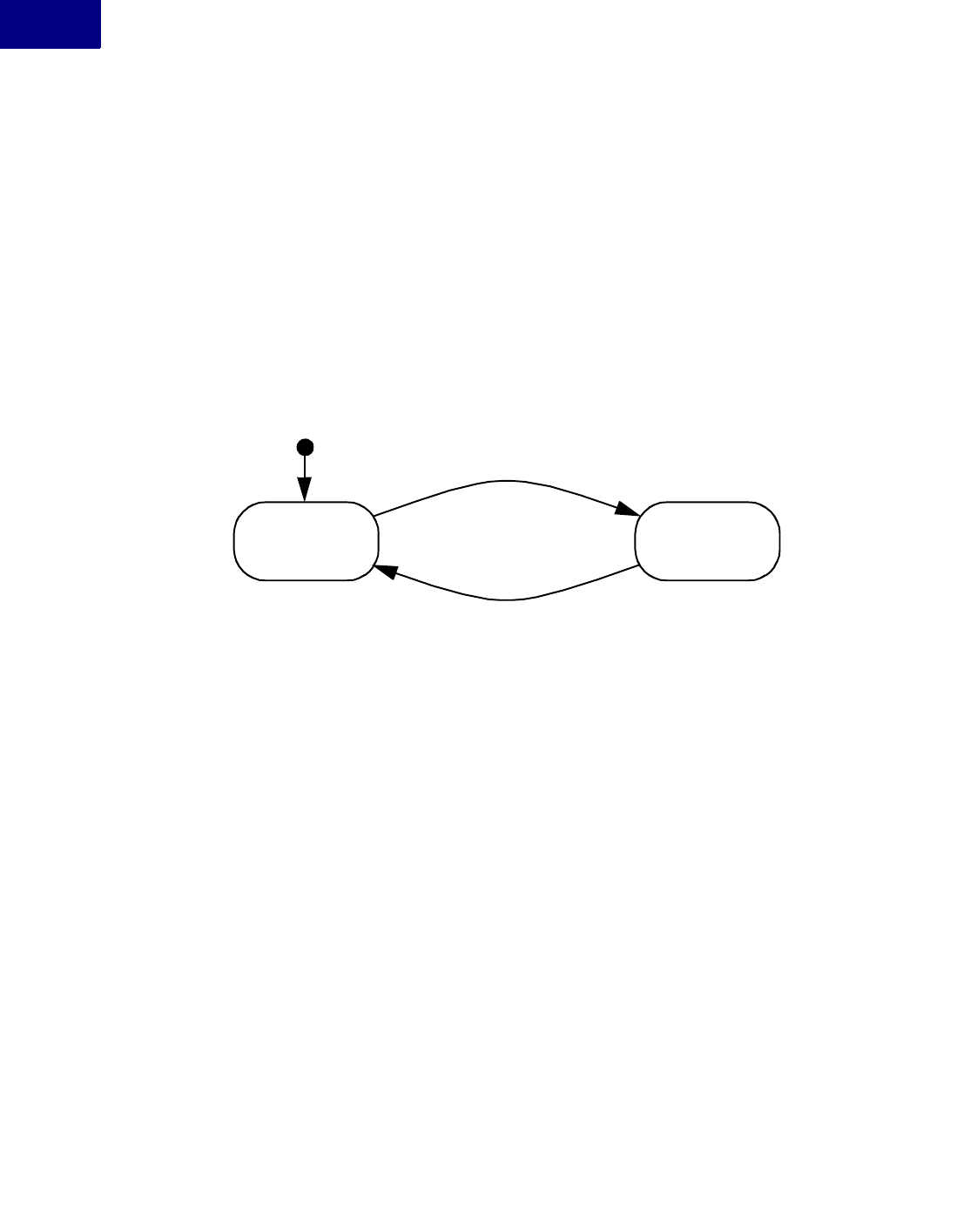
Text Fundamentals
Text composition
366
Phases of text composition
There are two distinct phases of text composition:
zDamage refers to changes that invalidate the wax for a range of composed text. Inserting
text and modifying frame size are examples of changes that cause damage. This is described
further in “Damage” on page 367.
zRecomposition is the process that repairs the damage and updates the wax to reflect the
change. This is described further in “Recomposition” on page 369.
Text composition toggles the wax between the states shown in Figure 162. The flow of damage
and recomposition is shown in Figure 163.
FIGURE 162 The wax state
Damaged.
Do recomposition.
The text model or text layout is updated.
Recomposition is completed.
Not damaged.
Start
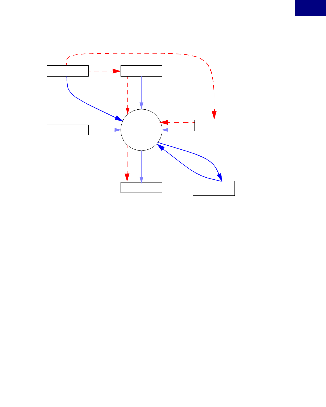
Text Fundamentals 367
Text Fundamentals
Text composition
FIGURE 163 Damage and recomposition, the phases of text composition
Figure 163 shows a plug-in can update the text model or text layout, causing the wax (the com-
posed representation of the text) to be damaged.
The text-composition subsystem exposes interfaces that mark the damaged story, frame par-
cels, and wax. The damage-recording flow is represented by dotted lines in Figure 163. The
text-composition subsystem also exposes interfaces that allow text to be recomposed. In the
figure, the recomposition flow is represented by solid lines.
Background composition (see “Background composition” on page 371) is a separate process
that drives text composition. Background composition runs as an idle task when the applica-
tion has no higher-priority tasks.
Consider the example in which the plug-in shown in Figure 163 is the text editor. In response
to typing, the plug-in processes a command to insert the typed characters into the text model.
This command calls text-composition interfaces that record the damage caused. Background
composition detects the damage and recomposes the affected text.
Damage
Damage is defined as the changes that invalidate the wax for a range of composed text. Damage
is recorded by marking the affected stories, parcels, frames, and wax. The damage indicates
where recomposition is required and the type of damage that has to be repaired.
The change counter on the frame list is incremented whenever something happens that causes
damage. No notification is broadcast when the change counter is incremented, so the change
The text model
The wax
Text
composition
Characters
+
text attributes
Parcels/
frames
Wax lines
Fonts
Glyphs
Plug-in
Background
composition
Update
MarkDamage Update
Recompose
Recompose
DetectDamage
MarkDamage
MarkDamage
Text layout

Text Fundamentals
Text composition
368
cannot be caught immediately; however IFrameList::GetChangeCounter returns a counter that
is incremented (and eventually rolls over) each time any parcel in any frame in the frame list
goes from undamaged to damaged, indicating some text in the frame list was damaged and
must be recomposed.
Damage drives and optimizes the recomposition process. For example, recomposition can
shuffle existing wax lines between frames to repair damage and avoid recomposing the text
from scratch. Based on the action that caused the damage, there are the following categories of
damage:
zInsert damage occurs when text is inserted.
zDelete damage occurs when a range of text is deleted.
zChange damage occurs when a range of text is replaced or the text attributes that apply to a
range of text are modified.
zResize damage occurs when a frame is resized.
zRect damage occurs when text wrap or text inset is applied.
zMove damage occurs when a frame is moved.
zDestroyed damage occurs when some combination of the above types of damage occurs.
When this happens, the existing wax for the affected range must be recomposed.
zKeeps damage occurs when a line must be pushed to the start of a new frame to eliminate
orphans and widows. Orphans and widows are words or single lines of text that become
separated from the other lines in a paragraph (see Figure 164). An orphan occurs when the
first line of a paragraph becomes separated from the rest of the paragraph body. A widow
occurs when the last line of a paragraph becomes separated from the rest of the paragraph
body.
FIGURE 164 Orphan (left) and widow (right)
Check for damage before relying on the information stored in the wax or the frame spans (see
“Span” on page 342). If your plug-in detects damage, it can either stop with a suitable error or
recompose the text.
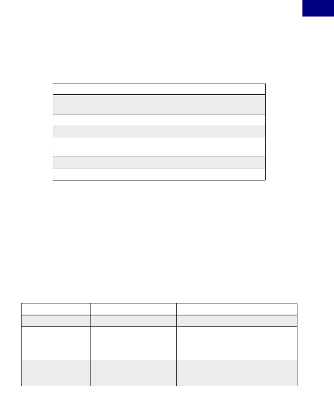
Text Fundamentals 369
Text Fundamentals
Text composition
Damage API
To detect damage, use the interface methods shown in Table 93 to detect damage. The damage
bookkeeping methods used to record the damage are not called directly by third-party plug-
ins; the text subsystem calls these methods as necessary in response to changes that affect text.
TABLE 93 Damage-inquiry interfaces and methods
Recomposition
Recomposition is the process of converting text from a sequence of characters and attributes
into the wax (fully formatted paragraphs ready for display). The components of recomposition
are as follows:
zInterfaces that control text composition.
zThe wax strand that manages the wax for the story.
zParagraph composers that create the wax for a line or paragraph.
Recomposition API
To request recomposition, use the interface methods shown in Table 94.
TABLE 94 Recomposition interfaces and methods
Interface Method
IStoryList CountDamagedStories, GetLastDamagedStory,
GetNthDamagedTextModelUID
IFrameList GetFirstDamagedFrameIndex
IFrameDamageRecorder GetCompState
IWaxLine IsContentDamaged, IsDamaged, IsDestroyed,
IsGeometryDamaged, IsKeepsDamaged
ITextParcelListData GetFirstDamagedParcel, GetParcelIsDamaged
ITextParcelList GetFirstDamagedParcel, GetIsDamaged
Interface Method Description
IFrameList QueryFramesContaining Helper method that causes recomposition.
IFrameListComposer RecomposeThruNthFrame,
RecomposeThruTextIndex
Controls recomposition of frames in the frame
list (kFrameListBoss). The methods delegate to
the parcel list composer
(ITextParcelListComposer).
IFrameComposer RecomposeThruThisFrame Controls recomposition of a frame. The
methods delegate to the wax strand
(IWaxStrand), which does the real work.
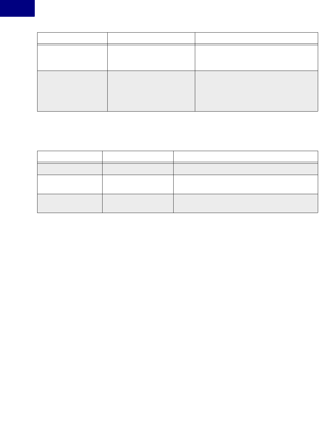
Text Fundamentals
Text composition
370
The interfaces and methods in Table 95 are not normally called by third-party plug-ins but play
a central role in the control of recomposition.
TABLE 95 Recomposition interfaces and key methods
Wax strand
The wax strand (IWaxStrand) manages the wax for a story and is responsible for updating the
wax to reflect changes in the text model or text layout. The wax strand controls the existing wax
and determines when and where a paragraph composer needs to be used to create new wax.
The wax strand also manages the overall damage-recording process.
The main text-recomposition methods are IFrameComposer::RecomposeThisFrame. The
recomposition methods on interfaces, such as IFrameList and IFrameListComposer, delegate
the actual work to these IWaxStrand methods.
NOTE:These methods are not called directly by third-party plug-ins.
The lifecycle of the wax is as follows:
1. The wax strand is informed a range in the text model was changed. In response, the wax
strand locates the wax lines that represent this range and marks them damaged.
2. On the next recomposition pass, the wax strand finds the first damaged wax line in the
story and asks a paragraph composer to recompose it.
3. The paragraph composer creates new wax lines and applies them to the wax strand (Recom-
poseHelper::ApplyComposedLine). RecomposeHelper is a helper class within IParagraph-
Composer, so any existing wax lines that represent the same range in the text model are
destroyed.
ITextParcelListComposer RecomposeThruNthParcel,
RecomposeThruTextIndex
Controls recomposition of parcels in a parcel
list. The methods delegate to the wax strand
(IWaxStrand), which does the real work.
IGlobalRecompose RecomposeAllStories,
SelectiveRecompose,
ForceRecompositionToComplete
Provides methods that can be used to force all
stories to recompose. This interface marks
damage that forces recomposition to recompose
the damaged element, even though they were
not actually changed.
Interface Method See
IFrameComposer RecomposeThisFrame “Wax strand” on page 370
IRecomposedFrames BroadcastRecomposition
Complete
“Recomposition notification” on page 372
IParagraphComposer Recompose,
RebuildLineToFit
“Paragraph composers” on page 371
Interface Method Description

Text Fundamentals 371
Text Fundamentals
Text composition
4. The wax strand repeats this process until it finds no more damaged wax lines or reaches the
end of the frame.
Paragraph composers
A paragraph composer (IParagraphComposer) takes up to a paragraph of text and arranges it
into lines to fit a layout. The paragraph composer creates the wax that represents the composed
text. Plug-ins can introduce new paragraph composers. For more information, see “Implemen-
tation notes for paragraph composers” on page 372.
The text-composition architecture is designed for paragraph-based composition. The most sig-
nificant implication of this design is that any change to text or attributes results in at least one
paragraph’s composition information being re-evaluated. For example, inserting one character
into a paragraph potentially can result in changes to any or all the line breaks in the paragraph,
including those preceding the inserted character.
Shuffling
Avoiding recomposition of text and simply moving existing wax lines up or down is called shuf-
fling. The performance improvement gained by shuffling is significant.
The wax strand can determine if a wax line was damaged because of something that occurred
around the wax line and not because the range of text it represents changed, in which case the
wax strand knows that the net result of recomposing the text is simply to move the wax line up
or down. The content of the wax line after recomposition is identical to its current content.
For example, if you select and delete an entire paragraph of text, the next paragraph has not
changed and does not need to be recomposed. By pulling the following paragraph up to the
position occupied by the deleted paragraph, the wax strand avoids the cost of recomposition.
When shuffling, the wax strand implements some of the behaviors of a paragraph composer,
like dealing with space before and after paragraph attributes.
Vertical justification
Vertical justification moves wax lines up and down within the container that displays them,
according to rules. For example, the lines can be justified to the top, center, or bottom. They
also can be justified to fill the available space. The wax strand is responsible for vertical justifi-
cation, and this mechanism is not extensible by third-party plug-ins.
Background composition
Background composition looks for damage, then fixes it by calling for recomposition. Back-
ground composition runs in the background as an idle task (IID_ICOMPOSITIONTHREAD
on kSessionBoss) and recomposes text. Each time background composition is called, it per-
forms the following actions in priority order:

Text Fundamentals
Text composition
372
1. Recomposes visible frames of damaged stories in the frontmost document.
2. Recomposes other damaged stories in the frontmost document.
3. Recomposes damaged stories in other open documents.
The actions are performed until the time slice allocated for background text composition
expires. Background composition requests recomposition by calling the RecomposeUntil
method on IFrameListComposer.
Recomposition transactional model
Plug-ins use commands to update the input data that drives text composition (the text model
and text layout). The commands cause damage to occur. Recomposition subsequently recom-
poses the text and generates the wax to reflect the changes. Recomposition does not execute
within the scope of a command; instead, the wax strand begins and ends a database transaction
around the recomposition process. This means recomposition cannot directly be undone; how-
ever, the commands used to update the input data are undoable. Undo causes damage, and
recomposition repairs it to ensure the wax (the text displayed) reflects the state of the text
model and text layout.
Recomposition notification
The IRecomposedFrames interface on the frame list (kFrameListBoss) keeps track of which
frames are recomposed, so text frame observers can be notified when recomposition com-
pletes. When the BroadcastRecompositionComplete method is called, each affected column
(kFrameItemBoss) receives notification that it was recomposed. Observers attach to the
kFrameItemBoss in which they are interested and then watch for the Update method to be
called with theChange == kRecomposeBoss and protocol==IID_IFRAMECOMPOSER.
Implementation notes for paragraph composers
This section provides more in-depth background for software developers developing a custom
paragraph composer for the application.
Paragraph composers
A paragraph composer (IParagraphComposer) takes up to a paragraph of text, arranges it into
lines to fit a layout, and creates the wax that represents the text it composed. Plug-ins can intro-
duce new paragraph composers.
The user selects the composer to be used for a paragraph from the menu on the Paragraph
panel (see Figure 165) or by using the Paragraph Styles palette. Selecting a paragraph composer
sets the kTextAttrComposerBoss paragraph attribute to indicate which paragraph composer to
use.
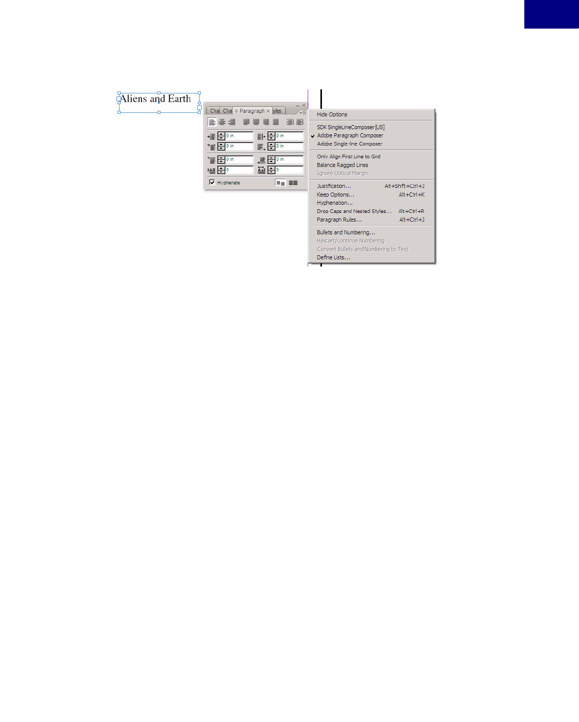
Text Fundamentals 373
Text Fundamentals
Text composition
FIGURE 165 Setting the paragraph composer
Hyphenation and justification (HnJ)
The term “hyphenation and justification” (‘HnJ’) often is used in computer systems to refer to
breaking of text into lines and spacing of text so it aligns with the margins. This term is not
used in this application’s API or documentation; however, the role performed by an HnJ system
is similar to the role of a paragraph composer. Hyphenation is intimately associated with line
breaking. In this application, the role is split out and implemented by a hyphenation service
(IHyphenationService). A paragraph composer that needs to hyphenate a word uses a hyphen-
ation service.
A paragraph composer’s environment
Paragraph composers are called by the text-composition subsystem. When text is to be recom-
posed, the wax strand examines the paragraph attribute kTextAttrComposerBoss that specifies
the paragraph composer to be used, locates it through the service registry, and calls the IPara-
graphComposer::Recompose method. This call gives the paragraph composer a context stored
in the helper class in which to work.
virtual bool16 Recompose(RecomposeHelper* helper)
The RecomposeHelper class is a wrapper of the story being recomposed. It stores information
like the story’s compose scanner, tiler, starting index, text span, and position. The Recompose-
Helper class definition is in IParagraphComposer.h.
Figure 166 shows an example of a paragraph composer called to compose text.
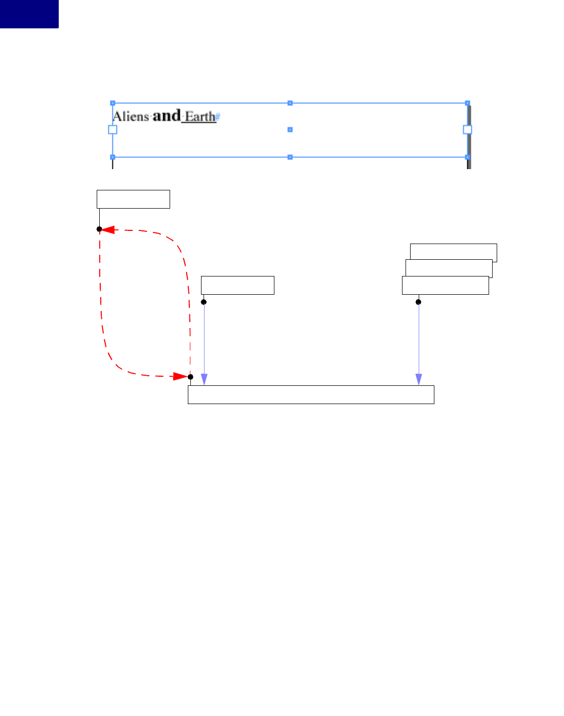
Text Fundamentals
Text composition
374
FIGURE 166 Paragraph-composer environment
The following steps occur:
1. The paragraph composer composes the text and creates at least one wax line in the helper.
2. The paragraph composer accesses the character-code and text-attribute data for the story,
using the IComposeScanner interface acquired from helper->GetComposeScanner.
3. The paragraph composer determines the areas in a line where glyphs can flow, using IPara-
graphComposer::Tiler.
4. The wax lines are applied to the IWaxStrand interface by calling helper->ApplyComposed-
Line.
NOTE:Both yPosition and tiles are specified in the inner bounds (coordinate system) in
RecomposeHelper.
The scanner and drawing style
The scanner (IComposeScanner) provides access to both character and formatting (text
attributes) information from the text model, as shown in Figure 167. The drawing style (inter-
face IDrawingStyle) represents the effective value of text attributes at a given index in the text
Other parcel list boss
kTextCellContentBoss
kTextStoryBoss
Paragraph composer boss class
kFrameListBoss
helper->GetComposeScanner
IParagraphComposer
IWaxStrand
Characters and effective attribute values
characters=”Aliens “
fontName=Times-Roman,
pointSize=8 point,
leading= 10 points
Tiles
firstBaselineOffset=leading
tile [0] = [-100, -15, 100, -5]
Wax lines and runs
Recompose
helper->ApplyComposedLine
kFrameListBoss
-100,-15
100,15

Text Fundamentals 375
Text Fundamentals
Text composition
model. The drawing style cached by interfaces on kComposeStyleBoss considerably simplifies
accessing text-attribute values. These interfaces remove the need to resolve text-attribute values
from their representation in the text model and the text styles it references. A drawing style
applies to at least one character. The range of characters it applies to is a run. For more infor-
mation on styles and overrides, see “Text formatting” on page 324.
FIGURE 167 The scanner and drawing style
Fonts and glyphs
Fonts contain the glyphs that display characters for a typeface at a particular size. Paragraph
composers use the drawing style (IDrawingStyle) to find the font to be used. The font APIs
provide the metrics required to compose the text into lines composed of a run of glyphs for
each stylistic run of text.
A font represents a typeface with a given size and style. A typeface, like Times, is the letters,
numbers, and symbols that make up a design of type. A glyph is a shape in a font that is used to
represent a character code on screen or paper. The most common example of a glyph is a letter,
but the symbols and shapes in a font like ITC Zapf Dingbats also are glyphs. For more informa-
tion, see Figure 168 and “Fonts” on page 389.
kStyleBoss
kStyleBoss
kTextDataStrandBoss
kTextStoryBoss
Paragraph composer boss class
IComposeScanner
IParagraphComposer
Characters Drawing style (effective attribute values)
Text attributes
kComposeStyleBoss
IDrawingStyle
ICompositionStyle
IHyphenationStyle
IJustificationStyle
kParaAttrStrandBoss kCharAttrStrandBoss
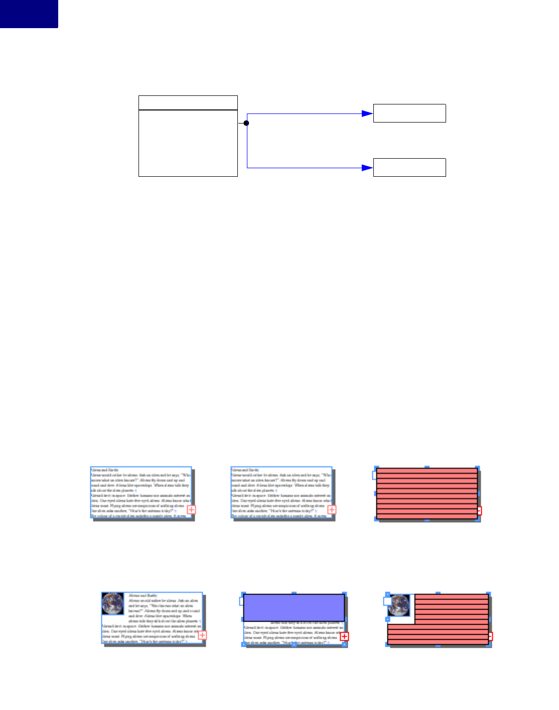
Text Fundamentals
Text composition
376
FIGURE 168 Accessing a font
Tiles
Tiles (IParagraphComposer::Tiler) represent the areas on a line into which text can flow. Nor-
mally, there is only one tile on a line; however, text wrap may cause intrusions that break up the
places in the line where text can go. The tiler takes care of this, as well as accounting for the
effect of irregularly shaped text containers.
Intrusions are the counterparts of tiles. Intrusions are not the inverse of tiles: they do not spec-
ify the areas in the line where text cannot be flowed. From the perspective of ITextTiler, an
intrusion is a horizontal band within a frame, in which text flow within the bounding box of
the frame may be interrupted. Intrusions can be used to optimize recomposition. An intrusion
is a flag that indicates that text cannot be flowed into the entire width of a line. Intrusions are
caused by text wrap and nonrectangular frames.
The tiles returned for a line depend on the y position where they are requested, their depth,
and their minimum width. The intrusions and tiles for some sample text frames are shown in
Figure 169 through Figure 173.
FIGURE 169 Text frame with no intrusions
FIGURE 170 Effect of image frame with text wrap
kComposeStyleBoss
IDrawingStyle
IPMFont
IFontInstance
QueryFont
QueryFontInstance
Frame Intrusions(none) Tiles
Frame Intrusions Tiles
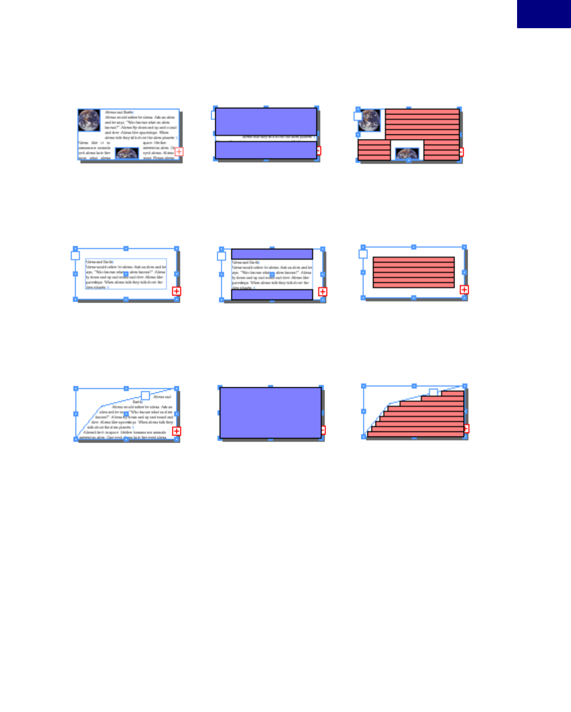
Text Fundamentals 377
Text Fundamentals
Text composition
FIGURE 171 Effect of two images with text wrap
FIGURE 172 Effect of text inset
FIGURE 173 Effect of nonrectangular frame
First-baseline offset
The first-baseline offset setting controls the distance between the top of a parcel or frame and
the baseline of the first line of text it displays. Some sample settings are shown in Figure 174.
Frame Intrusions Tiles
Frame Intrusions Tiles
Frame Intrusions Tiles
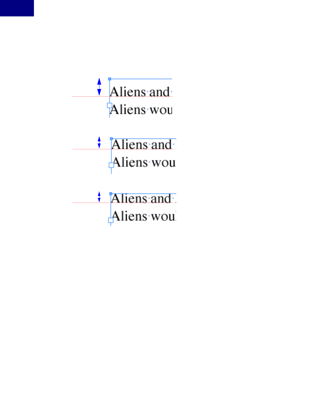
Text Fundamentals
Text composition
378
FIGURE 174 First-baseline offset examples
Control characters
A paragraph composer can apply an appropriate behavior to correctly implement the semantic
intent of many control characters. For a complete list of control-character codes, see Text-
Char.h in the API reference documentation.
Inline frames
Inline frames (kInlineBoss) allow frames to be embedded in the text flow. An inline frame
behaves as if it were one text character and moves along with the text flow when the text is
recomposed. The kTextChar_ObjectReplacementCharacter or kTextChar_Inline character is
inserted into the text data strand to mark the position of the inline frame in the text. The inline
frames are owned by the owned item strand (kOwnedItemStrandBoss) in the text model. Para-
graph composers obtain the geometry of the frame associated with the kInlineBoss by using
ITextModel to access this strand directly. Inline frames are represented in the wax by their own
type of wax run, kWaxILGRunBoss.
Leading
Ascent
Cap height
Use the largest leading on the line.
Use the largest ascent on the line. This
makes the top of the tallest glyph fall
below the top inset of the frame.
The setting controls the distance between
the top inset of the frame and the baseline
of the first line.
Use the largest Cap Height on the line. This
makes the top of upper case letters touch
the top inset of the frame.
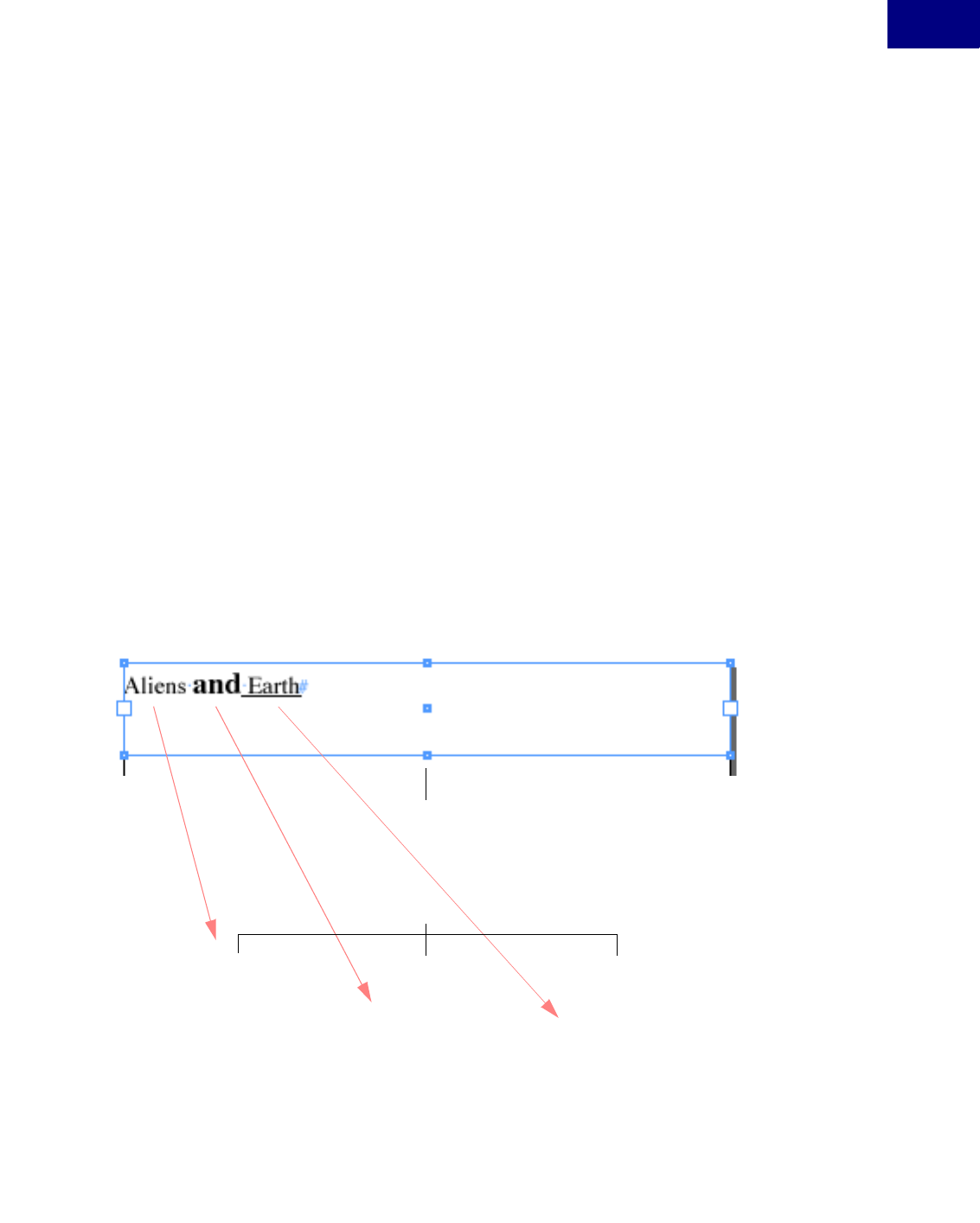
Text Fundamentals 379
Text Fundamentals
Text composition
Table frames
Table frames (kTableFrameBoss) are owned items anchored on a kTextChar_Table character
embedded in the text flow. Paragraph composers can and do compose text displayed in table
cells.; however, they never compose (create wax for) the character codes related to tables
(kTextChar_Table and kTextChar_TableContinued). When a paragraph composer encounters
either of these characters, it should create wax for any buffered text and return control to its
caller.
Creating the wax
During the process of building lines, a paragraph composer normally uses an intermediate rep-
resentation of the glyphs, so it can evaluate potential line-break points and adjust glyph widths.
The specific arrangement used depends on the overall feature set of the paragraph composer
and is beyond the scope of this document. Once the line-break decisions are made, the para-
graph composer must create wax lines and runs.
For details of the mechanics of the creation of wax lines and runs, see “The wax” on page 354.
Once created by a call to RecomposeHelper::QueryNewWaxLine, new wax lines are added to
the wax strand for a story with the following call:
RecomposeHelper::ApplyComposedLine(IWaxLine* newLine, int32 newTextSpan)
Figure 175 shows an example of the wax generated by a paragraph composer.
FIGURE 175 Wax for a single line with format changes
WaxLine
X=-100
Y=-5
Width=60.33
Origin=0
Span=17
-100,-15
100,15
WaxRun
X=0
Y=0
Width=22.89
Origin=0
Span=7
FontName=Times-Roman
FontMatrix=[8 0 0 8 0 0]
WaxRun
X=22.89
Y=0
Width=16.12
Origin=7
Span=3
FontName=Times-Bold
FontMatrix=[10 0 0 10 0 0]
WaxRun
X=39.01
Y=0
Width=21.32
Origin=10
Span=7
FontName=Times-Roman
FontMatrix=[8 0 0 8 0 0]
UnderlineMode=kUnderlineSingle
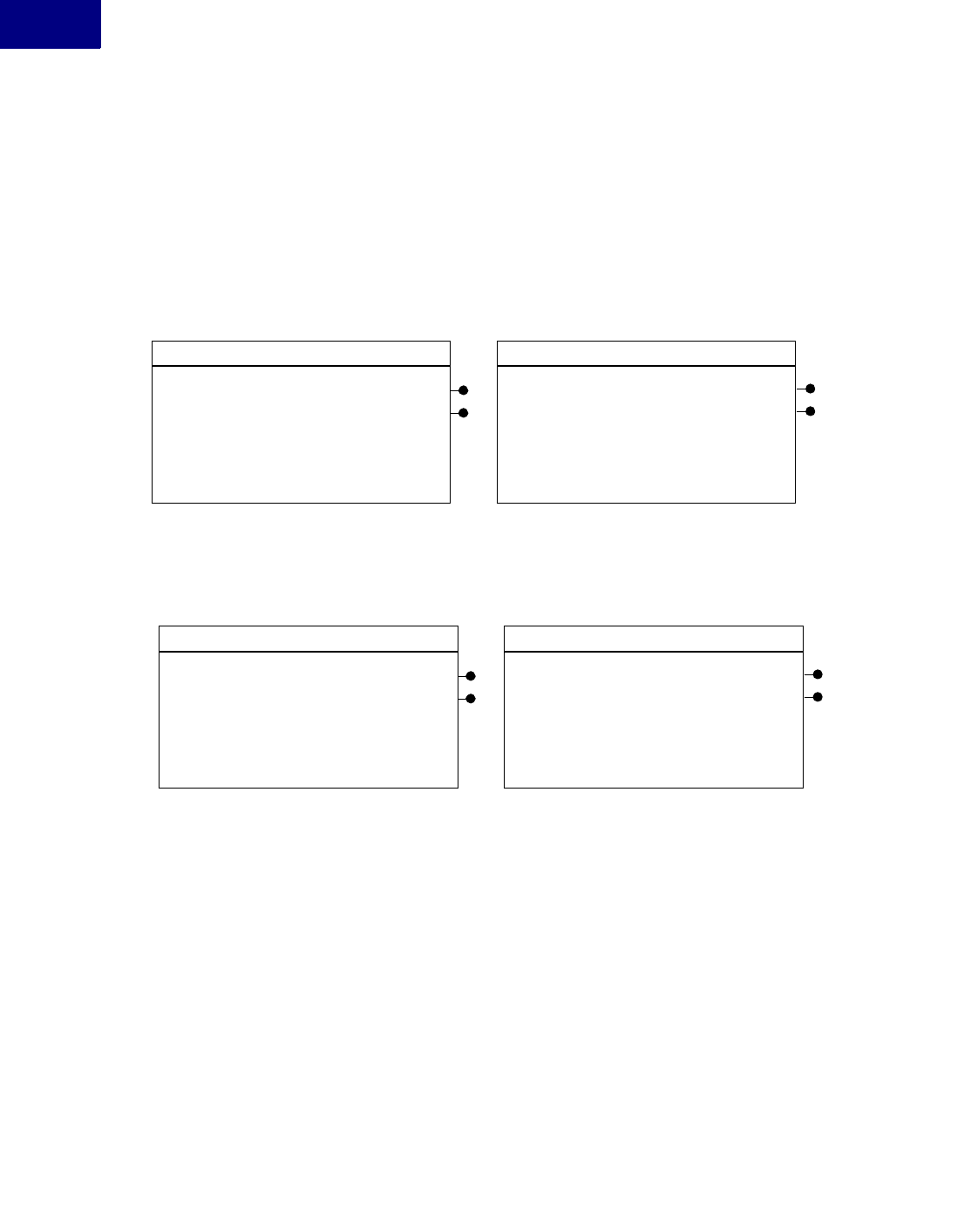
Text Fundamentals
Text composition
380
Adobe paragraph composers
Figure 176 shows the paragraph composers provided by the application under the Roman fea-
ture set. Figure 177 shows the paragraph composers provided under the Japanese feature set.
Paragraph composers are implemented as service providers (IK2ServiceProvider) and can be
located using the service registry. The ServiceID used to identify paragraph composers is kTex-
tEngineService.
FIGURE 176 Roman paragraph composers
FIGURE 177 Japanese paragraph composers
Key APIs
Class diagram
Paragraph composers are boss classes that implement IParagraphComposer, the interface
called by the application to compose text. To be recognized as a text composer, the boss class
also must implement a text-engine service (IK2ServiceProvider) with a ServiceID of kTex-
tEngineService. The service also must provide a name (a translatable string) for the paragraph
composer, which is displayed in the user interface. As output, composers generate wax lines
(IWaxLine) and associated wax runs (IWaxRun) for up to one paragraph of text at a time.
Figure 178 shows the class diagram of a custom paragraph composer.
kParagraphComposerBoss
IParagraphComposer
IK2ServiceProvider
GetServiceID=kTextEngineService
GetName="HL Composer"
kSingleLineComposerBoss
IParagraphComposer
IK2ServiceProvider
GetServiceID=kTextEngineService
GetName="HL Single"
kJParagraphComposerBoss
IParagraphComposer
IK2ServiceProvider
GetServiceID=kTextEngineService
GetName="HL Composer J"
kJSingleComposerBoss
IParagraphComposer
IK2ServiceProvider
GetServiceID=kTextEngineService
GetName="HL Single J"

Text Fundamentals 381
Text Fundamentals
Text composition
FIGURE 178 Custom paragraph composer
IParagraphComposer
There are two distinct phases to text composition, and IParagraphComposer reflects these
roles:
zPositioning the line and, if necessary, deciding where text in the line should break. This
information is represented persistently in the wax line. Features that affect line-break deci-
sions belong here. This is the role of the Recompose method.
zPositioning glyphs that represent the characters in the line and, if necessary, adjusting their
widths. This information is represented by a set of wax runs associated with the wax line.
Wax runs are not persistent and must be rebuilt for display when a wax line is read from
disk. Features that affect glyph position (paragraph alignment, justification, letter spacing,
word spacing, and kerning) belong here. This is the role of the RebuildLineToFit method,
which regenerates composed text data from the minimal data stored on disk.
Recompose is called when text needs to be fully recomposed. Each time this method is called, it
should compose at least one line and at most one paragraph of text into the passed-in helper.
RecomposeHelper actually does all the work, by creating wax starting from the character in the
story indicated by RecomposeHelper::GetStartingTextIndex. The top of the area text flows into
is given by RecomposeHelper::GetStartingYPosition, and composition is done using the sup-
plied scanner and tiler. The wax lines generated as a result are applied to the given wax strand.
NOTE:The paragraph composer is expected to create at least one wax line each time
Recompose is called, even when overset text is what is being composed.
RebuildLineToFit is called to regenerate the wax runs for a wax line from the minimal data
stored on the disk. No line breaking or line positioning needs to be done here.
IComposeScanner
IComposeScanner is an interface aggregated on kTextStoryBoss. It provides methods that help
access character and text-attribute information from the text model. It is the primary iterator
for reading a story.
Example 23 shows QueryDataAt, which gets a chunk of data from the text model starting from
a given TextIndex. QueryDataAt is a primary method text composition uses to iterate through
the text model. QueryDataAt returns a TextIterator, which has its own reference count on the
chunk of data in the model, and thus makes the TextModel lifecycle independent of the com-
kYourParagraphComposerBoss
IParagraphComposer
IK2ServiceProvider
GetServiceID=kTextEngineService
GetName=”Your Composer"

Text Fundamentals
Text composition
382
pose scanner cache. Optionally, QueryDataAt returns the drawing style and number of charac-
ters in the returned iterator. We recommend you always ask for the returned number of
characters.
EXAMPLE 23 IComposeScanner::QueryDataAt
virtual TextIterator QueryDataAt(TextIndex position, IDrawingStyle** newstyle,
int32* numChars) = 0;
You also can acquire the drawing style by one of the methods listed in Example 24. For more
information on the methods in IComposeScanner, see the API reference documentation.
EXAMPLE 24 Acquiring IDrawingStyle from IComposeScanner
virtual IDrawingStyle* GetCompleteStyleAt
(TextIndex position, int32* lenleft = nil) = 0;
virtual IDrawingStyle* GetParagraphStyleAt
(TextIndex position, int32* lenleft = nil, TextIndex* paragraphStart = nil) = 0;
QueryAttributeAt allows callers to query the effective value of one or more particular text
attributes at a given position. For more details, see the API reference documentation.
IDrawingStyle, ICompositionStyle, IHyphenationStyle, and IJustificationStyle
IDrawingStyle provides access to text-attribute values like font, point size, and leading. If the
text property you want is not in IDrawingStyle, you will find it in one of the other style inter-
faces on kComposeStyleBoss.
For details, see the API reference documentation for kComposeStyleBoss, IDrawingStyle,
ICompositionStyle, IHyphenationStyle, and IJustificationStyle.
IPMFont and IFontInstance
IPMFont encapsulates the CoolType font API. It represents a typeface and can generate
instances (IFontInstance) of it at various point sizes. IPMFont is not based on IPMUnknown,
but IPMFont is reference counted and can be used with InterfacePtr. For details, see the API
reference documentation.
IFontInstance encapsulates the CoolType font-instance API. IFontInstance represents an
instance of a typeface at a given size. IFontInstance is not based on IPMUnknown, but IFontIn-
stance is reference counted and can be used with InterfacePtr.
IFontInstance controls the mapping from a character code (UTF32TextChar) into the identifier
of its corresponding glyph (GlyphID). For details, see the API reference documentation.
IParagraphComposer::Tiler
IParagraphComposer::Tiler manages the tiles for a parcel list and is used by paragraph com-
posers to determine the areas on a line into which text can flow (see “Tiles” on page 376). It
controls the content area bounds of each line.
The GetTiles method is used to get the tiles. If GetTiles cannot find large enough tiles in the
current parcel that meet all the requirements, it returns kFalse and should be called again to see
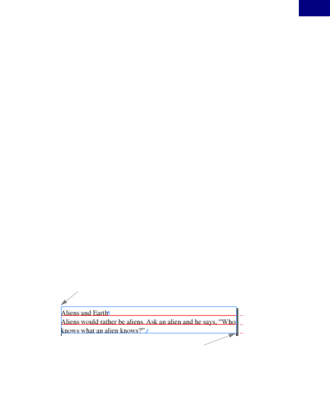
Text Fundamentals 383
Text Fundamentals
Text composition
if the next parcel in the list can meet the request. If no parcel can meet the request, the tiler
returns tiles into which overset text can flow.
GetTiles is a complex call to set up. To fully understand how to use it, see the API reference
documentation and the text-composer samples (SingleLineComposer) provided in the SDK.
The “TOP” abbreviation used in many of the parameter names is short for “top of parcel,”
because when a line falls at the top of a parcel, special rules apply that govern its height (see
“First-baseline offset” on page 377).
For Roman composers, a tile must be wide enough to receive one glyph plus any left and right
line indents that are active. A heuristic often is used that approximates the minimum glyph
width to be the same as the leading. The minimum tile height depends on the metric being
used to compose the line. Normally this is leading, but the first line in a parcel is a special case
in which the metric used may vary depending on the first-baseline offset (ascent, cap height,
and leading) associated with the parcel. The pYOffset value indicates the top of the area for text
to flow into. The pYOffset value actually is a position rather than an offset from the top of the
parcel. The pYOffset value initially is the yPosition stored in RecomposeHelper when the
IParagraphComposer::Recompose method is called. For more details, see the API reference
documentation.
Scenarios
This section illustrates how text gets recomposed. The scenarios presented here demonstrate
basic situations you may come across in developing a paragraph composer. To reduce complex-
ity for these examples, assume the paragraph composer being called generates only one line for
each call (a single-line composer).
Simple text composition
Figure 179 shows a composed text frame 200 points wide and 30 points deep, with its baseline
grid shown. The text is 8-point Times Regular with 10-point leading, and the first-baseline off-
set for the frame is set to leading.
FIGURE 179 Simple text composition
When text of the same appearance is flowed into the frame, the distance between the baselines
of succeeding lines of text is set to the leading.
-5
5
15
Baseline
left = -100, top = -15
right = 100, bottom = 15
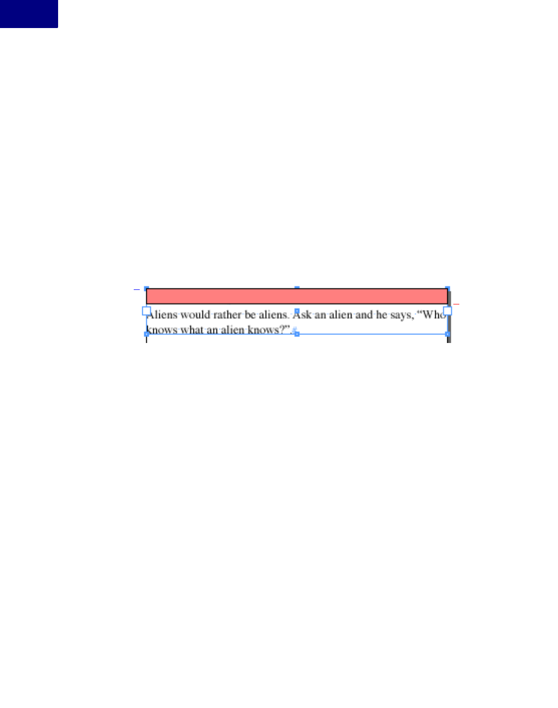
Text Fundamentals
Text composition
384
The wax strand examines the paragraph attribute that specifies which paragraph composer to
use and locates it through the service registry. The paragraph composer is then asked to recom-
pose the story from the beginning, causing text to flow into the frame starting from the top by
calling IParagraphComposer::Recompose(helper).
The yPosition stored in the helper indicates the top of the area into which glyphs can flow. This
is the baseline of the preceding line or the top of the parcel.
The composer examines the drawing style and its associated font and calculates the depth and
width of the tiles it needs. The example uses 8-point text with 10-point leading and no line
indents, so the minimum height and width is 10 points. The tiler is then requested for tiles of
the required depth and minimum width at the given yPosition, and it returns the tile shown in
Figure 180.
FIGURE 180 Tiles for the first line
The following sequence of actions then occurs:
1. The paragraph composer scans the text using IComposeScanner. Text flows into the tile
until the tile is full or an end-of-line character is encountered.
2. The composer chooses where the line is to be broken and creates a wax line for the range of
text the line will display.
3. The wax line is applied to the IWaxStrand and, as a side effect, the composer’s IParagraph-
Composer::RebuildLineToFit method is called to generate wax runs for the line.
4. The IParagraphComposer::Recompose method is finished with its work and returns control
to its caller.
5. The wax strand successively asks the paragraph composer to recompose the second and
third lines with yPositions of -5 and 5, respectively, until the text is fully composed.
The result is shown in Figure 181. For more details, see the SDK sample code SingleLineCom-
pose.
yPosition Baseline
-15
-5
Tile for line 1
Text Fundamentals 385
Text Fundamentals
Text composition
FIGURE 181 Tiles for the second and third lines
Change in text height on line
As a line is composed, attributes that control the height of the line, like point size and leading,
may change. The baseline of the text must be set to reflect the largest value of the metric, such
as leading or ascent, that is being used to compose the text. To achieve this, the composer asks
the tiler for tiles deep enough to take text of a given height. If an increase in text height is
encountered as composition proceeds along a line, the tiler needs to be asked for deeper tiles to
accommodate the text. It is the composer’s responsibility to ensure the parcel can receive the
deeper text.
For example, if the point size for the word “Ask” is changed to 16 points and its leading to 20
points, the text suffers change damage. The resulting sequence of recomposition is shown in
Figure 182.
yPosition Baseline
-5
5
5
15
Tile for line 2
Tile for line 3
-15
-5
5
15
-5
5
15
Composed frame with baseline grid displayed
Text Fundamentals
Text composition
386
FIGURE 182 Changing point size and leading of selected text
Initially, the composer encounters 8-point text on 10-point leading, and it requests tiles of an
appropriate depth. When the composer hits the style change to 16-point text and 20-point
leading, it goes back to the tiler and gets a deeper tile. When the style changes back to the
smaller point size, the composer already has a tile deep enough to take this text, so it fills the
tile with glyphs and breaks the line. Note how the baseline is set to reflect the largest leading
value encountered in the line.
yPosition Baseline
-5
5
-5
15
Initial tile for line 2
Leading increased. Get deeper tile.
-15
-5
5
15
-5
5
15
Recomposed frame
The text suffers change damage and the paragraph composer is called.
Text Fundamentals 387
Text Fundamentals
Text composition
Text wrap
Depending on the yPosition and depth of the tiles needed, the text-wrap settings on other page
items or a change to the shape of the frame may become significant during recomposition. To
illustrate this, in Figure 183, a graphic with text wrap is added to the simple text-frame arrange-
ment.
FIGURE 183 Simple text wrap
Figure 183 shows the text frame and the tiles the 8-point text flows into with 10-point leading.
Note that the third line in the frame is affected by the text wrap and flows around the bounding
box of the graphic.
The following sequence illustrates what happens when the point size for “Ask” is changed to 12
points and its leading is changed to 14 points. The initial case is shown in Figure 184.
FIGURE 184 Changing the selection to 12-point text, 14-point leading
The wax strand picks up the change damage and asks the paragraph composer to recompose
the first line of the second paragraph. The baseline of the first line of text in the frame, -5
points, is at the yPosition stored in the RecomposeHelper.
The paragraph composer gets tiles deep enough to take the initial leading value (10 points) it
encounters on the line, as shown in Figure 185.
Add graphic frame with text wrap set to wrap tightly around bounding box.
Text frame with 8-point Times regular text, 10-point leading
Frame Tiles
Text Fundamentals
Text composition
388
FIGURE 185 Composer begins to recompose
The paragraph composer then encounters the run of text with the changed point size and lead-
ing. Because the text is deeper than the tiles the paragraph composer obtained, the composer
goes back to the tiler and asks for a new set of tiles to receive the deeper text. This is shown in
Figure 186.
FIGURE 186 Composer asks for deeper tiles
Because of the request for deeper tiles and the text-wrap setting on the graphic, the tiler returns
the two tiles shown in Figure 187, causing text to tightly wrap to the bounding box of the
graphic.
FIGURE 187 Deeper tiles
The paragraph composer flows glyphs into the deeper tiles, generating a wax line with four wax
runs: one for the tile to the left of the graphic and three in the tile to the right of the graphic.
After this change, all text for the story cannot be displayed in the frame, so the story is overset,
as shown in Figure 188.
yPosition Baseline
-5
5
yPosition Baseline
-5
9
yPosition Baseline
-5
9

Text Fundamentals 389
Text Fundamentals
Fonts
FIGURE 188 Fully recomposed frame
It is important to note that the tiles returned by the tiler depend on the yPosition within the
frame for which they are requested and the depth asked for by the caller.
Frame too narrow or not deep enough
IParagraphComposer::Recompose must return a wax line each time it is called; however, it is
possible a frame is too narrow to accommodate text, when either the indent settings for a para-
graph are large or the text has a large point size. The result is overset text. Call the tiler (IPara-
graphComposer::Tiler’s GetTiles()) repeatedly until it returns kTrue. The tiler iterates over all
parcels; if none can accommodate the text, the tiler returns a tile into which overset text can
flow.
Fonts
This section explains how fonts fit into the InDesign text architecture. Fonts provide the basic
information required to render glyphs. A font is identified by a font name (e.g., “Minion Pro”)
and a face or style name (e.g., “Bold” or “Heavy”). A rendered font also has a size; for example,
this text is 11 pt (points). The font, along with the point size, is an instance of the font.
All rendered text in the application has an associated font. The operating system provides a set
of font services, though fonts unique to the application can be maintained in the application
fonts folder.
An application installation has a set of fonts available (from either the operating system or the
application fonts folder). The font manager provides these fonts to the user while the document
is being edited. There are times when the font manager gets a request for a font that is not avail-
able; for example, the font was removed from the system or the document was produced on a
system with a different set of available fonts. The font manager resolves this situation by replac-
ing the font with one that is available. The font manager warns the user when such a replace-
ment occurs.
Fonts have rights, which determine what can be done with a particular font. For example, a font
can indicate that it should not be embedded in a PDF document or it should not be printed.
The font subsystem provides access to these rights and implements the policies required to
adhere to these rights.
yPosition Baseline
-5
9
-5
9
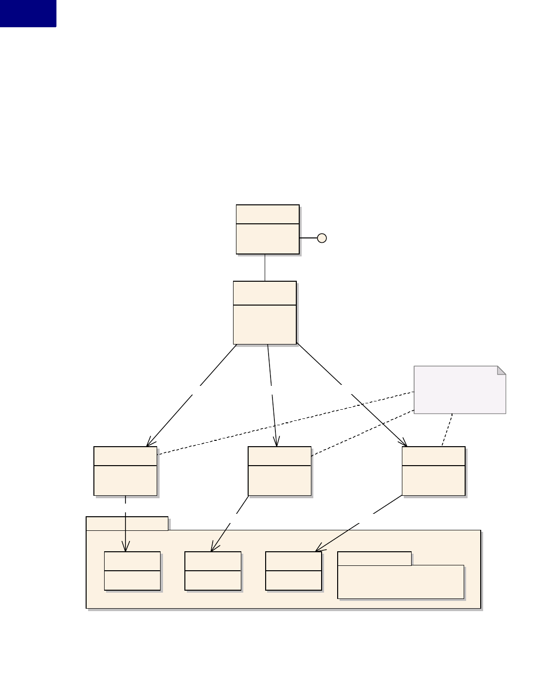
Text Fundamentals
Fonts
390
Font management within the application relies on a core piece of Adobe technology, CoolType.
CoolType wraps the operating-system font services to provide a cross-platform abstraction and
provides further services to clients.
Font-subsystem architecture
The application wraps the CoolType representation of fonts, font groups, and font instances
with application-specific types. This is shown in Figure 189.
FIGURE 189 Accessing CoolType fonts in the application
CoolType font sybsystem
OS font subsystem
IPMFont IFontGroupIFontInstance
InDesign wrappers for core
CoolType types. Interfaces do
not inherit from IPMUnknown.
CTFontDict CTFontGroupCTFontInstance
kSessionBoss
IFontMgr
«interface»
IFontMgr
GetCTFontDict
GetCTFontGroup GetCTFontInst
1
QueryFont
*
1
QueryFontGroup
*
1
QueryFontInstance
*
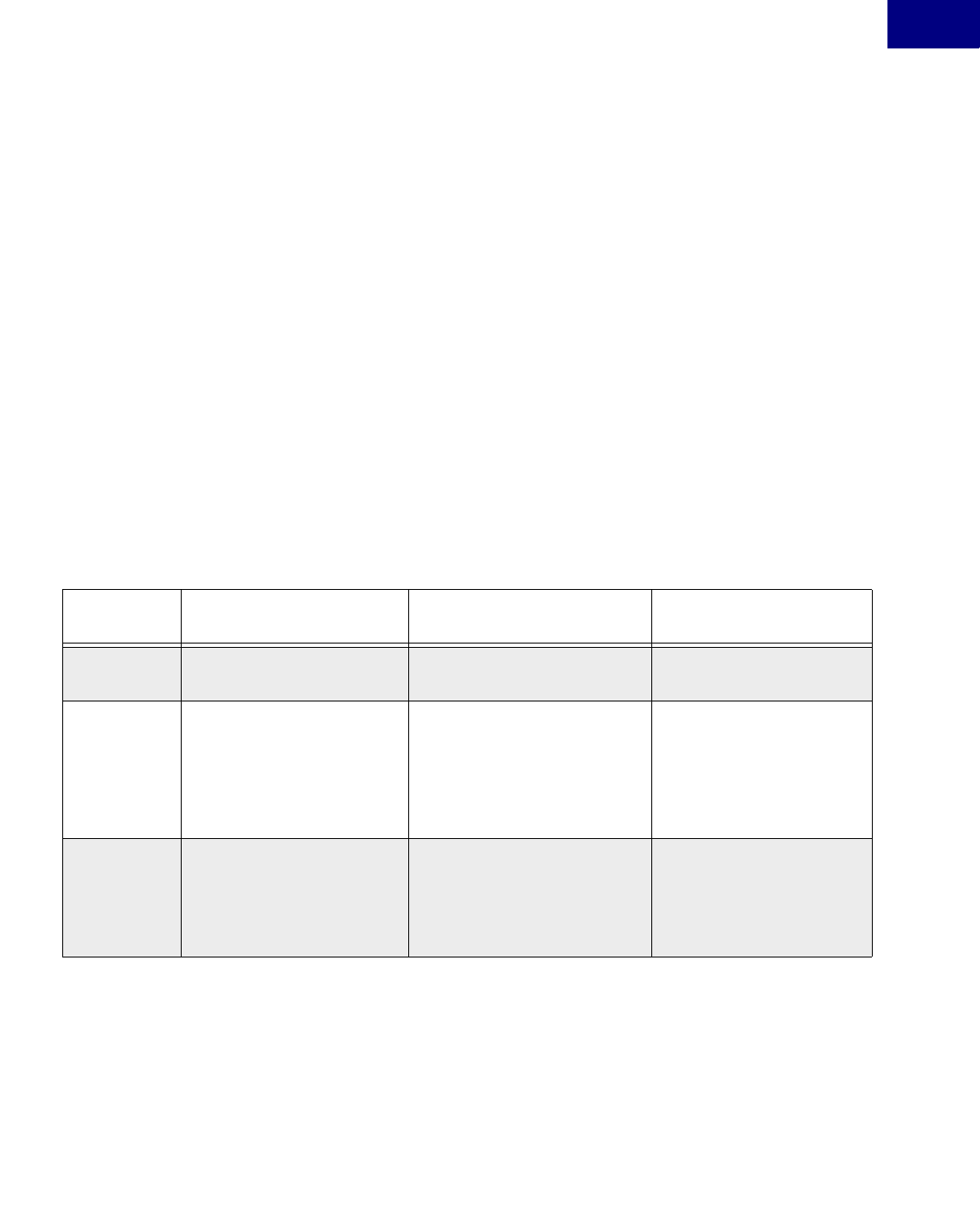
Text Fundamentals 391
Text Fundamentals
Fonts
IFontMgr on kSession provides access to the CoolType font wrappers. IPMFont is the repre-
sentation of a font, IFontGroup represents a group of related fonts, and IFontInstance repre-
sents a particular font at a particular point size.
Font manager
The font manager provides access to all font groups available to the application. Each font
group allows you to access each font in the group. The IFontMgr interface is aggregated on
kSessionBoss.
CoolType
CoolType is the core technology through which an application can access fonts. It automati-
cally loads the fonts made available by the operating system. In addition, CoolType can load
fonts directly from the common Adobe fonts folder and the Fonts folder inside the application’s
folder.
The API provides the IFontGroup, IPMFont, and IFontInstance interfaces as shells through
which the application calls CoolType. These are not standard interfaces; that is, they do not
derive from IPMUnknown. You cannot create them using CreateObject or query them for
other interfaces; however, these interfaces are reference counted, and you can manage their life-
time using InterfacePtr. See Table 96 and Figure 190.
TABLE 96 Interfaces that use CoolType
Interface Description How to get the interface Code snippet with example
of use
IFontGroup Represents all font groups
available to the application
IFontMgr::QueryFontGroup,
FontGroupIteratorCallBack
SnpPerformFontGroupIterat
or
IPMFont Provides extensive data
related to a particular font.
IPMFont provides font-name
mapping calls and access to
font metrics at a given point
size.
IFontMgr::QueryFont,
IFontMgr::QueryFontPlatform,
IFontFamily, text attributes
kTextAttrFontUIDBoss and
kTextAttrFontStyleBoss,
IStoryService, IWaxRenderData
SnpInspectFontMgr
IFontInstance Represents an instance of a
font of a given point size. Of
interest if you need to write a
paragraph composer or map
character codes to GlyphIDs.
IFontMgr, IDrawingStyle,
IStoryService
SnpInsertGlyph
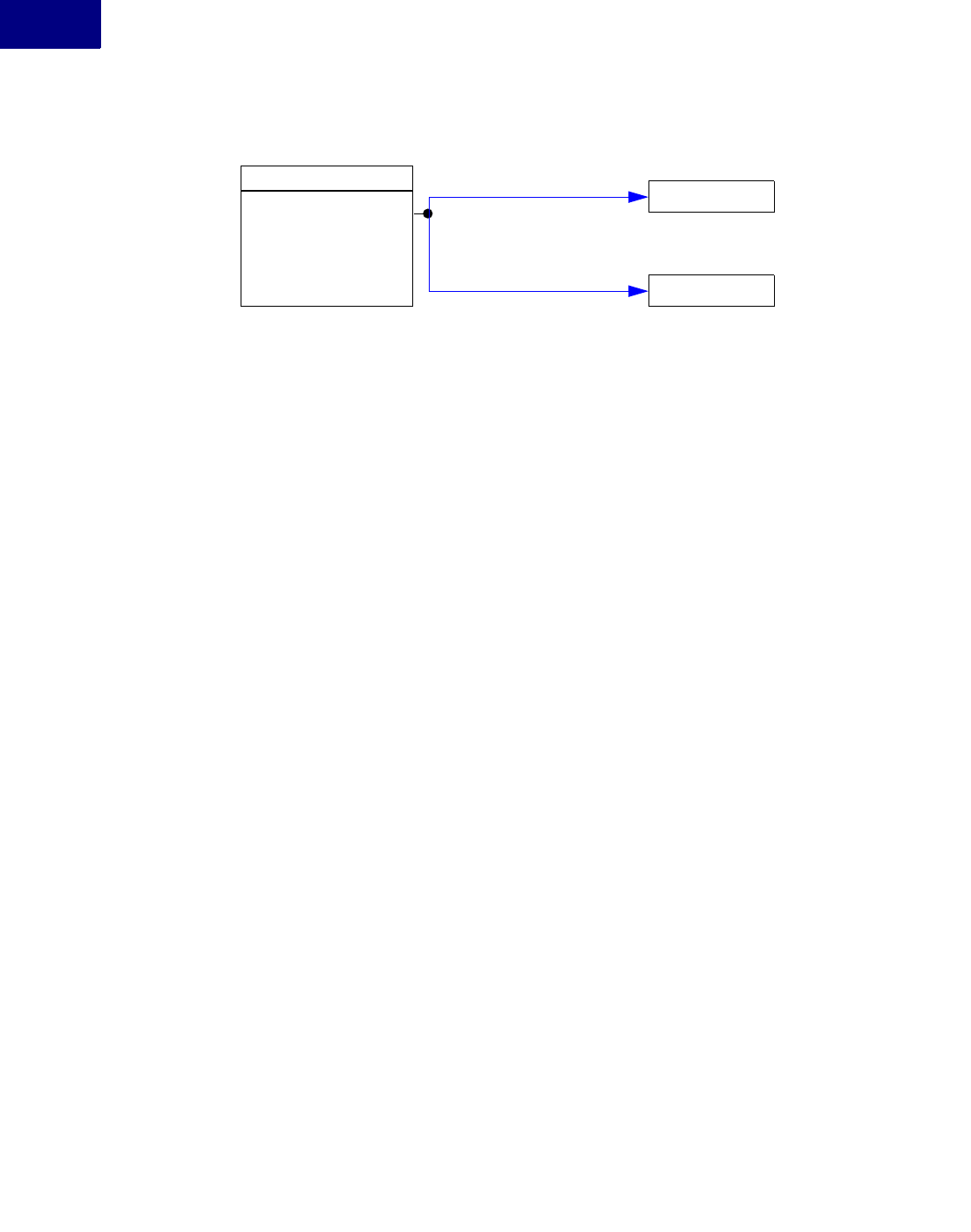
Text Fundamentals
Fonts
392
FIGURE 190 Accessing a font
Fonts are used when composing text, as fonts define the characteristics of individual glyphs.
kComposeStyleBoss is used by the composition engine. The IDrawingStyle interface provides
access to the font (IPMFont) and particular instance (IFontInstance) being used
Fonts within the document
Within a document, fonts are represented by the font name (plus information on font style and
point size). When the actual font is required, the font manager resolves the name-to-font (IPM-
Font or IFontInstance) mapping.
The document-font manager
The document-font manager (IDocFontMgr) provides access to all fonts that persist in a ses-
sion or document workspace. The fonts that exist in a document include a set of default fonts,
fonts used in visible stories, and fonts used for features that are modeled using the application
text subsystem but not intended to be viewed or printed as part of a story (for example, text
that exists in notes).
Fonts in the persistent document
Fonts are represented in the object model by kFontGroupBoss (signature interface IFontFam-
ily). Each font used in a story results in an instance of this boss object. A font family along with
a font style identifies a particular font in the font subsystem. The font family represents the
name of the font (more correctly, the set of names that identify each font within a particular
group). This decoupling between font and name in the document allows the font manager to
resolve the font when required and take appropriate measures if the font is not available to the
application. The relationship between font manager and fonts is shown in Figure 191
kComposeStyleBoss
IDrawingStyle
IPMFont
IFontInstance
QueryFont
QueryFontInstance
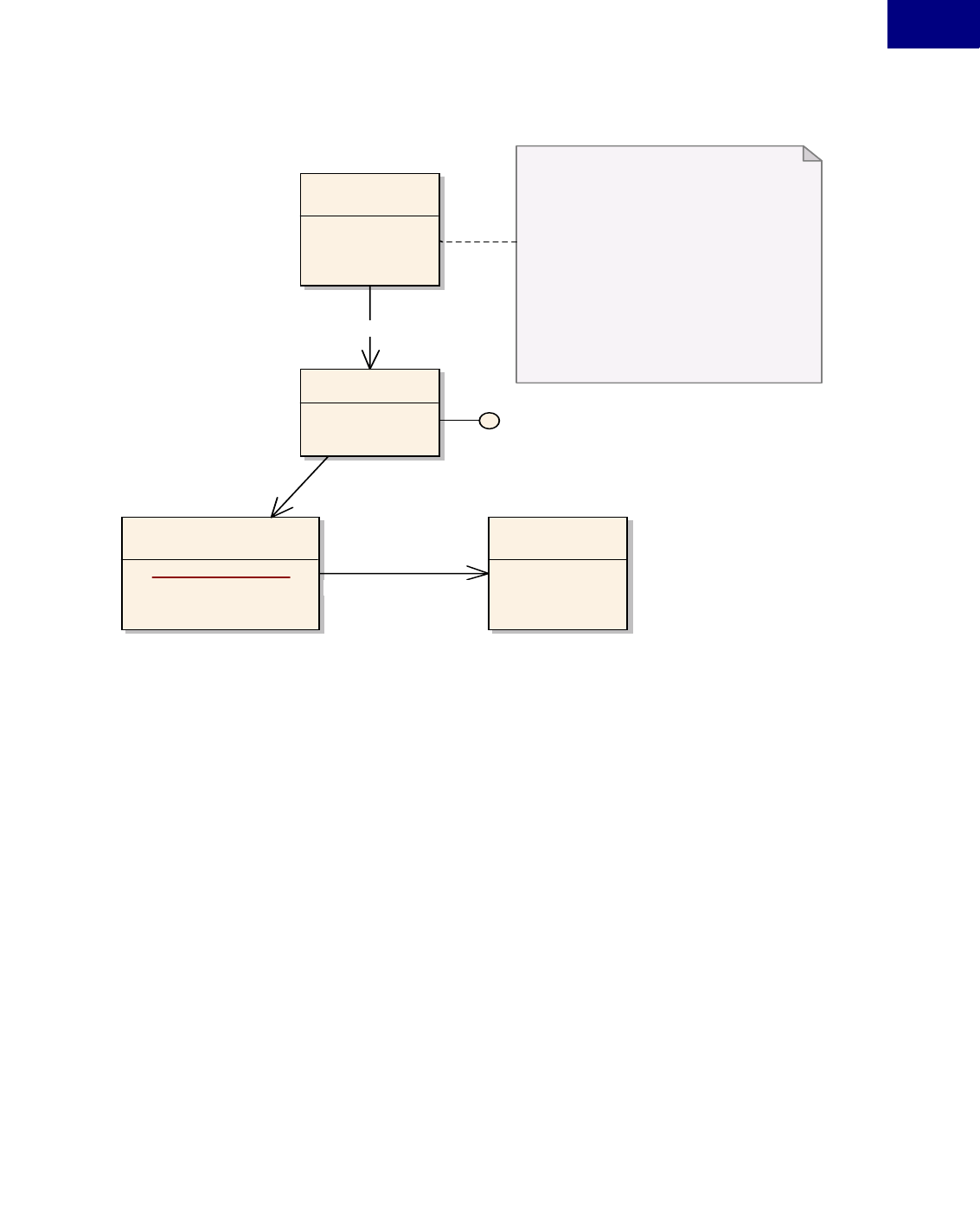
Text Fundamentals 393
Text Fundamentals
Fonts
FIGURE 191 How fonts persist in a document
A font persists as a name, contained within a persistent implementation of IFontFamily. Access
to these persistent objects is provided through the (session or document) workspace. IFont-
Family::QueryFace requests the font from the font manager. If the returned IPMFont is non-
nil, IPMFont::FontStatus can be used to determine the validity of the font.
A set of text within a story is associated with a particular font using standard text attributes.
The text attributes that refer to the font in which text appears are as follows:
zkTextAttrFontUIDBoss — ITextAttrUID gives the UID of the font family.
zkTextAttrFontStyleBoss — ITextAttrFont gives the name of the stylistic variant.
zkTextAttrPointSizeBoss — ITextAttrRealNumber gives the point size used.
The font family, along with the style of the font, identifies a particular font (IPMFont). The
point size of the text is used to provide an instance of the font (IFontInstance).
Text attributes are introduced and described fully in “Text formatting” on page 324.
The used-font list
The used-font list (IUsedFontList) on a document (kDocBoss) details the fonts associated with
story text. The used-font list does not include the fonts used in features that are not intended to
be viewed or printed as part of a story (for example, text that exists in notes).
«interface»
IDocFontMgr
kFontGroupBoss
IFontFamily
«interface»
IFontFamily
+ FontName: PMString
«interface»
IPMFont
IDocFontMgr exists on the session or document
workspace. e set of default fonts inherited by
new documents is maintained in IDocFontMgr
on the session workspace. e set of fonts used
by a document is maintained on the document
workspace.
Note that the fonts used by visible text in all
stories are identied by IDocFontMgr. Fonts
used in placed assets (EPS or PDF) and fonts used
in non-visible text in stories (such as with notes)
are not maintained on IDocFontMgr.
1
GetNthFontGroupUID
m..*
1
QueryFace
1..*
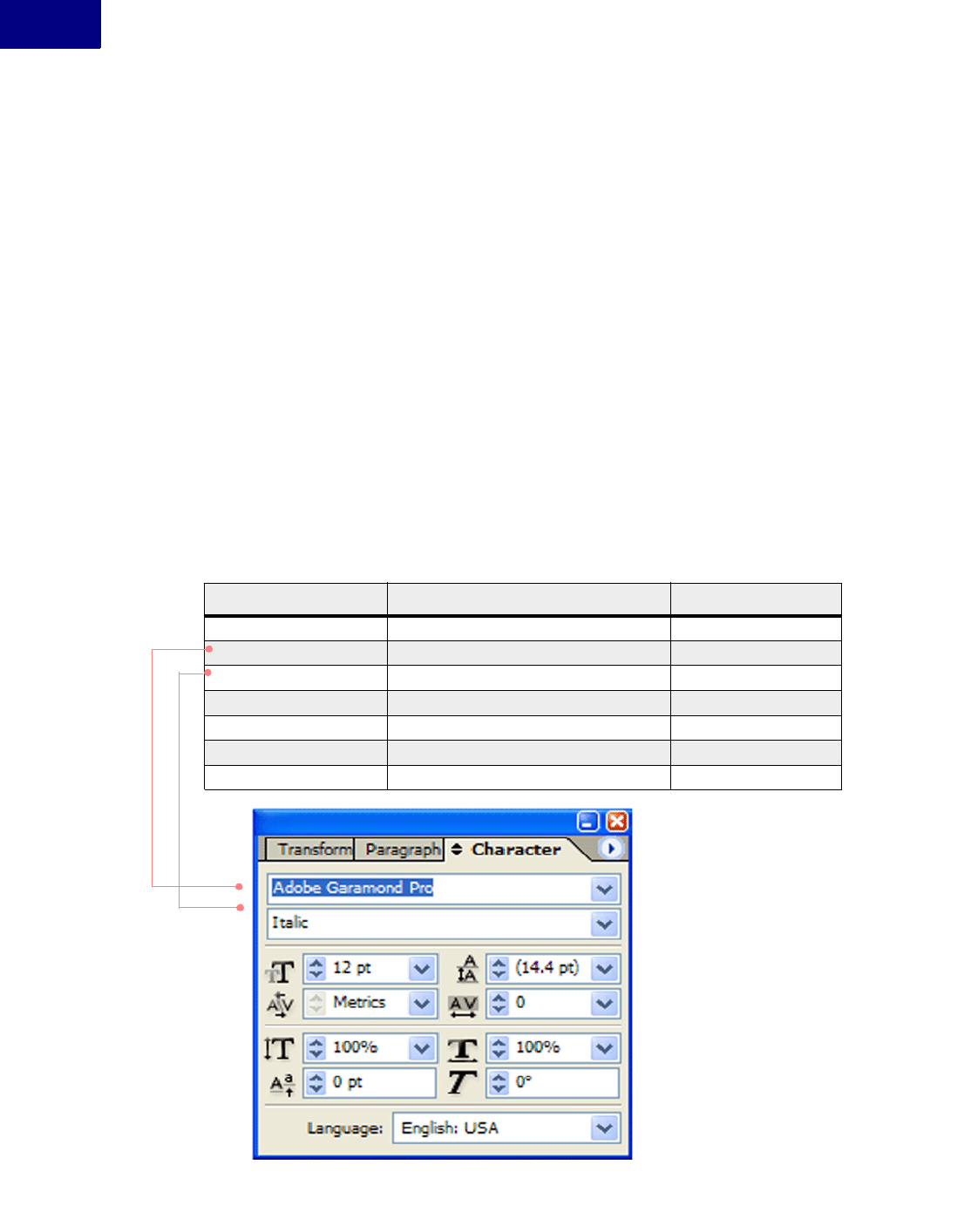
Text Fundamentals
Fonts
394
Fonts in placed assets
Placed (EPS or PDF) assets support the IFontNames interface. This interface reports the fonts
used for the particular asset, including whether the asset depends on the presence of fonts on
the system. Placed assets are maintained in the native asset’s format (PDF or EPS), with the
IFontNames interface providing access to information within the asset.
Document font use
A utility interface (IDocumentFontUsage) on the document (kDocBoss) provides a facade over
the two interfaces introduced above (IUsedFontList and IFontNames).
Font naming
Internally, application code uses PostScript font names. For example, IPMFont::AppendFont-
Name returns the PostScript font name. If you know the PostScript name of the font you want,
you can get the associated IPMFont using IFontMgr::QueryFont. Several other names are
available on IPMFont and IFontFamily. For example, if you use IFontMgr::QueryFont to
instantiate the PostScript font AGaramond-Italic, IPMFont gives you the names shown in the
table in Figure 192.
FIGURE 192 Font names
Name Method Example
PostScript font name IPMFont::AppendFontName AGaramond-Italic
Family name IPMFont::AppendFamilyName Adobe Garamond
Style name IPMFont::AppendStyleName Italic
IPMFont::AppendFullName Adobe Garamond Italic
IPMFont::AppendFamilyNameNative Adobe Garamond
IPMFont::AppendStyleNameNative Italic
IPMFont::AppendFullNameNative Adobe Garamond Italic

Text Fundamentals 395
Text Fundamentals
Fonts
Notice the typeface name Adobe Garamond Pro in the panel in Figure 192 does not match the
family name in the table. This is because ITextUtils::GetDisplayFontNames supplies the plat-
form-specific name in the Character panel. If you do not have the PostScript font name but
know the name of the typeface on a given platform (the typeface name in Windows or the fam-
ily name in Mac OS), IFontMgr::QueryFontPlatform returns the corresponding IPMFont.
Font warnings
The IDocumentFontUsage interface (on kDocBoss) manages used-font and missing-font
information for text in stories of a document. The IDocumentFontUsage interface does not
detail fonts used by features that rely on the application text model but are not rendered as part
of the document (for example, notes).
The IMissingFontSignalData interface provides data sent with the missing-font signal (of
which responders of type kMissingFontSignalResponderService are notified).
The IFontUseWarningManager interface can be called to check a particular font and possibly
warn the user about restrictions. Examples are restrictions based on user preferences or
because a font is a bitmap.
Composite fonts and international-font issues
Some languages too many glyphs to be contained in a font; for example, Japanese contains
about 50,000. To accommodate this, font developers create fonts with subsets of glyphs. Also,
there is a desire within typography to replace some glyphs with others to achieve a certain
visual effect. And users might want to shift the position of Roman glyphs relative to the base-
line or enlarge or reduce the size of glyphs. See Figure 193.
FIGURE 193 Japanese and Roman typography metrics
The ICompositeFont interface creates a new font composed of base fonts and provides for size
and positioning adjustments. Font switching is based on Unicode values. The base font must be
a Chinese, Japanese, or Korean font. For examples of using ICompositeFont, see the SnpPer-
formCompFont code snippet. An application can get this interface using any of the following:
zIStyleNameTable (from the active workspace or document workspace)
zInterfacePtr<IStyleNameTable> compFontList(workspace, IID_ICOMPOSITEFONTLIST)
zInterfacePtr<ICompositeFont> rootTable(docDatabase, compFontList-> GetRoot-
StyleUID(), IID_ICOMPOSITEFONT)
Em-box top
Em-box center
Em-box bottom
Ascent
Descent
Baseline
Japanese Roman
ICF box top
ICF box bottom

Text Fundamentals
Fonts
396
Use the ICompositeFontMgr interface to manage composite fonts. For examples of its use, see
the SDK code snippet SnpPerformCompFont.
The IFontMetricsTable interface obtains the correct tsume values (similar to side bearings on
glyphs) around either the top and bottom or left and right of glyphs from the document origi-
nator and caches them. Later users (who might have only bitmaps of the fonts used to create
the document) can use the tsume metrics saved in the document through this interface.

Tables 397
Tables
Concepts
Tables
This chapter describes concepts and architecture related to the table feature of InDesign.
Table attributes are boss classes with ITableAttrReport implementation; they are discussed in
“Table attributes” on page 407. Table and cell styles define a collection of table attributes that
are appropriate for tables or cells. They can be applied to individual tables and cells. See “Table
and cell styles” on page 409.
For information on how to work with table models and APIs, see the “Tables” chapter of Adobe
InDesign CS4 Solutions.
Concepts
Table structure
Tables in InDesign publications consist of rows, columns, and cells. Cells can span multiple
rows or columns, as in the HTML 4 table model, which evolved from the CALS SGML table
model.
There are helper classes in the InDesign API that are used to specify location, dimension of
cells, and areas within tables. The abstractions used to specify these are shown in Figure 194.
For this example, the resolution of the underlying grid is 4 (rows) by 3 (columns). Cells can
consist of merged elements on this underlying grid.
FIGURE 194 Table-structure example
GridAddress(0,0) GridSpan(1,3)
GridAddress(1,0) GridSpan(1,3)
GridAddress(2,0) GridSpan (1,2) GridAddress(2,2)
GridSpan(1,1)
GridAddress (3,0)
GridSpan(1,1)
GridAddress(3,1)
GridSpan(1,1)
GridAddress(3,2)
GridSpan(1,1)
Whole table:
GridArea(0,0,4,3)

Tables
Concepts
398
Anchor cells versus grid elements
The top-left of a cell is its anchor.
A grid element is a unit on the underlying grid. Grid elements may or may not be anchor cells.
A cell can comprise multiple elements on the underlying grid, but there is at most one anchor
point per cell.
To access the text content of a cell, some API methods require a GridAddress that refers to an
anchor, whereas other methods can work with a grid element that is not necessarily an anchor.
GridAddress
The API helper class GridAddress identifies the location of cells within tables. GridAddress
and the other GridXXX classes are defined in TableTypes.h. In InDesign, GridCoord is an alias
for the primitive type int32. The non-default constructor for GridAddress is as follows:
GridAddress(GridCoord row, GridCoord column)
where row and column are the row and column, respectively, in which the top-left of the cell is
located.
Another key concept is the underlying grid on which measurements are made, consisting of
grid elements.
For example, if a cell is split by a vertical line, this increases the resolution of the grid in the
horizontal direction. The resolution of the grid in a given direction is determined by projecting
all cell boundaries onto an axis in that direction. Adding another vertical line means an addi-
tional projection onto the horizontal axis; i.e., an increase in horizontal grid resolution.
The grid lines are not uniformly distributed. The grid is rectilinear.
Determining what row a particular cell is in can become quite complex in a table with many
split and merged cells; that is, tables with many nontrivial GridSpan values. The algorithm to
determine the GridAddress for a particular cell is straightforward:
1. Determine the resolution of the underlying grid. For the horizontal direction, this can be
calculated by projecting all vertical edges to the x-axis (top of the table). Similarly, for the
vertical direction, project all horizontal edges to the y-axis (left of the table).
2. Calculate the coordinates on this grid. The process is shown in Figure 195. The underlying
grid is just fine enough so there are no cell edges that do not lie on an edge in this underly-
ing grid. In the figure, the GridAddress of the red cell is (8, 9). The table has an underlying
grid 12 rows wide and 11 columns high.
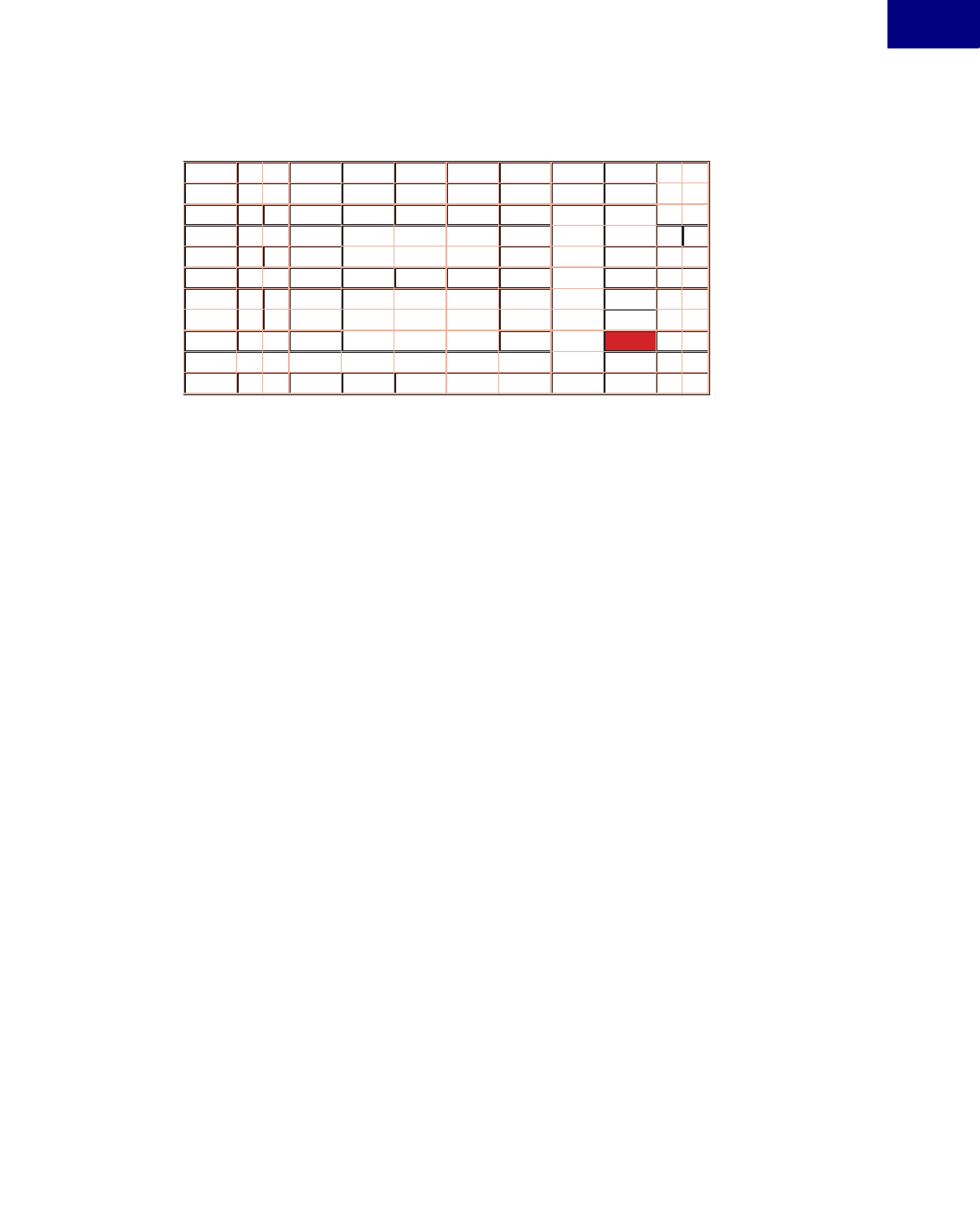
Tables 399
Tables
Concepts
FIGURE 195 Complex table and underlying grid
The GridAddress of a cell can change even if its physical location does not change.
GridSpan
GridSpan is a class that represents the dimension of an area within a table, expressed as cover-
age of elements in the notional underlying grid. GridSpan has a constructor with two argu-
ments:
GridSpan(int32 height, int32 width)
where height and columns are the numbers of rows and columns spanned, respectively (on the
underlying grid).
When a table is created (e.g., using the Insert Table menu command), each cell in the table has
the trivial GridSpan(1,1). The concept of GridSpan is illustrated in Figure 194, which shows the
GridSpan for several cell configurations
The GridSpan of a given cell can change as more cells are added to a table—for example, by a
cell being split vertically in a column that this cell spans—even if the physical dimension of the
cell of interest does not vary. GridSpan for a cell is affected by changes in the columns spanned
by a cell and the rows spanned by a cell.
Merging a pair of cells with trivial GridSpan(1,1) gives one cell with a GridSpan(2,1) if the cells
are merged vertically and GridSpan(1,2) if the cells are merged horizontally.
Cells may be unmerged by selecting any merged cells—even the whole table—and choosing
Unmerge Cells.
Splitting a cell with GridSpan(2,1) in the vertical direction gives two cells with trivial Grid-
Span(1,1). Splitting the cell horizontally leads to the GridSpan of other cells in the table being
recalculated.
0
1
2
3
4
5
6
7
0123456788,9

Tables
Concepts
400
GridArea
The GridArea class is used to specify a region within a table. Like GridSpan and GridAddress,
GridArea is calculated on the underlying grid. GridArea has a constructor with four argu-
ments:
GridArea(GridCoord topRow, GridCoord leftColumn, GridCoord bottomRow, GridCoord
rightColumn)
where:
ztopRow is the row coordinate for the top-left of area.
zleftColumn is the column coordinate for the top-left of area.
zbottomRow is one greater than the lowest row contained in the area; i.e., the row immedi-
ately below the given area and outside it.
zrightColumn is one greater than the rightmost column contained in this area; i.e., the col-
umn immediately to the right of the given area and outside it.
The choice of using one greater than the last row or column allows for specifying an empty area
in a simple way. That is, an empty GridArea can be specified by writing GridArea(0,0,0,0), for
example.
Alternately, given the definition of GridArea, it is equivalent to the following:
GridArea(top, left, row-span, column-span)
Table and cell selection
You can select a whole table or cells within a table, allowing the selected cells to be deleted or
their properties to be altered as a block. Alternately, you can select text within a table cell,
allowing the text properties to be specified for this text run. This is shown in Figure 196 and
Figure 197.
FIGURE 196 Table cells selected
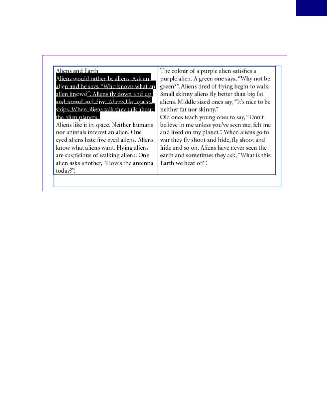
Tables 401
Tables
Concepts
FIGURE 197 Table text selected
The selection manager hides the detail of the particular selection type involved from client
code. The intent is that client code interact with the table model only indirectly, through the
integrator suite interfaces, which present a uniform facade to client code. When the cursor is
within a table cell, InDesign can perform operations for any of the three selection types: text
selection, cell selection, and table selection.
Some operations are possible only with table cells selected; for example, the Merge Cells com-
mand is enabled only when multiple table cells are selected.
Table composition
Typically, a table is associated with a text frame. One text frame can contain multiple tables.
The table composer flows the row content of tables between table frames. Once a table becomes
too deep for the containing text frame, rows from the table may be flowed to another text
frame, if there is one linked to the current table’s text frame. Only whole rows are flowed by the
table composer.
Text composition within a table cell uses the same text-composition engines that operates over
normal text (i.e., text outside tables). For more information on text composition, see the “Text
Fundamentals” chapter.
A text frame that contains one or more table rows that are too deep to display is marked as
overset. The overset rows can be flowed to another text frame by linking the frames, exactly as
for overset text. The visual indicator for table cell overset is drawn as a text adornment.
Tables can be wider than the containing text frame; table rows, on the other hand, flow between
linked cells, or the frame is marked as overset.

Tables
Design and architecture
402
Table region
A table can be viewed as composed of regions: header rows, footer rows, left column, right col-
umn, and body rows. When inserting a table, headers and footers can be specified in the Insert
Table dialog box. A table style can set different cell styles for each region.
Design and architecture
Table model versus text model
Text-model extensions for tables
The basic text model API is extended to accommodate tables. kTextStoryBoss aggregates inter-
faces to support the abstraction of text-story threads, which are spans of characters that repre-
sent the text content of one cell. The text-story thread interface (ITextStoryThread) is
aggregated on the kTextStoryBoss class, which is used to represent the main text flow within a
story designated as the primary story thread.
Many higher-level APIs make it possible to manipulate the content of text cells without having
to manipulate the underlying text model directly. The essential API for this is the ITableText-
Content interface, which is aggregated on the kTableModelBoss class. This provides a mecha-
nism to get and set table text in chunks.
How tables are connected to text
The kTextStoryBoss boss class is the fundamental class that represents the textual content of
stories. For more information, see the “Text Fundamentals” chapter.
A story can contain zero or more tables. Tables can be nested within tables to an arbitrary
depth. The text-model interface (ITextModel) is the fundamental API to interact with stories;
for every table, there is an embedding story. An ITextModel interface can be used to obtain the
text-cell contents. The UML diagram in Figure 198 is a graphical representation of the relation-
ship between the story and table models. It shows other key abstractions, such as the table-
model list and the TextStoryThreadDictHier.
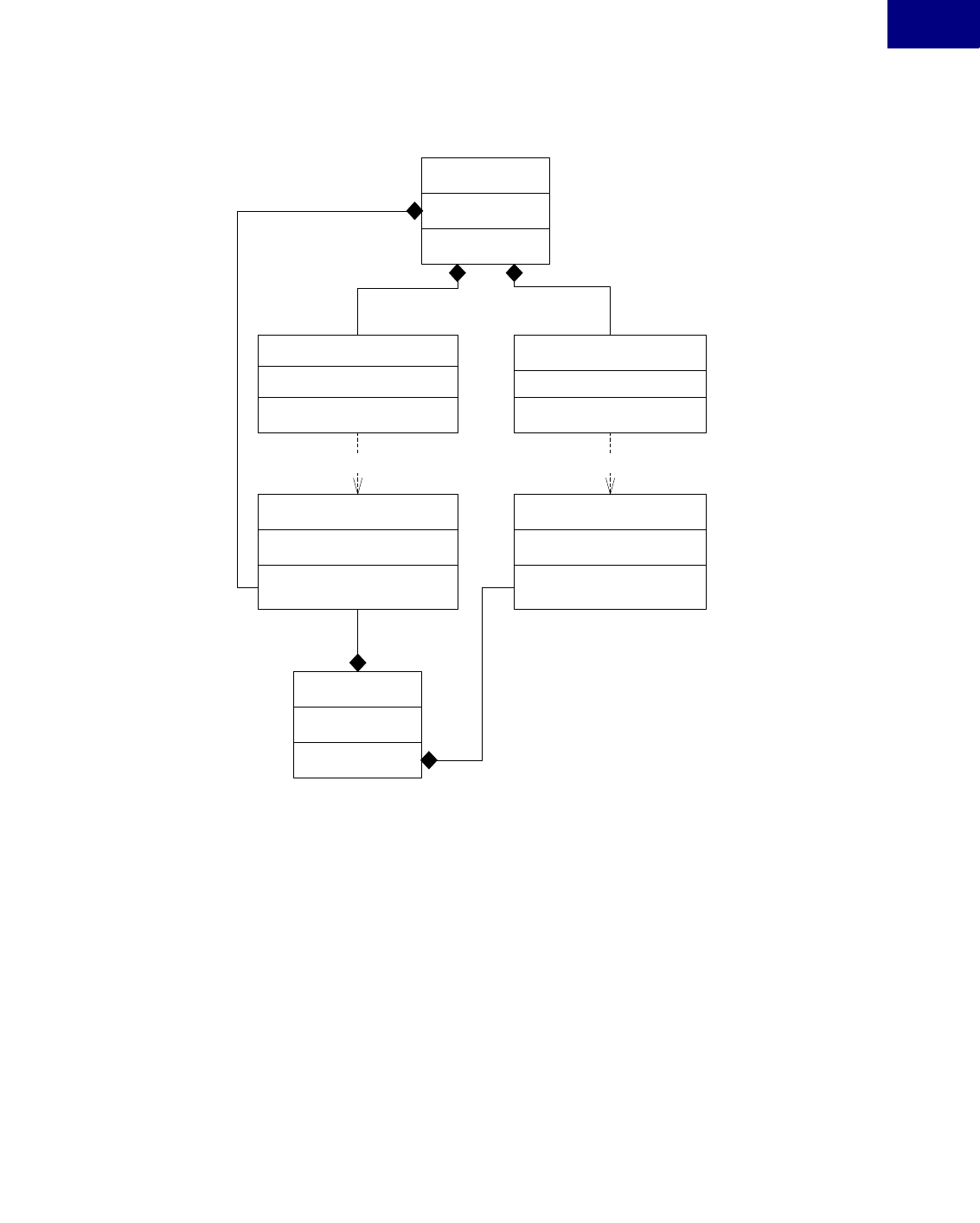
Tables 403
Tables
Design and architecture
FIGURE 198 Relation between story and table models
Text and tables are connected in two ways:
zThrough the table-model list (ITableModelList, aggregated on kTextStoryBoss). This is rela-
tively straightforward to understand, but it may be deprecated in future versions of the API.
zThrough ITextStoryThreadDictHier. This is more complex to understand, but it represents
the new architecture and will be a more dependable API moving forward.
Obtaining a reference to ITableModel through the table model list meant making a series of
API calls by client code to navigate the table architecture. The alternative scheme to obtain a
reference to an ITableModel has a starting point of an ITextModel interface on a kTextStory-
Boss object. The difference is that there is no dependence on ITableModelList.
Another API that allows connections between tables and text to be explored is ITableTextCon-
tainer. Given a table, ITableTextContainer allows client code to determine the embedding text
model. This interface is aggregated on kTableModelBoss.
KTextStoryBoss
text::ITextStoryThreadDictHier table::ITableModelList
table::ITableModeltext::ITextStoryThreadDict
kTableModelBoss
Manages collection Manages collection
1
1
1
1
11
11
1
1
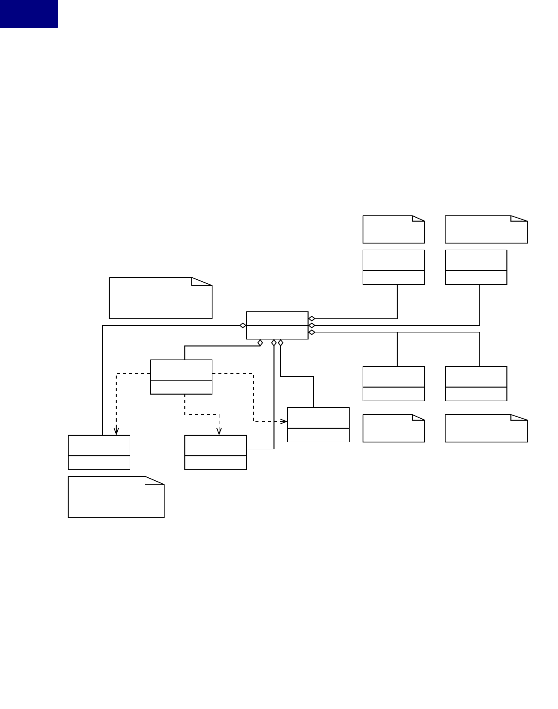
Tables
Design and architecture
404
Table data model
A key abstraction in the table model is the kTableModelBoss boss class. Among other things,
this class encapsulates the data model for a table, allows iteration over the cells in a table, allows
access and modification of the attributes of a table, and provides access to the text chunks (or
other content) in a table. It provides APIs that enable copy, paste, and deletion of content and
access to the geometry of the table. For some of the key interfaces aggregated on the boss class,
see Figure 199.
FIGURE 199 Interfaces on the kTableModelBoss boss class
NOTE:Plug-in (client) code that uses the API exposed through interfaces aggregated on the
kTableModelBoss class should be written to use the selection suites and facades.
The kTableModelBoss boss class aggregates interfaces like ITableModel. This interface has
methods to obtain table iterators; these can be used to navigate a table or iterate through a spe-
cific GridArea within a table. These are STL-like iterators, supporting both forward and reverse
iteration.
The ITableAttrAccessor and ITableAttrModifier interfaces also are aggregated on kTableMod-
elBoss. These provide detailed queries over the set of table attributes and allow applying over-
rides to table and cell attributes. In practice, most of the capability required for client code to
Access to text in cells Information about text flow in
which table is anchored
Read-only access to
the geometry
Core of the table model subsystem;
table structure, copy/paste, content
boss, and text content manager
access
ITableCommands encapsulates change
to the model in a command sequence
and provides undo/redo services to
client code.
kTableModelBoss
<<interface>>
ITableAttrAccessor
<<interface>>
ITableCommands
<<interface>>
ITableModel
<<interface>>
ITableAttrModifier
<<interface>>
ITableGeometry
<<interface>>
ITableLayout
<<interface>>
ITableTextContent
<<interface>>
ITableTextContainer
ITableLayout is responsible for
mapping the model to the
composed state.
<<use> <<use>
<<use>

Tables 405
Tables
Design and architecture
query attributes and apply overrides is provided by the more convenient suite interface, ITable-
Suite. ITableAttrModifier is not likely to be used directly by client code; all the capabilities
exposed by this interface are available through methods on ITableCommands, which wrap
changes to the document object model in a command sequence in a clean and convenient way
for client code to use. Client code should use ITableCommands (rather than ITableAttrModi-
fier). See the API Reference for details of the interfaces aggregated on kTableModelBoss.
The ITableTextContent interface is aggregated on kTableModelBoss; this allows the text con-
tained within cells to be accessed. Do not confuse this interface with ITableTextContainer,
which is a fundamental API that represents the connection between a table and the story
(kTextStoryBoss) within which it is embedded.
The kTableModelBoss class represents the data model for an entire table. A table is composed
into a set of table frames (kTableFrameBoss) by the table composer.
<SDK>/source/sdksamples/tablebasics indicates how to acquire a reference to a table model.
This code is in the context of a suite implementation that was added to a concrete-selection
boss class.
Table layout
ITableLayout on kTableModelBoss provides detailed information about the layout of the table.
ITableLayout centralizes the persistent data into one implementation and contains several sub-
classes responsible for maintaining table layout information, like Row (representing the com-
posed state of table-model rows), Frame (mapped to one persistent kTableFrameBoss object),
and Parcel (holding information about IParcel). ITableLayout also provides iterators to access
these layout elements. For example, ITableFrame can be obtained from ITableLayout using the
following snippet:
// Assume that iTableModel is a valid table model interface ptr.
InterfacePtr<ITableLayout> tableLayout(iTableModel , UseDefaultIID());
ITableLayout::frame_iterator frameIter = tableLayout->begin_frame_iterator();
ITableLayout::frame_iterator endFrameIter = tableLayout->end_frame_iterator();
while(frameIter != endFrameIter)
{
InterfacePtr<ITableFrame> tableFrame(frameIter->QueryFrame());
...
}
The ITableLayout::Row subclass represents the partial mapping of a model row to a table frame
(represented by the kTableFrameBoss). For each model row, there is one or more correspond-
ing table layout rows. Each row contains information for each parcel owned by a table cell, like
the GridCoord of the model row it maps and the UID of the table frame with which it is associ-
ated. Each layout row is associated with one table frame.
ITableLayout is responsible for the lifetime management of table frames. Besides containing the
layout rows, the table frame also is responsible for maintaining the link back to the containing
Parcel and associated ParcelList.

Tables
Design and architecture
406
Table frames
The rows in a table may not all fit in one text frame. The table composer groups as many rows
as will fit into the first text frame, the second text frame, and so on. A table with many rows
may be spread across multiple, linked, text frames.
These groups of rows are table frames. Each row is part of one and only one table frame.
A table is divided into one or more table frames, spread across one or more text frames. A table
frame (represented by the kTableFrameBoss boss class) is a collection of rows within a text
frame. There can be multiple table frames within a text frame (if the text frame contains multi-
ple tables), so there are at least as many table frames as text frames.
An occurrence of a table frame leads to its UID for the corresponding kTableFrameBoss object
appearing in the owned item strand.
Tables can have an arbitrary number of table frames, split between linked text frames. If rows
cannot be displayed within the last linked frame in the series, the frame is marked as overset.
For each text frame, there is a corresponding table frame that represents the collection of rows
being displayed within the given text frame.
For each row of a table, there is an occurrence of the kTextChar_Table or
kTextChar_TableContinued character in the text data strand. For more information, see the
“Text Fundamentals” chapter.
Cell data model
Cell-content managers
The table architecture supports having different cell-content managers. In practice, InDesign
has only text cell-content manager (with behavior provided by kTextCellContentMgrBoss) and
a dummy cell-content manager. (Future versions of InDesign may add canonical cell-content
managers for content types like images.) You may add your own types of cell-content manag-
ers. The main responsibility of a cell-content manager is to implement the ICellContentMgr
interface.
A cell-content manager is created during table creation. You can get the cell-content manager
from the table via ITableModel::QueryContentMgr().
Cell contents
Text cells (the only kind in InDesign) have behavior provided by the kTextCellContentBoss
boss class. Instances of this boss class do not store the content directly but provide a convenient
API on top of the table text model to allow its manipulation. It also is possible to quickly and
conveniently manipulate the text content of a cell through the text model. In this case, API
classes like TextIterator can be used to access a range within the text model.
To set cell text, the ITableCommands::SetCellText API method makes it straightforward to
change the cell text at a given GridAddress. The ITableCommands interface is aggregated on
kTableModelBoss.

Tables 407
Tables
Design and architecture
Code snippets like SnpAccessTableContent.cpp show how to work with the APIs to access cell
contents. See also the TableBasics plug-in and the SnpSortTable.cpp code snippet for examples
of accessing and manipulating table text content.
Cell strands
The kCellStrandBoss cell strand provides storage for cell attributes and aggregates an ITa-
bleStrand interface. This abstraction is likely to be hidden from client code and should be
treated as an implementation feature. Higher-level APIs, like ITableAttrAccessor and ITable-
Commands, provide methods to access and modify attributes without having to work at the
lower level of representation of the table strand.
Table attributes
The table architecture supports extensible attributes with inheritance. Attributes can be applied
to an entire table or one or more cells within a table, and there also are a small set of row-spe-
cific and column-specific attributes. As with the text subsystem, attributes are represented by
boss classes. Table-attribute boss classes have names that follow the pattern k<target-
entity>Attr<property>Boss, where <target-entity> is one of Table, Cell, Row, or Column. Some
text-cell-specific attributes have TextCell in the attribute name.
The ITableAttrReport::AppendDescription method reports whether an attribute is a cell-spe-
cific, row-specific, column-specific, or table-specific attribute. To obtain information about the
default value of each attribute, see the API reference documentation.
Table-specific attributes
A table attribute describes one property of an entire table. A table attribute is applied to the
table itself; the attributes collectively define aspects of how the table should appear.
A table attribute is represented by a table attribute boss with a name that conforms to the pat-
tern kTableAttr<property>Boss.
Row attributes
There are only a few row-specific attributes, which apply to a row or collection of rows within
the table. Row attributes are represented by boss classes. For details, see kRowAttrBaseBoss in
the API reference documentation. These are named to follow the pattern kRowAttr<prop-
erty>Boss.
Column attributes
There are very few column-specific attributes. For details, see kColAttrBaseBoss in the API ref-
erence documentation. These are represented by boss classes, which are named to follow the
pattern kColAttr<property>Boss.
Tables
Design and architecture
408
Cell-specific attributes
There are a wide range of cell-specific attributes that can be overridden. These can be divided
into those that apply to an entire cell and those that are specific to one border (bottom, left,
right, top) of the cell. See Figure 200.
FIGURE 200 Examples of cell-specific attributes
This cell has an override (2p) for the bottom
text inset kCellAttrBottomInsetBoss
This cell has an override for the bottom stroke
color kCellAttrBottomStrokeColorBoss
This cell has an override for the bottom tint
kCellAttrBottomStrokeTintBoss
This cell has an override (4 pt) for the bottom stroke
weight kCellAttrBottomStrokeWeightBoss
This cell has no overrides.
This cell has an override
for the rotation (90 deg.)
kCellAttrRotationBoss
This cell has an override
for the rotation (270 deg.)
kCellAttrRotationBoss
This cell has an override for the cell fi ll color
kCellAttrFillColorBoss
This cell has an override for a diagonal tint
kCellAttrDiagnolTintBoss
This is a cell that has had its fi rst line
offset set to be fi xed and with contents
clipped to cell kCellAttrClipBoss
This is a cell that has had its fi rst line off-
set set to be fi xed but without contents
clipped to cell kCellAttrClipBoss
This cell has an inline graphic and some
text that fl ows around it. It has a diagonal
in front of the cell contents
kCellAttrDiagnolsOnTopBoss
This cell has an inline graphic and some
text that fl ows around it. It has a diagonal
behind the cell contents
kCellAttrDiagnolsOnTopBoss
.

Tables 409
Tables
Design and architecture
Text-cell-specific attributes
Some cell attributes apply only to text cells. Text cells are the only supported kind of cell in
InDesign, but future versions may support other cell-content types, so text cells are not
generic-cell attributes.
Text-cell attributes are represented by boss classes named to follow the pattern kTextCel-
lAttr<property>Boss.
Default table attributes
The ITableAttributes interface is aggregated on the workspace (kWorkspaceBoss class) and the
document workspace (kDocWorkspaceBoss class), with interface identifier
IID_IDEFAULTTABLEATTRIBUTES.
When a new document is created, this root set of table attributes is applied to the document.
This attribute list is further enhanced when the swatch list is available for the new document,
since some of the attributes reference a swatch (black or none) by UID.
When a new table is created (by kNewTableCmdBoss class, an instance of which is created and
executed through the ITableCommands interface on kTableModelBoss), the root table style is
applied to the table.
Table and cell styles
A style can be considered a collection of attributes. Table and cell styles provide a mechanism
to name and persist a particular set of table attributes.
Table style and cell style are analogous to paragraph style and character style in the text. Each
style has an AttributeBossList list that maintains the set of attributes that apply to that style.
Access to the attributes in a style is achieved through the ITableAttributes interface. Cell styles
are associated with cell-specific attributes; however, table styles can be associated with both
table attributes and cell-specific and other attributes.
Styles form a hierarchy rooted at the root style. Each style (except the root style) is based on a
style. The AttributeBossList list for a particular style records only the differences from the style
on which it is based; that is, the set of attributes the particular style overrides.
As with other types of styles, table and cell styles support the Style Group concept. Users can
create, edit and delete folders (called Groups), in the table styles and cell styles palettes. Style
group is a collection of styles or groups. The user also can nest groups inside groups and drag
styles within the palette to edit the contents of a group. Styles do not need to be inside a group
and can exist at the root level of the palette.
Table styles
A table style is represented by a kTableStyleBoss. Its IStyleInfo stores general, style-related
information like style name and parent style. Its ITableAttributes interface stores a list of table
attributes that are different from its parent.
The root table style (known in the application user interface as [No Table Style]) contains a
complete set of default table attributes. This defines the default look of the table with no further
formatting applied.

Tables
Design and architecture
410
The application also defines a basic table style called [Basic Table]. The basic style cannot be
deleted, but you can change it. Initially, the basic style is based on the root style; however, its
parent style can be changed.
Table styles are accessible through the table-style group manager (signature interface IStyle-
GroupManager with interface identifier IID_ITABLESTYLEGROUPMANAGER) on the doc-
ument (kDocWorkspaceBoss) and session (kWorkspaceBoss) workspace boss classes. When a
document is created, its style group manager inherits the existing set of styles from the session
workspace.
THe IStyleGroupManager of the table styles works exactly the same way as that of paragraph
and character styles. For details, see the “Text Fundamentals” chapter.
Cell styles
A cell style is represented by a kCellStyleBoss. Its IStyleInfo store general, style-related infor-
mation like style name and parent style. Its ITableAttributes interface (with implementation
kCellStyleCellAttributeListImpl) stores a list of cell-specific attributes that are different from its
parent cell style.
The root cell style (known in the application user interface as [None]) is really nothing; in fact,
it defines nothing. It is synonymous with the root character style. The root cell style cannot be
deleted.
Cell styles are accessible through the cell-style group manager (signature interface IStyle-
GroupManager with interface identifier IID_ICELLSTYLEGROUPMANAGER) on the docu-
ment (kDocWorkspaceBoss) and session (kWorkspaceBoss) workspace boss classes. When a
document is created, its style group manager inherits the existing set of styles from the session
workspace.
As with table styles, the IStyleGroupManager of the cell styles works the same way as that of
paragraph and character styles. For details, see the “Text Fundamentals” chapter.
Regional cell styles
Each table style can assign different cell styles for different regions: headers rows, footers rows,
first column, last column, and body rows. When a table style is applied to a table, these regional
cell styles are applied to the appropriate regions.
Regional cell styles are considered as table attributes of a table style. Except for body rows, the
values of two related attributes, “cell style” and “use body,” determine a regional style. See
Table 97.

Tables 411
Tables
Design and architecture
TABLE 97 Regions and their controlling attributes
To set a regional cell style, you need to create and apply an appropriate “cell style” attribute as
well as create and apply an appropriate “use body” attribute (except for body rows). To get a
regional cell style, you need to look for these attributes at the complete list of attributes. For
more information, see the “Tables” chapter of Adobe InDesign CS4 Solutions.
Table and cell style in the data model
Figure 201 illustrates a simplified class diagram of table styles, cell styles, and their relation-
ships to application/document workspaces and the table model. The descriptions of the boss
classes give hints to navigate through these related classes.
Region Cell-style attribute boss Use body attribute boss
Body rows kTableAttrBodyCellStyleBoss kInvalidClass
Header rows kTableAttrHeaderCellStyleBoss kTableAttrHeaderUseBodyCellStyleBoss
Footer rows kTableAttrFooterCellStyleBoss kTableAttrFooterUseBodyCellStyleBoss
Left column kTableAttrLeftColCellStyleBoss kTableAttrLeftColUseBodyCellStyleBoss
Right column kTableAttrRightColCellStyleBoss kTableAttrRightColUseBodyCellStyleBoss
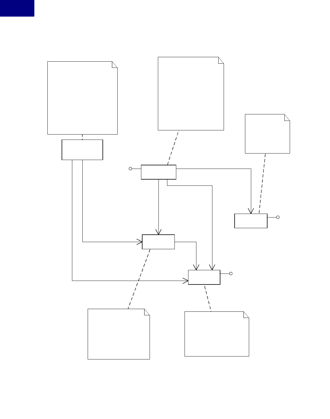
Tables
Design and architecture
412
FIGURE 201 Table and cell style
«boss»
kTableModelBoss
«boss»
kWorkspaceBoss
kDocWorkspaceBoss
1
1
ITableAttrModifier::GetTableStyle()
Represents
individual cell.
Its ITableStrand
stores cell attribute
overrides.
The application or document
preferences.
The workspace stores table
styles and cell styles. They
are accessible through
IStyleGroupManager interface
using interface identifier
IID_ITABLESTYLEGROUPMANAGER
and
IID_ITABLESTYLEGROUPMANAGER
respectviely.
1
1..*
ITableModelStorage::QueryNthStrand()
«struct»
kTableStyleBoss
The table style.
It can define different cell
style for different region.
They are defined as attributes
of the table style, thus need
to query appropriate Boss
class to get the regional style.
1
1..*
IStyleGroupManager::FindByName()
The table.
Table's own ITableAttributes
stores local overrides of table
attribute.
It's ITableAttrModifier interface
has access to the table style
applied.
Its ITableAttrAccess encapsulate
the access to applied cell style
for individual cell.
«boss»
kCellStrandBoss
«struct»
kCellStyleBoss
1
1..*
ITableAttrAccessor::GetCellStyle
1
1..*
ITableAttributes::QueryByClassID()
1
1..*
IStyleGroupManager::FindByName()
ITableAttributes
ITableStrand
ITableAttributes
The cell style.
Its ITableAttribute interface
stores the cell specific attribute
of the cell style, includes the
default paragraph style.

Tables 413
Tables
Design and architecture
Formatting tables, cells, and table text
Formatting a table
Tables are formatted according to table-specific attributes. Every table is assigned a table style.
ITableAttributes, aggregated on kTableModelBoss, provides coarse-grained access to the locally
overridden attribute list for a particular table. For a given attribute (such as table stroke), InDe-
sign follows these steps to format a table:
1. If there is a local override, format the table according to the override.
2. Otherwise, check the attributes in the table style of the table. If the attribute is among those
attributes defined in ITableAttributes of kTableStyleBoss, format the table according to the
value of the attribute defined in the table style.
3. Otherwise, check the table style’s parent style, until either the attribute is found or the root
table style (which defines all default attributes) is reached. Format the table according the
value of the attribute.
Formatting a cell
Cells are formatted according to cell-specific attributes, similar to tables. For a given cell
attribute, InDesign follows these steps to format a cell:
1. If there is a local override, format the cell according to the override (which is defined in ITa-
bleStrand on kCellStrandBoss).
2. Otherwise, check the attribute against the attribute list of the cell style applied to the cell. To
determine the cell style, check if a cell-style override is applied. If so, use the cell style; oth-
erwise, use the regional cell style defined in the table style of the table.
3. As with table styles, if the attribute is among the attributes defined in ITableAttributes of
kCellStyleBoss, format the cell according to the value of the attribute defined in the cell
style. Otherwise, check the cell style’s parent style, until either the attribute is found or the
root cell style (where nothing is defined) is reached. Format the cell according to the value
of the attribute or leave it as the default format.
Formatting text in a cell
It is helpful to view table attributes as equivalent to paragraph-level attributes for normal text,
and cell attributes as equivalent to character-level attributes. The analogy holds insofar as the
effective attributes are calculated by applying the following in the order listed below:
zTable-style attributes
zTable-level overrides
zRow or column cell style
zCell overrides
zThe paragraph style defined by the cell
zParagraph override

Tables
Essential APIs
414
zCharacter style
zCharacter overrides
To format a character in a table cell, InDesign looks at the reverse of the order above. An over-
ride always takes priority than a style; a smaller range style always takes priority over a coarse
one.
TABLE 98 Text-formatting priorities
A cell style can have a paragraph style used in the paragraphs of a cell to which the cell style is
applied. If a cell style does not have a paragraph style defined, any cell that has that cell style
applied to it will have all paragraph-style formatting removed.
Essential APIs
Table commands
ITableCommands is an interface that is aggregated by kTableModelBoss and provides methods
to create and execute table-related commands, instead of having to manipulate the table model
at a lower level. You can use ITableCommands to affect the table model on any specific table
area. Some functions in ITableCommands also are provided by ITableSuite, which instead
operates on the currently selected area of the table. For more details, see ITableCommands in
the API reference documentation.
ITableSuite
ITableSuite is a key API for manipulating tables in client code. It provides much of the required
capability for plug-ins, with the exception of insertion and retrieval of cell content.
The ITableSuite interface is aggregated on the integrator suite boss class (kIntegratorSuiteBoss),
which makes it available through the abstract selection. Implementations of this interface are
provided on various concrete-selection boss classes, which are hidden from client code
through the facade of the abstract selection. To obtain ITableSuite, client code should query the
selection manager (ISelectionManager) for the interface.
Overrides Styles
Character overrides Character styles
Paragraph overrides Paragraph styles
Cell overrides Cell style
Table overrides Table style

Tables 415
Tables
Essential APIs
The integrator suites expose methods that determine whether a capability is present on the cur-
rent selection; this always should be tested before trying to exercise a capability. For more detail
on the integrator suites, see the “Selection” chapter.
Suite interfaces typically use this pattern of checking for a service (capability) and, if the
abstract selection supports the capability, calling the method called. For details, see ITableSuite
in the API reference documentation.
Use is illustrated in the following code:
bool16 canDeleteTable = iTableSuite->CanDeleteTable();
if(canDeleteTable)
{
iTableSuite->DeleteTable();
}
ITableStyleSuite and ITableStylesFacade
ITableStyleSuite is the selection suite used to manipulate table styles, such as creating and edit-
ing table styles of a selected table; applying a table style to the current selection; and getting and
setting local overrides of table attributes. As with other selection suites, the interface can be
acquired through ISelectionManager.
Aggregated on kUtilsBoss, ITablesStylesFacade is used to manipulate table styles on a table or
table style directly. It is the counterpart of ITableStyleSuite.
The ITableAttrAccessor and ITableAttrModifier interfaces aggregated on the kTableModelBoss
provide access to and mutation of table attributes; however, we recommend you use suites and
facades whenever possible.
ICellStyleSuite and ICellStylesFacade
ICellStyleSuite is the selection suite used to manipulate cell styles, like creating and editing the
cell styles of selected cells; applying a cell style to the current cell selection; and getting and set-
ting local overrides of cell attributes.
The facade counterpart of ICellStyleSuite is ICellStylesFacade, aggregated on kUtilsBoss.
By using suites and facade, implementation details of cell strands and cell styles storage are
encapsulated. We recommend you use only suites and facades.

Tables
Essential APIs
416

Printing 417
Printing
Concepts
Printing
This chapter provides information about the concepts surrounding the process of printing a
publication, including the printing data model and commands, the printing user interface, key
interfaces, and how plug-ins can participate in the printing process.
Concepts
Printing is simply drawing to the printer
The implementation and user interface for printing from InDesign and InCopy are similar to
those for printing from other Adobe applications, like Photoshop and Illustrator. All these
applications use a common component, the Adobe Graphics Manager (AGM), to handle the
core printing tasks. Printing from the application entails drawing part or all of a document to a
printer rather than to the screen. Adobe applications use Display PostScript, supplied by AGM,
to draw graphics primitives to both the screen and the printer.
For more information on how document content is drawn to an output device, see the “Graph-
ics Fundamentals” chapter.
Control can be shared
The tasks of printing from InDesign can be shared among the following:
zAGM, which is responsible for PostScript generation.
zThe InDesign Print plug-in, which is responsible for the user interface, initialization of
print settings, and drawing pages. (See “The print action sequence” on page 421.)
zPlug-ins that implement various print-related extension patterns, which provide the ability
to participate in the printing process carried out by the Print plug-in
A plug-in can use printing commands, interfaces, structures, and event-handling mechanisms
to print with the C++ API. By understanding the flow of operations in the application’s Print
plug-in, you can design a plug-in to participate in the print process and the print user interface
by hooking onto the various extensibility points.
Third-party plug-in developers do not have direct access to the AGM API. Instead, the applica-
tion provides the user interface, commands, interfaces, and data structures necessary to drive
and participate in the printing process. For details, see “Printing data model” on page 419.
Inks and colors
When printing a document to any output device, the colors used in a printable item on each
page need to be rendered. Depending on the output device and print settings, each color can be
separated into multiple inks. This is done so a system like a four-color (CMYK) printing press

Printing
Concepts
418
can render each printable item. In some cases, printable items can contain spot colors, which
generally correspond to a specific ink.
Colors, gradients, and spot colors generally are referred to as swatches. A swatch is identified by
the IRenderingObject interface. Inks are identified by the IPMInkBossData interface.
For more details on inks and colors, see the “Graphics Fundamentals” chapter.
Overprinting
You can specify the way in which inks are printed on top of one another. Depending on how
you set up overprinting, the colors of overlapping items of different colors may appear differ-
ently. For more details on overprinting, see InDesign Help.
Trapping
Trapping allows an output device to compensate for printing problems due to paper misregis-
tration. When the print medium (e.g., paper) is not registered exactly in a multi-color press
system, the output can show unintended gaps between inks. An example of a case in which this
is especially important is when a printable item has a thin, dark border around a lighter-col-
ored shape. By specifying how trapping is set up, you can compensate for media-registration
errors.
Color management and proofing
What you see on the screen may not always be what you see printed on print media. This is due
to variances in how each device used in the design and print process renders colors. For exam-
ple, your computer monitor may show a bright red apple, but when that is printed on paper
using a specific set of inks on a specific output device, the apple may appear to be a different
color or brightness. Colors also may shift in the input device, such as digital scanners and cam-
eras. It can be hard to make sure the colors appear as you want on the print media. InDesign
and InCopy offer features to manage color throughout the design process.
For more details on color management and proofing, see “Color Management” in InDesign
Help and the “Graphics Fundamentals” chapter in this document.
Preflight and packaging
Preflight is a way to verify before you send a publication to the output device that you have all
associated files, fonts, assets (e.g., placed images and PDF files), printer settings, trapping
styles, and so on. For example, if you placed an image as a low-resolution proxy but do not have
the high-resolution original image accessible on your hard disk (or workgroup server), that
may result in an error during the printing process. Preflight checks for this sort of problem.
For details, see the “Implementing Preflight Rules” chapter.

Printing 419
Printing
Printing data model
Exporting to EPS and PDF
Although the user interface for exporting a publication to the EPS and PDF file formats is dif-
ferent from that for printing, the output processes incorporate the same types of drawing com-
ponents (AGM, inks and color swatches, color management, etc.). Some publishing workflows
may incorporate exporting to EPS or PDF as part of the proofing and output steps. Though this
document does not go into the details of extending the EPS and PDF export capabilities of the
application, you can refer to “Exporting to EPS and PDF” on page 450 for some highlights of
how to drive the EPS and PDF export features.
Printing data model
This section describes the printing data model, commands, interfaces, and structures available
in the SDK. InDesign and InCopy can print documents and books to a registered output
device. The registered output device can be a printer, PostScript file, or external file format like
EPS or PDF.
For more information on the PostScript language, see the PostScript Language Reference at
http://www.adobe.com/products/postscript/pdfs/PLRM.pdf.
Print settings
This section describes the data interfaces that make up the print-settings data model. For infor-
mation on bosses that aggregate these interfaces, see the API reference documentation. The
print settings generally are set by the user in either the Print or Print Presets dialog box. (For
more information on the Print user interface, see “Print user interface” on page 423.)
IPrintData
IPrintData is the main data interface that keeps most print-settings data. It also is the interface
passed among the print commands during a print operation or in the Print or Print Presets dia-
log box.
Other interfaces that store print settings
zIPrintDeviceInfo stores data about printing devices.
zIPrintJobData stores data specific to a print job.
zIPrintContentPrefs specifies which content (e.g., text, page items, Japanese layout grids, or
frame grids) should be printed or omitted from printing.
zIOutputPages stores data about pages or spreads to print.
zITrapStyle stores a set of trap settings with a specified name.
zIPrintGlyphThresholdPref specifies whether all glyphs of a font are to be downloaded to the
output device completely or subsetted.

Printing
Utility APIs
420
Print preset styles
A print preset style is a group of print settings with a specified name. Of the print-settings data
model interfaces, the IPrintData and IPrintDeviceInfo data interfaces are stored as part of a
print-preset style. A print-preset style is represented by kPrStStyleBoss, and a list of defined
print-preset-style boss instances is managed in the kWorkspaceBoss using the IPrStStyleList-
Mgr interface. kPrStStyleBoss also aggregates IGenStyleLockInfo, which specifies whether the
style is locked or can be deleted.
When a list of print-preset settings is exported to a file (database), the root of that database is
an instance of kPrStExportRootBoss, which also aggregates IPrStStyleListMgr. Using this
IPrStStyleListMgr interface, you can iterate through the print-preset styles that are stored in the
exported file.
Trap styles
A trap style is a set of trap settings with a specified name. A trap style is represented by kTrap-
StyleBoss and aggregates the ITrapStyle interface. kTrapStyleBoss also aggregates IGenStyle-
LockInfo, which specifies whether the style is locked or can be deleted. A trap style is
associated with an individual page in a document.
A list of trap styles is accessible from ITrapStyleListMgr on kDocWorkspaceBoss (the trap
styles used on a document), kWorkspaceBoss (the workspace default trap styles), and kBook-
Boss (the trap styles used in a book).
NOTE:ITrapStyleListMgr does not inherit from IGenStlEdtListMgr like IPrStStyleListMgr
does; therefore, the behavior of some ITrapStyleListMgr methods differs from that of
any interfaces derived from IGenStlEdtListMgr, and the general style-editing family of
APIs (commands like kGenStlEdtExportStylesCmdBoss and interfaces like
IGenericSettings) do not apply to trap styles managed in ITrapStyleListMgr.
Utility APIs
The following utility interfaces are available to facilitate the management and manipulation of
print data settings:
zIPrintUtils (kUtilsBoss) contains various methods for checking settings on IPrintData.
IPrintUtils also has InitializeOutputPages, a method that fills a list of pages to output, given
IPrintData and a document.
zITrapStyleUtils (kUtilsBoss) contains methods to facilitate manipulation of trap styles.
For details, see the API reference documentation.

Printing 421
Printing
The print action sequence
The print action sequence
When you print a document or book in InDesign or InCopy, the application processes a hierar-
chy of commands. This is the core feature provided by the Print plug-in. This section discusses
the sequence of events that take place during the print process and explains the various extensi-
bility points for third-party plug-ins.
The primary actions taken by the Print plug-in are as follows:
1. Client code (usually in the form of a menu action or script event) receives two pieces of
information: IDocument for the document to be printed and a user-interface options flag
indicating which parts of the print user interface should be displayed. The client code cre-
ates and executes a specific print-action command, which is one of the following:
zkPrintActionCmdBoss — for printing a document in InDesign.
zkBookPrintActionCmdBoss — for printing a book in InDesign.
zkInCopyPrintActionCmdBoss — for printing a document in InCopy.
NOTE:For brief descriptions of these commands, see “Print-action and supporting
commands” on page 448.
2. From within the print-action command, a series of supporting print commands is pro-
cessed. All subsequent steps originate from inside this print-action command.
3. A print-command data interface (IPrintCmdData) used by all print commands gets the
IDocument supplied by the client code, along with the UIDRef for the print style (if any),
the document’s ink list, and trap-style manager.
4. The print-action command polls print-setup providers (service providers of kPrintSetupS-
ervice) to determine whether any plug-in wants to participate in the print process by calling
IPrintSetupProvider::StartPrintPub (for document printing) or IPrintSetupProvider::Start-
PrintBook (for book printing). A print-setup provider can either take over the process at
this point (including aborting the printing process by means of a flag passed in the parame-
ter list) or perform an action and return control to the Print plug-in.
5. If control returns to the Print plug-in, a non-persistent instance of a print-settings data boss
(generally kPrintDataBoss) is created. This is passed around during the rest of the printing
process in each supporting print command.
6. The print-action command polls print-setup providers and calls IPrintSetupPro-
vider::BeforePrintUI. A print-setup provider can determine whether to display the print
user interface before returning control. After all print-setup providers are polled, the user-
interface options flag is examined. If the print user interface is to be shown, the kPrintDia-
logCmdBoss is created and processed. If the dialog box is opened, the user can modify the
settings for this particular print operation. The settings are stored back in the instance of
the print-settings data boss created in the previous step.

Printing
The print action sequence
422
7. The print-action command polls print-setup providers and calls IPrintSetupPro-
vider::AfterPrintUI. A print-setup provider can either take over the process at this point or
perform an action (for example, set the flag indicating whether to show the Save dialog box)
and return control to the Print plug-in. If the Save dialog box is to be shown, the kSaveFile-
DialogBoss is processed.
8. If control returns to the Print plug-in, the print settings data (IPrintData) is saved to the
document by means of processing kPrintSavePrintDataCmdBoss (for documents) or
kBookSavePrintDataCmdBoss (for books).
9. Data is gathered for the print job. kPrintGatherDataCmdBoss is created but not yet pro-
cessed. An instance of IOutputPages is created.
10. The print-action command polls print-setup providers and calls IPrintSetupPro-
vider::BeforePrintGatherCmd. A print-setup provider can determine whether to allow pro-
cessing of the kPrintGatherDataCmdBoss created earlier and whether to return control.
11. If control returns, the print-action command polls print-setup providers and calls IPrint-
SetupProvider::AfterPrintGatherCmd. A print-setup provider can determine whether to
quit here or return control to the Print plug-in.
12. If control returns, a core print command (kNewPrintCmdBoss if running in InDesign or
kInCopyNewPrintCmdBoss if running in InCopy) is created and processed. This is where
the document or book data actually is sent to the output device.
13.If an error occurs during the core print command, it polls print-setup providers and calls
IPrintSetupProvider::PrintErrorEvent. A print-setup provider can handle the print event
and determine whether the error message should be displayed to the user. The global error
code is set, and the core print command is aborted.
14.If no errors occurred in the core print command, the print-action command saves the print
data again (in case it changed during printing).
15. The print process ends. The print-action command polls print-setup providers and calls
IPrintSetupProvider::EndPrint. This is the final opportunity for print-setup providers to
participate in the print process.
Common print interfaces
The following are the data interfaces used during the print-action sequence and supporting
commands:
zIPrintCmdData stores most print settings. IPrintCmdData is used commonly among the
print commands.
zIPrintData stores most print settings data. (See “IPrintData” on page 419.)
zIOutputPages stores data about pages or spreads to print.
zIBookPrintData stores book-printing options for the kBookSavePrintDataCmdBoss.
zIPrintJobData stores data specific to a print job.

Printing 423
Printing
Print user interface
zIPrintDialogCmdData stores data for the kPrintDialogCmdBoss.
zIPrintContentPrefs specifies which content (e.g., text, page items, Japanese layout grids, and
frame grids) should be printed or omitted from printing.
zIInCopyGalleySettingData stores settings used to construct the Galley panel and contains
information about the constructed Galley panel for printing and PDF export in InCopy.
Print user interface
The print user interface lets an end user change print settings during a print process or in print
preset styles. This section describes the design of the Print and Print Presets dialog boxes and
how they are invoked, and it presents an overview of how to extend these dialog boxes.
Print dialog box
The Print dialog box shows the current print settings for the frontmost document. This dialog
box opens when the user chooses File > Print in InDesign or chooses one of the print preset
styles from the File > Print Presets menu. The Print dialog box also opens when the user
chooses Print from the Book panel. This dialog box is invoked programmatically in InDesign
by processing the kPrintDialogCmdBoss command.
NOTE:An InCopy version of the Print dialog box is invoked by processessing the
kInCopyPrintDialogCmdBoss box. This section focuses on the InDesign version of the
Print dialog box.
The Print dialog box is a selectable dialog box, which contains a list of panels that are selectable
by a list (located on the left-hand side of the dialog box). The Print dialog box contains the fol-
lowing panels:
zGeneral
zSetup
zMarks And Bleed
zOutput
zGraphics
zColor Management
zAdvanced
zSummary
The panels are shown in order in the following sections. Below a screen shot of each panel is a
list of methods on the print data-model interfaces (e.g., IPrintData) corresponding to each
user-interface element on the panel.
For details on these settings, see InDesign CS4 Help.
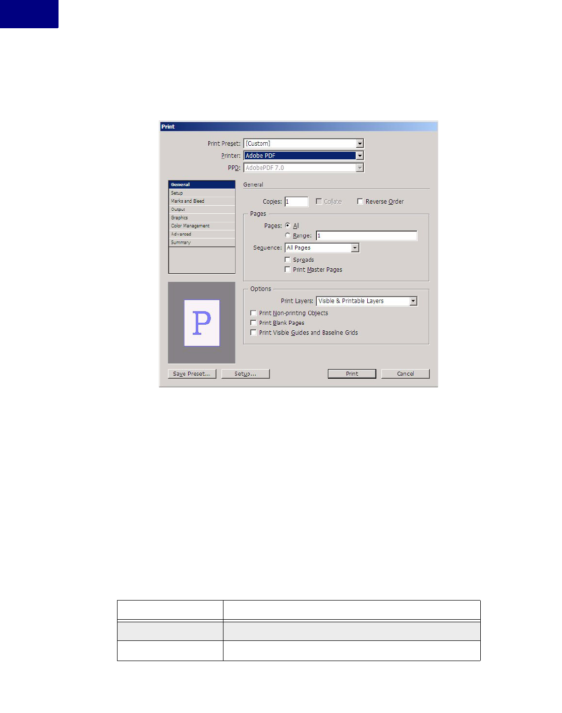
Printing
Print user interface
424
Print dialog box: General panel
FIGURE 202 Print dialog box: General panel
The three user-interface elements above the selectable panel region of the dialog box are com-
mon in all Print dialog box screenshots and are mapped to the following API methods:
zStyle Name — IPrintData::SetStyleName
zPrinter — IPrintDeviceInfo::UpdatePrinterInfo (which calls IPrintData::SetPrinter inter-
nally. Get with IPrintData::GetPrinter.)
zPPD — IPrintDeviceInfo::UpdatePrinterInfo (which calls IPrintData::SetPPDFile and
IPrintData::SetPPDName internally. Get with IPrintData::GetPPDFile and IPrintData::Get-
PPDName.)
NOTE:Generally, there is a corresponding Get method for each Set method.
The user-interface elements on the General panel are mapped to the API methods listed in
Table 99.
TABLE 99 Print dialog box: General panel
User-interface element API method
Copies IPrintData::SetCopies
Collate IPrintData::SetCollate
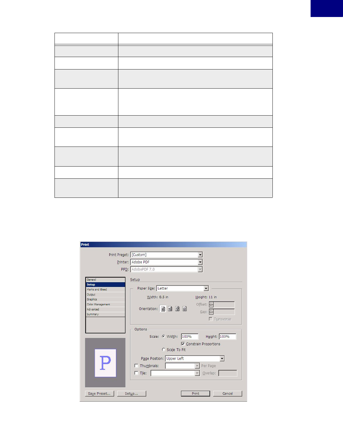
Printing 425
Printing
Print user interface
Print dialog box: Setup panel
FIGURE 203 Print dialog box: Setup panel
Reverse Order IPrintData::SetReverseOrder
Pages: All IPrintData::SetWhichPages(IPrintData::kAllPages)
Pages: Range IPrintData::SetWhichPages(IPrintData::kPageRange) (Range
text edit box): IPrintData::SetPageRange
Sequence IPrintData::SetPrintOption, using IPrintData::kBothPages
(for All Pages), IPrintData::kEvenPagesOnly, or
IPrintData::kOddPagesOnly
Spreads IPrintData::SetSpreads
Print Master Pages IPrintData::SetScope, using IPrintData::kScopeMaster or
IPrintData::kScopeDocument
Print Non-printing
Objects
IPrintData::SetPrintNonPrintingObjects
Print Blank Pages IPrintData::SetPrintBlankPages
Print Visible Guides
and Baseline Grids
IPrintData::SetPrintWYSIWYGGridsGuides
User-interface element API method
Printing
Print user interface
426
The user-interface elements on the Setup selectable panel are mapped to the API methods
listed in Table 100.
TABLE 100 Print dialog box: Setup panel
User-interface element API method
Paper Size IPrintData::SetPaperSizeSelection if defined by the user
(IPrintData::kPaperSizeDefinedByUser), printer driver
(IPrintData::kPaperSizeDefinedByDriver), or
IPrintData::SetPaperSizeName
Paper Size: Width IPrintData::SetCustomPaperWidth only if Paper Size is
defined by the user; otherwise (if defined by driver or paper-
size name),
IPrintData::SetCustomPaperWidth(IPrintData::kCustomPap
erSizeAuto)
Paper Size: Height IPrintData::SetCustomPaperHeight only if Paper Size is
defined by user; otherwise (if defined by driver or paper-size
name),
IPrintData::SetCustomPaperHeight(IPrintData::kCustomPap
erSizeAuto)
Offset IPrintData::SetCustomPaperOffset only if Paper Size is
defined by the user
Gap IPrintData::SetCustomPaperGap only if Paper Size is defined
by the user
Transverse IPrintData::SetPaperOrientation, using
IPrintData::kTransverse or IPrintData::kNormal
Orientation IPrintData::SetPageOrientation, using IPrintData::kPortrait,
IPrintData::kLandscape, IPrintData::kReversePortrait, or
IPrintData::kReverseLandscape
Scale (radio button) IPrintData::SetScaleMode using IPrintData::kScaleXAndY
Scale: Width IPrintData::SetXScale
Scale: Height IPrintData::SetYScale
Scale: Constrain
Proportions
IPrintData::SetProportional
Scale to Fit (radio
button)
IPrintData::SetScaleMode using IPrintData::kScaleToFit
Page Position IPrintData::SetPagePosition, using
IPrintData::kPagePositionUpperLeft,
IPrintData::kPagePositionCenterHorizontally,
IPrintData::kPagePositionCenterVertically, or
IPrintData::kPagePositionCentered
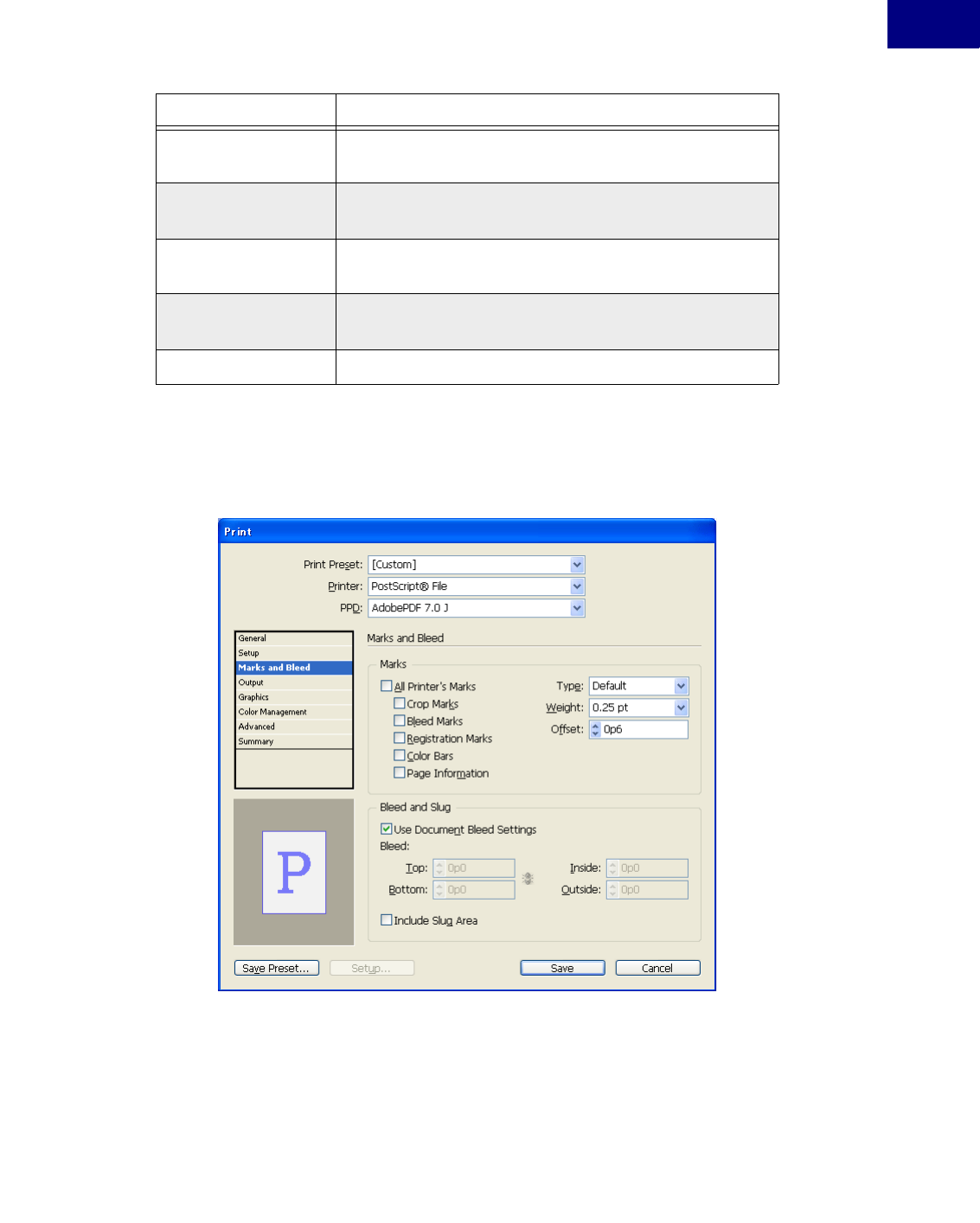
Printing 427
Printing
Print user interface
Print dialog box: Marks and Bleed panel
FIGURE 204 Print dialog box: Marks And Bleed panel (Roman feature set)
The user-interface elements on the Marks And Bleed selectable panel are mapped to the API
methods listed in Table 101.
Print Layers IPrintData::SetPrintLayers using kPrintAllLayers,
kPrintVisibleLayers, or kPrintVisiblePrintableLayers.
Thumbnails IPrintData::SetTileThumbMode, using
IPrintData::kThumbnails or IPrintData::kTileThumbOff
Per Page IPrintData::SetNumberOfThumbsPerPage. Calculate the
number of thumbnails on the page (e.g., 4x4 = 16).
Tile IPrintData::SetTileThumbMode, using IPrintData::kTiling or
IPrintData::kTileThumbOff
Overlap IPrintData::SetTilingOverlap
User-interface element API method
Printing
Print user interface
428
TABLE 101 Print dialog box: Marks and Bleed panel
User-interface element API method
All Printer’s Marks Checking this sets the state of the five check boxes below it.
Crop Marks IPrintData::SetCropMarks
Bleed Marks IPrintData::SetBleedMarks
Registration Marks PrintData::SetRegistrationMarks
Color Bars IPrintData::SetColorBars
Page Information PrintData::SetPageInformation
Type IPrintData::SetPageMarkFile. For the Roman and Japanese
feature sets, you get the Default setting; in this case, the
PMString passed into SetPageMarkFile is blank. There are
extra details when using the Japanese feature set; see
“Japanese page-mark files” on page 449.
Weight IPrintData::SetMarkLineWeight, using the enumerations
ranging from IPrintData::kMarkLineWeight125pt to
IPrintData::kMarkLineWeight30mm (see IPrintData.h.)
Offset IPrintData::SetPageMarkOffset
Use Document Bleed
Settings
IPrintData::SetUseDocumentBleed
Bleed (chain button) IPrintData::SetBleedChain
Bleed: Top IPrintData::SetBleedTop
Bleed: Bottom IPrintData::SetBleedBottom
Bleed: Inside IPrintData::SetBleedInside
Bleed: Outside IPrintData::SetBleedOutside
Include Slug Area IPrintData::SetIncludeSlug

Printing 429
Printing
Print user interface
Print dialog box: Output panel
FIGURE 205 Print dialog box: Output panel
The user-interface elements on the Output selectable panel are mapped to the API methods
listed in Table 102.
TABLE 102 Print dialog box: Output panel
User-interface element API method
Color IPrintData::SetOutputMode, using
IPrintData::kCompositeLeaveUnchanged,
IPrintData::kCompositeGray, IPrintData::kCompositeRGB,
IPrintData::kCompositeCMYK,
IPrintData::kSeparationBuiltIn, or
IPrintData::kSeparationInRIP
Text as Black IPrintData::SetPrintColorsInBlack
Trapping IPrintData::SetTrappingMode, using
IPrintData::kTrappingNone, IPrintData::kTrappingBuiltIn,
or IPrintData::kTrappingInRIP
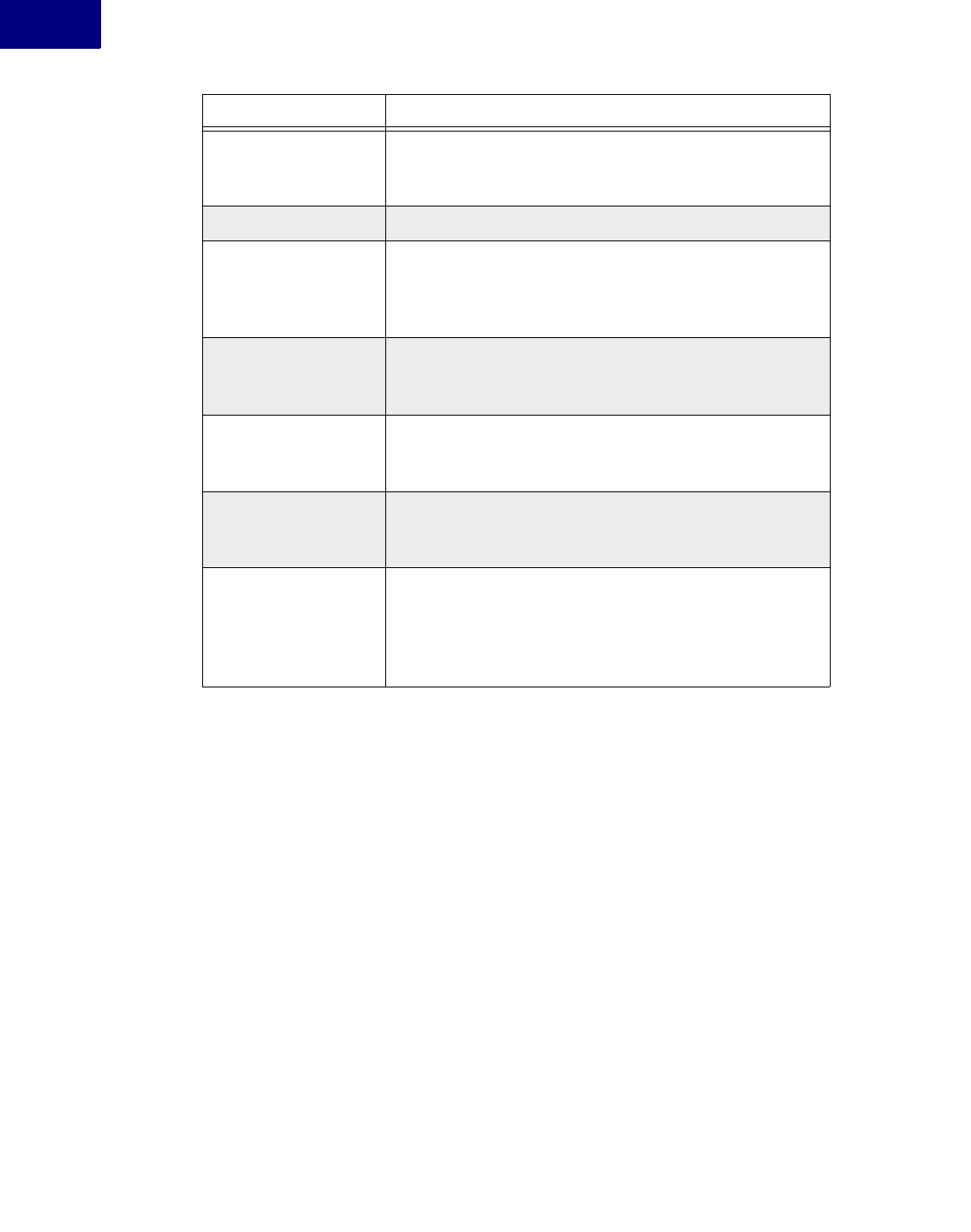
Printing
Print user interface
430
Flip IPrintData::SetFlipMode, using IPrintData::kFlipOff,
IPrintData::kFlipHorizontal, IPrintData::kFlipVertical, or
IPrintData::kFlipBoth
Negative IPrintData::SetNegative
Screening When the IPrintData::GetOutputMode is a separation mode,
IPrintData::SetSeparationScreenText; when the
IPrintData::GetOutputMode is a composite mode,
IPrintData::SetCompositeScreenText.
Frequency If output mode is kCompositeGray and the composite-screen
mode is string key “kCustom” (translates differently in each
locale), IPrintData::SetCompositeFrequency.
Angle If output mode is kCompositeGray and the composite-screen
mode is string key “kCustom” (translates differently in each
locale), IPrintData::SetCompositeAngle.
Simulate Overprint IPrintData::SetSpotOverPrint, using
IPrintData::kSimulatePress (if the radio button is checked) or
IPrintData::kLegacy (if the radio button is not checked).
Inks Stored temporarily in
IPrintDialogData::SetNthInkScreening. When the user clicks
the OK button in the Ind Manager dialog box, the
kChangeInkCmdBoss command is processed for each ink
listed.
User-interface element API method
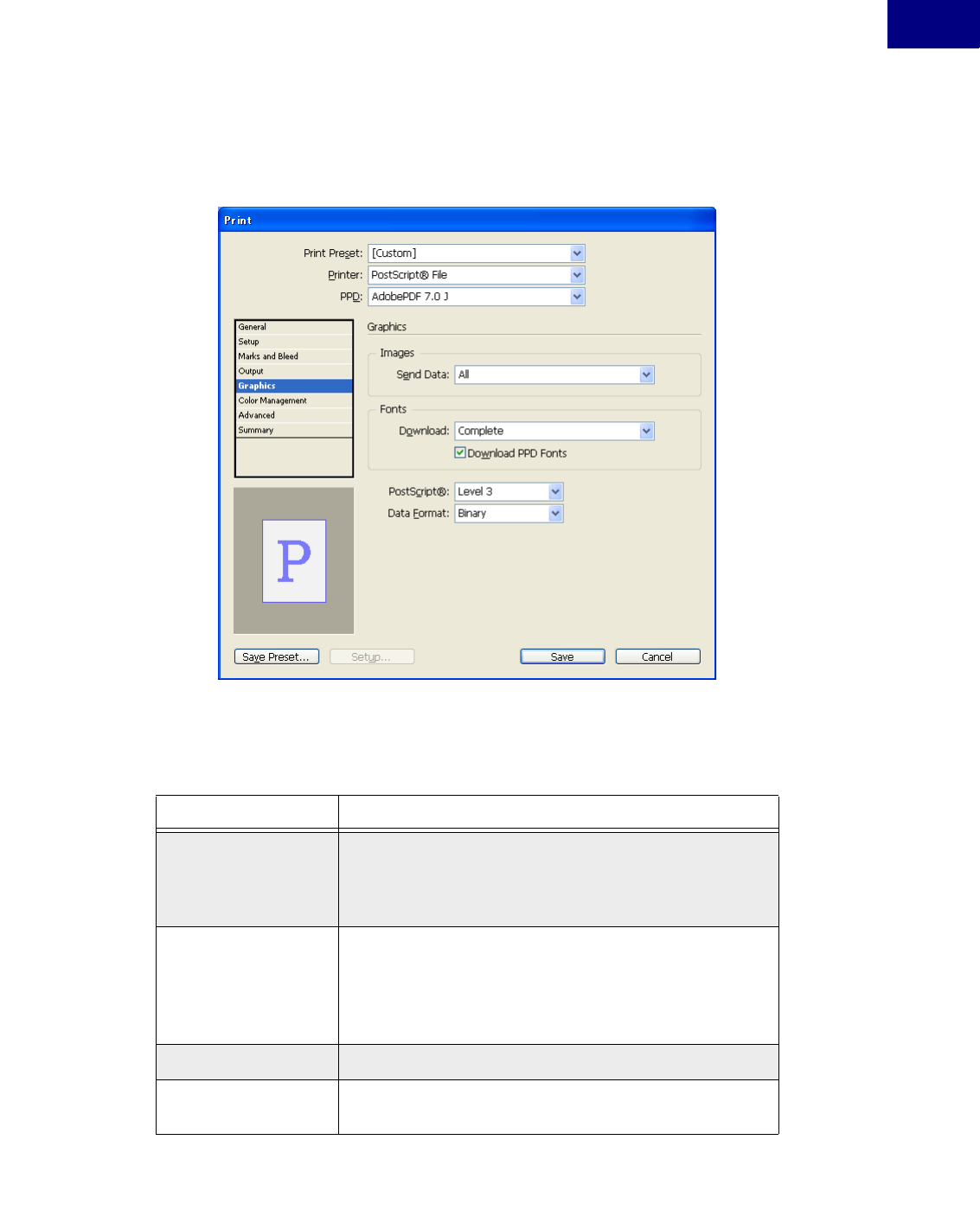
Printing 431
Printing
Print user interface
Print dialog box: Graphics panel
FIGURE 206 Print dialog box: Graphics panel
The user-interface elements on the Graphics selectable panel are mapped to the API methods
listed in Table 103.
TABLE 103 Print dialog box: Graphics panel
User-interface element API method
Images: Send Data IPrintData::SetImageData, using IPrintData::kImageDataAll,
IPrintData::kImageDataOptimized,
IPrintData::kImageDataLoRez, or
IPrintData::kImageDataProofPrint
Fonts: Download IPrintData::SetFontDownload,
usingIPrintData::kFontDownloadNone,
IPrintData::kFontDownloadComplete,
IPrintData::kFontDownloadSubset, or
IPrintData::kFontDownloadSubsetLrg
Download PPD Fonts IPrintData::SetDownloadPPDFonts
PostScript IPrintData::SetPSLangLevel, using
IPrintData::kPSLangLevel_2 or IPrintData::kPSLangLevel_3
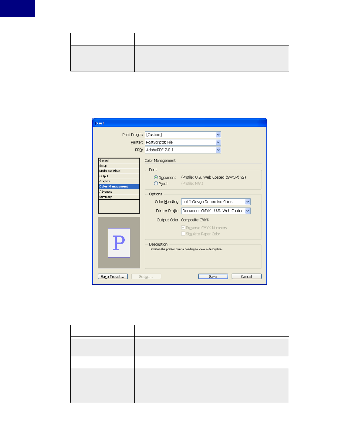
Printing
Print user interface
432
Print dialog box: Color Management panel
FIGURE 207 Print dialog box: Color Management panel
The user-interface elements on the Color Management selectable panel are mapped to the API
methods listed in Table 104.
TABLE 104 Print dialog box: Color Management panel
Data Form at IPrintData::SetImageDataFormat, using
IPrintData::kImageDataBinary or
IPrintData::kImageDataASCII
User-interface element API method
Print: Document IPrintData::SetSourceSpace(IPrintData::kDocumentSourceS
pace)
Print: Proof IPrintData::SetSourceSpace(IPrintData::kProofSourceSpace)
Color Handling IPrintData::SetProfileType, using
IPrintData::kUseDocumentProfile,
IPrintData::kUsePostScriptCMS, or
IPrintData::kUseNoCMS
User-interface element API method
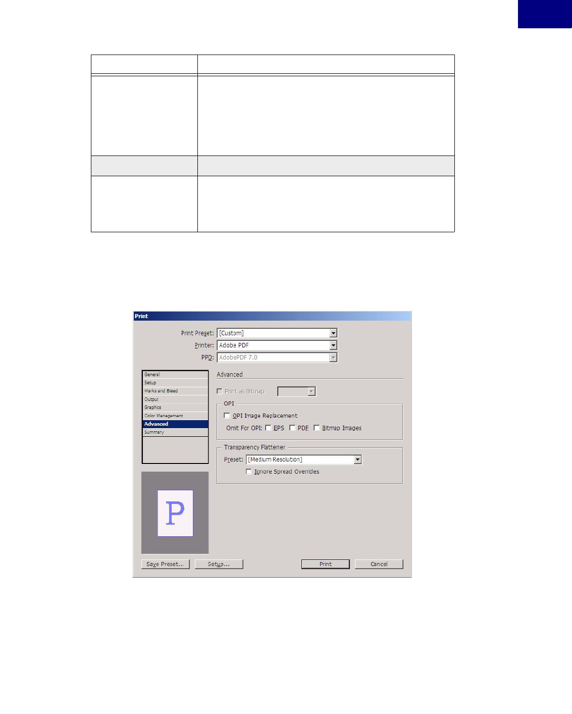
Printing 433
Printing
Print user interface
Print dialog box: Advanced panel
FIGURE 208 Print dialog box: Advanced panel
The user-interface elements on the Advanced selectable panel are mapped to the API methods
listed in Table 104.
Printer Profile IPrintData::SetProfileType, using
IPrintData::kUseDocumentProfile or
IPrintData::kUseWorkingProfile. If this is not one of the
predefined profiles, use IPrintData::kUseSpecificProfile and
then call IPrintData::SetProfileName, specifying the name of
the profile as displayed in the drop-down list.
Preserve CMYK Colors IPrintData::SetPreserveColorNumbers
Simulate Paper Color IPrintData::SetIntent, using
IPrintData::kRelativeColorimetric (if the radio button is
unselected) or IPrintData::kAbsoluteColorimetric (if the
radio button is selected).
User-interface element API method
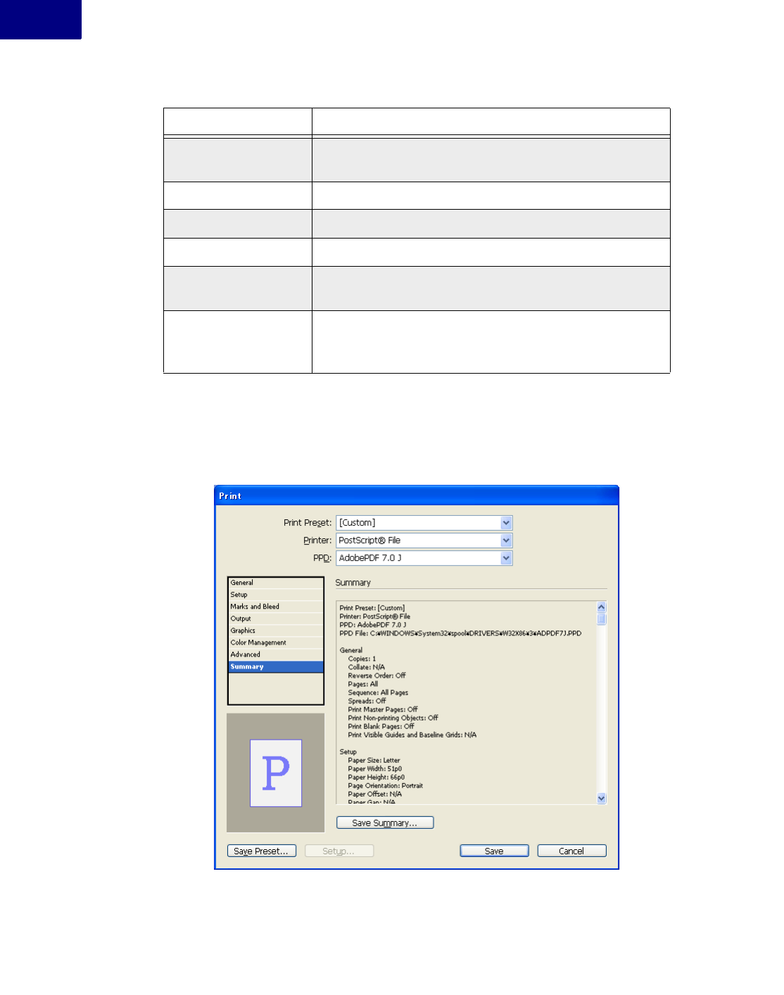
Printing
Print user interface
434
TABLE 105 Print dialog box: Advanced panel
Print dialog box: Summary panel
FIGURE 209 Print dialog box: Summary panel
When you click the Save Summary button, the Save File dialog box opens, asking for the path
of a text file to which to save the summary. If you call IPrStStyleListMgr::GetNthStyleDescrip-
User-interface element API method
OPI Image
Replacement
IPrintData::SetOPIReplacement
Omit for OPI: EPS IPrintData::SetOmitEPS
Omit for OPI: PDF IPrintData::SetOmitPDF
Omit for OPI: Images IPrintData::SetOmitImages
Transparency
Flattener: Preset
IPrintData::SetFlattenerStyleName
Transparency
Flattener: Ignore
Spread Overrides
IPrintData::SetIgnoreSpreadOverrides

Printing 435
Printing
Printing extension patterns
tion for a selected printer style, you get the same text as shown in the Summary multi-line text
widget.
Print Presets dialog box
The main Print Presets dialog box is opened when the user chooses File > Print Presets >
Define.
In the main Print Presets dialog box, the user can see the currently defined print presets and a
text summary of the currently selected preset. The main dialog box also has buttons for creat-
ing a new print preset (New), editing an existing print preset (Edit), deleting the selected print
preset (Delete), loading from a print presets file (Load), and saving the print presets to a file
(Save).
When the user clicks the New or Edit button, a selectable dialog box similar to the Print dialog
box opens. The design of the Print Presets selectable dialog box is mostly the same as the Print
dialog box, with a few minor differences:
zThe title of the dialog box differs based on what the end user is doing.
zThe thumbnail image on the bottom-left corner of the dialog box is shown only in the Print
dialog box and is disabled in the Print Presets dialog box.
zThe Print dialog box has a Save Preset button, which allows the user to save the current
print settings as a print-preset style in the workspace. The Print Presets dialog box does not
have that button, since the Print Presets dialog box is where you edit the print-preset style.
Extending the Print dialog box or the Print Presets selectable dialog box
The Print dialog box and the Print Presets selectable dialog boxes are extensible by third-party
plug-ins by means of custom, selectable, dialog panel. By implementing one selectable dialog
panel, you can add your own panel into both the Print dialog box and the Print Presets select-
able dialog box. For a discussion on SDK sample plug-ins that implement selectable dialog
panels, see “Adding your own panel to the Print and Print Presets dialog boxes” on page 446.
Printing extension patterns
Print-setup provider
A plug-in can register a print-setup service boss by providing an IK2ServiceProvider imple-
mentation that supports the kPrintSetupService service ID. The service is called at various
points during the print-action sequence (see “The print action sequence” on page 421). The
implementation for IPrintSetupProvider provides methods to set up or change print parame-
ters before and during the printing process. See Table 106 for implementation details.
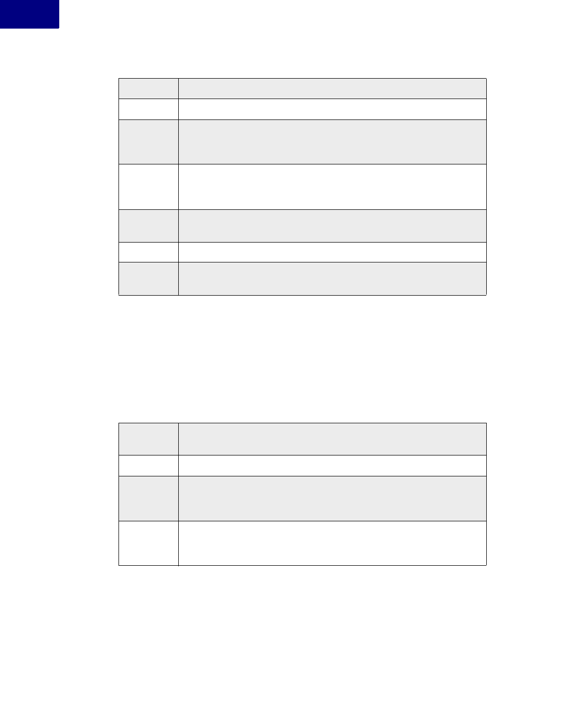
Printing
Printing extension patterns
436
TABLE 106 Implementation recipe for a print-setup provider
Print-insert-PostScript proc provider
A plug-in can inject PostScript statements into the print-output stream by registering an
IK2ServiceProvider implementation supporting the kPrintInsertPSProcService serviceID and
providing an implementation for IPrintInsertPSProcProvider. See Table 107 for implementa-
tion details.
TABLE 107 Implementation recipe for a print-insert-PostScript proc provider
Purpose Participate in various phases in the print process.
ServiceID kPrintSetupService
Required
companion
interface
IPrintSetupProvider
Boss class IID_IK2SERVICEPROVIDER with implementation ID
kPrintSetupServiceImpl (see PrintID.h) and
IID_IPRINTSETUPPROVIDER with your implementation ID
When
called
Methods of IPrintSetupProvider are called at various phases of the print
action command. See “The print action sequence” on page 421.
How called All providers of this ServiceID get called.
Sample
code
See “Participating in the stages of the print-action sequence” on
page 443.
Purpose Inject PostScript comments at predetermined phases of the printing
process.
ServiceID kPrintInsertPSProcService
Required
companion
interface
IPrintInsertPSProcProvider
Boss class IID_IK2SERVICEPROVIDER with implementation ID
kInsertPSProcServiceImpl (see PrintID.h) and
IID_IPRINTINSERTPSPROCPROVIDER with your implementation ID
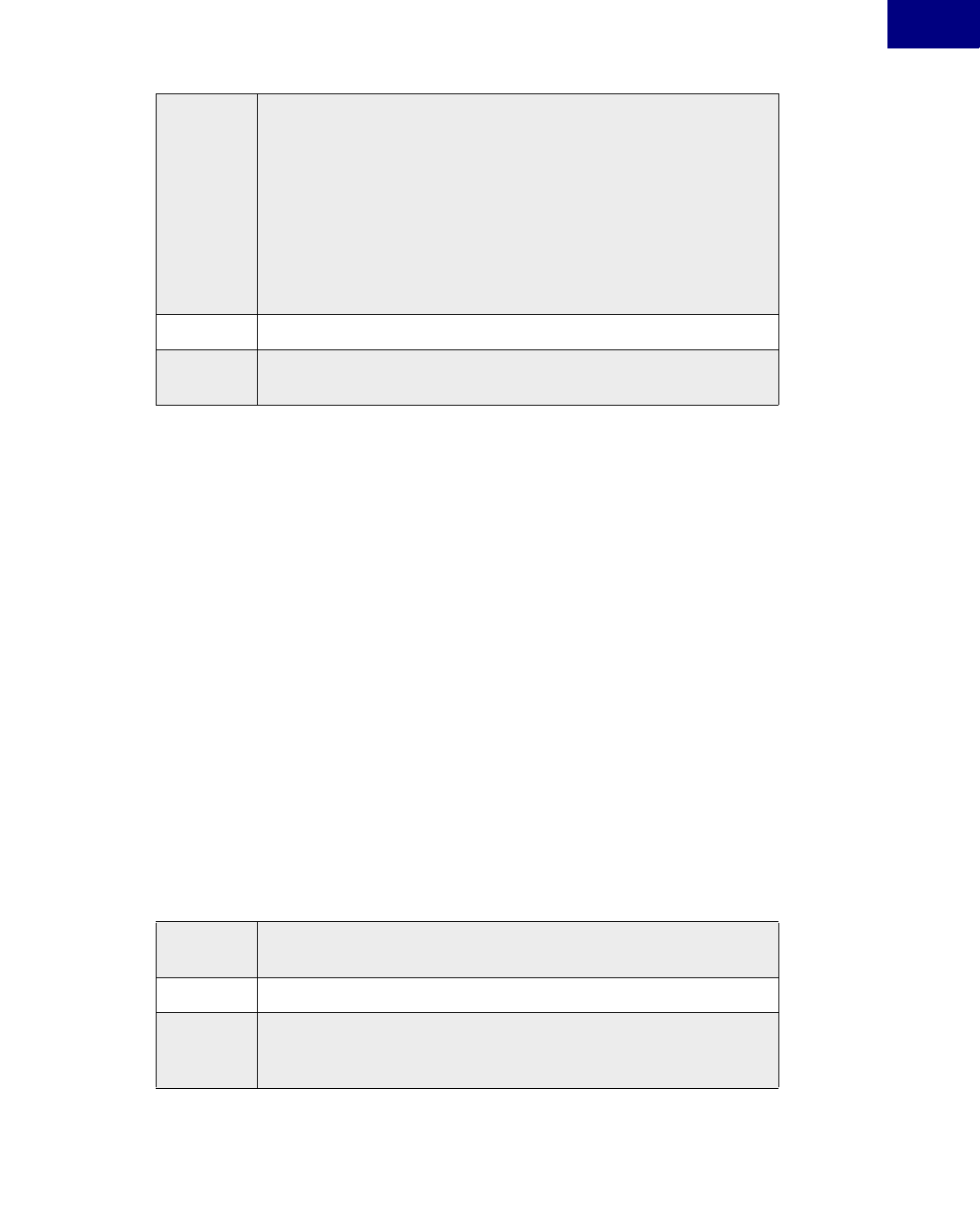
Printing 437
Printing
Printing extension patterns
Print-data helper-strategy provider
A plug-in can control whether to override the current locked state and relevant state of print
data items in the Print dialog box by registering an implementation of IK2ServiceProvider sup-
porting the kPrintDataHelperStrategyService serviceID. The IPrintDataHelperStrategy inter-
face provides two methods: IsLocked and IsRelevant.
IsLocked allows a plug-in to lock the Print and Print Presets dialog-box user-interface ele-
ments. Although an item's locked state can be partially controlled using this method, the appli-
cation print components are still free to change an item's value as necessary to maintain the
print data in a consistent and valid context.
IsRelevant allows a plug-in to disable specific Print and Print Presets dialog-box user-interface
elements. Although an item's relevant state can be partially controlled using this interface, the
application print components are still free to change an item's value as necessary to maintain
the print data in a consistent and valid context.
The most restrictive interface takes precedence. After an ID is set to be locked (the most
restrictive setting), other implementations are not called. After an ID’s relevance is set to kFalse
(the most restrictive setting), other implementations are not called.
See Table 108 for implementation details.
TABLE 108 Implementation recipe for a print-data helper-strategy provider
When
called
Methods of IPrintInsertPSProcProvider are called at various phases of
the core print command. See “The print action sequence” on page 421.
The Setup method is called first, to give the provider a chance to store
print settings. Then the GetInsertPSProcName method is called, so the
provider can return a name. (The following steps occur only if your
GetInsertPSProcName implementation returns a non-empty string.) The
GetClientData method gets called to obtain the provider’s custom client
data (if any), then the PrintInsertPSProc method is called at various
phases of the printing process. (For a list of phases, see the enum
IPrintInsertPSProcProvider::DocumentSection.)
How called All providers of this ServiceID get called.
Sample
code
See “Injecting PostScript comments or extra data into the print stream
during the print action sequence” on page 444.
Purpose Influence the Print and Print Presets dialog boxes through the ability to
suppress and lock print user-interface elements.
ServiceID kPrintDataHelperStrategyService
Required
companion
interface
IPrintDataHelperStrategy

Printing
Printing solutions
438
Draw-event handlers
A plug-in can register a draw-event handler (IDrwEvtHandler) to participate in various draw
events that happen during the printing process. For more details on draw-event handlers,
including implementation details, see the “Graphics Fundamentals” chapter. For samples that
implement this extension pattern for printing purposes, see “A d d i n g a c u s t o m w a t e r m a r k d u r -
ing the printing process” on page 444 and “Injecting PostScript comments or extra data into
the print stream during the print action sequence” on page 444.
Printing solutions
Getting started
Printing a document
Execute (not process) one of the following commands:
zkPrintActionCmdBoss, to print a document in InDesign
zkInCopyPrintActionCmdBoss, to print a document in InCopy
The minimal settings required to print a document with kPrintActionCmdBoss in InDesign
are as follows:
zThe document you want to print.
zThe range of pages in the document you want to print.
zPrint user-interface options.
The print-action command is executed (not processed), because there is no undo capability
provided. For a sample that uses either kPrintActionCmdBoss or kInCopyPrintActionCmd-
Boss, see the SnpPrintDocument.cpp sample code snippet, in particular SnpPrintDocu-
ment::DoPrintDocument.
Boss class IID_IK2SERVICEPROVIDER with implementation ID
kDataHelperStrategyServiceImpl(see PrintID.h) and
IID_IPRINTDATAHELPERSTRATEGY with your implementation ID
When
called
Whenever IPrintData::IsLocked or IPrintData::IsRelevant is called.
Generally this happens when the Print or Print Presets dialog box is
being prepared for display.
How called All providers of this ServiceID get called.
Related
sample
code
See “Specifying which parts of the Print and Print Presets dialog boxes
are relevant or locked” on page 447.

Printing 439
Printing
Printing solutions
Printing a Book
Execute the kBookPrintActionCmdBoss command.
Working with print-preset styles
Getting information about print-preset styles
Query for IPrStStyleListMgr on kWorkspaceBoss, then call the Get methods to get information
about the print-preset styles that are registered. IPrStStyleListMgr::GetNumStyles reports the
number of print-preset styles registered. IPrStStyleListMgr::GetNthStyleName reports the
name of the print-preset style at index n. IPrStStyleListMgr::GetNthStyleRef returns the
UIDRef of the print-preset style at index n. Using this UIDRef, you can query IPrintData, and
get further information about the print-preset style. There are other useful methods on IPrSt-
StyleListMgr.
NOTE:IPrStStyleListMgr.h does not declare any methods; however, it inherits
IGenStlEdtListMgr. See IGenStlEdtListMgr.h for details.
For more details, see the SnpManipulatePrintStyles.cpp code snippet, in particular SnpManip-
ulatePrintStyles::InspectPrintStyle.
Adding a print-preset style
Query for IPrStStyleListMgr on kWorkspaceBoss, then call IPrStStyleListMgr::AddStyle. When
the new style is created, it is appended to the end of the list of print-preset styles.
For details, see the SnpManipulatePrintStyles.cpp code snippet, in particular SnpManipulate-
PrintStyles::AddPrintStyle.
Duplicating a print-preset style
Query for IPrStStyleListMgr on kWorkspaceBoss, then call IPrStStyleListMgr::CopyNthStyle.
When the new style is created, it is appended to the end of the list of print-preset styles.
Modifying the name of a print-preset style
First, query for IPrStStyleListMgr on kWorkspaceBoss.
Then, call IPrStStyleListMgr::SetNthStyleName. When you do this, however, the name of the
print-preset style stored in IPrintData is not updated, so you must query for IPrintData and call
IPrintData::SetStyleName, using the same name. For details, see the SnpManipulatePrint-
Styles.cpp code snippet, in particular SnpManipulatePrintStyles::ModifyPrintStyleName.
Modifying the settings of a print-preset style
First, query for IPrStStyleListMgr on kWorkspaceBoss.
Then, call IPrStStyleListMgr::EditNthStyle, which invokes the Print Presets selectable dialog
box. This procedure requires a user to use the dialog box to change settings. For details, see the
SnpManipulatePrintStyles.cpp code snippet, in particular SnpManipulatePrintStyles::ModifyP-
rintStyle.

Printing
Printing solutions
440
Deleting a print-preset style
Query for IPrStStyleListMgr on kWorkspaceBoss, then call IPrStStyleListMgr::DeleteNthStyle.
For details, see the SnpManipulatePrintStyles.cpp code snippet, in particular SnpManipulate-
PrintStyles::DeletePrintStyle.
Exporting a set of print-preset styles to a file
Process the kGenStlEdtExportStylesCmdBoss command. In the IGenStlEdtCmdData data
interface, call SetListMgrIID to set the type of style list to be the print style list, by specifying
the IPrStStyleListMgr::kDefaultIID (IID_IPRSTSTYLELISTMGR), then call SetTargetFile to
specify the full path of the file to save. Optionally, specify a set of style indices you want to
export from IPrStStyleListMgr on kWorkspaceBoss. If you do not specify a set of style indices,
all styles stored in IPrStStyleListMgr are exported.
Importing a set of print-preset styles from a file
Process the kGenStlEdtImportStylesCmdBoss command. In the IGenStlEdtCmdData data
interface, call SetListMgrIID to set the type of style list to be the print style list, by specifying
the IPrStStyleListMgr::kDefaultIID (IID_IPRSTSTYLELISTMGR), then call SetTargetFile to
specify the full path of the file to import.
Getting notified when a print-preset style is imported to/exported from a
file
Implement a signal-responder extension pattern that responds one or more of the following
signals:
zkBeforeExportStyleSignalResponderService
zkAfterExportStyleSignalResponderService
zkBeforeImportStyleSignalResponderService
zkAfterImportStyleSignalResponderService
These IDs are defined in GenericSettingsID.h. In your implementation of IRe-
sponder::Respond, you can query for the IStyleSignalData interface using ISignalMgr::Query-
Interface (or InterfacePtr). IStyleSignalData gives you a reference to the file that is the target of
the export or import operation.
NOTE:Any preset style that is managed by the generic-settings framework and can be exported
or imported—such as PDF-export styles and document-preset styles—can be
monitored in the same way.

Printing 441
Printing
Printing solutions
Working with trap styles
Getting information about trap styles
First, query for ITrapStyleListMgr on one of the following bosses:
zkWorkspaceBoss, for trap styles registered in the workspace (also used as document
defaults when a new document is created)
zkDocWorkspaceBoss, for trap styles registered in a document
zkBookBoss, for trap styles registered in a book
The utility interface ITrapStyleUtils (on kUtilsBoss) has a QueryTrapStyleListMgr method to
simplify this process. There are two overloaded methods:
zThe one that takes IDocument* returns the ITrapStyleListMgr on kDocWorkspaceBoss
(i.e., the workspace related to the document).
zThe one that takes a UIDRef returns the ITrapStyleListMgr on the same boss as the UIDRef,
or the ITrapStyleListMgr on kWorkspaceBoss if the UID in the UIDRef is kInvalidUID.
Next, call the Get methods to get various information about the trap styles that are registered.
ITrapStyleListMgr::GetNumStyles reports the number of trap styles registered. ITrapStyleList-
Mgr::GetNthStyleName reports the name of the trap style at index n. ITrapStyleListMgr::Get-
NthStyleRef returns the UIDRef of the trap style at index n. Using this UIDRef, you can query
ITrapStyle and get further information about this trap style. There are other useful methods on
ITrapStyleListMgr.
NOTE:ITrapStyleListMgr does not inherit from IGenStlEdtListMgr the way IPrStStyleListMgr
does.
For details, see the SnpManipulateTrapStyles.cpp code snippet, in particular SnpManipulateT-
rapStyles::InspectTrapStyle.
Adding a trap style
Query for ITrapStyleListMgr, then call ITrapStyleListMgr::AddStyle. When the new style is
created, it is appended to the end of the list of trap styles.
For details, see the SnpManipulateTrapStyles.cpp code snippet, in particular SnpManipulateT-
rapStyles::AddTrapStyle.
Duplicating a trap style
Query for ITrapStyleListMgr, then call ITrapStyleListMgr::CopyNthStyle. When the new style
is created, it i appended to the end of the list of trap styles.
Modifying a trap style
Query for ITrapStyleListMgr, then call ITrapStyleListMgr::EditNthStyle. You are required to
pass in the trap-style data via the parameter list as ITrapStyle. You can create a non-persistent
instance of kTrapStyleBoss to store the settings.
For details, see the SnpManipulateTrapStyles.cpp code snippet, in particular SnpManipulateT-
rapStyles::ModifyTrapStyle.

Printing
Printing solutions
442
Deleting a trap style
Query for ITrapStyleListMgr, then call ITrapStyleListMgr::DeleteNthStyle.
For details, see the SnpManipulateTrapStyles.cpp code snippet, in particular SnpManipulateT-
rapStyles::DeleteTrapStyle.
Exporting a set of trap styles to another trap-style list
First, create a command sequence, as the following procedure processes multiple commands.
Next, query for ITrapStyleListMgr, then call ITrapStyleListMgr::ExportStyles. The first param-
eter is a UIDRef for the destination trap style list (note the source trap style list is identified by
this particular instance of ITrapStyleListMgr), and that UIDRef must refer to a boss that aggre-
gates ITrapStyleListMgr. If you want to export the trap styles to a file, you can create a new
database using DBUtils::CreateDataBase and IDataBase::New, then put a new root UID by call-
ing IDataBase::NewUID. The class for the new root should be kTrapStyleExportRootBoss. Cre-
ate a UIDRef for this new root, and pass it into ITrapStyleListMgr::ExportStyles. Once that
completes, save the database by calling IDataBase::SaveAs, and close the database by deleting
the IDataBase pointer.
Importing a set of trap styles from another trap-style list
First, create a command sequence, as the following procedure processes multiple commands.
Next, query for ITrapStyleListMgr, then call ITrapStyleListMgr::ImportStyles. The first param-
eter is a UIDRef for the source trap style list (note the destination trap style list is identified by
this particular instance of ITrapStyleListMgr), and that UIDRef must refer to a boss that aggre-
gates ITrapStyleListMgr. If you want to import the trap styles from a file, you can open a data-
base using DBUtils::CreateDataBase and IDataBase::Open, then get the root UID by calling
IDataBase::GetRootUID. The class for the new root should be kTrapStyleExportRootBoss. Cre-
ate a UIDRef for this root, and pass it into ITrapStyleListMgr::ImportStyles. Once that com-
pletes, close the database by deleting the IDataBase pointer.
Determining which trap style is associated with a page on a document
Given a specific page (kPageBoss) on a document (which you can query using IPageList on
kDocBoss), query for IPersistUIDData with the specific IID of IID_ITRAPSTYLEUIDDATA.
Get the UID from IPersistUIDData. That UID refers to the trap style registered in ITrapStyleL-
istMgr on the document workspace (kDocWorkspaceBoss). To find out the name of this trap
style, first call ITrapStyleListMgr::GetStyleIndexByUID and then call ITrapStyleListMgr::Get-
NthStyleName.
Alternately, you can collect a list of pages that use a specific trap style. Call ITrapStyleUtils::Get-
DocumentTrapStylePageList. For details, see the SnpManipulateTrapStyles.cpp code snippet,
specifically SnpManipulateTrapStyles::InspectTrapStyle.
Associating a trap style with a page on a document
Create a UIDList of pages (kPageBoss) to which you want to associate a trap style, and the
UIDRef of the trap style. Then call ITrapStyleUtils::AssignStyleToPageList. For details, see the
SnpManipulateTrapStyles.cpp code snippet, specifically SnpManipulateTrapStyles::Assign-
TrapStyleToPages.

Printing 443
Printing
Printing solutions
Participating in the print process
Participating in the stages of the print-action sequence
There are various ways to participate in the print-action sequence. The main way is to imple-
ment a print-setup provider (see “Print-setup provider” on page 435). By implementing IPrint-
SetupProvider, your plug-in can be notified at the stages of the print-action sequence described
in “The print action sequence” on page 421.
Other ways to participate in the print-action sequence are noted in the following list. Some of
these require extra hook-ups from within a print setup-provider implementation.
zImplement a print-insert PostScript proc provider to inject PostScript statements into the
print-output stream. (See “Print-insert-PostScript proc provider” on page 436 and “Inject-
ing PostScript comments or extra data into the print stream during the print action
sequence” on page 444.)
zImplement a print-data-helper strategy provider to influence the display of the Print and
Print Presets dialog boxes. (See “Print-data helper-strategy provider” on page 437 and
“Specifying which parts of the Print and Print Presets dialog boxes are relevant or locked”
on page 447.)
zImplement a draw-event handler that handles print-related drawing events. (See “Draw-
event handlers” on page 438, “Adding a custom watermark during the printing process” on
page 444, “Specifying which page items should be printed” on page 443, and “Injecting
PostScript comments or extra data into the print stream during the print action sequence”
on page 444).
zImplement a custom write stream so the print-action sequence writes to it. The custom
stream must be specified from one of the methods in your print-setup provider. (See “Writ-
ing printing data to a custom stream” on page 447.)
The following sample plug-ins contain an implementation of a print-setup provider:
zPrintMemoryStream prints document content to a custom memory stream.
zPrintSelection adds a flag to the document to print only selected page items.
For details, see the API reference documentation for each sample plug-in.
Specifying which page items should be printed
You can implement a print-setup provider (see “Participating in the stages of the print-action
sequence” on page 443) and a custom draw-event handler to specify which pages items should
be printed. From the print-setup provider (in any method that gets called before the core print
command is executed, the last chance being AfterPrintGatherCmd), you register the custom
draw-event handler that handles the print event only when it encounters document content
you want to print. When the printing is done, you de-register the custom draw-event handler
in your print-setup provider’s EndPrint implementation.
The PrintSelection sample plug-in shows how this is done. Here are the highlights of what the
PrintSelection plug-in does:

Printing
Printing solutions
444
zIn PrnSelPrintSetupProvider::AfterPrintUI, the currently selected page items are gathered
and the custom draw-event handler is registered for the draw event message kDrawShape-
Message.
zIn PrnSelPrintSetupProvider::BeforePrintGatherCmd, the set of pages to output is modified
based on which pages contain the selected page items.
zThe PrnSelDrawHandler::HandleEvent determines whether the current printable item
should be printed. This draw event handler does not do any drawing; the actual drawing of
the printable item is delegated to other draw-event handlers.
zIn PrnSelPrintSetupProvider::EndPrint, the custom draw-event handler is unregistered.
For details, see the API reference documentation for the PrintSelection plug-in.
Specifying which layer(s) of a document should be printed
In the Setup panel of the Print dialog box, there is a setting called “Print Layers,” which is a
drop-down list that allows the user to choose printing with visible and printable layers, visible
layers, or all layers. This option can be get/set through the IPrintData::GetPrintLayers/Set-
PrintLayers methods. Each layer’s visibility and printability, however, are managed by layer
options as described in the “Layer Options” section of the “Layout Fundamentals” chapter. To
set the visibility of a layer, use the kShowLayerCmdBoss command. To set the printability of a
layer, use the kPrintLayerCmdBoss command. The SnpPrintDocument.cpp SDK snippet
shows how to use a kPrintLayerCmdBoss. Before processing a kPrintLayerCmdBoss, make
sure the printability of the layer is different from the new state you are going to set. If the new
printability state is the same as the old one, kPrintLayerCmdBoss asserts, although the assert is
benign.
Adding a custom watermark during the printing process
You can implement a custom draw-event handler that draws the watermark on a page or a page
item. This is done in the BasicDrwEvtHandler sample plug-in, a canonical example of a draw-
event handler. For details, see the API reference documentation for the BasicDrwEvtHandler
plug-in.
Another way to add custom watermarks to page items is to implement a page-item adornment
that draws when the draw flag has the IShape::kPrinting bit set. While the FrameLabel sample
plug-in does not support printing (i.e., if flags contains IShape::kPrinting, the Draw method
breaks out), you can use the FrameLabel sample as a basis for implementing custom water-
marks and extra persistent data on page items. For details, see the API reference documenta-
tion for the FrameLabel plug-in.
Injecting PostScript comments or extra data into the print stream during
the print action sequence
You can implement a print-insert PostScript proc provider (see “Print-insert-PostScript proc
provider” on page 436) to inject PostScript comments during predetermined phases of the
print-output process as driven by the core print command. The PrintMemoryStream sample
plug-in contains an implementation of a print-insert PostScript proc provider. The print-insert
PostScript proc provider implementation in this sample is a canonical example that demon-
strates when each method in IPrintInsertPSProcProvider gets called by writing a trace mes-

Printing 445
Printing
Printing solutions
sage. This plug-in also demonstrates how to manage custom print settings throughout the
print-action sequence.
There are other ways to inject PostScript comments into the print stream during the print
action sequence:
zImplement a custom draw-event handler that calls the IGraphicsPort::AddComment
method. For a sample of a draw-event handler that responds to the kDrawShapeMessage for
printing, see PrnSelDrawHandler::HandleEvent in the PrintSelection sample plug-in. To
obtain IGraphicsPort, you can first get a pointer to the GraphicsData from DrawEvent-
Data::gd, then call GraphicsData::GetGraphicsPort.
zAdd custom registration marks on each page, if you are using the Japanese feature set of
InDesign or InCopy. See “Japanese page-mark files” on page 449.
Adding custom print settings so they are managed like other
print settings
Old method
First, write your own interface that allows you to manipulate your custom print-settings data
(e.g., IMyPrintData). Then, the simplest way to persist your custom print settings is to add a
persistent implementation of this interface (e.g., kMyPrintDataImpl) on a boss class that also is
persisted with the document, like kDocWorkspaceBoss or kDocBoss. By adding your imple-
mentation only in the specified boss classes, however, you will not be able to manage your cus-
tom print settings together with print-preset styles.
In addition, there are several places where you must copy your custom print-setting data, as
new instances of the aforementioned bosses are created (during processes like the print-action
sequence and the Print Presets dialog) for the purpose of adding a print preset style or keeping
a temporary instance for use during the print-action sequence. For print-data settings stored in
IPrintData, the application calls IPrintData::CopyData to copy only the data managed within
the IPrintData implementation to these new or temporary instances of the print data boss;
however, your custom print settings are not copied at that time. Furthermore, the commands
that copy the IPrintData to the appropriate instance print data boss do not notify any subjects.
To solve these problems, you can implement a special observer. This observer observes changes
that notify on the IID_ICOMMANDMGR protocol on a command’s target database. By know-
ing which commands copy IPrintData and when the data is copied, you can manage your cus-
tom print settings as the same time.
New method
Beginning in CS4, a new kPrintCopyCustomDataService is available; any plug-in that registers
for this service gets a chance to manage its own print data during the print process. This is the
preferred method for managing your own custom print data, instead of using the command-
observer technique discussed above. Note the service provider is called after the application’s
CopyData is done. You should provide the implementation for IPrintCopyCustomDataPro-
vider and aggregate it on the service-provider boss that registered as kPrintCopyCustom-
DataService. Then your IPrintCopyCustomDataProvider will get called whenever
IPrintData::CopyData is called.

Printing
Printing solutions
446
Adding your own panel to the Print and Print Presets dialog boxes
You can implement a panel that adds itself to the dialog box identified by kPrintSelectableDia-
logService. The panel should be 400 pixels wide and 345 pixels high. The ODFRez widget type
should inherit from PrimaryResourcePanelWidget, and the boss class that contains the neces-
sary implementations (see below) should inherit from kPrimaryResourcePanelWidgetBoss.
The required implementations in this boss class are as follows:
zIK2ServiceProvider (IID_IK2SERVICEPROVIDER), to register the ServiceID values speci-
fied in the IPanelCreator::GetServiceIDs method. You do not need to implement this your-
self; you can use the implementation ID provided by the application:
kDialogPanelServiceImpl (defined in WidgetID.h).
zIPanelCreator (IID_IPANELCREATOR), to specify the resource IDs in your ODFRez
resource file (.fr) that declares the selectable dialog ServiceID and the panel resource IDs
provided by the plug-in. Using this implementation, the IK2ServiceProvider in this boss
(kDialogPanelServiceImpl) can get the necessary data to register the panel into the appro-
priate selectable dialog box. The implementation of this interface must inherit from CPan-
elCreator.
zIDialogController (IID_IDIALOGCONTROLLER), to initialize the panel, validate the set-
tings on the panel when the OK button is clicked, apply the settings on the panel when the
OK button is clicked, and perform any clean-up if the user cancels the dialog. The imple-
mentation of this interface may inherit from CDialogController.
zIObserver (IID_IOBSERVER), to handle user-interface actions for widgets on the panel, as
well as widgets on the parent selectable dialog. (To get the widget IDs of the widgets on the
parent selectable dialog box, choose QA > Panel Edit Mode in the debug build of the appli-
cation.) The implementation of this interface must inherit from AbstractDialogObserver
(as opposed to CSelectableDialogObserver, which is used in the BasicSelectableDialog sam-
ple plug-in). See the API reference documentation for AbstractDialogObserver.
In addition to the panel user-interface definition and the supporting boss class, you must
include the following resources:
zIDList — Specifies the selectable-dialog service ID, which in this case is kPrintSelectableDi-
alogService.
zIDListPair — Specifies the selectable-dialog service ID (again, kPrintSelectableDialogSer-
vice), the resource ID of the panel you want to add to the selectable dialog box, and the
PluginID that owns the panel. You can specify multiple panels in this resource.
Both these resources should have the resource ID you specified in your IPanelCreator::GetPan-
elRsrcID implementation. For example, if the resource ID you specify in IPanelCreator::Get-
PanelRsrcID is kSDKDefIDListPairResourceID, the resource ID of the panel is
kSDKDefPanelResourceID, and the ID of the plug-in that provides this panel is
kPrtHokUIPluginID, the resources would be written like Example 25.

Printing 447
Printing
Printing solutions
EXAMPLE 25 An IDList and IDListPair to support the kPrintSelectableDialogService
resource IDList (kSDKDefIDListPairResourceID)
{
{
kPrintSelectableDialogService,
},
};
resource IDListPair (kSDKDefIDListPairResourceID)
{
{
kPrintSelectableDialogService, kSDKDefPanelResourceID, kPrtHokUIPluginID,
},
};
To find out whether the panel is being opened from the Print or Print Presets dialog box, you
can query the IPrintDialogData interface from the parent selectable dialog (by using the help of
IWidgetParent), and call IPrintDialogData::GetFlags. See Example 26.
EXAMPLE 26 Getting IPrintDialogData flags from a print-dialog selectable-panel implementation
// 'this' maybe a dialog controller or observer
InterfacePtr<IWidgetParent> widgetParent(this, UseDefaultIID());
InterfacePtr<IPrintDialogData> printDialogData
((IPrintDialogData*)widgetParent->QueryParentFor(IID_IPRINTDIALOGDATA));
printFlags = printDialogData->GetFlags();
If the returned value has the IPrintDialogData::kWorkingOnStyle bit set (test by doing a logical
AND on the value with IPrintDialogData::kWorkingOnStyle), the panel is in the Print Presets
dialog box.
A canonical implementation of a selectable dialog box (along with children panels) is provided
in the BasicSelectableDialog sample plug-in. You can use BasicSelectableDialog to understand
the interactions between the parent selectable dialog box and its child panels. For more details,
see the API reference documentation associated with the BasicSelectableDialog sample plug-
in.
Specifying which parts of the Print and Print Presets dialog boxes are
relevant or locked
You can implement a print-data helper strategy provider (see “Print-data helper-strategy pro-
vider” on page 437). Print-data helper strategy provider also are called when the Print or Print
Presets dialog box gets its summary text. (That is, if a setting is not relevant, it is not included in
the summary text.) For a sample implementation of IPrintDataHelperStrategy, see the Print-
MemoryStream sample plug-in.
Writing printing data to a custom stream
You can write a class that implements IPMStream (and inherits CStreamWrite), along with a
class that inherits IXferBytes, to copy the data to whatever your stream targets. Your stream
may target things like a file, a memory buffer, or even a database. This custom stream must be
reported to the print-action sequence by calling IOutputPages::SetOutputStream. You can do
this from one of the methods in your print-setup provider (see “Print-setup provider” on

Printing
Bosses that aggregate IPrintData
448
page 435 and “Participating in the stages of the print-action sequence” on page 443), like
IPrintSetupProvider::BeforePrintGatherCmd. For a sample implementation, see the Print-
MemoryStream sample plug-in.
Bosses that aggregate IPrintData
zkBookBoss stores the Custom print settings for a book.
zkBookPrintDataBoss stores the print settings when printing a book with the print com-
mands.
zkDocWorkspaceBoss stores the Custom print settings for a document.
zkInCopyTempPrintDataBoss stores the print settings for temporary use only (InCopy
only).
zkPrintDataBoss stores the print settings when printing a document with the print com-
mands. This is the most common boss class for storing print settings during the print pro-
cess.
zkPrintDataOnlyBoss stores the print settings for temporary use only.
zkPrStStyleBoss stores the print settings for a particular style in the list of defined print pre-
set styles. (See “Print preset styles” on page 420.)
zkStylePrintDataBoss stores the print settings for temporary use when generating the
human-readable text summary of a print-preset style. This text is displayed in the Print Pre-
sets dialog box.
For details on these bosses, such as other aggregated interfaces or boss hierarchy, see the API
reference documentation.
Print-action and supporting commands
Table 109 lists the main command bosses used in the print process.
TABLE 109 Command bosses used in the print process
Command boss Description
kBookPrintActionCmdBoss Top-level print-action command for printing a book. For most clients, this is
the command to execute to print a book in InDesign. It processes the
following supporting commands: kPrintDialogCmdBoss,
kBookSavePrintDataCmdBoss, kPrintGatherDataCmdBoss, and
kNewPrintCmdBoss.
kBookSavePrintDataCmdBoss Saves the print data into a book.
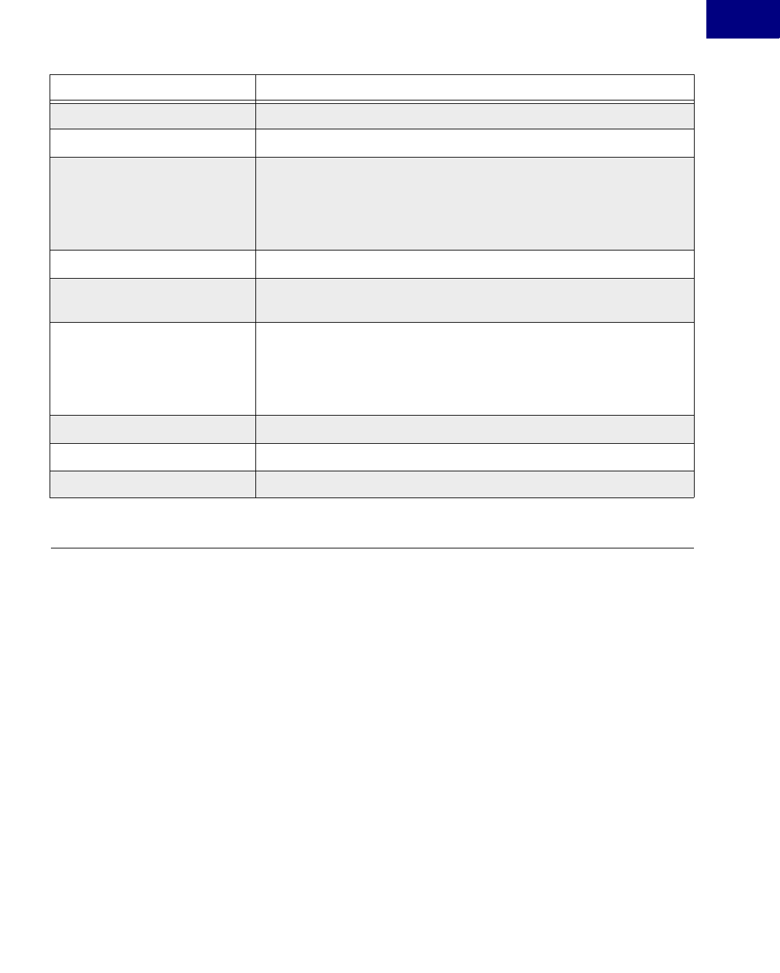
Printing 449
Printing
Japanese page-mark files
Japanese page-mark files
The Japanese feature set provides two extra Type options in the Marks And Bleed panel in the
Print dialog box and Print Presets selectable dialog box:
zMaru-tsuki Sentaa-tombo — The untranslated string key “kJMarksWithCircle” is passed
into IPrintData::SetPageMarkFile.
zMaru-nashi Sentaa-tombo — The untranslated string key “kJMarksWithoutCircle” is passed
into IPrintData::SetPageMarkFile.
In addition (with either the Roman or Japanese feature set), you can specify a filename (with-
out path or extension) of a file that contains a custom page mark written using PostScript. The
contents of this PostScript file are injected during printing. The actual file should have an .mrk
extension and be in one of the following locations:
(Windows) C:\Program Files\Common Files\Adobe\PrintSpt
(Mac OS) /Library/Application Support/Adobe/PrintSpt
kCreatePrintGalleyViewCmdBoss Creates a galley window view to print.
kInCopyNewPrintCmdBoss Performs the actual output of a document in InCopy.
kInCopyPrintActionCmdBoss Top-level print-action command for printing in InCopy. For most clients,
this is the command to execute to print a document in InCopy. It processes
the following supporting commands: kCreatePrintGalleyViewCmdBoss,
kInCopyPrintDialogCmdBoss, kInCopyNewPrintCmdBoss, and
kPrintGatherDataCmdBoss.
kInCopyPrintDialogCmdBoss Displays the print dialog box in InCopy.
kNewPrintCmdBoss Performs the actual output of a document or a book to the output device in
InDesign.
kPrintActionCmdBoss Top-level print-action command for printing a document. For most clients,
this is the command to execute to print a document in InDesign. It processes
the following supporting commands: kPrintDialogCmdBoss,
kPrintSavePrintDataCmdBoss, kPrintGatherDataCmdBoss, and
kNewPrintCmdBoss.
kPrintDialogCmdBoss Displays the print dialog box in InDesign.
kPrintGatherDataCmdBoss Gathers print data.
kPrintSavePrintDataCmdBoss Saves the print data into a document.
Command boss Description

Printing
Exporting to EPS and PDF
450
Exporting to EPS and PDF
The process of exporting to EPS and PDF file formats is somewhat similar to the process of
printing, in that similar components of the application are employed. The way you drive the
export process and the data model behind the EPS and PDF export features are somewhat dif-
ferent. This section provides highlights of how to drive the EPS and PDF export features in the
application.
Exporting to EPS
EPS export preferences
Settings for EPS export are stored in the IEPSExportPreferences interface on kWorkspaceBoss.
For details, see the API reference documentation.
To get the preferences, query for IEPSExportPreferences on kWorkspaceBoss and call its Get
methods.
To modify the preferences, process the kSetEPSExportPrefsCmdBoss command. This com-
mand has a data interface, IEPSExportPrefsCmdData, with which you specify the new values
of the EPS preferences. Before you call any Set methods, you can call IEPSExportPrefsCmd-
Data::CopyPrefs to copy the current preference settings in IEPSExportPreferences.
User interface
When you choose File > Export and specify the file to export and the export format to be EPS,
you will see a selectable dialog box with two panels, General and Advanced. The user-interface
elements on these panels are mapped to the methods on IEPSExportPreferences, as described
below.
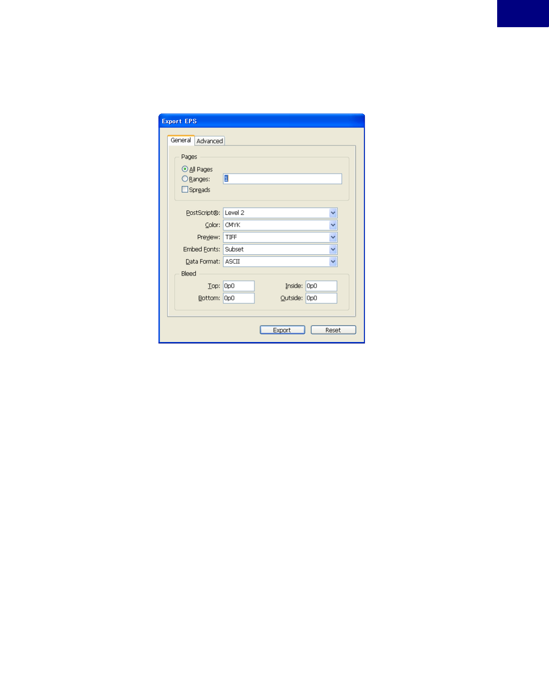
Printing 451
Printing
Exporting to EPS and PDF
Export EPS dialog box: General panel
FIGURE 210 Export EPS dialog box: General panel
zAll Pages — IEPSExportPreferences::SetEPSExPageOption using IEPSExportPrefer-
ences::kExportAllPages
zRanges (radio button) — IEPSExportPreferences::SetEPSExPageOption using IEPSExport-
Preferences::kExportRanges
zRanges (text-edit box) — IEPSExportPreferences::SetEPSExPageRange
zSpreads — IEPSExportPreferences::SetEPSExReaderSpread using IEPSExportPrefer-
ences::kExportReaderSpreadOFF or IEPSExportPreferences::kExportReaderSpreadON
zPostScript — IEPSExportPreferences::SetEPSExPSLevel using IEPSExportPrefer-
ences::kExportPSLevel2 or IEPSExportPreferences::kExportPSLevel3
zColor — IEPSExportPreferences::SetEPSExColorSpace, using IEPSExportPreferences::kEx-
portPSColorSpaceLeaveUnchanged, IEPSExportPreferences::kExportPSColorSpaceDIC,
IEPSExportPreferences::kExportPSColorSpaceCMYK, IEPSExportPreferences::kExportPS-
ColorSpaceGray, or IEPSExportPreferences::kExportPSColorSpaceRGB
zPreview — IEPSExportPreferences::SetEPSExPreview using IEPSExportPreferences::kEx-
portPreviewNone, IEPSExportPreferences::kExportPreviewTIFF, or IEPSExportPrefer-
ences::kExportPreviewPICT (Mac OS only)
zEmbed Fonts — IEPSExportPreferences::SetEPSExIncludeFonts using IEPSExportPrefer-
ences::kExportIncludeFontsNone, IEPSExportPreferences::kExportIncludeFontsWhole,
IEPSExportPreferences::kExportIncludeFontsSubset, or IEPSExportPreferences::kExport-
IncludeFontsSubsetLarge
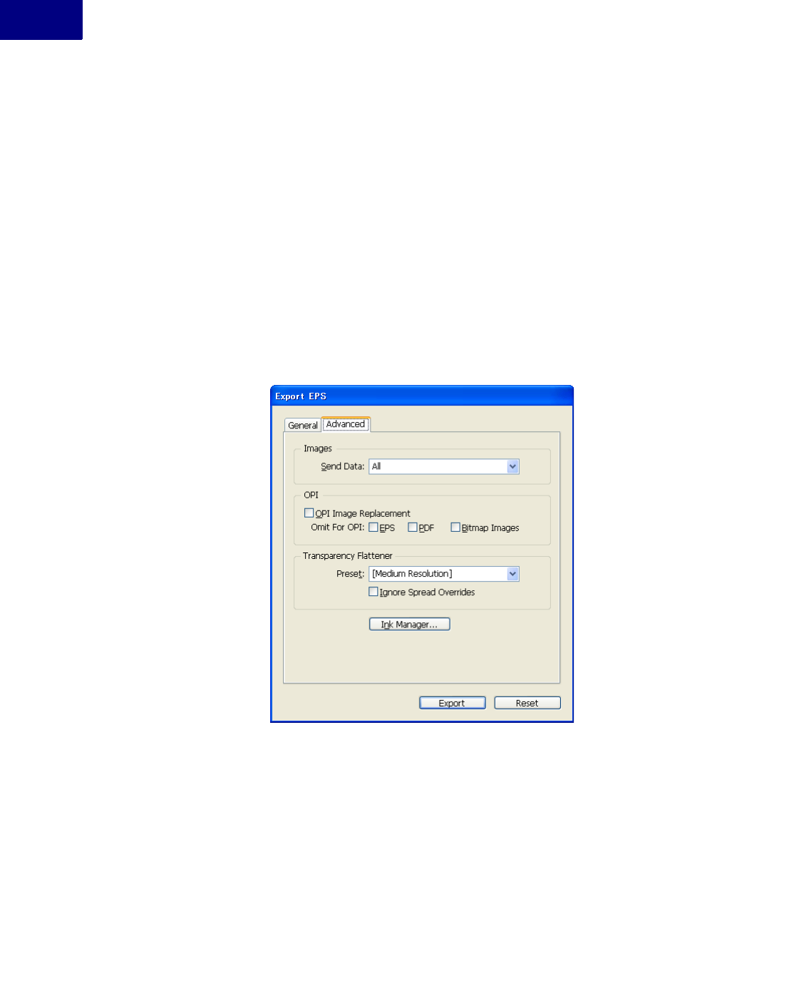
Printing
Exporting to EPS and PDF
452
zData Format — IEPSExportPreferences::SetEPSExDataFormat, using IEPSExportPrefer-
ences::kExportASCIIData or IEPSExportPreferences::kExportBinaryData
zBleed: Top — IEPSExportPreferences::SetEPSExBleedTop
zBleed: Bottom — IEPSExportPreferences::SetEPSExBleedBottom
zBleed: Inside — IEPSExportPreferences::SetEPSExBleedInside
zBleed: Outside — IEPSExportPreferences::SetEPSExBleedOutside
zIf any Bleed settings are over 0 — IEPSExportPreferences::SetEPSExBleedOnOff using
either IEPSExportPreferences::kExportBleedON, or IEPSExportPreferences::kExportBleed-
OFF
Export EPS dialog box: Advanced panel
FIGURE 211 Export EPS dialog box: Advanced panel
zSend Data — IEPSExportPreferences::SetEPSExBitmapSampling, using IEPSExportPrefer-
ences::kExportBMSampleNormal or kExportBMSampleLowRes
zOPI Image Replacement — IEPSExportPreferences::SetEPSExOPIReplace, using IEPSEx-
portPreferences::kExportOPIReplaceON or IEPSExportPreferences::kExportOPIRepla-
ceOFF
zOmit for OPI: EPS — IEPSExportPreferences::SetEPSExOmitEPS, using IEPSExportPrefer-
ences::kExportOmitEPSON or IEPSExportPreferences::kExportOmitEPSOFF
zOmit for OPI: PDF — IEPSExportPreferences::SetEPSExOmitPDF, using IEPSExportPrefer-
ences::kExportOmitPDFON or IEPSExportPreferences::kExportOmitPDFOFF

Printing 453
Printing
Exporting to EPS and PDF
zOmit for OPI: BitMap Images — IEPSExportPreferences::SetEPSExOmitBitmapImages,
using IEPSExportPreferences::kExportOmitBitmapImagesON or IEPSExportPrefer-
ences::kExportOmitBitmapImagesOFF
zPreset — IEPSExportPreferences::SetEPSExFlattenerStyle, using a UID of a kXPFlattener-
StyleBoss object (use IFlattenerStyleListMgr to find one)
zIgnore Spread Overrides — IEPSExportPreferences::SetEPSExIgnoreFlattenerSpreadOver-
rides, using IEPSExportPreferences::kExportIgnoreSpreadOverridesON or IEPSExport-
Preferences::kExportIgnoreSpreadOverridesOFF
Exporting
Using IK2ServiceRegistry, query for service providers supporting kExportProviderService.
Find an export provider that can support the format name “EPS,” by iterating over all export
providers and calling IExportProvider::CountFormats and IExportProvider::GetNthFormat-
Name, or IExportProvider::CanExportThisFormat. Once you find the export provider for EPS,
do the following:
zCall IExportProvider::CanExportToFile to check whether the document and current selec-
tion target can be exported.
zOptionally, query for IBoolData, set it to kTrue to set IPrintContentPrefs, and query for
IPrintContentPrefs and call its Set methods.
zCall IExportProvider::CanExportToFile or IExportProvider::ExportToStream to do the
export.
Exporting to PDF
The structure of the PDF-export architecture is very similar to that of EPS export; however, you
can specify a greater level of detail when exporting a document to PDF. For details of exporting
to PDF, see the “PDF Import and Export” chapter.

Printing
Exporting to EPS and PDF
454

PDF Import and Export 455
PDF Import and Export
PDF import
PDF Import and Export
PDF import
This section focuses on how you can control PDF import preferences during the PDF import
process.
Importing a file into InDesign requires a series of commands to be processed in a certain
sequence. Before a PDF file can be imported, a page item needs to be created to hold the PDF
content. Also, a proper datalink needs to be set up, so the association between the page item
and the external file can be established.
Figure 212 is a high-level illustration of the import process in InDesign for a standalone desk-
top PDF file (not a workgroup file) to be loaded into the place gun. The details of a complete
import process is beyond the scope of this document. We recommend you always try to import
(or place) a file using the method illustrated in the SnpPlaceFile.cpp snippet sample, which
uses kImportAndPlaceCmdBoss to place the file on the active spread. You also can use kIm-
portAndLoadPlaceGunCmdBoss to load the file into the place gun. Both commands check
with all the import providers and pick the appropriate provider for the type of file to import.
The PDF import provider (kPDFPlaceProviderBoss) is the default InDesign import provider
for PDF files. kPDFPlaceProviderBoss processes kPDFPlaceCmdBoss, which is the central
command that does the real work of importing a PDF file.
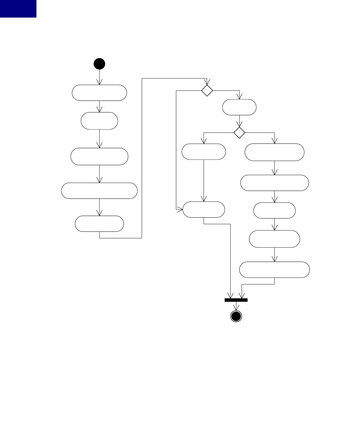
PDF Import and Export
PDF import
456
FIGURE 212 High-level view of importing a desktop PDF file
When you import a PDF file through the InDesign Place dialog box, if you choose Show
Import Options, the Place PDF dialog opens, as shown in Figure 213. The following options
offer flexible PDF import:
zPlacing multipage PDF pages (General tab) — You can place a range of PDF pages from a
multipage PDF file. Under Pages, select All or enter a value for Range. The place gun is
loaded as before, but the pointer changes to show that multiple pages exist. Each time you
click, a PDF page is placed on the page. If you hold down the Alt/Option keys, the pointer
changes to the cascade-place pointer, and clicking places all remaining pages on the page,
cascading down from the click point.
Receive an IDFile to import
Create a data link
from the IDFile
Open an IPMStream
from the data link for import
Display PDF import option if necessary
Create a new page item
Import PDF
Delete the page item Update user's PDF import pref
based on the pref just used
Add the data link to the page item
Make sure the page item
is in a graphic frame
Load the new item in the place gun
Release the datalink Release the datalink
fail succeed
fail succeed
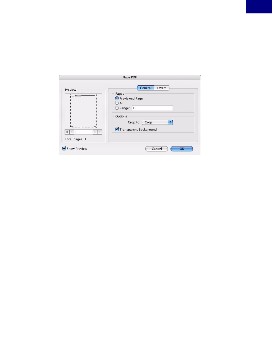
PDF Import and Export 457
PDF Import and Export
PDF import
zOptional content groups (OCG) layers support (Layers tab) — OCG groups content for
selective viewing and printing, supports complex mapping of objects to groups, and allows
special use cases like language and zoom factors. By recognizing OCG constructs in placed
PDF files, InDesign offers users the ability to selectively include those pieces of content.
FIGURE 213 PDF import options
General PDF import options are stored in the IPDFPlacePrefs interface, and layers options are
stored in IGraphicLayerInfo; both interfaces are added to the kWorkspaceBoss workspace.
Normally, these options are used unless the PDF import is performed through a link update; in
that case, the IGraphicLayerInfo on the page item (kPlacedPDFItemBoss) is used instead, and
some attributes from the IPDFAttributes aggregated on the kPlacedPDFItemBoss are used. The
following attributes override the defaults under the condition of a link update:
zIPDFAttributes::SetPage — Overrides PDF page number of the placed page.
zIPDFAttributes::SetTransparentBackground — Overrides Transparency background.
zIPDFAttributes::SetPreserveScreens — Overrides Preserve Halftone Screens.
zIPDFAttributes::SetUserPassword — Overrides Set User Password.
zIPDFAttributes::SetCropTo — Overrides Set Crop To.
Figure 214 shows how kPDFPlaceProviderBoss sets up the data interfaces for kPDFPlaceCmd-
Boss in different cases. If the import is done with the full user interface, the user can change
settings through the Place PDF dialog (see Figure 213). InDesign uses kPDFPlaceProviderBoss
to do its PDF import, so by changing import options you control InDesign’s PDF import
behavior.
Figure 214 has a “Minimal UI” decision point. If the user deselects Show Import Options when
importing a file, a minimal user interface is used: the user sees only a progress bar, not the
Place PDF dialog.
Figure 214 also has an “Is the PDF import for link update?” decision point. Link update is per-
formed when the user selects Relink or Update from the Links panel. Doing this triggers a PDF
import if the link is a PDF item.
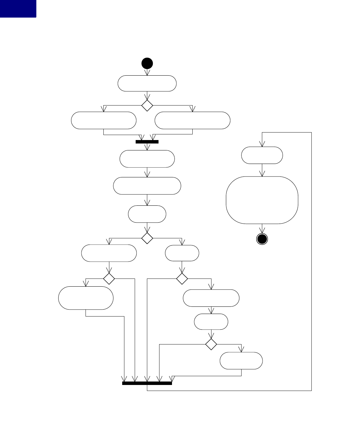
PDF Import and Export
PDF import
458
FIGURE 214 kPDFPlaceProviderBoss import option use
Get the session preference:
IGraphicLayerInfo
Is the PDF import
for link update?
Does the linked page
item have IPDFAttributes
Is the import from clipboard?
Get session prefs: IPDFPlacePrefs
from IID_IPDFPLACEPREFS
Get session prefs: IPDFPlacePrefs
from IID_IPDFCLIPBOARDPLACEPREFS
Suppress UI?
Minimal UI?
Copy session preference data to
kPDFPlaceCmdBoss data interface
Override some session data
with linked page item's
IPDFAttributes
Override the PDF password
setting from the source PDF
Bring up PDF Import
Dialog if available
Process
kPDFPlaceCmdBoss
If the import was successful,
and we are NOT importing from
clipboard, and we are NOT in
active INX context, then update
the user’s PDF place preferences
based on what they just chose using
kSetPDFPlacePrefsCmdBoss
Yes
Yes
Yes
Yes
Yes
No
No
No
No
No

PDF Import and Export 459
PDF Import and Export
PDF export
The main interfaces to control the PDF import options are IPDFPlacePrefs, IGraphicLayerInfo,
and IPDFAttributes. To modify the data stored in these interfaces, use the commands shown in
Table 110. Note there is no command to modify the IPDFPlacePrefs for clipboard import
(IID_IPDFCLIPBOARDPLACEPREFS). If you process your own kPDFPlaceCmdBoss, use the
IPDFPlacePrefs aggregated on the command boss to set up the import option. The IGraphi-
cLayerInfo on the page item passed to the kPDFPlaceCmdBoss is used for layer options.
TABLE 110 Commands to Change PDF Import Options
PDF export
InDesign/InCopy document export
The easiest way to export an InDesign or InCopy document is to use the PDF export service
provider. Example 27 is a snippet showing how to get the PDF export provider and call the
export method.
EXAMPLE 27 Getting the PDF export provider
PMString PDFFormat("Adobe PDF");
PDFFormat.SetTranslatable(kFalse);
InterfacePtr<ISelectionManager> selection(SelectionUtils::QueryActiveSelection());
IDocument *frontDoc = ::GetFrontDocument();
InterfacePtr<IK2ServiceRegistry> k2ServiceRegistry(gSession, UseDefaultIID());
// Look for all service providers with kExportProviderService.
int32 exportProviderCount = k2ServiceRegistry-
>GetServiceProviderCount(kExportProviderService);
// Iterate through them.
bool found = kFalse;
for (int32 exportProviderIndex = 0 ; exportProviderIndex < exportProviderCount ;
exportProviderIndex++)
To change... Use
IPDFPlacePrefs on the workspace kSetPDFPlacePrefsCmdBoss
IGraphicLayerInfo on the workspace kSetPDFPlacePrefsCmdBoss
IPDFAttributes on the page item kSetPDFAttributesCmdBoss
IGraphicLayerInfo on the page item kSetGraphicLayerInfoCmdBoss

PDF Import and Export
PDF export
460
{
// get the service provider boss class
InterfacePtr<IK2ServiceProvider> k2ServiceProvider
(k2ServiceRegistry->QueryNthServiceProvider(kExportProviderService,
exportProviderIndex));
// Get the export provider implementation itself.
InterfacePtr<IExportProvider> exportProvider(k2ServiceProvider,
IID_IEXPORTPROVIDER);
// Check to see if the current selection specifier can be exported by this
provider.
bool16 canExportByTarget = exportProvider->CanExportThisFormat(frontDoc,
selection, PDFFormat);
if (canExportByTarget)
{
found = kTrue;
// assume idFile is a valid IDFile to hold the soon to be created PDF
exportProvider->ExportToFile(idFile, frontDoc, selection, PDFFormat, kFullUI);
}
if (found)
break;
}
In the example, note the following:
zThe format name used to get the PDF export provider is Adobe PDF, defined in the begin-
ning of the example.
zThe example tells the PDF export provider to use the full user interface during the export,
meaning the PDF export settings dialog is brought up for the user to set export options. The
settings dialog box is provided by kPDFExportDialogBoss in InDesign and by kInCopyPD-
FExptDialogBoss in InCopy. They are selectable dialog service providers you can retrieve
through the IK2ServiceRegistry::GetServiceProviderIndex method, although it is most
practical to specify kFullUI and let the export provider do the work. If kSuppressUI is used
instead, no user interface is presented, and you can change the preference as described
below.
zThe example omits the steps that produce a valid IDFile to be passed into the IExportPro-
vider::ExportToFile method. Normally, the IDFile is obtained through a standard Save File
dialog box. You also can construct an IDFile from scratch. For more information on IDFile,
see the “Using Adobe File Library” chapter.
zThe example is for exporting an InDesign/InCopy document. To export an InDesign book,
see “InDesign book export” on page 468.
The PDF export provider for InDesign/InCopy documents is represented by kPDFExportBoss.
There is an IBoolData in kPDFExportBoss, which indicates whether print content preferences
(IPrintContentPrefs) should be considered. When you export from the InDesign menu, the
default value for the IBoolData is set to false, so no print content preference are used during the
default PDF export. Also, the PDF export provider allows you to use an export style (kPDFEx-
portStyleBoss) instead of dealing with the settings one by one. This is achieved by passing the
style UID in the IUIDData aggregated on the kPDFExportBoss.
The kPDFExportBoss processes kPDFExportCmdBoss. Before the command is processed,
kExportValidationCmdBoss is used to verify that the attributes set for the command will pro-
PDF Import and Export 461
PDF Import and Export
PDF export
duce a valid output. Table 111 summarizes the command interfaces kPDFExportBoss needs to
set up before it processes kPDFExportCmdBoss.
TABLE 111 Critical data interfaces for kPDFExportCmdBoss
From InDesign layout view
If a style is passed to the export provider, the IPDFExportPrefs on the kPDFExportStyleBoss is
copied to the IPDFExportPrefs on the kPDFExportCmdBos; otherwise, the IPDFExportPrefs
on the kWorkspaceBoss is used. You can query the session’s PDF export preference as follows:
InterfacePtr<IPDFExportPrefs>
appExportPrefs((IPDFExportPrefs*)::QuerySessionPreferences(IID_IPDFEXPORTPREFS));
To change the preferences, process kSetPDFExportPrefsCmdBoss and use the Set*** methods
of IPDFExportPrefs on the command boss to change the settings.
IPDFSecurityPrefs is set up using the preferences saved in the session (i.e., IPDFSecurityPrefs
on the kWorkspaceBoss). You can query the preferences as follows:
InterfacePtr<IPDFSecurityPrefs>
appSecurityPrefs((IPDFSecurityPrefs*)::QuerySessionPreferences(IID_IPDFSECURITYPREF
S));
To change the security preferences, process kSetPDFSecurityPrefsCmdBoss and use the Set***
methods of IPDFSecurityPrefs on the command boss to change the settings.
Another critical interface in kPDFExportCmdBoss that needs to be set up is IOutputPages. It
holds the UIDs of the pages from the document for export. The PDF export provider uses
IPageRange on the kWorkspaceBoss to initialize the IOutputPages on kPDFExportCmdBoss.
kPDFExportDialogBoss uses the same data to initialize the export settings dialog user inter-
Interface Purpose
IPDFExportPrefs Holds most of the PDF export settings as seen in the PDF
export options dialog.
IPDFSecurityPrefs Holds the PDF security preference.
ISysFileData Holds the destination IDFile for the PDF document.
IBoolData Indicates whether the IPrintContentPrefs should be used.
IPrintContentPrefs Allows certain contents to be removed from the output.
IBoolData (IID_IBOOKEXPORT) Indicates whether the command is used to export an
InDesign book.
IUIFlagData Tells the command to use kFullUI, kMinimalUI, or
kSuppressUI.
IOutputPages Holds the UIDs of the pages to output in layout mode.
IInCopyGalleySettingData Data for galley export.
IBoolData
(IID_IINCOPYPDFNOTEANNOTATIONDATA)
Layout export note annotation flag.

PDF Import and Export
PDF export
462
face, and it updates the session data when the user changes it from the dialog box. Example 28
shows how to set up IOutputPages from IPageRange on kWorkspaceBoss.
EXAMPLE 28 Setting up kPDFExportCmdBoss’s IOutputPages from IPageRange
InterfacePtr<IPageRange>
myPageRange((IPageRange*)::QuerySessionPreferences(IID_IPAGERANGE));
IPageRange::RangeFormat pageRangeFormat = myPageRange->GetPageRangeFormat();
// Assume theDoc is a valid IDocument* for export.
UIDList pageUIDs = UIDList(::GetDataBase(theDoc));
InterfacePtr<IPageList> iPageList((IPMUnknown*)theDoc, IID_IPAGELIST);
if (pageRangeFormat != IPageRange::kAllPages)
{
PMString pageRange;
pageRange = myPageRange->GetPageRange();
pageRange.SetTranslatable(kFalse);
iPageList->PageRangeStringToUIDList(pageRange, &pageUIDs);
}
else
{
int32 cPages = iPageList->GetPageCount();
for (int32 iPage = 0; iPage < cPages; iPage++ )
{
UID uidPage = iPageList->GetNthPageUID(iPage);
pageUIDs.Append( uidPage );
}
}
// Assume pdfExportCmd is the valid ICommand* from kPDFExportCmdBoss.
InterfacePtr<IOutputPages> iExportPages(pdfExportCmd, IID_IOUTPUTPAGES);
// Assume exportPrefs is the previously set IPDFExportPrefs from kPDFExportCmdBoss.
iExportPages->InitializeFrom(pageUIDs, (exportPrefs->GetPDFExReaderSpreads() ==
IPDFExportPrefs::kExportReaderSpreadsON));
PMString name;
theDoc->GetName(name);
iExportPages->SetName(name);
From InCopy layout view
There is an IInCopyPDFExptLayoutData interface on kWorkspaceBoss, which is used to store
some InCopy layout export settings. During an InCopy layout export, IPDFExportPrefs is set
up as described in “From InDesign layout view” on page 461. Then the IInCopyPDFExptLay-
outData on the kWorkspaceBoss is used to override some of the data on the command’s IPD-
FExportPrefs. Table 112 summarizes the overrides. To change the
IInCopyPDFExptLayoutData on the kWorkspaceBoss, use kSaveInCopyPDFExptLayout-
DataCmdBoss.
PDF Import and Export 463
PDF Import and Export
PDF export
TABLE 112 InCopy Layout-specific export settings
IOutputPages for kPDFExportCmdBoss is set up like kPDFExportCmdBoss IOutputPages
from IPageRange, except IInCopyPDFExptLayoutData::GetPDFExPageRangeFormat is used
to check the range format and IInCopyPDFExptLayoutData::GetPDFExPageRange is used to
get the range if the range format is not IInCopyPDFExptLayoutData::kAllPages.
kPDFExportCmdBoss also aggregates an interface, IInCopyGalleySettingData. During InCopy
layout export, IInCopyGalleySettingData::SetGalleySetting(kFalse) is called, so no IInCopyGa-
lleySettingData is used.
The IBoolData (IID_IINCOPYPDFNOTEANNOTATIONDATA) on the kPDFFxportCmd-
Boss is set to the value from IInCopyPDFExptLayoutData::GetPDFExAnnotationNotes.
From InCopy story view or galley view
Export from galley view is different than export from layout view, because the galley and story
view on-screen may not be the export (print) view. Galley export allows the user to output the
galley story with multiple columns and a selected range of story lines. When the user selects
Attributes Override
Launch Adobe
Acrobat
Changed by SetPDFExLaunchAcrobat. If
IInCopyPDFExptLayoutData::GetPDFExLaunchAcrobat is equal to kTrue, this is set to
kExportLaunchAcrobatON; otherwise, kExportLaunchAcrobatOFF.
Compatibility
Level
Changed by SetPDFExAcrobatCompatibilityLevel. Set to the value returned by
IInCopyPDFExptLayoutData::GetPDFExAcrobatCompatibilityLevel.
Compression Type Changed by SetCompressionType. If
IInCopyPDFExptLayoutData::GetPDFExAcrobatCompatibilityLevel >= kPDFVersion15,
this is set to kCompressObjects; otherwise, kCompressNone.
Embed Page
Thumbnails
Changed by SetPDFExThumbnails. If IInCopyPDFExptLayoutData::GetPDFExThumbnails
is equal to kTrue, this is set to kExportThumbnailsON; otherwise, kExportThumbnailsOFF.
Optimize for Fast
Web View
Changed by SetPDFExLinearized. If IInCopyPDFExptLayoutData::GetPDFExLinearized is
equal to kTrue, this is set to kExportLinearizedON; otherwise, kExportLinearizedOFF.
Include Page
Information
Changed by SetPDFExPageInfo. If IInCopyPDFExptLayoutData::GetPDFExPageInfo is
equal to kTrue, this is set to kExportPageInfoON; otherwise, kExportPageInfoOFF.
Subset Fonts
Threshold
Changed by SetPDFExSubsetFontsThreshold. Set to the value returned by
IInCopyPDFExptLayoutData::GetPDFExSubsetFontsThreshold.
Export Reader
Spreads
Changed by SetPDFExReaderSpreads. If
IInCopyPDFExptLayoutData::GetPDFExReaderSpreads is equal to kTrue, this is set to
kExportReaderSpreadsON; otherwise, kExportReaderSpreadsOFF.
Interactive
Elements
Changed by SetPDFExAddInteractiveElements. Set to the value returned by
IInCopyPDFExptLayoutData::GetPDFExAddInteractiveElements.
Multimedia
Content to Embed
Changed by SetContentToEmbed. Set to the value returned by
IInCopyPDFExptLayoutData::GetContentToEmbed.

PDF Import and Export
PDF export
464
export, a final view to the document is not yet available. The PDF export provider internally
executes kCreatePrintGalleyViewCmdBoss to generate an invisible galley view for PDF port
printing based on the user’s preferences.
IInCopyPDFExptGalleyData on the kWorkspaceBoss is the default galley-specific setting data
used during PDF export. It is used to set up some of the data in IPDFExportPrefs and IInCopy-
GalleySettingData; both are aggregated on kPDFExportCmdBoss. The PDF export provider
does not take the data from IInCopyPDFExptGalleyData on the kWorkspaceBoss as is: if the
galley document contains any story and the session’s IInCopyPDFExptGalleyData is default
(checked through IInCopyPDFExptGalleyData::GetIsDefaultValues), the data shown in
Table 113 is overridden.
TABLE 113 IInCopyPDFExptGalleyData overrides when it is default
Attributes Override
Font Leading Changed by SetPDFExFontLeading. Set to the string value returned from
IGalleySettingsOverwrite::GetDisplayFontLeading.
Font Name Changed by SetPDFExFont. Set to the value returned by Utils<IGalleyUtils>()-
>GetFontFamilyAndStyle.
Font Size Changed by SetPDFExFontSize. Set to the string value returned from
IGalleySettingsOverwrite::GetDisplayFontSize.
Font Type Changed by SetPDFExFontType. Set to the value returned by Utils<IGalleyUtils>()-
>GetFontFamilyAndStyle.
Include Accurate Line
Endings
Changed by SetPDFExALE. If ITextLine::GetLinesType is equal to
ITextLines::kLayoutLineEnds, set to kTrue; otherwise, kFalse.
Include Inline Notes Changed by SetPDFExInlineNotes. If there is at least one note anchor in the document,
set to kTrue; otherwise, kFalse.
Include Line
Numbers
Changed by SetPDFExLineNumber. Set to the value returned by Utils<IGalleyUtils>()-
>InGalley().
Include Paragraph
Styles
Changed by SetPDFExStyle. Set to the value returned from
IGalleySettingsOverwrite::GetShowParagraphStyleNames.
Include Track
Changes
Changed by SetPDFExTrackChanges. Set to the value returned from
IGalleySettingsOverwrite::GetShowTrackChanges.
Notes Type Changed by SetPDFExNotesType. Set to kVisible.
Show Notes
Backgrounds in Color
Changed by SetPDFExNotesBackground. Set to kFalse.
Show Track Changes
Backgrounds in Color
Changed by SetPDFExTrackChangesBackground. Set to kFalse.
Track Changes Type Changed by SetPDFExTrackChangesType. Set to kVisible.
PDF Import and Export 465
PDF Import and Export
PDF export
NOTE:ITextLine and IGalleySettingsOverwrite should be from the galley view
(kWritingModeWidgetBoss) of the exported document.
In galley view mode, the PDF export provider initializes IPDFExportPrefs and IPDFExport-
Prefs in much the same way as described in “From InCopy layout view” on page 462, but the
attributes from IPDFExportPrefs shown in Table 114 are overridden by IInCopyPDFExptGal-
leyData, as described above.
TABLE 114 Galley-specific settings for IPDFExportPrefs
As described in “From InCopy layout view” on page 462, IOutputPages is a critical interface
that holds the UIDs of pages to be exported for kPDFExportCmdBoss in layout mode. For
InCopy galley and story mode, however, IOutputPages cannot provide enough data for kPD-
FExportCmdBoss to draw a range of lines from galley view or rearrange the number of col-
umns in the output PDF that are allowed in the galley export options dialog box. Therefore, the
interface IInCopyGalleySettingData is aggregated on kPDFExportCmdBoss to hold the data
used to create a galley window for PDF export. In addition to settings specific to galley mode,
IInCopyGalleySettingData also holds the views (IControlView* of the galley writing widgets,
paragraph information panel, etc.) that represent the real output pages based on the user’s gal-
ley export settings. kPDFExportCmdBoss passes these views to the PDF drawing port for out-
put instead of using IOutputPages. The user of kPDFExportCmdBoss is responsible for setting
up IInCopyGalleySettingData properly before the command is processed. The PDF export pro-
vider executes kCreatePrintGalleyViewCmdBoss to get an invisible output view based on the
data from the current galley document and IInCopyPDFExptGalleyData. It then uses the view
and IInCopyPDFExptGalleyData to set up IInCopyGalleySettingData for kPDFExportCmd-
Boss. The PDF export provider sets up IOutputPages of kPDFExportCmdBoss with IOut-
putPages returned from kCreatePrintGalleyViewCmdBoss, which has the values shown in
Table 115.
Attributes Values
Acrobat Compatibility
Level
Set by SetPDFExAcrobatCompatibilityLevel. Set to the value returned from
IInCopyPDFExptGalleyData::GetPDFExAcrobatCompatibilityLevel.
Include Page
Information
Set by SetPDFExPageInfo. If IInCopyPDFExptGalleyData::GetPDFExPageInfo is equal
to kTrue, this is set to IPDFExportPrefs::kExportPageInfoON; otherwise,
IPDFExportPrefs::kExportPageInfoOFF.
Subset Fonts Threshold Set by SetPDFExSubsetFontsThreshold. Set to the value returned from
IInCopyPDFExptGalleyData::GetPDFExSubsetFontsThreshold.
PDF Import and Export
PDF export
466
TABLE 115 IOutput pages from kCreatePrintGalleyViewCmdBoss
The following steps summarize how the PDF export provider sets up IInCopyGalleySetting-
Data for kPDFExportCmdBoss.
1. A new kInCopyGalleySettingDataBoss is created, with default value.
2. IInCopyPDFExptGalleyData is used to override the IInCopyGalleySettingData of the new
kInCopyGalleySettingDataBoss.
3. IInCopyGalleySettingData is used to execute the kCreatePrintGalleyViewCmdBoss com-
mand.
4. A copy of IInCopyGalleySettingData returned from kCreatePrintGalleyViewCmdBoss in
Step 3 is used to set up kPDFExportCmdBoss.
Table 116 shows how attributes from IInCopyGalleySettingData get their values in different
stages. In the table, “PEGD” stands for IInCopyPDFExptGalleyData from Step 2 above.
TABLE 116 Setting up IInCopyGalleySettingData for kPDFExportCmdBoss
Attributes Values
ContiguousPages kTrue
Name Name of the galley document
IsSpreads kFalse
MasterDataBase Database for the window created by the
kCreatePrintGalleyViewCmdBoss
UIDs Placeholder. UIDs number from 0 to total pages-1. UIDs
contained in IOutputPages are not used by kPDFExportCmdBoss
in InCopy galley and story mode.
Attribute and description Default value Overridden value Final value after kCreatePrint-
GalleyViewCmdBoss
Galley/story control view nil nil Calculated by
kCreatePrintGalleyViewCmd
Boss
Paragraph panel control view
(GetInfoColumnView)
nil nil Calculated by
kCreatePrintGalleyViewCmd
Boss
Line number panel control view
(GetLineNumberView)
N/A, not used N/A, not used N/A, not used
Splitter control view
(GetInfoSplitterView)
nil nil Calculated by
kCreatePrintGalleyViewCmd
Boss
PDF Import and Export 467
PDF Import and Export
PDF export
Total content height of the
galley (GetTotalHeight)
0 0 Calculated by
kCreatePrintGalleyViewCmd
Boss
Start Line Number
(GetStartLineNumber)
N/A, not used N/A, not used N/A, not used
End Line Number
(GetEndLineNumber)
N/A, not used N/A, not used N/A, not used
Column width
(GetColumnWidth)
0 Calculated based on PEGD
and current unit settings
Calculated by
kCreatePrintGalleyViewCmd
Boss
GalleySetting kTrue kTrue kTrue
Document UIDRef
(GetDocUIDRef)
N/A UIDRef of galley document UIDRef of galley document
To print with paragraph style
info (GetParaStyle)
kFalse from PEGD from PEGD
To print with line number
(GetLineNumber)
kFalse from PEGD from PEGD
To print with accurate line
ending (GetALE)
kFalse from PEGD from PEGD
To print with notes displayed
(GetNotes)
kFalse from PEGD from PEGD
To print with tracked changes
displayed (GetTrackChange)
kFalse from PEGD from PEGD
Notes displayed type
(GetNotesType)
kVisible from PEGD from PEGD
Track change displayed type
(GetTrackChangesType)
kVisible from PEGD from PEGD
Font name (GetFontName) “” from PEGD from PEGD
Font type (GetFontType) “” from PEGD from PEGD
Font size (GetFontSize) “” from PEGD from PEGD
Font leading (GetFontLeading) “” from PEGD from PEGD
Attribute and description Default value Overridden value Final value after kCreatePrint-
GalleyViewCmdBoss
PDF Import and Export
PDF export
468
InDesign book export
You can use the high-level kBookExportActionCmdBoss to easily export a book. For details,
see SnpExportBookAsPDF.cpp.
kBookExportActionCmdBoss uses kPDFExportBookBoss (with service ID kExportBookSer-
vice), which uses the same PDF export service provider (kPDFExportProviderImpl) as the
To print with line range scope
(GetWhich)
IIncopyGalley
PrintData::kAll
If PEGD’s
GetPDFExlineRangeFormat
is
IInCopyPDFExptGalleyDat
a::kAllLine, set to kAllLines;
otherwise, kUseRange
If PEGD’s
GetPDFExlineRangeFormat
is
IInCopyPDFExptGalleyData:
:kAllLine, set to kAllLines;
otherwise kUseRange.
To print the line range
(GetRange)
“” from PEGD from PEGD
Galley frame size
(GetFrameSize)
Rect(0, 0, 0, 0) Set frame to the page
bounds from the first page
of the galley document.
Set frame to the page bounds
from the first page of the
galley document.
To print with content filled with
the page (GetFill)
kFalse If GetALE returns true, then
set to the return value from
PEGD’s GetPDFExFill;
otherwise, kFalse.
If GetALE returns true, then
set to the return value from
PEGD’s GetPDFExFill;
otherwise, kFalse.
Story range (GetScope) IInCopyGalley
PrintData::kAll
from PEGD from PEGD
To print with story information
(GetStoryInfo)
kFalse from PEGD from PEGD
To print with notes background
in color
(GetNotesBackgroundInColor)
kTrue from PEGD from PEGD
To print with track changes
background in color
(GetTrackChangesBackgroundI
nColor)
kTrue from PEGD from PEGD
To print with page information
(GetPagesInfo)
kFalse kFalse kFalse
(kPDFExportCmdBoss takes
this info from
IPDFExportPrefs)
To print with number of
columns (GetColumns)
1 1 Calculated by
kCreatePrintGalleyViewCmd
Boss
Attribute and description Default value Overridden value Final value after kCreatePrint-
GalleyViewCmdBoss

PDF Import and Export 469
PDF Import and Export
PDF export
kPDFExportBoss; however, kPDFExportBookBoss aggregates an IOutputPages interface that
lists document pages in the book to export. The regular document kPDFExportBoss does not
aggregate IOutputPages; it sets up IOutputPages for the kPDFExportCmdBoss based on the
IPageRange, as shown in Example 28.
Selected page-items export
There is no direct user interface to allow export of selected page items in InDesign; however,
you can copy selected page items to the pasteboard in PDF format. Then, when you paste into
an external application that supports PDF import, the pasted object is in PDF format. This is
done through kPDFExportItemsCmdBoss. The snippet in Example 29 shows how to process
the command.
EXAMPLE 29 How to process a kPDFExportItemsCmdBoss command
// Assume stream is the destination PDF file write stream.
// Assume realPageItems contains no guide item, which can
// cause trouble in PDF export.
InterfacePtr<ICommand> command(CmdUtils::CreateCommand(kPDFExportItemsCmdBoss));
if (command)
{
command->SetItemList(realPageItems);
// Initialize the command data from the session.
InterfacePtr<IPDFExportPrefs> appExportPrefs((IPDFExportPrefs *)
::QuerySessionPreferences(IID_IPDFCLIPBOARDEXPORTPREFS));
InterfacePtr<IPDFExportPrefs> exportPrefs(command, IID_IPDFEXPORTPREFS);
InterfacePtr<IPDFSecurityPrefs> appSecurityPrefs((IPDFSecurityPrefs *)
::QuerySessionPreferences(IID_IPDFSECURITYPREFS));
InterfacePtr<IPDFSecurityPrefs>
exportSecurityPrefs(command,IID_IPDFSECURITYPREFS);
exportPrefs->CopyPrefs(appExportPrefs);
exportSecurityPrefs->CopyPrefs(appSecurityPrefs);
// no progress bar
InterfacePtr<IBoolData> useProgressBar(command, IID_IUSEPROGRESSINDICATOR);
useProgressBar->Set(kFalse);
InterfacePtr<IUIFlagData> uiFlagData(command, IID_IUIFLAGDATA);
uiFlagData->Set(kSuppressUI);
// Assume no destination color profile (i.e., ignore IUIDData).
// (IID_IPDFDESTCMSPROFILE)
// Put the stream pointer in the IIntData.
InterfacePtr<IIntData> exportCmdStreamData(command, IID_IINTDATA);
exportCmdStreamData->Set((long) stream);
// process the command
CmdUtils::ProcessCommand(command);
success = ErrorUtils::PMGetGlobalErrorCode();
}

PDF Import and Export
PDF-style import and export
470
PDF-style import and export
When the PDF export provider brings up the Export Adobe PDF options dialog box, the dialog
box is initialized according to the following rules:
1. A preset style UID may be passed in. When it is available, use it.
2. Otherwise, if the last preset used is named “[Custom]” or the style name ends with “(modi-
fied),” use the application preferences of the workspace.
3. Otherwise, if the last preset used is not empty and is valid, use it.
4. Otherwise, use the default preferences. This is the first time the export dialog is run after
deleting Save Data.
PDF export style is represented by kPDFExportStyleBoss, which aggregates an IPDFExport-
Prefs interface that stores the settings. Usually, the IPDFExportPrefs -> CopyPrefs method is
used to copy the setting out of the style boss to another IPDFExportPrefs you are using. The
last preset style’s name is saved in the IPDFExportStyleLastUsed on the kWorkspace. You can
use the snippet in Example 30 to get the name in PMString:
EXAMPLE 30 Getting the last-used style name
InterfacePtr<IPDFExportStyleLastUsed>
iStyleLast((IPDFExportStyleLastUsed*)::QuerySessionPreferences
(IID_IPDFEXPORTSTYLELASTUSED));
PMString lastPreset;
if (iStyleLast)
lastPreset = iStyleLast->GetString();
lastPreset.SetTranslatable(false);
Given a style name, you can use IPDFExptStyleListMgr (aggregated on kWorkspace) to obtain
the UID style object, Continuing from Example 30, Example 31 shows how to get to a last used
style object from its name:
EXAMPLE 31 Getting a style object using name
InterfacePtr<IPDFExptStyleListMgr>
styleMgr((IPDFExptStyleListMgr*)::QuerySessionPreferences(IID_IPDFEXPORTSTYLELISTMG
R));
int32 nStyle = styleMgr->GetStyleIndexByName(lastPreset);
if (nStyle != -1)
{
UIDRef styleRef = styleMgr->GetNthStyleRef(nStyle);
InterfacePtr<IPDFExportPrefs> pStylePrefs(styleRef, UseDefaultIID());
if( pStylePrefs )
{
// assume myExportPrefs is an IPDFExportPrefs I am trying to set up
myExportPrefs->CopyPrefs(pStylePrefs);
};
}

PDF Import and Export 471
PDF Import and Export
PDF-style import and export
Adding, deleting, and editing styles
To add a style, use kPDFExportAddStyleCmdBoss. Example 32 shows how to process the com-
mand:
EXAMPLE 32 Adding a PDF-export style
InterfacePtr<ICommand> addCmd(CmdUtils::CreateCommand(kPDFExportAddStyleCmdBoss));
InterfacePtr<IExportStyleCmdData> cmdData(addCmd, IID_IEXPORTSTYLECMDDATA);
InterfacePtr<IWorkspace> workspace(gSession->QueryWorkspace());
UIDRef workspaceUIDRef = ::GetUIDRef(workspace);
cmdData->SetSrcList(workspaceUIDRef);
cmdData->SetDstList(workspaceUIDRef);
// Assume presetName is a PMString containing the new style name.
cmdData->SetNewName(presetName);
cmdData->SetStyleIndex(-2); // -2 means get the PDF preferences from the command.
InterfacePtr<IPDFExportPrefs> commandPrefs(cmdData, UseDefaultIID());
// Assume pSrcPref is my source IPDFExportPrefs to be made into the new style.
commandPrefs->CopyPrefs(pSrcPrefs);
commandPrefs->SetUIName(presetName);
ErrorCode rc = CmdUtils::ProcessCommand(addCmd);
The command boss aggregates an IExportStyleCmdData that has a method, SetStyleIndex, that
sets up a style index for the command. The style index tells the command where the source
style comes from, according to the following rules:
1. If there is valid index (index >= 0), that style's PDF preferences (queried from an IPDFExpt-
StyleListMgr returned by IExportStyleCmdData::GetSrcList) are used.
2. If the index is -2, the PDF preferences come from the command.
3. If the index is -3, the PDF preferences come from the command, but the data is not written
to disk.
4. Otherwise, the PDF preferences come from the current application preferences.
5. In all cases except -3, the data is written to disk.
To delete a style, use kPDFExportDeleteStyleCmdBoss. Example 33 shows how to delete a style
stored in the application’s workspace:
EXAMPLE 33 Deleting a PDF-export style
InterfacePtr<IWorkspace> workspace(gSession->QueryWorkspace());
UIDRef workspaceUIDRef = ::GetUIDRef(workspace);
InterfacePtr<ICommand>
deleteCmd(CmdUtils::CreateCommand(kPDFExportDeleteStyleCmdBoss));
InterfacePtr<IExportStyleCmdData> commandData(deleteCmd, IID_IEXPORTSTYLECMDDATA);
// Assume i is the (to-be-deleted) style index in the style list.
commandData->SetStyleIndex(i);
commandData->SetDstList(workspaceUIDRef);
CmdUtils::ProcessCommand(deleteCmd);

PDF Import and Export
Frequently asked questions
472
To edit a style, use kPDFEditStyleCmdBoss. Example 34 shows how to edit a style stored in the
application’s workspace:
EXAMPLE 34 Editing a PDF style
InterfacePtr<ICommand> editStyleCmd(CmdUtils::CreateCommand(kPDFEditStyleCmdBoss));
InterfacePtr<IIntData> data(editStyleCmd, IID_IINTDATA);
// Assume index is the index of the style to be edited.
data->Set(index);
InterfacePtr<IPDFExportPrefs> newPrefs(editStyleCmd, IID_IPDFEXPORTPREFS );
// Assume myPrefs is the edited copy of IPDFExportPrefs.
newPrefs->CopyPrefs(myPrefs);
CmdUtils::ProcessCommand(editStyleCmd);
Frequently asked questions
How does the PDF export provider determine whether it should start the
viewer after the export?
In InDesign, IPDFPostProcessPrefs is used to maintain persistent PDF preference data not part
of the standard IPDFExportPrefs. IPDFPostProcessPrefs is aggregated on kWorkspaceBoss and
can be queried through QuerySessionPreferences. Use IPDFPostProcessPrefs::GetViewAfter-
Export to determine whether the viewer should be launched.
In InCopy, IInCopyPDFExptGalleyData::GetPDFExLaunchAcrobat (for galley) and IInCopyP-
DFExptLayoutData::GetPDFExLaunchAcrobat (for layout) are used to determine whether the
viewer should be started.
How do I set the PDF clipboard setting as seen in the File Handling
preferences?
Those settings (e.g., Prefer PDF when Pasting) are kept in the IPDFClipboardPrefs aggregated
on the kWorkspaceBoss. To modify the settings, use kSetPDFCBPrefsCmdBoss.
How do I control which layer of a document should be exported?
IPDFExportPrefs::SetExportLayers can be used to control the function of layers for visibility
and printability. Use the enums kExportAllLayers, kExportVisibleLayers, and kExportVisible-
PrintableLayers to set the export layer’s preference. Each layer’s visibility and printability are
controlled by each layer’s option, managed by IDocumentLayer. For more information about
how to set each layer’s visibility and printability, see the “Layer Options” section of the “Layout
Fundamentals” chapter.

PDF Import and Export 473
PDF Import and Export
Frequently asked questions
How do I make the two-page spreads in my document export as two
separate PDF pages?
Set the Boolean control for reader spreads in the IPDFExportPrefs to false. The IOutputPages
on the kPDFExportCmdBoss usually is initialized as follows:
InterfacePtr<IOutputPages> iExportPages(cmd, IID_IOUTPUTPAGES);
iExportPages->InitializeFrom(pageUIDs, (exportPrefs->GetPDFExReaderSpreads() ==
IPDFExportPrefs::kExportReaderSpreadsON));
If the preference for the reader spreads is set to false and you set up IOutputPages as above, the
two pages spreads are exported as separated pages in the PDF. See “Setting up kPDFExportCm-
dBoss’s IOutputPages from IPageRange” on page 462.
Why does kPDFExportCmdBoss give me an assert after the command is
processed (ASSERT 'db != nil' in PDFExportController.cpp)?
Make sure you put the UIDRef of the pages in the IOutputPage interface. Also, set the item list
with the pages’ UIDRef values (in a UIDList). kPDFExportCmdBoss is used for exporting both
books (multiple .indd files) and multiple pages from a document. kPDFExportCmdBoss first
checks to see whether it has a valid IOutputPages and uses the database from the first UIDRef
of the output pages. If the command cannot find a valid database from IOutputPages, it looks
for it from the command item list.
How do I set up line ranges for output in InCopy Galley or Story mode?
Use IInCopyPDFExptGalleyData::SetPDFExLineRange. Pass in a PMString with a format like
“3-10” (i.e., the beginning page number, followed by a dash, followed by the ending page num-
ber). IInCopyPDFExptGalleyData is aggregated on the kWorkspaceBoss.
Is it possible to export only selected text from an InDesign document?
No. When printing or exporting to PDF, the decision to draw or not draw is made at the page-
item level. This is evidenced by the “Nonprinting” attribute, which can be applied to a text
frame but not the text itself. Similarly, draw event handlers work on the page-item level, such as
the text frame.

PDF Import and Export
Frequently asked questions
474

Implementing Preflight Rules 475
Implementing Preflight Rules
Introduction
Implementing Preflight Rules
Introduction
This chapter provides high-level information for developers who want to build their own rules
or set of rules. It complements the low-level information found in the SDK.
About preflight in InDesign CS4
InDesign CS4 has a new feature for profile-based preflight. There was a preflight feature before
CS4, but it was designed primarily for improving the reliability of the package operation. CS4
includes a fully rule-driven, parameterized, continuous preflight that can run in the back-
ground as you work.
The preflight model comprises several major areas, most of which are fully extensible by exter-
nal developers. Very little preflight code is written using private interfaces.
zThe preflight object model is a parallel view of the InDesign document and things that do
not appear in the document. It has references to both standard InDesign objects like page
items and documents and to non-persistent entities like marking operations. The object
model is fully extensible to support new objects.
zPreflight rule services are where objects are checked for compliance with a set of parameters.
A rule provides discovery, visitation, and reporting functions to the preflight engine.
zPreflight processes are idle-task-driven in-memory objects which coordinate all interactions
between the object model and the rule services. Processes also can be driven synchronously
if desired, but normally they run in the background. The processes are not extensible, but
developers have full access to their status and database.
This chapter is concerned only with the rule services, which are the most common type of
extension.
About rules
In the preflight model, rules are the entities that check conditions in the document and gener-
ate errors. An example of a rule is “Missing and Modified Graphics,” which looks for graphics
that are missing or outdated.

Implementing Preflight Rules
Rule IDs
476
To write a rule, you need two things:
zThe rule boss encapsulates both the intelligence and data for a rule.
zThe rule service tells InDesign that your rule exists and lets it create a boss for a rule. A rule
service can “host” as many rules as desired; the native InDesign rule service hosts dozens of
rules.
Rule IDs
Each unique rule (for example, missing fonts or image resolution) is identified by a rule ID. A
rule ID is simply a WideString that is never exposed in the user interface but serves to distin-
guish it from every other rule out there. For each rule you implement, you need to devise a
unique rule ID. For example, you could prefix your rule ID with your company name or use a
GUID converted to a string. Rule IDs are exposed to scripting.
Rule service
A rule service is implemented as a standard InDesign service with the service ID kPreflight-
RuleService. On the service boss, you need the IID_IK2SERVICEPROVIDER (you can use
kPreflightRuleSPImpl for the implementation) and an IPreflightRuleService. The latter inter-
face has two methods, shown in Table 117.
TABLE 117 Methods in your IPreflightRuleService implementation
In other words, this interface provides a map and boss factory for rule bosses. Most of the com-
plexity is in the rule bosses themselves.
CreateRule can be called on when InDesign is creating new preflight profiles or, in some cases,
for purely temporary purposes. For example, it might create a rule just to get some information
about it, then destroy it. It takes a database pointer to indicate whether it wants the boss to be
created in a document (or preferences) or in memory for temporary purposes.
Method Purpose
GetAllRules Returns a vector of rule IDs that your services hosts.
CreateRule Given a rule ID that you host, creates a rule boss and returns it.

Implementing Preflight Rules 477
Implementing Preflight Rules
Rule service
IPreflightRuleService example
To illustrate a typical rule-service implementation, here are some sample method implementa-
tions. In this example, there are two rules, Maximum Text Size and Maximum Rectangle Size.
IPreflightRuleService::GetAllRules
The first step is to create rule IDs for these rules; typically, we’ll also need rule bosses. If XYZCo
company is developing the rules, we might use the mapping shown in Table 118.
TABLE 118 Mappings used in our PreflightRuleService example
The GetAllRules method must return a vector of rule IDs. This is not complicated:
const PreflightRuleID kMaxTextSizeRuleID("XYZCo_MaxTextSize");
const PreflightRuleID kMaxRectSizeRuleID("XYZCo_MaxRectSize");
virtual PreflightRuleIDVector GetAllRules() const
{
PreflightRuleIDVector rules;
rules.push_back(kMaxTextSizeRuleID);
rules.push_back(kMaxRectSizeRuleID);
return rules;
}
This method usually will be called only once per session, by the rule manager, which then
holds onto the information in its internal maps.
IPreflightRuleService::CreateRule
This method creates the appropriate boss from a passed-in rule ID and fills in defaults. In our
example, we would do something like the following. (For ease of reading, most error handling
is omitted.)
virtual IPreflightRuleInfo* CreateRule
(
// Rule to create
PreflightRuleID ruleID,
// Database in which to create it (nil = in memory)
IDataBase* db
) const
{
ClassID bossID = 0;
PMString desc;
if (ruleID == kMaxTextSizeRuleID)
{
bossID = kMaxTextSizeRuleBoss;
desc = PMString("Maximum text size");
}
Rule Rule ID Boss
Maximum text size XYZCo_MaxTextSize kMaxTextSizeRuleBoss
Maximum rectangle size XYZCo_MaxRectSize kMaxRectSizeRuleBoss

Implementing Preflight Rules
Rule bosses
478
else if (ruleID == kMaxTextSizeRuleID)
{
bossID = kMaxRectSizeRuleBoss;
desc = PMString("Maximum rectangle size");
}
else return nil;
IPreflightRuleInfo* iRule = (IPreflightRuleInfo*)CreateObject
(db, bossID, IID_IPREFLIGHTRULEINFO);
iRule->SetRuleID(ruleID);
iRule->SetRuleDescription(desc);
iRule->SetPluginDescription("XYZCo Rules Plugin");
// Set up default parameter values.
InterfacePtr<IPreflightRuleUtilities> iUtils(iRule, UseDefaultIID());
iUtils->UpdateRuleData();
return iRule;
}
It is up to you what strategy to use for initialization, mapping rule IDs to bosses and descrip-
tions, and so on. If you have only a few rules, the method above should suffice.
Rule bosses
A rule boss is where all the heavy lifting goes on in the preflight world. A rule boss corresponds
to a particular rule and encapsulates all the behaviors of that rule, including the following:
zParameter data — For example, if your rule looks for things larger than X, and the user can
specify X, X is a rule parameter.
zUser interface — This is the interface used to modify your rule parameters.
zEvaluation — Your rule is a visitor. The preflight engine “carries it around” to objects it
wants to visit, and the rule must determine if the object is alright or has an error.
zAggregation — Once your rule finishes gathering errors, it must determine how to present
the errors to the user.
zUtilities — If your rule has any special requirements when copied or deleted, it needs to pro-
vide those implementations.
As shown in the previous example, each rule your plug-in supports typically has its own boss.
Each rule boss must have the interfaces shown in Table 119. You can add whatever other inter-
faces you want on your rule bosses.
Implementing Preflight Rules 479
Implementing Preflight Rules
Rule bosses
TABLE 119 Required interfaces on rule bosses
These interfaces are documented in the headers and doc++ comments, but the IPreflightRule-
Visitor interface is critical, so we expand on it below.
IPreflightRuleVisitor interface
The IPreflightRuleVisitor interface has three methods related to rule evaluation, shown in
Table 120.
TABLE 120 Rule evaluation methods on IPreflightRuleVisitor
Interface Purpose
IPreflightRuleData Stores the rule parameter data as a dictionary (key-value
pairs). Use kPreflightRuleDataImpl unless you have a really
good reason not to do so.
IPreflightRuleVisitor Provides all the evaluation and aggregation functions. This
interface tells InDesign what kinds of objects the rule wants
to visit (page items, styles, artwork, etc.), is called back when
it is time to visit one of those objects, and is called back when
it is time to aggregate (create final report of findings). Also, it
provides some parameter initialization and validation
methods.
IPreflightRuleUtilities Provides rule-specific utilities for your rule, including
copying the rule, any special deletion requirements, and
determining equality with other rules. In most cases, you can
use the default kPreflightRuleUtilitiesImpl implementation.
Method Description
GetClassesToVisit Preflight calls this method, generally on start-up, when it builds
its maps relating rules to objects. It must return a vector of
preflight object class IDs that your rule wants to visit. For
example, if you want to visit all images, you would return a vector
containing kPreflightOM_Image.
Visit Preflight calls this method when it is time to evaluate a given
object, either because it was not visited before or something was
changed such that the result might be different. This method is
passed an abstract utility class that your method uses to obtain
information and report its findings.
AggregateResults Preflight calls this method after the first pass (visitation) is
complete and the Visit method found something it might want to
report. This method takes the “raw” results found during
visitation into final presentation, in the form of nodes in the
results tree. This method typically consolidates multiple errors
into a single node, builds strings, and so on.

Implementing Preflight Rules
IPreflightRuleVisitor method examples
480
The IPreflightRuleVisitor interface also has two methods related to rule-parameter initial-
ization and validation, shown in Table 121. (These could be on another interface but since
every rule needs to implement them, there is less overhead to include them on this interface,
since every rule needs its own IPreflightRuleVisitor.)
TABLE 121 Parameter methods on IPreflightRuleVisitor
IPreflightRuleVisitor method examples
The methods in this interface concentrate on the discovery, visitation, and aggregation phases
of the preflight process. This is the trickiest interface to write.
IPreflightRuleVisitor::GetClassesToVisit
This method simply tells InDesign what object classes your rule wants to visit. For example the
missing-fonts rule looks at text runs (to see directly which fonts are used and where), as well as
placed content that has required-font data, namely placed EPS, EPS, and INDD files. Its imple-
mentation looks like the following:
virtual PreflightObjectClassIDVector GetClassesToVisit() const
{
PreflightObjectClassIDVector classes;
classes.push_back(kPreflightOM_WaxRun);
classes.push_back(kPreflightOM_EPS);
classes.push_back(kPreflightOM_PDF);
classes.push_back(kPreflightOM_INDD);
return classes;
}
Do not declare classes in which you are not actually interested. The preflight engine expands
only those portions of the model required to satisfy the rules in the profile, If you ask for art-
work, for instance, you will take a big hit in processing cycles; do this only if it is needed.
Method Description
UpdateRuleData Preflight calls this method at start-up (for application profiles)
and document open time (for document embedded profiles), to
give the rule an opportunity to initialize and/or update the rule
parameters.
ValidateRuleData Preflight calls this method when a parameter is set via scripting, to
ensure it is a legitimate value.
Implementing Preflight Rules 481
Implementing Preflight Rules
IPreflightRuleVisitor method examples
IPreflightRuleVisitor::Visit
This is the method in which your rule inspects objects it asked to visit. Typically, this method
consists of comparing attributes of the object against rule parameters.
The argument for this method is a IPreflightVisitInfo interface, which provides all the informa-
tion you should need about the object being visited. It also provides the mechanism for report-
ing the errors. Table 122 lists the methods in this interface.
TABLE 122 IPreflightVisitInfo methods
Here is an example of a Visit implementation, the page-count rule. (To enhance readability,
most error checking, like nil interfaces, is omitted.)
virtual void Visit(IPreflightVisitInfo* iVisit) override
{
InterfacePtr<IPreflightObject> iObj(iVisit->QueryObject());
InterfacePtr<IDocument> iDoc(iObj->GetModelRef(), UseDefaultIID());
InterfacePtr<IPageList> iDocPages(iDoc, UseDefaultIID());
int32 count = iDocPages->GetPageCount();
PreflightRuleDataHelper dh(this);
ComparisonType comp = (ComparisonType)dh.GetIntParam
(kParamCountComparisonType);
int32 value = dh.GetIntParam(kParamCountComparisonValue);
int32 value2 = dh.GetIntParam(kParamCountComparisonValue2);
bool32 fails = kFalse;
Method Purpose
QueryOptions Gets the IPreflightOptions interface for the current process. Not
typically used, but sometimes rules want to know the options.
GetObjectID Gets the PreflightObjectID of the thing being visited. Typically,
this is used to get the ClassID of that object, if your rule looks at
multiple object types.
QueryObject Obtains the IPreflightObject interface for the object being
visited. This is used in nearly every rule, because it lets you ask
questions about the object.
CreateResultRecord Creates a result record; that is, records a problem (or potential
problem) with this node. Usually, this is an error indication, but
not necessarily; you might use this to count instances of
something and have an error only if it finds more than a certain
number.

Implementing Preflight Rules
IPreflightRuleVisitor method examples
482
switch(comp)
{
case kComparison_EqualTo:
fails = (count != value);
break;
case kComparison_Minimum:
fails = (count < value);
break;
case kComparison_Maximum:
fails = (count > value);
break;
case kComparison_MultipleOf:
fails = value > 1 && (count % value != 0);
break;
case kComparison_Between:
fails = (count < value || count > value2);
break;
}
if (fails)
{
InterfacePtr<IPreflightResultRecord> iRec
(iVisit->CreateResultRecord());
iRec->SetCriteria(kPreflightRC_Default);
iRec->AddValue(count);
}
}
In this case, the rule is looking only at the document object, so it does not need to check for the
class ID of the object that is passed in. The first thing it does is as follows:
InterfacePtr<IPreflightObject> iObj(iVisit->QueryObject());
InterfacePtr<IDocument> iDoc(iObj->GetModelRef(), UseDefaultIID());
Since the object in question is the document, it has a model mapping, so iObj->GetModelRef()
produces the UIDRef of the document. Not all objects have a model mapping. You need to do
things that are unique to the kind of object you are looking at, even if in general those things
fall into general categories.
The rest of the implementation simply compares the number of pages against the rule parame-
ter, using the rule’s comparison type (also a rule parameter). If it fails, then it does the follow-
ing:
InterfacePtr<IPreflightResultRecord> iRec
(iVisit->CreateResultRecord());
iRec->SetCriteria(kPreflightRC_Default);
iRec->AddValue(count);
This code creates a result record, which is simply a small data structure that records what the
rule tells it to, and attaches it in the process database (a non-persistent database) to the node
representing the object (in this case, the document). This record can be produced later (along
with all other records the rule created as it inspected objects), in the results-aggregation
method. In this example, there is only one object, the document, but in a case where you are
inspecting page items or marking operations, there could be dozens or hundreds.
Implementing Preflight Rules 483
Implementing Preflight Rules
IPreflightRuleVisitor method examples
After the result record is created, the rule sets the criteria to kPreflightRC_Default. This is the
value used by rules that do not need to break down errors into different categories (or at least
not at the time it is finding the errors).
Finally, consider the case where the rule is adding a value to the record. The meaning of this
value and the use of the value vector are completely up to the rule; however, when the rule is
inspecting the object, it may make complex decisions or get calculated values that are inconve-
nient to repeat when results are aggregated. For example, a marking operation that looks at
stroke width will record the stroke width it found, because it does not want to have to look it up
again later. More examples of this are later in this section.
Table 123 shows the contents of a results record.
TABLE 123 Contents of a result record
IPreflightRuleVisitor::AggregateResults
This method is where your rule takes the results (specifically, the result records) found in the
Visit phase and produces nodes in the aggregated results tree. In other words, the input is the
array of result records; for example:
Field Uses
Object
ID
The PreflightObjectID of the entity to which the record refers. This always
is the object to which the record was attached.
Subparts A vector of subpart IDs. Normally, this is set up by one of the aggregation
utilities during the aggregation phase, but a rule also may specify a subpart,
if that is useful.
Values A vector of PMReals. Normally, this is a width, height, or other quantity
you want to record for this instance. For example, you can record the width
of a stroke you found. The aggregation utilities also use this information
when combining multiple records together.
Criteria This can be used to differentiate different kinds of failure. This field also is
used by the aggregation utilities to simplify the process of generating
results. An example is the image-resolution rule, which has different
criteria for each image type and min/max failure. This means that the
aggregation method does not have to determine what the image type was
again.
Aux
String
This is just string data that the rule can use as it wishes. For example, the
font-type rule records the font name here. This allows it to build results
easily, because the aggregation utilities can sort by this value.
Process
Node
If this record was created by IPreflightVisitInfo::CreateResultRecord, it has
the process node ID recorded here. This is useful if you want to look at the
result relative to other objects in the tree. The aggregation utilities use this
to determine the relationship between artwork and containing objects.

Implementing Preflight Rules
IPreflightRuleVisitor method examples
484
Stroke on object X is 0.1 pt
Stroke on object Y is 0.1 pt
The output is a hierarchy of preflight aggregated result nodes; for example:
Strokes are too small
Object X
Object Y
This example is simple. In the general case, especially with artwork, the raw results can be
numerous, with many grouped under the same object (e.g., the same PDF).
The tree contains several different kinds of nodes:
zCategory nodes are added by the preflight engine and represent the rule categories; for
example, Document, Links, and Text. These nodes are created automatically by preflight,
based on the categories the rule services declare and place the rules in.
zCriteria nodes are used to group failing objects together under the common failure type. For
example, “Strokes are too small” is a criteria, under which you would put the violations of
that rule (Object X and Object Y, in the above example).
zViolation nodes are individual failures of a rule. In the example above, “Object X” and
“Object Y” are violation nodes.
zCriteria/violation nodes are nodes that are both criteria and violation, because there is only a
single object or single failure for that rule. Typically, this means it is a document-level error,
like number of pages.
Each node has a short string that appears in the tree-view widget in the preflight panel and
long-form strings that appear in the Info section. In both cases, these strings also appear in the
preflight report.
Mapping the raw preflight result records to the tree hierarchy can be complex, because each
rule usually has its own strategy for reducing the complexity of the results presentation. The
preflight API allows the rules to do this any way they like, but it supports those mechanisms
with utilities that reduce the line count. All these utilities are in IPreflight-
AggregatedResultsUtils.
The recommended sequence of events in the AggregateResults method is as follows. The code
assumes a declaration with the following arguments:
virtual void AggregateResults
(
const IPreflightProcess* iProcess,
const IPreflightProcess::NodeIDVector& resultNodes,
IPreflightAggregatedResults* iResults,
IPreflightAggregatedResults::NodeID parentID
) const
The first two parameters can be thought of as the inputs to the aggregation process; i.e., the
nodes in the process database corresponding to the raw results found during the Visit. The last
two parameters can be thought of as the outputs: iResults is the artwork-tree interface you
would use to add nodes, and parentID is the node in that tree under which you should add
your nodes as children.

Implementing Preflight Rules 485
Implementing Preflight Rules
IPreflightRuleVisitor method examples
All utilities in the IPreflightAggregatedResultsUtils work on preflight result records, collecting
them in tables (IPreflightResultRecordTable) for most operations. A IPreflightResultRecord-
Table is simply a vector of ref-counted record pointers, so dividing a table into subtables is a
fairly quick operation; therefore, most of the utilities transform one table of results into
another, at which point those results are copied into the aggregated results tree.
Typical steps in aggregation are as follows:
1. Get the raw table of results — All the rule’s result records are extracted from the process
database, to get an initial, raw, unprocessed table.
2. Apply standard aggregations — Records are combined in the table using standard combina-
tion techniques, such as localizing artwork to the page items that contain it and combining
contiguous text runs. Improves the usability of the results and can dramatically reduce the
size of the results.
3. Combine records into buckets — Once the record list is reduced by standard aggregations,
there are various ways of grouping results together. In some cases, multiple records map to
one result node; in others, result nodes are grouped together.
4. Generate result nodes — To make a result node, all required strings are generated and
added to the result node; then, the result node is inserted into the tree.
Get the raw table of results
The first step in aggregation is getting the initial table of results by collecting them from the
process-database result nodes. Unless you have a good reason otherwise, use IPreflightAggre-
gatedResultsUtils::CreateTableFromNodes for this step:
Utils<IPreflightAggregatedResultsUtils> iUtils;
InterfacePtr<const IPreflightResultRecordTable> iRawTable(
iUtils->CreateTableFromNodes(iProcess, resultNodes));
The raw table now contains all the results added by your iVisit->CreateResultRecord() calls.
Apply standard aggregations
The usual next step is aggregating all results together using “standard” aggregations, using
IPreflightAggregatedResultsUtils::ApplyAllStandardAggregations:
InterfacePtr<const IPreflightResultRecordTable> iTable(
iUtils->ApplyAllStandardAggregations(iProcess, iRawTable));
The standard aggregations utilities do the following:
zAll records corresponding to marking operations are aggregated into the containing object
(shape, text run, table cell, etc.) that contains them. The subpart is determined automati-
cally. Only those records with the same subpart and criteria are aggregated together. Thus,
you are left with “high level” objects that can be selected, rather than artwork, which can-
not.
zText runs that share the same criteria, subpart, and value are aggregated into a larger text
range.

Implementing Preflight Rules
IPreflightRuleVisitor method examples
486
zRecords that share the same criteria and values, but different subparts, are aggregated
together. This is done last.
You do not need to call ApplyAllStandardAggregations. You do not need to make this call if
your rule looks at only one object or does not look at objects that would ever be aggregated, or
you simply do not want to do any standard aggregation. You also can use any of the “lesser”
aggregation utilities, which do only one kind of aggregation, not all of them.
Combine records into buckets
After standard aggregation, the nodes are more or less ready to go into the tree; however,
depending on your rule’s desired presentation, you may want to put them in buckets. The
native InDesign rules put records into buckets in two ways
zSingle node represents multiple violation records. For example, the image-resolution rule
can fail in multiple ways on the same object; in particular, when the images come from a
PDF, EPS, or INDD file. Rather than creating a node for each failure, there is a single node
for the PDF/EPS/INDD, and all failures are enumerated within that node’s information text.
zNodes grouped under a rule or criteria — If you just add violation nodes under parentID,
typically they appear as children of a category, which usually is not desirable. (The excep-
tion is nodes that can involve only one object, like the document object; these should share
both the criteria and violation in a single node.) Rather, you want a criteria node, which
describes the error, with the individual violations of that error added as children of the cri-
teria.
Several methods in IPreflightAggregatedResultsUtils are useful for bucketizing. Some of these
are shown in Table 124.
TABLE 124 Bucketizing IPreflightAggregatedResultsUtils methods
Method Purpose/use
CreateSubTable Use this when you have manually determined how to
divide entries and want to create a new table containing
just those entries (for example, for passing to your shared
node-building subroutine).
CreateSubTableByCriteria Use this to put all records under a common criteria node.
This method creates a table with only the matching
criteria, so you know all entries share that criteria.
CreateTablesByCriteriaCr
eateTablesByAuxString
Use this to group entries under the same criteria or aux
strings, and might have quite a few different criteria (or in
the case of strings, you probably don’t know ahead of time
how many strings to expect). This method gives you a
vector of tables, each sharing entries of the same criteria or
string. You can then iterate over the vector and pass each
to a common formatting utility.

Implementing Preflight Rules 487
Implementing Preflight Rules
IPreflightRuleVisitor method examples
You can use several of these together. For example, you could create tables by criteria, then for
each of those tables, create tables by object. Remember, tables are lightweight and ref counted,
so there is no record copying when creating subtables. Thus, you can use these utilities to your
advantage, without worrying too much about overhead.
As an example, the colorspace rule’s aggregation method looks like this:
// We only want one entry per object, so divide the table into multiple tables,
// one per common object.
IPreflightAggregatedResultsUtils::VectorOfTables byObject;
iUtils->CreateTablesByObject(iTable, byObject);
int32 i, n;
for(i = 0; i < byObject.size(); i++)
{
// Create a violation node for this object; then for each record just
// add strings corresponding to that record.
IPreflightResultRecordTable* iObjTable = byObject[i];
InterfacePtr<const IPreflightResultRecord> iRec(
iObjTable->QueryNthRecord(0));
InterfacePtr<IPreflightResultNodeInfo> iNode(
iUtils->CreateViolationNode(iRec->GetObjectID()));
InterfacePtr<IPreflightResultNodeData> iData(iNode, UseDefaultIID());
iData->AddInfoString(IPreflightResultNodeData::kFieldRequired, sRequirement);
// For each subpart create its own Problem line.
for(n = 0; n < iObjTable->GetRecordCount(); n++)
{
InterfacePtr<const IPreflightResultRecord> iRec(
ObjTable->QueryNthRecord(n));
Data->AddInfoString(IPreflightResultNodeData::kFieldProblem,
MyMakeProblemString(iRec));
}
}
In the above example, some of the details are omitted. The point of the example is to show how
the original, raw table, having been reduced through standard aggregation, is divided and con-
quered via CreateTablesByObject.
CreateTablesByObject Use this to ensure that an object appears in only one node.
If there are multiple criteria/subparts under that object,
you just want to add more information strings. For
example, this how the stroke-width rule works.
Method Purpose/use
Implementing Preflight Rules
IPreflightRuleVisitor method examples
488
Generating result nodes
The final step is generating the nodes that appear in the results tree. There are three substeps:
zCreate the node — You can create four kinds of nodes through the existing utilities: Generic,
Criteria, Violation, and Criteria/Violation.
zFill in the node’s short-form string (i.e., the one that appears in the tree view panel) — Viola-
tion nodes are self-describing through the object model, but the others require you to spec-
ify the string you want to appear. These strings also appear in the reports.
zFill in the node’s Info strings — These are label-value pairs, like “Required:” and “Text must
be either blue or green.” These strings appear in the Info pane below the tree view. They also
appear in the reports.
To create the nodes, the IPreflightAggregatedResultsUtils methods in Table 125 are handy.
TABLE 125 Methods for node creation
In most cases, you take the result of these methods and start adding info strings. Unless you are
going to build your own implementation of IPreflightResultNodeInfo, you do this via code like
the following:
Method Purpose
CreateGenericNode Creates a generic node. Typically, this is a child of
a criteria node and is used to group together like
items by something other than a criteria. The
native rules use this when they want to group by
font name, for example.
AddCriteriaNode Creates a criteria node and immediately adds it to
the tree. You specify the name at the time of
creation. Criteria nodes typically have no info
text, which is why this does both operations.
CreateViolationNode Creates a violation node; this is a node that
describes a particular problem with a particular
object. Thus, the name is generated automatically
from the passed-in object ID, and all other
behaviors are inherited automatically (page
number reporting, selection, etc).
CreateCriteriaAndViolationNode Creates a combination criteria and violation node.
Typically, this is used for rules that check only the
document or other singleton. There is not much
point in having a criteria node with a violation
child; that is unnecessary hierarchy.
Implementing Preflight Rules 489
Implementing Preflight Rules
IPreflightRuleVisitor method examples
InterfacePtr<IPreflightResultNodeInfo> iNode(
iUtils->CreateViolationNode(iRec->GetObjectID()));
InterfacePtr<IPreflightResultNodeData> iData(iNode, UseDefaultIID());
iData->AddInfoString(IPreflightResultNodeData::kFieldProblem,
"The object has the wrong color.");
iData->AddInfoString(IPreflightResultNodeData::kFieldFix,
"Set the color to something else.")
How you fill in the strings is up to you, but there are some utility methods that help with the
task. Some of them are explained in Table 126. Normally, these are used along with Strin-
gUtils::ReplaceStringParameters() to handle localization properly.
TABLE 126 IPreflightAggregatedResultsUtils methods that help with formatting
Here is an example of how you might use the above:
// Set up requirement string
PreflightRuleDataHelper dh(this);
PMString sRequired("Min size is ^1", PMString::kTranslateDuringCall);
StringUtils::ReplaceStringParameters(&sRequired,
iUtils->FormatXMeasure(dh.GetRealParam("min_size")));
iData->AddInfoString(IPreflightResultNodeData::kFieldRequired, sRequired);
// Set up problem string
PMString sProblem("Actual size is ^1", PMString::kTranslateDuringCall);
StringUtils::ReplaceStringParameters(&sProblem,
iUtils->FormatXMeasure(iRec->GetMinValue()));
if (!iRec->HasCommonValue()) sProblem += PMString(
" (smallest)", PMString::kTranslateDuringCall);
iData->AddInfoString(IPreflightResultNodeData::kFieldProblem, sProblem);
Method Purpose/application
IsPlacedContent Determines whether a given record corresponds to a placed
element or a subpart of a placed element. In many cases, the
recommended fix string depends on the distinction.
FormatXMeasureForma
tYMeasureFormatLine
MeasureFormatTextSize
MeasureFormatResoluti
onFormatAsInteger
Returns pre-translated strings ready for substitution via
StringUtils::ReplaceStringParameters(). These take
PMReals and return PMStrings. See below for an example.
GetSubpartsDescription Returns a description of the subpart (or subparts) for a
record. For example, if the subparts are
kPreflightOM_NativeStroke and kPreflightOSP_NativeFill,
this returns the string “Stroke, Fill”. This leverages the
object model.

Implementing Preflight Rules
IPreflightRuleVisitor method examples
490
// Set up fix string
if (iUtils->IsPlacedContent(iRec))
{
iData->AddInfoString(IPreflightResultNodeData::kFieldFix,
"Fix it in the original file.");
}
else
{
iData->AddInfoString(IPreflightResultNodeData::kFieldFix ,
"Use Object > Size to change the size.");
}
The above example is almost literally the code found in the InDesign native rules. It takes a
number of lines of code to write the string generation, but this is unavoidable; the presentation
depends entirely on the nature of your rule and how verbose you want the results to be. You do
not need to be this fancy, but users expect more in-depth information to be presented where
possible.
IPreflightRuleVisitor::UpdateRuleData
This method is called when a document is opened, at start-up, or when a new rule is created. It
examines the rule parameters, establishes defaults, and removes any parameters that are no
longer needed. This is analogous to the class constructor and converters used for stream-based
data in other interface implementations.
Typically, this method leverages the utilities in PreflightRuleDataHelper, which makes it easier
to set defaults.
The following example is from the colorspace rule:
virtual void UpdateRuleData() override
{
PreflightRuleDataHelper dh(this);
dh.SetBoolParamDefault(kParamNoRGB, kFalse);
dh.SetBoolParamDefault(kParamNoCMYK, kFalse);
dh.SetBoolParamDefault(kParamNoGray, kFalse);
dh.SetBoolParamDefault(kParamNoLAB, kFalse);
dh.SetBoolParamDefault(kParamNoSpot, kFalse);}
By using SetBoolParamDefault, there will be no change if the parameter was already initialized,
so this implementation works for both updating and initializing.
IPreflightRuleVisitor::ValidateRuleData
Preflight calls this method whenever a script sets a parameter on a rule. Since there is no range
metadata in the rule data, the rule must perform any required checking. If the rule exposes no
parameters with range restrictions, it can simply return kSuccess.

Implementing Preflight Rules 491
Implementing Preflight Rules
More on specific objects
The following example is from the bleed/trim hazard rule:
virtual ErrorCode ValidateRuleData
(
const IPreflightRuleData::Key& key,
const ScriptData& proposedValue
) const
{
PreflightRuleDataHelper dh(this);
if (!dh.DataExists (key.GetPlatformString ().c_str ()))
return kInvalidParameterError;
PMReal value = -1;
if (key == kParamLiveAreaL || key == kParamLiveAreaR ||
key == kParamLiveAreaT || key == kParamLiveAreaB)
{
if (proposedValue.GetType () == ScriptData::s_double)
{
proposedValue.GetPMReal (&value);
if (value < 0 || value > kMaxValue)
return kOutOfRangeError;
}
else
return kInvalidParameterError;
}
return kSuccess;
}
More on specific objects
This section describes how to work with particular objects in the model in your Visitor.
Native, UID-based objects
These are the simplest to work with because their preflight object boss does not have any addi-
tional interfaces. You simply use IPreflightObject::GetModelRef to get an interface on a native
(persistent) InDesign boss in the document database. There is no point in preflight providing
additional interfaces on the preflight object in this case, because you can get this information
from the UID and all existing InDesign model interfaces.
For example, the Scaled Graphics rule always looks at graphic page items, so its Visit code looks
like the following:
virtual void Visit(IPreflightVisitInfo* iVisit) override
{
InterfacePtr<IPreflightObject> iObj(iVisit->QueryObject());
InterfacePtr<IShape> iShape(iObj->GetModelRef(), UseDefaultIID());
InterfacePtr<ITransform> iTransform(iShape, UseDefaultIID());
// etc
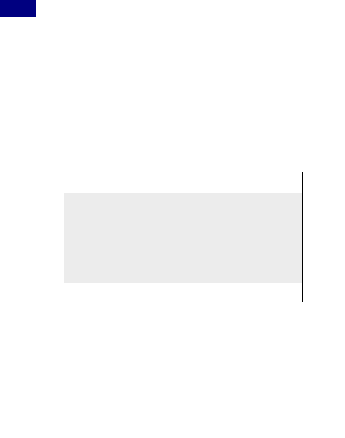
Implementing Preflight Rules
More on specific objects
492
This version has error checking removed, for readability. Initially, you may want to put in sev-
eral asserts in your rules, to satisfy yourself that the visitor is looking at the object it thinks it is.
Artwork
A rule can ask to look at marking operations. This is a powerful capability because you can
look at exactly what marking is done for a particular page item or graphic element, regardless
of whether you “own” the implementation of that object. Preflight renders the spread into a
port, then builds a tree data structure based on what it finds. That tree consists of the marking
operations, any logical artwork groups (for example, transparency groups), and groups corre-
sponding to native InDesign elements like wax runs and page items.
Unlike page items, artwork objects are not UID based, so all the information exists on the pre-
flight object boss in interfaces that you query.
Table 127 shows the artwork object types and their related interfaces.
TABLE 127 Artwork preflight object types
Preflight object
class ID
Description
kPreflightOM_
ArtworkMark
The most commonly inspected object type for artwork rules. The boss
that the service creates for this object type has the following interfaces:
zIPreflightArtworkMarkInfo — Provides informa-
tion about the marking operation, such as the
geometry, colorspace, opacity, and text versus path.
zIPreflightArtworkContext — Relates the marking
operation to any context objects of which it is a
child. This is useful when you need to know
whether the mark is, say, drawn as part of rendering
a text run or graphic.
kPreflightOM_
ArtworkGroup
Placeholder for future implementation.

Implementing Preflight Rules 493
Implementing Preflight Rules
More on specific objects
Regarding artwork-based rules: if a rule wants to see any of these classes (or any other class that
lists these classes as parents), preflight forces artwork expansion, which is fairly expensive com-
pared to looking at the attributes of native objects. This is one reason why the out-of-the-box
default profile (Basic) does not have any artwork rules. This is not to say you should not have
such rules; many native rules (like colorspace and CMY marking) are artwork rules. If you can
get the information you need by inspecting attributes instead of looking at artwork, however,
you probably should use attributes, which has much lower overhead.
An artwork-rule visitor usually looks something like that shown below. This is actual code
from the colorspace rule.
virtual void Visit(IPreflightVisitInfo* iVisit) override
{
InterfacePtr<IPreflightObject> iObj(iVisit->QueryObject());
InterfacePtr<IPreflightArtworkContext> iContext(iObj, UseDefaultIID());
if (iContext && iContext->GetShapeContextDepth(
kPreflightOSP_GraphicProxy) > 0)
{
kPreflightOM_
ArtworkContext
“Metadata” contexts that enclose artwork. In other words, the marking
operation tells you that a stroke of a specified width and color exists; the
context tells you what that stroke is associated with.Preflight supports the
following contexts:
zShape — The IShape-supporting page item contain-
ing the artwork. This also records the “subpart” of
the shape: stroke, fill, adornments, and so on. Shape
information is obtained via IPreflightArtwork-
ShapeContext.
zText — The text with which the artwork is associ-
ated, if any. This is defined by the text model, index,
and range. Text information is obtained via
IPreflightArtworkTextContext.
zTable — The associated table and cells, if any. This
information is available from IPreflightArtworkTa-
bleContext.
zOPI — If the artwork is being drawn as part of an
OPI reference, this context is present. It has no data
and only indicates that there is an OPI context.
To determine what contexts an artwork mark is associated with, you start
with the IPreflightArtworkContext interface on the mark boss; that
interface allows you to search for the nearest, or any, context of a given
type. You also can walk the context tree manually.You can ask to visit these
context types directly, although this would be uncommon. For example,
the OPI rule looks at OPI contexts, because it cares about only their
existence.
Preflight object
class ID
Description

Implementing Preflight Rules
More on specific objects
494
// Artwork is part of a graphic proxy (missing graphic); ignore
}
else
{
InterfacePtr<IPreflightArtworkMarkInfo> iMark
(iObj, UseDefaultIID());
InterfacePtr<IPreflightArtworkPaintInfo> iColor
(iMark->QueryColorPaintInfo());
if (!iColor) return;
InterfacePtr<IPreflightArtworkCSInfo> iCS
(iColor->QueryColorSpace());
// etc
Note the use of IPreflightArtworkContext, which looks for an enclosing shape context with a
subpart of kPreflightOSP_GraphicProxy. This identifies the marking operation as proxy-
related. Your rule may or may not want to exclude proxy artwork in this way.
Once the rule determines that the artwork is not part of a proxy, it gathers the marking data,
including the paint characteristics. All these secondary interfaces (e.g., IPreflightArtwork-
PaintInfo) are obtained via methods in IPreflightArtworkMarkInfo. In the case of the color-
space rule, it simply calls various IPreflightArtworkCSInfo methods to determine whether the
marking operation violates its rule parameters.
Text runs and ranges
Text runs are not persistent objects, so IPreflightObject::GetModelRef will not give you a UID
for one of these. Thus, a text run or range object has all its data on the preflight object boss
itself.
To obtain information about text objects, query for the following interfaces:
zIPreflightTextRangeInfo — This interface is available on all text-range objects
(kPreflightOM_TextRange, kPreflightOM_TextCharacter, kPreflightOM_WaxRun, and
kPreflightOM_TextParcel). It provides the text model, thread, parcel, index, and span
information for the text object. To obtain further information, you use the InDesign text
model.
zIPreflightWaxInfo — This interface is available only on a kPreflightOM_WaxRun object,
not the other text types, since they do not necessarily correspond to a wax-run boundary.
This provides the number of glyphs in the run, as well as a method that provides an
IWaxRun.
An example of the use of text interfaces follows (from the missing-fonts rule):
virtual void Visit(IPreflightVisitInfo* iVisit) override
{
const PreflightObjectID& objID = iVisit->GetObjectID();
InterfacePtr<IPreflightObject> iObj(iVisit->QueryObject());
if (objID.GetClassID() == kPreflightOM_WaxRun)
{
InterfacePtr<IPreflightWaxInfo> iWax(iObj, UseDefaultIID());
if (!iWax) return;

Implementing Preflight Rules 495
Implementing Preflight Rules
More on specific objects
InterfacePtr<const IWaxRun> iRun(iWax->QueryRun());
if (!iRun) return;
InterfacePtr<const IWaxRenderData> iRender(iRun, UseDefaultIID());
if (!iRender) return;
if (iRender->FontFaceMissing())
{
InterfacePtr<IPreflightResultRecord> iRec(
iVisit->CreateResultRecord());
iRec->SetCriteria(kPreflightRC_Default);
PMString fontName = iRender->GetFontName();
fontName.SetTranslatable(kFalse);
iRec->SetAuxString(fontName);
}
}
// etc
Tables, rows, columns, and cells
Many table elements in a document are composed of elements and may or may not have an
associated UID. Thus, some of the table objects are UID based (e.g., use GetModelRef) and
some are not. Those that are not have additional data on the preflight object boss.
For non-UID based elements, the IPreflightTableCellInfo interface on the preflight object boss
provides the necessary data, from which you can navigate to the InDesign model. The objects
that support this interface are kPreflightOM_TableCell, kPreflightOM_TableArea,
kPreflightOM_TableFrameCell, and kPreflightOM_TableFrameArea.
The following is an abbreviated example from the overprint rule, which looks for any overprint
attributes that are set. In this case, the rule is interested in page items, text, and tables, all of
which have overprint attributes.
virtual void Visit(IPreflightVisitInfo* iVisit) override
{
PreflightObjectID objID = iVisit->GetObjectID();
InterfacePtr<IPreflightObject> iObj(iVisit->QueryObject());
if (objID.GetClassID() == kPreflightOM_PageItem)
{
InterfacePtr<IGraphicStyleDescriptor> iStyle(iObj->GetModelRef(),
UseDefaultIID());
// Check graphic attributes..
}
else if (objID.GetClassID() == kPreflightOM_WaxRun)
{
InterfacePtr<IPreflightTextRangeInfo> iRange(iObj, UseDefaultIID());
if (!iRange) return;
// Check text attributes via the text model...
}

Implementing Preflight Rules
More on specific objects
496
else if (objID.GetClassID() == kPreflightOM_TableFrame)
{
InterfacePtr<ITableFrame> iFrame(iObj->GetModelRef(), UseDefaultIID());
if (!iFrame) return;
// Check the table attributes...
}
else if (objID.GetClassID() == kPreflightOM_TableFrameCell)
{
InterfacePtr<IPreflightTableCellInfo> iCellInfo(iObj, UseDefaultIID());
if (!iCellInfo) return;
// Check the cell attributes..
}
}
Note how the rule must use a different strategy for each object type. For page items and tables
there is a UID to work with, so it queries the model directly. For text and cells, which are com-
posed entities, the rule uses the interfaces hosted on the preflight object directly: IPreflightTex-
tRangeInfo for text and IPreflightTableCellInfo for table cells.
For example, the first thing it does when looking for cell attributes is to look up the table
attribute’s accessor interface from the table model, using IPreflightTableCellInfo::GetTableM-
odelRef:
InterfacePtr<ITableAttrAccessor> iTableAttrs(
iCellInfo->GetTableModelRef(), UseDefaultIID());
if (!iTableAttrs) return;

XML Fundamentals 497
XML Fundamentals
Introduction
XML Fundamentals
This chapter describes features of the InDesign XML subsystem relevant to plug-in developers,
and the architecture that supports them. It explains how client code can use these features and
take advantage of the XML-related extension patterns in the InDesign API.
For use cases, see the “XML” chapter of Adobe InDesign CS4 Solutions.
Introduction
XML-based workflow
There are several benefits of using an XML workflow in publishing:
zSeparation of concerns; for example, maintaining content and presentation information
independently.
zWorking with standards that are open, relatively stable, and defined by experts in a domain.
This avoids being locked into proprietary, unpublished file formats and helps reduce imple-
mentation effort. For example, having standards available like NITF (http://www.nitf.org)
and NewsML (http://www.newsml.org) prevents you from having to reinvent a language to
store articles, transmit news feeds, and support a newspaper workflow.
zRelatively easy processing, because you have a textual representation of XML documents.
zRelatively easy re-purposing of content for other media, like HTML and Mobile SVG, in
addition to print publishing and PDF delivery. The main advantage is that the content can
be single-sourced but published to multiple media with relatively little effort.
zRelatively easy manipulation of XML documents, thanks to the availability of many XML-
aware tools, software developer toolkits, and standardized APIs.
zExistence of many databases that can produce and consume XML data, some natively.
Disadvantages to an XML workflow can include the following:
zJournalists and graphic designers are unlikely to want to learn about XML. A system
designed around XML may need to shield end users from having to create mark-up manu-
ally. For example, templates can be pre-tagged.
zSome XML technologies are not straightforward to use and may require some effort to
understand (for example, XSLT/XPath), even for capable software developers.

XML Fundamentals
Terminology
498
Using XML with InDesign
Using XML-based data and XML templates in InDesign has some benefits to a programmer,
which include the following:
zThere are mature XML toolkits and technologies to manipulate XML data (see
http://xml.coverpages.org/software.html), which make it relatively straightforward to
manipulate XML data before import or after export. For example, using XSLT to manipu-
late XML data is particularly convenient in the context of the InDesign import architecture.
You can develop and debug your XSL stylesheets independently of InDesign, using existing
XSLT-aware tools, but deploy them as part of a workflow involving InDesign if you use its
features like the XML transformer. See “XML transformer” on page 554.
zImporting graphics into tagged placeholders is a convenient way to import and place graph-
ics without writing much (if any) code. See “Tagged graphic placeholder” on page 534.
zThe XML API of InDesign is well documented. The command facades and suite interfaces
in the XML API make it relatively straightforward to write client code. See “Key client API”
on page 552.
Terminology
See the “Glossary” for definitions of terms. Table 128 lists terms used in this chapter and sec-
tions that relate to them.
TABLE 128 Terminology
Term See ...
Acquirer; acquirer filter “Extension patterns” on page 553
Backing store “Backing store” on page 509
Comment, XML “Processing instructions and comments” on page 547
Content handler “Extension patterns” on page 553
Content item “Content items” on page 506
Document element “Document element and root element” on page 508
Document Type Declaration
(DTD)
“DTD” on page 545
Entity “SAX-entity resolver” on page 557
Logical structure “Native document model and logical structure” on
page 505 and “Elements and content” on page 534
Placed element; placed
content
“Unplaced content versus placed content” on page 518

XML Fundamentals 499
XML Fundamentals
XML features at a glance
XML features at a glance
XML extension patterns
Several XML extension patterns depend on the re-factored XML import architecture. You can
implement these extension patterns to customize how XML data is imported and exported and
other XML-related features. See “Extension patterns” on page 553.
Tagging in tables and inline graphics
InDesign supports tagging of tables and table cells. See “Tagged tables” on page 543. Inline
graphics can be tagged, and placeholders for inline graphics can be created in XML templates.
See “Tagged inline graphics” on page 542.
Throw away unmatched existing (right)
It may be desirable to filter out elements in your XML template that are not matched by ele-
ments in the incoming XML data. When enabled, this features discards unmatched existing
elements in an XML template. See “Throwing away unmatched existing elements on import
(delete unmatched right)” on page 520. The feature is implemented by an import-matchmaker
service, an extension pattern described in “XMl-import matchmaker” on page 555.
Processing instruction (PI) “Processing instructions and comments” on page 547
Repeating element “Importing repeating elements” on page 519
Root element “Document element and root element” on page 508
SBOS (small boss object store) “Persistence and the backing store” on page 510
Tag “Tags” on page 529
Unplaced element; unplaced
content
“Unplaced content versus placed content” on page 518
XML element “Elements and content” on page 534
Term See ...

XML Fundamentals
XML features at a glance
500
Throw away unmatched incoming (left)
It may be desirable to filter out incoming XML elements that have no corresponding match in
your XML template. When enabled, this feature discards inbound elements in the XML-based
data being imported that have no match in the XML template into which the data is being
imported. In API terms, the feature is called “throw away unmatched left.” See “Throwing away
unmatched incoming elements on XML import” on page 522. The feature is implemented by
an import-matchmaker service, described in “XMl-import matchmaker” on page 555.
Importing repeating elements
This feature allows text styling from elements in an XML template to be preserved (within one
story) when repeated elements are imported. It is described in “Importing repeating elements”
on page 519.
Importing CALS table
This feature allows CALS table to be imported as InDesign table. It is described in “Importing a
CALS table as an InDesign table” on page 524.
Support for DOM core level 2
This specification is implemented by the features related to matching and transforming on
import. Import matchmakers and XML transformers that operate on the DOM (Document
Object Model) are described in “Extension patterns” on page 553. For the DOM Level 2 Core
specification, see http://www.w3c.org/TR/2000/REC-DOM-Level-2-Core-20001113.
Support table- and cell-styles import
This feature allows table and cell styles to be applied to InDesign table when is imported. It is
described in “Support table and cell styles when importing an InDesign table” on page 524.
Support XML-rules processing
The scripting-based XML-rules feature allows an XML DOM to be altered after an XML file is
imported. XML rules also can be triggered by application events, such as open, place, and close.
The feature is described in the “XML Rules” chapter of Adobe InDesign CS4 Scripting Guide.
Snippets
The snippet architecture is described in the “Snippet Fundamentals” chapter. The snippet
architecture depends on the XML subsystem, as well as on INX (InDesign Interchange) or
IDML (InDesign Markup Language) import and export. Snippets are XML-based representa-
tions of parts of a document in INX or IDML file format.

XML Fundamentals 501
XML Fundamentals
The user interface for XML
The user interface for XML
Structure view
Figure 215 shows the structure view, a representation of the logical structure of a document
that lets you view and interact with its logical structure. You can make selections in this view
and create new elements as children of the selection, delete elements, create or delete attributes,
and so on. Figure 215 shows the structure view with text snippets visible, which provides con-
text to see what content items in the document are associated with the elements in the logical
structure.
FIGURE 215 Structure view
Depending on your workflow, it may be desirable to control the visibility and other properties
of the Structure pane. These properties are controlled by preferences. See “XML-related prefer-
ences” on page 549.
When you tag a graphic frame as a placeholder, the structure view draws a cross through the
icon representing the element to indicate its placeholder status. There are also other icons that
represent whether an element is associated with text content or image-based content.
Tags in layout view and story view
Figure 216 shows content that has been tagged, rendered in the layout view of the application.
In layout view, tags are shown as brackets with a width of zero; that is, they are intended to have
no effect on text composition. Start tags are indicated by brackets pointing right ([), and end
tags by brackets pointing left (]). The tag name associated with the tag markers is encoded by
color, corresponding to the color displayed in the Tags panel. Multiple tags can exist at the
same position in layout view.
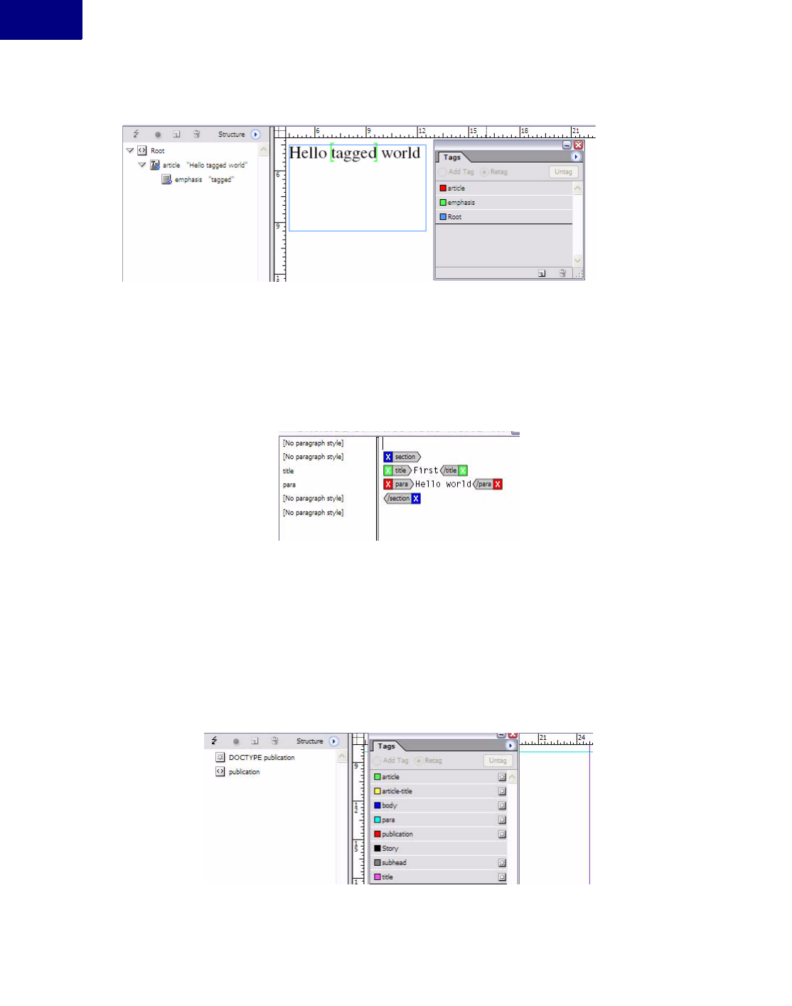
XML Fundamentals
The user interface for XML
502
FIGURE 216 Tags in layout view
Story view makes it somewhat easier to understand the logical structure of a story and edit its
structured content. Figure 217 shows structured content rendered in story view. In this view,
the names of tags are shown explicitly.
FIGURE 217 Tags in story view
Tags panel
Figure 218 shows part of the Tags panel, which has a list of tags that can be applied to docu-
ment content. Each tag has a name and associated color. In this example, some tags were cre-
ated when a DTD was imported, shown with icons at the right-hand end of the list elements.
FIGURE 218 Tags panel
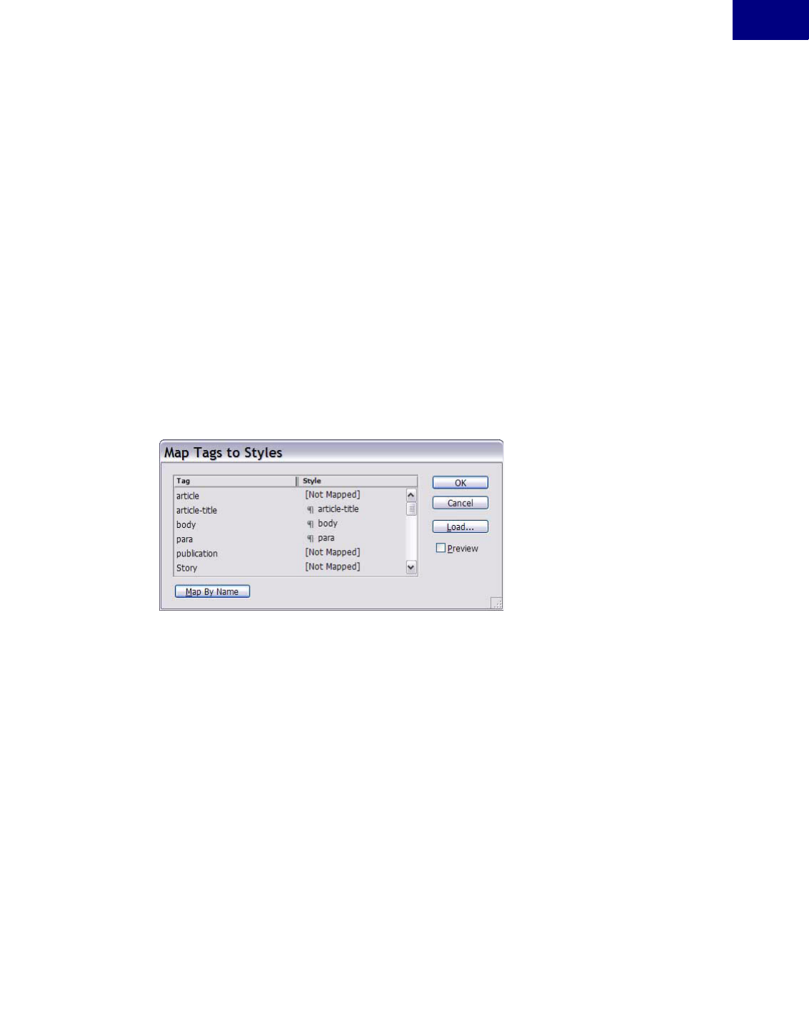
XML Fundamentals 503
XML Fundamentals
The user interface for XML
To open the Tags panel, choose Window > Tags. By default, the list of tags shown is sorted
alphabetically by tag name; the list has no inherent logical structure. The complete set of tags in
an imported DTD or imported tag list is shown, regardless of what is selected in the structure
view. To populate the tag list, end users can load a set of tags with the Load Tags menu com-
mand in the Tags-panel menu.
You can create a new tag through the Tags panel; this adds an entry to the tag list. Creating a
new tag means it is available to mark up content or tag placeholder graphic frames for content.
You can delete a tag through the Tags panel. You can export the tag with the Save Tags menu
command in the Tags-panel menu.
Mapping between tags and styles
You can choose to apply a mapping between element names and styles (character and para-
graph styles). Once the mapping is applied to a document, any marked-up text is styled as spec-
ified by the style on the right-hand side of this mapping. See Figure 219.
FIGURE 219 User interface for mapping tags to styles
An important use case for mapping tags to styles is preparing a document for XML import.
Assuming XML-based content does not carry style information, the tag-to-style map is a sim-
ple mechanism to apply styling to inbound XML-based content; more complex mechanisms
include styling based on XSLT or a proprietary mechanism like an Adobe FrameMaker Ele-
ment Definition Document (EDD). The FrameMaker EDD effectively is a style sheet contain-
ing rules specifying how to map tags to styles, but in a context-dependent way.
You can apply structure to an unstructured InDesign document by choosing to map styles to
tags. The effect of this is to mark up the text ranges that have the styles on the left-hand side of
the style-to-tag mapping. See Figure 220.
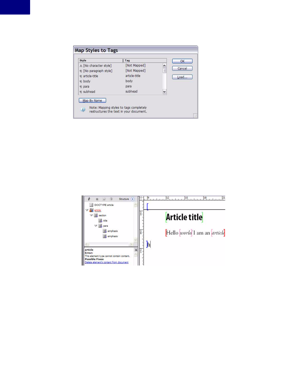
XML Fundamentals
The user interface for XML
504
FIGURE 220 User interface for mapping styles to tags
Validation window
The XML-validation-errors pane appears below the Structure pane; see Figure 221. The XML-
validation-errors pane contains hyperlinks. If the end user clicks on the hyperlinks, InDesign
tries to fix the validation errors. This may not always have the desired effect; for example, it
may delete content that was tagged incorrectly.
FIGURE 221 XML-validation-errors pane
Other
Other components of the user interface for XML—like context-sensitive menus for tagging the
selection—are beyond the scope of this chapter.

XML Fundamentals 505
XML Fundamentals
XML model
XML model
Native document model and logical structure
The InDesign native document model specifies how end-user documents are represented by
InDesign. The InDesign native document model consists of both the description of the docu-
ment in terms of boss classes and the scripting DOM. End users directly manipulate spreads,
pages, and the items they contain; these abstractions are represented by boss classes in the
native document model or objects in the scripting DOM.
For example, a spread is represented by kSpreadBoss in the low-level model or boss DOM.
Spread contents are organized into a hierarchy (IHierarchy). In the scripting DOM, a spread is
represented by a Spread object, with properties like Pages or PageItems to represent the object
hierarchy at a higher level of abstraction.
The logical structure of an InDesign document is specified by the user; for example, by tagging
content items in the layout or importing their XML data. An XML template, consisting of
tagged placeholders for text and graphics, provides the user with a way to define how user-
domain data is mapped into the native model.
The logical structure of an InDesign document is organized into a hierarchy of XML elements
(see IIDXMLElement) representing logical relationships between content. The IIDXMLEle-
ment interface plays the same role in the logical structure that IHierarchy plays in the spread
hierarchy. The key operation that modifies logical structure is tagging document objects, like
graphic frames, stories, and text ranges. Tagging establishes associations between objects in the
native document model and the logical structure. See “Elements and content” on page 534.
Importing XML-based data into an InDesign document creates new elements in the logical
structure (see “Importing XML” on page 511). If there are tagged placeholders, content can be
flowed into these placeholders. The logical structure of an InDesign document also can be
exported as an XML file (see “Exporting XML” on page 524). You also can create new elements
by mapping styles to tags (see “Tags” on page 529).
Elements and attributes
Elements represent user-defined logical relationships between content items in a document.
Elements are created by InDesign when XML data is imported or content is tagged. The imple-
mentation of elements in InDesign is closely related to the XML specification
(http://www.w3.org/TR/REC-xml), which defines an element as follows:
“Each XML document contains one or more elements, the boundaries of which are either
delimited by start-tags and end-tags, or, for empty elements, by an empty-element tag. Each
element has a type, identified by name, sometimes called its “generic identifier” (GI), and may
have a set of attribute specifications. Each attribute specification has a name and a value.”
You can create a new element in the logical structure with the New Element menu command
on the Structure-pane menu. The behavior of this feature depends on whether the element in
the structure view already is placed and, if placed, what is the associated content item. You can
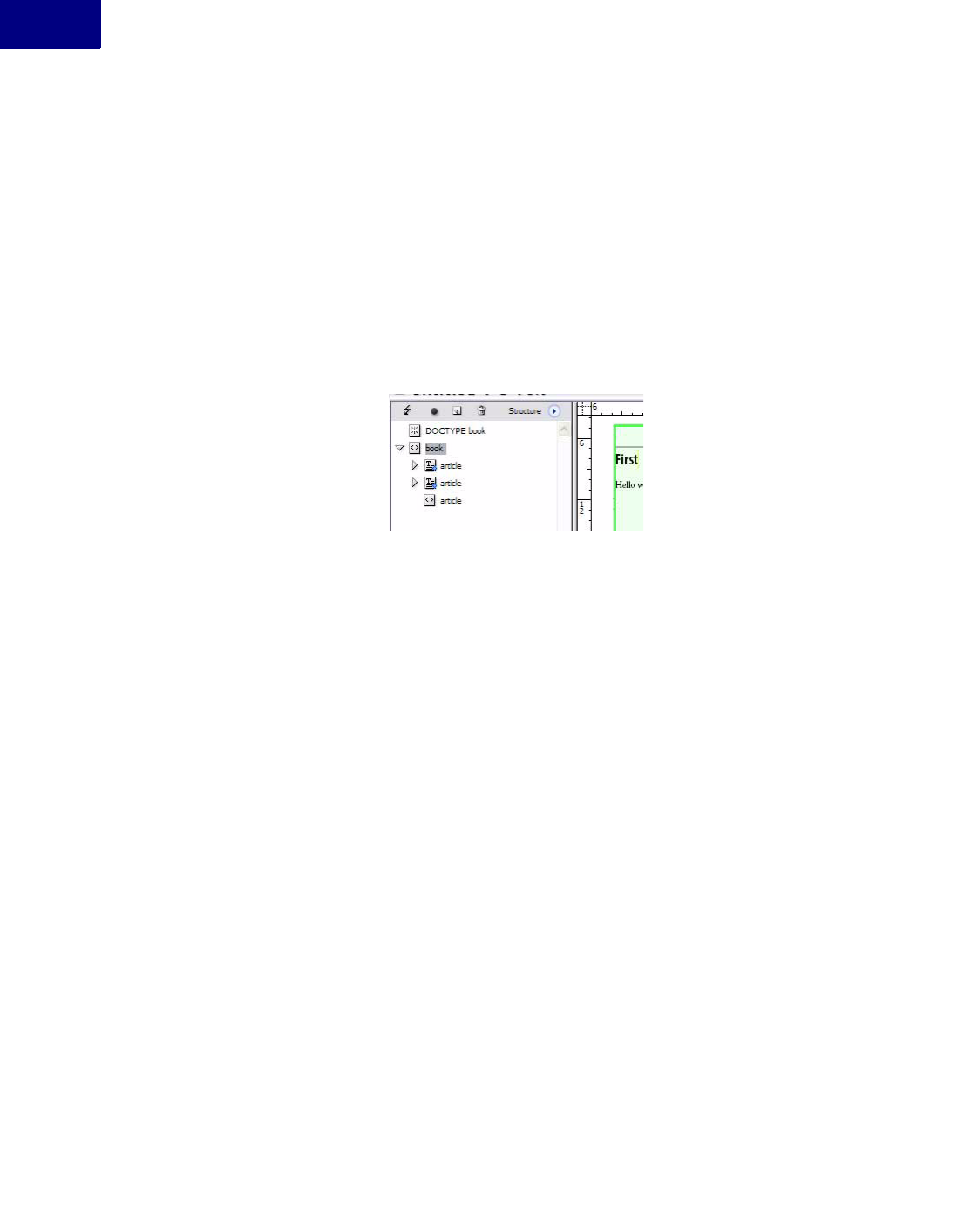
XML Fundamentals
XML model
506
choose a tag for the element or create a new one. The tag stores the element’s name and color in
the user interface.
Figure 222 shows what happens when the root element is selected in the structure view and the
user chooses the New Element menu command. The application adds a child element to the
logical structure’s root element. By default, the child element is added at the end of the collec-
tion of child elements of the root element. In this example, the root element <book> is selected
and a new element <article> is added. The new element is inserted into the logical structure as
the last child of the root element and is shown as unplaced content, since the top-level element
was not placed; only its child elements are placed content.
FIGURE 222 Inserting a new element
You can add an element to the logical structure in the structure view, in which case the element
is not directly associated with document content. You can indirectly add one or more elements
in another view, like layout view, by tagging (e.g., tagging a text range or graphic placeholder
frame).
Attributes are properties of elements. Attributes can be added by end users through the struc-
ture view, when a node is selected that supports added attributes. Some elements, like com-
ments, processing instructions, and the DTD element, do not support the addition of
attributes.
Elements are modeled by boss classes that have the IIDXMLElement interface. Tags are mod-
elled by the kXMLTagBoss boss class. See “Tags” on page 529. Attributes are modeled as prop-
erties of elements (IIDXMLElement). There are facades that make it relatively easy to change
the properties of elements, tags, and attributes (IXMLElementCommands, IXMLTagCom-
mands, and IXMLAttributeCommands).
Content items
Elements (IIDXMLElement) are created when content items are tagged. Elements also may be
created on import of XML data. New content items can be created when XML content is flowed
into an XML template. The main point is that elements are defined in the user domain and rep-
resent logical relationships between content items—or between elements, in the case of struc-
tural elements.
Content items are objects in the layout or text domain that can be tagged to create an associa-
tion with an element in the logical structure of an InDesign document. Many content items can
be tagged:

XML Fundamentals 507
XML Fundamentals
XML model
zPlaceholders for graphics (kPlaceHolderItemBoss)
zPlaceholders for inline graphics (kILPlaceHolderPageItemBoss)
zImages (kImageItem, any other descendants of kImageBaseItem)
zStories (kTextStoryBoss)
zText ranges
zTables (kTableModelBoss) and cells within them
zText within table cells
There is no easy way to identify a content item. Many but not all the objects that can be tagged
have the IXMLReferenceData interface. If you inspect the API reference documentation for
IXMLReferenceData and see the boss classes in the native document model that aggregate this
interface, you get some indication of the variety of document objects that can be tagged.
References to elements and content items
All elements in the logical structure of an InDesign document expose the IIDXMLElement
interface; therefore, one type of reference to an element is an interface pointer of type IIDXM-
LElement. A more convenient type for programmers to work with is XMLReference, an
instance of which can be obtained from IIDXMLElement::GetXMLReference. This XMLRefer-
ence is just another way to refer to the same element.
Conversely, given an XMLReference, you can obtain an IIDXMLElement interface pointer by
using XMLReference::Instantiate. XMLReference is the XML subsystem’s equivalent of
UIDRef; note that UIDRef applies only to UID-based objects, and elements in the logical struc-
ture are not UID-based.
XMLContentReference refers to a chunk of content rather than an element. Do not mistake the
XMLContentReference type for XMLReference: XMLContentReference is a reference to a con-
tent item, which might be a UID-based like a graphic frame or a non-UID-based object like a
table cell. An instance of XMLContentReference can be obtained from IIDXMLElement::Get-
ContentReference. This generalizes and replaces IIDXMLElement::GetContentItem, which is
deprecated.
An instance of XMLContentReference can tell you the type of object with which it is associ-
ated, through XMLContentReference::GetContentType. For example, kContentType_Normal
is used for elements associated with a UID-based object in the layout; this could be something
like a tagged graphic placeholder.
For more information on methods and use of these key types, see the API reference documen-
tation for XMLReference and XMLContentReference. The main difference between XMLRef-
erence and XMLContentReference is that XMLReference refers to an element
(IIDXMLElement), whereas XMLContentReference refers to a content item.
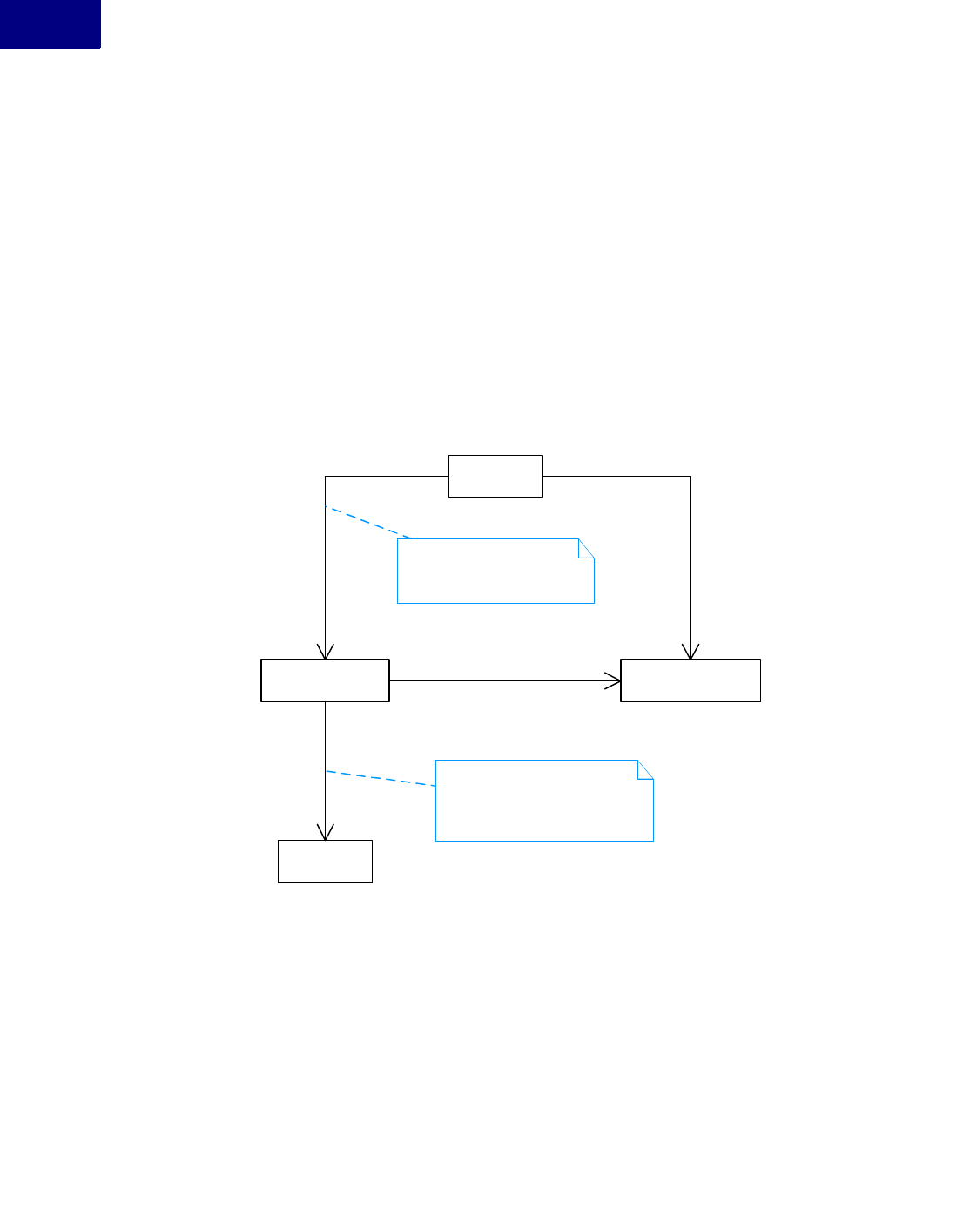
XML Fundamentals
XML model
508
Document element and root element
The IXMLReferenceData interface on kDocBoss stores a reference to the document element
(instance of kXMLDocumentBoss). There also is an interface on the document (kDocBoss),
with a different PMIID referring to the DTD element (kXMLDTDBoss), if one is associated
with the document. The document element associates with the root element both through
IXMLReferenceData (as shown in Figure 223) and through IIDXMLElement::GetNthChild,
because the document element is the parent of the root element. The class diagram in
Figure 223 shows associations involving the document element (kXMLDocumentBoss) and
other classes.
FIGURE 223 Document element, root element, and DTD
The document element is responsible for managing document-level information (like the
DTD) and comments and processing instructions that are peers of the root element.
The root element (kTextXMLElementBoss) appears as the root of the element hierarchy in the
structure view, although the root element is a child of the document element, which is not
shown in the structure view. By default, the root element for a new InDesign document has the
tag Root; you can change this to whatever the content model for your XML vocabulary
requires.
«boss»
kDocBoss
«boss»
kXMLDTDBoss
«boss»
kXMLDocumentBoss
«boss»
kTextXMLElementBoss
1
1
IXMLReferenceData::GetReference 1
1
IXMLUtils::QueryRootElement
11
IXMLReferenceData::GetReference
1
0..1
IXMLReferenceData::GetReference
Interface with PMIID of
IID_IXMLDTDXMLREFERENCEDATA
on kXMLDocumentBoss refers to
the DTD object, if one exists.
IXMLUtils::QueryDocElement is
another way to navigate this
association.
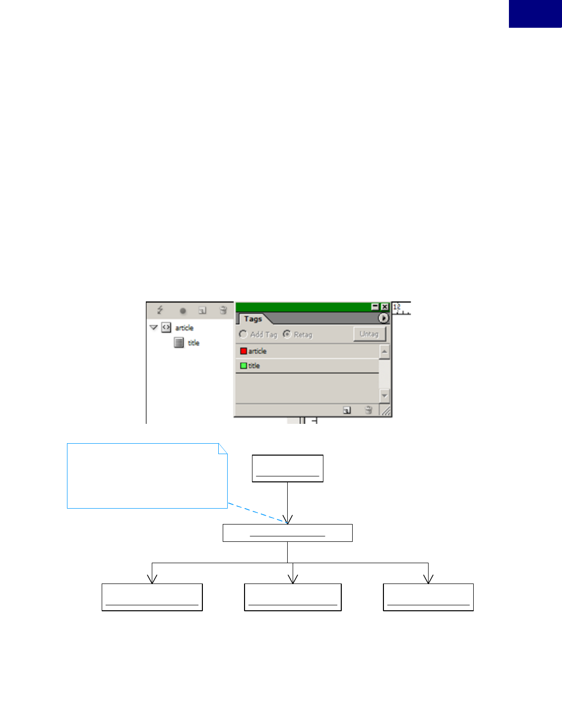
XML Fundamentals 509
XML Fundamentals
XML model
The document element and root element—along with the DTD element and any top-level
comments (kXMLCommentBoss) and processing instructions (kXMLPIBoss)—are held in the
backing store.
Backing store
Each InDesign document contains one backing store, which stores XML elements that are
unplaced and elements that are siblings of the root element, like the document element, root
element, DTD element, comments, and processing instructions. The backing store is a story
(kTextStoryBoss) that is not accessible to the user and is present in every InDesign document.
The architecture of the backing store is described in “Persistence and the backing store” on
page 510.
The object diagram in Figure 224 shows the relationship between the document, backing store,
and elements stored in the backing store.
FIGURE 224 Backing store
«boss»
document : kDocBoss
Backing store (opaque)
«boss»
doc-elem : kXMLDocumentBoss
«boss»
article : kTextXMLElementBoss
«boss»
title : kTextXMLElementBoss
There is exactly one backing store for
a document, an instance of a story
(kTextStoryBoss) that is not user-accessible.
It stores XML elements that are not on the page
and other elements, such as the
document element.

XML Fundamentals
XML model
510
The backing store is opaque to client code. Use facade methods like IXMLUtils::QueryDocEle-
ment and IXMLUtils::QueryRootElement to acquire objects like the document element
(kXMLDocumentBoss) or the root element (shown as the article object in Figure 224). To
acquire a reference to the backing store when you need it (e.g., for notification), use IXM-
LUtils::GetBackingStore.
For more information, see “Backing store and notification of changes in logical structure” on
page 558.
Persistence and the backing store
The main persistence mechanism for the native document model is UID-based; that is, each
instance of the classes shown in the model, like kSpreadBoss, has a record number or UID
(unique identifier) associated with it in the document’s database. The UID is unique only
within the context of a particular database, not globally.
UID-based objects also can store persistent boss objects without a UID; for example, this
model is used for attributes and widely within the table and XML subsystems. This as an exam-
ple of container-managed persistence, to distinguish it from the conventional, UID-based per-
sistence mechanism. The implementation of container-managed persistence in InDesign is
very efficient compared to UID-based persistence, which played a large part in the decision to
use it for both tables and XML. For more information, see the “Persistent Data and Data Con-
version” chapter.
This object diagram in Figure 225 is an elaborated version of Figure 224. The BaseUID shown
for each object is the UID of the kTextStoryBoss implementing the backing store. The LSID
(logical structure ID) starts at 1 for the document element (kXMLDocumentBoss). See the API
reference documentation for XMLReference. The root element, with LSID of 2 in this diagram,
is an instance of kTextXMLElementBoss; it has a reference to a tag (TagUID=126, name=
“Root”) but not to a content item. The image element has a reference to a tag (TagUID=159,
name= “image”) and to a content item (UID=161, an instance of kPlaceHolderItemBoss).
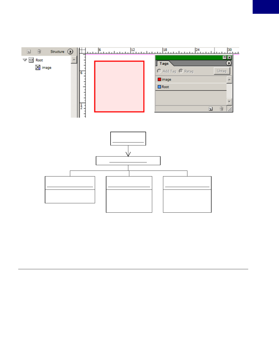
XML Fundamentals 511
XML Fundamentals
Importing XML
FIGURE 225 Backing store, with more detail
The backing store is an instance of a small-boss object store (SBOS), a storage container for
small boss objects. The container has a UID, but the objects it stores do not have UIDs. The
objects managed by the store have logical IDs (LSIDs) as keys. See the API reference documen-
tation for XMLReference::GetLogicalID and related methods.
Importing XML
The application supports import of XML data encoded as any of the following:
zUTF-8 (see http://www.ietf.org/rfc/rfc2279.txt)
zUTF-16 (see http://www.ietf.org/rfc/rfc2781.txt)
zShift-JIS, a two-byte format for Japanese (see http://www.w3.org/TR/2000/NOTE-japanese-
xml-20000414)
BaseUID = 111
LSID = 3
ContentItemUID = 161
TagUID = 159
«boss»
image : kTextXMLElementBoss
BaseUID = 111
LSID = 1
«boss»
doc-elem : kXMLDocumentBoss
BaseUID = 111
LSID = 2
ContentItemUID = 0
TagUID = 126
«boss»
Root : kTextXMLElementBoss
«boss»
document : kDocBoss
Backing store (opaque)

XML Fundamentals
Importing XML
512
There are two main workflows for importing XML data:
zImporting XML data into the backing store (see “Backing store” on page 509), then manu-
ally placing it onto the layout to set up the associations between elements in the logical
structure and document object.
zCreating an InDesign document as an XML template that contains placeholders, which are
tagged with names of the elements in the XML data to import. When the XML data is
imported, the contents of the XML file are flowed into the placeholders. The order in which
the elements appear in the logical structure determines how the content is flowed into the
tagged placeholders.
Import architecture
The import process is controlled by the XML importer (kXMLImporterBoss), which is the
main delegate for the low-level command that performs the import (kImportXMLFileCmd-
Boss). Unlike other forms of import—like EPS (import provider kEPSPlaceProviderBoss) and
PDF (import provider kPDFPlaceProviderBoss) import—importing XML data does not use
the standard import provider (IImportProvider) architecture. The importer controls the
import process by dispatching messages to extension patterns responsible for different parts of
the import sequence, as shown in Figure 226.
The sequence diagram shows some of the messages sent during XML import. The importer
object shown consists of the low-level import XML command (kImportXMLFileCmdBoss)
and its delegate (kXMLImporterBoss). The main points to note are the order in which the dif-
ferent extension patterns are sent messages and, for the transformer (IXMLTransformer), how
the stream transform precedes the DOM transform message.

XML Fundamentals 513
XML Fundamentals
Importing XML
FIGURE 226 XML-import sequence
A low-level command (kImportXMLFileCmdBoss) is processed to import an XML file. Much
of the work is done by this command’s delegate, an instance of the kXMLImporterBoss boss
class, in its implementation of IXMLImporter::DoImport. The following operations are per-
formed while importing an XML file:
1. The import parameters are specified through an instance of kImportXMLDataBoss. In par-
ticular, see IImportXMLData. This specifies either an IDFile (based on a path, which may
be a file path or an arbitrary URL-like string).
2. An acquirer service (IXMLAcquirerFilter) is located, which knows how to turn the import
specification (in IImportXMLData) into an XML stream, perhaps with a SAX entity
resolver. See “XML acquirer” on page 553 and “SAX-entity resolver” on page 557.
3. The SAX parser service (kXMLParserServiceBoss, ISAXServices) parses the inbound XML
from the stream.
4. XML transformer services (kXMLImporterTransformerService) are called to transform the
stream. See “XML transformer” on page 554.
5. At this point, the stream has been turned into an XML DOM. XML transformer services are
called to transform the DOM. See “XML transformer” on page 554.
6. The XML-import match driver calls XML-import matchmaker services (kXMLImport-
MatchMakerSignalService) to participate in matching the input XML data against the XML
Importer Acquirer
IXMLAcquirerFilter::CreateStreamAndResolver
Transformer
IXMLTransformer::TransformStream
IXMLTransformer::TransformDOM
Matchmaker
IXMLImportMatchMaker::MatchDocument
Serializer handler
ISAXDOMSerializerHandler::StartDocument
Post-import iterator
IXMLPostImportIteration::BeforeIteration
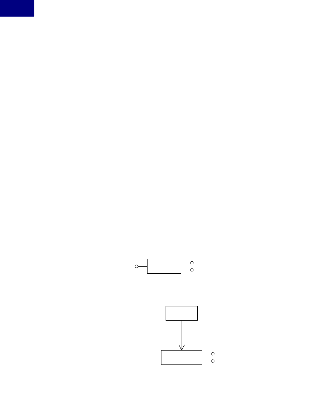
XML Fundamentals
Importing XML
514
template (the logical structure of the document into which content is being imported). See
“XMl-import matchmaker” on page 555.
7. Matches are registered by the XML match recorder (IXMLImportMatchRecorder) of the
importer (kXMLImporterBoss).
8. SAX DOM serializer handlers (ISAXDOMSerializerHandler) are called to create content
based on the DOM. See “SAX DOM serializer handler” on page 557. The parsing of the
final input XML data is controlled by a top-level SAX DOM serializer handler (kSAXDocu-
mentHandlerBoss). Dependent SAX DOM serializer handlers turn parts of the DOM into
InDesign content.
9. Post-import responders are called to iterate the DOM and take appropriate action. See
IXMLPostImportIteration and “Post-import responder” on page 555.
When XML data is imported, the XML subsystem creates elements (IIDXMLElement) in the
logical structure. See “Elements and content” on page 534. Import of XML data results in con-
tent items (IXMLReferenceData) being populated with the imported content, if the content
items are tagged before import. After import, unplaced elements are held in the document’s
backing store. See “Backing store” on page 509.
The UML diagrams in Figure 227 show some interfaces involved in storing options for import
and export of XML data at the session level (kWorkspaceBoss) or document level (kDocWork-
spaceBoss). There are other interfaces specific to individual components in the XML import
architecture (e.g., IXMLImportPreferences, which can be found on service boss classes), which
are not shown here.
FIGURE 227 Some preferences related to import and export
«boss»
kDocWorkspaceBoss
«boss»
kWorkspaceBoss
IXMLExportSessionOptions
IXMLImportOptions
IXMLImportOptions
«boss»
kDocBoss
IDocument
IXMLExportOptions
IXMLExportOptions

XML Fundamentals 515
XML Fundamentals
Importing XML
Importing a minimal XML file
A new, empty document has a logical structure consisting of one Root element. To construct a
slightly less trivial example, you can create a new document and import a minimal XML file
into the backing store. The content is as shown in Example 35.
EXAMPLE 35 Minimal XML data to be imported
<article><title>Hello World</title>
</article>
The scenario to perform the import is as follows:
1. Save the XML data above to a text file, hello-world.xml.
2. Create a new InDesign document.
3. Show the structure view. Rename the Root tag to be “article.”
4. Create a new tag named “title.”
5. Import the XML data from the hello-world.xml file. The structure view should look like
Figure 228.
The objects created and instances of associations between them are shown in Figure 228. The
UML object diagram shows the objects involved in representing the logical structure when
minimal XML content is imported into the backing store of a new InDesign document. The
logical structure of the InDesign document represents the tree structure of the original XML
document, which has one title element as a child of the root-article element. Instances of the
associations with the objects that represent tags are shown (kXMLTagBoss).
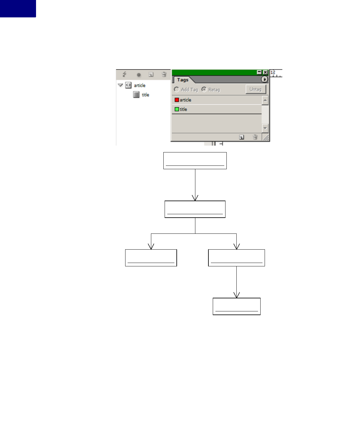
XML Fundamentals
Importing XML
516
FIGURE 228 Objects representing elements in logical structure and tags
Given a reference to the document (IDocument) or a document database (IDataBase), you can
acquire a reference to the document element or root element in the logical structure, using the
IXMLUtils facade.
The document element has no tag, but the root element always has a tag; in this example, it is
named “article.” The IIDXMLElement::GetTagString method discovers the tag name of an ele-
ment.
The root element is one starting point for traversing the logical structure. For the minimal
example, you can start from the root element and look at its children.
«boss»
article : kTextXMLElementBoss
«boss»
article-tag : kXMLTagBoss
IXMLTag
«boss»
title : kTextXMLElementBoss
IIDXMLElement
«boss»
title-tag : kXMLTagBoss
IXMLTag
«boss»
doc-elem : kXMLDocumentBoss
IIDXMLElement

XML Fundamentals 517
XML Fundamentals
Importing XML
XML elements have the signature interface IIDXMLElement. Given an IIDXMLElement inter-
face, you can obtain an XMLReference, another way to refer to an XML element. See IIDXM-
LElement::GetXMLReference. Conversely, given an XMLReference, you can get an
IIDXMLElement interface through XMLReference::Instantiate. XML elements are described in
more detail in “Elements and content” on page 534.
The UML object diagram in Figure 229 shows instances of associations between a document
(kDocBoss), document workspace (kDocWorkspaceBoss), and objects representing tags
(kXMLTagBoss) and their colors within the Tags panel (kUIColorDataBoss).
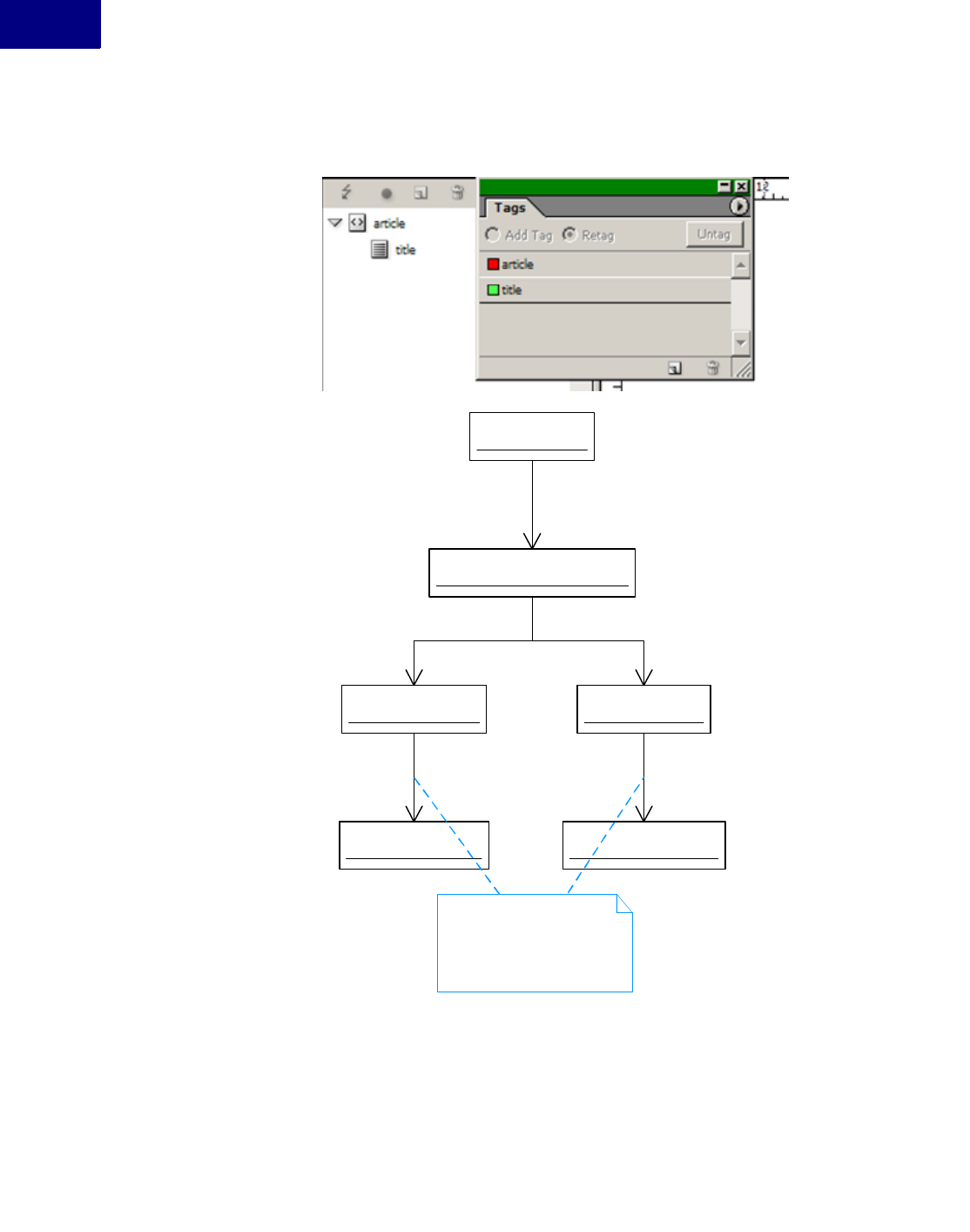
XML Fundamentals
Importing XML
518
FIGURE 229 Objects representing tags and colors
Unplaced content versus placed content
When XML content is imported with default options and there are no tagged placeholders for
the incoming content, the content is held in the backing store. See “Backing store” on page 509.
«boss»
document : kDocBoss
«boss»
doc-workspace : kDocWorkspaceBoss
IDocument
«boss»
article-tag : kXMLTagBoss
«boss»
title-tag : kXMLTagBoss
IXMLTagList IXMLTagList
«boss»
red-col : kUIColorDataBoss
IPersistUIDData
«boss»
green-col : kUIColorDataBoss
IPersistUIDData
Interface IPersistUIDData that
stores UID of color object has
the identifer (PMIID) of
IID_ICOLORPERSISTUIDDATA
on kXMLTagBoss.

XML Fundamentals 519
XML Fundamentals
Importing XML
XML template
An XML template is an InDesign document with tagged placeholders. These can be any of the
following:
zStories
zText ranges
zGraphic frames
zTables and table cells
In addition, for the template to be useful, it is likely to already have some styles established and
a mapping from tags to styles. See “Tag-to-style mapping” on page 531.
Matching against an XML template
When XML data is imported into an XML template that matches elements in the imported
XML data, some or all of the content becomes placed. Determining what constitutes a match is
not a straightforward process.
Architecture
Matching against an XML template is performed by XML-import matchmaker services (IXM-
LImportMatchMaker), which implement the matching logic. For a description of this exten-
sion pattern, see “XMl-import matchmaker” on page 555. There are several existing import
matchmaker services that support the import features; for example, for importing structured
tables or repeating elements. For a more complete listing, see the API reference documentation
for IXMLImportMatchMaker and the boss classes that aggregate this interface.
If you implement your own import matchmaker, you can customize how the matching against
the template is done. For example, you might want to add new pages to the document when
you encounter certain repeating elements in the incoming XML data or perform some other
operation not provided by the application. For details, see “XMl-import matchmaker” on
page 555.
Importing repeating elements
Suppose you have XML-based content that consists of many very similar elements, like classi-
fied advertisements for used automobiles. You want an XML template that can handle repeat-
ing elements in the incoming XML data, rather than having to specify up front how many
advertisements could be flowed into the template. In designing an XML template, it often is
desirable to design only one instance of a repeating substructure and, during import, have all
incoming instances of the substructure pick up the design of that instance.
Often, the number of instances in the incoming XML data is either unknown or variable, so
having the ability to handle repeating elements adds flexibility. During XML import, InDesign
examines the incoming XML data's structure, compares it to the existing structure in the XML
template, and makes duplicates of the existing template element as necessary when it detects
the incoming elements are repetitions of the existing template element.

XML Fundamentals
Importing XML
520
Suppose you are going to import this hypothetical XML data related to classified advertise-
ments for motor vehicles. The fields in the XML template tagged with the names of the differ-
ent elements may be styled differently. The number of items in the incoming XML data is
unknown. You may set up a template structure like that in Example 36.
EXAMPLE 36 Sample XML template
<classifieds>
<advert>
<vehicle>
<year></year>
<make></make>
<model></model>
<mileage></mileage>
<price></price>
...
</vehicle>
<contact>
<name></name>
<phone></phone>
</contact>
</advert>
</classifieds>
In this case, the “advert” element is the repeating element. You would set up styling for the
fields in each advert element. During XML import, InDesign duplicates the repeatable advert
element as many times as there are elements in the incoming XML.
When the data is imported into the XML template, the fields under advert retain the original
styling throughout the duplication process, so the final outcome is that there are as many
advert elements as there advert elements in the incoming XML.
Architecture
The feature is implemented by an import matchmaker service (IXMLImportMatchMaker)
whose ClassID is kXMLRepeatTextElementsMatchMakerServiceBoss, which is responsible for
duplicating elements in the XML template to accommodate the incoming XML elements.
The feature is turned on or off by an XML import preference (IXMLImportPreferences); see
“Service-level XML preferences” on page 551.
Throwing away unmatched existing elements on import (delete unmatched
right)
You can choose to throw away (delete) unmatched existing elements on import, to filter out
XML template elements that do not have a match in the incoming XML data. This might occur
if, for example, your XML template contains placeholders for all possible elements in the
incoming XML, including optional elements, and the incoming XML does not contain some of
the optional elements. If an element (like a byline element) in your XML template is not
matched in the actual content, you would not want to leave this unnecessary element in the
logical structure of the document. This feature removes any unmatched optional elements (and
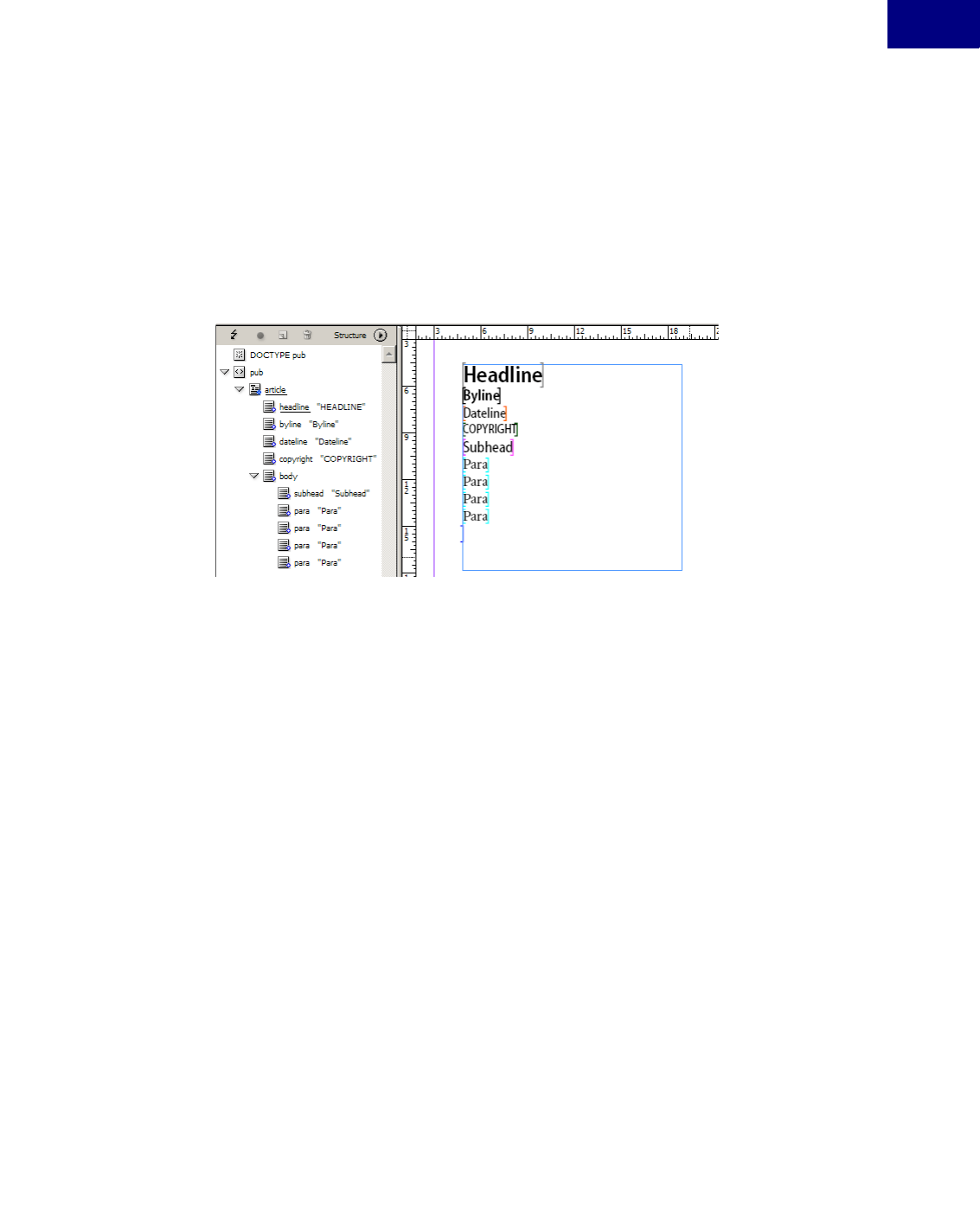
XML Fundamentals 521
XML Fundamentals
Importing XML
their content) in the document after XML import. The user sets this import option in the XML
Import Options dialog box.
Suppose you have an XML template with the logical structure and existing mark-up shown in
Figure 230. If the feature to throw away unmatched existing elements is enabled before import-
ing XML, and the inbound XML does not have elements that match a copyright element in the
template, the copyright element in the template is deleted on import.
FIGURE 230 XML template
For example, suppose the incoming XML contains only the elements shown in Example 37,
rather than the full set of elements in the XML template document in Figure 230.
EXAMPLE 37 Sample XML to import
<article><headline>Another Disastrous Night for Scotland</headline>
<byline>Chick O'Young</byline>
<dateline>22 July 2004</dateline>
<body><para>Scotland's World Cup qualification hopes were dampened by the news
that no-one in the current squad is fit to play for Scotland.</para></body>
</article>
The net result of importing the sample XML with the option to throw away unmatched existing
elements is that only the elements in the incoming XML data explicitly matched in the template
are retained, and the template elements and associated content are deleted from the document
on import. The result for this sample XML is shown in Figure 231.

XML Fundamentals
Importing XML
522
FIGURE 231 After throwing away unmatched existing elements on import
Architecture
This feature is implemented by a matchmaking service (kXMLThrowAwayUnmatchedRight-
MatchMakerServiceBoss); see “XMl-import matchmaker” on page 555. The feature is turned
on or off by a service-specific import preference (IXMLImportPreferences); see “Service-level
XML preferences” on page 551. For more information on controlling the feature, see the “XML”
chapter of Adobe InDesign CS4 Solutions.
Throwing away unmatched incoming elements on XML import
You can choose to throw away (delete) unmatched incoming elements, to filter out elements in
the incoming XML data that do not have a match in the XML template into which they are
being imported. You can use this feature when you know there are optional elements in the
incoming XML that you do not want to display, and you do not want to use XSLT to explicitly
filter them out.
Architecture
This feature is implemented by a matchmaking service (kXMLThrowAwayUnmatchedRight-
MatchMakerServiceBoss); see “XMl-import matchmaker” on page 555. This feature is turned
on or off by a service-specific import preference (IXMLImportPreferences); see “Service-level
XML preferences” on page 551. For more information on controlling the feature, see the “XML”
chapter of Adobe InDesign CS4 Solutions.
Attribute-style mapping
Suppose you want to import XML that has (or is transformed to have) attributes that specify
the character or paragraph style to apply to text content in the inbound XML. You can use the
attribute-style mapping feature, which looks for attributes pstyle and cstyle in the inbound
XML, then tries to match these to paragraph and character styles in the document.
Architecture
This feature is implemented by a post-import responder (kXMLImporterPostImportMapping-
Boss); see “Post-import responder” on page 555. This responder also implements tag-to-style

XML Fundamentals 523
XML Fundamentals
Importing XML
mapping on import; see “Tag-to-style mapping” on page 531. For information on how this fea-
ture is turned on or off, see “Service-level XML preferences” on page 551.
Creating links on XML import
When XML is imported into an XML template, the default behavior is not to create a link to the
imported XML file; however, it is possible to turn on a feature that supports creating a link to
the imported XML file.
XML linking is a feature that enables InDesign to keep track of imported XML files. Each
imported XML file has a corresponding link, which is shown in the Links panel along with sta-
tus. Operations that can be performed on XML links include the following:
zCreate — When an XML file is imported, a link (kXMLImportLinkBoss) is created and
associated with the root element of the imported content. Only one link can be associated
with one element. Importing into an element that already has a link replaces the old link
with the new one.
zDelete — Deleting an element deletes its associated link, if it has one.
zCopy, paste, duplicate — When an XML element associated with a link is copied, pasted, or
duplicated, a copy of the link is created and associated with the new element.
zPlace — Placing an element into the layout or unplacing it does not affect its XML link.
Both placed and unplaced elements can be associated with XML links.
zCheck status — An XML link's status (e.g., up-to-date, modified, or missing) is shown as an
icon in the Links panel.
Architecture
This feature is controlled by an XML-related preference. For details on how this feature is
turned on or off, see “Service-level XML preferences” on page 551.
Sparse import
If this feature is turned on during XML import, incoming elements that have no content (or
only whitespace for content) do not replace content in the matching existing XML element in
the XML template. By default, this feature is turned off.
Architecture
The feature is controlled by an XML-related preference (kXMLSparseImportOptionsService-
Boss). The top-level SAX handler (kSAXDocumentHandlerBoss) acts on this preference,
rather than the service (kXMLSparseImportOptionsServiceBoss) being responsible for provid-
ing the behavior. This explains why kXMLSparseImportOptionsServiceBoss has no service
interface: it is not implementing a particular extension pattern other than for XML import
preferences. For details on how to turn sparse import on and off, see “Service-level XML pref-
erences” on page 551.

XML Fundamentals
Exporting XML
524
Importing a CALS table as an InDesign table
You can choose whether to import a CALS table as an InDesign table. You can use this feature
when you have a table specified in CALS table format and you want to manipulate it the same
way as InDesign native tables.
Architecture
This feature is implemented by a matchmaking service (kXMLTableMatchMakerServiceBoss)
and DOM serializer handler service; see “XMl-import matchmaker” on page 555 and “SAX
DOM serializer handler” on page 557. During the matchmaker phase, a special attribute, kTa-
bleFormatAttr (“tformat”), with value kAttrValueCALS (“CALS”), is inserted into the table ele-
ment. During the DOM serializer phase, contents in the CALS table are altered to fit the
InDesign table format. This feature can be turned on or off by a service-specific import prefer-
ence (IXMLImportPreferences); see “Service-level XML preferences” on page 551. For more
information on controlling the feature, see the “XML” chapter of Adobe InDesign CS4 Solutions.
Support table and cell styles when importing an InDesign table
You can specify table and cell styles when importing an InDesign table. A table-style attribute
applies only to a table element. Cell-style attributes apply to either a table element or a cell ele-
ment; they are ignored for other types of elements. If the style name specified in the attribute
value does not exist, a new style with that name is created and then applied to the table or cell.
Architecture
This feature is implemented by a post-import responder (kXMLImporterPostImportMapping-
Boss), the same way as character style and paragraph style; see “At t r i b u t e - s t y l e m a p p i n g ” o n
page 522. The only difference is that the attribute names are tablestyle and cellstyle.
Exporting XML
Exporting XML data from InDesign is considerably more straightforward than importing
XML data into InDesign. The downside to this is that there are fewer opportunities for your
plug-in to customize the export side.
You can export the logical structure of an InDesign document as an XML document. The
export takes place in document order, meaning the logical structures of the InDesign docu-
ment and exported XML data are the same.
An XML file can be exported from any element in the logical structure. For example, if
exported from the root element, the exported XML data represents the logical structure of the
entire document. If another element—for example, E—is chosen, the exported XML data rep-
resents the logical structure of the subtree with E at its root.
Even an empty InDesign document has some (albeit trivial) logical structure: it has one root
element with no dependents. If exported as XML data, one element (<Root></Root>) is writ-

XML Fundamentals 525
XML Fundamentals
Exporting XML
ten to the output file. Figure 232 shows the logical structure of an new, empty document and
the XML data exported from InDesign with the default settings. Note the default encoding
(UTF-8).
FIGURE 232 Structure of empty document and XML exported
There are two points to note about the relationship between XML data exported from InDesign
and the logical structure:
zXML content can be exported from a document even if it is not associated with placed con-
tent in the document. Exported XML data is based on the logical structure, irrespective of
whether the elements are associated with content in the document.
zThe order in which the elements appear in the XML output is based on the logical structure
and has no direct relation with the hierarchy of the native document model. The exception
to this is a story with mark-up, in which case the order of the elements in the logical struc-
ture within the subtree corresponding to the story corresponds to the story-reading order.
Export architecture
An XML generator (IXMLGenerator) is an abstraction responsible for generating the XML
content during export. The IXMLGenerator interface is aggregated by classes representing
XML elements (IIDXMLElement) in the logical structure.
The mechanism that supports XML export is a standard export provider (kXMLExportPro-
viderBoss, IExportProvider). This delegates to an instance of kXMLExportHandlerBoss to per-
form the actual export. The implementation of IXMLHandler iterates elements in the logical
structure, calling methods through the IXMLGenerator interface of the elements.
This sequence diagram in Figure 233 shows some of the messages sent during a typical XML
export.
"[POYHUVLRQ HQFRGLQJ 87)VWDQGDORQH \HV"!
Root></Root>
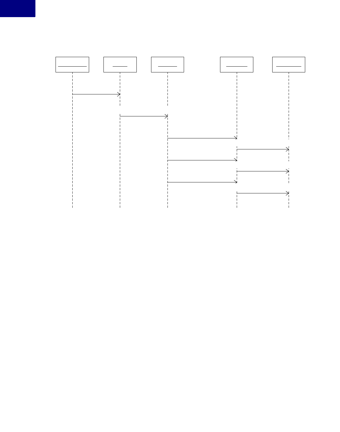
XML Fundamentals
Exporting XML
526
FIGURE 233 XML-export sequence
The export provider (kXMLExportProviderBoss), shown as export-provider in Figure 233,
starts the export. The parser service (kXMLParserServiceBoss) has an IXMLAccess interface,
shown as the xmlAccess object. An instance of kXMLExportHandlerBoss, shown as xmlHan-
dler, with signature interface IXMLHandler, iterates elements in the logical structure. The
implementation of the IXMLGenerator interface on these elements generates XML content to
the output stream. There are several implementations of this interface, generating different
content types on export.
Contributions to XML export come from instances of boss classes that expose the IXMLGener-
ator interface. These classes represent elements in the logical structure; e.g., kTextXMLEle-
mentBoss (tagged stories, tagged text ranges, and tagged graphics) and kXMLCommentBoss
(XML comments).
You can participate in the export process by providing a custom kXMLExportHandlerSig-
nalService. The providers are called when the XML handler iterates elements. For more infor-
mation, see the extension pattern in “XML-export handler” on page 558.
Document order
The logical structure of an InDesign document is exported as XML in document order, as
defined in the XPath specification (http://www.w3.org/TR/xpath#dt-document-order). For
convenience, part of the definition is repeated here:
export-provider xmlHandlerxmlUtils
IXMLUtils::ExportElement
xmlAccess
IXMLAccess::VisitAllElements
IXMLHandler::HandleElementBefore
IXMLHandler::HandleAfterNthChild
IXMLHandler::HandleElementAfter
xmlGenerator
IXMLGenerator::GenerateBeginTag
IXMLGenerator::GenerateContent
IXMLGenerator::GenerateEndTag
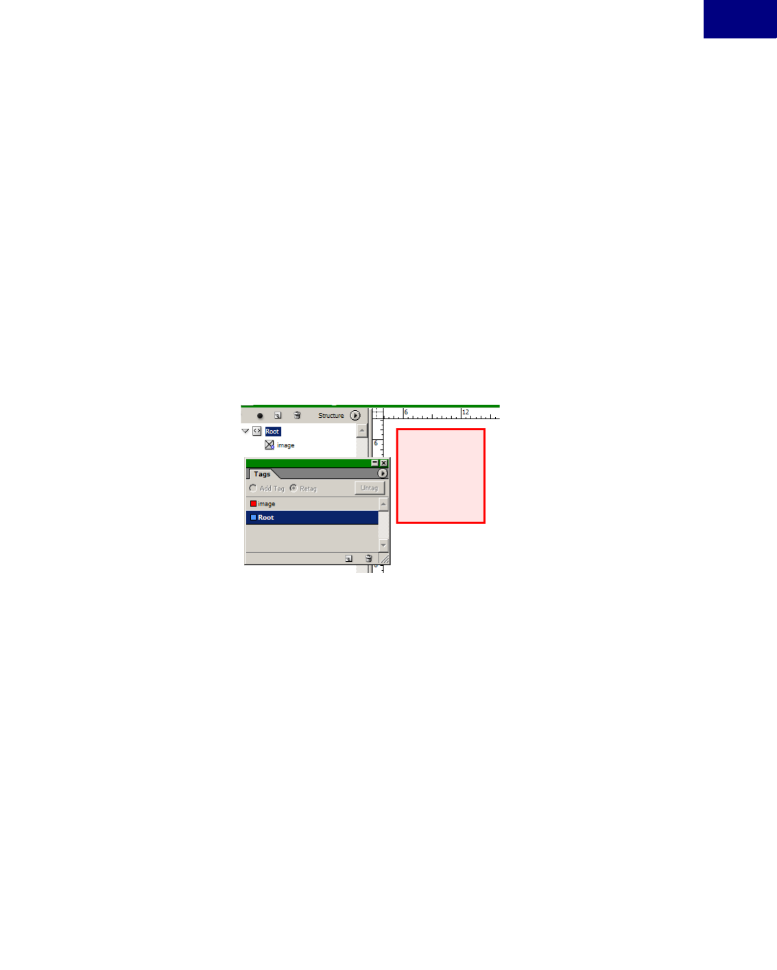
XML Fundamentals 527
XML Fundamentals
Exporting XML
“There is an ordering, document order, defined on all the nodes in the document correspond-
ing to the order in which the first character of the XML representation of each node occurs in
the XML representation of the document after expansion of general entities. Thus, the root
node will be the first node. Element nodes occur before their children. Thus, document order
orders element nodes in order of the occurrence of their start-tag in the XML (after expansion
of entities). The attribute nodes and namespace nodes of an element occur before the children
of the element. ... Reverse document order is the reverse of document order.”
Document order has no direct relationship with the order in which a document would be read
or other ordering schemes you might devise (e.g., based on page numbering).
Tagged graphic placeholder, exported
Consider the case, shown in Figure 234, of a simple but nontrivial logical structure in which a
tagged placeholder is intended as the destination for an image.
FIGURE 234 Tagged graphic placeholder
Exporting the logical structure with default export options results in the XML data shown in
Figure 235. To vary the options, like the encoding, see “XML-related preferences” on page 549.
FIGURE 235 Exported XML from document with tagged-graphic placeholder
The abstraction responsible for generating the XML data related to the tagged graphic is the
element (IIDXMLElement) that represents the graphic. It exposes the IXMLGenerator inter-
face, which is used during the export process.
<?xml version="1.0" encoding="UTF-8" standalone="yes" ?>
-<Root>
<image />
</Root>
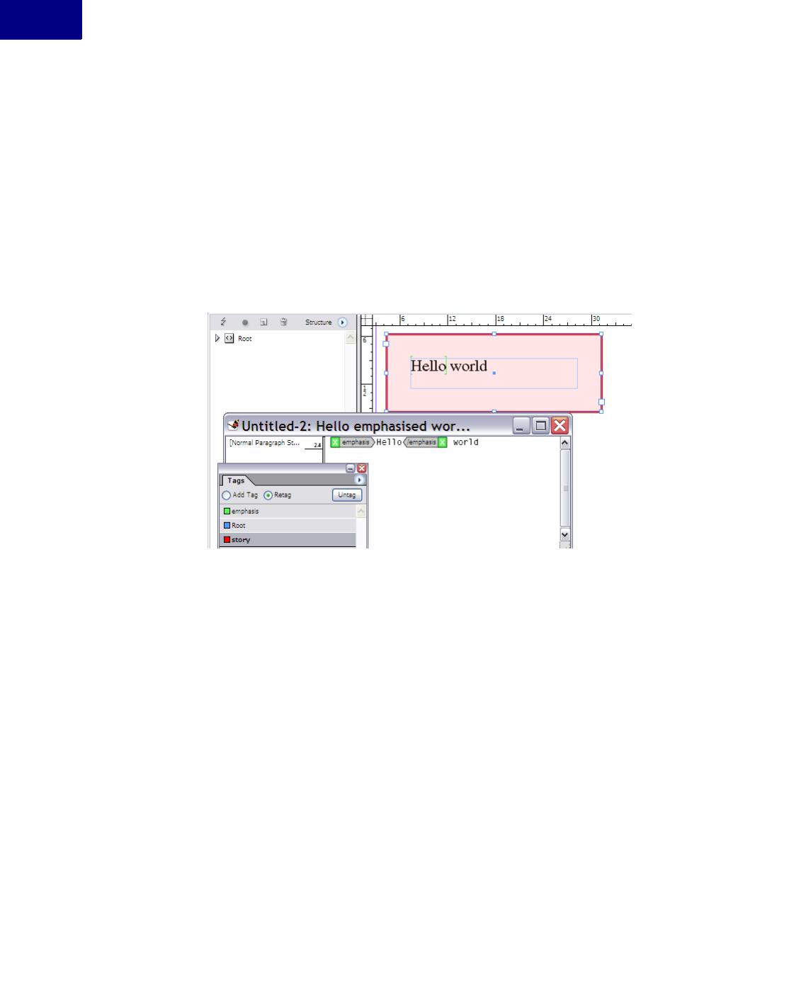
XML Fundamentals
Exporting XML
528
Tagged text range, exported
Consider the example in which you create a text frame, tag the story running through it with a
tag named “story,” then tag a range within that story with a different tag named “emphasis.” The
XML story element represents the instance of the tagged story. The XML emphasis element
represents the tagged content item with value “Hello.” This is shown in Figure 236. The screen-
shot shows logical structure, tags, and layout view for a document with one text frame, with a
tagged text range. The story is tagged “story” and represented by the story element in the logi-
cal structure. The text range is tagged “emphasis” and represented by the emphasis element.
FIGURE 236 Tagged text range before export
If you export the logical structure as XML data from the root element, you get the XML data
shown in Figure 237. This time, the export option to export with UTF-16 encoding is set, to
make it easier to inspect the Unicode character that represents the hard carriage return in the
story. This XML data was exported by InDesign from the document shown in Figure 236.
FIGURE 237 XML exported for tagged text range
The XML content of the exported story requires some study. The intent of the InDesign func-
tion is that stories should be represented in exported XML data as closely as possible to how
InDesign represents them internally. The end-of-line character corresponding to the hard car-
<?xml version="1.0" encoding="UTF-16" standalone="yes" ?>
-<Root>
-<story>
<emphasis>Hello</emphasis>
world
</story>
</Root>

XML Fundamentals 529
XML Fundamentals
Tags
riage return after the word “world” is represented by the Unicode character 0x2029. If you open
the XML file in a binary editor on Windows—which is little-endian—the Unicode character
0x2029 is represented as the octet 29 and then the octet 20. Soft carriage returns are repre-
sented by 0x2028. See IXMLOutStream. This is shown in Figure 238; the 0x2029 (hard carriage
return) is highlighted.
FIGURE 238 Story exported from InDesign as XML in UTF-16 encoding
Tags
Tags can be loaded from several different sources, including the following:
zAn InDesign tag file, an XML document containing only tag-specific information.
zAny XML document that is an instance of the document type being worked with.
zBy associating a DTD with the document. Doing this means the DTD is parsed for element
tag names, and tags are created correspondingly. Elements defined within entities are
ignored.
Example 38 is a sample tag list.
EXAMPLE 38 Sample tag list
<?xml version="1.0" encoding="UTF-16" standalone="yes"?>
<article colorindex="4">
<articleinfo colorindex="6"/>
... (other elements omitted)
<ulink colorindex="19"/>
</article>
It also is possible to specify the color of the tag using RGB coordinates, which are used for any
tags defined with a custom color. The coordinates are hex-encoded; for example, one tag with a
custom color (0,0,255) in decimal RGB coordinates appears below:
<link rgb="0 0,0 0,3ff00000 0"/>
In addition, the custom-tag service-extension pattern lets you customize what tags are created
when an XML document is being parsed. See “Custom-tag service” on page 557.

XML Fundamentals
Tags
530
Architecture
The kXMLTagBoss boss class represents an individual entry in a tag list. The signature inter-
face of this boss class is IXMLTag; this stores properties like the name and color in the user
interface. The tag list is represented by IXMLTagList.
IXMLTagList is aggregated on the session workspace (kWorkspaceBoss), representing a default
set of tags for any new document.
IXMLTagList is aggregated on the document workspace (kDocWorkspaceBoss), representing
tags in a given document.
The session workspace (kWorkspaceBoss) stores zero or more tags. A document workspace
(kDocWorkspaceBoss) stores one or more tags; the minimal tag set for a new document con-
sists of the Root tag.
Tagging relationships are represented by associations between classes representing elements in
the logical structure and those representing tags. For example, if a graphic frame is tagged for
use as a placeholder, an association is created between the placeholder boss object (an instance
of the kPlaceHolderItemBoss class) and an instance of the kTextXMLElementBoss class. An
association is created between an element in the logical structure (IIDXMLElement) and an
instance of kXMLTagBoss, to represent the tagging.
Tags (kXMLTagBoss) that can be used to mark up content items in the native document model
are held in the tag list (IXMLTagList) of a workspace (kDocWorkspaceBoss, kWorkspaceBoss).
Tags are rendered in the Tags panel (Figure 218) and shown in views like layout view
(Figure 216) or story view (Figure 217). XML elements that have tag names are associated with
tags (kXMLTagBoss) that store the tag names.
Given a reference to an XML element, you can find the tag string through a method on
IIDXMLElement. You also can use IIDXMLElement::GetTagUID to acquire a reference to an
instance of kXMLTagBoss representing the tag.
You can acquire a reference to a tag (kXMLTagBoss) in a document through the tag list (IXML-
TagList) on the document workspace (kDocWorkspaceBoss). The tagUIDRef variable refers to
an instance of kXMLTagBoss.
The class diagram in Figure 239 shows associations between tags and workspaces and the doc-
ument (kDocBoss).

XML Fundamentals 531
XML Fundamentals
Tags
FIGURE 239 Tags
Tag-to-style mapping
Suppose you have XML content with a headline tag and a p-head-1 paragraph style in your
XML template. You can create an association between tags and styles in the document, to
enable incoming XML to be styled automatically.
When a tag-to-style mapping is applied during the XML import, inbound XML content has the
styles applied when elements with tag names matching the tags in the tag-to-style map are
encountered. For example, if you create a mapping from the headline tag to the p-head-1 para-
graph style, textual content in a headline element has the p-head-1 style applied.
The user interface for this feature is shown in Figure 219. This establishes a one-to-one map-
ping from tag names to character or paragraph styles, which is sufficient when context-sensi-
tive styling is not required. If context-sensitive styling for incoming XML is required, you can
use a combination of a stream-based XML transformer and attribute-style mapping to achieve
this. See “XML transformer” on page 554 and “Attribute-style mapping” on page 522.
Architecture
Figure 240 is a class diagram for tag-to-style mappings (IXMLTagToStyleMap). The session
workspace (kWorkspaceBoss) stores the default mapping inherited by new documents. The
document workspace (kDocWorkspaceBoss) stores the mapping applied to a particular docu-
ment (kDocBoss).
«boss»
kWorkspaceBoss
«boss»
kDocWorkspaceBoss
«boss»
kXMLTagBoss
1
1..*IXMLTagList::GetTag
1
0..*
IXMLTagList::GetTag
«boss»
kDocBoss
1
1
IDocument::GetDocWorkspace
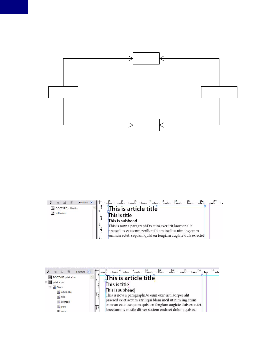
XML Fundamentals
Tags
532
FIGURE 240 Tag-to-style mapping
Style-to-tag mapping
Figure 241 is a screenshot of an unstructured but systematically styled document, which as an
associated DTD. Figure 242 shows the result of applying a style-to-tag mapping.
FIGURE 241 Before mapping styles to tags
FIGURE 242 After mapping styles to tags
«boss»
kXMLTagBoss
«boss»
kWorkspaceBoss
«boss»
kDocWorkspaceBoss
1
0..*
IXMLTagToStyleMap::GetTagAt
1
0..* IXMLTagToStyleMap::GetTagAt
«boss»
kStyleBoss
1
0..*
IXMLTagToStyleMap::GetStyleMappedToTag
1
0..*IXMLTagToStyleMap::GetStyleMappedToTag

XML Fundamentals 533
XML Fundamentals
Tags
Once a style-to-tag mapping is defined and applied, ranges of styled text with the styles
mapped to given tags end up tagged, creating new elements in the logical structure. There are
some default commitments in terms of the tags applied; for example, the Story tag is used for a
story, even if it is not in the tag list of the document when the style-to-tag mapping is applied.
Architecture
The class diagram in Figure 243 shows the associations between workspaces (IWorkspace),
tags (kXMLTagBoss), and styles (kStyleBoss), mediated by the style-to-tag map (IXMLStyle-
ToTagMap). The session workspace (kWorkspaceBoss) stores the default style-to-tag map for
new documents. The document workspace (kDocWorkspaceBoss) stores the style-to-tag map
for a given document (kDocBoss).
FIGURE 243 Style-to-tag mapping
Text styles are represented by kStyleBoss. Collections of styles are held in the style-name table
(IStyleNameTable) and stored in a workspace (IWorkspace). The session workspace (kWork-
spaceBoss) stores text styles that are defaults for new documents. The document workspace
(kDocWorkspaceBoss) stores text styles that can be used in the associated document. For more
information on text styles, see the “Text Fundamentals” chapter and the API reference docu-
mentation for kStyleBoss.
The workspace (IWorkspace) maintains an associative map between text styles (kStyleBoss)
and tags (kXMLTagBoss). This map is stored in the persistent interface IXMLStyleToTagMap.
The workspace style list (IStyleNameTable) may contain styles that are not referenced in the
style-to-tag map. Similarly, there may be tags in the tag list (IXMLTagList) of the workspace
that are not involved in the style-to-tag map.
«boss»
kDocWorkspaceBoss
«boss»
kWorkspaceBoss
«boss»
kStyleBoss
«boss»
kXMLTagBoss
1
0..*
IXMLStyleToTagMap::GetStyleAt
1
0..*IXMLStyleToTagMap::GetStyleAt
1
0..*
IXMLStyleToTagMap::GetTagMappedToStyle
1
0..*IXMLStyleToTagMap::GetTagMappedToStyle

XML Fundamentals
Elements and content
534
Elements and content
Tagged graphic placeholder
Suppose you are building an XML template and you want to create placeholders into which
images will be placed when an XML data file is imported. To create a placeholder graphic for an
image, follow these steps:
1. Create a new document.
1. Create a tag named “image” through the Tags panel (Window > Tags).
2. Create a rectangle page item with the Rectangle tool.
3. Leave the page item selected, and click on the image tag in the Tags panel.
4. Show the structure view. It should look like Figure 244.
Architecture
The UML object diagram in Figure 244 shows the boss objects representing a tagged graphic
placeholder and some of the relationships between them. The placeholder object (kPlaceHold-
erItemBoss) is a child of a graphic frame (kSplineItemBoss); the latter is omitted from this dia-
gram, in the interest of simplicity. Content items like kPlaceHolderItemBoss have an
IXMLReferenceData interface, which lets them refer to an element in the logical structure.
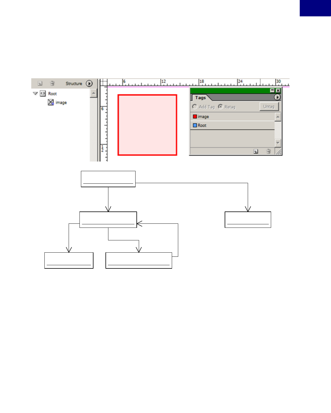
XML Fundamentals 535
XML Fundamentals
Elements and content
FIGURE 244 Tagged graphic placeholder
When document content is tagged, XML elements (IIDXMLElement) are created within the
logical structure. Tagging content creates associations between content items (see IXMLRefer-
enceData) and elements in the logical structure. Tagging also creates associations between ele-
ments and tags (kXMLTagBoss).
Figure 245 shows a class diagram for some of the classes representing a tagged placeholder
graphic. A graphic frame (kSplineItemBoss) acquires a placeholder item child (kPlaceHolder-
ItemBoss), when the frame is tagged to use as a placeholder. If a graphic frame is not tagged, it
has no dependent placeholder (kPlaceHolderItemBoss).
«boss»
Root : kTextXMLElementBoss
«boss»
image : kTextXMLElementBoss
«boss»
image-tag : kXMLTagBoss
IXMLTag
IIDXMLElement
«boss»
Root-tag : kXMLTagBoss
IXMLTag
«boss»
placeholder : kPlaceHolderItemBoss
IIDXMLElement::GetContentItem
IXMLReferenceData
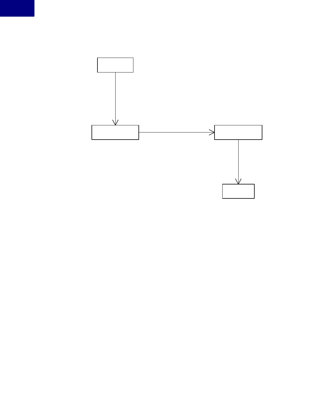
XML Fundamentals
Elements and content
536
FIGURE 245 Tagged placeholder
There are several key associations related to tagging of content items shown in Figure 244 and
Figure 245:
zContent items in the native document model associate with elements in the logical struc-
ture. The association is maintained by the IXMLReferenceData interface and the XMLRef-
erence helper class.
zElements in the logical structure associate with content items in the native document
model. The association is maintained by the IIDXMLElement interface. See GetContent-
Item and GetContentReference.
zElements in the logical structure associate with tags. The association is maintained by the
IIDXMLElement interface. See GetTagUID and GetTagString.
Tagged images
Figure 246 is an example of a minimal XML file that can be used to place an image. The path
shown is a relative one; the image would have to be in the same folder as the XML file that ref-
erenced it.
«boss»
kSplineItemBoss
«boss»
kPlaceHolderItemBoss
«boss»
kTextXMLElementBoss
«boss»
kXMLTagBoss
1
0..1
IHierarchy
1 0..1
IXMLReferenceData::GetReference
1
1
IIDXMLElement::GetTagUID

XML Fundamentals 537
XML Fundamentals
Elements and content
FIGURE 246 Minimal XML content to place an image
See the “XML” chapter of Adobe InDesign CS4 Solutions for an example of XML for importing
an image by reference. On importing the XML file, if we do not have a pre-existing placeholder
graphic frame tagged with the Image tag, the image is not placed.
Figure 247 shows the result of importing the minimal XML file.
FIGURE 247 Unplaced image
If there is a pre-existing graphic frame tagged with the Image tag, the image is placed on
import. One constraint is that if you intend an image to be placed in the graphic frame, the
Image element (for this example) must support the href attribute that on import should specify
the system path with which to locate the image to be placed, or you will have to place the image
yourself.
Architecture
Elements can be associated with a tagged placeholder (kPlaceHolderItemBoss) or a tagged
graphic content item, such as an image (kImageItem, kPlacedPDFItemBoss, kEPSItem, etc.).
When an XML tag is applied to a graphic frame with placeholder content (e.g., kSplineItem-
Boss containing a kPlaceHolderItemBoss), a new instance of the kTextXMLElementBoss class
is created, and a link is created between this object and the boss object representing the place-
holder item (kPlaceHolderItemBoss).
Tagged stories
Architecture
Elements (IIDXMLElement) can be associated with a content item that is either a story or a
range of text within a story. The story (kTextStoryBoss) in which the text range is contained
must be tagged before a range of text can be tagged. Tagging a story is useful when you want to
create a tagged placeholder for incoming, text-based content. The end-user action to tag a story
is to tag the text frame through which the story flows; this creates an association between the
story (kTextStoryBoss) and an XML element (IIDXMLElement).
<?xml version="1.0" encoding="UTF-8" ?>
-<Root>
<Image href="file://testfile.tif" />
</Root>
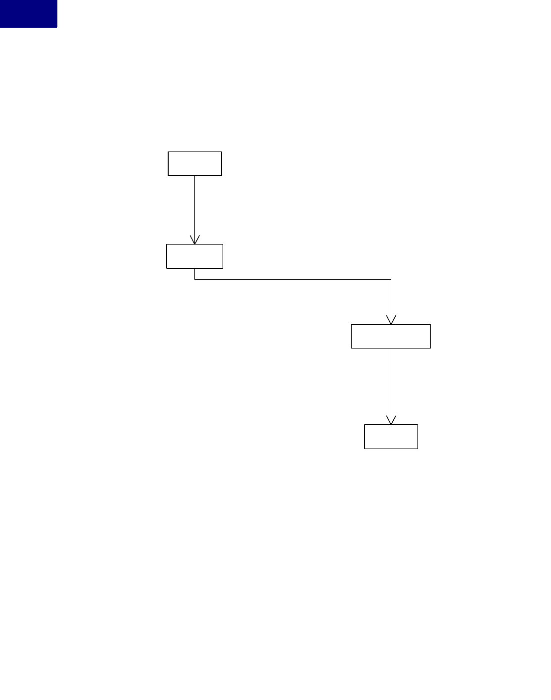
XML Fundamentals
Elements and content
538
Figure 248 shows associations for some of the classes representing a tagged story (kTextStory-
Boss). If a story is tagged, the IXMLReferenceData of the story boss object (kTextStoryBoss)
refers to a valid instance of an element (kTextXMLElementBoss).
FIGURE 248 Tagged stor y
You can iterate over the children of the element tagging the story, using XMLContentIterator,
to find out text ranges marked up by the child elements. For an example, see the section on
“Finding Text associated with Tagged Text Ranges” in the “XML” chapter of Adobe InDesign
CS4 Solutions.
Tagged text ranges
A tag is applied to a text range by making a text selection and either clicking a particular tag in
the Tags panel or selecting an item from a context-sensitive menu containing tag names. Once
the range is tagged, tag markers are placed before and after the tagged range. The “[” and “]”
adornment characters are nonprinting, zero-width spaces inserted into the text; these charac-
ters can be shown or hidden.
«boss»
kDocBoss
«boss»
kTextStoryBoss
1
1..*
IStoryList
«boss»
kTextXMLElementBoss
1
0..1
IXMLReferenceData::GetReference
«boss»
kXMLTagBoss
1
1
IIDXMLElement::GetTagUID
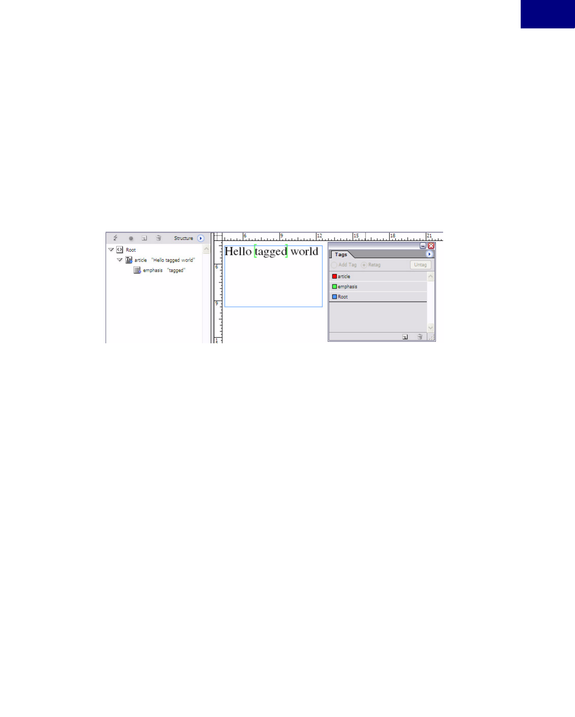
XML Fundamentals 539
XML Fundamentals
Elements and content
Text ranges within a tagged story can themselves be tagged. Text within table cells also can be
tagged. There are some constraints on what text can be tagged. The following text ranges can-
not be tagged:
zSome owned items, including notes (kNoteDataBoss), tracked changes, and hyperlinks.
zRuby text annotations in Japanese.
zText in locked stories (see IItemLockData).
Figure 249 shows a tagged range of text. In this example, the article tag is applied to the story,
and the emphasis tag is applied to the text range containing the characters “tagged.”
FIGURE 249 Tagged text range
Architecture
When tagging a text range in an untagged story, the following steps take place:
1. The story (kTextStoryBoss) in which the text range lies is tagged, and an element (IIDXM-
LElement) is created in the logical structure.
2. An element (IIDXMLElement) is created to represent the tagged-text range. This element
refers to a tag (kXMLTagBoss) with a tag name (“emphasis” in the example in Figure 249).
3. Characters are inserted into the text model to represent the start and end of the tagged-text
range (kTextChar_ZeroSpaceNoBreak).
4. Optionally, adornments (IGlobalTextAdornment, kXMLMarkerAdornmentBoss) are
drawn in layout view, as shown in Figure 249, if the preference to show tag markers is
enabled (see IXMLPreferences).
Figure 250 shows the classes involved in this minimal example of tagging a text range.
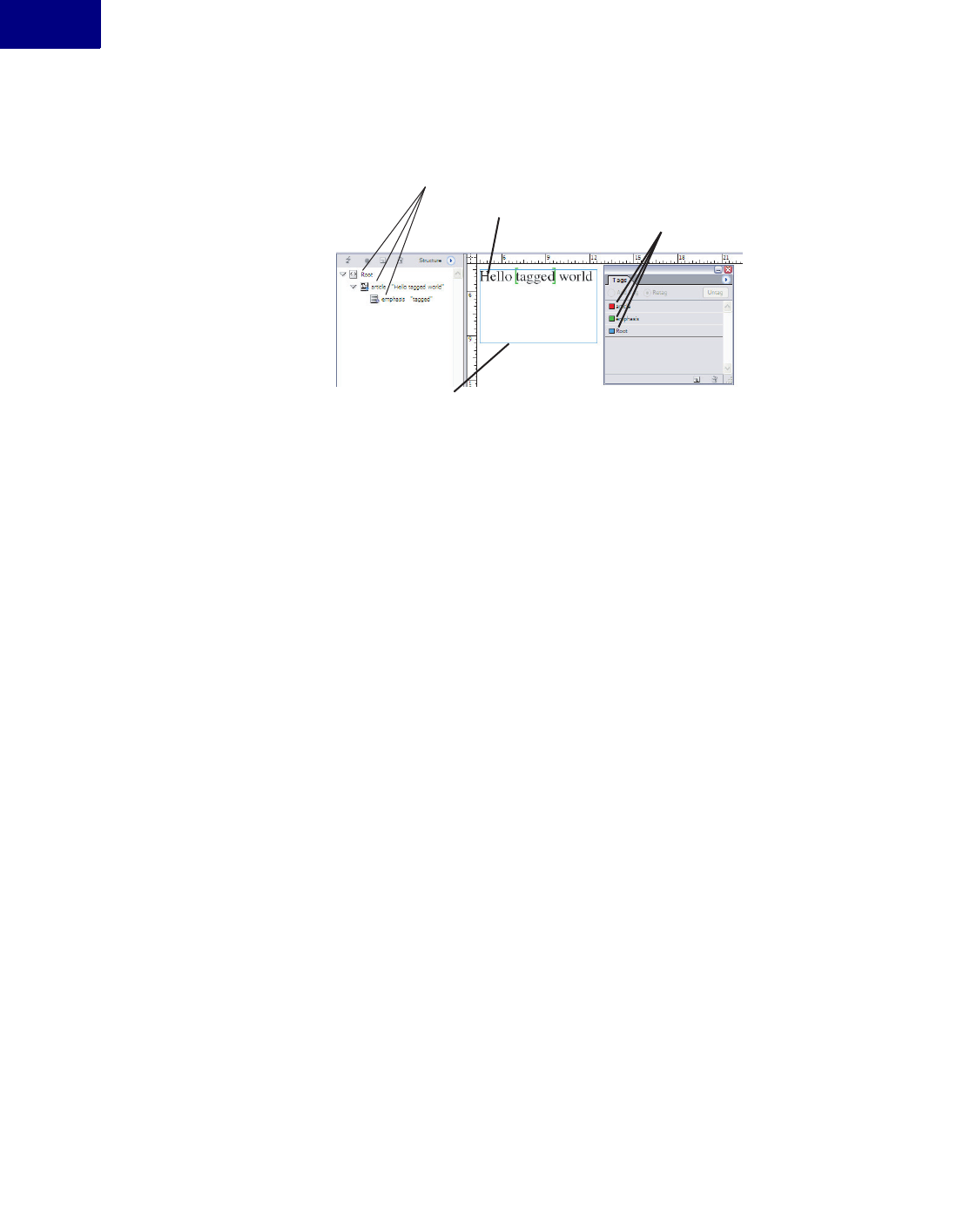
XML Fundamentals
Elements and content
540
FIGURE 250 Classes associated with tagged text range
Consider the example of one tagged text range, as shown in Figure 251, which shows objects
involved in representing a tagged text range. The result of tagging this text range is to create a
new element that is a child of the element associated with the tagged story. See “Tagged stories”
on page 537. In Figure 251, an emphasis element is created on tagging the text range. This is a
child of an article element for this example. The information about the range of text is encapsu-
lated in the kTextXMLElementBoss, but it can be accessed through using XMLContentIterator.
K4EXT8-,%LEMENT"OSS
K4EXT3TORY"OSS
K3PLINE)TEM"OSS
K-ULTI#OLUMN)TEM"OSS
K&RAME)TEM"OSS
K8-,4AG"OSS
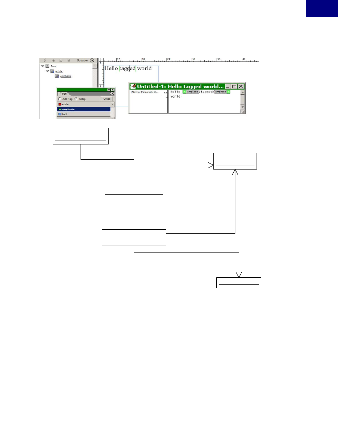
XML Fundamentals 541
XML Fundamentals
Elements and content
FIGURE 251 Tagged text range (class diagram)
«boss»
article : kTextXMLElementBoss
«boss»
emphasis : kTextXMLElementBoss
«boss»
Root : kTextXMLElementBoss
IIDXMLElement
IIDXMLElement
«boss»
Story : kTextStoryBoss
IIDXMLElement::GetContentReference
IIDXMLElement::GetContentReference
text-range : TextRange
XMLContentIterator
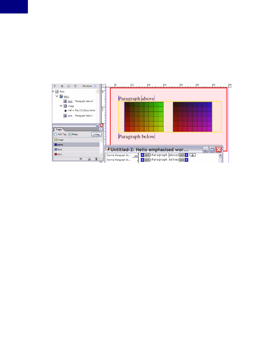
XML Fundamentals
Elements and content
542
Tagged inline graphics
You can create a tagged inline graphic by either selecting an existing inline graphic and tagging
it or placing an image into a tagged inline placeholder.
Figure 252 shows a tagged story, with two tagged paragraphs and a tagged inline graphic.
FIGURE 252 Tagged inline graphic
Architecture
From an XML perspective, tagged inline graphics are like tagged images, described in “Tagged
images” on page 536. The main differences are on the native-document-model side; the image
(e.g., kImageItem) is owned by a frame that itself is owned by an inline object (kInlineBoss).
The object diagram in Figure 253 above shows some objects that model a tagged inline graphic.
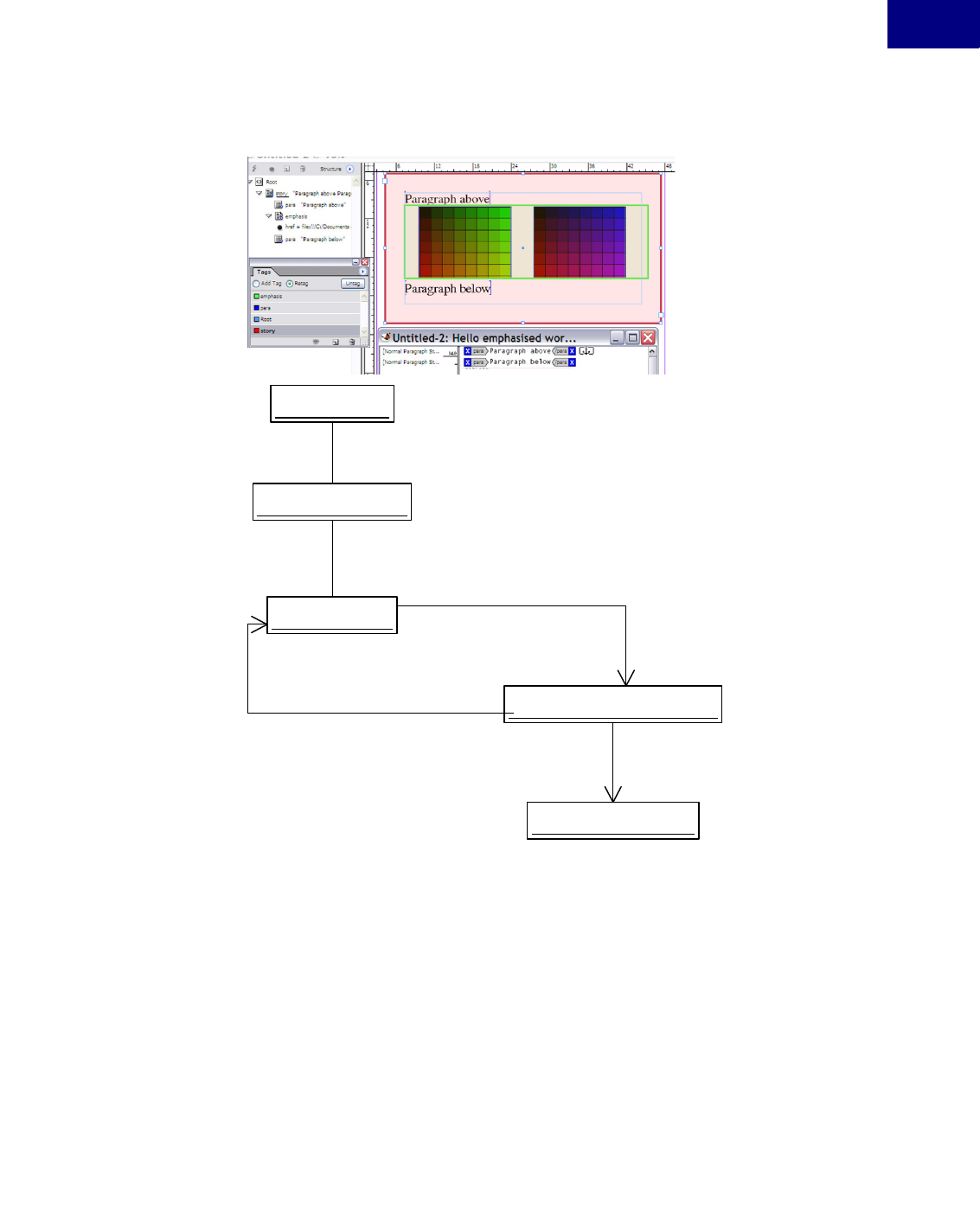
XML Fundamentals 543
XML Fundamentals
Elements and content
FIGURE 253 Tagged inline graphic (object-model diagram)
Tagged tables
You can tag a table and cells within a table. A table that is not explicitly tagged will not get
exported during XML export. If a table is tagged, all its cells must be tagged. In other words, a
tagged table cannot contain untagged cells, and a tagged table cell cannot be inside an untagged
table.
Tagged tables and table cells also can be untagged; that is, the mark-up associated with them
can be removed. Untagging a table or its cells untags the entire table, including the cells.
«boss»
inline : kInlineBoss
«boss»
image : kImageItem
«boss»
frame : kSplineItemBoss
«boss»
<image> : kTextXMLElementBoss
IHierarchy
IHierarchy
IXMLReferenceData::GetReference
«boss»
image-tag : kXMLTagBoss
IIDXMLElement::GetTagUID
IIDXMLElement::GetContentReference

XML Fundamentals
Elements and content
544
The model for tagging tables is restricted: you can tag either at the whole-table level or the cell
level, but you cannot tag rows or create other container elements within the logical structure of
a table.
Architecture
If you examine the API reference documentation for IXMLReferenceData and see the boss
classes that aggregate this interface, you will notice table-related classes like kTableModelBoss
and kTextCellContentBoss. The operation of tagging a table (kTableModelBoss) has the follow-
ing constraints:
zA tagged table must reside in a tagged story (kTextStoryBoss), so the act of tagging a table
also tags the story in which it resides, if the story is not already tagged. The story is auto-
tagged with the Story tag, if no other tag is specified.
zThe cells within the table also must be tagged when the table itself is tagged. The cells are
auto-tagged with the Cell tag, if no other tag is specified.
It also is possible to tag text within a table cell, which is not much different than the situation
described in “Tagged text ranges” on page 538. For example, if you create an element that is a
child of a Cell element, the new element becomes a placeholder for tagged text within a table
cell.
For more details on implementing tagging of tables, see the section on “Tagging a Table” in the
“XML” chapter of Adobe InDesign CS4 Solutions.
The object diagram in Figure 254 shows some of the objects that represent a tagged table. Note
how the table (kTableModelBoss) associates with an XML table element. The key to under-
standing the model is the XMLContentReference type, an instance of which can be obtained
from IIDXMLElement::GetContentReference. In the case of XML elements associated with
table cells, the properties of the cells can be discovered through XMLContentReference.
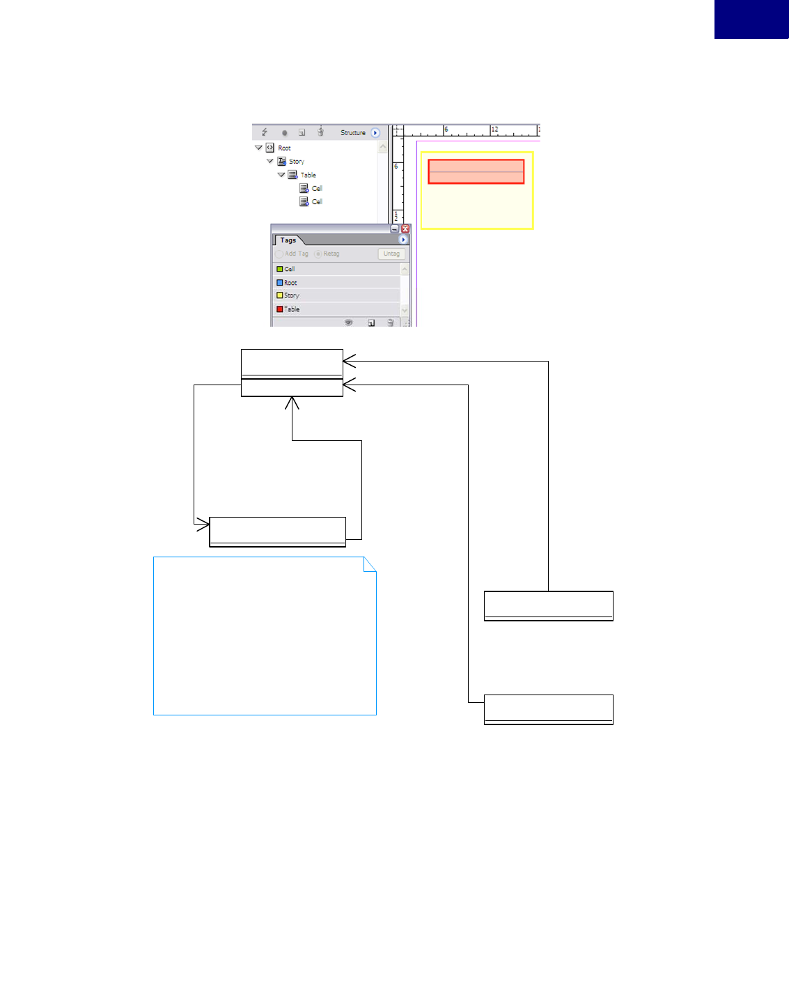
XML Fundamentals 545
XML Fundamentals
Elements and content
FIGURE 254 Tagged table
DTD
A document type declaration (DTD) is a grammar defined in an extended Backus-Naur format
that can be read by XML processors. The main point of associating a DTD with an InDesign
document is to allow the logical structure of the InDesign document to be checked or validated
against the grammar. The XML 1.0 specification (http://www.w3.org/TR/REC-xml) defines a
DTD as follows:
«boss»
table : kTableModelBoss
«boss»
<Table> : kTextXMLElementBoss
«boss»
<Cell> : kTextXMLElementBoss
1
0..1
IXMLReferenceData::GetReference
1
0..1
XMLContentReference::GetUID
1
0..1
XMLContentReference::GetUID
«boss»
<Cell> : kTextXMLElementBoss
1
0..1
XMLContentReference::GetUID
An XMLContentReference is obtained from
IIDXMLElement::GetContentReference.
You can use XMLContentReference::Instantiate
to get an IXMLReferenceData pointer, which refers
to the table in the case of a Cell element.
Other methods on XMLContentReference let
you find where the cell is when you have the
table (ITableModel, kTableModelBoss).

XML Fundamentals
Elements and content
546
“The XML document type declaration contains or points to markup declarations that provide a
grammar for a class of documents. This grammar is known as a document type definition, or
DTD. The document type declaration can point to an external subset (a special kind of external
entity) containing markup declarations, or can contain the markup declarations directly in an
internal subset, or can do both. The DTD for a document consists of both subsets taken
together.”
You can import a DTD to create an association between the DTD and the document’s logical
structure, using the Load DTD menu command in the Structure pane. This associates the DTD
with the logical structure of the document. New tags are created (see “Tags” on page 529) from
an element type declaration, if they are not already in the tag list.
After associating a DTD with the document, you can validate the logical structure of a docu-
ment against the DTD. The user interface for this is shown in Figure 221.
Once you load a DTD, you can validate the logical structure against the DTD, to determine the
extent to which the document’s structure violates the constraints expressed in the grammar
represented by the DTD. See Section “5.1 Validating and Non-Validating Processors” in the
XML 1.0 specification.
The API does not support validating the logical structure of an InDesign document against an
XML schema (http://www.w3.org/TR/xmlschema-0).
If you import a DTD, a new element is created in the logical structure, and new tags are created
as needed. A sample DTD is shown in Example 39. This was associated with the logical struc-
ture of a document after importing the minimal XML from Example 35.
EXAMPLE 39 Small Sample DTD
<!ELEMENT article (title, body?)>
<!ELEMENT body (subhead | para)+>
<!ELEMENT title (#PCDATA)>
<!ELEMENT subhead (#PCDATA)>
<!ELEMENT para (#PCDATA)>
Architecture
The DTD associated with the logical structure of an InDesign document is represented by an
instance of kXMLDTDBoss. When present, this instance is a child of the document element
(kXMLDocumentBoss) and a peer of the root element. See Figure 255 for an object diagram
showing relationships between objects representing the logical structure of a minimal InDe-
sign document. The UML diagram in Figure 255 shows objects representing the logical struc-
ture when a DTD is imported into the document. kXMLDTDBoss, as a participant in the
logical structure, has the IIDXMLElement interface; however, it does not have children and has
no associated tag.
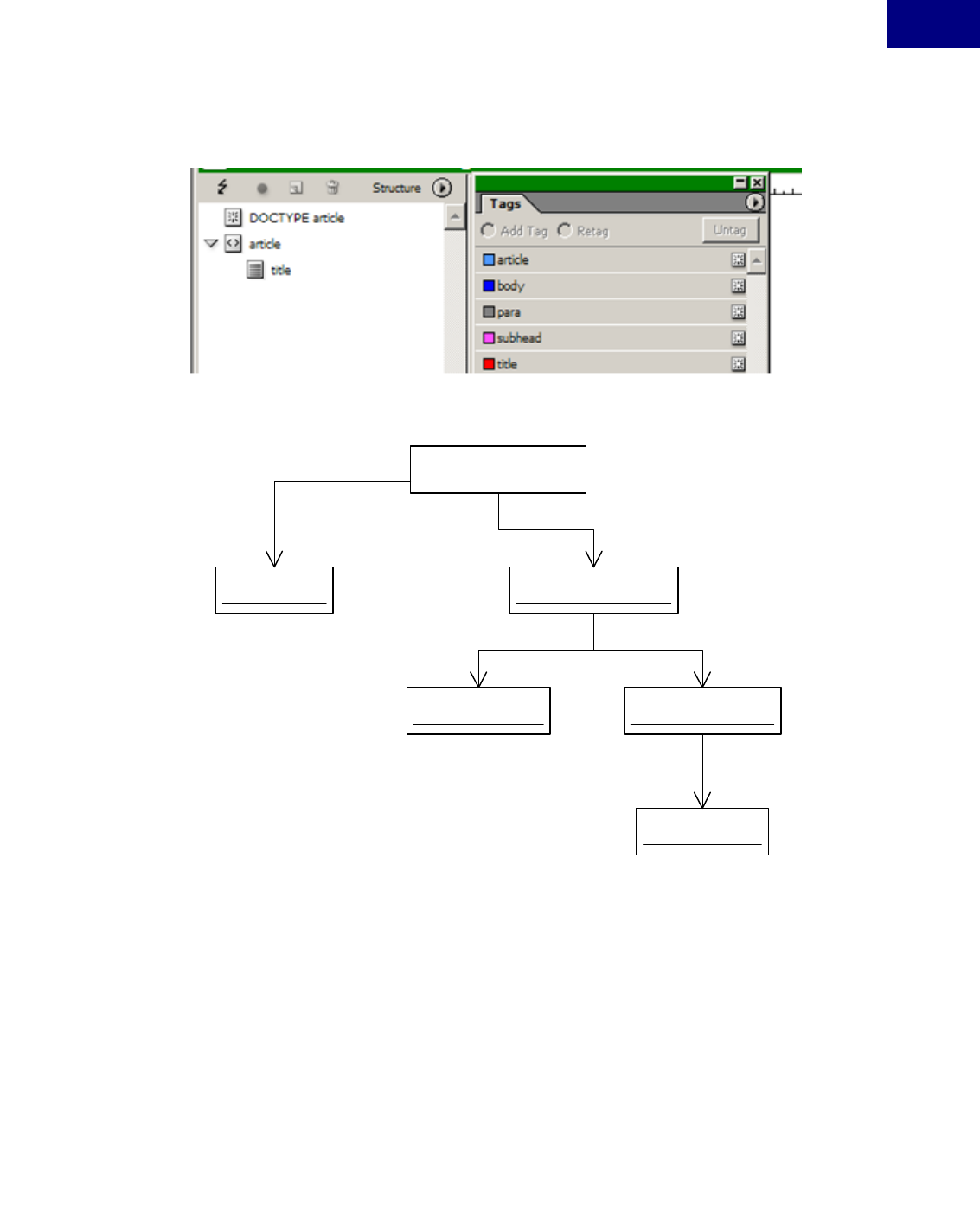
XML Fundamentals 547
XML Fundamentals
Elements and content
FIGURE 255 Elements when a DTD is imported
Processing instructions and comments
An XML comment stores text that is not considered part of the document content, but that
may be relevant when authoring. XML comments are defined in the XML 1.0 specification
(http://www.w3.org/TR/REC-xml) as follows:
“Comments may appear anywhere in a document outside other markup; in addition, they may
appear within the document type declaration at places allowed by the grammar. They are not
part of the document's character data ....”
«boss»
article : kTextXMLElementBoss
«boss»
article-tag : kXMLTagBoss
IXMLTag
«boss»
title : kTextXMLElementBoss
IIDXMLElement
«boss»
title-tag : kXMLTagBoss
IXMLTag
«boss»
doc-elem : kXMLDocumentBoss
IIDXMLElement
«boss»
DTD : kXMLDTDBoss
IID_IXMLDTDXMLREFERENCEDATA
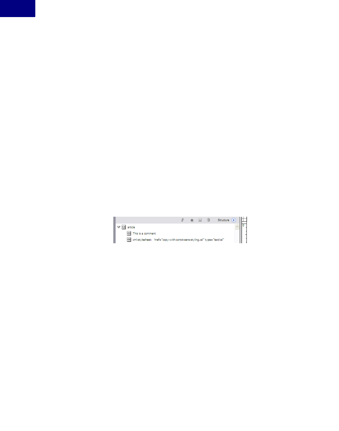
XML Fundamentals
Elements and content
548
XML comments can occur anywhere in the logical structure that is legal within the XML spec-
ification. An XML comment appears in the XML data like this:
<!-- This is a comment -->
Processing instructions (PIs) also store text that is not considered part of the document con-
tent, but the content may be relevant to an XML processor. Processing instructions are defined
in the XML specification as follows:
“PIs are not part of the document's character data, but must be passed through to the applica-
tion. The PI begins with a target (PITarget) used to identify the application to which the
instruction is directed.”
Processing instructions allow XML-based documents to contain instructions for applications
that know how to process them. It is possible to create new processing instructions anywhere in
the logical structure. A processing instruction appears in the XML data like this:
<?xml-stylesheet href="copy-with-contxt-sens-styling.xsl" type="text/xsl"?>
This processing instruction directs an XML application to choose a particular XSL stylesheet if
applying an XSL transform to the XML content.
Figure 256 shows how an XML comment and processing instruction are rendered in the struc-
ture view.
FIGURE 256 Comment and processing instruction in the structure view
Architecture
An XML comment is associated with one string. Comments are represented by kXMLCom-
mentBoss, with the text stored by an implementation of IStringData. On the other hand, a pro-
cessing instruction appears to the user as a pair of strings, one specifying the target for the
processing instruction and the other specifying the data. Processing instructions are repre-
sented by kXMLPIBoss; there are two IStringData interfaces implemented by this class,
(IID_IXMLPITARGET, IID_IXMLPIDATA) storing strings representing the key (target) and
value (data).
The kXMLCommentBoss and kXMLPIBoss boss classes have implementations of the IIDXM-
LElement interface (through inheritance) and are part of the logical-structure tree. Comment
and processing-instruction elements support some but not all properties of other XML ele-
ments. For example, you cannot add attributes to a comment or processing instruction, and
there is neither a valid content-item reference nor a valid tag reference for a comment or pro-
cessing instruction.

XML Fundamentals 549
XML Fundamentals
XML-related preferences
Structural (container) elements
You can add new elements to the logical structure of a document using the structure view and
its associated menu. Elements created in this way are not immediately associated with content
items and are, therefore, unplaced.
Unplaced elements can be placed from the logical structure onto the layout manually or pro-
grammatically, but sometimes it is useful to retain unplaced elements as structural or container
elements.
For example, suppose a publication is a collection of sections (e.g., “Arts” and “Motoring”),
each comprising one or more articles. You could model this with a Section element that con-
sists of a set of Article elements; the Section element might never itself have any content but
instead be used to structure the collection of Article elements. The Section element is a logical
element of the publication, rather than a content-related element.
The XML template for this publication might be set up as shown in Figure 257. The Article ele-
ments appear as placed content, because we tagged some stories with Article tags; these stories
are placeholders into which the XML-based data would be imported.
FIGURE 257 Creating elements as structural elements
Architecture
Structural elements differ from elements representing placed content only insofar as structural
elements do not have a valid content-item reference (IIDXMLElement::GetContentReference).
However, structural elements should have a valid tag reference (IIDXMLElement::Get-
TagUID).
XML-related preferences
The XML subsystem is relatively complex, and there are several interfaces that store XML pref-
erences. These can be grouped into workspace-level preferences and service-level preferences.
Workspace-level XML preferences
There are some XML-related preferences (options) interfaces stored in workspaces (kWorkspa-
ceBoss and kDocWorkspaceBoss). These are shown in Table 129, along with low-level com-
mands that enable them to be changed.
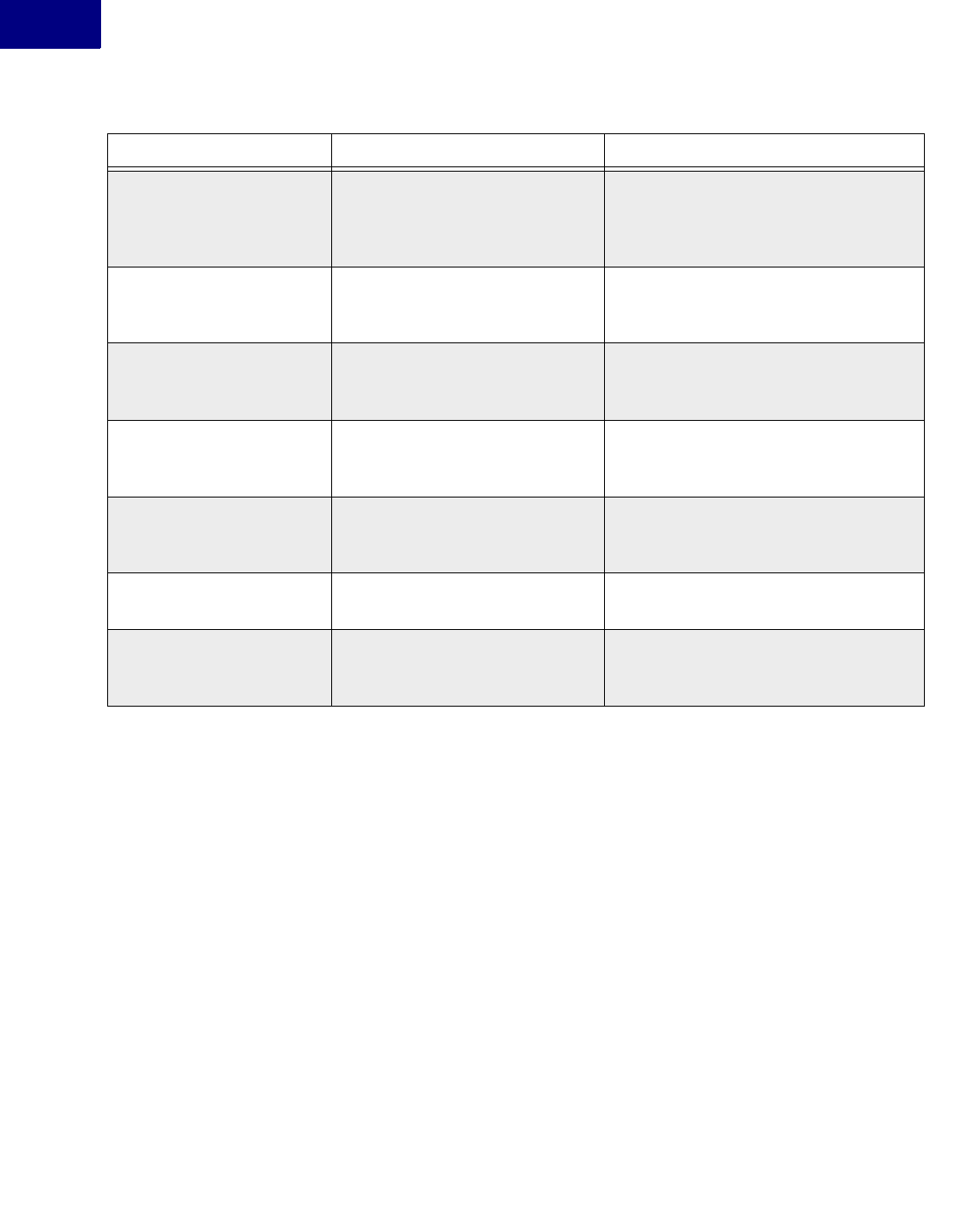
XML Fundamentals
XML-related preferences
550
TABLE 129 Interfaces storing workspace-level XML preferences
In most cases, the command required to change a data interface is specified in the API refer-
ence documentation or can be deduced when inspecting the boss classes that aggregate a given
interface.
The UML diagrams in Figure 258 show some of the interfaces involved in storing options for
import and export of XML at the session level (kWorkspaceBoss) or document level (kDoc-
WorkspaceBoss).
Interface Responsibility Command to process to change preference
IDocStructurePrefs Stores preferences like whether
structure view is visible when the
document is opened.
kChangeDocStructurePrefsCmdBoss to
change the data, but you need to execute
an action to change the structure-view
state.
IGeneralXMLPreferences Stores tagging preferences in the
session workspace, like default tag
name for story, table, and cell.
kSetGeneralXMLPreferencesCmdBoss
IStructureViewPrefs Stores information related to the
appearance of the structure view,
like whether comments are visible.
kChangeStructureViewPrefsCmdBoss
IXMLExportOptions Stores XML export options in the
workspace that control what gets
written to the XML data.
kChangeXMLExportOptionsCmdBoss
IXMLExportSessionOptions Stores XML export options in the
session workspace related to
viewing XML data after export.
kChangeXMLExportSOptionsCmdBoss
IXMLImportOptions Stores XML import options in the
workspace.
kChangeXMLImportOptionsCmdBoss
IXMLPreferences Stores user-interface preferences
related to XML.
kShowTaggedFramesCmdBoss,
kShowTagMarkersCmdBoss, and
kShowTagOptionsCmdBoss
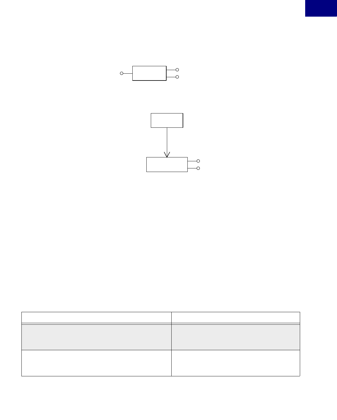
XML Fundamentals 551
XML Fundamentals
XML-related preferences
FIGURE 258 Key options related to import and export
Preferences related to structure view and other user-interface
components
The IDocStructurePrefs interface controls some properties of the structure view. IDocStruc-
turePrefs is present on the session workspace (kWorkspaceBoss) and document workspace
(kDocWorkspaceBoss). IDocStructurePrefs stores preferences related to whether to show the
structure pane and how wide it should be.
The IStructureViewPrefs interface (only on kWorkspaceBoss) stores other properties of the
structure view, like whether text snippets are to be shown. The IXMLPreferences interface on
the session workspace (kWorkspaceBoss) stores the visibility of tag markers, etc.
Service-level XML preferences
Some services that aggregate the IXMLImportPreferences interface are shown in Table 130.
TABLE 130 Object-specific preference interfaces related to XML
Service and its responsibility Semantics of its IXMLImportPreferences interface
kXMLRepeatTextElementsMatchMakerServiceBoss,
responsible for preserving story text styling when handling
repeating elements.
0th preference is bool16, whether to turn on, kTrue
by default.
kXMLThrowAwayUnmatchedRightMatchMakerServiceBos
s, responsible for discarding unmatched elements in the
XML template.
0th preference is bool16, whether to turn on
feature, kFalse by default.
«boss»
kDocWorkspaceBoss
«boss»
kWorkspaceBoss
IXMLExportSessionOptions
IXMLImportOptions
IXMLImportOptions
«boss»
kDocBoss
IDocument
IXMLExportOptions
IXMLExportOptions
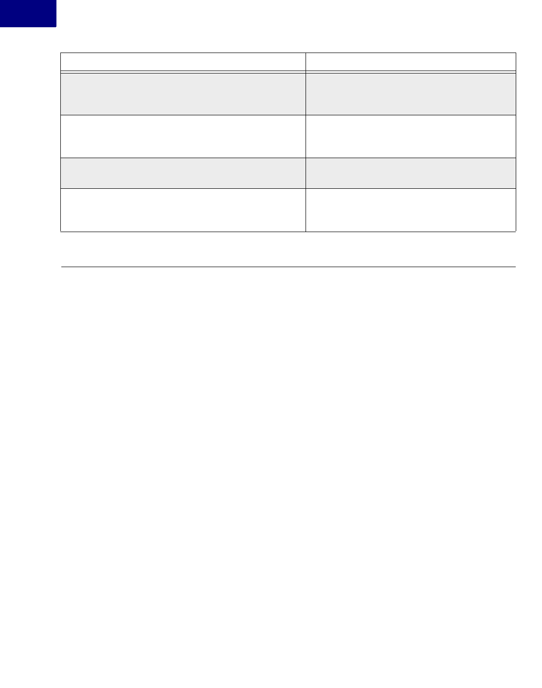
XML Fundamentals
Key client API
552
Key client API
XML suites
Some suite interfaces that represent a fairly high level of abstraction over the XML subsystem
can be used to program the XML features. We recommend you use these suites when possible
when programming using the XML features:
zIXMLNodeSelectionSuite can be used to make a programmatic selection in the Structure
pane. See also the extension pattern described in “Custom suite for the structure view” on
page 556.
zIXMLStructureSuite can be used when there is a selection in the Structure pane. IXML-
StructureSuite lets you change the logical structure of a document at the node selected in
the structure-view tree. If you are writing client code that involves the end user making
active selections, this is one mechanism to modify the logical-structure tree. The methods
on this suite interface delegate to the command facades (for example, IXMLElementCom-
mands and IXMLAttributeCommands).
zIXMLTagSuite can be used to apply tags to a selection, like a text range or graphic frames.
IXMLTagSuite also can be used for other purposes, like adding a processing comment to the
document’s logical structure. See “Elements and content” on page 534 and “Processing
instructions and comments” on page 547.
You can extend the application by writing a custom suite that is available when there is a selec-
tion in the Structure pane. See “Extension patterns” on page 553.
kXMLThrowAwayUnmatchedLeftMatchMakerServiceBoss,
responsible for discarding incoming elements that have no
match in the XML template.
0th preference is bool16, whether to turn on
feature, kFalse by default.
kXMLImporterPostImportMappingBoss, responsible for
attribute-style mapping.
0th preference, bool16, kTrue by default. Specifies
whether to delete namespace attribute (aid: for
example) and the namespace attribute (xmlns:).
kXMLSparseImportOptionsServiceBoss, just stores a
preference relating to sparse import.
0th preference, bool16, whether to use sparse
import, kFalse by default.
kXMLLinkingPostImportResponderBoss, responsible for
creating a link (kXMLImportLinkBoss) to imported XML
files.
0th preference, bool16, whether to create link,
kFalse by default.
Service and its responsibility Semantics of its IXMLImportPreferences interface

XML Fundamentals 553
XML Fundamentals
Extension patterns
Command facades and utilities
There are many command-related boss classes named kXML<whatever>CmdBoss, but in most
cases, you do not need to process these low-level commands, as there are command facades in
the XML API that encapsulate parameterizing and processing these commands.
Interfaces like IXMLUtils, IXMLElementCommands, IXMLMappingCommands, IXMLTag-
Commands, and IXMLAttributeCommands are examples of command facades. These encap-
sulate processing of almost all the commands required by plug-in code. These interfaces are
aggregated on kUtilsBoss; the smart pointer class Utils makes it straightforward to acquire and
call methods on these interface. You can call their methods by writing code that follows this
pattern:
Utils<IXMLElementCommands>()->MethodName(...)
When writing code that does not involve selection, always look first at the IXMLUtils or
IXML<whatever>Commands interfaces, to see if there is a method that serves your purpose on
one of these interfaces. By doing so, you can avoid the increased chance of confusion and error
that comes with processing low-level commands. Of course, your use case may require you to
process some low-level commands, if the facades do not provide all the functionality you
require.
Extension patterns
XML acquirer
Suppose you want to customize how InDesign obtains the XML data to be read by the standard
import-XML file operation. For example, you might query your database to get XML-based
data, and you want to allow InDesign to parse the XML data directly from a stream you open.
Architecture
An XML acquirer (IXMLAcquirerFilter) lets you take control to create a stream (IPMStream)
from which InDesign reads XML data, and optionally provide an entity resolver (ISAXEntity-
Resolver) for InDesign to use when importing the XML data in your stream. An XML acquirer
allows you to take control early in the XML-import sequence, to determine where the XML
data comes from. An XML acquirer is a service provider, characterized by the IXMLAcquirer-
Filter service interface. The ServiceID must be of type kAcquireXMLService; you can re-use
the API implementation kXMLFilterServiceProviderImpl (IK2ServiceProvider) for this.
XML import begins with a URL-style string that describes the XML source. This stage of the
import process (see “Import architecture” on page 512) has the task of converting the XML
source description into a stream (IPMStream). In the simplest case, the URL-style string is a
path to a local file. In more complex cases, it could be an XQuery, any kind of URL, or a
comma-separated values (CSV) file.

XML Fundamentals
Extension patterns
554
These different identifiers for the XML source are handled uniformly by the XML importer
(kXMLImporterBoss). The XML importer takes the source string and sends it to each of the
XML acquirer filters (IXMLAcquirerFilter) in turn, until it finds one that can handle the string.
Each filter examines the string and determines whether it can return a stream given the string.
The order in which the filters are called is undefined. The XML import mechanism of InDesign
includes a file-based, XML-acquirer filter (kXMLAcquirerTextFilterServiceProviderBoss), and
other filters can be added by third parties.
In theory, it should be possible to write a database connectivity acquirer to get XML data
directly out of a database (or content-management system) into InDesign. The URL string has
to be something that can be recognized by the target acquirer (and, hopefully, no one else). The
URL can even be an instruction that points to another file with more instructions (for example,
a binding file). The only thing the acquirer must do is return an XML stream in the end; the
acquirer can process instructions, get some XML data, process it further, and finally return
manipulated XML data if desired by the acquirer.
The import source is specified through data stored in the IImportXMLData of the data object
(kImportXMLDataBoss), which encapsulates an IDFile. To implement a custom acquirer, you
can construct an IDFile with an arbitrary path, then you can implement the IXMLAcquirerFil-
ter to interpret the path specified by the IDFile to take whatever action you want. For example,
you might plan to make a query on a server-based repository of some kind, then open a stream
to a local file that you copied onto the machine from the server. The query could be specified or
parameterized by information in the string you got back from IDFile::GetString, once you get
inside your acquirer code (see IImportXMLData::GetImportSource).
XML transformer
Suppose you want to transform the incoming XML data using something like the InDesign
built-in XSLT engine or a transformation engine of your own. The XML transformer is an
extension pattern you can implement if you want to transform the XML data being imported.
You have the choice of transforming the data when it is still a stream or when it has been
turned into a DOM.
Architecture
The XML transformer (IXMLTransformer) is an extension pattern for manipulating the
incoming XML DOM. It is an opportunity for a third-party software developer to add ele-
ments, throw away others, and change the rest before the incoming XML data is matched
against the existing XML template. An import transformer is a service provider characterized
by the service interface IXMLTransformer and signature interface IK2ServiceProvider. The
ServiceID must be of type kXMLImporterTransformerService; you can re-use the API imple-
mentation kXMLImportTransformerSignalServiceImpl (IK2ServiceProvider) for this.
You can transform the inbound XML data in one or both of two phases:
zThe first phase is while there is a stream (IPMStream); you can apply an XSLT transform to
the inbound stream (IPMStream) of XML-based data and turn it into another stream (IPM-
Stream). See IXMLTransformer::TransformStream.

XML Fundamentals 555
XML Fundamentals
Extension patterns
zThe second phase occurs immediately after the DOM is created. During this phase, you can
manually manipulate the DOM by inserting, removing, and changing elements. See IXML-
Transformer::TransformDOM and IIDXMLDOMDocument.
XMl-import matchmaker
Suppose you want to customize how the XML template is matched against the incoming XML
data.
Architecture
This is a service that participates in XML import, to determine how the incoming XML is
matched against the XML template (document) into which the XML is imported. An import
matchmaker is a service provider characterized by the service interface IXMLImportMatch-
Maker and signature interface IK2ServiceProvider. The ServiceID must be of type kXMLIm-
portMatchMakerSignalService; you can re-use the API implementation
kXMLImportMatchMakerSignalServiceImpl (IK2ServiceProvider) for this.
An XML-import matchmaker service (IXMLImportMatchMaker) is responsible for determin-
ing the behavior of InDesign when importing XML-based data into an XML template that has
structure which provides a partial match for the inbound XML data. For example, the features
to throw away unmatched existing or inbound are implemented by matchmaker services. In
theory, you can implement a custom XML-import matchmaker to specialize how matching
against an XML template is performed.
Post-import responder
Suppose you want to perform an operation just after the XML data is imported and the logical
structure created, like placing images based on information in the logical structure. Rather
than having to write your own code to traverse the logical structure after import, there is an
extension pattern that lets you be called when the logical structure of the document is being
traversed, just after the DOM is completed.
Architecture
A post-import iterator (IXMLPostImportIteration) is a type of responder (IResponder) that is
signalled during XML import. An post-import iterator is a service provider; specifically, it is a
responder service, characterized by the service interface IXMLPostImportIteration and signa-
ture interface IK2ServiceProvider. The ServiceID must be of type kXMLPostImportIteration-
Service; you can re-use the API implementation
kXMLPostImportIterationServiceProviderImpl (IK2ServiceProvider) for this.
A lot of post-processing tasks are of the form “go through the logical structure. and if you see
<something>, do <whatever>.” The iterator allows you to do this without writing the iteration
itself, while taking as little penalty in performance as possible. Essentially, InDesign iterates
over the structure one time and calls all the clients when every node is visited. If your task is
simple and localized, this is a good choice, because all you would write is your specialized code.
If you require, you can still write a full post-import processor of your own design and iterate
over the whole structure yourself.

XML Fundamentals
Extension patterns
556
Features of the application like tag-to-style mapping are implemented using a post-import iter-
ator.
Custom suite for the structure view
Suppose you want to allow some operations to be performed whenever there is a selection of
one or more nodes in the logical structure. For example, suppose you want to let an end user
verify the image references in the nodes selected in the structure view, perhaps through a con-
text-sensitive menu item that is present or enabled only when nodes are selected.
Architecture
A custom suite for the structure view lets your code be called only when there is a node-selec-
tion target (IXMLNodeTarget) in the structure view. You can follow the pattern of IXMLStruc-
tureSuite (see the API reference documentation for that interface). To implement a custom
suite for the structure view, follow these steps:
1. Add an appropriate implementation of your custom suite to kIntegratorSuiteBoss (ASB,
abstract-selection boss class).
2. Add an appropriate implementation of your custom suite in to kXMLStructureSuiteBoss
(CSB, concrete-selection boss class).
When you implement a custom suite, it gives you access to the nodes selected in the structure
view through IXMLNodeTarget, through your add-in to the concrete-selection boss class
kXMLStructureSuiteBoss.
SAX-content handler
Suppose you want to load a configuration from an XML file that contains information relevant
only to your plug-ins and does not specify document content.
Architecture
A custom SAX-content handler (ISAXContentHandler) lets you take control when XML is
being parsed by the XML-parser service early in the XML-import service. This extension pat-
tern can be used to read configuration data from an XML file, for example.
A SAX-content handler is not (any longer) a service. Your main requirement is to register with
the SAX services (ISAXServices) of the SAX parser (kXMLParserServiceBoss).
There are several instances of SAX-content handlers (e.g., parsing the tag list, itself an XML
file). See ISAXContentHandler in the API reference documentation and note the boss classes
that expose this interface.
See http://sax.sourceforge.net for information about the Simple API for XML (SAX).

XML Fundamentals 557
XML Fundamentals
Extension patterns
SAX DOM serializer handler
Suppose you want to take control when XML is being imported and the XML DOM is being
serialized into the document, and you want to handle the parsing of XML content for some
custom elements, to let you create some document content.
Architecture
A custom, SAX DOM serializer handler lets you take control when the XML DOM is imported
and is being serialized (written) into the document. If you implement this extension pattern,
you can choose how particular elements in the DOM are written into the document; for exam-
ple, you can create custom content. This is done for tables and Ruby annotations.
A SAX DOM serializer handler is a service provider characterized by the service interface
ISAXDOMSerializerHandler and signature interface IK2ServiceProvider. The ServiceID must
be of type kXMLContentHandlerService; you can re-use the API implementation kXMLCon-
tentServiceProviderImpl (implementation of IK2ServiceProvider) to do this.
Custom-tag service
Suppose you have custom content in the XML file that is created programmatically on export,
and you do not want end users to be able to apply the tags based on the element names in your
custom content.
Architecture
A tag service is given the opportunity to handle elements in an XML stream that has been
opened for reading element names to be used as tags.
A tag service is a service provider that is closely related to the SAX-content-handler service. A
tag service is characterized by the service interface ISAXContentHandler and interface
IK2ServiceProvider, which should yield a ServiceID of kXMLTagHandlerService. You can re-
use the API implementation kXMLTagServiceProviderImpl to achieve this.
For example, you may be using a tag service to filter out names of custom elements you do not
want to appear in the tag list. In this case, you would provide a minimal implementation of
ISAXContentHandler that registers your handler for the elements you want to filter out and
claims to handle a subtree. You then do not need to do anything when sent the other ISAXCon-
tentHandler messages for elements for which you do not want tags to be created.
SAX-entity resolver
Suppose you want to customize how external entities are resolved by the InDesign SAX parser.
An external entity needs to have an associated PUBLIC or SYSTEM identifier, which can be
translated to something like a URI, which should point at the input source where the entity is
defined:
“Attempts to retrieve the resource identified by a URI MAY be redirected at the parser level (for
example, in an entity resolver)”

XML Fundamentals
Commands and notification
558
See the XML specification (http://www.w3.org/TR/REC-xml, section 4.2.2) for a definition of
“external entity.”
Architecture
If you implement a custom entity resolver for external entities, it is your responsibility to create
a stream (IPMStream) to the input source where the entity is defined, when passed a PUBLIC
or SYSTEM identifier for the entity. An entity resolver is characterized by the ISAXEntityRe-
solver interface.
You create an instance of the boss class you defined with your own implementation of ISAXEn-
tityResolver when needed; for example, when implementing an XML acquirer (IXMLAcquirer-
Filter::CreateStreamAndResolver or CreateResolver).
XML-export handler
Suppose you want to control the output of some XML elements when they are being exported;
for example, you want to alter the structure of XML file for some custom elements, to better fit
your needs.
Architecture
A custom, XML-export handler lets you control the output. If you implement this extension
pattern, you can choose how particular elements in the document are written into the XML
file.
An XML-export handler is a service provider characterized by the service interface IXMLEx-
portHandler and signature interface IK2ServiceProvider. The ServiceID must be of type kXM-
LExportHandlerSignalService; you can re-use the API implementation
kXMLExportServiceImpl (implementation of IK2ServiceProvider).
To customize the output of an element or elements, override the CanHandleElement method to
return true for the element, and override other methods to write custom content to the output.
Commands and notification
Backing store and notification of changes in logical structure
When the logical structure of a document changes, the commands that change the logical
structure send notification about changes in the backing store. The subject for notifications
about change in the logical structure is a UID-based object (instance of kTextStoryBoss).
You can acquire the backing store with IXMLUtils::GetBackingStore and query for its ISubject
interface. Once you have the ISubject interface, you can attach an observer and listen for
changes of interest in the usual pattern.
Command output can be stored in the item list of a command boss object on output, which is
sent as the changedBy parameter in the IObserver::Update message. When implementing an

XML Fundamentals 559
XML Fundamentals
Entities supported
observer, you can cast the changedBy parameter of the Update method to an interface pointer
of type ICommand*, as shown below:
ICommand* iCommand = (ICommand*)changedBy;
const UIDList itemList = iCommand->GetItemListReference();
When the command output shows the output is stored in an interface on the command (e.g. as
an XMLReference), you might write code like this:
InterfacePtr<IXMLReferenceData> cmdData(iCommand, UseDefaultIID());
if(cmdData) {
XMLReference xmlRef = cmdData->GetReference();
...
}
Entities supported
Standard entities supported by default by the XML subsystem are shown in Table 131. If you
need to support a wider set—like the entire ISO-LATIN 1 set of character entities (e.g., &174;
for ™, the trademark symbol)—you can use them with the applications if they are defined in the
DTD. For example, Simplified DocBook (http://www.oasis-open.org/docbook/xml/sim-
ple/sdocbook) contains additional entity definitions within its DTD to support ISO-LATIN 1.
TABLE 131 Standard entities supported
Entity Meaning Description
& &Ampersand
< < Less than
> >Greater than
' ' Apostrophe
" "Quote

 CR Character replacement entity for carriage return

 LF Character replacement entity for line feed

XML Fundamentals
Assets from XSLT example
560
Assets from XSLT example
EXAMPLE 40 Basic grammar for article-based publications
<?xml version="1.0" encoding="UTF-8"?>
<!ELEMENT publication (article)+>
<!ELEMENT article (article-title, body)>
<!ELEMENT body (title | subhead | para)+>
<!ELEMENT article-title (#PCDATA)>
<!ELEMENT title (#PCDATA)>
<!ELEMENT subhead (#PCDATA)>
<!ELEMENT emphasis (#PCDATA)>
<!ENTITY % pub.content "#PCDATA">
<!ELEMENT para (%pub.content; | emphasis)*>
EXAMPLE 41 Fragment of XSL Stylesheet to Convert NITF to Basic Pub
<?xml version="1.0" encoding="UTF-8"?>
<xsl:stylesheet version="1.0" xmlns:xsl="http://www.w3.org/1999/XSL/Transform">
<xsl:strip-space elements="*"></xsl:strip-space>
<xsl:output method="xml" omit-xml-declaration="yes"/>
<xsl:template match="text()"><xsl:value-of select="normalize-space(.)"/>
</xsl:template>
<xsl:template match="/">
<xsl:apply-templates></xsl:apply-templates>
</xsl:template>
<!-- include content from these elements -->
<xsl:template match="nitf|block|body.head|ul">
<xsl:apply-templates></xsl:apply-templates>
</xsl:template>
<!-- exclude content we are not interested in with this empty template -->
<xsl:template match="*"/>
<xsl:template match="body">
<article><xsl:apply-templates></xsl:apply-templates></article>
</xsl:template>
<xsl:template match="body.content">
<body><xsl:apply-templates></xsl:apply-templates></body>
</xsl:template>
<xsl:template match="p">
<para><xsl:apply-templates></xsl:apply-templates></para>
<xsl:text>
</xsl:text></xsl:template>
<xsl:template match="hedline">
<article-title><xsl:value-of select="hl1"/></article-title><xsl:text>
</xsl:text>
</xsl:template>
<xsl:template match="hl1">
<title><xsl:value-of select="."/></title><xsl:text>
</xsl:text>
</xsl:template>
<xsl:template match="nitf-table">
<para><emphasis>Table omitted on import</emphasis></para><xsl:text>

XML Fundamentals 561
XML Fundamentals
Limitations of the InDesign XML architecture
</xsl:text>
</xsl:template>
<xsl:template match="hl2">
<subhead><xsl:apply-templates></xsl:apply-templates></subhead><xsl:text>
</xsl:text>
</xsl:template>
<xsl:template match="em">
<emphasis><xsl:apply-templates></xsl:apply-templates></emphasis>
<xsl:text> </xsl:text>
</xsl:template>
<xsl:template match="org">
<xsl:text> </xsl:text>
<emphasis><xsl:apply-templates></xsl:apply-templates></emphasis>
</xsl:template>
<xsl:template match="li">
<para><xsl:apply-templates></xsl:apply-templates></para>
<xsl:text>
</xsl:text></xsl:template>
</xsl:stylesheet>
Limitations of the InDesign XML architecture
The architecture is detailed and has a broad client API and many extension patterns, but there
are known limitations you should be aware of, which could make implementing particular
XML-based workflows tricky or impossible.
Specifically, XML elements associated with graphics cannot have dependents. The model for rep-
resenting logical structure does not allow you to have a subtree of elements that depend on the
element linked to a graphic item.

XML Fundamentals
Limitations of the InDesign XML architecture
562

Scriptable Plug-in Fundamentals 563
Scriptable Plug-in Fundamentals
Terminology
Scriptable Plug-in Fundamentals
This chapter describes how to extend your plug-in so that its features can be automated by a
script, accessed in InDesign Server and participate in technologies based on IDML.
You can add scripting support to a plug-in for InDesign, InCopy, or InDesign Server. This
chapter is the C++ programming counterpart to Adobe InDesign CS4 Scripting Guide and
Adobe InCopy CS4 Scripting Guide, which document how to write scripts that automate InDe-
sign and InCopy. Both the scripting guides and this chapter are recommended reading if you
are adding scripting support to your plug-in. This chapter also describes the relationship
between scripting and the InDesign Markup Language (IDML) file format. (For information
about IDML's predecessor, INX, and how it relates to scripting, read Making Your Plug-in
Scriptable from the InDesign CS3 Products SDK.)
Terminology
This following list contains terms used throughout this chapter. For other terms used in this
chapter that are not in the list below, see the “Glossary.”
zApple Event Terminology extension (AETE) — A resource that defines Apple Events and
objects which your application understands, both for scripts and for applications that send
you events. Developed by Apple.
zApple Events — High-level, semantic messages designed to allow for collaboration between
programs.
zBoss DOM — The model of a document as a set of boss objects; i.e. the boss objects found
under kDocBoss, like kDocWorkspaceBoss, kSpreadBoss, kPageBoss, and kSplineItemBoss.
See “Scripting plug-in” on page 570.
zComponent Object Model (COM) — An object-oriented system developed by Microsoft for
creating binary software components that can interact with each other. See Scripting DOM
below.
zDictionary — A set of definitions for words that are understood by a particular application
under AppleScript. A dictionary tells you which objects are available in a particular applica-
tion and which AppleScript commands you can use to control it. See Scripting DOM below.
zElement — Script element.
zEnum — Enumerates the list of potential values a property or parameter can have. See
“Scripting DOM” on page 568 and “Enum element” on page 603.
zEvent — A method call on a script object; e.g., open or close. See “Event element” on
page 595.
zICML — InCopy Markup Language. An ICML file is a snippet file containing an InCopy
story.

Scriptable Plug-in Fundamentals
Terminology
564
zIDML — InDesign Markup Language. IDML is based on serializing objects defined in a
scripting DOM tree to an XML-based format.
zNon-UID-based script object; A script object that represents a scriptable boss with no UID.
See “Scriptable boss classes” on page 574 and “Script-object inheritance” on page 619.
zPlural form — A script object that can exist in a collection is said to have a plural form. For
example, the plural form of document is documents, a collection of document script
objects. See “Scripting DOM” on page 568 and “Object element” on page 593.
zPreferences script object — A script object that represents preferences. See “Script providers”
on page 574 and “Script-object inheritance” on page 619.
zProperty — An attribute of a script object; e.g. color or width. See “Scripting DOM” on
page 568 and “Property element” on page 597.
zProvider — Associates a script provider with the script object(s), event(s), or property(ies) it
handles. See “Scripting DOM” on page 568 and “Provider element” on page 606.
zScript element — A script object, property, event, or enum. The elements from which the
scripting DOM is made. See “Scripting DOM” on page 568 and “Scripting resources” on
page 591.
zScript language — The language in which you write your scripts. AppleScript, Visual Basic,
and JavaScript are supported in InDesign scripting.
zScript manager — Manages a scripting DOM for a particular client of the scripting architec-
ture. For example, each scripting language has a script manager, kAppleScriptMgrBoss for
AppleScript, kOLEAutomationMgrBoss for Visual Basic, and kJavaScriptMgrBoss for Java-
Script. See “Script managers” on page 573.
zScript object — An object in the scripting DOM. See “Scripting DOM” on page 568 and
“Object element” on page 593).
zScript provider — A boss class that provides an implementation of IScriptProvider. This
manipulates a scriptable boss in response to requests made on a script object in the script-
ing DOM. See “Script providers” on page 574.
zScriptable boss — A boss class exposed in the scripting DOM. Scriptable boss classes have
the signature interface IScript. Each scriptable boss has a corresponding script object. See
“Scriptable boss classes” on page 574.
zScriptElementID — an identifier defined in kScriptInfoIDSpace; e.g. kDocumentObject-
ScriptElement. This is akin to kClassIDSpace, where a boss ClassID is defined. See
“ScriptElementIDs” on page 610.
zScriptID — A four-character identifier for a script element; e.g. “docu.” See “ScriptIDs” on
page 610.
zScripting DOM — A model of a document as a set of script objects with properties and
events that represent the end user’s view. This is a high-level abstraction of the boss DOM.
See “Scripting DOM” on page 568 and “Scripting plug-in” on page 570.
zSingleton — A script object that cannot exist in a collection. See plural form above, “Script-
ing DOM” on page 568, and “Script-object inheritance” on page 619. The term “singleton”
does not imply there is only one instance of the object (the common understanding of sin-

Scriptable Plug-in Fundamentals 565
Scriptable Plug-in Fundamentals
Overview
gleton in C++ programming and design patterns). It is common to find several instances of
a singleton in the scripting DOM; for example, the singleton kTextFramePreferencesOb-
jectScriptElement can have many instances, default text frame preference on the applica-
tion, default text frame preferences on the document, and text frame preferences on each
text frame.
zSurrogate — A concept that distinguishes an ownership relationship from a referential rela-
tionship. A surrogate is a referential relationship between parent and child; no ownership is
implied. See “Surrogate” on page 609.
zType library — Binary files (.tlb files) that include information about types and objects
exposed by a COM application.
zUID-based script object — A script object that represents a scriptable boss with a UID. See
“Scriptable boss classes” on page 574 and “Script-object inheritance” on page 619.
Overview
Scripting
Scripting allows users to exert virtually the same control of the application from a script as is
available from the user interface. This functionality can be used for purposes as simple as auto-
mating repetitive tasks, or as involved as controlling the application from a database. Scripts
can be written in AppleScript, Visual Basic, or JavaScript. For instructions on writing and run-
ning scripts, see Adobe InDesign CS4 Scripting Guide.
The extensibility of this scripting architecture allows you to provide scripting support for func-
tions added by your own plug-in. The architecture provides a platform-independent and
scripting-language-independent foundation on which you can build. It abstracts and provides
implementations for the common elements of scripting. Your task is adding implementations
for the functionality you are exposing.
Benefits of making a plug-in scriptable
For the plug-in developer, making a plug-in scriptable has several benefits:
zInDesign/InCopy users can automate the features added by your plug-in, by writing and
executing scripts. The potential for new solutions using automation means added produc-
tivity for you and your customers.
zClients of InDesign Server can use your plug-in’s features. A plug-in must be scriptable to
interact with InDesign Server. See Adobe InDesign CS4 Server Plug-in Techniques.
zPersistent data added to a document by your plug-in via boss objects and add-in interfaces
is expressed in the IDML file format and its derivative file formats and technologies.

Scriptable Plug-in Fundamentals
Overview
566
Scripting and IDML
IDML is an XML-based format used to serialize and deserialize a scripting DOM. For an over-
view of IDML and guidance on working with it, see IDML File Format Specification and Adobe
InDesign Markup Language Cookbook.
By exposing functionality through scripting, plug-ins can participate in technologies like Save
Backwards. You should make your plug-in scriptable if your plug-in adds persistent data to a
document or to the session workspace (kWorkspaceBoss) and your plug-in uses features that
depend on IDML, such as the following:
zSave backwards.
zAsset libraries.
zAssignments.
zInCopy stories.
zApplication preference import/export. Preferences on the session workspace can be round-
tripped as INDML To participate, a plug-in’s preferences must be exposed on the applica-
tion script object (kApplicationObjectScriptElement). For guidance, see the “Shared Appli-
cation Resources” chapter. Also see “Adding a new script object to make preferences
scriptable” on page 577, ISnippetExport::ExportAppPrefs, and ISnippetImport::Import-
FromStream.
Making a plug-in scriptable
These are the principal tasks involved in adding scripting support to your plug-in:
zDesign and implement script objects, properties and events. The features of your plug-in dic-
tate the script objects, events, and properties you need to add to the scripting DOM. Use
“How to make your plug-in scriptable” on page 575 as a guide.
zRefactor your code to fit into the scripting architecture. This chapter does not make sugges-
tions about how to refactor your own plug-in code; however, a common refactoring task is
de-coupling the user interface and model-related source code in your plug-ins. Your user
interface is a client of your plug-in’s model; the scripting architecture also is a client. The
time required for refactoring depends on the complexity of your plug-in and how well sepa-
rated your user interface is from your model.
zDocument scriptability. Users writing scripts need documentation on the objects, properties
and events your plug-in makes available. The Adobe InDesign CS4 Scripting Guide docu-
ments the scripting supported by the application for AppleScript, Visual Basic and JavaS-
cript. You need to document the additions provided by your plug-in.
zTest. There are three categories of testing:

Scriptable Plug-in Fundamentals 567
Scriptable Plug-in Fundamentals
Scripting architecture
1. Testing scriptability — This involves writing scripts in AppleScript (Mac OS), Visual Basic
(Windows), and/or JavaScript (cross-platform). For instructions on writing scripts, see
Adobe InDesign CS4 Scripting Guide. To learn how to verify that your plug-in exposes the
script objects you intend, see “Reviewing scripting resources” on page 583.
2. Testing scriptability for backwards compatibility — The application supports the ability to
execute scripts written for earlier versions of the product. For example, suppose you
released a scriptable plug-in for InDesign CS1 and you are releasing a new version for InDe-
sign CS4. You should test that scripts written for InDesign CS1 run successfully under
inDesign CS4 when targeted correctly. See “Running versioned scripts” on page 586.
3. Testing IDML support in the IDML-based technologies your plug-in requires — Basic IDML
support can be tested by exporting and importing documents containing your plug-in’s data
as an IDML file.
Tools for making a plug-in scriptable
To make your plug-in scriptable, you need the following tools:
zThe current SDK plug-in development environment. For details, see Adobe InDesign CS4
Porting Guide.
zFor AppleScript, you need the AppleScript Script Editor (Mac OS) or another tool used to
write and run AppleScript scripts.
zFor Visual Basic, you need Microsoft Visual Basic or Windows Script Host (Windows), the
tools used to write and run Visual Basic scripts. Alternatively, you can use any COM devel-
opment environment, including Microsoft Visual C++ and C#.
zFor JavaScript, you need a text editor. JavaScript can be run using the Scripts panel in InDe-
sign CS4 and InCopy CS4. To debug JavaScript you must install the ExtendScript Toolkit
(included in the InDesign installer).
For more information on writing and debugging scripts, see Adobe InDesign CS4 Scripting
Guide.
Scripting architecture
This section provides an architectural description of the framework that supports scripting.
Instructions on making your plug-in scriptable are in “How to make your plug-in scriptable”
on page 575).
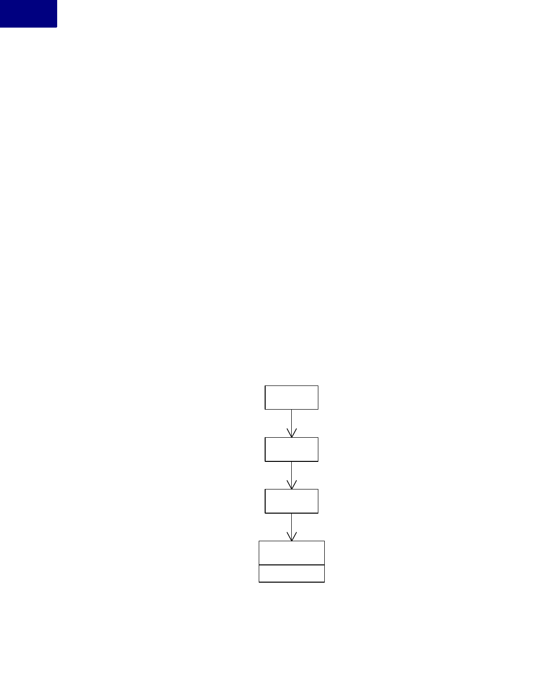
Scriptable Plug-in Fundamentals
Scripting architecture
568
Scripting DOM
The scripting DOM is the end-user representation of an application and document as a set of
script objects. Each script object has properties and/or events. The closest analogies for these
concepts in an object-oriented programming language are class (script object), attribute (prop-
erty), and method (event).
The scripting DOM describes a document as a tree structure of script objects, rooted at a docu-
ment script object. For example, a document may have several children that are color script
objects, several that are spreads, and so on. Besides having children, each script object can have
a set of properties and events. A color has properties that describe its name, color model, and
color value, among other things. At this level of abstraction, we have the objects that are part of
the end-user’s experience of an InDesign document (spreads, pages, frames, stories, etc.), but
the representation is less closely tied to the boss objects you manipulate with the C++ API.
NOTE:For a description of the script objects provided by the application, see “Scripting DOM
reference” on page 641. C++ programmers add new script objects, properties, and
events to expose their plug-in’s functionality.
Figure 259 shows a portion of the scripting DOM for an application that has a document con-
taining a page with a text frame. The scripting DOM is a hierarchy of script objects with events
and properties. Four script objects are shown in the figure: Application, Document, Page, and
TextFrame. The script property that stores the bounds of a text frame object is shown.
FIGURE 259 Scripting DOM
Scripts get or set properties and execute events. To do this, a script must find the right object
and then perform an operation. Example 42 shows a script written in JavaScript that creates an
instance of the scripting DOM shown in Figure 259 and sets a property of the text frame.
«script-object»
Application
«script-object»
Document
«script-object»
Page
+geometric bounds
«script-object»
TextFrame
collection
collection
collection

Scriptable Plug-in Fundamentals 569
Scriptable Plug-in Fundamentals
Scripting architecture
EXAMPLE 42 JavaScript that creates a document containing a text frame
app.documents.add(); // event creates a document
app.documents[0].pages[0].textFrames.add(); //event creates text frame
app.documents[0].pages[0].textFrames[0].geometricBounds = ["0p0", "0p0", "36p0",
"36p0"]; // sets a property
A script object is said to be a child of the script object on which it is exposed. The script object
that exposes another script object is said to be that object’s parent. For example, in Figure 259
the document script object is a child of the application, and the application script object is the
parent of the document.
A script object that can exist in a collection is said to have a plural form. The document, page,
and text frame script objects in Figure 259 have a plural form. A script object that has a plural
form must support the special script events used to manage collections (see “Special events” on
page 596).
A script objects that does not have a plural form often is called a singleton. Examples are the
application script object in Figure 259 and script objects that expose preferences.
Each script object, event, and property has a name, description, ScriptID, and ScriptElementID
defined, as described in “Scripting resources” on page 591. The script objects provided by
InDesign CS4 are identified in Table 149, later in this chapter.
Each script object, event, and property has an associated script provider (see “Script providers”
on page 574) that handles it.
Versioning the scripting DOM
The scripting DOM covers the entire boss DOM. As the boss DOM changes, the scripting
DOM evolves in response. The scripting DOM is versioned to maintain compatibility with past
and future versions.
Beginning in InDesign CS2, product releases must maintain at least one version of backward
compatibility of the scripting DOM. This ensures that clients of the scripting DOM (e.g.,
scripts, IDML, and INX) work seamlessly in new versions of the product.
Clients of the scripting DOM can specify which version of the scripting DOM should be used
by the application to interpret requests (see RequestContext in the API documentation).
Requests involving scripting elements (script objects, properties, and events) that are added in
a particular product version (for example, InDesign CS4) work only if the client specifies that
version (or later) of the scripting DOM. Similarly, objects, properties, and events removed from
the scripting DOM in InDesign CS4 will not work if the client specifies the InDesign CS4 ver-
sion of the scripting DOM; however, they must still work if the client specifies the InDesign
CS3 version of the scripting DOM.
Compatibility must be maintained not just for the elements in the scripting DOM, but for the
functionality they expose. This means any underlying function that changes in InDesign CS4
must still be exposed as it was in InDesign CS3 for clients of the scripting DOM. In some cases,
this requirement may constrain the ability to significantly re-architect the code. How to handle
exceptions to this requirement, such as for functionality that no longer exists, is determined on
a case-by-case basis. At the very least, script providers must degrade gracefully by implement-

Scriptable Plug-in Fundamentals
Scripting architecture
570
ing support as a no-op. For details of working with versioning, see “Versioning of scripting
resources” on page 621.
Special considerations and rules regarding versioning and IDML are in “Maintaining IDML
forward and backward compatibility” on page 589.
Scripting plug-in
The core architecture is implemented in the scripting plug-in, which manages the scripting
DOM. The scripting DOM is described by plug-ins using ODFRC resources (see “Scripting
resources” on page 591). These resources define script objects, their properties, events, and the
script provider (IScriptProvider) that handles them. The architecture is extensible. Plug-ins can
add new script objects or add new properties and events to existing script objects by defining
ODFRC resources and implementing a script provider.
See Figure 260. The scripting DOM represents a document as a set of script objects with prop-
erties and events. The boss DOM represents a document as a set of boss objects and interfaces.
Plug-ins expose their boss DOM data as objects and properties in the scripting DOM, by defin-
ing ODFRez resources. Plug-ins expose other functionality as scripting events in a similar way.
Plug-ins implement a script provider to manipulate data in the boss DOM when their script
objects, properties, and events are used. The scripting plug-in manages the scripting DOM.
When script managers access the scripting DOM, the scripting plug-in maps script object
properties and events to their associated script provider.
FIGURE 260 Scripting architecture
Client
n
p
Server
IDML SOAPAppleScript Visual
Basic
JavaScript
High-Level
API
Scripting Document Object Model
(Scripting Plug-in)
Text Script
Provider
PageItem
Script
Provider
Third Party
Script
Provider
New
Feature
Script
Provider
Boss Document Object Model

Scriptable Plug-in Fundamentals 571
Scriptable Plug-in Fundamentals
Scripting architecture
Clients of the Scripting DOM are called script managers (see the IScriptManager interface in
the API documentation). Scripting language support for AppleScript, Visual Basic, and JavaS-
cript is provided by optional plug-ins that implement a script manager. The scripting DOM
was conceived to make the scripting architecture easier to use and more extensible; in addition,
it has enabled other technologies to be built. The IDML file format is founded on the scripting
DOM.
NOTE:The high-level API is based on the scripting DOM provided by Adobe plug-ins. It is not
extensible by third parties.
Script interaction with the scripting DOM
Scripts interact with their associated script manager, which interacts with the scripting DOM,
which interacts with the application’s C++ API. The interaction varies somewhat depending on
the scripting language, as shown in Figure 261. AppleScript and Visual Basic communicate
with the application through their respective inter-application communication processes,
AppleEvents and COM/OLE automation.
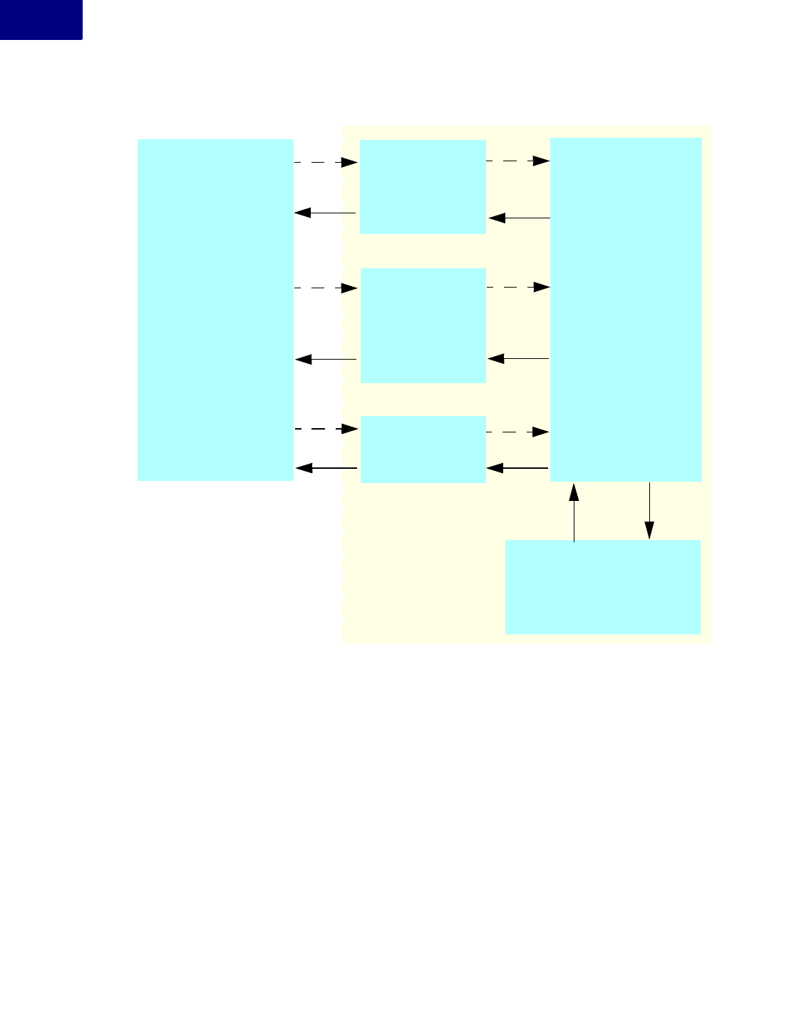
Scriptable Plug-in Fundamentals
Scripting architecture
572
FIGURE 261 Interaction between scripts and the application
Scripting process overview
1. Once the application launches, scripting system architecture support is available to the user
through scripts; however, nothing is activated until a scripting request is received.
2. When a scripting request is received, the script manager determines what to do with it. After
doing set-up, checks, and so on, the script manager populates the IScriptEventData inter-
face with the data that was passed in.
3. The script manager invokes the IScriptRequestHandler, which invokes the appropriate
script provider (IScriptProvider).
zIf a property comes in, the script provider gets or sets the property, based on the parameters
passed in through the IScriptEventData interface. For a get operation, the script provider
simply returns the requested data from the model. For a set operation, the script provider
RD0ARTY
3CRIPTS
!PPLE3CRIPT
$ICTIONARY
/3!
%XTEND3CRIPT
)NTERPRETER
*AVA3CRIPT
$ICTIONARY
6ISUAL"ASIC
#/-4,"
3CRIPTING
$/-
#!0)
K!PPLE3CRIPT-GR"OSS
K*AVA3CRIPT-GR"OSS
K/,%!UTOMATION-GR"OSS
Scriptable Plug-in Fundamentals 573
Scriptable Plug-in Fundamentals
Scripting architecture
extracts the input and either executes its code successfully (modifying the model) or returns
an error.
zEvents work similarly. Some events do not require any data, but most events take a set of
parameters. The script provider uses the IScriptEventData interface to get that input, exe-
cutes any necessary model modification via commands, and returns data or an error code.
4. Control returns to the script manager, which does clean-up and conversion. The script
manager takes the data in the IScriptEventData interface and converts it back to something
the scripting language understands.
5. The script manager returns, and control is passed back to the script.
Script managers
The application supplies script managers that handle the interaction the scripting client and
your plug-in. See Table 132.
TABLE 132 Major Script Manager Boss Classes
Scriptable plug-ins
This section describes the parts that enable a plug-in to receive a scripting request from a script
manager and report data back to the script manager. As with other client interfaces you would
give a plug-in, scripting is intended to query and change the boss DOM. To accomplish this, we
must be able to identify objects in the boss DOM via IScript and get and/or set values.
For instructions on making your plug-in scriptable, see “How to make your plug-in scriptable”
on page 575.
Script Manager ClassID Used with
kAppleScriptMgrBoss AppleScript
kINXScriptManagerBoss Base class for INX and IDML script -
manager bosses
kJavaScriptMgrBoss JavaScript
kOLEAutomationMgrBoss Visual Basic
kINXTraditionalImportScriptManagerBoss INX
kINXTraditionalExportScriptManagerBoss INX
kINXExpandedImportScriptManagerBoss IDML
kINXExpandedExportScriptManagerBoss IDML

Scriptable Plug-in Fundamentals
Scripting architecture
574
Scripting resources
Every scriptable plug-in needs to supply a VersionedScriptElementInfo ODFRez resource that
specifies the plug-in’s additions to the scripting DOM in the form of script objects, properties,
events, and the providers that handle these additions. In this resource, you identify details
about the script objects and their relationships with other script objects, and give them IDs so
your additions to the scripting DOM can be identified.
See “Scripting resources” on page 591.
Script providers
IScriptProvider is the signature interface of a script-provider boss class. This interface allows
the script manager to access a script object, get and set its properties, and execute its events.
Script providers know how to handle script objects, properties, and events in an abstract sense.
They map a request from the scripting DOM onto the boss DOM. For example, in response to
being called to get a property, a script provider might call an accessor method on an interface
on a scriptable boss. To set a property, it might process a command that changes a scriptable
boss.
When you implement a script provider boss, you normally extend kBaseScriptProviderBoss.
To see its interfaces, see the API documentation.
Partial implementations are as follows:
zCScriptProvider — Subclass this to add properties or events to existing objects in the Script-
ing DOM.
zPrefsScriptProvider — Subclass this to add a singleton script object and its properties to the
scripting DOM
zRepresentScriptProvider — Subclass this to expose a new script object to the scripting
DOM.
Scriptable boss classes
IScript is the signature interface of a scriptable boss; i.e. a boss class exposed in the scripting
DOM. A scriptable boss object is the ultimate target of an event or property request made on a
script object. The need to implement an IScript interface depends on whether you want to add
function to an existing script object or are implementing a new script object of your own. To
add function to an existing script object, such as the document, you do not implement the
IScript interface. To create a new script object, you must define a boss class that implements the
IScript interface, which maps your scriptable boss to its associated script object.
Partial implementations are as follows:
zCScript — Subclass this to expose a UID-based script object.
zCProxyScript — Subclass this to expose a non-UID based script object.
NOTE:If you are adding a property or event to an object that already exists in the scripting
DOM, you do not need to implement IScript.

Scriptable Plug-in Fundamentals 575
Scriptable Plug-in Fundamentals
How to make your plug-in scriptable
How to make your plug-in scriptable
Prerequisites
1. Examine the scripting samples provided by the SDK.
2. Determine how to represent your plug-in’s features in the scripting DOM:
zExamine the scripting DOM and choose the objects your plug-in’s features should be
exposed on. See the scripting references in <SDK>/docs/references, or create your own ref-
erence file as explained in “Scripting DOM reference” on page 641.
zDecide how to expose your plug-in’s data and functionality in the form of objects, proper-
ties, and events. Data is exposed by adding new script objects (see “Object element” on
page 593) that encapsulate properties or adding properties to existing script objects (see
“Property element” on page 597). Function is exposed by adding events to new or existing
script objects (see “Event element” on page 595).
3. Refactor your code so it is easy to call from a script provider:
zYour plug-in will have its own model implemented by some combination of data interfaces
and boss objects, together with commands that change this model.
zWe recommend you encapsulate the model manipulation code in a helper class, so this code
can be easily shared between your user interface and script provider.
zA facade interface added into kUtilsBoss is a good implementation solution. Another possi-
bility is a regular C++ class.
zIf you already refactored your plug-in for the selection architecture, you may be able to use
your selection suite interface from your script provider and your user interface code. The
recommended approach, however, is to factor code so your CSB suite and script provider
delegate to a facade that contains the shared code.
4. Examine the procedures in this section, and identify those that are relevant to your needs.
Making your plug-in scriptable always includes the following steps, at a minimum:
zAdd VersionedScriptElementInfo statement to your plug-in’s .fr file, to add script objects,
properties, events, and providers to the scripting DOM. See “Scripting resources” on
page 591.
zAdd a script provider (IScriptProvider) to handle your plug-in's scripting elements.
zAdd an error string service (see CErrorStringService), so your script provider can return
meaningful ErrorCode values.
zAdditional required steps depend on your plug-in’s features.

Scriptable Plug-in Fundamentals
How to make your plug-in scriptable
576
Defining IDs
You must define IDs that identify your plug-in’s additions to the Scripting DOM. See
“ScriptElementIDs, ScriptIDs, names, descriptions, and GUIDs” on page 610.
Adding a new property to an existing script object
1. Define a ScriptID/Name pair and a ScriptElementID for the new property.
2. Create VersionedScriptElementInfo resource statement and do the following:
zAdd a Property statement that defines the property.
zAdd a Provider statement to identify the existing script object(s) on which the property
should be exposed and define the script provider that will handle the property.
3. Create a script-provider boss that subclasses kBaseScriptProviderBoss.
4. Implement IScriptProvider by subclassing and completing CScriptProvider.
TABLE 133 Related sample code
Adding a new event to an existing script object
1. Define a ScriptID/Name pair and a ScriptElementID for the new event.
2. Create VersionedScriptElementInfo resource statement and do the following:
zAdd an Event statement to define the event.
zAdd a Provider statement to identify the existing script object(s) on which the event should
be exposed and define the script provider that will handle the event.
3. Create a script-provider boss that subclasses kBaseScriptProviderBoss.
4. Implement IScriptProvider by subclassing and completing CScriptProvider.
Sample Scripting DOM Notes
BasicPersistInterface Adds a string property to script objects
kPageItemObjectScriptElement and
kGraphicObjectScriptElement in the scripting DOM.
Exposes data stored in an add-in
data interface on
kDrawablePageItemBoss.
BasicTextAdornment Adds a boolean property to script objects
kTextStyleRangeObjectScriptElement and
kTextObjectScriptElement in the scripting DOM.
Exposes data stored in a custom
text attribute.

Scriptable Plug-in Fundamentals 577
Scriptable Plug-in Fundamentals
How to make your plug-in scriptable
TABLE 134 Related sample code
Adding a new script object to make preferences scriptable
A preference object contains preference settings and exists in the scripting DOM as a singleton
property. Normally, preferences reside in the kApplicationObjectScriptElement and kDocu-
mentObjectScriptElement objects in the scripting DOM. In the boss DOM, these generally
correspond to preference data interfaces on kWorkspaceBoss and kDocWorkspaceBoss,
respectively.
Follow these steps:
1. Define a ScriptID/Name pair and a ScriptElementID for the preferences script object.
Define a ScriptID/Name pair and a ScriptElementID for the property, that will allow the
new preference object to be accessed on its parent.
2. Create a VersionedScriptElementInfo resource and define the preferences script object, as
follows:
zAdd an Object statement to encapsulate the preferences in a script object. Normally, the
script object you add is based on kPreferencesObjectScriptElement.
zAdd a Property statement for each exposed preference in the script object.
zAdd a Property statement to allow the Object to be accessed on its parent.
zAdd a Provider statement to define the script provider that handles these preferences, the
parent object(s) in the scripting DOM (kApplicationObjectScriptElement for preferences
on kWorkspaceBoss, and kDocumentObjectScriptElement for preferences on kDocWork-
spaceBoss), the object itself, and its properties.
3. You do not have to define a new boss or provide an IScript implementation to make your
preferences scriptable. Normally, you can re-use kBasePrefsScriptObjectBoss.
Sample Scripting DOM Notes
CandleChart Adds events to script object
kDocumentObjectScriptElement in the scripting
DOM.
Exposes processes that manage this
sample’s function.
SnippetRunner Adds events and properties to script object
kApplicationObjectScriptElement in the scripting
DOM.
Exposes events and properties that
manage code snippets and the
framework that hosts them.
Scriptable Plug-in Fundamentals
How to make your plug-in scriptable
578
4. Create a script provider boss that subclasses kBaseScriptProviderBoss, as follows:
Class
{
kYourPrefsScriptProviderBoss,
kBaseScriptProviderBoss,
{
IID_ISCRIPTPROVIDER, kYourPrefsScriptProviderImpl,
}
}
5. Implement IScriptProvider by subclassing and completing PrefsScriptProvider. In the con-
structor, call PrefsScriptProvider::DefinePreference (for details, see the API documenta-
tion). This connects your preferences script object to the scriptable boss that handles
preferences.
TABLE 135 Preference-related sample code
Adding a new singleton script object
If the object you are exposing is a singleton, follow the procedure for preferences (see “A d d i n g a
new script object to make preferences scriptable” on page 577 and Example 55).
Adding a new script object to make a boss with a UID scriptable
1. Define the required ScriptID/Name pairs and ScriptElementIDs.
2. Create VersionedScriptElementInfo resources for the script object, events, properties, and
provider (see “Scripting resources” on page 591). Normally, the script objects you add are
based on kUniqueIDBasedObjectScriptElement and must be accessible from another script
object in the scripting DOM.
Sample Scripting DOM Notes
BasicPersistInterface Adds script object kBPIPrefObjectScriptElement
to kApplicationObjectScriptElement and
kDocumentObjectScriptElement in the scripting
DOM.
Exposes preferences stored in an add-
in interface on kWorkspaceBoss and
kDocWorkspaceBoss.
PrintSelection Adds script object
kPrintSelectionObjectScriptElement to
kDocumentObjectScriptElement in the scripting
DOM.
Exposes data stored in an add-in
interface on kDocBoss.
SnippetRunner Adds script object kSnipRunObjectScriptElement
to kApplicationObjectScriptElement in the
scripting DOM.
Exposes the Snippet Runner object as
a singleton object under
kApplicationObjectScriptElement,
which does not have any counterpart
interface on any workspace boss.

Scriptable Plug-in Fundamentals 579
Scriptable Plug-in Fundamentals
How to make your plug-in scriptable
3. Add an IScript implementation to the object's boss, as shown below:
Class
{
kYourBoss,
kInvalidClass,
{
... //Other interfaces on your boss
IID_ISCRIPT, kYourScriptImpl,
}
}
4. Implement IScript by subclassing and completing CScript.
5. Create a script-provider boss that subclasses kBaseScriptProviderBoss, as shown below:
Class
{
kYourScriptProviderBoss,
kBaseScriptProviderBoss,
{
IID_ISCRIPTPROVIDER, kYourScriptProviderImpl,
}
}
6. Implement IScriptProvider by subclassing and completing RepresentScriptProvider.
TABLE 136 Related sample code
Adding a new script object to make a boss with no UID scriptable
1. Define the required ScriptID/Name pairs and ScriptElementIDs.
2. Create VersionedScriptElementInfo resources for the object, events, properties, and pro-
vider. Normally, the script objects you add are based on kNonUniqueIDBasedObject-
ScriptElement and must be accessible from another script object in the scripting DOM.
3. Make your scriptable boss a subclass of kBaseProxyScriptObjectBoss, as shown below. (If
you cannot do this, proceed as in “Adding a new script object to make a C++ object with no
boss scriptable” on page 580.)
Sample Scripting DOM Notes
PersistentList Adds script object kPstLstDataObjectScriptElement to
kGraphicObjectScriptElement, kPageItemObjectScriptElement
and other page item related objects in the scripting DOM. (For the
complete list, see the Provider statement in PstLst.fr).
Exposes the UID-based
object kPstLstDataBoss.

Scriptable Plug-in Fundamentals
How to make your plug-in scriptable
580
Class
{
kYourBoss,
kBaseProxyScriptObjectBoss,
{
... //Other interfaces on your boss
IID_ISCRIPT, kYourScriptImpl,
}
}
4. Implement IScript by subclassing and completing CProxyScript.
5. Create a script-provider boss that subclasses kBaseScriptProviderBoss, as shown below:
Class
{
kYourScriptProviderBoss,
kBaseScriptProviderBoss,
{
IID_ISCRIPTPROVIDER, kYourScriptProviderImpl,
}
}
6. Implement IScriptProvider by subclassing and completing RepresentScriptProvider.
7. By default, proxy objects are specified by index. To specify by another property (e.g., name),
override CProxyScript::GetScriptObject and substitute code to build your custom script
object.
For sample code, see the SnippetRunner sample. For related APIs, see IScript, IScriptProvider,
and CProxyScript.
Adding a new script object to make a C++ object with no boss scriptable
1. Define the required ScriptID/Name pairs and ScriptElementIDs.
2. Create VersionedScriptElementInfo resources for the object, events, properties, and pro-
vider. Normally, the script objects you add are based on kNonIDBasedObjectScriptElement
and must be accessible from another script object in the Scripting DOM
3. Create a script object boss that subclasses kBaseProxyScriptObjectBoss, as shown below:
Class
{
kYourScriptObjectBoss,
kBaseProxyScriptObjectBoss,
{
IID_ISCRIPT, kYourScriptImpl,
}
}
4. Implement IScript by subclassing and completing CProxyScript.

Scriptable Plug-in Fundamentals 581
Scriptable Plug-in Fundamentals
How to make your plug-in scriptable
5. Create a script-provider boss that subclasses kBaseScriptProviderBoss, as shown below:
Class
{
kYourScriptProviderBoss,
kBaseScriptProviderBoss,
{
IID_ISCRIPTPROVIDER, kYourScriptProviderImpl,
}
}
6. Implement IScriptProvider by subclassing and completing RepresentScriptProvider.
7. In your implementation of RepresentScriptProvider::AppendNthObject, call IScrip-
tUtils::CreateProxyScriptObject to create your scriptable boss, kYourScriptObjectBoss.
8. By default, proxy objects are specified by index. To specify by another property (e.g., name),
follow these steps:
zAggregate an appropriate data interface to your proxy script object's boss (e.g.,
IID_ISTRINGDATA).
zIn your implementation of RepresentScriptProvider, set the specifier data after the call to
IScriptUtils::CreateProxyScriptObject.
zIn your implementation of IScript, override IScript::GetScriptObject and substitute code to
build your custom script object.
TABLE 137 Related sample code
Adding a new script object to make a panel scriptable
1. Define the required ScriptID/Name pairs and ScriptElementIDs.
2. Create VersionedScriptElementInfo resources for the object, events, properties, and pro-
vider. Normally, the script objects you add are based on kNonIDBasedObjectScriptElement
and must be accessible from another script object in the scripting DOM.
3. In the KitList resource for the panel, use the panel object's own ScriptID rather than the
default ID.
4. If your panel is created via an API call to IPanelMgr::RegisterPanel, pass the panel object's
own ScriptID to that method (instead of the default value for the parameter).
5. Specific panels are singleton objects (even if there can be multiple instances of a particular
panel type), so follow the procedure in “Adding a new singleton script object” on page 578.
for defining script elements. Unlike other singleton objects, do not expose a ParentProperty
for access; access is by name via the application's Panels collection.
Sample Scripting DOM Notes
SnippetRunner Adds script object kSnpRunnableObjectScriptElement to
represent a code snippet that can be run by SnippetRunner.
Code snippets are C++ objects
that have no associated boss.

Scriptable Plug-in Fundamentals
How to make your plug-in scriptable
582
6. Create a script-provider boss that subclasses kBaseScriptProviderBoss. Implement support
for the new panel object in a script provider that subclasses PrefsScriptProvider. Override
QueryPrefScript to call IPalettePanelScriptUtils::CreatePanelScriptObject, and pass the
ScriptID of the new panel object. See the following example.
Class
{
kYourScriptProviderBoss,
kBaseScriptProviderBoss,
{
IID_ISCRIPTPROVIDER, kYourScriptProviderImpl,
}
}
For related APIs, see IPalettePanelScriptUtils, IPanelMgr, and IScriptProvider.
Adding an error-string service
Your plug-in’s script provider (IScriptProvider) should return a meaningful ErrorCode. If it
returns kFailure, you will get an assert. To provide error information that is useful to clients,
you must add an error-string service to your plug-in. Follow these steps:
1. Define a ClassID and ImplementationID in your plug-in’s ID.h file for your error-string ser-
vice.
2. Define an error-string service boss in your plug-in’s.fr file.
3. Define a UserErrorTable resource in your plug-in’s .fr file.
4. Define string keys and translations in your plug-in’s StringTable resources.
5. Implement IErrorStringService by subclassing and completing CErrorStringService. See
BasicPersistInterface for sample code and IErrorStringService for related APIs.
Handling multiple concurrent requests
The scripting architecture can handle multiple requests concurrently in two ways: across multi-
ple target objects and across multiple properties.
Handling multiple objects concurrently
Many methods of IScriptRequestHandler, like DoHandleEvent, DoHandleCollectionEvent,
DoSetProperty, and DoGetProperty, can take either one IScript* or a const ScriptList&. The
request handler segregates the target objects according to which script provider handles them,
then hands each script provider its own list of targets (by calling IScriptProvider::HandleEven-
tOnObjects or IScriptProvider::AccessPropertyOnObjects).
The default implementations of these methods (in CScriptProvider) simply iterate through the
individual objects and call HandleEvent or AccessProperty for each one separately. A script
provider, however, may override the overloaded version of CScriptProvider::HandleEven-
tOnObjects or CScriptProvider::AccessPropertyOnObjects that takes a const ScriptList&, to
handle the request on all objects at once (e.g., by executing a single command on all targets).

Scriptable Plug-in Fundamentals 583
Scriptable Plug-in Fundamentals
How to make your plug-in scriptable
This approach is most useful for script providers that handle events for which there is a com-
mand that takes (or may take) multiple objects.
Handling multiple properties concurrently
Use IScriptRequestHandler::SetProperties and IScriptRequestHandler::GetProperties to set
and get multiple properties at a time. The request handler segregates the properties according
to which script provider handles them, then hands each script provider its own list of proper-
ties (by calling IScriptProvider::AccessProperties).
The default implementation of AccessProperties (in CScriptProvider) simply iterates through
the individual properties and calls AccessProperty to set each one separately. If you have a
property-heavy script provider, however, you can override this behavior as follows:
1. Override CScriptProvider::PreAccessProperty, to create a command (or other cache) on set
or acquire access to all the properties on get.
2. In the implementation of AccessProperty, cache the property information.
3. Override CScriptProvider::PostAccessProperty to execute the command (i.e., set all the
properties at once), or release access to the cache.
The prerequisite for the above approach is a script provider that uses the same command to set
all or most of the properties it supports, since the time to execute the command repeatedly is
most expensive. Preferences script providers are a good candidate, since a variety of prefer-
ences often are grouped together in one command.
For related APIs, see IScriptRequestHandler and IScriptProvider.
Reviewing scripting resources
Windows: COM Type library location
The COM type library is stored under the user’s defaults folder for the application on Win-
dows; for example:
C:\Documents and Settings\<username>\Local Settings\Application Data\Adobe\
<InDesign or InCopy or InDesign Server>\Version 6.0\en_US\Caches\
Scripting Support\6.0\
See the “Resources for Visual Basic.tlb” file.
This folder also contains a “Scripting SavedData” file that holds a list of scriptable plug-ins,
together with information that allows the application to detect changes that require the COM
type library to be updated. When the application launches, it creates the COM type library
(Windows only) if the files mentioned above do not exist or the “Scripting SavedData” file indi-
cates these files need to be regenerated.
Another copy of the COM type library is stored under the “All Users” defaults folder on Win-
dows; for example:
C:\Documents and Settings\All Users\Application Data\Adobe\<InDesign or InCopy or
InDesign Server>\Version 6.0\Scripting Support\6.0\

Scriptable Plug-in Fundamentals
How to make your plug-in scriptable
584
See the “Resources for Visual Basic.tlb” file. This is set up by the product installer and regener-
ated only if the application launches and finds the file does not exist. It is not regenerated when
the set of scriptable plug-ins changes.
Mac OS: AppleScript dictionary location
The AppleScript dictionary is stored under the user’s defaults folder for the application on the
Mac; for example:
/Users/<username>/Library/Caches/Adobe <InDesign or InCopy or InDesign
Server>/Version 6.0/en_US/Scripting Support/6.0/
See the “Resources for AppleScript.aete” file.
This folder also contains a “Scripting SavedData” file that holds a list of scriptable plug-ins,
together with information that allows the application to detect changes that require the dictio-
nary to be updated. When the application launches, it creates the AppleScript dictionary (Mac
OS only), if the files mentioned above do not exist or the “Scripting SavedData” file indicates
these files need to be regenerated.
Reviewing the scripting DOM
To verify that your new script elements were incorporated into the scripting DOM, follow these
steps:
1. Create a dump of the scripting DOM, as described in “Dumping the scripting DOM” on
page 642.
2. Open the dump in a text editor, and search for your script elements by either ScriptID or
ScriptElementID.
3. Verify that each of your properties, events, and enums is in the dump, and that they were
added to the script objects you expected.
Reviewing the AppleScript dictionary
To verify that your new script objects were incorporated into the AppleScript dictionary, follow
these steps:
1. Launch the AppleScript Script Editor on your system.
2. Choose File > Open Dictionary. . .
3. Select the application you want (for example, Adobe InDesign CS4), and browse the dictio-
nary.
Reviewing the COM type library
To verify that your new script objects were incorporated into the COM type library, choose one
of the following approaches:
Using Microsoft Visual Studio:
1. Launch Visual C++.
2. Select Tools > OLE/COM Object Viewer.
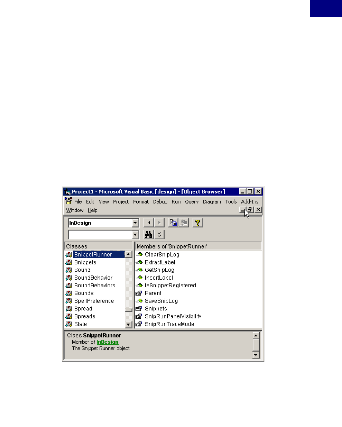
Scriptable Plug-in Fundamentals 585
Scriptable Plug-in Fundamentals
How to make your plug-in scriptable
3. Select File > View TypeLib...
4. Open “Resources for Visual Basic.tlb” (see “Windows: COM Type library location” on
page 583) and browse the type library.
Using Microsoft Visual Basic:
1. Launch Visual Basic and create a new project.
2. Select Project > References…
3. From the Available References list, check “Adobe InDesign CS4 Type Library” or “Adobe
InCopy CS4 Type Library” and click OK. If it does not appear in the list, click Browse… and
find “Resources for Visual Basic.tlb” (see “Windows: COM Type library location” on
page 583). Click OK on the References dialog.
4. Select View > Object Browser (or hit the F2 key). Pick “InDesign” or “InCopy” from the first
drop-down list, to view the type library. See Figure 262.
FIGURE 262 Reviewing the COM type library from Visual Basic
Using Microsoft Word or Excel's Macro Editor:
1. Launch Microsoft Word or Excel.
2. Select Tools > Macro > Visual Basic Editor.

Scriptable Plug-in Fundamentals
How to make your plug-in scriptable
586
3. Select Tools > References.
4. From the Available References list, check “Adobe InDesign CS4 Type Library” or “Adobe
InCopy CS4 Type Library” and click OK. If it does not appear in the list, click Browse and
find “Resources for Visual Basic.tlb” (see “Windows: COM Type library location” on
page 583).
5. Select View > Object Browser (or hit the F2 key). Pick “InDesign” or “InCopy” from the first
drop-down list, to view the type library.
Running versioned scripts
Three steps must be properly versioned to run an older script in a newer version of the prod-
uct:
1. Targeting — Scripts must be targeted to the version application in which they are being run
(i.e., the current version). The mechanics of targeting are language specific.
2. Compilation — This involves mapping the names in the script to the underlying identifiers,
which are what the application understands. The mechanics of compilation are language
specific.
3. Interpretation — This involves matching the identifiers to the appropriate request handler
within the application. The current version of the application correctly interprets a script
written to an earlier version of the scripting DOM, if you run it from a folder in the Scripts
panel named, for example, “Version 3.0 Scripts,” or explicitly set the application's script
preferences to the old DOM within the script.
Targeting
Targeting for AppleScript applications is done using the “tell” statement, as in Example 43. You
do not need a tell statement if you run the script from the Scripts panel, because there is an
implicit tell statement for the application launching the script.
EXAMPLE 43 Targeting for AppleScript applications
tell application "Adobe InDesign CS4" --target CS4
Targeting for Visual Basic applications and VBScripts is done using the “CreateObject”
method, as in Example 44:
EXAMPLE 44 Targeting for Visual Basic applications
Set myApp = CreateObject("InDesign.Application.CS4") 'Target CS4
Set myApp = CreateObject("InDesign.Application") 'Target the last version of
InDesign that was launched
Targeting for JavaScripts is implicit when launched using the Scripts panel. If launched from
elsewhere, use the “target” directive, as in Example 45:

Scriptable Plug-in Fundamentals 587
Scriptable Plug-in Fundamentals
How to make your plug-in scriptable
EXAMPLE 45 Targeting for JavaScript applications
#target "InDesign-6.0" //target CS4
#target "InDesign" //target the latest version of InDesign
Compilation
EXAMPLE 46 Compilation of AppleScript applications
Typically, AppleScripts are compiled using the targeted application's dictionary. You can over-
ride this behavior with the “using terms from” statement, which substitutes another applica-
tion's dictionary for compilation purposes.
tell application "Adobe InDesign CS4" --target CS4
using terms from application "InDesign CS3" --compile using CS
...
end using terms from
end tell
To generate a CS3 version of the AppleScript dictionary, use the publish terminology event,
which is exposed on the application object (see below). The dictionary is published into a
folder (named with the version of the DOM) under the “Scripting Support” folder. For exam-
ple: /Users/<username>/Library/Caches/Adobe <InDesign or InCopy or InDesign Server>/Ver-
sion 6.0/en_US/Scripting Support/3.0. (In this case, compile using the “Adobe InDesign CS
Dictionary” pseudo-application that results.)
tell application "Adobe InDesign CS4"
publish terminology version 3.0 --publish the Adobe InDesign CS dictionary
(version 3.0 DOM)
end tell
EXAMPLE 47 Compilation of Visual Basic applications
Compilation of Visual Basic applications may be versioned by referencing the Creative Suite 3
type library. To generate a Creative Suite 3 version of the type library, use the PublishTerminol-
ogy event, which is exposed on the Application object. The type library is published into a
folder (named with the version of the DOM) that is under the “Scripting Support” folder in
your application's preferences folder. For example: C:\Documents and Settings\<user-
name>\Local Settings\Application Data\Adobe\<InDesign or InCopy or InDesign Server>\Ver-
sion 6.0\en_US\Caches\Scripting Support\3.0\.
Set myApp = CreateObject("InDesign.Application.CS4")
myApp.PublishTerminology( 3.0 ) 'publish the InDesign CS type library (version 3.0
DOM)
VBScripts are not pre-compiled. The application generates and references the appropriate type
library automatically, based on the version of the DOM set for interpretation.
EXAMPLE 48 Compilation of JavaScript applications
JavaScripts are not pre-compiled. For compilation, the application uses the same version of the
DOM that is set for interpretation.

Scriptable Plug-in Fundamentals
How to make your plug-in scriptable
588
Interpretation
The Application object contains a Script Preferences object, which allows a script to get/set the
version of the scripting DOM to use for interpreting requests. The version will remain as set
until explicitly changed again, even across scripts. The version defaults to the current version of
the application and is persisted. See the examples below.
EXAMPLE 49 AppleScript interpretation
set version of script preferences to 3.0 --Set to 3.0 DOM
EXAMPLE 50 Visual Basic interpretation
Set myApp = CreateObject("InDesign.Application.CS4")
myApp.ScriptPreferences.Version = 3.0 'Set to 3.0 DOM
EXAMPLE 51 JavaScript interpretation
app.scriptPreferences.version = 3.0 ; //Set to 3.0 DOM
Supporting IDML
For the most part, you support the IDML file format simply by exposing your persistent data in
the scripting DOM.
If you are making a custom page item scriptable, make sure you do not rely on “with proper-
ties” (parameters) during the create event (e_Create). This is because the application compo-
nent that generates the IDML file format may not have all the data to create the IDML tag
attributes on your custom objects. Also, it may not set properties on your custom object in any
specific order. So, in your script provider where you support the create event (e_Create), you
should be able to support instantiation without properties while using reasonable defaults, and
tolerate setting properties in random order.
If you have read-only properties that are set automatically by the application or your plug-in
(e.g., file modification date/time), you may need a separate read/write version of the property
for use by the kINXScriptManagerBoss, so the IDML subsystem can update it while writing.
For example, kPageCountPropertyScriptElement is a read-only element that needs the follow-
ing:

Scriptable Plug-in Fundamentals 589
Scriptable Plug-in Fundamentals
How to make your plug-in scriptable
EXAMPLE 52 Page count, a read-only property to which IDML requires write access
{
//Contexts
{
kInitialScriptVersion, kINXScriptManagerBoss, kWildFS, k_Wild,
}
//Elements
{
Provider
{
kSpreadScriptProviderBoss,
{
Object{ kMasterSpreadObjectScriptElement },
Property{ kPageCountPropertyScriptElement, kReadWrite },
}
}
}
} ;
IDML writes object and property data to XML using their long name identifiers. To allow long
names to be written within a list of values, define your property using a StructType containing
StructFields that define key/value pairs for each value in the list. For example, here is a defini-
tion of key/value pairs to define list elements:
Property {
kBNRestartPolicyPropertyScriptElement,
"numbering restart policies",
"Numbering restart policies.",
StructType {
StructField("restart policy", EnumType( kBNRestartPolicyEnumScriptElement )),
StructField("lower level", Int32Type ),
StructField("upper level", Int32Type ) }
{PermitTypeChange}
kBNRestartPolicyBoss,
}
Maintaining IDML forward and backward compatibility
This section describes the versioning goals and rules for InDesign and the IDML file format.
The same versioning goals and rules apply to InCopy and its ICML file format.
Consider three InDesign versions, A, B and C, with A being the oldest. The scripting DOM
version is changed at the beginning of each product development cycle, so we also can speak of
scripting DOM versions A, B and C. Each product version has its own IDML file format ver-
sion, IDML-A, IDML-B, IDML-C, based on its associated scripting DOM.
Users do not want to specify which flavor of IDML they want to export or open. As a result,
Adobe and third-party developers must preserve the illusion that there is one version of IDML.

Scriptable Plug-in Fundamentals
How to make your plug-in scriptable
590
Goals
1. Each version of InDesign writes IDML in its own format. InDesign-C uses scripting DOM
version C to produce IDML-C, and similarly for earlier product versions.
2. Each version of InDesign can read its own IDML version and all previous versions. This is a
natural consequence of having a versioned scripting DOM. InDesign simply sets the script-
ing DOM to the correct version when the file is opened. Everything else falls into place.
InDesign-C can read IDML-A, IDML-B, and IDML-C, since it knows about all three ver-
sions of the scripting DOM. Likewise, InDesign-A knows about only its own scripting
DOM version.
3. Each version of InDesign can read IDML versions newer than itself. A given InDesign version
should ignore information it does not understand and provide reasonable defaults for miss-
ing information. This means InDesign-A should make a best effort to read files written in
IDML-B and IDML-C.
Whether goal 3 is met depends on how carefully people write script providers. For most script
objects, which are simple, just a small set of rules need to be followed.
Rules
Adding script objects or properties
If you add new script objects or add new properties to existing objects, there is no problem;
older versions of InDesign simply ignore the information.
Removing script objects and properties
If you remove an object or property, there is no problem. Suppose a property called weasel is no
longer needed in InDesign-B. Mark the weasel property Obsolete as of scripting DOM version
B. Leave support for the property intact, since it will be needed when version A of the scripting
DOM is active.
Changing the type of a property
We do not recommend changing the type of a property, and experience has shown that changes
to a property's type should be rare. Choose carefully when adding a new property and specify-
ing its type.
Verifying your plug-in’s data is round-tripped through IDML
To make sure your new script objects are exported in IDML, follow these steps:
1. Start the application with your scriptable plug-in present.
2. Create a new document, and create objects that have your plug-in’s data applied.
3. Choose File > Export, and select the “InDesign Markup (IDML)” format. Save your file with
an .idml extension.

Scriptable Plug-in Fundamentals 591
Scriptable Plug-in Fundamentals
Scripting resources
4. The IDML file is an archive package that contains XML files and other related files. To open
the IDML package, first extract it using WinZip or a similar tool. Search in the appropriate
XML files for your scripting object's name, specified in your plug-in's .fr file. For details
about the contents of the IDML package, see IDML File Format Specification.
5. Open the .idml file in InDesign, and verify there is no assert or data loss.
For example, the Watermark sample plug-in adds a preference object to the document. Follow
the instructions above, and use the Plug-ins > SDK > Watermark menu to define a watermark
for the document. Export an IDML file, uncompress it, open designmap.xml, and search for
“WatermarkPreference.”
Tips for debugging the scripting architecture
To help debug your scriptable plug-in, use the following debug-build-only menu items:
zTo trace BridgeTalk messages, turn on Test > TRACE > Script > BridgeTalk.
zTo trace the loading of scripts into the scripts panel, turn on Test > TRACE > Script >
ScriptPanelFile.
zTo trace requests and see which script providers are invoked, turn on Test > TRACE >
Script > ScriptRequestHandler.
zTo trace the instantiation of scripting DOMs, turn on Test > TRACE > Script > ScriptTimer.
zTo trace the loading of script information resources, turn on Test > TRACE> Script >
ScriptInfoManager > Registration.
zTo enable asserts when a dependent resource is missing, turn on Test > TRACE> Script >
ScriptInfoManager > Resource Dependencies.
zTo trace the specification and resolution of objects used by a JavaScript, turn on Test >
TRACE > Script > CoreObjectSpecifier.
zTo trace Apple events processed, turn on Test > TRACE > AppleScript > EventHandlers.
zTo trace operations on InDesign COM objects used by a Visual Basic script, turn on Test >
TRACE > GenericCOMObject.
zFrom the Test > Scripting menu, you can dump the contents of the ScriptInfoManager for
various clients to a text file in the QA Logs folder. This makes it easy to diff changes you are
making or between builds.
Scripting resources
The scripting DOM is made up of script objects, properties, events, and providers that are
defined by plug-ins using the ODFRez resource statements described in this section.

Scriptable Plug-in Fundamentals
Scripting resources
592
NOTE:The scripting DOM provided by the application is described in “Scripting DOM
reference” on page 641. The script objects to which C++ programmers can add script
objects, events, and properties are identified there.
The scripting resources in a plug-in:
zDescribe the objects, properties, and events exposed through the scripting DOM.
zDetermine how objects are related to each other in the scripting DOM object hierarchy.
zSpecify which script providers can handle which properties and events on which objects.
zAre stored in the plug-in’s .fr file and compiled like all ODFRC resources.
zAre loaded and validated on first launch, then persisted in the application’s SavedData.
zAre used to generate reference documentation required by specific clients (e.g., AppleScript
Dictionary, Visual Basic TypeLibrary, IDML DTD, and high-level API).
zAre versioned to maintain backward and forward compatibility between releases of the
product (see “Versioning of scripting resources” on page 621)
The scripting plug-in manages the scripting DOM via the IScriptInfoManager interface.
IScriptInfoManager:
zCaches data from the resources and makes it available programmatically.
zMatches requests to handle events and properties on particular objects with the appropriate
script provider.
NOTE:See <SDK>/source/public/includes/ScriptInfoTypes.fh for the script element type
definitions for Object, Event, Property, etc.
VersionedScriptElementInfo resource
A VersionedScriptElementInfo statement adds script objects, properties, events, and providers
to the scripting DOM. See Example 53.
EXAMPLE 53 VersionedScriptElementInfo statement
resource VersionedScriptElementInfo(1) // See Note 1
{
//Contexts
{
BasilScriptVersion, // See Note 2
kCoreScriptManagerBoss, // See Note 3
kWildFS, // See Note 4
k_Wild, // See Note 5
// See Note 6
}
//Elements
{
// See Note 7
}
}

Scriptable Plug-in Fundamentals 593
Scriptable Plug-in Fundamentals
Scripting resources
Notes:
1. There may be more than one VersionedScriptElementInfo resource in a plug-in’s .fr file.
Each must have its own distinct resource identifier. The statement shown has a resource
identifier of 1.
2. This is the version of the product the statement targets; kInitialScriptVersion for CS1 and
kBasilScriptVersion for CS4. See ScriptInfoTypes.fh for other versions. See “Versioning of
scripting resources” on page 621.
3. Use kCoreScriptManagerBoss if the statement contains resources that should be in all
scripting DOMs. If the statement applies only to a specific client, use its ClassID here. For
example, if the statement is specific to AppleScript, use kAppleScriptMgrBoss. See “Client-
specific scripting resources” on page 632.
4. This is the feature set identifier. kWildFS indicates this statement applies to all products and
feature sets.
5. This is the locale identifier. k_Wild indicates this statement applies to all user interface
locales.))
6. If the statement targets other contexts, repeat 1 through 4 to define the additional contexts.
7. Object, event, property, enum, and provider elements go here.
NOTE:The ScriptElementInfo resource is used by InDesign CS1 plug-ins to define script
elements. InDesign CS2 and later plug-ins should always use
VersionedScriptElementInfo. See “Versioning of scripting resources” on page 621.
Object element
An object element defines a new script object that can be added to the scripting DOM using a
Provider statement (see “Provider element” on page 606). Example 54 is an example of a state-
ment for a script object with a plural form:
EXAMPLE 54 Object statement for an object with a plural form
Object // See Note 1
{
kSpreadObjectScriptElement, // See Note 2
c_Spread, // See Note 3
"spread", // See Note 4
"A spread", // See Note 5
kSpread_CLSID, // See Note 6
c_Spreads, // See Note 7
"spreads", // See Note 8
"Every spread", // See Note 9
kSpreads_CLSID, // See Note 10
kUniqueIDBasedObjectScriptElement, // See Note 11
kLayoutSuiteScriptElement // See Note 12
}

Scriptable Plug-in Fundamentals
Scripting resources
594
Notes:
1. The object is defined within a VersionedScriptElementInfo resource (see “Versioned-
ScriptElementInfo resource” on page 592).
2. This is the ScriptElementID of the object (see “ScriptElementIDs” on page 610).
3. This is the ScriptID of the object (see “ScriptIDs” on page 610).
4. This is the name of the object (see “Names” on page 610).
5. This is a description of the object (see “Descriptions” on page 610).
6. This is the GUID of the object (see “GUIDs” on page 611).
7. This is the ScriptID of the object’s plural form (see “ScriptIDs” on page 610).
8. This is the name of the object’s plural form (see “Names” on page 610)
9. This is a description of the object’s plural form (see “Descriptions” on page 610)
10.This is the GUID of the object’s plural form (see “GUIDs” on page 611).
11. This is the script object on which this object is based (see “Script-object inheritance” on
page 619 and “Scripting DOM reference” on page 641.
12.This is the AppleScript suite to which the object belongs (see “Suite element” on page 609).
Example 55 is an example of a statement for a singleton script object (e.g., preferences):
EXAMPLE 55 Object statement for a singleton script object
Object
{
kMarginPrefsObjectScriptElement,
c_MarginPref,
"margin preference",
"Margin preferences",
kMarginPref_CLSID,
NoPluralInfo, // A preferences object has no plural form
kPreferencesObjectScriptElement, // Preferences are based on this script object.
kPreferencesSuiteScriptElement,
}
We recommend that any singleton script object be implemented using the pattern for prefer-
ences, for backward compatibility. A singleton is based on kPreferencesObjectScriptElement,
as shown in Example 55, and it follows the implementation pattern outlined in “A d d i n g a n e w
script object to make preferences scriptable” on page 577.
Earlier product versions (Creative Suite 1) required this, so the scripting DOM for JavaScript is
set up correctly. If you add script elements to the scripting DOM for Creative Suite 1, make
your singleton a preference script object).
Follow the above approach for any singleton, even if it exposing data to scripting that is not
stored in the normal locations for preference data (i.e., kDocWorkspaceBoss and kWorkspace-

Scriptable Plug-in Fundamentals 595
Scriptable Plug-in Fundamentals
Scripting resources
Boss). For sample code, see SnippetRunner’s kSnipRunObjectScriptElement object and Sni-
pRunScriptProvider.
Event element
An event element defines a new event that can be added to the scripting DOM using a Provider
statement (see “Provider element” on page 606). See Example 56:
EXAMPLE 56 Event statement
Event // See Note 1
{
kQuitEventScriptElement, // See Note 2
e_Quit, // See Note 3
"quit", // See Note 4
"Quit the application", // See Note 5
VoidType, // See Note 6
{ // See Note 7
en_SaveOptions, // See Note 8
"saving", // See Note 9
"Whether to save changes before closing open documents", // See Note 10
EnumDefaultType( kSaveOptionsEnumScriptElement, en_No ), // See Note 11
kOptional, // See Note 12
// See Note 13
}
}
Notes:
1. The event is defined within a VersionedScriptElementInfo resource (see “Versioned-
ScriptElementInfo resource” on page 592).
2. This is the ScriptElementID of the event (see “ScriptElementIDs” on page 610).
3. This is the ScriptID of the event (see “ScriptElementIDs, ScriptIDs, names, descriptions,
and GUIDs” on page 610).
4. This is the name of the event (see “Names” on page 610).
5. This is a description of the event (see “Descriptions” on page 610).
6. This is the data type of the event’s return value (see “Scripting data types” on page 615).
7. This is a list of event parameters (Notes 8-12)
8. This is the ScriptID of the parameter (see “ScriptIDs” on page 610).
9. This is the name of the parameter (see “Names” on page 610).
10. This is a description of the parameter (see “Descriptions” on page 610).
11.This is the type of the parameter, including a default value for optional parameters (see
“Scripting data types” on page 615).

Scriptable Plug-in Fundamentals
Scripting resources
596
12. This is kOptional or kRequired.
13.The definition of other parameters goes here.
Default parameter values
You may specify a default value for optional parameters, using a default type (see “Scripting
data types” on page 615). There are no default declarations for date, file, object, record, or array
types. (See the ScriptInfoTypes.fh file.)
NOTE:A default value is not available for parameters of these types: Date, File, Object, Record,
or Array. For some of these types, you can use one of the permitted default value types.
For example, a Unit typically can be specified as a real or a string; and a variable type
that includes object and string types could be specified using a string. However, there is
no supported way to specify an array of default values for an array type. You can try the
following workaround, but there is no guarantee it will be compatible in the future.
//Specify as the default a list of two unit values equal to 0.0 points
kScriptInfoUnitType, 2, NoValue, NoValue, {s_list{{ UnitValue(0.0), UnitValue(0.0)
}}}, {}
Special events
Create
The create event instantiates a script object.
Most script objects can re-use the predefined event kCreateEventScriptElement, unless they
have required parameters for the create event, which is strongly discouraged. To define your
own create event, use e_Create as the ScriptID and “add” as the name in your Event statement.
The create event is expected to use the WITHPROPERTIESPARAM macro to add a “with
properties” parameter for AppleScript and JavaScript.
The create event is added to the scripting DOM using a CollectionEvent field within a Provider
statement; e.g.: CollectionEvent{ kCreateEventScriptElement }. See “Provider element” on
page 606. This associates the event with the collection object (or container of, in AppleScript).
Count
The count event indicates how many script objects are instantiated. It is considered a property
in Visual Basic and appears on collections (the plural form of an object; e.g. “Books”) in the
type library.
Most script objects can re-use the predefined event kCountEventScriptElement.
The count event is added to the scripting DOM using a CollectionEvent field within a Provider
statement; e.g.: CollectionEvent{ kCountEventScriptElement }. See “Provider element” on
page 606.
Predefined events
Table 138 lists common predefined events. They are useful if you are adding a new script object
that has a plural form to the scripting DOM.
Scriptable Plug-in Fundamentals 597
Scriptable Plug-in Fundamentals
Scripting resources
TABLE 138 Common predefined events
Property element
A property element defines a new property that can be added to the scripting DOM using a
Provider statement (see “Provider element” on page 606). See Example 57:
EXAMPLE 57 Property statement
Property // See Note 1
{
kNamePropertyScriptElement, // See Note 2
p_Name, // See Note 3
"name", // See Note 4
"The name of the ^Object", // See Note 5
StringType, // See Note 6
{} // See Note 7
kNoAttributeClass, // See Note 8
}
Notes:
1. The property is defined within a VersionedScriptElementInfo resource (see “Versioned-
ScriptElementInfo resource” on page 592).
2. This is the ScriptElementID of the property (see “ScriptElementIDs” on page 610).
3. This is the ScriptID of the property (see “ScriptIDs” on page 610).
4. This is the name of the property (see “Names” on page 610).
5. This is a description of the property (see “Descriptions” on page 610).
6. This is the data type of the property (see “Scripting data types” on page 615, it can be one of
the default type available beginning in CS4.).
7. This is a list of additional data types acceptable to use when setting the value of the property
(in this case, none).
ScriptElementID ScriptID Name Notes
kCreateEventScriptElement e_Create add Instantiate a script object (“make” in Apple Script,
“Add” in Visual Basic, and “add” in JavaScript).
kCountEventScriptElement e_Count count Count how many script objects are instantiated.
kDeleteEventScriptElement e_Delete delete Delete a script object. (“delete” in Apple Script,
“Delete” in Visual Basic, and “remove” in
JavaScript).
kDuplicateEventScriptElement e_Duplicate duplicate Duplicate a script object.
kMoveEventScriptElement e_Move move Move a script object.

Scriptable Plug-in Fundamentals
Scripting resources
598
8. This is the ClassID of the text, graphic, or table attribute boss class associated with this
property. Use kNoAttributeClass if the property is not associated with an attribute.
Other examples of Property statements are in Example 58:
EXAMPLE 58 More property statements
// Property that can be set using the name of a swatch or a swatch object.
Property
{
kPrefsFillColorPropertyScriptElement,
p_FillColor,
"fill color",
"The fill color",
StringType,
{ ObjectType( kSwatchObjectScriptElement ) }
kNoAttributeClass,
}
// Accessor property for a new script object.
// Added to parent object in Scripting DOM using a
// ParentProperty field in a Provider statement.
Property
{
kMarginPrefsPropertyScriptElement,
p_MarginPref,
"margin preferences",
"Margin preferences",
// This property refers to another object by ScriptElementID
ObjectType( kMarginPrefsObjectScriptElement ),
{}
kNoAttributeClass,
}
TypeDef and TypeDefType
A TypeDef resource defines a synonym for another type. You can use a TypeDef type wherever
a type is required, by using a TypeDefType declaration; for example, the storage type of a prop-
erty resource or the return type or parameter types of an event resource. One TypeDef in the
core DOM corresponding to user-interface colors in InDesign is implemented using this tech-
nique; the TypeDef is shown below.
TypeDef
{
kInDesignUIcolortypeDefScriptElement,
t_IDUIColorType,
"InDesign UI color type",
"Properties or parameters using the InDesign UI Colors enumeration ...",
VariableType
{
RealMinMaxArrayType(3, 0, 255),
EnumType( kUIColorsEnumScriptElement )
}
}

Scriptable Plug-in Fundamentals 599
Scriptable Plug-in Fundamentals
Scripting resources
To use a TypeDef in a property definition, use TypeDefType to specify which TypeDef to use:
Property
{
kWatermarkFontColorPropertyScriptElement,
p_WatermarkFontColor,
"watermark font color",
"Watermark font color for a document",
TypeDefType(kInDesignUIColorTypeDefScriptElement),
{},
kNoAttributeClass,
}
Settable types
If a property takes a particular type on “set” but will never return that type on “get,” that type
should be in the list of additional settable types, rather than in a variable type.
EXAMPLE 59 Property with settable types
Instead of using this:
Property
{
kActiveLayerPropertyScriptElement,
p_ActiveLayer,
"active layer",
"The active layer",
VariableType{ ObjectType( kLayerObjectScriptElement ), StringType },
{}
kNoAttributeClass,
}
Use this:
Property
{
kActiveLayerPropertyScriptElement,
p_ActiveLayer,
"active layer",
"The active layer",
ObjectType( kLayerObjectScriptElement ),
{ StringType },
kNoAttributeClass,
}
Special properties
Special properties added via inheritance
The special properties in Table 139 are added when appropriate via inheritance and do not
need to be added to any Provider statement. For documentation on the inheritance of proper-
ties from base script objects, see “Script-object inheritance” on page 619.
Scriptable Plug-in Fundamentals
Scripting resources
600
TABLE 139 Special inherited properties
Name
This must be added into the Provider statement that supports the Name property; e.g.: Prop-
erty{ kNamePropertyScriptElement, kReadWrite }.
Predefined properties
The properties in Table 140 are predefined by the application and can be added to script objects
via a Provider statement:
TABLE 140 Predefined properties
ScriptElementID Name Description Note
kClassPropertyScriptElement class Class descriptor type. Provided under AppleScript by
kAnyObjectScriptElement.
kIDPropertyScriptElement id The object's
identifier.
Provided by
kUniqueIDBasedObjectScriptEleme
nt and
kNonUniqueIDBasedObjectScriptEle
ment.
kIndexPropertyScriptElement index Index of the object
within its parent.
Provided by
kAnyObjectScriptElement.
kLabelPropertyScriptElement label A label that can be set
to any string.
Provided by
kUniqueIDBasedObjectScriptEleme
nt and
kNonUniqueIDBasedObjectScriptEle
ment.
kObjectReferencePropertyScriptEl
ement
object
reference
An object reference
for this object.
Provided under AppleScript by
kAnyObjectScriptElement.
kParentPropertyScriptElement parent The object's parent. Provided by
kAnyObjectScriptElement.
kPropertiesPropertyScriptElement properties Property that allows
setting of several
properties at the same
time.
Provided by
kAnyObjectScriptElement.
ScriptElementID ScriptID Name Description Data type
kBottomPropertyScriptElement p_Bottom bottom Bottom edge of the
object.
UnitType
kBoundsPropertyScriptElement p_Bounds bounds Bounds of the object, in
the format (top, left,
bottom, right).
UnitArrayTy
pe(4)
Scriptable Plug-in Fundamentals 601
Scriptable Plug-in Fundamentals
Scripting resources
Struct element
The StructType allows you to assign long scripting names to data within a group in your
resource. This is especially useful for data that will be written to IDML.
EXAMPLE 60 StructType statement
TypeDef {
kEmployeeTypeDefScriptElement,
t_EmployeeType,
"An Adobe employee",
"Information about our most valuable asset.",
StructType {
StructField( "name", StringType ),
StructField( "id", Int32Type )
}
}
kDatePropertyScriptElement p_Date date Date and time. DateType
kDescriptionPropertyScriptElement p_Description description Description. StringType
kFullNamePropertyScriptElement p_FullName full name Full path including the
name.
FileType
kHeightPropertyScriptElement p_Height height Height of the object. UnitType
kLeftPropertyScriptElement p_Left left Left edge of the object. UnitType
kLockedPropertyScriptElement p_Locked locked Whether the object is
locked.
BoolType
kNamePropertyScriptElement p_Name name Name of the object. StringType
kPathPropertyScriptElement p_Path file path File path. FileType
kPropertiesPropertyScriptElement p_Properties properties Property that allows
setting of several
properties at the same
time.
RecordType(
kContainerO
bjectScriptEl
ement )
kRightPropertyScriptElement p_Right right Right edge of the
^Object.
UnitType
kTopPropertyScriptElement p_Top top Top edge of the
^Object.
UnitType
kVisiblePropertyScriptElement p_Visible visible Whether the ^Object is
visible.
BoolType
kWidthPropertyScriptElement p_Width width Width of the ^Object. UnitType
ScriptElementID ScriptID Name Description Data type

Scriptable Plug-in Fundamentals
Scripting resources
602
TypeDef element
A new feature added to the scripting resources is a TypeDef element and corresponding Type-
DefType. A TypeDef resource defines a synonym for another type. A TypeDef type may be
used wherever a type is required, by using a TypeDefType declaration; for example, the storage
type of a property resource or the return type or parameter types of an event resource.
Two TypeDefs in the core DOM corresponding to user-interface colors in InDesign and
InCopy were re-implemented using this technique. The new TypeDefs are shown below.
TypeDef
{
kInDesignUIcolortypeDefScriptElement,
t_IDUIColorType,
"InDesign UI color type",
"Properties or parameters using the InDesign UI Colors enumeration use this to
specify the type as either one of the enumerated UI colors or a list of
RGB values for a custom color.",
VariableType
{
RealMinMaxArrayType(3, 0, 255),
EnumType( kUIColorsEnumScriptElement )
}
}
TypeDef
{
kInCopyUIColorTypeDefScriptElement,
t_ICUIColorType,
"InCopy UI color type",
"Properties or parameters using the InCopy UI Colors enumeration use this to
specify the type as either one of the enumerated UI colors or a list of
RGB values for a custom color."
VariableType
{
RealMinMaxArrayType(3, 0, 255),
EnumType( kInCopyUIColorsEnumScriptElement )
}
}
Because these types were re-implemented, the following old #defines were removed from
ScriptingScriptInfo.fh:
#define UIColorType TypeDefType(kInDesignUIColorTypeDefScriptElement)
#define UIColorDefaultType(def)
TypeDefDefaultType(kInDesignUIColorTypeDefScriptElement) EnumValue(def){}
#define InCopyUIColorType TypeDefType( kInCopyUIColorTypeDefScriptElement)
The old #define constants that were used in properties and events were replaced with the new
TypeDefs. For example:

Scriptable Plug-in Fundamentals 603
Scriptable Plug-in Fundamentals
Scripting resources
Property
{
kWatermarkFontColorPropertyScriptElement,
p_WatermarkFontColor,
"watermark font color",
"Watermark font color for a document",
TypeDefType(kInDesignUIColorTypeDefScriptElement), // changed for CS4
{},
kNoAttributeClass,
}
Enum element
An enum element defines the list of enumerated values a property or parameter can take. See
Example 61:
EXAMPLE 61 Enum statement
Enum // See Note 1
{
kSaveOptionsEnumScriptElement, // See Note 2
en_SaveOptions, // See Note 3
"save options", // See Note 4
"Options for saving before closing a document", // See Note 5
{ // See Note 6
en_No, // See Note 7
"no", // See Note 8
"Don't save changes", // See Note 9
en_AskUserSaveFile, // See Note 10
"ask",
"Ask user whether to save changes",
en_Yes,
"yes",
"Save changes",
}
}
Notes:
1. The enum is defined within a VersionedScriptElementInfo resource (see “Versioned-
ScriptElementInfo resource” on page 592).
2. This is the ScriptElementID of the enum (see “ScriptElementIDs” on page 610).
3. This is the ScriptID of the enum (see “ScriptIDs” on page 610).
4. This is the name of the enum (see “Names” on page 610).
5. This is a description of the enum (see “Descriptions” on page 610).
6. This is a list of possible enum values (see Notes 7-9).
7. This is the ScriptID of the first enum value (see “ScriptIDs” on page 610).

Scriptable Plug-in Fundamentals
Scripting resources
604
8. This is the name of the first enum value (see “Names” on page 610).
9. This is a description of the first enum value (see “Descriptions” on page 610).
10.ScriptIDs, names, and descriptions of other possible enum values would go here.
An enum is referred to by a ScriptElementID from a Property statement or from parameters
within an Event statement. See Example 56 for an example of an Event statement that uses kSa-
veOptionsEnumScriptElement as a parameter.
Enumerator element
An enumerator element adds additional enumerators to an existing enum (see “Enum element”
on page 603). This is handy when adding a new value for an existing enumerated property. It
also can be used when the available values of an enum are different in the Roman and Japanese
feature sets. See Example 62:
EXAMPLE 62 Enumerator statement
Enumerator // See Note 1
{
kExportFormatEnumScriptElement, // See Note 2
{ // See Note 3
en_InCopyInterchange, "InCopy interchange", "InCopy Interchange"
en_InDesignInterchange, "InDesign interchange", "InDesign Interchange",
en_Snippet, "InDesign snippet", "InDesign Snippet",
}
}
Notes:
1. The enumerator is defined within a VersionedScriptElementInfo resource (see “Versioned-
ScriptElementInfo resource” on page 592).
2. This is the ScriptElementID of the enum being added to (see “ScriptElementIDs” on
page 610).
3. This is a list of additional enum values. See “Enum element” on page 603 for the syntax of
an enumerator value.
NOTE:To alter the existing enumerators of an enum or remove enumerators from an Enum,
you must obsolete the existing enum and define a new one (see “Versioning of scripting
resources” on page 621).
Metadata element
The metadata element allows you to add metadata to one or more existing Suite, Object, Event,
Property, Enum, and TypeDef elements. The target elements are listed by ScriptElementID; the
metadata takes the form of a ScriptID/ScriptData key/value pair. Metadata on an element can
be accessed at run time via the ScriptElement base class’s GetMetadata() and HasMetadata()

Scriptable Plug-in Fundamentals 605
Scriptable Plug-in Fundamentals
Scripting resources
methods. The CustomDataLink sample in the SDK provides an example of metadata element,
which is shown in Example 63.
EXAMPLE 63 Metadata statement that adds metadata to an existing element
Metadata
{
kTranFxSettingsINXPoliciesMetadataScriptElement, // see note 1
{
// see note 2
// Elements
kTranFxSettingsObjectScriptElement,
}
{
// see note 3
m_NoDefaultsCache, NoValue,
// How to handle these elements during import.
m_INXSnippetAttrImportState, Int32Value(e_SetElementAttributes),
}
}
Notes:
1. The ScriptElementID makes it possible to version the metadata resources included in a
DOM based on the client.
2. The first group of braces identifies the target element onto which the metadata is to be
added. Multiple elements can be added, and they can be different kind of element mixes,
such as suite, object, and event.
3. The second group of braces is where you put the key/values pair for the data.
Value types
The following metadata value types are supported:
zEnumValue( enumerator )
zBoolValue( kTrue or kFalse )
zInt16Value( short int )
zInt32Value( long int )
zNoValue()
zRealValue( real )
zStringValue( “string” )
zUnitValue( real ) //value in points

Scriptable Plug-in Fundamentals
Scripting resources
606
Provider element
A provider element adds the script objects, events, and properties you defined into the script-
ing DOM. It can be defined (used) in multiple places to represent different parent-child hierar-
chy client types. See “Object element” on page 593, “Event element” on page 595, and “Property
element” on page 597 for a description of how objects, events, and properties are defined. The
provider statement:
zIndicates which events and properties are available on which objects.
zDefines the script object hierarchy.
zSpecifies the script provider boss that handles the referenced object(s), event(s), and prop-
erty(s).
Example 64 is an example of a Provider statement that adds a property and an event to an exist-
ing object in the scripting DOM, kPageItemObjectScriptElement:
EXAMPLE 64 Provider Statement that adds to an Existing Object in the Scripting DOM
Provider // See Note 1
{
kYourScriptProviderBoss, // See Note 2
{
Object{ kPageItemObjectScriptElement }, // See Note 3
Event{ kYourEventScriptElement }, // See Note 4
Property{ kYourPropertyScriptElement, kReadOnly }, // See Note 5
// See Note 6
}
}
Notes:
1. The provider is defined within a VersionedScriptElementInfo resource (see “Versioned-
ScriptElementInfo resource” on page 592).
2. This is the ClassID of the script provider boss that handles the referenced event(s) and
property(s).
3. The script object referenced by this field is the object in the scripting DOM to which prop-
erties and events referenced by subsequent fields are added. See “Scripting DOM reference”
on page 641 for documentation on the script objects provided by the application.
4. The event referenced by this field is added to the script object referenced by the preceding
Object field. See “Event element” on page 595.
5. The property referenced by this field is added to the script object referenced by the preced-
ing Object field. See “Property element” on page 597. This also indicates whether the prop-
erty is read-write or read-only.
6. References to other events and/or properties handled by this script provider go here.
Example 65 is an example of a Provider statement that adds a new script object into the script-
ing DOM:

Scriptable Plug-in Fundamentals 607
Scriptable Plug-in Fundamentals
Scripting resources
EXAMPLE 65 Provider statement that adds a new script object with a plural form into the scripting
DOM
Provider // See Note 1
{
kDocumentScriptProviderBoss, // See Note 2
{
Parent{ kApplicationObjectScriptElement }, // See Note 3
RepresentObject{ kDocumentObjectScriptElement }, // See Note 4
CollectionEvent{ kCountEventScriptElement }, // See Note 5
CollectionEvent{ kCreateDocumentEventScriptElement }, // See Note 6
Event{ kCloseDocumentEventScriptElement }, // See Note 7
Property{ kNamePropertyScriptElement, kReadOnly }, // See Note 8
// See Note 9
}
}
Notes:
1. The provider is defined within a VersionedScriptElementInfo resource (see “Versioned-
ScriptElementInfo resource” on page 592).
2. This is the ClassID of the script provider boss that handles the referenced script object(s),
event(s), and property(s).
3. The script object referenced by this field is the parent in the scripting DOM for the new
script object referred to by the subsequent RepresentObject field. For documentation on the
script objects provided by the application, see “Scripting DOM reference” on page 641.
4. The script object referenced by this field is added to the scripting DOM. Its parent object is
defined by a preceding Parent field.
5. The count event referenced by this field is added to the script object referenced by the pre-
ceding RepresentObject field. See “Special events” on page 596.
6. The create event referenced by this field is added to the script object referenced by the pro-
ceeding RepresentObject field. See “Special events” on page 596.
7. The event referenced by this field is added to the script object referenced by the preceding
RepresentObject field.
8. The property referenced by this field is added to the script object referenced by the preced-
ing RepresentObject field. This also indicates whether the property is read-write or read-
only.
9. Other references to parents, objects, events, and/or properties handled by this script pro-
vider go here.
Fields in a provider statement
The types of field that can appear in a Provider statement are listed in Table 141. Each field
refers to an associated script element (a script object, event, property, or enum) using its
ScriptElementID.
Scriptable Plug-in Fundamentals
Scripting resources
608
TABLE 141 Field Types within a provider statement
Field type Purpose Use
Object The script object referenced by this field is the
object in the scripting DOM to which properties
and events referenced by subsequent fields are
added.
Add new properties and events to an
existing script object.
Event The script event referenced by this field is added to
the script object referenced by the preceding
Object or RepresentObject field.
Add event to a new or existing script
object.
Property The script property referenced by this field is
added to the script object referenced by the
preceding Object or RepresentObject field. This
identifies access rights as kReadOnly, kReadWrite,
or kReadOnlyButReadWriteForINX.
Add event to a new or existing script
object.
Parent The script object referenced by this field is a parent
in the scripting DOM for the new script object
referred to by a subsequent RepresentObject field.
Add a new script object to the scripting
DOM.
RepresentObject The script object referenced by this field is added
to the scripting DOM. Its parent object is defined
by a presiding Parent field.
Add a new script object to the scripting
DOM.
ParentProperty The script property referenced by this field is
added to the script object referred to by a
preceding Parent field.
Provide an accessor in the scripting
DOM for a singleton script object.
CollectionEvent A Create script event referenced by this field
creates an instance of a script object in a collection.
A Count script event referenced by this field
counts how many instances exist in the collection.
See “Special events” on page 596.
Provide access in the scripting DOM for
a collection of script objects. Script
objects that can exist in a collection are
said to have a plural form. For example,
the plural form of spread is spreads.
SurrogateParent See“Surrogate” on page 609. Deprecated. SurrogateParent is an old
mechanism used to avoid INX getting
confused about ownership relationships.
The preferred approach is to create an
INX-specific scripting resource (see
“Client-specific scripting resources” on
page 632) with a Provider statement that
uses the kNotSupported script provider.
Parent fields added to this Provider
statement indicate the parent-child
relationship that simply reference an
object without any ownership. These
parents are ignored by INX, and
confusion about owner versus reference
relationships is avoided.

Scriptable Plug-in Fundamentals 609
Scriptable Plug-in Fundamentals
Scripting resources
Surrogate
A surrogate is a concept that helps INX identify a parent object that does not have an owner-
ship relationship with a child object.
In the native InDesign model, a document is stored as a tree of boss objects, each of which is
bound to and stored persistently in a database. Each boss object (except the root object) has
one boss object (a parent boss object) that refers to it and “owns” it and zero or more boss
objects that simply reference it without any ownership.
In the scripting DOM, a surrogate indicates a parent-child relationship that does not have an
ownership relationship with the underlying boss object. A surrogate simply refers to a child
object. If you ask a child in the scripting DOM for its parent, the object you get back is the par-
ent that has the ownership relationship; you do not get surrogate. For example, a Page object
has both a primary parent (a Spread object) and a surrogate parent (the Document object). You
can access all pages in a document via the surrogate Document/Page relationship, but if you
ask a Page which object is its parent, you always get back a Spread object back.
Suite element
A suite element adds a suite script element, which is used by AppleScript to group related script
objects together. Each Object statement refers to its associated suite (see “Object element” on
page 593). See Example 66:
EXAMPLE 66 Suite statement
Suite // See Note 1
{
kBasicSuiteScriptElement, // See Note 2
s_InDesignBasicSuite, // See Note 3
"InDesign basics", // See Note 4
"Terms applicable to many InDesign operations", // See Note 5
}
1. The suite is defined within a VersionedScriptElementInfo resource (see “Versioned-
ScriptElementInfo resource” on page 592).
2. This is the ScriptElementID of the suite (see “ScriptElementIDs” on page 610).
3. This is the ScriptID of the suite (see “ScriptIDs” on page 610).
4. This is the name of the suite (see “Names” on page 610).
5. This is a description of the suite (see “Descriptions” on page 610).
The ScriptElementIDs for common suites are defined in ScriptingID.h (for example, see kBa-
sicSuiteScriptElement).

Scriptable Plug-in Fundamentals
Scripting resources
610
ScriptElementIDs, ScriptIDs, names, descriptions, and GUIDs
The scripting DOM is made up of script elements. A script element is a script object, script
event, script property, script enum, or script suite. Each script element has two identifiers, a
ScriptElementID and a ScriptID, together with a name and a description. Script objects also
require one or more GUIDs.
ScriptElementIDs
A ScriptElementID is a kScriptInfoIDSpace ID, an object model identifier based on a plug-in
prefix in the same way as the IDs for boss classes, interfaces, and implementations. These IDs
are defined in the ID.h file of the plug-in that adds the script element to the scripting DOM.
For example, kSpreadObjectScriptElement, the ID for the spread script object, is defined in
SpreadID.h.
ScriptIDs
A ScriptID is a four-character identifier for a script element. For example, “sprd” is the ScriptID
for a spread. Most ScriptIDs in the scripting DOM supplied by the application are defined in
the <SDK>/source/public/includes/ScriptingDefs.h header file.
NOTE:New ScriptIDs introduced by your plug-in must be registered with Adobe to prevent
clashes with other plugins. See “ScriptID/name registration” on page 612.
Names
The name field(s) in an Object, Event, Property, or Enum statement should contain a lowercase
string, using a space to delimit the parts of the name (e.g., “graphic layer” or “text frame”).
Optionally, you can force uppercase for an acronym (e.g., “URL”) or product name (e.g., “InDe-
sign basics”).
NOTE:New names introduced by your plug-in must be registered with Adobe to prevent
clashes with other plugins. See “ScriptID/name registration” on page 612.
Descriptions
The string in the description field(s) an Object, Event, Property, or Enum statement should be
sentence case (i.e., initial word capitalized), with no closing punctuation, unless the description
is more than one sentence long, in which case all sentences except the last should have closing
punctuation.
Object-sensitive descriptions
This option is particularly useful for events and properties that appear on multiple script
objects.
Often, it makes sense for the description field(s) of an event or property element to contain the
name of the script object on which the event or property is exposed. For example, consider an
object named “swatch”:

Scriptable Plug-in Fundamentals 611
Scriptable Plug-in Fundamentals
Scripting resources
zDescription of the name property: “The name of the swatch.”
zDescription of the count event: “The number of swatches.”
zDescription of the return value for the create event: “The new swatch.”
By using ^Object for the singular form and ^Objects for the plural form, the name of the rele-
vant object is substituted at run time. For example:
zDescription of the name property: “The name of the ^Object.”
zDescription of the count event: “The number of ^Objects.”
zDescription of the return value for the create event: “The new ^Object.”
GUIDs
A GUID is a Windows ID that allows COM to interact with the script manager. GUIDs are gen-
erated on Windows using the Microsoft GUID generator GUIDGEN.EXE.
Adding a singleton script object to the scripting DOM requires a GUID. Adding a script object
that has a plural form requires two GUIDs (see “Object element” on page 593).
NOTE:If your plug-in is scriptable only on Mac OS, you can opt to use kInvalid_CLSID (see
header Guid.h); however, we recommend you generate GUIDs for your script objects.
NOTE:Documentation on generating GUIDs on Mac OS can be obtained from
http://developer.apple.com, search for “Generating UUID.” See also
http://www.apple.com/downloads/macosx/development_tools/uuidfactory.html.
Example 67 is a sample GUID declaration:
EXAMPLE 67 Example of a GUID declaration
#define kDocument_CLSID { 0x1a5e8db4, 0x3443, 0x11d1, { 0x80, 0x3c, 0x0, 0x60,
0xb0, 0x3c, 0x2, 0xe4 } }
If you need to access the GUID from C++ code in your plug-in, you must declare the GUID, as
shown in Example 68. Normally this is not necessary in the course of making a plug-in script-
able.
EXAMPLE 68 Example of a DELCLARE_ GUID call
DECLARE_GUID( Document_CLSID, kDocument_CLSID );
Scripting ID naming idioms
Table 142 lists the ScriptID and ScriptElementID naming idioms:
TABLE 142 ScriptID and ScriptElementID naming idioms
Script element ScriptID prefix ScriptElementID Examples
Object c_ kXxxObjectScriptElement c_Spread, kSpreadObjectScriptElement
Event e_ kXxxEventScriptElement e_Open, kOpenEventScriptElement

Scriptable Plug-in Fundamentals
Scripting resources
612
Source-file organization
The current SDK sample organization of source files for scripting IDs is given below. For the
referenced sample files, see <SDK>/source/sdksamples/basicpersistinterface:
zDefine ScriptElementIDs for your script elements in your plug-in’s ID.h file (e.g., kBPIPre-
fObjectScriptElement in BPIID.h). The recommended style is to group identifiers by ele-
ment type (objects, events, properties, etc). See Example 69 for a template you can use in
your ID.h file.
zDefine ScriptIDs in your plug-in’s ScriptingDefs.h file (e.g., BPIScriptingDefs.h).
zIf you are adding new objects to the scripting DOM, define Windows GUIDs in your plug-
in’s ScriptingDefs.h file (e.g., kBPIPref_CLSID in BPIScriptingDefs.h). See “GUIDs” on
page 611.
NOTE:In a future SDK release, it is likely ScriptIDs and GUIDs will be consolidated in the
plug-in’s ID.h file.
EXAMPLE 69 Template for ScriptElementIDs
//Script Element IDs
//Suites
DECLARE_PMID(kScriptInfoIDSpace, k???SuiteScriptElement, k???Prefix + 1)
//Objects
DECLARE_PMID(kScriptInfoIDSpace, k???ObjectScriptElement, k???Prefix + 40)
//Events
DECLARE_PMID(kScriptInfoIDSpace, k???EventScriptElement, k???Prefix + 80)
//Properties
DECLARE_PMID(kScriptInfoIDSpace, k???PropertyScriptElement,k???Prefix + 140)
//Enums
DECLARE_PMID(kScriptInfoIDSpace, k???EnumScriptElement, k???Prefix + 220)
ScriptID/name registration
This section discusses the scenarios in which plug-in developers need to extend the scripting
DOM, and how ScriptIDs and names, referred to as ScriptID/name pairs, are managed.
When you add a new script element (script object, event, property, or enum) to the scripting
DOM, the element has a ScriptID and a name (see “ScriptIDs” on page 610) and “Names” on
page 610). The ScriptID and name are treated as a pair and must be used together. When you
Event parameter p_ not required p_ShowInWindow
Property p_ kXxxPropertyScriptElement p_LineWeight,
kStrokeWeightPropertyScriptElement
Enum en_ kXxxEnumScriptElement en_FitContentOptions,
kFitContentOptionEnumScriptElement
Suite s_ kXxxSuiteScriptElement s_TableSuite, kTableSuiteScriptElement
Script element ScriptID prefix ScriptElementID Examples

Scriptable Plug-in Fundamentals 613
Scriptable Plug-in Fundamentals
Scripting resources
need a new ScriptID/name pair, you must register them with Adobe via an online registration
process, to avoid conflicts with other plug-ins.
If you are unsure whether you need to register a ScriptID/name pair for the elements you want
to add to the scripting DOM, always do the safe thing. Register a new unique ScriptID/name
pair.
Use the ScriptID/name pairs you register consistently in your code:
zIf you allocate a pair to identify a script object (for example, ‘myob’/”my object”), always use
this pair to identify this type of script object.
zIf you allocate a pair to identify an event (for example, ‘myev’/”my event”), always use this
pair to identify this event.
zIf you allocate a pair to identify a property (for example, ‘mypr’/”my property”), always use
this pair to identify this type of property.
zFollow this consistency rule with the ScriptID/name pairs you register for other kinds of
script elements.
ScriptID/name registration Web page
The ScriptID/name registration database is accessed via the following Web page:
http://partners.adobe.com/public/developer/indesign/devcenter.html
All plug-in developers—third party and Adobe engineers—register new ScriptID/name pairs
via this Web page when needed.
The scenarios below indicate situations when a new ScriptID/name pair is needed. Do not use
an arbitrarily chosen ScriptID/name pair as a new ScriptID/name pair. If the ScriptID/name
pair you want is already registered, you must choose and register an alternative. Follow the pro-
cedures outlined in the scenarios below.
All plug-in developers must check for ScriptID/name pair conflicts with Adobe plug-ins, by
loading their plug-in under the debug build of the application having deleted the application’s
SavedData file before launching. If conflicts are detected, asserts are raised on start-up. Devel-
opers must change their scripting resources to fix any conflicts and be able to start the applica-
tion without asserts.
Reserved words in each scripting language (that do not yet have any corresponding IDs) are
pre-populated in the ASN ScriptID/name pair database with arbitrarily chosen IDs.
NOTE:Adobe-registered ScriptID/name pairs for InDesign CS4 are documented in “Scripting
DOM reference” on page 641.
Adding a new script object
1. Choose the ScriptID/Name pairs for your script object. If your object has a collection you
need two pairs; the second pair is for the collection. If your object is a singleton, you need
only one pair for the object; however, you need a second pair for a new property, to expose
your new object on its parent or parents.
2. Make your plug-in scriptable, then test against the debug application build and resolve any
conflicts with Adobe-registered ScriptID/name pairs.

Scriptable Plug-in Fundamentals
Scripting resources
614
3. Register the new, unique ScriptID/name pairs (see “ScriptID/name registration Web page”
on page 613). Conflicts with any other third-party developers' objects are mitigated by this
registration.
Adding a new property or event to an Adobe script object
You can add a new property or event to the application or document script object (kApplica-
tionObjectScriptElement or kDocumentObjectScriptElement). Follow these steps:
1. Choose the ScriptID/Name pair for your property or event.
2. Make your plug-in scriptable, then test against the debug application build and resolve any
conflicts with Adobe-registered ScriptID/name pairs.
3. Register the new, unique ScriptID/name pairs (see “ScriptID/name registration Web page”
on page 613). Conflicts with any other third-party developers' properties/events are miti-
gated by this registration.
Adding a new suite or enum
zChoose the ScriptID/Name pairs for your suite or enum.
zMake your plug-in scriptable then test against debug application build and resolve any con-
flicts with Adobe registered ScriptID/Name pairs.
zRegister the new, unique ScriptID/Name pairs (see “ScriptID/name registration Web page”
on page 613). Conflicts with any other third party developers' suites/enums will be miti-
gated by this registration.
Adding a new property or event to an Adobe script object using an Adobe
ScriptID/name pair
Suppose you want to add Adobe’s name property (kNamePropertyScriptElement) to the page-
item script object (kPageItemObjectScriptElement). In this example, the ScriptID/name pair is
‘pnam’/”name” and is registered by Adobe.
NOTE:Do not under any circumstances do this. If you do this, you are creating a potential
conflict should the same ScriptID/name pair be added by another developer.
Never use Adobe-registered ScriptID/name pairs to add elements to Adobe script objects. Instead,
register your own ScriptID/name pair for any new element you add to an Adobe script object.
See “Adding a new property or event to an Adobe script object” on page 614.
NOTE:If you ignore this guideline, you risk conflict with other parties, and someone will have to
give in. Adobe will not mediate such disputes.
You can re-use an Adobe-registered ScriptID/name pair in your own script object. This is
required if you are overriding an event or property in any base script object provided by Adobe.
When adding your new object, follow the guidelines in“Ad d i n g a n e w s c r i p t o b j e c t” on
page 613.
If you already registered the ScriptID/name pair for your element, this scenario does not apply
to you: you are not re-using an Adobe ScriptID/name pair). In this situation, the only party you
can clash with is yourself, so the resolution is under your control.

Scriptable Plug-in Fundamentals 615
Scriptable Plug-in Fundamentals
Scripting resources
Scripting data types
The data types that can appear in Property and Event statements are listed in Table 143. These
types are defined as ODFRC macros in <SDK>/source/public/Includes/ScriptInfoTypes.fh. A
table key follows:
zdefault — A value-type macro of the desired type
zenum_id — The ScriptElementID of an enum.
zlength — The number of items in the array. If it varies, use kVariableLength.
zmin, max, default — A value of the relevant type
zobject_id — The ScriptElementID of an object.
zstruct_type_list — A list of two or more StructField's separated by commas. A StructField
consists of a field name (string) and (non-Void) type.
ztypedef_id — A valid ScriptElementID of a typedef.
zvariable_type_list — A list of one or more basic types separated by commas.
TABLE 143 Scripting data types
ODFRC type Description ODL type AETE type
Void Ty pe Void void typeNull
Int16Type Short integer short typeShortInteger
Int16DefaultType (default)Default short Integer short typeShortInteger
Int16MinMaxType (min, max) Short integer range short typeShortInteger
Int16MinMaxDefaultType (min, max,
default)
Default short integer
range
short typeShortInteger
Int32Type Long integer long typeLongInteger
Int32DefaultType (default)Default long Integer long typeLongInteger
Int32MinMaxType (min, max) Long integer range long typeLongInteger
Int32MinMaxDefaultType (min, max,
default)
Default long integer range long typeLongInteger
BoolType Boolean VARIANT_BOOL typeBoolean
BoolDefaultType (default)Default boolean VA R IA N T _ B O O L typeBoolean
StringType String BSTR typeChar
StringDefaultType (default)Default string BSTR typeChar
UnitType Measurement unit VARIANT cFixed
UnitDefaultType (default)Default measurement
unit
VA R IA N T cFixed
Scriptable Plug-in Fundamentals
Scripting resources
616
UnitMinMaxType (min, max)Measurement unit rangeVARIANTcFixed
UnitMinMaxDefaultType (min, max,
default)
Default measurement
unit range
VA R IA N T cFixed
RealType Real number double cFixed
RealDefaultType (default)Default real number double cFixed
RealMinMaxType (min, max) Real number range double cFixed
RealMinMaxDefaultType (min, max,
default)
Default real number
range
double cFixed
DateType Date or Time DATE typeLongDateTime
FileType File name or path BSTR or VARIANT typeAlias
KeyStringDefaultType (default)Key string (untranslated
version of a translatable
string)
BSTR typeChar
EnumType (enum_id) Enum enum's name enum's ScriptID
EnumDefaultType (enum_id, default) Default enum enum's name enum's ScriptID
ObjectType (object_id)Object IDispatch* cObjectSpecifier
Int16ArrayType (length) Array of short integers VARIANT typeShortInteger
(listOfItems)
Int16MinMaxArrayType (length, min,
max)
Array of short integer
ranges
VA R I A N T typeShortInteger
(listOfItems)
Int32ArrayType (length) Array of long integers VARIANT typeLongInteger
(listOfItems)
Int32MinMaxArrayType (length, min,
max)
Array of long integer
ranges
VA R I A N T typeLongInteger
(listOfItems)
BoolArrayType (length) Array of booleans VARIANT typeBoolean
(listOfItems)
StringArrayType (length)Array of strings VA R I A N T typeChar
(listOfItems)
UnitArrayType (length)Array of measurement
units
VA R IA N T c Fix ed
(listOfItems)
UnitMinMaxArrayType (length, min,
max)
Array of measurement
unit ranges
VA R I A N T cFixed
(listOfItems)
RealArrayType (length) Array of real numbers VARIANT cFixed
(listOfItems)
ODFRC type Description ODL type AETE type
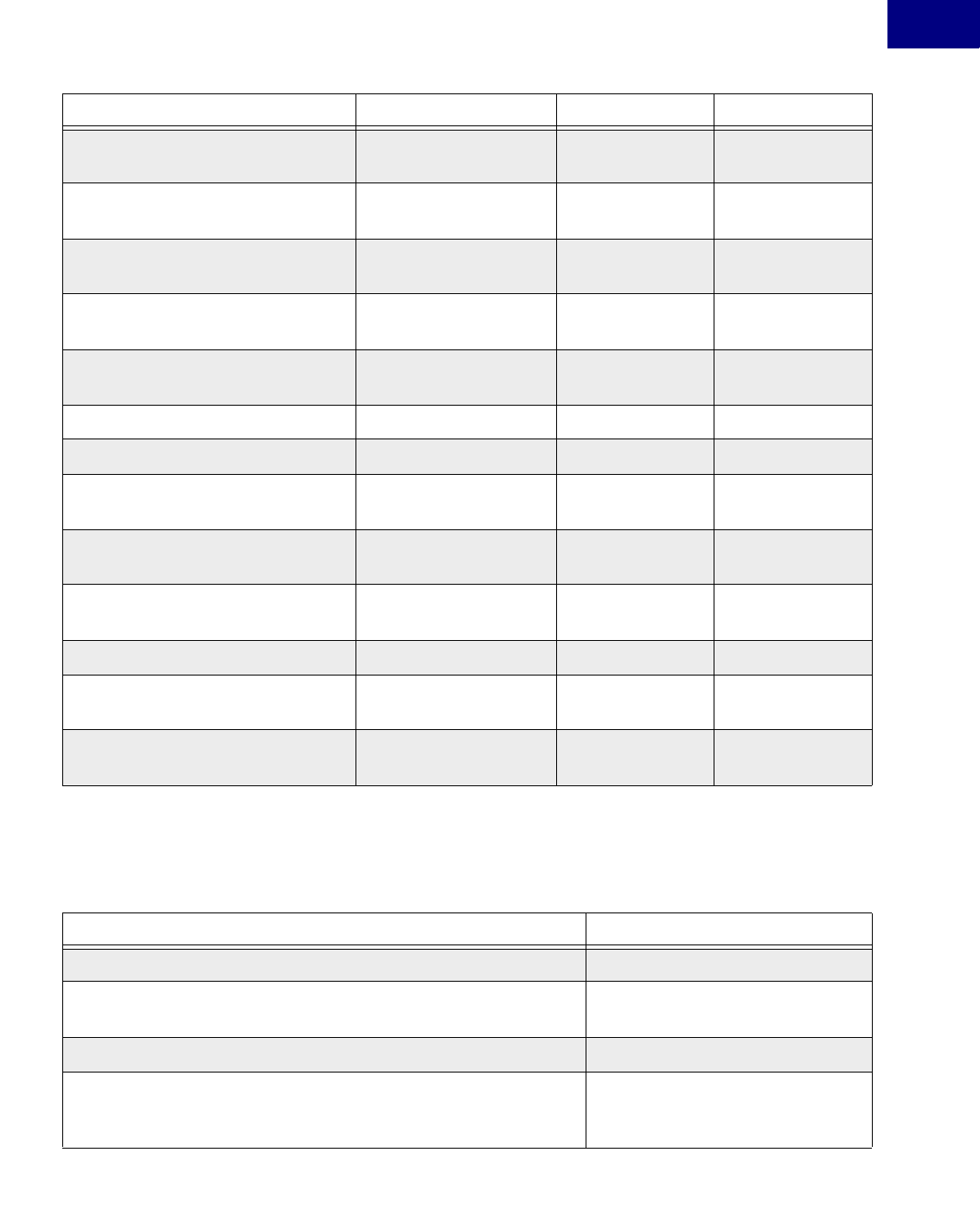
Scriptable Plug-in Fundamentals 617
Scriptable Plug-in Fundamentals
Scripting resources
VariableType examples
See Table 144:
TABLE 144 VariableType examples
RealMinMaxArrayType (length, min,
max)
Array of real number
ranges
VA R I A N T cFixed
(listOfItems)
DateArrayType (length) Array of dates/times VARIANT typeLongDateTime
(listOfItems)
FileArrayType (length)Array of file names/paths VA R I A N T typeAlias
(listOfItems)
EnumArrayType (enum_id), length) Array of enum values VARIANT enum's ScriptID
(listOfItems)
ObjectArrayType (object_id, length)Array of objects IDispatch* cObjectSpecifier
(listOfItems)
RecordType List of key/value pairs VARIANT typeAERecord
StructType {struct_type_list} Structure VA R I A N T typeWildCard
StructArrayType (length)
{struct_type_list}
Array of structures VARIANT typeWildCard
TypeDefType(typedef_id)Type definition (defined type is
substituted)
(defined type is
substituted)
TypeDefArrayType(typedef_id, length) Array of type definitions (defined type is
substituted)
(defined type is
substituted)
VariableType {variable_type_list}Variable VA R I A N T typeWildCard
Var i abl eD ef au lt Ty pe default,
{variable_type_list}
Variable with default VARIANT typeWildCard
VariableArrayType (length)
{variable_type_list}
Array of variable contents VA R I A N T typeWildCard
(listOfItems)
Example Description
VariableType{ FileType, FileArrayType( kVariableLength ) } A single file or an array of files.
VariableType{ ObjectType( kPageItemObjectScriptElement ),
ObjectArrayType( kPageItemObjectScriptElement, kVariableLength ) }
A single page item or an array of page
items.
VariableType{ StringType, EnumType( kNothingEnumScriptElement ) } A string or the enumeration “none.”
VariableType{ EnumType( kAnchorPointEnumScriptElement ),
UnitArrayType(2) }
An anchor point enumeration or an
array of two unit values (i.e., a
measurement point).
ODFRC type Description ODL type AETE type

Scriptable Plug-in Fundamentals
Scripting resources
618
Object-sensitive types
Object-sensitive types are useful for events and properties that appear on multiple script
objects. In such cases, it makes sense for the type of a property or the return type of an event to
be the type of the script object on which the event or property is exposed. A field containing
ObjectType( kContainerObjectScriptElement ) is used to indicate this. For example, the create
event that can be re-used by new script objects uses it as shown in Example 70:
EXAMPLE 70 Using objecttype( kContainerObjectScriptElement ) to define an event that returns
the type of the script object on which it is exposed
Event
{
kCreateEventScriptElement,
e_Create,
"add",
"Create a new ^Object",
ObjectType( kContainerObjectScriptElement ),
"The new ^Object",
{
WITHPROPERTIESPARAM,
}
}
The ObjectType( kContainerObjectScriptElement ) is commonly used by:
zThe type of the AppleScript object reference property.
zThe type of the object returned by a create or duplicate event.
zThe type of a parameter to the move event.
Less often, a property or event parameter may have the type of the parent script object. For
these cases, use ObjectType( kContainerParentScriptElement ) as the type. See Example 71:
VariableType{ ObjectType( kSwatchObjectScriptElement ), StringType } A swatch object or a string (i.e., the
name of the swatch).
VariableDefaultType StringValue( “None” ), { StringType, FileType } A string or file (defaults to the string
“None”).
VariableArrayType( kVariableLength ) { ObjectType(
kPageItemObjectScriptElement ),ObjectType(
kImageObjectScriptElement ), ObjectType( kEPSObjectScriptElement ),
ObjectType( kPDFObjectScriptElement ) }
An array of one or more page items,
images, EPS files, and/or PDF files.
Example Description

Scriptable Plug-in Fundamentals 619
Scriptable Plug-in Fundamentals
Scripting resources
EXAMPLE 71 Using ObjectType (kContainerParentScriptElement )
Property
{
kParentPropertyScriptElement,
p_Parent,
"parent",
"The ^Object's parent",
ObjectType(kContainerParentScriptElement),
{}
kNoAttributeClass,
}
The ObjectType(kContainerParentScriptElement) is used by:
zThe type of the parent property.
zThe type of the reference parameter to a move, duplicate, or create event.
Record type
A “record” is a list of key/value pairs, where the key is the ScriptID of a property and the value
is any appropriate one for that property. A RecordType declaration takes an object_id, which is
the ScriptElementID of the object to which the properties in the record apply. For example:
zRecordType( kDocumentEventScriptElement ) indicates the keys in the record correspond
to properties of the document object.
zFurthermore, you can use an object-sensitive type like RecordType(kContainerObject-
ScriptElement). In a property resource, this indicates the keys correspond to properties on
the object that contains the property; in an event's parameter resource, this indicates they
correspond to properties on the object that contains the event.
Script-object inheritance
Script-object inheritance is what you use to construct specialized script objects from existing
ones. If one script object is based on another, it inherits the base object's events and properties.
It does not inherit its parents, children/collections, or collection events. The root of the script-
object inheritance hierarchy is kAnyObjectScriptElement.
A script object is based on another by specifying the base object in its Object statement (see
“Object element” on page 593). Normally, a new script object is based on one of the base script
objects shown in Table 145:

Scriptable Plug-in Fundamentals
Scripting resources
620
TABLE 145 Base script objects
A new script object also can be based on an existing script object. The script object that repre-
sents page items is kPageItemObjectScriptElement, as shown in Example 72. An oval is a kind
of page item, so it is based on kPageItemObjectScriptElement, as shown in Example 73.
EXAMPLE 72 kPageItemObjectScriptElement
Object
{
kPageItemObjectScriptElement,
c_PageItem,
"page item",
"An item on a page, including rectangles, ellipses...",
kPageItem_CLSID,
c_PageItems,
"The page items collection ...",
"All page items",
kPageItems_CLSID,
kUniqueIDBasedObjectScriptElement,
kLayoutSuiteScriptElement,
}
ScriptElementID Description Based on
kNonIDBasedObjectScriptElement A non-ID-based script object. A
proxy object in scripting. The text
script objects that represent
character, word and line for example.
kAnyObjectScriptElement
kNonUniqueIDBasedObjectScriptElement A non-unique-ID-based script
object. A script object that exposes a
scriptable boss that has an ID of
some sort but not a UID e.g. table
cells.
kAnyObjectScriptElement
kPreferencesObjectScriptElement A script object that exposes
preferences.
kNonIDBasedObjectScript
Element
kUniqueIDBasedObjectScriptElement A unique-ID-based script object. A
script object that exposes a scriptable
boss that has a UID.
kAnyObjectScriptElement

Scriptable Plug-in Fundamentals 621
Scriptable Plug-in Fundamentals
Scripting resources
EXAMPLE 73 kOvalObjectScriptElement is based on kPageItemObjectScriptElement
Object
{
kOvalObjectScriptElement,
c_Oval,
"oval",
"An ellipse",
kOval_CLSID,
c_Ovals,
"ovals",
"A collection of ellipses",
kOvals_CLSID,
kPageItemObjectScriptElement, // Script object inheritance
kLayoutSuiteScriptElement,
}
NOTE:Basing a script object on another implies that a collection of the base objects (e.g., a
spread's collection of page items) automatically include any existing subclass objects
(e.g., the spread's ovals). This is a requirement for the IDML file format and
programmatically depends on the implementation of the IScriptProvider::GetObject
methods for the base object's collection.
Overloading an existing event or property
Two script objects can have the same property or event, but with a slightly different definition.
For example, the descriptions, types of the property, or parameters of the event may differ. In
this case, you must define a unique ScriptElementID for each resource. The name and ScriptID
must be identical in both resources. Other information (description, type, parameters, etc.)
may be identical or different.
Versioning of scripting resources
The sections below describe how to work with versioning in the scripting DOM (see “Version-
ing the scripting DOM” on page 569).
Versioned resources
Scripting resources include data for the first and last version of each script element. This data
may be altered on an element-by-element basis.
Adding a new resource
New script elements (objects, properties, events, etc.) are added to the scripting DOM using a
VersionedScriptElementInfo statement. For the version information, specify the first version of
InDesign for which the contained elements are applicable. The version information is called
the context for the elements. See Example 74:

Scriptable Plug-in Fundamentals
Scripting resources
622
EXAMPLE 74 VersionedScriptElementInfo statement for InDesign CS4
resource VersionedScriptElementInfo( 4010 )
{
//Contexts
{
//The contained elements are exposed beginning in InDesign CS4
kFiredrakeScriptVersion, kCoreScriptManagerBoss, kWildFS, k_Wild,
}
//Elements
{
// Object, Event, Property, Enum and Provider statements go here
}
} ;
VersionedScriptElementInfo resources can accommodate multiple contexts. See Example 75:
EXAMPLE 75 VersionedScriptElementInfo statement for InDesign CS4 and InDesign Server
resource VersionedScriptElementInfo( 4010 )
{
//Contexts
{
//The contained elements are only relevant to the Roman feature set in InDesign
kFiredrakeScriptVersion, kCoreScriptManagerBoss, kInDesignRomanFS, k_Wild,
//but are exposed for all feature sets in the InDesign Server product
kFiredrakeScriptVersion, kCoreScriptManagerBoss, kInDesignServerAllLanguagesFS,
k_Wild,
}
//Elements
{
...
}
} ;
Specifying an obsolete element
To designate an existing resource as obsolete (that is, no longer part of the scripting DOM as of
the current version), add “Obsolete” to the beginning of the keyword for the type of element
(e.g., ObsoleteSuite, ObsoleteObject, ObsoleteProperty, etc.) in the existing resource. Also, add
version information to specify the first version of InDesign for which the element is no longer
applicable. If you are removing a resource (rather than revising it), do not forget to also obso-
lete the relevant Provider resource.

Scriptable Plug-in Fundamentals 623
Scriptable Plug-in Fundamentals
Scripting resources
EXAMPLE 76 Removing a script element from the scripting DOM
resource VersionedScriptElementInfo( 20 ) //An existing resource
{
//Contexts
{
//The contained elements were exposed by InDesign CS1
kInitalScriptVersion, kCoreScriptManagerBoss, kWildFS, k_Wild,
}
//Elements
{
ObsoleteProperty
{
kBasilScriptVersion, //This element is no longer exposed as of Basil
kOldInfoPropertyScriptElement,
p_OldInfo,
"some old info",
"Information no longer relevant after Cobalt",
StringType,
{}
kNoAttributeClass,
}
ObsoleteProvider
{
kBasilScriptVersion, //This element is not exposed as of Basil
kApplicationScriptProviderBoss,
{
Object{ kApplicationObjectScriptElement },
Property{ kOldInfoPropertyScriptElement, kReadWrite },
}
}
... //Other, unaffected elements may remain in this resource
}
} ;
Splitting a provider resource
If the property is only one of many on an object that is being obsoleted, you must pull it out
into a new ObsoleteProvider resource, rather than obsoleting the entire provider. For example,
Example 77 shows an existing resource with two properties, foo and bar”
EXAMPLE 77 A Provider to be split due to an obsoleted property
Provider
{
kApplicationScriptProviderBoss,
{
Object{ kApplicationObjectScriptElement },
Property{ kFooPropertyScriptElement, kReadWrite },
Property{ kBarPropertyScriptElement, kReadWrite },
}
}

Scriptable Plug-in Fundamentals
Scripting resources
624
Example 78 shows what the resources would look like after making the “Foo” property obso-
lete:
EXAMPLE 78 Split providers
Provider
{
kApplicationScriptProviderBoss,
{
Object{ kApplicationObjectScriptElement },
Property{ kBarPropertyScriptElement, kReadWrite }, //This property is NOT
obsolete
}
}
ObsoleteProvider
{
kBasilScriptVersion, //This element is not exposed as of Basil
kApplicationScriptProviderBoss,
{
Object{ kApplicationObjectScriptElement },
Property{ kFooPropertyScriptElement, kReadWrite }, //This property is obsolete
}
}
Changing an existing property
This involves the following steps:
1. Indicating the existing definition is obsolete.
2. Creating a revised definition in a new VersionedScriptElementInfo statement.
Example 79 shows the existing resource before any changes:
EXAMPLE 79 Existing resource before changes
resource VersionedScriptElementInfo( 10 )
{
//Contexts
{
kInitialScriptVersion, kCoreScriptManagerBoss, kWildFS, k_Wild,
}
//Elements
{
Property
{
kTolerancePropertyScriptElement,
p_Tolerance,
"tolerance",
"Tolerance",
Int32Type,
{}
kNoAttributeClass,
}

Scriptable Plug-in Fundamentals 625
Scriptable Plug-in Fundamentals
Scripting resources
... //Other elements
}
} ;
Example 80 shows the existing resource after making it obsolete (in the existing .fr file):
EXAMPLE 80 Existing resource after making it obsolete
resource VersionedScriptElementInfo( 10 )
{
//Contexts
{
kInitialScriptVersion, kCoreScriptManagerBoss, kWildFS, k_Wild,
}
//Elements
{
ObsoleteProperty //Change type to RealType for Firedrake
{
kFiredrakeScriptVersion,
kTolerancePropertyScriptElement,
p_Tolerance,
"tolerance",
"Tolerance",
Int32Type,
{}
kNoAttributeClass,
}
... //Other, unchanged elements that remain exposed "as is" in Firedrake
}
} ;
Example 81 shows the new, corrected resource (in a new _40.fr file):
EXAMPLE 81 New, corrected resource
resource VersionedScriptElementInfo( 4010 )
{
//Contexts
{
kFiredrakeScriptVersion, kCoreScriptManagerBoss, kWildFS, k_Wild,
}
//Elements
{
Property //Change type to RealType for Firedrake
{
kTolerancePropertyScriptElement,
p_Tolerance,
"tolerance",
"Tolerance",
RealType,
{}
kNoAttributeClass,
}
}
} ;

Scriptable Plug-in Fundamentals
Scripting resources
626
Changing an existing event
This involves the following steps:
1. Indicating the existing definition is obsolete.
2. Creating a revised definition in a new VersionedScriptElementInfo statement.
Example 82 shows the statement that defines the event before any changes:
EXAMPLE 82 Event to be changed
resource VersionedScriptElementInfo( 200 )
{
//Contexts
{
kInitialScriptVersion, kCoreScriptManagerBoss, kWildFS, k_Wild,
}
{
Event
{
kDeleteSwatchEventScriptElement,
e_Delete,
"delete",
"Delete swatch",
VoidType,
{
p_Replace, "replacing with", "The swatch to apply in place of this one",
ObjectType( kSwatchObjectScriptElement ), kRequired,
}
}
... //Other elements
}
} ;
The statement is edited in the existing .fr file, to indicate the existing definition is obsolete (see
“Specifying an obsolete element” on page 622). See Example 83:
EXAMPLE 83 Obsoleting the event to be changed
resource VersionedScriptElementInfo( 200 )
{
//Contexts
{
kInitialScriptVersion, kCoreScriptManagerBoss, kWildFS, k_Wild,
}
//Elements
{
ObsoleteEvent
{
kFiredrakeScriptVersion,
kDeleteSwatchEventScriptElement,
e_Delete,
"delete",
"Delete swatch",

Scriptable Plug-in Fundamentals 627
Scriptable Plug-in Fundamentals
Scripting resources
VoidType,
{
p_Replace, "replacing with", "The swatch to apply in place of this one",
ObjectType( kSwatchObjectScriptElement ), kRequired,
}
}
... //Other, unchanged elements that remain exposed "as is" in InDesign CS4
}
} ;
A new VersionedScriptElementInfo statement (in a new _40.fr file) is used to define the
change. See Example 84:
EXAMPLE 84 Event changed to make a parameter optional as of InDesign CS4
resource VersionedScriptElementInfo( 40200 )
{
//Contexts
{
kFiredrakeScriptVersion, kCoreScriptManagerBoss, kWildFS, k_Wild,
}
//Elements
{
Event //Parameter is required in InDesign CS1, but optional in InDesign CS4
{
kDeleteSwatchEventScriptElement,
e_Delete,
"delete",
"Delete swatch",
VoidType,
{
p_Replace, "replacing with", "The swatch to apply in place of this one",
ObjectType( kSwatchObjectScriptElement ), kOptional,
}
}
}
} ;
Changing an existing enum
New enumerators can be added and removed using Enumerator and ObsoleteEnumerator ele-
ments. To add an additional enumerator, however, instead of obsoleting the entire enum, you
can use an enumerator resource. For example, suppose you want to add a new enumerator to
the enum shown in Example 85:

Scriptable Plug-in Fundamentals
Scripting resources
628
EXAMPLE 85 An enum before additional enumerator is added
resource VersionedScriptElementInfo( 110 )
{
{ kInitialScriptVersion, kCoreScriptManagerBoss, kAllProductsJapaneseFS, k_Wild, }
{
Enum
{
kKinsokuTypeEnumScriptElement,
en_KinsokuType,
"kinsoku type",
"Kinsoku type",
{
en_KinsokuPushInFirst, "kinsoku push in first", "Kinsoku push in first",
en_KinsokuPushOutFirst, "kinsoku push out first", "Kinsoku push out first",
en_KinsokuPushOutOnly, "kinsoku push out only", "Kinsoku push out only",
}
}
... //Other elements
}} ;
Using an enumerator resource, as shown in Example 86, you can add an additional enumerator
the existing enum without obsoleting the existing one:
EXAMPLE 86 Adding a new enumerator using the enumerator resource
resource VersionedScriptElementInfo( 40110 )
{
//Contexts
{
kFiredrakeScriptVersion, kCoreScriptManagerBoss, kAllProductsJapaneseFS, k_Wild,
}
//Elements
{
Enumerator
{
kKinsokuTypeEnumScriptElement,
{
en_KinsokuPushInAlways, "kinsoku push in always", "Kinsoku push in always", //new
enumerator
}
}
}
} ;
You also can use this approach for obsoleting one (or more) enumerators without obsoleting
the entire enum.
Example 87 shows the existing resource:

Scriptable Plug-in Fundamentals 629
Scriptable Plug-in Fundamentals
Scripting resources
EXAMPLE 87 Existing resource
Enum
{
kTextImportCharacterSetEnumScriptElement,
en_TextImportCharacterSet,
"text import character set",
"Character set options for importing text files.",
{
en_ANSI, "ansi", "The ANSI character set.",
en_ASCII, "ASCII", "ASCII",
en_DOSLatin2, "DOS latin 2", "DOS Latin 2",
en_CSUnicode, "unicode", "The Unicode character set.",
en_ShiftJIS83pv, "RecommendShiftJIS83pv", "The Recommend:Shift_JIS 83pv
character set.",
... //Other enumerators
}
}
Move the obsolete enumerator(s) into a separate, obsolete enumerator resource:
EXAMPLE 88 The changed enum resource
Enum
{
kTextImportCharacterSetEnumScriptElement,
en_TextImportCharacterSet,
"text import character set",
"Character set options for importing text files.",
{
en_ANSI, "ansi", "The ANSI character set.",
en_CSUnicode, "unicode", "The Unicode character set.",
en_ShiftJIS83pv, "RecommendShiftJIS83pv", "The Recommend:Shift_JIS 83pv
character set.",
...
}
}
ObsoleteEnumerator
{
kBasilScriptVersion,
kTextImportCharacterSetEnumScriptElement,
{
en_ASCII, "ASCII", "ASCII",
n_DOSLatin2, "DOS latin 2", "DOS Latin 2",
}
}

Scriptable Plug-in Fundamentals
Scripting resources
630
Client access to the version
The scripting architecture requires that all requests specify which version of the scripting DOM
to use.
Via the object model from IScriptProvider implementations
Script providers also can check which version of the scripting DOM to use when handling a
request:
// IScriptProvider methods have an "IScriptEventData* data" parameter
if ( data->GetRequestContext().GetVersion() >= kFiredrakeScriptVersion )
...
Major changes to function across versions should be implemented in a separate script provider
(see “Process for making changes” on page 630) and directed to the correct script provider via a
versioned resource.
Via the Object Model from IScriptManager Implementations
This is implemented via the IScriptPreferences interface, which is aggregated by every script
manager boss (i.e., those with IScriptManager).
The code is as you would expect:
//Where "this" is a subclass of IScriptManager*
InterfacePtr<IScriptPreferences> scriptPrefs( this, UseDefaultIID() ) ;
if ( scriptPrefs->GetVersion() >= kFiredrakeScriptVersion )
...
IScriptManager::GetRequestContext() returns a request context based on the current settings
(version and locale) of the aggregated IScriptPreferences interface. The default implementation
of IScriptManager::CreateScriptEventData() calls GetRequestContext(). This means you must
make sure the version information is set correctly before generating the IScriptEventData for a
client's request.
Via the scripting DOM
For information on accessing and setting the DOM version through scripting, see “Running
versioned scripts” on page 586.
For testing purposes
The Test > Scripting > Set Current DOM version menu contains items to set current DOM ver-
sion to a variety of versions. These reset all active script managers to the selected version.
Process for making changes
Most changes to the scripting DOM require creating a new VersionedScriptElementInfo state-
ment (usually in a new .fr file) and, possibly, a new script provider .cpp file.
Changes that may be made in the existing resource
You can make nonfunctional/superficial changes; e.g., correcting an element’s description.

Scriptable Plug-in Fundamentals 631
Scriptable Plug-in Fundamentals
Scripting resources
Changes that may be made in the existing script provider
You can fix bugs in the function of the script provider; for example:
zReturns kSuccess but actually fails (no return value).
zReturns error when it is expected to succeed.
zDoes something different than promised/expected.
Changes that must be made by versioning the resource and/or script provider
1. Semantic changes to the function of an element:
zScript-provider code change.
zUnderlying model code change.
2. Changes to the Context of a Script Resource
zScript manager boss id
zFeature set id
zLocale id
3. Changes to an element’s script resource:
zIdentity: Name, ScriptID, ScriptElementID.
zObject: Modify GUID, change inheritance, change suite membership.
zProperty: Modify type.
zEvent: Modify type of return value, add/remove return value, add/remove event parameters.
zEvent parameter: Modify type, modify whether optional or required, modify default value.
zEnum: Add/remove enumerators.
4. Changes to a provider’s script resource:
zChanges to the implementation of a script-provider boss ClassID.
zParent: Add/remove, make surrogate or not.
zEvent: Add/remove.
zObject: Add/remove, make represent or not
zProperty: Add/remove, change read-only access to/from read-write.
5. Delete/add elements and functions:
zSuite
zObject
zEvent
zProperty

Scriptable Plug-in Fundamentals
Scripting resources
632
zEnum
zProvider
Protocol for changes
New elements
zResources — Define new elements in a new VersionedScriptElementInfo statement in a
new .fr file. We recommend, for example, that the name of the new file be of the form
MyScriptInfo60.fr, to indicate that it was added in Basil and contains version 6.0 resources.
zCode — Implement support for the new elements in a new script provider .cpp file. We rec-
ommend the name of the file be in the form “MyScriptProvider60.cpp,” to indicate it was
added in InDesign CS4 and implements version 6.0 support.
Obsolete elements
zResources — Edit the existing element definition to designate it as obsolete in the existing
script info .fr file.
zCode — This should require no changes to script provider .cpp files.
Altered elements
zResources — Edit the existing element definition to designate it as obsolete. Define the
revised elements in a new VersionedScriptElementInfo statement (in a new .fr file).
zCode — If the function is changing, implement support for the changed function in a new
script provider .cpp file. The new script provider needs to contain the code for only the ele-
ments that are changing; unchanged elements (properties and events) can still be handled
by the existing script provider.
Bug fixes
zResources — Fixes to resources must be treated as a change to the scripting DOM (see
“Altered Elements” above).
zCode — If the functionality is changing radically, implement support for the changed func-
tionality in a new script provider .cpp file. Changes to the semantics of an existing element
must be treated as a change to the DOM (see “Altered Elements” above).
Client-specific scripting resources
Certain script elements are applicable to only one client of the scripting DOM. These script ele-
ments are declared in VersionedScriptElementInfo statements, but using the ClassID of the cli-
ent's script manager boss instead of kCoreScriptManagerBoss. These script elements are
managed automatically by the same IScriptManagerInfo interface and are visible (or not)
depending on the client that requested the information.
On first launch, all script elements are loaded into a single “database” managed by the scripting
plug-in and stored in SavedData. Each element includes a member datum of the ElementCon-

Scriptable Plug-in Fundamentals 633
Scriptable Plug-in Fundamentals
Scripting resources
text class (defined in ScriptInfo.h), which specifies the element's client (core or specific), fea-
ture set, locale, and version (first and last).
When a client wants access to the script information database, it must specify a RequestCon-
text (defined in ScriptInfo.h), which indicates the client, feature set, locale, and version in
which the client is interested. The client calls IScriptUtils::QueryScriptInfoManager or IScrip-
tUtils::QueryScriptRequestHandler. If this is the first request using a particular RequestCon-
text, the scripting plug-in creates a new ScriptInfoManager boss containing only the relevant
elements. If this RequestContext was received previously, the scripting plug-in returns the
appropriate interface on the existing boss.
The elements contained in a ScriptInfoManager boss for a particular RequestContext include
all core script elements plus all elements specific to the specified client (if any). Script elements
are included in the DOM for client X if they are exposed for client X or any parent bosses of X
in its boss inheritance hierarchy.
For example, suppose the boss inheritance hierarchy looks like this:
kCoreScriptManagerBoss > kINXScriptManagerBoss >
kINXExpandedExportScriptManagerBoss
Every DOM includes all core elements exposed to the base script manager kCoreScriptMan-
agerBoss. kINXScriptManagerBoss gets all core elements plus any elements specifically
exposed for it. kINXExpandedExportScriptManagerBoss gets everything in the kINXScript-
ManagerBoss's DOM, plus any INX Expanded (IDML)-specific elements.
If any element is exposed at more than one level, the element exposed to the most derived boss
is retained. For example, if an element with the same ScriptElementID is exposed to kCore-
ScriptManagerBoss and kINXScriptManagerBoss, the one for kINXScriptManagerBoss is
used. If another element with that ScriptElementID is exposed to kINXExpandedExportScript-
ManagerBoss, it would be used for the INX-ALT DOM.
Elements visible to only one client
All VersionedScriptElementInfo resources specify a client, the ClassID of a script manager
boss. For core script elements, this is kCoreScriptManagerBoss. For client-specific script ele-
ments, this is the ClassID of the client's script manager boss. See Example 89:
EXAMPLE 89 Client-specific VersionedScriptElementInfo statement
resource VersionedScriptElementInfo(10)
{
kInitialScriptVersion,
kMyScriptManagerBoss, // See Note 1
kWildFS, k_Wild,
{
// See Note 2
}
};

Scriptable Plug-in Fundamentals
Scripting resources
634
Notes:
1. This is the ClassID of the script manager for the client for which these resources are
exposed; e.g., kAppleScriptMgrBoss. See Table 132.
2. Client-specific suite, object, event, property, and provider resources go here.
Elements defined differently by different clients
Attributes of a script element that are intrinsic to its definition (i.e., that appear in fields of the
script element's resource) can be changed on a per-client basis. For example, a property might
have a different type, or an event might have different parameters.
One way to do this is to define a new script element with its own ScriptElementID, name, and
ScriptID. In this case, both versions of the element are available. Alternatively, you can use the
same ScriptElementID, but change some or all of the other attributes. In this case, only the cli-
ent-specific version of the element is available for that client. In either case, the alternative
script element could be handled by the same or a different script provider as the original one,
since that is determined by the provider resource.
For example, in Example 90, the delete event for the swatch object has one parameter by default
but no parameters for my client (which also uses a different script provider to handle the
event):
EXAMPLE 90 Script elements defined differently by different clients
resource VersionedScriptElementInfo( 20 )
{
{
kInitialScriptVersion, kCoreScriptManagerBoss, kWildFS, k_Wild,
}
{
Event
{
kDeleteSwatchEventScriptElement,
e_Delete,
"delete",
"Delete swatch",
VoidType,
{
p_Replace, "replacing with", "The swatch to apply in place of this one",
VariableType{ ObjectType( kSwatchObjectScriptElement ), StringType }, kRequired,
}
}

Scriptable Plug-in Fundamentals 635
Scriptable Plug-in Fundamentals
Scripting resources
Provider
{
kCoreSwatchScriptProviderBoss,
{
Object{ kSwatchObjectScriptElement },
Property{ kDeleteSwatchEventScriptElement },
}
}
}
} ;
resource VersionedScriptElementInfo( 21 )
{
{
kInitialScriptVersion, kMyScriptManagerBoss, kWildFS, k_Wild,
}
{
Event
{
kDeleteSwatchEventScriptElement,
e_Delete,
"delete",
"Delete swatch",
VoidType,
{
}
}
Provider
{
kMySwatchScriptProviderBoss,
{
Object{ kSwatchObjectScriptElement },
Event{ kDeleteSwatchEventScriptElement},
}
}
}
};
Relationships between elements that are different for different clients
In some cases, attributes of a script element that are related to its behavior for a specific object
are set in the provider resources; for example, whether an object has a particular parent or
whether a property is read-only or read-write. For a particular client to obtain behavior that is
different than the core attributes set in the core resources, define a separate provider resource
in a context-sensitive VersionedScriptElementInfo resource for that client.
In Example 91, the name property of the hyphenation exception object is read-only by default
but read-write for my client (and still handled by the same script provider implementation):

Scriptable Plug-in Fundamentals
Scripting resources
636
EXAMPLE 91 Relationships between elements that are different for different clients
resource VersionedScriptElementInfo( 30 )
{
{
kInitialScriptVersion, kCoreScriptManagerBoss, kWildFS, k_Wild,
}
{
Provider
{
kHyphExceptionScriptProviderBoss,
{
Object{ kHyphenationExceptionObjectScriptElement },
Property{ kNamePropertyScriptElement, kReadOnly },
}
}
}
} ;
resource VersionedScriptElementInfo( 31 )
{
{
kInitialScriptVersion, kMyScriptManagerBoss, kWildFS, k_Wild,
}
{
Provider
{
kHyphExceptionScriptProviderBoss,
{
Object{ kHyphenationExceptionObjectScriptElement },
Property{ kNamePropertyScriptElement, kReadWrite },
}
}
}
} ;
Relationships between elements that are not applicable to a particular
client
By default, elements specified in a core resource are available in all clients, although sometimes
these elements have an alternative, client-specific definition (see above). In most cases, how-
ever, whether these elements actually are accessible to a user of the client is determined by
whether they appear in a provider resource. That is because the provider resources determine
the parent/child relationships of the DOM hierarchy, as well as which events and properties are
supported by which objects. This makes it possible for a client to hide a particular element by
hiding relationships between elements. (This is not true of core suite or enum elements, which,
therefore, cannot be hidden.)
To remove a relationship, define a provider resource that uses kNotSupported as the identifier
of the script provider. Doing so means any relationships in that provider resource specifically is
not supported for the client in question.
In Example 92, a client-specific provider resource is used to add additional parents for the link
object and to remove a property these parents use to access links in the default case:

Scriptable Plug-in Fundamentals 637
Scriptable Plug-in Fundamentals
Scripting resources
EXAMPLE 92 Relationships between elements that are not applicable to a particular client
resource VersionedScriptElementInfo( 40 )
{
{
kInitialScriptVersion, kCoreScriptManagerBoss, kInDesignAllLanguagesFS, k_Wild,
}
{
//For core clients, only the Document has a links collection
Provider
{
kLinkScriptProviderBoss,
{
SurrogateParent{ kDocumentObjectScriptElement },
RepresentObject{ kLinkObjectScriptElement },
CollectionEvent{ kCountEventScriptElement },
}
}
Property
{
kItemLinkPropertyScriptElement,
p_Link,
"item link",
"Link to a placed file",
ObjectType( kLinkObjectScriptElement ),
{}
kNoAttributeClass,
}
//For core clients, there is a item link property on linkable objects
Provider
{
kLinkScriptProviderBoss,
{
Object{ kStoryObjectScriptElement },
Object{ kGraphicObjectScriptElement },
Property{ kItemLinkPropertyScriptElement, kReadOnly },
}
}
}
} ;
resource VersionedScriptElementInfo( 41 )
{
{
kInitialScriptVersion, kMyScriptManagerBoss, kInDesignAllLanguagesFS, k_Wild,
}
{

Scriptable Plug-in Fundamentals
Scripting resources
638
//For my client, there is a links collection on linkable objects
Provider
{
kLinkScriptProviderBoss,
{
Parent{ kStoryObjectScriptElement },
Parent{ kImageObjectScriptElement },
Parent{ kEPSObjectScriptElement },
Parent{ kWMFObjectScriptElement },
Parent{ kPICTObjectScriptElement },
Parent{ kPDFObjectScriptElement },
RepresentObject{ kLinkObjectScriptElement },
CollectionEvent{ kCountEventScriptElement },
}
}
//For my client, there is no item link property on linkable objects
Provider
{
kNotSupported,
{
Object{ kStoryObjectScriptElement },
Object{ kGraphicObjectScriptElement },
Property{ kItemLinkPropertyScriptElement, kReadOnly },
}
}
}
} ;
Elements that are not applicable to a particular object
It also is possible to use kNotSupported to remove elements from an object. Typically, this is
used for a subclass object that does not want to inherit elements from its parent object type. We
discourage this approach, since by definition subclasses should support all o their parent class'
DOM.
In the following example, the name property and delete event are removed from the foo object.
resource VersionedScriptElementInfo( 40 )
{
{
kInitialScriptVersion, kCoreScriptManagerBoss, kWildFS, k_Wild,
}
{
Provider
{
kNotSupported,
{
Object{ kFooObjectScriptElement },
Property{ kNamePropertyScriptElement, kReadOnly },
Event{ kDeleteEventScriptElement }
}
}
}
} ;

Scriptable Plug-in Fundamentals 639
Scriptable Plug-in Fundamentals
Key scripting APIs
Key scripting APIs
This section contains lists of commonly used scripting-related APIs. For reference documenta-
tion, either search in <SDK>/docs/references/index.chm for the specified class by name or, if
you uncompressed the HTML-based API documentation (sdkdocs.tar.gz), view
<SDK>/docs/references/api/class{ClassName}.html with your HTML browser.
Table 146 lists common scripting-related interfaces. Table 147 lists common partial implemen-
tation classes. Table 148 lists other headers. For more information, see the API documentation.
TABLE 146 Interfaces
Interface Location / description
IExportProviderSignal
Data
Data interface for export providers to use when signaling
responders. This is not scripting specific.
IScript <SDK>/public/interfaces/architecture/IScript.h
IScriptArgs For passing arguments into scripts.
IScriptCoreFunctor Represent a function object in scripting.
IScriptError Contains error state information for a scripting request.
IScriptErrorUtils Used to set event data for common errors.
IScriptEvent The interface for an attachable event in scripting.
IScriptEventData <SDK>/public/interfaces/architecture/IScriptEventData.h
IScriptEventTarget Any object that can be the target of attachable events in
scripting should aggregate this interface to the same boss as
its IID_ISCRIPT.
IScriptInfoManager Manages information about elements in the scripting DOM
IScriptLabel Script label.
IScriptManager Provides basic information about support for a particular
scripting client (including IDML)
IScriptObjectMgr Manages non-persistent (i.e., proxy) script objects.
IScriptObjectParent Allows script objects (usually proxy script objects) to refer to
the parent object in the scripting DOM.
IScriptPreferences Preferences for the application environment when executing
a script.
IScriptProvider <SDK>/public/interfaces/architecture/IScriptProvider.h
IScriptRequestHandler <SDK>/public/interfaces/architecture/IScriptRequestHandle
r.h
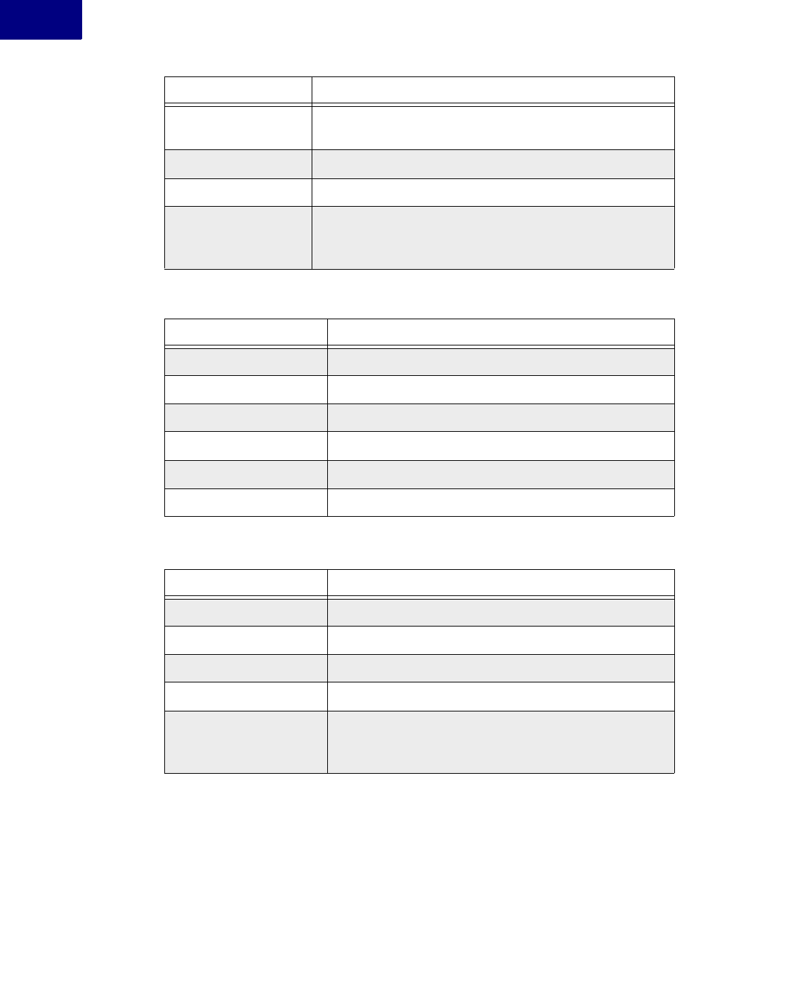
Scriptable Plug-in Fundamentals
Key scripting APIs
640
TABLE 147 Partial Implementation Classes
TABLE 148 Other headers
IScriptRequestHandler Matches requests from clients to the appropriate script
provider.
IScriptRunner Runs a script from within the application.
IScriptUtils <SDK>/public/interfaces/architecture/IScriptUtils.h
ITextObjectParent This interface must be implemented for any scripting object
that wants to act as a parent of text objects in the scripting
DOM.
Class Location
CProxyScript <SDK>/public/includes/CProxyScript.h
CScript <SDK>/public/includes/CScript.h
CScriptEventData <SDK>/public/includes/ CScriptEventData.h
CScriptProvider <SDK>/public/includes/CScriptProvider.h
PrefsScriptProvider <SDK>/public/includes/PrefsScriptProvider.h
RepresentScriptProvider <SDK>/public/includes/CScriptProvider.h
Header file Location
ScriptData.h <SDK>/public/includes/ScriptData.h
ScriptInfo.h <SDK>/public/includes/ScriptInfo.h
ScriptInfoTypes.(f)h <SDK>/public/includes/ScriptInfoTypes.(f)h
ScriptingDefs.h <SDK>/public/includes/ScriptingDefs.h
ScriptingID.h <SDK>/public/interfaces/architecture/ScriptingID.hThis
header is needed in .fr files for base boss class ID
declarations.
Interface Location / description
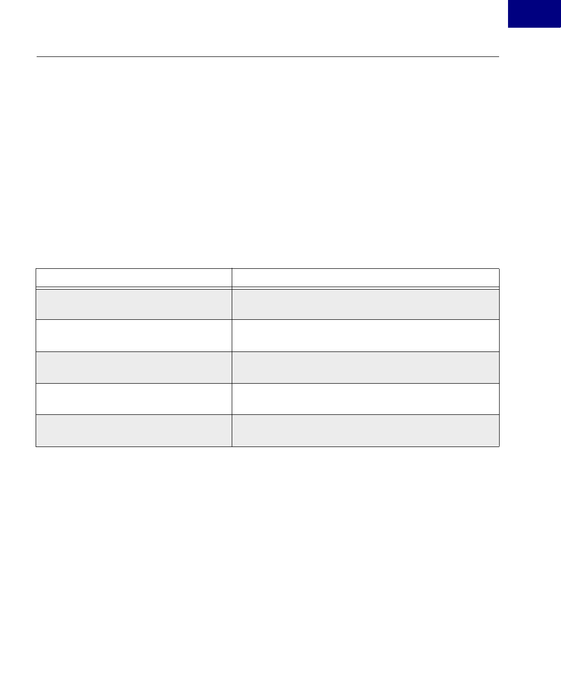
Scriptable Plug-in Fundamentals 641
Scriptable Plug-in Fundamentals
Scripting DOM reference
Scripting DOM reference
The scripting DOM made available for developers to extend is documented by the references
listed in Table 149. New script objects, properties, and events are added to the script objects
defined in these references. Most of the scripting DOM is common to all client scripting man-
agers; however, separate references for IDML, INX, AppleScript, JavaScript, and Visual Basic
are provided for completeness, so you can see the differences. These mainly show how base
script objects adapt to meet the needs of each script manager. If you need information on the
scripting DOM for another product (e.g., InCopy), version (e.g., CS1) or feature-set locale (e.g.,
Japanese), you can create your own dump containing the desired information (see “Dumping
the scripting DOM” on page 642.)
NOTE:Most of the ScriptIDs in the reference are defined as symbols in the header file
ScriptingDefs.h.
TABLE 149 Scripting DOM references for C++ programmers
Scripting DOM versioning
The scripting DOM is versioned by product, version, feature-set locale, and scripting client.
This means each product (InDesign, InCopy, and InDesign Server) has several distinct script-
ing DOMs. For more information, see RequestContext in the API documentation. For exam-
ple, each row in Table 150 represents an instance of a scripting DOM in InDesign CS4. The
scripting DOM varies by scripting client, but most of the DOM is core. There can be consider-
able variation by feature-set locale (Roman or Japanese) and product version (e.g., 3.0, 4.0, or
5.0). Similar tables could be created for InCopy CS4 and InDesign Server.
Scripting DOM reference Location
Adobe InDesign CS4 IDML Scripting DOM
Reference for C++ Programmers
<SDK>/docs/references/scripting-dom-idml-idr60.html
Adobe InDesign CS4 INX Scripting DOM
Reference for C++ Programmers
<SDK>/docs/references/scripting-dom-inx-idr60.html
Adobe InDesign CS4 AppleScript Scripting
DOM Reference for C++ Programmers
<SDK>/docs/references/scripting-dom-applescript-idr60.html
Adobe InDesign CS4 JavaScript Scripting DOM
Reference for C++ Programmers
<SDK>/docs/references/scripting-dom-javascript-idr60.html
Adobe InDesign CS4 Visual Basic Scripting
DOM Reference for C++ Programmers
<SDK>/docs/references/scripting-dom-visualbasic-idr60.html

Scriptable Plug-in Fundamentals
Scripting DOM reference
642
TABLE 150 Scripting DOM Instances in InDesign CS4 Roman
Dumping the scripting DOM
Via the diagnostics plug-in
The Adobe InDesign CS4 Scripting DOM Reference documents identified in Table 149 are cre-
ated via the diagnostics plug-in and an XSLT stylesheet. See the “Diagnostics” chapter for
information on dumping the scripting DOM in XML and transforming it from XML to HTML
using XSLT.
Via Test > Scripting > Dump All Script Resources
The scripting DOM can be dumped to a text file using the debug build. To find the script
objects provided by a product and the events and properties they expose, follow these steps:
1. Choose Test > Scripting > Dump All Script Resources and wait while the application dumps
a text file containing the scripting DOM for each client. Dump files are created in the
qa/Logs folder, in the folder that contains the application executable.
2. Choose the dump for the scripting client in which you are interested. See Table 132 for a list
of scripting clients. For example, under InDesign CS4, the dump file named
kJavaScriptMgrBossIDR60.txt contains the scripting DOM for JavaScript under InDesign
CS4.
The dump contains separate sections that describe the available suites, enums, events, proper-
ties, and script objects.
Product Version Locale Script manager
InDesign 6.0 Roman kAppleScriptMgrBoss
InDesign 6.0 Roman kJavaScriptMgrBoss
InDesign 6.0 Roman kOLEAutomationMgrBoss
InDesign 6.0 Roman kINXTraditionalImportScriptManagerBoss
InDesign 6.0 Roman kINXTraditionalExportScriptManagerBoss
InDesign 6.0 Roman kINXExpandedImportScriptManagerBoss
InDesign 6.0 Roman kINXExpandedExportScriptManagerBoss

Snippet Fundamentals 643
Snippet Fundamentals
Conceptual overview
Snippet Fundamentals
A snippet is a logically complete fragment of an InDesign document, expressed in one of two
XML formats, INX (.inds or .incx file extensions) or IDML (.idms or .icml file extensions).
INX-based snippets were introduced in InDesign CS, but because of the complexity of the for-
mat, we did not recommend using them to generate and manipulate content outside of InDe-
sign. IDML- and IDML-based snippets were designed for these purposes. This chapter
describes the snippet architecture and the organization of snippets for different asset types, and
it relates this to the low-level (boss) document object model (DOM). The snippet architecture
is the basis for the asset library in InDesign, which is a collection of snippets in a binary con-
tainer. The chapter discusses implications of the change to this snippet architecture if you store
your own persistent data in documents.
In addition to explaining what snippets are, the chapter describes the organization of some
snippets, identifies use cases involving snippet, and provides implementation hints.
Conceptual overview
Snippets as self-contained assets
Snippets are a feature added to InDesign to support factoring a document into components
that become self-contained assets. One special application of this is an InCopy story. A snippet
is a logically complete fragment of an InDesign document, saved in either InDesign Inter-
change format (INX) or InDesign Markup Language (IDML). Both are XML-based formats.
INX-based snippet files have the extension .inds (or .incx for InCopy stories). IDML-based
snippet files have the extension .idms, (or .icml for InCopy stories).
The snippet architecture allows a subset of the objects in a document (and their dependencies)
to be imported into a snippet file, which can be exported to another document. Features like
assignments depend on snippets to factor document content into XML documents, each of
which represents a subset of the information in the original InDesign document.
The asset-library subsystem takes advantage of the snippet architecture, reinforcing the notion
of a snippet as an asset. An InDesign library is a collection of snippets in a binary container. If
you store persistent data in InDesign documents (e.g., through adding your own persistent
interfaces to page items), you must make sure this content roundtrips through snippets, by
adding scripting support to your plug-in. See the “Scriptable Plug-in Fundamentals” chapter.
Snippets can contain page items, swatches, styles, XML tags, XML elements, and application
preferences. If you understand how to export and import snippets, you can assemble most of
the contents in an InDesign document from snippets. To make the process more straightfor-
ward, see the procedures in the “Snippets” chapter of Adobe InDesign CS4 Solutions.

Snippet Fundamentals
User interface for snippets
644
Snippet types
Snippets can—in one format—represent information previously exported from InDesign in
several quite different (and often opaque binary) formats. The object types that can be
exported from InDesign include the following:
zPage items, like text frames, group items, and placed images
zXML elements
zPreferences
zInCopy stories
These reduce down to a handful of basic snippet types, described in “Snippet types and poli-
cies” on page 648.
Features that depend on snippets
Several subsystems and features depend on the snippet architecture:
zAssets are stored as snippets in a library database file (.indl file). The database is a binary
file; however, within a database, assets are snippets.
zAssignments depend on the ability to factor out document content into distinct assets as
snippet files.
zInCopy Interchange (INCX) and InCopy Document (ICML) files are both snippet files.
zObject styles are stored in a snippet file. Load Object Styles reads in styles defined in a snip-
pet file.
User interface for snippets
The snippet architecture is more a foundation technology than a feature, so there is relatively
little user interface to let you interact directly with snippets; however, there are a few places
where snippets show up in the user interface, directly or indirectly.
Drag and drop
You can drag a snippet file onto the InDesign layout view, and the application takes appropriate
action. For example, if the snippet file contains a text style, a new text style may be created if
one matching the specification does not already exist. If you drag a snippet file defining a group
item with many page-item dependents, a new group item with dependents is created in the
InDesign document.
An end user can create a new snippet file on the desktop, by dragging a layout object from an
InDesign document onto the desktop. An end user also can drag an XML element from the
structure view to the desktop, to create a snippet on the desktop.

Snippet Fundamentals 645
Snippet Fundamentals
Snippet model
The snippet format is the primary representation for chunks of InDesign content for data
exchange. The user interface now strictly uses IDML-based (IDMS) snippets. You can still gen-
erate INX-based (INDS) snippets using the API.
Asset library
The asset library depends on page items being represented as snippets. An InDesign library
(INDL) file is a binary file containing a collection of snippets, and the Library panel can be
considered a view onto the snippets it contains.
When an asset is dragged from the library onto a document, the snippet is imported into the
document, and the new content is created. When an asset is dragged from a document into a
library or added through a menu item on the Library panel menu, the content is written to the
library file in a block of XML contained within the (binary) library.
Export snippet from selection
You can export snippets under certain selection conditions, including the existence of a layout
selection (page items) or structure-view selection (XML elements). You can export an InCopy
story (ICML or INCX) when there is a text selection. The snippet-export provider is responsi-
ble for serializing page items to snippet files after drag and drop. This export provider depends
on the suite ISnippetExportSuite. (See “Client API” on page 663.) For more information about
the selection architecture, see the “Selection” chapter.
Snippet model
Snippets contain collections of XML fragments that represent document content. What makes
snippet files interesting is that they are standalone representations of document assets (for
example, a styled page item) that can be imported into another document. The precise collec-
tion of XML fragments that compose a snippet depends on the objects you want to export into
the snippet and the objects on which it depends.
The objects represented in the snippet file are instances of classes in the scripting-level DOM.
Deciding what goes into a snippet file and understanding what is represented there requires
knowledge of the low-level boss DOM. Understanding what happens when a snippet file is
imported requires knowledge of the low-level boss DOM.
INX, IDML, and snippets
INX and IDML are XML-based formats that represent InDesign content at a higher level of
abstraction than the low-level binary InDesign document (INDD) files. These higher level files
contain a collection of XML elements that represent an entire InDesign document, created by
serializing the scripting DOM for a document instance.

Snippet Fundamentals
Snippet model
646
A major benefit of this representation is that the scripting DOM is stable relative to the low-
level (boss) document model. A price to be paid for this higher level of abstraction (and XML-
based format) is that it takes longer to read and write an INX- or IDML-based file than a binary
InDesign (INDD) document. InDesign binary documents load data on demand, whereas the
entire INX file must be loaded before it can be used.
A snippet file represents one or more root objects and their dependents in the document from
which they came. A root object in this context does not mean the root of the entire document,
but the root of a subtree within the scripting-DOM tree.
A root object must expose the IDOMElement interface. Parent-child relationships in a snippet
come from ownership relations in the scripting DOM; however, as we will see in the examples,
the elements in a snippet file have information that comes from the boss DOM (about UIDs,
for example), and the relationship between the boss DOM and scripting DOM is predictable.
Although INCX, the INX-based InCopy story format, is still supported, the default file format
for InCopy is ICML. The main difference between an INX or IDML file and a snippet file is
that INX and IDML files represent complete InDesign documents, whereas a snippet file repre-
sents only a subset of the information in an InDesign document.
There are two things you need to know to work with snippets:
zHow to acquire references to the objects you want to export as a snippet. Minimally, you
need an IDOMElement interface on each root object you want to export in a given snippet
and an export policy. For information on acquiring references to objects in the layout, see
the “Layout Fundamentals” chapter.
zWhere to target the snippet import; i.e., what DOM element (IDOMElement) you should
use as the parent for the objects in the snippet to import. To understand how to do this, you
need to understand the connection between the scripting DOM and the boss DOM,
because you target a node in the scripting DOM on import.
Generating a snippet from scratch is not easy. Snippets for even simple content page items are
complex, owing to the need to serialize the graph of dependencies. We do not recommend gen-
erating INX-based snippets. If you need to generate snippets outside of InDesign, create
IDML-based snippets. You still will have to be concerned with fulfilling all dependencies.
Boss DOM overview
The InDesign DOM is relatively complex on the surface, but it is fundamentally simple. An
InDesign (binary) document consists of the following:
zA set of persistent boss objects.
zRelationships between the boss objects.
zReferences to external content (images, fonts, etc.).
You can consider an InDesign (binary) document as a serialized graph of boss objects. The
boss DOM specifies InDesign documents at the level of boss classes and relationships between
them. Sometimes the relationships are hard to express purely in terms of classes, and we visual-
ize them in object diagrams to understand them better. See the “Layout Fundamentals” chapter.

Snippet Fundamentals 647
Snippet Fundamentals
Snippet model
A boss object can represent a spread (kSpreadBoss), guide (kGuideItemBoss), frame (kSpli-
neItemBoss), story (kTextStoryBoss), etc. The binary document stores the persistent state of
these boss objects, consisting of a hierarchy of objects on each spread (kSpreadBoss) and a set
of relationships between the boss objects.
One kind of relationship that can exist between boss objects is ownership, which is the same as
the concept of composition in object-oriented literature: coincident lifetime of part and whole,
composite object responsible for creation and destruction of parts. Boss objects can either own
other objects (and manage their lifetimes) or refer to them.
Boss objects expose interfaces which provide their behavior, and if they have persistent imple-
mentations, store their state across instantiations of InDesign. The persistent interfaces deter-
mine exactly what data a given boss object stores in the document; for example, it may store
references to other objects it depends on in some way or references to objects it owns.
Persistent implementations of interfaces on each boss class that participates in the boss DOM
read and write the data in an InDesign binary document. The interfaces themselves are part of
the low-level API for InDesign, which is fine-grained and extensive. This means an InDesign
(binary) document is very tightly coupled to the low-level API.
Scripting DOM overview
Compared to the boss DOM, there is a more abstract way to represent an InDesign document,
based on the notion of scriptable objects (IScript). This level of abstraction is the scripting-
DOM view of an InDesign document. This level of abstraction still involves the objects that are
part of the end user’s experience of an InDesign document (spreads, pages, frames, stories,
etc.), but the representation is less closely tied to the boss objects you manipulate with the low-
level API. There are several advantages of working at this level of abstraction:
zThe classes in the scripting DOM have names with meaning within the application domain,
rather than being associated with the implementation domain.
zThe weak coupling to the low-level API means you are somewhat shielded from changes in
the low-level API. This made it easier to stabilize the format and insulate it from changes in
the low-level API. Versioning also was built into the scripting DOM from its inception.
zThere are fewer entities in the scripting DOM than in the boss DOM.
The concepts of ownership relationships between classes versus referential associations also
exists in the scripting DOM and, therefore in snippets. These two types of associations are
important when it comes to understanding what is in a snippet file.
From boss DOM to scripting DOM
The low-level boss DOM is the ultimate truth as far as inDesign document is concerned, and
the scripting DOM is an abstraction over that very fine-grained, low-level model. When you
inspect snippet files, you will find information that comes directly from the boss DOM, like
UIDs.
Information can appear in a snippet file only if some boss object with an IDOMElement inter-
face generates it. As a C++ programmer, you inevitably work at the level of how scripting was

Snippet Fundamentals
Snippet model
648
implemented within the InDesign API, rather than at the consumer level. This means scripting
appears as an additional complexity, but it provides a stable abstraction over the low-level boss
document model.
Each script class has an identifier (ScriptElementID) defined in kScriptInfoIDSpace; this space
is parallel with kClassIDSpace, where a boss ClassID is defined. If you consider the scripting
DOM and boss DOM as distinct graphs, they have points of contact, where a node in the boss
DOM also participates in the scripting DOM (e.g., kSpreadBoss), and there are points of differ-
ence (sometimes there is a proxy boss class, sometimes no boss class at all).
The IScript and IDOMElement interfaces are exposed by any boss class that participates in the
scripting DOM. The signature interface of a scriptable object, IScript, provides the low-level
API programmer with a bridge into the scripting object world. IDOMElement can be used to
traverse the scripting DOM for a given document instance.
Snippet types and policies
The supported snippet types are listed in Table 151.
TABLE 151 Snippet types
Export
Application-preferences export
Exporting application preferences means serializing the state of preference objects that are
dependents of the application-script object (kApplicationObjectScriptElement). See IScrip-
tUtils::QueryApplicationScript and IINXInfo::IsPreferenceObject. In terms of where these
preferences are stored in the boss DOM, these are preferences stored in the session workspace
(kWorkspaceBoss) as persistent interfaces.
The export policy for application preferences (kAppPrefsExportBoss) would be specified
explicitly only if you were trying to export a subset of application preferences, which is beyond
the scope of this document. If you use methods like ISnippetExport::ExportAppPrefs, the pol-
icy is implicit. The exact behavior of the policy is beyond the scope of this document.
Application-preference export supports only INX-based snippets.
Snippet type Boss DOM source
ApplicationPreferences Session workspace (kWorkspaceBoss) preferences.
InCopyInterchange From story (kTextStoryBoss). InCopy default story format.
PageItem A page item in the spread hierarchy (kSpreadBoss/ISpread).
XMLElement XML elements (see IIDXMLElement) and associated
content, if elements are placed.

Snippet Fundamentals 649
Snippet Fundamentals
Snippet model
Document-element export
Exporting a document element means exporting something that is a fairly direct dependent of
the document (IDocument). For example, swatches are stored in the document workspace
(kDocWorkspaceBoss), and these are exported as DocumentElement snippets.
Page-item export
Exporting a page-item snippet means exporting one or more root objects and dependents. For
example, if you placed images or text frames containing content, exporting a page item gives
you a self-contained representation of the page item that you can import into another docu-
ment.
The page-item export policy contains rules including the following:
zIf all frames of a story are chosen for export, the entire story is exported as a story element.
The text contents for the entire story—including notes, tables, and tracked changes—is
exported as children of the story element.
zIf some frames of a story are not chosen for export, a story element is not exported. The text
contents for the frames chosen—including editorial notes, table, and tracked changes—that
lie within the span of the text frames are exported as children of the text-frame elements.
zHyperlink sources are exported if the source exists in/on an exported page item. Hyperlink
destinations are exported if the destination exists in/on an exported page item. Hyperlink
page destinations are not exported. Hyperlinks are exported if the associated hyperlink
source is exported, and destination references are set to nil if the destination is not
exported.
zBookmarks are exported if the associated hyperlink destination is exported.
A page-item snippet is exported from a layout selection (see ISnippetExportSuite), or you can
choose one or more page items by UID and export them using ISnippetExport.
InCopy stories
Exporting in InCopy stories can be done either through the export provider for this format or
by exporting a snippet with type InCopyInterchange and export policy kInCopyInterchange-
ExportBoss.
The export policy is very much the same as for a page item, with respect to how story content is
handled, as described in “Page-item export” on page 649.
There is a high-level suite responsible for exporting snippets (ISnippetExportSuite). It exports
an InCopyInterchange snippet if there is a text selection on export. If you used a lower-level
API like ISnippetExport, in which you must choose the document object from which to export,
you would export from a story (rather than text frame); you would export a story by calling
ISnippetExport::ExportInCopyInterchange().

Snippet Fundamentals
Snippet model
650
XML-element export
The high-level suite responsible for exporting snippets (ISnippetExportSuite) can export XML
elements selected in the structure view. If you use a lower-level API like ISnippetExport to per-
form the export, you need to explicitly identify the objects to export by XMLReference. For
more information on acquiring references to objects in the logical structure, see the “XML
Fundamentals” chapter. Use the XML-element export policy (kXMLElementExportBoss) when
exporting XML elements.
Import
Snippets are imported mostly as if they were standard INX or IDML files. Snippet-import poli-
cies are applied when importing a snippet, depending on the type of content in the snippet file.
As a programmer, you need to decide what object in the boss DOM should parent the objects
you are importing from the snippet. For example, if you import a page-item snippet and want
the page items in it to be top-level items on a spread, you specify a particular spread (kSpread-
Boss) to parent the content. For most other snippet types, the document (kDocBoss) is suffi-
cient.
The snippet type is carried by processing instructions at the start of a snippet file. These are of
the form <?aid ... ?>. See Table 151 for list of types that can occur. For example, if the snippet is
a page item, the following processing instruction occurs:
<?aid SnippetType="PageItem"?>
Importing snippets can be tricky for some snippet types, like XML elements, because you must
decide the node in the scripting DOM that will parent the incoming content, and sometimes
this is nontrivial to discover. When you import a snippet, you must choose a boss object to par-
ent the snippet content that has IDOMElement and IScript interfaces that characterize partici-
pants in the scripting DOM. Some snippet types are easy, and the choice is the document
(kDocBoss) or session workspace (kWorkspaceBoss). Others require more work and a detailed
understanding of how the scripting DOM works in terms of boss classes.
Application-preferences import
When you import application preferences, you need to identify an object that can parent the
import. This is the session workspace (kWorkspaceBoss). Suppose you opened a stream onto a
snippet file containing “ApplicationPreferences.” You might import it by writing code like the
following:
InterfacePtr<IScript> appScript(Utils<IScriptUtils>()->QueryApplicationScript());
InterfacePtr<IDOMElement> rootElement(
appScript, UseDefaultIID());
Utils<ISnippetImport>()->ImportFromStream(stream, rootElement);
The IScriptUtils::QueryApplicationScript method returns a reference to the session workspace
(kWorkspaceBoss) in the boss DOM through its IScript interface. The session workspace asso-
ciates with the application script object (kApplicationObjectScriptElement) in the scripting
DOM.
The import policy is complicated and beyond the scope of this document.

Snippet Fundamentals 651
Snippet Fundamentals
Snippet model
Page-item import
When importing a page item—like a placed image or text frame—you can target a Spread ele-
ment in the scripting DOM. This supposes you want the page item to be a top-level page item.
In boss terms, this means targeting a spread (kSpreadBoss) rather than the spread-layer boss
(kSpreadLayerBoss), the parent of top-level page items in the boss DOM.
A boolean interface, IID_ISNIPPETIMPORTUSESORIGINALLOCATIONPREF, was aggre-
gated on both kWorkspaceBoss and kDocBoss to determine whether the coordinates of the
page item imported should be same as where it was exported from or a new location. The
behavior also can be altered temporarily based on modifier key ALT/Option when the page
item is imported via the user interface, such as via drag-and-drop and use-place-gun.
NOTE:If the snippet contains guides, all page items, together with the guides, are placed at the
same location when they are exported.
The import policy does very little, because most of the work is done by the page-item export
policy during export.
InCopy-story import
When importing a story from an InCopy story snippet, you can go through the import pro-
vider, rather than trying to import the snippet directly. Importing InCopy stories directly using
the low-level snippet API (ISnippetImport) is not supported.
XML-element import
Deciding where in the scripting DOM an XML-element snippet should be parented is not
straightforward. This is because XML elements are represented by proxy objects in the script-
ing DOM. That is, boss classes like kTextXMLElementBoss that represent XML elements in the
boss DOM do not have IScript and IDOMElement interfaces. There are proxy boss classes that
participate in the scripting DOM, and you need to specify one of these as the parent for incom-
ing XML-element snippet content.
If you want to import an XML element into a specified location within the logical structure of
an InDesign document, you must construct a proxy boss object (kXMLItemProxyScriptOb-
jectBoss), configure it correctly, and set this as the target for ISnippetImport::ImportFrom-
Stream.
When you import a snippet containing XML elements, what happens depends on whether the
exported XML elements were placed or all unplaced content. If the XML elements in the snip-
pet were exported from placed elements, layout content is created on import.
The behavior of the import policy is beyond the scope of this document.

Snippet Fundamentals
Snippet examples
652
Snippet examples
Filled-rectangle snippet
In this scenario, a new document was created, a document layer (red-layer) added, and a single
page item created (with the Rectangle tool) on this layer. The rectangle had a swatch applied
(C=15, M=100, Y=0, K=0). For information on exporting a page item programmatically, see
the “Snippets” chapter of Adobe InDesign CS4 Solutions. Through the InDesign user interface,
you can drag a page item to the desktop to create a PageItem snippet.
Boss-level model
We consider the key boss objects that represent this page item, then examine the organization
of the snippet that results from exporting the asset. The objects referred to by a page item
depend on what the page item is and what relationships it has with other objects in the docu-
ment at the time of its export.
The object diagram in Figure 263 shows some of the objects that represent a rectangle page
item. The page item is a top-level item that is a child of a spread layer (kSpreadLayerBoss, with
signature ISpreadLayer). The spread layer is a child of a spread (kSpreadBoss). The spread layer
class associates with a document layer (kDocumentLayerBoss, with signature IDocument-
Layer). The document (kDocBoss, signature IDocument) manages the spreads via ISpreadList
and manages the document layers via ILayerList. The UID of the document layer and spline-
item boss objects are shown, as these will appear in the snippet as object references.
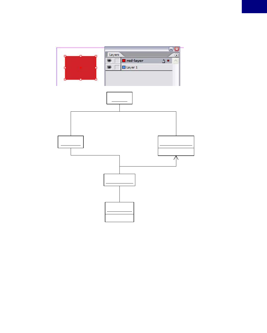
Snippet Fundamentals 653
Snippet Fundamentals
Snippet examples
FIGURE 263 Boss-object diagram for rectangle page item
The UML object diagram in Figure 264 shows relationships between objects that represent the
fill color and object style (Basic Graphic Frame) of a rectangle page item.
«boss»
: kDocBoss
«boss»
: kSpreadBoss
IHierarchy
«boss»
: kSpreadLayerBoss
UID = 0xa5
«boss»
: kDocumentLayerBoss
ILayerList
IHierarchy
ISpreadLayer::GetDocLayerUID
UID = 0xaa
«boss»
: kSplineItemBoss
IHierarchy
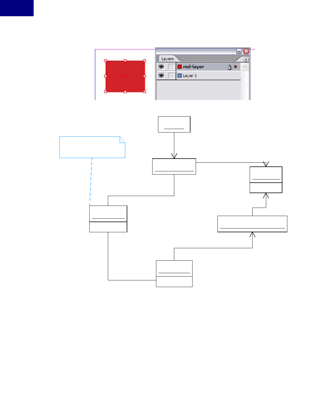
Snippet Fundamentals
Snippet examples
654
FIGURE 264 Boss-object diagram for page-item style
Snippet organization
When the filled-rectangle page item is exported as a snippet, a somewhat large XML file is gen-
erated. The contents depend on whether it is an IDML or INX snippet. Though this may seem
to be a lot of data to specify a red rectangle, consider that the intent of a snippet is to provide a
complete, standalone description of a collection of objects that can be imported into any other
InDesign document. The first few and last few characters are shown in Example 93 and
Example 94. This small percentage of the text shows some differences between the two formats.
The IDML-based snippet has a document element called Document, while the INX-based
example has a document element of SnippetRoot.
«boss»
: kDocBoss
UID = 0xaa
«boss»
: kSplineItemBoss
«boss»
: kDocWorkspaceBoss
IDocument::GetDocWorkspace
UID = 0x67
«boss»
: kObjectStyleBoss
IStyleNameTable (IID_IOBJECTSTYLENAMETABLE)
IPersistUIDData (IID_IPERSISTOBJECTSTYLEDATA)
UID = 0x16
«boss»
: kPMColorBoss
IPersistUIDData
«boss»
: kGraphicStyleFillRenderingAttrBoss
IGraphicStyleAttributeBossList (IID_IGRAPHICSTYLE_OVERRIDES)
ISwatchList::GetNthSwatch
Basic Graphic Frame, default
object style for newly created
graphic frame

Snippet Fundamentals 655
Snippet Fundamentals
Snippet examples
EXAMPLE 93 IDML-based (IDMS) extraction
<?xml version="1.0" encoding="UTF-8" standalone="yes"?>
<?aid style="50" type="snippet"...?>
<?aid SnippetType="PageItem"?>
<Document DOMVersion="6.0" Self="d">
<Color ...
</Document>
EXAMPLE 94 Snippet-file extract
<?xml version="1.0" encoding="UTF-8" standalone="yes"?>
<?aid style="33" type="snippet"... ?>
<?aid SnippetType="PageItem"?>
<SnippetRoot>
<colr ... (other x,000 characters omitted)
</SnippetRoot>
Inspecting the raw XML data contained in an INX snippet file is not immediately illuminating
(see the XML in Figure 265, for example), so some XSLT transformations have been applied to
render the data in a form that is easier to understand. The snippet file creating by exporting a
rectangle page item was transformed with XSLT, using information from the ScriptingDefs.h
file in the SDK as a translation table, to turn short names like “crec” into long names (Rectan-
gle). The amount of information was reduced by filtering out all but the names of elements and
some key attributes. The relationships between elements were represented as a graph of nodes
(the elements) and edges (the links between them).
FIGURE 265 Subset of XML from filled-rectangle snippet
-<Rectangle AnchoredObjectSettings="ro_uaacAOs1" TextWrap="ro_uaactxw1"
ItemGeometry="x_19_l_1_l_4_l_2_D_-231.5_D_-311.5_l_2_D_-231.5_D_-240.5_l_2_D_-
144.5_D_-240.5_l_2_D_-144.5_D_-311.5_b_f_D_-231.5_D_-311.5_D_-144.5_D_-
240.5_D_1_D_0_D_0_D_1_D_293_D_-22" ContentType="e_unas"
AssociatedXMLElement="ro_n" XPBlendMode="e_norm" XPOpacity="D_100"
XPKnockoutGroup="b_f" XPIsolateBlending="b_f" XPDSMode="e_none"
XPDSBlendMode="e_xpMb" XPDSOffsetX="U_7" XPDSOffsetY="U_7" XPDSBlurRadius="U_5"
XPDSColor="o_ub" XPDSOpacity="D_75" XPVGMode="e_none" XPVGWidth="U_9"
XPVGCornerType="e_xpCc" XPDSSpread="D_0" XPDSNoise="D_0" XPVGNoise="D_0"
StoryOffset="ro_n" FillColor="o_u16" FillTint="D_-1" Overprint="b_f" LineWeight="U_1"
MiterLimit="D_4" EndCap="e_bcap" EndJoin="e_mjon" StrokeType="o_di5a29"
LeftLineEnd="e_none" RightLineEnd="e_none" LineColor="o_ub" LineTint="D_-1"
CornerEffect="e_none" CornerRadius="D_12" GradientFillStart="x_2_U_0_U_0"
GradientFillLength="U_0" GradientFillAngle="D_0" GradientStrokeStart="x_2_U_0_U_0"
GradientStrokeLength="U_0" GradientStrokeAngle="D_0" StrokeOverprint="b_f" GapColor="o_ue"
GapTint="D_-1" StrokeAlignment="e_stAC" NonPrinting="b_f" ItemLayer="o_ua5" Locked="b_f"
LocalDisplaySetting="e_Dflt" AppliedObjectStyle="o_u67" Tag="c_" Self="rc_uaa"
SnippetParent="root">
<AnchoredObjectSettings Self="rc_uaacAOs1" />
-<TextWrap TextWrapType="e_none" TextWrapInset="e_none" TextWrapInverse="b_f"
ItemGeometry="x_5_l_0_D_0_D_0_D_0_D_0" ContourOptions="ro_uaactxw1ccos1"
Self="rc_uaactxw1">
<ContourOptions PSPathNames="rx_0" ACPathNames="rx_0" Self="rc_uaactxw1ccos1" />
</TextWrap>
</Rectangle>

Snippet Fundamentals
Snippet examples
656
The newer, IDML-based format is more readable. The example in Figure 266 is a similar sub-
set, in actual IDML.
FIGURE 266 IDML filled rectangle
If we visualize the XML from Figure 265 and Figure 266 as a graph showing a subset of the ele-
ments, we arrive at Figure 267. The Rectangle object (kRectangleObjectScriptElement) from
the scripting DOM corresponds to kSplineItemBoss in the boss DOM. The Color object (kCol-
orObjectScriptElement) corresponds to kPMColorBoss in the boss DOM. The Layer object
(kLayerObjectScriptElement) corresponds to kDocumentLayerBoss (IDocumentLayer) in the
boss DOM.
Figure 267 shows a subset of the elements in the snippet file exported from this document
asset. The long names for the elements are shown. The Self attribute (shown as e.g. 0xaa rather
than rc_uaa or u_123) corresponds to the UIDs for the boss objects shown in Figure 263 and
<?xml version="1.0" encoding="UTF-8"?>
<Rectangle Self="ud8" StoryTitle="$ID/" ContentType="Unassigned"
FillColor="Color/C=15 M=100 Y=100 K=0" GradientFillStart="0 0" GradientFillLength="0"
GradientFillAngle="0" GradientStrokeStart="0 0" GradientStrokeLength="0"
GradientStrokeAngle="0"
ItemLayer="ud3" Locked="false" LocalDisplaySetting="Default" GradientFillHiliteLength="0"
GradientFillHiliteAngle="0" GradientStrokeHiliteLength="0" GradientStrokeHiliteAngle="0"
AppliedObjectStyle="ObjectStyle/$ID/[Normal Graphics Frame]" ItemTransform="1 0 0 1 0 0"
FramelabelString="" FramelabelSize="12" FramelabelVisibility="false"
FramelabelPosition="FramelabelBottom" BpiData=" ">
<Properties>
<PathGeometry>
<GeometryPathType PathOpen="false">
<PathPointArray>
<PathPointType Anchor="89.75 -294.35714285714283"
LeftDirection="89.75 -294.35714285714283"
RightDirection="89.75 -294.35714285714283"/>
<PathPointType Anchor="89.75 -189.07142857142856"
LeftDirection="89.75 -189.07142857142856"
RightDirection="89.75 -189.07142857142856"/>
<PathPointType Anchor="188.07142857142858 -189.07142857142856"
LeftDirection="188.07142857142858 -189.07142857142856"
RightDirection="188.07142857142858 -189.07142857142856"/>
<PathPointType Anchor="188.07142857142858 -294.35714285714283"
LeftDirection="188.07142857142858 -294.35714285714283"
RightDirection="188.07142857142858 -294.35714285714283"/>
</PathPointArray>
</GeometryPathType>
</PathGeometry>
<FramelabelFontColor type="enumeration">Pink</FramelabelFontColor>
</Properties>
<TextWrapPreference Inverse="false" ApplyToMasterPageOnly="false" TextWrapSide="BothSides"
TextWrapMode="None">
<Properties>
<TextWrapOffset Top="0" Left="0" Bottom="0" Right="0"/>
</Properties>
</TextWrapPreference>
<InCopyExportOption IncludeGraphicProxies="true" IncludeAllResources="false"/>
<FrameFittingOption LeftCrop="0" TopCrop="0" RightCrop="0" BottomCrop="0"
FittingOnEmptyFrame="None" FittingAlignment="TopLeftAnchor"/>
<Transparencyeffectsettings Transparencyeffectmode="false"
Transparencyeffectoffsetxdirection="0" Transparencyeffectoffsetydirection="0"
Transparencyeffectuseblackasopaque="false" Transparencyeffectusealpha="false"
Transparencyeffectuseblur="false"/>
</Rectangle>
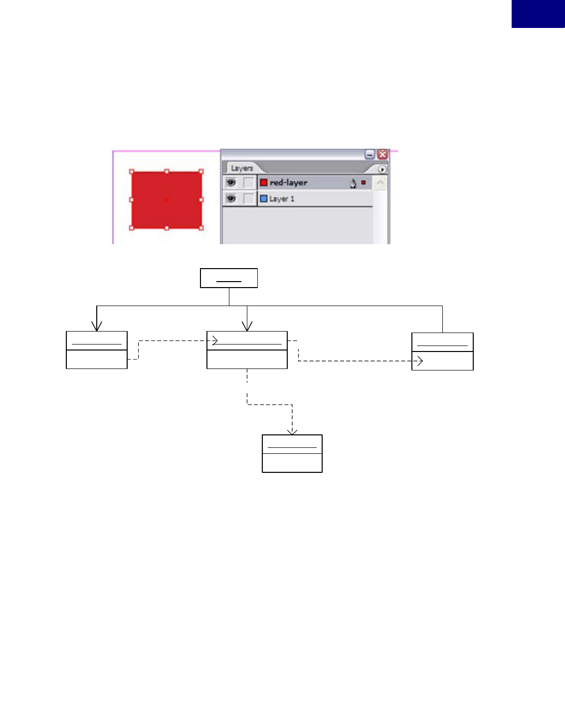
Snippet Fundamentals 657
Snippet Fundamentals
Snippet examples
Figure 264. The snippet (scripting DOM) model is simplified relative to the boss model; there
is no graphics-attribute object interposed between the page item and the object representing its
color.
FIGURE 267 Relationships between elements in snippet representing rectangle
NOTE:In Figure 267, “Root” can be either Document (for IDML) or SnippetRoot (for INX).
Two different views are shown of the elements and associations in a snippet file. Figure 267
shows the key objects that were explicitly identified by UID in Figure 263 and Figure 264.
Image-item snippet
A new document was created, and an image was placed in it. A page-item snippet was
exported, based on the graphic frame containing the image. We examine both the low-level
boss model for this and the organization of the snippet file. To create this through the InDesign
user interface, you can select the frame containing the image and just drag the page item from
the layout to the desktop. To do this programmatically, see the “Snippets” chapter of Adobe
InDesign CS4 Solutions.
: Root
Self = 0xaa
: Rectangle (crec)
Self = 0x16
: Color (colr)
FillColor (flcl)
Self = 0xa5
: Layer (layr)
Self = 0x67
: ObjectStyle
ItemLayer (pilr)
AppliedObjectStyle (aobs)
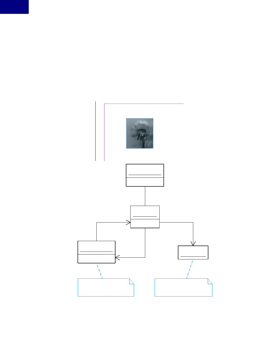
Snippet Fundamentals
Snippet examples
658
Boss-level model
Figure 268 contains an object diagram showing key boss objects that represent a placed (TIFF)
image (kImageItem) in a graphic frame (kSplineItemBoss), and links between them (instances
of associations between the boss classes). A low-resolution embedded proxy (kImageInDB) is
stored in the document. The actual high-resolution image is referenced from a link (kIm-
portLinkBoss). In the interest of clarity, associations with objects of class kSpreadLayerBoss
(which would own the kSplineItemBoss if it were a top-level page item) and so on are omitted.
FIGURE 268 Representation of a placed image
A placed image is represented by the boss class (kImageItem), which can be found as a child of
a graphic frame (kSplineItemBoss). The image item (kImageItem) refers to both a link
(through ILinkObject) and an object that may store a proxy (through IImageDataAccess or
IStoreInternal).
UID = 0xa9
«boss»
: kSplineItemBoss
UID = 0xa5
«boss»
: kImageItem
IHierarchy
UML = 0xa8
«boss»
: kImportLinkBoss
ILink::GetObject
«boss»
: kImageInDB
IImageDataAccess / IStoreInternal
Embedded, low-resolution
image proxy
Refers to high-resolution,
external image
ILinkObject::GetLinks

Snippet Fundamentals 659
Snippet Fundamentals
Snippet examples
The original high-resolution image placed is referenced by a link (kImportLinkBoss), and the
low-resolution image proxy may be stored by a boss object (kImageInDB). The embedded
proxy is referenced either through IStoreInternal interface of the kImageItem object (for exam-
ple, for PDF, EPS, and PICT) or by IImageDataAccess (as in the TIFF example here and for
other formats like JPEG).
Snippet organization
The complete snippet is quite complicated, but we can make sense of the picture by focusing on
the objects in the scripting model and considering the relationships to the boss objects we saw
in Figure 268.
The frame is represented in the scripting DOM by a Rectangle object (kRectangleObject-
ScriptElement), and the image placed by an Image object (kImageObjectScriptElement). The
scripting classes associate to kSplineItemBoss and kImageItem in the boss DOM. Conse-
quently, when we inspect the snippet, we see a Rectangle, with child element Image. The link to
a high-resolution image external to the InDesign file is maintained in the scripting DOM by a
Link object (kLinkObjectScriptElement), which associates with kImportLinkBoss (in the case
of a placed image file).
The object diagram in Figure 269 represents elements in the snippet file for a placed image.
The Rectangle element has a Self attribute matching the UID of the kSplineItemBoss in
Figure 267. The Image element has a Self attribute equal to the UID of the kImageItemBoss
object in Figure 267. The Link object has a Self attribute corresponding to the UID of the link
boss object (kImportLinkBoss) in Figure 267. The ClippingPath and TextWrap elements corre-
spond (approximately) to the IClipSettings and IStandOffData interfaces on kImageItem,
respectively.
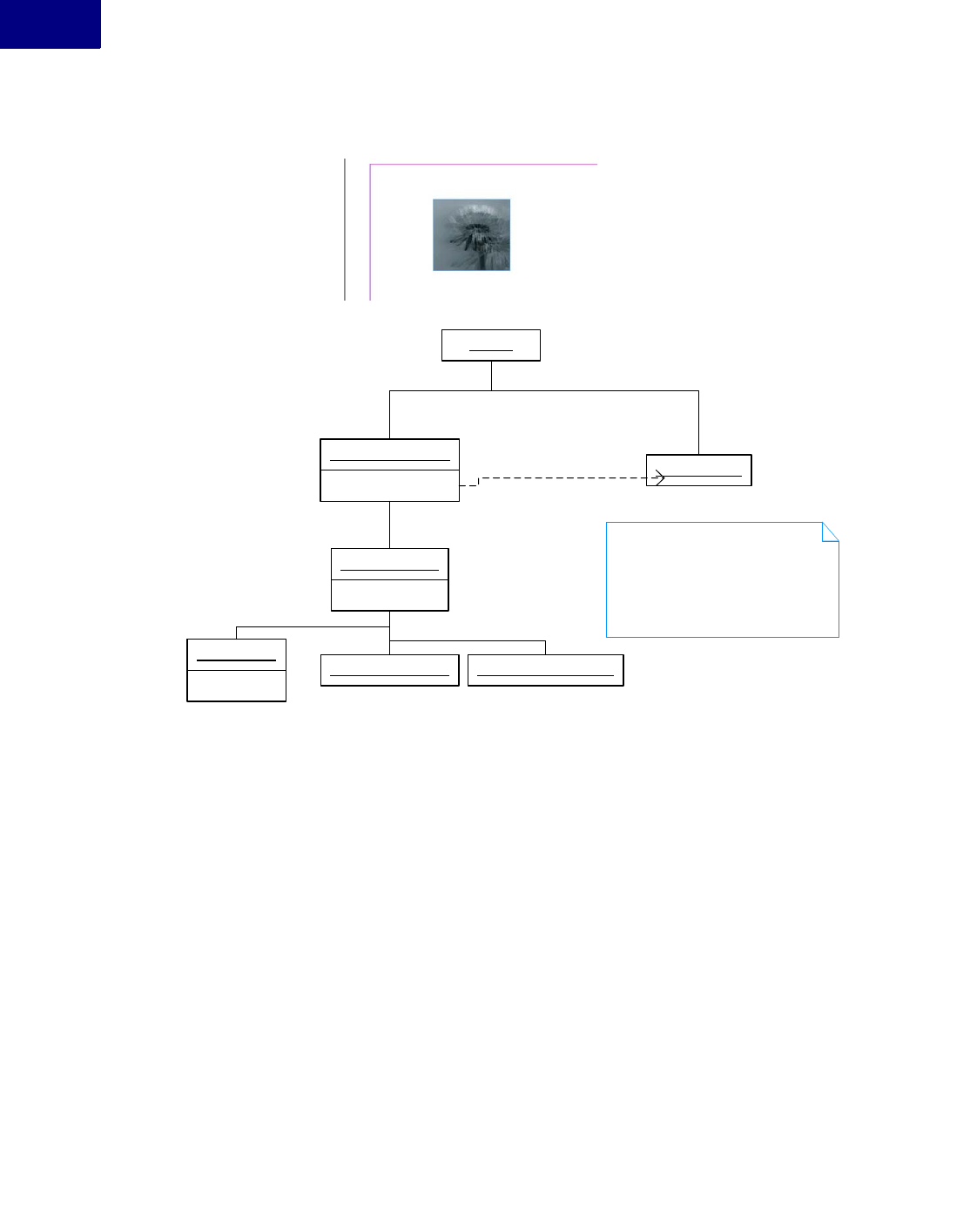
Snippet Fundamentals
Snippet examples
660
FIGURE 269 Relationships between elements in snippet for a placed image
NOTE:In Figure 269, “Root” can be either Document (for IDML) or SnippetRoot (for INX).
The Image element shown in Figure 268 has a dependent Link element, which maintains a link
to the high-resolution image that was placed. This Link element stores approximately the data
stored in or obtainable from a link boss object (kImportLinkBoss); it stores a path to the file
and other information, like link-import stamp and link-stored state. The snippet also main-
tains a low-resolution thumbnail of the image, but in the xap:Thumbnail metadata element,
intended for consumers of the XMP format.
XML element snippet, tagged placeholder
Consider the scenario of creating one element in the logical structure as a tagged placeholder
for an image to be placed later. We can examine the organization of a snippet obtained by
exporting a placed element from the logical structure.
Self = 0xa9
: Rectangle (crec)
Self = 0xa5
: Image (imag)
Self = 0xa8
: Link (clnk)
: Root
: Layer (layr)
ItemLayer
The low-resolution image
proxy that was embedded
in the document is stored
in the snippet as part of
its XAP metadata. Inspect
the xap:Thumbnails element.
: TextWrap (ctxw) : ClippingPath (cpth)
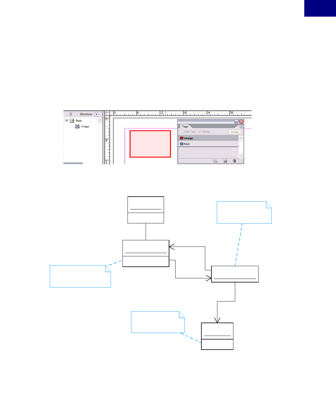
Snippet Fundamentals 661
Snippet Fundamentals
Snippet examples
Boss-level model
This is described in some detail in the “XML Fundamentals” chapter. Briefly, a tagged graphic
placeholder is represented by a kSplineItemBoss, with a kPlaceHolderItemBoss child. Associa-
tions with XML elements (IIDXMLElement) are maintained by the IXMLReferenceData on
the placeholder (kPlaceHolderItemBoss). See Figure 270.
FIGURE 270 Boss-object diagram for XML-tagged placeholder
UID = 0xa1
«boss»
: kSplineItemBoss
UID = 0xa7
«boss»
: kPlaceHolderItemBoss
IHierarchy
«boss»
: kTextXMLElementBoss
IXMLReferenceData
IIDXMLElement
UID = 0xa6
«boss»
: kXMLTagBoss
IIDXMLElement
Represents the element
<image> in the logical
structure
Object representing
the tag named "image"
Placeholder, to be replaced
by e.g. kImageItem, when
image is placed
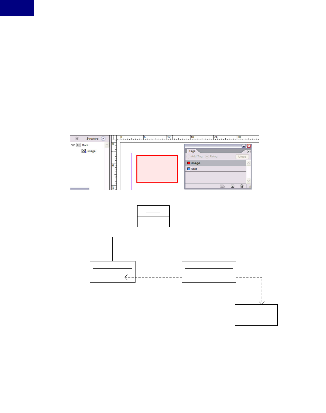
Snippet Fundamentals
Snippet examples
662
Snippet organization
An XML-element snippet is the serialized form of an XML element, its tree of elements
(IIDXMLElement) it owns, and any placed content that it or any of its dependents refer to,
along with dependencies. Because we only one tagged object, there is only one element
(XMLElement) in the snippet. Only the tags required for the exported XML elements are con-
tained in the snippet; in this case, we have only one XMLTag element in the snippet. The UIDs
of the frame (kSplineItemBoss) and tag (kXMLTagBoss) propagated to the snippet. XML ele-
ments are not UID-based, and the Self attributes for the XMLElement elements in the snippet
are less easy to relate to the original InDesign document. See Figure 271.
FIGURE 271 Key elements in snippet for tagged placeholder
NOTE:In Figure 271, “Root” can be either Document (for IDML) or SnippetRoot (for INX).
: XMLElement (cXML)
UID = 0xa6
: XMLTag (tagX)
: Root
Self = 0xa1
: Rectangle (crec) XMLContent XMLTag

Snippet Fundamentals 663
Snippet Fundamentals
Client API
Client API
Suites
To create a snippet based on the current selection, use ISnippetExportSuite. ISnippetExportS-
uite lets you export the layout selection or a selection in the structure view as a snippet, and a
text selection as an InCopyInterchange snippet (INCX or ICML). For more details, see the
“Snippets” chapter of Adobe InDesign CS4 Solutions.
Utilities
The following utilities are available:
zISnippetExport — A utility interface on kUtilsBoss that exposes the snippet types that can
be exported by the application. There are several snippet types you can export with this
interface, including text styles, XML tags, swatches, preferences, and InCopy stories. You
also can export a collection of objects with IDOMElement interfaces and specify the export
policy. Several methods take an INXOptions argument, allowing you to specify whether you
want to export INX- or IDML-based snippets. For more detail, see the API reference docu-
mentation.
zISnippetImport — A utility interface on kUtilsBoss, with a simpler API than the export
equivalent. The only requirement on import is that you know where you want to import in
the scripting DOM tree. You need an IDOMElement interface on a scriptable object. For
more detail, see the API reference documentation.
The ISnippetExportSuite suite can be used if you create a selection programmatically and are
not worried about trampling the user selection. For example, the ITextSelectionSuite, IXMLN-
odeSelectionSuite (structure view), and ILayoutSelectionSuite interfaces each create selections
that can be exported as snippets through ISnippetExportSuite. For more information on creat-
ing selections programmatically, see the “Selection” chapter.
If you have a non-selectable object you want to export as a snippet, you can use one of two
methods on the ISnippetExport interface (on the kUtilsBoss). ISnippetExport::ExportAppPrefs
can be used to export various application preferences; for examples, see the SnpShareAppRe-
sources code snippet. You also can use ISnippetExport::ExportDocumentResource to export
resources of the document; for examples, see the SnpImportExportSnippet code snippet.
For more information, see the “Snippets” chapter of Adobe InDesign CS4 Solutions.
Importing
On import, the main thing the client must specify is where on the scripting DOM tree the
incoming snippet will go. The incoming snippet will have one or more root objects (for exam-
ple, page items), and the client needs to specify where on the DOM tree they will go. For page
items, this typically means specifying the spread. For XML elements, it means specifying an
element on the structure tree that will be the parent of the imported element. For many other

Snippet Fundamentals
Extension patterns
664
snippet types (styles, swatches, etc.) the document is the parent. For more information, see the
“Snippets” chapter of Adobe InDesign CS4 Solutions.
Extension patterns
There are no specific extension patterns you can implement relating to snippets; however, if
you add persistent data to the low-level document model (e.g., through add-ins of interfaces
that have persistent implementations), your plug-in must expose this data to scripting.
Adding persistent data to snippet files
If you add persistent data to the boss DOM—for example, through an add-in to one of the
page-item boss classes—then for this data to be round-tripped through snippets, you need to
expose your data as properties in the scripting DOM. This also may require you to define new
object (classes) in the scripting DOM. For more information, see the “Scriptable Plug-in Fun-
damentals” chapter.
For example, if your custom data on page items needs to be round-tripped through asset librar-
ies (which depend on the snippet architecture), you need to ensure your persistent data is
scriptable. See, for example, the SDK sample CandleChart, which was updated to support
round-tripping persistent data through snippets by exposing the persistent data as properties
added to the scripting DOM.
Frequently asked questions
What is a snippet, and how do I create one?
A snippet is a logically complete fragment of an InDesign document, saved in the XML-based
InDesign Markup (IDMS) or InDesign Interchange (INX) formats. A snippet is created by
acquiring references to document objects you want to export (for example, by UID or XML-
Reference), then using one of the client APIs like ISnippetExport. Alternately, there is a ISnip-
petExportSuite suite interface that lets you export based on a selection in the layout or
structure view (XML elements) or a text selection, as InCopy Interchange format.
What happens if I export a snippet of a placed image?
See “Image-item snippet” on page 657. A snippet for a placed image maintains a link to the
asset within the XML representation. When the snippet is imported into a new document, a
link appears in the Links panel as if you had placed the image.

Snippet Fundamentals 665
Snippet Fundamentals
Frequently asked questions
What features are based on snippets?
See “Features that depend on snippets” on page 644.
How accurately is data round-tripped through snippets?
Maintaining a high-fidelity representation of a document asset was one of the design goals for
snippets. However, some limitations were designed in. For example, snippets do not carry doc-
ument-level preferences with them. If they did, they would create overrides of the existing doc-
ument-level preferences when imported into a new document, which is desirable.
When importing a new asset, it is reasonable for it to bring new document objects, like
swatches on which it depends, but it could have unintended global effects on the target docu-
ment if it starts to redefine document-level preferences that control typography, for example.
Importing a snippet should not alter the properties of other document objects in the document
into which you import the snippet.
When do I have to care about snippets?
If you are adding custom data to the document—e.g., to page items in some way—and you
want this data to be round-tripped through asset libraries, you must be sure you can get your
persistent data into snippet files. This is because asset libraries store their assets as snippets
internally, meaning your persistent data must be exported into a snippet. See “Adding persis-
tent data to snippet files” on page 664 for more discussion, and the “Scriptable Plug-in Funda-
mentals” chapter for information on how to do this.
Can I export spreads or pages as snippets?
Suppose you have a multipage document, and you want to decompose it into independent
pages by exporting each page as individual snippets containing all objects on each page and
dependencies. Alternately, you may want to export each spread as a snippet.
This is not possible, as pages are not re-created on snippet import, so you cannot factor a docu-
ment into individual spreads or pages using the snippet architecture alone.
Should we generate snippet files from scratch?
No. The INX-based snippet format should be regarded as a read-only format. We do not rec-
ommend using it to generate snippets from scratch.
We designed IDML-based snippets to facilitate programmatic assembly and disassembly of
snippets. You can validate your snippets using a RELAX NG-based schema. The SDK also
includes a sample plug-in that logs errors on import and export. Both schema validation and
the error-logging plug-in are covered in Adobe InDesign Markup Language (IDML) Cookbook.

Snippet Fundamentals
Frequently asked questions
666
Can I import a snippet directly into a library?
Although asset libraries (kSnippetBasedCatalogBoss) depend heavily on snippets for their rep-
resentation of assets, there is no public API to let you import a snippet directly into a library.
You must import the snippet into a document, then use the library APIs to add the item to an
existing library. See the “Snippets” chapter of Adobe InDesign CS4 Solutions.
Can I import a snippet into the scrap database?
The scrap database (kScrapDocBoss) does not support importing snippets; there is no DOM
element hierarchy (IDOMElement) on the scrap, which is required to import snippets.
Can we add our own new snippet types?
You cannot add new snippet types or policies; you are restricted to those identified in
Table 151. The existing snippet types, however, cover the range of document content it makes
sense to export as self-contained assets. Since you can export an arbitrary collection of root
objects (those with IDOMElement interfaces) to a snippet file, you can select what goes into a
snippet, at least in terms of root objects. What you cannot do is decide what dependents of
those objects to include or leave out when export is taking place. You might have to do some
additional work before export, to ensure those dependents were exported as if they were root
objects in determining what goes on in the snippet.

Shared Application Resources 667
Shared Application Resources
Introduction
Shared Application Resources
Introduction
With InDesign CS4 and a small amount of your own code, you can manage application
resources like preferences, text styles, XML tags, and swatches. This chapter describes how to
read and write these resources to or from a stream, using InDesign Interchange (INX) snippets.
This chapter does not require a full understanding of XML, INX, snippets, or scripting, nor
does it try to teach you those technologies. For background, see the “Scriptable Plug-in Funda-
mentals” and “Snippet Fundamentals” chapters. Also see Adobe InDesign CS4 Scripting Guide
and Adobe InCopy CS4 Scripting Guide.
NOTE:The shared-application-resources APIs support only INX snippets. IDML-based
snippets are not supported.
Terminology
zApplication preferences are the preferences in the InDesign or InCopy preference panel with
no documents open. These are the preferences used when InDesign creates a new docu-
ment.
zINX (InDesign Interchange) is an XML-based format InDesign uses to serialize and deserial-
ize native content. It is based on InDesign’s robust scripting support. An INX file is a script
expressed in XML that allows for the recreation of InDesign content and properties.
zShared application resources amounts to saving and refreshing resources like application
preferences, defaults, text styles, swatches, and XML tags, while the application is running.
zAn INX snippet is a logically complete INX fragment that represents pieces of an InDesign
document or other native application content such as application preferences. This chapter
focuses on using snippets to write out application resources like preferences and styles.
Architecture
InDesign and InCopy provide robust scripting support. It is very simple to change an applica-
tion preference via scripting. One approach to managing application preferences is to write a
script that sets these properties to some predefined state. Due to the large number of prefer-
ences in InDesign and InCopy, however, this would be fairly involved.

Shared Application Resources
Architecture
668
You could continue along this path, and manage character and paragraph styles, object styles,
swatches, and XML tags. This would become very involved, with a great deal of code to main-
tain. Fortunately, you do not have to write these scripts. Snippets achieve the same result, and
most of the work is done for you. You must write only the code that exports and imports the
snippet.
How it works
INX is an XML-based equivalent to a script, which recreates native InDesign content. Snippets
are INX fragments, which are complete enough to recreate part of an InDesign document or
workspace. For example, a snippet may recreate a page item and all the resources on which it
depends. This probably is the most common use of snippets to date. The Snippet Fundamentals
chapter provides details about exporting document content. Although beyond the scope of
what is covered in that chapter, snippets can be used to recreate most of the items saved in the
application workspace.
Instead of building elaborate scripts that set and reset your application workspace, you can use
the application’s user interface to set your application preferences and styles as required, then
export all or part of the workspace using INX snippets. The snippet then contains all the data
needed to recreate all or part of your application workspace via the scripting model.
From an API standpoint, special support was added to the snippet architecture for exporting
and importing application preferences and resources. The one caveat to using snippets is that
you cannot control which individual properties are exported. The API does not provide this
level of granularity; instead, it is based on classes of scriptable objects (for example
c_GeneralPrefs). All such objects that are marked as preference objects in the scripting model
and are children of the Application object can be exported. By default, several other classes also
are exported. These classes amount to elements of some style list. For instance, for Paragraph
Styles, the c_ParaStyle list element is exported. For your reference and use in code, the script-
ing IDs for these types are in AppPrefsListElementTypes.h.
A brief description of all relevant interfaces follows.
ISnippetExport
ISnippetExport is the interface used to write snippets to a stream. Most the methods have a
specific application (like ExportInCopyInterchange, ExportXMLTags, and ExportTextStyles).
There also are generic Export methods. It is important to note that these methods can be called
only with a predefined snippet export policy. You cannot create your own snippet export policy
using the publicly available SDK. Certain interfaces intentionally were left out; calling these
items with an invalid policy (kInvalidClass) exports invalid XML.
The method used to export application resources is ExportAppPrefs(). By default, this method
exports all application preference types and all other types specified in AppPrefsListElement-
Types.h. For the exact content, see the method. It contains a collection of list element types,
such as text and object styles.

Shared Application Resources 669
Shared Application Resources
Architecture
ExportAppPrefs also takes three optional arguments, which allow you to control exactly what is
exported:
zAn operation — You can specify one of two values (kInclude or kExclude) from the ISnip-
petExport::PreferenceOperation enumeration. Passing in kExclude causes everything to be
exported except the items listed in the K2Vector. Passing in kInclude causes only what is in
the vector to be exported.
zA reference to a K2Vector<ScriptID>.
zA pointer to an instance of IAppPrefsExportDelegate, described in the following section.
IAppPrefsExportDelegate
While you cannot create your own INX export policy, IAppPrefsExportDelegate allows for
finer control of the application preference export process. It gives the caller final say on exactly
what is exported and in what order. This may be important if your plug-in adds scripting sup-
port to an object you want to be exported by ExportAppPrefs(). You may need a way to reorder
the export, putting your item after objects on which it depends.
To add an IAppPresExportDelegate, create your own instance and pass in a pointer when you
call ExportAppPrefs().
ISnippetImport
ISnippetImport is the interface used to import snippets from a stream. You can access an
instance through Utils<> helper.
The methods in this interface are generic. They are not specific to importing application
resources, but rather any type of snippets. The difference in the two ImportFromStream meth-
ods is that one allows you to import a snippet containing multiple root objects. For our pur-
poses, we use the ImportFromStream method that specifies a single root object (the
application).
Like the generic export methods, ImportFromStream also takes an INX import policy. Again,
you cannot create this on your own. The argument itself is optional and defaults to kInvalid-
Class. The correct policy to use is kAppPrefsImportBoss; if you leave it as kInvalidClass (the
default value), the method will figure this out from the snippet.
IAppPrefsImportOptions
Two options must be defined when importing. These options are provided by an instance of
IAppPrefsImportOptions on the application workspace. To set these options, query for that
instance of IAppPrefsImportOptions and call the appropriate set method. That implementa-
tion in turn creates and processes a command to change its own state.
The first option is what to do when list items already in the application match those being
imported. For example, suppose you import Paragraph Styles A, B, and C into an application
workspace that already has Paragraph Style A. Should the import keep or replace Paragraph
Style A? To set the option for this, call SetHandleListItemsWithMatchingNames with either

Shared Application Resources
Working with snippet APIs: frequently asked questions
670
IAppPrefsImportOptions::kUseExistingListItems or IAppPrefsImportOptions::kReplaceLis-
tItems. The default value is kReplaceListItems.
The second option is what to do with list items that are not being imported. You can either
delete everything not in the imported list or leave existing items alone. For example, suppose
you import Paragraph Styles A, B, and C into an application workspace that contains Paragraph
Style D. Should the import keep or delete Paragraph Style D? To set this option, call Set-
DeleteNonImportedListItems with kTrue or kFalse. When called with kTrue, items not in the
imported list are deleted, which is the default behavior. To retain existing items, return kFalse.
To completely restore lists like paragraph styles to exported snippets, set the above two proper-
ties to kReplaceListItems and kTrue, respectively. This replaces any existing list items and
deletes list items not in the import. This is the default behavior, but it is up to you to know
whether IAppPrefsImportOptions was changed.
IAppPrefsImportDelegate
While you cannot create your own INX import policy, IAppPrefsImportDelegate allows for
finer control of the application preference import process. It gives the plug-in developer final
say on exactly what is imported, what is kept and/or deleted, and which property is used to
compare list elements. You may never need to use a delegate; however, if you need finer control
over the import, you need to provide an instance of IAppPrefsImportDelegate. To do this, add
your IAppPrefsImportDelegate instance to kAppPrefsImportBoss. This delegate is a way to
influence the import policy even though you cannot create your own policies.
Working with snippet APIs: frequently asked questions
See the “Share App Resources” snippet in <sdk>/source/sdksamples/codesnippets/SnpShare-
AppResources.cpp. This contains the sample code that demonstrates everything covered above
except the use of delegates (IAppPrefsImportDelegate and IAppPrefsExportDelegate).
How do I create streams for reading and writing snippets?
SnpShareAppResources::CreateStream() shows how to create file streams. It uses StreamUtils,
which has other useful methods for reading and writing different kind of streams.
How do I limit my export to those items in the preference panel?
You cannot be that precise, but you can come close. SnpShareAppResources::ExportPrefsPanel
contains all ScriptIDs for the objects that control the preference panels. Some of these objects
control other settings, like items on the view menu.

Shared Application Resources 671
Shared Application Resources
Working with snippet APIs: frequently asked questions
How do I export all text styles, object styles, XML tags, or swatches in the
application workspace?
Specify the correct list of ScriptIDs to include. See ExportTextStyles(), ExportObjectStyles(),
ExportXMLTagsAndPrefs(), and ExportSwatches() in SnpShareAppResources.cpp.
How do I import a snippet into the application?
Call ISnippetImport::ImportFromStream() with a pointer to the appropriate root object
(IDOMElement) instance. SnpShareAppResources::ImportToApp() shows how to query for
the application root and call ImportFromStream().
How do I control whether existing objects like paragraph styles are
replaced or deleted on import.
SnpShareAppResources::ImportToAppWithOptions() shows how to set the application work-
space’s IAppPrefsImportOptions before importing.
How do I determine the correct ScriptID to use for a preference I’m trying
to include or exclude?
This may involve trial and error. While all the native IDs are available in ScriptingDefs.h,
sometimes it is difficult to find the ID corresponding to a particular user interface feature.
Most of the ScriptIDs have meaningful names that map to the user interface or how they
appear in the scripting object model. To start, look at ScriptingDefs. If you cannot figure it out,
an understanding of the scripting object model will help. If you cannot identify the right ID,
open a developer support case.
How do I know which list element types will be exported by default?
The list of all such types is in AppPrefsListElementTypes.h. In ScriptingDefs.h, most list ele-
ment types have both a singular and plural ID; for example, c_ObjectStyle and c_ObjectStyles.
AppPrefsListElementTypes.h uses all singular IDs. In all cases, use the singular ID. The internal
snippet code considers these elements on a case-by-case basis. It does not export all object
styles if you pass in c_ObjectStyles.

Shared Application Resources
Working with snippet APIs: frequently asked questions
672

User-Interface Fundamentals 673
User-Interface Fundamentals
Introduction
User-Interface Fundamentals
This chapter introduces the key concepts in the user-interface architecture, such as type bind-
ings between widget boss classes or interfaces and ODFRez custom resource types. This chap-
ter also describes how the user-interface model is factored, discusses relevant design patterns
like the Observer pattern, and provides an overview of common plug-in resources.
The chapter has the following objectives:
zExplain user-interface programming for InDesign.
zHelp you create responsive user interfaces for InDesign plug-ins.
zIllustrate key concepts with a concrete example of a user interface.
zDescribe the factoring of the user-interface model.
zDiscuss design patterns relevant to user-interface programming.
zDescribe the role played by persistence in the user-interface model.
zOutline how resources are used in defining user interfaces.
Introduction
Plug-in developers often need to implement a user interface early in their plug-in program-
ming experience. To program user interfaces, a plug-in developer needs to understand con-
cepts like boss classes and interface aggregation, as much of the user interface is specified in
resources.
The initial state and properties of a plug-in user interface are specified in a cross-platform
resource language, ODFRez (OpenDoc Framework Resource language). Developing respon-
sive user interfaces for InDesign plug-ins requires understanding type binding between boss
classes (and persistent API interfaces) and types defined in ODFRez, and how persistent inter-
faces on widget boss classes read their initial state from the plug-in resources.
One benefit of the ODFRez data format is that it is a cross-platform resource definition lan-
guage. The initial geometry of widgets can be defined in ODFRez data, as well as other data
needed to define the initial state of widgets, like the labels on buttons. It is rare that a platform-
specific resource is required; in the SDK samples, this occurs only for image-based buttons.
“Sample user interface” on page 679 introduces a concrete example of a user interface to
explain abstract topics like type binding. “Factorization of the user-interface model” on
page 683 describes the user-interface programming model.

User-Interface Fundamentals
Key concepts
674
Key concepts
Design objectives for user-interface API
The following are some of the design objectives for the user-interface programming model:
zEnable cross-platform user-interface development.
zCreate re-usable user-interface components with rich behaviors.
zProvide a well factored design that separates data and presentation.
To meet these objectives, the design supports re-use, with the possibility of customizing widget
behavior and appearance, and it encapsulates of platform dependencies. Support for re-use is
established through the use of widget boss classes. Platform independence is achieved by using
a cross-platform resource format; widgets are defined in the ODFRez language.
The following are the key responsibilities of a plug-in developer:
zIdentify and use existing widgets where possible.
zDefine new boss classes, typically subclasses of existing widget boss classes.
zDefine ODFRez custom resource types. If widget boss classes are subclassed, the associated
ODFRez types also must be subclassed. These also go in the top-level framework resource
file.
zDefine ODFRez data statements, to specify the geometry and properties of the widgets, as
well as for localization.
Client code also may be responsible for the following:
zNavigation between boss objects. An example is finding the panel to which a pop-up menu
is attached, then locating a widget belonging to the panel.
zProcessing actions when menu items are executed or keyboard shortcuts are executed.
zHandling notifications about changes in widget state sent to interested observers. InDesign
client code rarely requires writing event-handling code. Instead, observers process update
messages that specify how the state of the subject has changed.
Idioms and naming conventions
This section describes some programming idioms and naming conventions that are strongly
recommended when writing plug-in user-interface code. There are two types of conventions:
zConventions used within the public API.
zNaming conventions used to minimize confusion and uncertainty about code intent.
Control-data interfaces on widget boss classes are predictably named. When working with con-
trols, there are many interfaces named I<Data-type>ControlData. Notifications of changes in
the data model of a control are performed by the implementations of these interfaces.

User-Interface Fundamentals 675
User-Interface Fundamentals
Key concepts
It is helpful to be disciplined in defining symbolic constants for identifiers. We strongly recom-
mend you observe the following conventions:
zEnsure constants like boss, implementation, and widget IDs begin with “k.”
zEnsure new interface identifier names begin with “IID_,” are in all uppercase, and are
declared in the interface ID namespace.
zUse “k<Name>Boss” to define a new ID in the boss namespace, where ideally <Name> is
related to the boss-class intent; e.g., kMyCustomButtonWidgetBoss.
zUse “k<Name>Impl” to define a new ID in the implementation ID namespace.
zUse “k<Name>WidgetID” to define a new ID in the widget ID namespace.
zUse “k<Name>Key” to define a new string key in the global string table.
zStrive for regular relationships between implementation class names and identifiers. For
example, kMyPluginObserverImpl is associated with a C++ class MyPluginObserver.
zMake ODFRez custom-resource type names indicative of the boss class they bind to, in as
regular a fashion as possible. For example, kMyCustomButtonWidgetBoss is bound to the
ODFRez type MyCustomButtonWidget.
Along with following the appropriate naming conventions for the domain, it is essential to
define symbolic constants in the correct namespace and make sure there are no constants
defined that clash numerically. In addition to the boss class IDs and implementation IDs used
throughout the API, there are widget identifiers and string tables consisting of key/value pairs
for each locale of interest.
In some cases, the namespaces are global; each plug-in must ensure any identifiers and strings
it creates are unique within the application. This applies to string keys; for example. However,
widget identifiers need be unique only within the list of descendants of a given widget, so in
some circumstances you can re-use a widget identifier (for example, across different dialog
boxes or panels you own), as long as you observe this constraint.
Abstractions and re-use
This section highlights the major abstractions in the InDesign API and the main strategy for
code re-use within the user-interface API: extending widget boss classes. This section also
reviews some of the fundamental material required for InDesign programming.
There is a very high degree of code re-use within the user-interface domain, and the boss class
hierarchies are particularly deep in this area compared to other application domains. Re-use
within the widget API typically takes the form of re-use of boss classes by inheritance. In some
circumstances, implementations from the API of particular interfaces can be re-used.
In general, it is not possible to predict whether an implementation of an interface on an exist-
ing boss class can be safely re-used. There might be implementation dependencies, like expect-
ing the container-widget boss object to expose an IBoolData interface. In general, it is not safe
to try to re-use just one implementation from a given widget boss class. The recommended re-
use policy is to extend an existing widget boss class and override an interface, if required, by
extending the implementation present on the parent boss class.

User-Interface Fundamentals
Key concepts
676
Widget boss classes and the user-interface API can be confusing, because there are widgets
defined in ODFRez and widgets in the boss-class space with very similar names. For example,
kButtonWidgetBoss is a boss class that provides implementations responsible for the behavior
of a given widget, and ButtonWidget is an ODFRez custom-resource type that specifies data for
the initial state and properties of a control.
Another source of confusion is that occasionally there are C++ helper classes and ODFRez cus-
tom-resource types with identical names (like CControlView) but different responsibilities. To
avoid confusing these types, it always is necessary to consider whether entities are from the
code domain (C++) or data domain (ODFRez).
Widgets versus platform controls
This section describes the relationship between InDesign widget classes and platform controls.
Widget boss classes provide a layer of abstraction over platform-specific controls and provide
additional capability beyond what is delivered by the platform controls. The user-interface
model extends widgets to the platform-specific control set, providing controls like measure-
edit boxes specialized for the domain of print publishing.
A widget boss class potentially encapsulates a platform control and provides additional capabil-
ities like entry validation—a cross-platform API to query and set data values and change notifi-
cation. This is the principal benefit of the user-interface model: the same code can be written to
develop a plug-in user interface for Mac OS and Windows, with little or no attention to plat-
form differences.
A widget boss class can be associated with a platform control, as in the case of an edit box.
Some classes, however, have no direct platform equivalent or platform peers; for example, the
iconic push buttons are not bound to a platform control. When writing client code, typically it
is not necessary to be aware of whether there is a platform peer control for an API widget, and
we recommend you manipulate the state of InDesign widgets through the InDesign API and
not through platform-specific APIs. In addition, use InDesign API-specific patterns to receive
notification about changes in control state (subject/observer).
Widget boss classes provide more capability than platform controls. For example, there is a
mechanism for controls to persist their state across instances of the application; this is not
default behavior for platform controls. The integer edit-box widget (kIntEditBoxWidgetBoss)
provides additional validation capability not typically provided by platform controls. Another
key point about widget boss classes is that they expose a cross-platform API and a uniform pro-
gramming model on both Mac OS and Windows. This provides true cross-platform develop-
ment of user interfaces, although at the cost of some complexity in the architecture.
Commands, model plug-ins, and user-interface plug-ins
This section introduces a common factoring in the InDesign plug-ins, which are decomposed
into model plug-ins and user-interface plug-ins. The core capabilities of the InDesign API are
delivered by required plug-ins, most of which are model plug-ins. A model plug-in delivers
required pieces of architecture every client plug-in needs, or it implements the document-
object model at the core of InDesign. Much of the application user interface is delivered by

User-Interface Fundamentals 677
User-Interface Fundamentals
Key concepts
plug-ins that named <whatever>UI.apln, indicating they are user-interface–specific and not
required plug-ins, which end in .rpln.
A plug-in’s user interface can be thought of as a means of parameterizing command sequences
that perform functions benefitting an end user, like changing the document object model to be
consistent with user intent. For example, the XML required plug-in provides the core cross-
media API (for example, IXMLElementCommands, a key wrapper interface), and the XMedia
user-interface plug-in creates the user interface and drives the commands delivered through
the XML required plug-in. Behind most plug-in user interfaces, a command or command
sequence is executed when a widget receives the appropriate end-user event.
Commands provide a means to encapsulate change, provide support for undoing commands,
and support notification of changes. The command pattern is a well-known design pattern,
described in depth in Gamma, Helm, Johnson, and Vlissides, Design Patterns: Elements of
Reusable Object-Oriented Software, Addison-Wesley, 1995.
Commands also use the messaging framework, which allows observers (IObserver) to attach to
subjects and receive notification of change to the underlying model. Frequently, notifications
about commands are received by observers associated with plug-in user-interface components.
For example, the Layers panel receives notifications about documents being opened and closed
through the command architecture and updates its views accordingly. It is particularly conve-
nient that the same design pattern (subject/observer) is used within the user-interface pro-
gramming model, since all widget boss classes expose an ISubject interface that can be
observed by another boss object that implements IObserver.
Previewable dialogs are closely connected with commands. Commands used in previewable
dialogs should be absolute; that is, do not try to increase or decrease the value of data. With
preview off, the dialog is operating in collect mode, queuing up the set of commands that will
execute. If preview is turned on, these commands are executed, and further updates are exe-
cuted immediately. If the user cancels the action or turns preview back off, the database rolls
back to the original state. Providing preview capability is an essential requirement in some cli-
ent code.
Suites and the user interface
Selection suites are a convenient way to package model-manipulation code that makes it
almost trivial to write a user interface to drive the code. As described above, you should factor
the code such that the suite is delivered by one plug-in, and the client code for your user inter-
face that exercises the methods on the suite is in another plug-in. For a more detailed discus-
sion of suites, see the “Selection” chapter of Learning the Adobe InDesign CS4 Architecture.
Suites are particularly appropriate to writing user-interface code because they simplify the pro-
cess. Whenever an end user is required to manipulate document objects by making active
selections, make maximum use of suites.

User-Interface Fundamentals
Key concepts
678
Finding widgets in the API
There are two main ways to inspect the widget set delivered by the API:
zLook at the boss classes delivered by the Widgets plug-in (see the API reference documen-
tation for WidgetBinClass).
zLook at the ODFRez counterparts for many of these boss classes, which can be found in the
API header file Widgets.fh.
For information on why there are widget boss classes and ODFRez types with similar names,
see “Type binding” on page 680.
Each widget in the API is best understood in terms of the boss class that provides its behavior.
Although there is an ODFRez type ButtonWidget, it really is the boss class kButtonWidgetBoss
that provides all the significant behavior. For simple widgets, however, you can use just the
ODFRez type without worrying about the boss class behind it; a static text widget is an example
of this.
For example, a button in the InDesign API can be understood mainly by the interfaces aggre-
gated on the button-widget boss classes and the semantics of those interfaces. For example,
kButtonWidgetBoss exposes the following key interfaces, among others:
zITextControlData represents the label on the button.
zIControlView is responsible for the button appearance.
zIBooleanControlData stores its state, pressed in or not.
zISubject lets client code attach an observer (IObserver) to receive notification about
changes in the button state.
Observers (IObserver) are notified of changes to an abstract subject (ISubject). When a button
is pressed by an end user, the button-widget boss object (kButtonWidgetBoss) notifies any
attached observers about the state change, by sending them a message along
IID_IBOOLEANCONTROLDATA protocol. The message contains additional information to
say whether the button is being pressed in.
Notifications about control events or changes
A change in control state can be caused by many events, such as a button click, a keystroke
entered in an edit box, or a selection in a list box. Within the InDesign API, you get notification
of changes by providing your own implementation of an observer (IObserver) that listens for
changes in the state of a subject (ISubject). Since all widget boss classes extend kBaseWidget-
Boss, which aggregates ISubject, all widgets are observable by default. The simplest way to get
notification about changes in state is to add an IObserver interface to the widget boss class in
which you are interested, and subclass the corresponding ODFRez type. While this pattern has
the advantage of simplicity, if you have any elaboration in your user interface, we recommend
you have one observer listen for changes in multiple widgets and be aggregated on the parent of
all widgets in whose state changes you are interested.
If you are accustomed to programming other user-interface APIs, you may expect to need to
extend the event-handler interface. Usually, however, this is not required for the InDesign API,

User-Interface Fundamentals 679
User-Interface Fundamentals
Sample user interface
where typically writing an observer (IObserver) implementation is sufficient to be notified
about the semantic events associated (e.g., check-box state changed) with the widgets, rather
than about the low-level events (left-mouse-button-click) transmitted through the event han-
dler (IEventHandler).
If you use model-view observers to update the user interface, and they update data that does
not always need to be synchronized with the model state, you can use lazy notification to
improve performance. For more information, see the “Notification” chapter of Learning the
Adobe InDesign CS4 Architecture.
Sample user interface
The Stroke panel has an assembly of widgets to let an end user vary the miter limit associated
with a line (Figure 272). There is a text-edit box (kIntEditBoxWidgetBoss), a pair of labels
(kStaticTextWidgetBoss), and a nudge-control widget (kNudgeControlWidgetBoss), which
increments or decrements values in the edit control by a specified amount.
FIGURE 272 Widgets from the Stroke panel
The edit-box widget (kIntEditBoxWidgetBoss) shown in Figure 272 is specialized for the input
of integers; for example, a warning message is generated for any input that is not a valid integer.
A widget boss object of type kIntEditBoxWidgetBoss encapsulates a standard platform native
edit box and adds behavior, like validation logic when accepting updates; for example, when
the end user presses Enter with focus in the edit box.
The nudge-control widget (kNudgeControlWidgetBoss) collaborates with the integer edit box,
allowing increments or decrements of the value in the edit box. A nudge-control widget boss
object (kNudgeControlWidgetBoss) is not based on any specific platform control. Instead, it
consists of two API iconic button-like widgets, although this detail is hidden from developers
of client code. This is an instance of the facade design pattern.
The initial state of widget boss objects must be specified through resources, and for each wid-
get boss class, there is an associated ODFRez custom-resource type used to specify initial state
for the widget. Table 152 shows the widget boss classes for the example in Figure 272 and asso-
ciated ODFRez resource types.
kIntEditBoxWidgetBoss
kStaticTextWidgetBoss
kNudgeControlWidgetBoss

User-Interface Fundamentals
Sample user interface
680
TABLE 152 Example widget boss classes and associated ODFRez resource types
The key behavior of each control comes from the boss classes shown in the first column. The
nudge control and edit box interact in a different way; the nudge control is coupled to the edit
box in ODFRez data statements, and you do not need to write any additional C++ code to have
an edit box with nudge capability. The code behind the nudge control is delivered by the appli-
cation’s required Widgets plug-in, and it can be safely re-used through the user-interface archi-
tecture.
Type binding
This section describes the type bindings that exist between widget boss classes or interfaces and
ODFRez custom-resource types, using the example shown in Figure 272. A key aspect of work-
ing with plug-in user interfaces is being able to interpret the binding between a widget boss
class and an ODFRez custom-resource type or the significance of the binding between an API
interface and an ODFRez custom-resource type.
Widget boss classes provide the behavior behind widgets, including the capability to draw and
manage internal state and mediate interactions with the end user. Boss classes implement sets
of interfaces. The example in Figure 272 uses an integer edit box (kIntEditBoxWidgetBoss),
which is a control specialized for the input of integers. The implementation of the IControl-
View interface on the kIntEditBoxWidgetBoss boss class is responsible for drawing the edit
box. The implementation of the ITextDataValidation interface on this boss class validates that
the input is an integer.
ODFRez custom-resource types define data to initialize widgets and other elements needed for
the interface. For example, the CControlView field in Example 95 specifies the initial location
and dimensions of each widget, along with other properties like its widget ID and visibility.
When a panel is shown for the first time, a set of widget boss objects is created by the applica-
tion framework, and the lifetime of these boss objects is managed by the framework. Each wid-
get boss object is invited to draw itself to the display. A widget boss class provides the capability
behind the user-interface element drawn to the screen and implements the user-interface
model.
For example, the kStaticTextWidgetBoss boss class is bound to the ODFRez custom-resource
type StaticTextWidget. The ODFRez data defines the initial state of a widget the first time it
instantiates; thereafter, the state of the widget is restored from a saved data database. This
enables widgets to persist their state across instances of the application, which is how end users
can save the state of their working areas in terms of the visible panels, their geometries, etc.
API Widget boss class ODFRez custom-resource type Displaying
kIntEditBoxWidgetBoss IntEditBoxWidget 4
kNudgeControlWidgetBoss NudgeControlWidget (Nothing)
kStaticTextWidgetBoss StaticTextWidget Miter limit
kStaticTextWidgetBoss StaticTextWidget x
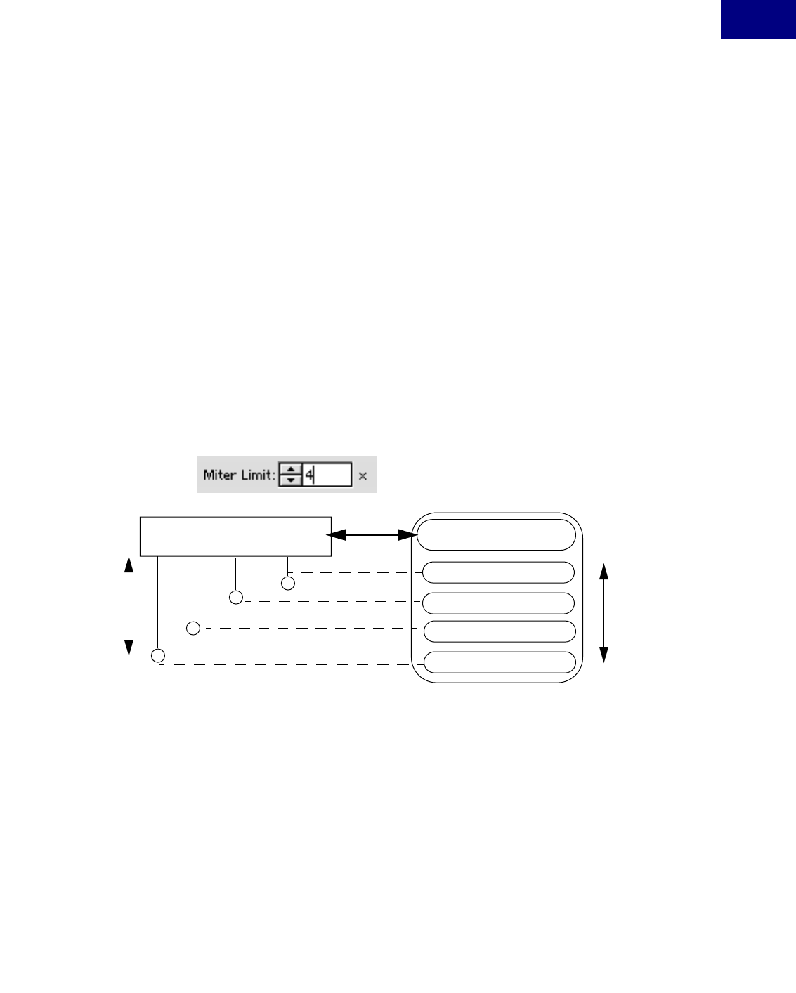
User-Interface Fundamentals 681
User-Interface Fundamentals
Sample user interface
A frequently encountered type expression is an ODFRez custom-resource type definition that
refers to an interface ID or boss class IDs. An ODFRez expression like ClassID = xxx (or IID =
xxx) establishes a binding between a widget boss class (or interface in the API) and an ODFRez
custom-resource type.
For Example 95, some of the type bindings are illustrated in Figure 273, which shows one of the
widget boss classes involved, the kIntEditBoxWidgetBoss class which provides an API to an
integer-specific edit control. Note how the ODFRez is made up of fields, like CControlView,
that map onto interfaces on the widget boss class. There also are other interfaces on the widget
boss class that do not map to fields in ODFRez, like IEventHandler. The ODFRez fields specify
the appearance of the control; they do not address its behavior, which is done by the widget
boss class.
Figure 273 shows the type binding between the kIntEditBoxWidgetBoss boss class and the
associated ODFRez custom-resource type IntEditBoxWidget. It also shows the type bindings
for each interface with persistent data exposed by kIntEditBoxWidgetBoss. Each persistent
interface is bound to an ODFRez custom-resource type that is used to define the initial state
stored in the interface by a widget boss object.
FIGURE 273 Binding between classes/interfaces and ODFRez types
The ODFRez fields in IntEditBoxWidget define the initial state for the integer edit-box widget,
whose behavior is provided by kIntEditBoxWidgetBoss. Example 95 shows the ODFRez data
statements for the widgets in Figure 272.
EXAMPLE 95 Data statement for widgets in example
// Miter Limit
StaticTextWidget
(
// CControlView fields below
kMiterStaticTextWidgetId, kPMRsrcID_None, // WidgetId, RsrcId
kBindNone, // Frame binding
Frame(0,30,58,47) // Frame
kTrue, kTrue, // Visible, Enabled,
kIntEditBoxWidgetBoss
IntEditBoxWidget
ODFRez custom resource type
IControlView
IEditBoxAttributes
ITextDataValidation
ITextControlData
CControlView
CEditBoxAttributes
TextDataValidation
CTextControlData
ODFRez
fields
Interfaces

User-Interface Fundamentals
Sample user interface
682
// StaticTextAttributes fields below
kAlignRight, // Alignment
kDontEllipsize, // Ellipsize style
// CTextControlData field below
"Miter Limit:",
// AssociatedWidgetAttributes field below
kMiterTextWidgetId
),
IntEditBoxWidget
(
// CControlView fields below
kMiterTextWidgetId, // WidgetId,
kSysEditBoxRsrcId, kStrokePanelPluginID, // RsrcId
kBindNone, // Frame binding
Frame(73,30,111,47) // Frame
kTrue, kTrue, // Visible, Enabled
// CEditBoxAttributes fields below
kMiterNudgeWidgetId, // widget id of nudge button
1, 10, // small/large nudge amount
3, // max num chars( 0 = no limit)
kFalse, // is read only
kFalse, // should notify each key stroke
// TextDataValidation fields below
kTrue, // range checking enabled
kFalse, // blank entry allowed
500, 1, // upper/lower bounds
"4" // initial value
),
NudgeControlWidget
(
kMiterNudgeWidgetId, kPMRsrcID_None, // WidgetId, RsrcId
kBindNone, // Frame binding
Frame(59,30,73,47) // Frame
kTrue, kTrue, // Visible, Enabled
),
StaticTextWidget
(
kXTextWidgetId, kPMRsrcID_None, // WidgetId, RsrcId
kBindNone, // Frame binding
Frame(115,30,125,47) // Frame
kTrue, kTrue, kAlignLeft, // Visible, Enabled, Alignment
kDontEllipsize, // Ellipsize style
"x",
kMiterTextWidgetId
),
NOTE:Although there are strings like “Miter Limit:” in the ODFRez data, these always are
translated for display in the user interface. The strings should be regarded as keys rather
than values to be displayed. The SDK string keys are defined with particular care, using
a scheme to avoid string-key clashes between plug-ins from different third-party
software developers. The approach taken within the application is less structured and
not recommended for third-party development.
User-Interface Fundamentals 683
User-Interface Fundamentals
Factorization of the user-interface model
The main point to note about the ODFRez data statements is that each comprises fields of sim-
pler types. For example, CTextControlData has one field, containing a string key. The contents
of this CTextControlData field are used to initialize the contents of the ITextControlData when
the widget boss object is created.
Widget boss objects read their initial state from the compiled version of the ODFRez data.
They persist their state to a saved-data database and read it back from this if the application
starts up with saved data.
Factorization of the user-interface model
Architecture
Often it is tedious and difficult to write a responsive user interface. Also, there are well known
differences in the user-interface APIs on Mac OS and Windows. A key design objective for the
InDesign user-interface architecture was to provide a cross-platform API and interface-defini-
tion format. The result is that the architecture is relatively elaborate; however, it is based on
simple and familiar concepts. The user-interface architecture consists of views, data models,
event handlers, and observers on the models. There also are attributes associated with the wid-
get boss classes. See Table 153.
TABLE 153 Aspects of the user-interface model
The event handlers have code that changes the data models. When the widget data models
change, the change manager is notified through the default ISubject implementation. It is the
change manager that notifies observers of changes to the data model of interest. This abstrac-
tion is described elsewhere, in connection with commands and the notification framework.
Aspect Description
Attributes Represent properties (rather than user data), like the point size a text
widget uses to displays its label. These are properties that can be defined
in ODFRez data statements, although typically they also can be set
through interfaces aggregated on the widget boss class providing the
widget behavior. See “Attributes” on page 685.
Control
data
models
Encapsulate the widget state. Typically, the control-data-model
implementation notifies when it changes, so observers on its state can get
notified about the changes. See “Control data models” on page 684.
Control
views
Specify the presentation of a widget, like whether it is visible, its widget
ID, or whether it is enabled. The particular implementation on a widget
boss class determines how the control draws. See “Control views” on
page 684.
Event
handlers
Convert events into changes to the data model. See “Event handlers” on
page 685.

User-Interface Fundamentals
Factorization of the user-interface model
684
Views are connected with the visual appearance of a widget. They can be manipulated to
change the visual representation of widgets, like the dimension of the bounding box or the vis-
ibility. They also encapsulate the process of rendering a view of the data model.
The only occurrence of an explicit controller abstraction is in the context of dialog boxes. Wid-
get boss classes have no externally visible controller abstraction; code with an equivalent
responsibility is encapsulated in the widget event handlers. The MVC pattern is not a complete
description of the user-interface architecture.
There also can be other interfaces aggregated on boss classes, often related to details about an
implementation of a particular widget.
At its simplest, a widget consists of at least a control view (IControlView). If a widget has a state
that can be changed, it also has a control data model, like IBooleanControlData, ITriStateCon-
trolData, or ITextControlData. If the widget is responsive to end-user events, it aggregates an
event handler (IEventHandler). It also may have other property-related interfaces.
Depending on the widget type, there can be additional interfaces to manipulate the control or
perform operations on data. For example, the combo-box widget boss class kIntComboBox-
WidgetBoss has additional interfaces, like IDropDownListController (to manipulate the list
component of the combo box) and ITextDataValidation (for performing validation on data
entered in the edit-box component of the combo box).
Control views
Control views are responsible for creating the visual representation of a widget boss class. For
example, the control-view implementation associated with a palette-panel widget draws a drop
shadow. The interface that allows control views to be manipulated is IControlView. This inter-
face, for example, can be used to show or hide a widget or to vary other visual properties.
The key method for widget drawing is IControlView::Draw. A widget boss class implements
this method to provide its default visual appearance. This method is called in response to sys-
tem paint events or explicit requests to redraw. Any owner draw widgets should override this
method to provide a specialized appearance.
Views also can control their own size in response to end-user events. Overriding the Con-
strainDimensions method on the IControlView interface allows a panel to resize to its con-
tainer palette. For more information, see the API documentation for this interface and
Table 156.
Control data models
A control data model represents the state of a widget and is responsible for notifying the appli-
cation core of changes in its state. For example, an edit box has a data model represented by a
PMString. Changes in this state are likely to be of interest to client code in a plug-in.
The widget boss classes that control the behavior of radio buttons (kRadioButtonWidgetBoss)
and check boxes (kCheckBoxWidgetBoss) aggregate an ITriStateControlData interface. This
interface queries and modifies the state of the check box. The possible states are checked,
unchecked, or indeterminate (mixed). The event handler interacts with the control data to set

User-Interface Fundamentals 685
User-Interface Fundamentals
Factorization of the user-interface model
the state. Client code also may have to set and query the control-data-model state and register
for notification about changes to the state of the control data model. Typically, observers asso-
ciated with widgets request notification about changes along a protocol, IID_I<name>CON-
TROLDATA. This is the standard mechanism for client code to receive messages about changes
in the state of a control.
Other APIs require that explicit event handlers be written to process messages from controls.
Coding event handlers are used relatively infrequently when programming with the user inter-
face API; the requirement to implement observers is far more common.
Event handlers
The main pattern for processing end-user events is the observer pattern; events are trans-
formed into semantic events by the widget boss class’s event-handler code. These semantic
events are then transmitted to the observer, as IObserver::Update messages with informative
parameters. An end user clicking the left mouse button when the pointer is over a button is a
low-level event; it becomes a semantic event when interpreted as a button press that takes the
control into a button-down state. The semantic event is of more interest to client code than the
low-level event, because it provides a useful level of abstraction over the details of how the end
user manipulates the state of different types of controls.
Event handlers are responsible for transforming end-user events into changes in the data
model. The event handler, therefore, mediates between the end user and the control’s internal
state.
It is important to be clear about the difference between an event handler and an observer. Event
handlers generally are of little interest to client code, except in highly specialized circum-
stances, when the standard behavior of the control needs to be overridden. There is no need to
code an event handler to be notified of events within a widget, like mouse clicks on a button, if
the semantic event of interest is the button press.
When an end user clicks in a widget, events are transformed by the application core into cross-
platform messages. For example, if an end user clicks on a button, the button-event handler
receives an IEvent::LButtonDn message. The responsibility of the event handler is to map these
events into changes to the state of the control, which it does through interaction with the con-
trol’s data model. For example, if a check box is selected, the state is represented by the control
data interface ITriStateControlData. The event handler determines this state and calls
ITriStateControlData::Deselect when the check box is clicked in the selected state. For more
information, see the API documentation for IEventHandler and Table 156.
Attributes
An attribute is a property of a control that is not an aspect of the data model but can be used in
defining its visual representation, as well as other nonvisual properties. For example, the fol-
lowing are some of the attributes of a multiline text widget:
zThe font ID used in rendering text.
zThe widget ID of the associated scrollbar.

User-Interface Fundamentals
Relevant design patterns
686
zLeading between the lines, expressed in pixels.
zAn instance of a PMPoint, specifying the inset of the text from its frame.
These attributes are defined in ODFRez data statements. The dimensions of a widget (for
example) also can be defined in data statements, but this is a property directly associated with
the view. The data model represents the widget state likely to be varied by an end user, like the
contents of an edit box.
Relevant design patterns
Design patterns are “simple and elegant solutions to specific problems in object-oriented soft-
ware design” (Gamma, et al.). The objective of such patterns is to write code with the following
characteristics:
zFlexible — The code can be reused from many different contexts.
zWell factored — Responsibilities of classes are not confused or confounded.
zEasily comprehensible — There is a low barrier to understanding by new software develop-
ers.
zEasy to extend and maintain.
To understand design patterns, you must be aware of how objects in the pattern interact and
how responsibilities are distributed between the classes involved. This section introduces some
of the design patterns in the API related to the user interface.
These patterns are introduced here to provide a clear outline of the design commitments made
in the API. Some of the abstractions may be unfamiliar, but they will be encountered repeat-
edly in developing plug-ins, so it is important to understand these patterns. Some patterns of
relevance and their applicable domain are as follows:
zObserver — Event-notification framework. For example, observers are notified of changes
in the control data model (the subject). See “Observer pattern” on page 686.
zChain of responsibility — Applicable to the event-handling architecture. The application
event handler maintains a stack of event handlers, which are invited in turn to process the
current event. If one does not handle the event, the next one down on the stack is invited to
handle the event. This is not identical with the pattern described in Gamma et al., but the
intent is the same. See “Chain of responsibility” on page 689.
zCommand pattern — Command processing by the application core is an elaborated imple-
mentation of this pattern.
Observer pattern
The observer pattern also is referred to with the term “publish-subscribe.” This pattern is fun-
damental to the user-interface model. Every widget boss class aggregates an ISubject interface
and, therefore, it can be observed.

User-Interface Fundamentals 687
User-Interface Fundamentals
Relevant design patterns
The observer pattern is appropriate in the following situations:
zWhen the situation being modeled has two aspects—one dependent on the other—and you
want to represent these in separate, lightly-coupled abstractions.
zWhen change to one object requires change to another, but it is not known beforehand how
many other objects need to be changed.
zWhen one object needs to broadcast a state change to other objects registering an interest.
The abstractions in the pattern are the observer and the subject. The subject abstraction encap-
sulates state of potential interest to client code, like the state of a check-box widget.
The observer is interested in changes to the subject. The observing abstraction determines
when to register with a particular subject and when to deregister.
The observer registers an interest in being informed when the subject changes. For complete-
ness, the pattern also specifies the ability of the observer to send a message to the subject to
state it is no longer interested in being told about changes in the subject.
The observer pattern defines simple abstractions and a straightforward protocol for communi-
cation between the subject and observer. The sequence is as follows:
1. The observer sends an attach message to the subject (similar to registering for a mailing list
by sending one’s e-mail address).
2. A client or owner of the subject sends it a notify message to indicate that any registered
observers should be informed of a change.
3. When a change occurs, the subject sends an update message to the observer.
4. The observer queries the subject for details of the subject state in which it is interested.
Changes in the state (data model) of widgets are observed by objects derived from a helper
C++ class (CObserver). This allows creation of a listener object that is notified when the data
model associated with a widget changes.
Observers are discussed in more detail in the “Notification” chapter of Learning the Adobe
InDesign CS4 Architecture.
How event handlers implement controllers
Events do not lead directly to observer notifications; there is an intermediate step in the user-
interface model. IEvent types, for example, do not convey the appropriate semantics to allow a
listener to determine the meaning of an event; a mouse click on a radio button does not tell a
listener enough about the action (selection or deselection). The listener would be aware only
that a particular mouse event occurred. The missing data is the state of the widget.
The correct process is to attach to the data model of the widget and register for notification on
changes in the data model. Rather than each individual observer having to maintain informa-
tion about the state of the widget, this state is held in the control's data model, and many
observers can listen for changes in this model.
For example, if a radio button is selected or deselected, the widget boss object’s event handler
changes the control data model. This, in turn, generates a call to the Update method in the

User-Interface Fundamentals
Relevant design patterns
688
observer. At this point, the implementation-specific code determines what operation to per-
form, based on the current state and the type of event. The parameters of the Update message
specify to an observer the new state of the control.
Model-view controller (MVC) is a well-known mutation of the observer pattern. The model
plays the role of subject in the observer pattern. The view is equivalent to the observer. The
only new abstraction is the controller, which is implicit in the observer pattern; it is the entity
that mediates between the end user (an event source) and the data model. The controller causes
views to update after the data model is changed. The responsibilities of the elements of the
MVC pattern are as follows:
zThe controller receives end-user input events, queries or updates the model, and forces the
views to refresh with new data.
zThe model is a data container. It is protected from the end user by the controller and encap-
sulates the state of interest to the end user.
zThe view consists of renderings of data supplied to it by the controller. Typically, the view
cannot actively query the model but passively renders data.
The controller separates the responsibility of dealing with user interaction from the entities
responsible for displaying a view of the model or maintaining model state. It becomes particu-
larly useful when not all end users have equal rights to change or query the model, and it medi-
ates between the users and the data (state).
This pattern is especially useful when an application is involved in creating multiple renderings
of the same data and keeping these synchronized across updates of the data.
The role of MVC in the user-interface model
Strictly speaking, the application does not implement the pattern from the SmallTalk MVC.
There are few explicitly named abstractions in the codebase named <name>Controller; for
example, the IDialogController interface. In SmallTalk, there are classes in the class library
named Model, View, and Controller, that are subclassed to build a user interface. There is no
direct equivalent in the InDesign API. MVC is an approximation to the architecture and is a
reasonable conceptual (high-level) description of the architecture; however, it is not accurate at
a more detailed level.
Event handlers are related to controllers, because they act upon and change a model (the wid-
get data model). The code that implements the widget data model in turn sends out notifica-
tions via the change manager, when the model is changed.
A widget’s event handler changes the data model of a widget boss object directly, without using
commands. A command sequence always is needed to change the native document model,
which does not involve user-interface widget boss objects. The event handler is in the same role
as the controller abstraction in the MVC pattern, because it sits between the data model and
the end user, mediates changes in the model initiated by the end user, and indirectly triggers
notifications about changes in the data model. In other words, within the InDesign user-inter-
face architecture, the data model actively notifies the change manager about its change in state,
rather than being a passive abstraction.

User-Interface Fundamentals 689
User-Interface Fundamentals
Relevant design patterns
The data model of a widget boss object sends a change message to the change manager through
the default ISubject implementation, and attached listeners receive an IObserver::Update mes-
sage.
This pattern is encountered in the context of creating dialog interfaces by subclassing the par-
tial implementation classes CDialogController and CDialogObserver. In the behavior of most
widget boss classes, the notion of an explicit controller is not encountered directly, and you can
largely forget about MVC when it comes to writing user-interface plug-ins. Think in terms of
the observer pattern, and consider that changes to the control data model (subject, represented
by ISubject) of a widget result in change notifications being sent to any registered observers
(IObserver) on the abstract subject.
Chain of responsibility
The chain-of-responsibility pattern also is referred to with the term “responder” (see IRe-
sponder in the API) or “event handler” (see IEventHandler in the API). Use it in the following
situations:
zWhen multiple objects might be able to handle a single request or event.
zWhen it is not known beforehand which event handler will be used for a specific event.
The key intent of this pattern is to give multiple objects a chance to handle a request or event.
This pattern is useful when writing event handlers for plug-ins, as event handlers are stacked
by the application core, and events are chained between the event handlers. If one handler does
not signify that an event was handled, the next event handler receives notification of the event.
The chaining stops if one handler claims responsibility for having handled the event and no
further event propagation would occur.
The user-interface model does not implement the pattern exactly as specified in Gamma et al.
In the API, there is an event dispatcher that takes responsibility for propagating the events
instead of having each event handler explicitly be aware of the next handler in the chain.
Facade
The intent of the facade pattern (Gamma et al.) is to provide a simplified interface to a complex
subsystem. The abstractions in a facade pattern are the facade itself and subsystem classes. The
facade knows the subsystem classes to which particular requests should be delegated. The suite
architecture uses the facade pattern; suites provide a simplified API for potentially complicated
selection format-specific code that has detailed knowledge of model structure.
Within the context of the InDesign selection architecture, the facade is the abstract interface of
the suite itself (for example, ITableSuite), and the subsystem classes are those such as
<name>ASB and <name>CSB, which add implementations of the suite interface to the
abstraction and concrete-selection boss classes, respectively.
In the facade pattern, a client sends requests to the facade, which forwards them to the appro-
priate object in the subsystem. In the case of suites and the selection architecture, the client is
the client code that handled (for example) a menu item. The integrator suite is responsible for

User-Interface Fundamentals
Relevant design patterns
690
choosing the correct implementation given the selection format and delegating the request to
the correct implementation.
There are other examples of the facade pattern in the API, like the nudge-control widget
(kNudgeControlWidgetBoss) and combo-box widgets (kComboBoxWidgetBoss). These are
relatively complex widgets that expose a more restricted API to client code, to allow it to
manipulate their state and properties.
Command
The intent of the command pattern (Gamma et al.) is to encapsulate a request as an object,
allowing clients to parameterize requests, enabling requests to be queued and executed at dif-
ferent times, and supporting an undo protocol. A major benefit of this pattern is that it de-cou-
ples the object that calls an operation from the object that knows how to perform it.
The key abstraction in the command pattern is the client, which creates a command, a specifi-
cation of a parameterized operation. The caller executes the command subject to its scheduling
preferences. A receiver abstraction knows how to perform the command; for example, an
abstraction that can perform a copy on a document page item. The receiver is referenced from
the command, to allow the caller to indirectly execute the required operations.
Within the application, client code (often user-interface code) takes on the role of the client;
the caller is the command-execution framework of the application core. Client code also may
provide the receiver (or delegate to another abstraction within the API). At its most basic, the
command abstraction should support an execute method; ideally, it also should support an
undo protocol.
Widget-observer pattern
The widget-observer pattern is a specialization of the observer pattern that applies in the fol-
lowing circumstances:
zYou have many controls on a panel, and you want to get notifications about changes in their
state.
zYou do not want to subclass every widget boss class involved, just to aggregate an IObserver
on each.
Rather than having to subclass all the controls you use on a panel, use one widget observer
aggregated on the parent panel boss class. Use the observer implementation to attach to and
detach from the ISubject interface on the widgets of interest, when this widget observer is sent
IObserver::AutoAttach and IObserver::AutoDetach messages.
There is an extension of this pattern that you can use when you also want to observe changes in
the active context. Observing changes in the active context is very common when writing pan-
els that may be constantly present and provide some form of read-out about the application
state. This extended pattern for receiving notification about changes in control state on a panel
and notification about changes in the active context can be called the “active-selection and wid-
get-observer pattern”; it requires you to aggregate a standard API implementation of IControl-
ViewObservers on the panel-widget boss class. The corresponding ODFRez data statements

User-Interface Fundamentals 691
User-Interface Fundamentals
Persistence and widgets
are sufficient to create all wiring for the observer implementations to be auto-attached and
detached. In the old InDesign 1.x architecture, there was no way to do this, and it would have
been necessary to create a dummy observer that simply called AutoAttach on other observers
on a given boss object.
IControlViewObserver
Adding a widget observer and active-selection observers to a single-panel boss class and using
the IControlViewObservers mechanism to wire these in ODFRez data is a very common pat-
tern in the InDesign application codebase. For example, panels—like the Character panel—
observe changes in the active context and update states of the widgets, while simultaneously
monitoring for changes in the state of many combo-box widgets and so on, using a widget
observer and an active-selection observer that are hooked up by IControlViewObservers.
For an example of adding a widget observer, an active-context observer, and control-view
observers, see the boss-class definition for kTblAttPanelWidgetBoss in {SDK}/source/sdksam-
ples/tableattributes/TblAttr.fr.
See the TblAttPanelWidget type definition, which adds the field to the type statement for the
ODFRez panel widget.
Persistence and widgets
Widget boss classes descend from kBaseWidgetBoss, which exposes the IPMPersist interface.
This means a widget boss object can read its initial or stored state for any persistent interfaces
exposed by the widget boss class. An interface is persistent if and only if its implementation is
declared with the CREATE_PERSIST_PMINTERFACE macro, in which case it must imple-
ment a ReadWrite method.
The initial state of a widget is created by reading data from the plug-in resource in the very first
instance. The persistent interfaces on a widget boss class, like IControlView, read their initial
state from the plug-in resource.
There is a simple rule for understanding which interfaces should be persistent in a widget boss
class: at least the interfaces that are bound to ODFRez types should be persistent. If not, there is
no way for them to read their initial state from the binary data in the plug-in resource.
Consider the example with the integer edit box and nudge control shown in Figure 272. There
are four interfaces bound to ODFRez types (see Figure 273), and other interfaces on this boss
class that are not bound to ODFRez types. Table 154 shows some of the interfaces on the boss
class, whether they are persistent, and whether they are bound to an ODFRez type.

User-Interface Fundamentals
Resource roadmap
692
TABLE 154 Interfaces, with persistence and binding information
NOTE:ITextValue is specified as persistent in the implementation code but is not bound to any
specific ODFRez type. This interface provides an API to read and write formatted
values, and it cannot be initialized by ODFRez data statements.
In theory, a third-party software developer can create an entirely new widget boss class, deriv-
ing from kBaseWidgetBoss and providing the implementation of required interfaces like ICon-
trolView and IEventHandler. Extreme care must be taken to ensure that the specification of the
fields in the xxx.fh file matches the order in which the data is read or written in the ReadWrite
method of any persistent interfaces on the new widget boss class. The key point to remember is
that a binding between an ODFRez type and an interface ID means the (implementation of)
the interface must be persistent.
All widgets have an initial state defined by ODFRez data statements. The ReadWrite method of
the persistent interface implementation is called during the initialization of widget boss
objects, when an object is created by reading its initial state from a plug-in resource or saved-
data database. If there is no saved data, the widget boss object is initialized from the plug-in
resource. If there is saved data, any persistent data associated with the widget is read back from
the saved data, including parameters like position and size (for resizable elements such as resiz-
able panels).
Resource roadmap
Architecture
A typical plug-in comprises the following:
zTop-level framework resource files (.fr) that contain boss-class definitions, new ODFRez
custom-resource type definitions, and other resources, like view definitions and nontrans-
lated string tables.
Interface Implementation ID Persistent? Bound to ODFREz type?
IControlView kNudgeEditBoxViewImpl Yes Ye s
IEditBoxAttributes kEditBoxAttributesImpl Yes Yes
IEventHandler kEditBoxEventHandlerImpl No No
IObserver kCNudgeObserverImpl No No
ITextControlData kEditBoxTextControlDataImpl Yes Ye s
ITextDataValidation kIntTextValidationImpl Yes Yes
ITextValue kIntTextValueImpl Yes * (see note
below table)
No

User-Interface Fundamentals 693
User-Interface Fundamentals
Resource roadmap
zLocalized framework resource files (the names of which end in something like “_enUS.fr”)
that contain the ODFRez data statements required to define the plug-in user interface on a
per-locale basis.
zC++ code that implements the interfaces in the boss-class definitions.
The framework resources are compiled using the ODF resource compiler (ODFRC). The C++
code is compiled by the appropriate compiler for the platform. The boss-class definitions are
the starting point to understand a new code base; they specify the subclasses for the new boss
classes that the plug-in adds to the API, and promise implementations of interfaces.
OpenDoc framework (ODF) resources
The ODF resource language (ODFRez) is a cross-platform solution for defining user-interface
resources. ODFRez is based on Rez, the Apple resource utility available with Apple MPW.
ODFRez differs from Rez in minor respects; it is intended as an object-oriented, cross-plat-
form, resource-definition format, and it is case-sensitive.
The ODF resource compiler, ODFRC, compiles files written in the ODFRez language. The
ODFRez language has a very simple grammar and provides a comprehensive way to define
resources, not write programs. There is support for code in other languages that can be embed-
ded, but this capability is limited; only constant C expressions can be embedded in ODFRez
files.
ODFRez files contain both type statements (defining new types, or the equivalent of resource
classes) and resource-data statements (instances of types). Example 96 shows a separator wid-
get type being defined; that is, definition of the ODFRez custom-resource type SeparatorWid-
get, which extends the ODFRez custom-resource type, Widget. A ClassID field is initialized to
the value of kSeparatorWidgetBoss, specifying the class that provides the behavior behind this
widget.
EXAMPLE 96 Annotated type definition for separator widget
// The ODFRez type expression defining that the SeparatorWidget extends the
// base type, Widget, and has a field of type CControlView.
type SeparatorWidget (kViewRsrcType) :
// note that this is a view-resource type Widget
// superclass for this type - the base ODFRez Widget
(ClassID = kSeparatorWidgetBoss)
// ClassID is a field of Widget, bound here to a boss class kSeparatorWidgetBoss
{
CControlView; // field belonging to the SeparatorWidget type
};
ODF resources are created in one or more ODF resource-definition files. These files are text
files with .fr extensions. There also may be platform-specific resources associated with a plug-
in, like icons, PICT, or Windows bitmap resources, though plug-ins should be using PNG-
based resources wherever possible, because it is a cross-platform format.

User-Interface Fundamentals
Resource roadmap
694
Top-level framework resources
PanelList resource
Panels are containers for widgets housed in palettes. They enable panels to be ordered, dragged
around, shown, and hidden. An example of a panel contained in a palette is the Stroke panel.
The root panel for a plug-in is defined in a PanelList resource. The ODFRez custom-resource
type PanelList specifies what plug-in ID the panels are associated with, a resource ID to use in
loading the panels, and how each panel interacts with the menu subsystem.
To understand the PanelList, it is important to be able to distinguish between the ODFRez Pan-
elList type (the template, just like a C++ class declaration) and an ODFRez data statement
defining an instance of a PanelList:
zThe template for PanelList is prefaced by type; for example: “type PanelList (kPanelListRsrc-
Type).”
zAn instance of a PanelList is prefaced by resource; for example: “resource PanelList (kSDK-
DefPanelResourceID).”
Nontranslated StringTable resource
There is a StringTable resource where the plug-in developer can place strings that are not to be
translated. To minimize the amount of unnecessary duplication of strings across the locale-spe-
cific string tables, pay careful attention to localization. For examples of localization, refer to the
SDK sample plug-ins.
Localizing framework resources
Strings displayed in the user-interface elements, except the layout widget (the document view),
are likely to require localization. From a programming perspective, consider the following enti-
ties when localizing:
zView resources — The geometry of a panel may change in a language like German, in which,
on average, strings are longer than in English.
zStrings — The display of strings may change on dialog boxes and panels (as labels), and on
menus as the names for menu items.
For each of these entities, there should be an ODFRez LocaleIndex custom resource, which
provides the offsets the application framework needs to switch to the localized data for a par-
ticular locale. There also should be an appropriate ODFRez StringTable or view resource in the
localized framework resource files, to match those promised in the ODFRez LocaleIndex state-
ments.
For most purposes, the recommended string class to use in the API is PMString. The applica-
tion architecture tries to translate all PMStrings for display in the user interface, unless they are
explicitly marked as nontranslatable, either by being included in the nontranslate string table
(which, in general, should be very small) or by calling a SetTranslatable(kFalse) on a PMString
before it is used. You should provide a translation for every string likely to be displayed in the
user interface, in locale-specific string tables.

User-Interface Fundamentals 695
User-Interface Fundamentals
Resource roadmap
Localization and LocaleIndex resources
The mechanism of localization is extremely straightforward using the application architecture.
The key is to manipulate string keys (keys into the StringTable for a locale) rather than think-
ing in terms of strings as values.
The LocaleIndex resource is a look-up table that specifies how to locate a particular resource
given the locale. A LocaleIndex resource should be declared for each of the following:
zEach view that is to be localized.
zThe localized string table.
zThe nontranslated string table.
When adding new resource statements for views, a common mistake is to forget the LocaleIn-
dex associated with the view. The type expressions and the data statements for the view may be
perfectly formed, but without the LocaleIndex resource telling the localization subsystem
which view to choose for which locale, the widgets corresponding to the view resource do not
appear. The LocaleIndex type is defined in the SDK header file LocaleIndex.h. The ODFRez
LocaleIndex type is a template for defining resources that enables the application core to
choose the correct views and strings, given the current locale setting.
Resource compilers
It is important to understand how the files that make up a plug-in project are compiled.
Table 155 lists the tools used for compiling resources.
TABLE 155 Tools for compiling user-interface plug-ins
The same (header) file may be compiled with the C++ compiler, ODFRC compiler, and plat-
form-native resource compiler; this is achieved by using macros. Some of the key macros can
be found in CrossPlatformTypes.h, with core data types defined in CoreResTypes.h.
Platform Tool Description
Mac OS ODFRC Plug-in for Metrowerks CodeWarrior.
Mac OS Rez Platform-native compiler which compiles any platform-
specific resources, like icons or .rsrs or .r files.
Windows ODFRC.exe Windows executable version of the ODF resource compiler
that produces Windows binary resources.
Windows RC.exe Platform-native resource compiler which compiles the RC
file present in a plug-in and any other platform-specific
resources, like icon definitions.

User-Interface Fundamentals
Customizing a widget
696
Customizing a widget
A common reason to add a new interface to an existing widget boss class is to create a new wid-
get boss class that exposes an IObserver interface. This is the pattern for obtaining notification
about changes to the data model of a particular widget boss object. If you have many widgets
on a panel, use the pattern described in “Widget-observer pattern” on page 690. Otherwise,
you risk the unnecessary proliferation of entities that may lead to problems later.
For example, suppose a software developer wrote a new type of panel with a single list box on
it. When an end user makes a new selection in the list box, client code receives an update mes-
sage on the IObserver interface. The parameters of the update message specify the type of
change that occurred. In this instance, the software developer would subclass the kWidgetList-
BoxWidgetNewBoss boss class and extend the ODFRez custom-resource type WidgetListBox-
WidgetN, binding it to the new boss type.
For controls on dialog boxes, generally there is no need to subclass a widget boss class for each
of the controls to get notification about events. There can be one observer for all controls on
the dialog box, which can choose to attach to particular controls on the dialog box if notifica-
tions about changes in data are required before the dialog box is closed. The helper class CDia-
logObserver (partial implementation of IObserver) provides an API that is extremely useful for
attaching to and detaching from controls on a dialog box. It also should be used as the basis for
an override of the IObserver interface on the kDialogBoss class. If you use DollyXs to generate
the boilerplate for a dialog box, by default you already have an implementation of an observer
that gets notification about all controls. This actually is an implementation of the widget-
observer pattern, which merely generalizes the notion to an arbitrary parent-widget type.
Advanced event handling
Writing a proxy event handler
The way in which the observer design pattern is implemented in the user-interface model
means client code can be notified about widget events without an event handler having to be
implemented in your plug-in. In general, this is sufficient for client code to be responsive to
end-user events. This pattern simplifies client code and avoids client code having to turn low-
level events (like a mouse move or button press) into semantic events (like a check-box widget
becoming checked). Even notification of single keystrokes can be sent to an observer of a text
widget, so the granularity of notification is potentially quite fine.
The event-handler implementations in the InDesign/InCopy user interface can have an inher-
itance hierarchy several levels deep. In most cases, it is not possible to subclass the implementa-
tion by straightforward C++ techniques, because most event-handler implementation headers
are not exposed to plug-in developers.
There are specialized cases in which some knowledge of the event-handling model is useful
and the ability to override the default event handling for a control is essential. An example is

User-Interface Fundamentals 697
User-Interface Fundamentals
Key abstractions in the API
when there is a requirement to specialize the event-handling behavior of a particular control,
such as to perform a special function in response to a double click. The challenge is that most
of the event-handler implementation classes are not exposed to plug-in developers, because
these may involve deep hierarchies of implementation classes that also are not public. It breaks
the encapsulation in the user-interface API if client code comes to depend on this code. Fortu-
nately, there is a convenient workaround for this, by using a proxy or delegate pattern.
Watching events
The concept of overriding the default event handler for a control using the proxy technique,
which is often all that is appropriate, implies handling many messages. Often, only a few mes-
sages are of interest, and you want a technique with more precision. The event-watcher
(IEventWatcher) abstraction can target specific events, and a particularly useful partial imple-
mentation class (CIdleMouseWatcher) can provide a convenient source of information about
MouseMove events, without the need to register every MouseMove event associated with a
control.
For example, the JPEG Export dialog box has a feature that allows a description of the widget
over which the mouse pointer is hovering, based on the CIdleMouseWatcher partial imple-
mentation. This implementation class can be used to create a mouse event watcher without
having to use a proxy event-handler pattern.
Key abstractions in the API
Table 156 shows some of the key interfaces and summarizes their responsibilities. The kBase-
WidgetBoss boss class is the ancestor for all API widget boss classes. Some of these are found
on kBaseWidgetBoss. For a complete list of interfaces on kBaseWidgetBoss, see the API refer-
ence documentation.

User-Interface Fundamentals
Key abstractions in the API
698
TABLE 156 Key widget-related interfaces
Name Key responsibilities
IControlView Implements the widget view (the visual representation of a widget) and stores properties like
its dimensions or visibility. Every widget boss class provides an implementation of the
IControlView interface, and the IControlView::Draw method determines how it renders its
appearance. For more detail on owner-draw controls, see the API reference documentation
for IControlView and the CustomDataLink and PanelTreeView SDK samples.
ISubject Makes a widget observable by observers. Exposed by kBaseWidgetBoss, so every widget also
is a subject.
IObserver Provides notification when widgets change. Implements the observer component of the
observer design pattern. You add an implementation of IObserver in to a widget boss class to
let your code be called when a widget or one of its dependents is changed.
IPanelControlData Used to traverse the widget tree in the direction of the leaves. Found on container widget
boss classes (like panels or dialog boxes).
IWidgetParent Allows the widget tree to be traversed in the direction of the root. At the root of a typical
widget hierarchy (associated with a panel or dialog box) is a window boss object. Given an
interface pointer referring to one widget boss object, it is possible to walk up the widget
hierarchy, querying for a particular interface, until reaching the root.
IEventHandler An event-handling API. The event dispatcher in the application core dispatches events to a
widget’s event handler, according to its own logic. Your client code typically uses the
observer pattern only to receive notification about changes in control state and does not
need to implement event handlers.
ITip Allows a tip to be defined in ODFRez data statements.
IPMPersist Allows the widget to read its state from the plug-in resource’s saved data and to write its state
back to saved data.

Suppressed User Interface 699
Suppressed User Interface
Introduction
Suppressed User Interface
Introduction
This chapter describes the suppressed user interface feature and how plug-in developers can
use it to hide or disable pieces of the InDesign or InCopy user interfaces.
Sometimes it is valuable to remove or disable some functions. For example, system integrators
may want to disable particular features or controls. The easiest way to do this is to remove non-
required user-interface plug-ins that provide access to the undesirable features. While this
works in the simplest of cases, it does not provide the granularity necessary in most cases. Most
often, it is desirable to disable parts of a plug-in. Suppressed user interface allows plug-in devel-
opers to disable or hide menus, actions, and widgets; and disable drop operations for specific
widgets.
In this chapter, suppress means hide or disable.
Architecture
The suppressed user-interface architecture is straightforward. An implementation of ISup-
pressedUI was added to kSessionBoss. The menu, action, widget and drag-and-drop code calls
methods on this interface to determine whether a user-interface element is suppressed. The
implementation of ISuppressedUI does not track suppressed widgets; instead, it forwards the
method calls to the ISuppressedUI implementations on kSuppressedUIService service provider
bosses. These service provider bosses are the extension point for third-party developers.
The minimum requirement for a plug-in to become part of the decision-making process is to
provide a service provider like the following:
Class
{
kMySuppressedUIServiceBoss,
kInvalidClass,
{
IID_IK2SERVICEPROVIDER, kSuppressedUIServiceProviderImpl,
IID_ISUPPRESSEDUI, kMySuppressedUIImpl
}
}
In the above, kSuppressedUIServiceProviderImpl is provided by InDesign. It is a pre-made
implementation of IK2ServiceProvider that identifies this service provider as type kSuppresse-
dUIService. The other implementation, kMySuppressedUIImpl, is where the interesting work
would occur.

Suppressed User Interface
XML-based implementation
700
For an illustration of how the method calls are forwarded to service providers, consider what
happens when an otherwise enabled widget is added to a panel. The widget code calls IsWid-
getDisabled() on the ISuppressedUI implementation aggregated on kSessionBoss. This imple-
mentation forwards the call to the service providers, by looping through calling
IsWidgetDisabled () on the ISuppressedUI implementation. If one service provider returns
kTrue, it breaks out of the loop by immediately returning kTrue. If all service providers return
kFalse, the forwarding method also returns kFalse. The widget is then enabled or disabled,
based on the results of this call.
NOTE:Supresssed user interface is architected for static solutions; i.e., the user-interface
configuration does not change during an application instantiation. To show the new
state, the user interface that is supressed needs to be re-drawn. If a suppressed control is
on a panel, the control’s new state is not drawn until the next update event on the
control, which does not happen until events occur like the panel being closed and re-
opened. The SDK sample “suppui” uses some of the user interfaces that always are re-
drawn before they are displayed, such as menu items; this may lead to confusion about
dynamic support for supressed user interface.
XML-based implementation
Depending on your requirements, you may not need to write your own ISuppressedUI imple-
mentation. InDesign provides an ISuppressedUI implementation (kSuppressedUIWithXML-
FileImpl) that suppresses user-interface items (menus, actions, widgets, and drop targets)
based on the content of a specified XML file. To use this implementation in your service pro-
vider boss, use kSuppressedUIWithXMLFileImpl as the ISuppressedUI implementation. You
also will need to provide an ISysFileData implementation, which is used to specify the XML
file. Your boss will look something like the following:
Class
{
kMySuppressedWithXMLUIServiceBoss,
kInvalidClass,
{
IID_IK2SERVICEPROVIDER, kSuppressedUIServiceProviderImpl,
IID_ISUPPRESSEDUI, kSuppressedUIWithXMLFileImpl,
IID_ISYSFILEDATA, kMySuppressedUISysFileImpl,
}
}
When providing an ISysFile Implementation, you may provide your own ISysFileData imple-
mentation, as shown above. Alternately, you can reuse kSysFileDataImpl which is provided by
InDesign. The difference lies in how the data is initialized. If you provide your own implemen-
tation, you can initialize your class to point to a file of your liking. If you reuse kSysFile-
DataImpl, you must set its data before it is used. One way to do that is to provide a start-up
service (IStartupShutdownService) that sets the SysFileData at start-up. Then, at any other
time, you could set ISysFileData and call ISuppressedUI::Reset() to force the kSuppressedUI-
WithXMLFileImpl to read the XML file. To get to the ISysFileData interface from your service

Suppressed User Interface 701
Suppressed User Interface
XML file format
boss, you can call IK2ServiceRegistry::QueryServiceProviderByClassID(kSuppressedUISer-
vice,kMySuppressedUIWithXMLUIServiceBoss). For an example of how to add your own
XML based service, see the SuppUI sample project.
XML file format
The XML file should be well formed, with a single root element of type SuppressedUI; for
example:
<?xml version="1.0" encoding="UTF-16" standalone="yes"?>
<SuppressedUI>
<SuppressedWidget widgetID="8457" ancestorWidgetID="0"
restrictionType="disable"></SuppressedWidget>
<SuppressedWidget widgetID="1538" ancestorWidgetID="23506"
restrictionType="disable"></SuppressedWidget>
<SuppressedAction actionID="263" restrictionType="disable"></SuppressedAction>
<SuppressedMenu menuName="Main:&Type:&Font"
restrictionType="hide"></SuppressedMenu>
<SuppressedDragDrop widgetID="8455" ancestorWidgetID="0"></SuppressedDragDrop>
<SuppressedPlatformDialogControl
PlatformDialogControlIdentifier="AllOpenDocDialogCustomControls">
</SuppressedPlatfrmDialogControl >
<SuppressedPlatformDialogControl
PlatformDialogControlIdentifier="PlaceFileImportOptionsCheckbox">
</SuppressedPlatfrmDialogControl ></SuppressedUI>
Any of the following five elements and their attributes can be used:
zSuppressedWidget
zSuppressedAction
zSuppressedMenu
zSuppressedDragDrop
zSuppressPlatformDialogControl
They are all described below.
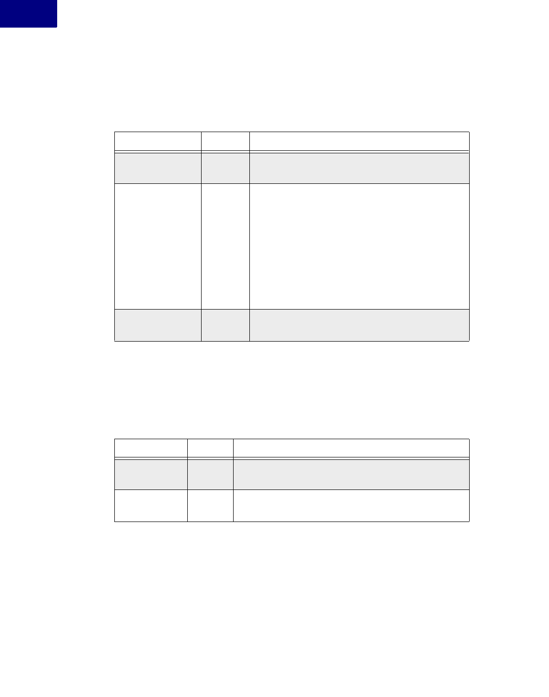
Suppressed User Interface
XML file format
702
SuppressedWidget
The SuppressedWidget element is used to suppress widgets. It should contain the attributes
shown in Table 157.
TABLE 157 Attributes of SuppressedWidget
SuppressedAction
The SuppressedAction element is used to suppress actions. It should contain the attributes
shown in Table 158.
TABLE 158 Attributes of SuppressedAction
Attribute name Type Summary
widgetID CDATA This specifies which widget is being disabled or
hidden. Provide a WidgetID in decimal format.
ancestorWidgetID CDATA In some cases, you may need to qualify a widgetID.
For example, suppose you want to disable the OK
button in the Style Options dialog. The Widget ID
(kOKButtonWidgetID) is shared by many dialogs.
Without qualifying it with an ancestorWidgetID, the
OK button would be suppressed on all dialogs. To
prevent this, you need to specify (in decimal format)
the WidgetID of the Style Options dialog, using the
ancestorWidgetID attribute. A value of “0” means no
ancestor.
restrictionType CDATA This specifies how the widget is suppressed. The
choices are disable or hide.
Attribute name Type Summary
actionID CDATA This specifies which action is being disabled or hidden.
Provide a ActionID in decimal format.
restrictionType CDATA This specifies how the action is suppressed. The choices
are disable or hide.
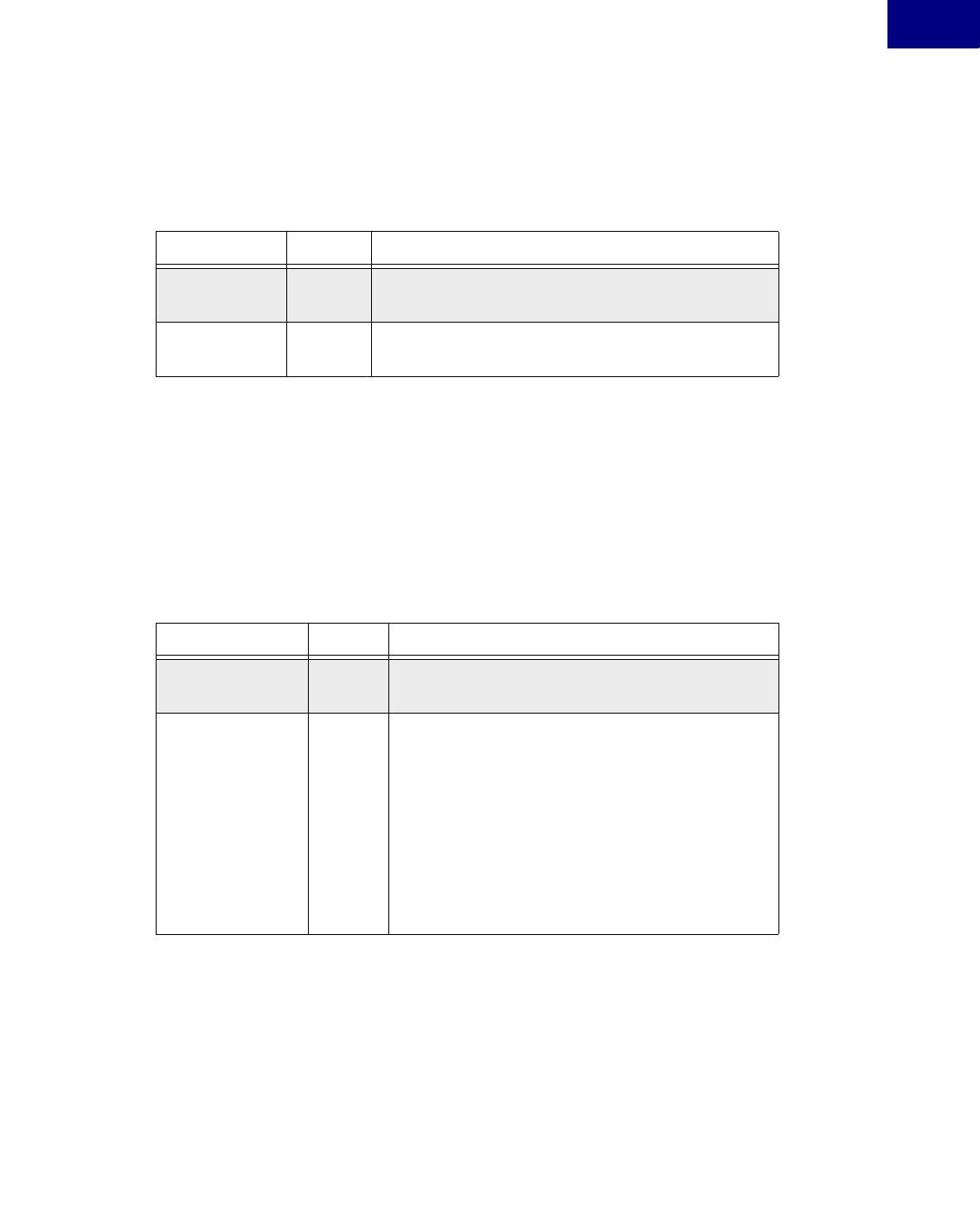
Suppressed User Interface 703
Suppressed User Interface
XML file format
SuppressedMenu
The SuppressedMenu element is used to suppress menus. It should contain the attributes
shown in Table 159.
TABLE 159 Attributes of SuppressedMenu
SuppressedDragDrop
Description
The SuppressedDragDrop element is used to disable drag and drop operations for particular
widgets. It should contain the attributes shown in Table 160.
Attributes
TABLE 160 Attributes of SuppressedDragDrop
Attribute name Type Summary
menuName CDATA This specifies a menu name; for example,
“Main:&Type:&Font.”
restrictionType CDATA This specifies how the action is suppressed. The choices
are disable or hide.
Attribute name Type Summary
widgetID CDATA This specifies a widget. Provide a WidgetID in
decimal format.
ancestorWidgetID CDATA In some cases, you may need to qualify a widgetID.
For example, suppose you want to disable the OK
button in the Style Options dialog. The Widget ID
(kOKButtonWidgetID) is shared by many dialogs.
Without qualifying it with an ancestorWidgetID, the
OK button would be suppressed on all dialogs. To
prevent this, you must specify (in decimal format) the
WidgetID of the Style Options dialog, using the
ancestorWidgetID attribute. A value of “0” means no
ancestor.

Suppressed User Interface
SuppressedUI tool
704
SuppressPlatformDialogControl
Description
Platform dialogs like Place, Open, and Save are provided by the operating system. InDesign
uses such dialogs but adds its own custom controls. This element is used to suppress these cus-
tom controls on platform dialogs. It should contain the attributes shown in Table 161.
TABLE 161 Attributes of SuppressPlatformDialogControl
SuppressedUI tool
The SuppressedUIPanel plug-in (also known as the SuppressedUI tool) can be used in con-
junction with the debug build to discover widget IDs and generate XML files as described
above. It is included with the debug builds of InDesign and InCopy (in the “tools” folder), but
due to start-up costs and potential confusion, it is not loaded by default. To load the plug-in,
you need to manually copy it to the “plug-ins” folder in your debug build. When installed, it is
available under the SuppressedUI Tool menu item in the Windows menu.
Although the SuppressedUI Tool can be very useful, it has several significant limitations.
Before using the tool, be sure to read and understand “SuppressedUI tool limitations” on
page 706.
The SuppressedUIPanel plug-in provides a kSuppressedUIService service provider boss that
uses the XML-based implementation (kSuppressedUIWithXMLFileImpl). This means when
the plug-in is loaded, the specified widgets are suppressed. This is only for debug purposes.
When your plug-in is deployed, you need to provide your own such service provider.
When the SuppressedUIPanel is loaded, it looks for the SuppressedUI.xml file in the user's
application preferences folder. If the XML file is present, it is parsed, and its data is used to sup-
press the user interface. If no file is present, it is created with no elements.
The SuppressedUIPanel contains two subpanels.
z“Configure Menus & Actions” can be used to suppress menu items and actions. See
Figure 274. It contains a Tree control that has a hierarchical list of menus and actions not
contained in menus. An icon button on each element toggles the state of the menu/action
among three values: unsuppressed, disabled, and hidden. A black eyeball icon indicates the
is unsuppressed; a grey eyeball, is disabled; and an eyeball with a red X, hidden. Top-level
menus, like File, Edit, and Object, cannot be suppressed. Palette menus (shown under Pop-
ups) may have strange names; because these names normally are not displayed in the user
interface, they use names from the code.
Attribute name Type Summary
PlatformDialogControlIdentifier CDATA This specifies which custom controls
to suppress.
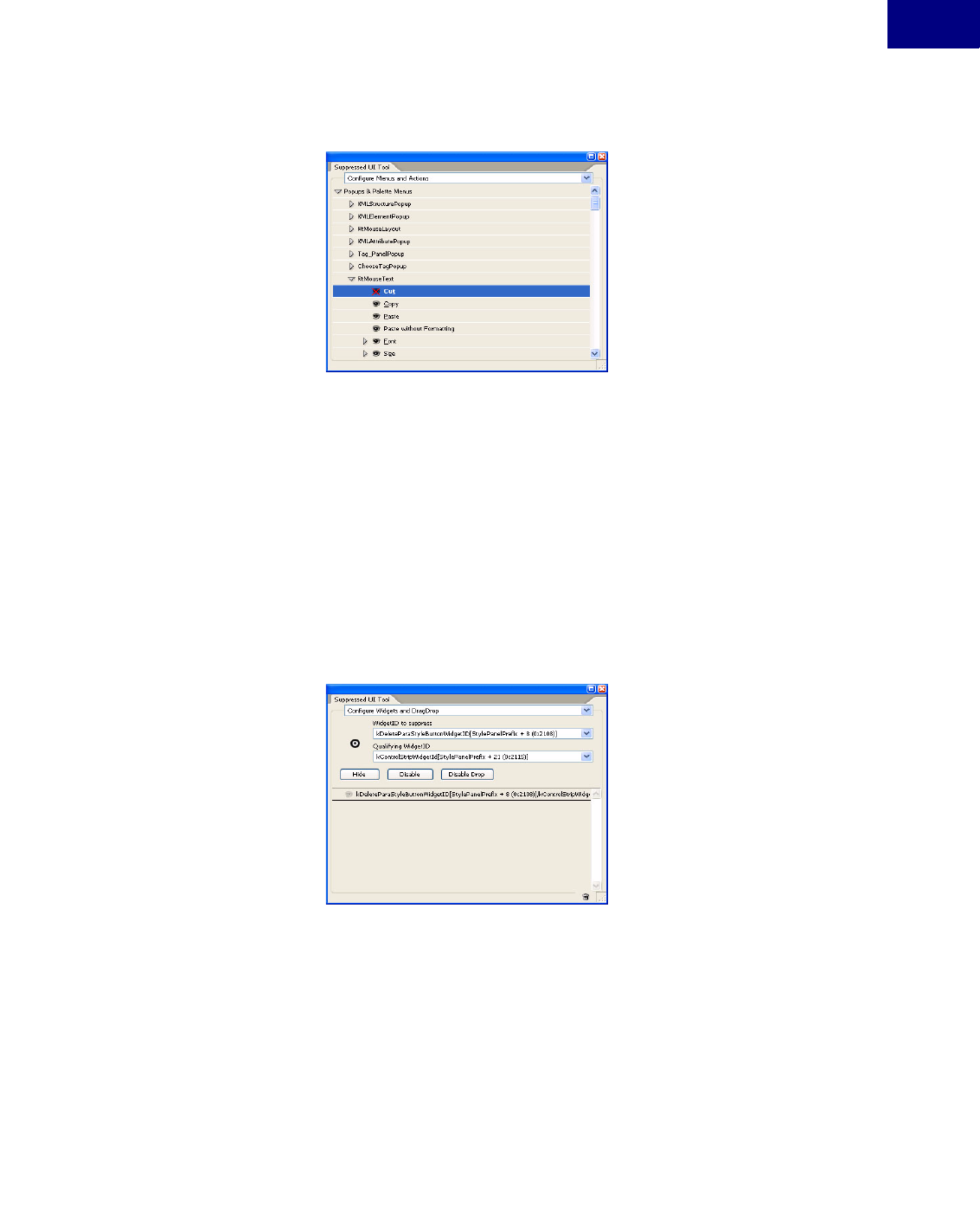
Suppressed User Interface 705
Suppressed User Interface
SuppressedUI tool
FIGURE 274 SuppressedUI Tool: Configure Menus and Actions subpanel
z“Configure Widgets and DragDrop” can be used to suppress widgets and disable them from
accepting drop operations. See Figure 275. You start by targeting the widget on which you
want to operate. In this pane, there is a button with a target icon. To target a widget, click
and drag from the button to the widget you want targeted. When you release the mouse, the
first drop-down list, “WidgetID to suppress,” contains the ID name of the targeted widget.
Next, suppress the item by clicking one of three buttons, Hide, Disable, or Disable Drop.
The widget should then appear in the list at the bottom of the panel, which shows sup-
pressed widgets. To unsuppress a widget, select it from the list and click the trash button at
the bottom of the panel.
FIGURE 275 SuppressedUI Tool: Configure Widgets and DragDrop subpanel
If you open the “WidgetID to suppress” drop-down, you will see the targeted widget at the top
of the list. For your convenience, all its ancestors also are added to the list. This is important
because it is easy to target the wrong widget. For example, if you try to target the stroke styles
drop-down, it may target the widget inside the drop-down that draws the line. This widget
contains sub-widgets, which can be targeted. If you disable the sub-widget instead of the drop-
down, the drop-down will still function. Instead, you need to select the appropriate ancestor, in
this case the kStrokTypePopupWidgetId.
There is another drop-down, “Qualifying WidgetID.” Its purpose is to provide more context
when WidgetIDs are shared. For example, many dialogs share the kOKButtonWidgetID. To

Suppressed User Interface
Working with the ISuppressedUI API
706
disable the OK button in a specific dialog, you must specify the button's parent WidgetID in
the “Qualifying WidgetID” drop-down. Doing so prevents the OK button from being disabled
in all dialogs that share the kOKButtonWidgetID. To do this using the tool, you target a widget,
then select the ancestor widget you want as your qualifier from the “Qualifying WidgetID”
drop-down. Click one of the buttons to add this widget/qualifier combination to the sup-
pressed list.
This tool does not handle platform dialog controls; these must be put in the XML file by hand.
For more information, see “XML file format” on page 701.
SuppressedUI tool limitations
Using the SuppressedUI tool on modal dialogs requires special care. For the SuppressedUI tool
to work on modal dialogs, it must already be open when the dialog is opened. Furthermore, it
must be opened before the dialog is opened for the first time. If you open the dialog before the
SuppressedUI tool, you need to quit and delete the SavedData file in your preferences folder, to
reset the dialog and allow you to use the tool for that dialog.
On Windows, if you have a modal dialog open, you can target a widget with the tool, but you
will not be able to click the Hide, Disable, or Disable Drop buttons. Instead, target the widget
and then dismiss the dialog. Once the dialog is dismissed, you can click the Hide (or other)
button to suppress the widget.
Do not disable the top level widget in a dialog. If you disable the dialog widget, when you dis-
miss the dialog, the menus remain disabled as they were when the dialog was open.
When browsing the available actions in the SuppressedUI tool, you may see strange actions like
“dynamic” or “doesn’t matter.” These actions are present because the tool makes no effort to fil-
ter out special-case actions; it simply lists all actions defined. These particular actions exist but
are not useful to the user; ignore them.
Working with the ISuppressedUI API
The ISuppressedUI interface is documented in the SDK API documentation. For a sample
implementation, see the SuppUI sample project. The interface itself is not complex, but it is
challenging to determine the appropriate IDs and menu paths. The best way to get around this
is to use the SuppressedUI tool to discover IDs and menu paths, even if ultimately you will not
use the XML-based implementation.
Before implementing this interface yourself, read and understand the following additional
points:
zThe methods of your implementation will be called very often. Performance is an important
consideration. Poor implementations can slow down the entire application.
zYou can use the Reset() method to improve performance. For instance, if your implementa-
tion reads data from a file, you should build a cache when Reset() is called. Then, anytime

Suppressed User Interface 707
Suppressed User Interface
Other user-interface “suppression” mechanisms
the data file changes, you will need to query for ISuppressedUI on your service provider,
and call Reset() to rebuild the cache.
zCalling Reset() on the gSession ISuppressedUI implementation forwards the Reset() call to
all kSuppressedUIService service providers. In most cases, this probably is not what you
want to do. If you just want to call your service providers ISuppressedUI::Reset(), query for
it yourself using IK2ServiceRegistry::QueryServiceProviderByClassID().
zIsWidgetDisabled and IsWidgetHidden take an IControlView*. See the SuppUI sample for
an example of how to extract a WidgetID or a parent WidgetID from the IControlView*.
zWhen suppressing widgets, the hardest part may be determining the widget’s WidgetID.
You can learn a lot by opening the ID.h file for the feature you care about. This assumes you
can identify the ID.h file in which the widget is defined. You may run into cases that are not
obvious. It is easiest to use the SuppressedUI tool to discover WidgetIDs.
zIsDragDropDisabled() is called with a lot of context. IDragDropTarget* and IDragDrop-
Source* allow you to extract information on the target and source. DataObjectIterator* lets
you peak at the flavors on the clipboard.
zTo suppress menu items with a corresponding action, implement IsActionDisabled() or
IsActionHidden(). The IsSubMenuDisabled() and IsSubMenuHidden() methods are used
to disable submenus. These are strictly menus and not items with a corresponding action.
For example, to disable the entire Edit menu, you could use IsSubMenuDisabled().
zDetermining a menu path may involve thought or investigation. The path needs to be spec-
ified as an untranslated string. Furthermore, each menu has a name, and you may not know
the name of the menu you are disabling. It is easiest to use the SuppressedUI tool.
zDetermining the names of platform dialog custom controls is more straightforward. The
available dialogs and controls are listed in SuppressedUIXMLDefs.h. For example, IsPlat-
formDialogControlSuppressed specifies all custom controls on the Place dialog.
Other user-interface “suppression” mechanisms
The application API supports other mechanisms that allow for customization and suppression
of the user interface behavior:
zSee IMenuFilter in the API documentation. This abstraction allows for configuration of
menu items as they are added.
zSee IActionFilter in the API documentation (and the CustomActionFilter SDK sample),.
This abstraction allows for configuration of actions as they are added.
zSee the section on “Working with the Quick Apply Dialog” in the “User Interfaces” chapter
of Adobe InDesign CS4 Solutions for examples of using the IQuickApplyService and IQuick-
ApplyFilterService extension patterns to control the function available through the quick
apply dialog.

Suppressed User Interface
Other user-interface “suppression” mechanisms
708

Using Adobe File Library 709
Using Adobe File Library
Introduction
Using Adobe File Library
Introduction
This chapter describes the Adobe File Library (AFL) as it applies to developers of plug-ins for
InDesign CS4. This library provides utilities for manipulating files, paths, and directories on
Windows and Mac OS. The chapter defines terms and explains key concepts related to the
Adobe file library, provides detailed descriptions of the design and class hierarchy of the Adobe
file library, guides you in porting code that uses SysFile, and answers common questions.
The SysFile container was removed. Any use of SysFile needs to be changed to use IDFile.
Before InDesign CS2, the InDesign code used a loose collection of utility classes and direct sys-
tem calls to manipulate files and directories. The SysFile container that held a reference to files
and directories was defined differently for Windows and Mac OS and was unable to be readily
adapted as the operating systems’ file APIs evolved. This problem was most prevalent on Mac
OS, which has a complex set of APIs for file manipulation and provides many approaches for
referencing files.
The Adobe file library was created to solve these problems. It was designed with two goals in
mind:
zProvide a unified collection of classes and utilities that can be used to perform all file and
directory manipulation.
zProvide a core architecture that can be used by other Adobe applications.
To this end, the design includes a core set of classes and utilities that are independent of InDe-
sign (i.e., they do not rely on the InDesign model). In addition to the core architecture, there
are classes and utilities that provide functions specific to InDesign, as well as model-dependent
features.
The SysFile container was removed for CS2. Plug-in developers should use the IDFile. IDFile is
an InDesign API class used to manipulate a file or directory specified by a path. IDFile has a
rich cross-platform method set including, for example, persistence of file and directory paths.
Terminology
The following terms are used throughout this chapter. They are illustrated in Figure 276.
zAdobe file library (AFL) — A file library with APIs for file and directory manipulation.
zBase name — The portion of a filename or directory name before the last period.
zDirectory — A construct provided by the operating system, which contains the names of
files, other directories, or both. Directories are identified by directory paths.
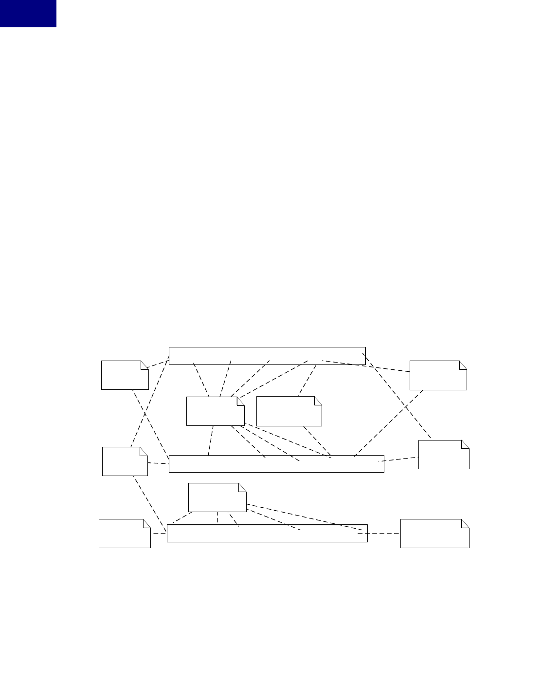
Using Adobe File Library
Terminology
710
zDirectory name — The last path component of a directory path.
zDirectory path — A path whose last component is a directory name.
zFilename — The last path component of a file path.
zFile path — A path whose last component is a filename.
zExtension — The portion of a filename or directory name after the last period.
zHierarchical File System (HFS) — The Mac OS standard file system format. It is used to rep-
resent a collection of files as a hierarchy of directories (folders), each of which may contain
files or folders themselves.
zPath — A sequence of path components. Each element except the last names a directory
that contains the next element. The last element may name a directory or a file. The first ele-
ment is closest to the root of the directory tree; the last element, farthest from the root.
zPath component — A name of a volume, directory, or file that is an element of a path, sepa-
rated by a path separator character (such as \, /, or :).
zSysFile — A container class that held a reference to a file or directory in pre-CS2 versions of
InDesign and InCopy.
FIGURE 276 File and path concepts
C:\mydir\second_level\filelibrary.pdf
Macintosh HD:macDir:fun:sunphoto.jpg
/user/john/unixpath/sampledocs/files
Path
File path
Directory
path
Path
components
File name
(filelibrary.pdf,
sunphoto.jpg)
Directory name
(files)
Base name
(filelibrary,
sunphoto)
Extension
(pdf, jpg)
Path
components

Using Adobe File Library 711
Using Adobe File Library
Adobe File Library architecture
Adobe File Library architecture
Adobe File Library is a dynamic library. It is in the Windows SDK at {SDK}\exter-
nal\afl\libs\win\{release|debug}\AFL.lib. On Windows, if you have a plug-in project that uses
Adobe file library, you need to explicitly link to AFL.lib. On Mac OS, AdobeAFL.framework is
included in InDesignModel.framework), a universal binary that can be used on both PPC and
i386 systems.
Adobe file library is not based on the InDesign object model and does not use concepts specific
to InDesign, like bosses and interface IDs.
Adobe File Library classes and utilities
See Figure 277 for an overview of file library classes and utilities provided by Adobe File
Library.
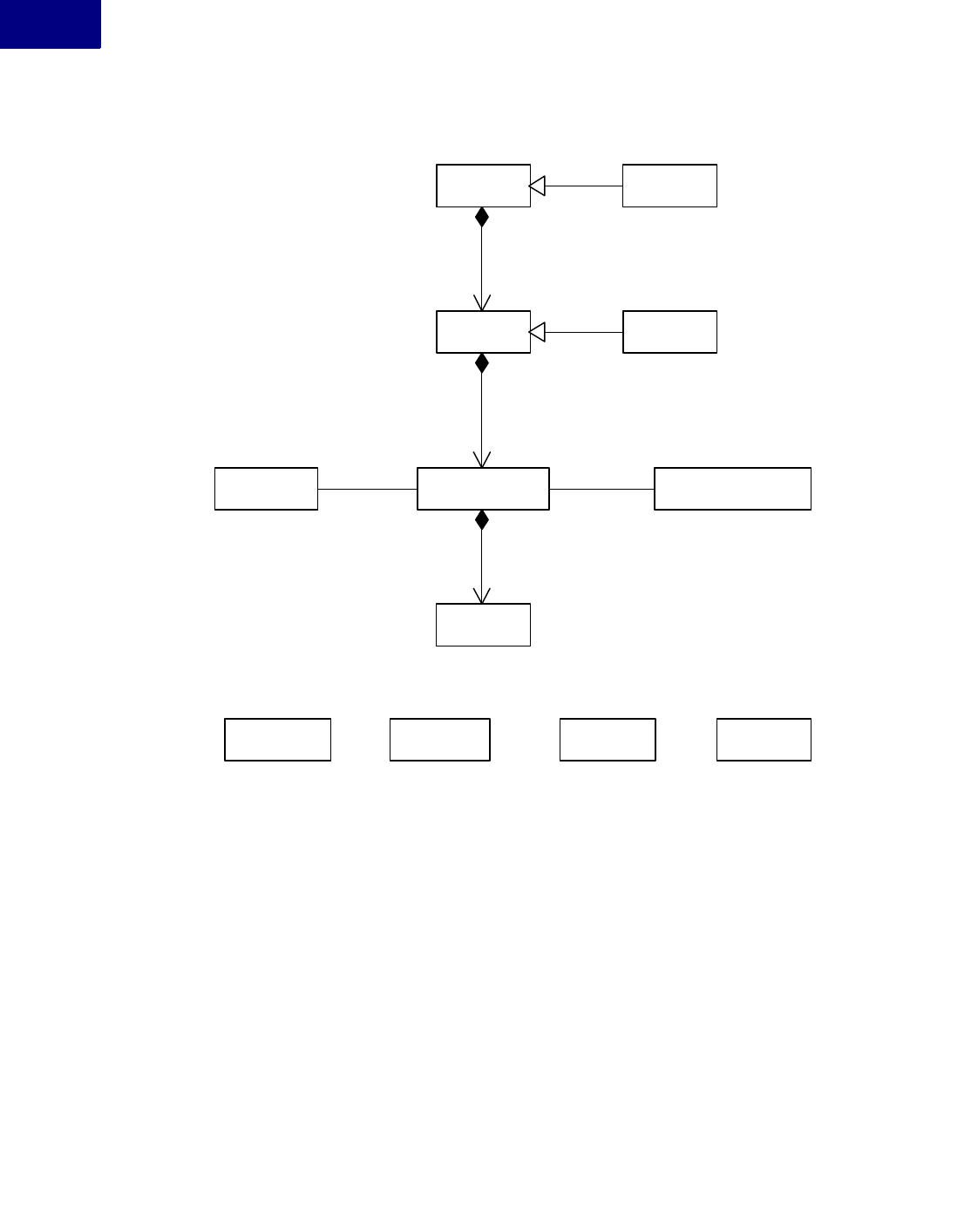
Using Adobe File Library
Adobe File Library architecture
712
FIGURE 277 File Library Classes and Utilities provided by Adobe File Library
AFile, APath, APathComponent, and AString form a composition chain. An AFile object rep-
resents a file or directory; it holds an APath object pointing to the full path of the file or direc-
tory. An APath object consists of one or more APathComponent objects; a sequence of path
components forms a path. An APathComponent object consists of two AString objects, repre-
senting base and extension parts, respectively.
AFile and APath are not pure virtual classes: they have their own implementations that may be
used by other Adobe products. IDFile is the InDesign implementation of AFile. IDPath is the
InDesign implementation of APath. They extend their parent classes by providing additional
methods specific to InDesign and InCopy.
CorePathUtils and CoreFileUtils provide core utilities that apply to both Windows and Mac
OS. WinFileUtils provides utilities specific to Windows. MacFileUtils provides utilities specific
to Mac OS. FileUtils, which has been in the SDK since InDesign CS/InCopy CS, provides file-
manipulation utilities specific to InDesign and InCopy. See “FileUtils class” on page 715.
«type»
AString
«type»
APathComponent
«type»
APath
«delegate»
APathIterator
«delegate»
APathReverseIterator
«type»
AFile
«utility»
CorePathUtils
«utility»
CoreFileUtils
«utility»
MacFileUtils
«type»
IDPath
«type»
IDFile
«utility»
WinFileUtils
1
1
1
1..*
1
1..*
-Iterator
11..* -Iterator
11..*

Using Adobe File Library 713
Using Adobe File Library
Adobe File Library architecture
Common file API
The common file API comprises classes and utilities that can be used in InDesign and InCopy,
as well as other Adobe products. For detailed methods and definitions, see the API reference
documentation.
AString class
AString is a class used to hold and manipulate a UTF-16 string. AString has general string-
manipulation methods, such as Append, Insert, and Length. AString has methods for convert-
ing to and from other string types. The common file implementation does not know InDesign
types, so AString cannot be constructed from PMString directly.
APathComponent class
APathComponent is a container class used to hold the name of a single component of a path. A
path component can be a volume name, directory name, or filename. APathComponent has
methods for getting and setting the base, extension, or full name of an APathComponent
object as an AString.
APath class
APath is a container class used to hold an absolute or relative path. The individual path ele-
ments are stored in a vector of APathComponent objects. Storing the path in a vector allows for
quick retrieval, manipulation, and iteration of the path components. APath does not require
that the contained path exist on the file system. It has methods for getting path information,
setting and changing the path, and begin(), end(), rbegin(), and rend() methods for use with its
iterator class APathIterator and APathReverseIterator.
APathIterator class
The APathIterator random access iterator class provides the ability to iterate over the path
components contained in an APath object. The class mimics the function provided by STL ran-
dom access iterators.
APathReverseIterator class
The APathReverseIterator random access reverse iterator class provides the ability to iterate
over the path components contained in an APath object in reverse order. The class mimics the
function provided by STL random access reverse iterators.
AFile class
The AFile class is used to create and delete files and directories, and to get and set file and
directory status and access properties. A file or directory referred to by the class does not need
to exist. Methods that require the existence of a file or directory are ignored and fail appropri-
ately when the file does not exist.
CorePathUtils class
CorePathUtils is a utility class that provides additional path function beyond the scope of
APathComponent and APath. CorePathUtils includes methods for converting UTF-8 to and

Using Adobe File Library
Adobe File Library architecture
714
from an APathComponent object, getting and setting current working directory, and checking
the path type of an APath object.
CoreFileUtils class
CoreFileUtils is a utility class that provides additional file and file system function. CoreFile-
Utils includes methods for creating temporary files, copying and moving a file, renaming a file,
and testing whether a file is on a server.
MacFileUtils class
MacFileUtils is a utility class that provides additional file and file system functions specific to
Mac OS. Methods are included for getting and setting VolumeRefNum, getting and setting the
creator and type of a file, converting AFile to and from FSRef, SpecInfo, FSSpec, and CFURL-
Ref.
WinFileUtils class
WinFileUtils is a utility class that provides additional file and file system functions specific to
Windows. Methods are included for getting UNC path, local path, and POSIX path.
File API specific to InDesign
IDPath class
IDPath is an InDesign class used to manipulate a file or directory specified by a path. IDPath is
a child of APath; therefore, it inherits all APath methods. IDPath can be constructed from an
APathComponent, an AString, or an InDesign WideString object.
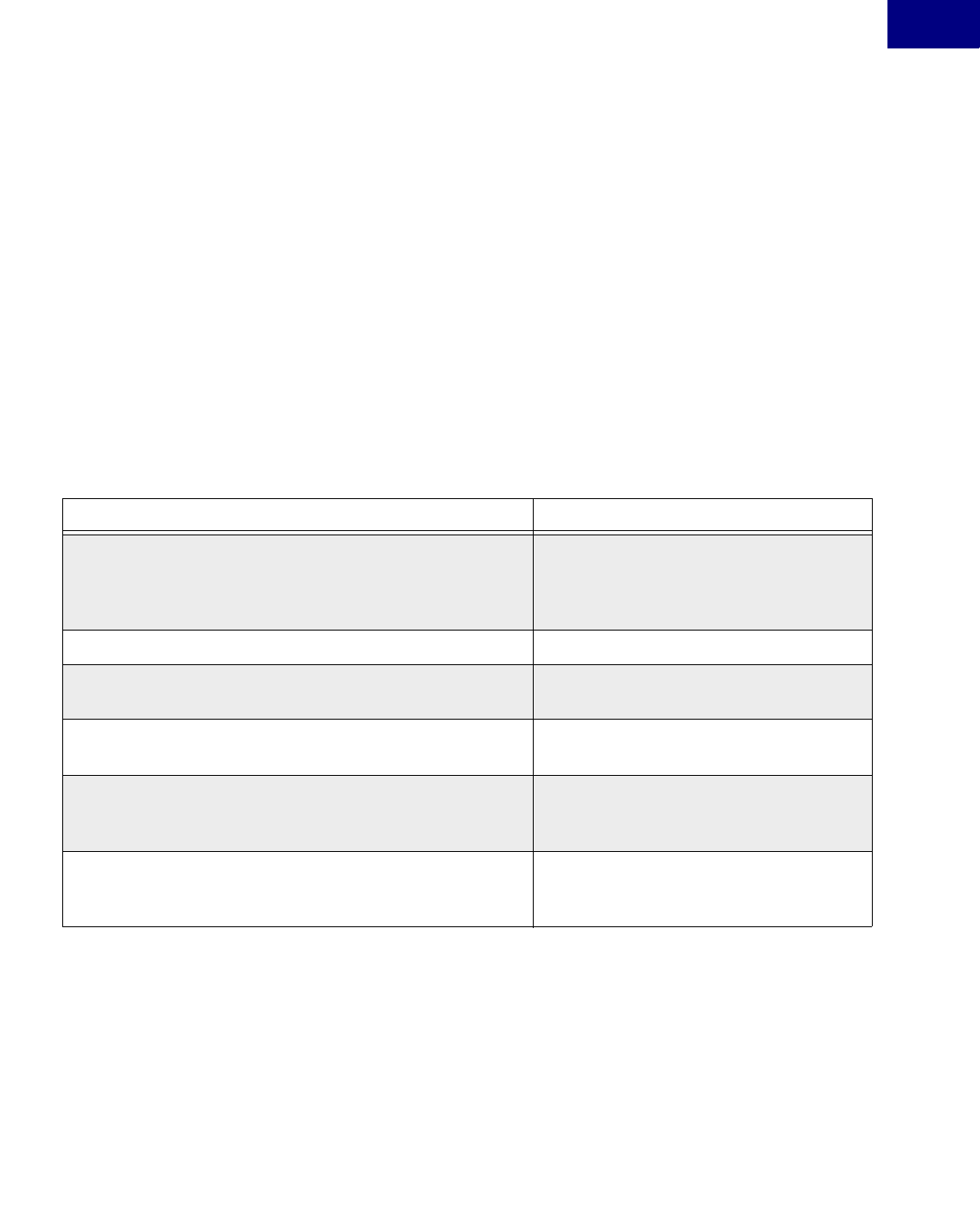
Using Adobe File Library 715
Using Adobe File Library
Adobe File Library architecture
IDFile class
IDFile is an InDesign class used to manipulate a file or directory. IDFile is a child of AFile;
therefore, it inherits all AFile methods. Like IDPath, IDFile can be constructed from an APath,
AString, or InDesign WideString. In addition, IDFile defines several methods specific to Win-
dows and Mac OS. IDFile has several deprecated methods that are provided to help the integra-
tion of the Adobe file library architecture into InDesign. Do not use these methods when
writing new code.
FileUtils class
The FileUtils class has been in existence since InDesign CS. During the integration (porting
Adobe code) of Adobe file library, the implementation of FileUtils went through substantial
changes; however, the behavior of existing methods in the class did not change. The FixF-
SSpecInSysFile and FixTrueNameInSysFile methods were removed, because there is no longer
any need to correct file components in IDFile. New methods specific to Mac OS were added.
Table 162 briefly describes the new methods.
TABLE 162 New methods in FileUtils (Mac OS only)
SDKFileHelper
SDKFileHelper is not part of Adobe file library. This class is listed here because it is used as a
utility class in SDK sample code and, presumably, it is used commonly in code written by third-
party plug-in developers. With Adobe file library integration, the implementation of SDKFile-
Helper also underwent changes. Like FileUtils, the behavior of existing methods in this class
did not change; however, two new methods—GetIDFile and setIDFile—replaced GetSysFile
and setSysFile.
Method Description
static FILE* OpenFile(const IDFile& file, const char* mode) Opens the file. This method uses FSpfopen,
FSRefParentAndFilenamefopen, or
FSReffopen to open the file, depending upon
the current state of the file.
static OSErr FSSpecToIDFile(const FSSpec& fsSpec, IDFile& file) Converts an FSSpec to an IDFile object.
static OSErr SpecInfoToIDFile(FSVolumeRefNum vRefNum,
uint32 parId, const PMString& name, IDFile& file)
Converts Mac OS file system specification
information to an IDFile object.
static OSErr IDFileToFSSpec(const IDFile& file, FSSpec& fsSpec,
PMString* unicodeName = nil, bool16 bCreateLong = kFalse)
Converts an IDFile object to an FSSpec.
static OSErr UnicodeNameToHFSName(const PMString&
unicodeName, PMString& hfsName, TextEncoding
textEncodingHint = kTextEncodingUnknown);
Converts a Unicode name to an HFS Pascal
name.
static OSErr HFSNameToUnicodeName(const PMString&
hfsName, PMString& unicodeName, TextEncoding
textEncodingHint = kTextEncodingUnknown)
Converts an HFS Pascal name to a Unicode
name.

Using Adobe File Library
Porting guidelines
716
Debugging IDFile
To help you debug your code containing IDFile objects, the IDFile class has a debug-only data
member, fDebugPath, that always contains the current path. The path contained by fDebug-
Path matches the path contained by the AFile implementation class, but it is much easier to get
from the debugger.
On Windows, fDebugPath is defined as a wchar_t string that contains a UTF-16 UNC or
mapped drive path. On Mac OS, fDebugPath is defined as a character string that contains a
UTF-8 POSIX path. On both platforms, if the current path is empty, fDebugPath is null.
NOTE:Warning: On Windows, do not use the fTmpPathStr data member contained by IDFile
objects to obtain the current path. The fTmpPathStr member is a temporary path string
used as a buffer to return the path as a PMString, CString, ConstCString, TCHAR buffer,
WString, or UTF16TextChar. The path contained by fTmpPathStr is neither guaranteed
nor expected to always match the IDFile object’s current path.
Porting guidelines
Creative Suite 2 porting concerns
For information on porting to Creative Suite 2, see the CS2 version of this chapter.
Creative Suite 3 porting concerns
The Adobe file library API has remained fairly consistent in Creative Suite 3; however, be aware
of the following:
zAdobe file library is now a dynamic library. Where previously it was built into Public, your
plug-in now needs to explicitly link against the dynamic library.
zThe Adobe file library API no longer accepts the std:string type. Instead, all methods that
used to take std::strings now take AString8 arguments. AString8 is a typedef of std::string
that uses a custom memory allocator. Applications that link to Adobe file library can now
specify the procedures Adobe file library will use to allocate and free memory.

Using Adobe File Library 717
Using Adobe File Library
Frequently asked questions
Frequently asked questions
Why should I use Adobe file library?
Adobe file library provides unified file-manipulation methods, so you no longer need to write
platform-specific code for Windows and Mac OS, or even UNIX.
Adobe file library provides classes and utilities that meet most file-manipulation needs, so your
code will be shorter, more robust, and easier to maintain.
Adobe file library will evolve with the operating systems, so your code will be easier to port.
Most importantly, InDesign code uses Adobe file library. Future interfaces will continue to be
based on Adobe file library.
We highly recommend porting your code now to use Adobe file library classes.
Does Adobe file library support cross-platform path conversion?
No.
However, Adobe file library directly supports POSIX paths on Mac OS. You can use File-
Utils::PMStringToSysFile to create an IDFile object from an HFS path (like Macintosh
HD:macfolder:myfile) or Windows file path (like C:\Program Files\Adobe\InDesign)
Should I still use the ICoreFileName interface?
Adobe file library does not replace ICoreFileName; however, we do not recommend using
ICoreFileName unless you absolutely have to (for example, when dealing with data links). On
Mac OS, the class still depends heavily on FSSpec and is not very efficient. Most of the function
is provided more efficiently in Adobe file library classes like CoreFileUtils, CorePathUtils,
MacFileUtils, WinFileUtils, AFile, and FileUtils.
Why was the GetSysFile method renamed GetIDFile in SDKFileHelper?
The renaming of GetSysFile to GetIDFile was done to reflect the change in the return type.
Because of this change, any code that uses the old GetSysFile method will result in a compiler
error, letting you know you need to review your usage of SysFile.
How do I navigate between IDFile and IDPath?
You can round-trip between IDFile and IDPath as shown in the following sample code:
IDFile idFile (existingFile); //assume existingFile already initialized
IDPath idPath = idFile.GetPath();
IDFile newFile(idPath);

Using Adobe File Library
Frequently asked questions
718
What are the differences between a file and a directory?
There is no difference between a file and a directory in terms of how they are represented as
IDFile objects. The differences are at the operating-system level: a directory has other files or
directories as its children, and a file does not.
What are the relationships between IDPath and IDFile?
IDPath and IDFile objects can point to the same file or directory. They differ mainly in con-
cepts: IDPath has methods that apply to a file path, and IDFile has methods that apply to file
operations.
Why should IDFile not be treated as PMString?
They are different conceptually. PMString represents a string, used primarily in the user inter-
face. IDFile deals primarily with file manipulation.
Also, not all IDFile objects are represented by a PMString, so treating an IDFile as a string
makes your code prone to errors. Mac OS has several ways to represent a file. Windows, UNIX,
and file URLs also have different formats.
IDFile does not allow an invalid path, so you may encounter runtime errors or asserts if you
assign a PMString to an IDFile with an invalid path. PMString does not validate paths at run
time.
How do an invalid path and a nonexistent path differ?
An invalid path is a path with one or more invalid path components in its respective platform.
For example, the wildcard *.* does not refer to a file, so any path containing *.* is an invalid
path.
A nonexistent path is a path that points to a file that does not exist. IDFile and IDPath fully
support nonexistent paths. You can create or delete a file using IDFile methods.
Can I construct an AString from PMString?
Yes a nd n o.
You cannot construct an AString from a PMString, because Adobe file library is not aware of
the InDesign type PMString. Since they both use UTF-16, however, you can construct an
AString with the following code:
String aString(pmString.GrabUTF16Buffer(nil));

Using Adobe File Library 719
Using Adobe File Library
Frequently asked questions
How can I convert a relative path to an absolute path?
Use APath::MakeAbsolute.
Make sure you are converting paths on the same platform. You cannot convert a Windows rel-
ative path on Mac OS, or vice versa. Instead, you must manipulate the relative path as a
PMString, convert it to the platform-specific format, and then convert to an absolute path.

Using Adobe File Library
Frequently asked questions
720

Performance Tuning 721
Performance Tuning
Use profiling tools
Performance Tuning
This chapter describes how to optimize InDesign plug-ins for peak performance. The InDesign
plug-in architecture and object model make it possible for software developers to add powerful
features to InDesign; however, the architecture also allows developers to accidentally create
very inefficient code.
Use profiling tools
Often, software developers believe they know the cause of a performance problem in their
code, only to be surprised by the results of a profile of that code. There are several very good
tools for identifying performance problems, and you always should use them before trying to
optimize your code manually. This section describe some of these tools.
Windows
There are several tools that can be used to profile your code and identify performance prob-
lems on Windows. For example, the InDesign engineering team has had success with Glow-
Code. GlowCode is a set of analysis tools to profile code and identify memory use problems.
GlowCode instruments a user-selected list of plug-ins, allows the user to define a trigger func-
tion, and provides accurate timings and function call counts. For more information about
GlowCode, including a trial version, see http://www.glowcode.com.
Mac OS
Sampler
Sampler is an Apple profiling tool that is part of the Xcode tools package, which comes with
Mac OS X. Sampler periodically samples an application to build profile data. Because Sampler
is a sampling profiler, it cannot provide accurate function-call counts; however, it provides very
good timing data, is very easy to use, and does not require any changes to your code. For Sam-
pler to provide timing information at the function level, you must turn on tracebacks in your
project. For more information, see the Apple Web site.
Shark
Shark is an Apple profiling tool that is part of the Xcode tools package, which comes with Mac
OS X. Like Sampler, Shark is very easy to use. Shark, however, can be used only with Mach-O
applications; therefore, it cannot be used with InDesign CS and earlier. For more information,
see the Apple Web site.

Performance Tuning
Commands
722
CodeWarrior
CodeWarrior probably is the best profiling tool for profiling on Mac OS 9; however, using
CodeWarrior requires several changes to your code:
zYou must enable Profiler Information in the PPC Processor project settings
zYou must include profiler.h in your source files and make calls to ProfilerInit, ProfilerSet-
Status, and ProfilerDump to obtain timing information.
After CodeWarrior generates a profile, you must use the separate CodeWarrior Profiler appli-
cation to view the profile data.
Profiles generated by CodeWarrior 9.2 are useless for Mach-O applications; therefore, they
should be avoided in plug-ins for InDesign CS2 and later.
Quartz Debug
Quartz Debug is an Apple tool that helps you to identify redundant drawing to the screen.
Commands
Commands are responsible for encapsulating compound modifications to the object model,
supporting the undo/redo protocol, and indicating to the object model when it should notify
its state to observers. If not used properly, commands can seriously reduce performance.
Commands should operate on lists of inputs
You can improve performance by reducing the number of commands processed, partly because
undo information for each command must be stored on the command history, and partly
because each command sends out a notification on completion. One good way to reduce the
number of commands processed is to write commands such that each accepts a list of inputs.
For example, a MovePageItem command should either call GetItemList to obtain the com-
mand’s list of inputs or include a separate data interface in the command’s boss. This makes it
possible to execute one command for an entire list of page items, instead of executing a sepa-
rate command for each page item.
Notify on the document subject instead of the page item object
Notifications can decrease performance because observers tend to do some work each time
they are notified; therefore, it is desirable to find ways to reduce the total number of notifica-
tions. One way, as mentioned above, is to reduce the number of commands executed. Another,
is to send one notification on the document subject instead of a separate notification for each
page item. This approach requires observers to attach at the document level instead of at the
page item level. See the following code:

Performance Tuning 723
Performance Tuning
Observers
void MyCommand::DoNotify()
{
const UIDList* itemList = GetItemList();
InterfacePtr<IDataBase> iDatabase(itemList->GetDataBase(), UseDefaultIID());
Utils<PageItemUtils>() -> NotifyDocumentObservers(iDatabase, kMyCmdBoss,
IID_MYIID_IDOCUMENT, this);
}
Mark commands that do not require undo support
Some commands do not require undo support. For example, a command to print a document
is not undoable. In such cases, the constructor of the command should call SetUndoabil-
ity(kUndoNotRequired).
Observers
Observers can be attached to and detached from any subject, but be careful to attach observers
only to subjects in which you are interested, since each attachment impairs performance. Per-
formance is affected by the level of the subject to which the observer is attached.
Attach to documents, not page items
It is inefficient for an observer to attach and observe at the page-item level. Instead, observers
should attach and observe at the document level.
Do work only when the command is done
Many commands notify several times. For example, when a page item moves, a pre-notify and
post-notify must occur, so the old and new locations can be invalidated on the screen. Often,
an observer can ignore all but the last notification, as follows:
void MyObserver::Update(const ClassID& theChange, ISubject* theSubject, const
PMIID& protocol, void* changeBy)
{
if (protocol == IID_MYIID)
{ if (theChange == kMyCmdBoss)
{ ICommand* cmd = (ICommand*) changeBy;
ICommand::CommandState cmdState = cmd->GetCommandState();
if(cmdState == ICommand::kDone)
{ const UIDList* contentList = cmd->GetItemList();
// do some work here
}
}
}
}

Performance Tuning
File input/output
724
Do not update the user interface from an observer
Many panels display information about the current selection, like graphic attributes, character
attributes, or information about the selection’s geometry. These panels must have an observer,
and it is tempting to update the panel from the Update method of the observer; however, in
general, updating a panel from an observer is a bad idea. Instead, it is much better to mark the
data in the panel as dirty or invalid, generate a screen invalidation for the panel, then update
the user interface in the Draw code for the panel.
Watch for lazy notification whenever possible
The application supports two types of notification, regular and lazy. If an observer needs to be
called as soon as a subject broadcasts the change message, it should request regular notifica-
tion. If the observer can afford to wait until idle time before being notified of a change of inter-
est, it can register for lazy notification.
Lazy notification is used when observers do not need to be in tight synchronization with
changes being made to the subject objects they observe. Rather than participating in each
change that occurs on a subject object, observers using lazy notification are notified after all
updates are made and the application is idle.
File input/output
Each operation to access a local disk or server can greatly reduce performance. For this reason,
it is very important to reduce the number of disk access operations as much as possible. For
example, if you need to parse a file using many very small read operations, consider reading a
large block into a memory buffer using one read operation, then operating on the buffer. This
kind of optimization is very important when working over a network.
Memory
Use memory caches for items accessed often
If a profile shows your code is spending a lot of time recomputing the same value or repeatedly
searching a list for the same element, consider caching the result or element. It is very impor-
tant to use profiling tools to identify where caches are needed. Unnecessary caches can
decrease performance, by forcing the software to keep the cache up to date even when it is not
needed.

Performance Tuning 725
Performance Tuning
Idle tasks
Avoid allocating too much memory
Allocating memory beyond what is physically available causes InDesign to try to purge its
caches and may cause a page fault in the operating system. Purging memory and page faults are
very slow; avoid them when possible.
Idle tasks
The InDesign object model is not thread-safe, so it does not use true threads; however, you can
use cooperative threads, in the form of idle tasks (IIdleTask). Idle tasks are given a chance to
execute when there are no events in the EventQueue for the application to process. Idle tasks
are a great way to defer expensive operations and allow the user to continue using the applica-
tion.
The remainder of this section presents guidelines that should be followed when implementing
an idle task.
Honor the RunTask flags
Each idle task has a RunTask method, which is passed a set of flags. These flags can be very
important to the application’s performance. For example, normally you will not want an idle
task to execute when the user is dragging a page item around the layout, and you may not want
the idle task to execute when a dialog box is open, because it slows the application’s responsive-
ness. So, a typical idle task starts with the following lines of code:
if (flags & IIdleTaskMgr::kMouseTracking || flags & IIdleTaskMgr::kModelDialogUp)
return (kOnFlagChange);
Do a small amount of work during each RunTask call
Idle tasks allow the software to perform computationally expensive operations when the user is
idle. The goal is to make the application as responsive as possible, so the user does not have to
wait for an expensive operation to complete. For this reason, you do not want one call to
RunTask to take a long time. It is better for each call to RunTask to perform some work, then
ask for RunTask to be called again. For example, your RunTask method may look like the fol-
lowing:
uint32 MyIdleTask::RunTask(uint32 schedulerFlags, uint32 (*timeCheck)())
{
if (InappropriateState(schedulerFlags))
return kOnFlagChange;
DoPeriodicThing();
return 1000; // Call this task again in 1 second.
}

Performance Tuning
Idle tasks
726
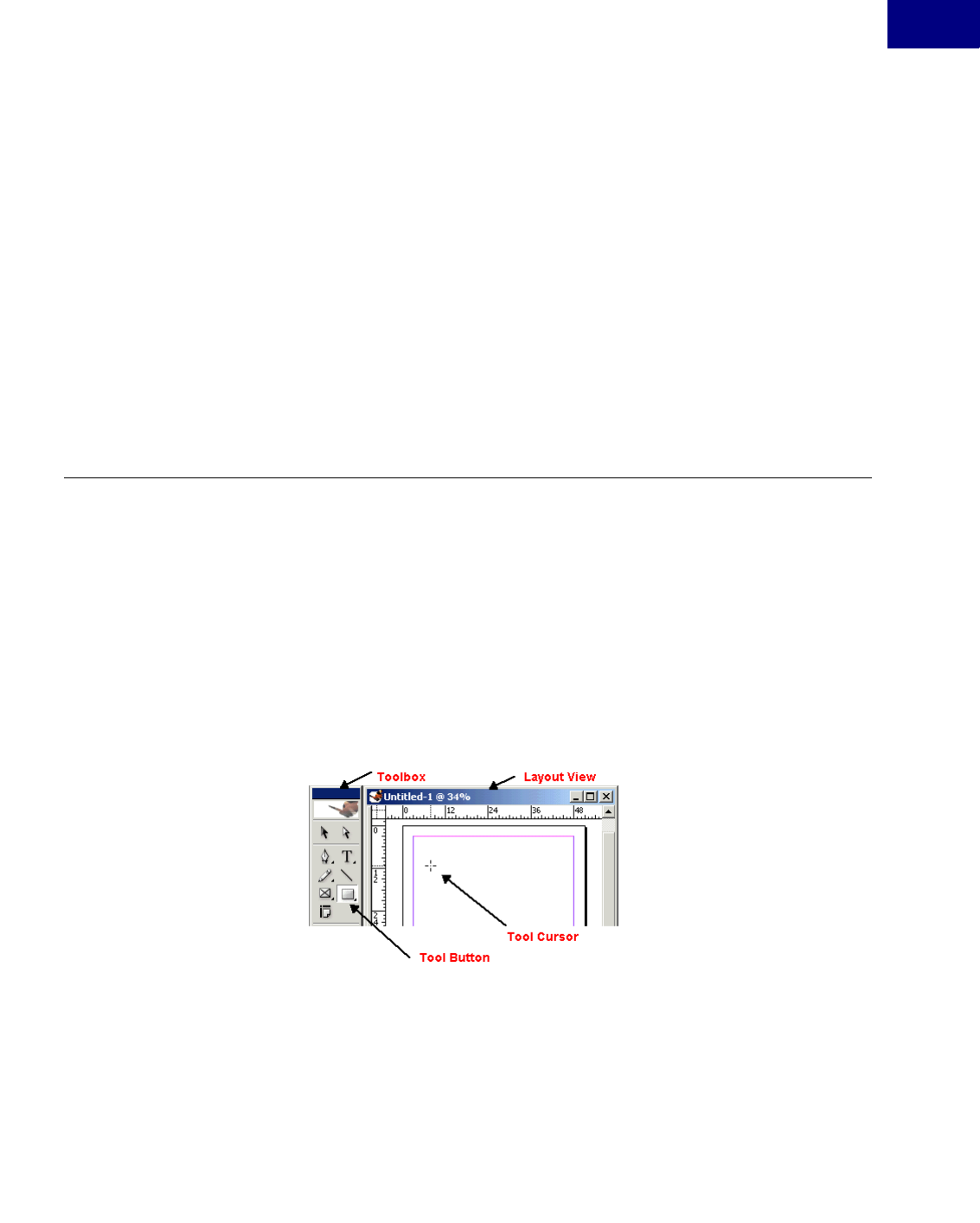
Tools 727
Tools
Key concepts
Tools
This chapter describes how tools work and how to implement your own custom tools and add
them to the toolbox.
The chapter has the following objectives:
zDefine terms related to tools, trackers, and the toolbox.
zIntroduce the layout view.
zExplain how tools work.
zExplain how to track the user’s mouse actions.
zExplain how to implement a custom tool.
zDescribe the extension patterns provided by the API that relate to tools.
Key concepts
The toolbox and the layout view
Tools are presented using the toolbox palette. Document content is presented in the layout
view. Tools create and manipulate document objects using keyboard and mouse events in the
layout view. This is illustrated in Figure 278.
FIGURE 278 The Toolbox and the Layout View
The layout view is a widget in which a document is presented and edited by the user. The layout
view is the IControlView interface on the kLayoutWidgetBoss boss object. For more informa-
tion on the layout widget, see the “Layout Fundamentals” chapter.
Tools commonly use interfaces on kLayoutWidgetBoss to discover the context in which they
are working. For example, the spread being manipulated is found using ILayoutControlData,
and hit testing can be done using ILayoutControlViewHelper. The toolbox contains a tool but-
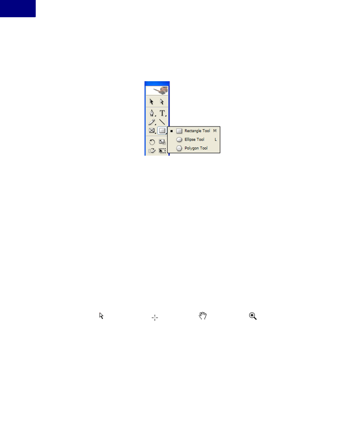
Tools
Key concepts
728
ton icon for each tool and, optionally, a hidden-tools panel containing other tools (see
Figure 279).
FIGURE 279 Hidden Tools Panel
Tools
A tool (ITool interface) has a button icon in the toolbox and, optionally, a keyboard shortcut. A
tool also may provide a cursor (pointer) as a visual cue to the user of the active tool and a tool
tip to help the user understand the purpose of the tool. To track mouse actions when the tool is
being used, the tool provides a tracker (ITracker interface).
Cursors
A cursor (ICursorProvider interface) provides a visual cue to the user of the active tool. Tools
that provide their own cursors must implement cursor providers. Cursor providers set the
mouse cursor and provide context-sensitive cursors for different areas of the screen. See
Figure 280.
FIGURE 280 Cursors
Direct Select Path Creation Grabber Hand Zoom In
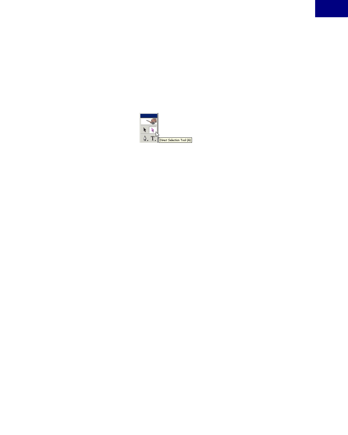
Tools 729
Tools
Key concepts
Tool tips
A tool tip (ITip interface) displays a string with the name of the tool and its keyboard shortcut,
when the pointer is positioned over the tool icon in the toolbox. See Figure 281. The strings
displayed are declared as ODFRez string resources in the plug-in’s .fr file. The application auto-
matically handles display of tool tips.
FIGURE 281 Tool tip
Trackers
Trackers (ITracker interface) monitor mouse movement while an object is being manipulated
by a tool. Trackers can provide visual feedback to the user. Trackers make changes to the
objects being manipulated using commands. A tool may have one or more trackers, though
only one tracker is active at a time.
Tracker factory, tracking, and event handling
The tracker factory (ITrackerFactory interface) allows you to introduce new trackers by manu-
facturing the tracker required for a particular context. The ITrackerFactory interface is aggre-
gated on the kSessionBoss boss class. The tracker factory maintains a table associating a tracker
with a given widget and tool by ClassID. When the tool is used in the context of the widget, the
associated tracker is created and receives control. Trackers for tools that appear in the toolbox
register themselves as being associated with the layout widget, kLayoutWidgetBoss. The code
in Example 97 adds an entry to the tracker factory.
EXAMPLE 97 Line-tracker registration in the tracker factory
void LineTrackerRegister::Register(ITrackerFactory *factory)
{
factory->InstallTracker(kLayoutWidgetBoss, kLineToolBoss, kLineTrackerBoss);
}
The framework maintains an event-handler stack that it uses to dispatch events (mouse, key-
board, and system events). Many event handlers (IEventHandler interface) are associated with
a widget. The widget that has the user-interface focus is on top of the stack and receives and
processes events.
When a mouse-down event occurs in layout view and the active tool is kLineToolBoss, the lay-
out view’s event handler asks the tracker factory to manufacture the tracker for this context. It
does this by making the following call to create kLineTrackerBoss and return its ITracker inter-
face:
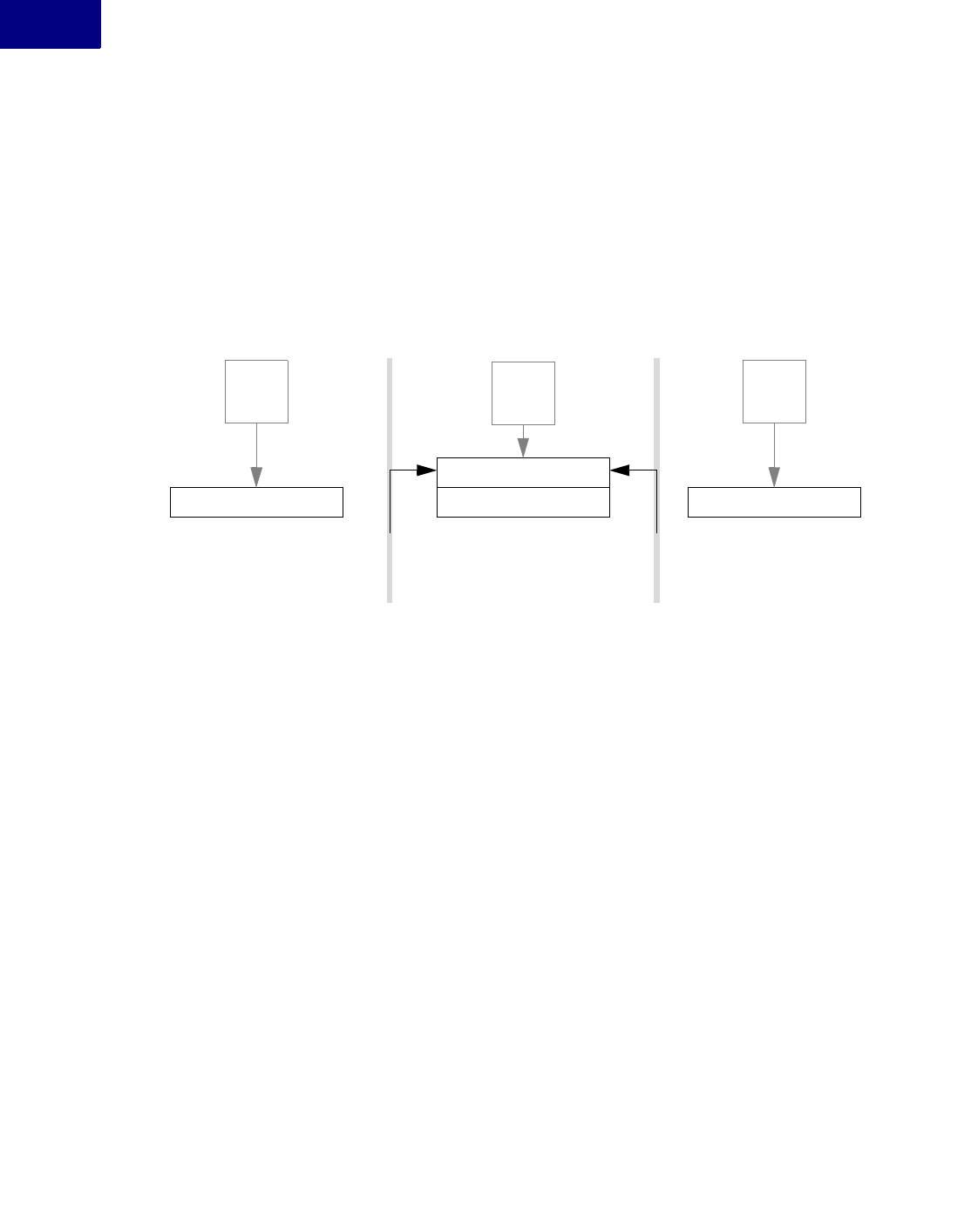
Tools
Key concepts
730
ITrackerFactory::QueryTracker(kLayoutWidgetBoss, kLineToolBoss)
The tracker is then focused on the layout view and begins tracking.
To follow mouse movement, a tracker must handle events for the duration of the tracking pro-
cess. To do this, the tracker pushes its event-handler interface onto the stack when tracking
begins and pops it off the stack when tracking ends. For example, when the Line tool is used to
drag the end points of a line, its tracker pushes and pops its event handler as shown in
Figure 282.
FIGURE 282 Event dispatching
All tracker boss classes that want to follow the mouse as it is dragged aggregate an
IEventHandler interface. When the LayoutEventHandler receives a mouse-down event, it calls
the tracker’s ITracker::BeginTracking method, which normally is implemented by
CTracker::BeginTracking. If the mouse is to be tracked, this method calls CTracker::Enable-
Tracking, which calls CTracker::PushEventHandler to push the tracker’s event handler (inter-
face IEventHandler) onto the event-handler stack using IEventDispatcher::Push. For more
implementation details, see CTracker.cpp in the SDK.
Beyond the toolbox
Tools do not have to appear in the toolbox. For example, the Place tool is activated after select-
ing a file using the File > Place menu command. Trackers also are used extensively in mouse-
dragging features, like setting the layout zero point and dragging guides from rulers.
Drawing and sprites
To provide visual feedback while an object is undergoing manipulation, a tracker can draw to
the screen.
Page items can be hard to draw when they are being changed dynamically. To ensure objects
are drawn on the screen smoothly and efficiently without flickering, the application provides a
sprite API. A sprite (ISprite interface) is a graphic object that can be moved around on screen
without causing any disturbance to the background.
LineTrackerEventHandler
LayoutEventHandler LayoutEventHandler
Event Event
LayoutEventHandler
Event
Event handler stack
before tracking
Event handler stack
during tracking
Event handler stack
after tracking
Push Pop

Tools 731
Tools
Key concepts
Documents, page items, and commands
Tools allow the manipulation of documents and page items by the user. For more information
on how documents are organized and page items are arranged, see the “Layout Fundamentals”
chapter. Tools use commands to make changes to a document.
Line-tool use scenario
The following scenario describing the Line tool shows how the objects in a tool collaborate.
The scenario is divided into three sections:
zControl is concerned with the registration of the tool with the application and the mecha-
nism allowing the user to select the tool
zDispatch is concerned with how the application begins active use of the tool.
zBehavior is concerned with what the tool does to create a line.
Figure 283 shows how the Line tool registers with the application and is used to create a line
between two points in a document. The tables following the figure define the abbreviations
used in the figure.
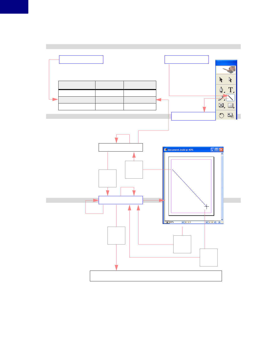
Tools
Key concepts
732
FIGURE 283 Line-tool scenario
Drag &
other
events
Behavior
LayoutEventHandler
LineTracker
LayoutWidget/LayoutView
LineTool
LineTrackerRegister LineToolRegister
Control
Dispatch
Mouse-
down
event
Mouse-
up
event
Cmd
Document
Mouse-
down
event
Tracker factory
Widget To o l Tr a c k e r
... ... ...
kLayoutWidgetBoss k LineToolBoss kLineTrackerBoss
... ... ...
Toolbox
C1 C2
C3
D1
D3
D4
B1
B2 B4
B5
B3
D2
B6
Tools 733
Tools
Key concepts
TABLE 163 Control
TABLE 164 Dispatch
TABLE 165 Behavior
Abbreviation Description
C1 The tool’s tracker is registered with the application’s tracker factory.
C2 The tool is registered with the application, and its tool-button icon in
the toolbox is initialized.
C3 The user clicks the tool’s button icon (kLineToolBoss becomes the
active tool).
Abbreviation Description
D1 The user clicks in the layout view (a mouse-down event is passed to the
LayoutEventHandler).
D2 The LayoutEventHandler looks at the active tool (kLineToolBoss) and
the context of the event (mouse-down over an empty page area). The
association identifies the tracker that should be created for the context
(kLineTrackerBoss).
D3 The appropriate tracker is manufactured by the tracker factory.
D4 The tracker is asked to begin tracking the mouse from the original
mouse-down event.
Abbreviation Description
B1 The tracker pushes its own event handler onto the application’s event
handler stack, so it can receive events and track the mouse.
B2 The user drags the mouse (events are passed into the tracker).
B3 The tracker provides appropriate dynamic visual feedback to the user
of the tool behavior: a line is drawn between the location of the original
mouse-down event and the current mouse position.
B4 The user releases the mouse (a mouse-up event is passed into the
tracker).
B5 The tracker implements an appropriate action (creation of a page item
describing the line between start and end points), using a command.
B6 The tracker pops its event handler from the application’s event-handler
stack, and tracking is complete.
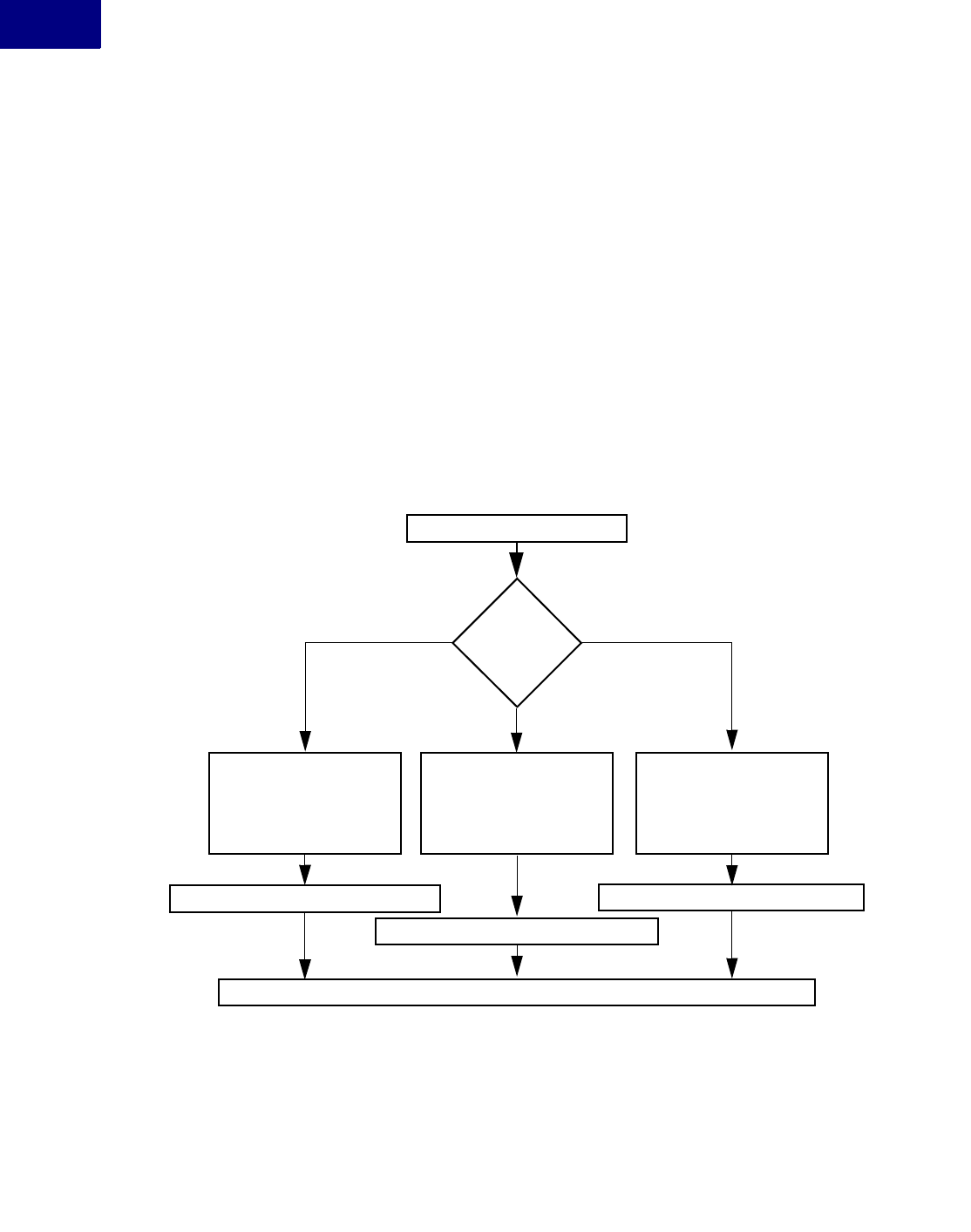
Tools
Key concepts
734
The scenario shown in Figure 283 is typical of a tool that creates items. The item itself is created
by the tracker, using a command after the user releases the mouse button; however, other cate-
gories of tools may execute commands dynamically, while tracking the mouse. For example,
the Selection tool dynamically executes commands when moving or resizing items.
Trackers with multiple behaviors
If a tracker needs to exhibit multiple behaviors, it can create another tracker that depends on
the context. For example, the Selection tool exhibits multiple behaviors. When it is active and a
mouse-down event occurs in a layout view, the pointer tracker (kPointerTrackerBoss) is cre-
ated. The pointer tracker considers the context of the click, then creates and dispatches control
to another tracker. Once the pointer tracker examines the context and creates an appropriate
tracker, its job is done. The trackers used by kPointerTrackerBoss to move and resize page
items are shown in Figure 284.
FIGURE 284 Pointer tracker move and resize behavior
Create resize tracker to
resize the page item as the
user drags. Each page item
registers its own resize
tracker.
PointerTracker::BeginTracking()
Mouse-down on
Page item bounding box
Empty area
Page item resize handle
MoveTracker::BeginTracking()
LayoutSelectionTracker::BeginTracking()
CRectResizeTracker::BeginTracking()
PointerTracker complete
Create layout selection
tracker to draw a marquee
selection as the user drags
and set the selection on
mouse-up.
Create move tracker to
move the page item as the
user drags.

Tools 735
Tools
Key concepts
Figure 284 does not show all kPointerTrackerBoss behaviors. For example, the following are
not shown in the figure:
zThe threading of text frames via in and out port handles by kPrePlaceTrackerBoss.
zThe tracking of when the layer on which the item lies is locked (kLockTrackerBoss).
zThe tracking of text on a path-handle manipulation (kTOPResizeTrackerBoss and kTOP-
MoveTrackerBoss).
Each page item can register its own resize tracker, although they all use the same one for resiz-
ing.
Tool manager
Tools are managed by the tool manager, kToolManagerBoss. You can navigate to the IToolMa-
nager interface as shown in the following code:
InterfacePtr<IApplication> app(GetExecutionContextSession()->QueryApplication());
InterfacePtr<IToolManager> toolMgr(app->QueryToolManager());
Toolbox utilities
The IToolBoxUtils interface provides a facade that should, in most situations, save you from
having to program to the IToolManager interface. IToolBoxUtils is a utility interface on kUtils-
Boss, accessed in the standard way. For example, the following code queries the active tool of
type kPointerToolBoss. The tool type in this context identifies a group of tools, of which only
one can be active:
const ClassID toolType = kPointerToolBoss;
InterfacePtr<ITool> currentTool(
Utils<IToolBoxUtils>()->QueryActiveTool(toolType));
Tool type
Tools are categorized as belonging to one or more of the categories given by ITool::ToolType.
This identifies what the tool does and how the selection in the layout view reacts when that tool
becomes active (IToolChangeSuite interface). Tools identify this type in their CTool construc-
tor by the toolInfo parameter.
ITool::ToolType easily can be confused with the ClassID parameter toolType defined by the
tool’s ToolDef statement (see “ToolDef ODFRez type” on page 738) and used by ITool::Get-
ToolType and other APIs. This ClassID is used to identify a group of mutually exclusive tools—
tools for which only one tool of a given tool type can be selected in the toolbox at any time.
Table 167 illustrates the distinction between these two different tool types and their values.
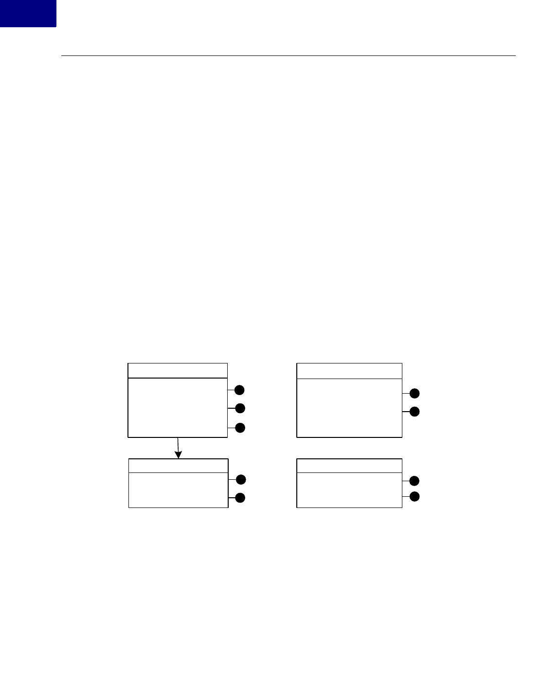
Tools
Custom tools
736
Custom tools
Architecture
This section describes the boss classes, interfaces, and resources you must implement to add a
new tool. The section also describes the APIs you use to build and catalogue custom tools.
Plug-ins that implement tools typically provide the following:
zA tool-register boss class.
zA tracker-register boss class.
zA tool boss class per tool.
zA tracker boss class per tracker.
zResources controlling how the tool is displayed.
Class diagram
The classes typically found in a custom tool are shown in Figure 285.
FIGURE 285 Custom-tool class diagram
kYourTrackerRegisterBoss registers the plug-in’s trackers with the tracker factory using the
ITrackerRegister interface.
kYourToolBoss allows the tool manager to control the tool using the ITool interface. kYour-
ToolBoss specifies information about the tool and gets called when the tool is selected or dese-
lected by the user and when a tool options dialog box should be displayed. ICursorProvider
allows the tool to customize the cursor when the tool is active. IPMPersist allows information
like the tool’s name and icon to be saved persistently.
kGenericToolBoss is the parent boss class for toolbox tools. The control view it provides dis-
plays the tool's buttons, and its event handler handles clicks on the tool’s buttons in the toolbox.
kGenericToolBoss
IControlView
kYourToolBoss
ITool
ICursorProvider
IPMPersist
kYourTrackerRegisterBoss
ITrackerRegister
IK2ServiceProvider
kYourTrackerBoss
ITracker
IEventHandler IEventHandler

Tools 737
Tools
Custom tools
kYourTrackerBoss responds to mouse actions in the layout view when your tool is being used.
There is at least one tracker boss for each tool in your plug-in. The interfaces on a tracker boss
class collaborate to provide the active behavior of the tool. Control is passed to the ITracker
interface, so the mouse can be tracked. This interface manages and controls the other interfaces
on the boss object.
The tracker pushes its event handler to the top of the event handler stack when tracking begins.
During tracking, IEventHandler forwards events into the ITracker interface. When tracking
ends, the event handler is popped from the stack, and the tracker is finished. Standard tracker
event-handler implementations are provided by the API. It is common for tracker boss classes
to have other interfaces particular to their needs. For example, trackers that create splines
aggregate ISprite and IPathGeometry. If a tracker needs to handle only one mouse click, how-
ever, it does not require an IEventHandler.
Partial implementation classes
The API provides helper classes that partially implement interfaces relevant to building tools.
Some relevant classes are shown in Table 166. For more information, see the API reference
documentation for each class.
TABLE 166 Partial implementation classes
Default implementations
The API provides default implementations that completely implement some of the interfaces
involved in building tools. If these meet your needs, you can re-use them in your boss class def-
inition and avoid writing the C++ code. See Table 168 for a list of re-usable implementations in
the API.
Interface Class
ICursorProvider CToolCursorProvider
IEventHandler CTrackerEventHandler (the C++ source code for this
implementation is provided on the SDK)
ITool CTool
ITracker CTracker (the C++ source code for this implementation is
provided on the SDK)
ITracker CPathCreationTracker (the C++ source code for this
implementation is provided on the SDK)
ITracker CLayoutTracker (the C++ source code for this implementation is
provided on the SDK)
ITracker CSliderTracker
ITrackerRegister None
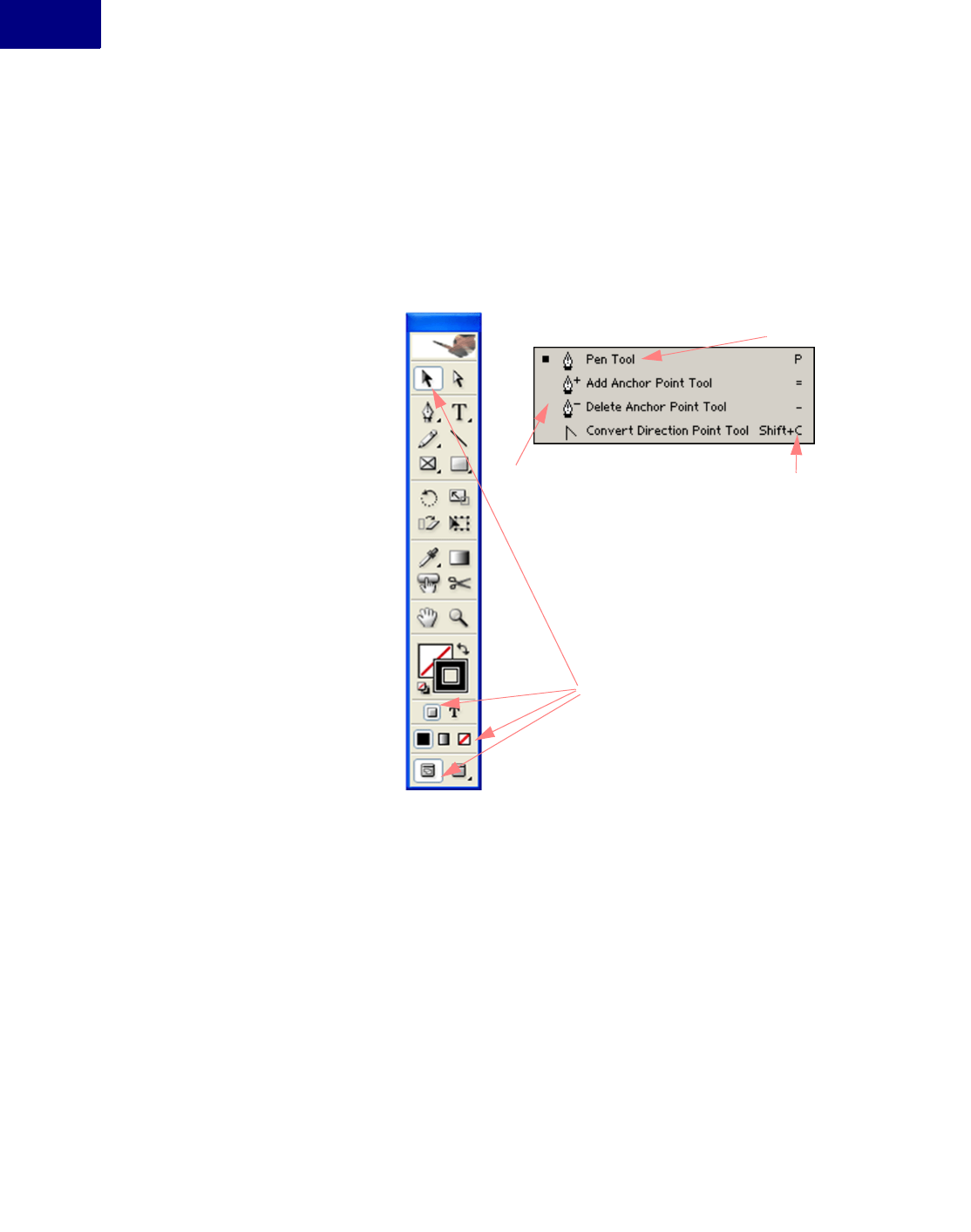
Tools
Custom tools
738
ToolDef ODFRez type
ODFRez provides a type, ToolDef, that controls how a tool is displayed within the toolbox. This
type controls the order in which tools are displayed, the way in which they are grouped, and
other properties, as shown in Figure 286.
FIGURE 286 Tool display in the toolbox
ToolDef resources are localizable, so you can define different resources for different locales and
have a tool show up in a different place or with a different icon. For example, for a currency
stamp tool, a tool icon could be provided for each locale (e.g., dollar and yen) and the icon for
the current locale would be shown in the toolbox. To localize your ToolDef resources, add a
locale index to your plug-in’s .fr file and define a ToolDef resource in the .fr file for each locale.
Icons and cursors
Icons and cursors can be created in their native-platform resource form. InDesign CS and later
also support PNG platform-independent files for icons, which is the preferred resource type to
use in icon-based widgets. All the application tools’ icons use PNG files, so they all have roll-
over effect.
Hidden tools panel
Subtools
Group numbers Parent tool
kFirstAdobeToolsGroup
kSecondAdobeToolsGroup
kThirdAdobeToolsGroup
kFourthAdobeToolsGroup
kFifthAdobeToolsGroup
kNinthAdobeToolsGroup
kTenthAdobeToolsGroup
kSeventhAdobeToolsGroup
Shortcut
Selected tools
Only one tool of a given tool type
can be selected at any one time in
the toolbox. Since four tools are
shown as selected, this toolbox has
four distinct tool types.

Tools 739
Tools
Custom tools
To create a PNG-based icon, follow these steps:
1. In your .fr file, where you have the ToolDef, declare the PNG resources. There should be
two states for each icon, normal and rollover. For example, the SDK Info button seen in sev-
eral SDK dialog uses the following PNG resources
resource PNGA(kSDKDefIconInfoResourceID) "SDKInfoButton.png"
resource PNGR(kSDKDefIconInfoRolloverResourceID) "SDKInfoButtonRollover.png"
2. Two PNG resources are defined in Step 1. The normal state, PNGA, has an ID of kSDK-
DefIconInfoResourceID and uses the SDKInfoButton.png file. The rollover state, PNGR,
has an ID of kSDKDefIconInfoRolloverResourceID and uses the SDKInfoButtonRoll-
over.png file. Both IDs should be defined as the same number; in this case, both are defined
as 180 in the SDKDef.h file.
3. Use the normal-state resource ID in your ToolDef definition, where you specify the icon ID
for the tool.
Mac OS icons need resources of type icl4, icl8, and ICN#. Cursors need resources of type
CURS.
Windows icons need an icon bitmap .ico file and an ICON resource declaration in your plug-in
project’s .rc file. Cursors need a cursor bitmap .cur file and a CURSOR resource declaration in
your plug-in project’s .rc file.
Tool-button icons come in two sizes: standard and mini. Normally, you use the standard size,
kStandardToolRect. CTool specifies the widget rects involved. In your CTool::Init implement-
ing, you control the size to be used by calling CTool::InitWidget and passing in the tool rects.
InDesign trackers
The API provides many trackers, and you may want to dispatch control to one of them. Gener-
ally, these can be divided into trackers used by tools to manipulate document content (see
Table 169) and trackers used by user-interface widgets to manipulate controls (see Table 170).
The ClassID needed by ITrackerFactory to make one of these trackers are listed in these tables.
Since no iterator generates all registered trackers the application supports at run time, two dis-
tinct tables are shown: one for tool-related trackers (Table 169) and another for user-interface
widget–related trackers (Table 170).
Often, the application’s existing trackers can be re-used for your custom tools. For example,
suppose you implemented a custom tracker, and the application already provides another
tracker to which, under certain circumstances, you want to pass control. Suppose you want to
pass control to the pointer tracker, kPointerTrackerBoss. You look up the tracker ClassID in the
Tracker ClassID column of the following tables and find the relevant widget ClassID and tool
ClassID. You then pass these into ITrackerFactory::QueryTracker.
If desired, you can suppress or replace one of the application’s trackers. See Table 169 for a list
of tool-related trackers.

Tools
Working with tools
740
Working with tools
Catching a mouse click or mouse drag on a document
If you want users to recognize that your tool will handle the event, you want a custom cursor. In
this case, you need to implement a custom tool, set your tool as the active tool, and handle the
mouse event in your tracker (see “The toolbox and the layout view” on page 727).
If you do not want users to recognize that your tool will handle the event, you probably want to
handle the event without the user receiving any visual cue. In this case, use another stimulus,
like a change in selection, to push an event handler onto the event-handler stack. If you are in
doubt about what stimulus to choose, use a tool and tracker. This is the recommended way to
catch mouse events in a layout view on a document.
Implementing a custom tool
See “Custom tools” on page 736, or refer to one of the sample tool plug-ins and adapt it to your
needs.
Displaying a Tool Options dialog box
Specialize the DisplayOptions and/or DisplayAltOptions methods in your ITool implementa-
tion. For an example, see SnapTool::displayOptions in the Snapshot sample.
Finding the spread nearest the mouse position
When implementing a tracker, you need to handle the fact that the user can click on any spread
in a layout view. Your tracker must identify the spread on which the user has clicked. To do
this, transform the position from the system-coordinate system to the pasteboard-coordinate
system, then use one of the methods in IPasteboardUtils.
Changing spreads
When implementing a tracker, you need to handle the fact that the user can click on any spread
in a layout view. A layout view caches the current spread in the ILayoutControlData interface.
Your tracker may need to change this if the spread that was clicked on is different. Process
kSetSpreadCmdBoss to change to another spread.
Performing a page-item hit test
ILayoutControlViewHelper provides page-item hit-testing methods that can be used. For an
example of using ILayoutControlViewHelper, see <SDK>/source/sdksamples/codesnip-
pets/SnpHitTestFrame.cpp.

Tools 741
Tools
Working with tools
Setting or getting the active tool
IToolBoxUtils provides methods you can use to set or get the active tool. For an example of
activating the Text tool, see <SDK>/source/sdksamples/codesnippets/SnpManipulateText-
Frame.
Observing when the active tool changes
Attach an observer (IObserver interface) to kToolManagerBoss. In your Update method, detect
the IID_ITOOLMANAGER protocol for the change kSetToolCmdBoss.
Changing the toolbox appearance from normal to skinny
Use kSetUserInterfacePrefsToolboxCmdBoss or IUserInterfacePreferencesFacade to change
the IUserInterfacePreferences.
Using default implementations for trackers
Your tracker can create and dispatch control to a tracker supplied by the application. For exam-
ple, to perform a marquee selection, you can create and dispatch control to a kLayoutSelection-
TrackerBoss. For a complete list of all trackers provided by the API, see Table 169.
Suppressing the application's default tracker for a custom toolbox
Suppose you implemented a special text tool on your custom toolbox that is to replace the
Adobe standard toolbox. You do not want your text tool to create a text frame and only allow
editing of text.
In this case, the frame creation you want to suppress is registered in the tracker factory under
kIBeamToolBoss and kFrameToolBoss. The tracker ClassID installed is kFrameTrackerBoss.
When your custom toolbox is activated, you could save this registered tracker and replace it
with your own, using the code in Example 98.
EXAMPLE 98 Suppressing the application default tracker
InterfacePtr<ITrackerFactory> factory(GetExecutionContextSession(),
UseDefaultIID());
if (factory)
{
InterfacePtr<ITracker> registeredTracker(factory->QueryTracker(kIBeamToolBoss,
kFrameToolBoss));
ClassID savedClassID = ::GetClassID(registeredTracker);
if (registeredTracker)
{
factory->RemoveTracker(kIBeamToolBoss, kFrameToolBoss);
factory->InstallTracker(kIBeamToolBoss, kFrameToolBoss, kYourTrackerBoss);
}
}

Tools
Tool-category information
742
In this case, when the text-tool tracker tries to drag out a new frame, your tracker receives the
control. If your CTracker::DoBeginTracking method returns kFalse, you suppress the frame-
creation behavior. When your custom toolbox is deactivated, restore the previously registered
tracker.
There is one drawback to this mechanism. If more than one third-party plug-in tries to replace
the same tracker, there is the potential for a collision. If you use the activation or deactivation
of your toolbox or tool to replace or restore the registered tracker, such collisions can be
avoided.
Tool-category information
TABLE 167 Tool categories
Tool Tool boss ITool::ToolType ClassID toolType
Add Anchor
Point
kSplineAddPointToolBoss kLayoutManipulationTool,
kPathManipulationTool
kPointerToolBoss
Apply color kBoss_ApplyCurrentColorTool kNone kBoss_ClearFillStrokeTool
Apply
gradient
kBoss_ApplyCurrentGradientTool kNone kBoss_ClearFillStrokeTool
Apply none kBoss_ClearFillStrokeTool kNone kBoss_ClearFillStrokeTool
Bleed mode kBleedModeToolBoss kNone kNormalViewModeToolBo
ss
Convert
Direction
kSplineDirectionToolBoss kLayoutManipulationTool,
kPathManipulationTool
kPointerToolBoss
Delete
Anchor
kSplineRemovePointToolBoss kLayoutManipulationTool,
kPathManipulationTool
kPointerToolBoss
Direct
Selection
kDirectSelectToolBoss kLayoutSelectionTool,
kPathManipulationTool
kPointerToolBoss
Erase kEraseToolBoss kLayoutCreationTool,
kLayoutManipulationTool,
kPathManipulationTool
kPointerToolBoss
Eyedropper private kLayoutManipulationTool,
kTextManipulationTool,
kTableManipulationTool
kPointerToolBoss
Fill stroke kStrokeFillProxyToolBoss kNone
Free
transform tool
kFreeTransformToolBoss kLayoutManipulationTool kPointerToolBoss
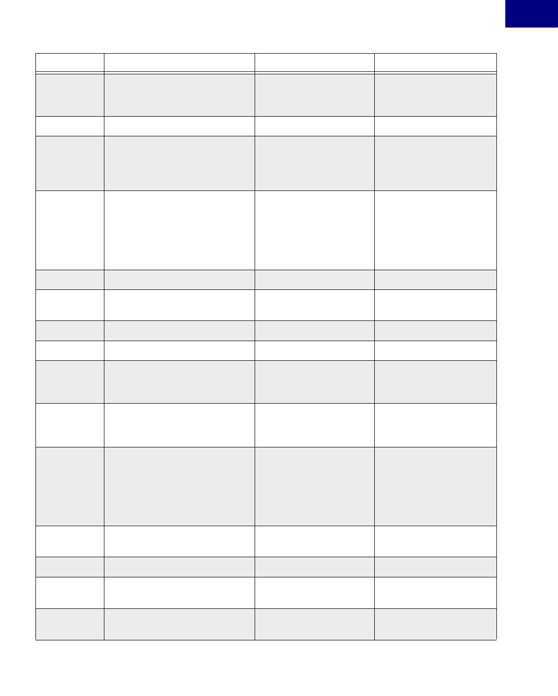
Tools 743
Tools
Tool-category information
Gradient kGradientToolBoss kLayoutManipulationTool,
kTextManipulationTool,
kTableManipulationTool
kPointerToolBoss
Hand kGrabberHandToolBoss kViewModificationTool kPointerToolBoss
Horizontal
frame grid
(Japanese
feature set)
private kLayoutCreationTool kPointerToolBoss
Horizontal
text on a path
kTOPHorzToolBoss kTextSelectionTool,
kTableSelectionTool,
kTextManipulationTool,
kTableManipulationTool,
kTextCreationTool,
kTableCreationTool
kPointerToolBoss
Line kLineToolBoss kLayoutCreationTool kPointerToolBoss
Normal view
mode
kNormalViewModeToolBoss kNone kNormalViewModeToolBo
ss
Oval kOvalToolBoss kLayoutCreationTool kPointerToolBoss
Oval Frame kOvalFrameToolBoss kLayoutCreationTool kPointerToolBoss
Pen kSplinePenToolBoss kLayoutCreationTool,
kLayoutManipulationTool,
kPathManipulationTool
kPointerToolBoss
Pencil kPencilToolBoss kLayoutCreationTool,
kLayoutManipulationTool,
kPathManipulationTool
kPointerToolBoss
Place kPlaceToolBoss kNone (The place tool
creates page items and is in
theory a layout -creation
tool, but because it does
not appear in the toolbox, it
has no category as such.)
not applicable
Preview mode kPreviewModeToolBoss kNone kNormalViewModeToolBo
ss
Rectangle kRectToolBoss kLayoutCreationTool kPointerToolBoss
Rectangle
Frame
kRectFrameToolBoss kLayoutCreationTool kPointerToolBoss
Regular
Polygon
kRegPolyToolBoss kLayoutCreationTool kPointerToolBoss
Tool Tool boss ITool::ToolType ClassID toolType
Tools
Tool-category information
744
Regular
Polygon
Frame
kRegPolyFrameToolBoss kLayoutCreationTool kPointerToolBoss
Rotate kRotateToolBoss kLayoutSelectionTool,
kLayoutManipulationTool
kPointerToolBoss
Scale kScaleToolBoss kLayoutSelectionTool,
kLayoutManipulationTool
kPointerToolBoss
Scissors kScissorsToolBoss kLayoutManipulationTool,
kPathManipulationTool
kPointerToolBoss
Selection kPointerToolBoss kLayoutSelectionTool kPointerToolBoss
Shear kShearToolBoss kLayoutSelectionTool,
kLayoutManipulationTool
kPointerToolBoss
Slug mode kSlugModeToolBoss kNone kNormalViewModeToolBo
ss
Smooth kSmoothToolBoss kLayoutCreationTool,
kLayoutManipulationTool,
kPathManipulationTool
kPointerToolBoss
Type kIBeamToolBoss kTextSelectionTool,
kTableSelectionTool,
kTextManipulationTool,
kTableManipulationTool,
kTextCreationTool,
kTableCreationTool
kPointerToolBoss
Vertical frame
grid (Japanese
feature set)
private kLayoutCreationTool kPointerToolBoss
Vertical text
on a path
(Japanese
feature set)
kTOPVertToolBoss kTextSelectionTool,
kTableSelectionTool,
kTextManipulationTool,
kTableManipulationTool,
kTextCreationTool,
kTableCreationTool
kPointerToolBoss
Zoom kZoomToolBoss kViewModificationTool kPointerToolBoss
Tool Tool boss ITool::ToolType ClassID toolType
Tools 745
Tools
Default implementations of tool-related interfaces
Default implementations of tool-related interfaces
TABLE 168 Default implementations
Interface ImplementationID
IK2ServiceProvider kCToolRegisterProviderImpl
IK2ServiceProvider kCTrackerRegisterProviderImpl
IEventHandler kCTrackerEventHandlerImpl
ICursorProvider kCreationCursorProviderImpl,
kDirectSelectCursorProviderImpl,
kRotateCursorProviderImpl,
kGrabberHandCursorProviderImpl,
kScaleCursorProviderImpl,
kShearCursorProviderImpl,
kCreationCursorProviderImpl,
kSplineAddCursorProviderImpl,
kSplineRemoveCursorProviderImpl,
kSplineDirectionCursorProviderImpl,
kScissorsCursorProviderImpl,
kHorizontalIBeamCrsrProviderImpl,
kVerticalIBeamCrsrProviderImpl,
kZoomToolCursorProviderImpl,
kSelectCursorProviderImpl,
kPlaceGunCursorProviderImpl,
kSplineCreationCursorProviderImpl,
kPencilCursorProviderImpl,
kSmoothCursorProviderImpl,
kEraseCursorProviderImpl,
kTOPHorzToolCursorProviderImpl,
kTOPVertToolCursorProviderImpl
ISprite kNoHandleSpriteImpl,
kGradientToolSpritekFreeTransformSpriteImpl,
kCSpriteImpl, kNoHandleAndCrossSpriteImpl,
kLayoutSpriteImpl, kPencilSpriteImpl,
kStandOffSpriteImpl, kTableResizeSpriteImpl,
kTextOffscreenSpriteImpl
IPathGeometry kPathGeometryImpl

Tools
Tracker listings
746
Tracker listings
TABLE 169 Tool-related trackers
Widget classID Tool classID Tracker classID
kDCSItemBoss kPathResizeToolBoss kSplinePathResizeTrackerBoss
kDCSItemBoss kResizeToolBoss kBBoxResizeTrackerBoss
kDCSItemBoss kScissorsToolBoss kSplineScissorsTrackerBoss
kDCSItemBoss kSplineAddPointToolBoss kSplineAddPointTrackerBoss
kDCSItemBoss kSplineDirectionToolBoss kSplineDirectionTrackerBoss
kDCSItemBoss kSplineRemovePointToolBoss kSplineRemovePointTrackerBoss
kEPSItem kPathResizeToolBoss kSplinePathResizeTrackerBoss
kEPSItem kResizeToolBoss kBBoxResizeTrackerBoss
kEPSItem kScissorsToolBoss kSplineScissorsTrackerBoss
kEPSItem kSplineAddPointToolBoss kSplineAddPointTrackerBoss
kEPSItem kSplineDirectionToolBoss kSplineDirectionTrackerBoss
kEPSItem kSplineRemovePointToolBoss kSplineRemovePointTrackerBoss
kEPSTextItemBoss kResizeToolBoss kBBoxResizeTrackerBoss
kFrameItemBoss kILGMoveToolImpl kILGMoveTrackerBoss
kFrameItemBoss kILGRotateToolImpl kILGRotateTrackerBoss
kFrameItemBoss kTextFrameILGMoveTrackerImpl kTextFrameILGMoveTrackerBoss
kGenericToolBoss kPrePlaceToolBoss kPrePlaceTrackerBoss
kGroupItemBoss kResizeToolBoss kTextBBoxResizeTrackerBoss
kGuideItemBoss kMoveToolBoss kGuideMoveTrackerBoss
kIBeamToolBoss kFrameToolBoss kFrameTrackerBoss
kIBeamToolBoss kTextSelectionToolBoss kTextSelectionTrackerBoss
kIBeamToolBoss kVerticalTextToolBoss kVerticalFrameTrackerBoss
kImageItem kPathResizeToolBoss kSplinePathResizeTrackerBoss
kImageItem kResizeToolBoss kBBoxResizeTrackerBoss
kImageItem kScissorsToolBoss kSplineScissorsTrackerBoss
kImageItem kSplineAddPointToolBoss kSplineAddPointTrackerBoss

Tools 747
Tools
Tracker listings
kImageItem kSplineDirectionToolBoss kSplineDirectionTrackerBoss
kImageItem kSplineRemovePointToolBoss kSplineRemovePointTrackerBoss
kLayoutWidgetBoss kDirectSelectToolBoss kDirectSelectTrackerBoss
kLayoutWidgetBoss kEraseToolBoss kEraseTrackerBoss
kLayoutWidgetBoss kFreeTransformMoveToolBoss kFreeTransformMoveTrackerBoss
kLayoutWidgetBoss kFreeTransformRotateToolBoss kFreeTransformRotateTrackerBoss
kLayoutWidgetBoss kFreeTransformScaleToolBoss kFreeTransformScaleTrackerBoss
kLayoutWidgetBoss kFreeTransformToolBoss kFreeTransformTrackerBoss
kLayoutWidgetBoss kGrabberHandToolBoss kGrabberHandTrackerBoss
kLayoutWidgetBoss kGradientToolBoss kGradientToolTrackerBoss
kLayoutWidgetBoss kGroupSelectToolImpl kGroupSelectTrackerBoss
kLayoutWidgetBoss kIBeamToolBoss kIBeamTrackerBoss
kLayoutWidgetBoss kLayoutLockToolImpl kLockTrackerBoss
kLayoutWidgetBoss kLayoutSelectionToolImpl kLayoutSelectionTrackerBoss
kLayoutWidgetBoss kLineToolBoss kLineTrackerBoss
kLayoutWidgetBoss kOvalFrameToolBoss kOvalFrameTrackerBoss
kLayoutWidgetBoss kOvalToolBoss kOvalTrackerBoss
kLayoutWidgetBoss kPencilToolBoss kPencilCreationTrackerBoss
kLayoutWidgetBoss kPlaceToolBoss kPlaceTrackerBoss
kLayoutWidgetBoss kPointerToolBoss kPointerTrackerBoss
kLayoutWidgetBoss kRectFrameToolBoss kRectangleFrameTrackerBoss
kLayoutWidgetBoss kRectToolBoss kRectangleTrackerBoss
kLayoutWidgetBoss kReferencePointToolImpl kReferencePointTrackerBoss
kLayoutWidgetBoss kRegPolyFrameToolBoss kRegPolyFrameTrackerBoss
kLayoutWidgetBoss kRegPolyToolBoss kRegPolyTrackerBoss
kLayoutWidgetBoss kRotateToolBoss kRotateTrackerBoss
kLayoutWidgetBoss kScaleToolBoss kScaleTrackerBoss
kLayoutWidgetBoss kScissorsToolBoss kScissorsTrackerBoss
kLayoutWidgetBoss kShearToolBoss kShearTrackerBoss
Widget classID Tool classID Tracker classID

Tools
Tracker listings
748
kLayoutWidgetBoss kSmoothToolBoss kSmoothTrackerBoss
kLayoutWidgetBoss kSplineAddPointToolBoss kAddPointTrackerBoss
kLayoutWidgetBoss kSplineDirectionToolBoss kConvertDirectionTrackerBoss
kLayoutWidgetBoss kSplinePenToolBoss kSplineCreationTrackerBoss
kLayoutWidgetBoss kSplineRemovePointToolBoss kRemovePointTrackerBoss
kLayoutWidgetBoss kTOPHorzToolBoss kTOPHorzToolTrackerBoss
kLayoutWidgetBoss kTOPVertToolBoss kTOPVertToolTrackerBoss
kLayoutWidgetBoss kVerticalTextToolBoss kVerticalTextTrackerBoss
kLayoutWidgetBoss kZoomToolBoss kZoomToolTrackerBoss
kMultiColumnItemBoss kPlaceToolBoss kPlacePITrackerBoss
kPageBoss kMoveToolBoss kColumnGuideTrackerBoss
kPageItemBoss kMoveToolBoss kMoveTrackerBoss
kPageItemBoss kPlaceToolBoss kPlacePITrackerBoss
kPICTItem kPathResizeToolBoss kSplinePathResizeTrackerBoss
kPICTItem kResizeToolBoss kBBoxResizeTrackerBoss
kPICTItem kScissorsToolBoss kSplineScissorsTrackerBoss
kPICTItem kSplineAddPointToolBoss kSplineAddPointTrackerBoss
kPICTItem kSplineDirectionToolBoss kSplineDirectionTrackerBoss
kPICTItem kSplineRemovePointToolBoss kSplineRemovePointTrackerBoss
kPlacedPDFItemBoss kPathResizeToolBoss kSplinePathResizeTrackerBoss
kPlacedPDFItemBoss kResizeToolBoss kBBoxResizeTrackerBoss
kPlacedPDFItemBoss kScissorsToolBoss kSplineScissorsTrackerBoss
kPlacedPDFItemBoss kSplineAddPointToolBoss kSplineAddPointTrackerBoss
kPlacedPDFItemBoss kSplineDirectionToolBoss kSplineDirectionTrackerBoss
kPlacedPDFItemBoss kSplineRemovePointToolBoss kSplineRemovePointTrackerBoss
kSplineItemBoss kPathResizeToolBoss kSplinePathResizeTrackerBoss
kSplineItemBoss kResizeToolBoss kTextBBoxResizeTrackerBoss
kSplineItemBoss kScissorsToolBoss kSplineScissorsTrackerBoss
kSplineItemBoss kSplineAddPointToolBoss kSplineAddPointTrackerBoss
Widget classID Tool classID Tracker classID
Tools 749
Tools
Tracker listings
TABLE 170 User-interface widget-related trackers
kSplineItemBoss kSplineDirectionToolBoss kSplineDirectionTrackerBoss
kSplineItemBoss kSplineRemovePointToolBoss kSplineRemovePointTrackerBoss
kSplitterWidgetBoss kSplitterWidgetBoss kSplitterTrackerBossMessage
kStandOffPageItemBoss kMoveToolBoss kStandOffMoveTrackerBoss
kStandOffPageItemBoss kPathResizeToolBoss kStandOffResizeTrackerBoss
kStandOffPageItemBoss kResizeToolBoss kStandOffResizeTrackerBoss
kStandOffPageItemBoss kSplineAddPointToolBoss kStandOffAddPointTrackerBoss
kStandOffPageItemBoss kSplineDirectionToolBoss kStandOffDirectionTrackerBoss
kStandOffPageItemBoss kSplineRemovePointToolBoss kStandOffRemovePointTrackerBoss
kTOPSplineItemBoss kTOPMoveToolBoss kTOPMoveTrackerBoss
kTOPSplineItemBoss kTOPResizeToolBoss kTOPResizeTrackerBoss
kWMFItem kPathResizeToolBoss kSplinePathResizeTrackerBoss
kWMFItem kResizeToolBoss kBBoxResizeTrackerBoss
kWMFItem kScissorsToolBoss kSplineScissorsTrackerBoss
kWMFItem kSplineAddPointToolBoss kSplineAddPointTrackerBoss
kWMFItem kSplineDirectionToolBoss kSplineDirectionTrackerBoss
kWMFItem kSplineRemovePointToolBoss kSplineRemovePointTrackerBoss
Widget classID Tool classID Tracker classID
kCmykColorSliderWidgetBoss kCmykColorSliderWidgetBoss kCmykColorSliderTrackerBoss
kColorSliderWidgetBoss kColorSliderWidgetBoss kColorSliderTrackerBoss
kGradientSliderWidgetBoss kGradientSliderWidgetBoss kGradientSliderTrackerBoss
kGroupItemBoss kResizeToolBoss kTextBBoxResizeTrackerBoss
kGuideItemBoss kMoveToolBoss kGuideMoveTrackerBoss
kHorzRulerWidgetBoss kGuideToolImpl kGuideCreationTrackerBoss
kHorzTabRulerBoss kTabCreationToolImpl kTabCreationTrackerBoss
kHorzTabRulerBoss kTabMoveToolImpl kTabMoveTrackerBoss
kHorzTextDocRulerBoss kTabCreationToolImpl kDocRulerTrackerBoss
Widget classID Tool classID Tracker classID

Tools
Tracker listings
750
kLabColorSliderWidgetBoss kLabColorSliderWidgetBoss kLabColorSliderTrackerBoss
kPencilFidelitySliderWidgetBoss kPencilFidelitySliderWidgetBoss kPencilSliderTrackerBoss
kPencilSmoothnessSliderWidgetBoss kPencilSmoothnessSliderWidgetBoss kPencilSliderTrackerBoss
kPencilWithinSliderWidgetBoss kPencilWithinSliderWidgetBoss kPencilSliderTrackerBoss
kRasterSliderCntrlViewBoss kRasterSliderCntrlViewBoss kRasterSliderTrackerBoss
kRgbColorSliderWidgetBoss kRgbColorSliderWidgetBoss kColorSliderTrackerBoss
kSpectrumWidgetBoss kSpectrumWidgetBoss kSpectrumTrackerBoss
kSplitterWidgetBoss kSplitterWidgetBoss kSplitterTrackerBossMessage
kStructureSplitterWidgetBoss kStructureSplitterWidgetBoss kXorSplitterTrackerBoss
kThresholdSliderWidgetBoss kThresholdSliderWidgetBoss kThresholdSliderTrackerBoss
kTintSliderWidgetBoss kTintSliderWidgetBoss kColorSliderTrackerBoss
kToleranceSliderWidgetBoss kToleranceSliderWidgetBoss kThresholdSliderTrackerBoss
kTransparencySliderCntrlViewBoss kTransparencySliderCntrlViewBoss kXPSliderTrackerBoss
kVectorSliderCntrlViewBoss kVectorSliderCntrlViewBoss kVectorSliderTrackerBoss
kVertRulerWidgetBoss kGuideToolImpl kGuideCreationTrackerBoss
kVertTabRulerBoss kTabCreationToolImpl kTabCreationTrackerBoss
kVertTabRulerBoss kTabMoveToolImpl kTabMoveTrackerBoss
kVertTextDocRulerBoss kTabCreationToolImpl kDocRulerTrackerBoss
kZeroPointWidgetBoss kGuideToolImpl kGuideCreationTrackerBoss
kZeroPointWidgetBoss kZeroPointToolImpl kZeroPointTrackerBoss
Widget classID Tool classID Tracker classID

Diagnostics 751
Diagnostics
Introduction
Diagnostics
Introduction
This chapter describes how you can use the diagnostics plug-in when developing plug-ins for
InDesign, InCopy, and InDesign Server. The Diagnostics plug-in provides a detailed look at the
internal operations of command processing; the organization of document content inside
spreads, layers and page items; INX DTD generation; and object model IDs and UIDs. Note,
the newer IDML file format supports schema generation and validation. For information on
IDML and RelaxNG schema validation see Adobe InDesign Markup Language (IDML) Cook-
book.
The diagnostics plug-in can help you find answers to questions like the following:
zWhich commands is the application using to manipulate content?
zWhat is exposed in the scripting Document Object Model (DOM)?
zWhat types of page items are used to store content?
zHow are page items organized inside spreads and layers?
zWhat is the symbolic name (e.g., kSessionBoss) that corresponds to a numeric object model
ID (e.g., 0x101)?
zWhat type of boss class does a given UID refer to?
Using the diagnostics plug-in
The diagnostics plug-ins (Diagnostics.apln and DiagnosticsUI.apln) are found on Windows in
<SDK>\build\win\debug\testing and on Mac OS in <SDK>/build/mac/debug/package-
folder/contents/macos/testing.
This chapter describes the use of the Diagnostics plug-in through the application user interface
and scripting.
To use the plug-in with the debug build of InDesign or InCopy, select one of the Test > Diag-
nostics menu items. To use the plug-in with the release build of InDesign or InCopy or with
InDesign Server, you must use a script. See “Diagnostics > Scripting DOM menu” on page 756.
You can use the diagnostics plug-in to generate traces, which provide an equivalent of printf
debug messages to a log. You can filter messages by category. To see the trace, use the Test >
TRACE menu to enable the logs you want use. If you do not see any traces when you use the
plug-in’s menus, make sure the Diagnostics category is checked on the Test > TRACE menu.
Unchecking these categories filters the trace produced by the plug-in. If you do not see a Test >
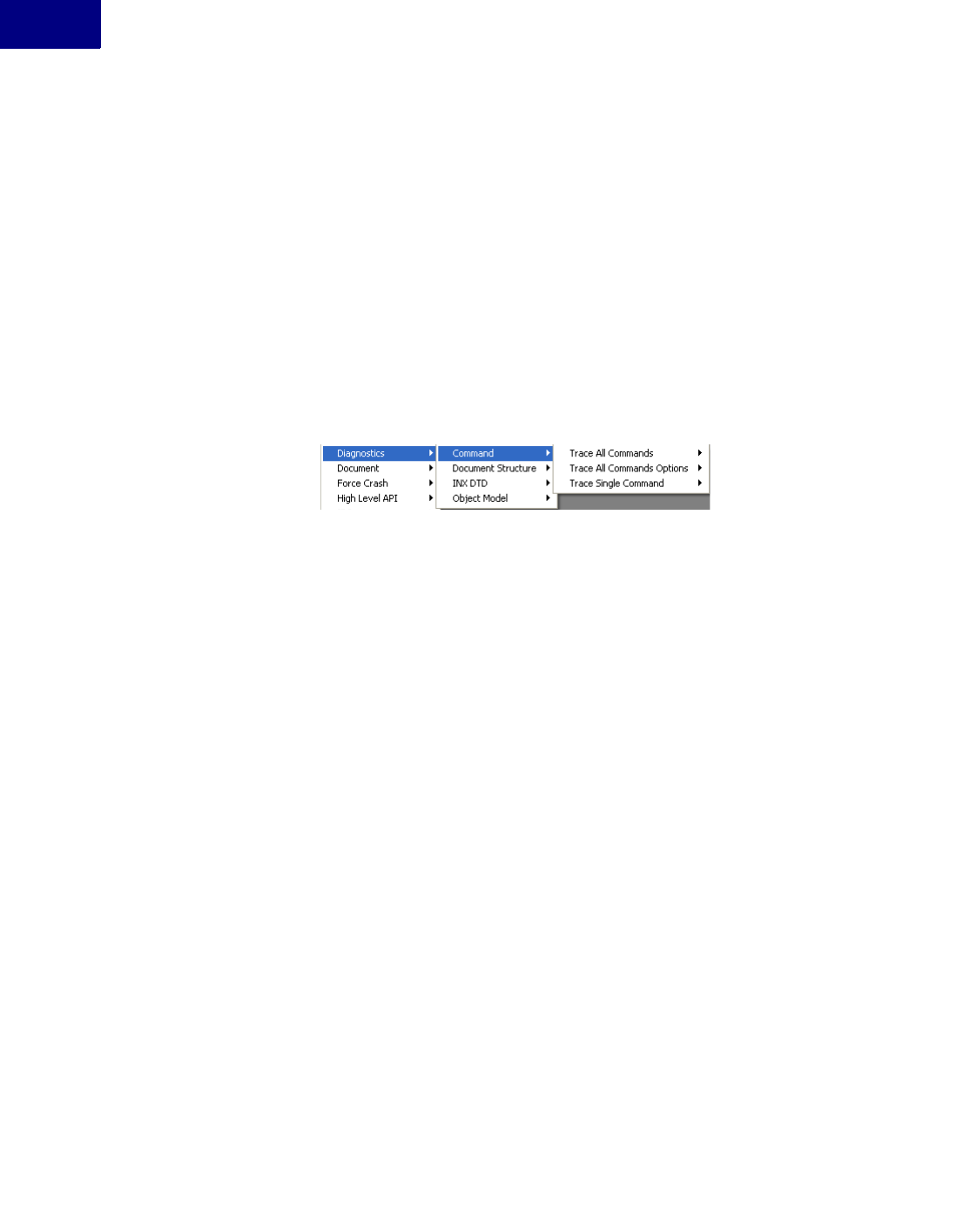
Diagnostics
Using the diagnostics plug-in
752
TRACE > Diagnostics menu, select Test > Diagnostics > ObjectModel > TraceID. Some trace
output must be written before the Test > TRACE menu shows the category.
Diagnostics menu
Plug-in options are not persistent; that is, settings you make to control the level of reporting
must be applied for each session.
Diagnostics > Command menu
This menu contains items to trace one or more commands. See Figure 287.
FIGURE 287 Diagnostics > Command menu
The three commands in the menu are described below.
Trace All Commands — This traces all commands being processed by the application. Use this
to discover the command being used to manipulate content in response to a user action. For
example, this trace is created in response to grouping a set of page items:
kMoveReferencePointCmdBoss Diagnostics::ProcessCommand()
kSetDefaultRefPointPositionCmdBoss Diagnostics::ProcessCommand()
kSetAttributeTargetCommandBoss Diagnostics::ProcessCommand()
kGroupCmdBoss Diagnostics::ProcessCommand()
kNewPageItemCmdBoss Diagnostics::ProcessCommand()
kApplyObjectStyleCmdBoss Diagnostics::ProcessCommand()
kBPISetDataCmdBoss Diagnostics::ProcessCommand()
kMoveReferencePointCmdBoss Diagnostics::ProcessCommand()
kSetDefaultRefPointPositionCmdBoss Diagnostics::ProcessCommand()
kSetAttributeTargetCommandBoss Diagnostics::ProcessCommand()
kCheckExportSettingsCmdBoss Diagnostics::ScheduleCommand()
kCheckColorSettingsCmdBoss Diagnostics::ScheduleCommand()
kCheckExportSettingsCmdBoss Diagnostics::ProcessCommand()
kCheckColorSettingsCmdBoss Diagnostics::ProcessCommand()
Trace All Commands Options — Several options are available to control the detail of the infor-
mation reported by Trace All Commands:
zData Interfaces — Turn this on to trace the data interfaces (e.g., IID_BOOLDATA) aggre-
gated by each command for parameter passing.
zItemList UIDs — Turn this on to trace the UIDs of objects in each command’s item list.
zItemList ClassIDs — Turn this on to trace the ClassID values of objects in each command’s
item list. Use this to find the type of object (e.g., kSplineItemBoss) a command manipulates.
zDynamic Commands — Turn this on to trace dynamic command processing (e.g., the com-
mands processed by a tracker when a page item is moved using the mouse).
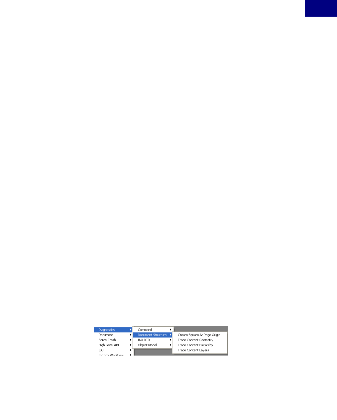
Diagnostics 753
Diagnostics
Using the diagnostics plug-in
Trace Single Command — Once you know the command of interest (e.g., kGroupCmdBoss),
you can use Trace Single Command to examine its processing in more detail. Use this when
you know the ClassID of the command about which you want to know more. The trace is
indented to show the commands used by the command of interest. For example:
Begin cmd no. 0 'kGroupCmdBoss' (class id 0x405)
Begin cmd no. 1 'kNewPageItemCmdBoss' (class id 0x2c01)
## Begin Sequence
Begin cmd no. 2 'kGfxApplyMultAttributesCmdBoss'
## Begin Sequence
## End Sequence
End cmd 'kGfxApplyMultAttributesCmdBoss' (class id 0x6e4d)
## End Sequence
End cmd 'kNewPageItemCmdBoss' (class id 0x2c01)
>> Direct Change: SetDirty (id: 125)
>> Direct Change: SetDirty (id: 136)
>> Direct Change: SetDirty (id: 136)
>> Direct Change: SetDirty (id: 140)
>> Direct Change: SetDirty (id: 136)
>> Direct Change: SetDirty (id: 136)
>> Direct Change: SetDirty (id: 125)
>> Direct Change: SetDirty (id: 137)
>> Direct Change: SetDirty (id: 137)
>> Direct Change: SetDirty (id: 140)
>> Direct Change: SetDirty (id: 137)
>> Direct Change: SetDirty (id: 137)
>> Direct Change: SetDirty (id: 125)
>> Direct Change: SetDirty (id: 140)
>> Direct Change: SetDirty (id: 140)
>> Direct Change: SetDirty (id: 137)
>> Direct Change: SetDirty (id: 136)
// Direct Changes are Done
// Root Command is Done
End cmd 'kGroupCmdBoss' (class id 0x405)
Diagnostics > Document Structure menu
The menu contains items to report information on the spreads, pages, and page items in the
front document. See Figure 288.
FIGURE 288 Diagnostics > Document Structure Menu
The four commands in the menu are described below.

Diagnostics
Using the diagnostics plug-in
754
Create Square At Page Origin — This creates a 100pt-by-100pt square spline at the origin of the
current page in the front-most document and traces the geometry of the object and its parent
spread as it does so.
Trace Content Geometry — This traces the geometry of spreads and page items in their inner
coordinates, relative to their parent object and the pasteboard.
Trace Content Hierarchy — This traces the content of each spread, by the spread layer by which
the content is owned. For example:
TraceContentHierarchy() ********Begin
kDocBoss, uid 0x1
Untitled-2
kSpreadBoss, uid 0x7a
Spread 1 content by hierarchy...
kSpreadLayerBoss, uid 0x7b
kPageBoss, uid 0x7f
kSpreadLayerBoss, uid 0x7c
kSpreadLayerBoss, uid 0x7d
kSplineItemBoss, uid 0x8c
kImageItem, uid 0x88
kSpreadLayerBoss, uid 0x7e
kMasterPagesBoss, uid 0x81
A-Master master spread content by hierarchy...
kSpreadLayerBoss, uid 0x82
kPageBoss, uid 0x86
kPageBoss, uid 0x87
kSpreadLayerBoss, uid 0x83
kSpreadLayerBoss, uid 0x84
kSpreadLayerBoss, uid 0x85
TraceContentHierarchy() ********End
Trace Content Layers — This traces the content of each spread, by the document layer on which
the content is displayed.
Diagnostics > INX DTD menu
This menu contains items related to INX DTD generation. InDesign Interchange (INX) format
is an XML-based format used to serialize and deserialize the InDesign scripting DOM. The
API supports several options for export to INX file format, and this menu item demonstrates
generating DTDs that correspond to these options. See Figure 289.
NOTE:The application itself does not provide these options during export.
FIGURE 289 Diagnostics > INX DTD menu
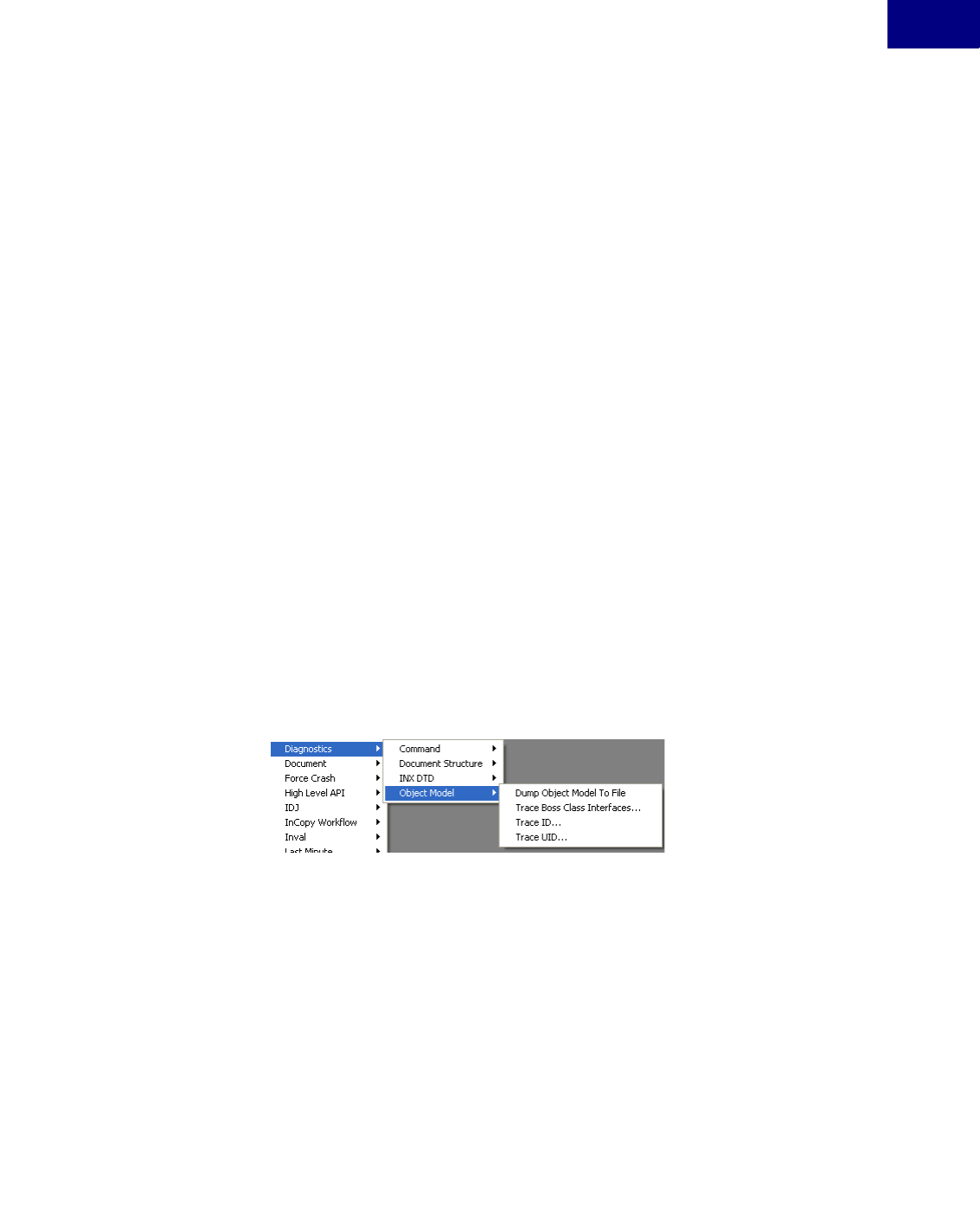
Diagnostics 755
Diagnostics
Using the diagnostics plug-in
The five commands in the menu are described below.
Generate — This generates a DTD according to the current scripting model at run time. This
means if your newly developed plug-in supports scripting, the generated DTD covers that. The
menu command is disabled if no document is open. The generated DTD is saved to the same
directory as InDesign recovery and named INXFile.DTD.
Tog gle Use DTD — This toggles use of the DTD. The default setting for INX export is false.
Tog gle Us e Namespace — This toggles use of the namespace. The default setting for INX export
is false.
Toggle Use Readable Numbers — This toggles use of readable numbers. The default setting for
INX export is true. When true, the real number in exported INX is represented as human-
readable text; otherwise, binary.
Toggle Use Verbose Name — This toggles use of verbose names. The default setting for INX
export is false. When true, the verbose name is used to represent element and attribute name
instead of the four-character value (e.g., “document” instead of “docu”).
NOTE:InDesign supports RelaxNG schema validation of IDML. It does not, and will not,
support DTD validation of INX files. We recommend IDML to assemble and
disassemble content outside of InDesign. For details about schema validation with
IDML, see Adobe InDesign Markup Language (IDML) Cookbook.
Diagnostics > Object Model menu
See Figure 290 for this menu.
FIGURE 290 Diagnostics > Object Model menu
The four commands in the menu are described below.
Dump Object Model To File — This exports the object model to a tab-separated file in the folder
where the application is installed. A record is produced for each interface on each boss class.
The output file is IObjectModel_RomanFS.txt if the application is running with the Roman
feature set and IObjectModel_JapaneseFS.txt if the application is running with the Japanese
feature set. These reports are suitable for import into a spreadsheet or database application. You
can then do filtered searches to get answers to question like “Which boss classes aggregate
IID_IATTRREPORT?”
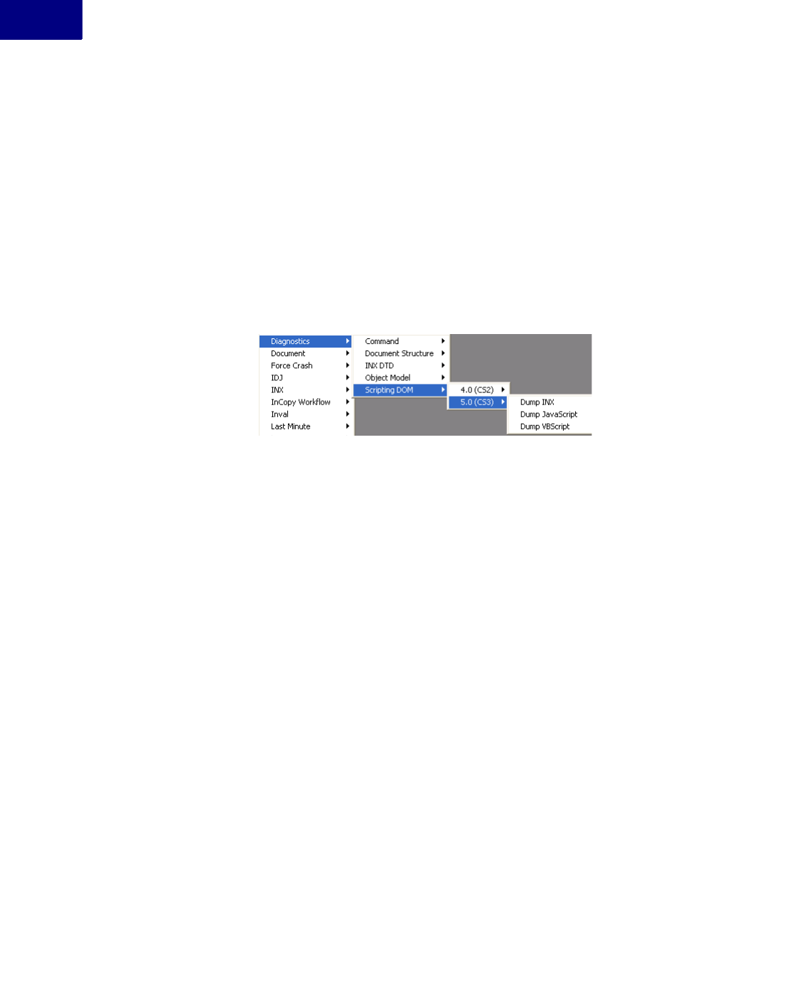
Diagnostics
Using the diagnostics plug-in
756
Trace Boss Class Interfaces — This traces the interfaces aggregated by a given boss class.
Trace ID — This traces the symbolic name of a given numeric ID in each ID space.
Trace UID — This traces the ClassID of a given UID, by instantiating an object of that UID in
the front document and examining its associated boss class. If no documents are open, the
InDesign Defaults database is used.
Diagnostics > Scripting DOM menu
See Figure 291 for this menu.
FIGURE 291 Diagnostics > Scripting DOM menu
The Scripting DOM menu can be used to dump a language-specific scripting DOM to an XML
file. It contains submenus that allow you to specify the product version, followed by the lan-
guage to dump. IDML, INX, and JavaScript DOMs are available on both Windows and Mac
OS. Also, Visual Basic is available on Windows, and AppleScript is available on Mac OS.
These XML files can be transformed into two useful HTML representations, using an XSLT
processor and the style sheets included at <sdk>/docs/references/. The scripting-dom-to-
html.xsl file produces an HTML representation of the entire DOM. The scripting-dom-
idname-table.xsl file produces a simple table that maps scriptIDs to names. See the comments
at the top of the style sheets for detailed use instructions.
Running the Diagnostics plug-in in indesign/incopy with a script
You may run the Diagnostics plug-in with a script. The following examples demonstrate how to
do so using JavaScript.
The following Windows example dumps the object model to c:\dump.txt:
var myDiagnostics = app.diagnostics;
myDiagnostics.dumpObjectModel("c:\\dump.txt");
// Note: the path separator is \\ and not a single \.
The following Windows example produces c:\vbDOM-5.xml, a Visual Basic DOM for InDe-
sign 5.0 or InCopy 5.0:
var myDiagnostics = app.diagnostics;
myDiagnostics.dumpScriptingDOM(ScriptingDOMLanguage.visualBasic, "5.0", "c:\\vbDOM-
5.xml");

Diagnostics 757
Diagnostics
Using the diagnostics plug-in
The following Mac OS example dumps the object model to dump.txt on the disk gokkyo:
var myDiagnostics = app.diagnostics;
myDiagnostics.dumpObjectModel("gokkyu:dump.txt");
// Note: posix paths are not supported, use old style for now.
The following Mac OS example produces appleScriptDOM-5.xml, an AppleScript DOM for
InDesign 5.0 or InCopy 5.0:
var myDiagnostics = app.diagnostics;
myDiagnostics.dumpScriptingDOM(ScriptingDOMLanguage.applescriptLanguage, "5.0",
"gokkyu:appleScriptDOM-5.xml");
Once you save a script on your hard drive, you can run it using the Scripts panel. To open the
Scripts panel, select Window > Automation > Scripts. Open the scripts folder, add a shortcut to
your script, and run the script.
Running the Diagnostics plug-in in InDesign Server on Windows with a
script
To run the above scripts with InDesign Server on Windows, open a command window, locate
InDesign Server CS4 through Windows Explorer, drag it to the command prompt, and append
the port on which you want it to listen. For example:
<path>\InDesignServer.com -port 12345
Open another command window. Locate sampleclient through Windows Explorer, drag it to
the command prompt, and append the host to which you want it to send. For example:
<path>\sampleclient.exe <path>\MyScript.js -host localhost:12345
Before running InDesign Server, make sure the TCP/IP port (from which InDesign Server is
listening for SOAP messages) is open (especially if you have a firewall set up).
Running the Diagnostics plug-in in InDesign Server on Mac OS with a script
To run the above scripts with InDesign Server on Mac OS, open a terminal window, locate
InDesign Server CS4 through the Finder, drag it to the terminal window, and append the port
on which you want it to listen. For example:
<path>/InDesignServer -port 12345
Open another terminal window. Locate sampleclient using the Finder and drag it to the termi-
nal window. Append the host to which you want it to send. For example:
<path>/sampleclient <path>/MyScript.js -host localhost:12345
Before running InDesign Server, make sure the TCP/IP port (from which InDesign Server is
listening for SOAP messages) is open (especially if you have a firewall set up).

Diagnostics
Frequently asked questions
758
Frequently asked questions
Where is the Diagnostics panel?
In InDesign CS4, the user interface for the features provided by the Diagnostics plug-in is in
the Test > Diagnostics menu. The panel used by previous versions of this plug-in is no longer
needed.
What is trace?
A trace provides a printf style of debug log. Traces are available with the debug build of the
application. Trace output under the release build is not supported.
Why don’t I get trace messages?
Make sure you checked one of the available logs presented on the Test > TRACE menu and Test
> TRACE > Diagnostics is selected. If you do not see a Test > TRACE > Diagnostics menu, use
Test > Diagnostics > ObjectModel > TraceID first. (Some trace output must be written to the
category before the Test > TRACE menu shows it.)

InCopy: Getting Started 759
InCopy: Getting Started
About InCopy
InCopy: Getting Started
This chapter introduces InCopy as a programming platform. Because the SDK is unified for
InDesign CS and InCopy CS and later, information specific to InCopy is a relatively small por-
tion of this document.
This chapter has the following objectives:
zAcquaint you with elements of the programming environment specific to InCopy.
zDirect you to documentation that expands on topics mentioned briefly here.
About InCopy
InCopy is a collaborative, text-editing application developed for integrated use with InDesign.
InCopy enables you to track changes, add editorial notes, and fit copy tightly into the space
designed for it. InCopy uses the same text-composition engine as InDesign, so InCopy fits copy
within a layout with identical composition.
InCopy is for the editorial environment; it allows editorial workflow participants to collaborate
on magazines, newspapers, and corporate publishing, enabling concurrent text and layout edit-
ing. Its users are editors, writers, proofreaders, copy editors, and copy processors.
InCopy shares many panels and palettes with InDesign but also provides its own user-interface
items.
Developing for InCopy
Previous releases of InCopy focused on large installations and were available for purchase only
through system integrators, so system integrators were the primary group developing for
InCopy. Several software developers also wrote plug-ins targeted for magazine and newspaper
use.
With the current release, smaller developers have additional opportunities to write plug-ins
targeted at magazines, newspapers, corporate publishing, and other collaborative users.
Using the combined InDesign/InCopy SDK
This section looks at the SDK from an InCopy perspective. InDesign and InCopy share an
SDK.
In the great majority of cases, when you write code in the InDesign source base, you also are
writing code for InCopy. Statistically speaking, the programs are nearly identical; nevertheless,

InCopy: Getting Started
Synchronization of design and architecture
760
you will need to keep InCopy in mind when working with files, links, text and page items, as
there are behaviors that can be broken easily.
InDesign, InDesign Server, and InCopy all run the same code. This means any specific behaviors
must be implemented at run time, not at compile time. The only uniquely built portions of the
program are the application shells for each version. All other plug-ins can be loaded into any of
the applications, although a plug-in also has a resource in its class file that lists which variants
should load it.
The InCopy API
Since InCopy does not support the entire InDesign API, it is important to know which APIs are
available for use with InCopy. To determine whether a particular API is appropriate for
InCopy, consult the API reference documentation for boss classes; for each interface exposed
by a given boss class, you can see in which application(s) the interface can be found.
Compiler settings
Compiler settings do not differ between InDesign and InCopy plug-ins. For details on plug-in
development environments, see the “Development Environment” section of Adobe InDesign
CS4 Porting Guide.
Resources
InCopy and InDesign plug-ins are compiled from the same code base; therefore, the informa-
tion on whether a plug-in is intended for InDesign or InCopy is built into the PluginVersion
resource found in a plug-in's.fr file, using the kInDesignProduct and kInCopyProduct identifi-
ers. When both identifiers are used in the resource definition, the plug-in is intended for use in
both InDesign and InCopy.
Additional feature-set IDs exist that may be applicable to your InCopy plug-in. For informa-
tion on additional feature-set IDs, see FeatureSets.h.
Synchronization of design and architecture
Important areas of integration between InDesign and InCopy are described below:
zExtended InCopy file format — The InCopy file format supports persistent features from
InDesign, like table headers and footers, as well as Japanese-specific features.
zAssignment files — Users can group related document constituents (like headline, byline,
copy, graphics, and captions) into meaningful elements that can be worked on as a group.
InDesign and InCopy support the creation of such groupings. For details, see the “InCopy:
Assignments” chapter.

InCopy: Getting Started 761
InCopy: Getting Started
File relationships
zAuto undo/redo — The Auto undo/redo architecture in the core code makes implementing
and maintaining commands much easier. This change affects change-tracking, notes and
the story editor.
zScripting architecture — InCopy plug-ins use the scripting architecture.
zDocument actions — File actions between the two applications are consistent.
zSymbol glyph-font resolution — The story editor uses a default display font to show text.
Where a glyph is used that is not native to the default display font, another font capable of
correctly displaying the glyph is searched for and used instead.
zUnified text navigation — Text-navigation behavior within layout, story, and galley views is
identical.
File relationships
This section describes relationships between InDesign and InCopy files. These relationships
are important because of the division of labor in a publication workflow that occurs when
much of the same material is opened and modified in both applications.
There are two common scenarios for exporting from InCopy:
zYou can export an (IDML-based) ICML file.
zYou can export an (INX-based) INCX file.
There are two common scenarios for exporting from InDesign that involve InCopy in some
way:
zStories exported from InDesign as InCopy files are XML files or streams; the InCopyExport
and InCopyWorkflow plug-ins loaded into InDesign provide this function. Some of the
practical implications of this approach for InCopy files are that they are much smaller, they
are faster over the network, they do not contain any page geometry, and data within the
XML file or stream is available outside InDesign/InCopy (for search engines, database tools,
etc.).
zGroupings within an article (like a headline, byline, copy, graphics, and captions) also can
be exported. InDesign and Incopy support the creation of groupings with assignment files,
which handle file management by adding an additional file that tracks the other files. In
essence, an assignment is a set of files whose contents are assigned to one person for some
work to be done (e.g., copy edit, layout, and/or writing). Any stories in an assignment are
exported as InCopy files. Geometry information and the relationship of the files are held in
the assignment file. InDesign allows the user to export a given set of stories by exporting
into an assignment. InCopy opens all stories that are in an assignment together (as one
unit). For details, see the “InCopy: Assignments” chapter.

InCopy: Getting Started
File relationships
762
Stories
Each InCopy file represents one story. An InDesign document containing several stories can be
modularized to the same number of InCopy documents, through export. Those exported
InDesign stories contain a link, which may be viewed in the Links panel (InDesign) or the
Story List palette as assignment files (InCopy).
InCopy does not maintain a link to the InDesign document it is associated with (if one exists).
InDesign maintains any links with InCopy files as bi-directional links (kBidirectionalLink-
Boss).
Stories can be structured in XML. This means XML data can be contained within XML data.
This feature can be used to design a data structure in which the raw text of a story is contained
within an outer structure that contains data specific to InCopy (like styles).
Within InCopy, content can be saved in an ICML/INCX format or, if there is structure in the
story, the logical structure can be exported in XML.
An ICML or INCX file can contain both InCopy data and marked-up text. If the file is exported
as XML data, the data specific to InCopy is stripped out, leaving the marked-up content minus
the information about how it is to be styled.
Page geometry
InCopy files do not contain page geometry. When geometry is needed, it must be obtained
from the InDesign document. InCopy can open InDesign documents and extract design infor-
mation and links to the exported stories where needed. When page geometry is desired from
within InCopy, assignment files can be supplied with it.
Metadata
The Adobe Extensible Metadata Platform (XMP) provides a practical method for creating,
interchanging, and managing metadata. InCopy files support XMP.
Just as InDesign provides the File > File Info menu command to view XMP data, InCopy pro-
vides the File > Story Info menu command. The ability for that data to be retained or stripped
out during export is provided to systems integrators.
Metadata added to stories by third-party software developers is preserved when incorporated
into InDesign documents. Added metadata can be viewed within InDesign from the File Info
dialog box, available from the Links panel menu, as well as viewed within InCopy. Further,
third-party software developers can add function to InDesign to view that metadata in a cus-
tom user interface.
An extensibility point exists for service providers to add metadata content to InCopy files. For
further information on the metadata API, see MetaDataID.h. Also, the XMP SDK provides
documentation, tools, and sample code to help you build support for XMP metadata.

InCopy: Getting Started 763
InCopy: Getting Started
File relationships
The document model
InDesign documents are the basis for all content in InDesign. InCopy also uses InDesign docu-
ments, but they are not the default document type. Symbolic constants are used to identify doc-
ument types: InDesign documents are identified with kInDesignFileTypeInfoID, whereas
InCopy documents are identified with kInCopyFileTypeInfoID. There also is a constant that
means “this program's document,” kPublicationFileTypeInfoID. There also is a corresponding
template ID, kTemplateFileTypeInfoID.
In both InDesign and InCopy, the basic document always is a database based on IDocument; in
InCopy, however, this document may be an incomplete document. In InDesign, the main doc-
ument typically is an opened InDesign file, but it also can be an opened INX or IDML file,
which typically appears to be an unsaved InDesign document.
InCopy has a few other permutations. There is the basic InDesign file, as well as a new docu-
ment with an InCopy story (or plain or RTF text) imported into it; this is known as a standal-
one document and can be identified by the IStandAloneDoc interface on the kDocBoss. Also,
there are IDML- and INX-based assignment files, which has some part of an InDesign file
stored in an XML file. The InDesign/InCopy document model corresponds to the base
required model plug-in set, versioned against changes over time. It is important that all
IDML/INX scripting work in both InDesign and InCopy, so documents can be moved with
high fidelity between the applications.
User-interface differences
InDesign and InCopy share most of their panels, but InCopy has a smaller set and several addi-
tional toolbars along the top, left, and bottom screen borders. Most InCopy panels also can be
docked on these bars, providing a smaller but always-visible view of the panel. Modifications
made to these panels in InDesign also may need to modify their alternate view in InCopy.
InCopy support for alternate panel layouts (kits) involves KitList resources.
InCopy also has a custom window layout with multiple views, in a main window with three
tabs: Galley view, Story view, and Layout view. Layout view is the InDesign window view. Gal-
ley and story views are simply the story-editor view, with and without accurate line endings,
respectively.
Checking the feature set
The most popular practice is checking for the proper feature set with the LocaleID utility. The
most important thing to remember about this is that there are three products: InDesign, InDe-
sign Server, and InCopy. As a result, you should almost never check for the InDesign feature
set. Instead, check for InCopy or InDesignServer as needed:
bool16 isInCopy = LocaleSetting::GetLocale().IsProductFS(kInCopyProductFS);
bool16 isServer = LocaleSetting::GetLocale().IsProductFS(kInDesignServerProductFS);
Also, because InCopy is now localized for Japanese, checking for the Japanese-language feature
set should no longer include product information:
bool16 isJapanese = LocaleSetting::GetLocale().IsLanguageFS(kJapaneseLanguageFS);

InCopy: Getting Started
Workflow
764
Workflow
The InCopy workflow interface is an extensibility layer available to all third-party software
developers and system integrators. The major pieces of this workflow are the following:
zAn internal interface (IInCopyWorkflow) that provides core functions and guarantees com-
patibility.
zA set of three general action categories—Import, Export, and FileActions—that are sup-
plied as plug-ins in source code form. These plug-ins are intended to be modified by soft-
ware developers and system integrators to meet their own unique workflow needs.
zInDesign (with InCopyBridge) and InCopy inline, editorial-notes features let you add com-
ments, annotations, or notes directly to the text without affecting the flow of the story. The
notes features are designed to be used in a workgroup environment, so the notes can be
color-coded and turned on or off based on certain criteria. For more information, see the
“InCopy: Notes” chapter.
zThe InCopy Track Changes features give editors and writers the ability to track edits as a
document moves through the writing and editing system. They need to be able to selectively
track, show, hide, accept, and reject changes. For more information, see the “InCopy: Track
Changes” chapter.
zNew InCopyBridge plug-ins (InCopyBridge and InCopyBridgeUI) are supplied as out-of-
the-box workflow solutions.
Design and architecture
Story/file relationship
ICML is an IDML-based representation of an InCopy story. It represents the future direction of
InDesign/InCopy and is an especially good choice if you need to edit a file outside of InDesign.
ICML format
Each InCopy file or stream is in XML. One of the advantages of this is that InCopy files can be
parsed easily and opened by any text editor.
INCX format
INCX is an INX-based representation of an InCopy story. This format is not as readable as
ICML, but it is still available to support INCX-based workflows.
Document operations
InCopy provides default implementations of document operations (file actions) like New, Save,
Save As, Save A Copy, Open, Close, Revert, and Update Design. All these InCopy file actions
are in one plug-in (InCopyFileActions) in source-code form that software developers or system
integrators are expected to replace with their own implementations, to customize the interac-
tion for their workflow system.

InCopy: Getting Started 765
InCopy: Getting Started
Workflow
Using service providers for document interchange
InCopy uses the service-provider architecture for import and export. The InCopy Import and
Export provider plug-ins function in both InDesign and InCopy applications. It is expected
that system integrators will replace these default service providers with their own, to customize
the interaction for their workflow system.
zFrom InDesign, InCopy import provider — With the appropriate InCopy plug-ins installed
into InDesign, the user can place an InCopy document into the InDesign document. The
Place mechanism is the same as for any other kind of text file.
zFrom InDesign, InCopy export provider — With the appropriate InCopy plug-ins installed
into InDesign, the user can export a story to an InCopy document by choosing the Export
menu item and selecting the InCopy file format. Behind the scenes, this export process cre-
ates a link pointing to the resulting InCopy file and associates the link with the story. The
InCopy document does not have any geometry information associated with it.
zFrom InCopy, InCopy import provider — The Place mechanism is the same as for any other
kind of text file.
zFrom InCopy, InCopy export provider — The user can export a story to PDF or one of sev-
eral text documents, by choosing the Export menu item and selecting the desired file for-
mat.
Using XMP metadata
The user can enter and edit metadata by choosing File > Story Info. Panels are supplied for
General, Keywords, and Summary data. This metadata is saved in the InCopy file. Software
developers and system integrators can create and store their own metadata using the XMP
SDK.
Locked page items
One of the most common problems is making changes to locked page items. All page items
have an IItemLockData interface on them, and this interface controls whether the page item is
locked. Stories and images that are managed (i.e., exported to InCopy) get locked, so unin-
tended changes cannot be made. All tools in InDesign need to check and respect this interface,
as there is no magical bottleneck that can prevent changes from occurring. Always check this
interface before making changes to page items.
There are two properties of IItemLockData, InsertLock and AttributeLock. Only InsertLock is
used, for both content and attribute changes. The rule is simple: if InsertLock is set, you cannot
make any changes to the contents of the frame.

InCopy: Getting Started
InCopyBridge plug-in
766
Plug-in availability
InCopy has all InDesign model plug-ins but a substantially different set of user-interface plug-
ins. It is essential that you check for nil on any interfaces that may not be present in one or
more products. The most notorious interfaces that go missing in these cases are utility inter-
faces provided by plug-ins that are not required. It is almost never safe to assume an interface
will be available, although plug-in dependencies can be specified that prevent your plug-in
from loading if a requisite plug-in is unavailable. Because interfaces can move between plug-ins
between versions, however, it is best to always check for nil.
InCopyBridge plug-in
The InCopyBridge plug-in is intended for small publishing workgroups—like corporate pub-
lishing, a newspaper, or a magazine—with an editorial and production staff of 2–10 people.
The InCopyBridge plug-in enables the user to manage InCopy files through a regular file sys-
tem. This is done by writing out lock files. When a lock file exists for an InCopy file, the
InCopy file is locked, so no other user can check it out. When the user submits changes, the
lock file goes away, and the InCopy file is available for someone else to check out. The lock file
holds the name of the user currently using the file, as well as the application; this way, when
people users try to edit a locked file, they are told who has it checked out. This works for both
InDesign and InCopy.
The new InCopyBridge plug-ins provide a ready-to-use alternative to the InCopyFileActions
plug-in, which is supplied as source code in the SDK. These two plug-ins (InCopyBridge and
InCopyBridgeUI) are supplied as out-of-the-box workflow solutions. The older InCopyFileAc-
tions plug-in continues to be supplied as a foundation for third-party solutions.
The InCopyBridge plug-ins provide a file-based system for preventing simultaneous editing of
InCopy stories by multiple InCopy and InDesign users that is based on a shared file-system
(file-server) workflow. InCopyBridge is designed for explicitly checking in and out InCopy sto-
ries. This user model restricts access to InCopy stories that are being edited by other users.
NOTE:This user model is different from the workflow user model, which offers implicit check-
out and explicit check-in and in which the user is warned of conflicts during check-out.
The user can make changes, and changes are resolved on synchronize or save
operations.
InCopyBridge
This plug-in provides the core function but no user interface. This plug-in can run in an envi-
ronment without any user interface, such as an InDesign server process. This plug-in also pro-
vides code for scripting and testing InCopyBridge core function.

InCopy: Getting Started 767
InCopy: Getting Started
InCopyBridge plug-in
InCopyBridgeUI
This plug-in provides the user interface for InCopyBridge. InCopyBridgeUI implements warn-
ing dialog boxes for handling check-in and check-out conflicts. InCopy adds Bridge menu
items to its File menu and Story list, whereas InDesign adds them to its Edit menu and the
Links panel. While the InCopyBridge plug-in has implications for many menu items, the menu
items most involved with the InCopyBridge plug-in are the following:
zEdit Story In InDesign — Checks out a linked InCopy story, locking it for use by the current
InDesign user. If the InCopy story changed since the InDesign version was updated, an alert
appears, prompting the user for action.
zSubmit Story — Saves the latest changes in the current story to its storage location on disk
and makes them available for others to check out and edit. Releases editing control of the
checked-out story.
zSubmit All Stories — Saves the latest changes to all checked-out stories to their respective
locations on disk and makes them available for others to check out and edit. Releases edit-
ing control of all checked-out stories.
zRevert Story Changes — Discards changes made since the last time the user used the Save
Story or Save command, and restores the content from the storage location on disk.
zUser — Displays the User dialog box for entering a name by which InCopyBridge processes
identify who has control of a document at a given time. Invoking an InCopyBridge-related
action without having entered a user name brings up a prompt asking for this information.

InCopy: Getting Started
InCopyBridge plug-in
768

InCopy: Notes 769
InCopy: Notes
Concepts
InCopy: Notes
This chapter describes the inline, editorial notes features of InDesign and InCopy for software
developers.
The chapter has the following objectives:
zDescribe the notes environment.
zDescribe the capabilities of notes.
zShow the data model for notes.
zDescribe the essential API for notes.
For use cases, see “Working with notes” on page 786.
Concepts
With the InDesign and InCopy inline, editorial notes features, you can add comments and
annotations as notes directly to text without affecting the flow of a story. Notes features are
designed to be used in a workgroup environment, so the notes can be color coded or turned on
or off based on certain criteria.
End-user requirements
Unlike in Acrobat or Photoshop—in which sticky notes float on top of document content—
each InDesign/InCopy note is anchored to a specific location in the text. This is necessary
because notes are intended to be used as annotations to text, rather than to a layout element or
the document as a whole. Notes can be created using the Note tool in the toolbox, the Notes >
New Note command, or the New Note icon on the Notes palette.
Figure 292 shows most of the user interface related to notes. The notes features are context-sen-
sitive; an action is available to the end user only when the context is appropriate for that action.
Some of the menu items in Figure 292 are disabled, because their function does not apply at the
current location of the text-insertion point.
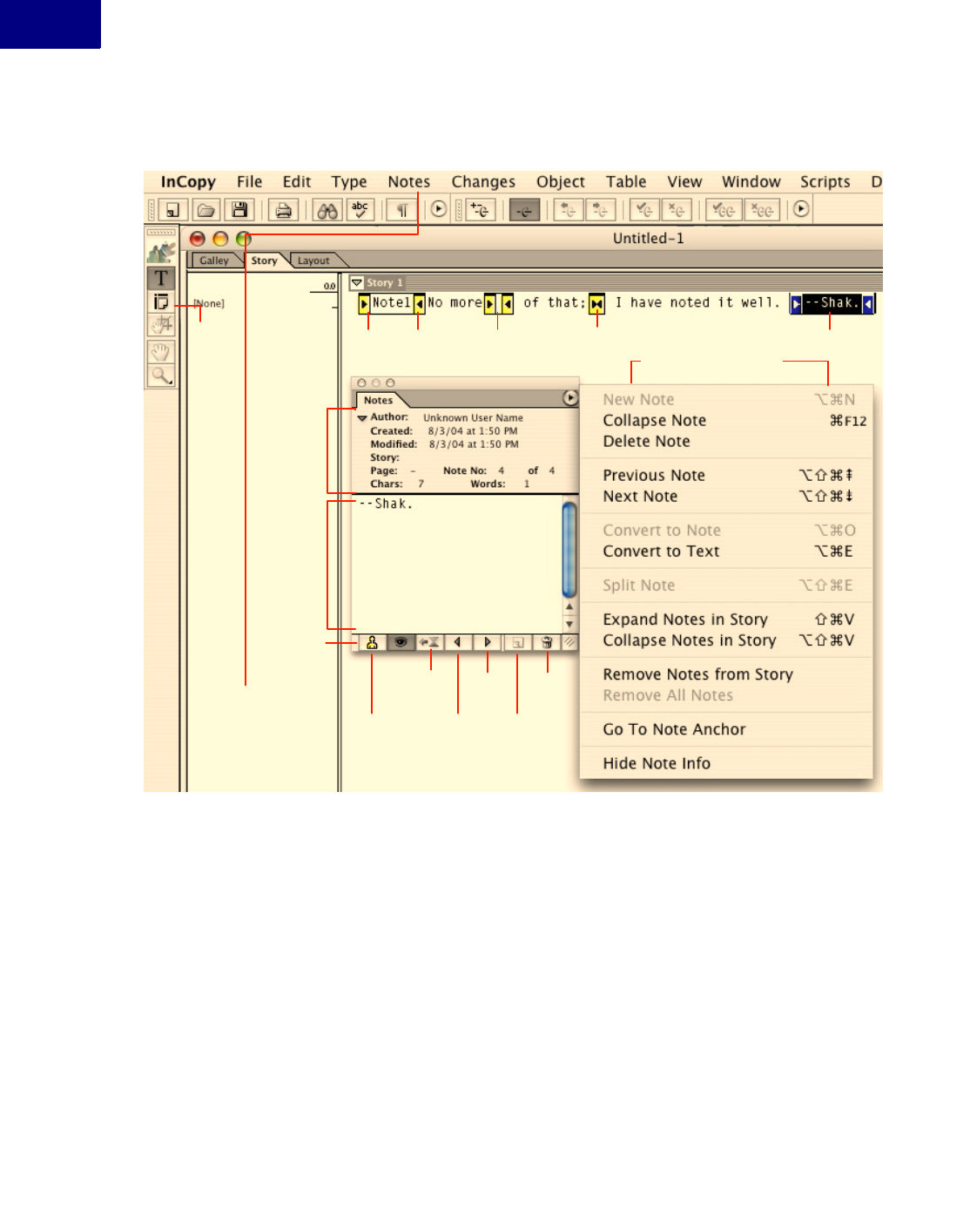
InCopy: Notes
Concepts
770
FIGURE 292 Notes user interface in InCopy story view
Note anchors
Each notes is associated with a specific location in the text, indicated by a note-anchor icon.
Figure 292 shows examples of note anchors in different states. Content is visible only within a
note container:
zIn layout view, the container for note content is the Notes palette.
zIn story and galley views, the container for note content is an inline note container within
the document text, between the two bookend icons that make up the note-anchor icon. In
story and galley views, note content also can be seen in the Notes palette.
The content of a note is the same, regardless of the note container or view used. Anchors can be
placed anywhere within text in layout or galley view, including the beginning or end of a word,
within a word, and between a word and a punctuation mark; however, only one note anchor
can occupy a single location within text. Users can create notes only in the text flow. If the user
Note
tool
Begin note
bookend
(anchor)
icon
End note
bookend
(anchor)
icon
Collapsed
bookend
(anchor) icon
Default
anchor
icon
Note that is
selected
Notes palette menu
Note info
area
Editing
area
Button
area
User
color
icon
Go To
Note
Anchor
Previous
Note
Next
Note
New
Note
Delete
Note
Notes menu:
functions similar
to that of Notes
palette menu

InCopy: Notes 771
InCopy: Notes
Concepts
moves the Note tool pointer over an area that does not contain an open story, the pointer
changes to the No Drop pointer, and clicking does not create a new note.
Note anchors perform multiple functions:
zNote anchors indicate the location of the note. When the text reflows, the anchor moves as
part of the text.
zNote anchors offer a clickable screen element, so the user can open, move, edit, or delete the
note or its contents.
In galley or story view, each inline note icon has an anchor icon consisting of a start-note book-
end icon and an end-note bookend icon. When the note is expanded, the content of the note
appears between these bookends. New inline notes have a thin, empty, inline note container,
with an insertion point ready for note-text entry. When the user begins typing the note text, the
bookend icons move apart to accommodate the added text.
Editing text containing note anchors
The note anchor is an access point for opening and editing notes. Selected note anchors can be
cut, copied, deleted, and moved by dragging. Selecting text also selects all note anchors within
that text. Cutting, copying, or pasting text cuts, copies, or pastes all note anchors in the selected
text, with the following exceptions:
zNo note anchors can be created or placed within other notes.
zIf text containing note anchors is pasted into a note, only the selected surrounding text is
copied to the note, not the anchors or note contents.
When text containing a note anchor is deleted, cut, copied, or pasted, whatever happens to the
enclosing text happens to the note whose anchor is contained within. This includes notes that
are hidden.
Although note content always is drawn in plain text (i.e., with no styles, color, size, or other
text-formatting attributes shown), any text copied or pasted to a note retains all formatting
information it had, even though that formatting is not shown when the text is part of a note.
Text with formatting may be copied and pasted to a note, and at a later time that text may be
copied and pasted to non-note text; when the text is placed as regular (non-note) text, any for-
matting information it contains is rendered (shown) once again.
Capabilities
Adding a note
You can add notes to a story using the Note tool in the toolbox, the Notes > New Note com-
mand, or the New Note icon on the Notes palette. You also can create a note from an existing
story, by converting or copying the text into a new note. In galley or story view, type your note
between the note bookends. In layout view, type your note in the Notes palette.
Converting text to a note
The Convert To Note command converts the selected text to a note; a new note is created, and
selected text is removed and copied into the new note. In galley and story views, the container
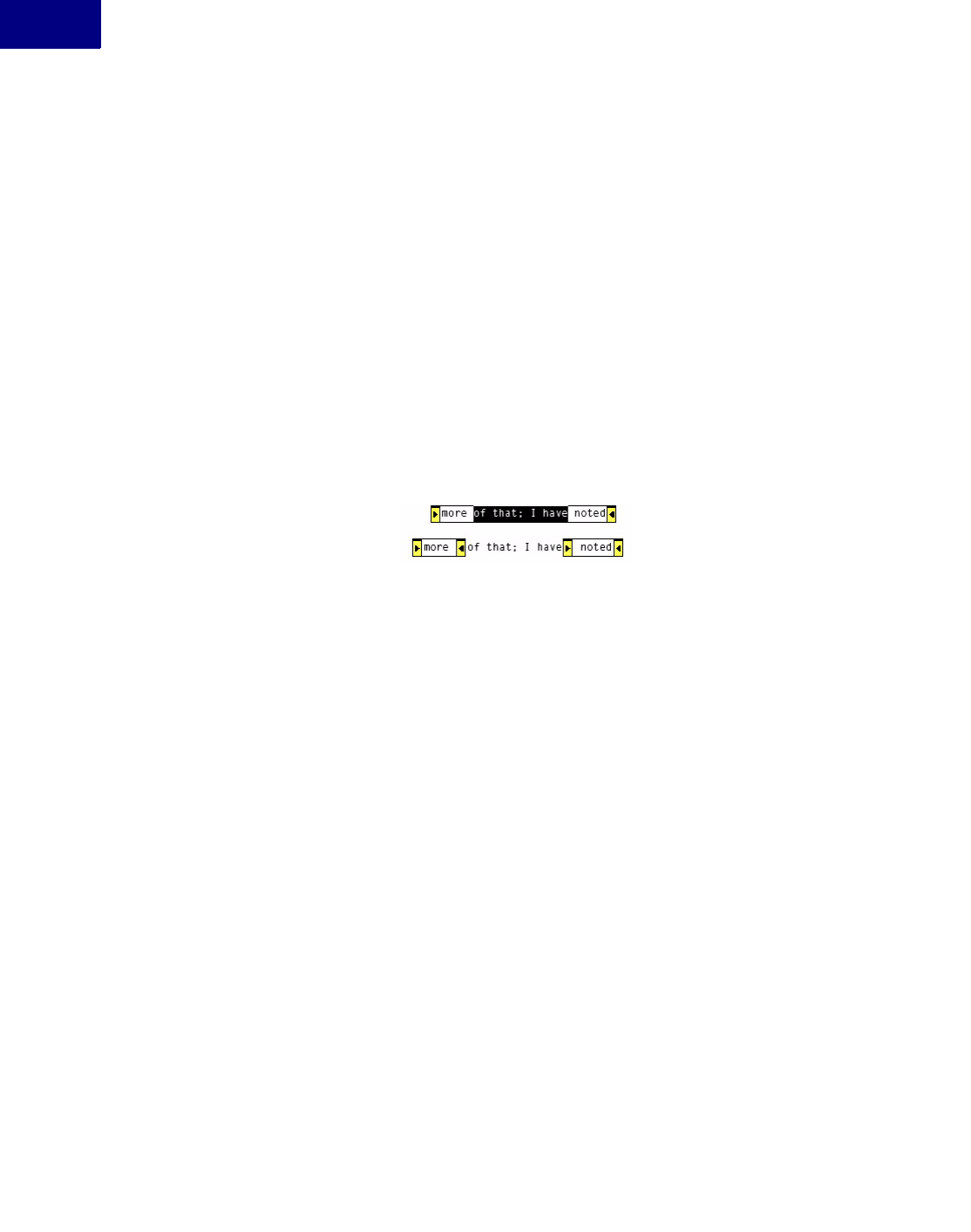
InCopy: Notes
Concepts
772
of the new note is expanded, and the text focus is at the beginning of the new note. The note
contents appear in the Notes palette. The note anchor is located where the end of the text selec-
tion range was before the Convert To Note operation.
Converting a note to text
The Convert To Text command converts the selected note or selected text in a note container
into regular text. Depending on the selection of the note, this command removes the selected
text from the note and pastes the text into the document text in the location where the inser-
tion point was before the Convert To Text operation. If the entire note is selected or the inser-
tion point is inside the note container with no text selected, the entire note contents are
converted to text. If only part of the content of a note is selected, only the selection is converted,
while the remaining content stays in the note—or in two notes, if the selection does not include
the beginning or end of the note content. Figure 293 shows the case in which the selection is in
the middle of the note content, resulting in two notes after conversion.
FIGURE 293 Conversion of note content to text results in splitting the note
Navigating among notes
The Next Note and Previous Note commands enable navigation among notes. These com-
mands select the next or previous note anchor in the text flow. If the current note is the final or
first note in the text, the first or last note is selected, respectively.
Splitting a note
The Split Note command breaks a note into two notes at the insertion point. After a note is
split, the insertion point moves to the story text, between the two notes produced by the split.
Deleting a note
The Delete Note command deletes the selected note. The command is available if a note anchor
is selected, the current insertion point is within an inline note, or the current insertion point is
within the text editing area of the Notes palette. The Remove Notes From Story command
deletes all notes from the current story, whereas the Remove All Notes command deletes all
notes from the document.
Expanding and collapsing notes
The Expand Note or Collapse Note command expands or collapses the selected note. Only one
of these commands is visible at a time, depending on the state of the selected note. Alternately,
in story or galley view, click on a note’s bookend icon to expand or collapse the note. You can
expand all collapsed inline notes in the current document with the Expand All Notes com-
mand. You can collapse all inline notes in the current document with the Collapse All Notes
command.

InCopy: Notes 773
InCopy: Notes
Concepts
The View > Hide Notes and View > Show Notes commands hide and show notes. Which of
these commands is available depends on the current state of the notes.
Setting notes preferences
You can customize the appearance and behavior of notes using the Preferences settings, by
choosing Edit > Preferences > Notes (Windows) or InCopy > Preferences > Notes (Mac OS).
Data model for notes
How notes are connected to text
When a note is added, through either the menu or the Notes palette, INoteSuite::DoAddNote is
called. You can add a note only when the text tool is active but no text is selected; i.e., there is a
blinking insertion point somewhere in the story. If a range of text is selected, you can convert
the text to a note. The DoAddNote method first checks the INoteSettings on the kWorkspace-
Boss, to determine the note’s global visibility state. If the note is hidden, the kSetHideNo-
teStateCmdBoss is used to turn on the note’s visibility. Next, INoteDataUtils::NewNote is used
to make the new note by processing a kCreateNoteCmdBoss command.
Although the note seems to be embedded in the text, it actually is maintained in the text system
as an owned item. A special anchor character (kTextChar_ZeroSpaceNoBreak) is inserted in
the primary story thread of the text model, at the position where the note is to be placed. Then,
an instance of kNoteDataBoss is instantiated to hold the note data; this object is anchored in
the text model by associating the owned-item strand of the text model with the kNoteDataBoss
object. This is done by the kCreateNoteCmdBoss, which sets the class of the owned-item
strand at the offset to kNoteDataBoss with the UID of the kNoteDataBoss object. In the pri-
mary story thread, the note is represented by the special character
kTextChar_ZeroSpaceNoBreak. The real note text is stored in a separate story thread. kNote-
DataBoss implements ITextStoryThreadDict and ITextStoryThread, to maintain its story
thread. For more information on the story thread dictionaries, see the “Text Fundamentals”
chapter. The kNoteDataBoss object’s INoteData holds information like note author and note
creation time. It is important to understand that INoteData does not contain the note’s text
content; the note content is held by a separate story thread, accessible through the kNoteDa-
taBoss object’s ITextStoryThreadDict interface. See Figure 294.
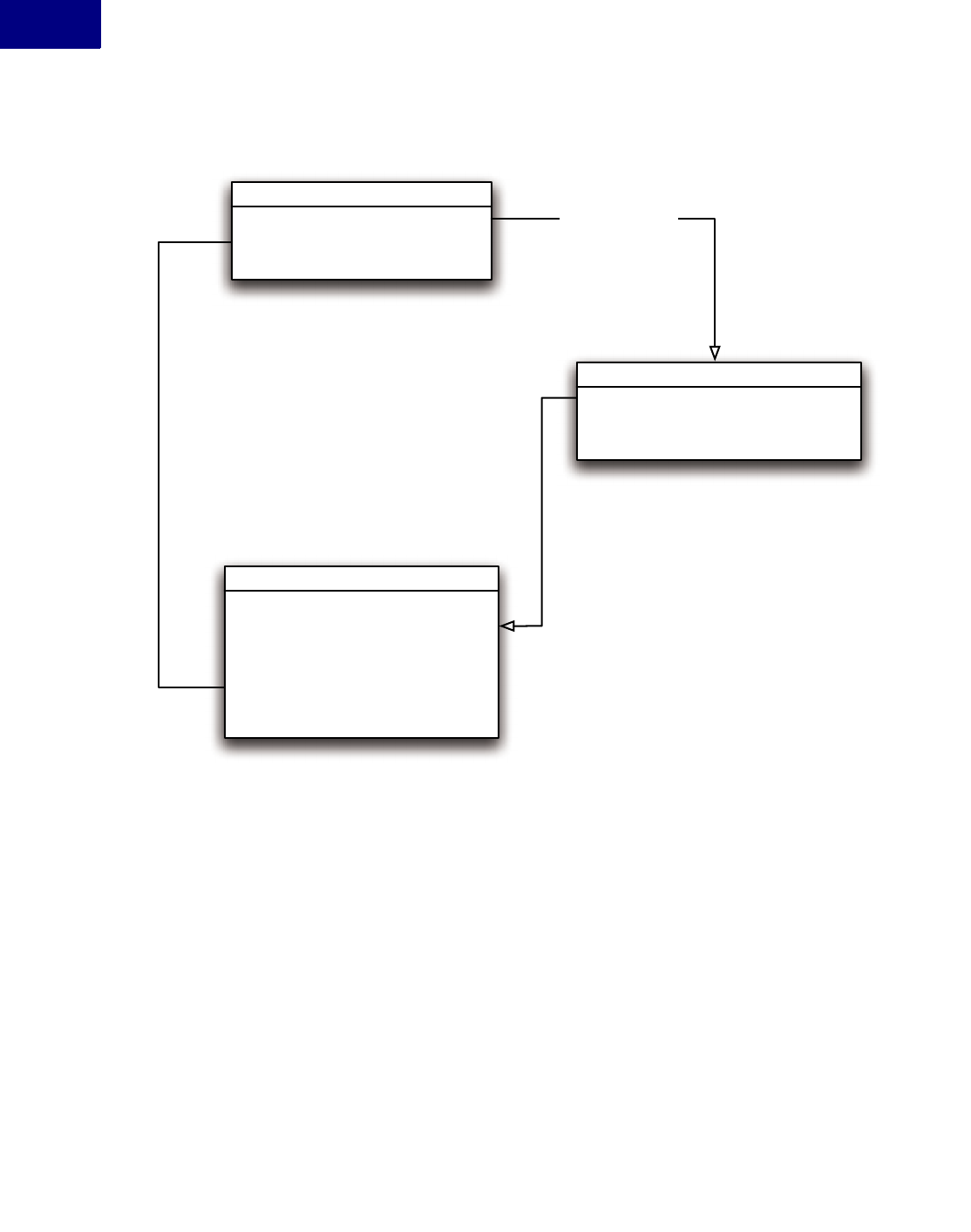
InCopy: Notes
Concepts
774
FIGURE 294 Relationship between a note and its parent story
Using the SnippetRunner InspectTextModel snippet, we can inspect how the story threads are
changed when a note is being added. Assume you have a text story with the text “abc.” There
are three characters, plus the carriage return at the end, so the primary story thread’s character
count is four, as shown in Figure 295.
kTextStoryBoss
ITextModel
ITextStoryThreadDictHier
...
kOwnedItemStrandBoss
IItemStrand
IStrand
...
kNoteDataBoss
INoteData
IOwnedItem
...
ITextStoryThreadDict
ITextStoryThread
...
ITextModel::Q
ueryStrand()
IItemStrand::SetOwnedUID()
kNoteDataBoss is connected to kTextStoryBoss
through the owned item strand, but the note's text
content is maintained as a separate story thread
in the story, which is managed by both
ITextStoryThreadDictHier and ITextStoryThreadDict.
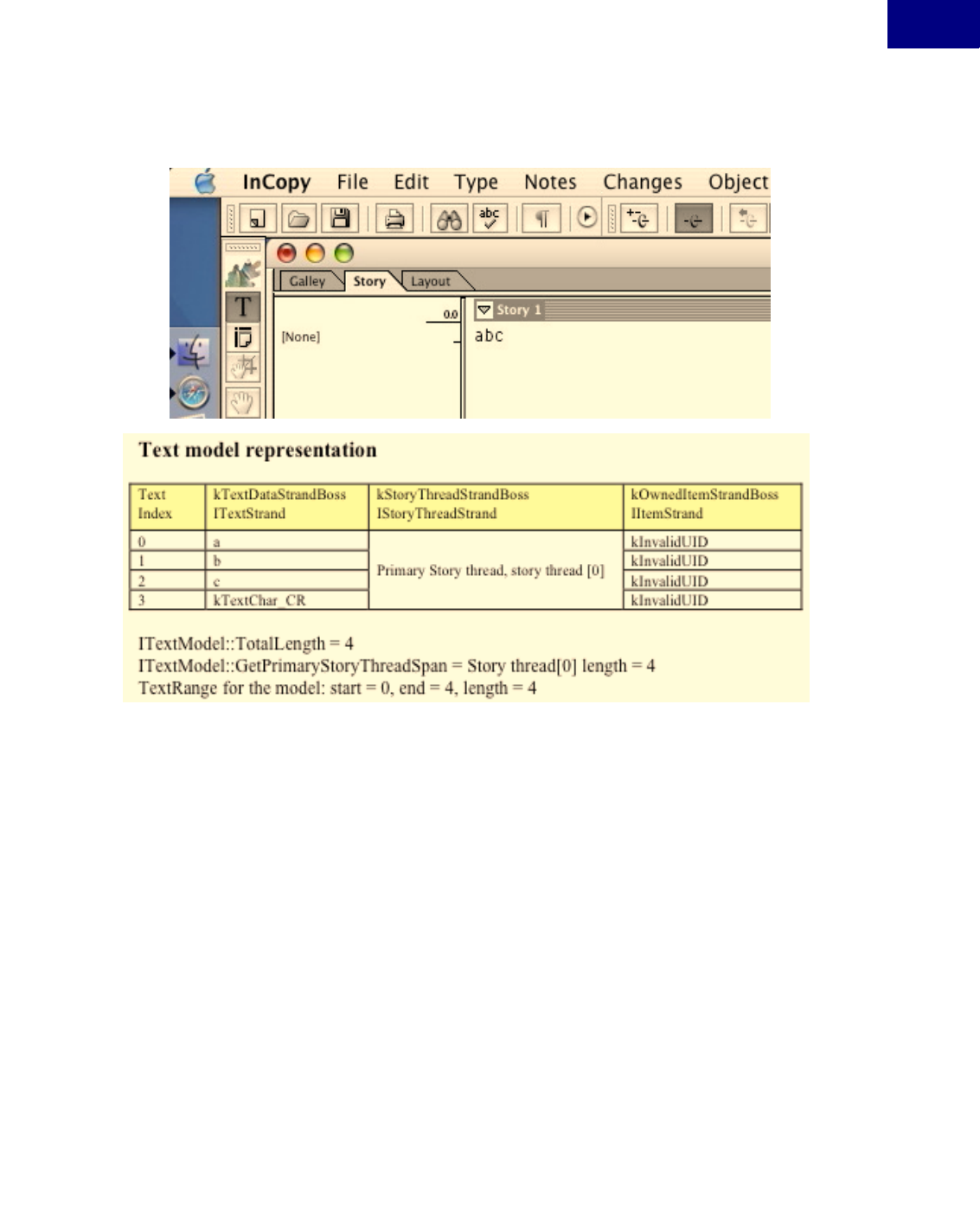
InCopy: Notes 775
InCopy: Notes
Concepts
FIGURE 295 Text story containing only regular text
If you insert an empty note at the beginning, InDesign adds an owned-item strand to the text
model, and this strand is represented by kTextChar_ZeroSpaceNoBreak (0xfeff). Also, a story
thread is created to represent the note’s content. When there is no initial text in the note, the
thread is initialized to kTextChar_CR, which makes the note’s story thread length 1. Thus, the
text model’s length is increased to 6 from the original 4, because of the added
kTextChar_ZeroSpaceNoBreak for the owned item and kTextChar_CR for the note’s initial
data. In the output of InspectTextModel, the carriage return is not reported; but if you read
ITextStoryThread[0], its length is reported as 5, which is equal to the PrimaryStoryThread-
Span. TextIndex 4 is for the carriage return. Figure 296 illustrates the text model when an
empty note is inserted into a story.
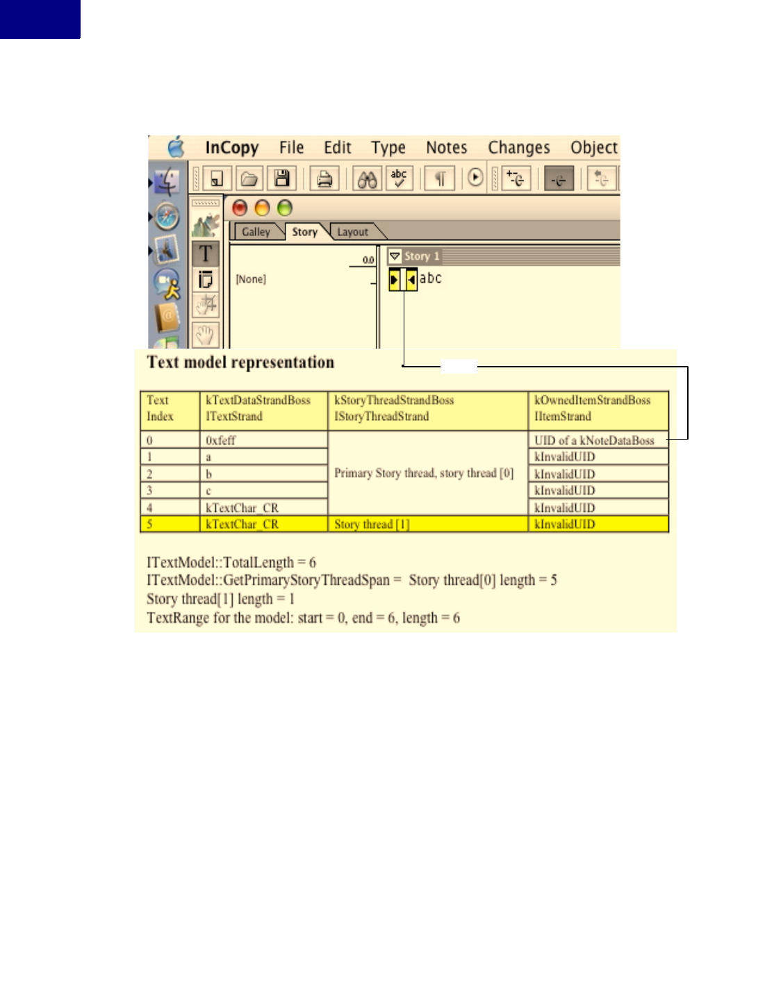
InCopy: Notes
Concepts
776
FIGURE 296 Text story with an empty note anchored
If you type something into the note—for example, type “d” in the note, so you see “<d> abc”—
you can see the text model has seven characters, which is one character more than the version
with empty note. Note, however, that the primary story thread looks the same as before. The
new text is added into the thread that represents the note’s text, which now has a length of 2
(for the “d” character plus the default carriage-return character). See Figure 297.
Note
Note
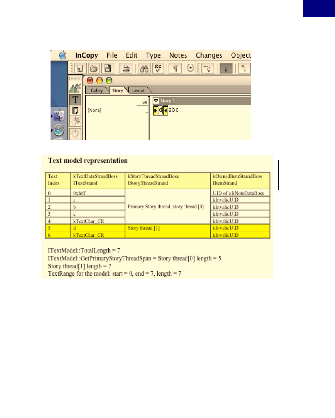
InCopy: Notes 777
InCopy: Notes
Concepts
FIGURE 297 Text story with a one-character note
Notes suite and utilities
Much of the capability required for client code to work with notes is provided in a high-level
suite interface, INoteSuite (with the ID IID_INOTESUITE interface), which is available
through a reference to a selection (kIntegratorSuiteBoss). This interface is described in detail in
“INoteSuite” on page 779.
This interface encapsulates the details of interacting with the note model and hides details
about the selection format that is active, providing a capability-driven API that can be used to
do things like add, delete, and convert notes.
Most of the note suite methods do not interact directly with model; instead, a few utility classes
were added to kUtilsBoss. These utilities are used in most of the suite implementations. We
highly recommend you use the suite functions when possible. If the suite does not meet your
needs, look into the utilities before using a command directly.
Note
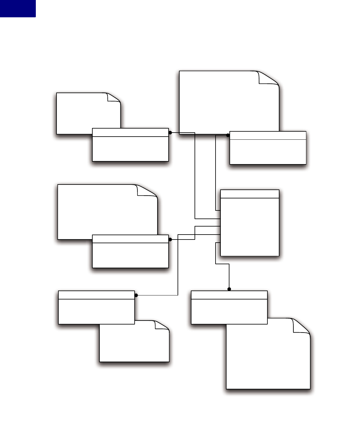
InCopy: Notes
Concepts
778
See Figure 298 for an overview of notes utility classes.
FIGURE 298 Notes utility classes
kUtilsBoss
...
INotePaletteUtils
INoteDrawUtils
INoteDataUtils
INoteUIUtils
INoteUtils
...
Mainly for internal use
to draw the user
feedback in the note.
INoteDrawUtils
DrawHitTestBox
DrawNoteCaret
...
Mainly used to interact with the
InCopy Notes palette. For example,
if you create a note from your plug-
in and you want the Notes palette to
show the content, you can use
SetNoteToPalette to do that. The
INoteSuite provides a similar
function on a higher level.
INotePaletteUtils
SetNoteToPalette
ResetNotePalette
...
Mainly a collection of
methods that help in
interacting with the document
hierarchy and the text model.
It also contains an often used
method, QueryNoteData,
which returns an INoteData*
given a text index.
INoteUtils
QueryNoteData
NoteInCurrentSpread
...
Mainly deals with note
selections (e.g., go to
and select a note) and
visibility (expand/
collapse) note.
INoteUIUtils
GoToNextNote
ExpandAllNotes
...
Mainly responsible for providing the
NewNote method that is used in the
note suite and various commands.
It also provides some supporting
functions used by NewNote.
INoteDataUtils
NewNote
SetupOwnedItemInfo
...

InCopy: Notes 779
InCopy: Notes
Concepts
Notes preferences
An INotePref interface (with the ID IID_INOTEPREFERENCE interface) is added to the
kWorkspaceBoss. This interface is responsible for maintaining note settings in the Preferences
panel, like note color. To access this interface, do the following:
InterfacePtr<INotePref> notePref
((INotePref*)::QuerySessionPreferences(IID_INOTEPREFERENCES));
if (notePref != nil)
{
// Do something with the preference.
}
There also is an INoteSettings interface (with the ID IID_INOTESETTINGS interface) added
to kWorkspaceBoss. This interface’s sole responsibility is to maintain the visibility state of the
note. Users typically show and hide notes with the View > Show Notes and View > Hide Notes
menu commands. To access this interface, do the following:
InterfacePtr<IWorkspace> sessionWorkSpace(GetExecutionContextSession()-
>QueryWorkspace());
InterfacePtr<INoteSettings> noteSettings(sessionWorkSpace, UseDefaultIID());
Essential APIs
INoteSuite
The INoteSuite suite interface is a key API for manipulating notes in client code. Most of a
note’s user-interface functions are provided through this interface. This interface provides
much of the required capability for plug-ins.
The INoteSuite interface is aggregated on the integrator-suite boss class (kIntegratorSuiteBoss),
which makes this interface available through the abstract selection. Implementations of this
interface are provided on various concrete-selection boss classes, like kGalleyTextSuiteBoss
and kNoteTextSuiteBoss, which are hidden from client code through the facade of the abstract
selection. To obtain INoteSuite, client code should query the selection manager (ISelection-
Manager) for the interface, as shown below:
// Many functions are passed in an IActiveContext as a parameter.
// It should be used whenever possible.
InterfacePtr<IActiveContext> activeContext(GetExecutionContextSession()-
>GetActiveContext(), UseDefaultIID());
if (!activeContext)
return;
ISelectionManager *selectionManager = activeContext->GetContextSelection();
InterfacePtr<INoteSuite> noteSuite(selectionManager, UseDefaultIID());
Generally speaking, the INoteSuite interface is active when the text-insertion point is active in
the layout, story, galley, or Notes palette editing area. The suite interfaces typically use this pat-
tern of checking for a service or capability and, if the abstract selection supports this capability,
the method can be called. For example, the INoteSuite interface exposes a method that allows
you to delete a selected note. To use this method, do the following:

InCopy: Notes
Concepts
780
bool16 canDeleteNote = iNoteSuite->CanDeleteNote(ac->GetContextView(), docView);
if(canDeleteNote )
{
iNoteSuite->DeleteNote(ac->GetContextView(), docView);
}
See Table 171 for a list of INoteSuite methods.
TABLE 171 INoteSuite Can[DoSomething] – [DoSomething] look-up table
CanDoSomething method DoSomething method
CanAddNote DoAddNote
CanConvertToNote DoConvertToNote
CanOpenNote DoOpenNote
CanDeleteNote DoDeleteNote
CanConvertToText DoConvertToText
CanScrollToNote DoScrollToNote
CanNavigateNote DoNavigateNote
CanRemoveAllNotes DoRemoveAllNotes
CanRemoveStoryNotes DoRemoveStoryNotes
CanSplitNote DoSplitNote
CanShowHideNote DoShowHideNote
CanExpandAllNotes DoExpandAllNotes
CanCollapseAllNotes DoCollapseAllNotes

InCopy: Notes 781
InCopy: Notes
Concepts
kNoteDataBoss
kNoteDataBoss is anchored as an owned item in the text story. The following code snippet
shows one way to get the kNoteDataBoss from the story:
// Find notes in current storyRef.
InterfacePtr<ITextModel> textModel(storyRef, UseDefaultIID());
InterfacePtr<IItemStrand> itemStrand((IItemStrand*)textModel
->QueryStrand(kOwnedItemStrandBoss, IID_IITEMSTRAND));
int32 mainStoryLength =
textModel->GetPrimaryStoryThreadSpan() - 1;
// Collect owned item from the story.
Text::CollectOwnedItems(textModel, 0, mainStoryLength, &ownedItemList);
if (ownedItemList.Length() > 0)
{
// Remove non-note items.
for (i = ownedItemList.Length()-1; i>=0; i--)
{
if (!Utils<INoteDataUtils>()->IsNoteOwnedItem(ownedItemList[i].fClassID))
ownedItemList.Remove(i);
}
}
See Figure 299 for the key interfaces of kNoteDataBoss.
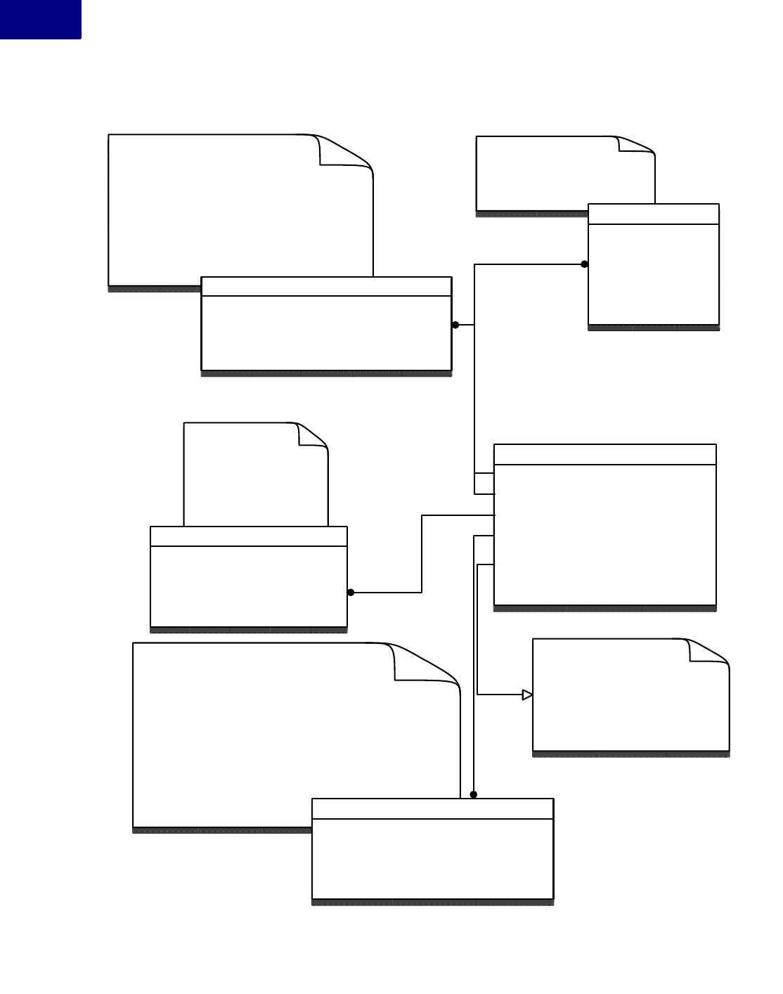
InCopy: Notes
Concepts
782
FIGURE 299 kNoteDataBoss and its key interfaces
Implements the
story thread
(ITextStoryThread)
that represents the
note content.
kNoteDataBoss
INoteData
IOwnedItem
ITextStoryThread
ITextStoryThreadDict
IParcelList
ITextParcelList
...
Storage for the note
information such as
author and creation date
The IOwnedItem and
ITextModelMemento (on a separate
boss,
kNoteDataTextModelMementoBoss)
implementations are the hooks that
allow the note to be managed when it
is affected by text model operations.
IOwnedItem
CollectStoryRanges
GetNumSpecialAnchorChars
...
INoteData
GetAuthor
SetAuthor
GetCollapse
SetCollapse
...
ITextStoryThread
GetDictUID
GetTextStart
QueryTextModel
...
Note's ITextStoryThreadDict implementation
manages only one
story thread.
Many instances of notes can be embedded in a
story, but each has its own note data
(kNoteDataBoss) with its own dictionary
(ITextStoryThreadDict) and story
thread(ITextStoryThread).
ITextStoryThreadDict
QueryThread
GetAnchorTextRange
GetThreadBlockTextRange
...
Because Note does not
support display of
composed text, all of the
parcel-related interface are
implemented as stubs.

InCopy: Notes 783
InCopy: Notes
Concepts
Useful commands and associated notification protocols
This section summarizes some of the most common commands related to notes, the critical
data interfaces that users of the commands must supply, and the notification protocols associ-
ated with the commands so an observer who wants to observe certain commands can know
what protocols to listen to.
kCollapseStateCmdBoss
Description
Sets the INoteData collapsed state according to the command’s IBoolData. Used to expand
(open) or collapse (close) a note.
Item list
The UID of the text story that contains the note to be expanded or collapsed.
Data interface
zIBoolData — Whether the note should be collapsed (true for collapsed, false for expanded).
zIIntData — The TextIndex at which the note of interest is anchored in the text story.
Notification
zNotify kTextStoryBoss with the IID_INOTEDATA protocol.
zNotify kDocBoss with the IID_COLLAPSESTATE_DOCUMENT protocol.
kCreateNoteCmdBoss
Description
Creates a new note in a text story at the location specified by a text index.
Item list
The UID of the text story that contains the note to be created.
Data interface
zIIntData — The TextIndex where the new note is to be created. A note is not allowed in
another note, so make sure the index is not in an existing note’s story range.
zICreateNoteCmdData — This data interface is optional. You can set note class using SetNo-
teClass to kNoteDataBoss. Set the note content’s range using SetNoteContentRange(cre-
ateAt, createAt), if the note is to be initialized to an empty note; createAt is the TextIndex
where the new note anchor will be. You also should use the Set method to set the author and
collapsed state. You do not need to set the marker range, because it is for an unsupported
feature.

InCopy: Notes
Concepts
784
Notification
zNotify kTextStoryBoss with the IID_INOTEDATA protocol.
zNotify kDocBoss with the IID_INOTEDATA protocol.
kConvertToNoteCmdBoss
Description
Converts a range of text into a note.
Item list
The UID of the text story that contains the text to be converted.
data interface
Data should be set up as for kCreateNoteCmdBoss:
zIIntData — The start text index of the text range to be converted.
zICreateNoteCmdData — The note’s content range should be set from the start index to the
end index of the text to be converted, using the SetNoteContentRange method.
Notification
zNotify kTextStoryBoss with the IID_INOTEDATA protocol. When the notification is
broadcast, the command boss’s IIntData is set to the note’s content-range start index.
zNotify kDocBoss with the IID_INOTEDATA protocol.
kConvertNoteToTextCmdBoss
Description
Converts a whole note or part of the note content into regular text. When the note content to
be converted is between another note text in the same note, the portion of the note that is not
converted is split into two notes, one on each side of the converted text.
Item list
The command needs two items: the UID of the story that contains the note to be converted,
and the UID of the kNoteDataBoss of the note to be converted. When the text focus is in the
note-content area, ITextModel::QueryStoryThread can be used to find out the note’s story
thread, from which you can get to the corresponding kNoteDataBoss. When the text focus is
on the anchor, use INoteUtils::QueryNoteData to get to the INoteData, from which you can
reach the kNoteDataBoss.

InCopy: Notes 785
InCopy: Notes
Concepts
data interface
zIIntData with interface ID IID_ISTARTFOCUSINTDATA — The start-text index of the
range of note content to be converted to text. This range should be in the note’s story thread.
If the range is in the note’s anchor range, you should find out the text range that covers the
note content.
zIIntData with interface ID IID_IENDFOCUSINTDATA — The end-text index of the range
of note content to be converted to text. This range should be in the note’s story thread. If the
range is in the note’s anchor range, you should find out the text range that covers the real
note content.
zIBoolData — Was used to restore text focus in an undo operation. With the introduction of
automatic undo in InCopy CS4, this has no effect.
zIConvertNoteToTextCmdData — Required to suspend galley drawing while converting to
text. Pass in the UIDRef of the IControlView* returned by INoteSuiteUtils::GetDocControl-
View.
Notification
Generally, the broadcast is based on how the note is converted.
If the entire note is converted:
zNotify the kDocBoss with the kNoteRemovedMsg message along with the
IID_ICONVERTNOTETOTEXTCMD protocol.
If the note is spit into two notes after the conversion:
zNotify the kDocBoss with the kConvertNoteToTextMsg message along with the
IID_ICONVERTNOTETOTEXTCMD protocol.
zNotify the kTextStoryBoss with the kConvertNoteToTextMsg message along with the
IID_ICONVERTNOTETOTEXTCMD protocol.
If the converted text is to the left or right of the original note:
zNotify the kDocBoss with the kMoveNoteToTextMsg message along with the
IID_ICONVERTNOTETOTEXTCMD protocol.
zNotify the kTextStoryBoss with the kMoveNoteToTextMsg message along with the
IID_ICONVERTNOTETOTEXTCMD protocol.
kSplitNoteCmdBoss
Description
Splits a note into two notes at the text-index location specified by the data interface.
Item list
The command needs two items: the UID of the story that contains the note to be split, and the
UID of the kNoteDataBoss of the note to be split. This is similar to the kConvertNoteToTextC-
mdBoss. For more details on how to get to the kNoteDataBoss from a text location, see “kNote-
DataBoss” on page 781.

InCopy: Notes
Working with notes
786
Data interface
zIIntData with interface ID IID_ISTARTFOCUSINTDATA —The text index of the location
where you want to split the note. The index should be in the note’s story thread.
zIConvertNoteToTextCmdData — Required to suspend galley drawing while converting to
text. Pass in the UIDRef of the IControlView* returned by INoteSuiteUtils::GetDocControl-
View.
Notification
zNotify the kTextStoryBoss with the kSplitNoteMsg message along with the
IID_ISPLITNOTECMD protocol.
zNotify the kDocBoss with the kSplitNoteMsg message along with the
IID_ISPLITNOTECMD protocol.
kNotePrefCmdBoss
Description
Modifies the notes preference as seen in the application’s Notes Preferences panel.
Item list
The item needed is the application’s workspace UID.
Data interface
INotePrefCmdData — Use its Set method to set the preference.
Notification
Notify the kWorkspaceBoss with the IID_INOTEPREFERENCES protocol.
Working with notes
Adding a note at the current insertion-point position
When proper context is available, use INoteSuite::DoAddNote to add a new note. For an exam-
ple, see the SnpPerformNoteFunction snippet.
When the INoteSuite interface is not available, first process a kSetHideNoteStateCmdBoss
command, to make sure the note’s visibility is on. Next, use kCreateNoteCmdBoss to create the
note. A note is not allowed inside another note, but a note is allowed in deleted text (you can
use ITrackChangeUtils::DeletedTextToPrimaryIndex to check if it is in deleted text), so you
should make sure the text index for the note anchor is in either the primary story thread span
or deleted text but not in an existing note’s story thread range.

InCopy: Notes 787
InCopy: Notes
Working with notes
Inserting text into a note
Use ITextModelCmds::InsertCmd to insert text into note. This is just like a regular text inser-
tion operation. For an example, see the SnpPerformNoteFunction snippet.
Converting text to a new note
When proper context is available, use INoteSuite::DoConvertToNote to convert selected text to
a note. For an example, see the SnpPerformNoteFunction snippet.
When the INoteSuite interface is not available, check whether the text for conversion contains
any XML tags. Normally, if there is a tag in the text range, you should abort the operation. Use
INoteSuiteUtils::CheckRemoveXML to check for XML tags. If a tag is found in the selected
text, this method causes an alert to pop up, asking whether the user wants to remove the XML
tag. Proceed with the conversion only when the function returns a true value; then use the
kSetHideNoteStateCmdBoss command to make sure the note’s visibility is turned on. Use
kConvertToNoteCmdBoss to convert the text.
Converting note content to text
When proper context is available, use INoteSuite::DoConvertToText to convert selected note
content to text. For an example, see the SnpPerformNoteFunction snippet.
When the INoteSuite interface is not available, use kConvertNoteToTextCmdBoss to convert
note content to regular text. If text focus is in the note content area and no text is selected, or if
the note anchor is selected, the whole note is converted. If only part of the note content is
selected, only that portion is converted to regular text.
Pay special attention to the text range to be converted. Consider the sample story “<Convert
Me> Please,” where “<Convert Me>” is a note and “<” and “>” are the bookends. If the whole
note is selected, the current selection range is [0, 1], because the selection is on the anchor
character. If the selection is in the note content area—for example, the whole ‘Convert Me’—
the selection range is [9, 19], because the selection is in the note’s story thread, not in the pri-
mary story thread. The command’s focus-start and focus-end data (IIntData with the interface
IDs IID_ISTARTFOCUSINTDATA and IID_IENDFOCUSINTDATA) need to be the indices
in the note’s story thread. So, if the selection is the note anchor (where the selection range is
[0,1]), find out where that note’s story thread is, and pass in the corresponding text index to the
data interface. Use INoteUIUtils::TextFocusInNote to check whether the focus is in the note’s
content area. Also, the following snippet shows how to find the whole note’s range; after index-
Start and indexEnd are found, they can be passed into the command’s data interface:

InCopy: Notes
Working with notes
788
//Note anchor is selected.
InterfacePtr<INoteData> noteData(Utils<INoteUtils>()->QueryNoteData(textModel,
indexStart));
if (!noteDataOnLeft)
return; // no note
noteDataRef = ::GetUIDRef(noteDataOnLeft);
if(textModel->FindStoryThread(noteDataRef.GetUID(), 0, &threadStart,
&threadLength))
{
// Range is a whole note.
indexStart = threadStart;
indexEnd = threadStart+threadLength-1;//no carriage return
}
The item list in this command needs both the UID of the kTextStoryBoss that contains the note
and the kNoteDataBoss of the note.
Navigating among notes
When proper context is available, use INoteSuite::DoNavigateNote to go to the next or previ-
ous note. For an example, see the SnpPerformNoteFunction snippet.
Navigating the notes without INoteSuite is very difficult, because there are so many factors to
consider. You must collect all the notes by yourself, and you must consider the situation in
which the insertion point is in a different context (e.g., table or deleted text), and there is no
command to do it. The closest thing is the INoteSuiteUtils::NavigateNote, which also involves
the selection subsystem. Therefore, we highly recommend you do the navigation through the
INoteSuite interface. In general, if you have a text story in the document, with a visible note
anchored somewhere in the story, the INoteSuite::CanNavigateNote returns true, and you can
navigate the notes with much greater ease.
Splitting a note
When proper context is available, use INoteSuite::DoSplitNote to split a note. For an example,
see the SnpPerformNoteFunction snippet.
When the INoteSuite interface is not available, use kSplitNoteCmdBoss to split the note at the
position indicated by the text-index argument. As with kConvertNoteToTextCmdBoss, you
must make sure the text index where you want to split is inside the note’s content area; i.e., the
text index needs to be in the note’s story-thread range. By default, notes are not splittable in lay-
out view.
Expanding and collapsing notes
When proper context is available, use INoteSuite::DoOpenNote to expand or collapse one note,
use INoteSuite::DoExpandAllNotes to expand all notes in the document, and use INoteSu-
ite::DoCollapseAllNotes to collapse all notes in the document.

InCopy: Notes 789
InCopy: Notes
Working with notes
If the INoteSuite interface is not available, use kCollapseStateCmdBoss, supplying a valid Tex-
tIndex that points to a note anchor. Given a text-index location, use INoteUIUtils::TextFo-
cusInNote to check whether that location is in the note contents area. If it is not, also check
whether the location is on the note anchor. Both situations should be allowed to expand/col-
lapse a note. After the command is processed, a text selection may need to be set to have a text
focus in a desired location. INoteData in the kNoteDataBoss stores the current collapsed state
data on the note. Normally, you toggle between the two states when processing the kCollaps-
eStateCmdBoss.
Normally, if there are notes in the story and they are not already all expanded or all collapsed,
INoteSuite::CanCollapseAllNotes or INoteSuite::CanExpandAllNotes returns true, so you
should be able to use these suite methods when you need to expand or collapse all notes.
By default, layout view does not support the expand note and collapse note features.
Selecting a note
Whenever possible, use INoteSuite::DoNavigateNote, as shown in the SDK snippet SnpPer-
formNoteFunction::NavigateNote. When you do not have a proper selection context to work
with, however, you can use the following low level-method.
Assuming you know the UID of the note’s kNoteDataBoss and the UID of the kTextStoryBoss
that contains the note, do the following to select that note in galley view:
// Assume storyRef is the story and noteDataRef is the note.
InterfacePtr<ITextModel> textModel(storyRef, UseDefaultIID());
InterfacePtr<IItemStrand> itemStrand(
(IItemStrand*)textModel->QueryStrand(kOwnedItemStrandBoss, IID_IITEMSTRAND));
InterfacePtr<IOwnedItem> ownedItem(noteDataRef, UseDefaultIID());
TextIndex noteDataPos = itemStrand->GetOwnedItemIndex(ownedItem);
ASSERT(noteDataPos != kInvalidTextIndex);
InterfacePtr<ISelectionManager> viewSelMgr (docView, UseDefaultIID());
Utils<ISelectUtils>()->GoToTextWithMarker( storyRef, noteDataPos, 1);
In layout view, instead of using ISelectUtils::GoToTextWithMarker, use the following to select
the note anchor:
// docView is the document window's IControlView*
Utils<ISelectUtils>()->ProcessSelectText( ::GetUIDRef(textModel),
RangeData(noteDataPos, RangeData::kLeanForward),
Selection::kScrollIntoView,nil,viewSelMgr, docView);
Getting kNoteDataBoss, given a text index whose position is anchored to
note
Use INoteUtils::QueryNoteData to get to the kNoteDataBoss. For an example, see “Converting
note content to text” on page 787.

InCopy: Notes
Working with notes
790
Deleting notes
When proper context is available, use INoteSuite::DoDeleteNote to delete a note, use INoteSu-
ite::DoRemoveStoryNotes to delete all notes from a story, and use INoteSu-
ite::DoRemoveAllNotes to delete all notes from a document.
When the INoteSuite interface is not available, delete the note by simply removing the note-
anchor character, which subsequently asks the note owned item to handle the rest of the data
removal:
// Assume textModelCmds is the ITextModelCmds from the kTextStoryBoss.
// Assume noteAnchorPos is the note anchor position.
InterfacePtr<ICommand> typeCmd(textModelCmds->
TypeTextCmd(noteAnchorPos, noteAnchorPos + 1, WideString::kNil_shared_ptr));
PMString newName = "Delete Note";
typeCmd->SetName(newName);
CmdUtils::ProcessCommand(typeCmd);
To remove all stories when the INoteSuite interface is not available, use INoteUtils::Clear-
AllNotes.
Changing notes-palette content to reflect particular note data
Use INotePaletteUtils>()->SetNoteToPalette to bring up the note data in the Notes palette.
Checking note spelling
INotePref::SetSpellCheckContent lets you turn on spell checking in the note content, but you
cannot change the behavior of how the note interacts with the text’s spell-checking engine.
Observing a note that is being modified
Many note commands notify with the IID_INOTEDATA protocol along with its command ID,
so attach an observer and listen to that protocol on an appropriate subject. The following code
attaches an observer for IID_INOTEDATA broadcast to a document subject:
InterfacePtr<IDocument> document(Utils<ILayoutUIUtils>()->GetFrontDocument(),
IID_IDOCUMENT);
InterfacePtr<ISubject> docSubject(document, IID_ISUBJECT);
if (docSubject && !docSubject->IsAttached(this, IID_INOTEDATA))
docSubject->AttachObserver(this, IID_INOTEDATA);
Using notes in InDesign
InCopy Workflow plug-ins install the InCopy Notes and Track Changes features in InDesign
for use in the InCopyBridge workflow. These features use InCopyBridge user names to identify
the author of a note.
When you add editorial notes to a managed story in InDesign, these notes become available to
others in the workflow.
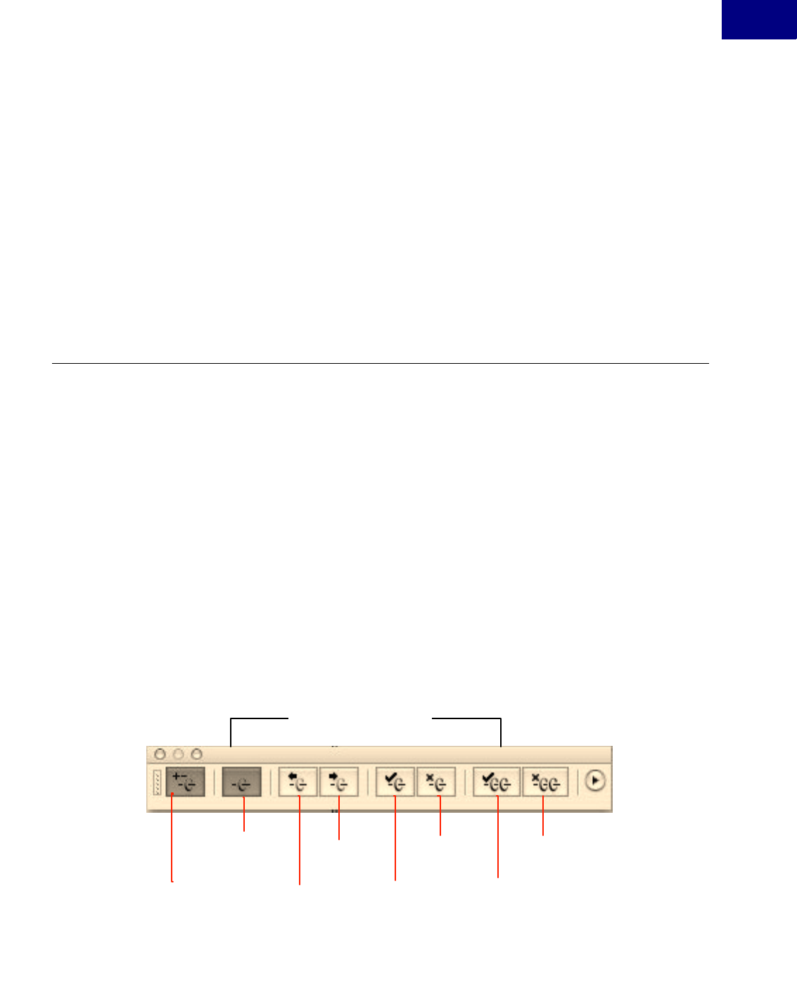
InCopy: Track Changes 791
InCopy: Track Changes
Concepts
InCopy: Track Changes
This chapter describes the change-tracking features of InDesign and InCopy for software
developers.
The chapter has the following objectives:
zExplain how change tracking fits into the application architecture.
zShow the relationship between a story and the tracked changes it contains.
zDescribe important APIs for tracking changes.
zList common commands and the notification protocols associated with them.
For use cases, see “Working with Track Changes” on page 821.
Concepts
User interface for Track Changes feature
Editors and writers need the ability to selectively track, show, hide, accept, and reject changes as
a document moves through the writing and editing process. The Track Changes features of
InDesign and InCopy address these needs.
Changes are tracked in both InDesign and InCopy, and the API is available in both applica-
tions; however, the user interface is available only in InCopy. In galley view or story view, the
user can choose to see changes; tracked changes are not visible in layout view.
Figure 300 shows the Track Changes toolbar, which provides most of the relevant user inter-
face. The same functions can be found in the Track Changes menu, shown in Figure 301.
FIGURE 300 Track Changes tool bar
Enable/Disable
Track Changes
Show/Hide
Track Changes
Previous
Change
Next
Change
Accept
Change
Reject
Change
Accept All
Changes
Reject All
Changes
Track Changes toolbar
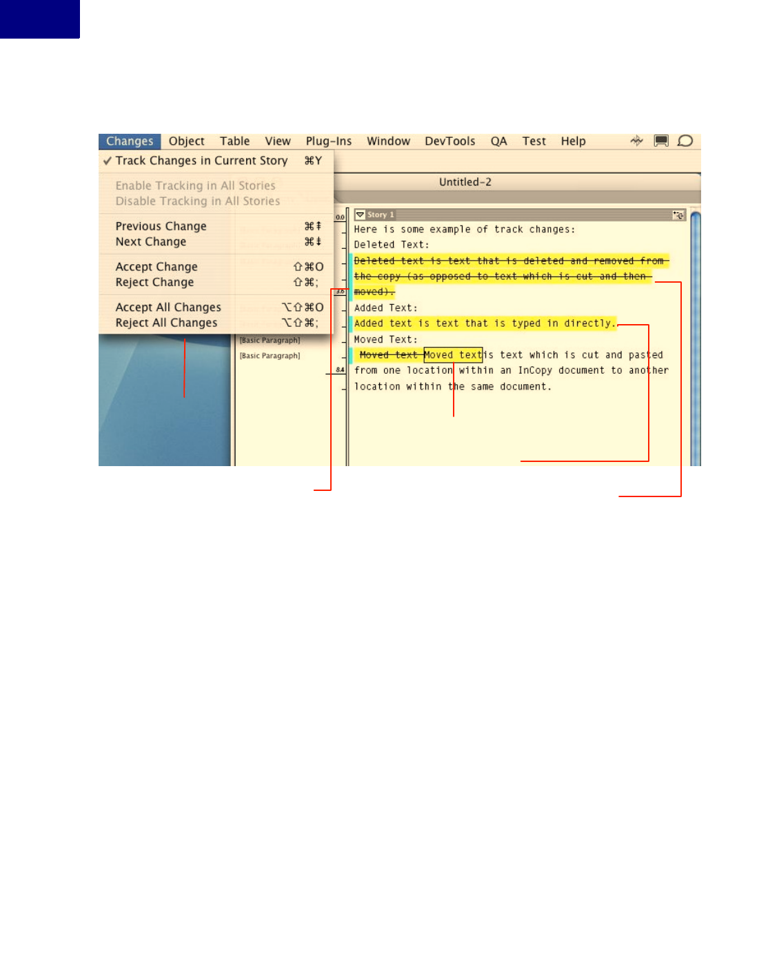
InCopy: Track Changes
Concepts
792
FIGURE 301 Track Changes user interface
To turn Track Changes on or off, choose Changes > Track Changes. When Track Changes is
turned on, changes to text are tracked. When changes are shown, tracked changes in text are
highlighted with the color assigned to the user who made the change. An optional change bar
may appear to the left of the body of the text, to indicate which lines contain tracked changes.
The Change Info panel displays information about the change at the insertion point, as shown
in Figure 302. See InCopy Help for more information about the user interface.
Track Changes menu
Deleted text is highlighted with strikethrough.
Added text is highlighted.
Moved text is highlighted and boxed.
The change bar is the cyan vertical
bar that appears to the left of the
text body to indicate which lines
have tracked changes.
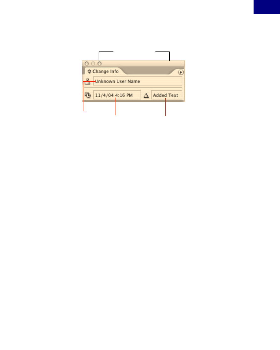
InCopy: Track Changes 793
InCopy: Track Changes
Concepts
FIGURE 302 Change Info panel
There are three types of tracked changes, each indicated in a manner chosen in the Track
Changes Preferences panel:
zAdded text — Text typed in directly; text pasted from within the same InCopy document,
from which the text was copied (not cut); and text pasted from another document.
zDeleted text — Text that is deleted or cut. Deleted text appears in its original position when
tracked changes are shown.
zMoved text — Text pasted from another location in the same InCopy document, from
which the text was cut (not copied). Moved text is shown highlighted and boxed, to differ-
entiate it from added text.
Showing and hiding changes
In galley view or story view, choose View > Show Changes or View > Hide Changes to show or
hide changes. For more information, see InCopy Help.
Navigating tracked changes
If the story contains a record of tracked changes, the user can navigate sequentially through
tracked changes. Navigating to a change selects the change.
zTo navigate to the change following the insertion point, choose Changes > Next Change.
zTo navigate to the change before the insertion point, choose Changes > Previous Change.
Accepting and rejecting tracked changes
The user can accept and reject changes—added, deleted, or moved text—made by any user. For
more information, see InCopy Help.
Partially accepting or rejecting tracked changes often results in replacing one tracked change
with multiple tracked changes, and vice versa. When an operation results in multiple tracked
changes in contiguous text, any adjacent tracked changes are concatenated into one contiguous
User
name Change
time
Change
type
Change Info panel

InCopy: Track Changes
Data model for Track Changes
794
tracked change. Conversely, accepting or rejecting part of a tracked change may result in multi-
ple, discontiguous tracked changes with non-tracked (normal) text between them.
Copy, cut, and paste behavior
When copying, cutting, or pasting text that includes tracked changes, it is the text itself that is
copied, cut, or pasted—not the tracked change that was applied to the text in its previous loca-
tion. In other words, when you copy something out of a tracked change, you copy the text con-
tent, not the type of tracked change. Copying or cutting text from a tracked deletion does not
affect the tracked deletion; pasting this text is treated the same way as adding new text.
Track Changes preferences
The Track Changes panel in the Preferences dialog box contains user settings for tracking
changes, like which types of changes to show and the color of the highlight that indicates a
change.
Data model for Track Changes
Redline strand
Tracked changes are recorded in a story (kTextStoryBoss) on the redline strand (kRed-
lineStrandBoss). They are accessed through an iterator, RedlineIterator.
Figure 303 illustrates the relationship between a story and its tracked changes. Track Changes
implements kRedlineNewStoryResponderBoss. When a new story is created—for example,
using kNewStoryCmdBoss—the Track Changes plug-in is notified to create and initialize a
new text strand, kRedlineStrandBoss, which is responsible for maintaining the Track Changes
information. During the initialization of the kRedlineStrandBoss, the story's Track Changes
state (ITrackChangeStorySettings from kTextStoryBoss) is set to the state from the session
(ITrackChangeAppSettings) using the kSetRedlineTrackingCmdBoss.
During a normal text operation performed by a text command—like Insert or Delete—each
strand (including kRedlineStrandBoss) on the text story gets a chance to react to the operation.
This results in the IRedlineStrand methods—like Insert or Cut—being called to manage the
corresponding change record before the text is inserted into or cut from the text model.
kRedlineStrandBoss uses a virtual object store (VOS) to store and manage the Track Changes
records. Each change record is represented by the VOSRedlineChange class. In the redline
strand, one or more VOS_RedlineObject objects manage the VOSRedlineChange. We strongly
discourage direct access to the VOS object; instead, the IRedlineDataStrand interface in kRed-
lineStrandBoss provides RedlineIterator to access the strand and let you examine and manipu-
late the change record. You should view RedlineIterator as the primary access to tracked
changes.
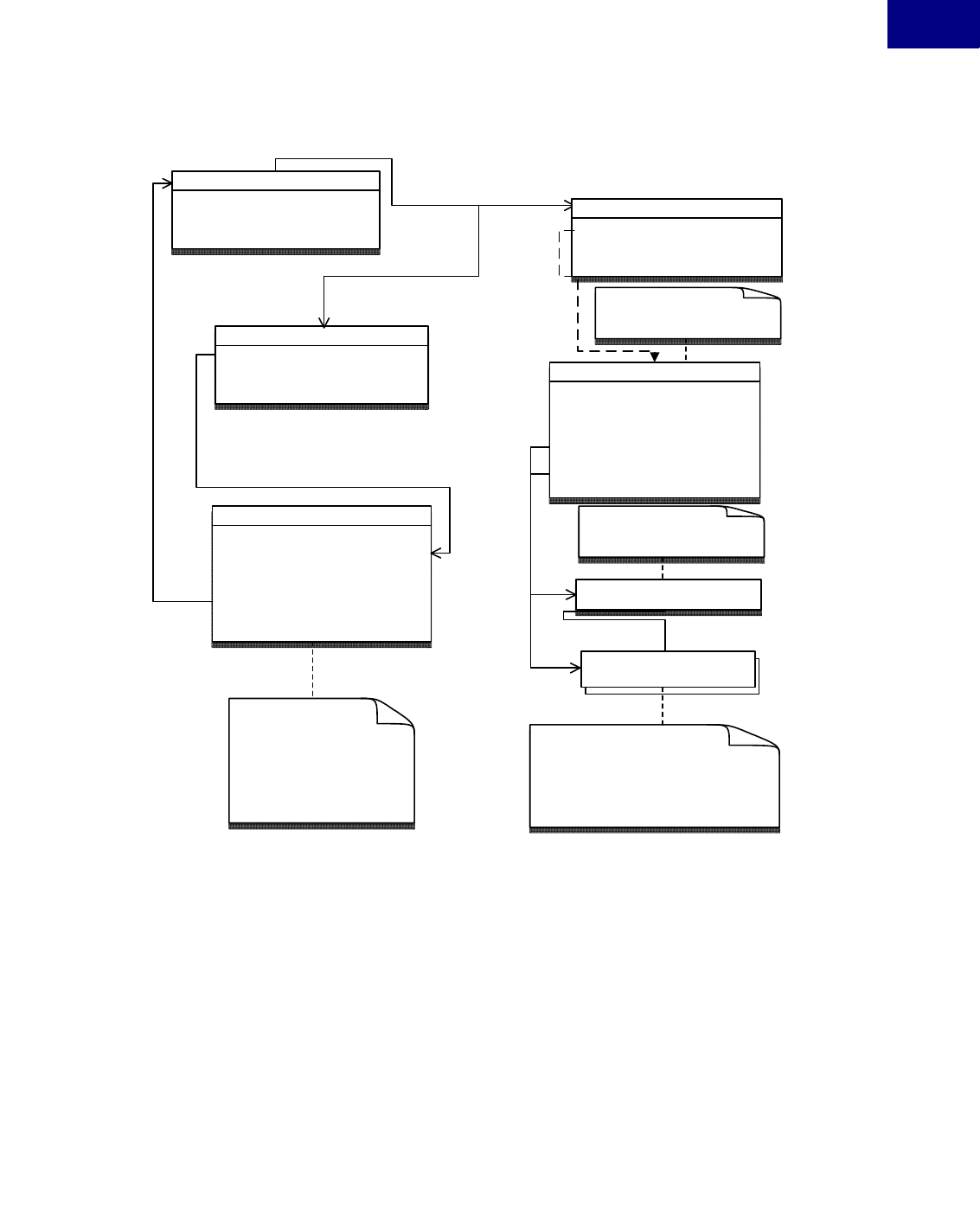
InCopy: Track Changes 795
InCopy: Track Changes
Data model for Track Changes
FIGURE 303 Relationship between a story and the tracked changes it contains
Tracking text insertion and deletion
When text is inserted, IStrand::Insert from kRedlineStrandBoss places a change record
(VOSRedlineChange) on a VOS redline object (VOS_RedlineObject); length is the number of
characters inserted. When a new story is created, a carriage-return character is inserted at the
end of the story. This means IStrand::Insert from kRedlineStrandBoss is called during the exe-
cution of kNewStoryCmdBoss. Figure 304 shows the activities in kRedlineStrandBoss when
text is inserted into a story.
kTextStoryBoss
ITextModel
ITextStoryThreadDictHier
...
kOwnedItemStrandBoss
IItemStrand
IStrand
...
kDeletedTextBoss is
connected to kTextStoryBoss
through the owned item
strand, but the deleted text
content is maintained as a
separate story thread in the
story.
kDeletedTextBoss
IDeletedTextData
IOwnedItem
...
ITextStoryThreadDict
ITextStoryThread
...
kRedlineStrandBoss
IRedlineDataStrand
IStrand
...
IItemStrand::
GetNthOwnedUID()
ITextModel::
QueryStrand()
IRedlineDataStrand::
NewRedlineIterator()
VOS_RedlineObject manages
VOSRedlineChange.
VOS_RedlineObject
RedlineIterator is provided to
access track changes.
RedlineIterator
MoveToPosition
ProcessAccept
Increment
GetCurrentChangeRecord
QueryCurrentObject
...
VOSRedlineChange represents a change
record. It indicates the type of the tracked
change as added, deleted, or moved text.
There could be multiple change record at
the same text position because you can
delete text in front of added text.
VOSRedlineChange
1
1..*
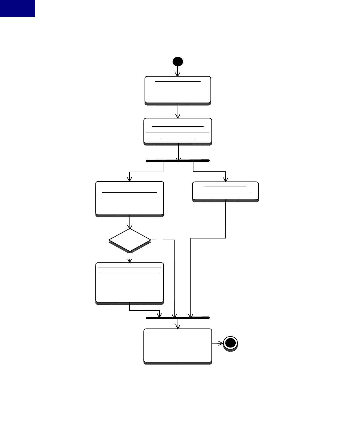
InCopy: Track Changes
Data model for Track Changes
796
FIGURE 304 kRedlineStrandBoss Activity on text insertion
start
Text model notifies
each strand boss about
the insertion.
User inserts text.
kUserTypeTextCmdBoss is
processed.
Is Track
Changes
on?
Create a change record
at the insertion point.
VOS_RedlineObject is
inserted with a new change
record (VOSRedlineChange).
kRedlineStrandBoss
handles the insertion
IStrand::Insert() is called.
All other strand
bosses handle the
insertion.
Insertion finished.
In Galley view, the tracked
change will be shown if the
user chooses to show tracked
changes.
end
Yes
No

InCopy: Track Changes 797
InCopy: Track Changes
Data model for Track Changes
When text is deleted, a change record (VOSRedlineChange) is placed on a VOS redline object
(VOS_RedlineObject), on the character following the deleted text. Also, the text is copied to a
story thread, so the deleted text can be retrieved and displayed in story view or galley view. To
preserve the deleted text before it is deleted, Track Changes implements a kRedlinePreproces-
sorBoss service provider, which enables Track Changes to participate in a pre-processing text
event, like deletion, so it can preserve the soon-to-be-deleted text. During deletion, if Track
Changes is turned on, and (private) IRedlineUtils>()->ShouldStoreDelete returns true, Red-
linePreProcessor::StoreDeletedText gets called. The deleted text is represented by an owned
item accessed through the kOwnedItemStrandBoss on the text story, with an owned-item boss
(kDeletedTextBoss) anchored in the deleted position. A new story thread is created to hold the
deleted text content, and the owned item’s class ID is set to the kDeletedTextBoss. Figure 305
shows the activities in kRedlineStrandBoss when text is deleted from a story.
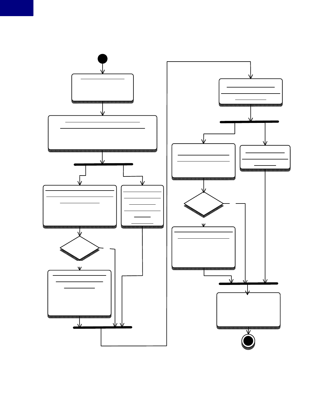
InCopy: Track Changes
Data model for Track Changes
798
FIGURE 305 kRedlineStrandBoss Activity on text deletion
start
Text model pre-notifies delete
preprocessors about the deletion.
delete preprocessor is a service provider
with service ID kEditCmdPreProcessService
User deletes text.
kUserTypeTextCmdBoss is
processed.
Is Track
Changes
on?
Create a change record
at the deletion point.
VOS_RedlineObject is
inserted with a new change
record (VOSRedlineChange).
kRedlineStrandBoss
handles the deletion.
IStrand::Cut() is called.
All other strand
bosses handle the
deletion.
Deletion finished.
In Galley view, the tracked
text will be shown if user
chooses to show tracked
deletions.
end
Yes
No
Should
preserve
deleted text?
A new story thread is
created to hold the
deleted text.
kDeletedTextBoss (an owned
item boss) is created, it
provides access to the new
story thread.
kRedlinePreprocessorBoss
handles the preprocessing
for the deletion.
ITextCommandPreProcess::
DeletePreProcess() is called.
Text model notifies
each strand boss about
the deletion.
All other delete
preprocessors
handle the
preprocessing
for the
deletion.
Yes
No

InCopy: Track Changes 799
InCopy: Track Changes
Data model for Track Changes
In some situations, there can be multiple VOSRedlineChanges for one text position. The most
likely scenario is one in which the character following the deleted text is an insertion change;
then the insertion change is nested. In this case, it is possible to iterate through changes and
have the current text position be the same, even though the iterator was incremented or decre-
mented (through RedlineIterator::Increment or RedlineIterator::Decrement). Calling the
accessor methods returns the appropriate change-record information given the state of an
internal flag, or the useUI flag if passed when the iterator was constructed with NewRedlineIt-
erator. Accepting a nested insertion does not affect the deletion; however, rejecting a nested
insertion rejects the deletion.
Example: Track Changes in action
Consider the example of the story “0123456789,” with “3” and “7” converted to notes, as shown
in the InCopy story view in Figure 306. This story, with embedded owned items—the notes—
demonstrates what happens in a text story when deletion and insertion are performed while
Track Changes is turned on. Below the story view in Figure 306 is a table showing the funda-
mental text model data, with which you can understand the basics of change tracking.
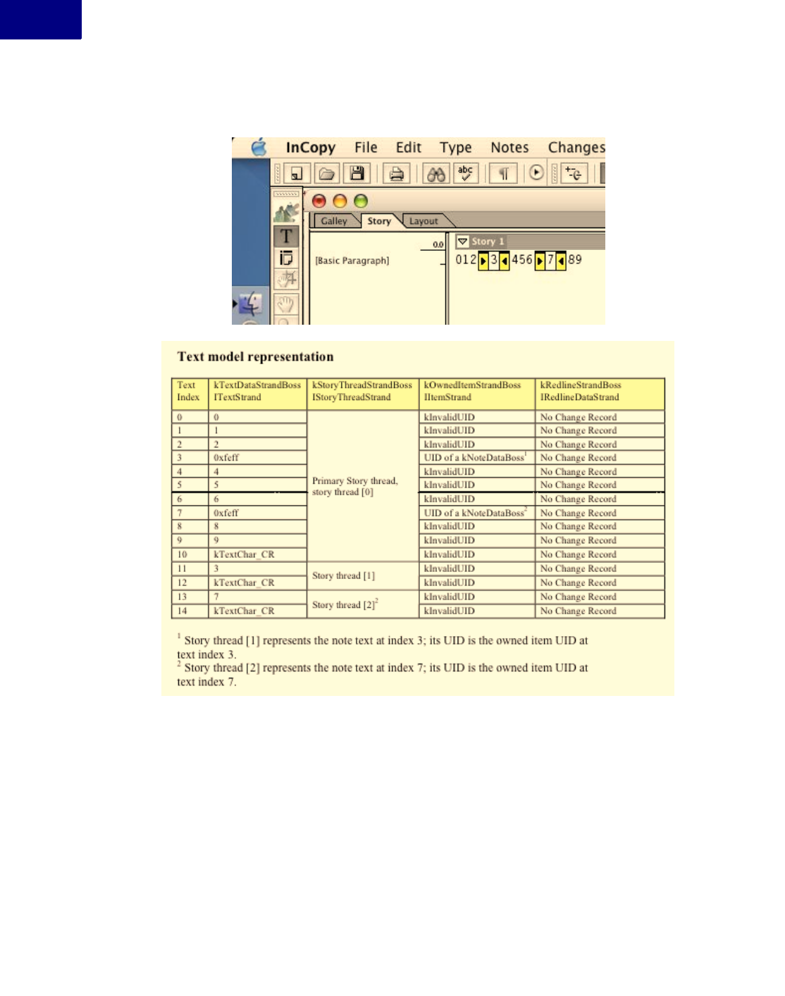
InCopy: Track Changes
Data model for Track Changes
800
FIGURE 306 Track Changes action 1: before Track Changes is turned on
NOTE:The complete text data model is more complex than that depicted in this table. For
more information on the text model, see the “Text Fundamentals” chapter.
In the table, the columns are interpreted as follows:
zThe first column represents the text index in the text model.
zThe second column represents the text data stored in the kTextDataStrandBoss object. The
visual story representation you see in the InDesign or InCopy document window does not
necessarily represent the sequence in which the data is stored in the text model. For exam-
ple, although the note with content “3” is located between characters “2” and “4,” the real
note-text content is stored in a different story thread in text index 11. Between characters
“2” and “4,” the text data is inserted with a note anchor.

InCopy: Track Changes 801
InCopy: Track Changes
Data model for Track Changes
zThe third column from the left shows the text-story threads. The InDesign text engine uses
an owned item strand (kOwnedItemStrandBoss) to figure out where to find the corre-
sponding text when the engine comes to compose the text.
zThe fourth column shows the owned-item strand data.
zThe fifth column shows tracked-change data; the information is obtained from RedlineIter-
ator.
Looking at the text model representation in Figure 306, see in the kTextDataStrandBoss that
each note is anchored at the note’s visual location (text index 3 and text index 7) with a special
anchor character, 0xfeff. At the same position, the UID of the note’s kNoteDataBoss is stored
through the IItemStrand interface on the kOwnedItemStrandBoss. The kNoteDataBoss also
aggregates the interfaces to access the story threads that store the note contents. To find the text
content of a note, you can go through the kOwnedItemStrandBoss to find its corresponding
story thread. Because the story was entered with Track Changes off, the kRedlineStrandBoss
does not contain any tracked-change information at this point.
Using the SnippetRunner SnpInspectTextModel snippet, you can inspect the text model while
Track Changes is turned on. Some methods in SnpInspectTextModel were used to produce the
results you see in Figure 306. The SnpInspectTextModel::InspectTrackChange method uses the
RedlineIterator to examine the change record under each text index in the story. The SnpIn-
spectTextModel::InspectStoryThreads and SnpInspectTextModel::CountStoryOwnedItems
methods were used to examine the story threads, owned item, and text data.
Next, turn on Track Changes, select the text “234,” and delete the selected text. The result is
shown in Figure 307.
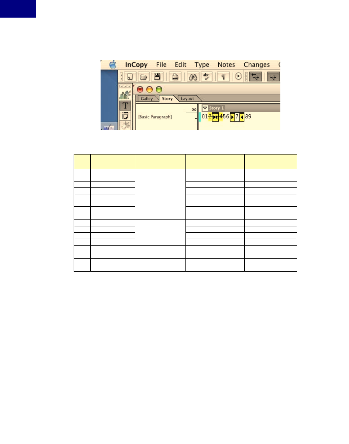
InCopy: Track Changes
Data model for Track Changes
802
FIGURE 307 Track Changes action 2: delete one block of text
Unlike unlike the note—which uses a kTextChar_ZeroSpaceNoBreak character to anchor the
note—Track Changes does not insert anchor characters for deleted text in text position 2 in the
kTextDataStrandBoss; that position is occupied by the character “5” after the deletion. The text
model uses kRedlineStrandBoss to maintain tracked-change information. In text index 2 of the
kRedlineStrandBoss, there is a change record with the type kDelete stored in that location,
which tells the text model that at least one character was deleted at that location. Similar to the
inline note, the tracked change stores the deleted text in an owned-item boss, kDeletedText-
Boss. In text index 2, where the text was deleted, the kOwnedItemStrandBoss stores the UID of
the kDeletedTextBoss. The kDeletedTextBoss aggregates ITextStoryThread and ITextStoryTh-
Text model representation
Text
Index
kTextDataStrandBoss
ITextStrand
kStoryThreadStrandBoss
IStoryThreadStrand
kOwnedItemStrandBoss
IItemStrand
kRedlineStrandBoss
IRedlineDataStrand
0 0 kInvalidUID No Change Record
1 1 kInvalidUID No Change Record
2 5 UID of a kDeletedTextBoss
1
kDelete
3 6 kInvalidUID No Change Record
4 0xfeff UID of a kNoteDataBoss
3
No Change Record
5 8 kInvalidUID No Change Record
6 9 kInvalidUID No Change Record
7kTextChar_CR
Primary Story thread,
story thread [0]
kInvalidUID No Change Record
8 2 kInvalidUID No Change Record
90xfeff UID of a kNoteDataBoss
2
No Change Record
10 4kInvalidUID No Change Record
11 kTextChar_CR
Story thread [1]
1
kInvalidUID No Change Record
12 3kInvalidUID No Change Record
13 kTextChar_CR
Story thread [2]
2
kInvalidUID No Change Record
14 7kInvalidUID No Change Record
15 kTextChar_CR
Story thread [3]
3
kInvalidUID No Change Record
1Story thread [1] represents the deleted text at text index 2; its UID is the owned item
UID at text index 2. The deleted text includes a note at index 9, which is represented by
another owned item.
2Story thread [2] represents the note text in the deleted text in story thread [1]; its UID is
the owned item UID at text index 9.
3Story thread [3] represents the note text at index 4; its UID is the owned item UID at
text index 4.

InCopy: Track Changes 803
InCopy: Track Changes
Data model for Track Changes
readDict, as shown in Figure 303, which points back to the text-story thread, represented by
the kStoryThreadStrandBoss of the text model. The result of SnpInspectTextModel.cpp can
show you the UID stored in the kOwnedItemStrandBoss and the UID of the associated story
thread, so you can make the connection. For simplicity, the UIDs are omitted from the table in
Figure 307.
Notice how embedded content is being stored in the event, such as deletion, and how it is
tracked. The deleted text includes a note. The UID of the kDeletedTextBoss in position 2 leads
to story thread [1] in Figure 307. By examining this thread’s corresponding kTextdataStrand-
Boss and kOwnedItemStrandBoss, you can see that all attributes in the pre-deletion indices 2–
4 are preserved in indices 8–9, including the deleted note’s information. The kRedlineStrand-
Boss does not keep any change record in the position under the deleted text-story thread,
though. In the SnpInspectTextModel::InspectTrackChange, when in the deleted text thread,
the text index is not used to create a RedlineIterator. Instead, the corresponding deleted text
position is found, and that position is used in the primary story thread to check its correspond-
ing change record. To find the deleted note’s text content, go to the story thread [1], which rep-
resents the deleted text. From there, find the UID of the deleted note’s kNoteDataBoss, which
leads to the thread [2]. Note that the text content of the inline note in text index 7 is now the
text thread [3], because a new story thread was created and inserted to hold the deleted text.
Next, select and delete the text “678.” The result is shown in Figure 308. Since both notes are
deleted, you will not see any UIDs of kNoteDataBoss if you examine the kOwnedItemStrand-
Boss in the primary story-thread range; they are all preserved in the deleted text’s threads,
which can be reached through the UIDs of the kDeletedTextBoss at indices 2 and 3. Also, the
kRedlineStrandBoss data shows there are kDelete items at both index 2 and index 3, which is
consistent with what you see in story view, in which the deleted text is displayed immediately
before the character “5” (at index 2) and immediately before the character “8” (at index 3).
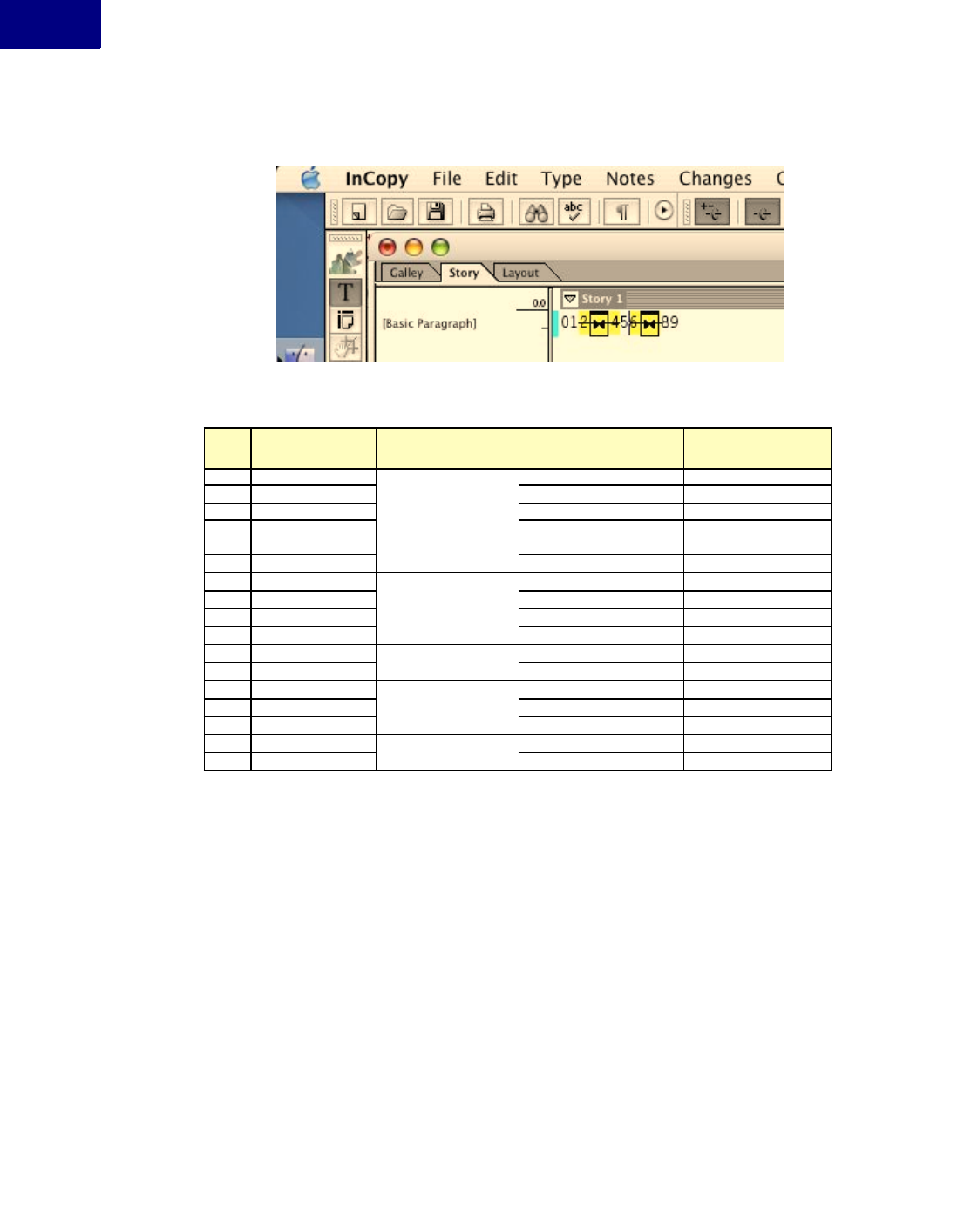
InCopy: Track Changes
Data model for Track Changes
804
FIGURE 308 Track Changes action 3: delete two blocks of text
Text model representation
Text
Index
kTextDataStrandBoss
ITextStrand
kStoryThreadStrandBoss
IStoryThreadStrand
kOwnedItemStrandBoss
IItemStrand
kRedlineStrandBoss
IRedlineDataStrand
0 0 kInvalidUID No Change Record
1 1 kInvalidUID No Change Record
2 5 UID of a kDeletedTextBoss1kDelete
3 8 UID of a kDeletedTextBoss3kDelete
4 9 kInvalidUID No Change Record
5kTextChar_CR
Primary Story thread,
story thread [0]
kInvalidUID No Change Record
6 2 kInvalidUID No Change Record
70xfeff UID of a kNoteDataBoss2No Change Record
8 4 kInvalidUID No Change Record
9kTextChar_CR
Story thread [1]1
kInvalidUID No Change Record
10 3kInvalidUID No Change Record
11 kTextChar_CR Story thread [2]2
kInvalidUID No Change Record
12 6kInvalidUID No Change Record
13 0xfeff UID of a kNoteDataBoss4No Change Record
14 kTextChar_CR
Story thread [3]3
kInvalidUID No Change Record
15 7kInvalidUID No Change Record
16 kTextChar_CR Story thread [4]4
kInvalidUID No Change Record
1Story thread [1] represents the deleted text at text index 2; its UID is the owned item
UID at text index 2. The deleted text includes a note at index 7, which is represented by
another owned item.
2Story thread [2] represents the note text in the deleted text in story thread [1]; its UID is
the owned item UID at text index 7.
3Story thread [3] represents the deleted text at text index 3; its UID is the owned item
UID at text index 3. The deleted text includes a note at index 13, which is represented by
another owned item.
4Story thread [4] represents the note text in the deleted text in story thread [3]; its UID is
the owned item UID at text index 13.
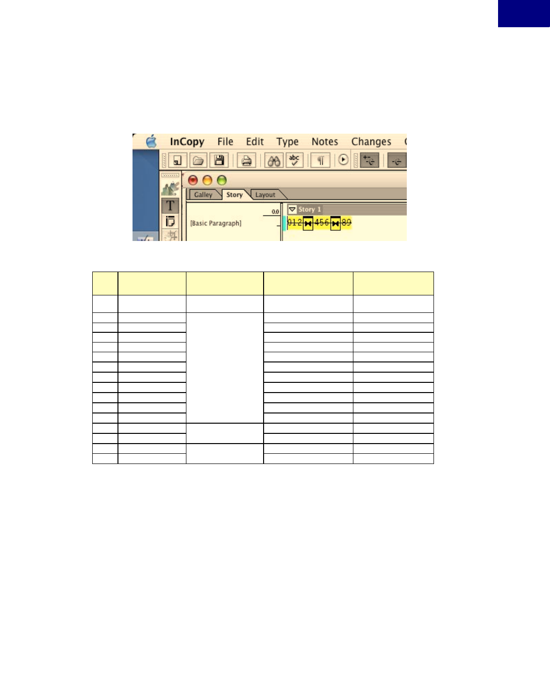
InCopy: Track Changes 805
InCopy: Track Changes
Data model for Track Changes
Next, select and delete all text. The result is shown in Figure 309. The deleted text contains all
original text and notes. Only one kDeletedTextBoss is needed to maintain the deleted text.
FIGURE 309 Track Changes action 4: delete all text
Text model representation
Text
Index
kTextDataStrandBoss
ITextStrand
kStoryThreadStrandBoss
IStoryThreadStrand
kOwnedItemStrandBoss
IItemStrand
kRedlineStrandBoss
IRedlineDataStrand
0 kTextChar_CR Primary Story thread,
story thread [0]
UID of a kDeletedTextBoss
1
kDelete
1 0 kInvalidUID No Change Record
2 1 kInvalidUID No Change Record
3 2 kInvalidUID No Change Record
4 0xfeff UID of a kNoteDataBoss
2
No Change Record
5 4 kInvalidUID No Change Record
6 5 kInvalidUID No Change Record
7 6 kInvalidUID No Change Record
80xfeff UID of a kNoteDataBoss
3
No Change Record
9 8 kInvalidUID No Change Record
10 9kInvalidUID No Change Record
11 kTextChar_CR
Story thread [1]
1
kInvalidUID No Change Record
12 3kInvalidUID No Change Record
13 kTextChar_CR Story thread [2]
2
kInvalidUID No Change Record
14 7kInvalidUID No Change Record
15 kTextChar_CR Story thread [3]
3
kInvalidUID No Change Record
1Story thread [1] represents the deleted text at text index 0; its UID is the owned item
UID at text index 0. The deleted text includes 2 notes at index 4 and 8, which are
represented by other owned items.
2Story thread [2] represents the note text at text index 4 in the deleted text in story thread
[1]; its UID is the owned item UID at text index 4.
3Story thread [3] represents the note text at text index 8 in the deleted text in story thread
[1]; its UID is the owned item UID at text index 8.
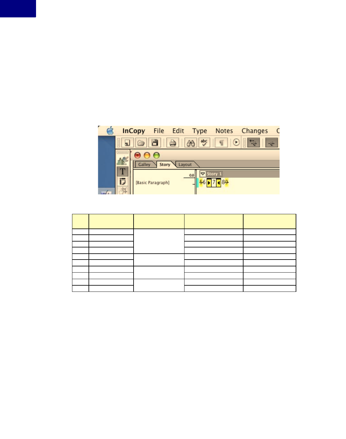
InCopy: Track Changes
Data model for Track Changes
806
Next, select “01234” and accept the change, then select “678” and reject the change. The result
is shown in Figure 310. When you accept the deletion, the tracked change no longer tracks that
portion of deleted text; therefore, the tracked text “01234” is removed from the story view, and
the corresponding kDeletedTextBoss is purged. The only way to get the deleted text back is
through the undo operation. Because you rejected the change partially (“6[7]8” out of the
tracked “56[7]89,” where “[7]” is a note), the tracked text is not in a contiguous block; there-
fore, two separate kDeletedTextBoss objects are needed, one to track “5” and one to track “9.”
FIGURE 310 Track Changes action 5: partially accept and partially reject a change
Text model representation
Text
Index
kTextDataStrandBoss
ITextStrand
kStoryThreadStrandBoss
IStoryThreadStrand
kOwnedItemStrandBoss
IItemStrand
kRedlineStrandBoss
IRedlineDataStrand
0 6 UID of a kDeletedTextBoss
1
kDelete
1 0xfeff UID of a kNoteDataBoss
2
No Change Record
2 8 kInvalidUID No Change Record
3kTextChar_CR
Primary Story thread,
story thread [0]
UID of a kDeletedTextBoss
3
kDelete
4 5 kInvalidUID No Change Record
5kTextChar_CR Story thread [1]
1
kInvalidUID No Change Record
6 7 kInvalidUID No Change Record
7kTextChar_CR Story thread [2]
2
kInvalidUID No Change Record
8 9 kInvalidUID No Change Record
9kTextChar_CR Story thread [3]
3
kInvalidUID No Change Record
1
Story thread [1] represents the deleted text at text index 0; its UID is the owned item
UID at text index 0.
2
Story thread [2] represents the note text at text index 1 in the primary story thread [0];
its UID is the owned item UID at text index 1.
3
Story thread [3] represents the deleted text at text index 3; its UID is the owned item
UID at text index 3.
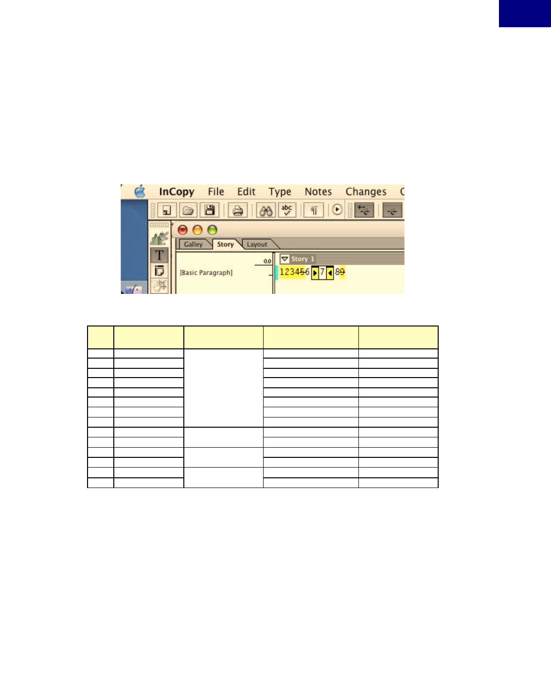
InCopy: Track Changes 807
InCopy: Track Changes
Data model for Track Changes
Next, insert “1234” before the deleted “5.” Because Track Changes is still turned on, the new
insertion is tracked, as shown in Figure 311. In this case, the inserted text is simply added into
the text model as normal: the data is added into kTextDataStrandBoss at a normal text index,
and no owned item boss needs to be created. The corresponding position in the kRed-
lineStrandBoss is marked as kInsert. With this one flag, the text model can hide, show, accept,
or reject a tracked change when user chooses to do so.
FIGURE 311 Track Changes action 6: insert a block of text
Text model representation
Text
Index
kTextDataStrandBoss
ITextStrand
kStoryThreadStrandBoss
IStoryThreadStrand
kOwnedItemStrandBoss
IItemStrand
kRedlineStrandBoss
IRedlineDataStrand
0 1 kInvalidUID kInsert
1 2 kInvalidUID kInsert
2 3 kInvalidUID kInsert
3 4 kInvalidUID kInsert
4 6 UID of a kDeletedTextBoss11kDelete
50xfeff UID of a kNoteDataBoss2No Change Record
6 8 kInvalidUID No Change Record
7kTextChar_CR
Primary Story thread,
story thread [0]
UID of a kDeletedTextBoss13kDelete
8 5 kInvalidUID No Change Record
9kTextChar_CR Story thread [1]1
kInvalidUID No Change Record
10 7kInvalidUID No Change Record
11 kTextChar_CR Story thread [2]2
kInvalidUID No Change Record
12 9kInvalidUID No Change Record
13 kTextChar_CR Story thread [3]3
kInvalidUID No Change Record
1
Story thread [1] represents the deleted text at text index 4; its UID is the owned item
UID at text index 4.
2
Story thread [2] represents the note text at text index 5 in the primary story thread [0];
its UID is the owned item UID at text index 5.
3
Story thread [3] represents the deleted text at text index 7; its UID is the owned item
UID at text index 7.
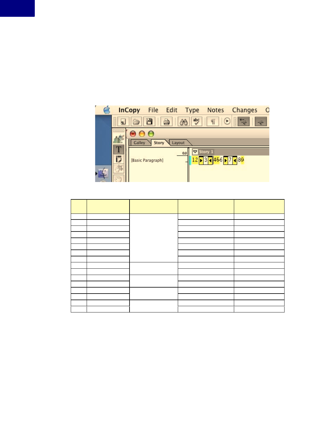
InCopy: Track Changes
Data model for Track Changes
808
Next, select the text “3” and convert it to a note. The result is shown in Figure 312. The note is
created in text index 2 and tracked as inserted text in that position. The tracked text’s change
information in the kRedlineStrandBoss will not change until the user accepts or rejects the
change or the text is cut. So, if you highlight the note in index 2 and accept the change, you will
see the kRedlineStrandBoss change the change data from kInsert to none.
FIGURE 312 Track Changes action 7: convert tracked text to a note
Text model representation
Text
Index
kTextDataStrandBoss
ITextStrand
kStoryThreadStrandBoss
IStoryThreadStrand
kOwnedItemStrandBoss
IItemStrand
kRedlineStrandBoss
IRedlineDataStrand
0 1 kInvalidUID kInsert
1 2 kInvalidUID kInsert
2 0xfeff UID of a kNoteDataBoss1kInsert5
3 4 kInvalidUID kInsert
4 6 UID of a kDeletedTextBoss2kDelete
50xfeff UID of a kNoteDataBoss3No Change Record
6 8 kInvalidUID No Change Record
7kTextChar_CR
Primary Story thread,
story thread [0]
UID of a kDeletedTextBoss4kDelete
8 3 kInvalidUID No Change Record
9kTextChar_CR Story thread [1]1
kInvalidUID No Change Record
10 5kInvalidUID No Change Record
11 kTextChar_CR Story thread [2]2
kInvalidUID No Change Record
12 7kInvalidUID No Change Record
13 kTextChar_CR Story thread [3]3
kInvalidUID No Change Record
14 9kInvalidUID No Change Record
15 kTextChar_CR Story thread [4]4
kInvalidUID No Change Record
1Story thread [1] represents the note text at text index 2 in the primary story thread [0];
its UID is the owned item UID at text index 2.
2Story thread [2] represents the deleted text at text index 4 in the primary story thread
[0]; its UID is the owned item UID at text index 4.
3Story thread [3] represents the note text at text index 5 in the primary story thread [0];
its UID is the owned item UID at text index 5.
4Story thread [4] represents the deleted text at text index 7 in the primary story thread
[0]; its UID is the owned item UID at text index 7.
5The note is converted from the tracked text, so it is continuously tracked as inserted
text. If the user selects this note and accept the change, then the kInsert status on the
kRedlineStrandBoss changes to the status indicating that there is no tracked change.

InCopy: Track Changes 809
InCopy: Track Changes
Key client APIs
Track Changes preferences
An ITrackChangeAppSettings interface is added to the kWorkspaceBoss. This interface is
responsible for maintaining the Track Changes settings in the Preferences panel. To access this
interface, you can do the following:
InterfacePtr<IWorkspace> workSpace(GetExecutionContextSession()->QueryWorkspace());
InterfacePtr<ITrackChangeAppSettings> tcAppSettings(
(ITrackChangeAppSettings*)workSpace->
QueryInterface(IID_ITRACKCHANGEAPPSETTINGS));
if (tcAppSettings != nil)
{
// Do something with the preference.
}
The ITrackChangeStorySettings interface (IID_ITRACKCHANGESTORYSETTINGS) is
added to the kTextStoryBoss. This interface’s responsibility is to maintain story-level settings,
like whether Track Changes is turned on for the story. To access this interface, you can do the
following:
// Assume textModel is a valid ITextModel interface pointer.
InterfacePtr<ITrackChangeStorySettings>
trackSetting(textModel, IID_ITRACKCHANGESTORYSETTINGS);
if (trackSetting && trackSetting->GetIsTracking())
{
// Track Changes is on for this story. Do something.
{
Key client APIs
Track Changes utilities
ITrackChangeUtils, added to the kUtilsBoss, provides convenient methods for a client to access
some Track Changes features. For more information, see ITrackChangeUtils.h.
Suite interfaces
Much of the capability required for client code to work with Track Changes is provided in a
high-level suite interface, ITrackChangeSuite, which is available through a reference to a selec-
tion. To obtain the interface, query a selection manager (ISelectionManager) for the ITrack-
ChangeSuite interface. For information on obtaining a reference to the selection manager, see
the “Selection” chapter of Learning the Adobe InDesign CS4 Architecture. ITrackChangeSuite
encapsulates the details of interacting with the Track Changes model and hides details about
the selection format that is active, providing a capability-driven API that can be used to accept
and reject tracked change. Other suites for accessing Track Changes are discussed in this sec-
tion.

InCopy: Track Changes
Key client APIs
810
ITrackChangeSuite
ITrackChangeSuite is a key API for manipulating Track Changes in client code; most Track
Changes user-interface functions are provided through this interface. It provides much of the
required capability for plug-ins.
The ITrackChangeSuite interface is aggregated on the integrator-suite boss class (kIntegrator-
SuiteBoss), which makes it available through the abstract selection. Implementations of this
interface are provided on concrete-selection boss classes kGalleyTextSuiteBoss and kTextSuite-
Boss, which are hidden from client code through the facade of the abstract selection. To obtain
ITrackChangeSuite, client code should query the selection manager (ISelectionManager) for
the interface, as shown below:
InterfacePtr<ITrackChangeSuite> iTCSuite
(ac->GetContextSelection(), IID_ITRACKCHANGESUITE);
if (iTCSuite)
// Do something with Track Changes through the suite.
Generally, ITrackChangeSuite is active when the text cursor is active in story view or galley
view. Suite interfaces typically use this pattern of checking for a service or capability, and if the
abstract selection supports this capability, the method can be called; however, ITrackChange-
Suite does not follow this pattern. The ITrackChangeSuite::CanAccept and ITrackChangeSu-
ite::CanReject methods check only whether the workspace preference
ITrackChangeAppSettings::GetUserCanAcceptRejectChanges method returns true. If true—
and the story is not locked—the CanAccept and CanReject methods always return true.
IChangesReviewSuite
Because ITrackChangeSuite does not provide meaningful CanDo-types of methods (see
ITrackChangeSuite), another suite interface, IChangesReviewSuite, is provided for determin-
ing whether a tracked change is available in the current text position. The application uses this
suite to decide whether the user interface related to Track Changes—like the menu and the
Track Changes toolbar buttons—should be enabled or disabled when the text selection
changes. For example, to determine whether the current cursor position has a change record
the user can accept, call IChangesReviewSuite::IsAcceptChangeEnabled.
ITrackChangeSettingsSuite
IChangesReviewSuite is mainly responsible for getting and setting a story’s change-tracking
state. You also can apply the state to multiple stories at the same time with one call.
IChangeInfoSuite
IChangeInfoSuite provides one method to get the current tracked-change information, based
on the current text selection. IChangeInfoSuite returns the information in a public ChangeInfo
class, which stores three pieces of information: story user, date of change, and change type. This
suite is used by the application for the Change Info panel.
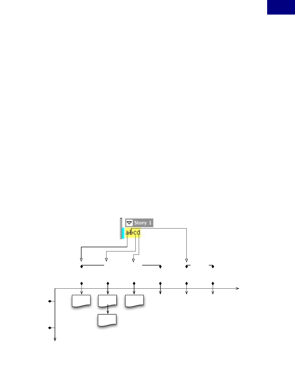
InCopy: Track Changes 811
InCopy: Track Changes
Key client APIs
RedlineIterator
RedlineIterator is the primary access to the tracked change object; it also provides for process-
ing acceptance and rejection of tracked changes. Create a new iterator using IRedlineDataS-
trand::NewRedlineIterator as shown below; the caller is responsible for destroying the iterator.
// Assume textModel is a valid ITextModel interface pointer.
InterfacePtr<IRedlineDataStrand> redline((IRedlineDataStrand*)textModel
->QueryStrand(kRedlineStrandBoss, IRedlineDataStrand::kDefaultIID));
if (redline)
{
RedlineIterator *redIterator = redline->NewRedlineIterator(0L);
if (redIterator)
{
// Use the iterator to access the Track Changes.
// When done with the iterator, delete it!
delete redIterator;
}
}
As discussed in “Example: Track Changes in action” on page 799, there may be more than one
change record under each text index. Currently, the only situation that results in multiple
change records under one text index is the deletion of text that results in a deleted text record
in front of added text, which causes a deletion record and an insertion record at the same text
position. The records are managed so the deletion always is at change position 0. The underly-
ing change record can be viewed as being laid out in a two-dimensional map, as shown in
Figure 313.
FIGURE 313 Conceptual change record structure map
Text Index
Change record position
kDelete
0
1
012 34 5
ac bcr cr
primary story thread [0] thread [1]
kInsert
kInsert kInsert
d

InCopy: Track Changes
Key client APIs
812
The RedlineIterator::MoveToPosition method provides the means to move in this two-dimen-
sional space:
virtual bool16 MoveToPosition(TextIndex t, int32 c = -1) = 0;
The first parameter lets you go horizontally (i.e., navigate by the text), and the second parame-
ter lets you go vertically (i.e., navigate among change records at the same text index).
You also can use RedlineIterator::Increment or RedlineIterator::Decrement to access the
change record. When you use Increment, it first goes down to the next change record on the
same text index, then moves to the next text index that has a change record, and then goes
downward from the first record in that index before moving to the next index again. SnpIn-
spectTextModel::InspectTrackChange uses this method to iterate through all change records in
a story.
kDeletedTextBoss
kDeletedTextBoss is anchored as an owned item in the text story. The following code snippet
shows one way to get to the kDeletedTextBoss from the story. After you gain access to the
owned item, you have access to the whole kDeletedTextBoss, and you can use it to find the pri-
mary story thread index where the owned item is anchored.
// Find deleted text owned item in current storyRef.
InterfacePtr<ITextModel> textModel(storyRef, UseDefaultIID());
InterfacePtr<IItemStrand> itemStrand((IItemStrand*)textModel
->QueryStrand(kOwnedItemStrandBoss, IItemStrand::kDefaultIID));
int32 mainStoryLength = textModel->GetPrimaryStoryThreadSpan() - 1;
// Collect owned item from the story.
Text::CollectOwnedItems(textModel, 0, mainStoryLength, &ownedItemList);
if (ownedItemList.Length() > 0)
{
// Remove non-deleted text items.
for (i = ownedItemList.Length()-1; i>=0; i--)
{
if (ownedItemList[i].fClassID != kDeletedTextBoss)
ownedItemList.Remove(i);
}
}
See Figure 314 for an illustration of kDeletedTextBoss and its key interfaces.
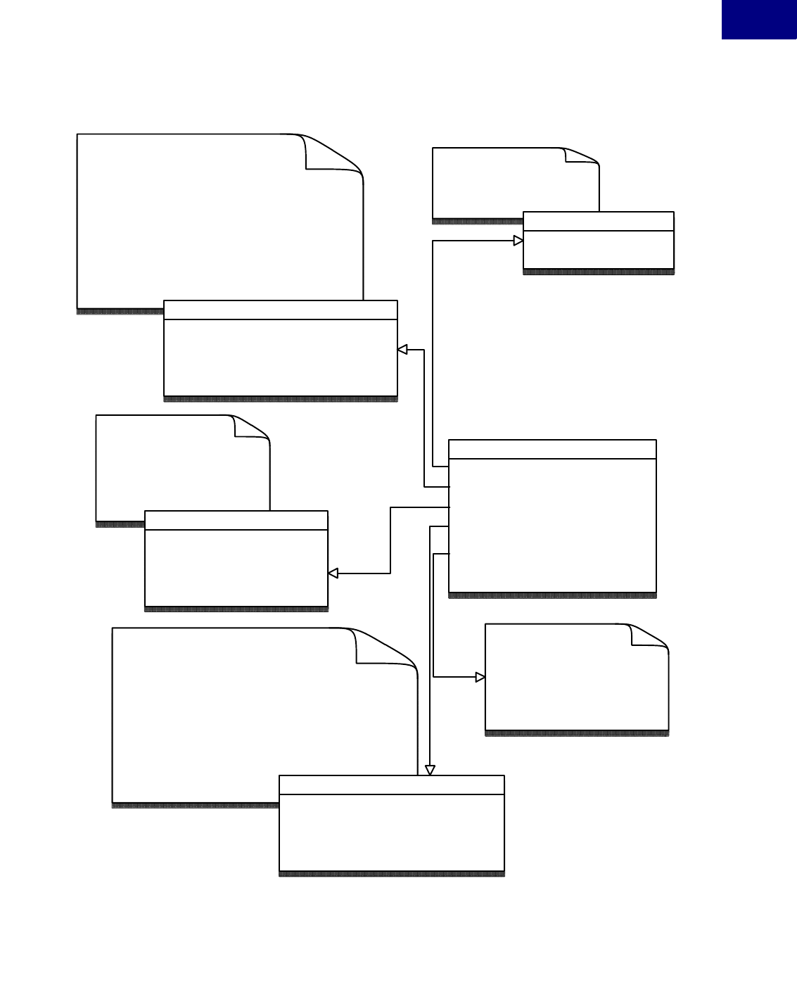
InCopy: Track Changes 813
InCopy: Track Changes
Key client APIs
FIGURE 314 kDeletedTextBoss and its key interfaces
Implements the story
thread (ITextStoryThread)
that represents the
deleted text content.
kDeletedTextBoss
IDeletedTextData
IOwnedItem
ITextStoryThread
ITextStoryThreadDict
IParcelList
ITextParcelList
...
storage for the deleted
text story UID.
The IOwnedItem and ITextModelMemento
(on a separate boss,
kDeletedTextModelMementoImpl)
implementations are the hooks that allow the
deleted text to be managed when it is
affected by text model operations. However,
when Track Changes is turned on, text
deletion is handled by a pre-processor.
IOwnedItem
CollectStoryRanges
GetNumSpecialAnchorChars
...
IDeletedTextData
GetStoryUID
SetStoryUID
ITextStoryThread
GetDictUID
GetTextStart
QueryTextModel
...
Deleted text's (kDeletedTextBoss)
ITextStoryThreadDict implementation manages
only one story thread.
Many instances of kDeletedDataBoss can be
embedded in a story, but each has its own
deleted text data (kDeletedTextBoss) with its
own dictionary (ITextStoryThreadDict) and story
thread(ITextStoryThread). ITextStoryThreadDict
QueryThread
GetAnchorTextRange
GetThreadBlockTextRange
...
Because deleted text does
not support display of
composed text, all of the
parcel-related interface are
implemented as stubs.

InCopy: Track Changes
Useful commands and associated notification protocols
814
Useful commands and associated notification protocols
This section summarizes some of the most common commands related to Track Changes.
Critical data interfaces that users of the command must supply are explained, and the notifica-
tion protocol associated with the command is listed.
kSetRedlineTrackingCmdBoss
Description
Sets the tracking flag for the story or workspace (whichever is specified in the command’s item
list) to the specified boolean setting. Changes remain tracked, but no new changes are tracked.
Item list
UIDList that contains either the workspace pointer (from GetExecutionContextSession()-
>QueryWorspace()) or UIDs of the text stories for the setting change.
Data interface
IBoolData, to turn Track Changes on or off for the target.
kSetTrackChangesPrefsCmdBoss
Description
Sets the session preference ITrackChangeAppSettings to the settings specified in the data inter-
face.
Item list
UIDList that contains the workspace pointer (from GetExecutionContextSession()->Query-
Worspace()).
Data interface
ITrackChangesPrefsCmdData can be changed to the user’s preference. Table 172 shows the
default values in ITrackChangesPrefsCmdData. A Set method changes all preference data, and
individual Get or Set methods modify individual attributes.

InCopy: Track Changes 815
InCopy: Track Changes
Useful commands and associated notification protocols
TABLE 172 Default Track Changes preferences
Notification
Notify kSessionBoss with kSetTrackChangesPrefsCmdBoss message along with the
IID_ITRACKCHANGEAPPSETTINGS protocol.
Attribute Default value
Added Text Background Color
Choice
ITrackChangeAppSettings::kUseUserColorBG
Added Text Background Color Index 2 (InCopyUIColors => yellow)
Added Text Color Choice ITrackChangeAppSettings::kUseGalleyColor
Added Text Color Index 1 (InCopyUIColors => black)
Added Text Marking 0 (ITrackChangeAppSettings::kNone)
Change Bar Color Index 18 (InCopyUIColors => cyan)
Change Bar Location 0 (ITrackChangeAppSettings::kLeftMargin)
Deleted Text Background Color
Choice
ITrackChangeAppSettings::kUseUserColorBG
Deleted Text Background Color
Index
2 (InCopyUIColors => yellow)
Deleted Text Color Index 1 (InCopyUIColors => black)
Deleted Text Marking 1 (ITrackChangeAppSettings::kStrikethrough)
Deleted TextColor Choice ITrackChangeAppSettings::kUseGalleyColor
Moved Text Background Color
Choice
ITrackChangeAppSettings::kUseUserColorBG
Moved Text Background Color
Index
2 (InCopyUIColors => yellow)
Moved Text Color Choice ITrackChangeAppSettings::kUseGalleyColor
Moved Text Color Index 1 (InCopyUIColors => black)
Moved Text Marking 3 (ITrackChangeAppSettings::kOutline)
Show Added Text kTrue
Show Change Bar kTrue
Show Deleted Text kTrue
Show Moved Text kTrue
Spellcheck Deleted Text kTrue

InCopy: Track Changes
Useful commands and associated notification protocols
816
kActivateRedlineCmdBoss
Description
Create the kRedlineStrandBoss, and attach it to the story. It synchronizes the redline strand to
the story to which it is attached. Usually, the kRedlineStrandBoss is created when a new story is
created. If the redline strand cannot be found, this command can be processed to get the strand
back. The following is one way to check whether a redline strand is available in a story:
InterfacePtr<IRedlineDataStrand> redlineStrand
((IRedlineDataStrand*)textModel->QueryStrand(
kRedlineStrandBoss,
IRedlineDataStrand::kDefaultIID));
If QueryStrand returns a valid IRedlineDataStrand interface pointer, a redline strand is con-
nected to the story.
Item List
UIDList that contains the UID of the text story to which the redline is supposed to be con-
nected.
kDeactivateRedlineCmdBoss
Description
This is the reverse of kActivateRedlineCmdBoss. To delete the kRedlineStrandBoss associated
with a story, this command purges the strand from the associated VOS disk page, deregisters
the redline strand from the text model, and removes the UID of the kRedlineStrandBoss from
the database. This command accepts all changes before it deletes the strand.
Item list
UIDList that contains the UID of the text story from which the redline is supposed to be dis-
connected.
kRejectAllRedlineCmdBoss
Description
Rejects all tracked change (redline) data in a story.
Item list
UIDList that contains the UID of the text story for which the redline data is supposed to be
rejected.
Data interface
IBoolData with interface ID IID_IRESTORESELECTIONDATA. This interface defaults to
false. Set to true to restore the selection.

InCopy: Track Changes 817
InCopy: Track Changes
Useful commands and associated notification protocols
Notification
Notify kTextStoryBoss with the kRejectAllRedlineCmdBoss message and IID_ITEXTMODEL
protocol. Notify kDocBoss with the kRejectAllRedlineCmdBoss message and
IID_REJECTALLREDLINE_DOCUMENT protocol.
kRejectRangeRedlineCmdBoss
Description
Rejects changes in the specified range. If the range’s start index or end index corresponds to a
deletion, this deletion is not rejected; such deletions should be detected and rejected individu-
ally if desired.
Item list
UIDList containing UID of the text story for which the redline data is supposed to be rejected.
Data interface
zIRedlineChangeData — Not needed. The command finds the change record based on the
text index on which it is working. This interface is a placeholder for original change data, so
it can be preserved.
zIRangeData with IID_IRANGEDATA — The range of text for which you want to reject the
change records.
zIBoolData with IID_IBOOLDATA — Not needed.
zIBoolData with IID_IRESTORESELECTIONDATA — The default is false; true restores the
selection.
Notification
zNotify kTextStoryBoss with the kRejectRangeRedlineCmdBoss message and
IID_ITEXTMODEL protocol.
zNotify kDocBoss with the kRejectRangeRedlineCmdBoss message and
IID_REJECTRANGEREDLINE_DOCUMENT protocol.
kRejectRedlineCmdBoss
Description
Rejects the change record at the text index specified by the user.
Item list
UIDList containing the UID of the text story for which the redline data is to be rejected.

InCopy: Track Changes
Useful commands and associated notification protocols
818
Data interface
zIRedlineChangeData with IID_IREDLINECHANGEDATA — Set this data interface to a
VOSRedlineChange pointer returned from the RedlineIterator::GetCurrentChangeRecord.
The GetCurrentChangeRecord takes a TextIndex and returns the current track change
record for that index.
zIRangeData with IID_IRANGEDATA — The text index of the change record to be rejected
should be used as the range start and range end.
zIBoolData with IID_IBOOLDATA — Set to false to prevent notification if rejection is
within reject-all context.
zIBoolData with IID_IRESTORESELECTIONDATA — This interface defaults to false. Set to
true to restore selection.
Notification
The command notifies only when the IBoolData (with IID_IBOOLDATA) is set to false.
zNotify kTextStoryBoss with the kRejectRedlineCmdBoss message and IID_ITEXTMODEL
protocol.
zNotify kDocBoss with the kRejectRedlineCmdBoss message and
IID_REJECTREDLINE_DOCUMENT protocol.
kAcceptAllRedlineCmdBoss
Description
Accepts all tracked change (redline records) in a story.
Item list
UIDList containing the UID of the text story for which the changes are to be accepted.
Data interface
IBoolData with IID_IRESTORESELECTIONDATA — The default is false. True restores selec-
tion.
Notification
zNotify kTextStoryBoss with the kAcceptAllRedlineCmdBoss message and
IID_ITEXTMODEL protocol.
zNotify kDocBoss with the kAcceptAllRedlineCmdBoss message and
IID_ACCEPTREDLINE_DOCUMENT protocol.

InCopy: Track Changes 819
InCopy: Track Changes
Useful commands and associated notification protocols
kAcceptRangeRedlineCmdBoss
Description
Accepts changes in the specified range. If the range start index or end index corresponds to a
deletion, it is not accepted. Such deletions should be detected and accepted individually if
desired.
Item list
UIDList containing the UID of the text story for which the changes are to be accepted.
Data interface
zIRedlineChangeData — Not needed. The command finds the change record based on the
text index on which it is working. This interface is a placeholder for the original change
data, so it can be preserved.
zIRangeData with IID_IRANGEDATA — This is the range of text for which you want to
accept the change record.
zIBoolData with IID_IBOOLDATA — Not needed.
zIBoolData with IID_IRESTORESELECTIONDATA — The default is false; true restores
selection.
Notification
zNotify kTextStoryBoss with the kAcceptRangeRedlineCmdBoss message and
IID_ITEXTMODEL protocol.
zNotify kDocBoss with the kAcceptRangeRedlineCmdBoss message and
IID_ACCEPTRANGEREDLINE_DOCUMENT protocol.
kAcceptRedlineCmdBoss
Description
Accepts the change record at the text index specified by the user
Item list
UIDList containing the UID of the text story for which the change is to be accepted.
Data interface
zIRedlineChangeData IID_IREDLINECHANGEDATA — Set this data interface to a
VOSRedlineChange pointer returned from RedlineIterator::GetCurrentChangeRecord,
which takes a TextIndex and returns the current track change record for that index.
zIRangeData with IID_IRANGEDATA — The text index of the change record to be accepted
should be used to as the range start and range end.

InCopy: Track Changes
Useful commands and associated notification protocols
820
zIBoolData with IID_IBOOLDATA — Set to false to prevent notification if acceptance is
within accept-all context.
zIBoolData with IID_IRESTORESELECTIONDATA — The default is false; true restores the
selection.
Notification
The command notifies only when the IBoolData (with IID_IBOOLDATA) is set to false.
Notify kTextStoryBoss with the kAcceptRedlineCmdBoss message and IID_ITEXTMODEL
protocol.
kMoveRedlineChangeCmdBoss
Description
Moves a tracked-change (redline) record from one (source) location to another (destination)
location within the same story.
Item list
UIDList containing the UID of the text story for which a change is to be moved.
Data interface
zIRedlineChangeData with IID_IREDLINECHANGEDATA — Set this data interface to a
VOSRedlineChange pointer returned from RedlineIterator::GetCurrentChangeRecord. The
RedlineIterator should be based on the source location.
zIRangeData with IID_IRANGEDATA — The text index of the source change record should
be used to as the range start, and the text index of the destination change record should be
used to as the range end.
zIBoolData with IID_IRESTORESELECTIONDATA — The default is false; true restores
selection.
Notification
The command notifies only when the IBoolData (with IID_IRESTORESELECTIONDATA) is
set to true.
Notify kTextStoryBoss with the kMoveRedlineChangeCmdBoss message and
IID_ITEXTMODEL protocol.

InCopy: Track Changes 821
InCopy: Track Changes
Working with Track Changes
kRedlinePreserveDeletionCmdBoss
Description
Copies a deletion record from one location to another. This works across stories.
Item list
When copying within the same story: a UIDList that contains the UID of the text story for
which the deletion record is supposed to be copied.
When copying across stories: a UIDList with the first item (index 0 in the list) the UID of the
source text story from which the deletion record is supposed to be copied, and the second item
(index 1 in the list) the destination text story to which the deletion record is supposed to be
copied.
Data interface
zIIntData with IID_ISRCDELDATA — Set this data interface to the source text index where
the deletion record is anchored.
zIIntData with IID_IDESTDELDATA — Set this data interface to the destination text index
where the deletion record is to be anchored.
Commands that should not be called directly
DeletedTextEditCmds methods provide the function to split deleted text into two deletions, to
allow text to be inserted into the main story while the selection is in deleted text. Use these
methods. Do not use kDeletedTextDeleteCmdBoss, kDeletedTextTypeCmdBoss, kDeletedTex-
tPasteCmdBoss, or kDeletedTextInsertCmdBoss directly.
Working with Track Changes
Navigating tracked changes
Whenever possible, use ITrackChangeSuite::GotoNextChange and ITrackChangeSuite::Goto-
PreviousChange. ITrackChangeSuite should be available as long as Track Changes is turned on.
Alternately, you can access each change record using RedlineIterator.
Accepting and rejecting tracked changes
Use the ITrackChangeSuite::Accept and ITrackChangeSuite::Reject methods whenever possi-
ble. Alternately, use RedlineIterator::ProcessAccept and RedlineIterator::ProcessReject. In gen-
eral, low-level commands should be used only when the problem cannot be solved by
RedlineIterator or the suite.

InCopy: Track Changes
Working with Track Changes
822
Understanding multiple change records in one location
When multiple change records in one location occur, the Track Changes subsystem manages
them so the deletion record is at index 0 and the insertion record is at index 1. Use this infor-
mation to get to the desired change record, as illustrated in the InspectTrackChange method in
<SDK>/source/sdksamples/codesnippets/SnpInspectTextModel.cpp. This sample shows how
to reach the insertion record when there are multiple change records in one location.
Avoid insignificant tracked changes
Use the redline phase, documented in the IRedlineDataStrand.h, to modify the redline strand
decision of whether to track an edit. For example, there probably is no need to track the inser-
tion and deletion of carriage returns during paste operations, or the removal and insertion of
XML tag characters.
Undoing accepted deleted text
Redlining can use the auto-undo architecture implemented for InDesign. Since accept and
reject actions cause model changes, and the redline strand is on the model, accept and reject
actions can be converted to auto-undo commands.
Basically, a snapshot is taken of the model during Do, which is restored during Undo. Accept-
ing a deletion removes the change record; but since the redline strand is on the model, it also is
part of the snapshot restored on Undo. This is what brings back the change record.
Determining whether a location in a story is in deleted text
Use IRedlineUtils::DetectDeletedText to determine whether a location is in deleted text.
Alternately, see the InspectTrackChange method in <SDK>/source/sdksamples/codesnip-
pets/SnpInspectTextModel.cpp, which provides a way to achieve the same result.
Determining whether a primary story-thread location is at a deleted-text
anchor
Use the following:
InterfacePtr<IItemStrand> itemStrand((IItemStrand*)textModel->
QueryStrand(kOwnedItemStrandBoss, IID_IITEMSTRAND));
UID ownedUID = itemStrand->GetOwnedUID(withinPrimaryIndex, kDeletedTextBoss);
if (ownedUID != kInvalidUID)
{
// if you find a kDeletedTextBoss owned item in this index,
// it is a deleted text anchor
}
Alternatively, you can use ITrackChangeUtils::PrimaryIndexToDeletedText, which returns true
if deleted text is anchored at a specified primary index. This method also returns the deleted
thread start and thread span.

InCopy: Track Changes 823
InCopy: Track Changes
Working with Track Changes
Getting kDeletedTextBoss, given a text index having deleted text
The following snippet shows one way to get kDeletedTextBoss if you know the position has
deleted text:
InterfacePtr<IItemStrand> itemStrand((IItemStrand*)model
->QueryStrand(kOwnedItemStrandBoss, IID_IITEMSTRAND));
if (itemStrand)
{
UID deletedTextUID = itemStrand->GetOwnedUID(position, kDeletedTextBoss);
// deletedTextUID is the UID of the kDeletedTextBoss
}
Even better, use ITrackChangeUtils::GetDeletedText to get the same UID plus the deleted text
stored in a WideString or PMString of your choice.
Removing deleted text
Accepting a deletion removes the associated kDeletedTextBoss from the text model and makes
the deletion permanent (unless you undo the accept operation). There are many ways to accept
a deletion, as described in “Accepting and rejecting tracked changes” on page 821. If you know
the UID of the kDeletedTextBoss, you can use IRedlineUtils::RemoveDeletion, which calls
RedlineIterator::ProcessAccept to remove the deleted-text owned item.
Moving a change record from one story to another
Moving a change record from one story to another is not always straightforward; it depends on
what kind of change record you want to move. kRedlinePreserveDeletionCmdBoss is a com-
mand for preserving deletions that works across stories. There are methods on the IRedline-
DataStrand to remove and apply insertions that could be used across stories similar to
kMoveRedlineChangeCmdBoss, which does not work across stories.
Maintaining kRedlineStrandBoss text-run information
Text-run information cannot be maintained. The redline strand has a similar concept to text
run, but its objects are divided on change boundaries rather than attributes, and they are not
really considered runs but, rather, objects that may or may not have a change record. Use the
RedlineIterator to find the tracked changes.

InCopy: Track Changes
Working with Track Changes
824

InCopy: Assignments 825
InCopy: Assignments
Concepts
InCopy: Assignments
This chapter provides information about InCopy assignment files. To understand this chapter,
you should have a basic understanding of XML and have a basic knowledge of the InDe-
sign/InCopy workflow.
This chapter has the following objectives:
zProvide key concepts of assignments and assignment files.
zGive a detailed illustration of the assignment data model and assignment file structure.
zDescribe how to work with the assignment API.
For common use cases, see the “InCopy: Assignments” chapter of Adobe InDesign CS4 Solu-
tions.
Concepts
Assignment-file features address the following user needs:
zVersions of InDesign prior to InDesign CS2 exported one story, all stories on a layer, or all
stories in a publication. An InCopy user, however, might want to export a few related stories
(headline, byline, copy), and therefore needs more convenient export options for many
common workflows.
zAn InCopy user might want to open several exported stories as one file. Having to open
separate files (e.g., heading, story, caption) is counterintuitive for many customers who may
see these files as a logical whole.
zAn InCopy user might want to see how stories fit into an InDesign layout without opening
the entire InDesign document. (Opening a large InDesign document can be very time-con-
suming, especially if it is located on another computer across a network.)
Users want to be able to group related document constituents—not just stories, but graphics as
well—into meaningful elements that can be worked on as a group. For example, users might
want to group a headline, byline, copy, graphics, and captions into a group; if a company has
dedicated headline writers or editors, they may want to group all headlines into a meaningful
unit.
InDesign and InCopy support the creation of such groupings with assignment files. Assign-
ment files solve the file-management issue by adding an additional file that tracks the other
files. In essence, an assignment is a set of files, the contents of which are assigned to one person
for some work to be done (e.g., copy-editing, layout, and writing). Stories in an assignment are
exported as InCopy files. Geometry information and the relationships between the files are
held in the assignment file. InDesign allows the user to export a given set of stories by export-
ing into an assignment. InCopy open all the stories in an assignment together, as a single unit.

InCopy: Assignments
Assignment workflow
826
Assignment files have the following attributes:
zUsers can create and name assignments, including any set of elements of one document.
zWhen exporting a group of items from InDesign, an additional file—the assignment file—is
created. It contains links or pointers to the grouped page elements and any transforms on
those elements. This lets the user open one file in InCopy and have editorial access to mul-
tiple stories. Assignment files also include page geometry, so InCopy users can see the lay-
out of the frame for the content they are editing, without the slowdown of opening the
entire InDesign file. Optionally, users can see the context of their editing (other items on the
same page) by exporting entire spreads on which one or more assigned frames lie. For
details, see “Assignment-export options” on page 826.
zUsers can see the contents of an assignment in two ways: a list of contents (in the Assign-
ments palette) and by special highlighting or color coding of frames in a single assignment
(in the document window). Even after the assignment grouping is created, users can add
items to and remove items from the group.
With the introduction of IDML in CS4, assignments are saved in one of two file formats,
IDML-based IMCA files or INX-based INCA files. Assignment files group content into chunks
smaller than a complete publication that InDesign understands and manages. Assignment files
provide the basis for asset control on a scale smaller than an entire publication.
Assignment workflow
Here is a common workflow for users collaborating by means of assignment files:
zA layout designer designs the framework of a document layout and assigns contents (i.e.,
stories and images) to different users, by creating an assignment file for each user.
zContent contributors or editors check out the assigned stories and images, do their editing,
and check in finished content.
zThe layout designer receives notification by an indicator in the Assignments palette that a
document is out of synchronization. The layout designer can then update the document.
For more information on the use of assignment files, see InCopy Help or InDesign Help.
Assignment-export options
To give users control over how much geometry information an assignment file contains, InDe-
sign allows users to choose assignment-export options. These options determine what content
the user can see in InCopy when opening the assignment file. InDesign provides three such
options:

InCopy: Assignments 827
InCopy: Assignments
Assignment
zPlaceholder frames — Lets the InCopy user see the text and frames in the assignment, as
well as boxes or other shapes representing all other frames on the InDesign pages that con-
tain frames in the assignment. All frames and placeholders accurately reflect the size, shape,
and location of the InDesign originals. Note, however, that placeholders are empty shapes
and do not show any of the content in the InDesign file. These shapes, which are visible in
InCopy layout view, are gray, so the user can distinguish them from empty frames that may
be part of the assignment. This option provides the minimum information to the InCopy
user; anything less would remove possible text wraps that affect copy fitting.
zAssigned spreads — Lets the InCopy user see everything described in the Placeholder
Frames option, as well as showing the entire contents of any spreads that happen to intersect
with the assignment (i.e., spreads that contain at least one frame in the assignment). This
non-editable content is visible in InCopy layout view.
zAll spreads — Shows the entire InDesign file of which the assignment is a part. The differ-
ence between using this option and opening an actual InDesign file is that a user who opens
an assignment file with this option can see the design and layout of every page but can edit
(after checking out) only those frames in the current assignment.
Assignment
The primary tool for working with assignments is the Assignment palette. Through the pal-
ette’s interface, users can create, delete, add, and remove content of any assignment, as well as
check out and check in InCopy stories and change assignment options.
The content of a document could be any of the following:
zAssigned content — Content belonging to an assignment.
zUnassigned InCopy content — Content exported as InCopy stories, but not belonging to any
assignment.
zUnassigned content — Content that was never exported as stories or page items.
An assignment may become out of date when there is a change to the InDesign document after
the assignment is exported. Saving an InDesign document does not clear the state; the user
must choose Update Selected Assignment or Update All Assignments to re-export the assign-
ment.
In the screenshot in Figure 315, two text frames in the lower-right part of the page are unas-
signed contents. The remaining content is part of Assignment 1 (magenta border) or Assign-
ment 2 (gold border).
In the figure, there are several ways to distinguish an assignment: the assignment name
(assignment_1, assignment_2), the user to whom it is assigned (user_1, user_2), and the color
of the assignment (magenta, gold). The image on the lower-left part of the page is colored gold
because it belongs to assignment_2. The magenta frames belong to assignment_1.
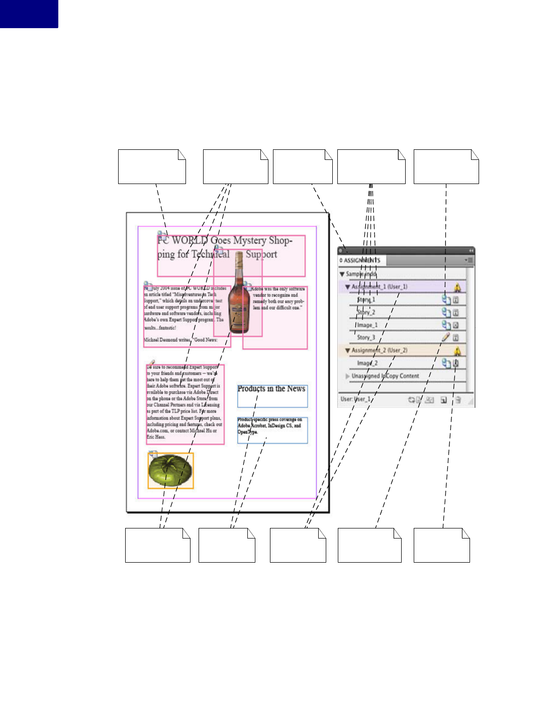
InCopy: Assignments
Assignment
828
Contents of an assignment are listed in the Assignments palette as children of the assignment.
The palette shows the assigned story name as well as the status of the story file; e.g., whether it
is checked out by another InCopy user.
FIGURE 315 Assignment concepts
In Figure 316, an assignment belongs to a publication (document) and is made up of several
assigned stories. An assigned story holds text or an image. An assigned story holding an image
is an assigned image.
Assigned story
(image)
Unassigned
content
Assignment
out of date
Story checked
out (editing)
Assignments
palette
Assigned to
(assignee)
InCopy stories
of assignment 1
Assignment
color (magenta)
Assigned story
(text)
Story available
for check-out

InCopy: Assignments 829
InCopy: Assignments
Assignment data model
FIGURE 316 Assignment structure
Assignment data model
Assignment hierarchy
In the terms of the document object model (DOM), an assignment is a child of the document.
Assignment-related boss class objects form a hierarchical tree.
In Figure 317, IAssignedDocument stores a list of assignments for a document, each described
by a kAssignmentBoss. An assignment consists of a number of assigned stories, each either a
text story (kAssignedStoryBoss) or an image story (kAssignedImageBoss). Assigned stories
have references back to the assignment.
document
assignment
assigned story
assigned image
1
0..*
owns
1
0..*
owns
A publication (InDesign/InCopy
document) with assignment
capability. An assignment refers to a
group of stories and images
that are assigned to a
particular user.
An assigned image is a
special case of an assigned
story. The only difference
is that the story it holds is
an image.
An assigned story
holds story information
in an assignment.
It stores InCopy story
file location and
reference to an actual
story in the document.
It could be a text story
or an image story
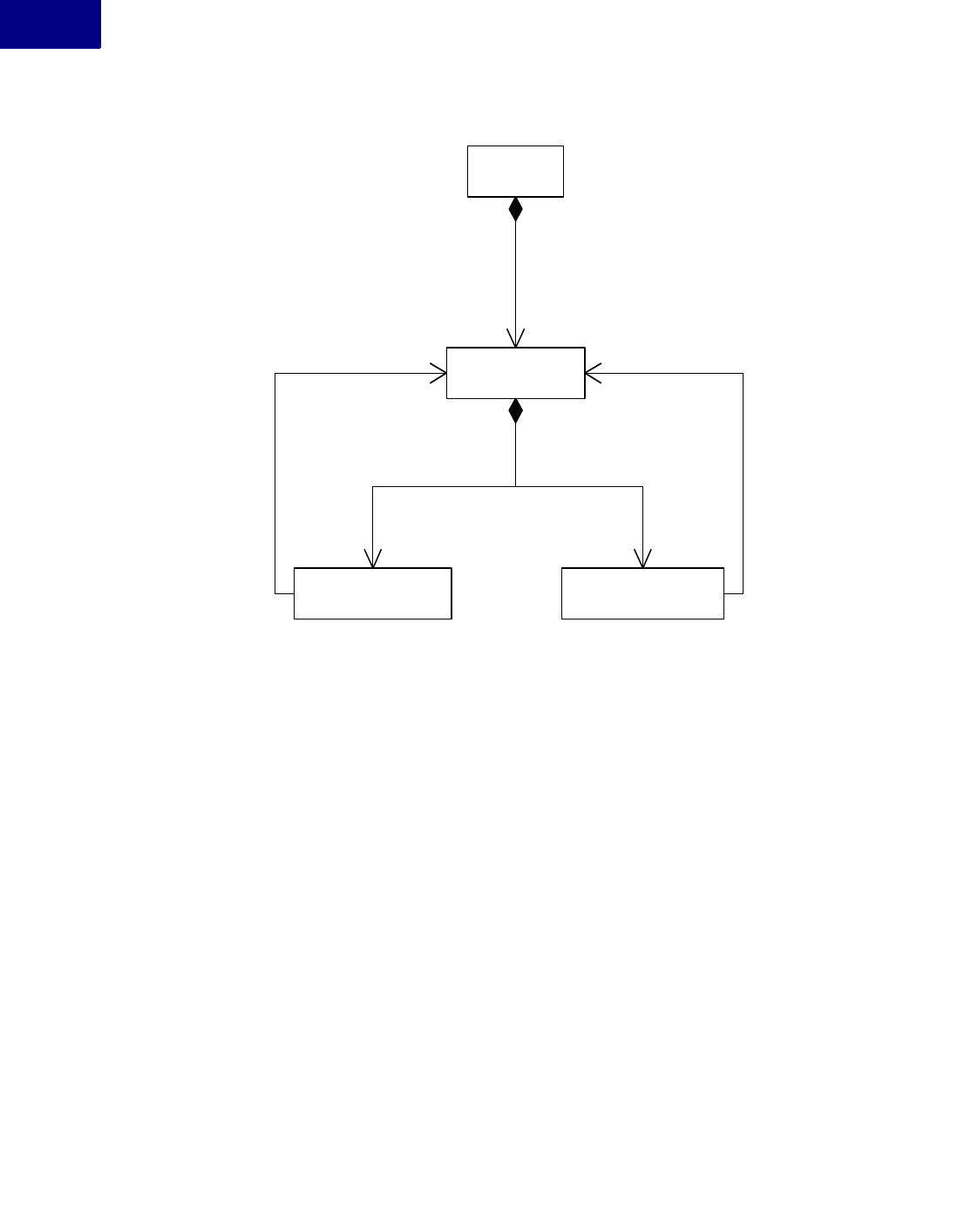
InCopy: Assignments
Assignment data model
830
FIGURE 317 Assignment class diagram
Object structure of an assignment
The object structure of an assignment is constructed dynamically, as a user creates assignments
and adds contents to assignments.
The sample document in Figure 318 contains two assignments (kAssignmentBoss):
zAssignment_1 has three assigned stories, two of which are text stories (kAssignedStory-
Boss), and one of which is an image story (kAssignedImageBoss). The stories are Story_1,
Story_2, and Image_1, respectively.
zAssignment_2 has two assigned stories, one of which is a text story (Story_3) and one of
which is an image story (Image_2).
«boss»
kDocBoss
«boss»
kAssignmentBoss
«boss»
kAssignedImageBoss
«boss»
kAssignedStoryBoss
1
0..*
IAssignedDocument
1
0..*
IAssignment
1
0..*
IAssignment
1
1
IAssignedStory
1
1
IAssignedStory
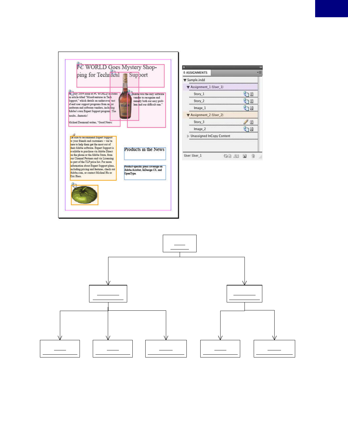
InCopy: Assignments 831
InCopy: Assignments
Assignment data model
FIGURE 318 Assignment object model for two assignments and their assigned stories
«boss»
sample
: kDocBoss
«boss»
Assignment_1
: kAssignmentBoss
«boss»
Assignment_2
: kAssignmentBoss
«boss»
Story_1
: kAssignedStoryBoss
«boss»
Story_3
: kAssignedStoryBoss
«boss»
Story_2
: kAssignedStoryBoss
«boss»
Image_1
: kAssignedImageBoss
«boss»
Image_2
: kAssignedImageBoss
IAssignedDocument::GetAssignments()[0] IAssignedDocument::GetAssignments()[1]
IAssignment
::GetStories()[0] IAssignment
::GetStories()[1]
IAssignment
::GetStories()[2] IAssignment
::GetStories()[0]
IAssignment
::GetStories()[1]

InCopy: Assignments
Assignment data model
832
Moving assignment content
Text frames and images in an InDesign document can never have been assigned, or they can
have been assigned or exported and, therefore, can be moved among different assignments and
unassigned InCopy content. When adding content to an assignment, the following is true:
zIf the selected text or text frame is within a story with multiple text frames, the story
becomes an assigned story, and all text frames of the story are assigned.
zIf the selected content already belongs to another assignment, the content is removed auto-
matically from that assignment.
Figure 319 shows the new screenshot and object diagram of the document shown in
Figure 318, after reassigning the lower-left text frame from Assignment_2 to Assignment_1.
Assignment_1 has four assigned stories (three text stories and one image story). Assignment_2
has only one assigned story (an image story).
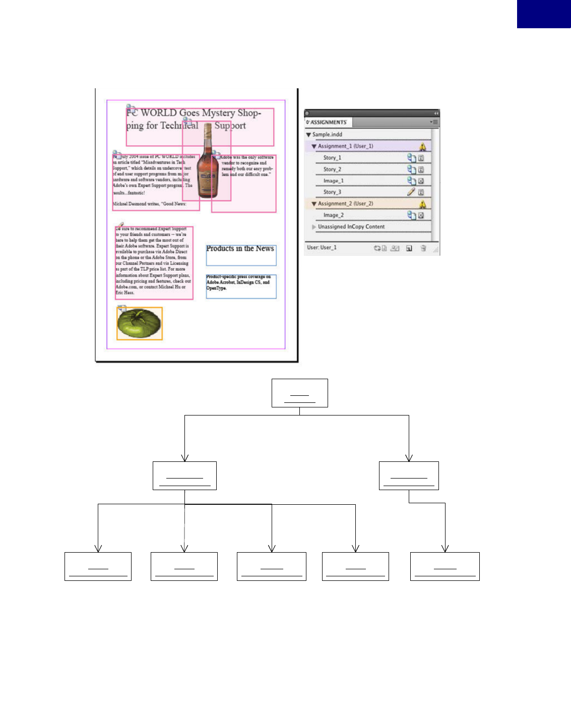
InCopy: Assignments 833
InCopy: Assignments
Assignment data model
FIGURE 319 Assignment object diagram after reassignment
«boss»
sample
: kDocBoss
«boss»
Assignment_1
: kAssignmentBoss
«boss»
Assignment_2
: kAssignmentBoss
«boss»
Story_1
: kAssignedStoryBoss
«boss»
Story_3
: kAssignedStoryBoss
«boss»
Story_2
: kAssignedStoryBoss
«boss»
Image_1
: kAssignedImageBoss
«boss»
Image_2
: kAssignedImageBoss
IAssignedDocument::GetAssignments()[0] IAssignedDocument::GetAssignments()[1]
IAssignment
:GetStories()[0] IAssignment
::GetStories()[1]
IAssignment
::GetStories()[2]
IAssignment
::GetStories()[3] IAssignment
::GetStories()[0]

InCopy: Assignments
Assignment files
834
After the reassignment operation, the following is true:
zIn the object model, Story_3 is removed from Assignment_2 and added to Assignment_1.
zIn the document window, the color of the text frame changes from gold (the color of
Assignment_2) to magenta (the color of Assignment_1).
zIn the Assignments palette, Story_3.incx becomes part of Assignment_1.
Assignment files and links
The assignment feature relies on links to track the status of assignments and stories. Assign-
ment files do not appear in the Links palette, but they work the same way as links:
zIf the assignment file is moved to another location, the application reports a missing file and
prompts the user to find the file.
zThe user can find the missing file during document opening or relink the assignment file
later from Assignments palette.
zWhen the files are changed outside the application, the application prompts for an update.
Assignment files
Assignment files are stored as separate entities using the designated storage medium (e.g., hard
disk or network resource). Assignment files use the .inca or .icma filename extensions.
Assignment files store the following information:
zReference to the InDesign document (file path, in case the user wants to open the docu-
ment with the stories).
zAssignee, the user responsible for the content in the assignment.
zA list of references or links to the stories and graphics in the assignment.
zCharacter and paragraph styles and swatch information used in the document. The assign-
ment file contains the style and swatch information for the entire document, whereas each
story contains only the style and swatch information applicable to that story.
zXML tags maintaining the assignment file structure.
zFrame geometry; i.e., coordinates and dimensions of each frame in the assignment, along
with its page location and any transforms users have done to the frames.

InCopy: Assignments 835
InCopy: Assignments
Assignment files
Comparing assignment files to InDesign and InCopy files
The assignment-files feature requires collaborative work with InDesign and InCopy files. Only
InDesign writes to assignment files; InCopy cannot create an assignment. InCopy can only
open an assignment file and work on its contained stories. The following sections summarize
how assignment-related information is stored in the InCopy file and the InDesign file.
InCopy file (*.incx or *.icml)
An InCopy file holds InCopy story contents—frame information and all relevant transform
information for graphics; style, swatch, and tag definitions used in the story; user names asso-
ciated with the story (e.g., in notes, tracked changes); and story XMP data.
InDesign file (*.indd)
An InDesign file contains a list of references to the assignment files that contain elements from
the document. InDesign needs to locate these files when moving the document from one
machine to another. InDesign needs to open and potentially update these assignment files
when the InDesign document is saved.
Assignment-file format
InDesign and InCopy support two assignment-file formats. The original, INX-based format is
supported; it uses the .inca file extension. A newer, IDML-based format also is included; it uses
the .icma file extension. The user interface provides a Compatibility option for assignment cre-
ation. The INX-based format is listed as “Compatible with CS3,” while the IDML-based format
is listed as “Optimized for CS4.” While INX-based support is available in CS4, you should con-
sidered it to be deprecated.
Consider examples of INCA (INX-based) and ICMA (IDML-based) assignment files.
INCA assignment file
<?xml version="1.0" encoding="UTF-8" standalone="yes"?>
<?aid style="1" type="assignment" DOMVersion="4.0" buildNumber="214"
featureSet="257" longNames="false" ?>
<AssignmentRoot>
<docu InLi="x_0" zero="x_2_U_0_U_0" ptag="c_" DCcp="c_U.S. Web Coated (SWOP) v2"
DCrp="c_Adobe RGB (1998)" DCci="e_RIcs" DCbi="e_RIcs" DCii="e_RIcs"
CSrp="e_CPpp" CScp="e_CPpp" DCsa="b_f" enUn="s_1" Self="rc_d">
<colr clmd="e_prss" clsp="e_CMYK" clvl="x_4_D_0_D_0_D_0_D_100" ovrd="e_eOvB"
clbs="o_n" pnam="c_Black" edbl="b_f" rmbl="b_f" pvis="b_t" ptag="c_"
Self="rc_ub"/>

InCopy: Assignments
Assignment files
836
...
Omitted content
...
<AsMt hDPT="rf_C:\Examples\Sample.indd" pnam="c_Assignment~sep~1"
path="c_C:\Examples\Assignment~sep~1.inca" UsrN="c_User~sep~1" AFCl="e_iMgn"
Self="rc_di13f">
<AsSt pnam="c_Story~sep~1.incx" path="c_C:\Examples\Story~sep~1.incx"
pStR="o_ub9" Self="rc_di13fi143"/>
<AsSt pnam="c_Story~sep~2.incx" path="c_C:\Examples\Story~sep~2.incx"
pStR="o_ucf" Self="rc_di13fi146"/>
<AsSt pnam="c_Image~sep~1.incx" path="c_C:\Examples\Image~sep~1.incx"
pStR="o_u132" Self="rc_di13fi148"/>
<AsSt pnam="c_Story~sep~3.incx" path="c_C:\Examples\Story~sep~3.incx"
pStR="o_ue8" Self="rc_di13fi14c"/>
</AsMt>
<cXML STof="o_u6fcins1" Xcnt="o_u6fcins1:u6fcins2" strp="ro_n" XMLt="o_u7e"
Self="rc_di1i2"/>
</docu>
</AssignmentRoot>
When comparing the assignment file with the INX file exported from InDesign, Note the fol-
lowing:
zLine 2 of the assignment file is type = “assignment.” In an INX file, you would see type =
“document.”
zThere is an AssignmentRoot as the outermost XML element encapsulating the docu (docu-
ment) element.
zSome assignment-related elements, like AsMt (Assignment) exist in both INX and INCA
files, but they do not exist in INX files exported from InDesign documents without assign-
ments created.
zAn assignment file has only one instance of AsMt (Assignment) referring to itself, whereas
an INX file contains instances of AsMt for each assignment in a pub.
zThere are some elements and attributes that assignment files do not include, like metadata.
For a complete list of elements and attributes that are left out of the assignment file, see the
“InCopy: Assignments” chapter of Adobe InDesign CS4 Solutions.
zNot all spreads of the document are included in the assignment file, depending on the
export option chosen for assignment. For details, see “Assignment-export options” on
page 826.
zAn assignment file usually is smaller than an INX file.
The detailed information about assignment-specific scripting IDs (i.e., element and attribute
names) can be found in InDesign Scripting Reference. Search for “AsMt” or “Assignment,” then
look for its properties and children.

InCopy: Assignments 837
InCopy: Assignments
Assignment files
ICMA assignment file
<?xml version="1.0" encoding="UTF-8" standalone="yes"?>
<?aid style="50" type="assignment" readerVersion="6.0" featureSet="257"
product="6.0(338)" ?>
<Document DOMVersion="6.0" Self="d" ZeroPoint="0 0" CMYKProfile="U.S. Web Coated
(SWOP) v2"
RGBProfile="sRGB IEC61966-2.1" SolidColorIntent="UseColorSettings"
AfterBlendingIntent="UseColorSettings" DefaultImageIntent="UseColorSettings"
RGBPolicy="PreserveEmbeddedProfiles"
CMYKPolicy="CombinationOfPreserveAndSafeCmyk"
AccurateLABSpots="false">
<Language Self="Language/$ID/English%3a USA" Name="$ID/English: USA"
SingleQuotes="''"
DoubleQuotes="""" PrimaryLanguageName="$ID/English"
SublanguageName="$ID/USA" Id="269"
HyphenationVendor="Proximity" SpellingVendor="Proximity"/>
<Color Self="Color/Black" Model="Process" Space="CMYK" ColorValue="0 0 0 100"
ColorOverride="Specialblack" AlternateSpace="NoAlternateColor"
AlternateColorValue=""
Name="Black" ColorEditable="false" ColorRemovable="false" Visible="true"
SwatchCreatorID="7937"/>
<!--... Omitted Content ...!-->
<Assignment Self="u102" Name="Assignment 1" UserName="hlynn"
ExportOptions="AssignedSpreads"
IncludeLinksWhenPackage="true"
FilePath="C:\Examples\Assignments\Assignment 1.icma">
<Properties>
<FrameColor type="enumeration">LightBlue</FrameColor>
</Properties>
<AssignedStory Self="u107" Name="myDoc.icml" StoryReference="uea"
FilePath="C:\Examples\Assignments\content\myDoc.icml"/>
<AssignedStory Self="u10d" Name="story-1.icml" StoryReference="ud3"
FilePath="C:\Examples\Assignments\content\story-1.icml"
/>
</Assignment>
</Document>
Notes:
zICMA- (or IDML-based) assignments also use the “assignment” type in a Processing
Instruction on line 2 of the file.
z<Document> is the outermost element (or document element) of an ICMA assignment file.
zICMA uses robust (descriptive) scripting names similar to JavaScript; for example, an
assignment is contained in the Assignment element. Like INX, assignment-related elements
exist in both IDML (if assignments are created) and ICMA files.
zAn assignment file has only one Assignment element referring to itself, whereas an IDML
file contains an Assignment element for each assignment in the document.
zThere are some elements and attributes that assignment files do not include.

InCopy: Assignments
The assignment API
838
zNot all spreads of the document are included in the assignment file, depending on the
export option chosen for assignment. For details, see “Assignment-export options” on
page 826.
zAn assignment file usually is smaller than an IDML file.
zAssignment files can be validated with the single file format of the RelaxNG schema. For
information on schema validation, see Adobe InDesign Markup Language (IDML) Cook-
book.
The assignment API
IAssignmentMgr
IAssignmentMgr is aggregated into kSessionBoss. IAssignmentMgr serves as a manager for
assignment file function, so it has the broadest scope, serving all assignments in all documents.
IAssignmentMgr also has the broadest range of methods, including manipulation methods like
open, save, export, and import assignment; create, add, and remove content of an assignment;
and general management methods like finding out whether a page item is assigned and check-
ing whether an assigned story is a text story.
IAssignedDocument
Aggregated into kDocBoss, IAssignedDocument serves all assignments in one document, so its
methods are designed to work for managing assignments in a document. IAssignedDocument
has methods for adding assignments, removing assignments, and getting the list of all assign-
ments for a document.
IAssignment
IAssignment represents an individual assignment; therefore, it is a typical entry point for
accessing an assignment. IAssignment has get and set methods to access assignment informa-
tion, like assignment name, location of the assignment file, and export options for the assign-
ment. IAssignment also has methods to access its assigned content and add, remove, and delete
assigned stories.
IAssignedStory
IAssignedStory represents an assigned story. IAssignedStory has two different implementa-
tions: kAssignedStoryImpl and kAssignedImageImpl, representing text story and image story,
respectively. Despite the difference in implementation, text story and image story share the
same interface. IAssignedStory has access methods to get and set assigned story name, file loca-
tion of the story, UIDRef of the story in the InDesign document to which it refers, and the
assignment to which it belongs.
InCopy: Assignments 839
InCopy: Assignments
The assignment API
IAssignmentSelectionSuite
IAssignmentSelectionSuite is a typical selection-suite interface that has CanAssign and Assign
methods to add the current selection to an assignment.
IAssignmentUtils
IAssignmentUtils is aggregated into kUtilsBoss. IAssignmentUtils has useful methods for
assignment scripting.
IAssignmentUIUtils
IAssignmentUIUtils is aggregated into kUtilsBoss. IAssignmentUIUtils has very useful utility
functions for assignment user-interface control. IAssignmentUIUtils has methods that check
front document, current layout selection, and Assignments palette selection, to determine what
type of operation might apply and execute it, such as create, delete an assignment, add content
to an assignment, remove content from an assignment, update, relink assignment, check out,
submit changes, and revert changes to the assignment.
IAssignmentPreferences
IAssignmentPreferences controls how assignment contents are drawn in the document win-
dow. If Show Assigned Frame is set, InDesign draws a colored frame for the assigned story;
otherwise, InDesign draws a normal frame.
Common commands
Commands are the only recommended way to change the model. Table 173 lists commands
used to manipulate assignments and their contents.
TABLE 173 Assignment command list
Command name Command data Description
kAssignDocCmdBoss IID_IASSIGNSETPR
OPSCMDDATA
Creates a new assignment. The UIDRef of the
document is passed as the command’s ItemList.
Other information (assignment name, assignment
file path, assignee, color, assignment export
options, etc.) is passed as command-data interface
IID_IASSIGNSETPROPSCMDDATA. After
execution, the new assignment is stored in the
command’s ItemList.
kAssignSetPropsCmdBoss IID_IASSIGNSETPR
OPSCMDDATA
Sets assignment properties. The ItemList of the
command is the assignment UIDRef, and the
command shares the same command data as
kAssignDocCmdBoss.

InCopy: Assignments
The assignment API
840
kUnassignDocCmdBoss IID_ISTRINGDATA Deletes an assignment. The command’s ItemList is
the UIDRef of the assigned document, and the
command data IID_ISTRINGDATA passes in the
assignment’s file path.
kAddToAssignmentCmdBoss None Adds content to an existing assignment. The
content to be added and the assignment are passed
as the first and second items of the command’s
ItemList, respectively.
kAssignStorySetPropsCmdBoss IID_IASSIGNSTORY
SETPROPSCMDDA
TA
Sets assigned story properties. The ItemList of the
command is the UIDRef of the assigned story. Its
command data
IID_IASSIGNSTORYSETPROPSCMDDATA
stores UIDRef of the story that the assigned story
points to, the filename of the story in the disk, and
the assigned story name.
kAssignmentSetColorCmdBoss IID_IUIDDATA Sets assignment color. The command’s ItemList
stores the UIDRef of stories. Its command data
IID_IUIDDATA stores the UID of the color the
client wants to set.
kRemoveAssignedStoryCmdBoss None Removes the assigned story from any assignment.
The UIDRef of the assigned story to be removed is
passed to the command as ItemList.
kRemoveAssignedFrameCmdBoss None Keeps assignment up to date when a frame is
deleted in the document. Removes the assigned
story from an assignment if the deleted frame is the
only frame an assigned story has. UIDRef of the
deleted frame is passed to the command as
ItemList.
kMoveAssignedStoryCmdBoss None Moves an assigned story within an assignment.
Moves the assigned story referenced by the first
item of ItemList before the assigned story
referenced by the second item of ItemList.
kShowAssignedFramesCmdBoss IID_IBOOLDATA Sets show or hide assigned frame preference of
IAssignmentPreferences.
Command name Command data Description

Glossary 841
Glossary
Glossary
Text in [brackets] following a definition is the chapter where the term is used primarily.
zAbsolute command — A command that modifies the model, specified as an absolute new
value the model is to take.
zAbstract selection — The layer that allows client code to access and change attributes of
selected objects. The abstract selection decouples client code from the need to know where
or how these attributes are stored in the underlying model.
zAbstract-selection boss (ASB) — A class that represents the abstract selection and lets client
code use suites to access or change selection attributes. If you add an interface to the
abstract-selection boss class (through an add-in to kIntegratorSuiteBoss class), user-inter-
face code can query for this interface on the active selection and call methods to manipulate
the selection target; for example, to change the attributes of a table or filter or sort its data.
zACE [“Graphics Fundamentals”] — Adobe Color Engine. Responsibilities include conver-
sion between different color spaces.
zAcquirer; acquirer filter [“XML Fundamentals”]— Responsible for translating an XML
source into an XML stream.
zAction — A piece of functionality that can be called through a menu component or key-
board shortcut. Plug-ins can implement actions that execute in response to an IActionCom-
ponent::DoAction message from the application framework.
zActive context — The context the user has chosen to work with. There can be several views
open, each with its own selection subsystem; however, only one view is active at any time.
The active context is represented by the IActiveContext interface and gives access to the key
constructs, like the document, view, workspace, and selection manager.
zActive layer [“Layout Fundamentals”] — The layer targeted for edit operations. New objects
are assigned to the active layer.
zAdd-in — An ODFRez type expression with keyword AddIn that defines one or more inter-
faces (and their implementations) to be added to an existing boss class. An add-in lets you
add functionality to an existing class; it allows you to extend the type system without defin-
ing a new class. Add-ins and boss classes are the two primary mechanisms for an extender
of the application. Normally, implementing building blocks requires defining new add-ins
and/or boss classes.
zAggregated interfaces; exposed interfaces — The set of interface/implementation pairs that
compose a distinct boss class. A boss class aggregates (exposes) a set of interfaces; the exact
behavior depends on the implementations of these interfaces. The API reference documen-
tation shows the complete set of interfaces each boss class exposes. Some (or even all) of the
exposed interfaces on a boss class can come from add-ins, whereas others can be declared in
the boss-class definition. A boss class aggregates an interface if it provides an implementa-
tion of that interface. A boss class exposes an interface of a specific type. InDesign/InCopy
interfaces are descendants of the type IPMUnknown. There are some abstract classes in the
API that do not descend from IPMUnknown, like IEvent, and these cannot be reference-
counted.

Glossary
842
zAGM [“Graphics Fundamentals”] — Adobe Graphics Manager. This is the core API used to
draw vector graphics, perform rasterization, work with device-independent descriptions of
graphics, and so on. AGM should be used for drawing anything that is to be printed or
exported to a format that may later be printed, like PDF.
zAnchor — The top-left element of a cell. An anchor is a location in the underlying grid and,
therefore, it is represented by a GridAddress.
zAPI — Application programming interface. Sometimes used as a shorthand for InDesign
API.
zApplication — Executable program that loads plug-ins; a plug-in host. The program could
be a product in the InDesign family: InDesign, InCopy or InDesign Server.
zApplication core — Software that performs functions like inviting plug-in panels to register,
sending IObserver::Update messages to registered observers, and sending IActionCompo-
nent::DoAction messages when a particular action component is activated by a shortcut or
menu item.
zApplication database, database — Where InDesign documents are stored. This is a funda-
mental provider of persistence to the application. It is a lightweight, object-oriented data-
base that stores a tree of persistent boss objects. Each object in the database (except the root
object) has another object (a parent object) that refers to it by UID and “owns” it, and has
zero or more objects that simply reference it without any ownership. See IDataBase in the
API reference documentation.
zApplication object model — Responsible (among other things) for loading and unloading
plug-ins and managing the lifetimes of boss objects.
zApplications — Executable programs that support the InDesign API.
zASB — See abstract-selection boss.
zAutomatic undo and redo — a change to the application architecture introduced in InDesign
CS4, which takes over responsibility reverting and restoring the state of objects in the model
at undo and redo.
zBackdrop [“Graphics Fundamentals”] — One of the inputs used to calculate resultant colors
for transparent objects. The object being blended with the backdrop conventionally is
referred to as the source object. By convention, the backdrop is 100% white and 100%
opaque.
zBacking store [“XML Fundamentals”] — Storage for unpolished content and other key
objects like the document element and root element. It can contain a DTD element, objects
representing processing instructions and comments that are peers of the root element, and
unplaced elements.
zBinary plug-in — The result of compiling and linking the source for a plug-in; a shared
library (DLL/framework) that supports a protocol allowing it to be loaded by the applica-
tion.
zBitmap image [“Graphics Fundamentals”] — An image composed of small squares (pixels)
on a grid. Each pixel defines its own color and is independent. Paint programs manipulate
bitmap images. Same as raster image.

Glossary 843
Glossary
zBlend [“Graphics Fundamentals”] — A mixing of colors to produce interesting visual
effects. Although blending can produce results similar to physical transparency, blending is
not an attempt to model translucent materials directly.
zBlending mode [“Graphics Fundamentals”] — Specifies how a transparent source object
combines with other objects and the backdrop. For example, the normal blend specifies that
the resultant backdrop color is simply the color of the corresponding point in the source
object.
zBlending space [“Graphics Fundamentals”] — The color space (user-specified) in which the
colors are blended. Document RGB and document CMYK are the available choices.
zBoss class — A class in the InDesign type system. Boss classes are the fundamental building
blocks of the application object model. A boss class is a compound ODFRez type expression
consisting of a set of interfaces and their implementations, some or all of which can come
from add-ins. Boss classes support inheritance of implementation from a single superclass.
Boss classes represent objects in the application domain and provide their behavior; for
example, a spread (kSpreadBoss) or page (kPageBoss). The term “boss” was coined for an
entity that manages, or bosses, a collection of interfaces.
zBoss-class definition — An ODFRez type expression with the keyword Class. There may be a
superclass (or kInvalidClass if none) and a list of interface/implementation (PMIID/Imple-
mentationID) pairs. Some or all of the interface/implementation pairs that compose a boss
can come from add-ins. The boss-class definition is a single place where the core interfaces
that compose a boss are declared, without considering add-ins.
zBoss class factory, class factory — A method used by the application core to construct an
instance of a boss class. CREATE_PMINTERFACE is where these methods are defined.
zBoss DOM — Document object model specified in terms of boss classes and associations
between them. The boss DOM contrasts with the scripting DOM, which is a somewhat
more abstract model of the document.
zBoss leak — The state in which a boss object’s reference count is nonzero when the applica-
tion quits. A boss leak usually is caused by mismatched AddRef-with-Release calls and/or
unmatched QueryInterface/ Instantiate/ CreateObject-with-Release calls. A boss leak
results in a memory leak. See also UID leak.
zBoss-leak tracking — A debugging aid built into the applications to help find boss leaks.
zBoss object— An instance of a boss class. At its lowest level, an InDesign document is struc-
tured as a graph of persistent boss objects, with relationships between them; for example,
spreads (kSpreadBoss) and pages (kPageBoss). There also are boss objects that exist only in
memory. For more information on how boss objects represent documents, see the “Layout
Fundamentals” chapter.
zBoss-object hierarchy; hierarchy — A tree-structured organization of boss objects in parent-
child relationships with one another. The API has several different types of hierarchy; each
with its own characteristic interface to allow it to be traversed. The hierarchies commonly
encountered the spread hierarchy traversed by IHierarchy, the XML-element hierarchy tra-
versed by IIDXMLElement, and the scripting-DOM hierarchy traversed by IDOMElement.
zBounding box [“Layout Fundamentals”] — The smallest rectangle (PMRect) that encloses a
geometric page item.

Glossary
844
zCell — Visual containers for content that appear to end users as the components of a table.
A cell consists of one or more elements; each cell has an anchor. A cell corresponds to a
<TD> (table data) item in the HTML 4 table model.
zCell attribute — A boss class that represents an aspect specific to one or more cells.
zCharacter-attributes strand — A strand that maintains formatting information for ranges of
characters.
zChild [“Layout Fundamentals”] — A page item contained within a parent. For example, a
graphic page item is contained in a frame and is said to be a child of the frame.
zCIE [“Graphics Fundamentals”] — Commission Internationale de l'Eclairage (International
Commission on Illumination). CIE has a technical committee, Vision and Color, which
plays a leading role in colorimetry and defining color standards.
zClass factory — See boss-class factory.
zClient — Any code that interacts with the selection; typically, user-interface code. This
includes widgets in palettes, menu items, actions, and tools. The interaction can include
reflecting the value of a selection attribute, changing the attribute, or both.
zClient code — Code written by a third-party plug-in developer that uses the InDe-
sign/InCopy API to use the services of the application. Client code typically drives suites,
processing commands or wrapper interfaces that in turn process commands, like ITable-
Commands and IXMLElementCommands.
zCode-based converter — A conversion provider that converts persistent data from one for-
mat to another, based on specific coded instructions. Generally, this is implemented as a
subclass of CConversionProvider, which inherits from IConversionProvider and provides
several housekeeping methods.
zColor component [“Graphics Fundamentals”] — A coordinate in a given color space. A Col-
orArray item is used to represent the color components in the implementations of IColor-
Data interface. Colors defined in different color spaces may have different number of
components; for example, four components in CMYK and three components in RGB.
zColor model [“Graphics Fundamentals”] — The dimensional coordinate system used to
numerically describe colors. Some models are RGB (red, green, blue), CMYK (cyan,
magenta, yellow, black), HLS (hue, lightness, saturation), and L*a*b* (lightness, a, b). Color
space also can refer to the range of colors in a particular color model. Also known as gamut.
zColor space [“Graphics Fundamentals”] — Same as color model.
zCommand — Transactions that change the data model must be implemented as commands.
A command in the API is a boss class with an ICommand implementation and optional
data interfaces. A custom command is an extension pattern you can implement to change
aspects of the data model you may have contributed yourself. For example, if you add your
own persistent interfaces somewhere in the boss document object model, you would imple-
ment custom commands to change these.
zComment, XML [“XML Fundamentals”] — A comment valid within an XML document
(kXMLCommentBoss).

Glossary 845
Glossary
zComposite font — An extension of the basic PostScript font mechanism that enables the
encoding of very large character sets and handles non-horizontal writing modes. You can
create a composite font that contains any number of base fonts.
zCompound path [“Graphics Fundamentals”] — Two or more simple paths that interact with
or intercept each other.
zCompound shape [“Graphics Fundamentals”] — Two or more paths, compound paths,
groups, blends, text outlines, text frames, or other shapes that interact with and intercept
one another to create new, editable shapes.
zConcrete selection — The layer underlying abstract selection that knows which objects are
selected and how to access and change their attributes in the underlying model. Comprises
one or more CSBs. See also CSB (concrete selection boss).
zContainer (structural) element [“XML Fundamentals”] — An XML element that does not
itself have an associated content item but is intended to be an ancestor for other content
items.
zContainer-managed persistent-boss object — An object stored in an application database,
whose storage is managed by another UID-based persistent boss object. Examples are text
attributes, graphic attributes, XML elements. None of these is associated with UIDs.
zContent handler [“XML Fundamentals”] — Responsible for reading XML content from an
input stream.
zContent item [“XML Fundamentals”] — An object in a document that can be tagged. An
object in the native document model that can be associated with an element in the logical
structure. A content item is represented by boss classes with IXMLReferenceData. Examples
include placeholder items (kPlaceHolderItemBoss), images (kImageItem), and stories
(kTextStoryBoss). A text range within a story (kTextStoryBoss) also is a content item, since
it can be tagged.
zContent page item [“Layout Fundamentals”] — A frame, path, group, or page item that rep-
resents another type of content that can be placed on a spread.
zContent manager — The component that manages plug-ins that add content to documents
(i.e., any plug-in with persistent data that is saved to a document). The content manager
(identified by the IContentMgr interface) works with the conversion manager to determine
whether data conversion is needed.
zControl-data model — An aspect of a widget boss class that represents the data associated
with a widget's state. The control-data model typically can be changed by an end user or
through the API. The control-data model is associated with an interface named I<data-
type>ControlData. For example, there is an ITextControlData interface associated with
text-edit boxes, the internal state of which is represented by a PMString.
zControl view — An aspect of a widget boss class that represents the appearance of a widget.
It is associated with the IControlView interface, which also can be used to change the visual
representation of a given widget. For example, use this interface to vary the resources used
in representing the states of an iconic button or to show/hide a widget.

Glossary
846
zConversion manager — The component that manages persistent-data conversions between
different versions of plug-ins. By comparing format numbers both in the persistent data and
the currently loaded plug-in, the conversion manager finds the appropriate conversion pro-
vider, which determines whether conversion is needed and, if necessary, converts the data.
This component is identified by the IConversionMgr interface.
zConversion provider — A service provider that determines whether a data conversion needs
to be performed and performs the appropriate conversions. This component is identified by
the IConversionProvider interface. There are two types of conversion providers: schema-
based and code-based.
zCSB (concrete selection boss) — A class that encapsulates a selection format and supports
access, change, and observation of the selected objects in its underlying model.
zCSB suite — The suite implementation for a selection format that understands how to
access and change some attributes of the selected objects in the underlying model.
zCurrent spread [“Layout Fundamentals”] — The spread targeted for edit operations. New
objects created by the user interface are contained in the current spread.
zData conversion — The process of converting persistent data in a database from one format
to another.
zData flavor — Describes the data involved in data exchange, like cut-and-paste and drag-
and-drop operations. Internal types are represented by PMFlavor; external types, Exter-
nalPMFlavor. For a list of built-in types, see source/public/includes/PMFlavorTypes.h.
zDatabase — See application database.
zDetail control — The process of varying the resolution of a user interface by varying the
composition of the widget set or the size of elements in the interface. This capability is rep-
resented by IPanelDetailController.
zDeveloper prefix; plug-in prefix — Identifier defining the range of 256 values in which you
can define the unique identifiers in any ID space (e.g., kClassIDSpace, kInterfaceIDSpace,
and kImplementationIDSpace) required for your contributions to the object model. The
prefix must be obtained from Adobe Developer Support before you can release your prod-
uct, to ensure your plug-ins do not conflict with other plug-ins.
zDialog protocol — Message sequencing for dialog boss objects (kDialogBoss and descen-
dants). This protocol consists of messages delivered in this sequence: IDialogControl-
ler::InitializeDialogFields, ValidateDialogFields, and ApplyDialogFields. A
ResetDialogFields also may be sent, but only if the dialog is enabled to do so.
zDirect model change — A call to a mutator method on a persistent interface.
zDLL (dynamic-link library) — A library linked in at run time or load time, not at build time.
Normally this is associated with the Windows operating system.
zDocument [“Layout Fundamentals”] — An InDesign document, unless otherwise stated. A
publication that stores layout data. The content is organized in a set of spreads. Each spread
has one or more pages on which page items are arranged. Page items are assigned to layers,
which control whether the content is displayed or editable.

Glossary 847
Glossary
zDocument element [“XML Fundamentals”] — Element in the logical structure associated
with the document (kDocBoss), represented by kXMLDocumentBoss. A singleton instance
of this class is present in the document’s backing store. Be aware this is defined differently
than “document element” in the XML 1.0 specification (http://www.w3.org/TR/REC-xml),
which is equivalent to “root element in the InDesign XML API.
zDocument layer [“Layout Fundamentals”] — The objects shown in the Layers panel that,
together with their corresponding spread layers in each spread, represent the layers in a
document.
zDocument object model (DOM) — A specification for how objects in a document are pre-
sented. For example, the InDesign scripting DOM refers to sets of objects and properties
that make up an InDesign document, including page items in the document hierarchy and
various document preferences.
zDocument Type Declaration (DTD) [“XML Fundamentals”] — Defines the grammar for a
class of documents. This is represented by kXMLDTDBoss.
zDollyXs — A plug-in developer productivity tool, written entirely in Java™, which uses XSL
templates to generate fundamental plug-in projects. Details on its use can be found in
<SDK>/devtools/sdktools/dollyxs/Readme.txt.
zDOM — See document object model.
zDTD — See Document Type Declaration.
zElement — A unit item on the underlying grid of a table. An element may or may not have
an anchor. Elements always have the unit (trivial) GridSpan(1,1). There is no corresponding
entity in the HTML 4 table model.
zEntity [“XML Fundamentals”] — Container for content in an XML document.
zEvent handler — Handler responsible for processing events and changing the data model of
a widget. An event handler is equivalent to a controller. Unlike other APIs, in which you
must extend an event handler to receive notification about control changes, there are very
few circumstances in the InDesign/InCopy API in which overriding a widget event handler
is required. Notifications about changes in control state are sent as IObserver::Update mes-
sages, because InDesign/InCopy update for every keystroke for edit boxes, if they are con-
figured correctly in the ODFRez data statements.
zExposed interfaces — See aggregated interfaces.
zExtending — Subclassing. Boss classes and ODFRez types can be extended (subclassed).
zExtension pattern — A software pattern that fits into an extension point for the application.
It is associated with a well-defined purpose; for instance, to signal that a document was
opened. Every plug-in should implement one or more extension patterns to do something
useful. A common extension pattern is the service provider.
zExtension point — A hook in the application for a plug-in developer, where you can plug an
extension pattern so your implementation code gets called. For example, if you implement a
specific extension pattern (Open-doc Responder), you can be called when documents are
opened. The extension point in this example is in the code that opens documents. Exten-
sion points know about the extension patterns that plug into them.

Glossary
848
zFacing pages [“Layout Fundamentals”] — Used for publications like magazines, books, and
newspapers that have both left-hand (verso) and right-hand (recto) pages.
zFamily name — The name of a font family; for example, Times, Courier, or Times New
Roman. The group name and the family name always are the same.
zFeather (vignette) [“Graphics Fundamentals”] — A transparency effect that ships with
InDesign, that allows designers to create smooth, diffuse edges on frames.
zFill [“Graphics Fundamentals”] — Color or gradient applied to area inside a path.
zFlatten [“Graphics Fundamentals”] — To remove the transparency information from the
representation of what is to be drawn, leaving only a representation of the resulting color
information at each point once blending is computed. Typically this is implemented by fac-
toring the area to be printed into a set of atomic regions that can be printed with opaque
inks.
zFont — A collection of glyphs designed together and intended to be used together. See the
IPMFont interface.
zFont family — A font group used within a document. See the IFontFamily interface.
zFont group — A collection of fonts designed together and intended to be used together. Font
groups describe all fonts available to the application. Within a group, there might be several
different stylistic variants. See the IFontGroup interface.
zFont group name — The name of a font group; for example, Times, Courier, or Times New
Roman.
zFormat number — A tuple, defined in the PluginVersion ODFRez resource, that identifies
the version of a persistent data format for a particular plug-in. The format number is differ-
ent from the application version or a plug-in version number. Format numbers are incre-
mented when changes to persistent data formats occur.
zFrame [“Layout Fundamentals” and “Graphics Fundamentals”] — The page item (kSpli-
neItemBoss) that acts as a container or placeholder for a graphic page item, text page item,
or page item that represents content of another format. This is defined by one or more
paths.
zFrame content [“Graphics Fundamentals”] — Text or graphic object inside a frame. Fill is
not frame content.
zFrame list — Lists the text frames that are displayed.
zFramework — See resources.
zFront document [“Layout Fundamentals”] — The document displayed in the layout presen-
tation the user is using to edit and view a publication.
zFront view [“Layout Fundamentals”] — The layout view the user is using to edit and view a
publication.
zGeneric identifier [“XML Fundamentals”] — Name of an element in an XML document,
which corresponds to the tag name.
zGeometric page item [“Layout Fundamentals”] — A page item with IGeometry and ITrans-
form interfaces that define its coordinate space.

Glossary 849
Glossary
zGlyph — A shape used to represent a character code on screen or in print.
zGradient [“Graphics Fundamentals”] — Continuous, smooth, color transitions along a vec-
tor from one color (a gradient stop) to another (another gradient stop). The colors are
defined only at the stops and interpolated elsewhere. A gradient may have two or more gra-
dient stops.
zGradient stop [“Graphics Fundamentals”] — One of the points of a range over which a gra-
dient is defined.
zGraphic frame [“Layout Fundamentals” and “Graphics Fundamentals”] — A frame that
contains or is designated to contain a graphic page item. A placeholder for graphic content.
The spline item wrapping a graphic or image. In the API, boss classes (e.g., kSplineItem-
Boss) that represent the behavior of graphic frames have the signature interface IGraphic-
FrameData.
zGraphic page item [“Layout Fundamentals” and “Graphic Fundamentals”] — A page item
that represents a picture of one format or another (e.g., kImageItem). A page item that con-
tains graphics. A graphic page item is the content of a graphics frame.
zGroup [“Layout Fundamentals” and “Graphics Fundamentals”] — A collection of two or
more page items, which can be manipulated as a single entity. A transparency group is a
group with at least one transparency-related attribute.
zGroup blending mode [“Graphics Fundamentals”] — The blending mode applied to blend a
group of objects. This is independent of the blending modes of the group members.
zGroup opacity [“Graphics Fundamentals”] — An opacity attribute applied to a group of
transparent objects. Grouping is performed with the rule that an object can belong to only
one immediate group, although groups can contain other groups. The group opacity is
independent of individual object opacities.
zGuide [“Layout Fundamentals”] — An object used to help align and position other objects.
zHeadless document [“Layout Fundamentals”] — A document (kDocBoss) that has no layout
presentation. Headless documents can be edited programmatically.
zHeap corruption; memory trampling — When code illegally accesses memory. InDesign
gives you some help in detecting this. All new memory in debug mode allocated with global
new is cleared to 0xFBFB. If you see this as a value of a memory block (instance variable,
etc.), this is a sign it was not initialized properly. All de-allocated memory in debug mode is
cleared to 0xEAEA. If you see this value in a memory block, you are using it after it was
deleted. When a boss object is destroyed in debug mode, the application object model
deletes each interface and sets the pointer to the interface to have the value 0xDEADBEEF.
If you see 0xDEADBEEF as the value of a pointer, you have queried for an interface on a
boss object that was in the process of being destroyed. When allocating memory with global
new in debug mode, the actual memory allocated is bracketed by an extra head and a tail.
Look at the ASCII value of memory, and search for “Chck” and “Blck” to see the block
header and trailer.

Glossary
850
zHelper class — Partial implementation class; a C++ class in the API that provides most or all
of the code required to implement a particular interface, like IObserver. A helper class may
leave key method implementations to be filled in by the plug-in developer. For example,
CObserver provides a basic implementation of IObserver. CActiveSelectionObserver pro-
vides a richer implementation for client code to observe changes in the active context.
zHierarchy — See boss-object hierarchy.
zHigh-level API — An API based on the scripting DOM. Classes in the high-level API are
prefixed by hla_ and reside in the C++ namespace hla.
zHost — Application in which a client plug-in is loaded. Plug-ins can choose the hosts that
should load them. For example, a plug-in may specify that it should load within both InDe-
sign and InCopy.
zHybrid selection — The ability to select objects of differing selection formats simultaneously.
An example of hybrid selection is selecting a frame containing a picture (a layout selection),
adding a range of text (a text selection) to that selection, and then changing the color of
both the frame and the text with one action. Hybrid selection is not yet supported. but the
new selection architecture was implemented to accommodate it in the future by means of
integrator suites.
zICC [“Graphics Fundamentals”] — International Color Consortium. Most notable for their
characterization of the properties of hardware represented in ICC device profiles. For the
specification of the ICC file format, see their Web site at http://www.color.org.
zID space — A set of numeric values in which an identifier (e.g., ClassID or Implementa-
tionID) is defined. For example, kClassIDSpace identifies the set of numbers in which a
ClassID can be defined; the values that can be used run from 0x0 to 0xFFFF. Likewise, an
ImplementationID is defined in kImplementationIDSpace. The ID spaces are disjoint, so
you can have the same number in two or more different spaces without a clash. You do need
to ensure that identifiers you define are unique within the given ID space; obtain a devel-
oper prefix to achieve this.
zIDE (integrated development environment) — An application or set of applications used to
develop other computer applications. At the minimum, IDEs include a text editor, a com-
piler, a linker, and a debugger.
zIdle task — One way to perform a background task within the application. An idle task is a
function point that can called when the application is waiting to receive user events. Idle
tasks are used to spread the load of CPU-bound tasks. For example, text composition is per-
formed by an idle task, allowing the application to remain responsive to the user as text is
being composed. See the IIdleTask interface.
zImplementation — A C++ class that implements an interface. An implementation can either
extend a partial implementation class or be based on CPMUnknown.
zIDML — InDesign Markup Language file format. Based on serializing objects defined in a
scripting DOM tree to an XML-based format.
zImplementation identifier — An identifier for a C++ implementation.
zINCX — InCopy Interchange file format. An INCX file is a snippet file containing an
InCopy story.

Glossary 851
Glossary
zInDesign API — API for the InDesign platform, consisting of InDesign and related prod-
ucts.
zInk [“Graphics Fundamentals”] — Foundation colors that can make a color; for example,
cyan, magenta, yellow, black, and spot inks.
zIntegrator suite — Suite implementation on an ASB called by client code to access or change
attributes of the selection. An integrator suite forwards any member function call to its cor-
responding CSB suite on one or more CSBs.
zInterface — An abstract C++ class in the API that extends IPMUnknown. Interfaces are
aggregated by boss classes and represent the capability or services a boss class provides to
client code. (Exception: There are a handful of abstract C++ classes named IXXX that do
not derive from IPMUnknown; IDataBase is a frequently encountered example.)
zInvariant data — A data format that does not vary based on what is contained within. For
example, if a data structure contains a field that identifies whether the next field is a string
or an integer, that data structure is variant; otherwise, it is invariant.
zINX — InDesign Interchange file format. Based on serializing objects defined in a scripting
DOM tree to an XML-based format.
zIsolated blending [“Graphics Fundamentals”] — A boolean property of a group. An isolated
group does not blend with the backdrop as individual elements, but rather blends as a group
object. This is independent of knockout; a group can have both knockout and isolation-
group properties.
zKnockout group [“Graphics Fundamentals”] — A boolean property of a group. Objects in a
knockout group of transparent objects do not interact transparently with each other in cal-
culating the blend color, but they do interact transparently with the backdrop. This is used
in creating effects where the group as a whole is composited onto the background rather
than mistakenly compositing elements onto each other.
zLayer [“Layout Fundamentals”] — Either document (user-interface) layer or spread (con-
tent) layer. This is the abstraction that controls whether objects in a document are displayed
and printed and whether they can be edited. A layer can be shown or hidden, locked or
unlocked, arranged in front-to-back drawing order, etc. A page item is assigned to a layer. If
a layer is shown, its associated page items are drawn; if a layer is hidden, its associated page
items are not drawn. Layers affect an entire document: if you alter a layer, the change applies
across all spreads. See IDocumentLayer and ISpreadLayer in the API reference documenta-
tion.
zLayers panel [“Layout Fundamentals”] — The user interface for creating, deleting, and
arranging layers.
zLayout [“Layout Fundamentals”] — The spreads in a document that store the page items in
a publication.
zLayout hierarchy [“Layout Fundamentals”] — The hierarchy under each spread in a docu-
ment, which controls how page items are stored and displayed.
zLayout item; layout object — Page item.
zLayout view [“Layout Fundamentals”] — The part of the layout presentation that presents
the layout of a document. (This also is known as the layout widget.)

Glossary
852
zLayout presentation [“Layout Fundamentals”] — The user-interface window in which the
layout of a document is presented for viewing and editing. The layout presentation contains
the layout view and other widgets that control the presentation of the document within the
view.
zLazy notification — A new notification mechanism. An observer can opt to observe a sub-
ject in the model lazily and get notified once per step. The notification is lazy in the sense
that the observer gets notified after all commands in the step are processed. See IOb-
server::LazyUpdate.
zLink — An explicit relationship between a document object or part thereof and another
entity (e.g., external content, like an image or a hyperlink destination that is a text frame in
another document). Links (represented by the type ILink) can represent the path to a placed
image; they also are used by the hyperlink subsystem and the book subsystem.
zLogical structure [“XML Fundamentals”] — A tree of elements that represents the logical
relationships between content items. The elements are represented by boss classes with the
IIDXMLElement interface, which maintains the logical structure and allows it to be tra-
versed. The logical structure also can contain a DTD element, processing instructions, and
comments.
zLow-level API — The API at the level of boss classes, interfaces, and partial-implementation
classes.
zLow-level event — Something like a window system occurrence or low-level input, like one
keystroke.
zMask [“Graphics Fundamentals”] — A raster version of the outline of an object.
zMaster page [“Layout Fundamentals”] — A page that provides background content for
another page. When a page is based on a master page, the page items that lie on the master
page also appear on the page. A master page eliminates the need for repetitive page format-
ting and typically contains page numbers, headers and footers, and background pictures.
zMaster spread [“Layout Fundamentals”] — A special kind of spread that contains a set of
master pages.
zMatrix — See transformation matrix.
zMemory trampling — See heap corruption.
zMessage protocol — The IID sent with the IObserver::Update message. An observer listens
along a particular protocol; it is merely a way of establishing a filter on the semantic events
about which an observer might be informed.
zMessaging architecture — How client code can be written to receive notifications from the
application core when widget data models change. The main architecture of interest uses
the observer pattern.
zMixed ink [“Graphics Fundamentals”] — An ink defined as a mixture of process-color inks
and spot-color inks.

Glossary 853
Glossary
zModel — Persistent boss objects and persistent interfaces that represent a feature and are
stored in a database that supports undo. Also, from the perspective of selection, the com-
mands that mutate this data are part of the model. There may be several distinct yet related
models in a document. For example, the layout model represents layout and stories, their
text models represent text and tables, and their table model represents tables and so on. A
selection format sits atop each distinct model that contains selectable objects.
zModel notification — Indicates to observers that one or more objects in the model have
changed.
zNative document model — Specifies how end-user documents are represented within the
InDesign API. It consists of a hierarchy of persistent boss objects, with a root node of class
kDocBoss.
zNesting — The containing of one object within another object. Three kinds of nesting are
common: paths inside frames, frames inside frames, and groups inside groups. You can also
use combinations of paths, frames, and groups to build hierarchies of nested objects.
zObject model — Model responsible for (among other things) loading and unloading plug-
ins and managing the lifetimes of boss objects.
zObserver — An abstraction (represented by the IObserver interface) that listens for changes
in a subject. Typically, implementations use CObserver or one of its subclasses to imple-
ment an IObserver interface, which can listen for changes in the control-data model of a
subject (ISubject) and respond appropriately. The observer pattern is central to the messag-
ing architecture.
zODF — OpenDoc Framework, a cross-platform software effort initiated by Apple and IBM
that defined an object-oriented extension of the Apple Rez language to specify user-inter-
face resources.
zODFRC — OpenDoc Framework Resource Compiler, the SDK-supplied compiler for
framework resource (.fr) files.
zODFRez — OpenDoc Framework Resource Language, which allows cross-platform
resources to be defined for plug-ins. Boss classes and add-ins must be defined in ODFRez,
along with data statements defining scripting entities, menu elements, user-interface wid-
gets, and so on. The SDK tool DollyXs can generate ODFRez.
zODFRez custom-resource type — The type defined in the top-level framework resource file
and typically populated in data statements in the localized framework resource files.
zODFRez data statement — An expression in ODFRez other than a type expression. It can
define the properties of a given widget or a key/value pair in a string table.
zOpacity [“Graphics Fundamentals”] — Defined as (1-transparency), in a continuous range
[0,1], with 0 being entirely opaque and 1 entirely transparent.
zOwned-item strand — A strand that maintains information on objects inserted into the text
flow, like inline frames.
zOwnership relation — Parent-child relationship between two classes. For example, spreads
(kSpreadBoss) own spread layers (kSpreadLayerBoss).
zPage [“Layout Fundamentals”] — The object in a spread on which page items are arranged.

Glossary
854
zPage item [“Layout Fundamentals”] — An object that can participate in a layout; for exam-
ple, a graphic frame or text frame. This represents content the user creates and edits on a
spread, like a path, a group, or a frame and its content.
zPages layer [“Layout Fundamentals”] — The layer to which pages (kPageBoss) are assigned.
zPages panel [“Layout Fundamentals”] — The user interface for creating, deleting, and
arranging pages and masters.
zPalette — A floating window that is a container for one or more panels. A palette can be
dragged around, and its children can be re-ordered.
zPanel — A container for widgets. The Layers panel is an example. Panels can reside in
tabbed palettes.
zParagraph-attributes strand — A strand that stores paragraph boundaries and formatting
information for ranges of paragraphs.
zParcel — A lightweight container associated with at most one text frame, into which text
can be flowed for layout purposes. A parcel can be considered a lightweight text frame;
however, a parcel has geometry information, so it is not a page item, nor is it UID-based.
zParcel list — A list of the parcels associated with a story thread.
zParent [“Layout Fundamentals”] — A page item that contains other page items. For exam-
ple, a frame that contains a graphic page item is the parent of that graphic page item.
zParent widget — A container widget; a widget that contains another widget. The parent wid-
get can determine when the children draw and which of the children receive events.
zPasteboard [“Layout Fundamentals”] — The area that surrounds the pages of a spread. Page
items can be positioned on the pasteboard for temporary storage.
zPath [“Layout Fundamentals” and “Graphics Fundamentals”] — A set of straight and/or
curved segments. These segments can connect to one another at anchor points (to form
closed shapes like rectangles, ellipses, or polygons) or be disconnected. A path comprises
one or more segments, each of which may be straight or curved. A path can be open or
closed.
zPath page item [“Graphics Fundamentals”] — A page item that defines its paths. The most
common path page item is the spline item, which represents such path types as lines,
curves, and polygons.
zPersistence — This is defined by Wiktionary as: “Property of some data to continue existing
after the execution of the program.” See database.
zPersistent boss object — A boss object that saves its state between sessions. Persistent boss
objects store their state to an application database through persistent interfaces.
zPersistent data — Data stored in a database and retained between sessions. InDesign publi-
cation files are referred to as databases. Types of persistent data include preferences, page
item, and text data, as well as user-interface states.
zPersistent interface — A boss class aggregates interfaces, some of which may be persistent.
An interface is persistent to the application object model when
CREATE_PERSIST_PMINTERFACE is used in the implementation code when defining it.
It must call PreDirty before it changes a persistent member, and it must implement a Read-

Glossary 855
Glossary
Write() method to deserialize and serialize an instance of the class. For example, the ICon-
trolView interface on widget boss objects always is persistent. This is why every widget has
at least one CControlView field in the ODFRez data—to set up its initial state, such as wid-
get ID, whether it is enabled, or whether it is visible (properties common to all widgets).
zPlaced element; placed content [“XML Fundamentals”] — An element associated with docu-
ment content; i.e., with a content item in the layout. There is a small visual indicator in the
Structure view that indicates whether an element is associated with a placed-content item.
In terms of the model, this means the IIDXMLElement::GetContentItem returns something
other than kInvalidUID. This is contrasted with unplaced element.
zPlaceholder [“XML Fundamentals”] — A target for XML import. It can be a graphic frame
that has a tag applied to identify it as a target for content from an XML import. If a text con-
tainer is marked up, the placeholder is the story (kTextStoryBoss) rather than the contain-
ing frame.
zPlug-in — A library that extends or changes the behavior of the application and follows the
rules for extending the application. On Windows, a plug-in is a DLL; on Mac OS, a frame-
work. Plug-ins are loaded and managed by the application object model.
zPlug-in prefix — See developer prefix.
zPostScript points [“Layout Fundamentals”] — The standard internal measurement unit,
equal to 1/72 inch. All measurements stored in databases are stored using PostScript points
as the unit.
zPre-dirty — Indicates to the application object model that persistent data is about to change.
As of Creative Suite 3, a mutator method on a persistent interface just call PreDirty() before
changing any persistent data.
zPrimary-story thread — The main flow of text that is not for table cells or other features that
store text in the story.
zProcess color [“Graphics Fundamentals”] — (i) A scheme used to print full-color images,
typically with four passes through the printing press, one for each ink color. (ii) A single
color within the CMYK system; for example, cyan. The term is used within the user inter-
face as a shorthand for a color intended to be printed with process color as in definition (i).
zProcessing instruction (PI) [“XML Fundamentals”] — Instruction for an application. PIs
take the form <?application-name ... ?>.
zProxy image [“Graphics Fundamentals”] — A screen-resolution bitmap image with which
the end user can view designs on the screen faster than with the original image.
zPseudo-buttons — Items that have a button-like facility, like being responsive to mouse
clicks, but that are intended as image-based buttons rather than text-labeled buttons.
zPublication [“Layout Fundamentals”] — A document that stores layout data. The page items
are organized in a set of spreads. Each spread has one or more pages on which content is
arranged. Page items are assigned to layers that control whether the content is displayed or
editable.
zRaster image [“Graphics Fundamentals”] — See bitmap image.

Glossary
856
zRegular notification — Notification broadcast immediately after the model is modified by a
command. After the command’s Do() method returns, its DoNotify() method is called. This
method initiates the broadcast and observers are called. See IObserver::Update().
zRelative command — A command that modifies data in the model by some delta; for exam-
ple, a command that increased the point size of text by 1.
zRendering intent [“Graphics Fundamentals”] — Methods or rules for converting from one
color space to another. Examples of rendering intent include perceptual, saturation, relative
colorimetric, and absolute colorimetric.
zRepeating element [“XML Fundamentals”] — An element with the same tag name as its pre-
vious sibling.
zResources; framework — Initializes widgets, and are held in files written in ODFRez. These
files also contains locale-specific information that allows user interfaces to be localized.
Platform-specific resources (defined in an .rc, .r, or .rsrc file) play a very small role in InDe-
sign plug-ins and typically are used only for icons or images in image-based widgets.
zRevision history — Records the state required for undo and redo of changes made to objects
in a database that supports undo. Includes snapshots of the persistent interfaces modified
by commands during a step. The database and its revision history are associated but distinct
states
zRoot element [“XML Fundamentals”] — Top-level XML element in the logical structure of a
document. This is a child of the document element.
zRuler guide [“Layout Fundamentals”] — A horizontal or vertical guide line used to align or
position objects on a spread.
zRun — Strands are subdivided into runs. Run lengths differ depending on the strand. For
example, a text-data strand uses runs to split character data into manageable chunks, and a
character-attribute strand uses runs to indicate formatting changes.
zSBOS (small boss object store) [“XML Fundamentals”] — Where the objects representing
XML elements are held. It is an example of container-managed persistence.
zSchema — An ODFRez resource that contains metadata about a persistent data format.
There are various kinds of resources.
zSchema-based converter — A conversion provider that converts persistent-data formats
from one format to another based on format numbers in a document and plug-ins, along
with instructions given in schema resources.
zScript ID value — A concise identifier for an element from the DOM. This is a four-charac-
ter value (32-bit integer), like “docu” or “colr.”
zScript ID name — A verbose identifier for an element from the DOM. This is the full name
of the element, like “document” or “color.”
zScripting DOM — View of the document-object model seen through the scripting sub-
system (IDOMElement).
zScripting DOM tree — An instance of a document, described from the scripting subsystem’s
perspective. At its root is the document object (kDocBoss, with the IDOMElement inter-
face), which has element name “docu” in the scripting DOM.

Glossary 857
Glossary
zSDK — The combined software development kit for InDesign and related products.
zSection [“Layout Fundamentals”] — A range of pages with a defined set of properties that
control how the pages within that section are numbered. For example, a section can have its
own starting page number and numbering style such as Roman or Arabic.
zSegment [“Graphics Fundamentals”] — A curve or line connecting two path points.
zSelection attribute — A property of a selectable object, like stroke color, height, or opacity.
zSelection extension — An extension that can be made to a suite implementation when
advanced features are needed.
zSelection format — The model format of a selectable object. Examples of selection formats
are layout (page items), text, table cells, and XML structure.
zSelection manager — The abstraction ISelectionManager that manages a selection sub-
system.
zSelection notification — Indicates that either the set of objects selected by the user changed
(e.g., a frame was selected or deselected) or a property of these objects changed (e.g. the
stroke color of selected frames changed). See ActiveSelectionObserver().
zSelection observer — The abstraction ActiveSelectionObserver that allows client code to be
notified when the selection changes.
zSelection subsystem — The abstraction responsible for managing selection in a particular
view.
zSelection target — The means by which a selection format identifies the set of objects that
are selected.
zSemantic event — Directly corresponds to high-level user interactions with a user-interface
component. Clicking a button is an example of a semantic event. These events are commu-
nicated to client code through IObserver::Update messages with various protocols, like
IID_IBOOLEANCONTROLDATA for a button click, and other message parameters.
zService provider — A class that provides a service identified by a specific ServiceID. It aggre-
gates an implementation of the IK2ServiceProvider interface and a second provided inter-
face. For example, an export-provider service provides the IExportProvider interface.
zSession — Depending on context, this can mean the period of use of the application
between starting up and shutting down or the session boss object (instance of kSession-
Boss), referred to through global variable gSession of type ISession*.
zSmart pointer — A construct that automatically manages the lifetime of the object it encap-
sulates. At a minimum, it should provide an implementation of the -> operator that can be
used as a pointer. It also can provide an implementation of the * (de-reference) operator. In
the context of the InDesign API, smart pointers, like InterfacePtr<T>, implement the neces-
sary reference-counting behavior to avoid memory leaks and controlled access to memory.
There also are other smart pointers in the InDesign API, like TreeNodePtr and
K2::scoped_ptr.
zSnapshot — A copy of the state of an interface at a particular time. Snapshots of interfaces
are kept in the revision history for the database, to support undo and redo.

Glossary
858
zSnippet, XML snippet — XML-based file containing a definition of one or more objects in
an InDesign document. Snippet files are standalone assets that can range from defining a
spot-color swatch to a group of page items or an InCopy story (ICML) file. For more infor-
mation, see the “Snippet Fundamentals” chapter.
zSpot color [“Graphics Fundamentals”] — A color intended to be printed with its own indi-
vidual ink.
zSpread [“Layout Fundamentals”] — The primary container for layout data; a collection of
pages that belong together in a document. A spread contains a set of pages on which page
items that represent pictures, text, and other content are arranged. The pages can be kept
together to form an island spread, a layout that spans multiple pages.
zSpread layer [“Layout Fundamentals”] — The object (kSpreadLayerBoss) in a spread used to
realize layers.
zStandard buttons — Buttons that descend from kButtonWidgetBoss.
zStory — A piece of textual content.
zStory thread — A range of text in the text model that represents a flow of text content. There
can be multiple flows of text content stored in the text model—the main flow and one flow
per table cell for the tables embedded in the story.
zStory-thread strand — A strand that stores the content boundaries of story threads within a
story.
zStrand — Parallel sets of information that, when combined, provided a complete descrip-
tion of the text content in a story.
zString table — A collection consisting of key/value pairs for a specific locale, which contain
the strings that may be displayed in the user interface by the plug-in and are candidates for
localization. A string table is represented in a plug-in by an instance of the ODFRez cus-
tom-resource type StringTable.
zStroke [“Graphics Fundamentals”] — The outline of a path, with characteristics like color,
weight, and stroke type, that affect the visual presentation of the path.
zStyle — A collection of text attributes. There are paragraph styles and character styles. Styles
are defined in a hierarchy. The root style contains a value for all attributes. Leaf styles define
differences from their parent.
zStyle name — The name of a stylistic variant. Typically, the Roman—also called Plain or
Regular—member of a font group is the base font; the name varies from group to group.
The group might include variants like Bold, Semibold, Italic, and Bold Italic.
zStylistic variant — A difference in the appearance—other than size—of a font in a font
group.
zSubject — An abstraction that is the target for the attention of observers. In the user-inter-
face API, widget boss objects are the typical subjects.
zSubject identifier — A means of uniquely identifying the selected objects for a selection for-
mat. For example, layout page items have a subject identifier similar to a UIDList, and text
uses a story UID and a text range. All boss classes, interfaces, and relationships that contrib-

Glossary 859
Glossary
ute to the functioning of a selectable object also are part of that selectable object's selection
format. This also includes commands and observers.
zSuite — A suite interface is an interface that lets you manipulate the properties of an
abstract selection. See the interfaces aggregated on kIntegratorSuiteBoss. Suite interfaces
represent a level of abstraction between the low-level API and the high-level (scripting
DOM–based) API. Implement a custom suite if you need to interact with the model behind
a selection.
zSuite boss class — Boss classes to which suite interfaces get added. These extend the set of
attributes of selected objects that can be accessed and changed.
zSwatch [“Graphics Fundamentals”] — A representation of color-related objects that end
users manipulate. A swatch can represent a process color, spot color, gradient, tint, or mixed
ink.
zTable attribute — A boss class that represents an attribute for an entire table.
zTable frame — A composed piece of the table that exists in a parcel or text column. In gen-
eral, header and footer rows repeat in all table frames with at least one body row.
zTable iterator — An abstraction that allows sequential access to the cells in a table. Table
iterators return references to GridAddress objects for anchor cells. There are forward and
reverse variants that can be used to traverse a table from beginning to end or from end to
beginning, both using the same increment operator (++ ). These are STL-like iterators.
zTable layout — Represents the composed state of the table. The composer creates layout
rows as rows are composed. One model row can map to one or more layout rows.
zTag [“XML Fundamentals”] — Stores tag names of elements and the color in which they
appear in the user interface (see kXMLTagBoss).
zTag collection; tag list [“XML Fundamentals”] — The set of tags that can participate in the
logical structure of a document. Represented in the API by IXMLTagList, stored in a work-
space (e.g., kDocWorkspaceBoss).
zTag ged conte nt item [“XML Fundamentals”] — An instance of a content item that has been
subject to tagging. In terms of the model, this means IXMLReferenceData::GetReference
would return a valid XMLReference.
zTag ging [“XML Fundamentals”] — The process of applying mark-up to content items. This
has no connection with tagged text, a format not based on XML that the applications use to
import and export styled text. Content items that can be tagged aggregate the IXMLRefer-
enceData interface.
zText attr ibute — A property of text, like point size, font, color, or left indent. Identified by a
ClassID, such as kTextAttrPointSizeBoss.
zText composition — Flows textual content in story threads into a layout, which is repre-
sented by parcels in a parcel list, creating the wax as output.
zText-data strand — A strand that stores characters in Unicode encoding.
zText frame [“Layout Fundamentals”] — A frame that displays or is designated to display
text.

Glossary
860
zText page item [“Layout Fundamentals”] — The page item that represents a visual container
that displays text.
zText model — Holds the textual content of a story (character codes, their formatting, and
other associated data) as separate but related strands.
zTint [“Graphics Fundamentals”] — A percentage of a color. Tint also can be defined over an
already-tinted color.
zTool — Abstraction an end user experiences in the toolbox window of the user interface;
represented in the API by ITool For example, the Text tool can be used to create text frames.
You can add custom tools to extend the applications that have a user interface. For more
information, see the “Tools” chapter.
zTop-level FR file — The file that is included in the compilation as a custom build element. In
SDK samples, these are called <plug-in-short-name>.fr; for example, BscMnu.fr.
zTransform — For a page item, the ITransform interface stores mapping between inner coor-
dinates of the page item and its parent in the spread hierarchy. See the “Layout Fundamen-
tals” chapter. See also ITransform and PMMatrix.
zTransformation matrix; matrix [“Layout Fundamentals”] — A matrix that specifies the rela-
tionship between two coordinate spaces, giving a linear mapping of one coordinate space to
another coordinate space (PMMatrix).
zType binding — An association between a widget boss class and an ODFRez custom-
resource type. Alternately, interfaces can be bound to ODFRez custom-resource types (by
the identifier IID_<whatever>) that compose more complex types. This type binding
occurs in the context of an ODFRez type expression. For example, the type expression
defining the ODFRez type ButtonWidget binds it to kButtonWidgetBoss (see the API
header file Widgets.fh for many examples of this). The ODFRez type delineates how the
data is laid out in a binary resource for the widget boss class to deserialize itself. That is, the
ButtonWidget type specifies the layout for data that allows an instance of kButtonWidget-
Boss to read its initial state from the binary resource. When an interface is bound to an
ODFRez custom-resource type, it is expected that the implementation in the boss class
reads its initial state from the fields defined in the ODFRez custom-resource type. When
the plug-in resource is being parsed for the first time, the type information represented in
the binary resource provides sufficient information for the application core to make an
instance of the correct type of widget and give it the intended widget ID. By reading the data
in the resource, that is effectively a serialized form of the widget boss object.
zUID — Unique identifier; an identifier for a persistent boss object that is unique within a
given InDesign document, equivalent to a record number within the document’s database.
Not all persistent boss objects have a UID—only those that expose IPMPersist. Other per-
sistent boss objects may be managed by a UID-based object; for example, XML elements
(see IIDXMLElement).
zUID leak — The state in which a boss object has been orphaned from the boss object that
owns it, which may have been deleted. A UID leak is a potentially serious condition,
because it means the underlying document in which the object is stored can become cor-
rupt. See also boss leak

Glossary 861
Glossary
zUIDRef — Reference to a persistent boss object, composed of a reference to an application
database (IDataBase) and UID. See the API reference documentation for UIDRef. A
UIDRef works only for UID-based persistent boss objects; how you refer to container-man-
aged persistent boss objects depends on the container.
zUnderlying grid — The coarsest grid that can contain all cell edges for a given table, with the
constraint that each cell in the underlying grid has trivial GridSpan(1,1).
zUnplaced element; unplaced content [“XML Fundamentals”] — An element in the logical
structure with no associated content item. These are associated with text or reference
images but are not in the document layout and are not linked to items in the native docu-
ment model.
zUtils boss — The kUtilsBoss boss class, which exposes utility interfaces that span the appli-
cation domain. There is a smart pointer class, Utils, that makes it easier to access interfaces
on this boss class. Along with the suite interfaces, you should look first at the utility inter-
faces when looking for a particular capability.
zValue-name look-up table — A table that takes the Script ID value as input and returns the
Script ID name. Specifically, this refers to ScriptingDefs.h or Scripting Reference and the
INX-specific script ID names and values.
zVector graphics [“Graphics Fundamentals”] — Graphic objects made up of lines and curves
defined mathematically. These objects are not converted to pixels until they are displayed or
printed. Drawing programs enable you to create and manipulate vector graphics.
zVignette [“Graphics Fundamentals”] — See feather.)
zWax — The output of text composition that draws text.
zWax strand — A strand that stores the composed representation of text that can be drawn
and selected. The wax strand is the result of composition.
zWidget — This term is particularly prone to confusion and is qualified in this document to
make its meaning clear. For example, “static text widget” is highly ambiguous and could
refer to one of at least four things: the boss class that provides the behavior (kStaticTextWid-
getBoss), an instance of this boss class, the ODFRez custom-resource type StaticTextWid-
get, or an instance of this ODFRez type used to specify initial state and properties of a
kStaticTextWidgetBoss object.
zWidget boss class — Boss classes that derive from the kBaseWidgetBoss. They are typically,
but not invariably, named k<Widgetname>WidgetBoss. The only difference between a wid-
get boss class and a normal boss class is that a widget boss class can be associated with an
ODFRez custom-resource type through an associating or type binding. The ODFRez type is
concerned with the layout of plug-in resource data, so a widget boss object can be correctly
instantiated and initialized by the application framework. The ODFRez type defines the
data required to correctly deserialize a particular widget boss object from the plug-in
resource.
zWidget boss object — An instantiated widget boss class. Because it is aggregated on any wid-
get boss object that has a visual representation, the most common way to manipulate widget
boss objects from client code is through an IControlView pointer.

Glossary
862
zWidget notification — Indicates that a user-interface object, like a button or check box, has
changed state.
zWindow-paning — X-join of stripes where the stripes do not overlap in the intersection; i.e.,
the middle stripes meet in an X, and the outer stripes meet the adjoining outer stripes, so no
stripes draw over each other.
zWorkf low user model — Web-based Distributed Authoring and Versioning (WebDAV),
which is a set of extensions to the HTTP protocol that allows users to collaboratively edit
and manage files on remote web servers.
zXML (Extensible Markup Language) [“XML Fundamentals”] — A meta-language for defin-
ing mark-up languages. The specification for current version is defined as the W3C Recom-
mendation (see http://www.w3.org/TR/REC-xml).
zXML data [“XML Fundamentals”] — Content defined in an XML-based language
zXML element [“XML Fundamentals”] — A node in the logical structure of a document.
XML elements are represented by boss classes with the signature interface IIDXMLEle-
ment).
zXML element, existing [“XML Fundamentals”] — An element in an XML template (an
InDesign document), which may receive content as a result of import or be deleted subject
to import options.
zXML element, incoming [“XML Fundamentals”] — An element in the input XML, which
may replace content of an existing element in the XML template or be deleted subject to
import options.
zXML snippet [“XML Fundamentals”] — See snippet.
zXML template [“XML Fundamentals”] — An InDesign document with tagged placeholders
into which XML data can be flowed. Using XML templates avoids end users having to man-
ually place content or mark up content manually once it is imported.
zXMP SDK — Extensible Metadata Platform software development kit, a facility for software
developers to create and store their own metadata.
zXP [“Graphics Fundamentals”] — Refers to transparency boss classes and interface names.
This not be confused with other potential meanings, such as cross-platform or Windows
XP.
zXSLT (Extensible Stylesheet Language Transformations) [“XML Fundamentals”] — The
specification for the current version is defined as the W3C Recommendation (see
http://www.w3.org/TR/xslt).
zZ-order [“Layout Fundamentals”] — The order in which objects are drawn, which deter-
mines which object is in the foreground when objects are stacked.
