Autodesk Print Preview C 3ds Max 9 User’s Reference Volume 1 3dsmax Ref Vol1
User Manual: autodesk 3ds Max - 9 - User’s Reference Volume 1 Free User Guide for Autodesk 3ds Max Software, Manual
Open the PDF directly: View PDF ![]() .
.
Page Count: 1358 [warning: Documents this large are best viewed by clicking the View PDF Link!]

User’s Reference
AUTODESK®
3
9
DS MAX®
Volume I

© 2007 Autodesk, Inc. All rights reserved.
This publication, or parts thereof, may not be reproduced in any form, by any method, for any purpose.
AUTODESK, INC., MAKES NO WARRANTY, EITHER EXPRESS OR IMPLIED, INCLUDING BUT NOT LIMITED TO ANY IMPLIED
WARRANTIES OF MERCHANTABILITY OR FITNESS FOR A PARTICULAR PURPOSE REGARDING THESE MATERIALS, AND MAKES SUCH
MATERIALSAVAILABLESOLELYONAN"AS-IS"BASIS.INNOEVENTSHALLAUTODESK,INC.,BELIABLETOANYONEFORSPECIAL,
COLLATERAL, INCIDENTAL, OR CONSEQUENTIAL DAMAGES IN CONNECTION WITH OR ARISING OUT OF PURCHASE OR USE OF
THESE MATERIALS. THE SOLE AND EXCLUSIVE LIABILITY TO AUTODESK, INC., REGARDLESS OF THE FORM OF ACTION, SHALL NOT
EXCEED THE PURCHASE PRICE OF THE MATERIALS DESCRIBED HEREIN.
Autodesk, Inc., reserves the right to revise and improve its products as it sees fit. This publication describes the state of this product at the time of its
publication, and may not reflect the product at all times in the future.
The following are registered trademarks or trademarks of Autodesk, Inc., in the USA and other countries: 3DEC (design/logo), 3December,
3December.com,3dsMax,ActiveShapes,Actrix,ADI,Alias,Alias(swirldesign/logo), AliasStudio, Alias|Wavefront (design/logo), ATC, AUGI,
AutoCAD, AutoCAD Learning Assistance, AutoCAD LT, AutoCAD Simulator, AutoCAD SQL Extension, AutoCAD SQL Interface, Autodesk,
Autodesk Envision, Autodesk Insight, Autodesk Intent, Autodesk Inventor, Autodesk Map, Autodesk MapGuide, Autodesk Streamline, AutoLISP,
AutoSnap, AutoSketch, AutoTrack, Backdraft, Built with ObjectARX (logo), Burn, Buzzsaw, CAiCE, Can You Imagine, Character Studio, Cinestream,
Civil3D,Cleaner,CleanerCentral,ClearScale,ColourWarper,Combustion,CommunicationSpecification,Constructware,ContentExplorer,
Create>what’s>Next> (design/logo), Dancing Baby (image), DesignCenter, Design Doctor, Designer’s Toolkit, DesignKids, DesignProf, DesignServer,
DesignStudio, Design|Studio (design/logo), Design Your World, Design Your World (design/logo), DWF, DWG, DWG (logo), DWG TrueConvert,
DWG TrueView, DXF, EditDV, Education by Design, Extending the Design Team, FBX, Filmbox, FMDesktop, GDX Driver, Gmax, Heads-up Design,
Heidi,HOOPS,HumanIK,i-drop,iMOUT,Incinerator,IntroDV,Kaydara,Kaydara(design/logo),LocationLogic,Lustre,Maya,MechanicalDesktop,
MotionBuilder, ObjectARX, ObjectDBX, Open Reality, PolarSnap, PortfolioWall, Powered with Autodesk Technology, Productstream, ProjectPoint,
Reactor, RealDWG, Real-time Roto, Render Queue, Revit, Showcase, SketchBook, StudioTools, Topobase, Toxik, Visual, Visual Bridge, Visual
Construction, Visual Drainage, Visual Hydro, Visual Landscape, Visual Roads, Visual Survey, Visual Syllabus, Visual Toolbox, Visual Tugboat,
VisualLISP,VoiceReality,Volo,andWiretap.
The following are registered trademarks or trademarks of Autodesk Canada Co. in the USA and/or Canada and other countries: Backburner, Discreet,
Fire,Flame,Flint,Frost,Inferno,Multi-MasterEditing,River,Smoke,Sparks,Stone,Wire.
clothfx is a trademark of Size8 Software, Inc. mental ray is a registered trademark of mental images GmbH licensed for use by Autodesk, Inc. RE:Flex is
a trademark of RE:Vision Effects, Inc. Intel is a registered trademark and the Intel Optimizer Logo is a trademark of Intel Corporation, used under
license. Havok is a trademark or registered trademark of Havok.com, Inc. or its affiliates in the United States and/or in other countries. All other brand
names, product names, or trademarks belong to their respective holders.
Third-Party Software Credits and Attributions
OpenEXR Bitmap I/O Plugin © 2003-2005 SplutterFish, LLC.
OpenEXR © 2003 Industrial Light and Magic a division of Lucas Digital Ltd. LLC.
Zlib © 1995-2003 Jean-loup Gaily and Mark Adler.
HDRI Import created 2002 by SplutterFish and Cuncyt Ozdas.
Portions Copyrighted © 2000-2005 Size8 Software, Inc.
Portions of this software are Copyright 1998-2004 Hybrid Graphics Limited.
This product includes Radiance software (http://radsite.lbl.gov/) developed by the Lawrence Berkeley National Laboratory (http://www.lbl.gov/).
The JPEG software is copyright © 1991-1998, Thomas G. Lane. All Rights Reserved.
Portions Copyrighted mental images GmbH 1989-2002.
Portions Copyright © IntegrityWare, Inc.; Npower Software LLC. All rights reserved.
Portions Copyright © 1991-1996 Arthur D. Applegate. All rights reserved.
Lenzfx and Max R2 Copyright © Digimation, Inc. All rights reserved.
GOVERNMENT USE
Use, duplication, or disclosure by the U.S. Government is subject to restrictions as set forth in FAR 12.212 (Commercial Computer Software-Restricted
Rights) and DFAR 227.7202 (Rights in Technical Data and Computer Software), as applicable.
Published By: Autodesk, Inc.
111 McInnis Parkway
San Rafael, CA 94903, USA

toc
Introduction.............................................. xiii
What’s New in 3ds Max 9 Extension 1..................... xiii
3ds Max Documentation Set.................................... xiv
About MAXScript ................................................... xvii
1 Getting Started with 3ds Max..................... 1
Getting Started with 3ds Max ..................................... 1
Project Workflow......................................................... 1
Setting Up Your Scene ................................................. 4
Modeling Objects ........................................................ 5
Using Materials............................................................ 6
Placing Lights and Cameras........................................ 7
Animating Your Scene................................................. 8
Rendering Your Scene ................................................. 9
The 3ds Max Window ................................................. 9
Special Controls......................................................... 12
Managing Files .......................................................... 15
Importing, Merging, Replacing, and Externally
Referencing Scenes ................................................. 16
Using the Asset Browser ............................................ 17
Startup Files and Defaults ......................................... 17
3dsmax.ini File .......................................................... 18
Backing Up and Archiving Scenes ............................ 19
Crash Recovery System ............................................. 20
2 Viewing and Navigating 3D Space ........... 21
Viewing and Navigating 3D Space............................ 21
General Viewport Concepts...................................... 22
Home Grid: Views Based on the World
Coordinate Axes ..................................................... 23
Understanding Views ................................................ 24
Setting Viewport Layout ........................................... 26
Controlling Viewport Rendering.............................. 27
Controlling Display Performance ............................. 28
Using Standard View Navigation .............................. 29
Zooming, Panning, and Rotating Views................... 29
Using Walkthrough Navigation ................................ 30
Navigating Camera and Light Views......................... 33
Adaptive Degradation Toggle ................................... 34
Grab Viewport........................................................... 35
View-Handling Commands.................................... 35
View-Handling Commands...................................... 35
Undo View Change / Redo View Change ................. 36
Save Active View........................................................ 37
Restore Active View................................................... 37
Viewport Background Dialog................................... 38
Select Background Image Dialog.............................. 42
Update Background Image ....................................... 44
Reset Background Transform ................................... 45
Show Transform Gizmo ............................................ 45
Show Ghosting .......................................................... 46
Show Key Times ........................................................ 46
Shade Selected ........................................................... 47
Show Dependencies .................................................. 47
Create Camera From View........................................ 48
Add Default Lights to Scene...................................... 49
Redraw All Views....................................................... 50
Activate All Maps ...................................................... 50
Deactivate All Maps .................................................. 50
Update During Spinner Drag.................................... 51
Expert Mode.............................................................. 51
Controlling Object Display .................................... 51
Controlling Object Display ....................................... 51
Display Color Rollout ............................................... 52
Hide By Category Rollout ......................................... 52
Hide Rollout .............................................................. 53
Freeze Rollout............................................................ 54
Display Properties Rollout ........................................ 55
Contents

iv Contents
Link Display Rollout.................................................. 58
Object Display Culling Utility................................... 58
3 Selecting Objects....................................... 61
Selecting Objects ....................................................... 61
Introducing Object Selection .................................... 61
Basics of Selecting Objects ........................................ 64
Selecting by Region ................................................... 65
Using Select By Name................................................ 67
Using Named Selection Sets...................................... 67
Using Selection Filters............................................... 68
Selecting with Track View ......................................... 69
Selecting with Schematic View.................................. 69
Freezing and Unfreezing Objects .............................. 70
Hiding and Unhiding Objects by Selection .............. 70
Hiding and Unhiding Objects by Category .............. 72
Isolate Selection......................................................... 73
Introduction to Sub-Object Selection....................... 74
Selection Commands ............................................. 76
Selection Commands ................................................ 76
Select Object ............................................................. 77
Select By Name ......................................................... 77
Selection Floater........................................................ 79
Selection Region Flyout............................................. 80
Selection Filter List.................................................... 81
Filter Combinations Dialog....................................... 81
Named Selections................................................... 83
Named Selection Sets ................................................ 83
Named Selection Sets Dialog ................................... 84
Edit Named Selections Dialog................................... 86
Select All .................................................................... 87
Select None................................................................ 88
Select Invert............................................................... 88
Select By..................................................................... 88
Select By Color .......................................................... 88
Select By Name (Edit Menu)..................................... 88
Select Similar ............................................................. 88
Region Selection..................................................... 89
Rectangular Selection Region .................................. 89
Circular Selection Region ......................................... 89
Fence Selection Region ............................................. 90
Lasso Selection Region ............................................. 90
Paint Selection Region .............................................. 91
Region ....................................................................... 92
Select Region Window .............................................. 92
Select Region Crossing ............................................. 93
Window/Crossing Selection Toggle ......................... 93
Edit Commands....................................................... 94
Edit Commands ........................................................ 94
Undo/Redo ............................................................... 94
Hold/Fetch................................................................. 95
Delete......................................................................... 95
Groups and Assemblies.......................................... 95
Groups and Assemblies............................................. 95
Using Groups............................................................. 96
Using Assemblies....................................................... 98
Character Assembly ................................................ 102
Group Commands................................................. 104
Group Commands .................................................. 104
Group....................................................................... 104
Open Group ............................................................ 105
Close Group............................................................. 105
Ungroup .................................................................. 106
Explode Group ........................................................ 106
Detach Group.......................................................... 106
Attach Group........................................................... 106
Assembly Commands........................................... 107
Assembly Commands ............................................. 107
Assemble.................................................................. 107
Open Assembly ....................................................... 109
Close Assembly........................................................ 109
Disassemble............................................................. 110
Explode Assembly ................................................... 110
Detach Assembly..................................................... 110
Attach Assembly...................................................... 111
Assembly Head Helper Objects ........................... 111
Assembly Head Helper Object ................................ 111
Luminaire Helper Object ........................................ 111
Character Assembly Commands ......................... 112
Character Assembly Commands ........................... 112
Create Character...................................................... 112
Destroy Character ................................................... 115
Lock/Unlock Character........................................... 115
Insert Character....................................................... 115
Save Character......................................................... 115
Skin Pose Commands ............................................. 116
4 Object Properties.....................................117
Object Properties..................................................... 117
Object Properties Dialog Panels ......................... 117
General Panel (Object Properties Dialog) .............. 117
Advanced Lighting Panel (Object Properties
Dialog) .................................................................. 123
mental ray Panel (Object Properties Dialog).......... 126
User Defined Panel (Object Properties Dialog)...... 127
Rename Objects Tool .............................................. 128
Custom Attributes ................................................... 129
Parameter Collector ............................................. 138

Contents v
Parameter Collector ................................................ 138
Parameter Collector Menu Bar ............................... 142
Notes Dialog (Parameter Collector) ....................... 145
Expression Techniques......................................... 146
Expression Techniques............................................ 146
Trigonometric Functions ........................................ 150
Vectors ..................................................................... 151
5 Creating Geometry..................................153
Creating Geometry.................................................. 153
Basics of Creating and Modifying Objects.......... 153
Basics of Creating and Modifying Objects ............. 153
Using the Create Panel............................................. 154
Identifying the Basic Building Blocks ..................... 155
Creating an Object .................................................. 157
Assigning Colors to Objects................................. 159
Assigning Colors to Objects.................................... 159
Object Color Dialog ................................................ 159
Color Selector Dialog .............................................. 161
Color Clipboard Utility........................................... 165
Adjusting Normals and Smoothing .................... 166
Adjusting Normals and Smoothing ........................ 166
Viewing and Changing Normals............................. 166
Viewing and Changing Smoothing......................... 167
Creating Geometric Primitives ............................ 169
Geometric Primitives .............................................. 169
Creating Primitives from the Keyboard.................. 169
Standard Primitives.............................................. 170
Standard Primitives................................................. 170
Box Primitive........................................................... 171
Cone Primitive ........................................................ 172
Sphere Primitive ...................................................... 174
GeoSphere Primitive ............................................... 176
Cylinder Primitive................................................... 177
Tube Primitive ......................................................... 179
Torus Primitive........................................................ 180
Pyramid Primitive................................................... 182
Teapot Primitive ...................................................... 183
Plane Primitive ........................................................ 185
Extended Primitives ............................................. 186
Extended Primitives ................................................ 186
Hedra Extended Primitive ...................................... 187
Torus Knot Extended Primitive .............................. 189
ChamferBox Extended Primitive............................ 191
ChamferCyl Extended Primitive............................. 192
OilTank Extended Primitive ................................... 194
Capsule Extended Primitive.................................... 195
Spindle Extended Primitive .................................... 196
L-Ext Extended Primitive........................................ 198
Gengon Extended Primitive.................................... 199
C-Ext Extended Primitive ....................................... 200
RingWave Extended Primitive ................................ 202
Prism Extended Primitive ....................................... 205
Hose Extended Primitive ........................................ 206
Architectural Objects ........................................... 209
Architectural Objects .............................................. 209
AEC Extended Objects.......................................... 210
AEC Extended Objects............................................ 210
Working with AEC Design Elements...................... 210
Foliage...................................................................... 214
Railing ..................................................................... 217
Wall.......................................................................... 223
Editing Wall Objects................................................ 228
Stairs...................................................................... 231
Stairs ........................................................................ 231
L-Type Stair ............................................................. 232
Spiral Stair ............................................................... 235
Straight Stair............................................................ 239
U-Type Stair ............................................................ 243
Doors ..................................................................... 246
Doors....................................................................... 246
Pivot Door ............................................................... 251
Sliding Door ............................................................ 251
BiFold Door............................................................. 252
Windows................................................................ 253
Windows.................................................................. 253
Awning Window...................................................... 256
Casement Window .................................................. 257
Fixed Window ......................................................... 258
Pivoted Window...................................................... 259
Projected Window................................................... 260
Sliding Window....................................................... 261
Shapes ................................................................... 262
Shapes ..................................................................... 262
Shape Check Utility................................................. 265
Splines................................................................... 266
Splines and Extended Splines.................................. 266
Line Spline ............................................................... 270
Rectangle Spline ...................................................... 272
Circle Spline............................................................. 273
Ellipse Spline ........................................................... 274
Arc Spline ................................................................ 274
Donut Spline............................................................ 276
NGon Spline ............................................................ 277
Star Spline................................................................ 277
Text Spline ............................................................... 278
Helix Spline ............................................................. 281
Section Spline .......................................................... 282

vi Contents
Extended Splines.................................................. 284
WRectangle Spline .................................................. 284
Channel Spline ........................................................ 285
Angle Spline............................................................. 286
Tee Spline................................................................. 287
Wide Flange Spline.................................................. 288
Editable Spline...................................................... 289
Editable Spline......................................................... 289
Editable Spline (Object) .......................................... 295
Editable Spline (Vertex) ......................................... 297
Editable Spline (Segment) ...................................... 303
Editable Spline (Spline) .......................................... 308
Compound Objects............................................... 313
Compound Objects ................................................. 313
Morph Compound Object ...................................... 314
Scatter Compound Object....................................... 318
Conform Compound Object................................... 324
Connect Compound Object.................................... 328
BlobMesh Compound Object ................................. 331
ShapeMerge Compound Object ............................. 336
Boolean Compound Object ................................. 338
Boolean Compound Object .................................... 338
Material Attach Options Dialog.............................. 345
Terrain Compound Object...................................... 347
Loft Compound Object......................................... 352
Loft Compound Object........................................... 352
Creation Method Rollout ........................................ 354
Surface Parameters Rollout ..................................... 354
Path Parameters Rollout.......................................... 356
Skin Parameters Rollout.......................................... 358
Deformations .......................................................... 363
Deform Scale ........................................................... 364
Deform Twist........................................................... 364
Deform Teeter.......................................................... 365
Deform Bevel........................................................... 366
Deform Fit ............................................................... 367
Deformation Dialog ................................................ 368
Path Commands...................................................... 372
Shape Commands ................................................... 373
Compare Dialog ...................................................... 374
Mesher Compound Object...................................... 374
ProBoolean/ProCutter Compound Objects........ 377
ProBoolean/ProCutter Compound Objects ........... 377
ProBoolean Compound Object .............................. 378
ProCutter Compound Object ................................. 388
Quad Meshing and Smoothing............................... 392
Creating Dynamics Objects ................................. 395
Dynamics Objects ................................................... 395
Damper Dynamics Object ...................................... 396
Spring Dynamics Object ......................................... 400
Creating Systems.................................................. 404
Systems .................................................................... 404
Bones System........................................................ 404
Bones System........................................................... 404
Using Objects as Bones ........................................... 410
Bone Tools ............................................................... 411
Bone Tools Rollouts.............................................. 411
Bone Editing Tools Rollout ..................................... 411
Fin Adjustment Tools Rollout ................................. 413
Object Properties Rollout (Bone Tools).................. 414
Ring Array System................................................... 415
Sunlight and Daylight Systems ........................... 418
Sunlight and Daylight Systems................................ 418
Geographic Location Dialog................................... 422
6 Transforms: Moving, Rotating, and
Scaling Objects ........................................ 423
Moving, Rotating, and Scaling Objects .................. 423
Axis Tripod and World Axis ................................... 424
Using Transforms.................................................. 424
Using Transforms .................................................... 424
Using Transform Gizmos ........................................ 426
Transform Type-In .................................................. 431
Animating Transforms ............................................ 432
Transform Managers ............................................... 433
Specifying a Reference Coordinate System............. 435
Choosing a Transform Center................................. 435
Using the Axis Constraints...................................... 437
Reset Transform Utility ........................................... 438
Transform Commands.......................................... 438
Transform Commands............................................ 438
Select and Move ...................................................... 439
Select and Rotate .................................................... 439
Select and Scale ....................................................... 440
Select and Uniform Scale ........................................ 441
Select and Non-Uniform Scale ............................... 441
Select and Squash ................................................... 442
Transform Coordinates and Coordinate
Center ................................................................. 442
Transform Coordinates and Coordinate Center..... 442
Reference Coordinate System ................................. 443
Use Center Flyout .................................................... 445
Use Pivot Point Center ............................................ 446
Use Selection Center ............................................... 447
Use Transform Coordinate Center ......................... 447
Transform Tools .................................................... 448
Transform Tools ...................................................... 448
Array Flyout............................................................. 448

Contents vii
Mirror Selected Objects .......................................... 448
Array ....................................................................... 450
Snapshot ................................................................. 453
Spacing Tool ........................................................... 455
Clone and Align Tool .............................................. 459
Align Flyout............................................................. 462
Align ....................................................................... 462
Quick Align ............................................................ 465
Normal Align .......................................................... 465
Place Highlight ....................................................... 467
Align Camera .......................................................... 468
Align to View .......................................................... 468
7 Creating Copies and Arrays ....................471
Creating Copies and Arrays .................................... 471
Overview of Copies, Instances, and References...... 472
Cloning Objects .................................................... 474
Techniques for Cloning Objects.............................. 474
Clone ....................................................................... 476
Clone Options Dialog ............................................. 476
Using Shift +Clone ............................................... 478
Cloning with Shift +Move .................................... 479
Cloning with Shift +Rotate................................... 480
Cloning with Shift +Scale ..................................... 481
Animating Shift +Rotate and Shift +Scale......... 482
Cloning Objects Over Time with Snapshot ............ 483
Arraying Objects................................................... 484
Arraying Objects ..................................................... 484
Using the Array Dialog............................................ 485
Creating Linear Arrays............................................ 487
Creating Circular and Spiral Arrays........................ 489
Mirroring Objects ................................................... 491
Using the Spacing Tool............................................ 491
8 Modifiers .................................................. 493
Modifiers ................................................................. 493
Transforms, Modifiers, and Object Data Flow ....... 494
List of Available Modifiers....................................... 497
Using Modifiers .................................................... 499
Using Modifiers....................................................... 499
Using the Modify Panel........................................... 499
Using the Modifier Stack......................................... 502
Editing the Stack ..................................................... 504
Edit Modifiers and Editable Objects....................... 506
Modifying at the Sub-Object Level ......................... 506
Using the Stack at the Sub-Object Level ................. 508
Modifying Multiple Objects.................................... 509
How Instanced Modifiers Work.............................. 511
World-Space Modifiers......................................... 512
World-Space Modifiers (WSMs)............................. 512
Camera Map Modifier (World Space) .................... 513
Displace Mesh Modifier (World Space).................. 514
Displace NURBS Modifier (World Space).............. 515
Hair and Fur Modifier (WSM)............................... 516
Hair And Fur Modifier............................................ 516
Selection Rollout (Hair and Fur) ............................ 521
Tools Rollout (Hair and Fur)................................... 523
Styling Rollout (Hair and Fur)................................ 526
Quad Menu for Hair Styling ................................... 532
General Parameters Rollout (Hair and Fur) ........... 534
Material Parameters Rollout (Hair and Fur) .......... 537
mr Parameters Rollout (Hair and Fur) ................... 540
Frizz Parameters Rollout (Hair and Fur)................ 540
Kink Parameters Rollout (Hair and Fur) ................ 542
Multi Strand Parameters Rollout (Hair and Fur) ... 544
Dynamics Rollout (Hair and Fur)........................... 545
Display Rollout (Hair and Fur)............................... 549
LS Colors Modifier (World Space).......................... 550
MapScaler Modifier (World Space) ........................ 551
PatchDeform Modifier (World Space).................... 552
PathDeform Modifier (World Space) ..................... 552
Point Cache Modifier (World Space)...................... 555
Subdivide Modifier (World Space) ......................... 555
Surface Mapper Modifier (World Space)................ 556
SurfDeform Modifier (World Space)...................... 557
Object-Space Modifiers........................................ 557
Object-Space Modifiers........................................... 557
Affect Region Modifier............................................ 557
Attribute Holder Modifier....................................... 559
Bend Modifier ......................................................... 560
Bevel Modifier ......................................................... 562
Bevel Profile Modifier ............................................. 565
Camera Map Modifier (Object Space).................... 567
Cap Holes Modifier ................................................. 569
Cloth and Garment Maker Modifiers .................. 571
Cloth and Garment Maker Modifiers ..................... 571
Cloth Overview ....................................................... 571
Cloth Modifier......................................................... 578
Object Properties Dialog (Cloth)............................ 602
Garment Maker Modifier........................................ 607
Troubleshooting and Error Codes in Garment
Maker.................................................................... 622
CrossSection Modifier ............................................ 623
Delete Mesh Modifier.............................................. 626
Delete Patch Modifier.............................................. 627
Delete Spline Modifier............................................. 627
Disp Approx Modifier ............................................. 628
Displace Modifier.................................................... 629

viii Contents
Edit Mesh Modifier ................................................. 634
Edit Normals Modifier ............................................ 634
Edit Patch Modifier ................................................. 638
Edit Poly Modifier ................................................. 640
Edit Poly Modifier ................................................... 640
Selection Rollout (Edit Poly Modifier) ................... 647
Edit Poly (Object).................................................... 651
Edit Poly (Vertex) ................................................... 652
Edit Poly (Edge) ...................................................... 656
Edit Poly (Border) .................................................. 663
Edit Poly (Polygon/Element) .................................. 666
Edit Geometry Rollout (Edit Poly Modifier) .......... 673
Align Geometry Dialog........................................... 679
Detach Dialog.......................................................... 679
Edit Spline Modifier ................................................ 680
Extrude Modifier..................................................... 680
Face Extrude Modifier............................................. 682
FFD (Free-Form Deformation) Modifiers.............. 683
FFD (Box/Cylinder) Modifiers ............................... 685
FFD (Free-Form Deformation) Select Modifier..... 689
Fillet/Chamfer Modifier.......................................... 689
Flex Modifier......................................................... 691
Flex Modifier ........................................................... 691
Spring Option Dialog.............................................. 700
HSDS Modifier ...................................................... 701
HSDS Modifier........................................................ 701
Adaptive Subdivision Dialog .................................. 706
Lathe Modifier......................................................... 707
Lattice Modifier....................................................... 709
Linked XForm Modifier.......................................... 712
LS Mesh Modifier.................................................... 713
MapScaler Modifier (Object Space)........................ 713
Material Modifier .................................................... 714
MaterialByElement Modifier .................................. 716
Melt Modifier........................................................... 717
Mesh Select Modifier............................................... 719
MeshSmooth Modifier ............................................ 722
Mirror Modifier....................................................... 728
Morpher Modifier ................................................... 729
MultiRes Modifier ................................................... 739
Noise Modifier......................................................... 743
Normal Modifier ..................................................... 746
Normalize Spline Modifier...................................... 747
NSurf Sel Modifier................................................... 747
Optimize Modifier .................................................. 748
Patch Select Modifier............................................... 751
PatchDeform Modifier ............................................ 754
PathDeform Modifier.............................................. 755
Point Cache Modifier .............................................. 758
Poly Select Modifier ................................................ 762
Preserve Modifier .................................................... 766
Projection Modifier .............................................. 769
Projection Modifier................................................. 769
Selection Rollout (Projection Modifier) ................. 771
Reference Geometry Rollout (Projection
Modifier)............................................................... 772
Cage Rollout (Projection Modifier)........................ 773
Selection Check Rollout (Projection Modifier) ...... 775
Projection Rollout (Projection Modifier) ............... 776
ProjectMappingRollout(ProjectionModifier).....777
Projection Holder Modifier..................................... 778
Push Modifier.......................................................... 779
Relax Modifier......................................................... 779
Renderable Spline Modifier .................................... 781
Ripple Modifier ....................................................... 783
Select By Channel Modifier..................................... 785
Shell Modifier .......................................................... 785
Skew Modifier.......................................................... 790
Skin Modifier ........................................................ 791
Skin Modifier........................................................... 791
Load Envelopes Dialog (Skin Modifier) ................. 805
Weight Tool Dialog.................................................. 807
Weight Table (Skin Modifier).................................. 810
Skin Morph Modifier .............................................. 812
Skin Wrap Modifier................................................. 818
Skin Wrap Patch Modifier....................................... 824
Slice Modifier .......................................................... 825
Smooth Modifier..................................................... 828
Spherify Modifier .................................................... 829
Spline IK Control Modifier ..................................... 830
Spline Select Modifier ............................................. 831
Squeeze Modifier..................................................... 833
STL Check Modifier ................................................ 834
Stretch Modifier ...................................................... 836
Subdivide Modifier ................................................. 839
Substitute Modifier.................................................. 840
Surface Modifier...................................................... 842
SurfDeform Modifier .............................................. 848
Sweep Modifier..................................................... 848
Sweep Modifier........................................................ 848
Pick Shape Dialog.................................................... 857
Extract Shape Dialog............................................... 858
Merge File (Sweep Modifier)................................... 859
Symmetry Modifier ................................................ 861
Taper Modifier......................................................... 863
Tessellate Modifier................................................... 865
Trim/Extend Modifier............................................. 866
TurboSmooth Modifier........................................... 868

Contents ix
Turn To Mesh Modifier ........................................... 871
Turn To Patch Modifier ........................................... 873
Turn To Poly Modifier ............................................. 874
Twist Modifier ......................................................... 876
Unwrap UVW Modifier ......................................... 878
Unwrap UVW Modifier .......................................... 878
Edit UVWs Dialog .................................................. 888
Edit UVWs Dialog Menu Bar ................................. 895
Unwrap UVW Shortcuts......................................... 900
UVW Editor Dialogs.............................................. 907
Flatten Mapping Dialog........................................... 907
Normal Mapping Dialog ......................................... 908
Pack UVs Dialog ..................................................... 909
Pelt Map Parameters Dialog.................................... 909
Relax Tool Dialog .................................................... 912
Render UVs Dialog ................................................. 914
Sketch Tool Dialog................................................... 916
Stitch Tool Dialog.................................................... 918
Unfold Mapping Dialog .......................................... 919
Unwrap Options Dialog.......................................... 920
UVW Map Modifier................................................ 922
UVW Mapping Add Modifier................................. 933
UVW Mapping Clear Modifier............................... 933
UVW Mapping Paste Modifier ............................... 934
UVW XForm Modifier............................................ 934
Vertex Weld Modifier ............................................. 935
VertexPaint Modifier............................................ 936
VertexPaint Modifier ............................................... 936
VertexPaint Paintbox............................................... 941
Adjust Color Dialog (VertexPaint Modifier) .......... 949
Color Palette (VertexPaint Modifier)...................... 950
Volume Select Modifier ........................................... 952
Wave Modifier ......................................................... 957
XForm Modifier ...................................................... 959
Painter Options Dialog............................................ 960
9 Surface Modeling ....................................963
Surface Modeling .................................................... 963
Subdivision Surfaces ............................................... 963
Soft Selection Rollout.............................................. 963
Collapse Utility........................................................ 966
Editable Patches ................................................... 968
Editable Patch Surface............................................. 968
Selection Rollout (Editable Patch) .......................... 971
Editable Patch (Object) ........................................... 974
Editable Patch (Vertex) ........................................... 975
Editable Patch (Handle) ......................................... 979
Editable Patch (Edge) ............................................. 980
Editable Patch (Patch) ............................................ 981
Editable Patch (Element) ........................................ 984
Geometry Rollout (Patch)....................................... 986
Patch Grids............................................................ 993
Patch Grids .............................................................. 993
Quad Patch .............................................................. 994
Tri Patch................................................................... 995
Meshes .................................................................. 996
Editable Mesh Surface ............................................. 996
Working with Mesh Sub-Objects............................ 998
Selection Rollout (Editable Mesh) .......................... 999
Editable Mesh (Object) ..........................................1001
Editable Mesh (Vertex) ..........................................1003
Editable Mesh (Edge) ............................................1006
Editable Mesh (Face/Polygon/Element) ...............1009
Edit Geometry Rollout (Mesh) ..............................1011
Attach Options Dialog ...........................................1018
Cut and Slice...........................................................1019
Polymeshes ......................................................... 1022
Editable Poly Surface..............................................1022
Selection Rollout (Polymesh) ................................1024
Editable Poly (Object) ............................................1028
Editable Poly (Vertex) ...........................................1029
Editable Poly (Edge) ..............................................1035
Editable Poly (Border) ...........................................1044
Editable Poly (Polygon/Element) ..........................1048
Edit Geometry Rollout (Polymesh) .......................1055
Subdivision Surface Rollout (Polymesh) ...............1060
Subdivision Displacement Rollout (Polymesh).....1063
Paint Deformation Rollout.....................................1064
Editable Poly Settings Dialogs .......................... 1066
Bevel Polygons Dialog ............................................1066
Bridge Borders/Polygons Dialog............................1067
Bridge Edges Dialog ...............................................1068
Chamfer Vertices/Edges/Borders Dialog...............1070
Connect Edges Dialog............................................1070
Extrude Polygons Along Spline Dialog..................1071
Extrude Polygons Dialog........................................1072
Extrude Vertices/Edges Dialog ..............................1073
Hinge Polygons From Edge Dialog ........................1073
Inset Polygons Dialog.............................................1074
MeshSmooth Selection Dialog...............................1074
Preserve Map Channels Dialog ..............................1075
Relax Dialog ...........................................................1076
Tessellate Selection Dialog .....................................1077
Weld Vertices/Edges Dialog ...................................1077
NURBS ................................................................. 1078
NURBS Modeling...................................................1078
Working with NURBS Models ............................ 1078
NURBS Models: Objects and Sub-Objects............1078

xContents
Creating NURBS Models .......................................1079
Working with NURBS Models...............................1080
Surface Trimming...................................................1080
Modifying NURBS Models and Creating
Sub-Objects .........................................................1081
Quad Menu for NURBS Objects ............................1082
Using the NURBS Toolbox to Create
Sub-Objects .........................................................1083
Sub-Object Selection..............................................1084
CV Sub-Objects and Point Sub-Objects ................1085
Dependent Sub-Objects .........................................1087
Rigid Surfaces.........................................................1089
NURBS and Modifiers ...........................................1089
NURBS and Animation .........................................1091
NURBS Concepts ...................................................1091
NURBS Tips and Techniques .............................. 1094
NURBS Tips and Techniques.................................1094
How to Make Objects with NURBS Modeling ......1094
How to Fix NURBS Objects ...................................1098
How to Improve Performance................................1099
Animation, Textures, and Rendering.....................1099
NURBS Surface Primitives.................................. 1101
NURBS Surfaces.....................................................1101
Point Surface...........................................................1102
CV Surface..............................................................1103
NURBS Curve Primitives..................................... 1106
NURBS Curves.......................................................1106
Point Curve.............................................................1106
CV Curve................................................................1110
Creating NURBS Curve and Surface Objects .... 1114
Creating Independent Surfaces from NURBS
Curve Objects ......................................................1114
Creating NURBS Curves from Splines ..................1115
Creating NURBS Surfaces from Geometric
Primitives.............................................................1116
Nonrelational NURBS Surfaces .............................1116
Display Controls for NURBS Models ....................1117
Display Line Parameters for NURBS Surfaces.......1119
Creating and Editing NURBS Sub-Objects ........ 1120
Attaching and Importing 3ds Max Objects ...........1120
Common Sub-Object Controls..............................1122
Editing Point Sub-Objects......................................1123
Editing Curve CV Sub-Objects..............................1127
Editing Surface CV Sub-Objects............................1130
Editing Curve Sub-Objects ....................................1135
Editing Surface Sub-Objects ..................................1141
Soft Selection Rollout (NURBS) ............................1147
Material Properties Rollout....................................1149
Creating Curve Sub-Objects .............................. 1151
Creating Curve Sub-Objects ..................................1151
CV Curve Sub-Object ...........................................1153
Point Curve Sub-Object ........................................1155
Curve Fit ................................................................1157
Transform Curve ...................................................1157
Blend Curve ...........................................................1158
Offset Curve ...........................................................1159
Mirror Curve .........................................................1160
Chamfer Curve ......................................................1161
Fillet Curve ............................................................1164
Surface-Surface Intersection Curve ......................1166
Surface Offset Curve ..............................................1167
U and V Iso Curves ...............................................1168
Normal Projected Curve .......................................1169
Vector Projected Curve ..........................................1171
CV Curve on Surface .............................................1172
Point Curve on Surface ..........................................1175
Surface Edge Curve ...............................................1177
Creating Surface Sub-Objects ........................... 1177
Creating Surface Sub-Objects ................................1177
CV Surface Sub-Object .........................................1179
Point Surface Sub-Object ......................................1181
Transform Surface .................................................1182
Blend Surface .........................................................1183
Offset Surface .........................................................1186
Mirror Surface .......................................................1187
Extrude Surface .....................................................1188
Lathe Surface .........................................................1190
Ruled Surface .........................................................1193
Cap Surface ............................................................1195
U Loft Surface ........................................................1196
UV Loft Surface .....................................................1200
1-Rail Sweep Surface .............................................1204
2-Rail Sweep Surface .............................................1209
Multisided Blend Surface ......................................1213
Multicurve Trimmed Surface ................................1214
Fillet Surface ..........................................................1216
Creating and Editing Point Sub-Objects........... 1219
Creating and Editing Point Sub-Objects................1219
Point (NURBS) ......................................................1219
Offset Point ............................................................1219
Curve Point ............................................................1220
Surface Point ..........................................................1222
Curve-Curve Intersection Point ............................1223
Surface-Curve Intersection Point ..........................1224
NURBS Editing Dialogs....................................... 1225
Convert Curve Dialog ............................................1225
Convert Curve on Surface Dialog ..........................1226
Convert Surface Dialog ..........................................1227

Contents xi
CV Curve: Close Curve Dialog..............................1228
Detach Dialog (NURBS)........................................1228
Edit Curve on Surface Dialog.................................1229
Edit Texture Surface Dialog....................................1230
Join Curves Dialog .................................................1232
Join Surfaces Dialog ...............................................1233
Make Loft Dialog....................................................1234
Make Point Dialog..................................................1235
Make Point Curve Dialog.......................................1235
Point Curve: Close Curve Dialog...........................1235
Rebuild CV Curve Dialog ......................................1236
Rebuild CV Surface Dialog ....................................1236
Rebuild Texture Surface Dialog..............................1236
Reparameterize Dialog...........................................1237
Sub-Object Clone Options Dialog .........................1237
Select By Material ID Dialog ..................................1238
Curve and Surface Approximation.................... 1238
Curve Approximation ............................................1238
Surface Approximation ..........................................1239
Advanced Surface Approximation Dialog .............1245
Surface Approximation Utility .......................... 1245
Surface Approximation Utility...............................1245
Surface Approximation Rollout .............................1246
Surface Display Rollout ..........................................1252
Tools for Low-Polygon Modeling ...................... 1252
Tools for Low-Polygon Modeling...........................1252
Show Statistics ........................................................1253
Level of Detail Utility .............................................1253
Index .......................................................1259

xii Contents

intro
What’s New in 3ds Max 9 Extension
1
This latest release of 3ds Max brings compelling
new features and value to the problems you face
onaday-by-daybasis.Thisshortguideistohelp
you understand what those features are and how
they can help you.
Note: This topic doesn’t comprehensively list all
the changes in 3ds Max. As you proceed through
the documentation, keep an eye out for the
icon, which designates a new feature. You can also
use the index in this reference to identify topics
that contain information about new features in the
program. For topics that describe new program
features, check the index entry "new feature". For
changes in existing features, check the index entry
"changed feature".
Followingisalistofmajornewfeatureswithbrief
descriptions and links to the relevant reference
topic:
General Improvements
• ThenewSamplefunctionintheColor Selector
dialog (page 1–161) lets you grab colors from
anywhere on the screen.
•Parameter wiring (page 2–412) is made easier
with the dialog’s new ability to list only nodes
that are selected in the scene.
• Gettingarenderedimageintoabitmapeditor
is a snap with the Rendered Frame Window’s
(page 3–5) newCopyBitmapfunction.
Scene and Project Management
• 3ds Max supports multiple materials per object
in DWG files exported as ACIS solids from
Revit Architecture/Structure/MEP 2008 and
later, as well as solid primitives created in
AutoCAD Architecture 2008 (formerly ADT)
and later. See Support of Multiple Materials on
Imported ACIS Solids (page 3–537).
•DWF Export (page 3–555) now supports named
camera views, so you can choose different views
by name in the DWF Viewer program.
•Reloading XRef items works correctly even
whenanobjectinthesourcescenehasbeen
renamed, or deleted and then re-created with
thesamename.
•ThenewSelect Similar (page 1–88) command
lets you select all items in an imported or linked
DWG file with the same style(s) (page 3–461),
as defined in AutoCAD Architecture.
Introduction

xiv Introduction
• Thanks to a revamped interface, the DWG
Import (page 3–539) toolset for geometry is
now significantly easier to use.
Animation Improvements
• If you enable animation layers for an object that
has animation loaded in the Motion Mixer,
3ds Max can automatically create new map files
for you.
• New Biped quadrants on the quad menu
provide quick access to many commonly used
Bipedtools.Justselectanybipedpartandthen
right-click the biped.
• You can assign the same type of controller or
constraint to several different objects at once.
Just select the objects and then choose the
controller or constraint from the Animation
menu.
• Visualizing and editing biped IK animation
is easier thanks to new color-coded keys and
trajectories in the viewports, and color-coded
keys on the track bar. Trajectories use gradients
to depict transitions between FK and IK
periods. See Biped Color-coded Keys and
Trajectories (page 2–1005).
• You can view and edit controller properties
simply by double-clicking the controller label
anywhere it appears.
•ThenewEuler Filter utility (page 2–564) in
Track View can automatically correct rotation
anomalies caused by gimbal flipping.
•NewTrack View filtering options (page 2–542)
let you show or hide global tracks, display
only animated tracks with full hierarchies, and
assign filters to hotkeys and other custom UI
elements.
• Switch pivot points on biped hands and feet
faster and more easily with the new Pivot
Selection Dialog feature.
• Remapping an XAF animation file when
loading it onto an object whose animation
layers status has changed is easier thanks to the
new Load Into Active Layer switch.
• Animate an effect such as a curling finger with
ease with Use Pivot Point Center’s (page 1–446)
new support for accumulated rotation of linked
objects.
Modeling Improvements
•Usersofnormalbumpmappingcantake
advantage of new export/import functionality
available on the Projection modifier > Cage
rollout (page 1–773). You can convert the cage
into standard geometry of the same type and
topology as the cage and modified object,
which you can edit using standard methods
andthenusetodefineanewshapeforthe
cage. This provides access to the full range of
mesh-editing tools available in 3ds Max for
shaping the cage to your precise requirements.
•Automaticallyroundoffchamfered edges (page
1–1070) of poly meshes with the new Segments
parameter.
3ds Max Documentation Set
The documentation set for 3ds Max®comprises
online material only.
•3ds Max Installation Guide: Contains
complete installation and configuration
instructions, as well as Read This First
information to help you get started.
The Installation Guide includes information
about system requirements and
troubleshooting. It also tells you how to
uninstall 3ds Max.
The Installation Guide is available in PDF
format on the product disc, in the \manuals
folder.

3ds Max Documentation Set xv
•3ds Max 9 Extension 1 User Reference :
This document covers fundamental concepts
and strategies for using the product, as well
as details about the features of 3ds Max. In
this version of the product, the this manual is
availableonlineonly.
Access the reference online by choosing Help
> User Reference.
Note: Aprintableversionofthe
reference in PDF format is available for
downloading from the Training Website at
http://www.autodesk.com/me_training. From
the Product Training drop-down list, choose
Autodesk 3ds Max, and then click the link for
Documentation, Online Tutorials, Sample Files.
•3ds Max 9 Tutorials: Contains tutorial
information and detailed procedures to walk
you through increasingly complex operations.
This is the best source for learning 3ds Max.
Accesstheonlineversionofthetutorialsby
choosing Help > Tutorials.
Note: All the sample files required to do the
tutorials are found on the program disc. None
of these files are installed automatically.
The printed 3ds Max Tutorials book (included
with 3ds Max 9) duplicates a subset of the
online tutorials.
Note: Due to print time requirements, some
topics in the printed tutorials could differ
slightlyfromtheonlineversion.Wherethereis
adifference,theonlineversionismorecurrent.
•Backburner Reference: Describes procedures
for rendering with networked computers.
Available from the 3ds Max Reference online
Contents tab.
•MAXScript Reference: Describes the
MAXScript scripting language (page 1–xvii).
This reference is available online only. Check
out the “Learning MAXScript” chapter there if
you’re new to MAXScript.
Access the MAXScript Reference by choosing
Help > MAXScript Reference.
•Readme (Readme.rtf): Contains the latest
information about 3ds Max. Find this file
in electronic format in the program install
directory.
Additional Help Files
In addition to the main documentation
components described above, these additional
online documents describe various features
available in 3ds Max.
• The 3ds Max SDK Help system documents the
software development kit (SDK) for:
•3dsMax
•GameExportInterface
•ParticleFlow
•mentalray
•CharacterStudio
•MAXScript
Using the SDK, you can create new 3ds Max
features and tools by writing your own plug-ins.
Note: To in s t a l l the S DK an d t h e SD K
documentation, choose 3ds Max 9 SDK under
the Install Supplemental Tools section of the
Installer program. You can do this the first time
you install 3ds Max, or run the setup program
to add them at a later time. See the Installation
Guide for more information. You can also
findSDKdownloads,samplesolutions,and
documentation updates on the sparks Web site.
•Additional mental ray® Help Files:
Documentation from mental images® is
available from Help menu > Additional Help.
There, you’ll find the mental ray 3.5 Reference,
comprising the mental ray Manual,mental ray
Shader Reference,andLumeTools Collection.
Note: Third-party shaders are documented in
the mental ray Shader Reference,andLumeTools

xvi Introduction
Collection documents, but the 3ds Max User
Reference documents all other mental ray
components available in the 3ds Max user
interface. This includes documentation for
lights for mental ray and specific shadow
types, controls for adding mental ray shaders
to lights and cameras, mental ray materials,
custom shaders for 3ds Max, and the mental
ray renderer controls.
•Autodesk License Borrowing Utility Help:
Available as the file adsk_brw.chm,installed
in the \program files\common files\autodesk
shared\enu folder on your local drive.
•Portable License Utility Help: Available as the
file adsk_plu.chm,installedinthe\program
files\common files\autodesk shared\enu folder
on your local drive.
•3ds Max Software Development Kit
Help Files: Available as the files sdk.chm,
sparks_archive.chm,andigamehelp.chm,
installed in the 3dsmax9\maxsdk\help folder on
your local drive. The file index.chm is installed
in the 3dsmax9\maxsdk\samples\howto\xrefutil
folder.
Yo u c a n f i n d u p d a t e d S D K d o c u m e n t a t i o n o n
the sparks Web site.
Note: By default, the SDK and its document
files are not installed. You can choose to add
them when you first install 3ds Max, or you
can run the setup program to add them to your
installation at a later time. See the Installation
Guide for more information.
•The3dsMaxSDKHelp.chm file is installed in
the 3dsmax8\maxsdk\help folder on your local
drive. The Help system documents the SDKs
for 3ds Max, Game Export Interface, Particle
Flow, mental ray, and Character Studio. (Note
that mental ray still has a separate Help for
reference information.)
Yo u c a n f i n d u p d a t e d S D K d o c u m e n t a t i o n o n
the sparks Web site.
Note: By default, the SDK and its document
files are not installed. You can choose to add
them when you first install 3ds Max, or you
can run the setup program to add them to your
installation at a later time. See the Installation
Guide for more information.
Install Documentation
All of the following install documents are available
from the 3ds Max Install DVD. You can find them
in the \Manuals folder.
•Stand-Alone Licensing Guide: Available as the
file adsk_slg.pdf.
•Network Licensing Guide: Available as the file
adsk_nlg.pdf.
•Network Administrator’s Guide: Available as
the file adsk_nag.pdf.
•Network Installation Guide: Available as the
file NetInstallGuide.pdf,ontheproductdisc,
in the \Manuals folder.
•SAMreport-Lite User’s Guide: Available as the
file SAMlite_UG.pdf.
How to Print from the Online
Documentation Files
If your computer is connected to a printer, you can
print single help topics or entire chapters.
To print a topic or chapter, highlight the topic or
chapter title and click the Print button at the top of
the help display. A dialog appears.
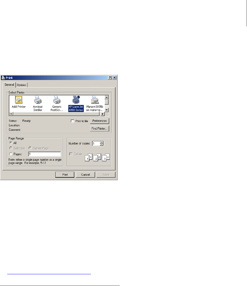
About MAXScript xvii
Choose to print only the selected topic, or to print
all topics in that chapter. After you make your
selection, another dialog appears where you can
choose your printer and other options.
The tabs available at the top of the dialog depend
on the selected printer. Choose options for the
print job, and click OK to begin printing.
How to Contact Us
We are also interested in hearing your views about
3dsMax.We’dliketohearwaysyouthinkwecan
improve our program, features you’re interested
in, as well as your views on the documentation set.
Please send us email about the documentation set
at: me.documentation@autodesk.com
About MAXScript
MAXScript is the built-in scripting language for
3dsMax.Itprovidesuserswiththeabilityto:
•Scriptallaspectsof3dsMaxuse,suchas
modeling,animation,materials,rendering,and
so on.
• Control 3ds Max interactively through a
command-line shell window.
•Packagescriptswithincustomutilitypanel
rollouts or modeless windows, giving them a
standard 3ds Max user interface.
• Build custom import/export tools using the
built-in file I/O.
• Write procedural controllers that can access the
entire state of the scene. Build batch-processing
tools, such as batch-rendering scripts.
• Set up live interfaces to external system using
OLE Automation.
The MAXScript language is specifically designed
tocomplement3dsMax. Itisobject-oriented,
and has several special features and constructs
that mirror high-level concepts in the 3ds Max
user interface. These include coordinate-system
contexts, an animation mode with automatic
keyframing, and access to scene objects using
hierarchical path names that match the 3ds Max
object hierarchy.
Thesyntaxissimpleenoughfornon-programmers
to use, with minimal punctuation and formatting
rules.
Visual MAXScript
Visual MAXScript is a powerful addition to
MAXScript, making the MAXScript feature easier
to learn and use. With Visual MAXScript, you
can quickly create UI elements and layouts for
scripting.
For detailed information about Visual MAXScript,
open the MAXScript Reference, available from
Help menu > MAXScript Reference.
See also
MAXScript Interface (page 3–780)

xviii Introduction
Procedure
To access MAXScript, do one of the following:
• On the menu bar, choose MAXScript. The
MAXScript menu appears.
•ChooseUtilitiespanel>MAXScript.
From here, you can either write new scripts, edit
orrunexistingscripts,opentheMAXScript
Listener, or use the Macro Recorder.
To access the MAXScript Listener, you can also
right-click in the Mini Listener and choose
Open Listener Window from the right-click
menu.
For detailed information about the MAXScript
utility, open the MAXScript Reference, available
from Help menu > MAXScript Reference.

Yo u u s e 3 d s M a x t o q u i c k l y c r e a t e
professional-quality 3D models, photorealistic still
images, and film-quality animation on your PC.
Image by Michael McCarthy
Before using this reference material, we highly
recommend you get to know 3ds Max firsthand by
following the included tutorials. You can access
the tutorials using the Help menu > Tutorials
command, or in the printed version.
This section presents these brief topics designed to
help you quickly start using 3ds Max.
•Project Workflow (page 1–1)
•Setting Up Your Scene (page 1–4)
•Modeling Objects (page 1–5)
•Using Materials (page 1–6)
•Placing Lights and Cameras (page 1–7)
•Animating Your Scene (page 1–8)
•Rendering Your Scene (page 1–9)
The 3ds Max Window (page 1–9)
•Special Controls (page 1–12)
•Quad Menu (page 3–694)
•Customize Display Right-Click Menu (page
3–787)
Managing Files (page 1–15)
•Importing, Merging, and Replacing Scenes (page
1–16)
•Using the Asset Browser (page 1–17)
•Startup Files and Defaults (page 1–17)
•3dsmax.ini File (page 1–18)
•Backing Up and Archiving Scenes (page 1–19)
•Crash Recovery System (page 1–20)
Project Workflow
Once you’ve installed 3ds Max (see the Installation
Guide included with your software package), you
open it from the Start menu, or use any other
Windows method. The figure below shows the
application window with a scene file loaded.
Getting Started with 3ds Max
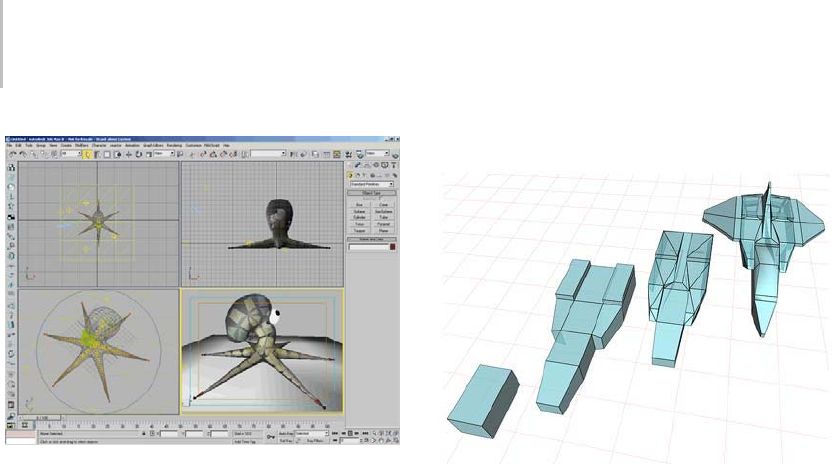
2Chapter 1: Getting Started with 3ds Max
Main program window
Note: If you open 3ds Max from a Command
Prompt window or batch file, you can add
command-line switches. See Starting 3ds Max
from the Command Line (page 3–671).
Note: 3ds Max is a single-document application,
meaningyoucanworkononlyonesceneatatime.
However, you can open more than one copy of
3dsMaxandopenadifferentsceneineachcopy.
Opening additional copies of 3ds Max requires a
lot of RAM. For the best performance, you should
plan to open one copy and work on one scene at a
time.
Openingmultiplecopiesof3dsMaxisnot
supported in Windows ME.
Modeling Objects
You model and animate objects in the viewports,
whose layout is configurable. You can start with a
variety of 3D geometric primitives. You can also
use2Dshapesasthebasisforloftedorextruded
objects. You can convert objects to a variety of
editable surface types, which you can then model
further by pulling vertices and using other tools.
Another modeling tool is to apply modifiers to
objects. Modifiers can change object geometry.
Bend and Twist are examples of modifiers.
Modeling, editing, and animation tools are
available in the command panels and toolbar. See
Modeling Objects (page 1–5). Also, you can learn
a good deal about modeling from the tutorials
available from Help menu > Tutorials.
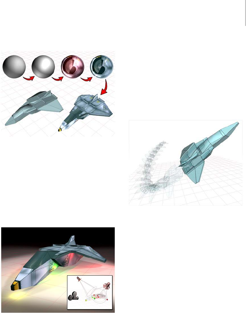
Project Workflow 3
Material Design
You design materials using the Material Editor,
which appears in its own window. You use the
Material Editor to create realistic materials by
defining hierarchies of surface characteristics.
The surface characteristics can represent static
materials, or be animated. See Material Editor
(page 2–1409). Tutorials especially helpful for
learning about materials include "Overview of
Creating a Scene: Still Life" and "Using Materials."
Lights and Cameras
Yo u c r e a t e l i g h t s w i t h v a r i o u s p r o p e r t i e s t o
illuminate your scene. The lights can cast shadows,
project images, and create volumetric effects for
atmospheric lighting. Physically-based lights let
you use real-world lighting data in your scenes and
Radiosity (page 3–51) provides incredibly accurate
light simulation in renderings. See Lights (page
2–1272). You can learn more about lighting by
following the Introduction to Lighting tutorial.
The cameras you create have real-world controls
for lens length, field of view, and motion control
such as truck, dolly, and pan. See Cameras (page
2–1365).
Animation
You can begin animating your scene at any time by
turning on the Auto Key button. Turn the button
offtoreturntomodeling. Youcanalsoperform
animated modeling effects by animating the
parameters of objects in your scene. You can learn
more about animating in the Animating Your Scene
topic (page 1–8) and from most of the tutorials.
When the Auto Key button is on, 3ds Max
automatically records the movement, rotation, and
scale changes you make, not as changes to a static
scene, but as keys on certain frames that represent
time. You can also animate many parameters to
make lights and cameras change over time, and
preview your animation directly in the 3ds Max
viewports.
Yo u u s e Track View (page 2–501) to control
animation. Track View is a floating window
where you edit animation keys, set up animation
controllers, or edit motion curves for your
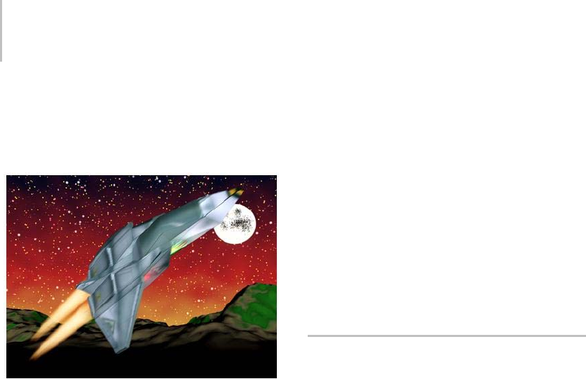
4Chapter 1: Getting Started with 3ds Max
animated effects. The Lip Sync tutorial covers
Track Vie w usage.
Rendering
Rendering adds color and shading to your scene.
The renderers available with 3ds Max include
features such as selective ray tracing, analytical
antialiasing, motion blur, volumetric lighting, and
environmental effects. See Rendering Your Scene
(page 1–9). The tutorials can help you learn about
rendering.
When you use the default scanline renderer,
aradiosity solution (page 3–51) can provide
accurate light simulation in renderings, including
the ambient lighting that results from reflected
light. When you use the mental ray renderer,
acomparableeffectisprovidedbyglobal
illumination (page 3–93).
If your workstation is part of a network, network
rendering can distribute rendering jobs over
multiple workstations. See Network Rendering
(page 3–173).
With Video Post (page 3–311),youcanalso
compositethescenewithanimationsstoredon
disk.
A Typical Project Workflow
These topics explain the basic procedures for
creating scenes:
Setting Up Your Scene (page 1–4)
Modeling Objects (page 1–5)
Using Materials (page 1–6)
Placing Lights and Cameras (page 1–7)
Animating Your Scene (page 1–8)
Rendering Your Scene (page 1–9)
Setting Up Your Scene
You start with a new unnamed scene when you
open the program. You can also start a new scene
atanytimebychoosingNeworResetfromthe
File menu.
Choosing a Unit Display
You choose a system of unit display on the Units
Setup dialog (page 3–848).ChoosefromMetric,
Standard US, and Generic methods, or design a
custom measuring system. You can switch between
differentsystemsofunitdisplayatanytime.
Note: For best results, use consistent units when
you are going to:
•Merge scenes and objects (page 3–463).
•UseXRef objects (page 3–394) or XRef scenes
(page 3–407).
Setting the System Unit
The System Unit setting, in the Units Setup dialog
(page 3–848),determineshow3dsMaxrelatesto
distance information you input to your scene. The
setting also determines the range for round-off
error. Consider changing the system unit value
only when you model very large or very small
scenes.
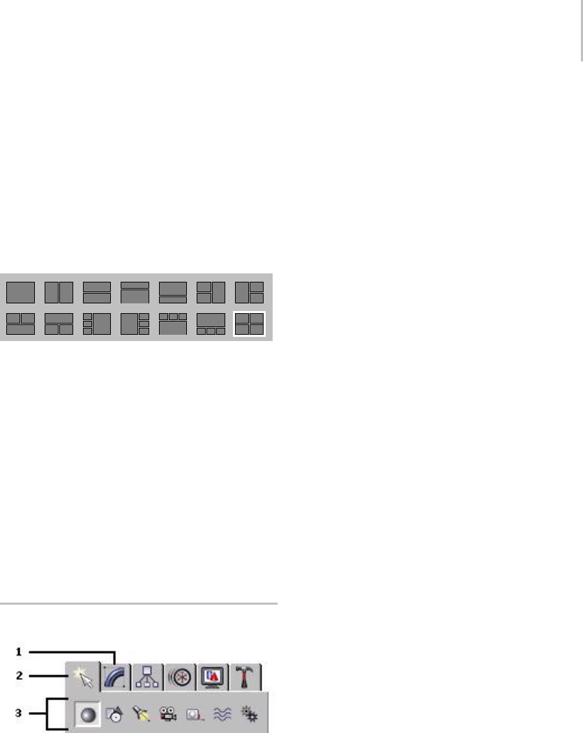
Modeling Objects 5
Setting Grid Spacing
Set spacing for the visible grid in the Grid And
Snap Settings dialog > Home Grid panel (page
2–49). You can change grid spacing at any time.
See Precision and Drawing Aids (page 2–1) for
information about the system unit, unit display,
andgridspacing.
Setting the Viewport Display
Viewport layout options
The default four viewports in 3ds Max represent
anefficientandpopularscreenlayout.Setoptions
in the Viewport Configuration dialog (page 3–853)
to change viewport layout and display properties.
See Viewing and Navigating 3D Space (page 1–21)
for more information.
Saving Scenes
Save your scene frequently to protect yourself from
mistakes and loss of work. See Backing Up and
Archiving Scenes (page 1–19).
Modeling Objects
1. Modify panel
2. Create panel
3. Object categories
Yo u m o d e l o b j e c t s i n y o u r s c e n e b y c r e a t i n g
standard objects, such as 3D geometry and 2D
shapes, and then applying modifiers to those
objects. The program includes a wide range of
standard objects and modifiers.
Creating Objects
Yo u c r e at e o b j e c t s b y c l i c k i n g a n o b j e c t c a t e g o r y
and type on the Create panel and then clicking
or dragging in a viewport to define the object’s
creation parameters. The program organizes the
Create panel into these basic categories: Geometry,
Shapes, Lights, Cameras, Helpers, Space Warps,
and Systems. Each category contains multiple
subcategories from which you can choose.
You can also create objects from the Create
menu by choosing an object category and type
and then clicking or dragging in a viewport to
define the object’s creation parameters. The
program organizes the Create menu into these
basic categories: Standard Primitives, Extended
Primitives, AEC Objects, Compound, Particles,
PatchGrids,NURBS,Dynamics,Shapes,Lights,
Cameras, Helpers, Space Warps, and Systems.
See Basics of Creating and Modifying Objects (page
1–153).
Selecting and Positioning Objects
You select objects by clicking or dragging a region
around them. You can also select objects by name
or other properties such as color or object category.
After selecting objects, you position them in your
scene using the transform tools Move, Rotate, and
Scale. Use alignment tools to precisely position
objects.
See Selecting Objects (page 1–61),Moving,
Rotating, and Scaling Objects (page 1–423),and
Precision and Drawing Aids (page 2–1).
Modifying Objects
Yo u s c u l p t a n d e d i t o b j e c t s i n to t h e i r f i n a l f o r m b y
applying modifiers from the Modify panel. The
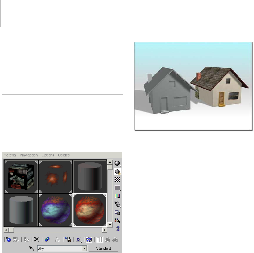
6Chapter 1: Getting Started with 3ds Max
modifiers you apply to an object are stored in a
stack. You can go back at any time and change the
effect of the modifier, or remove it from the object.
See Basics of Creating and Modifying Objects (page
1–153).
Using Materials
You use the Material Editor to design materials and
maps to control the appearance of object surfaces.
Mapscanalsobeusedtocontroltheappearance
of environmental effects such as lighting, fog, and
the background.
A variety of materials in the Material Editor’s sample slots
House on left uses the default standard material.
House on right uses a compound material.
Basic Material Properties
Yo u s e t b a s i c m a t e r i a l p r o p e r t i e s t o c o n t r o l
such surface characteristics as default color,
shininess, and level of opacity. You can create
realistic, single-color materials using just the basic
properties.
Using Maps
You extend the realism of materials by applying
maps to control surface properties such as texture,
bumpiness, opacity, and reflection. Most of the
basic properties can be enhanced with a map. Any
imagefile,suchasoneyoumightcreateinapaint
program, can be used as a map, or you can choose
procedural maps that create patterns based on
parameters you set.
The program also includes a raytrace material
and map for creating accurate reflections and
refraction.
Viewing Materials in the Scene
You can view the effect of materials on objects
in a shaded viewport, but the display is just an
approximation of the final effect. Render your
scene to view materials accurately.
See Designing Materials (page 2–1395).
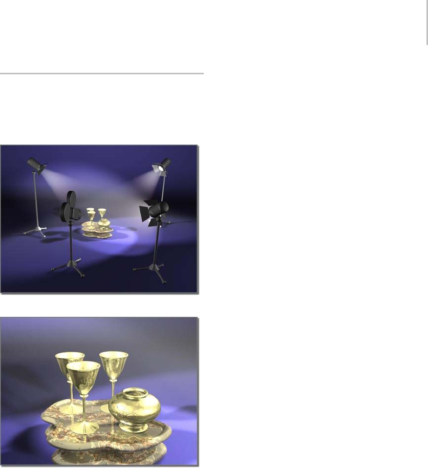
Placing Lights and Cameras 7
Placing Lights and Cameras
You place lights and cameras to complete your
scene in much the same way lights and cameras are
placed on a movie set prior to filming.
Lights and cameras placed to compose a scene
The resulting scene
Default Lighting
Default lighting evenly illuminates the entire scene.
Such lighting is useful while modeling, but it is not
especially artistic or realistic.
Placing Lights
You create and place lights from the Lights category
of the Create panel when you are ready to get more
specific about the lighting in your scene.
The program includes the following standard light
types: omni, spot, and directional lights. You can
setalighttoanycolorandevenanimatethecolor
to simulate dimming or color-shifting lights. All
of these lights can cast shadows, project maps, and
use volumetric effects.
See Guidelines for Lighting (page 2–1280).
Photometric Lights
Photometric lights (page 2–1301) provide you
with the ability to work more accurately and
intuitively using real-world lighting units (lumens
and candelas). Photometric lights also support
industry-standard photometric file formats (IES
(page 2–1328),CIBSE (page 3–921),LTL I (p ag e
3–964)) so that you can model the characteristics
of real-world manufactured luminaires, or even
drag ready-to-use luminaires from the Web.
Used in conjunction with the 3ds Max radiosity
solution (page 3–51),photometriclightsletyou
evaluate more accurately (both physically and
quantitatively) the lighting performance of your
scene.
Photometric lights are available from the Create
panel > Lights drop-down list.
Daylight System
The Daylight system (page 1–418) combines
sunlight (page 3–1018) and skylight (page 3–1012)
to create a unified system that follows the
geographically correct angle and movement of
thesunovertheearthatagivenlocation. You
can choose location, date, time, and compass
orientation. You can also animate the date and
time.Thissystemissuitableforshadowstudiesof
proposed and existing structures.
Viewing Lighting Effects in the Scene
When you place lights in a scene, the default
lighting turns off and the scene is illuminated only
by the lights you create. The illumination you

8Chapter 1: Getting Started with 3ds Max
see in a viewport is just an approximation of the
true lighting. Render your scene to view lighting
accurately.
Tip: If the Daylight system appears to wash out the
scene, try using the Logarithmic exposure control
(page 3–297).
Placing Cameras
You create and place cameras from the Cameras
category of the Create panel. Cameras define
viewpoints for rendering, and you can animate
cameras to produce cinematic effects such as
dollies and truck shots.
You can also create a camera automatically from a
Perspective viewport by using the Create Camera
from View command (page 1–48) found on the
Views menu. Just adjust your Perspective viewport
until you like it, and then choose Views > Create
Camera From View. 3ds Max creates a camera and
replaces the Perspective viewport with a Camera
viewport showing the same perspective.
See Common Camera Parameters (page 2–1373).
Animating Your Scene
You can animate almost anything in your scene.
Click the Auto Key button to enable automatic
animation creation, drag the time slider, and make
changes in your scene to create animated effects.
Controlling Time
The program starts each new scene with 100
frames for animation. Frames are a way of
measuring time, and you move through time by
dragging the time slider (page 3–701).Youcanalso
open the Time Configuration dialog (page 3–725)
to set the number of frames used by your scene
and the speed at which the frames are displayed.
Animating Transforms and Parameters
While the Auto Key button is on, the program
creates an animation key (page 3–960) whenever
you transform an object or change a parameter.
Toanimateaparameteroverarangeofframes,
specify the values at the first and last frames of the
range.Theprogramcalculatesthevaluesforallof
the frames in between.
See AnimationConceptsandMethods(page
2–275).
Editing Animation
You edit your animation by opening the Track
View window or by changing options on the
Motion panel. Track View is like a spreadsheet that
displays animation keys along a time line. You edit
the animation by changing the keys.
Track View has two modes. You can display the
animation as a series of function curves that
graphically show how a value changes over time
in the Curve Editor mode. Alternatively, you can
display your animation as a sequence of keys or
ranges on a grid in the Dope Sheet mode.
See Track View (page 2–501).
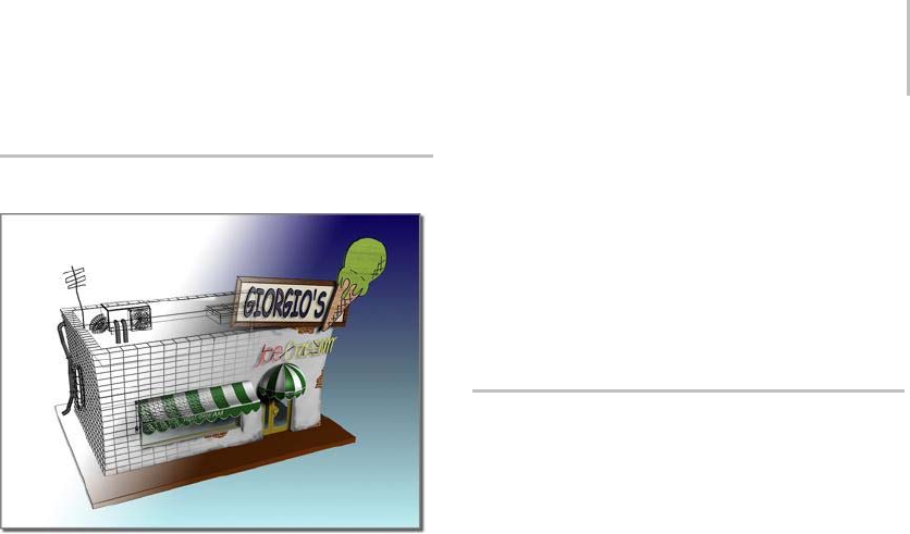
Rendering Your Scene 9
Rendering Your Scene
Rendering "fills in" geometry with color, shadow, lighting
effects, and so on.
Use the rendering features to define an
environment and to produce the final output from
your scene.
Defining Environments and
Backgrounds
Rarely do you want to render your scene against the
default background color. Open the Environment
And Effects dialog > Environment panel (page
3–272) to define a background for your scene, or
to set up effects such as fog.
Setting Rendering Options
To set the size and quality of your final output,
you can choose from many options on the Render
Scene dialog (page 3–2).Youhavefullcontrol
over professional grade film and video properties
as well as effects such as reflection, antialiasing,
shadow properties, and motion blur.
Rendering Images and Animation
You render a single image by setting the renderer
to render a single frame of your animation. You
specify what type of image file to produce and
where the program stores the file.
Rendering an animation is the same as rendering
a single image except that you set the renderer to
render a sequence of frames. You can choose to
render an animation to multiple single frame files
or to popular animation formats such as AVI or
MOV.
See Render Scene Dialog (page 3–2).
The 3ds Max Window
Most of the main window is occupied by the
viewports, where you view and work with your
scene. The remaining areas of the window hold
controls and show status information.
One of the most important aspects of using
3ds Max is its versatility. Many program functions
are available from multiple user-interface
elements. For example, you can open Track View
for animation control from the Main toolbar as
well as the Graph Editors menu, but the easiest
way to get to a specific object’s track in Track View
is to right-click the object, and then choose Track
View Selected from the quad menu.
You can customize the user interface in a variety
of ways: by adding keyboard shortcuts, moving
toolbars and command panels around, creating
new toolbars and tool buttons, and even recording
scripts into toolbar buttons.
MAXScript lets you create and use custom
commands in the built-in scripting language.
For more information, access the MAXScript
Reference from the Help menu.
Menu Bar
AstandardWindowsmenubarwithtypicalFile
(page 3–673),Edit (page 3–673),andHelp (page
3–684) menus. Special menus include:
•Tools (page 3–674) contains duplicates of many
of the Main toolbar commands.

10 Chapter 1: Getting Started with 3ds Max
•Group (page 3–674) contains commands for
managing combined objects.
•Views (page 3–675) contains commands for
setting up and controlling the viewports.
•Create (page 3–675) contains commands for
creating objects.
•Modifiers (page 3–678) contains commands for
modifying objects.
•Animation (page 3–681) contains commands
for animating and constraining objects, plus
commands such as Bone Tools for setting up
animated characters.
•Graph Editors (page 3–682) provides graphical
access to editing objects and animation: Track
View lets you open and manage animation
tracks in Track View (page 2–501) windows,
and Schematic View (page 3–640) gives you an
alternate way to work with the objects in your
scene and navigate to them.
•Rendering (page 3–683) contains commands
for rendering, Video Post, radiosity, (page
3–51)and the environment.
•Customize (page 3–683) gives you access
to controls that let you customize the user
interface.
•MAXScript (page 3–780) hascommandsfor
working with MAXScript, the built-in scripting
language.
For more information about the 3ds Max menus,
see Menu Bar (page 3–672).
Time Controls
The Auto Key button (page 2–278) turns on
animation mode. The other controls navigate
through time and play back an animation.
Command Panel
This collection of six panels provides handy
access to most of the modeling and animation
commands.
You can "tear off " the command panel and place it
anywhere you like.
By default, the command panel is docked at the
right of your screen. You can access a menu
that lets you float (page 3–930) or dismiss the
command panel by right-clicking just above it.
If it is not displayed, or you want to change its
location and docking or floating status, right-click
in a blank area of any toolbar, and choose from
the shortcut menu.
•Create (page 3–757) holds all object creation
tools.
•Modify (page 3–758) holds modifiers and
editing tools.
•Hierarchy (page 3–773) holds linking and
inverse kinematics parameters.
•Motion (page 3–774) holds animation
controllers and trajectories.
•Display (page 3–775) holds object display
controls.
•Utilities (page 3–778) holds miscellaneous
utilities.
Status Bar and Prompt Line
Thesetwolinesdisplaypromptsandinformation
about your scene and the active command. They
also contain system toggles controlling selections,
precision, and display properties. See Status Bar
Controls (page 3–698).
Viewports
You can display from one to four viewports. These
canshowmultipleviewsofthesamegeometry,
as well as the Track View, Schematic View, and
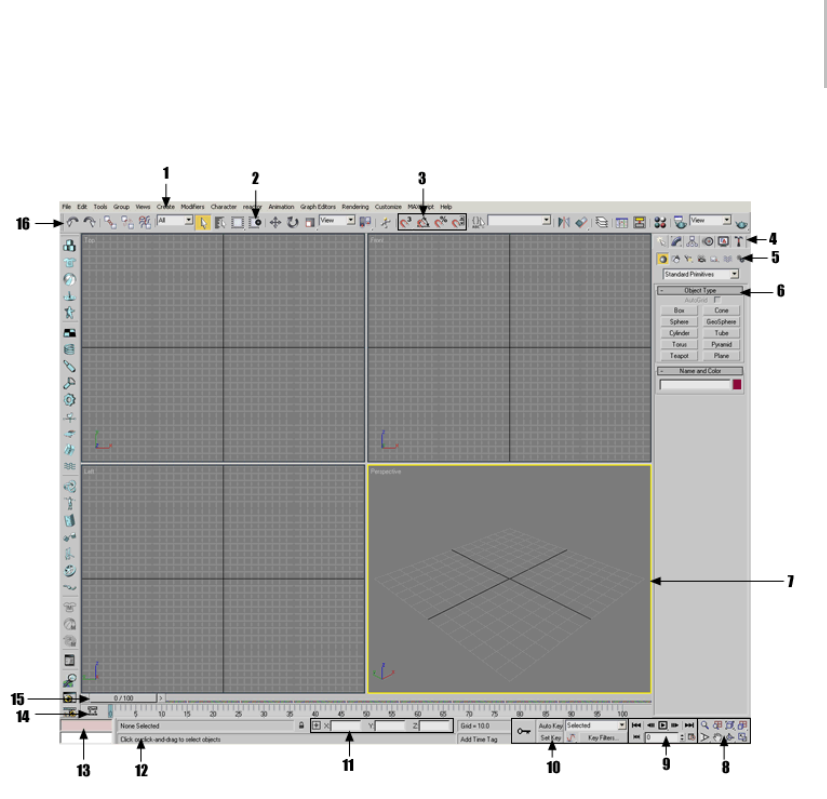
The 3ds Max Window 11
1. Menu bar
2. Window/Crossing selection toggle
3. Snap tools
4. Command panels
5. Object categories
6. Rollout
7. Active viewport
8. Viewport navigation controls
9. Animation playback controls
10. Animation keying controls
11. Absolute/Relative coordinate toggle and coordinate display
12. Prompt line and status bar
13. MAXScript mini-listener
14. Track bar
15. Time slider
16. Main toolbar
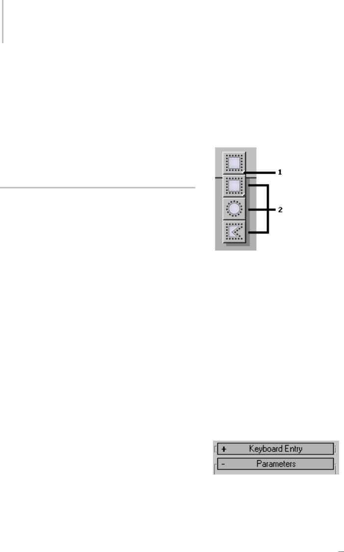
12 Chapter 1: Getting Started with 3ds Max
other informational displays. See Viewports (page
3–729).
Viewport Navigation Buttons
Thebuttonclusteratthelower-rightcornerof
the main window contains controls for zooming,
panning, and navigating within the viewports. See
Viewport Controls (page 3–729).
Special Controls
3ds Max uses some special user interface controls,
which are described in this topic.
•Right-click menus (page 1–12)
•Flyouts (page 1–12)
•Rollouts (page 1–12)
•Scrolling panels and toolbars (page 1–13)
•Spinners (page 1–13)
•Numerical Expression Evaluator (page 1–13)
•Entering numbers (page 1–14)
•Controls and color (page 1–14)
•Undoing actions (page 1–14)
Right-Click Menus
The program uses several different types of
right-click menus.
For object editing and ActiveShade control (page
3–22),youusethequad menu (page 3–694).
Commands on the quad menu vary depending on
thekindofobjectyouareeditingandthemode
you are in.
Right-clicking a viewport label displays the
viewport right-click menu (page 3–731),which
lets you change viewport display settings, choose
which view appears in the viewport, and so on.
Also, the command panel and the Material Editor
have right-click menus that let you manage rollouts
and navigate the panel quickly. And most other
windows, including Schematic View and Track
View, have right-click menus that provide fast
access to commonly used functions.
Flyouts
1. Flyout arrow
2. Flyout buttons
Aflyout (page 3–943) is similar to a menu, except
that its items are buttons. A flyout button is
indicated by a small arrow in the lower-right
corner. To display the flyout, click and hold the
button for a moment, then choose a button by
dragging the cursor to it and then releasing the
mouse button.
Note: You can define customized text annotations
for flyouts by editing the maxstart.cui file. See
Customize Menu (page 3–683).
Rollouts
Rollouts are areas in the command panels and
dialogs that you can expand (roll out) or collapse
(roll in) to manage screen space. In the illustration
above, the Keyboard entry rollout is collapsed, as
indicatedbythe+sign,andtheParametersrollout
is expanded, as indicated by the sign.
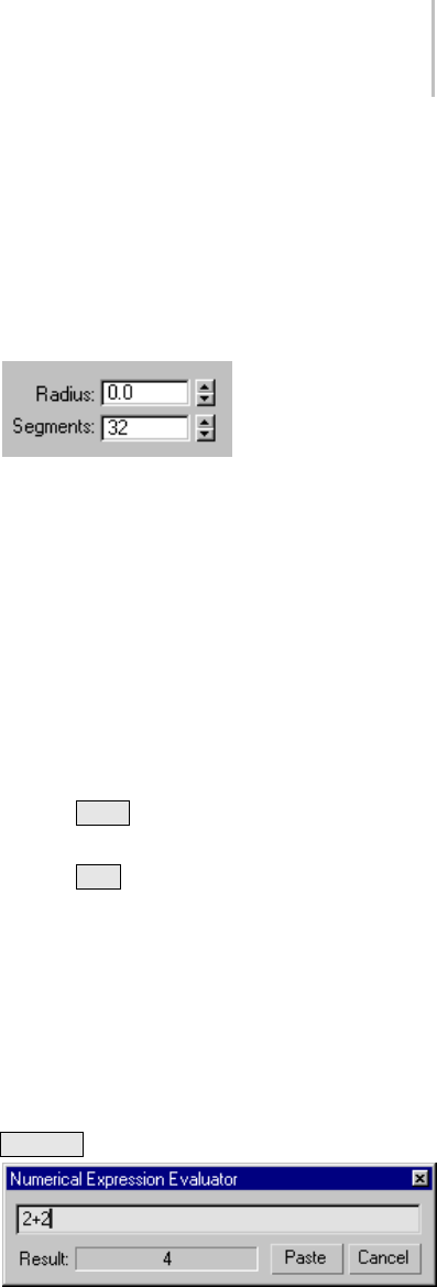
Special Controls 13
To open and close a rollout:
• Clicktherollouttitlebartotogglebetween
expanded and collapsed.
To move a rollout:
• You can move a rollout in the expanded or
collapsed state. To move the rollout, drag the
rollout title bar to another location on the
command panel or dialog. As you drag, a
semi-transparent image of the rollout title bar
follows the mouse cursor. When the mouse is
positioned over or near a qualifying position
for the rollout, a blue, horizontal line appears at
the position where the rollout will drop when
you release the mouse button.
Scrolling Panels and Toolbars
Sometimes a command panel or dialog is not large
enough to display all of its rollouts. In this case,
a pan ("hand") cursor appears over the inactive
parts of the panel. You can scroll command panels
and dialogs vertically, and you can scroll a toolbar
along its major axis.
To scroll a panel:
1. Place the pointer over an empty area of a panel
to display the pan cursor.
2. When the pointer icon changes to a hand, drag
the panel up or down.
A thin scroll bar also appears on the right side
of the scrolling panel. You can use the pointer
to drag the scroll bar as well.
To scroll a toolbar:
You can scroll a toolbar only when some tool
buttons are not visible. This typically occurs when
the program window is smaller than full screen.
1. First, follow either of the procedures below:
• Place the pointer over an empty area of a
toolbar to display the pan cursor.
• Place the pointer over any part of a toolbar,
then press and hold the middle mouse
button.
2. When the pointer icon changes to a hand, drag
the toolbar horizontally.
Spinners
A spinner is a mouse-based control for numeric
fields. You can click or drag the spinner arrows to
changethevalueinthefield.
To change a value using a spinner, do any of the
following:
• Click the spinner’s up arrow to increment the
value; click the down arrow to decrement the
value. Click and hold for continuous change.
• Drag upward to increase the value, or drag
downward to decrease it.
•Press
Ctrl while you drag to increase the rate
at which the value changes.
•Press
Alt whileyoudragtodecreasetherate
at which the value changes.
•Right-clickaspinnertoresetthefieldtoits
minimum value.
Numerical Expression Evaluator
While a numeric field is active, you can display
a calculator called the Numerical Expression
Evaluator. To display the calculator, press
Ctrl+N .
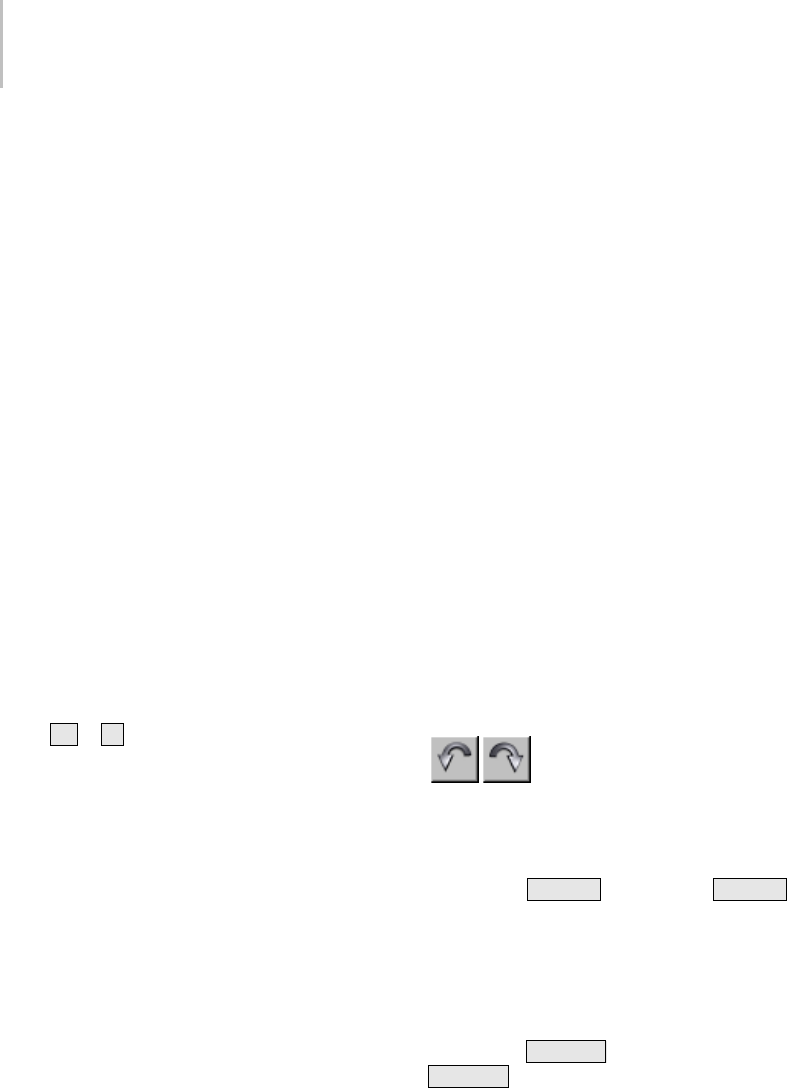
14 Chapter 1: Getting Started with 3ds Max
The expression you enter is evaluated, and its
result is displayed in the Result field. Click Paste
to replace the field value with the result of the
calculation. Click Cancel to exit the Expression
Evaluator.
The expressions you can enter are described in
Expression Techniques (page 1–146).Youcan’tuse
variables in the Expression Evaluator, but you can
entertheconstantspi(circularratio),e(natural
logarithm base), and TPS (ticks per second).
These constants are case-sensitive: the Expression
Evaluator does not recognize PI, E, or tps.
You can also enter a vector expression or an
Expression Controller function call, but the result
of the expression or function must be a scalar
value. Otherwise, the Expression Evaluator won’t
evaluate it.
Entering Numbers
You can change a numeric value by a relative offset
by highlighting the contents of a numeric field
(not in the Numerical Expression Evaluator) and
typing Ror rfollowed by the offset amount.
Forexample,aRadiusfieldshows70andyou
highlight it:
•IfyouenterR30, 30 is added to the radius and
the value changes to 100.
•IfyouenterR-30,30issubtractedfromthe
radius and the value changes to 40.
Controls and Color
The user interface uses color cues to remind you
what state the program is in.
Note: You can customize most of these colors
by using the Colors panel (page 3–799) of the
Customize User Interface dialog (page 3–792).
•Red for animation: The Auto Key button,
thetimesliderbackground,andtheborderof
the active viewport turn red when you are in
Animate mode.
•Yellow for modal function buttons: When
you turn on a button that puts you in a generic
creation or editing mode, the button turns
yellow.
•Ye l l o w f o r s p e c i a l a c t i o n m o d e s : When you
turnonabuttonthataltersthenormalbehavior
of other functions, the button is highlighted
inyellow.Commonexamplesofthisbehavior
include sub-object selection and locking your
current selection set.
Yo u c a n e x i t a f u n c t i o n a l m o d e b y c l i c k i n g a n o t h e r
modal button. Other exit methods supported by
some buttons include right-clicking in a viewport,
or clicking the modal button a second time.
Undoing Actions
You can easily undo changes you make to your
scene and your viewports. There are separate
Undo buffers for both the scene objects and each
viewport.
Use the toolbar Undo and Redo buttons (page 1–94)
or the Edit menu > Undo and Redo commands to
reverse the effects of most scene operations. You
can also use Ctrl+Z for Undo and Ctrl+Y for
Redo. Most things you do in the program can be
undone.
Use the Views menu > Undo and Redo commands
(page 1–36) to reverse the effects of most viewport
operations, such as zooming and panning. You
can also use Shift+Z for Undo View Change and
Shift+Y for Redo View Change.
You can also undo actions by using the Hold and
Fetch commands on the Edit menu. Choose Edit
menu>Holdtosaveacopyofyoursceneina
temporary file. Then choose Edit menu > Fetch to
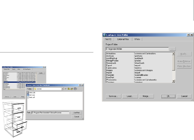
Managing Files 15
discard your current scene and revert to the held
scene at any time.
Managing Files
File-management dialogs
3ds Max supports many types of files for working
with plug-ins, image maps, models from other
programs, rendering images and animations, and
of course saving and opening your scene files.
File dialogs (such as Open, Save, Save As)
uniformly remember the previous path you used,
and default to that location.
Configuring File Paths
The locations that 3ds Max searches to locate all
file types are specified on the Customize menu >
Configure Paths dialogs (page 3–808).
You can choose to open and save files in any path
location. The Configure Paths dialog contains four
panels for the general categories of support files.
Setting General File Paths
The File I/O panel (page 3–810) contains paths for
most of the standard support files. You can specify
one path for each of file types 3ds Max uses.
Setting Plug-In File Paths
Many features of 3ds Max are implemented as
plug-ins. This means you can change and extend
3ds Max functionality by adding new plug-ins
from Autodesk Media and Entertainment or from
third-party developers.
You tell 3ds Max where to find additional plug-in
files by adding path entries on the 3rd Party
Plug-Ins panel (page 3–814). If you place all of
your plug-ins in a single directory, plug-in file
management can become messy. That’s why the
program supports multiple entries on the 3rd
Party Plug-Ins panel.
Setting Bitmap, FX, and Download File Paths
The External Files panel (page 3–811) contains
multiple path entries that the program searches
for image files (page 3–608),downloadedfiles(via
i-drop (page 3–523)), and FX files (page 3–946).
Image files are used for many purposes, such as
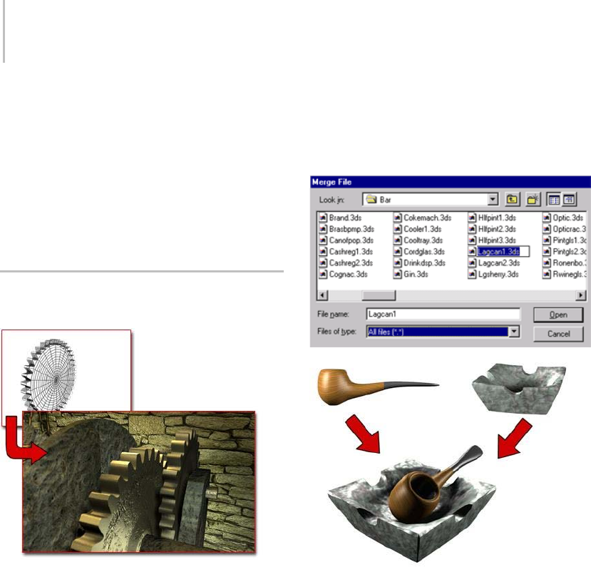
16 Chapter 1: Getting Started with 3ds Max
material and map definition, light projections, and
environment effects.
Setting XRefs File Paths
The XRefs panel (page 3–812) contains multiple
path entries that the program uses to search for
externally referenced files. These are used for
sharing files in a workgroup situation.
Importing, Merging, Replacing,
and Externally Referencing Scenes
Gear model imported to become part of another scene
You can realize great productivity gains when
you reuse work by combining geometry from
scenes or other programs. 3ds Max supports this
technique with the Import, Merge, and Replace
commands. You can also share scenes and objects
with others working on the same project using
XRef functionality.
Importing Geometry from Other
Programs
UseFilemenu>Import (page 3–485) to bring
objects from other programs into a scene. The
types of files that you can import are listed in
the Files Of Type list in the Select File To Import
dialog.
Depending on the file type you choose, you might
have options available for that import plug-in.
Merging Scenes Together
Pipe and ashtray models merged into one scene
Use Merge (page 3–463) to combine multiple
scenes into a single large scene. When you merge
a file, you can select which objects to merge. If
objectsbeingmergedhavethesamenameas
objects in your scene, you have the option to
rename or skip over the merged objects.
Merging Animation into Scenes
Use Merge Animation (page 3–466) to merge the
animation from one scene into another with the
same (or similar) geometry.
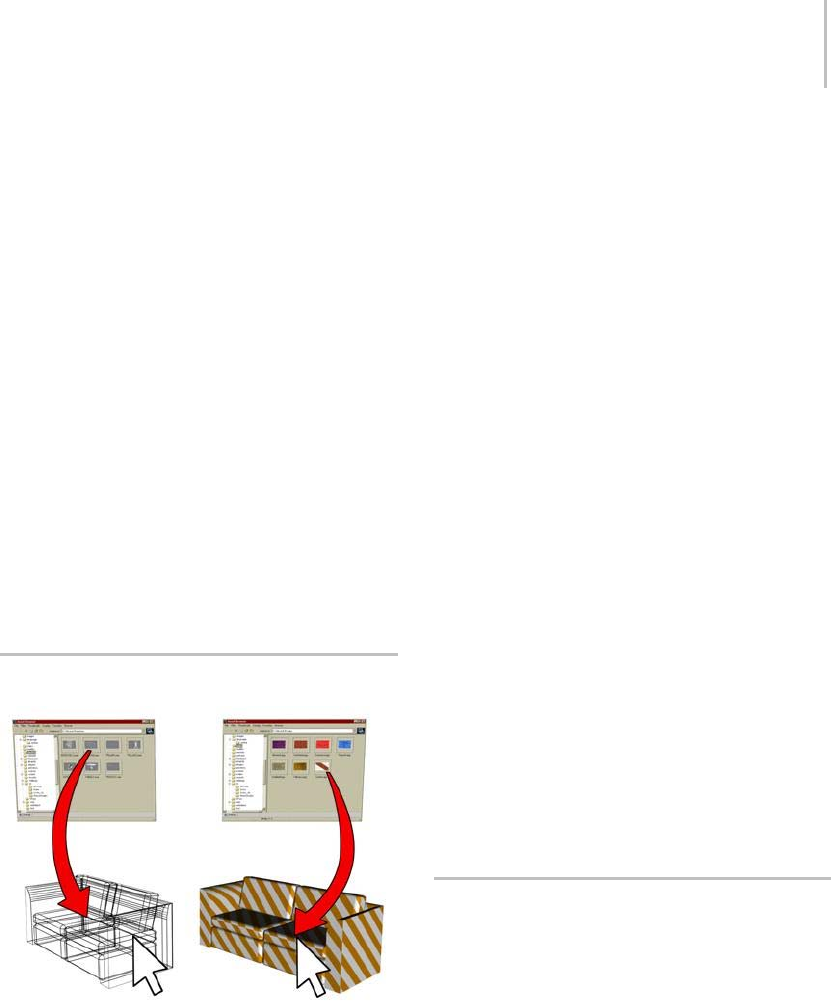
Using the Asset Browser 17
Replacing Scene Objects
Use Replace (page 3–470) to replace objects in
your scene with objects in another scene that have
duplicate names. Replace is useful when you want
to set up and animate your scene with simplified
objects,andthenreplacethesimpleobjectswith
detailed objects before rendering.
The Replace dialog looks and functions the same
as Merge, except that it lists only objects that have
thesamenameasobjectsinyourcurrentscene.
Using External References
Use XRef Objects (page 3–394) and XRef Scenes
(page 3–407) to use objects and scene setups
in your scene that are actually referenced from
external MAX files. These functions allow sharing
files with others in your workgroup, with options
for updating and protecting external files.
Using the Asset Browser
Left: Dragging geometry into the scene
Right: Dragging a bitmap onto the geometry
The Asset Browser provides access from your
desktop to design content on the World Wide Web.
From within 3ds Max you can browse the Internet
for texture samples and product models. This
includesbitmaptextures(BMP,JPG,GIF,TIF,and
TGA) and geometry files (MAX, 3DS, and so on).
You can drag these samples and models into
yoursceneforimmediatevisualizationand
presentation. You can snap geometry into
predefined locations, or drag and drop them
interactively in your scene.
You can also use the Asset Browser to browse
thumbnail displays of bitmap textures and
geometry files on your hard disk or shared
network drives. Then you can either view them or
drag and drop them into your scene or into valid
map buttons or slots.
Note: The thumbnail display of a geometry file is a
bitmap representation of a view of the geometry.
Since the thumbnail display is not a vector-based
representation, you can’t rotate it or perform
zooms on it.
You can drag and drop most graphic images that
areembeddedinaWebpageintoyourscene.The
exceptionisimagesorregionsofaWebpagethat
are tagged as hyperlinks or other HTML controls
(such as when a bitmap is tagged as a button).
Important: Downloaded content might be subject to
use restrictions or the license of the site owner. You are
responsible for obtaining all content license rights.
For complete details, see Asset Browser (page
3–504).
Startup Files and Defaults
When you start 3ds Max, several auxiliary files
load, setting things like program defaults and
UI layout. You can even create a scene, named
maxstart.max, that automatically loads when you
start or reset the program. In some cases, the
program updates files when you change settings
and when you quit the program.
Note: 3ds Max comes with several different
market-specific defaults (page 3–790). These set
different program defaults on startup, based on
thetypeoffilesyouexpecttoworkonmostoften.

18 Chapter 1: Getting Started with 3ds Max
Youcanloadthepresetdefaultsthatcomewith
3ds Max, or you can create your own.
In general, you don’t need to work directly with the
auxiliary files, but it’s good to know about them.
Among the auxiliary files the program uses are:
•3dsmax.ini (page 1–18) :Thisfilegetsupdated
when you start and exit 3ds Max, as well as
when you change most Preferences settings. It
contains values relating to program defaults,
including the graphics driver, directories used
to access external files such as sounds and
images, preset render sizes, dialog positions,
snap settings, and other preferences and default
settings. If you edit this file, be sure to make a
copy first, so you can return to the original if
anything goes wrong.
Note: Many program defaults are set in
currentdefaults.ini, found within the \defaults
directory. For more information on this file, see
Market-Specific Defaults (page 3–790).
•maxstart.max:Atstartupandwhenyoureset
theprogram,3dsMaxlooksforthisfileinthe
MaxStart folder specified in Configure User
Paths > File I/O panel (page 3–810),andif
found, loads it. This allows you to specify the
default state of the workspace whenever you
start or reset the program. For example, if you
always use a ground plane, you can make it the
default setup by creating one, and then saving it
as maxstart.max.
Ifyousaveadifferentfileovermaxstart.max,
you can return to program defaults by deleting
the maxstart.max file, and then resetting the
program.
•maxstart.cui:Thisisthedefaultcustomuser
interface file. You can load and save CUI files,
and set the program to use a different default
CUI file. See Customize Menu (page 3–683).
•plugin.ini: This file contains directory paths
for plug-ins. Most other paths are kept in the
program INI file, but plugin.ini is maintained
as a separate file because third-party plug-ins
often add entries to the list at installation.
Note: It is possible to use multiple plug-in
configuration files by nesting additional paths
in your plugin.ini file. This can be very useful
for allowing an entire network of users to share
one plugin.ini file, making the system easier
to maintain for the network administrator.
For more information, see Network Plug-In
Configuration (page 3–814).
•startup.ms:AMAXScriptfilethatautomatically
executes at startup time. For more information,
see Startup Script (page 3–1015).
•splash.bmp: To substitute a custom splash
screen (startup screen) for the default image,
copy any Windows Bitmap (.bmp)fileinto
the program root directory and rename it
splash.bmp.Theprogramwillthereafteruse
this image at startup.
3dsmax.ini File
The file 3ds Max uses to store settings between
sessions is named 3dsmax.ini.Bydefault,youcan
find it in the location indicated by the MaxData
setting on the Configure System Paths dialog (page
3–810).
You can make changes to 3ds Max startup
conditions by editing the 3dsmax.ini file in a text
editor such as Notepad. If you do edit the file, be
sure to maintain the structure and syntax of the
original file.
Tip: If you encounter unusual and unexplained
user-interface problems using 3ds Max, try
deleting the 3dsmax.ini file and restarting.
3ds Max writes a new 3dsmax.ini file to replace the
deleted one. Often this will fix problems related to
the state of the user interface.

Backing Up and Archiving Scenes 19
Note: Startup scene conditions are defined by
the maxstart.max file. To save a particular
startup condition, such as a Plane object
representing the ground, create a scene file
with the condition present and then save it as
maxstart.maxvizstart.maxvizstart.drf.3dsMax
automatically opens this file when you start
3ds Max.
The 3dsmax.ini file includes the following
categories:
[Directories]—Defines the default paths for various
file operations.
[Performance]—Controls that speed up viewport
performance.
[PlugInKeys]—Turns on or of f the key bo ard
shortcuts for plug-ins.
[Renderer]—Controls for rendering alpha and filter
backgrounds.
[RenderPresets]—DefinesthepathsforRendering
Preset files.
[BitmapDirs]—Defines the default map paths for
bitmaps used by materials.
[Modstack]—Controls modifier stack button sets
and icon display.
[WindowState]—Settings for software display,
OpenGL, or Direct3D drivers.
[CustomMenus]—Defines path for the .mnu file.
[CustomColors]—Defines the path for the .clr file.
[KeyboardFile]—Defines the path for the .kbd file.
[Material Editor]—Material Editor settings.
[ObjectSnapSettings]—Settings associated with
snaps.
[CommandPanel]—Sets number of columns, and
controls rollout display in multiple columns.
Backing Up and Archiving Scenes
You should regularly back up and archive
your work. One convenient method is to save
incremental copies of your scenes. This method
creates a history of your work process.
Saving Incremental Files
IfyouturnontheIncrementOnSaveoptionon
the Files panel (page 3–819) of the Preferences
dialog, the current scene is renamed by appending
atwo-digitnumbertotheendofthefileand
incrementing the number each time you save. For
example, if you open a file named myfile.max and
then save it, the saved file is named myfile01.max.
Eachtimeyousavethefileitsnameisincremented,
producing the files myfile02.max,myfile03.max,
and so on.
You can also use Save As (page 3–391) to increment
thefilenamemanuallywithatwo-digitnumber
by clicking the increment button (+) on the Save
As dialog.
Using Auto Backup
Yo u c a n a ut om a t i c a l l y s av e b a c k u p f i l e s a t r e g u l a r
intervals by setting the Auto Backup options
(page 3–820) on the Preferences dialog (see File
Preferences (page 3–819)). The backup files are
named AutoBackupN.max,whereNisanumber
from 1 to 99, and stored, by default, in the
\autoback folder. You can load a backup file like
any other scene file.
Archiving a Scene
3ds Max scenes can make use of many different
files. When you want to exchange scenes with
other users or store scenes for archival purposes,
you often need to save more than just the scene file.
Use the File menu > Archive command (page
3–499) to pass the scene file and any bitmap

20 Chapter 1: Getting Started with 3ds Max
files used in the scene to an archiving program
compatible with PKZIP® software.
Crash Recovery System
If 3ds Max encounters an unexpected crash, it
attempts to recover and save the file currently
in memory. This is fairly reliable, but it does
not always work: the recovered scene could be
damaged during the crash.
The recovered file is stored in the
configured Auto Backup path. It is saved
as "<filename>_recover.max"inthispath.Itisalso
placed in the INI file as the most recently used file
intheFilemenu.Thismakesiteasytoreturnto
thefile,ifyouchoosetodoso.
The crash recovery system identifies when
something in an object’s modifier stack is corrupt.
In these cases, the corrupt object is replaced with
a red dummy object to maintain the object’s
position and any linked object hierarchy.
Note: We recommend that you not rely on this
file-recovery mechanism as an alternative to good
data backup practices:
• Save your work frequently.
• Take advantage of automatic incremental file
naming: Go to Customize menu > Preferences
>Files panel (page 3–819) >FileHandling
group, and turn on Increment On Save.
• Use File menu > Save As, and click the
Increment button (+) to save incremental
copies of work in progress.
• If you are forgetful about saving, use the Auto
Backup feature. Go to Customize menu >
Preferences > Files tab > Auto Backup group,
and turn on Enable.

Everything you create in 3ds Max is located in
a three-dimensional world. You have a variety
ofoptionsforviewingthisenormousstage-like
space, from the details of the smallest object to the
full extent of your scene.
Using the view options discussed in this section
you move from one view to another, as your
work and imagination require. You can fill your
screen with a single, large viewport, or set multiple
viewports to track various aspects of your scene.
For exact positioning, flat drawing views are
available, as are 3D perspective (page 3–992) and
axonometric views (page 3–913).
You navigate 3D space by adjusting the position,
rotation and magnification of your views. You
have full control over how objects are rendered
and displayed on the screen.
Yo u c a n a l s o u s e t h e Grab Viewport command
(page 1–35) to create snapshots of your work as
you go.
This section presents these brief topics designed to
help you quickly start learning how to organize
viewports and navigate through 3D space:
General Viewport Concepts (page 1–22)
Home Grid: Views Based on the World Coordinate
Axes (page 1–23)
Understanding Views (page 1–24)
Setting Viewport Layout (page 1–26)
Controlling Viewport Rendering (page 1–27)
Controlling Display Performance (page 1–28)
Using Standard View Navigation (page 1–29)
Zooming, Panning, and Rotating Views (page 1–29)
Navigating Camera and Light Views (page 1–33)
Grab Viewport (page 1–35)
For details about viewport commands, see
Viewport Controls (page 3–729).
Viewing and Navigating 3D Space
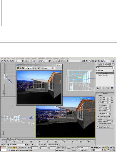
22 Chapter 2: Viewing and Navigating 3D Space
General Viewport Concepts
The 3ds Max main window, with a docked toolbar and
viewport layout displaying multiple views.
Viewports are openings into the three-dimensional
space of your scene, like windows looking into
an enclosed garden or atrium. But viewports are
more than passive observation points. While
creating a scene, you can use them as dynamic and
flexible tools to understand the 3D relationships
among objects.
Attimesyoumightwanttolookatyourscene
through a large, undivided viewport, giving you
a "picture-window" view of the world you’re
creating. Often you use multiple viewports, each
settoadifferentorientation.
If you want to move an object horizontally in the
world space, you might do this in a top viewport,
looking directly down on the object as you move it.
Atthesametime,youcouldbewatchingashaded
perspective viewport to see when the object you’re
moving slides behind another. Using the two
windows together, you can get exactly the position
and alignment you want.
You also have pan and zoom features available in
either view, as well as grid alignment. With a few
mouse clicks or keystrokes, you can reach any level
of detail you need for the next step in your work.
Another way to use viewports is to place a camera
in your scene and set a viewport to look through
its lens. When you move the camera, the viewport
tracks the change. You can do the same thing with
spotlights.
In addition to geometry, viewports can display
other views such as Track View and Schematic
View, which display the structure of the scene
and the animation. Viewports can be extended to
display other tools such as the MAXScript Listener
and the Asset Browser. For interactive rendering,
theviewportcandisplaytheActiveShadewindow.
Active Viewport
One viewport, marked with a highlighted border,
is always active. The active viewport is where
commands and other actions take effect. Only one
viewportcanbeintheactivestateatatime.Ifother
viewports are visible, they are set for observation
only; unless disabled, they simultaneously track
actionstakenintheactiveviewport.
Saving the Active Viewport
You can save the view in any active viewport and
later restore it with the Views menu’s Save Active
View (page 1–37) and RestoreActiveView(page
1–37) commands. One view can be saved for each
of the following view types: Top, Bottom, Left,
Right, Front, Back, User, Perspective.
For example, while in the Front view, you choose
Save Active Front View, and then zoom and pan
that view. You then activate the Top viewport,
choose Save Active Top View, and then click Zoom
Extents. You return to the Front view, and choose
Restore Active Front View to return to its original
zoom and pan. At any time, you can activate the
Top viewport, and then choose Restore Active Top
View to restore its saved view.
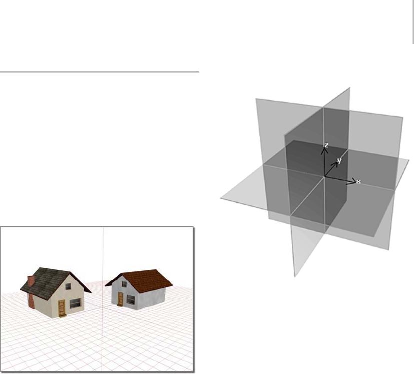
Home Grid: Views Based on the World Coordinate Axes 23
Home Grid: Views Based on the
World Coordinate Axes
The grid you see in each viewport represents
one of three planes that intersect at right angles
to one another at a common point called the
origin. Intersection occurs along three lines (the
world coordinate axes: X, Y, and Z) familiar from
geometry as the basis of the Cartesian coordinate
system.
Home Grid
Using the home grid to position houses
The three planes based on the world coordinate
axes are called the home grid; this is the basic
reference system of the 3D world.
To simplify the positioning of objects, only one
plane of the home grid is visible in each viewport.
Thefigureshowsallthreeplanesastheywould
appear if you could see them in a single perspective
viewport.
Axes, Planes, and Views
Home grid axes and planes
Twoaxesdefineeachplaneofthehomegrid.In
thedefaultPerspectiveviewport,youarelooking
across the XY plane (ground plane), with the X
axis running left-to-right, and the Y axis running
front-to-back. The third axis, Z, runs vertically
through this plane at the origin.
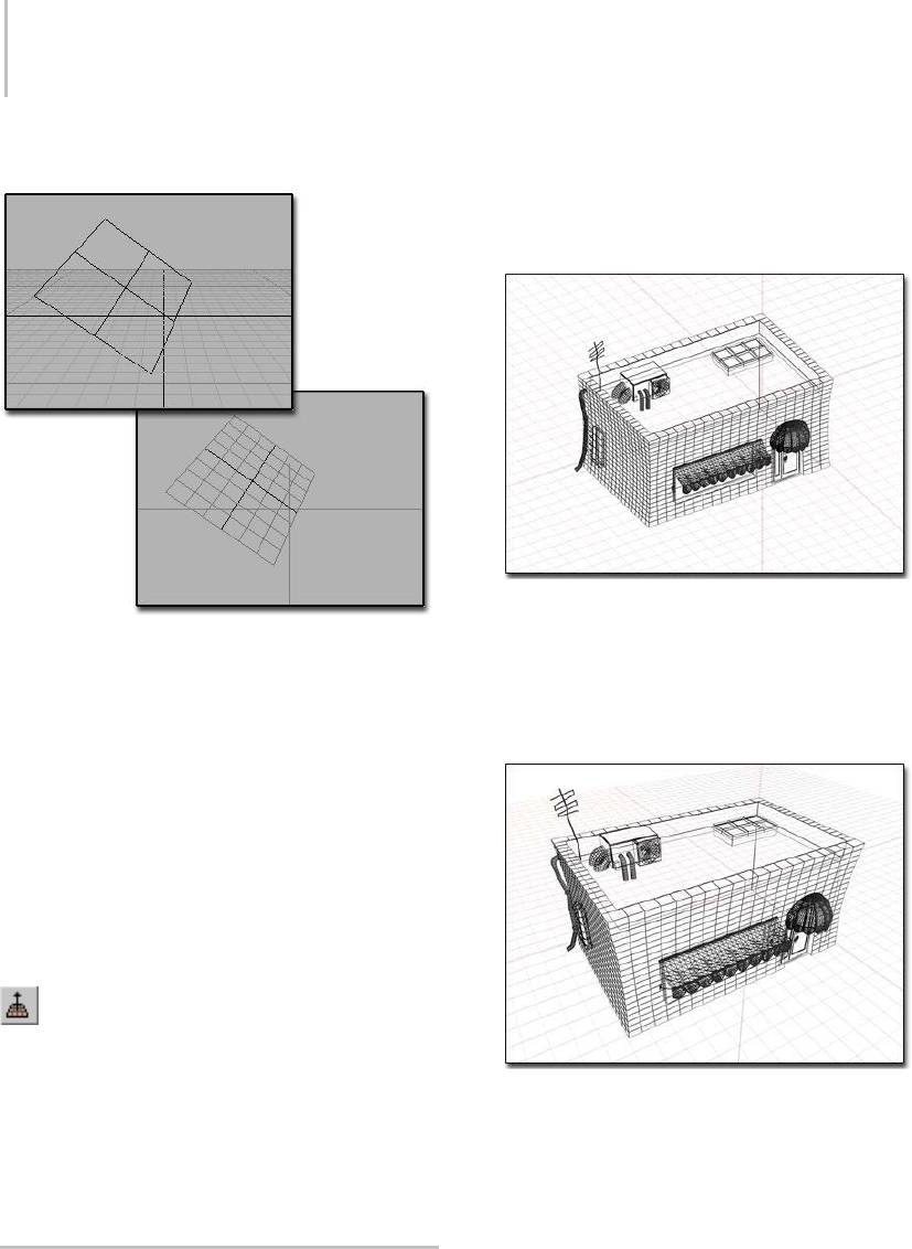
24 Chapter 2: Viewing and Navigating 3D Space
HomeGridandGridObjects
Above: Inactive grid object in a scene
Below:Activatedgridobject
Thehomegridisalignedwiththeworldcoordinate
axes. You can turn it on and off for any viewport,
butyoucan’tchangeitsorientation.
For flexibility, the home grid is supplemented by
grid objects: independent grids you can place
anywhere, at any angle, aligned with any object or
surface. They function as "construction planes"
you can use once and discard or save for reuse. See
Precision and Drawing Aids (page 2–1).
AutoGrid
The AutoGrid feature lets you create and activate
temporary grid objects on the fly. This lets you
create geometry off the face of any object by first
creating the temporary grid, then the object. You
also have the option to make the temporary grids
permanent. See AutoGrid (page 2–7).
Understanding Views
There are two types of views visible in viewports:
•Axonometric views (page 3–913) show the scene
without perspective. All lines in the model are
parallel to one another. The Top, Front, Left,
and User viewports are axonometric views.
Axonometric view of a scene
•Perspective views (page 3–992) show the
scene with lines that converge at the horizon.
The Perspective and Camera viewports are
examples of perspective views.
Perspective view of the same model
Perspective views most closely resemble human
vision, where objects appear to recede into the
distance, creating a sense of depth and space.
Axonometric views provide an undistorted view
of the scene for accurate scaling and placement. A
common workflow is to use axonometric views
to create the scene, then use a perspective view to
render the final output.
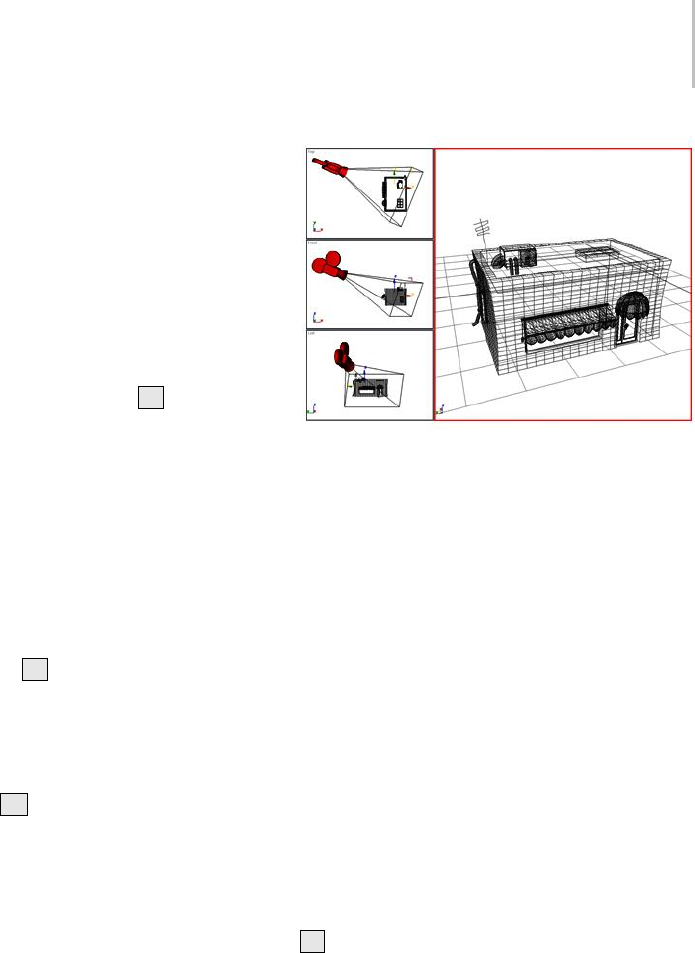
Understanding Views 25
Axonometric Views
There are two types of axonometric views you can
use in viewports: orthographic and rotated.
An orthographic view (page 3–986) is a straight-on
view of the scene, such as the view shown in the
Top, Front, and Left viewports. You can set a
viewport to a specific orthographic view using the
viewport right-click menu (page 3–731) or keyboard
shortcuts (page 3–871). For example, to set an
active viewport to Left view, press L.
You can also rotate an orthographic view to see
the scene from an angle while retaining parallel
projection. This type of view is represented by a
User viewport.
Perspective Views
A perspective viewport, labeled Perspective, is
one of the startup viewports in 3ds Max. You can
change any active viewport to this "eye-like" point
of view by pressing P.
Camera View
Once you create a camera object in your scene,
you can change the active viewport to a camera
view by pressing Cand then selecting from a list
of cameras in your scene. You can also create a
camera view directly from a perspective viewport,
using the Create Camera from View (page 1–48)
command.
A camera viewport tracks the view through the
lens of the selected camera. As you move the
camera (or target) in another viewport, you see the
scenemoveaccordingly.Thisistheadvantageof
the Camera view over the Perspective view, which
can’t be animated over time.
IfyouturnonOrthographicProjectionona
camera’s Parameters rollout, that camera produces
an axonometric view like a User view. See Cameras
(page 2–1365).
Theviewportontherightisseenthroughacamerainthescene.
Two and Three-Point Perspective and the
Camera Correction Modifier
By default, camera views use three-point
perspective, in which vertical lines appear to
converge with height (in traditional photography
this is known as keystoning). The Camera
Correction modifier (page 2–1392) applies
two-point perspective to a camera view. In
two-point perspective, vertical lines remain
vertical. A similar effect can be attained by putting
a Skew modifier on a camera.
Light View
Light view works much like a targeted camera
view.Youfirstcreateaspotlightordirectionallight
andthensettheactiveviewporttothatspotlight.
The easiest way is to press the keyboard shortcut
$.SeeLights (page 2–1272).
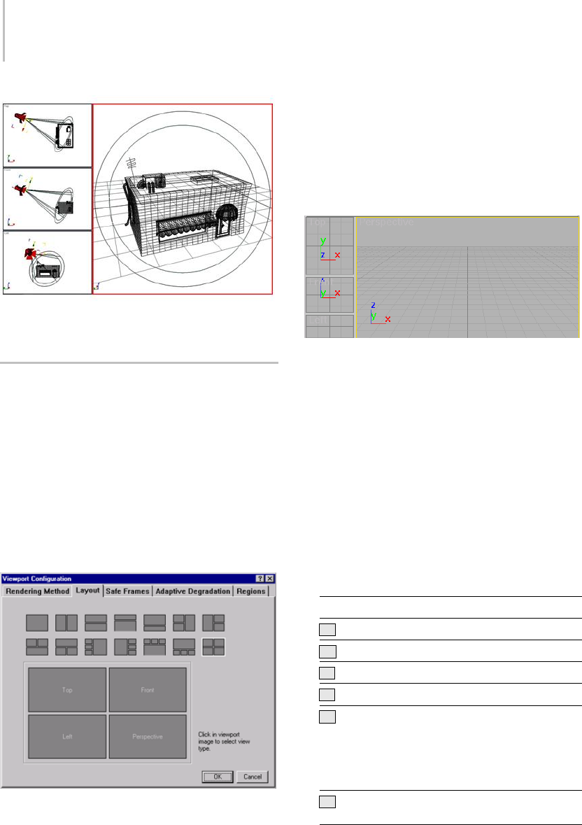
26 Chapter 2: Viewing and Navigating 3D Space
The viewport on the right looks through the lens of a spotlight
in the scene.
Setting Viewport Layout
3ds Max defaults to a two-over-two arrangement
of viewports. Thirteen other layouts are possible,
but the maximum number of viewports on the
screen remains four.
Using the Layout panel (page 3–856) of the
Viewport Configuration dialog, you can pick from
the different layouts and customize the viewports
in each. Your viewport configuration is saved with
your work.
Resizing the Viewport
After choosing a layout you can resize the
viewports so they have different proportions
by moving the splitter bars that separate the
viewports. This is only available when multiple
viewports are displayed.
Resized viewport
Changing the View Type
As you work, you can quickly change the view in
any viewport. For example, you can switch from
front view to back view. You can use either of two
methods: menu or keyboard shortcut.
• Right-click the label of the viewport you want
to change and click Views. Then, click the view
type that you want.
• Click the viewport you want to change, and
then press one of the keyboard shortcuts in the
following table.
Key View type
TTop view
BBottom view
FFront view
LLeft view
CCamera view. If your scene has only one
camera,oryouselectacamerabeforeusing
this keyboard shortcut, that camera supplies
the view. If your scene has more than one
camera, and none are selected, a list of
cameras appears.
PPerspective view. Retains viewing angle of
previous view.
Controlling Viewport Rendering 27
Key View type
UUser (axonometric) view. Retains viewing
angle of previous view. Allows use of Zoom
Region (page 3–742).
none Rightview.Useviewportright-clickmenu.
none Shape view. Use viewport right-click menu.
Automatically aligns view to the extents of a
selected shape and its local XY axes.
See also
Viewport Layout (page 3–856)
Camera Viewport Controls (page 3–745)
Spotlight Parameters (page 2–1338)
Precision and Drawing Aids (page 2–1)
Track View (page 2–501)
Controlling Viewport Rendering
Box display, wireframe display, and smooth shading
You can choose from multiple options to display
your scene. You can display objects as simple
boxes, or render them with smooth shading and
texture mapping. If you want, you can choose a
different display method for each viewport.
Tip: If you want to display individual objects as
wireframe, you can use Wireframe materials. If
you want individual objects to display as boxes,
youcanselecttheobjectandchooseDisplay
as Box on the Display properties rollout on the
display panel.
Using Viewport Rendering Controls
Viewport rendering options are found on the
Rendering Method panel (page 3–853) of the
Viewport Configuration dialog. Using this panel
you choose a rendering level and any options
associated with that level. You can then choose
whether to apply those settings to the active
viewport or all viewports, or to all but the active
viewport.
The rendering level you choose is determined
by your need for realistic display, accuracy, and
speed. For example, Box Mode display is much
faster than Smooth Shading with Highlights. The
more realistic the rendering level, the slower the
display speed.
Afterchoosingarenderinglevel,youcanset
rendering options. Different options are available
for different rendering levels.
Yo u c a n a l s o u s e ActiveShade (page 3–21) in a
viewport. This feature helps you quickly preview
changes you make to lighting and materials.
Viewport rendering has no effect on final
renderings produced by clicking Render Scene.
Rendering Methods and Display Speed
The rendering methods not only affect the quality
of your view display, they can also have a profound
effect on display performance. Using higher
quality rendering levels and realistic options slows
display performance.
After setting a rendering method, you can
choose additional options that adjust display
performance. One of these controls, Adaptive
Degradation, speeds up display performance when
you use realistic rendering levels.

28 Chapter 2: Viewing and Navigating 3D Space
Tip: If your scene mysteriously disappears and only
displays as boxes when you rotate your viewport,
youhavepressedthe“o”keyonthekeyboard,and
unintentionally turned on Adaptive Degradation.
See Rendering Method (page 3–853).
Controlling Display Performance
3ds Max contains controls to help you adjust
display performance: the balance between quality
and time in displaying objects.
Depending on your needs, you might give up some
display speed to work at higher levels of rendering
quality, or you might choose to maximize display
speed by using Wireframe or Bounding Box
display. Which method you choose depends on
your preferences and the requirements of your
work.
Display Performance Controls
You use display performance controls to determine
how objects are rendered and displayed.
Viewport Preferences
The Customize > Preferences dialog’s Viewports
panel contains options for fine-tuning the
performance of the viewport display software. See
Viewport Preferences (page 3–821).
How Objects Are Rendered
The Adaptive Degradation panel on the Viewport
Configuration dialog dynamically drops the
rendering level on display performance. You set
the parameters controlling the trade-off between
display quality and display speed.
How Objects Are Displayed
To see and modify an object’s display properties,
right-click the object, select Properties, and go
to the Display Properties group box; see Object
Properties (page 1–117).Theseoptionsaffect
display performance much the same way as
viewport rendering options. For example, turning
on Vertex Ticks for an object with a lot of vertices
will slow performance.
Note: Display Properties are only available when
the By Object/By Layer toggle is set to By Object.
Toseeandmodifyhowobjectsaredisplayed,you
can use layers (page 3–655).Youcanthenquickly
control the visibility and editability of similar
objects from the quad menu.
Which Objects Are Displayed
One way to increase display speed is not to display
something. You can use the Hide and Freeze
features on the Display panel or quad menu to
changethedisplaystateofobjectsinyourscene.
TheHideandFreezefeaturesalsoaffectfinal
Rendering and Video Post output. See Hide
Rollout (page 1–53) and FreezeRollout(page1–54).
Setting Adaptive Degradation
Adaptive Degradation dynamically adjusts your
rendering levels to maintain a desired level of
display speed. You have direct control over how
much "degradation" occurs and when it occurs.
Active and General Degradation use the same
choices as the viewport Rendering Levels panel.
Active Degradation controls rendering in the
active viewport while General Degradation
controls rendering in all other viewports.
The selected levels determine which rendering
levels 3ds Max falls back to when it cannot
maintain the desired display speed. You can
choose as many levels as you want but you are
advised to choose only one or two levels for each
type of degradation.
See Adaptive Degradation (page 3–905).
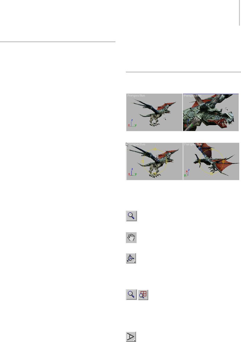
Using Standard View Navigation 29
Using Standard View Navigation
To navigate through your scene, use the view
navigation buttons located at the lower-right
corner of the program window. All view types,
except Camera and Light views, use a standard set
of view navigation buttons.
Button Operation
Clicking standard view navigation buttons
produces one of two results:
• Executes the command and returns to your
previous action.
• Activates a view navigation mode.
Youcantellthatyouareinamodebecausethe
button remains selected and is highlighted. This
mode remains active until you right-click or
choose another command.
While in a navigation mode, you can activate other
viewports of the same type, without exiting the
mode, by clicking in any viewport. See Viewport
Controls (page 3–729).
Undoing Standard
View Navigation Commands
Use the Undo View Change and Redo View Change
commands (page 1–36) on the Views menu to
reset standard view navigation commands without
affecting other viewports or the geometry in your
scene. These commands are also found in the
menu displayed when you right-click a viewport
label.
Views menu > Undo and Views menu > Redo
are separate from Undo and Redo on the Edit
menu or the toolbar. 3ds Max maintains separate
Undo/Redo buffers for scene editing and for each
viewport.
The View Undo/Redo buffer stores your last 20
view navigation commands for each viewport.
You can step back through the Undo View/Redo
Viewbufferuntilyouhaveundoneallofthestored
view-navigation commands.
Zooming, Panning, and Rotating
Views
Before and after zooming a viewport
Before and after rotating a viewport
When you click one of the view navigation buttons,
you can change these basic view properties:
View magnification—Controls zooming in
and out.
View position—Controls panning in any
direction.
View rotation—Controls rotating in any
direction
Zooming a View
Click Zoom (page 3–739) or Zoom All
(page 3–740) and drag in a viewport to change the
view magnification. Zoom changes only the active
view, while Zoom All simultaneously changes all
non-camera views.
If a perspective view is active, you can also
click Field of View (FOV) (page 3–741).Theeffect
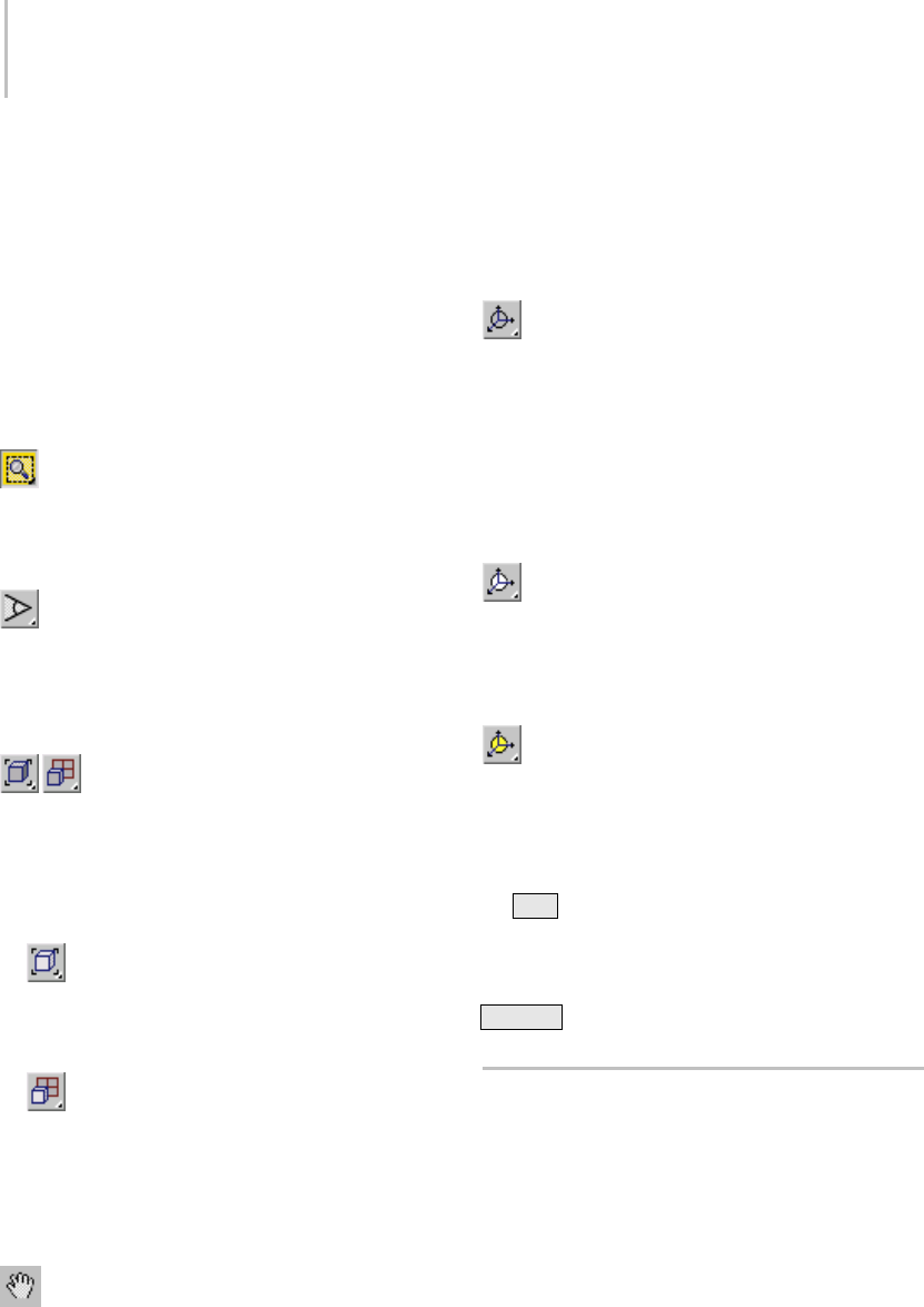
30 Chapter 2: Viewing and Navigating 3D Space
of changing FOV is similar to changing the lens on
a camera. As FOV gets larger you see more of your
scene and perspective becomes distorted, similar
to using a wide-angle lens. As FOV gets smaller
you see less of your scene and the perspective
flattens, similar to using a telephoto lens.
Warning: Be cautious using extreme Field of View
settings. These can produce unexpected results.
Zooming a Region
Click Zoom Region (page 3–742) to drag a
rectangular region within the active viewport and
magnify that region to fill the viewport. Zoom
Region is available for all standard views.
In a perspective viewport, Zoom Region
mode is available from the Field of View flyout
(page 3–741).
Zooming to Extents
Click the Zoom Extents or Zoom Extents
All flyout buttons to change the magnification
and position of your view to display the extents
of objects in your scene. Your view is centered on
the objects and the magnification changed so the
objects fill the viewport.
•The Zoom Extents, Zoom Extents Selected
buttons (page 3–737) zoomtheactiveviewport
to the extents of all visible or selected objects
in the scene.
•The Zoom Extents All, Zoom Extents
All Selected buttons (page 3–737) zoom all
viewportstotheextentsofallobjectsorthe
current selection.
Panning a View
Click Pan View (page 3–743) and drag in
a viewport to move your view parallel to the
viewport plane. You can also pan a viewport by
draggingwiththemiddlemousebuttonhelddown
while any tool is active.
Rotating a View
Click Arc Rotate, Arc Rotate on Selection, or
Arc Rotate Sub-Object (page 3–744) to rotate your
view around the view center, the selection, or the
current sub-object selection respectively. When
you rotate an orthogonal view, such as a Top view,
it is converted to a User view.
With Arc Rotate, if objects are near the edges of
the viewport they might rotate out of view.
With Arc Rotate Selected, selected objects
remainatthesamepositionintheviewportwhile
the view rotates around them. If no objects are
selected, the function reverts to the standard Arc
Rotate.
With Arc Rotate Sub-Object, selected
sub-objects or objects remain at the same position
intheviewportwhiletheviewrotatesaround
them.
Note: Yo u c a n r o t a t e a v i e w b y h o l d i n g d o w n
the Alt key while you drag in a viewport using
middle-button. This uses the current Arc Rotate
mode, whether or not the Arc Rotate button is
active. You can also activate Arc Rotate by pressing
Ctrl+R .
Using Walkthrough Navigation
Walkthrough navigation lets you move through
a viewport by pressing a set of shortcut keys,
including the arrow keys, much as you can navigate
a3Dworldinmanyvideogames.
When you enter the walkthrough navigation
mode, the cursor changes to a hollow circle that
shows a directional arrow while you are pressing
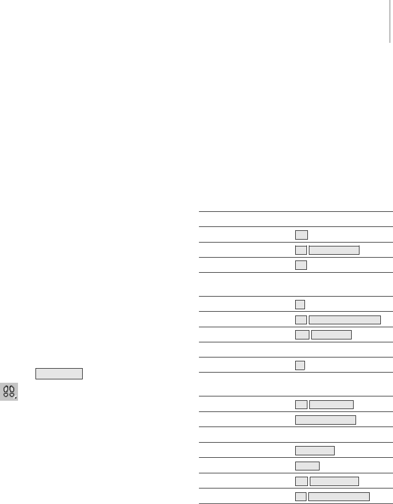
Using Walkthrough Navigation 31
one of the directional keys (forward, back, left, or
right).
This feature is available for perspective and camera
viewports. It is not available for orthographic
views or for spotlight viewports.
Animating a Walkthrough
Whenyouusewalkthroughnavigationina
Camera viewport, you can animate the camera
walkthrough using either Auto Key (page 3–717)
or Set Key (page 2–280).Ineithercase,togetan
animatedcamerayouhavetochangetheframe
number manually (the easiest way is to use the
Time Slider (page 3–701)), and in the case of Set
Key,youhavetochangetheframenumberand
click Set Keys.
Tip: Selectthecamerabeforeyouanimateit.Ifthe
camera isn’t selected, its keys won’t appear in the
Track Bar (page 3–703).
Procedures
To begin using walkthrough navigation, do one of
the following:
•PresstheUp Arrow key.
•Click the Walk T hroug h but ton (page
3–738) to turn it on.
This button is found on the Pan/Truck And
Walkthrough flyout (page 3–738).
To stop using walkthrough navigation, do one of
the following:
•Right-click.
•Activateadifferentviewport.
• Change the active viewport to a different type.
• Turnonadifferentviewportnavigationtool
(such as Zoom or Pan).
• Turn on Select Object or one of the transform
tools.
Note: Yo u do not exit walkthrough mode when
you select an object or change the viewport
shading type (between shaded and wireframe, for
example).
Interface
The Walk Through button is the only graphical
element of the interface to walkthrough navigation.
The other features are provided by mouse actions
or by keyboard shortcuts. The following table
shows the keyboard actions:
Command Shortcut
Accelerate Toggle Q
Back S,Down Arrow
Decelerate Toggle Z
Decrease Rotation
Sensitivity
Decrease Step Size [
Down C,Shift+Down Arrow
Forward W,Up Arrow
Increase Rotation Sensitivity
Increase Step Size ]
Invert Vertical Rotation
Toggle
Left A,Left Arrow
Level Shift+Spacebar
Lock Horizontal Rotation
Lock Vertical Rotation Spacebar
Reset Step Size Alt+[
Right D,Right Arrow
Up E,Shift+Up Arrow
If nothing appears in the Shortcut column, no
default key is assigned to this command. You can
set custom keystrokes using the Keyboard panel
(page 3–793) of the Customize User Interface
dialog.
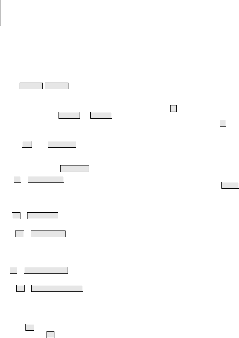
32 Chapter 2: Viewing and Navigating 3D Space
Forward, Backward, and Sideways Movement
Formovement,youcanuseeitherthearrowkeys,
or letters at the left of the keyboard pad.
Tip: When you are in a Perspective viewport,
you can use Undo View Change and Redo View
Change ( Shift+Z ,Shift+Y )toundoorredo
your navigation. However, when you are in
aCameraviewport,walkthroughanimation
transforms the camera object, so you must use Edit
>UndoandEdit>Redo(Ctrl+Z and Ctrl+Y ).
Holding down any of these keys causes the motion
to be continuous.
Forward— Wor the Up Arrow .Movesthe
camera or the viewpoint forward.
Note: If you are not already in walkthrough
navigation mode, pressing Up Arrow enters it.
Back— Sor Down Arrow .Movesthecameraor
the viewpoint backward.
When you are in a camera viewport, Forward and
Back are equivalent to dollying in or out.
Left— Aor Left Arrow .Movesthecameraor
the viewpoint to the left.
Right— Dor Right Arrow .Movesthecamera
or the viewpoint to the right.
When you are in a camera viewport, Left and
Right are equivalent to trucking left or right.
Up— Eor Shift+Up Arrow . Moves the camera
or the viewpoint up.
Down— Cor Shift+Down Arrow .Movesthe
camera or the viewpoint down.
Acceleration and Deceleration
Accelerate Toggle and Decelerate Toggle—Pressing
Accelerate ( Q)causesmotiontobequicker.
Pressing Decelerate ( Z)causesmovementtobe
slower. These controls are toggles: pressing the
key a second time restores the default motion rate
(and pressing the alternate key turns off the first).
They are especially useful when you are navigating
by holding down keys.
The acceleration and deceleration toggles are
independent of the step size.
Adjusting Step Size
Increase Step Size and Decrease Step Size—Pressing
Increase Step Size ( ])increasesthemotion
increments when you move the camera or
viewpoint. Pressing Decrease Step Size ( [)
reduces them. You can press either of these
shortcuts repeatedly, to increase the effect.
Changingthestepsizeisapparentwhenyou
navigate either by single clicks, or by holding down
keys. Stepsizechangesareusefulforadjusting
movement to the scale of the scene. They are saved
with the MAX file.
Reset Step Size—Pressing Reset Step Size ( Alt+[ )
restoresthestepsizetoitsdefaultvalue.
The step size is independent of acceleration or
deceleration.
Rotation (Tilting)
Tilt View—Click+drag to tilt the camera or
viewpoint.
Whenyouareinacameraviewport,TiltViewis
equivalent to panning the camera.
Increase Rotation Sensitivity and Decrease Rotation
Sensitivity—Pressing Increase Rotation Sensitivity
(no default key) increases the motion increments
when you use Tilt View. Pressing Decrease
Rotation Sensitivity (no default key) decreases
them. You can press either of these shortcuts
repeatedly, to increase the effect. They are useful
for adjusting movement to the scale of the scene.
They are saved with the MAX file.
Lock Horizontal Rotation—Pressing Lock
Horizontal Rotation (no default key) locks the
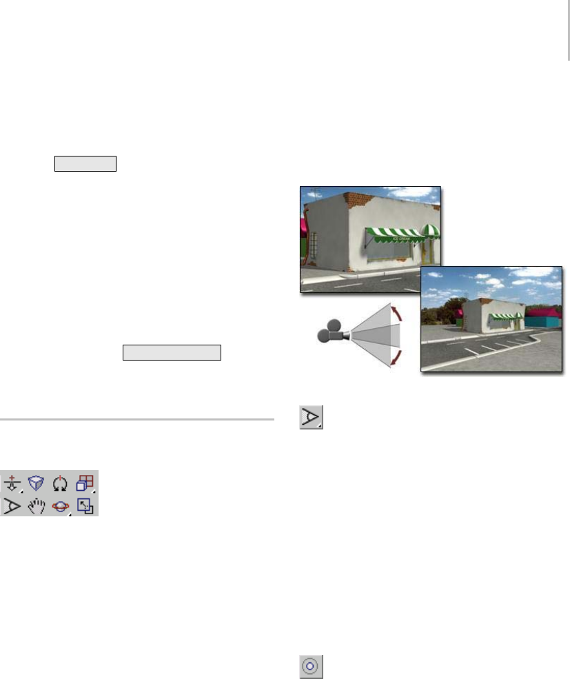
Navigating Camera and Light Views 33
horizontal axis, so the camera or viewpoint tilts
only vertically.
Lock Vertical Rotation—Pressing Lock Vertical
Rotation ( Spacebar )lockstheverticalaxis,so
the camera or viewpoint tilts only horizontally.
Invert Vertical Rotation Toggle—Pressing Invert
Vertical Rotation (no default key) inverts the tilt
directionwhenyoudragthemouse. Whenthis
toggle is off, dragging up causes scene objects to
descend in the view, and dragging down causes
them to rise (this is like tilting a physical camera).
Whenthistoggleison,objectsintheviewmovein
thesamedirectionyouaredraggingthemouse.
Level—Pressing Level ( Shift+Spacebar )removes
anytiltorrollthecameraorviewpointmighthave,
making the view both level and vertical.
Navigating Camera and Light
Views
The camera navigation buttons
The Camera and Light view navigation buttons
are the same with a few exceptions. The buttons
are visible when a viewport with a Camera or
Light view is active. The Camera and Light view
navigation buttons do more than adjust your view.
They transform and change the parameters of the
associated camera or light object.
Lightviewstreatthelight(spotlightordirectional
light) as if it were a camera. The light falloff is
treated the same as the camera field of view.
Keep in mind the following:
•UsingtheCameraandLightviewport
navigation buttons is the same as moving or
rotating the camera or Light, or changing their
base parameters.
• Changes made with Camera or Light view
navigation buttons can be animated the same
as other object changes.
Zooming a Camera or Light View
Zooming a camera
Yo u z o o m a c a m e r a v i e w b y c l i c k i n g FOV
(page 3–741) andthendraggingintheCamera
viewport.
The field of view defines the width of your view as
an angle with its apex at eye level and the ends at
thesidesoftheview.TheeffectofchangingFOVis
exactly like changing the lens on a camera. As the
FOV gets larger you see more of your scene and
the perspective becomes distorted, similar to using
awide-anglelens. AstheFOVgetssmalleryou
see less of your scene and the perspective flattens,
similar to using a telephoto lens. See Cameras
(page 2–1365).
Click Light Hotspot (page 3–752) for a light
viewport to achieve the same effect as zooming.
The hotspot is the inner of the two circles or
rectangles visible in a light viewport. Objects
insidethehotspotareilluminatedwiththe
full intensity of the light. Objects between the
hotspot and falloff are illuminated with decreasing
intensity as objects approach the falloff boundary.
See Using Lights (page 2–1274).
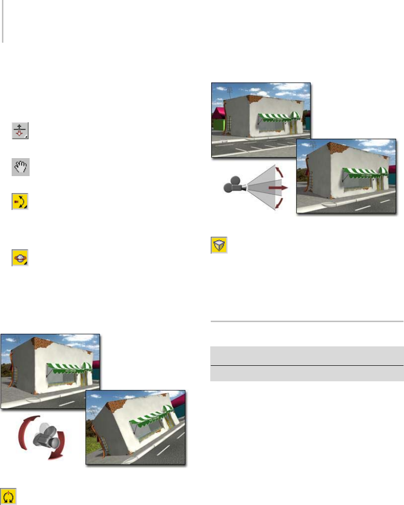
34 Chapter 2: Viewing and Navigating 3D Space
MovingaCameraorLightView
You move a camera or light view by clicking one of
the following buttons and dragging in the camera
or light viewport.
•Dolly (page 3–746) moves the camera or
light along its line of sight.
•Truck (page 3–748) moves the camera or
light and its target parallel to the view plane.
•Pan (page 3–749) moves the target in a
circle around the camera or light. This button
is a flyout that shares the same location with
Orbit.
•Orbit (page 3–749) moves the camera
or light in a circle around the target. The
effect is similar to Arc Rotate for non-camera
viewports.
Rolling a Camera or Light View
Rolling a camera
Click Roll (page 3–747), and drag in a camera
or a light viewport to rotate the camera or light
about its line of sight. The line of sight is defined
asthelinedrawnfromthecameraorlighttoits
target. The line of sight is also the same as the
camera’s or the light’s local Z axis.
Changing Camera Perspective
Changing perspective
Click Perspective (page 3–747), and drag in
a camera viewport to change the Field of View
(FOV) and dolly the camera simultaneously. The
effect is to change the amount of perspective flare
while maintaining the composition of the view.
Adaptive Degradation Toggle
Views menu > Adaptive Degradation Toggle
Keyboard > O(the letter O)
When on (the default), the Adaptive Degradation
Toggle supersedes the adaptive degradation
(page 3–905) that can occur when you transform
geometry, change the view, or play back an
animation in a shaded viewport. In this case,
the geometry remains shaded even if that slows
down viewport display and animation playback.
Animation playback might drop frames if the
graphics card cannot display frames in real time.
Turn off the Adaptive Degradation Toggle if you
have large models you need to navigate around
and if you are finding performance sluggish.
Adaptive degradation causes shaded objects to be
replaced by a quicker display mode. By default,
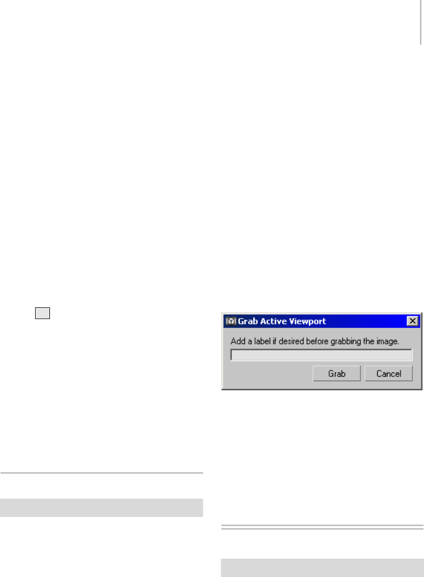
Grab Viewport 35
shaded objects are replaced by their bounding
boxes.
You can change the display option, and set
other adaptive degradation parameters, on the
Viewport Configuration dialog (Customize menu
> Viewport Configuration > Adaptive Degradation
panel (page 3–859)).
Note: When you use arc rotate (page 3–744) in a
shaded viewport while the Adaptive Degradation
Toggle is off, objects degrade to bounding boxes
regardless of the adaptive degradation settings.
Procedures
To turn off or override adaptive degradation, do one
of the following:
• Choose Views menu > Adaptive Degradation
To g g l e .
•Press
O(the letter O).
To change the level of adaptive degradation in the
viewport:
1. Right-click the viewport label and choose
Configure, or choose Customize > Viewport
Configuration.
2. On the Viewport Configuration dialog, open
theAdaptiveDegradationpanel.
3. Adjust settings in the General and Active
Degradation group boxes.
Grab Viewport
Tools menu > Grab Viewport
Grab Viewport creates a snapshot of the active
viewport in the Rendered Frame Window (page
3–5), where you can save it as an Imagefile(page
3–608).
Procedure
To create a snapshot of a viewport:
1. Activate the viewport you want to capture.
2. Choose Tools menu > Grab Viewport.
A dialog appears that allows you to add a label
to your snapshot.
3. Enter a label for your snapshot, if desired.
The label appears in the lower-right corner of
the image as you enter it into the dialog.
4. Click Grab.
The Rendered Frame Window opens to display
a snapshot of your viewport.
5. UsethecontrolsintheRenderedFrame
Window to save your image.
Interface
Label—Enter text here to add a label to your
screenshot. The text you enter is displayed in the
lower-right corner of your screenshot.
Grab—Opens the Rendered Frame Window with a
snapshot of the active viewport.
Cancel—Cancels the Grab Viewport command.
View-Handling Commands
Menu bar > Views menu
These viewport-handling commands are provided
on the default main menu:

36 Chapter 2: Viewing and Navigating 3D Space
Views Menu (page 3–675)
Undo View Change / Redo View Change (page
1–36)
Save Active View (page 1–37)
Restore Active View (page 1–37)
Display Color Rollout (page 1–52)
Grid Commands (page 2–33)
Viewport Background Dialog (page 1–38)
Select Background Image Dialog (page 1–42)
Update Background Image (page 1–44)
Reset Background Transform (page 1–45)
Show Transform Gizmo (page 1–45)
Show Ghosting (page 1–46)
Show Key Times (page 1–46)
Shade Selected (page 1–47)
Show Dependencies (page 1–47)
Create Camera From View (page 1–48)
Add Default Lights to Scene (page 1–49)
Redraw All Views (page 1–50)
Activate All Maps (page 1–50)
Deactivate All Maps (page 1–50)
Update During Spinner Drag (page 1–51)
Adaptive Degradation Toggle (page 1–34)
Smart Object Culling (page 1–58)
Expert Mode (page 1–51)
See also
Viewing and Navigating 3D Space (page 1–21)
Views Menu (page 3–675)
Quad Menu (page 3–694)
Undo View Change / Redo View
Change
Views menu > Undo View Change or Redo View Change
Keyboard > Shift+Z (Undo) or Shift+Y (Redo)
Undo View Change cancels the last change made to
thecurrentviewport.RedoViewChangecancels
thelastUndointhecurrentviewport.
These commands act like Undo and Redo on the
Main toolbar and Edit menu, but operate on a
different list of events. They affect changes made to
the viewport, rather than changes made to objects
in the viewport.
Use Undo View Change and Redo View Change
when you have inadvertently made a view unusable
by zooming in too close, or rotating the wrong
way. You can keep stepping back until a useful
view appears. The keyboard shortcuts are handy
for multiple commands.
You can also access Undo View Change and Redo
View Change of view changes by right-clicking the
viewport label and choosing Undo View or Redo
View. The last change made in that viewport will
be indicated (for example, "Undo View Zoom").
Each viewport has its own independent undo/redo
stack.
Camera and Spotlight viewports use object-based
Undo and Redo, because the viewport change is
actually a change to the camera or spotlight object.
In these viewports, use Edit > Undo ( Ctrl+Z )or
Edit > Redo ( Ctrl+Y ).
Interface
Undo View Change—Cancels viewport changes.
Thenameofthechangeyou’reundoingis
displayed in the View menu beside the command.
Undo is useful when you are working with a
background image in the viewport. You can zoom

Save Active View 37
into the geometry to adjust it, then use Undo
Viewport Zoom to restore the original alignment
of the geometry with the background.
Redo View Change—Cancels the previous Undo
View Change. The name of the change you’re
redoing appears in the View menu beside the
command.
Save Active View
Views menu > Save Active View (the name of the active
viewport is part of the command)
Save Active View stores the active view to an
internal buffer. If you have framed a shot in any
view other than a camera, use Save Active View
to preserve the viewport’s appearance. The saved
active view is saved with the scene file. Once saved,
you can retrieve it using Restore Active View (page
1–37).
Theviewportthatwillberestoredisdisplayed
in the menu item (for example, "Save Active
Perspective View"). You can save and restore up
to eight different views (Top, Bottom, Left, Right,
Front, Back, User, Perspective).
Viewport changes that are saved include viewport
type, zoom and rotations, and field-of-view
(FOV).
Theoptionsavailableontheviewport right-click
menu (page 3–731),suchasShowSafeFrameand
Viewport Clipping, are not saved. If these settings
areimportanttotheview,makeanoteofwhatthey
are so you can reset them after restoring the view.
Procedure
To save an active view:
1. Activate the viewport with the view you want
to save.
2. Choose Views menu > Save Active View. The
view is now saved and can be recalled using
RestoreActiveView.
Restore Active View
Viewsmenu>RestoreActiveView(thenameofthe
active viewport is part of the command.)
RestoreActiveViewdisplaystheviewpreviously
stored with Save Active View (page 1–37).
The viewport to be restored is displayed in
themenuitem(forexample,"RestoreActive
Perspective View").
Theactiveviewisrestoredifthesameviewport
and layout are active.
If an active view won’t restore with this command,
check the following:
•Besuretheviewportisactive.
• Makesurethelayoutisthesameasbefore.
Use Viewport Configuration (right-click any
viewport label and choose Configure) and
choose Layout.
• If the layout and active viewport are the same,
be sure Viewport Clipping on the Viewport
Right-Click Menu (page 3–731) is set the same
as it was when the viewport was saved.
Procedure
To restore a saved view:
1. Activate the viewport where you saved the view.
2. Choose Views menu > Restore Active View.
This option is available only in a viewport with
a saved view.
3. Theviewportreturnstothesavedview.
Ifyou’renotsurewhetheraviewporthasa
saved view, check the Views menu. Restore
Active View is unavailable unless a view is saved
in the active viewport.
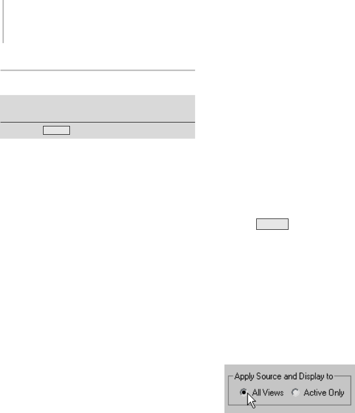
38 Chapter 2: Viewing and Navigating 3D Space
Viewport Background Dialog
Views menu > Viewport Background > Viewport
Background dialog
Keyboard > Alt+B
The Viewport Background dialog controls display
of an image or animation as the background for
one or all viewports.You can use this for modeling,
for example, by placing front, top or side view
sketches in the corresponding viewports. Or use
Viewport background to match 3D elements with
digitized camera footage, or for rotoscoping (page
3–1003).
Yo u s e l e c t t h e i m a g e o r a n i m a t i o n t o d i s p l ay i n
the active viewport, set the frame synchronization
between the animated image file and the current
scene, and turn the assigned image on and off.
These changes do not affect the rendered scene.
Toplaceanimageinthebackgroundofthe
rendered scene, use the Environment And Effects
dialog > Environment panel (page 3–271), accessed
from the Rendering menu.
Note: When safe frames are displayed in a viewport,
and the Aspect Ratio options are set to either
Match Viewport or Match Rendering Output, the
assigned viewport background image is confined
to the Live area of the safe frames and will correctly
match the rendered background bitmap.
Tip: If you are using a viewport driver with
hardware acceleration (OpenGL or Direct3D),
the viewport background might not appear. If
this happens, choose Customize > Preferences.
In the Viewports preferences (page 3–821),click
Configure Driver. Then in the Configure OpenGL
dialog (page 3–841) or the Configure Direct3D
dialog (page 3–844),gototheBackgroundTexture
Size group and turn on Match Bitmap Size As
Closely As Possible (do not change the numeric
setting). Click OK in both dialogs to accept your
change.
See also
Select Background Image Dialog (page 1–42)
Update Background Image (page 1–44)
Reset Background Transform (page 1–45)
Procedures
To assign an image to one or all viewports:
1. Activatetheviewportthatistodisplaythe
background image.
2. Choose Views menu > Viewport Background
or press Alt+B .
This opens the Viewport Background dialog.
3. In the Background Source group, click the Files
button.
This opens the Select Background Image dialog.
4. Use the dialog to open the image or animation
to use.
5. To display the image in all viewports, choose
All Views in the Apply Source And Display To
group.
6. Click OK.
The image is displayed in a single viewport or
all viewports.
To update the image or map in the viewport:
Because of the time it takes to render the image or
map in the viewport, the map is not automatically
updated when you alter the bitmap or assign a new
bitmap.
• ChooseViewsmenu>UpdateBackground
Image.

Viewport Background Dialog 39
The revised image or map is displayed in the
viewport.
To display the environment map in a viewport:
1. In the Environment dialog, assign an
environment map. (See the procedure “To
choose an environment map.” (page 3–272))
2. In the Environment dialog > Background
group, be sure Use Map is turned on (the
default).
3. Activatetheviewportwhereyouwantthemap
displayed.
4. Choose Views menu > Background Image.
5. In the Viewport Background dialog >
Background Source group, turn on Use
Environment Background.
6. Click OK.
The map is displayed in the viewport.
To display an animated back ground:
1. Assign an animation file (AVI, MOV, or IFL
file)astheviewportbackground.
2. Tur n on A ni mate Bac kg rou nd .
3. Choose Customize > Preferences. On the
Viewportspanel,turnonUpdateBackground
While Playing.
Now the background plays when you click Play,
or when you drag the time slider.
Tip: If you follow these steps and the background
still doesn’t appear to animate, open the Time
Configuration dialog (page 3–725) and in the
Playback group, turn off Real Time.
To use the environment map with animation
controls:
Thisprocedureisusefulifyou’veassignedan
animated environment map and want access to the
animationcontrolsontheViewportBackground
dialog.
1. In the Viewport Background dialog >
Background Source group, turn off Use
Environment Background.
2. Inthesamegroup,clickFile.
3. Choose the same map you’re using as the
environment map.
4. Set parameters in the Animation
Synchronization group.
5. Click OK.
The environment map appears in the viewport.
The image is renderable.
To match the viewport background with the
rendered background:
1. Activate the viewport to render.
2. Right-click the viewport label and choose Show
Safe Frame.
This turns on Safe Frames (page 3–857) in the
viewport.
Note: You can also use Views menu > Configure
>SafeFrametab.IntheApplicationgroup,
turn on Show Safe Frames In Active View.
3. In the Material Editor, create a material
that contains the bitmap for your rendered
background.
4. At the bitmap level of the Material Editor, on
the Coordinates rollout, choose Environ.
The Mapping control is automatically set to
Screen. Thisistheonlymappingtypethat
works for this purpose.
5. On the main menu, choose Rendering >
Environment.
6. Drag the map from the Material Editor > Maps
rollouttotheEnvironmentMapbuttononthe
Environment dialog. Click OK on the Instance
(Copy) Map dialog.
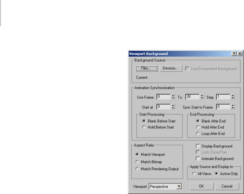
40 Chapter 2: Viewing and Navigating 3D Space
7. In the Viewport Background dialog >
Background Source group, click Files to assign
the same bitmap.
8. In the Aspect Ratio group, turn on either Match
Viewport or Match Rendering Output. Click
OK.
9. Render the viewport.
The background displayed in the rendered
scene should exactly match the background
displayed in the Live area of the safe frames.
Note: When you use the Match Bitmap option,
the bitmap reverts to its original aspect ratio
and does not match the rendered scene, unless
you’re rendering to the same aspect ratio.
To remove a background image:
1. Activate the viewport in which the background
image is visible.
2. On the Views menu, choose Viewport
Background.
Noticethenameandpathofthebackground
file is displayed in the Current field in the
Background Source group
3. In the Background Source group, click Devices.
4. On the Select Image Input Device dialog,
chooseNoI/OHandlersfromthedrop-down
list, then click OK.
5. On the Bitmap Manager Error dialog, click OK.
The current field no longer displays the
background file name. Instead No I/O Handler
is listed in the Current field.
6. Click OK to close the Viewport Background
dialog.
Next time you open up the Viewport
Backgrounddialog,nofilenamewillbe
displayed in the Current field.
Tip: This technique will work only on systems
thatdon’thaveanyotherImageInputDevices
installed.
Interface
Background Source group
Options let you select the background image,
either from a bitmap image file (page 3–917),
a video file, or from a device such as a video
recorder.
Files—Displays the Select Background Image dialog
(page 1–42), which lets you select a file or sequence
of files for your background.
Devices—Displays the Select Image Input Device
dialog. This lets you use a background from a
digital device. (No device is supported by the
default 3ds Max installation.)
Use Environment Background—Lets you display
in the viewports the map you’ve assigned as your
environment background. If no environment
map has been assigned in the Environment
dialog, or Use Map in that dialog is off, then the
Use Environment Background check box is not
available.

Viewport Background Dialog 41
Animation Synchronization group
Controls how sequences of images (for example,
from IFL (page 3–616),AVI (page 3–609),or
MOV (page 3–621) files) are synchronized to the
viewport for rotoscoping (page 3–1003).
Use Frame—The first field sets the first frame of the
incoming sequence that you want to use, and the
second field sets the last one.
Step—Sets the interval between the frames you
want to use. For example, if this spinner is set to 7,
3ds Max uses every seventh frame.
Start At—Specifies the frame number at which you
want the first input frame to appear. What happens
in the viewport before the start frame depends
on the option you choose for "Start Processing,"
below.
Sync Start To Frame—Determines which frame
from your incoming sequence is displayed at the
Start At frame. For example, you could have a
30-frame IFL sequence that starts in your scene at
frame10,butyoucouldusethe5thframefromthe
IFL on frame 10 by setting Sync Start to 5.
Start Processing group
Determines what happens in the viewport
background before the start frame.
Blank Before Start—Makes the viewport
background blank before the start frame.
Hold Before Start—Specifies that the viewport
background will contain the start frame.
End Processing group
Determines what happens in the viewport
background after the last input frame.
Blank After End—Makes the viewport background
blank after the last input frame.
Hold After End—Specifies that the viewport
background will contain the last input frame until
the last frame in the animation.
Loop After End—Specifies that the viewport
background will loop from the end frame back to
the start frame, ad infinitum.
Aspect Ratio group
Controls the proportions of the viewport
background by matching it to the bitmap,
rendering output, or to the viewport itself.
Match Viewport—Changes the aspect ratio (page
3–911) of the image to match the aspect ratio of
the viewport.
Match Bitmap—Locks the aspect ratio of the image
to the native aspect ratio of the bitmap.
Match Rendering Output—Changes the aspect
ratiooftheimagetomatchtheaspectratioofthe
currently chosen rendering output device.
Note: When the Match Bitmap or Match Rendering
Output option is chosen, 3ds Max centers the
imageandclearstheedgesoftheviewporttothe
background color.
Display Background
Turns on display of the background image or
animation in the viewport.
Lock Zoom/Pan
Locks the background to the geometry during
zoom and pan operations in orthographic or
user viewports. When you Zoom or Pan the
viewport, the background zooms and pans along
withit.WhenLockZoom/Panisturnedoff,the
background stays where it is, and the geometry
moves independently of it. Use Match Bitmap
or Match Rendering Output to enable Lock
Zoom/Pan. This control is disabled if you choose
Match Viewport.
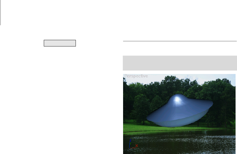
42 Chapter 2: Viewing and Navigating 3D Space
Keyboard shortcut: Ctrl+Alt+B
Warning: If you zoom in too far, you can exceed the
limit of virtual memory, and crash 3ds Max. When you
perform a zoom that requires more than 16 megabytes
of virtual memory, an alert asks if you want to display the
background during the zoom. Choose No to perform
the zoom and turn off the background. Choose Yes to
zoom with the background image. Your machine might
run out of memory as a result.
Animate Background
Turnsonanimationofthebackground.Showsthe
appropriateframeofthebackgroundvideointhe
scene.
ApplySourceAndDisplayTogroup
All Views—Assigns the background image to all
viewports.
Active Only—Assigns the background image to
only the active viewport.
Viewport
Thenameofthecurrentlyactiveviewportappears
in a list to the left of the OK and Cancel buttons.
This reminds you which viewport you’re working
with and lets you change the active viewport by
selecting its name from the list.
Note: When you use different images for different
viewports, the settings for each viewport are stored
separately. Each time you display the Viewport
Background dialog, the settings of the currently
active viewport are displayed. If you switch the
viewport using the list, the settings remain the
same.Thisisusefulforcopyingsettingsfromone
viewport to another.
Select Background Image Dialog
Views menu > Viewport Background > Background
Source group > Files > Select Background Image dialog
UFO model rendered against a background
The Select Background Image dialog allows you
to choose a file or sequence of files for a viewport
background.
You can also convert a set of sequentially numbered
files to an Image File List (IFL) (page 3–616).This
isthesameprocessusedbytheIFL Manager Utility
(page 3–619).
Procedures
To select a background image for a viewport:
1. Activatetheviewportwhereyouwantthe
image.
2. Choose Views menu > Viewport Background.
3. Under Background Source in the dialog that
displays, click Files.
4. In the Look In field, navigate to the directory
containingthefileyouwanttouseforthe
background.
Note: The Select Background Image File dialog
uses the last location where a bitmap was
chosen, rather than the default bitmap path
defined on the Configure User Paths dialog
(page 3–808).
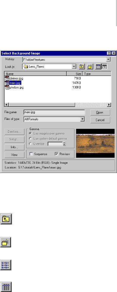
Select Background Image Dialog 43
5. Highlight the file name in the file list window.
6. Click Open to select the image and close the
dialog.
7. Click OK to close the Viewport Background
dialoganddisplaythebackgroundimage.
To select a set of still images as a viewport
background:
1. Activatetheviewportwhereyouwantthe
image.
2. Choose Views menu > Viewport Background.
3. Under Background Source, click Files.
4. IntheLookInfield,navigatetothedirectory
containing the sequence of files.
The files must be sequentially numbered
(for example, image01.bmp, image02.bmp,
image03.bmp).
Tip: If necessary, change Files Of Type to match
thefileextensionofthesequence,orchoose
All Formats.
5. Turn on Sequence, and choose the name of the
first sequential file (for example, image01.bmp).
Tip: Click the Setup button to display the Image
File List Control dialog (page 3–618).
6. In the Image File List Control dialog, use
theBrowsebuttontosettheTargetPathtoa
directory on your hard disk. Do not set this
path to a CD-ROM drive, because you cannot
save the file there.
7. Choose the options you want, and then click
OK.
The Image File List (IFL) file is saved to the
target directory.
Interface
History—Displays a list of the directories most
recently searched.
Look In—Opens a navigation window to move to
other directories or drives.
Up One Level—Move up a level in the
directory structure.
Create New Folder—Lets you create a new
folder while in this dialog.
List—Displays the contents of a directory by
file name.
Details—Displays the contents of a directory
including all the file details.
List Window—WhenDetailsison,thecontentsof
the directory are displayed with Name, Size, Type,
Date Modified, and Attributes. You can sort the
files by clicking the label of each parameter.
File Name—Displays the name of the file selected
in the list.

44 Chapter 2: Viewing and Navigating 3D Space
Files of Type—Displays all the file types that can be
displayed. This serves as a filter for the list.
Open—Selects the highlighted file and closes the
dialog.
Cancel—Cancels the selection and closes the
dialog.
Devices—Lets you select a background image from
a digital device. (No device is supported by the
default 3ds Max installation.)
Setup—Displays the Image File List Control dialog
(page 3–618) to create an IFL file. Available only
when Sequence is on and there are sequentially
numbered files in the displayed directory.
Info—Displays expanded information about the
file, such as frame rate, compression quality, file
size, and resolution. The information here is
dependent on the type of information that is saved
with the file type.
View—Displays the file at its actual resolution. If
the file is a movie, the Media Player is opened to
play the file.
Gamma—Selects the type of gamma to be used
for the selected file. Available only when Enable
Gamma Selection is turned on in the Gamma
panel (page 3–824).
Use Image’s Own Gamma—Uses the gamma of the
incoming bitmap.
Use System Default Gamma—Ignores the image’s
own gamma and uses the system default gamma
instead, as set in the Gamma panel (page 3–824).
Override—Defines a new gamma for the bitmap
that is neither the image’s own, nor the system
default.
Sequence—Creates an "Image File List" to your
specifications. Each selected image is checked to
see if a valid IFL sequence can be created. If the
selected image doesn’t yield a list, this option is
still available, but doesn’t do anything.
Preview—Displays the image as a thumbnail in the
Image Window.
Image Window—Displays a thumbnail of the
selected file if Preview is on.
Statistics—Displays the resolution, color depth, file
typeandnumberofframesoftheselectedfile.
Location—Displays the full path for the file. With
this information at the bottom of the dialog, you
always know exactly where you are.
Update Background Image
Views menu > Update Background Image (available only
when a viewport background is displayed)
Thiscommandupdatesthebackgroundimage
displayed in the active viewport. If the active
viewport is not displaying a background image,
this command is unavailable.
Use this command to update the background for
changes that are not updated automatically, such
as the following:
• Reassigning the map, or changing any
parameters affecting the map in the Materials
Editor, the Environment dialog, or the
Viewport Background dialog.
• Changing the rendering resolution and aspect
ratio.
Thefollowingchangesupdatetheviewport
background image automatically:
• Changing the camera view.
• Undo (for views).
• Undo (for objects).
• Assigning a different view type.
• Toggling Safe Frames display on or off.
• Changing the rendering parameters.
• Moving the time slider when the viewport
contains an animated background image.

Reset Background Transform 45
Note: Viewports can use the current Environment
Map (set on the Environment panel (page 3–272)
of the Environment and Effects dialog) as the
background image.
Procedure
To update the background image displayed in a
viewport:
1. Activate a viewport that contains a background
image.
2. Choose Views menu > Update Background
Image.
Reset Background Transform
Views menu > Reset Background Transform (available
only when a viewport background image is displayed and
Lock Zoom/Pan is turned on)
Reset Background Transform rescales and
recenters the current background to fit an
orthographic or user viewport. Use this command
when you want to reset the background to the
new position of your geometry. See Procedure for
detailed requirements.
Procedure
To reset the background to fit the viewport:
1. Activate an orthographic or user viewport that
has a background image.
2. Press Alt+B .
3. Turn on either Match Bitmap or Match
RenderingOutput,andthenturnonLock
Zoom/Pan.
4. Click OK.
5. Choose Views menu > Reset Background
Trans for m.
The background image readjusts in the
viewport.
Show Transform Gizmo
Views menu > Show Transform Gizmo
Keyboard > X
Show Transform Gizmo toggles the display of
the Transform gizmo axis tripod (page 1–424)
for all viewports when objects are selected and a
transform is active.
Additional controls for the Transform gizmo are
found on the Gizmo Preferences settings (page
3–832).
When the Transform gizmo is turned off, Show
Transform Gizmo controls the display of the axis
tripod on selected objects.
The state of Transform gizmo is saved in
3dsmax.ini, so it’s maintained between scenes and
sessions.
The related entries in the 3dsmax.ini file are:
• INI: Transformgizmo=1 (for Transform Gizmo
visibility, controlled by Preferences)
• INI: ShowAxisIcon=1 (for Axis Icon visibility,
controlled in Views menu)
The visibility of the Axis tripod overrides the
visibility of the Transform Gizmo. If you turn off
the Transform Gizmo in Preferences, the Axis
tripod remains on the selected object. If you then
turn off the Show Transform Gizmo in the Views
menu, it actually turns off the Axis tripod. When
theAxistripodisdisabled,theTransformGizmo
is also hidden.
Tip: Theconverseisnottrue. Ifthetransform
gizmo is turned off, turning on the axis tripod
visibility does not display the transform gizmo.
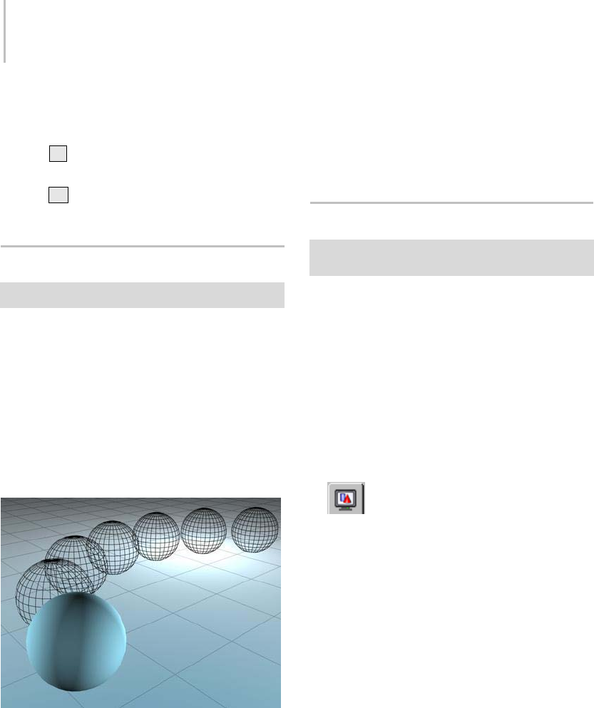
46 Chapter 2: Viewing and Navigating 3D Space
Procedure
To scale the transform gizmo, do one of the following:
•Press–(hyphen) to shrink the Transform
gizmo.
•Press
=(equal sign) to enlarge the Transform
gizmo.
Show Ghosting
Views menu > Show Ghosting
Ghosting is a method of displaying wireframe
"ghostcopies"ofananimatedobjectatanumber
of frames before or after the current frame. Use it
to analyze and adjust your animation. Ghosts that
overlap indicate slower motion; ghosts that are
spread further apart show faster motion.
When this command is active, ghosting is
displayed for selected objects in the scene. Only
currently selected objects display the ghosting.
Ghosting helps to visualize animation.
To change Ghosting parameters choose Customize
> Preferences. On the Viewport panel of the
Preferences dialog you can determine the number
of ghosting frames, whether to ghost before or
afterthecurrentframe,orboth,andyoucanalso
show frame numbers with the ghosts.
Procedure
To show wireframe ghost copies of an animated
object:
• Choose Views menu > Show Ghosting.
Show Key Times
Select an object with animation. > Views menu > Show
Key Times
Key Times shows the frame numbers along a
displayed animation trajectory (page 2–301).
Key times correspond to the settings in Time
Configuration (page 3–725) for Frames or SMPTE
(page 3–1013).Bydefault,keytimesareshown
as frame numbers.
Procedure
To display trajectory time values in the viewport:
1. Select an object with animation.
2. On the Display panel > Display
Properties rollout, turn on Trajectory.
Tip: If the rollout controls are unavailable,
right-click the object in the active viewport,
choose Properties, and in the Display Properties
group, click By Layer to change to By Object.
This will make the Trajectory option become
available.
3. Choose Views menu > Show Key Times.
Thetimevaluesaredisplayedaswhitenumbers
along the trajectory. They remain displayed in
red when the animated object is deselected.
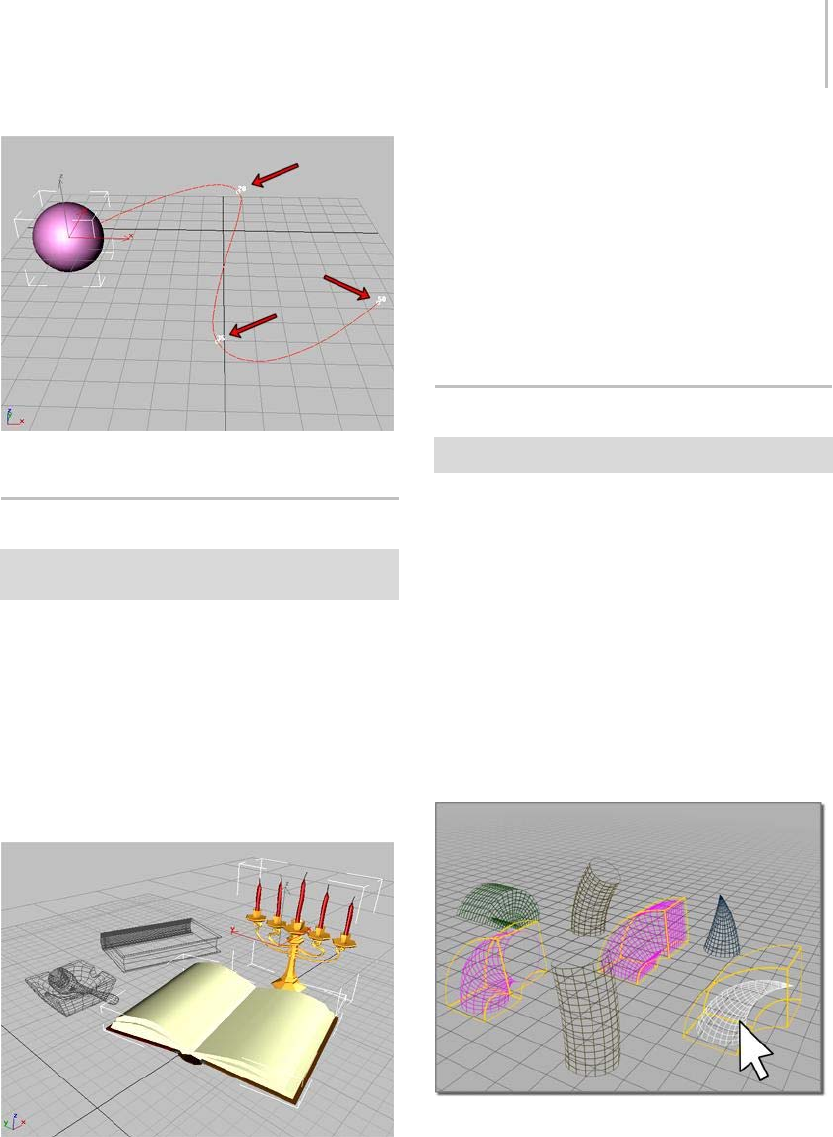
Shade Selected 47
Keyframes with frame number shown on a trajectory.
Shade Selected
Select an object to be shaded. > Views menu > Shade
Selected
Shade Selected shades only the selected objects in
thescenewhentheviewportissettoWireframe
or Other. When Smooth + Highlights is on, all
objects are shaded whether they are selected or not.
Shade Selected lets you work with a wireframe
scene and shade only the selected objects when
you want to visualize them more clearly. All other
objects in the scene will appear in wireframe.
Selected objects shaded in a wireframe viewport.
Procedure
To shade only selected objects in a scene:
1. Choose Views menu > Shade Selected.
2. Right-click the viewport label and choose
Wireframe.
3. Select the object.
Only the selected object is shaded.
Show Dependencies
Views menu > Show Dependencies
WhileyouareusingtheModifypanel,this
command toggles viewport highlighting of objects
dependent on the currently selected object.
When Show Dependencies is on and the Modify
panel is active, any object that is dependent upon
the currently selected object in any way appears
magenta. This includes instances (page 3–957),
references (page 3–1002),andsharedmodifiers
(page 3–974). Default=off.
You can also see similar dependencies in Schematic
View (page 3–638).
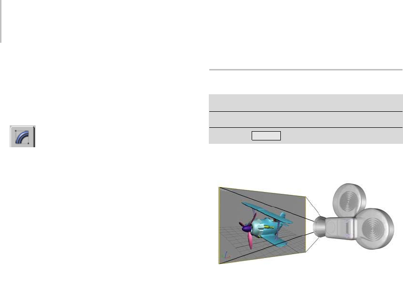
48 Chapter 2: Viewing and Navigating 3D Space
Procedures
To show dependencies between objects:
1. Select an object with an instanced modifier
(page 1–511).
2. OntheModifypanel,choosethe
instanced modifier in the modifier stack.
3. Choose Views menu > Show Dependencies
Other objects with instances of the same
modifierappearinadifferentcolor.
Example: To use Show Dependencies when
animating with Linked XForm:
1. Select the sub-object geometry you want to
animate, and apply a Linked XForm modifier
(page 1–712).
2. On the Parameters rollout, click Pick Control
Object.
3. Click an object to be the control object. Choose
adummyobjectifyouwanttokeepthecontrol
hidden in final rendering.
4. The chosen object is now linked as parent to
the sub-object selection and its name is listed
on the Parameters rollout.
5. Choose Views menu > Show Dependencies to
make the link visible when the control object
is selected.
6. Use any of the transforms to animate the
control object.
The selection is animated in parallel with the
control object.
Create Camera From View
Views menu > Create Camera From View
Createmenu>Cameras>CreateCameraFromView
Keyboard > Ctrl+C
Create Camera From View creates a Ta r g e t c am e r a
(page 2–1371) whose field of view matches an
active, Perspective viewport. At the same time, it
changes the viewport to a Camera viewport (page
3–745) for the new camera object, and makes the
new camera the current selection.
Alternatively, if the scene already contains a camera
and the camera is selected, then Create Camera
From View does not create a new camera from
the view. Instead, it simply matches the selected
camera to the active, Perspective viewport. This
functionality was adopted from the Match Camera
to View command, which is now available only as
an assignable main user interface shortcut (see
Keyboard Shortcuts (page 3–871)).
Note: Create Camera From View is available only
when a Perspective viewport is active.
To create a camera from a view, assuming any
existing cameras are unselected:
1. Activate a Perspective viewport.
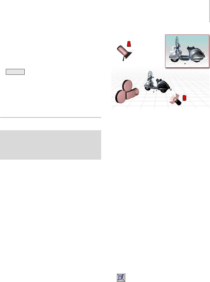
Add Default Lights to Scene 49
2. If necessary, adjust the viewport using Pan,
Zoom and Arc Rotate until you have a view you
like.
3. Leaving the viewport active, on the Views menu
choose Create Camera From View or press
Ctrl+C .
3ds Max creates a new camera, matching its
view to that of the Perspective viewport, and
then switches the Perspective viewport to a
Camera viewport, showing the view from the
new camera.
Add Default Lights to Scene
Right-click a viewport label. > Configure > Viewport
Configuration dialog > Rendering Method tab >
Rendering Options group > Turn on Default Lighting and
choose 2 Lights (to activate the Add Default Lights To
Scene menu item) > Views menu > Add Default Lights
To Scene
ThiscommanddisplaystheAddDefaultLightsTo
Scene dialog, which provides options that let you
convertthedefaultscenelightingintoactuallight
objects (page 2–1272).
The default lighting for viewports consists of a
key light, positioned in front and to the left of
thescene,whichbehavesasanomni light (page
2–1295)..
This command is unavailable unless you use the
Viewport Configuration dialog (page 3–853) to
configure the active viewport to use two lights.
When viewports use two lights, and you invoke
this command, the lights are added to the scene as
omni lights. You can add either the key light, the
fill light, or both.
Two default lights are placed opposite to each other.
A, the key light is in front of the object, on the upper left side,
while B, the fill light is behind on the lower right side.
You can add either the key light, the fill light, or
both. The omni light objects have the names
DefaultKeyLight and DefaultFillLight.
If you have already added one or both default
lights, a warning prompts you to rename or delete
the previous default light object before you add
another.
Procedure
To add the default lights as objects:
1. Right-click a viewport label, and click
Configure.
2. On the Viewport Configuration dialog >
Rendering Method tab, in the Rendering
Options group, turn on Default Lighting and
choose 2 Lights. Click OK to close the dialog.
3. Choose Views menu > Add Default Lights To
Scene.
4. On the Add Default Lights To Scene dialog,
choose Key Light, Fill Light, or both.
5. Activate the Top viewport, and on the
status bar, click Zoom Extents.
The lights are now visible in the viewport.
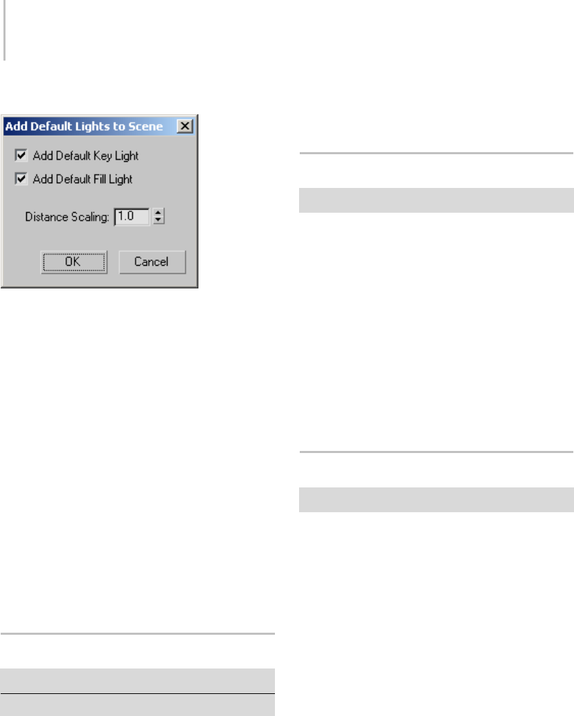
50 Chapter 2: Viewing and Navigating 3D Space
Interface
Add Default Key Light—When on, adds the default
key light to the scene. The key light is in front of
the scene and to the left. The key light becomes
an omni light (page 2–1295) with the name,
DefaultKeyLight. Default=on.
Add Default Fill Light—When on, adds the default
fill light to the scene. The fill light is behind the
scene and to the right. The fill light becomes
an omni light (page 2–1295) with the name,
DefaultFillLight. Default=on.
Distance Scaling—Affects how far the lights are
placed from the origin (0,0,0). The default value
leaves the scene’s lighting unchanged. Larger
values move the lights farther away, dimming
the scene, and smaller values move them closer,
brightening the scene. Default=1.0. Range=0.0
to 1000.0.
Redraw All Views
Views menu > Redraw All Views
Keyboard > ‘(accent grave)
Redraw All Views refreshes the display in all
viewports. When you move, rotate, scale, or
otherwisemanipulategeometry,theviewports
may display the scene with some irregularities,
or with objects or parts of objects missing. Use
Redraw All Views to redisplay your scene with all
lines and shading restored.
Activate All Maps
Views menu > Activate All Maps
Activate All Maps turns on the Show Map In
Viewport flag for all materials assigned to the
scene.
To undo this action, use Views menu > Deactivate
All Maps. This will turn off the maps for all
materials. If you only want to turn off individual
maps, you need to turn off Show Map In Viewport
in the Material Editor.
Note: This command does not apply to XRef objects
(page 3–394) and objects in XRef scenes (page
3–407).
Deactivate All Maps
Views menu > Deactivate All Maps
Deactivate All Maps turns off the Show Map In
Viewport flag for all materials assigned to the
scene.
To u n d o t h i s ac t i on , u s e Vi e ws m e nu > Ac t i v at e A l l
Maps.Thiswillturnonthemapsforallmaterials.
If you only want to turn on individual maps, you
needtoturnonShowMapinViewportinthe
Material Editor.
Note: This command does not apply to XRef objects
(page 3–394) and objects in XRef scenes (page
3–407).

Update During Spinner Drag 51
Update During Spinner Drag
Views menu > Update During Spinner Drag
When Update During Spinner Drag is on, dragging
a spinner (such as a Radius spinner for a sphere)
updates the effects in real time in the viewports.
Default=on.
When Update During Spinner Drag is off, the
effect is updated after the drag, when you release
the mouse. Use this option when you’re adjusting
processor-intensive controls.
Expert Mode
Views menu > Expert Mode
Keyboard > Ctrl+X
WhenExpertmodeison,thetitlebar,toolbar,
command panel, status bar, and all of the viewport
navigation buttons are removed from the display,
leaving only the menu bar, time slider, and
viewports. Use Expert mode when you need to
view your composition alone without the rest of
the interface.
With the ability to customize the user interface
in 3ds Max, you can create your own versions
of Expert mode by hiding whatever you want
item-by-item. Expert mode is only a quick way to
hide everything that can be hidden at once.
You can assign keyboard shortcuts to hide and
unhide the command panel, toolbars, and so on
and then use these while in Expert mode. You can
also use the quad menu to access tools quickly in
Expert mode as well.
Procedures
To turn on Expert mode, do one of the following:
• Choose Views menu > Expert Mode.
•Press
Ctrl+X .
To turn off Expert mode and return to full display,
do one of the following:
• Click the Cancel Expert Mode button to the
right of the time slider.
•Press
Ctrl+X .
•ChooseViewsmenu>ExpertMode.
Controlling Object Display
Yo u u s e t h e D i s p l a y p a n e l o r layers (page 3–655)
to control how objects and selected objects are
displayed in viewports, and to hide or freeze
objects.
Yo u c a n a l s o u s e layers (page 3–655) to hide or
unhide objects in the viewport.
Tip: Yo u c a n a l s o u s e t h e Isolate Selection command
(page 1–73) to hide everything except your
selection set.
Display Color Rollout (page 1–52)
Hide By Category Rollout (page 1–52)
Hide Rollout (page 1–53)
Freeze Rollout (page 1–54)
Display Properties Rollout (page 1–55)
Link Display Rollout (page 1–58)
Object Display Culling Utility (page 1–58)
See also
Object Properties (page 1–117)
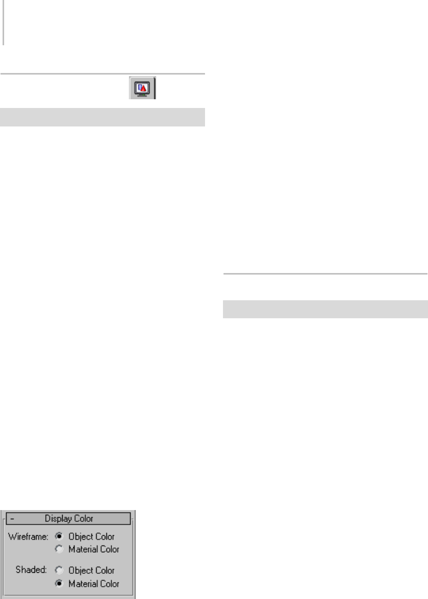
52 Chapter 2: Viewing and Navigating 3D Space
Display Color Rollout
Display panel > Display Color rollout
The Display Color rollout specifies whether
3ds Max displays objects using their object colors
or their diffuse material colors (page 3–929),when
the objects have their display properties (page
1–117) set to By Object. If the display properties
of an object is set to By Layer, the layer color
will be used for the display. You can choose one
method for wireframe display and a different one
for shaded display. In each shading mode you can
specify whether the material or the object color
is used.
As a default, all new objects have their display
properties set to By Layer. The default can be
changed in Customize > Preferences > Preferences
dialog > General panel > Layer Defaults group. If
you turn off Default To By Layer For New Nodes,
all new objects created in 3ds Max will display in
the viewports based on the settings in the Display
Color rollout. You can switch individual objects
between By Object and By Layer by setting the
Display Properties in the Object Properties dialog
(page 1–117), accessible by right-clicking any
selected object.
If the object color box displays black and white
rectangles, this indicates that the object has its
display properties set to By Layer.
Interface
Wireframe— Controls the color of objects when the
viewport is in wireframe display mode.
Object Color—Displays the wireframes in object
color.
Material Color—Displays the wireframes using the
material color.
Shaded—Controls the color of the object when the
viewport is in any shaded display mode.
Object Color—Displays the shaded objects using
the object color.
Material Color—Displays the shaded objects using
the material color.
Hide By Category Rollout
Displaypanel>HideByCategoryrollout
The Hide By Category rollout toggles the display
of objects by category (objects, cameras, lights,
and so on).
By default, 3ds Max displays all objects in the
scene. Objects hidden by category aren’t evaluated
in the scene, so hiding objects by category
improves performance.
Yo u c a n u s e a n y o f t h e d e f a u l t d i s p l a y f i l t e r s
provided, or add new display filters for fast
selection of objects to hide.
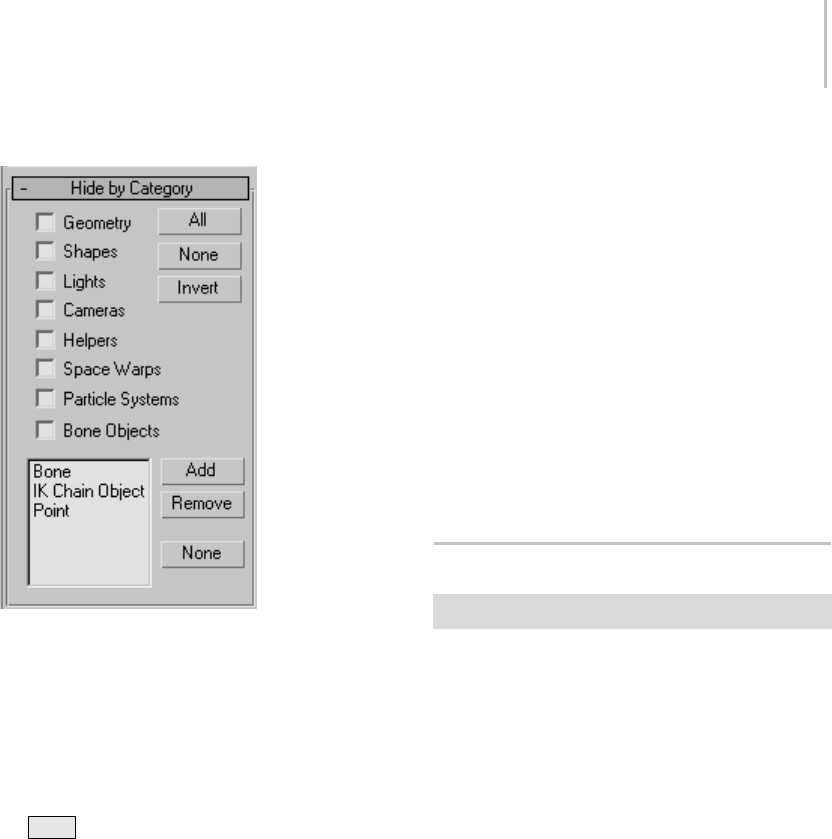
Hide Rollout 53
Interface
Turnonthecheckboxestohideobjectsofthat
category. You can use the All, None, and Invert
buttons to quickly change the settings of the check
boxes.
The Display Filter box gives you finer control in
creating categories to hide. Click the Add button
to display a list of display filters. Hold down
the Ctrl key and click the filter name to select
whatever category you’d like to hide.
Geometry—Hides all geometry in the scene.
Shapes—Hides all shapes in the scene.
Lights—Hides all lights in the scene.
Cameras—Hides all cameras in the scene.
Helpers—Hides all helpers in the scene.
Space Warps—Hidesallspacewarpsinthescene.
Particle Systems—Hides all particle systems in the
scene.
Bone Objects—Hides all bones in the scene.
Bones—Hidesallbonesinthescene.
IK Chain—Hides all IK chains in the scene.
Point—Hides all points in the scene.
All—Hides everything in the scene.
None—Unhides everything in the scene
Invert—Hides everything that is visible and
unhides everything currently hidden.
Add—Adds a display filter category to the list.
Remove—Removes a display filter category.
None—Deselects all highlighted display filters in
the list.
Hide Rollout
Display panel > Hide rollout
The Hide rollout provides controls that let you
hide and unhide individual objects by selecting
them, regardless of their category.
You can also hide and unhide objects using the
Display Floater (page 3–775).
See also
Hide By Category Rollout (page 1–52)
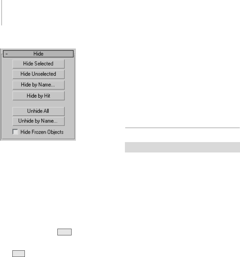
54 Chapter 2: Viewing and Navigating 3D Space
Interface
Hide Selected—Hides the selected objects.
Hide Unselected—Hides all visible objects except
theselectedones.Usethistohideallobjectsexcept
the one you’re working on. Objects hidden by
category aren’t affected.
Hide by Name—Displays a dialog you use to
hide objects you choose from a list. See Select
Objects dialog (page 1–78),whichdescribesnearly
identical controls.
Hide by Hit—Hides any object you click in the
viewport. If you hold the Ctrl key while selecting
anobject,thatobjectandallofitschildrenare
hidden. To exit Hide by Hit mode, right-click,
press Esc , or select a different function. This
mode is automatically turned off if you hide all
objects in the scene.
Unhide All—Unhides all hidden objects. The
unhide buttons are available only when you have
specifically hidden one or more objects. They
won’t unhide objects hidden by category.
Note: If you click Unhide All in a scene with hidden
layers,adialogwillpopuppromptingyouto
unhide all layers. You cannot unhide an object on
ahiddenlayer.
Unhide by Name—Displays a dialog you use to
unhide objects you choose from a list. See Select
Objects dialog (page 1–78),whichdescribesnearly
identical controls.
Note: Ifyouselectanobjectonahiddenlayer,a
dialogwillpopuppromptingyoutounhidethe
object’s layer. You cannot unhide an object on a
hidden layer.
Hide Frozen Objects—Hides any frozen objects.
Turn it off to display hidden frozen objects.
Freeze Rollout
Display panel > Freeze rollout
The Freeze rollout provides controls that let you
freeze or unfreeze (page 3–945) individual objects
by selecting them, regardless of their category.
Frozen objects remain on the screen, but you can’t
select,transform,ormodifythem. Bydefault,
frozen objects turn dark gray. Frozen lights and
cameras, and their associated viewports, continue
to work as they normally do.
You can choose to have frozen objects retain their
usual color or texture in viewports. Use the Show
Frozen In Gray toggle in the Object Properties
dialog (page 1–117).
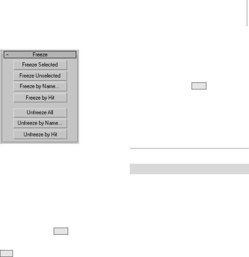
Display Properties Rollout 55
Interface
Freeze Selected—Freezes the selected object(s).
Freeze Unselected—Freezes all visible objects
except the selected ones. Use this to quickly freeze
all the objects except the one you’re working on.
Freeze by Name—Displays a dialog that lets you
choose objects to freeze from a list. See Select
Objects dialog (page 1–78),whichdescribesnearly
identical controls.
Freeze by Hit—Freezes any object you click in a
viewport. If you press Ctrl while selecting an
object,thatobjectandallofitschildrenarefrozen.
To exit Freeze by Hit mode, right-click, press
Esc , or select a different function. This mode is
automatically turned off if you freeze all objects
in the scene.
Unfreeze All—Unfreezes all frozen objects.
Note: If you click Unfreeze All in a scene with
frozen layers, a dialog opens prompting you to
unfreeze all layers. You cannot unfreeze an object
onafrozenlayer.
Unfreeze by Name—Displays a dialog that lets you
choose objects to unfreeze from a list. See Select
Objects dialog (page 1–78),whichdescribesnearly
identical controls.
Note: Ifyouunfreezebynameanobjectonafrozen
layer, a dialog opens prompting you to unfreeze
the object’s layer. You cannot unfreeze an object
onafrozenlayer.
Unfreeze by Hit—Unfreezes any object you click in
the viewport. If you press Ctrl while selecting
an object, that object and all of its children are
unfrozen.
If you select an object on a frozen layer, a dialog
will pop up prompting you to unfreeze the object’s
layer. Youcannotunfreezeanobjectonafrozen
layer.
Display Properties Rollout
Display panel > Display Properties rollout
The Display Properties rollout provides controls
for altering the display of selected objects.
See also
Link Display Rollout (page 1–58)
Procedure
To display trajectories using the Display panel:
1. Select one or more animated objects.
2. Right-click the selection, and choose
Properties.
3. In the Display properties group, click By Layer
to change it to By Object, and then click OK.
4. Expand the Display Properties rollout in the
Display panel.
5. Tu r n on Tr aj e c to r y.
By default, object trajectories appear with the
following properties:
•Thetrajectorycurveisdrawninred.
• Frame increments display as white dots on
the curve.
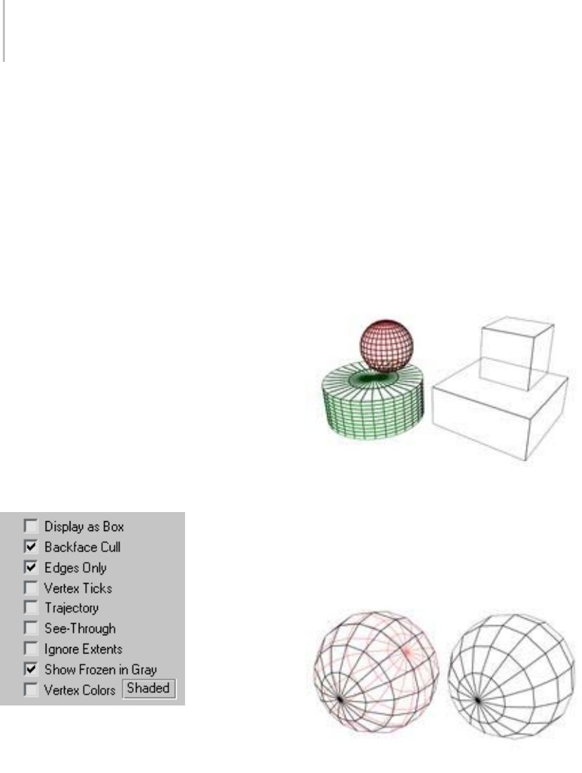
56 Chapter 2: Viewing and Navigating 3D Space
• Position keys display as red boxes
surrounding the appropriate frame dot on
the curve. The boxes are white when the
object is selected.
• IfViews>ShowKeyTimesisturnedon,the
keyframe numbers are displayed along side
the keys on the trajectory.
Trajectories can also be displayed through
Object Properties. Right-click any object
and choose Properties, then in the Display
properties group change By Layer to By
Object. Turn on Trajectories when it
becomes available in the Display Properties
group.
You can change the colors for these items on
the Colors panel (page 3–799) of the Customize
User Interface dialog.
Yo u c a n a l s o u s e o b j e c t p ro p e r t i e s t o d i s p l ay
trajectories: right-click any object and choose
Properties,thenturnonTrajectory.
Interface
The first three options reduce the displayed
geometric complexity of selected objects in a
scene, resulting in faster response time because the
computerhaslesstocalculate.Theseoptionsare
also available in the Display Properties group of
the Object Properties dialog > General panel (page
1–117) and the Display floater (page 3–775).
Display as Box—Toggles the display of selected
objects,including3Dobjectsand2Dshapes,as
bounding boxes (page 3–919).Producesminimum
geometric complexity.
Particle systems appear as bounding boxes when
adaptive degradation takes effect. Because particle
systems naturally exist in world space, their
bounding box is always oriented parallel to the
world planes.
Backface Cull—Toggles the display of faces, edges,
and vertices with normals (page 3–980) pointing
away from the point of view. When off, all entities
are visible. Default=off.
Edges Only—Toggles the display of hidden edges
and polygon diagonals (page 3–928).Whenon,
only outside edges appear. When off, all mesh
geometry appears. Applies to Wireframe viewport
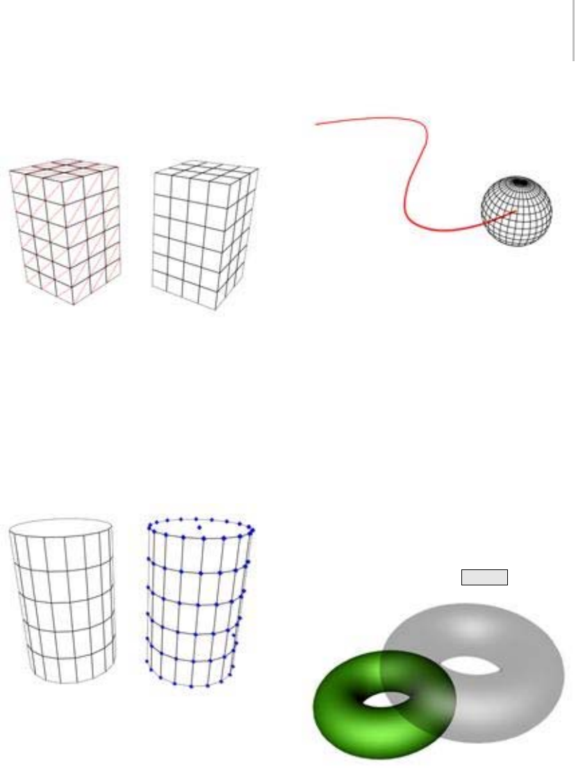
Display Properties Rollout 57
display mode, as well as other modes with Edged
Faces turned on.
Vertex Ticks—Displays the vertices in the selected
geometry as tick marks.
If the current selection has no displayed tick
marks,thecheckboxisclear. Ifsomeofthe
vertices in the current selection display tick marks,
the check box contains a gray X. If all vertices in
the current selection display tick marks, the check
box contains a black X.
Trajectory—To g g l e s trajectory (page 3–1025)
display for the selected object so its trajectory is
visible in viewports.
See-Through—Makes the object or selection
translucent in viewports. This setting has no
effect on rendering: it simply lets you see what’s
behind or inside an object in a crowded scene, and
is especially useful in adjusting the position of
objects behind or inside the See-Through object.
This is very handy when you have objects within
other objects in your scene.
This option is also available from Object Properties
dialog (page 1–117) and the Tools > Display Floater
(page 3–775).
You can customize the color of see-through objects
by using the Colors panel (page 3–799) of the
Customize > Customize User Interface dialog (page
3–792).
Keyboard shortcut (default): Alt+X
Ignore Extents—When turned on, the object is
ignored when you use the display control Zoom
Extents. Use this on distant lights.
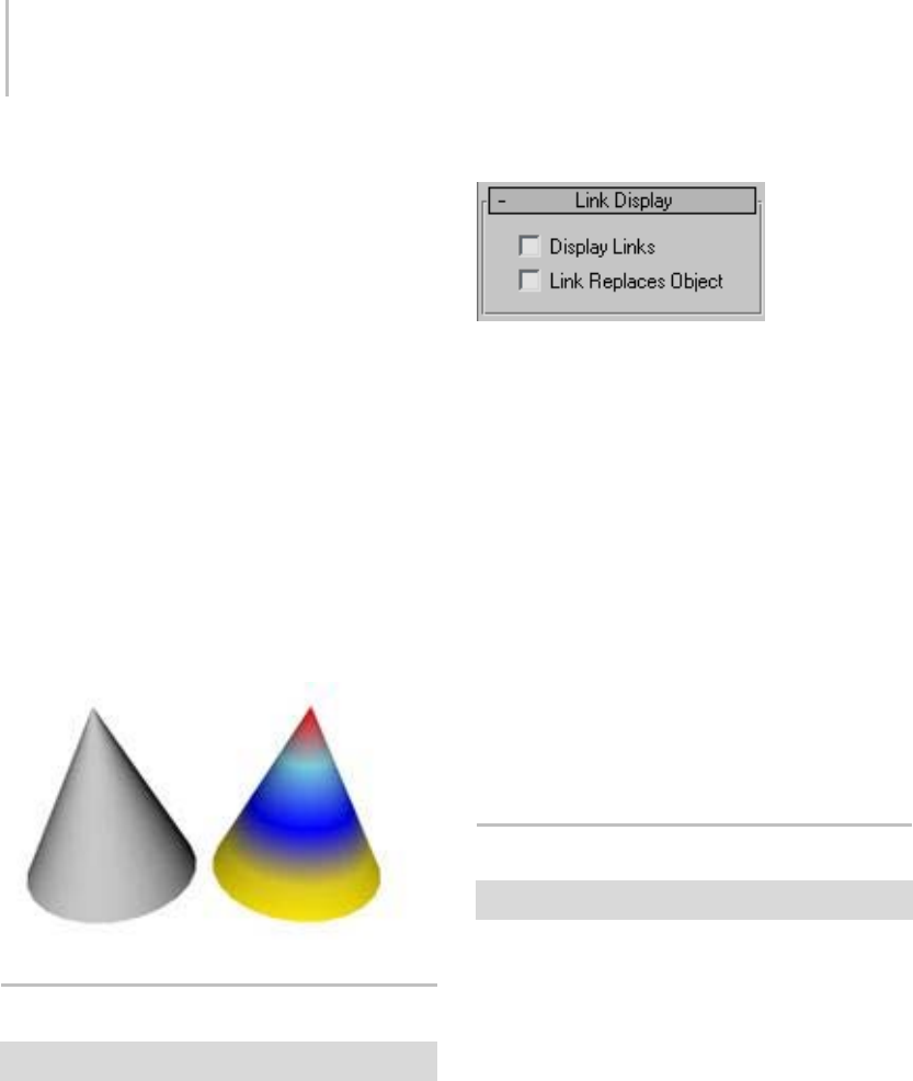
58 Chapter 2: Viewing and Navigating 3D Space
Show Frozen in Gray—When on, the object turns
gray in viewports when you freeze it. When off,
viewports display the object with its usual color or
texture even when it is frozen. Default=on.
Vertex Colors—Displays the effect of assigned
vertex colors. You assign vertex colors using the
A s s i g n Ve r t e x C o l o r u t i l i t y, o r t h e Ve r t e x P a i nt
modifier. Once vertex colors have been assigned
they can also be edited in the Vertex Properties
rollout in the editable mesh or editable poly in
vertex or face sub-object level.
The Shaded button determines whether the object
with the assigned vertex colors appears shaded in
the viewport. When this button is off, the colors
are unshaded and appear in their pure RGB values,
looking a little like self-illuminated materials.
WhentheShadedbuttonison,thecolorsappear
like any other assigned color in the viewports.
Link Display Rollout
Display panel > Link Display rollout
The Link Display rollout provides controls that
alter the display of hierarchical linkages (page
3–951).
Interface
Display Links—Displays a wireframe representation
of any hierarchical links affecting the selected
object.
Note: Display Links must be turned on in order to
see Joint Limits on a inverse kinematics chain.
Link Replaces Object—Replaces the selected
object with the wireframe representation of the
hierarchical link. This option offers another way
to reduce the geometric complexity of selected
objects in a scene. See also Display Properties
rollout (page 1–55).
TheDrawLinksAsLinesoptionontheViewports
panel (page 3–821) of the Preference Settings
dialog further reduces the display of links to a
single line.
Object Display Culling Utility
Utilities panel > More button > Object Display Culling
The Object Display Culling utility lets you
navigate and manipulate large and complex scenes
more easily and quickly by intelligently hiding
less-important objects as you work.
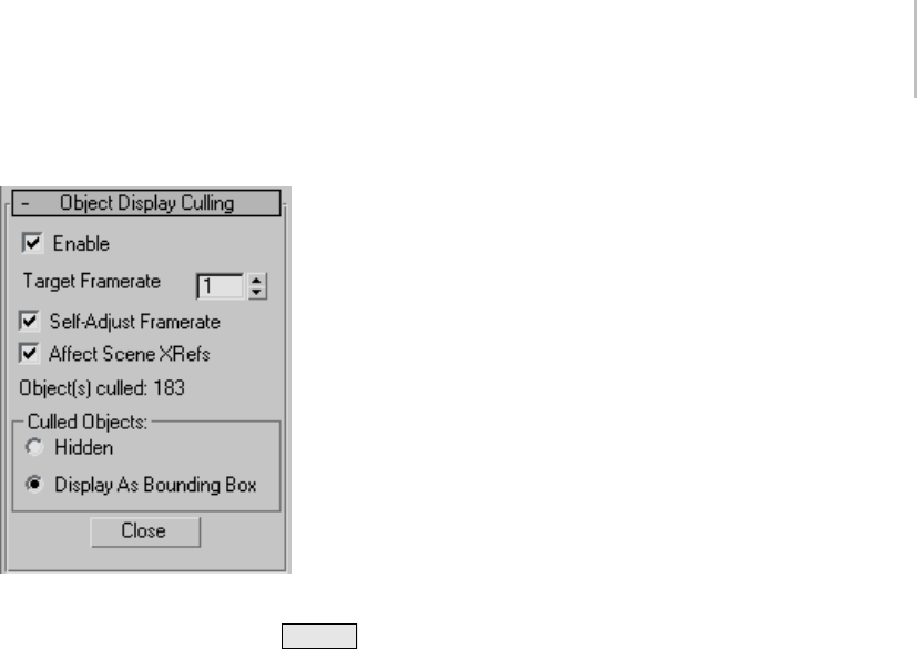
Object Display Culling Utility 59
Interface
Enable—Turns Object Display Culling on and off.
Default=off. Keyboard shortcut: Alt+O .
You can also toggle Object Display Culling from
the Views menu.
Target Framerate—The desired frame rate. If the
frameratedropsbelowthis,3dsMaxcullsobjects
as necessary to achieve the frame rate, beginning
with those farthest from the current viewpoint.
If Self-Adjust Framerate is on, 3ds Max sets this
value automatically.
Self-Adjust Framerate—When on, 3ds Max sets
theTargetFrameratevalueautomatically. The
software lowers the frame rate as necessary while
minimizing object culling, and then raises it later,
if possible.
Affect Scene XRefs—When on, XRef scenes (page
3–407) areculledaswellasnativeobjects.
Static/Object(s) culled—If no culling is happening,
such as when you first open the utility, this
read-only field shows “Static”.
When Object Display Culling is enabled, this field
shows the number of objects currently hidden or
displayedasboundingboxes.
Culled Objects—Choose how to prevent display of
culled geometry:
• Hidden: Culled objects don’t appear in the
viewports.
•DisplayasBoundingBox:Culledobjects
appear as bounding boxes (page 3–919).
Close—Closes the rollout.

60 Chapter 2: Viewing and Navigating 3D Space

Mostactionsin3dsMaxareperformedonselected
objects in your scene. You must select an object in
a viewport before you can apply a command. As a
result, the act of selection is an essential part of the
modeling and animation process.
This section presents the selection tools available
in 3ds Max. Besides the basic techniques of
selecting single and multiple objects using mouse
and keyboard, these topics cover the use of named
selection sets and other features that help you
manage object selection, such as hiding and
freezing objects and layers. Also included is an
introduction to sub-object selection, essential to
working with an object’s underlying geometry.
Lastly, a technique for grouping objects is
presented. Grouping lets you create more
permanent selections that have many of the
characteristics of independent objects.
This section presents the following topics:
Introducing Object Selection (page 1–61)
Basics of Selecting Objects (page 1–64)
Selecting by Region (page 1–65)
Using Select By Name (page 1–67)
Using Named Selection Sets (page 1–67)
Using Selection Filters (page 1–68)
Selecting with Track View (page 1–69)
Selecting with Schematic View (page 1–69)
Freezing and Unfreezing Objects (page 1–70)
Hiding and Unhiding Objects by Selection (page
1–70)
Hiding and Unhiding Objects by Category (page
1–72)
Isolate Selection (page 1–73)
Introduction to Sub-Object Selection (page 1–74)
Using Assemblies (page 1–98)
Using Groups (page 1–96)
Introducing Object Selection
3ds Max is an object-oriented program. This
means that each object in the 3D scene carries
instructions that tell the program what you can
do with it. These instructions vary with the type
of object.
Because each object can respond to a different
set of commands, you apply commands by
first selecting the object and then selecting the
command.Thisisknownasanoun-verbinterface,
because you first select the object (the noun) and
then select the command (the verb).
Selecting Objects
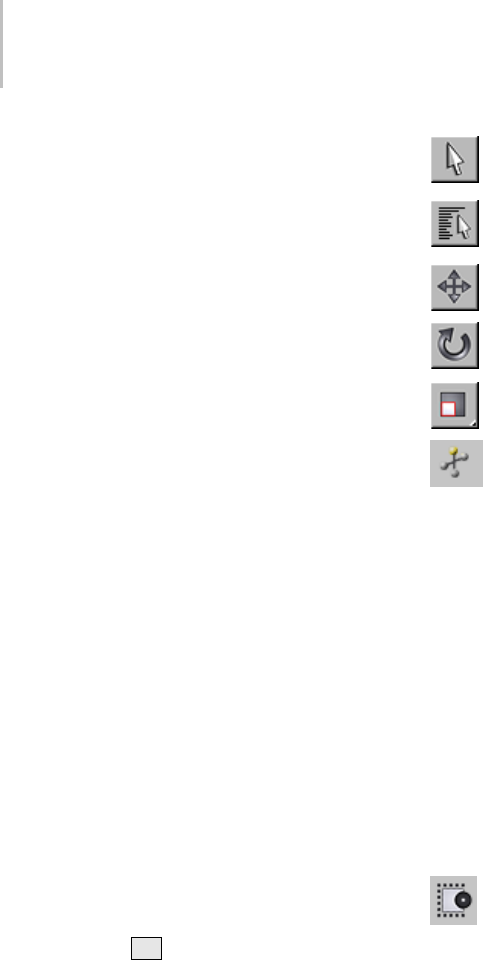
62 Chapter 3: Selecting Objects
Identifying the Selection Interface
In the user interface, selection commands or
functions appear in the following areas:
•Maintoolbar
•Editmenu
• Quad menu (while objects are selected)
•Toolsmenu
•TrackView
•Displaypanel
•SchematicView
Thebuttonsonthemaintoolbarareadirectmeans
of selection. The Selection Floater, available from
theToolsmenu,iseasytouse,whiletheEditmenu
provides more general selection commands, plus
methods of selecting objects by property. Track
View and Schematic View let you select objects
from a hierarchical list.
Selecting From the Quad Menu
The quickest way to select an object is from the
Transform quadrant of the quad menu, where you
can easily switch among the Move, Rotate, Scale,
and Select modes. Choose any of these and click
on the object you want to select in the viewport.
Selecting by Name
Another quick way to select an object is to
use keyboard shortcuts for the Select by Name
command. Press Hon the keyboard then select
theobjectbynamefromthelist.Thisisthemost
foolproof way to ensure you select the correct
object when you have many overlapping objects
in the scene.
Selection Buttons
Another way to select an object is to click one of
thesebuttons,thenclicktheobject.
Select Object
Selection Objects
Select And Move
Select And Rotate
Select And Scale
Select And Manipulate
The main toolbar has several selection-mode
buttons. When any of the selection buttons is
active, the program is in a state where you can
select objects by clicking them.
Of the selection buttons, you use Select Object
or Selection Floater when you want selection
only. The remaining buttons let you both select
and transform or manipulate your selection.
Use transforms to move, rotate, and scale your
selection. See Moving, Rotating, and Scaling
Objects (page 1–423) and Select and Manipulate
(page 2–15).
Crossing Versus Window Selection
The Selection toggle, available from the
toolbar, switches between Window and Crossing
modes when you select by region. In Window
mode, you select only the objects within the
selection. In Crossing mode, you select all objects
within the region, plus any objects crossing the
boundaries of the region.
Edit Menu Commands
The Edit menu contains selection commands that
operate globally on your objects.
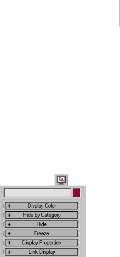
Introducing Object Selection 63
Edit menu selection commands include:
Select All (page 1–87)
Select None (page 1–88)
Select Invert (page 1–88)
Select By Color (page 1–88)
Select By Name (Edit Menu) (page 1–88) (also a
toolbar button)
Select by Rectangular Region (page 1–89)
Select by Circular Region (page 1–89)
Select by Fence Region (page 1–90)
Select by Lasso Region (page 1–90)
Region Window (page 1–92) (also a toolbar button)
Region Crossing (page 1–93) (also a toolbar button)
Edit Named Selections (page 1–84)
Tools Menu Commands
The Tools menu contains two options for modeless
(page 3–973) selection dialogs or "floaters."
Youcanplacethemanywhereonthescreen,or
minimize them by right-clicking the title bar and
choosing Minimize.
Selection Floater
• SamefeaturesasSelectByName.SeeSelection
Floater (page 1–79).
Display Floater
• Provides options for hiding and freezing
selections as well as some display options. See
Display Floater (page 3–775).
Selection Floater
The Tools menu contains an option for a modeless
(page 3–973) selection dialog called the Selection
Floater. You can place it anywhere on the screen.
TheSelectionFloaterhasthesamefeaturesas
Select By Name. See Selection Floater (page 1–79).
Track/Schematic View Selection
Track View (page 2–501) is primarily designed
as an animation tool, but you can also use its
Hierarchy List window as an alternative method
of selecting objects by name and hierarchy. This
works in both the Curve Editor and Dope Sheet
modes of Track View.
Schematic View (page 3–638) is specifically
designed to let you navigate your scene efficiently,
presenting a hierarchical view and letting you
select objects and their properties by name.
Display Panel Selection
The Display panel provides options for hiding and
freezing objects. These techniques exclude objects
from other selection methods, and are useful in
simplifying complex scenes. Frozen objects are
still visible, but hidden objects are not.
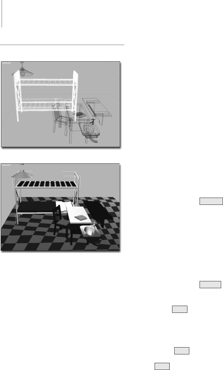
64 Chapter 3: Selecting Objects
Basics of Selecting Objects
Bed selected in wireframe
Bed selected in smooth and shaded view
The most basic selection techniques use either
the mouse, or the mouse in conjunction with a
keystroke.
Procedures
To select an object:
1. Click one of the selection buttons on the
toolbar: Select Object, Select by Name, Select
and Move, Select and Rotate, or Select and
Scale, or Select and Manipulate.
2. In any viewport, move the cursor over the
object you want to select.
Thecursorchangestoasmallcrosswhenit’s
positioned over an object that can be selected.
The valid selection zones of an object depend
onthetypeofobjectandthedisplaymode
in the viewport. In shaded mode, any visible
surface of an object is valid. In wireframe
mode, any edge or segment of an object is valid,
including hidden lines.
3. While the cursor displays the selection cross,
click to select the object (and to deselect any
previously selected object).
A selected wireframe object turns white. A
selected shaded object displays white brackets
at the corners of its bounding box.
To select all objects do one of the following:
•ChooseEditmenu>SelectAll.
This selects all objects in your scene.
•Onthekeyboardpress
Ctrl+A .
To invert the current selection do one of the
following:
•ChooseEditmenu>SelectInvert.
This reverses the current selection pattern. For
example, assume you begin with five objects in
your scene, and two of them are selected. After
choosing Invert, the two are deselected, and the
remaining objects are selected.
•Onthekeyboardpress
Ctrl+I .
To extend or reduce a selection:
•HolddownCtrl while you click to make
selections.
This toggles the selection state of the objects
you select. Use this method to select or deselect
objects. For example, if you have two objects
selected and Ctrl +click to select a third, the
third object is added to the selection. If you
now Ctrl +click any of the three selected
objects, that object is deselected.
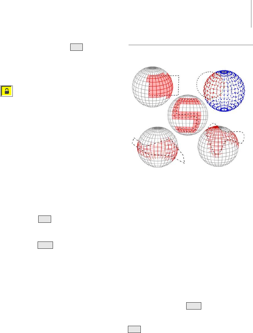
Selecting by Region 65
Tip: You can also hold down Alt while you
click to remove objects from selections.
To lock a selection:
1. Select an object.
2. Click the Selection Lock Toggle (page
3–707) on the status bar to turn on locked
selection mode.
While your selection is locked, you can drag the
mouseanywhereonthescreenwithoutlosing
the selection. The cursor displays the current
selection icon. When you want to deselect or
alteryourselection,clicktheLockbuttonagain
to turn off locked selection mode. SPACEBAR
is the keyboard toggle for locked selection
mode.
To deselect an object, do any of the following:
•Clickanemptyareaanywhereoutsidethe
current selection.
•Holddownthe
Alt key, and either click an
object, or drag a region around the object to
deselect it.
•Holddownthe
Ctrl key and click to deselect a
selected object. This also selects non-selected
objects.
• Choose Edit menu > Select None to deselect
all objects in the scene.
Selecting by Region
Top Left: Selecting face sub-objects with a rectangular region
Top Right: Selecting vertex sub-objects with a circular region
Center: Selecting face sub-objects with a painted region
Bottom Left: Selecting edge sub-objects with a fence region
Bottom Right: Selecting edge sub-objects with a lasso region
The region-selection tools let you use the mouse to
select one or more objects by defining an outline
or area.
Region Selection
By default, when you drag the mouse a rectangular
region is created. When you release the mouse
all objects within and touched by the region are
selected. The remainder of this topic describes
how you can change each of these settings.
Note: If you hold down Ctrl while specifying
a region, the affected objects are added to the
current selection. Conversely, if you hold down
Alt while specifying a region, the affected objects
are removed from the current selection.

66 Chapter 3: Selecting Objects
Setting Region Type
Thetypeofregionyoudefinewhenyoudragthe
mouseissetbytheRegionflyoutbuttontothe
right of the Select By Name button. You can use
any of five types of region selection:
•Rectangular Region—Dragging the mouse
selects a rectangular region. See Rectangular
Selection Region (page 1–89).
•Circular Region—Dragging the mouse selects a
circular region. See Circular Selection Region
(page 1–89).
•Fence Region—Draw an irregular
selection-region outline by alternating
between moving the mouse and clicking (begin
with a drag). See Fence Selection Region (page
1–90).
•Lasso Region—Dragging the mouse outlines an
irregular selection region. See Lasso Selection
Region (page 1–90).
•Paint Region—Drag the mouse over objects or
sub-objects to be included in the selection. See
Paint Selection Region (page 1–91)
Setting Region Inclusion
This option lets you specify whether to include
objects touched by the region border. It applies to
all region methods.
Choose Edit menu > Region to display a submenu
ofthefollowingtwoitems.Onlyonecanbeactive
atatime.Theoptionisalsoavailableonthemain
toolbar.
•Window—Selects only objects that are
completely within the region. See Select Region
Window (page 1–92)
•Crossing—Selects all objects that are within
the region and crossing the boundaries of the
region. Thisisthedefaultregion. SeeSelect
Region Crossing (page 1–93).
The Window/Crossing toggle (page 1–93) on the
main toolbar also switches between these two
modes.
You can set up a preference to automatically
switch between Window and crossing based
on the direction of your cursor movement. See
Auto Window/Crossing by Direction in General
Preferences (page 3–815).
Procedure
To make a region selection using defaults:
1. Click Select Object (page 1–77).
2. Drag the mouse to define a region.
Arubber-bandrectangleappears.
3. Releasethemousebuttontoselectallobjects
within or touching the region.
The selected objects turn white.
You can also use the Select and Transform buttons
on the main toolbar to select by region. You must
start defining the region over an unselectable area
of the viewport. Otherwise, you’ll transform the
object beneath your mouse when you begin to
drag.
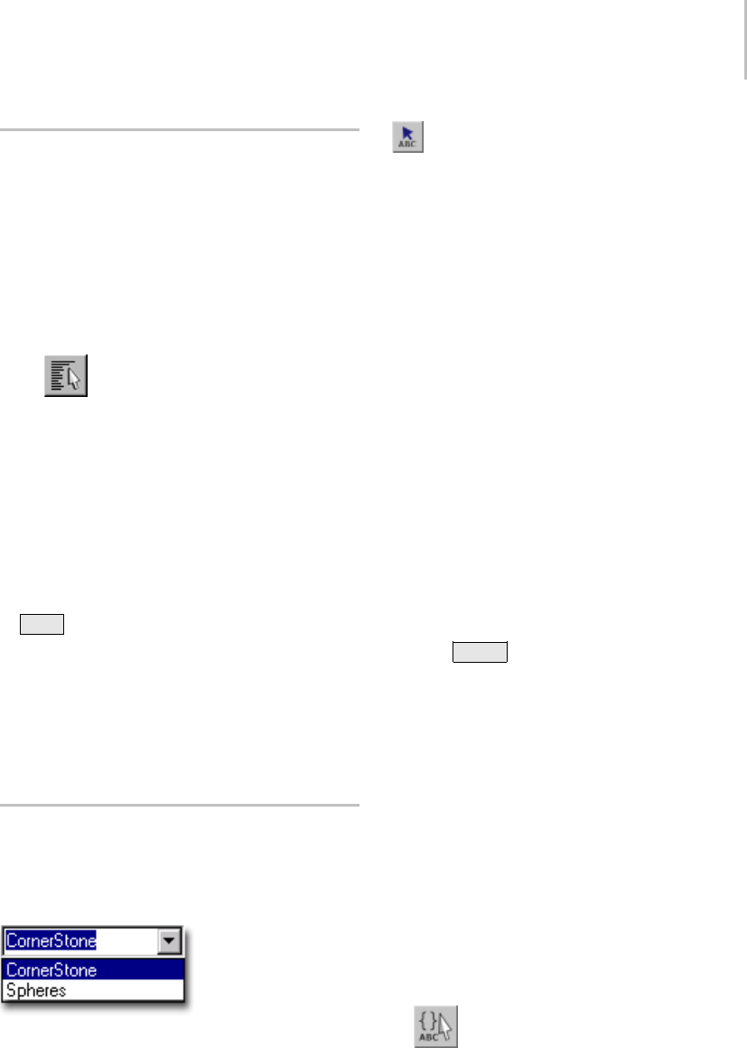
Using Select By Name 67
Using Select By Name
You can select objects by their assigned names,
avoiding mouse clicks completely, from the Select
Objects dialog.
Procedure
To select objects by name:
1. Do one of the following:
•On the main toolbar, click Select By
Name.
•ChooseEditmenu>SelectBy>Name.
•ChooseToolsmenu>SelectionFloater.
The Select Objects or Selection Floater
dialog is displayed. By default, these dialogs
list all objects in the scene. Any selected
objects are highlighted in the list.
2. Choose one or more objects in the list. Use
Ctrl to add to the selection.
3. Click Select to make the selection.
Select Object closes, while Selection Floater
remains active.
For more information, see the Select Objects dialog
description (page 1–78).
Using Named Selection Sets
You can assign a name to the current selection, and
then later reselect those objects by choosing their
selection name from a list.
Named Selection Sets
You can also edit the contents of named sets
from the Named Selection Sets dialog (page 1–84).
Editing Named Selections
As you model and create a scene, you’re likely
to rearrange the objects making up your named
selection sets. If you do, you’ll need to edit the
contents of those sets.
Procedures
To assign a name to a selection set:
1. Select one or more objects or sub-objects using
any combination of selection methods.
2. Click in the Named Selection field on the main
toolbar.
3. Enteranameforyourset. Thenamecancontain
any standard ASCII characters, including
letters, numerals, symbols, punctuation, and
spaces.
Note: Names are case-sensitive.
4. Press Enter to complete the selection set.
You can now select another combination of objects
or sub-objects and repeat the process to create
another named selection set.
To retrieve a named selection set:
1. In the Named Selection field, click the arrow.
Note: If you’re working with a sub-object
selection set, you must be at the same level
at which you created the selection set (for
example, editable mesh > vertex) for it to
appear on the list.
2. On the list, click a name.
To edit named selection sets:
•On the main toolbar, click Named
Selection Sets to display the Named Selection
Sets dialog.
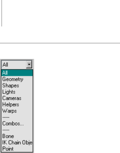
68 Chapter 3: Selecting Objects
Using Selection Filters
You can use the Selection Filter list on the main
toolbar to deactivate selection for all but a specific
category of object. By default, all categories can be
selected, but you can set the Selection Filter so that
only one category, such as lights, can be selected.
You can also create combinations of filters to add
to the list.
For greater ease of use while working with
animations, you can choose filters that let you
select only Bones, objects in IK chains, or Points.
Using Combos
The Combos feature allows you to combine two or
more categories into a single filter category.
Procedures
To use the selection filter:
• Click the Selection Filter arrow and click a
category from the Selection Filter list.
Selection is now limited to objects defined in
this category. The category remains in effect
until you change it.
Thefollowingcategoriesareavailable:
All—Allcategoriescanbeselected.Thisisthe
default setting.
Geometry—Only geometric objects can be
selected. This includes meshes, patches, and
other kinds of objects not specifically included
in this list.
Shapes—Only shapes can be selected.
Lights—Only lights (and their targets) can be
selected.
Cameras—Only cameras (and their targets) can
be selected.
Helpers—Only helper objects can be selected.
Warps—Only space warps can be selected.
Combos—Displays a Filter Combinations dialog
(page 1–81) that lets you create custom filters.
Bone—Only bones objects can be selected.
IK Chain—OnlyobjectsinIKchainscanbe
selected.
Point—Only point objects can be selected.
To create a combination category:
1. Fromthedrop-downlist,chooseCombosto
display the Filter Combinations dialog (page
1–81).
All single categories are listed.
2. Select the categories you want to combine.
3. Click Add.
Thecombinationappearsinalisttotheright,
abbreviated by the first letter of each category.
Click OK.
For example, if you selected Geometry, Lights,
and Cameras, the Combo would be named
GLC. This name appears below Combo on the
drop-down list. For more information, see
Selection Filters List (page 1–81).
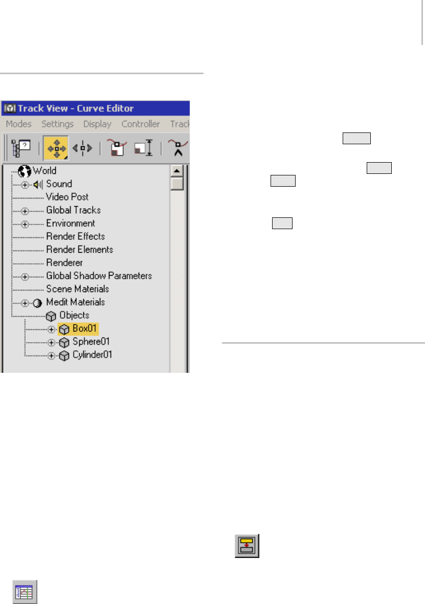
Selecting with Track View 69
Selecting with Track View
TrackViewprovidessophisticatedmethodstoedit
your animation tracks. In addition, its Hierarchy
list displays all objects in the scene by name and
hierarchy. Using Track View, you can select any
object in the scene by clicking its object icon in the
Hierarchy list.
Procedure
You can use Track View selection functionality in
both the Curve Editor (page 2–507) and the Dope
Sheet (page 2–507).Thisprocedureillustrates
usageoftheCurveEditor;thesamemethodswork
intheDopeSheet.
To open Track View and display and select objects:
1. On the main toolbar, click Curve Editor
(Open).
2. Click any cube icon in the list to select the
named object.
Yo u c a n m a k e t h e f o l l o w i n g k i n d s o f s e l e c t i o n s :
• Select several adjacent objects in the list. Click
the first object, hold down Shift ,andclick
another object elsewhere in the list.
• Modify the selection by pressing Ctrl while
clicking. Ctrl lets you toggle individual items
on and off without deselecting others in the list.
• Select an object and all its descendants. Press
and hold Alt ,right-clicktheobject’scube
icon (keep the right mouse button held down),
and choose Select Children from the menu.
You can open a Track View window for the
sole purpose of selecting objects by name.
Shrink the window until only a portion of the
Hierarchy appears, and then move the window to
aconvenientareaonyourscreen.
Selecting with Schematic View
Schematic view is a window that displays the
objects in your scene in a hierarchical view. It
gives you an alternate way to select and choose the
objects in your scene and navigate to them.
When the Modify panel is open, double-clicking
an object modifier in Schematic view navigates the
modifier stack to that modifier for quick access
to its parameters.
Procedure
To open Schematic View and display and select
objects:
1. Click Open Schematic View on the main
toolbar.
2. Click the rectangle containing the name of your
object.
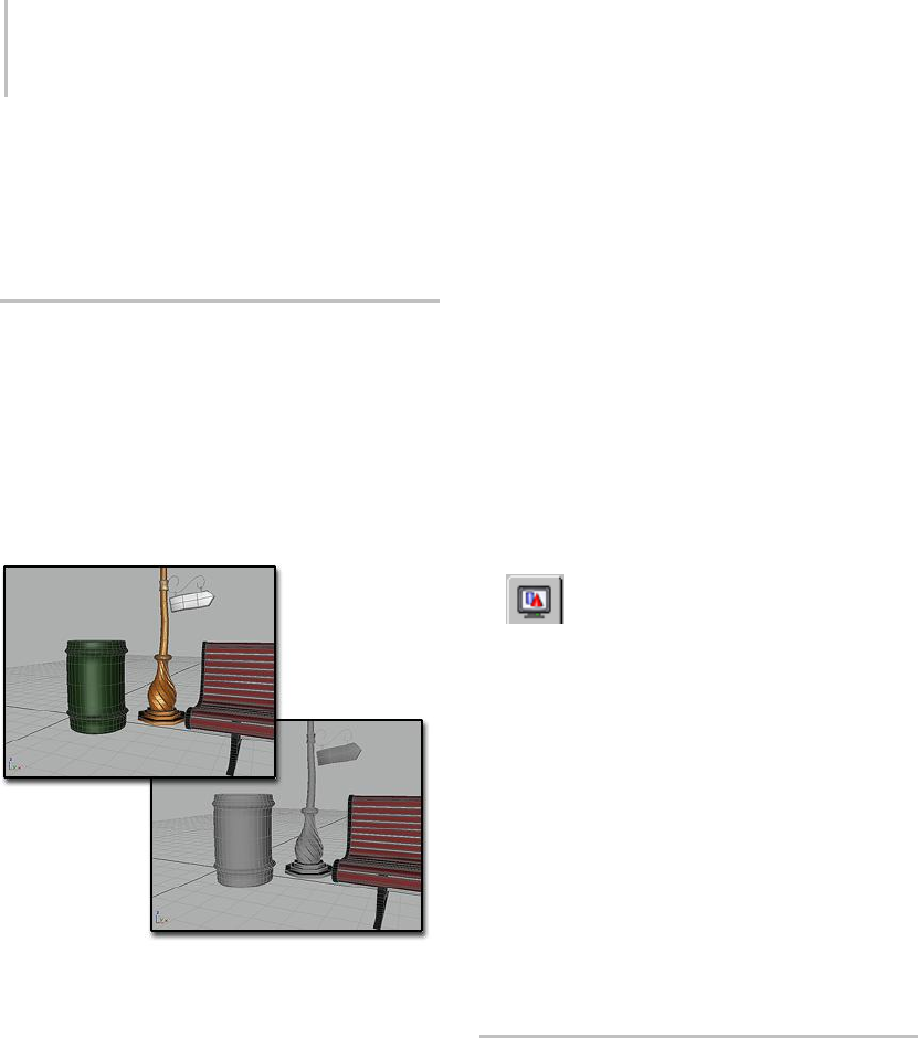
70 Chapter 3: Selecting Objects
You can select any number of objects in Schematic
View using standard methods, including dragging
a region. For more information, see Using
Schematic View (page 3–640).
Freezing and Unfreezing Objects
You can freeze any selection of objects in your
scene. By default, frozen objects, whether
wireframe or rendered, turn a dark gray. They
remain visible, but can’t be selected, and therefore
can’t be directly transformed or modified.
Freezing lets you protect objects from accidental
editing and speeds up redraws.
Above: No layers frozen
Below: Trash can and streetlight are frozen, and displayed in
gray
You can choose to have frozen objects retain their
usual color or texture in viewports. Use the Show
Frozen In Gray toggle in the General tab of the
Object Properties dialog (page 1–117).
Frozen objects are similar to hidden objects.
Linked, instanced, and referenced objects behave
when frozen just as they would if unfrozen. Frozen
lights and cameras and any associated viewports
continue to work as they normally do.
For more information, see Freeze Rollout (page
1–54).
Freezing Objects
You can freeze one or more selected objects. This
is the usual method to put objects "on hold."
You can also freeze all objects that are not selected.
This method lets you keep only the selected object
active, useful in a cluttered scene, for example,
where you want to be sure no other objects are
affected.
Procedure
To access Freeze options, do one of the following:
•Open the Display panel, then expand
theFreezerollout.
• Choose Tools menu > Display Floater. This
modeless dialog has the same options as the
Freeze rollout. It also contains Hide options.
• Access the Object Properties dialog (page 1–117)
from either the right-click (quad) menu or the
Edit menu. Turn on Hide and/or Freeze.
• In the Layer Manager, click in the Freeze
column to freeze/unfreeze each layer in the list.
• Right-click in the active viewport and choose
a Freeze or Unfreeze command from the quad
menu > Display quadrant.
Hiding and Unhiding Objects by
Selection
You can hide any selection of individual objects in
your scene. They disappear from view, making it
easier to select remaining objects. Hiding objects
also speeds up redraws. You can then unhide
all objects at once or by individual object name.
You can also filter the names by category, so only
hidden objects of a certain type are listed.
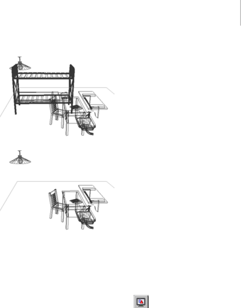
Hiding and Unhiding Objects by Selection 71
Note: Hiding a light source doesn’t alter its effect; it
still illuminates the scene.
Original scene
Scene with bed hidden
Hidingobjectsissimilartofreezingobjects.
Linked, instanced, and referenced objects behave
when hidden just as they would if unhidden.
Hiddenlightsandcamerasandanyassociated
viewports continue to work normally.
For more information, see Hide Rollout (page
1–53).
Hiding Objects
Hidingobjectsissimilartofreezingobjects.See
Freezing and Unfreezing Objects (page 1–70).You
can hide one or more selected objects. You can
also hide all objects that are not selected.
Another option is to hide objects by category. See
Hiding and Unhiding Objects by Category (page
1–72).
Unhiding Objects
You can unhide objects in either of two ways:
• Use Unhide All to unhide all objects at the same
time.
• UseAllOntodisplayallobjectsatthesame
time.
• Use Unhide By Name to unhide object
selectively. When you click Unhide By Name,
the same dialog is displayed as for hiding, now
called Unhide Objects.
TheUnhidebuttonsareunavailablewhenno
object in the scene is hidden.
Objects that were first hidden by selection and then
hiddenbycategorydonotreappear.Although
they are unhidden at the selection level, they are
still hidden at the category level. See Hiding and
Unhiding Objects by Category (page 1–72) for more
details.
Important: Objectsonahiddenlayercannotbe
unhidden. If you try to unhide an object on a hidden
layer, you are prompted to unhide the object’s layer.
Procedure
To access Hide options, do one of the following:
•OpentheLayer Manager (page 3–656).
In the Layer Manager, you can easily hide
groups of objects or layers.
•Open the Display panel. Click Hide, if
necessary, to expand the rollout.
• Choose Tools menu > Display Floater. This
modeless dialog has the same options as the
Hide rollout. It also contains Freeze options.
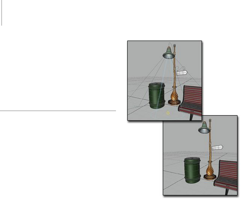
72 Chapter 3: Selecting Objects
• Access the Object Properties dialog (page 1–117)
from either the right-click (quad) menu or the
Edit menu. Turn on Hide, Freeze, or both. If the
button is unavailable because By Layer is turned
on,clickByLayertochangeittoByObject.
• Right-click in the active viewport and choose a
Hide or Unhide command from the quad menu
>Displayquadrant.
Hiding and Unhiding Objects by
Category
You can hide objects by category, the basic types
of objects. For example, you can hide all lights
in your scene at one time, or all shapes, or any
combination of categories. By hiding all categories,
your scene appears empty. Hidden objects, while
not displayed, continue to exist as part of the
geometry of your scene but cannot be selected.
Above: All objects displayed
Below: Lights and shapes are hidden
Hiding Geometry and Particle Systems
Geometry and particle systems have separate
categories, even though particle systems are also
geometry.
• Selecting Geometry hides all geometry in the
scene, including particle systems. The option
for particle systems becomes unavailable.
• Selecting Particle Systems hides only these
objects, leaving the other geometry unaffected.
Effects of Hiding by Category
• If you create an object in a category that is
hidden, the category selection is cleared and
the objects in that category are unhidden.
•Unhidingbycategoryhasnoeffectonobjects
hidden with the controls on the Hide rollout
Isolate Selection 73
(see Hiding and Unhiding Objects by Selection
(page 1–70)). These objects remain hidden.
You need to use the controls on that rollout to
unhide them.
• Unhiding by selection does not return a hidden
object to the scene if the category of the object is
hidden. The Unhide All and Unhide By Name
controls continue to work, but the effect is not
seen until the category is cleared.
• Lightshiddenbycategorycontinuetoshine.
Views through cameras and targeted lights are
still active.
• Linked, instanced, and referenced objects
behave when hidden just as they would if
visible.
Procedures
To hide a category of objects:
1. Open the Display panel.
2. Click Hide by Category, if necessary, to expand
the rollout. By default, all categories are turned
off (unhidden) on this rollout.
3. Choose the category you want to hide. All
objects of that category disappear from your
sceneassoonasyoumakethechoice.
ThesameHideByCategoryoptionsappearonthe
Object Level panel of the Display Floater (Tools
menu > Display Floater).
To unhide a category of objects:
• Deselect the category.
All objects in the category reappear, unless
some have been hidden by selection. See
“Effects of Hiding by Category”.
Isolate Selection
Tools menu > Isolate Selection
Right-click to open the quad menu. > Display
(upper-right) quadrant > Isolate Selection
Keyboard > Alt + Q
The Isolate Selection tool lets you edit a single
object or selection set of objects while hiding the
rest of the scene on a temporary basis. This guards
against selecting other objects while working
on a single selection. It allows you to focus on
the objects you need to see, without the visual
distraction of the surroundings. It also reduces
the performance overhead that can come from
displaying other objects in the viewports.
When you turn on Isolate Selection, the isolated
objectselectioniscenteredinallviewports.The
active viewport also does a Zoom Extents (page
3–737) on the isolated objects.
When an isolated selection includes multiple
objects, you can select a subset of these, and
choose Isolate Selection once again. This isolates
the subset. However, clicking Exit Isolation
unhides the entire scene. You can’t “step back”
through individual levels of isolation.
Note: Isolate Selection works only at the object
level. You can’t choose it while at the sub-object
level. If you go to a sub-object level while working
with an isolated object, you can click Exit Isolation,
but you can’t isolate sub-objects.
Tip: You can also use Isolate Unselected to isolate
all of the unselected objects in your scene.
Interface
WhiletheIsolatetoolisactive,adialoglabeled
Warning: Isolated Selection appears.
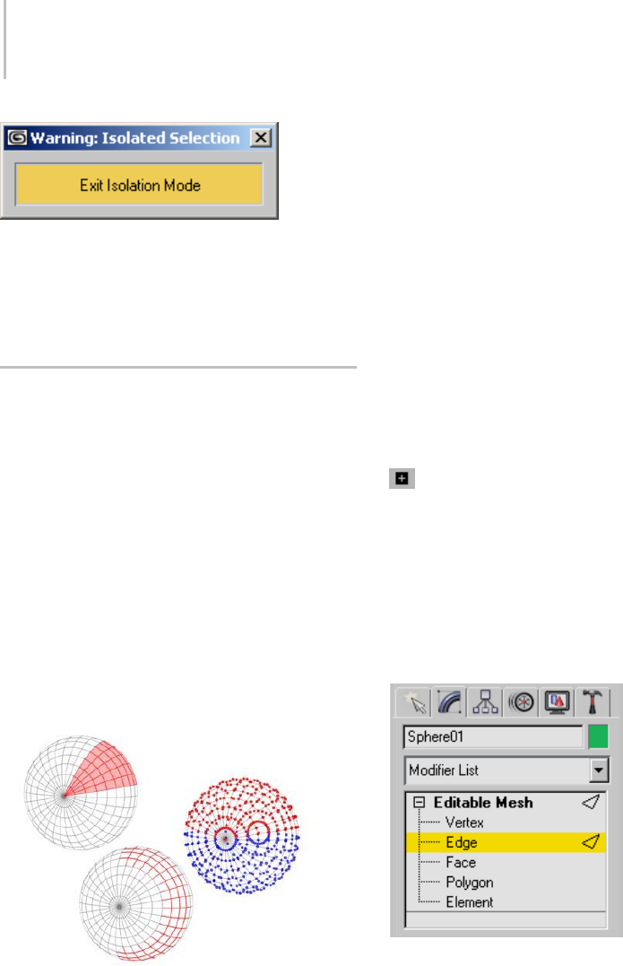
74 Chapter 3: Selecting Objects
Exit Isolation Mode—Click to end isolation, close
thedialog,andunhidetherestofthescene.
The views are restored to what they showed before
you chose Isolate Selection.
Introduction to Sub-Object
Selection
This is a general introduction to sub-object
selection. For specific information, see Editable
Mesh (page 1–996),Editable Patch (page 1–968),
Editable Poly (page 1–1022),andEditable Spline
(page 1–289).
When you model an object, often you edit a
portion of its underlying geometry, such as
a set of its faces or vertices. Or when you are
working with a model, you may want to apply
mapping coordinates to a portion of its underlying
geometry. Use the methods described in this topic
to make sub-object selections.
Left: A selection of face sub-objects
Middle: A selection of edge sub-objects
Right: A selection of vertex sub-objects
You can access sub-object geometry through a
variety of methods. The most common technique
is to convert an object into "editable" geometry
such as a mesh, spline, patch, NURBS, or poly
object. These object types let you select and edit
geometry at the sub-object level.
If you have a primitive object and want to retain
control of its creation parameters, you can apply
amodifiersuchasEdit Mesh (page 1–634),Edit
Spline (page 1–680),Edit Patch (page 1–638),or
Mesh Select (page 1–719).
Spline Lines and NURBS curves and surfaces are
the exception: you can edit their sub-objects as
soon as you create these kinds of objects.
You choose a sub-object level in the stack
display. Click the plus sign that appears next to
thenameofanobjectthathassub-objects.This
expands the hierarchy, showing the available
sub-object levels. Click a level to choose it. The
name of the sub-object level highlights in yellow,
and the icon for that sub-object level appears to
therightofbothitsnameandthenameofthe
top-level object.
Stack display shows the sub-object hierarchy, letting you
choose a sub-object level.
Editing at the Sub-Object Level
When you edit an object at the sub-object level,
you can select only components at that level, such
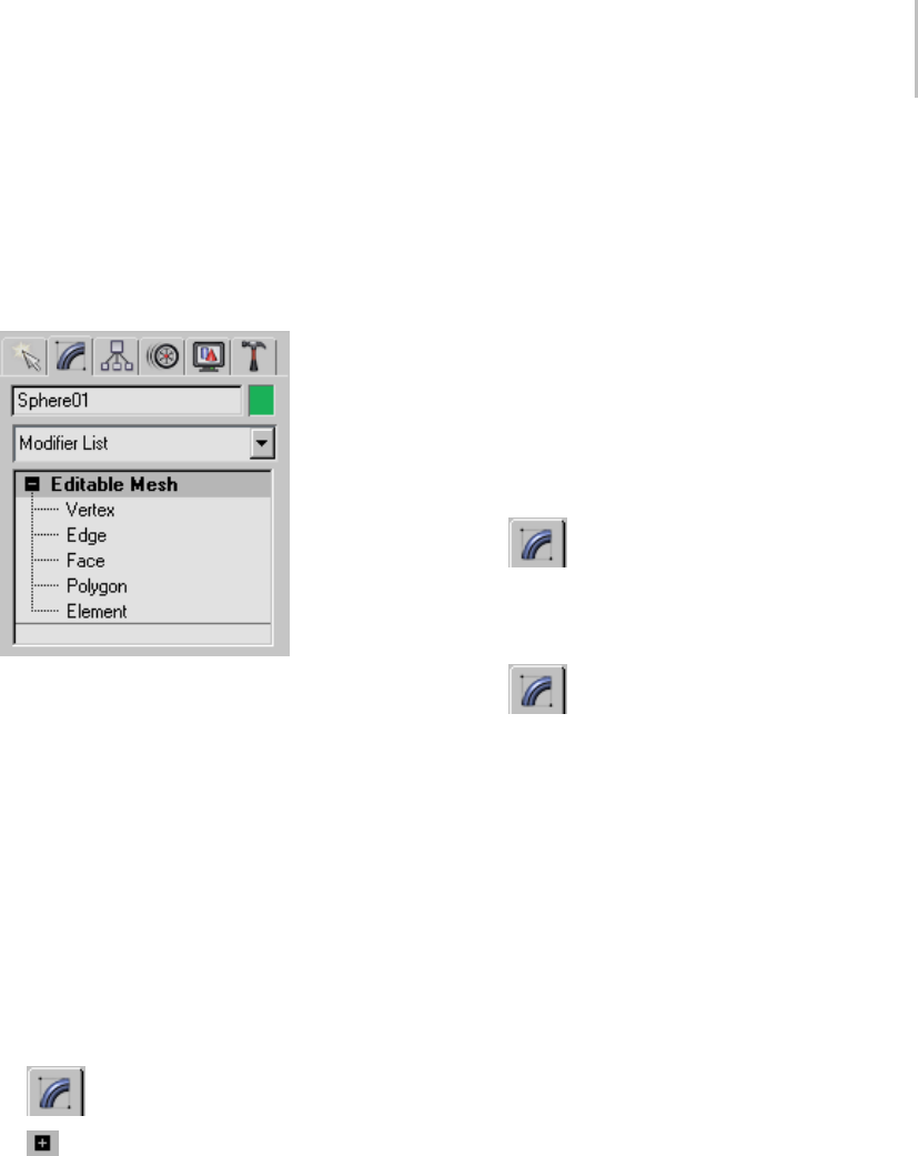
Introduction to Sub-Object Selection 75
as vertex, edge, face sub-objects, and so on. You
can’t deselect the current object, nor can you select
other objects. To leave sub-object editing and
return to object-level editing, click the top-level
name of the object in the modifier stack, or click
the highlighted sub-object level.
Click the top-level object name to exit sub-object editing.
Procedures
To make a sub-object selection:
These methods assume the object has sub-object
levels. If the object has no sub-object levels (for
example, a primitive such as a sphere), the + icon
isnotpresent.Inthatcase,youneedtocollapse
the object or apply an Edit modifier before you can
edit its sub-object geometry.
1. Select the object you want to edit.
2. Apply an Edit Mesh modifier (optional,
depending on the object you select).
3. Open the Modify panel.
4. On the modifier stack display, click the +
icon to expand the object’s hierarchy.
5. On the stack display, click to choose a level of
selection, such as vertex, edge, face, and so on.
Tip: For some kinds of objects, such as editable
meshes, shaded viewports don’t display
sub-object selections. If this is the case,
right-click the viewport label and choose
Wireframe or Edged Faces view.
Tip: For a detailed selection, you might want to
zoom in on the object.
6. Click one of the toolbar selection buttons, and
then use the same selection methods you’d use
on objects to select the sub-object components.
Or from the quad menu > Transform quadrant,
choose one of the selection methods and select
the sub-object components.
There are two alternative ways to go to a sub-object
level:
•Select the object and go to the Modify
panel. Then right-click the object, and use the
quad menu > Tools 1 (upper-left) quadrant >
Sub-objects submenu.
•Choose the selection level using buttons
in the Modify panel’s Selection rollout, if one is
present for the type of object you’re editing.
Tip: Once you’re at a sub-object level, the INSERT
keycyclesthroughthelevelsofotherkindsof
sub-objects.
To exit sub-object selection mode, do one of the
following:
•Inthestackdisplay,clickthehighlighted
sub-object name or the top-level name of the
object.
• If the object has a Selection rollout, click to turn
off the button of the active sub-object level.
• Right-click the object, and then in the Tools
1(upper-left)quadrantofthequadmenu,
choose Top-level.
• Open another command panel. This turns off
sub-object editing.
If you think you’ve turned off sub-object editing
but top-level object selection is still not restored, it
might be due to the following reasons:
76 Chapter 3: Selecting Objects
•Yo u r s e l e c t i o n i s l o c k e d . C l i c k t h e L o c k
Selection Set button in the prompt line to turn
it off.
•You’vesettheSelection Filter (page 1–68) on the
main toolbar to a specific category of object, so
you can’t select any of the other categories. To
fix this, select All in the Selection Filter list.
Selection Commands
Selection commands appear on the quad menu,
on the main toolbar, on the Edit menu, and on the
status bar.
The simplest method of selection is to turn on
Select Object mode (page 1–77),andthenclick
an object in a viewport (or drag to surround the
object). While the method is simple, it is not
effectiveforselectingmultipleobjects,especially
in a crowded scene. Other tools let you select
objectsbyname,filteroutthekindsofobjectsyou
want to select, and to create named selection sets
you can select repeatedly.
See also
Basics of Selecting Objects (page 1–64)
IsolateSelection(page1–73)
Selection Floater (page 1–79)
Selection Commands on the Main
Toolbar
The following selection commands appear by
default on the Main toolbar.
Select Object (page 1–77)
Select By Name (page 1–77)
Rectangular Selection Region (page 1–89)
Circular Selection Region (page 1–89)
Fence Selection Region (page 1–90)
Lasso Selection Region (page 1–90)
Paint Selection Region (page 1–91)
Selection Filter List (page 1–81)
Window/Crossing Selection Toggle (page 1–93)
Named Selection Sets (page 1–83)
TheWindow/Crossingtoggledetermineshowthe
region selection options (on the toolbars) behave.
Selection Commands on the Edit Menu
The following selection commands appear by
default on the Edit menu. They complement the
toolbar selection commands.
Select All (page 1–87)
Select None (page 1–88)
Select Invert (page 1–88)
Select By (page 1–88)
Select By Color (page 1–88)
Select By Name (Edit Menu) (page 1–88)
Region (page 1–92)
Region Window (page 1–92)
Region Crossing (page 1–93)
Edit Named Selections (page 1–84)
Selection Command on the Status Bar
The Selection Lock Toggle (page 3–707) is located
on the status bar. Locking a selection is useful
when you are doing a lot of editing on a selection,
and don’t want to select something else by mistake.
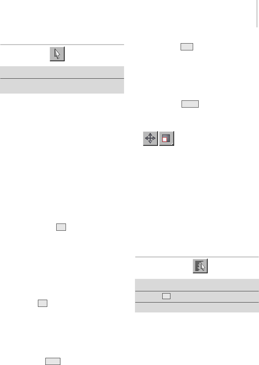
Select Object 77
Select Object
Main toolbar > Select Object
Right-click to open quad menu. > Transform quadrant
> Select
Select Object lets you select an objects and
sub-objects for manipulation.
Object selection is affected by several other
controls:
• The active Selection Region type: Rectangular
(page 1–89),Circular (page 1–89),Fence (page
1–90),Lasso (page 1–90),orPaint (page 1–91).
•Theactiveselectionfilter(All,Geometry,
Shapes, Lights, and so forth).
• The state of the crossing selection tool (which
determines whether completely surrounded
objects or surrounded and crossing objects are
selected).
You can also select objects by name using the Select
By Name list; press the Hkey to access the list.
A number of objects selected together are called a
selection set (page 1–67).Youcannameselection
sets in the Named Selection Sets field on the main
toolbar and then recall them for later use.
Note: The Smart Select command activates
the Select Object function and, with repeated
invocations, cycles through the available Selection
Regionmethods. Bydefault,SmartSelectis
assigned to the Qkey; you can use Customize
User Interface (page 3–792) to assign it to a
different keyboard shortcut, a menu, etc.
Procedures
To add or remove individual objects from a selection
set:
•HolddowntheCtrl key and select the objects
to add or remove.
•Holddownthe
Alt key and select objects to
remove from the current selection set.
Note: Adding and removing objects doesn’t
change a named selection set.
To toggle the selected/deselected state of multiple
objects in the selection set:
•HolddowntheShift key and drag to
region-select the objects to toggle.
To select objects and move, rotate, or scale them:
•Use the Select And Move,Select
And Rotate, or Select And Scale tools, available
from the Main toolbar and the quad menu >
Transform quadrant.
When you rotate a selection set, the pivot of
rotation depends on which option is selected
on the Use Center flyout (page 1–445) on the
toolbar.
These tools are restricted to a specific axis
or plane, which you choose from the axis
constraints toolbar. Right-click any blank area
of the toolbar and activate the Axis Constraints
toolbar to access these tools.
Select By Name
main toolbar > Select By Name
Keyboard > H
Edit menu > Select By > Name
Select By Name lets you select objects by choosing
them from a list of all objects currently in the scene
presented via the Select Objects dialog.
Note: The Select Objects dialog name and
functionality are context dependent. When a
transform such as Select And Move is active, the
dialog lets you choose from all objects in the scene.
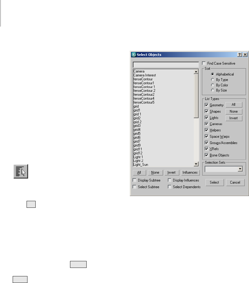
78 Chapter 3: Selecting Objects
But when certain modes are active, the choices in
the dialog are more limited. For example, when
Select And Link is active, the dialog is entitled
Select Parent, and shows linkable objects but
not the child object already selected. Similarly,
if Group > Attach is active, the dialog is named
AttachtoGroupandlistsgroupsbutnotsolitary
objects.
See also
Selection Floater (page 1–79)
Procedure
To select objects by name:
1. Do one of the following:
•Click the Select By Name button on
the main toolbar.
•ChooseEditmenu>SelectBy>Name.
•Press
H.
The Select Objects dialog appears. By
default, it lists all objects in the scene.
Currently selected objects are highlighted
in the list.
2. Choose one or more objects in the list by doing
one of the following:
•Drag,orclickandthen
Shift +click to
select a continuous range of objects and
Ctrl +click to select noncontinuous objects.
• In the field above the list, type a name to
select that object. You can use the asterisk
(*) and the question mark (?) as wildcards
to select multiple names. You can also
enable Find Case Sensitive to list objects
with uppercase letters at the top of the list
and objects with lowercase letters at the
bottom of the list.
3. Click Select.
The selection is made as the dialog disappears.
Interface
[select objects field]
Enter a name to highlight objects in the list whose
names begin with the text you specify.
Find Case Sensitive—When on, the select objects
field above the list is case-sensitive. For example,
if the list contains objects named apple and Apple
andFindCaseSensitiveison,typing“a”will
highlight only the apple entry. Also, sorts the list
so uppercase names come before lowercase.
Select Objects list
Objects are listed according to the current Sort
and List Types selections.
Influences—When you highlight an object in the
list window and then click the Influences button,
the selected object’s influences are highlighted as
well.
You can choose to load and save influences with or
without their dependents.

Selection Floater 79
All, None, and Invert—These buttons alter the
pattern of selection in the list window.
Display Subtree—Displays each item in the list so
that its hierarchical branch (page 3–951) is included
(for example, Thigh/Shin/Foot). Hierarchical
branches are indented.
Select Subtree—When this is on and you select
an item in the list window, all of its hierarchical
children are selected as well.
Display Influences—When this is on and you select
an item in the list window, all of its influences
are shown in blue. If you want to highlight these
influences, click Influences.
You can choose to load and save influences with or
without their dependents.
Select Dependents—When this is on and you select
an item in the list window, all of its dependent
objects are selected as well.
When both Select Subtree and Select Dependents
are on, the subtree of any newly selected node is
selected, and then the dependents are selected.
(Dependents of the subtree are selected, but not
the subtrees of all dependents.)
If you click Select By Name while Select And
Link is active, then the Select Subtree and Select
Dependents check boxes are not available.
You can choose to load and save dependents
with or without their influences. To maintain the
behavior and relationship between the dependents
and their influences, you need to load and save
dependents with their influences.
Sort group
Specifies the sort order of the items displayed in
the list.
Alphabetical—Sorts from numeric characters at
the top, then A to Z at the bottom.
By Type—Sorts by category, using the same order
as the check boxes in the List Types group.
By Color—Sorts by object wireframe color. The
sorting order is arbitrary; the value of this option is
that objects of the same color are grouped together.
By Size—Sorts based on the number of faces in
each object. The object with the least number
offacesislistedfirst,followedbyobjectswith
successivelygreaternumberoffaces.
List Types group
Determines the types of objects to display in the
list.
All, None, and Invert—These buttons alter the
patternofactivationoftheListTypesoptions.
Selection Sets group
Lists any named selection sets that you have
defined in the scene. When you choose a selection
set from the drop-down list, 3ds Max highlights its
component objects in the main list.
Selection Floater
Tools menu > Selection Floater
This modeless dialog lets you select objects in the
scene.
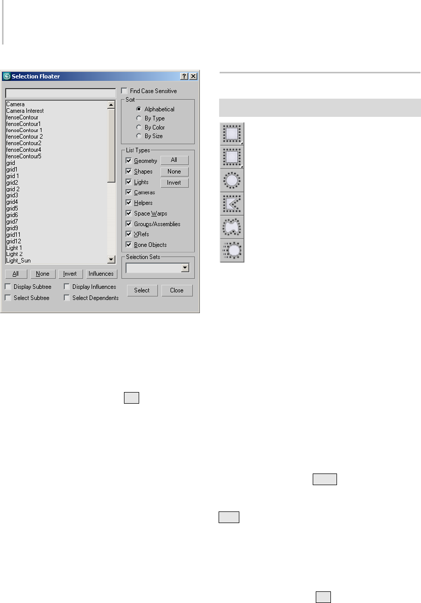
80 Chapter 3: Selecting Objects
You can leave this dialog up while you work in
your scene, making it easier to select objects. The
selection options are the same as those in the Select
Objects dialog (page 1–78).
You can display the Selection Floater only from
the Tools menu. If you use the Hkey during
selection, the modal Select Objects dialog appears
instead.
SelectionRegionFlyout
Main toolbar > Selection Region flyout
Selection Region flyout
The Selection Region flyout provides access to
five methods you can use to select objects by
region. Clicking the Selection Region button
displays a flyout containing the Rectangle (page
1–89),Circular (page 1–89),Fence (page 1–90),
Lasso (page 1–90),andPaint (page 1–91) Selection
Region buttons.
For the first four methods, you can select either
objects that are completely within the selection
region (window method), or objects that are
within or touched by the selection shape (crossing
method). Toggle between the window and crossing
selection methods by using the Window/Crossing
Selection button (page 1–93) on the Main toolbar.
Note: If you hold down Ctrl while specifying
a region, the affected objects are added to the
current selection. Conversely, if you hold down
Alt while specifying a region, the affected objects
are removed from the current selection.
Note: The Smart Select command activates the
Select Object (page 1–77) function and, with
repeated invocations, cycles through the available
SelectionRegionmethods. Bydefault,Smart
Select is assigned to the Qkey; you can use
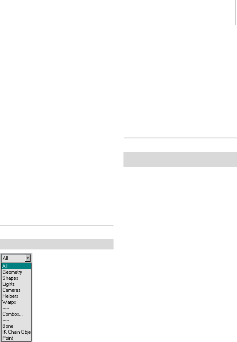
Selection Filter List 81
Customize User Interface (page 3–792) to assign it
to a different keyboard shortcut, a menu, etc.
Procedure
To select using a region (general method):
1. Choose a Selection Region method from the
flyout.
2. Drag in a viewport, then release the mouse.
The first location you click is one corner of the
rectangle, and where you release the mouse is
theoppositecorner.
Important: If you’re using Select Object (page 1–77),
you can start dragging anywhere to select a region:
on an object or off. However, if you’re using one of
the transform tools, such as Select and Move (page
1–439), start the drag operation away from an object;
that is, in an empty part of the viewport. Otherwise,
if you start dragging on an object, most likely the
software will assume you intend to select where
you click and will begin the transform operation
immediately.
To cancel the selection, right-click before you
release the mouse.
Selection Filter List
Main toolbar > Selection Filter
The Selection Filter list lets you restrict to specific
types and combinations of objects that can be
selected by the selection tools. For example, if you
choose Cameras, you can select only cameras with
the selection tools. Other objects do not respond.
When you need to select objects of a certain type,
this is useful as a quick method of freezing all other
objects.
Use the drop-down list to select a single filter.
Choose Combos from the drop-down list to use
multiple filters from the Filter Combinations dialog
(page 1–81).
Filter Combinations Dialog
Main toolbar > Selection Filter list > Combos > Filter
Combinations dialog
Use the Filter Combinations dialog to create your
own custom combinations of categories to add to
the Selection Filters list (page 1–81).
You can also add specific types of objects, or Class
IDs, to the list. For example, you can set a filter
that lets you select only Sphere primitives.
Procedures
To create a combination filter:
1. Open the Selection Filter list and choose
Combos.
The Filter Combinations dialog appears.
2. Turn on one or more of the check boxes in the
Create Combination group.
3. Click the Add button.
The specified combination appears in the
CurrentCombinationslisttotherightasa
combination of the first letters of each selected
category.
4. Click OK.
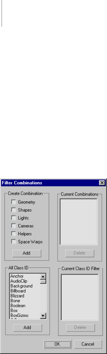
82 Chapter 3: Selecting Objects
The new combo item appears at the bottom of
the Select Filter list.
Combos are stored in the 3dsmax.ini (page
1–18) file,sotheyremainineffectforallscenes
through all sessions.
To delete a combination filter:
1. Open the Selection Filter list and choose
Combos.
The Filter Combinations dialog appears.
2. Choose one or more of the combos in the
Current Combinations list.
3. Click the Delete button.
4. Click OK.
Interface
Create Combination group
Geometry, Shapes, Lights, Cameras, Helpers, Space
Warps—Choose the category or categories you
want included in the combination.
Add—After choosing the categories to include
in a combination, click this button to place the
categories, labeled with the categories’ initials, in
the Current Combinations list, as well as at the
bottom of the Selection Filter list.
Current Combinations group
Current Combinations list—Lists current
combinations. To delete one or more
combinations, choose them, and then click Delete.
Delete—After choosing one or more combinations
in the Current Combinations list, click this button
to delete them.
All Class ID group
Class ID list—Lists all the available categories that
can be added to custom filters for display and
selection. Highlight a category to add, then click
Add.
Add—After choosing a class to include in the
filter list, click this button to place the class in the
Current Class ID Filter list, as well as at the bottom
of the Selection Filter list.
Current Class ID Filter group
Class ID list—Lists current classes to filter. To delete
a class, choose it, and then click Delete.
Delete—AfterchoosingaclassintheCurrentClass
ID Filter list, click this button to delete the class.
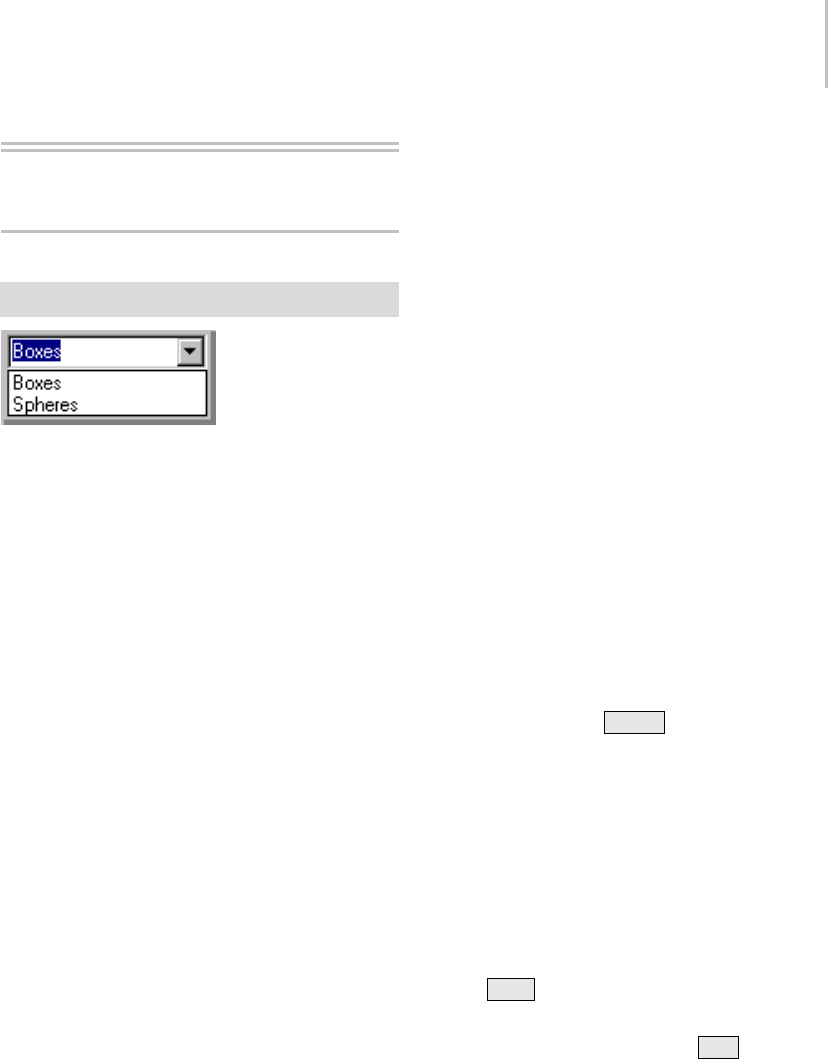
Named Selection Sets 83
Named Selections
Named Selection Sets
Main toolbar > Named Selection Sets
The Named Selection Sets list allows you to name a
selection set and recall the selection for later use. It
supports selection sets both at the object level and
at sub-object levels. You edit named object-level
selection sets with the Named Selections Sets dialog
(page 1–84)and sub-object level sets with the Edit
Named Selections dialog (page 1–86).
A named selection set is removed from the list if
all of its objects have been deleted from the scene,
or if all of its objects have been removed from the
named set in the Named Selections Sets dialog.
Selection set names are case sensitive at both the
object level and at sub-object levels.
You can transfer sub-object named selections from
onelevelinthestacktoanother. TheCopyand
Paste buttons let you copy named selections from
one modifier to another.
While at a specific sub-object level, such as Vertex,
you can make selections and name those selections
in the Named Selection Sets field of the toolbar.
The named sets are specific to both the selection
level and the level on the stack.
Keep in mind the following restrictions:
• You can transfer named selections only between
thesametypeofsub-objectlevel. Inother
words, you can transfer named selections
from vertex sub-object to another vertex
sub-object, but you can’t transfer it to face or
edge sub-object level.
• You must transfer the selection between
modifiersthathandlelikegeometry.Youcan
copy and paste between an editable mesh and
ameshselectmodifier,butyoucan’tcopyand
paste between a mesh select modifier and an
editable spline.
• You can copy and paste between two modifiers
in two different objects, as long as you’re at the
same level and both modifiers handle the same
type of geometry.
• If you change the topology of a mesh after
creating a named selection (such as deleting
some vertices), the named selections will
probably no longer select the same geometry.
Procedures
To create a named selection set:
1. Selecttheobjectsyouwanttobeinaset.
2. Type the name of the set in the Named Selection
Set field and press Enter .
3. Whenever you want to access the selection,
choose its name from the Named Selection Sets
list.
To select a named selection set, do one of the
following:
• To select a single item, click it in the list.
• To select more than one item in the list, select
one, and then select others while holding down
the Ctrl key.
• To deselect single items after you’ve selected
multiple items, hold down the Alt key.
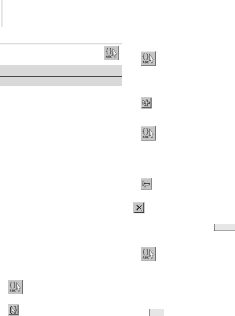
84 Chapter 3: Selecting Objects
Named Selection Sets Dialog
Edit menu > Edit Named Selections
Main toolbar > Named Selection Sets
The Named Selection Sets dialog, available from
the Edit menu, is a modeless dialog (page 3–973)
that lets you create named selection sets or select
objects to add to (or remove from) a selection set,
directly from the viewport. The dialog also lets
you organize your current named selection sets,
browse their members, delete or create new sets, or
identify which named selection sets a particular
object belongs to.
Note: This dialog applies to objects only. For editing
sub-object named selection sets, see Edit Named
Selections Dialog (page 1–86).
See also
Named Selection Sets (page 1–83)
Using Named Selection Sets (page 1–67)
Edit Named Selections Dialog (page 1–86)
Procedures
To create a named selection:
1. In the viewport, select the objects you want to
gather as a selection set.
2. Click the toolbar Named Selection Sets
button or choose Edit > Edit Named Selections.
3. On the Named Selection Sets dialog, click
Create New Set.
4. Enteranameforthenewselectionset.
To add objects to a named selection set:
1. Click the toolbar Named Selection Sets
button or choose Edit > Edit Named Selections.
2. Choose the named selection set in the dialog.
3. Selectoneormoreobjectsintheviewport.
4. In the dialog, click Add Selected Objects.
To remove objects from a named selection set:
1. Click the toolbar Named Selection Sets
button or choose Edit > Edit Named Selections.
2. Choose the named selection set in the dialog.
3. In the viewport, select the objects you want to
remove.
4. In the dialog, click Subtract Selected
Objects.
Note: You can also remove objects by
selecting them in the Named Selection Sets dialog,
then clicking Remove or pressing Delete .
To move an object from one set to another:
1. Click the toolbar Named Selection Sets
button or choose Edit > Edit Named Selections.
2. In the Named Selection Sets dialog, expand the
selection sets.
3. Drag an object from one set to another.
The object is moved into the second set. If you
use Ctrl +drag, the object will be copied into
the second set.
Tip: You can also copy the contents of an entire
set into another, by dragging them into the
desired selection set.
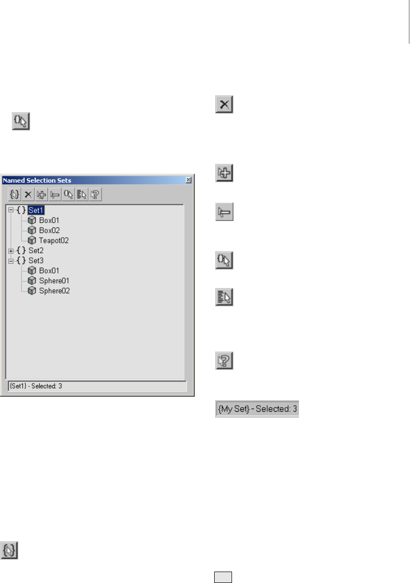
Named Selection Sets Dialog 85
To select objects in a set:
1. Highlight the set in the Named Selection Sets
dialog.
2. Click Select Objects In Set to select all of
the objects in the highlighted set.
Interface
In the Named Selection Sets dialog, all of the
current named selection sets are displayed. By
clicking the plus (+)orminus(-)icon,youcan
expand or collapse (respectively) the object list for
each set.
The buttons along the top of the dialog let you
create or delete sets, add or remove objects from a
set, select objects (independently or as a selection
set), and see which named selection set(s) a
particular object belongs to.
Create New Set—Creates a new selection
set, including any currently selected objects as
members.
Note: If no objects are selected, an empty set is
created.
Remove—Removes the selected object or
selection set.
Note: Deleting an object or its selection set does not
delete the object; it only destroys the named set.
AddSelectedObjects—Adds the currently
selected objects to the selected named selection set.
Subtract Selected Objects—Removes currently
selected objects from the selected named selection
set.
Select Objects in Set—Selects all members of
the current named selection.
Select Objects by Name—Opens the Select
Objects dialog (page 1–78),whereyoucanselecta
group of objects. The selected objects can then be
added to or removed from any named selection set.
Highlight Selected Objects—Highlights all of
the named selection sets that contain the current
scene selection.
Status Bar—Displays the
current named selection set, as well as what’s
currently selected in the scene. If more than one
object is selected, the number of selected objects is
displayed.
Right-click menu
Additional commands are available when you
right-click in the Named Selection Sets dialog.
Rename—Lets you rename the selected set or
object.
Tip: Youcanrenameobjectsorsetsbypressing
F2 .
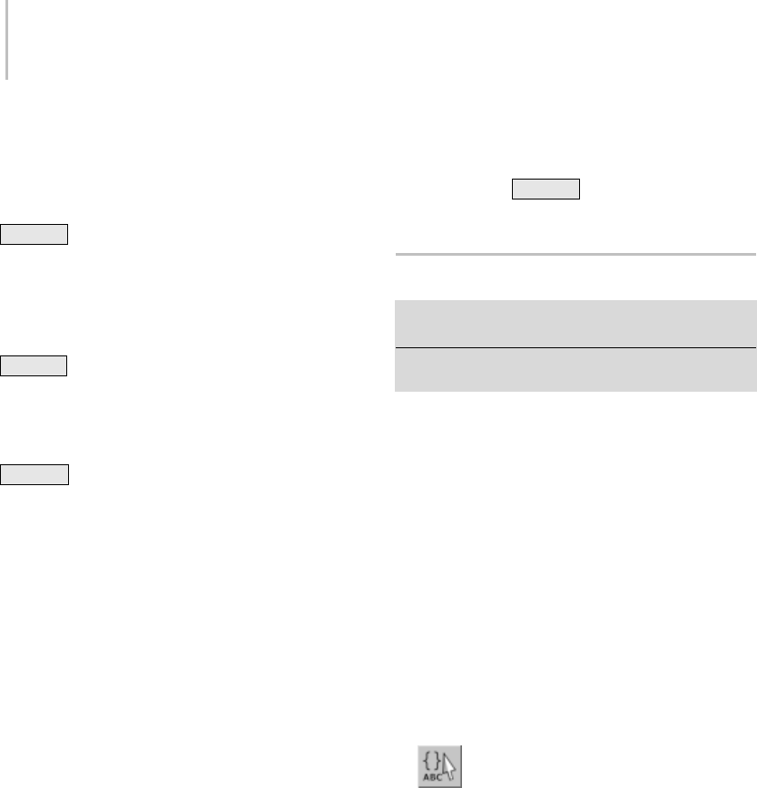
86 Chapter 3: Selecting Objects
Cut—Removes the selected object or set and stores
it in a buffer for reuse with the Paste command,
similar to the Cut command in Windows.
Tip: You can cut an object or set by pressing
Ctrl+X .
Copy—Copies the selected object or set and stores
it in a buffer for reuse with the Paste command,
similar to the Copy command in Windows.
Tip: You can copy an object or set by pressing
Ctrl+C .
Paste—Adds a Cut or Copied object or set into
another set.
Tip: You can paste an object or set by pressing
Ctrl+V .
Collapse All—Collapses all expanded selection sets.
Expand All—Expands all collapsed selection sets.
Create New Set—Creates a new selection set,
including any currently selected objects as
members.
Remove—Removes the selected object or selection
set.
Add Selected Objects—Adds currently selected
objects to the selected named selection set.
Subtract Selected Objects—Removes currently
selected objects from the selected named selection
set.
Select Objects in Set—Selects all members of the
current named selection.
Select Objects by Name—Opens the Select Objects
dialog (page 1–78), and adds all objects selected
there to the current named selection set.
Highlight Selected Objects—Highlights all of the
named selection sets that contain the current scene
selection.
Find Next—Toggles through selection sets
containing the selected object, when used in
collaboration with the Highlight Selected Objects
command.
Tip: Yo u c a n u s e Ctrl+G to toggle through the
sets.
Edit Named Selections Dialog
Make a sub-object selection. > Edit menu > Edit Named
Selections
Make a sub-object selection. > Main toolbar > Named
Selection Sets
EditNamedSelectionsdisplaystheEditNamed
Selections dialog, letting you manage named
selection sets of sub-objects (page 1–74).Unlike
the Named Selection Sets dialog (page 1–84),which
applies to objects only,itisamodaldialog,which
meansthatyoumustcloseitinordertoworkin
other areas of 3ds Max. Also, you can work only
with existing named sub-object selections; you
cannot use the dialog to create new selections.
Procedure
To edit named sub-object selections:
1. At a sub-object level, create one or more named
selection sets (page 1–83).
2. Click the toolbar Named Selection Sets
button or choose Edit > Edit Named Selections.
The Edit Named Selections dialog opens,
listing all named selection sets for the current
sub-object level.
3. Use the dialog controls to edit the named
selection sets.
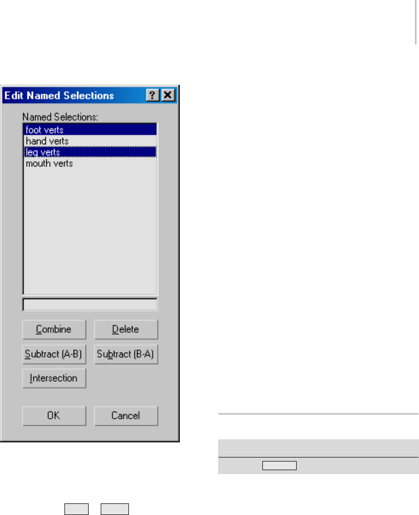
Select All 87
Interface
The dialog window lists all named selections at
the current sub-object level. The buttons beneath
the windows let you delete, merge, and edit the
listed items. Use standard mouse-plus-keyboard
methods (using Ctrl or Shift ) to highlight
list items and designate them for subsequent
operations.
To rename a set, click it in the list, and then edit its
name in the one-line window immediately below
the list.
Combine—Merges all objects from the highlighted
selection sets into a single, new selection set. Select
two or more selection sets, and then click Combine
and enter a new name for the selection set. Use
Delete to delete the original sets.
Delete—Deletes all highlighted items from the
Named Selections window. This affects only
selection sets, not the sub-objects they refer to.
Subtract (A-B)—Removes the sub-objects contained
in one selection set from another. Select one
item in the Named Selections window, and then
select the other. The top highlighted item in the
window is operand A, and the bottom is operand
B (regardless of the order of their selection). Click
Subtract (A-B) to subtract the sub-objects in the
bottom item from those in the top item. There
must be some overlap between the two selection
sets for this command to have any effect.
Subtract (B-A)—Subtracts the sub-objects in the
top selected item from those in the bottom item.
Intersection—Creates a selection set that consists
only of sub-objects that all highlighted selection
sets have in common. Highlight two or more items
in the Named Selections window, and then click
Intersection. In the dialog that appears, enter a
new set name and click OK.
Select All
Edit menu > Select All
Keyboard > Ctrl + A
This command selects all objects in the scene
matching the current selection filter type (page
1–81) on the main toolbar.

88 Chapter 3: Selecting Objects
Select None
Edit menu > Select None
Keyboard > Ctrl + D
This command deselects all objects in the scene
conforming to the current selection filter type (page
1–81) on the main toolbar.
Select Invert
Edit menu > Select Invert
Keyboard > Ctrl + I
This command inverts the current selection set.
All objects not currently selected are selected,
and all objects currently selected are deselected,
respecting the current selection filter type (page
1–81) on the main toolbar.
Select By
Edit menu > Select By
TheSelectBysubmenuontheEditmenuprovides
commands for selecting objects in the scene by
color, name, and other characteristics. It also
gives quick access to the various Region selection
options.
Select By Color (page 1–88)
Select By Name (Edit Menu) (page 1–88)
Select Similar (page 1–88)
Rectangular Selection Region (page 1–89)
Circular Selection Region (page 1–89)
Fence Selection Region (page 1–90)
Lasso Selection Region (page 1–90)
Paint Selection Region (page 1–91)
Select By Color
Edit menu > Select By > Color
Select By Color lets you select all objects having the
same color as the selected object. Selection is made
by wireframe color (see Object Color Dialog (page
1–159)), rather than by any materials associated
with the objects.
After you choose this command, click any object
inthescenetodeterminethecolorfortheselection
set.
Tip: To select objects by material, use Schematic
View (page 3–640).
Select By Name (Edit Menu)
Edit menu > Select By > Name
Keyboard > H
Select By Name lets you select objects by choosing
them from a list of all objects in the scene.
For a full description of the Select By Name
function, see Select By Name (page 1–77).
Tip: To select objects by material, use Select By
Material (page 2–1439).
Select Similar
Edit menu > Select By > Select Similar
Use this command to select all items in the selected
object’s or objects’ layer that have the same style(s)
(page 3–461), as defined in AutoCAD Architecture
(formerly known as ADT, or Architectural
Desktop). For example, if you’ve imported or
linked to a DWG file that contains walls in several
different styles, such as CMU-8, Concrete-8, and
Stud-4, you could select all CMU-8 wall segments
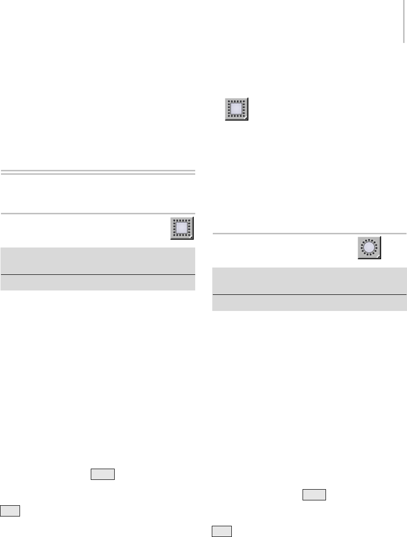
Rectangular Selection Region 89
inthesamelayerbyselectingoneandthen
invoking Select Similar.
If you start by selecting multiple objects with
different styles, Select Similar will select all objects
with those styles.
Region Selection
Rectangular Selection Region
Main toolbar > Rectangular Selection Region (Selection
Region flyout)
Edit menu > Select By > Rectangular Region
The Rectangular Selection Region option, available
from the Selection Region flyout (page 1–80) and
theEditmenu,providesoneoffivemethodsyou
can use to select objects by region. The other
methods are Circular (page 1–89),Fence (page
1–90),Lasso (page 1–90),andPaint (page 1–91).
You can use Rectangular to select either objects
that are completely within the selection region
(window method), or objects that are either
within or touched by the selection shape (crossing
method). Toggle between the window and crossing
selection methods by using the Window/Crossing
Selection button (page 1–93) on the main toolbar.
Note: If you hold down Ctrl while specifying
a region, the affected objects are added to the
current selection. Conversely, if you hold down
Alt while specifying a region, the affected objects
areremovedfromthecurrentselection.
Procedure
To select using a rectangle:
1. Click the Rectangular Selection Region
button.
2. Drag in a viewport, then release the mouse.
The first location you click is one corner of the
rectangle, and where you release the mouse is
theoppositecorner.
To cancel the selection,right-clickbeforeyou
release the mouse.
Circular Selection Region
Main toolbar > Circular Selection Region (Selection
Region flyout)
Edit menu > Select By > Circular Region
The Circular Selection Region option, available
from the Selection Region flyout (page 1–80) and
theEditmenu,providesoneoffivemethodsyou
can use to select objects by region. The other
methods are Rectangular (page 1–89),Fence (page
1–90),Lasso (page 1–90),andPaint (page 1–91).
YoucanuseCirculartoselecteitherobjectsthatare
completely within the selection region (window
method), or objects that are either within or
touched by the selection shape (crossing method).
Toggle between the window and crossing selection
methods by using the Crossing Selection button
(page 1–93) on the main toolbar.
Note: If you hold down Ctrl while specifying
a region, the affected objects are added to the
current selection. Conversely, if you hold down
Alt while specifying a region, the affected objects
are removed from the current selection.
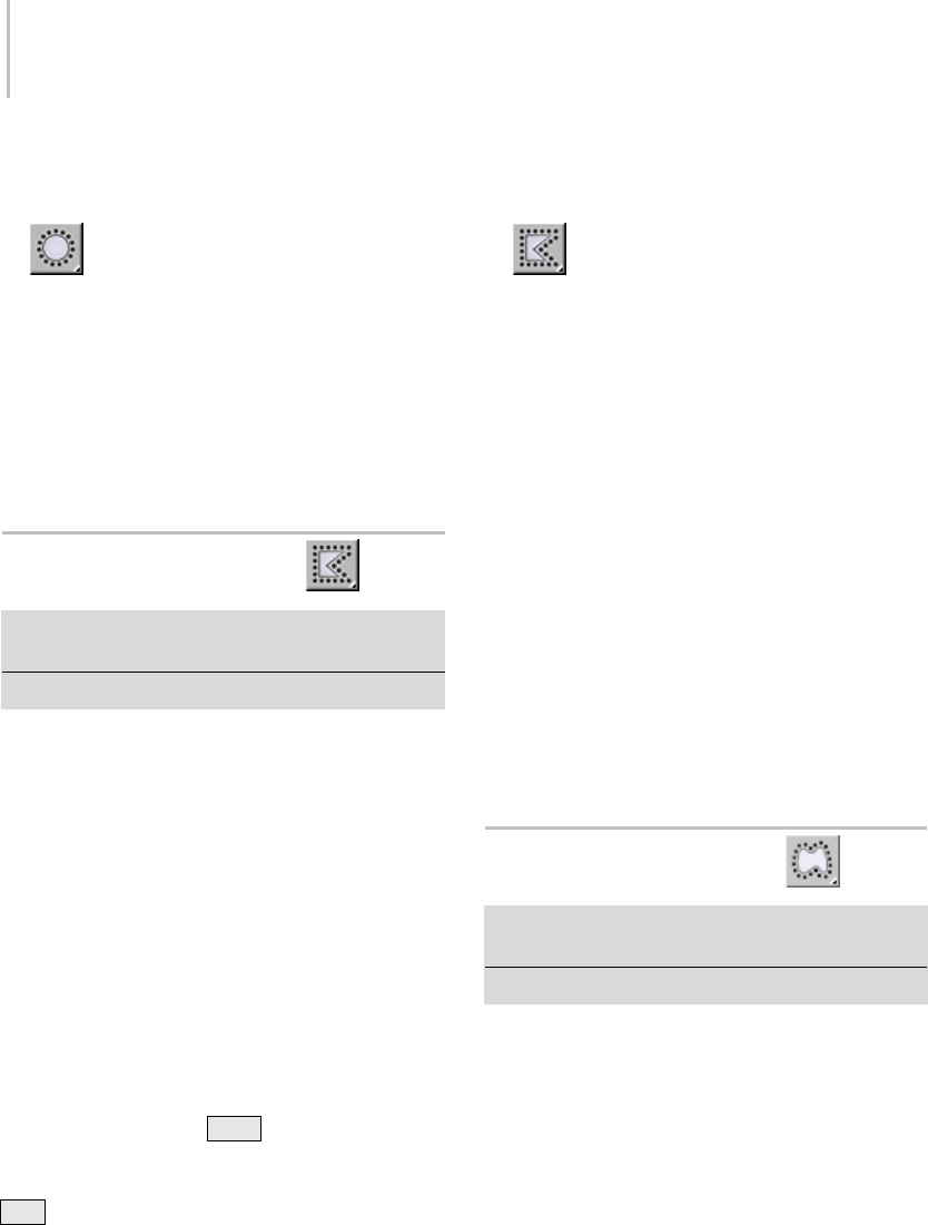
90 Chapter 3: Selecting Objects
Procedure
To select using a circle:
1. Click the Circular Selection Region
button.
2. Drag in a viewport, then release the mouse.
The first location you click is the center of the
circle, where you release the mouse defines the
circle’s radius.
To cancel the selection,right-clickbeforeyou
release the mouse.
Fence Selection Region
Main toolbar > Fence Selection Region (Selection Region
flyout)
Edit menu > Select By > Fence Region
The Fence Selection Region option, available from
the Selection Region flyout (page 1–80) and the Edit
menu, provides one of five methods you can use
to select objects by region. The other methods
are Rectangular (page 1–89),Circular (page 1–89),
Lasso (page 1–90),andPaint (page 1–91).
You can use Fence to select either objects that are
completely within the selection region (window
method), or objects that are either within or
touched by the selection shape (crossing method).
Toggle between the window and crossing selection
methods by using the Window/Crossing button
(page 1–93) on the main toolbar.
Note: If you hold down Ctrl while specifying
a region, the affected objects are added to the
current selection. Conversely, if you hold down
Alt while specifying a region, the affected objects
areremovedfromthecurrentselection.
Procedure
To select using a fence:
1. Click the Fence Selection Region button.
2. Drag to draw the first segment of a polygon,
then release the mouse button.
A "rubber-band line" is now attached to the
cursor, anchored at the point of release.
3. Movethemouseandclicktodefinethenext
segment of the fence. You can make as many
steps as you want.
4. To complete the fence, either click the first
point, or double-click.
A pair of cross hairs appears when you’re near
enough to click the first point. This creates a
closed fence.
Double-clicking createsanopenfence,which
can select objects only by the crossing method.
To cancel the selection, right-click before you
release the mouse.
Lasso Selection Region
Main toolbar > Lasso Selection Region (Selection Region
flyout)
Edit menu > Select By > Lasso Region
The Lasso Selection method lets you select
multiple objects within a complex or irregular
region with a single mouse action.
The Lasso Selection Region option, available from
the Selection Region flyout (page 1–80) and the Edit
menu,providesoneoffivemethodsyoucanuse
to select objects by region. The other methods
are Rectangular (page 1–89),Circular (page 1–89),
Fence (page 1–90),andPaint (page 1–91).
You can use Lasso to select either objects that are
completely within the selection region (window
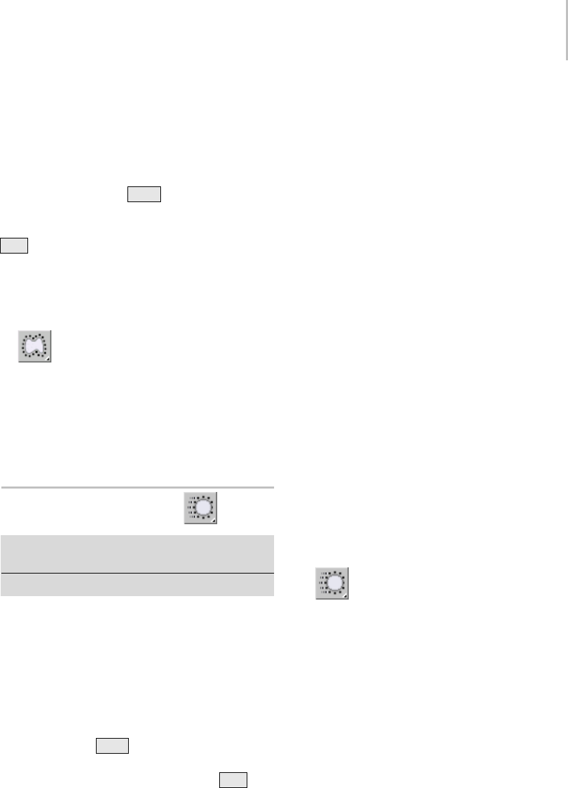
Paint Selection Region 91
method), or objects that are either within or
touched by the selection shape (crossing method).
Toggle between the window and crossing selection
methods by using the Window/Crossing button
(page 1–93) on the Main toolbar.
Note: If you hold down Ctrl while specifying
a region, the affected objects are added to the
current selection. Conversely, if you hold down
Alt while specifying a region, the affected objects
areremovedfromthecurrentselection.
Procedure
To select using a lasso:
1. Click the Lasso Selection Region button.
2. Drag to draw a shape around the object(s) that
should be selected, then release the mouse
button.
Note: To cancel the selection, right-click before
you release the mouse.
Paint Selection Region
Main toolbar > Paint Selection Region (Selection Region
flyout)
Edit menu > Select By > Paint Region
The Paint Selection method lets you select multiple
objects or sub-objects by dragging the mouse over
them. To change the brush size, right-click the
Paint Selection Region button, and then, on the
Preference Settings dialog > General tab > Scene
Selection group, change the Paint Selection Brush
Size value.
If you hold down Ctrl while specifying a region,
the affected objects are added to the current
selection. Conversely, if you hold down Alt
while specifying a region, the affected objects are
removed from the current selection.
Tip: You can also create custom tools for changing
the brush size; choose Customize menu >
Customize User Interface and set keyboard
shortcuts or other user interface items for the
actions Paint Selection Size Up and Paint Selection
Size Down.
Note: Paint Selection Region respects the
Window/Crossing selection toggle (page 1–93)
setting. If the toggle is set to Select Region Window
(page 1–92) and the brush is smaller than an object
or sub-object to be selected, you won’t be able to
selecttheitem.Toresolvethis,enlargethebrush
or choose Select Region Crossing (page 1–93).
Note: With editable poly (page 1–1022) and Edit
Poly (page 1–640) objects, you can also paint soft
selections (page 1–966) and deformation (page
1–1024).
The Paint Selection Region button, available from
the Selection Region flyout (page 1–80),provides
oneoffivemethodsyoucanusetoselectobjectsby
region. The other methods are Rectangular (page
1–89),Circular (page 1–89),Lasso (page 1–90),
and Fence (page 1–90).
Procedure
To select by painting a region:
1. ChoosePaintSelectionRegionfromthe
flyout.
2. Drag over the object(s) to select, then release
the mouse button. As you drag, a circle showing
the brush radius appears attached to the mouse.
Note: To cancel the selection, right-click before
you release the mouse.
3. To change the brush size, right-click the
Paint Selection Region button, and then, on
the Preference Settings dialog > General tab
> Scene Selection group, change the Paint
Selection Brush Size value.
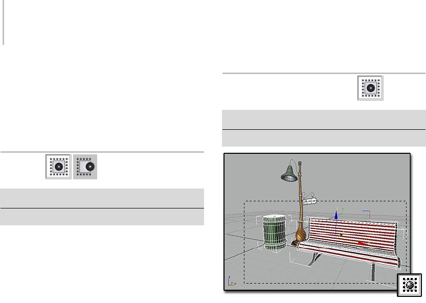
92 Chapter 3: Selecting Objects
You can also set keyboard shortcuts for
changing the brush size. To do so, use the
Paint Selection Size Up and Paint Selection Size
Down action items. See Keyboard Panel (page
3–793).
Region
Edit menu > Region
Main toolbar > Window Selection or Crossing Selection
When dragging the mouse to select one or more
objects, the Region options let you switch between
selecting objects within, or crossed by, a window
region that you draw with the mouse. Choose the
appropriate Region submenu command, or use
the Window/Crossing Selection Toggle (page 1–93)
on the Status bar.
You can automatically switch between Window
and Crossing Region Selection based on cursor
movement direction. To set this up, choose
Customize > Preferences and on the General
tabintheSceneSelectiongroupturnonAuto
Window/Crossing Selection by Direction.
See also
Select Region Window (page 1–92)
Select Region Crossing (page 1–93)
Select Region Window
Edit menu > Region > Window
Main toolbar > Window/Crossing Selection
Select Region Window selects only those objects completely
inside the window: the trash can and bench.
Select Region Window selects objects within a
selection region (page 1–80).
After you choose this command, draw a selection
region around any objects in the scene. Only those
objects that are entirely inside the region boundary
are selected.
Procedure
To select objects within a selection region:
1. Do one of the following:
• Choose Edit > Region > Window.
•ClicktheWindow/Crossing Selection Toggle
(page 1–93) to display the Window icon.
2. From the Main toolbar, click the Selection
Region flyout (page 1–80) and choose a method:
Rectangular, Circular, Fence or Lasso Selection
region.
Note: This setting also applies to Paint Selection
Region, but in this case the boundary is that of
the brush, not the region. In other words, when
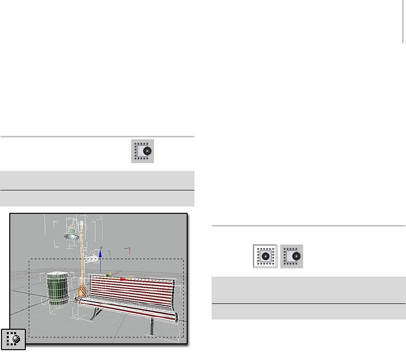
Select Region Crossing 93
painting a selection region, the brush must
completely encompass an object or sub-object
to select it.
3. Drag to specify the region and select the objects.
Select Region Crossing
Edit menu > Region > Crossing
Main toolbar > Crossing Selection
Select Region Crossing selects objects within the window and
also objects it crosses: the trash can, bench, and streetlight.
Select Region Crossing selects objects within and
crossed by a selection region (page 1–80) boundary.
After you choose this command, draw a selection
region around or crossing objects in the scene.
Objects within the region boundary as well as
those that intersect the boundary are selected.
Procedure
To select objects within and crossed by a selection
region:
1. Do one of the following:
1. Choose Edit > Region > Crossing.
2. Click the Window/Crossing Selection Toggle
(page 1–93) to display the Crossing icon.
2. From the Main toolbar, click the Selection
Region flyout (page 1–80) and choose a method:
Rectangular, Circular, Fence or Lasso Selection
region.
Note: This setting also applies to Paint Selection
Region, but in this case the boundary is that of
the brush, not the region. In other words, when
paintingaregioninCrossingmode,thebrush
selects every object or sub-object it touches or
encompasses.
3. Drag to specify the region and select the objects.
Window/Crossing Selection
Toggle
Main Toolbar > Crossing Selection or Window Selection
from the Window/Crossing toggle
Edit menu > Region > Window or Crossing
TheWindow/CrossingSelectiontoggleswitches
between window and crossing modes when you
select by region.
•InWindow mode (page 1–92), you select only
the objects or sub-objectswithin the selection.
•InCrossing mode (page 1–93),youselect
all objects or sub-objects within the region,
plus any objects or sub-objects crossing the
boundaries of the region.
Tip: If you’re making sub-object selections of faces
and you select more faces than you want, make
sure you’re in Window mode.
The Selection Region flyout (page 1–80) on the
toolbar allows you to create different-shaped
boundaries.
3ds Max automatically saves the Window/Crossing
setting in the 3dsmax.ini (page 1–18) file.
94 Chapter 3: Selecting Objects
Edit Commands
These commands on the Edit menu (page 3–673)
are for basic edit manipulations of selections.
UndoandRedoworkasinstandardWindows
applications. These commands are available on the
default main toolbar as well. 3ds Max also provides
a history of commands. Right-clicking the Undo
or Redo buttons displays a list of commands you
can undo or redo. Not all operations are reversible
using Undo.
Note: Viewport changes such as panning and
zooming have a separate Undo and Redo. See
View-Handling Commands (page 1–35).
The Hold and Fetch command pair serves as an
alternative to Undo and Redo. Hold saves the
current state of the scene. After using Hold, you
can restore that state at a later point by using Fetch.
Sometimes, when you are about to perform a risky
operation, an alert prompts you to first use Hold.
3ds Max does not have the Cut or Paste functions
found in many Windows applications. The Delete
command simply removes the selection from the
scene.
Undo/Redo (page 1–94)
Hold/Fetch (page 1–95)
Delete (page 1–95)
Undo/Redo
Edit menu > Undo or Redo
Main toolbar > Undo or Redo
Keyboard > Ctrl+Z (Undo) or Ctrl+Y (Redo)
The Undo command reverses the last operation
performed on any selected objects. Redo reverses
the last operation performed by the Undo
command.
Some actions cannot be undone: for example,
applyingtheCollapseutilityorResetTransform
utility, or saving a file, which overwrites the
previous version. When you know something
cannot be undone, use Hold (page 1–95) first.
Then if you want to undo it, use Fetch. Hold and
Fetch are also commands on the Edit menu (page
3–673).
Afer you perform an action that is undoable, the
Edit menu shows the name of the function to be
undone. After you undo an action, the Edit menu
shows the name of the function you can redo.
Undo and Redo are also available as buttons on
the main toolbar. You can right-click the Undo
or Redo button to display a box that lists the
last operations performed. You can highlight
and reverse any number of these operations
insequencewiththerespectiveUndoorRedo
command. By default, there are 20 levels of Undo.
You can change the number of levels with the
Customize > Preferences > General tab (page
3–815) >SceneUndogroup.
Undo/Redo and Object Creation
When you create an object, the Create operation
is recorded by 3ds Max and displayed next to the
activated Undo command in the Edit menu. When
you undo the Create operation, the Redo Create
operation is displayed next to the activated Redo
command in the Edit menu. The Undo and Redo
commands in the Edit menu are unavailable when
no valid operation was performed or recorded.
Procedures
To undo the most recent action:
•Click Undo, choose Edit menu > Undo,
or press Ctrl+Z .
Hold/Fetch 95
To undo several actions:
1. Right-click Undo.
2. From the list, select the level where you want
to return. You must chooseacontinuous
selection; you can’t skip over items in the list.
3. Click the Undo button.
To exit the list without performing an action,
click the Cancel button, or click somewhere
outside of the list.
To redo an action, do one of the following:
•Click Redo.
•Editmenu>Redo.
•Press
Ctrl+Y .
To redo several actions:
1. Right-click Redo.
2. From the list, click the action to return to.
Your selection must be continuous: you can’t
skip over any items in the list.
3. Click the Redo button.
To exit the list without performing an action,
click the Cancel button or click somewhere
outside of the list.
Hold/Fetch
Edit menu > Hold or Fetch
Hold saves the scene and its settings to a disk-based
buffer. Fetch restores the contents of the buffer
stored by the previous Hold command. The
information stored includes geometry, lights,
cameras, the viewport configuration, and selection
sets.
Use Hold before you perform an operation
thatmightnotworkasexpected,thatisnewor
unfamiliar to you, or that cannot be undone. If
the results aren’t as expected, you can use Fetch to
returntothepointwhereyouchoseHold.
Tip: AlsouseSaveorSaveAsbeforeyouperform
an operation that cannot be undone: for example,
applying the Reset Transform utility.
If you experience an unexpected end of operation
or crash after you perform Hold, you can retrieve
your scene from the buffer with the Fetch
command after you restart 3ds Max.
Additional Details
• The Hold buffer is a temporary file
(maxhold.mx)inthedirectoryspecifiedbythe
AutoBackup path on the Configure User Paths
dialog > File I/O panel (page 3–810).
• Fetch also deletes all operations recorded in the
Undo and Redo History lists.
Delete
Make a selection. > Edit menu > Delete
Make a selection. > Keyboard > Delete
The Delete command deletes the current selection
from the model.
The Undo command (page 1–94) can restore
the deleted selection to the model. (The Undo
command is also available as a button on the main
toolbar.)
Groups and Assemblies
You use groups and assemblies in 3ds Max to
combine arbitrary sets of scene entities into a

96 Chapter 3: Selecting Objects
single, non-hierarchical object that you can then
manipulate as one. Grouping works with all
objects, while assemblies are best used for light
fixtures and characters.
For more information about groups, see Using
Groups (page 1–96) and Group Commands (page
1–104).
For more information about assemblies, see Using
Assemblies (page 1–98) and Assembly Commands
(page 1–107)
For more information about character assemblies,
see Character Assembly (page 1–102) and Character
Assembly Commands (page 1–112)
Using Groups
Object on the right is a group and treated as a single entity.
Grouping lets you combine two or more objects
into a single grouped object. The grouped object
is given a name, and then treated much like any
other object.
Group names are similar to object names, except
that they’re carried by the group object. In lists like
the one for the Select Object dialog, group names
appear in square brackets, for example [Group01].
The commands to manage groups are on the
default Group menu (page 3–674).
General Features of Groups
Once you group objects, you can treat them as
a single object in your scene. You can click any
object in the group to select the group object.
When you create a group, all of its member objects
are rigidly linked to an invisible dummy object.
Thegroupobjectusesthepivotpointandthe
local transform coordinate system of this dummy
object.
Groups can be nested. That is, groups can contain
other groups, up to any level.
Transforming and Modifying a Group
You can transform or modify a group as if it were a
single object, and you can animate the transforms
and the modifiers.
When you apply a modifier to the group, this
applies an instance of the modifier to each object
in the group. A grouped object retains its modifier
instance, even if you later remove it from the
group.
Whenyouapplyatransformtothegroup,onthe
other hand, this applies only to the group as a
whole. More precisely, 3ds Max applies transforms
to the dummy object that represents the group.
You can transform and animate individual objects
within a group independently from the group
itself. However, when you transform the group
itself, the transform affects all grouped objects
equally. The group transform is uniformly added
to objects that have independent motions. An
analogy is a cage of birds, each flying around on
itsown,whilethecageitselfisbeingmoved. In
thecaseofgroups,the"cage"(thedummyobject)
expands to surround all objects in the group,
wherever the objects’ independent transforms take
them.

Using Groups 97
Accessing Objects in a Group
You can open and close groups to access the
individual objects contained in them without
dissolving the group. These commands maintain
the integrity of the group.
•Open (page 1–105): Temporarily opens the
group so that you can access its member
objects. While a group is open, you can treat
the objects (or nested groups) as individuals.
You can transform them, apply modifiers, and
access their modifier stacks.
•Close (page 1–105): Restores the group when
you’re finished working with the individual
objects.
Dissolving Groups
You can permanently dissolve groups by either
ungrouping or exploding them. Both commands
dissolve groups, but to different levels.
•Ungroup (page 1–106):Goesoneleveldeepin
the group hierarchy. It separates the current
group into its component objects (or groups),
and deletes the group dummy object.
•Explode (page 1–106):SimilartoUngroup,
but dissolves all nested groups as well, leaving
independent objects.
When you Ungroup or Explode a group, the
objects within the group lose all group transforms
not on the current frame. However, objects retain
any individual animation.
To transform or modify the objects within a group,
you must first remove them from the group, either
temporarily or permanently. The Open command
lets you do this.
Comparing Groups with Other Selection
Methods
Compared to the other methods you can use to
combine objects in 3ds Max, grouping is more
permanent than selection sets, but less permanent
than attaching objects.
•Selection sets (page 1–64): Form a temporary
collection of objects to which you apply the
current commands. As soon as you select
another object, the selection set is gone.
•Named selection sets (page 1–67):Letyou
reselectthesamepatternofobjects,butthe
positional relationship between those objects
(their transforms) might be different each time
you recall the named set.
• Grouped objects: Maintain their positional
relationshipsunlessyouopenthegroupand
rearrange them. A group also keeps its identity
as an individual object.
Each object in a group retains its modifier stack,
including its base parameters. At any time, you
canopenthegrouptoeditanobject,andthen
closethegrouptorestorethegroupidentity.
• Attached objects (see Editable Mesh (Object)
(page 1–1001)): Attached objects form a
single object. The modifier stacks of the
original objects are lost, including their base
parameters. Youcanregaintheformofthe
original objects by detaching them, but they
become plain meshes.
•Assemblies (page 1–98) are useful for creating
combinations of geometry and light objects
that act as lighting fixtures.
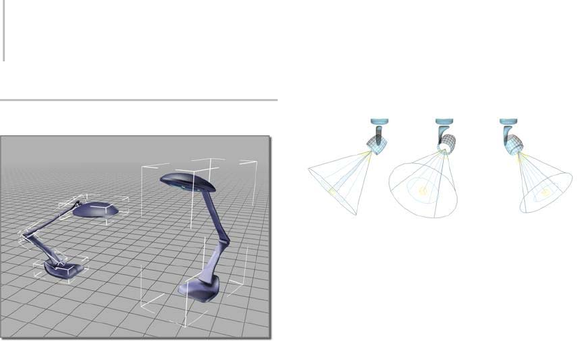
98 Chapter 3: Selecting Objects
Using Assemblies
Object on the right is an assembly and is treated as a single
entity.
Assemblies are useful for creating combinations
of geometry and light objects that act as lighting
fixtures; you use them to represent the housing of
a lamp and its light source or sources. You can use
assemblies to represent lighting fixtures such as
simple desk lamps, lighting strips, track systems,
wall sconces with fluorescent or incandescent
lights, chandelier systems, line voltage cable
systems, and so on.
When you create light assemblies, first you create
your objects and build a hierarchy, then set joint
parameters and assign inverse kinematics (IK)
(page 2–435). As a final step, you assemble the
object hierarchy. The lights you use in the assembly
have light-multiplier and filter color controls. You
wire (page 2–411) the Dimmer and Filter Color
parameters of the Luminaire helper object to the
parameters of the light sources that are members
of the light assembly.
Note: InordertowiretheLuminairecontrolstothe
light parameters, you must first open (page 1–109)
the assembly; then, after wiring, you close (page
1–109) it.
You can use IK to point a luminaire’s beam by simply moving
the light’s target object.
Assemblies and Groups
Assembly functionality is a superset of grouping
(page 1–96). Like grouping, creating an assembly
lets you combine two or more objects and treat
them as a single object. The assembled object
is given a name, and then treated much like any
other object.
Themaindifferencewithassembliesisthat,
when you assemble (page 1–107) the member
objects, you specify a head object (page 1–111):a
Luminaire helper object (page 1–111).Thehead
object acts as a front end for the assembly, and its
parameters appear in the Modify panel when the
assembly is selected. You can use these parameters
to control the light sources in the assembly via
parameter wiring (page 2–411).Youcancreate
other types of head objects with MAXScript;
for further information, open the MAXScript
Reference,availablefromtheHelpmenu,andlook
in Creating MAXScript Tools > Scripted Plug-ins
> Scripted Helper Plug-ins.
Assembly names are similar to object names,
except that they’re carried by the assembly. In lists
like the one in the Select Object dialog, assembly
names appear in square brackets, for example
[Assembly01].
Tip: After you’ve created one fixture and assembled
the parts, use instancing (page 3–957) to copy (page
1–471) the fixture, and then distribute them in
your scene. That way, if you change the attributes

Using Assemblies 99
foralightsourceinanassembly,thechangewill
be reflected in all the instanced light sources. For
example, in the early design stages, you might
use shadow maps, but later you might want to
switch to advanced ray-trace shadows for greater
accuracy in rendering. Using instancing makes it
easier to change such settings globally.
General Features of Assemblies
Once you assemble objects, you can treat them as
a single object in your scene. You can click any
object in the assembly to select the entire assembly.
When you create an assembly, all of its member
objects are rigidly linked to an invisible Luminaire
helper object. The assembly uses the pivot point
and the local transform coordinate system of this
helper object.
You can nest assemblies. That is, assemblies can
contain other assemblies (or groups), up to any
level.
The head object parameters appear in the Modify
panel when the assembly is selected. You can
use the 3ds Max Wire Parameters (page 2–411)
functionality to connect these parameters to those
of light objects in the assembly. For a step-by-step
procedure, see To w i re a hea d ob j ect to a li g ht
source (page 1–108).
Luminaire types
Left: Fixed
Middle: Orientable
Right: Multiple lights
Transforming and Modifying an
Assembly
You can transform or modify an assembly as if
it were a single object, and you can animate the
transforms.
Unlikeagroup,whenyouapplyamodifiertothe
assembly, only the luminaire receives the modifier.
Thus, deforming modifiers such as Bend don’t
have any effect on assemblies.
When you apply a transform to the assembly, it
applies to the assembly as a whole. More precisely,
3dsMaxappliestransformstothedummyobject
that represents the assembly. To modify member
objects, you must first open the assembly, select the
objects, and then apply modifiers. Such modifiers
do not appear in the modifier stack when the
assembly is closed.
You can transform and animate individual objects
within an assembly independently from the
assembly itself. However, when you transform the
assembly itself, the transform affects all assembled
objects equally. The assembly transform is
uniformly added to objects that have independent
motions. An analogy is a cage of birds, each flying
around on its own, while the cage itself is being
moved. In the case of assemblies, the "cage" (the
dummyobject)expandstosurroundallobjectsin
the assembly, wherever the objects’ independent
transforms take them.
Accessing Objects in an Assembly
Yo u c a n open and close assemblies to access the
individual objects contained in them without
dissolving the assembly. These commands
maintain the integrity of the assembly.
•Open (page 1–109):Temporarilyopensthe
assembly so that you can access its member
objects. While an assembly is open, you can
treat the objects (or nested assemblies/groups)

100 Chapter 3: Selecting Objects
as individuals. You can transform them, apply
modifiers, and access their modifier stacks.
•Close (page 1–109): Restores the assembly when
you’re finished working with the individual
objects.
Using Make Unique with Assemblies
When you clone assemblies using instancing,
and then make the clones unique, it’s important
to consider how this affects parameter wiring.
Consider the following typical usage case:
1. Drag an assembly, such as a light fixture, into
the scene.
2. Clone the assembly several times using the
Instance option and position the instances in
the scene.
3. To make the scene look more realistic, giving
theappearanceofrandomnesstotheobjectsin
thescene,makesomeoftheassemblyinstances
unique and adjust their parameters to differ
from the rest of the instances.
When you clone-instance an assembly, all objects
in the assembly, along with all the parameter wires,
are instanced. So if you change a wired luminaire
parameter, all instanced assemblies are affected.
When the modifier stack displays an assembly
head that is an instance or reference, the Make
Unique (page 3–770) button is active. By clicking
it, the assembly head object is made unique
with respect to its instances and all the assembly
members are also made unique.
The parameter wiring between the unique
assembly head and its members is de-coupled from
the other instances of the assembly. Changing the
parametersoftheuniqueassemblyheadobject
affectsonlytheparametersofitsownmembers,
not the members of the other instances of the
assembly.
When multiple assembly instances are selected, the
Make Unique command works the same as when
multiple instances of an object are selected. You’re
asked whether you want to make the selected
assemblies unique one with respect to each other.
• If you answer Yes, 3ds Max makes the
assemblies unique one with respect to another
and parameter wires are reconnected inside
each unique assembly. That is, the parameters
of each unique assembly head drives only the
parameters of its own members, not that of the
members in any other assembly instances.
• If you answer No, then the selected assemblies
aremadeuniqueonlywithrespecttotheother
assembly instances. The parameters of unique
assembly heads drive only the parameters of
their members, not the members of the other
assembly instances.
Note: If you chose to instance the controllers
when you instanced the assembly, the Modify
panel > Make Unique command does not make
the controllers unique. You can make them
unique by doing the following: Open Track
View, select the Transform track for object
whose controller you want to make unique, and
click the Make Unique button in the Track View
toolbar.
Dissolving Assemblies
You can permanently dissolve assemblies by either
disassembling or exploding them. Both commands
dissolve assemblies, but to different levels.
•Disassemble (page 1–110):Goesoneleveldeep
in the assembly hierarchy. It separates the
currentassemblyintoitscomponentobjects(or
assemblies/groups), and deletes the assembly
head object.
•Explode (page 1–110): Similar to Disassemble,
but dissolves all nested assemblies and groups
as well, leaving independent objects.

Using Assemblies 101
When you disassemble or explode an assembly,
any transform animation applied to the assembly is
lost,andobjectsremainastheywereintheframe
at which the dissolution is performed. However,
objects retain any individual animation.
To transform or modify the objects within an
assembly, you must first remove them from the
assembly, either temporarily or permanently. The
Open command lets you do this.
Comparing Assemblies with Other
Selection Methods
Compared to the other methods you can use to
combine objects in 3ds Max, assembling is more
permanent than selection sets, but less permanent
than attaching objects.
•Selection sets (page 1–64):Formatemporary
collection of objects to which you apply the
current commands. As soon as you select
another object, the selection set is gone.
•Named selection sets (page 1–83):Letyou
reselectthesamepatternofobjects,butthe
positional relationship between those objects
(their transforms) might be different each time
you recall the named set.
• Assembled and grouped (page 1–96) objects:
Maintain their positional relationships unless
you open the assembly and rearrange them. An
assembly also keeps its identity as an individual
object.
Each object in an assembly retains its modifier
stack, including its base parameters. At any
time,youcanopentheassemblytoeditan
object, and then close the assembly to restore
the assembly identity.
• Attached objects (see Editable Mesh (Object)
(page 1–1001)): Attached objects form a
single object. The modifier stacks of the
original objects are lost, including their base
parameters. You can regain the form of the
original objects by detaching them, but they
become plain meshes.
See also
Lights (page 2–1272)
Procedures
To insert and place an existing assembly:
1. Tur n on AutoGrid (page 2–7).
2. Drag the assembly from a Web page (if it’s an
i-drop object (page 3–523))orfromyourlocal
disk and drop it into your scene, placing it on
any existing surface.
3. On the main toolbar, click Use Pivot
Point Center (page 1–446).
4. Position the assembly as you would any other
objecttoaimitinaspecificdirection.
5. If necessary, wire (page 1–108) the assembly
luminaire to its light source or sources.
6. Select the assembly, and then use the Modify
panel settings to adjust the intensity of the light
with the Dimmer control.
To create your own luminaire:
1. Create the geometry of the lighting fixture.
2. Create a light source (page 2–1274) or on the
Create panel, click Lights to add a standard
or photometric light to the geometry of the
lighting fixture you just made.
3. Select all the objects in the assembly, including
geometrical objects and lights.
Note: If using IK, leave the light targets out of
the assembly so that you can manipulate them
independently.
4. Choose Assembly menu > Assemble.
A dialog appears requesting a name for the
assembly and that you specify a head object.
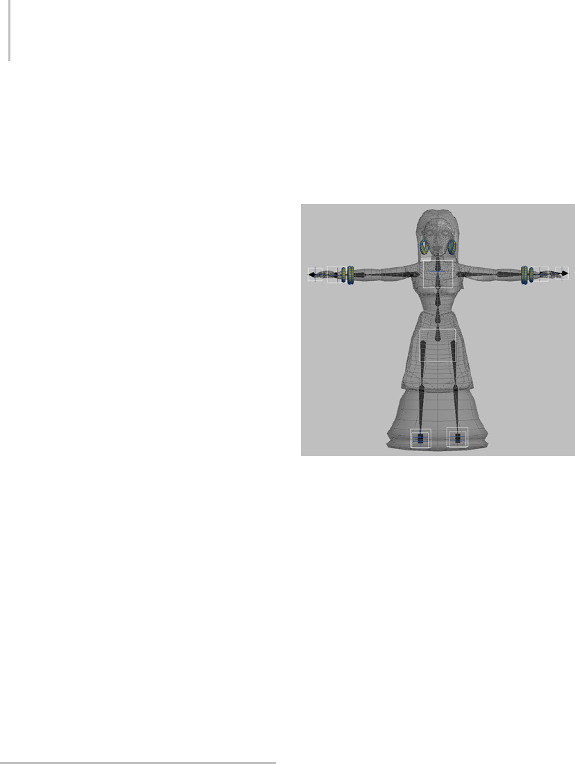
102 Chapter 3: Selecting Objects
The only head object type available by default is
Luminaire (page 1–111).
5. EnteranamefortheassemblyandclickOK.
6. Wire (page 1–108) the assembly luminaire to its
light source or sources. More information on
parameter wiring is available at the link in this
step.
If more than one light source is present
inside the assembly, create a chain of wired
parameters. Then enter the desired relationship
expression in the expression text box.
To adjust the pivot location of an assembly:
•Whenyouadjustthepivotpointofaclosed
group or assembly, the pivot point of all group
and assembly members are affected, not only
the pivot point of the group or assembly head
object. Therefore, we recommend that you
open the assembly, adjust the pivot of the head
object, and then close the assembly.
Touseanassemblywithradiosity:
• Right-click the Luminaire, choose Properties,
and on the Object Properties dialog (page 1–117)
choose the Radiosity tab. You can exclude and
control radiosity parameters of the geometry
and lights independently.
To adjust the properties of an assembly:
1. AfterwiringtheDimmerandFilterColor
parameters, select the Luminaire, and then
go to Modify panel to display the luminaire
parameters.
2. Adjust the parameters.
The effect is visible in the viewport.
Character Assembly
Acharacter assembly is a special type of group
for objects particular to a character setup:
the character mesh, bones, IK chains, helper
objects, controllers, and other objects used to
animatecharacters.Oncetheobjectsaregrouped
(assembled), you can perform various functions
onthegroupasawhole,suchassavingandloading
animation for the entire bone/mesh set.
The objects that make up a typical character assembly
Unlike an ordinary group, there is no need to open
a character assembly to work with its individual
members.
When a character assembly is created, it is
designated by a placeholder object called a node,
placed near the bottom of the character assembly.
Selecting the node gives access to special tools for
working with character models and animation.

Character Assembly 103
Character assembly node
A character assembly will not create a character
mesh or bone structure for you. The character
assembly tool is designed for use on character
structures that have already been set up using
other tools.
Althoughthecharacterassemblyfeaturewas
designed for use with character structures, it will
work equally well with any type of hierarchy or
related set of objects.
Adding Character Assembly Commands
to the UI
By default, the character-assembly commands
describedherearenotpartofthe3dsMax
user interface. To add them, choose Customize
menu > Customize User Interface, click the tab
representing the part of the UI to which you’ll add
the commands (Keyboard, Toolbars, etc.) and
then, from the Category drop-down list, choose
Characters. Use standard CUI functionality (page
3–792) to add the commands.
Creating a Character Assembly
To create a character assembly, first select the
objects that will make up the assembly. Next, you
need to add any character-assembly commands
you wish to use to the user interface; see Adding
Character Assembly Commands to the UI (page
1–103). Last,choosetheCreateCharacter
command.
All selected objects become members of the
assembly, and the character assembly node is
created. Other objects can be manually added to
the assembly after it has been created.
Once the character assembly has been created,
you can work with it in a variety of ways. For
information about the Modify panel options
available after a character assembly is created, see
Create Character (page 1–112).
Linked Objects in Character Assemblies
Any or all members of the character assembly can
be linked to a single object outside the assembly,
but no more than one. For example, ThighLeft
and ThighRight, which are both part of the
assembly, can both be linked to Pelvis, which is
notpartoftheassembly.However,ifThighLeft
and ThighRight are each linked to different objects
outside the assembly, the creation of the assembly
will fail, and will show the following error message:
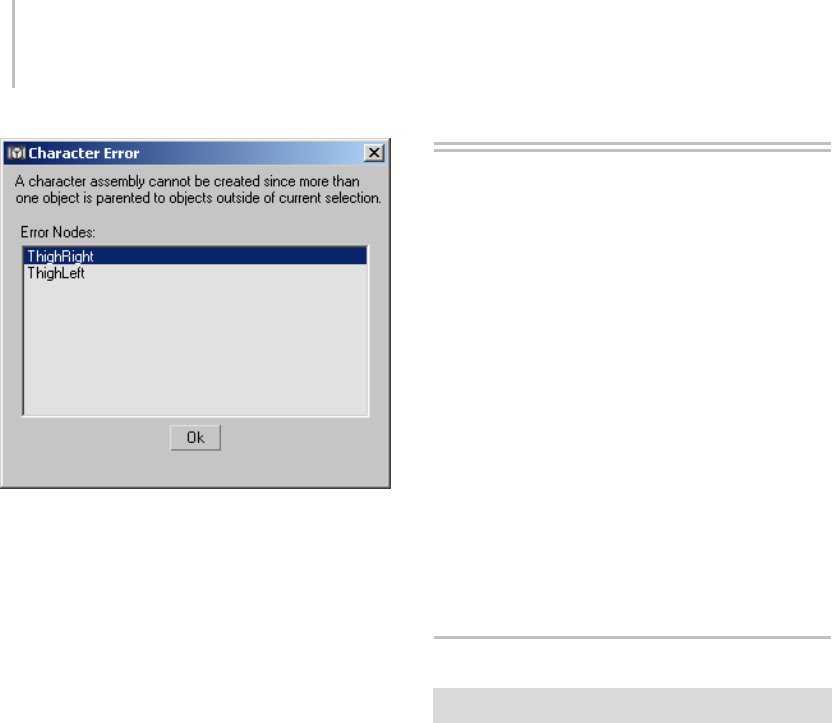
104 Chapter 3: Selecting Objects
Parameter Wiring and Animation
If you plan to wire parameters between two
objects, create the assembly first and then set up
the wiring. Be sure to include both objects in the
assembly.
Becausewiringshouldbedoneaftertheassembly
is created, you will probably find it easiest to
create the character assembly before animating
the character.
See also
Create Character (page 1–112)
Destroy Character (page 1–115)
Lock/Unlock Character (page 1–115)
Save Character (page 1–115)
Insert Character (page 1–115)
Skin Pose Commands (page 1–116)
Merge Animation (page 3–466)
Group Commands
The commands to manage groups are on the
Group menu (page 3–674).
Group (page 1–104)
Open Group (page 1–105)
Close Group (page 1–105)
Ungroup (page 1–106)
Attach Group (page 1–106)
Detach Group (page 1–106)
Explode Group (page 1–106)
See also
Using Groups (page 1–96)
Group
Group menu > Group
The Group command combines a selection set of
objectsorgroupsintoasinglegroup.
Once you group objects, you can treat them as
a single object in your scene. You can click any
object in the group to select the group object. You
cantransformthegroupasasingleobject,andyou
canapplymodifiersasifitwereasingleobject.
Groups can contain other groups, up to any level.
Group names are similar to object names, except
that they’re carried by the group object. In lists
like the one in the Select Objects dialog (page
1–78),groupnamesappearinsquarebrackets.For
example: [Group01].
If a group is selected, its name will appear in
“bolded”textintheNameAndColorrollout.

Open Group 105
All members of a group inherit the visibility of
the parent when a visibility controller is assigned
to the parent.
Groups are considered whole objects in the Light
Exclude/Include dialog, so you can exclude (or
include) all objects in a group by selecting the
group in the list. If a group is nested within
another group, only the "outer" group is available
in the list. To exclude only certain objects in
a group, open the group before displaying the
Exclude/Include dialog.
Procedures
To define a group:
1. Select two or more objects.
2. Choose Group menu > Group.
A dialog appears requesting a name for the
group.
3. Enter a name for the group and click OK.
To define a nested group:
1. Selecttwoormoregroupsoranycombination
of groups and objects.
2. Choose Group > Group.
A dialog appears requesting a name for the
group.
3. Enteranameforthenewgroupobjectandclick
OK.
Open Group
Select one or more groups. > Group menu > Open
The Open command lets you ungroup a group
temporarily, and access objects within a group.
You can transform and modify the objects within
the group independently from the rest of the
group, then restore the original group using the
Close command.
Procedures
To open a group:
1. Selectoneormoregroups.
2. Choose Group > Open. A pink bounding box
appears, and the objects in the group are now
accessible.
To open nested groups:
1. Select the group within the opened group.
2. Choose Group > Open.
Close Group
Select the pink dummy object of an opened group. >
Group menu > Close
The Close command regroups an opened group.
For nested groups, closing the outermost group
object closes all open inner groups.
When you link an object to a closed group, the
object becomes a child of the group parent rather
than of any member of the group. The entire group
flashes to show that you’ve linked to the group.
Procedures
To close all opened groups nested within a main
group:
1. Select the pink bounding box representing the
main group.
2. Choose Group > Close.
To close a nested group:
1. Select any object in the nested group or its
dummy.
2. Choose Group > Close.

106 Chapter 3: Selecting Objects
Ungroup
Select one or more groups. > Group menu > Ungroup
Ungroup separates the current group into its
component objects or groups.
The Ungroup command ungroups one level,
unlike Explode (page 1–106),whichungroupsall
levels of nested groups.
When you Ungroup a group, the objects within the
group lose all group transforms that were applied
on nonzero frames, but they retain any individual
animation.
All ungrouped entities remain in the current
selection set.
Procedure
To ungroup a group:
1. Select one or more groups.
2. ChooseGroup>Ungroup.
All components of the group remain selected,
but are no longer part of the group. The group
dummy is deleted.
Explode Group
Select one or more groups. > Group menu > Explode
The Explode command ungroups all objects in a
group, regardless of the number of nested groups,
unlike Ungroup (page 1–106), which ungroups one
level only.
As with the Ungroup command, all exploded
entities remain in the current selection set.
Warning: Ungroup and Explode remove all transform
animations that have been applied to the group as a
whole. As with the Ungroup command, all exploded
entities remain in the current selection set.
Procedure
To explode a group:
1. Selectoneormoregroups.
2. ChooseGroup>Explode.
All objects in the groups remain selected but no
longer belong to groups. All nested groups are
exploded. All group dummies in the selection
are deleted.
Detach Group
Select a group. > Group menu > Open > Select one or
more objects detach. > Group menu > Detach
The Detach command detaches the selected object
from its group.
This command becomes active when you open the
group by choosing the Open command from the
Group menu.
Procedure
To detach an object from a group:
1. Open the group.
2. ChooseGroup>Detach.
The selected objects are now separate,
independent objects, no longer members of the
group.
Attach Group
Select one or more objects. > Group menu > Attach
The Attach command makes the selected object
part of an existing group.
With an object selected, choose this command,
and then click a group in the scene.

Assembly Commands 107
Procedure
To attach an object to a group:
1. Selectoneormoreobjectstoattach.
2. Choose Group > Attach.
3. Click any member of a closed group.
The selected objects become part of the group,
which is now selected.
Note: To attach an object to an open group, click
the pink bounding box.
Assembly Commands
Thecommandstomanageassembliesareavailable
fromtheGroup>Assemblysubmenu.
Assemble (page 1–107)
Disassemble (page 1–110)
Open Assembly (page 1–109)
Close Assembly (page 1–109)
Attach Assembly (page 1–111)
Detach Assembly (page 1–110)
Explode Assembly (page 1–110)
See also
Using Assemblies (page 1–98)
Assemble
Select the objects to assemble. > Group menu >
Assembly > Assemble
The Assemble command combines a selection set
of objects, assemblies, and/or groups into a single
assembly, and adds a Luminaire helper object (page
1–111) as a head object (page 1–111).
Once you assemble objects, you can treat them as
a single object in your scene. You can click any
objectinthegrouptoselecttheentireassembly.
You can transform the assembly as a single object,
and you can apply modifiers as if it were a single
object.
Assemblies can contain other assemblies and/or
groups, up to any level.
Assembly names are similar to object names,
except that they’re carried by the assembly. In
listsliketheoneintheSelect Objects dialog (page
1–78), assembly names appear in square brackets.
For example: [Assembly01].
Each member of an assembly inherits the visibility
of the parent when a visibility controller is assigned
to the parent, providing its Object Properties
>RenderingControlgroup>InheritVisibility
check box is turned on, or if its Rendering Control
is set to By Layer and Inherit Visibility is turned
on for its layer.
Assemblies are considered whole objects in the
Light Exclude/Include dialog, so you can exclude
(or include) all objects in an assembly by selecting
the assembly in the list. If an assembly is nested
within another assembly, only the "outer" assembly
is available in the list. To exclude only certain
objects in an assembly, open the assembly before
displaying the Exclude/Include dialog.
See also
Using Assemblies (page 1–98)
Procedures
To define an assembly:
1. Select two or more objects.
2. Choose Group menu > Assembly > Assemble.
The Create Assembly dialog appears. It requests
youtospecifyanamefortheassemblyand

108 Chapter 3: Selecting Objects
ahead object (page 1–111).Thedefaulthead
object type is Luminaire (page 1–111).
3. Enteranamefortheassembly,choose
Luminaire (page 1–111) from the list, and click
OK.
The selected objects are assembled. The
assembly head object position and orientation
is determined as follows:
• If there are multiple immediate children
of the assembly head (for example, you’re
assembling several non-hierarchical
objects), the head object is aligned with
center of bottom face of the assembly
bounding box.
• If there’s only one immediate child of the
assembly head, the assembly head pivot
point is aligned with that object’s pivot
point. For example, if you’re assembling a
single hierarchy, the topmost object in the
hierarchy would be the single immediate
child of the assembly head.
To define a nested assembly:
1. Select two or more assemblies or any
combination of assemblies and objects.
2. Choose Group menu > Assembly > Assemble.
The Create Assembly dialog appears. It requests
anamefortheassembly,andaheadobject.
3. Enteranameforthenewassemblyobjectand
click OK.
To wire a head object to a light source:
1. Create a hierarchy of lights and geometrical
objectsthatmodelsalightingfixture.Setsupall
the necessary IK chains and other constraints
that make the model behave properly when the
user interacts with it (orients, positions, aims,
etc.).
Important: For any photometric lights that
you want to control with the head object, be
sure to turn on the Multiplier check box on the
Intensity/Color/Distribution rollout.
2. Select all objects in the fixture and define them
as an assembly.
When the assembly is selected, the luminaire
parameters Dimmer and Filter Color appear in
the Modify panel.
3. From the Animation menu, choose Wire
Parameters > Parameter Wire Dialog.
4. The Parameter Wiring dialog (page 2–412)
appears.
5. On one side of the dialog, find the assembly
and expand the branch titled Object
(LuminaireHelper). Click the Dimmer item to
highlight it.
6. On the other side, find the assembly and
expand its hierarchy branch (click the + symbol
in the square box). Find and expand the branch
for the light source, and then expand its Object
branch. Click the Multiplier item to highlight it.
7. Between the two hierarchy lists, click the
Control Direction arrow button that points
from the selected Dimmer item to the selected
Multiplier item.
8. If you’re wiring a photometric light, skip this
step. If you’re wiring a standard light, or any
light whose default Multiplier setting is 1.0, do
this:
• The Expression box below the selected
Multiplier item contains the word "Dimmer."
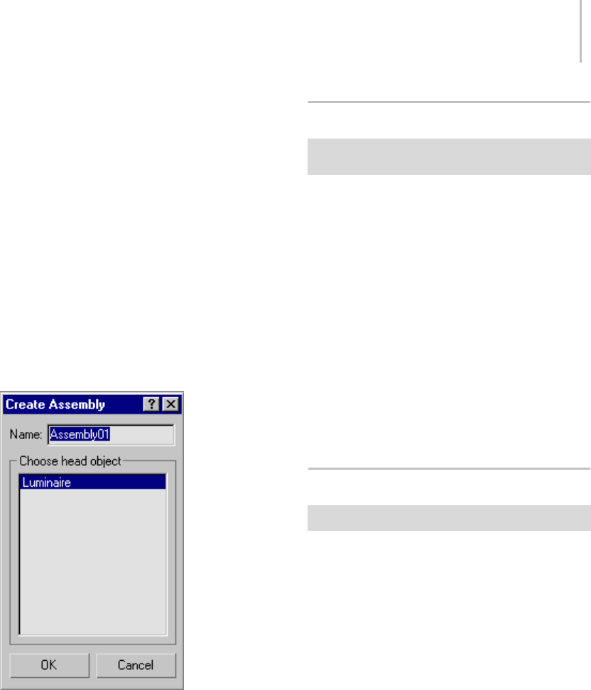
Open Assembly 109
Edit this to read "Dimmer/100". This divides
the Dimmer value by 100, giving a 1:1 value
ratio between it and the Multiplier setting.
9. Click the Connect button.
Now, when you change the luminaire’s Dimmer
setting, the light source intensity changes as
well.
10.If you like, use the same method to wire the
luminaire to any additional light sources in the
light fixture.
Youcanalsousethismethodtowirethe
luminaire’s Filter Color parameter to any light
sources’ color settings.
Interface
Name—Specifies the name of the new assembly.
The default name is "Assembly" followed by
a two-place number starting with 01 and
incremented by one for each new assembly.
Choose Head Object—Lets you choose the type of
object to serve as the assembly head object.
Open Assembly
Select one or more assemblies. > Group menu >
Assembly > Open
The Open command lets you temporarily
disassemble an assembly and access its head and
member objects individually.
You can transform and modify the head
and member objects within the assembly
independently from the rest of the assembly, then
restore the original assembly using the Close
command (page 1–109).
Procedure
To open nested assemblies:
1. Select the assembly within the opened assembly.
2. Choose Group menu > Assembly > Open.
Close Assembly
Select the luminaire. > Group menu > Assembly > Close
The Close command reassembles an opened
assembly. For nested assemblies, closing the
outermost assembly object closes all open inner
assemblies.
When you link an object to a closed assembly,
the object becomes a child of the assembly parent
rather than of any member of the assembly. The
entire assembly flashes to show that you’ve linked
to the assembly.
Procedures
To close all opened assemblies nested within a main
assembly:
1. Select any object in the main assembly or its
luminaire head object.

110 Chapter 3: Selecting Objects
Note: Ifyouselectanobjectwithinanopened
inner assembly, using Close will close only that
assembly.
2. Choose Group menu > Assembly > Close.
To close a nested assembly:
1. Select any object in the nested assembly or its
luminaire.
2. Choose Group menu > Assembly > Close.
Disassemble
Select one or more assemblies. > Group menu >
Assembly > Disassemble
Disassemble separates the current assembly into
itscomponentobjectsorassemblies.
The Disassemble command separates one level,
unlike Explode (page 1–110),whichseparatesall
levels of nested assemblies.
When you disassemble an assembly, all
components of the assembly remain selected, but
are no longer part of the assembly. Any transform
animation applied to the assembly is lost, and
objectsremainastheywereintheframeatwhich
the dissolution is performed. However, objects
retain any individual animation.
All disassembled entities remain in the current
selection set.
Note: If you have wired the luminaire head to
any other parameters, those parameters are still
controlled by the wiring setup after disassembly
and are not adjustable until you apply a standard
controller, such as Bezier Float. Use Track View
to do this.
Explode Assembly
Select one or more assemblies. > Group menu >
Assembly > Explode
TheExplodecommandseparatesallobjectsin
an assembly, regardless of the number of nested
assemblies and/or groups, unlike Disassemble
(page 1–110),whichseparatesonelevelonly.
When you explode an assembly, all components of
the assembly remain selected, but are no longer
part of the assembly. Any transform animation
applied to the assembly is lost, and objects remain
as they were in the frame at which the dissolution is
performed. However, objects retain any individual
animation.
Note: Ifyouhavewiredtheluminaireheadto
any other parameters, those parameters are still
controlled by the wiring setup after exploding
and are not adjustable until you apply a standard
controller, such as Bezier Float. Use Track View
to do this.
Detach Assembly
Select an assembly. > Group menu > Assembly > Open
> Select one or more objects to detach. > Assembly >
Detach
Select one or more objects to detach in an open assembly.
>Groupmenu>Assembly>Detach
The Detach command detaches the selected object
from its assembly. If the object is a member of a
nested assembly, after you detach it, it is no longer
a member of any assembly.
This command becomes active when you open the
assembly by choosing Open (page 1–109) from the
Assembly menu.
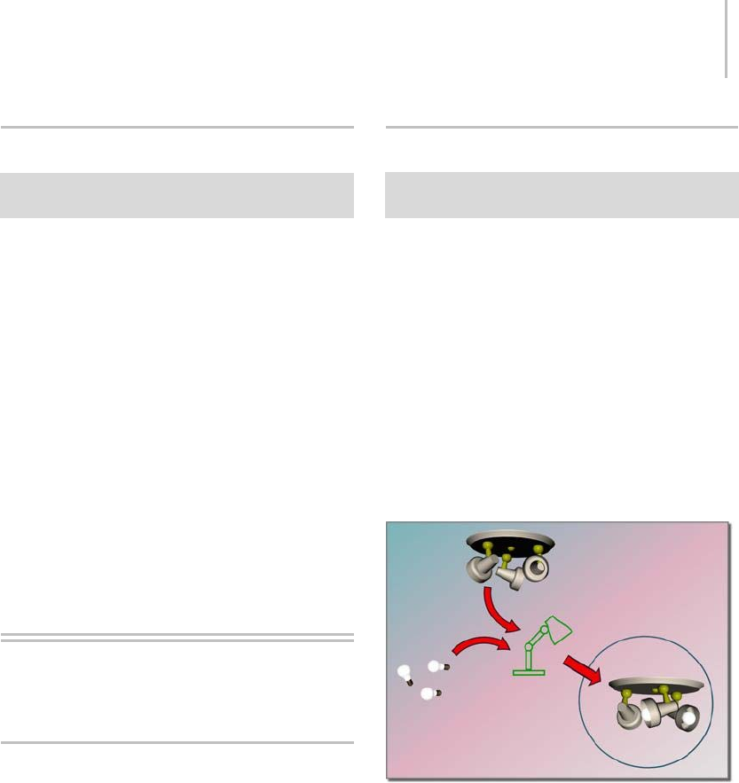
Attach Assembly 111
Attach Assembly
Select one or more objects. > Group menu > Assembly
> Attach
The Attach command makes the selected object
part of an existing assembly.
With an object selected, choose this command,
and then click either a closed assembly in the
scene, or the head object of an open assembly.
Procedure
To attach an object to an assembly:
1. Selectoneormoreobjectstoattach.
2. Choose Group menu > Assembly > Attach.
3. Click any member of an assembly.
The selected objects become part of the
assembly, which is now selected.
Assembly Head Helper
Objects
Assembly Head Helper Object
When you create an assembly (page 1–98) in
3ds Max, the program automatically adds a special
type of helper object called a head object, or
assembly head. This object serves as the fulcrum
of the assembly and also exposes parameters,
available in the Modify panel when the assembly
is selected, that you can wire (page 2–411) to
properties of objects inside the assembly. Thus,
you can change and animate parameters of
assembly member objects without having to open
the assembly, as you would with a group.
Luminaire Helper Object
Create panel > Helpers > Assembly Heads > Object Type
rollout > Luminaire
The Luminaire helper object serves primarily as a
head, or control, object for light fixtures. When
you assemble (page 1–107) asetofobjectsinto
alightfixture,youspecifythatanewluminaire
object should be used as the assembly head object.
The luminaire’s parameters, available from the
Modify panel, let you control the light sources in
the fixture. See Using Assemblies (page 1–98) for
more information.
You can also add a Luminaire object separately
from the Create panel, but in general it’s not
necessary.
A luminaire object groups and manages the components as a
whole.
Interface
When a selected assembly is closed, the Modify
panel displays the Luminaire parameters.
However, when you open an assembly, 3ds Max
shows you the parameters of the whichever
object is selected. The Luminaire object provides
Dimmer and Filter Color parameters. You wire
these to the light objects that are part of the
assembly.
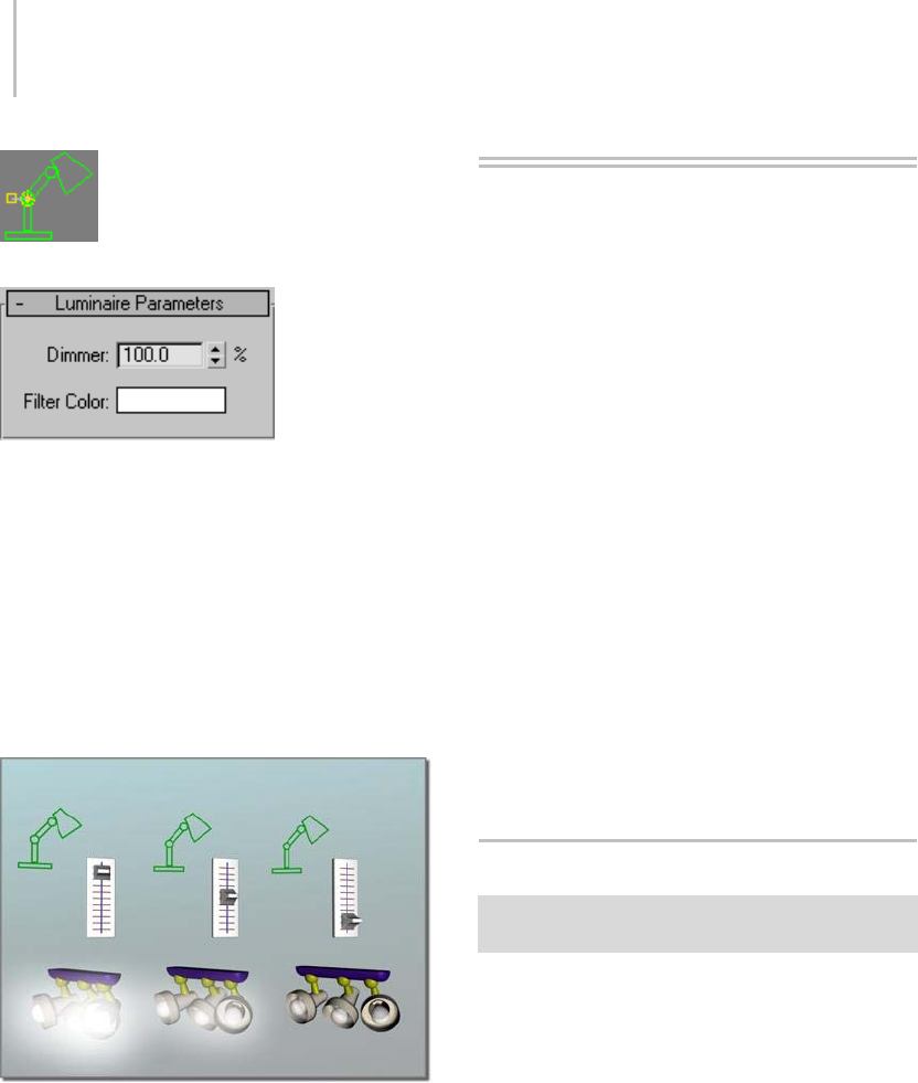
112 Chapter 3: Selecting Objects
Luminaire icon in the viewport
Luminaire rollout
Dimmer—Emulates the dimmer switch of a
real-world lighting fixture. The setting determines
the percentage of the default light intensity is
emitted by the light source of a lighting fixture.
Youwirethisparametertooneormorelight
sources’ Multiplier settings.
Filter Color—An RGB color parameter that you
link to a light source’s color or filter color.
The Dimmer option can control the intensity of all the lights in
the luminaire
Character Assembly
Commands
By default, the character-assembly commands
listedherearenotpartofthe3dsMaxuser
interface. To add them, choose Customize
menu > Customize User Interface, click the tab
representing the part of the UI to which you’ll add
the commands (Keyboard, Toolbars, etc.) and
then, from the Category drop-down list, choose
Characters. Use standard CUI functionality (page
3–792) to add the commands.
Create Character (page 1–112)
Destroy Character (page 1–115)
Lock/Unlock Character (page 1–115)
Save Character (page 1–115)
Insert Character (page 1–115)
Skin Pose Commands (page 1–116)
Merge Animation (page 3–466)
Create Character
See Adding Character Assembly Commands to the UI (page
1–103).
This command creates a character assembly (page
1–102).
Procedure
To create a character assembly:
1. Create a linked structure of bones or other
objects. The structure can have several chains.
You can also use the linked structure with the
Skin modifier, and/or set up character rigs and
controllers as needed.
2. Select all objects that will become members of
the assembly.
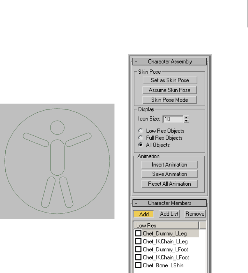
Create Character 113
3. Use this method (page 1–103) to add the
character-assembly commands to the user
interface, and then choose the Create Character
command.
The character-assembly node is created at the
bottom of the entire selection, as viewed in the
Front viewport.
4. On the Modify panel, use the character
assembly tools to work with the character
structure.
The character assembly is given the default
name of Character01, which can be changed.
Allmembersoftheassemblyarelistedinthe
Character Members rollout.
Interface
To work with the character assembly, select the
character assembly node and work with the
parameters on the Modify panel.
Character Assembly rollout
Skin Pose group
The Skin pose is the bone structure pose used by
the Skin modifier for associating bones with the
mesh. When the Skin modifier is first applied, the
current bone structure pose is used as the Skin
pose. The Skin pose can sometimes be accidentally
altered by animating the bone structure on frame
0. If this occurs, you can use these options to fix
the Skin pose.
You can use these options both before and after
applying the Skin modifier. You can also invoke

114 Chapter 3: Selecting Objects
these options when any member of the character
assembly is selected.
Set as Skin Pose—SetstheSkinposetothecurrent
bone structure’s pose. The Skin modifier’s
envelopes and vertex weighting are automatically
recalculated to work with the new pose.
Assume Skin Pose—Causesthebonestructureto
take on the Skin pose. This feature can be useful
during the animation phase. For example, if you
have animated the character on various keyframes
and want the character to animate back to its Skin
pose at frame 50, you can turn on Auto Key at
frame 50 and click Assume Skin Pose.
Skin Pose Mode—Poses the character in its Skin
pose and allows the Skin pose to be refined.
Changes to the bone structure when Skin Pose
ModeisonwillaffectonlytheSkinposeandnot
theanimation.WhenSkinPoseModeisturned
off, the bone structure returns to its pose at the
current frame.
Display group
When a high resolution character model is
animated, redraw time can slow the animation
process. To speed up your work, a low resolution
version of the model can be used for the animation
process, then switched for the full resolution
version at render time. Character assembly objects
can be designated as Full Res or Low Res on the
Character Members rollout.
Low Res Objects—Displays only the objects
checked in the Low Res display in the Character
Members rollout.
Full Res Objects—Displays only the objects not
checked in the Low Res display in the Character
Members rollout.
All Objects—Displays all objects in the character
assembly.
Animation group
Animation for the character assembly can be saved
or reset in this group. Previously saved animation
fromanothercharactercanalsobeinsertedtothe
current character assembly.
Insert Animation—Displays the Merge Animation
dialog (page 3–466),andpromptsforapreviously
saved animation file.
Save Animation—Saves the character assembly
animation in an ANM or XML file. Both file types
contain the character assembly and its animation.
An ANM file is a proprietary format that can be
read and saved only by 3ds Max. An XML file
formats the information as XML code, and can be
edited with a text editor.
Animation saved as an ANM file loads and saves
faster than an XML file. Saving and editing an
XML animation file is recommended only for
users who are familiar with the XML language,
and who have a specific need for editing the file.
Reset All Animation—Removes all animation from
the character assembly.
Character Members rollout
Add—Allows you to select individual objects to
add to the character assembly.
Add List—Displays the Pick Character Members
dialog, where you can select multiple objects from
a list and add them to the character assembly.
Remove—Removes highlighted object(s) from the
assembly. Bones and objects upon which other
assembly objects depend, cannot be removed.
Low Res—All members of the character assembly
are displayed on this list. By default, all members
aredesignatedasFullResobjects.Todesignatea
member as Low Res, check the object on the list.
The Full Res and Low Res designations are used in
conjunction with the Display group selection in
the Character Assembly rollout.

Destroy Character 115
See also
Destroy Character (page 1–115)
Lock/Unlock Character (page 1–115)
Save Character (page 1–115)
Merge Animation (page 3–466)
Destroy Character
See Adding Character Assembly Commands to the UI (page
1–103).
Destroying a character deletes the character
assembly node. If the character assembly is locked,
theentireassemblyisdeleted.Iftheassemblyis
unlocked, the members of the assembly and any
animationonthemembersareunaffected.
This command is available only when a character
assembly node is selected.
See also
Character Assembly (page 1–102)
Lock/Unlock Character (page 1–115)
Lock/Unlock Character
See Adding Character Assembly Commands to the UI (page
1–103).
Locking a character assembly prevents the
character from being animated. Use these
commands when you want to prevent accidental
animation of the character, such as when the
animation process is complete.
Unlocking a locked character assembly allows you
to animate the character.
These commands are available only when a
character-assembly node is selected.
See also
Character Assembly (page 1–102)
Insert Character
See Adding Character Assembly Commands to the UI (page
1–103).
Choose this command to insert a previously saved
character into the current scene.
You save a character assembly as a CHR file with
Save Character (page 1–115).ACHRfilecontains
the character assembly node, all members of the
assembly and any animation on the members.
When a character is inserted into the scene, it is
placed at the same world-space location it had
when saved.
See also
Character Assembly (page 1–102)
Save Character (page 1–115)
Save Character
See Adding Character Assembly Commands to the UI (page
1–103).
Saving a character saves a character assembly (page
1–102) at its current location, including its node,
all members, and any animation on its members.
Use this command for storing a character assembly
to disk prior to inserting it into another scene.
Saving a character with this command saves the
assembly as a CHR file. You can then insert the
CHR file into a scene with Insert Character (page
1–115).
This option is available only when a character
assembly node is selected.

116 Chapter 3: Selecting Objects
Skin Pose Commands
Animation menu > Set as Skin Pose
Animation menu > Assume Skin Pose
Animation menu > Skin Pose Mode
When the Skin modifier is first applied to a mesh,
thebonestructure’scurrentposeisusedasthe
skin pose. Subsequent animation of the bone
structure on frame 0 can cause the skin pose to
bealtered.Theskinposecommandsallowyouto
change and set the skin pose either before or after
you apply the Skin modifier.
The skin pose stores a specific position, rotation
andscaleforanobject. Itsintendeduseisfor
storing a character assembly’s pose for the Skin
modifier. However, a skin pose can be used for
any object to store its current transforms for later
retrieval.
These commands work on any object, regardless
of whether the structure is part of a character
assembly, or whether the bones have been assigned
to a mesh with the Skin modifier.
Set as Skin Pose—Stores the selected objects’
current position, rotation and scale as the skin
pose. If the selected objects are assigned as bones
for the Skin modifier, the envelopes and vertex
weighting are automatically recalculated to work
with the new pose.
Assume Skin Pose—Causes the selected objects to
take on the stored skin pose. This feature can be
useful during the animation phase. For example,
if you have animated the character on various
keyframes and want the character to animate back
to its skin pose at frame 50, you can turn on Auto
Key at frame 50 and click Assume Skin Pose.
Skin Pose Mode—Poses the character in its skin
pose and allows the skin pose to be refined.
Changes to the objects when Skin Pose Mode
is on will affect only the skin pose and not the
animation. When Skin Pose Mode is turned off,
the structure returns to its pose at the current
frame.
See also
Character Assembly (page 1–102)

The Object Properties dialog, available from the
Edit and right-click menus, lets you view and edit
parameters for how selected objects behave in
viewports and renderings. Note that you cannot
necessarily edit all properties; parameters that
apply to renderable geometry are unavailable for
non-renderable objects. However, parameters
that apply to any object, such as Hide/Unhide,
Freeze/Unfreeze, Trajectory, and so on, remain
available for these non-renderable objects.
With the Object Properties dialog you can specify
settings per object or by layer (page 3–920).Object
settings affect only the object or objects selected.
When an object is set to By Layer, it inherits its
properties from the layer settings, which you set
with the Layer Properties dialog (page 3–662).
The Object Properties dialog panels are:
•General Panel (Object Properties Dialog) (page
1–117)
•Advanced Lighting Panel (Object Properties
Dialog) (page 1–123)
•mental ray Panel (Object Properties Dialog)
(page 1–126)
•User Defined Panel (Object Properties Dialog)
(page 1–127)
Object Properties Dialog
Panels
General Panel (Object Properties
Dialog)
Edit menu > Object Properties > Object Properties dialog
> General panel
Select object or objects. > Right-click. > Transform
(lower-right) quadrant of the quad menu > Properties >
Object Properties dialog > General panel
Layer manager > Click the icon next to an object’s name.
> Object Properties dialog > General panel
This panel of the Object Properties dialog displays
general object information, as well as controls for
rendering the object and displaying it in viewports.
Object Properties
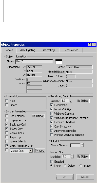
118 Chapter 4: Object Properties
Interface
Object Information group
This group displays information about the selected
object, including the following:
Name—Shows the name of the object. When a
single object is selected, you can edit this field to
give the object a new name. When multiple objects
are selected, this field shows "Multiple Selected,"
and cannot be edited.
Color—The color swatch shows the object’s color.
Yo u c a n c l i c k i t t o d i s p l a y t h e Object Color dialog
(page 1–159) and select a different color.
Dimensions—Displays the X, Y, and Z dimensions
of the object’s extents (page 3–936).
Vertices and Faces—Display the number of vertices
and faces in the object. For shapes (page 1–262),
these values are the values used if you have made
the shape renderable. Faces for renderable shapes
are generated only at rendering time.
Shape Vertices and Shape Curves—Appear only
forshapeobjects. ShapeVerticesisthenumber
ofverticesintheshape,andShapeCurvesisthe
numberofpolygons.(ShapeCurvesisthevalue
that appeared as "Polygons" in previous releases.)
These values can change over time: they are valid
only for the current frame and the current view.
Parent—Displays the name of the object’s parent in
a hierarchy. Shows "Scene Root" if the object has
no hierarchical parent.
Material Name—Displaysthenameofthematerial
assigned to the object. Displays "None" if no
material is assigned.
Num. Children—Displays the number of children
hierarchically linked to the object.
In Group/Assembly—Displaysthenameofthe
group or assembly to which the object belongs.
Displays "None" if the object is not part of a group.
Layer—Displaysthenameofthelayerwhichthe
object is assigned to.
Interactivity Group
Hide— Hides the selected object or objects.
Hiddenobjectsexistinthescene,butdonot
appear in the viewports or rendered images. To
unhide hidden objects, use the Display panel (page
3–775) or choose Tools > Display Floater (page
3–775).
Note: Objectsresidingonahiddenlayerare
automatically hidden, regardless of this setting.
Tip: The Layer Manager (page 3–656) is the easiest
way to hide groups of objects or layers.
Freeze—Freezes the selected object or objects.
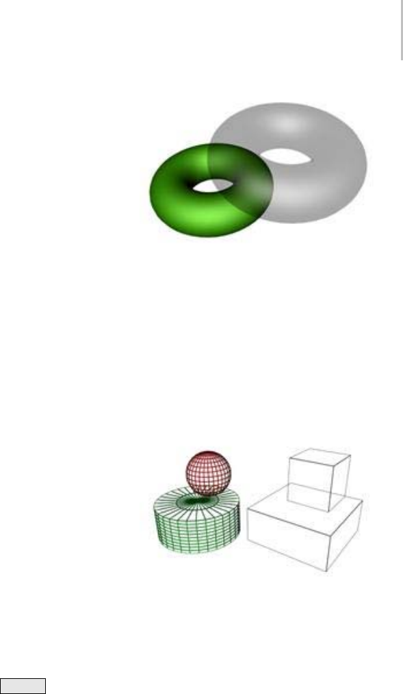
General Panel (Object Properties Dialog) 119
Frozen objects appear in the viewports, but cannot
be manipulated. To unfreeze frozen objects, use
the Display panel (page 3–775) or choose Tools >
Display Floater (page 3–775).
Note: Objects residing on a frozen layer are
automatically frozen, regardless of this setting.
Tip: The Layer Manager (page 3–656) is the easiest
way to freeze groups of objects or layers.
Display Properties group
By Object/By Layer—Toggles between object
settings or object layer settings. Object settings
affect only the object or objects selected. Object
layer settings affect all objects on the same layer as
the selected object.
Note: If multiple objects are selected and have
different By Layer settings, this button will read
‘Mixed’.
See-Through—Makes the object or selection
translucentinviewports. Thissettinghasno
effect on rendering: it simply lets you see what
is behind an object in a crowded scene, and
especially to adjust the position of objects behind
the see-through object. Default=off.
Note: This option is also available in the Display
panel (page 3–775) and by choosing Tools >
Display Floater (page 3–775).
You can customize the color of see-through objects
by using the Colors panel (page 3–799) of the
Customize > Customize User Interface dialog (page
3–792).
Keyboard shortcut (default): Alt+X
Display as Box—Toggles the display of selected
objects, both 3D objects and 2D shapes, as
bounding boxes (page 3–919).Producesminimum
geometric complexity for rapid display in
viewports. Default=off.
Note: This option is also available in the Display
panel (page 3–775) and by choosing Tools >
Display Floater (page 3–775).
Backface Cull—Toggles the display of faces with
normals (page 3–980) that point away from the
view. When on, you see through the wireframe
to the backfaces. Applies only to wireframe
viewports. Default=on.
Note: This option is also available in the Display
panel (page 3–775) and by choosing Tools >
Display Floater (page 3–775).
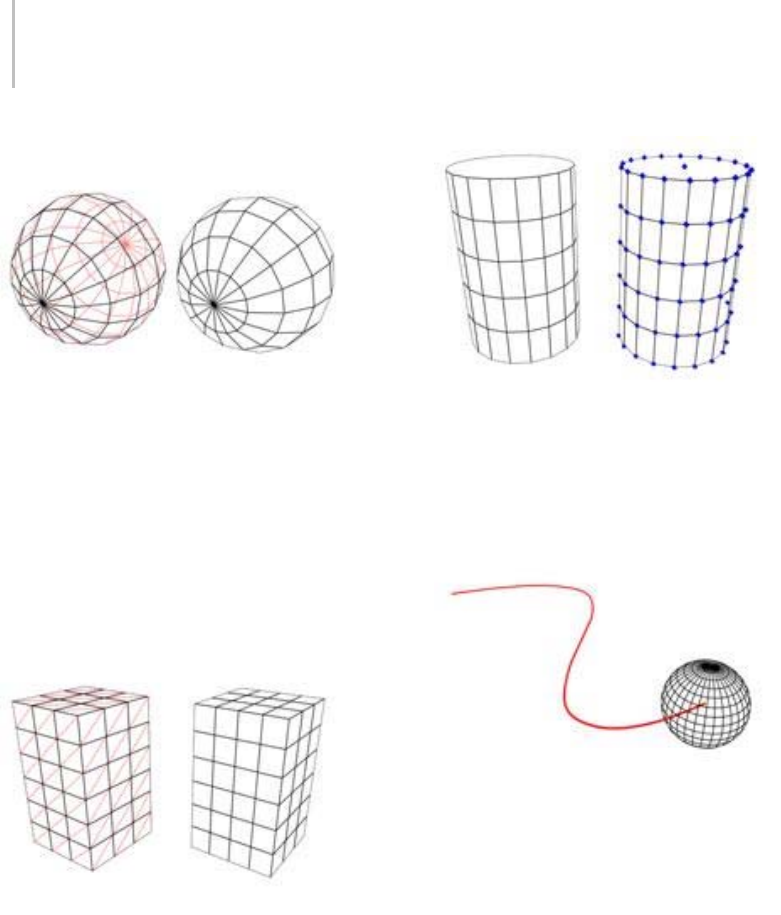
120 Chapter 4: Object Properties
Edges Only—Toggles the display of hidden edges
and polygon diagonals (page 3–928).Whenon,
only outside edges appear. When off, all mesh
geometry appears. Applies to Wireframe viewport
display mode, as well as other modes with Edged
Faces turned on.
Note: This option is also available in the Display
panel (page 3–775) and by choosing Tools >
Display Floater (page 3–775).
Vertex Ticks—Displays the object’s vertices as tick
marks. Default=off.
Note: This option is also available in the Display
panel (page 3–775) and by choosing Tools >
Display Floater (page 3–775).
Trajectory—Displays the object’s trajectory (page
3–1025).Default=off.
Note: This option is also available in the Display
panel (page 3–775) and by choosing Tools >
Display Floater (page 3–775).
Ignore Extents—When on, this object is ignored
when you use the display controls Zoom Extents
(page 3–740) and Zoom Extents All (page 3–737).
Note: This option is also available in the Display
panel (page 3–775) and by choosing Tools >
Display Floater (page 3–775).
Keyboard shortcut: No default, but you can
customize it using the Keyboard panel (page 3–793)
of the Customize > Customize User Interface dialog
(page 3–792).
Show Frozen in Gray—When on, the object turns
gray in viewports when you freeze it. When off,
viewports display the object with its usual color or
textureevenwhenitisfrozen.Default=on.
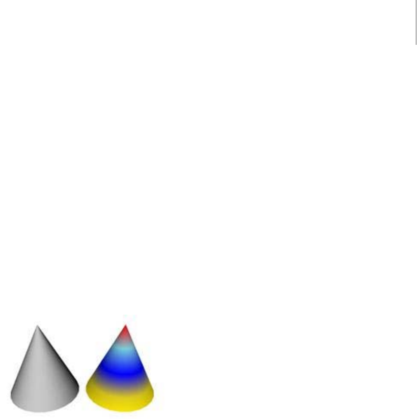
General Panel (Object Properties Dialog) 121
Note: This option is also available in the Display
panel (page 3–775) and by choosing Tools >
Display Floater (page 3–775).
Vertex Channel Display—For editable mesh (page
1–996),editable poly (page 1–1022),andeditable
patch (page 1–968) objects, displays the assigned
vertex colors in viewports. The drop-down list
l e t s y o u c h o o s e t o d i s p l a y Ve r t e x C o l o r, Ve r t e x
Illumination, Vertex Alpha, Map Channel Color,
or Soft Selection Color. Default=off.
You can assign vertex colors at all sub-object levels
except Edge.
Note: This option is also available on the Display
panel (page 3–775).
Map Channel—Sets the map channel for the vertex
color. Available only when the Map Channel Color
option is active.
Shaded—When on, shaded viewports add shading
to the vertex coloring. When off, colors are
unshaded. Default=off.
Note: This option is also available on the Display
panel and by choosing Tools > Display Floater
(page 3–775).
Rendering Control group
Yo u c a n s e t r e n d e r i n g c o n t r o l f o r l i g h t s t o B y
ObjectorByLayer(thelatteristhedefaultsetting),
and you can also change their Renderable setting.
This allows you to turn individual lights on and off
in your renderings, but more importantly, you can
quickly turn large groups of lights on or off using
the Layer Manager (page 3–656).
By Object/By Layer—To g g l e s b e t w e e n o b j e c t
settings or object layer settings. Object settings
affect only the object or objects selected. Object
layer settings affect the rendering controls of all
objectsonthesamelayerastheselectedobject.
Note: If multiple objects are selected and have
different By Layer settings, this button will read
‘Mixed’.
Visibility—Controls the rendered visibility of the
object. At 1.0, the object is fully visible. At 0.0,
the object is completely invisible when rendered.
Default=1.0.
You can animate this parameter. Animating
Visibility assigns a visibility controller to the
object. By default this is a Bezier float controller
(page 2–310).
Renderable—Makes an object or selected objects
appear or disappear from rendered output.
Nonrenderable objects don’t cast shadows or
affect the visual component of the rendered scene.
Like dummy objects, nonrenderable objects can
manipulate other objects in the scene.
Shape (page 1–262) objects have the Renderable
option turned on by default. In addition, each
shape has an Enable In Renderer parameter.
When both check boxes are on, the shape appears
in rendered output. If Renderable in the Object
Properties dialog is off, the shape is not renderable,
regardless of the state of its local Enable In
Renderer check box.
If you apply a modifier that converts the shape
into a mesh object, such as a Lathe modifier (page
1–707) or Extrude modifier (page 1–680),theshape
automatically becomes renderable regardless of
the state of its local Enable In Renderer setting.
For shapes, the Renderable check box in the
Object Properties dialog affects the main object,

122 Chapter 4: Object Properties
so the check box also affects all instances of and
references to the shape.
Inherit Visibility—Causes the object to inherit
a percentage of the visibility of its parent (as
determined by the parent’s Visibility track in Track
View). When a group parent is assigned a visibility
track, Inherit Visibility is automatically turned on
for all children in the group. The children will have
the maximum visibility of the parent. Transparent
materials and hidden objects have no effect on this
function.
Visible to Camera—When on, the object is visible
to cameras in the scene. When off, cameras do
not view this object; however, its shadows and
reflections are rendered. Default=on.
Visible to Reflection/Refraction—When on, the
object has “secondary” visibility: it appears in
rendered reflections and refractions. When off,
the object does not appear in rendered reflections
or refractions. Default=on.
Note: An object can have Visible To Camera on but
Visible To Reflection/Refraction off, in which case
the object renders in the scene but does not appear
in reflections or refractions.
Receive Shadows—When on, the object can receive
shadows. Default=on.
The mental ray renderer supports the Receive
Shadows toggle.
Cast Shadows—When on, the object can cast
shadows. Default=on.
Apply Atmospherics—When on, atmospheric
effects are applied to the object. When off,
atmospheric effects do not change the rendered
appearance of this object. Default=on.
Render Occluded Objects—Allows special effects
to affect objects in the scene that are occluded by
this object. The special effects, typically applied
by plug-ins (page 3–995) such as Glow (page
3–226),useG-buffer (page 3–946) layers to access
occludedobjects.Turningonthiscontrolmakes
the object transparent for the purposes of special
effects. This makes no difference when you render
to most image files. When you render to either
the RLA (page 3–630) or RPF (page 3–631) file
format, however, occluded objects appear with the
effect applied on their designated G-buffer layer.
Default=off.
G-Buffer group
Allows you to tag an object as a target for a render
effect (page 3–218) based on the G-buffer (page
3–946) channel. Assigning the object a nonzero ID
creates a G-buffer channel that can be associated
with a render effect.
Warning: The mental ray renderer (page 3–78) does not
recognize Z-depth with G-buffers. G-buffer data is saved
on a single layer. Also, the mental ray renderer does not
support the following effects:
•Glow lens effect (page 3–226) (rendering effect)
•Ring lens effect (page 3–230) (rendering effect)
•Lens effects Focus filter (page 3–362) (Video
Post)
Object Channel—Setting this spinner to a nonzero
number means that the object will receive the
rendering effects associated with that channel in
Render Effects and the post-processing effects
associated with that channel in Video Post.
To save the channel data with the rendering,
render to either the RLA (page 3–630) or RPF
(page 3–631) file format.
Motion Blur group
By Object/By Layer—To g g l e s b e t w e e n o b j e c t
settings or object layer settings. Object settings
affect only the object or objects selected. Object
layer settings affect all objects on the same layer as
the selected object.
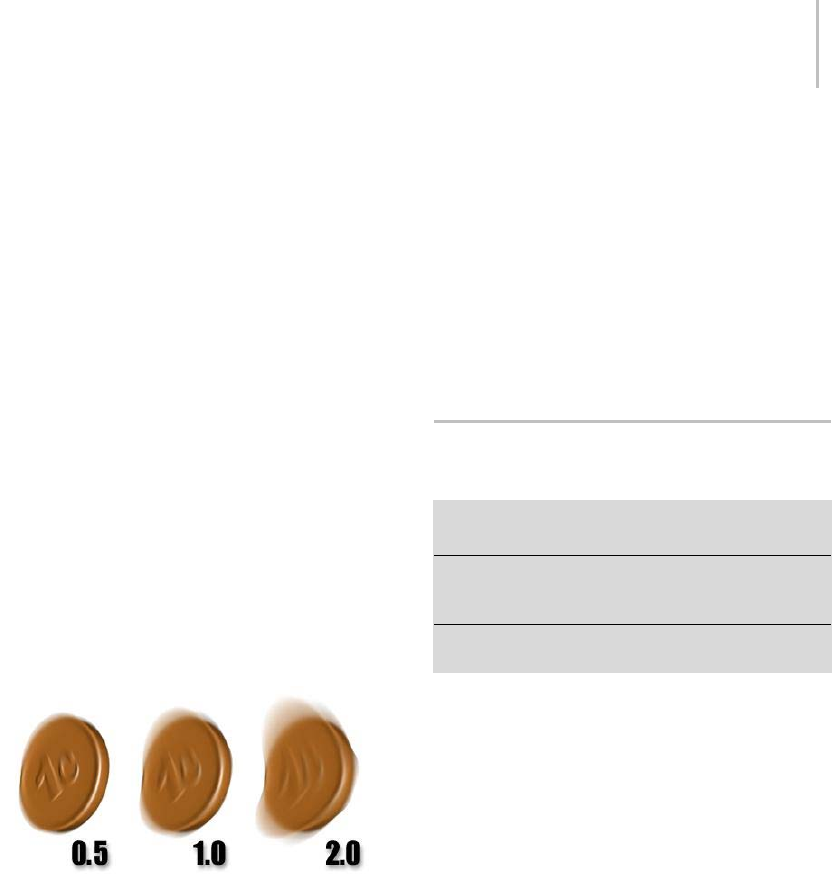
Advanced Lighting Panel (Object Properties Dialog) 123
Note: If multiple objects are selected and have
different By Layer settings, this button will read
‘Mixed’.
Multiplier—Affects the length of the motion-blur
streak.
If you choose either form of motion blur here in
theObjectPropertiesdialog,youmustalsochoose
to apply that type of blur in the Render Scene dialog
(page 3–2).
The rendering speed of object motion blur
depends on the complexity of the geometry to
which it’s assigned. The rendering speed of image
motion blur depends on the amount of rendered
screen space taken up by the blurring object.
In most cases image motion blur renders more
quickly. Object motion blur renders more quickly
when applied to very simple objects, and image
motion blur renders more slowly when the object
takesupalotofscreenspace,andmovesallthe
way across the screen in a single frame.
Changing the Object Blur Multiplier value.
Enabled—When on, enables motion blur for
this object. When off, motion blur is disabled
regardless of the other blur settings. Default=on.
You can animate the Enabled check box. The
main use of animating Enable is to apply motion
blur over only a limited range of frames. This can
save a tremendous amount of time when you are
rendering an animation.
You can enable motion blur for lights and cameras.
With the mental ray renderer, moving lights and
cameras can generate motion blur. However,
they do not generate motion blur with the default
scanline renderer.
•None—Turns off the state of motion blur for the
object.
•Object—Object motion blur (page 3–981)
provides a time-slice blur effect.
•Image—Image motion blur (page 3–955) blurs
the object’s image based on the velocity of each
pixel.
Advanced Lighting Panel (Object
Properties Dialog)
Select object or objects. > Edit menu > Object Properties
> Object Properties dialog > Advanced Lighting panel
Select object or objects. > Right-click. > Transform
(lower-right) quadrant of the quad menu > Properties >
Object Properties dialog > Advanced Lighting panel
Layer manager > Click the icon next to an object’s name.
> Object Properties dialog > Advanced Lighting panel
This panel of the Object Properties dialog lets you
customize how objects behave under advanced
lighting (the Light Tracer (page 3–44) or radiosity
(page 3–51)).
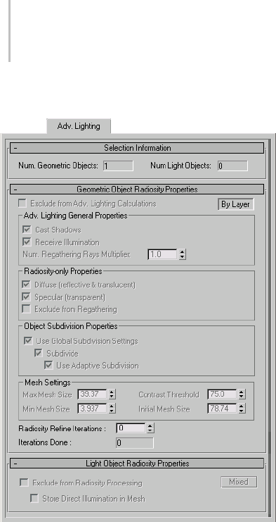
124 Chapter 4: Object Properties
Interface
Selection Information rollout
Num. Geometric Objects—The number of
geometric objects present in the current selection.
Num. Light Objects—The number of lights present
in the current selection.
Geometric Object Radiosity Properties rollout
Exclude from Adv. Lighting Calculations—When
on, the current selection is excluded from
advanced lighting (radiosity or light tracing).
Objectsexcludedfromadvancedlightingwillnot
contribute to indirect illumination.
By Object/By Layer—Toggles between object
settings and object layer settings. Object settings
affect only the object or objects selected. Object
layer settings affect all objects on the same layer as
the selected object. Most settings on this rollout
are available only when this toggle is set to By
Object. Default=By Object.
Note: If multiple objects with different settings are
selected, this button will read “Mixed.”
Adv. Lighting General Properties group
Cast Shadows—Determines whether objects will
cast shadows in the radiosity solution.
Note: When disabling Cast Shadows, you should
also turn off Diffuse (reflective & translucent)
and Specular (transparent) in the Radiosity-only
Properties group. If these switches are left turned
on, objects will still generate light that can produce
artifacts in the solution.
Receive Illumination—Determines whether objects
will receive indirect illumination.
Num. Regathering Rays Multiplier— Lets you
adjust the number of rays cast by this object, per
pixel. If an object looks “blotchy” after rendering,
Increasing this value can improve its appearance.
Default=1.0.
Tip: Increasing this setting is most useful for
objects with large, smooth surfaces. More complex
geometry tends not to show advanced lighting
artifactsasmuchassmoothsurfacesdo.
Radiosity-only Properties group
Diffuse (reflective & translucent)—When on, the
radiosity solution will process diffuse reflection
and translucency (page 3–1027) of the selected
objects.
Specular (transparent)—When on, radiosity will
process transparency of the selected objects.
Exclude from Regathering—When on, objects
are excluded from the regathering process when
rendering.

Advanced Lighting Panel (Object Properties Dialog) 125
For more information on the Radiosity-only
Properties group, see Radiosity Control Panel (page
3–61).
Object Subdivision Properties group
Use Global Subdivision Settings—When on, the
object’s meshing settings correspond to the global
subdivision settings on the Radiosity Control
Panel. When off, you can change the meshing
settings for each object. Default=on.
•Subdivide—When on, a radiosity mesh is
created for the objects regardless of the
global meshing state. The subdivision that is
performed is determined by the Use Adaptive
Subdivision switch. When off, the settings
in the Mesh Settings group are unavailable.
Default=on.
•UseAdaptiveSubdivision—Toggles adaptive
subdivision. Default=on.
Tip: Adaptive meshing is computed for an
object only if ShootDirectLightsis turned on in
the Radiosity Meshing Parameters rollout (page
3–67).
Note: The Mesh Settings group parameters
Contrast Threshold, Min Mesh Size, and Initial
Mesh Size are available only when Use Adaptive
Subdivision is turned on.
Mesh Settings group
Max Mesh Size—The size of the largest faces after
adaptive subdivision. Default=36” for imperial
units and 100cm for metric units.
WhenUseAdaptiveSubdivisionisoff,MaxMesh
Size sets the size of the radiosity mesh in world
units.
Min Mesh Size—Faces are not divided smaller than
the minimum mesh size. Default=3 inches for
Imperial units and 10cm for metric units.
Contrast Threshold—Faces that have vertex
illuminations that differ by more than the Contrast
Threshold setting are subdivided. Default=75.0.
Initial Mesh Size—When improving the face shape,
faces that are smaller than the Initial Mesh Size
are not subdivided. The threshold for deciding
whether a face is poorly shaped also gets larger
asthefacesizeisclosertotheInitialMeshSize.
Default=12 inches for Imperial units and 30cm for
metric units.
Radiosity Refine Iterations—The number of refine
iterations in the radiosity process for the current
selection.
Iterations Done—Thenumberofrefineiterations
performed on the current selection.
Light Object Radiosity Properties rollout
Theseoptionsareavailableonlyforlightobjects.
Exclude from Radiosity Processing—When on, the
current selection is excluded from the radiosity
solution. When lights are excluded from radiosity,
their direct contribution is only used for rendering.
This option is available only when By Object is
selected.
By Object/By Layer—To g g l e s b e t w e e n o b j e c t
settings or object layer settings. Object settings
affect only the object or objects selected. Object
layer settings affect all objects on the same layer as
the selected object.
Note: If multiple objects are selected and have
different settings, this button reads “Mixed.”
Store Direct Illumination in Mesh—When on, the
light’s direct illumination is added to the radiosity
mesh, even if the global rendering mode is Render
Direct Illumination. This is comparable to the
Re-Use Direct Illumination option when rendering
radiosity, but only for this particular light.
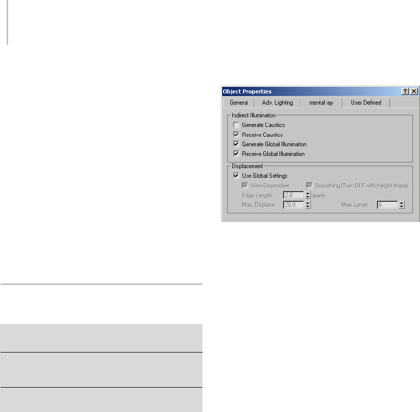
126 Chapter 4: Object Properties
When off, the light’s direct illumination is
used only when you render the scene. This is
comparable to the Render Direct Illumination
option.
for more information about the Re-Use Direct
Illumination and Render Direct Illumination
options, see Rendering Parameters Rollout
(Radiosity) (page 3–71). In general, re-using
direct illumination stored in the radiosity mesh
improves render time, but shadows appear coarse
and inaccurate unless the mesh is very fine.
Rendering direct illumination and shadows (using
the radiosity mesh to provide only indirect light)
takes more time but gives you a more finished and
accurate image.
mental ray Panel (Object
Properties Dialog)
Edit menu > Object Properties > Object Properties dialog
>mentalraypanel
Select object or objects. > Right-click. > Transform
(lower-right) quadrant of the quad menu > Properties >
Object Properties dialog > mental ray panel
Layer manager > Click the icon next to an object’s name.
> Object Properties dialog > mental ray panel
This panel of the Object Properties dialog supports
mental ray rendering; specifically, the indirect
illumination features caustics (page 3–92) and
global illumination (page 3–93).Theycontrol
whether objects generate or receive caustics or
global illumination.
These settings are ignored where they aren’t
appropriate. For example, lights can be set to
generate caustics, but for a light, the Receive
Causticssettinghasnoeffect,aslightsaren’t
renderable. Similarly, these settings have no
meaning for cameras.
Also available on this panel are controls for setting
displacement parameters on a per-object basis.
Interface
Thementalraypanelcontainsparametersforthementalray
renderer.
Indirect Illumination group
Generate Caustics—When on, the object can
generate caustics. (For this to happen, Caustics
must also be enabled using the Render Scene
dialog’s Caustics And Global Illumination rollout
(page 3–106).) When off, the object does not
generate caustics. Default=off.
Receive Caustics—When on, the object can receive
caustics. That is, caustic effects are cast onto
this object. (For this to happen, Caustics must
also be enabled using the Caustics And Global
Illumination rollout.) When off, the object does
not receive caustics. Default=on.
Generate Global Illumination—When on, the object
can generate global illumination. (For this to
happen, Global Illumination must also be enabled
using the Caustics And Global Illumination
rollout.) When off, the object does not generate
global illumination. Default=off.
Receive Global Illumination—When on, the object
can receive global illumination. That is, reflected
lightiscastontothisobject.(Forthistohappen,
Global must also be enabled using the Caustics
And Global Illumination rollout.) When off,
theobjectdoesnotreceiveglobalillumination.
Default=on.

User Defined Panel (Object Properties Dialog) 127
Displacement group
These settings let you apply displacement
parameters on a per-object basis.
Use Global Settings—When on, applies to all
objects the Displacement settings on the Render
Scene dialog > Renderer panel > Shadows and
Displacement rollout (page 3–114).Turnoffto
make settings on a per-object basis. Default=on.
View-Dependent—Defines the space for
displacement. When View-Dependent is on, the
Edge Length setting specifies the length in pixels.
When off, Edge Length is specified in world-space
units. Default=on.
Smoothing—Turn off to have the mental ray
renderer correctly render height maps. Height
maps can be generated by normal mapping; see
Creating and Using Normal Bump Maps (page
3–150).
When on, mental ray simply smoothes the
geometry using the interpolated normals, making
the geometry look better. This result, however,
cannot be used for height map displacement
because smoothing affects geometry in a way that
is incompatible with height mapping.
Edge Length—Defines the smallest allowable
edge length. The mental ray renderer will stop
subdividing an edge once it reaches this size.
Default=2.0 pixels.
Max. Displace—Controls the maximum offset, in
world units, that can be given to a vertex when
displacing it. This value can affect the bounding
box of an object. Default=20.0.
Tip: If displaced geometry appears to be “clipped,”
try increasing the value of Maximum Displace.
Note: When using placeholders (see the Translator
Options rollout (page 3–119)), if this value is larger
than it needs to be, it can reduce performance. If
youexperienceslowtimeswhiledisplacedobjects
when Use Placeholder Objects is on, try lowering
the Max. Displace value.
Max. Level—Controls how many times a triangle
can be subdivided. Default=6.
User Defined Panel (Object
Properties Dialog)
Edit menu > Object Properties > Object Properties dialog
>UserDefinedpanel
Select object or objects. > Right-click. > Transform
(lower-right) quadrant of the quad menu > Properties >
Object Properties dialog > User Defined panel
Layer manager > Click the icon next to an object’s name.
> Object Properties dialog > User Defined panel
This panel of the Object Properties dialog lets
you enter properties or comments that you define
yourself.
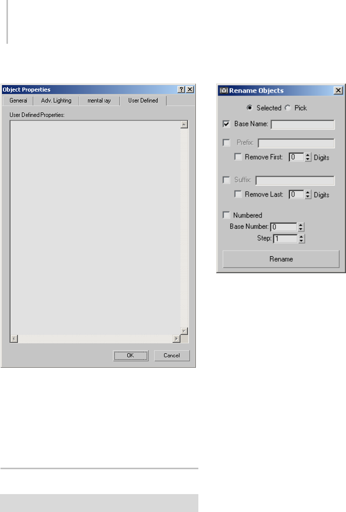
128 Chapter 4: Object Properties
Interface
User Defined Properties—In this text box, you can
enter properties for the object, or comments about
it, that you define yourself. 3ds Max doesn’t use
these properties, but it saves them with the scene,
and they reappear whenever you view the Object
Properties dialog for the object.
Rename Objects Tool
Tools menu > Rename Objects
The Rename Objects tool helps you rename several
objects at once.
Interface
Selected—When chosen, renaming affects
currently selected objects.
Pick—Click to display a Pick Objects To Rename
dialog to choose which objects to rename. This
dialog has the same controls as the Select Objects
dialog (page 1–78).
Base Name—Enter a base name for all objects. The
toggle enables or disables this name.
Prefix—When on, lets you enter a string that will
be a prefix to the name of all renamed objects.
Remove First N Digits—When on, the first N
characters in the base name are removed from
object names. The spinner sets the value of N.
Suffix—When on, lets you enter a string that will
be a suffix to the name of all renamed objects.
Remove Last N Digits—When on, the last N
characters in the base name are removed from
object names. The spinner sets the value of N.
Numbered—When on, lets you number object
names incrementally.
•Base Number—Thebasenumberappendedto
the name of the first renamed object.

Custom Attributes 129
•Step—Thestepbywhichthebasenumberis
incremented in succeeding renamed objects.
Rename—Click to rename the affected objects and
have your changes take effect.
Custom Attributes
Animation menu > Parameter Editor
Keyboard > Alt+1
Use the Parameter Editor to assign custom
attributes to objects, modifiers, materials, and
animation tracks. A custom attribute is an
additional, abstract parameter; abstract in
the sense that it does not directly extend the
functionality of the object by default. It affects an
object only after wire parameters (page 2–411),
reaction controllers (page 2–358),orexpression
controllers (page 2–320) are set up to connect
the custom attribute to another parameter in the
scene. You can also use custom attributes to store
job-specific notes and data.
Custom attributes behave like other object
parameters in several ways:
• They are saved and loaded in the scene file
along with the object.
• They can be animated and keyframed.
• They are displayed in Track View along with the
base parameters.
Each custom attribute parameter can be one of a
number of different data types, including integers,
floating numbers, Booleans, arrays, nodes, colors,
and texture maps. Parameters added to an object
or modifier appear on a Custom Attributes rollout
on the Modify panel. For each custom attribute
parameter you create, you can specify the name,
layout, value range, default value, and UI type:
spinnerorsliderforfloatsandintegers,checkbox
for Booleans, etc.
As you customize an attribute, the result is
displayedontheTestingAttributerolloutatthe
bottom of the dialog.
See also
Parameter Collector (page 1–138)
Attribute Holder Modifier (page 1–559)
Custom Attributes Special Features
The Custom Attributes feature offers an array of
workflow-enhancing functionality, including:
• the ability to add custom attributes to specific
animation tracks.
• the ability to edit existing custom attributes.
• 13 available data types.
• a variety of available UI options, such as
ComboBox and ListBox for the Array data type.
• the ability to position UI elements precisely
with X and Y Offset controls.
•theabilitytopreserve custom attributes when
collapsing the stack.
•AspecialAttribute Holder modifier (page
1–559) that lets you collect attributes from
different entities and access them in one place
on the Modify panel.
Procedures
To add a parameter to an object:
1. Select the object.
2. Choose Animation menu > Parameter Editor.
The Parameter Editor opens.
3. Change settings as desired.
4. Click Add.
The parameter is added to the level specified
in the Add To Type list. If an object has no
custom attributes, Parameter Editor first adds a
Custom Attributes entry to the current Add To
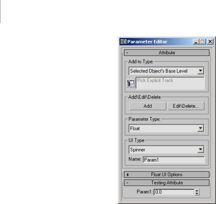
130 Chapter 4: Object Properties
Type level, and then adds the parameter to the
Custom Attributes entry. If an object has more
than one Custom Attributes entry as a result of
collapsing its stack, the parameter is added to
the first Custom Attributes entry.
If a custom attribute parameter is assigned to
an object or modifier, you can see and edit its
value on the Modify panel after adding it by
activating the entity to which the attribute is
assigned. If the custom attribute is assigned
to a material, it’s available for that material in
the Material Editor, on the Custom Attributes
rollout. To access a parameter that’s assigned to
an animation track, open Track View, highlight
the track’s Custom Attributes entry, and then
right-click and choose View Attribute Dialog.
To edit a parameter or custom attribute:
1. Select the object.
2. Choose Animation menu > Parameter Editor.
The Parameter Editor opens.
3. From the Add To Type drop-down list, choose
the type of parameter to edit, and then click
Edit/Delete.
The Edit Attributes/Parameters dialog opens.
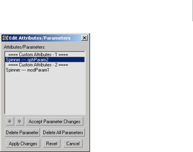
Custom Attributes 131
Note: If you chose Add To Type > Picked Track,
the Track View Pick dialog might open first
to prompt you to choose the animation track
whose attribute to edit.
4. In the Edit Attributes/Parameters dialog,
highlight the parameter to edit.
ItssettingsappearintheParameterEditor.
5. Change the settings in the Parameter editor,
and then click Accept Parameter changes.
6. With multiple parameters or custom attributes,
to change the ordering, click the entity to move,
and then use the up and down arrow buttons to
move the entity in the list. Moving a Custom
Attributes entry also moves its parameters.
Note: You cannot rename a Custom Attributes
entry.
7. When finished editing, click Apply Changes,
and then exit the dialog by clicking the Close
or Cancel button.
To delete a custom attribute or parameter:
1. Select the object.
2. Choose Animation menu > Parameter Editor.
The Parameter Editor opens.
3. From the Add To Type drop-down list, choose
the type of parameter to delete, and then click
Edit/Delete.
The Edit Attributes/Parameters dialog opens.
Note: If you chose Add To Type > Picked Track,
the Track View Pick dialog might open first to
prompt you to choose the animation track from
which to delete the attribute.
4. In the Edit Attributes/Parameters dialog,
highlight the parameter to delete, and then click
Delete Parameter. Alternatively, to delete all
parameters under the same Custom Attributes
heading as the highlighted parameter, click
Delete All Parameters.
To delete one or more custom attributes instead,
click a Custom Attributes heading, and then
click Delete Attribute or Delete All Attributes.
Multiple attributes can result from collapsing an
object’s stack with Preserve Custom Attributes
on. For example, one set of custom attributes
might be applied to an object and a second set
of attributes assigned to one of its modifiers.
Collapsing such an object results in two sets of
custom attributes.
5. Click Apply Changes, and then close the dialog
by clicking its Close box or the Cancel button.
Interface
The Parameter Editor takes the form of a dialog
with several rollouts: The first rollout sets general
options for the attribute; the central rollout sets
options for the current parameter type; and the
third lets you preview the attribute user interface
(UI).
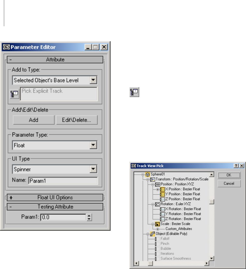
132 Chapter 4: Object Properties
Attribute rollout
Add to Type group
Add to Type list—Choose whether the custom
attribute is assigned to the selected object, its
active modifier (as highlighted in the modifier
stack), its material, or a picked track. Also use
this drop-down list to choose the attribute type to
delete or edit.
If the text “Pick Explicit Track” appears in the
box below the drop-down list before you choose
Picked Track , the Track View Pick dialog appears
showing the Track View hierarchy. Expand the
hierarchy as necessary, click the track to add the
attribute to, and then click OK.
Note: If you choose Selected Object’s Current
Modifier and multiple modifiers are highlighted in
the stack when you click Add, Parameter Editor
applies the custom attribute to the first modifier
you highlighted and removes the highlighting
from the other modifiers.
[pick explicit track]—Click this button to open
a Track View hierarchy window from which to
choose an animation track. Navigate the hierarchy
to find the desired track, highlight the track, and
then click OK. The controller information for the
track then appears in the text box to the right of
the button, and the Parameter Editor will then use
this track for adding or editing custom attributes
and parameters.
Add/Edit/Delete group
Add—Applies the custom attribute parameter to
the current object, modifier, material, or track,
depending on the current choice in the Add To
Type list.
If a custom attribute parameter is assigned to an
object or modifier, you can see and edit its value
on the Modify panel after adding it by activating
the entity to which the attribute is assigned. If
the custom attribute is assigned to a material, it’s

Custom Attributes 133
available for that material in the Material Editor. To
access a parameter that’s assigned to an animation
track, open Track View, highlight the track’s
Custom Attributes entry, and then right-click and
choose View Attribute Dialog.
Edit/Delete—Opens the Edit Attributes/Parameters
dialog.
This dialog displays a list of all of the custom
attribute parameters assigned to the currently
object at the current level. Dialog behavior is
described in these two procedures: To edit a
parameter or custom attribute: (page 1–130) and
To delete a custom attribute or parameter: (page
1–131).
Parameter Type group
Parameter Type—Use the drop-down list to
choose the data type for the current parameter.
The following list includes links to the sections
describing the UI settings for each parameter’s
data type:
•Angle:Spinner (page 1–133) or Slider (page
1–134)
•Array (page 1–135)
•Boolean:CheckBox (page 1–135) or
CheckButton (page 1–135)
•Color (page 1–136)
•Float:Spinner (page 1–133) or Slider (page
1–134)
•fRGBA (page 1–136)
•Integer:Spinner (page 1–133) or Slider (page
1–134)
•Material (page 1–137)
•Node (page 1–136)
•Percent:Spinner (page 1–133) or Slider (page
1–134)
•String (page 1–137)
•TextureMap (page 1–137)
•WorldUnits:Spinner (page 1–133) or Slider
(page 1–134)
UI Type group
UI Type—Selects the type of UI element that
controls the parameter.
The UI types available depend on which parameter
type you specify. For example, float and integer
values are controlled by spinners or sliders, and
Boolean values by check boxes or check buttons.
Array values are always controlled by drop-down
lists, node values by pick buttons, color values
by color pickers, and texture map values by map
buttons.
Full descriptions of each UI Options rollout
follow, and the list of parameter types, above,
includeslinkstotherespectiveUIOptionsrollout
descriptions.
Name—The name of the parameter. Parameter
Editor gives the parameter the default name
Param#, with # being a number. Change the name
by editing this field.
Angle/Float/Integer/Percent/WorldUnits UI
Options rollout: Spinner
This is a numeric value that the user can set with a
standard 3ds Max spinner.
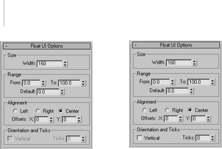
134 Chapter 4: Object Properties
Size group
Width—Sets the width of the spinner.
Range group
From—Sets the minimum value of the spinner.
To—Sets the maximum value of the spinner.
Default—Sets the default value of the spinner.
Alignment group
Left/Right/Center—Sets the alignment of the
spinner in the rollout.
Offsets X/Y—Fine-tune the position of the spinner
on the horizontal and vertical axes.
Angle/Float/Integer/Percent/WorldUnits UI
Options rollout: Slider
This is a numeric value that the user can set with a
standard 3ds Max slider.
Size group
Width—Sets the width of the slider.
Range group
From—Sets the minimum value of the slider.
To—Sets the maximum value of the slider.
Default—Sets the default value of the slider.
Alignment group
Left/Right/Center—Sets the alignment of the slider
in the rollout.
Offsets X/Y—Fine-tune the position of the slider on
the horizontal and vertical axes.
Orientation And Ticks group
Vertical—When on, the slider will be displayed
vertically. When off, the slider is displayed
horizontally.
Ticks—Sets the number of ticks along the slider.
Theticksaredistributedevenlyalongthelength
of the slider.
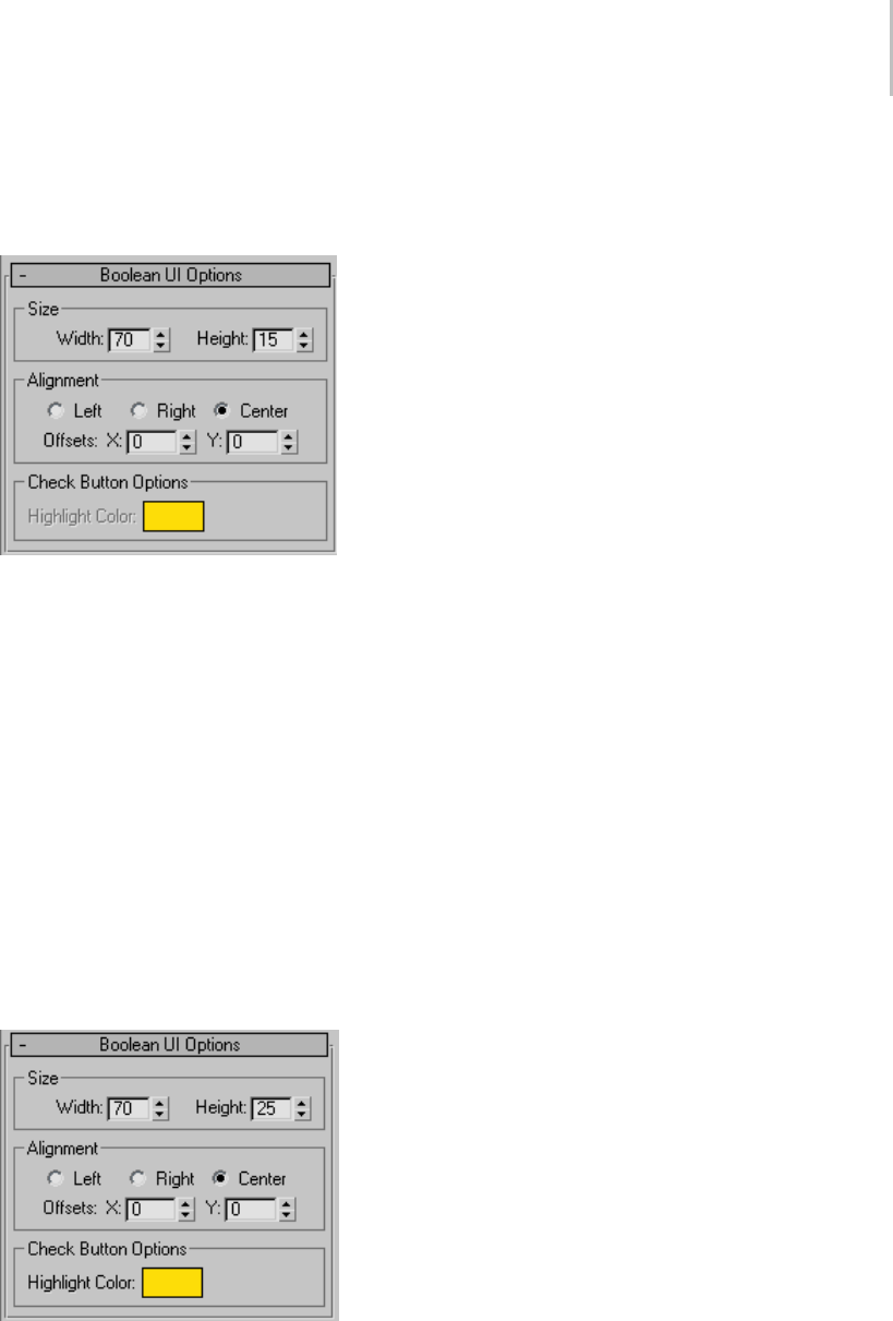
Custom Attributes 135
Boolean UI Options rollout: Check Box
This is a standard 3ds Max check box that the user
canturnonandoffbyclickingitwiththemouse.
Size group
Width—Sets the width of the check box.
Height—Sets the height of the check box.
Alignment group
Left/Right/Center—Sets the alignment of the check
box in the rollout.
Offsets X/Y—Fine-tunethepositionofthecheck
box on the horizontal and vertical axes.
Boolean UI Options rollout: Check Button
This is a standard 3ds Max check button that the
user can turn on and off by clicking it with the
mouse.
Size group
Width—Sets the width of the check button.
Height—Sets the height of the check button.
Alignment group
Left/Right/Center—Sets the alignment of the check
button in the rollout.
Offsets X/Y—Fine-tune the position of the check
button on the horizontal and vertical axes.
Check Button Options group
Highlight Color—Sets the color of the button when
it is pressed.
Array UI Options rollout: Drop-Down
List/ComboBox/ListBox
This lets the user of the custom attribute choose
anamedoptionfromalist.Theoptionsforthe
three Array UI types are the same; they differ in
how they appear on the Custom Attributes rollout.
The types are:
• Drop-Down List: Only the current choice is
visible by default. The user clicks the field
to open the list and then clicks to choose a
different item.
• ComboBox: Displays an editable field above a
list box. The user clicks to choose from the list,
or edits the field.
• ListBox: Displays a list. The user clicks the
desired item; the highlighting indicates the
current choice.
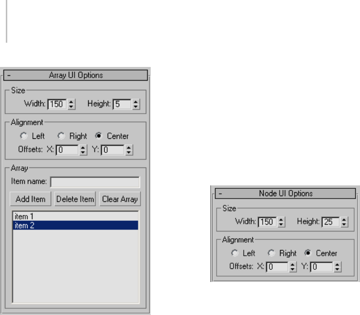
136 Chapter 4: Object Properties
Size group
Width—Sets the width of the list.
Height—Sets the height of the list.
Alignment group
Left/Right/Center—Sets the alignment of the
drop-down list in the rollout.
Offsets X/Y—Fine-tune the position of the array list
on the horizontal and vertical axes.
Array group
Item name—Lets you enter a name into the list.
Click Add Item to add the name to the array list.
To remove an item, highlight its name and click
Delete Item. Click Clear Array to remove all items
from the list.
[array list]—Displays the contents of the list.
The item at the top of the array list is the default
selection.
Node UI Options rollout: Pick Button
Anodeisanyobjectinthe3dsMaxscene.The
Node UI element creates a button that, when
clicked,letstheuserpickascenenodeotherthan
the one to which the attribute is attached. After
selecting the node, its name appears on the button.
Size group
Width—Sets the width of the pick button.
Height—Sets the height of the pick button.
Alignment group
Left/Right/Center—Sets the alignment of the pick
button in the rollout.
Offsets X/Y—Fine-tune the position of the pick
button on the horizontal and vertical axes.
Color UI Options rollout: Color Picker
This creates a color swatch that displays the current
color and lets the user click it to choose a new color
with the Color Selector dialog.
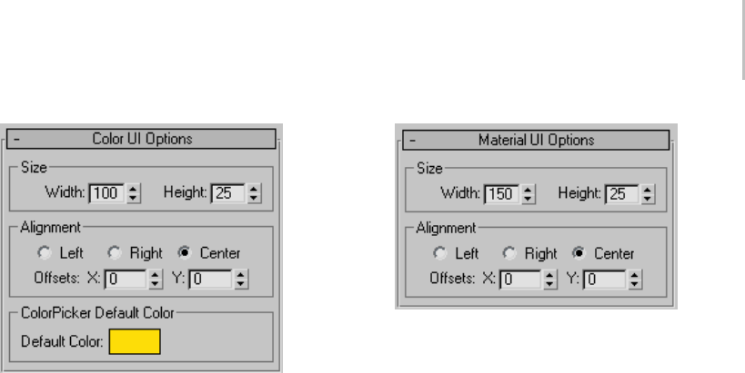
Custom Attributes 137
Size group
Width—Sets the width of the color picker.
Height—Sets the height of the color picker.
Alignment group
Left/Right/Center—Sets the alignment of color
picker in the rollout.
Offsets X/Y—Fine-tune the position of the color
picker on the horizontal and vertical axes.
ColorPicker Default Color group
Default Color—Sets the default color of the color
picker.
Material/TextureMap Options rollout:
MaterialButton/MapButton
The options for the Material UI type
(MaterialButton) and TextureMap UI type
(MapButton) are the same. The difference is that,
when the user clicks the resulting button to open
the Material/Map Browser, the former displays
only materials and the latter displays only maps.
Size group
Width—Sets the width of the material/map button.
Height—Sets the height of the material/map
button.
Alignment group
Left/Right/Center—Sets the alignment of the
material/map button in the rollout.
Offsets X/Y—Fine-tune the position of the
material/map button on the horizontal and vertical
axes.
String Options rollout: EditText
The String parameter type creates a text box that
the user can edit with the keyboard, with optional
default text.
Size group
Width—Sets the width of the material/map button.
Height—Sets the height of the material/map
button.
Alignment group
Left/Right/Center—Sets the alignment of the text
box in the rollout.
Offsets X/Y—Fine-tune the position of the text box
on the horizontal and vertical axes.
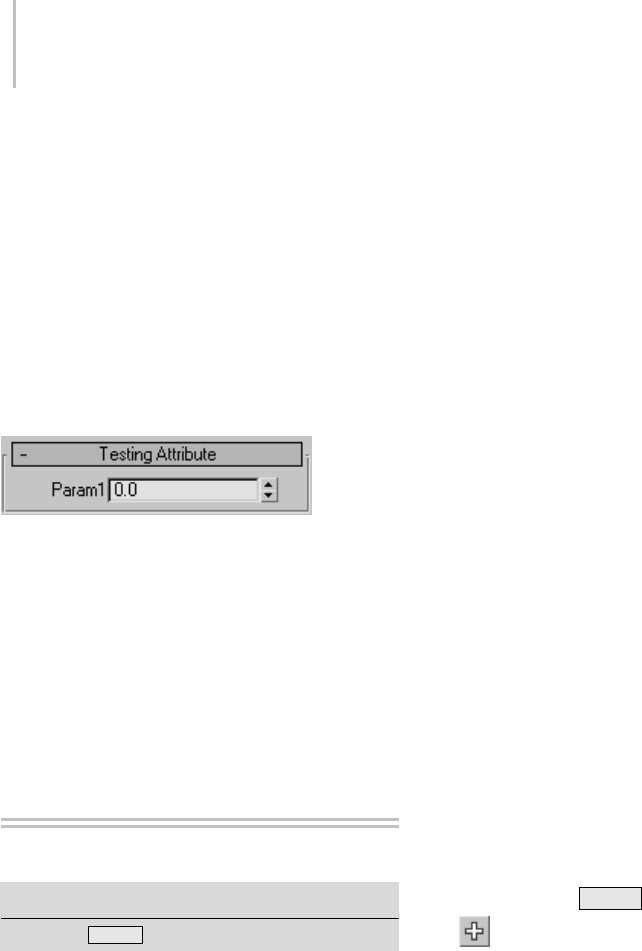
138 Chapter 4: Object Properties
Label group
Label above text box—When off, the label
(parameter name) appears to the left of the text
box. When on, the label appears above the text
box.
EditTextDefaultTextgroup
Default Text—Enteranydefaulttextthatshould
appear in the box before the user edits it.
Testing Attribute rollout
This rollout displays the UI layout for the custom
attribute that you are working on. It updates
continuously so that you can see how different
settings in the various rollouts affect the UI display
of the attribute.
The UI element is operational in this rollout in
the sense that it can be moved, clicked, toggled,
and so on.
Parameter Collector
Animation menu > Parameter Collector
Keyboard > Alt+2
Parameter Collector lets you sort and present
animatable parameters so that you can access and
key selected parameter sets with a click or two. It
takes the form of a resizable dialog that regenerates
dynamically as parameters change. The dialog
supports drag-and-drop rollout reordering.
Collections are saved with their scenes and can be
merged into other scenes.
One of Parameter Collector’s most powerful
features is the ability to change all parameters
in a collection simultaneously, in an absolute or
relative mode. For example, if you’re animating a
character’s hand, you can use Parameter Collector
to easily make all the fingers curl up together to
form a fist.
Note: Parameter Collector does not support
parameters of externally referenced objects (page
3–394) or objects in externally referenced scenes
(page 3–407).
See also
Custom Attributes (page 1–129)
Attribute Holder Modifier (page 1–559)
Procedure
Example: To use Parameter Collector:
This exercise demonstrates some basic Parameter
Collector functions.
In general, start with a scene containing one or
more objects whose parameters you’ll collect.
Ideally, they should be animated, but it’s not
absolutely necessary.
1. For this example, reset 3ds Max and then add a
sphere.
2. Open Parameter Collector from the Animation
menu, or press Alt+2 .
3. On the Parameter Collector toolbar, click
the Add To New Rollout button.
The Track View Pick dialog opens. This lets you
specify parameters to collect.
4. On the Track View Pick dialog, expand
Objects > Sphere01 > Transform:
Position/Rotation/Scale > Position:
Position XYZ.
5. Click X Position: Bezier Float.
The parameter highlights.
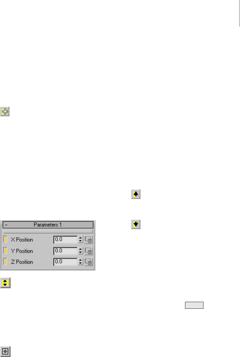
Parameter Collector 139
6. Click OK to close the dialog.
A new rollout named Parameters 1 appears,
containing the X Position parameter.
Note: A parameter in Parameter Collector can
contain only a single value (e.g., float, integer,
color), so the software doesn’t let you add
parameters such as Position: Position XYZ,
which contains three distinct values.
7. Click Add To Selected Rollout and then
use the same method to add the Y Position
and Z Position parameters: Highlight both
parameters on the Track View Pick dialog and
then click Add To Selected Rollout to add both
at once to the Parameters 1 rollout.
8. Drag each spinner in turn to move the sphere
on the respective axis.
As you change each parameter value, the sphere
movesinrealtimeintheviewports.
9. Set all three parameters to 0.0.
10.Click the check button next to each parameter
to select all three.
11. Onthetoolbar,turnonMultipleEdits.
12.Drag one of the spinners.
All three change by the same amount, so that
thespheremovesdiagonallyinthescene.
13.UsethekeyboardtochangetheYPosition
value to 30.0.
Again, the other two change.
14. Click the Absolute/Relative button to turn
on Relative mode.
All the values display 0.0, as with Offset mode
on the status bar coordinate display.
15.Use the spinner to set Y Position to 0.65.
The three change in unison, and then reset back
to 0.0 when you release the mouse button. This
has added the value you set to each of the three
positions, as you’ll see in the next step.
16. Click the Absolute/Relative button to return
to Absolute mode.
The values are all set to 30.65, reflecting the
relative change that you made.
Next, you’ll try a few Edit commands.
17.Click the Y Position check button to deselect
the parameter.
18.From the Edit menu, choose Select Invert.
The Y Position parameter is now selected, and
the other two are deselected.
19. Click the Move Parameters Up button.
The Y Position parameter now sits above the
X Position parameter.
20. Click the Move Parameters Down button.
The Y Position returns to its position below the
X Position parameter.
21.Choose Edit > Edit Notes.
The Notes dialog opens. Here you can change
the parameter name, set a URL or file location
with further information about the parameter,
and enter comments.
22.In the box below Parameter Name, type Sphere
YLoc., and then press Enter .
Thenewnamereplacestheoldoneonthe
rollout. You can see the original name by
hovering the mouse cursor over the parameter
name;itappearsonatooltip.
To conclude this exercise, you’ll use Parameter
Collector to set and edit animation keyframes.
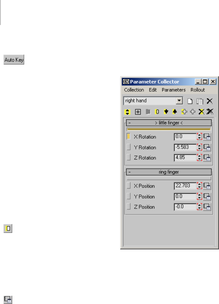
140 Chapter 4: Object Properties
23.On the Collection menu, turn on Show Keys In
Track Bar if necessary.
24. On the 3ds Max status bar, turn on
Auto Key.
25.ChangetheSphereYLoc.(theoldYPosition)
parameter value to 20.0.
Becauseyou’reatframe0,nokeyisset.Thisis
thesamewayAutoKeyworksnormally.
26.Go to frame 20 and then set Sphere Y Loc. to
30.0.
This sets animation keys at frames 0 and 20.
27.Right-click the key at frame 20.
The menu shows that a key exists at frame 20
only for Y Position. Normally, 3ds Max would
create keys for all three axes, even if you moved
thesphereonlyononeaxis.
Parameter Collector can set keys for unselected
objectsaswell.
28.Click in an empty area of the active viewport
to deselect the sphere, and then go to frame 30
and change the Sphere Y Loc. value to 40.0.
This sets another key for Y Position at frame 30.
29. In Parameter Collector, select the X
Position and Z Position parameters, and then
click Key Selected.
This button is available only when Auto Key is
on.
30.Checkthetrackbarkeyagain.Nowthereare
keys for all three parameters, as demonstrated
by the red brackets on the spinners in Parameter
Collector.
31. Click the Properties button to the right of
theSphereYLoc.parameter.
This opens a Key Info dialog (page 2–304) for
the parameter, with the ability to edit the key
time and value as well as interpolation with
other keys. The dialog is also available from
the track bar right-click menu, but it’s much
easier to access the data for a specific key from
Parameter Collector.
Interface
Parameter Collector takes the form of a dialog with
a menu bar, a toolbar, and rollouts that you create
and modify using the dialog tools. You can resize
the dialog horizontally and vertically; expanding it
lets you see all rollouts simultaneously.
Menu Bar
The menu bar provides a range of functions for
using Parameter Collector. See Parameter Collector
Menu Bar (page 1–142) for details. Also, you can
open the Spinner Right-Click menu (page 2–282)
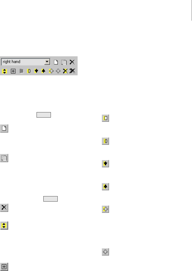
Parameter Collector 141
by right-clicking a numeric field in Parameter
Collector.
Toolbar
The Parameter Collector toolbar provides button
access to the most commonly used functions.
[collection name]—If empty, enter a name for the
current collection, or choose a different collection
from the drop-down list. If a name appears and
you edit it, pressing Enter duplicates the current
collection with the new name.
New Collection—Creates a new, empty
collection, clearing the current collection name
and the rollout area. You can restore any existing
collection by choosing it from the drop-down list.
Duplicate Collection—Creates a new, unnamed
collection containing the same data as the current
collection. Enter a name for the duplicate selection
intheeditablefield.
You can also duplicate a collection and name it at
thesametimebyeditingthenameofanexisting
collection and pressing Enter .
Delete Collection—Removes the current
collection from memory.
Multiple Edits—Enables multiple editing,
in which changing the value of any selected
parameter simultaneously changes all selected
parametersofthesametypebythesameamount.
This applies to both Absolute and Relative modes
(see following).
Absolute/Relative—Wor ks t he s ame w ay a s
the Absolute/Offset mode toggle on the Coordinate
Display (page 3–708). When Absolute is chosen,
modifyingavaluechangesittotheexactamount
you specify. When Relative is chosen, the displayed
value is 0, and modifying the parameter adds the
specified change to the original value. The actual
value appears only in Absolute mode.
This applies to numeric values only; any changes
to other values, such as color, are always absolute.
Note: With multiple parameters selected, and
Multiple Edits on, changing the value of a selected
parameter changes the other selected parameter
values by the same amount, not to the same
amount. This happens in both Absolute and
Relative modes.
Key Selected—Sets keys (page 3–960) for
selected parameters only at the current frame.
Available only when Auto Key (page 3–717) is on.
Reset Selected—Sets all selected numeric
parameters to 0. Has no effect on other parameter
types.
Move Parameters Down—Moves each selected
parameter down one position within its rollout,
if possible.
Move Parameters Up—Moves each selected
parameter up one position within its rollout, if
possible.
AddtoSelectedRollout—Lets you add new
parameters to the selected rollout. Click this
button to open the Track View Pick dialog, and
then choose the parameters from the dialog.
Note: Yo u c a n a d d s e v e r a l p a r a m e t e r s a t o n c e b y
highlighting them in the dialog before clicking OK.
Add to New Rollout—Lets you add new
parameters to a new rollout. Click this button
to open the Track View Pick dialog, and then
choose the parameter from the dialog. Parameter
Collector creates a new rollout to hold the
parameters.
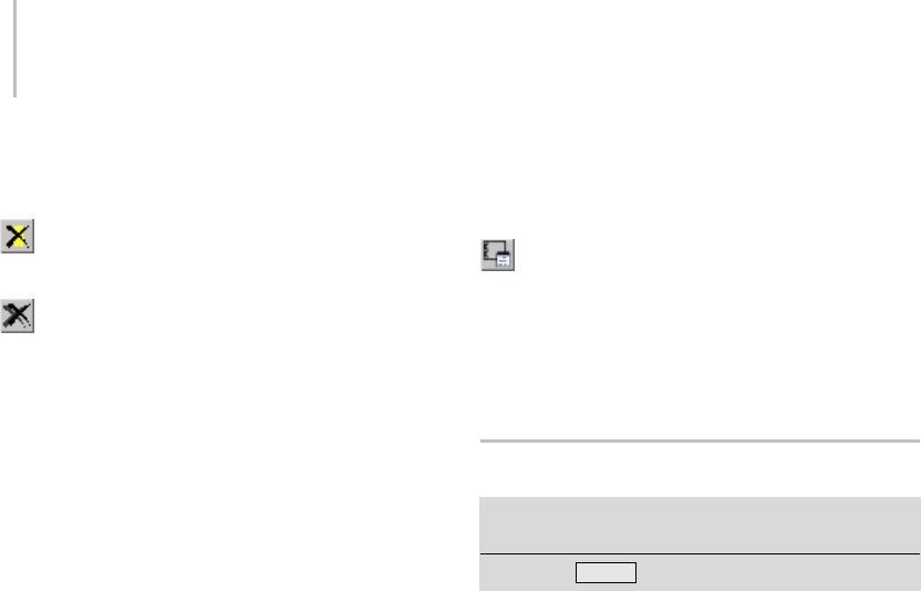
142 Chapter 4: Object Properties
Note: You can add several parameters at once by
highlighting them in the dialog before clicking OK.
Delete Selected—Deletes all selected
parameters.
Delete All—Deletes all parameters and rollouts.
Rollouts
Rollouts work the same way in Parameter Collector
as they do on the command panel (page 1–12).
You can expand and collapse a rollout by clicking
its title bar, and move it to another location by
dragging the title bar. You can resize the dialog to
be able to see all rollouts at once.
Only one rollout can be selected at a time.
Youselectarolloutbyclickingthehorizontal
bar beneath the title; when selected, this bar
is orange-yellow in color, and angle brackets
surround the rollout title (for example, “> Hand
Parameters <”).
The interface for each parameter on a rollout is as
follows:
[Select Parameter]—Asmallcheckbuttonon
the left side of the rollout. Click it to toggle the
parameter’s selection status. When selected,
the button appears pressed in and is colored
yellow-orange.
[parameter name]—By default, the parameter has
the same name as is shown in Track View, but you
can change it with the Edit menu > Edit Notes
command. You can see the default name for a
parameter as well as the object it controls, if any,
by hovering the mouse over the parameter name;
theinformationappearsonatooltip.
[parameter value]—Shows the current value of the
parameter. The parameter type determines how
this appears: numeric field/spinner, color swatch,
etc.Youcaneditthevaluethesamewayasonthe
command panel or a dialog.
If a key exists for the value at the current frame,
the spinner or swatch appears with red brackets
at the corners.
[Properties]—Opens a Key Info dialog (page
2–304) for the parameter. Available only if the
parameter has an animation controller.
Use the Key Info dialog to edit an animation key’s
value, time, and interpolation methods.
Parameter Collector Menu Bar
Animation menu > Parameter Collector > Parameter
Collector menu bar
Keyboard > Alt+2 > Parameter Collector menu bar
The Parameter Collector dialog menu bar provides
access to a number of important commands.
Some of these commands are replicated on the
dialog toolbar; others, such as the Select tools,
are available only from the menus. Also, you can
open the Spinner Right-Click menu (page 2–282)
by right-clicking a numeric field in Parameter
Collector.
Interface
Collection menu
Thefirstthreeitemsinthismenuareunavailable
untilyouenteranameforthecurrentcollectionin
theeditablefield(drop-downlist)justbelowthe
menu bar.
New Collection—Creates a new, empty collection,
clearing the current collection name and the
rollout area. You can restore any existing collection
by choosing it from the drop-down list.
Duplicate Collection—Creates a new, unnamed
collection containing the same data as the current
collection. Enter a name for the duplicate selection
intheeditablefield.

Parameter Collector Menu Bar 143
Delete Collection—Removes the current collection
from memory.
Show Keys in Track Bar—Displays in the track bar
(page 3–703) animation keys for all objects with
parameters in the current collection, whether or
not the objects are selected in the scene.
Isolate Keys in Track Bar—The track bar displays
only keys for parameters in the Parameter
Collector.
Show Selected Keys in Track Bar—Displays in the
track bar (page 3–703) animation keys for all
objects with selected parameters in the current
collection, whether or not the objects are selected
in the scene.
Isolate Selected Keys in Track Bar—The track bar
displays only keys for selected parameters in the
Parameter Collector.
Put to Object—Stores the current collection as part
of an object in the scene. Opens the Put To Object
dialog; highlight an object in the list, and then
click Pick.
Although parameter collections are stored with
the scene in which they’re created, you can use
this function to transfer a collection to a different
scene. After putting the collection to an object,
save the scene. Open or create another scene,
mergetheobjectfromthesavedscenetothenew
one, and then use Get from Object.
You can also back up, organize and streamline
parameter collections by putting and getting
different collections to and from various objects in
your scene. Just remember that if you add, reorder,
or remove parameters or rollouts to a collection
that has been put to an object, you must then put
it to the object again so the changes are saved to
the collection.
Link to Object—Stores the current collection using
a live link as part of an object in the scene. Any
change to the collection instantly updates the
version of the collection stored in the object.
Opens the Link To Object dialog; highlight an
object in the list, and then click Pick.
Link to Object has basically the same function as
Put To Object (see previous entry), except that
it guarantees an up-to-date stored version of the
collection, especially when merging the object
intoanotherscenethatisacommonproduction
workflow.
Note: Onlyone“linked-to”objectcanbeactive
in a scene, but you can use Put To Object on any
number of objects at a time.
Get from Object—Retrieves a collection that you
stored with Put To Object or Link To Object.
Remove from Object—Deletes a collection that you
stored with Put To Object or Link To Object.
Edit menu
Parameter Collector lets you select parameters
in any combination, but you can select no more
than one rollout at a time. To select or deselect
a parameter, click the small button on its left
side. To select or deselect a rollout, click the wide
horizontal button just below the rollout title.
Selecting a rollout deselects any other selected
rollout.
Select All—Selects all parameters and rollouts.
Select All Rollout—Selects all parameters on
the current rollout. Unavailable if no rollout is
selected.
Select None—Deselects all parameters.
Select Invert—Inverts the current selection of
parameters.
Delete Selected—Deletes all selected parameters.
Delete All—Deletes all parameters and rollouts.

144 Chapter 4: Object Properties
Multiple Edits—Enables multiple editing, in which
changing any parameter simultaneously changes
all selected parameters of the same or similar type.
Note: The changed parameter need not be selected.
Absolute/Relative—This works the same as the
Absolute/Offset mode toggle on the Coordinate
Display (page 3–708). When Absolute is chosen,
modifyingavaluechangesittotheexactamount
you specify. When Relative is chosen, the displayed
value shows 0, and modifying the parameter adds
the specified change to the original value. This
applies to numeric values only; changes to any
othervaluetypessuchascolorarealwaysabsolute.
Edit Notes—Opens a single Notes dialog (page
1–145) for all selected parameters.
You can open the Notes dialog for a single
parameter by right-clicking its Select Parameter
button.
Parameters menu
Add to Selected—Lets you add new parameters to
the selected rollout.
Add to New Rollout—Lets you add new parameters
to a new rollout.
Move Up—Moves selected parameters up one
position within their rollout, if possible.
Move Down—Moves selected parameters down
one position within their rollout, if possible.
Move Up By Rollout—Moves selected parameters
to the rollout above, if possible. If the same
parameter already exists in the rollout above, the
selected parameter is simply deleted.
Move Down By Rollout—Moves selected parameters
to the next rollout, if possible. If the same
parameter already exists in the next rollout, the
selected parameter is simply deleted.
Key All—Sets keys (page 3–960) for all parameters
at the current frame. Available only when Auto Key
(page 3–717) is on.
Key Selected—Sets keys (page 3–960) for selected
parameters only at the current frame. Available
only when Auto Key (page 3–717) is on.
Reset All—Sets all numeric parameters to 0. Has
no effect on other parameter types.
Reset Selected—Sets all selected numeric
parameters to 0. Has no effect on other parameter
types.
Rollout menu
Note: While there are no menu commands for
moving rollouts, you can do so simply by dragging
the rollout title bar to a new location.
New Rollout—Creates a new, empty rollout.
New Rollout Selected Parameters—Creates a new
rolloutandpopulatesitwithcopiesofanyselected
parameters.
Rename Rollout—Opens a small dialog that lets
you rename the selected rollout.
Delete Rollout—Deletes the selected rollout.
Delete Rollout Move Up—Deletes the selected
rollout and moves its parameters to the rollout
above.
Delete Rollout Move Down—Deletes the selected
rollout and moves its parameters to the rollout
below.
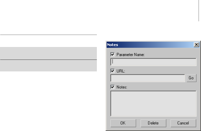
Notes Dialog (Parameter Collector) 145
Notes Dialog (Parameter Collector)
Parameter Collector > Select one or more parameters. >
Parameter Collector menu bar > Edit menu > Notes
Parameter Collector > Right-click a Parameter Select
button.
The Notes dialog lets you enter a name, URL, and
comments for one or more selected parameters
in Parameter Collector.
Choosing Notes from the Edit menu with multiple
parameters selected opens a single dialog common
to all selected parameters. Right-clicking a
Parameter Select button opens a dialog for that
parameter only.
When you open Notes from the Edit menu with
multiple parameters selected, if the text contents
for a box in all selected parameters are the same (or
null), its check box is on, indicating that changes
to the text will apply to all selected parameters.
If a text box has different contents for different
selected parameters, the check box is off, and the
corresponding text box is empty and unavailable,
preventing any changes. If you turn on a check
box, you can edit the text, and changes will be
applied to all selected parameters.
Interface
The Notes dialog interface comprises three text
boxes, each with its respective check box, and a
button. By default, the text boxes are empty; you
can enter any text into each box, although each has
a specific purpose, as described below.
Parameter Name—Lets you change the parameter
nameshowninParameterCollector.
By default, the parameter name displayed in
Parameter Collector is the same as the name
that appeared in the Track View Pick dialog
when you added it to Parameter Collector. If
you enter a different name in the Notes dialog,
Parameter Collector then displays that name. The
changed name is used only in Parameter Collector;
elsewhere, such as the Modify panel, it remains
thesameasbefore.
You can see the original parameter name, as well
as the object to which it’s attached, by hovering
the mouse over the parameter name in Parameter
Collector; the information appears in a tooltip.
URL—Lets you enter a URL, such as
www.discreet.com.
This could be a link to a Web or intranet page, or
even a network location or file pertaining to the

146 Chapter 4: Object Properties
selected parameter. To access the link, click the
Go button.
Go—If the URL text box contains a valid URL,
clicking Go opens the URL in a separate browser
window.
Notes—Contains any comments on the parameters.
This field is strictly for informational purposes.
Expression Techniques
In 3ds Max, you can use mathematical expressions
(rather than constant numbers) to express
parametervalues.Forexample,youcouldusethe
expression 24*6 to represent the number 144.
You can use mathematical expressions to control
the following object properties:
• Object parameters, such as length, width, and
height
• Transform and modifier values, such as an
object’s position coordinates
Parameter wiring (page 2–411),theexpression
controller (page 2–320),andthenumerical
expression evaluator (page 1–13) all use
expressions, which are described in this topic.
An expression is a mathematical function that
returns a value. You can use expressions to control
thefollowingsceneelements:
Scene element Calculatable property
Creation
parameters
Any numeric creation parameter
Transforms Position [X, Y, Z]
XRotation
YRotation
ZRotation
Scale [X%, Y%, Z%]
Scene element Calculatable property
Modifiers Any numeric modifier parameter
(including creation parameters)
Materials Colors [R, G, B]
Any numeric material parameter
Note: Expressions only work with the individual
XYZ components of Euler rotation. You can’t
assign an expression to TCB rotation or other
kinds of rotation controllers.
The links below are to the sections that follow in
this topic.
Expression Return Types (page 1–146)
Operators (page 1–147)
Variables (page 1–148)
Functions (page 1–148)
See also
Trigonometric Functions (page 1–150)
Vectors (page 1–151)
Expression Controller Techniques (page 2–324)
Expression Return Types
Thetypeofvaluereturnedbyanexpression
depends on the kind of controller:
• Float expressions return a floating-point
scalar value (For example, 5.617). Scalars are
used in the animation controllers of numeric
parameters.
If the parameter has an integer value, the
expression rounds the float value to the nearest
integer.
• Position, Scale, and Point3 expressions return a
three-component vector. For example, [5, 18,
24]. The vector can represent an object’s X,Y,Z
location,percentscalinginX,Y,andZ,ora
color (RGB values) in a material.

Expression Techniques 147
Operators
In the following tables, p and q are any scalar value
or expression, V and W are any vector value or
expression. (The character "x" is used as the vector
cross-product operator.)
Scalar Operators
Thesearethearithmeticoperatorsforscalar
values:
Operator Use Meaning
+p+q
Addition
-p-q Subtraction
--p Additive inverse
*p*q
Multiplication
/ p/q Division
^p^q
power (p to the
power of q)
** p**q ^ and ** are the
same operation
You can also use logical (Boolean) operators with
scalar values. These operators all return 1 if true, 0
otherwise:
Operator Use Meaning
=p=q equal to
<p<q
less than
>p>q
Greater than
<= p<=q less than or equal
to
>= p>=q Greater than or
equal to
|p|q
Logical OR,
returns 1 if either
p or q is nonzero;
otherwise, returns
0
&p&q
Logical AND,
returns 1 if p and q
are both nonzero;
otherwise, returns
0
Tip: Logicaloperatorsareusefulwiththe"if"
function.
Vector Operators
For vectors that have a variable name, you can use
a special component operator (.) to refer to the
three scalar components of the vector:
Use Meaning
V.x first component (X)
V.y second component (Y)
V.z third component (Z)
Thesearetheoperatorsforvectorarithmetic:
Operator Use Meaning
+V+W Addition
-V-W subtraction
*p*V
scalar multiplication
*V*p
scalar multiplication
*V*W
dot product
XVxW
cross product
/V/p
scalar division
Operator Precedence
Expressions have eight levels of precedence. The
higher the operator is on the list, the earlier it is
evaluated.
Operator Level of Precedence
-+ as unary operators, as in -8, +25
.the component operator, as in V.x
** ^
Xcross product
*/
+-
=<><=>=
|&

148 Chapter 4: Object Properties
Parentheses are a special case. They are a grouping
or subexpression operator that is provided so you
can override the precedence order of the other
operators.
Variables
In expressions you write for expression controllers
(page 2–320), variables are represented by
symbolic names. You create them to contain
constant or variable values in your expressions.
Several predefined variables are also provided.
Some of these have a constant value, others can
vary.
In expressions used for parameter wiring (page
2–411) and the numerical expression evaluator
(page 1–13), you can use predefined variables with
constant values.
Predefined Variables with Constant Values
Thesearethepredefinedvariablesthathavea
constant value (variable names are case-sensitive):
Variable
Name
Constant
Value
Use
pi 3.14159 Ratio of a circle’s
circumference to its diameter.
e2.71828 Base of natural logarithms.
TPS 4800 Ticks per second. The tick is
the basic time unit of 3ds Max
animation.
Predefined Variables with Variable Values
Thesearethepredefinedvariablesthathavea
variable, time-based value (variable names are
case-sensitive).
Variable
Name
Meaning
FFrame number. For each frame, F equals the
current frame number, counting from zero.
The range of frames can vary depending
on the number of frames in the active time
segment.
Variable
Name
Meaning
NT Normalized time. By definition, normalized
time (NT) ranges from 0 to 1 over the active
time segment, regardless of how many
frames are in the segment. If you base
an expression on NT, its effect happens
exactly once over the range. You can also
multiply NT by a factor for the expression’s
effect to occur a certain number of times
(for example, 2*NT causes the expression’s
effect to occur twice). Expressions based
on NT speed up or slow down if you change
the length of the time segment.
SSeconds (elapsed time in seconds). Elapsed
time is measured from the first frame to the
current frame. The range of seconds can
vary depending on the total time of the
active time segment.
TTicks (elapsed time in ticks). There are 4800
ticks per second. Elapsed time is measured
from the first frame to the current frame.
The range of ticks can vary depending on
thetotaltimeoftheactivetimesegment.
Rules for Variable Names
• Variable names can contain as many
alphanumeric characters as you like. Their
length is not limited.
• Variable names cannot contain spaces.
• The variable name must begin with a letter.
Numbers are valid within a variable name (as
in "Pos1" or "M23").
• Variable names are case-sensitive. For example,
"pos", "Pos", and "POS" designate three
different variables.
•Youcan’tcreateavariablewithanamethat
duplicates another name, including the variable
names that are predefined.
Functions
Following is a list of the functions provided for
expressions. In this list, p, q, and r represent scalar
values or scalar expressions. V and W represent
vector values or vector expressions.

Expression Techniques 149
To use a function in an expression, enter the name
of the function and appropriate arguments to it.
Trigonometric Functions
The sine, cosine, and tangent functions take an
angle in degrees and return a floating-point value.
Thearcfunctionstakeafloating-pointvalueand
return a value in degrees.
Function Meaning
sin(p) sine
cos(p) cosine
tan(p) tangent
asin(p) arc sine
acos(p) arc cosine
atan(p) arc tangent
Hyperbolic Functions
Hyperbolic functions take a floating-point value
and return a floating-point value.
Function Meaning
sinh(p) hyperbolic sine
cosh(p) hyperbolic cosine
tanh(p) hyperbolic tangent
Conversion Between Radians and Degrees
Function Meaning
radToDeg(p) takes p in radians and
returns the same angle in
degrees
degToRad(p) takes p in degrees and
returns the same angle in
radians
Rounding Functions
Function Meaning
ceil(p) smallest integer greater
than or equal to p
floor(p) largest integer less than or
equal to p
Standard Calculations
Function Meaning
ln(p) natural (base e) logarithm
log(p) common (base 10)
logarithm
exp(p) exponential function
exp(p)=e^p
pow(p,q) p to the power of q (p^q)
sqrt(p) square root
abs(p) absolute value
min(p,q) minimum returns p or q,
depending on which is
smaller
max(p,q) maximum returns p or q,
depending on which is
greater
mod(p,q) remainder of p divided by q
Conditional Functions
Function Meaning
if(p,q,r) works like the common
spreadsheet "if" (If p is
nonzero then "if" returns q,
otherwise "if" returns r.)
vif(c,V1,V2) "Vector If" (Value is V1 if c is
true, else V2.)
Vector Handling Functions
Function Meaning
length(V) length of V
comp(V,i) i’th component (I=0,1,2):
comp([5,6,7],1)=6
unit(V) returns a unit vector in the
same direction as V
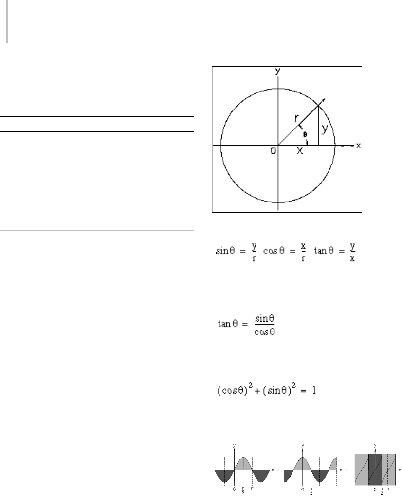
150 Chapter 4: Object Properties
Note: Thecompfunctionisanalternativetothe
n o t a t i o n V. x , V. y, V. z .
Special Animation Function
Function Meaning
noise(p,q,r) 3D noise: returns a randomly
generated position
Thearbitraryvaluesp,qandr,areusedasa
random-generation seed. You can reuse these
values to ensure that noise() returns the same
value.
Trigonometric Functions
This topic is a quick review for readers who need a
reminder about this area of mathematics. If you’re
familiar with trigonometry, you can skip this topic.
If you find this topic difficult to follow, you might
consult a more basic reference on mathematics.
Trigonometric functions are principally used to
model or describe:
• Therelationbetweenanglesinatriangle(hence
the name).
• Rotations about a circle, including locations
giveninpolarcoordinates.
•Cyclicalorperiodicvalues,suchassound
waves.
The three basic trigonometric functions are
derived from an angle rotating about a unit circle.
Trigonometric functions based on the unit circle
The tangent function is undefined for x=0.
Another way to define the target is:
Because XYR defines a right-angled triangle, the
relation between the sine and cosine is:
The graphs of the basic trigonometric functions
illustrate their cyclical nature.
Graphs of basic trigonometric functions
Thesineandcosinefunctionsyieldthesame
values, but the phase differs along the X axis by
∏/2: in other words, 90 degrees.
Theinversefunctionsforthetrigonometric
functions are the arc functions; the inverse only
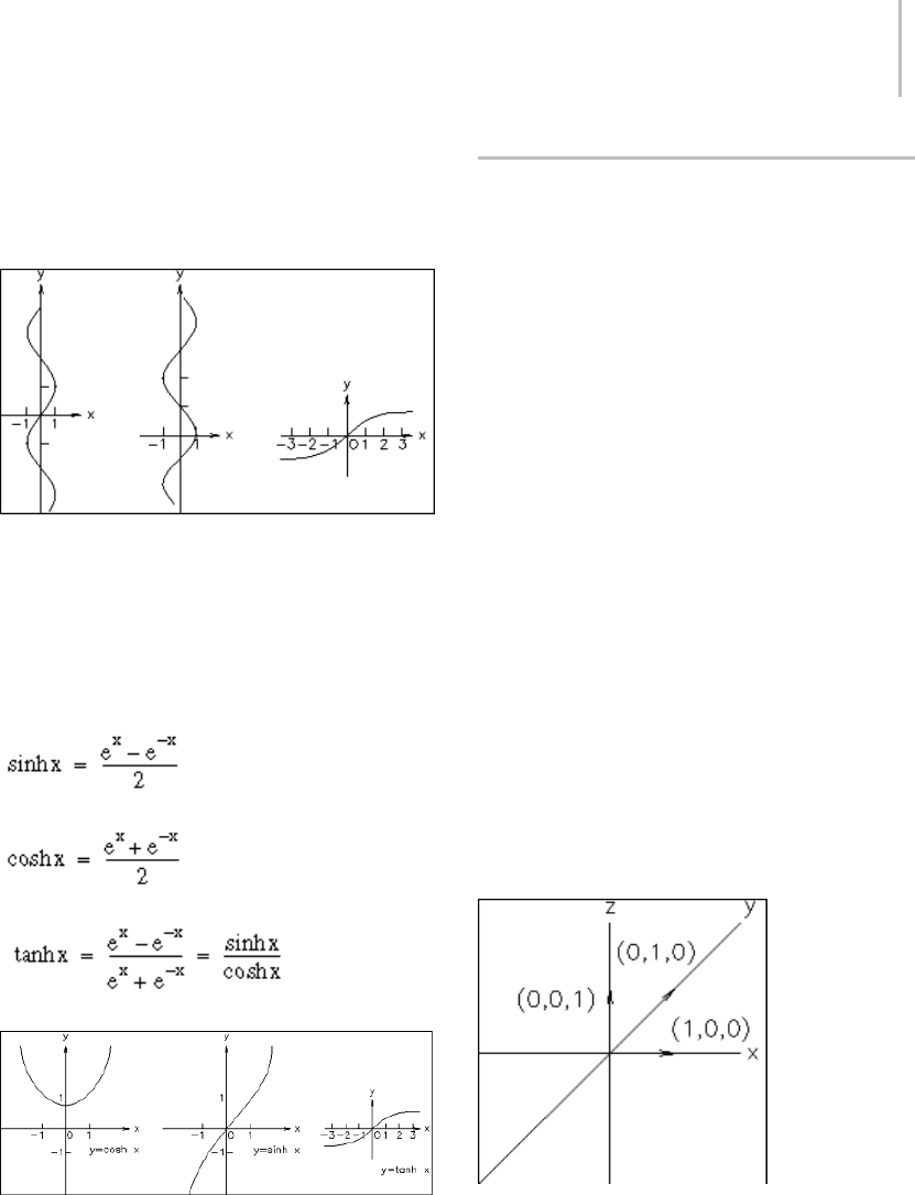
Vectors 151
appliestovaluesofxrestrictedby–∏/2 ≤X≤∏/2.
The graphs for these functions appear like the
basic trigonometric function graphs, but turned
on their sides.
Graphs of basic arc functions
The hyperbolic functions are based on the
exponential constant einstead of on circular
measurement. However, they behave similarly to
the trigonometric functions and are named for
them.Thebasichyperbolicfunctionsare:
Graphs of basic hyperbolic functions
Vectors
This topic is a quick review for readers who need
a reminder about vector arithmetic. If you’re
familiar with vectors and vector calculations,
you can skip this topic. If this topic is difficult to
follow, you might consult a more basic reference
on mathematics.
A vector expresses a length and a direction in
a particular space. The vector is expressed as a
point; for example, [5, 5, 7]. The length is the
distance from the origin to that point, and the
direction is similarly from the origin to (and
through) the point.
In3dsMax,vectorshavethreevaluesanddescribe
positions in three-dimensional space. They can
also represent percent scaling in X, Y, and Z; and
(more abstractly) describe locations in RGB color
space.
Unit Vectors and Basic Vectors
A unit vector has a length of one. Unit vectors are
often used to express direction only. The three
basic vectors are unit vectors that describe the
threeaxes(X,Y,andZ)of3Dspace.
Basic vectors and the XYZ axes
Adding and Subtracting Vectors
Adding two vectors creates a new vector that
combines the length and direction of the
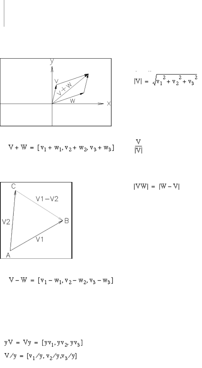
152 Chapter 4: Object Properties
original two. Vector addition is commutative:
V+W=W+V.
Adding two vectors
Subtracting two vectors gives the vector between
the two points.
Subtracting two vectors
Scalar Multiplication and Division
Multiplying a vector by a scalar changes the
vector’slength,asdoesdividingthevectorbya
scalar.
Vector Length and Direction
The length of a vector is obtained from the
Pythagorean theorem.
In 3ds Max expressions, the length() function
returnsthisvalue.
The direction of the vector is the vector divided
by its length; this gives you a unit vector with the
same direction.
The distance between two points is the length of
the vector between them.
Subtracting vectors to obtain a distance

The solid 3D objects in the scene, and the objects
used to create them, are known as geometry.
Usually, geometry comprises the subject of your
scene and the objects that you render.
This section describes the types of geometry you
can create using the Create panel (page 3–757).
Basics of Creating and Modifying Objects (page
1–153)
Geometric Primitives (page 1–169)
Shapes (page 1–262)
Compound Objects (page 1–313)
Dynamics Objects (page 1–395)
Systems (page 1–404)
See also
Surface Modeling (page 1–963)
Space Warps and Particle Systems (page 2–55)
Basics of Creating and
Modifying Objects
This section provides an introduction to
techniques for creating and modeling objects.
The Create panel (page 3–757) contains controls
for creating new objects, the first step in building
a scene. Despite the variety of object types, the
creation process is consistent for most objects.
The Modify panel (page 3–758) provides controls
to complete the modeling process. Any object
can be reworked, from its creation parameters
to its internal geometry. Both object-space and
world-space modifiers let you apply a wide range
of effects to objects in your scene. The modifier
stack allows editing of the modifier sequence.
In 3ds Max, you model basic parametric (page
3–989) objects into more complex ones by:
•Changingparameters (page 3–989)
• Applying modifiers
• Directly manipulating sub-object geometry
These topics will help you start creating and
modifying objects:
Using the Create Panel (page 1–154)
Creating an Object (page 1–157)
Creating Geometry

154 Chapter 5: Creating Geometry
Using the Modify Panel (page 1–499)
Using the Modifier Stack (page 1–502)
Editing the Stack (page 1–504)
Modifying at the Sub-Object Level (page 1–506)
Using the Stack at the Sub-Object Level (page
1–508)
Modifying Multiple Objects (page 1–509)
How Instanced Modifiers Work (page 1–511)
Transforms,Modifiers,andObjectDataFlow(page
1–494)
Varying the Parameters
Unlike physical objects, with a fixed shape and
size, you can change the creation parameters of
objects and shapes to dramatically alter topology.
Herearesomeexamplesofchangesyoucanmake:
• Turnaconeintoafour-sidedpyramidby
reducing the number of sides and turning the
Smooth option off.
• Slice any circular object as if it were a pie.
• Animate almost all creation parameters, and
interactively change their settings during
animation playback.
• Render splines directly at any assigned width.
• Break, detach, and divide wall segments.
• Change the number of risers without affecting
theoverallriseofthestairs.
Collapsing Primitives to Base Geometry
You can collapse a geometric primitive or shape to
oneofavarietyofbasegeometrictypesonceyou
no longer need access to its creation parameters.
For example, you can convert any standard
primitive to an editable mesh (page 1–996),editable
poly (page 1–1022),editable patch (page 1–968),or
NURBS (page 1–1091) object, and you can convert
a spline shape to an editable mesh, editable spline
(page 1–289), or NURBS object. The easiest way
to collapse an object is to select it, right-click it,
and choose a "Convert to" option from the quad
menu > Transform quadrant. This lets you use
explicit editing methods with the object, such as
transforming vertices. You can also use the Modify
panel to collapse a primitive.
Mapping Coordinates
MostGeometryobjectshaveanoptionfor
generating mapping coordinates. Objects need
these mapping coordinates if you plan to apply
amappedmaterialtothem. Mappedmaterials
include a wide range of rendered effects, from
2D bitmaps to reflections and refractions. See
Mapping Coordinates (page 2–1405) and Using
Maps to Enhance a Material (page 2–1403).If
mapping coordinates have already been applied to
an object, the check box for this feature is turned
on.
Using the Create Panel
TheCreatepanelprovidesthecontrolsforcreating
objects and adjusting their parameters.
ToaccesstheCreatepanel:
1. Click the Create tab in the command
panels (page 3–756).
By default, this panel is open when you start the
program. If the command panel isn’t visible,
choose it from the Customize Display right-click
menu (page 3–787).
2. Click an object type to display its Parameters
rollout.
The Creation Process
The actual creation of objects is accomplished
with a single click of the mouse, a drag, or some

Identifying the Basic Building Blocks 155
combination, depending on the object type. This
is the general sequence:
•Chooseanobjecttype.
• Clickordraginaviewporttocreateanobject
of approximate size and location.
• Adjust the object’s parameters and position,
either immediately or later.
See Creating an Object (page 1–157).
Create Panel Interface
Controls in the Create panel vary depending on
thekindofobjectyouarecreating. However,
certain controls are always present, and others are
shared by nearly all object types.
Category—Buttons at the top of the panel access
the seven main categories of objects. Geometry
is the default category.
Subcategory—A list lets you select subcategories.
Forexample,subcategoriesunderGeometry
include Standard Primitives, Extended Primitives,
Compound Objects, Particle Systems, Patch Grids,
NURBS Surfaces, and Dynamics Objects.
Each subcategory contains one or more object
types. If you’ve installed plug-in components for
additional object types, these might be grouped
as a single subcategory.
Object Type—A rollout contains labeled buttons
forcreatingobjectsinaparticularsubcategory,
plus the AutoGrid (page 2–7) check box.
Name and Color—TheNameshowsthe
automatically assigned name of the object. You can
edit this name or replace it with another. (Different
objects can have the same name, though this is not
recommended.) Clicking the square color swatch
brings up an Object Color dialog (page 1–159)
to change the color of the object as it appears in
viewports (the wireframe color).
Creation Method—This rollout provides a choice of
howyouusethemousetocreateanobject. For
example, you can use either the center (radius) or
edge (diameter) to define the size of a Circle shape.
A default creation method is always selected
when you access the tool. If you want to use an
alternate method, choose the option before you
create the object. The creation method has no
effect on a finished object; the options are for your
convenience during creation.
Keyboard Entry—This rollout lets you enter
creation parameters from the keyboard for
geometric primitive and shape objects.
Parameters—This rollout shows creation
parameters: the defining values for an object.
Some parameters can be preset, while others
are only for adjustment after an object has been
created.
Other rollouts—Additional rollouts can appear
on the Create panel, depending on what kind of
object you create.
Identifying the Basic Building
Blocks
On the Create panel, the categories for Geometry
and Shapes supply the "building blocks" to
combine and modify into more sophisticated
objects. These parametric (page 3–989) objects are
ready to use. By adjusting values and turning some
buttons on or off, you can create dozens of "new"
building blocks from the ones listed here.
You can choose these types from the sub-categories
listontheCreatepanel.
Geometry Types
Standard Primitives—Relatively simple 3D objects
such as Box, Sphere, and Cylinder, as well as

156 Chapter 5: Creating Geometry
Torus, Plane, Cone, GeoSphere, Tube, Teapot, and
Pyramid.
Extended Primitives—More complex 3D objects
such as Capsule, OilTank, Spindle, Hedra, Torus
Knot, and Prism.
Compound Objects—Compound objects include
Scatter, Connect, ShapeMerge, Booleans, Morph,
BlobMesh,Terrain,andLoft.Booleanscombine
the geometry of two objects using union,
intersection, and difference operations. Morphs
are animated objects that change one geometric
shape into other shapes over time. ShapeMerge
lets you embed a spline shape into a geometric
mesh. Loft (page 1–352) uses shapes as cross
sections along a path to produce a 3D object.
Particle Systems—Animated objects that simulate
spray, snow, blizzard, and similar collections of
small objects.
Patch Grids—Simple 2D surfaces ready for
modeling or repairing existing meshes.
NURBS Surfaces—Analytically generated surfaces
especially suited for modeling surfaces with
complicated curves.
AEC Extended—Elements useful for AEC design,
including Terrain, Foliage (plants and trees),
Railing, for creating custom railings, and Wall, for
the production of Wall objects.
Stairs—Four types of stairs: Spiral, L-Type,
Straight, and U-Type.
Doors—Parametric door styles include Pivot,
BiFold, and Sliding.
Windows—Parametric window styles include
Awning,Fixed,Projected,Casement,Pivoted,and
Sliding.
Note: Default materials are automatically applied
to Foliage, as well as to the following object types:
Railing, Stairs, Doors, and Windows.
Dynamics Objects—Objects designed for use in
dynamics simulations.
Shape Types
Splines—Common 2D shapes such as a Line,
Rectangle,Circle,Ellipse,Arc,Donut,NGon,and
Star. Text shapes support TrueType fonts. Section
creates a spline from the cross-section of an object.
Helix is a 3D shape.
NURBS Curves—A Point Curve and CV Curve
provide the starting points for complex surfaces.
See Introduction to NURBS Modeling (page
1–1078).
Extended Splines—More complex 2D shapes
including Walled Rectangle, Channel Spline,
AngleSpline,TeeSpline,andWideFlangeSpline.
Extended splines can be used in architectural and
similar applications.
Varying the Parameters
Unlike physical building blocks, with fixed shape
and size, you can change the parameters of objects
and shapes to dramatically alter topology. Here are
some examples of changes you can make:
• Turnaconeintoafour-sidedpyramidby
reducing the number of sides and turning the
Smooth option off.
• Slice any circular object as if it were a pie.
• Animate almost all creation parameters, and
interactively change their settings during
animation playback.
• Render splines directly at any assigned width.
• Break, detach, and divide wall segments.
• Change the number of risers without affecting
the overall rise of the stairs.
Collapsing Primitives to Base Geometry
You can collapse a building-block object to one
of a variety of base geometric types once you no
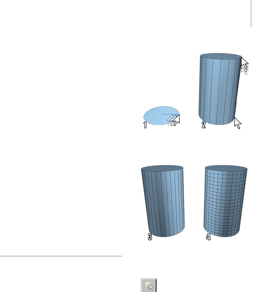
Creating an Object 157
longer need access to its creation parameters. For
example, you can convert any standard primitive
to an editable mesh (page 1–996),editable poly
(page 1–1022),editable patch (page 1–968),or
NURBS (page 1–1091) object, and you can convert
a spline shape to an editable mesh, editable spline
(page 1–289),orNURBSobject.Theeasiestway
to collapse an object is to select it, right-click it,
and choose a "Convert to" option from the quad
menu > Transform quadrant. This lets you use
explicit editing methods with the object, such as
transforming vertices. You can also use the Modify
panel to collapse a primitive.
Mapping Coordinates
MostGeometryobjectshaveanoptionfor
generating mapping coordinates. Objects need
these mapping coordinates if you plan to apply
a mapped material to them. Mapped materials
include a wide range of rendered effects, from
2D bitmaps to reflections and refractions. See
Mapping Coordinates (page 2–1405) and Using
Maps to Enhance a Material (page 2–1403).If
mapping coordinates have already been applied to
an object, the check box for this feature is turned
on.
Creating an Object
With some variations, the steps shown in the
following images apply to creating any type of
object on the Create panel. For specific examples,
see the Procedures section in any object’s topic.
1. Radius defined
2. Height defined
3. Sides increased
4. Height Segments increased
To choose an object category:
1. Click the Create tab to view the Create
panel.
2. Click one of the buttons at the top of the Create
panel. For example, Geometry.
3. Choose the subcategory Standard Primitives
from the list.
A number of buttons appear on the Object
Type rollout.

158 Chapter 5: Creating Geometry
To choose an object type:
• Clickthebuttonforthetypeofobjectyouwant
to create.
The button highlights, showing that it is
active. Four rollouts appear: Name and
Color, Creation Method, Keyboard Entry, and
Parameters.
To choose a creation method (optional):
You can accept the default method and skip this
step.
• Choose a method in the Creation Method
rollout.
To preset the creation parameters (optional):
Yo u c a n a d j u s t all creation parameters after you
create an object. Skip this step if you prefer.
• In the Parameters rollout, you can set
parameters before you create an object.
However, the values of parameters you set by
dragging the mouse (for example, the Radius
and Height of a cylinder) have no effect until
after you create the object.
To create the object:
1. Put the cursor at a point in any viewport where
you want to place the object, and hold the
mousebuttondown(donotreleasethebutton).
2. Dragthemousetodefinethefirstparameter
of the object; for example, the circular base of
acylinder.
3. Releasethemousebutton.Thefirstparameter
is set with this release.
4. Move up or down without touching the mouse
button. Thissetsthenextparameter;for
example, the height of a cylinder.
If you want to cancel: Until you complete the
next step, you can cancel the creation process
with a right-click.
5. Click when the second parameter has the value
you want, and so on.
The number of times you press or release the
mouse button depends on how many spatial
dimensions are required to define the object.
(For some kinds of objects, such as Line and
Bones, the number is open-ended.)
When the object is complete, it is in a selected state
and ready for adjustments.
To name the object (optional):
• Highlight the default object name in the Name
and Color rollout, and then enter a name. This
optionisavailableonlywhenasingleobjectis
selected.
Namingobjectsisagoodpracticefor
organizing your scenes. To name a set of
selected objects, see Named Selection Sets (page
1–67).
To change the object’s display color (optional):
• The color swatch next to the object name field
displays the selected object’s color and lets you
select a new one. The color is the one used to
display the object in viewports. Click the color
swatch to display the Object Color dialog (page
1–159).
You can also change object colors with Layers
(page 3–656).
To adjust the object’s parameters:
• You can change the creation parameters
immediately after you complete an object, while
it’s still selected. Or, you can select the object
later and adjust its creation parameters on the
Modify panel.
While making adjustments, you can use viewport
navigation controls like Zoom, Pan, and Arc
Rotate to change your view of the selected object.
You can also adjust the time slider.

Assigning Colors to Objects 159
To end the creation process:
While the object type button remains active, you
cancontinuecreatingobjectsofthesametype
until you do one of the following:
• Select an object other than the one you created
most recently.
•Transformanobject.
• Change to another command panel.
• Use commands other than viewport navigation
or the time slider.
After you end the creation process, changing
parametersontheCreatepanelwillhavenoeffect
on the object; you must go to the Modify panel
to adjust the object’s parameters. See Using the
Modify Panel (page 1–499).
Assigning Colors to Objects
3ds Max is a truecolor (page 3–1027) program.
When you pick a color in the program, you are
specifying 24 bits of color data, which provide a
range of over 16 million colors.
Object wireframe colors are used primarily as an
organizational tool. Object naming strategies,
named selection sets, and object wireframe color
strategies provide a rich set of tools for organizing
even the most complex scenes.
Yo u c a n u s e t w o d i a l o g s t o s p e c i f y c o l o r s :
•TheObject Color dialog (page 1–159) contains
twopresetpalettesofcolorsthatyouusetoset
an object’s wireframe color. This is also the
surface color you see in a rendered viewport.
The two color palettes are Default palette and
AutoCAD ACI palette.
•TheColor Selector (page 1–161) is a generic
dialog that you use to define any color in the
24-bit color range. For the purpose of defining
colors to assign to objects, it is available only
through the Default palette.
Note:
The Layers functionality lets you organize your
scene and can also be used for assigning object
colors. For more information, see Layer Manager
(page 3–656).
Object Color Dialog
Click the color swatch by the object’s name in any
command panel.
The Object Color dialog contains two preset
palettes of colors that you use to set an object’s
wireframecolor.Thisisalsothesurfacecoloryou
see in a shaded viewport.
Using Random Color Assignment
Bydefault,3dsMaxassignscolorsrandomlyas
objects are created. The colors are chosen from the
current palette in the Object Color dialog. If you
turn on Customize > Preferences > General panel
(page 3–815) >DefaulttoByLayerforNewNodes,
new objects are assigned the color set by the layer.
For individual objects, you can click the By
Layer/By Object button on the Object Color dialog
tochangethemethodusedtosettheobjectcolor.
Defining Custom Colors
When using the 3ds Max palette, the Object
Color dialog contains a palette of 16 custom color
swatches. You can define any color for each of the
16 color swatches by selecting a swatch from the
Custom Colors group, then clicking Add Custom
Colors.
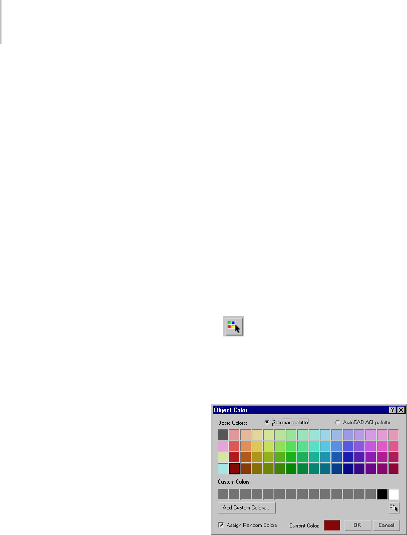
160 Chapter 5: Creating Geometry
Switching Between Palettes
You can alternate between two versions of the
Object Color dialog at any time by clicking the
appropriate Basic Colors toggle:
•3ds Max palette: Contains a fixed palette of 64
colors, plus a custom palette of 16 user-defined
custom colors.
Use this version when you want to work with a
smaller palette of colors or when you want to
define custom object wireframe colors.
•AutoCAD-compatible version: Contains a
fixed palette of 256 colors matching the colors
in the AutoCAD Color Index (ACI).
Use this version when you want to assign object
colors that match the AutoCAD Color Index.
Using ACI colors is useful if you plan to export
objects to AutoCAD and want to organize
them by object color, or when you want a wide
selection of colors to choose from.
Procedures
Tosetobjectcolor:
This is the general procedure for selecting object
color.
1. Select one or more objects.
2. On any command panel, click the color swatch
totherightoftheObjectNamefieldtodisplay
the Object Color dialog.
3. Click a color swatch from the palette, and then
click OK to apply the color to the selection.
To create objects of the same color:
• Choose the color you want to use and turn off
Assign Random Colors.
Newlycreatedobjectsappearinthiscoloruntil
you change the setting.
To define a custom color:
1. With the 3ds Max palette option active, click
one of the 16 custom color swatches.
2. Click Add Custom Colors to display the Color
Selector (page 1–161).
3. DefineacustomcolorandclickAddColor.
The custom color is stored in the selected color
swatch of the Object Color dialog and is set as
the current color.
To copy a custom color from an object in your scene
to one of your custom color swatches:
•DragtheActiveColorswatchuptooneofthe
custom color swatches.
The Active Color swatch is in the Object Color
dialog, to the left of the OK button.
To select objects by color:
•Click Select By Color. This displays the
Select Objects dialog (page 1–78).Allobjects
that have the same color as the current object
are highlighted in the list. Click Select.
Interface
Palette—Choose one of these:
•3ds Max palette—When chosen, the dialog
displays Basic Colors and Custom Colors
groups, and you have the option to add custom
colors.

Color Selector Dialog 161
•AutoCAD ACI palette—When chosen, the
AutoCAD ACI palette is shown. When you
click a color, its ACI# is displayed at the bottom
of the dialog.
Basic Colors—A set of 64 default colors, available
only when 3ds Max Palette is active.
Custom Colors—Displays 16 custom colors when
3dsMaxPaletteisactive. Tochooseacustom
color, click its swatch. To define or change a
custom color, click its swatch and then click Add
Custom Colors.
Add Custom Colors—Available only when 3ds Max
Palette is active. Clicking this option displays the
Color Selector (page 1–161),whichallowsyouto
modify the currently selected custom color. If
you click Add Custom Colors with a basic color
chosen, the dialog switches to the first custom
color before opening the Color Selector.
By Layer/By Object—Sets the object’s color by layer
or by object. If color is set by object, choosing a
new color on the Object Color dialog changes the
object’s wireframe color in viewports.
ACI#—Displays the ACI number for the selected
color. Available only when AutoCAD ACI palette
is active.
Select by Color—Displays a Select Objects
dialog (page 1–78) listing all objects that use the
current color as their wireframe color.
Note: This button is available only if at least one
object in the scene has the Current Color as its
wireframe color.
Assign Random Colors—When on, 3ds Max will
assign a random color to each object created.
When off, 3ds Max will assign the same color
to every object created until the color swatch is
changed. This setting affects wireframe colors only
when By Object is turned on as the color method.
Active/Current Color—Displays the active color (if
no object is selected) or current color. When you
click the color swatch, the Color Selector dialog
(page 1–161) opens, where you can mix a custom
color.
Color Selector Dialog
Any command panel > Name and Color fields > Click
color swatch. > Object Color dialog > Add Custom Colors
button or Current Color swatch.
Material Editor > Click any color swatch.
Select or add a light object. > Modify panel >
Intensity/Color/(Distribution/Attenuation) rollout > Click
colororFilterColorswatch.
Rendering menu > Environment > Environment and
Effects dialog > Click color swatch for Background, Tint,
and Ambient components of Global Lighting, and various
components of atmospheric effects such as Fire, Fog, and
so on..
The Color Selector dialog lets you specify a
custom color parameter in 3ds Max. You can work
simultaneously with three different color models
tohelpyouzeroinontheexactcoloryouwant.
Yo u c a n u s e t h e C o l o r S e l e c t o r t o s p e c i f y m a n y
color parameters, such as light colors, material
colors, background colors, and custom object
colors. (Another way to choose an object’s
viewportcoloristousethepredefinedcolorsin
the Object Color dialog (page 1–159).)
In most contexts, the Color Selector is modeless
(page 3–973); that is, it remains on the screen until
you dismiss it, and you can use other controls or
work in a viewport while the dialog is still visible.
In other contexts, the Color Selector is modal, and
youmustclosethedialogbeforeproceeding.
The dialog is divided into three different color
selection models. You can use the controls for any
modeltodefineacolor.Thethreecolormodels
are:
• Hue/Blackness/Whiteness (HBW)

162 Chapter 5: Creating Geometry
The most prominently displayed and intuitive
color model is the HBW model. This model
represents a natural, pigment-based way of
mixing color by starting with a pure color (hue)
and then making it darker by adding black, or
lighter by adding white.
The main feature of the HBW model is a large
square box displaying the color spectrum.
Across the top of this box you have the spectrum
of pure colors, or hue. Down the side of the box
you see increasing levels of blackness, making
the color dark as you approach the bottom.
To the right of the color spectrum box is the
Whiteness box, which controls the amount
ofwhiteinthecolor.Usehigherpositionsto
decrease the whiteness, or lower positions to
increase the whiteness.
• Red/Blue/Green (RGB)
The RGB model adjusts the mix of Red,
Green,andBluetodefineacolor.Thismodel
represents the way colored light can be mixed.
This is additive color mixing, as opposed to the
subtractive color mixing for paint and other
pigments. You can adjust values using the color
sliders, the numeric fields to their right (via the
keyboard),orthespinnerstotherightofthe
numeric fields.
• Hue/Saturation/Value (HSV)
The HSV color model adjusts Hue, Saturation,
and Value. Hue sets the color; Saturation
(labeled "Sat") sets the color’s purity; and Value
sets the color’s brightness, or intensity. You
can adjust values using the color sliders, the
numeric fields to their right (via the keyboard),
or the spinners to the right of the numeric fields.
As you adjust the controls of one color model, the
controls of the other two models change to match.
The color defined by the color model is displayed
in the right half of the Color Output box. The
original color, before you began making changes,
is displayed in the left half.
Procedures
To display the Color Selector:
1. Click the color swatch of a color parameter
such as the color of a light or of a material
component.
Note: Theobjectcolordisplayednexttoan
object’s name on command panels uses the
Object Color dialog (page 1–159).OntheObject
Color dialog, clicking the Active (or Current)
Color swatch or the Add Custom Colors button
displays a Color Selector.
2. Make a color selection and click OK or Cancel,
or the Close button (X).
If using the Add Color version of the Color
Selector,besuretoclickAddColorfirst.
3. To revert to the original color, click Reset.
To choose the hue of a color, do one of the following:
• Click anywhere in the Hue rainbow (the large,
multicolored square).
• Drag the Hue slider at the top of the rainbow.
•DragtheRed,Green,andBluesliders.
•DragtheHueslider.
• Use the Red, Green, Blue, or Hue spinners.
To make a color lighter, do one of the following:
• Drag the vertical Whiteness slider (at the right
of the Hue rainbow) downward.
• Drag the vertical Blackness slider (at the left of
the Hue rainbow) upward.
• Drag the Saturation (Sat.) slider to the left.
• Use the Saturation spinner to decrease
saturation.
• Drag the Value slider to the right.
• Use the Value spinner to increase the value.
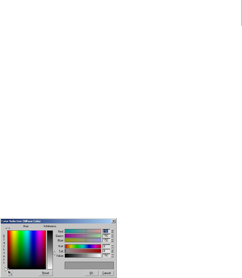
Color Selector Dialog 163
To make a color darker, do one of the following:
• Drag the vertical Whiteness slider (at the right
of the Hue rainbow) upward.
• Drag the vertical Blackness slider (at the left of
the Hue rainbow) downward.
• Drag the Saturation (Sat.) slider to the right.
• Use the Saturation spinner to increase
saturation.
• Drag the Value slider to the left.
• Use the Value spinner to decrease the value.
To return to the original color:
•ClickReset.
The new color is replaced by the original color,
and all parameter values are reset.
To dismiss the Color Selector, do one of the following:
•ClickOKorCancel.
• Click the dialog’s Close (X) button.
Interface
Hue—Define a pure color by dragging the hue
pointer across the top of the box.
Blackness—Drag the blackness pointer down the
side to darken the pure color by adding black. You
can also click or drag inside the box to change hue
and blackness at the same time.
Whiteness—Theverticalbartotherightcontrols
the amount of whiteness. The color set by the hue
and blackness pointers is displayed at the top of
thebarandpurewhiteatthebottom.Dragthe
whiteness pointer down to lighten the color by
adding white.
Red, Green, and Blue—Whenared,green,orblue
slider is all the way to the left, its numeric field
contains 0; none of the color controlled by that
slider is used. If the slider is all the way to the right,
the field reads 255; the maximum amount of that
color is being used.
The spinners to the right of each slider are another
way of setting the red, blue, or green component.
The colors in the sliders change to show an
approximation of what the color result will be
if you move the slider to that location, without
adjusting any other color parameter.
Hue—Sets the pure color. Locating the slider all
thewaytotheleftgivesyoupurered. Asyou
drag the slider to the right you move through
the spectrum of Red, Yellow, Green, Cyan, Blue,
Magenta, and back to Red again. Hue is more
accurately represented as a color wheel rather than
a linear slider. That is why the Hue slider is red at
both ends. Think of the hue range from 0 to 255 as
being points on a circle where the numbers 0 and
255 are right next to each other.
Saturation ("Sat")—Sets the purity or strength of
the color. A weak color, with a saturation near 0,
is dull and gray. A strong color, with a saturation
near 255 is very bright and pure.
Value—Sets the lightness or darkness of a color.
Low values darken the color toward black. High
values lighten the color toward white. A value in
the middle, at a setting of 127, gives you the color
definedonlybyhueandsaturation.
Color Output—This pair of color swatches, below
the Value slider, lets you compare the new color,
shownontheright,totheoriginalcolor,shown
on the left.
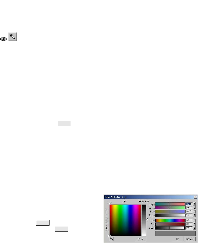
164 Chapter 5: Creating Geometry
Sample Screen Color—Lets you pick a
new color from anywhere on the screen. After
clicking this button, the mouse cursor changes to
the eyedropper icon shown on the button. While
this cursor appears, use any of these methods:
• Click anywhere on the screen to replace the
current color with the color of the pixel under
the lower-right corner of the cursor.
• Drag to continually update the current color
with the color of the pixel under the lower-right
corner of the cursor. This makes it easier to
make sure you get the right color if the desired
color area is small (say, a one-pixel-thick line).
•Atanytime,pressandhold
Shift to average
the current color with colors the cursor moves
over.
Instead of replacing the current color with
the new sampled color, smoothed sampling
gradually mixes the sampled color with
the current color, giving a smoothed color
transition during sampling. This is useful for
sampling noisy areas, where the variations
in colors are accumulated to provide a
representative general color.
Unlike the other methods, releasing the left
mouse button only does not exit the sampler
mode; you can move the mouse elsewhere
(without sampling) and then start dragging
again to continue smoothed sampling in other
areas. Releasing Shift only returns to regular
sampling. Releasing both Shift and the
left mouse button exits the sampler mode,
returning the mouse cursor and behavior to
normal.
Sampling can occur under any conditions
anywhere within any windows that belong to the
current instance of 3ds Max. To sample anywhere
outside of 3ds Max (for example, the desktop),
drag the mouse from within one of these 3ds Max
windows.
The color sampler tool compensates for any
gamma applied to the color selector using the
Customize > Preferences > Gamma And LUT
(page 3–824) > Affect Color Selectors option. This
means that the color-corrected, displayed sampled
visualcolorinthecolorselectoralwaysmatches
the on-screen visual color of the sampled location.
If the gamma of the color selector does not match
the gamma of the sampled location, the true color
values (RGB/HSV) of the sampled color will differ
from the true color values of the sampled location.
This behavior applies to both regular gamma and
Autodesk LUT gamma correction modes.
Reset—Clicktorestorecolorsettingstothe
original color.
OK—Accepts any changes and closes the dialog.
Cancel—Restores the original color and closes the
dialog.
Color Selector for mental ray Materials and
Shaders
When you click a color swatch in the interface for
amental ray material (page 2–1543) or mental ray
shader (page 2–1710),oraDirectX material (page
2–1613),youseeavariantoftheColorSelector.
This dialog differs from the standard Color
Selector in two ways:
• TheRGBandHSVvaluesappearasnormalized
values between 0.0 and 1.0, rather than as 8-bit
integers (0–255).
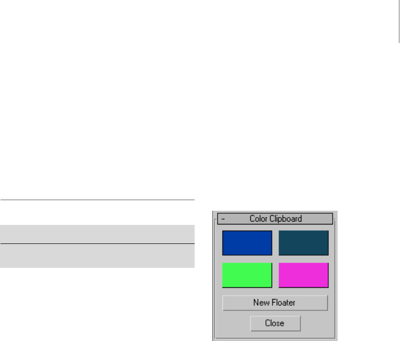
Color Clipboard Utility 165
• An additional Alpha slider and spinner let you
explicitly set the alpha value for this color. This
value is also normalized, where 0.0 represents
fully transparent, and 1.0 represents fully
opaque.
This version of the Color Selector also appears
when you use the DirectX 9 Shader material (page
2–1613) and the mental ray renderer’s Sampling
Quality rollout (page 3–98).
Color Clipboard Utility
Tools menu > Color Clipboard
Utilities panel > Utilities rollout > More button > Utilities
dialog > Color Clipboard button
The Color Clipboard utility stores color swatches
for copying from one map or material to another.
For example, if in the Material Editor, you want
to copy a color from a swatch in one level of a
material to a swatch in another level (or from
another material), there would be no way to do
it with drag and drop. This is because you can’t
have two materials/maps visible at the same time.
However, you can drag the color from one material
to the color clipboard, switch to the other material,
and then drag the color from the clipboard to the
swatch in the new material.
You can save and load color clipboard files. The
saved file, which is given a .ccb (color clip board)
extension, is an ASCII file that contains a palette
description. The first 12 lines of the file consist
of three RGB numbers, so you can easily edit or
create your own clipboard files. This file format is
also used by the VertexPaint modifier (page 1–936).
Procedure
To copy a color from a swatch to the color clipboard:
1. On the Utilities panel, click Color Clipboard.
2. Open the Material Editor.
3. Select a color from any swatch in a material.
4. Drag the color to a swatch in the color
clipboard.
5. A dialog appears asking if you want to copy or
swap the material. Choose copy to replace the
swatch in the color clipboard with the swatch
from the material you selected. Choose swap
to swap colors on the Color Clipboard swatch
and material swatch.
Interface
Color swatches—Click a color swatch to edit its
value with the Color Selector.
Note: The Color Selector invoked by this utility
uses decimal numbers in the range 0.0 to 1.0,
instead of integers in the range 0 to 255 as with
other color-selection dialogs in 3ds Max.
New Floater—Displays a floating clipboard with 12
slots, plus buttons for opening and saving color
clipboardfiles.Youcanopenupasmanyofthese
floaters as you want and you can minimize them.
If you exit the Utilities panel or select the Close
button to exit the Color Clipboard utility, any
visible floaters remain open. When you close a
floater, any changed values are lost.
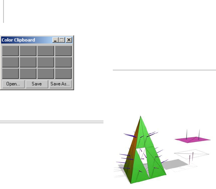
166 Chapter 5: Creating Geometry
Close—Exits the Clipboard utility.
Adjusting Normals and
Smoothing
In general, you adjust normals and smoothing to
prepare objects for rendering.
Anormal (page 3–980) is a unit vector that defines
which way a face or vertex is pointing. The
directioninwhichthenormalpointsrepresents
thefront,oroutersurfaceofthefaceorvertex,
which is the side of the surface that is normally
displayed and rendered.
You can manually flip or unify face normals to fix
surfaceerrorscausedbymodelingoperationsor
byimportingmeshesfromotherprograms.
Smoothing groups define whether a surface is
rendered with sharp edges or smooth surfaces.
Smoothinggroupsarenumbersassignedtothe
faces of an object. Each face can carry any number
of smoothing groups up to the maximum of 32.
If two faces share an edge and share the same
smoothing group, they render as a smooth surface.
Iftheydon’tsharethesamesmoothinggroup,the
edge between them renders as a corner. You can
manually change or animate smoothing group
assignment. Changing smoothing groups does not
alter geometry in any way; it only changes the way
facesandedgesareshaded.
See also
Viewing and Changing Normals (page 1–166)
Viewing and Changing Smoothing (page 1–167)
Viewing and Changing Normals
When you create an object, normals (page 3–980)
are generated automatically. Usually objects render
correctly using these default normals. Sometimes,
however, you need to adjust the normals.
Left: The normals shown as spikes indicate the orientation of
faces on the pyramid.
Right: Flipping normals can make faces invisible (or visible) in
shaded viewports and renderings.
Undesired normals can appear in these objects:
• Meshes imported from other applications.
• Geometry generated by complex operations
such as Boolean objects, lathe objects, or lofts.
Normals are used to define which side of a face or
vertex is considered the "out" side. The out side of
a face or vertex is the side that gets rendered unless
you are using two-sided materials, or turn on the
Force2-SidedoptionintheRenderScenedialog
>Commonpanel>Common Parameters rollout
(page 3–27).
Do one of the following to view or change face
normals:
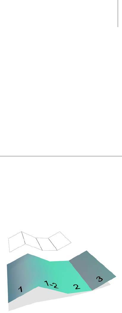
Viewing and Changing Smoothing 167
•ApplyaNormal modifier (page 1–746).IfaFace
sub-object selection is active, Normal applies
to the selected faces. If no faces are selected,
Normal applies to the entire object.
•ApplyanEdit Mesh modifier (page 1–634),
enable Face, Polygon or Element sub-object
mode, and then use the features on the Surface
Properties rollout to change the directions in
which normals point.
•Converttheobjecttoaneditable mesh (page
1–996), enable Face, Polygon or Element
sub-object mode, and use the features on the
Surface Properties rollout
Viewing Normals
The easiest way to view normals is to look at an
object in a shaded viewport. In this case, you are
not viewing the normal arrows themselves, but
rather their effects on the shaded surface. If the
object looks as if it is inside-out, or has holes, then
some of the normals might be pointing in the
wrong direction.
You can display the normal vectors for selected
faces or vertices by enabling Show Normals on the
Selection rollout of an editable mesh object or the
Edit Mesh modifier.
Unifying Normals
Use Unify Normals to make normals point in a
consistent direction. If an object has normals that
are inconsistent (some point outward and others
inward) the object will appear to have holes in its
surface.
Unify Normals is found on the Surface Properties
rollout and on the Normal modifier.
If you are animating the creation of a complex
object such as a nested Boolean or a loft, and you
think the operation might result in inconsistent
faces, apply a Normal modifier (page 1–746) to the
result, and turn on Unify Normals.
Flipping Normals
Use Flip Normals to reverse the direction of all
selected faces. Flipping the normals of an object
turns it inside-out.
Flip Normals is found on the Surface Properties
rollout and on the Normal modifier.
The Lathe modifier (page 1–707) sometimes creates
an object with normals pointing inward. Use the
Flip Normals check box on the Lathe modifier’s
Parametersrollouttoadjustthenormals.Youcan
also use the Normal modifier with both Unify and
Flip turned on to fix inside-out lathed objects.
Viewing and Changing Smoothing
Smoothingblendstheshadingattheedges
between faces to produce the appearance of a
smooth, curved surface. You can control how
smoothing is applied to a surface so your objects
canhavebothsmoothsurfacesandsharpfaceted
edges at the appropriate places.
The face labeled “1-2” shares smoothing groups with adjacent
faces, so the edges between them are smoothed over in
renderings.
The face labeled “3” does not share a smoothing group, so its
edge is visible in renderings.
Smoothing does not affect geometry. It affects only
the way geometry is colored when rendered.

168 Chapter 5: Creating Geometry
Smoothing is controlled by smoothing groups,
which are numbered groups ranging from 1 to 32.
Each face is assigned to one or more smoothing
groups. When a scene is rendered, the renderer
checks each adjacent pair of faces to see if they
share a smoothing group, and renders the object
as follows:
• If faces have no smoothing groups in common,
thefacesarerenderedwithasharpedge
between them.
• If faces have at least one smoothing group
incommon,theedgebetweenthefacesis
“smoothed”, meaning it is shaded in such a
way that the area where the faces meet appears
smooth.
Becauseeachfacehasthreeedges,onlythree
smoothing groups can be in effect for any face.
Extra smoothing groups assigned to a face are
ignored.
Do one of the following to view or change
smoothing group assignments:
• Turn on the Smooth check box on the
Parameters rollout of a parametric object to set
default smoothing for the object.
• TurnontheAutoSmoothcheckboxonthe
Rendering rollout of a spline shape to turn on
smoothing.
•ApplyaSmooth modifier (page 1–828).IfaFace
sub-object selection is active, Smooth applies
to the selected faces. If no faces are selected,
Smooth applies to the entire object.
•ApplyanEdit Mesh modifier (page 1–634),
enable Face (or Polygon or Element) sub-object
mode,thenusethefeaturesontheSurface
Properties rollout.
•Converttheobjecttoaneditable mesh (page
1–996),enableFace(orPolygonorElement)
sub-object mode, then use the features on the
Surface Properties rollout.
Viewing Smoothing Groups
The easiest way to view smoothing is to look at an
object in a shaded viewport. In this case, you are
not viewing the smoothing groups themselves but
rather their effects on the shaded surface.
You can see the smoothing group numbers for
selected faces of an editable mesh object or the Edit
Mesh modifier by looking at the Smoothing Group
buttonsontheSurfacePropertiesrollout,orof
an editable poly object on the Polygon Properties
rollout.
SmoothingGroupbuttonsappearasfollows:
• Group numbers not used by any face in the
selection, appear normal.
•Groupnumbersusedbyallfacesinthe
selection, appear selected.
•Groupnumbersusedbysome,butnotall,faces
in the selection, appear blank.
Automatically Smoothing an Object
Click Auto Smooth to assign smoothing
automatically. You set a Threshold angle to
determine whether to smooth adjacent faces.
• If the angle between face normals is less than or
equal to the threshold, the faces are assigned to
a common smoothing group.
• If the angle between face normals is greater
than the threshold, the faces are assigned to
separate groups.
Auto Smooth is found on the Surface Properties
rollout and on the Smooth modifier.
Manually Applying Smoothing Groups
You manually assign smoothing groups to a
selection of faces by clicking Smoothing Group
buttonsontheSurfacePropertiesrolloutorthe
Smooth modifier. The smoothing group of each
button you click is assigned to the selection.

Geometric Primitives 169
Selecting Faces by Smoothing Group
You can also select faces according to the assigned
smoothing groups. Click Select By SG on the
SurfacePropertiesrollout(editablemesh)or
Polygon Properties rollout (editable poly) and then
click the smoothing group of the faces to select.
This is a convenient way to examine smoothing
groups on an object someone else created.
Creating Geometric
Primitives
Geometric primitives are basic shapes that
3ds Max provides as parametric objects (page
3–989). Primitives are divided into two categories:
Standard Primitives (page 1–170)
Extended Primitives (page 1–186)
See also
Basics of Creating and Modifying Objects (page
1–153)
Creating an Object (page 1–157)
Creating Primitives from the Keyboard (page 1–169)
Creating Primitives from the
Keyboard
Create panel > Geometry > Standard or Extended
Primitives > Keyboard Entry rollout
You can create most geometric primitives from
your keyboard using the Keyboard Entry rollout.
In a single operation, you define both the initial
size of an object and its three-dimensional
position. The object’s name, color, and default
material (optional), are automatically assigned.
See Object Name and Wireframe Color (page
3–757).
This method is generally the same for all
primitives; differences occur in the type and
number of parameters. The Hedra primitive, a
complex and highly visual family of objects, is
unsuited to this method and has no keyboard
entry.
Procedures
To open the Keyboard Entry rollout:
1. On the Create panel for Standard or Extended
Primitives, click any of the primitive Object
Typerolloutbuttons,exceptHedraor
RingWave.
2. Click the Keyboard Entry rollout to open it.
This rollout is closed by default.
Note: ThebuttonsontheCreationMethod
rollout have no effect on keyboard entry.
To create a primitive from the keyboard:
1. On the Keyboard Entry rollout, select a numeric
field with the mouse and then enter a number.
2. Press Tab to move to the next field. You do
not have to press Enter after entering a value.
Press Shift+Tab to reverse direction.
3. When you have all fields set, press Ta b to move
thefocustotheCreatebutton.Press Enter .
4. Theobjectappearsintheactiveviewport.
Once created, a new primitive is unaffected by the
numeric fields in the Keyboard Entry rollout. You
can adjust parameter values on the Parameters
rollout, either immediately after creation or on the
Modify panel.
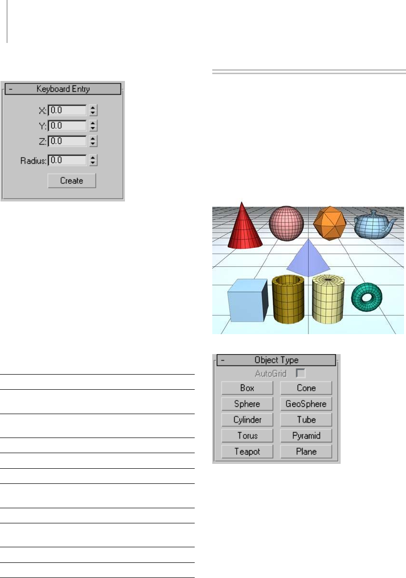
170 Chapter 5: Creating Geometry
Interface
The Keyboard Entry rollout contains a common
set of position fields, labeled X, Y, and Z. The
numbers you enter are offsets along the axes of the
active construction plane; either the home grid or
a grid object. Plus and minus values correspond
to positive and negative directions for these axes.
Defaults=0,0,0; the center of the active grid.
The location set by X,Y is equivalent to the first
mouse-downpositioninthestandardmethodof
creating objects.
Each standard primitive has the following
parameters on its Keyboard Entry rollout.
Primitive Parameters XYZ point
Box Length, Width,
Height
Center of base
Cone Radius 1, Radius 2,
Height
Center of base
Sphere Radius Center
GeoSphere Radius Center
Cylinder Radius, Height Center of base
Tube Radius 1, Radius 2,
Height
Center of base
Torus Radius 1, Radius 2 Center
Pyramid Width, Depth,
Height
Center of base
Teapot Radius Center of base
Plane Length, Width Center
Standard Primitives
Geometric primitives are familiar as objects in
the real world such as beach balls, pipes, boxes,
doughnuts, and ice cream cones. In 3ds Max,
you can model many such objects using a single
primitive. You can also combine primitives into
more complex objects, and further refine them
with modifiers.
A collection of standard primitive objects
3ds Max includes a set of 10 basic primitives. You
can easily create the primitives with the mouse in
the viewport, and most can be generated from the
keyboard as well.
These primitives are listed in the Object Type
rollout and on the Create menu:
Box Primitive (page 1–171)
Cone Primitive (page 1–172)
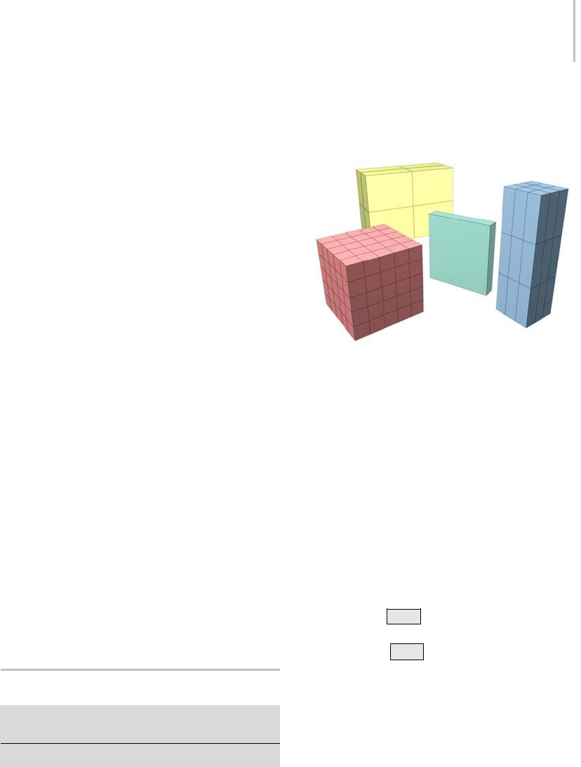
Box Primitive 171
Sphere Primitive (page 1–174)
GeoSphere Primitive (page 1–176)
Cylinder Primitive (page 1–177)
Tube Primitive (page 1–179)
Torus Primitive (page 1–180)
Pyramid Primitive (page 1–182)
Teapot Primitive (page 1–183)
Plane Primitive (page 1–185)
Also available from the Object Type rollout is the
AutoGrid option (page 2–7).
You can convert standard primitive objects to
editable mesh objects (page 1–996),editable poly
objects (page 1–1022),andNURBS surfaces. (page
1–1116) You can also convert primitives to patch
objects; see the path annotation at Editable Patch
(page 1–968) (the information at the start of the
topic that tells you how to create this type of
object).
Allprimitiveshavenameandcolorcontrols,and
allow you to enter initial values from the keyboard.
See these topics:
Object Name and Wireframe Color (page 3–757)
Creating Primitives from the Keyboard (page 1–169)
Theremainingrolloutsarecoveredinthetopicfor
each primitive.
Box Primitive
Create panel > Geometry button > Standard Primitives >
Object Type rollout > Box button
Create menu > Standard Primitives > Box
Box produces the simplest of the primitives. Cube
is the only variation of Box. However, you can vary
thescaleandproportiontomakemanydifferent
kinds of rectangular objects, from large, flat panels
and slabs to tall columns and small blocks.
Examples of boxes
Procedures
To create a box:
1. On the Object Type rollout, click Box.
2. In any viewport, drag to define a rectangular
base, then release to set length and width.
3. Move the mouse up or down to define the
height.
4. Click to set the finished height and create the
box.
To create a box with a square base:
•HolddownCtrl as you drag the base of the
box. This keeps length and width the same.
Holding the Ctrl key has no effect on height.
To create a cube:
1. On the Creation Method rollout, choose Cube.
2. In any viewport, drag to define the size of the
cube.
3. As you drag, a cube emerges with the pivot
pointatthecenterofitsbase.
4. Release to set the dimensions of all sides.
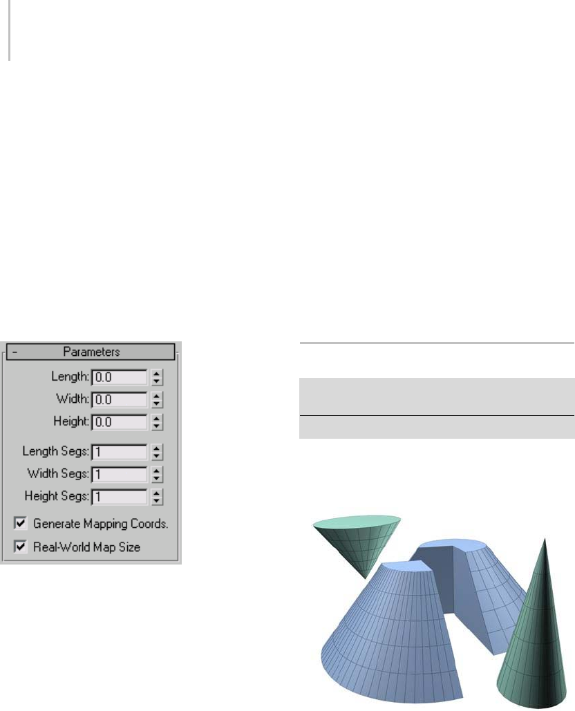
172 Chapter 5: Creating Geometry
Interface
Creation Method rollout
Cube—Forces length, width, and height to be equal.
Creating a cube is a one-step operation. Starting at
the center of the cube, drag in a viewport to set all
three dimensions simultaneously. You can change
acube’sindividualdimensionsintheParameters
rollout.
Box—Creates a standard box primitive from one
corner to the diagonally opposite corner, with
different settings for length, width, and height.
Parameters rollout
Thedefaultsproduceaboxwithonesegmenton
each side.
Length, Width, Height—Sets the length, width, and
height of the Box object. These fields also act
as readouts while you drag the sides of the box.
Default=0,0,0.
Length, Width, Height Segments—Sets the number
of divisions along each axis of the object. Can be
set before or after creation. By default, each side of
theboxisasinglesegment.Whenyouresetthese
values, the new values become the default during a
session. Default=1,1,1.
Tip: Increase the Segments settings to give objects
extra resolution for being affected by modifiers.
For example, if you’re going to bend (page 1–560) a
box on the Z axis, you might want to set its Height
Segments parameter to 4 or more.
Generate Mapping Coords—Generates coordinates
for applying mapped materials to the box.
Default=on.
Real-World Map Size—Controls the scaling method
used for texture mapped materials that are applied
totheobject. Thescalingvaluesarecontrolled
by the Use Real-World Scale settings found in
the applied material’s Coordinates rollout (page
2–1625).Default=off.
Cone Primitive
Create panel > Geometry button > Standard Primitives
>ObjectTyperollout>Conebutton
Create menu > Standard Primitives > Cone
TheConebuttonontheCreationcommandpanel
lets you produce round cones, either upright or
inverted.
Examples of cones
Procedure
To create a cone:
1. OntheCreatemenuchooseStandard
Primitives > Cone.
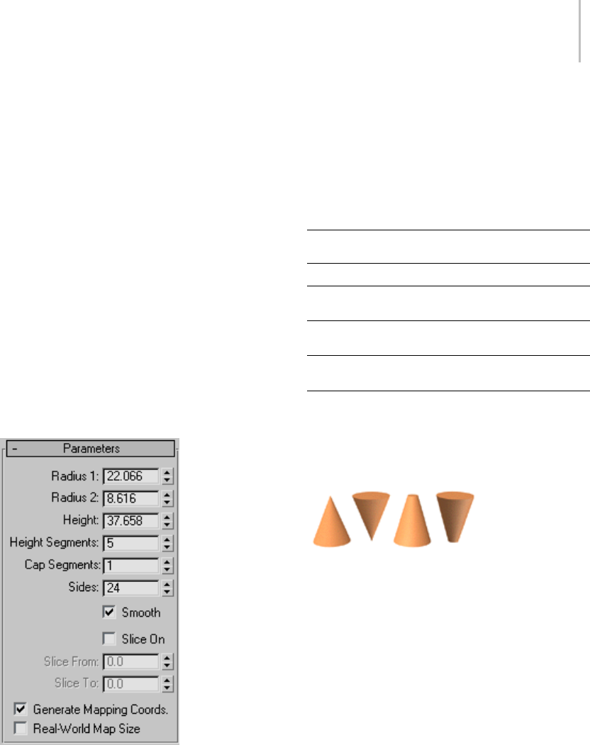
Cone Primitive 173
2. In any viewport, drag to define a radius for the
base of the cone, then release to set it.
3. Move to up or down to define a height, either
positive or negative, then click to set it.
4. Move to define a radius for the other end of the
cone. Decrease this radius to 0 for a pointed
cone.
5. Click to set the second radius and create the
cone.
Interface
Creation Method rollout
Edge—Draws a cone from edge to edge. You can
change the center location by moving the mouse.
Center—Draws a cone from the center out.
Parameters rollout
The defaults produce a smooth, round cone of 24
sides with five height segments, one cap segment,
and the pivot point at the center of the base. For
improved rendering of smoothly shaded cones,
particularly those with pointed tips, increase the
number of height segments.
Radius 1, Radius 2—Setthefirstandsecondradii
for the cone. The minimum value for both is 0.0.
If you enter a negative value, the software converts
it to 0.0. You can combine these settings to create
pointedandflat-toppedcones,uprightorinverted.
The following combinations assume a positive
height:
Radius Combinations Effect
Radius 2 is 0 Creates a pointed cone
Radius 1 is 0 Creates an inverted pointed
cone
Radius 1 is larger than
Radius 2
Creates a flat-topped cone
Radius 2 is larger than
Radius 1
Creates an inverted
flat-topped cone
IfRadius1and2arethesame,acylinderis
created. If the two radius settings are close in size,
the effect is similar to applying a Taper modifier
to a cylinder.
Effect of Radius settings
Height—Sets dimension along the central axis.
Negative values create the cone below the
construction plane.
Height Segments—Sets the number of divisions
along the cone’s major axis.
Cap Segments—Sets the number of concentric
divisions around the center of the cone’s top and
bottom.
Sides—Sets the number of sides around the cone.
Higher numbers shade and render as true circles
with Smooth selected. Lower numbers create
regular polygonal objects with Smooth off.
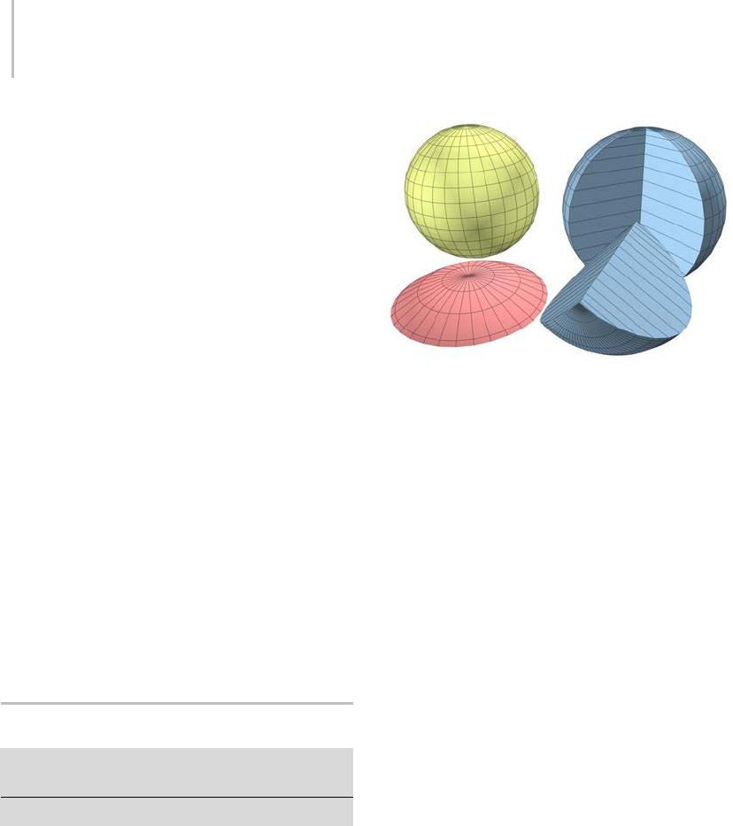
174 Chapter 5: Creating Geometry
Smooth—Blendsthefacesofthecone,creatinga
smooth appearance in rendered views.
Slice On—Enables the Slice function. Default=off.
WhenyoucreateasliceandthenturnoffSliceOn,
thecompleteconereappears. Youcanusethis
check box to switch between the two topologies.
Slice From, Slice To—Sets the number of degrees
around the local Z axis from a zero point at the
local X axis.
For both settings, positive values move the end of
the slice counterclockwise; negative values move it
clockwise. Either setting can be made first. When
the ends meet, the whole cone reappears.
Generate Mapping Coords—Generates coordinates
for applying mapped materials to the cone.
Default=on.
Real-World Map Size—Controls the scaling method
used for texture mapped materials that are applied
totheobject. Thescalingvaluesarecontrolled
by the Use Real-World Scale settings found in
the applied material’s Coordinates rollout (page
2–1625). Default=off.
Sphere Primitive
Create panel > Geometry button > Standard Primitives >
Object Type rollout > Sphere button
Create menu > Standard Primitives > Sphere
Sphere produces a full sphere, or a hemisphere or
other portion of a sphere. You can also "slice" a
sphere about its vertical axis.
Examples of spheres
Procedures
To create a sphere:
1. OntheCreatemenuchooseStandard
Primitives > Sphere.
2. In any viewport, drag to define a radius.
As you drag, a sphere emerges with its center
at the pivot point.
3. Releasethemousetosettheradiusandcreate
the sphere.
To create a hemisphere:
You can reverse the order of the following steps,
if you like.
1. Create a sphere of desired radius.
2. Type 0.5 in the Hemisphere field.
Thesphereisreducedtoexactlytheupperhalf,
a hemisphere. If you use the spinner, the sphere
changes in size.
Interface
Creation Method rollout
Edge—Draws a sphere from edge to edge. You can
change the center location by moving the mouse.
Center—Draws a sphere from the center out.

Sphere Primitive 175
Parameters rollout
The defaults produce a smooth sphere of 32
segments with the pivot point at its center.
Radius—Specifies the radius of the sphere.
Segments—Sets the number of polygonal divisions
for the sphere.
Smooth—Blends the faces of the sphere, creating a
smooth appearance in rendered views.
Hemisphere—Increasing values progressively will
"cut off" the sphere, starting at the base, to create a
partial sphere. Values range from 0.0 to 1.0. The
default is 0.0, producing a full sphere. A setting of
0.5 produces a hemisphere, and 1.0 reduces the
sphere to nothing. Default=0.0.
Chop and Squash toggle creation options for
Hemisphere.
Chop—Reduces the number of vertices and faces
inthesphereby"chopping"themoutasthe
hemisphere is cut off. Default=on.
Squash—Maintains the number of vertices and
faces in the original sphere, "squashing" the
geometry into a smaller and smaller volume
toward the top of the sphere.
Effects of Chop and Squash during hemisphere creation
Slice On—Uses the From and To angles to create
a partial sphere. The effect is similar to lathing a
semicircular shape fewer than 360 degrees.
Slice From—Sets the start angle.
Slice To—Sets the stop angle.
For both settings, positive values move the end of
the slice counterclockwise; negative values move it
clockwise. Either setting can be made first. When
the ends meet, the whole sphere reappears.
Smoothing groups are assigned to sliced spheres
asfollows: Thesurfaceofthesphereisalways
assigned group 1; the bottom, when Smooth is on,
gets group 2. Facing the pie-slice surfaces, the cut
ontheleftgetsgroup3,andthecutontheright
gets group 4.
Material IDs are assigned to sliced spheres as
follows: The bottom is 1 (when Hemisphere is
greater than 0.0), the surface is 2, and the slice
surfaces are 3 and 4.
Base To Pivot—Movesasphereupwardalongits
local Z axis so the pivot point is at its base. When
off, the pivot point is on the construction plane at
the center of the sphere. Default=off.
Tur n ing on B ase To Pivot lets you pla ce sph ere s so
they rest on the construction plane, like pool balls
on a table. It also lets you animate a hemisphere so
it appears to grow out of the construction plane
or sink into it.
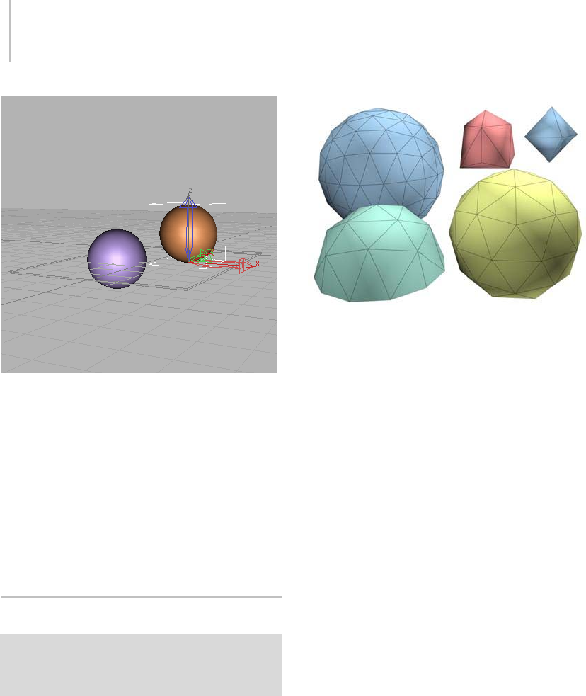
176 Chapter 5: Creating Geometry
Effect of using Base To Pivot setting
Generate Mapping Coords—Generates coordinates
for applying mapped materials to the sphere.
Default=on.
Real-World Map Size—Controls the scaling method
used for texture mapped materials that are applied
totheobject. Thescalingvaluesarecontrolled
by the Use Real-World Scale settings found in
the applied material’s Coordinates rollout (page
2–1625). Default=off.
GeoSphere Primitive
Create panel > Geometry button > Standard Primitives >
Object Type rollout > GeoSphere button
Create menu > Standard Primitives > GeoSphere
Use GeoSphere to make spheres and hemispheres
based on three classes of regular polyhedrons.
Examples of geospheres
Geospheres produce a more regular surface than
standard spheres. They also render with a slightly
smoother profile than a standard sphere given
thesamenumberoffaces. Unlikeastandard
sphere, a geosphere has no poles, which can be an
advantage when you apply certain modifiers such
as Free-Form Deformation (FFD) modifiers (page
1–685).
Procedures
To create a geosphere:
1. OntheCreatemenuchooseStandard
Primitives > Geosphere.
2. In any viewport, drag to set the center and
radius of the geosphere.
3. Set parameters such as Geodesic Base Type and
Segments.
To create a geo-hemisphere:
1. Create a geosphere.
2. In the Parameters rollout, turn on the
Hemisphere check box. The geosphere is
converted to a hemisphere.
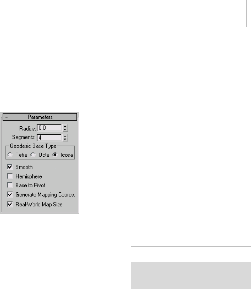
Cylinder Primitive 177
Interface
Creation Method rollout
Diameter—Drawsageospherefromedgetoedge.
You can change the center location by moving the
mouse.
Center—Draws a geosphere from the center out.
Parameters rollout
Radius—Sets the size of the geosphere.
Segments—Sets the total number of faces in the
geosphere. The number of faces in a geosphere is
equal to the sides of the base polyhedron times the
segments squared.
Lower segment values work best. Using the
maximum segment value of 200 can generate up to
800,000 faces, impairing performance.
Geodesic Base Type group
Lets you choose one of three types of regular
polyhedrons for the geosphere’s basic geometry.
•Tetra—Based on a four-sided tetrahedron. The
triangular facets can vary in shape and size. The
sphere can be divided into four equal segments.
•Octa—Based on an eight-sided octahedron.
The triangular facets can vary in shape and
size. The sphere can be divided into eight equal
segments.
•Icosa—Based on a 20-sided icosahedron. The
facets are all equally sized equilateral triangles.
The sphere can be divided into any number
of equal segments, based on multiples and
divisions of 20 faces.
Smooth—Applies smoothing groups to the surface
of the sphere.
Hemisphere—Creates a half-sphere.
Base To Pivot—Sets the pivot point location. When
on, the pivot is at the bottom of the sphere. When
off, the pivot is at the center of the sphere. This
option has no effect when Hemisphere is on.
Generate Mapping Coords—Generates coordinates
for applying mapped materials to the geosphere.
Default=on.
Real-World Map Size—Controls the scaling method
used for texture mapped materials that are applied
totheobject. Thescalingvaluesarecontrolled
by the Use Real-World Scale settings found in
the applied material’s Coordinates rollout (page
2–1625).Default=off.
Cylinder Primitive
Create panel > Geometry button > Standard Primitives >
Object Type rollout > Cylinder button
Create menu > Standard Primitives > Cylinder
Cylinder produces a cylinder, which you can
"slice" around its major axis.
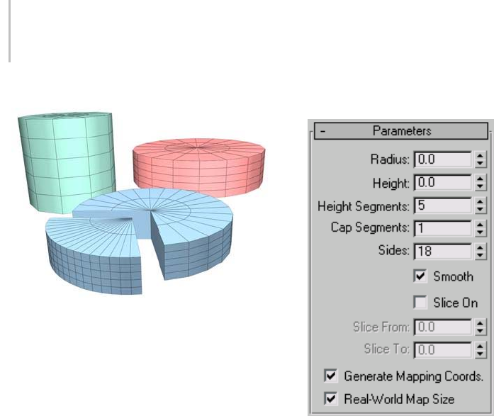
178 Chapter 5: Creating Geometry
Examples of cylinders
Procedure
To create a cylinder:
1. OntheCreatepanel,chooseStandard
Primitives > Cylinder.
2. In any viewport, drag to define the radius of the
base, then release to set the radius.
3. Move up or down to define a height, either
positive or negative.
4. Click to set the height and create the cylinder.
Interface
Creation Method rollout
Edge—Draws a cylinder from edge to edge. You
can change the center location by moving the
mouse.
Center—Draws a cylinder from the center out.
Parameters rollout
The defaults produce a smooth cylinder of 18 sides
with the pivot point at the center of the base. There
arefiveheightsegmentsandonecapsegment.If
you don’t plan to modify the cylinder’s shape, such
as with a Bend modifier, set Height Segments to 1
to reduce scene complexity. If you plan to modify
the ends of the cylinder, consider increasing the
Cap Segments setting.
Radius—Sets the radius of the cylinder.
Height—Sets the dimension along the central axis.
Negative values create the cylinder below the
construction plane.
Height Segments—Sets the number of divisions
along the cylinder’s major axis.
Cap Segments—Sets the number of concentric
divisions around the center of the cylinder’s top
and bottom.
Sides—Sets the number of sides around the
cylinder.WithSmoothon,highernumbersshade
and render as true circles. With Smooth off, lower
numbers create regular polygonal objects.
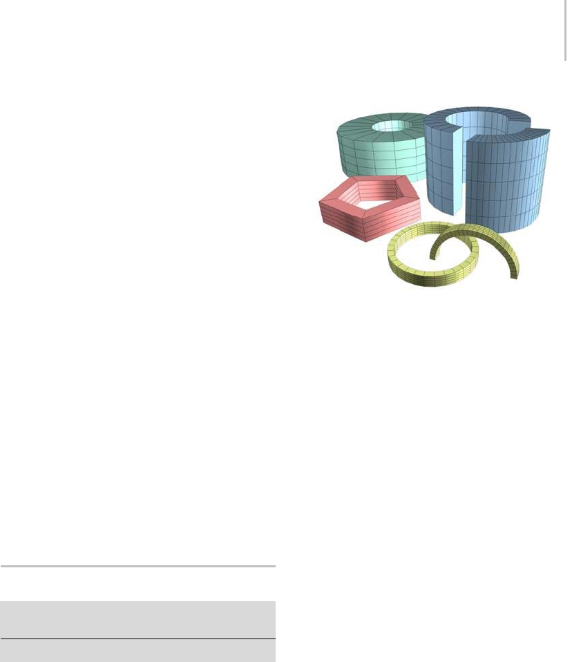
Tube Primitive 179
Smooth—Thefacesofthecylinderareblended
together, creating a smooth appearance in
rendered views.
Slice On—Enables the Slice function. Default=off.
WhenyoucreateasliceandthenturnoffSliceOn,
thecompletecylinderreappears.Youcanusethis
check box to switch between the two topologies.
Slice From, Slice To—Sets the number of degrees
around the local Z axis from a zero point at the
local X axis.
For both settings, positive values move the end of
the slice counterclockwise; negative values move it
clockwise. Either setting can be made first. When
the ends meet, the whole cylinder reappears.
Generate Mapping Coords—Generates coordinates
for applying mapped materials to the cylinder.
Default=on.
Real-World Map Size—Controls the scaling method
used for texture mapped materials that are applied
totheobject. Thescalingvaluesarecontrolled
by the Use Real-World Scale settings found in
the applied material’s Coordinates rollout (page
2–1625). Default=off.
Tube Primitive
Create panel > Geometry button > Standard Primitives
>ObjectTyperollout>Tubebutton
Create menu > Standard Primitives > Tube
Tube produces both round and prismatic tubes.
The tube is similar to the cylinder with a hole in it.
Examples of tubes
Procedures
To create a tube:
1. OntheCreatemenuchooseStandard
Primitives > Tube.
2. In any viewport, drag to define the first radius,
which can be either the inner or outer radius of
thetube.Releasetosetthefirstradius.
3. Move to define the second radius, then click
to set it.
4. Move up or down to define a height, either
positive or negative.
5. Click to set the height and create the tube.
To create a prismatic tube:
1. Set the number of sides for the kind of prism
you want.
2. Tur n Sm ooth off.
3. Create a tube.
Interface
Creation Method rollout
Edge—Draws a tube from edge to edge. You can
change the center location by moving the mouse.
Center—Draws a tube from the center out.
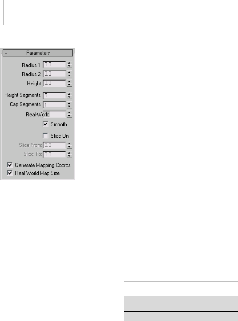
180 Chapter 5: Creating Geometry
Parameters rollout
The defaults produce a smooth, round tube of
18 sides with the pivot point at the center of the
base.Therearefiveheightsegmentsandonecap
segment. If you don’t plan to modify the cylinder’s
shape, such as with a Bend modifier, set Height
Segments to 1 to reduce scene complexity. If you
plan to modify the ends of the cylinder, consider
increasing the Cap Segments setting.
Radius 1, Radius 2—The larger setting specifies
theoutsideradiusofthetube,whilethesmaller
specifies the inside radius.
Height—Sets the dimension along the central
axis. Negative values create the tube below the
construction plane.
Height Segments—Sets the number of divisions
along the tube’s major axis.
Cap Segments—Sets the number of concentric
divisionsaroundthecenterofthetube’stopand
bottom.
Sides—Sets the number of sides around the tube.
Higher numbers shade and render as true circles
with Smooth on. Lower numbers create regular
polygonal objects with Smooth off.
Smooth—When on (the default), faces of the
tube are blended together, creating a smooth
appearance in rendered views.
Slice On—Enables the Slice feature, which removes
part of the tube’s circumference. Default=off.
WhenyoucreateasliceandthenturnoffSliceOn,
thecompletetubereappears.Youcantherefore
usethischeckboxtoswitchbetweenthetwo
topologies.
Slice From, Slice To—Sets the number of degrees
around the local Z axis from a zero point at the
local X axis.
For both settings, positive values move the end of
the slice counterclockwise; negative values move it
clockwise. Either setting can be made first. When
the ends meet, the whole tube reappears.
Generate Mapping Coords—Generates coordinates
for applying mapped materials to the tube.
Default=on.
Real-World Map Size—Controls the scaling method
used for texture mapped materials that are applied
totheobject. Thescalingvaluesarecontrolled
by the Use Real-World Scale settings found in
the applied material’s Coordinates rollout (page
2–1625).Default=off.
Torus Primitive
Create panel > Geometry button > Standard Primitives
>ObjectTyperollout>Torusbutton
Create menu > Standard Primitives > Torus
Torusproducesatorus,oraringwithacircular
cross section, sometimes referred to as a doughnut.
You can combine three smoothing options with
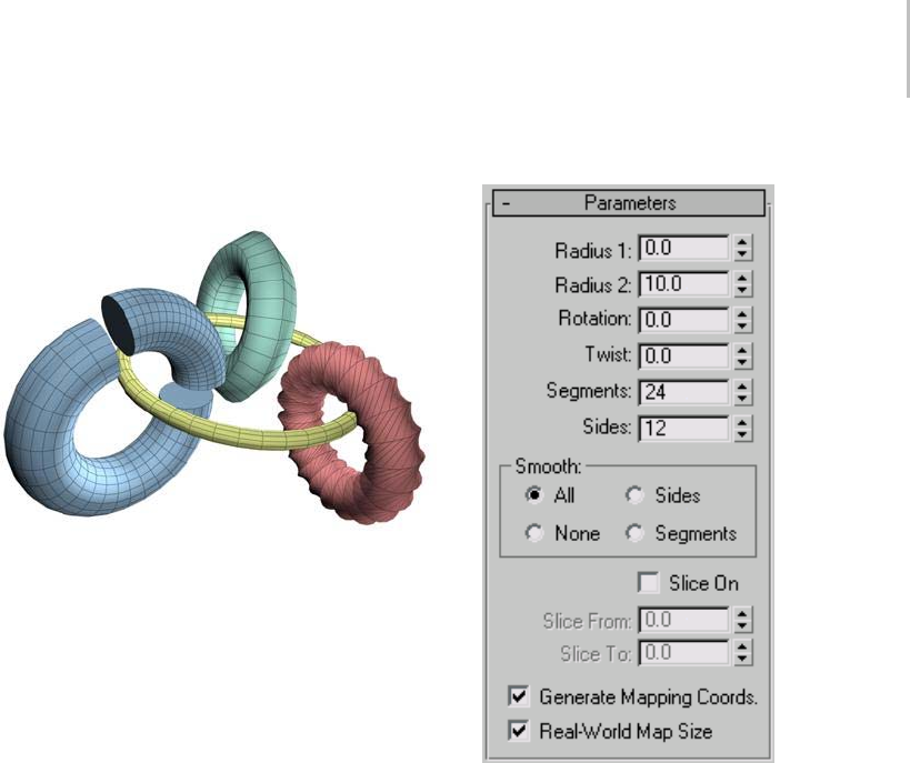
Torus Primitive 181
rotation and twist settings to create complex
variations.
Examples of tori
Procedure
To create a torus:
1. From the Create menu, choose Standard
Primitives > Torus.
2. In any viewport, drag to define a torus.
3. As you drag, a torus emerges with its center at
the pivot point.
4. Release to set the radius of the torus ring.
5. Move to define the radius of the cross-sectional
circle, then click to create the torus.
Interface
Creation Method rollout
Edge—Drawsatorusfromedgetoedge.Youcan
change the center location by moving the mouse.
Center—Drawsatorusfromthecenterout.
Parameters rollout
The defaults produce a smooth torus with 12 sides
and24segments.Thepivotpointisatthecenter
of the torus on the plane, cutting through the
center of the torus. Higher settings for sides and
segments produce a more dense geometry that
might be required for some modeling or rendering
situations.
Radius 1—Sets the distance from the center of the
torus to the center of the cross-sectional circle.
This is the radius of the torus ring.
Radius 2—Sets the radius of the cross-sectional
circle. This value is replaced each time you create a
torus. Default = 10.
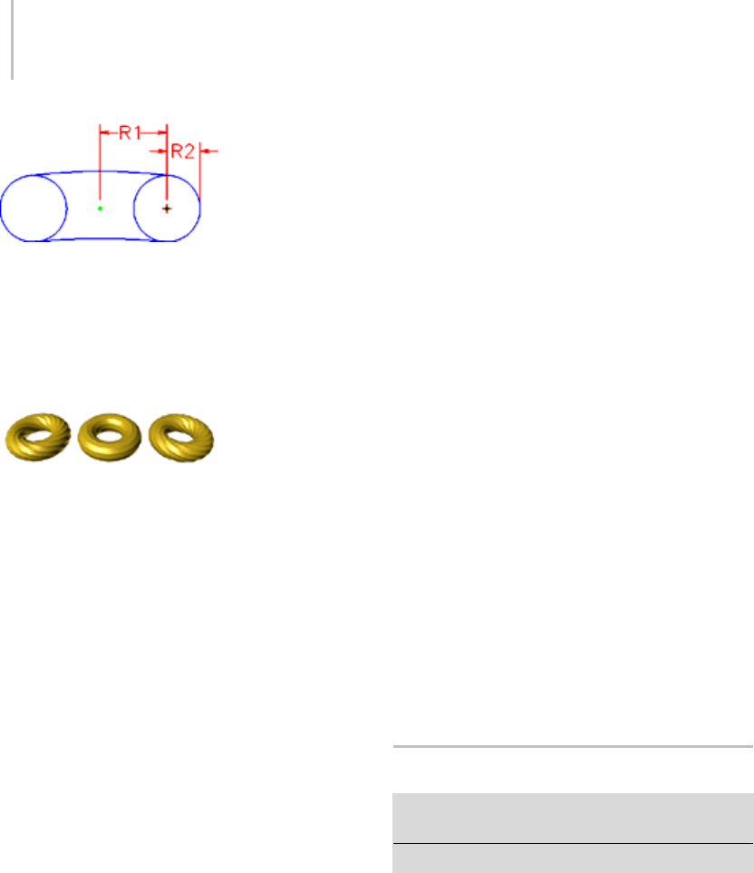
182 Chapter 5: Creating Geometry
Radius 1 and Radius 2
Rotation—Sets the degree of rotation. Vertices
are uniformly rotated about the circle running
through the center of the torus ring. Positive and
negative values for this setting "roll" the vertices in
either direction over the surface of the torus.
Rotation and Twist
Twist—Sets the degree of twist. Cross sections
areprogressivelyrotatedaboutthecirclerunning
through the center of the torus. Beginning with
twist, each successive cross section is rotated until
the last one has the number of degrees specified.
Twisting a closed (unsliced) torus creates a
constriction in the first segment. You can avoid
this by either twisting in increments of 360 degrees,
or by turning Slice on and setting both Slice From
and Slice To to 0 to maintain a complete torus.
Segments—Sets the number of radial divisions
around the torus. By reducing this number, you
can create polygonal rings instead of circular ones.
Sides—Sets the number of sides on the
cross-sectional circle of the torus. By reducing this
number, you can create prism-like cross sections
instead of circular ones.
Smooth group
Choose one of four levels of smoothing:
•All—(default) Produces complete smoothing on
all surfaces of the torus.
•Sides—Smoothes the edges between adjacent
segments, producing smooth bands running
around the torus.
•None—Turns off smoothing entirely, producing
prism-like facets on the torus.
•Segments—Smoothes each segment
individually, producing ring-like segments
along the torus.
Slice On—Creates a portion of a sliced torus rather
than the entire 360 degrees.
Slice From—When Slice On is on, specifies the
anglewherethetorusslicebegins.
Slice To—When Slice On is on, specifies the angle
where the torus slice ends.
Generate Mapping Coords—Generates coordinates
for applying mapped materials to the torus.
Default=on.
Real-World Map Size—Controls the scaling method
used for texture mapped materials that are applied
totheobject. Thescalingvaluesarecontrolled
by the Use Real-World Scale settings found in
the applied material’s Coordinates rollout (page
2–1625).Default=off.
Pyramid Primitive
Create panel > Geometry button > Standard Primitives >
Object Type rollout > Pyramid button
Create menu > Standard Primitives > Pyramid
The Pyramid primitive has a square or rectangular
base and triangular sides.
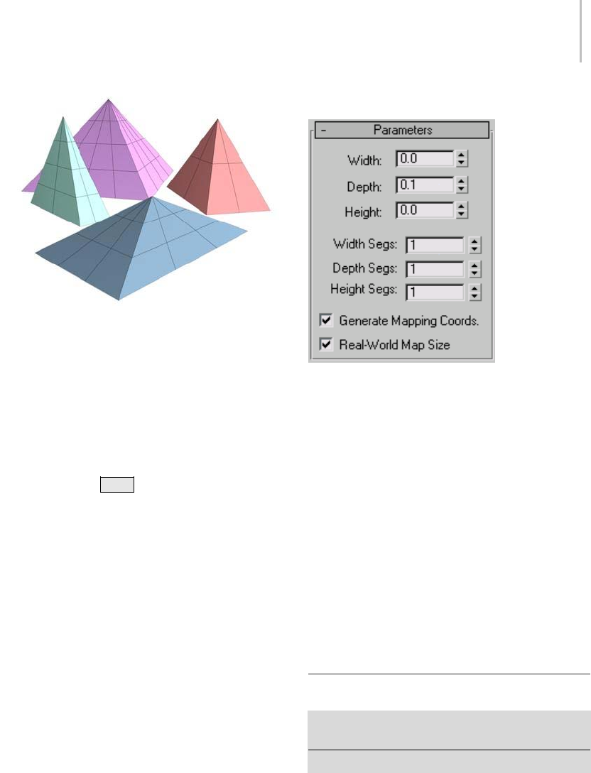
Teapot Primitive 183
Examples of pyramids
Procedure
To create a Pyramid:
1. OntheCreatemenuchooseStandard
Primitives > Pyramid.
2. Choose a creation method, either Base/Apex
or Center.
Note: Hold the Ctrl key while using either
creation method to constrain the base to a
square.
3. In any viewport, drag to define the base of the
pyramid. If you’re using Base/Apex, define the
opposite corners of the base, moving the mouse
horizontally or vertically to define the width
and depth of the base. If you’re using Center,
drag from the center of the base.
4. Click, and then move the mouse to define the
Height.
5. Click to complete the pyramid.
Interface
Creation Method rollout
Base/Apex—Creates the pyramid base from one
cornertothediagonallyoppositecorner.
Center—Creates the pyramid base from the center
out.
Parameters rollout
Width, Depth and Height—Sets the dimension of
the corresponding side of the pyramid.
Width, Depth and Height Segs—Sets the number
of segments to the corresponding sides of the
pyramid.
Generate Mapping Coords—Generates coordinates
for applying mapped materials to the pyramid.
Default=on.
Real-World Map Size—Controls the scaling method
used for texture mapped materials that are applied
totheobject. Thescalingvaluesarecontrolled
by the Use Real-World Scale settings found in
the applied material’s Coordinates rollout (page
2–1625).Default=off.
Teapot Primitive
Create panel > Geometry button > Standard Primitives >
Object Type rollout > Teapot button
Create menu > Standard Primitives > Teapot
Te a p o t p ro d u c es a t e a p o t . You c a n c h o o s e t o m a k e
the whole teapot at once (the default), or any of
its parts. Since the Teapot is a parametric object,
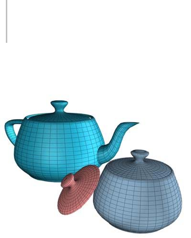
184 Chapter 5: Creating Geometry
you can choose which parts of the teapot to display
after creation.
Examples of teapots
History of the Teapot
This teapot derives from the original data
developed by Martin Newell in 1975. Beginning
with a graph-paper sketch of a teapot that he kept
on his desk, Newell calculated cubic Bezier splines
(page 3–915) to create a wireframe model. James
Blinn, also at the University of Utah during this
period, produced early renderings of exceptional
quality using this model.
Theteapothassincebecomeaclassicincomputer
graphics. Its complexly curved and intersecting
surfaces are well suited to testing different kinds
of material mappings and rendering settings on a
real-world object.
Procedures
To create a teapot:
1. On the Create menu, choose Standard
Primitives > Teapot.
2. In any viewport, drag to define a radius.
As you drag, a teapot emerges with the pivot
pointatthecenterofitsbase.
3. Release the mouse to set the radius and create
the teapot.
To create a teapot part:
1. In Parameters rollout > Teapot Parts group,
turn off all parts except the one you want to
create.
2. Create a teapot.
The part you left on appears. The pivot point
remainsatthecenteroftheteapot’sbase.
3. In Parameters rollout > Teapot Parts group,
turn off all parts except the one you want.
The teapot has four separate parts: body, handle,
spout, and lid. Controls are located in the Teapot
Parts group of the Parameters rollout. You can
check any combination of parts to create at the
same time. The body alone is a ready-made bowl,
or a pot with optional lid.
To turn a part into a teapot:
1. Selectateapotpartintheviewport.
2. On the Modify panel > Parameters rollout, turn
on all parts. (This is the default.)
The whole teapot appears.
You can apply modifiers to any separate part. If
you later turn on another part, the modifier affects
the additional geometry as well.
Interface
Creation Method rollout
Edge—Draws a teapot from edge to edge. You can
change the center location by moving the mouse.
Center—Draws a teapot from the center out.
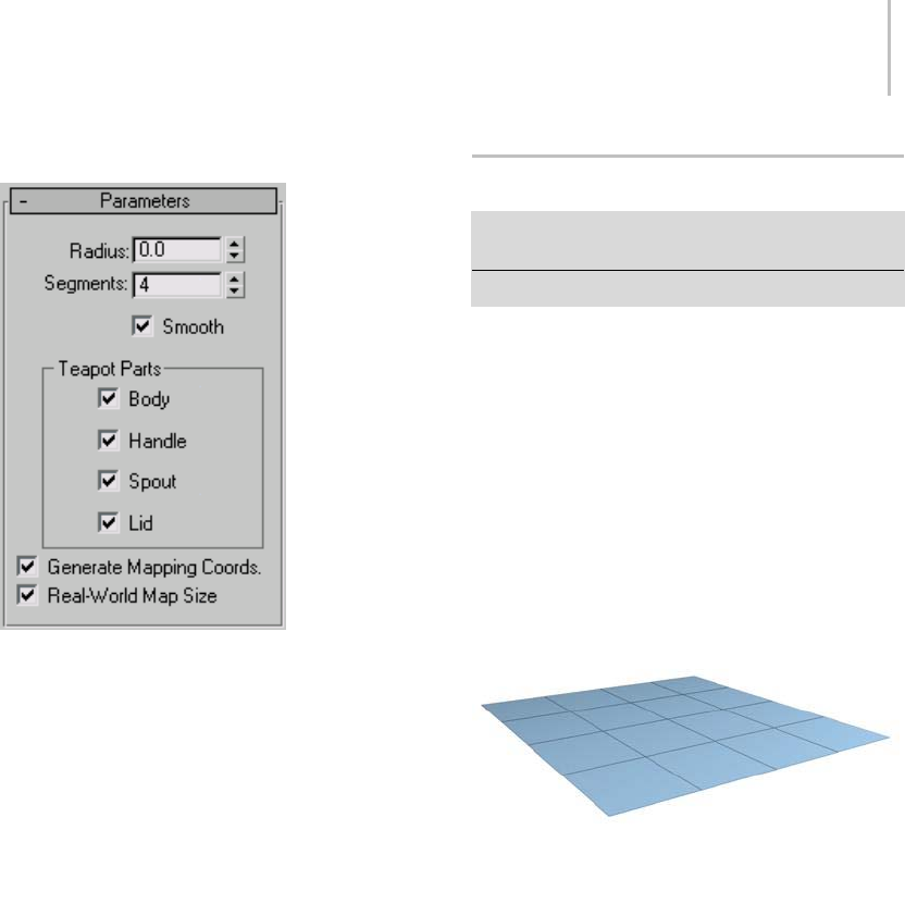
Plane Primitive 185
Parameters rollout
Radius—Sets the radius of the teapot
Segments—Sets the number of divisions for the
teapot or its individual parts.
Smooth—Blends faces of the teapot, creating a
smooth appearance in rendered views.
Teapot Parts group
Turn check boxes on or off for teapot parts. By
default, all are on, producing a complete teapot.
Generate Mapping Coords—Generates coordinates
for applying mapped materials to the teapot.
Default=on.
Real-World Map Size—Controls the scaling method
used for texture mapped materials that are applied
totheobject. Thescalingvaluesarecontrolled
by the Use Real-World Scale settings found in
the applied material’s Coordinates rollout (page
2–1625). Default=off.
Plane Primitive
Create panel > Geometry button > Standard Primitives
> Object Type rollout > Plane button
Create menu > Standard Primitives > Plane
The Plane object is a special type of flat polygon
mesh that can be enlarged by any amount at render
time. You can specify factors to magnify the size
or number of segments, or both. Use the Plane
object for creating a large-scale ground plane that
doesn’t get in the way when working in a viewport.
You can apply any type of modifier to the plane
object, such as Displace (page 1–629) to simulate
ahillyterrain.
Example of plane
Procedure
To create a plane:
1. OntheCreatemenuchooseStandard
Primitives > Plane.
2. In any viewport, drag to create the Plane.
Interface
Creation Method rollout
Rectangle—Creates the plane primitive from
one corner to the diagonally opposite corner,
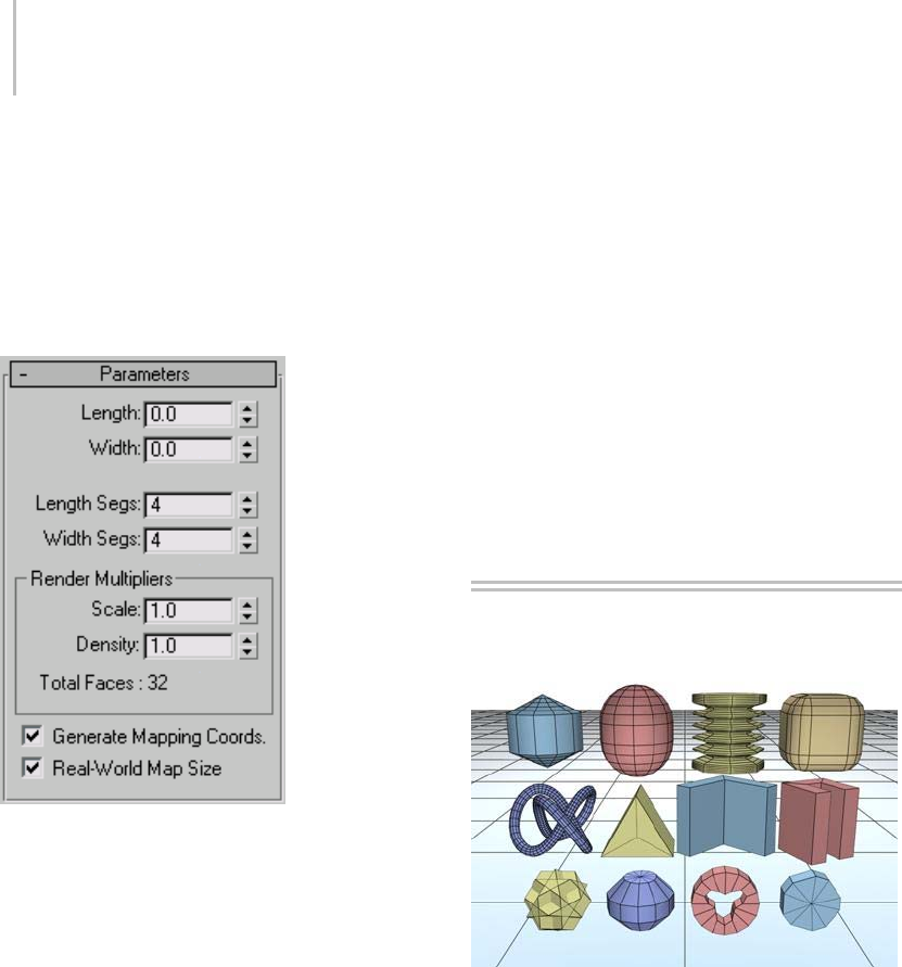
186 Chapter 5: Creating Geometry
interactively setting different values for length and
width.
Square—Creates a square plane where length and
width are equal. You can change dimensions in the
Parameters rollout subsequent to creation.
Parameters rollout
Length, Width—Sets the length and width of the
planeobject. Thesefieldsactalsoasreadouts
whileyoudragthesidesofthebox.Youcanrevise
these values. Defaults= 0.0, 0.0.
Length Segs, Width Segs—Sets the number of
divisions along each axis of the object. Can be set
before or after creation. By default, each side of
the plane has four segments. When you reset these
values, the new values become the default during a
session.
Render Multipliers group
Render Scale—Specifies the factor by which both
length and width are multiplied at render time.
Scalingisperformedfromthecenteroutward.
Render Segs—Specifies the factor by which the
number of segments in both length and width are
multiplied at render time.
Generate Mapping Coords—Generates coordinates
for applying mapped materials to the plane.
Default=on.
Real-World Map Size—Controls the scaling method
used for texture mapped materials that are applied
totheobject. Thescalingvaluesarecontrolled
by the Use Real-World Scale settings found in
the applied material’s Coordinates rollout (page
2–1625).Default=off.
Extended Primitives
A collection of extended primitive objects
Extended Primitives are a collection of complex
primitives for 3ds Max. The topics that follow
describe each type of extended primitive and its
creation parameters.
TheseprimitivesareavailablefromtheObject
Type rollout on the Create panel and from the
Create menu > Extended Primitives.
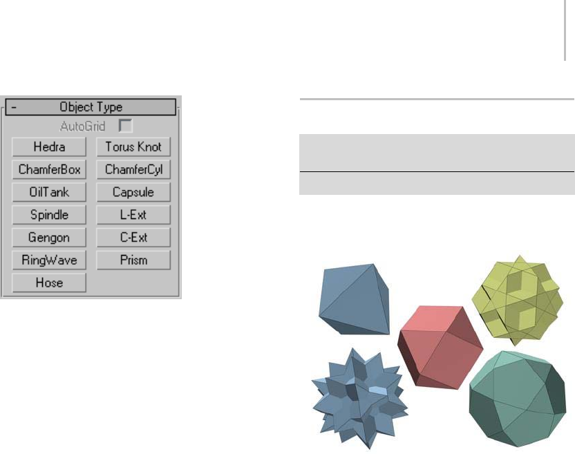
Hedra Extended Primitive 187
AutoGrid (page 2–7)
Hedra Extended Primitive (page 1–187)
Torus Knot Extended Primitive (page 1–189)
ChamferBox Extended Primitive (page 1–191)
ChamferCyl Extended Primitive (page 1–192)
OilTank Extended Primitive (page 1–194)
Capsule Extended Primitive (page 1–195)
Spindle Extended Primitive (page 1–196)
L-Ext Extended Primitive (page 1–198)
Gengon Extended Primitive (page 1–199)
C-Ext Extended Primitive (page 1–200)
RingWave Extended Primitive (page 1–202)
Hose Extended Primitive (page 1–206)
Prism Extended Primitive (page 1–205)
Allprimitiveshavenameandcolorcontrols,and
allow you to enter initial values from the keyboard.
See these topics:
Object Name and Wireframe Color (page 3–757)
Creating Primitives from the Keyboard (page 1–169)
(not applicable to Hedra, RingWave, or Hose)
Theremainingrolloutsarecoveredinthetopicfor
each primitive.
Hedra Extended Primitive
Create panel > Geometry button > Extended Primitives >
Object Type rollout > Hedra button
Create menu > Extended Primitives > Hedra
Use Hedra to produce objects from several families
of polyhedra.
Examples of hedra
Procedure
To create a polyhedron:
1. FromtheCreatemenu,chooseExtended
Primitives > Hedra.
2. In any viewport, drag to define a radius, then
release to create the polyhedron.
As you drag, a polyhedron emerges from the
pivot point.
3. Adjust the Family Parameter and Axis Scaling
spinners to vary the Hedra’s appearance.
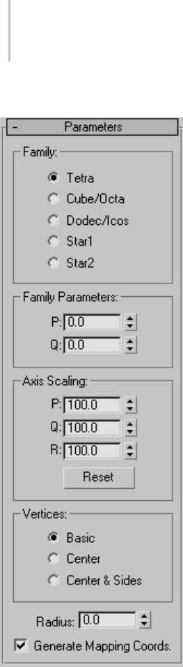
188 Chapter 5: Creating Geometry
Interface
Family group
Usethisgrouptoselectthetypeofpolyhedronto
create.
Tetra—Creates a tetrahedron.
Cube/Octa—Creates a cubic or octahedral
polyhedron (depending on parameter settings).
Dodec/Icos—Creates a dodecahedron or
icosahedron (depending on parameter settings).
Star1/Star2—Creates two different star-like
polyhedra.
Tip: You can animate between Hedra types.
TurnontheAutoKeybutton,gotoanyframe,
and change the Family check box. There is no
interpolation between types; the model simply
jumps from a star to a cube or tetrahedron, and
so on.
Family parameters group
P, Q — Interrelated parameters that provide a
two-way translation between the vertices and
facets of a polyhedron. They share the following:
• Rangeofpossiblevaluesis0.0through1.0.
• The combined total of the P and Q values can
be equal to or less than 1.0.
• Extremes occur if either P or Q is set to 1.0; the
other is automatically set to 0.0.
• Midpoint occurs when both P and Q are 0.
In the simplest terms, P and Q change the
geometry back and forth between vertices and
facets. At the extreme settings for P and Q,
one parameter represents all vertices, the other
represents all facets. Intermediate settings are
transition points, with the midpoint an even
balancebetweenthetwoparameters.
Axis Scaling group
Polyhedra can have as many as three kinds of
polygonal facets, such as triangle, square, or
pentagon. These facets can be regular or irregular.
If a polyhedron has only one or two types of facet,
only one or two of the axis scaling parameters are
active. Inactive parameters have no effect.
P, Q , R —Controls the axis of reflection for one of
the facets of a polyhedron. In practice, these fields
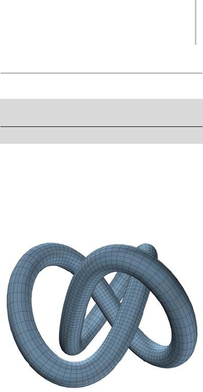
Torus Knot Extended Primitive 189
have the effect of pushing their corresponding
facets in and out. Defaults=100.
Reset—Returnsaxestotheirdefaultsetting.
Vertices group
Parameters in the Vertices group determine the
internal geometry of each facet of a polyhedron.
Center and Center & Sides increase the number of
vertices in the object and therefore the number of
faces. These parameters cannot be animated.
Basic—Facets are not subdivided beyond the
minimum.
Center—Each facet is subdivided by placing an
additional vertex at its center, with edges from
each center point to the facet corners.
Center & Sides—Each facet is subdivided by placing
an additional vertex at its center, with edges from
each center point to the facet corners, as well as
to the center of each edge. Compared to Center,
Center & Sides doubles the number of faces in the
polyhedron.
Note: If you scale the axis of the object, the Center
option is used automatically, unless Center & Sides
is already set.
To see the internal edges shown in the figure, turn
off Edges Only on the Display command panel.
Radius—Sets the radius of any polyhedron in
current units.
Generate Mapping Coords—Generates coordinates
for applying mapped materials to the polyhedron.
Default=on.
Torus Knot Extended Primitive
Create panel > Geometry > Extended Primitives > Object
Type rollout > Torus Knot button
Create menu > Extended Primitives > Torus Knot
Use Torus Knot to create a complex or knotted
torus by drawing 2D curves in the normal planes
around a 3D curve. The 3D curve (called the Base
Curve) can be either a circle or a torus knot.
YoucanconvertatorusknotobjecttoaNURBS
surface (page 1–1116).
Example of torus knot
Procedure
To create a Torus Knot:
1. On the Create menu, choose Extended
Primitives > Torus Knot.
2. Dragthemousetodefinethesizeofthetorus
knot.
3. Click, then move the mouse vertically to define
the radius.
4. Click again to finish the torus.
5. Adjust the parameters on the Modify panel.
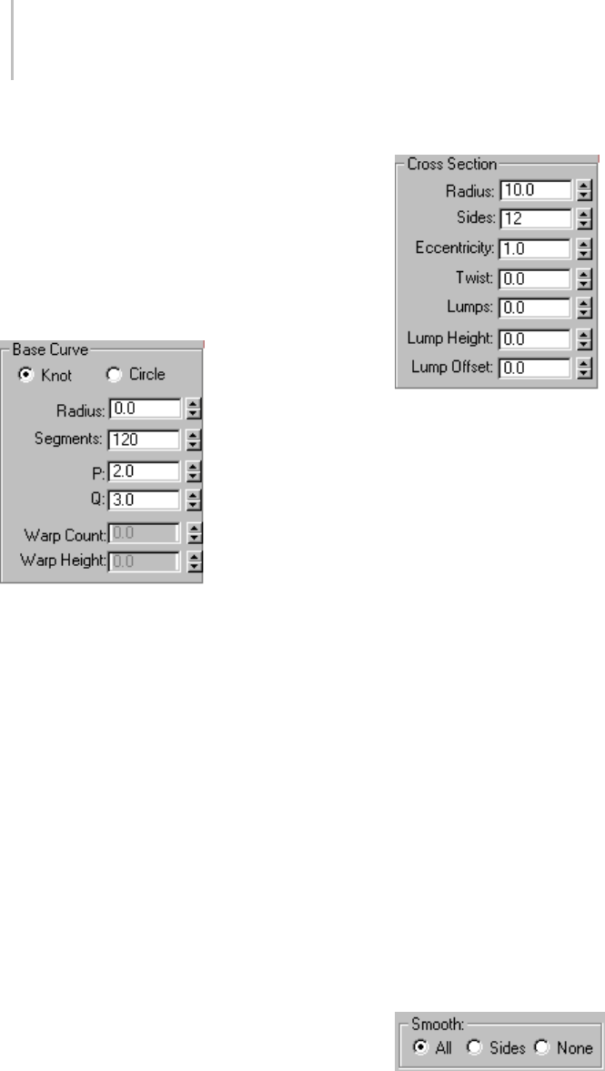
190 Chapter 5: Creating Geometry
Interface
Creation Method rollout
Diameter—Draws the object from edge to edge.
You can change the center location by moving the
mouse.
Radius—Draws the object from the center out.
Parameters rollout > Base Curve group
Provides parameters that affect the base curve.
Knot/Circle—With Knot, the torus interweaves
itself, based on various other parameters. With
Circle, the base curve is a circle, resulting in a
standard torus if parameters such as Warp and
Eccentricityareleftattheirdefaults.
Radius—Sets the radius of the base curve.
Segments—Sets the number of segments around
the perimeter of the torus.
PandQ—Describes up-and-down (P) and
around-the-center (Q) winding numbers. (Active
only when Knot is chosen.)
Warp Count—Sets the number of "points" in a star
shapearoundthecurve.(ActiveonlywhenCircle
is chosen.)
Warp Height—Sets the height of the "points" given
as a percentage of the base curve radius.
Parameters rollout > Cross Section group
Provides parameters that affect the cross section
of the torus knot.
Radius—Sets the radius of the cross section.
Sides—Sets the number of sides around the cross
section.
Eccentricity—Sets the ratio of the major to minor
axes of the cross section. A value of 1 provides
a circular cross section, while other values create
elliptical cross sections.
Twist—Sets the number of times the cross section
twists around the base curve.
Lumps—Sets the number of bulges in the torus
knot. Note that the Lump Height spinner value
must be greater than 0 to see any effect.
Lump Height—Sets the height of the lumps, as a
percentage of the radius of the cross section. Note
that the Lumps spinner must be greater than 0 to
see any effect.
Lump Offset—Sets the offset of the start of the
lumps, measured in degrees. The purpose of this
valueistoanimatethelumpsaroundthetorus.
Parameters rollout > Smooth group
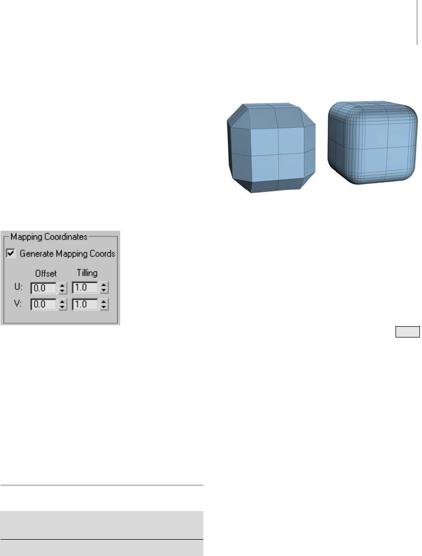
ChamferBox Extended Primitive 191
Provides options to alter the smoothing displayed
or rendered of the torus knot. This smoothing
doesnotdisplaceortesselatethegeometry,itonly
adds the smoothing group information.
All—Smoothes the entire torus knot.
Sides—Smoothes only the adjacent sides of the
torus knot.
None—The torus knot is faceted.
Parameters rollout > Mapping Coordinates
group
Provides methods of assigning and adjusting
mapping coordinates.
Generate Mapping Coords—Assigns mapping
coordinates based on the geometry of the torus
knot. Default=on.
Offset U/V—Offset the mapping coordinates along
UandV.
Tiling U/V—Tile the mapping coordinates along U
and V.
ChamferBox Extended Primitive
Create panel > Geometry button > Extended Primitives >
Object Type rollout > ChamferBox button
Create menu > Extended Primitives > Chamfer Box
UseChamferBoxtocreateaboxwithbeveledor
rounded edges.
Examples of chamfered boxes
Procedures
To create a standard chamfered box:
1. FromtheCreatemenu,chooseExtended
Primitives > Chamfer Box.
2. Drag the mouse to define the diagonal corners
of the base of the chamfered box. (Press Ctrl
to constrain the base to a square.)
3. Release the mouse button, and then move the
mouseverticallytodefinetheheightofthebox.
Click to set the height
4. Move the mouse diagonally to define the width
of the fillet, or chamfer (toward the upper left
increases the width; toward the lower right
decreases it).
5. Click again to finish the chamfered box.
To create a cubic chamfered box:
1. On the Creation Method rollout, click Cube.
2. Beginning at the center of the cube, drag
in a viewport to set all three dimensions
simultaneously.
3. Releasethebutton,andmovethemousetoset
the fillet or chamfer.
4. Click to create the object.
You can change a cube’s individual dimensions
in the Parameters rollout.
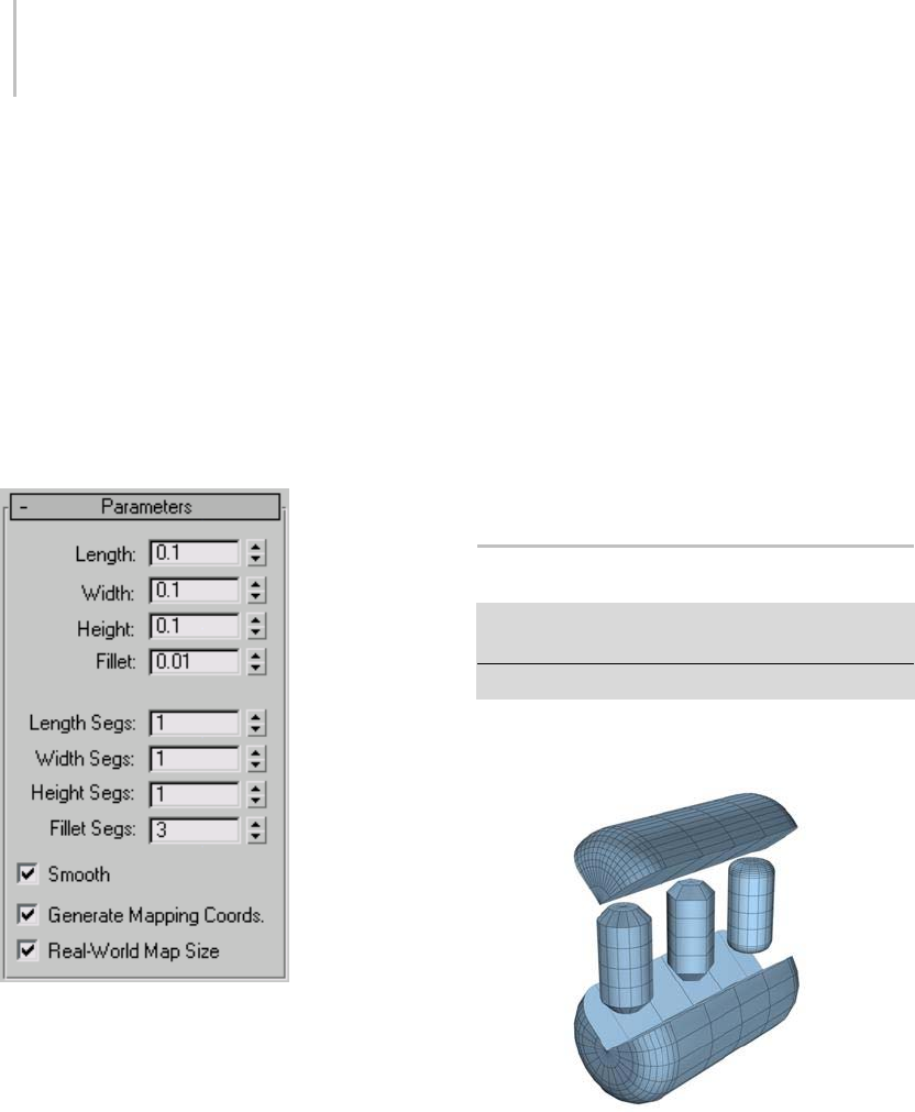
192 Chapter 5: Creating Geometry
Interface
Creation Method rollout
Cube—Forces length, width, and height to be
equal. You can change a cube’s individual
dimensions in the Parameters rollout.
Box—Creates a standard chamfered box primitive
from one corner to the diagonally opposite corner,
with individual settings for length, width, and
height.
Parameters rollout
Length, Width, Height—Sets the corresponding
dimensions of the chamfered box.
Fillet—Slices off the edges of the chamfered box.
Higher values result in a more refined fillet on the
edges of the chamfered box.
Length, Width, Height Segs—Sets the number of
divisions along the corresponding axis.
Fillet Segs—Sets the number of segments in the
filleted edges of the box. Adding fillet segments
increases the edge roundness.
Smooth—Blends the display of the faces of the
chamfered box, creating a smooth appearance in
rendered views.
Generate Mapping Coords—Generates coordinates
for applying mapped materials to the chamfered
box. Default=on.
Real-World Map Size—Controls the scaling method
used for texture mapped materials that are applied
totheobject. Thescalingvaluesarecontrolled
by the Use Real-World Scale settings found in
the applied material’s Coordinates rollout (page
2–1625).Default=off.
ChamferCyl Extended Primitive
Create panel > Geometry button > Extended Primitives >
Object Type rollout > ChamferCyl button
Create menu > Extended Primitives > Chamfer Cylinder
Use ChamferCyl to create a cylinder with beveled
or rounded cap edges.
Examples of chamfered cylinders
Procedure
To create a chamfered cylinder:
1. FromtheCreatemenu,chooseExtended
Primitives > Chamfer Cylinder.
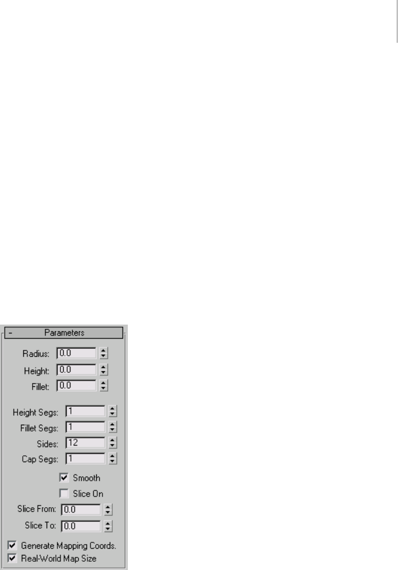
ChamferCyl Extended Primitive 193
2. Drag the mouse to define the radius of the base
of the chamfered cylinder.
3. Releasethemousebutton,andthenmovethe
mouse vertically to define the height of the
cylinder. Click to set the height.
4. Move the mouse diagonally to define the width
of the fillet, or chamfer (toward the upper left
increases the width; toward the lower right
decreases it).
5. Click to finish the cylinder.
Interface
Creation Method rollout
Edge—Draws the object from edge to edge. You
can change the center location by moving the
mouse.
Center—Draws the object from the center out.
Parameters rollout
Radius—Sets the radius of the chamfered cylinder.
Height—Sets the dimension along the central axis.
Negative values create the chamfered cylinder
below the construction plane.
Fillet—Chamfers the top and bottom cap edges of
the chamfered cylinder. Higher numbers result in
a more refined fillet along the cap edge.
Height Segs—Sets the number of divisions along
the corresponding axis.
Fillet Segs—Sets the number of segments in
the filleted edges of the cylinder. Adding fillet
segments curves the edges, producing a filleted
cylinder.
Sides—Sets the number of sides around the
chamfered cylinder. Higher numbers shade and
render as true circles with Smooth on. Lower
numbers create regular polygonal objects with
Smooth off.
Cap Segs—Sets the number of concentric divisions
along the center of the chamfered cylinder’s top
and bottom
Smooth—Blends the faces of the chamfered
cylinder, creating a smooth appearance in
rendered views.
Slice On—Enables the Slice function. Default=off.
WhenyoucreateasliceandthenturnoffSliceOn,
the complete chamfered cylinder reappears. You
can use this check box to switch between the two
topologies.
Slice From, Slice To—Sets the number of degrees
around the local Z axis from a zero point at the
local X axis.
For both settings, positive values move the end of
the slice counterclockwise; negative values move it
clockwise. Either setting can be made first. When
the ends meet, the whole chamfered cylinder
reappears.
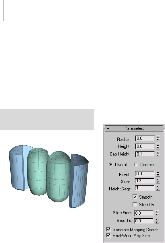
194 Chapter 5: Creating Geometry
Generate Mapping Coords—Generates coordinates
for applying mapped materials to the chamfered
cylinder. Default=on.
Real-World Map Size—Controls the scaling method
used for texture mapped materials that are applied
totheobject. Thescalingvaluesarecontrolled
by the Use Real-World Scale settings found in
the applied material’s Coordinates rollout (page
2–1625). Default=off.
OilTank Extended Primitive
Create panel > Geometry button > Extended Primitives >
Object Type rollout > OilTank button
Create menu > Extended Primitives > Oil Tank
Use OilTank to create a cylinder with convex caps.
Examples of oil tanks
Procedure
To create an oil tank:
1. FromtheCreatemenu,chooseExtended
Primitives > Oil Tank.
2. Drag the mouse to define the radius of the base
of the oil tank.
3. Releasethemousebutton,andthenmovethe
mouseverticallytodefinetheheightoftheoil
tank. Click to set the height.
4. Movethemousediagonallytodefinetheheight
of the convex caps (toward the upper left to
increase the height; toward the lower right to
decrease it).
5. Click again to finish the oil tank.
Interface
Creation Method rollout
Edge—Draws the object from edge to edge. You
can change the center location by moving the
mouse.
Center—Draws the object from the center out.
Parameters rollout
Radius—Sets the radius of the oil tank.
Height—Sets the dimension along the central
axis. Negative values create the oil tank below the
construction plane.
Cap Height—Sets the height of the convex caps.
The minimum value is 2.5% of the Radius setting.
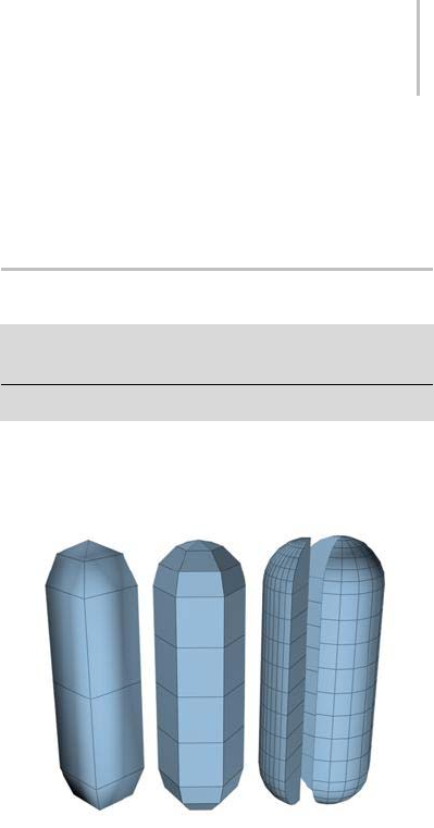
Capsule Extended Primitive 195
The maximum value is the Radius setting, unless
theabsolutevalueoftheHeightsettingisless
than the double Radius setting, in which case cap
height cannot exceed ½ of the absolute value of
the Height setting.
Overall/Centers—Determines what the Height
valuespecifies.Overallistheoverallheightofthe
object. Centers is the height of the midsection of
the cylinder, not including its convex caps.
Blend—When greater than 0, creates a bevel at the
edge of the caps.
Sides—Sets the number of sides around the oil
tank. To create a smoothly rounded object, use
ahighernumberofsidesandturnSmoothon.
To create an oil tank with flat sides, use a lower
number of sides and turn Smooth off.
Height Segs—Sets the number of divisions along
the oil tank’s major axis.
Smooth—Blends the faces of the oil tank, creating
a smooth appearance in rendered views.
Slice On—Tur ns on the S lice f unct ion. Default=off.
When you create a slice and then turn off Slice
On, the complete oil tank reappears. You can
therefore use this check box to switch between the
two topologies.
Slice From, Slice To—Sets the number of degrees
around the local Z axis from a zero point at the
local X axis.
For both settings, positive values move the end of
the slice counterclockwise; negative values move it
clockwise. Either setting can be made first. When
theendsmeet,thewholeoiltankreappears.
Generate Mapping Coords—Generates coordinates
for applying mapped materials to the oil tank.
Default=on.
Real-World Map Size—Controls the scaling method
used for texture mapped materials that are applied
totheobject. Thescalingvaluesarecontrolled
by the Use Real-World Scale settings found in
the applied material’s Coordinates rollout (page
2–1625).Default=off.
Capsule Extended Primitive
Create panel > Geometry button > Extended Primitives >
Object Type rollout > Capsule button
Create menu > Extended Primitives > Capsule
Use Capsule to create a cylinder with hemispherical
caps.
Examples of capsules
Procedure
To create a capsule:
1. FromtheCreatemenu,chooseExtended
Primitives > Capsule.
2. Drag the mouse to define the radius of the
capsule.
3. Release the mouse button, and then move the
mouse vertically to define the height of the
capsule.
4. Click to set the height and finish the capsule.
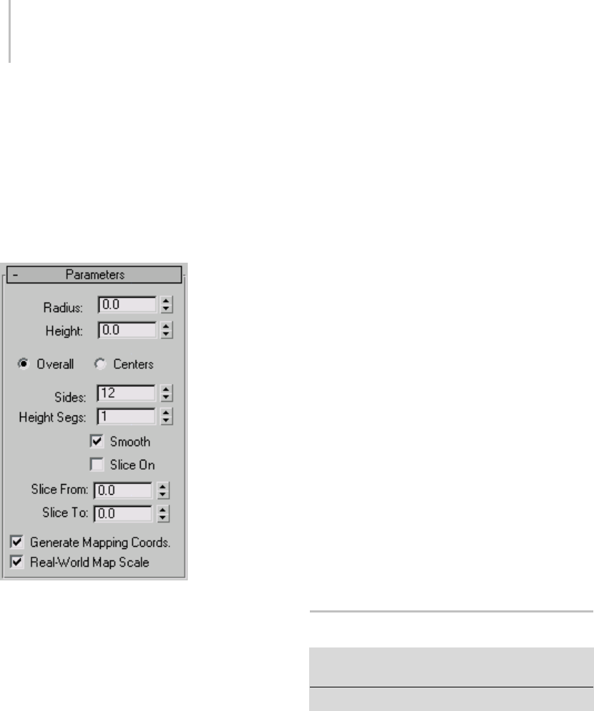
196 Chapter 5: Creating Geometry
Interface
Creation Method rollout
Edge—Draws the object from edge to edge. You
can change the center location by moving the
mouse.
Center—Draws the object from the center out.
Parameters rollout
Radius—Sets the radius of the capsule.
Height—Sets the height along the central axis.
Negative values create the capsule below the
construction plane.
Overall/Centers—Determines what the Height
value specifies. Overall specifies the overall height
of the object. Centers specifies the height of
the midsection of the cylinder, not including its
domed caps.
Sides—Sets the number of sides around the
capsule. Higher numbers shade and render as true
circleswithSmoothon.Lowernumberscreate
regular polygonal objects with Smooth off.
Height Segs—Sets the number of divisions along
the capsule’s major axis.
Smooth—Blends the faces of the capsule, creating a
smooth appearance in rendered views.
Slice On—Turns on the Slice function. Default=off.
WhenyoucreateasliceandthenturnoffSliceOn,
the complete capsule reappears. You can use this
check box to switch between the two topologies.
Slice From, Slice To—Sets the number of degrees
around the local Z axis from a zero point at the
local X axis.
For both settings, positive values move the end of
the slice counterclockwise; negative values move it
clockwise. Either setting can be made first. When
theendsmeet,thewholecapsulereappears.
Generate Mapping Coords—Generates coordinates
for applying mapped materials to the capsule.
Default=on.
Real-World Map Size—Controls the scaling method
used for texture mapped materials that are applied
totheobject. Thescalingvaluesarecontrolled
by the Use Real-World Scale settings found in
the applied material’s Coordinates rollout (page
2–1625).Default=off.
Spindle Extended Primitive
Create panel > Geometry button > Extended Primitives >
Object Type rollout > Spindle button
Create menu > Extended Primitives > Spindle
Use the Spindle primitive to create a cylinder with
conical caps.
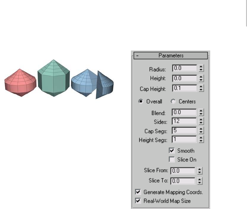
Spindle Extended Primitive 197
Examples of spindles
Procedure
To create a spindle:
1. FromtheCreatemenu,chooseExtended
Primitives > Spindle.
2. Drag the mouse to define the radius of the base
of the spindle.
3. Releasethemousebutton,andthenmovethe
mouse vertically to define the height of the
spindle. Click to set the height.
4. Move the mouse diagonally to define the height
of the conical caps (toward the upper left to
increase the height; toward the lower right to
decrease it).
5. Click again to finish the spindle.
Interface
Creation Method rollout
Edge—Draws the object from edge to edge. You
can change the center location by moving the
mouse.
Center—Draws the object from the center out.
Parameters rollout
Radius—Sets the radius of the spindle.
Height—Sets the dimension along the central
axis. Negative values create the spindle below the
construction plane.
Cap Height—Sets the height of the conical caps.
The minimum value is 0.1; the maximum value is
½ the absolute value of the Height setting.
Overall/Centers—Determines what the Height
value specifies. Overall specifies the overall height
of the object. Centers specifies the height of
the midsection of the cylinder, not including its
conical caps.
Blend—When greater than 0, creates a fillet where
the caps meet the body of the spindle.
Sides—Sets the number of sides around the
spindle. Higher numbers shade and render as true
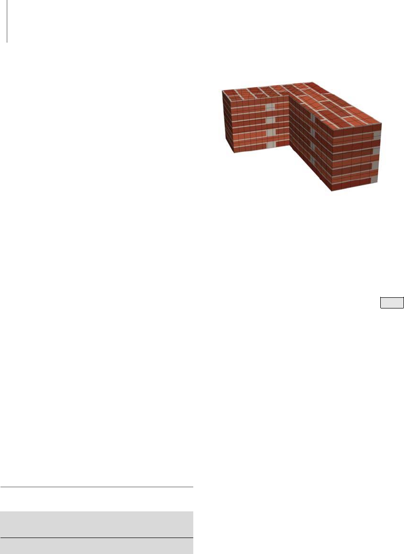
198 Chapter 5: Creating Geometry
circleswithSmoothon.Lowernumberscreate
regular polygonal objects with Smooth off.
Cap Segs—Sets the number of concentric divisions
along the center of the spindle’s top and bottom.
Height Segs—Sets the number of divisions along
the spindle’s major axis.
Smooth—Blends the faces of the spindle, creating a
smooth appearance in rendered views.
Slice On—Tur ns on the S lice f unct ion. Default=off.
WhenyoucreateasliceandthenturnoffSliceOn,
thecompletespindlereappears.Youcantherefore
usethischeckboxtoswitchbetweenthetwo
topologies.
Slice From, Slice To—Sets the number of degrees
around the local Z axis from a zero point at the
local X axis.
For both settings, positive values move the end of
the slice counterclockwise; negative values move it
clockwise. Either setting can be made first. When
theendsmeet,thewholespindlereappears.
Generate Mapping Coords—Sets up the required
coordinates for applying mapped materials to the
spindle. Default=on.
Real-World Map Size—Controls the scaling method
used for texture mapped materials that are applied
totheobject. Thescalingvaluesarecontrolled
by the Use Real-World Scale settings found in
the applied material’s Coordinates rollout (page
2–1625). Default=off.
L-Ext Extended Primitive
Create panel > Geometry button > Extended Primitives
>ObjectTyperollout>L-Extbutton
Create menu > Extended Primitives > L-Extrustion
Use L-Ext to create an extruded L-shaped object.
Example of L-Ext
Procedure
To create an L-Ext object:
1. FromtheCreatemenu,chooseExtended
Primitives > L-Ext.
2. Drag the mouse to define the base. (Press Ctrl
to constrain the base to a square.)
3. Release the mouse and move it vertically to
define the height of the L-extrusion.
4. Click, and then move the mouse vertically to
define the thickness or width of the walls of the
L-extrusion.
5. Click to finish the L-extrusion.
Interface
Creation Method rollout
Corners—Draws the object from corner to corner.
You can change the center location by moving the
mouse.
Center—Draws the object from the center out.
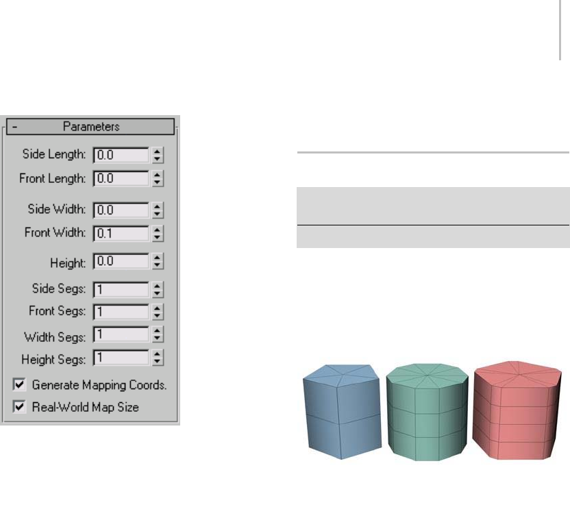
Gengon Extended Primitive 199
Parameters rollout
Side/Front Length—Specify the lengths of each
"leg" of the L.
Side/Front Width—Specify the widths of each "leg"
of the L.
Height—Specifies the height of the object.
Side/Front Segs—Specify the number of segments
for a specific "leg" of the object.
Width/Height Segs—Specify the number of
segments for the overall width and height.
Note: Theobject’sdimensions(Back,Side,Front)
are labeled as though it were created in the Top or
Perspective viewports, and seen from the front in
world space.
Generate Mapping Coords—Sets up the required
coordinates for applying mapped materials to the
object. Default=on.
Real-World Map Size—Controls the scaling method
used for texture mapped materials that are applied
totheobject. Thescalingvaluesarecontrolled
by the Use Real-World Scale settings found in
the applied material’s Coordinates rollout (page
2–1625).Default=off.
Gengon Extended Primitive
Create panel > Geometry button > Extended Primitives >
Object Type rollout > Gengon button
Create menu > Extended Primitives > Gengon
UseGengontocreateanextruded,regular-sided
polygon with optionally filleted side edges.
Examples of gengons
Procedure
To create a gengon:
1. FromtheCreatemenu,chooseExtended
Primitives > Gengon.
2. Set the Sides spinner to specify the number of
side wedges in the gengon.
3. Dragthemousetocreatetheradiusofthe
gengon.
4. Releasethemousebutton,thenmovethe
mouse vertically to define the height of the
gengon. Click to set the height.
5. Move the mouse diagonally to specify the size
of the chamfer along the side angles (toward the
upper left to increase the size; toward the lower
right to decrease it).
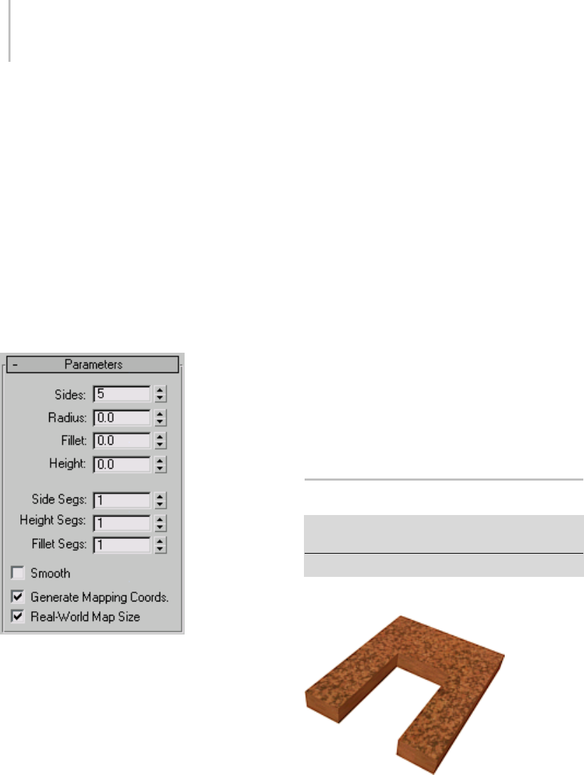
200 Chapter 5: Creating Geometry
6. Click to finish the gengon.
Tip: In the Parameters rollout, increase the Fillet
Segs spinner to round the chamfered corners into
fillets.
Interface
Creation Method rollout
Edge—Draws the object from edge to edge. You
can change the center location by moving the
mouse.
Center—Draws the object from the center out.
Parameters rollout
Sides—Sets the number of sides around the
gengon. Higher numbers shade and render as true
circleswithSmoothon.Lowernumberscreate
regular polygonal objects with Smooth off.
Radius—Sets the radius of the gengon.
Fillet—Sets the width of the chamfered corners.
Height—Sets the dimension along the central
axis. Negative values create the gengon below the
construction plane.
Side Segs—Sets the number of divisions around
the gengon.
Height Segs—Sets the number of divisions along
the gengon’s major axis.
Fillet Segs—Sets the number of divisions for the
edge filleting. Increasing this setting will produce
round, filleted corners instead of chamfers.
Smooth—Blendsthefacesofthegengon,creatinga
smooth appearance in rendered views.
Generate Mapping Coords—Sets up the required
coordinates for applying mapped materials to the
gengon. Default=on.
Real-World Map Size—Controls the scaling method
used for texture mapped materials that are applied
totheobject. Thescalingvaluesarecontrolled
by the Use Real-World Scale settings found in
the applied material’s Coordinates rollout (page
2–1625).Default=off.
C-Ext Extended Primitive
Create panel > Geometry > Extended Primitives > Object
Typerollout>C-Extbutton
Create menu > Extended Primitives > C-Extrusion
Use C-Ext to create an extruded C-shaped object.
Example of C-Ext
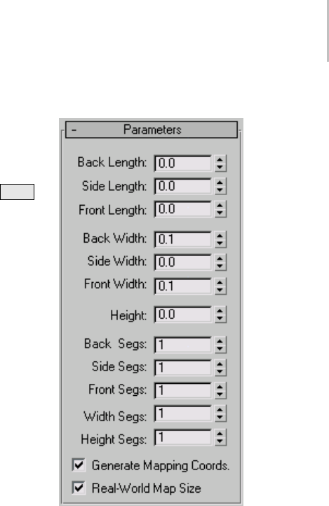
C-Ext Extended Primitive 201
Procedure
To create a C-Ext object:
1. FromtheCreatemenu,chooseExtended
Primitives > C-Extrusion.
2. Drag the mouse to define the base. (Press Ctrl
to constrain the base to a square.)
3. Release the mouse and move it vertically to
define the height of the C-extrusion.
4. Click, and then move the mouse vertically to
definethethicknessorwidthofthewallsofthe
C-extrusion.
5. Click to finish the C-extrusion.
Interface
Creation Method rollout
Corners—Draws the object from corner to corner.
You can change the center location by moving the
mouse.
Center—Draws the object from the center out.
Parameters rollout
Back/Side/Front Length—Specify the length of each
of the three sides.
Back/Side/Front Width—Specify the width of each
of the three sides.
Height—Specifies the overall height of the of the
object.
Back/Side/Front Segs—Specify the number of
segments for a specific side of the object.
Note: Theobject’sdimensions(Back,Side,Front)
are labeled as though it were created in the Top or
Perspective viewports, and seen from the front in
world space.
Width/Height Segs—Set these to specify the
number of segments for the overall width and
height of the object.

202 Chapter 5: Creating Geometry
Generate Mapping Coords—Sets up the required
coordinates for applying mapped materials to the
object. Default=on.
Real-World Map Size—Controls the scaling method
used for texture mapped materials that are applied
totheobject. Thescalingvaluesarecontrolled
by the Use Real-World Scale settings found in
the applied material’s Coordinates rollout (page
2–1625). Default=off.
RingWave Extended Primitive
Create panel > Geometry button > Extended Primitives >
Object Type rollout > RingWave button
Create menu > Extended Primitives > RingWave
Example of ringwave
Use the RingWave object to create a ring,
optionally with irregular inner and outer edges
whose shapes can be animated. You can also
animatethegrowthoftheringwaveobject,and
you can use keyframing to animate all numeric
settings. Use RingWave for various types of
special-effects animation, for example, to depict
the shock wave emanating from the explosion of a
star or planet.
Procedure
To create a basic animated ringwave:
1. On the menu bar choose Create > Extended
Primitives > Ringwave.
2. Drag in a viewport to set the outer radius of the
ringwave.
3. Release the mouse button, and then move the
mousebacktowardthecenteroftheringtoset
the inner radius.
4. Click to create the ringwave object.
5. Dragthetimeslidertoseethebasicanimation.
This is determined by the Inner Edge Breakup
group > Crawl Time settings.
6. To animate the ring’s growth, choose RingWave
Timing group > Grow And Stay or Cyclic
Growth.
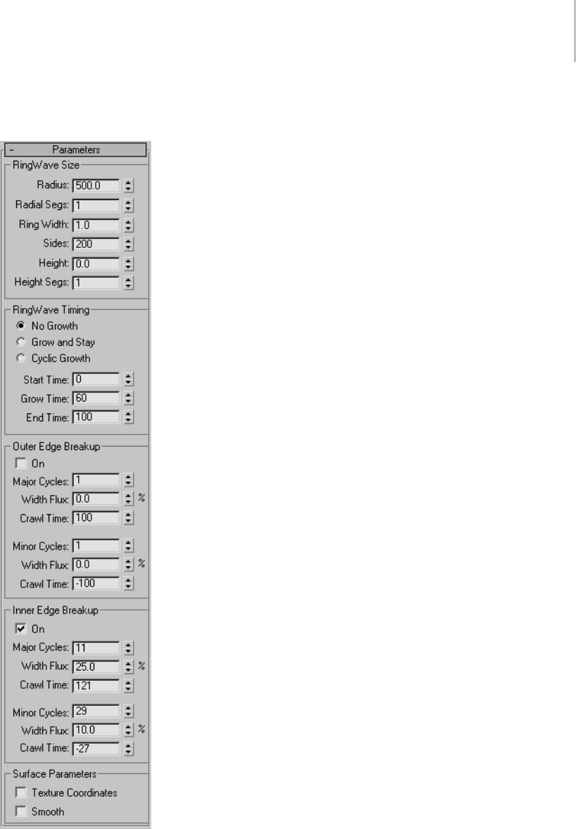
RingWave Extended Primitive 203
Interface
Parameters rollout
RingWave Size group
Use these settings to change the ringwave’s basic
parameters.
Radius—Sets the outside radius of the ringwave.
Radial Segs—Sets the segment count between the
innerandoutersurfacesinthedirectionofthe
radius.
Ring Width—Sets the mean ring width as measured
inward from the outer radius.
Sides—Sets the number of segments in the
circumferential direction for both the inner, outer,
and end (cap) surfaces.
Height—Sets the height of the ringwave along its
major axis.
Tip: If you leave the Height at 0 for an effect like
ashockwave,youwillwanttoapplyatwo-sided
material so that the ring can be seen from both
sides.
Height Segs—Sets the number of segments in the
direction of the height.
RingWave Timing group
Use these settings for ringwave animation where
theringwavegrowsfromnothingtoitsfullsize.
No Growth—Sets a static ringwave, which appears
at Start Time and disappears after End Time.
Grow and Stay—Animates a single growth cycle.
TheringwavebeginsgrowingattheStartTimeand
reaches its full size at Start Time plus Grow Time.
Cyclic Growth—Theringwavegrowsrepeatedly
fromtheStartTimetoStartTimeplusGrowTime.
For example, if you set Start Time to 0 and Grow
Time to 25, leaving End Time at the default value
of 100, and choose Cyclic Growth, the ringwave
grows from nothing to its full size four times over
thecourseoftheanimation.

204 Chapter 5: Creating Geometry
Start Time—The frame number where the ringwave
appears, and begins to grow if you choose Grow
and Stay or Cyclic Growth.
Grow Time—The number of frames after Start
Timetheringwavetakestoreachfullsize.Grow
Time is available only if Grow and Stay or Cyclic
Growth is chosen.
End Time—The frame number after which the
ringwave disappears.
Outer Edge Breakup group
Use these settings to change the shape of the
ringwave’s outer edge.
Tip: For effects like shock waves, the ringwave
typically has little or no breakup on the outer edge
but relatively massive breakup on the inner edge.
On—Turns on breakup of the outer edge. The
remaining parameters in this group are active only
when this is on. Default=off.
Major Cycles—Sets the number of major waves
around the outer edge.
Width Flux—Sets the size of the major waves,
expressed as a percentage of the unmodulated
width.
Crawl Time—Sets the number of frames each
major wave takes to move around the outer
circumference of the RingWave.
Minor Cycles—Sets the number of random-sized
smaller waves in each major cycle.
Width Flux—Sets the average size of the
smaller waves, expressed as a percentage of the
unmodulated width.
Crawl Time—Sets the number of frames each minor
wavetakestomoveacrossitsrespectivemajor
wave.
Inner Edge Breakup group
Use these settings to change the shape of the
ringwave’s inner edge.
On—Turns on the breakup of the inner edge. The
remaining parameters in this group are active only
when this is on. Default=on.
Major Cycles—Sets the number of major waves
around the inner edge.
Width Flux—Sets the size of the major waves,
expressed as a percentage of the unmodulated
width.
Crawl Time—Sets the number of frames each
major wave takes to move around the inner
circumference of the RingWave.
Minor Cycles—Sets the number of random-sized
smallerwavesineachmajorcycle.
Width Flux—Sets the average size of the
smaller waves, expressed as a percentage of the
unmodulated width.
Crawl Time—Sets the number of frames each minor
wavetakestomoveacrossitsrespectivemajor
wave.
Note: Negative values in the Crawl Time parameters
change the direction of the wave. To produce
interference patterns, use Crawl Time settings
of opposite sign for major and minor waves, but
similar Width Flux and Cycles settings.
Tip: To produce the best "random" results, use
prime numbers for major and minor cycles that
differ by a multiple of two to four. For example, a
majorwaveof11or17cyclesusingawidthflux
of 50 combined with a minor wave of 23 or 31
cycles with a width flux of 10 to 20 makes a nice
random-appearing edge.
Texture Coordinates—Sets up the required
coordinates for applying mapped materials to the
object. Default=on.
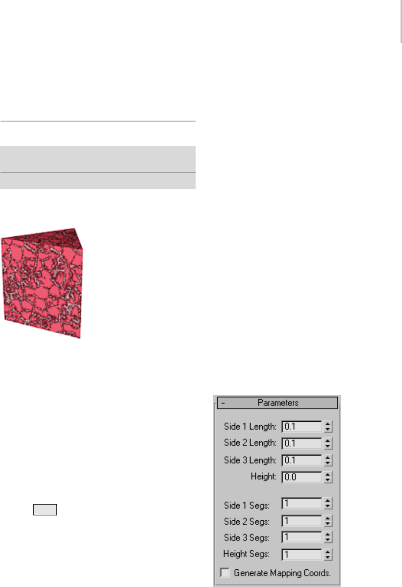
Prism Extended Primitive 205
Smooth—Applies smoothing to the object by
setting all polygons to smoothing group 1.
Default=on.
Prism Extended Primitive
Create panel > Geometry button > Extended Primitives
>ObjectTyperollout>Prismbutton
Create menu > Extended Primitives > Prism
Use Prism to create a three-sided prism with
independently segmented sides.
Example of a prism
Procedures
To create a prism with an isosceles triangle as its
base:
1. Choose Isosceles on the Creation Method
rollout.
2. Drag horizontally in the viewport to define
thelengthofSide1(alongtheXaxis).Drag
vertically to define the length of Sides 2 and 3
(along the Y axis).
(Toconstrainthebasetoanequilateraltriangle,
press Ctrl before performing this step.)
3. Release the mouse, and move it vertically to
define the height of the prism.
4. Click to complete the prism.
5. On the Parameters rollout, alter the length of
the sides as needed.
To create a prism with a scalene or obtuse triangle
at its base:
1. Choose Base/Apex in the Creation Method
rollout.
2. Drag horizontally in the viewport to define
thelengthofSide1(alongtheXaxis).Drag
vertically to define the length of Sides 2 and 3
(along the Y axis).
3. Click, and then move the mouse to specify
the placement of the apex of the triangle. This
alters the length of sides 2 and 3, and the angles
of the corners of the triangle.
4. Click, and then move the mouse vertically to
define the height of the prism.
5. Click to complete the prism.
Interface
Creation Method rollout
Isosceles—Draws a prism with an isosceles triangle
at its base.
Base/Apex—Draws a prism with a scalene or
obtuse triangle at its base.
Parameters rollout
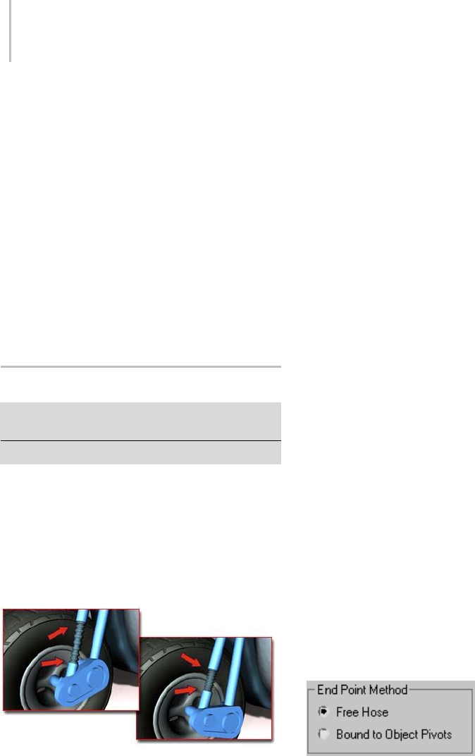
206 Chapter 5: Creating Geometry
Side (n) Length—Sets the length of triangle’s
corresponding side (and thus the triangle’s corner
angles).
Height—Sets the dimension of the prism’s central
axis.
Side (n) Segs—Specifies the number of segments
for each side of the prism.
Height Segs—Sets the number of divisions along
the prism’s central axis.
Generate Mapping Coordinates—Sets up the
required coordinates for applying mapped
materials to the prism. Default=off.
Hose Extended Primitive
Create panel > Geometry > Extended Primitives > Object
Type rollout > Hose button
Create menu > Extended Primitives > Hose
The Hose object is a flexible object that you can
connect between two objects, whereupon it reacts
to their movement. It’s similar to Spring (page
1–400),butdoesnothavedynamicsproperties.
You can specify the overall diameter and length of
thehose,thenumberofturns,andthediameter
and shape of its "wire."
Hose models a workable spring on a motorcycle
Procedures
To create a hose:
1. Fromthemenubar,chooseCreate>Extended
Primitives > Hose.
2. Drag the mouse to define the radius of the hose.
3. Release the mouse, and then move it to define
the length of the hose.
4. Click to finish the hose.
To bind a hose to two objects:
1. Add a hose and two other objects. Select the
hose.
2. IntheModifypanel>HoseParametersrollout
> End Point Method group, choose Bound To
Object Pivots.
3. In the Binding Objects group, click Pick Top
Object, and then select one of the two objects.
4. In the Binding Objects group, click Pick Bottom
Object, and then select the second of the two
objects.
Thetwoendsofthehoseattachthemselvesto
the two objects.
5. Move one of the objects.
The hose adjusts itself to remain attached to
both objects.
Interface
Hose Parameters rollout > End Point Method
group
Free Hose—Choose this when using the hose as a
simple object that’s not bound to other objects.
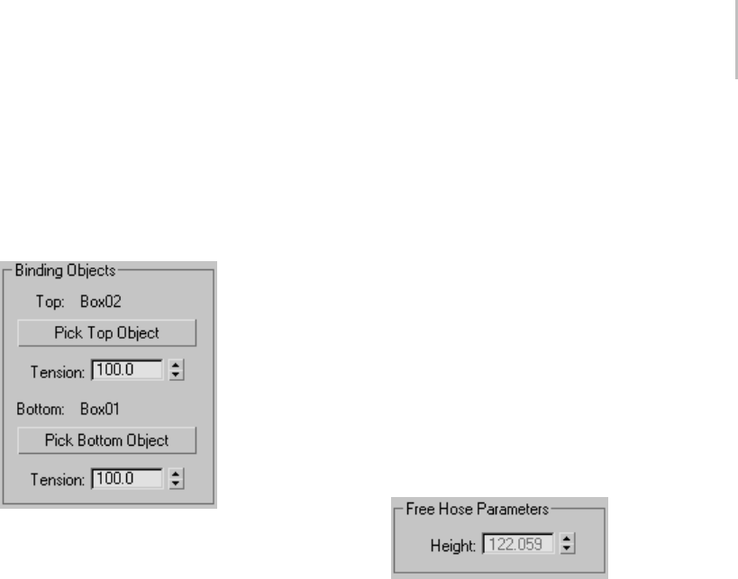
Hose Extended Primitive 207
Bound to Object Pivots—Choose this when binding
thehosetotwoobjects,usingthebuttonsinthe
Binding Objects group.
Hose Parameters rollout > Binding Objects
group
Available only when Bound To Object Pivots is
chosen. Use the controls to pick the objects to
which the hose is bound and to set the tension
between them. "Top" and "Bottom" are arbitrary
descriptors; the two bound objects can have any
positional relationship to each other.
Each end point of the hose is defined by the center
oftheoveralldiameter.Thisendpointisplacedat
the pivot point of the object to which it is bound.
Youcanadjusttherelativepositionofthebinding
object to the hose by transforming the binding
object while the Affect Object Only button is
turned on in the Hierarchy panel > Adjust Pivot
rollout.
Top (label)—Displaysthenameofthe"top"binding
object.
Pick Top Object—Click this button and then select
the "top" object.
Tension—Determinesthetensionofthehosecurve
near the Top object as it reaches for the Bottom
object.Lowerthetensiontohavethebendoccur
closer to the Top object, raise the tension to have
the bend occur further away from the Top object.
Default=100.
Bottom (label)—Displaysthenameofthe"bottom"
binding object.
Pick Bottom Object—Click this button and then
select the "bottom" object.
Tension—Determinesthetensionofthehosecurve
near the Bottom object as it reaches for the Top
object. Lower the tension to have the bend occur
closer to the Bottom object, raise the tension to
have the bend occur further away from the Bottom
object. Default=100.
Hose Parameters rollout > Free Hose Parameters
group
Height—Use this field to set the straight-line height
or length of the hose when it is not bound. This
is not necessarily the actual length of the hose.
AvailableonlywhenFreeHoseischosen.
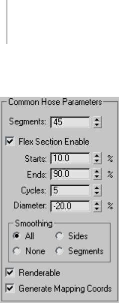
208 Chapter 5: Creating Geometry
Hose Parameters rollout > Common Hose
Parameters group
Segments—The total number of segments in the
hose’s length. Increase this setting for a smooth
profile when the hose is curved. Default=45.
Flex Section Enable—When on, lets you set the
following four parameters for the central, flexible
section of the hose. When off, the hose’s diameter
is uniform throughout its length.
Starts—Thepercentageofthehoselengthfrom
the starting extremity of the hose at which the flex
section begins. By default, the starting end of the
hose is the end at which the object pivot appears.
Default=10%.
Ends—Thepercentageofthehoselengthfromthe
endextremityofthehoseatwhichtheflexsection
ends. By default, the end extremity of the hose is
opposite the end at which the object pivot appears.
Default=90%.
Cycles—The number of corrugations in the flex
section. The number of visible cycles is limited by
the number of segments; if Segments isn’t high
enough to support the number of cycles, then not
all cycles will appear. Default=5.
Tip: To set the appropriate number of segments,
first set Cycles, and then increase Segments until
the number of visible cycles stops changing.
Diameter—The relative width of the "outside"
parts of the cycles. At negative settings, these are
smaller than the overall hose diameter. At positive
settings, these are larger than the overall hose
diameter. Default=-20%. Range=-50% to 500%.
Smoothing—Defines the geometry that gets
smoothed. Default=All:
•All—Theentirehoseissmoothed.
•Sides—Smoothingisappliedalongthelength
of the hose but not around its circumference.
•None—No smoothing is applied.
•Segments—Smoothingisappliedonlyonthe
inner section of the hose.
Renderable—When on, the hose is rendered using
the specified settings. When off, the hose is not
rendered. Default=on.
Generate Mapping Coords—Sets up required
coordinates for applying mapped materials to the
hose. Default=on.
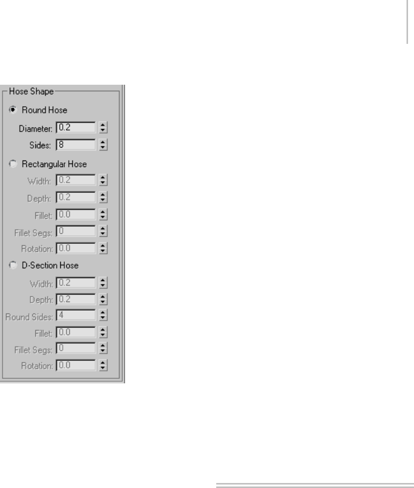
Architectural Objects 209
Hose Parameters rollout > Hose Shape group
Sets the shape of the hose cross section.
Default=Round Hose.
Round Hose—Sets a circular cross section.
Diameter—The maximum width of the hose at the
ends.
Sides—Thenumberofsidesofthehose.ASides
settingof3givesatriangularcrosssection;4gives
a square cross section; and 5 gives a pentagonal
cross section. Increase Sides for a circular cross
section. Default=8.
Rectangular Hose—Lets you specify different
settings for width and depth.
Width—The width of the hose.
Depth—The height of the hose.
Fillet—The amount by which the cross-section
corners are rounded. For this to be visible, Fillet
Segs must be set to 1 or higher. Default=0.
Fillet Segs—The number of segments across each
filleted corner. A Fillet Segs setting of 1 cuts the
corner straight across; use higher settings for
rounded corners. Default=0.
Rotation—The orientation of the hose along its
long axis. Default=0.
D-Section Hose—Similar to Rectangular Hose, but
rounds one side for a D-shaped cross-section.
Width—The width of the hose.
Depth—The height of the hose.
Round Sides—The number of segments on the
rounded side. Increase for a smoother profile.
Default=4.
Fillet—The amount by which the two cross-section
corners opposite the rounded side are rounded.
For this to be visible, Fillet Segs must be set to 1 or
higher. Default=0.
Fillet Segs—The number of segments across each
filleted corner. A Fillet Segs setting of 1 cuts the
corner straight across; use higher settings for
rounded corners. Default=0.
Rotation—The orientation of the hose along its
long axis. Default=0.
Architectural Objects
3ds Max provides an array of architectural objects,
useful as building blocks for models of homes,
businesses, and similar projects. These include:
AEC Extended Objects (page 1–210):Foliage,
Railing, and Wall
Stairs (page 1–231)
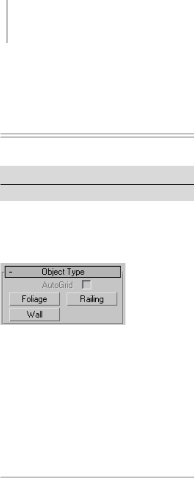
210 Chapter 5: Creating Geometry
Doors (page 1–246)
Windows (page 1–253)
AEC Extended Objects
Create panel > Geometry > AEC Extended
Create menu > AEC Objects
AEC Extended objects are designed for use in
the architectural, engineering, and construction
fields.UseFoliagetocreateplants,Railingtocreate
railings and fences, and Wall to create walls.
Interface
Foliage (page 1–214)
Railing (page 1–217)
Wall (page 1–223)
The Object Name and Wireframe Color rollout (page
3–757) in each AEC Extended object’s creation
panel functions identically. The remaining rollouts
are covered in each object’s topic.
Working with AEC Design
Elements
3ds Max includes such features as Foliage, Doors,
Windows, Stairs, Railing, and Wall to make
exploring three-dimensional design ideas much
easier.
This section provides general information about
these features. For detailed explanations and
procedures, see the topics listed below:
Doors (page 1–246)
Windows (page 1–253)
Stairs (page 1–231)
Railing (page 1–217)
Wall (page 1–223)
Foliage (page 1–214)
Doors and Windows
3ds Max supplies a number of parametric window
and door objects that you can place into wall
openings to add realism to an architectural model.
These objects let you control details like trim and
panelfillinyourmodel.
Tip: Use Snaps (page 2–46) for added precision
when adding doors and windows.
When you create a new door or window, you must
select four points in the scene that define the size
and orientation of the rectangle that will be the
door or window. You may find it easier to select
thesepointsinagivensequence,dependingon
your scene and views of the scene.
If you already have a rectangular hole you want to
fill, you can still create a door or window to your
specifications by using the following procedure.
To create a door or window:
1. Set up an angled User view so that you can see
thebottomandoneverticaledgeoftheopening
and its full height.
2. Settheappropriateobjectsnaps,suchasVertex
or Endpoint. This helps make the model more
precise.

Working with AEC Design Elements 211
3. After clicking Window or Door, choose one of
two Creation Methods: Width/Depth/Height
or Width/Height/Depth.
4. Make parameter adjustments to define details.
The width and orientation of the door/window
is always defined by the first mouse click and
subsequent mouse drag. Depending on the
creation method you use, either the height or
depth of the object is defined next.
Ifyouhavenoobjectsnapssetandareworking
in a Perspective or User Viewport, using
the Width/Depth/Height Creation Method
creates an upright Door or Window. The
Width/Height/Depth Creation Method creates the
object as if it were lying on its side.
Allowing Non-vertical Jambs
TheAllowNon-verticalJambstoggleisuseful
for creating doors or windows that do not fit in
a vertical plane, such as a skylight window in a
sloping roof. By default, this toggle is off, making
the third point in the creation sequence either
directly above (Width/Height/Depth) or on the
same horizontal plane (Width/Depth/Height)
with the second point.
WhenyouturnonAllowNon-verticalJambs,the
third point in the creation sequence falls wherever
youchooseandthefourthpointisaddedbythe
program. Its offset from the plane is determined
by the first three points.
Using the Width/Height/Depth Creation Method
in Perspective and User viewports with Allow
Non-vertical Jambs off can be an efficient way
to create doors and windows with Object Snaps.
However, it can also be confusing at first. Keep in
mind that the third point you define, the Height,
is interpreted as a point on the home grid until
you indicate a point higher or lower than the grid.
If you are using an Object Snap setting, 3ds Max
mightnotknowyoumeanapointoffthegrid
unless you bring the cursor in proximity to a
nonplanar point to which it can snap.
Additional Parameters
There are additional parameters specific to
each door and window type that control overall
dimension parameters, as well as detailed
parameters for sub-object components such as
mullions, trim, and panels within leaves. See Doors
(page 1–246) and Windows (page 1–253) for more
information on these parameters.
Animating Doors and Windows
Certain door and window creation parameters,
including the Open parameter, can be animated.
See Doors (page 1–246) and Windows (page 1–253)
for more information.
Creating Stairs and Railings
3ds Max contains four types of stair objects: spiral
stairs (page 1–235),U-type stairs (page 1–243) with
an intermediate landing, L-type stairs (page 1–232)
with a landing at the bend in the stair, and straight
stairs (page 1–239) with no intermediate landing.
A complementary Railing object can be used to
create any number of handrail designs that follow
along a spline path.
For more information, see Stairs (page 1–231).
The Railing Object
UsetheRailingbuttonontheCreatepanelinthe
to produce railing objects. Railing components
include rails, AEC Extended category (page
1–210)posts, and fencing. Fencing includes pickets
(balusters) or solid-filled material (such as glass or
wood strips).
You can create a railing in two ways: specify the
orientation and height of the railing, or pick a
spline path and apply the railing to that path.
Thesplinepathwitharailingiscalledarailpath.
Later, if you edit the rail path, the Railing object

212 Chapter 5: Creating Geometry
automatically updates to follow the changes you
make. Rail paths can occupy three-dimensional
space.
When you create the lower rails, posts, and fencing
components of a Railing object, you use a special
version of the Spacing Tool to specify the spacing
ofthosecomponents.Theprogramdisplaysthe
Spacing Tool dialog for each railing component:
Lower Rail, Post Spacing, or Picket Spacing. For
moreinformationontheSpacingTool,seeSpacing
Tool (page 1–455).
For details on Railing parameters and information
on creating a Railing object, see Railing (page
1–217).
Creating Walls
Use the Wall button (page 1–223) on the Create
panel, in the AEC Extended category, to produce
straight-wall objects. A wall object is made up of
sub-object segments that you can edit with the
Modify panel.
Yo u c a n :
• Break or insert wall segments to create separate
wall objects.
• Delete wall segments.
• Connect two wall objects.
When you create two wall segments that meet at a
corner, 3ds Max removes any duplicate geometry.
This “cleaning up” of the corners might involve
trimming. 3ds Max cleans up only the first two
wall segments of a corner, not other wall segments
that might share the corner. 3ds Max does not
clean up intersections.
You can edit the segments of a wall using
sub-objectselectionmodeontheModifypanel.
For example, you can define a wall’s height profile.
3dsMaxmovestheactivegridtotheplaneofthe
wall you’re editing. This allows you to snap to the
profileverticesintheplaneofthewall.
If you move, scale, or rotate the wall object, the
linked door and window moves, scales, or rotates
along with the wall. If you move the linked door or
windowalongthewall,usingthedoororwindow’s
Local coordinate system and activating Restrict
to XY Plane in the Axis Constraints toolbar (page
1–437), the opening will follow. Also, if you change
adoororwindow’soverallwidthandheightinthe
Modifypanel,theholewillreflectthosechanges.
Usage Tips
The following are a few tips for working with wall
objects:
• Use the Top viewport when creating wall
objects.
• Single walls with many windows and doors can
slow down snap calculations and movement
of the wall object. To speed up insertion and
editing, use multiple walls instead of a single
wall.
• Youcanspeedupperformanceinascenewith
many walls, windows, and doors by collapsing
them. First save an uncollapsed version for any
future parametric changes you might want to
make. Then right-click the wall and pick Select
Children from the right-click menu. Next use
Collapse in the Utility rollout to collapse them
all.
For complete information, see Wall (page 1–223).
To create a wall:
1. OntheCreatepanel,intheAECExtended
category, click Wall.
2. Use Customize > Units Setup to establish
precision, and then set the parameters for the
Width, Height, and Justification of the wall.
3. In any viewport, click, release the mouse, drag
thewallsegmenttothelengthyouwantand
click again.

Working with AEC Design Elements 213
This creates a wall segment. You can end the
wall or you can continue to create another wall
segment.
4. To complete the wall, right-click, or to add
another wall segment, drag the next wall
segmenttothelengthyouwantandclickagain.
If you create a room by ending a segment at
the end of another segment of the same wall
object, the program displays the Weld Point
dialog.Thisdialogletsyouconvertthetwoend
vertices into a single vertex, or keep the two end
vertices separate.
5. If you want the wall segments to be welded at
a corner (when you move one wall, the other
wall stays at the corner), click Yes. Otherwise,
click No.
6. Right-click to complete the wall, or continue to
add another wall segment.
To attach separate walls:
1. Select a wall object.
2. On the Modify panel, click Attach, and then
pick another wall object.
Thetwowallobjectsbecomepartofthesame
wall object, but are not physically connected.
Attach stays active, and you can continue
clicking wall segments to attach. To stop
attaching, click the Attach button or right-click
in the active viewport.
To attach multiple wall objects simultaneously
to the selected wall object, click Attach Multiple
on the Modify panel to open the Attach
Multipledialog.Thisworksthesameasthe
Select Objects dialog (page 1–78),exceptthatit
shows only wall objects; choose multiple walls
to attach, and then click the Attach button.
To connect vertices in a wall:
This method lets you connect two separate wall
sections with a new segment.
Tip: It is easier to work with wall vertices in
wireframe view mode.
1. Selectawallobjectthathasmorethanone
section. Typically you would use Attach to
create such an object.
2. In the modifier stack (page 3–760),gotothe
Vertex sub-object level.
3. Click Connect and point the mouse over an end
vertex until the cursor changes to a cross.
4. Click once over the end vertex.
5. Move the cursor to another end vertex, and
then click to connect the two segments.
To insert a vertex in a wall:
It is easier to work with wall vertices in wireframe
view mode.
1. Select a wall segment.
2. In the modifier stack (page 3–760),gotothe
Vertex sub-object level.
3. Click Insert.
A highlighted line appears along the bottom of
the wall, showing where you can insert vertices.
4. Click anywhere on the highlighted line to insert
avertex.
The new vertex is attached to the mouse cursor.
5. Move the mouse to position the vertex, and
then click to place it.
Now the mouse is attached to one of the new
segments.
6. Move the mouse along the segment and click to
add vertices.
7. Right-click to finish working on this segment.
You can now insert vertices in other segments,
or right-click again to exit Insert mode.
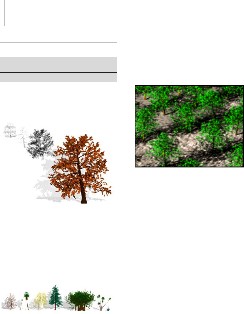
214 Chapter 5: Creating Geometry
Foliage
Create panel > Geometry > AEC Extended > Foliage
button
Create menu > AEC Objects > Foliage
Foliageproducesvarioustypesofplantobjects
such tree species. 3ds Max generates mesh
representations to create fast, efficient, and
good-looking plants.
Youcontrolheight,density,pruning,seed,canopy
display, and level of detail. The seed option
controls creation of different representations of the
same species. You can create millions of variations
ofthesamespecies,soeachobjectcanbeunique.
With the viewport canopy mode (page 1–217)
option, you can control the amount of plant detail,
reducing the number of vertices and faces 3ds Max
uses to display the plant.
Some of the plants that can be created from the standard
library
Tips
•UsetheSpacing tool (page 1–455) to place plants
along a path.
• Use vertex or face snapping (see Snaps Settings
(page 2–41)) to position plants on a surface.
Using the Spacing tool to distribute trees along paths
Procedure
To add plants to a scene:
1. Click the Favorite Plants rollout > Plant Library
button to display the Configure Palette dialog.
2. Double-click the row for each plant you want to
addorremovefromthePaletteandclickOK.
3. OntheFavoritePlantsrollout,selectaplantand
dragittoalocationinaviewport.Alternatively,
select a plant in the rollout and then click in the
viewport to place the plant.
4. On the Parameters rollout, click the New button
to display different seed variations of the plant.
5. Adjust the remaining parameters to show
elements of the plants, such as leaves, fruit,
branches, and if you want, to view the plant in
canopy mode.
Interface
Object Name and Wireframe Color rollout
This rollout lets you set the foliage object’s
name, color, and default material. For detailed
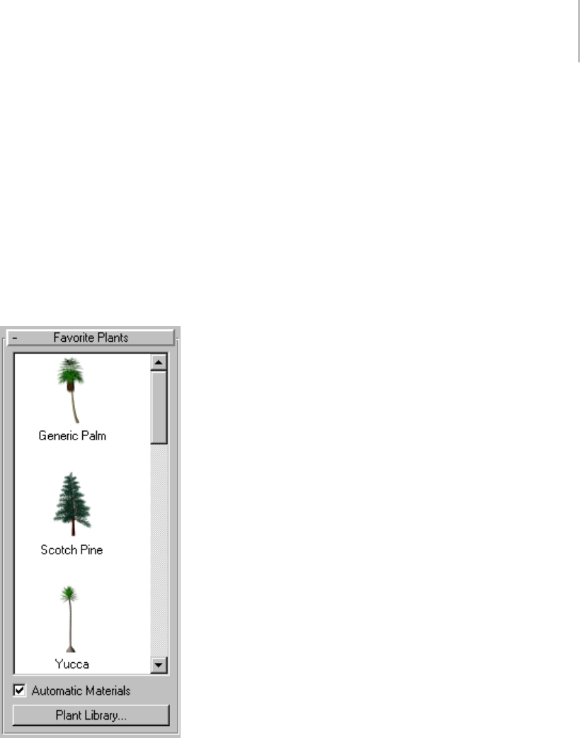
Foliage 215
information, see Object Name and Wireframe
Color (page 3–757).
When Favorite Plants rollout > Automatic
Materialsison,eachplantisassigneditsown
default material. For more information, see
Favorite Plants rollout, following.
Keyboard Entry rollout
See Creating Primitives from the Keyboard (page
1–169).
Favorite Plants rollout
Thepalettedisplaystheplantscurrentlyloaded
from the Plant Library.Therearethreewaysto
add a plant to the scene:
•Usekeyboardentry.
• Click the icon in the Favorite Plants list and then
click a location in a viewport. Double-click the
icon to place the plant at the world origin.
• Drag the plant from the palette and drop it into
aviewport.
Automatic Materials—Assigns default materials for
the plant. To modify these material assignments,
use the Material Editor (page 2–1409).Selectthe
plant in the viewport, and click Main toolbar >
Material Editor. Click the Get Material button
(page 2–1439) to display the Material/Map
Browser. Under Browse From, choose Selected.
Then,fromthelistpane,double-clickthematerial
list item for the plant to display the materials in the
Basic Parameters rollout of the Material Editor.
If you turn off Automatic Materials, 3ds Max
assigns no materials to the object, unless the Name
And Color rollout > Default Material check box
is on and a default material is assigned. This way
you can specify a particular default material for all
foliage objects. For more information, see Object
Name and Wireframe Color (page 3–757).
When on, Automatic Materials overrides the
Default Material settings.
Note: Even if Automatic Materials is off, 3ds Max
still assigns material IDs to the foliage objects,
so that the object is ready for a multi/sub-object
material.
Plant Library—Displays the Configure Palette
dialog. Using this window, you can view
information on the available plants including
their names, whether they’re in the palette, their
scientific names, types, descriptions, and the
approximate number of faces per object. You can
also add and remove plants from the palette, and
clear the palette, which removes all plants from the
palette.
Tip: To quickly add or remove a plant from the
palette, double-click its row in the Configure
Palette dialog. The Fav. (Favorite Plants) column
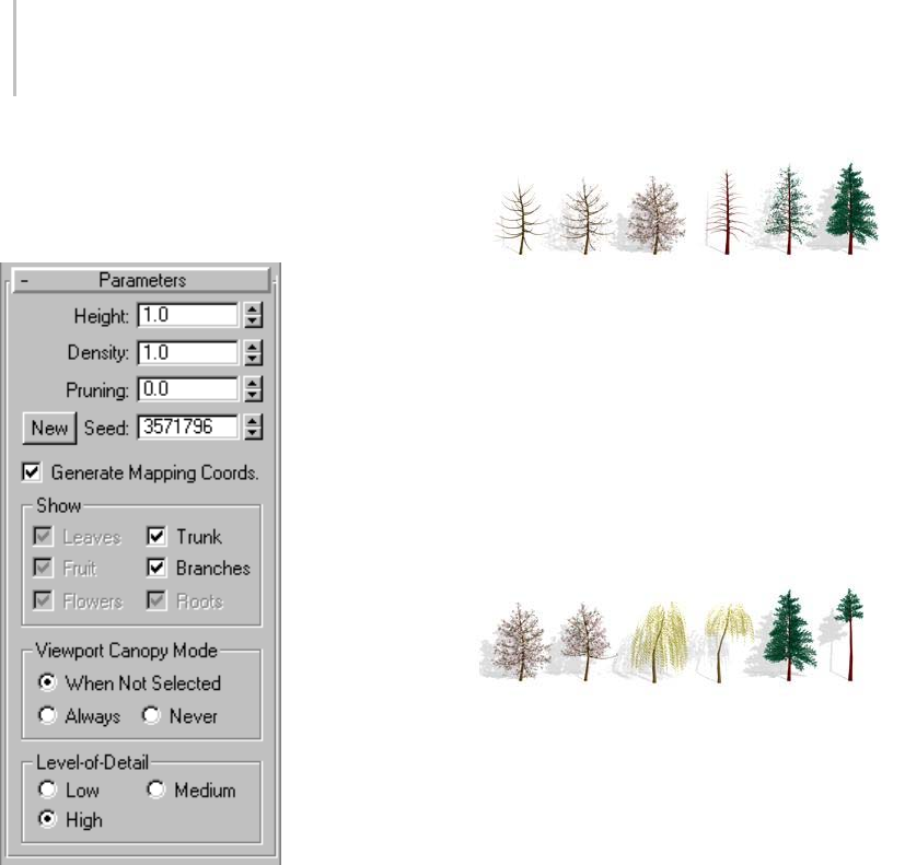
216 Chapter 5: Creating Geometry
entry switches between "no" and "yes." Click OK
to accept the changes and exit the window.
Parameters rollout
Height—Controls the approximate height of the
plant. 3ds Max applies a random noise factor to
the height of all of the plants. Therefore, the actual
height of a plant, as measured in the viewports,
won’t necessarily match the setting given in the
Height parameter.
Density—Controls the amount of leaves and
flowers on the plant. A value of 1 displays a plant
with all its leaves and flowers, .5 displays a plant
withhalfitsleavesandflowers,and0displaysa
plant with no leaves or flowers.
Two trees with varying foliage densities
Pruning—Appliesonlytoplantswithbranches.
Removes branches that lie below an invisible plane
parallel to the construction plane. A value of 0
prunes nothing, a value of .5 prunes the plant at a
plane halfway up its height from the construction
plane, and a value of 1 prunes everything possible
from the plant. What 3ds Max prunes from the
plant depends on the type of plant. The trunk is
never pruned.
Three pairs of trees, showing different values of pruning
New—Displays a random variation of the current
plant. 3ds Max displays the seed value in the
numeric field next to the button.
Tip: Click the New button repeatedly until you find
the variation you want. This is often easier than
trying to adjust the tree using modifiers.
Seed—A value between 0 and 16,777,215
representing the possible variations of branch and
leaf placement and shape and angle of the trunk of
the current plant.
Generate Mapping Coords—Applies default
mapping coordinates (page 3–967) to the plant.
Default=on.
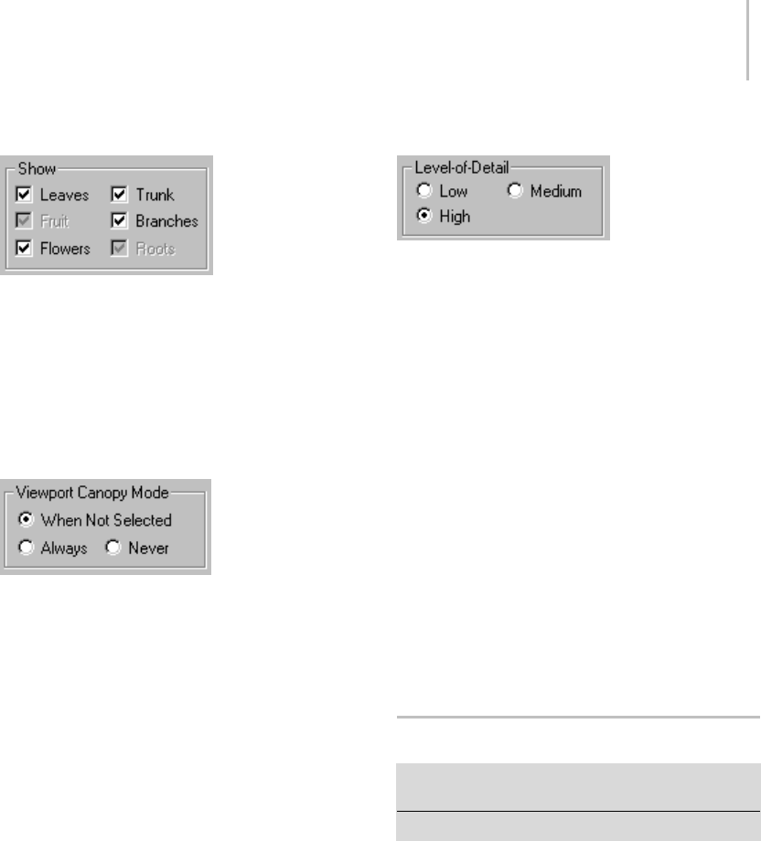
Railing 217
Show group
Controls the display of leaves, fruit, flowers,
trunk, branches, and roots of plants. Available
options depend on the type of plant you select.
For example, if a plant doesn’t have fruit, 3ds Max
disables that option. Turning off options reduces
the number of vertices and faces displayed.
Viewport Canopy Mode group
In3dsMax,thecanopyofaplantisashellcovering
the outermost parts of the plant, such as the leaves
or the tips of the branches and trunk. The term
derives from "forest canopy." Use reasonable
parameters when you create many plants and want
to optimize display performance.
Because this setting applies only to the plant’s
representation in the viewports, it has no effect on
how 3ds Max renders the plant. For information on
how 3ds Max renders the plant, see Level-of-Detail
(page 1–217).
When Not Selected—Displays the plant in canopy
mode when it’s not selected.
Always—Always displays the plant in canopy
mode.
Never—Never displays the plant in canopy mode.
3ds Max displays all the features of the plant.
Level-of-Detail group
Controls how 3ds Max renders the plant. For
information on how 3ds Max displays the plant in
the viewports, see Viewport Canopy Mode (page
1–217).
Low—Renders the plant canopy, providing the
lowest level of detail.
Medium—Renders a reduced-face-count version
of the plant. How 3ds Max reduces the face count
varies from plant to plant, but it usually involves
removing smaller elements of the plant or reducing
the number of faces in the branches and trunk.
High—Renders all the faces of the plant, providing
the highest level of detail.
Tip: Set the parameters before creating multiple
plants. This can avoid slowing down the display,
and might reduce editing you have to do on the
plants.
Railing
Create panel > Geometry > AEC Extended > Railing
button
Create menu > AEC Objects > Railing
Components of the railing object include rails,
posts, and fencing. Fencing includes either pickets
(balusters) or solid-filled material, such as glass
or wood strip.

218 Chapter 5: Creating Geometry
Railings used to create fences in a field.
You can create a railing object either by specifying
the orientation and height of the railing, or by
picking a spline path and applying the railing to
that path. When 3ds Max applies railing to a spline
path, the latter is called a rail path.Later,ifyou
edittherailpath,therailingobjectautomatically
updatestofollowthechangesyoumade.Youcan
use three-dimensional splines as rail paths.
When you create the lower rails, posts, and fencing
components of a railing, you use the Spacing
tool (page 1–455) to specify the spacing of those
components. 3ds Max names the Spacing tool
dialog for each railing component: Lower Rail
Spacing, Post Spacing, or Picket Spacing.
Tip: Use Railing to create complete railings
for stairs. See Stairs (page 1–231) for more
information.
Railings and Materials
By default, 3ds Max assigns five different material
IDs to railings. The aectemplates.mat material
library includes Rail-Template,amulti/sub-object
material (page 2–1594) designed to be used with
railings. Each component of the railing/material is
listed below along with its corresponding Material
ID.
Material ID Railing/Material Component
1Lower rails
2Posts of the railing
3Solid fill of the railing
4Top of the railing
5Pickets of the railing
Note: 3ds Max does not automatically assign a
material to the railing object. To use the included
material, open the library and then assign the
material to your object.
Procedures
The following procedures describe how to create
railings combining each of the components: upper
rail, lower rails, posts, picket fencing, and solid
filled fencing.
You can create a railing object in any viewport,
but for best results, use a Perspective, Camera, or
To p v i e w p o r t .
To create a railing:
1. Click and drag the railing to the desired length.
2. Release the mouse button, and then move the
mouse vertically to set the height. Click to
finish.
Bydefault,3dsMaxcreatesthetoprailalong
with two posts, a lower rail at half the railing
height, and two evenly spaced pickets.
3. If you need to, change any of the parameters
to adjust the segments, length, profile, depth,
width, and height of the rail.
To adjust lower rails:
1. To modify the lower rail, or add more, choose
an option from the Lower Rail(s) group >
Profile list.
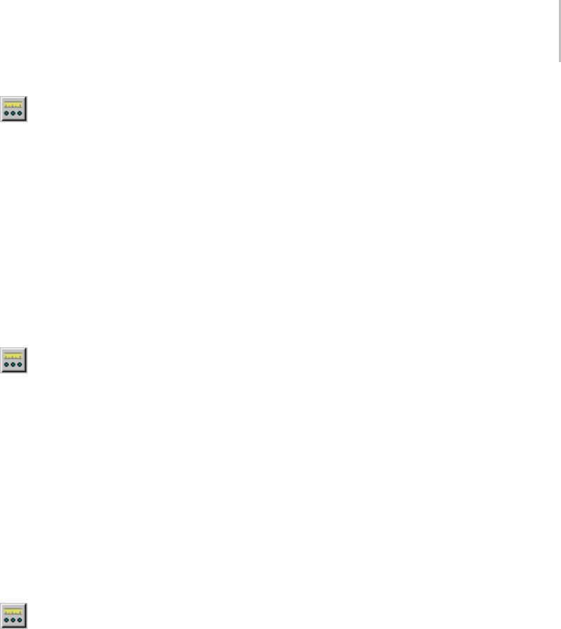
Railing 219
2. Specifythedepthandwidthforthelower
rails and then click the Lower Rail(s) > Spacing
button.
3. Specify the number of lower rails you want
using the Count option. Click Close to apply
your changes. For more information on spacing
optionsinthisdialog,seeSpacing Tool (page
1–455).
To create posts:
1. If you want to modify the posts, or add more,
chooseanoptionfromtheProfilelistunderthe
Posts rollout.
2. Specify the depth and width of the posts
and how much they should extend above the
toprail.ThenclickthePostsrollout>Spacing
button.
3. Specify the number of posts you want using
the Count option. Click Close to apply your
changes. For more information on spacing
optionsinthisdialog,seeSpacing Tool (page
1–455).
To create pick et fencing:
1. Choose Fencing rollout > Type list > Pickets.
The Solid Fill options will be unavailable.
2. Choose an option from the Profile list,
specifythedepthandwidthofthepickets,and
then click the Picket rollout > Spacing button.
3. Specify the number of pickets you want using
the Count option. Click Close to apply your
changes. For more information on spacing
options in this dialog, Spacing Tool (page
1–455).
To create solid-fill fencing:
1. Choose Fencing rollout > Type list > Solid Fill.
(The options under Picket are unavailable).
2. Under Solid Fill, adjust the options for
Thickness and offsets.
To create railings along a spline path:
Before you can create railings along a spline path,
you need to create a spline, or use an existing
spline from your scene.
1. Click Create panel > Geometry > AEC
Extended > Railing.
2. Click Pick Railing Path, then select a spline in
your scene.
Since the number of segments is 1 by default,
the upper rail extends for one segment between
the start and end of the spline.
3. Change the amount of segments using the
Modify panel > Segment setting.
The higher the segment value, the more closely
therailingapproximatesthesplineshape.
4. If you want the railing to contain corners where
thesplinedoes,turnonRespectCorners.
5. Complete the remainder of the railing options
as described in the preceding procedures.
Thereafter, the spline is associated with the
railing; any changes you make to the spline
shape are reflected in the railing.
Interface
Name and Color rollout
This rollout lets you set the selected railing’s name
and color. For detailed information, see Object
Name and Wireframe Color (page 3–757).
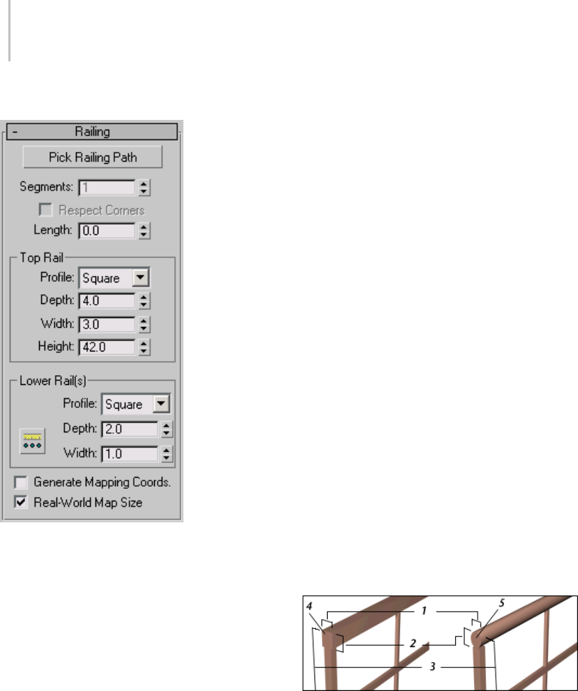
220 Chapter 5: Creating Geometry
Railing rollout
Pick Railing Path—Click this, and then click a spline
intheviewporttouseastherailingpath.3dsMax
uses the spline as the path along which to apply
the railing object.
If you edit the spline you’ve used as a railing
path, the railing adjusts to the changes you make.
3ds Max doesn’t immediately recognize 2D Shapes
from a linked AutoCAD drawing. To recognize
Shapes from a linked AutoCAD drawing, edit the
Shape with Edit Spline (page 1–680) in the Modify
panel.
Tip: When you create a railing using a closed spline
for the rail path, open the PostSpacingdialog(page
1–455), turn off Start Offset and End Offset, and
lock End Offset. This will ensure that 3ds Max
properly creates the railing with any fill, pickets,
and posts you specify.
Note: Railing objects that use Pick Path do not stay
on the path when substituted using the Substitute
modifier. Substituted externally referenced
railings do not undo when railings are associated
with a path.
Segments—Sets the number of segments of the
railing object. Available only when you’re using
arailingpath.
For a close approximation to a railing path,
increase the number of segments. Be aware that a
high number of segments increases file size and
slows down the rendering speed. You might use
fewer segments when the spline path has a low
curvature (or none) and fewer segments provide
an adequate approximation.
Respect Corners—Puts corners in the railing to
match the corners of the railing path.
Length—Sets the length of the Railing object.
When you drag the mouse, the length displays in
the edit box.
Top Rail group
The defaults produce a top rail component,
consisting of one segment by the length you
specify, a square profile, four units deep, three
units wide, and the height you specify.
1. Width
2. Depth
3. Height
4. Profile for the square top rail
5. Profile for the round top rail
Profile—Sets the cross-section shape of the top rail.
Depth—Sets the depth of the top rail.
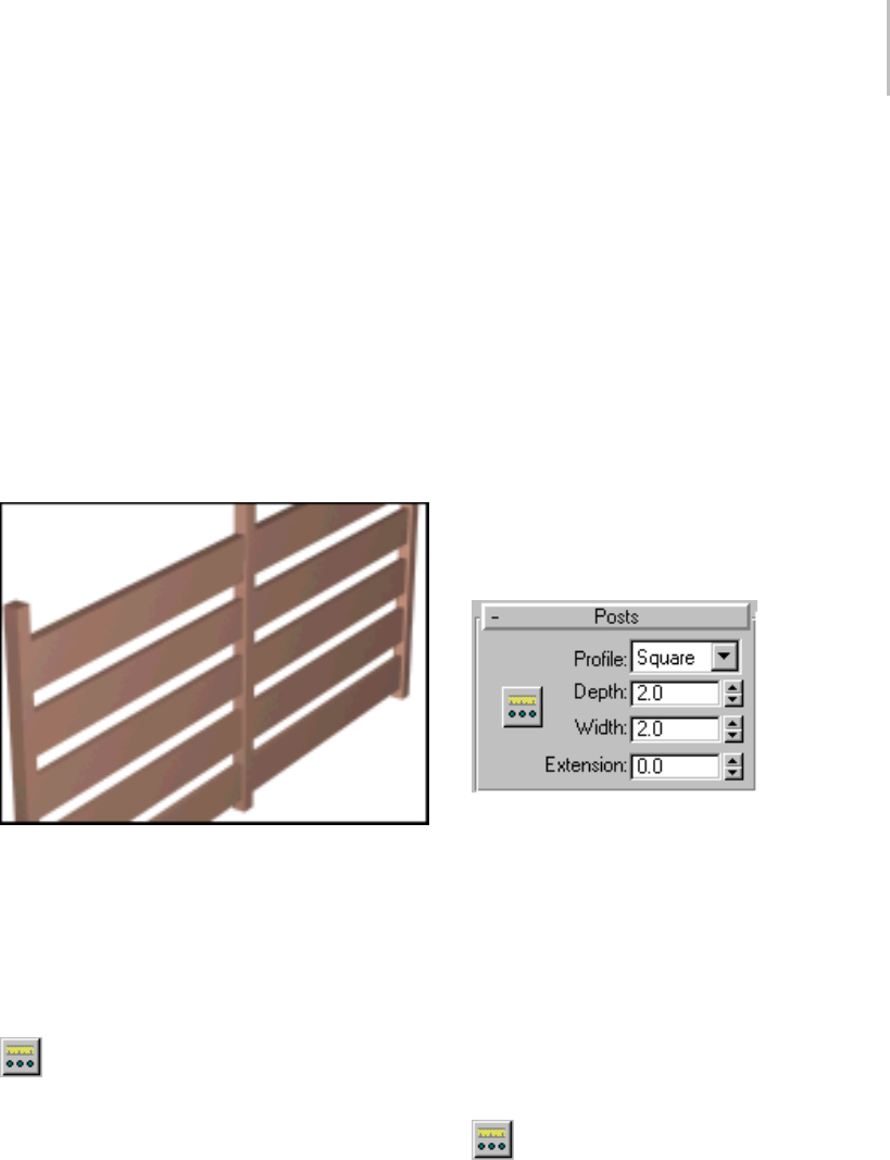
Railing 221
Width—Sets the width of the top rail.
Height—Sets the height of the top rail. During
creation, you can drag the top rail to the height
you want using the mouse in the viewport. Or you
can enter the height amount from the keyboard
or use the spinners.
Lower Rail(s) group
Controls the profile, depth, width, and spacing
between the lower rails. You specify how many
lower rails you want using the Lower Rail Spacing
button.
A railing with the rails defined by their profile, depth, and width
as planks.
Profile—Sets the cross-section shape of the lower
rails.
Depth—Sets the depth of the lower rails.
Width—Sets the width of the lower rails.
Lower Rail Spacing—Sets the spacing of the
lower rails. When you click this button, the Lower
Rail Spacing dialog displays. Specify the number
of lower rails you want using the Count option.
For more information on spacing options in this
dialog, see Spacing Tool (page 1–455).
Generate Mapping Coords—Assigns mapping
coordinates (page 3–967) to the railing object.
Note: If a visible viewport is set to a non-wireframe
or non-bounding-box display, Generate Mapping
Coordinatesisonforallprimitivestowhichyou
apply a material containing a map with Show
Map In Viewport on. If all viewports are set to
wireframe or bounding box, 3ds Max turns on
Generate Mapping Coordinates for primitives
containing mapped materials at render time.
Real-World Map Size—Controls the scaling method
used for texture mapped materials that are applied
totheobject. Thescalingvaluesarecontrolled
by the Use Real-World Scale settings found in
the applied material’s Coordinates rollout (page
2–1625).Default=off.
Posts rollout
Controlstheprofile,depth,width,extension,and
spacing between the posts. You specify how many
posts you want using the Post Spacing button.
Profile—Sets the cross-section shape of the posts:
none, Square, or Round.
Depth—Sets the depth of the posts.
Width—Sets the width of the posts.
Extension—Sets the amount the posts extend above
the bottom of the top railing.
Post Spacing—Sets the spacing of the posts.
When you click this button, the Post Spacing
dialog displays. Specify the number of posts
you want using the Count option. For more
information on spacing options in this dialog, see
Spacing Tool (page 1–455).
222 Chapter 5: Creating Geometry
Tip: Setting Profile to (none) makes an "invisible"
post.Youmightwanttodothistocreatearailing
with gaps between solid fill fencing. Or you could
useittomakearailingwithopeningsbetween
groups of pickets. This is different from setting the
postcountto0inthePostSpacingdialog.
Fencing rollout
Type—Sets the type of fencing between the posts:
none,Pickets,orSolidFill.
Picket group
Controls the profile, depth, width, and spacing
between the pickets. Specify how many pickets you
wantusingthePicketSpacingbutton. Available
only when you set Type to Pickets.
1. A railing with pickets using a square profile
2. A railing with pickets using a round profile
Profile—Sets the cross-section shape of the pickets.
Depth—Sets the depth of the pickets.
Width—Sets the width of the pickets.
Extension—Sets the amount the pickets extend
above the bottom of the top railing.
Bottom Offset—Sets the amount the pickets are
offset from the bottom of the railing object.
Picket Spacing—Sets the spacing of the
pickets. When you click this button, the Picket
Spacing dialog displays. Specify the number of
pickets you want using the Count option. For more
information on spacing options in this dialog, see
Spacing Tool (page 1–455).
Solid Fill group
Controls the thickness and offsets of the solid fill
between the posts. Available only when you set
Type to Solid.
Thickness—Sets the thickness of the solid fill.
Top Offset—Sets the offset of the solid fill from the
bottom of the top rail.
Bottom Offset—Sets the offset of the solid fill from
the bottom of the railing object.
Left Offset—Sets the offset between the solid fill
and the adjacent left post.
Right Offset—Sets the offset between the solid fill
and the adjacent right post.

Wall 223
Wall
Create panel > Geometry > AEC Extended > Object Type
rollout > Wall button
Create menu > AEC Objects > Wall
The Wall object is made up of three sub-object
typesthatyoucaneditintheModifypanel.
Similarly to the way you edit splines, you can edit
the wall object (page 1–228),itsvertices (page
1–228),itssegments (page 1–229),anditsprofile
(page 1–230).
When you create two wall segments that meet at a
corner, 3ds Max removes any duplicate geometry.
This "cleaning up" of the corners might involve
trimming. 3ds Max cleans up only the first two
wall segments of a corner, not any other wall
segments that might share the corner. 3ds Max
does not clean up intersections.
Inserting Doors and Windows in a Wall
3ds Max can automatically make openings for
doorsandwindowsinawall.Atthesametime,it
links the door or window to the wall as it child.
The most effective way of doing both is to create
the doors and windows directly on a wall segment
by snapping to the faces, vertices, or edges of the
wall object.
If you move, scale, or rotate the wall object, the
linked door or window moves, scales, or rotates
along with the wall. If you move the linked door or
window along the wall, using the door or window’s
local coordinate system and constraining motion to
the XY plane (page 3–687),theopeningwillfollow.
Also,ifyouchangeadoororwindow’soverall
width and height on the Modify panel, the hole
will reflect those changes.
For further information, see the procedure To
createandplaceawindowordoorinawall(page
1–226).
Walls and Materials
Bydefault,3dsMaxassignsfivedifferentmaterial
IDs to walls. The aectemplates.mat material
library includes Wall-Templ ate,amulti/sub-object
material (page 2–1594) designed to be used with
walls. Each component of the wall/material is
listed below along with its corresponding Material
ID.
Material ID Wall/Material Component
1Vertical ends of the wall
2Outside of the wall
3Inside of the wall
4Top of the wall, including any edges cut
out of the wall
5Bottom of the wall
Note: 3ds Max does not automatically assign a
material to the wall object. To use the included
material, open the library and then assign the
material to your object.
Note: The definitions of slots 2 and 3 are
interchangeable; inside and outside simply depend
on your point of view, and how you created the
wall.
See also
Editing Wall Objects (page 1–228)
Tips
• To make a passageway through a wall you can
perform a Boolean operation (page 1–338) with
the wall as Operand A, and another object,
such as a box or an extruded archway shape,
as Operand B. The wall will still be accessible
at the Boolean sub-object level. Then, you can
add a window or door in the passageway, and
link (page 2–421) it as a child of the wall.
• Single walls with many windows and doors
can become slow to use because of the amount
of boolean calculations used. To speed up

224 Chapter 5: Creating Geometry
movement and editing, you might consider
using multiple walls instead of a single wall.
• You can speed up performance in a scene with
manywalls,windowsanddoorsbycollapsing
them. First save an uncollapsed version for any
future parametric changes you might want to
make. Then double-click the wall to select it
and its children. Next use Convert To from the
right-click menu to convert them to an editable
mesh, and so on.
Procedures
To create a wall:
Yo u c a n c r e a t e a w a l l i n a n y v i e w p o r t , b u t f o r
vertical walls, use a Perspective, Camera, or Top
viewport.
1. Set parameters for the Width, Height, and
Justification of the wall.
2. In a viewport, click and release, move the
mouse to set the desired length for the wall
segment, and click again.
This creates a wall segment. You can end the
wall by right-clicking or you can continue to
create another wall segment.
3. To add another wall segment, move the mouse
to set the length of the next wall segment and
click again.
If you create a room by ending a segment at the
end of another segment of the same wall object,
3ds Max displays the Weld Point dialog. This
dialog lets you convert the two end vertices into
a single vertex, or to keep the two end vertices
distinct.
4. If you want the wall segments to be welded at
that corner so that when you move one wall,
the other wall stays correct at the corner, click
Yes. Otherwise, click No.
5. Right-click to end the wall, or continue to add
other wall segments.
To attach separate walls:
1. Select a wall object.
2. On the Modify panel, click Attach, and then
pick another wall object.
Thetwowallobjectsbecomepartofthesame
wall object, but are not physically connected.
Attach stays active, and you can continue
clicking wall segments to attach. To stop
attaching, click the Attach button or right-click
in the active viewport.
To attach multiple wall objects simultaneously
to the selected wall object, click Attach Multiple
on the Modify panel to open the Attach
Multipledialog.Thisworksthesameasthe
Select Objects dialog (page 1–78),exceptthatit
shows only wall objects; choose multiple walls
to attach, and then click the Attach button.
To connect vertices in a wall:
This method lets you connect two separate wall
sections with a new segment.
Tip: It is easier to work with wall vertices in
wireframe view mode.
1. Selectawallobjectthathasmorethanone
section. Typically you would use Attach to
create such an object.
2. In the modifier stack (page 3–760),gotothe
Vertex sub-object level.
3. Click Connect and point the mouse over an end
vertex until the cursor changes to a cross.
4. Click once over the end vertex.
5. Move the cursor to another end vertex, and
then click to connect the two segments.
To insert a vertex in a wall:
It is easier to work with wall vertices in wireframe
view mode.
1. Select a wall segment.

Wall 225
2. In the modifier stack (page 3–760),gotothe
Vertex sub-object level.
3. Click Insert.
A highlighted line appears along the bottom of
the wall, showing where you can insert vertices.
4. Click anywhere on the highlighted line to insert
avertex.
The new vertex is attached to the mouse cursor.
5. Move the mouse to position the vertex, and
then click to place it.
Now the mouse is attached to one of the new
segments.
6. Move the mouse along the segment and click to
add vertices.
7. Right-click to finish working on this segment.
You can now insert vertices in other segments,
or right-click again to exit Insert mode.
To detach and reorient a copy of a wall segment:
Tip: It is easier to work with wall vertices in
wireframe view mode.
1. Select a wall.
2. In the modifier stack (page 3–760),gotothe
Segment sub-object level.
3. Select a wall segment.
4. Turn on both Reorient and Copy, and then
click Detach.
5. Enteranameforthenewwallobjectinthe
Detach dialog or click OK to accept the default
name.
3ds Max copies the original wall’s Local
coordinate system (page 3–963) when it makes
the copy of the detached segment. It places the
new object so that its Local coordinate system
is coincident with the World space or ig in (page
3–1035).
To add a gable point to a wall profile or adjust for
uneven terrain:
Tip: It is easier to work with wall vertices in
wireframe view mode.
1. Select a wall.
2. In the modifier stack (page 3–760),gotothe
Profile sub-object level.
3. Select a wall profile by clicking a wall segment.
Agridappears.
4. To add a gable point procedurally, set the height
and click Create Gable.
If you prefer to add the profile point manually,
click Insert, click a point on the highlighted top
profile, drag the new point into place and then
release where you want to place the new gable
point. You can move profile points you create
with Insert only within the plane of the wall
segment, and you cannot move them below the
original top edge.
If you want to adjust the profile for uneven
terrain below a wall, click Insert, pick the
highlighted bottom profile and add points as
necessary.
If you want to extend multiple segments
uniformly downward below floor level, do the
following: At the Segment sub-object level,
select the segments and, on the Edit Segment
rollout, enter a negative Bottom Offset value
to move the segments downward. Add the
absolute value of the Bottom Offset setting back
to the Height value to bring the top of the wall
height back up and make it flush with the other
wall segments.
To apply a texture to a wall:
Walls are created with five different material IDs
(page 3–969) for their various parts.
The aectemplates.mat material library includes
Wall- Templ ate,aMulti/Sub-Objectmaterial

226 Chapter 5: Creating Geometry
designed for use with walls. You can copy or copy
and modify this template, or create your own
material as follows:
1. Create a Multi/Sub-Object material (page
2–1594) using five textures for the following
Material IDs:
• Slot #1 is the material for the vertical ends
on the wall
• Slot #2 is the material for the outside of the
wall
•Slot#3isthematerialfortheinsideofthe
wall
• Slot #4 is the material for the top of the wall,
as well as any inside edges cut out of the wall
• Slot #5 is the material for the bottom of the
wall
Note: The definitions of slots 2 and 3 are
interchangeable; inside and outside simply
depend on your point of view, and how you
created the wall.
2. If the top and bottom surfaces of the wall aren’t
visible in the rendered scene, you can use a
three-sided material instead. The inside and
outsideofthewallarerelativetothedirection
in which the wall was created. To swap a texture
between slots in the Material Editor, drag one
of the textures over the other slot in the Basic
Parameters rollout of the Multi/Sub-Object
material, and then choose Swap.
3. For greater control in tiling across the wall
surface, apply a Map Scaler world-space modifier
(page 1–551) tothewall.Thenadjustthescale
of the map in the Map Scaler’s Parameters
rollout.
To create and place a window or door in a wall:
For best results, perform this procedure in a
wireframe viewport.
1. Create a window (page 1–253) or door (page
1–246) (hereafter referred to as "window" for
brevity) directly on an existing wall. You can
define the window’s exact dimensions after
insertion. Use edge snap (page 2–41) for the
firstsnapstoplaceandalignthewindowonthe
wall and to establish its exact depth. Snap to
and then click the near top edge of the wall to
start creation. Drag to another edge snap point
on the near top edge of the wall and release to
align the window with the wall segment and to
set its width. Snap to the rear top edge of the
wall to set the proper depth and click. Move
thecursordownwardandclicktodefinethe
window height. This final click doesn’t require
asnap,asitsimplydefinesaroughheight.
2. The window should now be cut out of the wall.
On the Modify panel for windows or doors,
set the correct width and height. Change the
depth if it’s different from the snap depth you
set above.
3. Use vertex snap to move the window or door
from a reference point to a known point on the
wall segment. Then
Next, use relative offset values from this new
position to accurately locate the window or
door. As an example, following the next two
steps, you could move a window from its top
left corner to the top left corner of the wall
segmentsothatyoucanthenmoveit3feetto
the right and 2 feet down.
4. With the window or door selected, set the
coordinate system to Local.
5. On the Coordinate Display (page 3–708),
activate Offset mode and then enter the offset
distances on the X axis for horizontal and the Y
axis for vertical.
Note: For best results, do not position an inserted
window or door at the bottom of a wall.
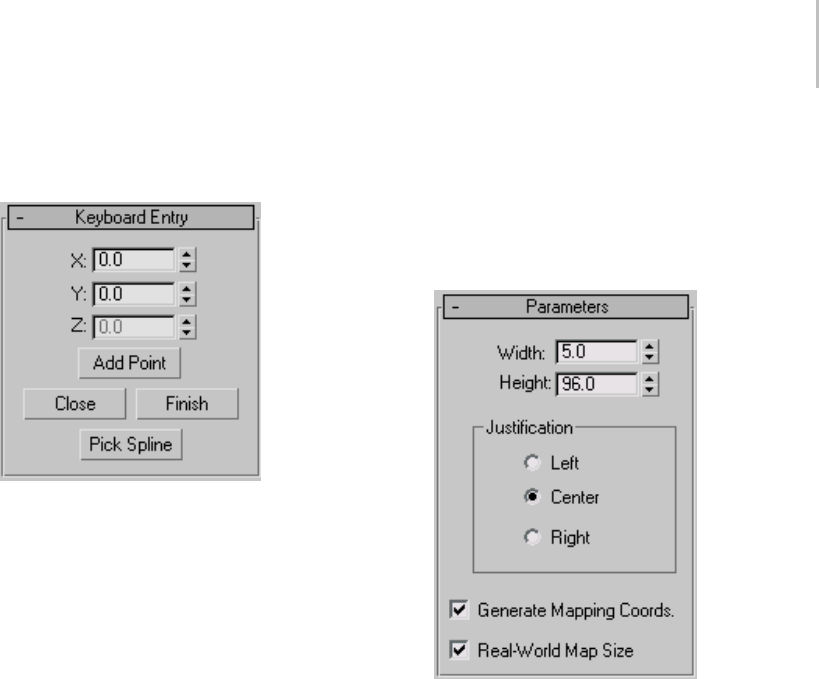
Wall 227
Interface
Keyboard Entry rollout
X—Sets the coordinate position along the X axis
for the start point of a wall segment in the active
construction plane.
Y—Sets the coordinate position along the Y axis
for the start point of a wall segment in the active
construction plane.
Z—Sets the coordinate position along the Z axis
for the start point of a wall segment in the active
construction plane.
Add Point—Adds the point from the X, Y, and Z
coordinate values you enter.
Close—Ends creation of the wall object and creates
a segment between the end point of the last
segmentandthestartpointofthefirstsegment,to
make a closed wall.
Finish—Ends creation of the wall object, leaving
it open ended.
Pick Spline—Lets you use a spline as the wall path.
Clickthis,andthenclickasplineintheviewport
touseasthewallpath.3dsMaxusesthespline
asthepathalongwhichtoapplythewallobject.
3ds Max doesn’t immediately recognize 2D Shapes
from a linked AutoCAD drawing. To recognize
Shapes from a linked AutoCAD drawing, edit
the Shape with Edit Spline (page 1–680) from the
Modify panel.
Note: If you designate a curved spline as the
path, 3ds Max creates straight wall segments that
approximate the spline as closely as possible, with
onewallsegmentpersplinesegment.
Parameters rollout
Thedefaultsproduceawallobject5unitswide,96
units high, and justified at the center of the wall.
Width—Sets the thickness of the wall. Range=0.01
unit to 100,000 units. Default=5.
Height—Sets the height of the wall. Range=0.01
unit to 100,000 units. Default=96.
Justification group
Left—Justifiesthewallattheleftedgeofitsbaseline
(the line between the wall’s front and back sides,
which is equal to the wall thickness). If you turn
Grid Snap on, the left edge of the wall’s baseline
snaps to the grid line.
Center—Justifies the wall at the center of its
baseline. If you turn Grid Snap on, the center of
thewall’sbaselinesnapstothegridline. Thisis
the default.

228 Chapter 5: Creating Geometry
Right—Justifies the wall at the right edge of its
baseline. If you turn Grid Snap on, the right edge
ofthewall’sbaselinesnapstothegridline.
Generate Mapping Coords—Assigns mapping
coordinates (page 3–967) to the wall. Default=on.
Real-World Map Size—Controls the scaling method
used for texture mapped materials that are applied
totheobject. Thescalingvaluesarecontrolled
by the Use Real-World Scale settings found in
the applied material’s Coordinates rollout (page
2–1625). Default=off.
Editing Wall Objects
Select a wall object. > Modify panel
ThefollowingreferencedescribestheWalloptions
on the Modify panel. It’s generally easiest to edit
wall objects in wireframe mode.
See also
Wall (page 1–223)
Interface
Edit Object rollout
This rollout appears when you select a wall object
at the object level; other rollouts, discussed below
appear at the different sub-object levels.
Attach—Attaches another wall in a viewport to the
selected wall by a single pick. The object you attach
must also be a wall. 3ds Max applies the material
of the selected wall to the wall being attached.
Attach Multiple—Attaches other walls in a viewport
to the selected wall. Click this button to open the
Attach Multiple dialog, which lists all the other
wall objects in the scene. Select the walls you want
to attach from the list and click the Attach button.
3ds Max applies the material of the selected wall to
the walls being attached.
Justification group
See Justification (page 1–227).
Generate Mapping Coords.—Assigns mapping
coordinates (page 3–967) to the wall. Default=on.
Real-World Map Size—Controls the scaling method
used for texture mapped materials that are applied
totheobject. Thescalingvaluesarecontrolled
by the Use Real-World Scale settings found in
the applied material’s Coordinates rollout (page
2–1625).Default=off.
Edit Vertex rollout
Appears at the Vertex sub-object level. Each wall
segment has two vertices; one in each bottom
corner. In wireframe views, wall vertices appear as
+ symbols. Connected segments in the same wall
object each share a vertex. Moving a wall vertex
has the effect of scaling attached segments as well
as rotating them about their other vertices. You
cannot rotate or scale wall vertices.
Connect—Lets you connect any two vertices,
creating a new linear segment between the vertices.
Click this button, click a vertex, and then click a
second vertex on a different segment. When you
movethecursoroveravalidsecondvertex,the
mouseiconchangestoaConnecticon.
Break—Lets you disconnect segments at a shared
vertex.
Tip: Select a vertex shared between wall segments,
and then click the Break button. The segments
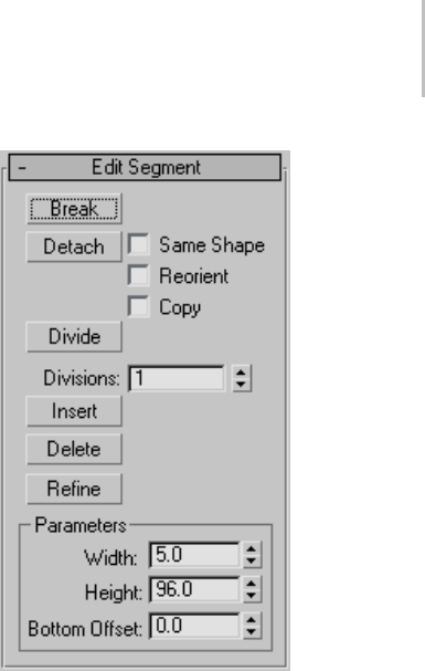
Editing Wall Objects 229
become disconnected, and each has its own end
vertex at the position of the previously shared
vertex.
Refine—Adds a vertex to the position along a wall
segmentthatyouclick.Whenyoumovethecursor
over a valid Refine point, the mouse icon changes
to a Refine icon.
Insert—Inserts one or more vertices, creating
additional segments. When you move the cursor
overtheavalidInsertpoint,themouseicon
changes to an Insert icon. Right-click to stop
inserting new vertices and segments.
Delete—Deletes the currently selected vertex or
vertices, including any segments in between.
Deleting vertices shared by two or more segments
doesn’tcreateagap,butratherresultsinasingle
segment connecting vertices adjacent to those
being deleted.
Edit Segment rollout
This rollout appears when you select a wall object
and then access Segment sub-object level.
Each wall segment is defined by, and effectively
connects, two wall vertices. Moving a segment is
the same as moving its two vertices in tandem. It
has the effect of scaling adjacent wall segments as
well as rotating them about their other vertices.
You can scale a wall segment horizontally only
(any Scale function does this). You cannot rotate
asegment.
Break—Specifies a break point in a wall segment.
Youneedn’tselectasegmentfirst.Whenyoumove
the cursor over the object, the mouse icon changes
to a Break icon. The position you select on the
segment becomes two coincident vertices, and
3ds Max breaks the segment in two.
Detach—Detaches wall segments you select and
creates a new wall object out of them.
Same Shape—Detaches the wall segment keeping
itpartofthesamewallobject. Ifyoualsoturn
on Copy, 3ds Max places a detached copy of the
segment in the same location.
Reorient—Detaches the wall segment, copies the
object’s Local coordinate system (page 3–963),
and places the segment so that its object Local
coordinate system is coincident with the Wor ld
space origin (page 3–1035).Ifyoualsoturnon
Copy, 3ds Max detaches a copy of the segment and
leaves the original segments in place.
Copy—Copies the detached wall segment rather
than moving it.
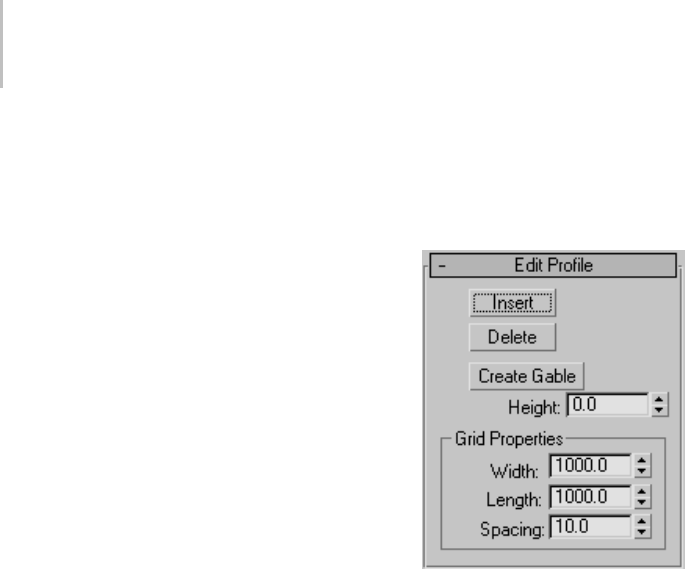
230 Chapter 5: Creating Geometry
Divide—Subdivides each segment by the number
of vertices specified in the Divisions spinner.
Select one or more segments, set the Divisions
spinner, and then click Divide.
Divisions—Sets the number by which to divide the
segment.
Insert—ProvidesthesamefunctionastheInsert
button in Vertex sub-object selection. Inserts one
or more vertices, creating additional segments.
When you move the cursor over the a valid Insert
point, the mouse icon changes to an Insert icon.
Right click to stop inserting new vertices and
segments.
Delete—Deletes any selected wall segments in the
current wall object.
Refine—ProvidesthesamefunctionastheRefine
button at the Vertex sub-object level. Adds a vertex
to the position along a wall segment you select.
When you move the cursor over a valid Refine
point, the mouse icon changes to a Refine icon.
Parameters group
Width—Changes the width of a selected segment
or segments.
Height—Changes the height of a selected segment
or segments.
Bottom Offset—Sets the distance of the bottom of
the selected segment or segments from the floor.
Edit Profile rollout
This rollout appears when you select a wall object
and then access Profile sub-object level.
The term "profile" refers to the outline of a wall
segment’s top and bottom edges. When in Profile
sub-object mode, the selected wall object’s inner
horizontal edges appear dark orange. Click any of
these edges to select the corresponding segment,
highlightitinred,andplaceatemporaryactive
grid in the plane of the segment. At that point, you
can insert and delete vertices along the horizontal
edges, move an inserted vertex along the grid to
changetheprofile,creategables,andchangethe
grid properties.
Insert—Inserts a vertex so that you can adjust the
profile of the selected wall segment.
Usethisoptiontoadjusttheprofileofwallsunder
gables or to align walls to a slope. When you move
the cursor over the selected segment, the mouse
icon changes to an Insert icon. Click to insert a
new profile point, then drag and release to position
and place it. You can add new profile points to
both the top and the bottom of the wall, but you
cannot position profile points below the original
top edge or above the original bottom edge.
Delete—Deletes the selected vertices on the profile
of the selected wall segment.
Create Gable—Createsagablebymovingthecenter
point of the top profile of the selected wall segment
to a height you specify.
Select the segment, set the height, and then click
Create Gable.
Height—Specifies the height of a gable.

Stairs 231
Grid Properties group
The grid constricts profile point insertion and
movement to the plane of the wall and allows you
to snap to grid points on the plane of the wall.
Width—Sets the width of the active grid.
Length—Sets the length of the active grid.
Spacing—Sets the size of the smallest square in the
active grid.
Stairs
Create panel > Geometry > Stairs
Create menu > AEC Objects
You can create four different types of stairs in
3ds Max:
Spiral Stair (page 1–235)
Straight Stair (page 1–239)
L-Type Stair (page 1–232)
U-Type Stair (page 1–243)
Railings and Materials
By default, 3ds Max assigns seven different material
IDs to stairs. The aectemplates.mat material
library includes Stair-Template,amulti/sub-object
material (page 2–1594) designed to be used with
stairs. Each component of the stair/material is
listed below along with its corresponding Material
ID.
Material ID Railing/Material Component
1Treads of the stairs
2Front riser of the stairs
3Bottom, back, and sides of the risers of
the stairs
Material ID Railing/Material Component
4Center pole of the stairs
5Handrails of the stairs
6Carriage of the stairs
7Stringers of the stairs
Note: 3ds Max does not automatically assign a
material to the stairs object. To use the included
material, open the library and then assign the
material to your object.
Procedure
To create railings on stairs:
1. Create the stairs. See individual stair-type
topics for more information.
2. In the Generate Geometry group, turn on Rail
Path > Left and Right.
3ds Max places left and right rail paths above
the stairs.
3. In the Railings rollout, set Height to 0.0.
4. Click Create panel > AEC Extended > Railing
(page 1–217) to create the first railing.
5. Click Railing rollout > Pick Railing Path and
select one of the rail paths on the stairs.
6. Adjust the railing parameters.
3ds Max remembers the parameters you set.
When you create the next railing, it will have the
same parameters as you set for the first railing.
7. Right-click to end the creation of the first
railing.
8. Click Railing again to create the second railing.
9. Click Pick Railing Path and select the other rail
path on the stairs.
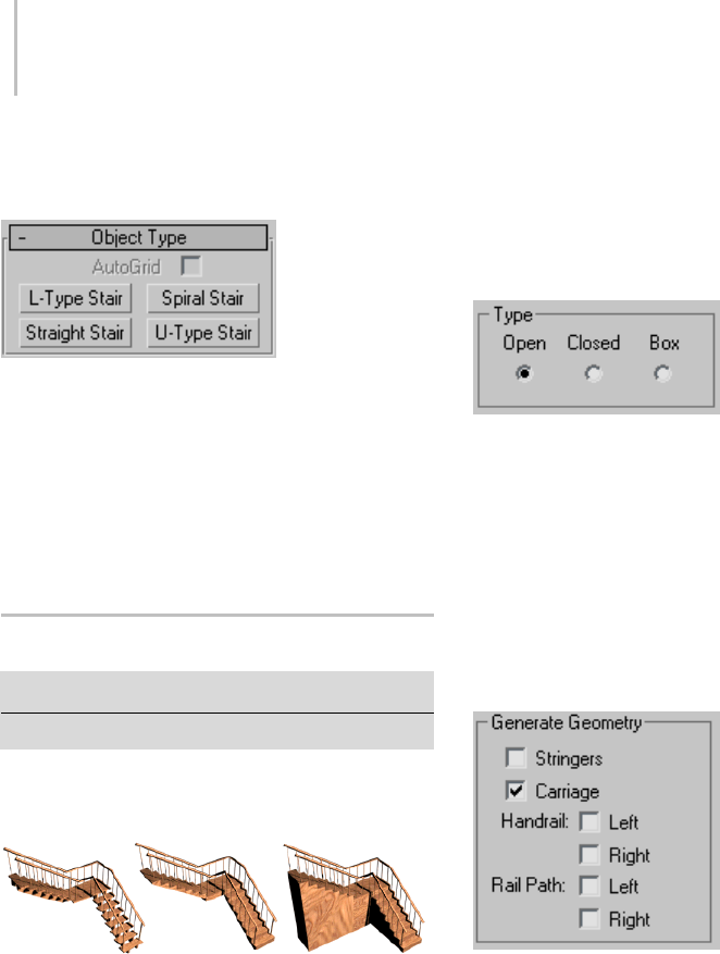
232 Chapter 5: Creating Geometry
Interface
Object Type rollout
Stair Selection Buttons—Click one of these to
specify the type of stairs you want to create.
Name and Color rollout
This rollout lets you set the stairs object’s name
and color. For detailed information, see Object
Name and Wireframe Color (page 3–757).
L-Type Stair
Create panel > Geometry > Stairs > L-Type Stair button
Create menu > AEC Objects > L-Type Stair
TheL-TypeStairobjectletsyoucreateastaircase
with two flights at right angles to each other.
Types of L-type stair: open, closed, and boxed
L-type stairs have two flights at right angles, and a landing.
Procedure
To create L-Type stairs:
1. In any viewport, drag to set the length for the
firstflight. Releasethemousebutton,then
move the cursor and click to set the length,
width, and direction for the second flight.
2. Movethecursorupordowntodefinetherise
of the stairs, then click to end.
3. Adjust the stairs by using the options in the
Parameters rollout.
Interface
Parameters rollout > Type group
Open—Creates an open riser stair, as shown on the
left in the illustration above.
Closed—Creates a closed riser stair, as shown in
the center in the illustration above.
Box—Creates a stair with closed risers and closed
stringers on both sides, as shown on the right in
the illustration above.
Generate Geometry group
Stringers—Createsstringersalongtheendsof
the treads of the stairs. To modify the stringers’
depth, width, offset and spring from the floor, see
Stringers rollout (page 1–234).
Carriage—Creates an inclined, notched beam
under the treads which supports the steps or adds
support between the stringers of the stairs. You
mightalsoknowthisasacarriage piece,ahorse,or
arough string.SeeCarriage rollout (page 1–234) to
modify the parameters.
Handrail—Createsleftandrighthandrails. See
Railings rollout (page 1–235) to modify the
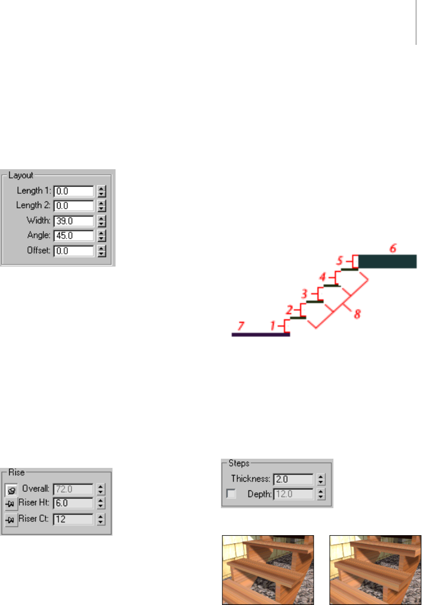
L-Type Stair 233
handrails’ height, offset, number of segments, and
radius.
Rail Path—Creates left and right paths you can use
to install railings on the stairs. See Stairs (page
1–231) for the instructions on how to do this.
Layout group
Length 1—Controls the length of the first flight of
stairs.
Length 2—Controls the length of the second flight
of stairs.
Width—Controls the width of the stairs, including
the steps and the landing.
Angle—Controls the angle of the second flight
from the landing. Range=-90 to 90 degrees.
Offset—Controlsthedistanceofthesecondflight
from the landing. The length of the landing adjusts
accordingly.
Rise group
3dsMaxkeepsoneRiseoptionlockedwhileyou
adjust the other two. To lock an option, you click a
push pin. To unlock an option you click a raised
push pin. 3ds Max locks the spinner value of the
parameterwiththedepressedpushpinandallows
the spinner values of the parameter with the raised
push pins to change.
Overall—Controls the height of the flight of stairs.
Riser Ht—Controls the height of the risers.
Riser Ct—Controls the number of risers. There will
always be one more riser than steps. This implied
riser is between the top step of the stair and the
upper floor.
Linear stair with five risers
1through4. Risers
5. The implied riser
6. The upper floor you snap to
7. The lower floor you snap to
8. The steps
Steps group
Thickness—Controlsthethicknessofthesteps.
Step thickness variance between two stairs
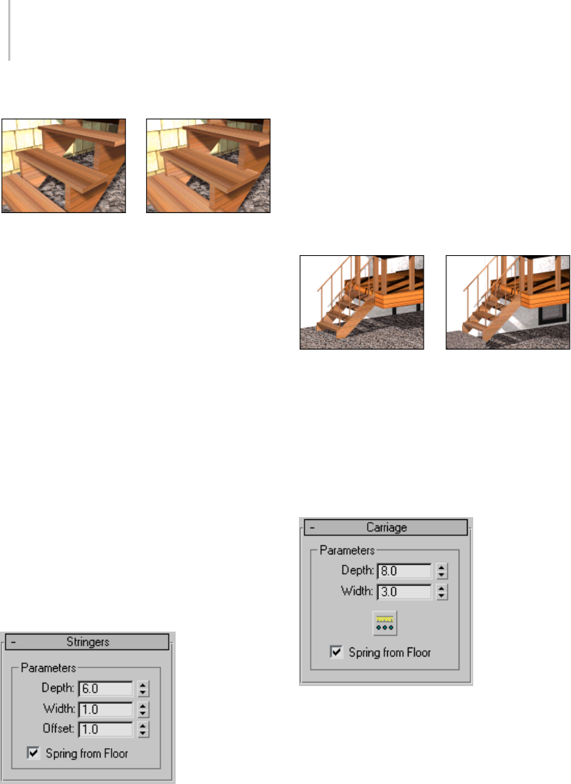
234 Chapter 5: Creating Geometry
Depth—Controls the depth of the steps.
Step depth variance between two stairs
Generate Mapping Coords—Applies default
mapping coordinates (page 3–967) to the stairs.
Note: If a visible viewport is set to a non-wireframe
or non-bounding-box display, Generate Mapping
Coordinatesisonforallprimitivestowhichyou
apply a material containing a map with Show
Map In Viewport on. If all viewports are set to
wireframe or bounding box, 3ds Max turns on
Generate Mapping Coordinates for primitives
containing mapped materials at render time.
Real-World Map Size—Controls the scaling method
used for texture mapped materials that are applied
totheobject. Thescalingvaluesarecontrolled
by the Use Real-World Scale settings found in
the applied material’s Coordinates rollout (page
2–1625). Default=off.
Stringers rollout
These controls are available only when you turn
on Stringers on the Parameters rollout > Generate
Geometry group.
Depth—Controls how far down the stringers reach
toward the floor.
Width—Controls the width of the stringers.
Offset—Controls the vertical distance of the
stringers from the floor.
Spring from Floor—Controls whether the stringer
starts at the floor, flush with the start of the first
riser, or if the stringer extends below the floor. You
control the amount the stringer extends below the
floor with the Offset option.
Left: The stringer extending below the floor. (Spring From Floor
off.)
Right: The stringer springing from the floor. (Spring From Floor
on.)
Carriage rollout
Thesecontrolsareavailableonlywhenyouturn
on Carriage on the Parameters rollout > Generate
Geometry group.
Depth—Controls how far down the carriage
reaches toward the floor.
Width—Controls the width of the carriage.
Carriage Spacing—Sets the spacing of the carriage.
Whenyoupickthisbutton,theCarriageSpacing
dialog displays. Specify the number of carriages
you want using the Count option. For more
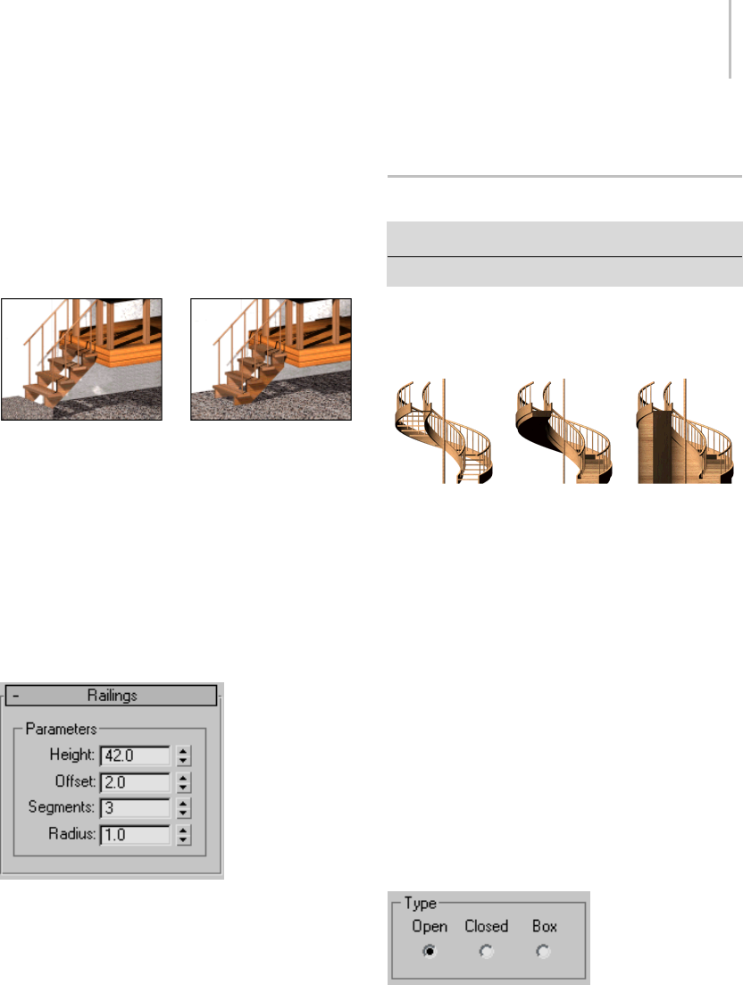
Spiral Stair 235
informationonspacingoptionsinthisdialog,see
Spacing Tool (page 1–455).
Spring from Floor—Controls whether the carriage
starts at the floor, flush with the start of the first
riser, or if the carriage extends below the floor. You
control the amount the carriage extends below the
floor with the Offset option.
Left: The carriage springing from the floor. (Spring From Floor
on.)
Right: The carriage extending below the floor. (Spring from
Floor off.)
Railings rollout
These controls are available only when you turn on
one or more of the Handrail or Rail Path options
on the Parameters rollout > Generate Geometry
group. Also, Segments and Radius aren’t available
if neither of the Handrail options is on.
Height—Controls the height of the railings from
the steps.
Offset—Controls the offset of the railings from the
ends of the steps.
Segments—Controls the number of segments
in the railings. Higher values display smoother
railings.
Radius—Controls the thickness of the railings.
Spiral Stair
Create panel > Geometry > Stairs > Spiral Stair button
Create menu > AEC Objects > Spiral Stair
The Spiral Stair object lets you specify the radius
and number of revolutions, add stringers and a
center pole, and more.
Types of spiral stair: open, closed, and boxed
Spiral stairs wind around a center
Procedure
To create spiral stairs:
1. In any viewport, click for the start point of the
stairs, and drag to the specify the radius you
want.
2. Release the mouse button, move the cursor up
or down to specify the overall rise, and click
to end.
3. Adjust the stairs with options in the Parameters
rollout.
Interface
Parameters rollout > Type group
Open—Creates an open riser stair, as shown on the
left of the illustration above.
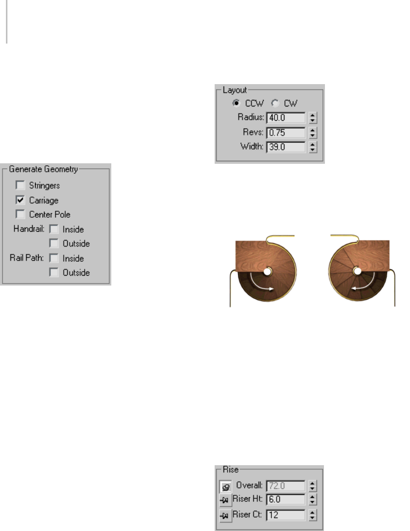
236 Chapter 5: Creating Geometry
Closed—Creates a closed riser stair, as shown in
the center of the illustration above.
Box—Creates a stair with closed risers and closed
stringersonbothsides,asshownontherightof
the illustration above.
Generate Geometry group
Stringers—Createsstringersalongtheendsof
the treads of the stairs. To modify the stringers’
depth, width, offset and spring from the floor, see
Stringers rollout (page 1–237).
Carriage—Creates an inclined, notched beam
under the treads which supports the steps or adds
support between the stringers of the stairs. You
mightalsoknowthisasacarriage piece,ahorse,or
arough string.SeeCarriage rollout (page 1–238) to
modify the parameters.
Center Pole—Creates a pole at the center of the
spiral. See Center Pole rollout (page 1–238) to
modify the parameters of the pole.
Handrail—Creates inside and outside handrails.
See Railings rollout (page 1–239) to modify the
handrails’ height, offset, number of segments, and
radius.
Rail Path—Creates inside and outside paths which
you can use to install railings on the stairs. See
Stairs (page 1–231) for the instructions on how to
do this.
Layout group
CCW—Orients the spiral stairs to be a right-hand
flight of stairs.
CW—Orients the spiral stairs to be a left-hand
flight of stairs.
Left: CCW (counterclockwise) right-hand spiral stairs. The
arrow indicates “Up.”
Right: CW (clockwise) left-hand spiral stairs. The arrow
indicates “Up.”
Radius—Controlsthesizeoftheradiusofthe
spiral.
Revs—Controls the number of revolutions in the
spiral.
Width—Controls the width of the spiral stairs.
Rise group
3dsMaxkeepsoneRiseoptionlockedwhileyou
adjust the other two. To lock an option, click a
pushpin button. To unlock an option, click a
raised pushpin. 3ds Max locks the spinner value
of the parameter with the depressed pushpin and
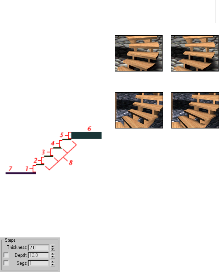
Spiral Stair 237
allows the spinner values of the parameter with the
raised pushpins to change.
Overall—Controls the height of the flight of stairs.
Riser Ht—Controls the height of the risers.
Riser Ct—Controls the number of risers. There will
always be one more riser than steps. This implied
riser is between the top step of the stair and the
upper floor.
Linear stair with five risers
1 through 4. Risers
5. The implied riser
6. The upper floor you snap to
7. The lower floor you snap to
8. The steps.
Steps group
Thickness—Controls the thickness of the steps.
Step thickness variance between two stairs
Depth—Controls the depth of the steps.
Step depth variance between two stairs
Segs—Controls the number of segments 3ds Max
uses to construct the steps.
Generate Mapping Coords—Applies default
mapping coordinates (page 3–967) to the stairs.
Note: If a visible viewport is set to a non-wireframe
or non-bounding-box display, Generate Mapping
Coordinatesisonforallprimitivestowhichyou
apply a material containing a map with Show
Map In Viewport on. If all viewports are set to
wireframe or bounding box, 3ds Max turns on
Generate Mapping Coordinates for primitives
containing mapped materials at render time.
Real-World Map Size—Controls the scaling method
used for texture mapped materials that are applied
totheobject. Thescalingvaluesarecontrolled
by the Use Real-World Scale settings found in
the applied material’s Coordinates rollout (page
2–1625).Default=off.
Stringers rollout
Thesecontrolsareavailableonlywhenyouturn
on Stringers on the Parameters rollout > Generate
Geometry group.
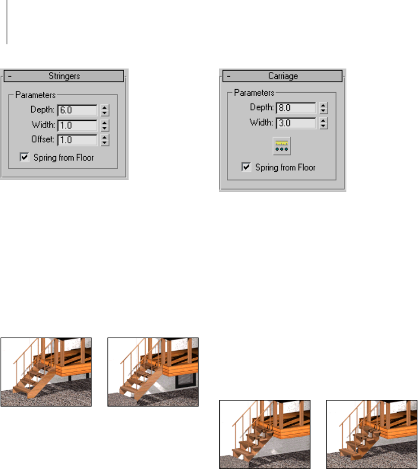
238 Chapter 5: Creating Geometry
Depth—Controls how far down the stringers reach
toward the floor.
Width—Controls the width of the stringers.
Offset—Controls the vertical distance of the
stringers from the floor.
Spring from Floor—Controls whether the stringer
starts at the floor, flush with the start of the first
riser, or if the stringer extends below the floor. You
control the amount the stringer extends below the
floor with the Offset option.
Left: The stringer extending below the floor. (Spring From Floor
turned off.)
Right: the stringer springing from the floor. (Spring From Floor
turned on.)
Carriage rollout
These controls are available only when you turn
on Carriage on the Parameters rollout > Generate
Geometry group.
Depth—Controls how far down the carriage
reaches toward the floor.
Width—Controls the width of the carriage.
Carriage Spacing—Sets the spacing of the carriage.
Whenyoupickthisbutton,theCarriageSpacing
dialog displays. Specify the number of carriages
you want using the Count option. For more
information on spacing options in this dialog, see
Spacing Tool (page 1–455).
Spring from Floor—Controls whether the carriage
starts at the floor, flush with the start of the first
riser, or if the carriage extends below the floor. You
control the amount the carriage extends below the
floor with the Offset option.
Left: The carriage springing from the floor. (Spring From Floor
turned on.)
Right: The carriage extending below the floor. (Spring From
Floor turned off.)
Center Pole rollout
These controls are available only when you turn on
Center Pole on the Parameters rollout > Generate
Geometry group.
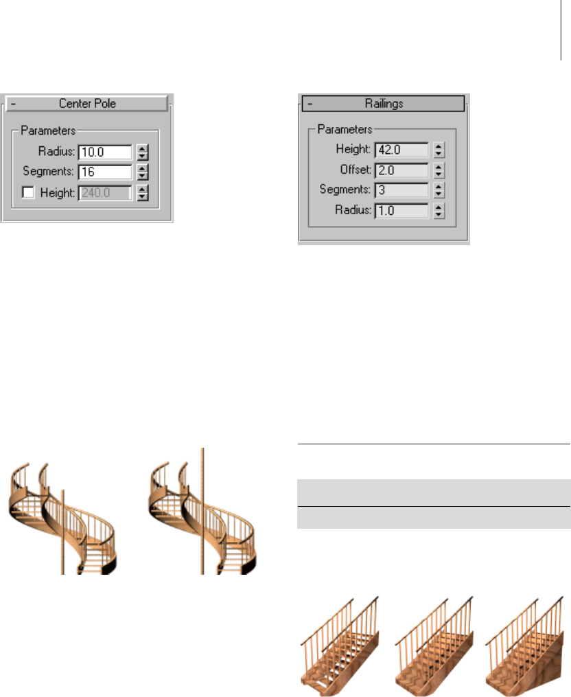
Straight Stair 239
Radius—Controls the radius size of the center pole.
Segments—Controls the number of segments in
the center pole. Higher values display a smoother
pole.
Height—Thespinnercontrolstheheightofthe
center pole. Turning on Height lets you adjust
the height of the pole independently of the stairs.
Turning off Height makes the spinner unavailable
and locks the top of the pole to the top of the
implied last riser. Typically, this riser would attach
to the fascia of a landing.
Left: The center pole locked to the top of the implied last riser.
(Height turned off.)
Right: The center pole adjusted to the height you specify.
(Height turned on.)
Railings rollout
These controls are available only when you turn on
one or more of the Handrail or Rail Path options
on the Parameters rollout > Generate Geometry
group. Also, Segments and Radius aren’t available
if neither of the Handrail options is on.
Height—Controls the height of the railings from
the steps.
Offset—Controls the offset of the railings from the
ends of the steps.
Segments—Controls the number of segments
in the railings. Higher values display smoother
railings.
Radius—Controls the thickness of the railings.
Straight Stair
Create panel > Geometry > Stairs > Straight Stair button
Create menu > AEC Objects > Straight Stair
The Straight Stair object lets you create a simple
staircase, with optional stringers, carriage, and
handrail.
Types of straight stair: open, closed, and boxed
Straight stairs have a single flight.
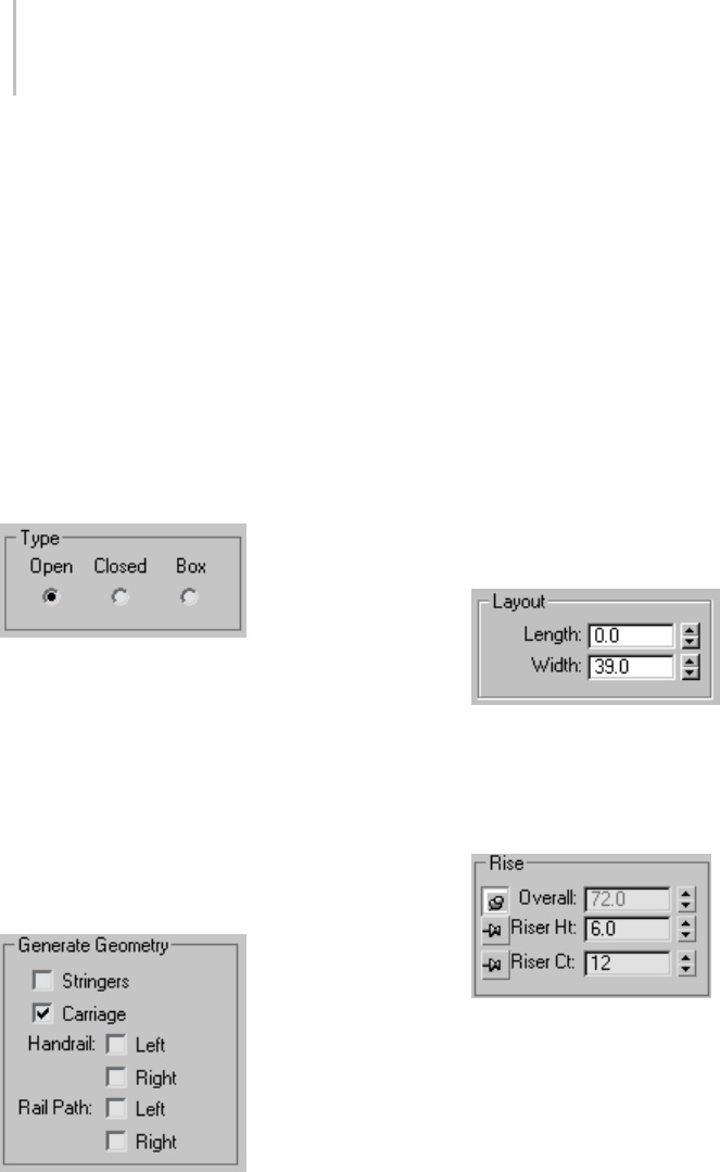
240 Chapter 5: Creating Geometry
Procedures
To create straight stairs:
1. In any viewport, drag to set the length. Release
the mouse button, then move the cursor and
click to set the width you want.
2. Movethecursorupordowntodefinetherise
of the stairs, and click to end.
3. Adjustthestairswiththeoptionsinthe
Parameters rollout.
Interface
Parameters rollout > Type group
Open—Createsanopenriserstairasshownonthe
left of the illustration above.
Closed—Creates a closed riser stair as shown in the
center of the illustration above.
Box—Creates a stair with closed risers and closed
stringers on both sides as shown on the right of the
illustration above.
Generate Geometry group
Stringers—Createsstringersalongtheendsof
the treads of the stairs. To modify the stringers’
depth, width, offset and spring from the floor, see
Stringers rollout (page 1–241).
Carriage—Creates an inclined, notched beam
under the treads which supports the steps or adds
support between the stringers of the stairs. You
mightalsoknowthisasacarriage piece,ahorse,or
arough string.SeeCarriage rollout (page 1–242) to
modify the parameters.
Handrail—Createsleftandrighthandrails. See
Railings rollout (page 1–242) to modify the
handrails’ height, offset, number of segments, and
radius.
Rail Path—Createsleftandrightpathsyoucanuse
to install railings on the stairs. See Stairs (page
1–231) for the instructions on how to do this.
Layout group
Length—Controls the length of the stairs.
Width—Controls the width of the stairs.
Rise group
3dsMaxkeepsoneRiseoptionlockedwhileyou
adjust the other two. To lock an option, you click a
push pin. To unlock an option you click a raised
push pin. 3ds Max locks the spinner value of the
parameterwiththedepressedpushpinandallows
the spinner values of the parameter with the raised
push pins to change.
Overall—Controls the height of the flight of stairs.
Riser Ht—Controls the height of the risers.
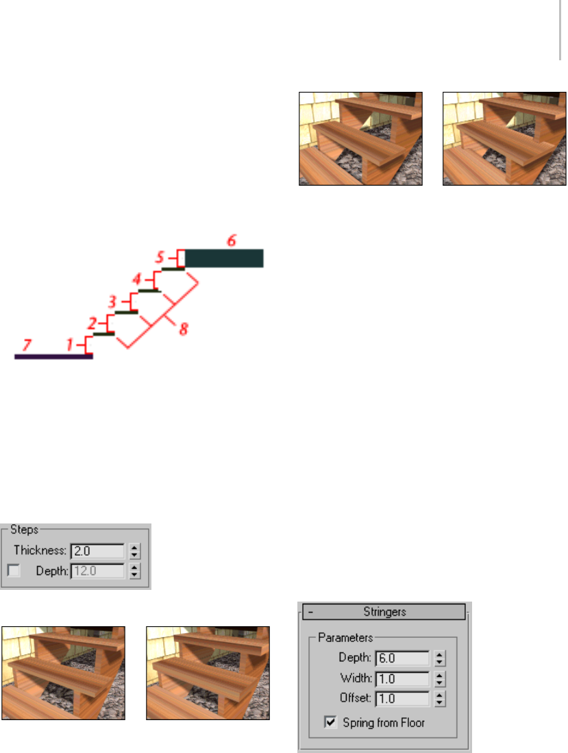
Straight Stair 241
Riser Ct—Controls the number of risers. There will
always be one more riser than steps. This implied
riser is between the top step of the stair and the
upper floor.
Linear stair with five risers
1 through 4. Risers
5. The implied riser
6. The upper floor you snap to
7. The lower floor you snap to
8. The steps.
Steps group
Thickness—Controls the thickness of the steps.
Step thickness variance between two stairs
Depth—Controls the depth of the steps.
Step depth variance between two stairs
Generate Mapping Coords—Applies default
mapping coordinates (page 3–967) to the stairs.
Note: If a visible viewport is set to a non-wireframe
or non-bounding-box display, Generate Mapping
Coordinatesisonforallprimitivestowhichyou
apply a material containing a map with Show
Map In Viewport on. If all viewports are set to
wireframe or bounding box, 3ds Max turns on
Generate Mapping Coordinates for primitives
containing mapped materials at render time.
Real-World Map Size—Controls the scaling method
used for texture mapped materials that are applied
totheobject. Thescalingvaluesarecontrolled
by the Use Real-World Scale settings found in
the applied material’s Coordinates rollout (page
2–1625).Default=off.
Stringers rollout
Thesecontrolsareavailableonlywhenyouturn
on Stringers on the Parameters rollout > Generate
Geometry group.
Depth—Controls how far down the stringers reach
toward the floor.
Width—Controls the width of the stringers.
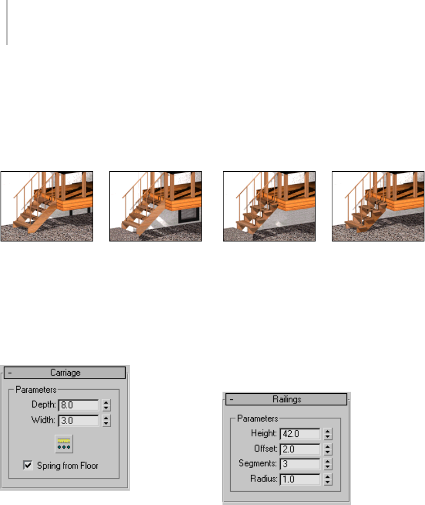
242 Chapter 5: Creating Geometry
Offset—Controls the vertical distance of the
stringers from the floor.
Spring from Floor—Controls whether the stringer
starts at the floor, flush with the start of the first
riser, or if the stringer extends below the floor. You
control the amount the stringer extends below the
floor with the Offset option.
Left: The stringer extending below the floor. (Spring From Floor
off.)
Right: The stringer springing from the floor. (Spring From Floor
on.)
Carriage rollout
These controls are available only when you turn
on Carriage on the Parameters rollout > Generate
Geometry group.
Depth—Controls how far down the carriage
reaches toward the floor.
Width—Controls the width of the carriage.
Carriage Spacing—Sets the spacing of the carriage.
Whenyoupickthisbutton,theCarriageSpacing
dialog displays. Specify the number of carriages
you want using the Count option. For more
information on spacing options in this dialog, see
Spacing Tool (page 1–455).
Spring from Floor—Controls whether the carriage
starts at the floor, flush with the start of the first
riser, or if the carriage extends below the floor. You
control the amount the carriage extends below the
floor with the Offset option.
Left: The carriage springing from the floor. (Spring From Floor
on.)
Right: The carriage extending below the floor. (Spring From
Floor off.)
Railings rollout
These controls are available only when you turn on
one or more of the Handrail or Rail Path options
on the Parameters rollout > Generate Geometry
group. Also, Segments and Radius aren’t available
if neither of the Handrail options is on.
Height—Controls the height of the railings from
the steps.
Offset—Controls the offset of the railings from the
ends of the steps.
Segments—Controls the number of segments
in the railings. Higher values display smoother
railings.
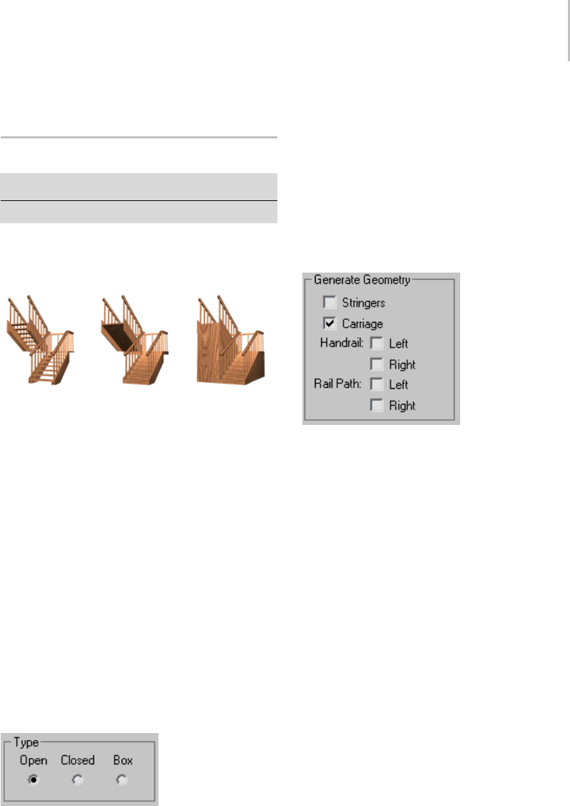
U-Type Stair 243
Radius—Controls the thickness of the railings.
U-Type Stair
Create panel > Geometry > Stairs > U-Type Stair button
Create menu > AEC Objects > U-Type Stair
TheU-TypeStairobjectletsyoucreateatwo-flight
staircase, with the two flights parallel to each other
and a landing between them.
Types of U-type stair: open, closed, and boxed
U-type stairs have two flights in opposite directions, and a
landing.
Procedure
To create U-Type stairs:
1. In any viewport, drag to set the length for the
firstflight. Releasethemousebutton,then
movethecursorandclicktosetthewidthof
the landing, or the distance separating the two
flights.
2. Clickandmovethecursorupordowntodefine
theriseofthestairs,thenclicktoend.
3. Adjust the stairs by using the options in the
Parameters rollout.
Interface
Parameters rollout > Type group
Open—Createsanopenriserstairasshownonthe
left in the illustration above.
Closed—Creates a closed riser stair as shown in the
center in the illustration above.
Box—Creates a stair with closed risers and closed
stringersonbothsidesasshownontherightinthe
illustration above.
Generate Geometry group
Stringers—Createsstringersalongtheendsof
the treads of the stairs. To modify the stringers’
depth, width, offset and spring from the floor, see
Stringers rollout (page 1–245).
Carriage—Creates an inclined, notched beam
under the treads which supports the steps or adds
support between the stringers of the stairs. You
might also know this as a carriage piece, a horse,
or a roughstring. See Carriage rollout (page 1–245)
to modify the parameters.
Handrail—Createsleftandrighthandrails. See
Railings rollout (page 1–246) to modify the
handrails’ height, offset, number of segments, and
radius.
Rail Path—Createsleftandrightpathsyoucanuse
to install railings on the stairs. See Stairs (page
1–231) for the instructions on how to do this.
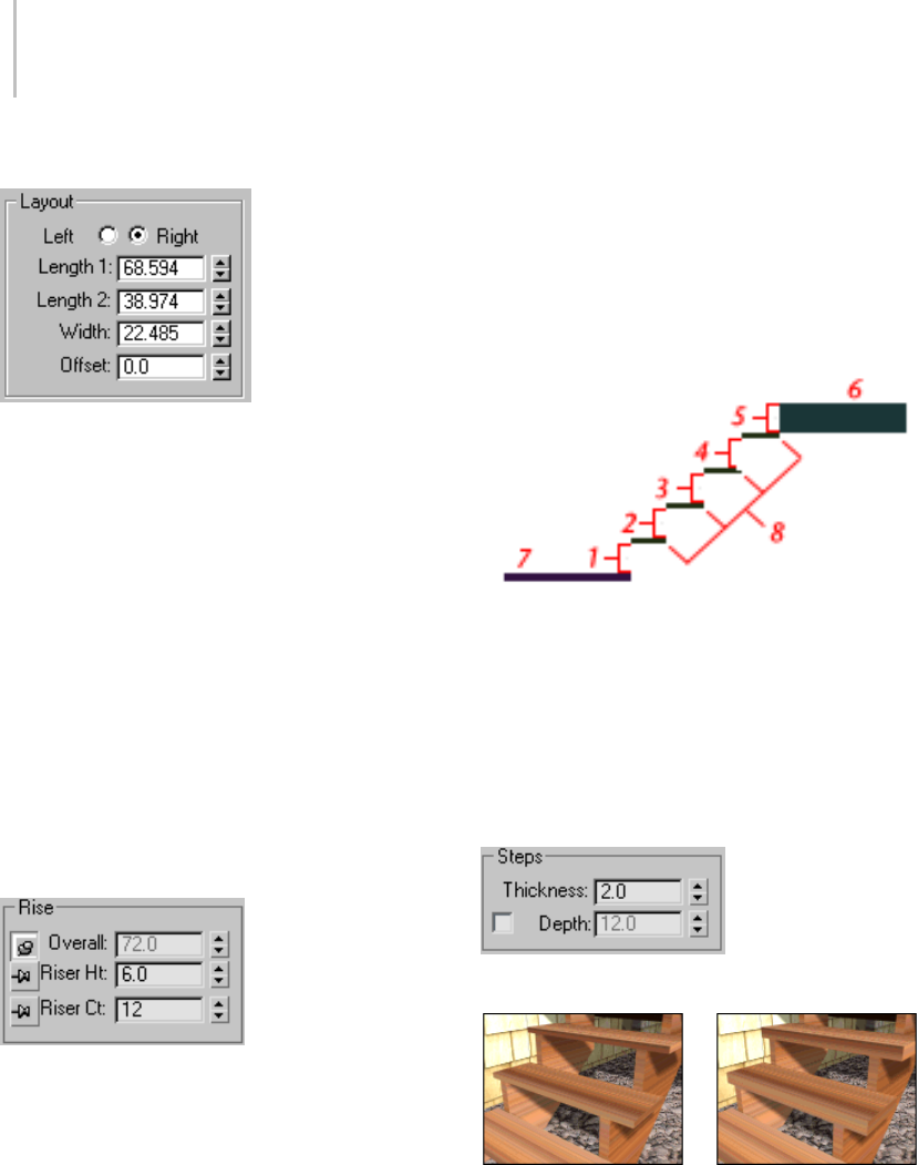
244 Chapter 5: Creating Geometry
Layout group
Left/Right—Controls the position of the two flights
(Length 1 and Length 2) relative to each other.
If you select left, then the second flight is on the
left from the landing. If you select right, then the
second flight is the right from the landing.
Length 1—Controls the length of the first flight of
stairs.
Length 2—Controls the length of the second flight
of stairs.
Width—Controls the width of the stairs, including
the steps and the landing.
Offset—Controlsthedistanceseparatingthetwo
flights and thus the length of the landing.
Rise group
3dsMaxkeepsoneRiseoptionlockedwhileyou
adjust the other two. To lock an option, you click a
push pin. To unlock an option you click a raised
push pin. 3ds Max locks the spinner value of the
parameterwiththedepressedpushpinandallows
thespinnervaluesoftheparameterwiththeraised
push pins to change.
Overall—Controls the height of the flight of stairs.
Riser Ht—Controls the height of the risers.
Riser Ct—Controls the number of risers. There will
always be one more riser than steps. This implied
riser is between the top step of the stair and the
upper floor.
Linear stair with five risers
1through4. Risers
5. The implied riser
6. The upper floor you snap to
7. The lower floor you snap to
8. The steps.
Steps group
Thickness—Controlsthethicknessofthesteps.
Step thickness variance between two stairs
Depth—Controls the depth of the steps.
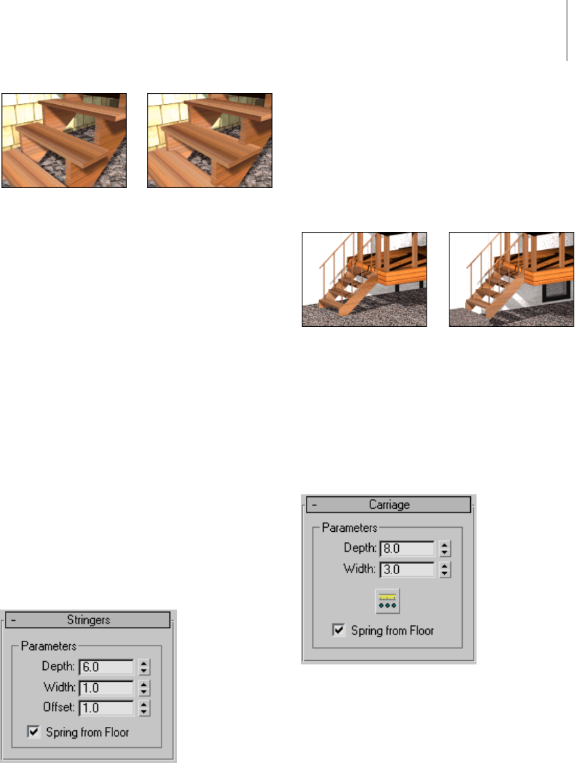
U-Type Stair 245
Step depth variance between two stairs
Generate Mapping Coords—Applies default
mapping coordinates (page 3–967) to the stairs.
Note: If a visible viewport is set to a non-wireframe
or non-bounding-box display, Generate Mapping
Coordinatesisonforallprimitivestowhichyou
apply a material containing a map with Show
Map In Viewport on. If all viewports are set to
wireframe or bounding box, 3ds Max turns on
Generate Mapping Coordinates for primitives
containing mapped materials at render time.
Real-World Map Size—Controls the scaling method
used for texture mapped materials that are applied
totheobject. Thescalingvaluesarecontrolled
by the Use Real-World Scale settings found in
the applied material’s Coordinates rollout (page
2–1625). Default=off.
Stringers rollout
These controls are available only when you turn
on Stringers on the Parameters rollout > Generate
Geometry group.
Depth—Controls how far down the stringers reach
toward the floor.
Width—Controls the width of the stringers.
Offset—Controls the vertical distance of the
stringers from the floor.
Spring from Floor—Controls whether the stringer
starts at the floor, flush with the start of the first
riser, or if the stringer extends below the floor. You
control the amount the stringer extends below the
floor with the Offset option.
Left: The stringer extending below the floor. (Spring From Floor
off.)
Right: The stringer springing from the floor. (Spring From Floor
on.)
Carriage rollout
Thesecontrolsareavailableonlywhenyouturn
on Carriage on the Parameters rollout > Generate
Geometry group.
Depth—Controls how far down the carriage
reaches toward the floor.
Width—Controls the width of the carriage.
Carriage Spacing—Sets the spacing of the carriage.
Whenyoupickthisbutton,theCarriageSpacing
dialog displays. Specify the number of carriages
you want using the Count option. For more
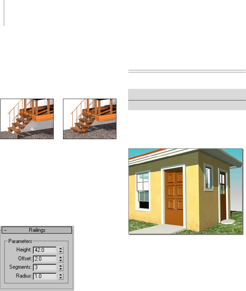
246 Chapter 5: Creating Geometry
informationonspacingoptionsinthisdialog,see
Spacing Tool (page 1–455).
Spring from Floor—Controls whether the carriage
starts at the floor, flush with the start of the first
riser, or if the carriage extends below the floor. You
control the amount the carriage extends below the
floor with the Offset option.
Left: The carriage springing from the floor. (Spring From Floor
on.)
Right: The carriage extending below the floor. (Spring From
Floor off.)
Railings rollout
These controls are available only when you turn on
one or more of the Handrail or Rail Path options
on the Parameters rollout > Generate Geometry
group. Also, Segments and Radius aren’t available
if neither of the Handrail options is on.
Height—Controls the height of the railings from
the steps.
Offset—Controls the offset of the railings from the
ends of the steps.
Segments—Controls the number of segments
in the railings. Higher values display smoother
railings.
Radius—Controls the thickness of the railings.
Doors
Create panel > Geometry > Doors
Create menu > AEC Objects
The door models provided let you control details
of a door’s appearance. You can also set the door
to be open, partially open, or closed and you can
animate the opening.
Different door types in a model of a house
There are three kinds of doors. The Pivot door
(page 1–251) is the familiar door that is hinged
ononesideonly.TheBifold door (page 1–252) is
hingedinthemiddleaswellastheside,likemany
closet doors. You can also make these kinds of
doors a set of double doors. The Sliding door (page
1–251) has a fixed half and a sliding half.
Thetopicforeachkindofdoordescribesitsunique
controls and behavior. Most door parameters are
common to all kinds of doors, and are described
here.

Doors 247
Doors and Materials
By default, 3ds Max assigns five different material
IDs to doors. The aectemplates.mat material
library includes Door-Template,amulti/sub-object
material designed to be used with doors. Each
component of the door/material is listed below
along with its corresponding Material ID.
Material ID Door/Material Component
1Front
2Back
3Inner Bevel (used for glazing when
Panels set to Glass or Beveled).
4Frame
5Inner Door
Note: 3ds Max does not automatically assign a
material to the door object. To use the included
material, open the library and then assign the
material to your object.
Making an Opening for a Door
To m a ke a n o p e n i ng in a wa l l , yo u c a n p e r f or m a
Boolean operation (page 1–338) with the wall as
Operand A, and another object, such as a box, as
Operand B. Then, you can create and add a door
in the opening, and link (page 2–421) it, if you
choose, as a child of the wall.
Note: Using snaps, you can insert a door in a wall
object, automatically linking the two and creating
a cutout for the door. See the procedure To c re at e
and place a window or door in a wall: (page 1–226).
Procedures
To create a door:
1. On the Object Type rollout, click the button for
thetypeofdooryouwanttocreate.
2. Choose options as needed, such as changing
the default creation method. Turn off Create
Frame to eliminate the door frame. Turn
on Allow Non-vertical Jambs if you want an
inclined door.
3. Drag the mouse in the viewport to create the
first two points, defining the width and angle
of the base of the door.
4. Release the mouse and move to adjust the depth
of the door (default creation method), and then
click to set.
By default, the depth is perpendicular to the
line between the first two points and parallel
to the active grid.
5. Move the mouse to adjust the height, and then
click to finish.
The height is perpendicular to the plane defined
by the first three points and perpendicular to
theactivegrid.
You can adjust the Height, Width, and Depth
values on the Parameters rollout.
On the Creation Method rollout, you can change
the creation order to width-height-depth instead
of width-depth-height.
To create a door material:
1. Createadoororselectanexistingdoor.
2. Open the Material Editor, and select a slot for
the material.
3. Click the Type button below the Material Editor
toolbar.
The Material/Map Browser dialog opens.
4. In the Material list, double-click the
Multi/Sub-Object item, and then on the
Replace Material dialog that appears, choose
either option and click OK.
5. On the Multi/Sub-Object Basic Parameters
rollout, click Set Number and change Number
Of Materials to 5. Click OK.
6. Optionally, change the sub-material names to
those specified in the above table.
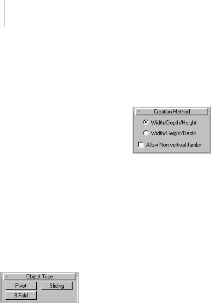
248 Chapter 5: Creating Geometry
7. Edit the material as you would any
Multi/Sub-Object material.
To animate a door:
You can animate a door opening and closing by
keyframing the Open setting.
1. Createadoororselectanexistingdoor.
If using an existing door, also access the Modify
panel.
2. SettheParametersrollout>Openparameter
to the amount you want the door to be open at
the start of the animation. If you want it to be
closed, set it to 0.
3. Click the Auto Key button and advance to the
first keyframe.
4. Change the Open setting.
5. Continue moving to any additional keyframes
and changing the Open setting as necessary.
6. Play the animation.
Interface
The topic for each kind of door describes its unique
controls and behavior. Most door parameters are
common to all kinds of doors, and are described
here.
Object Type rollout
There are three kinds of doors in 3ds Max:
Pivot—Thefamiliardoortypethatishingedon
onesideonly.SeePivot Door (page 1–251).
Sliding—Has a fixed half and a sliding half. See
Sliding Door (page 1–251).
BiFold—Hinged in the middle as well as the side,
like many closet doors. You can also use this type
of door to make a set of double doors. See BiFold
Door (page 1–252).
Name and Color rollout
See Object Name and Wireframe Color (page
3–757).
Creation Method rollout
Youdefineeachtypeofdoorwithfourpoints:
Drag the first two, followed by two move-click
sequences. The Creation Method setting
determines the order in which these actions define
the door’s dimensions.
Width/Depth/Height—The first two points define
the width and angle of the base of the door. You
set these points by dragging in a viewport, as the
first step in creating a door. The first point, where
youclickandholdbeforedragging,definesa
point on the jamb at the hinge for single-pivot and
bifolddoors(bothjambshavehingesondouble
doors, and sliding doors have no hinge). The
second point, where you release the button after
dragging, specifies the width of the door, as well as
the direction from one jamb to the other. This lets
you align the door with a wall or opening when
you place it. The third point, where you click after
moving the mouse, specifies the depth of the door,
and the fourth click, where you click after moving
the mouse again, specifies the height.
Width/Height/Depth—Wo rk s l ike t he
Width/Depth/Height option, except that
the last two points create first the height and then
the depth.
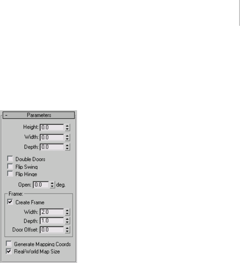
Doors 249
Note: With this method, the depth is perpendicular
totheplanesetbythefirstthreepoints. Thus,
if you draw the door in the Top or Perspective
viewport, the door lies flat on the active grid.
Allow Non-vertical Jambs—Lets you create tilted
doors. Set snaps (page 2–35) to define points off
the construction plane. Default=off.
Parameters rollout
Height—Sets the overall height of the door unit.
Width—Sets the overall width of the door unit.
Depth—Sets the depth of the door unit.
Open—With Pivot doors, specifies in degrees the
extent to which the door is open. With Sliding and
BiFold doors, Open specifies the percent that the
door is open.
Frame group
This rollout has controls for the door-jamb frame.
Though part of the door object, the frame behaves
as if it were part of the wall. It doesn’t move when
you open or close the door.
Create Frame—This is turned on as a default to
display the frame. Turn this off to disable display
of the frame.
Width—Sets the width of the frame parallel to the
wall. Available only when Create Frame is on.
Depth—Sets the depth of the frame as it projects
from the wall. Available only when Create Frame
is on.
Door Offset—Sets the location of the door relative
totheframe. At0.0,thedoorisflushwithone
edge of the trim. Note that this can be a positive or
negative value. Available only when Create Frame
is on.
Generate Mapping Coords—Assigns mapping
coordinates to the door.
Real-World Map Size—Controls the scaling method
used for texture mapped materials that are applied
totheobject. Thescalingvaluesarecontrolled
by the Use Real-World Scale settings found in
the applied material’s Coordinates rollout (page
2–1625).Default=off.
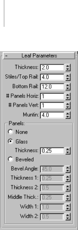
250 Chapter 5: Creating Geometry
Leaf Parameters rollout
Provides controls that affect the door itself (as
opposed to the door unit, which includes the
frame). You can adjust the dimensions of the
door, add panels, and adjust the dimensions and
placement of those panels. The total number of
panelsforeachdoorelementisthenumberof
horizontal divisions times the number of vertical
divisions. Pivot doors have a single door element
unlesstheyaredoubledoors.BiFolddoorshave
two door elements, or four if they are double
doors. Sliding doors have two door elements.
Thickness—Sets the thickness of the door.
Stiles/Top Rail—Sets the width of the panel framing
on the top and sides. This setting is apparent only
if the door is paneled.
Bottom Rail—Sets the width of the panel framing at
thebaseofthedoor.Thissettingisapparentonly
if the door is paneled.
#PanelsHoriz.—Sets the number of panel divisions
along the horizontal axis.
# Panels Vert.—Sets the number of panel divisions
along the vertical axis.
Muntin—Sets the width of the separations between
the panels.
Panels group
Determines how panels are created in the door.
None—The door has no paneling.
Glass—Creates glass panels with no beveling.
Thickness—Sets the thickness of the glass panels.
Beveled—Choose this to have beveled panels.
The remaining spinners affect the beveling of the
panels.
Bevel Angle—Specifies the angle of the bevel
between the outer surface of the door and the
surface of the panel.
Thickness 1—Sets the outer thickness of the panel.
Thickness 2—Sets the thickness where the bevel
begins.
Middle Thick.—Sets the thickness of the inner part
of the panel.
Width 1—Sets the width where the bevel begins.
Width 2—Sets the width of the inner part of the
panel.
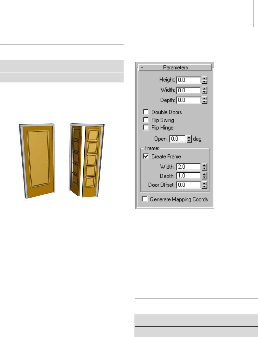
Pivot Door 251
Pivot Door
Create panel > Geometry > Doors > Pivot button
Create menu > AEC Objects > Pivot Door
The Pivot door is hinged on one side only. You can
also make the door a double door, with two door
elements, each hinged on its outer edge.
Single and double pivot doors
This topic describes only controls and behavior
unique to the Pivot door. Most door parameters
are common to all kinds of doors; see Doors (page
1–246).
Interface
Parameters rollout
The Parameters rollout contains three check boxes
specific to Pivot doors.
Double Doors—Makes a double door.
Flip Swing—Changes the direction the door
swings.
Flip Hinge—Places the door hinges on the opposite
side of the door. This option is unavailable for
double doors.
Sliding Door
Create panel > Geometry > Doors > Sliding button
Create menu > AEC Objects > Sliding Door
The Sliding door slides as if on a track or railing.
It has two door elements: one remains stationary
while the other moves.
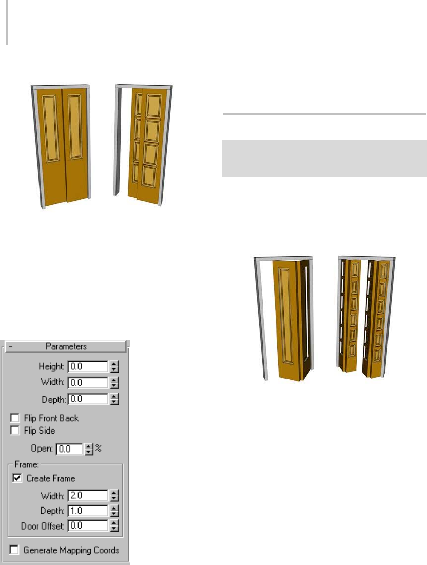
252 Chapter 5: Creating Geometry
Sliding doors with different numbers of panels
This topic describes only controls and behavior
unique to the Sliding door. Most door parameters
are common to all kinds of doors; see Doors (page
1–246).
Interface
Parameters rollout
Flip Front Back—Changes which element is in front,
compared to the default.
Flip Side— Changes the current sliding element to
the stationary element, and vice versa.
BiFold Door
Create panel > Geometry > Doors > BiFold button
Create menu > AEC Objects > BiFold Door
The BiFold door is hinged in the middle as well
as on the side. It has two door elements. You can
also make the door a double door, with four door
elements.
Single and double bifold doors
This topic describes only controls and behavior
unique to the BiFold door. Most door parameters
are common to all kinds of doors; see Doors (page
1–246).
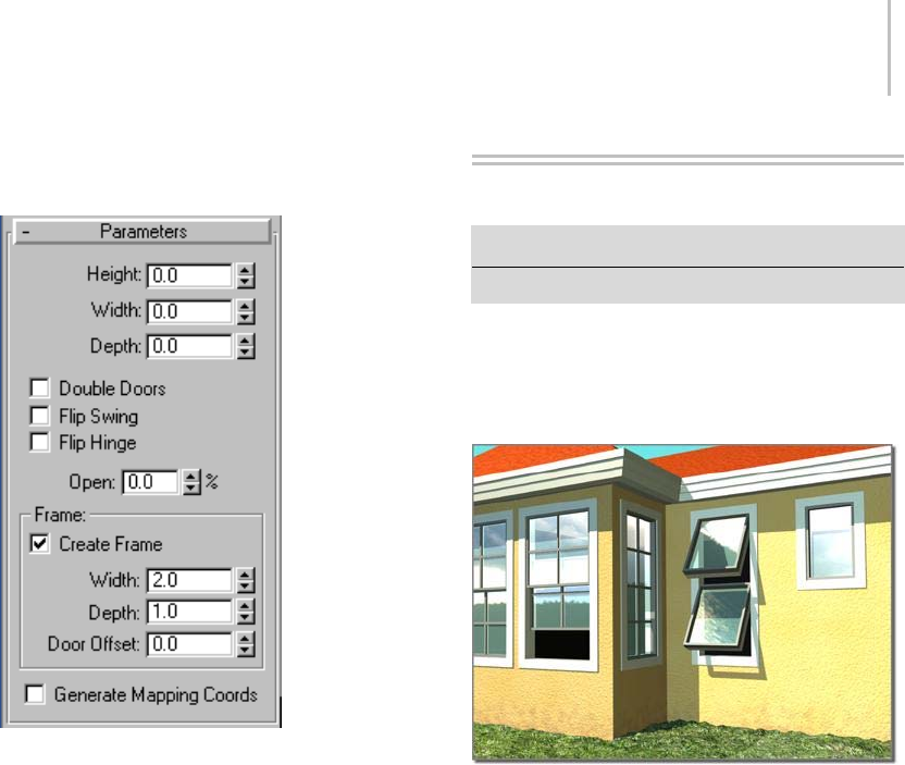
Windows 253
Interface
Parameters rollout
The Parameters rollout contains three check boxes
specific to BiFold doors.
Double Doors—Makes the door a double door,
with four door elements, meeting in the center.
Flip Swing—Makes the door swing in the opposite
direction from the default.
Flip Hinge—Makes the door hinged on the opposite
side from the default. Flip Hinge is unavailable
when Double Doors is on.
Windows
Create panel > Geometry > Windows
Create menu > AEC Objects
The window object lets you control details of a
window’s appearance. You can also set the window
to be open, partially open, or closed, and you can
animate the opening over time.
Different types of windows in a model of a house
3ds Max offers six kinds of windows:
•TheCasement window (page 1–257) has one
or two door-like sashes that swing inward or
outward.
•ThePivoted window (page 1–259) pivots
at the center of its sash, either vertically or
horizontally.
•TheProjected window (page 1–260) has three
sashes, two of which open like awnings in
opposite directions.
•TheSliding window (page 1–261) has two
sashes, one of which slides either vertically or
horizontally.
•TheFixed window (page 1–258) doesn’t open.
•TheAwning window (page 1–256) has a sash
that is hinged at the top.

254 Chapter 5: Creating Geometry
Windows and Materials
By default, 3ds Max assigns five different
material IDs to windows. The aectemplates.mat
material library includes Window-Template,
a multi/sub-object material designed to be
used with windows. Each component of the
window/material is listed below along with its
corresponding Material ID.
Material ID Window/Material Component
1Front Rails
2Back Rails
3Panels (glazing), with 50% opacity
4Front Frame
5Back Frame
Note: 3ds Max does not automatically assign a
material to the window object. To use the included
material, open the library and then assign the
material to your object.
Making an Opening for a Window
To m a ke a n o p e n i ng in a wa l l , yo u c a n p e r f or m a
Boolean operation (page 1–338) with the wall as
Operand A, and another object, such as a box,
as Operand B. Then, you can create and add a
window in the opening, and link (page 2–421) it, if
you choose, as a child of the wall.
Note: Using snaps, you can insert a window
in a wall object, automatically linking the two
and creating a cutout for the window. See the
procedure To c r ea te a n d p l a ce a w i n d o w o r d o o r
in a wall: (page 1–226).
Procedures
To create a window:
1. On the Object Type rollout, click the button for
the type of window you want to create.
2. Choose options as needed, such as changing
thedefaultcreationmethod.TurnonAllow
Non-vertical Jambs if you want an inclined
window.
3. Drag the mouse in the viewport to create the
first two points, defining the width and angle of
the base of the window.
4. Release the mouse and move to adjust the depth
of the window (default creation method), and
then click to set.
By default, the depth is perpendicular to the
line between the first two points and parallel
to the active grid.
5. Move the mouse to adjust the height, and then
click to finish.
The height is perpendicular to the plane defined
by the first three points and perpendicular to
theactivegrid.
You can adjust the height, width, and depth
values on the Parameters rollout.
In the Creation Method rollout, you can change
the creation order to width-height-depth instead
of width-depth-height.
To create a window material:
1. Create a window or select an existing window.
2. Open the Material Editor, and select a slot for
the material.
3. Click the Type button below the Material Editor
toolbar.
The Material/Map Browser dialog opens.
4. In the Material list, double-click the
Multi/Sub-Object item, and then on the
Replace Material dialog that appears, choose
either option and click OK.
5. On the Multi/Sub-Object Basic Parameters
rollout, click Set Number and change Number
Of Materials to 5. Click OK.
6. Optionally, change the sub-material names to
those specified in the above table.
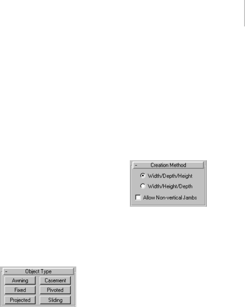
Windows 255
7. Edit the material as you would any
Multi/Sub-Object material.
To animate a window:
You can animate a window opening and closing by
keyframing the Open setting.
1. Create a window or select an existing window.
2. Ifusinganexistingwindow,alsoaccessthe
Modify panel.
3. SettheParametersrollout>Openparameterto
the amount you want the window to be open at
the start of the animation. If you want it to be
closed, set it to 0.
4. Click the Auto Key button (page 3–717) to turn
it on, and advance to the first keyframe.
5. Change the Open setting.
6. Continue moving to any additional keyframes
and changing the Open setting as necessary.
7. Play the animation.
Interface
Most window parameters are common to all kinds
of windows, and are described here. The topic for
each window type describes its unique controls
and behavior.
Object Type rollout
Six types of window are available in 3ds Max:
Awning—Has a sash that is hinged at the top. See
Awning (page 1–256).
Casement—Has one or two door-like sashes that
swing inward or outward. See Casement (page
1–257).
Fixed—Doesn’t open. See Fixed (page 1–258).
Pivoted—Pivots at the center of its sash, either
vertically or horizontally. See Pivoted (page 1–259).
Projected—Has three sashes, two of which open
like awnings in opposite directions. See Projected
(page 1–260).
Sliding—Has two sashes, one of which slides
vertically or horizontally. See Sliding (page 1–261).
Name and Color rollout
See Object Name and Wireframe Color (page
3–757).
Creation Method rollout
You define each type of window with four points:
Drag the first two, followed by two move-click
sequences. The Creation Method setting
determines the order in which these actions define
the window’s dimensions.
Width/Depth/Height—The first two points define
the width and angle of the base of the window. You
set these points by dragging in a viewport, as the
firststepincreatingawindow.Thisletsyoualign
the window with a wall or opening when you place
it. The third point, where you click after moving
the mouse, specifies the depth of the window, and
the fourth click, where you click after moving the
mouseagain,specifiestheheight.
Width/Height/Depth—Wo rk s l ike t he
Width/Depth/Height option, except that
the last two points create first the height and then
the depth.
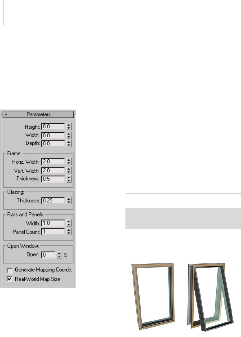
256 Chapter 5: Creating Geometry
Note: With this method, the depth is perpendicular
to the plane set by the first three points. Thus, if
you draw the window in the Top or Perspective
viewport, the door lies flat on the active grid.
Allow Non-vertical Jambs—Select to create tilted
windows. Set snaps (page 2–35) to define points
off the construction plane. Default=off.
Parameters rollout
Height/Width/Depth—Specifies the overall
dimensions of the window.
Frame group
Horiz. Width—Sets the width of the horizontal part
of the window frame (at the top and bottom).
This setting also affects the glazed portion of the
window’s width.
Vert. Width—Sets the width of the vertical part of
the window frame (at the sides). This setting also
affects the glazed portion of the window’s height.
Thickness—Sets the thickness of the frame. This
also controls the thickness of casements or railings
on the window’s sashes.
Glazing group
Thickness—Specifiesthethicknessoftheglass.
Generate Mapping Coordinates—Creates the object
with the appropriate mapping coordinates (page
3–967) already applied.
Real-World Map Size—Controls the scaling method
used for texture mapped materials that are applied
totheobject. Thescalingvaluesarecontrolled
by the Use Real-World Scale settings found in
the applied material’s Coordinates rollout (page
2–1625).Default=off.
Awning Window
Create panel > Geometry > Windows > Awning button
Create menu > AEC Objects > Awning Window
The Awning window has one or more sashes that
are hinged at the top.
Awning window
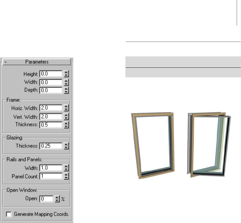
Casement Window 257
Interface
Parameters rollout
The topic for each kind of window describes its
unique controls and behavior. Some window
parameters are common to all kinds of windows;
see Windows (page 1–253).
Rails and Panels group
Width—Sets the width (depth) of the rails in the
sashes.
Panel Count—Sets the number of sashes in the
window. If you use more than one sash, each is
hinged at its top edge. Range=1 to 10.
Open Window group
Open—Specifies the percent the window is open.
This control is animatable.
Casement Window
Create panel > Geometry > Windows > Casement button
Create menu > AEC Objects > Casement Window
The Casement window has one or two sashes that
are hinged on the side, like a door.
Casement window
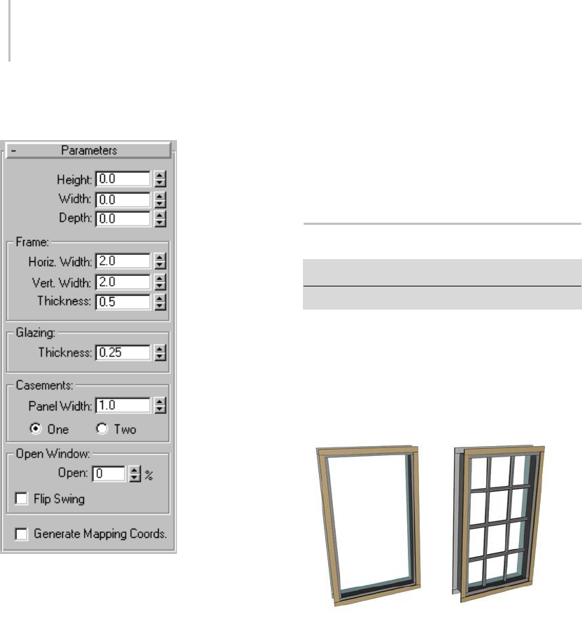
258 Chapter 5: Creating Geometry
Interface
Parameters rollout
The topic for each kind of window describes its
unique controls and behavior. Some window
parameters are common to all kinds of windows;
see Windows (page 1–253).
Casements group
Panel Width—Changes the size of the glazed panel
within each sash.
One/Two—Specifies the number of window panels:
one or two. Using two panels creates a window like
a double door; each panel is hinged on its outside
side edge.
Open Window group
Open—Specifies the percent that the window is
open. This control is animatable.
Flip Swing—Turn this on to have the sashes open in
theoppositedirection.
Fixed Window
Create panel > Geometry > Windows > Fixed button
Create menu > AEC Objects > Fixed Window
Fixed windows do not open, thus have no Open
Window control. In addition to the standard
window object parameters, the Fixed window
provides the Rails And Panels group of settings for
subdividing the window.
Fixed windows
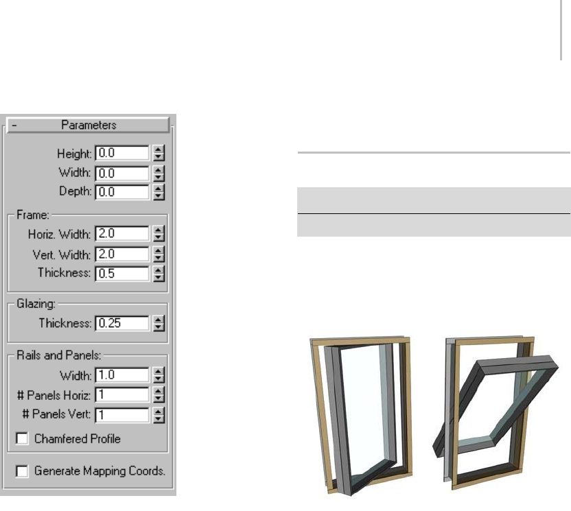
Pivoted Window 259
Interface
Parameters rollout
The topic for each kind of window describes its
unique controls and behavior. Some window
parameters are common to all kinds of windows;
see Windows (page 1–253).
Rails and Panels group
Width—Sets the width (depth) of the rails in the
sashes.
#PanelsHoriz—Sets the number of horizontal
divisions in the window.
# Panels Vert—Sets the number of vertical divisions
in the window.
Chamfered Profile—Chamfers the rails between
the glazed panels, as in a conventional wooden
window. When Chamfered Profile is off, the rails
have a rectangular profile.
Pivoted Window
Createpanel>Geometry>Windows>Pivotedbutton
Create menu > AEC Objects > Pivoted Window
A pivoted window has one sash only, hinged
midway through the side of the sash. It can swing
open either vertically or horizontally.
Pivoted windows
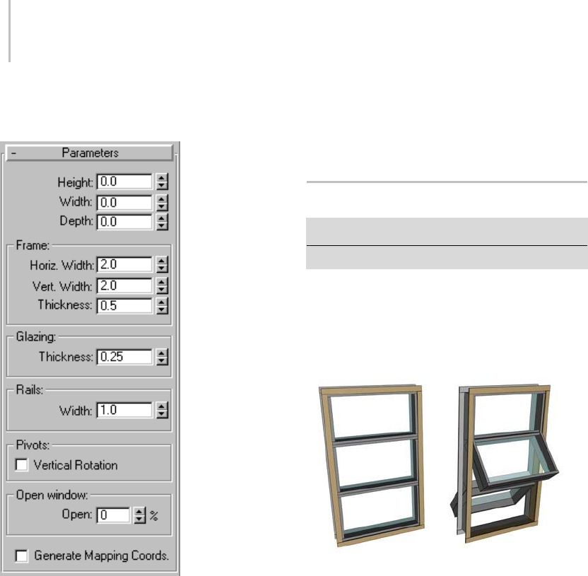
260 Chapter 5: Creating Geometry
Interface
Parameters rollout
The topic for each kind of Window describes its
unique controls and behavior. Most Window
parameters are common to all kinds of Windows;
see Windows (page 1–253).
Rails group
Width—Sets the width of the rails in the sash.
Pivots group
Vertical Rotation—Switches the pivot axis from
horizontal to vertical.
Open Window group
Open—Specifies the percent that the window is
open. This control is animatable.
Projected Window
Create panel > Geometry > Windows > Projected button
Create menu > AEC Objects > Projected Window
Projected windows have three sashes: The top
sash doesn’t move, while the bottom two sashes
swing open like awning windows, but in opposite
directions.
Projected window
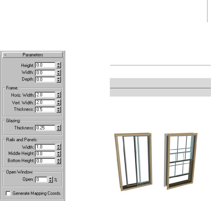
Sliding Window 261
Interface
Parameters rollout
The topic for each kind of window describes its
unique controls and behavior. Some window
parameters are common to all kinds of windows;
see Windows (page 1–253).
Rails and Panels group
Width—Sets the width (depth) of the rails in the
sashes.
Middle Height—Sets the height of the middle sash,
relative to the window’s frame.
Bottom Height—Sets the height of the bottom sash,
relative to the window’s frame.
Open Window group
Open—Specifies the percent that the two movable
sashes are open. This control is animatable.
Sliding Window
Create panel > Geometry > Windows > Sliding button
Create menu > AEC Objects > Sliding Window
Sliding windows have two sashes: one fixed,
one movable. The sliding part can move either
vertically or horizontally.
Sliding windows
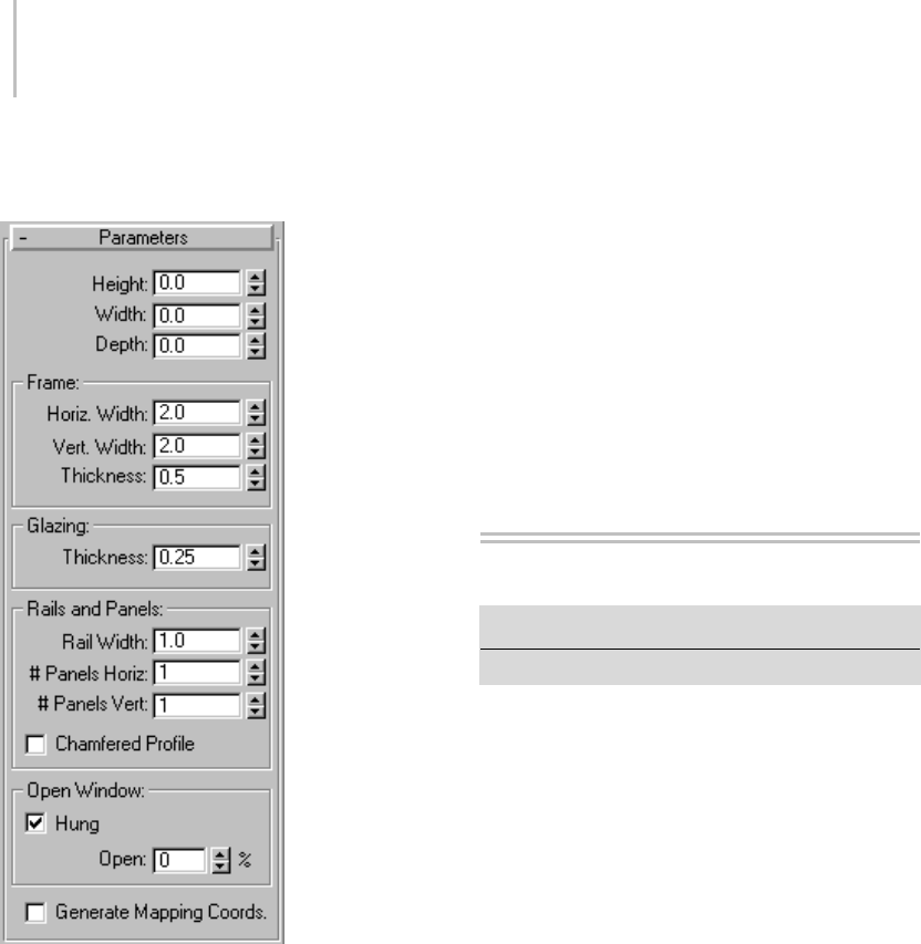
262 Chapter 5: Creating Geometry
Interface
Parameters rollout
The topic for each kind of Window describes its
unique controls and behavior. Most Window
parameters are common to all kinds of Windows;
see Windows (page 1–253).
Rails and Panels group
Rail Width—Sets the width of the rails in the sash.
#PanelsHoriz—Sets the number of horizontal
divisions in each sash.
# Panels Vert—Sets the number of vertical divisions
in each sash.
Chamfered Profile—Chamfers the rails between
the glazed panels, as in a conventional wooden
window. When Chamfered Profile is off, the rails
have a rectangular profile.
Open Window group
Hung—When on, the window slides vertically.
When off, the window slides horizontally.
Open— Specifies the percent that the window is
open. This control is animatable.
Shapes
Create panel > Shapes
Create menu > Shapes
A shape is an object made from one or more
curved or straight lines.
3ds Max includes the following shape types:
Splines and Extended Splines (page 1–266)
NURBS Curves (page 1–1106)
Using Shapes
Shapes are 2D and 3D lines and groups of lines that
youtypicallyuseascomponentsofotherobjects.
Mostofthedefaultshapesaremadefromsplines.
Youusethesesplineshapestodothefollowing:
• Generate planar and thin 3D surfaces
• Define loft components such as paths, shapes,
and fit curves
• Generate surfaces of revolution
•Generateextrusions
•Definemotionpaths
Theprogramsupplies11basicsplineshape
objects, plus two types of NURBS curves. You
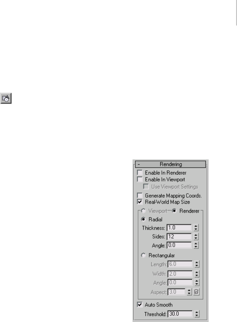
Shapes 263
can quickly create these shapes using mouse
or keyboard entry and combine them to form
compound shapes. See Splines (page 1–266) for
information about the methods and parameters
used to create these shapes.
Creating Shapes
To access the shape creation tools, go to
the Create panel and click the Shapes button.
You’ll find the standard shapes under Splines in
the category list, and Point Curve and CV Curve
under NURBS Curves.
As you add plug-ins, other shape categories might
appear in this list.
TheObjectTyperolloutcontainsthespline
creation buttons. You can combine one or more of
these spline types into a single shape.
Create Shape from Edges
You can create shapes from edge selections in
mesh objects. In Edit/Editable Mesh objects, at the
Edgeselectionlevel,intheEditGeometryrollout,
is a button called Create Shape from Edges that
creates a spline shape based on selected edges. See
Editable Mesh (Edge) (page 1–1006).Similarly,
with Editable Poly objects, you can use the Create
ShapebuttonattheEdgeselectionlevel. See
Editable Poly (Edge) (page 1–1035)
Editable Splines
Yo u c a n c o n v e r t a b a s i c s p l i n e t o a n editable spline
object (page 1–289). The editable spline has a
variety of controls that let you directly manipulate
it and its sub-objects. For example, at the Vertex
sub-object level you can move vertices or adjust
their Bezier handles. Editable splines let you create
shapes that are less regular, more free-form than
the basic spline options.
Whenyouconvertasplinetoaneditablespline,
you lose the ability to adjust or animate its creation
parameters.
Renderable Shapes
When you use a shape to create a 3D object by
lofting, extruding, or other means, the shape
becomes a renderable 3D object. However, you
canmakeashaperenderwithoutmakingitintoa
3D object. There are three basic steps to rendering
ashape:
1. On the Rendering rollout of the shape’s creation
parameters,turnonEnableInRenderer.
2. Specify the thickness for the spline using the
Thickness spinner in the Rendering rollout.
3. Ifyouplantoassignamappedmaterialtothe
spline, turn on Generate Mapping Coords.

264 Chapter 5: Creating Geometry
When Enable in Renderer is on, the shape is
rendered using a circle as a cross section. Mapping
coordinates are generated with U mapped once
around the perimeter, and V mapped once along
the length.
The software provides more control over
renderable shapes; viewports, including wireframe
viewports, can display the geometry of renderable
shapes. The rendering parameters for shapes
appear in their own rollout.
The Steps settings affect the number of cross
sections in the renderable shape.
Please observe the following:
• When you apply a modifier that converts a
shape into a mesh (such as Extrude (page
1–680) or Lathe (page 1–707)), the object
automatically becomes renderable, regardless
of the state of the Enable in Renderer check box.
You need to turn on the Enable in Renderer
check box only when you want to render an
unmodified spline shape in the scene.
• As with all objects, a shape’s layer must be on
for the shape to render. See Layer Properties
(page 3–656).
•TheObject Properties dialog (page 1–117) also
has a Renderable check box, which is turned on
by default. Both this check box and the General
rollout > Renderable check box must be turned
on in order to render a shape.
Shapes as Planar Objects
A straightforward usage for shapes is 2D cutouts or
planar objects. Examples include ground planes,
text for signs, and cutout billboards. You create a
planar object by applying an Edit Mesh modifier
(page 1–634) to a closed shape, or by converting it
to an editable mesh object (page 1–996).
2D objects
Yo u c a n a l s o a p p l y a n E d i t M e s h m o d i f i e r t o a 3 D
shape (for example, a shape whose vertices have
been moved vertically away from the construction
plane by different amounts) to create a curved
surface. The resulting 3D surface often requires
manual editing of faces and edges to smooth
surface ridges.
Extruded and Lathed Shapes
You can apply modifiers to a shape to create a 3D
object. TwoofthesemodifiersareExtrudeand
Lathe. Extrude (page 1–680) creates a 3D object
by adding height to a shape. Lathe (page 1–707)
creates a 3D object by rotating a shape about an
axis.

Shape Check Utility 265
Initial text shape with extruded shape below
Lathed object with initial shape on right
Lofting Shapes
Yo u c r e a t e Lofts (page 1–352) by combining two
or more splines in special ways. Shapes form the
lofting path, loft cross-sections, and loft fit curves.
Shapes as Animation Paths
You can use shapes to define the position of an
animated object. You create a shape and use it to
define a path that some other object follows.
Some possible ways for a shape to control animated
position are:
•YoucanuseaPath constraint (page 2–398) to
use a shape to control object motion.
• You can convert a shape into position keys using
the Motion panel > Trajectories > Convert
From function (see Trajectories (page 2–301)).
See also
Edit Modifiers and Editable Objects (page 1–506)
Modifying at the Sub-Object Level (page 1–506)
Modifier Stack Controls (page 3–760)
Shape Check Utility
Utilities panel > Utilities rollout > More button Utilities
dialog > Shape Check
The Shape Check utility tests spline and
NURBS-based shapes and curves for
self-intersection and graphically displays
any instances of intersecting segments.
Self-intersecting shapes used to produce lathed,
extruded, lofted, or other 3D objects can result in
rendering errors.
The utility is "sticky" in that once you’ve picked
a shape object for it to check, you can pan/zoom
viewports and it will continually display the
locations of intersecting curves in the shape you
pick.
If a shape is animated, moving the time slider will
recheck the shape on each frame of the animation,
allowing for easy checking of these changing
shapes.
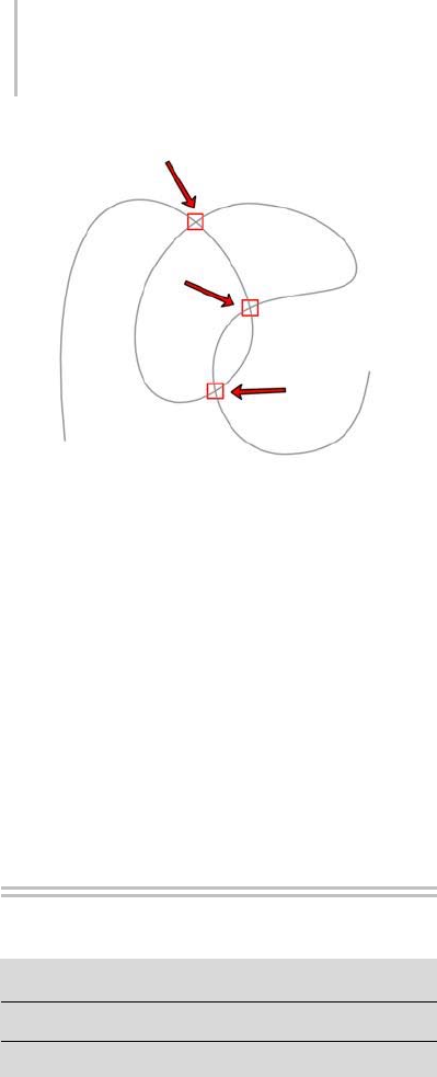
266 Chapter 5: Creating Geometry
Intersection points highlighted by Shape Check
Interface
Pick Object—Click this button, and then click the
shapefortheutilitytocheck.Youcanpickonly
spline- and NURBS-based shapes and curves.
Points of intersection discovered by the utility are
highlighted with red boxes. The text below the
button indicates whether any points of intersection
occur.
Close—Closes the utility.
Splines
Create panel > Shapes > Splines
Create menu > Shapes
Create panel > Shapes > Extended Splines
Splines include the following object types:
Line Spline (page 1–270)
Rectangle Spline (page 1–272)
Circle Spline (page 1–273)
Ellipse Spline (page 1–274)
Arc Spline (page 1–274)
Donut Spline (page 1–276)
NGon Spline (page 1–277)
Star Spline (page 1–277)
Text Spline (page 1–278)
Helix Spline (page 1–281)
Section Spline (page 1–282)
Extended Splines include the following object
types:
WRectangle Spline (page 1–284)
Channel Spline (page 1–285)
Angle Spline (page 1–286)
Tee Spline (page 1–287)
Wide Flange Spline (page 1–288)
This topic covers aspects of spline and extended
spline creation that are common to all spline
object types, including the parameters available
in the General rollout. For parameters unique to
a particular spline or extended spline type, see its
section by clicking the appropriate link above.
Procedures
To control starting a new shape manually:
1. OntheCreatepanel,turnoffthecheckbox
next to the Start New Shape button.
2. Click the Start New Shape button.
3. Begin creating splines.
Each spline is added to the compound shape.
Youcantellyouarecreatingacompoundshape
because all the splines remain selected.
4. Click Start New Shape to complete the current
shapeandpreparetostartanother.
Issues to remember about creating shapes:
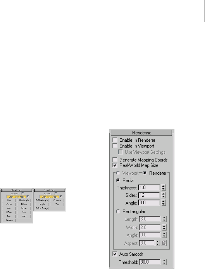
Splines and Extended Splines 267
• You can go back and change the parameters
of a shape containing a single spline after the
shape is created.
• You can create a compound shape by adding
splines to a shape: Select the shape, turn off
Start New Shape, and then create more splines.
• You cannot change the parameters of a
compound shape. For example, create a
compound shape by creating a circle and then
adding an arc. Once you create the arc, you
cannot change the circle parameters.
To create a spline using keyboard entry:
1. Click a spline creation button.
2. Expand the Keyboard Entry rollout.
3. EnterX,Y,andZvaluesforthefirstpoint.
4. Enter values in any remaining parameter fields.
5. Click Create.
Interface
Object Type rollout (Splines and Extended
Splines)
AutoGrid—Lets you automatically create objects
on the surface of other objects by generating and
activating a temporary construction plane based
on normals of the face that you click.
For more information, see AutoGrid (page 2–7).
Start New Shape—Ashapecancontainasingle
spline or it can be a compound shape containing
multiple splines. You control how many splines are
inashapeusingtheStartNewShapebuttonand
check box on the Object Type rollout. The check
box next to the Start New Shape button determines
when new shapes are created. When the box is on,
the program creates a new shape object for every
spline you create. When the box is off, splines are
added to the current shape until you click the Start
New Shape button.
Shape Selection buttons—Lets you specify the type
of shape to create.
Name and Color rollout
Lets you name an object and assign it a viewport
color. For details, see Object Name and Wireframe
Color (page 3–757).
Rendering rollout
Letsyouturnonandofftherenderabilityofa
spline or NURBS curve, specify its thickness in the
rendered scene, and apply mapping coordinates.

268 Chapter 5: Creating Geometry
You can animate render parameters, such as the
number of sides, but you cannot animate the
Viewport settings.
You can convert the displayed mesh into a mesh
object by applying an Edit Mesh or Edit Poly
modifier or converting to an editable mesh or
editable poly object. If Enable In Viewport is off
when converting, closed shapes will be “filled
in” and open shapes will contain only vertices;
no edges or faces. If Enable In Viewport is on
when converting, the system will use the Viewport
settings for this mesh conversion. This gives
maximum flexibility, and will always give the
conversion of the mesh displayed in the viewports.
Enable In Renderer—When on, the shape is
rendered as a 3D mesh using the Radial or
Rectangular parameters set for Renderer. In
previous versions of the program, the Renderable
switch performed the same operation.
Enable In Viewport—When on, the shape is
displayedintheviewportasa3Dmeshusingthe
Radial or Rectangular parameters set for Renderer.
In previous versions of the program, the Display
Render Mesh performed the same operation.
Use Viewport settings—Lets you set different
rendering parameters, and displays the mesh
generated by the Viewport settings. Available only
when Enable in Viewport is turned on.
Generate Mapping Coords—Tur n t hi s on to a pp ly
mapping coordinates. Default=off.
3ds Max generates the mapping coordinates in
the U and V dimensions. The U coordinate
wraps once around the spline; the V coordinate is
mappedoncealongitslength.Tilingisachieved
using the Tiling parameters in the applied material.
For more information, see Mapping Coordinates
(page 2–1405).
Real-World Map Size—Controls the scaling method
used for texture mapped materials that are applied
totheobject. Thescalingvaluesarecontrolled
by the Use Real-World Scale settings found in
the applied material’s Coordinates rollout (page
2–1625).Default=off.
Viewport—Choose this to specify Radial or
Rectangular parameters for the shape as it will
displayintheviewportswhenEnableInViewport
is on.
Renderer—Choose this on to specify Radial or
Rectangular parameters for the shape as it will
displaywhenrenderedorviewedintheviewport
when Enable in Viewport is turned on.
Radial—Displays the 3D mesh as a cylindrical
object.
Thickness—Specifies the diameter of the viewport
or rendered spline mesh. Default=1.0. Range=0.0
to 100,000,000.0.
Splines rendered at thickness of 1.0 and 5.0, respectively
Sides—Sets the number of sides (or facets) for
thesplinemeshntheviewportorrenderer.For
example, a value of 4 results in a square cross
section.
Angle—Adjusts the rotational position of the
cross-section in the viewport or renderer. For
example, if the spline mesh has a square cross
section you can use Angle to position a "flat" side
down.
Rectangular—Displays the spline’s mesh shape as
arectangle.
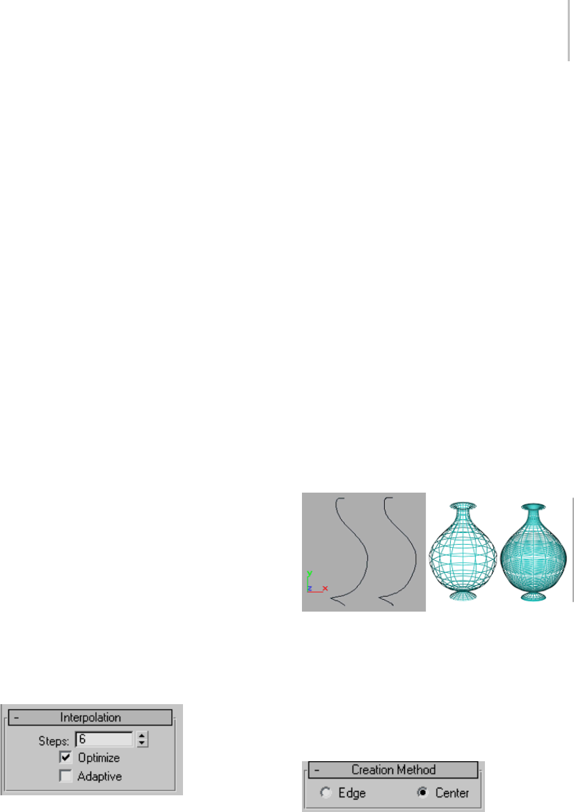
Splines and Extended Splines 269
Length—Specifies the size of the cross–section
along the local Yaxis.
Width—Specifies the size of the cross–section
along the local Xaxis.
Angle—Adjusts the rotational position of the
cross-section in the viewport or renderer. For
example, if you have a square cross-section you
canuseAngletopositiona"flat"sidedown.
Aspect—Sets the aspect ratio for rectangular
cross-sections. The Lock check box lets you lock
the aspect ratio. When Lock is turned on, Width is
locked to Length that results in a constant ratio of
Width to Length.
Auto Smooth—If Auto Smooth is turned on, the
spline is auto-smoothed using the threshold
specified by the Threshold setting below it. Auto
Smooth sets the smoothing based on the angle
between spline segments. Any two adjacent
segmentsareputinthesamesmoothinggroupif
the angle between them is less than the threshold
angle.
Note: Turning Auto Smooth on for every situation
doesnotalwaysgiveyouthebestsmoothing
quality. Altering the Threshold angle may be
necessary or turning Auto Smooth off may
produce the best results.
Threshold—Specifies the threshold angle in
degrees. Any two adjacent spline segments are put
inthesamesmoothinggroupiftheanglebetween
them is less than the threshold angle.
Interpolation rollout
These settings control how a spline is generated.
All spline curves are divided into small straight
linesthatapproximatethetruecurve.Thenumber
of divisions between each vertex on the spline are
called steps. The more steps used, the smoother
the curve appears.
Steps—Spline steps can be either adaptive (that
is,setautomaticallybyturningonAdaptive)or
specified manually.
When Adaptive is off, use the Steps field/spinner
to set the number of divisions between each vertex.
Splines with tight curves require many steps to
look smooth while gentle curves require fewer
steps. Range=0 to 100.
Optimize—When on, removes unneeded steps
from straight segments in the spline. Optimize is
not available when Adaptive is on. Default=on.
Adaptive—When off, enables manual interpolation
control using Optimize and Steps. Default=off.
When on, Adaptive sets the number of steps for
each spline to produce a smooth curve. Straight
segments always receive 0 steps.
Optimized spline left and adaptive spline right. Resulting
wireframe view of each, respectively, on the right.
The main use for manual interpolation of splines is
in morphing or other operations where you must
have exact control over the number of vertices
created.
Creation Method rollout
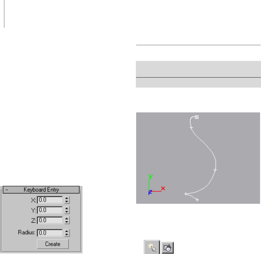
270 Chapter 5: Creating Geometry
Many spline tools use the Creation Methods
rollout. On this rollout you choose to define
splines by either their center point or their
diagonal.
Edge—Your first click defines a point on the side or
at a corner of the shape and you drag a diameter
or the diagonal corner.
Center—Your first click defines the center of the
shape and you drag a radius or corner point.
Text (page 1–278) and Star (page 1–277) do not
haveaCreationMethodsrollout.
Line (page 1–270) and Arc (page 1–274) have
unique Creation Methods rollouts that are
discussed in their respective topics.
Keyboard Entry rollout
You can create most splines using keyboard entry.
The process is generally the same for all splines
and the parameters are found under the Keyboard
Entry rollout. Keyboard entry varies primarily in
the number of optional parameters. The image
aboveshowsasampleKeyboardEntryrolloutfor
theCircleshape.
The Keyboard Entry rollout contains three
fields for the X, Y, and Z coordinates of the
initial creation point, plus a variable number of
parameters to complete the spline. Enter values
in each field and click the Create button to create
the spline.
Line Spline
Create panel > Shapes > Splines > Object Type rollout
>Line
Create menu > Shapes > Line
UseLinetocreateafree-formsplinemadeof
multiple segments.
Example of line
Procedures
To create a line:
1. Go to the Create panel and choose
Shapes.
2. OntheObjectTyper
ollout, click the Line
button.
3. Chooseacreationmethod.
4. Click or drag the start point.
Clicking creates a corner vertex; dragging
creates a Bezier vertex.
5. Click or drag additional points.
Clicking creates a corner vertex; dragging
creates a Bezier vertex.
6. Do one of the following:
•Right-clicktocr
eate an open spline.
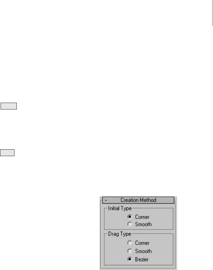
Line Spline 271
• Click the first vertex and click Yes in the
"Close spline?" dialog to create a closed
spline.
To create a line using rectilinear and angle-snap
options:
These two options aid in creating regular shapes:
• While creating a spline with the mouse, press
and hold Shift to constrain new points to
90-degree-angle increments from previous
points. Use the default Initial type setting of
Corner and click all subsequent points to create
fully rectilinear shapes.
• While creating a spline with the mouse, press
and hold Ctrl to constrain new points to angle
increments determined by the current Angle
Snap setting (page 2–12). To set this angle, go
to Customize menu > Grid and Snap Settings,
click the Options tab (page 2–46) in the Grid
and Snap Settings dialog, and change the value
in the Angle (deg) field.
The angle for each new segment relates to the
previous segment, so the angle snap works only
after you’ve placed the first two spline vertices
(that is, the first segment). Angle Snap need not be
enabled for this feature to work.
To create a line from the keyboard:
1. Enter values in the X, Y, and Z fields to specify a
vertex coordinate.
2. Click Add Point to add a vertex to the current
line at the specified coordinate.
3. Repeat steps 1 and 2 for each additional vertex.
4. Do one of the following:
• Click Finish to create an open spline.
• ClickClosetoconnectthecurrentvertexto
thefirstvertexandcreateaclosedspline.
Interface
Automatic Conversion to an Editable Spline
Because the Line object has no dimension
parameters to be carried over to the Modify panel,
it converts to an editable spline (page 1–289) when
you move from the Create panel to the Modify
panel. While you are creating the line, the Create
panel displays the original controls, such as
Interpolation, Rendering, Creation Method, and
Keyboard Entry. After creating the line, when you
go to the Modify panel you have immediate access
to the Selection and Geometry rollouts to edit the
vertices or any part of the shape.
Rendering and Interpolation rollouts
All spline-based shapes share these parameters.
See Splines (page 1–266) for an explanation of
these parameters.
Creation Method rollout
Creation method options for lines are different
from other spline tools. You choose options to
control the type of vertex created when you click
or drag vertices.
You can preset the default types of spline vertices
during line creation with these settings:
Initial Type group
Sets the type of vertex you create when you click
avertexlocation.
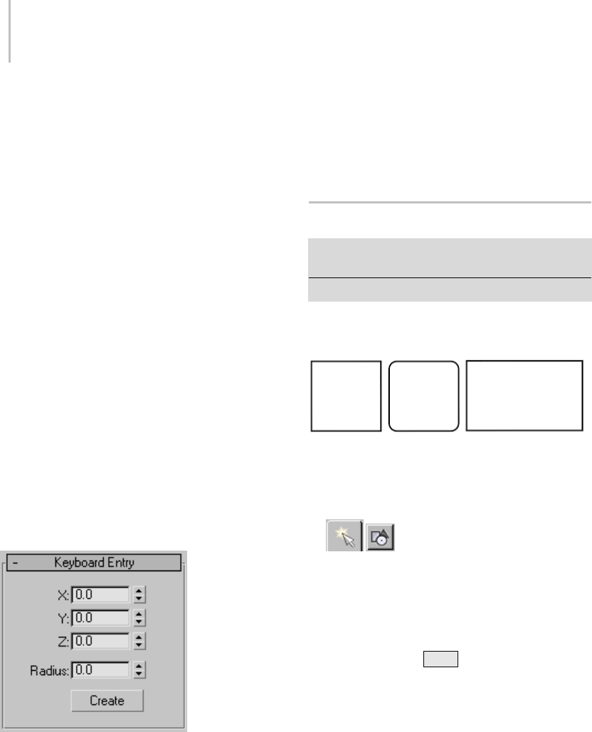
272 Chapter 5: Creating Geometry
Corner—Produces a sharp point. The spline is
linear to either side of the vertex.
Smooth—Produces a smooth, nonadjustable curve
through the vertex. The amount of curvature is set
bythespacingofthevertices.
Drag Type group
Sets the type of vertex you create when you drag a
vertex location. The vertex is located at the cursor
position where you first press the mouse button.
Thedirectionanddistancethatyoudragareused
only when creating Bezier vertices.
Corner—Produces a sharp point. The spline is
linear to either side of the vertex.
Smooth—Produces a smooth, nonadjustable curve
through the vertex. The amount of curvature are
set by the spacing of the vertices.
Bezier—Produces a smooth, adjustable curve
through the vertex. The amount of curvature
and direction of the curve are set by dragging the
mouse at each vertex.
Keyboard Entry rollout
Keyboard entry for lines is different from keyboard
entry for other splines. Entering keyboard values
continues to add vertices to the existing line until
you click Close or Finish.
Add Point—Adds a new point to the line at the
current X/Y/Z coordinates.
Close—Closes the shape, adding a final spline
segment between the most recent vertex and the
first.
Finish—Finishes the spline without closing it.
Rectangle Spline
Create panel > Shapes > Splines > Object Type rollout
>Rectangle
Create menu > Shapes > Rectangle
Use Rectangle to create square and rectangular
splines.
Examples of rectangles
Procedure
To create a rectangle:
1. Go to the Create panel and choose
Shapes.
2. Click Rectangle.
3. Chooseacreationmethod.
4. Drag in a viewport to create a rectangle.
Optionally, press Ctrl while dragging to
constrain the spline toasquare.
Interface
Rendering and Interpolation rollouts
All spline-based shapes share these parameters.
See Splines (page 1–266) for an explanation of
these parameters.
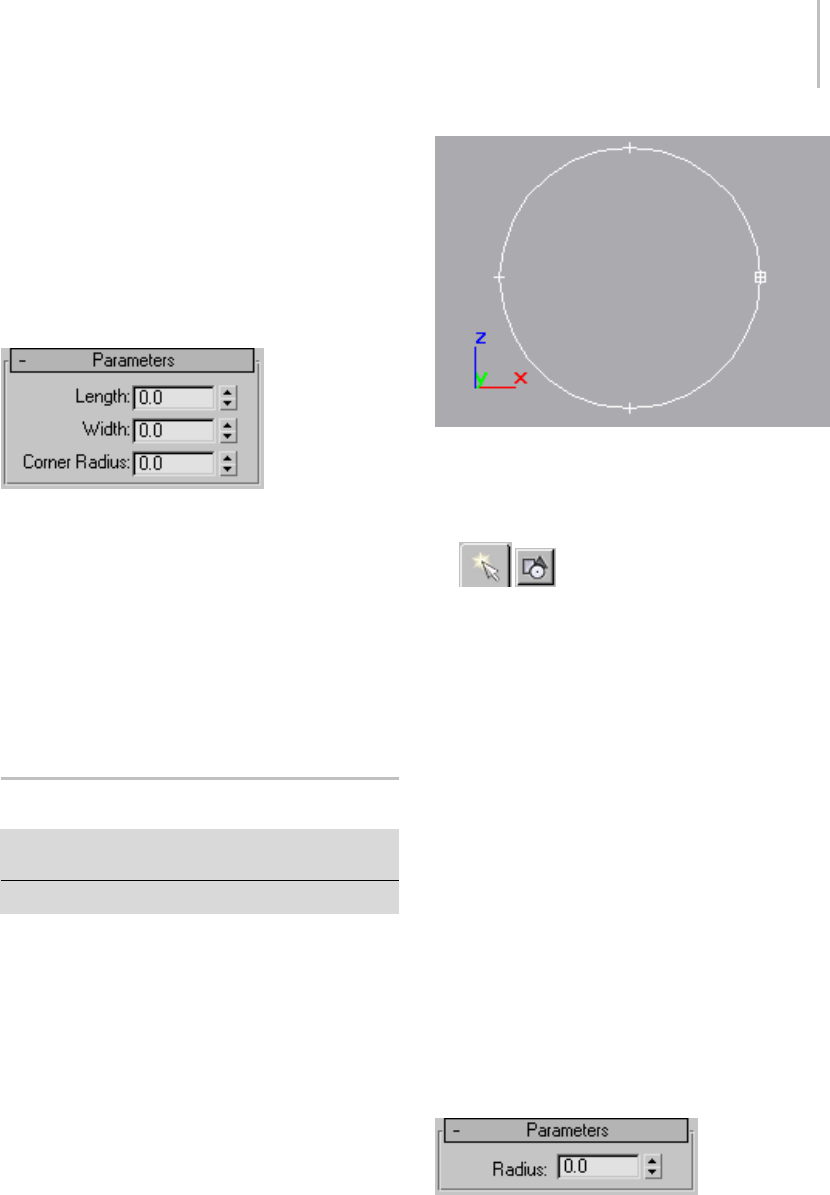
Circle Spline 273
Creation Method rollout
The Rectangle shape uses the standard creation
methods of Center or Edge. Most spline-based
shapes share the same Creation Method
parameters. See Splines (page 1–266) for an
explanation of these parameters.
Parameters rollout
Once you have created a rectangle, you can make
changes using the following parameters:
Length—Specifies the size of the rectangle along
the local Y axis.
Width—Specifies the size of the rectangle along the
local X axis.
Corner Radius—Creates rounded corners. When
set to 0, the rectangle contains 90-degree corners.
Circle Spline
Create panel > Shapes > Splines > Object Type rollout >
Circle
Create menu > Shapes > Circle
Use Circle to create closed circular splines made of
four vertices.
Example of circle
Procedure
To create a circle:
1. Go to the Create panel and choose
Shapes.
2. Click Circle.
3. Chooseacreationmethod.
4. Drag in a viewport to draw the circle.
Interface
Rendering and Interpolation rollouts
All spline-based shapes share these parameters.
See Splines (page 1–266) for explanations of these
parameters.
Creation Method rollout
TheCircleshapeu
ses the standard creation
methodsofCenterorEdge. Mostspline-based
shapes share the same Creation Method
parameters. See Splines (page 1–266) for an
explanation of these parameters.
Parameters rollout
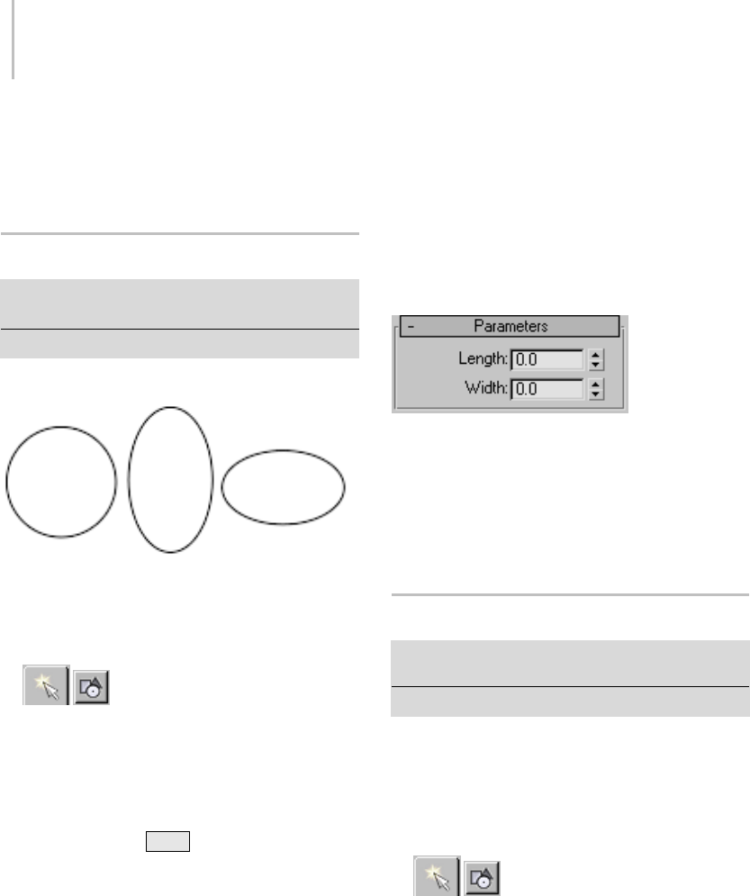
274 Chapter 5: Creating Geometry
Once you have created a circle, you can make
changes using the following parameter:
Radius—Specifies the radius of the circle.
Ellipse Spline
Create panel > Shapes > Splines > Object Type rollout
> Ellipse
Create menu > Shapes > Ellipse
Use Ellipse to create elliptical and circular splines.
Examples of ellipses
Procedure
To create an ellipse:
1. GototheCreatepanelandchoose
Shapes.
2. Click Ellipse.
3. Chooseacreationmethod.
4. Drag in a viewport to draw the ellipse.
Optionally, press Ctrl while dragging to
constrain the spline to a circle.
Interface
Rendering and Interpolation rollouts
All spline-based shapes share these parameters.
See Splines (page 1–266) for explanations of these
parameters.
Creation Method rollout
The Ellipse shape uses the standard creation
methodsofCenterorEdge. Mostspline-based
shapes share the same Creation Method
parameters. See Splines (page 1–266) for an
explanation of these parameters.
Parameters rollout
Once you have created an Ellipse, you can make
changes using the following parameters:
Length—Specifies the size of the Ellipse along the
local Y axis.
Width—Specifies the size of the Ellipse local X axis.
Arc Spline
Create panel > Shapes > Splines > Object Type rollout
>Arc
Create menu > Shapes > Arc
Use Arc to create open and closed circular arcs
made of four vertices.
Procedures
To create an arc using the end-end-middle method:
1. Go to the Create panel and choose
Shapes.
2. Click Arc.
3. ChoosetheEnd-End-Middlecreationmethod.
4. Drag in a viewport to set the two ends of the arc.
5. Releasethemousebutton,thenmovethe
mouse and click to specify a third point on an
arc between the two endpoints.
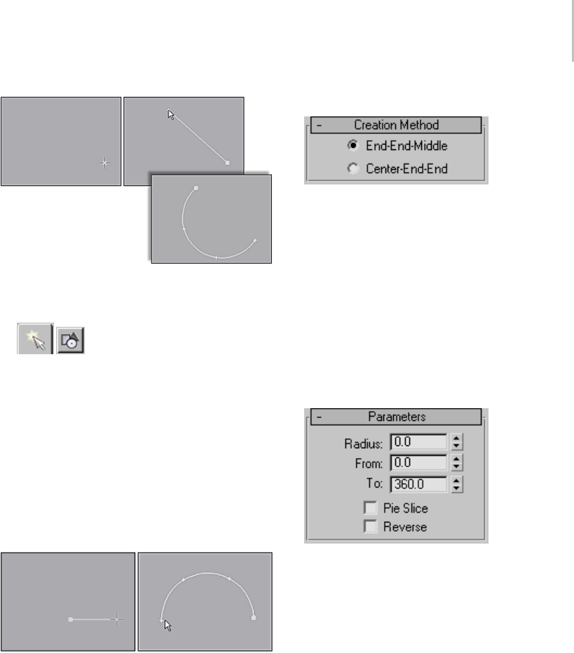
Arc Spline 275
Creating an arc using the End-End-Middle creation method
To create an arc using the center-end-end method:
1. GototheCreatepanelandchoose
Shapes.
2. Click Arc.
3. Choose the Center-End-End creation method.
4. Press the mouse button to define the center of
the arc.
5. Drag and release the mouse button to specify
the start point of the arc.
6. Move the mouse and click to specify the other
end of the arc.
Creating an arc using the Center-End-End creation method
Interface
Rendering and Interpolation rollouts
All spline-based shapes share these parameters.
See Splines (page 1–266) for an explanation of
these parameters.
Creation Method rollout
Theseoptionsdeterminethesequenceofmouse
clicks involved in the creation of the arc.
End-End-Middle—Drag and release to set the two
endpoints of the arc, and then click to specify the
third point between the two endpoints.
Center-End-End—Press the mouse button to specify
the center point of the arc, drag and release to
specify one endpoint of the arc, and click to specify
the other endpoint of the arc.
Parameters rollout
Once you have created an arc, you can make
changes using the following parameters:
Radius—Specifies the arc radius.
From—Specifies the location of the start point as
an angle measured from the local positive X axis.
To—Specifies the location of the end point as an
angle measured from the local positive X axis.
Pie Slice—Whenon,createsaclosedsplineinthe
form of a pie. The start point and end point are
connected to the center with straight segments.
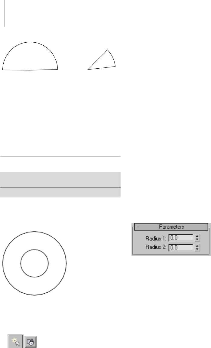
276 Chapter 5: Creating Geometry
Closed pie slice arcs
Reverse—When on, the direction of the arc spline
is reversed, and the first vertex is placed at the
opposite end of an open arc. As long as the shape
remains an original shape (and not an editable
spline), you can switch its direction by toggling
Reverse. Once the arc is converted to an editable
spline, you can use Reverse at the Spline sub-object
level to reverse direction.
Donut Spline
Create panel > Shapes > Splines > Object Type rollout
>Donut
Create menu > Shapes > Donut
Use Donut to create closed shapes from two
concentric circles. Each circle is made of four
vertices.
Example of donut
Procedure
To create a donut:
1. GototheCreatepanelandchoose
Shapes.
2. Click Donut.
3. Chooseacreationmethod.
4. Drag and release the mouse button to define
the first donut circle.
5. Move the mouse and then click to define the
radius of the second concentric donut circle.
Thesecondcirclecanbelargerorsmallerthan
the first.
Interface
Rendering and Interpolation rollouts
All spline-based shapes share these parameters.
See Splines (page 1–266) for explanations of these
parameters.
Creation Method rollout
The Donut shape uses the standard creation
methodsofCenterorEdge. Mostspline-based
shapes share the same Creation Method
parameters. See Splines (page 1–266) for an
explanation of these parameters.
Parameters rollout
Once you have created a donut, you can make
changes using the following parameters:
Radius 1—Sets the radius of the first circle.
Radius 2—Sets the radius of the second circle.
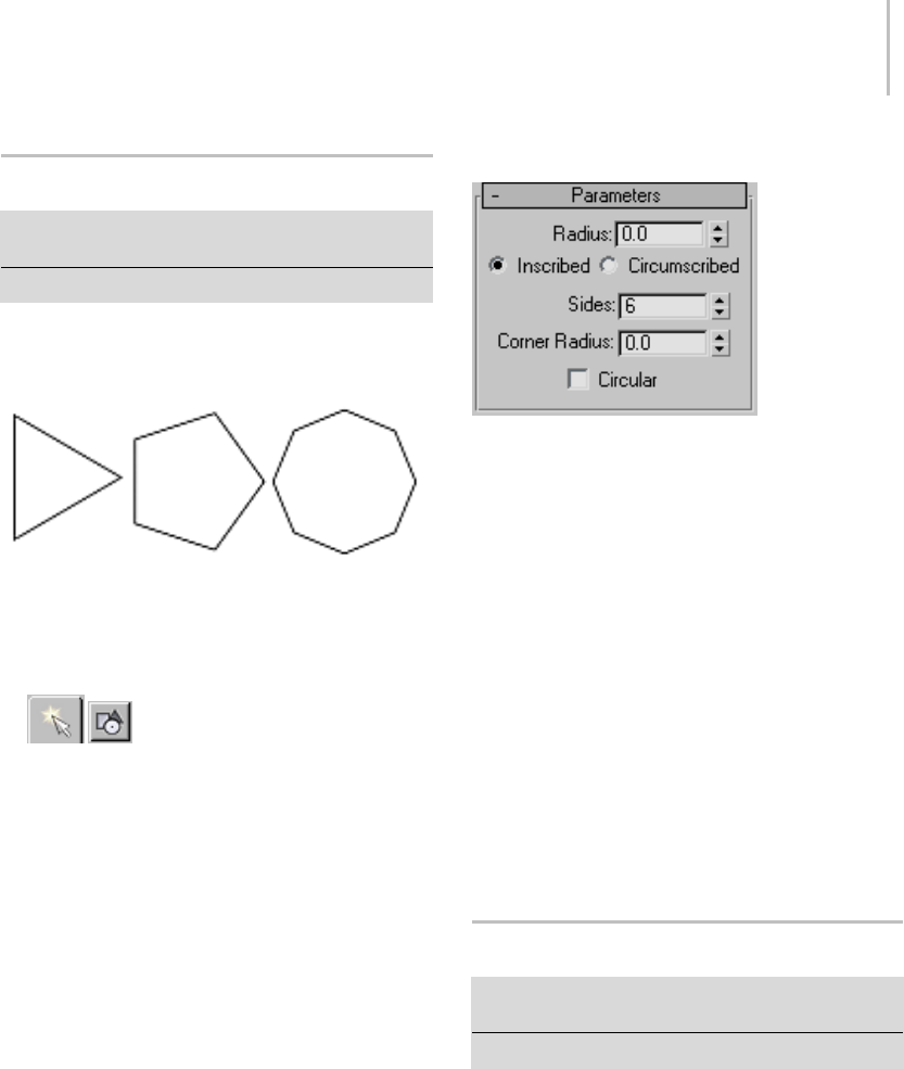
NGon Spline 277
NGon Spline
Create panel > Shapes > Splines > Object Type rollout >
NGon
Create menu > Shapes > NGon
Use NGon to create closed flat-sided or circular
splines with any number (N) of sides or vertices.
Examples of NGons
Procedure
To create an NGon:
1. GototheCreatepanelandchoose
Shapes.
2. Click NGon.
3. Chooseacreationmethod.
4. Drag and release the mouse button in a
viewport to draw the NGon.
Interface
Rendering and Interpolation rollouts
All spline-based shapes share these parameters.
See Splines (page 1–266) for an explanation of
these parameters.
Creation Method rollout
TheNGonshapeusesthestandardcreation
methods of Center or Edge. Most spline-based
shapes share the same Creation Method
parameters. See Splines (page 1–266) for an
explanation of these parameters.
Parameters rollout
Once you have created an NGon, you can make
changes using the following parameters:
Radius—Specifies the NGon radius. You can use
either of two methods to specify the radius:
•Inscribed—The radius from the center to the
corners of the NGon
•Circumscribed—The radius from the center to
the sides of the NGon.
Sides—Specifies the number of sides and vertices
used by the NGon. Range=3 to 100.
Corner Radius—Specifies the degree of rounding to
apply to the corners of the NGon. A setting of 0
specifies a standard unrounded corner.
Circular—When on, specifies a circular NGon.
Star Spline
Create panel > Shapes > Splines > Object Type rollout
>Star
Create menu > Shapes > Star
Use Star to create closed star-shaped splines with
any number of points. Star splines use two radiuses
to set the distance between the outer points and
inner valleys.
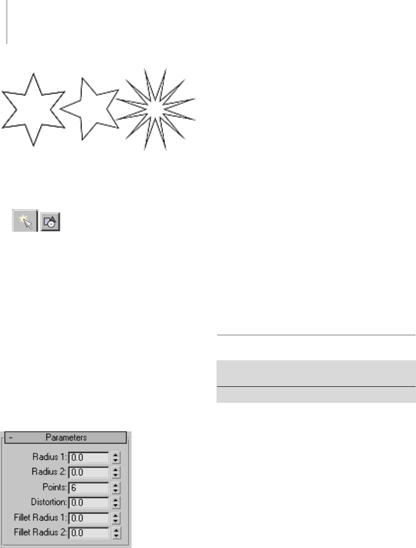
278 Chapter 5: Creating Geometry
Examples of stars
Procedure
To create a star:
1. GototheCreatepanela
nd choose
Shapes.
2. Click Star.
3. Drag and release the mouse button to define
the first star radius.
4. Move the mouse and then click to define the
second star radius.
Interface
Rendering and Interpolation rollouts
All spline-based shapes share these parameters.
See Splines (page 1–266) for explanations of these
parameters.
Parameters rollout
Once you have created a star, you can make
changes using the following parameters:
Radius 1—Specifies the radius of the inner vertices
(the valley) of the star.
Radius 2—Specifies the radius of the outer vertices
(the points) of the star.
Points—Specifies the number of points on the star.
Range=3 to 100.
A star has twice as many vertices as the specified
number of points. Half the vertices lie on one
radius, forming points, and the remaining vertices
lie on the other radius, forming valleys.
Distortion—Rotates the outer vertices (the points)
about the center of the star. This produces a
sawtooth affect.
Fillet Radius 1—Rounds the inner vertices (the
valleys) of the star.
Fillet Radius 2—Rounds the outer vertices (the
points) of the star.
Text Spline
Create panel > Shapes > Splines > Object Type rollout
>Text
Create menu > Shapes > Text
UseTexttocreatesplinesintheshapeoftext.
ThetextcanuseanyWindowsfontinstalledon
your system, or a Type 1 PostScript font installed
in the directory pointed to by the Fonts path on
the Configure System Paths dialog (page 3–810).
Because fonts are loaded only at first use, changing
the font path later in the program has no effect.
The program must be restarted before the new
path is used, if the font manager has been used by
the program.
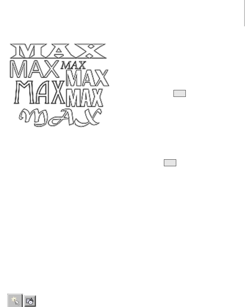
Text Spline 279
Examples of text
You can edit the text in the Create panel, or later in
the Modify panel.
Using Text Shapes
Text shapes maintain the text as an editable
parameter. You can change the text at any time.
If the font used by your text is deleted from the
system, 3ds Max still properly displays the text
shape. However, to edit the text string in the edit
box you must choose an available font.
Thetextinyoursceneisjustashapewhereeach
letter and, in some cases, pieces of each letter are
individual splines. You can apply modifiers like
Edit Spline (page 1–680),Bend (page 1–560),and
Extrude (page 1–680) to edit Text shapes just like
any other shape.
Procedures
To create text:
1. Go to the Create panel and choose
Shapes.
2. Click Text.
3. Enter text in the Text box.
4. Do either of the following to define an insertion
point:
• Click in a viewport to place the text in the
scene.
• Drag the text into position and release the
mouse button.
To enter a special Windows character:
1. Hold down the Alt key.
2. Enter the character’s numeric value on the
numeric keypad.
Yo u must use the numeric keypad, not the row
of numbers above the alphabetic keys.
For some characters, you must enter a leading
zero. For example, 0233 to enter an e with an
acute accent.
3. Release the Alt key.
Interface
Settings available for text include kerning, leading,
justification, multiple lines, and a manual update
option.
Rendering and Interpolation rollouts
All spline-based shapes share these parameters.
See Splines (page 1–266) for an explanation of
these parameters.
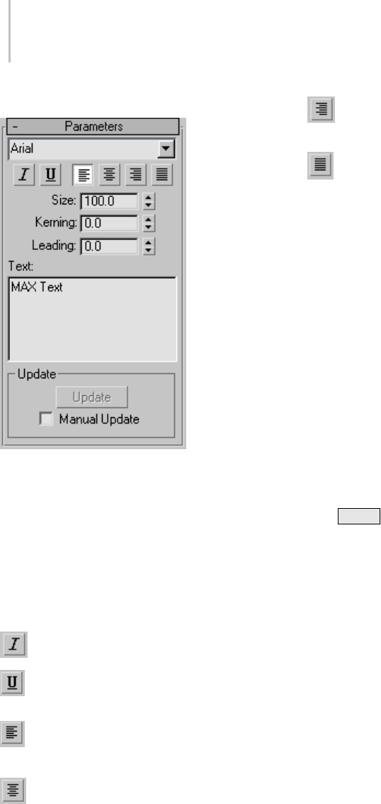
280 Chapter 5: Creating Geometry
Parameters rollout
Onceyouhavecreatedtext,youcanmakechanges
using the following parameters:
Font list—Choose from a list of all available fonts.
Available fonts include:
•FontsinstalledinWindows.
• Type1PostScriptfontslocatedinthedirectory
pointed to by the Fonts path on the Configure
System Paths dialog (page 3–810).
Italic style button—Toggles italicized text.
Underline style button—Toggles underlined
text.
Align Left—Aligns text to the left side of its
bounding box.
Center—Aligns text to the center of its
bounding box.
Align Right—Aligns text to the right side of
its bounding box.
Justify—Spaces all lines of text to fill the
extents of the bounding box.
Note: The four text-alignment buttons require
multiple lines of text for effect because they act
on the text in relation to its bounding box. If
there’sonlyonelineoftext,it’sthesamesizeas
its bounding box.
Size—Sets the text height where the height
measuring method is defined by the active font.
The first time you enter text, the default size is 100
units.
Kerning—Adjusts the kerning (the distance
between letters).
Leading—Adjusts the leading (the distance
between lines). This has an effect only when
multiple lines of text are included in the shape.
Text edit box—Allows for multiple lines of text.
Press Enter aftereachlineoftexttostartthenext
line.
• The initial session default is "MAX Text."
• The edit box does not support word wrap.
• You can cut and paste single- and multi-line
text from the Clipboard.
Update group
These options let you select a manual update
option for situations where the complexity of the
text shape is too high for automatic updates.
Update—Updates the text in the viewport to match
the current settings in the edit box. This button is
available only when Manual Update is on.
Manual Update—When on, the text that you type
into the edit box is not shown in the viewport until
youclicktheUpdatebutton.
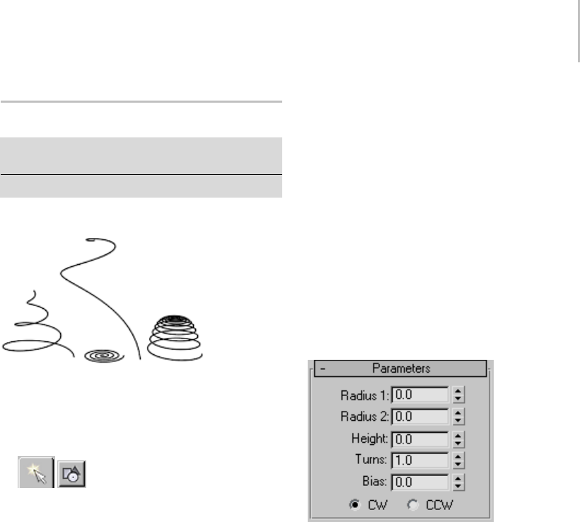
Helix Spline 281
Helix Spline
Create panel > Shapes > Splines > Object Type rollout >
Helix
Create menu > Shapes > Helix
Use Helix to create open flat or 3D spirals.
Examples of helixes
Procedure
To create a helix:
1. GototheCreatepanelandchoose
Shapes.
2. Click Helix.
3. Chooseacreationmethod.
4. Press the mouse button to define the first point
of the Helix start circle.
5. Drag and release the mouse button to define
the second point of the Helix start circle.
6. Move the mouse and then click to define the
height of the Helix.
7. Move the mouse and then click to define the
radius of the Helix end.
Interface
Rendering rollout
All spline-based shapes share these parameters.
See Splines (page 1–266) for explanations of these
parameters.
Interpolation
The helix differs from other spline-based shapes
in that it always uses adaptive interpolation:the
number of vertices in a helix is determined by the
number of turns.
Creation Method rollout
The Helix shape uses the standard creation
methodsofCenterorEdge. Mostspline-based
shapes share the same Creation Method
parameters. See Splines (page 1–266) for an
explanation of these parameters.
Parameters rollout
Onceyouhavecreatedahelix,youcanmake
changes using the following parameters:
Radius 1—Specifies the radius for the Helix start.
Radius 2—Specifies the radius for the Helix end.
Height—Specifies the height of the Helix.
Turns—SpecifiesthenumberofturnstheHelix
makes between its start and end points.
Bias—Forces the turns to accumulate at one end of
the helix. Bias has no visible affect when the height
is 0.0.
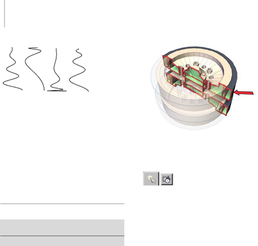
282 Chapter 5: Creating Geometry
Helical spline varied only by bias settings
• A bias of –1.0 forces the turns toward the start
of the helix.
• A bias of 0.0 evenly distributes the turns
between the ends.
• A bias of 1.0 forces the turns toward the end of
the helix.
CW/CCW—The direction buttons set whether the
Helix turns clockwise (CW) or counterclockwise
(CCW).
Section Spline
Create panel > Shapes > Splines > Object Type rollout
>Section
Create menu > Shapes > Section
This is a special type of object that generates other
shapes based on a cross-sectional slice through
mesh objects. The Section object appears as a
bisected rectangle. You simply move and rotate
it to slice through one or more mesh objects, and
then click the Create Shape button to generate a
shape based on the 2D intersection.
Red line shows the section shape based on the structure.
Procedure
To create and use a section shape:
1. Go to the Create panel and choose
Shapes.
2. Click Section.
3. Drag a rectangle in the viewport in which you
want to orient the plane. (For example, create it
intheTopviewporttoplacetheSectionobject
parallel with the XY home grid.)
The Section object appears as a simple rectangle
with crossed lines indicating its center. With
the default settings, the rectangle is for display
purposes only, because the effect of the Section
objectextendsalongitsplanetothefullextents
of the scene.
4. Move and rotate the section so that its plane
intersects mesh objects in the scene.
Yellow lines are displayed where the sectional
plane intersects objects.
5. On the Create panel, click Create Shape, enter a
name in the resulting dialog, and click OK.
An editable spline (page 1–289) is created, based
on the displayed cross sections.
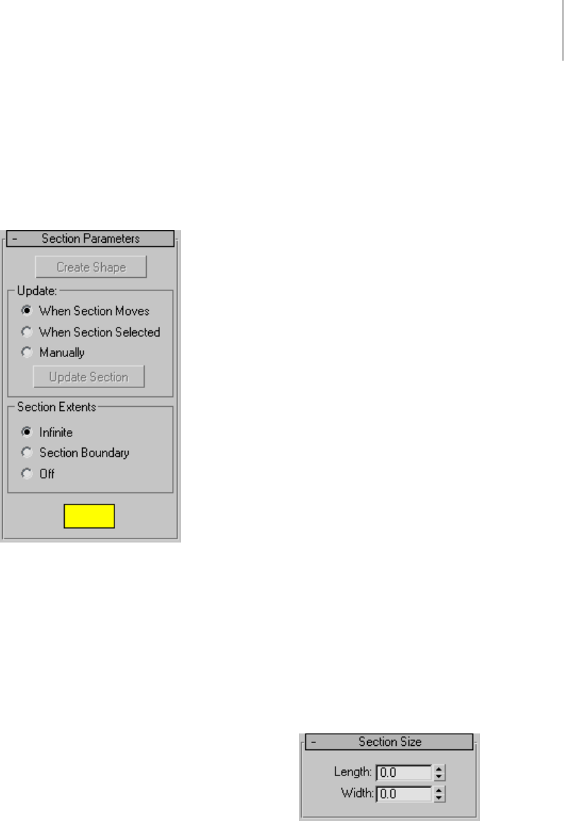
Section Spline 283
Interface
Rendering and Interpolation rollouts
All spline-based shapes share these parameters.
See Splines (page 1–266) for an explanation of
these parameters.
Section Parameters rollout
Create Shape—Creates a shape based on the
currently displayed intersection lines. A dialog is
displayed in which you can name the new object.
Theresultingshapeisaneditablesplineconsisting
of curve segments and corner vertices, based on all
intersected meshes in the scene.
Update group
Provides options for specifying when the
intersection line is updated.
When Section Moves—Updates the intersection line
when you move or resize the Section shape.
When Section Selected—Updates the intersection
line when you select the section shape, but not
while you move it. Click the Update Section button
to update the intersection.
Manually—Updates the intersection line only when
youclicktheUpdateSectionbutton.
Update Section—Updates the intersection to match
the current placement of the Section object when
using When Section Selected or Manually option.
Note: When using When Section Selected or
Manually, you can offset the generated cross
section from the position of the intersected
geometry. As you move the section object, the
yellow cross-section lines move with it, leaving
the geometry behind. When you click Create
Shape, the new shape is generated at the displayed
cross-section lines in the offset position.
Section Extents group
Choose one of these options to specify the extents
of the cross-section generated by the section
object.
Infinite—Thesectionplaneisinfiniteinall
directions, resulting in a cross section at any mesh
geometry in its plane.
Section Boundary—The cross-section is generated
only in objects that are within or touched by the
boundary of the section shape.
Off—No cross section is displayed or generated.
TheCreateShapebuttonisdisabled.
Color swatch—Click this to set the display color of
the intersection.
Section Size rollout
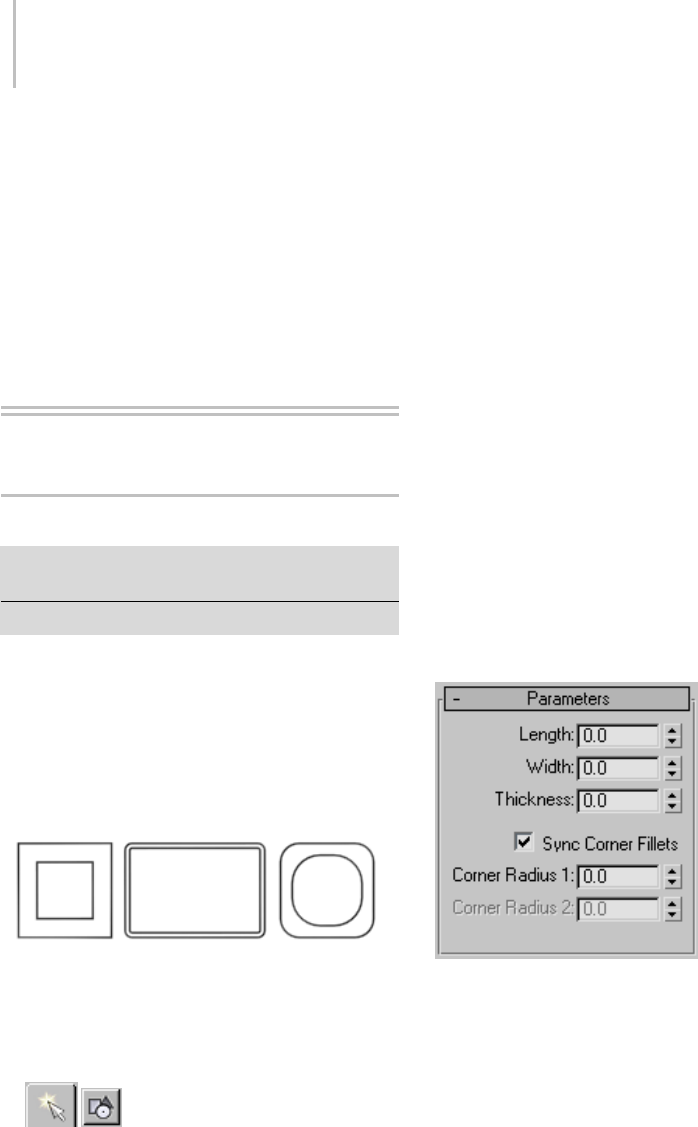
284 Chapter 5: Creating Geometry
Provides spinners that let you adjust the length
and width of the displayed section rectangle.
Length/Width—Adjustthelengthandwidthofthe
displayed section rectangle.
Note: If you convert the section grid to an editable
spline, it’s converted to a shape based on the
current cross section.
Extended Splines
WRectangle Spline
Create panel > Shapes > Extended Splines > Object Type
rollout > WRectangle
Create menu > Shapes > WRectangle
UseWRectangletocreateclosedshapesfromtwo
concentric rectangles. Each rectangle is made of
four vertices. The WRectangle is similar to the
Donuttoolexceptitusesrectanglesinsteadof
circles.
WRectangle stands for “walled rectangle”.
Example of WRectangle
Procedure
To create a wrectangle:
1. GototheCreatepanelandchoose
Shapes.
2. Open the Shapes List and choose Extended
Splines.
3. Click WRectangle.
4. Drag and release the mouse button to define
the outer rectangle.
5. Move the mouse and then click to define the
inner rectangle.
Interface
Rendering and Interpolation rollouts
All spline-based shapes share these parameters.
For explanations, see Splines and Extended Splines
(page 1–266).
Creation Method rollout
TheWRectangleshapeusesthestandard
creation methods of Center or Edge. Most
spline-based shapes share the same Creation
Method parameters. For explanations, see Splines
and Extended Splines (page 1–266).
Parameters rollout
Length—Controls the height of the wrectangle
section.
Width—Controls the width of the wrectangle
section.
Thickness—Controls the thickness of the walls of
the wrectangle.
Sync Corner Fillets—When turned on, Corner
Radius 1 controls the radius of both the interior
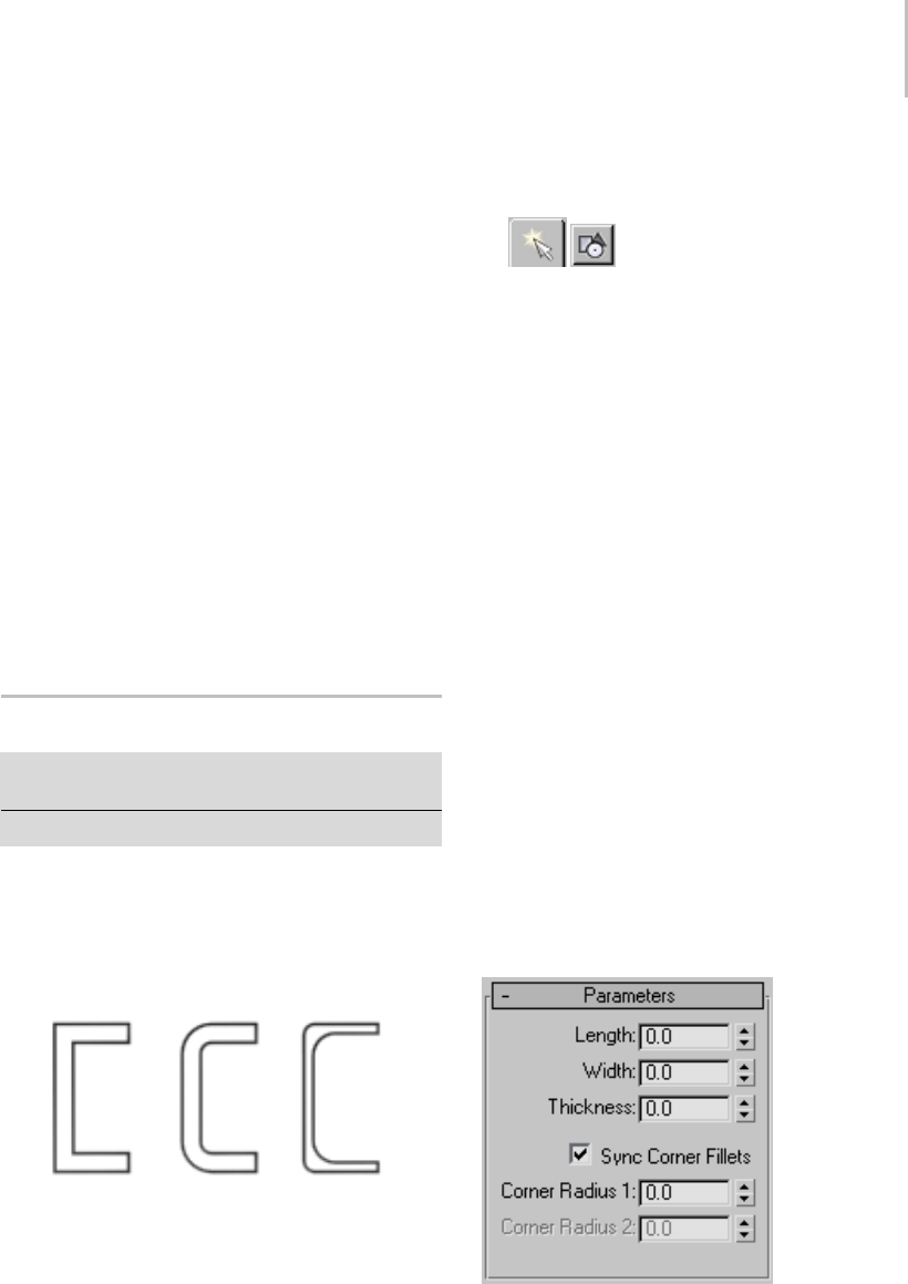
Channel Spline 285
and exterior corners of the wrectangle. It also
maintains the thickness of the section. Default=on.
Corner Radius 1—Controls the radius of all four
interior and exterior corners of the section.
IfSyncCornerFilletsisturnedoff,CornerRadius
1 controls the radius of the four exterior corners
of the wrectangle.
Corner Radius 2—Controls the radius of the four
interior corners of the wrectangle.
Corner Radius 2 is only available when Sync
Corner Fillets is turned off.
Note: Take care when adjusting these settings.
There are no constraining relationships between
them. Therefore, it’s possible to set an inside
radius(CornerRadius2)thatisgreaterthanthe
length and width of the sides.
Channel Spline
Create panel > Shapes > Extended Splines > Object Type
rollout > Channel
Create menu > Shapes > Channel
Use Channel to create a closed “C” shaped spline.
You have the option to specify the interior and
exterior corners between the vertical web and
horizontal legs of the section.
Example of Channel
Procedure
To create a channel:
1. Go to the Create panel and choose
Shapes.
2. Open the Shapes List and select Extended
Splines.
3. Click Channel.
4. Drag and release the mouse button to define
the outer perimeter of the channel.
5. Move the mouse and then click to define the
thicknessofthewallsofthechannel.
Interface
Rendering and Interpolation rollouts
All spline-based shapes share these parameters.
For explanations, see Splines and Extended Splines
(page 1–266).
Creation Method rollout
TheChannelshapeusesthestandardcreation
methodsofCenterorEdge. Mostspline-based
shapes share the same Creation Method
parameters. For explanations, see Splines and
Extended Splines (page 1–266).
Parameters rollout
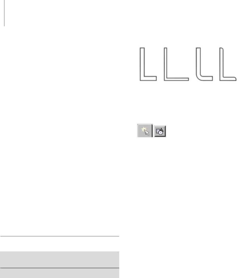
286 Chapter 5: Creating Geometry
Length—Controls the height of the vertical web
of the channel.
Width—Controls the width of the top and bottom
horizontal legs of the channel.
Thickness—Controls the thickness of both legs of
the angle.
Sync Corner Fillets—When turned on, Corner
Radius 1 controls the radius of both the interior
and exterior corners between the vertical web and
horizontal legs. It also maintains the thickness of
the channel. Default=on.
Corner Radius 1—Controls the exterior radius
between the vertical web and horizontal legs of the
channel.
Corner Radius 2—Controls the interior radius
between the vertical web and horizontal legs of the
channel.
Note: Take care when adjusting these settings.
There are no constraining relationships between
them. Therefore, it’s possible to set an inside
radius(CornerRadius2)thatisgreaterthanthe
length of the web or width of the legs.
Angle Spline
Create panel > Shapes > Extended Splines > Object Type
rollout > Angle
Create menu > Shapes > Angle
Use Angle to create a closed “L” shaped spline. You
have the option to specify the radii of the corners
between the vertical and horizontal legs of the
section.
Example of Angle
Procedure
To create an Angle spline:
1. Go to the Create panel and choose
Shapes.
2. Open the Shapes List and select Extended
Splines.
3. Click Angle.
4. Drag and release the mouse button to define
the initial size of the angle.
5. Move the mouse and then click to define the
thicknessofthewallsoftheangle.
Interface
Rendering and Interpolation rollouts
All spline-based shapes share these parameters.
For explanations, see Splines and Extended Splines
(page 1–266).
Creation Method rollout
The Angle shape uses the standard creation
methodsofCenterorEdge. Mostspline-based
shapes share the same Creation Method
parameters. For explanations, see Splines and
Extended Splines (page 1–266).

Tee Spline 287
Parameters rollout
Length—Controls the height of the vertical leg of
the angle.
Width—Controls the width of the horizontal leg
of the angle.
Thickness—Controls the thickness of both legs of
the angle.
Sync Corner Fillets—When turned on, Corner
Radius 1 controls the radius of both the interior
and exterior corners between the vertical and
horizontal legs. It also maintains the thickness of
the section. Default=on.
Corner Radius 1—Controls the exterior radius
between the vertical and horizontal legs of the
angle.
Corner Radius 2—Controls the interior radius
between the vertical and horizontal legs of the
angle.
Edge Radii—Controls the interior radius at the
outermost edges of the vertical and horizontal legs.
Note: Take care when adjusting these settings.
There are no constraining relationships between
them. Therefore, it’s possible to set an inside
radius(CornerRadius2)thatisgreaterthanthe
length or width of the legs of the angle.
Tee Spline
Create panel > Shapes > Extended Splines > Object Type
rollout > Tee
Create menu > Shapes > Tee
Use Tee to create a closed T-shaped spline. You
can specify the radius of the two interior corners
between the vertical web and horizontal flange of
the section.
Example of Tee
Procedure
To create a Tee spline:
1. Go to the Create panel and choose
Shapes.
2. Open the Shapes List and select Extended
Splines.
3. Click Tee.
4. Drag and release the mouse button to define
the initial size of the tee.
5. Move the mouse and then click to define the
thickness of the walls of the tee.
Interface
Rendering and Interpolation rollouts
All spline-based shapes share these parameters.
For explanations, see Splines and Extended Splines
(page 1–266).
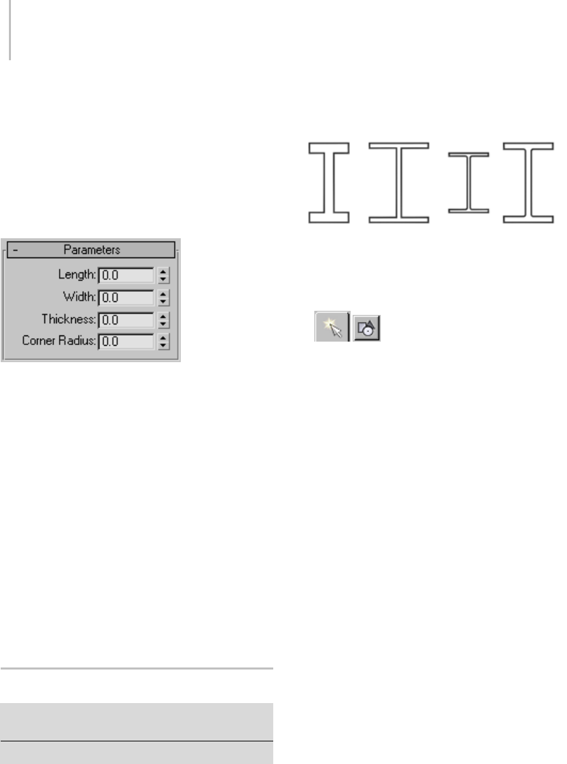
288 Chapter 5: Creating Geometry
Creation Method rollout
The Tee shape uses the standard creation methods
of Center or Edge. Most spline-based shapes
share the same Creation Method parameters. For
explanations, see Splines and Extended Splines
(page 1–266).
Parameters rollout
Length—Controls the height of the vertical web of
the tee.
Width—Controls the width of the flange crossing
the tee.
Thickness—Controls the thickness of the web and
flange.
Corner Radius—Controls the radius of the two
interior corners between the vertical web and
horizontal flange of the section.
Note: Take care when adjusting these settings.
There are no constraining relationships between
them. Therefore, it’s possible to set a radius
(Corner Radius) that is greater than the length of
the web or width of the flange.
Wide Flange Spline
Create panel > Shapes > Extended Splines > Object Type
rollout > Wide Flange
Create menu > Shapes > Wide Flange
Use Wide Flange to create a closed spline shaped
like a capital letter I. You can specify the interior
corners between the vertical web and horizontal
flanges of the section.
ExampleofWideFlange
Procedure
To create a Wide Flange spline:
1. Go to the Create panel and choose
Shapes.
2. Open the Shapes List and select Extended
Splines.
3. Click Wide Flange.
4. Drag and release the mouse button to define
theinitialsizeofthewideflange.
5. Move the mouse and then click to define the
thickness of the wallsofthewideflange.
Interface
Rendering and Interpolation rollouts
All spline-based shapes share these parameters.
For explanations, see Splines and Extended Splines
(page 1–266).
Creation Method rollout
TheWideFlangeshapeusesthestandard
creation methods of Center or Edge. Most
spline-based shapessharethesameCreation
Method parameters. For explanations, see Splines
and Extended Splines (page 1–266).
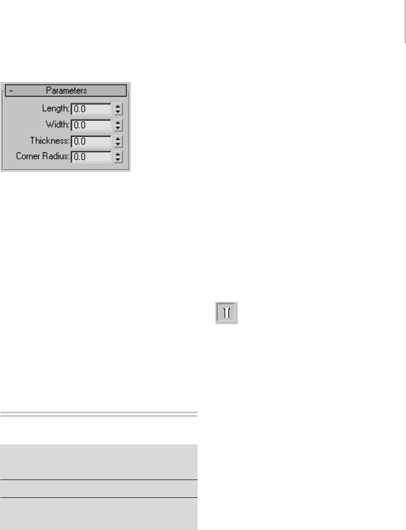
Editable Spline 289
Parameters rollout
Length—Controls the height of the vertical web
of the wide flange.
Width—Controls the width of the horizontal
flanges crossing the wide flange.
Thickness—Controls the thickness of the web and
flanges.
Corner Radius—Controls the radius of the four
interior corners between the vertical web and
horizontal flanges.
Note: Take care when adjusting these settings.
There are no constraining relationships between
them. Therefore, it’s possible to set a radius
(Corner Radius) that is greater than the length of
the web or width of the flanges.
Editable Spline
Create or select a spline > Modify panel > Right-click
spline entry in the stack display > Convert To: Editable
Spline
Create a line > Modify panel
Create or select a spline > Right-click the spline >
Transform (lower-right) quadrant of the quad menu >
Convert To: > Convert to Editable Spline
Editable Spline provides controls for manipulating
an object as a spline object and at three sub-object
levels: vertex, segment, and spline.
The functions in Editable Spline are the same as
those in the Edit Spline modifier (page 1–680).The
exceptionisthatwhenyouconvertanexisting
spline shape to an editable spline, the creation
parameters are no longer accessible or animatable.
However, the spline’s interpolation settings (step
settings) remain available in the editable spline.
When a spline-editing operation (typically,
moving a segment or vertex) causes end vertices
to overlap, you can use the Weld command to
weld the overlapping vertices together or the Fuse
command if you want the two overlapping vertices
tooccupythesamepointinspacebutremain
separate vertices.
Note: Welding coincident vertices is controlled by
the End Point Auto-Welding feature.
Show End Result
If you have several modifiers higher in
themodifierstack,andwanttoseetheresults
of edits in an Edit Spline modifier or Editable
Spline object, then turn on Show End Result on
theModifypanel.Asyoueditthesplinenetwork,
you’ll be able to see the result of modifiers above
theEditableSplineobject. Thisisusefulfor
SurfaceToolsworkwhereyouaddaSurface
modifieraboveanEditableSplineobjectinthe
modifier stack.
See also
Edit Modifiers and Editable Objects (page 1–506)
Modifying at the Sub-Object Level (page 1–506)
Modifier Stack Controls (page 3–760)
Procedures
Toproduceaneditablesplineobject,firstselectthe
shape, and then do one of the following:
• Right-click the shape entry in the stack display
andchooseConvertTo:EditableSpline.

290 Chapter 5: Creating Geometry
• In a viewport, right-click the object and choose
Convert To: > Convert to Editable Spline from
the Transform (lower-right) quadrant of the
quad menu.
• Create a shape with two or more splines by first
turning off Start New Shape (on the Create
panel). Any shape made up of two or more
splinesisautomaticallyaneditablespline.
•ApplyanEditSplinemodifiertoashape,and
then collapse the stack. If you use the Collapse
utility (page 1–966) to collapse the stack, be sure
to choose Output Type > Modifier Stack Result.
•Importa.shp file.
To select shape sub-objects:
1. Expandtheobject’shierarchyinthestack
display and choose a sub-object level, or click
one of the sub-object buttons at the top of the
Selection rollout.
You can also right-click the object in the
viewports and choose a sub-object level from
the quad menu: Tools 1 (upper-left) quadrant
>Sub-objects>Choosethesub-objectlevel.
2. Click a selection or transform tool, and then
select sub-objects using standard click or
region-selection techniques.
Because sub-object selections can be complex,
you might consider using one of the following
techniques to prevent clearing the sub-object
selection by accident:
•UseLock Selection (page 3–707).
• Name the sub-object selection (see Named
Selection Sets List (page 1–67)).
To clone sub-object selections:
•HolddowntheShift key while transforming
the sub-objects.
You can clone segment and spline sub-objects,
but not vertices.
To draw a spline cage:
1. Select a segment sub-object on a spline.
2. On the Geometry rollout in the Connect Copy
group, turn on Connect.
3. Hold down the Shift key and transform the
selected segment. You can move, rotate or
scale using the transform gizmo to control the
direction.
Notice that with Connect Copy on, new splines
are drawn between the locations of the segment
and its clone.
Tip: Use Area Selection or Fuse before selecting
and moving these vertices. They will not move
together as they do with the Cross-Section
modifier. Or use Fuse to keep the vertices
together.
Interface
The following controls are available at the object
(top) level and at all sub-object levels.
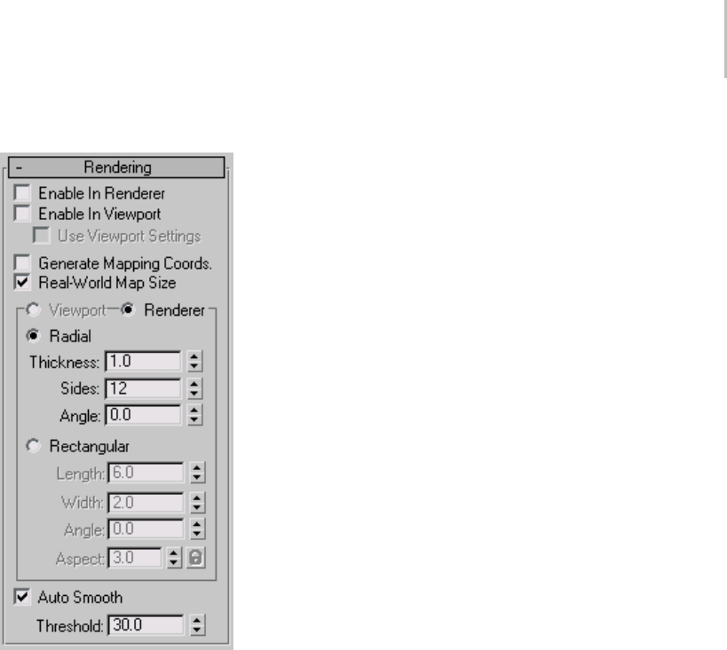
Editable Spline 291
Rendering and Interpolation rollouts
These creation parameters appear in these rollouts
for editable splines. For splines to which the
Edit Spline modifier has been applied, creation
parameters are available by selecting the object
type entry (for example, Circle or NGon) at the
bottom of the modifier stack (page 3–760).
Rendering rollout
Controls here let you turn on and off the
renderability of the shape, specify its thickness
in the rendered scene, and apply mapping
coordinates. The spline mesh can be viewed
in the viewports. You can animate the render
parameters, such as the number of sides. Viewport
settings cannot be animated.
You can also convert the displayed mesh into a
mesh object by applying an Edit Mesh modifier
or converting to an Editable Mesh. The system
will use the Viewport settings for this mesh
conversion if Use Viewport Settings is turned on;
otherwise it will use the Renderer settings. This
gives maximum flexibility, and will always give the
conversion of the mesh displayed in the viewports.
The U coordinate wraps once around the thickness
of the spline; the V coordinate is mapped once
along the length of the spline. Tiling is achieved
using the Tiling parameters in the material itself.
Enable In Renderer—When on, the shape is
rendered as a 3D mesh using the Radial or
Rectangular parameters set for Renderer. In
previous versions of the program, the Renderable
switch performed the same operation.
Enable In Viewport—When on, the shape is
displayedintheviewportasa3Dmeshusingthe
Radial or Rectangular parameters set for Renderer.
In previous versions of the program, the Display
Render Mesh performed the same operation.
Use Viewport settings—Lets you set different
rendering parameters, and displays the mesh
generated by the Viewport settings. Available only
when Enable in Viewport is turned on.
Generate Mapping Coords—Tur n this on to apply
mapping coordinates. Default=off.
The U coordinate wraps once around the thickness
of the spline; the V coordinate is mapped once
along the length of the spline. Tiling is achieved
using the Tiling parameters in the material itself.
Real-World Map Size—Controls the scaling method
used for texture mapped materials that are applied
totheobject. Thescalingvaluesarecontrolled
by the Use Real-World Scale settings found in
the applied material’s Coordinates rollout (page
2–1625).Default=off.
Viewport—Turn this on to specify Radial or
Rectangular parameters for the shape as it will
display in the viewport when Enable in Viewport
is turned on.
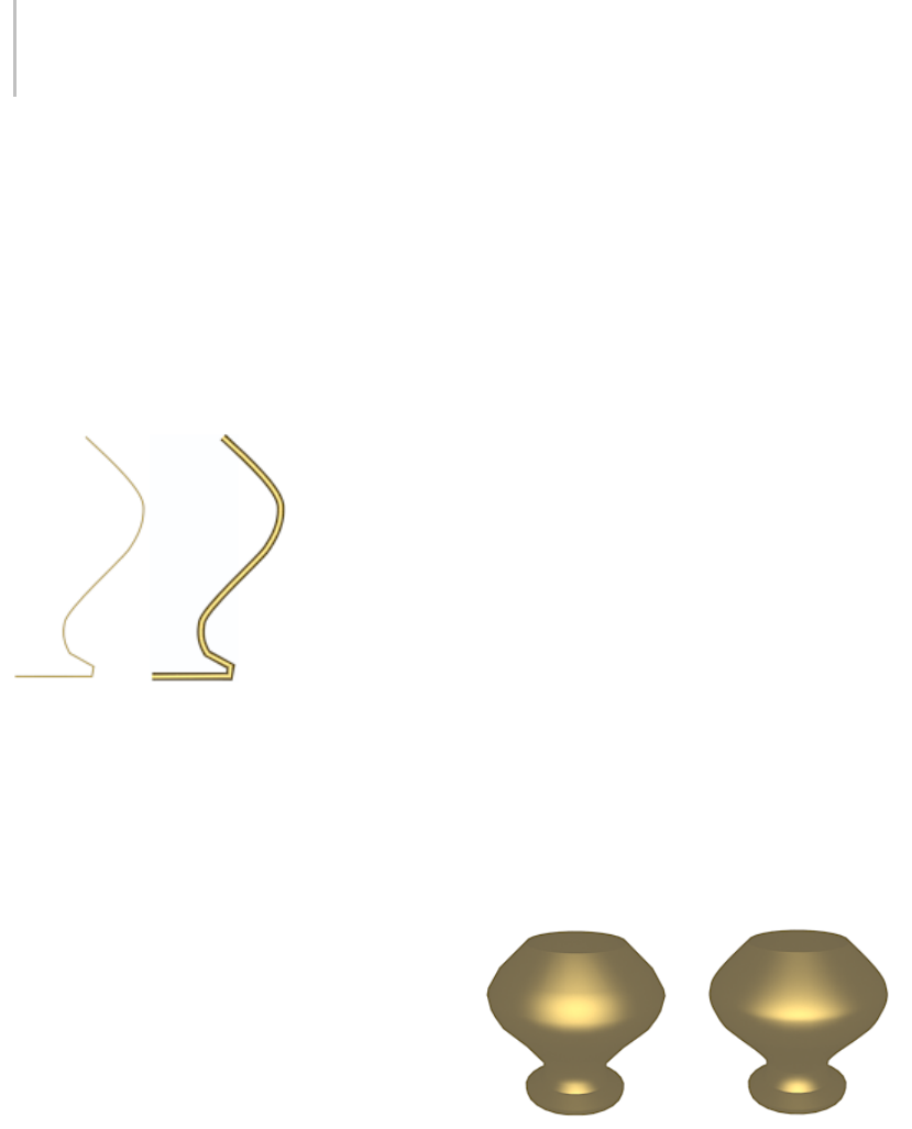
292 Chapter 5: Creating Geometry
Renderer—Turn this on to specify Radial or
Rectangular parameters for the shape as it will
displaywhenrenderedorviewedintheviewport
when Enable in Viewport is turned on.
Radial—Displays the 3D mesh as a cylindrical
object.
Thickness—Specifies the diameter of the viewport
or rendered spline mesh. Default=1.0. Range=0.0
to 100,000,000.0.
Splines rendered at thickness of 1.0 and 5.0, respectively
Sides—Sets the number of sides (or facets) for
thesplinemeshntheviewportorrenderer. For
example, a value of 4 results in a square cross
section.
Angle—Adjusts the rotational position of the
cross-section in the viewport or renderer. For
example, if the spline mesh has a square cross
section you can use Angle to position a "flat" side
down.
Rectangular—Displays the spline’s mesh shape as
rectangular.
Aspect—Sets the aspect ratio for rectangular
cross-sections. The Lock check box lets you lock
the aspect ratio. When Lock is turned on, Width
is locked to Depth that results in a constant ratio
of Width to Depth.
Length—Specifies the size of the cross–section
along the local Yaxis.
Width—Specifies the size of the cross–section
along the local Xaxis.
Angle—Adjusts the rotational position of the
cross-section in the viewport or renderer. For
example, if you have a square cross-section you
can use Angle to position a "flat" side down.
Auto Smooth—If Auto Smooth is turned on, the
spline is auto-smoothed using the threshold
specified by the Threshold setting below it. Auto
Smooth sets the smoothing based on the angle
between spline segments. Any two adjacent
segmentsareputinthesamesmoothinggroupif
the angle between them is less than the threshold
angle.
Threshold—Specifies the threshold angle in
degrees. Any two adjacent spline segments are put
inthesamesmoothinggroupiftheanglebetween
them is less than the threshold angle.
Interpolation rollout
The Interpolation controls set how the program
generates a spline. All spline curves are divided
into small straight lines that approximate the true
curve. The number of divisions between each
vertex on the spline is called steps.Themoresteps
used, the smoother the curve appears.
Splines used in above lathed objects contained two steps (left)
and 20 steps (right)
Steps—Use the Steps field to set the number of
divisions, or steps, the program uses between each
vertex. Splines with tight curves require many
steps to look smooth while gentle curves require
fewer steps. Range=0 to 100.
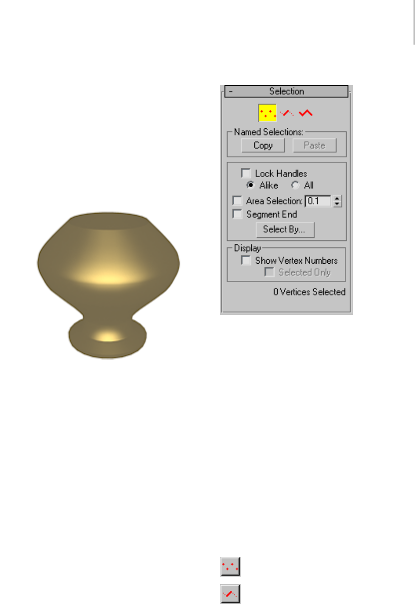
Editable Spline 293
Spline steps can be either adaptive or manually
specified. The method used is set by the state of
theAdaptivecheckbox.Themainuseformanual
interpolation is to create splines for morphing
or other operations where you must have exact
control over the number of vertices created.
Optimize—When on, removes unneeded steps
from straight segments in the spline. Default=on.
Note: Optimize is not available when Adaptive is
on.
Optimize was used to create spline in this lathed object.
Adaptive—When on, automatically sets the
number of steps for each spline to produce a
smooth curve. Straight segments always receive
0 steps. When off, enables manual interpolation
control using Optimize and Steps. Default=off.
Selection rollout
Provides controls for turning different sub-object
modes on and off, working with named selections
and handles, display settings, and information
about selected entities.
When you first access the Modify panel with
an editable spline selected, you’re at the Object
level, with access to several functions available as
described in Editable Spline (Object) (page 1–295).
You can toggle the sub-object modes and access
relevant functions by clicking sub-object buttons
at the top of the Selection rollout.
You can work with parts of shapes and splines
using shape sub-object selection of the Editable
Spline object. Clicking a button here is the same
as selecting a sub-object type in the Modifier List.
Click the button again to turn it off and return to
object selection level.
Vertices—Define points and curve tangents.
Segments—Connect vertices.

294 Chapter 5: Creating Geometry
Splines—Are a combination of one or more
connected segments.
Named Selections group
Copy—Places a named selection into the copy
buffer.
Paste—Pastes a named selection from the copy
buffer.
Lock Handles—Normally you can transform the
tangent handles of only one vertex at a time, even
when multiple vertices are selected. Use the Lock
HandlescontrolstotransformmultipleBezierand
Bezier Corner handles simultaneously.
Alike—As you drag the handle of an incoming
vector, all incoming vectors of the selected vertices
move simultaneously. Likewise, moving the
outgoing tangent handle on one vertex moves the
outgoing tangent handle for all selected vertices.
All—Anyhandleyoumoveaffectsallhandlesin
the selection, regardless of whether they’re broken.
This option is also useful when working with a
single Bezier Corner vertex when you want to
move both handles.
Shift +click a handle to "break" the tangent
and move each handle independently. The Alike
option must be chosen to break the tangent.
Area Selection—Lets you select automatically all
vertices within a specific radius of the vertex you
click. At the Vertex sub-object level, turn on Area
Selection, and then set the radius with the spinner
to the right of the Area Selection check box. This
is useful when moving vertices that have been
created using Connect Copy or Cross Section
button.
Segment End—Select a vertex by clicking a
segment.InVertexsub-object,turnonandselecta
segment close to the vertex that you want selected.
Use this when there are a number of coincident
vertices and you want to select a vertex on a
specific segment. The cursor changes to a cross
when it is over a segment. By holding down the
Ctrl key you can add to the selection.
Select By—Selectsverticesontheselectedspline
or segment. First select a spline or segment in
sub-object spline or segment, then turn on vertex
sub-object and click Select By and choose Spline
or Segment. All the vertices on the selected spline
or segment are selected. You can then edit the
vertices.
Display group
Show Vertex Numbers—When on, the program
displays vertex numbers next to the selected
spline’s vertices at any sub-object level.
Selected Only—When on, the vertex number or
numbers appear only next to selected vertices.
Soft Selection
For information on the Soft Selection rollout
settings, see Soft Selection Rollout (page 1–963).
Selection Info
At the bottom of the Selection rollout is a text
display giving information about the current
selection. If 0 or more than one sub-object is
selected, the text gives the number selected.
At the Vertex and Segment sub-object levels,
if one sub-object is selected, the text gives the
identification numbers of the current spline (with
respect to the current object) and of the current
selected sub-object. Each spline object contains
a spline number 1; if it contains more than one
spline, the subsequent splines are numbered
consecutively higher.
When a single spline is selected at the Spline
sub-object level, the first line displays the
identification number of the selected spline and
whetherit’sopenorclosed,andthesecondline
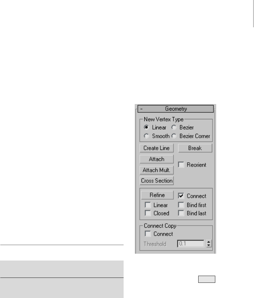
Editable Spline (Object) 295
displays the number of vertices it contains. When
morethanonesplineisselected,thenumber
ofsplinesselectedisdisplayedonthefirstline,
and the total number of vertices they contain is
displayed on the second line.
Geometry rollout
The Geometry rollout provides functions for
editing a spline object and sub-objects. The
functions available at the spline object level (when
no sub-object level is active; see Editable Spline
(Object) (page 1–295))arealsoavailableatall
sub-object levels, and work exactly the same at
each level. Other functions are also available,
depending on which sub-object level is active.
Thosethatapplytoothersub-objectlevelsare
unavailable.
For specific information, see these topics:
Editable Spline (Object) (page 1–295)
Editable Spline (Vertex) (page 1–297)
Editable Spline (Segment) (page 1–303)
Editable Spline (Spline) (page 1–308)
Editable Spline (Object)
Select an editable spline > Modify panel > Editable spline
(not a sub-object level) selected in the modifier stack
Select an editable spline > Right-click the spline > Tools
1 (upper-left) quadrant of the quad menu > Sub-objects
> Top-level
The functions available at the editable spline object
level (that is, when no sub-object level is active)
are also available at all sub-object levels, and work
exactly the same at each level.
Interface
Rendering, Interpolation, and Selection rollouts
See the Editable Spline topic for information on
the Rendering and Interpolation rollouts (page
1–291),andSelection rollout (page 1–293) settings.
Geometry rollout
New Vertex Type group—The radio buttons in this
group let you determine the tangency of the new
vertices created when you Shift +Clone segments
or splines. If you later use Connect Copy, vertices
on the splines that connect the original segment or
splinetothenewonewillhavethetypespecified
in this group.
This setting has no effect on the tangency of
vertices created using tools such as the Create Line
button, Refine, and so on.
•Linear—New vertices will have linear tangency.
•Smooth—New vertices will have smooth
tangency.
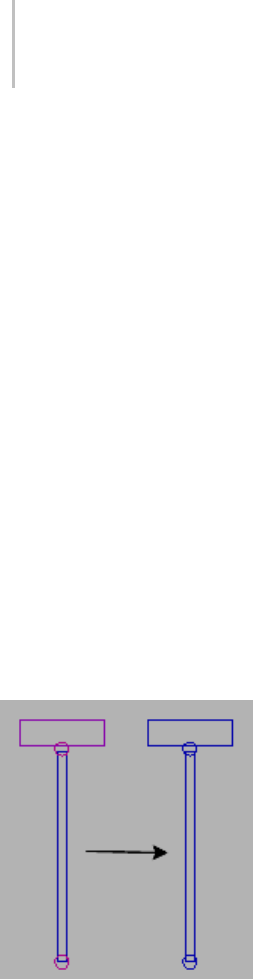
296 Chapter 5: Creating Geometry
When this option is chosen, new vertices that
overlap are automatically welded.
•Bezier—New vertices will have bezier tangency.
•Bezier Corner—New vertices will have bezier
corner tangency.
Create Line—Adds more splines to the selected
spline. These lines are separate spline sub-objects;
create them in the same way as the line spline (page
1–270). To exit line creation, right-click or click
to turn off Create Line.
Break—Splits a spline at the selected vertex or
vertices. Select one or more vertices and then
click Break to create the split. There are now two
superimposed non-connected vertices for every
previous one, allowing the once-joined segment
ends to be moved away from each other.
Attach—Lets you attach another spline in the scene
to the selected spline. Click the object you want to
attach to the currently selected spline object. The
object you’re attaching to must also be a spline.
Unattached splines (left) and attached splines (right)
When you attach an object, the materials of the
two objects are combined in the following way:
• If the object being attached does not have a
material assigned, it inherits the material of the
object it is being attached to.
• Likewise if the object you’re attaching to doesn’t
have a material, it inherits the material of the
object being attached.
• If both objects have materials, the resulting new
material is a multi/sub-object material (page
2–1594) that encompasses the input materials.
A dialog appears offering three methods of
combining the objects’ materials and material
IDs. For more information, see Attach Options
Dialog (page 1–1018).
Attached shapes lose their identity as individual
shapes, with the following results:
• The attached shape loses all access to its
creation parameters. For example, once you
attach a circle to a square you cannot go back
and change the radius parameter of the circle.
• The modifier stack of the attached shape is
collapsed.
Any edits, modifiers, and animation applied
to the attached shape are frozen at the current
frame.
Reorient—When on, rotates the attached spline so
that its creation local coordinate system is aligned
with the creation local coordinate system of the
selected spline.
Attach Mult.—Click this button to display the
Attach Multiple dialog, which contains a list of all
other shapes in the scene. Select the shapes you
want to attach to the current editable spline, then
click OK.
Cross Section—Creates a spline cage out of
cross-sectional shapes. Click Cross Section,
select one shape then a second shape, splines are
created joining the first shape with the second.
Continue clicking shapes to add them to the cage.
This functionality is similar to the Cross Section
modifier, but here you can determine the order
of the cross sections. Spline cage tangency can be
defined by choosing Linear, Bezier, Bezier Corner
or Smooth in New Vertex Type group.

Editable Spline (Vertex) 297
End Point Auto-Welding group
•Automatic Welding—When Automatic Welding
is turned on, an end point vertex that is
placed or moved within the threshold distance
of another end point of the same spline is
automatically welded. This feature is available
at the object and all sub-object levels.
•Threshold—Aproximitysettingthatcontrols
how close vertices can be to one another before
they are automatically welded. Default=6.0.
Insert—Inserts one or more vertices, creating
additional segments. Click anywhere in a segment
to insert a vertex and attach the vertex to the
mouse. Optionally move the mouse and then
click to place the new vertex. Continue moving
the mouse and clicking to add vertices. A single
click inserts a corner vertex, while a drag creates a
Bezier (smooth) vertex.
Right-click to complete the operation and release
the mouse. At this point, you’re still in Insert
mode, and can begin inserting vertices in a
different segment. Otherwise, right-click again or
clickInserttoexitInsertmode.
Editable Spline (Vertex)
Select an editable spline > Modify panel > Expand the
editable spline in the stack display > Vertex sub-object
level
Select an editable spline > Modify panel > Selection
rollout > Vertex button
Select an editable spline > Right-click the spline > Tools
1 (upper-left) quadrant of the quad menu > Sub-objects
>Vertex
While at the Editable Spline (Vertex) level, you can
select single and multiple vertices and move them
using standard methods. If the vertex is of the
Bezier or Bezier Corner type, you can also move
and rotate handles, thus affecting the shapes of any
segments joined at the vertex. You can copy and
paste the handles between vertices using tangent
copy/paste. You can reset them or switch between
types using the quad menu. The tangent types are
alwaysavailableonthequadmenuwhenavertex
is selected; your cursor doesn’t have to be directly
over them in the viewport.
Procedures
To set a vertex type:
1. Right-click any vertex in a selection.
2. Choose a type from the shortcut menu. Each
vertex in a shape can be one of four types:
•Smooth: Nonadjustable vertices that create
smooth continuous curves. The curvature
at a smooth vertex is determined by the
spacing of adjacent vertices.
•Corner: Nonadjustable vertices that create
sharp corners.
•Bezier: Adjustable vertex with locked
continuous tangent handles that create a
smooth curve. The curvature at the vertex
is set by the direction and magnitude of the
tangent handles.
•Bezier Corner: Adjustable vertex with
discontinuous tangent handles that create a
sharp corner. The curvature of the segment
as it leaves the corner is set by the direction
and magnitude of the tangent handles.
Smooth vertex (left) and Corner vertex (right)
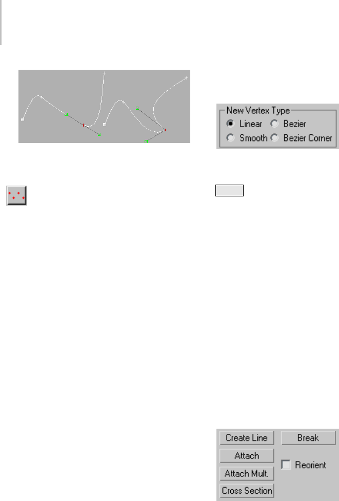
298 Chapter 5: Creating Geometry
Bezier vertex (left) and Bezier Corner vertex (right)
To copy and paste vertex tangent handles:
1. Turn on Vertex Selection, then Select the
vertex you want to copy from.
2. On the Geometry rollout scroll down to the
Ta nge nt g ro up a n d cl ic k C op y.
3. Move your cursor over the vertices in the
viewport. The cursor changes to a copy cursor.
Click the handle you wish to copy.
4. On the Geometry rollout scroll down to the
Ta nge nt g ro up a n d cl ic k Pa s te .
5. Move your cursor over the vertices in the
viewport. The cursor changes to a paste cursor.
Click the handle you wish to paste to.
The vertex tangency changes in the viewport.
To reset vertex handle tangency:
It is easy to make the handles very small and
coincident with the vertex, which makes them
hard to select and edit. Reset the vertex handle
tangency to redraw your handles
1. Select the vertex that is problematic.
2. Right-click and choose Reset Tangents.
Anyvertexhandleeditingyouhavedoneis
discarded and the handles are reset.
Interface
Soft Selection rollout
For information on the Soft Selection rollout
settings, see Soft Selection Rollout (page 1–963).
Geometry rollout
New Vertex Type group
The radio buttons in this group let you determine
thetangencyofthenewverticescreatedwhenyou
Shift +Clone segments or splines. If you later use
Connect Copy, vertices on the splines that connect
the original segment or spline to the new one will
havethetypespecifiedinthisgroup.
This setting has no effect on the tangency of
vertices created using tools such as the Create Line
button, Refine, and so on.
•Linear—New vertices will have linear tangency.
•Smooth—New vertices will have smooth
tangency.
When this option is chosen, new vertices that
overlap are automatically welded.
•Bezier—New vertices will have bezier tangency.
•Bezier Corner—New vertices will have bezier
corner tangency.
Create Line—Adds more splines to the selected
object. These lines are separate spline sub-objects;
createtheminthesamewayastheline spline (page
1–270). To exit line creation, right-click or click
to turn off Create Line.
Break—Splits a spline at the selected vertex or
vertices. Select one or more vertices and then
click Break to create the split. There are now two

Editable Spline (Vertex) 299
superimposed non-connected vertices for every
previous one, allowing the once-joined segment
ends to be moved away from each other.
Attach—Attaches another spline in the scene to the
selected spline. Click the object you want to attach
to the currently selected spline object. The object
you’re attaching must also be a spline.
For further details, see Attach.
Attach Mult.—Click this button to display the
Attach Multiple dialog, which contains a list of all
other shapes in the scene. Select the shapes you
want to attach to the current editable spline, then
click OK.
•Reorient—When on, reorients attached splines
so that each spline’s creation local coordinate
system is aligned with the creation local
coordinate system of the selected spline.
Cross Section—Creates a spline cage out of
cross-sectional shapes. Click Cross Section,
select one shape then a second shape, splines are
created joining the first shape with the second.
Continue clicking shapes to add them to the cage.
This functionality is similar to the Cross Section
modifier, but here you can determine the order
of the cross sections. Spline cage tangency can be
defined by choosing Linear, Bezier, Bezier Corner
or Smooth in New Vertex Type group.
Tip: When you edit the spline cage, use Area
Selection before selecting your vertices. This will
keep their positions together as you transform
them.
Refine group
TheRefinegroupincludesanumberoffunctions
useful for building spline networks for use with
the Surface modifier (page 1–842).
Refine—Lets you add vertices without altering the
curvature values of the spline. Click Refine, and
then select any number of spline segments to add
a vertex each time you click (the mouse cursor
changes to a "connect" symbol when over an
eligible segment). To finish adding vertices, click
Refine again, or right-click in the viewport.
Youcanalsoclickexistingverticesduringarefine
operation, in which case 3ds Max displays a dialog
asking if you want to Refine or Connect Only to
thevertex.IfyouchooseConnectOnly,3dsMax
willnotcreateavertex:itsimplyconnectstothe
existing vertex.
The Refine operation creates a different type of
vertex depending on the types of vertices on the
endpoints of the segment being refined.
• If the bordering vertices are both Smooth types,
theRefineoperationcreatesaSmoothtype
vertex.
• If the bordering vertices are both Corner types,
theRefineoperationcreatesaCornertype
vertex.
• If either of the bordering vertices is a Corner
or Bezier Corner, the Refine operation creates
aBezierCornertype.
• Otherwise, the operation creates a Bezier type
vertex.
Connect—When on, creates a new spline
sub-object by connecting the new vertices. When
you finish adding vertices with Refine, Connect
makes a separate copy of each new vertex and then
connects all of the copies with a new spline.
Note: For Connect to work, you must turn it on
before you click Refine.
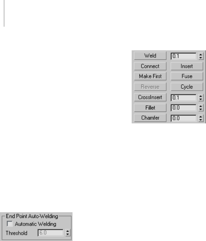
300 Chapter 5: Creating Geometry
After turning on Connect and before beginning
the refinement process, turn on any combination
of these options:
•Linear—When on, makes all segments in the
new spline straight lines by using Corner
vertices. When Linear is off, the vertices used
to create the new spline are of the Smooth type.
•Bind First—Causes the first vertex created in a
refinement operation to be bound to the center
of the selected segment. See Bound Vertex (page
3–919).
•Closed—When on, connects the first and last
vertices in the new spline to create a closed
spline. When Closed is off, Connect always
creates an open spline.
•Bind Last—Causes the last vertex created in a
refinement operation to be bound to the center
of the selected segment. See Bound Vertex (page
3–919).
End Point Auto-Welding group
Automatic Welding—When Automatic Welding is
turned on, an end point vertex that is placed or
moved within the threshold distance of another
endpointofthesamesplineisautomatically
welded. This feature is available at the object and
all sub-object levels.
Threshold—The threshold distance spinner is a
proximity setting that controls how close vertices
can be to one another before they are automatically
welded. Default=6.0.
Weld—Converts two end vertices, or two adjacent
vertices within the same spline, into a single vertex.
Move either two end vertices or two adjacent
vertices near each other, select both vertices, and
then click Weld. If the vertices are within the unit
distance set by the Weld Threshold spinner (to the
right of the button), they’re converted into a single
vertex.Youcanweldaselectionsetofvertices,as
long as each pair of vertices is within the threshold.
Connect—Connects any two end vertices, resulting
in a linear segment, regardless of the tangent
values of the end vertices. Click the Connect
button, point the mouse over an end vertex until
the cursor changes to a cross, and then drag from
one end vertex to another end vertex.
Insert—Inserts one or more vertices, creating
additional segments. Click anywhere in a segment
to insert a vertex and attach the mouse to the
spline. Then optionally move the mouse and
click to place the new vertex. Continue moving
the mouse and clicking to add vertices. A single
click inserts a corner vertex, while a drag creates a
Bezier (smooth) vertex.
Right-click to complete the operation and release
the mouse. At this point, you’re still in Insert
mode, and can begin inserting vertices in a
different segment. Otherwise, right-click again or
click Insert to exit Insert mode.

Editable Spline (Vertex) 301
Make First—Specifies which vertex in the selected
shape is the first vertex. The first vertex of a spline
is indicated as a vertex with a small box around
it. Select one vertex on each spline within the
currently edited shape that you want to change and
click the Make First button.
On open splines, the first vertex must be the
endpoint that is not already the first vertex. On
closedsplines,itcanbeanypointthatisn’talready
the first vertex. Click the Make First button, and
the first vertices will be set.
The first vertex on a spline has special significance.
The following table defines how the first vertex is
used.
Shape Use First Vertex Meaning
Loft Path Start of the path. Level 0.
Loft Shape Initial skin alignment.
Path
Constraint
Start of the motion path. 0% location on
the path.
Trajectory First position key.
Fuse—Moves all selected vertices to their averaged
center.
Fuse is useful for making vertices coincide when
building a spline network for use with the Surface
modifier (page 1–842).
Note: Fuse doesn’t join the vertices; it simply moves
them to the same location.
Three selected vertices (left); fused vertices (right)
Cycle—Selects successive coincident vertices.
Select one of two or more vertices that share the
exactsamelocationin3Dspace,andthenclick
Cycle repeatedly until the vertex you want is
selected.
Cycle is useful for selecting a specific vertex from a
group of coincident vertices at a spline intersection
when building a spline network for use with the
Surface modifier (page 1–842).
Tip: Watch the info display at the bottom of the
Selection rollout to see which vertex is selected.
CrossInsert—Adds vertices at the intersection of
two splines belonging to the same spline object.
Click CrossInsert, and then click the point of
intersection between the two splines. If the
distance between the splines is within the unit
distance set by the CrossInsert Threshold spinner
(to the right of the button), the vertices are added
to both splines.
You can continue using CrossInsert by clicking
different spline intersections. To finish, right-click
intheactiveviewportorclicktheCrossInsert
button again.
CrossInsert is useful for creating vertices at spline
intersectionswhenbuildingasplinenetworkfor
use with the Surface modifier (page 1–842).
Note: CrossInsert doesn’t join the two splines, but
simply adds vertices where they cross.
Fillet—Lets you round corners where segments
meet, adding new control vertices. You can apply
this effect interactively (by dragging vertices) or
numerically (using the Fillet spinner). Click the
Fillet button, and then drag vertices in the active
object. The Fillet spinner updates to indicate the
fillet amount as you drag.
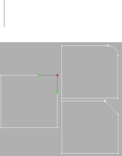
302 Chapter 5: Creating Geometry
Original rectangle (left), after applying Fillet (top right), and
after applying Chamfer (bottom right)
If you drag one or more selected vertices, all
selected vertices are filleted identically. If you drag
an unselected vertex, any selected vertices are first
deselected.
You can continue using Fillet by dragging on
different vertices. To finish, right-click in an active
viewport or click the Fillet button again.
A fillet creates a new segment connecting new
points on both segments leading to the original
vertex. These new points are exactly <fillet
amount> distance from the original vertex along
both segments. New fillet segments are created
with the material ID of one of the neighboring
segments (picked at random).
For example, if you fillet one corner of a rectangle,
thesinglecornervertexisreplacedbytwovertices
movingalongthetwosegmentsthatleadtothe
corner, and a new rounded segment is created at
the corner.
Note: Unlike the Fillet/Chamfer modifier, you can
apply the Fillet function to any type of vertex, not
just Corner and Bezier Corner vertices. Similarly,
adjoining segments need not be linear.
•Fillet Amount—Adjust this spinner (to the right
of the Fillet button) to apply a fillet effect to
selected vertices.
Chamfer—Lets you bevel shape corners using
a chamfer function. You can apply this effect
interactively (by dragging vertices) or numerically
(using the Chamfer spinner). Click the Chamfer
button, and then drag vertices in the active object.
The Chamfer spinner updates to indicate the
chamfer amount as you drag.
If you drag one or more selected vertices, all
selected vertices are chamfered identically. If you
drag an unselected vertex, any selected vertices are
first deselected.
You can continue using Chamfer by dragging on
different vertices. To finish, right-click in an active
viewport or click the Chamfer button again.
A chamfer "chops off " the selected vertices,
creating a new segment connecting new points
on both segments leading to the original vertex.
These new points are exactly <chamfer amount>
distance from the original vertex along both
segments. New chamfer segments are created with
thematerialIDofoneoftheneighboringsegments
(picked at random).
For example, if you chamfer one corner of a
rectangle,thesinglecornervertexisreplacedby
two vertices moving along the two segments that
lead to the corner, and a new segment is created
at the corner.
Note: Unlike the Fillet/Chamfer modifier, you
can apply the Chamfer function to any type of
vertex, not just Corner and Bezier Corner vertices.
Similarly, adjoining segments need not be linear.
•Chamfer Amount—Adjust this spinner (to the
right of the Chamfer button) to apply a chamfer
effect to selected vertices.
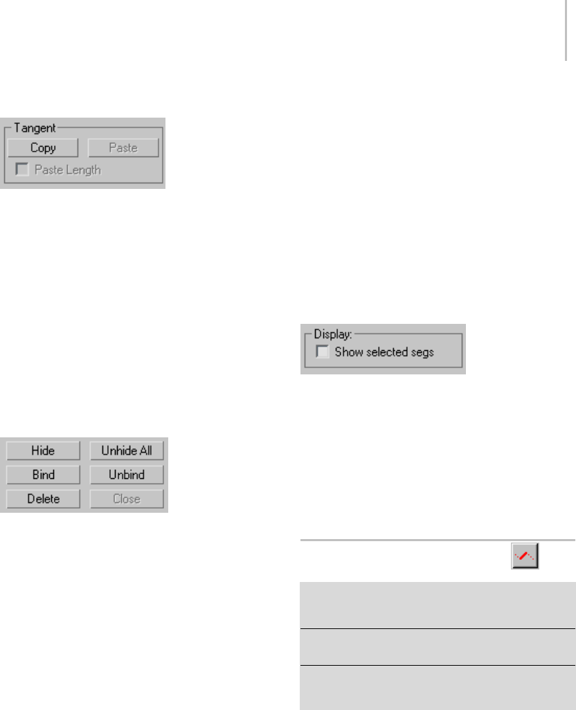
Editable Spline (Segment) 303
Tangent group
Toolsinthisgroupletyoucopyandpastevertex
handles from one vertex to another.
Copy— Turn this on, then choose a handle. This
action copies the selected handle tangent into a
buffer.
Paste—Turn this on, then click a handle. This
pastes the handle tangent onto the selected vertex.
Paste Length—When this is on, the handle length is
also copied. When this is off, only the handle angle
is considered, the handle length is unchanged.
HideandBindgroup
Hide—Hides selected vertices and any connected
segments. Select one or more vertices, and then
click Hide.
Unhide All—Displays any hidden sub-objects.
Bind—Lets you create bound vertices (page 3–919).
Click Bind, and then drag from any end vertex
in the current selection to any segment in the
current selection except the one connected to the
vertex. Before dragging, when the cursor is over
an eligible vertex, it changes to a + cursor. While
dragging, a dashed line connects the vertex and
the current mouse position, and when the mouse
cursor is over an eligible segment, it changes to
a"connect"symbol. Whenyoureleaseoveran
eligible segment, the vertex jumps to the center of
the segment and is bound to it.
Bind is useful for connecting splines when building
a spline network for use with the Surface modifier
(page 1–842).
Unbind—Lets you disconnect bound vertices
(page 3–919) from the segments to which they’re
attached. Select one or more bound vertices, and
theclicktheUnbindbutton.
Delete—Deletes the selected vertex or vertices,
along with one attached segment per deleted
vertex.
Display group
Show selected segs—When on, any selected
segments are highlighted in red at the Vertex
sub-object level. When off (the default), selected
segments are highlighted only at the Segment
sub-object level.
Thisfeatureisusefulforcomparingcomplex
curves against each other.
Editable Spline (Segment)
Select an editable spline > Modify panel > Expand the
editable spline in the stack display > Segment sub-object
level
Select an editable spline > Modify panel > Selection
rollout>Segmentbutton
Select an editable spline > Right-click the spline > Tools
1 (upper-left) quadrant of the quad menu > Sub-objects
>Segment
A segment is the portion of a spline curve between
two of its vertices. While at the Editable Spline
(Segment) level, you can select single and multiple
segments and move, rotate, scale or clone them
using standard methods.
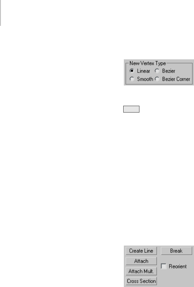
304 Chapter 5: Creating Geometry
Procedure
To change segment properties:
1. Select an editable spline segment, and then
right-click.
2. On the Tools 1 (upper-left) quadrant of the
quadmenu,chooseLineorCurve.
The effect of changing segment properties
varies according to the type of vertices at the
segment end.
•Cornerverticesalwaysresultinline
segments regardless of the segment property.
• Smooth vertices can support both line or
curve segment properties.
• Bezier and Bezier Corner vertices apply their
tangent handles only to curve segments.
Tangent handles are ignored by line
segments.
•Atangenthandleassociatedwithaline
segment displays an X at the end of the
handle. You can still transform the handle,
butithasnoeffectuntilthesegmentis
converted to a curve segment.
Tip: Ifyouhaveproblemstransformingthe
handles, display the axis constraints toolbar
and change the transform axis there.
Interface
Rendering, Interpolation, and Selection rollouts
For information on the Rendering, Interpolation
(page 1–291) and Selection rollout (page 1–293)
settings, see Editable Spline (page 1–289).
Soft Selection rollout
For information on the Soft Selection rollout
settings, see Soft Selection Rollout (page 1–963).
Geometry rollout
New Vertex Type group
The radio buttons in this group let you determine
thetangencyofthenewverticescreatedwhenyou
Shift +Clone segments or splines. If you later use
Connect Copy, vertices on the splines that connect
the original segment or spline to the new one will
havethetypespecifiedinthisgroup.
This setting has no effect on the tangency of
vertices created using tools such as the Create Line
button, Refine, and so on.
•Linear—New vertices will have linear tangency.
•Smooth—New vertices will have smooth
tangency.
When this option is chosen, new vertices that
overlap are automatically welded.
•Bezier—New vertices will have bezier tangency.
•Bezier Corner—New vertices will have bezier
corner tangency.
Create Line—Adds more splines to the selected
spline. These lines are separate spline sub-objects;
createtheminthesamewayastheline spline (page
1–270). To exit line creation, right-click or click
to turn off Create Line.
Break—Letsyouspecifyabreakpointatany
segment in the shape (you do not have to first select
a segment). When on, the mouse icon changes

Editable Spline (Segment) 305
to a Break icon. You can now click any spot on a
segment. The clicked spot becomes two coincident
vertices, and the segment is split into two parts.
Attach—Attaches another spline in the scene to the
selected spline. Click the object you want to attach
to the currently selected spline object. The object
you’reattachingtomustalsobeaspline.
For further details, see Attach.
Reorient—Reorients the attached spline so that its
creation local coordinate system is aligned with
the creation local coordinate system of the selected
spline.
Attach Mult.—Click this button to display the
Attach Multiple dialog, which contains a list of all
other shapes in the scene. Select the shapes you
want to attach to the current editable spline, then
click OK.
Cross Section—Creates a spline cage out of
cross–sectional shapes. Click Cross Section, select
one segment then another sub-object segment,
splines are created joining the first shape with the
second. Continue clicking segments to add them
tothecage.Allsegmentsmustbepartofthesame
object to build cross sections. This functionality
is similar to the Cross Section modifier, but here
you can determine the order of the cross sections.
Spline cage tangency can be defined by choosing
Linear, Bezier, Bezier Corner or Smooth in New
Ve r t e x Ty p e g r o u p.
Tip: When you want to move these vertices, turn
on Area Selection before you select them. When
you transform them, the vertices will stay together.
Refine group
TheRefinegroupincludesanumberoffunctions
useful for building spline networks for use with
the Surface modifier (page 1–842).
Refine—Lets you add vertices without altering the
curvature values of the spline. Click Refine, and
then select any number of spline segments to add
a vertex each time you click (the mouse cursor
changes to a "connect" symbol when over an
eligible segment). To finish adding vertices, click
Refine again, or right-click in the viewport.
Youcanalsoclickexistingverticesduringarefine
operation, in which case 3ds Max displays a dialog
asking if you want to Refine or Connect to the
vertex. If you choose Connect, 3ds Max will not
create a vertex: it simply connects to the existing
vertex.
The Refine operation creates a different type of
vertex depending on the types of vertices on the
endpoints of the segment being refined.
• If the bordering vertices are both Smooth types,
theRefineoperationcreatesaSmoothtype
vertex.
• If the bordering vertices are both Corner types,
theRefineoperationcreatesaCornertype
vertex.
• If either of the bordering vertices is a Corner
or Bezier Corner, the Refine operation creates
aBezierCornertype.
• Otherwise, the operation creates a Bezier type
vertex.
Connect—When on, creates a new spline
sub-object by connecting the new vertices. When
you finish adding vertices with Refine, Connect
makes a separate copy of each new vertex and then
connects all of the copies with a new spline.
Note: For Connect to work, you must turn it on
before you click Refine.
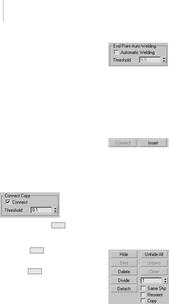
306 Chapter 5: Creating Geometry
After turning on Connect and before beginning
the refinement process, turn on any combination
of these options:
•Linear—When on, makes all segments in the
new spline linear by using Corner vertices.
When Linear is off, the vertices used to create
the new spline are of the Smooth type.
•Bind First—Causes the first vertex created in a
refinement operation to be bound to the center
of the selected segment.
For more information, see Bound Vertex (page
3–919).
•Closed—When on, connects the first and last
vertices in the new spline to create a closed
spline. When Closed is off, Connect always
creates an open spline.
•Bind Last—Causes the last vertex created in a
refinement operation to be bound to the center
of the selected segment.
For more information, see Bound Vertex (page
3–919).
Connect Copy group
Connect Copy—When on, Shift +Cloning a
segment creates a new spline sub-object with
additional splines that connect the new segment’s
vertices to the vertices of the original segment. It
is analogous to Shift +Cloning edges in Editable
Mesh and Editable Poly objects.
Note: For Connect Copy to work, you must turn it
on before you Shift +Clone.
Threshold— Determinesthedistancesoftselection
will use when Connect Copy is on. A higher
threshold results in more splines being created; a
lower threshold results in fewer splines.
End Point Auto-Welding group
Automatic Welding—When Automatic Welding is
turned on, an end point vertex that is placed or
moved within the threshold distance of another
endpointofthesamesplineisautomatically
welded. This feature is available at the object and
all sub-object levels.
Threshold—The threshold distance spinner is a
proximitysettingthatcontrolshowclosevertices
canbetooneanotherbeforetheyareautomatically
welded. Default=6.0.
Insert—Inserts one or more vertices, creating
additional segments. Click anywhere in a segment
to insert a vertex and attach the mouse to the
spline. Then optionally move the mouse and
click to place the new vertex. Continue moving
the mouse and clicking to add vertices. A single
click inserts a corner vertex, while a drag creates a
Bezier (smooth) vertex.
Right-click to complete the operation and release
the mouse. At this point, you’re still in Insert
mode, and can begin inserting vertices in a
different segment. Otherwise, right-click again or
click Insert to exit Insert mode.
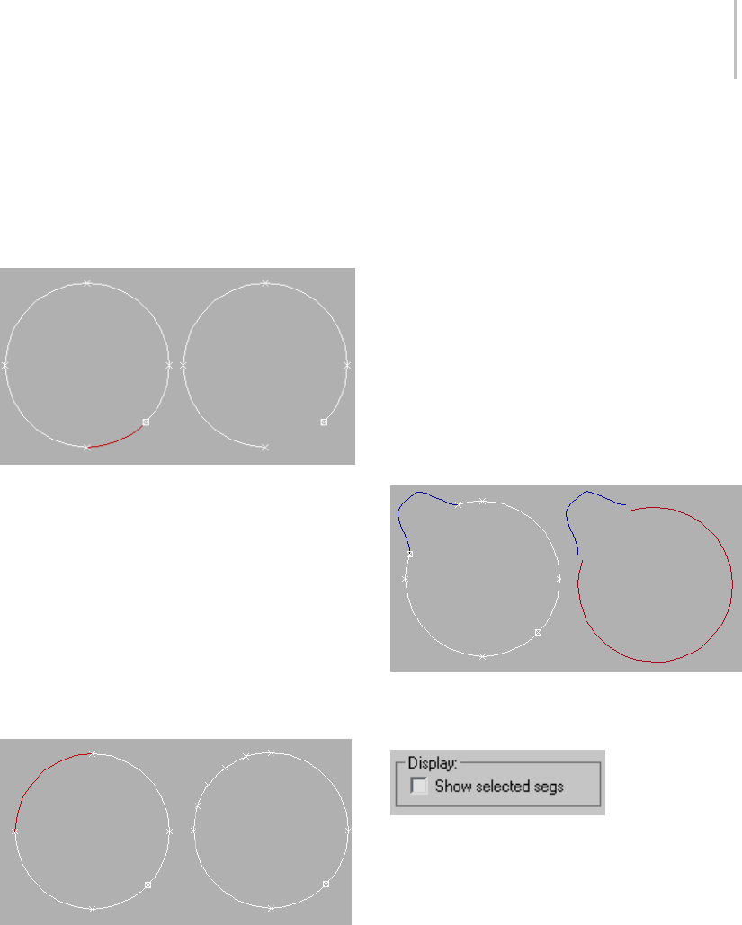
Editable Spline (Segment) 307
Hide—Hides selected segments. Select one or more
segments, and then click Hide.
Unhide All—Displays any hidden sub-objects.
Delete—Deletes any selected segments in the
current shape.
Selected and deleted segment
Divide—Subdivides the selected segment or
segments by adding the number of vertices
specified by the spinner. Select one or more
segments, set the Divisions spinner (to the button’s
right), and then click Divide. Each selected
segment is divided by the number of vertices
specified in the Divisions spinner. The distance
between the vertices depends on the segment’s
relative curvature, with areas of greater curvature
receiving more vertices.
Selected and divided segment
Detach—Lets you select several segments in
various splines and then detach them (or copy
them) to form a new shape. Three options are
available:
•Same Shp—(Same Shape) When on, Reorient
is disabled, and a Detach operation keeps the
detached segment as part of the shape (rather
than producing a new shape). If Copy is also
on, you end up with a detached copy of the
segment in the same location.
•Reorient—The detached segment copies the
position and orientation of the source object’s
creation Local coordinate system. The new
detached object is moved and rotated so that
its Local coordinate system is positioned and
aligned with the origin of the current active
grid.
•Copy—Copies the detached segment rather
than moving it.
Original and detached splines
Display group
Show selected segs—When on, any selected
segments are highlighted in red at the Vertex
sub-object level. When off (the default), selected
segments are highlighted only at the Segment
sub-object level.
Thisfeatureisusefulforcomparingcomplex
curves against each other.
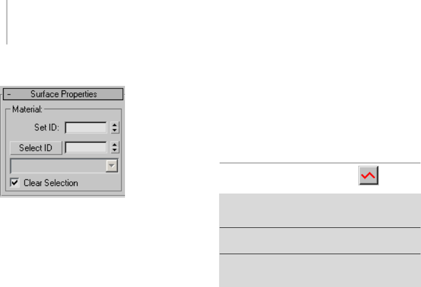
308 Chapter 5: Creating Geometry
Surface Properties rollout
Material group
You can apply different material IDs to spline
segments (see Material ID (page 3–969)). You
canthenassignamulti/sub-object material (page
2–1594) to such splines, which appears when the
spline is renderable, or when used for lathing or
extrusion. Be sure to turn on Generate Material
IDs and Use Shape IDs when lofting, lathing or
extruding.
Set ID—Lets you assign a particular material
ID number to selected segments for use with
multi/sub-object materials and other applications.
Usethespinnerorenterthenumberfromthe
keyboard. The total number of available IDs is
65,535.
Select ID—Selects the segments or splines
corresponding to the Material ID specified in
theadjacentIDfield.Typeorusethespinnerto
specify an ID, then click the Select ID button.
Select By Name—This drop-down list shows
the names of sub-materials if an object has a
Multi/Sub-object material assigned to it. Click
the drop arrow and select a material from the list.
The segments or splines that are assigned that
material are selected. If a shape does not have a
Multi/Sub-Object material assigned to it, the name
list will be unavailable. Likewise, if multiple shapes
areselectedthathaveanEditSplinemodifier
appliedtothem,thenamelistisinactive.
Clear Selection—When turned on, selecting a new
ID or material name forces a deselection of any
previously selected segments or splines. When
turnedoff,selectionsarecumulativesonewID
or material name selections add to a previous
selection set of segments or splines. Default=on.
Editable Spline (Spline)
Select an editable spline > Modify panel > Expand the
editable spline in the stack display > Spline sub-object
level
Select an editable spline > Modify panel > Selection
rollout > Spline button
Select an editable spline > Right-click the spline > Tools
1 (upper-left) quadrant of the quad menu > Sub-objects
>Spline
While at the Editable Spline (Spline) level, you can
select single and multiple splines within a single
spline object and move, rotate, and scale them
using standard methods.
Procedure
To change spline properties:
• You change the properties of a spline from Line
to Curve by right-clicking and choosing Line or
Curve from the Tools 1 (upper-left) quadrant
of the quad menu.
Changingthesplinepropertyalsochangesthe
property of all vertices in the spline:
• Choosing Line converts vertices to Corners.
• Choosing Curve converts vertices to Beziers.
Interface
Rendering, Interpolation and Selection rollouts
For information on the Rendering, Interpolation
(page 1–291) and Selection rollout (page 1–293)
settings, see Editable Spline (page 1–289).
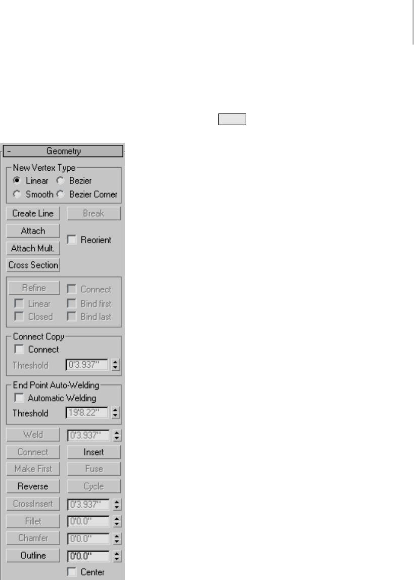
Editable Spline (Spline) 309
Soft Selection rollout
See Soft Selection Rollout (page 1–963) for
informationontheSoftSelectionrolloutsettings.
Geometry rollout
New Vertex Type group
The radio buttons in this group let you determine
thetangencyofthenewverticescreatedwhenyou
Shift +Clone segments or splines. If you later use
Connect Copy, vertices on the splines that connect
the original segment or spline to the new one will
havethetypespecifiedinthisgroup.
This setting has no effect on the tangency of
vertices created using tools such as the Create Line
button, Refine, and so on.
•Linear—New vertices will have linear tangency.
•Smooth—New vertices will have smooth
tangency.
When this option is chosen, new vertices that
overlap are automatically welded.
•Bezier—New vertices will have bezier tangency.
•Bezier Corner—New vertices will have bezier
corner tangency.
Create Line—Adds more splines to the selected
spline. These lines are separate spline sub-objects;
createtheminthesamewayastheline spline (page
1–270). To exit line creation, right-click or click
to turn off Create Line.
Attach—Attaches another spline in the scene to the
selected spline. Click the object you want to attach
to the currently selected spline object. The object
you’reattachingtomustalsobeaspline.
For further details, see Attach.
Reorient—Reorients the attached spline so that its
creation local coordinate system is aligned with
the creation local coordinate system of the selected
spline.
Attach Mult.—Click this button to display the
Attach Multiple dialog, which contains a list of all
other shapes in the scene. Select the shapes you
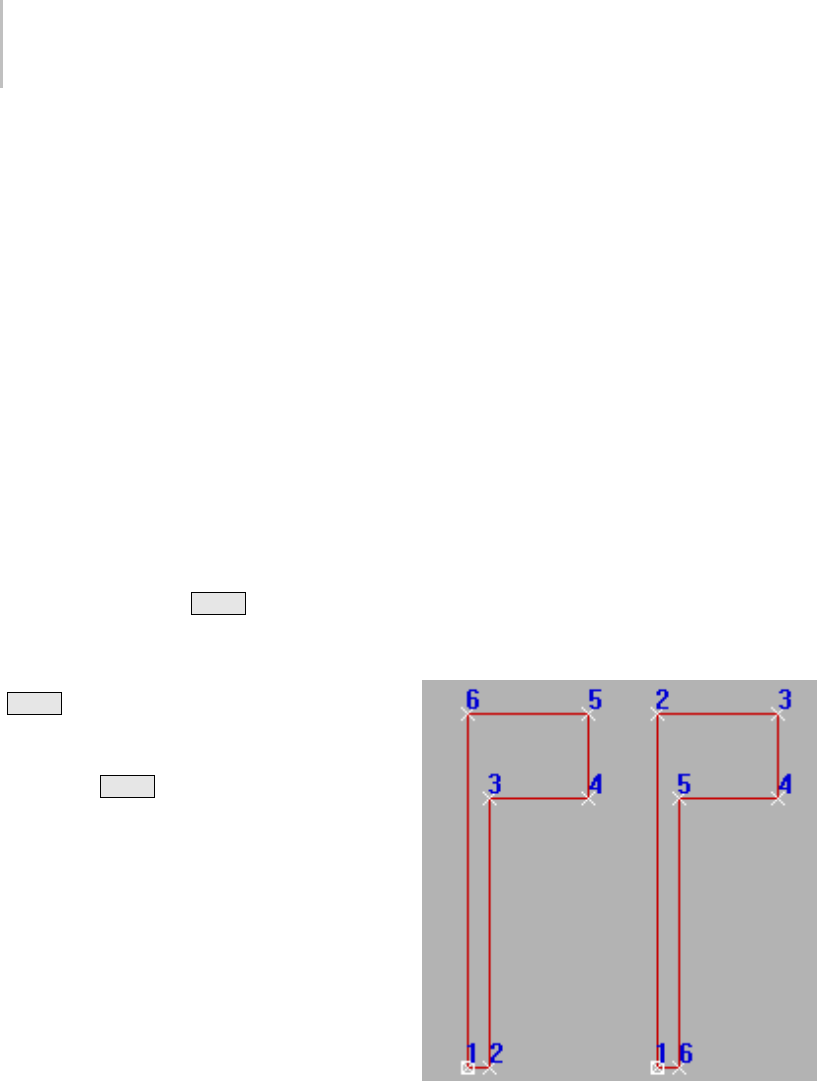
310 Chapter 5: Creating Geometry
want to attach to the current editable spline, then
click OK.
Cross Section—Creates a spline cage out of
cross–sectional shapes. Click Cross Section,
select one shape then a second shape, splines are
created joining the first shape with the second.
Continue clicking shapes to add them to the cage.
This functionality is similar to the Cross Section
modifier, but here you can determine the order
of the cross sections. Spline cage tangency can be
defined in the New Vertex Type group.
Tip: When you edit the spline cage, use Area
Selection before selecting your vertices. This will
keep their positions together as you transform
them.
Connect Copy group
Connect Copy—When on, Shift +Cloning a spline
creates a new spline sub-object with additional
splines that connect the new spline’s vertices to the
vertices of the original segment. It is analogous
to Shift +Cloning edges in Editable Mesh and
Editable Poly objects.
Note: For Connect Copy to work, you must turn it
on before you Shift +Clone.
Threshold—Determines the distance soft selection
uses when Connect Copy is on. A higher value
results in more splines being created, a lower value
results in fewer splines.
End Point Auto-Welding group
Automatic Welding—When Automatic Welding is
turnedon,anendpointvertexthatisplacedor
moved within the threshold distance of another
endpoint of the same spline is automatically
welded. This feature is available at the object and
all sub-object levels.
Threshold—Aproximitysettingthatcontrolshow
close vertices can be to one another before they are
automatically welded. Default=6.0.
Insert—Inserts one or more vertices, creating
additional segments. Click anywhere in a segment
to insert a vertex and attach the mouse to the
spline. Then optionally move the mouse and
click to place the new vertex. Continue moving
the mouse and clicking to add vertices. A single
click inserts a corner vertex, while a drag creates a
Bezier (smooth) vertex.
Right-click to complete the operation and release
the mouse. At this point, you’re still in Insert
mode, and can begin inserting vertices in a
different segment. Otherwise, right-click again or
click Insert to exit Insert mode.
Reverse—Reverses the direction of the selected
spline. If the spline is open, the first vertex will
be switched to the opposite end of the spline.
Reversing the direction of a spline is usually done
in order to reverse the effect of using the Insert
tool at vertex selection level.
Original and reversed splines
Outline—Makes a copy of the spline, offset on
allsidestothedistancespecifiedbytheOutline
Width spinner (to the right of the Outline button).
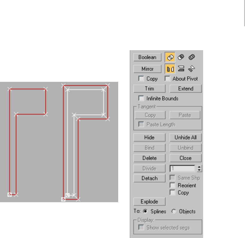
Editable Spline (Spline) 311
Select one or more splines and then adjust the
outline position dynamically with the spinner, or
click Outline and then drag a spline. If the spline is
open, the resulting spline and its outline will make
asingleclosedspline.
Original and outlined splines
Note: Normally, if using the spinner, you must first select a spline
beforeusingOutline.If,however,thesplineobjectcontainsonly
one spline, it is automatically selected for the outlining process.
Center—When off (default), the original spline
remains stationary and the outline is offset on
one side only to the distance specified by Outline
Width. When Center is on, the original spline and
the outline move away from an invisible center line
to the distance specified by Outline Width.
Boolean—Combines two closed polygons by
performinga2DBooleanoperationthatalters
the first spline you select, and deletes the second
one. Select the first spline, then click the Boolean
buttonandthedesiredoperation,andthenselect
the second spline.
Note: 2D Booleans only work on 2D splines that
are in the same plane.
There are three Boolean operations:
•Union—Combines two overlapping splines
into a single spline, in which the overlapping
portion is removed, leaving non-overlapping
portionsofthetwosplinesasasinglespline.
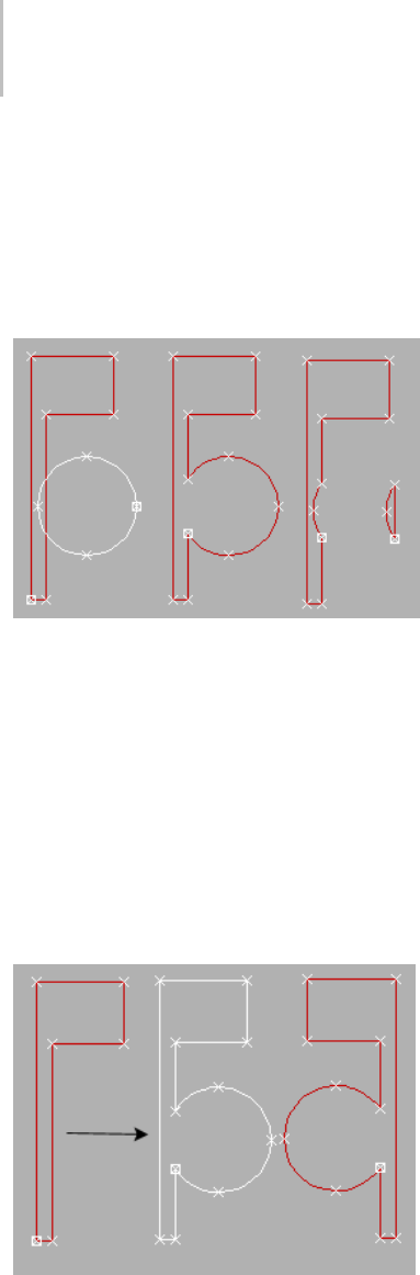
312 Chapter 5: Creating Geometry
•Subtraction—Subtracts the overlapping portion
of the second spline from the first spline, and
deletes the remainder of the second spline.
•Intersection—Leaves only the overlapping
portions of the two splines, deleting the
non-overlapping portion of both.
Original splines (left), Boolean Union, Boolean Subtraction,
and Boolean Intersection, respectively
Mirror—Mirrors splines along the length, width, or
diagonally. Click the direction you want to mirror
first so it is active, then click Mirror.
•Copy—When selected, copies rather than moves
thesplineasitismirrored.
•About Pivot—When on, mirrors the spline
about the spline object’s pivot point (see Pivot
(page 2–487)). When off, mirrors the spline
about its geometric center.
Mirrored splines
Trim—Use Trim to clean up overlapping segments
in a shape so that ends meet at a single point.
To trim, you need intersecting splines. Click the
portion of the spline you want to remove. The
spline is searched in both directions along its
lengthuntilithitsanintersectingspline,and
deleted up to the intersection. If the section
intersects at two points, the entire section is
deleteduptothetwointersections.Ifthesection
is open on one end and intersects at the other, the
entire section is deleted up to the intersection and
the open end. If the section is not intersected, or
ifthesplineisclosedandonlyoneintersectionis
found, nothing happens.
Extend—Use Extend to clean up open segments in
a shape so that ends meet at a single point.
To extend, you need an open spline. The end of
thesplinenearestthepickedpointisextended
until it reaches an intersecting spline. If there is
no intersecting spline, nothing happens. Curved
splines extend in a direction tangent to the end of
the spline. If the end of a spline lies directly on a
boundary (an intersecting spline), then it looks for
an intersection further along.
Infinite Bounds—For the purposes of calculating
intersections, turn this on to treat open splines as
infinite in length. For example, this lets you trim
onelinearsplineagainsttheextendedlengthof
another line that it doesn’t actually intersect.
Hide—Hides selected splines. Select one or more
splines, and then click Hide.
Unhide All—Displays any hidden sub-objects.
Delete—Deletes the selected spline.
Close—Closes the selected spline by joining its end
vertices with a new segment.
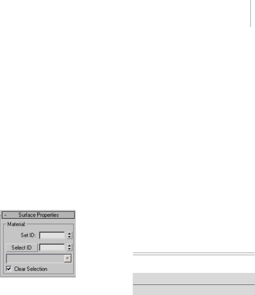
Compound Objects 313
Detach—Copies selected splines to a new spline
object, and deletes them from the currently
selected spline if Copy is clear.
•Reorient—The spline being detached is moved
and rotated so that its creation local coordinate
system is aligned with the creation local
coordinate system of the selected spline.
•Copy—When selected, copies rather than moves
thesplineasitisdetached.
Explode—Breaks up any selected splines by
converting each segment to a separate spline
orobject. Thisisatime-savingequivalentof
using Detach on each segment in the spline in
succession.
You can choose to explode to splines or objects. If
you choose Object, you’re prompted for a name;
each successive new spline object uses that name
appended with an incremented two-digit number.
Surface Properties rollout
Material group
You can apply different material IDs (see
material ID (page 3–969)) to splines in shapes
containing multiple splines. You can then assign
amulti/sub-object material (page 2–1594) to
such shapes, which appears when the spline is
renderable, or when used for lathing or extrusion.
Set ID—Lets you assign a particular material
ID number to selected segments for use with
multi/sub-object materials and other applications.
Usethespinnerorenterthenumberfromthe
keyboard. The total number of available IDs is
65,535.
Select ID—Selects the segments or splines
corresponding to the Material ID specified in
theadjacentIDfield.Typeorusethespinnerto
specify an ID, then click the Select ID button.
Select By Name—This drop-down list shows
the names of sub-materials if an object has a
Multi/Sub-object material assigned to it. Click
the drop arrow and select a material from the list.
The segments or splines that are assigned that
material are selected. If a shape does not have a
Multi/Sub-Object material assigned to it, the name
list will be unavailable. Likewise, if multiple shapes
areselectedthathaveanEditSplinemodifier
appliedtothem,thenamelistisinactive.
Clear Selection—When turned on, selecting a new
ID or material name, forces a deselection of any
previously selected segments or splines. If turned
off, selections are cumulative so new ID or material
name selections add to a previous selection set of
segments or splines. Default=on.
Compound Objects
Create panel > Geometry > Compound Objects
Create menu > Compound
Compound objects generally combine two or
more existing objects into a single object.
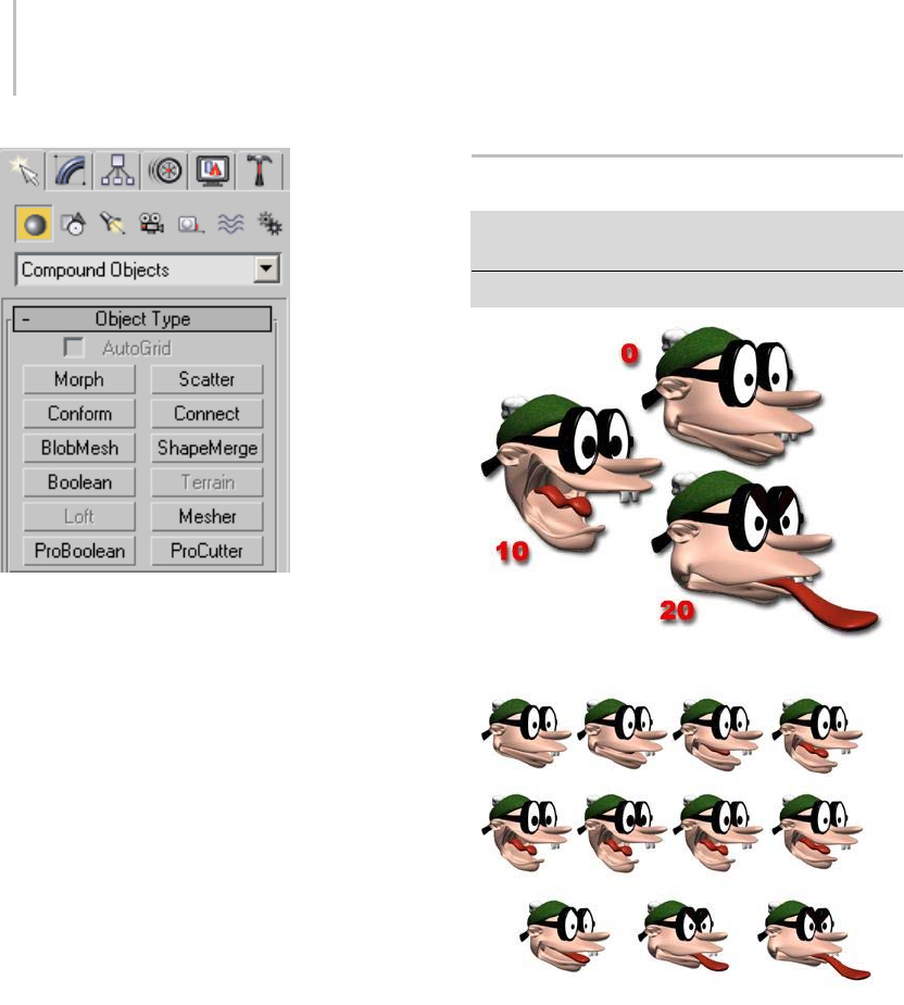
314 Chapter 5: Creating Geometry
Compound objects include the following object
types:
Morph Compound Object (page 1–314)
Scatter Compound Object (page 1–318)
Conform Compound Object (page 1–324)
Connect Compound Object (page 1–328)
BlobMesh Compound Object (page 1–331)
ShapeMerge Compound Object (page 1–336)
Boolean Compound Object (page 1–338)
Terrain Compound Object (page 1–347)
Loft Compound Object (page 1–352)
Mesher Compound Object (page 1–374)
ProBoolean Compound Object (page 1–378)
ProCutter Compound Object (page 1–388)
Morph Compound Object
Select an object. > Create panel > Geometry > Compound
Objects > Object Type rollout > Morph
Select an object. > Create menu > Compound > Morph
Seed or base object, and the target objects at specific frames
The resulting animation
Morphing is an animation technique similar
to tweening in 2D animation. A Morph object
combines two or more objects by interpolating
the vertices of the first object to match the
vertex positions of another object. When this
interpolation occurs over time, a morphing
animation results.

Morph Compound Object 315
The original object is known as the seed or base
object. The object into which the seed object
morphs is known as the target object.
You can morph one seed into multiple targets; the
seed object’s form changes successively to match
the forms of the target objects as the animation
plays.
Before you can create a morph, the seed and target
objects must meet these conditions:
• Both objects must be mesh, patch, or poly
objects.
• Both objects must have an equal number of
vertices.
If these conditions don’t apply, the Morph button
is unavailable.
You can use any kind of object as a morph target,
including an animated object or another morph
object,aslongasthetargetisameshthathasthe
same number of vertices as the seed object.
Creating a morph involves the following steps:
• Modelthebaseobjectandtargetobjects.
•Selectthebaseobject.
• Click Create panel > Geometry > Compound
Objects > Morph.
• Add the target objects.
•Animate.
Setting Up the Morph Geometry
Make sure that the objects you want to use as the
seed and targets have the same number of vertices.
Tip: When you create Loft objects that you want
to use as morph seeds and targets, make sure that
Morph Capping is on and Adaptive Path Steps and
Optimize are turned off. All shapes in the Loft
object must have the same number of vertices.
You should also turn off Adaptive and Optimize
for other shape-based objects that you want to use
with Morph, such as those with Extrude or Lathe
modifiers.
Warning: The selected object is permanently converted
to a morph object as soon as you click Morph, whether or
not you proceed to select a target object. The only way
to restore the original object is to undo the Morph click.
Morph Object and Morpher Modifier
Therearetwowaystosetupmorphinganimations:
the Morph compound object and the Morpher
modifier.
The Morpher modifier (page 1–729) is more
flexible because you can add it multiple times at
any place in an object’s modifier stack display.
This flexibility lets you animate the base object or
the morph targets before reaching the Morpher
modifier, for example with a noise modifier. The
Morpher modifier works hand in hand with the
Morpher material. The Morpher modifier is the
ideal way to morph characters.
The Barycentric Morph controller can be simpler
to use in Track View. The Track View display for
Compound Morph has only one animation track
regardless of the number of targets. Each key on
the track represents a morph result based on a
percentage of all the targets. For basic morphing
needs, Compound Morph may be preferable to
the Morpher modifier.
Lastly, you can add the Morpher modifier to the
stack of a Compound Morph object.
Procedures
Example: To create a basic morph:
1. On the Create panel > Geometry > Patch Grids
>ObjectTyperollout,clickQuadPatch.
2. In the Top viewport, click and drag to create a
patch on the left side of the viewport.

316 Chapter 5: Creating Geometry
3. Right-click the modifier stack display in the
Modify panel and select Convert To Editable
Patch from the pop-up menu.
4. Right-click the patch, and then click Move in
the Transform quadrant of the quad menu.
5. In the Top viewport, hold Shift and drag with
the patch to create a copy on the right side of
the viewport.
6. On the Modify panel > Selection rollout, go to
the Vertex sub-object level.
7. In the Front viewport, select and move vertices
on the selected patch to alter its shape.
8. On the Modify panel, in the stack display, click
Editable Patch again to return to the top level.
9. Select the original patch in the viewports.
10.On the Create panel > Geometry > Compound
Objects > Objects Type rollout, click Morph.
11.On the Pick Targets rollout, click Pick Target.
12.In the viewports, click the second patch object.
Both patch objects are listed in the Morph
Targets list.
13.Click Modify panel.
MorphdisplaysabovetheEditablePatchinthe
modifier stack.
14.Move the time slider to frame 10.
15.In the Morph Targets list, click
M_QuadPatch01.
16.On the Current Targets rollout, click Create
Morph Key.
On the track bar, a key is displayed at frame 10.
17.On the track bar, right-click the key at frame 10
and click QuadPatch01:Morph in the menu.
AKeyInfodialogdisplays.
18.On the Key Info dialog, select M_QuadPatch01
from the list.
19.On the Key Info dialog, drag the percentage
spinner.
The base object changes shape.
20.Close the Key Info dialog and drag the time
slider back and forth. The patch morphs its
shape.
To select the targets for a morph:
1. Select the seed object.
2. On the Create panel > Geometry > Compound
Objects, click Morph.
The name of the seed object is displayed at the
top of the Morph Targets list on the Current
Ta r ge t s r o l l ou t .
3. On the Pick Targets rollout, choose the method
for creating targets: Reference, Move, Copy, or
Instance.
4. Click Pick Target.
5. Selectoneormoretargetobjectsinthe
viewports.
As you select each target, its name is added to
the Morph Targets list. If an object can’t be a
target (for example, if it has a different number
of vertices than the morph seed), you can’t
select it.
If you select a target object while you are not at
frame 0, creating the target also creates a morph
key. You can create additional morph keys from
targets you’ve already selected, as described in
the following procedure.
To create morph keys from existing targets:
1. Dragthetimeslidertotheframewhereyou
want to place the morph key.
Note: The Auto Key button does not need to be
on to set morph keys.
2. Highlight the name of a target object on the
Morph Targets list.
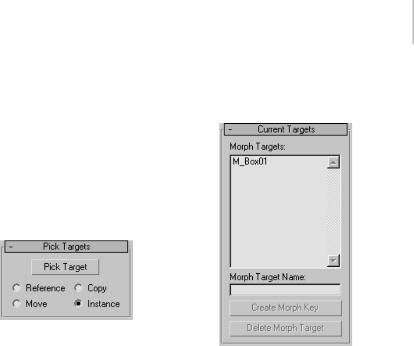
Morph Compound Object 317
TheCreateMorphKeybuttonisavailableonly
when a target object name is selected.
3. Click Create Morph Key.
3ds Max places a morph key at the active frame.
4. To preview the effect of the morph, drag the
time slider back and forth. You can view and
edit the morph keys in Track View, which
also lets you view the morph’s target object
parameters.
Interface
Pick Targets rollout
When you pick target objects, you designate each
target as a Reference, Move (the object itself),
Copy, or Instance. Base your selection on how you
wanttousethescenegeometryafteryoucreate
the morph.
Pick Target—Use this button to designate the target
object or objects.
Reference/Copy/Move/Instance—Lets you specify
how the target is transferred to the compound
object. It can be transferred either as a reference
(page 3–1002),acopy,aninstance (page 3–957),or
it can be moved, in which case the original shape
isnotleftbehind.
• Use Copy when you want to reuse the target
geometry for other purposes in the scene.
• Use Instance to synchronize morphing with
animated changes to the original target object.
• Use Move if you’ve created the target geometry
to be only a morph target, and have no other
use for it.
You can use an animated object or another morph
as the target of a morph.
Current Targets rollout
Morph Targets—Displays a list of the current
morph targets.
Morph Target Name—Use this field to change the
name of the selected morph target in the Morph
Targets list.
Create Morph Key—Adds a morph key for the
selected target at the current frame.
Delete Morph Target—Deletes the currently
highlighted morph target. If morph keys reference
the deleted target, then those keys are deleted as
well.
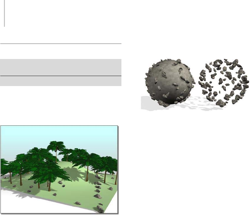
318 Chapter 5: Creating Geometry
Scatter Compound Object
Select an object. > Create panel > Geometry > Compound
Objects > Object Type rollout > Scatter
Select an object. > Create menu > Compound > Scatter
Scatter is a form of compound object that
randomly scatters the selected source object either
as an array, or over the surface of a distribution
object.
The plane of the hill is used to scatter the trees and two different
sets of rocks.
Procedures
To create a Scatter object:
1. Create an object to be used as a source object.
2. Optionally,createanobjecttobeusedasa
distribution object.
3. Select the source object, and then click Scatter
in the Compound Objects panel.
Note: Thesourceobjectmustbeeitheramesh
object or an object that can be converted to a
mesh object. If the currently selected object is
invalid, the Scatter button is unavailable.
Results of scattering source object with distribution object
visible (above) and hidden (below)
You now have two choices. You can either
scatter the source object as an array without
using a distribution object, or use a distribution
object to scatter the object. See the following
procedures.
To scatter the source object without a distribution
object:
1. Choose Use Transforms Only in the Scatter
Objects rollout > Distribution group.
2. Set the Duplicates spinner to specify the desired
total number of duplicates of the source object.
3. Adjust the spinners on the Transforms rollout
to set random transformation offsets of the
source object.
To scatter the source object using a distribution
object:
1. Makesurethesourceobjectisselected.
2. Choose the method by which you want to clone
the distribution object (Reference, Copy, Move,
or Instance.)
3. Click Pick Distribution Object, and then select
the object you want to use as a distribution
object.
4. Make sure that Use Distribution Object on the
Scatter Object rollout is chosen.
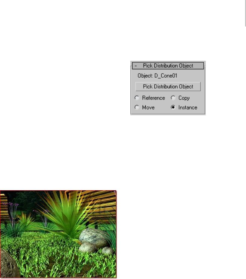
Scatter Compound Object 319
5. Use the Duplicates spinner to specify the
number of duplicates. (This is not necessary
ifyou’reusingtheAllVertices,AllEdge
Midpoints or All Face Centers distribution
methods.)
6. Choose a distribution method in the Scatter
Object rollout > Distribute Object Parameters
group under Distribute Using.
7. Optionally, adjust the Transform spinners to
randomly transform the duplicates.
8. If the display is too slow, or the meshes too
complicated, consider choosing Proxy on the
Display rollout or decreasing the percentage of
displayed duplicates by reducing the Display
percentage.
Mostofthespinnervaluesareanimatable,soyou
can animate things like the number of duplicates,
their transformations, and so on.
Scatter objects (the grass) with a high number of duplicates
Interface
Pick Distribution Object rollout
Contains the options for selecting a distribution
object.
Object—Displaysthenameofthedistribution
object selected with the Pick button.
Pick Distribution Object—Click this button, then
clickanobjectinthescenetospecifyitasa
distribution object.
Reference/Copy/Move/Instance—Lets you specify
how the distribution object is transferred to the
scatter object. It can be transferred either as a
reference (page 3–1002),acopy,aninstance (page
3–957), or moved, in which case the original shape
is not left behind.
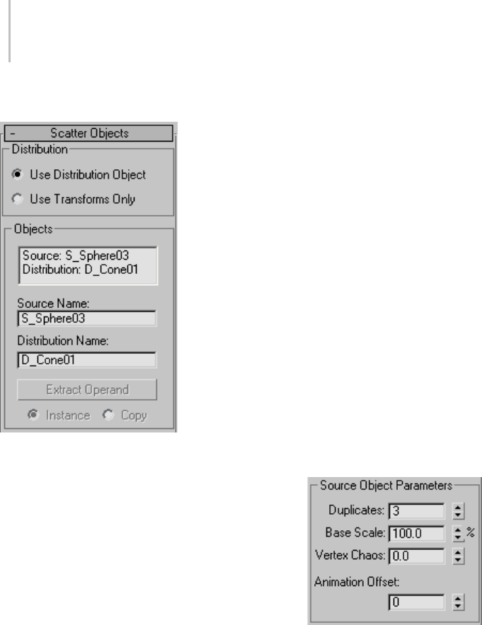
320 Chapter 5: Creating Geometry
Scatter Objects rollout
The options on this rollout let you specify how the
source object is scattered, and let you access the
objects that make up the compound Scatter object.
Distribution group
Thesetwooptionsletyouchoosethebasicmethod
of scattering the source object.
Use Distribution Object—Scattersthesourceobject
based on the geometry of the distribution object.
Use Transforms Only—This options doesn’t need
a distribution object. Instead, duplicates of the
source object are positioned using the offset values
on the Transforms rollout. If all of the Transform
offsets remain at 0, you won’t see the array because
the duplicates occupy the same space.
Objects group
Contains a list window showing the objects that
make up the Scatter object.
List Window—Click to select an object in the
window so that you can access it in the Stack. For
example, if your distribution object is a sphere,
you can click Distribution: D_Sphere01, open the
Stack list, and select Sphere to access the sphere’s
parameters.
Source Name—Lets you rename the source object
within the compound Scatter object.
Distribution Name—Lets you rename the
distribution object.
Extract Operand—Extract a copy or an instance of
theselectedoperand.Chooseanoperandinthe
list window to enable this button.
Note: This button is available only on the Modify
panel. You can’t extract an operand while the
Create panel is active.
Instance/Copy—This option lets you specify how
the operand is extracted: as either an instance
(page 3–957) or a copy.
Source Object Parameters group
Theseoptionsaffectthesourceobjectlocally.
Duplicates—Specifies the number of scattered
duplicates of the source object.
This number is set to 1 by default, but you can
setitto0ifyouwanttoanimatethenumberof
duplicates, beginning with none. Note that the
Duplicates number is ignored if you’re distributing
the duplicates using either Face Centers or Vertices.
In these cases, one duplicate is placed at each
vertex or face center, depending on your choice.
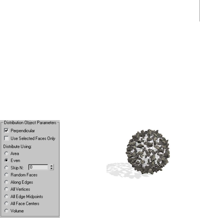
Scatter Compound Object 321
Base Scale—Altersthescaleofthesourceobject,
affecting each duplicate identically. This scale
occurs before any other transforms.
Vertex Chaos—Applies a random perturbation to
the vertices of the source object.
Animation Offset—Lets you specify the number of
frames by which each source object duplicate’s
animation is offset from the previous duplicate.
You can use this feature to produce wave-type
animation. At the default setting of 0, all duplicates
move identically.
Distribution Object Parameters group
These options affect how the duplicates of
the source object are arranged, relative to the
distribution object. These options have an effect
only when a distribution object is used.
Perpendicular—When on, orients each duplicate
object perpendicular to its associate face, vertex,
or edge in the distribution object. When off, the
duplicates maintain the same orientation as the
original source object.
Use Selected Faces Only—When on, limits
distribution to the selected faces passed up the
Stack. Perhaps the easiest way to do this is to use
the Instance option when picking the distribution
object.YoucanthenapplyaMeshSelectmodifier
to the original object and select only those
faces you want to use for the distribution of the
duplicates.
Distribute Using
The following options let you specify how the
geometry of the distribution object determines the
distribution of the source object. These options are
ignored if you’re not using a distribution object.
Area—Distributes duplicate objects evenly over the
total surface area of the distribution object.
Objects distributed over a spherical surface with Area turned on
Even—Dividesthenumberoffacesinthe
distribution object by the number of duplicates,
and skips the appropriate number of faces in the
distribution object when placing duplicates.
Skip N—Skips N number of faces when placing
duplicates. The editable field specifies how many
facestoskipbeforeplacingthenextduplicate.
When set to 0, no faces are skipped. When set to 1,
every other face is skipped, and so on.
Random Faces—Appliesduplicatesrandomlyover
the surface of the distribution object.
Along Edges—Assignsduplicatesrandomlytothe
edges of the distribution object.
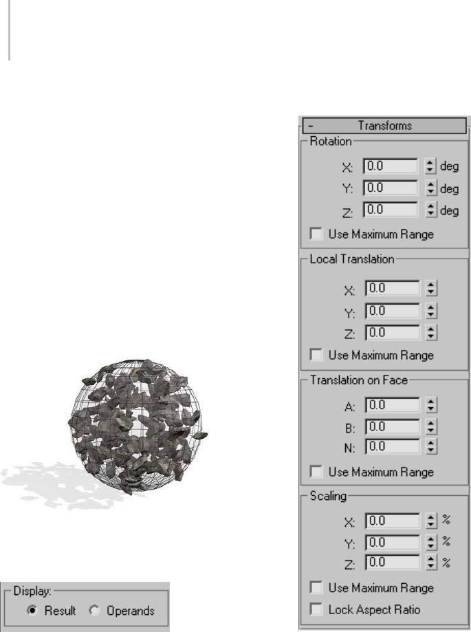
322 Chapter 5: Creating Geometry
All Vertices—Places a duplicate object at each
vertex in the distribution object. The Duplicates
value is ignored.
All Edge Midpoints—Places a duplicate at the
midpoint of each segment edge.
All Face Centers—Places a duplicate object at the
center of each triangular face on the distribution
object. The Duplicates value is ignored.
Volume—Scatters objects throughout the
distribution object’s volume. All other options
restrict distribution to the surface. Consider
turning on Display rollout > Hide Distribution
Object with this option.
ObjectsfillasphericalvolumewithVolumeturnedon
Display group
Result/Operands—Choose whether to display the
results of the scatter operation or the operands
before the scattering.
Transforms rollout
The settings in the Transforms rollout let you
apply random transform offsets to each duplicate
object. The values in the transform fields specify
a maximum offset value that’s applied randomly
with a positive or negative value to each duplicate.
Thus, if you set a rotation angle of 15 degrees,
duplicates are rotated randomly from -15 to +15
degrees. For example, one duplicate might be
rotated 8 degrees, another -13, another 5, and so
on. You can use the Transform settings with or
without a distribution object. When there is no
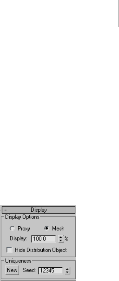
Scatter Compound Object 323
distribution object, you must adjust the Transform
settings in order to see the duplicates.
Rotation group
Specifies random rotation offsets.
X, Y, Z deg—Enterthemaximumrandomrotational
offset you want about the local X, Y, or Z axis of
each duplicate.
Use Maximum Range—When on, forces all three
settings to match the maximum value. The other
two settings become disabled, and the setting
containing the maximum value remains enabled.
Local Translation group
Specifies translation of the duplicates along their
local axes.
X, Y, Z—Enterthemaximumrandommovement
you want along the X, Y, or Z axis of each duplicate.
Use Maximum Range—When on, forces all three
settings to match the maximum value. The other
two settings become disabled, and the setting
containing the maximum value remains enabled.
Translation on Face group
Lets you specify the translation of duplicates
along barycentric (page 3–914) face coordinates
of the associate face in the distribution object.
Thesesettingshavenoeffectifyou’renotusinga
distribution object.
A, B, N—The first two settings specify the
barycentric coordinates on the surface of the face,
whiletheNsettingsetstheoffsetalongthenormal
of the face.
Use Maximum Range—When on, forces all three
settings to match the maximum value. The other
two settings become disabled, and the setting
containing the maximum value remains enabled.
Scaling group
Lets you specify the scaling of duplicates along
their local axes.
X, Y, Z %—Specifies the percent of random scaling
along the X, Y, or Z axis of each duplicate.
Use Maximum Range—When on, forces all three
settings to match the maximum value. The
other two settings become disabled, and the one
containing the maximum value remains enabled.
Lock Aspect Ratio—When on, maintains the
original aspect ratio of the source object. Typically,
this provides uniform scaling of duplicates. When
LockAspectRatioisoff,andanyoftheX,Y,and
Z settings contain values greater than 0, the result
is non-uniform scaling of duplicates because the
values represent random scaling offsets in both
positive and negative directions.
Display rollout
Provides options that affect the display of the
Scatter object.
Display Options group
Theseoptionsaffectthedisplayofthesourceand
destination objects.
Proxy—Displaysthesourceduplicatesassimple
wedges and speeds up viewport redraws when
manipulating a complex Scatter object. This has
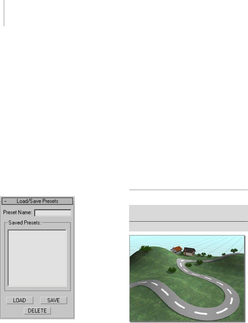
324 Chapter 5: Creating Geometry
no effect on the rendered image, which always
displays the mesh duplicates.
Mesh—Displays the full geometry of the duplicates.
Display %—Specifies the percentage of the total
duplicate objects that appear in the viewports.
This has no effect on the rendered scene.
Hide Distribution Object—Hides the distribution
object. The hidden object does not appear in the
viewport or in the rendered scene.
Uniqueness group
Lets you set a seed number upon which the
random values are based. Thus, altering this value
changes the overall effect of the scattering.
New—Generates a new, random seed number.
Seed—Use this spinner to set the seed number.
Load/Save Presets rollout
Lets you store preset values to use in other Scatter
objects. For example, after setting all of your
parameters for a specific Scatter object and saving
the settings under a specific name, you can then
select another Scatter object and load the preset
values into the new object.
Preset Name—Lets you define a name for your
settings. Click the Save button to save the current
settings under the preset name.
Saved Presets group
A list window containing saved preset names.
LOAD—Loads the preset currently highlighted in
the Saved Presets list.
SAVE—Saves the current name in the Preset Name
field and places it in the Saved Presets window.
DELETE—Deletes the selected items in the Save
Presets window.
Note: Animated parameter values subsequent to
frame 0 are not stored.
Conform Compound Object
Select an object. > Create panel> Geometry > Compound
Objects > Object Type rollout > Conform
Select an object. > Create menu > Compound > Conform
Conform fits the road to the surface of the hills.
Conform is a compound object created by
projecting the vertices of one object, called the
Wrapper, onto the surface of another object, called

Conform Compound Object 325
the Wrap-To. There is also a space-warp version
of this function; see Conform space warp (page
2–103).
Because the space-warp version is somewhat easier
to use, it’s a good idea to read that topic first, try
the example, and then return here. This topic
provides additional methods of projecting the
wrapper vertices.
Note: This tool gives you the ability to morph
between any two objects, regardless of the
number of vertices in each object. See Ve r t e x
Projection Direction group (page 1–326) for more
information.
Procedure
Example: To create a Conform object:
1. Position two objects, one of which will be the
Wrapper, and the other the Wrap-To. (For this
example, create a box as the Wrap-To object,
and then create a larger sphere that completely
surroundsit.ThespherewillbetheWrapper.)
2. Select the Wrapper object (the sphere), and
click Create panel> Geometry > Compound
Objects > Object Type rollout > Conform
button.
Note: Both objects used in Conform must be
either mesh objects or objects that can be
converted to mesh objects. If the selected
Wrapper object is inv alid, the Confor m button
is unavailable.
3. Specify the method of vertex projection in the
Vertex Projection Direction group. (Use Along
Vertex Normals for this example.)
Note: IfyouweretochooseUseActive
Viewport, you would next activate whichever
viewportlooksinthedirectionthatyouwant
to project the vertices. For example, if the
Wrapper hovered over a Wrap-To terrain on the
home plane, you’d activate the Top viewport.
4. Choose Reference, Copy, Move, or Instance
to specify the type of cloning to perform on
the Wrap-To object. (Choose Instance for this
example.)
5. Click Pick Wrap-To Object, and then click the
object onto which to project the vertices. (You
can press the Hkey and use the Select Objects
dialog (page 1–78) to select the box.)
The list windows display the two objects,
andthecompoundobjectiscreatedwiththe
Wrapper objec t confor ming to the Wrap-To
object. (In the example, the sphere is wrapped
into the shape of the box.)
6. Use the various parameters and settings to alter
the vertex projection direction, or adjust the
vertices that are being projected.
To project a road onto terrain:
1. Create the road and terrain objects.
Tip: You can quickly make a terrain by creating a
patch grid (page 1–993) and applying the Noise
modifier (page 1–743) to it. For the road, you
can use a Loft compound object (page 1–352)
by lofting a rectangle along a curved line. Both
objects must have a sufficient level of detail to
conform smoothly.
2. Orient both the road and the terrain so you
are looking straight down at them in the Top
viewport. Position the road so it’s completely
abovetheterrain(higherontheworldZaxis).
Note: For the conform projection to work
correctly,theroadshouldnotextendbeyond
the boundaries of the terrain when viewed in
the Top viewport.
3. Select the road object.
4. Click Conform.
5. In the Pick Wrap-To Object rollout, make sure
the Instance option is selected.
6. ClickPickWrap-ToObject,andclickthe
terrain.
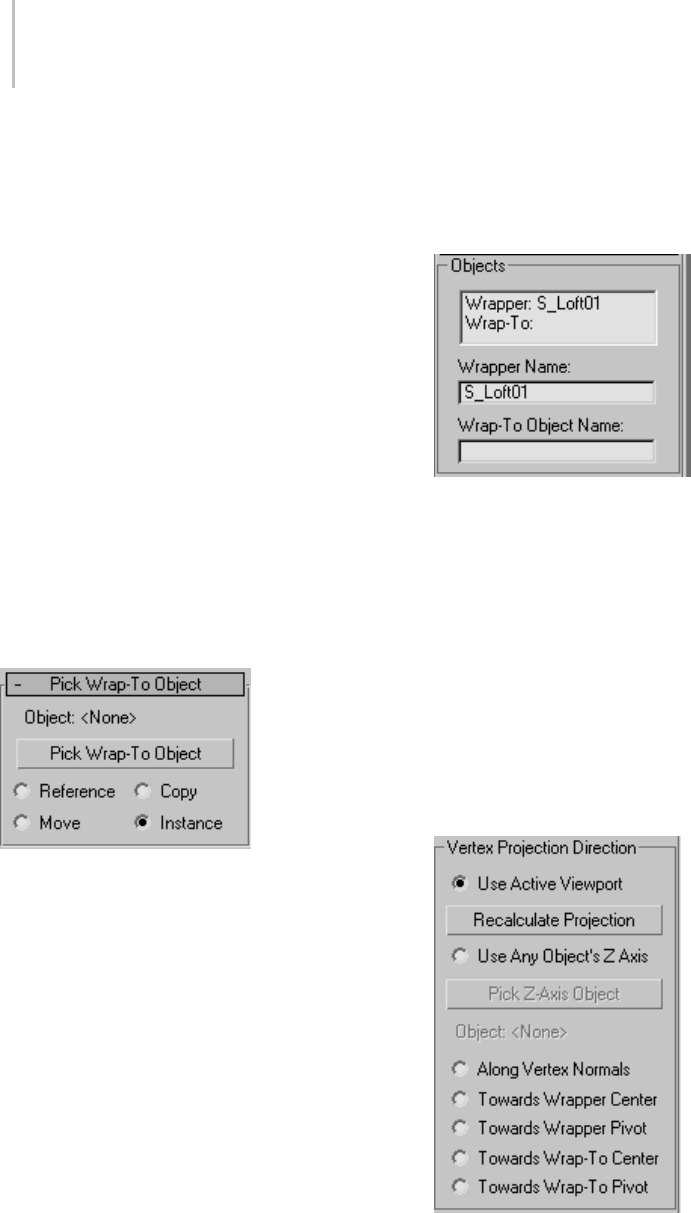
326 Chapter 5: Creating Geometry
An instance of the terrain object is created, with
thesameobjectcolorastheroad.
7. Activate the Top viewport. In the Parameters
rollout > Vertex Projection Direction group,
choose Use Active Viewport, and click
Recalculate Projection.
8. IntheUpdategroup,turnonHideWrap-To
Object.
This hides the instance of the terrain so you can
clearly see the road projected onto it.
The Parameters rollout > Wrapper Parameters
group > Standoff Distance value sets the
numberofunitsbywhichtheroadsitsabove
the terrain along the world Z axis.
9. If necessary, adjust the Standoff Distance to
raise or lower the road.
Interface
Pick Wrap-To Object rollout
Object—Displays the name of the selected Wrap-To
object.
Pick Wrap-To Object—Click this button, and then
selecttheobjecttowhichyouwantthecurrent
object to wrap.
Reference/Copy/Move/Instance—This option lets
you specify how the Wrap-To object is transferred
to the Conform object. It can be transferred either
as a reference (page 3–1002),acopy,aninstance
(page 3–957), or it can be moved, in which case the
original is not left behind.
Parameters rollout
Contains all parameters for the Conform object.
Objects group
Provides a list window and two edit fields that let
you navigate the compound object and rename its
components.
List Window—Lists the Wrapper and the Wrap-To
objects. Click to select an object in the window so
that you can access it in the Modifier stack.
Wrapper Name—Lets you rename the wrapper
object within the compound Conform object.
Wrap-To Object Name—Lets you rename the
Wrap-To object.
Vertex Projection Direction group
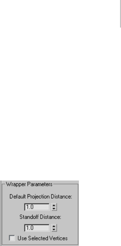
Conform Compound Object 327
Choose one of these seven options to determine
the projection of the vertices.
UseActiveViewport—The vertices are projected
away (inward) from the active viewport.
Recalculate Projection—Recalculates the projection
direction for the currently active viewport.
Because the direction is initially assigned when
you pick the Wrap-To object, if you want to change
viewports after assignment, click this button to
recalculate the direction based on the new active
viewport.
Use Any Object’s Z Axis—Lets you use the local Z
axis of any object in the scene as a direction. Once
an object is assigned, you can alter the direction of
vertex projection by rotating the direction object.
Pick Z-Axis Object—Click this button, and then
click the object you want to use to indicate the
direction of the projection source.
Object—Displaysthenameofthedirectionobject.
•Along Vertex Normals—Projects the vertices of
the Wrapper object inward along the reverse
direction of its vertex normals. A vertex normal
is a vector produced by averaging the normals
of all faces attached to that vertex. If the
Wrapper object encloses the Wrap-To object,
the Wrapper takes on the form of the Wrap-To
object.
•Towards Wrapper Center—Projects the vertices
toward the bounding center of the Wrapper
object.
•Towards Wrapper Pivot—Projects the vertices
toward the original pivot center of the Wrapper
object.
•Towards Wrap-To Center—Projects the vertices
toward the bounding center of the Wrap-To
object.
•Towards the Wrap-To Pivot—Projects the vertices
towardthepivotcenteroftheWrap-Toobject.
Note: Towards Wrapper Pivot and Towards the
Wrap-To Pivot operate on the position of the
original pivot point of the object before the
Conform object is created. Once you create the
Conform object, it’s a new compound object with
a single pivot point.
Tip: You can animate the conforming effect by
morphing between the compound object and a
previously made copy of the original wrapper
object. Todothis,however,youmustturnon
Hide Wrap-To Object in the Update group so that
the original object and the compound object have
the same number of vertices. Using this technique,
you can effectively morph between two objects
with a different number of vertices.
Wrapper Parameters group
Provides controls that determine how far the
vertices are projected.
Default Projection Distance—The distance a vertex
in the Wrapper object will move from its original
location if it does not intersect the Wrap-To object.
Standoff Distance—Thedistancemaintained
between the vertex of the Wrapper object and the
surface of the Wrap-To object. For example, if
you set Standoff Distance to 5, the vertices can be
pushed no closer than 5 units from the surface of
the Wrap-To object.
Use Selected Vertices—When turned on, only the
selected vertex sub-objects of the Wrapper object
are pushed. When turned off, all vertices in the
object are pushed, regardless of the Modifier stack
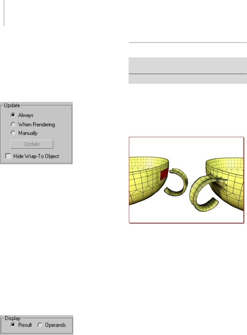
328 Chapter 5: Creating Geometry
selection. To access the Modifier stack of the
Wrapper object, select the Wrapper object in the
list window, open the Modifier stack, and select
thebaseobjectname.Atthispointyoucanapplya
Mesh Select modifier, for example, and select the
vertices you want to affect.
Update group
The items in this group determine when the
projection for the compound object is recalculated.
Because complex compound objects can slow
performance, you can use these options to avoid
constant calculation.
•Always—The object is updated constantly.
•When Rendering—The object is recalculated
only when the scene is rendered.
•Manually—Activates the Update button for
manual recalculation.
Update—Recalculates the projection.
Hide Wrap-To Object—When on, hides the Wrap-To
object.
Display group
Determines whether the shape operands are
displayed.
•Result—Displays the result of the operation.
•Operands—Displays the operands.
Connect Compound Object
Select an object. > Create panel > Geometry > Compound
Objects > Object Type rollout > Connect
Select an object. > Create menu > Compound > Connect
The Connect compound object lets you connect
two or more objects between "holes" in their
surfaces. To do this, you delete faces in each object
to create one or more holes in their surfaces,
position them so that the holes face one another,
and then apply Connect.
Left: Before connect
Right: After connect
Note: Connect is not suited to NURBS objects,
because they convert into many separate meshes
instead of one big mesh. The workaround is
simple: apply a Weld modifier to the NURBS
object(thusconvertingittoameshandzippingup
its seams) before using it as part of a connect.
Connect generates the best mapping coordinates it
can for the bridges between the various holes in the
meshes. While some ideal cases, such as a cylinder
above another cylinder, can generate good UVW
map interpolations, most cases cannot. You’ll need
to apply mapping to the bridge faces with a UVW
Map modifier (page 1–922).

Connect Compound Object 329
Vertex colors, on the other hand, interpolate
smoothly.
Notes:
• You can use Connect on objects that have
multiple sets of holes. Connect will do its best
to match up the holes between the two objects.
• The mapping coordinates assigned to the
original two objects are maintained to the
extent possible. You might find irregularities in
the bridged area, depending on the complexity
and difference between the two original sets
of mapping coordinates and the types of
geometry.
Procedures
To create a Connect object:
1. Create two mesh objects.
2. Delete faces on each to create holes where you
want to bridge the objects.
Position the objects so that the normals of
the deleted faces of one object point toward
the normals of the deleted faces of the other
object (assuming that deleted faces could have
normals).
3. Selectoneoftheobjects.OntheCreatepanel>
Geometry > Compound Object Type rollout,
click Connect.
4. Click the Pick Operand button, and then select
the other object.
5. Faces are generated connecting the holes in the
two objects.
6. Adjust the connection with the various options.
Example: To connect two cylinders:
1. Create a cylinder with a radius of 15 and a
height of 30. Use the default settings for the
remaining parameters.
2. Create a second cylinder centered on the first
with a radius of 30, a height of 30, and 13 sides.
(Thefewersidesaretodemonstratethemesh
interpolation in the connection.)
3. Move the first, narrower cylinder straight up
alongZsoitsbottomcapisabout15units
abovethetopcapofthelargercylinder.
4. Convert both cylinders to editable meshes.
5. Delete the lower cap of the upper cylinder, and
the upper cap of the bottom cylinder. (Hint: Go
to Editable Mesh (Polygon) mode, select each
end in turn, and then press the Delete key.)
6. Exit sub-object mode, select the lower cylinder,
and click Connect.
7. Click the Pick Operand button, and then click
the upper cylinder.
New faces are created that span the openings in
the two cylinders.
Example continued: To try out some options and
create animation:
1. Go to the Modify panel and increase the
Segments spinner to 5or more.
As the segments increase, the connection
becomes curved.
2. Set the Tension spinner to 0to straighten the
connecting surface, increase it to 1, and then
return it to 0.5.
3. Try different combinations of the Bridge and
Ends options.
4. Select the upper cylinder, turn on the Auto
Keybutton,andapplyvarioustransformsat
different frames.
5. Play the animation.
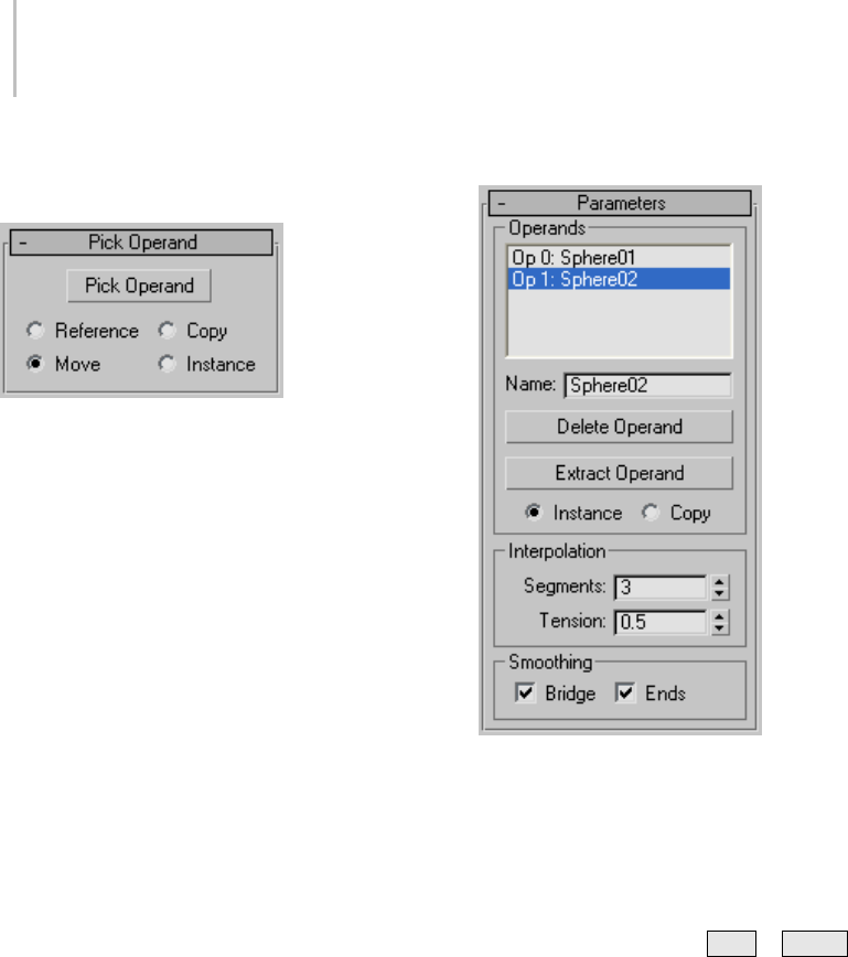
330 Chapter 5: Creating Geometry
Interface
Pick Operand rollout
Pick Operand—Click this button to connect an
additional operand to the original object.
For example, you might begin with a single object
with two holes, and arrange two additional objects,
each with one hole, outside of those holes. Click
the Pick Operand button and select one of the
objects, which is connected, and then click Pick
Operand again and select the other object, which
is connected. Both connected objects are added to
the Operands list.
Reference/Copy/Move/Instance—Lets you specify
how the operand is transferred to the compound
object. It can be transferred either as a reference
(page 3–1002),acopy,aninstance (page 3–957),
or moved, in which case the original is not left
behind.
Note: Connect works only with objects that are
capable of being converted into editable surfaces,
such as editable meshes (page 1–996).
Parameters rollout
Operands group
Operands list—Displays the current operands.
Select an operand to rename, delete or extract by
clicking it in this list.
Name—Renames a selected operand. Type in a
new name, and then press Ta b or Enter .
Delete Operand—Deletes a selected operand from
the list.
Extract Operand—Extracts a copy or an instance of
theselectedoperand.Chooseanoperandinthe
list to enable this button.
Note: This button is available only in the Modify
panel. You can’t extract an operand while in the
Create panel.
Instance/Copy—Lets you specify how the operand
is extracted: as either an instance (page 3–957) or a
copy.
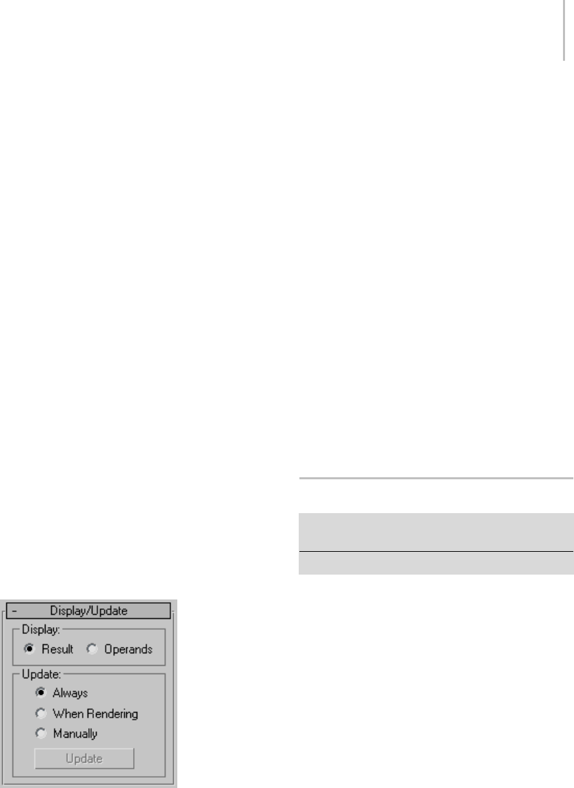
BlobMesh Compound Object 331
Interpolation group
Segments—Sets the number of segments in the
connecting bridge.
Tension—Controls the curvature in the connecting
bridge. A value of 0 provides no curvature, while
higher values create curves that attempt to more
smoothly match the surface normals on either
end of the connecting bridge. This spinner has no
apparent effect when Segments is set to 0.
Smoothing group
Bridge—Applies smoothing between the faces in
the connecting bridge.
Ends—Applies smoothing between the faces that
border the old and new surfaces of the connecting
bridge and the original objects. When turned off,
3dsMaxassignsanewmaterialIDnumberto
thebridge. Thenewnumberisonehigherthan
the highest ID number assigned to either of the
original objects. When on, the ID number is taken
from one of the original objects.
Note: If both Bridge and Ends are on, but the
original objects contain no smoothing groups,
thensmoothingisassignedtothebridgeandto
the faces bordering the bridge.
Display/Update rollout
Display group
Determines whether the shape operands are
displayed.
•Result—Displays the result of the operation.
•Operands—Displays the operands.
Update group
Theseoptionsdeterminewhentheprojectionfor
the compound object is recalculated. Because
complex compound objects can slow performance,
you can use these options to avoid constant
calculation.
•Always—The object is updated constantly.
•When Rendering—The object is recalculated
only when the scene is rendered.
•Manually—Activates the Update button for
manual recalculation.
Update—Recalculates the projection.
BlobMesh Compound Object
Create panel > Geometry > Compound Objects > Object
Type rollout > BlobMesh
Create menu > Compound > BlobMesh
The BlobMesh compound object creates a set of
spheres from geometry or particles, and connects
the spheres together as if they were made of a soft,
liquid substance. When the spheres move within
a certain distance of one another, they connect
together. When they move apart, they take on a
spherical form again.
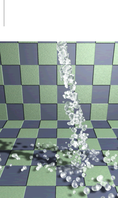
332 Chapter 5: Creating Geometry
In the 3D industry, the general term for spheres
that operate in this way is metaballs (page 3–972).
The BlobMesh compound object generates
metaballs based on specified objects in the
scene, and the metaballs, in turn, form a mesh
result called a blobmesh.Ablobmeshisidealfor
simulating thick liquids and soft substances that
move and flow when animated.
When you associate an object or particle
system with the BlobMesh compound object,
themetaballsareplacedandsizeddifferently
depending on the object used to generate them:
• For geometry and shapes, a metaball is placed
ateachvertex,andthesizeofeachmetaballis
determined by the size of the original BlobMesh
object. Soft selection can be used to vary the
sizes of the metaballs.
• For particles, a metaball is placed at each
particle, and the size of each metaball is
determined by the size of the particle on which
it’s based.
• For helpers, a metaball is placed at the pivot
point, and the size of the metaball is determined
by the original BlobMesh object.
Note: Yo u c a n a p p l y motion blur (page 3–975) to a
BlobMesh object to enhance the effects of motion
in renderings. For particle systems other than
Particle Flow, use Image motion blur. For Particle
Flow particle systems and all other types of objects
including geometry, shapes, and helpers, use
Object motion blur.
Procedures
To create a blobmesh from geometry or helpers:
1. Createoneormoregeometryorhelperobjects.
If the scene requires animation, animate the
objects as desired.
2. Click BlobMesh, and click anywhere on the
screen to create the initial metaball.
3. Go to the Modify panel.
4. In the Blob Objects group, click Add. Select the
objects you wish to use to create metaballs. A
metaball appears at each vertex of each selected
object,oratthecentersofhelperobjects.
5. In the Parameters rollout, set the Size parameter
as necessary to cause the metaballs to connect.
To create a blobmesh with soft selection on
geometry:
1. Create a geometry object, and convert it to an
Editable Mesh or Editable Poly.
2. Apply a Mesh Select modifier to the object, and
select some of the vertices on the object.
3. In the Soft Selection rollout, turn on Use Soft
Selection. Set the Falloff value as desired.
4. Apply a Tur n to Mesh or Tur n to Poly modifier
to the object.

BlobMesh Compound Object 333
This will retain the soft selection and pass it
up the stack regardless of whether you exit the
sub-object mode.
5. Click Create panel > Compound Objects >
BlobMesh, and click anywhere on the screen to
create the initial metaball.
6. Go to the Modify panel.
7. In the Blob Objects group, click Add. Select the
Editable Mesh or Editable Poly object.
A metaball appears at each vertex of the selected
object.
8. In the Parameters rollout, turn on Use Soft
Selection.
Metaballs are limited to those vertices that are
affected by the soft selection.
9. Set the Size and Min. Size parameters to set the
sizes of the metaballs.
To create a blobmesh with soft selection on a spline:
1. Create the spline, and convert it to an Editable
Spline.
2. In the Rendering rollout, turn on both
Renderable and Display Render Mesh.
3. Apply a Mesh Select modifier, and select the
appropriate vertices for soft selection.
4. In the Soft Selection rollout, turn on Use Soft
Selection. Set the Falloff value as desired.
5. Apply a Turn to Mesh or Turn to Poly modifier
to the object.
This will retain the soft selection and pass it
up the stack regardless of whether you exit the
sub-object mode.
6. Click Create panel > Compound Objects >
BlobMesh, and click anywhere on the screen to
create the initial metaball.
7. Go to the Modify panel.
8. In the Blob Objects group, click Add. Select the
Editable Spline.
A metaball appears at each vertex of the selected
object.
9. IntheParametersrollout,turnonUseSoft
Selection.
Metaballs are limited to those vertices that are
affected by the soft selection.
10.Set the Size and Min. Size parameters to set the
sizes of the metaballs.
To create a blobmesh from a particle system:
When you use BlobMesh with a particle system, a
metaball is created at each particle’s location. The
size of the metaball is determined by the size of
the particle.
1. Create a particle system (page 2–108),andset
up its parameters to animate the particles.
2. Click Create panel > Compound Objects >
BlobMesh, and click anywhere on the screen to
create the initial metaball.
3. Go to the Modify panel.
4. In the Blob Objects group, click Add. Select
the particle system. A metaball appears at each
particle in the system.
5. If you have added a Particle Flow system (page
2–109) to the blobmesh and you want to create
metaballs only for particles in specific events,
clickAddontheParticleFlowParameters
rollout to choose the events from a list.
Tip: If you need to prevent the particles
from rendering, do not hide them as this
can prevent the blobmesh from generating
correctly. Instead, turn off the particle system’s
Renderable option on the Object Properties
dialog (page 1–117).
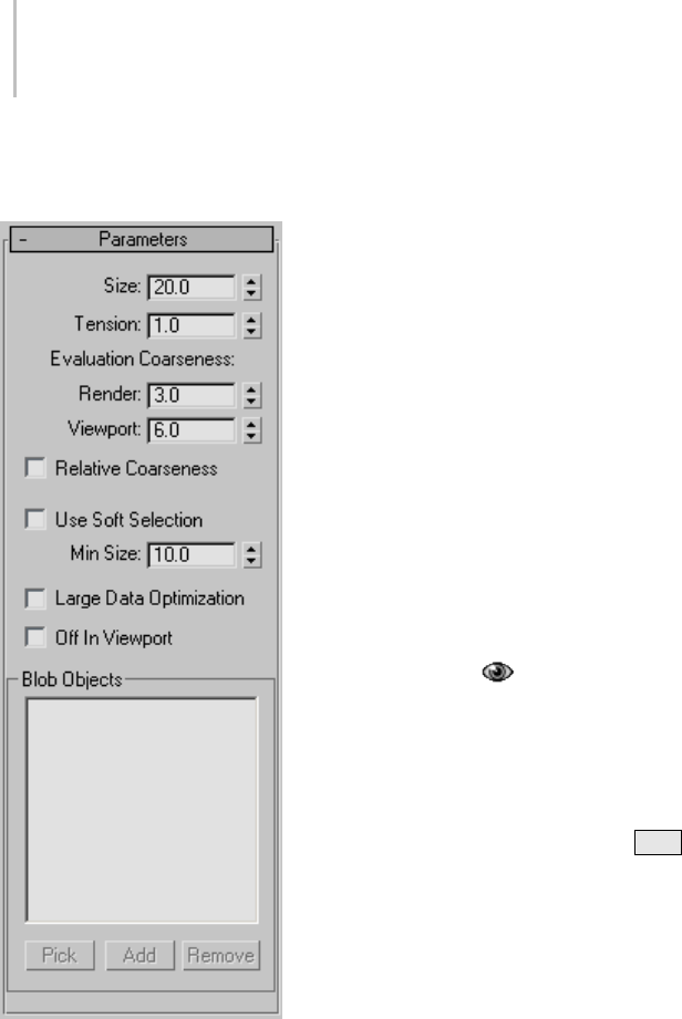
334 Chapter 5: Creating Geometry
Interface
Parameters rollout
Size—The radius of each metaball for objects
otherthanparticles.Forparticles,thesizeofeach
metaball is determined by the size of the particle,
whichissetbyparametersintheparticlesystem.
Default=20.
Note: Theapparentsizeofthemetaballsisaffected
by the Tension value. When Tension is set to its
lowest possible value, the radius of each metaball
accurately reflects the Size setting. Higher Tension
values will tighten the surface, and make the
metaballs smaller.
Tension—Determines how relaxed or tight the
surface will be. A smaller value makes a looser
surface. Thisvaluecanrangefrom0.01to1.0.
Default=1.0.
Evaluation Coarseness—Sets the coarseness, or
density, of the resulting blobmesh. When Relative
Coarseness (see following) is off, the Render
andViewportvaluessettheabsoluteheight
and width of blobmesh faces, and lower values
create a smoother, denser mesh. When Relative
Coarseness is on, the height and width of blobmesh
facesisdeterminedbytheratioofmetaballsize
to this value. In this case, higher values create
a denser mesh. Range (both)=0.001 to 1000.0.
Render default=3.0, Viewport default =6.0.
The lower end of the range for both Coarseness
settings, previously limited to 0.5, is now 0.001,
which allows for much higher-resolution metaball
geometry when Relative Coarseness is off. Using
such low values can also cause lengthy calculation
delays; if this happens and you wish to halt
calculation, press Esc .
Relative Coarseness—Determines how the
coarseness values will be used. If this option
is turned off, the Render Coarseness and View
Coarseness values are absolute, where the height
and width of each face on the blobmesh is always
equal to the coarseness value. This means the faces
ontheblobmeshwillretainafixedsizeevenif
themetaballschangesize.Ifthisoptionisturned
on, the size of each blobmesh face is based on the
ratio of the metaball size to the coarseness, which
will cause the blobmesh face size to change as the
metaballs become larger or smaller. Default=Off.
Large Data Optimization—This option provides an
alternate method for calculating and displaying
the blobmesh. This method is more efficient than
the default method only when a large number of
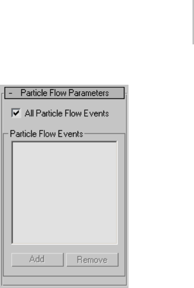
BlobMesh Compound Object 335
metaballs are present, such as 2,000 or more. Turn
on this option only when using a particle system
or other object that produces a large number of
metaballs. Default=Off.
Off in Viewport—Turns off the display of the
blobmesh in viewports. The blobmesh will still
appearing in renderings. Default=Off.
Use Soft Selection—If soft selection has been used
on geometry you add to the blobmesh, turning on
this option causes the soft selection to be used for
the size and placement of metaballs. Metaballs
areplacedatselectedverticeswiththesizesetby
the Size parameter. For vertices that lie within the
falloff set on the geometry’s Soft Selection rollout,
smaller metaballs are placed. For vertices outside
the falloff, no metaballs are placed. This option has
an effect only if the Vertex sub-object level for the
geometry is still enabled, and Use Soft Selection
on the geometry’s Soft Selection rollout is turned
on. If Use Soft Selection is turned off either for the
blobmesh for the geometry, metaballs are placed at
all vertices on the geometry. Default=Off.
Min Size—Sets the minimum size for metaballs
within the falloff when Use Soft Selection is turned
on. Default=10.0.
Pick—Allows you to pick objects or particle
systems from the screen to add to the blobmesh.
Add—Displays a selection dialog where you can
select objects or particle systems to add to the
blobmesh.
Remove—Removes objects or particles from the
blobmesh.
Particle Flow Parameters rollout
UsethisrolloutifyouhaveaddedaParticleFlow
system to the blobmesh, and want particles to
generate metaballs only during specific events.
Beforeyoucanspecifyeventsonthisrollout,you
must add the Particle Flow system to the blobmesh
on the Parameters rollout.
All Particle Flow Events—When turned on, all
Particle Flow Events will generate metaballs. When
turned off, only Particle Flow Events specified in
the PFlow Events list will generate metaballs.
Add—Displays a list of PFlow events in the scene so
you can pick events to add to the PFlow Events list.
Remove—Removes the selected event from the
PFlow Events list.
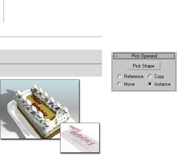
336 Chapter 5: Creating Geometry
ShapeMerge Compound Object
Select an object. > Create panel > Geometry > Compound
Objects > Object Type rollout > ShapeMerge
Select an object. > Create menu > Compound >
ShapeMerge
ShapeMerge combines the lettering, a text shape, with the
mesh that models the cake.
ShapeMerge creates a compound object consisting
of a mesh object and one or more shapes. The
shapes are either embedded in the mesh, altering
theedgeandfacepatterns,orsubtractedfromthe
mesh.
Procedure
To create a ShapeMerge object:
1. Create a mesh object and one or more shapes
2. Align the shapes in the viewport so they can be
projected toward the surface of the mesh object.
3. Select the mesh object, and click the
ShapeMerge button.
4. Click Pick Shape, and then select the shape.
The geometry of the surface of the mesh object is
altered to embed a pattern matching that of the
selected shape.
Interface
Pick Operand rollout
Pick Shape—Click this button, and then click the
shape you want to embed in the mesh object. The
shape is projected onto the mesh object in the
direction of the shape’s local negative Z axis. For
example, if you create a box, and then create a
shape in the Top viewport, the shape is projected
onto the top of the box. You can repeat this process
toaddshapes,andtheshapescanbeprojectedin
different directions. Simply click Pick Shape again,
and then pick another shape.
Reference/Copy/Move/Instance—Lets you specify
how the shape is transferred to the compound
object. It can be transferred either as a reference
(page 3–1002),acopy,aninstance (page 3–957),
or moved, in which case the original shape is not
left behind.
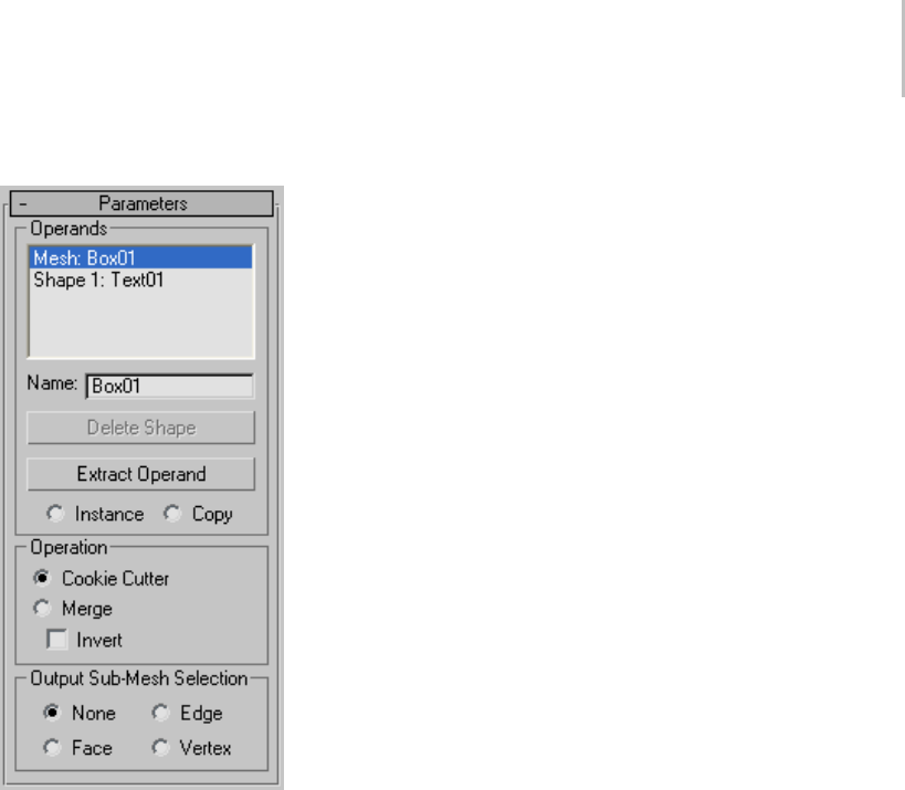
ShapeMerge Compound Object 337
Parameters rollout
Operands group
Operands list—Lists all operands in the compound
object. The first operand is the mesh object, and
any number of shape-based operands can follow.
Delete Shape—Remove selected shapes from the
compound object.
Extract Operand—Extractsacopyoraninstanceof
theselectedoperand.Chooseanoperandinthe
list window to enable this button.
Instance/Copy—Lets you specify how the operand
is extracted. It can be extracted either as an
instance (page 3–957) or a copy.
Operation group
Theseoptionsdeterminehowtheshapeisapplied
to the mesh.
Cookie Cutter—Cuts the shape out of the mesh
object’s surface.
Merge—Merges the shape with the surface of the
mesh object.
Invert—Reverses the effect of Cookie Cutter or
Merge.WiththeCookieCutteroption,theeffect
is obvious. When Invert is off, the shape is a hole
in the mesh object. When Invert is on, the shape
is solid and the mesh is missing. When you’re
using Merge, Invert reverses the sub-object mesh
selection. As an example, if you merge a circle
shapeandapplyaFaceExtrude,thecircularareais
extruded when Invert is off, and all but the circular
area is extruded when Invert is on.
Output Sub-Mesh Selection group
Provides options that let you specify what selection
level is passed up the Stack. The ShapeMerge
object stores all selection levels; that is, it stores the
vertices, faces, and edges of the merged shape with
the object. (If you apply a Mesh Select modifier
and go to the various sub-object levels, you’ll see
that the merged shape is selected.) Thus, if you
followtheShapeMergewithamodifierthatactson
aspecificlevel,suchasFaceExtrude,thatmodifier
will work properly.
If you apply a modifier that can work on any
selection level, such as Volume Select or XForm,
the options will specify which selection level is
passed to that modifier. Although you can use
aMesh Select modifier (page 1–719) to specify a
selection level, the Mesh Select modifier considers
the selection only at frame 0. If you’ve animated
the shape operand, that animation will be passed
up the Stack for all frames only by using the
Output Sub-Mesh Selection options.
•None—Outputs the full object.
•Face—Outputsthefaceswithinthemerged
shape.
•Edge—Outputs the edge of the merged shape.
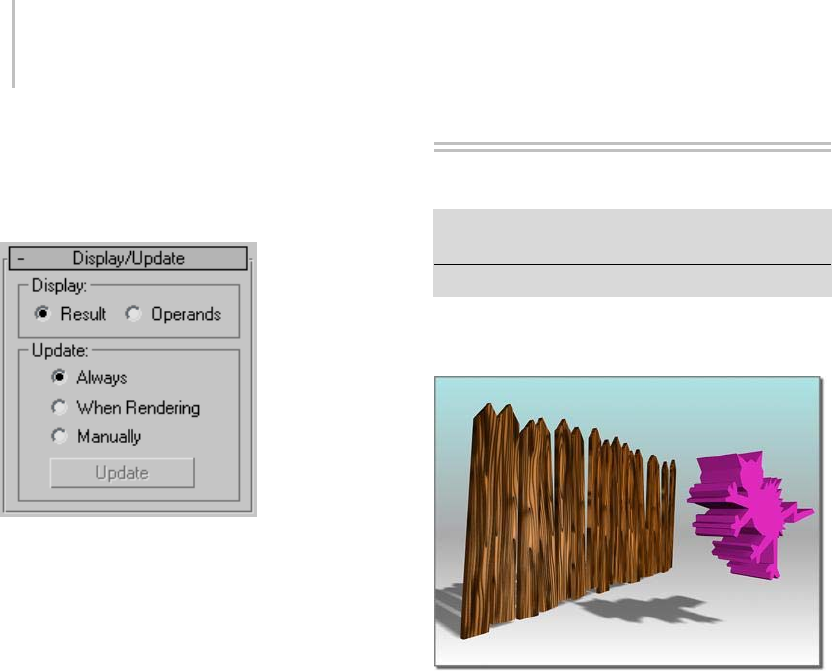
338 Chapter 5: Creating Geometry
•Vertex—Outputs the vertices defined by the
spline of the shape.
Display/Update rollout
Display group
Determines whether the shape operands are
displayed.
•Result—Displays the result of the operation.
•Operands—Displays the operands.
Update group
These options specify when the display is updated.
Typically, you use them when you’ve animated the
merged shape operands and the viewport display
is slow.
•Always—Updates the display at all times.
•When Rendering—Updates the display only
when the scene is rendered.
•Manually—Updates the display only when you
click the Update button.
Update—Updates the display when any option
except Always is chosen.
Boolean Compound Object
Select an object. > Create panel > Geometry > Compound
Objects > Object Type rollout > Boolean
Select an object. > Create menu > Compound > Boolean
A Boolean object combines two other objects by
performing a Boolean operation on them.
Operand A (left); Operand B (right)
These are the Boolean operations for geometry:
Union—The Boolean object contains the volume
of both original objects. The intersecting or
overlapping portion of the geometry is removed.
Intersection—The Boolean object contains only
the volume that was common to both original
objects (in other words, where they overlapped).
Subtraction (or difference)— The Boolean object
contains the volume of one original object with the
intersection volume subtracted from it.
The two original objects are designated as operand
AandB.
Beginning with version 2.5 of 3ds Max, a new
algorithm computes the Boolean operation. This
algorithm produces more predictable results and
less complex geometry than earlier 3D Studio
Booleans. If you open a file that contains a Boolean
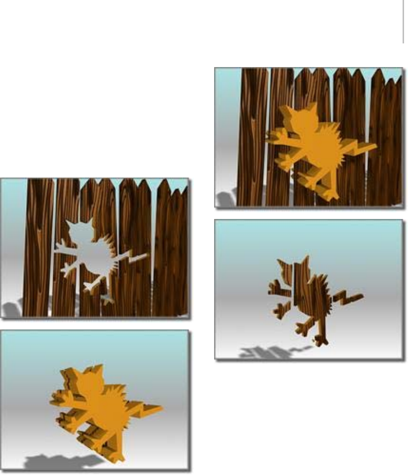
Boolean Compound Object 339
from an earlier version of 3ds Max, the Modify
paneldisplaystheinterfacefortheearlierBoolean
operation.
You can layer Booleans in the stack display, so that
a single object can incorporate many Booleans. By
navigating through the stack display, it’s possible
to revisit the components of each Boolean and
make changes to them.
Subtraction: A-B (above); B-A (below)
Union (above); Intersection (below)
Booleans with Objects That Have
Materials Assigned to Them
Most primitives use several material IDs (page
3–969) ontheirsurfaces. Forexample,abox
uses material IDs 1–6 on its sides. If you assign a
Multi/Sub-Object material (page 2–1594) with six
sub-materials, 3ds Max assigns one to each side. If
you assign a multi/sub-object material with two
sub-materials, 3ds Max assigns the first material
to sides 1, 3, and 5, and the second goes to sides
2, 4, and 6.
When you create a Boolean from objects that have
materials assigned to them, 3ds Max combines the
materialsinthefollowingway:

340 Chapter 5: Creating Geometry
• If operand A doesn’t have a material, it inherits
operand B’s material.
• If operand B doesn’t have a material, it inherits
operand A’s material.
•Ifbothoperandshavematerials,thenew
material is a multi/sub-object material that
combines the materials from both operands.
For more information, see Material Attach Options
Dialog (page 1–345).
Solutions When Working with Booleans
The Boolean algorithm caused unpredictable
behavior in earlier releases. The solutions are
discussed here.
Surface Topology
Boolean requires that operands’ surface topology
be intact: This means no missing or overlapping
faces and no unwelded vertices. The surface
should be one continuous closed surface.
The Boolean corrects operands that fail to
meet this requirement. However, the automatic
correctionmaynotbeexactlywhatyouwant,soin
some cases it might be safer to correct the surfaces
manually.
To check for holes in the geometry, use the
STL-Check modifier (page 1–834) or the Measure
utility (page 2–52).
To f i l l h o l es , u s e t h e Cap Holes modifier (page
1–569).
Face Normals
Booleans require that the face normals of the
surface be consistent. Flipped normals can
produce unexpected results. Surfaces where some
faces are facing one way and adjacent faces are
flipped are also problematic, and are commonly
found in geometry imported from CAD programs.
TheBooleanfixesthesefacesasbestitcan.
Again, it might make more sense to correct these
manually.
Use shaded viewports to look for normal problems,
watching for objects that appear inside-out or look
otherwise incorrect. You can also turn on Show in
the Editable Mesh (Face) (page 1–1009) >Surface
Properties rollout > Normals group. Fix normals
here, or with a Normal modifier (page 1–746).
Overlapping Elements
Because Boolean operations depend on a clear
understanding of what is inside and what is outside
a mesh, meshes that overlap themselves can
produce invalid results. For instance, if you use the
Collapse utility (page 1–966) with two overlapping
objectswithoutturningontheBooleanfeature,
the resulting object will not make a good Boolean
operand. This is also a problem for the Teap ot
primitive (page 1–183) (with all parts turned on),
which overlaps itself.
If you need to use such an object as a Boolean
operand, you might reconstruct it as a single
non-overlapping mesh by separating the
components and combining them with Boolean.
Working with Inverted Meshes
Boolean doesn’t always produce the ideal result on
"inverted meshes" (meshes that have been turned
inside-out by having their normals flipped).
The problem is that the area inside the flipped
mesh is correctly seen as "outside," but the area
outside it may also be seen as “outside.” To remedy
this, instead of inverting the mesh, make a very
large box or other primitive centered on (but not
touching) the mesh and subtract the mesh from
it using Boolean. Then convert it to an editable
mesh, and delete the box faces. This produces a
correctly inverted mesh that works correctly with
Boolean.

Boolean Compound Object 341
Alignment
If two Boolean operands are perfectly aligned
without actually intersecting, the Boolean
operation might produce the wrong result.
Although this is rare, if it does occur, you can
eliminate it by making the operands overlap
slightly.
Relative Complexity Between Operands
Boolean works best when the two operands are
of similar complexity. If you wish to subtract
text (a complex object made of many faces and
vertices) from a box without any segments, the
result is many long, skinny faces that are prone to
rendering errors. Increasing the number of box
segments produces better results. Try to maintain
a similar complexity between operands.
Coplanar Faces/Colinear Edges
Previously, Boolean required that objects overlap.
If two objects did not overlap but merely touched
an edge to an edge, or a face to a face, the Boolean
would fail.
Boolean allows for non-overlapping objects.
Coincident faces/edges and vertices are no longer
aproblem.Youcanuseobjectscompletelyencased
within another object, where no edges intersect,
to create Booleans.
See also Collapse Utility (page 1–966) to create
Booleans with multiple objects.
See also
Fixing Boolean Problems (page 3–885)
Procedures
To create a Boolean object:
1. Select an object. This object becomes operand
A.
2. Click Boolean. The name of operand A appears
in the Operands list on the Parameters rollout.
3. On the Pick Boolean rollout, choose the copy
method for operand B: Reference, Move, Copy,
or Instance. (These methods are described in
the Pick Boolean rollout section, later in this
topic.)
4. On the Parameters rollout, choose the Boolean
operation to perform: Union, Intersection,
Subtraction (A-B), or Subtraction (B-A). You
canalsochooseoneoftheCutoperations,
described later in the Operation group section.
5. On the Pick Boolean rollout, click Pick
Operand B.
6. Click in a viewport to select operand B. 3ds Max
performs the Boolean operation.
The operand objects remain as sub-objects
of the Boolean object. By modifying the
creation parameters of the Boolean’s operand
sub-objects, you can later change operand
geometryinordertochangeoranimatethe
Boolean result.
Example: To create and modify a single object that
contains multiple Booleans:
Suppose you want to create a box with two holes
in it. One hole is to be cut by a sphere, and the
second by a cylinder. If you want to make changes
tothesphereorthecylinderlater,youcandoso
by following these steps:
1. CreateaBooleanfollowingthestepsinthe
previous sections. The original object (the box)
isconvertedtoaBoolean,andisdesignated
operand A. The second object (the sphere) is
converted to operand B.
2. Deselect the Boolean object. Build the cylinder
if it does not already exist.
3. Select the Boolean object; and under
Compound Objects, click Boolean again.
4. Click Pick Operand B and click the cylinder in
the viewport. It is converted to operand B.
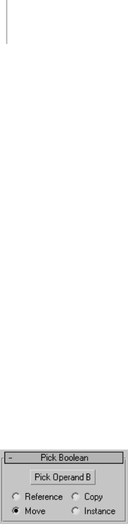
342 Chapter 5: Creating Geometry
5. On the Modify panel, choose Operand B from
the Parameters rollout > Operands list. If you
want to see operand B, choose Display/Update
rollout > Display group > Operands or Result
+ Hidden Ops.
IfyouwanttoanimatetheCylinderorthe
Cylinder’s parameters you can now access them
in the modifier stack display.
6. If you want to modify the sphere’s parameters,
choose the box in the Operands list.
7. Now there are two entries labeled Boolean in
the stack display. Choose the lower entry. The
Sphere is displayed in the Operands list.
8. Choose the Sphere from the Operands list. The
sphere’s parameters are available by clicking the
sphere’s name in the modifier stack display.
9. Use this technique to change parameters or
animateanyoftheoperandswithinthemultiple
Boolean.
You can also navigate multiple Booleans through
Track View. Clicking the operand in Track View
gives you direct access to its entry in the modifier
stack display. In complex objects with many
Booleans, this is an easier method than the one
outlined above.
Interface
Pick Boolean rollout
When you select operand B, you designate it
as a Reference, Move (the object itself), Copy,
or Instance, according to your choice in the
Pick Boolean rollout for Boolean objects. Base
yourselectiononhowyouwanttousethescene
geometry after you create the Boolean.
Because you usually create Boolean objects from
overlapping objects, if the B object isn’t removed
(if you don’t use the default Move option), it often
obstructs your view of the completed Boolean.
You can move the Boolean or the B object to better
see the result.
Pick Operand B—Use this button to select the
second object to use to complete the Boolean
operation.
Reference/Copy/Move/Instance—Lets you specify
how operand B is transferred to the Boolean
object. It can be transferred either as a reference
(page 3–1002),acopy,aninstance (page 3–957),
or moved.
• Use Reference to synchronize modifier-induced
changes to the original object with operand B,
but not vice-versa.
• Use Copy when you want to reuse the operand
B geometry for other purposes in the scene.
• Use Instance to synchronize animation of the
Boolean object with animated changes to the
original B object, and vice-versa.
• Use Move (the default) if you’ve created the
operand B geometry only to create a Boolean,
andhavenootheruseforit.
Object B geometry becomes part of the Boolean
object regardless of which copy method you
use.
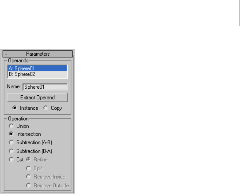
Boolean Compound Object 343
Parameters rollout
Operands group
Operands list field—Displays the current operands.
Name—Edit this field to change the name of the
operands.ChooseanoperandintheOperandslist
and it will also appear in the Name box.
Extract Operand—Extractsacopyoraninstanceof
the selected operand. Choose one of the operands
in the list window to enable this button.
Note: This button is available only in the Modify
panel. You can’t extract an operand while the
Create panel is active.
Instance/Copy—Lets you specify how the operand
is extracted: as either an instance (page 3–957) or a
copy.
Operation group
Union—The Boolean object contains the volume
of both original objects. The intersecting or
overlapping portion of the geometry is removed.
Intersection—The Boolean object contains only
the volume that was common to both original
objects (in other words, where they overlapped).
Subtraction (A-B)—Subtracts the intersection
volume of operand B from operand A. The
Boolean object contains the volume of operand A
with the intersection volume subtracted from it.
Subtraction (B-A)—Subtracts the intersection
volume of operand A from operand B. The
Boolean object contains the volume of operand B
with the intersection volume subtracted from it.
Cut—Cuts operand A with operand B, but doesn’t
addanythingtothemeshfromoperandB.This
works like the Slice modifier (page 1–825),but
instead of using a planar gizmo, Cut uses the shape
of operand B as the cutting plane. Cut treats the
geometry of the Boolean object as volumes rather
than closed solids. Cut does not add geometry
from operand B to operand A. Operand B
intersections define cut areas for altering geometry
in operand A.
There are four types of Cut:
•Refine—Adds new vertices and edges to
operand A where operand B intersects the faces
of operand A. 3ds Max refines the resulting
geometry of operand A with additional faces
inside the intersected area of operand B. Faces
cut by the intersection are subdivided into new
faces. You might use this option to refine a
boxwithtextsothatyoucanassignaseparate
material ID to the object.
•Split—Works like Refine but also adds a second
or double set of vertices and edges along the
boundary where operand B cuts operand A.
Split produces two elements belonging to the
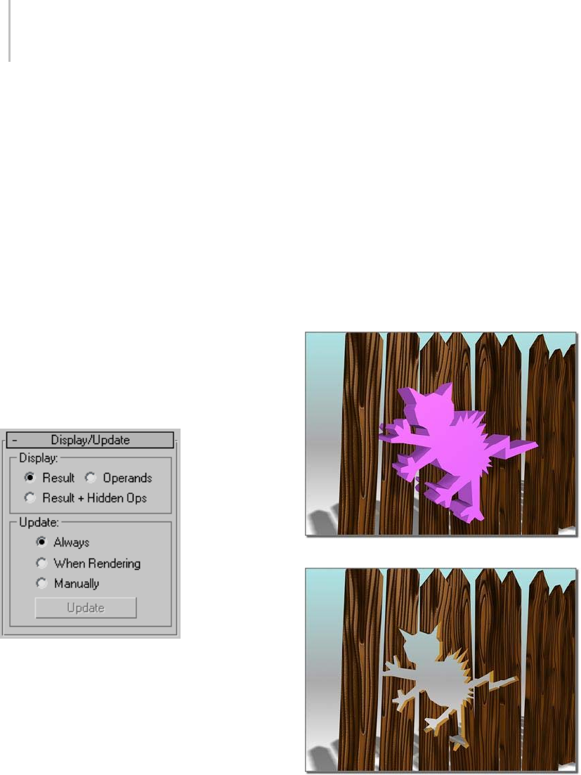
344 Chapter 5: Creating Geometry
same mesh. Use Split to break an object into
two parts along the bounds of another object.
•Remove Inside—Deletes all operand A faces
inside operand B. This option modifies and
deletes faces of operand A inside the area
intersected by operand B. It works like the
subtraction options, except that 3ds Max adds
no faces from operand B. Use Remove Inside to
delete specific areas from your geometry.
•Remove Outside—Deletes all operand A faces
outside operand B. This option modifies and
deletes faces of operand A outside the area
intersected by operand B. It works like the
Intersection option, except that 3ds Max adds
no faces from operand B. Use Remove to delete
specific areas from your geometry.
Display/Update rollout
Display group
Visualizing the result of a Boolean can be tricky,
especially if you want to modify or animate it. The
Display options on the Boolean Parameters rollout
help you visualize how the Boolean is constructed.
The display controls have no effect until you’ve
created the Boolean.
•Result—Displays the result of the Boolean
operation; that is, the Boolean object itself.
•Operands—Displays the operands instead of the
Boolean result.
Tip: When operands are difficult to see in a
viewport, you can use the Operand list to select
one or the other. Click the name of the A or B
operand to select it.
•Results + Hidden Ops—Displays the "hidden"
operands as wireframe.
Operand geometry remains part of the
compound Boolean object, although it isn’t
visible or renderable. The operand geometry is
displayedaswireframesinallviewports.
Displaying the operands
Displaying the result (A-B)

Material Attach Options Dialog 345
Displaying the hidden operand after A-B
Displaying the hidden operand after B-A
Update group
By default, Booleans are updated whenever you
change the operands. A scene that contains one
or more complicated, animated Booleans can
impede performance. The update options provide
alternate methods to improve performance.
•Always—UpdatesBooleansimmediatelywhen
you change an operand, including the original
object of an instanced or referenced B operand.
This is the default behavior.
•When Rendering—Updates Booleans only when
you render the scene or click Update. With this
option, viewports don’t always show current
geometry, but you can force an update when
necessary.
•Manually—UpdatesBooleansonlywhenyou
click Update. With this option, the viewports
and the render output don’t always show
current geometry, but you can force an update
when necessary.
Update—UpdatestheBoolean.TheUpdatebutton
is not available when Always is selected.
Material Attach Options Dialog
Use objects with different materials assigned to them. >
Create panel > Geometry > Compound Objects > Object
Type rollout > Boolean > Pick Boolean rollout > Pick
Operand B button > Select object in the viewport that
is operand B.
When you use Boolean operations with objects
that have been assigned different materials,
3ds Max displays the Material Attach Options
dialog. This dialog offers five methods for
handling the materials and the material IDs (page
3–969) in the resultant Boolean object.
Note: If operand A has no material, and operand
B has a material assigned, the Boolean dialog lets
youchoosetoinheritthematerialfromoperandB.
If operand A has a material assigned and operand
B has no material assigned, the Boolean object
automatically inherits materials from operand A.

346 Chapter 5: Creating Geometry
Procedure
To create a Boolean from objects that match material
IDs to material:
1. Create a Boolean (page 1–341) using at least one
object that has a multi/sub-object material (page
2–1594) assigned to it.
2. On the Pick Boolean rollout, click Pick
Operand B.
3. Click in a viewport and select the B operand.
3ds Max displays the Match Attach Options
dialog.
4. Choose Match Material IDs to Material to
complete the Boolean operation.
Interface
Match Material IDs to Material—3ds Max modifies
the number of material IDs in the combined object
to be no greater than the number of sub-materials
assigned to the operands. For example, if you
combinetwoboxesthathavestandardmaterials
and each box is assigned six material IDs (the
default), the resulting combined object has two
operands with one material ID each, rather
than the 12 that would result from using the
Match Material to Material ID option. After you
complete the operation, 3ds Max creates a new
multi/sub-object material with two slots. 3ds Max
assigns the sub-materials to the operands as they
appeared before the operation. The number of
resultingmaterialIDsmatchesthenumberof
materials between the original objects. You might
use this option to reduce the number of material
IDs.
Match Material to Material IDs—Maintains the
original material ID assignment in the operands
by adjusting the number of sub-materials in
the resultant multi/sub-object material. For
example, if you combine two boxes, both
assigned single materials, but with their default
assignment of six material IDs, the result would
be a multi/sub-object material with 12 slots (six
containing instances of one box’s material, and six
containing instances of the other box’s material).
Use this option when it’s important to maintain
the original material ID assignments in your
geometry. Also use this option when material IDs
have been assigned, but materials have not been
assigned.
Note: To make the instanced sub-materials unique,
select them in Track View, and click the Make
Unique button on the Track View toolbar. You
canalsomakethemuniqueoneatatimewiththe
Make Unique button (page 2–1442) in the Material
Editor.
Do Not Modify Mat IDs or Material—If the number of
materialIDsinanobjectisgreaterthanthenumber
of sub-materials in its multi/sub-object material,
then the resultant face-material assignment might
be different after the Boolean operation.
Discard New Operand Material—Discards the
material assignment of operand B. 3ds Max assigns
operand A’s material to the Boolean object.
Discard Original Material—Discards the material
assignment of operand A. 3ds Max assigns
operand B’s material to the Boolean object.
Note: AUVW Map modifier (page 1–922) must be
used with compound objects to apply mapping
coordinates.
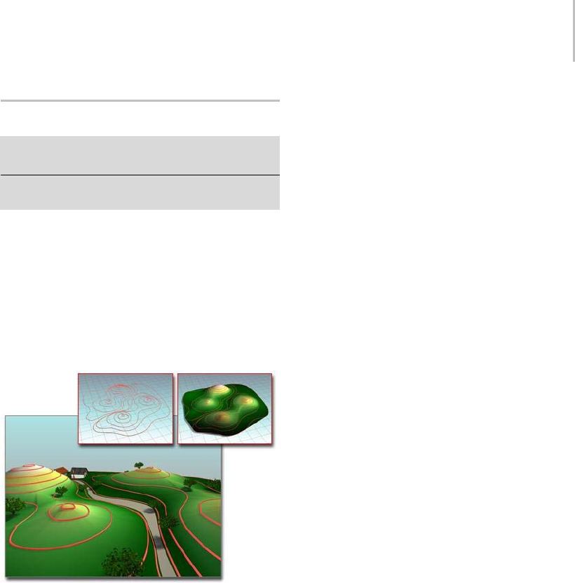
Terrain Compound Object 347
Terrain Compound Object
Select spline contours. > Create panel > Geometry >
Compound Objects > Object Type rollout > Terrain
Select spline contours. > Create menu > Compound >
Terrain
The Terrain button lets you produce terrain
objects. 3dsMaxgeneratestheseobjectsfrom
contourlinedata. Youselecteditablesplines
representing elevation contours and create a mesh
surface over the contours. You can also create a
"terraced" representation of the terrain object so
that each level of contour data is a step, resembling
traditional study models of land forms.
Using contours to build a terrain
Upper left: The contours
Upper right: The terrain object
Lower left: Terrain object used as the basis of a landscape
If you import an AutoCAD drawing file to use as
contour data, 3ds Max names each object based on
the AutoCAD object’s layer, color, or object type.
A number is appended to each name. For example,
an AutoCAD object on the layer BASE becomes an
object named BASE.01.SeeImporting DWG Files
(page 3–536) for more information.
After you import or create the contour data, select
the objects, and click the Terrain button, 3ds Max
creates a new triangulated mesh object based on
the contour data. The name of the first selected
spline becomes the name of the terrain object.
Other splines in the selection are treated according
to the previously set Reference, Move, Copy, or
Instance selection in the Pick Operand rollout,
described below.
Keep in mind that the Terrain object can use
any spline objects as operands, whether they
are horizontal splines or not. Though the most
common scenario is when sets of elevational
contours are used to create terrain forms, it is
possible to append or refine Terrain objects by
using non-horizontal splines.
Note: To ensure that 3ds Max imports polylines as
splines, when you import an AutoCAD drawing
file, turn off Import AutoCAD DWG File dialog >
Geometry Options group > Cap Closed Entities.
Following are examples of uses of the Terrain
feature:
• Visualizing the effects of grading plans in 3D.
• Maximizing views or sunlight by studying
topographical undulation of land forms.
• Analyzing elevation changes by using color on
the data.
• Adding buildings, landscaping, and roads
to a terrain model to create virtual cities or
communities.
• Viewing corridors and completing ridge
analyses from particular locations on a site by
adding cameras to the scene.
Procedure
To analyze elevation changes:
1. Import or create contour data.
2. Select the contour data, and click the Terrain
button.
3. On the Color By Elevation rollout, enter
elevation zone values between the maximum
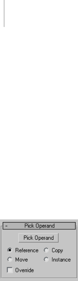
348 Chapter 5: Creating Geometry
and minimum elevations in the Base Elev box.
Click Add Zone after entering the value.
3ds Max displays the zones in the list under the
Create Defaults button.
4. Click the Base Color swatch to change the color
of each elevation zone. For example, you could
use a deep blue for low elevations, a light blue
for intermediate elevations, and perhaps greens
forhigherelevations.
5. Click Solid To Top of Zone to see the elevation
changes in a striped effect.
6. Click Blend To Color Above to see the elevation
changes blended.
Interface
Name and Color rollout
Displays the name of the terrain object. 3ds Max
uses the name of one of the selected objects to
name the terrain object.
Pick Operand rollout
Pick Operand—Adds splines to the terrain object.
You might do this if you didn’t select all the objects
before generating the terrain object, or if some
objects in the imported data weren’t included in
the terrain object. You can also use this option
to add existing splines in the current scene to the
terrain object.
Reference/Copy/Move/Instance—When you click
Pick Operand, the copy method you designate
determines how the operands are used. When
Move is the method, the original contour data
ismovedfromthesceneandintotheoperands
of the new terrain object. Copy, Reference, and
Instance retain the original contour data in the
scene and create copies, references or instances of
the contour data as operands in the terrain object.
This is similar to the copy method for Boolean
(page 1–338).
Override—Allows you to select closed curves that
override any other operand data within their
interior. Within the area an Override operand
encloses (as seen in plan), other curves and points
ofthemesharedisregardedandtheelevation
of the Override operand supersedes them. An
Override operand is indicated in the operands list
by a # after its name. Override is only effective
on closed curves. If multiple override operands
overlap, later overrides (higher operand numbers)
take preference.
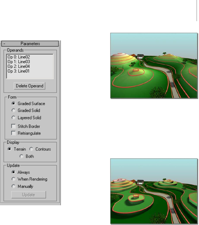
Terrain Compound Object 349
Parameters rollout
Operands group
Operand list—Displays the current operands. Each
operandislistedas"Op"followedbyanumber
and the name of the object that is being used as
the operand. The operand name comprises layer,
color, or object type name plus a numeric suffix.
Delete Operand—Deletes a selected operand from
the Operands list.
Form group
•Graded Surface—Creates a graded surface of the
mesh over the contours.
Terrain created as a graded surface
•Graded Solid—Creates a graded surface with
skirts around the sides and a bottom surface.
This represents a solid that is visible from every
direction.
•Layered Solid—Creates a "wedding cake"
or laminated solid similar to cardboard
architectural models.
Terrain created as a "layered solid" surface, with levels
Stitch Border—When on, suppresses the creation of
new triangles around the edges of terrain objects
when edge conditions are defined by splines that
are not closed. Most terrain forms display more
reasonably when this is turned off.
Retriangulate—The basic Terrain algorithm tends
to flatten or notch contours when they turn
sharply upon themselves. A typical situation in
which this may happen is when a narrow creek
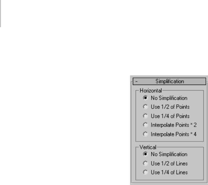
350 Chapter 5: Creating Geometry
bed is described with contours; the resulting
form may look more like a series of cascades at
each elevational contour, rather than a smoothly
descending ravine. When Retriangulate is
checked, a somewhat slower algorithm is used
thatfollowscontourlinesmoreclosely. This
maybeparticularlyevidentintheLayeredSolid
display mode. For additional precision, try using
Retriangulate in conjunction with horizontal
interpolation.
Display group
•Terrain—Displays only the triangulated mesh
over the contour line data.
•Contours—Displays only the contour line data
of the terrain object.
•Both—Displays both the triangulated mesh
and the contour line data of the terrain object.
Yo u c a n s e l e c t t h e t e r r a i n o b j e c t b y c l i c k i n g
itssurface,butnotbyclickingacontourline.
When Both is selected, contour lines may not
be apparent in Wireframe display modes or
when Edged Faces are displayed.
Update group
The items in this group box determine when
3ds Max recalculates the projection for the terrain
object. Because complex terrain objects can slow
performance, you can use these options to avoid
constant calculation.
•Always—Updates the terrain object immediately
when you change an operand, including the
original object of an instanced or referenced
operand.
•When Rendering—Updates the terrain object
when you render the scene or when you click
Update. With this option, viewports won’t
show current geometry unless you click Update.
•Manually—Updates the terrain object when you
click Update.
Update—Updates the terrain object. This button is
not enabled only when Always is the active option.
Simplification rollout
Horizontal group
•No Simplification—Uses all the operands’
vertices to create a complex mesh. This results
in greater detail and a larger file size than the
two fractional options.
•Use 1/2 of Points—Uses half the set of vertices
intheoperandstocreatealesscomplexmesh.
This results in less detail and a smaller file size
than using No Simplification.
•Use 1/4 of Points—Uses a quarter of the of
vertices in the operands to create a less complex
mesh. This results in the least detail and
smallest file size of these options.
•Interpolate Points * 2—Doubles the set of
vertices in the operands to create a more refined
but more complex mesh. This is most effective
in terrain forms that use constructive curves
such as circles and ellipses. This results in
more detail and a larger file size than using No
Simplification.
•Interpolate Points * 4—Quadruples the set
ofverticesintheoperandstocreateamore
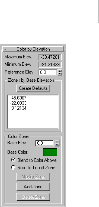
Terrain Compound Object 351
refined but more complex mesh. This is most
effective in terrain forms that use constructive
curves such as circles and ellipses. This results
in more detail and a larger file size than using
No Simplification.
Vertical group
•No Simplification—Uses all the spline
operandsvertices of the terrain object to create
a complex mesh. This results in greater detail
and a larger file size than the other two options.
•Use 1/2 of Lines—Uses half the set of spline
operands of the terrain object to create a less
complexmesh.Thisresultsinlessdetailanda
smallerfilesizethanusingNoSimplification.
•Use 1/4 of Lines—Uses a quarter of the of spline
operands of the terrain object to create a less
complex mesh. This results in the least detail
andsmallestfilesizeofthethreeoptions.
Color by Elevation rollout
Maximum Elev.—Displays the maximum elevation
in the Z axis of the terrain object. 3ds Max derives
this data from the contour data.
Minimum Elev.—Displays the minimum elevation
in the Z axis of the terrain object. 3ds Max derives
this data from the contour data.
Reference Elev.—This is the reference elevation, or
datum, that 3ds Max uses as a guide for assigning
colors to zones of elevation. After entering a
reference elevation, click the Create Defaults
button. 3ds Max treats elevations above the
reference elevation as solid land and those below
the reference elevation as water.
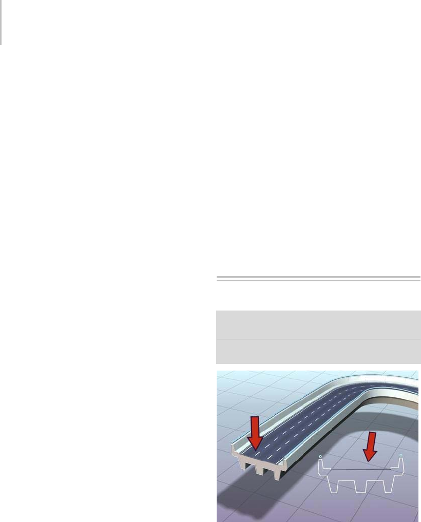
352 Chapter 5: Creating Geometry
If you enter a value no greater than the minimum
elevationintheobject,3dsMaxdividestherange
between the reference and minimum elevations
into five color zones: dark green, light green,
yellow, purple, and light gray.
If you enter a value between the minimum and
maximumelevations,3dsMaxcreatessixcolor
zones. Two zones (dark blue and light blue) are
used for elevations below the reference elevation.
These are considered to be under water. One zone
(dark yellow) is used for a narrow range around
the reference elevation. Three zones (dark green,
light green, light yellow) are used for elevations
above the reference elevation.
If you enter a value at or above the maximum
elevation, 3ds Max divides the range between
the minimum and reference elevations into three
zones (dark blue, medium blue, light blue).
Zones by Base Elevation group
Create Defaults—Creates elevation zones. 3ds Max
lists the elevation at the bottom of each zone,
referenced to the datum (the reference elevation).
3dsMaxappliesthecolorofthezoneatthebase
elevation. Whether the colors blend between zones
depends on your choice of the Blend to Color
Above or Solid to Top of Zone option.
Color Zone group
The items in this group box assign colors to
elevation zones. For example, you might want
to change levels of blue to indicate the depth for
water. Your changes in the Color Zone area don’t
affect the terrain object until you click the Modify
Zone or Add Zone button.
Base Elev—This is the base elevation of a zone to
which you assign color. After entering a value,
click Add Zone to display the elevation in the list
under Create Defaults.
Base Color—Click the color swatch to change the
color of the zone.
•Blend to Color Above—Blends the color of the
current zone to the color of the zone above it.
•Solid to Top of Zone—Makes a solid color at the
top of the zone without blending to the color of
thezoneaboveit.
Modify Zone—Modifies selected options of a zone.
Add Zone—Adds values and selected options for a
new zone.
Delete Zone—Deletes a selected zone.
Loft Compound Object
Select a path or shape. > Create panel > Geometry >
Compound Objects > Object Type rollout > Loft
Select a path or shape. > Create menu > Compound
Objects > Loft
Roadway created as a lofted shape
Loft objects are two-dimensional shapes extruded
along a third axis. You create loft objects from
two or more existing spline objects. One of these
splinesservesthepath. Theremainingsplines
serve as cross-sections, or shapes, of the loft object.

Loft Compound Object 353
As you arrange shapes along the path, 3ds Max
generates a surface between the shapes.
You create shape objects to serve as a path for
any number of cross-section shapes. The path
becomes the framework that holds the cross
sections forming your object. If you designate
only one shape on the path, 3ds Max assumes an
identical shape is located at each end of the path.
The surface is then generated between the shapes.
3ds Max places few restrictions on how
you create a loft object. You can create
curved, three-dimensional paths and even
three-dimensional cross sections.
When using Get Shape, as you move the cursor
over an invalid shape, the reason the shape is
invalid is displayed in the prompt line.
Unlike other compound objects, which are created
from the selected object as soon as you click the
compound-objectbutton,aLoftobjectisnot
created until you click Get Shape or Get Path, and
then select a shape or path.
Loft is enabled when the scene has one or more
shapes. To create a loft object, first create one
or more shapes and then click Loft. Click either
Get Shape or Get Path and select a shape in the
viewports.
Once you create a loft object, you can add and
replace cross-section shapes or replace the path.
You can also change or animate the parameters of
the path and shapes.
You can’t animate the path location of a shape.
YoucanconvertloftobjectstoNURBS surfaces
(page 1–1116).
Procedures
To create a loft object:
Creatingloftobjectsisdetailedandoffersmany
choices, but the basic process is quite simple.
1. Create a shape to be the loft path.
2. Create one or more shapes to be loft cross
sections.
3. Do one of the following:
• Select the path shape and use Get Shape to
addthecrosssectionstotheloft.
• Select a shape and use Get Path to assign
a path to the loft. Use Get Shape to add
additional shapes.
You can use the loft display settings to view the
skin generated by your loft in both wireframe and
shaded views.
To create a loft with Get Path:
1. Select a shape as the first cross-section shape.
2. Click Create panel > Geometry > Compound
Objects > Loft.
3. On the Creation Method rollout, click Get Path.
4. Choose Move, Copy, or Instance.
5. Clickashapeforthepath.
ThecursorchangestotheGetPathcursorasyou
move it over valid path shapes. If the cursor does
not change over a shape, that shape is not a valid
path shape and cannot be selected. The first vertex
oftheselectedpathisplacedatthefirstshape’s
pivot and the path tangent is aligned with the
shape’s local Z axis.
To create a loft with Get Shape:
1. Select a valid path shape as the path.
2. Iftheselectedshapeisnotavalidpath,theGet
Shape button is unavailable.
3. Click Create panel > Geometry > Compound
Objects > Loft.
4. On the Creation Method rollout, click Get
Shape.
5. Choose Move, Copy, or Instance.
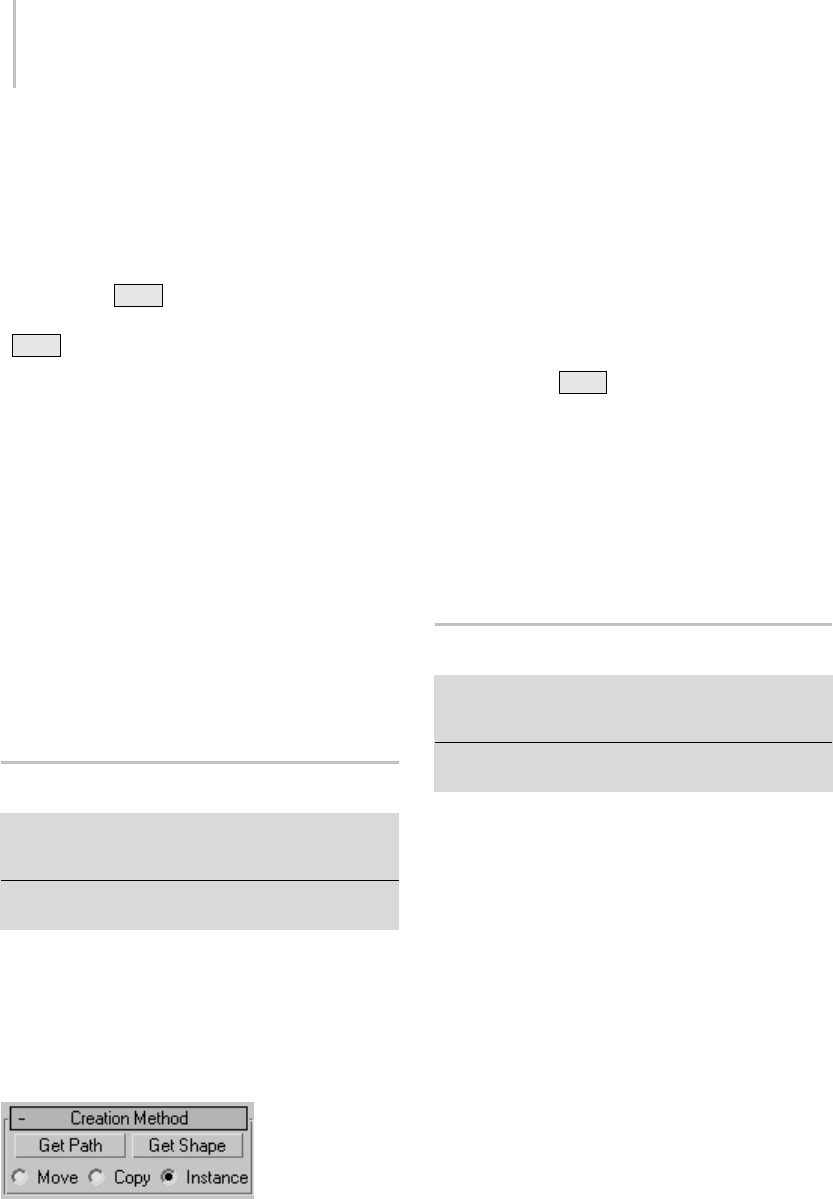
354 Chapter 5: Creating Geometry
6. Click a shape.
ThecursorchangestotheGetShapecursorasyou
move it over potential shapes. The selected shape
is placed at the first vertex of the path.
Tip: You can flip the shape along the path by
holding down Ctrl when using Get Shape. For
example, if you select the lowercase letter "b" with
aCtrl +click, the loft will look like the letter "d".
Interface
You use the following rollouts for setting loft object
parameters:
Creation Method Rollout (page 1–354)
Surface Parameters Rollout (page 1–354)
Path Parameters Rollout (page 1–356)
Skin Parameters Rollout (page 1–358)
Once you’ve created a loft object, you can also use
the Modify panel’s Deformations rollout to add
complexity. See Deformations (page 1–363) for
further information.
Creation Method Rollout
Select a path or shape. > Create panel > Geometry
> Compound Objects > Object Type rollout > Loft >
Creation Method rollout
Select a path or shape. > Create menu > Compounds >
Loft > Creation Method rollout
You can choose between a shape or a path for
creating the loft object using the Creation Method
rollout, as well as the type of action for the loft
object.
Interface
On the Creation Method rollout, you determine
whether to use a shape or path for creating the loft
object,andthetypeofactionyouwantforthe
resulting loft object.
Get Path—Assigns a path to the selected shape or
changes the current assigned path.
Get Shape—Assigns a shape to the selected path or
changes the current assigned shape.
Tip: Hold down Ctrl whilegettingtheshapeto
flip the direction of the shape’s Z axis.
Move/Copy/Instance—Lets you specify how the
path or shape is transferred to the loft object. It can
be moved, in which case no copy is left behind, or
transferred as a copy or an instance (page 3–957).
Tip: UsetheInstanceoptionifyouexpecttoeditor
modify the path after the loft is created.
Surface Parameters Rollout
Select a path or shape. > Create panel > Geometry >
Compound Objects > Object Type rollout > Loft > Surface
Parameters rollout
Select a path or shape. > Create menu > Compounds >
Loft > Surface Parameters rollout
On the Surface Parameters rollout, you control
smoothingofthesurfaceoftheloftaswellas
designateiftexturemappingisappliedalongthe
loft object.
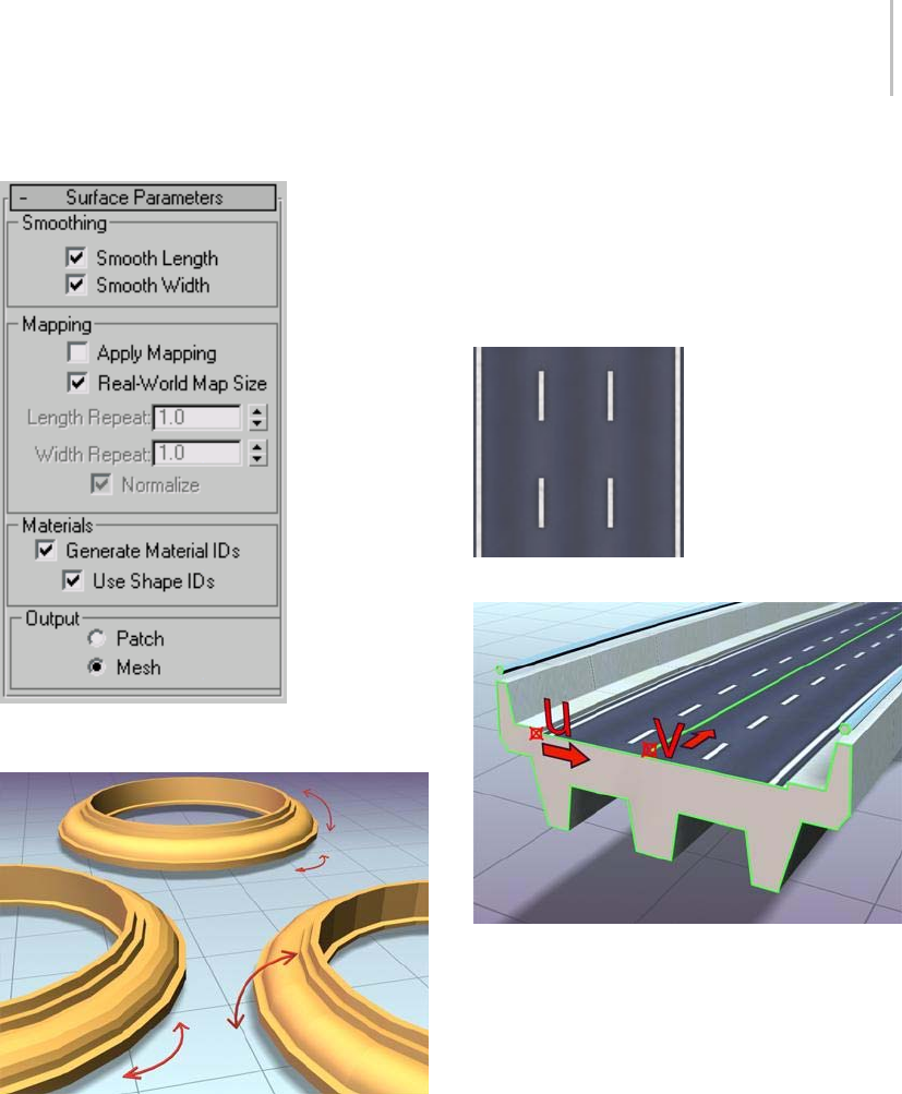
Surface Parameters Rollout 355
Interface
Smoothing group
Left: Smoothing the length
Right: Smoothing the width
Rear: Smoothing both length and width
Smooth Length—Provides a smooth surface along
the length of the path. This type of smoothing is
useful when your path curves or when shapes on
thepathchangesize.Default=on.
Smooth Width—Provides a smooth surface around
the perimeter of the cross-section shapes. This
type of smoothing is useful when your shapes
change the number of vertices or change form.
Default=on.
Mapping group
Bitmap used to create the lines on the road
Mapped roadway showing U and V dimensions for the loft
Apply Mapping—Turns lofted mapping coordinates
on and off. Apply Mapping must be on in order to
access the remaining items.
Real-World Map Size—Controls the scaling method
used for texture mapped materials that are applied
totheobject. Thescalingvaluesarecontrolled
by the Use Real-World Scale settings found in
the applied material’s Coordinates rollout (page
2–1625).Default=off.
Length Repeat—Sets the number of times a map
repeats along the length of the path. The bottom
of the map is placed at the first vertex of the path.
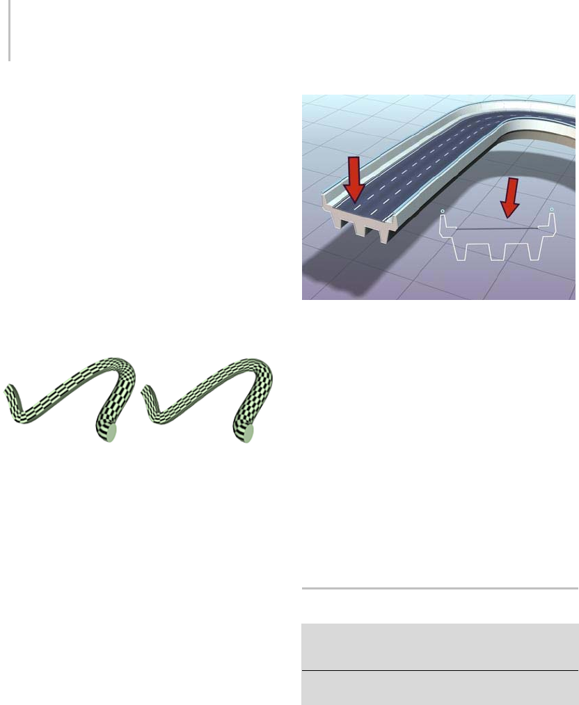
356 Chapter 5: Creating Geometry
Width Repeat—Sets the number of times a map
repeats around the perimeter of cross-section
shapes. The left edge of a map is aligned with the
first vertex of each shape.
Normalize—Determines how path vertex spacing
affects a map along both the path length and
shape width. When on, vertices are ignored.
Map coordinates and Repeat values are applied
evenly along the length of the path and around the
shapes. When off, major path divisions and shape
vertex spacing affects map coordinate spacing.
Map coordinates and Repeat values are applied
proportionally according to the path division
spacing or shape vertex spacing.
Before and after applying Normalize to loft
Materials group
Generate Material IDs—Creates Material IDs during
the loft process.
Use Shape IDs—Offers the choice of using the
spline material IDs to define the material IDs.
Note: Prior to version 3 of 3ds Max, splines could
not hold material IDs.
Note: ShapeIDsareinheritedfromshapecross
sections, not from the path spline.
Shape material IDs used to give the roadway two materials:
concrete for supports and railings, asphalt with white lines for
the traffic lanes
Output Group
Patch—Theloftingprocessproducesapatch
object.
Mesh—Theloftingprocessproducesamesh
object.Thisisthedefault,andwastheonlyoutput
type available with Loft in versions prior to version
3of3dsMax.
You can also create NURBS objects from lofting by
choosing Convert To: NURBS from the modifier
stack right-click menu (page 3–766).
Path Parameters Rollout
Select a path or shape. > Create panel > Geometry >
Compound Objects > Object Type rollout > Loft > Path
Parameters rollout
Select a path or shape. > Create menu > Compounds >
Loft > Path Parameters rollout
The Path Parameters rollout lets you control the
position of shapes at various intervals along the
path of the loft object.
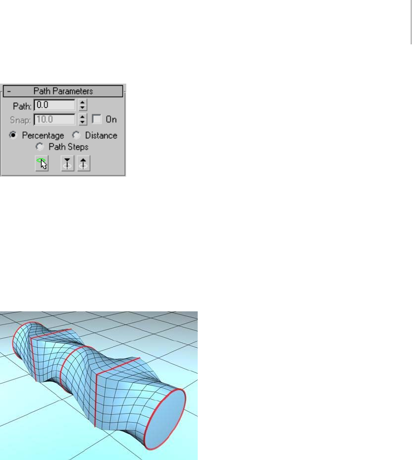
Path Parameters Rollout 357
Interface
On the Path Parameters rollout, you control the
position of multiple shapes at different intervals
along the path of the loft object.
Path—Lets you set a path level by entering a value
or dragging the spinner. If Snap is on, the value
will jump to the previous snap increment. The
Path value depends on the selected measuring
method. Changing the measuring method causes
the Path value to change.
Inserting different shapes at different positions on the path
Snap—Lets you set a consistent distance between
shapes along the path. The Snap value depends
on the selected measuring method. Changing the
measuring method also changes the Snap value to
keep snap spacing constant.
On—When On is turned on, Snap is active.
Default=off.
Percentage—Expresses the path level as a
percentage of the total path length.
Distance—Expresses the path level as an absolute
distance from the first vertex of the path.
Path Steps—Places shapes on path steps and
vertices, rather than as a percentage or a distance
along the path.
When Path Steps is on, the following take place:
• The Path spinner specifies the step along the
path. The first step, at 0, is the first vertex.
• The total number of steps, including vertices,
appears in parentheses beside the Path spinner.
• The current path level is indicated by the
standard yellow X when it’s a step, and by a
small boxed X when it’s a vertex.
• Get Shape places a selected shape on the
specified step or a vertex of the path.
• Adaptive Path Steps on the Skin Parameters
rollout is unavailable. (If it were available, the
path steps and shapes would change positions
along the path, depending on the result of the
adaptive algorithm.)
Please note the following when using the Path
Steps option:
• When you switch to Path Steps with a loft object
that already contains one or more shapes, an
alert message tells you that this action may
relocate shapes. This is because there are a
limited number of path steps, and only one
shape can be on a single step or vertex. The
Percentage and Distance options, on the other
hand, provide an almost unlimited number of
levels on which to place shapes. Thus, if you
change from Percentage or Distance to Path
Steps, the shapes must be moved to existing
steps. If there are more shapes than can be
movedtonearbysteps,youcouldendupwith
more than one shape on a step. Switching from
Path Steps to either Percentage or Distance,
however,canalwaysbedonewithoutlossof
data.

358 Chapter 5: Creating Geometry
•IfyoualterthePathStepsspinnerwhileinPath
Steps mode, the location of your shapes might
change. An alert message warns you of this.
• If you animate the topology of the path while
in Path Steps mode (such as animating the
number of sides of an NGon), your shapes
might jump around trying to find a legitimate
position, and you could end up with more than
oneshapeonthesamepathlevel.
Pick Shape—Sets the current level at any shape
onthepath.Whenyoupickashapeonthepath,
Snap is turned off and Path is set to the level of
the picked shape, where a yellow X appears. Pick
Shape is available only from the Modify panel.
Previous Shape—Jumps the path level from its
current location to the previous shape along the
path. A yellow X appears at the current level.
Clicking this button turns Snap off.
Next Shape—Jumps the path level from its current
location to the next shape along the path. A yellow
X appears at the current level. Clicking this button
turns Snap off.
Skin Parameters Rollout
Select a path or shape. > Create panel > Geometry >
Compound Objects > Object Type rollout > Loft > Skin
Parameters rollout
Select a path or shape. > Create menu > Compounds >
Loft > Skin Parameters rollout
On the Skin Parameters rollout, you adjust the
complexity of the mesh of the loft object. You can
also optimize the mesh by controlling the face
count.
Procedure
Example: To use a constant cross-section:
1. Enlarge the Front viewport to full screen, and
then draw a Rectangle object (page 1–272) with
Ctrl held down to create a square about 20
x20units.
2. Create another rectangle beside it about 200 x
100 units.
3. Apply a Skew modifier to the large rectangle,
but don’t alter the Skew parameters.
4. Create a loft object in which the larger rectangle
isthepathandthesquareistheshape.
5. On the Modify panel, open the Skin Parameters
rollout,andturnonSkinintheDisplaygroup.
Youcannowseethewireframestructureof
the lofted rectangle, with cross-sectional sides
parallel to its corners.
Make sure the color assigned the loft object is
easily visible. Change it if necessary.
6. Turn off Constant Cross-Section, and observe
the corners.
When Constant Cross-Section is off, the
corners become pinched.
7. Turn on Constant Cross-Section to restore the
corners.
Acuteanglescancauseproblemswhenthecross
sections formed by the path steps intersect at
the corners. You can mitigate this by avoiding
acute angles or by reducing the path steps.
8. Press Hon the keyboard to display the
Select Objects dialog (page 1–78),andchoose
Rectangle02 (the second larger rectangle).
9. On the Skew panel, change the Skew Axis to Y,
and then set the Amount spinner to 95.
10.Use Zoom Region to zoom in on the upper-left
corner of the rectangle so you can see the mesh
in detail.
At a skew of less than 100, the acute angle still
works because the path cross-sections haven’t
intersected.
11.Set the Skew Amount to 300,andexaminethe
same corner.
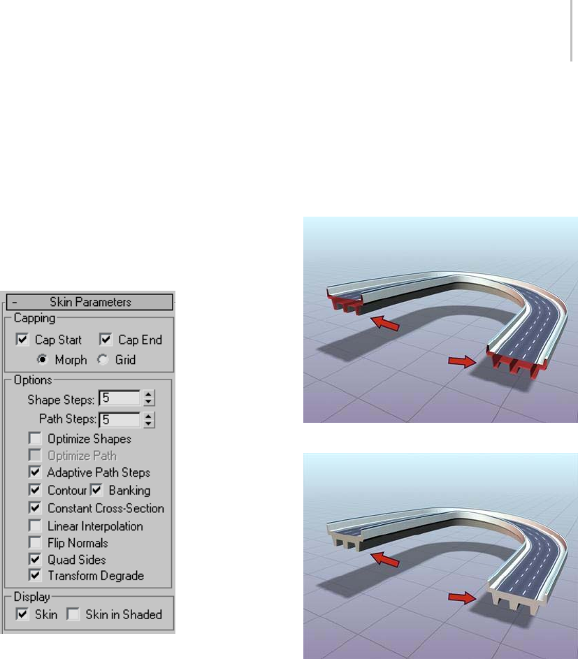
Skin Parameters Rollout 359
At this angle, the path cross sections intersect,
causingproblemsinthemesh.
12.Select the loft object, and set the Path Steps to 1.
The cross sections no longer intersect, and the
corner is clean.
When creating straight-edge molding for
architectural modeling, you can avoid mangled
cornersbysimplyreducingthepathstepsto0.
Interface
Capping group
Cap Start—When on, the end of a loft at the first
vertex of the path is covered, or capped. When off,
the end is open, or uncapped. Default=on.
Cap End—When on, the end of a loft at the last
vertex of the path is covered, or capped. When off,
the end is open, or uncapped. Default=on.
Morph—Arranges cap faces in a predictable,
repeatable pattern necessary for creating morph
targets. Morph capping can generate long, thin
faces that do not render or deform as well as those
created with grid capping.
Grid—Arranges cap faces in a rectangular grid
trimmed at the shape boundaries. This method
produces a surface of evenly sized faces that can be
deformed easily by other modifiers.
Roadway lofted with capping turned off
Roadway lofted with capping turned on
Options group
Shape Steps—Sets the number of steps between
each vertex of the cross-section shapes. This value
affectsthenumberofsidesaroundtheperimeter
of the loft.
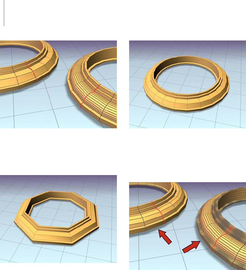
360 Chapter 5: Creating Geometry
Left: Shape Steps=0.
Right: Shape Steps=4.
Path Steps—Sets the number of steps between each
main division of the path. This value affects the
number of segments along the length of the loft.
Frame lofted with Path Steps=1
Frame lofted with Path Steps=5
Optimize Shapes—When on, the Shape Steps
settingisignoredforstraightsegmentsof
cross-section shapes. If multiple shapes are on the
path,onlystraightsegmentsthathaveamatchon
all shapes are optimized. Default=off.
Left: Optimize Shapes turned on
Right: Optimize Shapes turned off
Optimize Path—When on, the Path Steps setting is
ignored for straight segments of the path. Curved
sections respect the Path steps setting. Available
only with Path Steps mode. Default=off.
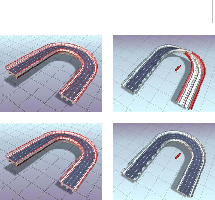
Skin Parameters Rollout 361
When Optimize Path is off, the lofted roadway uses more steps.
When Optimize Path is on, straight sections of the lofted
roadway don’t require additional steps.
Adaptive Path Steps—When on, analyzes the
loft and adapts the number of path divisions
to generate the best skin. Main divisions along
the path occur at path vertices, shape locations,
and deformation curve vertices. When off,
main divisions along the path occur only at path
vertices. Default=on.
Contour—When on, each shape follows the
curvature of the path. The positive Z axis of each
shape is aligned with the tangent to the path at the
shape’s level. When off, shapes remain parallel
and have the same orientation as a shape placed
at level 0. Default=on.
Lofting the roadway with Contour off causes it to twist.
Roadway lofted with Contour turned on
Banking—Whenon,shapesrotateaboutthepath
whenever the path bends and changes height in the
path’s local Z axis. The bank amount is controlled
by 3ds Max. Banking is ignored if the path is 2D.
When off, shapes do not rotate about their Z axis
as they traverse a 3D path. Default=on.
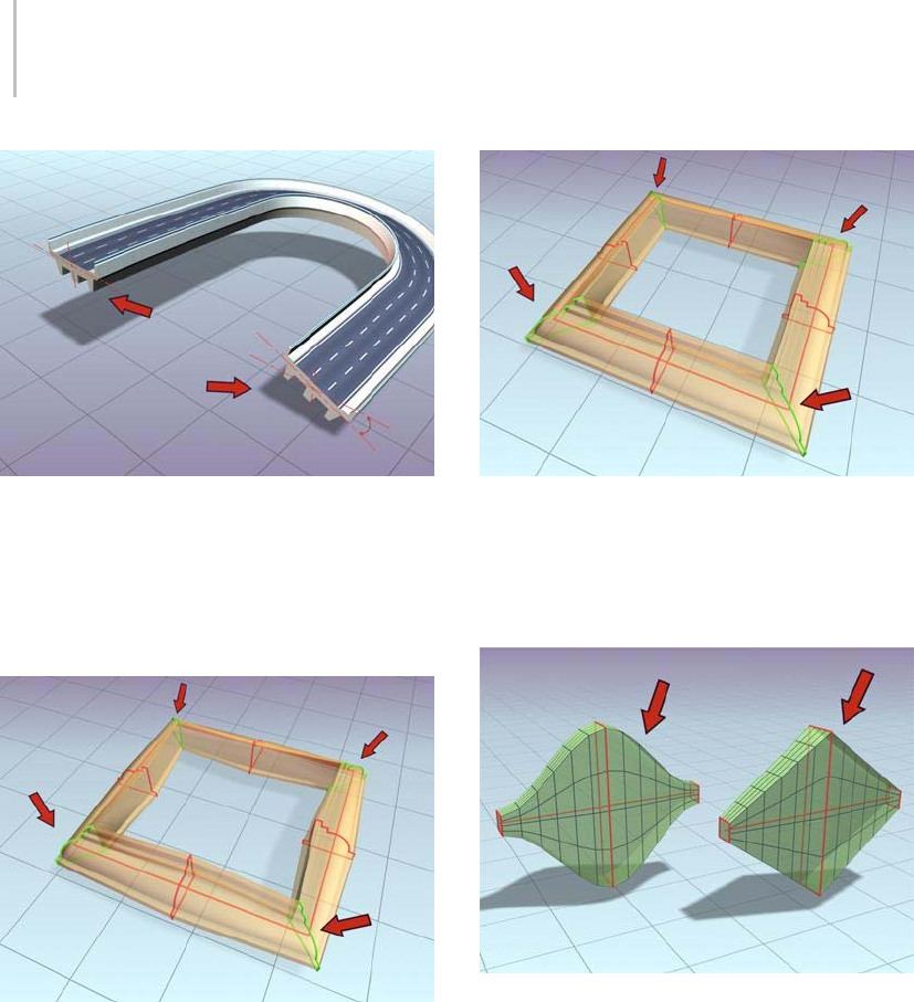
362 Chapter 5: Creating Geometry
Roadway lofted with Banking turned on
Constant Cross Section—When on, the cross
sections are scaled at angles in the path to maintain
uniform path width. When off, the cross sections
maintain their original local dimensions, causing
pinching at path angles.
Frame lofted with Constant Cross Section turned off
Frame lofted with Constant Cross Section turned on
Linear Interpolation—When on, generates a loft
skin with straight edges between each shape.
When off, generates a loft skin with smooth curves
between each shape. Default=off.
Left: Object lofted with Linear Interpolation turned off
Right: Object lofted with Linear Interpolation turned on
Flip Normals—When on, reverses the normals 180
degrees. Use this option to correct objects that are
inside-out. Default=off.
Quad sides—When on, and when two sections of
aloftobjecthavethesamenumberofsides,the
faces that stitch the sections together are displayed
as quads. Sides between sections with different
numbers of sides are not affected, and are still
connected with triangles. Default=off.

Deformations 363
Transform Degrade—Causes the loft skin
to disappear during sub-object shape/path
transformations. For example, moving a vertex
on the path causes the loft to disappear. When
off, you can see the skin during these Sub-Object
transformations. Default=off.
Display group
Skin—When on, displays a loft’s skin in all views
using any shading level and ignores the Skin In
Shaded setting. When off, displays only the loft
sub-objects. Default=on.
Skin in Shaded—When on, displays a loft’s skin in
shaded views regardless of the Skin setting. When
off, skin display is controlled by the Skin setting.
Default=on.
TheloftobjectnowretainstheSkinandSkinIn
Shaded settings from one loft object to the next
one created.
Deformations
Select a Loft object. > Modify panel > Deformations
rollout
Deformation controls let you scale, twist, teeter,
bevel or fit shapes along the path. The interface
for all deformations is a graph. Lines with control
points on the graph represent the deformations
along the path. Control points on the graphs can
bemovedoranimatedformodelingpurposesor
for various special effects.
Manually creating and placing shapes along the
path to produce these models would be a difficult
task. Lofts solve this problem through the use
of deformation curves. The deformation curves
define changes in scale, twisting, teetering, and
beveling along the path.
Yougainaccesstoloftdeformationcurves
throughtheModifypanel’sDeformationsrollout.
DeformationsarenotavailableintheCreatepanel.
You must open the Modify panel after you’ve lofted
to access the Deformations rollout, which offers
the following features:
• Each deformation button displays its own
deformation dialog.
• You can display any or all of the deformation
dialogs simultaneously.
• The button to the right of each deformation
buttonisatoggletoenableordisablethe
deformation’s effect.
Procedures
To apply deformations to a loft:
1. Select a loft object.
2. Go to the Modify panel and choose Loft from
the modifier stack display if it’s not already
displayed.
3. Expand the Deformations rollout.
4. Click the deformation that you want to use.
The window for the selected deformation
appears.
To toggle the deformation effect:
• Click Enable/Disable to the right of the
deformation buttons.
Interface
Deform Scale (page 1–364)
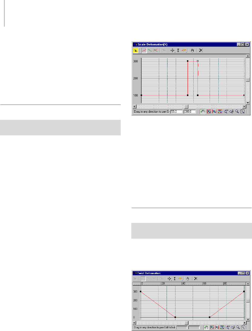
364 Chapter 5: Creating Geometry
Deform Twist (page 1–364)
Deform Teeter (page 1–365)
Deform Bevel (page 1–366)
Deform Fit (page 1–367)
Deformation Dialog (page 1–368)
Deform Scale
Select a Loft object. > Modify panel > Deformations
rollout > Scale
Youcanloftobjectssuchascolumnsandbugles
from a single shape that changes only its scale as it
travels along a path. Use Scale deformation when
you want to make these types of objects.
Tip: By animating scale, a loft object can appear to
travel along a path. Using this technique, you can
create animations in which letters or lines write
themselves onto the screen.
ThesearethepropertiesofScaledeformation
curves:
• The two curves are red for X-axis scaling and
green for Y-axis scaling.
• Default curve values are at 100%.
• Values greater than 100% make the shape larger.
• Values between 100% and 0% make the shape
smaller.
• Negative values scale and mirror the shape.
See Deformation Dialog (page 1–368) for specific
information on the dialog controls.
Scale deformation curve dialog
Procedure
To use Scale deformation:
1. Select a loft object.
2. Click Loft in the modifier stack display.
3. Click Scale on the Deformations rollout.
4. Edit the deformation curves for the X axis and
Yaxis.
Deform Twist
Select a Loft object. > Modify panel > Deformations
rollout > Twist
Twist deformation lets you create objects that
spiral or twist along their length. Twist specifies
the amount of rotation about the path.
Twist deformation curve dialog
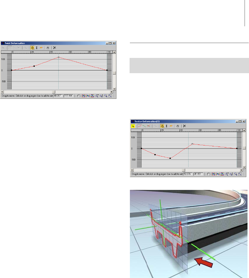
Deform Teeter 365
Using twist to deform the lofted roadway
These are the properties of Twist deformation
curves:
• A single red curve determines shape rotation
about the path.
• The default curve value is 0 degrees of rotation.
• Positive values produce counterclockwise
rotation, when viewed from the start of the
path.
• Negative values produce clockwise rotation.
•Bothtwistdeformationandbankingproduce
rotation about the path. Twist rotation is added
to a shape after the banking angle is applied.
You can use Twist deformation to exaggerate or
reduce the amount of banking.
See Deformation Dialog (page 1–368) for specific
information on the dialog controls.
Procedure
To use Twist deformation:
1. Select a loft object.
2. Click Loft in the modifier stack display.
3. Click Twist on the Deformations rollout.
4. Editthesingledeformationcurvetospecify
rotation about the path.
Deform Teeter
Select a Loft object. > Modify panel > Deformations
rollout > Teeter
Teeter deformation rotates shapes about their local
X axis and Y axis. Teetering is what 3ds Max does
automatically when you select Contour on the Skin
Parameters rollout. Use Teeter deformation when
you want to manually control contour effects.
Teeter deformation curve dialog
Roadway lofted with no teeter
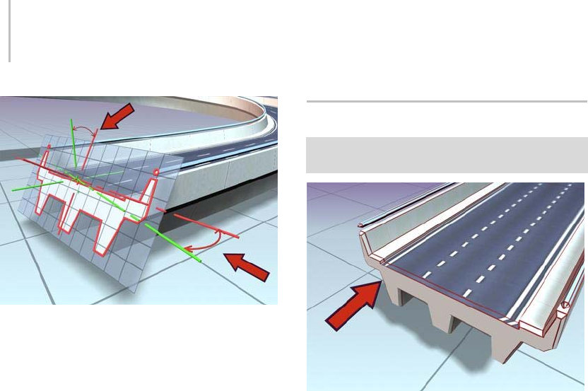
366 Chapter 5: Creating Geometry
Roadway lofted with teeter turned on. Teeter affects the X and
Y axis orientation of the shape in relation to the path.
ThesearethepropertiesofTeeterdeformation
curves:
• The two curves are red for X-axis rotation and
green for Y-axis rotation.
• Default curve values are at 0 degrees rotation.
•Positivevaluesrotatetheshape
counterclockwise about the shape’s
positive axis.
• Negativevaluesrotatetheshapeclockwise
about the shape’s positive axis.
See Deformation Dialog (page 1–368) for specific
information on the dialog controls.
Procedure
To use Teeter deformation:
1. Select a loft object.
2. Click Loft in the modifier stack display.
3. Click Teeter on the Deformations rollout.
4. Edit the deformation curves for X axis and Y
axis rotation.
Deform Bevel
Select a Loft object. > Modify panel > Deformations
rollout > Bevel
Roadway with beveled edges
Nearly every object that you encounter in the
real world is beveled. Because it is difficult and
expensive to manufacture a perfectly sharp edge,
most objects are created with chamfered, filleted,
or eased edges. Use Bevel deformation to simulate
these effects.
Note: Bevelisnotavailablewhenloftoutputisset
to Patch.
ThesearethepropertiesofBeveldeformation
curves:
•Thesingleredcurveisforbevelamount.
• Bevel values are specified in current units.
• The default curve value is 0 units.
• Positive values reduce the shape, bringing it
closer to the path.
• Negativevaluesaddtotheshape,movingit
away from the path.
When shapes are nested, the bevel direction is
reversed for interior shapes.
See Deformation Dialog (page 1–368) for specific
information on the dialog controls.
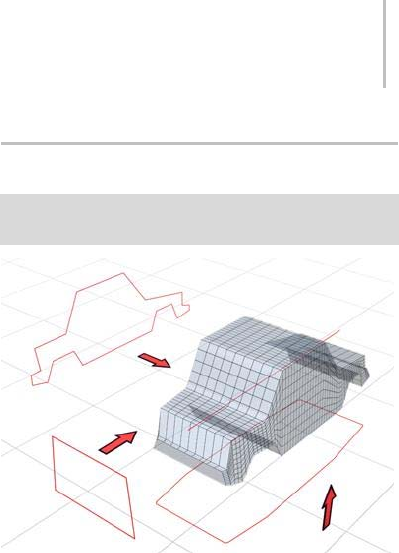
Deform Fit 367
Normal and Adaptive Beveling
The Bevel Deformation dialog provides three
types of beveling: Normal, Adaptive Linear, and
AdaptiveCubic.Theseareavailablefromaflyout
at the right end of the dialog toolbar.
With normal beveling, the beveled shape
remains parallel to the original, regardless of the
crotch angle of the shape. Steep crotch angles
combined with excessive bevel amounts result in
overshooting at the crotch.
Adaptive beveling alters the length of the bevel
shapebasedonthecrotchangle.AdaptiveLinear
alters the length-to-angle in a linear fashion.
Adaptive Cubic alters it more on steep angles than
on shallow angles, producing a subtly different
effect. Both forms of adaptive beveling result in
nonparallel beveled edges, and both are less likely
to produce invalid bevels due to overshoots at the
crotch.
To see the differences in the three types of beveling,
loft a star shape along a straight path and apply
a bevel. When you switch among the three types
of beveling, you’ll see the difference in the bevel
outline. Alter one radius of the star to examine
thebevelingwithshallowandwithsharpcrotch
angles.
Procedure
To use Bevel deformation:
1. Select a loft object.
2. Click Loft in the modifier stack display.
3. Click Bevel on the Deformations rollout.
4. Adjust the deformation curve.
Deform Fit
Select a Loft object. > Modify panel > Deformations
rollout > Fit
Fit curves define a lofted shape.
Fit deformation lets you use two Fit curves to
definethetopandsideprofilesofyourobject.Use
Fitdeformationwhenyouwanttogenerateloft
objects by drawing their profiles.
Fit shapes are really scale boundaries. As your
cross-section shape travels along the path, its X
axis is scaled to fit the boundaries of the X-axis fit
shape and its Y axis is scaled to fit the boundaries
of the Y-axis fit shape.
Note: Fitisnotavailablewhenloftoutputissetto
Patch.
Procedure
To use Fit deformation:
1. Select a loft object.
2. Click Loft in the modifier stack display.
3. Click Fit on the Deformations rollout.
4. Select shapes in the viewport to use as fit curves.
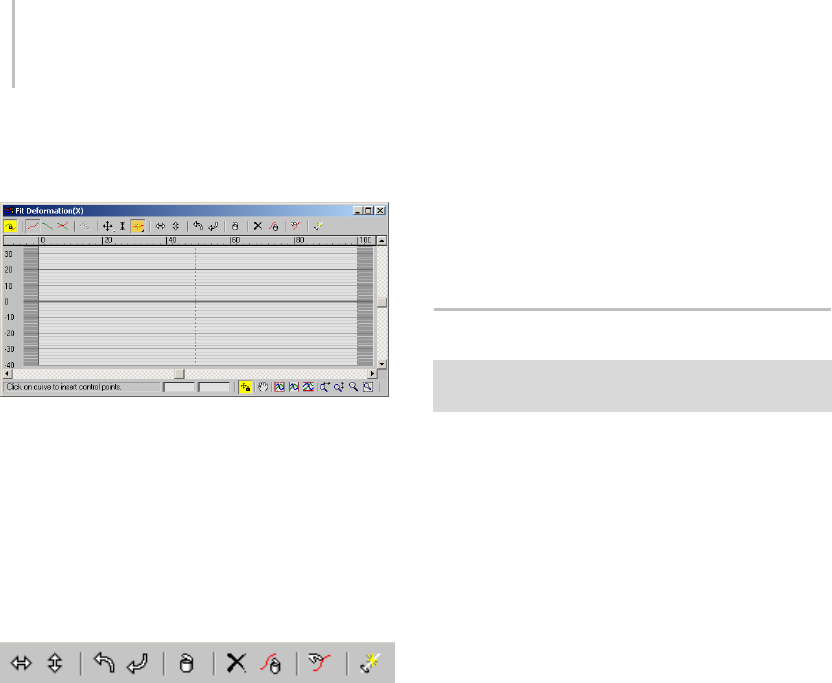
368 Chapter 5: Creating Geometry
Interface
Fit Deformation dialog
The Fit Deformation dialog contains different
buttons than the other deformations. For
descriptions of the first eight buttons on the
toolbar, see Deformation Dialog (page 1–368).The
following descriptions apply to the tools specific to
Fit deformation, and are listed from left to right in
the order they appear on the toolbar.
Fit Deformation toolbar
Mirror Horizontally—Mirrorstheshapeacrossthe
horizontal axis.
Mirror Vertically—Mirrorstheshapeacrossthe
vertical axis.
Rotate 90 CCW—Rotates the shape 90 degrees
counterclockwise.
Rotate 90 CW—Rotates the shape 90 degrees
clockwise.
Delete Control Point—Deletes the selected control
point.
Reset Curve—Replaces the displayed Fit curve with
a rectangle 100 units wide and centered on the
path. If Make Symmetrical is on, both Fit curves
are reset even though only one might be displayed.
Delete Curve—Deletes the displayed Fit curve.
IfMakeSymmetricalison,bothFitcurvesare
deleted even though only one might be displayed.
Get Shape—Lets you select the shape to use for Fit
deformation. Click Get Shape, and then click the
shape to use in a viewport.
Generate Path—Replacestheoriginalpathwitha
new straight-line path.
Deformation Dialog
Select a Loft object. > Modify panel > Deformations
rollout > Scale, Twist, Teeter, Bevel, or Fit
The Deformation dialogs for Scale, Twist, Teeter,
Bevel, and Fit use the same basic layout. The
buttons in the window’s toolbar and prompt area
perform the following functions:
• Changedeformationcurvedisplay.
• Edit control points (these can be animated).
• Navigate the Deformation dialog.
Editing Deformation Curves
A deformation curve starts as a straight line using
a constant value. To produce more elaborate
curves, you insert control points and change their
properties.
Use the buttons in the center of the Deformation
dialog toolbar to insert and change deformation
curve control points (see Interface, later in this
topic).
Control Point Types
Control points on a deformation curve can
produce curves or sharp corners, depending on
the control point type. To change a control point
type, right-click the control point and choose one
of these from the shortcut menu:
•Corner—Non-adjustable linear control point
producing a sharp corner.
•Bezier Corner—Adjustable Bezier control point
with discontinuous tangent handles set to

Deformation Dialog 369
produce a sharp corner. This type produces a
curvethatlookslikethecornertypebuthas
control handles like the Bezier Smooth type.
•Bezier Smooth—Adjustable Bezier control point
with locked continuous tangent handles set to
produce a smooth curve.
Selecting Control Points
Use the Move Control Point and Scale Control
Point buttons with standard selection techniques
to select control points.
Procedures
To drag Bezier tangent handles:
1. SelectoneormoreBezierSmoothorBezier
Corner control points to display their tangent
handles.
2. Click one of the Move Control Point buttons.
3. Drag any tangent handle.
• Only the tangent handle you drag is affected.
Tangent handles on other selected control
points do not change.
• If the tangent handle you drag is part of a
Bezier Smooth control point, both handles
move to maintain the Bezier Smooth type.
• If the tangent handle you drag is part of
a Bezier Corner control point, only that
handle moves.
To move a control point using the Position and
Amount fields:
1. Select a single control point.
2. Do one of the following:
• Move the control point horizontally by
entering a value in the Position field.
• Move the control point vertically by entering
a value in the Amount field.
To change the control point type:
You can change control point types at any time by
right-clicking a selection of one or more control
points.
1. Selectoneormorecontrolpoints.
2. Right-click any selected control point.
3. Choose a control point type from the shortcut
menu.
The following conditions apply to changing
control point types:
• The first and last control points must use the
Corner or Bezier Corner type.
•ConvertingaBezierSmoothpointtoa
Bezier Corner point unlocks the tangent
handles but does not change their position.
The curve appears smooth until you drag
one of the tangent handles.
• Converting a Bezier Corner point or inserted
Bezier point to Bezier Smooth locks the
tangent handles and changes their position
and magnitude. The handles are rotated to
the average between their two angles. The
handle magnitudes are averaged and set
equal.
Interface
Toolbar
Buttons for working with a second curve are
disabled for the Twist and Bevel deformations,
which use only one curve. The disabled buttons

370 Chapter 5: Creating Geometry
areMakeSymmetrical,DisplayXAxis,DisplayY
Axis, Display XY Axes, and Swap Deform Curves.
Make Symmetrical—Yo u c a n a pp l y t h e s a m e
deformation to both axes of a shape using Make
Symmetrical, which is both an action button
and a curve editing mode. Turning on Make
Symmetrical has the following effect:
• When a single curve is displayed, it copies the
displayed deformation curve to the curve for
the hidden axis.
• When both axes are displayed, the Apply
Symmetrydialogisalsodisplayed.Clickthe
button for the curve you want to apply to both
axes.
• Changes you make to the selected curve are
duplicated on the other curve.
When Make Symmetrical is not active, curve
editing is applied only to the selected curve.
Display X Axis/Y Axis/XY Axes—Yo u c a n d i s p l a y
one or both deformation curves using the curve
display buttons near the upper-left corner of the
Deformation dialog.
Turn on the following buttons to display
deformation curves:
•Display X Axis—Displays only the X axis
deformation curve in red.
•Display Y Axis—Displays only the Y axis
deformation curve in green.
•Display XY Axes—Displays X axis and Y axis
deformation curves together, each using its
own color.
Swap Deform Curves—Copies curves between the
X axis and Y axis. This button has no effect when
Make Symmetrical is on.
Click Swap Deform Curves to copy the X axis
curve to the Y axis, and the Y axis curve to the X
axis. It doesn’t matter which curve is currently
displayed or selected.
Move Control Points—This flyout contains three
buttons for moving control points and Bezier
handles:
•Move Control Point—Changes the amount
of deformation (vertical movement) and
the location of the deformation (horizontal
movement).
•Move Vertical—Changes the amount of
deformation without changing the location.
•Move Horizontal—Changes the location of the
deformation without changing the amount.
If one control point is selected, you can move it by
entering values in the control point Position and
Amount fields at the bottom of the Deformation
dialog.
You cannot move end points horizontally.
Intermediate control points are constrained
horizontally to stay between the points on either
side. The amount of horizontal constraint is
determined by the control point type.
• You can move corner control points very close
together, until one is directly above the other.
• You can move Bezier control points no closer
than the length of their tangent handles.
Moving Bezier Tangent Handles—Yo u c a n u s e t h e
Move Control Point buttons to drag a tangent
handle’s angle and magnitude on Bezier Smooth
and Bezier Corner vertices.
Dragging a tangent handle has the following
constraints:
• You cannot move tangent angles beyond
vertical. This prevents deformation curves
from doubling back on themselves.
• You cannot move tangent magnitudes beyond
the preceding or next control point on the path.
Pressing Shift while moving a Bezier Smooth
tangent handle converts the control point to a
Bezier Corner type.

Deformation Dialog 371
Scale Control Point—Scales the value of one or
more selected control points with respect to 0. Use
this function when you want to change only the
deformation amounts of selected control points
while maintaining their relative ratio of values.
•Dragdownwardtoreducevalues.
•Dragupwardtoincreasevalues.
Insert Control Point—This flyout contains buttons
for inserting two control point types.
Insert Corner Point—Click anywhere on a
deformation curve to insert a corner control point
at that location.
Insert Bezier Point—Click anywhere on a
deformation curve to insert a modified Bezier
control point at that location. The tangent handles
of the Bezier control point are set to maintain the
shapeofthecurvebeforethepointwasinserted.
If you are not sure which type of control point
you need, or if you change your mind, you can
convert the point to another type by right-clicking
thepointandselectingthetypefromtheshortcut
menu.
Both Insert Control Point buttons put you in
insertion mode. Right-click or choose another
button to exit the mode.
Delete Control Point—Deletes selected control
points. You can also delete selected points by
pressing the DELETE key.
Reset Curve—Deletes all but the end control points
and sets the curves back to their default values.
Bevel Type—This flyout, available only in the Bevel
Deformation dialog, lets you choose Normal,
Adaptive Linear or Adaptive Cubic as the bevel
type. For more information, see Deform Bevel
(page 1–366).
Deformation grid
TheareaintheDeformationdialogthatdisplays
the deformation curves is called the deformation
grid. This grid charts the value of the deformation
along the length of the path.
These are the main grid components:
Active area—The light-colored area of the grid
defines the first and last vertex boundaries of
the path. The ends of the deformation curve lie
on each boundary and cannot be moved off the
boundary.
Horizontal lines—Mark deformation values on
the vertical scale. The following table lists each
deformation curve type and the meaning of the
deformation values.
Deformation Type Deformation Value
Scale Percentage
Twist Rotation Angle
Teeter Rotation Angle
Bevel Current Units
The thick horizontal line at 0 represents the
deformation value at the loft path.
Vertical lines—Mark levels of the path. The levels
displayed vary with the Adaptive Path Steps setting
on the Skin Parameters rollout (page 1–358).
IfAdaptivePathStepsison,levelsaredisplayedat
all path vertices and shape locations.
IfAdaptivePathStepsisoff,levelsaredisplayed
only at path vertices.
Path ruler—Measures the length of the path. The
valuesontherulermeasurepercentagealongthe
path. You can drag the path ruler vertically in the
Deformation dialog.
Deformation curves—Yo u c a n s e e o n e o r t w o
curves in the Deformation dialog, based on the

372 Chapter 5: Creating Geometry
deformationtypeandthecurvedisplaysetting.
The curves are color-coded by axis.
A red curve displays deformation along the shape’s
local X axis. A green curve displays deformation
alongtheshape’slocalYaxis.
Control Point fields—At the bottom of the
Deformation dialog are two edit fields. When a
single control point is selected these fields display
the path location and deformation amount of the
control point.
Control Point Position—The left field displays the
location of the control point on the loft path as a
percentage of the total path length.
Control Point Amount—The right field displays the
deformation value of the control point.
Deformation Dialog status bar
The Deformation dialogs have their own view
navigation buttons in the lower-right corner.
Thesegiveyoucontrolsforzoomingandpanning
the view of the deformation grid as you edit
the curve values. The status bar also displays
information about the current tool and the selected
control point.
Numeric fields—These two fields are accessible only
if a single control point is selected. The first gives
the point’s horizontal position, and the second
gives its vertical position, or value. You can edit
these fields with the keyboard.
Lock Aspect—This button is present only in the
Fit Deformation dialog. When active, it restricts
zooming to vertical and horizontal at the same
time.
Zoom Extents—Changes the view magnification so
theentiredeformationcurveisvisible.
Zoom Horizontal Extents—Changes the view
magnification along the path length so the entire
path area is visible in the dialog.
Zoom Vertical Extents—Changes the view
magnification along the deformation values so the
entire deformation curve is displayed in the dialog.
Zoom Horizontally—Changes magnification along
the path length.
• Dragtotherighttoincreasemagnification.
• Drag to the left to decrease magnification.
Zoom Vertically—Changes magnification along the
deformation value.
• Drag upward to increase magnification.
• Drag downward to decrease magnification.
Zoom—Changes magnification along both the
path length and the deformation value, preserving
the curve aspect ratio.
• Drag upward to increase magnification.
• Drag downward to decrease magnification.
Zoom Region—Dragaregiononthedeformation
grid. The region is then magnified to fill the
deformation dialog.
Pan—Drag in the view to move in any direction.
Scroll bars—Drag the horizontal and vertical scroll
bars to pan the view in a single direction.
Path Commands
Select a Loft object. > Modify panel > Modifier stack
display > Sub-object level > Path > Path Commands
ThePathCommandsrolloutappearsonlywhen
you are modifying an existing loft object and have
selected Path from the Sub-Object list. The Put
command allows you to make a copy or instance
of the loft path.
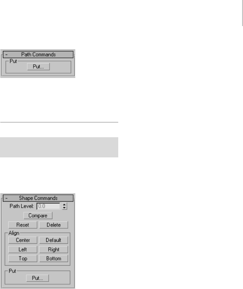
Shape Commands 373
Interface
Put group
Put—Places the path into the scene as a separate
object (as a Copy or Instance).
Shape Commands
Select a Loft object. > Modify panel > Modifier stack
display > Sub-object level > Shape > Shape Commands
rollout
These controls let you align and compare shapes
along the loft path.
Interface
Path Level—Adjuststheshape’spositiononthe
path.
Compare—Displays the Compare dialog (page
1–374) in which you can compare any number of
cross-section shapes.
Reset—Undoes rotation and scale of the shape
performedwiththeSelectandRotateorSelect
and Scale.
Delete—Deletes the shape from the loft object.
Align group
Thesixbuttonsinthisgroupletyoualignthe
selectedshapeinrelationtothepath. Looking
down at a shape from the viewport in which it’s
created, the orientation is left to right along the X
axis, and top to bottom along the Y axis.
Yo u c a n u s e a c o m b i n a t i o n o f t h e s e b u t t o n s
forplacementssuchascorneralignment. The
operations are additive. In other words, you can
use both Bottom and Left to place the shape in the
lower-left quadrant.
Center—Centers the shape on the path, based on
the bounding box of the shape.
Default—Returns the shape to its position when
first placed on the loft path. When you use Get
Shape, the shape is placed so that the path goes
through its pivot point. This is not always the
same as the center of the shape. Therefore, clicking
Center is different than clicking Default.
Left—Alignstheleftedgeoftheshapetothepath.
Right—Aligns the right edge of the shape to the
path.
Top—Alignsthetopedgeoftheshapetothepath.
Bottom—Alignsthebottomedgeoftheshapeto
the path.
Put group
Put—Puts the shape into the scene as a separate
object.
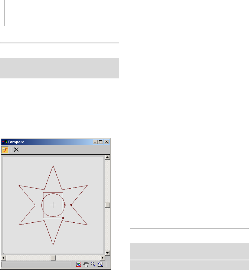
374 Chapter 5: Creating Geometry
Compare Dialog
Select a Loft object. > Modify panel > Modifier stack
display > Sub-object level > Shape > Shape Commands
rollout > Compare button
The Compare dialog lets you compare any number
of cross-section shapes in a loft object for purposes
of making sure their first vertices are properly
aligned. Ifshapes’firstverticesaren’taligned,
unexpected lofting results can occur.
Interface
Pick Shape—Lets you select shapes to display from
the selected loft object. Click the Pick Shape
button in the upper-left corner of the dialog. Then,
in the viewport, select the shapes to display. Select
ashapeasecondtimetoremoveitfromthedisplay.
When you position the mouse cursor over a shape
in the loft object, the cursor image changes to
show whether the shape appears in the dialog
window: a + sign appears if the shape isn’t selected
(indicating that if you select the shape, it will be
added to the dialog window), and a - sign appears
if the shape is already selected.
With each shape, the Compare dialog displays the
first vertex as a small square. For correct lofting,
the first vertices of all shapes on the path need to
be in the same position.
Reset—Removes all shapes from the display.
Dialog controls
You can scroll the Compare dialog with the scroll
bars at the bottom and right sides. You can also use
the buttons in the lower-right corner to perform
View Extents, Pan, Zoom, and Zoom Region
functions.
Align group
WhiletheComparedialogisopen,youcanaffect
the shapes’ positions in the dialog window with the
Shape Commands rollout > Align group buttons.
Turn off Pick Shape, select a shape in the viewport,
and then click the Align group buttons. See Shape
Commands (page 1–373) for further information.
Mesher Compound Object
Create panel > Geometry > Compound Objects > Object
Type rollout > Mesher
Create menu > Compound > Mesher
The Mesher compound object converts procedural
objects to mesh objects on a per-frame basis so
that you can apply modifiers such as Bend or
UVW Map. It can be used with any type of object,
but is designed primarily to work with particle
systems (page 2–237).Mesherisalsousefulfor
low-overhead instancing of objects with complex
modifier stacks.
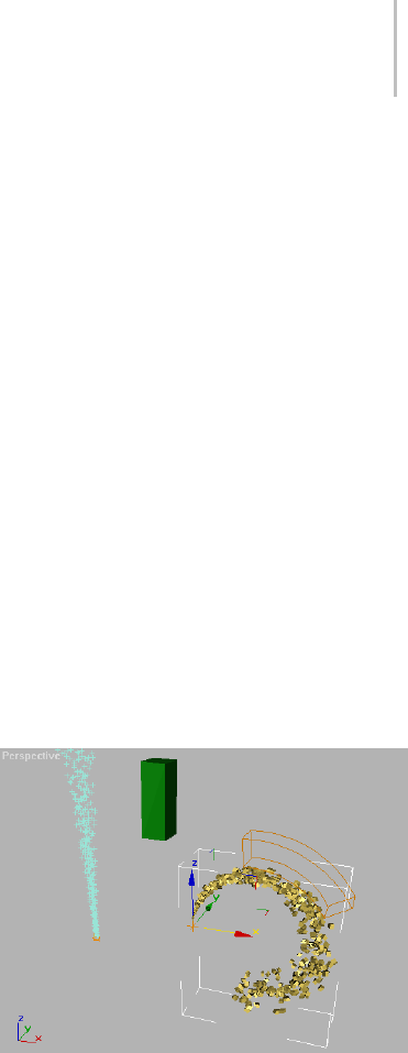
Mesher Compound Object 375
Procedure
To use a Mesher object:
1. Add and set up a particle system.
2. Click the Create panel> Geometry >
Compound Objects > Object Type rollout >
Mesher button.
3. DraginaviewporttoaddtheMesherobject.
The size doesn’t matter, but the orientation
shouldbethesameasthatoftheparticle
system.
4. Go to the Modify panel, click the Pick Object
button, and then select the particle system.
The Mesher object becomes a clone of the
particlesystem,andshowstheparticlesasmesh
objectsintheviewportsnomatterwhatthe
particle system’s Viewport Display setting is.
5. Apply a modifier to the Mesher object, and set
its parameters. For example, you might apply
a Bend modifier and set its Angle parameter
to 180.
6. Play the animation.
Depending on the original particle system and
its settings, as well as any modifiers applied
to the Mesher object, you might be getting
unexpected results. This typically occurs
because the bounding box for the modifier, as
applied to the particle system, is recalculated
at each frame. For example, with a bent Super
Spray particle system set to spread out over
time,astheparticlesstreamawayandseparate,
the bounding box becomes longer and thicker,
potentially causing unexpected results. To
resolvethis,youcanuseanotherobjectto
specify a static bounding box.
7. To use another object’s bounding box to limit
the modified Mesher object, first add and set
up the object. Its position, orientation, and size
are all used in calculating the bounding box.
8. SelecttheMesherobject,andgototheMesher
stack level.
9. In the Parameters rollout, turn on Custom
Bounding Box, click the Pick Bounding box
button, and then select the bounding box
object.
Theparticlestreamusesthenew,static
bounding box.
Tip: Yo u c a n u s e a n y o b j e c t a s a b o u n d i n g b o x ,
so it is often fastest to use the particle system
itself. Movetotheframewheretheparticle
system is the size you want and pick it.
In the following illustration, you can see a Super
Spray particle system (left) and a Mesher object
derived from the Super Spray (right). A Bend
modifier is applied to the Mesher. In the center
isaboxobjectbeingusedasacustombounding
box. The bounding box applied to the Bend
modifier is visible as an orange wireframe when
the modifier is highlighted in the stack.
Using a custom bounding box with a bent particle system
To modify the particles aspect of the Mesher,
edit the original particle system.
To m o d i f y t h e c u s t om b o u n d i n g b o x , m o ve ,
rotate,orscaletheboundingboxobject,and
then reapply it using the Mesher object.
At this point, both particle systems will render.
The original particle system must exist in order

376 Chapter 5: Creating Geometry
to be able to be used by the Mesher object, so
if you want only the Mesher replica to render,
hidetheoriginalsystembeforerendering.
Interface
Parameters rollout
Pick Object—Click this button and then select the
object to be instanced by the Mesher object. After
doingso,thenameoftheinstancedobjectappears
on the button.
Time Offset—The number of frames ahead of
or behind the original particle system that the
Mesher’s particle system will run. Default=0.
Build Only At Render Time—When on, the Mesher
results do not appear in the viewports, but only
when you render the scene. Default=off.
Usethisoptiontoreducetheamountof
computation required for the viewport display.
Update—After editing the original particle system
settings or changing the Mesher Time Offset
setting, click this button to see the changes in the
Mesher system.
Custom Bounding Box—When on, Mesher
replaces the dynamic bounding box derived from
theparticlesystemandmodifierwithastatic
bounding box of the user’s choice.
Pick Bounding Box—To specify a custom bounding
box object, click this button and then select the
object.
Thecustomboundingboxappearsasanorange
wireframe when the modifier is highlighted in the
stack.
Tip: You can use any object as a bounding box, so
it is often fastest to use the particle system itself.
Movetotheframewheretheparticlesystemisthe
size you want and pick it.
(coordinate values)—Displays the coordinates of
theoppositecornersofthecustomboundingbox.
Use All PFlow Events—When on, and you’ve applied
Mesher to a Particle Flow (page 2–109) system,
Mesher automatically creates mesh objects for
every event (page 3–935) in the system.
To use only certain events, turn this off and specify
the events to use with the PFlow Events group
controls (see following).
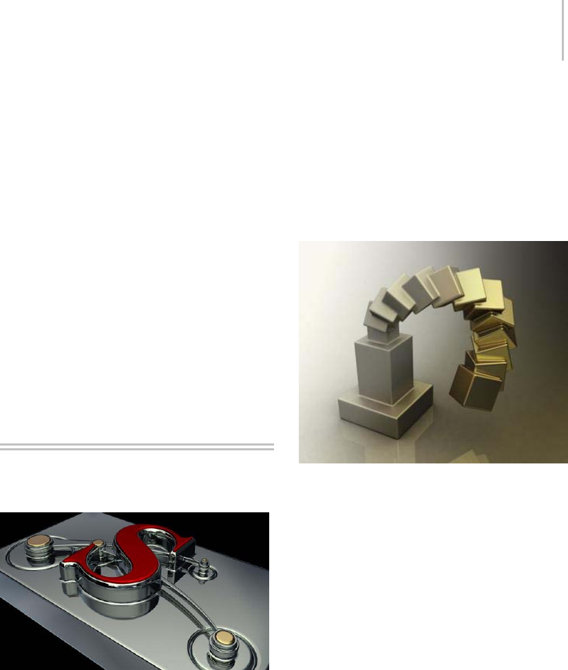
ProBoolean/ProCutter Compound Objects 377
PFlow Events group
When the Mesher object is applied to a Particle
Flow system, use these controls to create meshes
for specific events in the system. Mesher does not
create meshes for the remaining events.
[list box]—Displays all Particle Flow events
currently affected by Mesher.
Add—Lets you specify Particle Flow events to be
affected by Mesher.
If the Mesher object is applied to a Particle Flow
system, when you click Add, an Add PF Events
dialog opens listing all events in the system.
Highlight the events to add, and then click OK.
Theeventsnowappearinthelist.
Remove—Deletes highlighted events from the list.
ProBoolean/ProCutter
Compound Objects
The ProBoolean and ProCutter compound objects
provide you with modeling tools for combining 2D
and3Dshapesinwaysthatwouldbedifficultor
impossible otherwise. The ProBoolean compound
object (page 1–378) takesa3dsMaxmeshandadds
extra intelligence to it prior to performing Boolean
operations. First it combines the topologies, then
it determines coplanar triangles and removes
incident edges. The Booleans are then performed
not on triangles but N-sided polygons. Once the
Boolean operations are completed, the result is
retriangulated and sent back into 3ds Max with
coplanar edges hidden. The result of this extra
work is twofold: The reliability of the Boolean
object is extremely high, and the resulting output
is much cleaner in terms of having fewer small
edges and triangles.
Advantages of ProBoolean over the legacy 3ds Max
Boolean compound object include:
•Better quality mesh - fewer small edges, fewer
narrow triangles.
•Smaller mesh - fewer vertices and faces.
•Easier and faster to use - unlimited objects per
Boolean operation.
•Cleaner-looking mesh -coplanaredges
remain hidden.
•Integrated decimation and quad meshing
In addition, ProCutter (page 1–388) is an excellent
tool for exploding, breaking apart, assembling,
sectioning, or fitting together objects such as a
3D puzzle. See the following illustration for an
example of a goblet shattering.
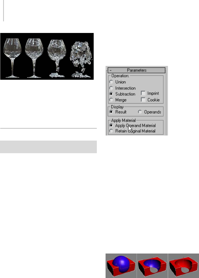
378 Chapter 5: Creating Geometry
See also
ProBoolean Compound Object (page 1–378)
ProCutter Compound Object (page 1–388)
Quad Meshing and Smoothing (page 1–392)
ProBoolean Compound Object
Select an object. > Create panel > Geometry > Compound
Objects > Object Type rollout > ProBoolean
A Boolean object combines two or more other
objectsbyperformingaBooleanoperationor
operations on them. ProBoolean adds a range of
functionality to the traditional 3ds Max Boolean
object, such as the ability to combine multiple
objects at once, each using a different Boolean
operation. ProBoolean can also automatically
subdivide the Boolean result into quadrilateral
faces, which lends itself well to smoothing edges
with MeshSmooth (page 1–722) and TurboSmooth
(page 1–868).
Materials, Textures, Vertex Colors
ProBoolean and ProCutter transfer texture
coordinates, vertex colors, optionally materials,
and maps from the operands to the final results.
You can choose to apply the operand material to
the resulting faces, or you can retain the original
material. If one of the original operands had
material maps or vertex colors, the resulting
faces derived from that operand maintain those
graphical attributes. However, when texture
coordinates or vertex colors are present, it is
impossible to remove coplanar faces, so the
resulting mesh quality will be lower. We suggest
that you apply textures after the ProBoolean
operations.
ProBoolean provides two options for applying
materials. You can see these two options in the
Apply Material group on the Parameters panel
(see above illustration). The default choice is
Apply Operand Material. This option applies the
operand material to the resulting faces. Choosing
Retain Original Material causes the resulting faces
to use the material of the first selected object in
the Boolean operation.
You can see the difference in the following
illustration. The Boolean operation starts with
a red box and a blue sphere. The box is used as
thebaseobjectandthesphereisthesubtracted
operand. Using the default Apply Operand
Material option gives the result shown in the center
of the illustration. Choosing Retain Original
Material yields the result shown on the right side
of the illustration.

ProBoolean Compound Object 379
Supported Boolean Operations
ProBoolean supports Union, Intersection,
Subtraction, and Merge. The first three operations
work similarly to their counterparts in the
standard Boolean compound object. The Merge
operation intersects and combines two meshes
without removing any of the original polygons.
This can be useful for cases in which you need to
selectively remove parts of the mesh.
Also supported are two variants of the Boolean
operations: Cookie Cutter and Imprint. Cookie
Cutter performs the specified Boolean operation
butdoesnotaddthefacesfromtheoperandsinto
the original mesh. It can be used to cut a hole
in a mesh or to get the portion of a mesh inside
of another object. The Imprint option inserts
(imprints) the intersection edges between the
operands and the original mesh without removing
or adding faces. Imprint only splits faces and adds
new edges to the mesh of the base object (original
selected object).
Editing the Boolean Object
When you access a ProBoolean or ProCutter object
from the Modify panel, you can add operands
totheexistingset. Youcanalsoremoveand
transform (move, rotate, etc.) operands.
Polygon Reduction
ProBoolean and ProCutter have a built-in
decimation function. Typically, decimation is of
better quality if it is integrated with the Boolean
operations.ThereasonforthisisthattheBoolean
object contains meta-information about which
edges are intersection edges. The decimation
function takes this information into account and
uses it to properly maintain intersection edges.
Text, Lofts and NURBS
When performing Boolean operations with text
objects (page 1–278),makesurecharactersdon’t
intersect each other and that each letter is closed.
Also, it’s easy to inadvertently create loft objects
(page 1–352) and NURBS objects (page 1–1078) in
such a way as to have self-intersections. With loft
objects, check the ends and points where the loft
curve bends.
See also
ProCutter Compound Object (page 1–388)
Procedures
To create a ProBoolean compound object:
1. Set up objects for the Boolean operation. For
example, to subtract spherical shapes from a
box, create the box and spheres and arrange the
spheres so that their volumes intersect the box
where the subtractions should take place.
2. Select the base object. In the example in step 1,
you would select the box.
3. On the Create panel > Geometry section,
choose Compound Objects from the
drop-down list, and then click ProBoolean.
4. On the Parameters rollout, choose the type of
Boolean operation you want to use: Union,
Intersection, Subtraction, etc. Also choose
how the software will transfer the next operand
you pick into the Boolean object: Reference,
Copy, Move, or Instance. You can also choose
to retain the original material, or keep the
default Apply Material choice: Apply Operand
Material.
5. Click the Start Picking button.
6. Pickoneormoreobjectstoparticipateinthe
Boolean operation.
7. As you pick objects, you can also change,
for each newly picked object, the Boolean
operation (Merge, etc.) and options (Cookie
or Imprint), as well as how the next operand is
transferred to the Boolean (Reference, Copy,
etc.) and the Apply Material choice. You
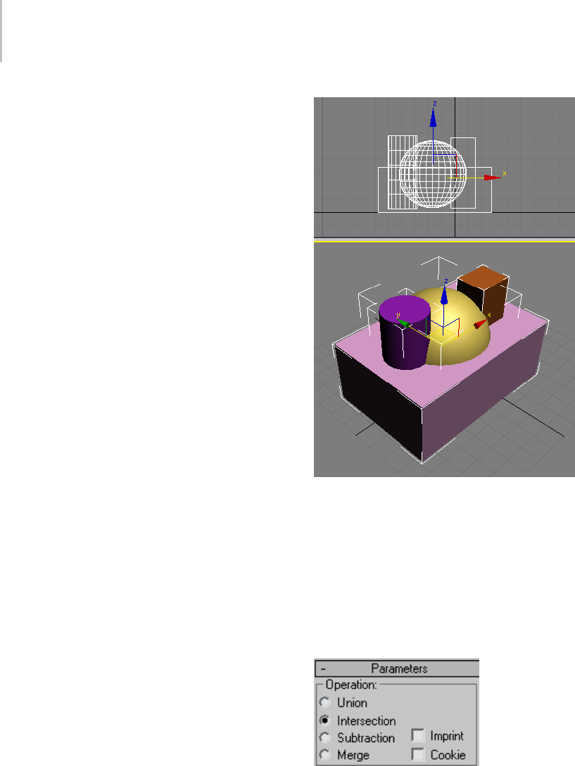
380 Chapter 5: Creating Geometry
can continue picking operands as long as the
Start Picking button stays pressed in. Each of
the objects you pick is added to the Boolean
operation.
When the Modify panel is active, you can
add objects to a selected ProBoolean object
by clicking the Start Picking button and then
pickingtheobjectstoadd.
Example: To change an existing Boolean with
sub-object operations:
ProBoolean offers a great deal of flexibility
in combining various Boolean operations
simultaneously, plus the ability to change the way
operands combine both as you build the Boolean
object and after the fact.
1. Startbyaddingabox,asphere,asmaller
box, and a cylinder, as shown in the following
illustration.
Top: Front viewport
Bottom: Perspective viewport
2. Select the box.
3. On the Create panel > Geometry section,
choose Compound Objects from the
drop-down list, and then click ProBoolean.
4. On the Parameters rollout, in the Operation
group, choose Intersection.
5. On the Pick Boolean rollout, click Start Picking,
and then click the sphere.
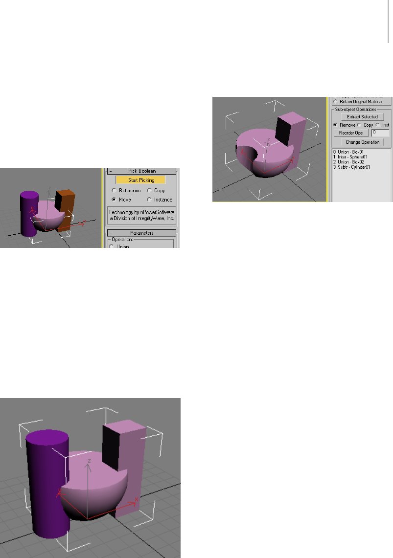
ProBoolean Compound Object 381
The result is the intersection of the sphere and
thebox;thatis,asingleobjectthatrepresents
the common volume both objects occupy. In
this case, it’s the overlap of the sphere and the
box. Although neither has a material at this
point, the result uses the default color originally
assigned by the software, at random, to the box
when it was created.
Note that Start Picking stays active (yellow).
This means you can continue picking objects to
incorporate into the Boolean object, optionally
changing the operation as you go.
6. Set Operation to Union, and then click the
small box.
The result is the union (adding) of the small
box with the intersection of the sphere and
larger box. Again, the original object’s color is
assigned to the result.
7. Set Operation to Subtraction, and then click
the cylinder.
Thecylinder’sintersectingvolumeissubtracted
from the previous Boolean result.
Note that the entire history of operands
and operations used to build the Boolean
object is listed in the hierarchy view list at
the bottom of the Parameters rollout. Box01
starts the Boolean with Union, Sphere01 is
then incorporated with Intersection, Box02
is incorporated with Union, and finally
Cylinder01 is incorporated with Subtraction.
Note: The operation for the first object in the
list has no effect on the Boolean object, but if
you move it to another position in the list it
does. You’ll see an example of this at the end of
this exercise.
You can use the list and the other controls in
the Sub-object Operations group to change the
results.
8. In the list, highlight the Subtr - Cylinder01
entry, and then set Operation to Union.
9. In the Sub-object Operations group, click the
Change Operation button.
As a result of the change of operation, the
cylinder appears in the Boolean object as an
additive volume instead of a subtractive one.
Also, its entry in the list changes to “Union
- Cylinder01”, showing that the Boolean
operation for the cylinder is now Union.
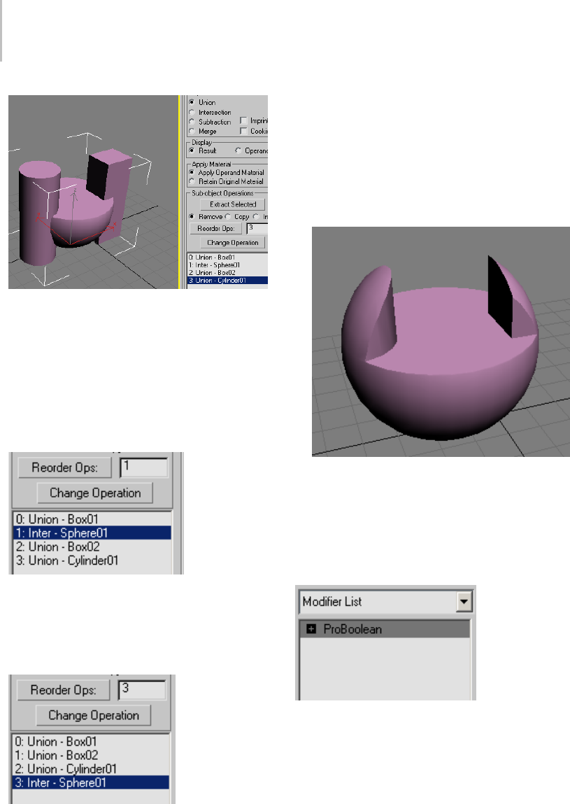
382 Chapter 5: Creating Geometry
You can also change the order of the operations,
which can affect the results.
10.In the list, click the Union - Cylinder01 entry to
remove the highlighting, and then highlight the
entry 1: Inter - Sphere01.
Note that its position in the list, 1, appears in the
editable field next to the Reorder Ops button.
11.Change the value in the field from 1 to 3,and
then click the Reorder Ops button.
The Inter - Sphere01 item jumps to the end of
the list.
The Boolean object changes significantly. The
new order in the list tells you how this shape was
achieved: The two boxes and the cylinder were
all combined with Union, adding their volumes
together, and then the sphere was incorporated
into that result with Intersection, leaving only
the volume shared by all four objects.
Interface
Modifier stack
With an unmodified ProBoolean object selected,
the modifier stack shows a single, expandable
entry: ProBoolean.
Expandingthisentry(byclickingthe+icon)
reveals a single subsidiary branch: Operands.
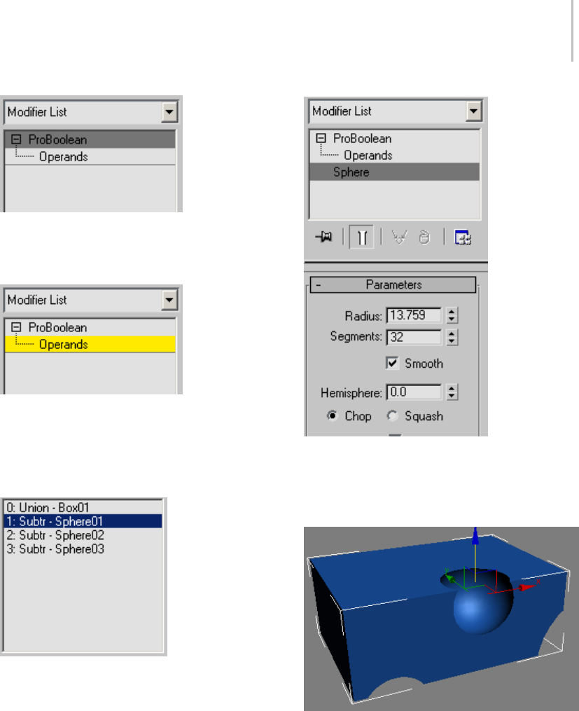
ProBoolean Compound Object 383
To transform operands in the ProBoolean
object independent of the entire object, click the
Operands branch to highlight it.
You can then select one or more operands, either
by using standard selection methods in the
viewport, or by highlighting their names in the
hierarchy view (page 1–386) list at the bottom of
the Parameters rollout.
When one, and only one, operand is selected, the
object type (not its name) appears as a separate
stack entry below the ProBoolean entry. Clicking
this entry provides direct access to the operand’s
parameters on the Modify panel.
If Parameters rollout > Display is set to Result,
selecting an operand displays the operand’s
axis tripod or transform gizmo in the viewport,
although the operand itself is not visible by default.
To view the operand, set Parameters rollout >
Display to Operands.
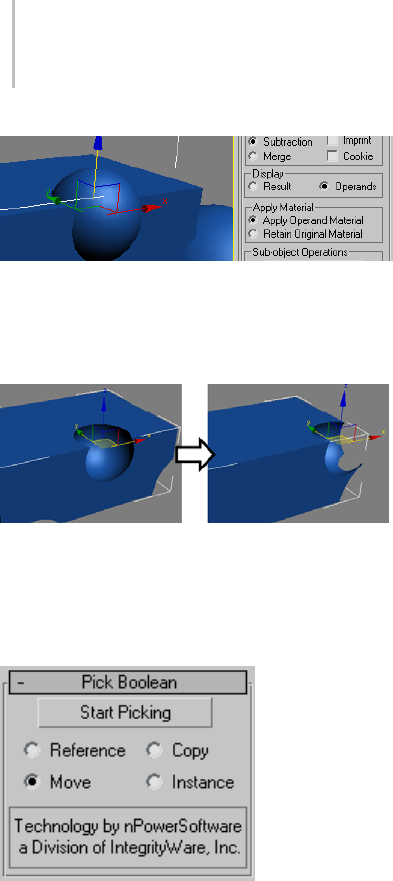
384 Chapter 5: Creating Geometry
Whetherornottheoperandsarevisible,youcan
transform and animate them at the Operands
sub-object level, as with any other object in
3ds Max.
You can also transform and animate the base
object; that is, the first object in the hierarchy view
list.
Pick Boolean rollout
Start Picking—Click this and then click each
operand to transfer to the Boolean object in turn.
Before picking each operand, you can change
the Reference/Copy/Move/Instance choice, the
Operation options, and the Apply Material choice.
Tip: When you’re adding many operands to
a Boolean object using the default settings,
calculating the result each time you pick an object
canslowdowntheprocess.Tomaintainoptimum
feedback, set Parameters rollout > Display to
Operands. Then, when you’re finished, set it back
to Result. Alternatively, on the Advanced Options
rollout set Update to Manually, and then click the
Update button to view the results after performing
the Boolean operations.
Choose a radio button to specify how the next
operand you pick is transferred to the Boolean
object:
•Reference—The Boolean operation uses a
reference (page 3–1002) to the picked operand,
so the object remains after being incorporated
into the Boolean object. Future modifications
to the originally picked object will also modify
theBooleanoperation. UseReferenceto
synchronize modifier-induced changes to the
original operand with the new operand, but not
vice-versa.
•Copy—The Boolean operation uses a copy of
the picked operand. The selected object is
unaffected by the Boolean operation, but a copy
of it participates in the Boolean operation.
•Move—The picked operand becomes part of the
Boolean operation and is no longer available
as a separate object in the scene. This is the
default choice.
•Instance—The Boolean operation makes an
instance (page 3–957) of the selected object.
Future modifications of the selected object will
also modify the instanced object participating
in the Boolean operation and vice-versa.
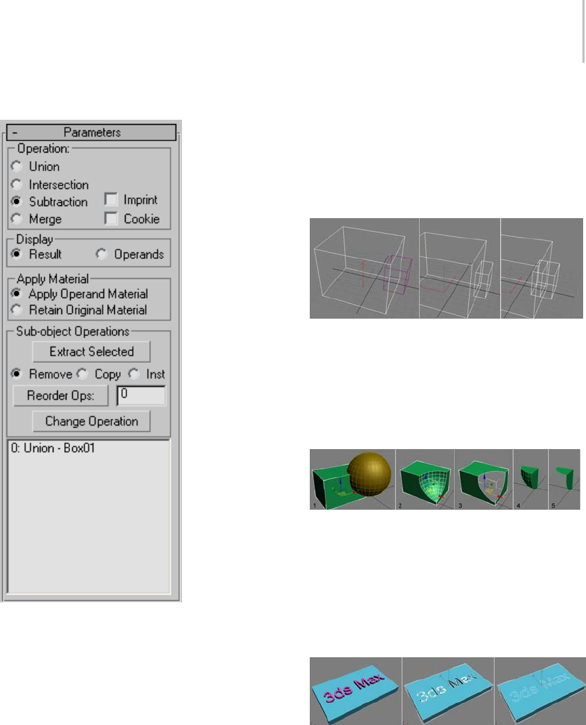
ProBoolean Compound Object 385
Parameters rollout
Operation group
These settings determine how the Boolean
operands interact physically.
Union—Combines two or more separate entities
into a single Boolean object.
Intersection—Creates a "new" object from the
physical intersection between the original objects;
the non-intersecting volumes are removed.
Subtraction—Removes the volume of a selected
object from the original object.
Merge—Combines objects into a single object
without removing any geometry. New edges are
created where the objects intersect.
Note: In the following illustration, the display
property Backface Cull was turned off so that all
edges are visible.
Left: Original object (box) and operand (small box)
Center: Union operation; part of the smaller box is removed.
Right: Merge operation, showing new edges at intersection
Cookie—Cuts the faces of the original mesh shape,
affecting only those faces. The faces of the selected
operand are not added to the Boolean result.
1. Original object (box) and operand (sphere)
2. Standard Subtraction operation
3. Subtraction with Cookie on
4. Standard Intersection operation
5. Intersection with Cookie on
Imprint—Prints the outline of the shape (or
intersection edges) onto the original mesh object.
Left: Original object (box) and operand (text)
Center: Standard Subtraction operation
Right:SubtractionwithImprint
Note: The result of the Imprint operation is always
the same; the main Operation choice has no effect
on it.

386 Chapter 5: Creating Geometry
Display—Choose one of the following display
modes:
•Result—Displays only the result of the Boolean
operations, not the individual operands.
Choosing Result also activates the ProBoolean
level in the modifier stack (page 1–382).
•Operands—Displays the operands that define
the Boolean result. Use this mode to edit the
operands and modify the result.
Choosing Operands also activates the Operands
level in the modifier stack (page 1–382).
Also,whenpickingmanyoperands,usethis
mode to avoid having to recalculate the result
each time, and then set Display back to Result
at the end.
Apply Material—Choose one of the following
material application modes:
•Apply Operand Material—New faces created by
the Boolean operation acquire the material of
the operand.
•Retain Original Material—New faces created by
the Boolean operation retain the material of the
original object.
Sub-object Operations group
These functions operate on operands highlighted
in the hierarchy view list (see following).
Note: Fortheseoperations,youneednotbeatthe
Operands sub-object level in the modifier stack.
Extract Selected—Based on the chosen radio
button (Remove, Copy, or Inst; see following),
Extract Selected applies the operation to the
highlighted operand in the hierarchy view list.
Three modes of extraction are available:
•Remove—Removes the operand or operands
highlighted in the hierarchy view list from
the Boolean result. It essentially undoes the
addition of the highlighted operand(s) to
the Boolean object. Each extracted operand
becomes a top-level object again.
•Copy—Extracts a copy of the operand or
operands highlighted in the hierarchy view
list. The original operand remains part of the
Boolean result.
•Inst—Extracts an instance of the operand or
operands highlighted in the hierarchy view list.
Subsequent modifications to this extracted
operand also modify the original operand, thus
affecting the Boolean object.
Reorder Ops—Changes the ordering of the
highlighted operand in the hierarchy view list. The
reordered operand is moved to the position listed
in the text field next to the Reorder Ops button.
Change Operation—Changes the type of operation
(see Operation group (page 1–385))forthe
highlighted operand. To change the operation
type, highlight the operand in the hierarchy view,
thenchoosetheoperationtyperadiooption,and
then click Change Operation.
Hierachy View
The hierarchy view, found at the bottom of the
Parameters rollout, displays a list of all of the
Boolean operations that define the selected mesh.
Each time you perform a new Boolean operation,
the software adds an entry to the list.
You can highlight operands for modification
by clicking them in the hierarchy view list. To
highlight multiple contiguous items in the list,
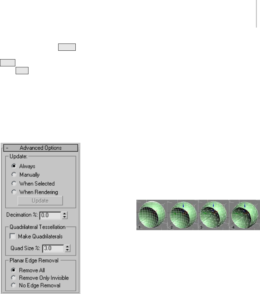
ProBoolean Compound Object 387
click the first, and then Shift +click the last. To
highlight multiple non-contiguous entries, use
Ctrl +click. To remove highlighting from a list
entry, Alt +click the highlighted item.
At the ProBoolean level in the modifier stack,
you can perform only sub-object operations (page
1–386) on highlighted items. At the Operands
sub-object level, you can transform highlighted
operands as well as perform sub-object operations;
see Modifier stack (page 1–382) for details.
Advanced Options rollout
Update group
Theseoptionsdeterminewhenupdatesare
performed on the Boolean object after you make
changes. Choose one of the following:
•Always—Updates occur as soon as you make
changes to the Boolean object.
•Manually—Updates occur only when you click
the Update button.
•When Selected—Updates occur whenever the
Boolean object is selected.
•When Rendering—Updates are applied to the
Boolean object only at render time, or when
you click Update.
Update—Applies changes to the Boolean object.
Available with all options except Always.
Note: When you first create a ProBoolean object
with Manually or When Rendering active, no
operands, including the base object, are visible
until you update at least once. Thereafter, the
base object is visible, but no subsequently picked
operands are until you update again.
Decimation %—The percentage of edges to remove
from the polygons in the Boolean object, thus
reducingthenumberofpolygons.Forexample,a
Decimation % setting of 20.0 removes 20 percent
of the polygon edges.
1. Decimation %=0.0
2. Decimation %=30.0
3. Decimation %=60.0
4. Decimation %=80.0
Quadrilateral Tessellation group
These options enable quadrilateral tessellation of
the Boolean object. This makes the object suitable
for editing subdivision surfaces (page 1–963) and
for smoothing meshes. It also makes the object
suitable for conversion to Editable Poly format.
For further discussion of this option, see the topic
Quad Meshing and Smoothing (page 1–392).
Make Quadrilaterals—When on, changes the
tessellation of the Boolean object from triangles to
quadrilaterals.

388 Chapter 5: Creating Geometry
Note: When Make Quadrilaterals is on, the
Decimation setting has no effect.
Quad Size %—Determines the size of the
quadrilaterals as a percentage of the overall
Boolean object length.
Planar Edge Removal group
This option determines how the polygons on
planar faces are handled. Choose one of the
following:
•Remove All—Removes all extra coplanar edges
on a face such that the face itself will define the
polygon.
•Remove Only Invisible—Removes invisible edges
on each face.
•No Edge Removal—No edges are removed.
ProCutter Compound Object
Select an object. > Create panel > Geometry > Compound
Objects > Object Type rollout > ProCutter
The ProCutter Compound object lets you perform
specialized Boolean operations, primarily for the
purpose of breaking apart or subdividing volumes.
The results of ProCutter operations are particularly
suitable for use in dynamics simulations where an
object explodes or is shattered by impact with a
force or another object.
Following is a list of ProCutter features:
• Break apart a stock object into elements of an
editable mesh or into separate objects using
cutters that are either solids or surfaces.
• Use one or more cutters on one or more stock
objects at the same time.
• Perform a volume decomposition of a set of
cutter objects.
•Useasinglecuttermanytimeswithout
maintaining the history.
See also
ProBoolean Compound Object (page 1–378)
Procedure
To use ProCutter:
1. Select an object to use as a cutter.
2. Activate the ProCutter compound object.
3. On the Cutter Picking Parameters rollout, click
Pick Cutter Objects, and then select additional
cutters.
4. On the Cutter Picking Parameters rollout, click
Pick Stock Objects, and then select objects to
be cut by the cutter objects.
5. In the Cutter Parameters rollout > Cutter
Options group, choose the parts of the originals
you wish to keep: Stock Outside Cutters, Stock
Inside Cutters, Cutters Outside Stock.
6. To get separate objects to manipulate or
animate, collapse the result to an Editable Mesh
(page 1–996) object and use the Explode tool set
to 180.0. Alternatively, use Auto Extract Mesh
and Explode By Elements, described below.
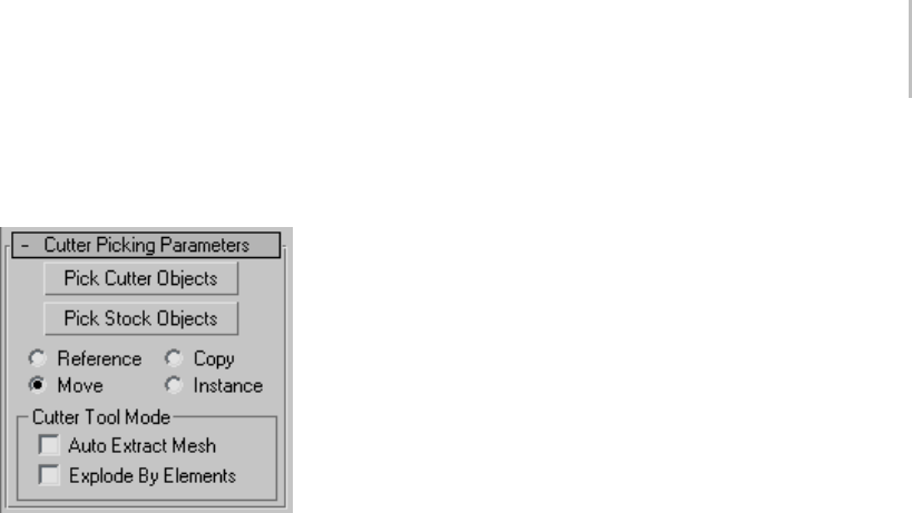
ProCutter Compound Object 389
Interface
Cutter Picking Parameters rollout
Pick Cutter Objects—When on, objects you select
are designated as cutters, used to subdivide stock
objects.
Pick Stock Objects—When on, objects you select
are designated as stock objects; that is, objects that
are subdivided by cutters.
Choose a radio button to specify how the next
object you pick is transferred to the ProCutter
object:
•Reference—The Boolean operation uses a
reference (page 3–1002) to the picked operand,
so the object remains after being incorporated
into the Boolean object. Future modifications
to the originally picked object will also modify
the Boolean operation. Use Reference to
synchronize modifier-induced changes to the
original operand with the new operand, but not
vice-versa.
•Copy—The Boolean operation uses a copy of
the picked operand. The selected object is
unaffected by the Boolean operation, but a copy
of it participates in the Boolean operation.
•Move—The picked operand becomes part of the
Boolean operation and is no longer available
as a separate object in the scene. This is the
default choice.
•Instance—The Boolean operation makes an
instance (page 3–957) of the selected object.
Future modifications of the selected object will
also modify the instanced object participating
in the Boolean operation and vice-versa.
Cutter Tool Mode group
These options let you use the cutter as a sculpting
tool, cutting the same object repeatedly in different
places. You can also get separate objects without
having to go through Editable Mesh conversion.
Auto Extract Mode—Automatically extracts the
result when you select a stock object. It does not
maintain the stock as a sub-object, but edits it and
replaces the object with the result of the cut. This
lets you quickly cut, move the cutter, and cut again.
Explode By Elements—When Auto Extract is on,
detaches each element into a separate object
automatically.HasnoeffectwhenAutoExtract
is off.
This convenient option makes it unnecessary to
converttheProCutterobjecttoEditableMesh
format and then use Explode, as mentioned in
this procedure (page 1–388).Thisisusefulwhen
cutting up an object. For example, you could use it
to slice a loaf of bread. You use the cutter to cut a
pieceoff,movethecutter,andthencutagain.
Parameters rollout
You can choose any combination of the three
cutting options to get the desired result. If you
have non-closed meshes, the orientation of the
mesh might determine which part of the stock is
considered to be inside or outside the cutter.
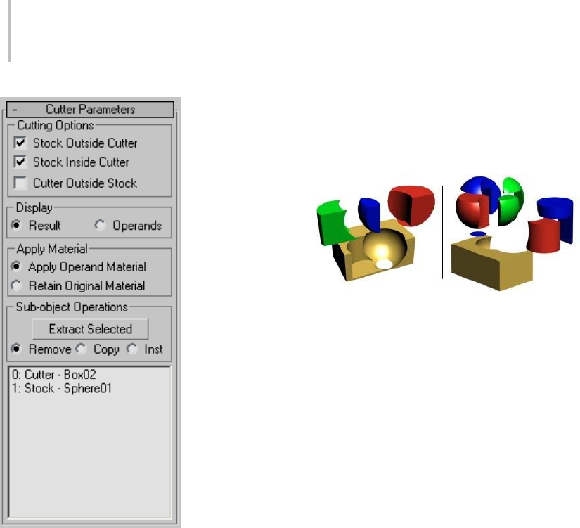
390 Chapter 5: Creating Geometry
Stock Outside Cutter—The result contains the parts
of the stock outside of all of the cutters. This option
givesyouasimilarresulttoaBooleansubtraction
of the cutters from the stock objects. The gold part
of the object in the following illustration results
from this option.
Stock Inside Cutter—The result contains the parts
of the stock inside one or more cutters. This option
gives you similar results to a Boolean intersection
of the cutters and the stock objects. There is
some difference because each cutter is treated
individually. The green, blue and red parts of the
object on the left side of the following illustration
are the results of this option.
Cutters Outside Stock—The result contains the
parts of the cutters that are not inside the stock
objects. Note that the cutters will cut each other if
they intersect also. You can see in the following
illustration. The parts on the right side of the
following illustration that are not present on the
left side are results of this option.
Cylinder and sphere as cutters and box as stock
Left: Keeping stock inside and outside cutters
Right: Keeping stock inside/outside cutters and cutters outside
stock
Display—Choose one of the following display
modes:
•Show Result—Displays the result of the Boolean
operations.
•Show Ops—Displays the operands that define
the Boolean result. Use this mode to edit the
operands and modify the result.
Apply Material—Choose one of the following
material application modes:
•Apply Operand Material—New faces created by
the Boolean operation acquire the material of
the operand.
•Retain Original Material—New faces created by
the Boolean operation retain the material of the
original object.
Sub-object Operations group
These functions operate on operands highlighted
in the hierarchy view list (see following).
Extract Selected—Based on the chosen radio
button (Remove, Copy, or Inst; see following),
Extract Selected applies the operation to the
highlighted operand in the hierarchy view list.
Three modes of extraction are available:
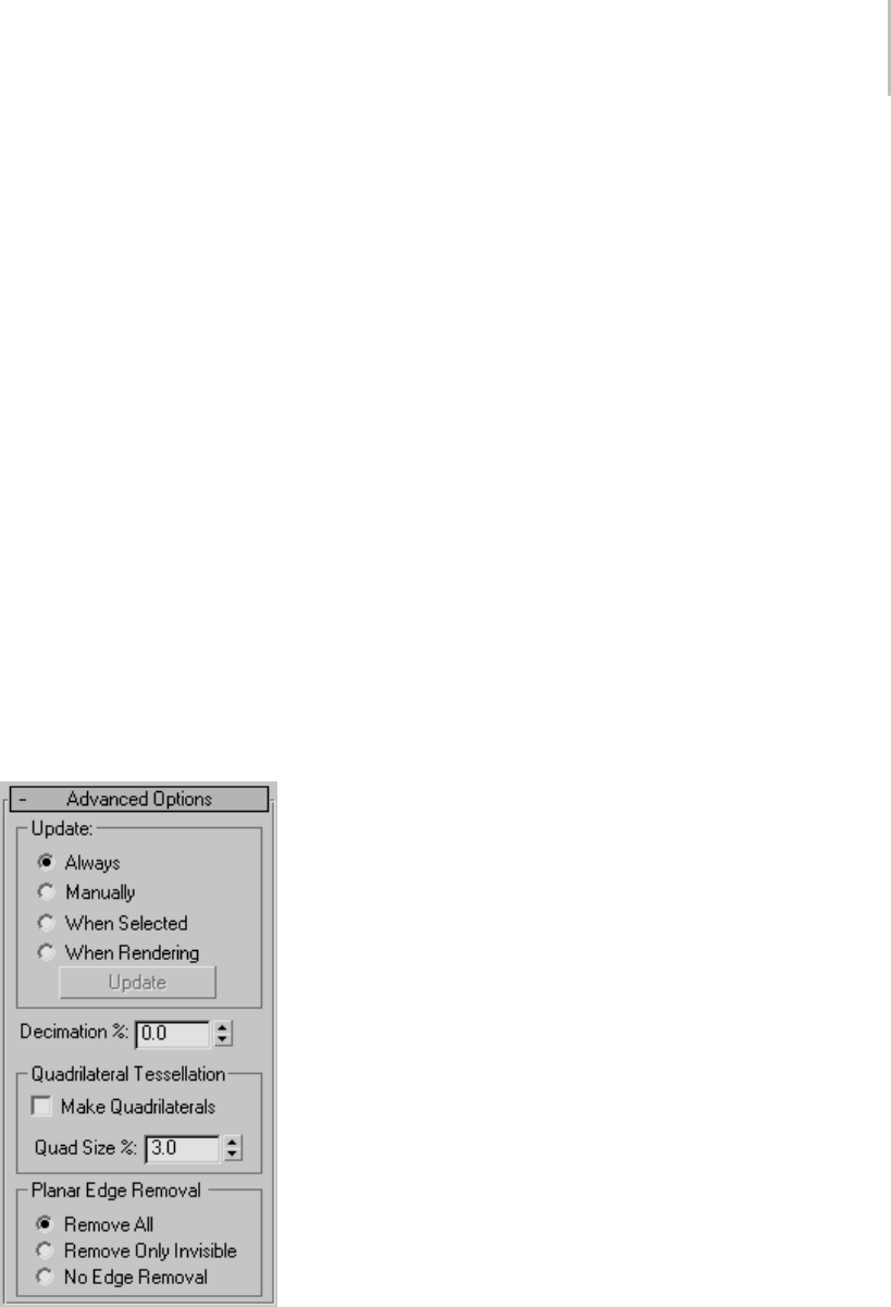
ProCutter Compound Object 391
•Remove—Removes the operand or operands
highlighted in the hierarchy view list from
the Boolean result. It essentially undoes the
addition of the highlighted operand(s) to
the Boolean object. Each extracted operand
becomes a top-level object again.
•Copy—Extracts a copy of the operand
highlighted in the hierarchy view list. The
original operand remains part of the Boolean.
•Inst—Extracts an instance of the operand
highlighted in the hierarchy view list.
Subsequent modifications to this extracted
operand also modify the original operand, thus
the Boolean object.
Hierachy View
The hierarchy view displays a list of all operands:
cutters and stock objects. You can select and
editobjectsusingthehierarchyview,aswith
ProBoolean.
Advanced Options rollout
Update group
Theseoptionsdeterminewhenupdatesare
performedontheBooleanobjectafteryoumake
changes. Choose one of the following:
•Always—Updates occur as soon as you make
changes to the Boolean object.
•Manually—Updates occur only when you click
the Update button.
•When Selected—Updates occur whenever the
Boolean object is selected.
•When Rendering—Updates are applied to the
Boolean object only at render time, or when
you click Update.
Update—Applies changes to the Boolean object.
Available with all options except Always.
Note: When you first create a ProCutter object with
Manually or When Rendering active, no operands,
including the base object, are visible until you
update at least once. Thereafter, the base object is
visible, but no subsequently picked operands are
until you update again.
Decimation %—The percentage of edges to remove
from the polygons in the Boolean object, thus
reducingthenumberofpolygons.Forexample,a
Decimation % setting of 20.0 removes 20 percent
of the polygon edges.
Quadrilateral Tessellation group
Make Quadrilaterals—When on, changes the
tessellation of the Boolean object from triangles
to quadrilaterals. This makes the object suitable
for editing subdivision surfaces (page 1–963) and
for smoothing meshes. It also makes the object
suitable for conversion to Editable Poly format.
Quad Size %—Determines the size of the
quadrilaterals as a percentage of the overall
Boolean object length.
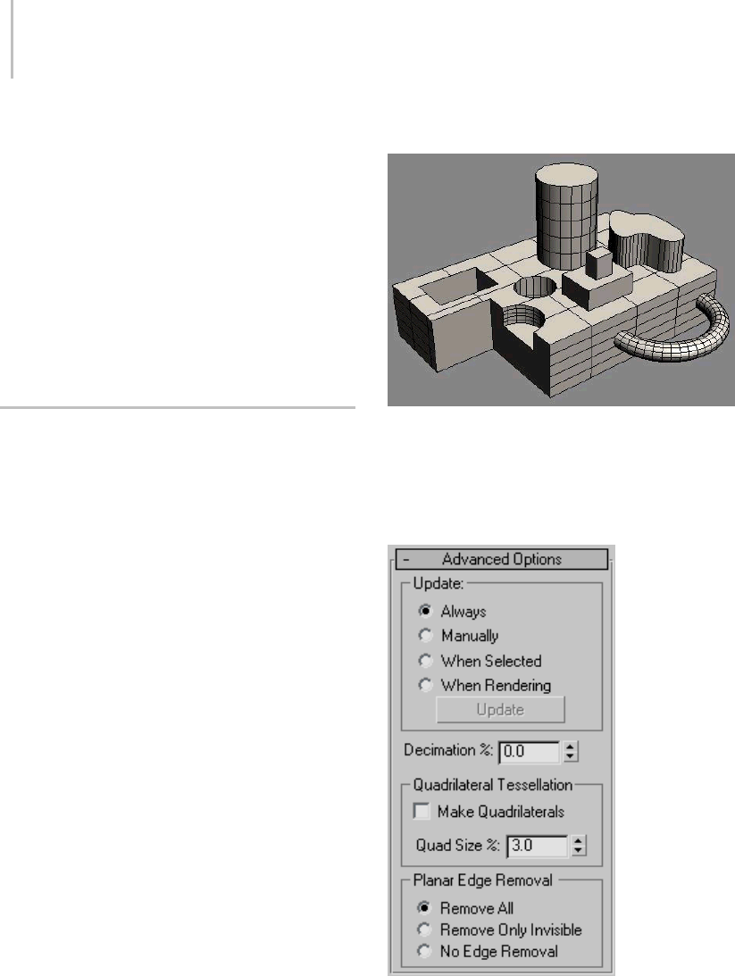
392 Chapter 5: Creating Geometry
Planar Edge Removal group
This option determines how the polygons on
planar faces are handled. Choose one of the
following:
•Remove All—Removes all extra coplanar edges
on a face such that the face itself will define the
polygon.
•Remove Only Invisible—Removes invisible edges
on each face.
•No Edge Removal—No edges are removed.
Quad Meshing and Smoothing
ProBoolean and ProCutter can re-mesh
planar surfaces using a quadrilateral meshing
algorithm. This capability, in combination with
thesubdivisionsurfacetoolsinMeshSmooth,
TurboSmooth, and Editable Poly, can produce
dramatic results.
Itdoesrequiresomelevelofexpertiseto
understand what is possible and how to achieve
the best results using the quadrilateral tessellation.
This topic shows the basics of how to use quad
meshing and also contains tips and tricks about
what works and how it works.
Tip: You can apply quadrilateral tessellation to a
mesh object without necessarily performing an
actual Boolean operation on it. First create an
additional object that’s not touching the object you
want to tessellate. Select the object to tessellate,
apply ProBoolean, turn on Make Quadrilaterals,
and then subtract the other object. You can
then collapse the tessellated object to Editable
Mesh/Poly if you like.
Quad Meshing Basics
ProBoolean of an object containing several primitives
To make a quadrilateral mesh, select a ProBoolean
or ProCutter object, go to the Modify panel, and
expand the Advanced Options panel as shown
following.
To get a result similar to the following illustration,
turn on Make Quadrilaterals check box:
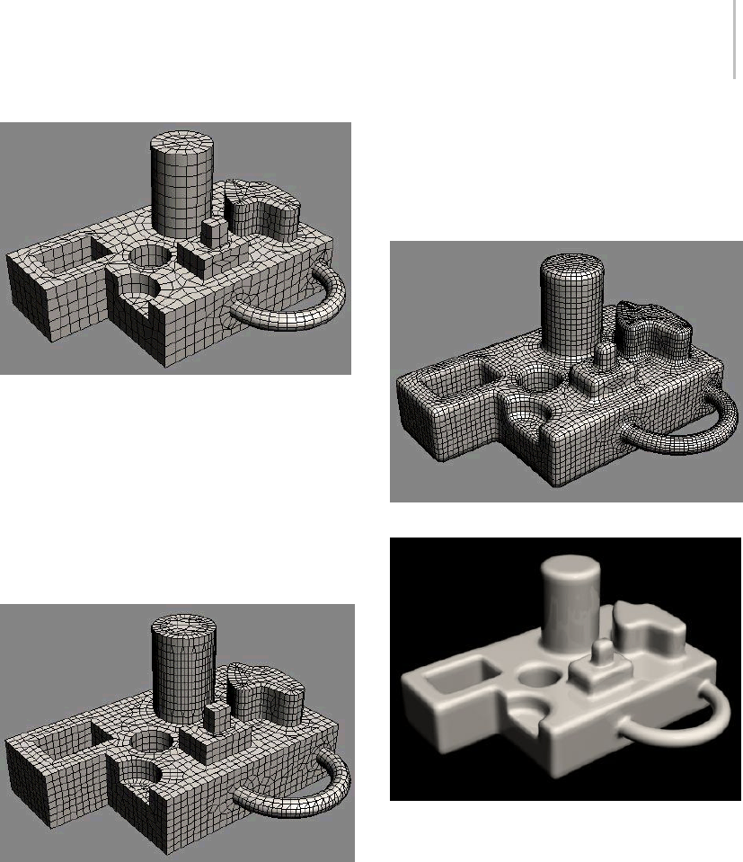
Quad Meshing and Smoothing 393
ResultofaquadmeshwithQuadSize%=3.0
Tochangethesizeoftheindividualquadrilaterals,
adjusttheQuadSize%parameter. Typicallya
value between 1 and 4 percent achieves the desired
results. The smaller the quad size, the smaller the
resulting fillets or blends between the surfaces
when the mesh is smoothed. The default Quad
Size value is 3.0 percent. A Quad Size value of 2.0
percent produces the following result:
Quad meshing with Quad Size %=2.0
If you know that you have the desired result and
don’tplantogobackandchangethequadsizeor
the original primitives, you can convert the object
to Editable Poly format and apply smoothing with
the Subdivision Surface settings. If this is not
the case, however, and you plan to make further
adjustments, use the MeshSmooth (page 1–722) or
TurboSmooth (page 1–868) modifier to retain the
history of the ProBoolean object. The following
illustration shows the result of a MeshSmooth
modifier with Subdivision Amount > Iterations=1
applied to a ProBoolean object with Quad Size %
set to 3.0.
MeshSmooth modifier with NURMS and Iterations=1
Rendered image after MeshSmooth modifier applied
Quad Meshing Tips and Tricks
Sometimes the results of quad meshing can
produce undesirable results in the smoothed
model.
Problem #1:Stripesalongcylindersorbumpiness
on other surface
Solution: Increase the number of subdivisions
around cylinders or along other surfaces.
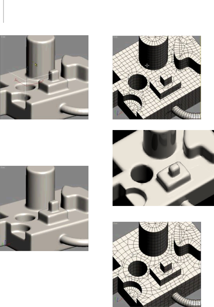
394 Chapter 5: Creating Geometry
StripesandbumpswithQuadSize%=2.0
To fix the problem depicted above, the number of
sidesonthetwocylinderswaschangedfrom18to
30 and the number of segments on the torus was
changed from 24 to 36. The following illustration
shows the improved result:
Increasing the primitives’ resolution fixes the problem.
Problem #2: Triangles along boundaries caused
by conflicts with visible edges from original mesh
Solution:MakesureAdvancedOptionsrollout
> Planar Edge Removal is set to Remove All or
create the original primitives without subdivisions
on coplanar faces.
Coplanar edges not removed from original box
When rendered, misshapen geometry results from the presence
of coplanar edges.
Quad mesh with all coplanar edges removed
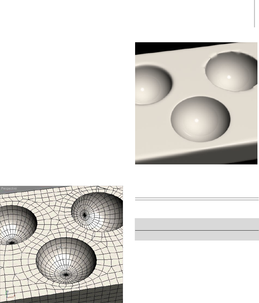
Dynamics Objects 395
Problem #3: Poor alignment of original primitive
meshes causes undesirable results.
Solution: Rotate or move original primitives into
position to maximize mesh quality.
The following illustration shows the result of
subtracting three spheres of the same size from a
box. The left-hand sphere is aligned properly so
that there are good quads along both boundaries.
This should produce a good result when smoothed.
Themiddlespherewasliftedsothatthereisa
strip of very thin quads near the boundary. This
produces very little smoothing along that edge, as
you can see in the rendered image. The right-hand
sphere was rotated, producing poor alignment
and many triangles on the sphere as well as small
quads on the plane of the box. You can see the
undesirable results in the rendered image.
Quads produced by three spheres with different rotations and
translations
Rendered image of smoothed three-sphere example
Creating Dynamics Objects
Create panel > Geometry > Dynamics Objects
Create menu > Dynamics
Dynamics objects are similar to other mesh
objects, except that they can be made to react to
the motion of objects to which they are bound, or
they can provide dynamic forces when included in
adynamics simulation (page 2–686).
Thefollowingtopicsdescribethetypesof
dynamics objects and how to create and use them:
Spring Dynamics Object (page 1–400)
Damper Dynamics Object (page 1–396)
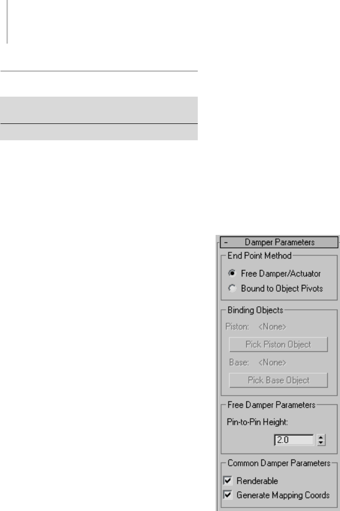
396 Chapter 5: Creating Geometry
Damper Dynamics Object
Create panel > Geometry > Dynamics Objects > Object
Type rollout > Damper button
Create menu > Dynamics > Damper
The Damper object provides a dynamic object
that can behave as either a shock-absorber or an
actuator. It consists of a base, a main housing,
and a piston, with an optional boot. The piston
slides within the main housing, providing different
heights. The overall height can be affected by
binding objects, in the same way as the Spring
dynamic object.
Note: Damper is similar to Spring in many respects.
See Spring object (page 1–400) for more detailed
descriptions of similar parameters and procedures.
Procedures
To create a damper:
1. Drag and release to specify the diameter.
2. Move the mouse and click to specify the overall
height of the damper.
To use a damper in a dynamics simulation:
Thefollowingmustbeinplacetousethedamper
forces in a dynamics simulation:
1. Bind two objects to the ends of the damper, and
chooseBoundtoObjectPivotsintheEndPoint
Method group box at the top of the command
panel.
2. In the dynamics simulation, add the damper
to the Object List. (The damper itself is not
adjusted in the dynamics simulation, so all of
the dynamics parameters will be disabled for
the damper object.)
3. Includeatleastoneoftheboundobjectsor
aparentof one of the bound objects in the
simulation. For example, you can bind two
dummy objects to the ends of a damper, and
oneofthedummiescanbethechildofan
object that’s included in the simulation. In this
case, the dummy itself does not need to be in
the simulation.
Note: Damper is an "ideal" object with no mass.
While it can be used in dynamics simulations,
it cannot participate directly in collisions or
effects. As a result, when you assign a damper
object to a dynamics simulation, and then view
it in the Edit Object dialog, all of the parameter
settings are disabled.
Interface
End Point Method group
Free Damper/Actuator—Choose this when using
the damper as a simple object that’s not bound to
others or used in a dynamics simulation.
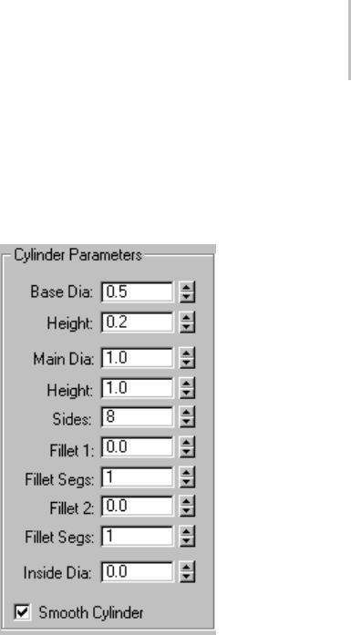
Damper Dynamics Object 397
Bound to Object Pivots—Choose this option when
binding the damper to two objects, using the
buttons described next.
Binding Objects group
Use these controls to pick the objects to which the
damper is bound. To complete the binding, you
must select two binding objects, and then click
Bound to Object Pivots.
Piston (label)—Displaysthenameoftheobject
bound to the piston of the damper.
Pick Piston Object—Click this button and then
selecttheobjecttobeboundtothepistonofthe
damper.
Base (label)—Displaysthenameoftheobject
bound to the base of the damper.
Pick Base Object—Click this button and then select
theobjecttobeboundtothebaseofthedamper.
Free Damper Parameters group
Pin-to-Pin Height—Use this field/spinner to specify
thedistancebetweenthebottomcenterofthebase
and the top center of the piston when the damper
is not bound.
Common Damper Parameters group
Renderable—When on, the object appears in the
rendering; when off, the object does not appear.
Material IDs are assigned to the damper object as
follows:
1: Base
2: Main housing
3: Piston
4: Boot Stop (appears only if you enable Boot
Parameters)
5: Boot (appears only if you enable Boot
Parameters)
Generate Mapping Coords—Sets up the required
coordinates for applying mapped materials to the
object. Default=on.
Cylinder Parameters group
Provides parameters for the base and main
cylinder of the damper.
Base Dia—The diameter of the base, or "mount"
of the damper.
Height—The height of the base.
Main Dia—The diameter of the main housing of
the damper.
Height—The height of the main housing.
Sides—The number of sides of both the base and
the main housing.
Fillet 1—Thesizeofthefilletontheloweredgeof
the main housing.
Fillet Segs—The number of segments for Fillet
1.Thehigherthissetting,therounderthefillet
profile appears.
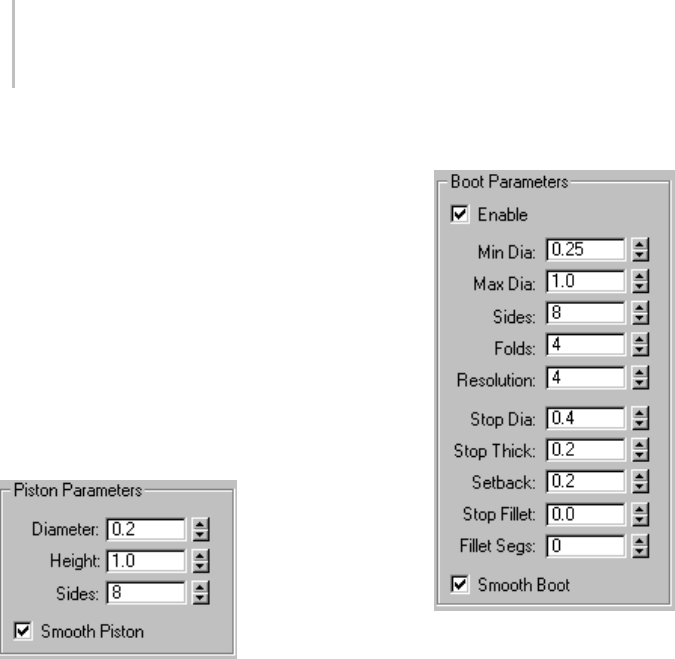
398 Chapter 5: Creating Geometry
Fillet 2—The size of the fillet on the upper edge of
the main housing.
Fillet Segs—The number of segments for Fillet
2. The higher this setting, the rounder the fillet
profile appears.
Inside Dia—Specifies the inside diameter of the
main housing, which is actually a tube rather than
acylinder.
Smooth Cylinder—When on, smoothing is applied
to both the base and the main housing.
Piston Parameters group
Provides parameters for the piston of the damper.
Diameter—The diameter of the piston.
Height—The height of the piston.
Sides—The number of sides in the piston.
Smooth Piston—When on, smoothing is applied
to the piston.
Boot Parameters group
The boot is an optional component of the damper
that’s similar to the rubber "accordion" boot
found on various types of dampers, such as shock
absorbers. Thebootactslikeabounddynamic
object, in that one of its ends is bound to the main
housing, while the other is bound to the piston.
Thus, as the piston moves within the housing, the
boot expands and contracts to follow.
Enable—Turn this on to add the boot to the
damper.
Min Dia—The minimum diameter of the boot.
This and the next parameter affect the depth of the
accordion folds in the boot.
Max Dia—The maximum diameter of the boot.
Sides—Thenumberofsidesmakinguptheboot.
Folds—The number of accordion folds (bulges)
along the height of the boot.
Resolution—The number of segments in each fold.
Stop Dia—The diameter of the stop, which is the
ring at the top of the boot.
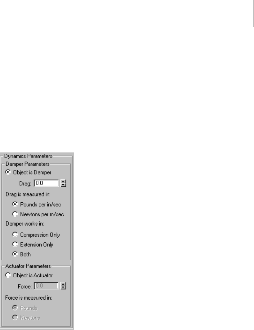
Damper Dynamics Object 399
Stop Thick—The thickness (height) of the stop ring.
Setback—The distance of the stop ring from the
top of the piston.
Stop Fillet—The size of the fillet on the upper edge
of the stop ring.
Fillet Segs—The number of segments the stop fillet.
The higher this setting, the round the fillet profile
appears.
Smooth Boot—When on, smoothing is applied to
the boot.
Dynamics Parameters group
Unlike the Spring object, the damper can also be
used as an actuator. Basically, a damper absorbs
force (like a shock absorber) while an actuator
applies force.
The parameters in this group box, available only
when End Point Method is set to Bound to Object
Pivots, specify how forces are applied by the
damper object in a dynamics simulation.
Damper Parameters—Provides parameters for a
damper type of object. Specifically, this simulates
a viscous linear damper, which provides linear
resistance to motion (between the two binding
objects) proportional to the rate at which the
damper experiences displacement. The faster it
gets hit, the harder it fights back. Push it slowly,
and there’s almost no resistance.
•Object is Damper—Select this option to use
the damper object as a damper rather than an
actuator.
Drag—Specifies the force per unit linear speed,
measured in one of the methods specified below.
•Drag is measured in—Lets you specify the
measurement of drag to use: Pounds per
in(ch)/sec or Newtons per m(eter)/sec.
•Damper works in—Provides directional options
for the damper.
Compression Only—The damper reacts only to
compression forces.
Extension Only—The damper reacts only to
expansion forces.
Both—The damper reacts to both compression
and expansion forces.
Actuator Parameters—Provides parameters for an
actuator.Whenusedasanactuator,thedamper
object exerts force between the two binding
objects. A real-world example might be the
thrustingpistoninalogsplitter.Whenusedina
simulation, the force is applied by adjusting the
valueintheForcespinner.Youcanseetheresult
only after solving the dynamics simulation.
•Object is Actuator—Choose this when using the
damper object as an Actuator.
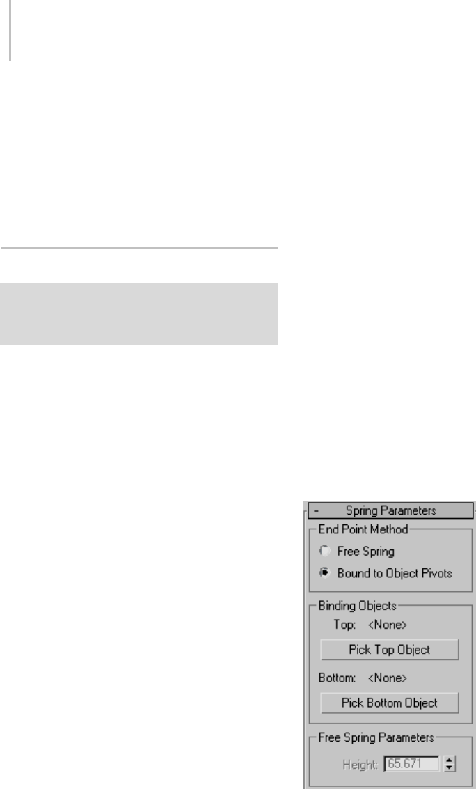
400 Chapter 5: Creating Geometry
Force—Specifies the amount of force exerted
between the two bound objects. Positive values
pushtheobjectsapart,whilenegativevaluespull
them together.
•Force is measured in— Lets you specify the
measurement of force to use: Pounds per inch
or Newtons per meter.
Spring Dynamics Object
Create panel > Geometry > Dynamics Objects > Object
Type rollout > Spring button
Create menu > Dynamics > Spring
TheSpringobjectisadynamicsobjectintheshape
of a coiled spring that lets you simulate a flexible
spring in dynamics simulations. You can specify
the overall diameter and length of the spring, the
number of turns, and the diameter and shape of its
“wire.” When used in a dynamics simulation, the
compression and extension pressure of the spring
are calculated as well.
Procedures
To create a spring:
1. Drag and release to specify the outside
diameter.
2. Move the mouse and click to specify the overall
length of the spring.
To use a spring in a dynamics simulation:
Thefollowingmustbeinplacetousethespring
forces in a dynamics simulation:
1. Bind two objects to the ends of the spring, and
chooseBoundtoObjectPivotsintheEndPoint
Method group box at the top of the command
panel.
2. In the dynamics simulation, add the spring
to the Object List. (The spring itself is not
adjustable in the dynamics Edit Object dialog,
so all of the dynamics parameters will be
disabled for the spring object.)
3. Includeatleastoneoftheboundobjectsor
aparentof one of the bound objects in the
simulation. For example, you can bind the
ends of a spring to two dummy objects, and
oneofthedummiescanbethechildofan
object that’s included in the simulation. The
dummy without a parent will be stationary and
the spring will pass its force through the other
dummy to its parent.
Note: Spring is an "ideal" object with no mass.
While it can be used in dynamics simulations,
it cannot participate directly in collisions or
effects. A spring can only exert force on other
objectsinsimulations.Asaresult,whenyou
assignaspringobjecttoadynamicssimulation,
and then view it in the Edit Object dialog, all of
the parameter settings are disabled.
Interface
Spring Parameters rollout
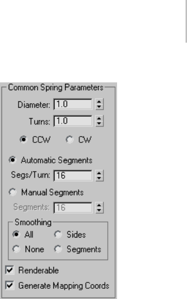
Spring Dynamics Object 401
End Point Method group
Free Spring—Choosethiswhenusingthespringas
a simple object that’s not bound to other objects or
used in a dynamics simulation.
Bound to Object Pivots—Choose this when binding
the spring to two objects, using the buttons
described next.
Binding Objects group
Use these controls to pick the objects to which the
spring is bound. "Top" and "Bottom" are arbitrary
descriptors; the two bound objects can have any
positional relationship to each other. To complete
the binding, select two binding objects, and then
click Bound to Object Pivots.
Each end point of the spring is defined by the
center of the overall diameter and the center of the
wire. Thisendpointisplacedatthepivotpoint
of the object to which it is bound. You can adjust
therelativepositionofthebindingobjecttothe
spring by transforming the binding object while
theAffectObjectOnlybuttonisturnedoninthe
Hierarchy > Pivot panel.
Top (label)—Displaysthenameofthe"top"binding
object.
Pick Top Object—Click this button and then select
the "top" object.
Bottom (label)—Displaysthenameofthe"bottom"
binding object.
Pick Bottom Object—Click this button and then
select the "bottom" object.
Free Spring Parameters group
Height—Use this field/spinner to set the
straight-line height or length of the spring when it
isnotbound.Thisisnottheactuallengthofthe
spring’s wire.
Common Spring Parameters group
Diameter—The overall diameter of the spring, as
measured at the center of the wire. (The diameter
of the wire itself has no effect on this setting.)
Turns—The number of full 360-degree turns in
the spring.
CCW/CW—Specifies whether the coils of the spring
arecounterclockwise(CCW)orclockwise(CW).
Automatic Segments—Choose this option to force
each turn of the spring to contains the same
number of segments, as specified in the Segs/Turn
spinner. Thus, if you increase the number of turns,
the number of segments also increases.
Segs/Turn—This spinner lets you specify the
number of segments in each 360-degree turn of
the spring.
Manual Segments—When this option is chosen,
the length of the spring contains a fixed number of
segments, no matter how many turns in the spring.
Thus, as you increase the number of turns, you
must manually increase the number of segments
to maintain a smooth curve.
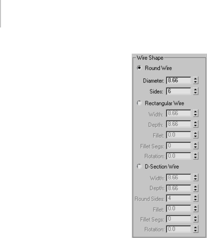
402 Chapter 5: Creating Geometry
Segments—This spinner lets you specify the total
number of manual segments in the spring.
Smoothing—Provides various methods of
smoothing the object. The options here work the
same as those in the Torus primitive (page 1–180).
•All—All surfaces are smoothed.
•Sides—Smoothingrunsalongthelengthofthe
wire, but not around its perimeter.
•Segments—Smoothing runs around the
perimeter of the wire, but not along its length.
•None—No smoothing is applied.
Renderable—When on, the object appears in the
rendering; when off, the object does not appear.
Generate Mapping Coords—Assigns mapping
coordinates to the object. Default=on.
Wire Shape group
Provides three different types of wire cross-sections
for the spring: round, rectangular, or D-shaped.
Each type has its own set of parameters.
Round Wire—Specifies a round wire for the spring.
•Diameter—The diameter of the wire.
•Sides—The number of sides that make up the
cross section.
Rectangular Wire—Specifies a rectangular wire.
•Width—Determines the width of the cross
section.
•Depth—Determines the depth of the cross
section.
•Fillet—When combined with Fillet Segs
(below), this lets you fillet (round) the corners
of the cross section.
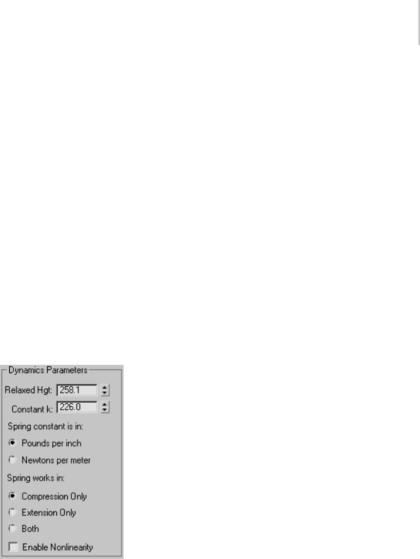
Spring Dynamics Object 403
•Fillet Segs—Specifies the number of segments
in the fillet.
•Rotation—Rotates the angle of the cross section
along the entire length of the spring.
D-Section Wire—Specifies a D-shaped wire.
•Width—Determines the width of the cross
section.
•Depth—Determines the depth of the cross
section.
•Round Sides—Specifies the number of segments
that make up the rounded side of the D-shape.
•Fillet—When combined with Fillet Segs
(below), this lets you fillet (round) the corners
of the cross section.
•Fillet Segs—Specifies the number of segments
in the fillet.
•Rotation—Rotates the angle of the cross section
along the entire length of the spring.
Dynamics Parameters group
These parameters specify the forces that the spring
contributes to a dynamic simulation.
Relaxed Hgt—Specifies the height (or length)
at which the spring is "relaxed" and therefore
contributes no force--either compression or
extension. Forexample,iftheplacementofthe
binding objects stretches the spring to a length of
50 units but the Relaxed Len is set to 30, then an
extension force is in effect because the spring is
stretched further than its relaxed length.
Constant k—The amount of force exerted per unit
change in length with respect to the Relaxed Hgt
value. This could also be described as the measure
of force-per-units-change in length as compared
to the Relaxed Length. For example, if your spring
is set to a Spring Constant of k=10 lb per in, and
you stretch it to be ten inches longer than the
Relaxed Hgt value, it will try to close with a force
of 100 pounds. If you compress it two inches
shorter than the Relaxed Hgt value, it will push
back with 20 pounds of force.
Spring constant is in—Lets you specify the
measurement of force to use: Pounds per inch or
Newtons per meter.
Spring works in—Letsyouspecifythetypeofforce
you want the spring to exert. While most springs
actually provide both compression and extension
force, if your simulation requires only one, you can
save calculation time by using one instead of both.
•Compression Only—This type of spring provides
only expansive force when its length is shorter
than the specified Free Length.
•Extension Only—Provides contractive force
when its length is greater than the specified
Free Length.
•Both—Provides both expansive and contractive
force,dependingonthevariationfromRelaxed
Hgt.
Enable Nonlinearity—When on, the compression
and extension of the spring are non-linear, based
on the assumption that a spring has physical
limits to the amount it can stretch or contract.
Thus, the further the spring gets from the Relaxed
Hgt setting, the less linear the feedback. The
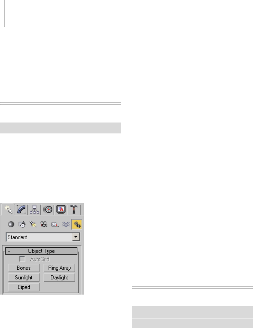
404 Chapter 5: Creating Geometry
non-linear compression is calculated using the
relationship between the coil dimensions, wire
diameter, and length. Extension compares the
relationship between the wire diameter and overall
spring diameter.
Creating Systems
Create panel > Systems
Asystemcombinesobjects,linkages,and
controllers to produce an object set that has
behavior as well as geometry. Systems help you
create animations that would be much more
difficult or time-consuming to produce using
features independently. Systems can range from
simple object generators to full-scale subsystem
programs.
•Bones (page 1–404) creates a hierarchically
linked set of bones and joints.
You can transform and animate bones using
both forward and inverse kinematics. See
Animating with Forward Kinematics (page
2–426) and Inverse Kinematics (IK) (page
2–435).
•Ring Array (page 1–415) creates a ring of boxes.
•Sunlight (page 1–418) creates and animates a
directional light that follows the geographically
correct angle and movement of the sun over the
earth at a given location.
•Daylight (page 1–418) creates an assembly with
a sky and a sun. Using the Get location function
you can create and animate a light that follows
the geographically correct angle and movement
of the sun over the earth at a given location.
•Biped (page 2–843) creates a two-legged
character skeleton designed for animation.
Systems are primarily intended for plug-in (page
3–995) component software. Additional systems
might be available if your configuration includes
plug-in systems.
You can externally reference system objects in your
scene. For more information, see XRef Objects
(page 3–394).
Procedure
To create a system:
1. On the Create panel, click Systems.
The Systems panel is displayed.
2. OntheObjectTyperollout,chooseasystem
to create.
3. Drag in a viewport to create the system.
Bones System
Create panel > Systems > Bones button
Animation menu > Bone Tools > Create Bones
A Bones system is a jointed, hierarchical linkage
of bone objects that can be used to animate
other objects or hierarchies. Bones are especially
useful for animating character models that have
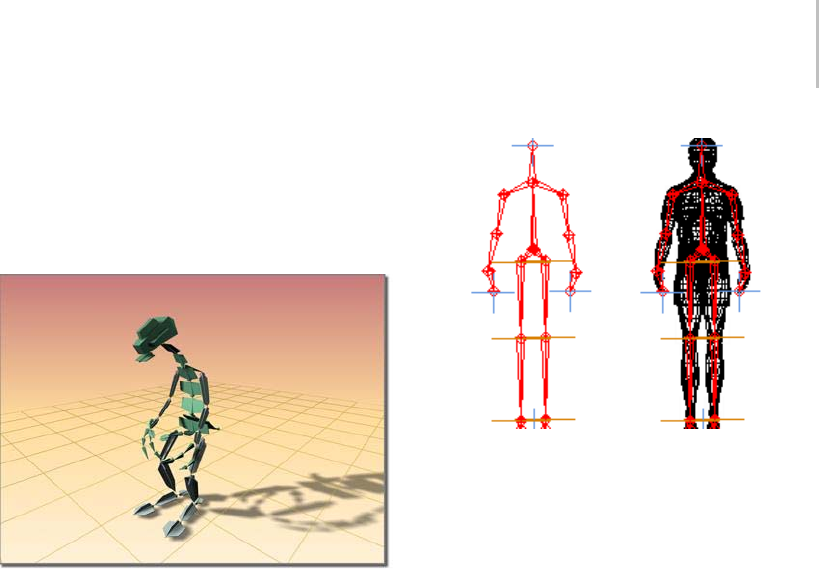
Bones System 405
a continuous skin mesh. You can animate bones
with forward or inverse kinematics. For inverse
kinematics, bones can use any of the available IK
solvers (page 2–440),orthroughInteractive (page
2–480) or applied IK (page 2–481).
Dinosaur character modeled using bones
Bones are renderable objects. They have several
parameters, such as taper and fins, that can be
usedtodefinetheshapethebonerepresents.The
finsmakeiteasiertoseehowtheboneisrotating.
For animation, it is very important that you
understand the structure of a bone object. The
bone’s geometry is distinct from its link. Each link
hasapivotpointatitsbase.Thebonecanrotate
about this pivot point. When you move a child
bone, you are really rotating its parent bone.
Itmightbeusefultothinkofbonesasjoints,
becauseitistheirpivotplacementsthatmatter,
more than the actual bone geometry. Think of the
geometry as a visual aid that is drawn lengthwise
from the pivot point to the bone’s child object.
The child object is usually another bone.
Bones system seen alone and inside a wireframe model
Any hierarchy can display itself as a bone structure
(see Using Objects as Bones (page 1–410)), by
simplyturningonBoneOnintheBone Editing
Tools rollout (page 1–411).
See also
Bone Tools (page 1–411)
Creating Bones
You start creating bones by clicking the Create
Bones button on the Bone Editing Tools rollout
(page 1–411),orbyclickingtheBonesbuttonin
the Systems category on the Create panel.
To create bones, do the following.
1. Your first click in a viewport defines the start
jointofthefirstbone.
2. The second click in a viewport defines the start
joint of the next bone. Visually only one bone
is drawn at this point because bones are visual
aids drawn between two pivot points. It is the
actualpivotpoint’splacementthatisimportant.
3. Each subsequent click defines a new bone as
a child of the previous bone. The result of
multiple clicks is a single chain of bones.
4. Right-click to exit bone creation.
This creates a small “nub” bone at the end of
the hierarchy, which is used when assigning an
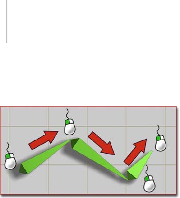
406 Chapter 5: Creating Geometry
IK chain. If you are not going to assign an IK
chain to the hierarchy, you can delete the small
nub bone.
Creating a simple chain of three bones
3ds Max lets you create a branching hierarchy of
bones. To create a branching hierarchy, such as
legs branching from a pelvis, do the following:
1. Create a chain of bones, and then right-click
to exit bone creation.
2. Click Bones (or Create Bones) again, and
then click the bone where you want to begin
branching. The new chain of bones branches
from the bone you click.
Warning: The behavior of a branching bone
hierarchy is not always intuitive.
Note: Yo u c a n a l s o u s e Select And Link (page 2–422)
to connect one bone hierarchy to its branches.
However, except for this one special case, using
Select And Link with bones is not recommended.
To edit an existing bone structure, whether
branching or not, use the Bone Tools (page 1–411)
instead.
Assigning IK Controllers to Bones
By default, bones are not assigned inverse
kinematics (IK). Assigning an IK solver can be
done in one of two ways. Typically, you create a
bone hierarchy, then manually assign an IK solver.
This allows for very precise control over where IK
chains are defined.
The other way to assign an IK solver is more
automatic. Whenyoucreatebones,chooseIK
solverfromthelistintheIKChainAssignment
rollout,andthenturnonAssignToChildren.
Whenyouexitbonecreation,thechosenIKsolver
is automatically applied to the hierarchy. The
solver extends from the first bone in the hierarchy
to the last.
For more information about IK, see Introduction
to Inverse Kinematics (page 2–435).
Setting the Initial Position of Bones
When you first create a bones system, the position
of the bones is the initial state. Before you assign
an IK solver or method, you can change the
initial state of the bones by moving, rotating, or
stretching the bones individually.
Bone Color
By default, bones are assigned the color specified
for Bones in the Colors panel (page 3–799) of the
Customize User Interface dialog (page 3–792).
Choose Object as the Element and then choose
Bonesinthelist. Youcanchangethecolorof
individual bones by selecting the bone, clicking the
active color swatch next to the bone’s name in the
Create panel or Modify panel, and then selecting a
color in the Object Color dialog (page 1–159).
You can also use the Bone Tools (page 1–411) to
assign bone colors, or to assign a color gradient
to a bone hierarchy.
Bone Fins
Fins are visual aids that help you clearly see a
bone’s orientation. Fins can also be used to
approximate a character’s shape. Bones have three
sets of fins: side, front, and back. By default, fins
are turned off.
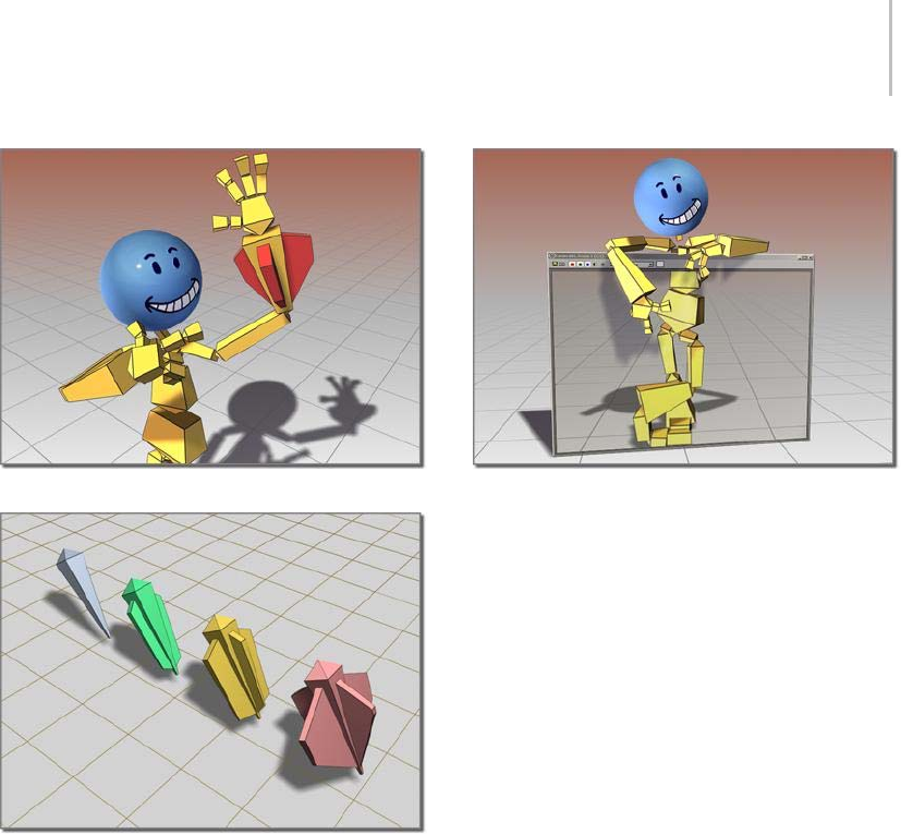
Bones System 407
Bones can have fins.
Bones with various fin configurations
Renderable Bones
Bones can be renderable, though by default, they
arenot. Tomakeabonerenderable,turnon
the Renderable check box in the bone’s Object
Properties dialog (page 1–117).
Bones can be renderable.
Object Properties for Bones
In addition to visual properties, bones have
behavioral properties. The controls for these are
located on the Bone Tools floater (page 1–411).
You can use these controls to turn other kinds of
objects into bones.
Using Constraints with Bones
Yo u c a n a p p l y constraints (page 2–392) to bones as
long as an IK solver or method is not controlling
thebones. IftheboneshaveanassignedIK
controller, you can constrain only the root of the
hierarchy or chain. However, applying position
controllers or constraints to a linked bone can
cause undesirable effects, such as breaking of the
bone chain.
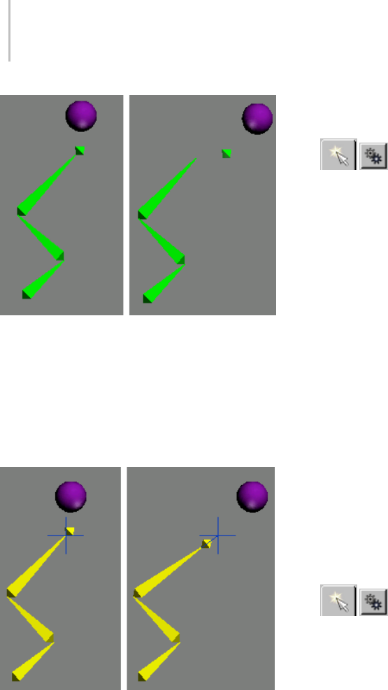
408 Chapter 5: Creating Geometry
The “nub” bone at the end of the chain has a Spring controller
applied to it. The Spring controller is connected to an animated
sphere.
Right: The sphere’s movement breaks the bone chain.
To avoid this problem, don’t apply position
controllers directly to child bones. Instead, create
an IK chain and apply the controller to the IK
chain’s end effector.
A IK chain has been applied, connecting the end nub to its
parent bone. The IK chain’s end effector is connected to the ball
by a Spring controller.
Right: Now when the sphere moves, the IK chain prevents the
bones from breaking.
Constraints and controllers that affect orientation
only, such as Orientation or Look At, do not
present this problem when applied to child bones.
Procedures
To create a bones system:
1. On the Create panel, click Systems,
and then click Bones.
You can also access Create Bones through the
Bone Tools rollout.
2. Click in a viewport.
This creates a joint that is the base of the bone’s
hierarchy.
3. Drag to define the length of the second bone.
4. Click to set the length of the second bone, and
then drag to create the third bone. Drag and
click to continue creating new bones.
5. Right-click to end creation.
3dsMaxcreatesasmall“nub”boneatthe
end of the hierarchy. This bone is used when
assigning an IK chain.
Thefirstboneyoucreateisatthetopofthe
hierarchy. The last bone you create is at the
bottom. For more about linked objects, see the
Hierarchy Panel (page 3–773).
To create a bones hierarchy with an IK solver
automatically applied:
1. IntheCreatepanel,clickSystems,
and then click Bones.
2. In the IK Chain Assignment rollout, select an
IK solver from the list.
3. Tur n on As sig n To Child ren .
4. In a viewport, click and drag to create the
bones. Right-click to end bone creation.
After the bones are created, the chosen IK
solver is applied to them.
To edit the appearance of a bone:
1. Select a bone.
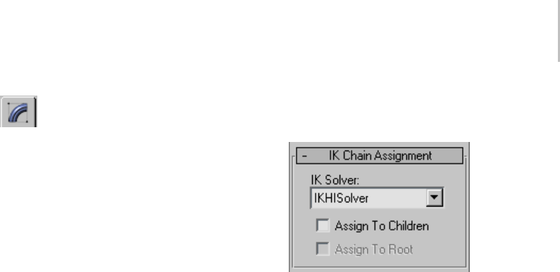
Bones System 409
2. Click the Modify tab on the command
panel.
3. Change settings in the Bone Parameters rollout.
To change the length of bones after they’ve been
created:
Important: Repositioning a bone affects its length
visually. More importantly, it affects the bone’s pivot
position. The length of the bone is only a visual aid
drawn between each bone’s pivot point. A bone has
only one pivot. The bone you see visually is connecting
its pivot point to the next bone’s pivot point.
1. Choose Animation menu > Bone Tools.
2. OntheBoneToolsdialog,clickBoneEdit
Mode.
3. Movethechildoftheboneyouwanttochange.
The length of its immediate parent changes to
reach the child bone.
4. Turn off Bone Edit Mode when you are finished
editing the bones.
To add fins to bones:
1. Select the bone.
2. Choose Animation menu > Bone Tools.
3. Select the bones to which you want to add fins.
4. In the Fin Adjustment Tools rollout, turn on
Side Fins, Front Fin or Back Fin.
5. Adjust the size and appearance of the fins with
the appropriate spinners.
Note: You can also add fins to an individual
bone on the Modify panel.
Interface
IK Chain Assignment rollout (creation time only)
Provides the tools to quickly create a bone chain
with an IK solver automatically applied. Also
allows for bone creation with no IK solver.
IK Solver drop-down list—Specifies the type of IK
solver to be automatically applied if Assign To
Children is turned on.
Assign To Children—When on, assigns the IK solver
named in the IK solver list to all the newly created
bonesexceptthefirst(root)bone. Whenoff,
assigns a standard PRS Transform controller (page
2–357) to the bones. Default=off.
Note: Choosing the SplineIKSolver and turning
on Assign To Children causes the Spline IK Solver
dialog (page 2–477) to appear after bones have
been created.
Assign To Root—When on, assigns an IK solver
to all the newly created bones including the first
(root) bone.
Turning on Assign To Children also automatically
turns on Assign To Root.
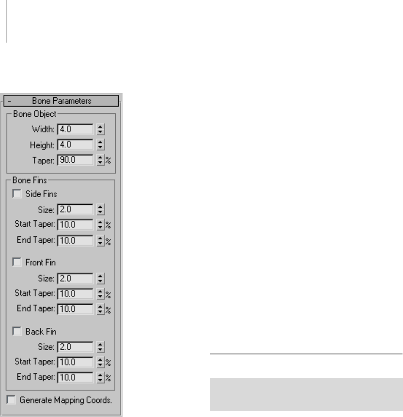
410 Chapter 5: Creating Geometry
Bone Parameters rollout (creation and
modification time)
These controls change the appearance of the
bones.
Bone Object group
Width—Sets the width of the bone to be made.
Height—Sets the height of the bone to be made.
Taper—Adjusts the taper of the bone shape. A
Taper of 0 produces a box-shaped bone.
Bone Fins group
Side Fins—Lets you add a set of fins to the sides of
the bones you create.
•Size—Controlsthesizeofthefin.
•Start Taper—Controls the start taper of the fin.
•End Taper—Controls the end taper of the fin.
•
Front Fin—Lets you add a fin to the front of the
bone you create.
•Size—Controlsthesizeofthefin.
•Start Taper—Controls the start taper of the fin.
•End Taper—Controls the end taper of the fin.
Back Fin—Lets you add a fin to the back of the bone
you create.
•Size—Controlsthesizeofthefin.
•Start Taper—Controls the start taper of the fin.
•End Taper—Controls the end taper of the fin.
Generate Mapping Coords—Creates mapping
coordinates on the bones. Since the bones are
renderable, they can also have materials applied,
which can use these mapping coordinates.
Using Objects as Bones
Select a linked object or multiple objects linked to
each other. > Animation menu > Bone Tools > Object
Properties rollout > Bone On toggle
You can use arbitrary objects such as cylinders or
boxes as bones, controlling their animation as if
they were bones in a bones system (page 1–404).
Yo u c a n a p p l y a n IK solver (page 2–440) to the
boned objects.
To use objects as bones, select them and then turn
ontheBoneOntoggleontheObjectProperties
rollout of the Bone Tools dialog (page 1–411).
Warning: Turning on Freeze Length has no visible effect
unless you transform the child of the object to which
Freeze Length is applied.
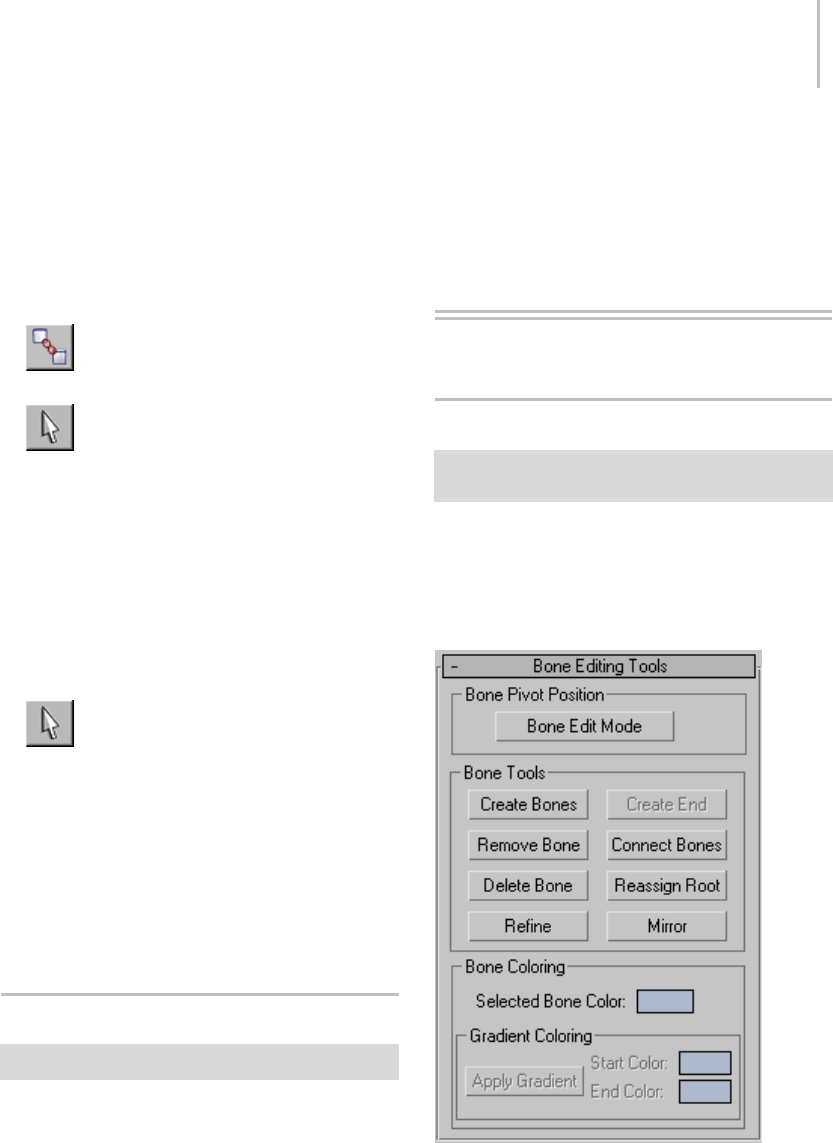
Bone Tools 411
Once you’ve set objects to function as bones,
applyinganIKsolutionbehavesasitdoesfor
standard bone objects. The geometry of the boned
objects can stretch or squash during animation.
Procedure
To use objects as bones:
1. Link the objects you want to display as
bones.
2. Select all of these objects.
Note: You can set a single object to work as a
bone, but this doesn’t have much use.
3. Choose Animation menu > Bone Tools.
The floating Bone Tools dialog is displayed.
4. OntheObjectPropertiesrollout,turnonBone
On.
3dsMaxnowtreatstheselectedobjectsas
bones.
5. Select the object to use as the start of the
IK chain.
6. Choose Animation > IK Solvers > HI Solver.
Yo u c a n c h o o s e a d i f f e r e n t I K s o l v e r, b u t t h e H I
Solver is the preferred choice.
7. Click to select the end of the IK chain.
Now when you transform the boned objects,
their movement is governed by the IK solver.
Bone Tools
Animation menu > Bone Tools
This command opens theBoneToolsfloater,
which provides functions for working with bones.
The floater contains three rollouts, described in
these topics:
Bone Editing Tools Rollout (page 1–411)
Fin Adjustment Tools Rollout (page 1–413)
Object Properties Rollout (Bone Tools) (page 1–414)
Bone Tools Rollouts
Bone Editing Tools Rollout
Animation menu > Bone Tools > Bone Tools floater >
Bone Editing Tools rollout
Controls on the Bone Editing Tools rollout let you
create and modify bone geometry and structure,
and set bone color for one or more bones.
Interface

412 Chapter 5: Creating Geometry
Bone Pivot Position group
Bone Edit Mode—Lets you change the lengths of
bones and their positions relative to one another.
When this button is on, you can change the length
of a bone by moving its child bone. In effect, you
can scale or stretch a bone by moving its child
bonewhileinthismode. Youcanusethistool
both before and after assigning an IK chain to the
bone structure.
When Bone Edit Mode is on, you cannot animate,
and when Auto Key or Set Key is on, Bone Edit
Mode is unavailable. Turn off Auto/Set Key to edit
bones.
Note: MovingaboneinBoneEditmodeaffects
the length of both the child and its parent.Ifthe
bones aren’t spatially aligned in the usual way (for
example, if you are using other objects as bones),
this might have unexpected results.
Bone Tools group
Create Bones—Begins the bone-creation process.
Clicking this button is the same as clicking Create
panel > Systems > Bones (page 1–404).
Create End—Creates a nub bone at the end of the
currently selected bone. If the selected bone is not
at the end of a chain, the nub is linked in sequence
between the currently selected bone and the next
bone in the chain.
Remove Bone—Removes the currently selected
bone. The bone’s parent bone is stretched to reach
the removed bone’s pivot point, and any children
of the removed bone are linked to its parent. Any
IK chains that included the removed bone will
remain intact.
Connect Bones—Creates a connecting bone
between the currently selected bone and another
bone. When you click this button, a dotted line
appears in the active viewport from the first
selected bone. Move the cursor to another bone to
create a new connecting bone. The first selected
bone will become a parent to the connecting bone,
whichisinturnaparenttothesecondselected
bone.
Delete Bone—Deletes the currently selected bone,
removing all its parent/child associations. A nub is
placed at the end of the deleted bone’s parent. Any
IK chains that included this bone become invalid.
Reassign Root—Makes the currently selected bone
the root (parent) of the bone structure.
If the current bone is the root, clicking this has no
effect. If the current bone is the end of the chain,
the chain is completely reversed. If the current
bone is in the middle of the chain, the chain
becomesabranchinghierarchy.
Refine—Splitsaboneintwo. ClickRefine,and
then click a bone where you want it to split.
Mirror—Opens the Bone Mirror dialog (see
following), which lets you create mirror copies of
selected bones without changing the sign of the
bones’ scale. Instead, Mirror flips one of the bone
axes: Y or Z. You can specify the mirroring axis
and the flip axis with the dialog controls.
Bone Mirror Dialog
Opens when you click the Mirror button. Use it
to specify the mirroring axis, the flip axis, and an
offset value.
While the dialog is open, you can see a preview of
the mirrored bone(s) in the viewports. Click OK
to create the bones, or Cancel to prevent creation.
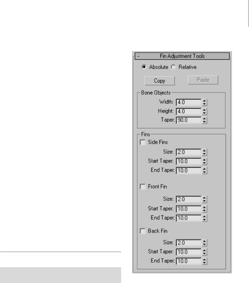
Fin Adjustment Tools Rollout 413
Mirror Axis—Choose an axis or plane about which
the bones will be mirrored: X/Y/Z or XY/YZ/ZX.
Bone Axis to Flip—To avoid creating a negative
scale, choose the bone axis to flip: Y or Z.
Offset—The distance between the original bones
and the mirrored bones. Use this to move the
mirrored bones to the other side of the character.
Bone Coloring group
Selected Bone Color—Sets the color for selected
bones.
Apply Gradient—Applies a gradient color across
several bones based on the Start Color and End
Color values. This option is available only when
two or more bones are selected. The Start Color is
appliedtothehighestparentboneintheselected
chain,whiletheEndColorisappliedtothelast
child object in the selected chain. Intermediate
colors in the gradient are applied to bones in
between.
Start Color—Sets the starting color for the gradient.
End Color—Sets the ending color for the gradient.
Bones System (page 1–404)
Fin Adjustment Tools Rollout
Animation menu > Bone Tools > Bone Tools floater > Fin
Adjustment Tools rollout
Controls on the Fin Adjustment Tools rollout are
for adjusting some aspects of bone geometry,
including fins.
Interface
Absolute—Sets the fin parameters as absolute
values. Use this option to set the same fin values
for all selected bones.
Relative—Sets the fin parameters relative to their
currentvalues. Usethisoptiontoretainsize
relationships between bones with different-sized
fins.
Copy —Copiestheboneandfinsettingsforthe
currently selected bone, in preparation for pasting
to another bone.
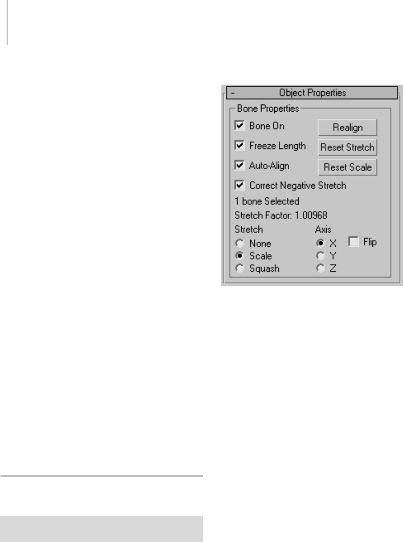
414 Chapter 5: Creating Geometry
Paste—Pastes the copied bone and fin settings to
the currently selected bone.
Bone Objects group
Width—Sets the width of the bone.
Height—Sets the height of the bone.
Taper—Adjusts the taper of the bone shape. A
Taper with a 0 value produces a box-shaped bone.
Higher values pinch the bone where it joins its
child bone, while lower values expand that end of
the bone.
Fins group
Side Fins—Adds side fins to selected bones.
•Size—Controls the size of the fin.
•Start Taper—Controls the start taper of the fin.
•End Taper—Controls the end taper of the fin.
Front Fin—Adds front fins to selected bones.
•Size—Controls the size of the fin.
•Start Taper—Controls the start taper of the fin.
•End Taper—Controls the end taper of the fin.
Back Fin—Adds fins to the backs of selected bones.
•Size—Controls the size of the fin.
•Start Taper—Controls the start taper of the fin.
•End Taper—Controls the end taper of the fin.
Object Properties Rollout (Bone
Tools)
Animation menu > Bone Tools > Bone Tools floater >
Object Properties rollout
Controls on the Object Properties rollout for bones
let you turn other objects into bones. They also
control bone rigidity and alignment.
Note: You can reset the scale of bones with the
Reset Scale option.
Interface
Bone On/Off—When turned on, the selected
bone or object behaves as a bone. Turning this
option off causes the object to stop behaving like
a bone: there is no auto alignment or stretching.
Default=on for bone objects, off for other kinds
of objects.
Note: Turningthisoptionondoesn’timmediately
cause objects to align or stretch. However, future
transforms of children can cause rotation and
stretching.
Freeze Length—When turned on, the bone
maintains its length. When turned off, the bone’s
length is based on the translation of its child bone.
This option is available only if Bone On is on.
Default=on.
Warning: When you turn on Freeze Length, this has no
visible effect unless you transform the child of the object
to which Freeze Length is applied.
Auto-Align—When turned off, the bone’s pivot
point doesn’t align to its child object. The
translation of a child bone will not be converted
into rotation of the parent. Instead, the child is
allowed to move away from the parent’s X axis.

Ring Array System 415
This option is available only if Bone On is on.
Default=on.
Note: Changing the Auto-Align state does not
have an immediate visual effect on the skeleton. It
affects future behavior when bones are moved.
Correct Negative Stretch—When turned on, any
stretching of the bone that results in a negative
scale factor will be corrected to a positive number.
This option is available only if Bone On is on.
Default=on.
Realign—Causes the bone’s X axis to realign and
pointatthechildbone(ortheaveragepivotof
multiple children). Normally this alignment
is maintained, and there is no need to use this
option. However, it is possible for the bones to
come out of alignment by turning off Auto-Align
andmovingachildbone.UseRealigntoalignthe
bone back to its child. This option is available only
if Bone On is on.
Reset Stretch—Stretches the bone to reach its child
object if the child has been moved away from the
bone. This option is available only if Bone On is
on.
Reset Scale—Resets a stretched bone’s internally
calculated scale to 100% on each axis. Using this
option avoids unexpected behavior due to objects
which are both linked and scaled. This option
has no visual effect on the bone. This option is
availableonlyifBoneOnison.
Stretch Factor Information
Under the Correct Negative Stretch options is a
text display giving information about the number
of bones selected and the respective stretch factor
forallthreeaxes.Ifmorethanoneboneisselected,
the Stretch Factor text displays undefined.
Note: The Stretch Factor text only updates when
you are in Bone Edit Mode (page 1–411).
Stretch and Axis Options
Stretch—Determines what kind of stretch takes
place when the child bone is transformed and
Freeze Length is off. Default=Scale.
•None—No stretch takes place.
•Scale—Lets the bone scale. The stretch happens
along one axis.
•Squash—Lets the bone squash. The bone gets
fatter as it gets shorter, and thinner as it gets
longer.
Axis—Determines the axis used for the stretch.
•X/Y/Z—Choose the axis for scaling or squashing.
•Flip—Flips the stretch along the selected axis.
Ring Array System
Create panel > Systems > Ring Array button
The Ring Array object consists of a dummy object
(page 2–16) surrounded by a ring of boxes. You
can arrange the boxes in the ring along a sine
curve, vary their number, and animate the ring
array’s parameters. You can also replace the boxes
with other objects using Track View, as described
in the Procedures section, below.
Example of ring array
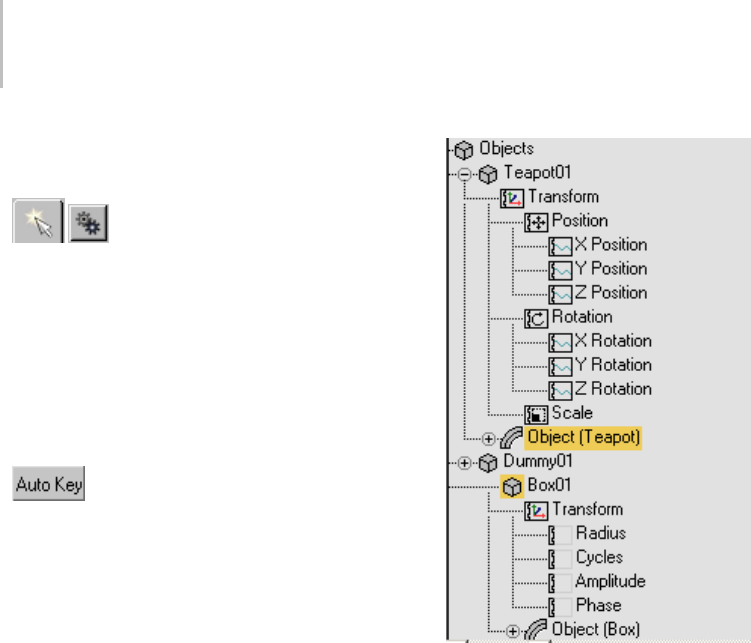
416 Chapter 5: Creating Geometry
Procedures
To create the ring array system:
1. OntheCreatepanel,clickSystems,
and then click Ring Array.
2. Drag in a viewport to set the center and radius
of the array.
Adummyobjectappearsatthecenter. By
default, four boxes are evenly spaced in a circle
around it.
To animate the ring array:
1. Tur n on Auto Ke y.
2. Move to a nonzero frame.
3. Adjust the ring array parameters.
You can’t animate the number of boxes in the
ring.
4. Repeat steps 2 and 3 for additional keyframes.
Note: To animate the ring array after creation,
use the Motion panel, not the Modify panel.
To put other kinds of objects in the ring:
You can use either version of Track View: Curve
Editor or Dope Sheet.
1. In the Track View Controller window, click the
name of object container of the object to put
in the ring.
Thenamehighlights.
2. Still in the Controller window, right-click and
choose Copy from the menu.
3. Highlight the object container of one of the ring
array boxes.
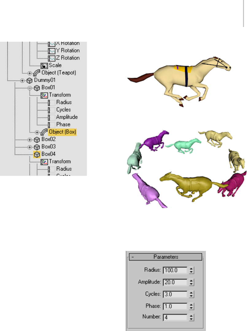
Ring Array System 417
4. Right-click and choose Paste.
5. InthePastedialog,chooseCopyorInstance.
Optionally, to replace all the boxes with the
copiedobject,turnonReplaceAllInstances.
Click OK.
The box or boxes are replaced with the copied
object.
Tip: To see the replacement objects, you might
need to refresh the viewports.
Top: Object substituted for boxes in array
Bottom: The result
Interface
These parameters control ring arrays. To adjust
and animate the ring array after creation, select
one of the array objects (not the dummy), and
then go to the Motion panel, not the Modify panel.
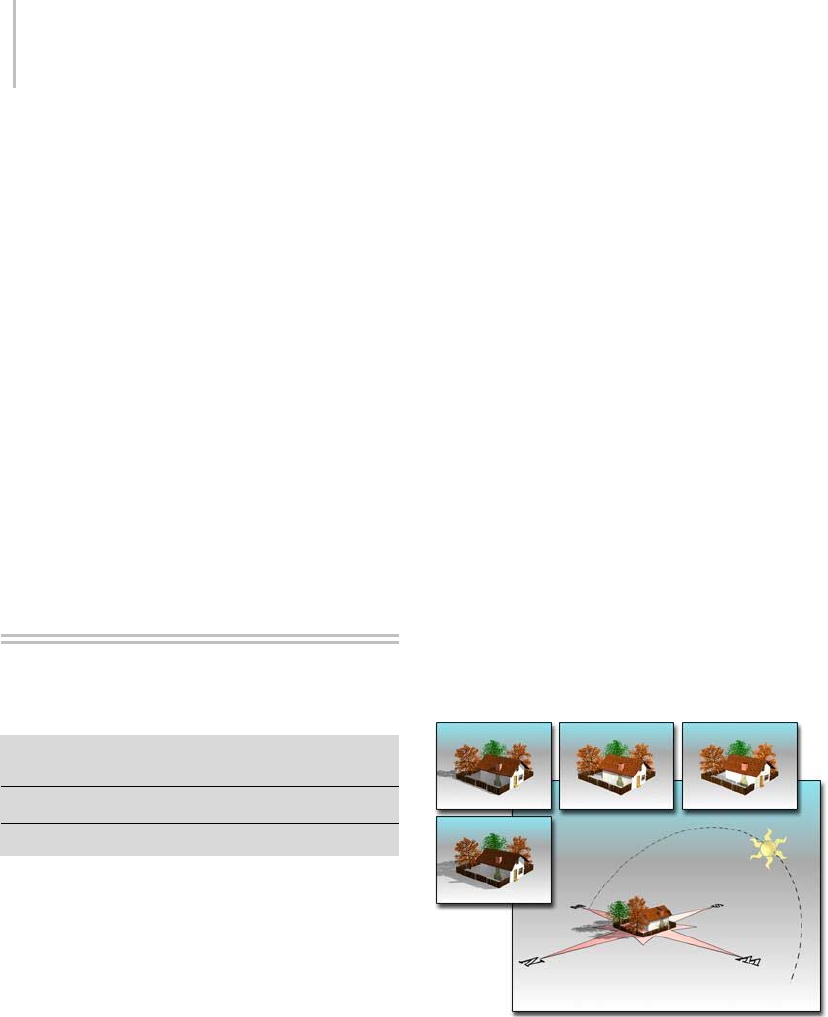
418 Chapter 5: Creating Geometry
Radius—Sets the radius of the ring. You set the
initial Radius value when you drag to create the
ring array.
Amplitude—Sets the amplitude of the ring’s sine
curve, in active units. Amplitude is a height offset
from the local origin of the center dummy object.
Cycles—Sets the number of cycles in the ring’s sine
curve. When Cycles is 0.0, the ring is flat. When
Cycles is 1.0, the ring is tilted. Greater values
increase the number of peaks in the curve.
Phase—Offsets the phase of the wave. That is,
it has the effect of moving the wave along the
circumference of the ring. Whole values have no
effect; only fractional values do.
Number—Sets the number of boxes in the ring.
Sunlight and Daylight
Systems
Create panel > Systems > Sunlight button and Daylight
button
Create menu > Lights > Daylight System
Create menu > Systems > Daylight System
The Sunlight and Daylight systems use light in
a system that follows the geographically correct
angle and movement of the sun over the earth at
a given location. You can choose location, date,
time, and compass orientation. You can also
animate the date and time. This system is suitable
for shadow studies of proposed and existing
structures. In addition, you can animate Latitude,
Longitude, North Direction, and Orbital Scale.
Sunlight and Daylight have a similar user interface.
Thedifferenceisthat:
•Sunlightusesadirectional light (page 2–1293).
•DaylightcombinesSunlight (page 3–1018)
and Skylight (page 3–1012).TheSunlight
component can be an IES Sun light (page
2–1309),anmr Sun light (page 2–1319),or
astandardlight(atarget direct light (page
2–1292)). The Skylight component can be an
IES Sky light (page 2–1312),anmr Sky light
(page 2–1318),oraSkylight (page 2–1296).
•TheIESSunandIESSkylightsare
photometric lights. It is appropriate to use
them if you are creating a rendering that uses
radiosity (page 3–51) with exposure control
(page 3–293).
• The mr Sun and mr Sky lights are also
photometric, but are intended for use with
the mental ray Sun & Sky (page 2–1313)
solution.
• The Standard light and Skylight are not
photometric. It is appropriate to use them if
your scene uses standard lighting (Sunlight
with its Directional light works for this, too),
or if you are using light tracing (page 3–44).
Large view shows compass and light in a viewport. The
resulting rendered images are seen above it.
Note: When you create a sunlight system or a
daylight system that uses a target direct light for
the sun, the directional light’s hotspot is set to
encompass all geometry in the scene, so that
shadows will render correctly. Specifically, the
Sunlight and Daylight Systems 419
diameter of the hotspot is set to 65 per cent of the
longest diagonal length of the scene extents (page
3–1007).
Procedures
To create a Sunlight or Daylight system:
1. On the Create panel, click Systems
and then click Sunlight or Daylight.
Alternatively, you can create a Daylight system
fromtheCreatemenu>LightsorSystems
submenu.
2. Choose a viewport in which to create a compass
rose (the compass direction of your "world").
This should be a Top or Perspective/Camera
view.
3. Drag to create the radius of a compass rose (the
radius is for display purposes only), and then
release the mouse button and move the mouse
to set the orbital scale of the sun light over the
compass rose. This can be any distance you
find convenient, since directional and IES Sun
lights produce parallel illumination regardless
of where their icon is located. Click to finish.
Upon creation you have two objects in your
scene:
•Thecompass rose (page 2–27),whichis
ahelperobjectthatprovidestheworld
direction for your sun.
• The light itself, which is a child of the
compass rose, and is permanently targeted
on the center of the compass rose.
If you created a Daylight system, the Daylight
Parameters rollout on the Modify panel lets
you choose the type of sunlight and skylight.
The Sunlight drop-down list lets you choose
IESSun,mrSun,orStandard(directional).
The Skylight drop-down list lets you choose
IES Sky, mr Sky, or Skylight. These lists
also offer you the options of choosing no
sunlight or no skylight.
Controls for the geographic location and time
of day are on the Motion panel. The default
timeisnoon,andthedefaultdateandtimezone
are based on your computer’s local settings.
The default location is San Francisco, CA.
The directional light created by the system is
managed by two special controllers: Solar Date
and Solar Time. After you create your system,
you can access its creation parameters (time
and date, location, orbital scale, and location)
in the Motion panel for the directional light.
The parameters are interrelated, so you can
adjust them in any order. Generally, it’s easiest
to choose a location first, and then adjust the
date and time. You can access the parameters
for selected sunlight or skylight objects in the
Modify panel. The radius of the compass rose
is also editable from the Modify panel, after
selecting the compass rose object.
If Date/Time position is selected the Sun
and Sky multipliers are automatically set and
animated according to their position. They can
be edited only by using the Manual Position
override.
Tip: UseExposureControlwithDaylightifyour
scene rendering is too bright or too dark.
Example: To create a shadow study:
1. Create a Daylight system.
2. OntheModifypanel,setthedateandLocation.
Note: Once the Daylight system has been
created, you can find these controls on the
Motion panel.
3. Turn on the Auto Key button.
4. In the Control Parameters Time group, adjust
the Hours spinner to a start time in early
morning.
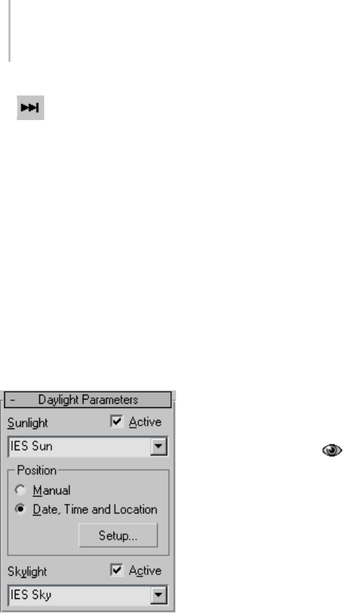
420 Chapter 5: Creating Geometry
5. Click the Go To End button.
6. Animatetheendtimetolateafternoon.
7. For a complete view of your environment and
its shadows, render an animation from a Top
viewport or a view above your scene.
Interface
Daylight Parameters rollout (Daylight system
only)
The Daylight Parameters rollout lets you define
the daylight system’s sun object. You can set the
sunlight and skylight behaviors.
This rollout appears on the Modify panel when the
light component of the Daylight system is selected.
Sunlight—Select one of three options for sunlight
in your scene:
•IES Sun—Uses an IES Sun object (page 2–1309)
to simulate the sun.
•mr Sun—Uses the mr Sun light (page 2–1319) to
simulate the sun.
•Standard—Uses a Ta rg e t Direct li ght (p a ge
2–1292) to simulate the sun.
•No Sunlight—No sunlight is simulated.
Active—Turnssunlightonandoffintheviewport.
Position group
Manual—When on, you can manually adjust the
location of the daylight assembly head object in
your scene, as well as the intensity value of the
sunlight.
Date, Time and Location—When on, uses the
geographically correct angle and movement of the
sun over the earth at a given location.
Note: When Date, Time And Location is active,
adjusting the light’s intensity has no effect.
Setup—Opens the Motion panel (page 3–774),
allowing you to adjust the time, location, and site
of your daylight system.
Skylight—Select one of three options for skylight
in your scene:
•IES Sky—Uses an IES Sky (page 2–1312) object
to simulate skylight.
•mr Sky—Uses the mr Sky light (page
2–1318) to simulate the sun.
•Skylight—Uses a Skylight (page 2–1296) object
to simulate skylight.
•No Skylight—No skylight is simulated.
Active—Turnsskylightonandoffintheviewport.
Motion panel, Daylight and Sunlight system
Control Parameters rollout
This rollout appears on the Create panel, and on
the Motion panel when the light component of the
Daylight or Sunlight system is selected.

Sunlight and Daylight Systems 421
Manual Override (Daylight system only)—When on,
you can manually adjust the location of the sun
object in your scene, as well as the intensity value
of the sun object.
Azimuth/Altitude—Displays the azimuth and
altitude of the sun. Azimuth is the compass
directionofthesunindegrees(North=0,
East=90). Altitude is the height of the sun above
the horizon in degrees (Sunrise or Sunset=0).
Time group
Provides settings for the time, date, and time zone.
If the location you choose uses Daylight Savings
Time, turn on the Daylight Saving Time checkbox.
The Sunlight system adjusts the sun’s azimuth and
altitude accordingly during the summer months.
Hours/Mins/Secs—Specify the time of day.
Month/Day/Year—Specify the date.
Time Zone—Time zones range from –12 to 12. If
you’reuncertainaboutatimezone,youcanlook
them up in Window’s Date > Time Properties
dialog (available through My Computer > Control
Panel > Date > Time). Click the Time Zone tab,
and then display the list of world locations and
their time zones.
Daylight Savings Time—When on, calculates
daylight savings by adjusting azimuth and altitude
during the summer months.
Location group
Provides controls for setting the location of your
scene in the world.
Get Location—Displays the Geographic Location
dialog (page 1–422), which lets you set the latitude
and longitude values by selecting a location from
a map or a list of cities.
Note: For precise locations, enter exact coordinates
using Latitude/Longitude.
[city name text box]—Displaysthenameofthecity
you choose from the Geographic Location dialog.
If you adjust the Latitude or Longitude spinners
after choosing a location, this area becomes blank.
Latitude/Longitude—Specify the location based on
the latitude and longitude.
Site group
Orbital Scale—Sets the distance of the sun (the
directional light) from the compass rose. Because a
directionallightcastsparallelbeams,thisdistance
has no effect on the accuracy of the sunlight.
However, the light must point toward your model
(not away from it), and the light’s hotspot and
falloff do have an effect.
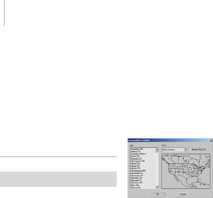
422 Chapter 5: Creating Geometry
The best way to ensure that the light is set up
correctly is to change one viewport to the light’s
view (for example, Sun 01). Then adjust the light’s
location using Dolly (page 3–751),andsetthe
hotspot so it illuminates the whole model, with no
falloff.
North Direction—Sets the rotational direction
of the compass rose in the scene. This is the
geographical orientation of the compass rose. By
default, north is 0 and points along the positive Y
axis of the ground plane. Positive X (East) is 90
degrees. Adjust the North Direction to correspond
to your site. Accuracy of the system depends on
this correspondence.
Geographic Location Dialog
Select Sunlight or Daylight system > Motion panel >
Location group > Get Location button
TheGeographicLocationdialogispartofthe
Sunlight and Daylight systems’ (page 1–418)
interface. It lets you set the latitude and longitude
values by selecting a location from a map or a list
of cities. The dialog displays a list of cities at left,
and a map on the right.
Procedures
To use a map:
1. IntheLocationgroupontheControl
Parameters rollout, click the Get Location
button.
2. On the Geographic Location dialog choose a
mapfromtheMaplist.
3. Click in the map to specify a location.
3dsMaxdisplaysasmallcrossatthelocation
you picked. If Nearest Big City is on, it places
thecrossatthenearestlargecityonthelist,and
highlights the city’s name in the list.
4. ClickOKtosettheLatitudeandLongitudeto
the location of the cross.
Tochooseacitybyname:
1. Choose a map from the Map list.
The City list updates to show cities in the region
of the map.
2. Choosethenameofacityfromthelist.
3. ClickOKtosettheLatitudeandLongitudeto
the location of the city.
Interface
City—Displays a list of cities within the selected
Map region. As an alternative to selecting a
location by clicking the map, you can select a city
directly from this list. The cross on the map moves
to the location of the selected city.
Map—Lets you choose a map for a portion of the
world, or you can choose the World map, which
includestheentireworld.
Nearest Big City—When on, clicking the map
movesthecrosstothenearestlistedcity,which
becomes highlighted in the list. When off, clicking
the map places the cross exactly where you
clicked, and its position generates the Latitude and
Longitude values for that position, regardless of
any cities that might be nearby.
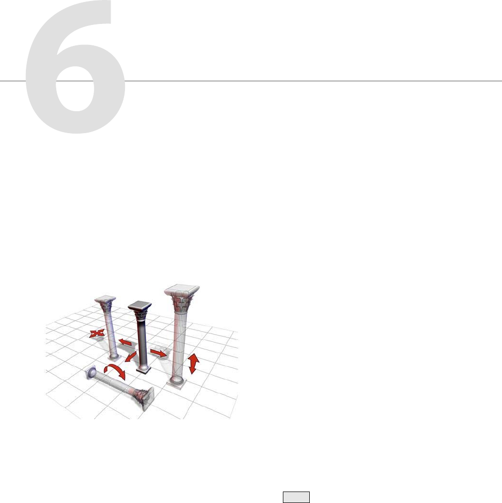
To change an object’s position, orientation, or
scale, click one of the three transform buttons
on the Main toolbar or choose a transform from
ashortcutmenu. Applythetransformtoa
selected object using the mouse, the status bar
Coordinate Display fields, a type-in dialog, or any
combination of the above.
The column can be moved, rotated, and scaled.
These topics describe how to use and animate
transforms, with procedures:
Using Transforms (page 1–424)
Using Transform Gizmos (page 1–426)
Transform Type-In (page 1–431)
Animating Transforms (page 1–432)
Transform Managers (page 1–433)
Specifying a Reference Coordinate System (page
1–435)
Choosing a Transform Center (page 1–435)
Using the Axis Constraints (page 1–437)
Transform Commands (page 1–438)
Transform Coordinates and Coordinate Center
(page 1–442)
Transform Tools (page 1–448)
Scaling and Dimensions
If you scale an object and later check its base
parameters in the Modify panel, you see the
dimensions of the object before it was scaled. The
base object exists independently of the scaled
object that is visible in your scene.
Yo u c a n u s e t h e Measureutility(page2–52)to
measure the current dimensions of an object that
has been scaled or changed by a modifier.
Creating Copies and Arrays (page 1–471)
Using Shift +Clone (page 1–478)
Transforms: Moving, Rotating, and
Scaling Objects
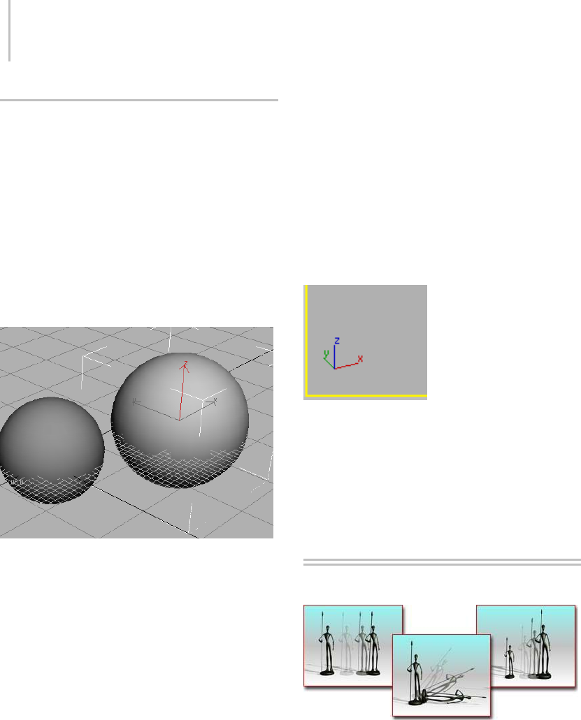
424 Chapter 6: Transforms: Moving, Rotating, and Scaling Objects
Axis Tripod and World Axis
Two visual aids in 3ds Max give you information
about your current orientation in the workspace.
Axis Tripod
If no transform tool is active, an axis tripod
appears in the viewports whenever you select one
or more objects, to assist you visually in your
transforms. When a transform tool is active, the
transform gizmo (page 1–426) appears instead,
unless you’ve turned it off.
The axis tripod appears when the transform gizmo is inactive.
The axis tripod consists of three lines, labeled X, Y,
and Z, and shows you three things:
• The orientation of the tripod reveals the
orientation of the current reference coordinate
system.
• The location of the junction of the three axis
lines shows you where your transform center is.
• The highlighted red axis lines show you the axis
or axes to which the transform is constrained.
For example, if only the X axis line is red, you
can move objects only along the X axis.
World Axis
In the lower-left corner of each viewport you
can find the world axis, which shows the current
orientation of the viewport with respect to world
coordinate system. The world axis colors are red
for X, green for Y, and blue for Z. You can toggle
the display of the world axis in all viewports by
turning off Display World Axis, on the Viewports
panel (page 3–821) of the Preference Settings
dialog.
The world axis shows the current viewport orientation.
See also
Using Transform Gizmos (page 1–426)
Transform Managers (page 1–433)
Using Transforms
Changing a model by changing its position, rotation, or scale
A transform is an adjustment of an object’s
position,orientation,orscale,relativetothe3D
world (or world space) in which you’re working.
You can apply three types of transform to an
object:
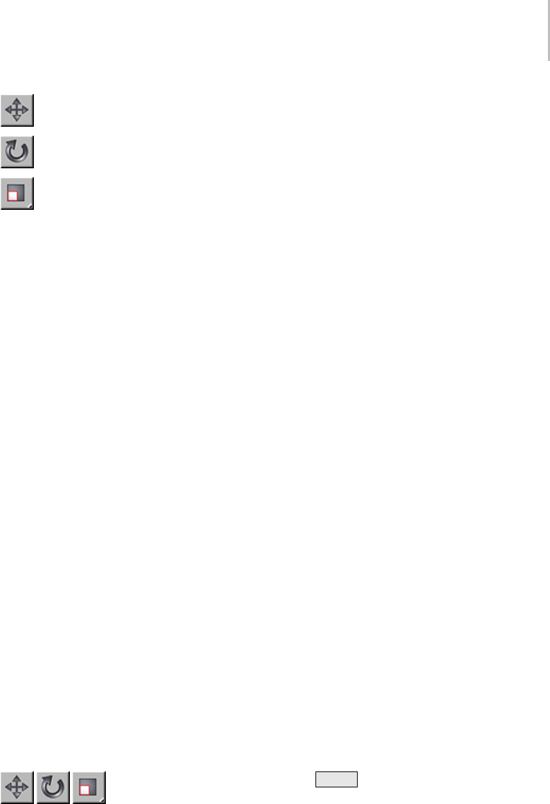
Using Transforms 425
•Position (page 1–439)
•Rotation (page 1–439)
•Scale (page 1–440)
This section presents these brief topics designed to
help you quickly start learning how to transform
objects, and how to animate your transforms:
Using Transform Gizmos (page 1–426)
Animating Transforms (page 1–432)
Transform Managers (page 1–433)
Specifying a Reference Coordinate System (page
1–435)
Choosing a Transform Center (page 1–435)
Using the Axis Constraints (page 1–437)
FailuretoMoveorRotate
In some cases, an object might fail to move or
rotate, even when the proper button is on and the
object is selected. This could be due to one of the
following reasons:
•Theobjectisfrozen.SeeSelecting Objects (page
1–61).
• A transform controller has been assigned to the
object. See Animation Controllers (page 2–307).
•InverseKinematicsmodeisonandthe
preference called Always Transform Children
of the World is off. See Introduction to Inverse
Kinematics (IK) (page 2–435).
Procedures
To transform an object using the Main toolbar:
1. On the Main toolbar, click
oneofthethreetransformbuttons:Select And
Move (page 1–439),Select And Rotate (page
1–439),orSelect And Scale (page 1–440).These
buttons are usually referred to as Move, Rotate,
and Scale.
2. Position the mouse over the object you want
to transform.
•Iftheobjectisalreadyselected,thecursor
changes to indicate the transform.
•Iftheobjectisnotselected,thecursor
changestoasmallplussigntoshowthatthe
object can be selected.
3. Drag the mouse to apply the transform.
If you drag the mouse over an unselected object,
it becomes selected and is also transformed.
You can use the Transform gizmo to easily
restrict transforms to one or two axes. See
Using Transform Gizmos (page 1–426).
To cancel a transform:
• Right-clickwhileyou’redraggingthemouse.
Totransformanobjectfromthequadmenu:
1. Right-click a selected object. The quad menu
(page 3–694) lists the three transforms.
2. Choose one of the transforms. The equivalent
transform button is selected on the main
toolbar.
3. Drag the object to apply the transform.
To use transform type-in:
1. Choose Tools menu > Transform Type-In to
display the dialog.
2. Apply a transform to a selected object.
3. You can do any of the following, switching from
one to the other as required.
• Typeavalueinanaxisfieldandpress
Enter to apply the transform change to the
selection.
• Dragaspinnerinanaxisfieldtoupdatethe
selection.
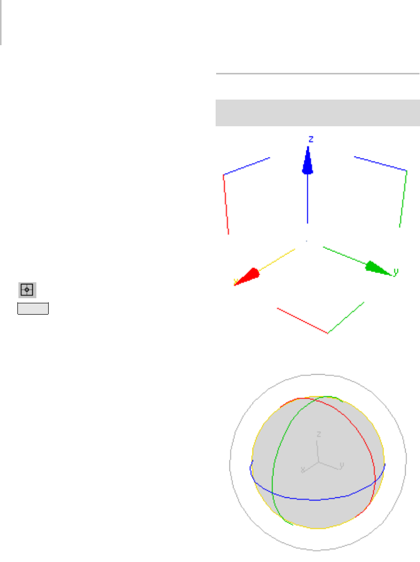
426 Chapter 6: Transforms: Moving, Rotating, and Scaling Objects
• Drag the object to apply the transform and
read the resulting change in the dialog.
For example, if Move is active, the dialog fields
read out both the absolute and offset positions of
the selected object in world space. If no object is
selected, the fields turn gray.
To use transform type-in on the status bar:
1. Select an object or a group of objects.
2. On the Main toolbar, choose a transform
(Move, Rotate, or Scale) to perform on the
objects.
3. On the status bar, you can do any of the
following, switching from one to another as
required:
•Type a value in an axis field and press
Enter to apply the transform change to the
selection. The Absolute/Offset toggle, to the
right of the X, Y, and Z fields, lets you switch
between entering values that are absolute
(in world space) or offset (relative to the
selection’s present position, orientation, and
dimensions).
• Dragaspinnerinanaxisfieldtoupdatethe
selection.
• Drag the object to apply the transform and
read the resulting change in the X, Y, and Z
fields.
Tip: To see the Z field, drag the transform
type-in portion of the toolbar while a pan
hand is visible.
Using Transform Gizmos
Select an object. > main toolbar > Click any transform
button to display the object’s Transform Gizmo icon.
Move gizmo
Rotate gizmo
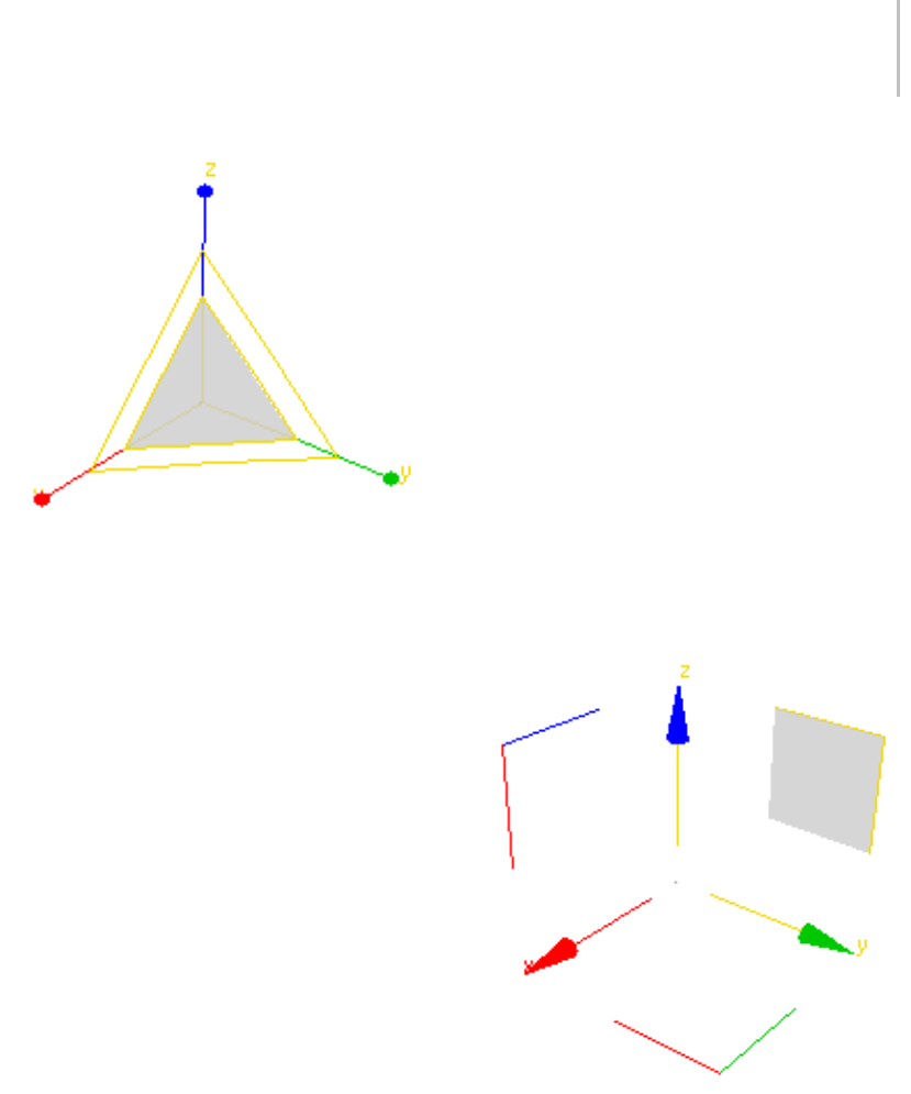
Using Transform Gizmos 427
Scale gizmo
TheTransformgizmosareviewporticonsthat
let you quickly choose one or two axes when
transforming a selection with the mouse. You
chooseanaxisbyplacingthemouseoveranyaxis
of the icon, and then drag the mouse to transform
the selection along that axis. In addition, when
moving or scaling an object, you can use other
areasofthegizmotoperformtransformsalong
any two axes simultaneously. Using a gizmo avoids
the need to first specify a transform axis or axes
on the Axis Constraints toolbar (page 3–687),and
also lets you switch quickly and easily between
different transform axes and planes.
A Transform gizmo appears when one or more
objects are selected and one of the transform
buttons (Select And Move (page 1–439),Select And
Rotate (page 1–439),orSelect And Scale (page
1–440)) is active on the toolbar. Each transform
type uses a different gizmo. By default, each axis is
assigned one of three colors: X is red, Y is green,
and Z is blue. The corners of the Move gizmo are
assigned the two colors of the related axes; for
example, the corner for the XZ plane is red and
blue.
When you position the mouse over any axis, it
turns yellow to indicate that it’s active. Similarly,
positionthemouseoveroneoftheplanehandles,
andbothassociatedaxesturnyellow.Youcannow
drag the selection along the indicated axis or axes.
Doing so changes the Axis Constraints toolbar
"Restrict to ..." setting (page 1–437).
Move Gizmo
TheMovegizmoincludesplanehandles,andthe
option to use a center box handle.
You can select any of the axis handles to constrain
movement to that axis. In addition, the plane
handles allow you to constrain movement to the
XY, YZ, or XZ planes. The selection hotspot is
within the square formed by the plane handles.
You can change the size and offset of the handles
and other settings on the Gizmos panel (page
3–832) of the Preferences dialog (page 3–815).
TheMovegizmowiththeYZaxesselected.
You can constrain translation to the viewport
plane by dragging the center box. To use this
optional control, turn on Move In Screen Space.
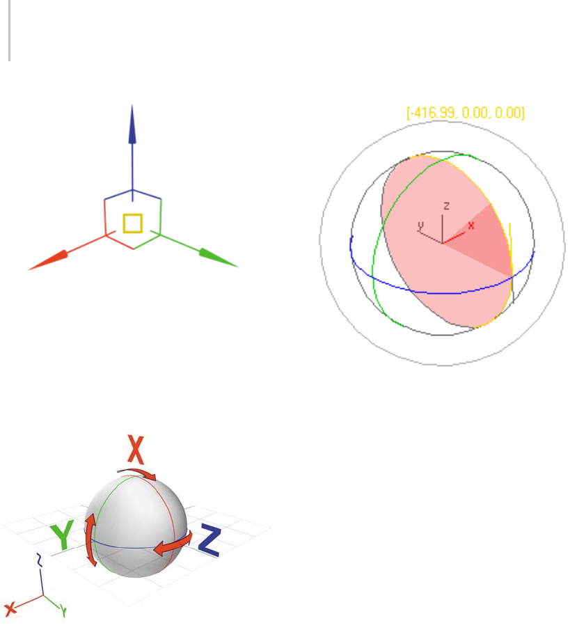
428 Chapter 6: Transforms: Moving, Rotating, and Scaling Objects
Rotate Gizmo
The Rotate gizmo is built around the concept
of a virtual trackball. You can rotate an object
freely,abouttheX,Y,orZaxis,oraboutanaxis
perpendicular to the viewport.
The axis handles are circles around the trackball.
Drag anywhere on one of them to rotate the
object about that axis. As you rotate about the X,
Y, or Z axis a transparent slice provides a visual
representation of the direction and amount of
rotation. If you rotate more than 360°, the slice
overlaps and the shading becomes increasingly
opaque. The software also displays numerical data
to indicate a precise rotational measurement.
In addition to XYZ rotation, you can also use free
rotation or the viewport handle to rotate objects.
Drag inside the Rotate gizmo (or the outer edge
of the gizmo) to perform free rotation. Rotation
should behave as if you were actually spinning the
trackball.
TheoutermostcirclearoundtheRotategizmois
the Screen handle, which lets you rotate the object
on a plane parallel to the viewport.
You can adjust settings for the Rotate gizmo on
the Gizmos panel (page 3–832) of the Preferences
dialog (page 3–815)
Scale Gizmo
The Scale gizmo includes plane handles and
scaling feedback through the stretching of the
gizmo itself.
The plane handles let you perform uniform and
non-uniform scaling without changing your
selection on the main toolbar:
• To perform Uniform scaling, drag in the center
of the gizmo.
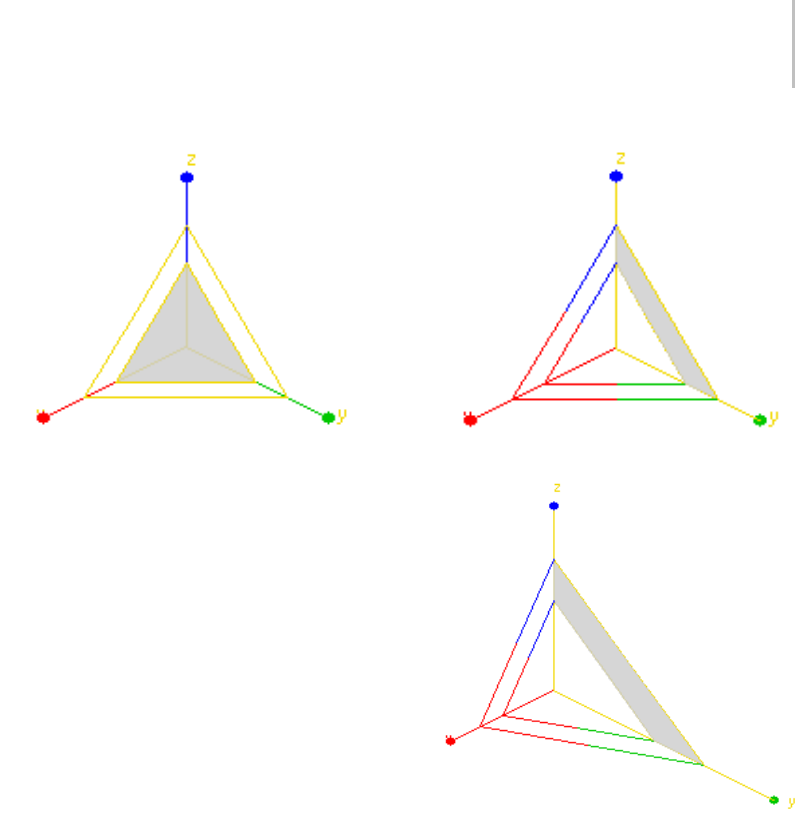
Using Transform Gizmos 429
The Transform gizmo with Uniform scaling selected.
• To perform non-uniform scaling, drag on a
single axis or a plane handle.
Top: The Scale gizmo with the YZ plane handle selected
Bottom: Non-uniform scaling on the YZ plane
Note: To perform a Squash operation, you must
choose Select and Squash (page 1–442) on the
main toolbar.
The Scale gizmo provides feedback by changing
itssizeandshape;inthecaseofauniformscale
operation, it will grow or shrink as the mouse
moves, and during non-uniform scaling, the
gizmo will stretch and deform while dragging.
However, once the mouse button is released, the
gizmo returns to its original size and shape.
430 Chapter 6: Transforms: Moving, Rotating, and Scaling Objects
You can adjust settings for the Scale gizmo on
the Gizmos panel (page 3–832) of the Preferences
dialog (page 3–815)
Notes
Using a Transform gizmo sets the default axis
constraint to the last axis or plane you used.
If Lock Selection Set is on, you can drag anywhere
in the viewport to transform the object. Dragging
an axis, however, still applies the constraint along
that axis.
Procedure
Example: To explore use of the transform gizmo:
1. Reset the program, then create a sphere,
and then click the Select and Move button.
TheTransformgizmoappearsatthecenterof
the sphere. Because the default axis constraint
on the Axis Constraints toolbar is XY Plane,
the X and Y shafts of the Transform gizmo are
yellow (active), while the Z shaft is blue.
2. Use Arc Rotate (page 3–744) to adjust
the Perspective viewforabetterviewof
the Transform gizmo. When you’re done,
right-click to return to Select and Move .
3. Pointtoanypartofthesphereawayfromthe
Trans for m g izmo, and drag to confirm that the
sphere is locked to the XY plane.
4. Point to the Z-axis shaft, and drag.
The Z shaft turns yellow, the X and Y shafts
turn red and green, respectively, and the sphere
moves along theZaxis.
5. Point to the Y shaft, and drag.
The Y shaft turns yellow, and the sphere moves
along only the Y axis.
6. Point to the red-and-green corner mark
opposite the ends of the X and Y axes, and drag.
ThespheremovesalongtheXYplane.
7. Press the Spacebar to turn on Selection Lock
(page 3–707).
8. Drag the mouse anywhere in a viewport away
from the selection.
ThespheremovesalongtheXYplane.
9. Point to the X shaft, and drag.
ThespheremovesalongonlytheXaxis.
Experiment with other transformations, such
as rotation and scale. Try different reference
coordinate systems. Experiment with sub-object
transformations.
Interface
Change default colors—Customize menu >
Customize User Interface dialog > Colors panel
(page 3–799) > Gizmos Element > Active
Transform Gizmo and Transform Gizmo X/Y/Z.
Enable/disable Transform Gizmo—Customize menu
> Preferences > Gizmos panel (page 3–832) >On
check box.
Note: When you turn off the Transform gizmo
in Preferences, the standard axis tripod appears
instead. To toggle display of either the gizmo or
the tripod, press the Xkey or use Views menu >
Show Transform Gizmo.
There are additional controls for each Gizmo in
the Gizmos panel (page 3–832) of the Preferences
dialog.
Gizmos Preferences (page 3–832)
Transform Type-In 431
Transform Type-In
Status bar > Transform Type-In
Edit menu > Transform Type-In
F12
Main toolbar > Right-click Select And Move, Select And
Rotate, or one of the Select And Scale buttons.
Transform Type-In is a dialog that lets you
enter precise values for move, rotate, and scale
transforms (page 3–1026). You can use Transform
Type-In w ith any thing that can display an axis
tripod or Transform gizmo.
You can also use the Transform Type-In boxes on
the status bar (page 3–698).TousetheTransform
Type-In boxes on the status bar, simply enter the
appropriatevaluesintheboxesandpress Enter
to apply the transformation. You can alternate
between entering absolute transform values or
offset values by clicking the Relative/Absolute
Transform Type-In button to the left of the
transform boxes.
If you choose Transform Type-In from the Edit
menu, press F12 ,orright-clickoneofthe
transform toolbar buttons, Transform Type-In
pops up as a dialog. The title of the dialog reflects
theactivetransform.IfRotateisactive,thedialog’s
titleisRotateTransformType-Inanditscontrols
affect rotation. If Scale is active, its title is Scale
Transform Type-In, and so on. You can enter
either absolute transform values or offset values.
In most cases, both absolute and offset transforms
use the active reference coordinate system (page
1–443). The exceptions are View, which uses the
World coordinate system, and Screen, which uses
World for absolute moves and rotations. Also,
absolute scaling always uses the Local coordinate
system. The dialog labels change to show the
reference coordinate system being used.
When you use the Transform Type-In at a
sub-object level, you transform the transform
gizmo of the sub-object selection. So, for example,
theabsolutepositionvaluesrepresenttheabsolute
world position of the transform gizmo. If you’ve
selectedasinglevertex,it’stheabsoluteworld
position of the vertex.
If multiple vertices are selected, the Transform
gizmo is placed at the center of the selection, so the
position you specify in the Transform Type-In sets
theabsolutepositionofthecenteroftheselected
vertices.
When multiple vertices are selected in Local
transform mode, you end up with multiple
transform gizmos. In this case, only the Offset
control is available.
Because the axis tripods are not scaled, the
Absolute Scale control is not available at the
sub-object level. Only Offset is available.
When you use the Transform Type-In for Absolute
rotation, the state of the Center flyout is respected.
You can perform absolute rotations about the
pivot point of the object, the selection center,
or transform coordinate center. See Choosing a
Transform Center (page 1–435).
Using Type-In with Sub-Object Selection
Yo u c a n u s e Tr a n s f or m Ty p e - I n w i t h a n y
sub-object selection or gizmo. The transform
affects the axis tripod for the selection.
Absoluteandoffsetworldcoordinatesarethose
of the object’s or selection’s coordinate system,
whoseoriginisindicatedbytheaxistripod. If
multiple vertices are selected, the tripod is at the
center of the selection and its location is given in
world coordinates.
Because axis tripods cannot be scaled, Absolute
Scalefieldsareunavailablewhenyouareata
sub-object level.
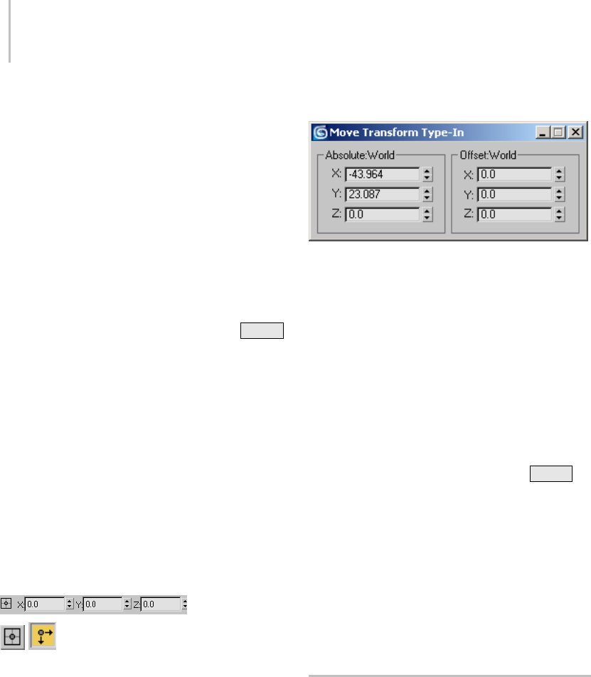
432 Chapter 6: Transforms: Moving, Rotating, and Scaling Objects
See Basics of Creating and Modifying Objects (page
1–153) for information on sub-object selection
and gizmos.
Procedure
To use transform type-in:
1. Select an object or a group of objects.
2. Choose a transform to perform on the objects
(Move, Rotate, or Scale).
3. You can do any of the following, switching from
one to another as required:
• Type a value in an axis field and press Enter
to apply the transform change to the object
in the viewport.
• Dragaspinnerinanaxisfieldtoupdatethe
object in the viewport.
• Drag the object to apply the transform and
read the resulting change in the axis fields.
For example, if Move is active, the fields
read out both the absolute positions of the
selected object in world space. If no object is
selected, the fields turn gray.
Interface
Status bar
Absolute/Offset Mode Transform
Type-In—When this is off, the software treats
valuesyouenterintotheX,Y,andZfieldsas
absolutes. When this is on, the software applies
transform values you enter as relative to current
values; that is, as an offset. Default=off.
X, Y, and Z—Displayandacceptentryforvaluesof
position, rotation, and scale along each axis.
Absolute group (Dialog)
X, Y, and Z—Display and accept entry for absolute
values of position, rotation, and scale along each
axis. Position and rotation are always displayed, as
world scale is always local.
Offset group (Dialog)
X, Y, and Z—Displayandacceptentryforoffsets
of the position, rotation, and scale values along
each axis.
Displayed offset values revert to 0.0 after each
operation. For example, if you enter 45 degrees
in a Rotate Offset field, when you press Enter ,
the software rotates the object 45 degrees from
itspreviousposition,increasestheAbsolutefield
value by 45 degrees, and resets the Offset field to
0.0.
Offset labels reflect the active reference coordinate
system. The Offset can be Offset: Local, Offset:
Parent, and so on. If you use Pick to select the
reference coordinate system of a particular object,
the Offset will be named with that object.
Animating Transforms
You can animate changes in position, rotation, and
scale (transforms) by turning on the Auto Key
button and then performing the transform at any
frame other than frame 0. This creates a key for
that transform at the current frame.
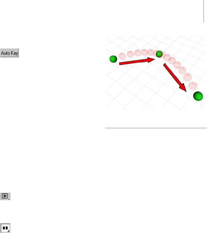
Transform Managers 433
Example: To animate an object moving among three
points:
1. Tur n on the Auto Key button (page
2–278).
The Auto Key button and the highlight border
around the active viewport both turn red.
2. Dragthetimeslidertoframe25.
3. Move the object from its current position (point
A) to another location (point B).
ThesoftwarecreatesMovekeysatframes0and
25. These appear on the track bar (page 3–703).
The establishing key at frame 0 describes the
object’s original position, at point A. The key
atframe25describestheobject’spositionat
point B.
4. Dragthetimeslidertoframe50.
5. Move the object from point B to a third location
(point C).
ThesoftwarecreatesaMovekeyatframe50
that describes the object’s position at point C.
6. Click the Auto Key button to stop recording.
7. Click the Play button (page 3–723).
TheobjectmovesfrompointAtopointBover
frames 0 to 25, and then proceeds to point C
over frames 26 to 50.
8. The Play button has turned into a Stop
button; click Stop to stop playback.
You can combine different transforms in a single
animation sequence, so that an object appears to
move as it rotates and changes in size.
See Animation Concepts and Methods (page 2–275)
for more information on animation techniques.
An object animated among three points
Transform Managers
3ds Max provides three controls, collectively
referred to as the transform managers, for
modifying the action of the transform tools.
The transform manager controls are as follows:
•TheReferenceCoordinateSystemdrop-downlist
(page 1–443), which controls the orientation of
the transform axes, is found to the right of the
Move, Rotate, and Scale transform buttons on
the main toolbar.
•TheTransform Center flyout (page 1–445),
which controls the center about which the
software applies the transform, is found to
the right of the Reference Coordinate System
drop-down list.
•TheAxis Constraint setting (page 1–437) lets
you restrict the transform to a single axis or two
axes (that is, a plane). The axis constraint tools
appear on the Axis Constraints toolbar, which
is off by default. You can open the toolbar
by right-clicking an empty spot on the main
toolbar and choosing Axis Constraints from
the menu.
Tip: You can also restrict transforms with the
transform gizmos (page 1–426).

434 Chapter 6: Transforms: Moving, Rotating, and Scaling Objects
Definitions
Certain terms are used in the description of
transforms and the transform managers.
•Anaxis is a straight line along which an object
is moved or scaled, or about which an object is
rotated. When you work in 3D, you use three
axes, labeled X, Y, and Z, which are oriented 90
degrees from each other.
•Acoordinate system specifies the orientation of
the X, Y, and Z axes used by a transform.
For example, in the World coordinate system,
as seen from the Front view, the X axis runs
horizontally from left to right, the Y axis
runs from back to front, and the Z axis runs
vertically, from bottom to top.
On the other hand, each object carries its own
Local coordinate system. If the object has been
rotated, its Local coordinate system might be
different from the world coordinate system.
•Thetransform center, or pivot point, is the spot
about which a rotation takes place, or to and
from which scaling occurs.
Using the transform managers, you can specify
any combination of axes, transform coordinate
systems, and transform centers.
Axis Tripod Icon
• An axis tripod appears in the viewports when
you select one or more objects, to assist you
visually in your transforms. This tripod
consists of three lines, labeled X, Y, and Z, and
shows you three things:
• The orientation of the tripod reveals the
orientation of your coordinate system.
• The location of the junction of the three axis
lines shows you where your transform center is.
• The highlighted red axis lines show you the axis
or axes to which the transform is constrained.
For example, if only the X axis line is red, you
can move objects only along the X axis.
Note: The Transform gizmo supplants the axis
tripod for selections when a transform mode
is active. Besides providing all of the above
functions, it lets you specify the transform axis
or axes without explicitly setting constraints;
see Using the Axis Constraints (page 1–437).
For more on the Transform gizmo, see Using
Transform Gizmos (page 1–426).
You can toggle the display of the axis tripod in
all viewports by choosing Views menu > Show
Transform Gizmo, or by pressing the Xkey.
Transform Manager Settings
The state of the three transform managers
(coordinate system, center, and axis constraints)
is stored with each type of transform. When you
switch from Move to Rotate to Scale, the transform
managers change to whatever combination they
were in when you last used that transform.
For example, if you click Rotate and set the
transform managers to Local, Selection Center,
and Y constraint, when you click Move, the
controls might shift to View, Pivot Point, and XY
constraint (whichever combination was set the
last time you used Move). When you go back
to Rotate, the controls revert to Local, Selection
Center, and Y constraint.
Tip: To avoid surprises, always click the transform
button first, and then set the transform managers.
If, instead, you first set the transform managers,
their settings are likely to change as soon as you
choose a new transform button. One way to
remember this is always to set the transform and
managers by working from left to right on the
toolbar. Alternatively, you can turn on Customize
menu > Preferences > General tab > Reference
Coordinate System group > Constant, which keeps
the transform manager settings the same for all
transforms.

Specifying a Reference Coordinate System 435
Specifying a Reference Coordinate
System
The reference coordinate system determines the
orientation of the X, Y, and Z axes used by the
transform. The type of transform system you use
affects all transform operations.
You specify the transform coordinate system using
the Reference Coordinate System list (page 1–443).
Creating a Local Axis
While modeling, it’s often helpful to have a
temporary, movable local axis so you can rotate or
scale about an arbitrary center.
Note: This technique does not work for animation.
See Choosing a Transform Center (page 1–435) for
animation tips.
To create an adjustable local axis:
1. Create a Point helper object.
You can use the Create panel or the Create
menu. On the Create panel, click the Helpers
button, click Point, and then click in a viewport.
Or,chooseCreatemenu>Helpers>Point,and
then click in a viewport.
2. From the Transform Coordinate System list,
choose Pick, and then click the point object.
Thenameofthepointobjectappearsinthelist
astheactivecoordinatesystem.
Now you can use the point object’s coordinate
system as an adjustable axis.
To use the adjustable axis:
1. Placethepointobjectwhereyouwanttherotate
or scale transform to be centered.
2. Select the object you want to transform.
3. Choose the point object’s name in the
TransformCoordinateSystemdrop-downlist.
4. From the Use Center flyout (page 1–445) choose
Use Transform Coordinate Center. For more
information, see Choosing a Transform Center
(page 1–435).
5. Proceed with the transform.
Choosing a Transform Center
The transform center affects scale and rotation
transforms, but has no effect on position
transforms.
The software lets you choose from three types of
transform center using the Use Center flyout (page
1–445) on the main toolbar. When you change the
transform center, the junction of the axis tripod
icon moves to the location you specify.
By default, 3ds Max sets the transform center to
Use Pivot Point center for single objects. When
you select multiple objects, the default transform
center changes to Use Selection Center, because
selection sets have no pivot point. You can change
the transform center in either case, and the
program remembers and restores the transform
center setting separately for selections of single
and multiple objects (during the current session).
Forexample,youmightselectasingleobjectand
choose Use Transform Coordinate Center, and
then select multiple objects and choose Use Pivot
Point Center. When you next select a single object,
the program switches back to Use Transform
Coordinate Center. Then, when you select multiple
objects, the center switches back to Pivot Point.
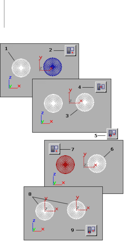
436 Chapter 6: Transforms: Moving, Rotating, and Scaling Objects
1. User selects single object.
2. User clicks Use Transform Coordinate Center from Use Center
flyout on Main toolbar.
3. User adds second object to selection.
4. Transform center changes to Use Selection Center when
selection set contains more than one object.
5. User clicks Use Pivot Point Center while multiple objects
still selected.
6. User selects single object.
7. Transform center returns to Use Transform Coordinate
Center (see step 2).
8. User selects multiple objects.
9. Transform center returns to Use Pivot Point Center (see step
5).
Transforming About Snapped Points
While the transform center choices are often useful
at the object level, they are not usually convenient
when transforming sub-object selections. You can
override the active transform center and perform
the current transform about a temporary point
by using snaps. When Snaps is active, and your
selection is locked, the point you snap to will set
the point about which the transform is performed.
Usingthistechnique,youcan:
• Moverelativetotwosnappoints.
• Rotate about a snapped point.
• Scale about a snapped point.
For more details, see Snap Settings (page 2–41).
Animation and the Transform Center
Because of the nature of keyframing, you can
animate rotation and scale transforms properly
only by using an object’s local pivot point. For
example, while modeling, you can rotate an object
that’s offset from the world origin around the
world center coordinate system. The object sweeps
around the origin in a large arc. However, if you
attempt to animate this, the object rotates about its
localaxisandmovesinastraightlinefromone
end of the arc to the other.
To avoid this discrepancy, if the Auto Key button is
on and either the Rotate or Scale button is active,
the Use Center flyout is unavailable and set to Use
Pivot Point. When the Auto Key button is off,
all transforms use the center settings previously
described.
You can override this behavior by turning off
Local Center During Animate (page 3–830) in the
Animation Preferences settings.
Keep in mind that this affects only the center of
the transform. The orientation of the selected
transformcoordinatesystemisstillineffect.
Animating "Off-Center"
You can animate a rotation or scale about an
off-center point by linking your object as the child
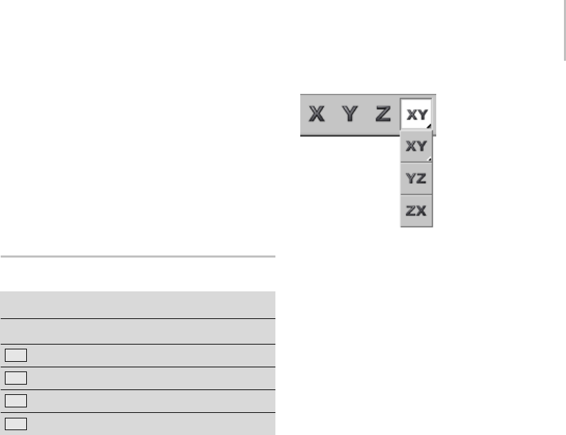
Using the Axis Constraints 437
of a dummy helper object, and then rotating or
scaling the dummy.
Another technique is to offset the pivot point of
your object using the Hierarchy panel.
For information about linking, dummy objects,
and the Hierarchy panel, see Hierarchies (page
2–416).
Using the Axis Constraints
AxisConstraintstoolbar>RestricttoX,Y,Z,oraplane
Keyboard >
F5 restricts to X
F6 restricts to Y
F7 restricts to Z
F8 cycles through the three plane restrictions
The Restrict to ... buttons, also called the Axis
Constraint buttons, are located on the Axis
Constraints toolbar (page 3–687),whichisoffby
default. You can turn it on by right-clicking an
empty spot on the main toolbar and choosing
Axis Constraints from the pop-up menu. These
buttons let you specify one or two axes about or
along which the transform takes place. They help
you avoid transforming an object in a direction
you didn’t intend.
Note: It’s generally easier to use the Transform
gizmos than these buttons; see Using Transform
Gizmos (page 1–426). However, it is helpful to
understand the concepts explained below.
Axis Constraint buttons
Only one axis constraint can be active at a time.
Whenabuttonisturnedon,transformsare
constrained to the specified axis (or plane). For
example,ifyouturnontheRestrictToXbutton,
you can rotate an object only about the X axis of
the current transform coordinate system.
The axis or axes to which you’re constrained
are highlighted in red on the axis tripod icon in
viewports, or in yellow on the Transform gizmo.
Note: By default, axis constraints don’t apply when
using Snap. You can override this by turning on
Snaps Use Axis Constraint Toggle on the Axis
Constraints toolbar (page 3–687),orbyturningon
Use Axis Constraints in Snap Options (page 2–46).
Note: Constraintsaresetonatransform-by-
transform basis, so select the transform before you
select the axis constraint. If you do not want the
constraints to change, turn on Customize menu >
Preferences > General tab > Reference Coordinate
System group > Constant.
The axis constraints are stored separately at
object and sub-object levels. If you set these
three controls one way while in sub-object mode
and another way while in object selection level,
when you return to sub-object mode, they’re
restored to the way they were previously set. For
example, if you’re using XY constraints at object
level, then switch to sub-object level and use Z
constraint, when you return to object level, XY
will be restored.
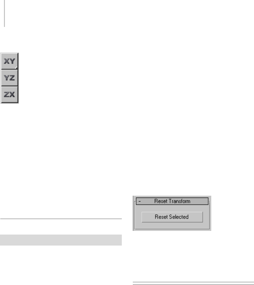
438 Chapter 6: Transforms: Moving, Rotating, and Scaling Objects
Restrict to Plane Flyout
The Restrict To Plane flyout, available from
the Axis Constraints toolbar, lets you limit all
transformations (move, rotate, scale) to the XY,
YZ, or ZX planes (by default, parallel with the Top
view).
You can also select planar constraint by using the
Move Transform Gizmo (page 1–426). Instead of
dragging one of the axis indicators, drag one of the
plane indicators near the center of the gizmo.
Whenyoumoveanobjectalongaplanethatis
head-on to your view, the object moves along the
single available axis shown in the view.
Reset Transform Utility
Utilities panel > Utilities rollout > Reset XForm button
Use the Reset Transform utility to push object
rotation and scaling values onto the modifier
stack and align object pivot points and bounding
boxes with the World coordinate system. Reset
Transform removes all Rotation and Scale values
from selected objects and places those transforms
in an XForm modifier.
To r e s e t t h e t r a n s fo r m o f a g r o u p, u s e t h e
TransformbuttonintheResetgroupboxofthe
Hierarchy > Pivot command panel.
Procedure
To reset an object’s transform:
1. Select an object.
2. On the Utilities panel, click Reset XForm.
3. On the Reset Transform rollout, click Reset
Selected.
Object rotation and scaling are now carried
by an XForm modifier placed at the top of the
modifier stack.
When you apply the Reset Transform utility,
an XForm modifier (page 1–959) that carries
the rotation and scale values is placed at the
top of the Modifier Stack display. You can
apply other modifiers above and below the
XForm modifier. You can select the XForm
modifier and add other Move, Rotate, and Scale
transforms. You can delete the XForm modifier
to completely remove the transforms from the
object. You can collapse the object to absorb the
rotation and scale values into the object mesh.
Interface
Reset selected—Removes all Rotation and Scale
values from selected objects and places those
transforms in an XForm modifier.
Transform Commands
The basic transform commands are the most
straightforward way to change an object’s position,
rotation, or scale. These commands appear on the
default main toolbar (page 3–686).Theyarealso
available from the default quad menu (page 3–694).
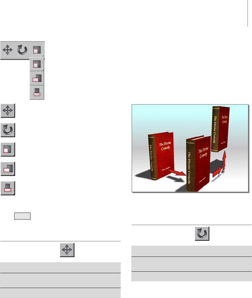
Select and Move 439
Select and Move (page 1–439)
Select and Rotate (page 1–439)
Select and Uniform Scale (page 1–441)
Select and Non-Uniform Scale (page 1–441)
Select and Squash (page 1–442)
Moving, Rotating, and Scaling Objects (page 1–423)
Using Shift +Clone (page 1–478)
Transform Type-In (page 1–431)
Select and Move
Main toolbar > Select and Move
Right-click an object. > quad menu > Transform quadrant
>Move
Edit menu > Select and Move
UsetheSelectAndMovebuttonortheMove
command on the Edit or quad menu to select and
move objects.
To move a single object, you do not need to select it
first. When this button is active, clicking an object
selects it and dragging the mouse moves it.
The direction of the movement is determined
both by your mouse and by the current reference
coordinate system. To restrict object movement
to the X, Y, or Z axis, or to any two axes, click
theappropriatebuttonontheAxis Constraints
toolbar (page 3–687),usetheTran sfor m g i zm o
(page 1–426), or right-click the object, and select
the constraint from the Transform submenu.
Moving an object
Move Gizmo (page 1–427)
Select and Rotate
Main toolbar > Select and Rotate
Right-click an object. > quad menu > Transform quadrant
>Rotate
Edit menu > Select and Rotate
Use the Select and Rotate button or the Rotate
command on the Edit or quad menu to select and
rotate objects.
To rotate a single object, you don’t need to select it
first. When this button is active, clicking an object
selects it and dragging the mouse rotates it.
When you are rotating an object about a single
axis(asisusuallythecase),don’trotatethe
mouse, expecting the object to follow the mouse
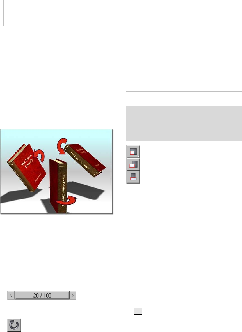
440 Chapter 6: Transforms: Moving, Rotating, and Scaling Objects
movement. Just move the mouse straight up and
straight down. Up rotates the object one way,
down rotates it the opposite way.
The center of rotation is determined by the
Transform Center setting (page 1–442).
To restrict rotation about the X, Y, or Z axis, or
to any two axes, click the appropriate button on
the Axis Constraints toolbar (page 3–687),use
the Transform gizmo (page 1–426),orright-click
the object, and select the constraint from the
Trans for m subm enu .
Rotating an object
Rotate Gizmo (page 1–428)
Procedure
This procedure illustrates the intuitive usage of the
default Euler XYZ rotation controller (page 2–318).
To animate object rotation interactively:
1. Add an object.
2. Move the time
slider (page 3–701) to a frame other than 0 and
turn on Auto Key (page 3–717).
3. Choose Select And Rotate.
4. Rotate the object on any axis by any amount.
5. Movethetimeslidertoalaterframe.
6. Rotate the object on the same axis by an amount
greater than 180 degrees.
7. Play back the animation.
The rotation plays back exactly as you recorded
it.
Select and Scale
Main toolbar > Select and Scale flyout
Right-click an object. > quad menu > Transform quadrant
>Scale
Edit menu > Select and Scale
The Select And Scale flyout on the main toolbar
providesaccesstothreetoolsyoucanuseto
change object size. These are, from top to bottom:
Select and Uniform Scale (page 1–441)
Select and Non-Uniform Scale (page 1–441)
Select and Squash (page 1–442)
In addition, the Scale command is available on
theEditmenuandtheTransformquadrantofthe
quad (right-click) menu; this activates whichever
scaletooliscurrentlychosenintheflyout.
Note: TheSmartScalecommandactivatesthe
Select And Scale function and, with repeated
invocations, cycles through the available scaling
methods. By default, Smart Scale is assigned to
the Rkey; you can use Customize User Interface
(page 3–792) to assign it to a different keyboard
shortcut, a menu, etc.
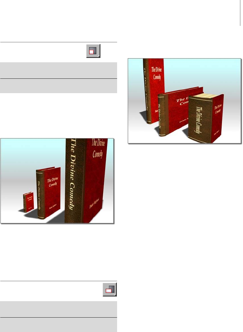
Select and Uniform Scale 441
Select and Uniform Scale
Main toolbar > Select and Uniform Scale (on Select And
Scale flyout)
Right-click an object. > Scale (selects current toolbar
Scale mode)
The Select And Uniform Scale button, available
from the Select And Scale flyout (page 1–440),
lets you scale objects by the same amount along
all three axes, maintaining the object’s original
proportions.
Uniform scale does not change an object’s proportions.
To scale a single object, you don’t need to select it
first. When this tool is active, clicking an object
selects it and dragging the mouse scales it.
Scale Gizmo (page 1–428)
Select and Non-Uniform Scale
Main toolbar > Select and Non-Uniform Scale (on Select
And Scale flyout)
Right-click an object. > Scale (selects current toolbar
Scale mode)
The Select And Non-Uniform Scale button,
available from the Select And Scale flyout (page
1–440), lets you scale objects in a non-uniform
manner according to the active axis constraint.
Non-uniform scale can change proportions with different
values for different axes.
Yo u c a n r e s t r i c t t h e o b j e c t s ’ s c a l i n g a b o u t t h e X , Y,
or Z axis, or to any two axes, by first clicking the
appropriatebuttonontheAxis Constraints toolbar
(page 3–687),orwiththeTransform gizmo (page
1–426).
To scale a single object, you don’t need to select it
first. When this tool is active, clicking an object
selects it and dragging the mouse scales it.
Important: Avoid applying non-uniform scale at
the object level. Non-uniform scaling is applied as
a transform and changes the axes of the object, so
it affects other object properties. It also alters the
properties passed hierarchically from parent to child.
When you perform other operations on the object, such
as rotation, inverse kinematic calculations, and other
positioning operations, you might not get the results
you expect. To recover from these problems, use the
Hierarchy panel’s Reset Scale button or the Utilities
panel’s Reset XForm utility. Either of these options
will reset the axes to use the non-uniform scale as the
fundamental scale for the object.
As an alternative to non-uniform scaling, consider using
the XForm modifier (page 1–959).
Scale Gizmo (page 1–428)
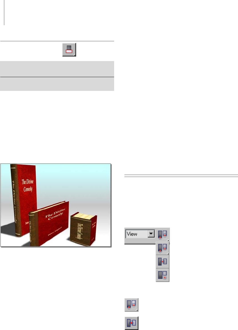
442 Chapter 6: Transforms: Moving, Rotating, and Scaling Objects
Select and Squash
Main toolbar > Select And Squash (on Select And Scale
flyout)
Right-click an object. > Scale (selects current toolbar
Scale mode)
The Select And Squash tool is useful for creating
different phases of the “squash and stretch”-style
animation often found in cartoons. The Select
And Squash tool, available from the Select And
Scale flyout (page 1–440), lets you scale objects
according to the active axis constraint. Squashing
an object always involves scaling down on one axis
while simultaneously scaling up uniformly on the
othertwo(orvice-versa).
Squash scales two axes in opposite directions, maintaining
the object’s original volume.
You can restrict object scaling to the X, Y, or
Z axis, or to any two axes, by first clicking the
appropriatebuttonontheAxis Constraints toolbar
(page 3–687).
When the Select And Squash tool is active, clicking
an object selects it and dragging the mouse scales
it.
Important: Avoid using Select And Squash at the object
level. The non-uniform scaling that it effects is applied
as a transform and changes the axes of the object,
so it affects other object properties. It also alters the
properties passed hierarchically from parent to child.
When you perform other operations on the object, such
as rotation, inverse kinematics calculations, and other
positioning operations, you may not get the results
you expect. To recover from these problems, use the
Hierarchy panel’s Reset Scale button or the Utilities
panel’s Reset XForm utility. Either of these options
will reset the axes to use the non-uniform scale as the
fundamental scale for the object.
As an alternative to non-uniform scaling with Select And
Squash, consider using the XForm modifier (page 1–959).
See also
Scale Gizmo (page 1–428)
Transform Coordinates and
Coordinate Center
Controls for setting the coordinate system and
the active center for transforms to use are on the
default main toolbar (page 3–686).
Reference Coordinate System (page 1–443)
Use Pivot Point Center (page 1–446)
Use Selection Center (page 1–447)
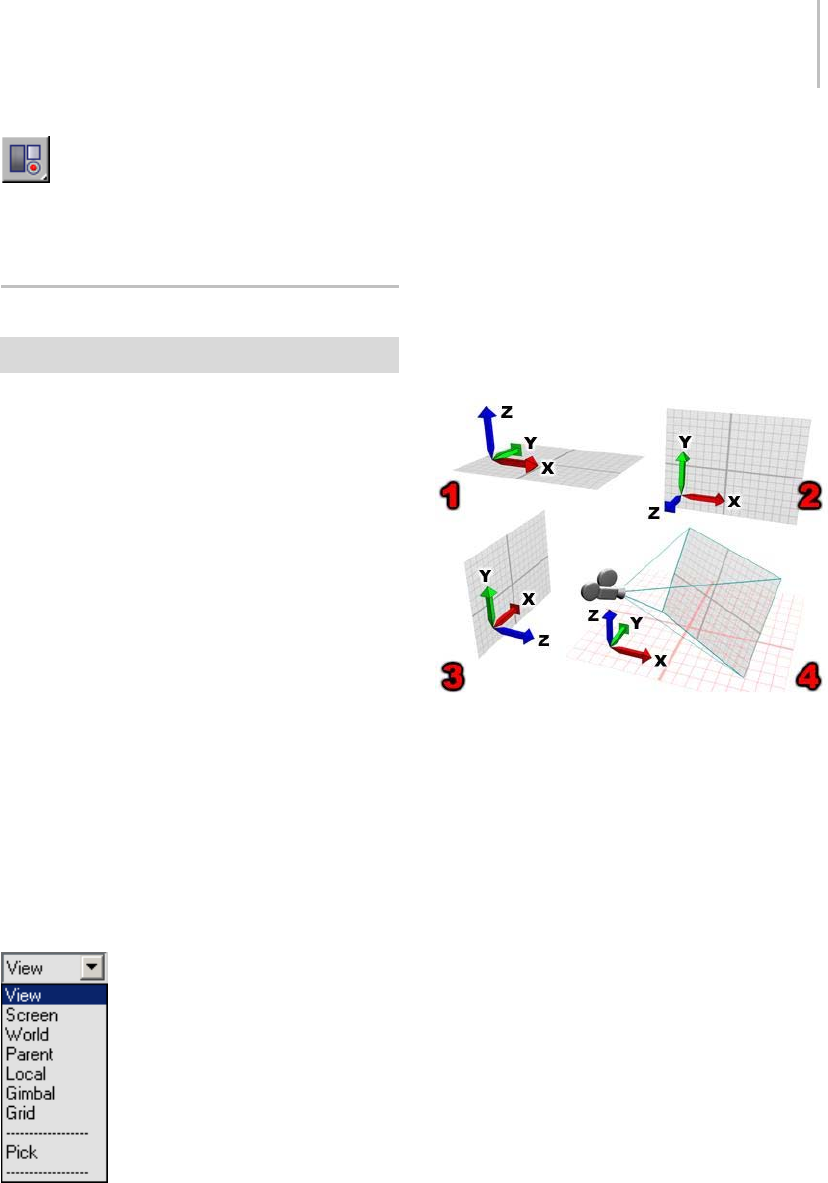
Reference Coordinate System 443
Use Transform Coordinate Center (page
1–447)
Moving, Rotating, and Scaling Objects (page 1–423)
Reference Coordinate System
Main toolbar > Reference Coordinate System list
The Reference Coordinate System list lets
you specify the coordinate system used for a
transformation (Move, Rotate, and Scale). Options
include View, Screen, World (page 3–1035),Parent,
Local (page 3–963),Gimbal,Grid,andPick.
In the Screen coordinate system, all views
(including perspective views) use the viewport
screen coordinates.
ViewisahybridofWorldandScreencoordinate
systems. Using View, all orthographic views use
the Screen coordinate system, while perspective
views use the World coordinate system.
Note: Thecoordinatesystemissetona
transform-by-transform basis, so choose the
transform before you specify the coordinate
system. If you do not want the coordinate system
tochange,turnonCustomizemenu>Preferences
> General tab > Ref. Coord. System group >
Constant.
Interface
View—In the default View coordinate system,
X, Y, and Z axes are the same in all orthogonal
viewports. When you move an object using this
coordinate system, you are moving it relative to
the space of the viewport.
• X always points right.
•Yalwayspointsup.
• Z always points straight out of the screen
toward you.
Different orientations of the View coordinate system:
1. Top viewport.
2. Front viewport.
3. Left viewport.
4. Perspective viewport.
Screen—Uses the active viewport screen as the
coordinate system.
• X is horizontal, running in a positive direction
toward the right.
• Y is vertical, running in a positive direction
upward.
• Z is depth, running in a positive direction
toward you.
Since the Screen mode depends on the active
viewport for its orientation, the X, Y, and Z
labels on an axis tripod (page 1–424) in an
inactive viewport show the orientation of
the currently active viewport. The labels on
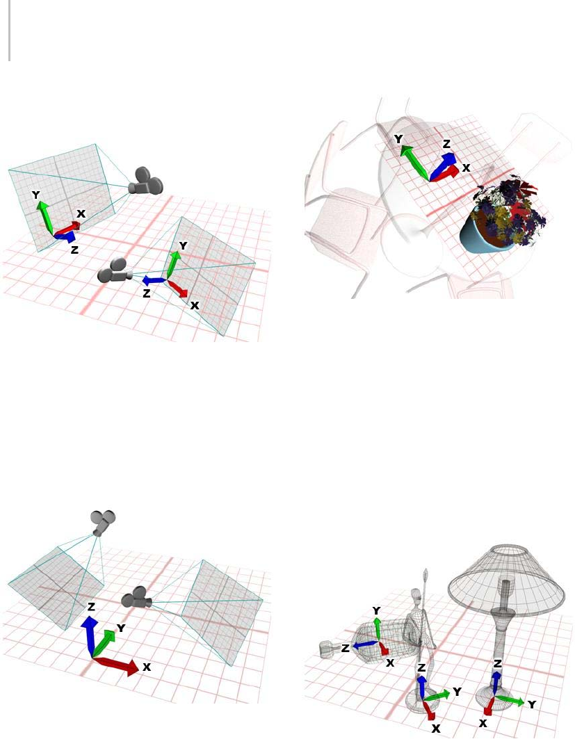
444 Chapter 6: Transforms: Moving, Rotating, and Scaling Objects
that tripod will change when you activate the
viewport it is in.
The coordinate system in Screen mode is always relative to the
point of view.
World—Uses the world coordinate system. Seen
from the front:
• X runs in a positive direction to the right.
• Z runs in a positive direction upward.
• Y runs in a positive direction away from you.
The World coordinate system is always fixed.
Parent—Usesthecoordinatesystemoftheparent
of the selected object. If the object is not linked to
a specific object, it’s a child of the world, and the
parent coordinate system is the same as the world
coordinate system.
Example of a Parent object coordinate system
Local—Uses the coordinate system of the selected
object. An object’s local coordinate system is
carried by its pivot point (page 3–995).Youcan
adjust the position and orientation of the local
coordinate system, relative to its object, using the
options on the Hierarchy command panel.
When Local is active, the Use Transform Center
button is inactive and all transforms use the local
axis as the center of transformation. In a selection
set of several objects, each uses its own center for
the transform.
Local uses an individual coordinate system for each object.
Gimbal—TheGimbalcoordinatesystemismeant
to be used with the Euler XYZ Rotation controller
(page 2–318).ItissimilartoLocal,butitsthree
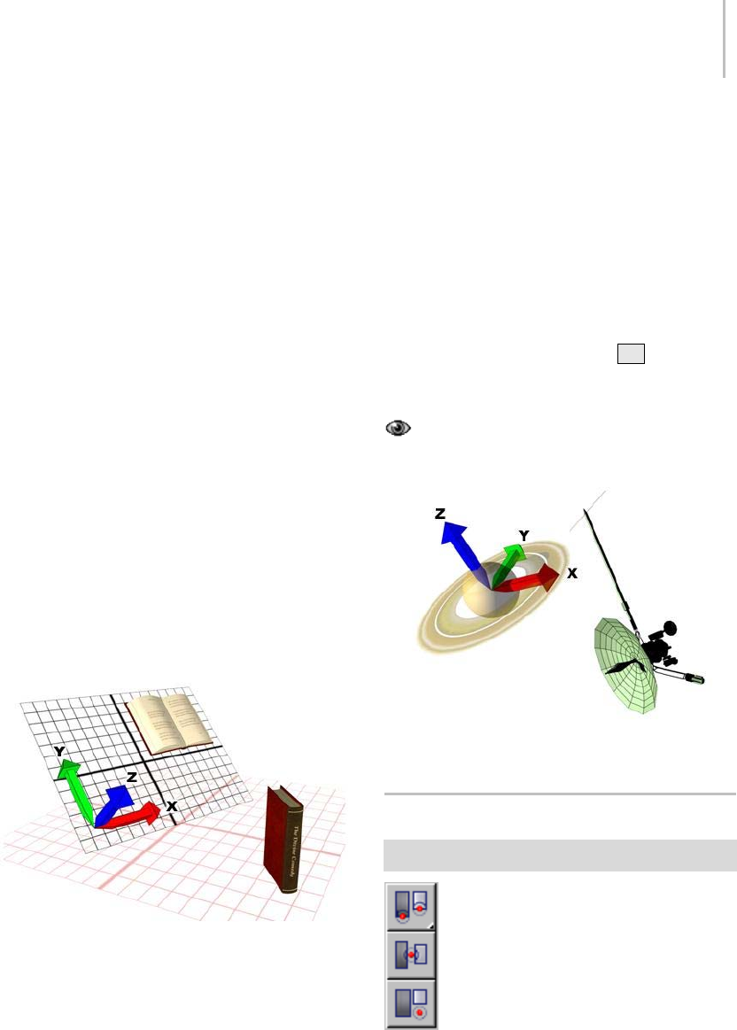
Use Center Flyout 445
rotation axes are not necessarily orthogonal to
each other.
WhenyourotateaboutasingleaxiswiththeLocal
and Parent coordinate systems, this can change
twoorthreeoftheEulerXYZtracks.TheGimbal
coordinate system avoids this problem: Euler XYZ
rotation about one axis changes only that axis’s
track. This makes function curve editing easier.
Also, absolute transform type-in with Gimbal
coordinates uses the same Euler angle values as
the animation tracks (as opposed to Euler angles
relative to the World or Parent coordinate system,
as those coordinate systems require).
For move and scale transforms, Gimbal
coordinatesarethesameasParentcoordinates.
When the object does not have an Euler XYZ
Rotation controller assigned, Gimbal rotation is
the same as Parent rotation.
The Euler XYZ controller can be the active
controller in a List controller, too.
Grid—Uses the coordinate system of the active
grid.
Using an active grid coordinate system.
Pick—Usesthecoordinatesystemofanotherobject
in the scene.
After you choose Pick, click to select the single
objectwhosecoordinatesystemthetransforms
willuse. Theobject’snameappearsinthe
Trans for m Coordi nate System list.
Becausethesoftwaresavesanobject’snameinthe
list, you can pick an object’s coordinate system,
changetheactivecoordinatesystem,andthen
use the object’s coordinate system again at a later
time. The list saves the four most recently picked
object names.
When using Pick to specify an object as a reference
coordinate system, you can press Hto display
the Select Objects dialog (page 1–78) and pick the
object from there.
YoucanpickobjectswithinanXRefsceneas
coordinate reference system.
Using another object as the coordinate system
Use Center Flyout
Main toolbar > Use Center flyout
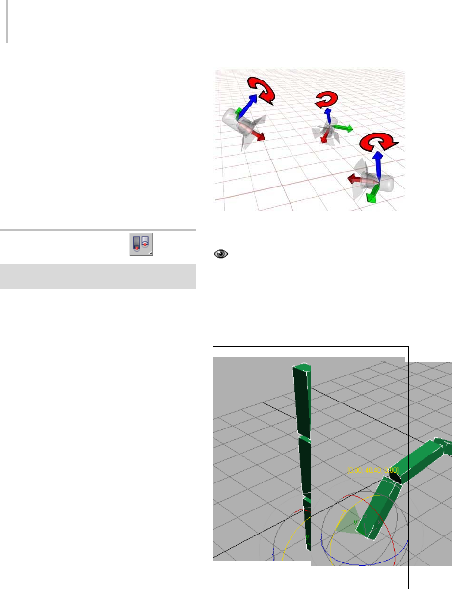
446 Chapter 6: Transforms: Moving, Rotating, and Scaling Objects
The Use Center flyout provides access to three
methods you can use to determine the geometric
center for scale and rotate operations. They are,
from top to bottom:
Use Pivot Point Center (page 1–446)
Use Selection Center (page 1–447)
Use Transform Coordinate Center (page 1–447)
See also
Choosing a Transform Center (page 1–435)
Use Pivot Point Center
Main toolbar > Use Pivot Point Center (on Use Center
flyout)
The Use Pivot Point Center option, available
from the Use Center flyout (page 1–445),letsyou
enable rotation or scaling of one or more objects
around their respective pivot points (page 3–995).
When Auto Key (page 3–717) is active, Use Pivot
Point Center is automatically chosen and no other
option is available.
The axis tripods (page 1–424) show the centers that
are currently being used.
Note: Thetransformationcentermodeisseton
a transform-by-transform basis, so select the
transform before you select the center mode. If
you do not want the center setting to change, turn
on Customize menu > Preferences > General tab >
Reference Coordinate System group > Constant.
Applying a rotation with the Pivot Point rotates each object
around its own local axis.
Rotating Multiple Linked Objects
When rotating a chain of linked (page 2–421)
objects (that is, a hierarchy) with Use Pivot Point
Center active, the rotation is applied equally
to each object in the chain. This results in a
accumulated rotations, which makes it easy to
animate such effects as fingers curling.
Hierarchy before rotation
(parentatbottom) Hierarchy rotated
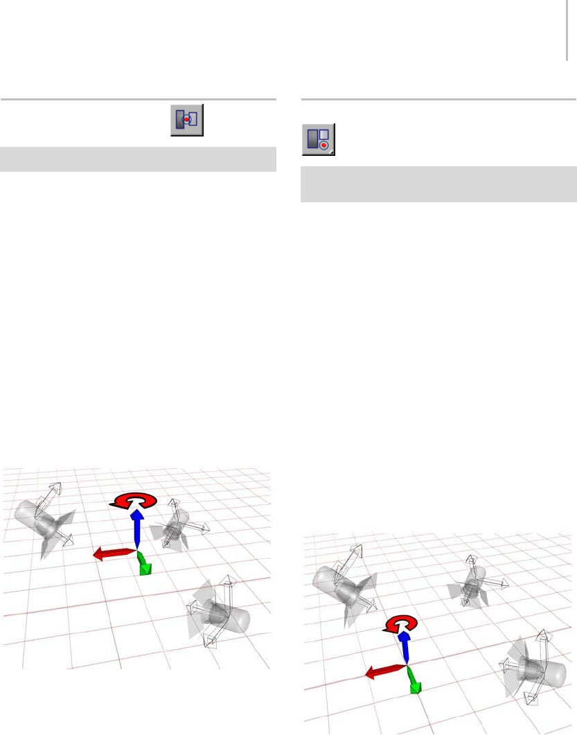
Use Selection Center 447
Use Selection Center
Main toolbar > Use Selection Center (on Use Center flyout)
The Use Selection Center button, available from
the Use Center flyout (page 1–445),letsyouenable
rotation or scaling of one or more objects around
their collective geometric center. If you transform
multiple objects, the software calculates the
average geometric center of all the objects and uses
that for the transform center.
The axis tripod (page 1–424) shows the center that
is currently being used.
Note: Thetransformationcentermodeisseton
a transform-by-transform basis, so select the
transform before you select the center mode. If
you do not want the center setting to change, turn
on Customize menu > Preferences > General tab >
Reference Coordinate System group > Constant.
With the Selection Center option, an averaged coordinate
system is used to rotate the objects.
Use Transform Coordinate Center
Main toolbar > Use Transform Coordinate Center (on Use
Center flyout)
The Use Transform Coordinate Center button,
available from the Use Center flyout (page 1–445),
lets you enable rotation or scaling of an object or
objects around the center of the current coordinate
system. When you designate another object as
thecoordinatesystemwiththePickfunction(see
Specifying a Reference Coordinate System (page
1–435)), the coordinate center is the location of
that object’s pivot.
The axis tripod (page 1–424) shows the center that
is currently being used.
Note: Thetransformationcentermodeisseton
a transform-by-transform basis, so select the
transform before you select the center mode. If
you do not want the center setting to change, turn
on Customize menu > Preferences > General tab >
ReferenceCoordinateSystemgroup>Constant.
An example of the World coordinate center
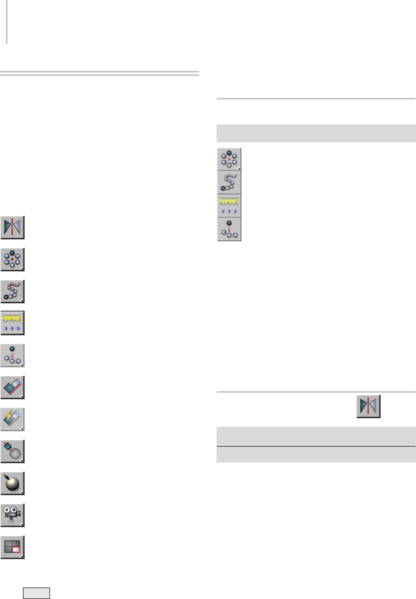
448 Chapter 6: Transforms: Moving, Rotating, and Scaling Objects
Transform Tools
The transform tools can transform objects
according to certain conditions. Some of them,
such as Array, can also create copies of objects.
These tools (except for Array, Snapshot, Spacing
Tool, and Clone And Align) are available on the
default main toolbar (page 3–686);theremainder
are on the Extras toolbar (page 3–688).Also,they
all appear on the default Tools menu (page 3–674).
Mirror Selected Objects (page 1–448)
Array (page 1–450)
Snapshot (page 1–453)
Spacing Tool (page 1–455)
Clone and Align Tool (page 1–459)
Align (page 1–462)
Quick Align (page 1–465)
Normal Align (page 1–465)
Place Highlight (page 1–467)
Align Camera (page 1–468)
Align to View (page 1–468)
Moving, Rotating, and Scaling Objects (page 1–423)
Using Shift +Clone (page 1–478)
Creating Copies and Arrays (page 1–471)
Array Flyout
Extras toolbar > Array flyout
The Array flyout, available from the Extras toolbar
(page 3–688), provides access to various tools for
creating arrays of objects. These are, from top to
bottom:
Array (page 1–450)
Snapshot (page 1–453)
Spacing Tool (page 1–455)
Clone and Align Tool (page 1–459)
Mirror Selected Objects
Main toolbar > Mirror Selected Objects
Tools menu > Mirror
Clicking Mirror displays the Mirror dialog, which
enables you to move one or more objects while
mirroring their orientation. The Mirror dialog
also allows you to mirror the current selection
about the center of the current coordinate system.
You can create a clone with the mirror dialog at the
same time. If you mirror a hierarchical linkage,
youhavetheoptiontomirrortheIKlimits.
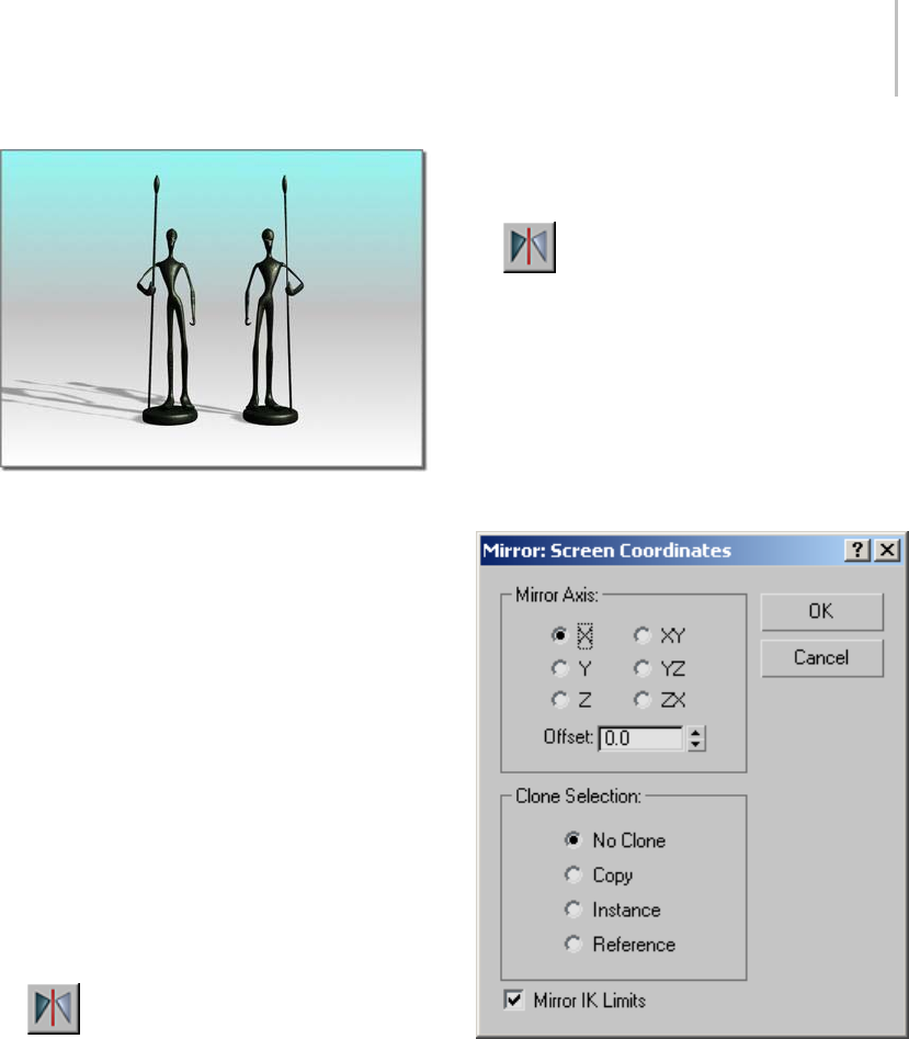
Mirror Selected Objects 449
Mirroring an object
TheMirrordialogusesthecurrentreference
coordinate system (page 1–443),asreflectedin
its name. For example, if Reference Coordinate
System is set to Local, the dialog is named Mirror:
Local Coordinates. There is one exception: If
Reference Coordinate System is set to View, Mirror
uses Screen coordinates.
As you adjust the various settings in the Mirror
dialog, you see the results in the viewports.
For more information on using Mirror, see
Mirroring Objects (page 1–491).
Procedures
To mirror an object:
1. Make any object selection.
2. Click Mirror on the Main toolbar, or
choose Tools menu > Mirror.
The Mirror dialog opens.
3. Set the mirror parameters in the dialog and
click OK.
Theactiveviewportchangestoshowtheeffect
of each parameter as you set it. When you click
OK, the software creates the choice of mirror
that you see previewed.
To make a clone using mirror:
1. Make any object selection
2. Click Mirror on the Main toolbar, or
choose Tools menu > Mirror.
The Mirror dialog opens.
3. In the Clone Selection group, choose Copy,
Instance, or Reference.
4. Make any additional settings as desired and
then click OK.
Interface
Mirror Axis group
ThemirroraxischoicesareX,Y,Z,XY,XZ,
and YZ. Choose one to specify the direction of
mirroring. These are equivalent to the option
buttons on the Axis Constraints toolbar (page
3–687).
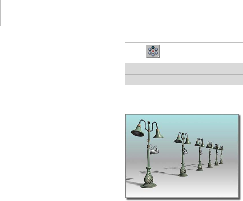
450 Chapter 6: Transforms: Moving, Rotating, and Scaling Objects
Offset—Specifies the distance of the mirrored
object’s pivot point (page 3–995) from the original
object’s pivot point.
Clone Selection group
DeterminesthetypeofcopymadebytheMirror
function. Default is No Clone.
No Clone—Mirrors the selected object without
making a copy.
Copy—Mirrors a copy of the selected object to the
specified position.
Instance—Mirrors an instance (page 3–957) of the
selected object to the specified position.
Reference—Mirrors a reference (page 3–1002) of
the selected object to the specified position.
If you animate (page 2–275) the mirror operation,
mirroring generates a Scale key. If you set Offset
to a value other than 0.0, mirroring also generates
Position keys.
Mirror IK Limits—Causes the IK constraints to be
mirrored (along with the geometry) when you
mirror the geometry about a single axis. Turn
thisoffifyoudon’twanttheIKconstraintstobe
affected by the mirror command.
The end effectors used by the IK are not affected
by the Mirror command. To successfully mirror
an IK hierarchy, first delete the end effectors: Go
to the Motion panel > IK Controller Parameters
rollout > End Effectors group and, under Position,
click the Delete button. After the mirror operation,
create the new end effector using the tools on the
same panel.
Array
Extras toolbar > Array
Tools menu > Array
TheArraycommanddisplaystheArraydialog,
which enables you to create an array of objects
based on the current selection.
A one-dimensional array
TheitemsintheArrayDimensionsgrouplet
you create one-, two-, and three-dimensional
arrays. For example, a row of five objects is a
single-dimension array, even though it takes up
three-dimensional space in the scene. An array
ofobjectsthat’sfiverowsbythreecolumnsisa
two-dimensional array, and an array of objects
that’s five rows by three columns by two levels is a
three-dimensional array.
Tip: Youcanpreviewthearraybyturningonthe
Preview button. With Preview on, changing the
array settings updates the viewports in real time.
For more information on using Array, see Arraying
Objects (page 1–484).
Procedures
To create an array:
1. Select the objects to array.

Array 451
2. Choose Tools > Array.
3. On the Array dialog, select the type of object
to output: Copy, Instance, (page 3–957) or
Reference (page 3–1002)).
4. In the Preview group, click the Preview button
to turn it on.
This lets you see the results of the array
operationintheviewports,withchanges
appearing in real time.
5. In the Array Transformation group, click
the arrows to set Incremental or Totals array
parameters for Move, Rotate, and Scale.
6. EntercoordinatesfortheArrayTransformation
parameters.
7. Indicate whether you want a 1D, 2D, or 3D
array.
8. Set Count to the number of copies on each axis.
9. Enter the appropriate values in the numeric
fields for Incremental Row Offsets.
10.Click OK.
The current selection is duplicated the specified
number of times, with each object transformed
as indicated.
To replace an array:
1. Undo the array to replace, using Edit > Undo
Create Array, or press Ctrl+Z .
2. Changethecoordinatesystemandtransform
center, if needed.
3. Choose Tools > Array, and adjust any
parameters on the Array dialog that is
displayed.
4. ClickOKtocreateanewarray,whichreplaces
the previous version. Repeat these steps to
fine-tune the array.
Example: To create an array of objects that numbers
5x4x3:
1. Create a teapot with a radius of 10 units.
2. Choose Tools > Array to display the Array
dialog.
3. In the Incremental set of parameters, set Move
X(theupper-leftfield)to50.Thiscauseseach
object in the array to be positioned 50 units
apart on the X axis.
4. In the Array Dimensions group, choose the 3D
button to enable all the spinners in that group.
5. Setthe1DCountspinnerto5,the2DCount
spinner to 4, and the 3D Count spinner to 3.
Thiscreatesarowof5objectsthatare50units
apart, and then 4 rows of those five objects,
and then 3 rows of the 5 x 4 matrix of objects,
resulting in a box array.
6. Inthe2Drow,settheYspinnerto80.
7. In the 3D row, set the Z spinner to 100.
8. Click OK.
A box array of teapots appears. The first
dimensional array is five teapots created along
the X world axis, 50 units apart (as specified
in the Array Transform group). The second
dimensional array is four layers created along
the Y world axis, 80 units apart (as specified
in the Array Dimensions group). The third
dimensional array is three layers created along
the Z world axis, 100 units apart. The total
numberofobjectsinthearrayis60.
Example: To create a 360-degree array:
1. Reset 3ds Max.
2. Near the top of the Front viewport (away
from its center), create a long, thin box at the
twelve-o’clock position (as if the viewport were
aclockface).
3. Choose Use Transform Coordinate Center on
the Main toolbar.
4. Choose Tools > Array.

452 Chapter 6: Transforms: Moving, Rotating, and Scaling Objects
5. Click the arrow button to the right of the Rotate
labeltoenablethethreeRotatefieldsinthe
To t a l s s e c t i o n .
6. Set the Z parameter to 360.0.
7. In the Array Dimensions group, choose 1D and
set Count to 12.
8. Click OK.
The software creates an array of 12 boxes in a
full circle.
Interface
Array Transformation group
Specifies which combination of the three
transformstousetocreatethearray. Youalso
specify the extent, along the three axes, for each
transform. You can specify the extent of the
transform in increments between each object,
or in totals for all objects. In either case, the
distances are measured between the pivot points
of the objects. The arrays occur using the current
transform settings, so the group title changes
depending on the transform settings.
Click the left or right arrow button for Move,
Rotate, or Scale to indicate whether you want to set
Incremental or Total array parameters.
Incremental
Move—Specifies the distance between each arrayed
object along the X, Y, and Z axes, in units.
Rotate—Specifies the degree of rotation about any
of the three axes for each object in the array, in
degrees.
Scale—Specifies the percentage of scale along any
of the three axes for each object in the array, in
percentages.
Totals
Move—Specifies the overall distance, along each of
the three axes, between the pivot points of the two
outer objects in the resulting array. For example, if
you’re arraying 6 objects and set Move X total to
100, the six objects will be arrayed in a row that’s
100 units between the pivot points of the two outer
objects in the row.
Rotate—Specifies the total degrees of rotation
applied to the objects along each of the three axes.
Youcanusethis,forexample,tocreateanarray
that totals 360 degrees.
Re-Orient—Rotates the generated objects about
their local axes while rotating them about the
world coordinates. When clear, the objects
maintain their original orientation.
Scale—Specifies the total scale of the objects along
each of the three axes.
Uniform—DisablestheYandZspinnersand
applies the X value to all axes, resulting in a
uniform scale.
Type of Object group
Determine the type of copies made by the Array
function. The default is Copy.
Copy—Arrays copies of the selected object to the
specified position.
Instance—Arrays instances of the selected object
to the specified position.
Reference—Arrays references of the selected object
to the specified position.
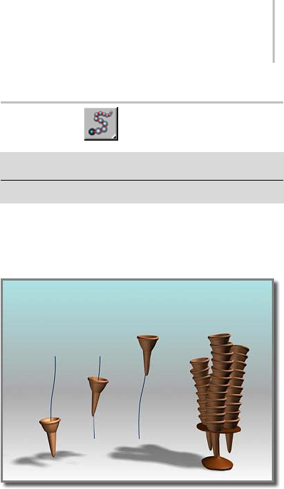
Snapshot 453
Array Dimensions group
Lets you add to the Array Transformation
dimension. The additional dimensions are
positional only. Rotation and scale are not used.
1D—Creates a one-dimensional array, based on
the settings in the Array Transformation group.
Count—Specifies the total number of objects along
this dimension of the array. For 1D arrays, this is
the total number of objects in the array.
2D—Creates a two-dimensional array.
Count—Specifies the total number of objects along
this second dimension of the array.
X/Y/Z—Specifies the incremental offset distance
along each axis of the second dimension of the
array.
3D—Creates a three-dimensional array.
Count—Specifies the total number of objects along
this third dimension of the array.
X/Y/Z—Specifies the incremental offset distance
along each axis of the third dimension of the array.
Total in Array—Displays the total number of entities
that the array operation will create, including the
current selection. If you’re arraying a selection set,
the total number of objects will be the result of
multiplying this value times the number of objects
in the selection set.
Preview—Toggles a viewport preview of the
current array settings. Changing a setting updates
the viewports immediately. If the update slows
down feedback with large arrays of complex
objects, turn on Display As Box.
Display as Box—Displays the array-preview objects
as bounding boxes instead of geometry.
Reset All Parameters—Resets all the parameters to
their default settings.
Snapshot
Extras toolbar > Snapshot (on Array flyout)
Tools menu > Snapshot
Choosing Tools > Snapshot displays the Snapshot
dialog. This enables you to clone an animated
object over time.
Using an ice-cream cone animated along a path, Snapshot
creates a stack of cones.
Snapshot spaces the clones equally in time.
Adjustments in Track View let you space the clones
equally along the path instead (see the second
procedure, below).
Like other clone techniques, Snapshot creates
copies, instances, or references. You can also
chooseameshoptionforusewithparticlesystems.
Particle Snapshots
You can clone particle systems as static mesh
objects. You can also produce clones of the
particlesthemselvesasmeshes,whenusingthe
Snapshot dialog > Clone Method > Mesh option.
This works with all configurations of particle
systems, including those using MetaParticles.
Usage is the same as with other types of objects.
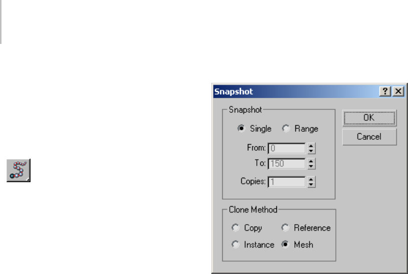
454 Chapter 6: Transforms: Moving, Rotating, and Scaling Objects
Procedures
To clone an object over time:
1. Select an object with an animation path.
Snapshot also shows the effect of any other
transform animations, such as rotate or scale as
well as parametric modifier animation.
2. Click the Snapshot button on the Extras
toolbar > Array flyout, or choose Tools menu
>Snapshot.
3. Set parameters in the dialog, and click OK.
To space clones evenly by distance:
1. Select an object with an animated position.
2. Open Track View and find the Position track
for the original object.
3. Click Assign Controller and check that the
track is using a Bezier Position controller. Do
one of the following:
• If the track is already using a Bezier Position
controller, proceed to step 4.
• If the track is not using a Bezier Position
controller, change the controller (page
2–546), then proceed to step 4.
4. Select all the transform keys and right-click
one of the selected keys to display the Key Info
dialog (page 2–304).
5. Click Advanced to expand the dialog.
6. Click Normalize Time.
7. Set Constant Velocity on.
8. Choose Tools menu > Snapshot.
The Snapshot dialog appears.
9. Set parameters in the dialog, and click OK.
Interface
Snapshot group
Single—Makes a clone of the geometry of the
object at the current frame.
Range—Makesclonesofthegeometryofthe
object along the trajectory over a range of frames.
Specify the range with the From/To settings and
the number of clones with the Copies setting.
From/To—Specifies the range of frames to place the
cloned object along the trajectory.
Copies—Specifies the number of clones to place
along the trajectory. They are evenly distributed
overthetimeperiod,butnotnecessarilyoverthe
spatial distance along the path.
Clone Method group
With the Copy, Instance, and Reference methods,
the clone retains any animation within the object,
so all the clones will be animated in the same way.
Copy—Clones copies of the selected object.
Instance—Clones instances (page 3–957) of
the selected object. Not available with particle
systems.
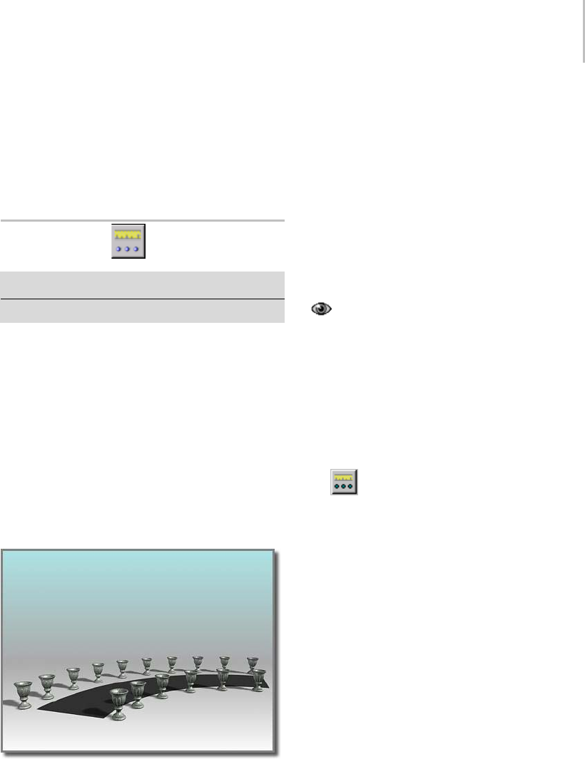
Spacing Tool 455
Reference—Clones references (page 3–1002) of
the selected object. Not available with particle
systems.
Mesh—Usethistocreatemeshgeometryoutof
particle system. Works with all kinds of particles.
Spacing Tool
Extras toolbar > Spacing Tool (on Array flyout)
Tools menu > Spacing Tool
TheSpacingtoolletsyoudistributeobjectsbased
onthecurrentselectionalongapathdefinedbya
spline or a pair of points.
The distributed objects can be copies, instances
(page 3–957),orreferences (page 3–1002) of the
current selected object. You define a path by
picking a spline or two points and by setting a
number of parameters. You can also specify how
the spacing between objects is determined and
whether the pivot points of the objects align to the
tangent of the spline.
The Spacing tool distributes the vases along the sides of the
curved street. The vases are all the same distance from each
other;fewerappearontheshorterside.
Tip: You can use compound shapes containing
multiplesplinesasthesplinepathfordistributing
objects. Before creating shapes, turn off Start
New Shape on the Create panel. Then create your
shapes. The software adds each spline to the
current shape until you click the Start New Shape
button so that it’s turned on. When you select the
compound shape so that the Spacing tool can use
it as a path, objects are distributed along all of
the splines of the compound shape. For example,
you might find this technique useful in spacing
light standards along a path defined by separated
splines.
You can pick splines within an XRef scene as
path reference.
For more information, see UsingtheSpacingTool
(page 1–491).
Procedure
To distribute objects along a path:
1. Select the objects to distribute.
2. Click Spacing Tool, or choose Tools menu
>SpacingTool.
Note: The Spacing tool is also available on
rollouts for various components of the Railing
object (page 1–217).
3. On the Spacing Tool dialog, click Pick Path or
Pick Points to specify a path.
If you click Pick Path, select a spline from your
scene to use as the path.
If you click Pick Points, pick a start and an end
to define a spline as the path. When you’re
finished with the Spacing tool, the software
deletesthisspline.
4. Choose a spacing option from the Parameters
list.
The parameters available for Count, Spacing,
Start Offset, and End Offset are dependent on
the spacing option you choose.
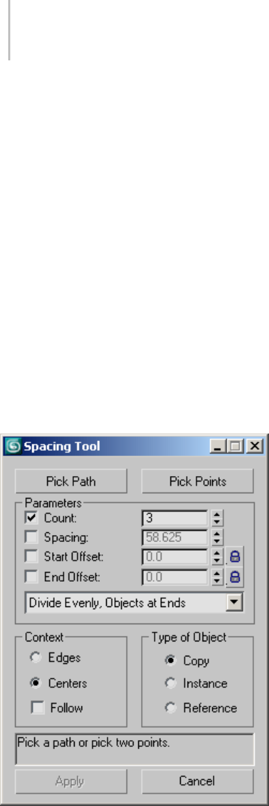
456 Chapter 6: Transforms: Moving, Rotating, and Scaling Objects
5. Specify the number of objects to distribute by
setting the value of Count.
6. Depending on the spacing option you choose,
adjust the spacing and offsets.
7. Under Context, choose Edge to specify that
spacing be determined from the facing edges of
each object’s bounding box, or choose Centers
to specify that spacing be determined from the
center of each object’s bounding box.
8. Tur n on Follow if you want to a li g n th e pivo t
points of the distributed objects to the tangent
of the spline.
9. UnderTypeofObject,selectthetypeofobject
to output (copy, instance (page 3–957),or
reference (page 3–1002)).
10.Click Apply.
Interface
TheSpacingtoolgivesyouachoiceoftwobasic
methods for setting spacing: using a path, or
specifying endpoints explicitly.
Pick Path—Clickthis,andthenclickasplineinthe
viewport to use as the path. The software uses the
spline as the path along which to distribute objects.
Pick Points—Clickthis,andthenclickastartand
an end to define a path on the construction grid.
You can also use object snap to specify points in
space. The software uses these points to create a
spline as the path along which to distribute objects.
When you’re finished with the Spacing tool, the
software deletes the spline.
Parameters group
Count—The number of objects to distribute.
Spacing—Specifies the space in units between the
objects. Thesoftwaredeterminesthisspacing
based on whether you chose Edges or Centers.
Start Offset—The number of units specifying an
offset from the start of the path. Clicking the lock
icon locks the start offset value to the spacing value
and maintains the count.
End Offset—The number of units specifying an
offset from the end of the path. Clicking the lock
icon locks the end offset value to the spacing value
and maintains the count.
Distribution drop-down list—This list contains a
number of options for how to distribute the objects
alongthepath,asfollows:
•Free Center—Distributes equally spaced objects
along a straight line toward the end point of the
path, beginning at the start of the path. A spline
or a pair of points defines the path. You specify
the number of objects and the spacing.
•Divide Evenly, Objects at Ends—Distributes
objects along a spline. The group of objects
is centered at the middle of the spline. The
Spacing tool evenly fills the spline with the

Spacing Tool 457
number of objects you specify and determines
the amount of space between objects. When
you specify more than one object, there are
always objects at the ends of the spline.
•Centered, Specify Spacing—Distributes objects
along a path. The group of objects is centered
atthemiddleofthepath. TheSpacingtool
attempts to evenly fill the path with as many
objectsasitcanfitalongthelengthofthe
path using the amount of space you specify.
Whether there are objects at the ends of the
path depends on the length of the path and the
spacing you provide.
•End Offset—Distributes the number of objects
you specify along a straight line. The objects
beginatanoffsetdistancethatyouspecify.
Thisdistanceisfromtheendofthesplinetoits
start point, or from the second pair of points
to the first point. You also specify the spacing
between objects.
•End Offset, Divide Evenly—Distributes the
number of objects you specify between the start
of a spline or a pair of points and an end offset
that you specify. The software always places an
object at the end or its offset. When you specify
more than one object, there is always an object
placed at the start. The Spacing tool attempts
to evenly fill the space with the objects between
the end offset and the start.
•End Offset, Specify Spacing—Distributes objects
toward the start of a spline or a pair of points,
starting at the end or its offset. The software
always places an object at the end or its offset.
You specify the spacing between objects and the
offset from the end. The Spacing tool attempts
to evenly fill the space with as many objects
asitcanfitbetweentheendoritsoffsetand
the start. There might not always be an object
placed at the start.
•Start Offset—Distributes the number of objects
you specify along a straight line. The objects
startatanoffsetdistancethatyouspecify.This
distanceisfromthestartofthesplinetoitsend
point, or from the first of a pair of points to the
second. You also specify the spacing between
objects.
•Start Offset, Divide Evenly—Distributes the
number of objects you specify between the
end of a spline or a pair of points, starting at
an offset that you specify from the start. The
software always places an object at the start or
its offset. When you specify more than one
object, there is always an object placed at the
end. The Spacing tool attempts to evenly fill
the space with the objects between the start or
its offset and the end.
•Start Offset, Specify Spacing—Distributes
objects toward the end of a spline or a pair of
points, starting at the start. The software always
places an object at the start or its offset. You
specify the spacing between objects and the
offset from the start. The Spacing tool attempts
to evenly fill the space with as many objects
as it can fit between the start or its offset and
the end. There might not always be an object
placed at the end.
•Specify Offsets and Spacing—Distributes as
many equally spaced objects as possible along a
spline or between a pair of points. You specify
the spacing between objects. When you specify
offsets from the start and end, the software
distributes equally spaced objects between the
offsets. There might not always be an object
placed at the start and ends.
•Specify Offsets, Divide Evenly—Distributes the
number of objects you specify along a spline
or between a pair of points. If you specify one
objectthesoftwareplacesitatthecenterofthe
path. If you specify more than one object the
software always places an object at the start
offset and the end offset. If you specify more
than two objects the software evenly distributes
the objects between the offsets.
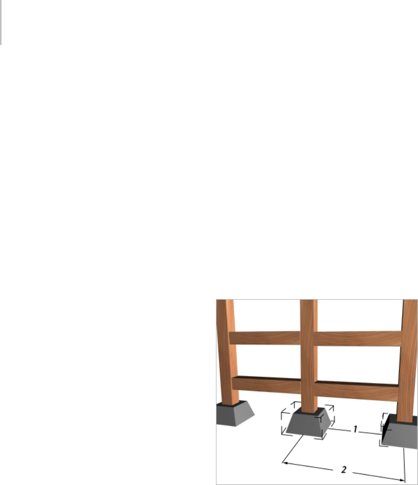
458 Chapter 6: Transforms: Moving, Rotating, and Scaling Objects
•Space from End, Unbounded—Distributes the
number of objects you specify along a straight
line from the end toward the start of a spline
or a pair of points. You specify the spacing
betweenobjects.Thesoftwarelockstheend
offsetsothatit’sthesameasthespacing.
•Space from End, Specify Number—Distributes
the number of objects you specify toward the
start of a spline or a pair of points, starting
at the end. The Spacing tool determines the
amount of space between objects based on the
number of objects and the length of the spline
orthedistancebetweenthepairofpoints.The
software locks the end offset so that it’s the
same as the spacing.
•Space from End, Specify Spacing—Distributes as
many equally spaced objects as possible toward
the start of a spline or a pair of points, starting
at the end. You specify the spacing between
objects.Thesoftwarelockstheendoffsetso
that it’s the same as the spacing.
•Space from Start, Unbounded—Distributes the
number of objects you specify along a straight
line toward the end of a spline or a pair of
points, starting at the start. You specify the
spacing between objects. The software locks the
startoffsetsothatit’sthesameasthespacing.
•Space from Start, Specify Number—Distributes
the number of objects you specify toward the
endofasplineorapairofpoints,startingat
the start. The Spacing tool determines the
amount of space between objects based on the
number of objects and the length of the spline
orthedistancebetweenthepairofpoints.The
software locks the start offset so that it’s the
same as the spacing.
•Space from Start, Specify Spacing—Distributes
as many evenly spaced objects as possible
towardtheendofasplineorapairofpoints,
starting at the start. You specify the spacing
between objects. The software locks the start
offset so that it’s the same as the spacing.
•Specify Spacing, Matching Offsets—Distributes
as many evenly spaced objects as possible along
asplineorbetweenapairofpoints(andtheir
offsets). You specify the spacing. The software
locks the start and end offsets so that they’re
thesameasthespacing.
•Divide Evenly, No Objects at Ends—Distributes
the number of objects you specify along a spline
or between a pair of points (and their offsets).
The Spacing tool determines the amount of
spacebetweenobjects.Thesoftwarelocksthe
start and end offsets so that they’re the same as
the spacing.
Context group
1. Edge-to-edge spacing
2. Center-to-center spacing
Edges—Usethistospecifythatspacingis
determined from the facing edges of each object’s
bounding box.
Centers—Use this to specify that spacing be
determined from the center of each object’s
bounding box.
Clone and Align Tool 459
Follow—Usethistoalignthepivotpointsofthe
distributed objects to the tangent of the spline.
Type of Object group
DeterminesthetypeofcopiesmadebytheSpacing
tool. The default is Copy. You can copy, instance
(page 3–957),orreference (page 3–1002) objects.
Copy—Distributes copies of the selected object to
the specified position.
Instance—Distributes instances of the selected
object to the specified position.
Reference—Distributes references of the selected
object to the specified position.
Tip: You can use compound shapes containing
multiplesplinesasthesplinepathfordistributing
objects. Before creating shapes, turn off Start New
Shape under Shapes on the Create panel. Then
create your shapes. 3ds Max adds each spline to
thecurrentshapeuntilyouclicktheStartNew
Shape button so that it’s checked. When you select
the compound shape so that the Spacing tool can
use it as a path, objects are distributed along all of
the splines of the compound shape. For example,
you might find this technique useful in spacing
light standards along a path defined by separated
splines.
Clone and Align Tool
Extras toolbar > Clone and Align Tool (on Array flyout)
Tools menu > Clone and Align
The Clone And Align tool lets you distribute source
objects based on the current selection to a second
selection of destination objects. For example, you
can populate several rooms simultaneously with
thesamefurniturearrangement.Similarly,ifyou
import a CAD file that contains 2D symbols that
represent chairs in a conference room, you can use
CloneAndAligntoreplacethesymbolswith3D
chair objects en masse.
The distributed objects can be copies, instances
(page 3–957),orreferences (page 3–1002) of the
current selected object. You determine the number
of clones or clone sets by specifying any number of
destinationobjects.Youcanalsospecifyposition
and orientation alignment of the clones on one,
two, or three axes, with optional offsets.
Yo u c a n u s e a n y n u m b e r o f s o u r c e o b j e c t s a n d
destination objects.
YoucanpickobjectswithinanXRefsceneas
destination objects.
With multiple source objects, Clone And Align
maintains the positional relationships among
the members of each cloned group, aligning the
selection center with the destination’s pivot.
Procedure
To use the Clone And Align tool:
1. Create or load an object or objects to be cloned,
aswellasoneormoredestinationobjects.
2. Select the object or objects to be cloned.
3. Open the Clone And Align dialog.
Note: Theorderofsteps2and3canbereversed.
4. Do either of the following:
• Click Pick once and then click each
destination object in turn. Next, click Pick
again to turn it off.
• Click Pick List and then use the Pick
Destination Objects dialog to pick all
destination objects simultaneously.
5. On the Clone Parameters rollout, choose the
type of clone, and, if appropriate, how to copy
the controller. For details, see Clone Options
Dialog (page 1–476).
6. UsetheCloneParametersrolloutsettingsto
specify position, orientation, and scale options.
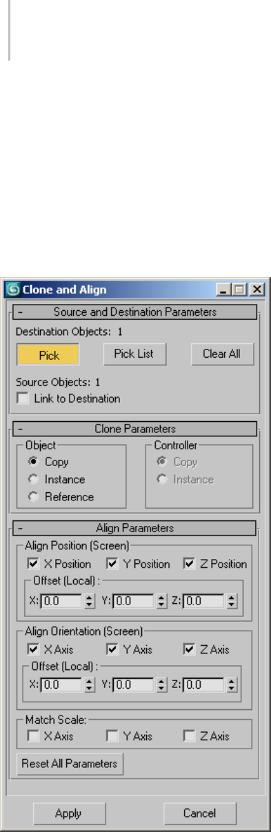
460 Chapter 6: Transforms: Moving, Rotating, and Scaling Objects
7. At any time, when Pick is off, you can change
the source selection in a viewport. This causes
the dialog to lose focus; click it again to regain
focus and refresh the viewport preview of the
clone operation.
8. To make the clones permanent, click Apply,
and then click Cancel or the close button (X, in
upper-right corner) to close the dialog.
Interface
The Clone and Align tool takes the form of a
non-modal dialog; it remains open while you
work in the viewports. While the dialog is active,
the results of the current settings appear as a
preview in the viewports. Because of the dialog’s
non-modal nature, you can change the selection of
source and destination objects on the fly and see
the results immediately in the viewports.
When the dialog focus is lost by activating another
dialog or clicking in a viewport (that is, its title bar
is gray rather than blue), the preview no longer
appears in the viewports. To make the cloned
objects permanent, click Apply when the dialog
is active.
Source and Destination Parameters rollout
Designatesourceobjectsbyselectingthemina
viewport. If you do this with the Clone And Align
dialog open, the dialog loses focus; click the dialog
to regain focus and update the settings.
Destination Objects [label]—This read-only field
shows the number of destination objects. To
change this value, use Pick, Pick List, and Clear.
Pick—When on, each object you click in the
viewports is added to the list of destination objects.
Click again to turn off after picking all destination
objects.
To qualify as a valid destination object, an object
must:
•nothavebeendesignatedasasourceor
destination object.
• be selectable (frozen objects can’t be selected).
• not be a temporary cloned object.
Pick List—Opens the Pick Destination Objects
dialog, which lets you pick all destination objects
simultaneously, by name. In the dialog, highlight
the destination objects, and then click Pick.

Clone and Align Tool 461
Clear All—Removes all destination objects from the
list. Available only when at least one destination
object is designated.
Source Objects [label]—This read-only field shows
the number of source objects. To change this value,
keep the dialog open, make sure Pick is off, and
then select source objects in the viewports. When
you click the dialog, the field updates.
Link to Destination—Links each clone as a child of
its destination object.
Clone Parameters rollout
These settings let you determine the type of clone
to create, and, if appropriate, how to copy the
controller. For details, see Clone Options Dialog
(page 1–476).
Align Parameters rollout
The Align Position and Align Orientation group
names are followed by the current reference
coordinate system (page 1–443), in parentheses,
which they use as the coordinate system for
positioning and aligning the clones. When the
View coordinate system is active, alignment uses
the World coordinate system.
TheOffsetparametersalwaysuseeachdestination
object’s Local coordinate system.
Align Position group
X/Y/Z Position—Specifies the axis or axes on
which to align the clones’ position. Turning on all
three options positions each set of clones at the
respective destination object’s location.
X/Y/Z Offset—Thedistancebetweenthedestination
object’s pivot and the source object’s pivot (or
source objects’ coordinate center). For an Offset
valuetotakeeffect,therespectivePositioncheck
box must be on.
Align Orientation group
X/Y/Z Orientation—Specifies the axis or axes about
which to align orientation. Turning on all three
options aligns each set of clones’ orientation fully
with that of the respective destination object.
X/Y/Z Offset—The angle by which the source
objects are rotated away from the destination
object’s orientation about each axis. For an Offset
valuetotakeeffect,therespectiveOrientation
check box must be on.
Match Scale —Use the X Axis, Y Axis, and Z Axis
options to match the scale axis values between the
source and destination.
This matches only the scale values you’d see in
the coordinate display (page 3–708).Itdoesnot
necessarily cause two objects to be the same size.
Matchingscalecausesnochangeinsizeifnoneof
the objects has previously been scaled.
Reset All Parameters—Returns all settings in the
Align Parameters rollout to their default values.
Apply—Generates the clones as permanent objects.
After clicking Apply, you can use Clone And Align
to generate additional clones, using the results of
previous clonings as source or destination objects
if you like.
Cancel—Aborts the current cloning operation and
closes the dialog.
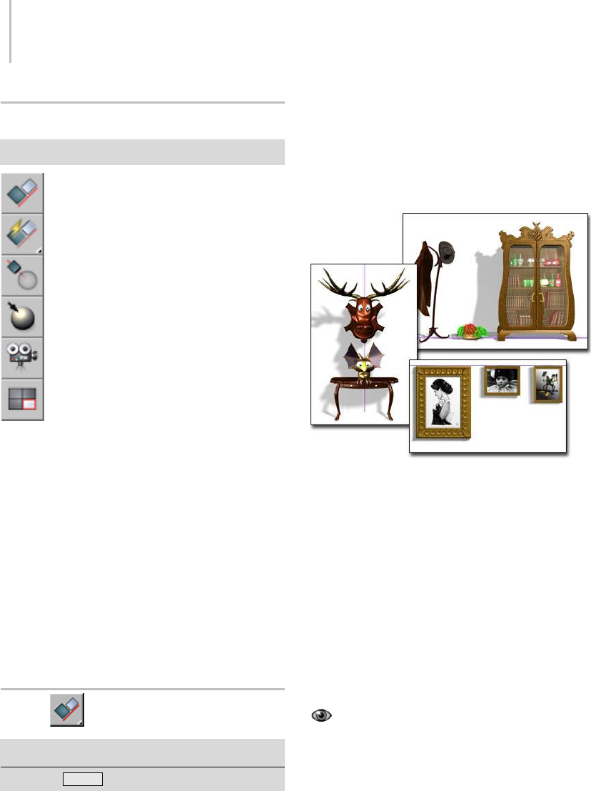
462 Chapter 6: Transforms: Moving, Rotating, and Scaling Objects
Align Flyout
Main toolbar > Align flyout
The Align flyout, available from the Main toolbar
(page 3–686),providesaccesstosixdifferent
tools for aligning objects. These are, from top to
bottom:
Align (page 1–462)
Quick Align (page 1–465)
Normal Align (page 1–465)
Place Highlight (page 1–467)
Align Camera (page 1–468)
Align to View (page 1–468)
Align
Main toolbar > Align (on Align flyout)
Keyboard > Alt+A
Interface (page 1–464)
Clicking Align , available from the Align flyout
(page 1–462),thenselectinganobject,displays
the Align dialog, which lets you align the current
selection to a target selection. The name of the
target object appears in the title bar of the Align
dialog. When performing sub-object alignment,
the title bar of the Align dialog reads "Align
Sub-Object Selection."
Aligning objects along an axis
Left: X position, center
Upper right: Y position, minimum
Lower right: Y position, maximum
You can align the position and orientation of the
bounding box (page 3–919) of the source object to
the bounding box of a target object.
You can use the Align tool with any selection that
canbetransformed.Ifanaxistripodisdisplayed,
you can align the tripod (and the geometry it
represents) to any other object in the scene. You
canusethistoalignanobject’spivotpoint.
You can use objects within an XRef scene as
references with all alignment tools on the Align
flyout, except Align to View.
When performing sub-object alignment, the
CurrentObjectoptionsandtheMatchScaleboxes
are disabled. If you plan to align orientation for
sub-objects, first switch to Local transform mode
Align 463
on the Main toolbar so that the axis tripod is
properly aligned with your sub-object selection.
OtheralignmenttoolsontheAlignflyoutare
Quick Align (page 1–465),Normal Align (page
1–465),Place Highlight (page 1–467),Align to
Camera (page 1–468),andAlign to View (page
1–468).
Procedures
Toalignanobjectwithapointobject:
1. Create a point helper object and position it at
atargetlocationinyourscene. Rotateitas
necessary to adjust final orientation.
2. Select a source object.
3. On the Main toolbar, click Align, or
choose Tools > Align.
The Align cursor appears attached to a pair of
cross hairs.
4. Move the cursor over the point object and click.
The Align Selection dialog appears. If
necessary, move the dialog out of the way so
you can see the active viewport.
5. In the Align Position group, turn on X Position.
Theselectedsourceobjectshiftstoalignwith
theXaxisofthepointobject.
6. Turn on Y Position and Z Position.
Thesourceobjectmovessoitscenterisatthe
point object.
7. Turn on X Axis, Y Axis, and Z Axis in the Align
Orientation group to reorient the object to
match the coordinates of the point.
To align objects by position and orientation:
1. Selectasourceobject(theobjecttomoveinto
alignment with the target object).
2. On the Main toolbar, click Align, or
choose Tools > Align.
The Align cursor appears. When over an
eligible target object, the cursor also shows
crosshairs.
3. Positionthecursoroverthetargetobjectand
click.
The Align Selection dialog appears. By default,
all options in the dialog are turned off.
4. In the Current Object and Target Object
groups,chooseMinimum,Center,PivotPoint,
or Maximum.
These settings establish the points on each
object that become the alignment centers.
5. Beginalignmentbyturningonanycombination
of X Position, Y Position, and Z Position.
Thesourceobjectmovesinrelationtothe
target object, along the axes of the reference
coordinate system. Setting all three moves the
objects as close as possible, given the Current
Object and Target Object settings.
6. In the Align Orientation group, turn on any
combination of X Axis, Y Axis, or Z Axis.
Thesourceobjectrealignsaccordingly.Ifthe
objects already share an orientation, turning
on that axis has no effect. Once two axes are
aligned in orientation, the third is automatic.
Toalignagizmotoanotherobject:
1. Display the gizmo level of the Sub-Object
selection.
2. On the Main toolbar, click Align, or
choose Tools > Align.
3. Click to select a target object in the viewport.
(You can select the same object containing the
gizmo to align the gizmo to a part of its own
object.)
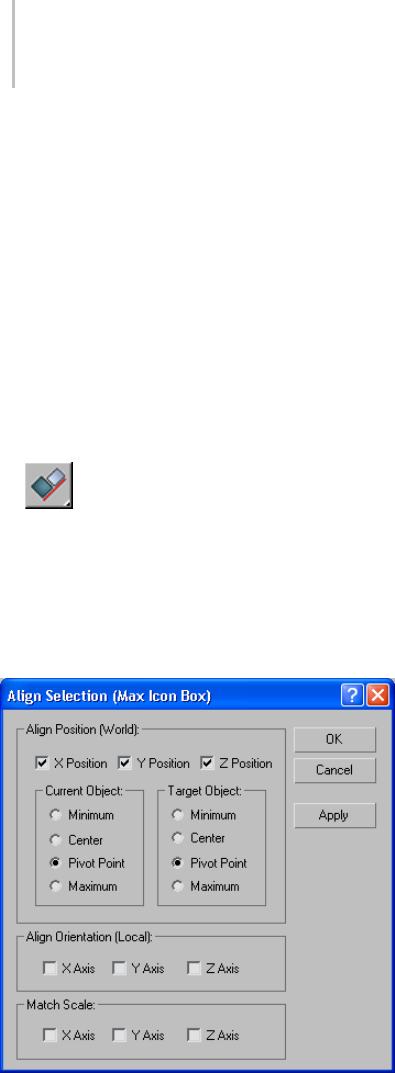
464 Chapter 6: Transforms: Moving, Rotating, and Scaling Objects
4. UsetheavailablesettingsintheAligndialogto
adjust the transformation of the gizmo.
To align a sub-object selection of geometry to
another object:
1. Do one of the following:
• Convert the object to an editable mesh, and
then perform the sub-object selection at any
level.
• Apply a Mesh Select modifier, followed by an
XForm modifier. (The Mesh Select modifier
by itself doesn’t allow transforms.)
2. On the Main toolbar, click Align, or
choose Tools > Align, and then select a target
object.
3. Use the settings in the Align dialog to perform
the alignment.
Interface
Align Position group
X/Y/Z Position—Specifies on which axis or axes
to perform the alignment. Turning on all three
options moves the current object to the target
object’s location.
Current Object/Target Object groups
Specify which points on the objects’ bounding
boxes to use for the alignment. You can choose
different points for the current object and the
target object. For example, you can align the
current object’s pivot point (page 3–995) with the
center of the target object.
Minimum—Aligns the point on the object’s
bounding box with the lowest X, Y, and Z values
with the chosen point on the other object.
Center—Aligns the center of the object’s bounding
box with the chosen point on the other object.
Pivot Point—Aligns the object’s pivot point with
the chosen point on the other object.
Maximum—Aligns the point on the object’s
bounding box with the highest X, Y, and Z values
with the chosen point on the other object.
Align Orientation (Local) group
These settings let you match the orientation of the
local coordinate systems between the two objects
on any combination of axes.
This option is independent of the position
alignment settings. You can leave the Position
settings alone and use the Orientation check
boxes to rotate the current object to match the
orientation of the target object.
Position alignment uses world coordinates (page
3–1035), while orientation alignment uses local
coordinates. (page 3–963)
Match Scale group
Use the X Axis, Y Axis, and Z Axis options to
match the scale axis values between the two
selected objects. This matches only the scale values
you’d see in the Transform Type-In (page 1–431).
Quick Align 465
It does not necessarily cause two objects to be the
same size. There will be no change in size if neither
of the objects has previously been scaled.
Quick Align
Main toolbar > Quick Align (on Align flyout)
Tools menu > Quick Align
Keyboard > Shift+A
Quick Align lets you instantly align the position
of the current selection to that of a target object.
If the current selection is a single object, Quick
Align uses the two objects’ pivots (page 3–995).If
the current selection comprises multiple objects
or sub-objects, Quick Align aligns the source’s
selection center (page 1–447) with the pivot of the
target object.
Procedure
To use Quick Align:
1. Select one or more objects or sub-objects to
align.
2. Press Shift+A or choose Quick Align from
the Tools menu or Main toolbar > Align flyout.
The mouse cursor turns into a “lightning-bolt”
symbol. When positioned over an acceptable
alignment target, a crosshairs symbol also
appears.
3. Clickanobjecttowhichtoaligntheselection
from step 1.
The alignment is performed.
Normal Align
Main toolbar > Normal Align (on Align flyout)
Tools menu > Normal Align
Keyboard > Alt+N
Normal Align uses the Normal Align dialog to
align two objects based on the direction of the
normal (page 3–980) of a face or selection on each
object. ToopentheNormalAligndialog,select
theobjecttobealigned,clickafaceontheobject,
and then click a face on a second object. Upon
releasing the mouse, the Normal Align dialog
appears.
If you use Normal Align while a sub-object
selection is active, only that selection is aligned.
This is useful when aligning sub-object selections
of faces, since otherwise there’s no valid face
normal for the source object.
Normal Align respects smoothing groups and uses
the interpolated normal, based on face smoothing.
Asaresult,youcanorientthesourceobjectfaceto
any part of the target surface, rather than having
it snap to face normals.
Foranobjectwithnofaces(suchashelperobjects,
space warps, particle systems, and atmospheric
gizmos), Normal Align uses the Z axis and origin
of the object as a normal. Thus, you can use a Point
object (page 2–23) with Normal Align.
Other alignment tools on the Align flyout are Align
(page 1–462),Quick Align (page 1–465),Place
Highlight (page 1–467),Align to Camera (page
1–468),andAlign to View (page 1–468).
Procedure
To align normals:
1. Select a source object. This is the object that
movesduringalignment.
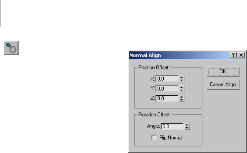
466 Chapter 6: Transforms: Moving, Rotating, and Scaling Objects
2. Click Normal Align on the Main toolbar,
or choose Tools > Normal Align.
3. Dragacrossthesurfaceofthesourceobject.
The Normal Align cursor appears, attached to a
pair of cross hairs. A blue arrow at the cursor
indicates the current normal.
4. Move the cursor and blue arrow until you locate
the normal you want to use, then release.
Thebluearrowremainsasreferencetothe
source normal.
5. Drag across the surface of the target object.
A green arrow at the cursor indicates the
current normal.
6. Move the cross hairs and green arrow until you
locate the normal you want to use as a target,
then release.
The source object moves into alignment with
the target normal, and the Normal Align dialog
appears.
7. Do one of the following:
• Click OK to accept the alignment.
•Usingthedialog,makemodificationstothe
alignment before clicking OK.
• Click Cancel Align to cancel the alignment
procedure.
Interface
The Normal Align dialog lets you adjust or cancel
the current alignment, and contains the following
controls:
Position Offset group
Lets you translate the source object perpendicular
to the normal on the X, Y or Z axes.
X/Y/Z—These three fields let you affect how much
of an offset will be given to the selected faces.
Rotation Offset group
Lets you rotate the source object about the
normal’s axis. You see the rotation in real time.
Angle—This field lets you define the angle for the
rotational offset.
Flip Normal—Determines whether the source
normal matches the target normal’s direction.
This defaults to off, since you usually want the
two normals to have opposing directions. When
youturnthisonoroff,thesourceobjectflips180
degrees.
OK/Cancel Align—The Cancel button is labeled
Cancel Align to make it clear that you’re not only
canceling the settings in the dialog, but canceling
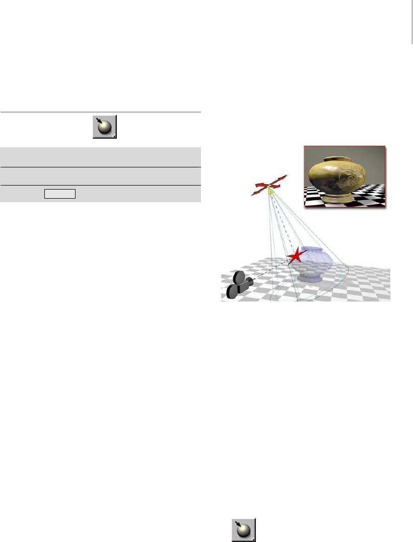
Place Highlight 467
the original transform (page 3–1026) of the source
object.
Place Highlight
Main toolbar > Place Highlight (on Align flyout)
Tools menu > Place Highlight
Keyboard > Ctrl+H
Place Highlight, available from the Align flyout
(page 1–462),enablesyoutoalignalightorobject
toanotherobjectsothatitshighlightorreflection
can be precisely positioned.
In Place Highlight mode, you can click and
drag the mouse around in any viewport. Place
Highlight is a viewport-dependent function, so
usetheviewportthatyou’regoingtoberendering.
As you drag the mouse in the scene, a ray is shot
from the mouse cursor into the scene. If it hits a
surface, you see the surface normal (page 3–980) at
that point on the surface.
When you designate a surface, any selected objects
are positioned along a line that represents the ray
reflected off the surface about the surface normal.
The objects are positioned along this line based on
their original distance from the surface point. For
example, if the object is 100 units from the surface
point before being moved, it will be positioned 100
units from the surface point along the reflected ray.
If the object is a light, the position of the highlight
on the surface of the object will be the surface
pointthatyou’vechosen.
Tip: Place Highlight works with any kind of
selected object. It can be used to move objects
based on a combination of face normals and initial
distance from the face. You can also use Place
Highlight with a selection set that contains more
than one object. All objects maintain their initial
distance from the face. In this case it has nothing
to do with highlights, but is simply being used to
position objects.
Note: Highlight rendering depends on the
material’s specular properties and the type of
rendering you use.
Place Highlight aligns a camera and a spotlight to the same
face.
Other alignment tools on the Align flyout are Align
(page 1–462),Quick Align (page 1–465),Normal
Align (page 1–465),Align to Camera (page 1–468),
and Align to View (page 1–468).
Procedure
To position a light to highlight a face:
1. Make sure the viewport you plan to render is
active, and that the object you want to highlight
is visible in it.
The result of Place Highlight depends on what
is visible in the viewport.
2. Select a light object.
3. Click Place Highlight, or choose Tools >
Place Highlight.
Choose Tools > Place Highlight.
Ifthebuttonisnotvisibleonthetoolbar,
choose it from the Align flyout.
468 Chapter 6: Transforms: Moving, Rotating, and Scaling Objects
4. Drag over the object to place the highlight.
When you place an omni, free spot, or
directional light, the software displays a face
normal for the face the mouse indicates.
When you place a target spotlight, the software
displays the light’s target and the base of its
cone.
5. Releasethemousewhenthenormalortarget
display indicates the face you want to highlight.
The light now has a new position and
orientation. You can see the highlight
illumination in shaded viewports that show
thefaceyouchose,andwhenyourenderthose
views.
Align Camera
Main toolbar > Align Camera button (on Align flyout)
Tools menu > Align Camera
Align Camera, available from the Align flyout
(page 1–462), lets you align a camera to a selected
face normal.
AlignCameraworkssimilarlytoPlace Highlight
(page 1–467),exceptthatitoperatesonface
normals instead of the angle of incidence, and
occurs when you release the mouse button instead
of dynamically acting during the mouse drag. Its
purposeistoletyoualignaCameraviewportto
a specified face normal.
Other alignment tools on the Align flyout are Align
(page 1–462),Quick Align (page 1–465),Normal
Align (page 1–465),Place Highlight (page 1–467),
and Align to View (page 1–468).
Procedure
To use Align Camera:
1. Select the camera used for the viewport you
want to align.
2. Click Align Camera or choose Tools
menu > Align Camera.
3. In any viewport, drag the mouse over an object
surface to choose a face.
The chosen face normal appears as a blue arrow
beneath the cursor.
4. Releasethemousetoperformthealignment.
Thesoftwaremovesthecamerasoitfaces
and centers the selected normal in the camera
viewport.
Align to View
Main toolbar > Align to View (on Align flyout)
Tools menu > Align to View
Align to View, available from the Align flyout
(page 1–462), displays the Align To View dialog,
whichletsyoualignthelocalaxisofanobjector
sub-object selection with the current viewport.
You can use Align to View with any selection that
can be transformed.
Other alignment tools on the Align flyout are Align
(page 1–462),Quick Align (page 1–465),Normal
Align (page 1–465),Place Highlight (page 1–467),
and Align to Camera (page 1–468).
Procedure
To align the local axis of a selection with the current
viewport:
1. Select the objects or sub-objects to align.
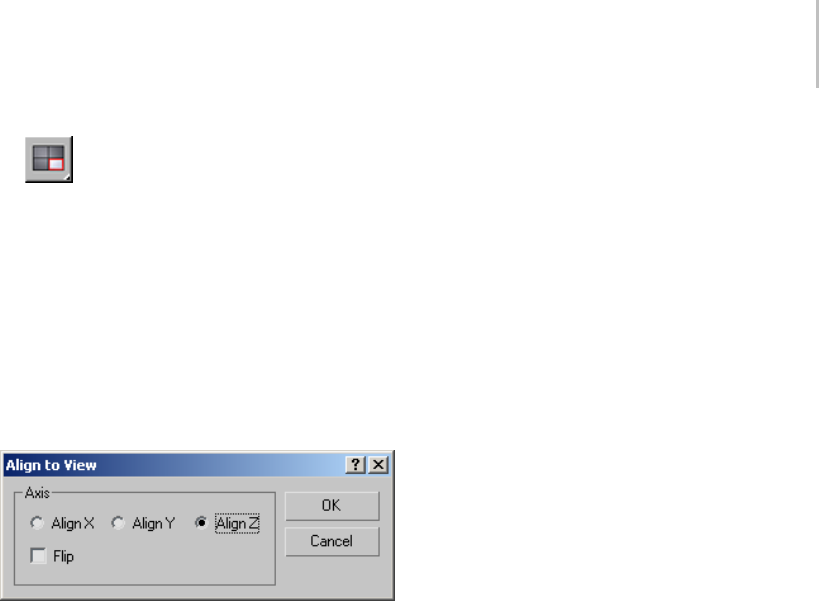
Align to View 469
2. Click Align to View.
3. Specify the local axis of the selected object to
align with the current viewport’s Z axis.
4. Select the Flip check box when you switch the
direction of the alignment.
The alignment takes place while the dialog is
displayed.
5. Click OK to complete the process.
Interface
TheAligntoViewdialogcontainsthefollowing
options:
Align X, Align Y, Align Z—Specifies which local
axis of the selected object will be aligned with the
current viewport’s Z axis.
Flip—Switches the direction of the alignment.

470 Chapter 6: Transforms: Moving, Rotating, and Scaling Objects
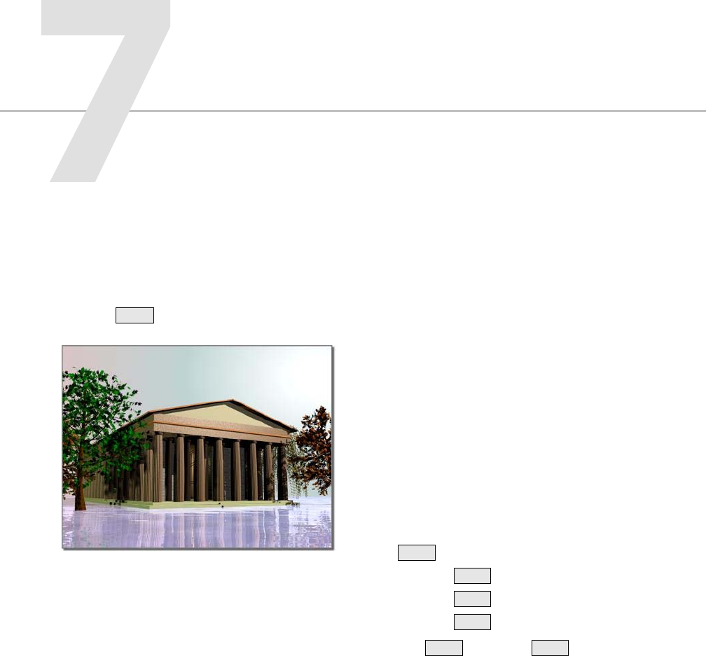
With 3ds Max, you can quickly create multiple
versions of one or more selected objects during
a transform operation. You do this by holding
down the Shift key as you move, rotate, or scale
the selection.
Portico created from arrays of columns
The general term for duplicating objects is cloning.
This section presents all the methods and choices
available for cloning objects. In addition to the
transformmethod,thetoolsincludethefollowing:
•Array lets you set all three transforms, in all
threedimensions,atthesametime.Theresults
are precise linear and circular arrays in 2D or
3D space.
•Mirror produces a "reflected" clone about one
or more axes. If you mirror an object without
cloning, the result is a "flip" of the geometry,
optionally to a new location.
•Snapshot lets you create clones equally spaced
over time or distance, based on an animation
path.
•Spacing Tool distributes objects based on the
current selection along a path defined by a
spline or pair of points.
You can animate any of the cloning techniques.
These topics supply overview information, as well
as specifics of animation for each of them:
Techniques for Cloning Objects (page 1–474)
Overview of Copies, Instances, and References (page
1–472)
Using Shift +Clone (page 1–478)
•Cloning with Shift +Move (page 1–479)
•Cloning with Shift +Rotate (page 1–480)
•Cloning with Shift +Scale (page 1–481)
Animating Shift +Rotate and Shift +Scale (page
1–482)
Cloning Objects Over Time with Snapshot (page
1–483)
Arraying Objects (page 1–484)
•Using the Array Dialog (page 1–485)
Creating Copies and Arrays

472 Chapter 7: Creating Copies and Arrays
•Creating Linear Arrays (page 1–487)
•Creating Circular and Spiral Arrays (page 1–489)
Mirroring Objects (page 1–491)
Using the Spacing Tool (page 1–491)
Overview of Copies, Instances,
and References
Toduplicateanobject,youuseoneofthree
methods. For all three methods, the original and
clone (or clones) are identical at the geometry
level.Wherethemethodsvaryisinthewaythey
handle modifiers (for example, Bend or Twist).
An object can be a copy of another.
Copy method: Creates a completely separate clone
fromtheoriginal.Modifyingonehasnoeffecton
the other.
Instance method: Creates a completely
interchangeable clone of the original. Modifying
an instanced object is the same as modifying the
original.
Reference method: Creates a clone dependent
on the original up to the point when the object is
cloned. Changing parameters for modifiers that
were applied to the object before the object was
referenced, will change both objects. However, a
new modifier can be applied to one of the reference
objects,anditwillaffectonlytheobjecttowhichit
is applied.
Depending on the method used to create them,
cloned objects are called copies,instances,or
references.
The following discussion focuses on how you
might use these methods.
Copies
Copies are the most familiar kind of clone object.
When you copy an object, you create a new,
independent master object and data flow resulting
in a new, named object. The copy duplicates all
of the data of the original object at the time it is
copied. The copy has no connection to the original
object.
Example of Using Copied Objects
If you modeled a basic head shape and wanted to
create a group of individual characters, you would
probably make a copy of the basic head shape
each time you started a new character. You could
thenmodelanindividualnose,mouth,andother
features.
Copying Actively Linked Objects
When you copy objects that are actively linked
through the File Link Manager (page 3–422),the
software automatically converts the copies to
editable mesh objects. If your selection contains
several objects that instance another object, the
resulting copies also instance the same object.
Instances
Instances are alike not only in geometry, but also
in every other way as well. Instancing an object
resultsinmultiplenamedobjectsbasedonasingle
master object. Each named object instance has its
own set of transforms, space warp bindings, and
object properties, but it shares the object modifiers

Overview of Copies, Instances, and References 473
and master object with the other instances. The
data flow for an instance branches just after
evaluating object modifiers.
When you change one instance by applying or
adjusting a modifier, for example, all the other
instances change with it.
Within 3ds Max, instances derive from the same
master object. What you’re doing "behind the
scenes" is applying a single modifier to a single
master object. In the viewport, what you see as
multiple objects are multiple instances of the same
definition.
Example of Using Instanced Objects
If you wanted to create a school of swimming
fish, you might begin by making many instanced
copies of a single fish. You could then animate the
swimming motion by applying a Ripple modifier
to any fish in the school. The whole school would
swim with exactly the same motions.
Instances of Actively Linked Objects
Creating instances of actively linked objects is not
recommended. Reliability issues can arise if the
instanced object is deleted in the linked file.
References
References arebasedontheoriginalobject,asare
instances, but can also have their own unique
modifiers. Like instances, references share, at
minimum,thesamemasterobjectandpossibly
some object modifiers.
The data flow for a reference branches just after
the object modifiers but then evaluates a second
set of object modifiers unique to each reference.
When you create references, 3ds Max displays
a gray line, called the derived-object line,atthe
top of the modifier stack for all clones. Any
modification made below the line is passed on to
other references, and to the original object. New
modifiers added above the line are not passed on
to other references. Changes to the original object,
such as in its creation parameters, are passed on to
its references.
This effect is useful for maintaining an original that
will affect all its references, while the references
themselves can take on individual characteristics.
All shared modifiers reside below the
derived-object line and are displayed in bold. All
modifiers unique to the selected reference reside
above the derived-object line and are not bold.
The original object does not have a derived object
line: its creation parameters and modifiers are
all shared, and all changes to this object affect all
references.
The results of changing or applying a modifier to a
named object reference depends on where in the
modifier stack it is applied:
• Applying a modifier to the top of the modifier
stack affects only the selected named object.
• Applying a modifier below the gray line affects
all references branching above that line.
•Applyingamodifieratthebottomofthe
modifier stack affects all references derived
from the master object.
References of Actively Linked Objects
Creating references of actively linked objects is not
recommended. Reliability issues can arise if the
referenced object is deleted in the linked file.
Example of Using Referenced Objects
In the example of modeling heads, you might want
to keep a family resemblance in your characters.
You could model basic features on the original,
then model specifics on each reference.
At some point, if you wanted to see what your
characters would look like as "cone-heads," you
could apply a Taper modifier to the original head,
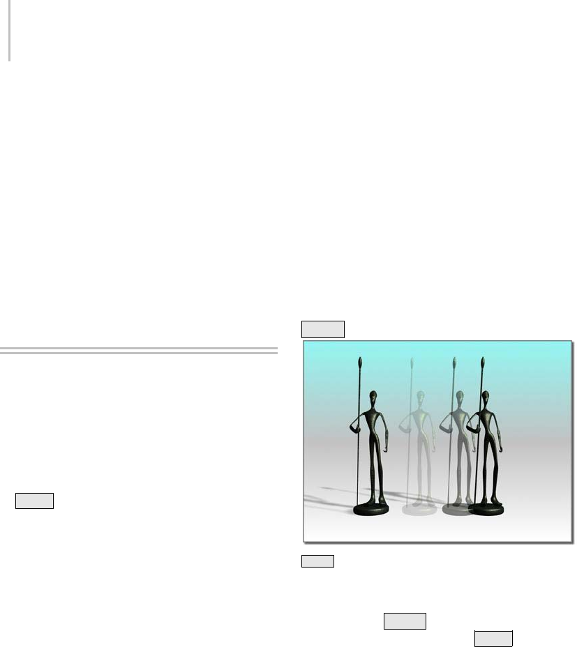
474 Chapter 7: Creating Copies and Arrays
and have all the other characters take on the same
feature. You could give the original character a
very pointed head, then apply a separate Taper to
some referenced characters to reduce the point
toward normal.
For swimming fish, you might choose to make all
members of the school as referenced objects based
on a single, original fish. You could still control
the swimming motion from the original fish, and
also add modifiers to individual fish in the school
to vary their behavior.
Cloning Objects
3ds Max provides several techniques for copying
or duplicating objects; cloning is the general term
for this process. These techniques can be used to
clone any selection set.
•Clone
•Shift +Clone
• Snapshot
•Array
•Mirror
•SpacingTool
•CloneandAlignTool
Shared Features
While each technique has distinct uses and
advantages in cloning objects, in most cases the
cloning techniques share some similarities in how
they work:
• You can apply a transform when you clone.
New objects are moved, rotated, or scaled as
they are created.
•Thetransformisrelativetothecurrent
coordinate system, axis constraint, and
transform center.
• When cloning creates new objects, you have
the choice of making them copies, instances,
or references.
Eachofthefollowingitemsisdiscussedlaterin
this chapter.
Clone
Using the Clone command on the Edit menu is
the easiest method for copying an object in place;
no transformation is involved. See Clone (page
1–476).
Shift +Clone
Shift +Clone clones an object when you transform it.
You can clone an object as you transform it
interactively in the viewport. The process is
referred to as SHIFT +Clone (page 1–478):the
technique of holding down the Shift key while
transforming a selected object with the mouse.
Quick and versatile, this technique is probably
theoneyou’llusemostoftentoduplicateobjects.
Snap settings give you precise results.
How you set the center and axes for the transforms
determines the arrangement of the cloned objects.
Depending on the settings, you can create both
linear and radial arrays.
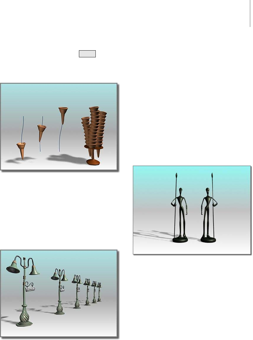
Techniques for Cloning Objects 475
You need a working knowledge of transform
features to take full advantage of Shift +Clone.
See Using Transforms (page 1–424).
Snapshot
Using an ice-cream cone animated along a path, Snapshot
creates a stack of cones.
Snapshot (page 1–453) clones an animated object
overtime. Youcancreateasinglecloneon
any frame, or space multiple clones along the
animation path. The spacing is a uniform time
interval; it can also be a uniform distance.
Array
A one-dimensional array
Array creates repeating design elements: for
example, the gondolas of a Ferris wheel, the treads
of a spiral stair, or the battlements along a castle
wall.
Array gives you precise control over all three
transforms and in all three dimensions, including
theabilitytoscalealongoneormoreaxes.Itis
the combination of transforms and dimensions,
coupled with different centers, that gives you so
many options with a single tool. A spiral stair,
for example, would be a combination of Move
andRotatearoundacommoncenter. Another
array using Move and Rotate might produce the
interlocked links of a chain.
See Arraying Objects (page 1–484).
Mirror
Mirroring an object
Mirror produces a symmetrical copy around any
combinationofaxes.Thereisalsoa"NoClone"
option that performs the mirror operation without
copying. The effect is a flip or move of the object
to a new orientation.
Mirror has an interactive dialog. As you change
settings, you see the effect in the active viewport;
in other words, a preview of what the mirror will
look like.
There is also a Mirror modifier that gives you
parametric control of the mirror effect.
See Mirroring Objects (page 1–491).
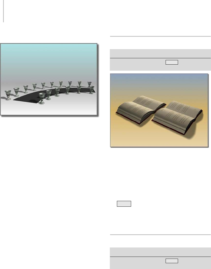
476 Chapter 7: Creating Copies and Arrays
Spacing Tool
The Spacing Tool distributes the vases along the sides of the
curved street.
The Spacing Tool distributes along a path defined
byasplineorpairofpoints.Youdefineapathby
picking a spline or two points and by setting a
number of parameters. You can also specify how
the spacing between objects is determined and
whether the insertion points of the objects align to
the tangent of the spline.
See Spacing Tool (page 1–455).
Clone and Align Tool
The Clone And Align tool lets you distribute
source objects based on the current selection to
a second selection of destination objects. For
example, you can use Clone And Align to populate
several rooms simultaneously with the same
furniture arrangement. Similarly, if you import a
CAD file that contains 2D symbols that represent
chairs in a conference room, you can use Clone
And Align to replace the symbols with 3D chair
objects en masse.
See Clone and Align Tool (page 1–459).
Clone
Make a selection. > Edit menu > Clone
Make a selection. > Hold down Shift key. > Move,
rotate, or scale the selection with the mouse.
Clone creates a copy, instance, or reference of an object.
With the Clone command you can create copies,
instances, or references of a selected object or a
set of objects.
TheClonecommandontheEditmenucreates
a single copy of your selection. Alternatively,
youcanclonemultiplecopiesbyholdingdown
the Shift key as you move (page 1–439),rotate
(page 1–439),orscale (page 1–440) your selection.
Either method displays the Clone Options dialog
(page 1–476).
Clone Options Dialog
Make a selection. > Edit menu > Clone
Make a selection. > Hold down Shift key. > Move,
rotate, or scale the selection with the mouse.
Clone creates a copy, instance (page 3–957),or
reference (page 3–1002) of a selected object or set
of objects. The Clone command on the Edit menu
creates a single copy. You can clone multiple copies
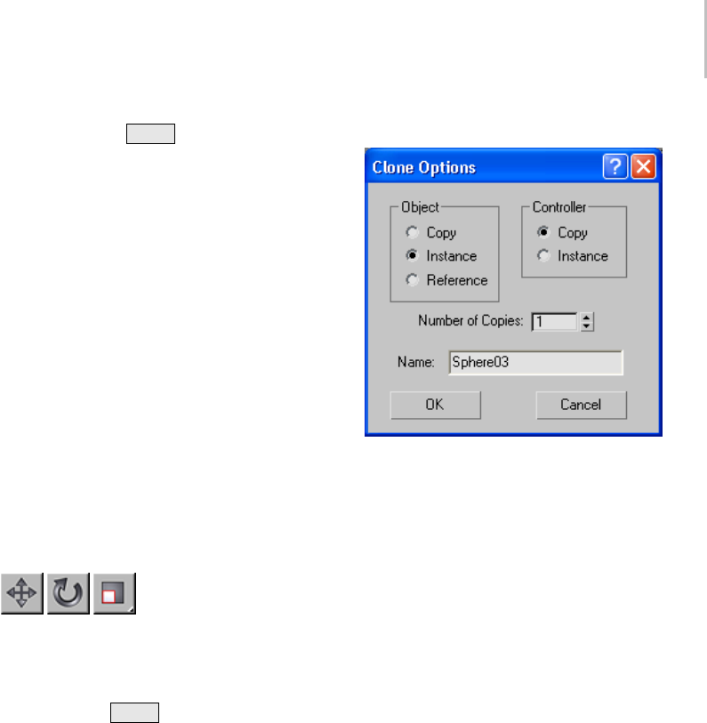
Clone Options Dialog 477
by holding down the Shift key as you transform
the selection.
Procedures
To clone an object without transforming it:
1. Select an object, or set of objects.
2. From the Edit menu, choose the Clone
command.
3. The Clone Options dialog opens.
Note: All options are present except Number
Of Copies.
4. Change the settings or accept the defaults, and
then click OK.
Each new, cloned object occupies the same
space as the original. Select a clone by name
to move or modify it.
To clone and transform an object:
1. On the main toolbar, click
the Move, Rotate, or Scale button.
2. Select an object, multipleobjects,group,or
sub-object.
3. Hold down the Shift key and drag the
selection.
As you drag your selection, the clone is created,
selected, and transformed. The original object
is deselected and unaffected by the transform.
When you release the mouse button, the Clone
Optionsdialogdisplays.
4. Change the settings or accept the defaults, and
then click OK.
Interface
Object group
Copy—Places a copy of the selected object at the
specified position.
Instance—Places an instance of the selected object
at the specified position.
Reference—Places a reference of the selected object
at the specified position.
Controller group
Lets you choose to copy or instance the transform
controllers (page 3–909) of the original object’s
childobjects.Thisoptionisavailableonlywhen
the selection you are cloning includes two or more
hierarchically linked objects (page 3–951).
When cloning non-linked objects, transform
controllers are simply copied. Also, when cloning
linked objects, the highest-level cloned object’s
transform controller is simply copied. This option
applies only to the transform controllers of objects
at levels below the top of the cloned hierarchy.
Copy—Copies the cloned objects’ transform
controllers.
Instance—Instances the cloned objects’ transform
controllers below the top level of the cloned
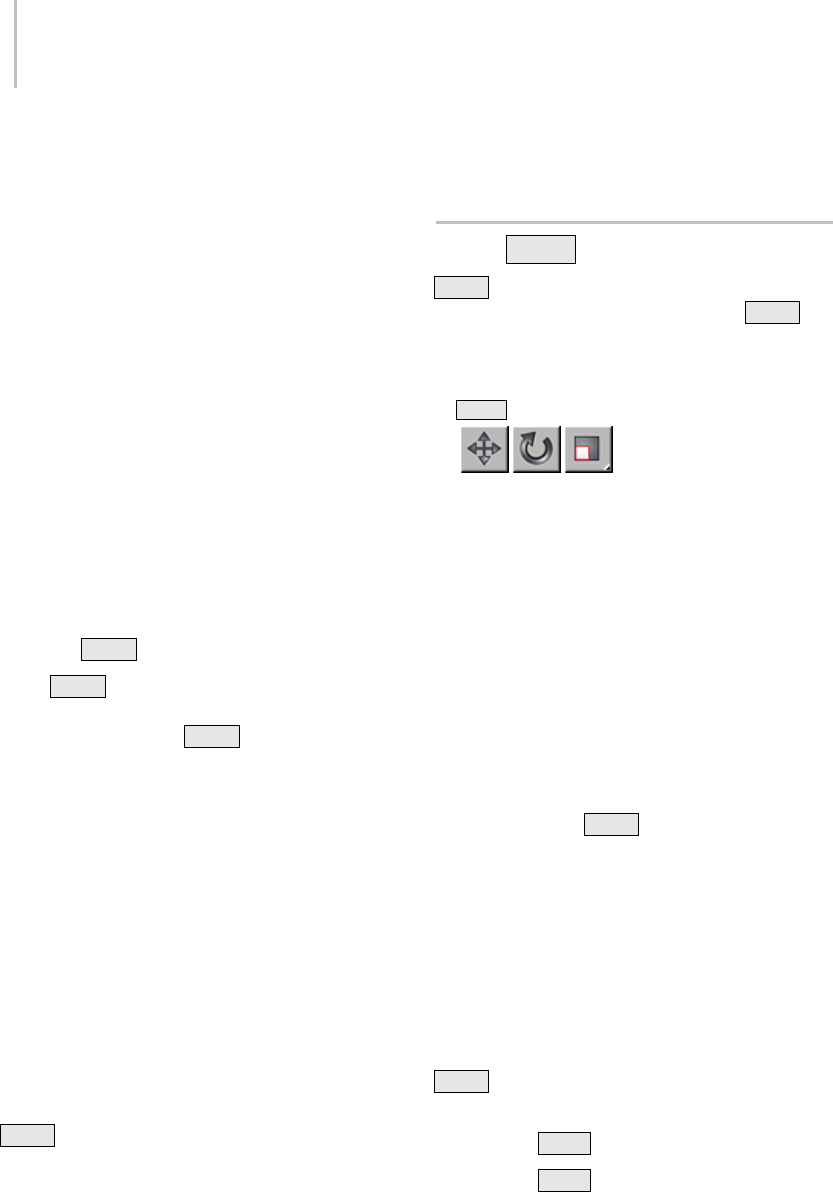
478 Chapter 7: Creating Copies and Arrays
hierarchy. With instanced transform controllers,
you can change the transform animation of one
setoflinkedchildren,andautomaticallyhavethe
change affect any cloned sets.
This allows you to animate all clones identically
with a single animation setup. For example,
consider a scene containing three objects named
Torso, Thigh, and Calf. The objects are linked
hierarchically so that Torso is the parent of
Thigh and Thigh is the parent of Calf. Say you
select all three objects and then clone them, and
choose Clone Options > Controller > Instance.
Thereafter, if you transform either Thigh or Calf
object, the corresponding object in the other
hierarchy is transformed identically, along with
any child objects. However, if you transform either
Torso object, the other hierarchy is not affected.
Number of Copies—Specifies the number of copies
of the object you want to create. Available only
when you Shift +Clone an object.
Using Shift +Clone to generate multiple copies
applies the transform successively to each
additional copy. If you Shift +Move an object
andspecifytwocopies,thesecondcopyisoffset
fromthefirstcopybythesamedistancethatthe
first copy is offset from the original. For Rotate,
two copies of the rotated object are created, with
thesecondcopyrotatedtwiceasfarasthefirst.For
Scale, two copies of the scaled object are created,
with the second copy scaled from the first copy by
thesamepercentagethatthefirstcopywasscaled
from the original.
Name—Displaysthenameoftheclonedobject.
You can use this field to change the name;
additional copies use the same name followed by a
two-digit number, starting at 01 and incrementing
by one for each copy. So, for instance, if you
Shift +Move an object and then specify the name
building and two copies, the first copy will be
named building and the second will be named
building01.
Using Shift +Clone
Shift +Clone is the primary way to duplicate
objects in 3ds Max. You hold down the Shift key
anddragduringanyofthestandardtransform
operations: Move, Rotate, or Scale.
To Shift +Clone an object:
1. On the main toolbar, click
the Move, Rotate, or Scale button.
2. Select a transform coordinate system and
constraints. Each transform carries its own
settings. To avoid surprises, always click the
transform button first, and then set your
transformcoordinatesystemandconstraints.
Note: You can also use the Transform Gizmo
to set axis constraints.
3. Select the object or set of objects you want to
clone. The selection can be a single object,
multiple objects, a group, or a sub-object
selection.
4. Hold down the Shift key anddragthe
selection to apply the transform.
As you drag, a clone is created and selected; it is
now the object being transformed. The original
object is no longer selected and is unaffected
by the transform.
When you release the mouse button, the Clone
Optionsdialoga
ppears. Change settings in this
dialog or accept the defaults, and then click OK.
Shift +Clone uses the Clone Options dialog (page
1–476) for any transform you choose.
Cloning with Shift +Move (page 1–479)
Cloning with Shift +Rotate (page 1–480)
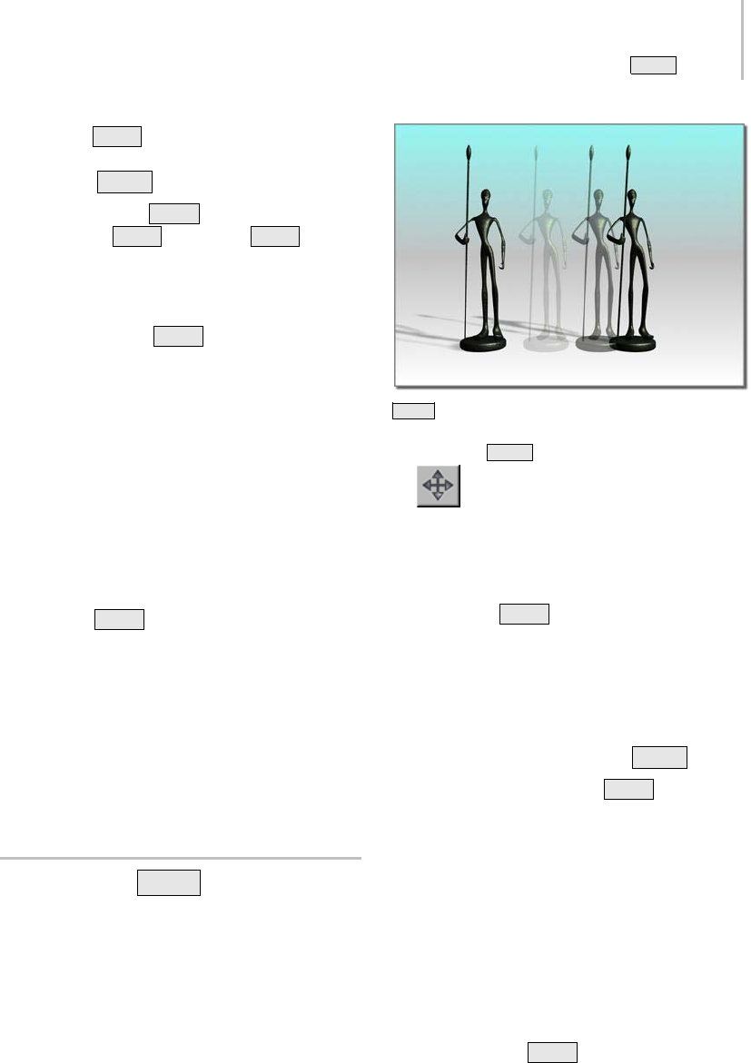
Cloning with Shift +Move 479
Cloning with Shift +Scale (page 1–481)
Animating Shift +Clone
You can animate any Shift +Clone operation. See
Animating with Shift +Rotate and Shift +Scale
(page 1–482).
Cloning Without Transforming
Cloning objects with Shift +Clone requires
transforming them at the same time, by moving,
rotating, or scaling them. In some cases, you might
want to clone an object without transforming it in
any way. The Edit menu Clone command gives
you this option, which lets you create only one
clone at a time.
To clone objects without transforming:
1. Select the object or objects to clone.
2. Choose Edit menu > Clone. The Clone
Optionsdialogappears.Thisisthesamedialog
used with Shift +Clone except that there’s
no Number Of Copies setting. The Clone
command lets you create only one copy.
3. Change settings in this dialog or accept the
defaults, and click OK.
Note: The cloned object occupies the exact
same space as the original, and is selected when
cloning is complete. Use Select By Name (page
1–77) to select the original or reselect the clone.
Cloning with Shift +Move
Cloning objects while moving them is quick and
easy. It produces a linear array of two or more
objects.
Shift +Move creates a clone in a different location.
To clone with Shift +Move:
1. Click the Move button on the main
toolbar.
2. Choose a coordinate system and axis constraint.
3. Make the selection you want to clone.
4. Hold down Shift anddragtomoveacloneof
the selection away from the original.
5. Choose the number of copies you want to make
on the Clone Options dialog, and whether you
want them to be copies, instances, or references.
About Arrays Created with Shift +Move
Multiple clones produced by Shift +Move
form an equally spaced linear array with these
characteristics:
• The line of the array runs from the center of the
original through the centers of the clones.
• The distance between each neighboring pair
of copies is the same the distance between the
original and the first clone.
By using snaps as you move the selection, you can
make precise arrays.
An example of the Shift +Move array is a picket
fence. From a single picket, you can generate long
runs of fencing. You can array the fence along
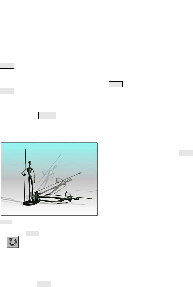
480 Chapter 7: Creating Copies and Arrays
a major axis of the home grid, then group the
pickets, rotate them to a particular angle, and
move them into position.
You can also make three-dimensional arrays with
Shift +Move.Themainchoiceisthecombination
of axes to allow movement off the construction
plane. For example, to build a stairway, you can
create a box that forms the top step, then use
Shift +Move to copy it diagonally downward,
using an array to create a downward flight.
Cloning with Shift +Rotate
Cloningobjectswhilerotatingthemproducesa
variety of effects, depending on how you set up
the transformation.
Shift +Rotate creates a clone with a different orientation.
To clone with Shift +Rotate:
1. Click the Rotate button on the main
toolbar.
2. Choose a coordinate system, transformation
center, and axis constraint.
3. Make the selection you want to clone.
4. Hold down the Shift key and drag to rotate
the selection.
5. Choose the number of copies you want to make
on the Clone Options dialog, and whether you
want them to be copies, instances, or references.
Effects of Transform Settings
Where you locate the transform center determines
how 3ds Max positions clones when using
Shift +Rotate.
• For all settings, the direction of rotation is
constrained by the active axis or axes of the
viewport’s coordinate system.
• Each clone is rotated from the previous one
bythesameamountasthefirstclonefromthe
original.
Local Pivot at Center
An object’s default pivot point is often located at
itscenteroritsbase.Whenyouuse Shift +Rotate
around an object’s default pivot point, the clones
overlap evenly as each one is rotated the same
amount. Thisistrueformultipleobjectswitha
local-pivot setting, since each object uses its own
local center.
Clones of a circular object, like a sphere or
cylinder, can be overlaid exactly on the original.
You might need to move them away from the
original to see them.
With angle snap (page 2–12) set to divide a circle
evenly, you can produce complex symmetrical
objects from simple ones. For example, you can
clone a tetrahedron around one axis, then clone
the new set about another axis to produce a faceted
star.
Local Pivot at a Distance
When you separate the local pivot from the
original, clones create a wheel-like arrangement.
Long shapes like petals or blades, cloned with
the center near one end, can create flowers or
propellers. See Adjust Pivot Rollout (page 2–488).
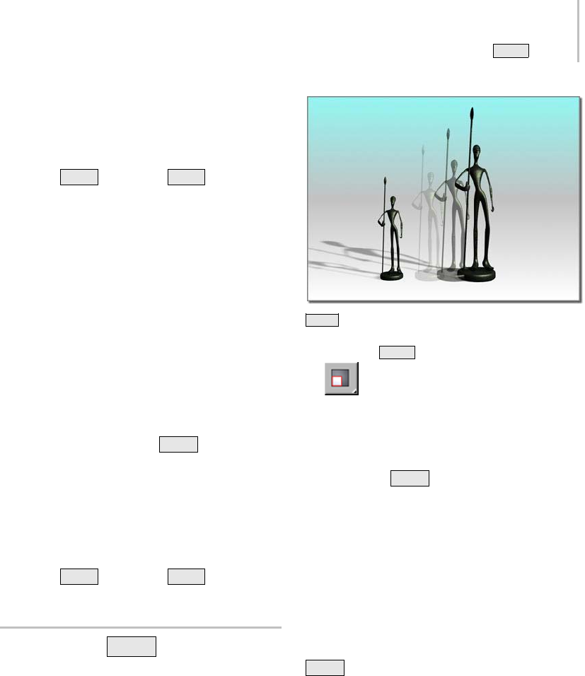
Cloning with Shift +Scale 481
You can move the local pivot any distance from
the object, creating large circular arrays. Since
direct animation is limited to the local pivot, this is
a key technique in animating circular arrays. See
Animating Shift +Rotate and Shift +Scale (page
1–482).
Selection Center
Foreithersingleormultipleobjects,theselection
center is the geometric center of the bounding box
(page 3–919) enclosing the entire selection. Clones
are arrayed around this center, forming wheel-like
arrays.
For a single object, this center is usually different
from its local center, but the effects are similar to
those based on a local pivot.
Coordinate Center
Using the coordinate center, Shift +Rotate can
produce circular arrays of any size.
The rotation takes place around the center of the
home grid, the screen, or whichever coordinate
system you choose. While clones can be created
this way, the process cannot be directly animated.
For details on overcoming this limitation, see
Animating Shift +Rotate and Shift +Scale (page
1–482).
Cloning with Shift +Scale
Cloning objects while scaling them can produce a
variety of nested objects and arrays, depending on
the center you choose.
Shift +Scale creates a clone of a different size.
To clone with Shift +Scale:
1. ClickaScalebuttononthemaintoolbar.
2. Choose a coordinate system, axis constraint,
and transform center.
3. Make the selection you want to clone.
4. Hold down Shift and drag to scale the
selection.
5. UsetheCloneOptionsdialogtochoosethe
number of clones you want to make and
whether you want them to be copies, instances,
or references.
Effects of Transform Settings
Transform settings determine how 3ds Max
distributesclonesofaselectionduring
Shift +Scale. In all scaling operations, the
transform center acts as the center of scaling:
• When clone objects decrease in size, they
shrink toward the transform center.
• When clone objects increase in size, they
expand away from the transform center.
The distance between cloned objects is scaled
like the clones themselves, based on the initial
distance from the original to the first clone. The
482 Chapter 7: Creating Copies and Arrays
spacing increases or decreases proportionately
with respect to the transform center.
Nested Copies
When the selection center is used as the
transform center for a single object, scaling occurs
symmetrically around that center, producing
nested copies.
• As you scale in toward the center, smaller and
smaller copies are created.
• In the other direction, the original object is
enclosed by increasingly larger copies.
Variations are possible, depending on the type
of scale and axis limitations. For example, you
can scale a flat box into a progressively stepped
pyramid by using Squash (page 1–442) and cloning
inward on the Z axis.
Offset Centers
For Shift +Scale, any center other than the
local pivot has the effect of creating an array of
progressively scaled objects. Again, objects scale
down in size toward the center, while increasing in
size further away. However, this effect is limited by
the particular scale option and the axis constraints,
as discussed next.
Axis Constraints
Uniform Scale is unaffected by axis constraints,
which you can set with the Transform Gizmo.
Copies are always arrayed in or out from the center
of the current coordinate system.
For Non-Uniform Scale and Squash, scaling
occurs only along the axis or axes set with the
restricted axes.
Note: The Restrict To ... buttons (also called the
Axis Constraints buttons) are available on the
Axis Constraints toolbar (page 3–687),whichisoff
by default. You can toggle display of this toolbar
by right-clicking an empty area of a toolbar and
choosing Axis Constraints from the Customize
Display right-click menu (page 3–787).
Animating Shift +Rotate and
Shift +Scale
When the Auto Key button (page 3–717) is on, the
transform center defaults to local pivot, and the
Use Center flyout (page 1–445) on the toolbar is
unavailable. If you choose one of the other centers
and activate Auto Key, the center returns to the
local pivot. This means you can’t directly animate
about a non-local pivot center with Shift +Rotate
and Shift +Scale. For example, you can’t use this
method to create clones in an arc or circular array
around a common center.
Using Non-Local Centers
Touseacenterseparatefromtheobjectyou’re
cloning, you can do any of the following:
•Useadummyobject.
• Offset the local pivot.
• Change the default animation center.
Using a Dummy Object as Center
In this procedure, you use the axis tripod of the
dummy object as the center for rotation or scale.
To use a dummy object as center:
1. Create a dummy object (page 2–16) at the center
of rotation or scaling.
2. Link the object or objects you want to
clone to the dummy object, which becomes the
parent.
3. Select both the dummy and the objects,
thentransformthemwith Shift +Rotate or
Shift +Scale.
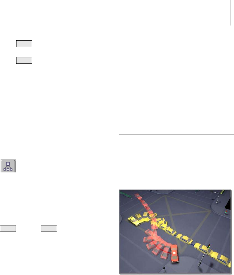
Cloning Objects Over Time with Snapshot 483
•ForShift +Rotate, the dummy’s center
becomes the pivot.
•For
Shift +Scale, the dummy and selected
objects scale together toward the center of
the dummy.
For details of dummy object use in hierarchies, see
Using Dummy Objects (page 2–429).
Offsetting the Local Pivot
In this procedure, you move the object’s pivot to
thecenterofrotationorscale.Thisworksmuch
like using a dummy object.
To offset the local pivot:
1. Selecttheobjectwhosepivotyouwishtomove.
2. On the Hierarchy command panel,
choosePivotandthenturnonAffectPivot
Only.
3. Move the local pivot of the original object to
anotherlocationinyourscene.
4. On the Hierarchy panel, click Affect Pivot Only
againtoturnitoff.
Shift +Rotate or Shift +Scale now animates
around the offset center. This works with the
default setting for local center.
Note: Moving the local pivot can adversely
affect linking and inverse kinematics. If this is
a possibility, consider changing the default axis
instead of moving the local pivot.
To change the default axis while animating:
In this procedure, you set 3ds Max to allow
animation of transforms about any center on the
Use Center flyout.
1. Choose Customize menu > Preferences and
click the Animation tab of the Preference
dialog.
2. In the Animate group, turn off Local Center
During Animate.
This changes the default and makes all the
transform center options available when
animating. You can now animate around either
the selection or transform coordinate center,
as well as local pivot.
Note: Changingthedefaultsettinganimatesthe
rotation you see in viewports as a rotation plus
translation, which might not be the effect you
wanted.
Cloning Objects Over Time with
Snapshot
The Snapshot tool (page 1–453) lets you clone an
object along its animation path. You can make
a single clone at any frame, or multiple clones
spaced over a selected number of frames.
Using car models animated along paths, Snapshot creates an
image of a collision.
Snapshot can also clone a particle system’s
particles.
Snapshot spaces the clones equally in time.
Adjustments in Track View let you space the clones
equally along the path instead.
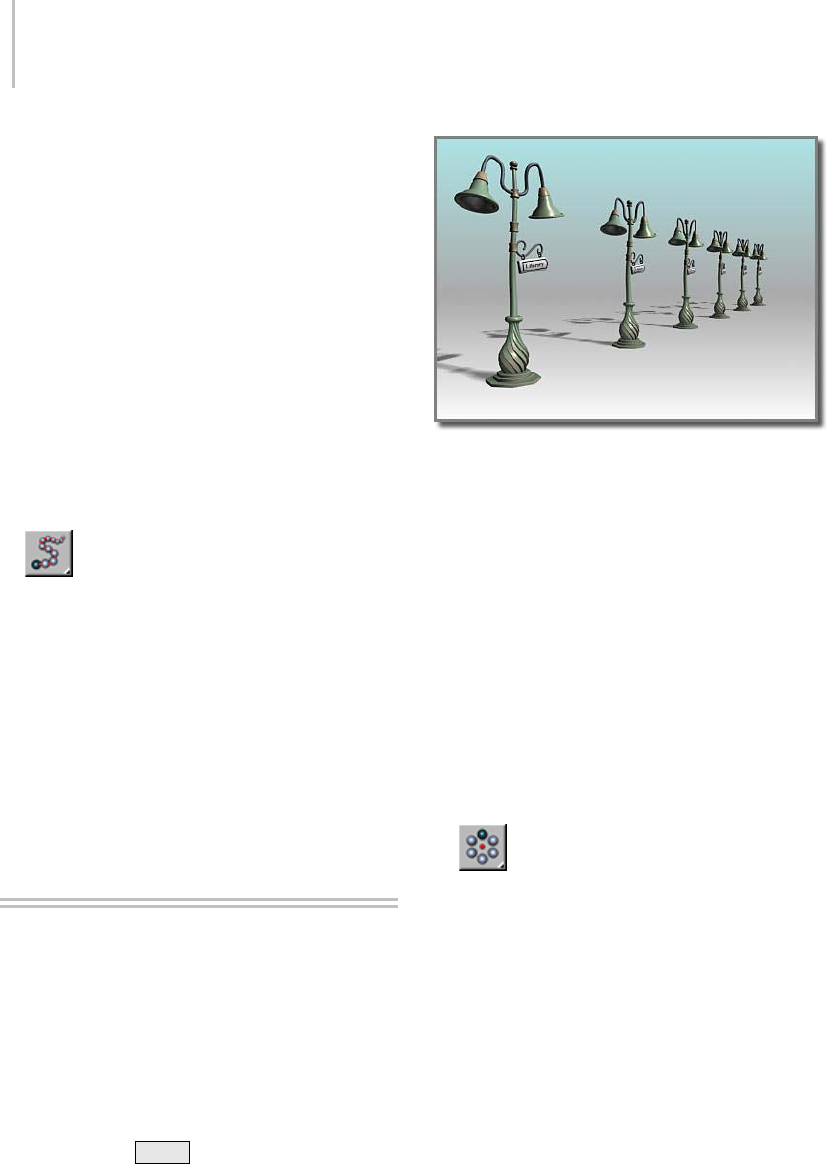
484 Chapter 7: Creating Copies and Arrays
Like other clone techniques, Snapshot creates
copies, instances, or references. You can also
choose a mesh option.
To clone an object with Snapshot, the object must
alreadybeanimated.YoucanuseSnapshotfrom
anyframeonthepath.TheAutoKeybuttonhas
no effect on Snapshot, since Snapshot creates
static clones, not animation. This is the general
procedure:
TocloneanobjectwithSnapshot:
1. Select an object with an animation path, or
aparticlesystem. Theanimationcanresult
from applying transforms, controllers, or any
combination of effects.
2. On the Array flyout (page 1–448) click
Snapshot, or choose Tools menu > Snapshot to
display the Snapshot dialog.
Note: TheArrayflyoutisontheExtrastoolbar,
which is off by default. You can toggle display of
this toolbar by right-clicking an empty spot on
the main toolbar and choosing Axis Constraints
from the Customize Display right-click menu
(page 3–787).
3. Set parameters in the dialog, and click OK.
Arraying Objects
Array is a dedicated tool for cloning and precisely
transforming and positioning groups of objects in
one or more spatial dimensions. For each of the
three transforms (move, rotate, and scale), you
can specify parameters for individual objects in
thearray,orforthearrayasawhole.Manyresults
you can get with Array would be laborious or
impossible using Shift +Clone techniques.
A one-dimensional array
Creating an Array
This is the general procedure. For more details,
see these topics:
Using the Array Dialog (page 1–485)
Creating Linear Arrays (page 1–487)
Creating Circular and Spiral Arrays (page 1–489)
To create an array:
1. Select one or more objects to be in the array.
2. Choose a coordinate system and transform
center.
3. Click Array on the Array flyout, or
choose Array (page 1–450) from Tools menu.
The Array dialog appears.
Note: The Array flyout is on the Extras toolbar,
which is off by default. You can toggle display of
this toolbar by right-clicking an empty spot on
the main toolbar and choosing Axis Constraints
from the Customize Display right-click menu
(page 3–787).
4. Set array parameters on this dialog, then click
OK.
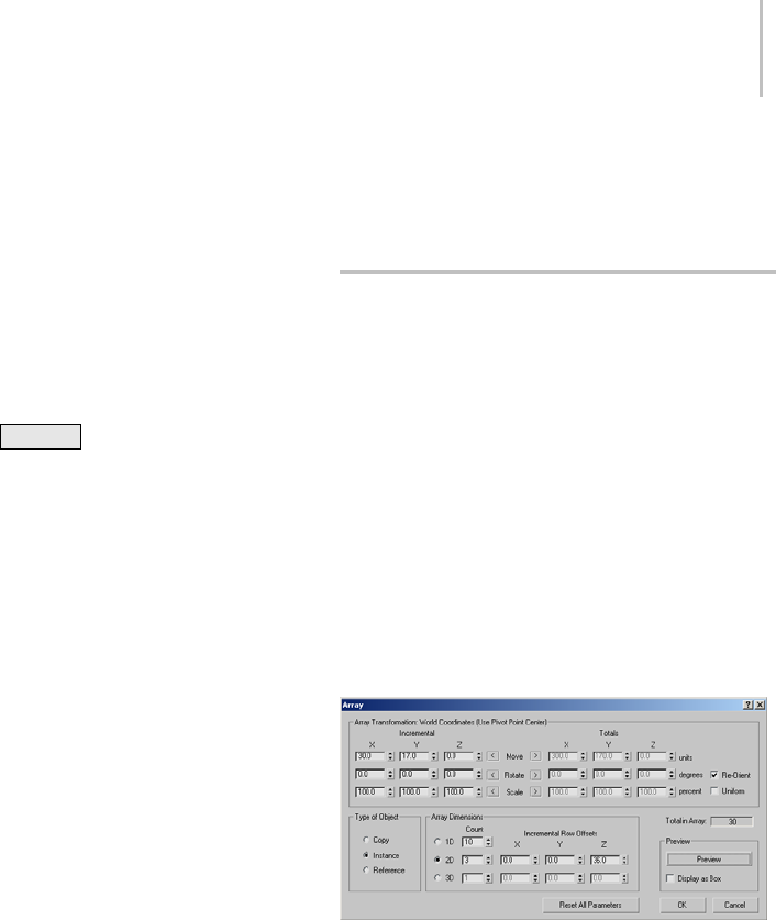
Using the Array Dialog 485
Reuse of Array Settings
Generally you should approach Array creation as
an iterative process. The dialog settings are not
interactive, so you get feedback only after creating
the array. By revising the current settings and
repeating the array, you develop a solution that
meets your needs.
Aftercreatinganarrayandcheckingitsresult,
youcanundothearrayusingEditmenu>Undo
Create Array or Ctrl+Z .Thisleavestheoriginal
selection set in place.
Repeating an Array
When you create an array, object selection moves
to the last copy or set of copies in the array. By
simply repeating current settings, you create a
seamless continuation of the original array.
During a session, 3ds Max maintains all the dialog
settings for your current array.
Arraysettingsaresavedonlyduringthecurrent
session, not with the file. Be sure you’ve finished
an array before you quit 3ds Max.
General Considerations
When you create an array, keep these points in
mind:
• Array is relative to the current viewport settings
forcoordinatesystemandtransformcenter.
• Axis constraints do not apply, because Array
allows you to specify transforms along all axes.
• You can animate array creation. By changing
the default Animate preferences setting, you
canactivateallthetransformcenterbuttons,
allowing direct animation around either the
selection or coordinate center, as well as local
pivot. For information about changing the
default setting, see the procedure, To change t he
default axis while animating (page 1–483).
• To make an array of a hierarchically linked
object, select all the objects in the hierarchy
before you click Array.
Using the Array Dialog
The Array dialog provides two main control areas
where you set the important parameters: Array
Transformation and Array Dimensions.
You can set parameters in any order, but in practice
it’s useful to start with Array Transformation. This
creates the basic building block for the larger array,
as defined by Array Dimensions.
These topics discuss specific strategies for using
these controls:
Creating Linear Arrays (page 1–487)
Creating Circular and Spiral Arrays (page 1–489)
See also
Array (page 1–450)
Array Transformation
This area lists the active coordinate system
and transform center. It’s where you set the
transforms that define the first row of the array.
You decide here on the distance, rotation, or scale
of individual elements, and along what axes.
You then repeat this row in other dimensions to
produce the finished array.

486 Chapter 7: Creating Copies and Arrays
Move, Rotate, and Scale Transforms
You set Move, Rotate, and Scale parameters along
any of the three axes of the current coordinate
system.
• Move is set in current units. Use a negative
valuetocreatethearrayinthenegative
direction of the axis.
• Rotateissetindegrees.Useanegativevalueto
create the array in a clockwise direction around
the axis.
• Scale is set as a percentage. 100 percent is full
size. Settings below 100 decrease the size, and
above 100 increase it.
Incremental and Totals
For each transform, you have the choice of whether
to apply the transforms successively to each newly
created element in the array or to the overall array.
Forexample,ifyousetIncremental>X>Moveto
120.0 and Array Dimensions > 1D > Count to 3,
theresultisanarrayofthreeobjects,eachofwhose
transform centers is 120.0 units apart. However,
if you set Totals > X > Move to 120.0 instead, the
three elements are spaced 40.0 units apart for a
total array length of 120.0 units.
• Click arrows on either side of the transform
labels to choose between Incremental or Totals.
Incremental and Totals settings are toggles for each
transform. When you set a value on one side, the
other side is unavailable. However, the unavailable
value updates to show the equivalent setting.
Incremental: Parameters set on this side apply to
individual objects in the array. Here are examples:
• An Incremental Move X setting of 25 specifies
aspacingof25unitsontheXaxisbetween
centers of arrayed objects.
• An Incremental Rotate Z setting of 30 specifies
a progressive rotation of 30 degrees on the Z
axis for each object in the array. In the finished
array, each object is rotated 30 degrees farther
than the one before it.
To t a l s : Parameters set on this side apply to the
overall distance, number or degrees, or percentage
scale in the array. Here are examples:
• A Totals Move X setting of 25 specifies a total
distanceof25unitsontheXaxisbetweenthe
centers of the first and last arrayed objects.
• A Totals Rotate Z setting of 30 specifies a
combined rotation of 30 degrees on the Z axis
divided equally among every object in the array.
Type of Object
Copy—Creates new array members as copies of
the originals.
Instance—Creates new array members as instances
of the originals.
Reference—Creates new array members as
references of the originals.
For further information, see Overview of Copies,
Instances, and References (page 1–472).
Array Dimensions
The Array Dimensions controls determine the
number of dimensions used in the array and the
spacing between the dimensions.
Count: The number of objects, rows, or layers in
each dimension.
1D: One-dimensional arrays form a single line
of objects in 3D space, like a line of columns.
1DCountisthenumberofobjectsinarow.
Spacing for these objects is defined in the Array
Transformation area.
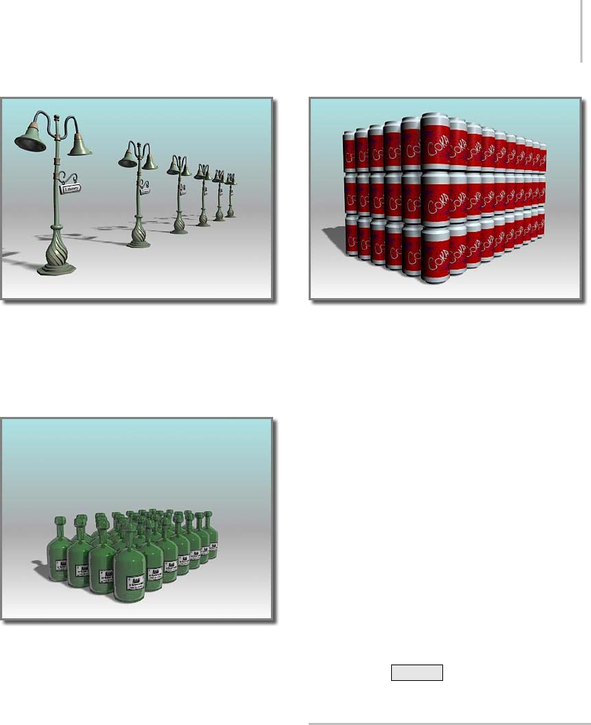
Creating Linear Arrays 487
A one-dimensional array, with 1D Count=6
2D: Two-dimensional arrays form a layer of
objects along two dimensions, like the rows of
squaresonachessboard.2DCountisthenumber
of rows in the array.
A two-dimensional array, with 1D Count=7 and 2D Count=4
3D: Three-dimensional arrays form multiple layers
of objects in 3D space, like neatly stacked boxes.
3D Count is the number of layers in the array.
A three-dimensional array, with 1D Count=10, 2D Count=6,
3D Count=3
Incremental Row Offsets
These parameters become available when you
choose a 2D or 3D array. These are distances along
anyofthethreeaxesofthecurrentcoordinate
system.
• IfyousetaCountvaluefor2Dor3D,butnorow
offsets, the array is created with overlapping
objects. You need to specify at least one offset
distance to prevent this.
• If some objects appear to be missing from the
array, it is possible that some objects have been
created exactly on top of other objects in the
array. To determine whether this has occurred,
use Select By Name (page 1–77) to see the full
listing of objects in your scene. If objects are
on top of one another and you don’t want this
effect, click Ctrl+Z to undo the array, and
try again.
Creating Linear Arrays
A linear array is a series of clones along one or
more axes. A linear array can be anything from a
line of trees or cars to a stairway, a picket fence, or
a length of chain. Any scene requiring repeated
objectsorshapesisacandidateforalineararray.
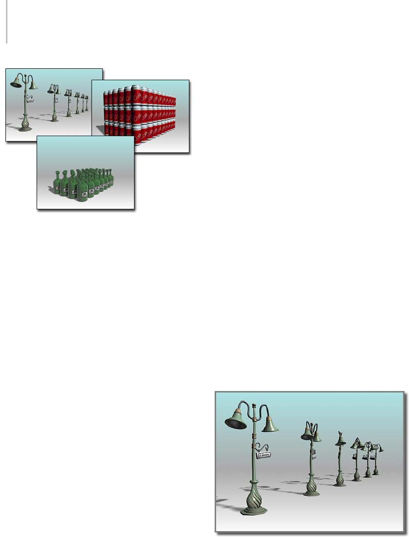
488 Chapter 7: Creating Copies and Arrays
Examples of linear arrays
For an explanation of interface terms used here,
see Using the Array Dialog (page 1–485).For
thebasicstepsinmakinganarray,seeArraying
Objects (page 1–484).
Creating Simple Linear Arrays
The simplest 2D linear array is based on moving
asingleobjectalongasingleaxis. Thesearethe
basic choices to make on the Array dialog.
Make these choices in the Array Transformation
group:
•UseIncremental Move settings where you know
the spacing you want between objects.
•UseTo t a l s Mo ve settings when you know the
overall space or volume you want the array to
occupy.
• For either of these two types of arrays, enter a
valueforoneaxis.Leavetheothertransforms
at their default values.
Make these choices in the Array Dimensions
group:
•Choose1D.
• Enter a Count value for the number of objects
in the array. The Total In Array field updates
to show you the current total of objects in the
array you are designing.
• Click OK to create a linear array along the
chosen axis, with the number of objects
specified by Count.
2D and 3D Linear Arrays
Arrays in 2D and 3D have the same Array
Transformation group setup as 1D, with the
addition of Incremental Row Offsets settings for
moving the additional dimensions apart.
• Set 2D or 3D and enter a Count value.
If you set 3D, the 2D values also become
available. Both Count values are 1 by default,
which has the same effect as 1D. Set the 2D and
3D Count values greater than 1 to produce a
more complex array.
• Set a nonzero value for at least one Incremental
Row Offsets setting for 2D and 3D. Otherwise,
there will be no separation between the 1D row
and the new clones.
A wide variety of linear arrays are possible.
Experiment with moving along all three axes and
varying the row offsets in 2D and 3D.
Using Rotation in Linear Arrays
Linear array with elements rotated about their Y axis
You can rotate elements in a linear array by
applying a Rotate value for a specified axis. When
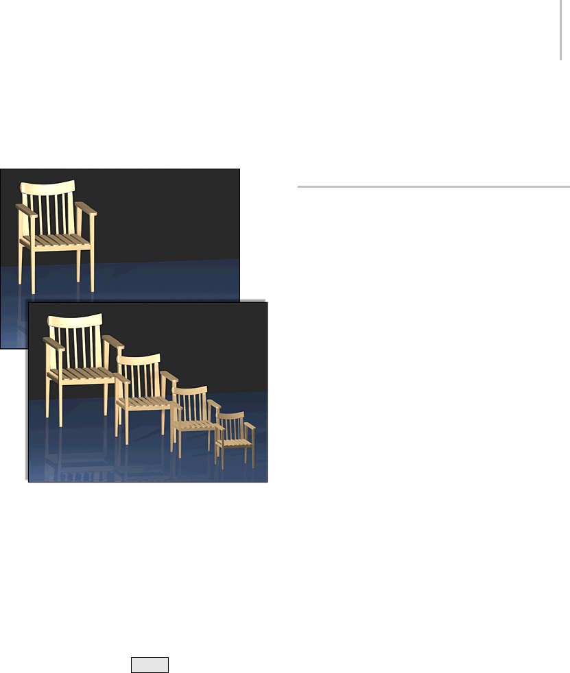
Creating Circular and Spiral Arrays 489
you add rotation to a linear array, the choice of
transform center becomes important.
Using Scale in Linear Arrays
Linear array with progressive scaling
When you apply a Scale factor, 3ds Max scales
each copy from the previous copy. Objects in the
array become progressively smaller or larger, as
in the illustration.
Scale and Movement in Nested Arrays
Using only Scale settings and the local pivot of an
object produces nested arrays, like Russian dolls,
just as it does when you Shift +Scale from the
local pivot. However, with the Array tool, you can
add movement as well. This means you can create
increasingly larger or smaller copies and array
thematthesametime.
Using Uniform Scaling
By default, all axes are available for scaling.
IfyouturnonUniform,onlytheScaleXfieldis
active; the Y and Z fields are unavailable. The X
value is applied as uniform scaling on all axes of
the arrayed objects.
Creating Circular and Spiral Arrays
Creating circular and spiral arrays typically
involves some combination of moving, scaling,
and rotating copies along one or two axes and
aroundacommoncenter. Theeffectscanvary
from the uniform radial arrangement of bolts on
a wheel hub to the complex geometry of a spiral
staircase. You can model many circular patterns
with these techniques.
See Using the Array Dialog (page 1–485) for an
explanation of interface terms used here. See
Arraying Objects (page 1–484) for the basic steps
in making an array.
Using a Common Center
Both circular and spiral arrays require a common
center for the arrayed objects. This can be the
world center, the center of a custom grid object, or
the center of the object group itself. You can also
move the pivot point of an individual object and
use that as the common center.
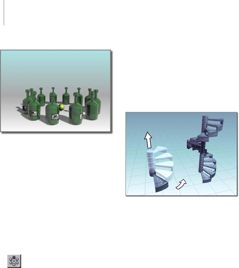
490 Chapter 7: Creating Copies and Arrays
Circular Arrays
A circular array
Circular arrays are similar to linear arrays, but
basedonrotationaroundacommoncenterrather
than movement along an axis. The following
proceduremakesacircleofobjectsontheXY
plane of the home grid with the Z axis as the center.
To create a circular array:
1. On the main toolbar, choose a transform center
to become the center of the array. In this case,
choose Use Transform Coordinate Center so
the center of the grid becomes the array center.
2. Select an object and position it at some distance
from the center of the grid.
This distance is the radius of the finished circle.
3. Choose Array from the Array flyout or
the Tools menu to display the Array dialog.
Note: TheArrayflyoutisontheExtrastoolbar,
which is off by default. You can toggle display
of this toolbar by right-clicking the main
toolbar and choosing Axis Constraints from
the Customize Display right-click menu (page
3–787).
4. On the Array dialog, enter 360 in the Totals
Rotate Z field.
This is the total rotation for the array, a
complete circle. To create a partial circle, enter
asmallervalue.
5. Choose 1D and enter a Count value (this can be
any number) and click OK.
3ds Max arrays that number of clones within
the total rotational angle you specify.
Spiral Arrays
Aspiralarray
The simplest spiral arrays are rotated circular
arrays with a movement along the central axis.
Thesamecircleisformed,butnowthecirclerises
upward.
If Z is the central axis, enter a value for Incremental
Move Z. Each clone is then moved upward this
amount as the circle is formed.
Rotation in Spiral Arrays
In spiral arrays, the direction of rotation
determines the direction of the spiral: which way
it winds up or down.
Enter a positive rotation for a counterclockwise
spiral.
Enter a negative rotation for a clockwise spiral.
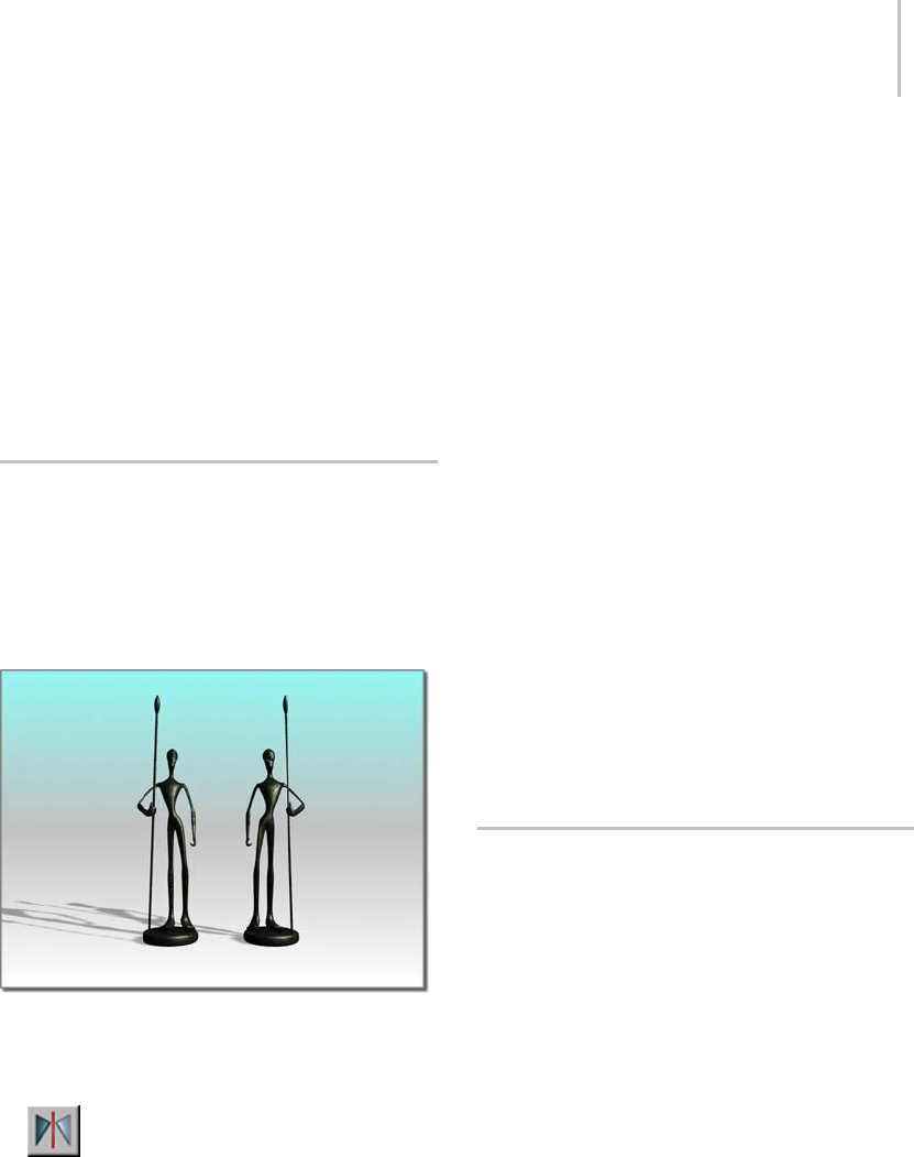
Mirroring Objects 491
Reorienting an Array
By default, each object, when copied into the
array, rotates around its own center to follow the
main rotation around the common center. This is
controlled by the Re-Orient option.
To cause objects to maintain their original
orientation while being rotated, turn off
Re-Orient. In effect, objects remain "facing the
same direction" as the original object.
Mirroring Objects
The Mirror tool uses a dialog that either creates a
mirrored clone of a selected object, or mirrors the
orientation of the object without creating a clone.
You can preview the effects of settings before
committing to the operation.
Mirroring an object
This is the general procedure for mirroring an
object. Begin by selecting the object.
•Click the Mirror button on the main
toolbar, or choose Tools menu > Mirror.
This displays the Mirror dialog. The title bar
indicates the coordinate system currently in
use.
For information on the Mirror dialog options, see
Mirror Selected Objects (page 1–448).
Mirrored Arrays
You can combine the Mirror and Array tools by
using them in succession. An entire array can
be mirrored, or you can set up mirrored objects
before creating an array.
Animating Mirror
When you use Mirror with Auto Key turned on,
you see the transition occur as the mirrored object
moves into place. For example, a cylinder mirrored
to the other side of an axis appears to flatten and
reshapeitself.Theobjectis,infact,scaledfrom
100% to 0% to –100%. This effect is not visible
unless the mirror operation is animated.
Mirror Modifier
The Mirror modifier (page 1–728) provides a
parametric method of mirroring an object or
sub-object selection within the modifier stack.
You can apply the Mirror modifier to any type of
geometry. You can animate the mirror effect by
animating the modifier’s gizmo.
Using the Spacing Tool
The Spacing Tool distributes objects based on the
current selection along a path defined by a spline
or pair of points. The distributed objects can be
copies, instances, or references of the current
selected object. You define a path by picking a
spline or two points and by setting a number of
parameters. You can also specify how the spacing
between objects is determined and whether the
insertion points of the objects align to the tangent
of the spline.
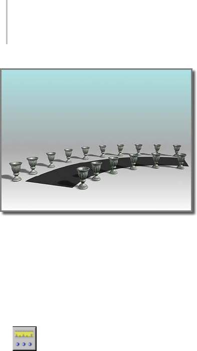
492 Chapter 7: Creating Copies and Arrays
The Spacing Tool distributes the vases along the sides of the
curved street. The vases are all at the same distance from each
other; fewer of them appear on the shorter side.
For details on the Spacing Tool parameters, see
Spacing Tool (page 1–455).
To distribute objects along a path:
1. Select one or more objects to distribute.
2. Choose Spacing tool from the Array
flyout or the Tools menu.
Note: TheArrayflyoutisontheExtrastoolbar,
which is off by default. You can toggle display of
this toolbar by right-clicking an empty area on
the main toolbar and choosing Axis Constraints
from the Customize Display right-click menu
(page 3–787).
3. On the Spacing Tool dialog, click Pick Path or
Pick Points to specify a path.
If you click Pick Path, select a spline from your
scene to use as the path.
If you click Pick Points, click a start point and
an end point to define a spline as the path.
When you’re finished with the Spacing Tool,
3dsMaxdeletesthisspline.
4. From the drop-down list at the bottom of the
Parameters group, choose a spacing option.
The parameters available for Count, Spacing,
Start Offset, and End Offset depend on the
spacing option you choose.
5. Specify the number of objects to distribute by
entering a Count value, or by using the spinner.
6. Depending on the spacing option you choose,
adjust the spacing and offsets.
7. In the Context group, choose one of the
following:
•Edges specifies that spacing be determined
from the facing edges of each object’s
bounding box.
•Centers specifies that spacing be determined
from the center of each object’s bounding
box.
8. To align the insertion points of the distributed
objects to the tangent of the spline, turn on
Follow.
9. IntheTypeOfObjectgroup,choosethetypeof
object to output (copy, instance, or reference)
and click Apply.
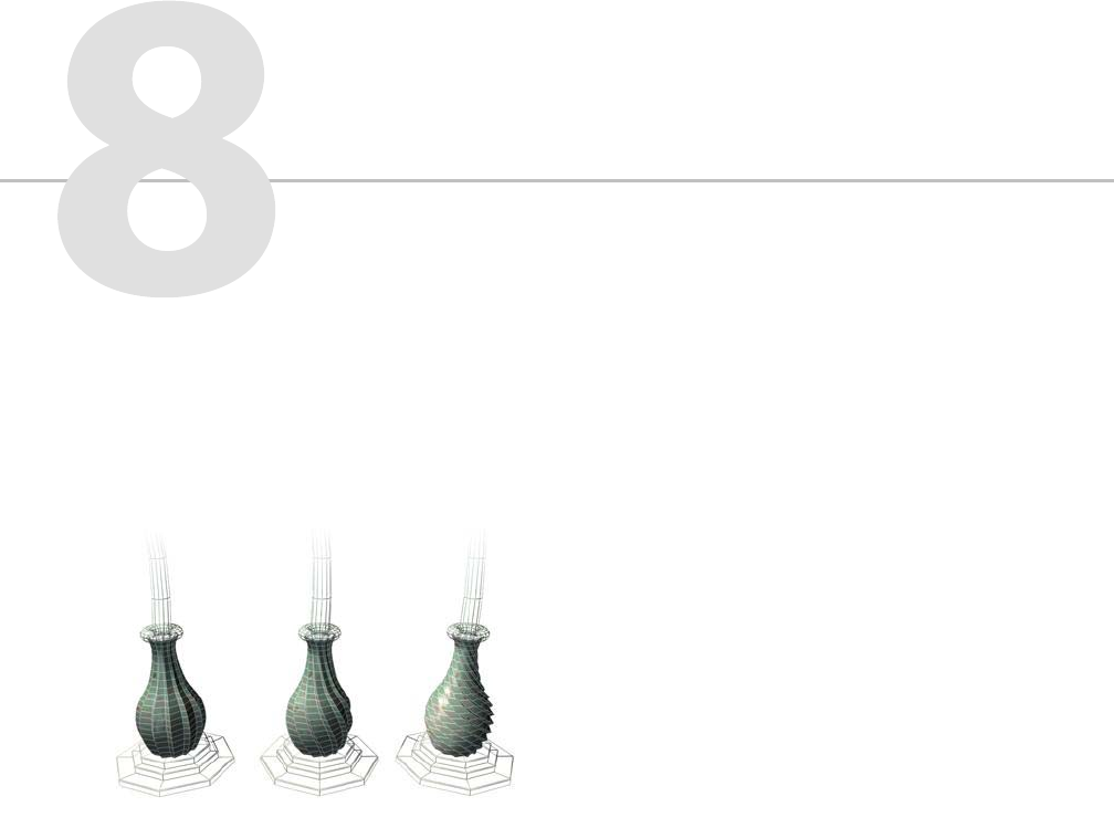
Modifiers provide a way for you to sculpt and
edit objects. They can change the geometry of an
object, and its properties.
Example: effects of the Twist modifier on an object
The modifiers you apply to an object are stored
in a stack (page 3–973). By navigating up and
down the stack, you can change the effect of the
modifier, or remove it from the object. Or you
can choose to “collapse” the stack and make your
changes permanent.
There are other general things to know about using
modifiers:
• You can apply an unlimited number of
modifierstoanobjectorpartofanobject.
• Whenyoudeleteamodifier,allitschangesto
the object disappear.
• You can move and copy modifiers to other
objects using controls in the modifier stack
display (page 3–760).
• The order or sequence in which you add
modifiersisimportant.Eachmodifieraffects
thosethatcomeafterit.Forinstance,addinga
Bend modifier (page 1–560) before a Taper (page
1–863) can give you distinctly different results
than if you first added the Taper followed by
the Bend.
List of Available Modifiers (page 1–497)
Using the Modifier Stack (page 1–502)
Modifier Stack Controls (page 3–760)
How Modifiers Differ from Transforms
Modifiers and transforms differ in how they affect
an object and the order in which they are applied
to an object.
Transforms
Thetransformisthemostbasicof3D
manipulations. Unlike most modifiers, transforms
are independent of an object’s internal structure,
and they always act in world space (page 3–1036).
An object can carry any number of modifiers, but
it always has only a single set of transforms.
Modifiers

494 Chapter 8: Modifiers
The transforms of an object are expressed as
a matrix of values that contain the following
information:
• Position of the object center in world space
• Rotation of the object in world space
• Scale of the object along its local axes
The matrix is called the transformation matrix,and
its information relates directly to the transforms
Move, Rotate, and Scale. Applying one of these
transforms alters the values in the transformation
matrix.
Transforms have the following properties. They
are:
• Appliedtotheentireobject.
• Independent of their order of application. No
matterhowmanytimesyoutransforman
object, the results are stored as one set of values
in the matrix.
• Applied after all object-space modifiers have
been evaluated, but before the world-space
modifiers. See Using the Modifier Stack (page
1–502).
Most transforms produce equal displacement
along one or more axes of an object, or part
of an object. For Move (page 1–439),Rotate
(page 1–439),andUniform Scale (page 1–441)
transforms, the displacement is equal along all
threeaxes.Whenyourotateabox,allsidesremain
parallel. In general, all vertices keep the same
relative position to one another. The exceptions
are Squash (page 1–442) and Non-Uniform Scale
(page 1–441), which displace axes by different
amounts.
Tip: Use the XForm modifier (page 1–959) if you
wanttotransformanobjectataspecificlocation
in the stack (that is, after some object-space
modifiers but before others), or if you want to
transform a sub-object selection. See Modifying at
the Sub-Object Level (page 1–506).
Modifiers
Most modifiers allow you to perform operations
on the internal structure of an object in object
space (page 3–982). For example, when you apply
a modifier such as Twist (page 1–876) to a mesh
object, the position of each vertex of the object is
changed in object space to produce the twisting
effect.
Modifiers can operate at the sub-object level, and
are dependent on the internal structure of the
object when the modifier is applied.
Modifiers have the following properties. They are:
• Applied to all of an object or part of an object
(using a sub-object selection).
• Dependent on the order of application.
ApplyingaBendfollowedbyaTwistproducesa
result different from applying a Twist followed
by a Bend.
• Displayed as individual entries in the modifier
stack,whereyoucanturnthemonoroff,and
change the order in which they’re applied.
Some modifiers operate in world space. These
use world-space coordinates, and are applied to
the object after all object-space modifiers and
transforms have been applied. Otherwise, they
havethesameoverallpropertiesasobject-space
modifiers.
Transforms, Modifiers, and Object
Data Flow
Once you have defined an object, 3ds Max
evaluates changes affecting the base object and
displays the result in the scene. What these changes
are, and the order in which they are evaluated, is
called the object data flow.
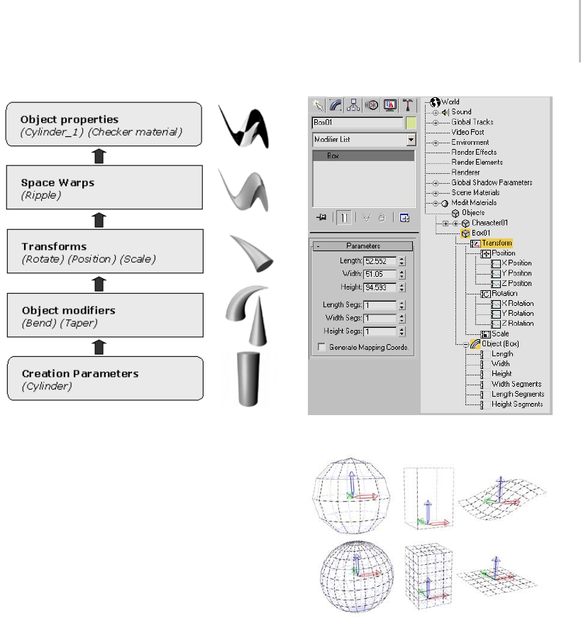
Transforms, Modifiers, and Object Data Flow 495
Diagram of data flow
Master Object
Master object refers to an object defined by a set
of creation parameters and the original position
and orientation of its pivot point. You never see
the master object. What you see in the viewport is
alwaystheresultofatleastthefollowingdataflow:
Master Object
-> Object Transforms
-> Object Properties
Object creation parameters in the Modify panel and Track View
An example of master objects with different creation
parameters.
Object-Space Modifiers
The object-space modifiers (page 1–557) are the
next group evaluated in the data flow. Each
modifier is evaluated in the order it was placed on
the modifier stack. The modifications all occur
in the object’s object space and the result is called
the modified object.
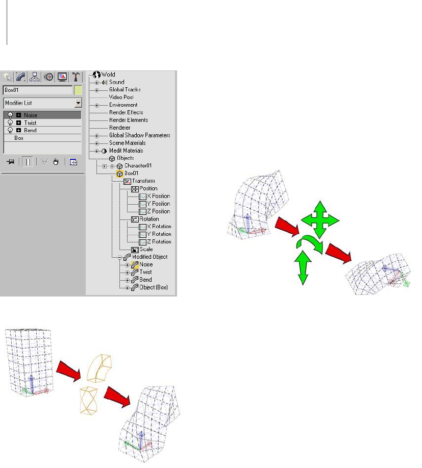
496 Chapter 8: Modifiers
Object modifiers in the Modify panel and Track View
The effect of modifiers on a master object.
Object Transforms
Once the modified object has been evaluated, it is
transformed within the world coordinate system.
Transforms cover the position, rotation, and scale
changes applied from the transform buttons on
the toolbar.
The method of evaluating all modifiers first and
then evaluating the combined transforms has
ramifications for the way you work with 3ds Max.
Theeffectoftransformsisindependentofthe
order in which they are applied. The order in
which you apply modifiers, on the other hand,
does affect the resulting geometry. If you want to
apply a transform that is evaluated in a specific
order in the modifier stack, use the XForm modifier
(page 1–959).
Transforming a modified object
Space Warps
Space warps (page 2–55) are evaluated after
transforms. They distort objects bound to the
space warp based on the position of the object in
world space. For example, a Wave spa ce war p (page
2–100) causes the surface of an object to undulate
in the form of a wave. As the object or the space
warp moves through world space, the waves move
across the object’s surface.
Like space warps, world-space modifiers (page
1–512) are evaluated after transforms. A
world-space modifier is like a space warp bound
to a single object.
Object Properties
Object properties are the last to be evaluated
before the object is displayed. These are values
specific to an object such as its name or settings
you specify on the Object Properties dialog (page
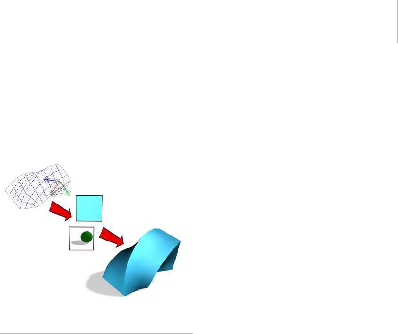
List of Available Modifiers 497
1–117), such as shadow-casting properties; and
materials you have applied to the object.
This is the end of the data flow, and the result is the
named object you see in your scene.
Right-click an object and choose Properties to
display its Object Properties dialog.
Object Properties affect the look of an object’s rendered output.
List of Available Modifiers
Following is a list of the modifiers, listed in
alphabetical order.
Note: The availability of certain modifiers depends
on the current selection. For example, Bevel
and Bevel Profile appear in the Modifier List
drop-down menu only when a shape or spline
object is selected. For the conditions under
which a specific modifier is available, see the path
annotation at the top of the modifier’s topic in this
reference.
Affect Region Modifier (page 1–557)
Attribute Holder Modifier (page 1–559)
Bend Modifier (page 1–560)
Bevel Modifier (page 1–562)
Bevel Profile Modifier (page 1–565)
Camera Map Modifier (Object Space) (page 1–567)
Camera Map Modifier (World Space) (page 1–513)
Cap Holes Modifier (page 1–569)
Cloth Modifier (page 1–578)
CrossSection Modifier (page 1–623)
Delete Mesh Modifier (page 1–626)
Delete Patch Modifier (page 1–627)
Delete Spline Modifier (page 1–627)
Disp Approx Modifier (page 1–628)
Displace Modifier (page 1–629)
Displace Mesh Modifier (World Space) (page 1–514)
Displace NURBS Modifier (World Space) (page
1–515)
Edit Mesh Modifier (page 1–634)
Edit Normals Modifier (page 1–634)
Edit Patch Modifier (page 1–638)
Edit Poly Modifier (page 1–640)
Edit Spline Modifier (page 1–680)
Extrude Modifier (page 1–680)
Face Extrude Modifier (page 1–682)
FFD (Free-Form Deformation) Modifiers (page
1–683)
FFD (Free-Form Deformation) (Box/Cyl) Modifier
(page 1–685)
FFD (Free-Form Deformation) Select Modifier
(page 1–689)
Fillet/Chamfer Modifier (page 1–689)
Flex Modifier (page 1–691)
Garment Maker Modifier (page 1–607)
Hair And Fur Modifier (page 1–516)
HSDS Modifier (page 1–701)

498 Chapter 8: Modifiers
Lathe Modifier (page 1–707)
Lattice Modifier (page 1–709)
Linked XForm Modifier (page 1–712)
LS Colors Modifier (World Space) (page 1–550)
LS Mesh Modifier (page 1–713)
MapScaler Modifier (Object Space) (page 1–713)
MapScaler Modifier (World Space) (page 1–551)
Material Modifier (page 1–714)
MaterialByElement Modifier (page 1–716)
Melt Modifier (page 1–717)
Mesh Select Modifier (page 1–719)
MeshSmooth Modifier (page 1–722)
Mirror Modifier (page 1–728)
Morpher Modifier (page 1–729)
MultiRes Modifier (page 1–739)
Noise Modifier (page 1–743)
Normal Modifier (page 1–746)
NSurf Sel Modifier (page 1–747)
Normalize Spline Modifier (page 1–747)
Optimize Modifier (page 1–748)
PatchDeform Modifier (World Space) (page 1–552)
PathDeform Modifier (World Space) (page 1–552)
PatchDeform Modifier (page 1–754)
Patch Select Modifier (page 1–751)
PathDeform Modifier (page 1–755)
Physique Modifier (page 2–1106)
Point Cache Modifier (page 1–758)
Point Cache Modifier (World Space) (page 1–555)
Poly Select Modifier (page 1–762)
Preserve Modifier (page 1–766)
Projection Modifier (page 1–769)
Projection Holder Modifier (page 1–778)
Push Modifier (page 1–779)
Relax Modifier (page 1–779)
Renderable Spline Modifier (page 1–781)
Ripple Modifier (page 1–783)
Select By Channel Modifier (page 1–785)
Shell Modifier (page 1–785)
Skew Modifier (page 1–790)
Skin Modifier (page 1–791)
Skin Morph Modifier (page 1–812)
Skin Wrap Modifier (page 1–818)
Skin Wrap Patch Modifier (page 1–824)
Slice Modifier (page 1–825)
Smooth Modifier (page 1–828)
Spherify Modifier (page 1–829)
Spline IK Control Modifier (page 1–830)
Spline Select Modifier (page 1–831)
Squeeze Modifier (page 1–833)
STL Check Modifier (page 1–834)
Stretch Modifier (page 1–836)
Subdivide Modifier (page 1–839)
Substitute Modifier (page 1–840)
SurfaceMapperModifier(WorldSpace)(page
1–556)
Surface Modifier (page 1–842)
SurfDeform Modifier (page 1–848)
SurfDeform Modifier (World Space) (page 1–557)

Using Modifiers 499
Sweep Modifier (page 1–848)
Symmetry Modifier (page 1–861)
Taper Modifier (page 1–863)
Tessellate Modifier (page 1–865)
Trim/Extend Modifier (page 1–866)
TurboSmooth Modifier (page 1–868)
Turn To Mesh Modifier (page 1–871)
Turn To Patch Modifier (page 1–873)
Turn To Poly Modifier (page 1–874)
Twist Modifier (page 1–876)
Unwrap UVW Modifier (page 1–878)
UVW Map Modifier (page 1–922)
UVW Mapping Add Modifier (page 1–933)
UVW Mapping Clear Modifier (page 1–933)
UVW XForm Modifier (page 1–934)
VertexPaint Modifier (page 1–936)
Vertex Weld Modifier (page 1–935)
Volume Select Modifier (page 1–952)
Wave Modifier (page 1–957)
XForm Modifier (page 1–959)
Using Modifiers
This section contains a number of topics intended
to help you learn how to use modifiers and the
Modify panel. These include:
Using the Modify Panel (page 1–499)
Using the Modifier Stack (page 1–502)
Editing the Stack (page 1–504)
Edit Modifiers and Editable Objects (page 1–506)
Modifying at the Sub-Object Level (page 1–506)
Using the Stack at the Sub-Object Level (page
1–508)
Modifying Multiple Objects (page 1–509)
How Instanced Modifiers Work (page 1–511)
Using the Modify Panel
After adding objects to your scene from the Create
panel, you often move to the Modify panel to
change an object’s original creation parameters
and to apply modifiers. Modifiers are the basic
tools for reshaping and adjusting primitive
geometry.
Note: Yo u c a n float (page 3–930) or dismiss the
command panel using the Customize Display
right-click menu (page 3–787).Thedefaultsetting
is to display the command panel docked at the
right of your screen. If it is not displayed or you
want to change its location and docking or floating
status, right-click in a blank area on any toolbar,
and choose from the shortcut menu.
The Modify panel stays in view until you click
another command panel tab. The panel updates to
show the options and controls that are available for
the currently selected object or modifier.
Procedures
To use the Modify panel:
1. Select an object in your scene.
2. Click the Modify tab to display the
Modify panel.
Thenameoftheselectedobjectappearsatthe
top of the Modify panel, and fields change to
match this object.
500 Chapter 8: Modifiers
The objects creation parameters appear in
rollouts on the Modify panel, below the
modifier stack display. You can use these
rollouts to change the creation parameters for
an object. As you change them, the object
updates in the viewports.
3. Apply a modifier to an object (described in the
next procedure).
After you apply a modifier, it becomes active,
and rollouts below the modifier stack display
settings specific to the active modifier.
To apply a modifier to an object:
1. Select the object.
2. Do one of the following:
• Choose a modifier from the Modifier List.
This is a drop-down list at the top of the
Modify panel.
Tip: You can use the mouse or keyboard to
choose a modifier from the Modifier List.
To use the keyboard, first open the list with
the mouse, and then type the first letter in
the modifier’s name. From there you can
use the arrow keys or the method described
in the following paragraph to highlight the
desired modifier, and then press Enter to
assign the modifier.
In many cases, several modifier names
start with the same letter. You can go
directly to a particular modifier if you type
the first few letters (enough for a unique
combination) in the desired modifier’s
name quickly. For example, say you want
to assign the Mirror modifier to an object.
Pressing Mgoes to Mesh Select, which isn’t
anywhere near Mirror in the Modifier list,
but typing MI goes directly to Mirror.
• ChooseamodifierfromtheModifiers
menu. This menu is organized into sets by
functionality.
Not all modifiers appear on the Modifiers
menu.
• If the modifier buttons are visible on the
Modify panel and the modifier you want is
one of them, click the button.
If the buttons are not visible but
you want to use them, click the Configure
Modifier Sets button (page 3–772) (below
the modifier stack display) and choose
Show Buttons. A set of buttons with the
names of modifiers appears between the
modifier list and the stack display. Click
Configure Modifier Sets again, choose
the set of modifiers you want to use (for
example, Free-Form Deformations), and
then click the button for the modifier you
want to apply.
Rollouts are now displayed below the modifier
stack display, showing settings for the modifier.
As you change these settings, the object updates
in viewports.
To drag a modifier to an object:
1. Select an object that already has a modifier you
would like to use on another object.
2. To copy the modifier without instancing it,
drag the modifier’s name from the stack display
to the object in a viewport that you want to
use the same modifier. To move the modifier,
use Shift +drag; this removes it from the
original object and applying it to the new one.
To instance the modifier, use Ctrl +drag; this
creates an instanced modifier applied to both
the original object and the new one.
Note: Instancing a modifier causes its name to
be displayed in italics in the modifier stack.
This indicates that the modifier is instanced,
meaning that a change to the modifier
parameters of one object will affect the other.
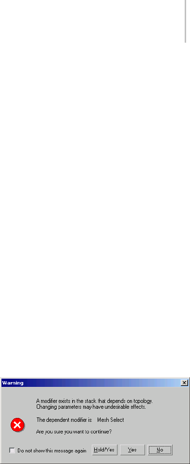
Using the Modify Panel 501
Using Modifiers
Once you’ve applied modifiers to an object, you
can use the Modifier Stack (page 3–760) to find a
particular modifier, change its parameters, edit its
sequence in the modifier stack, copy its settings to
another object, or delete it entirely.
You can find a complete, alphabetical list of
modifiers in List of Available Modifiers (page
1–497).
General Guidelines
You can generally do the following with the Modify
panel:
• Modify anything you can select. This includes
any object or set of objects, or any part of
an object down to the sub-object level. For
example, you can use the Mesh Select modifier
to select a single face, then apply a Taper
modifier to it.
• Apply an unlimited number of modifiers to an
object or part of an object.
The order or sequence in which you make
modifications is important. Each modification
affects those that come after it. See Using the
Modifier Stack (page 1–502).
Note: Some modifiers can be applied only to
certain types of objects.
Modifier Sub-Object Levels
In addition to its own set of parameters, a modifier
typically has one or more sub-object levels that you
access through the modifier stack (page 1–502).
Themostcommonoftheseareagizmoanda
center.
Gizmo—Displaysinviewportsasawireframethat
initially surrounds the selected object. A gizmo
acts like a mechanical apparatus that transfers its
modification to the object it’s attached to. To alter
the effect of the modifier on the object, you can
move, scale, and rotate the gizmo as you would
any object.
Center—The center is the modifier’s pivot point
(page 3–995). You can move a modifier’s center,
which alters the effect of the modifier on the object.
Parametric Deformations and Other Modifier
Types
One set of object-space modifiers is known as
parametric deformations (“parametric deforms”
on the Modifiers menu). Twist (page 1–876) and
Bend (page 1–560) are examples. Parametric
deformations alter the selection passed to them
without explicitly depending on topology.
Many other types of modifiers, however, perform
operations on the explicit topology of sub-object
selections. The Edit modifiers and Select modifiers
are examples. When a topology-dependent
modifier is present on the stack, you can adversely
affect its results if you visit previous stack
operations and change the number or order of
sub-objects (such as faces or vertices) in the
selection. If you try to do this, a warning alerts
you to the situation.
You can safely edit the stack beneath the
topology-dependent modifier, as long as you do
not add or remove sub-objects from the selection
on which it operates.
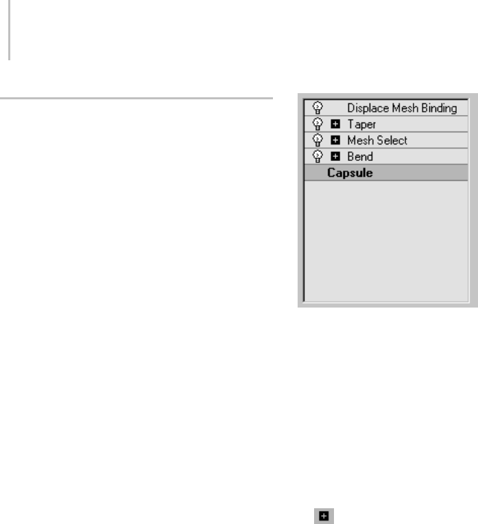
502 Chapter 8: Modifiers
Using the Modifier Stack
The modifier stack and its editing dialog are the
keys to managing all aspects of modification. You
use these tools to:
• Find a particular modifier and adjust its
parameters.
• View and manipulate the sequence of modifiers.
• Copy, cut, and paste modifiers between objects,
or sets of objects.
• Deactivate the effect of a modifier in the stack,
the viewport display, or both.
• Select a modifier’s components, such as gizmo
or center.
• Delete modifiers.
See also
Editing the Stack (page 1–504)
Modifier Stack Controls (page 3–760)
Modifier Stack Right-Click Menu (page 3–766)
Examining the Modifier Stack
The modifier stack (or "stack" for short) is a list
on the Modify panel. It contains the accumulated
history of a selected object and any modifiers you
have applied to it.
Internally, the software "evaluates" an object
beginning at the bottom of the stack and applies
changes to the object by moving sequentially to
the top of the stack. You should therefore "read"
the stack from bottom up to follow the sequence
usedbythesoftwareindisplayingorrendering
the final object.
Here is an example of stack entries for a capsule
object (an extended primitive):
• At the bottom of the stack, the first entry always
lists the object type (in this case, Capsule). You
click this entry to display the original object
creation parameters so you can adjust them. If
you haven’t applied any modifiers yet, this is the
only entry in the stack.
• Object-space modifiers appear above the object
type. You click a modifier entry to display the
modifier’s parameters so you can adjust them,
or to delete the modifier.
Modifiers are preceded by a plus or minus
icon if they have sub-object (or sub-modifier)
levels. See UsingtheStackatSub-ObjectLevel
(page 1–508).
• At the top of the stack are world-space modifiers
and space warps bound to the object. (In the
illustration, Displace Mesh is a world-space
modifier.) These always appear at the top, and
are described as "bindings."
Basics of Using the Stack
With the stack feature, no modification has to be
permanent. By clicking an entry in the stack, you
can go back to the point where you made that
modification. You can then rework your decisions,
temporarily turn off the modifier, or discard the
modifier entirely by deleting it. You can also insert
a new modifier in the stack at that point. The
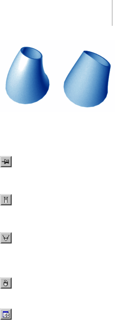
Using the Modifier Stack 503
changes you make ripple upward through the
stack, changing the current state of the object.
Adding Multiple Modifiers
Yo u c a n a p p l y a n y n u m b e r o f m o d i f i e r s t o a n
object, including repeated applications of the same
modifier. As you start applying object modifiers
to an object, the modifiers "stack up" in the order
they’re applied. The first modifier appears just
above the object type at the bottom of the stack.
• The program inserts a new modifier in the stack
just above the current selection, but always
in the proper location. If you try to insert a
world-space modifier between two object-space
modifiers, the program automatically places it
at the top of the stack.
• If you select the object type on the stack and
apply a new object-space modifier, it appears
justabovetheobjecttypeandbecomesthefirst
modifier evaluated.
Effect of Stack Sequence
Thesoftwareappliesmodifiersintheirstack
order (beginning at the bottom and carrying
thecumulativechangeupward),soamodifier’s
location in the stack can be critical.
The following figure shows the difference between
the objects based entirely on a reversal in the stack
order of two modifiers. On the left-hand tube, a
Taper modifier is applied before a Bend modifier,
and on the right-hand tube, the Bend is applied
first.
Results of reversing stack order of two modifiers
Using the Buttons
The Modifier Stack rollout has the following
buttons to help you manage the stack:
Pin Stack—Locks the stack and all Modify
panel controls to the selected object’s stack. You
can continue to edit the object even if you select a
different object in the viewports.
Show End Result—When on, shows the effect
oftheentirestackontheselectedobject.When
off, shows the effect of the stack only up to the
currently highlighted modifier.
Make Unique—Makes an instanced object
unique, or an instanced modifier unique to a
selected object. See details in Editing the Stack
(page 1–504).Thisoptionisalsoavailablefrom
the Modifier Stack right-click menu (page 3–766).
Remove Modifier—Deletes the current
modifier from the stack, eliminating all changes
caused by that modifier.
Configure Modifier Sets—Click to display
a pop-up menu that lets you configure how to
display and choose modifiers on the Modify panel.

504 Chapter 8: Modifiers
Editing the Stack
You can copy, cut, and paste modifiers within an
object’s stack, or into the stacks of other objects.
Among other features, you can give modifiers
explicit names to help you remember the intended
effect.
To edit the stack:
1. Choose an item in the stack.
2. Right-click.
This displays the Modifier Stack right-click
menu (page 3–766), which is briefly introduced
in this topic.
Rearranging and Sharing Modifiers
To rearrange modifiers:
The easiest way to move a modifier to a different
location in the stack is simply to drag it there.
Alternatively, you can use the following cut/copy
and paste procedure.
1. Choose one or more modifiers, right-click, and
choose Copy or Cut.
2. Choose a new location in the list, right-click,
and choose Paste. The paste occurs immediately
above the new location.
To share modifiers with other objects:
1. Choose one or more modifiers, right-click, and
choose Copy.
2. Select a different object or group of objects.
3. Choosealocationinthenewstack,right-click,
and choose Paste.
You can also drag from the modifier stack
displaytoanobjectinaviewport.
Tip: Select world-space and object-space
modifiers separately. Cut, Copy, and Paste are
disabled if both types are selected. If you try to
paste a world-space modifier into the section
for object-space types, the paste occurs at the
top of the world-space section. The reverse is
also true.
Unique and Instanced Modifiers
By default, pasted modifiers are unique: they lose
all connection with the modifier from which they
were copied. Compare with an instanced modifier,
which is shared between two or more objects.
Changing a parameter on an instanced modifier
automatically changes the same parameter on the
other instanced objects.
To create an instance of a modifier:
• After copying or cutting the modifier,
right-click and choose Paste Instanced.
In the stack, the name of an instanced modifier
appears in italics.
Any instance of a modifier controls all other
instances. Use this feature when you want a
number of objects to take on the same feature.
For example, copying an instanced Bend modifier
(page 1–560) to a number of trees would make
them all bend identically. Changing Bend
parameters on any one tree would change the bend
on all the others.
To remove the instancing from a modifier:
•Select the instanced modifier and click
MakeUnique.Thisconvertsthemodifierfrom
instanced to unique.
UsingMakeUniquewithMultipleItems
Assume you have a group of trees all sharing the
same instanced Bend modifier. If you select two
of them and clickMake Unique (page 3–770),a
message asks, "Do you want to make the selected
objects unique with respect to each other?"

Editing the Stack 505
• If you click Yes, the two trees become
independent of one another. Each has a unique
copy of the modifier and can be bent separately.
• If you click No, the two trees continue to share
thesameinstancedmodifier,butseparately
from the instance in the original group. The
two trees can be bent together.
See How Instanced Modifiers Work (page 1–511).
Collapsing the Stack
YoucanuseCollapseAllorCollapseTotocollapse
all or part, respectively, of an object’s stack to an
editable object that preserves the cumulative effect
of the collapsed modifiers on the base object. You
might choose to do this in these cases:
• You’ve finished modifying an object and want
to keep it as is.
•Youwanttodiscardanobject’sanimation
tracks. Alternatively, you can Alt +right-click
a selected object and choose Delete Selected
Animation.
• You want to simplify a scene and save some
memory.
Note: In most cases, collapsing all or part of the
stack will save memory. However, collapsing some
modifiers, such as Bevel, increases file size and
memory use.
After you collapse an object’s stack, you can no
longer parametrically adjust either its creation
parameters or the individual modifiers affected by
thecollapse.Animationtracksthatwereassigned
to such parameters also disappear.
Collapsingthestackdoesnotaffecttheobject’s
transforms; it affects world-space bindings only if
you use Collapse To. Collapsing the stack does not
save memory if the stack contains no modifiers.
Tip: Before you use either Collapse option, use File
menu>SaveSelectedtopreserveacopyofthe
original parametric object.
To collapse the stack:
1. Right-clickthemodifierstackdisplay.
2. If modifiers have been applied to the object,
choose Collapse To or Collapse All.
Collapse To—Collapses the stack, up to and
including the chosen modifier, into an editable
object. Modifiers on the stack above the chosen
modifier are not affected, and you can still
adjust them individually.
The resultant object type depends on the
uppermost modifier that outputs a specific
geometrytype,ifany.Ifthestackcontainsno
such modifier, the result is an editable mesh
(page 1–996). If the collapsed portion of the
stack contains a modifier that outputs a specific
geometrytype,andnoothersuchmodifieris
aboveit,theresultisthattypeofobject. For
example, if the topmost such collapsed modifier
isEditPoly,theresultantobjectisEditablePoly.
Collapse All—Collapses the entire stack into
an editable object, other than world-space
bindings. Any world-space bindings on the
stack are left intact.
The resulting stack list shows a single entry:
EditableMesh,unlessanymodifiersonthe
stackoutputadifferenttypeofgeometry.For
example, if the topmost such modifier is Edit
Poly, the resultant object is Editable Poly.
If no modifiers are applied to the object, choose
one of the Convert To options:
•EditableMesh
•EditableSpline
•EditablePatch
•EditablePoly
•NURBS
Note: Depending on the object type, not all
Convert To options might be available.

506 Chapter 8: Modifiers
Edit Modifiers and Editable
Objects
To achieve highly detailed modeling effects, you
can directly transform, modify, and align the
geometry of objects at a sub-object level (page
3–1017),usingtheModify panel (page 3–758).The
following table shows the different object types
and their respective sub-objects.
Object Type Sub-Object Geometry
Mesh Vertex,Edge,Face,Polygon,Element
Poly Vertex,Edge,Border,Polygon,Element
Spline Vertex,Segment,Spline
Patch Surface Vertex, Edge, Patch, Element, Handle
NURBS Curve Curve CV or Point, Curve
NURBS Surface Surface CV or Point, Surface
With the exception of NURBS, to gain access to an
object’s sub-objects, in most cases you must first
either convert the object into an editable object,
or apply any of various modifiers to the object,
such as Edit Mesh/Spline/Patch or Mesh/Spline
Select. The Select modifiers simply let you specify
sub-objects for modification by subsequently
applied modifiers. The distinctions between
transforming an object into an editable object and
applying an Edit modifier to it are as follows:
Method Advantage Disadvantage
Editable object More efficient
Can animate
sub-objects
Lose creation
parameters
Edit/Select
modifier
Keep creation
parameters
Less efficient
Cannot animate
sub-objects
To convert a parametric object to an editable
object, see any of the following topics:
Editable Mesh Surface (page 1–996)
Editable Poly Surface (page 1–1022)
Editable Spline (page 1–289)
Editable Patch Surface (page 1–968)
ToapplyanEditmodifier,seeanyofthefollowing
topics:
Edit Mesh Modifier (page 1–634)
Edit Spline Modifier (page 1–680)
Edit Patch Modifier (page 1–638)
To apply a Select modifier, see the following topics:
Mesh Select Modifier (page 1–719)
Poly Select Modifier (page 1–762)
Spline Select Modifier (page 1–831)
Volume Select Modifier (page 1–952)
Patch Select Modifier (page 1–751)
Modifying at the Sub-Object Level
To achieve highly detailed modeling effects, you
can directly transform, modify, and align the
geometry of objects at the sub-object level (page
3–1017).
Sub-objectsarethepiecesthatmakeupobjects,
such as vertices and faces. You can also access
and transform the sub-object components of
modifiers.
The particular geometry available at sub-object
level depends on the object type. See Edit Modifiers
and Editable Objects (page 1–506) for details on
each object type.
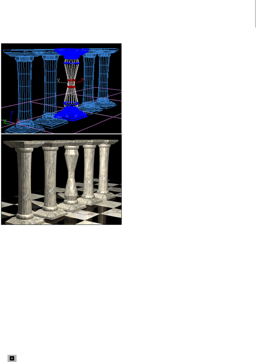
Modifying at the Sub-Object Level 507
In a row of column sub-objects, a single column has been
modified at the sub-object level.
Making a Sub-Object Selection
These are the general steps in setting up an
object for sub-object selection. See Edit Modifiers
and Editable Objects (page 1–506) for more
information.
1. Convert the object into an editable object such
as an editable mesh, editable spline, editable
poly, and so on. (Some modifiers you can apply
to the object, such as Edit Mesh, Mesh Select or
Spline Select, also have sub-object levels.)
Tip: Work in a wireframe viewport so you can
see the geometry.
2. On the modifier stack display, click the
plusicontotheleftofthenameofthemodifier
or editable object. This expands the object’s
hierarchy, showing the names of the sub-object
levels at which you can work.
3. On the stack display, choose the kind of
sub-object geometry you want to work with:
forexample,Vertex,Face,orEdge. Each
sub-object selection level has rollouts with their
own sets of options.
The sub-object level highlight is yellow by
default.
4. Use standard selection techniques to select
sub-object geometry, from a single sub-object
to the entire object. By default, the sub-object
selectionhighlightsinred.
Once you make a sub-object selection of geometry,
you can do any of the following:
• Apply any options supplied for the kind of
object and the selection level.
• Apply standard transforms (move, scale,
rotate). See Transforming a Sub-Object
Selection (below).
• Apply object-space modifiers (Bend, Taper, and
Twist, for example) to perform useful modeling
operations.
•Bindaspace warp (page 2–55) to the selection.
The rest of the object is unaffected by the
warping.
• Use the toolbar commands Align (page 1–462),
Normal Align (page 1–465),andAlign To View
(page 1–468) with face selections.
Transforming a Sub-Object Selection
Usinganeditablemesh,poly,patch,orspline,you
can directly transform any sub-object selection.
However, “Select” modifiers like Mesh Select (page
1–719) and Spline Select (page 1–831) enable only
selection.
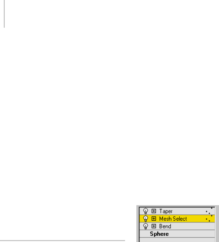
508 Chapter 8: Modifiers
To transform a sub-object selection made with a
Select modifier:
1. Add an XForm modifier (page 1–959) to the
stack, following (or somewhere above) the
Select modifier.
2. In the stack, open the Select modifier and make
a sub-object selection.
3. Choose XForm in the stack. You then transform
the XForm gizmo, which applies the transform
to the selection.
Selecting and Transforming Modifier
Components
Most modifiers have sub-object components,
such as a gizmo and center. Like sub-object
geometry, these components can be accessed
and transformed at sub-object level, directly
modifying the object’s shape.
Other modifiers, like those for free-form
deformation, have control points and lattices at a
sub-object level. Moving these components creates
the modeling effects of the modifier.
Using the Stack at the Sub-Object
Level
Witheditableobjectssuchasmeshesandsplines,
or modifiers with sub-object levels such as Mesh
Select and Spline Select, you can continue to model
a single sub-object selection by applying any
number of other modifiers. When you go back and
change the original selection, the new selection is
"passed up the stack" to the modifiers that follow.
Editable meshes and splines have "built-in"
sub-object selection at their base level. But the
selections you make with Mesh Select and Spline
Selectworkexactlythesamewayonthestack.
Thistopicusesmeshesforitsexamples. You
canapplythesameconceptstoeditablesplines,
patches, and poly objects.
Working at Two Levels
When you select an object and apply modifiers
(for example, Bend and Taper), you’re working
with the object as a single unit, or "whole object",
at the object level.
Whenyoumakeasub-objectselection,thestack
display changes to show you are no longer working
with the whole object. Consider the effect of a
Mesh Select applied between Bend and Taper
modifiers (Bend is below Taper). To the right of
the Mesh Select and Taper modifiers, a sub-object
icon (similar to the sub-object button in the
Selection rollout) appears to show that sub-object
selection is now in effect.
The vertex sub-object selection made at the Mesh
Select level is passed up the stack to the Taper
modifier. This means the Taper modifier is applied
only to the vertices selected at the Mesh Select
level.
Sub-object icon (in this case, for Vertex) to the right of modifier
names in the stack display
Sub-object selection carries upward through the
stack. If you add more modifiers, each shows the
sub-object icon to indicate this state.
By learning to "read the stack," you can move back
and forth between the object and sub-object levels
while you work on an object.
Returning to Whole-Object Level
When you finish modeling a certain sub-object
selection, you can return to work on the whole
object.
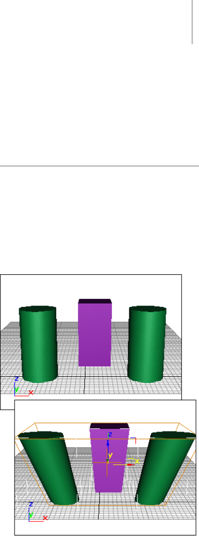
Modifying Multiple Objects 509
To return the stack to object level:
1. At any point in the stack, apply another Mesh
Select modifier.
2. Leave this Mesh Select modifier at the top level
(the object level, which highlights in gray).
Any modifiers already on the stack above this
modifier no longer show the sub-object icon.
Any modifiers you add above the second Mesh
Select now apply to the whole object.
3. To continue sending the sub-object selection
up the stack, delete the second Mesh Select.
Naming Sub-Object Selections
Sub-object selections are often quite complex,
involving a great many small elements that would
be difficult to select a second time. For this reason,
it’s a good idea to name important selection sets
using the Named Selection Sets list (page 1–67) on
the Main toolbar.
Named sub-object selections only appear at the
type of level where they were first named. For
example, if you select a set of vertices, you can
name the selection at that vertex sub-object level.
Then, when you later go to retrieve the named
selection, you can access it only from the same
modifier’s vertex sub-object level.
Copying Sub-Object Selections
Once you name a sub-object selection set, you
can copy it between modifiers in the same stack,
or to the stack of another object of the same type.
Editable meshes and Mesh Select (and their spline
, patch, and poly counterparts) have buttons for
Copy and Paste at each level of geometry, in the
Modify panel > Selection rollout.
To copy/paste named sub-object selections:
1. Make a sub-object selection.
2. In the Selection rollout, click Copy. From the
dialog, choose any available named selection
set for that level of geometry.
3. GotoanotherSelectmodifierortoaneditable
mesh or poly, at the same level of geometry.
Click Paste to complete the copy.
Modifying Multiple Objects
You can apply modifiers to multiple objects.
In general, the process is parallel to modifying
a single object. You make a selection set and
apply an available modifier. The modifier then
appears on a special stack that refers only to the
commonality of that selection set.
Top: Original objects
Bottom: Single modifier applied to objects
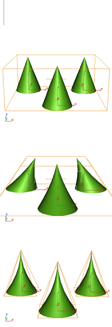
510 Chapter 8: Modifiers
Original objects
Single modifier applied to all objects
Single modifier applied with Use Pivot Points turned on
The Principle of Commonality
When you select multiple objects, 3ds Max
determines what the particular selected set of
geometry has in common, if anything.
Given any "commonality" among objects, 3ds Max
presents the options as available modifiers.
Unavailable modifiers represent areas where
commonality does not hold.
You can apply modifiers to different categories of
objects, depending on the modifier. For example,
you might apply a Bend to both a 3D object and a
2D shape. You can apply Mesh Select to a spline
primitive and convert it to a mesh, but the reverse
is not true: Spline Select is restricted to objects of
the spline category.
To modify multiple objects:
1. Select two or more objects.
For selection sets, the name at the top of
the Modify panel changes to read "Multiple
Selected." If the objects are grouped, the group
name appears.
2. Choose the kind of pivot point you want to use.
See Using Pivot Points, (below).
3. Apply a modifier and adjust its parameters.
If you apply a Mesh Select modifier, you can
select geometry on one or more of the objects
to use as a sub-object selection set.
Using Pivot Points
The first item in the Modifier List is a toggle called
UsePivotPoints.Thistoggleisunavailableunless
multiple objects are selected.
• When turned on, the program uses the pivot
point of each object as the center of a modifier’s
operation. If you bend a line of trees around the
Z axis, they all bend along their trunks.
• When turned off, the program calculates a
central pivot point for the entire selection set,
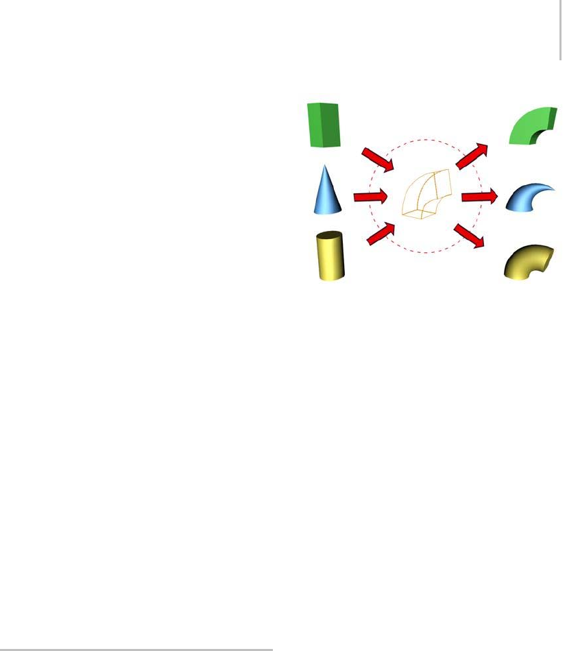
How Instanced Modifiers Work 511
and modifies the selection as a whole. For a
Z-axis bend, trees at the end of a line would
deform more than those at the center where the
pivot is located.
Tip: Choose the pivot setting before you apply
the modifier. You can’t change the pivot point
afterward, although you can delete the modifier
and start over without deselecting the selection
set.
Instanced Modifiers
When you apply a modifier to multiple objects,
each object receives an identical version of the
modifier. These are called instanced modifiers.
They are interchangeable. A change to any one of
the instances affects all the other instances. How
Instanced Modifiers Work (page 1–511) covers
instanced modifiers in detail.
Tip: Sometimes you might apply modifiers to a
selection set, perform some other operations, and
select the set again, only to find its modifier stack
is empty. This happens if you applied another
modifier to an individual object in the original
selection set. When you select the set again, the
modifierstackisemptybecauseallmembersofthe
set no longer have all modifiers in common. You
can still access the instanced modifiers by selecting
asingleobjectintheset.Theindividualobject’s
stacks still contain the modifiers you applied to
the set as a whole.
How Instanced Modifiers Work
When you apply a modifier to a selection set, the
same modifier is carried on the stack for each
individual object. These are instanced modifiers:
they are all exactly the same, and a change to the
instanceforanyoneobjectwillchangeallthe
others.
In the stack, the name of an instanced modifier
appears in italic.
Objects sharing a single instanced modifier
Identifying Instanced Modifiers
You can quickly lose track of which objects share
the same modifier. An option on the Views menu
highlights those objects.
To identify objects sharing instanced modifiers:
1. Select an object with an instanced modifier.
Choose the instanced modifier in its stack.
2. Choose Views menu > Show Dependencies.
Other objects with instances of the same
modifier appear in a distinctive color (purple
by default).
Adjusting Instanced Modifiers
You can make changes to an entire set of objects
from a single instance. This is a major advantage
of instanced modifiers.
To adjust instanced modifiers:
1. Selectanyobjectinasetofobjectswith
instances of the same modifier.
2. Choose the instanced modifier in its stack.
The single object highlights and the appropriate
gizmos appear for the entire selection set.
Adjustmentstothismodifiernowaffectthe
entire set.
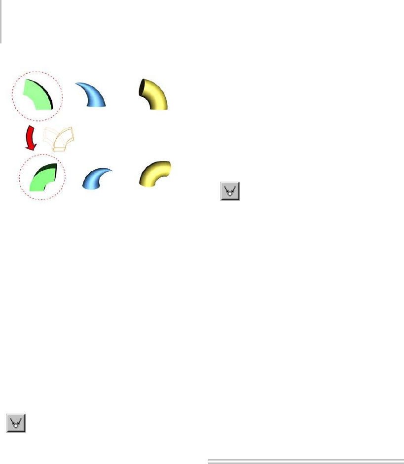
512 Chapter 8: Modifiers
Changing the parameter of an instanced modifier for one
object affects all the objects sharing the modifier.
Making Instanced Modifiers Unique
At some point in your work, you might want
to turn a modifier instance into a local copy
that affects only a single object. To do so, click
Make Unique (page 3–770) on the Modify panel.
This button appears beneath the modifier stack
display.(MakeUniqueisalsoavailableasapop-up
menu choice when you right-click the instanced
modifier’s name in the stack display.)
To make an instanced modifier unique:
1. Select an object with an instanced modifier.
2. Choose the instanced modifier in its stack.
3. ClickMakeUniquebeneaththemodifier
stack display. The modifier is no longer listed in
italic text and if Show Dependencies is set, the
highlight disappears from the other objects.
The modifier is now separate from the set of
instanced modifiers. Adjustments you make
to this modifier no longer affect other objects.
Its parameters and gizmo remain unchanged
from their original, instanced settings until you
adjust them.
To make multiple modifier instances unique:
1. Select two or more objects with the same
instanced modifier. The stack now shows what
the objects have in common.
2. Choose the instanced modifier in the stack.
There can be more than one instanced modifier
in this stack. Click the one you want to make
unique for each of the selected objects.
3. Click Make Unique.
4. Click Yes to make the two objects become
independent of one another. Click No for
thetwoobjectstocontinuetosharethesame
instanced modifier, but separate from the
instance in the original group.
The parameters for this modifier disappear,
because the objects no longer share the
modifier. For each object, the modifier is now
separate from the set of instanced modifiers.
As with a single object, the parameters and gizmo
are unchanged in the now unique modifiers.
• To access the unique modifiers, select the
objects individually.
Note: If both the object and the modifier are
instances, you can choose either in the stack
before you click Make Unique.
World-Space Modifiers
World-space modifiers act as object-specific
space warps. They are carried with the object,
but like space warps use world space (page
3–1036) rather than object space for their effects.
World-space modifiers eliminate the need for
binding to a separate space-warp gizmo, making
them convenient for modifying a single object or
selection set.
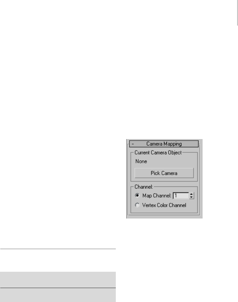
Camera Map Modifier (World Space) 513
You apply world-space modifier like you apply
standard object-space modifier. You can access
world-space modifiers from the Modifiers
menu, the Modifier List in the Modify panel,
and applicable modifier sets (page 3–771).A
world-space modifier is indicated by either
an asterisk or the letters “WSM” next to its
name. (The asterisk or “WSM” distinguishes the
world-spaceversionfromtheobject-spaceversion
of the same modifier, if one exists.)
When you assign a world-space modifier to an
object, it appears at the top of the modifier stack,
listed as a binding, in the same area as the space
warp bindings.
For a list of world-space modifiers, see List of
Available Modifiers (page 1–497).
World-Space Modifiers and Earlier Space
Warps
3ds Max 1provided PathDeform and MapScaler
space warps. In subsequent versions, these were
replaced by comparable world-space modifiers.
Whenyouopenav1MAXfileinalaterversion
of 3ds Max, objects bound to the v1 space warps
are automatically assigned the corresponding
world-space modifiers.
Camera Map Modifier (World
Space)
Modify panel > Select an object. > Modifier List >
World-Space Modifiers > * Camera Map
Select an object. > Modifiers menu > UV Coordinates > *
Camera Map
The Camera Map world-space modifier is similar
to the Camera Map modifier (page 1–567),inthat
it applies UVW mapping coordinates to the object
basedonaspecifiedcamera.Asaresult,ifyou
assign the same map as a Screen environment to
the background as you apply to the object, the
object is invisible in the rendered scene.
Themaindifferencebetweentheworld-space
version of Camera Map and the object-space
version is that, when you move the camera or the
object using the object-space version, the object
becomes visible, because the UVW coordinates are
fixed to the object’s local coordinates. When you
move the camera or object using the world-space
version, the object remains invisible because world
coordinates are used instead.
Interface
Current Camera Object group
Label—Names the current camera used for
mapping. If there is no current camera, reads
"None."
Pick Camera—Click this button, and then select the
camera you want used for mapping.
Channel group
Map Channel—Specifies use of a map channel (page
3–966). Map channels are specified in the Material
Editor (page 2–1409).
Vertex Color Channel—Specifies use of the Vertex
Color Channel (see UVW Map Modifier (page
1–922)).
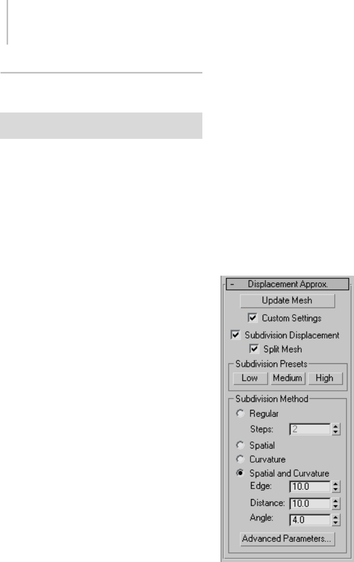
514 Chapter 8: Modifiers
Displace Mesh Modifier (World
Space)
Select an object. > Modify panel > Modifier List >
World-Space Modifiers > * Displace Mesh
The Displace Mesh world-space modifier (World
Space) lets you see the effect of displacement
mapping (page 2–1511) on editable mesh objects
(page 1–996) and objects with a Disp Approx
modifier (page 1–628) applied to them. If a
displacement map is applied to the object, the
mesh shows the effect of the displacement map.
DisplaceMeshreplacesthemeshwithitsdisplaced
version.
There are two main reasons for using Displace
Mesh:
• As a visualization aid to see the effect of
a displacement map in viewports, and to
compare the placement of displaced objects
with other objects in the scene.
For example, if you use an animated
displacement map to create waves on a water
surface, you might temporarily apply Displace
Meshtoseewheretheripplesmeetthewaterline
of a boat.
When you use Displace Mesh in this way,
usually you delete it once you’ve obtained the
effect you want.
• To obtain an editable mesh created from a
displacement map
To u s e t h e D i s p l a c e M e s h t h i s w ay, y ou a p pl y
it to the object that has a displacement map,
then apply the Snapshot command (page 1–453)
fromtheToolsmenu,andchooseMeshasthe
clone method.
Snapshot creates a permanently displaced mesh.
As it does for other kinds of objects, Snapshot
also leaves the original, displacement-mapped
object in the scene. After applying Snapshot,
you can delete the original object, or you can
keep it in your scene to use for other purposes.
Tip: Use Disp Approx to displace editable
meshes. Use Displace Mesh for previewing,
as in the first item, but avoid using Snapshot.
The mesh created by using Displace Mesh and
Snapshot can have a high polygon count. This
makes it slow to use interactively, and can cause
smoothing problems, where the underlying
mesh edges are visible.
Interface
TherolloutforDisplaceMeshletsyouchoose
which surface approximation settings are used to
produce the mesh.
Update Mesh—Updates the mesh if you have
changed the displacement mapping and want
to see the results of the change. The mesh isn’t

Displace NURBS Modifier (World Space) 515
updated automatically because that can become
extremely time consuming.
Custom Settings—When turned off, Displace Mesh
uses default settings to subdivide the mesh for the
purposes of displacement mapping. When turned
on, the subdivision controls in this rollout are
enabled. Default=off.
Subdivision Displacement—Subdivides mesh faces
to accurately displace the map, using the method
and settings you specify in the Subdivision Presets
and Subdivision Method group boxes. When
turned off, the modifier applies the map by moving
vertices in the mesh, the way the Displace modifier
(page 1–629) does. Default=on.
Split Mesh—Affectstheseamsofdisplacedmesh
objects; also affects texture mapping. When on,
the software splits the mesh into individual faces
before displacing them; this helps preserve texture
mapping.Whenoff,thesoftwareusesaninternal
method to assign texture mapping. Default=on.
Tip: This parameter is required because of an
architectural limitation in the way displacement
mapping works. Turning Split Mesh on is usually
the better technique, but it can cause problems for
objects with clearly distinct faces, such as boxes,
or even spheres. A box’s sides might separate as
they displace outward, leaving gaps. And a sphere
might split along its longitudinal edge (found in
the rear for spheres created in the Top view) unless
you turn off Split Mesh. However, texture mapping
works unpredictably when Split Mesh is off, so
you might need to add a Displace Mesh modifier
and make a snapshot (page 1–453) of the mesh.
Yo u w o u l d t h e n a p p l y a UVW Map modifier (page
1–922) and then reassign mapping coordinates to
the displaced snapshot mesh.
Subdivision Presets group and Subdivision
Method group
Thecontrolsinthesetwogroupboxesspecifyhow
the modifier applies the displacement map when
Custom Settings and Subdivision Displacement
are both turned on. They are identical to the
surface approximation controls (page 1–1239) for
NURBS surfaces.
Displace NURBS Modifier (World
Space)
Select a NURBS object. > Modify panel > Modifier List >
World-Space Modifiers > * Displace NURBS
The Displace NURBS world-space modifier
(World Space) converts a NURBS (page 1–1078)
objectintoamesh. Ifadisplacementmapis
applied to the object, the mesh shows the effect of
the displacement map in viewports. There are two
main reasons for using Displace NURBS:
•Asavisualizationaidtoseetheeffectofa
displacement map in viewports
When you use Displace NURBS this way,
you usually delete the modifier once you’ve
obtained the effect you want.
• Toobtainaneditablemeshcreatedfroma
displacement map on a NURBS object
TouseDisplaceNURBSthisway,youapplyit
to the object that has a displacement map, then
use the Snapshot command (page 1–453) from
the Tools menu, and choose Mesh as the Clone
Method.
Snapshot creates a permanently displaced mesh.
As it does for other kinds of objects, Snapshot
also leaves the original, displacement-mapped
object in the scene. After applying Snapshot,
you can delete the original object, or you can
keep it in your scene to use for other purposes.
Interface
The rollout for Displace NURBS lets you choose
which surface approximation settings are used to
produce the mesh.
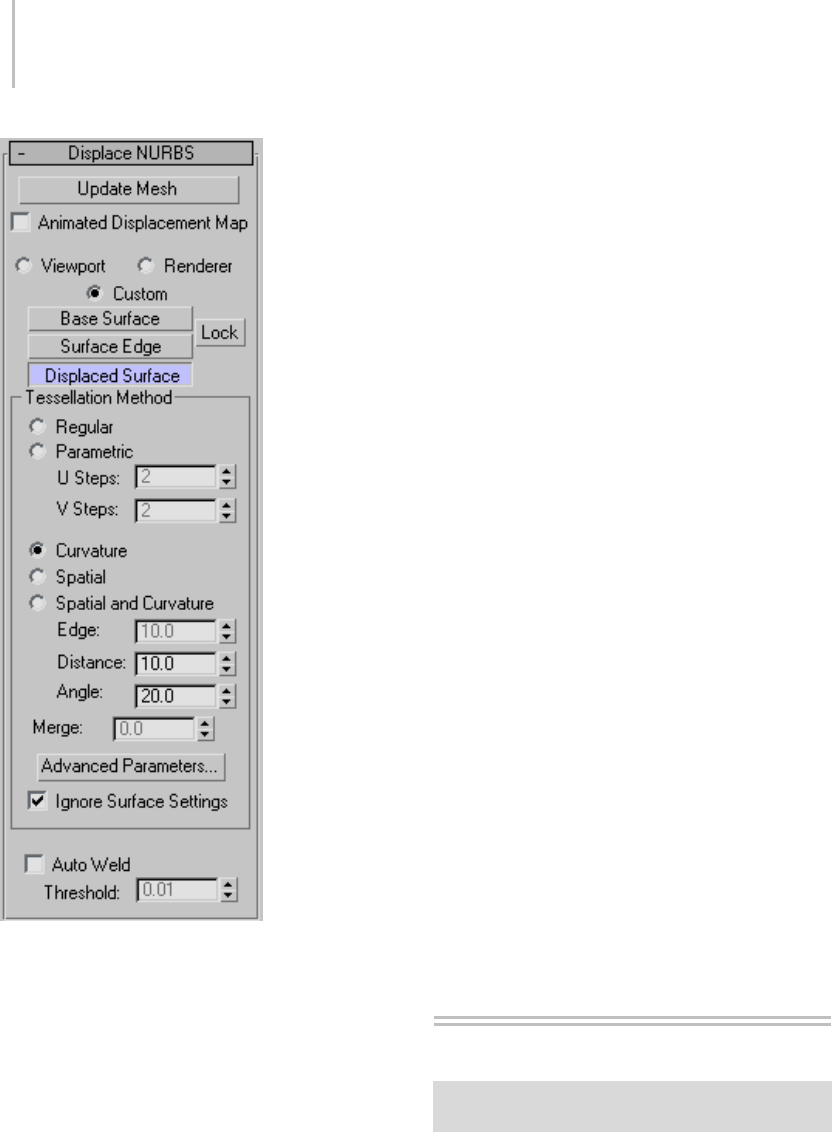
516 Chapter 8: Modifiers
Animated Displacement Map—If you use an
animated displacement map on the mesh, turn
on this toggle to have the NURBS Modifier
correctlyupdatethemeshasthedisplacement
map animates.
Yo u c a n a p p l y a displacement map (page 2–1511)
using the Material Editor (page 2–1409).
Update Mesh—Click to update the mesh if you
have changed the displacement mapping and want
to see the results of the change. The mesh isn’t
updated automatically because that could become
extremely time consuming.
Viewport—Uses the tessellation that the NURBS
object currently uses in viewports.
Renderer—Uses the tessellation that the NURBS
object currently uses for the renderer.
Custom—Set the tessellation directly in the
Tessellation Method group box.
Base Surface, Surface Edge, Displaced Surface, and
Lock—Thesecontrolsarethesameasinthesurface
approximation controls (page 1–1239) for NURBS
objects.
Tessellation Method group
The controls in this group are the same as the
surface approximation controls for NURBS
objects.
Ignore Surface Settings—When turned off,
Displace NURBS uses the surface approximation
settings for surface sub-objects. When turned
on, Displace NURBS uses the settings in the
Tessellation Method group and overrides settings
for surface sub-objects. Default=off.
Auto Weld—All vertices closer than the Threshold
value are automatically welded together. This can
simplify the mesh geometry. It is useful to turn
this on when you have increased the Merge value
in order to eliminate gaps between surface edges
in the approximation of the NURBS object.
Hair and Fur Modifier (WSM)
Modify panel > Make a selection. > Modifier List >
World-Space Modifiers > Hair And Fur
TheHairAndFurmodifieristheheartoftheHair
And Fur feature. You apply it to any object that
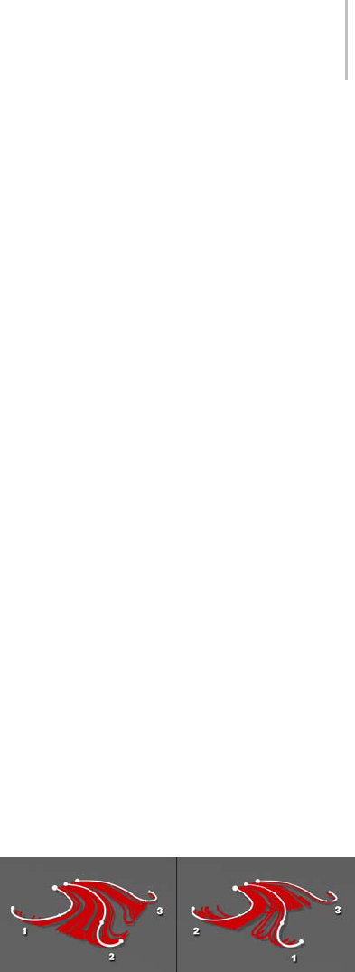
Hair And Fur Modifier 517
you want to grow hair from: either a mesh object
or a spline object. If object is a mesh, the hair
grows from the entire surface unless you make a
sub-object selection. If the object is a spline, hair
grows between the splines.
When you select an object modified by Hair And
Fur, hair is displayed in viewports. The hair itself
as displayed in the viewports is not selectable,
though hair guides areselectablewhenyouwork
at the Guides sub-object level or style hair (see
below).
Note: Hair And Fur renders only in Perspective
and Camera views. If you attempt to render an
orthographic view, 3ds Max displays a warning
that says the hair will not appear.
Components of the Hair And Fur Feature
Hair And Fur in 3ds Max has a few different
components in the interface:
•TheHairAndFurmodifieristhemain
component. This is where you style the
hair guides, and set parameters for size and
coloration, kinkiness, frizziness, and so on.
•TheHair And Fur render effect (page 3–220)
more directly controls how hair is rendered.
Typically you don’t need to change the render
effect parameters, unless you have special
rendering requirements.
AHairAndFurrendereffectisautomatically
added to your scene when you apply the Hair
And Fur modifier.
•AHair Light Attributes rollout (page 2–1351)
appears for all supported lights when a Hair
And Fur render effect is active using the
scanline renderer, and the render effect’s Use
All Lights At Render Time toggle is turned on.
Controls on this rollout let you fine-tune how
hair shadows appear under specific lights.
The following light types are not supported
when rendering hair with the “buffer” method
(see “Lighting Considerations,” below):
Skylight, mr Area Omni, mr Area Spot, IES
Sun, IES Sky, mr Sky and mr Sun. However, mr
AreaOmni,mrAreaSpot,mrSky,andmrSun
are supported forhairwhenyouusethe“mr
prim” method and the mental ray renderer.
Note: For the purposes of rendering shadows in
hair, Direct lights are treated as point (omni)
lights.
•ThereisalsoaHair And Fur render element
(page 3–140), which you can use when you are
doing your own compositing.
Growth Objects
You can grow Hair either from a surface or from
splines.
To grow hair from a surface, select the object and
then apply the Hair And Fur modifier. You can use
either geometric primitives or an editable surface
type such as Polymesh.
To grow hair from splines, you can draw several
splines and combine them into a single object
(or turn off Start New Shape during creation),
and then apply the Hair And Fur modifier. You
will see some preview interpolated hairs appear
inviewports.Theorderofthesplinesub-objects
is important because Hair uses this order to
interpolate hair in between the splines. If the
interpolation seems incoherent, you might need to
physically rearrange the splines.
Using a spline emitter, Hair interpolates hair growth between
pairs of splines in logical, numerical order.
Left: Splines in sequential order result in predictable hair
growth.
Right: Splines in nonsequential order can produce undesirable
results.
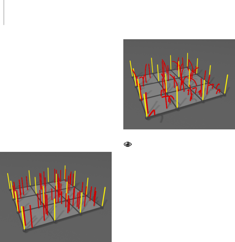
518 Chapter 8: Modifiers
Tip: To check the numerical order of splines, go
totheEditableSplinelevelofthemodifierstack
and access the Spline sub-object level. Then click
each spline in turn and check its ID number at the
bottom of the Selection rollout. It also can help to
make sure that each spline’s first vertex is where
the hair roots should be.
Guide Hairs
Storing and manipulating millions of dynamic,
simulated hairs is demanding on today’s
technology. Therefore, just as standard 3D
graphics technology uses boundaries such as
surfaces to describe solid objects, Hair uses hair
“guides” to describe basic hair shape and behavior.
Guides (yellow) occur at each polygon corner.
Hairs (red) are interpolated between guides.
When the growth object is a surface, Hair And Fur
generatesguidehairsatthecornersofpolygons.
When the growth object is a spline, the spline
sub-objects are themselves the guides.
For surface-grown hair, you can manipulate
the guides with styling tools (page 1–526) to
form a “control volume” that gets populated by
interpolated hairs. The hairs can then be further
manipulated with distorting controls such as Kink
(page 1–542) and Frizz (page 1–540), which can be
driven by maps or solid textures.
Frizz settings affect the hairs but not the guides.
By default, a percentage of hairs are displayed
in the viewports, but surface-grown guides do not
appear except when you are working at the Guides
sub-object level. You can adjust the viewport
display of guides and hairs with settings on the
Display rollout (page 1–549).
Guidesarealsousedtocalculatedynamics.After
this calculation, hair interpolation takes place
when you render. This is when parameters such
as Frizz, as well as displacement and coloration,
are calculated. You don’t have control of every
single hair, but this two-phase process makes the
creation of realistic hair computationally feasible
on a typical computer.
Styling Hair
TheHairAndFurmodifier’sgrowthsettings
haveagreateffectonthehair’sappearanceand
behavior, but you can also manipulate the guides
directly (or in other words, style the hair).
For surface-grown hair, use the tools on the Styling
rollout (page 1–526). First, select the surface whose
hair you want to edit, and then on the Modify
panel, either click the Style Hair button on the
StylingrolloutorchoosetheGuidessub-object
level from the Selection rollout (page 1–521) or the
modifier stack display.
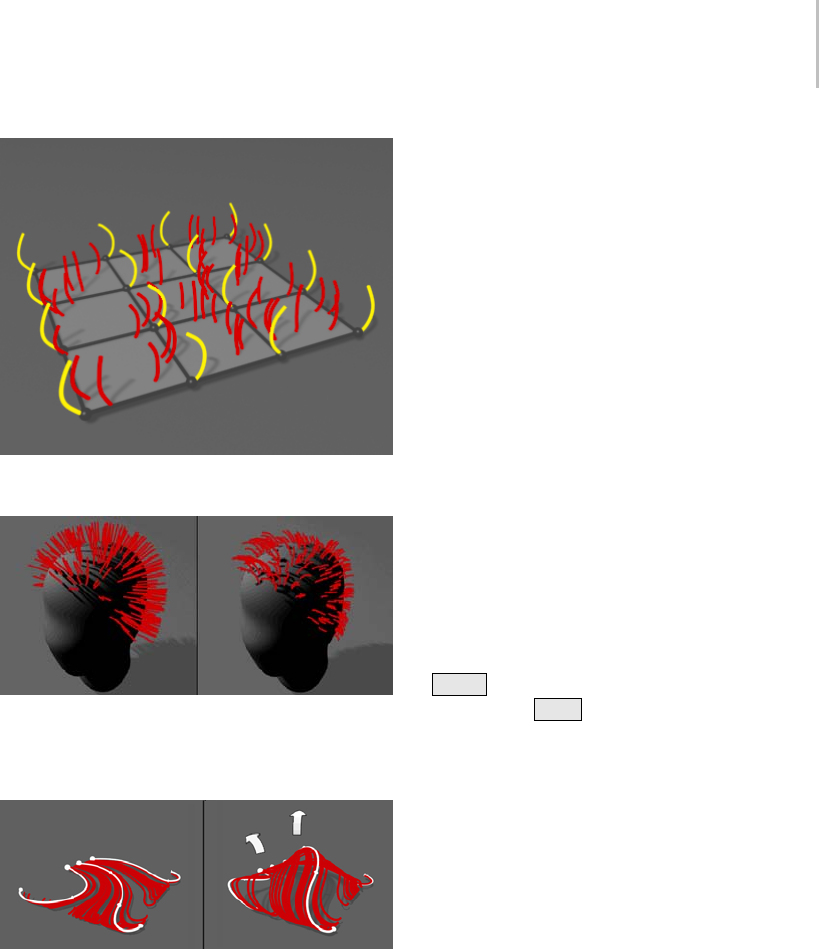
Hair And Fur Modifier 519
After guides have been styled, hair is interpolated between
neighboring guide pairs.
Mesh-based hair guides before and after styling.
With spline growth, you style the hair by editing
the growth splines in the viewports.
Style spline-based hair by manipulating the splines.
Copying and Pasting Hair
You can copy and paste a Hair And Fur modifier
from one stack to another, but you need to line up
the objects as closely as possible, because Hair uses
proximity to determine how to position copied
guides. If the objects have significantly different
geometry, the transfer of guides can be inaccurate.
Copying and pasting the Hair And Fur modifier
automatically adjusts the hair scaling. Copying
fromalargeobjecttoasmallobject,forinstance,
resultsinasmallerdefaultsizeinthecopied
modifier.
IfyoucopyanobjectthathasHairAndFurinits
modifier stack, Hair will also copy the modifier’s
data to a new modifier that will track the new
object.
Textures, Vertex Maps, and Shaders
You can control many Hair And Fur modifier
parameters with maps. If you apply a map to a
parameter that is not a color, such as Density,
Hair uses the texture as a grayscale map that is
multiplied by the parameter value (0.0 to 100.0) .
You apply a map by clicking the square button to
therightoftheparameter.Afterapplyingamap,
the letter “M” appears on the button. To place
this map in the first slot in the Material Editor,
Shift +click the button. To disable the map
temporarily, Ctrl +click the button. A disabled
map is indicated by a lower-case “m”.
Lighting Considerations
When you render using the default “buffer”
method,HairAndFurprovidesitsowndefault
lighting (a single omni light), unless you have one
or more supported lights in the scene.
Supported lights for the scanline renderer and
“buffer” method include spotlights, omni lights,
direct lights (which are treated as omni lights for
hair purposes), and photometric lights except
for IES Sun and IES Sky. Supported lights for
the mental ray renderer and “mr prim” method
include the lights supported by the scanline
renderer, and these mental ray light types: mr
Area Omni Light, mr Area Spotlight, mr Sky, and
mr Sun.

520 Chapter 8: Modifiers
If supported lights exist in the scene, by default
they are used to light the hair, and the internal
default omni light is not used. This is because
in the Hair And Fur render effect (page 3–220),
the Use All Lights At Render Time option is on
by default. Also, any supported lights set to cast
shadow-mapped shadows will cast shadows from
rendered hair.
ForHair’s“buffer”rendertoconsideronlycertain
lights, select the lights you’d like Hair to use, go to
theHairAndFurrendereffect,turnoffUseAll
Lights At Render Time, and then click Add Hair
Properties.Thiscausesonlythedesignatedlights
to illuminate the hair. It also adds a Hair Light Attr
rollout (page 2–1351) to each of the designated
lights. This lets you fine-tune the light’s shadow
settings for Hair.
With the “buffer” method, you can also raytrace
your scene.
Note: The other rendering methods provided
are “geometry” and “mr prim.” The “geometry”
method creates actual geometry for the rendered
hair at render time. The “mr prim” method uses a
mental ray shader to generate hair, and is for use
only with the mental ray renderer. Use the Hair
And Fur render effect to choose the rendering
method.
Loading and Saving
Hair And Fur data in your scene is automatically
saved when you save your MAX scene file. The
statedataforthehaircanconsumequiteabit
of space, so your scene file will probably be
significantly larger than it was before you applied
hair.
Animating Hair
You cannot keyframe hair styling. You can
keyframe Modify panel parameters to create
special effects such as hair growing. But to animate
hair motion, you can use the Frizz Animation
parameters or use dynamics.
To a n i m a t e f r i z z , u s e t h e Frizz Anim.,Anim.
Speed, and Frizz Anim. Dir. parameters. It’s not
necessarytokeyframethesetocreateanimation;
just set them to values other than the defaults.
To animate with dynamics, use the Dynamics
rollout (page 1–545).SeeTo generate a precomputed
dynamics simulation with Hair (page 1–545).A
gravity force is built in to Hair And Fur. You can
add space warps to act as external forces (for
example, Wind).
See also
Hair and Fur Render Effect (page 3–220)
Hair and Fur Render Element (page 3–140)
Hair Light Attr(ibutes) Rollout (page 2–1351)
Procedures
To use the Hair And Fur modifier:
This procedure lists the essential steps for growing
hair on an object. For more information, see other
Hair And Fur topics in this reference, and the
tutorials in 3ds Max 9 Tutorials.
1. Apply the Hair And Fur modifier to a mesh or
spline object.
The hairs appear in the viewports as brown
lines.
2. Set the modifier parameters according to the
desired results (see Interface (page 1–521)).
Available settings include the number of hairs,
length, thickness, and coloring.
3. Activate a Perspective or Camera viewport, and
then render the scene.
Hair cannot render in an orthogonal viewport.

Selection Rollout (Hair and Fur) 521
To apply hair to a limited area of a high-resolution
object:
An efficient working method for applying hair
to part of a high-poly-count object is to use a
low-poly proxy object.
1. Create the object to which you wish to apply
hair.
2. Makeacopyoftheobjectinthesamelocation
as the original, remove any geometry where
hair shouldn’t grow, and reduce the polygon
count. For example, you could use the MultiRes
modifier (page 1–739).
3. If the original object is to move, make the
low-resolution proxy object a child of the
original object.
4. Apply the Hair And Fur modifier to the
low-resolution proxy object and adjust as
necessary.
5. Make the low-resolution proxy object
non-renderable (see General Panel (Object
Properties Dialog) (page 1–117)). The hair will
still render.
Interface
YoucontroltheHairAndFurmodifierfroma
series of rollouts on the Modify panel. See these
topics:
Selection Rollout (Hair and Fur) (page 1–521)
Tools Rollout (Hair and Fur) (page 1–523)
Styling Rollout (Hair and Fur) (page 1–526)
General Parameters Rollout (Hair and Fur) (page
1–534)
Material Parameters Rollout (Hair and Fur) (page
1–537)
mr Parameters Rollout (Hair and Fur) (page 1–540)
Frizz Parameters Rollout (Hair and Fur) (page
1–540)
Kink Parameters Rollout (Hair and Fur) (page
1–542)
Multi Strand Parameters Rollout (Hair and Fur)
(page 1–544)
Dynamics Rollout (Hair and Fur) (page 1–545)
Display Rollout (Hair and Fur) (page 1–549)
Selection Rollout (Hair and Fur)
Select an object with the Hair And Fur modifier applied. >
Modify panel > Selection rollout
The Selection rollout provides tools for accessing
different sub-object levels and display settings and
for creating and modifying selections, and displays
information about selected entities.
When you first apply the Hair And Fur modifier
to an object, the entire object is affected by the
modifier. You can specify that the only part of an
object should grow hair by accessing a sub-object
level and making a selection.
Clickingabuttonhereisthesameaschoosing
a sub-object level in the modifier stack display.
Click the button again to turn it off and return to
the Object selection level.
Interface
Note: Controls on this rollout are available only
when the growth object is a mesh. If the growth
object is a spline, the Selection controls have no
effect, and sub-object levels for the Hair And Fur
modifierarenotvisibleinthemodifierstack.
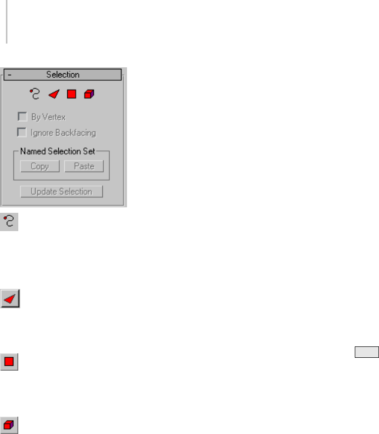
522 Chapter 8: Modifiers
Guides—Accesses the Guides sub-object level,
which lets you edit the styling guides using tools
on the Styling rollout (page 1–526).Whenyou
click Guides, the Style Hair button on the Styling
rollout is automatically turned on, and vice versa.
Face—Accesses the Face sub-object level,
which lets you select a triangular face beneath the
cursor; region selection selects multiple triangular
faces within the region.
Polygon—Accesses the Polygon sub-object
level, which lets you select polygons beneath the
cursor. Region selection selects multiple polygons
within the region.
Element—Accesses the Element sub-object
level, which lets you select all contiguous polygons
in an object by clicking once. Region selection lets
you select multiple elements.
By Vertex—When on, you can select a sub-object
only by selecting a vertex that it uses. When you
click a vertex, all sub-objects that use the selected
vertex are selected.
Ignore Backfacing—When on, using the mouse
to select sub-objects affects only those facing
you. When off (the default), you can select any
sub-objects under the mouse cursor, regardless
of their visibility or facing. If there are more
than one sub-object under the cursor, repeated
clicking cycles through them. Likewise, with
Ignore Backfacing off, region selection includes all
sub-objects, regardless of the direction they face.
Note: The state of the Backface Cull setting on the
Display panel does not affect sub-object selection.
Thus, if Ignore Backfacing is off, you can still select
sub-objects, even if you can’t see them.
Named Selection Set group
Copy—Places a named selection into the copy
buffer.
Paste—Pastes a named selection from the copy
buffer.
Tip: You can use this to grow hair from an existing
selection lower on the stack. However, because
theHairAndFurmodifieroutputsaneditable
mesh, the copied sub-object selection should be
from a mesh-based modifier. For example, if
your base object is an editable poly, you can use
tools such as Ring, Loop, and Grow to make a
procedural edge selection, and then Ctrl +click
the Polygon button on the Selection rollout to
convert the selection to polygons. Next, apply a
Mesh Select modifier (not Poly Select), and go
to the Polygon sub-object level; the Mesh Select
modifier inherits the Editable Poly selection. Use
the Named Selection Sets field on the main toolbar
to name the selection, and then use the Mesh Select
modifier’s Copy function on the named selection.
Finally, apply the Hair And Fur modifier, go to the
Poly sub-object level, and paste the selection.
Update Selection—Recalculates the area from
which hair is grown, based on the current
sub-object selection, and refreshes the display.
When you access a sub-object level within the
Hairmodifierandmakeaselection,theareaof
hair growth doesn’t automatically update. Click
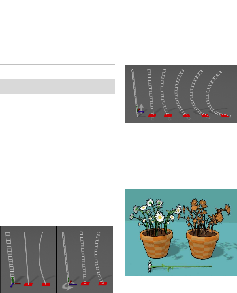
Tools Rollout (Hair and Fur) 523
Update Selection to view the results of a change
in sub-object selection.
Tools Rollout (Hair and Fur)
Select an object with the Hair And Fur modifier applied. >
Modify panel > Tools rollout
This rollout provides tools for accomplishing a
variety of tasks with Hair, including creating a
hairstyle from an existing spline object, resetting
the hair, and loading and saving general presets
for the modifier as well as specific hairdos. Here
you can also specify an object from the current
scenetobeusedashair,suchasaflowerorgroup
of flowers for creating a garden.
Using Instanced Hair
Besides the built-in hair strands, which are created
at render time, you can assign any source object as
hair strands, using the Instance Node controls on
the Tools rollout. For example, in the following
illustration, the original orientation of the source
object affects its orientation when it is used as hair
strands.
Rotating the source object affects the hair orientation.
The next illustration shows how increasing the
FrizzRootvaluecreatesgreateramountsof
distortion in the resulting instanced hairs. This
image also shows how a raised pivot in the source
object causes the root of the hair to go below the
surface of the growth object (the red square).
Compare this with the previous illustration, in
which the pivot rests at the base of the source
object.
Frizz causes the instanced hairs to change shape.
ThenextillustrationshowstheeffectoftheMerge
Material check box. On the left side, Merge
Material was left on, with the result that the flower
model retained its original material and coloring
when used as hair. On the right, Merge material
wasturnedoff,sotheflower-hairstookonthe
material of the flower pot growth object.
Left: Merge Material on
Right: Merge Material off
Inthenextillustration,theRootThicksetting,
from left to right, is 2.0, 10.0, 20.0, and 30.0. With
instanced geometry, the Root Thick value affects
the thickness of the resulting object uniformly
along its height, while the Tip Thick value has no
effect. (The Root Thick and Tip Thick settings are
on the General Parameters rollout (page 1–534).)
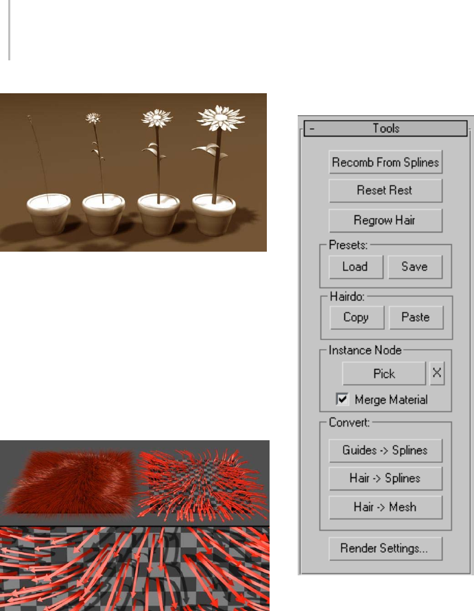
524 Chapter 8: Modifiers
Increasing Root Thick affects the overall thickness of the hair
geometry.
From left to right: Root Thick = 2.0, 10.0, 20.0, and 30.0
The final illustration, below, shows how the
instanced hair aligns itself faithfully to the guides,
no matter how they’re styled. The styled hair was
brushed from the center, and the instances align
perfectly in all directions, face up, without twisting
or other distortion. This makes it easy to style
instancesasscales,forexample.
Top left: The original styled hair
Top right: The instanced hair (arrows) conforms to the styling.
Bottom: Close-up view of instanced hair
Interface
Recomb From Splines—Lets you use a spline object
to style the hair. Click this button and then select
an object that is made up of spline curves. Hair
will turn the curves into guides and populate each
guide of the selected growth mesh with a replica of
the closest curve.
This tool is particularly useful for creating a
specific style and length, such as short hair with
apartontheside,withouthavingtomanually
groom the hair in the Style dialog. For optimal
control, position the splines fairly closely together
and use as many as possible.
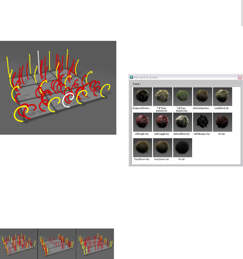
Tools Rollout (Hair and Fur) 525
Hair and guides are recombed by the spline object (white).
Reset Rest—Performs an averaging of hair guides
using the growth mesh’s connectivity.
This function is particularly useful after using
Recomb From Splines. It’s also advantageous
when you change the size ratios of polygons in the
growth object. For example, if you stretch part of
the mesh by moving some vertices, by default the
larger polygons will contain fewer hairs per unit
area. Use Reset Rest to redistribute the number of
hairs on the surface for more even coverage.
Left: Even hair distribution before resizing polygons
Center: Uneven hair distribution after moving edges, altering
polygon size ratios
Right: After using Reset Rest, distribution is again evened out.
Regrow Hair—Discards any styling information,
resetting the hair to its default state, retaining all
current Modify panel settings.
Presets group
Lets you load and save hair presets. Each preset
contains all current Modify panel settings (except
Display settings), but not any styling information.
Load—Opens the Hair Presets dialog, which
contains a list of presets in the form of named
swatches. To load a preset, double-click its swatch.
Severalsamplepresetsareincludedwith3dsMax.
Hair And Fur Presets dialog
Save—Creates a new preset. You’re prompted for
a preset name; after entering one, Hair renders
the swatch, as shown by a message on the status
bar. You can abort the creation of the preset by
clicking the Cancel button on the status bar during
rendering. If you enter an existing preset name,
Hair asks you to confirm overwriting the preset.
Hairdo group
Lets you copy and paste hairdos. Each hairdo
contains all the current Modify panel settings
(except Display settings) and styling information.
This lets you apply all hair settings from one object
to another.
Copy—Copies all hair settings and styling
information into a paste buffer.
Paste—Pastes all hair settings and styling
information to the current Hair-modified object.
Instance Node group
Lets you specify an object to use as custom hair
geometry. The hair geometry is not instanced

526 Chapter 8: Modifiers
from the original object, but all hairs created from
it are instances of each other, to save memory.
Note: Hair does not use animation from instance
objects. If an object is animated, Hair uses its state
at the first animation frame.
Pick—To specify a hair object, click the Pick button
and then pick an object to use. Thereafter, the
button shows the name of the object you picked.
To use a different instance object, or to use a
modified version of the original object, click this
button and then pick the new object.
Tip: In order for the instances to be properly scaled
and fit to the hair, place the model’s pivot at the
“root” of the object. Hair will then scale your
model appropriately so that the height of each
instance matches the length of the hair it has been
applied to. Any part of your model that extends
below the pivot will intersect the surface. This can
be useful; if the hair grows at an oblique angle to
the growth surface, you can raise the pivot in the
original model to make sure the instanced hairs
will extend all the way to the growth surface.
Also, bear in mind that the instancing engine will
be deforming your model as it fits it to the hairs.
Make sure that your model has enough divisions
along the Z (vertical) axis for the deformation
to look as smooth as it needs to; the number of
subdivisions should be approximately equal to
theHairSegmentsvalue. Hairdoesn’tperform
automatic subdivision on the geometry.
X—To stop using the instance node, click the Clear
Instance button (labeled “X”).
Merge Material—When on, combines the
material applied to the growth object and
thematerialappliedtothehairobjectintoa
single Multi/Sub-Object material and applies
it to the growth object. When off, the growth
object’s material is applied to the instanced hair.
Default=on.
Note: The merged material is instanced from
the instance node, so that changing the original
materialaffectstheresultingmaterialappliedto
the hair.
Convert group
Use these controls to convert guides or hair
generated by the Hair And Fur modifier to
3ds Max objects that you can operate on directly.
Guides -> Splines—Copies all guides to a new, single
spline object. The original guides are left intact.
Hair -> Splines—Copies all hairs to a new, single
spline object. The original hairs are left intact.
Hair -> Mesh—Copies all hair to a new, single mesh
object. The original hairs are left intact.
Render Settings—Opens the Effects panel and
rollout (page 3–219) and adds a Hair And Fur
render effect (page 3–220) to the scene, if one
doesn’t already exist.
Note: TheHairAndFurrendereffectsettingsare
global, so even if you click Render Settings to
open the effect settings from different Hair And
Fur modifiers, you’ll get the same render-effect
settings.
Styling Rollout (Hair and Fur)
Select an object with the Hair And Fur modifier applied. >
Modify panel > Styling rollout
The Guides sub-object level of the Hair And
Fur modifier (page 1–516) lets you style hair
interactively in viewports. Interactive styling
controls are on the Styling rollout, which has a
Style Hair button that you can also click to begin
styling.

Styling Rollout (Hair and Fur) 527
Styling with Hair Guides
Styling tools aren’t available until you click Style
Hair to turn it on, or choose the Guides sub-object
level in either the Selection rollout or the modifier
stack.
Each guide hair has 15 segments and 14 vertices
(there’s an additional, non-selectable vertex at the
root); for a tool to affect a guide, at least one of its
vertices must be selected. To select vertices, click
Select(intheStylinggroup)toturniton,then
use standard 3ds Max selection tools to select a
portion of the guides. For example, you might
drag a selection rectangle to select vertices on
adjacent hair guides. By default, selected guides
are displayed as orange, and unselected guides are
displayed as yellow.
Selections you make this way are constrained
by the buttons at the top of the Selection group:
Select Hair By Ends, Select Whole Guide (the
default), Select Guide Vertices, or Select Guide By
Root. As these names imply, the constraints affect
how the Hair Brush modifies hair guides. The
best way to get a feel for the difference between
selection constraints is to practice using the
various selection constraints with tools such as
Translate. The Hair Brush uses a combination of
these constraints and IK to alter guide geometry.
Left: Hair guide before styling
Center: Translating while Select Whole Guide is active
Right: Translating while Select Hair By Ends is active
Once you’ve made a selection, typicall you will
click Hair Brush (also in the Styling group, to
the left of Select), and then use the brush in
conjunction with one of the tools at the bottom
of the Styling group: Translate, Stand, Puff Roots,
Clump, Rotate, or Scale.
While you style, only selected guides are affected,
and in addition, only guides that fall within the
brush area are affected at any given time. You
can change the brush size using the slider in the
Styling group, or by holding down Ctrl+Shift
and dragging the mouse.
TheHairCuttoolontheStylingrollout(between
HairBrushandSelect)cutshairguidesbyscaling
them based on the brush location.
Interface
Note: Controls on this rollout are available only
when the growth object is a mesh. If the growth
object is a spline, the Styling controls have no
effect. Instead, you can style the hair by editing the
underlying spline object.
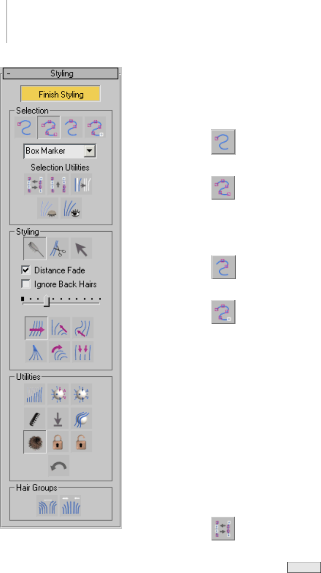
528 Chapter 8: Modifiers
Style Hair / Finish Styling—Click Style Hair to begin
styling. Click Finish Styling to turn off styling
mode. When you turn this button on, a brush is
immediatelyavailableandbydefaulttheactive
tool is Transl ate. Turning on St y le Ha ir turns on
the Guides sub-object level in the Selection rollout
(page 1–521),andviceversa.
Selection group
Select Hair by Ends—You can select only the
vertexattheendofeachguidehair.
Select Whole Guide—(The default.)
Selecting any vertex on a guide hair selects all
vertices on the guide hair. When you first turn on
StyleHair,Hairactivatesthismodeandselectsall
vertices of all guide hairs.
Select Guide Vertices—You can select any
vertices on a guide hair.
Select Guide by Root—You can select only
the vertex at the root of each guide hair, and doing
so selects all vertices on the guide hair.
Vertex display drop-down list—Chooses how
selected vertices are displayed in viewports.
•Box Marker—(The default.) Selected vertices
display as small squares.
•Plus Marker—Selected vertices display as small
plus signs.
•XMarker—Selected vertices display as small
Xes.
•Dot Marker—Selected vertices display as dots.
Selection Utilities—The buttons labeled “Selection
Utilities” are for handling selections.
Invert Selection—Inverts the vertex
selection.
Keyboard shortcut: Ctrl+I
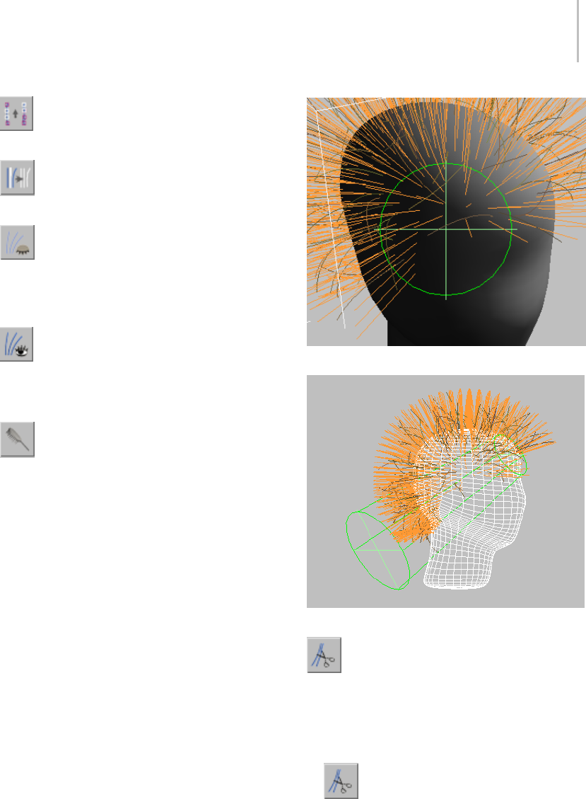
Styling Rollout (Hair and Fur) 529
Rotate Selection—Rotates the selection in
space.
Expand Selection—Expands the selection by
growing its area incrementally.
Hide Selected—Hides selected guide hairs.
Tip: If interactive styling in viewports seems to be
slow, try hiding those guides you aren’t working
on.
Show Hidden—Unhides any hidden guide
hairs.
Styling group
Hair Brush—(The default.) In this styling
mode, dragging the mouse affects only selected
vertices within the brush area.
While Hair Brush is on, a brush gizmo is
displayed in viewports. In the active viewport,
thebrushappearsasacircle,butasyoucansee
in the other viewports, the brush is actually a
three-dimensional cylindrical region.
Intheactiveviewport,thebrushappearstobeacircle.
Inactive viewports show the brush to be a cylindrical region.
Hair Cut—Lets you trim the guide hairs. To
cut hair, follow this suggested procedure:
1. In Selection mode, choose any selection
method.
2. Drag the mouse to select guide hairs to trim.
3. Tur n on Ha ir Cut.
4. Resize the brush using the slider.
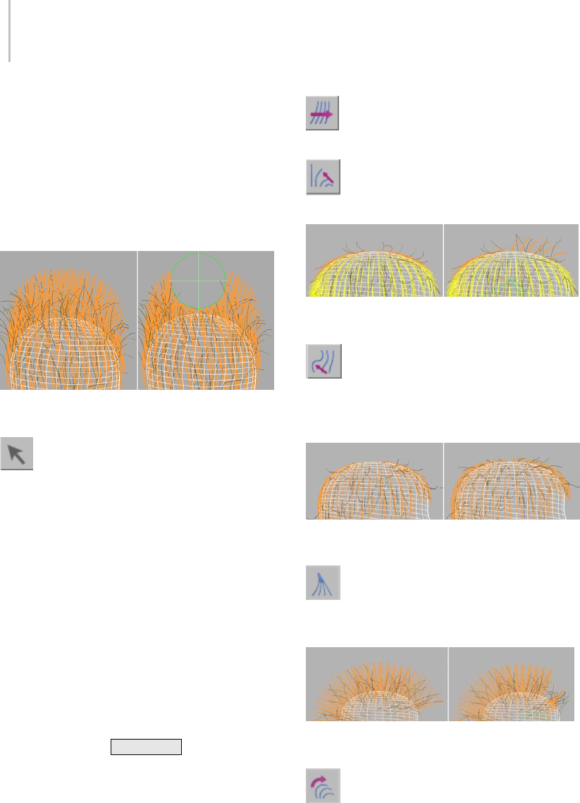
530 Chapter 8: Modifiers
5. Position the brush circle over hairs to cut, and
then click to cut the hairs. Hairs with vertices
inside the brush circle are shortened so that
their endpoints touch the brush circle.
Note: Cutting hair doesn’t actually remove vertices;
it only scales the guide hairs. You can restore guide
hairs to their original length with Scale or one of
the Pop commands.
Left: Hair guides before cutting
Right: Hair guides after cutting
Select—Goes into selection mode, where
youcanuse3dsMaxselectiontoolstoselectguide
vertices according to the constraints chosen in the
Selection group (Whole Guide, Ends, and so on).
Distance Fade—Available only for Hair Brush.
When on, the effect of brushing fades toward the
edges of the brush, giving a gentler effect. When
off, brushing affects all selected vertices equally,
giving a hard-edged effect. Default=on.
Ignore Back Hairs—Available only for Hair Brush
and Hair Cut. When on, hairs on back faces are
not affected by the brush. Default=off.
Brush size slider—Drag this slider to change the
size of the brush.
Keyboard shortcut: Ctrl+Shift +drag
The styling buttons below the Brush Size Slider are
available only while Hair Brush is on.
Translate—Moves selected vertices in the
direction that you drag the mouse.
Stand—Pushes selected guides toward a
perpendicular orientation to the surface.
Left: Guide hairs before styling with Stand
Right: Guide hairs after styling with Stand (on the right)
Puff Roots—Pushes selected guide hairs
toward a perpendicular orientation to the surface.
The bias for this tool is closer to the root of the hair
than to the endpoint.
Left: Hair guides before puffing roots
Right: Hair guides after puffing roots
Clump—Forces selected guides to move
towards each other (drag mouse leftward) or
farther apart (drag mouse rightward).
Left: Hair guides before clumping
Right: Hair guides after clumping (at the right)
Rotate—Rotate or swirls guide hair vertices
around the cursor location (at the center of the
brush).
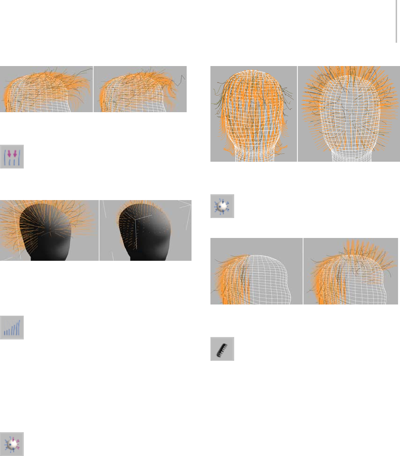
Styling Rollout (Hair and Fur) 531
Left: Hair guides before rotating
Right: Hair guides after rotating (at the forelock)
Scale—Scales selected guides larger (drag
mouserightward)orsmaller(dragmouse
leftward).
Left: Hair guides at original lengths
Right: Hair guides after scaling shorter
Utilities group
Attenuate Length—Scales selected guides
according to the surface area of underlying
polygons. This is useful, for example, in applying
fur to an animal model, which typically has
smaller polygons in areas with shorter hair. For
example, the polygons on an animals paws are
usually smaller than the ones on the chest, and the
chest fur tends to be longer.
Pop Selected—Pops selected hairs out along
the surface normal.
Left: Hair guides before using Pop Selected
Right: Hair guides after using Pop Selected
Pop Zero-Sized—Wor k s l i ke Po p S e l e c t ed ,
but only operates on zero-length hairs.
Left: Hair guides on top of head were scaled to zero length.
Right: Using Pop Zero affects only the zero-length hair guides.
Recomb—Makes a guide parallel to the
surface, using the guide’s current direction as a
hint.
Here’s a suggested procedure: Turn on Hair Brush,
select guides using Select Whole Guide, and then
move the guides around not worrying about skin
penetration or hair shape. You’re just trying
to indicate the direction of the hair flow. Click
Recomb frequently, and you will soon start to see
hair flowing smoothly wherever you want it to.
Once you have this flow, you can do your other
styling. With the Recomb tool, you probably won’t
needtouseCombAway.Onceyouhavetheflowas
you like it, you can go in and start styling in scale,
cutguides,andmovesomeofthetipsaround,
“shaping” or “styling” the hair.
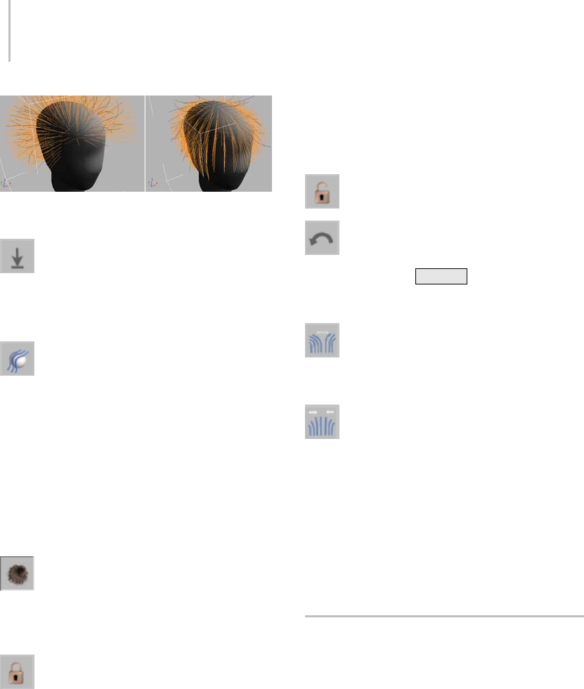
532 Chapter 8: Modifiers
Left: Hair guides in their default position
Right: Hair guides after clicking Recomb
Reset Rest—Performs an averaging of hair
guides using the growth mesh’s connectivity.
This function is particularly useful after using
Recomb.
Toggle Collisions—When on, styling takes
hair collisions into account. When off, styling
ignores collisions. Default=off.
For collisions to be used while styling, you need
to have already added at least one collision object
using the Dynamics rollout (page 1–545).Ifno
collisions are specified, this button has no effect.
Tip: If you collisions are enabled and styling
interaction seems slow, try turning off Toggle
Collisions.
Toggle Hair—Toggles viewport display of
generated (interpolated) hair. This doesn’t affect
display of the hair guides. Default=on (hair is
displayed).
Lock—Locks selected vertices with respect
to the orientation to and distance from the nearest
surface. Locked vertices can be selected, but they
can’t be moved.
This is useful for creating different types of hair
shapes. For example, to make a braid, you would
comb hair down some straight tubes, and then
lock the vertices to the tubes. Then, in 3ds Max,
when you twist the tubes, the hairs will follow.
Locked vertices are no longer dynamic, although
they will follow whatever the surface does, but if
other vertices on the same guides aren’t locked,
they can still move freely, as usual.
Unlock—Unlocks all locked guide hairs.
Undo—Reverses the most recent action.
Keyboard shortcut: Ctrl+Z
Hair Groups group
Split Selected Hair Groups—Splits the
selected guides into a group. This can be useful for
creatingapartoracowlick,forexample.
Merge Selected Hair Groups—Recombines
selected guides.
If you don’t use Split Selected Hair Groups,
then when you render hair, the generated hairs
are interpolated across a styled part. When
Split Selected Hair Groups is on, there is no
interpolation between the split group and other
hairs. To remove this effect and make the part less
“clean,” click Merge Selected Hair Groups.
Quad Menu for Hair Styling
WhileyouarestylinghairattheGuidessub-object
level, right-clicking a viewport displays a quad
menu that contains shortcuts to many styling
controls that are also found on the Styling rollout
(page 1–526).
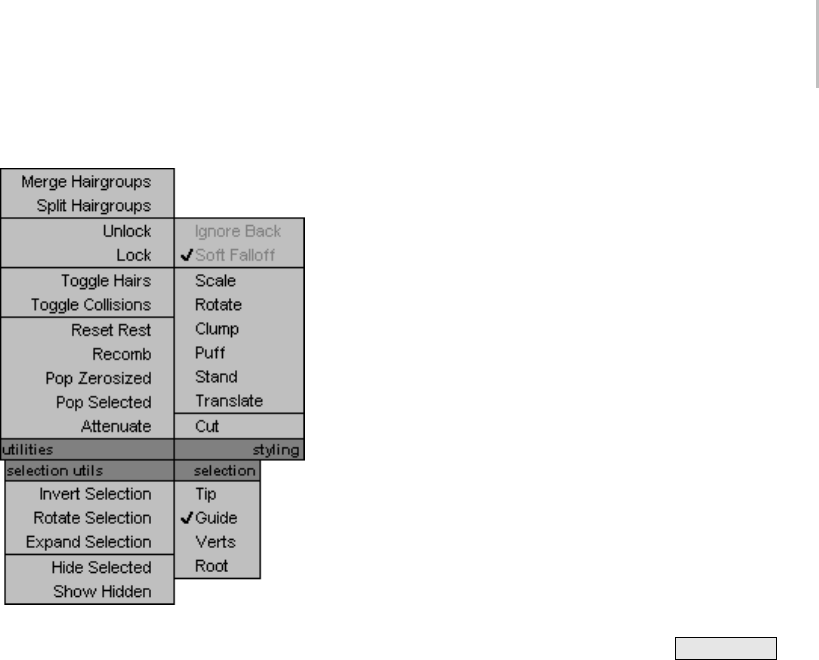
Quad Menu for Hair Styling 533
Interface
Utilities quadrant
The first two choices are shortcuts to the buttons
in the Hair Groups group:
•Merge Hairgroups
•Split Hairgroups
The other choices in this quadrant are shortcuts to
thebuttonsintheUtilitiesgroup:
•Unlock
•Lock
•To g g l e H ai r s
•To g g l e C o l li s i o n s
•Reset Rest
•Recomb
•Pop Zerosized
•Pop Selected
•Attenuate
Styling quadrant
The choices in this quadrant are shortcuts to most
of the controls in the Styling group:
•Ignore Back
•Soft Falloff
•Scale
•Rotate
•Clump
•Puff
•Stand
•Tran sl ate
•Cut
To exit Cut mode and return to the hair brush,
choose one of the other styling modes in this
quadrant.
Tip: While the brush is active, you can resize it
in viewports by holding down Ctrl+Shift and
dragging the mouse.
Selection Utils quadrant
These choices are shortcuts to the buttons under
“Selection Utilities” in the Selection group:
•Invert Selection
•Rotate Selection
•Expand Selection
•Hide Selected
•Show Hidden
Selection quadrant
Thesechoicesareshortcutstothebuttonsatthe
top of the Selection group that constrain how you
can select hair guides:
•Tip
•Guide
•Ve r t s
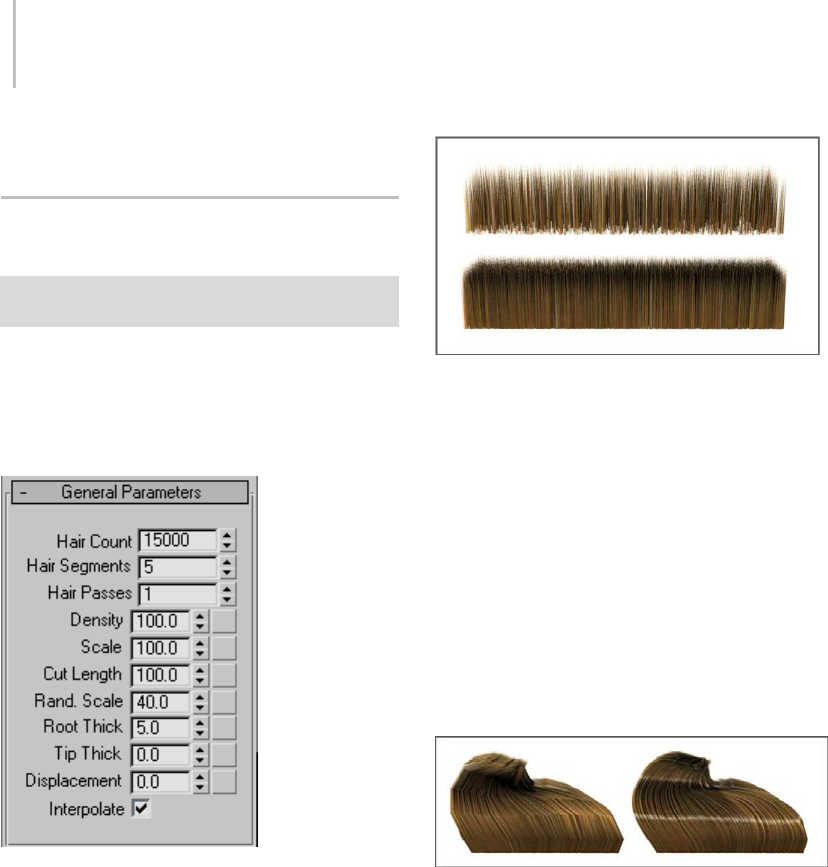
534 Chapter 8: Modifiers
•Root
GeneralParametersRollout(Hair
and Fur)
Select an object with the Hair And Fur modifier applied. >
Modify panel > General Parameters rollout
This rollout lets you set the hair count and density,
the length, thickness at the root and tip, and
various other comprehensive parameters.
Interface
Hair Count—The total number of hairs generated
by Hair. In some cases this is an approximate
count, but the actual count is usually very close to
the specified quantity. Default=15000. Range=0
to 10000000 (ten million).
Top: Hair Count=1000
Bottom: Hair Count=9000
By default, Hair normalizes density to surface area;
that is, larger polygons receive more hairs than
smaller ones. If you edit the growth object in a way
that changes the polygon-size ratios, use Reset Rest
to adjust the hair distribution automatically.
Hair Segments—The number of segments per hair.
Default=5. Range=1 to 150.
This is equivalent to spline segments; with more
segments, curly hair looks more natural, but the
generated mesh object is larger. For perfectly
straight hair, set Hair Segments to 1.
Left: Hair Segments=5
Right: Hair Segments=60
Hair Passes—Sets the number of transparency
passes. Default=1. Range=1 to 20.
Hair’s buffer render has a fairly novel way of
handling hair transparency. Instead of resolving
actual hair transparency, the hair is rendered
multiple times (as opaque hair) with different
random seeds. These buffers are then blended
together. As you increase the Hair Passes value, the
transparency (or wispiness) of the hair increases.
In addition, increasing the value increases the
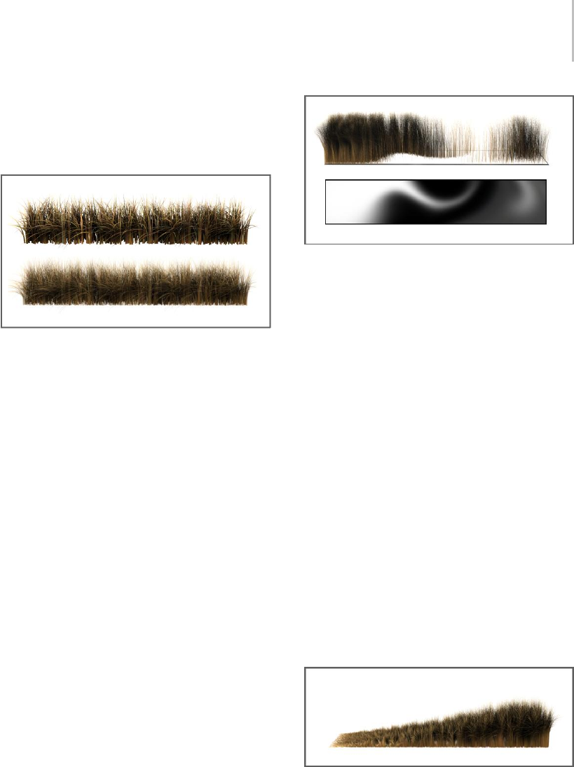
General Parameters Rollout (Hair and Fur) 535
actual number of rendered hairs as well, although
the apparent density, or fill, seems about the same
because of the additional transparency. Render
time also increases linearly.
Top: Hair Passes=1
Bottom: Hair Passes=4
Note: For best results when using the “mr prim”
hair rendering method (see Hair and Fur Render
Effect (page 3–220))withthementalrayrenderer,
be sure to set the Trace Depth > Max. Depth
value (see Rendering Algorithms Rollout (mental
ray Renderer) (page 3–116)) higher than the Hair
Passes value.
Density—Thenumericvaluesetstheoverallhair
density;thatis,itactsasapercentagemultiplierof
the Hair Count value. Default=100.0. Range=0.0
to 100.0.
Thisattributeisalsomappableviathemapbutton
to the right of the spinner. Mapping lets you add a
texture map to control the amount of hair. An area
ofthemapwhosegrayvalueis50%willreduce
the amount of hair grown in that area by 50%. To
change the overall hair count, use the Hair Count
value (see above).
Top: Density=100.0 + map
Bottom: The bitmap used to control density
Tip: Foroptimalefficiency,usetheHairCount
value to set the actual number of hairs, leave
Density at 100.0, and use mapping to create
uneven hair distribution. Simply lowering the
Density value without specifying a map causes
hairs to be created and then discarded, which
unnecessarily increases rendering time.
Scale—Sets the overall scaling for the hairs.
Default=100.0. Range=0.0 to 100.0.
At the default value of 100.0, the hairs are full size.
Reduce this value to make the hairs smaller. To
make the hairs larger, use the styling tools (page
1–526). Default=100.0. Range=0.0 to 100.0.
This attribute is also mappable via the map button
to the right of the spinner. Mapping allows you
to add a texture map to control the length of the
hair. An area of the map whose gray value is 50%
will cut the hair grown in that area to 50% of its
original length, with no shape change.
Scale value ramped from 0.0 (left) to 100.0 (right) using a linear
gradient map
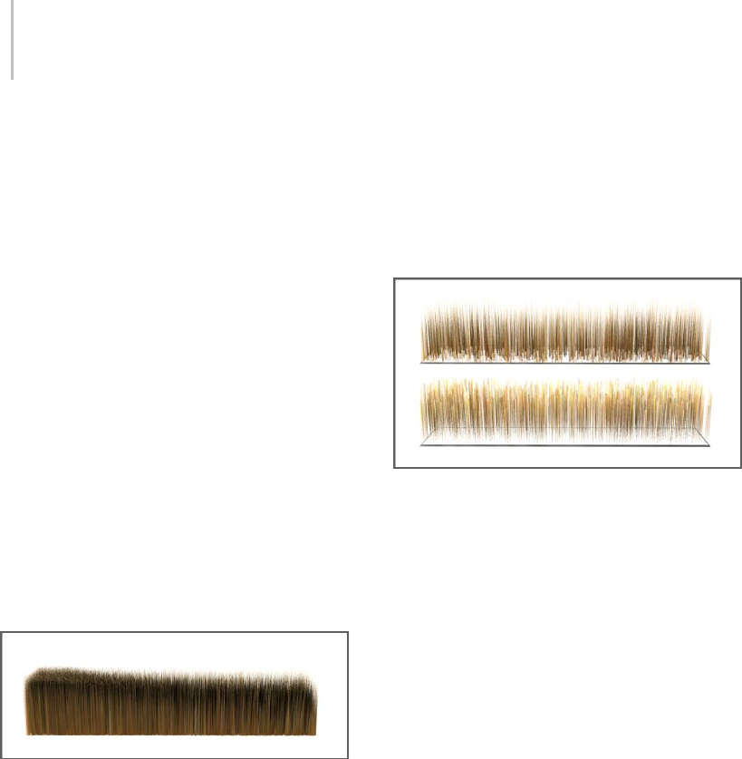
536 Chapter 8: Modifiers
Note: Thedefaultsizeofthehairsdependsonthe
sizeoftheobjecttowhichthemodifierisapplied.
Thelargertheobject,thegreatertheinitialsize.
Cut Length—The numeric value sets the overall
hair length as a percentage multiplier of the Scale
value. Default=100.0. Range=0.0 to 100.0.
Thisattributeisalsomappableviathemapbutton
totherightofthespinner. Mappingallowsyou
to add a texture map to control the length of the
hair. An area of the map whose gray value is 50%
will cut the hair grown in that area to 50% of its
original length, with no shape change.
This parameter is more computationally
expensive than a density map, since each curve
is re-parameterized on the fly, and should not
be confused with a density map. It’s really more
useful as an animated effect for growing hair (for
example, creating a wolfman character).
Rand. Scale—Introduces random scaling into the
rendered hairs. Default=40.0. Range=0.0 to 100.0.
Random Scale value ramped from 0.0 (left) to 100.0 (right)
using a linear gradient map
At the default value of 40.0, 40 percent of the hairs
are scaled down randomly by varying amounts. At
0.0, no random scaling is introduced.
Root Thick—Controls the thickness of the hair at its
root. With instanced hair, this controls the overall
thickness as a multiplier of the original object’s
dimensions on the X and Y axes in object space.
This setting affects both native hair and instanced
hair. With instanced hair, Root thick controls the
overall thickness of the hair, not just at the root.
Tip Thick—Controls the thickness of the hair at its
tip.
This setting affects native hair only, not instanced
hair. To create tapering in instanced hair, apply the
tapering when modeling the object to be instanced
within Hair.
Top: Root Thick=10.0, Tip Thick=0.0
Bottom: Tip Thick=10.0, Root Thick=0.0
Hair is translucent if its width is less than one pixel.
Thin hair that rendered as opaque in previous
versions of the software might give unexpected
results when rendered in this version. On the other
hand, setting Root Thick and Tip Thick to small
values (close to or less than 1.0) can be a good way
to obtain translucent hair.
Displacement—Displacesthehairrootsfrom
the surface of the growth object. Default=0.0.
Range=–999999.0 to 999999.0.
When you render an object with a high polygon
count, but use a low-polygon proxy object to grow
the hair, adjusting Displacement can help make the
hair seem to grow from the high-polygon object,
rather than floating above it.
Anotheruseforthissettingcanbeanimatingthe
hair falling onto or moving away from the growth
object.
Interpolate—When on, hair growth is interpolated
among the guide hairs, and the surface is fully
populated with hair according to the General
Parameters settings. When off, Hair generates
only one hair per triangular face on the growth
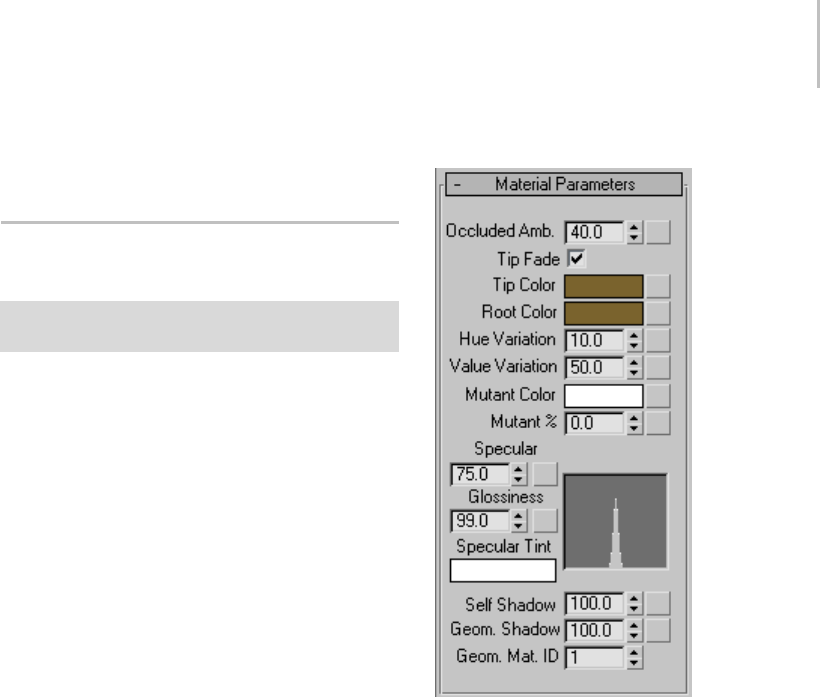
Material Parameters Rollout (Hair and Fur) 537
object, up to the limit imposed by the Hair Count
setting. Default=on.
Material Parameters Rollout (Hair
and Fur)
Select an object with the Hair And Fur modifier applied. >
Modify panel > Material Parameters rollout
The parameters on this rollout apply to
buffer-rendered hair generated by Hair. In the
case of geometry-rendered hair, the hair coloring
is derived from the growth object. In the case of
hair rendered by “mr prim”, all parameters apply
except Self Shadow and Geom. Shadow. With
instanced hair, Hair uses the material from the
instanced object.
Youcanapplyamaptoanyvaluebyclickingthe
blank button to the right of the parameter. Values
in the map act as multipliers to the base value.
Tip: If you apply a colored texture map to a color
attribute such as Tip Color, start by setting the
base color to white. Because the map acts as a
multiplier, not doing so can lead to unexpected
results. For example, if Tip Color is set to yellow
and you apply a blue texture map, the hair will be
black: this is because if you multiply those RGB
values, they zero each other out.
Interface
Occluded Amb.—Controls the bias of the
ambient/diffuse contributions of the illumination
model. A setting of 100.0 renders the hair with flat
lighting. A value of 0.0 is lit only by scene light
sources, typically resulting in a higher-contrast
solution. Default=40.0. Range=0.0 to 100.0.
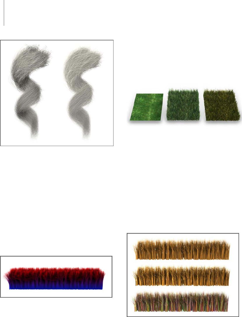
538 Chapter 8: Modifiers
Left: Occluded Amb=0.0
Right: Occluded Amb=100.0
Both: Color=white, Self Shadow=50.0
Tip Fade—Applies only to mr prim rendering (with
the mental ray renderer). When on, the hair fades
to transparent toward its tip. When off, the hair is
equallyopaqueforitsentirelength.
Tip Color—Haircoloratthetips,farthestfromthe
growth object surface. To change the color, click
the color swatch and use the Color Selector.
Root Color—Hair color at the roots, closest to the
growth object surface. To change the color, click
the color swatch and use the Color Selector.
Tip Color=red
Root Color=blue
Hue Variation=0.0
The Tip Color and Root Color attributes are also
mappable via the map buttons to the right of
the spinners. These let you add texture maps to
control the hair coloring, separately at the tip and
base. The UVW mapping used for the texture is
thesameasthatofthegrowthobject.
For results closest to the map colors, set Tip Color
and Root Color to white. Alternatively, set a
different color to tint the map coloring.
Left: The texture map used for the hair (center and right)
Center: The map applied to Tip Color and Root Color causes the
hair to use the same coloring.
Right: Setting Tip Color and Root Color to orange adds an
orange tint to the hair.
Hue Variation—The amount by which Hair varies
the color of the hairs. The default value results in
natural-looking hair. Default=10.0. Range=0.0
to 100.0.
Value Variation—The amount by which Hair varies
the brightness of the hairs. The default value
results in natural-looking hair. Default=50.0.
Range=0.0 to 100.0.
Top: Hue/Value Variation=0.0
Middle: Value Variation=100.0
Bottom: Hue Variation=100.0
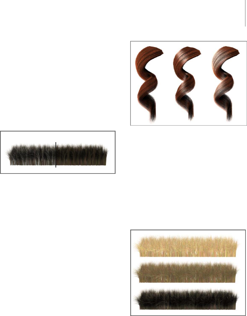
Material Parameters Rollout (Hair and Fur) 539
Mutant Color—The color for mutant hairs. Mutant
hairs are randomly selected, based on the Mutant
% value (see following), and receive this color.
One example of mutant hairs are the gray hairs
that appear as we age.
Mutant %—The percentage of hairs that receive the
mutant color (see above).
You can animate the Mutant % value to
produce, for example, a rapidly aging character.
Default=0.0. Range=0.0 to 100.0.
Left: Mutant %=30.0
Right: Mutant %=0.0
Both: Color=brown, Mutant Color=white
Specular—The brightness of highlights on the
hairs.
Glossiness—Therelativesizeofhighlightsonthe
hairs. Smaller highlights result in glossier-looking
hair.
The combined results of the Specular and
Glossiness settings appear in a graph to the right
of the two parameters.
Left: Specular=0.0, Glossiness=0.0
Center: Specular=100.0, Glossiness=75.0
Right: Specular=100.0, Glossiness=0.1
Specular Tint—This color tints specular highlights.
Click the color swatch to use the Color Selector.
Default=white.
Self Shadow—Controls the amount of
self-shadowing; that is, hairs casting shadows on
other hairs within the same Hair And Fur modifier.
A value of 0.0 disables self shadowing, while a
value of 100.0 results in maximum self-shadowing.
Default=100.0. Range=0.0 to 100.0.
Top: Self Shadow=0.0
Center: Self Shadow=50.0
Bottom: Self Shadow=100.0
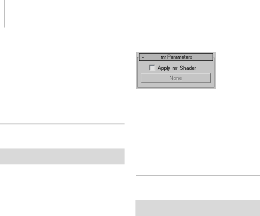
540 Chapter 8: Modifiers
Note: You can adjust the shadow characteristics by
changing the Hair Light Attr rollout (page 2–1351)
settings for lights that illuminate the hair.
Geom. Shadow—The amount of shadow
contribution hair receives from geometry in the
scene. Default=100.0. Range=0.0 to 100.0.
Geom.Mat.ID—The material ID assigned to
geometry-rendered hair.Default=1.
mr Parameters Rollout (Hair and
Fur)
Select an object with the Hair And Fur modifier applied. >
Modify panel > mr Parameters rollout
Lets you assign a mental ray shader (page 2–1710)
to generate hair. 3ds Max passes the object’s UV
coordinate data, including map channels, to the
mental ray shader; strictly speaking, the shader
generateshairfromthisUVandmappingdata,
not from the object geometry itself. (Multiple map
channels are supported.)
When you use a mental ray shader for hair, you
must render your scene using the mental ray
renderer (page 3–78) and set the Hair And Fur
render effect (page 3–220) method to “mr prim”.
Important: When you assign a mental ray shader, only
the shader’s own controls apply to the generated hair.
All other Hair And Fur settings are disregarded.
Aside from the “mr prim” option that you can
choose as a render effect (see Hair and Fur Render
Effect (page 3–220)), no mental ray hair shaders
are provided with 3ds Max. This feature is meant
to support third-party hair shader products or
custom-coded hair shaders.
Interface
Apply mr Shader—When on, lets you apply a
mental ray shader to generate hair.
[shader button]—Enabledonlywhen“Applymr
Shader” is on. Click to display a Material/Map
Browser (page 2–1412) and assign the shader.
When no shader is assigned, this button is labeled
“None”. When a shader is assigned, the button’s
label shows the shader’s name.
Frizz Parameters Rollout (Hair and
Fur)
Select an object with the Hair And Fur modifier applied. >
Modify panel > Frizz Parameters rollout
Frizz displacement is accomplished by doing a
Perlin noise lookup at the hair’s rest position
root, and then displacing the hair much the way
bump mapping displaces a surface normal. The
frequency of the noise function is set by the Frizz
X/Y/Z Frequency parameters. The magnitude of
the displacement is controlled with Frizz Root and
Frizz Tip. If you set dynamics mode (page 1–547)
to Live, the viewports show the effects of changing
these settings in real time.
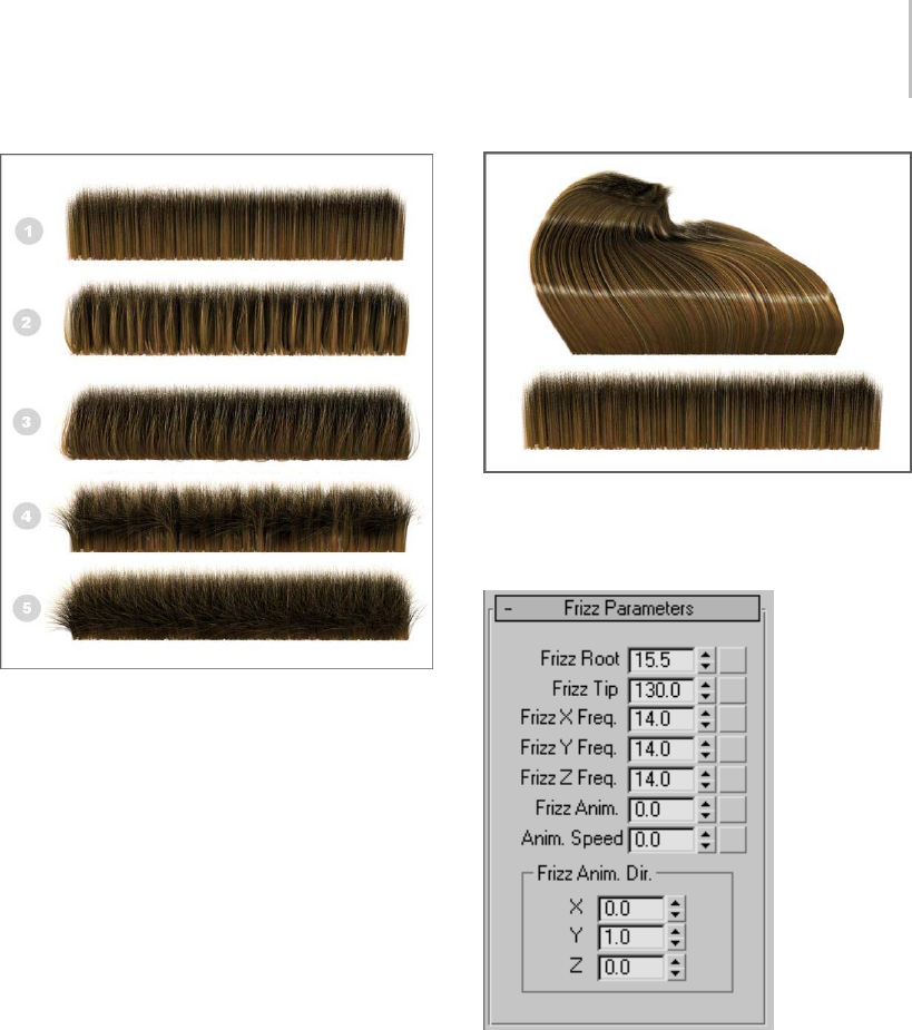
Frizz Parameters Rollout (Hair and Fur) 541
1. Frizz Root/Tip=0.0
2. Frizz Root=50.0, Frizz X/Y/Z Freq=14.0
3. Frizz Root=150.0, Frizz X/Y/Z Freq=60.0
4. Frizz Tip=30.0, Frizz X/Y/Z Freq=14.0
5. Frizz Root=50.0, Frizz Root=100.0, Frizz X/Y/Z Freq=60.0
Frizz actually calculates two noise fields, both of
which use the same frequency settings and tip/root
amplitudes. One of the noise fields is static relative
to the hair. The Anim parameters let you animate
the second noise field through the hair over time.
This is useful for things like grassy fields, where
it would be overkill to compute real dynamics.
These parameters give you a similar result, at a
small fraction of the computational overhead.
All Frizz/Kink settings=0.0; this reference image provided for
comparison with the Frizz and Kink illustrations (below).
Interface
Frizz Root—Controls the displacement of the hair
at its root. Default=15.5. Range=0.0 to 360.0.
Frizz Tip—Controls the displacement of the hair at
its tip. Default=130.0. Range=0.0 to 360.0.
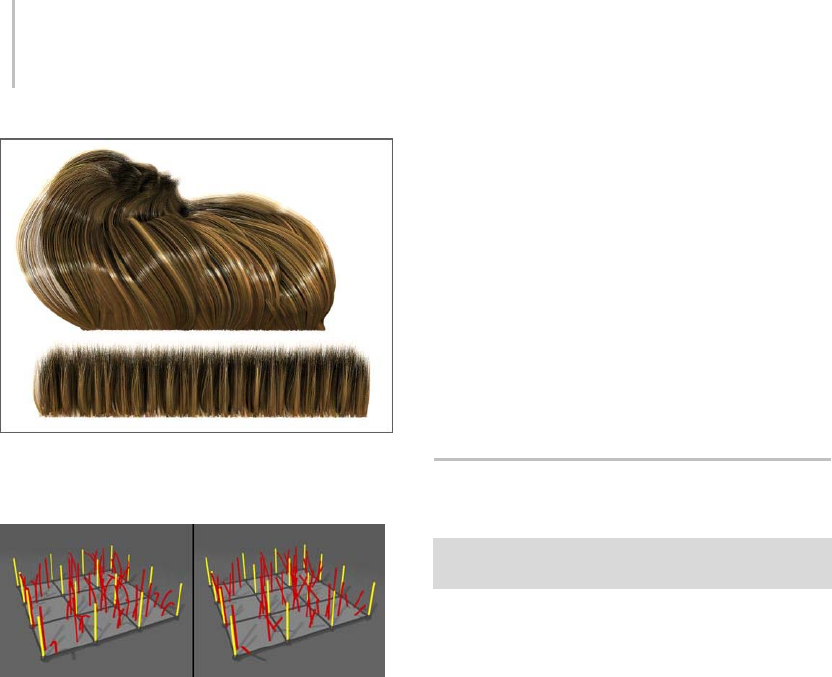
542 Chapter 8: Modifiers
Frizz Root=30.0, Frizz Tip=100.0, Frizz X/Y/Z Freq=14.0
Top: Styled
Bottom: Unstyled
Left: Differing values for Frizz Root and Frizz Tip result in curved
hairs.
Right: When Frizz Root=Frizz Tip, the hairs are straight.
Frizz X/Y/Z Freq(uency)—Controls the frequency
of the frizz effect on each of the three axes.
Default=14.0. Range=0.0 to 100.0.
Like frizz, Frizz Anim displaces the hair with a
noise field. The difference is that you can move
the noise field to create animated displacement,
resulting in wavy movement without having to
resort to dynamics.
Frizz Anim.—Sets the amplitude of the wavy
motion. Default=0.0. Range=–9999.0 to 9999.0.
Anim. Speed—This multiplier controls the speed
at which the animating noise field moves through
space. This value is multiplied by the X, Y, and
Z components of the Frizz Anim Dir attribute to
determinetheper-frameoffsetoftheanimating
noise field. Default=0.0. Range=-9999.0 to 9999.0.
Frizz X/Y/Z Anim. Dir(ection)—Sets the direction
vector of the frizz animation. Default=0.0.
Range=–1.0 to 1.0.
This vector is not normalized before use. This
means that you can apply small tweaks to the
values to achieve fine control over the speed of the
animationonagivenaxis.Toreduceconfusionit’s
a good idea to keep these directions either –1, 0,
or 1. Once you’ve got the animation close to what
you want, you can diverge from these and adjust
the values to achieve the exact result you need.
Kink Parameters Rollout (Hair and
Fur)
Select an object with the Hair And Fur modifier applied. >
Modify panel > Kink Parameters rollout
Kink displacement works similarly to Frizz, but
evaluates noise lookups along the whole length of
the guide. The result is a noise pattern that works
on a larger scale than the Frizz noise. The effect is
similar to crimped hair.
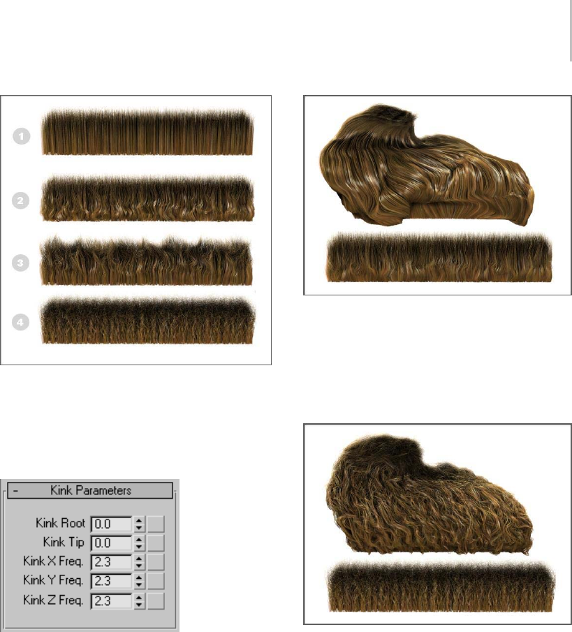
Kink Parameters Rollout (Hair and Fur) 543
1. All settings=0.0 (no kink)
2. Kink Root=0.5 (rest=0.0)
3. Kink Tip=10.0, Kink Root=0.0, Kink X/Y/Z Freq=4.0,
4. Kink Tip=10.0, Kink Root=0.0, Kink X/Y/Z Freq=50.0,
Interface
Kink Root—Controls the amount of kink
displacement of the hair at its root. Default=0.0.
Range=0.0 to 100.0
KinkRoot=0.5,KinkTip=0.0,KinkX/Y/ZFreq=4.0
Top: Styled
Bottom: Unstyled
Kink Tip—Controls the amount of kink
displacement of the hair at its tip. Default=0.0.
Range=0.0 to 100.0
Top: Styled, Kink Tip=10.0, Kink Root=0.5, Kink X/Y/Z Freq=50.0
Bottom: Unstyled, Kink Tip=10.0, Kink Root=0.0, Kink X/Y/Z
Freq=50.0
Kink X/Y/Z Freq(uency)—Controls the frequency
ofthekinkeffectoneachofthethreeaxes.
Default=0.0. Range=0.0 to 100.0.
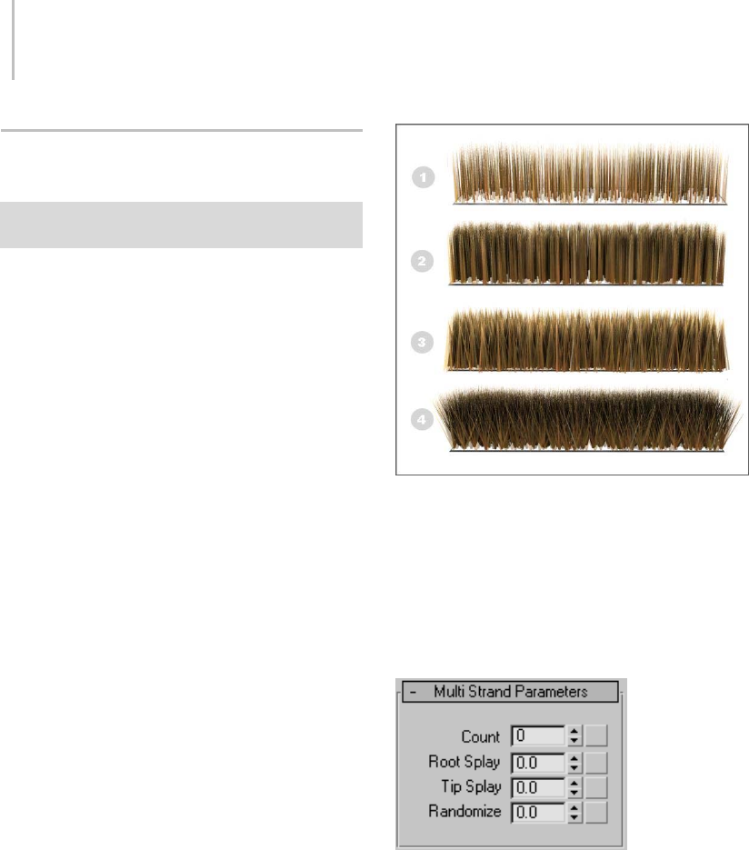
544 Chapter 8: Modifiers
Multi Strand Parameters Rollout
(Hair and Fur)
Select an object with the Hair And Fur modifier applied. >
Modify panel > Multi Strand Parameters rollout
Some degree of clumping gets naturally created
when you use Frizz at low frequencies, but you
can go a bit further here with the Multi Strand
parameters. For each hair that is normally
rendered, Multi Strand renders a clump of
additional hairs scattered around the original hair.
The Splay settings control the degree of scattering
at the roots and tips, and Multi Strand Count
controls the number of hairs to create for the
clump. You can use Splay to shape the clump by
spreading or compressing the roots and tips.
Tip: For each original hair, Multi Strand creates
a cluster of hairs around that hair, offset at the
bottom by the Root Splay factor. The hair is offset
in the plane tangent to the root of the hair, which is
not necessarily the surface of the object. To make
sure Multi Strand hairs actually make contact with
thesurface,makethegrowthsurfaceabitsmaller
than the rendered surface.
1. Multi Strand Count=0, Hair Count=500
2. Multi Strand Count=10, Root Splay=0.1, Tip Splay=0.1, Hair
Count=500
3. Multi Strand Count=10, Root Splay=0.4, Tip Splay=0.1, Hair
Count=500
4. Multi Strand Count=10, Root Splay=0.0, Tip Splay=1.0, Hair
Count=500
Interface
Count—The number of hairs per clump.
Root Splay—Provides a random offset for each hair
in a clump, at the root.
Tip Splay—Provides a random offset for each hair
in a clump, at the tip.
Randomize—Randomizesthesizeofeachhairin
aclump.

Dynamics Rollout (Hair and Fur) 545
Dynamics Rollout (Hair and Fur)
Select an object with the Hair And Fur modifier applied. >
Modify panel > Dynamics rollout
For hair to seem natural in an animation, it must
respond to the motion of the body it’s attached
toandtoexternalinfluencessuchaswindand
gravity. Hair’s Dynamics functions let the hair
behave like real-world hair, in interactive (Live)
or Precomputed mode.
Designating Collision Surfaces
Hair dynamics uses guide hairs to calculate
collision. To reduce computation, you have to
explicitly designate the objects with which hair will
collide. The object from which the hair grows is a
special case: to have hair collide with this object
(for example, a human head), simply turn on Use
Growth Object.
If there is a collision object that you want more
than one Hair modifier to interact with, you have
toaddthatobjectasacollisionobjectforeach
different Hair And Fur modifier.
There are two different methods for calculating
collision: Sphere and Polygon. Spherical collision
uses a bounding sphere for collision objects;
polygonal collision uses the collision object’s
actual geometry. The Polygon option is more
accurate, but the Sphere option is quicker to
calculate.
Procedures
Example: To view hair dynamics in real time:
1. Apply the Hair And Fur modifier to an object.
2. OntheDynamicsrollout(scrollthecommand
panel down to view it), set Mode to Live.
3. Move the object around.
The hair moves realistically.
4. On the Tools rollout, click Regrow Hair.
The hair resumes its default position, growing
straight out of the object.
5. Click the Play Animation button.
6. The hair settles and droops, as if affected by
gravity. Note that, as the animation repeats,
the effects of gravity are cumulative; the hair
animation doesn’t restart at the first frame.
7. On the Tools rollout, click Regrow Hair again.
8. Add a Wind space warp to the scene.
9. On the Dynamics rollout, set Dynamics Params
>Gravityto0.0.
10.In the External Forces group (at the bottom
of the Dynamics rollout), click Add and then
select the Wind space warp.
11.Play the animation again.
This time, the hair isn’t affected by gravity, but
simply blown by the wind. Again, the effect is
cumulative and the animation doesn’t repeat.
All of this animation takes place only in real
time; no keyframes are set, so it can’t be
rendered. To learn how to set up a renderable
dynamics simulation with Hair, see the
following procedure.
To generate a precomputed dynamics simulation
with Hair:
1. Apply the Hair And Fur modifier to an object.
2. Set up the animation. It could simply be motion
of the growth object, or you could use the
Dynamics rollout > External Forces group to
add space warps, such as Wind, that should
affect the hair. Actually, because the hair is
affected by its own gravity by default, you don’t
need to set up any explicit animation at all to
see hair dynamics.
3. On the Modify panel > Dynamics rollout, use
the Collisions group to set objects the hair
should collide with. Also set other simulation
parameters in the Dynamics Params group.

546 Chapter 8: Modifiers
4. In the Stat Files group, click the ellipsis (...)
button. UsetheSaveAsdialogtospecify
the location and name of the stat files to be
generated.
Note: When you run the simulation, Hair will
generate a separate stat file for each animation
frame.
Important: If you plan to render the animation with
a networked render farm, make sure the path you
specify can be seen in exactly the same way from
each node on the render farm. If stat files aren’t
found, hair will be stiff and just oriented to the skin
as it moves. If the wrong stat files are found, hair can
float right off an object.
Tip: If using Windows XP, click the My Network
Places button to set a path using the Universal
Naming Convention (UNC), even if it’s on a
local drive. Such a path can be accessed readily
by other computers on the network.
The path and stat file name appear in the text
field next to the ellipsis button.
5. IntheSimulationgroup,settheframerangefor
the simulation and then click Run.
Hair runs the dynamics simulation and
generates a stat file for each frame in the
animation. It also automatically sets the mode
to Precomputed, so when you play or render
the animation, it reads the stat files and uses
the information for the hair positioning in each
frame.
6. Play the animation.
The dynamics simulation stored in the stat files
appears in the viewports.
7. IntheModegroup,chooseNone,andthenplay
the animation again.
The dynamics animation no longer appears.
However, it’s still stored in the stat files, and will
reappear if you choose Precomputed.
8. MakesurePrecomputedison,andthenrender
the animation.
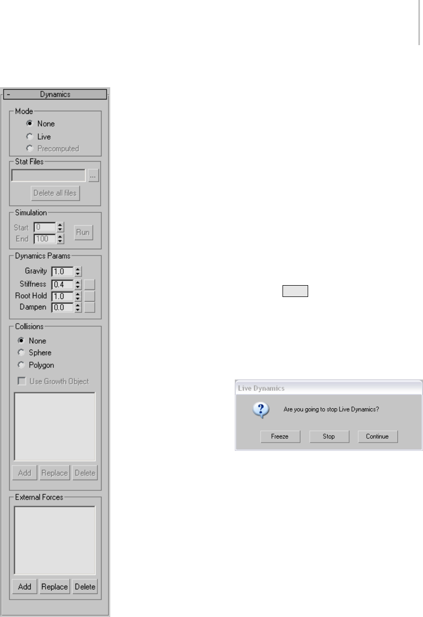
Dynamics Rollout (Hair and Fur) 547
Interface Mode group
Chooses the method Hair uses to generate
dynamics. Livemodeissuitablefor
experimentation, but for best results when
rendering animation with Hair, use Precomputed
mode.
•None—Hair doesn’t simulate dynamics.
•Live—Hair simulates dynamics interactively in
the viewports, but doesn’t generate animation
keyframesorstatfilesforthedynamics. For
best results with Live mode, turn off Display
rollout > Display Hairs group > As Geometry.
Forsomemethodsofusinglivedynamics,see
this procedure: Example: To view hair dynamics
in real time: (page 1–545).
If you press ESC while using live dynamics,
3dsMaxdisplaysadialogthataskswhetheryou
want to stop live dynamics. Both Freeze and
Stop reset the mode to None, but Freeze freezes
the hair in its current position. You can use this
as a starting point for precomputed dynamics,
or as a point from which you style the hair.
•Precomputed—Lets you generate stat files for
rendering dynamics-animated hair. Available
only after setting a name and location for
stat files (see following and To g e n e ra t e a
precomputed dynamics simulation with Hair:
(page 1–545)).
Stat Files group
Stat files let you record and play back a
Hair-generated dynamics simulation. For a
workflow example, see this procedure: To g e n e ra te

548 Chapter 8: Modifiers
aprecomputeddynamicssimulationwithHair:
(page 1–545).
Text field—Displays the path and file name for the
stat files.
... (ellipsis) button—Click to choose a name prefix
and location for stat files using the Save As dialog.
Hair adds a four-digit frame number (with
leading zeroes) and the file name extension
“.stat” tothenameyouprovide(forexample,
hair_test0001.stat).
Delete all files—Deletes stat files from the target
directory.Thefilesmusthavethenameprefixyou
assigned using the ... button.
Tip: You can still use stat files even if you move
them to another location. Follow this procedure:
1. Open the MAX file used to generate the stat
files.
2. On the Modify panel > Dynamics rollout, click
the ... [ellipsis] button.
3. Use the Save As dialog to navigate to the
directory with the stat files, and then click any
stat file. Its name appears in the File Name field.
4. EdittheFileNamefieldtodeletethefour-digit
extension after the stat file name. For example,
ifthestatfilenameistest0033.stat,deletethe
“0033” so that it reads test.stat.
5. Click the Save button. The new stat file path
appearsintheStatFilesfield.
Now,whenyouplayorrendertheanimation,Hair
uses the stat files as originally generated.
Simulation group
Determines the extent of the simulation, and lets
you run it. These controls become available only
after you choose Precomputed mode and specify
stat files in the Stat Files group. Set Start and
Endtotheframesatwhichtobeginandendthe
simulation, and then click the Run button. The
software then computes the dynamics and saves
the stat files.
Start—The first frame to consider in calculating
the simulation.
End—The final frame to consider in calculating
the simulation.
Run—Click to run the simulation and generate the
stat files within the frame range indicated by Start
and End.
To abort a simulation while it’s running, click
Cancel on the status bar.
Dynamics Params group
Thesecontrolsspecifythebasicparametersforthe
dynamics simulation. The Stiffness, Root Hold,
and Dampen values can be mapped: click the
mapbuttontotherightofthespinnertoassign
a map. Grayscale values in the map multiply the
parameter’s value at that hair location.
Gravity—Lets you specify a force that moves hair
vertically in world space. Negative values pull hair
upwhilepositivevaluespullitdown.Tocausehair
not to be affected by gravity, set the value to 0.0.
Default=1.0. Range=–999.0 to 999.0.
Stiffness—Controls the magnitude of the effect of
dynamics. If you set Stiffness to 1.0, the dynamics
will have no effect. Default=0.4. Range=0.0 to 1.0.
Root Hold—Comparable to stiffness, but affects the
hair only at the roots. Default=1.0. Range=0.0 to
1.0.
Dampen—Dynamic hair carries velocity forward
to the next frame. Increasing dampening
increases the amount by which these velocities are
diminished. Thus, a higher Dampen value means
that hair dynamics will be less active (the hair can
also start to get “floaty”). Default=0.0. Range=0.0
to 1.0.
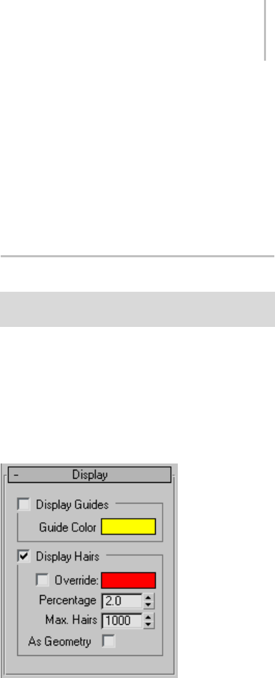
Display Rollout (Hair and Fur) 549
Collisions group
Use these settings to determine which objects hair
collides with during a dynamic simulation and the
method by which collision is calculated.
•None—Collisions are not considered during the
dynamic simulation. This can cause the hair
to penetrate its growth object as well as other
objects it comes into contact with.
•Sphere—Hair uses a spherical bounding box
to calculate collisions. This method is faster
because it requires less computation, but can
cause inaccurate results. It’s most effective
when the hair is seen from a distance.
•Polygon—Hair considers each polygon in the
collision objects. This is the slowest method,
but the most accurate.
Use Growth Object—When on, hair collides with
the growth (mesh) object.
Objects list—Liststhenamesofsceneobjectswith
which hair should collide.
Add—To add an object to the list, click Add and
then click the object in a viewport.
Replace—To replace an object, highlight its name
in the list, click Replace, then click a different
object in a viewport.
Delete—To remove an object, highlight its name in
the list, then click Delete.
External Forces group
This group lets you specify space warps (page
2–55) that will affect the hair during the dynamics
simulation. For example, you can add a Wind
space warp (page 2–75) to cause the hair to be
blown by a breeze.
Note: Hair dynamics already has a built-in gravity
force, so it’s not necessary to add one.
Objects list—Liststhenamesofforcesthat
dynamically affect the hair.
Add—To add a space warp to the list, click Add and
then click the warp’s icon in a viewport.
Replace—Toreplaceaspacewarp,highlightits
name in the list, click Replace, then click a different
warp’s icon in a viewport.
Delete—To r e m ov e a s p a c e w a r p , h i g h l i g h t i t s
name in the list, then click Delete.
Display Rollout (Hair and Fur)
Select an object with the Hair And Fur modifier applied. >
Modify panel > Display rollout
These settings let you control how hairs and guides
display in the viewports. By default, Hair displays a
small percentage of the hairs as lines. Alternatively,
you can display the hairs as geometry, and you can
also choose to display the guides.
Interface
Display Guides group
Display Guides toggle—When on, Hair displays
guides in the viewports, using the color shown in
the color swatch. Default=off.
Note: At the Guides sub-object level, guides always
appear in the viewports.
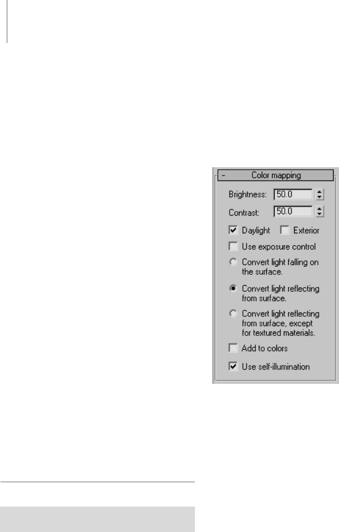
550 Chapter 8: Modifiers
Guide Color—Click to display the Color Selector
and change the color used to display guides.
Guides do not reflect some settings made to the
hair,suchasFrizz.UsetheGuidesdisplaymainly
to see where hair will appear on the growth object.
Hair places one guide at each vertex on the growth
surface.
Display Hairs group
Display Hairs toggle—When on, Hair displays hairs
in the viewports. Default=on.
Override—Whenoff,3dsMaxdisplayshairsusing
an approximation of their rendered color. When
on, displays hairs using the color shown in the
color swatch. Default=off.
Color swatch—Click to display the Color Selector
and change the color used to display hairs when
Override is on.
Note: When hair is displayed as geometry (see
below), the color setting is ignored.
Percentage—Thepercentageoftotalhairs
displayed in the viewports. Lower this value to
improve real-time performance in the viewports.
Max. Hairs—The maximum number of hairs
displayed in the viewports, regardless of the
Percentage value.
As Geometry—When on, displays the hairs in the
viewports as the actual geometry to be rendered,
rather than the default lines. Default=off.
LS Colors Modifier (World Space)
Select a Lightscape mesh object. > Modify panel >
Modifier List > World-Space Modifiers > * LS Colors
The LS Colors modifier converts Lightscape
radiosity values to 3ds Max vertex colors.
When a Lightscape model is imported into
3ds Max, the radiosity values are kept as
irradiances; that is, they describe the intensity
of light falling on a mesh in physical units. This
modifier converts the physical units to RGB colors.
In conjunction with the Lightscape mesh modifier,
this modifier can be used to produce meshes
suitable for game engines.
Interface
Brightness—Controls the brightness of the
displayed image on your monitor. The setting
of this control does not affect the actual lighting
levels in the model. Default=50.0.
Contrast box—Controls the contrast between light
and dark regions in the model. Default=50.0.
Daylight—Determines whether you want natural
daylight to be used in the calculation. Default=on.
Exterior Scene—Tur n on for exterior daylight
simulations. Default=off.
Tip: Use the logarithmic exposure control (page
3–297) to control the brightness and contrast of
the colors when you render.

MapScaler Modifier (World Space) 551
Use exposure control—When on, disregards the
settings of Brightness, Contrast, Daylight, and
Exterior, and instead uses the settings of the active
exposure control. If no exposure control is active
in the scene, this toggle is disabled. Default=off.
The three radio buttons that follow choose how to
handle irradiance values.
•Convert light falling on the surface—When
chosen, converts the irradiance values directly
to RGB values. In order to properly render the
mesh, the vertex colors need to be interpolated
andmultipliedbythecolorofthematerialon
the mesh.
•Convert light reflecting from the surface—When
chosen, takes the irradiance values and
multiplies them by the material’s ambient color,
then converts the result to RGB. To properly
render the mesh, you need to interpolate the
vertex colors over the faces. If textures are
displayed by multiplying them by the vertex
colors, they will not be correctly displayed
unless the material color is white.
By default, this is the active option.
•Convert light reflecting from the surface, except
for textured materials—When chosen, takes the
irradiance values and multiplies them by the
material’s ambient color, and then converts
the result to RGB, unless a texture is applied
to the material’s ambient component. If the
ambient component has a map, this method
converts the irradiance value directly to the
vertex color. To properly render the mesh, you
need to interpolate the vertex colors over the
faces, unless the material is textured. If textures
are displayed by multiplying them by the vertex
colors, they will be correctly displayed.
Add to colors—When on, the result of the color
conversion is added to existing vertex color values,
if there are any. Default=off.
Use self-illumination—When on, the material’s self
illumination is included in the final vertex colors.
Default=on.
MapScaler Modifier (World Space)
Select an object. > Modify panel > Modifier List >
World-Space Modifiers > MapScaler (WSM)
Select an object. > Modifiers menu > UV Coordinates >
Map Scaler (WSM)
MapScaler maintains the scale of a map applied to
an object. This lets you resize the object without
alteringthescaleofthemap.Typically,youmight
use this to maintain the size of a map regardless of
how the geometry is scaled.
MapScaler sets the scale of a map on an object.
This differs from the MapScaler (OSM) modifier
(page 1–713), which maintains the scale of the map
with respect to the object size when scaled with a
Select And Scale tool. See the latter’s definition for
other differences between the two versions.
Note: This world-space modifier is for use
primarily with vertically oriented objects, such
as walls in an architectural model, or objects
with large, flat surfaces. While you can apply the
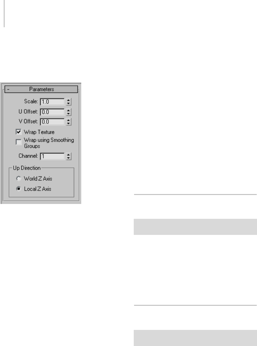
552 Chapter 8: Modifiers
MapScaler to any object, the results are less realistic
on curved surfaces, especially complex ones,
which can show cracks in the finished texture.
Interface
Scale—Represents the size of one repetition of the
texture pattern. Size is measured in current system
units. Repetitions occur across the object in the U
and V directions. Default=1.0.
Note: When the Use Real-World Texture
Coordinates switch is active in the General
Preferences dialog (page 3–815),thescalesetting
defaults to 1.0. If Use Real-World Texture
Coordinates is turned off, scale defaults to 100.0.
U/V Offset—Specify horizontal and vertical offsets
respectively. Available only when Wrap Texture
is off.
Wrap Texture—When on, Map Scaler attempts
to wrap the texture evenly around the object.
This option requires more computing, but
usually produces the most satisfactory results.
Default=on.
Wrap Using Smoothing Groups—When turned
on, textures are wrapped around corners when
they share the same smoothing groups. Curved
wallswillmapsmoothlywhilesharpcornersgeta
newtextureorigin. Thisswitchisonlyavailable
when the Wrap Textures switch is turned on.
Default=off.
Channel—Specifies the map channel (page 3–966).
Default=1.
Up Direction group
World Z Axis—Aligns the map with the Z axis of
the world.
If you choose this option and then rotate the
object, the mapping is not fixed to the object.
Local Z Axis—Aligns the map with the local Z axis
of the object.
With this option, the mapping remains fixed to
the object.
PatchDeform Modifier (World
Space)
Select an object. > Modify panel > Modifier List >
World-Space Modifiers > * PatchDeform
The PatchDeform world-space modifier lets you
deform an object based on the contours of a patch
object.ItworksthesameasthePathDeform (World
Space) (page 1–552), but uses a patch instead of a
curve. With the exception of the Move to Patch
button, its parameters are the same as those in the
object-space PatchDeform modifier (page 1–754).
PathDeform Modifier (World
Space)
Select an object. > Modify panel > Modifier List >
Animation Modifiers > * PathDeform
The PathDeform world-space modifier deforms an
object based on a shape, spline or NURBS curve
path. With the exceptions noted in the Interface
PathDeform Modifier (World Space) 553
section, this world-space modifier works the same
as the object-space PathDeform modifier (page
1–755).
Procedures
The first two examples, below, demonstrate
the basic differences in orientation and the
relationship between the object and its path
when using the PathDeform modifier and the
PathDeform (WSM) modifier.
Example: To use the PathDeform modifier to curve
text:
1. IntheTopviewport,createacirclethat’s100
units in radius.
2. In the Front viewport, create a text shape with
six or seven letters, and a size of 25.
3. Apply an Extrude modifier to the text shape,
and set the Amount to -5.0.
4. On the Main toolbar, set the Reference
Coordinate System to Local.
Looking at the axis tripod for the extruded text
object, you can see that its Z axis runs from
back to front relative to world space.
5. Apply a PathDeform (page 1–755) object-space
modifier to the text object. Click the Pick Path
button, and then select the circle.
A circular gizmo appears. The circle runs
through the local Z axis of the text object.
Because of its orientation, its effect is minimal,
but you can see a slight wedge-shaped
deformation from the top view.
6. InthePathDeformAxisgroup,choosetheY
option, and then the X option.
Thecirclegizmorotatestorunthroughthe
specified axes, deforming the text object
differentlywitheachchange.
7. Adjust the Percent spinner to view its effect, and
then set it to zero. Try the same with Stretch,
Rotation, and Twist, and then restore them to
their original values.
Tip: Use the Ctrl key with Twist to amplify
the effect.
8. Turn on Flip to switch the direction of the path,
andthenturnitoff.
9. Go to the Gizmo sub-object level, and move
the gizmo path around.
The text object is further deformed by its
relative position to the gizmo.
10.Selecttheoriginalcircleshape,andchangeits
radius.
The deformation of the text object alters
becauseitsgizmoisaninstanceoftheshape
object.
Example: To use the PathDeform world space
modifier:
This procedure continues from the previous one.
1. Select the text object, and then remove the Path
Deform modifier from the stack.
2. Apply a Path Deform (WSM) modifier.
3. Click Pick Path, and select the circle.
Thetextobjectflipsaroundandmovesin
world space. Note that its orientation and
deformation are difficult to analyze because
there’s an offset distance between the path and
the object.
4. Click Move to Path.
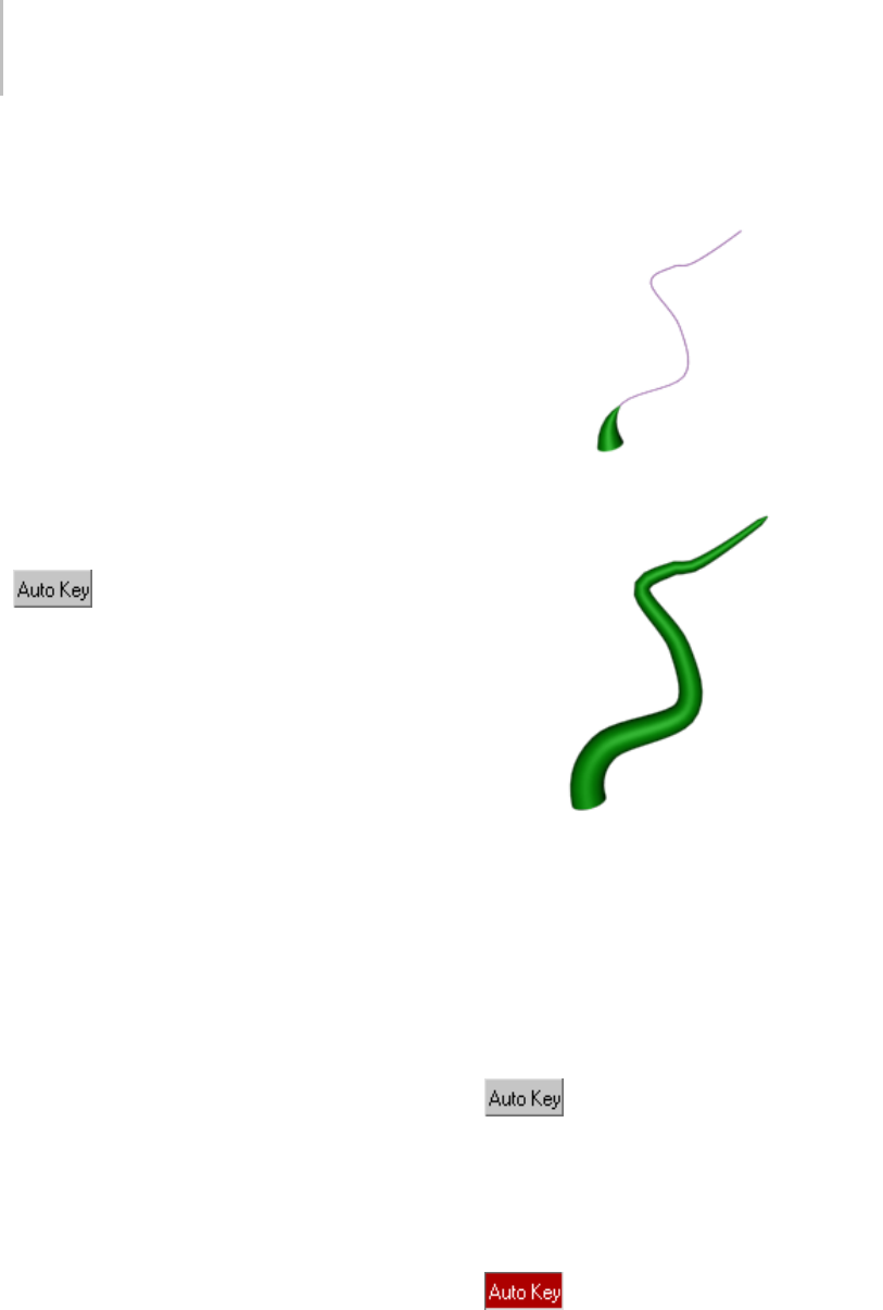
554 Chapter 8: Modifiers
Thetextobjectistransformedsothatitslocal
Zaxisisalignedwiththepathanditsposition
is at the first vertex of the path.
In the following steps, you’ll use various
controls to re-orient the text object so that it’s
at the front of the circle and readable from the
Front viewport.
5. Choose the X option in the Path Deform Axis
group to place the length of the text object
along the path.
6. Adjust the Percent spinner to -25 to move the
text to the front of the circle.
7. Adjust the Rotation spinner to -90 to rotate the
text so it faces the Front viewport.
8. Turn on Auto Key, go to frame 100,
and set Percent to -125.
9. Play the animation to watch the text run around
the circle.
Example: To create a growing vine:
1. Use the Line tool and, optionally, Editable
Spline to createapathalongwhichthevinewill
grow.
2. Create a Cone, and apply the * Path Deform
modifier.
3. Pick the path, and then click Move to Path.
(The local Z axis of the cone should be along
the path.)
4. Go to frame 100, and turn on Auto
Key.
5. Increase theStretchvaluetostretchthecone
along the path until it reaches the end. There
won’tbeenoughheightsegmentsinthecone,
but you canfixthatinstep7.
6. Tur n of f Auto Key.
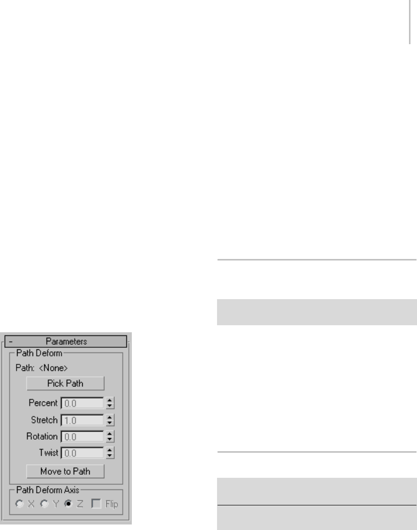
Point Cache Modifier (World Space) 555
7. In the stack, click Cone, and then in the
Parameters rollout increase the Height
Segments setting until the stretched cone is
smooth on the path.
8. Play the animation.
Theconegrowsalongthepath,likeavine.
Interface
Since this is a world-space rather than an
object-space modifier, the object is affected in
world space coordinates, and also affected by the
relative position of the path to the object. Thus, if
you transform the object relative to the path, or
vice-versa, it has an affect on the deformation.
Generally speaking, the Path Deform world-space
modifier leaves the path in place while moving
the object to the path, while the Path Deform
object-space modifier leaves the object in place
while moving the path to the object.
For all parameters except the following, refer to
the PathDeform modifier (page 1–755).
Path Deform group
Move to Path—Movestheobjectfromitsoriginal
position to the start of the path.
When you first pick a path, the object is deformed
by the path based on the offset distance between
the first vertex in the path and the object’s location.
Thus, as you adjust the Percent spinner, for
example, the result will be distorted depending on
the offset distance.
Important: Using the Move To Path button applies
a transform to the object that’s not removed if you
later remove the Path Deform binding from the object.
However, you can undo (page 1–94) the transform
immediately after it’s been performed.)
Note: If the Auto Key button is on when you
perform Move To Path, transform keys are created.
Point Cache Modifier (World
Space)
Select an object. > Modify panel > Modifiers List >
World–Space Modifiers > * Point Cache
The world-space version of the Point Cache
modifierworksexactlythesameasthePoint
Cache modifier (page 1–758),exceptthatituses
world-space coordinates instead of local-space
coordinates. Use this version when animating
with world-space modifiers such as PatchDeform
(WSM) modifier (page 1–552) or PathDeform
(WSM) modifier (page 1–552).
Subdivide Modifier (World Space)
Make a selection. > Modify panel > Modifier List >
World-Space Modifiers > Subdivide
Make a selection. > Modifiers menu > Radiosity Modifiers
>*Subdivide
The Subdivide (WSM) modifier is similar to the
object-space Subdivide modifier (page 1–839),
and has the same parameters. In the world-space
version of Subdivide, the size limit is on the
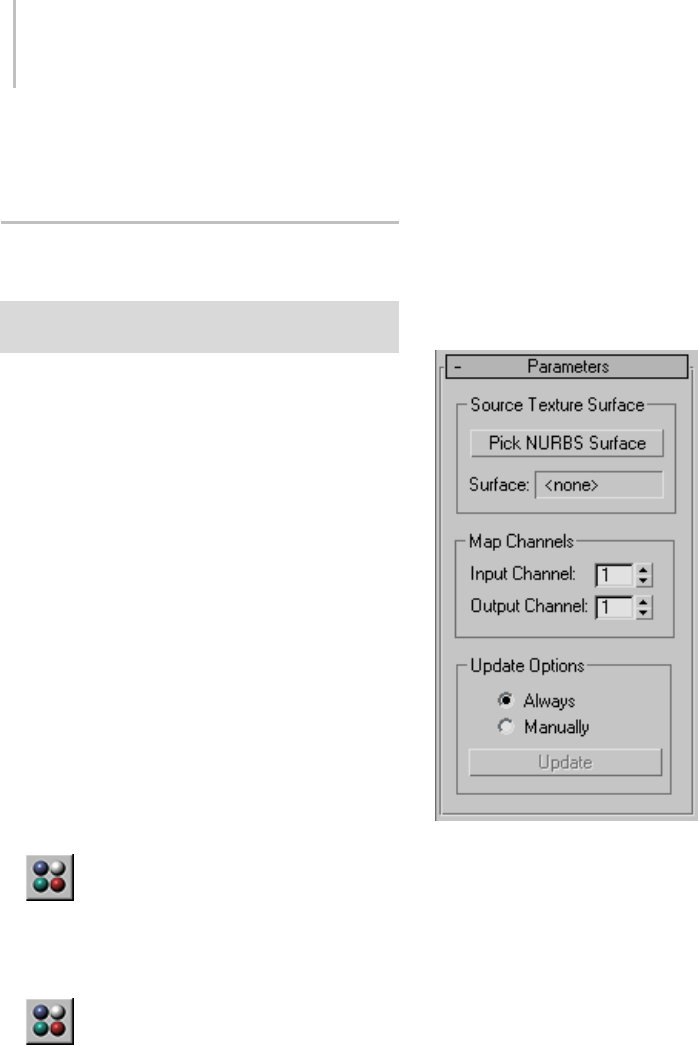
556 Chapter 8: Modifiers
mesh after it is transformed into world space
coordinates.
Surface Mapper Modifier (World
Space)
Make a selection. > Modify panel > Modifier List >
World-Space Modifiers > * Surface Mapper
The Surface Mapper (WSM) modifier takes a map
assigned to a NURBS (page 1–1078) surface and
projects it onto the modified object or objects.
Surface Mapper is especially useful for seamlessly
applyingasinglemaptoagroupofsurface
sub-objects within the same NURBS model. You
can also use it for other kinds of geometry.
The NURBS surface’s map is projected onto the
other geometry in the direction of the NURBS
surface’s normals, or opposite the normals if the
modified object is on the other side of the NURBS
surface.
Procedure
To use the surface mapper world-space modifier:
1. CreatetheNURBSsurfacetouseforprojection,
and transform it so it wraps the objects you
want to map.
2. Use the Material Editor (page 2–1409)
to assign a mapped material to the NURBS
surface.
3. Select the objects you want to map.
4. Use the Material Editor to assign the
same material to the objects you want to map.
5. Apply the Surface Mapper world-space
modifier.
6. In the Parameters rollout, turn on Pick NURBS
Surface, and then click the NURBS projection
surface in a viewport.
ThesoftwarenowusestheNURBSsurface’s
normals to project the texture onto the
modified objects.
Tip: To f i n e - t u n e t h e m a p p l a c e m e n t o n t h e
mesh, you can use the NURBS surface’s Edit
Texture Surface dialog (page 1–1230).
Interface
Source Texture Surface group
These controls let you choose the NURBS surface
to project.
Pick NURBS Surface—Picks the NURBS surface
to use for projection. Click to turn on this
button,thenclicktheNURBSsurfaceinanactive
viewport.
Surface—Shows "<none>" before you pick a
NURBSsurface;showsthenameofthesurface
after you pick one.

SurfDeform Modifier (World Space) 557
Map Channels group
These controls let you choose which map channels
(page 3–966) to use.
Input Channel—Selects the NURBS surface map
channel to use before projection.
Output Channel—Selects the modified object’s
map channel to use after projection.
Update Options group
Thesecontrolsletyouchoosehowtoupdatethe
mapping displayed in viewports. They have no
effect if Show Map In Viewport (page 2–1445) is
turned off.
Always—Updates viewports whenever the
mapping changes.
Manually—Updates viewports only when you click
Update.
Update—Updatesviewports.Thisisunavailable
unless you’ve chosen Manually.
SurfDeform Modifier (World
Space)
Select an object. > Modify panel > Modifier List >
World-Space Modifiers > * Surf Deform
Select an object. > Modifiers menu > Animation Modifiers
>*SurfDeform
The SurfDeform (WSM) modifier works the same
as the PathDeform (WSM) modifier (page 1–552),
except that it uses a NURBS Point or CV surface
instead of a curve.
Object-Space Modifiers
Object-space modifiers directly affect an object’s
geometry in local object space (page 3–982).
When you apply an object-space modifier, it
appears directly above the object with other
object-space modifiers in the modifier stack (page
3–760). The order in which the modifiers appear
in the stack can affect the resulting geometry.
For a list of object-space modifiers, see List of
Available Modifiers (page 1–497).
Affect Region Modifier
Modify panel > Make a vertex sub-object selection. >
Modifier List > Object-Space Modifiers > Affect Region
Make a vertex sub-object selection. > Modifiers menu >
Parametric Deformers > Affect Region
The Affect Region modifier is a surface modeling
tool, primarily used with vertex sub-object
selections while surface modeling. With Affect
Region, transforming a selection of vertices
can also transform vertices in the region that
surrounds the selection. This can help you form a
bubbleorindentationinthesurfaceofanobject.
The easiest way to see this modifier’s effect is with a
shallow, flat box object with plenty of subdivisions.
The Affect Region modifier has a two-part,
arrow-shaped gizmo plus numeric controls.
When you apply the Affect Region modifier, it
assigns an arrow-like gizmo consisting of two
points connected by a line. The base of the arrow
is the start point. The length and direction of the
arrow defines the amount of movement of the
vertices. Any vertices within Falloff distance of the
baseofthearrowaretranslatedinthedirectionof
the arrow.
Because no points on the mesh are directly
selected, this modifier doesn’t depend on the
topology of the input object. You can apply it to
any renderable object. However, you can limit the
effect by using a selection modifier like Mesh Select
(page 1–719) or Volume Select (page 1–952) to pass
a sub-object selection up the stack.
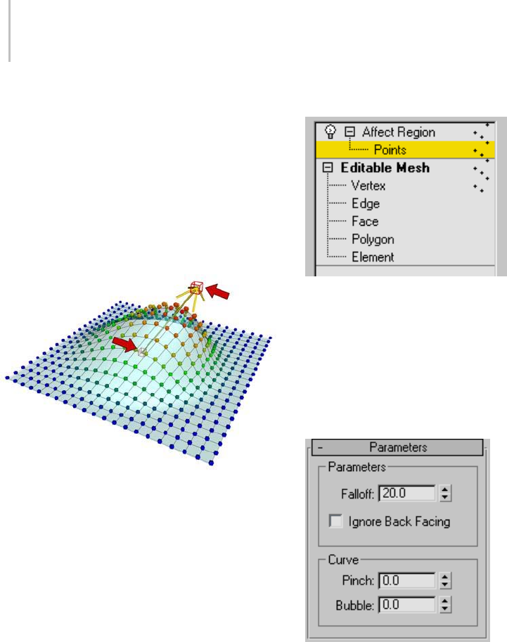
558 Chapter 8: Modifiers
Note: The Affect Region modifier is ideal for simple
animated effects, especially when you need to use
interactive parameters. However, for fine-tuned
modeling, you’ll probably prefer the expanded
capabilities of Soft Selection (page 1–963) in
Editable Mesh (page 1–996),Editable Poly (page
1–1022),Edit Mesh (page 1–634),Mesh Select (page
1–719),Volume Select (page 1–952),theHSDS
modifier (page 1–701),andNURBS (page 1–1089).
Affect Region modifier applied
Procedure
Example: To form a bubble over the surface of a
plane:
1. Create a plane with 15 width and length
segments.
2. Set the length and width of the plane to 50 units.
3. Apply the Affect Region modifier.
4. In the Parameters group, set Falloff to 50.
5. Adjust the parameters to achieve different
effects.
Interface
Note: The parameters of this modifier are similar
to those of the Soft Selection function (page 1–963)
of an Editable Mesh.
Modifier Stack
Pointsub-objectlevel—At this sub-object level, the
base and tip of the gizmo arrow are points that can
be selected. You can select, translate, and animate
these two points together or individually.
For more information on the stack display, see
Modifier Stack (page 3–760).
Parameters rollout
Parameters group
Falloff—Sets the radius of affected vertices, in
units,fromthebaseofthegizmoarrow.(Spinner
value range: float, 0.0 to 999,999.0)
Ignore Back Facing—Affects only those vertices
whosefacenormalsareinthesamegeneral
direction as the gizmo arrow. When turned off, all
vertices in the Falloff group are affected.

Attribute Holder Modifier 559
Curve group
Pinch—Affects the tangency of the curve where
it meets the arrow tip. Positive values produce
a pointed tip while negative values produce a
dimple. (Spinner value range: float, -999,999.0 to
999,999.0)
Bubble—Changes the curvature of the affected
vertices. A value of 1.0 produces a half-dome. As
you reduce this value, the sides of the dome slope
more steeply. Negative values lower the base of the
curvebelowthebaseofthearrowgizmo.(Spinner
value range: float, -999,999.0 to 999,999.0)
Attribute Holder Modifier
Create or select an object. > Modify panel > Modifier List
> Object–Space Modifiers > Attribute Holder
Create or select an object > Modifiers menu > Animation
> Attribute Holder
The Attribute Holder modifier is an empty
modifier that provides a readily accessible user
interface on the Modify panel to which you can
add custom attributes (page 1–129).Ithasnouser
interface of its own; the interface consists solely
of those attributes you assign to it. In essence,
Attribute Holder is a stripped-down version of
Parameter Collector (page 1–138) that can collect
only custom attributes and appears on the Modify
panel instead of a floating dialog.
Procedure
Example: To collect different custom attributes in an
Attribute Holder modifier:
Before undertaking this procedure, you should be
familiar with basic usage of the Parameter Wiring
dialog (page 2–412).
1. Add a small box to an empty scene. Make it
about 20.0 units on a side.
2. Apply a Taper modifier and an Attribute Holder
modifier, in that order.
In the modifier stack, the Attribute Holder
modifier should be highlighted.
3. From the Animation menu, choose Parameter
Editor.
4. In Parameter Editor, on the Attribute Rollout,
make or ensure the following settings:
• Add to Type=Selected Object’s Current
Modifier
• Parameter Type=Float
•UIType=Slider
•Name=Box Height
5. On the Float UI Options rollout, keep all the
default settings.
6. On the Attribute Rollout, click Add.
The Custom Attributes rollout appears on the
Modify panel, containing the new Box Height
slider.
7. Add another attribute:
• Add to Type=Selected Object’s Current
Modifier
• Parameter Type=Integer
•UIType=Spinner
•Name=Box Height Segs
• Integer UI Options > Range=From 1to 50.
8. Add two more Float/Spinner attributes named
Ta p e r A m o u nt and Ta p er Cu r v e .
The Attribute Holder modifier now has four
custom attributes, but they don’t do anything
because they’re not connected. You’ll use
Parameter Wiring to hook them up.
9. Close the Parameter Editor dialog.
10.In the active viewport, right-click the box and
choose Wire Parameters. From the pop-up
menu that appears, choose Modified Object >
Box (Object) > Height.
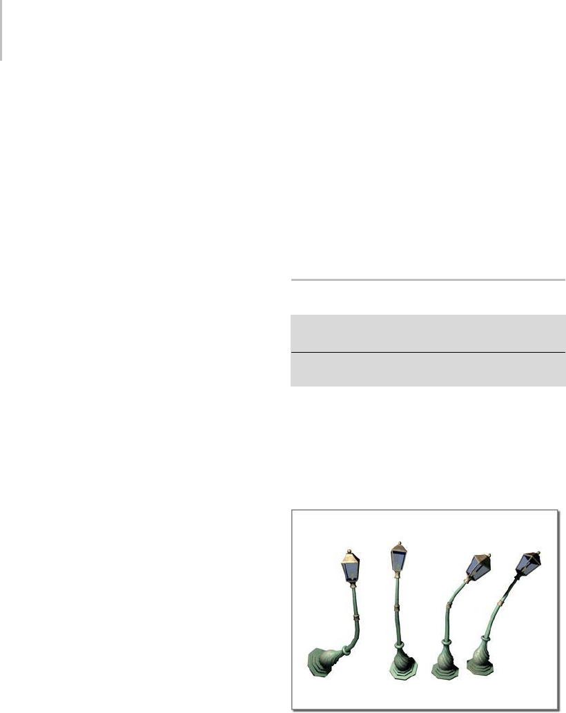
560 Chapter 8: Modifiers
A rubber-band dashed line appears connecting
the mouse cursor to the box.
11.You can’t connect this “wire” directly to the
custom attribute, so just left-click in an empty
part of the viewport to open the Parameter
Wiring dialog.
Thehierarchylistontheleftside,Box01,is
expanded to the box’s Height parameter, which
is highlighted.
12.On the right side, expand this path: Object >
Box01 > Modified Object > Attribute Holder >
Custom Attributes, and then click Box Height
to highlight it.
13.Click the Two-way Connection button
(double-headed arrow), and then click
Connect.
14.Similarly, connect Height Segments on the left
side to Box Height Segments on the right.
15.Close the Parameter Wiring dialog.
16.Right-click the box again, choose Parameter
Wiring, choose Modified Object > Taper
> Amount, and then left-click to open the
Parameter Wiring dialog.
The Amount parameter is highlighted on the
left side of the dialog.
17.On the right side, click the Attribute Holder’s
Taper Amount parameter, and then connect
them.
18.Connect Curvature on the left side to Taper
Curve on the right side, and then close the
dialog.
All the parameters are now hooked up.
19.Experiment with changing the values on the
Custom Attributes rollout.
The Attribute Holder modifier lets you change
the box’s creation parameters as well as the
Taper modifier’s settings without switching
back and forth in the modifier stack. In this
way you can access, in one convenient location,
as many different parameters from different
levels in an object’s modifier stack, or even
from different objects, as you like.
Youmightnoticethatyoucan’tsetthetaperto
curve inward. You can resolve this by reopening
Parameter Editor, clicking Edit/Delete, and
then modifying the Taper Curve attribute to
allownegativevalues.Thechangetakeseffect
immediately, with no rewiring required.
Bend Modifier
Modify panel > Make a selection. > Modifier List >
Object-Space Modifiers > Bend
Make a selection. > Modifiers menu > Parametric
Deformers > Bend
The Bend modifier lets you bend the current
selection up to 360 degrees about a single axis,
producing a uniform bend in an object’s geometry.
You can control the angle and direction of the
bend on any of three axes. You can also limit the
bend to a section of the geometry.
Bend applied to a streetlight model
Procedures
To bend an object:
1. Select an object and apply the Bend modifier.
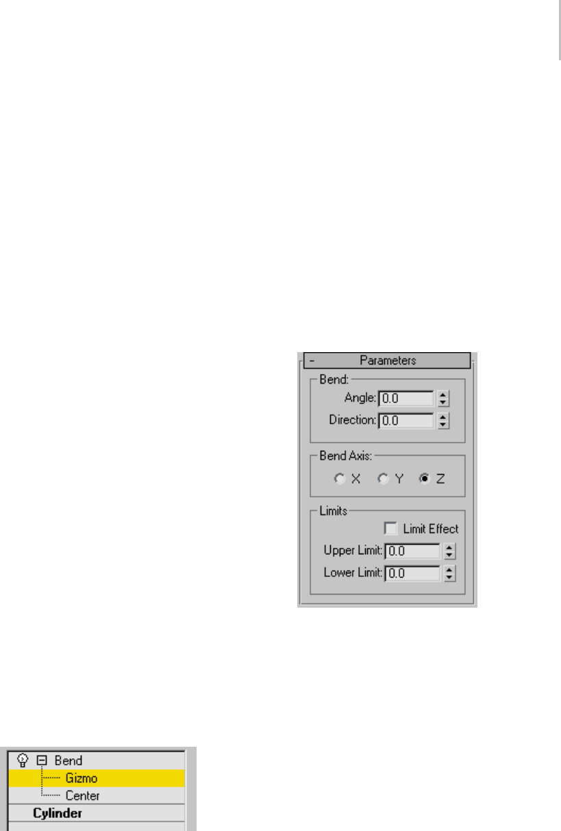
Bend Modifier 561
2. On the Parameters rollout, set the axis of the
bend to X, Y, or Z. This is the axis of the Bend
gizmo, not the axis of the selected object.
You can switch between axes at any time, but
the modifier carries only one axis setting.
3. Set the angle of the bend along the chosen axis.
The object bends to this angle.
4. Set the direction of the bend.
The object swivels around the axis.
You can reverse angle and direction by changing a
positive value to a negative value.
To limit the bend:
1. TurnonLimitEffectintheLimitsgroup.
2. Set values for the upper and lower limits. These
are distances in current units above and below
the modifier’s center, which is at zero on the
gizmo’s Z axis by default. You can make the
upper limit zero or positive, and the lower limit
zero or negative. If the limits are equal, the
resultisthesameasturningoffLimitEffect.
The bend is applied between these limits. The
surrounding geometry, while unaffected by the
bend itself, rotates to keep the object intact.
This is analogous to bending a pipe, where the
unbent sections rotate but remain straight.
3. At the sub-object level, you can select and move
the modifier’s center.
The Limit settings remain on either side of the
center as you move it. This lets you relocate the
bend area to another part of the object.
Interface
Modifier Stack
Gizmo sub-object—You can transform and animate
the gizmo like any other object at this sub-object
level, altering the effect of the Bend modifier.
Translating the gizmo translates its center an equal
distance. Rotating and scaling the gizmo takes
place with respect to its center.
Center sub-object—You can translate and animate
the center at this sub-object level, altering the
Bend gizmo’s shape, and thus the shape of the bent
object.
For more information on the stack display, see
Modifier Stack (page 3–760).
Parameters rollout
Bend group
Angle—Sets the angle to bend from the vertical
plane. Range=-999,999.0 to 999,999.0.
Direction—Sets the direction of the bend relative
to the horizontal plane. Range=-999,999.0 to
999,999.0.
Bend Axis group
X/Y/Z—Specifies the axis to be bent. Note that this
axis is local to the Bend gizmo and not related to
the selected entity. Default=Z.

562 Chapter 8: Modifiers
Limits group
Limit Effect—Applies limit constraints to the bend
effect. Default=off.
Upper Limit—Sets the upper boundary in world
units from the bend center point beyond which
the bend no longer affects geometry. Default=0.
Range=0 to 999,999.0.
Lower Limit—Sets the lower boundary in world
units from the bend center point beyond which
the bend no longer affects geometry. Default=0.
Range=-999,999.0 to 0.
Bevel Modifier
Select a shape. > Modify panel > Modifier List > Bevel
The Bevel modifier extrudes shapes into 3D
objectsandappliesaflatorroundbeveltothe
edges. A common use for this modifier is to create
3D text and logos, but you can apply it to any
shape.
Bevel takes a shape as the base of a 3D object. You
then extrude the shape up to four levels and assign
an outline amount for each level.
Beveled text
Procedure
Example: To create beveled text:
This example produces typical 3D beveled text,
with equal bevels in front and back.
1. Create text (page 1–278) using default settings.
Font=Arial, Size=100.0.
2. Apply the Bevel modifier.
3. Type -1.0 in the Start Outline field.
4. For Level 1, do the following:
•Type5.0 for Height.
•Type2.0 for Outline.
5. Turn on Level 2, and do the following:
•Type5.0 for Height.
•Type0.0 for Outline.
6. Tur n on Le vel 3 and do t he follow ing :
•Type5.0 for Height.
•Type-2.0 for Outline.
7. If needed, turn on Keep Lines From Crossing.
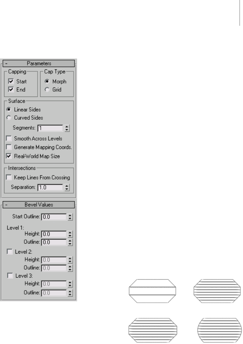
Bevel Modifier 563
Interface
Parameters rollout
Capping group
Yo u c a n d e t e r m i n e w h e t h e r o r n o t t h e b e v e l e d
object is capped at either end with the check boxes
in the Capping group.
Start—Caps the end with the lowest local Z value
(bottom) of the object. When turned off, the
bottom is open.
End—Caps the end with the highest local Z value
(top) of the object. When turned off, the end is
left open.
Cap Type group
Two radio buttons set the type of cap used.
Morph—Createscapfacessuitableformorphing.
Grid—Creates cap faces in a grid pattern. This
cap type deforms and renders better than morph
capping.
Surface group
Controlsthesidecurvature,smoothing,and
mapping of the surface.
The first two radio buttons set the interpolation
method used between levels; a numeric field sets
the number of segments to interpolate.
Linear Sides—When active, segment interpolation
between levels follows a straight line.
Curved Sides—When active, segment interpolation
between levels follows a Bezier curve. For visible
curvature, use multiple segments with Curved
Sides.
Segments—Sets the number of intermediate
segments between each level.
Four-levelbevelswith1and2segments
Bevels with linear and curved sides
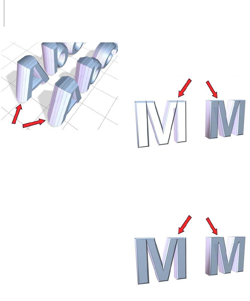
564 Chapter 8: Modifiers
Rounding and smoothing the bevel object sides
Smooth Across Levels—Controls whether
smoothinggroupsareappliedtothesidesof
abeveledobject. Capsalwaysuseadifferent
smoothing group than the sides.
• When turned on, smoothing groups are applied
to the sides. The sides appear rounded.
• When turned off, smoothing groups are not
applied. The sides appear as flat bevels.
Generate Mapping Coordinates—When turned on,
mapping coordinates are applied to the beveled
object.
Real-World Map Size—Controls the scaling method
used for texture mapped materials that are applied
totheobject. Thescalingvaluesarecontrolled
by the Use Real-World Scale settings found in
the applied material’s Coordinates rollout (page
2–1625).Default=on.
Intersections group
Prevents sharp corners from overlapping
neighboring edges.
Bevel works best with rounded shapes or shapes
with corners greater than 90 degrees. Acute angles
(less than 90 degrees) produce extreme bevels and
often overlap nearby edges.
Keep Lines From Crossing—Prevents outlines from
crossing over themselves. This is accomplished by
inserting extra vertices in the outline and replacing
sharp corners with a flat line segment.
Using Keep Lines From Crossing:
Left: Off
Right: On
Separation—Sets the distance to be maintained
between edges. The minimum value is 0.01.
Changing the Separation value
Bevel Values rollout
Contains the parameters that set the height and
bevel amount of up to four levels.

Bevel Profile Modifier 565
A beveled object requires a minimum of two levels:
a start and an end. You add more levels to vary the
amount and direction of bevel from start to end.
You can think of bevel levels as layers on a cake.
The Start Outline is the bottom of the cake and the
Level 1 parameters define the height and size of
the first layer.
Turning on Level 2 or Level 3 adds another layer
to the beveled object with the height and outline
specifyingtheamountofchangefromtheprevious
level.
The last level on is always the top of the object.
You must always set the Level 1 parameters.
Start Outline—Sets the distance the outline is
offset from the original shape. A non-zero setting
changes the original shape’s size.
• Positivevaluesmaketheoutlinelarger.
• Negativevaluesmaketheoutlinesmaller.
Level 1—Includes two parameters that indicate the
change from the Start level.
Height—Sets the distance of Level 1 above the Start
level.
Outline—Sets the distance to offset the Level 1
outline from the Start Outline.
Levels 2 and Level 3 are optional and allow you to
change the bevel amount and direction.
Level 2—Adds a level after Level 1.
Height—Sets the distance above Level 1.
Outline—Sets the offset distance of the Level 2
outline from Level 1.
Level 3—Adds a level after the previous level. If
Level 2 is not on, Level 3 is added after Level 1.
Height—Sets the distance above the previous level.
Outline—Sets the offset distance of Level 3 from
the previous level.
Traditional beveled text uses all levels with these
typical conditions:
• Start Outline can be any value, usually 0.0.
• Level 1 Outline is a positive value.
• Level 2 Outline is 0.0. No change from Level 1.
• Level 3 Outline is the negative of Level 1.
Returns Level 3 to the same size as the Start
Outline.
Bevel Profile Modifier
Select a shape. > Modify panel > Modifier List > Bevel
Profile
The Bevel Profile modifier extrudes a shape using
another shape path as the "beveling profile." It’s a
variationontheBevel modifier (page 1–562).
Important: Bevel Profile fails if you delete the original
beveling profile. Unlike a loft object, which incorporates
the shape, Bevel Profile is simply a modifier.
Note: Although this modifier might seem similar
to a loft object with varying scale settings, it’s
actually different because it uses different outline
values as distances between line segments rather
than as scale values. This more complex method of
resizing a shape results in some levels having either
more or less vertices than others, and generally
works better with text, for example.
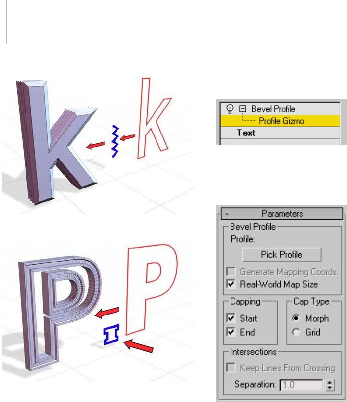
566 Chapter 8: Modifiers
BevelProfilecreatesanobjectusinganopenspline.
BevelProfilecreatesanobjectusingaclosedspline,yielding
a different result.
Procedure
To use the Bevel Profile modifier:
1. Create the shape you want to bevel (preferably
in the Top viewport).
2. IntheFront(XZ)viewport,createashapeto
use as the beveling profile.
3. SelectthefirstshapeandapplytheBevelProfile
modifier.
4. ClickthePickProfilebuttonintheBevelProfile
modifier, and then click the profile shape.
Interface
Modifier Stack
For more information on the stack display, see
Modifier Stack (page 3–760).
Parameters rollout
Bevel Profile group
Pick Profile—SelectsashapeorNURBScurvetobe
used for the profile path.
Generate Mapping Coords—Assigns UV
coordinates.
Real-World Map Size—Controls the scaling method
used for texture mapped materials that are applied
totheobject. Thescalingvaluesarecontrolled
by the Use Real-World Scale settings found in
the applied material’s Coordinates rollout (page
2–1625).Default=on.
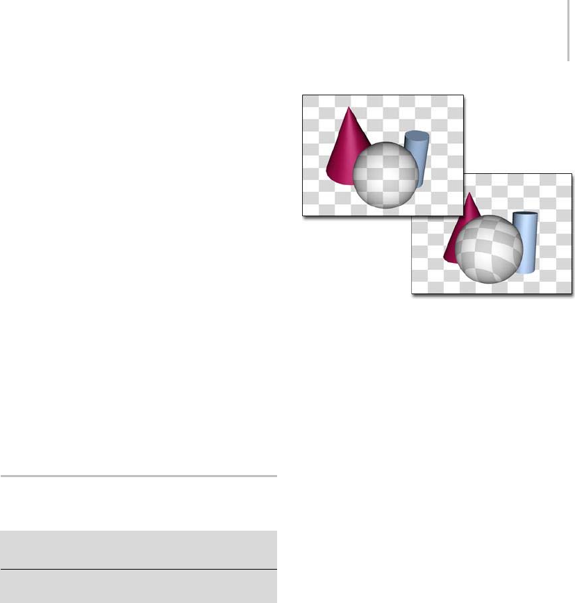
Camera Map Modifier (Object Space) 567
Capping group
Start—Caps the bottom of the extruded shape.
End—Capsthetopoftheextrudedshape.
Cap Type group
Morph—Selects a deterministic method of capping
that provides the same number of vertices for
morphing between objects.
Grid—Creates gridded caps that are better for cap
deformations.
Intersections group
Keep Lines From Crossing—Prevents beveled
surfaces from self intersecting. This requires more
processor calculation and can be time-consuming
in complex geometry.
Separation—Sets the distance that sides should be
kept apart to prevent intersections.
Camera Map Modifier (Object
Space)
Select one object. > Modify panel > Modifier List >
Object-Space Modifiers > Camera Map
Select one object. > Modifiers menu > UV Coordinates
>CameraMap
The Camera Map modifier (object-space version)
assigns planar mapping coordinates based on
the current frame and the camera specified in
the Camera Map modifier. This differs from the
Camera Map (WSM) modifier (page 1–513) that
updates the object’s mapping coordinates on every
frame.
Left: The texture of an object with a camera map modifier
matches the background when seen by the camera the
modifier uses.
Right: When seen by a camera not used by camera map, the
object’s texture is based on object geometry.
Blending an Object into the Background
In the Procedures section (below), you’ll be
blending an object into the background using the
Camera Map modifier. If the background uses the
same image as the object’s texture map, then the
object blends with the background at the frame
where the modifier is applied and a camera is
specified. The object becomes visible if either the
camera or object moves. In order to make the
illusion work, you must assign the same map to
the background that you assign to the object.
Mapping Coordinates
Because the accuracy of mapped objects depends
partly on the complexity of the mesh, the "blend to
background" effect works best when applied to an
object with a relatively high density of triangular
faces. The necessary density also depends on the
distance of the object from the camera.
A simple box might look fine when it occupies only
a small portion of the background, but up close
the mapping will look distorted without adequate
tessellation. Some experimentation is required
to get an ideal mapping and still minimize the

568 Chapter 8: Modifiers
complexity of the geometry. (In general, for a
box object that’s filling a quarter of the screen, a
tessellation of 4x4x4 works well.)
Note: When using the Camera Map modifier, apply
the modifier to a single object at a time. If it’s
applied to a selection set, only the first item in the
selection will be mapped properly.
Use Camera Map (WSM) (page 1–513) if you want
to move the camera and maintain the match to the
background.
Using the Plate Match/MAX R2.5
Rendering Filter
Prior to 3ds Max 3,theantialiasingaffectedonly
geometric edges, with the filtering of bitmaps
being controlled in the Bitmap Map parameters
(pyramidal, summed area, or no filtering).
Antialiasing filters affect every aspect of the object,
filteringtexturesalongwithgeometricedges.
While antialiasing provides superior results, it
produces inconsistencies when rendering objects
that are supposed to match the environment
background.Thisisbecausetheantialiasingfilters
donotaffectthebackgroundbydefault.Youcan
turn on background antialiasing in Customize
>Preferences>Rendering>Background
Antialiasing > Filter Background. To correctly
match an object’s map to an unfiltered background
image, you need to use the Plate Match/MAX
R2.5 filter so the texture is not affected by the
antialiasing.
There are three ways you can render objects in
3ds Max to blend seamlessly into a background
environment:
• By assigning a Matte/Shadow Material
• By assigning a 100% self-illuminated diffuse
texture to an object using Camera Mapping
• By assigning a 100% self-illuminated diffuse
texture using Environment/Screen projection
The Plate Match/MAX R2.5 antialiasing should be
used whenever trying to match foreground objects
with an unfiltered background or when trying to
match the antialiasing qualities of the 3ds Max 2.5
renderer.
Procedures
ThefollowingstepsshowhowtoapplytheCamera
Map modifier, and how to set up your scene.
To apply the Camera Map modifier:
1. Createascenewithacameraandoneormore
objects. Make sure the object you want to map
is visible in the Camera viewport.
2. Select the object, and apply the Camera Map
modifier.
Use the Object-Space Camera Map modifier,
the one without the asterisk.
3. Ifyouhaveanimationinthescene,movetothe
frame where you want the object map to match
the background. For example, if the camera is
animated, the mapping will match only at this
frame.
4. On the Camera Mapping rollout, click Pick
Camera, and then select the camera used for
the rendered view.
To assign a background image to the Camera
viewport:
Note: This procedure is not necessary for successful
rendering, but if you want to see the effect in a
viewport, follow these steps.
1. Activate the Camera viewport and turn off the
grid.
2. Choose Views menu > Viewport Background.
3. On the Viewport Background dialog that
displays, click the Files button, and choose
thesamebitmapthatyouplantoapplyasa
background for the rendered scene, and as a
diffuse map on the object.
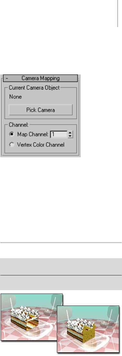
Cap Holes Modifier 569
4. In the Aspect Ratio group, choose Match
Rendering Output.
5. Turn on Display Background, and click OK.
Thedialogisdismissedandthemapis
displayed in the viewport.
To assign a mapped material to the object:
1. In the Material Editor, create a standard
material to whose Diffuse component you’ve
assigned the same bitmap as you assigned to
the background.
2. AttheDiffuseMaplevelofthematerial,turnon
the Show Map In Viewport button.
3. Select the object, and click Assign Material To
Selection.
The map on the object in the viewport matches
the viewport background, but the shading
makes the object visible. To make the object
truly invisible, go to the next step.
4. At the top level of the object’s material, set
Specular Level and Glossiness to 0. Turn off Self
Illumination Color, and set Self Illumination
to 100.
The object is now camouflaged against the
background.
To assign the background to the rendered
background:
1. Choose Rendering menu > Environment.
2. In the Environment dialog that displays, click
the button below "Environment Map" to open
the Material/Map Browser.
3. Under the Browse From group box, choose
Material Editor.
4. Turn off Root Only, find the map in the list
window, highlight it, and choose OK.
5. Choose Copy in the dialog, and click OK.
6. Render the Camera viewport.
The mapped object is camouflaged against the
background in the rendered scene.
Interface
Pick Camera—To a p p ly t h e U V W c o o r d i na te s , c l i c k
this button, and then select the camera through
which you’re going to view the scene.
Map Channel—Turn on and choose a map channel
to use. Map channels are specified in the Material
Editor.
Vertex Color Channel—Uses the Vertex Color
channel.
Cap Holes Modifier
Select a mesh object. > Modify panel > Modifier List >
Cap Holes
Select a mesh object. > Modifiers menu > Mesh Editing
>CapHoles
Cap Holes used to make the cake appear solid
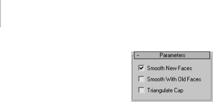
570 Chapter 8: Modifiers
The Cap Holes modifier builds faces in the holes in
a mesh object. A hole is defined as a loop of edges,
each of which has only one face. For example,
one or more missing faces from a sphere would
produceoneormoreholes.Themodifierworks
best on reconstructing planar holes, but can do a
reasonable job on non-planar holes as well.
Note: This modifier can cap holes in a sub-object
selection passed up the stack. It caps any part of
theholethat’sadjacentto,orwithintheselected
geometry, whether vertex, edge, or face.
Tips
• If the Cap Holes modifier doesn’t appear to
work, remove it, apply a Mesh Select modifier
(page 1–719) to select the faces surrounding the
hole, then apply Cap Holes to the sub-object
selection.
• The Cap Holes modifier creates faces with
invisible edges unless you turn on All New
Edges Visible before you apply it.
Procedure
Example: To cap a hole in a sphere:
1. Create a sphere.
2. Apply an Edit Mesh modifier to the sphere.
3. In the stack display, choose the Face selection
level.
4. Select and delete a contiguous group of faces.
5. Tur n of f th e Fa ce sele cti on le vel .
6. Apply a Cap Holes modifier.
Theholeyoucreatedshouldbefilled.
Tip: TurningonSmoothWithOldFacesmakes
the cap less visible.
Interface
Smooth New Faces—Assigns the same smoothing
group number to all new faces. If possible, this will
be a smoothing group number not used elsewhere
in the object.
SmoothWithOldFaces—Smoothes new triangular
faces using the smoothing groups from bordering
oldfaces.Thissmoothesonlyonelevelinfromthe
perimeter of the border of the hole, so you might
need to use both this and the Smooth New Faces
option to properly smooth a large hole.
Note: When Smooth With Old Faces is turned on,
the faces in the capped holes inherit a material face
ID from one of the surrounding faces. When this
item is turned off, the faces in the capped holes are
assigned a new ID.
Triangulate Cap—Makes all of the edges visible in
the new faces.

Cloth and Garment Maker Modifiers 571
Cloth and Garment Maker
Modifiers
Laura by Georges Walser
Cloth provides you with advanced tools for
creating realistic fabrics and tailor-made clothing
for characters and creatures. The Cloth system
comprises two modifiers:
•TheCloth modifier (page 1–578) is responsible
for simulating the motion of cloth as it interacts
with the environment, which may include
collision objects (a character or a table, for
example) and external forces, such as gravity
and wind.
•TheGarment Maker modifier (page 1–607) is a
specialized tool for creating 3D garments from
2D splines, similarly to the way real clothes are
made, by stitching together flat pieces of cloth.
You can model clothing in two ways: by creating
the cloth objects with standard 3ds Max modeling
methods and applying the Cloth modifier to
them, or by designing virtual clothing patterns
with splines and stitching together these various
virtual panels to form a full garment using the
Garment Maker modifier. With Garment Maker,
you can even import spline patterns from external
applications and use these as your pattern panels.
See also
Cloth Overview (page 1–571)
Cloth Overview
Clothisanadvancedcloth-simulationengine
that lets you create realistic garments for your
characters and other creations. Cloth is designed
to work in concert with the modeling tools in
3ds Max and can turn just about any 3D object
into clothing; it also allows you to build garments
from scratch.
Before you begin working with Cloth, we
recommend that you read this overview.
It provides background information on
cloth-simulation technology, so you can begin to
grasp exactly the way Cloth works. It will give you
a better overall understanding of how to set up
Clothscenes,thewaytheclothbehaves,andthe
array of advanced controls you will have at your
disposal.
As an artist and creator, you can use this
knowledge to tailor (no pun intended) how Cloth
will affect and interact with your scenes, and how
you can best take advantage of this software.
Cloth-Simulation Technology
Cloth simulation is the process of replicating the
movement and deformation of a piece of fabric or
clothing to mimic how cloth would react in the real
world. To make cloth simulation work, first you
need a cloth object, such as a tablecloth or a pair of
pants. Next, you need something for the fabric to
interact with. This can be a collision object such
as a table top or character’s leg, or a force such as
wind or gravity.
Limitations
While Cloth is designed to help you create
clothing for your models, you should be aware

572 Chapter 8: Modifiers
that, by its very nature, cloth simulation is only
an approximation of how real fabric would react
under certain circumstances; this system does
have some limitations.
One of the most important aspects of working
with Cloth is the amount of time it can take to
create a simulation. If you’re looking to create a
fully physically correct simulation, you might run
into problems. Even with a fast computer, cloth
dynamics at that level of accuracy (and geometric
detail) could take virtually forever. So you must
learn to scale your simulations back to a reasonable
level. This doesn’t mean you can’t get believable
clothing; it simply means that there are tradeoffs
you should be willing to make.
Tradeoffs
In order to create a believable simulation, you
need to balance time against quality and accuracy.
Themoretimeyouhave,themoreaccuracyand
quality your simulation can have. There’s no
reason to make a model with 10,000 polygons if
you can define the form equally well with 3,000.
Thesameruleappliestoclothsimulations.
Internal and External Forces
When simulating cloth, different forces come
into play. Some internal forces like bend, stretch,
and shear allow the fabric to deform in a realistic
manner. External forces such as gravity, wind,
and collisions make the cloth interact with
its environment. To obtain a good-looking
simulation, most or all of these things need to
come into play. Without these forces, a piece of
cloth will remain a flat, lifeless plane.
Collision Detection
Whenputtingashirtorpairofpantsona
character, you don’t want any part of the body
to protrude through the fabric. The desired
result is to have the garment deform around the
mesh (rather than through it) so there are no
intersections. This is done with collision detection;
with Cloth, you tell the simulation system which
objects will act as cloth, and which ones will act
as collision objects.
Basically, virtual feelers are sent out from the
vertices of the cloth objects to see if there are
any other objects that they might collide with.
When one of the feelers hits something, the
simulationknowsthatitmustdeformthefabric.It
is important to remember that a cloth mesh with
more vertices has more feelers and can do a better
job of collision detection. This is critical, because
if you are working with a high-poly character
(collision object), you will need to increase the
densityofyourcloth,orthehigh-polymeshwill
protrude through the lower-poly cloth object. The
reason is that there aren’t enough feelers to detect
all of the detail in the collision object.
The alternative to this is to add one or more
low-polygon proxy meshes for the character so
there doesn’t need to be such high density cloth
objects that will slow down simulation. We’ll cover
the mesh density a bit more in the next section.
Lastly, if you are simulating with fast-moving cloth
objects, you might need to increase the Density
value to give you the benefit of more feelers. You
also might adjust the Step size to check more often
for collision objects in the way.
Clothing and Pattern Design Overview
Traditionally, sewing patterns are cut from flat
pieces of cloth and stitched together. The place
where one piece of cloth is sewn to another is called
a seam. Patterns are generally symmetrical, where
theleftsideofthegarmentmatchestheright.
Skirt
The simplest is a skirt pattern with two pieces, with
a similar shape for the front and back. The back
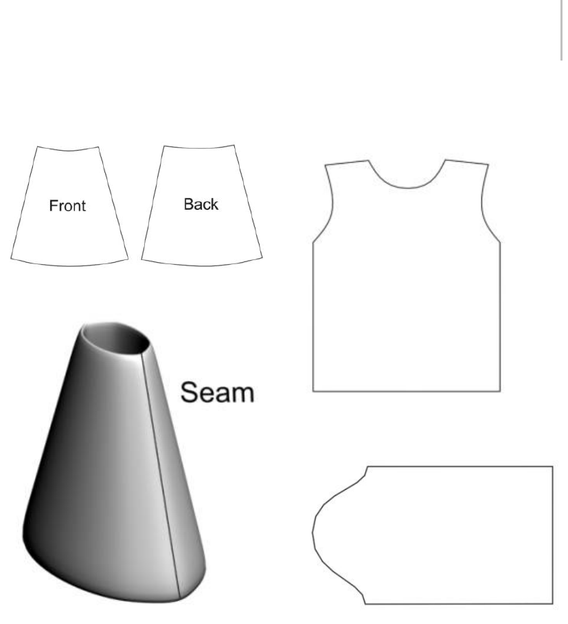
Cloth Overview 573
shape is a little larger than the front to account for
the hips and buttocks.
The shapes are sewn together at the sides to form a simple skirt.
Thebottomedgeofagarmentiscalledahem.In
the skirt pattern, the waistline and hem are slightly
curved. When a person puts on the skirt, the
curve sits flat on the waist, while the skirt falls in
folds to the hem. Because both the waistline and
hem are curved, the skirt falls to the same length
all the way around.
Shirt
A shirt pattern is slightly more complicated. A
simple T-shirt pattern is made of two pieces, one
for the front and another for the back. The collar
on the back piece is higher than the collar on
the front. You sew seams up the sides and at the
shoulders, leaving the arm hole open.
You can also add sleeves to the shirt. A sleeve
pattern is bell-shaped.
It might not be immediately obvious how this
pattern turns into a sleeve. The large hump of the
bell fits over the shoulder, to give room for it to
move.
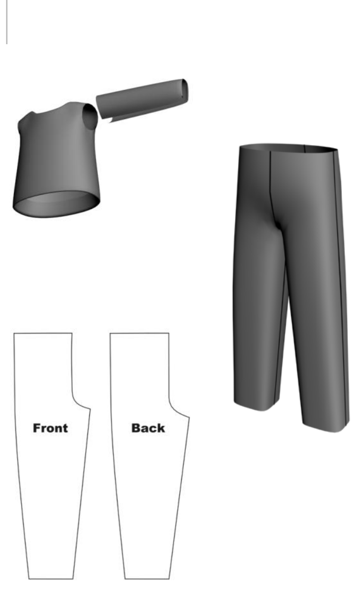
574 Chapter 8: Modifiers
Pants
A pants pattern has a curved shape at the top to
accommodate the hips. The longer straight edge
is the outside seam, while the shorter edge is the
inseam. The curve near the top fits around the
belly or buttocks, and under the crotch area.
Eachpieceiscuttwice.Thetwofrontpiecesare
sewn together along the crotch, and the two back
pieces are sewn together in the same way. Then the
front is attached to the back at the outside seams
and inseams.
Darts
Darts are diamond-shaped holes inside a panel or
V-shaped cutouts at an edge of a garment panel
(see figure below), which when closed up cause the
garment to assume a curved shape.
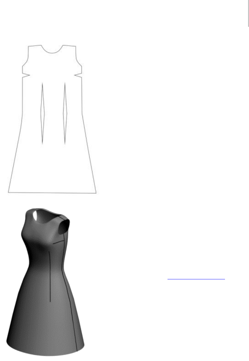
Cloth Overview 575
Darts used to be a common part of women’s
everyday clothing, especially in blouses and
dresses. However, darts are not needed with loose
garments or stretchy clothing. Today, they are used
mostly in formal wear and tailored garments.
Clothing Design and Techniques
One way to create clothing is to lay out a pattern
and put it together with Garment Maker. Garment
Maker is a modifier that is used to make seams,
lay out cloth panels and define fabric densities.
You can use Garment Maker to create seams for
the pattern either in a traditional, flat layout or in
a visual, easy-to-use 3D layout.
Intherealworld,clothesaremadebycutting
outshapesfrompiecesofclothandsewingthem
together along seams with thread. Garment Maker
emulates this approach. First you must create a
pattern that will define the shapes of the panels.
Clothing patterns typically use shapes that we
don’t encounter in everyday life. Those of us
who aren’t an experienced clothing designers
might have a hard time creating these shapes from
scratch. It’s often best to start out with a pattern
made by somebody else. Cloth includes a variety
of patterns for shirts, pants, jackets and so forth.
You can also buy software that will generate these
patterns in DXF format.
One program that does this is PatternMaker,
available from www.patternmaker.com.When
you want to move beyond editing the patterns
included with Cloth, it’s often helpful to use such
applications to help create patterns and familiarize
yourself with the process .
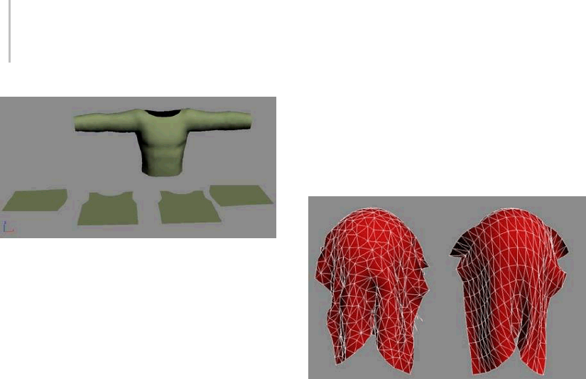
576 Chapter 8: Modifiers
Shirt pattern and shirt sewn together with Garment Maker
Modeling Clothing
Garment Maker is a useful tool for putting
together patterns and adjusting seams, but you
can also achieve good results by modeling with
the standard 3ds Max tools and using Cloth on
top of these meshes. You can create clothing with
polygons, patches, or NURBS.
Important: Keep in mind that modeled clothing must
not have any overlapping vertices or interpenetrating
faces. This type of geometry can cause the simulation
to fail. Using Garment Maker; you will not run into this
problem. If you are careful in creating your mesh, then
this is an easy rule to follow.
Pros and Cons
When designing clothing, Garment Maker is
usually the best way to go. It lets you define
seams, seam strength, pleats, and other clothing
parameters that cannot be defined with clothing
modeled via other methods. Either methods lets
you define separate portions of your clothing with
different fabrics, but Garment Maker gives you
greater control over this. The advantage to using
modeled clothing is that it can sometimes be a
faster setup with familiar methods and it’s a great
way to repurpose older clothing models you have
made in the past. Using polygon-modeled clothing
can result in overly regular creases and folds.
Garment Maker uses a Delaunay mesh, which
tends to avoid this problem. However, the irregular
triangulation can result in rendering artifacts
for low-resolution clothes, so it is advisable to
apply the HSDS modifier after Cloth on garments
created with Garment Maker and subdivide all the
triangles once.
Note: MeshSmooth does not give good results with
Garment Maker meshes.
Left: Garment Maker Delaunay mesh
Right:Modeledquadmesh
How Cloth Works
Cloth exists within 3ds Max as a pair of modifiers:
Garment Maker and Cloth. Between these two,
you can turn just about any 3D object into a
cloth object, or you can create clothing in a more
traditionalmethodfrom2Dpatterns,andthen
sew the panels together. However, before getting
into the specifics of the two modifiers, it’s useful
to discuss how to preplan for using Cloth. This
includes how geometry affects Cloth behavior as
wellasthedensityofthemeshesyouuseasfabric.
Effect of Geometry on Cloth
Ideally, the way you model your cloth should
notaffecthowitbehaves. However,inpractice,
thenatureoftheclothgeometryimpactsthe
simulation. First of all, the density of the mesh
defines how fine the folds are that can develop. If
youcreateaplanewithonlyninevertices,when
you drape it over a sphere, you are obviously not
going to get much detailed folding.
In addition to this aspect, there is the nature of
the edges in the mesh. Folding can occur only
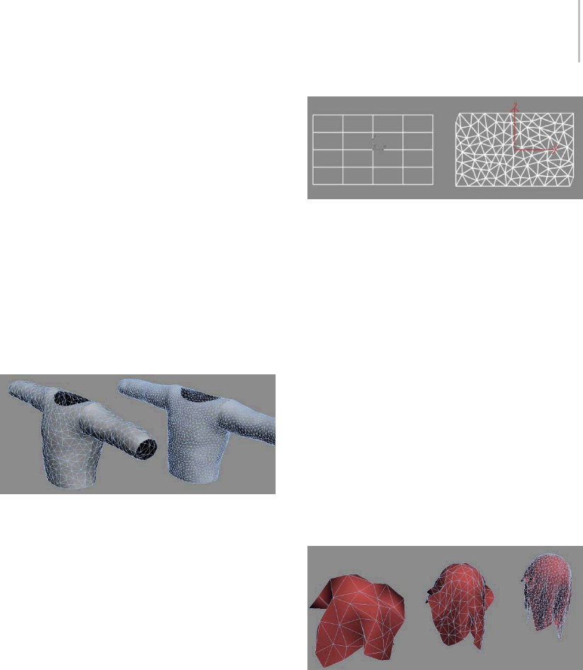
Cloth Overview 577
at edges between triangles, so the regularity
or irregularity of the mesh also dictates the
resulting deformation. For example, a plane all of
whosetrianglehypotenuseedgesarealignedwill
result in a cloth with folds aligned along those
edges. Garment Maker creates meshes with an
irregular layout (but with fairly equal-sized and
close-to-equilateral triangles) that avoids this
folding bias. However, this can also result in
rendering artifacts with low-resolution cloths, so
it is advisable to apply the HSDS modifier after
Cloth on garments created with Garment Maker
and subdivide all the triangles once.
Note: MeshSmooth does not give good results with
Garment Maker meshes.
Left: A low-density shirt.
Right:ThesameshirtwithHSDSapplied,aboveClothinthe
modifier stack
Note: There should never be any modifiers that can
alter topology between Garment Maker and Cloth.
For example, you can use Unwrap UVW, but not
modifierssuchasEditMesh,MeshSmooth,or
HSDS.
Thetypeofgeometryyouworkwithcanhavea
great impact on how the cloth will react. You’re
probably accustomed to using triangular and
quadrilateral polygons for modeling. Garment
Maker uses a Delaunay mesh subdivision that
promotes non-uniform deformation. When using
quad polygons for cloth simulation be careful of
getting uniform or symmetrical results.
Left: A quad mesh
Right: A Delaunay mesh
ClothMeshDensity
It is important to think about how dense your
meshhastobetoachievetheresultyouwant.
Makingthemeshtoodensewillslowdown
thesystem,whilehavingyourmeshattoolow
resolution might not give you the folds or detail
you want to see.
For example, if you applied a Bend modifier to a
cylinder with only a few height segments, the result
would be angular and unsmooth. On the other
hand, if you created the cylinder with 1,000 height
segments, you’d be wasting resources. The same
is true for Cloth. You must find a balance between
levelofdetailandperformancethatisappropriate
foryourscene.
Low, medium, and high-density meshes and the way they
deform
Notes on the HSDS Modifier
Using the HSDS modifier to add detail to your
model can be an effective solution that lets you
simulate with a lower resolution mesh, and still get
high-quality results. However, if you choose to use
the HSDS modifier on top of your Cloth garments,
you may want to apply an Edit Mesh modifier
below it to weld the vertices together along the
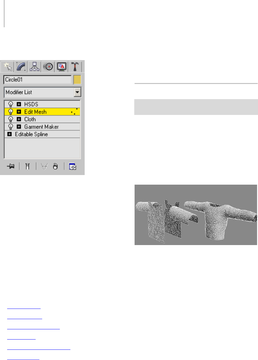
578 Chapter 8: Modifiers
seams. This prevents the mesh from coming apart
at the seams as it is subdivided.
Shown above is how the modifier stack should
look when using HSDS. The intermediate Edit
Mesh modifier is used to weld the panel edge
vertices together. If you want to preserve the seam
creases, you should apply further Mesh Select and
Smooth modifiers to reselect the panels and apply
different smoothing groups across the garment.
Pattern-Making Software
Below is a list of traditional pattern-making
software that you can use to create patterns for
import into 3ds Max and use with Cloth. After
ensuring that your Internet connection is active,
click the software names to display the makers’
Web s i te s.
•Fashion CAD
•PatternMaker
•Wild Ginger Software
•Autometrix
•AccuMark Pattern Design
•TUKATECH
See also
Cloth Modifier (page 1–578)
Garment Maker Modifier (page 1–607)
Cloth Modifier
Select an object. > Modify panel > Modifier List >
Object-Space Modifiers > Cloth
The Cloth modifier is the heart of the Cloth
system, and is applied to all objects in your scene
that need to be part of the Cloth simulation. This
is where you define cloth and collision objects,
assign properties, and execute the simulation.
Other controls include creating constraints,
interactively dragging the cloth, and erasing parts
of the simulation.
Left: Cloth modifier not yet applied
Right: Cloth modifier applied and simulated
See also
Object Properties Dialog (Cloth) (page 1–602)
Cloth and Garment Maker Modifiers (page 1–571)
Cloth Overview (page 1–571)
Garment Maker Modifier (page 1–607)
Basic Concepts
In a Cloth simulation, you will let Cloth know
which objects will be part of the simulation, and
which objects will not. Once you have done this,
you define what the objects are made of. You can

Cloth Modifier 579
specify what is made of cloth, and what is a solid,
collision object.
Because Cloth is a modifier, an instance of it is
assigned to each object to be included in the Cloth
simulation. This includes all cloth and collision
objects. Be aware that two cloth objects with two
separate applications of the Cloth modifier will
not interact with one another. There are a couple
of ways to include objects in the simulation:
• Select all of the objects at once and apply the
Cloth modifier to them.
• Apply Cloth to one or more objects and then
add objects with the Add Objects button,
available on both the Object rollout and the
Object Properties dialog (page 1–602).
Units of Measure
Important: The following information is necessary only
if you change the system unit after applying the Cloth
modifier. If you change the system unit before applying
Cloth, the modifier automatically adjusts the cm/unit
setting.
Itisimportanttothinkaboutsizeindoingclothing
simulations. A very large flag behaves differently
from a handkerchief. If the scale is off, then
the simulation will be off. Because Cloth deals
with real-world physics, it works in real-world
units. This means that Cloth needs to know the
relationshipbetweenunitsin3dsMaxandunitsin
its own world.
Forexample,supposeyoucreateaplanethatis
10x103dsMaxunits. Ifyouwantthisplaneto
behave like a 10-inch x 10-inch handkerchief, you
would tell Cloth that 1 3ds Max unit=1 inch. If you
want it to behave like a 10-foot x 10-foot bed sheet,
you would tell Cloth that 1 3ds Max unit=1 foot.
Except as noted at the start of this section, Cloth
ignoresthe3dsMaxSystemUnitsSetup(under
Customizemenu>UnitsSetup>SystemUnits
Setup). Cloth has its own units setup, which
is determined by the cm/unit parameter on the
Simulation Parameters rollout. This tells Cloth
how many centimeters (cm) correspond to each
3ds Max unit. One inch equals 2.54 cm, so the
default setting of 2.54 means that one 3ds Max unit
corresponds to 1 inch.
Followingistheproceduretofollowtodetermine
what setting to use here.
1. Usethemeasureutilityortapehelperto
measure some dimension of your cloth (or
character) in 3ds Max units (call this number
x).
2. Decidehowbigyouwantthisobjecttobeinthe
real world Convert this number to centimeters.
Ifyouhavethedimensionininches,simply
multiply by 2.54 (call this number y).
3. cm/unit=y/x
Here is a quick example: You import a file,
man.obj, into 3ds Max, and want to put a shirt on
him.
1. Using the Measure utility, you find that the man
is 170 3ds Max units tall. So y=170.
2. You determine that this man is about 6 feet tall.
6 feet=72 inches.
And 72 inches=72x2.54=182.88cm. So
x=182.88
3. So now you have the values to make
sure the shirt behaves correctly.
Cm/unit=y/x=170/182.88=0.929. Or
you can round the spinner’s value up to 1.0,
since pinpoint accuracy is not needed here.
Fabric Behavior
Cloth provides many different ways to set up fabric
behaviors. You can make your cloth behave like
leather, silk, burlap, and anything in between.
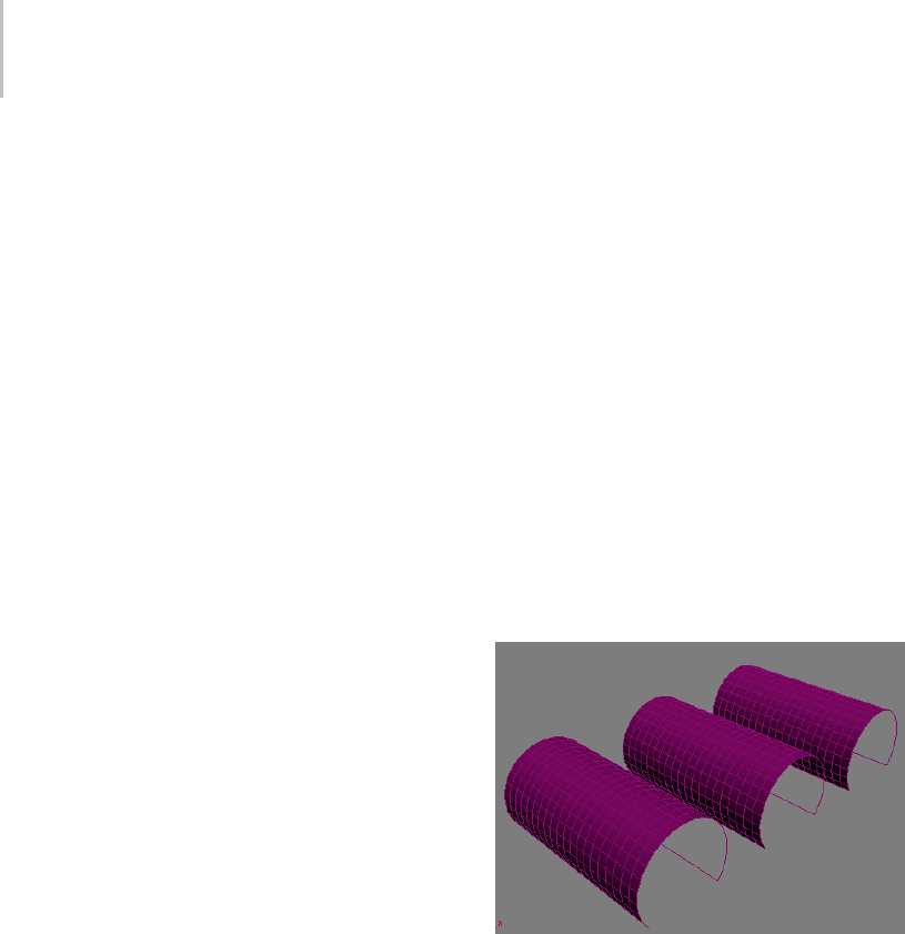
580 Chapter 8: Modifiers
The Simulation
Once all of your parameters are set and you’re
ready to go, it’s time to simulate. In many cases,
you will first perform a local simulation to fit your
fabric to your character. Once your fabric is in
place, you can simulate over time.
Running a simulation in Cloth is very freeform.
You are able to make many changes and edits to a
simulation, making it more of a work in progress
than a click and a “hope for the best” scenario.
Constraints
You can constrain fabric in various ways to create
different fabric effects during simulations. Cloth
can constrain cloth to have extra drag as it flies
through the air, or can cause it to be affected by
a space warp in the scene. Linking a portion
of the fabric to an animated object or attaching
to a surface are other common constraints. If
you wanted to create a pair of pants you would
constrain the top portion of the pants to the waist
of the character or a curtain can be constrained
to a rod. Constraints are a very important and
robust part of Cloth. Cloth has the ability to make
multiple groups of constrained vertices for great
flexibility. You can constrain many different parts
of a piece of clothing to different nodes’ surfaces or
other cloth objects.
You build constraints in Cloth at the modifier’s
Group sub-object level (page 1–589).Atthislevel,
you can see vertices of all selected objects, both
cloth and collision. You can then select these and
place them in groups. Once a group is defined,
you can then attach or "constrain" the selection
set to another object, or have it affected by some
external force.
Procedures
Example: To use the Keep Shape option:
If your cloth object starts out with 3D shape that
you’d like to retain during the simulation, you
can use the Keep Shape option and setting to
preserve this shape, or even reverse it. This simple
procedure provides an example of how to use Keep
Shape.
1. IntheToporPerspectiveviewport,addaPlane
primitive object of about 90 x 90 units, with 20
x20segments.
2. Apply a Bend modifier, set Angle to 250.0,and
set Bend Axis to X.
This produces the initial tubular shape.
3. Copy the bent plane twice so you have three
planes in a row. Rename the planes as follows:
•don’t keep shape
•keep shape
•reverse shape
4. Select all three planes and apply the Cloth
modifier.
5. On the Simulation Parameters rollout, turn off
Gravity and set cm/unit to 0.5.
Turning off Gravity keeps the cloth objects
from falling during the simulation, so they
stay in view, and lowering the cm/unit setting
compensates for the planes’ relatively large size.
6. On the Object rollout, click Object Properties.
This opens the Object Properties dialog.
7. In the Objects In Simulation list, highlight all
three planes (by dragging), and then, above the
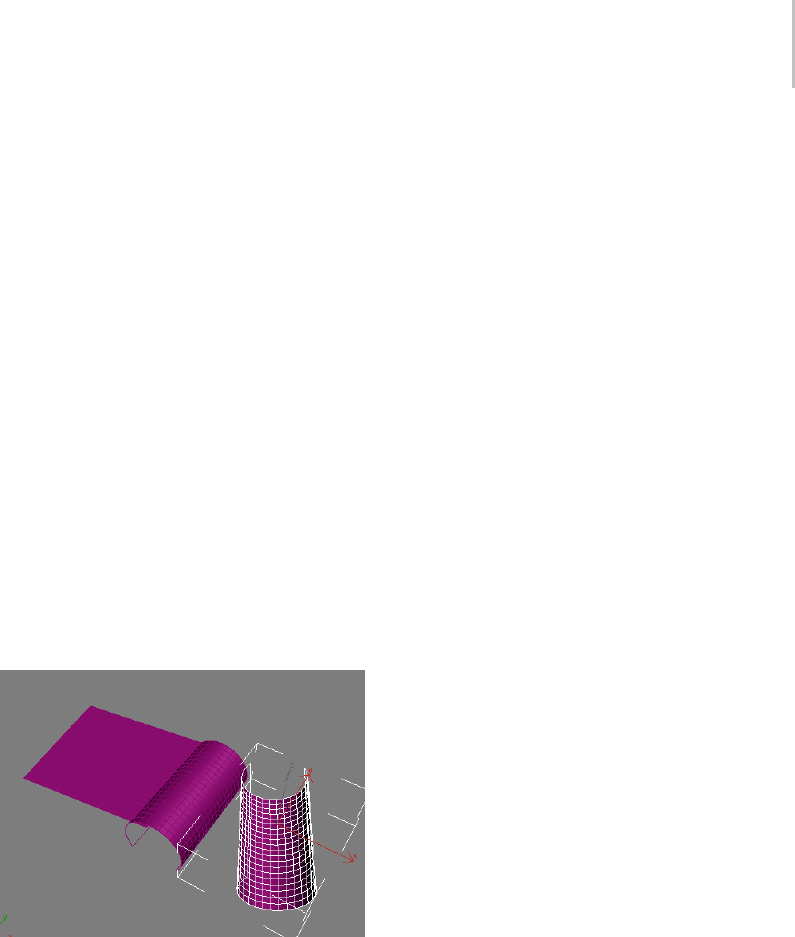
Cloth Modifier 581
Cloth Properties group, choose Cloth. Also set
UBendto500.0.
This sets V Bend also to 500.0 automatically.
UsinghighBendvaluesallowsthesimulation
to proceed more quickly.
Next, you’ll set different Keep Shape properties
separately for each object.
8. Highlight the reverse shape object in the list and
set the Bend % value to -100.0.
Note: The default value was 100.0.
9. Click OK to exit the dialog.
10.Select the don’t keep shape object and note that
Object rollout > Selected Objects Manip group
> Use Target State is off.
11.Select both the reverse shape and the keep shape
objects, but not don’t keep shape, and then turn
on Use Target State.
12.On the Object rollout, click Simulate Local.
After a few seconds, the don’t keep shape object
starts to flatten out, the keep shape object
doesn’t change, and the reverse shape object has,
in fact, reversed its shape, effectively creating
anegativebendangle.
Tip: You can also use Use Target State with Grab
State to maintain or reverse a shape created with
a previous cloth simulation or shape-changing
modifier.
Torunaclothsimulationwithanetworkedrender
farm:
A complex cloth simulation can require extensive
computation and take a long time. Cloth includes
commandsthatmakeiteasytorunasimulation
onanetworkedmachine(partofarenderfarm),
freeing up your machine for working on other
parts of the scene.
1. Set up the simulation.
2. For each cloth object in the simulation, select
the object, and then on the Selected Object
rolloutclickSetandspecifyapathandfile
name for the cache.
For best results, specify a mapped drive and
turn on Force UNC Path. This specifies the
path using the Universal Naming Convention
so that it can be found by all computers in the
network. Also, it’s probably a good idea to keep
allthecachefilesinthesamedirectory.
3. On the Simulation Parameters rollout, turn on
Sim On Render.
4. Save the scene file.
5. On the Render Scene dialog, turn on Net
Render, and then click Render. Submit the job
to a single Server.
Unlike rendering, network Cloth simulation
cannot be split up among multiple Server
machines.
Note: You needn’t render the entire animation
to trigger the cache creation; a single frame
suffices.
As soon as the Server machine starts the
render, it begins computing the simulation and
saving it to disk. At any point you can load the
simulation in its current state from the cache
file to check its progress by clicking the Load
button.
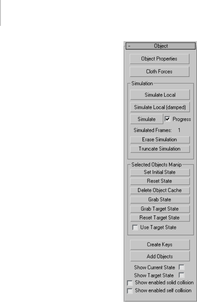
582 Chapter 8: Modifiers
Interface
The Cloth interface varies depending on the
current modifier stack level: Object (page 1–582)
or one of the four sub-object levels:
•Group (page 1–589)
•Panel (page 1–597)
•Seams (page 1–601)
•Faces (page 1–602)
Object rollout
The Object rollout is the first rollout you see on
the Command panel once you apply the Cloth
modifier. It comprises mostly controls to create a
Cloth simulation and adjust fabric properties.
Object Properties—Opens the Object Properties
dialog (page 1–602),whereyoucandefinewhich
objects to include in the simulation, whether they
are cloth or collision objects, and the parameters
associated with them.
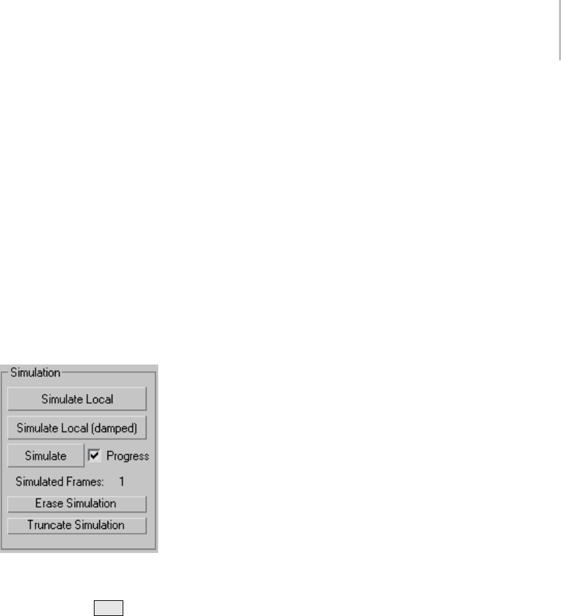
Cloth Modifier 583
Cloth Forces— Add forces (that is, space warps in
thescene)suchaswindtothesimulation.Click
ClothForcestoopentheForcesdialog. Toadd
forces to the simulation, in the Forces In Scene
list on the left side, highlight the forces to add,
and then click the > button to move them to the
Forces In Simulation list, thus adding them to the
simulation. Thereafter, the forces affect all cloth
objects in the simulation.
To remove forces from the simulation, in the Forces
In Simulation list on the right side, highlight the
forces to remove, and then click the < button to
move them to the Forces In Scene list.
Simulation group
To run a cloth simulation, click any of the
threeSimulatebuttonsinthisgroup. Tohalta
simulation, press Esc or if the Cloth Simulation
dialog is open (i.e., Progress is on), click the Cancel
button.
Simulate Local—Starts the simulation process
without creating animation. Use this to drape
the clothes on a character or sew the panels of a
garment together.
Simulate Local (damped)—Same as Simulate Local,
butwithalargeamountofdampingaddedto
the cloth. When sewing a garment together,
sometimes the panels come together at high speed,
causing problems. Using a damped simulation
alleviates this problem.
Simulate—Creates a simulation over the active
time segment. Unlike Simulate Local, this creates
animationdataintheformofasimulationcache
at every frame.
The simulator advances by a time step called
dT. The initial value is the Step setting on the
Simulation Parameters rollout. When the
simulator encounters certain situations, it
decreases dT in order to overcome the obstacles.
Sometime later, the simulator increases dT again
uptothemaximumStepvalueyouset.Thecurrent
valueofdTappearsontheClothSimulationdialog
that shows the progress of the simulation as it takes
place (see following).
WhenthesimulatordecreasesdT,itshows"dT
decreased" on the Cloth Simulation dialog along
withoneofthefollowingmessages(explanation
follows each message):
• could not solve equations – The solver could
not solve the equations of motion.
• cloth has become over-stretched – In
attempting to solve one step, some edges of the
cloth became too elongated, indicating a failure
of the solver.
• cloth-solid collision velocity was too large –
The speed of the cloth relative to that of the
collision object is too high.
• cloth-cloth collision velocity was too large –
The speed of colliding cloth parts is too high.
Progress—When on, opens the Cloth Simulation
dialog during the simulation. The dialog shows the
progress of the simulation, including information
about time, and messages about errors or time
step size adjustments.
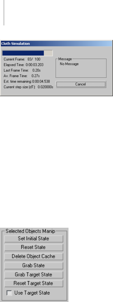
584 Chapter 8: Modifiers
The Cloth Simulation dialog shows information about the
simulation while it’s running.
Simulated Frames—Shows the number of frames
simulated so far.
Erase Simulation—Deletes the current simulation.
This deletes the cache of all cloth objects and sets
the Simulated Frames count back to 1.
Truncate Simulation—Deletes animation created by
the simulation after the current frame.
For example, if you’ve simulated an animation to
frame 50 but want to keep only animation keys
from frames 0 to 30, set the time slider to frame
30, then click this button. The simulation is then
deleted from frame 31 on.
Selected Object Manip group
Set Initial State—Updates the first frame of
the selected cloth object’s cache to the current
position.
Reset State—Resets the selected cloth object’s state
to the state before Cloth in the modifier stack.
When you click this, the simulation is erased; that
is, Simulated Frames returns to 1.
Delete Object Cache—Deletes the cache for selected
non-cloth objects. If an object is simulated as
cloth, and is then turned into a collision object (or
inactive) via the Object Properties dialog, it will
retain the cloth motion in its cache.
This is useful for simulating clothes in layers. For
example, you may simulate a character’s pants,
then turn the pants into a collision object for
simulating a coat. By simulating in layers, you
avoid the problems of cloth-to-cloth collision
detection. If you want to remove the cached
motion from the selected object(s), click this
button.
Grab State—Grabs the current state from the top
of the modifier stack and updates the cache for the
current frame.
Followingisanexampleofhowthismightbeused:
1. Simulate to frame 100. When you play back the
simulation, you see a collision object poking
through the cloth at frame 24.
2. Add an Edit Mesh modifier after Cloth and pull
the cloth vertices so the object doesn’t poke
through.
3. Go down the stack to Cloth and click Grab
State. The vertices are now moved twice
as far as you intended because the vertex
displacement was applied once by Cloth, and
again with Edit Mesh.
4. RemovetheEditMeshmodifier.Thevertices
should now be where you want them.
Grab Target State—Lets you specify the target shape
for Keep Shape. Grabs the current deformation
from the top of the modifier stack and uses that
mesh to define the target bend angles between
triangles. Also turns on Use Target State.
Note: Only the bend angles from the Target State
mesh are used, not the edge lengths.

Cloth Modifier 585
Tip: To add some natural creasing to your cloth,
drop the cloth on the floor, click Grab Target State,
and then run the simulation. After clicking Grab
Target State and before running the simulation,
click Reset State (unless you want the cloth to stay
on the floor!).
Reset Target State—Resets the default bend angles
tothemeshbelowClothinthestack.
Note: For Garment Maker (page 1–607) objects,
the target bend angles will depend on the output
method set in the Garment Maker modifier. To see
what is actually being used, use Show Target State.
Use Target State—When on, preserves the shape of
the mesh as stored by Grab Target State.Itusesthe
Bend % and Stretch % settings in the Keep Shape
group on the Object Properties dialog for Cloth.
If multiple cloth objects with different Use Target
State settings are selected, this check box appears
unavailable, but you can click it to make the setting
for all selected objects.
Note: In previous versions, this check box was
labeledKeepShapeandwasfoundontheObject
Properties dialog for Cloth.
Create Keys—Creates keys for a selected cloth
object. The object is collapsed to an editable mesh,
andanydeformationisstoredasvertexanimation.
Add Objects—Lets you add objects to the
simulationwithoutopeningtheObjectProperties
dialog. Click Add Objects, and then click an object
to add. To add multiple objects at once, press H
and use the Pick Objects dialog.
Show Current State—Shows the current state of the
cloth at the end of the last simulation time step.
If the simulation is cancelled, the last time step
could lie between two frames. If the simulation
is allowed to successfully finish, the last time step
corresponds to the last frame.
Show Target State—Showsthecurrenttargetstate
of the cloth; that is, the desired bend angles used
by the Keep Shape option.
Show enabled solid collision—When on, highlights
all groups of vertices for which Solid Coll is on.
This is handy for seeing exactly which vertices will
be involved in solid-object collisions.
Show enabled self collision—When on, highlights
all groups of vertices for which Self Coll is on. This
is handy for seeing exactly which vertices will be
involved in cloth-to-cloth collisions.
Selected Object rollout
The Selected Object rollout lets you control
the simulation caches, control and optionally
animate the cloth properties with a texture map
or interpolation, and specify a bend map. This
rollout appears only when a single object in the
simulation is selected.
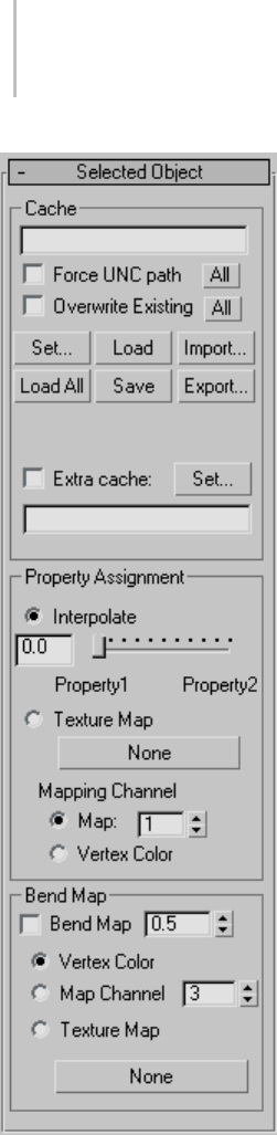
586 Chapter 8: Modifiers
Cache group
Use these settings for network simulation. When
you render with Sim On Render on, Cloth can run
the simulation on a networked machine, leaving
your local machine free for other work. For a
procedure, see Torunaclothsimulationwitha
networked render farm: (page 1–581).
[text field]—Shows the current path and file name
for the cache file. You can edit this field, but the
path must exist; the file will be created if necessary.
For any cloth object for which you have not
specified a file name, Cloth creates one based on
the object name.
Force UNC Path—If the text field path is to a mapped
drive, converts the path to UNC format (page
3–1028).Thismakesthepathreadilyaccessibleto
any computer on the network. To convert cache
paths for all cloth objects in the current simulation
to UNC format, click the All button.
Overwrite Existing—When on, Cloth can overwrite
existing cache files. To enable overwriting for all
cloth objects in the current simulation, click the
All button.
Set—Lets you specify the path and filename of
the cache file for the selected object. Click Set,
navigate to the directory, enter the file name, and
then click Save.
Load—Loads the specified file into the selected
object’s cache.
Import—Opens a file dialog to load a cache file
other than the specified one.
Load All—Loads the specified cache file for every
cloth object in the simulation.
Save—Saves the current cache, if any, using the
specified file name and path. If no file is specified,
Cloth creates one based on the object name.
Export—Opens a file dialog to save the cache to a
file other than the specified one. You can save in
the default CFX format or in PointCache2 format.
Extra Cache—To create a second cache in
PointCache2 format, turn on Extra Cache and
click Set to specify a path and file name. This file is
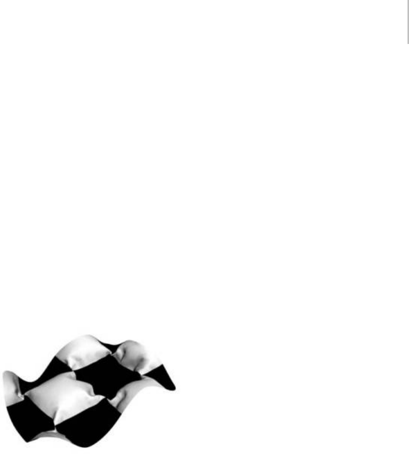
Cloth Modifier 587
also created when you render with Sim On Render
on.
Property Assignment group
Interpolate—Interpolates between the two different
property settings in the Object Properties dialog
(page 1–602) (as determined by the Property 1 and
Property 2 radio buttons at the top right corner).
Yo u c a n u s e t h i s s l i d e r t o a n i m a t e b e t w e e n t h e s e
twopropertiestoadjustthetypeoffabricsettings
the garment is using.
Texture Map—Set a texture map and apply the
Property 1 and Property 2 settings to the cloth
object. You can add a grayscale texture map in
this slot to blend between the two properties set in
the Object Properties dialog. Black will represent
property 1 and white property 2. Any grayscale
value will blend between these two properties. You
can drag a texture map onto this button.
Cloth object with a burlap material in Property 1 and silk in
Property 2 being controlled by a Checker procedural map
Mapping Channel—Lets you specify the mapping
channel the Texture map will work from, or choose
Vertex Color to use that instead. Vertex color
can be particularly useful in conjunction with
the new painting tools in 3ds Max. You can paint
vertex colors directly onto your object and use the
painted areas for material assignment.
Bend Map group
The Bend Map option lets you use a texture map,
map channel, or vertex colors to modulate the
target bend angles. The value of this is that you can
paint deformations onto your cloth, or use some
kind of noise map to add irregularity to the cloth.
Bend Map—TogglestheuseoftheBendMap
option.
Set the strength of the modulation with the
numeric value. In most cases, the value should be
less than 1.0. Range=0.0 to 100.0. Default=0.5.
[map type]—Choose the map type for the Bend
map:
•Vertex Color—Uses the Vertex Color channel for
modulation.
•Map Channel—Uses a map channel other than
Vertex Color for modulation. Set the channel
with the spinner.
•Texture Map—Uses a texture map for
modulation. To specify a texture map, click
the button (labeled None by default) and then
use the Material/Map Browser to choose the
map. Thereafter the map name appears on the
button.
Simulation Parameters rollout
The Simulation Parameters rollout settings let you
specify general properties of the simulation such as
gravity, start and end frames, and sewing-spring
options. These settings apply to the simulation
on a global scale, that is, to all objects in the
simulation.
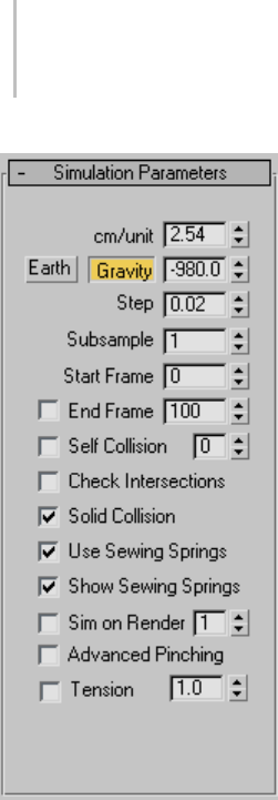
588 Chapter 8: Modifiers
cm/unit—Determines how many centimeters there
are per 3ds Max system unit.
Cloth automatically sets cm/unit to the equivalent
of 2.54 centimeters per inch (the default system
unit in 3ds Max). For example, if you set the
system unit to one foot, Cloth automatically sets
cm/unit to 30.48 (12x2.54).
Size and scale are important when doing cloth
simulation because a 10-foot curtain behaves much
differently from a one-foot square handkerchief,
even if they are made from the same fabric.
Earth—Click this button to set the Gravity value
to that of planet Earth.
Gravity—When on, the Gravity value (see
following) affects cloth objects in the simulation.
[Gravity value]—The force of gravity in cm/sec2.
A negative value applies gravitational force
downward. A positive value (i.e., no sign) means
gravity will act to move cloth objects upward.
ThedefaultvalueissettobethesameasEarth’s
gravity: -980.0 cm/sec2.
Step—Themaximumsizeofthetimestepthe
simulator takes.
This value is measured in seconds. The value
must be less than the length of one frame (less
than 0.033333 for 30 fps animation). A value of
0.02 is generally the largest value you want to
use. Reducing this value causes the simulator to
take longer to calculate, but will in general give
better results. The simulator will automatically
reduce its time steps as needed, but this is the
maximum value that it will try. This value works
in conjunction with the Subsample parameter:
The actual maximum value=Step value divided
by Subsampl value.
Subsample—The number of times per frame that
the software samples the position of solid objects.
Default=1.
At the default value, Cloth samples the solid objects
in the simulation once every frame. Increasing
this value should help when objects are moving or
rotating quickly, but be aware that the higher you
set the value, the slower the simulation will be.
Start Frame—The frame at which the simulation
starts. If you change this value after the simulation
has been performed, the cache will be moved to
this frame. Default=0.
End Frame—When on, determines the frame at
which the simulation will stop. Default=100.
Self Collision—When on, detects cloth-to-cloth
collisions. Leaving this off will speed up
the simulator, but will allow cloth objects to
interpenetrate.

Cloth Modifier 589
The numeric setting specifies the extent to which
Cloth tends to avoid self-colliding cloth objects,
at the cost of simulation time. Range=0 to 10.
Default=1.
This is a maximum limit. If Cloth needs fewer
calculations to resolve all collisions, it will use
fewer. In most cases, a value greater than 1 isn’t
necessary.
Solid Collision—When on, the simulator takes into
account cloth-to-solid object collisions. This is
almost always left on.
Use Sewing Springs—When on, uses the sewing
springs created with Garment Maker to pull the
fabric together.
This works only with objects that have been
made with Garment Maker (page 1–607).Turn
this option off once the garment has been pulled
together. When off, Cloth will identify vertices
that are sewn together and will always keep them
coincident. When on, there is always a chance for
the vertices to come apart if the sewing springs are
not strong enough (actually, there will always be
some slight gap between the vertices in this case).
Show Sewing Springs—Toggles the visual
representation of the sewing springs in the
viewports. These do not render.
Sim on Render—When on, triggers the simulation
at render time. Use this for generating a simulation
with a network computer, which lets you continue
to work on other aspects of your scene with your
own computer. See a procedure here (page 1–581).
After the render is completed, Cloth writes a cache
for each cloth object. You can specify this cache file
on the Selected Object rollout (page 1–585) (which
is available only when a single object is selected).
If you do not specify a name, the software creates
one.
The numeric value indicates the priority of the
simulation; the simulations are run in ascending
order. For modifiers with the same priority, the
order is undefined.
Note: Each object has its own cache file, which is
temporarily created when the MAX file is opened.
On saving the file, the cache is incorporated into
the MAX file. When Sim On Render is on, the
cache file specified is created and written to, but is
not read from as you change the time slider. The
cachefilemustbeloaded into the internal cache
file before you can see it.
Advanced Pinching—When on, Cloth tests for cloth
pinched between two parts of the same collision
object.
This option helps with cloth colliding with
small features of the collision objects, such as
fingers. There is a significant performance hit for
high-resolution collision objects.
Tension—Lets you visualize the compression/
tensioninthefabricbymeansofvertexcoloring.
Stretched cloth is indicated by red, compressed
by blue, neutral by green. The numeric setting
lets you change the range of tension/compression
illustrated by a complete traversal from red to
blue. The higher this value, the more gradual the
shading. This works only for Garment Maker
objects.
Group rollout
The Group sub-object rollout is for selecting
groups of vertices and constraining them to
surfaces, collision objects, or other cloth objects.
At the Group sub-object level, all selected objects
that are part of the Cloth simulation are shown
with their vertices visible so that you can select
them in an efficient fashion.
When you create or select a group at this sub-object
level, the Group Parameters rollout becomes
available.
Important: The concept of a group for Cloth can be
applied to both the cloth objects and to the collision
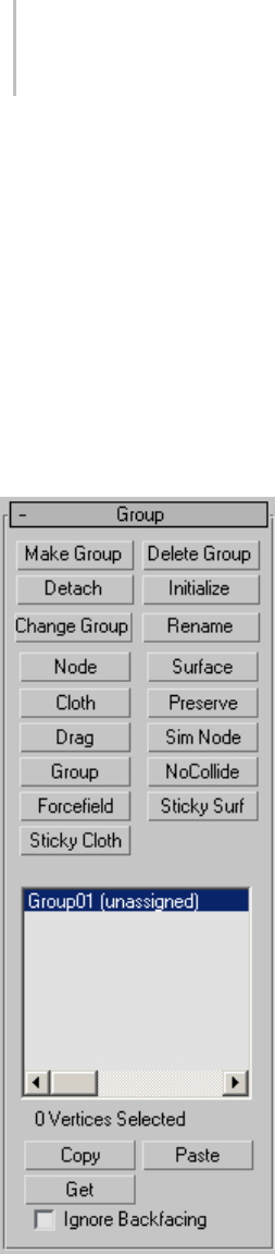
590 Chapter 8: Modifiers
objects in the simulation. And when created, groups can
then be given unique properties. For example, a group
on a collision object can have a different collision offset
from the rest of the object. This is a powerful feature
when working with groups.
Note: You can select groups of vertices explicitly,
with the mouse in the viewports, and you can
also specify a soft selection or use a texture map
to select vertices using controls on the Group
Parameters rollout. See Soft Selection group (page
1–596). In addition, named selection set (page
1–83) toolsareavailableatthislevel.
Make Group—Makes a group out of selected
vertices. Select the vertices to include in the group,
and then click this button. Name the group, and it
will then show up in the list below for you assign
to an object.
Delete Group—Deletes the group highlighted in
the list.
Detach—Removes any constraint assigned to the
group and sets it back to being unassigned (i.e.,
without any constraint). Any unique properties
assigned to this group will remain in effect.
Initialize—Constraints that involve attaching
the vertices to another object (Node, SimNode,
Surface and Cloth constraints) contain
information regarding the relative positions
of the group vertices to the other object. This
information is created upon the creation of the
constraint. To regenerate this information, click
this button.
Change Group—Lets you modify the vertex
selection in the group. To use, follow this
procedure:
1. Choose the group in the list.
2. Change the selection of vertices.
3. Click Change Group.
Rename—Renames the highlighted group.
Node—Constrains the highlighted group to the
transforms of an object or node in the scene.
To use, click Node, and then select the node for
constraining. The node cannot be an object in
the simulation; for that purpose, use the SimNode
constraint.
Note: Node and SimNode simply constrain the
group to an object’s transforms,nottotheobject
itself. They need not be near each other. When
the cloth and the constraining object should be
incloseproximity,suchaswithclothingona
character mesh, use the Surface constraint instead
(see following).

Cloth Modifier 591
Surface—Attaches the selected group to the surface
of a collision object in the scene. To use, click
Surface, and then select the node for attaching.
Tip: This constraint is best suited for when the cloth
and the constraining object should be in close
proximity, such as with clothing on a character
mesh.
Cloth—Attaches the selected group of cloth vertices
to another cloth object.
Preserve—This group type preserves the motion
from below the Cloth modifier in the modifier
stack. For example, you might have a dress that
you’ve skinned to a skeleton. You want the upper
portion of the dress to be unaffected by the Cloth
simulation (that is, to retain its deformation
defined by the skinning), and the lower part to
be simulated. In this case, you’d make a Preserve
constraint from the upper vertices.
Drag—This group type locks the vertices in place
or adds a damping force to selected group. When
Group Parameters rollout > Soft is off, you can
use this constraint for “nailing” vertices in place
sothattheydonotmoveatall.WhenSoftison,
theverticeswillhaveadragforceappliedwhere
the amount of drag is controlled by the Strength
and Damping values, also on the Group Properties
rollout.
SimNode—This option works the same as the Node
option, except the node must be part of the Cloth
simulation.
Group—Attaches one group to another. This is
recommended only for single-vertex groups. (that
is, groups that contain only one vertex). With this,
you can make one cloth vertex stick to another
cloth vertex. Select one group, click this button
to open the Pick Group dialog , and then choose
another group.
NoCollide—Causes collisions between the currently
selected group and another group to be ignored.
When you click this button, you’re prompted to
choose another group. You could use this option
to prevent the simulator from processing collisions
between cloth and the body under an arm or
between the legs.
Forcefield—Allows you to link a group to a space
warp and have the space warp affect the vertices.
Sticky Surf—The group sticks to a surface only
after it has collided with that surface. Solid Coll
must be enabled for this constraint to work.
Sticky Cloth—The group sticks to a surface only
after it has collided with that surface. Self Coll must
be enabled for this constraint to work.
[group list]—Shows all current groups. The
number of vertices associated with the highlighted
group is shown below the list. To assign, copy,
paste, delete or alter a created group, first highlight
the group name in the list.
Copy—Copies a named selection set to the copy
buffer.
Paste—Pastes the named selection set from copy
buffer.
Group Parameters rollout
The Group Parameters rollout appears after you
use Make Group on a vertex selection to create at
least one group. Thereafter, highlight the group
intheGrouprolloutlisttodisplayandeditthe
group’ssettingswiththeGroupParametersrollout.
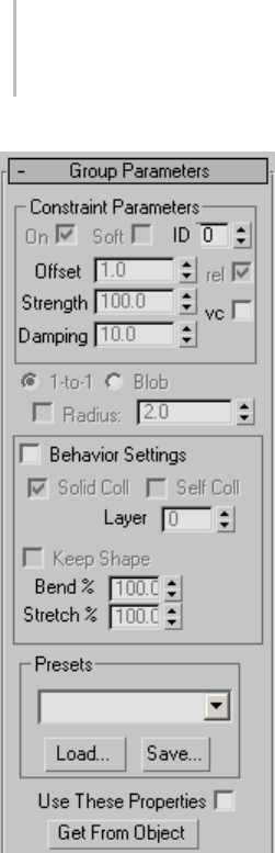
592 Chapter 8: Modifiers
Constraint Parameters group
On—When on, enables the constraint specified for
the current group in the group list on the Group
rollout, using remaining settings in this group box.
Soft—Sets the constraint type to soft. A soft
constraint uses springs between vertices. When
off, the constraint is hard or rigid. The constraint
types Node, Surface, Preserve, Drag, and SimNode
can be hard or soft. Cloth, Group, and Forcefield
constraints are always soft.
ID—Uses a Material ID to attach the group to
an object. This option applies only to Surface
and Cloth constraints. If, when the constraint is
created or initialized, the cloth vertices are not
over a triangle, then the constraint will be created
to the center of the nearest triangle that has the
requisite Material ID. This could mean that several
vertices might be constrained to the center of the
same triangle. In this case, you should only use
soft constraints. A hard constraint would pull all
thoseclothverticestothesameexactpointonthe
triangle, which would look strange.
Offset—The variance in the distance between a
constrained group and its constraining, or target,
object. The default value is 1.0 with Rel. on. This
sets the constrained group to maintain its original
distance from the target object. When set to 0.0,
the constraint seeks to set the distance to the target
object to zero.
Strength—Thestiffnessofthespringsusedifthe
constraint is soft.
Damping—The damping of the springs if the
constraint is soft.
Rel.—Specifies the offset as a ratio of the original
value.AvailableonlywiththeSurfaceandCloth
constraint types. For example, if you want to move
a constrained vertex by half its original distance,
turn on the Rel. check box and set Offset to 0.5.
Vc—Sets vertex colors to determine the strength of
the constraint.
1-to-1—When the mesh density is changed in
Garment Maker, the group selection is reassigned.
The 1-to-1 option selects the vertex closest to the
original vertex.
Blob—When the mesh density is changed in
Garment Maker, the group selection is reassigned.
The Blob option selects the original vertex and
the ones created within a certain radius of it. The
radiuscanbeleftatdefaultorauto,oritcanbe
set manually.

Cloth Modifier 593
Radius—When on, lets you set the radial distance
used by the Blob option (see preceding). When
off, Blob uses an automatic radial value.
Behavior Settings group
Behavior Settings—Toggles the availability of the
other settings in this group. When off, the other
settings have no effect.
Solid Coll—When on, the group vertices are used
in solid-collision detection.
Self Coll—When on, the group vertices are used in
self-collision detection.
Layer—Indicates the correct "order" of cloth
pieces that might come in contact with each other.
Range=-100 to 100. Default=1.
If your garments and/or panels are all correctly
orientated to begin with, then cloth-to-cloth
collision detection should keep items from
interpenetrating. However, the initial state of a
garment/panel might have some interpenetration
that cannot be resolved. For example, suppose you
make a jacket with Garment Maker where the front
rightpanelissupposedtositontopofthefront
left panel. When you sew together the garment
(generally with self-collision off), the front panels
will interpenetrate, so to make sure that the right
panelsitsoutsidetheleftpanel,youmighthave
to use constraints or Live Drag. Using the Layers
option on the panels can help here.
Here is the logic of layers: When two pieces of
cloth (A and B) are in collision-detection range,
their layers (layerA and layerB) are compared and
the following rules are applied:
• If either layerA or LayerB is 0, then Cloth uses
the regular cloth-to-cloth collision method.
• If layerA=layerB, then Cloth uses the regular
cloth-to-cloth collision method.
• If abs(layerA) > abs(layerB) then piece A is
pushedtotheappropriatesideofpieceB.
Which side? If layerB > 0, then to the side
indicated by the face normals. If layerB<0 then
to the opposite side.
The sign of the Layer value indicates what the
"outside" of that piece of cloth is. A positive sign
means "The side that the normals face is the
outside".
Keep Shape—When on, preserves the shape of the
mesh based on the Bend % and Stretch % settings
(see following). In normal operation, when Cloth
creates a simulation, it tries to "flatten out" the
cloth.
Bend %—Modulates the target bend angles to a
value between 0.0 and the angles defined by the
target state. A negative value inverts the angles.
Range=-100.0 to 100.0. Default=100.0.
Stretch %—Modulates the target stretch angles to
a value between 0.0 and the angles defined by the
target state. A negative value inverts the angles.
Range=-100.0 to 100.0. Default=100.0.
Presets group
Sets the Cloth Properties parameters to the preset
selected in the drop-down list. Any presets that
arebuiltintothesystemorthathavebeenloaded
will show up here.
Load—Loads presets from the hard drive. Click
this button and then navigate to the directory
with your presets to load them into your Cloth
Properties.
Save—Saves your Cloth Properties parameters to a
file that you can then load at a later time.
Use These Properties—Determines the cloth
properties from the settings on the rollout below.
Get From Object—Sets the cloth properties of the
group to be the same as the object they are selected
on.
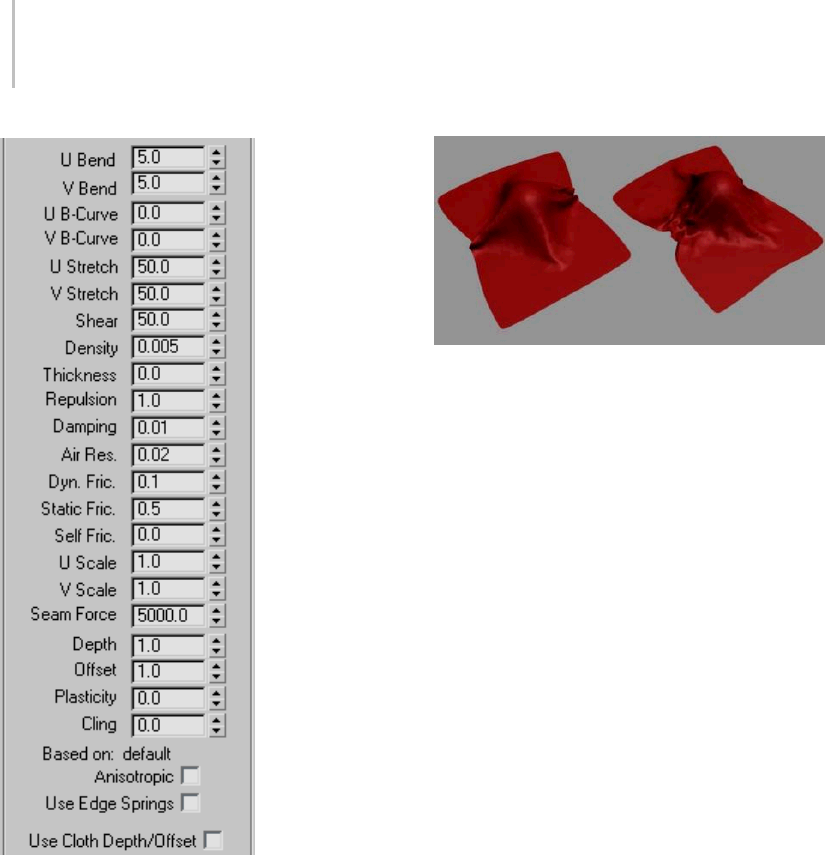
594 Chapter 8: Modifiers
U Bend/V Bend—Resistance to bending. The higher
thisvalueisset,thelessthefabricwillbeableto
bend. A cotton fabric might bend more easily than
leather, so a value of 15.0 for both U and V Bend
might be good for cotton, while 50.0 would work
well for leather.
By default, the U Bend and V Bend parameters
are locked together so that changing one sets the
other to the same value. You can set different
values for the two only when Anisotropic is off. It is
recommended to do this only for Garment Maker
(page 1–607) objects.
Left: U and V Bend=50, simulating a burlap material
Right: U and V Bend=2.5, simulating silk or other light fabric
UB-Curve/VB-Curve—Resistance to bending as
the fabric folds. The default value of 0 sets the
bend resistance to be constant. A setting of 1
makes the fabric very resistant to bending as the
angle between triangles approaches 180 degrees.
You never want two adjacent triangles to pass
througheachother,soyoucanincreasethisvalue
to prevent this from happening.
By default, the U B-Curve and V B-Curve
parameters are locked together so that changing
one sets the other to the same value. You can set
different values for the two only when Anisotropic
is off. It is recommended to do this only for
Garment Maker (page 1–607) objects.
UStretch/VStretch—Resistance to stretching. The
default value of 50.0 is a reasonable value for most
types of cloth. A Larger value will be stiffer, while
asmalleronewillbestretchylikerubber.
By default, the U Stretch and V Stretch parameters
are locked together so that changing one sets the
other to the same value. You can set different
values for the two only when Anisotropic is off. It is
recommendedtodothisonlyforGarment Maker
(page 1–607) objects.
Shear—Resistance to shearing. Higher values
result in stiffer cloth fabrics. Shear defines how
much the individual triangles can deform. If you
were to lay the edges of the triangle out in a strait
line this value would represent how long this line
can stretch out to. With a high value this length
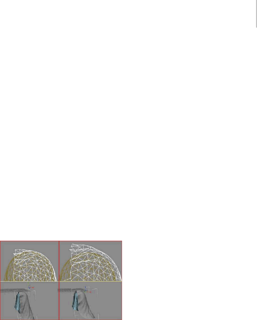
Cloth Modifier 595
will only be the sum of the length of all of the
sides at rest. A low value will allow this length to
be greater then that off all of its sides at rest. This
length of stretched sides is not on a one to one
basis. One side of the polygon may stretch more
then another as long as the total shear value is not
exceeded.
Density—The weight of the cloth per unit area (in
gm/cm2). Higher values mean heavier cloth like
denim. Use smaller values for lighter cloth like silk.
Thickness—Defines the virtual thickness of a
fabric for the purpose of detecting cloth-to-cloth
collisions. This value is irrelevant if cloth-to-cloth
collisions are disabled. Larger values keep the
cloth separated by greater distances. Be careful
nottousetoolargeorsmallvaluesinthisfield.
Very large values will interfere with the natural
behavior of the cloth. Very small values will cause
the simulator to take too long to calculate. This
distance is measured in cm (centimeters) and
should be smaller than the size of the triangles that
make up the cloth object. A setting of 0.0 will let
Cloth automatically assign a reasonable value for
thickness.
Left:ThetoppieceofclothwithaThicknessof0
Right: Thickness of 9
Repulsion—The amount of force used to repel
other cloth objects. This value is irrelevant
if cloth-to-cloth collisions are disabled. The
simulator will apply a repulsion force scaled by
this value to keep the cloth from coming in contact
with other cloth objects. Increase this value if there
are a lot of collisions between different parts of
cloth, or if the cloth is tending to interpenetrate.
Damping—The larger this value, is the more
sluggishly the fabric will react. With a lower value,
thefabricwillbehavewithmorespring. Cloth
with more damping will come to rest sooner then
clothwithlessdamping.Highdampingresultsin
cloth that behaves as though it is moving through
oil. Excessive damping may also cause simulation
instabilities. A good value is the default, 0.01.
Air Res.—Resistance to Air. This value will
determinehowmuchtheairwilleffectthecloth.A
higher amount of air resistance would be useful for
a tightly woven fabric, while a lower amount would
be suitable for a loose-knit garment.
Dyn. Fric.—Dynamic friction between the cloth
and solid objects. A larger value will add more
friction and cause the fabric to slide less across
an object. A lower value will allow the fabric to
slip off an object very easily, similarly to how silk
would react.
Static Fric.—Static friction between the cloth and
solid objects. When the cloth is in stationary
position, this value will control its ability stay
where it is, or slip away.
Self Fric.—Friction between the cloth and itself.
This is similar to dynamic and static friction, but
applies to cloth-to-cloth or self-collisions. A larger
value will cause more friction between the cloth
and itself.
UScale—Controls how much to shrink or expand
the cloth along the U direction (as defined by
Garment Maker. For non-Garment Maker meshes,
this applies a uniform scaling to the cloth along
both axes, and the V Scale parameter is ignored).
A value of less than 1 will shrink the fabric at
simulation time, while a value of more than 1 will
stretch it.
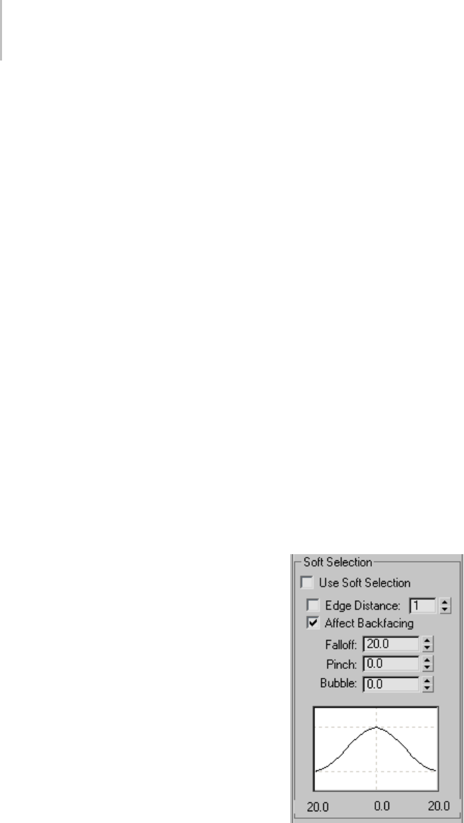
596 Chapter 8: Modifiers
VScale—
Controls how much to shrink or expand
the cloth along the V direction (as defined by
Garment Maker). A value of less than 1 will shrink
thefabricatsimulationtime,whileavalueofmore
than 1 will stretch it.
Seam Force—Notpresentlyusedandonlykeptfor
backward compatibility with older versions of the
former product called Stitch. This was a global
seam strength, but seam strength is now defined
on a seam-by-seam basis in the Seams sub-object
Mode.
Depth—Collision depth. If a portion of cloth
reaches this depth inside a collision object, then
the simulation will no longer try to push the cloth
out of the mesh. This value is measured in 3ds Max
units.
Offset—The amount of distance kept between the
cloth and the collision object. A very low value
can cause the collision mesh to protrude out from
under the cloth. A very high value will cause
thefabrictolookasifitisfloatingontopofthe
collision object.
Plasticity—The tendency of the cloth to keep its
current deformation (that is, the bend angles).
This is different from Keep Shape,which
determinestheextenttowhichtheclothtendsto
keep its original deformation (or the one defined
by the Target State). If you set Plasticity to 100.0,
the cloth will not attempt to change the angles
between triangles. If you want stiffer cloth, but you
don’twanttheclothto"balloon"up,increasethe
Plasticity value.
Cling—Theextenttowhichtheclothobjectadheres
to a collision object. Range=0.0 to 99999.0.
Default=0.0.
You can use this parameter to simulate effects such
as wet cloth. A setting of 1.0 should be just enough
to hold the default material onto a surface against
its own weight.
Based on—Displays the preset that the group
properties are based on. When you modify
parameters and save a preset, Cloth uses the name
of the last preset you loaded as the “Based on”
name.
Anisotropic—When on, you can set different U
andVvaluesfortheBend,B-Curve,andStretch
parameters. The U and V directions are defined
by Garment Maker (page 1–607) and do not apply
to non-Garment Maker meshes, for which setting
different U/V values might result in unexpected
behavior.
UseEdgeSprings—This is an alternative method
for calculating stretch. When this option is on,
stretch force is based on springs along triangle
edges. (Whereas normally the stretch and shear
forcesarecalculatedinamoresophisticated
manner to more accurately reflect the underlying
physics).
Use Cloth Depth/Offset—Uses the Depth and Offset
values set for the group. When on, the cloth object
ignores the collision object Depth and Offset
values.
Soft Selection group
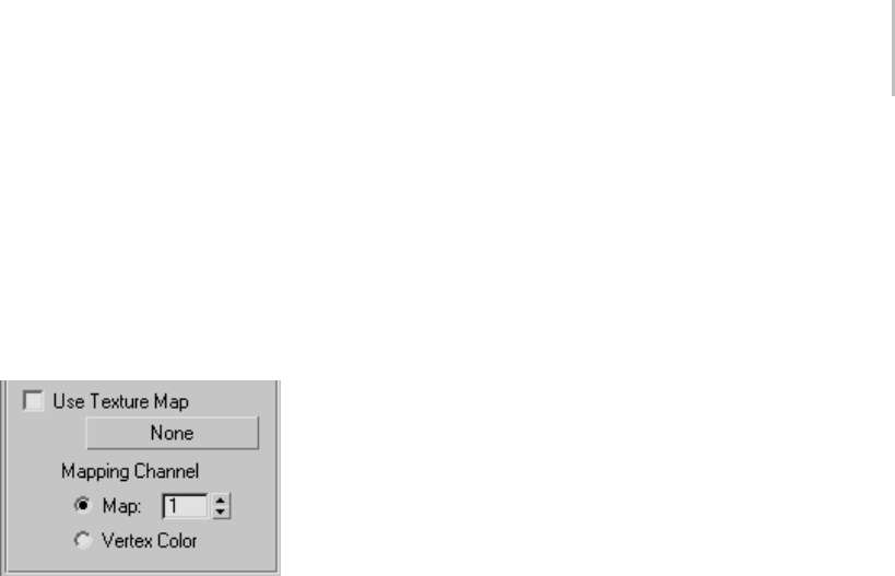
Cloth Modifier 597
The Soft Selection controls apply on a per-group
basis to permit soft selection of vertices
neighboring the explicitly selected group
members. This works the same as soft selection of
vertices in other parts of 3ds Max. For details, see
Soft Selection Rollout (page 1–963).Alternatively,
you can select vertices for a group based on a
texture map.
Use Texture Map—When on, Cloth uses a texture
map to specify a soft selection of vertices that
belong to the current group. Click the button (by
default, labeled “None”) to choose a texture map.
Use the Mapping Channel controls to choose a
map channel or vertex color channel.
You can add a grayscale texture map in this slot to
blend between unselected and fully selected pixels
in the group. Black represents unselected and
white represents fully selected. Any grayscale value
blends between the two. You can drag a texture
map onto this button.
Note: For a texture map to apply to a group, at least
onevertexmustbeexplicitlyselected. However,
whenUseTextureMapison,thegroup’sexplicit
vertex selection has no effect.
Panel rollout
At the Panel sub-object level, you can select one
panel (cloth section) at a time and change its cloth
properties. A panel, which must be created by the
Garment Maker modifier (page 1–607),isaclosed
spline that is not enclosed by another spline. If
a closed spline is enclosed by another spline, it
forms a hole in the outer spline.
Note: To be able to select a panel at this sub-object
level, you must first use Object Properties (page
1–602) to specify that the object is cloth. Also, to
be able to change settings on this rollout, first turn
on Object Properties > Use Panel Properties.
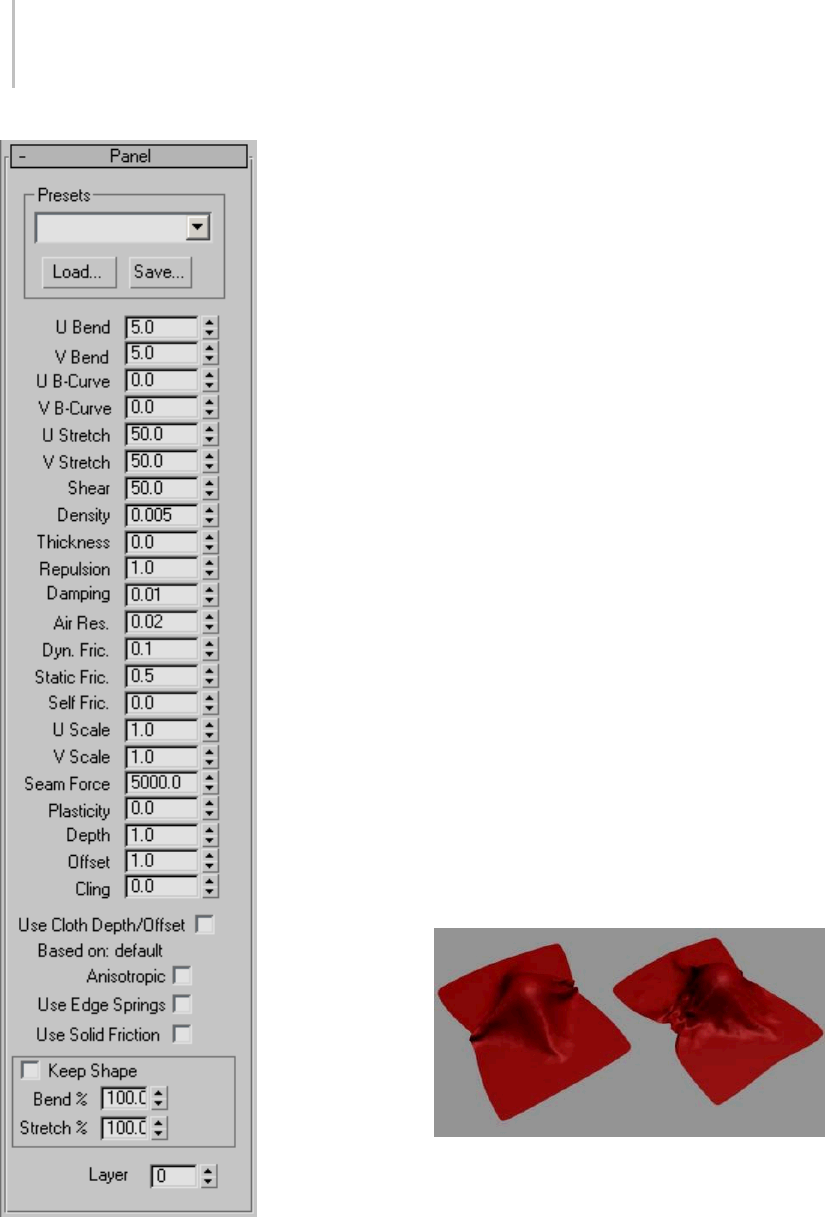
598 Chapter 8: Modifiers
Presets group
Presets—Sets the selected panel’s properties
parameters to the preset selected in the drop-down
list. Any presets that are built into the system or
that have been previously saved and loaded will
show up here. Presets have the filename extension
.sti.
Load—Load presets from a specified location on
your hard drive. Click this button and navigate to
the directory with your presets to load them into
your Cloth Properties.
Save—Save your Cloth Properties parameters to a
file to be loaded at a later time. By default, Cloth
preset files are saved to the \cloth folder inside the
program install directory.
U Bend/V Bend—Resistance to bending. The higher
thisvalueisset,thelessthefabricwillbeableto
bend. A cotton fabric might bend more easily than
leather, so a value of 15.0 for both U and V Bend
might be good for cotton, while 50.0 would work
well for leather.
By default, the U Bend and V Bend parameters
are locked together so that changing one sets the
other to the same value. You can set different
values for the two only when Anisotropic is off. It is
recommendedtodothisonlyforGarment Maker
(page 1–607) objects.
Left: U and V Bend=50, simulating a burlap material
Right: U and V Bend=2.5, simulating silk or other light fabric
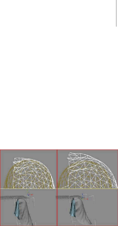
Cloth Modifier 599
UB-Curve/VB-Curve—
Resistance to bending as
the fabric folds. The default value of 0 sets the
bend resistance to be constant. A setting of 1
makes the fabric very resistant to bending as the
angle between triangles approaches 180 degrees.
You never want two adjacent triangles to pass
through each other, so you can increase this value
to prevent this from happening.
By default, the U B-Curve and V B-Curve
parameters are locked together so that changing
one sets the other to the same value. You can set
different values for the two only when Anisotropic
is off. It is recommended to do this only for
Garment Maker (page 1–607) objects.
UStretch/VStretch—Resistance to stretching. The
default value of 50.0 is a reasonable value for most
typesofcloth.ALargervaluewillbestiffer,while
a smaller one will be stretchy like rubber.
By default, the U Stretch and V Stretch parameters
are locked together so that changing one sets the
other to the same value. You can set different
values for the two only when Anisotropic is off. It is
recommended to do this only for Garment Maker
(page 1–607) objects.
Shear—Resistance to shearing. Higher values
result in stiffer cloth fabrics. Shear defines how
much the individual triangles can deform. If you
were to lay the edges of the triangle out in a strait
line this value would represent how long this line
can stretch out to. With a high value this length
will only be the sum of the length of all of the
sides at rest. A low value will allow this length to
be greater then that off all of its sides at rest. This
length of stretched sides is not on a one to one
basis. One side of the polygon may stretch more
then another as long as the total shear value is not
exceeded.
Density—The weight of the cloth per unit area (in
gm/cm2). Higher values mean heavier cloth like
denim. Use smaller values for lighter cloth like silk.
Thickness—Defines the virtual thickness of a
fabric for the purpose of detecting cloth-to-cloth
collisions. This value is irrelevant if cloth-to-cloth
collisions are disabled. Larger values keep the
cloth separated by greater distances. Be careful
not to use too large or small values in this field.
Very large values will interfere with the natural
behavior of the cloth. Very small values will cause
the simulator to take too long to calculate. This
distance is measured in cm (centimeters) and
should be smaller than the size of the triangles that
make up the cloth object. A setting of 0.0 will let
Cloth automatically assign a reasonable value for
thickness.
Left: The top piece of cloth with a Thickness of 0
Right: Thickness of 9
Repulsion— The amount of force used to repel
other cloth objects. This value is irrelevant
if cloth-to-cloth collisions are disabled. The
simulator will apply a repulsion force scaled by
this value to keep the cloth from coming in contact
with other cloth objects. Increase this value if there
are a lot of collisions between different parts of
cloth, or if the cloth is tending to interpenetrate.
Damping— The larger this value, is the more
sluggishly the fabric will react. With a lower value,
thefabricwillbehavewithmorespring. Cloth
with more damping will come to rest sooner then
clothwithlessdamping.Highdampingresultsin
cloth that behaves as though it is moving through
oil. Excessive damping may also cause simulation

600 Chapter 8: Modifiers
instabilities. A good value is 0.01 (note: the default
is 0.1, but in practice, it seems that this value is
too high).
Air Res.— Resistance to Air. This value will
determine how much the air will effect the cloth. A
higher amount of air resistance would be useful for
a tightly woven fabric, while a lower amount would
be suitable for a loose-knit garment.
Dyn. Fric.— Dynamic friction between the cloth
and solid objects. A larger value will add more
friction and cause the fabric to slide less across
an object. A lower value will allow the fabric to
slip off an object very easily, similarly to how silk
would react.
Static Fric.— Static friction between the cloth and
solid objects. When the cloth is in stationary
position, this value will control its ability stay
where it is, or slip away.
Self Fric.— Friction between the cloth and itself.
This is similar to dynamic and static friction, but
applies to cloth-to-cloth or self-collisions. A larger
value will cause more friction between the cloth
and itself.
UScale—Controls how much to shrink or expand
the cloth along the U direction (as defined by
Garment Maker. For non-Garment Maker meshes,
this applies a uniform scaling to the cloth along
both axes, and the V Scale parameter is ignored).
Avalueoflessthan1willshrinkthefabricat
simulation time, while a value of more than 1 will
stretch it.
VScale—Controls how much to shrink or expand
the cloth along the V direction (as defined by
Garment Maker). A value of less than 1 will shrink
thefabricatsimulationtime,whileavalueofmore
than 1 will stretch it.
Seam Force—Notpresentlyusedandonlykeptfor
backward compatibility with older versions of the
former product called Stitch. This was a global
seam strength, but seam strength is now defined
on a seam-by-seam basis at the Seams sub-object
level.
Plasticity—The tendency of the cloth to keep its
current deformation (that is, the bend angles).
This is different from Keep Shape,which
determines the extent to which the cloth tends to
keep its original deformation (or the one defined
by the Target State). If you set Plasticity to 100.0,
the cloth will not attempt to change the angles
between triangles. If you want stiffer cloth, but you
don’twanttheclothto"balloon"up,increasethe
Plasticity value.
Depth—Collision depth. If a portion of cloth
reaches this depth inside a collision object, then
the simulation will no longer try to push the cloth
out of the mesh. This value is measured in 3ds Max
units.
Offset—The amount of distance kept between the
cloth and the collision object. A very low value
can cause the collision mesh to protrude out from
under the cloth. A very high value will cause
thefabrictolookasifitisfloatingontopofthe
collision object.
Use Cloth Depth/Offset—Uses the Depth and Offset
values set for the panel (see preceding). When on,
the cloth object ignores the collision object Depth
and Offset values.
Cling—Theextenttowhichtheclothobjectadheres
to a collision object. Range=0.0 to 99999.0.
Default=0.0.
You can use this parameter to simulate effects such
as wet cloth. A setting of 1.0 should be just enough
to hold the default material onto a surface against
its own weight.
Based on—Lists the preset that the panel properties
are based on. When you modify parameters and
save a preset, Cloth uses the name of the last preset
you loaded as the “Based on” name.
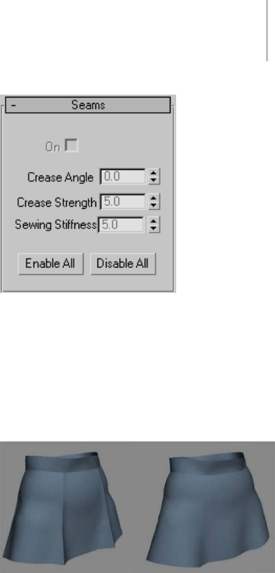
Cloth Modifier 601
Anisotropic—When on, you can set different U
and V values for the Bend, B-Curve, and Stretch
parameters. The U and V directions are defined
by Garment Maker (page 1–607) and do not apply
to non-Garment Maker meshes, for which setting
different U/V values might result in unexpected
behavior.
UseEdgeSprings—This is an alternative method
for calculating stretch. When this option is on,
stretch force is based on springs along triangle
edges. (Whereas normally the stretch and shear
forces are calculated in a more sophisticated
manner to more accurately reflect the underlying
physics).
Use Solid Friction—Uses the friction of the collision
object to determine friction. Values for collision
can be assigned either to the cloth or the collision
objects. This enables you to set different friction
values for each collision object
Keep Shape—When on, preserves the shape of the
mesh based on the Bend % and Stretch % settings
(see following). In normal operation, when Cloth
creates a simulation, it tries to "flatten out" the
cloth.
Bend %—Modulates the target bend angles to a
value between 0.0 and the angles defined by the
target state.Anegativevalueinvertstheangles.
Range=-100.0 to 100.0. Default=100.0.
Stretch %—Modulates the target stretch angles to
avaluebetween0.0andtheanglesdefinedbythe
target state.Anegativevalueinvertstheangles.
Range=-100.0 to 100.0. Default=100.0.
Seams rollout
The Seams sub-object rollout is used to define
seam properties.
On—Turn t he seam on or off to make it ac tive or
inactive.
Crease angle—Creates a crease at your seam. The
anglevaluewilldeterminetheangleofthecrease
that will be between the two panels. (Can be
positive or negative depending on which way you
want to crease)
Left: High crease angle
Right: Low crease angle
Crease Strength—Increase or decrease the strength
of your seam. This value will effect how much
the seam will resist bending in relation to the rest
of the cloth object. A value of 2.0 means that the
clothwillhavetwicetheresistancetobending
that it would otherwise have (as defined by the
object/panel/vertex group properties).
Sewing Stiffness—The amount of force with which
thepanelswillbepulledtogetheratsimulation
time.Alargervaluewillpullthepanelstogether
harder and faster.
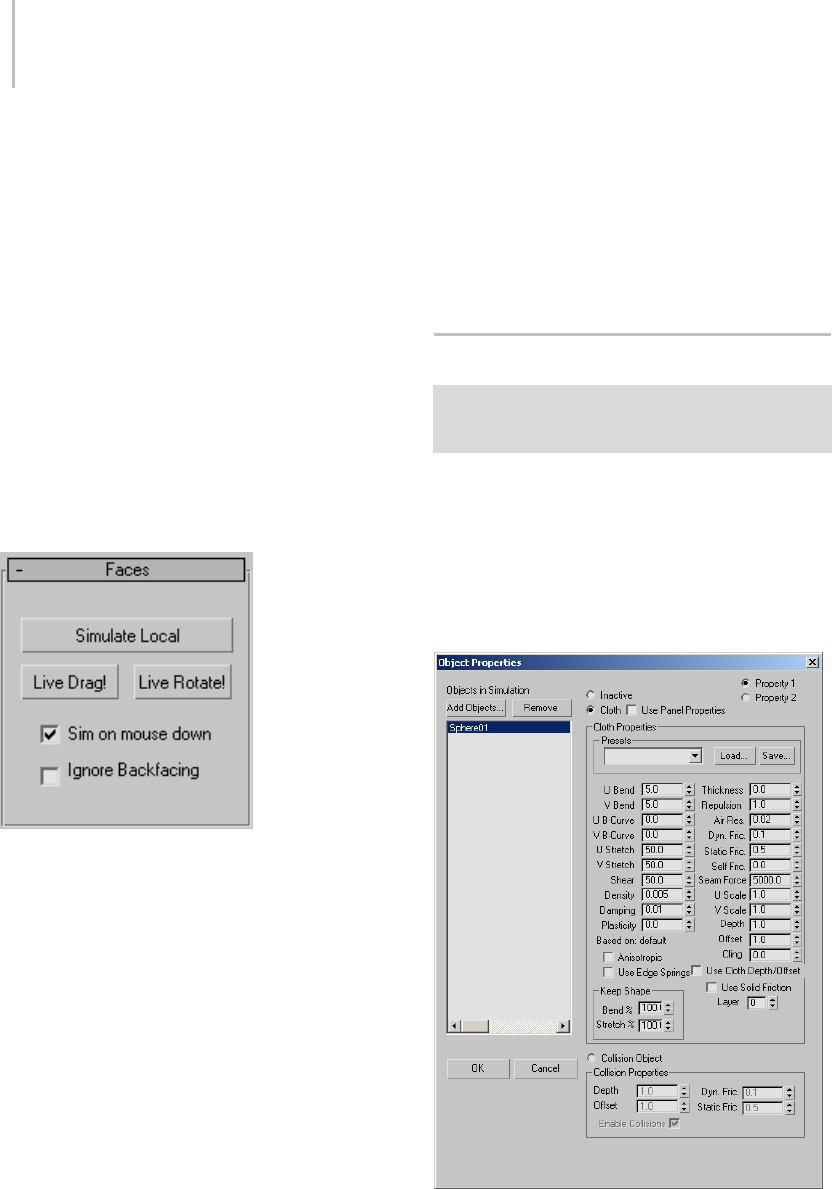
602 Chapter 8: Modifiers
Enable All—Sets all seams on selected garment to
be active.
Disable All—Sets all seams on selected garment to
be off. This button deactivates the On check box
for all seams.
Faces rollout
The Faces sub-object rollout enables interactive
dragging of cloth objects while they are simulated
locally. This sub-object level is useful for
positioning cloth within your scenes in a more
interactive way.
Note: If you position your cloth incorrectly, you
canrestoretheoriginalpositionbyreturningto
the Object level and clicking the Reset State button.
Simulate Local—Starts local simulation of the cloth.
In order for the real-time interactive feedback with
the cloth to occur, this button must be on.
Live Drag!—When active you can drag selected
facesasthelocalsimulationistakingplace.
Live Rotate!—When active, you can rotate selected
facesasthelocalsimulationistakingplace.
Sim on mouse down—Runs the local simulation
only when the left mouse button is clicked. This
mode is usually preferred since you can start and
stop the local simulation simply by releasing the
mouse button. As a result, it makes it far easier to
position and rotate the faces of your cloth within
your scene.
Ignore Backfacing—When on, you can select only
faces facing you. When off (the default), you can
select any faces under the mouse cursor, regardless
of visibility or facing.
Object Properties Dialog (Cloth)
Select an object. > Modify panel > Modifier List >
Object-Space Modifiers > Cloth > Object rollout > Object
Properties button
Use the Object Properties dialog to specify which
objects are included in a Cloth (page 1–578)
simulation, whether they are cloth or collision
objects, and define parameters associated with
them.
Interface

Object Properties Dialog (Cloth) 603
Objects in Simulation—Lists objects currently
included in the simulation. To change an object’s
properties, first highlight its name in the list.
You can highlight multiple object names using
standard methods: Ctrl +click, Shift +click, and
dragging.
Add Objects—Opens a dialog that lets you select
objects from your scene to be added to the Cloth
simulation. After adding an object with this
button, it appears in the Objects In Simulation list,
and an instance of the Cloth modifier is applied
to the object.
Remove—Removes objects highlighted in the
ObjectsInSimulationlistfromthesimulation.
You cannot remove objects currently selected in
3ds Max.
Inactive—Makesanobjectinactiveinthe
simulation. The object can still be in the
simulation, but it will not react to anything. This
is good for testing how different objects react and
isolating dynamic effects.
Property 1/Property 2—These two radio buttons let
you assign two different sets of cloth properties to
objects highlighted in the Objects In Simulation
list. YoucanthenusetheProperty Assignment
group (page 1–587) settings to interpolate
or animate between the sets. The Use Cloth
Depth/Offset, Use Edge Springs, Use Solid
Friction, and Keep Shape options can be set only
for Property 1 because Property 2 uses the same
settings.
Cloth—Sets the object or objects highlighted in
the Objects In Simulation list to cloth objects and
allows you to define parameters for them in the
Cloth Properties section of the dialog.
Use Panel Properties—When on, tells Cloth
to use the Cloth Properties from the Panel
sub-object level of the Cloth modifier. This allows
you to define different cloth properties on a
panel-by-panel basis.
Cloth Properties group
Presets—Sets the Cloth Properties parameters to
the preset chosen from the drop-down list. Any
presets that are built into the system or that have
been previously saved and loaded will show up
here.
Load—Loads presets from your hard drive. Click
this button and then navigate to the directory with
your presets to load them into Cloth Properties.
Save—Saves Cloth Properties parameters to a file
to be loaded at a later time. By default, all Cloth
preset files are saved to your \scenes\cloth folder.
U Bend/V Bend—Resistance to bending. The higher
thisvalueisset,thelessthefabricwillbeableto
bend. A cotton fabric might bend more easily than
leather, so a value of 15.0 for both U and V Bend
might be good for cotton, while 50.0 would work
well for leather.
By default, the U Bend and V Bend parameters
are locked together so that changing one sets the
other to the same value. You can set different
values for the two only when Anisotropic is off. It is
recommendedtodothisonlyforGarment Maker
(page 1–607) objects.
Left: U and V Bend=50, simulating a burlap material
Right: U and V Bend=2.5, simulating silk or other light fabric
Thickness— Defines the virtual thickness of a
fabric for the purpose of detecting cloth-to-cloth
collisions. This value is irrelevant if cloth-to-cloth
collisions are disabled. Larger values keep the
cloth separated by greater distances. Be careful
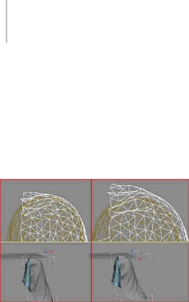
604 Chapter 8: Modifiers
nottousetoolargeorsmallvaluesinthisfield.
Very large values will interfere with the natural
behavior of the cloth. Very small values will cause
the simulator to take too long to calculate. This
distance is measured in cm (centimeters) and
should be smaller than the size of the triangles that
make up the cloth object. A setting of 0.0 will let
Cloth automatically assign a reasonable value for
thickness.
Left:ThetoppieceofclothwithaThicknessof0
Right: Thickness of 9
Repulsion—The amount of force used to repel
other cloth objects. This value is irrelevant
if cloth-to-cloth collisions are disabled. The
simulator will apply a repulsion force scaled by
this value to keep the cloth from coming in contact
with other cloth objects. Increase this value if there
are a lot of collisions between different parts of
cloth, or if the cloth is tending to interpenetrate.
UB-Curve/VB-Curve—Resistance to bending as
the fabric folds. The default value of 0 sets the
bend resistance to be constant. A setting of 1
makes the fabric very resistant to bending as the
angle between triangles approaches 180 degrees.
You never want two adjacent triangles to pass
through each other, so you can increase this value
to prevent this from happening.
By default, the U B-Curve and V B-Curve
parameters are locked together so that changing
one sets the other to the same value. You can set
different values for the two only when Anisotropic
is off. It is recommended to do this only for
Garment Maker (page 1–607) objects.
Air Res.—Resistance to air. This value will
determinehowmuchtheairwilleffectthecloth.A
higher amount of air resistance would be useful for
a tightly woven fabric, while a lower amount would
be suitable for a loose-knit garment.
Dyn. Fric.—Dynamic friction between the cloth
and solid objects. A larger value will add more
friction and cause the fabric to slide less across an
object. A lower value will allow the fabric to slip off
an object easily, similarly to how silk would react.
UStretch/VStretch—Resistance to stretching. The
default value of 50.0 is a reasonable value for most
types of cloth. A Larger value will be stiffer, while
asmalleronewillbestretchylikerubber.
By default, the U Stretch and V Stretch parameters
are locked together so that changing one sets the
other to the same value. You can set different
values for the two only when Anisotropic is off. It is
recommendedtodothisonlyforGarment Maker
(page 1–607) objects.
Static Fric.—Static friction between the cloth and
solid objects. When the cloth is in stationary
position, this value will control its ability stay
where it is, or slip away.
Self Fric.—Friction between the cloth and itself.
This is similar to dynamic and static friction, but
applies to cloth-to-cloth or self-collisions. A larger
value will cause more friction between the cloth
and itself.
Shear—Resistance to shearing. Higher values
result in stiffer cloth fabrics. Shear defines how
much the individual triangles can deform. If you
were to lay the edges of the triangle out in a strait
line this value would represent how long this line
canstretchoutto.Withahighvaluethislengthwill
only be the sum of the length of all of the sides at
rest. A low value will allow this length to be greater
then that off all of its sides at rest. This length of

Object Properties Dialog (Cloth) 605
stretched sides is not on a one to one basis. One
side of the polygon may stretch more then another
as long as the Seam Force—Not presently used and
only kept for backward compatibility with older
versions of the former product, called Stitch. This
was a global seam strength, but seam strength is
now defined on a seam-by-seam basis at the Seams
sub-object level.total shear value is not exceeded.
Density— The weight of the cloth per unit area (in
gm/cm2). Higher values mean heavier cloth like
denim. Use smaller values for lighter cloth like silk.
Damping— The larger this value, is the more
sluggishlythefabricwillreact.Withalowervalue,
thefabricwillbehavewithmorespring. Cloth
with more damping will come to rest sooner then
clothwithlessdamping.Highdampingresultsin
cloth that behaves as though it is moving through
oil. Excessive damping may also cause simulation
instabilities. A good value is 0.01 (note: the default
is 0.1, but in practice, it seems that this value is
too high).
UScale—Controls how much to shrink or expand
the cloth along the U direction (as defined by
Garment Maker). For non-Garment Maker
meshes, this applies a uniform scaling to the cloth
along both axes, and the V Scale parameter is
ignored). A value of less than 1 will shrink the
fabric at simulation time, while a value of more
than 1 will stretch it.
VScale—Controls how much to shrink or expand
the cloth along the V direction (as defined by
Garment Maker). A value of less than 1.0 will
shrink the fabric at simulation time, while a value
of more than 1.0 will stretch it.
Plasticity—The tendency of the cloth to keep its
current deformation (that is, the bend angles).
This is different from Keep Shape,which
determinestheextenttowhichtheclothtendsto
keep its original deformation (or the one defined
by the Target State). If you set Plasticity to 100.0,
the cloth will not attempt to change the angles
between triangles. If you want stiffer cloth, but you
don’twanttheclothto"balloon"up,increasethe
Plasticity value.
Depth—Collision depth for the cloth object. If
a portion of cloth reaches this depth inside a
collision object, then the simulation will no longer
trytopushtheclothoutofthemesh.Thisvalueis
measured in 3ds Max units.
To specify a Depth value specific to the cloth
object, use this setting and be sure to turn on Use
Cloth Depth/Offset.
Offset—The distance maintained between the
cloth object and the collision object. A very low
value can cause the collision mesh to protrude
from under the cloth. A very high value causes the
fabric to appear to be floating above the collision
object. This value is measured in 3ds Max units.
To specify an Offset value specific to the cloth
object, use this setting and be sure to turn on Use
Cloth Depth/Offset.
Cling—Theextenttowhichtheclothobjectadheres
to a collision object. Range=0.0 to 99999.0.
Default=0.0.
You can use this parameter to simulate effects such
as wet cloth. A setting of 1.0 should be just enough
to hold the default material onto a surface against
its own weight.
Use Cloth Depth/Offset—Uses the Depth and Offset
values set in Cloth Properties. When on, the cloth
object ignores the collision object Depth and
Offset values.
Based on—DisplaysthepresetthattheCloth
Properties are based on. When you modify some
parameters and save a preset, it will use the name
ofthelastpresetyouloadedastheBased on name.
Anisotropic—When on, you can set different U
andVvaluesfortheBend,B-Curve,andStretch
parameters. The U and V directions are defined

606 Chapter 8: Modifiers
by Garment Maker (page 1–607) and do not apply
to non-Garment Maker meshes, for which setting
different U/V values might result in unexpected
behavior.
UseEdgeSprings—Enables an alternative method
for calculating stretch. When on, stretch force
is based on springs along triangle edges. When
off, the stretch and shear forces are calculated in
a more sophisticated manner to more accurately
reflect the underlying physics.
Use Solid Friction—Uses the friction of the collision
object to determine friction. Values for collision
can be assigned either to the cloth or the collision
objects. This enables you to set different friction
values for each collision object.
Keep Shape—These settings preserves the shape
of the mesh based on the values of Bend % and
Stretch % (see following). In normal operation,
when Cloth creates a simulation, it tries to "flatten
out" the cloth. To enable these settings, turn on
Use Target State.
Bend %—Modulates the target bend angles to a
value between 0.0 and the angles defined by the
target state.Anegativevalueinvertstheangles.
Range=-100.0 to 100.0. Default=100.0.
Stretch %—Modulates the target stretch angles to
avaluebetween0.0andtheanglesdefinedbythe
target state.Anegativevalueinvertstheangles.
Range=-100.0 to 100.0. Default=100.0.
Layer—Indicates the correct "order" of cloth
pieces that might come in contact with each other.
Range=-100 to 100. Default=1.
If your garments and/or panels are all correctly
orientated to begin with, then cloth-to-cloth
collision detection should keep items from
interpenetrating. However, the initial state of a
garment/panel might have some interpenetration
that cannot be resolved. For example, suppose you
make a jacket with Garment Maker where the front
rightpanelissupposedtositontopofthefront
left panel. When you sew together the garment
(generally with self-collision off), the front panels
will interpenetrate, so to make sure that the right
panel sits outside the left panel, you might have
to use constraints or Live Drag. Using the Layers
option on the panels can help here.
Here is the logic of layers: When two pieces of
cloth (A and B) are in collision-detection range,
their layers (layerA and layerB) are compared and
the following rules are applied:
• If either layerA or LayerB is 0, then Cloth uses
the regular cloth-to-cloth collision method.
• If layerA=layerB, then Cloth uses the regular
cloth-to-cloth collision method.
• If abs(layerA) > abs(layerB) then piece A is
pushedtotheappropriatesideofpieceB.
Which side? If layerB > 0, then to the side
indicated by the face normals. If layerB<0 then
to the opposite side.
The sign of the Layer value indicates what the
"outside" of that piece of cloth is. A positive sign
means "The side that the normals face is the
outside".
Collision Properties group
Collision Object—Sets the object or objects
highlighted in the left-hand column to be collision
objects. Cloth objects bounce off or wrap around
collision objects.
Depth—Collision depth for the collision object.
If a portion of cloth reaches this depth inside a
collision object, then the simulation will no longer

Garment Maker Modifier 607
trytopushtheclothoutofthemesh.Thisvalueis
measured in 3ds Max units.
Offset—The distance maintained between the
cloth object and the collision object. A very low
value can cause the collision mesh to protrude out
from under the cloth. A very high value will look
like the fabric is floating on top of the collision
object. This value is measured in 3ds Max units.
Dyn. Fric.—Dynamic friction between the cloth
and this particular solid object. A larger value will
add more friction and cause the fabric to slide
across an object less. A lower value will allow the
fabric to slip of an object very easily, similarly to
how silk would react. This value is only used for
interaction with cloth objects that have Use Solid
Friction enabled, otherwise the friction value is
taken from the cloths own properties.
Static Fric.—Static friction between the cloth and
solid objects. When the cloth is in stationary
position, this value will control its ability stay
where it is, or slip away. This value is only used for
interaction with cloth objects that have Use Solid
Friction enabled otherwise the friction value is
taken from the cloths own properties.
Enable Collisions—Enables or disables collisions
for this object while still allowing it to be in the
simulation. This means the object can still be used
for making surface constraints.
Garment Maker Modifier
Select a shape object (spline or NURBS curve). > Modify
panel > Modifier List > Object-Space Modifiers > Garment
Maker
Garment Maker is a modifier that is designed to
put together 2D patterns that you can then use
with Cloth (page 1–578).WithGarmentMaker
you can take a simple, flat, spline-based pattern
and convert it to a mesh, arrange its panels, and
create seams to sew the panels together. You can
also specify internal seam lines (page 1–610) for
creases and cuts.
See also
Troubleshooting and Error Codes in Garment Maker
(page 1–622)
Cloth and Garment Maker Modifiers (page 1–571)
Cloth Overview (page 1–571)
Cloth Modifier (page 1–578)
Basic Concepts
Splines
When you start working with Garment Maker, you
begin either by importing or drawing traditional
2D splines in the 3ds Max Top viewport. To use a
spline with Garment Maker and eventually Cloth,
it must be a closed shape. This does not mean
that you cannot have splines inside of splines, but
ifyouhavemultiplesplineshapesinsideofone
another, the inner splines are treated as "holes" in
the fabric, as shown below.
Two closed splines - one with a nested spline inside
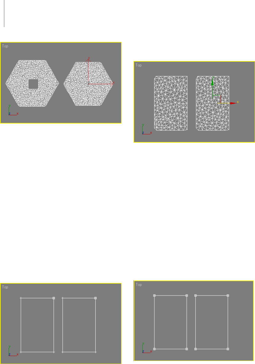
608 Chapter 8: Modifiers
Resulting geometry after applying Garment Maker
Tip: For best results, when applying Garment
Maker to multiple splines, first combine the splines
into a single object.
Also,tokeepyourpatternsprecise,norounding
of boundary edges and corners, you must break
the splines at the corner vertices. This is also
important because it directly impacts the segments
ofthesplinesthataretobeusedtocreateseams
between the individual panels. To understand this
better, take a look at the following example.
In the image below are two rectangular splines to
which a user might want to apply Garment Maker.
AfterapplyingGarmentMaker,theideaistothen
create a seam between the two panels along the
inner edge. First, it should be noted that both
splines are closed shapes and have been attached
so they are part of the same editable spline object.
When Garment Maker is assigned, look what
happens:
Garment Maker seems to have "chopped" corners
of the rectangular splines off, altering the pattern.
Beyond that, if the user tried to select the edges of
thepanelsthatmakeuptheseam,theywillnotbe
able to. This is because Garment Maker currently
has only a single spline to work with for each panel.
Tokeepthepatternclean,dothefollowing:
1. Access the Vertex sub-object level of the
editable spline.
2. Selecttheverticeswhereseamsaretobe
created.
3. Click Break to create unique segments that
Garment Maker can use to create a seam.
Shown below are the results when all of the vertices
are selected and then broken.
All vertices in both panels selected and then "broken"
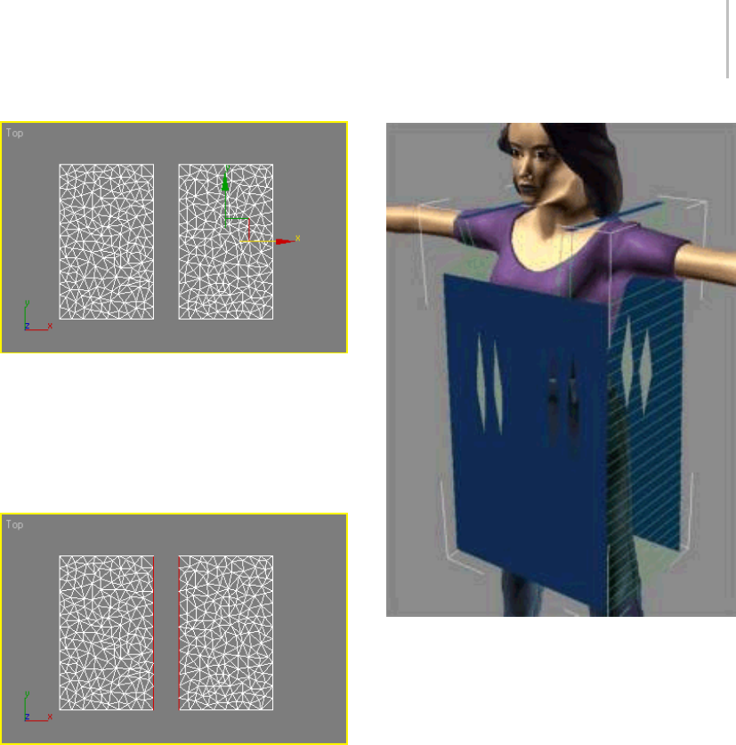
Garment Maker Modifier 609
Garment Maker applied to "broken" splines
Thecornersarenowpreserved. Whentheuser
goes to select the edges between the panels to act
as seams, they will be selected independently of
the other panel edges and highlight in red. This is
what you want in order to create seams.
Seam edges selected at the Seam sub-object level in red
Garment Panels
Garment Maker’s Panels sub-object level lets
you arrange the panels of the pattern around the
character. You can then create seams where the
panels should connect and be "sewn" together.
This lets you create the seams you need while
seeing how the clothing will look around your
character. Creating seams like this is in many cases
farsuperiortomakingtheminaflatlayoutbecause
it allows you to visualize what is being done.
Arranged panels with seams defined
Pattern Creation
To m a k e p a t t e r n s y ou c a n u s e t h e b a s i c 2 D s p l i n e
tools in 3ds Max. Cloth comes with several
patterns, but after you learn to use them, you
will most likely want to start making your own.
Patterns can take advantage of many features
that real sewing patterns have, such as darts and
multi-segment seams. To learn about other pattern
making software, see Pattern-Making Software
(page 1–578).
Tricky Assemblies
As you begin to move beyond the basic patterns
foryourgarments,thereareanumberofrulesthat
you should follow in order to work effectively with
Cloth:
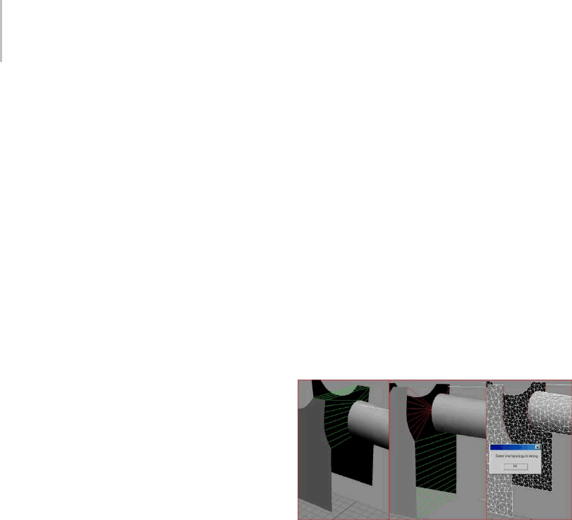
610 Chapter 8: Modifiers
• Always create your pattern splines in the Top
viewport. Garment Maker assumes that the
pattern is laid out this way.
• When seaming garments with MultiSegment
edges, you must take care of the order in which
theseamsaremade.
Note: A MultiSegment comprises two or more
individual segments acting as a single segment;
you create it with Garment Maker.
When creating a seam you cannot use:
• A MultiSegment that has multiple gaps in it,
unless all but one of those gaps are bridged by
another seam.
• AsegmentorMultiSegmentthatformsaclosed
loop (that is, a path directly, or via seams,
completely encloses the MultiSegment).
Both these issues arise in the common sleeve
assembly shown below. The sleeve needs to be
sewn to the armhole. When assembled, both
thesleeveandthearmholeformclosedloops.
The sleeve forms a loop via the seam along its
underside. The armhole is closed by two seams:
one across the shoulder and one down the side.
Now, since you cannot seam closed loops together,
it therefore follows that both the armhole and
sleevemustbeleftopenwhencreatingtheseam
connecting them. So the order is as follows:
1. Becausethesleeveisonesegmentandthe
armhole is two segments, you must make a
MultiSegment out of those two segments first.
2. When dealing with MultiSegment seams, the
orderofcreationisimportant.Ifyouattempt
to create seams in the wrong order, you might
get a “Seamline topology is wrong” error,
and the seams will not be created. When
dealing with MultiSegment seams, create the
minimum number of seams necessary to make
the MultiSegment seam match the topology of
theotherpiecetothatyouaregoingtoconnect.
Inthiscase,youhaveanarmseamthatisopen
at the bottom, and a MultiSegment that is open
at both the top and the bottom. If you closed
the side of the garment, you’d end up with
the situation illustrated in the center image
below, where the seam is twisted (it cannot
be “untwisted” by reversing the seam). By
closing the top of the armhole MultiSegment
with a seam at the shoulder, you’ll create proper
topology to make the MultiSegment seam.
3. Next, you can seam up the sleeve to the
armhole. See the leftmost image below.
4. Finally, you can add the seam down the side of
thegarmentandacrosstheundersideofthe
sleeve (the order is irrelevant here).
Left: Seam created for shoulder first and then for the
MultiSegment, producing the desired result.
Middle: Seam created at the bottom of the body MultiSegment
first, resulting in an irreversible MultiSegment seam from the
arm to the body.
Right: No seams made on the body to connect its
MultiSegment, resulting in a seam topology error.
Internal Seam Lines
When drawing panels, you can use extra open
splines to define seam lines within the panels,
also known as internal seam lines. Triangulation
always occurs along these internal seam lines, so
youcanusethemtohelpdefinethestructureof
the cloth panel, and as crease lines.Also,youcan
specify that an internal seam line should be cut,
so that the cloth separates along the line during
the simulation.
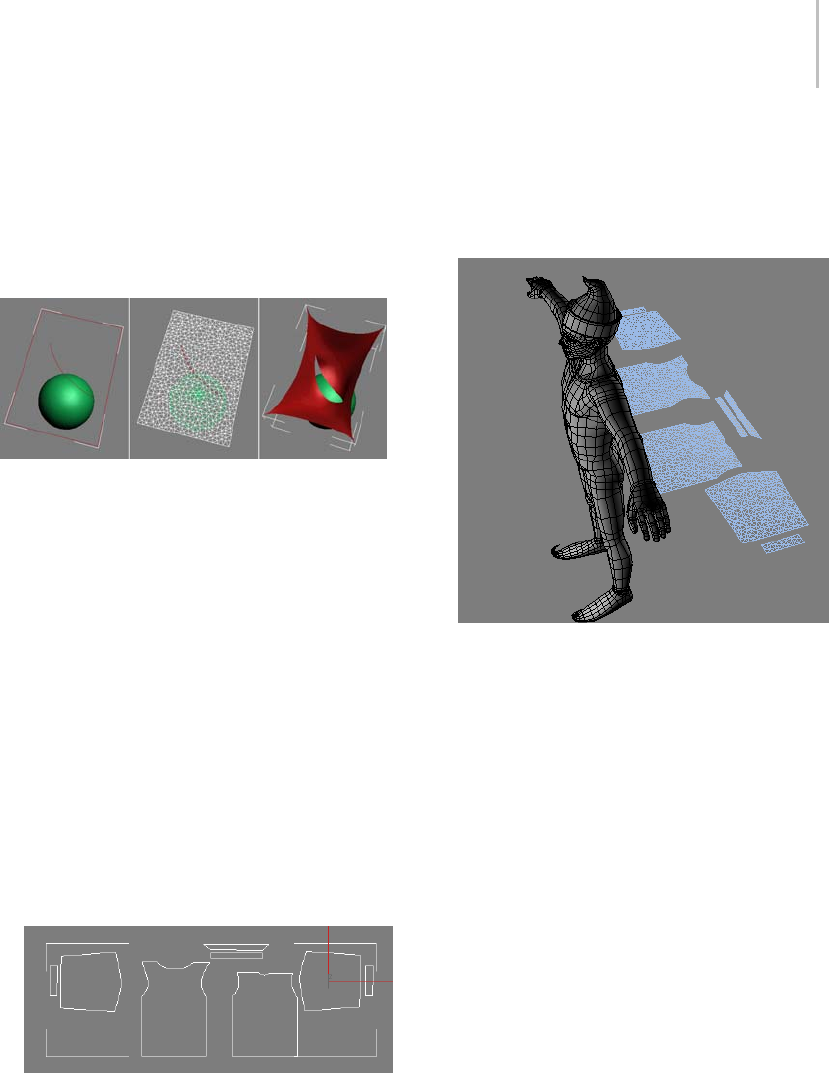
Garment Maker Modifier 611
To create an internal seam line, simply specify
a Material ID of 2 for the internal spline, which
should not be closed. Also, for best results, keep
its endpoints away from other splines in the shape.
And, as with outside seam lines, an internal spline
should not cross over itself or other splines.
Left: Open spline, set to Material ID 2, specifies internal seam
line.
Center: At Garment Maker > Curves or Seams sub-object level,
seam line is selected and Cut is turned on.
Right: Cloth separates along cut line during simulation.
Procedure
To place garment panels automatically:
The Garment Maker modifier provides tools
for positioning garment panels on a humanoid
character model. This automatic placement is
approximate; further adjustment is typically
necessary.
1. Load or create your character model.
2. Create your panels as splines or NURBS curves
parallel to the world XY plane (that is, create
them in the Top viewport).
Shirt panels, as seen in the Top viewport
Tip: When applying Garment Maker to multiple
splines, for best results, first combine the splines
into a single object. You can still manipulate
theseparatepieceswithintheGarmentMaker
modifier at the Panels sub-object level.
3. Apply the Garment Maker modifier. Set
parameters as necessary.
4. On the Main Parameters rollout, click the None
button, and then click the character model.
Theobject’snameappearsonthebutton.
5. Below this button, click the Mark Points On
Figure button.
A character outline appears in the corner of
each viewport. Superimposed on the outline
are seven asterisk-shaped points; the one at the
center-top of the chest is highlighted in red.
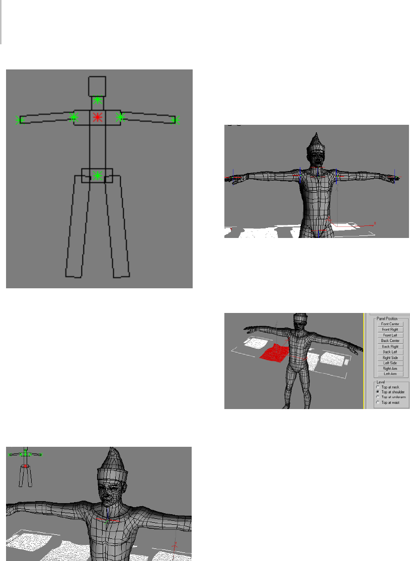
612 Chapter 8: Modifiers
The character outline lets you mark points for positioning
panels.
6. Click the corresponding point on the front of
your model.
As you move the mouse cursor over the surface
of the model, a red circle shows where the
marker will be placed. When you click, an axis
tripod appears on the surface at that location,
and the next point on the character outline, at
the center of the pelvic region, is highlighted
in red.
The axis tripod appears on the object surface where you
click.
7. Continue to click at each location on your
model that corresponds to the highlighted
marker on the character outline until you’ve
designated all seven points.
All seven points are marked on the character model.
To finish, right-click in the viewport.
8. Go to the Panels sub-object level and select a
panel.
The front shirt panel is selected.
9. At the bottom of the Panels rollout, choose a
Level,andtheninthePanelPositiongroup,
click the button corresponding to the desired
position for the panel.
The panel moves to the designated position.
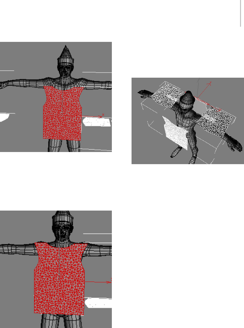
Garment Maker Modifier 613
Panel Position=Front Center; Level=Top at shoulder
10.Adjust as necessary. For example, in the above
illustration, Level should probably be set to Top
At Neck. To correct this, you would choose Top
At Neck, and then click Panel Position > Front
Center again.
Panel Position=Front Center; Level=Top at neck
Of course, you can also move the panel
manually; in fact, in most cases it will probably
be necessary to do so. Panel Position serves
primarily as a starting point for placing panels.
11.Continue selecting panels and placing them,
adjusting as necessary.
All panels placed with Panel Position. Note that sleeve
panels need to be rotated 90 degrees, and cuff panels need
to be rotated and moved to the wrists.
Interface
The Garment Maker interface varies depending
on the current modifier stack level: object (Main
Parameters) (page 1–613) or one of the four
sub-object levels:
•Curves (page 1–616)
•Panels (page 1–618)
•Seams (page 1–620)
Main Parameters rollout
The Main Parameters rollout is the first rollout
youseeontheModifypanelonceyouapplythe
Garment Maker modifier. This rollout comprises
mostly controls to create and adjust the mesh.
The remaining rollouts are available at the
sub-object levels.
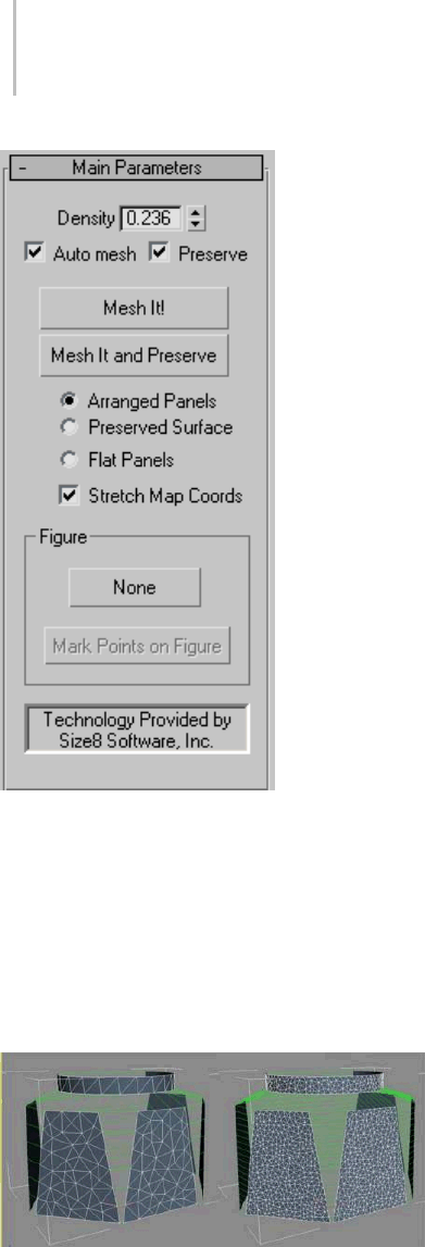
614 Chapter 8: Modifiers
Density—Adjusts the relative density of the mesh
(in other words, the number of triangles per unit
area). Possible values range between 0.01 and 10.0.
A value of 10.0 creates a very dense mesh, while
0.01 creates a comparatively low-resolution mesh.
For best results, use the lowest possible density
to achieve the desired result. This speeds up
simulation time and overall performance.
Left: Density=0.5
Right: Density=1.5
Auto mesh—When on, Garment Maker updates
themeshautomaticallyifyouchangethedensity
or add/remove seams.
This setting is active at all sub-object levels, so it’s
recommended you leave it on to see changes as
youmakethem.Theonlytimeyoumightwantto
turn off Auto Mesh is while creating the seams at
the Curves sub-object level. Re-meshing can take
some time, so you might want to define a number
of seams before re-meshing.
Preserve—When on along with Auto mesh,
Garment Maker preserves the 3D shape of the
object. When off, if you change the Density value,
the panels are flat.
Mesh It!—Applies a change in the Density value.
If Auto mesh is off when you change the Density
value, you must click the Mesh It! button to apply
the change.
Tip: SometimesinanerrorconditionMeshIt!will
no longer respond. If this happens, go to the spline
levelinthemodifierstack,andthenreturntothe
Garment Maker level.
Mesh It and Preserve—Applies a Density change
andalsopreservesthe3Dshapeoftheobject.
This lets you change the density of the cloth or the
underlying spline shape after simulating without
having to run the simulation again.
The following setting, comprising three radio
buttons, determines how the cloth panels are
passed up the modifier stack to the Cloth modifier:
•Arranged Panels—With this option, the mesh
passed up the stack will be have the panels
arranged/bent around the figure as they were
placed by the user in panels sub-object mode.
•Preserved Surface—When both Auto mesh and
Preserve are on, or when you click Mesh It And
Preserve, Garment Maker takes a snapshot of
the mesh at the top of the stack (where Cloth
is applied). This snapshot is passed up the
stack when you choose Preserved Surface. This
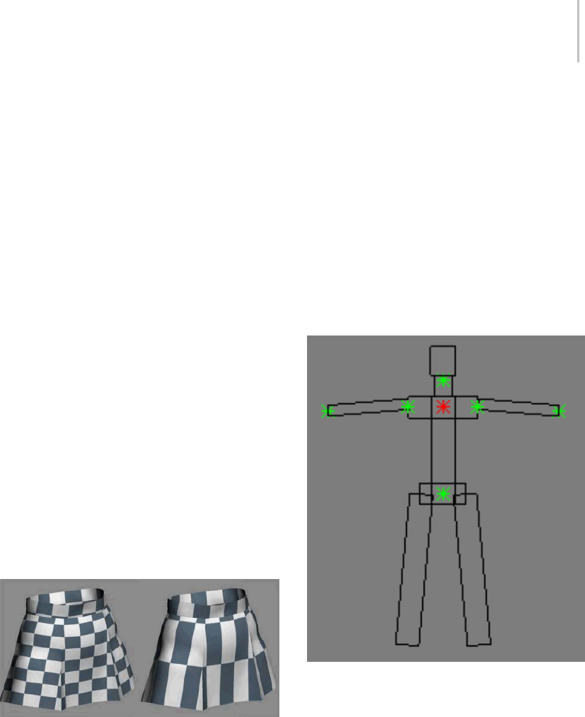
Garment Maker Modifier 615
way, if you change the Density value, the mesh
will retain its deformation. Once a snapshot
has been taken, at the Panel sub-object level,
thepanelswillhavetheUsePreservedcheck
box on. This means you can move the panels
around while maintaining their deformation.
Also note that once a snapshot has been taken,
Garment Maker automatically chooses the
Preserved Surface option.
•Flat Panels—Displays all the panels as flat
surfaces. This mode defines the texture
coordinates of the garment vertices. With this
output mode active, you can adjust texture
coordinatesatthePanelsub-objectlevelby
moving and rotating the panels.
Stretch Map Coords—When on, Garment Maker
uses the bounding box of the original spline shape
in defining the texture mapping coordinates. The
lower-left corner of the box is always assigned UV
coordinates of (0,0). If Stretch Map Coords is on,
the upper-right corner has coordinates of (1,1).
This conforms to the 3ds Max convention for
bitmap textures. If the box is off, the upper-right
corner has coords (1,a) (a>1) or (a,1) (a>1), which
are chosen to preserve the proportions of the box.
This is appropriate for procedural textures.
Left: Stretch Map Coords on
Right: Stretch Map Coords off
Figure group
Use these controls to specify locations for each
panel on the figure to be clothed
[button]—Click this button, labeled “None” by
default, and then click the object, or figure, to
which the clothing is to be applied. Typically this
is a character model. Thereafter, the name of the
object appears on the button.
Mark Points on Figure—After specifying a figure
using the “None” button (see preceding), use
this control to specify locations on the figure for
automatically positioning panels in the garment.
When you click Mark Points On Figure, this
character outline appears in the corner of each
viewport:
The character outline lets you mark points for positioning
panels.
As each point highlights in red, click the
correspondinglocationonyourfigure.Whenyou
do so, an axis tripod appears on the object surface
and the next point on the outline highlights.
During this process you can manipulate the
viewport as usual, zooming, panning, and rotating
freely. You can continue clicking points as long as
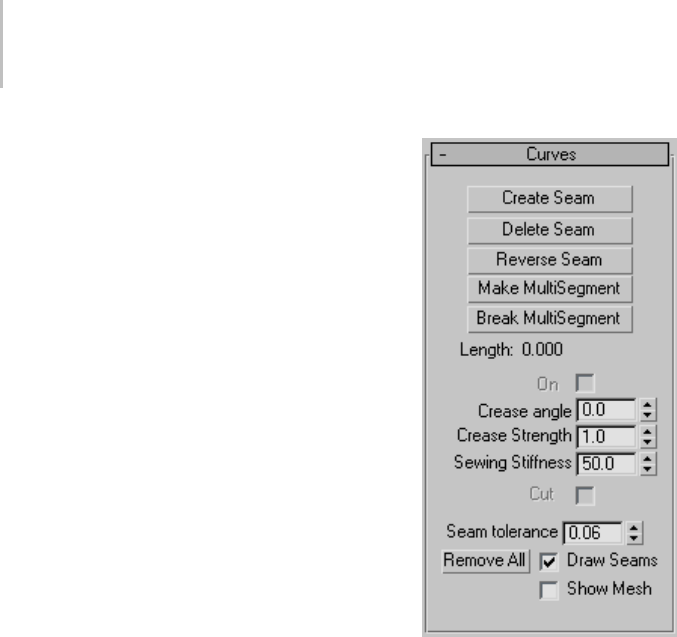
616 Chapter 8: Modifiers
you like; to stop, right-click in the viewport, or
turn the button off.
Note: If you return to marking points later, the
software starts again where you left off earlier.
The points highlight in this order:
1. Upper Chest
2. Pelvis
3. Neck
4. Right shoulder
5. Left shoulder
6. Right hand
7. Left hand
After setting the points, you can use the Panel
Position and Level controls at the Panels sub-object
level to place the panels automatically.
Curves rollout
Use the Curves sub-object level to stitch your
pattern panels together. You can also connect
seams in the Seams sub-object mode with a more
three-dimensional representation of the panels.
The Curves sub-object level provides a flat layout
to work in that can be useful for more complex
patterns. You can create and delete seams and
adjust the way your pattern fits together.
Create Seam—Creates a seam between two
segments. Select two segments of the panels
you would like to sew together, and click Create
Seam. This will make a seam between these two
panels that will be sewn together at simulation
time. Seams get a randomly-generated color to
distinguishthemfromthepanels.
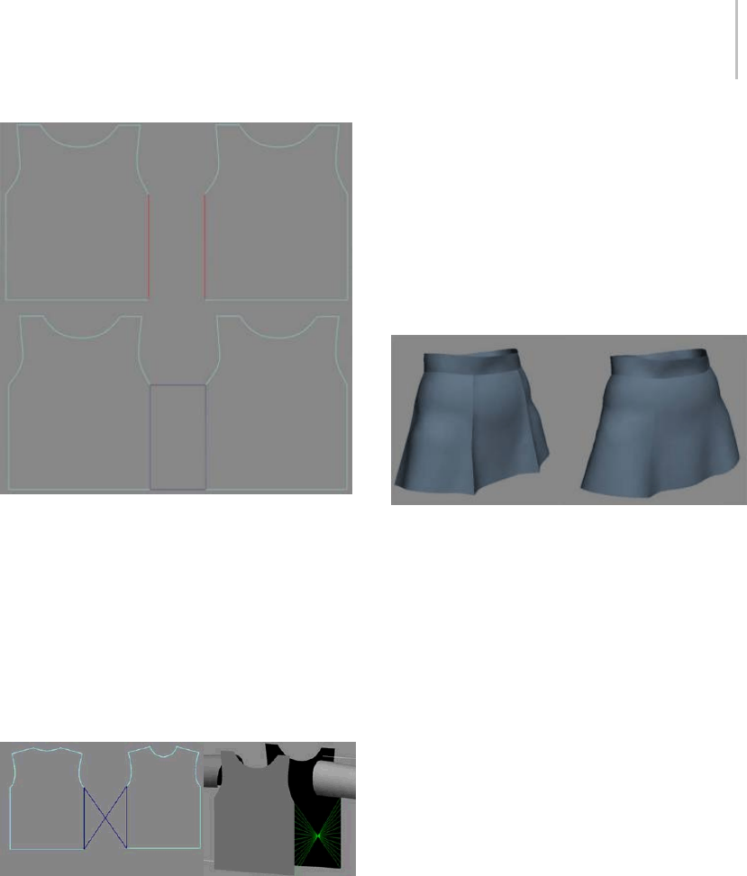
Garment Maker Modifier 617
Top: Segments selected
Bottom: Seam made between two panels
Delete Seam—Deletes selected seam. (Selected
seam is colored red).
Reverse Seam—Reverses or flips a twisted seam.
When creating seams, the first vertex on each
segment is used to line up the resulting seam panel.
Sometimes you can end up with a twisted seam
and will need to use Reverse Seam to untwist it.
A twisted seam that needs to be reversed
Make MultiSegment—AMultiSegmentisa
combination of two or more segments that will be
treated as one segment for the purpose of creating
seams. Select the segments you want to combine
then click this button. Note that if the segments are
not contiguous, the gaps must be bridged by seams
beforethisMultiSegmentcanbeusedinaseam.
Break MultiSegment—Break apart selected
MultiSegments.
On—Turns the selected seam on or off, making it
active or inactive.
Crease angle—Creates a crease at the selected seam.
Theanglevaluedeterminesthetargetangleofthe
crease between the two panels or along an internal
seam line (page 1–610)
Left: High crease angle
Right: Low crease angle
Crease Strength—Increase or decrease the strength
of the selected seam. This value affects how much
the seam will resist bending in relation to the rest
of the cloth object. A value of 2.0 means that the
clothwillhavetwicetheresistancetobending
that it would otherwise have (as defined by the
object/panel/vertex group properties).
Sewing Stiffness—The amount of force with which
the panels are pulled together at simulation time.
A larger value pulls the panels together harder and
faster.
Cut—Applies only to an internal seam line (page
1–610). Makes a cut in the fabric at this seam line.
Seam Tolerance—Theamountofdifferencein
length between two edges that is permitted in
the formation of a seam. The two segments
that comprise a seam should be about the same
length. If they have different lengths, the difference
must be within this tolerance range. If you seam
together two segments that are significantly
different in length, the cloth will tend to bunch up
(which could be a desired effect). In order to allow

618 Chapter 8: Modifiers
the creation of such a seam, the Seam Tolerance
will need to be increased. The default value is 0.06,
which means that the two segment lengths must be
within 6 percent of each other’s lengths.
Draw Seams—Showstheseamsintheviewport;
hides them when off.
Show Mesh—Shows the mesh in the viewport, or
hides it to work on your pattern. When this option
is off, the mesh is represented with a bounding box.
Panels rollout
The Panels sub-object level of the Garment Maker
modifier lets you position and bend the panels
of your pattern to fit your object or figure. You
can also use these controls to adjust the texture
mapping of your garment.
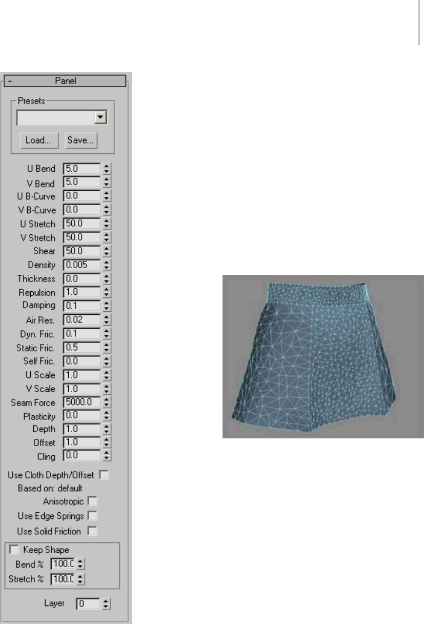
Garment Maker Modifier 619
Density—Controls the mesh density of a selected
panel. This value is applied as a multiplier of the
Main Parameters rollout > Density setting.Youcan
increase the density of a particular panel by raising
this value.
If Main Parameters rollout > Auto Mesh is off
when you change this value, go back to the Main
Parameters rollout (Cloth level in modifier stack)
and click Mesh It! to update the mesh. For this
reason, it is recommended that you leave Auto
Mesh on. The only time you might want to turn
off Auto Mesh is while creating the seams at the
Curves sub-object level. Re-meshing can take
some time, so you might want to define a number
of seams before re-meshing.
Different Density settings applied to separate panels
Mat ID—Set the material ID for the selected panel.
Usingthisoptionenablesyoutoassigndifferent
materials to select portions of the clothing.
Position group
Reset—Resets the position of the selected panels
to their original locations (that is, the locations
immediately after Garment Maker was applied).
Reset All—Resets the position of all panels to their
original locations.

620 Chapter 8: Modifiers
Deformation group
Most controls in this group are available only when
one or more panels are selected.
Reset—Removes the deformation of the selected
panels (restoring the flat state).
Reset All—Removes the deformation from all
panels.
Use Preserved—Turn this on to override the None
or Curved deformation options. When on, the
panel gets its shape from the preserved mesh
instead of the deformation options.
None—Makesthispanelflat.
Curved—UsethevalueintheCurvaturefieldto
bend the panel.
Curvature—Sets the amount of curve or bend of a
panel. The higher this value is, the more the panel
will curve.
X-axis—Sets the axis for the curvature to the
panel’s local X axis.
Y-axis—Sets the axis for the curvature to the
panel’s local Y axis.
Panel Position—Moves the selected panel to the
position specified by the button you click. These
locations are determined by the software based
on the positions you set with the Mark Points On
Figure controls at the Garment Maker object level.
The positions are:
• Front Center
•FrontRight
•FrontLeft
•BackCenter
•BackRight
•BackLeft
•RightSide
•LeftSide
•RightArm
•LeftArm
Note: The terms Front, Back, Right, and Left refer
to the character’s orientation.
Level—Sets where the top of the panel should go.
Garment Maker derives these locations from the
locations you specify with the Mark Points On
Figure controls. The choices are:
•Topatneck
•Topatshoulder
•Topatunderarm
•Topatwaist
If you change the setting here, it affects the
subsequent Panel Position results.
Adjusting Texture Coordinates
When Garment Maker is in Flat Panels mode (that
is, the Main Parameters rollout > Flat Panels option
is chosen), the texture coordinates are defined by
the positions of the panels. Imagine the panels are
being cut out of a large piece of fabric. The location
and orientation of a panel in that large piece of
fabric determine how the texture is aligned on it.
By moving and rotating a panel, you can change
its texture coordinates. Remember, you must be in
Flat Panels mode to do this.
Seams rollout
At the Seams sub-object level, you can define and
edit seams and their properties. Seams have the
same functionality as curves, but at this level the
mesh is displayed three-dimensionally instead of
inaflatlayout.Also,atthislevelthemeshisalways
updatedwhenyouaddorremoveaseam.
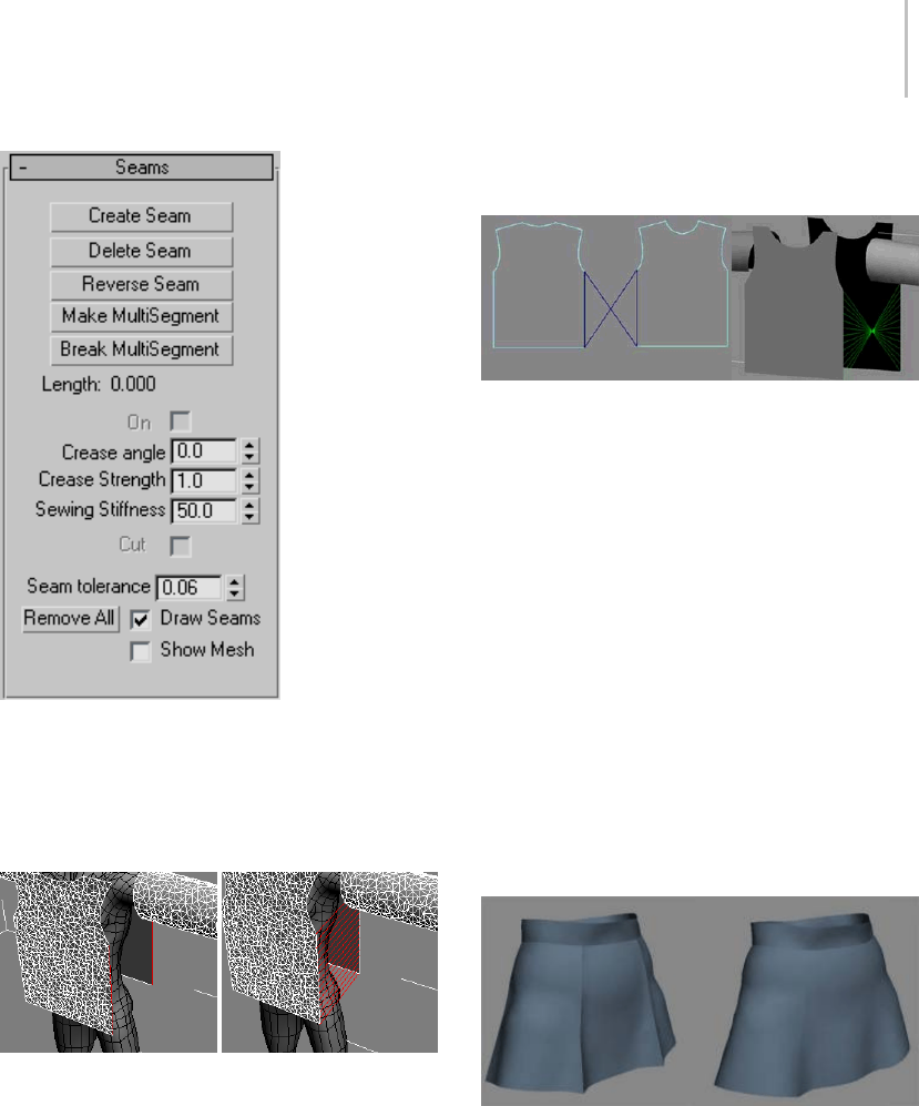
Garment Maker Modifier 621
Create Seam—Creates a seam between two
segments. Select two segments of the panels you
would like to sew together and then click Create
Seam. This creates a seam between the two panels
that will be sewn together at simulation time.
Left: Segments selected
Right: Seam created between the two segments
Delete Seam—Deletes selected seam. (Selected
seam is colored red).
Reverse Seam—Reverses or flips a seam that has
been made with a twist in it. When creating seams,
the first vertex on each segment is used to line
up the resulting seam panel. Sometimes you can
end up with a twisted seam and will need to use
Reverse Seam to untwist it.
A twisted seam that needs to be reversed
Make MultiSegment—AMultiSegmentisa
combination of two or more segments that will be
treated as one segment for the purpose of creating
seams. Select the segments you want to combine
then click this button. Note that if the segments are
not contiguous, the gaps must be bridged by seams
beforethisMultiSegmentcanbeusedinaseam.
Break MultiSegment—Break apart selected
MultiSegments.
On—Turns the selected seam on or off, making it
active or inactive.
Crease angle—Creates a crease at the selected seam.
Theanglevaluedeterminesthetargetangleofthe
crease between the two panels or along an internal
seam line (page 1–610).
Left: High crease angle
Right: Low crease angle
Crease Strength—Specifies the strength of the
selected seam. This value affects the extent to
which the seam resists bending in relation to the
rest of the cloth object. A value of 2.0 means that
the cloth will have twice the resistance to bending

622 Chapter 8: Modifiers
that it would otherwise have (as defined by the
object/panel/vertex group properties).
Sewing Stiffness—The amount of force with which
the panels are pulled together at simulation time.
A larger value will pull the panels together harder
and faster.
Cut—This applies only to an internal seam line
(page 1–610).Makesacutinthefabricatthis
seam line.
Seam Tolerance—Theamountofdifferencein
length between two edges that is permitted in
the formation of a seam. The two segments that
compriseaseamshouldbeaboutthesamelength.
If they have different lengths, the difference must
be within this tolerance range. If you seam together
two segments that are significantly different in
length, the cloth will tend to bunch up (which may
be a desired effect). In order to allow the creation
of such a seam, the Seam Tolerance will need to be
increased. The default is 0.06, which means that
the two segment lengths must be within 6%.
Remove All—Deletes all seams.
Draw Seams—Showstheseamsintheviewport;
hides them when turned off.
Show Mesh—Show the mesh in the viewport, or
hide it to work on your pattern. When this option
is off, the mesh is represented with a bounding box.
Troubleshooting and Error Codes
in Garment Maker
When you are working with Garment Maker, you
may encounter errors if your splines are set up
incorrectly. Here is a list of the common error
messages you may see, and how to correct them.
Cannot remesh: the number of panels has
changed: This error occurs when the user has
modified the original pattern, and added new
closed splines to it. The only way to correct this
is to delete the original Garment Maker modifier
and reapply a new one.
Number of boundary curves has changed: Users
will get this error if they add or remove splines
from the pattern after the initial application of
Garment Maker. To correct it, delete the original
Garment Maker modifier and reapply a new one.
Boundary splines do not form a closed loop: In
this case, the splines that the user has tried to apply
Garment Maker to don’t form closed loops. Often,
this is caused by an extra vertex and segment
attached to one of the splines, and usually this
segmentissosmallyoucannotseeit. Itcanbe
difficult to find the offending part. To remedy this
situation, select all the vertices, weld them, then
re-break them at the corners.
Splines form overlapping loops: Whenauser
gets this error, it means that some panel loops
overlap others (in the XY plane of the local view).
If you create the shape in the Top view this should
not happen (provided you don’t create overlapping
loops). Most commonly, this occurs when the user
create the splines in a viewport other than Top and
onaplaneotherthantheXYplane.
Unable to create seam: This error happens in
when trying to create a seam in two cases:
• One (or more) of the segments/MultiSegments
in the attempted seam forms a closed loop (for
example, if you make a MultiSegment from the
armhole segments, that MultiSegment forms a
closed loop if you create seams at the shoulder
andbelowthearmhole).Youwillhavetodelete
one of the seams so that the MultiSegment is no
longer closed. For an armhole, you generally
keep the seam below the armhole open when
youjoinitwiththesleeve.Youcanthenclose
the seam. For the same reason, the sleeve
cannot be seamed at the underside before
joining to the armhole.
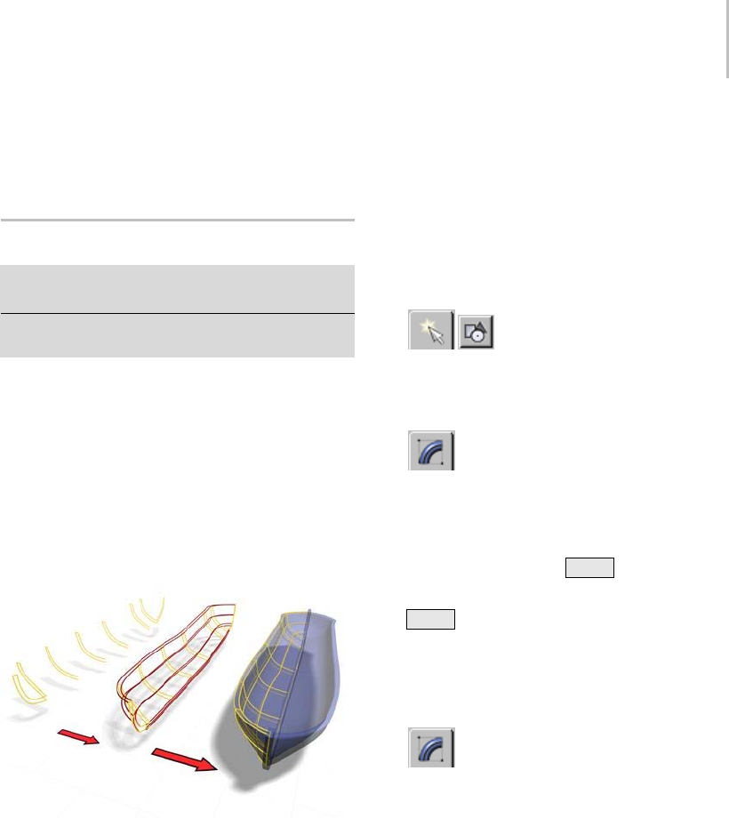
CrossSection Modifier 623
• A MultiSegment in the attempted seam contains
segments that are not contiguous and that are
not linked by any seam.
CrossSection Modifier
Select a spline object with spline cross sections. > Modify
panel > Modifier List > CrossSection
Make a selection. > Modifiers menu > Patch/Spline
Editing > CrossSection
The CrossSection modifier creates a "skin" across
multiple splines. It works by connecting the
vertices of 3D splines to form a skin. The resulting
object is another spline object that can be used
with the Surface modifier (page 1–842) to create
a patch surface. These two modifiers, when used
together, are sometimes referred to collectively as
“Surface Tools.”
CrossSection uses splines to create a model of a boat.
CrossSectioncanbuildaskinacross
various-shaped splines with different vertex counts
and open/closed status. The more different the
splines in vertex count and complexity, the more
likelytheskinwillhavediscontinuity.
Note: Similar functionality is provided by the
Editable Spline object (page 1–289).AttheEditable
Spline > Segment and Spline sub-object levels,
you can create a spline cage using Connect Copy
and Cross Section. Using this method, you need
to region-select the created vertices to transform
them. Also, this method lets you define the
ordering of the spline more easily than does the
CrossSection modifier.
Procedures
Example: To explore the CrossSection modifier:
1. OntheCreatepanel,clickShapes,
then click Circle.
2. Drag in the Top viewport to create a circle about
100 units in radius.
3. On the Modify panel, choose Edit Spline
from the Modifier List.
4. In the modifier stack display, turn on Spline
sub-object, then select the circle.
5. In the Front viewport, Shift +Move the spline
up to copy it.
6. Shift +Move the copy up to create a third
circle.
Note: The order that you attach or clone splines
is important: this is the order that CrossSection
uses to create the skin.
7. On the Modify panel, choose
CrossSection from the Modifier List.
CrossSection joins the vertices of the three
circles. A basic spline cylinder is displayed.
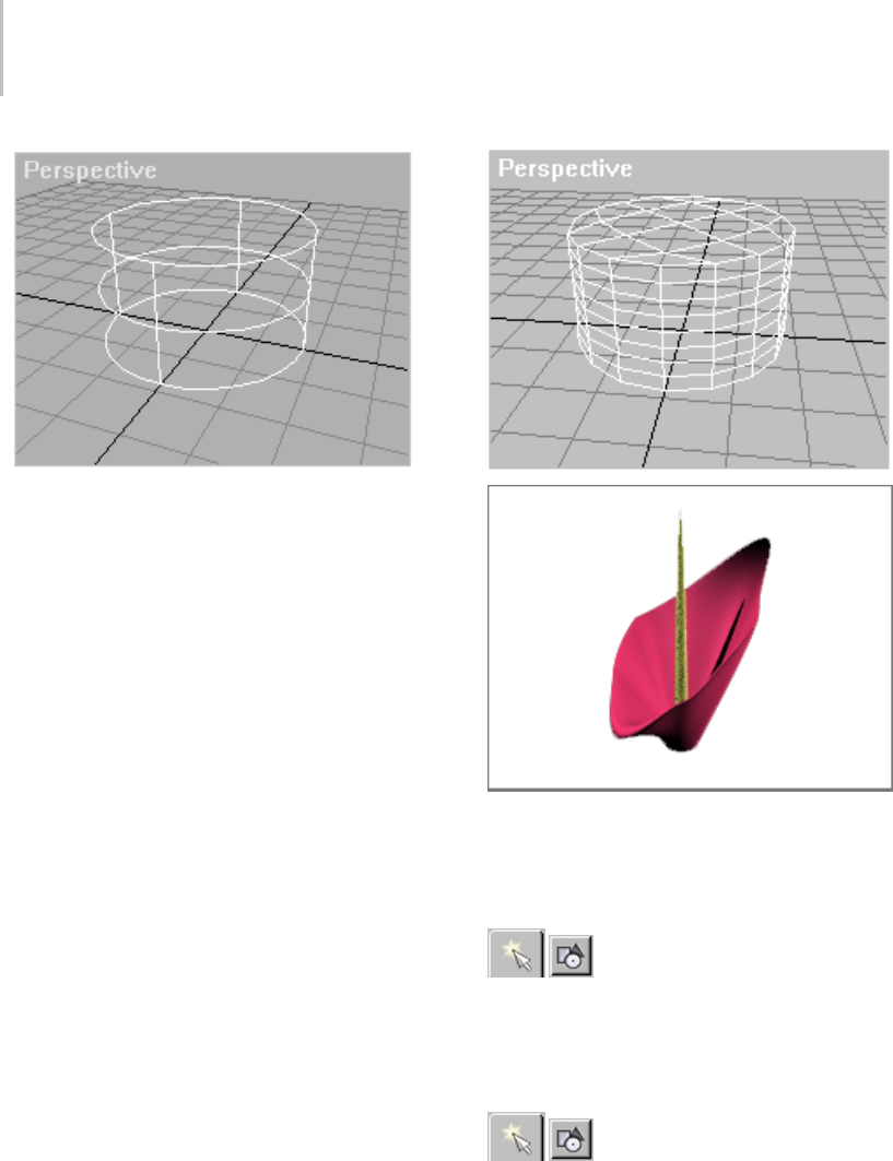
624 Chapter 8: Modifiers
8. On the Modify panel, on the Modifiers List,
choose Surface to add the Surface modifier.
The spline cylinder is transformed into a patch
surface by the Surface modifier.
9. To edit the model’s surface, change the splines
using controls in the Edit Spline modifier. Or,
since the output of the Surface modifier is a
patch surface, add an Edit Patch modifier and
use patch edit controls to change the surface.
An Edit Patch modifier above the Surface modifier was
used to create the image.
Example: Using the CrossSection modifier to skin
several splines with different shapes:
1. OntheCreatepanel,clickShapes.
2. OntheObjectTyperollout,turnonStartNew
Shape, then click NGon.
3. IntheTopviewport,createtwofive-sided
circular NGons.
4. OntheCreatepanel,withShapes
still active, click Line. Create two lines,
each with four vertices. Create the vertices
left-to-right.
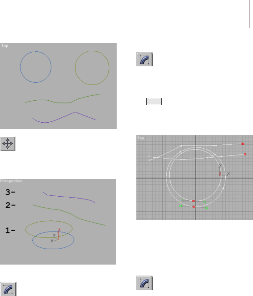
CrossSection Modifier 625
5. On the main toolbar, click Select And
Move, then move the objects in the viewport to
order them along the Z axis with the NGons at
the bottom and the lines above the NGons.
6. Select the bottom NGon.
7. OntheModifypanel,chooseEditSpline
from the Modifier List.
8. In the Geometry rollout, click Attach.
9. Select the remaining NGon and lines in an
ascending order, as numbered in the image.
Note: The order of selection is important. The
CrossSection modifier uses the selection order
to define the skin.
Example continued: Lining up the vertices:
1. On the Modify panel, choose the Vertex
sub-object level in the stack display.
Lining up the first vertex of each spline is
important to prevent the surface from twisting.
2. Use Ctrl +click to select the rightmost vertex
of each line and the bottommost vertex of each
NGon.
3. On the Geometry rollout, click Make First.
Aligning the first vertex is important. This is
where the seam forks, going from a closed to an
open spline.
Example continued: Using CrossSection and Surface
to "skin" the shapes:
1. On the Modify panel, choose
CrossSection from the Modifier List.
The CrossSection modifier connects the splines
at the vertices.
2. On the Modifiers List, choose Surface.
The Surface modifier generates a patch surface
based on the splines.
3. In the modifier stack display, choose the
CrossSection modifier.
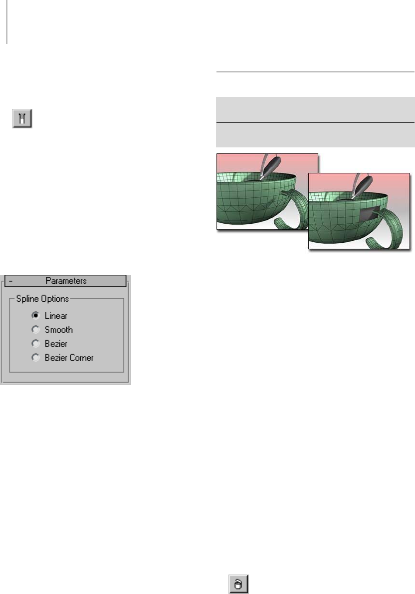
626 Chapter 8: Modifiers
4. On the CrossSection Parameters rollout, toggle
between Linear and Smooth. Notice how the
splines change.
5. On the Modify panel, toggle the Show
End Result On/Off Toggle button to display the
final patch surface. The toggle won’t remain on
if the CrossSection modifier is current. Drop
down to the Editable Patch in the stack and
turnontheShowEndResulttoggleifyoulike.
Tip: When you use CrossSection, draw splines
in a consistent direction. A twisted surface
results when lines are created from vertices that
are not lined up.
Interface
Linear/Smooth/Bezier/Bezier Corner—Determines
what type of curve will be used through the spline
vertices.
Delete Mesh Modifier
Modify panel > Make a sub-object selection. > Modifier
List > Delete Mesh
Modify panel > Make a sub-object selection. > Modifiers
menu > Mesh Editing > Delete Mesh
Delete Mesh used to remove the faces where the handle joins
the cup.
Delete Mesh provides parametric deletion based
on the current sub-object selection level in the
stack. The possible choices are faces, vertices,
edges, and objects. Apply the Delete Mesh
modifier to delete the geometry specified at that
sub-object level.
For example, you can apply a Mesh Select modifier
(page 1–719), select a row of faces in a cylinder,
and then apply a Delete Mesh modifier to delete
thosefaces.Toundothedeletion,youcansimply
remove the Delete Mesh modifier.
Tip: Try applying a Delete Mesh modifier following
an animated Vol. Select modifier (page 1–952).
Procedure
Example: To delete a row of faces in a cylinder:
1. Create a cylinder (page 1–177).
2. Apply a Mesh Select modifier and select a row
of faces in the cylinder.
3. Apply the Delete Mesh modifier to delete those
faces.
To undo the deletion, remove the Delete
Mesh modifier.
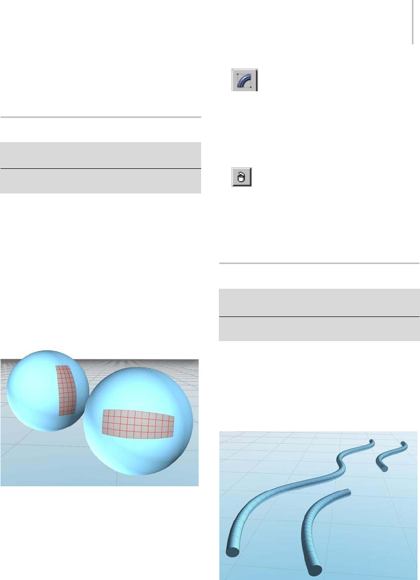
Delete Patch Modifier 627
Interface
This modifier has no parameters.
Delete Patch Modifier
Modify panel > Make a patch selection. > Modifier List
> Delete Patch
Make a selection. > Modifiers menu > Patch/Spline
Editing > Delete
Delete Patch provides parametric deletion based
on the current sub-object level in the stack. The
possible choices are vertices, edges, patches, and
elements. Apply the Delete Patch modifier to delete
the geometry specified at that sub-object level.
For example, you can apply a Patch Select modifier,
selectarowofpatchesinapatchsphere,and
then apply a Delete Patch modifier to delete those
patches. To undo the deletion, remove the Delete
Patch modifier.
Delete Patch used to remove sections of a patch sphere.
Procedure
Example: To delete a patch in a sphere:
1. Create a sphere.
2. Right-click the sphere, and choose Convert To
>ConvertToEditablePatchonthequadmenu.
3. On the Modify panel, in Editable Patch,
choose the Patch sub-object level, and select
apatch.
4. In the Modifier List, choose the Delete Patch
modifier.
This deletes the selected patch.
To undo the deletion, remove the Delete
Patch modifier.
Interface
There are no parameters for this modifier.
Delete Spline Modifier
Modify panel > Select a spline sub-object. > Modifier List
> Delete Spline
Modify panel > Select a spline sub-object. > Modifiers
menu > Patch/Spline Editing > Delete Spline
TheDeleteSplinemodifierprovidesparametric
deletion of spline geometry based on the current
sub-object selection level in the stack. The possible
selection levels include vertices, segments, and
splines. Apply the Delete Spline modifier to delete
the geometry specified at that sub-object level.
Delete Spline used to remove a segment in the middle of a
spline.
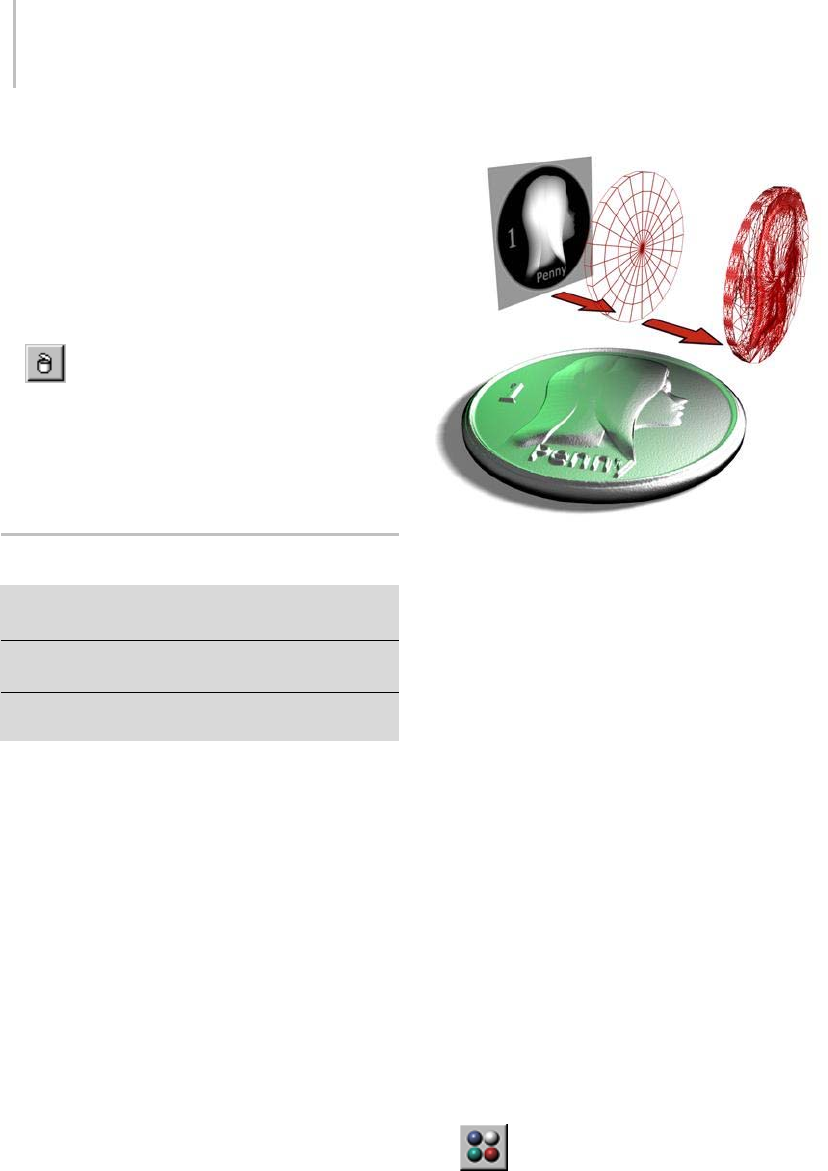
628 Chapter 8: Modifiers
Procedure
To use the delete spline modifier:
1. Create a shape that contains multiple splines.
2. Apply a Spline Select modifier (page 1–831) and
select a section of the spline for deletion.
3. Apply a Delete Spline modifier to delete the
section.
To undo the deletion, remove the Delete
Spline modifier.
Interface
This modifier has no parameters.
Disp Approx Modifier
Modify panel > Make a selection. > Modifier List >
Object-Space Modifiers > Disp Approx
Make a selection. > Modifiers menu > Surface Deformers
> Disp Approx
Make a selection. > Modifiers menu > NURBS Editing >
Disp Approx
The Disp Approx modifier (short for Displacement
Approximation) lets you make the displacement
mappingsettingsonanobjectinthemodifier
stack (page 3–760).Itconvertsitsinputobject
to an editable mesh (page 1–996),soyoucanuse
this modifier to add displacement mapping to
geometry primitives (page 1–170) and any other
kind of object that can convert to an editable mesh.
Using an image to displace the surface of a cylinder
Displacement mapping (page 2–1511) uses a map
to change surface geometry. You apply the map
using the Material Editor (page 2–1409).
You don’t need to apply this modifier to NURBS
(page 1–1078) surfaces, patches (page 1–993),
editable meshes (page 1–996),oreditable
polymeshes (page 1–1022),becauseyoucanapply
displacement mapping directly to these kinds of
objects.
Procedure
To apply displacement mapping:
1. Select an object other than a NURBS surface,
patch, editable mesh, or editable poly.
2. Apply the Disp Approx modifier.
Now you can apply displacement mapping
to the object. The Displacement Approx.
rollout has parameter that you can adjust, but
displacement mapping will work using the
default settings.
3. Go to the Material Editor. Apply a
Standard material to the object.
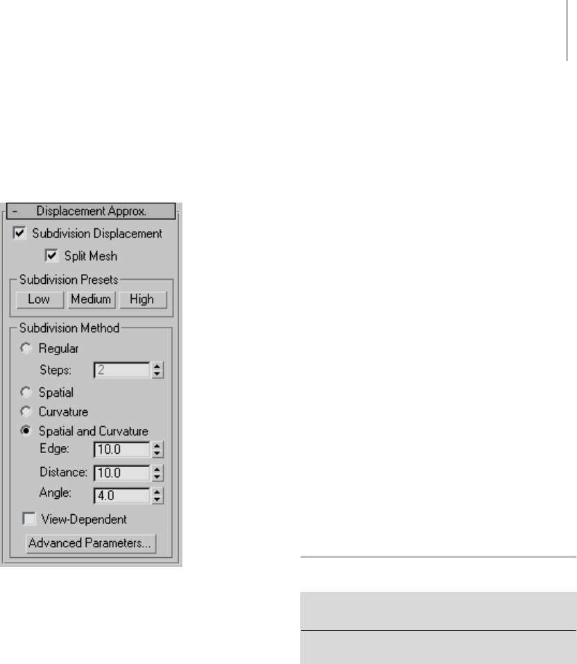
Displace Modifier 629
4. In the material’s Maps rollout, click
the Displacement button, then use the
Material/Map Browser to apply a displacement
map.
Interface
Subdivision Displacement—Subdivides mesh faces
to accurately displace the map, using the method
and settings you specify in the Subdivision Presets
and Subdivision Method group boxes. When
turned off, the modifier applies the map by moving
vertices in the mesh, the way the Displace modifier
(page 1–629) does. Default=on.
Split Mesh—Affectstheseamsofdisplacedmesh
objects; also affects texture mapping. When
on, the mesh is split into individual faces before
displacing them; this helps preserve texture
mapping. When off, texture mapping is assigned
using an internal method. Default=on.
Tip: This parameter is required because of an
architectural limitation in the way displacement
mapping works. Turning Split Mesh on is usually
the better technique, but it can cause problems for
objects with clearly distinct faces, such as boxes,
or even spheres. A box’s sides might separate as
they displace outward, leaving gaps. And a sphere
might split along its longitudinal edge (found in
the rear for spheres created in the Top view) unless
you turn off Split Mesh. However, texture mapping
works unpredictably when Split Mesh is off, so
you might need to add a Displace Mesh modifier
(page 1–514) and make a snapshot (page 1–453)
of the mesh. You would then apply a UVW Map
modifier (page 1–922) andthenreassignmapping
coordinates to the displaced snapshot mesh.
Subdivision Presets and Subdivision Method
group boxes
The controls in these two group boxes specify how
the modifier applies the displacement map when
Custom Settings and Subdivision Displacement
are both turned on. They are identical to the
Surface Approximation controls (page 1–1239) used
for NURBS surfaces.
Displace Modifier
Modify panel > Make a selection. > Modifier List >
Object-Space Modifiers > Displace
Make a selection. > Modifiers menu > Parametric
Deformers > Displace
The Displace modifier acts as a force field to push
and reshape an object’s geometry. You can apply
its variable force directly from the modifier gizmo,
or from a bitmapped image.
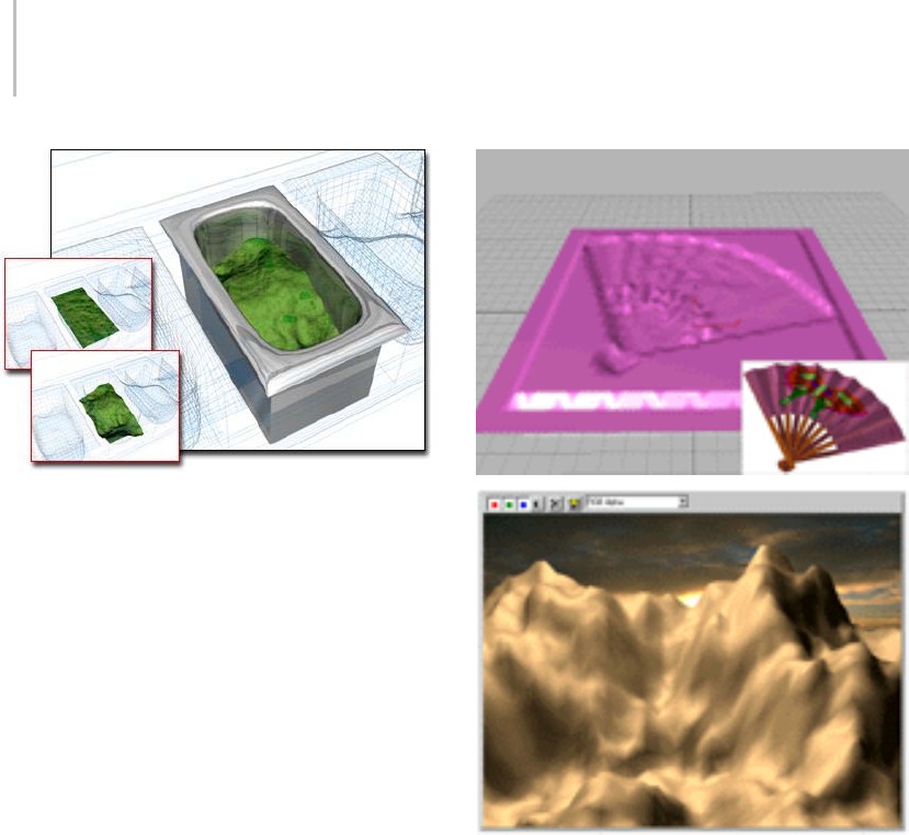
630 Chapter 8: Modifiers
Displace used to change the surface in the container
There are two basic ways to use the Displace
modifier:
• Apply displacement effects directly by setting
Strength and Decay values.
•Applythegrayscalecomponentofabitmapped
imagetogeneratethedisplacement.Lighter
colors in the 2D image push outward more
strongly than darker colors, resulting in a 3D
displacement of the geometry.
The Displace space warp (page 2–76) has similar
features. It’s useful for applying effects to a large
number of objects or a particle system. Top: Bitmap displacement on a patch and the bitmap used.
Bottom: Terrain effects using Displace
Force Distribution
Displace distributes its force through four different
gizmos: Planar, Cylindrical, Spherical, and
Shrink Wrap. Gizmos are also used as mapping
coordinates for applying bitmaps. Sphere and
Shrink Wrap have the same effect when modeling,
but differ in the way they map.
The Spherical and Shrink Wrap gizmos begin
withauniformfieldaroundthem.TheCylinder
and Planar gizmos are both directional. Cylinder
pushes at right angles to its axis, and Planar pushes
at right angles to its surface.
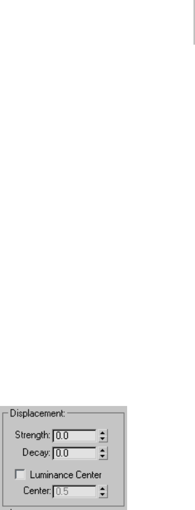
Displace Modifier 631
By default, gizmos are centered on the object.
However, you can transform any of these shapes
and use it directly as a tool to deform the geometry
of an object.
Modeling Options
Displace is a versatile modifier with many possible
applications. Here are some options:
• Produce interior modeling effects by scaling
down the gizmo and moving it inside the
object. The outward force shapes the geometry
from within.
• Animate the modeling process. One result is
a roving, magnetic-like field that pushes and
pulls on a surface.
• Add additional Displace modifiers to an object,
using each one to create a different modeling
effect.
• Collapse a finished model into a plain mesh.
This reduces the object’s complexity and
removes all modifiers, but keeps the modeled
surface intact.
Procedures
To displace an object:
1. Select an object and apply the Displace
modifier.
2. In the Parameters rollout > Map group, select
one of the four gizmo types.
3. In the Displacement group, set values for
Strength and Decay. Vary these settings to see
the effect of the displacement on the object.
Depending on the object and the complexity of
the bitmap, you might need to use dense geometry
to see the effect clearly. Try a test run and, if
necessary, add tessellation in the areas of greatest
detail.
To apply a bitmap as a displacement map:
1. In the Parameters rollout > Image group, click
the Bitmap button (which is labeled "None"
until a map has been chosen). Use the file
dialog to choose a bitmap.
2. Adjust the Strength value. Vary the strength
ofthefieldtoseetheeffectofthebitmap
displacing the object’s geometry.
After you get the image you want from bitmapped
displacement, you can apply an Optimize modifier
(page 1–748) to reduce the complexity of the
geometry while retaining the detail.
To model with the displace modifier:
1. Apply Displace to the object you want to model.
Choose a gizmo from the Map group.
2. Increase the Strength setting until you begin to
seeachangeintheobject.
3. Scale, rotate, and move the gizmo to concentrate
the effect. As you do this, adjust the Strength
and Decay settings to fine-tune the effect.
Interface
Displacement group
Strength—When set to 0.0, Displace has no effect.
Values greater than 0.0 displace object geometry
or particles away from the position of the gizmo.
Values less than 0.0 displace geometry toward the
gizmo. Default=0.0.
Decay—Varies the displacement strength with
distance.
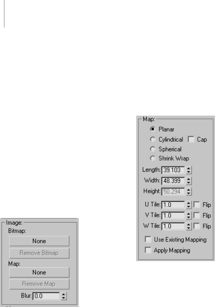
632 Chapter 8: Modifiers
By default, Displace has the same strength
throughout world space. Increasing Decay causes
the displacement strength to diminish as distance
increases from the position of the Displace gizmo.
This has the effect of concentrating the force
field near the gizmo, similar to the field around a
magnet repelling its opposite charge. Default=0.0.
Luminance Center—Determines which level of gray
Displace uses as the zero displacement value.
By default, Displace centers the luminance by using
medium(50percent)grayasthezerodisplacement
value. Gray values greater than 128 displace in the
outward direction (away from the Displace gizmo)
andgrayvalueslessthan128displaceintheinward
direction(towardtheDisplacegizmo).Usethe
Center spinner to adjust the default. With a Planar
projection, the displaced geometry is repositioned
above or below the Planar gizmo. Default=0.5.
Range=0 to 1.0.
Image group
Lets you choose a bitmap (page 3–917) and map
(page 3–968) to use for displacement. Both are
assigned and removed in the same way.
Bitmap button—Assigns a bitmap or map from a
selection dialog. After you make a valid choice,
these buttons display the name of the bitmap or
map.
This button is labeled "None" until you choose a
map.
Remove Bitmap/Map—Removes the bitmap or map
assignment.
Blur—Increase this value to blur or soften the effect
of the bitmapped displacement.
Map group
Contains mapping parameters for bitmapped
displacement. See UVW Map modifier (page
1–922).
The four mapping modes control how Displace
projects its displacement. The type of Displace
gizmo and its location in the scene determine the
final effect.
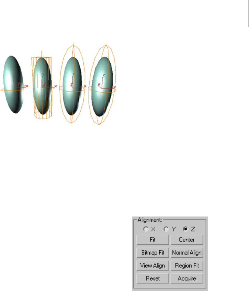
Displace Modifier 633
Displace gizmos: Planar, Cylindrical, Spherical, and Shrink
Wrap
Planar—Projects the map from a single plane.
Cylindrical—Projects the map as if it were wrapped
around the cylinder. Turn on Cap to project a copy
of the map from the ends of the cylinder.
Spherical—Projects the map from a sphere, with
singularities at the top and bottom of the sphere
where the bitmap edges meet at the sphere’s poles.
Shrink Wrap—Projects the map from a sphere, as
Spherical does, but truncates the corners of the
map and joins them all at a single pole, creating
only one singularity at the bottom.
Length, Width, Height—Specifies the dimensions of
the Displace gizmo’s bounding box. Height has no
effect on Planar mapping.
U/V/W Tile—Sets the number of times the bitmap
repeats along the specified dimension. The default
value of 1.0 maps the bitmap exactly once; a
value of 2.0 maps the bitmap twice, and so on.
Fractional values map a fractional portion of the
bitmap in addition to copies of the whole map. For
example, a value of 2.5 maps the bitmap two and a
half times.
Flip—Reverses the orientation of the map along
the corresponding U, V, or W axis.
Use Existing Mapping—Has Displace use mapping
set earlier in the stack. This has no effect if the
object is not mapped.
Apply Mapping—Applies the Displace UV mapping
to the bound object. This lets you apply material
maps to the object using the same mapping
coordinates as the modifier.
Channel group
Specifies whether to apply the displacement
projection to a mapping channel or a vertex color
channel, and which channel to use. For more
information on these channels, see UVW Map
modifier (page 1–922).
Map Channel—Choose this to specify a UVW
channel to use for the mapping, and use the
spinner to its right to set the channel number.
Vertex Color Channel—Choose this to use the
vertex color channel for the mapping.
Alignment group
Contains controls for adjusting the mapping
gizmo’s size, position, and orientation.
X, Y, Z—Flips the alignment of the mapping gizmo
along its three axes.
Fit—Scales the gizmo to fit the object’s bounding
box.
Center—Centers the gizmo relative to the object’s
center.

634 Chapter 8: Modifiers
Bitmap Fit—Displays a Select Bitmap dialog. The
gizmoisscaledtofittheaspectratioofthebitmap
you select.
Normal Align—Turns on Pick mode to let you select
a surface. The gizmo is aligned to the normal of
that surface.
View Align—Orients the gizmo in the same
direction as the view.
Region Fit—Tur ns o n Pick mo de to let you d rag tw o
points.Thegizmoisscaledtofitthespecifiedarea.
Reset—Returns the gizmo to its defaults.
Acquire—Turns on Pick mode to let you choose
another object and acquire its Displace gizmo
settings.
Edit Mesh Modifier
Create or select an object > Modify panel > Modifier List
>Object–SpaceModifiers>EditMesh
Create or select an object > Modifiers menu > Mesh
Editing > Edit Mesh
The Edit Mesh modifier provides explicit editing
tools for different sub-object levels of the selected
object: vertex, edge, and face/polygon/element.
The Edit Mesh modifier matches all the capabilities
of the base Editable Mesh object, except that
youcannotanimatesub-objectsinEditMesh.
See Editable Mesh (page 1–996) for a complete
parameter reference.
When possible, it’s far more efficient and reliable
toperformexplicitmodelingattheEditableMesh
level rather than store those edits within the Edit
Mesh modifier. The Edit Mesh modifier must copy
the geometry passed to it, and this storage can lead
to large file sizes. The Edit Mesh modifier also
establishes a topological dependency that can be
adversely affected if earlier operations change the
topology being sent to it.
There are, however, situations where using the Edit
Mesh modifier is the preferred method.
• You want to edit a parametric object as a mesh,
butwanttoretaintheabilitytomodifyits
creation parameters after the edit.
• You want to store your edits temporarily within
Edit Mesh until you are satisfied with the
results, before collapsing them permanently to
an editable mesh object.
• You need to make edits across several objects
atonce,butdonotwanttoconvertthemtoa
single editable mesh object.
• You have a modifier in the stack that must
remain parametric, and the mesh must be
edited after the modifier is applied.
Edit Normals Modifier
Select a mesh, patch, spline or NURBS object. > Modify
panel > Modifier List > Edit Normals
Select a mesh, patch, spline, or NURBS object. > Modifiers
menu > Mesh Editing > Edit Normals
The Edit Normals modifier gives you explicit and
procedural, interactive control over each of an
object’s vertex normals (page 3–980).Itismeantto
be used primarily with mesh objects destined for
output to game engines and other 3D rendering
engines that support specified normals. The
results are visible in the viewports and in rendered
images.
The orientation of a vertex normal affects how
neighboring surfaces reflect light. By default,
normals are set so that reflection of light in 3ds Max
followstherulesofreal-worldphysics:Theangle
of reflection equals the angle of incidence. But by
reorienting vertex normals, you can set the angle
of reflection to be anything you want. The Edit
Normals modifier lets you specify vertex normals’
directions, combine and separate them, change the
type, and copy and paste values among normals.

Edit Normals Modifier 635
Warning: Don’t apply an Edit Normals modifier to the
low-res object used in normal bump projection (page
3–150). Normal bump projection relies on the low-res
object having standard normals, and altering them
causes normal bump maps to have unpredictable
results.
Types of Normals
Three types of normals are available with the Edit
Normals modifier:
•Unspecified: These are the normals that the
modifier derives from smoothing groups and
initially assigns to the modified mesh vertices.
Thesoftwarecalculatesthedirectionofan
unspecified normal based on the average facing
of all polygons to which it belongs that are in
its smoothing group.
By default, each vertex has as many normals as
thenumberofuniquesmoothinggroupsused
by surrounding polygons. For example, each
sideofaboxusesadifferentsmoothinggroup
by default, so each vertex at which three sides
meet (typically a corner) has three different
normals: one perpendicular to each of the
three sides. On the other hand, a sphere uses a
single smoothing group, so each of its vertices
has one normal, perpendicular to the average
facing of the polygons that share it. By default,
unspecified normals are displayed as blue.
•Specified: These are normals that are intended
for use by particular corners of particular
faces, without regard to smoothing groups.
For instance, you might create a box, apply
Edit Normals, select a group of normals at a
particular vertex, and click Unify. Now those
three faces are told specifically to use that
one unified normal, and they ignore their
smoothinggroupsatthatvertex.Butspecified
normals are not set to explicit values; they
ignore smoothing groups, but they’re still based
on the face normals of the faces that use them.
Specified normals are displayed as cyan.
•Explicit: These are normals that are set to
particular values. For instance, if you use the
Move or Rotate command to change a normal
from its default value, it has to be made explicit,
so it won’t be recomputed based on the face
normals. Explicit normals are green by default.
Note: Explicit normals are also considered to
be specified.
Note: Aselectednormalisalwaysred.Whennot
selected, its color indicates as type, as noted above.
Yo u c a n f i n d t h e customizable color entries (page
3–799) for these normal types in the Elements >
Geometry list. The three entry names are:
• Normals - Explicit
•Normals-Specified
•Normals-Unspecified
Usage Examples
Following are two instances in which a 3D artist
creating content for output to a game engine might
find practical use for the Edit Normals modifier:
• An artist is working on a knight with a chrome
shield. The chrome shield has a DirectX cube
map shader (page 3–1010) on it so that the
artist can see the reflections in the viewport.
The artist would like to make the reflections
in the shield look "dented" by fights in battle.
TheartistappliestheEditNormalsmodifier
to the shield object. He then adjusts several
of the normals slightly, viewing the results in
real time, thanks to the pixel shader. He then
exports the character with a custom export tool
designed to handle normal information.
• A game artist is working on an object that will
explodeinthegame. Todothis,thegame
engine requires the object to be split into
multiple objects: the broken pieces that will
result from the explosion. When the object
is broken apart in 3ds Max (using Slice), the
normals are pointing in different directions;

636 Chapter 8: Modifiers
this makes it easy to see the seams between the
broken pieces. To fix this, the artist selects all
the pieces of the breaking object and applies the
Edit Normal modifier to all of them at once.
She then selects the normals across the seam
and unifies them so they are pointing in the
same direction. The artist then exports to the
game engine.
Usage Notes
Please observe the following notes and precautions
when using the Edit Normals modifier:
• Edit Normals supports both poly objects
(polygon-based) and mesh objects
(triangle-based). If you apply Edit Normals to
a poly object, the result is a poly object. If you
apply Edit normals to any other object type, the
result is a mesh object.
• Edit Normals also supports embedding of
edited-normal data when collapsing the stack,
and when converting from poly object to mesh
object, but not when converting from a mesh
object to any other object type. If you apply
Edit Normals to a primitive object, adjust
the normals, and then collapse the stack (or
convert to Editable Mesh), the software embeds
any changes to the normals in the mesh object,
including selection status. Primitive objects are
mesh-based, so if you convert the same object
to Editable Poly, the edited normals are lost.
On the other hand, if you convert a primitive
object to Editable Poly, apply Edit Normals,
adjust the normals, and then collapse the stack,
resulting in a poly object, the normals are
retained. You can subsequently regain access to
embedded, edited normals in a collapsed object
by applying another Edit Normals modifier.
• Any modifiers that change topology will remove
changes applied to the normals with the Edit
Normals modifier. These include MeshSmooth,
Tessellate, Slice, Mirror, Symmetry, Face
Extrude, and Vertex Weld. Oddly enough, it
also means that the Normal modifier (used
to flip face orientations) will not support the
edited normals. Since Turn To Poly can be used
to modify face topology, it also strips off the
edited normals.
• All compound objects strip off the edited
normals from their operands.
• The good news: All deformation and map
modifiers preserve the normals. For instance, if
you apply a Bend, the normals should be bent
along with the geometry. Map modifiers, such
asUnwrapUVW,won’taffectthenormalsatall.
• However, a few geometric modifiers do not
fully support the new normals. They won’t
strip them away, but neither will they correctly
deform any explicit normals. Modifiers in this
category include Push and Relax.
• The Smooth modifier correctly modifies any
non-specified normals, while leaving the
specified and explicit normals alone.
• Like Mesh Select and Poly Select, Edit Normals
“inherits” attributes from below it in the stack.
Forexample,ifyoucreateabox,applyanEdit
Normals modifier, change some normals, and
then apply a second Edit Normals modifier, the
top Edit Normals "inherit" the user-specified
normals from the pipeline, just as Mesh Select
adoptsthecurrentselectionwhenyouapply
it. But the top Edit Normals modifier ignores
any subsequent changes to the original Edit
Normals modifier, just as Mesh Select ignores
any changes made to the selection below it in
the stack after it is applied.
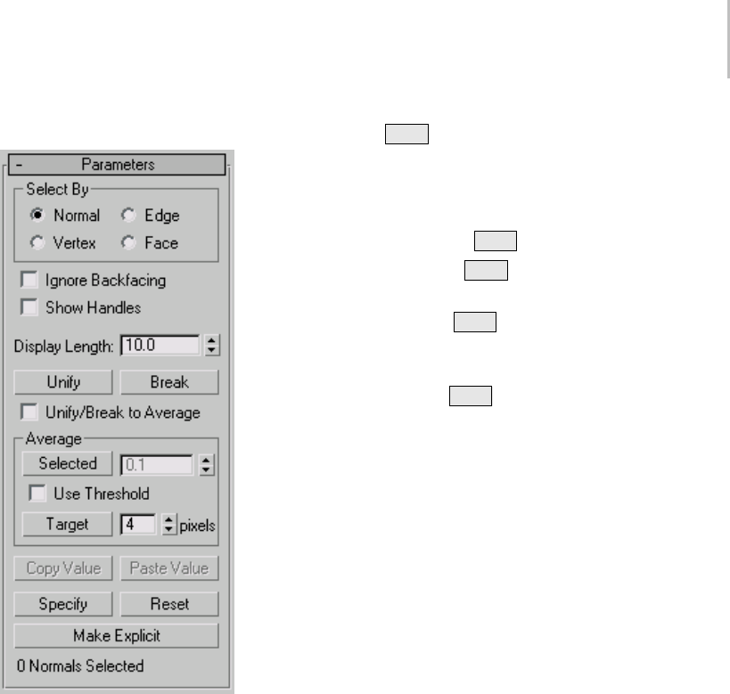
Edit Normals Modifier 637
Interface
The Edit Normals modifier is useful mainly at the
sub-object level, Normal, so this level is active by
defaultassoonasyouapplythemodifiertoan
object. At this point, you can see the normals as
lines emanating from the mesh vertices, select and
transform them, copy and paste them, and change
their settings on the Modify panel.
You can transform normals only by moving and
rotating them, not by scaling them. However,
moving a normal effectively rotates it, so in most
cases you’ll have better control by using the Rotate
tool.
The following command reference includes
keyboard shortcuts, which are available when the
Keyboard Shortcut Override Toggle (page 3–872)
(on the toolbar) is on. In addition, you can use
Ctrl +0 (zero) to access the object level of the
modifier.
Select By group—Lets you specify how to select
normals in the viewport:
•Normal ( Ctrl +1): Click a normal to select it.
•Ve r t e x ( Ctrl +2): Click a mesh vertex to select
all of its normals.
•Edge ( Ctrl +3): Click a mesh edge to select
the normals associated with the neighboring
polygons.
•Face ( Ctrl +4): Click a mesh face (or polygon)
to select the associated normals.
Of course, with all of these methods, you can also
use region selection to select multiple normals at
once.
Ignore Backfacing—When on, selection of
sub-objects affects only those facing you. When
off (the default), you can select any sub-object(s)
under the mouse cursor, regardless of their
visibility or facing. If there are more than one
sub-object under the cursor, repeated clicking
cyclesthroughthem. Likewise,withIgnore
Backfacing off, region selection includes all
sub-objects, regardless of the direction they face.
Show Handles—Enables the display of handles,
which are small squares at the end of each normal.
Turn this on to make it easier to select normals.
Display Length—Specifies the length of each
normal. Thisisfordisplaypurposesonly;the
length has no effect on the normal’s functionality.
Unify (U)—Combines all selected normals at
each vertex into a single specified normal.By
default, with Unify/Break To Average off, Unify
sets the direction for each unified normal to be
perpendicular to the averaged surface at that point.
With Unify/Break To Average on, Unify sets the
directionbetheaverageofthecombinednormals
at each location.

638 Chapter 8: Modifiers
Break (B)—Separates all selected, unified normals
into their original components. With Unify/Break
To Average off, Break orients each separated
normal perpendicular to its respective face, thus
splaying out the normals at each vertex if the
connected faces are at different angles (as with a
sphere). With Unify/Break To Average on, each
separated normal uses the orientation of the
original normal.
Break converts any selected normals to specified
normals.
Unify/Break to Average—Determines normal
orientation as the result of a Unify or Break
operation. See the descriptions above for details.
Default=off.
Average group
These controls give you different methods of
averaging vertex normals; that is, setting them all
tothesameabsoluteangle,whichistheaverageof
their combined angles.
Selected—Sets selected normals to the same
absolute angle: the average angle of all of them. If
Use Threshold is on, averages only normals whose
distance from each other is less than that specified
in the Average Threshold spinner (to the button’s
right).
Use Threshold—Activates the Average Threshold
setting, and causes the Selected to average only
normals whose distance from each other is less
than the specified value.
Target—Enters an interactive mode in which you
specify pairs of normals to average. Click Target,
andthenselectanormal.Whenthemousecursor
is over a normal, it changes to a + cursor. After
clicking the first normal, a rubber-band dashed
lineconnectsthenormaltothemousecursor.
Click a second normal to average the angles of the
two normals.
The pixels spinner to the right of the Target
button sets the maximum distance in screen pixels
between the mouse cursor and the target normal.
Copy Value (Ctrl+C)—Copies the selected normal’s
orientation to the copy buffer. Available only when
asinglenormalisselected.
Use Copy Value and Paste Value to apply a
normal’s orientation to one or more others within
thesameEditNormalsmodifier.Youcannotcopy
normals between modifiers.
Paste Value (Ctrl+V)—Applies the paste buffer
contents to the current selection. Available only
after Copy Value has been used to place a normal’s
orientation in the copy, and one or more target
normals are selected.
Specify (S)—Converts selected normals to specified
normals.
Reset (R)—Causes all selected normals to revert to
unspecified status, and returns them to their initial,
calculated positions. Also breaks apart unified
normals.
Make Explicit (E)—Converts selected normals to
explicit normals.
[Selection Display]—When one normal is selected,
shows its ID number. When 0 or more than one
normal is selected, shows the number of normals
selected.
Edit Patch Modifier
Create or select an object > Modify panel > Modifier List
>Object–SpaceModifiers>EditPatch
Create or select an object > Modifiers menu >
Patch/Spline Editing > Edit Patch
The Edit Patch modifier provides editing tools for
different sub-object levels of the selected object:
vertex,handle,edge,patch,andelement.TheEdit
Patch modifier matches all the capabilities of the

Edit Patch Modifier 639
base Editable Patch object, except that you cannot
animate sub-objects in Edit Patch. See Editable
Patch (page 1–968) for a parameter reference.
Other than the inability to animate sub-objects
with Edit Patch, the main difference between
Edit Patch and Editable Patch is that the modifier
incorporates the ability of the Surface modifier to
generate a patch object from a spline cage. For
details, see Spline Surface (page 1–639).
When possible, it’s far more efficient and reliable
to perform explicit editing on an Editable Patch
object rather than store those edits within the Edit
Patch modifier. The Edit Patch modifier must copy
the geometry passed to it, and this storage can lead
to large file sizes. The Edit Patch modifier also
establishes a topological dependency that can be
adversely effected if earlier operations change the
topology being sent to it.
There are, however, situations where using the Edit
Patch modifier is the preferred method.
• You want to edit a parametric object as a patch,
butwanttoretaintheabilitytomodifyits
creation parameters after the edit.
• You want to store your edits temporarily within
Edit Patch until you are satisfied with the
results, before committing them permanently
to an editable patch.
• You want to streamline your workflow with the
SplineSurfacetools,whichareuniquetoEdit
Patch.
• You need to make edits across several patch
objectsatonce,butdonotwanttoconvert
them to a single editable patch object.
• You have a modifier in the stack that must stay
parametric, and the resulting patch must be
edited after the modifier is applied.
Procedure
To create a patch object using the Cross Section and
Spline Surface tools:
This procedure describes how to simplify the
workflow of building objects using a spline cage
to which a patch surface is applied, a method
described in the Surface modifier (page 1–842)
topic as “Surface Tools.”
1. Create a spline object.
Make sure that the spline vertices form valid
three-sided or four-sided polygons. Vertices
on splines that cross one another should be
coincident.
To m a ke s p l i n e v e r t i c e s c o i n c i de n t , d r a g
vertices over each other with 3D Snap turned
on. 3D Snap must have the Vertex or End Point
option turned on. With 3D Snap turned on,
you can snap to vertices on existing splines
as you create new splines. You can also select
vertices and use the Fuse option in an Editable
Spline to make vertices coincident.
2. Convert the spline object to an Editable Spline,
if necessary, or apply an Edit Spline modifier.
3. Use the Cross Section command in Edit/Editable
Spline to add splines connecting different
splines in the spline object, thus creating a
spline cage.
This replaces the previous workflow of using
the CrossSection modifier.
4. Apply the Edit Patch modifier to the spline
object.
By default, in Edit Patch the Geometry rollout >
Spline Surface group > Generate Surface option
is on, causing the modifier to create patches
over all valid three- and four-sided polygons
in the spline cage.
This replaces the previous workflow of using
the Surface modifier.

640 Chapter 8: Modifiers
5. Adjust the Spline Surface settings and edit
the object as necessary. If you modify the
spline object, for best results, edit at the Vertex
sub-object level, and be sure to select all vertices
at an intersection before moving them.
Interface
Spline Surface group
TheGeometryrollout>SplineSurfacegroupis
found only in the Edit Patch modifier; it’s not
availableintheEditablePatchobject.Thegroup
becomes available when the object to which the
Edit Patch modifier is applied consists of splines.
Its controls replicate the functionality of the
Surface modifier (page 1–842).
For best results, apply the Spline Surface controls
after creating a spline cage with the CrossSection
modifier (page 1–623) or the Editable Spline
Cross Section command.Thelatterapproach
approximates the Surface Tools workflow
(described in the Surface Modifier topic), but with
a simpler modifier stack; instead of additional
CrossSection and Surface modifiers, the stack
need contain only an Editable Spline object and an
Edit Patch modifier. Alternatively, you can use the
Edit Spline modifier’s Cross Section command.
Generate Surface—Creates a patch surface
usingexistingsplinestodefinethepatchedges.
Default=on.
Threshold—Determines the overall distance that
is used to weld the vertices of the spline object.
All vertices/vectors within the threshold distance
of each other are treated as one. Threshold uses
units set in the Units Setup dialog (page 3–848).
Default=1.0.
Note: Spline control handles are also treated as
vertices, so setting high Threshold levels can
produce unexpected results.
Flip Normals—Reverses the facing direction of the
patch surface. Default=off.
Remove Interior Patches—Removes interior faces
of an object that you would not normally see.
Thesearethefacescreatedwithinthecapsor
otherinteriorpatchesofthesametypeofaclosed
polygon. Default=on.
Use Only Selected Segs—Only segments selected
in the Edit Spline modifier or the editable spline
object will be used by the Surface modifier to
create patches. Default=off.
Note: SegmentSub-Objectdoesnothavetobeleft
on in the Edit Spline modifier or editable spline
object.
Edit Poly Modifier
Create or select an object. > Modify panel > Modifier List
>Object-SpaceModifiers>EditPoly
Create or select an object. > Modifiers menu > Mesh
Editing > Edit Poly
The Edit Poly modifier provides explicit editing
tools for different sub-object levels of the selected
object: vertex, edge, border, polygon, and element.
The Edit Poly modifier includes most capabilities
of the base Editable Poly object, except for Vertex
Color information, Subdivision Surface rollout,
Weight and Crease settings, and Subdivision
Displacement rollout. Edit Poly lets you animate
sub-object transforms and parameter changes. In
addition, because it’s a modifier, you can retain
the object creation parameters and change them
later. For detailed information about animating
with Edit Poly, see these procedures (page 1–643).
Edit Poly gives you these options:
•Transformor
Shift +Clone the selection, as
with any object.
• UsetheoptionsontheEditrolloutstomodify
the selection or object. Later topics discuss

Edit Poly Modifier 641
these options for each of the polymesh
components.
•Passasub-objectselectiontoamodifier
higherinthestack.Youcanapplyoneormore
standard modifiers to the selection.
Tip: You can exit most Edit Poly command modes,
such as Extrude, by right-clicking in the active
viewport.
Differences Between Edit Poly and
Editable Poly
FunctionalityinEditPolyismostlythesameas
that of Editable Poly. Please note the following
differences:
• Edit Poly is a modifier, with all properties
that modifier status entails. These include the
ability to place Edit Poly above a base object
and other modifiers on the stack, to move the
modifier to different locations in the stack,
and to apply multiple Edit Poly modifiers to
the same object, each containing different
modeling or animation operations.
• Edit Poly has two distinct modes of operation:
Model and Animate. See Edit Poly Mode rollout
(page 1–645).
• Delete Isolated Vertices is now an option on the
Edit Geometry rollout. Previously, it appeared
as a dialog every time you deleted contiguous
polygons. Now you can set it and forget it.
• Edit Poly eliminates the Full Interactivity
switch; this feature is on all the time.
• EditPolyprovidestwonewwaysofobtaining
an existing selection from lower in the stack:
Use Stack Selection and Get Stack Selection.
• In addition to the Settings dialogs from Editable
Poly, Edit Poly gives you a new Settings dialog
for Align operations, available on the Edit Poly
Mode rollout (page 1–645).
• Edit Poly lacks Editable Poly’s Subdivision
Surface and Subdivision Displacement rollouts.
There are no Weight or Crease settings for
vertices, edges, or borders. If you need to use
Weight and Crease settings, apply a Meshsmooth
modifier (page 1–722),setIterationsto0,and
then make the settings as desired. Also, there is
no provision for setting vertex properties such
as color.
• In Animate mode, you begin a slice operation
by clicking Slice, not Slice Plane. You still need
to click Slice Plane to move the plane around.
You can animate the slice plane.
• In some cases, several Undo commands (page
1–94) might be required to revert from changes
made with certain Edit Poly operations, such
as Extrude.
For example, if you extrude a polygon using the
Extrude Polygons dialog (page 1–1072),there
will be three Undo actions. The first undoes the
Commit, which happens automatically when
you click the dialog OK button at the end; the
second undoes the change in height (from 0 to
the height you set); and the third undoes the
entry into the Extrude operation.
FollowingisatableshowingtheEditPolyfunctions
that are and are not animatable. Functions that are
not animatable are unavailable in Animate mode.
Functions marked “Yes” can be animated explicitly
in Animate mode.
Functions marked “Proc” cannot be animated
explicitly, but can be animated procedurally. This
means they can be applied to different parts of the
Edit Poly object at different points in the animation
by means of an animated sub-object selection
passed up the stack. For further information, see
ToapplyanEditPolyoperationtoananimated
sub-object selection: (page 1–644).

642 Chapter 8: Modifiers
Function Animatable?
Transform sub-objects Yes
Shift +Transform
sub-objects Yes
Constraints No
Preserve UVs No
By Vertex No
Ignore Backfacing No
Ring No
Loop No
Shrink No
Grow No
Selection conversion No
Named Selection
copy/paste No
Soft Selection (most
settings)
Yes (but not painting soft
selection)
Shaded Face toggle No
Delete Proc
Create Vertex No
Create Face No
Create Edge No
Collapse Proc
Attach / Attach List No
Detach No
Slice Yes
Quickslice No
Cut No
MSmooth Proc
Tessellate Proc
Make Planar Proc
View Align Yes
Grid Align Yes
Relax Yes
Hide Selected No
Function Animatable?
Hide Unselected No
Unhide All No
Remove Proc
Break Proc
Extrude Yes
Chamfer Yes
Bridge Yes
Weld (selected)
Proc (can animate Weld
Threshold)
Target Weld No
Connect Yes
Remove Isolated Vertices Proc
Remove Unused Map Verts Proc
Remove Yes
Split Yes
Insert Vertex No
Weld (selected) Yes (Threshold)
Target Weld No
Connect (Vertex) Proc
Connect (Edge) Yes
Create Shape No
Edit Triangulation No
Cap Proc
Insert Vertex No
Extrude Yes
Bevel Yes
Outline Yes
Inset Yes
Retriangulate Proc
Flip Proc
Hinge from Edge Yes
Extrude Along Spline Yes
Set Material ID Yes

Edit Poly Modifier 643
Function Animatable?
Select by Material ID No
Set Smoothing Group Yes
Select by Smoothing Group No
Auto Smooth Proc
Edit Poly Workflow
Edit Poly differs from other Edit modifiers in
3ds Max in that it provides two different modes,
available on the Edit Poly Mode rollout: one
for modeling, and the other for animating. By
default, Edit Poly operates in Model mode, whose
functionalityismostlythesameasthatofEditable
Poly. Alternatively, you can work in Animate
mode, where only functions you can animate are
available.
Each Edit Poly modifier can preserve any number
of keyframes animating a single operation type,
such as transforming faces, on the same sub-object
selection. To animate other parts of the object,
or to animate a different operation on the same
sub-object selection, just use another Edit Poly
modifier.
Sub-object-specific functions in the Edit Poly
user interface can be found in their own rollouts,
leaving the Edit Geometry rollout with functions
thatcanbeusedatmostsub-objectlevels,aswell
as at the object level.
Also, many commands are accompanied by a
Settings button, which gives you two ways of using
the command:
• In Direct Manipulation mode, activated by
clicking the command button, you apply the
command by manipulating sub-objects directly
in the viewport. An example of this is Extrude.
Note: Some buttons, such as Tessellate, operate
on the mesh immediately, with no viewport
manipulation required.
•Interactive Manipulation mode is well
suited to experimentation. You activate this
mode by clicking the command’s Settings
button. This opens a non-modal settings dialog
and places you in preview mode, where you can
set parameters and see results immediately in
the viewport. You can then accept the results by
clicking OK, or reject them by clicking Cancel.
You can also use this mode to apply the same or
different settings to several different sub-object
selections in a row. Make the selection,
optionally change the settings, click Apply, and
then repeat with a different selection.
Important: When you click Apply, the settings are
“baked into” the selection, and then applied again
to the selection as a preview. If you then click OK to
exit, you will have applied the settings twice. If your
intention is to apply them only once, simply click OK
the first time, or click Apply, and then Cancel.
See also
Poly Select Modifier (page 1–762)
Turn To Poly Modifier (page 1–874)
Editable Poly Surface (page 1–1022)
Procedures
To animate an Edit Poly operation on a sub-object
selection:
1. Select an object.
2. Apply the Edit Poly modifier.
3. Go to the first frame at which to set a
key and turn on Auto Key.
4. On the Modify panel > Edit Poly Mode rollout,
choose Animate.
5. Make a sub-object selection.
6. Perform an operation on the selection, such as
atransformorextrusion.

644 Chapter 8: Modifiers
7. Proceed to the next keyframe and continue to
change settings for the current operation and
sub-object selection.
If you change the selection, the existing
animation is applied to the new selection, and
lost from the previous one. If you change
the operation, any changes from the previous
animation are frozen (that is, “baked” into the
model) at the current frame, and only new
keyframes are recorded in the current Edit Poly
modifier.
To animate different sub-object selections using
different operations, use multiple applications
of the Edit Poly modifier.
To apply an Edit Poly operation to an animated
sub-object selection:
This procedure demonstrates procedural
animation with Edit Poly: the ability to change
the location of application on an object during an
animation using an existing, animated sub-object
selection.
1. Select an object.
2. Create an animated sub-object selection. One
waytodothisistoapplyaVo lu m e S e l e c t
modifier (page 1–952) and animate the gizmo’s
transform, or animate the modifier effect by
using an animated texture map.
3. Apply the Edit Poly modifier.
4. Gotothesamesub-objectlevelinEditPoly,
and then, on the Selection rollout, turn on Use
Stack Selection.
5. Scrub the time slider.
The animated selection appears on the Edit
Poly object.
6. On the Modify panel > Edit Poly Mode rollout,
choose Animate.
7. Perform an operation on the sub-object
selection, such as a chamfer or extrusion. You
needn’t turn on Auto Key or use Set Key.
Note: With Use Stack Selection on, you can’t
change the selection.
Now, when you play the animation, the Edit
Poly effect moves along with the animation of
the sub-object selection.
If you decide to animate a different function
procedurally, first click Edit Poly Mode rollout
>Cancel.
Example: To apply an Edit Poly operation
procedurally to an animated model:
Edit Poly lets you layer an animated sub-object
operationontopofanexistinganimation.Trythis
brief example:
1. Create an animated model, such as a box with
an animated Bend modifier.
2. ApplyanEditPolymodifier,andontheEdit
Poly Mode rollout, choose Animate. Also turn
on Auto Key.
3. Go to the Polygon sub-object level.
4. Gotoframe20andextrudeapolygon.
5. Play the animation.
The extrusion animation plays “on top” of the
existing animation. This isn’t possible with the
Edit Mesh modifier.
Interface
Stack Display
For more information on the stack display, see
Modifier Stack (page 3–760).
Show End Result—Because Edit Poly is a modifier,
if you apply further modifiers and then return
totheEditPolystackentry,ShowEndResultis
on by default, and you can still see the results of
any modifiers above Edit Poly on the stack. This
is different from the Editable Poly object, where
if you apply a modifier such as Symmetry (page
1–861) andthenreturntotheEditablePolystack
entry, you cannot see the effect of the modifier
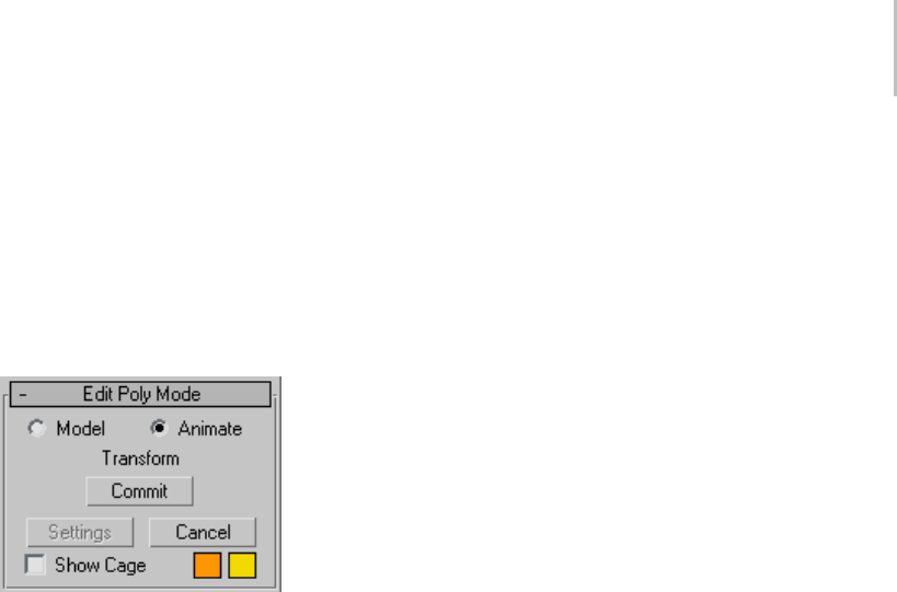
Edit Poly Modifier 645
ontheobject’sgeometry.Whileatasub-object
level,ifyouturnonShowCageontheEditPoly
Mode rollout, you can see the final object as a
white mesh, the original sub-object selection as a
yellow mesh, and the original Edit Poly object as
an orange mesh.
Edit Poly Mode rollout
ThisrolloutprovidesaccesstoEditPoly’stwo
modes of operation: Model, for modeling, and
Animate, for animation of modeling effects. For
example, you can animate the Taper and Twist
settings for polygons extruded along a spline.
During and between sessions, the software
remembers the current mode for each object
separately. The same mode remains active at all
sub-object levels.
Edit Poly Mode also gives you access to the
current operation’s Settings dialog, if any, and
lets you commit to or cancel out of modeling and
animation changes.
Model—Lets you model using the Edit Poly
functions. Operations in Model mode cannot be
animated.
Animate—Lets you animate using the Edit Poly
functions.
In addition to choosing Animate, you must turn
on Auto Key (page 3–717) or use Set Key (page
3–718) for animating sub-object transforms and
parameter changes. Alternatively, in Animate
mode you can apply a single command, such as
Extrude or Chamfer, to an animated sub-object
selection passed up the stack.
Tip: If you use Set Key to animate with Edit Poly, be
sure to turn on Key Filters > Modifiers.
Note: The Edit Poly modifier can store any number
of keyframes animating a single operation, such as
transforming polygons, on the same sub-object
selection. Use additional Edit Poly modifiers to:
• animate other parts of the object;
• animate repeated applications of the same
operationonthesamesub-objectselection;
• animate repeated applications of a different
operationonthesamesub-objectselection.
For example, say you want to animate a polygon
extruding from an object from frame 1 to 10, and
then moving back to the original position over
the next 10 frames. You can accomplish this with
a single Edit Poly modifier using the Extrude
function, setting one keyframe at 10 and another
at 20. However, say you want to animate a polygon
extruding outward, and then animate movement
of one of the resultant side polygons. In that case,
you’d need two Edit Poly modifiers: one for the
extrusion, and another for the poly transform.
Tip: While modeling in Animate mode, you can
use Commit to freeze the animation at the current
frame.
[label]—Shows the current command, if any.
Otherwise, it shows <No Current Operation>.
When you’re working in Model mode using direct
manipulation (that is, working in the viewports),
the label shows the current operation during drag
operations, and then returns to the unavailable
state.
When you’re working in Model mode using a
Settings dialog, or in Animate mode using direct
manipulation or a Settings dialog, the label
continually shows the current operation.
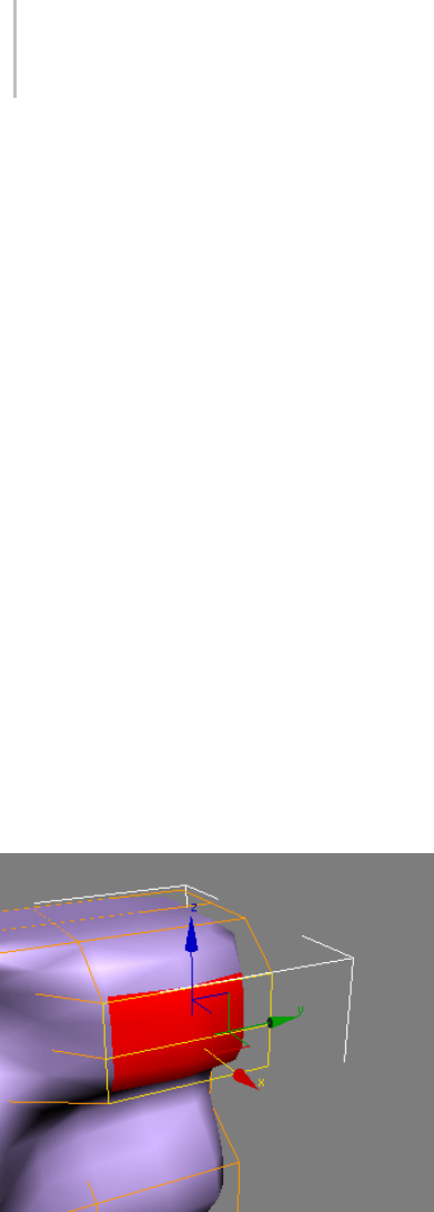
646 Chapter 8: Modifiers
Commit—In Model mode, using a Settings dialog,
acceptsanychangesandclosesthedialog(sameas
theOKbuttononthedialog).InAnimatemode,
freezes the animated selection in its state at the
current frame and closes the dialog. Any existing
keyframes are lost.
Tip: Commit lets you use animation as a modeling
aid. For example, you could animate a vertex
selection between two positions, scrub between
thetwotofindasuitablein-betweenposition,and
thenuseCommittofreezethemodelatthatpoint.
Settings—Toggles the Settings dialog for the
current command.
Cancel—Cancels the most recently used command.
Show Cage—Toggles the display of a two-color
wireframethatshowstheeditablepolyobject
before modification or subdivision. The cage
colors are shown as swatches to the right of the
check box. The first color represents unselected
sub-objects, and the second color represents
selected sub-objects. Change a color by clicking its
swatch. The Show Cage toggle is available only at
sub-object levels.
Thecagedisplaystheoriginalstructureoftheeditedobject.
Typically this feature is used in conjunction with
the MeshSmooth modifier (page 1–722) because it
lets you easily toggle visibility of the unsmoothed
base object while simultaneously viewing the
smoothed result, but it works with any modifier.
Tip: Show Cage is also particularly helpful when
used with the Symmetry modifier (page 1–861).
Selection rollout
The Selection rollout provides tools for accessing
different sub-object levels and display settings
and for creating and modifying selections. See
Selection Rollout (Edit Poly Modifier) (page 1–647).
Soft Selection rollout
Soft Selection controls apply a smooth falloff
between selected sub-objects and unselected
ones.WhenUseSoftSelectionison,unselected
sub-objectsnearyourselectionaregivenpartial
selection values. These values are shown in the
viewports by means of a color gradient on the
vertices, and optionally on the faces. They affect
most types of sub-object deformations, such as
theMove,Rotate,andScalefunctionsandany
deformation modifiers (such as Bend) applied to
the object. This provides a magnet-like effect with
a sphere of influence around the selection.
For more information, see Soft Selection Rollout
(page 1–963).
Edit (sub-object) rollout
The Edit (sub-object) rollout provides
sub-object-specific functions for editing an Edit
Poly object and its sub-objects. For specific
information, click any of the following links:
Edit Vertices rollout (page 1–653)
Edit Edges rollout (page 1–658)
Edit Borders rollout (page 1–663)
Edit Polygons/Elements rollout (page 1–667)
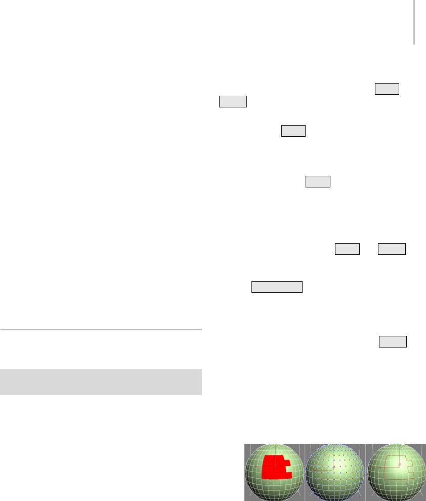
Selection Rollout (Edit Poly Modifier) 647
Edit Geometry rollout
The Edit Geometry rollout (page 1–673) provides
global functions for editing an Edit Poly object
and its sub-objects. For information specific to a
sub-object level, click one of the following links:
Edit Poly (Object) (page 1–651)
Edit Poly (Vertex) (page 1–652)
Edit Poly (Edge) (page 1–656)
Edit Poly (Border) (page 1–663)
Edit Poly (Polygon/Element) (page 1–666)
Paint Deformation rollout
Paint Deformation lets you stroke elevated and
indented areas directly onto object surfaces. For
more information, see Paint Deformation Rollout
(page 1–1064).
Selection Rollout (Edit Poly
Modifier)
Select an Edit Poly object. > Modify panel > Selection
rollout
The Selection rollout provides tools for accessing
different sub-object levels and display settings
and for creating and modifying selections. It also
displays information about selected entities.
When you first access the Modify panel with an
Edit Poly object selected, you’re at the Object level,
with several functions available as described in
Edit Poly (Object) (page 1–651). You can toggle
the various sub-object levels and access relevant
functions by clicking the buttons at the top of the
Selection rollout.
Clickingabuttonhereisthesameaschoosing
a sub-object type in the modifier stack display.
Click the button again to turn it off and return to
the Object selection level.
Note: Youcanconvertsub-objectselectionsin
three different ways with the use of the Ctrl and
Shift keys:
• Clicking a sub-object button in the Selection
rollout with Ctrl held down converts the
current selection to the new level, selecting
all sub-objects in the new level that touch the
previous selection. For example, if you select
avertex,andthen Ctrl +click the Polygon
button, all polygons using that vertex are
selected.
• To convert the selection to only sub-objects
all of whose source components are originally
selected, hold down both Ctrl and Shift
as you change the level. For example, if you
convert a vertex selection to a polygon selection
with Ctrl+Shift +click, the resultant selection
includes only those polygons all of whose
vertices were originally selected.
• To convert the selection to only sub-objects
that border the selection, hold down Shift as
you change the level. The selection conversion
is inclusive, meaning:
• When you convert faces, the resulting
selection of edges or vertices all belong to
selected faces that bordered unselected faces.
Only the edges or vertices that bordered
unselected faces are selected.
Face selection (left) converted to vertex border (center)
and edge border (right)
• When you convert vertices to faces, the
resulting selection of faces had all of their
vertices selected and bordered unselected
faces. When you convert vertices to edges,
the resulting selection contains only edges
all of whose vertices were previously selected
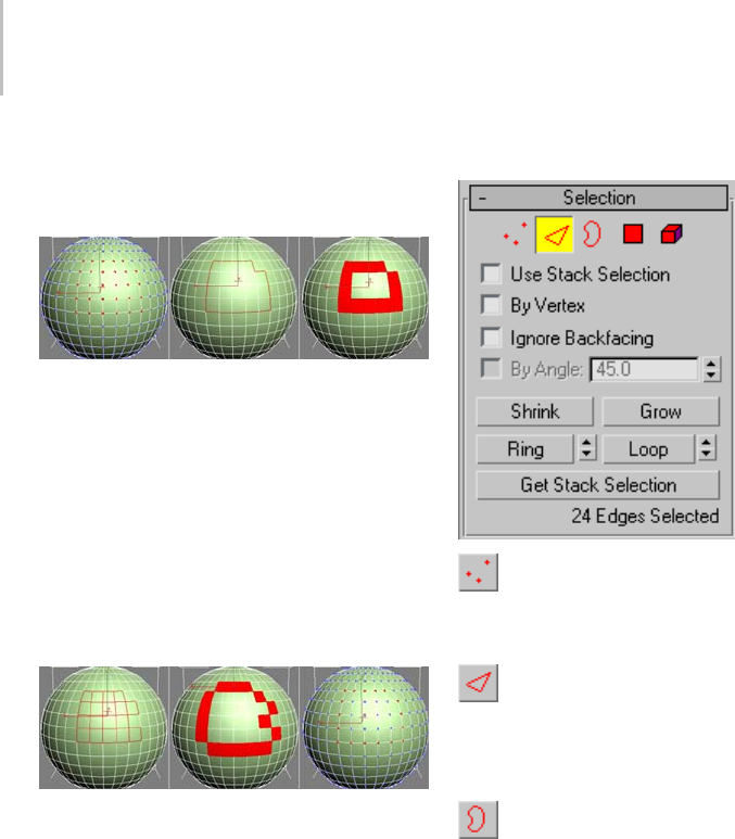
648 Chapter 8: Modifiers
and only edges of faces that did not have all
vertices selected; that is, of faces around the
border of the vertex selection.
Vertex selection (left) converted to edge border (center)
and face border (right)
• When you convert edges to faces, the
resulting selection of faces had some but
not all of their edges selected, and were
next to faces with no edges selected. When
you convert edges to vertices, the resulting
vertices are on previously selected edges,
butonlyatintersectionswherenotalledges
were selected.
Edge selection (left) converted to face border (center)
and vertex border (right)
Conversion commands are also available from the
quad menu.
Interface
Vertex—Accesses the Vertex sub-object level,
which lets you select a vertex beneath the cursor;
region selection selects vertices within the region.
Edge—Accesses the Edge sub-object level,
which lets you select a polygon edge beneath the
cursor; region selection selects multiple edges
within the region.
Border—Accesses the Border sub-object level,
which lets you select a sequence of edges that
borders a hole in the mesh. A border is always
composed of edges with faces on only one side of
them, and is always a complete loop. For example,
a box doesn’t normally have a border, but the
Teapot object has several of them: on the lid, on the
body, on the spout, and two on the handle. If you
create a cylinder and then delete one end, the row
of edges around that end forms a circular border.
When Border sub-object level is active, you can’t
selectedgesthataren’tonborders. Clickinga
single edge on a border selects the whole border.
Youcancapaborder,eitherinEditPolyorby
applying the Cap Holes modifier (page 1–569).You
can also connect borders between objects with the
Connect compound object (page 1–328).
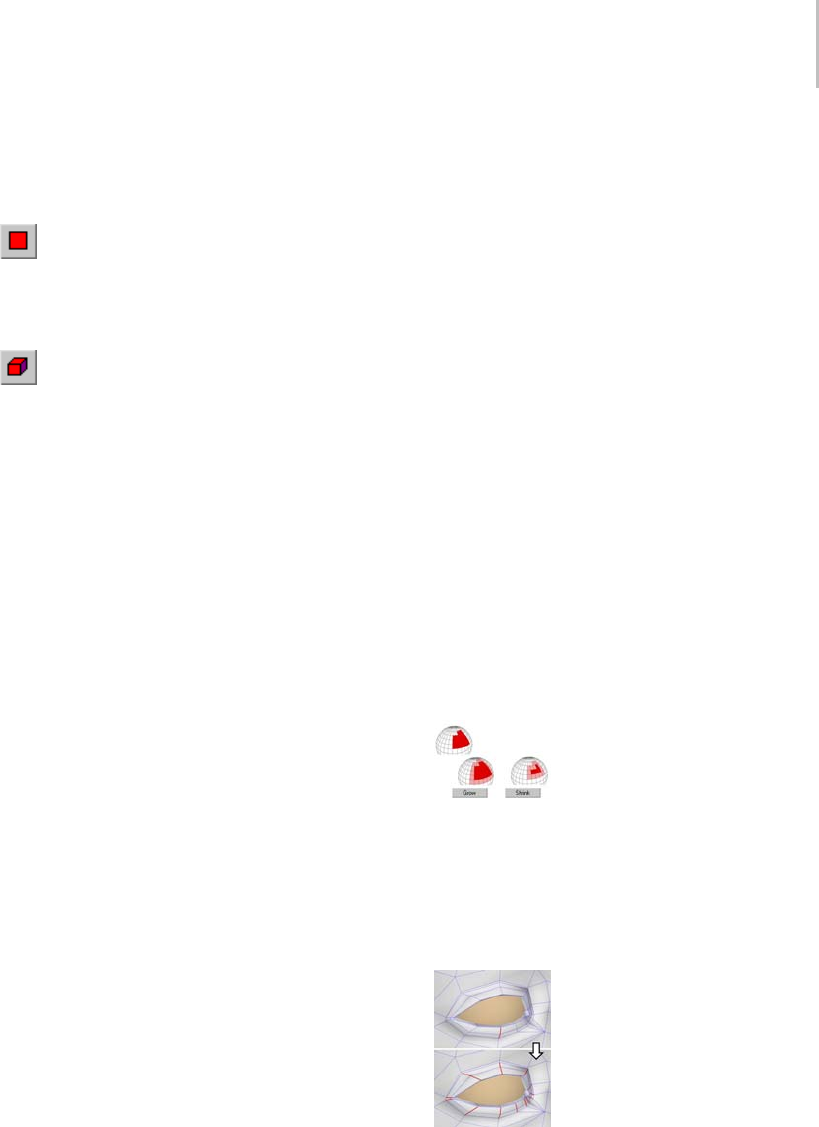
Selection Rollout (Edit Poly Modifier) 649
TheEdgeandBordersub-objectlevelsare
compatible, so if you go from one to the other, any
existing selection is retained.
Polygon—Accesses the Polygon sub-object
level, which lets you select polygons beneath the
cursor. Region selection selects multiple polygons
within the region.
Element—Turns on Element sub-object level,
which lets you select all contiguous polygons in an
object. Region selection lets you select multiple
elements.
The Polygon and Element sub-object levels are
compatible, so if you go from one to the other, any
existing selection is retained.
Use Stack Selection—When on, Edit Poly
automatically uses any existing sub-object
selection passed up the stack, and prevents you
from manually changing the selection.
By Vertex—When on, you can select a sub-object
only by selecting a vertex that it uses. When you
click a vertex, all sub-objects that use the selected
vertex are selected.
Ignore Backfacing—When on, selection of
sub-objects affects only those facing you. When
off (the default), you can select any sub-object(s)
under the mouse cursor, regardless of visibility or
facing.Ifmultiplesub-objectslieunderthecursor,
repeated clicking cycles through them. Likewise,
with Ignore Backfacing off, region selection
includes all sub-objects, regardless of the direction
they face.
Note: ThestateoftheBackfaceCullsettinginthe
Display panel does not affect sub-object selection.
Thus, if Ignore Backfacing is off, you can still select
sub-objects, even if you can’t see them.
By Angle—When on, if you select a polygon,
the software also selects neighboring polygons
basedontheanglesettingtotherightofthe
check box. This value determines the maximum
angle between neighboring polygons that will be
selected. Available only at the Polygon sub-object
level.
For example, if you click a side of a box and the
angle value is less than 90.0, only that side is
selected, because all sides are at 90-degree angles to
each other. But if the angle value is 90.0 or greater,
all sides of the box are selected. This function
speeds up selection of contiguous areas made up
of polygons at similar angles to one another. You
can select coplanar polygons with a single click at
any angle value.
Shrink—Reduces the sub-object selection area
by unselecting the outermost sub-objects. If
the selection size can no longer be reduced, the
remaining sub-objects are unselected.
Grow—Expands the selection area outward in all
available directions.
Forthisfunction,aborderisconsideredtobean
edge selection.
With Shrink and Grow, you can add or remove neighboring
elements from the edges of your current selection. This works
at any sub-object level.
Ring—Expandsanedgeselectionbyselectingall
edges parallel to the selected edges. Ring applies
only to edge and border selections.
Ring selection adds to the selection all the edges parallel to
the ones selected originally.
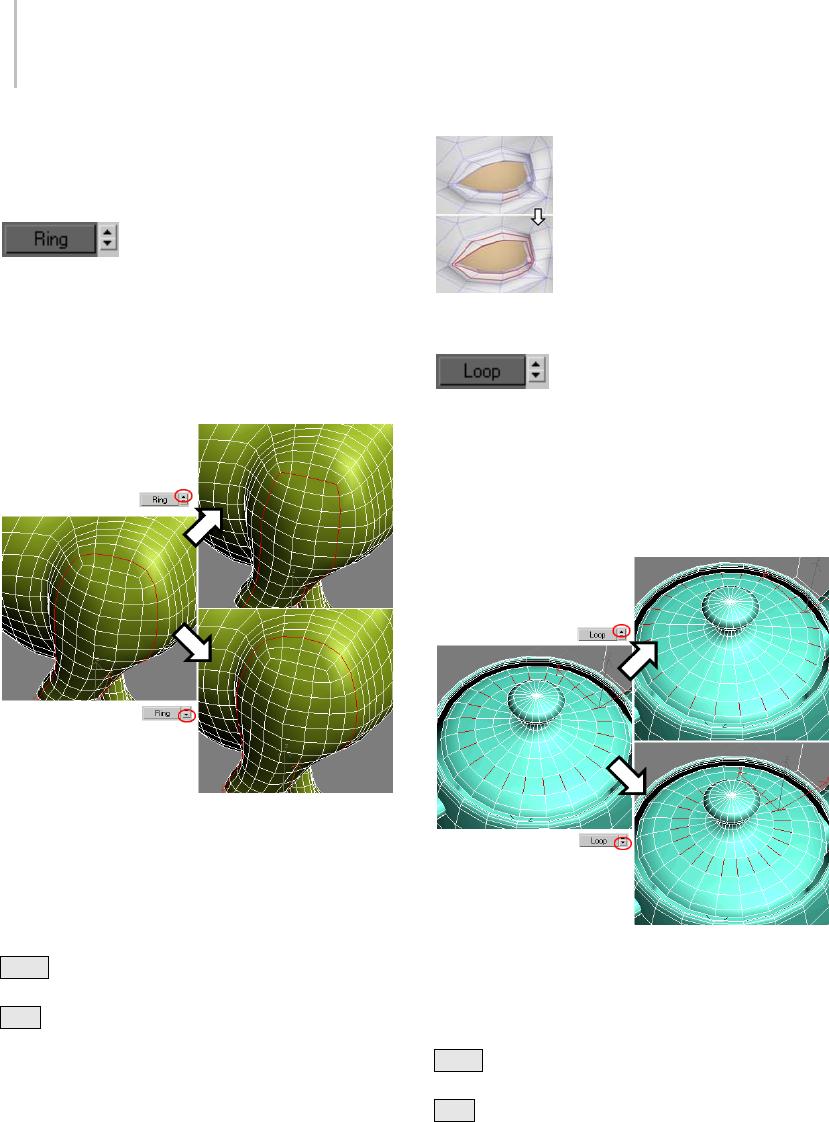
650 Chapter 8: Modifiers
Tip: After making a ring selection, you can use
Connect to subdivide the associated polygons into
new edge loops.
[Ring Shift]—The spinner next to
the Ring button lets you move the selection in
either direction to other edges in the same ring;
thatis,toneighboring,paralleledges.Ifyouhave
a loop selected, you can use this function to select
a neighboring loop. Applies only to Edge and
Border sub-object levels.
Left: Original loop selection
Upper right: Ring Shift up moves selection outward (from
center of model).
Lower right: Ring Shift down moves selection inward (toward
center of model).
To expand the selection in the chosen direction,
Ctrl +click the up or down spinner button. To
shrink the selection in the chosen direction,
Alt +click the up or down spinner button.
Loop—Expandstheselectionasfaraspossible,in
alignment with selected edges.
Loop applies only to edge and border selections,
and propagates only through four-way junctions.
Loop selection extends your current edge selection by adding
all edges aligned to the ones selected originally.
[Loop Shift]—The spinner next to
the Loop button lets you move the selection in
either direction to other edges in the same loop;
that is, to neighboring, aligned edges. If you have a
ring selected, you can use this function to select a
neighboring ring. Applies only to Edge and Border
sub-object levels.
Left: Original ring selection
Upper right: Loop Shift up moves selection outward.
Lower right: Loop Shift down moves selection inward.
To expand the selection in the chosen direction,
Ctrl +click the up or down spinner button. To
shrink the selection in the chosen direction,
Alt +click the up or down spinner button.
Get Stack Selection—Replaces the current selection
with the sub-object selection passed up the stack.
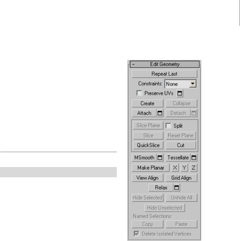
Edit Poly (Object) 651
You can then modify this selection using standard
methods.
If no selection exists in the stack, all sub-objects
are unselected.
Selection Information
At the bottom of the Selection rollout is a text
display giving information about the current
selection. If zero or more than one sub-object
is selected, the text gives the number and type
selected. If one sub-object is selected, the text gives
the identification number and type of the selected
item.
Edit Poly (Object)
Select an Edit Poly object. > Modify panel
Edit Poly (Object) functions are available when no
sub-object levels are active. These functions are
also available at all sub-object levels, and work the
same in each mode, except as noted below.
Interface
Edit Geometry rollout
See Edit Geometry Rollout (Edit Poly Modifier)
(page 1–673) for detailed descriptions of these
controls.
Paint Deformation rollout
Paint Deformation lets you stroke elevated and
indented areas directly onto object surfaces. For
more information, see Paint Deformation Rollout
(page 1–1064).
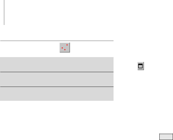
652 Chapter 8: Modifiers
Edit Poly (Vertex)
Select an Edit Poly object. > Modify panel > Selection
rollout > Vertex
Select an Edit Poly object. > Modify panel > Modify Stack
display > Expand Edit Poly. > Vertex
Select an Edit Poly object. > Quad menu > Tools 1
quadrant > Vertex
Verticesarepointsinspace:Theydefinethe
structure of other sub-objects that make up the
poly object. When vertices are moved or edited,
the geometry they form is affected as well. Vertices
can also exist independently; such isolated vertices
can be used to construct other geometry but are
otherwise invisible when rendering.
AttheEditPoly(Vertex)sub-objectlevel,youcan
select single and multiple vertices and move them
using standard methods. This topic covers the
Edit Vertices and Edit Geometry rollouts; for other
controls, see Edit Poly Modifier (page 1–640).
Procedure
To weld polygon vertices:
Yo u c a n u s e e i t h e r o f t w o m e t h o d s t o c o m b i n e
severalverticesintoone,alsoknownaswelding.If
theverticesareveryclosetogether,usetheWeld
function. You can also use Weld to combine a
number of vertices to the average position of all
of them.
Alternatively, to combine two vertices that are far
apart, resulting in a single vertex that’s in the same
position as one of them, use Target Weld.
1. To u s e We l d :
1. On the Selection rollout, turn on Ignore
Backfacing, if necessary. This ensures that
you’reweldingonlyverticesyoucansee.
2. Select the vertices to weld.
3. If the vertices are very close together, simply
click Weld. If that doesn’t work, proceed to
the next step.
4. Click the Settings button to the right of
the Weld button.
This opens the Weld Ver tic es di alog (page
1–1077).
5. IncreasetheWeldThresholdvaluegradually
using the spinner (click and hold on the
up-down arrow buttons to the right of the
numeric field and then drag upward). If you
need the value to change more quickly, hold
down the Ctrl key as you drag.
When the threshold equals or exceeds
thedistancebetweentwoormoreofthe
vertices, the weld occurs automatically, and
the resulting vertex moves to their average
location.
6. If not all the vertices are welded, continue
increasing the Weld Threshold value until
they are.
7. Click OK to exit.
2. To u s e Ta r g e t We l d :
1. On the Selection rollout, turn on Ignore
Backfacing, if necessary. This ensures that
you’reweldingonlyverticesyoucansee.
2. Find two vertices you want to weld, and
determine the ultimate location of the
resulting vertex. The two vertices must be
contiguous; that is, they must be connected
by a single edge.
For this example, we’ll call the vertices A and
B, and the resulting vertex will be at vertex
B’s location.
3. Click the Target Weld button.
The button stays highlighted, to indicate that
you’re now in Target Weld mode.
4. Click vertex A and then move the mouse.
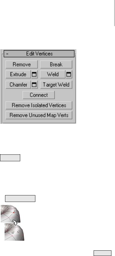
Edit Poly (Vertex) 653
A rubber-band line connects the vertex and
the mouse cursor.
5. PositionthecursoroververtexB,whereupon
the cursor image changes from an arrow
to a crosshairs. Reminder: Only vertices
connected to the first vertex by a single edge
qualify for target welding.
6. Click to weld the two.
The resulting vertex remains at vertex B’s
position,andyouexitTargetWeldmode.
Interface
Edit Poly Mode rollout
See Edit Poly Mode rollout (page 1–645) for
information on the Edit Poly Mode rollout
settings.
Selection rollout
See Selection rollout (page 1–646) for information
on the Selection rollout settings.
Soft Selection rollout
Soft Selection controls apply a smooth falloff
between selected sub-objects and unselected
ones. When Use Soft Selection is on, unselected
sub-objectsnearyourselectionaregivenpartial
selectionvalues. Thesevaluesareshowninthe
viewports by means of a color gradient on the
vertices, and optionally on the faces. They affect
most types of sub-object deformations, such as the
Move, Rotate, and Scale functions, as well as any
deformation modifiers (such as Bend) applied to
the object. This provides a magnet-like effect with
a sphere of influence around the selection.
For more information, see Soft Selection Rollout
(page 1–963).
Edit Vertices rollout
Thisrolloutincludescommandsspecifictovertex
editing.
Note: To delete vertices, select them and press the
Delete key. This can create one or more holes
in the mesh. To delete vertices without creating
holes, use Remove (see following entry).
Remove—Deletes selected vertices and combines
the polygons that use them. The keyboard shortcut
is Backspace .
Removing one or more vertices deletes them and retriangulates
the mesh to keep the surface intact. If you use the Delete key
instead, the polygons depending on those vertices are deleted
as well, creating a hole in the mesh.
Warning: Use of Remove can result in mesh shape
changes and non-planar polygons.
Break—Creates a new vertex for each polygon
attached to selected vertices. This allows the
polygon corners to move away from each other
where they were once joined at each original
vertex. If a vertex is isolated or used by only one
polygon, it is unaffected.
Extrude—Lets you extrude vertices manually via
direct manipulation in the viewport. Click this
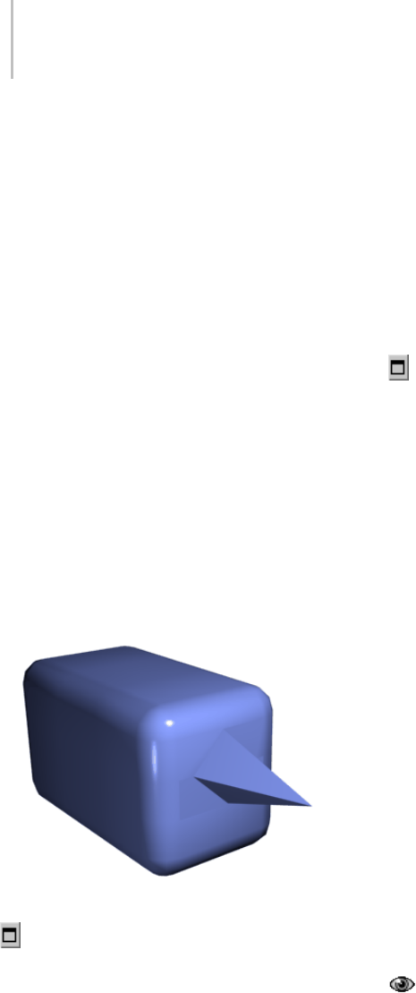
654 Chapter 8: Modifiers
button, and then drag vertically on any vertex to
extrude it.
Extruding a vertex moves it along a normal and
creates new polygons that form the sides of the
extrusion, connecting the vertex to the object.
The extrusion has the same number of sides as
the number of polygons that originally used the
extruded vertex.
Important aspects of vertex extrusion are:
• The mouse cursor changes to an Extrude cursor
when over a selected vertex.
• Drag vertically to specify the extent of the
extrusion, and horizontally to set the size of the
base.
• With multiple vertices selected, dragging on
any one extrudes all selected vertices equally.
• You can drag other vertices in turn to extrude
them while the Extrude button is active. Click
Extrude again or right-click in the active
viewport to end the operation.
Chamfer box showing extruded vertex
Extrude Settings—Opens the Extrude Vertices
dialog (page 1–1073),whichletsyouperform
extrusion via interactive manipulation.
If you click this button after performing a manual
extrusion, the same extrusion is performed on the
current selection as a preview and the dialog opens
with Extrusion Height set to the amount of the last
manual extrusion.
Weld—Combines contiguous, selected vertices
that fall within the tolerance specified in the Weld
dialog (page 1–1077). All edges become connected
to the resulting single vertex.
Weld is best suited to automatically simplify
geometrythathasareaswithseveralverticesin
close proximity.
Weld Settings—Opens the Weld dialog (page
1–1077), which lets you specify the weld threshold.
Chamfer—Click this button and then drag
vertices in the active object. To chamfer vertices
numerically, click the Chamfer Settings button and
adjust the Chamfer Amount value.
If you chamfer multiple selected vertices, all of
them are chamfered identically. If you drag an
unselected vertex, any selected vertices are first
unselected.
Each chamfered vertex is effectively replaced by
a new face that connects new points on all edges
leading to the original vertex. These new points
are exactly <chamfer amount> distance from the
original vertex along each of these edges. New
chamfer faces are created with the material ID of
one of the neighboring faces (picked at random)
and a smoothing group that is an intersection of all
neighboring smoothing groups.
Forexample,ifyouchamferonecornerofabox,
thesinglecornervertexisreplacedbyatriangular
face whose vertices move along the three edges
that led to the corner. Outside faces are rearranged
and split to use these three new vertices, and a
triangle is created at the corner.
Alternatively, you can create open space
around the chamfered vertices; for details, see
Chamfer Vertices dialog (page 1–1070).
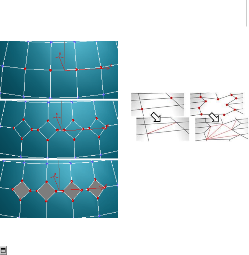
Edit Poly (Vertex) 655
Top: The original vertex selection
Center: Vertices chamfered
Bottom: Vertices chamfered with Open on
Chamfer Settings—Opens the Chamfer Vertices
dialog (page 1–1070),whichletsyouchamfer
vertices via interactive manipulation and toggle
the Open option.
If you click this button after performing a manual
chamfer, the same chamfer is performed on the
current selection as a preview and the dialog opens
with Chamfer Amount set to the amount of the
last manual chamfer.
Target Weld—Lets you select a vertex and weld it
to a target vertex. When positioned over a vertex,
the cursor changes to a + cursor. Click and move
the mouse and a dashed line appears from the
vertex with an arrow cursor at the other end of the
line. Position the cursor over a neighboring vertex
and when the + cursor appears again, click the
mouse. The first vertex moves to the position of
the second, and the two are welded.
Connect—Creates new edges between pairs of
selected vertices.
Connectwillnotletthenewedgescross. For
example, if you select all four vertices of a
four-sided polygon and then click Connect, only
two of the vertices will connect. In this case, to
connect all four vertices with new edges, use Cut.
Remove Isolated Vertices—Deletes all vertices that
don’t belong to any polygons.
Remove Unused Map Verts—Certain modeling
operations can leave unused (isolated) map
vertices that show up in the Unwrap UVW editor
(page 1–888),butcannotbeusedformapping.
You can use this button to delete these map vertices
automatically.
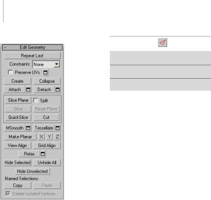
656 Chapter 8: Modifiers
Edit Geometry rollout
See Edit Geometry Rollout (Edit Poly Modifier)
(page 1–673) for detailed descriptions of these
controls.
Paint Deformation rollout
Paint Deformation lets you stroke elevated and
indented areas directly onto object surfaces. For
more information, see Paint Deformation Rollout
(page 1–1064).
Edit Poly (Edge)
Select an Edit Poly object. > Modify panel > Selection
rollout > Edge
Select an Edit Poly object. > Modify panel > Modifier
Stackdisplay>ExpandEditPoly.>Edge
Select an Edit Poly object. > Quad menu > Tools 1
quadrant > Edge
An edge is a line connecting two vertices that forms
thesideofapolygon.Anedgecan’tbesharedby
more than two polygons. Also, the normals of the
two polygons should be adjacent. If they aren’t,
you wind up with two edges that share vertices.
At the Edit Poly Edge sub-object level, you can
select single and multiple edges and transform
them using standard methods. This topic covers
the Edit Geometry and Edit Edges rollouts; for
other controls, see Edit Poly Modifier (page 1–640).
Procedure
To create a shape from one or more edges:
1. Selecttheedgesyouwanttomakeintoshapes.
2. On the Edit Edges rollout, click the Create Shape
button. This creates the shape immediately,
using default settings. Alternatively, click the
Settings button next to Create Shape.
3. Make changes, as needed, on the Create Shape
dialog that appears.
• Enter a curve name or keep the default.
• Choose Smooth or Linear as the shape type.
4. Click OK.
The resulting shape consists of one or more
splines whose vertices are coincident with the
vertices in the selected edges. The Smooth
option results in rounded-corner Bezier
vertices, while the Linear option results in
straight-line splines with Corner vertices.
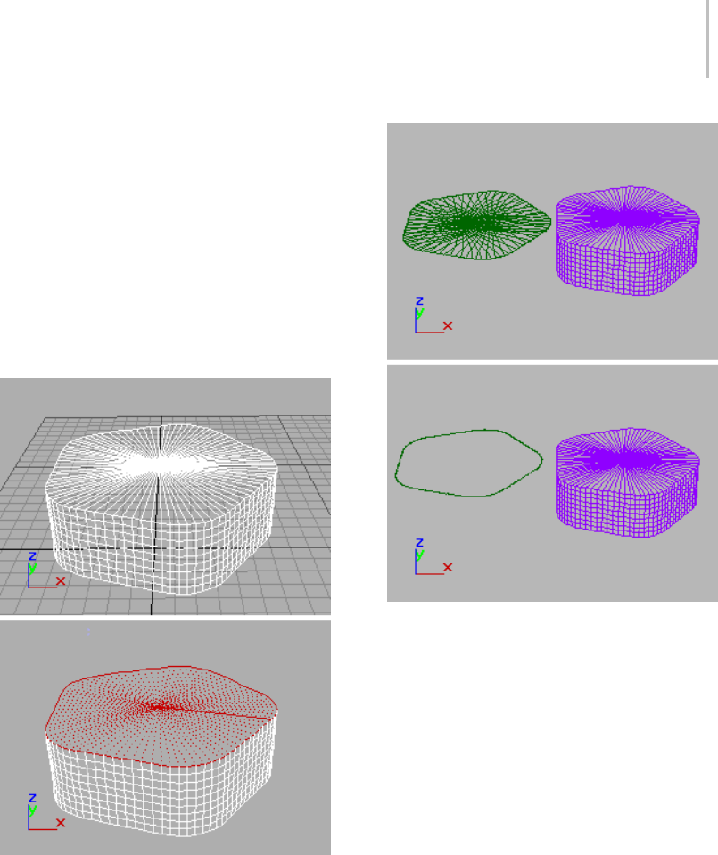
Edit Poly (Edge) 657
If the selected edges are not continuous, or if
they branch, the resulting shape will consist of
morethanonespline.WhentheCreateShape
function runs into a branching ’Y’ in the edges,
it makes an arbitrary decision about which edge
produces which spline. If you need to control
this, select only edges that will result in a single
spline, and perform a Create Shape operation
repeatedly to make the correct number of
shapes. Finally, use Attach (page 1–308) in the
Editable Spline to combine the shapes into one.
Above: Original object
Below: Object with edges selected
Above: Selected edges removed from original object
Below: Unwanted edges removed
Interface
Edit Poly Mode rollout
See Edit Poly Mode rollout (page 1–645) for
information on the Edit Poly Mode rollout
settings.
Selection rollout
See Selection rollout (page 1–646) for information
on the Selection rollout settings.
Soft Selection rollout
Soft Selection controls apply a smooth falloff
between selected sub-objects and unselected
ones.WhenUseSoftSelectionison,unselected
sub-objectsnearyourselectionaregivenpartial
selection values. These values are shown in the
viewports by means of a color gradient on the
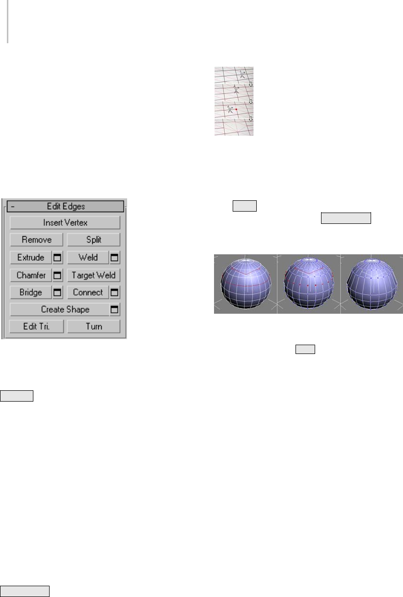
658 Chapter 8: Modifiers
vertices, and optionally on the faces. They affect
most types of sub-object deformations, such as the
Move, Rotate, and Scale functions, as well as any
deformation modifiers (such as Bend) applied to
the object. This provides a magnet-like effect with
a sphere of influence around the selection.
For more information, see Soft Selection Rollout
(page 1–963).
Edit Edges rollout
This rollout includes commands specific to edge
editing.
Note: To delete edges, select them and press the
Delete key. This deletes all selected edges and
attached polygons, which can create one or more
holes in the mesh. To delete edges without creating
holes, use Remove (see following entry).
Insert Vertex—Lets you subdivide visible edges
manually.
After turning on Insert Vertex, click an edge to
add a vertex at that location. You can continue
subdividing polygons as long as the command is
active.
To stop inserting edges, right-click in the viewport,
or click Insert Vertex again to turn it off.
Remove—Deletes selected edges and combines the
polygonsthatusethem.Thekeyboardshortcutis
Backspace .
Removing one edge is like making it invisible. The mesh
is affected only when you remove all but one of the edges
depending on one vertex. At that point, the vertex itself is
deleted and the surface is retriangulated.
To delete the associated vertices as well, press and
hold Ctrl while executing a Remove operation,
either by mouse or with the Backspace key. This
option, called Clean Remove, ensures that the
remainingpolygonsareplanar.
Left: The original edge selection
Center: Standard Remove operation leaves extra vertices.
Right: Clean Remove with Ctrl +Remove deletes the extra
vertices.
Edges with the same polygon on both sides usually
can’t be removed.
Warning: Use of Remove can result in mesh shape
changes and non-planar polygons.
Split—Divides the mesh along the selected edges.
Split does nothing when applied to a single edge in
themiddleofamesh. Theverticesattheendof
affected edges must be separable for this option
to work. For example, it would work on a single
edge that intersects an existing border, since the
border vertex can be split in two. Additionally, two
adjacent edges could be split in the middle of a
grid or sphere, since the shared vertex can be split.
Extrude—Lets you extrude edges manually via
direct manipulation in the viewport. Click this
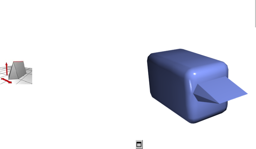
Edit Poly (Edge) 659
button, and then drag vertically on any edge to
extrude it.
When extruding a vertex or edge interactively in the viewport,
you set the extrusion height by moving the mouse vertically
and the base width by moving the mouse horizontally.
Extruding an edge moves it along a normal and
creates new polygons that form the sides of the
extrusion, connecting the edge to the object. The
extrusion has either three or four sides; three if the
edgewasonaborder,orfourifitwassharedby
two polygons. As you increase the length of the
extrusion, the base increases in size, to the extent
of the vertices adjacent to the extruded edge’s
endpoints.
Important aspects of edge extrusion are:
• The mouse cursor changes to an Extrude cursor
when over a selected edge.
• Drag vertically to specify the extent of the
extrusion, and horizontally to set the size of the
base.
• With multiple edges selected, dragging on any
one extrudes all selected edges equally.
• Youcandragotheredgesinturntoextrude
them while the Extrude button is active. Click
Extrude again or right-click in the active
viewport to end the operation.
Chamfer box showing extruded edge
Extrude Settings—Opens the Extrude Edges
dialog (page 1–1073),whichletsyouperform
extrusion via interactive manipulation.
If you click this button after performing a manual
extrusion,thesameextrusionisperformedonthe
current selection as a preview and the dialog opens
with Extrusion Height set to the amount of the last
manual extrusion.
Weld—Combines selected edges that fall within
the threshold specified in the Weld dialog (page
1–1077).
You can weld only edges that have one polygon
attached; that is, edges on a border. Also, you
cannot perform a weld operation that results in
illegal geometry, such as an edge shared by more
than two polygons. For example, you cannot weld
opposite edges on the border of a box that has a
side removed.
Weld Settings—Opens the Weld dialog (page
1–1077), which lets you specify the weld threshold.
Chamfer—Click this button and then drag edges in
the active object. To chamfer vertices numerically,
click the Chamfer Settings button and change the
Chamfer Amount value.
If you chamfer multiple selected edges, all of
them are chamfered identically. If you drag an

660 Chapter 8: Modifiers
unselected edge, the software first deselects any
selected edges.
An edge chamfer "chops off " the selected edges,
creating a new polygon connecting new points on
all visible edges leading to the original vertex. The
new edges are exactly <chamfer amount> distance
fromtheoriginaledgealongeachoftheseedges.
New chamfer faces are created with the material
ID of a neighboring face (picked at random) and
a smoothing group that is an intersection of all
neighboring smoothing groups.
For example, if you chamfer one edge of a box,
each corner vertex is replaced by two vertices
moving along the visible edges that lead to the
corner. Outside faces are rearranged and split
to use these new vertices, and a new polygon is
created at the corner.
Alternatively, you can create open space around
the chamfered edges; for details, see Chamfer Edges
dialog (page 1–1070).
Chamfer Settings—Opens the Chamfer Edges
dialog (page 1–1070),whichletsyouchamferedges
via interactive manipulation and toggle the Open
option.
If you click this button after performing a manual
chamfer, the same chamfer is performed on the
current selection as a preview and the dialog opens
with Chamfer Amount set to the amount of the
last manual chamfer.
Target Weld—Allows you to select an edge and
weld it to a target edge. When positioned over an
edge, the cursor changes to a + cursor. Click and
move the mouse and a dashed line appears from
the vertex with an arrow cursor at the other end
of the line. Position the cursor over another edge
and when the + cursor appears again, click the
mouse. The first edge is moved to the position of
the second, and the two are welded.
You can weld only edges that have one polygon
attached; that is, edges on a border. Also, you
cannot perform a weld operation that results in
illegal geometry, such as an edge shared by more
than two polygons. For example, you cannot weld
opposite edges on the border of a box that has a
side removed.
Bridge—Connects border edges on an object with
a polygon “bridge.” Bridge connects only border
edges; that is, edges that have a polygon on only
one side. This tool is particularly useful when
creating edge loops or profiles.
TherearetwowaystouseBridgeinDirect
Manipulation mode (that is, without opening the
BridgeEdgessettingsdialog):
• Select two or more border edges on the object,
and then click Bridge. This immediately creates
the bridge between the pair of selected borders
using the current Bridge settings, and then
deactivates the Bridge button.
• If no qualifying selection exists (that is, two or
more selected border edges), clicking Bridge
activatesthebuttonandplacesyouinBridge
mode. First click a border edge and then move
the mouse; a rubber-band line connects the
mouse cursor to the clicked edge. Click a
second edge on a different border to bridge the
two. This creates the bridge immediately using
the current Bridge settings; the Bridge button
remains active for connecting more edges.
To exit Bridge mode, right-click the active
viewport or click the Bridge button.
Note: Bridge always creates a straight-line
connection between edges. To make the bridge
connection follow a contour, apply modeling
toolsasappropriateafter creating the bridge. For
example, bridge two edges, and then use Bend
(page 1–560).
Bridge Settings—Opens the Bridge Edges
dialog (page 1–1068),whichletsyouadd
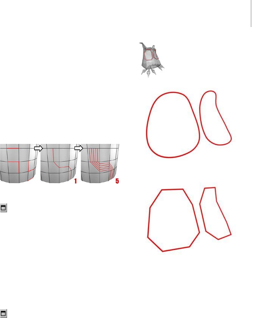
Edit Poly (Edge) 661
polygons between pairs of edges via interactive
manipulation.
Connect—Creates new edges between pairs of
selected edges using the current Connect Edges
dialog settings. Connect is particularly useful for
creating or refining edge loops.
Note: You can connect only edges on the same
polygon. Also, Connect will not let the new edges
cross. For example, if you select all four edges of a
four-sided polygon and then click Connect, only
neighboring edges are connected, resulting in a
diamond pattern.
Connecting two or more edges creates equally spaced edges.
The number of edges is set in the dialog.
Connect Settings—Opens the Connect Edges
dialog (page 1–1070),whichletsyoupreview
the Connect results, specify the number of edge
segments created by the operation, and set spacing
and placement for the new edges.
Create Shape—Afterselectingoneormoreedges,
click this button to create a spline shape or
shapes from the selected edges, using the current
settings from the Create Shape Settings dialog (see
following).
The new shape’s pivot is placed at the same
location as that of the Edit Poly object.
Create Shape Settings—Lets you preview the
Create Shape function, name the shape, and set
it to Smooth or Linear.
An edge selection (top); a smooth shape (center); a linear
shape (bottom)
Edit Tri[angulation]—Lets you modify how
polygons are subdivided into triangles by drawing
diagonals.
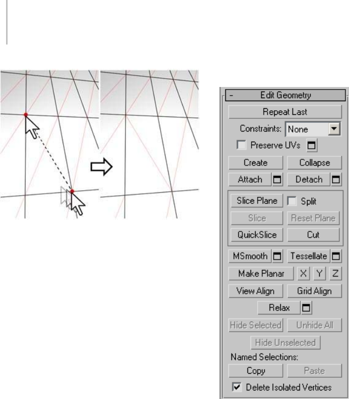
662 Chapter 8: Modifiers
In Edit Triangulation mode, you can see the current
triangulation in the viewport, and change it by clicking two
vertices on the same polygon.
To edit triangulation manually, turn on this
button. The diagonals appear. Click a polygon
vertex. A rubber-band line appears, attached to
the cursor. Click a non-adjacent vertex to create a
new triangulation for the polygon.
Tip: For easier editing of triangulation, use the
Turn command instead (see following).
Turn—Lets you modify how polygons are
subdivided into triangles by clicking diagonals.
When you activate Turn, the diagonals (page
3–928) become visible as dashed lines in wireframe
and edged-faces views. In Turn mode, click a
diagonal to change its position. To exit Turn mode,
right-click in the viewport or click the Turn button
again.
Each diagonal has only two available positions
at any given time, so clicking a diagonal twice in
succession simply returns it to its original position.
But changing the position of a nearby diagonal
can make a different alternate position available
to a diagonal.
For more information on how to use Turn with
the enhanced Cut tool, see this procedure (page
1–1035).
Edit Geometry rollout
See Edit Geometry Rollout (Edit Poly Modifier)
(page 1–673) for detailed descriptions of these
controls.
Paint Deformation rollout
Paint Deformation lets you stroke elevated and
indented areas directly onto object surfaces. For
more information, see Paint Deformation Rollout
(page 1–1064).
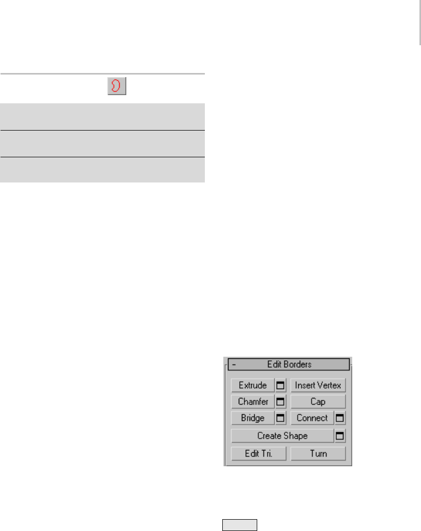
Edit Poly (Border) 663
Edit Poly (Border)
Select an Edit Poly object. > Modify panel > Selection
rollout > Border
Select an Edit Poly object. > Modify panel > Modifier
Stack display > Expand Edit Poly. > Border
Select an Edit Poly object. > Quad menu > Tools 1
quadrant > Border
Aborderisalinearsectionofameshthatcan
generallybedescribedastheedgeofahole.Thisis
usually a sequence of edges with polygons on only
one side. For example, a box doesn’t have a border,
but the teapot object has several: on the lid, on the
body, on the spout, and two on the handle. If you
create a cylinder, and then delete an end polygon,
the adjacent row of edges forms a border.
At the Edit Poly Border sub-object level, you can
select single and multiple borders and transform
them using standard methods. This topic covers
the Edit Geometry and Edit Borders rollouts; for
other controls, see Edit Poly Modifier (page 1–640).
Procedure
To create a polygon that closes the surface at the
selected border:
1. At the Border sub-object level, select any open
edge.
This selects the entire closed loop of continuous
open edges that make up the border selection.
2. Click Edit Borders rollout > Cap.
Interface
Edit Poly Mode rollout
See Edit Poly Mode rollout (page 1–645) for
information on the Edit Poly Mode rollout
settings.
Selection rollout
See Selection rollout (page 1–646) for information
on the Selection rollout settings.
Soft Selection rollout
Soft Selection controls apply a smooth falloff
between selected sub-objects and unselected
ones.WhenUseSoftSelectionison,unselected
sub-objectsnearyourselectionaregivenpartial
selection values. These values are shown in the
viewports by means of a color gradient on the
vertices, and optionally on the faces. They affect
most types of sub-object deformations, such as the
Move, Rotate, and Scale functions, as well as any
deformation modifiers (such as Bend) applied to
the object. This provides a magnet-like effect with
a sphere of influence around the selection.
For more information, see Soft Selection Rollout
(page 1–963).
Edit Borders rollout
This rollout includes commands specific to editing
borders.
Note: To delete a border, select it and press the
Delete key. This deletes the border and all
attached polygons.
Extrude—Lets you extrude a border manually via
direct manipulation in the viewport. Click this
button, and then drag vertically on any border to
extrude it.

664 Chapter 8: Modifiers
Extrudingabordermovesitalonganormaland
creates new polygons that form the sides of the
extrusion, connecting the border to the object.
The extrusion can form a varying number of
additional sides, depending on the geometry
near the border. As you increase the length of the
extrusion, the base increases in size, to the extent
of the vertices adjacent to the extruded border’s
endpoints.
Important aspects of border extrusion are:
• The mouse cursor changes to an Extrude cursor
when over a selected border.
• Drag vertically to specify the extent of the
extrusion, and horizontally to set the size of the
base.
• With multiple borders selected, dragging on
any one extrudes all selected borders equally.
• Youcandragotherbordersinturntoextrude
them while the Extrude button is active. Click
Extrude again or right-click in the active
viewport to end the operation.
Extrude Settings—Opens the Extrude Edges
dialog (page 1–1073),whichletsyouperform
extrusion via interactive manipulation.
If you click this button after performing a manual
extrusion, the same extrusion is performed on the
current selection as a preview and the dialog opens
with Extrusion Height set to the amount of the last
manual extrusion.
Insert Vertex—Lets you subdivide border edges
manually.
After turning on Insert Vertex, click a border edge
to add a vertex at that location. You can continue
subdividing border edges as long as the command
is active.
To stop inserting vertices, right-click in the
viewport, or click Insert Vertex again to turn it off.
Note: In previous versions of the software, this
command was called Divide.
Chamfer—Click this button and then drag a border
in the active object. The border need not be
selected first.
If you chamfer multiple selected borders, all of
them are chamfered identically. If you drag an
unselected border, any selected borders are first
unselected.
A border chamfer essentially “frames” the border
edges, creating a new set of edges paralleling the
border edges, plus new diagonal edges at any
corners. These new edges are exactly <Chamfer
Amount> distance from the original edges. New
chamfer faces are created with the material ID
of a neighboring face (picked at random) and a
smoothing group which is an intersection of all
neighboring smoothing groups.
Alternatively, you can create open space
around the chamfered borders, essentially cutting
away at the open edges; for details, see Chamfer
Edges dialog (page 1–1070).
Chamfer Settings—Opens the Chamfer Edges
dialog (page 1–1070), which lets you chamfer
borders via interactive manipulation and toggle
the Open option.
If you click this button after performing a manual
chamfer, the same chamfer is performed on the
current selection as a preview and the dialog opens
with Chamfer Amount set to the amount of the
last manual chamfer.
Cap—Caps an entire border loop with a single
polygon.
Select the border, and then click Cap.
Bridge—Connectstwobordersonanobjectwitha
polygon “bridge.” There are two ways to use Bridge
in Direct Manipulation mode (that is, without
opening the Bridge Settings dialog):

Edit Poly (Border) 665
• Selectanevennumberofbordersontheobject,
and then click Bridge. This immediately creates
the bridge between each pair of selected borders
using the current Bridge settings, and then
deactivates the Bridge button.
• If no qualifying selection exists (that is, two
or more selected borders), clicking Bridge
activatesthebuttonandplacesyouinBridge
mode. First click a border edge and then move
the mouse; a rubber-band line connects the
mouse cursor to the clicked edge. Click a
second edge on a different border to bridge the
two. This creates the bridge immediately using
the current Bridge settings; the Bridge button
remains active for connecting more pairs of
borders. To exit Bridge mode, right-click the
active viewport or click the Bridge button.
Note: Bridge always creates a straight-line
connection between border pairs. To make
thebridgeconnectionfollowacontour,apply
modelingtoolsasappropriateafter creating the
bridge. For example, bridge two borders, and then
use Bend (page 1–560).
Bridge Settings—Opens the Bridge dialog (page
1–1067), which lets you connect pairs of borders
via interactive manipulation.
Connect—Creates new edges between pairs of
selected border edges. The edges are connected
from their midpoints.
You can connect only edges on the same polygon.
Connect will not let the new edges cross. Thus, for
example, if you select all four edges of a four-sided
polygon and then click Connect, only neighboring
edges are connected, resulting in a diamond
pattern.
Connect Settings—Lets you preview the
Connectandspecifythenumberofedgesegments
created by the operation. To increase the mesh
resolution around the new edge, increase the
Connect Edge Segments setting.
Create Shape—Afterselectingoneormore
borders, click this button to create a spline shape or
shapes from the selected edges, using the current
settings from the Create Shape Settings dialog (see
following).
The new shape’s pivot is placed at the same
location as that of the Edit Poly object.
Create Shape Settings—Lets you preview the
Create Shape function, name the shape, and set
it to Smooth or Linear.
Edit Tri[angulation]—Lets you modify how selected
polygons are subdivided into triangles by drawing
internal edges.
To manually edit triangulation, turn on this
button. The hidden edges appear. Click a polygon
vertex. A rubber-band line appears, attached to
the cursor. Click a non-adjacent vertex to create a
new triangulation for the polygon.
Tip: For easier editing of triangulation, use the
Turn command instead (see following).
Turn—Lets you modify how polygons are
subdivided into triangles by clicking diagonals.
When you activate Turn, the diagonals (page
3–928) become visible as dashed lines in wireframe
and edged-faces views. In Turn mode, click a
diagonal to change its position. To exit Turn mode,
right-click in the viewport or click the Turn button
again.
Each diagonal has only two available positions
at any given time, so clicking a diagonal twice in
succession simply returns it to its original position.
But changing the position of a nearby diagonal
can make a different alternate position available
to a diagonal.
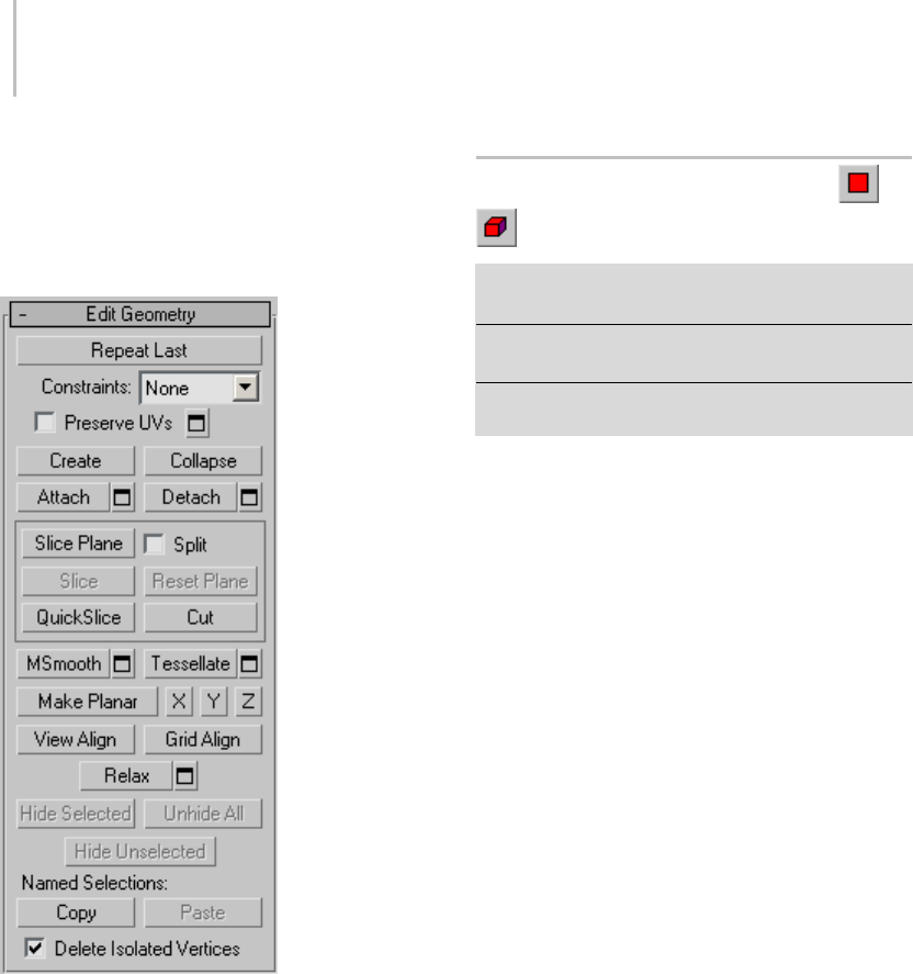
666 Chapter 8: Modifiers
For more information on how to use Turn with
the enhanced Cut tool, see this procedure (page
1–1035).
Edit Geometry rollout
See Edit Geometry Rollout (Edit Poly Modifier)
(page 1–673) for detailed descriptions of these
controls.
Paint Deformation rollout
Paint Deformation lets you stroke elevated and
indented areas directly onto object surfaces. For
more information, see Paint Deformation Rollout
(page 1–1064).
Edit Poly (Polygon/Element)
Select an Edit Poly object. > Modify panel > Selection
rollout > Polygon/Element
Select an Edit Poly object. > Modify panel > modifier
stack display > Expand Edit Poly. > Polygon/Element
Select an Edit Poly object. > Quad menu > Tools 1
quadrant > Polygon/Element
Apolygon is a closed sequence of three or more
edges connected by a surface. Polygons provide
the renderable surface of Edit Poly objects.
At the Edit Poly (Polygon) sub-object level, you
can select single and multiple polygons and
transform them using standard methods. This is
similar for the Element sub-object level; for the
distinctions between polygon and element, see
Edit Poly > Selection rollout (page 1–646).This
topic covers the Edit Polygons/Elements rollout
and Edit Geometry rollout functions for these
sub-object types. For other controls, see Edit Poly
Modifier (page 1–640).
Note: Workflow enhancements in the Edit Poly
userinterfacegiveyouachoiceofeditingmethods.
See Edit Poly Workflow (page 1–643) for more
information.
Interface
Edit Poly Mode rollout
See Edit Poly Mode rollout (page 1–645) for
information on the Edit Poly Mode rollout
settings.
Selection rollout
See Selection rollout (page 1–646) for information
on the Selection rollout settings.
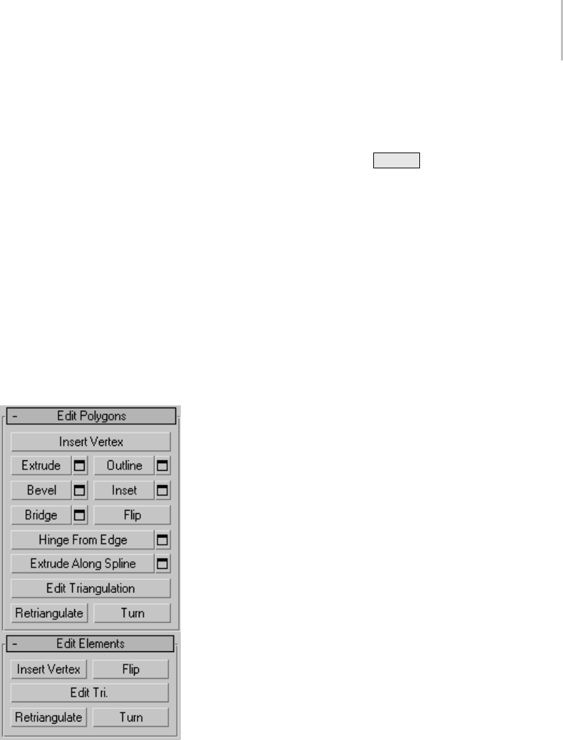
Edit Poly (Polygon/Element) 667
Soft Selection rollout
Soft Selection controls apply a smooth falloff
between selected sub-objects and unselected
ones. When Use Soft Selection is on, unselected
sub-objectsnearyourselectionaregivenpartial
selectionvalues. Thesevaluesareshowninthe
viewports by means of a color gradient on the
vertices, and optionally on the faces. They affect
most types of sub-object deformations, such as the
Move, Rotate, and Scale functions, as well as any
deformation modifiers (such as Bend) applied to
the object. This provides a magnet-like effect with
a sphere of influence around the selection.
For more information, see Soft Selection Rollout
(page 1–963).
Edit Polygons/Elements rollout
At the Element sub-object level, this rollout
includes commands common to both polygons
and elements, plus, at the Polygon level, some
thatareuniquetopolygons. Thecommands
available at both levels are Insert Vertex, Flip, Edit
Triangulation, Retriangulate, and Turn.
Note: To delete polygons or elements, select them
and press the Delete key. If Delete Isolated
Ve r t i c e s isoff,thiscanresultinisolatedvertices;
that is, vertices with no associated face geometry.
Insert Vertex—Lets you subdivide polygons
manually. Applies to polygons, even if at the
element sub-object level.
After turning on Insert Vertex, click a polygon to
add a vertex at that location. You can continue
subdividingpolygonsaslongasthecommandis
active.
To stop inserting vertices, right-click in the
viewport, or click Insert Vertex again to turn it off.
Note: In previous versions of the software, this
command was called Divide.
Extrude—Lets you perform manual extrusion via
direct manipulation in the viewport. Click this
button, and then drag vertically on any polygon
to extrude it.
Extrudingpolygonsmovesthemalonganormal
and creates new polygons that form the sides of the
extrusion, connecting the selection to the object.
Important aspects of polygon extrusion are:
• The mouse cursor changes to an Extrude cursor
when over a selected polygon.
• Drag vertically to specify the extent of the
extrusion, and horizontally to set the size of the
base.
• With multiple polygons selected, dragging on
any one extrudes all selected polygons equally.
• You can drag other polygons in turn to extrude
them while the Extrude button is active. Click
Extrude again or right-click in the active
viewport to end the operation.
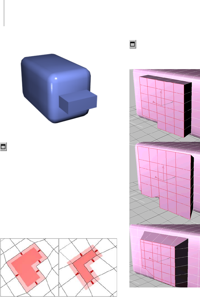
668 Chapter 8: Modifiers
Chamfer box showing extruded polygon
Extrude Settings—Opens the Extrude Faces
dialog (page 1–1072),whichletsyouperform
extrusion via interactive manipulation.
If you click this button after performing an
extrusion, the same extrusion is performed on the
current selection as a preview and the dialog opens
with Extrusion Height set to the amount of the last
manual extrusion.
Outline—Lets you increase or decrease the
outside edge of each contiguous group of selected
polygons.
Outline is often used after an extrusion or bevel to
adjustthesizeoftheextrudedfaces.Itdoesn’tscale
the polygons; only changes the size of the outer
edge. For example, in the following illustration,
note that the sizes of the inner polygons remain
constant.
Click the Outline Settings button to open the
Outline Selected Faces dialog, which lets you
perform outlining with a numeric setting.
Extruded polygons (top), outline expanded (middle), outline
reduced (bottom)
Note that the size of inner polygons doesn’t change.
Bevel—Lets you perform manual beveling via
direct manipulation in the viewport. Click this
button, and then drag vertically on any polygon
toextrudeit.Releasethemousebuttonandthen
move the mouse vertically to outline the extrusion.
Click to finish.
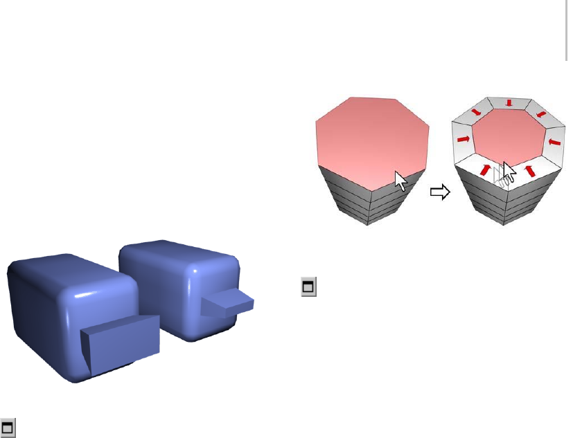
Edit Poly (Polygon/Element) 669
• The mouse cursor changes to a Bevel cursor
when over a selected polygon.
• With multiple polygons selected, dragging on
any one bevels all selected polygons equally.
• You can drag other polygons in turn to bevel
them while the Bevel button is active. Click
Bevel again or right-click to end the operation.
Polygon beveled outward (left) and inward (right)
Bevel Settings—Opens the Bevel Polygons dialog
(page 1–1066),whichletsyouperformbeveling
via interactive manipulation.
If you click this button after performing a bevel,
thesamebevelisperformedonthecurrent
selection as a preview and the dialog opens with
thesamesettingsusedforthepreviousbevel.
Inset—Performs a bevel with no height; that is,
within the plane of the polygon selection. Click
this button, and then drag vertically on any
polygon to inset it.
• The mouse cursor changes to an Inset cursor
when over a selected polygon.
• With multiple polygons selected, dragging on
any one insets all selected polygons equally.
• You can drag other polygons in turn to inset
them while the Inset button is active. Click
Inset again or right-click to end the operation.
Inset works on a selection of one or more polygons. As with
Outline, only the outer edges are affected.
Inset Settings—Opens the Inset Selected Faces
dialog (page 1–1074), which lets you inset polygons
via interactive manipulation.
If you click this button after performing a manual
inset, the same inset is performed on the current
selection as a preview and the dialog opens with
InsetAmountsettotheamountofthelastmanual
inset.
Bridge—Connects two polygons or polygon
groups on an object with a polygon “bridge.” There
aretwowaystouseBridgeinDirectManipulation
mode (that is, without opening the Bridge Settings
dialog):
• Make two separate polygon selections on the
object, and then click Bridge. This creates the
bridge immediately using the current Bridge
settings, and then deactivates the Bridge button.
• If no qualifying selection exists (that is, two
or more discrete polygon selections), clicking
Bridge activates the button and places you in
Bridge mode. First click a polygon and move
the mouse; a rubber-band line connects the
mouse cursor to the clicked polygon. Click a
second polygon to bridge the two. This creates
thebridgeimmediatelyusingthecurrentBridge
settings; the Bridge button remains active for
connecting more pairs of polygons. To exit
Bridge mode, right-click the active viewport or
click the Bridge button.
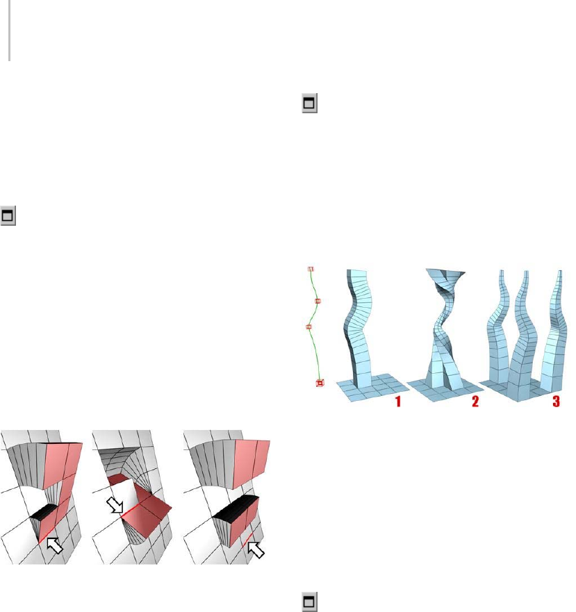
670 Chapter 8: Modifiers
Note: Bridge always creates a straight-line
connection between polygon pairs. To make
thebridgeconnectionfollowacontour,apply
modelingtoolsasappropriateafter creating the
bridge. For example, bridge two polygons, and
then use Bend (page 1–560).
Bridge Settings—Opens the Bridge dialog (page
1–1067), which lets you connect pairs of polygon
selections via interactive manipulation.
Flip—Reversesthedirectionsofthenormalsof
selected polygons, hence their facing.
Hinge From Edge—Lets you perform a manual
hingeoperationviadirectmanipulationinthe
viewport. Make a polygon selection, click this
button, and then drag vertically on any edge to
hinge the selection. The mouse cursor changes to
a cross when over an edge.
Thehingeedgeneedn’tbepartoftheselection.Itcanbeany
edge of the mesh. Also, the selection needn’t be contiguous.
Hinging polygons rotates them around an edge
and creates new polygons that form the sides of the
hinge, connecting the selection to the object. It’s
essentially an extrusion with rotation, with one
exception: If the hinge edge belongs to a selected
polygon, that side is not extruded. The manual
version of Hinge From Edge works only with an
existing polygon selection.
Tip: Turn on Ignore Backfacing to avoid
inadvertently hinging around a backfacing edge.
Hinge Settings—Opens the Hinge From Edge
dialog (page 1–1073),whichletsyouhinge
polygons via interactive manipulation.
If you click this button after performing a manual
hinge, the dialog opens with Angle set to the extent
of the last manual hinge.
Extrude Along Spline—Extrudes the current
selection along a spline.
You can extrude a single face (1) or a selection of contiguous
(2) or non-contiguous faces (3). Extrusion 2 uses Taper Curve
and Twist. Extrusion 3 uses Taper Amount; each extrusion has
a different curve rotation.
Make a selection, click Extrude Along Spline,
and the select a spline in the scene. The selection
is extruded along the spline, using the spline’s
current orientation, but as though the spline’s start
point was moved to the center of each polygon or
group.
Extrude Along Spline Settings—Opens the
Extrude Polygons Along Spline dialog (page
1–1071),whichletsyouextrudealongsplinesvia
interactive manipulation.
Edit Triangulation—Lets you modify how polygons
are subdivided into triangles by drawing internal
edges.
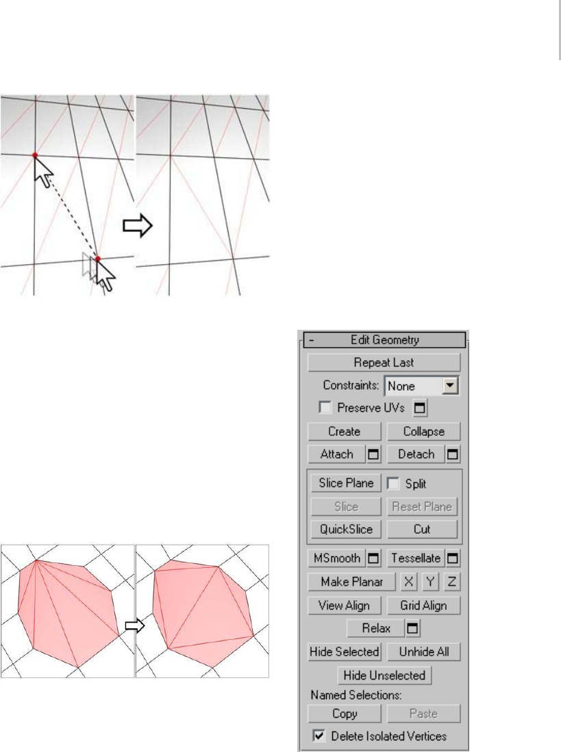
Edit Poly (Polygon/Element) 671
In Edit Triangulation mode, you can see the current
triangulation in the viewport, and change it by clicking two
vertices on the same polygon.
To edit triangulation manually, turn on Edit
Triangulation. The hidden edges appear. Click
a polygon vertex. A rubber-band line appears,
attached to the cursor. Click a non-adjacent vertex
to create a new triangulation for the polygon. You
can continue clicking vertices to retriangulate, or
right-click in the viewport to exit this mode.
Retriangulate—Lets the software automatically
performoptimaltriangulationonthepolygonor
polygons currently selected.
Retriangulate attempts to optimize the subdivision of selected
polygons into triangles.
Tip: For easier editing of triangulation, use the
Turn command instead (see following).
Turn—Lets you modify how polygons are
subdivided into triangles by clicking diagonals.
When you activate Turn, the diagonals (page
3–928) become visible as dashed lines in wireframe
and edged-faces views. In Turn mode, click a
diagonal to change its position. To exit Turn mode,
right-click in the viewport or click the Turn button
again.
Each diagonal has only two available positions
at any given time, so clicking a diagonal twice in
succession simply returns it to its original position.
But changing the position of a nearby diagonal
can make a different alternate position available
to a diagonal.
Edit Geometry rollout
See Edit Geometry Rollout (Edit Poly Modifier)
(page 1–673) for detailed descriptions of these
controls.
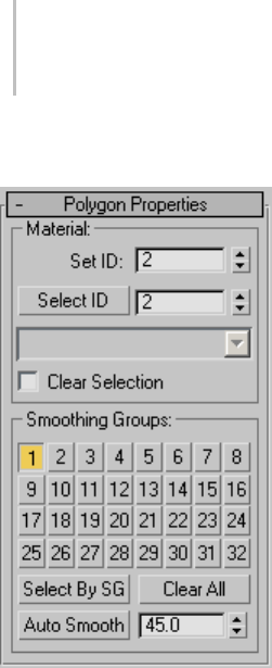
672 Chapter 8: Modifiers
Polygon Properties rollout
These controls let you work with material IDs and
smoothing groups.
Material group
Set ID—Lets you assign a particular material ID
(page 3–969) number to selected sub-objects for
use with multi/sub-object materials (page 2–1594)
and other applications. Use the spinner or enter
the number from the keyboard. The total number
of available IDs is 65,535.
Select ID—Selects sub-objects corresponding to
the Material ID specified in the adjacent ID field.
Type or use the spinner to specify an ID, then click
the Select ID button.
[Select By Name]—This drop-down list shows
the names of sub-materials if an object has a
multi/sub-object material assigned to it. Click the
drop arrow and choose a sub-material from the list.
This selects any sub-objects assigned that material.
If an object does not have a multi/sub-object
material assigned, the name list is unavailable.
Likewise, if multiple selected objects have an Edit
Patch, Edit Spline, or Edit Mesh modifier applied,
thenamelistisinactive.
Note: Sub-material names are those specified in the
Name column on the material’s multi/sub-object
Basic Parameters rollout. By default, 3ds Max
assigns the material name “No Name” followed by
a sequence number in parentheses. These names
don’t appear in the Material Editor, but they do
show up in the drop-down list.
Clear Selection—When on, choosing a new ID or
material name unselects any previously selected
sub-objects. When off, selections are cumulative,
so new ID or sub-material name selections add to
the existing selection set of patches or elements.
Default=off.
Smoothing Groups group
Use these controls to assign selected polygons to
different smoothing groups (page 3–1013),andto
select polygons by smoothing group.
To assign polygons to one or more smoothing
groups, select the polygons, and then click the
number(s) of the smoothing group(s) to assign
them to.
Select By SG (Smoothing Group)—Displays a dialog
that shows the current smoothing groups. Select
a group by clicking the corresponding numbered
button and clicking OK. If Clear Selection is
on, any previously selected polygons are first
unselected. If Clear Selection is off, the new
selection is added to any previous selection set.
Clear All—Removesanysmoothinggroup
assignments from selected polygons.
Auto Smooth—Sets smoothing groups based on
the angle between polygons. Any two adjacent
polygonsareputinthesamesmoothinggroupif
theanglebetweentheirnormalsislessthanthe
threshold angle, set by the spinner to the right of
this button.
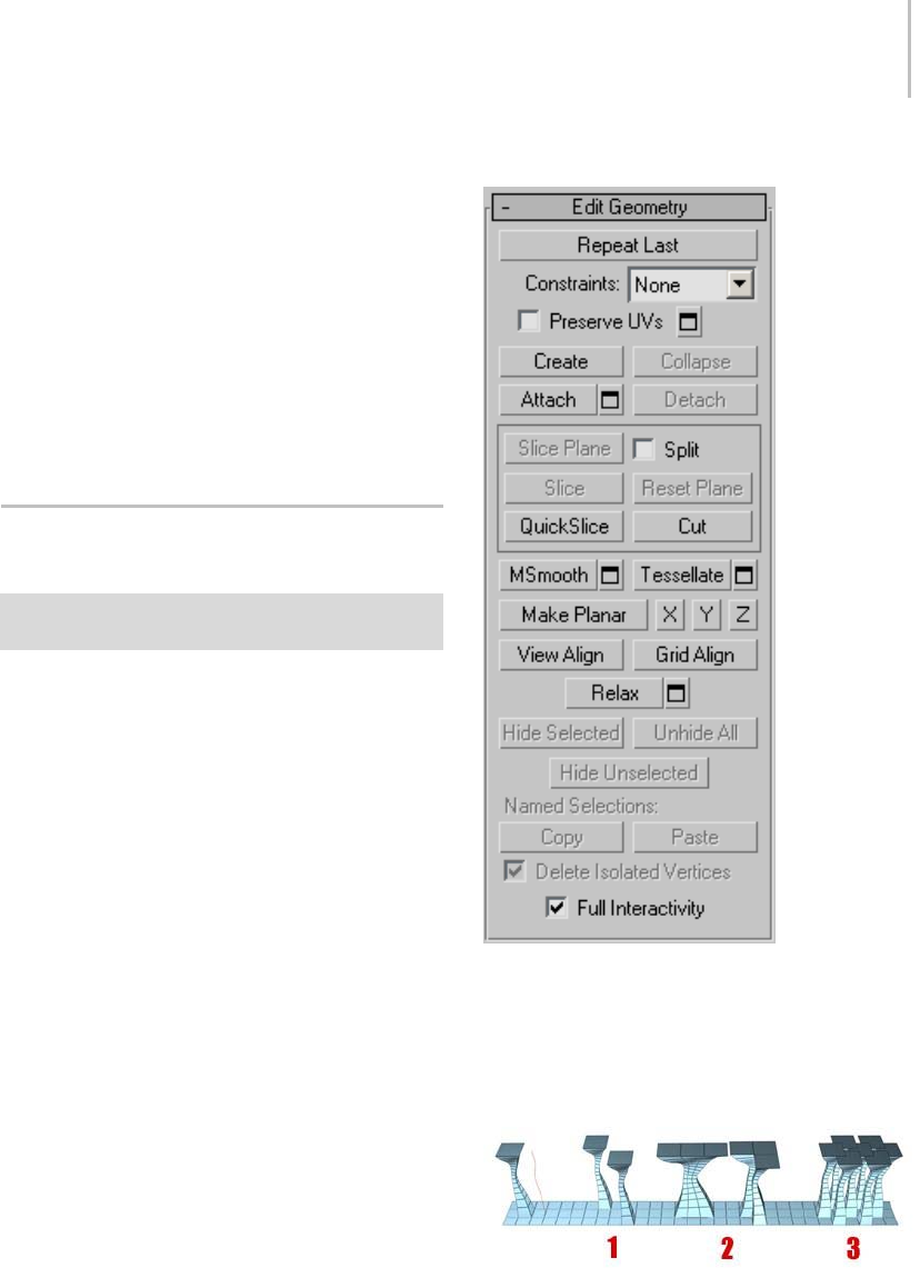
Edit Geometry Rollout (Edit Poly Modifier) 673
[threshold]—This numeric setting (to the right of
AutoSmooth)letsyouspecifythemaximumangle
between the normals of adjacent polygons that
determines whether those polygons will be put in
thesamesmoothinggroup.
Paint Deformation rollout
Paint Deformation lets you stroke elevated and
indented areas directly onto object surfaces. For
more information, see Paint Deformation Rollout
(page 1–1064).
Edit Geometry Rollout (Edit Poly
Modifier)
Select an Edit Poly object. > Modify panel > Edit
Geometry rollout
The Edit Geometry rollout provides global
controls for changing the geometry of the Edit
Poly object, at either the top (Object) level or the
sub-object levels. The control are the same at all
levels, except as noted in the descriptions below.
Interface
Repeat Last—Repeats the most recently used
command.
For example, if you extrude a polygon, and want to
apply the same extrusion to several others, select
the others, and then click Repeat Last.
You can apply a spline extrusion of a single polygon (left)
repeatedly to other single polygons (1) or to multiple polygon
selections, contiguous (2) or not (3).
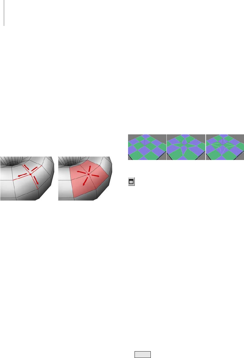
674 Chapter 8: Modifiers
Note: Repeat Last does not repeat all operations.
For example, it does not repeat transforms. To
determine which command will be repeated when
you click the button, check the button’s tooltip. If
no tooltip appears, nothing will happen when it is
clicked.
Constraints—Lets you use existing geometry to
constrain sub-object transformation. Use the
drop-down list to choose the constraint type:
•None: No constraints.
•Edge: Constrains vertex transformations to
edge boundaries.
•Face: Constrains vertex transformations to face
surfaces.
When set to Edge, moving a vertex will slide it along one
of the existing edges, depending on the direction of the
transformation. If set to Face, the vertex moves only on the
polygon’s surface.
Note: You can set constraints at the Object level, but
their use pertains primarily to sub-object levels.
The Constraints setting persists at all sub-object
levels.
Preserve UVs—When on, you can edit sub-objects
without affecting the object’s UV mapping. You
can choose any of an object’s mapping channels
to preserve or not; see Preserve UVs Settings,
following. Default=off.
Without Preserve UVs, there is always a direct
correspondence between an object’s geometry
and its UV mapping. For example, if you map an
objectandthenmovevertices,thetexturemoves
along with the sub-objects, whether you want it
toornot.IfyouturnonPreserveUVs,youcan
perform minor editing tasks without changing
the mapping.
Tip: For best results with Preserve UVs at the
vertex level, use it for limited vertex editing. For
example, you’ll usually have no trouble moving
avertexwithinedgeorfaceconstraints. Also,
it’s better to perform one big move than several
smaller moves, as multiple small moves can begin
to distort the mapping. If, however, you need
to perform extensive geometry editing while
preserving mapping, use the Channel Info utility
(page 2–1738) instead.
Original object (left); Scaled vertices with Preserve UVs off
(center); Scaled vertices with Preserve UVs on (right)
Preserve UVs Settings—Opens the Preserve Map
Channels dialog (page 1–1075),whichletsyou
specify which vertex color channels and/or texture
channels (map channels) to preserve. By default,
all vertex color channels are off (not preserved),
and all texture channels are on (preserved).
Create—Lets you create new geometry. How this
button behaves depends on which level is active.
•Object, Polygon, and Element levels—Lets you
create polygons from isolated vertices and
border vertices. All vertices in the object are
highlighted. Click three or more existing
vertices in succession to define the shape of the
new polygon. (The cursor changes to a cross
when it is over a vertex that can legally be part
of the polygon.) To finish polygon creation,
double-click the last vertex. You can also finish
creating the polygon by clicking any vertex
of the new polygon a second time. You can
also create new polygons at the Polygon and
Element sub-object levels.
Youcanaddverticesinthismodeby
Shift +clickinginanemptyspace;these

Edit Geometry Rollout (Edit Poly Modifier) 675
vertices are incorporated into the polygon
you’re creating.
Yo u c a n s t a r t c r e a t i n g p o l y g o n s i n a n y v i e w p o r t ,
but all subsequent clicks must take place in the
same viewport.
Tip: For best results, click vertices in
counterclockwise (preferred) or clockwise
order. If you use clockwise order, the new
polygon will face away from you.
•Vertex level—Lets you add vertices to a single
selected poly object. After selecting the object
and clicking Create, click anywhere in space
to add free-floating (isolated) vertices to the
object. The new vertices are placed on the active
construction plane unless object snapping is
on. For example, with face snapping on, you
can create vertices on object faces.
•Edge and Border levels—Creates an edge from
vertex to vertex. Click Create, click a vertex,
and then move the mouse. A rubber-band line
extends from the vertex to the mouse cursor.
Click a second, non-adjacent vertex on the
same polygon to connect them with an edge.
Repeat,or,toexit,right-clickintheviewport
or click Create again.
Edges you create separate the polygons.
Forexample,bycreatinganedgeinsidea
quadrilateral polygon, you turn it into two
triangles.
Collapse (Vertex, Edge, Border, and Polygon levels
only)—Collapsesgroupsofcontiguousselected
sub-objects by welding their vertices to a vertex
at the selection center.
Attach—Lets you attach another object in the scene
to the selected editable poly. You can attach any
type of object, including splines, patch objects,
and NURBS surfaces. Attaching a non-mesh
object converts it to editable-poly format. Click
the object you want to attach to the currently
selected poly object.
When you attach an object, the materials of the
two objects are combined in the following way:
• If the object being attached does not have a
material assigned, it inherits the material of the
object it is being attached to.
• Likewise, if the object you’re attaching to
doesn’t have a material, it inherits the material
of the object being attached.
• If both objects have materials, the resulting
new material is a multi/sub-object material
(page 2–1594) that includes the input materials.
A dialog appears offering three methods of
combining the objects’ materials and material
IDs. For more information, see Attach Options
Dialog (page 1–1018).
Attach remains active in all sub-object levels,
but always applies to objects.
Attach List—Lets you attach other objects in
the scene to the selected mesh. Click to display a
Select Objects dialog (page 1–78) where you choose
multiple objects to attach.
Shaded view of model (upper left); wireframe view of model
(upper right); model with objects attached (lower left); and
subsequent multi/sub-object material (lower right)
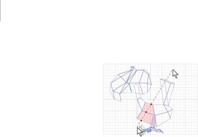
676 Chapter 8: Modifiers
Detach (sub-object levels only)—Detaches the
selected sub–objects and the polygons attached to
them as a separate object or element. The Detach
As Clone option copies the sub-objects rather than
moving them.
You’re prompted to enter a name for the new
object. Detached faces leave a hole in the original
object when you move them to a new position,
unless you use the Detach As Clone option.
Cut and Slice group
Theseknife-liketoolsletyousubdividethepoly
mesh along a plane (Slice) or in a specific area
(Cut). Also see Full Interactivity.
Slice Plane (sub-object levels only)—Creates a
gizmoforasliceplanethatyoucanpositionand
rotate to specify where to slice. Also enables the
Slice and Reset Plane buttons.
If snapping is turned off, you see a preview of the
slice as you transform the slice plane. To perform
the slice, click the Slice button.
Split—When on, the QuickSlice and Cut
operations create double sets of vertices at the
points where the edges are divided. This lets you
easily delete the new polygons to create holes, or
animatethenewpolygonsasseparateelements.
Slice (sub-object levels only)—Performs the slice
operation at the location of the slice plane.
Available only when Slice Plane is on. This tool
slicesthepolyjustlikethe“OperateOn:Polygons”
mode of the Slice modifier (page 1–825).
Reset Plane (sub-object levels only)—Returns the
Slice plane to its default position and orientation.
Available only when Slice Plane is on.
QuickSlice—Lets you quickly slice the object
without having to manipulate a gizmo. Make a
selection, click QuickSlice, and then click once
at the slice start point and again at its endpoint.
You can continue slicing the selection while the
command is active.
To stop slicing, right-click in the viewport, or click
QuickSlice again to turn it off.
With Quickslice on, you can draw a line across your mesh in
any viewport, including Perspective and Camera views. The
mesh is sliced interactively as you move the line endpoint.
Note: At the Object level, QuickSlice affects the
entire object. To slice only specific polygons, use
QuickSliceonapolygonselectionatthePoly
sub-object level.
Note: At the Polygon or Element sub-object level,
QuickSlice affects only selected polygons. To
slice the entire object, use QuickSlice at any other
sub-object level, or at the object level.
Cut—Lets you create edges from one polygon to
another or within polygons. Click at the start
point, move the mouse and click again, and
continue moving and clicking to create new
connected edges. Right-click once to exit the
current cut, whereupon you can start a new one,
or right-click again to exit Cut mode.
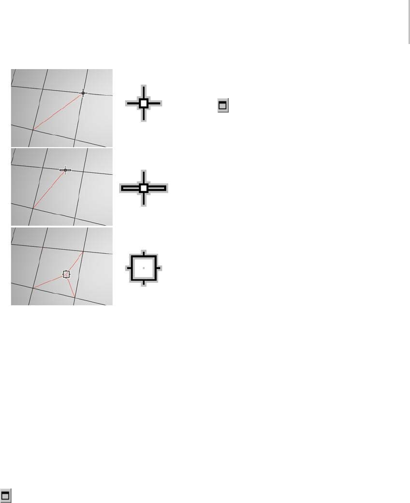
Edit Geometry Rollout (Edit Poly Modifier) 677
Cutting to a vertex (top); cutting an edge (center); cutting a
polygon (bottom). Cut is available at the object level and all
sub-object levels.
Note: You can use Cut with Turn for enhanced
productivity. For more information, see this
procedure (page 1–1035).
MSmooth—Smoothes the object using the current
settings. This command uses subdivision
functionality similar to that of the MeshSmooth
modifier (page 1–722) with NURMS Subdivision,
but unlike NURMS Subdivision, it applies the
smoothing instantly to the selected area of the
control mesh.
MSmooth Settings—Opens the MeshSmooth
Selection dialog (page 1–1074),whichletsyou
specify how smoothing is applied.
Tessellate—Subdivides all polygons in the object
based on the Tessellation settings (page 1–1077).
Tessellation is useful for increasing local mesh
density while modeling. You can subdivide any
selection of polygons. Two tessellation methods
are available: Edge and Face.
Tessellate Settings—Opens the Tessellate
Selection dialog (page 1–1077),whichletsyou
specify how smoothing is applied.
Make Planar—Forces all selected sub-objects to be
coplanar. The plane’s normal is the average surface
normal of the selection.
At the Object level, forces all vertices in the object
to become coplanar.
Tip: OneapplicationforMakePlanarismakinga
flat side on an object. Normally, you would use a
contiguous selection set. If the selection includes
vertices on various parts of the object, the vertices
are still made planar, but with distorting effects on
the rest of the geometry.
X/Y/Z—Makes all selected sub-objects planar and
aligns the plane with the corresponding plane
in the object’s local coordinate system. The
planeusedistheonetowhichthebuttonaxisis
perpendicular; so, for example, clicking the X
button aligns the object with the local YZ axis.
At the Object level, makes all vertices in the object
planar.
View Align—Aligns all vertices in the object to the
planeoftheactiveviewport.Ifasub-objectmode
is active, this function affects only selected vertices
or those belonging to selected sub-objects. In the
case of orthographic viewports, using View Align
has the same effect as aligning to the construction
gridwhenthehomegridisactive.Whenaligning
to a perspective viewport (including camera and
light views), the vertices are reoriented to be
aligned to a plane that is parallel to the camera’s
viewing plane. This plane is perpendicular to
the view direction that is closest to the vertices’
average position.
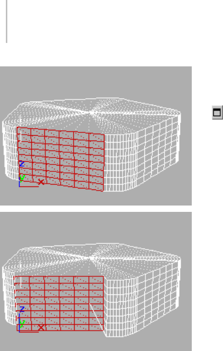
678 Chapter 8: Modifiers
Above: Selected polygons in Perspective view
Below: Same polygons aligned to Front view
Grid Align—Aligns all vertices in the selected object
totheplaneofthecurrentview.Ifasub-object
mode is active, function aligns only selected
sub-objects. This function aligns the selected
vertices to the current construction plane. The
current plane is specified by the active viewport
in the case of the home grid. When using a grid
object, the current plane is the active grid object.
Relax—Applies the Relax function to the current
selection, using the Relax dialog settings (see
following). Relax normalizes mesh spacing by
moving each vertex toward the average location of
itsneighbors.ItworksthesamewayastheRelax
modifier (page 1–779).
Note: At the object level, Relax applies to the entire
object. At any sub-object level, Relax applies only
to the current selection.
Relax Settings—Opens the Relax dialog (page
1–1076), which lets you specify how the Relax
function is applied.
Hide Selected (Vertex, Polygon, and Element levels
only)—Hides any selected sub-objectgs.
Unhide All (Vertex, Polygon, and Element levels
only)—Restores any hidden sub-objects to
visibility.
Hide Unselected (Vertex, Polygon, and Element
levels only)—Hides any unselected sub-objects.
Named Selections (sub-object levels only)
Lets you copy and paste named selection sets of
sub-objects between objects. Start by creating one
or more named selection sets, copy one, select a
different object, go to the same sub-object level,
and then paste the set.
Note: This function uses sub-object IDs, so if the
target object’s geometry differs from that of the
source object, the pasted selection will probably
comprise a different set of sub-objects.
For more information, see Named Selection Sets
(page 1–67).
Copy—Opens a dialog that lets you specify a
named selection set to place into the copy buffer.
Paste—Pastes the named selection from the copy
buffer.
Delete Isolated Vertices (Edge, Border, Polygon, and
Element levels only)—When on, deletes isolated
vertices when you delete a selection of contiguous
sub-objects. When off, deleting sub-objects leaves
all vertices intact. Default=on.
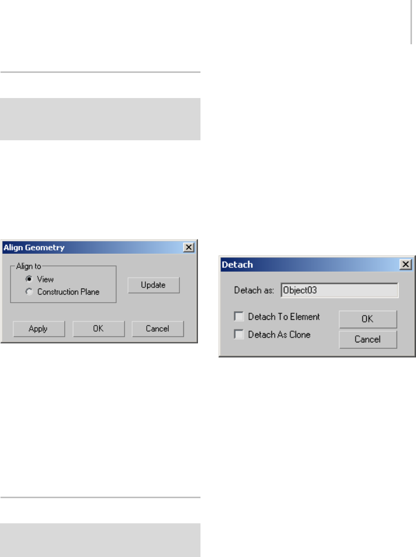
Align Geometry Dialog 679
Align Geometry Dialog
Select an Edit Poly object. > Modify panel > object level
or any sub-object level > Animate mode > Edit Geometry
rollout > Click View Align or Grid Align > Edit Poly Mode
rollout > Settings button
This Edit Poly-specific dialog lets you change the
alignment method after using the View Align or
Grid Align function. Available only in Animate
mode after using the View Align or Grid Align
command.
Interface
Align to—Lets you choose what to align the
selection with:
•View—Aligns the selection with the view plane.
•Construction Plane—Aligns the selection with
theactivegrid.
Update—Click this button to realign the selection
with the designated entity after changing it.
Typically you’d use this with the View option after
rotating the view.
Detach Dialog
Select an Edit Poly object. > Modify panel > any
sub-object level > Edit Geometry rollout > Detach
Settings button
This dialog lets you specify how a sub-object
selection is detached from an Edit Poly object.
By default, both Detach To Element and Detach As
Clone are off. Thus, when you detach a sub-object
selection, it’s removed from the original object
and becomes a new object. The dialog options let
you keep the detached item as an element of the
original object and/or detach it as a copy of the
original selection.
Note: When you detach a vertex or an edge, any
adjacent polygons are detached as well. Also, a
detached item remains in its original location.
Note: Any Detach dialog settings you change are
saved as program defaults automatically.
Interface
Detach as—Lets you assign a name to the new
object. By default, the name is "Object" followed
by a sequence number.
This option is unavailable when Detach To
Element is on.
Detach To Element —The detached sub-object
selection remains as part of the original object,
but becomes a new element. It can then be
manipulated independently at the Element
sub-object level. Default=off.
Detach As Clone—Detaches the selection as a copy
of the original selection; the latter remains intact.
Default=off.
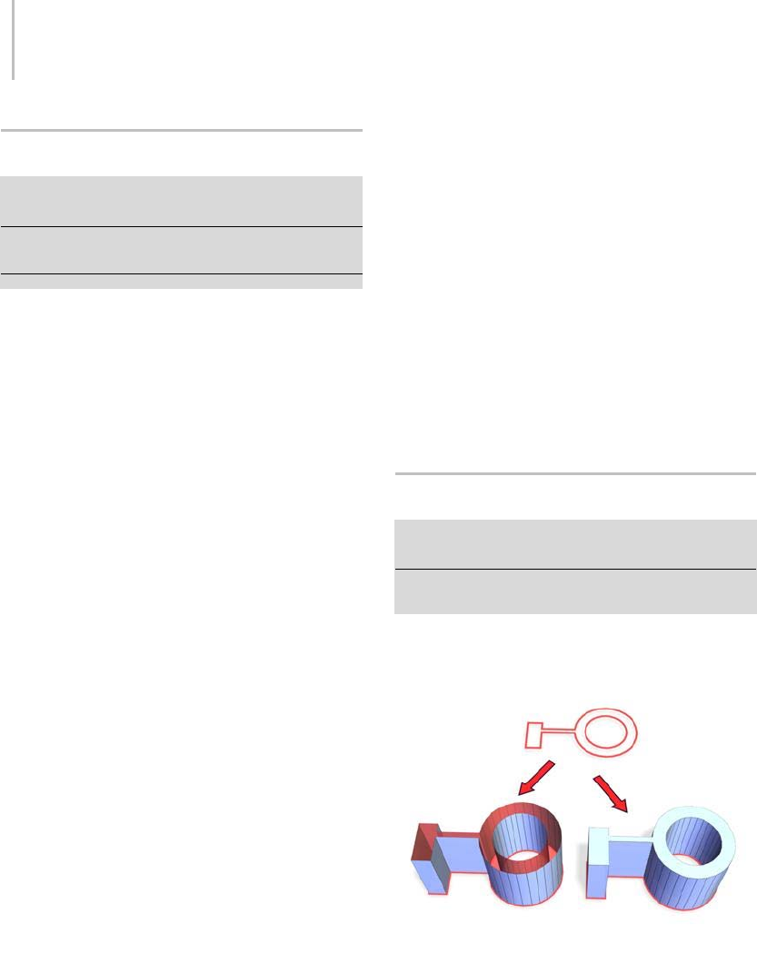
680 Chapter 8: Modifiers
Edit Spline Modifier
Create or select a spline > Modify panel > Object–Space
Modifiers > Edit Spline
Create or select a spline > Modifiers menu > Patch/Spline
Editing > Edit Spline
TheEditSplinemodifierprovidesexplicitediting
tools for different levels of the selected shape:
vertex,segment,orspline. TheEditSpline
modifier matches all the capabilities of the base
Editable Spline object, with the exceptions noted
below. See Editable Spline (page 1–289) for a
complete parameter reference.
TheEditSplinemodifierprovidesexplicitediting
tools for different levels of the selected shape:
vertex,segment,orspline. TheEditSpline
modifier matches all the capabilities of the base
Editable Spline object, with the exceptions noted
below. For a complete parameter reference, see
Editable Spline (page 1–289).
The Rendering and Interpolation rollouts found in
Editable Spline, which allows manipulation of the
spline’s creation parameters, are not available in
the Edit Spline modifier. (The creation parameters
are available in the modifier stack (page 3–760)
for a spline to which Edit Spline is applied.) In
addition, the direct vertex animation capabilities
of Editable Spline are not possible in Edit Spline.
When possible, it’s far more efficient and reliable
to perform explicit editing at the Editable Spline
level rather than store those edits within the Edit
Spline modifier. The Edit Spline modifier must
copy the geometry passed to it, and this storage
can lead to large file sizes. The Edit Spline modifier
also establishes a topological dependency that can
be adversely effected if earlier operations change
the topology being sent to it.
There are, however, situations where Edit Spline
is the preferred method.
• You want to edit a parametric shape as a spline,
butwanttoretaintheabilitytomodifyits
creation parameters after the edit.
• You want to store your edits temporarily within
Edit Spline until you are satisfied with the
results, before committing them permanently
to an editable spline object.
• You need to make edits across several shapes
atonce,butdonotwanttoconvertthemtoa
single editable spline object.
• You have a modifier in the stack that must stay
parametric, and the resulting spline must be
edited after the modifier is applied.
Extrude Modifier
Select a shape. > Modify panel > Modifier List >
Object-Space Modifiers > Extrude
Select a shape. > Modifiers menu > Mesh Editing >
Extrude
The Extrude modifier adds depth to a shape and
makes it a parametric object.
Above: Spline before extrusion
Below left: Extruded spline with Cap End off
Below right: Extruded spline with Cap End on
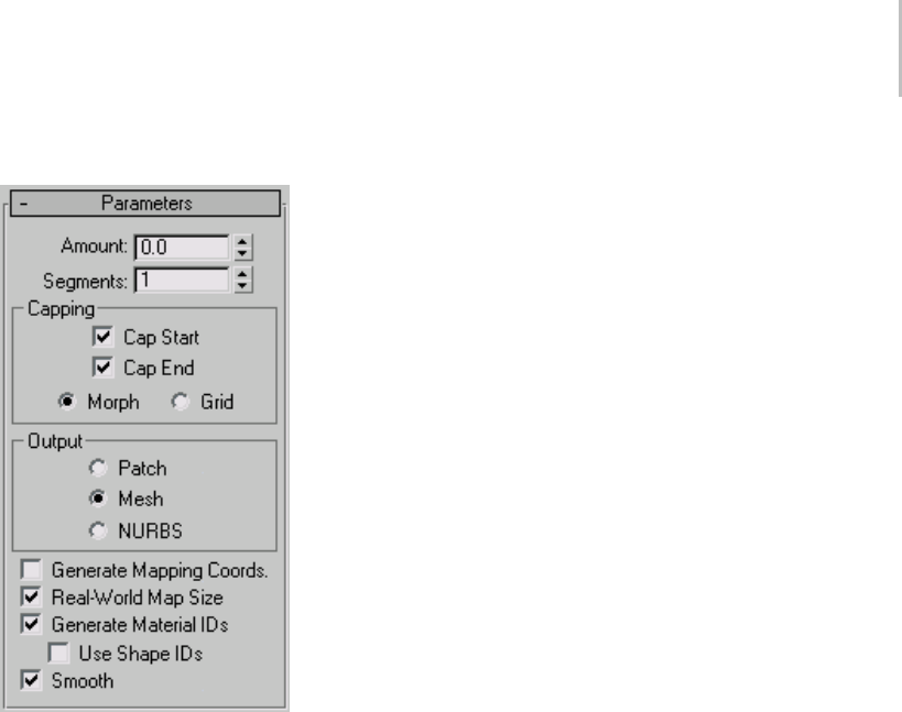
Extrude Modifier 681
Interface
Amount—Sets the depth of the extrusion.
Segments—Specifies the number of segments that
will be created in the extruded object.
Capping group
Cap Start—Generates a flat surface over the start
of the extruded object.
Cap End—Generates a flat surface over the end of
the extruded object.
Morph—Arranges cap faces in a predictable,
repeatable pattern, which is necessary for creating
Morph targets (page 1–314).Morphcapping
can generate long, thin faces that don’t render
or deform as well as grid capping. Use morph
capping primarily if you’re extruding multiple
morph targets.
Grid—Arranges cap faces in a square grid trimmed
at the shape boundaries. This method produces a
surface of evenly sized faces that can be deformed
easily by other modifiers. When you choose the
Grid capping option, the grid lines are hidden
edges rather than visible edges. This primarily
affects any objects assigned a material with the
Wire option turned on, or any objects that use the
Lattice modifier (page 1–709).
Output group
Patch—Produces an object that you can collapse to
apatchobject;seeEditing the Stack (page 1–504).
Mesh—Produces an object that you can collapse to
a mesh object; see Editing the Stack (page 1–504).
NURBS—Produces an object that you can collapse
to a NURBS surface; see Editing the Stack (page
1–504).
Generate Mapping Coords—Applies mapping
coordinates to the extruded object. Default=off.
When on, Generate Mapping Coordinates applies
separate mapping coordinates to the end caps,
placingasingle1x1tileoneachcap.
Real-World Map Size—Controls the scaling method
used for texture mapped materials that are applied
totheobject. Thescalingvaluesarecontrolled
by the Use Real-World Scale settings found in
the applied material’s Coordinates rollout (page
2–1625).Default=on.
Generate Material IDs—Assigns different material
IDstothesidesandthecapsoftheextruded
object. Specifically, the sides receive ID 3, and the
caps receive IDs 1 and 2.
This check box is turned on as a default when
you create an extruded object, but if you load an
extruded object from a MAX file, the check box
is turned off, maintaining the same material ID
assignmentforthatobjectasithadinR1.x.
Use Shape IDs—Uses the material ID values
assigned to segments in the spline (page 1–266)
you extruded, or curve sub-objects in the NURBS
(page 1–1078) curve you extruded.
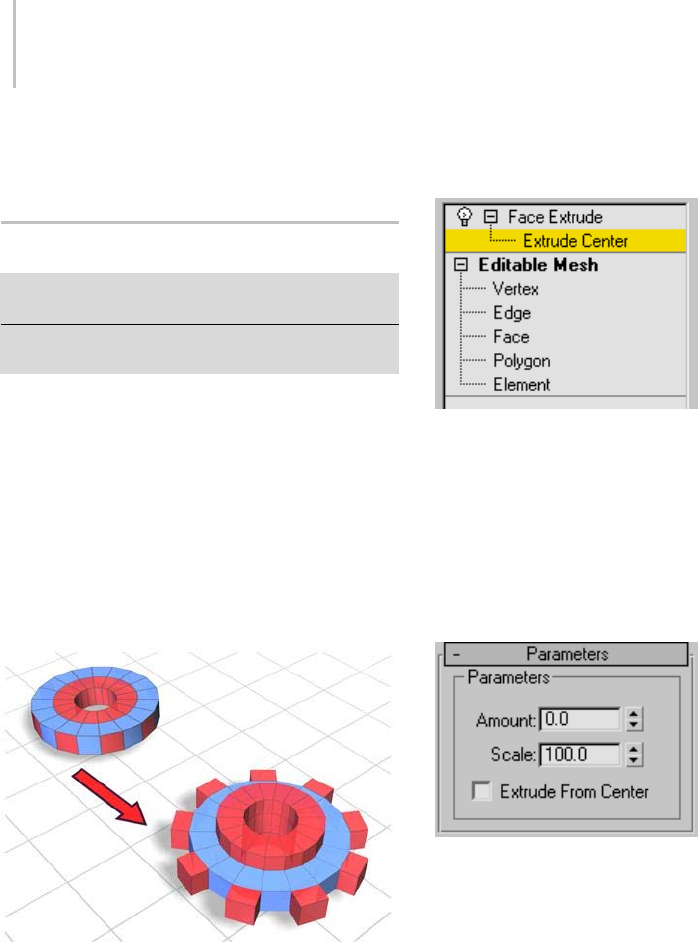
682 Chapter 8: Modifiers
Smooth—Applies smoothing to the extruded
shape.
Face Extrude Modifier
Modify panel > Select one or more faces of a mesh object.
>ModifierList>FaceExtrude
Modify panel > Select one or more faces of a mesh object.
>Modifiersmenu>MeshEditing>FaceExtrude
TheFaceExtrudemodifierextrudesfacesalong
their normals, creating new faces along the sides
of the extrusion that connect the extruded faces to
their object. As with most modifiers, this affects
the current face selection passed up the stack.
There are various differences between the Face
Extrude modifier and the Face Extrude function in
an editable mesh (page 1–996),especiallythefact
that all parameters in the Face Extrude modifier
are animatable.
Faces extruded on the top and along the edge of the object
Interface
Modifier Stack
Extrude Center—At this sub-object level, you can
select and move (or animate) the center point.
This affects the geometry only if you turn on
Extrude From Center.
For more information on the stack display, see
Modifier Stack (page 3–760).
Parameters rollout
Amount—Determines the extent of the extrusion.
You can adjust and readjust the Amount spinner
as often as you choose. To extrude a second level,
apply another Face Extrude modifier.
Scale—Scales each cluster of selected faces
independently about its center.
Note: By using multiple extrude modifiers with
Scale, you can achieve a bevel effect.
Extrude From Center—Extrudes each vertex
radially from the center point.
The direction in which the faces are extruded is
slightly different than Face Extrude in the editable
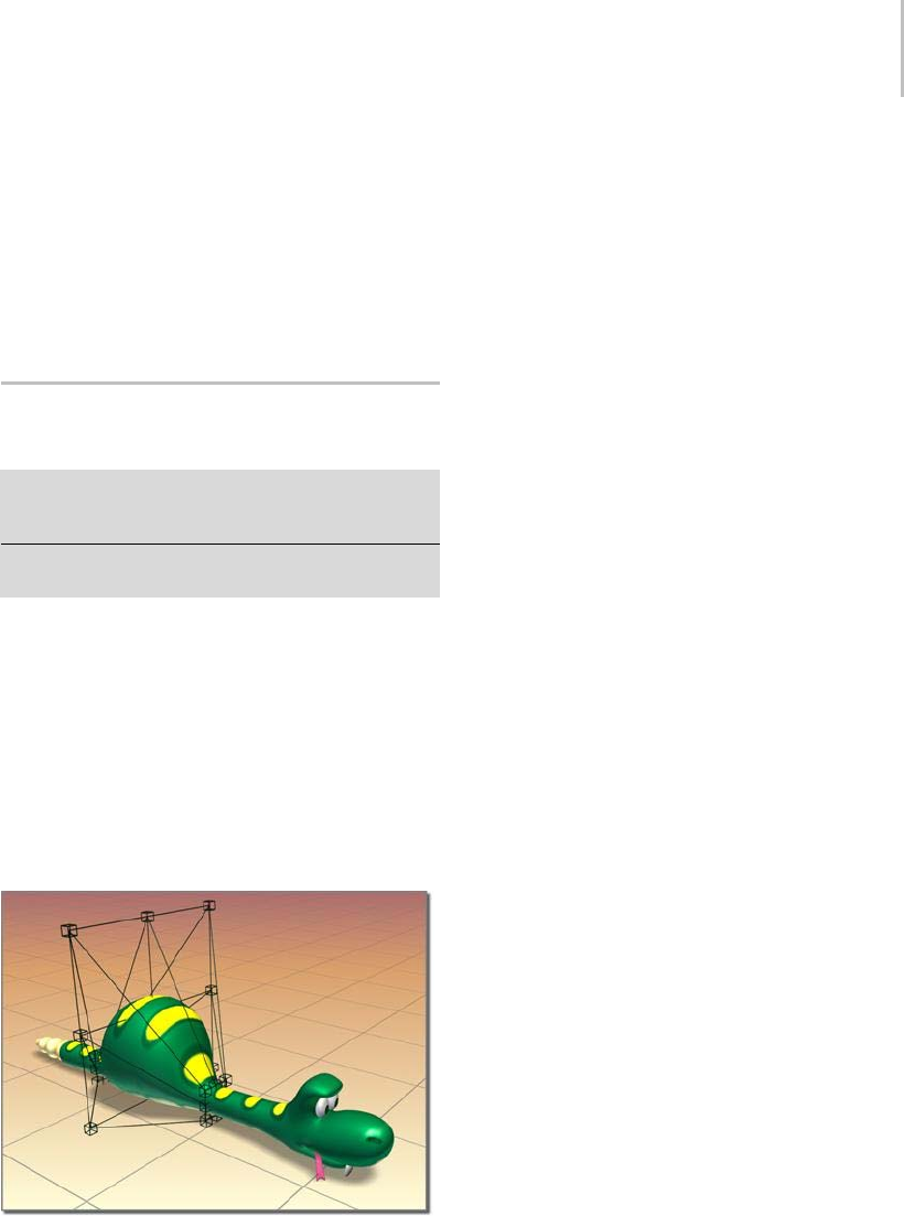
FFD (Free-Form Deformation) Modifiers 683
mesh. Each vertex is displaced in the direction of
the average surface normal of selected faces that
share that vertex. So each vertex may move in a
slightly different direction. Put another way, each
vertex is extruded in the direction of the surface
normalatthepointonthesurfacewherethat
vertex lies.
FFD (Free-Form Deformation)
Modifiers
Modify panel > Make a selection. > Modifier List >
Object-Space Modifiers > FFD 2x2x2, FFD 3x3x3, or FFD
4x4x4
Make a selection. > Modifiers menu > Free Form
Deformers > FFD 2x2x2, FFD 3x3x3, or FFD 4x4x4
FFD stands for Free-Form Deformation. Its effect
is used in computer animation for things like
dancing cars and gas tanks. You can use it as well
for modeling rounded shapes such as chairs and
sculptures.
The FFD modifier surrounds the selected
geometry with a lattice. By adjusting the control
points of the lattice, you deform the enclosed
geometry.
FFD deformation creates a bulge in the snake.
There are three FFD modifiers, each providing a
different lattice resolution: 2x2, 3x3, and 4x4. The
3x3 modifier, for example, provides a lattice with
three control points across each of its dimensions
or nine on each side of the lattice.
There are also two FFD-related modifiers that
provide supersets of the original modifiers; see
FFD (Box/Cyl) modifier (page 1–685).Withthe
FFD (Box/Cyl) modifiers, you can set any number
of points in the lattice, which makes them more
powerful than the basic FFD modifier.
Animating FFD Control Points and the
Master Point Controller
Turn on the Auto Key button and move the lattice
points to animate an FFD and any underlying
geometry. When you animate FFD control points,
a Master Point Controller is created automatically.
In Track View the master controller allows you to
move multiple animated control points in time
by simply moving one master key (master keys
display green in Track View).
Procedure
To use an FFD modifier:
1. Select the geometry. This can be the whole
object, or you can use a Mesh Select modifier to
select a portion of the object’s vertices.
2. Apply the FFD 2X2, FFD 3X3, or FFD 4X4
modifier, depending on the resolution of the
lattice you want.
An orange lattice gizmo surrounds the
geometry.
3. In the stack display, choose the Control Points
sub-object level, and then move the control
points of the lattice to deform the underlying
geometry. (Turn on the Auto Key button if you
want to animate the deformation.)
The lattice volume defaults to the bounding box
of the selected geometry. However, you can
position, rotate, and/or scale the lattice box so that
it modifies only a subset of vertices. Choose the
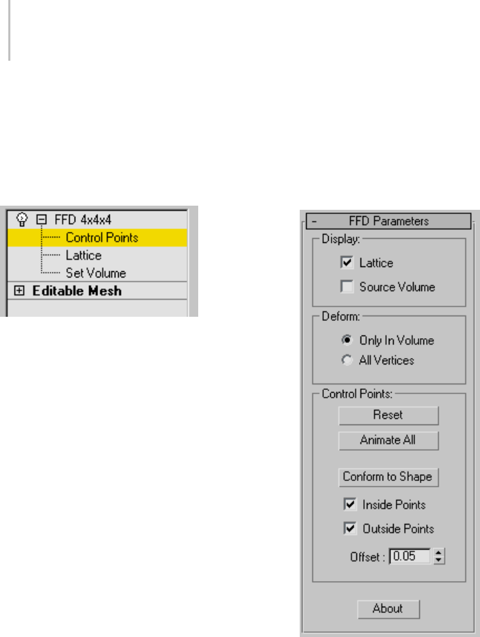
684 Chapter 8: Modifiers
Lattice sub-object level, and then use any of the
transform tools to adjust the lattice volume relative
to the geometry.
Interface
Modifier Stack
Control Points—At this sub-object level, you can
select and manipulate control points of the lattice,
one at a time or as a group (select multiple points
using standard techniques). Manipulating control
points affects the shape of the underlying object.
You can use standard transformation methods
with the control points. If the Auto Key button is
turned on when modifying the control points, the
points become animated.
Lattice—At this sub-object level, you can position,
rotate, or scale the lattice box separately from the
geometry. If the Auto Key button is turned on,
the lattice becomes animated. When you first
apply an FFD, its lattice defaults to a bounding box
surrounding the geometry. Moving or scaling the
lattice so that only a subset of vertices lies inside
thevolumemakesitpossibletoapplyalocalized
deformation.
Set Volume—At this sub-object level, the
deformation lattice control points turn green,
and you can select and manipulate control points
without affecting the modified object. This lets you
fitthelatticemorepreciselytoirregular-shaped
objects, giving you finer control when deforming.
Set Volume essentially lets you set the initial state
ofthelattice.Ifyouuseitafteryouhaveanimated
a control point or when the Auto Key button is
turnedon,thenitworksthesameasattheControl
Points sub-object level, deforming the object as
you manipulate points.
For more information on the stack display, see
Modifier Stack (page 3–760).
FFD Parameters rollout
Display group
Affects the display of the FFD in the viewports.
Lattice—Draws lines connecting the control points
to make a grid.
Although the viewports can sometimes become
cluttered when these lines are drawn, it helps to
visualize the lattice.

FFD (Box/Cylinder) Modifiers 685
Source Volume—Displays the control points and
lattice in their unmodified state.
When you’re in the Lattice selection level, this
helps to position the source volume.
Tip: Toseewhichpointslieinthesourcevolume
(andthereforewillbedeformed),temporarily
deactivate the modifier by clicking to turn off the
light bulb icon in the modifier stack display.
Deform group
Only in Volume—Deforms vertices that lie inside
thesourcevolume.Default=on.
All Vertices—Deforms all vertices, regardless of
whether they lie inside or outside the source
volume.
The deformation outside the volume is a
continuous extrapolation of the deformation
insidethevolume. Thedeformationcanbe
extreme for points far away from the source lattice.
Control Points group
Reset—Returns all control points to their original
positions.
Animate All—Assigns Point3 controllers to all
control points so that they’re immediately visible
in Track View.
By default the control points of an FFD lattice
don’t appear in Track View because they don’t have
controllers assigned to them. But when a control
point is animated, a controller is assigned to it and
becomes visible in Track View. With Animate All,
you can add and delete keys and perform other
key operations.
Conform to Shape—Moves each FFD control point
to the intersection of the modified object with a
straight line extending between the object’s center
to the control point’s original location, plus an
offset distance specified by the Offset spinner.
Note: Conform to Shape works best with regular
shapes, such as primitives. It’s less effective if
the object has degenerate (long, narrow) faces or
sharp corners. All the controls are unavailable with
shapes, because there are no faces to intersect with.
Inside Points—Only control points inside the object
are affected by Conform to Shape.
Outside Points—Only control points outside the
object are affected by Conform to Shape.
Offset—Thedistancebywhichcontrolpoints
affected by Conform to Shape are offset from the
object surface.
About—Displays a dialog with copyright and
licensing information.
FFD (Box/Cylinder) Modifiers
Modify panel > Make a selection. > Modifier List >
Object-Space Modifiers > FFD(box) or FFD(cyl)
Make a selection. > Modifiers menu > Free Form
Deformers > FFD Box or FFD Cylinder
FFD stands for Free-Form Deformation. Its effect
is used in computer animation for things like
dancing cars and gas tanks. You can use it as well
for modeling rounded shapes such as chairs and
sculptures.
The FFD modifier surrounds the selected
geometry with a lattice box. By adjusting the
control points of the lattice, you deform the
enclosed geometry. With the Auto Key button
turned on, you can animate the lattice points, and
thus the deformation of the geometry.
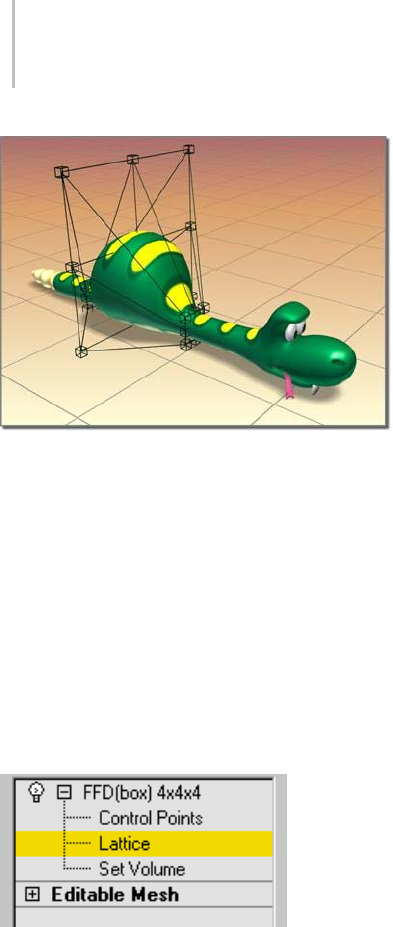
686 Chapter 8: Modifiers
FFD deformation creates a bulge in the snake.
With the FFD(box) and FFD(cyl) modifiers you
can create box-shaped and cylinder-shaped lattice
free-form deformation objects. Both are available
as object modifiers and as space warps.
The source lattice of an FFD modifier is fitted to
the geometry it’s assigned in the stack. This can be
a whole object, or a sub-object selection of faces
or vertices.
Interface
Modifier Stack
Control Points—At this sub-object level, you can
select and manipulate control points of the lattice,
one at a time or as a group (select multiple points
using standard techniques). Manipulating control
points affects the shape of the underlying object.
You can use standard transformation methods
with the control points. If the Auto Key button is
turned on when modifying the control points, the
points become animated.
Lattice—At this sub-object level, you can position,
rotate, or scale the lattice box separately from the
geometry. If the Auto Key button is turned on,
the lattice becomes animated. When you first
apply an FFD, its lattice defaults to a bounding box
surrounding the geometry. Moving or scaling the
lattice so that only a subset of vertices lie inside
thevolumemakesitpossibletoapplyalocalized
deformation.
Set Volume—At this sub-object level, the
deformation lattice control points turn green,
and you can select and manipulate control points
without affecting the modified object. This lets you
fitthelatticemorepreciselytoirregular-shaped
objects, giving you finer control when deforming.
Set Volume essentially lets you set the initial state
of the lattice. If a control point is already animated
or the Animate button is turned on, then Set
Volume works the same as at the Control Points
sub-object level, deforming the object as you
manipulate points.
For more information on the stack display, see
Modifier Stack (page 3–760).
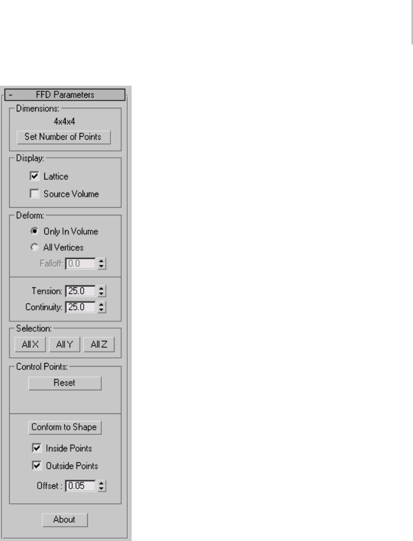
FFD (Box/Cylinder) Modifiers 687
FFD Parameters rollout
Dimensions group
Adjusts the unit dimensions of the source volume
and specifies the number of control points in the
lattice. Note that the point dimensions also show
up beside the modifier name in the stack list.
Lattice dimensions—The text displays the current
number of control points in the lattice (for example
3x4x4).
Set Number of Points—Displays a dialog containing
three spinners labeled Length, Width, and Height,
plus OK/Cancel buttons. Specify the number of
control points you want in the lattice, and then
click OK to make the change.
Warning: Make changes to the lattice dimensions
before you adjust the positions of the lattice control
points. When you change the number of control points
with this dialog, you lose any adjustments you’ve already
made to the control points. (You can undo this dialog.)
Display group
Affects the display of the FFD in the viewports.
Lattice—Draws lines connecting the control points
to make a grid. Although the viewports can
sometimes become cluttered when these extra
lines appear, they help to visualize the lattice.
Source Volume—Displays the control points
and lattice in their unmodified state. This is
an important display when you’re adjusting the
source volume to affect specific vertices that lie
inside or outside it.
Tip: Toseewhichpointslieinthesourcevolume
(and therefore will be deformed), temporarily
deactivate the modifier by clicking to turn off the
light bulb icon in the modifier stack display.
Deform group
Provides controls that specify which vertices are
affected by the FFD.
Only In Volume—Deformsverticesthatlieinside
thesourcevolume. Verticesoutsidethesource
volume are not affected.

688 Chapter 8: Modifiers
All Vertices—Deforms all vertices regardless of
whether they lie inside or outside the source
volume depending on the value in the Falloff
spinner. The deformation outside the volume is
a continuous extrapolation of the deformation
inside the volume. Note that the deformation can
be extreme for points far away from the source
lattice.
Falloff—Determinesthedistancefromthelattice
that the FFD effect will decrease to zero. Available
only when you choose All Vertices. When set to 0,
it’s effectively turned off, and there is no falloff. All
vertices are affected regardless of how far they are
from the lattice. The units of the Falloff parameter
areactuallyspecifiedrelativetothesizeofthe
lattice. A falloff of 1 means that the effect will go to
0 for points that are a lattice width/length/height
away from the lattice (depending on which side
they are).
Tension/Continuity—Adjusts the tension and
continuity of the deformation splines. Although
you can’t actually see the splines in an FFD, the
lattice and control points represent the structure
that controls the splines. As you adjust the control
points, you alter the splines (which move through
each of the points). The splines, in turn, deform
the geometry of the object. By altering the tension
and continuity of the splines, you alter their effect
on the object.
Selection group
Provides additional methods of selecting the
control points. You can toggle the state of any
combination of the three buttons to select in one,
two, or three dimensions at once.
AllX,AllY,AllZ—Selects all control points along
the specified local dimension when you select a
control point. By turning on two buttons, you can
select all control points in two dimensions.
Control Points group
Reset—Returns all control points to their original
positions.
Animate All—By default, the control points of an
FFD lattice don’t appear in Track View because
they don’t have controllers assigned to them. But
whenyouanimateacontrolpoint,acontrolleris
assigned and it becomes visible in Track View. You
can also add and delete keys and perform other key
operations. Animate All assigns Point3 controllers
to all control points so that they’re immediately
visible in Track View.
Conform to Shape—Moves each FFD control point
to the intersection of the modified object with a
straight line extending between the object’s center
to the control point’s original location, plus an
offset distance specified by the Offset spinner.
Note: Conform to Shape works best with regular
shapes, such as primitives. It’s less effective if
the object has degenerate (long, narrow) faces or
sharp corners. All the controls are unavailable
with shapes, because there are no faces for the
lattice to intersect with.
Inside Points—Only control points inside the object
are affected by Conform to Shape.
Outside Points—Only control points outside the
object are affected by Conform to Shape.
Offset—Thedistancebywhichcontrolpoints
affected by Conform to Shape are offset from the
object surface.
About—Displays a dialog with copyright and
licensing information.
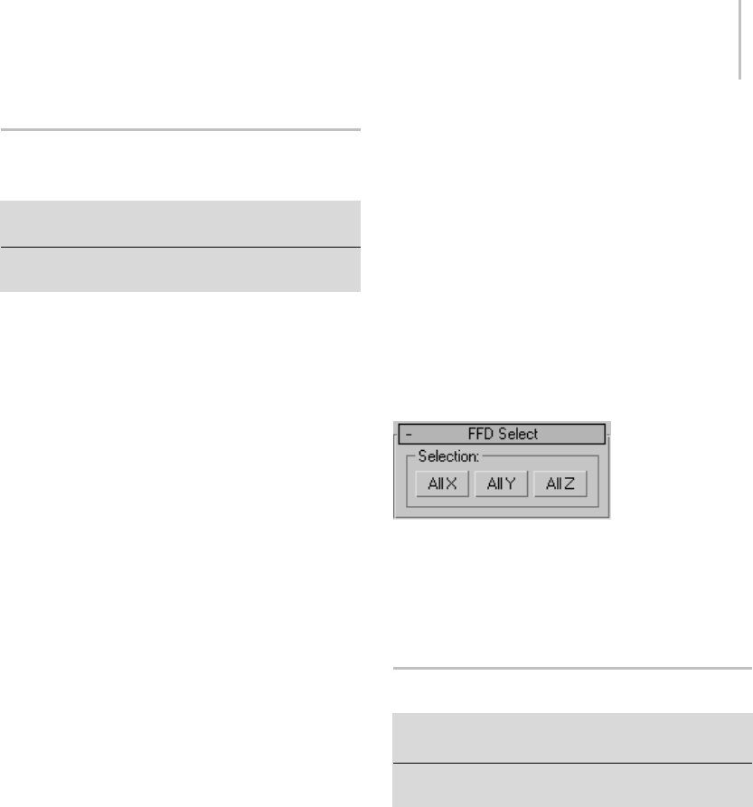
FFD (Free-Form Deformation) Select Modifier 689
FFD (Free-Form Deformation)
Select Modifier
Select an FFD space warp. > Modify panel > Modifier List
> FFD Select
Select an FFD space warp. > Modifiers menu > Selection
Modifiers > FFD Select
The FFD Select modifier works on an FFD (Box)
Space Warp (page 2–91) or FFD (Cyl) Space Warp
(page 2–95) to change the selection of its control
points, and pass the selection up the stack.
The space-warp versions of the FFD modifiers
provide sub-object geometry that you can
manipulate in the stack. For example, you can
apply a Bend modifier (page 1–560) to an FFD
space warp, bend its control points, and thus bend
theobjecttowhichthespacewarpisbound.
Using the FFD Select modifier, you can select a
sub-object pattern of control points, and then use
the subsequent modifier(s) to deform the selected
points.
The FFD Select modifier is especially useful for
assigning Linked XForm modifiers (page 1–712) to
portions of an FFD space warp.
Procedure
Example: To use the Linked XForm modifier with an
FFD space warp:
1. Create an object, an FFD space warp (such
as FFD (Box) (page 2–91)), and a couple of
dummies (page 2–16).
2. Bind the FFD space warp to the object you want
to deform.
3. Select the FFD space warp and apply an FFD
Select modifier.
4. In the Control Points sub-object mode, select
the control points you want to use to affect the
object.
5. Apply a Linked XForm modifier, and then pick
one of the dummies as a control object.
6. Apply another FFD Select modifier, and select a
different collection of control points.
7. Apply another Linked XForm modifier and
assign the other dummy as a control object.
8. You can now move either of the dummy objects
to both translate the linked control points in
the FFD space warp, and to deform the target
object.
Interface
AllX/AllY/AllZ—Select the control points
corresponding to the specified axis plane.
First click a selection button, and then select FFD
control points in the viewports.
Fillet/Chamfer Modifier
Select a shape. > Modify panel > Modifier List >
Object-Space Modifiers > Fillet/Chamfer
Select a shape. > Modifiers menu > Patch/Spline editing
>Fillet/Chamfer
The Fillet/Chamfer modifier lets you fillet or
chamfer the corners between linear segments of
Shape objects (page 3–1011). Fillet rounds corners
where segments meet, adding new control vertices.
Chamfer bevels corners, adding another vertex
andlinesegment.Notethatthismodifierworkson
the splines at the sub-object level of the shape. It
does not work between two or more independent
shape objects.
When you apply Fillet/Chamfer, you’re placed in
a Vertex sub-object selection level. You can select
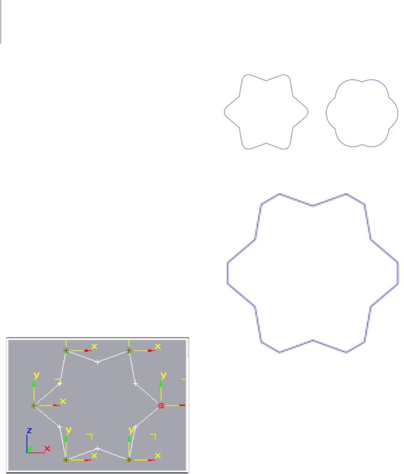
690 Chapter 8: Modifiers
(and move) any vertex, but only Corner vertices
and Bezier Corner vertices are valid for fillet and
chamfer functions. In addition, both segments
connected by a Bezier Corner vertex must be
linear rather than curved.
There are two methods for applying either fillets
or chamfers:
• Select one or more valid corner vertices, and
then adjust either the Radius spinner to fillet
theselectedcorners,ortheDistancespinnerto
chamfer the corners.
• You can preset the Radius or Distance values,
andthenselectoneormorevalidcorner
vertices, and click one of the Apply buttons to
apply the specified value to the selected vertices.
Note: As of version 3 of 3ds Max, Edit/Editable
Spline (page 1–297) includes interactive
fillet/chamfer functions. The only reason to use
this modifier is to apply it at a specific location
on the stack.
Star with selected vertices
Fillet applied to above star with radius of 20 (left) and 40
(right)
Chamfer applied to above star with distance of 20
Procedure
Example: To fillet/chamfer a star:
1. Create a Star shape (page 1–277).
2. Apply a Fillet/Chamfer modifier.
3. Selectoneormoreofthestar’svertices.
4. Adjust the parameters to achieve different
effects.
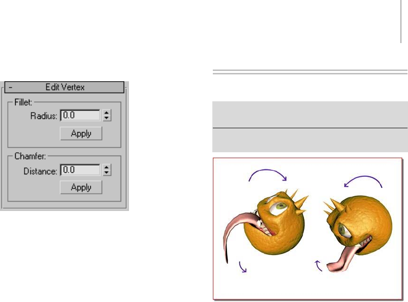
Flex Modifier 691
Interface
Fillet group
Radius—Specifies the radius of the filleted corner.
Apply—Applies the value specified in the Radius
spinner to selected vertices. For example, before
selecting any vertices, set the Radius to the desired
value, then select your vertices and click Apply to
fillet the selection with the specified radius.
Chamfer group
Distance—Specifies the distance of the new vertices
from the original corner vertex.
Apply—AppliesthevaluespecifiedintheDistance
spinner to selected vertices. For example, before
selecting any vertices, set Distance to the desired
value, then select your vertices and click Apply to
chamfer the corners.
Flex Modifier
Select a Mesh , Patch, or NURBS object. > Modify panel >
Modifier List > Object-Space Modifiers > Flex
Select a Mesh, Patch, or NURBS object. > Modifiers menu
> Animation Modifiers > Flex Modifier
Flexcausesthetonguetowagastheheadrotates.
The Flex modifier simulates soft-body dynamics
using virtual springs between an object’s vertices.
You can set the springs’ stiffness, or how actively
they keep vertices from coming close to each other,
as well as stretch, or how far apart they can move.
At a more advanced level, you can also control the
sway, or how much the spring angle can change.
At its simplest, this system causes vertices to lag
behind an object as it moves.
Flex works with NURBS, patches, meshes, shapes,
FFD space warps, and any plug-in-based object
types that can be deformed. You can combine Flex
with space warps such as Gravity, Wind, Motor,
Push, and PBomb to add realistic physically based
animation to an object. In addition, you can
apply deflectors to soft-body objects to simulate
collision.
Note: The Flex modifier is aware of
vertex/control-point motion in any animated
modifier that deforms points below Flex in the
modifier stack, such as the Morphermodifier(page

692 Chapter 8: Modifiers
1–729). Use this to simulate soft body motion on a
morphed or otherwise deform-animated object.
Tip: After applying the Flex modifier to an object
or sub-object selection, choose the Flex modifier’s
Center sub-object and use Move to change where
the flex effect is centered.
Tip: Using Flex’s advanced capabilities can
significantly impede real-time playback. In such
cases, use the Point Cache modifier (page 1–758) to
record the vertex animation to disk, and then play
it back using the cache.
The antennae, with the Flex modifier applied, move around like
springs reacting to the motion of the character’s head.
Surfaces Influenced by the Flex Modifier
• On a mesh surface, the Flex modifier influences
every vertex.
• On a patch surface, the Flex modifier influences
both control points and tangent handles.
Tangent handles are unlocked and moved
independentlybytheFlexmodifier.
• OnaNURBSsurface,theFlexmodifier
influences control vertices (CVs) or points.
• On a Spline (shape), the Flex modifier
influences both control points and tangent
handles.
• OnanFFDSpaceWarp,theFlexmodifier
influences control points.
Effects
Yo u c a n a p p l y s p a c e w a r p s t o t h e F l e x m o d i f i e r.
For example, you can add Wind to animate plants
and trees, or a waving flag. In such cases, you don’t
need to create keyframes to see the effects; the
space warp alone can animate the surface.
Character Animation
Use Flex above the Skin modifier (page 1–791) to
add secondary motion to a character animated
withBones.Ifyouareusingthe3dsMaxproduct,
useFlexabovethePhysiquemodifiertoadd
secondary motion to a character.
Procedures
Example: To paint on weights:
1. Create a sphere on the left side of the Top
viewport.
2. Turn on the Auto Key button and
movethetimeslidertoframe50.
3. In the Top viewport, move the sphere to the
right side of the viewport.
4. Tur n of f Auto Key.
5. On the Modify panel, click Modifier
List, and then choose Flex.
The Flex modifier is applied to the sphere.
6. Click Play.
ThesphereflexesaroundtheTransformgizmo
evenly.
Flex Modifier 693
7. Open the Flex modifier hierarchy in the stack
display, and click Weights & Springs.
This enables modification of the Weights &
Springs sub-object settings.
8. InthePaintWeightsgroup,turnonPaint.
9. In the Left viewport, paint on the lower part
of the sphere.
Thevertexcolorchangesasthevertexweight
changes. Yellow vertices are more rigid, blue
vertices are less rigid.
Note: You can change Flex vertex colors
through Customize menu > Customize User
Interface > Colors > Geometry > Subselection
Hard/Medium/Soft.
10. Click Play.
Thespherewobblesononesidemorethanthe
other.
If the Strength setting in the Paint Vertex group
is a positive value, you paint rigidity. If the
values are negative, you paint flexibility.
Paint with negative numbers for Strength to
reverse the effect.
Example: To use wind as a force:
1. IntheTopviewport,createasphere.
2. On the Create panel, click Space
Warps, and then, if necessary, choose Forces
from the drop-down list.
3. Click Wind, and then click and drag in the
Front viewport to create a wind gizmo.
4. On the Wind Parameters rollout, set Strength
and Turbulence to 4.
5. Select the Sphere.
6. Apply the Flex modifier.
7. On the Modify panel > Parameters rollout, set
Samples to 1.
8. On Forces and Deflectors rollout > Forces
group, click the Add button, and then select the
Wind gizmo in the viewports.
9. Click Play.
Thesphereundulatesinthewind. The
Advanced Parameters rollout > Reference
Framesettingdeterminestheframewherethe
force(s) in the list take effect.
Yo u c a n a l s o u s e t h i s e x a m p l e t o s e e h o w t h e
Chase Springs option works.
10. Turn off Chase Springs and click Play
again.
The sphere keeps moving in the direction the
wind is blowing without "bouncing" back.
That’s because the chase springs, which attempt
to return the object to its original shape, are no
longer in effect.
To add custom springs:
1. Apply Flex to an object and go to the Weights &
Springs sub-object level.
The Flex vertices appear at object vertices in
the viewports.
2. In the Advanced Springs rollout, turn on Show
Springs.
3. Click the Options button and in the Spring
Option dialog (page 1–700),choosehowyou
want to add springs. Exit the Spring Option
dialog.
4. Select vertices according to the options.
For instance, if you want to add one Hold
Shape spring between two vertices, select both
vertices.
5. Click Add Spring.
The new spring or springs appear. Edge springs
are blue and Hold Shape springs are red.
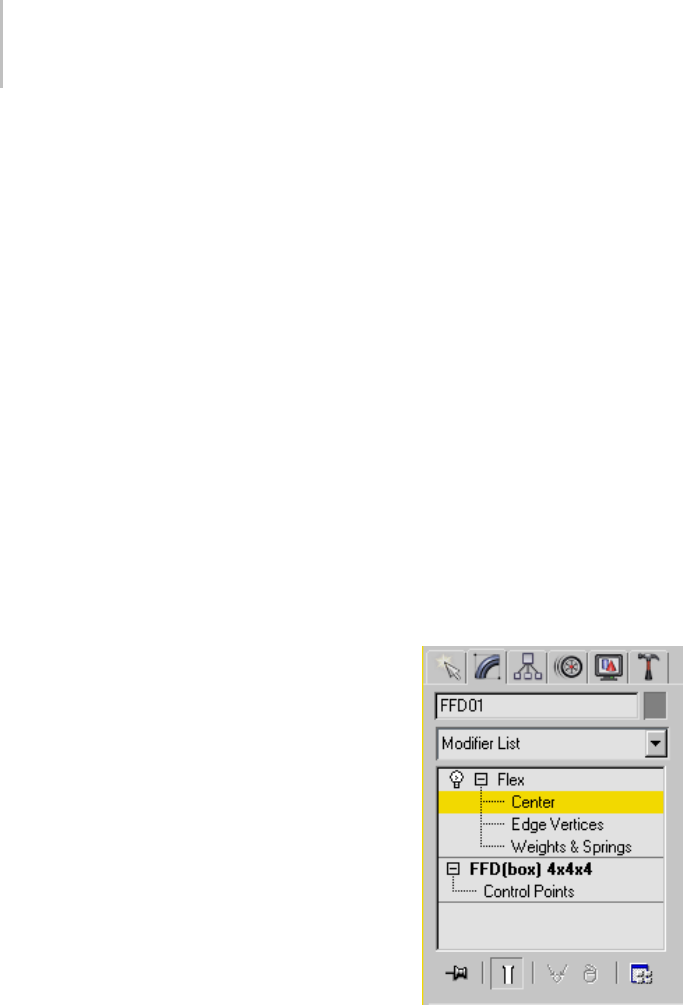
694 Chapter 8: Modifiers
Example: To create a swinging rope:
1. UseCreatemenu>SpaceWarpstoaddaDrag
and a Gravity space warp in the Top viewport.
2. UseCreatemenu>Shapes>Linetocreatea
line with ten vertices spaced evenly in the top
viewport.
3. IntheModifypanel,turnonVertexsub-object
and select all the vertices except the first vertex.
4. Add the Flex modifier.
5. In the modifier stack view, open Weights and
Springs sub-objects.
6. Turn off Use Chase Springs.
7. Turn off Use Weights.
8. Set the solver to Runge-Kutta4.
9. Set Samples to 5.
10.In a viewport, select all the points on the spline.
11.In the Advance Springs rollout, click the Option
button.
12.In the dialog, turn on Hold Edge Length
Springs and click OK.
13.Click Add Springs.
14.On the Forces and Deflectors rollout, add
Gravity and Drag in the Forces group.
15.Click Play.
The spline resembles a swinging rope.
Example: To create cloth draping on a sphere:
1. UseCreatemenu>SpaceWarpstoaddaDrag
and a Gravity space warp in the Top viewport.
2. UseCreatemenu>SpaceWarps>Deflectors
>SDeflectortocreateasphericaldeflector.
Set Bounce to 0 and Friction to 100. Place the
deflector below Z=0.
3. UseCreatemenu>Geometry>Standard
Primitives > Plane to create a 20 x 20 plane
intheTopviewport. Itshouldbeabovethe
spherical deflector.
4. Apply a Mesh Select modifier to the plane.
5. In the Top viewport, select all the vertices
except for the leftmost column.
6. Apply the Flex modifier to the plane.
7. Turn off Use Chase Springs and Use Weights.
8. Set Samples to 3.
9. ClickCreateSimpleSoftBody.
10.In the Forces and Deflectors rollout, add the
Gravity and Drag forces.
11.In the Forces and Deflectors rollout, add the
spherical deflector.
12.Click Play.
Theplanedrapesoverthesphericaldeflector
like cloth.
Interface
Modifier Stack
These modifier sub-object levels are available in
the stack display by opening the modifier hierarchy
(click the + icon to the left of the modifier name).
Center—Move the Transform gizmo in the
viewports to set the center of the effect.
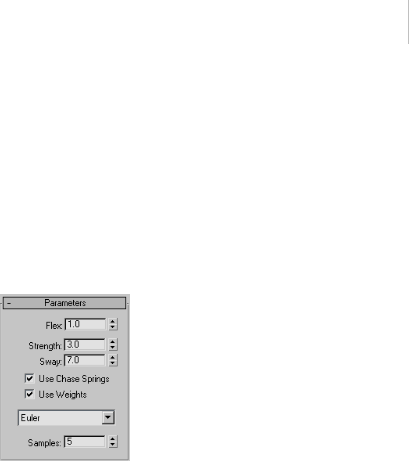
Flex Modifier 695
The flex effect increases as the distance between
the center and a vertex increases.
Edge Vertices—Select vertices in the viewports to
control the falloff and direction of the flex effect.
Selected vertices flex less than unselected vertices.
Weights & Springs—Use the Weights And Painting
rollout controls to select and deselect vertices
forsubsequentoperationsintheWeightsAnd
Painting rollout and the Advanced Springs rollout.
You can paint weights at any sub-object level, and
add and remove springs at any sub-object level (or
even at the Flex modifier object level), but while
a Weights & Springs selection is active, only the
selected vertices are affected.
Parameters rollout
Flex—Sets the amount of flex and bend. Range=0
to 1000; Default=1.
This value represents the amount of the flexed
animation that is used; the flexed animation
is determined by other factors such as motion
and vertex weighting. The default setting of 1
causes the flexed animation to occur unmodified;
higher settings cause unnaturally high amounts of
stretching, and lower settings cause diminished
stretching.
Strength—Sets the overall spring strength of the
chase springs.
A value of 100 is rigid. Range=0 to 100; Default=3.
Sway—Sets the time for the object to come to rest
for chase springs.
Lowervaluesincreasethetimefortheobjectto
come to rest. Range=0 to 100; Default=7.
Use Chase Springs—When on, enables chase
springs, which force the object to return to its
original shape. When off, no chase springs are
used, and the amount by which vertices move
depends only on their weights. Default=on.
Typically, for soft-body simulations when you
wantobjectstobeinfluencedbyforcesand
deflectors, you would turn off Use Chase Springs.
Use Weights—When on, Flex recognizes the
different weights assigned to an object’s vertices,
applying different amounts of flexing accordingly.
When off, the flex effect applies itself to the object
as a monolithic whole. Default=on.
Typically, for soft-body simulations when you
wantobjectstobeinfluencedbyforcesand
deflectors, you would turn off Use Weights.
Solver Type—Choose a solver for the simulation
from the drop-down list. The three choices are
Euler, Midpoint, and Runge-Kutta4. Midpoint
and Runge-Kutta4 require successively more
computationthanEuler,butaremorestableand
accurate. Default=Euler.
Tip: In most cases, you can use Euler successfully,
but if unexpected object deformations occur
during a simulation, try using one of the more
accurate solver types. Specifically, you might need
to use Midpoint or Runge-Kutta4 with higher
Stretch and Stiffness settings.
Samples—ThenumberoftimesperframetheFlex
simulation is run at equal time intervals. The
more samples you take, the more accurate and
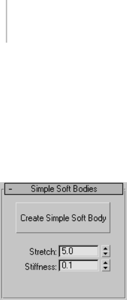
696 Chapter 8: Modifiers
stable the simulation. When using the Midpoint or
Runge-Kutta4 solver, you might not need as many
samples as with Euler. Default=5.
Tip: If your simulation produces unexpected
results, such as object vertices moving to seemingly
random locations, try increasing the Samples
setting.
Simple Soft Bodies rollout
Lets the software determine spring settings for
theentireobjectautomatically.Alternatively,you
can use the Advanced Springs (page 1–699) rollout
settings to specify spring settings between each
pair of vertices.
Create Simple Soft Body—Generates spring settings
for the object based on the Stretch and Stiffness
settings.
Note: AfteryouuseCreateSimpleSoftBody,
you can change the Stretch and Stiffness settings
without having to click the button again; the
changes take effect immediately.
Stretch—Determines how much object edges
can elongate. When Advanced Springs rollout >
Enable Advanced Springs is off, the Stretch setting
is linked to the Advanced Springs rollout > Stretch
Str. and Stretch Sway settings.
Stiffness—Determines how rigid the object
is. When Advanced Springs rollout > Enable
AdvancedSpringsisoff,theStretchsettingis
linked to the Advanced Springs rollout > Shape
Str. and Shape Sway settings.
The differences between Stretch and Stiffness
are subtle, and understanding them is further
complicated by the fact the two affect each other.
In addition, how they work depends on object
topology. For example, say you create a box, add a
Flex modifier, apply Create Simple Soft Body, and
then set a high Stretch value and a low Stiffness
value. If you use the box in a Flex-based dynamics
simulation, such as dropping it onto a surface
(deflector) with gravity, you might expect the box
to fall over and flatten out. But instead, because
of the box’s topology, which causes Create Simple
Soft Body to apply a relatively small number of
shape springs, you’d actually get better results
with a low Stretch value and a high Stiffness value.
However, if you use a sphere of eight segments
instead, you’ll get the collapsing behavior with
the default Stretch and Stiffness settings, and as
expected, increasing rigidity with higher Stiffness
settings.
In soft-body simulations, such as the above-cited
example of dropping an object onto a surface,
particularly with dense meshes, you might get
betterresultsbyapplyingthemeshtoanFFD
space warp that’s bound to the object. If the
object’s shape isn’t suitable for use with the space
warp, you might have to instead use the Advanced
Springs (page 1–699) rollout settings to apply
springs manually. In such cases, you should create
shape springs between opposite vertices rather
than adjacent ones.
Cloth-like animation usually works best with a
high Stretch setting and a low Stiffness setting. For
soft bodies, you would usually use high settings
for both Stretch and Stiffness, depending on how
"squishy" you want the object to be.
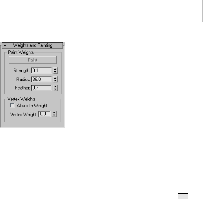
Flex Modifier 697
Weights and Painting rollout
When you first apply Flex to an object, the
modifier automatically sets vertex weights based
on distance from the modifier’s center. The
higher a vertex weight, the less prone it is to being
affected by Flex effects. The modifier applies the
highest weights to vertices closest to its center,
and the lowest weights to vertices farthest from
the center. So, for example, with a cylinder whose
pivot point is at the base, you’ll get the greatest
amount of flexing at the top. But with a sphere, all
of whose vertices are equidistant from the pivot
point (center), all vertices have, by default, equal
weight values.
The Paint Weights controls let you use a spherical
brush with adjustable radius and falloff to change
vertex weights in the viewports, thus controlling
theamountoflag.TheVertexWeightscontrolslet
you apply absolute or relative weighting to single
vertices or groups of vertices.
Paint Weights group
Paint—At any sub-object level, click Paint,
andthendragthecursoroverthemeshinthe
viewports to "paint" vertex weights using the
current Strength and Feather settings. Vertex
colors changes to reflect the new vertex weight.
Painting changes vertex weights relative to their
currentvalues;itdoesnotapplyanabsolute
weight. Longer strokes over an area of the mesh
will increase or decrease vertex weights more than
short strokes, and repeated strokes over the same
area will cause incremental changes in weight
values unless they’re already at their extremes.
ThevertexcoloringshownatanyFlexsub-object
level provides an approximate indication of
weighting. The colors are determined by the
settings in Customize menu > Customize User
Interface > Colors tab > Elements: Geometry.
In this list are three color entries: Subselection
Hard, used to display vertices with the highest
Weight values; Subselection Medium, used to
display vertices with medium Weight values; and
Subselection Soft, used to display vertices with low
We i g ht v a l ue s .
Strength—Sets the amount by which painting
changes weight values. Higher values change
weighting more quickly. At Strength=0, painting
does not change weight values. Range=-1 to 1;
Default=0.1.
Negative values allow you to remove weight.
Tip: When painting, you can use the Alt key to
invert the strength.
Radius—Sets the size of the brush in world units.
Range=.001 to 99999; Default=36.
Note: If you position the mouse cursor over the
object before painting, you can see a wireframe
representation of the spherical "brush" that depicts
the Radius setting.
Feather—Sets the falloff in strength from the center
of the brush to its edge. Default=.7. Range=.001
to 1.
Vertices at the center of the brush are always
changed by the full amount of the Strength setting,
but the higher the Feather setting, the less vertices
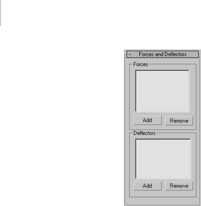
698 Chapter 8: Modifiers
closertotheedgechange.Atthelowestsetting,all
vertices inside the radius are changed equally.
Vertex Weights group
Sets vertex weighting manually. At the Weights
& Springs sub-object level, select vertices in the
viewports, and then change the value of the Vertex
Weight parameter. Alternatively, turn on Absolute
Weight, set the desired Vertex Weight, and then
select vertices to set; changes are immediate.
Absolute Weight—Turn on to assign absolute
weights to the selected vertices. Turn off to add or
remove weight based on the Vertex Weight setting.
Vertex Weight—Assigns weight to selected vertices.
Depending on the state of the Absolute Weight
parameter, weight assignment is either absolute
or relative.
Note: The Vertex Weight range is -100 to 100.
With Absolute Weight on, the negative Vertex
Weight settings have no effect; the effective range
is 0 to 100. With Absolute Weight off, changing
the Vertex Weight setting adds the amount to the
current weights of selected vertices, and then the
setting is reset to 0.
Forces and Deflectors rollout
Forces group
Use these controls to add space warps in the Forces
category to the Flex modifier. Supported space
warps are:
•Displace (page 2–76)
•Drag (page 2–66)
•Gravity (page 2–73)
•Motor (page 2–61)
•PBomb (page 2–68)
•Push (page 2–59)
•Vortex (page 2–63)
•Wind (page 2–75)
List Window—Displays particle space warps
applied to the Flex modifier.

Flex Modifier 699
Add—Click this, and then select a particle space
warp in the viewports to add the effect to Flex. The
added space warp displays in the list window.
Remove—Select a space warp in the list and click
Remove to remove the effect from Flex.
Deflectors group
UsingdeflectorswithFlexletsobjectmovement
be impeded by surfaces. This lets you simulate
collisions with soft-body objects. For best results
with collisions, in the deflector settings use a low
value for Bounce and a high value for Friction.
Supported deflectors are:
•POmniFlect (page 2–78)
•SOmniFlect (page 2–84)
•UOmniFlect (page 2–85)
•UDeflector (page 2–89)
•SDeflector (page 2–87)
•Deflector (page 2–90)
List Window—Displays deflectors applied to the
Flex modifier.
Add—Click this, and then select a deflector in the
viewports to add the effect to Flex. The added
deflector displays in the list window.
Remove—Select a deflector in the list and click
Remove to remove the effect from Flex.
Advanced Parameters rollout
Reference Frame—Sets the first frame at which Flex
begins its simulation.
End Frame—When on, sets the last frame at which
Flex is to take effect. After this frame, the object
snaps back to its shape as currently defined by the
stack. For instance, if you animate a Bend modifier
in the stack under Flex, then when Flex stops, the
object’s shape is altered only by the Bend modifier
settings as of that frame.
Affect All Points—Forces Flex to ignore any
sub-object selection in the stack and apply itself
to the entire object.
Set Reference—Updates the viewports.
After moving the effect center, click Set Reference
to update the viewports.
Reset—Resets vertex weighting to the defaults.
Advanced Springs rollout
Use these settings when you need a more precise
springs setup than is provided by the Simple
Soft Body feature. Flex uses two types of spring:
edge springs, which create springs only along
existing edges, and shape springs, which can exist
between any two vertices in the object that are not
connected by an edge. In general, add edge springs
alongexistingedgesandshapespringsbetween
vertices that don’t share an edge.
Note: Before using these controls, go to the Weights
& Springs sub-object level.
Note: Additional spring types are available using
MAXScript. See the MAXScript reference for
details.
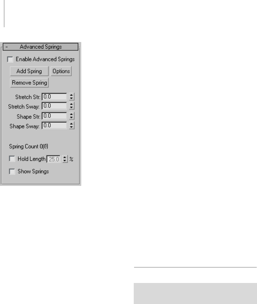
700 Chapter 8: Modifiers
Enable Advanced Springs—Makes the numeric
controls available for editing, and disconnects the
Strength and Sway settings from the Simple Soft
Bodies controls. Default=off.
The four numeric Stretch and Sway settings in this
rollout are available only when Enable Advanced
Springs is on.
Add Spring—Adds one or more springs to the
object based on the vertex selection at the Weights
&Springssub-objectlevelandtheSpring Option
dialog (page 1–700) settings.
Note: You cannot undo this action. To delete
existing springs, select the endpoints and click
Remove Spring.
Options—Opens the Spring Option dialog (page
1–700) for determining how springs are added
with the Add Spring function.
Remove Spring—Deletesanyspringsthathave
both vertices selected at the Weights & Springs
sub-object level.
Stretch Str.—Determines the strength of the edge
springs; the higher the strength, the less the
distance between them can vary.
Stretch Sway—Determines the sway of the edge
springs; the higher the strength, the less the angle
between them can vary.
Shape Str.—Determines the strength of the shape
springs; the higher the strength, the less the
distance between them can vary.
Shape Sway—Determines the sway of the shape
springs; the higher the strength, the less the angle
between them can vary.
Spring Count—Displays the number of edge
springs, followed by the number of shape springs
in parentheses.
Hold Length—Maintains the length of edge springs
within the specified percentage.
Note: This setting, which is applied after the Flex
simulation,canaffecttheobjectshape,andthus
cause collision detection to fail.
Show Springs—Displays edge springs as blue lines
and shape springs as red lines. Springs are visible
only when a Flex sub-object mode is active.
You can change the spring colors using MAXScript.
Spring Option Dialog
Select a Mesh, Patch, or NURBS object. > Modify panel >
Modifier List > Animation Modifiers > Flex > Advanced
Springs rollout > Options button
Use the Spring Option dialog to determine how
springs are added in the Flex modifier when you
click the Advanced Springs rollout > Add Spring
button.
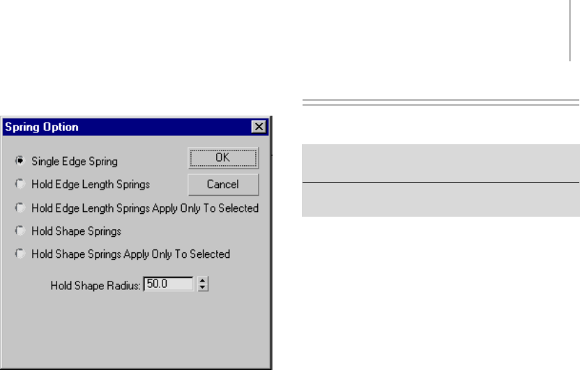
HSDS Modifier 701
Interface
Single Edge Spring—Creates one edge spring
between two selected vertices. If any number of
vertices is selected other than two, no springs are
created.
Hold Edge Length Springs—Creates edge springs
along the edges of the objects between any vertex
selection and neighboring vertices.
Hold Edge Length Springs Apply Only To
Selected—Createsedgespringsalongtheedgesof
the objects between all selected vertices.
Hold Shape Springs—Createsshapespringsfrom
the selected vertex or vertices to all other vertices
within the Hold Shape Radius.
Hold Shape Springs Apply Only To Selected—Creates
shape springs between all selected vertices within
the Hold Shape Radius.
Hold Shape Radius—The radius within which shape
springs are created. No shape springs are created
between vertices farther apart than this distance.
At the bottom of the dialog is an informational
display showing the object’s average edge length,
maximum edge length, and minimum edge length.
This information can help in determining an
appropriate Hold Shape Radius setting.
HSDS Modifier
Select an object. > Modify panel > Modifier List >
Object-Space Modifiers > HSDS Modifier
Select an object. > Modifiers menu > Subdivision
Surfaces > HSDS Modifier
The HSDS modifier implements Hierarchical
SubDivision Surfaces. It is intended primarily as a
finishing tool rather than as a modeling tool. For
best results, perform most of your modeling using
low-polygon methods, and then use HSDS to add
detail and adaptively refine the model.
Note: Better speed optimization has been
implemented in the HSDS modifier. Subdivision
calculations are now handled more efficiently
making the HSDS modifier faster.
The modifier’s primary features are:
•Localrefinement
• Hierarchical modeling
• Adaptive tessellation
With local refinement, you subdivide part of a
polygon mesh and edit the mesh in the subdivided
area. Thisisdoneindirectlybymanipulating
sub-objects in a control grid.Usethisfeaturewhen
you need to increase mesh resolution in specific
areas of a model rather than uniformly over the
entire object, as with the Te ss el l at e mo di fi er ( p age
1–865). An example of usage would be a human
hand. Once you’ve modeled the basic shape, you
might use the HSDS modifier to add bumps for
the knuckles.
The HSDS modifier supports multiple levels
of detail, hence its hierarchical nature. The
Subdivision Stack lets you visually navigate
the levels of detail at any time while using the
modifier. Thus, you can edit the same part of a
mesh at different mesh resolutions. If you work at
a level of detail lower than the highest available,

702 Chapter 8: Modifiers
the higher-detail areas are still in effect, but you
controlthemindirectlybymeansofthemore
widespread sub-objects at the lower level.
Sub-object animation is supported only at
the lowest level of detail: Base Level. This is
accomplished by animating the mesh below the
HSDS modifier. To apply deformation animation
after HSDS modeling, first convert the object to an
editable mesh by right-clicking the modifier stack
and choosing Collapse All.
The adaptive tessellation automatically subdivides
polygons as needed to maintain a smoothly curved
surface when transforming mesh sub-objects. You
can use a preset or provide custom settings.
Important: HSDS models are not passed up the modifier
stack. The HSDS modifier takes a polygon mesh as input,
and outputs a triangle-based mesh.
Also, The HSDS modifier does not handle changes
to the modified object’s topology, such as altering
a sphere’s Segments setting. Topology changes to
the input mesh results in the loss of all edits made
in the HSDS modifier.
Procedure
To use the HSDS modifier:
1. Apply the HSDS modifier to an object.
By default, the HSDS modifier doesn’t convert
non-quadrilateral polygons to quads. Because
the modifier works best with four-sided
polygons, it’s recommended you perform the
conversion if necessary.
2. If the object contains any non-quadrilateral
polygons, in the HSDS Parameters dialog, turn
on Force Quads. Click Yes in the Force Quads?
dialog that appears.
Note: Upon conversion to quads, the modifier
automatically performs one level of subdivision
with smoothing (like MeshSmooth (page 1–722)
with one iteration) on the object to which
it’s applied. Thus, for best results, use it with
relatively low-polygon objects. For example, if
you usually work with the Sphere object at the
default 32 segments, use a 16-segment sphere
with HSDS.
Iftheobjectismadeupofquadsonly,Force
Quads isn’t available because no conversion is
necessary.
3. Choose a sub-object mode at which to
subdivide.
The object is covered with a gold control
grid (or, in Vertex sub-object mode, a white
grid with blue vertices), indicating that the
entire mesh is available for subdivision and/or
sub-object transformation at base level.
4. Select one or more sub-objects.
5. Click the Subdivide button.
The modifier again subdivides and smoothes
the selected sub-objects as well as all
surrounding polygons. The resultant
sub-objects reside at a higher level of detail,
as indicated by the addition of a level in the
Subdivision Stack. Now the control grid
shows only polygons at the new level. With
sub-objects other than Element, this typically
covers only part of the object’s surface.
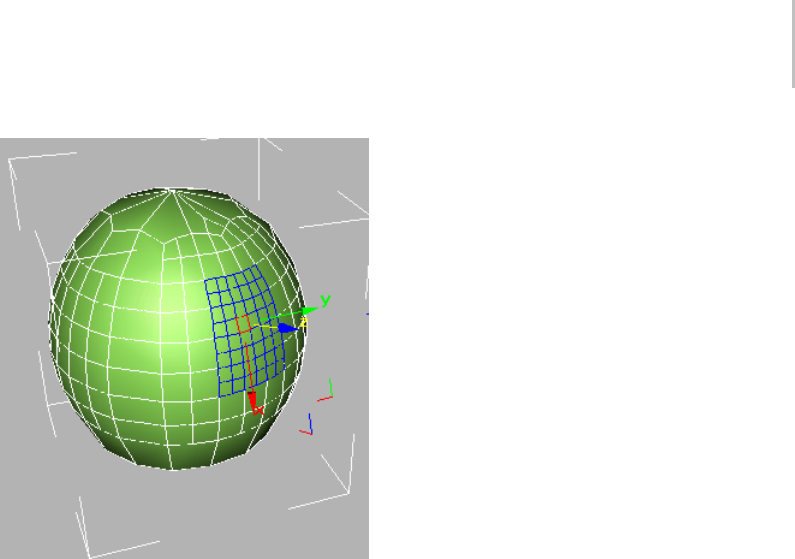
HSDS Modifier 703
A control grid on a sphere at level 2. Subdivisions at lower
levels are visible as gold lines.
In wireframe views, you can still see polygons
at lower levels of detail, but you can select only
sub-objects resulting from the subdivision, as
indicated by the control grid. You can subdivide
sub-objects further, transform them, hide and
delete them, and change material IDs.
Note: When you transform an HSDS sub-object,
the control grid tends to expand by adding
segments at its edges, in order to maintain
surface smoothness.
6. To subdivide a different part of the object,
choose a lower level in the Subdivision Stack,
and then repeat steps 2–4.
Each time you subdivide a sub-object that
has been subdivided, a higher level in the
Subdivision Stack is hightlighted, indicating a
finer mesh resolution. You can then work at that
level, or any lower level by selecting the level.
Note: Ifyoutransformasub-objectatalevel
lower than the highest level in which the subject
exists, the mesh uses the resolution imparted by
the detail in the higher levels.
Interface
HSDS Parameters rollout
The sub-objects available in the HSDS modifier
belong to the control grid rather than the mesh
object itself. Transforming the grid sub-objects
also transforms the underlying mesh, but the mesh
doesn’t always move to the full extent of the control
grid. Thisisparticularlytrueincaseswhereyou
transform a sub-object at a level lower than the
highest level in which the sub-object resides.
For example, if you subdivide a vertex at the Base
Level, it then resides in the Base Level and Level 1.
Ifyouthenmovethevertexinthebaselevel,the
mesh doesn’t, by default, move as far as the vertex.
This is roughly analogous to the way free-form
deformation works, but with HSDS, the control
grid conforms much more closely to the shape of
the mesh object.
With vertices, you can control the degree to which
the mesh follows the control-grid vertex with the
settings on the Vertex Interpolation group.
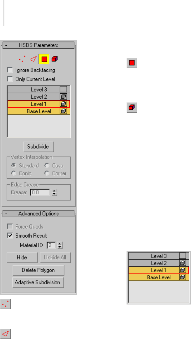
704 Chapter 8: Modifiers
Vertex—Turns on Vertex sub-object mode,
which lets you select a vertex beneath the cursor;
region selection selects vertices within the region.
Edge—Turns on Edge sub-object mode,
which lets you select a face or polygon edge
beneath the cursor; region selection selects
multiple edges within the region.
Polygon—Tur ns on Polygon sub -object mode ,
whichletsyouselectasinglefaceorpolygon.A
polygon is the area you see within the visible wire
edges. Region selection selects multiple polygons
within the region.
Element—Turns on Element sub-object
mode, which lets you select all contiguous
polygons beneath the cursor in the current level
of detail.
Ignore Backfacing—When on, you can select only
those sub-objects whose normals are visible in
the viewport. When off (the default), selection
includes all sub-objects, regardless of the direction
of their normals. Default=off.
Only Current Level—Displays only polygons at the
current level of detail, with highlights, but without
smoothing. Use this option to speed up the display
when working with complex objects. Default=off.
Subdivision Stack—Shows the current level of the
subdivision hierarchy. Automatically increments
when you subdivide a sub-object selection. To edit
at a different level of detail, select the level in the
stack. The current level is outlined in red.
• Visibility is controlled by the box icon to the
right of the level label. Turning on the visibility
at one level activates the visibility from that
level down to the base level. Visibility above
thatlevelwillbeturnedoff.
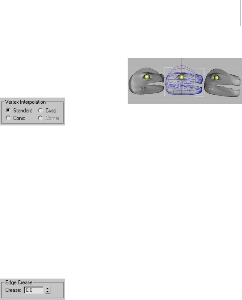
HSDS Modifier 705
Subdivide—Performs subdivision and smoothing
on the current selection, and adds a level to the
Subdivision Stack. When the subdivision results
in a control grid and other subdivisions have been
performed at the same level of detail, the control
grids may become interconnected.
Vertex Interpolation group—
Determines how selected vertices are treated
during subdivision. Available only in Vertex
sub-object mode.
For best results, use when moving control grid
vertices at a level of detail lower than the highest in
which the vertex resides.
Standard/Conic/Cusp/Corner—Determines how
closely mesh vertices follow the movement of
control grid vertices. Standard provides the
leastamountofrelativemovement,whileCusp
and Corner provide the most. Corner also
keeps edges adjacent to subdivided vertices
from being rounded off during subdivision.
Default=Standard.
Note: Corner is available only when the selected
vertex or vertices aren’t surrounded by polygons,
such as the vertices on the edge of a plane object.
Edge Crease group—
Determines the extent to which selected edges are
treated as creases during subdivision. Available
only in Edge sub-object mode.
For best results, use with control grid edges at
a level of detail lower than the highest in which
theedgeresides.Also,forcreasingtobevisible,
theedgeshouldbeoffsetfromthesurrounding
surface by a significant amount.
Left: Crease=1.0
Center: The eyebrow edges selected at LOD 0
Right: Crease=0.0
Crease—Specifies how much creasing is performed
ontheselectededgeoredges.Atlowsettings,the
edge is relatively smooth. At higher settings, the
crease becomes increasingly visible. At 1.0, the
highest setting, the edge is not smoothed at all.
Default=0.0. Range=0.0 to 1.0.
Advanced Options rollout
Force Quads—When on, the modifier converts all
non-quadrilateral faces or polygons to four-sided
polygons. When off, converts all polygons
to triangles. Available only when the object
contains any non-quadrilateral faces or polygons.
Default=off.
When you change the status of Force Quads, any
edits made in the HSDS modifier are lost. A
message appears warning you of this, and asking
you to confirm the change.
Because the modifier works best with four-sided
polygons, it’s recommended you confirm the
conversion if an object contains non-quadrilateral
faces or polygons. The sphere primitive is an
example of such an object; the uppermost and
lowermost faces are three-sided.
Smooth Result—When turned on, all faces on
theobjectwillbeinsmoothinggroup1,butif
Smooth Result is turned off, each face will inherit
smoothinggroupsfromtheinputMNMesh.

706 Chapter 8: Modifiers
Material ID—Displays the material ID assigned to
the current selection. Available only in Polygon
and Element sub-object modes. If multiple
sub-objects are selected and they don’t share an
ID, this field is blank.
You can change the material ID assigned to
selected sub-objects at the current and higher
levels of detail by changing this setting.
Material IDs are used primarily with
Multi/Sub-Object material (page 2–1594).
Hide—Hides the current polygon selection.
Available only at the Polygon and Element
sub-object levels. Use Unhide All to reveal hidden
polygons.
Tip: UseHidetoisolatepartofanobjectyouwant
to work on. The Select Invert command on the
Edit menu is useful in this case. Select the faces
youwanttofocuson,chooseEdit>SelectInvert,
then click the Hide button.
Unhide All—Reveals hidden polygons.
Delete Polygon—Deletes the current polygon
selection, creating a hole or holes in the surface.
Available only in Polygon sub-object mode.
Note: When the current level of detail does not
encompass the entire object surface, you cannot
delete polygons at the border of the control grid;
that is, polygons that do not share all edges with
other polygons in the grid.
Adaptive Subdivision—Opens the Adaptive
Subdivision dialog (page 1–706).Thisoptionis
best used for smoothing subdivided and edited
portions of the mesh when you’re finished using
the HSDS functionality.
Soft Selection rollout
These controls let you set a gradual falloff of
influence between selected and unselected vertices.
See Soft Selection Rollout (Edit/Editable Mesh)
(page 1–963).
Adaptive Subdivision Dialog
Select an object. > Modify panel > Modifier List >
Object-Space Modifiers > HSDS Modifier > HSDS
Parameters rollout > Adaptive Subdivision button
Select an object. > Modifiers menu > Subdivision Surfaces
> HSDS Modifier > HSDS Parameters rollout > Adaptive
Subdivision button
Use adaptive subdivision for smoothing
subdivided and edited portions of the mesh
when you’re finished using the HSDS modifier
(page 1–701).Alternatively,youcanuseadaptive
subdivision to remove a level of detail from the
object.
Procedure
To use adaptive subdivision:
1. Edit an object with the HSDS modifier.
2. Choose Add Detail or Remove Detail,
depending which operation you want to
perform.
3. Setthedesiredamountofdetailwithoneofthe
presets or by specifying custom Length and
Angle settings.
4. Click OK to perform the specified operation.
The detail addition or removal is performed,
andyou’rereturnedtotheHSDSmodifier.
Depending on whether you removed or added
detail, the highest level of detail is decremented
or incremented by 1.
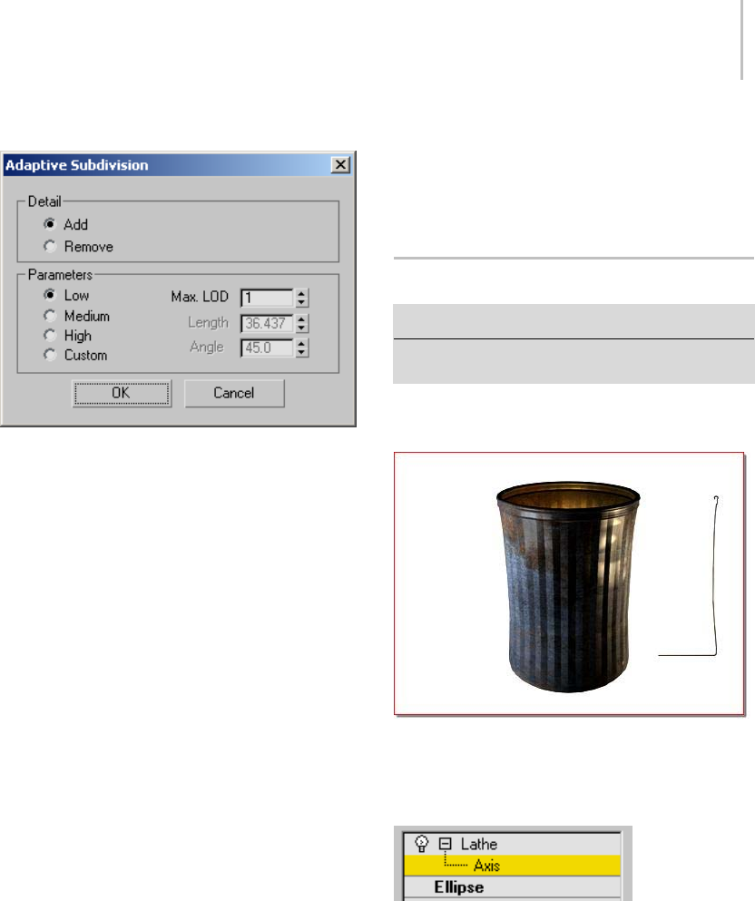
Lathe Modifier 707
Interface
Detail group
Add/Remove—Determines whether clicking the
OK button increases or decreases detail.
Parameters group
These settings determine the extent to which
detail is added or removed. The Length and Angle
settings are available for editing only when the
Custom option is chosen. However, they show the
default settings for the Low, Medium, and High
options.
Low/Medium/High/Custom—Choose one of the
presets, or choose Custom to set your own Length
and Angle values.
Max. LOD—Specifies the highest number of levels
of detail that the software can add when increasing
detail. Not available when removing detail.
Length—The maximum permissible length of any
edge after adding or removing detail. The smaller
thelength,thehighertheamountoftessellation
that is allowed.
Angle—Themaximumpermissibleanglebetween
two opposite edges emanating from a vertex.
Thesmallertheangle,thehighertheamountof
tessellation that is allowed.
OK—Performs the subdivision or removal of detail
and closes the dialog.
Cancel—Closes the dialog without changing the
mesh.
Lathe Modifier
Select a shape. > Modify panel > Modifier List > Lathe
Select a shape. > Modifiers menu > Patch/Spline Editing
>Lathe
Lathe creates a 3D object by rotating a shape or
NURBS curve about an axis.
Object resulting from 360-degree lathe
Interface
Modifier Stack
Axis—At this sub-object level, you can transform
and animate the axis of revolution.
For more information on the stack display, see
Modifier Stack (page 3–760).
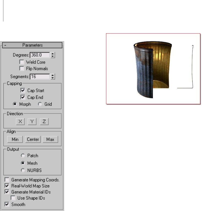
708 Chapter 8: Modifiers
Parameters rollout
Degrees—Determines the number of degrees that
the object is spun around the axis of revolution (0
to 360, default=360). You can set keyframes for
Degrees to animate the circular growth of a lathed
object. The Lathe axis auto-sizes itself to the height
of the shape being lathed.
Object resulting from 270-degree lathe
Weld Core—Simplifies the mesh by welding
together vertices that lie on the axis of revolution.
Keep it turned off if you intend to create morph
targets.
Flip Normals—Dependingonthedirectionof
the vertices on your shape, and the direction of
rotation, the lathed object might be inside out.
Toggle the Flip Normals check box to fix this.
Segments—Determineshowmanyinterpolated
segmentsarecreatedinthesurfacebetween
the start and endpoint. This parameter is also
animatable. Default=16
Note: You can create up to 10,000 segments using
thesegmentsspinner.Trynottocreategeometry
that is more complex than you need. Often you can
get satisfactory results by using smoothing groups
or smoothing modifiers, rather than increasing
segmentation.
Capping group
Controls whether or not caps are created for the
interior of the lathed object if Degrees is set to less
than 360.
Cap Start—Caps the start of the lathed object with
Degrees set to less than 360 and a closed shape.
Cap End—Caps the end of the lathed object with
Degrees set to less than 360 and a closed shape.

Lattice Modifier 709
Morph—Arranges cap faces in a predictable,
repeatable pattern necessary for creating morph
targets. Morph capping can generate long, thin
faces that don’t render or deform as well as grid
capping. Use morph capping primarily if you are
lathing multiple morph targets.
Grid—Arranges cap faces in a square grid trimmed
at the shape boundaries. This method produces
a surface of evenly sized faces that can easily be
deformed by other modifiers.
Direction group
Sets up the direction of the axis of revolution,
relative to the pivot point of the object.
X/Y/Z—Set the direction of the axis of revolution
relative to the pivot point of the object.
Align group
Min/Center/Max—Align the axis of revolution to
the minimum, center, or maximum extents of the
shape.
Output group
Patch—Produces an object that you can collapse to
a patch object (see Editing the Stack (page 1–504)).
Mesh—Produces an object that you can collapse to
a mesh object (see Editing the Stack (page 1–504)).
NURBS—Produces an object that can be collapsed
to a NURBS surface (see Editing the Stack (page
1–504)).
Generate Mapping Coordinates—Applies mapping
coordinates to the lathed object. When Degrees is
less than 360, and Generate Mapping Coordinates
is turned on, additional mapping coordinates are
appliedtotheendcaps,placinga1x1tileoneach
cap.
Real-World Map Size—Controls the scaling method
used for texture mapped materials that are applied
totheobject. Thescalingvaluesarecontrolled
by the Use Real-World Scale settings found in
the applied material’s Coordinates rollout (page
2–1625).Default=on.
Generate Material IDs—Assigns different material
IDstothesidesandthecapsofthelathedobject.
Specifically, the sides receive ID 3, and the caps
(when Degrees is less than 360 and the lathed
shape is closed) receive IDs 1 and 2. Default=on.
Use Shape IDs—Uses the material ID values
assigned to segments in the spline (page 1–266)
you lathed, or curve sub-objects in the NURBS
(page 1–1078) curve you lathed. Use Shape IDs
is available only when Generate Material IDs is
turned on.
Smooth—Applies smoothing to the lathed shape.
Lattice Modifier
Select an object or a shape. > Modify panel > Modifier
List > Object-Space Modifiers > Lattice
Select an object or a shape. > Modifiers menu >
Parametric Deformers > Lattice
The Lattice modifier converts the segments or
edges of a shape or object into cylindrical struts
with optional joint polyhedra at the vertices. Use
this either to create renderable structural geometry
based on the mesh topology, or as an alternate
method to achieve a rendered wireframe effect.
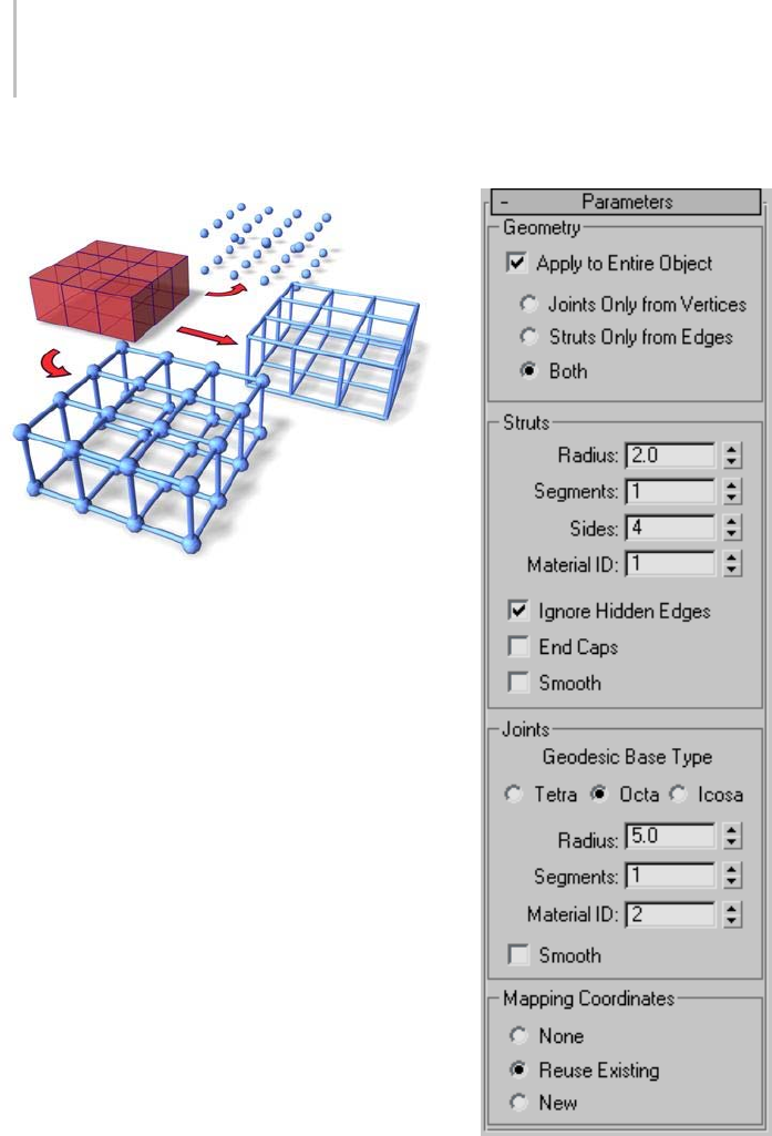
710 Chapter 8: Modifiers
Top: Joints only
Middle: Struts only
Bottom: Both (joints and struts)
Note: This modifier can act on the whole object or
on sub-object selections in the stack.
Tip: You can combine the Scatter compound object
(page 1–318) with the Lattice modifier to place
any object you want as a joint, rather than the
provided polyhedra. To do this, create your mesh
distribution object and your source object (for
example, a box). Use Scatter to scatter the box at
the vertices of the distribution object. (Be sure to
use the Copy option rather than Instance.) In the
Scatter Display parameters, hide the distribution
object. Select the original object that was used as
a distribution object, apply Lattice to it, and turn
off the joints. You’ll have two coincident objects:
one providing the lattice struts, and the other
positioning the boxes.
Interface
Geometry group
Specifies whether to use the whole object or
selected sub-objects, and which of the two
components (struts and joints) is displayed.

Lattice Modifier 711
Apply To Entire Object—Applies Lattice to all edges
or segments in the object. When turned off,
applies Lattice only to selected sub-objects passed
up the stack. Default=on.
Note: When Apply To Entire Object is turned
off, unselected sub-objects render normally. For
example, if you convert a box to an editable mesh,
select one polygon, and then apply Lattice with
ApplyToEntireObjectturnedoff,thefacedoes
not render, while the edges and vertices that form
that face are converted to struts and joints, and
the remaining faces render normally. However, if
you select the four edges surrounding the polygon
andturnoffIgnoreHiddenEdges,thestrutsand
joints are added to the object while all faces render
as normal. If you turn on Struts group > Ignore
Hidden Edges, one of the polygon’s faces renders,
while the other doesn’t.
Joints Only From Vertices—Displays only the joints
(polyhedra) generated by the vertices of the
original mesh.
Struts Only From Edges—Displays only the struts
(cylinders) generated by the segments of the
original mesh.
Both—Displays both struts and joints.
Struts group
Provides controls that affect the geometry of the
struts.
Radius—Specifies the radius of the struts.
Segments—Specifies the number of segments
alongthestruts.Increasethisvaluewhenyouneed
to deform or distort the struts with subsequent
modifiers.
Sides—Specifies the number of sides around the
perimeter of the struts.
Material ID—Specifies the material ID to be used
for the struts. The struts and the joints can have
different material IDs, making it easy to assign
them different materials. The struts default to ID
#1.
Ignore Hidden Edges—Generatesstrutsonly
for visible edges. When turned off, generates
struts for all edges, including the invisible edges.
Default=on.
End Caps—Applies end caps to the struts.
Smooth—Applies smoothing to the struts.
Joints group
Provides controls that affect the geometry of the
joints.
Geodesic Base Type—Specifies the type of
polyhedron used for the joints.
Tetra—Uses a tetrahedron.
Octa—Uses an octahedron.
Icosa—Uses an icosahedron.
Radius—Specifies the radius of the joints.
Segments—Specifies the number of segments in
thejoints.Themoresegments,themorespherical
the joints’ shape.
Material ID—Specifies the material ID to be used
for the joints. Defaults to ID #2.
Smooth—Applies smoothing to the joints.
Mapping Coordinates group
Determinesthetypeofmappingassignedtothe
object.
None—Assigns no mapping.
Reuse Existing—Uses the mapping currently
assigned to the object. This might be the mapping
assigned by Generate Mapping Coords., in the
creation parameters, or by a previously assigned
mapping modifier. When using this option,
each joint inherits the mapping of the vertex it
surrounds.
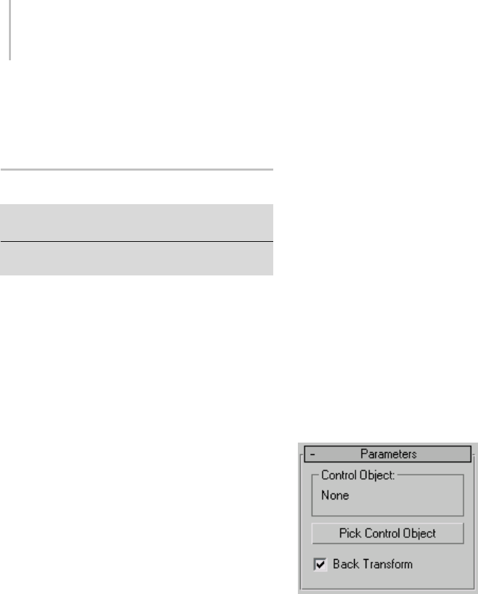
712 Chapter 8: Modifiers
New—Uses mapping designed for the Lattice
modifier. Applies cylindrical mapping to each
strut, and spherical mapping to each joint.
Linked XForm Modifier
Modify panel > Select objects or sub-objects. > Modifier
List > Object-Space Modifiers > Linked XForm
Select an object or sub-objects. > Modifiers menu >
Animation Modifiers > Linked XForm
The Linked XForm modifier links the transforms
for any object or sub-object selection to another
object, called the control object. The control
object’s motion, rotation, and/or scale transforms
are passed onto the object or sub-object selection.
Using Linked XForm
Linked XForm connects any geometry it receives
from the stack to another object, which is called
the control object. Its single control simply picks
the control object. To use this modifier, you must
have at least two objects in your scene.
See also
XForm Modifier (page 1–959)
Procedure
To apply a Linked XForm modifier:
1. Choosealocationinanobject’sstackandapply
a Linked XForm from the Modifier List.
2. On the Parameter’s rollout, click Pick Control
Object. When animating, do this at frame 0.
3. Select the object you want to be the control
object.
This completes the link. The name of the
control object appears on the Parameters
rollout.
To apply a Linked XForm modifier at a Sub-Object
level:
1. Choose an Editable Mesh or an object to which
a Mesh Select modifier has been applied.
2. Turn on the Vertex sub-object level and select
some vertices on the object.
3. Apply a Linked XForm modifier.
4. On the Parameter’s rollout, click Pick Control
Object. When animating, do this at frame 0.
5. Select another object that you want to control
the sub-object selection.
This completes the link. The name of the
control object appears on the Parameters
rollout.
6. Move the control object and see how the
vertices are affected.
Interface
Control Object—Object that the vertices are linked
to. When transformed, the vertices follow.
Pick Control Object—Click this button, and then
selecttheobjectthatyouwanttobethecontrol
object.
Back Transform—Allows an object with a Linked
XForm modifier to be linked to a Control Object.
Normally, moving the Control Object causes the
linked object to move twice as much as it should,
once with the Control Object and once with the
link. When the switch is turned on, any transforms
to the Control Object are only applied to the
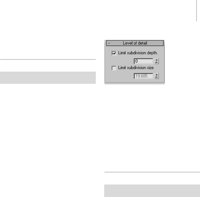
LS Mesh Modifier 713
linked object once. This switch is similar to the
’Back Transform Vertices’ switch of the Skin (page
1–791) modifier.
LS Mesh Modifier
Select a Lightscape mesh object. > Modify panel >
Modifier List > LS Mesh
The LS Mesh modifier refines a Lightscape mesh
object.
When a Lightscape scene is imported into 3ds Max,
themeshproducedbyLightscapedoesn’tcontain
the refinements that Lightscape introduced
to improve the lighting. This information is
keptandusedbytheLightscape material (page
2–1604) while rendering. This modifier will add
theserefinementstotheLightscapemesh. In
conjunction with the LS Colors modifier (page
1–550), this modifier can be used to produce
meshes suitable for game engines.
The refinement stored in a Lightscape mesh is
hierarchical. When a polygon is refined, it is
broken into four smaller polygons. These polygons
canthenberefinedfurther. Apolygoninthe
refinement has a depth from the original polygon,
which is the number of refinements needed to
get from the original polygon to the polygon in
question.
Themodifierallowsyoutoreducethenumber
of polygons in the result by limiting the depth to
which the modifier will descend, or by limiting the
size of polygons that will be refined.
You can apply the LS Mesh modifier to a Face
sub-object selection of a Lightscape mesh object.
In this case, only the selected faces will be refined.
Interface
Limit subdivision depth—Whenthetoggleison,
the value sets the maximum depth of refinement.
Whenthetoggleisoff,thenthemeshmodifier
will descend to the bottom of the refinement.
Default=on, 0.
Limit subdivision size—Whenthetoggleison,the
value limits the size of polygons that are refined.
Whenthetoggleisoff,thenthemeshmodifierwill
refine polygons to any size. The size is a length in
the current view units. Polygons smaller than that
size squared will not be refined by the modifier.
Default=off, 19.685 units or 0.5 meters.
MapScaler Modifier (Object Space)
Select an object. > Modify panel > Modifier List >
Object-Space Modifiers > MapScaler
The MapScaler (OSM) modifier works in object
space to maintain the scale of a map applied to
an object. This lets you resize the object via its
creation parameters without altering the scale of
the map. Typically, you might use this to maintain
thesizeofamapregardlessofhowthegeometryis
scaled, if you change the object size by adjusting its
creation parameters. However, if you use a Select
And Scale tool to change the object size, the map
scales along with the object.
To maintain the scale of the map regardless of how
the object is resized, use the MapScaler (WSM)
modifier (page 1–551).

714 Chapter 8: Modifiers
For example, if you scale a brick wall with the
MapScaler (WSM) modifier applied, the bricks
will all remain the same size as you increase the
size of the wall. However, if you scale the same
wall with the MapScaler (OSM) modifier applied,
thesizeofthebrickswillgrowinproportionwith
the scale of the wall.
The MapScaler (OSM) modifier has two primary
benefits compared to the WSM version:
• As an object-space modifier, it can reside
anywhere in the stack and be collapsed with the
stack, rather than being restricted to the top of
the stack, as with world-space modifiers. This
lets other object-space modifiers take effect
after the map-scaling operation.
• When instanced among multiple objects, the
object-space version appears in the modifier
stack display when any number of objects is
selected. This differs from the world-space
version, which, when instanced among multiple
objects, appears in the stack display only when
a single object is selected.
Tip: MapScaler also works at the sub-object level.
If the object you’re working on requires different
scaling of the texture map on each surface, you can
do so by creating a modifier stack with multiple
occurrences of the MapScaler modifier.
Interface
Scale—Representsthesizeofonerepetitionofthe
texture pattern. Size is measured in current scene
units. Repetitions occur across the object in the U
and V directions. Default=1.0.
Note: When the Use Real-World Texture
Coordinates switch is active in the General
Preferences dialog (page 3–815),thescalesetting
defaults to 1.0. If Use Real-World Texture
Coordinates is turned off, scale defaults to 100.0.
U/V Offset—Specify horizontal and vertical offsets
respectively. Available only when Wrap Texture
is off.
Wrap Texture—When on, Map Scaler attempts
to wrap the texture evenly around the object.
This option requires more computing, but
usually produces the most satisfactory results.
Default=on.
Wrap Using Smoothing Groups—When turned
on, textures are wrapped around corners when
they share the same smoothing groups. Curved
wallswillmapsmoothlywhilesharpcornersgeta
newtextureorigin. Thisswitchisonlyavailable
when the Wrap Textures switch is turned on.
Default=off.
Channel—Specifies the map channel (page 3–966).
Default=1.
Material Modifier
Select an object. > Modify panel > Modifier List >
Object-Space Modifiers > Material
Select an object. > Modifiers menu > Surface > Material
Select an object. > Modifiers tab > Material Modifier
The Material modifier allows you to animate, or
simply change, the assignment of material IDs
(page 3–969) on an object. If the material ID is
animated, the change to a new material ID is
abrupt, from one frame to the next.
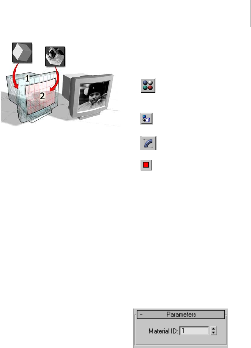
Material Modifier 715
Object mapped using a multi/sub-object material:
Material ID 1 for the housing of the monitor
Material ID 2 for the image on the screen
Tip: If you want a gradual blend from one material
to another, try animating the Mix parameter on a
Blend (page 2–1588) material.
Use this modifier in conjunction with the
multi/sub-object (page 2–1594) material type, to
assign different materials to objects or faces at
different frames of an animation, or to quickly
change the material ID of an object.
See also
Editable Mesh Surface (page 1–996)
Patches
As of 3ds Max 4, patch objects coming up the
modifier stack are not converted to a mesh by this
modifier. A patch object input to the Material
modifier retains its patch definition. Files that
contain patch objects with the Material modifier
from previous versions of the software will be
converted to meshes to maintain backward
compatibility.
Procedure
Example: To change the material ID of a sub-object
selection:
1. In the Top viewport, create a sphere.
2. In the Material Editor, create a
multi/sub-object material.
Make the colors of material ID 1 and 2 different.
3. Assign the multi/sub-object material to
the sphere.
4. OntheModifypanel,chooseMesh
Select from the Modifier List.
5. On the Mesh Select Parameters rollout,
click Polygon.
6. In the Front viewport, region-select the lower
half of the sphere.
The selected polygons turn red.
7. While Polygon is still the active sub-object level
(in the stack display, a square polygon icon
appears to the right of Mesh Select), choose
Material from the Modifier List.
8. On the Material modifier Parameters rollout,
set the value of the Material ID to 1and 2to
toggle the color on and off.
In the shaded viewport, the lower half of the
sphere changes to the color of the selected
material ID.
Interface
Material ID—Sets the material ID to be assigned;
this can be animated. If the input object is in

716 Chapter 8: Modifiers
face sub-selection, then the ID is only applied
to selected faces; otherwise, it is applied to the
entire object. The ID number refers to one of the
materials in a multi/sub-object material.
MaterialByElement Modifier
Modify panel > Make a selection. > Modifier List >
Object-Space Modifiers > MaterialByElement
Make a selection. > Modifiers menu > Surface > Material
By Element
The MaterialByElement modifier lets you apply
different material IDs to objects containing
multiple elements, at random or according to a
formula. When animated, this effect is useful for
such applications as an office building at night
with window illumination turning on and off at
random.
Various materials randomly applied to the leaves of the plant
Procedure
Example: To assign colors randomly in a group of
spheres:
1. Create six spheres.
Tip: One method is to add a sphere (page
1–174) primitive, then use Shift +Move (page
1–439) with the Copy option, and enter 5in the
Number Of Copies field.
2. Combine the spheres into a single editable
mesh object.
Right-click a selected sphere and from the
Transform (lower-right) quadrant of the quad
menu, choose Convert To: > Convert to
Editable Mesh. Then click Modify panel > Edit
Geometry rollout > Attach List. In the Attach
List dialog, click All, and then Attach.
3. Create a multi/sub-object material (page
2–1594) with six materials, and specify a
different color for each material. Assign the
material to the object with multiple spheres.
Becausesphereprimitivesareassignedmaterial
ID 2 by default, all the spheres now have the
color assigned to material number 2 in the
multi/sub-object material.
4. Assign the MaterialByElement modifier to the
object.
5. From the Parameters rollout, turn on Random
Distribution.
BecausethedefaultIDCountsettingis2,some
of the spheres are assigned sub-material #1, and
the rest are assigned #2.
6. Use the spinner to increase the ID Count setting
to 3. Also change the Uniqueness group > Seed
value.
Now the first three materials are assigned to the
spheres at random, although with some Seed
settings, you may see only two different colors.
7. Keep increasing the ID Count setting until
you see all six colors in the multi/sub-object
material. As the assignments are random, it
may take awhile.
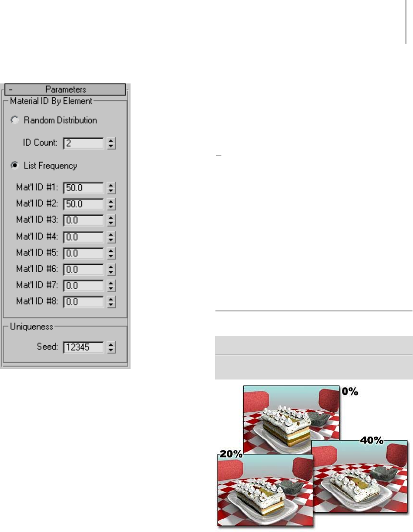
Melt Modifier 717
Interface
Material ID By Element group
The two choices in this group let you either create a
truly random distribution of material IDs or divide
the assignments among up to eight materials
according to percentages you set.
Random Distribution—Assignsthematerialsat
random to different elements in the object.
ID Count—Determines the minimum number
of material IDs to assign. Because material ID
assignment is random, setting it to the number
of materials in the multi/sub-object material or
higher doesn’t guarantee that all materials get used.
List Frequency—Determines an approximate
relative weight (percentage) for each of up to eight
material IDs, as set by the Mat’l ID #1-8 spinners.
The modifier assigns material IDs until the weights
total 100.
For example, if you set Mat’l ID #1 to 40, #2 to
35, and #3 to 60, approximately 40 percent of the
elements will be assigned material ID 1, 30 percent
will be assigned material ID 2, and 25 percent (100
[40 + 35]) will be assigned material ID 3. Any
remaining percentages (as set in Mat’l IDs 4-8) are
ignored.
Note: These percentages are approximate. The
more elements the object contains, the closer the
assigned percentage comes to the set percentage.
Uniqueness group
Seed—Sets the seed value for the
(pseudo-)randomization of material ID
assignments. Not animatable.
Melt Modifier
Modify panel > Make a selection. > Modifier List > Melt
Make a selection. > Modifiers menu > Animation
Modifiers > Melt
Increasing the Melt amount progressively melts the cake
The Melt modifier lets you apply a realistic
melting effect to all types of objects, including
editable patches and NURBS objects, as well as to
sub-object selections passed up the stack. Options
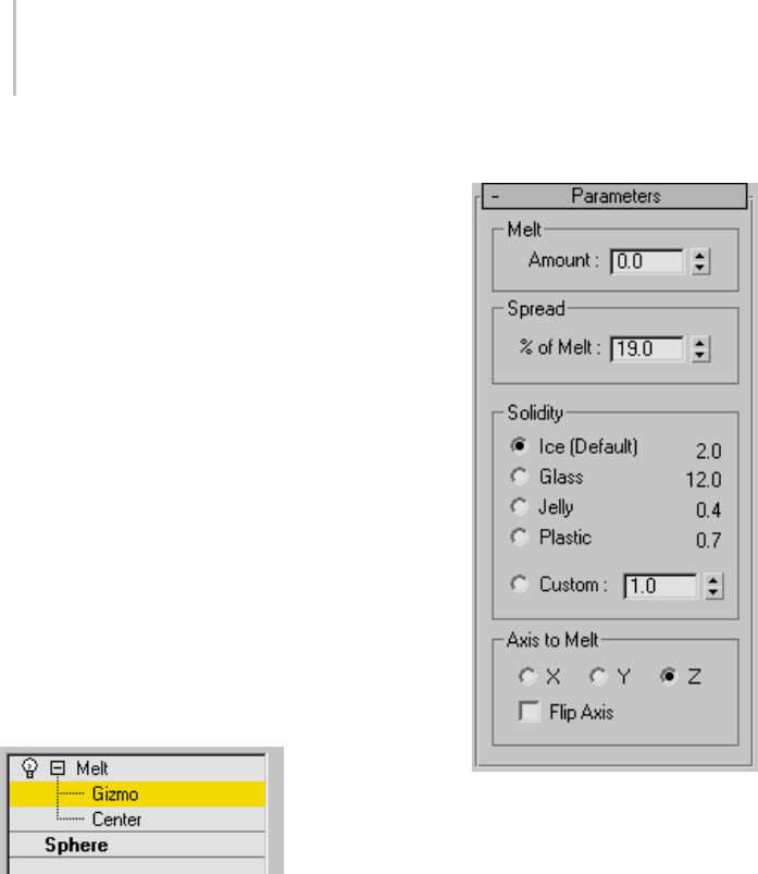
718 Chapter 8: Modifiers
include sagging of edges, spreading while melting,
and a customizable set of substances ranging from
a firm plastic surface to a jelly type that collapses
in on itself.
Procedure
Example: To animate a jelly-like melting sphere:
1. IntheTopviewport,createaSphereprimitive
with a radius of about 50 units.
2. Apply the Melt modifier.
3. TurnontheAutoKeybuttonandgotoframe
100.
4. IntheMeltgroupbox,setAmountto70.
5. IntheSoliditygroupbox,chooseJelly.
6. Turn off the Auto Key button.
7. Drag the time slider to see the sphere melt.
Interface
Modifier Stack
Gizmo—At this sub-object level, you can transform
and animate the gizmo like any other object,
altering the effect of the Melt modifier. Translating
the gizmo translates its center an equal distance.
Rotating and scaling the gizmo takes place with
respect to its center.
Center—At this sub-object level, you can translate
and animate the center, altering the Melt gizmo’s
shape, and thus the shape of the melted object.
For more information on the stack display, see
Modifier Stack (page 3–760).
Parameters rollout
Melt group
Amount—Specifies the extent of the "decay," or
melting effect applied to the gizmo, thus affecting
the object. Range=0.0 to 1000.0.
Spread group
%ofMelt—Specifies how much the object and melt
will spread as the Amount value increases. It’s
basically a "bulge" along a flat plane.
Solidity group
Determinestherelativeheightofthecenterof
the melted object. Less-solid substances like jelly
tend to settle more in the center as they melt. This
group provides several presets for different types
of substances, as well as a Custom spinner for
setting your own solidity.

Mesh Select Modifier 719
Ice—The default Solidity setting.
Glass—Uses a high Solidity setting to simulate
glass.
Jelly—Causes a significant drooping effect in the
center.
Plastic—Relatively solid, but droops slightly in the
center as it melts.
Custom—Sets any solidity between 0.2 and 30.0.
Axis to Melt group
X/Y/Z—Choosetheaxis(localtotheobject)on
which the melt will occur. Note that this axis is
localtotheMeltgizmoandnotrelatedtothe
selected entity. By default, the Melt gizmo’s axes
are lined up with the object’s local coordinates, but
you can change this by rotating the gizmo.
Flip Axis—Normally, the melt occurs from the
positive direction toward the negative along a
given axis. Turn on Flip Axis to reverse this
direction.
Mesh Select Modifier
Create or select and object > Modify panel > Modifier
List > Mesh Select
Make a selection. > Modifiers menu > Selection Modifiers
> Mesh Select
The Mesh Select modifier lets you pass a sub-object
selection up the stack to subsequent modifiers.
It provides a superset of the selection functions
available in the Edit Mesh modifier (page 1–634).
You can select vertices, edges, faces, polygons or
elements, and you can change the selection from
sub-object level to object level.
Note the following:
• When you apply the Mesh Select modifier
and then go to any sub-object level, the
select-and-transform buttons in the toolbar
are unavailable, and the Select Object button is
automatically activated.
•TheMeshSelectmodifierautomaticallyturns
off the Show End Result button, which becomes
"spring loaded" while you’re in the modifier.
For more information on the stack display, see
Modifier Stack (page 3–760).
Using XForm Modifiers to Animate a
Mesh Selection
When you apply a Mesh Select modifier, there
are no animation controllers assigned to the
sub-object selection. This means that the selection
has no way to "carry" the transform information
needed for animation.
To animate a sub-object selection using Mesh
Select, apply either an XForm or Linked XForm
modifier to the selection. These modifiers provide
the necessary controllers for animating the effects
of transforms. In a sense, they give "whole-object
status" to the sub-object selection.
•XForm (page 1–959)
Animates transforms directly on a sub-object
selection. Creates a gizmo and center for the
sub-object selection. You can animate both,
with the center acting as a pivot point for the
selection.
•Linked XForm (page 1–712)
Lets you choose another object to control the
animation. The sub-object selection is linked to
the "control object." When you transform the
control object, the sub-object selection follows
accordingly.
Procedure
To use the Mesh Select modifier:
1. Create a mesh object.
2. Apply a Mesh Select modifier.
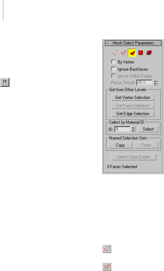
720 Chapter 8: Modifiers
3. Select vertices, edges, faces, polygons or
elements.
4. Add another modifier to affect only the
selection from step 3.
Interface
Modifier Stack controls
Show End Result—Normally, if you apply a
modifier such as Twist to an editable-mesh object
andthenreturntotheEditableMeshstackentry,
you cannot see the effect of the modifier on the
object’sgeometry.ButifyouturnonShowEnd
Result, you can see the final object as a white mesh,
and the original editable mesh as an orange mesh.
Note: WithmodifierssuchasMeshSmooth,which
apply by default to an entire object, no special
treatment is necessary. However, if you intend to
use this functionality with other modifiers that
work on a sub-object selection passed up the stack,
such as Bend, and you want to apply the modifier
totheentireobject,youshouldplaceaVo lu m e
Select modifier (page 1–952) between the editable
mesh object and the modifier in the stack. You
should leave the Volume Select modifier’s level at
the top (the default: no sub-object level chosen).
Mesh Select Parameters rollout
Provides buttons for turning different sub-object
modes on and off, working with named selections
and handles, display settings, and information
about selected entities.
TheiconsatthetopoftheSelectionrolloutletyou
specify the method of sub-object selection.
Clicking a button here is the same as selecting a
sub-object level in the modifier stack. Click the
button again to turn it off and return to the object
selection level.
Vertex—Selects a vertex beneath the cursor;
region selection selects vertices within the region.
Edge—Selects a face or polygon edge beneath
the cursor; region selection selects multiple edges
within the region.
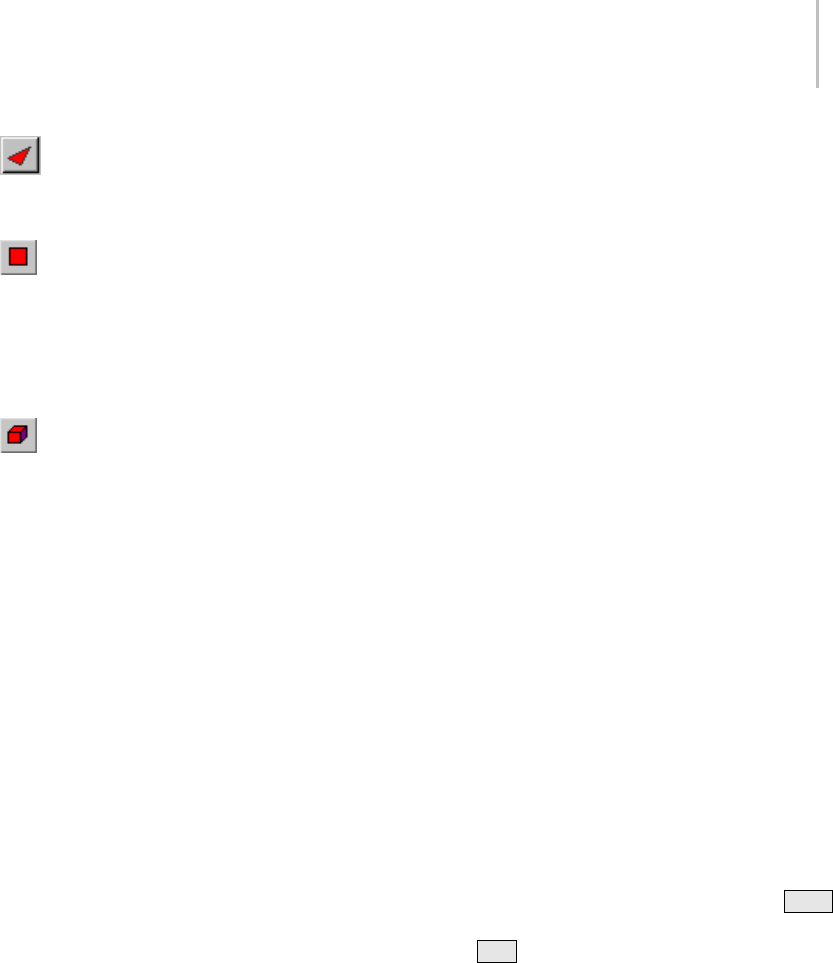
Mesh Select Modifier 721
Face—Selects a triangular face beneath the
cursor; region selection selects multiple triangular
faces within the region.
Polygon—Selects all coplanar faces (defined
by the value in the Planar Threshold spinner)
beneath the cursor. Usually, a polygon is the area
you see within the visible wire edges. Region
selection selects multiple polygons within the
region.
Element—Selects all contiguous faces in an
object. Region selection selects the same.
By Vertex—Selects any sub-objects at the current
level that use a vertex you click. Applies to all
sub-object levels except Vertex. Also works with
Region Select.
Ignore Backfaces—Selects only those sub-objects
whose normals make them visible in the viewport.
When turned off (the default), selection includes
all sub-objects, regardless of the direction of their
normals.
Note: ThestateoftheBackfaceCullsettinginthe
Display panel doesn’t affect sub-object selection.
Thus, if Ignore Backfacing is turned off, you can
select sub-objects even if you can’t see them.
Note: The state of the Ignore Backfaces check box
also affects edge selection at the Edge sub-object
selection level.
Ignore Visible Edges—When turned off (the
default), and you click a face, the selection won’t
go beyond the visible edges no matter what the
setting of the Planar Thresh spinner. When turned
on, face selection ignores the visible edges, using
the Planar Thresh setting as a guide. Enabled when
the Polygon face selection method is chosen.
Generally,ifyouwanttoselecta"facet"(acoplanar
collection of faces), you set the Planar Threshold
to 1.0. On the other hand, if you’re trying to select
a curved surface, increase the value depending on
the amount of curvature.
Planar Thresh (Planar Threshold)—Specifies the
threshold value that determines which faces are
coplanar for Polygon face selection.
GetfromOtherLevelsgroup
Appliesselectionsfromonesub-objectlevelto
another.
Get Vertex Selection—Selects faces based on the
last vertex selection. Selects all faces shared by
any selected vertex. The selection is added to the
current selection. Available only when Vertex is
notthecurrentsub-objectlevel.
Get Face Selection—Selectsverticesbasedonthe
last face/polygon/element selection. This selection
is added to the current selection. Available only
when Face/Polygon/Element is not the current
sub-object level.
Get Edge Selection—Selects faces based on the last
edge selection. Selects those faces that contain the
edge. Available only when Edge is not the current
sub-object level.
Select by Material ID group
Selects faces based on their material ID.
ID—Set the spinner to the ID number you want to
select, and then click the Select button. Press Ctrl
whileclickingtoaddtothecurrentselection,or
press Alt to remove from the current selection.
Named Selection Sets group
Thesefunctionsareprimarilyforcopying
named selection sets (page 1–67) of sub-objects
between similar objects, and between comparable
modifiers and editable objects. For example, you
canapplyameshselectmodifiertoasphere,
create a named selection set of edges, and then
copy the selection to a different sphere that’s been
converted to an editable mesh object. You can
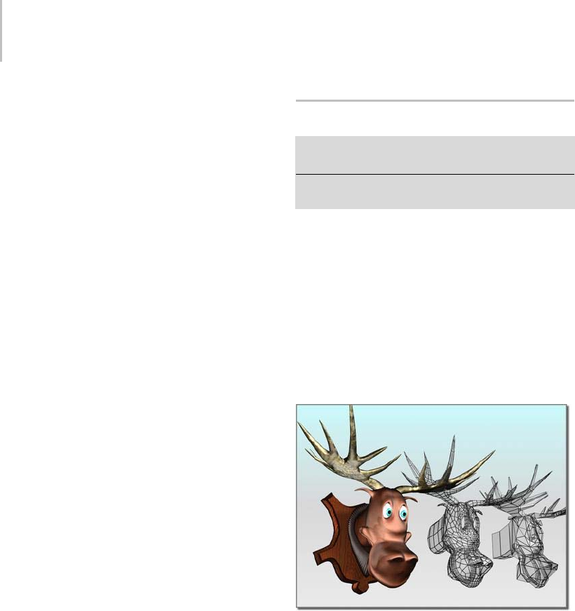
722 Chapter 8: Modifiers
even copy the selection set to a different type of
object, because the selection is identified by the
entities’ ID numbers.
The standard procedure is to create a selection set,
name it, and then use Copy to duplicate it into the
copy buffer. Next, select a different object and/or
modifier,gotothesamesub-objectlevelasyou
were in when you copied the set, and click Paste.
Note: Because sub-object ID numbers vary from
object to object, the results of copying named
selection sets between different objects can be
unexpected. For example, if the buffered set
contains only entities numbered higher than any
that exist in the target object, no entities will be
selected when the set is pasted.
Copy—Places a named selection into the copy
buffer.
Paste—Pastes a named selection from the copy
buffer.
Select Open Edges—Selects all edges with only one
face. In most objects, this will show you where
missing faces exist. Available only at the Edge
sub-object level.
Selection Information
At the bottom of the Mesh Select Parameters
rollout is a text display giving you information
about the current selection. If 0 or more than one
sub-object is selected, the text gives the number
and type selected. If one sub-object is selected, the
text gives the ID number and type of the selected
item.
Note: When the current sub-object type is Polygon
or Element, selection information is given in faces.
Soft Selection rollout
These controls let you set a gradual falloff of
influence between selected and unselected vertices.
See Soft Selection Rollout (Edit/Editable Mesh)
(page 1–963).
MeshSmooth Modifier
Modify panel > Make a selection. > Modifier List >
Object-Space Modifiers > MeshSmooth
Make a selection. > Modifiers menu > Subdivision
Surfaces > MeshSmooth
The MeshSmooth modifier smoothes geometry
in your scene by means of several different
methods. It lets you subdivide the geometry while
interpolating the angles of new faces at corners
and edges, and apply a single smoothing group to
all faces in the object. The effect of MeshSmooth
is to round over corners and edges as if they had
beenfiledorplanedsmooth. UseMeshSmooth
parameters to control the size and number of new
faces, and how they affect the surface of the object.
Angular model (shown on the right) changed to a smooth
model with MeshSmooth
Yo u c a n u s e M e s h Sm o o t h t o p r o d u c e a
Non-Uniform Rational MeshSmooth object
(NURMS for short). A NURMS object is similar
to a NURBS object in that you can set different
weights for each control vertex. You can further
control the object’s shape by changing edge
weights.
MeshSmooth’s effect is most dramatic on sharp
corners and least visible on rounded surfaces.
Use MeshSmooth on boxes and geometry with
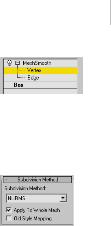
MeshSmooth Modifier 723
crisp angles. Avoid using it on spheres and similar
objects.
Tip: To better understand MeshSmooth, create a
sphere and a cube and apply MeshSmooth to both.
The cube’s sharp corners become rounded, while
the sphere’s geometry becomes more complex
without changing shape significantly.
Note: Having an animated deformer placed before
a meshsmoothed object that has had control
leveleditingcanresultinthemeshsmoothed
object becoming distorted. It’s recommended
that deforming modifiers be placed after the
MeshSmooth modifier in the stack if you’re using
the deformers for animation.
Procedures
To apply MeshSmooth to an object:
1. Select an angular object.
2. Apply the MeshSmooth modifier.
3. Set MeshSmooth parameters.
To apply MeshSmooth to sub-objects:
1. Select an object.
2. Apply a Mesh Select modifier.
3. Select a group of vertices or faces.
4. Apply MeshSmooth.
5. In the Subdivision Method rollout, turn off
Apply To Whole Mesh.
This lets MeshSmooth work only on the
sub-object selection.
6. Set MeshSmooth parameters.
Interface
Modifier Stack
Vertex—At this sub-object level you can transform
or edit vertices in the smoothed mesh.
Edge—At this sub-object level you can transform
or edit face edges in the smoothed mesh.
See Local Control rollout (page 1–725).
For more information on the stack display, see
Modifier Stack (page 3–760).
Subdivision Method rollout
Subdivision Method list—Choose one of the
following to determine the output of the
MeshSmooth operation:
•NURMS—Produces Non-Uniform Rational
MeshSmooth object (NURMS for short). The
Strength and Relax smoothing parameters are
unavailable with the NURMS type.
A NURMS object is similar to a NURBS object
in that you can set different weights for each
control vertex. You can further control the
object’sshapebychangingedgeweights.See
Display/Weighting group, following, for further
information on changing weights.
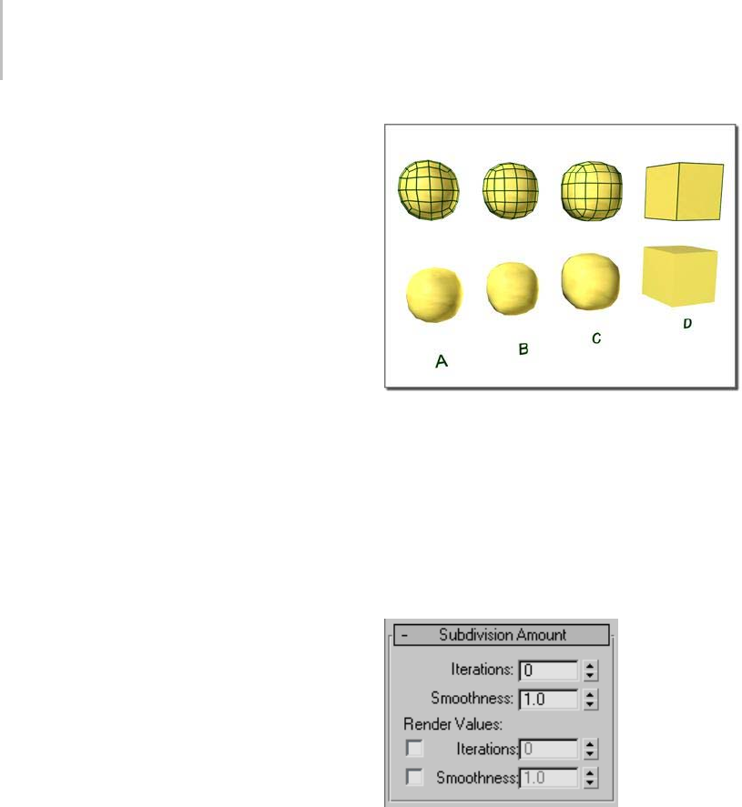
724 Chapter 8: Modifiers
•Classic—Produces three- and four-sided facets.
(ThisisthesameasapplyingMeshSmoothin
version 2.x without turning on Quad Output.)
•Quad Output—Produces only four-sided facets
(assuming you don’t look at the hidden edges,
since the object is still made up of triangular
faces). If you apply this with default parameters
to a whole object, like a box, it’s topologically
exactly the same as Tessellate (page 1–865),
edge-style. However, rather than using tension
to project face and edge vertices out of the
mesh, use the MeshSmooth Strength to relax
the original vertices and the new edge vertices
into the mesh.
Apply To Whole Mesh—When turned on, any
sub-object selection passed up the stack is ignored
and MeshSmooth is applied to the entire object.
Note that the sub-object selection is still passed up
the stack to any subsequent modifiers.
Old Style Mapping—Uses the 3ds Max version 3
algorithm to apply MeshSmooth to the mapping
coordinates. This technique tends to distort the
underlying mapping coordinates as it creates new
faces and as texture coordinates shift.
Effect of MeshSmooth with two iterations on a cube and
different iteration method:
A. NURMS
B. Quad
C. Classic
D. Original object with no MeshSmooth
Subdivision Amount rollout
SetshowmanytimestoapplyMeshSmooth.
Iterations—Sets the number of times the mesh is
subdivided. When you increase this value, each
new iteration subdivides the mesh by creating
smoothly interpolated vertices for every vertex,
edge, and face from the iteration before. The
modifier then subdivides the faces to use these
new vertices. Default=0. Range=0 to 10.
The default value of 0 iterations allows you to
modify any setting or parameter, such as the type
of MeshSmooth or the update options, before the
program starts subdividing the mesh.
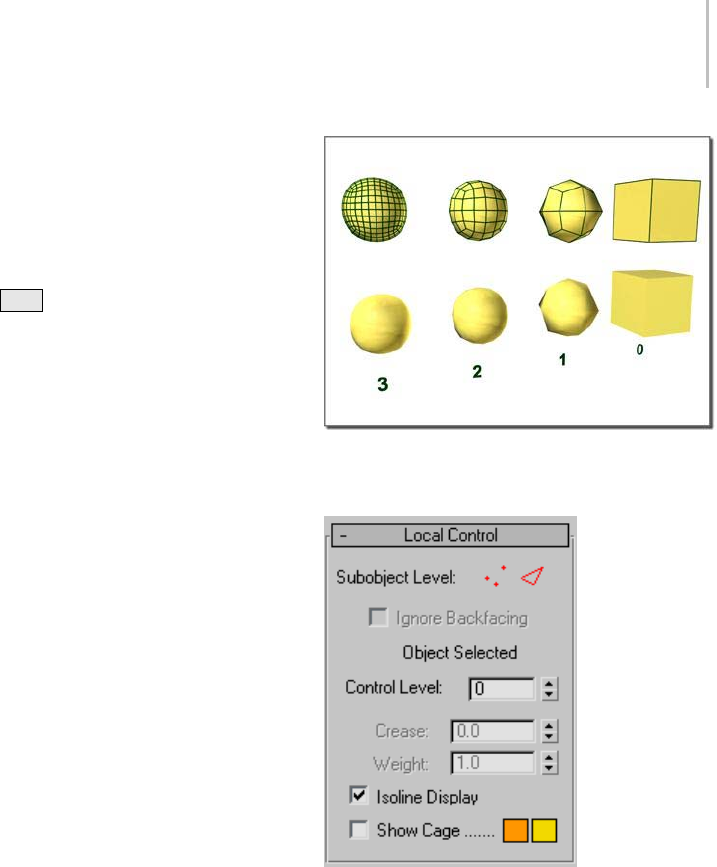
MeshSmooth Modifier 725
Note: Be cautious when increasing the number
of iterations. The number of vertices and faces
in an object (and thus the calculation time) can
increase as much as four times for each iteration.
Applying four iterations to even a moderately
complex object can take a long time to calculate.
Yo u c a n p r e s s Esc to stop calculation; this also
automatically sets Update Options to Manually.
Reduce the Iterations value before setting Update
Options back to Always.
Smoothness—Determines how sharp a corner
must be before faces are added to smooth it.
Smoothness is calculated as the average angle of
all edges connected to a vertex. A value of 0.0
prevents the creation of any faces. A value of 1.0
adds faces to all vertices even if they lie on a plane.
Tip: To subdivide only sharp edges and corners,
use a Smoothness value of less than 1.0. To see the
subdivisions in Wireframe/Edged Faces viewports,
turn off Isoline Display.
Render Values—These let you apply a different
number of smoothing iterations and a different
Smoothness value to the object at render time.
Typically you would use a low number of iterations
andalowerSmoothnessvalueformodeling,
and higher values for rendering. This lets you
work quickly with a low-resolution object in the
viewports, while producing a smoother object for
rendering.
Iterations—Lets you choose a different number of
smoothing iterations to be applied to the object at
rendertime.TurnonIterations,andthenusethe
spinnertoitsrighttosetthenumberofiterations.
Smoothness—Lets you choose a different
Smoothnessvaluetobeappliedtotheobjectat
rendertime.TurnonSmoothness,thenusethe
spinnertoitsrighttosetthesmoothnessvalue.
From right to left, effect of increasing the number of iterations
Local Control rollout
Sub-object Level—Turns Edge or Vertex level on or
off. When both levels are off, you’re working at the
object level. Information about the selected edges
or vertices is displayed in the message area under
theIgnoreBackfacingcheckbox.
Ignore Backfacing—When on, selection of
sub-objects selects only those sub-objects whose
normals make them visible in the viewport. When
off (the default), selection includes all sub-objects,
regardless of the direction of their normals.
Control Level—Allows you to see the control mesh
after one or more iterations and to edit sub-object
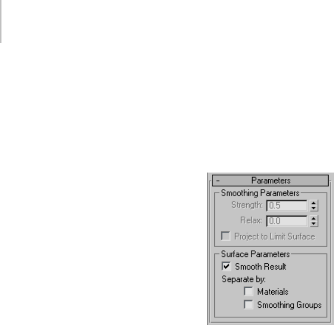
726 Chapter 8: Modifiers
points and edges at that level. Transform controls
and the Weight setting are available for all
sub-objects at all levels. The Crease setting is
available only at the Edge sub-object level.
Crease—Creates a discontinuity on a surface so
you get a hard edge, such as a wrinkle or lip. You
selectoneormoreedgesub-objectsandadjustthe
Crease setting; the crease appears in the surfaces
associated with the selected edges. Available only
attheEdgesub-objectlevel.
Weight—Sets the weight of selected vertices or
edges. Increasing a vertex weight "pulls" the
smoothed result toward that vertex. Edge weights
aremorecomplexandbehaveinanopposite
manner in some respects. They aren’t really
"weights" as such, but "knot intervals," in NURBS
terminology. Consequently, increasing an edge
weight tends to push the smoothed result away.
Kinks will form in the result if weights of 0 are
used.
Isoline Display—When on, the software displays
only isolines: the object’s original edges, before
smoothing. The benefit of using this option is
a less cluttered display. When off, the software
displays all faces added by MeshSmooth; thus,
higher Iterations settings (see Subdivision Amount
Rollout (page 1–724))resultinagreaternumberof
lines. Default=on.
Show Cage—Toggles the display of a two-color
wireframe that shows the modified object before
subdivision. The cage colors are shown as
swatchestotherightofthecheckbox. Thefirst
color represents unselected edges at the Vertex
sub-object level, and the second color represents
unselected edges at the Edge sub-object level.
Change a color by clicking its swatch.
Soft Selection rollout
Soft Selection controls affect the action of
sub-object Move, Rotate, and Scale functions.
When these are on, 3ds Max applies a spline curve
deformation to unselected vertices surrounding
the transformed selected sub-object. This provides
a magnet-like effect with a sphere of influence
around the transformation.
For more information, see Soft Selection Rollout
(page 1–963).
Parameters rollout
Parameters rollout > Smoothing Parameters
group
These settings are available only when
MeshSmooth Type is set to Classic or Quad
Output. Also, Project To Limit Surface is available
only in Classic mode.
Strength—Sets the size of the added faces using
arangefrom0.0to1.0.
• Values near 0.0 create small faces that are very
thin and close to the original vertices and edges.
• Values near 0.5 size faces evenly between edges.
• Values near 1.0 create large new faces and make
the original faces very small.
Relax—Applies a positive relax effect to smooth
all vertices.
Project to Limit Surface—Places all points on the
"limit surface" of the MeshSmooth result, which
is the surface that would be produced after an
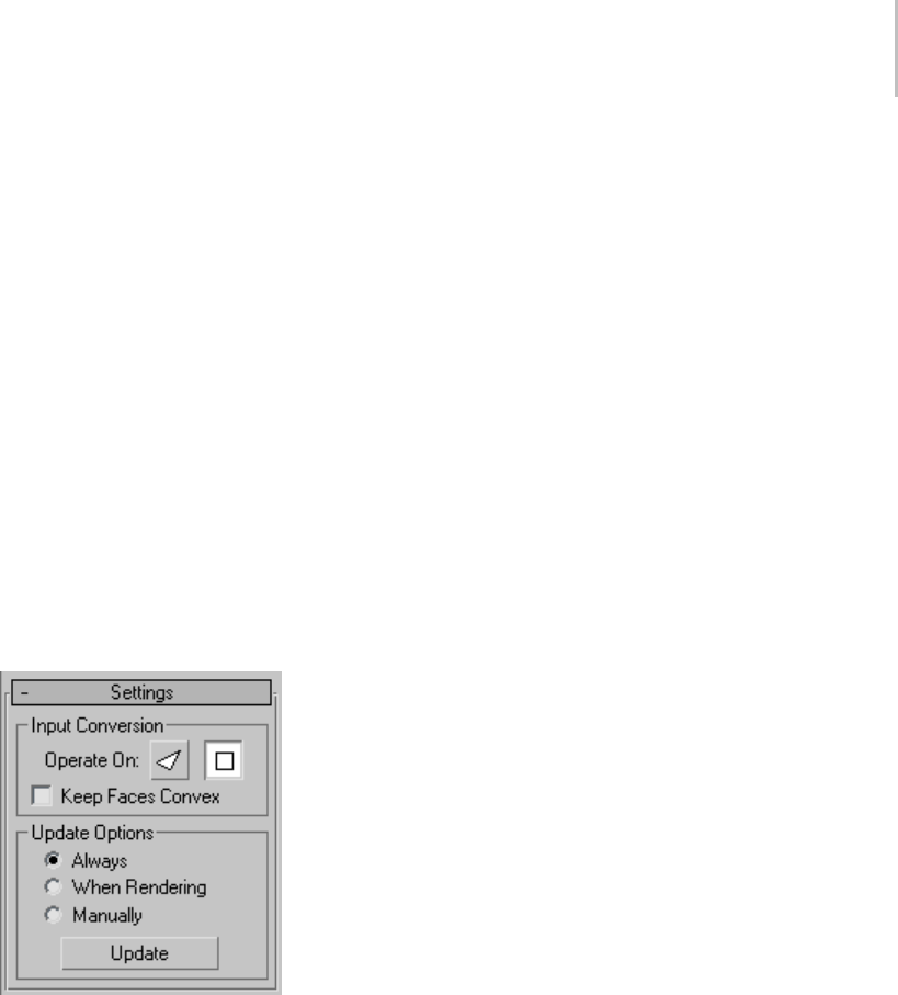
MeshSmooth Modifier 727
infinite number of iterations. The topology is still
controlled by the number of iterations.
Parameters rollout > Surface Parameters group
Applies smoothing groups to the object and
restrict the MeshSmooth effect by surface
properties.
Smooth Result—Applies the same smoothing
group to all faces.
Separate by Materials—Prevents the creation of
new faces for edges between faces that do not share
Material IDs.
Separate by Smoothing Groups—Prevents the
creation of new faces at edges between faces that
don’tshareatleastonesmoothinggroup.
Settings rollout
Settings rollout > Input Conversion group
Operate On Faces/Polygons—Operate On Faces
treats every triangle as a face and smoothes
across all edges, even invisible edges. Operate On
Polygons ignores invisible edges, treating polygons
(like the quads making up a box or the cap on a
cylinder)asasingleface.
Keep Faces Convex—(Available only with Operate
On Polygons mode.) Keeps all input polygons
convex. Selecting this option causes non-convex
polygons to be handled as a minimum number of
separate faces, each of which is convex. (Turn on
Display/Weighting group > Display Control Mesh
to see what’s happening here.)
"Convex" means that you can connect any two
points in the polygon with a line that doesn’t go
outside the polygon. Most letters aren’t convex.
In the capital letter "T," for example, you can’t
connect the upper-left corner to the bottom with
a straight line without going outside the shape.
Circles, rectangles, and regular polygons are all
convex.
Problems that can occur with non-convex faces
include the fact that changes in the geometry of the
inputobjectcanresultinadifferenttopologyfor
the MeshSmooth result. For instance, in a box, if
youdragoneofthetopcornersacrossthemiddle
of the top face, the box becomes non-convex.
MeshSmooth would then see this as two triangles
insteadofonequad,andthenumberofpointsin
the result would change.
If you need to make sure your output topology is
stable,turnthisoff.Ifyouhavealotoflettersor
other non-convex faces in your mesh, however,
you’ll probably want it on.
Settings rollout > Update Options group
Sets manual or render-time update options, for
situations where the complexity of the smoothed
object is too high for automatic updates. Note that
you can also set a greater degree of smoothing to
be applied only at render time, on the Subdivision
Amount rollout.
Always—Updates the object automatically
whenever you change any MeshSmooth settings.
When Rendering—Updates the viewport display of
theobjectonlyatrendertime.
Manually—Tur ns on manual up dating . When
manual updating is selected, any settings you
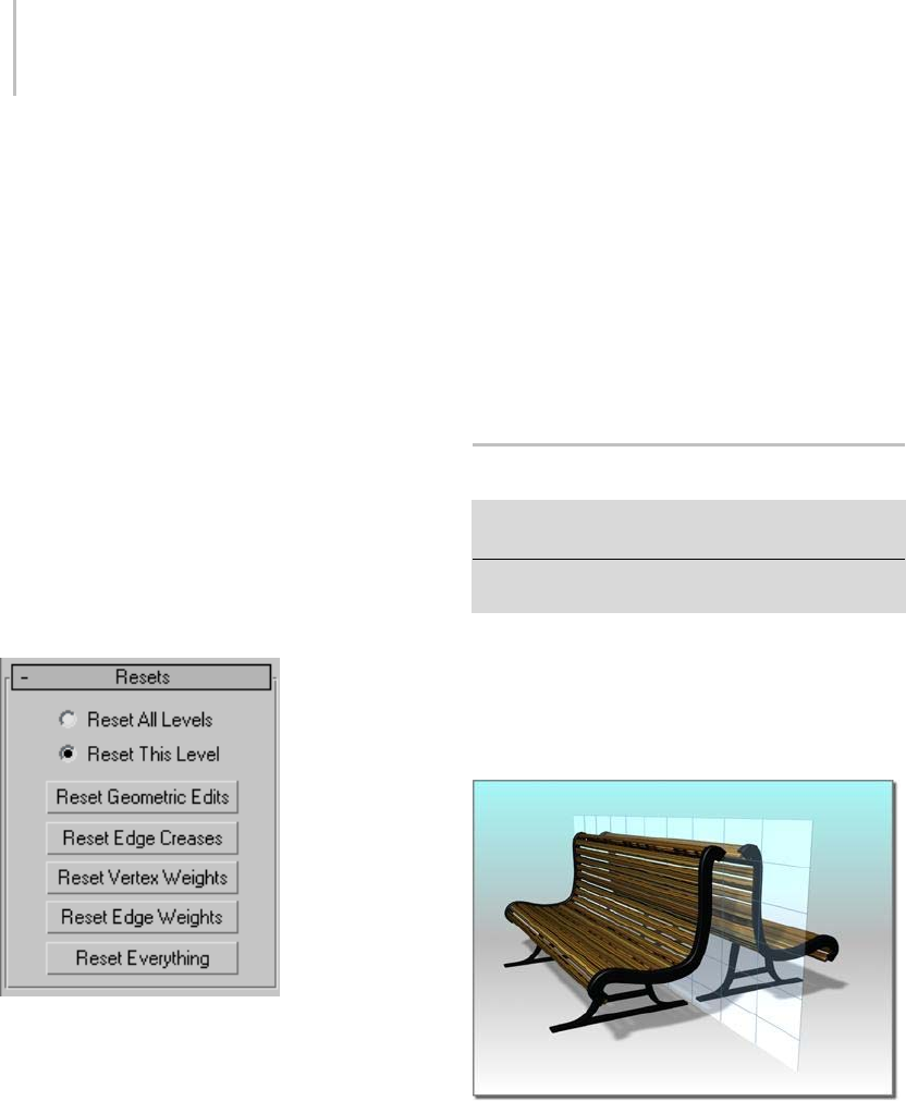
728 Chapter 8: Modifiers
change don’t take effect until you click the Update
button.
Update—Updates the object in the viewport to
matchthecurrentMeshSmoothsettings.Works
only when you choose When Rendering or
Manually.
Resets rollout
This rollout allows you to go back to default or
initial settings on any changes you made such
as sub-object transforms (geometric edits), and
changes to edge creases, vertex weights, and edge
weights.
Yo u c a n r e s e t c h a n g e s f o r a l l c o n t r o l l e v e l s o r t o
the current control level. Turn on the reset option
for the sub-object level you want, and then click
theappropriatebutton.
Reset All Levels—Returns to the default or initial
settings for geometric edits, creases, and weights
for all sub-object levels.
Reset This Level—Returns to the default or initial
settings for geometric edits, creases, and weights
forthecurrentsub-objectlevel.
Reset Geometric Edits—Returns to the default or
initial settings for any transforms made to vertices
or edges.
Reset Edge Creases—Returns to the default or
initial setting for edge creases.
Reset Vertex Weights—Returns to the default or
initial setting for vertex weights.
Reset Edge Weights—Returns to the default or
initial setting for edge weights.
Reset Everything—Returns to the default or initial
setting for everything.
Mirror Modifier
Modify panel > Make a selection. > Modifier List >
Object-Space Modifiers > Mirror
Make a selection. > Modifiers menu > Parametric
Deformers > Mirror
The Mirror modifier provides a parametric
method of mirroring an object or a sub-object
selection. You can apply the Mirror modifier to
any type of geometry, and you can animate the
mirror effect by animating the modifier’s gizmo.
Mirroring a bench
Procedure
To apply the Mirror modifier:
1. Apply the Mirror modifier to a selection.
2. Set the axis or axis pair on which to mirror the
object.
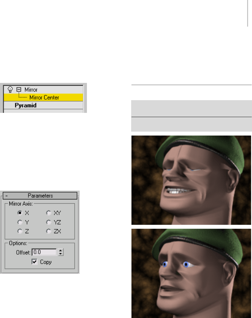
Morpher Modifier 729
3. To create a mirrored pair, specify an Offset
amount and turn on Copy.
Interface
Modifier Stack
Mirror Center—Represents the axis of the mirror
effect. You can move, rotate or scale the gizmo to
affect the mirroring. You can animate the gizmo
transforms, which you can’t do with the toolbar
Mirror (page 1–448) tool.
For more information on the stack display, see
Modifier Stack (page 3–760).
Parameters rollout
Mirror Axis group
X, Y, Z, XY, YZ, ZX—Specify the axis or axes about
which the mirroring takes place. You can usually
seetheeffectintheviewportasyouselectthe
option.
Options group
Offset—Specifies the offset, in units, from the
mirroraxis.Thisisananimatableparameter.
Copy—Copies the geometry rather than simply
mirroring it.
Note: The Copy option affects only geometry with
triangular meshes.
Morpher Modifier
Select a mesh, patch, or NURBS object. > Modify panel
> Modifier List > Morpher
Select a mesh, patch, or NURBS object. > Modifiers menu
> Animation Modifiers > Morpher
On this patch model, morph targets are created by moving
control vertices and tangent handles in an Editable Patch.
Use the Morpher modifier to change the shape of
a mesh, patch, or NURBS model. You can also
morph shapes (splines), and World Space FFDs.
As well as morphing from one shape to another,

730 Chapter 8: Modifiers
the Morpher modifier also supports material
morphing.
Morphing is commonly used for lip sync and facial
expressionona3Dcharacter,butcanbeusedto
change the shape of any 3D model. There are 100
channels available for morph targets and materials.
Channel percentages can be mixed, and the result
ofthemixcanbeusedtocreateanewtarget.
On a mesh object, vertex count on the base object
and targets must be the same. On a patch or
NURBS object, the Morpher modifier works on
control points only. This means that the resolution
of patches or NURBS surfaces can be increased on
the base object to increase detail at render time.
A Flex modifier above the Morpher modifier
is aware of vertex/control point motion in the
Morpher modifier. If, for example, a jaw is
morphed to slam shut, then the Flex modifier
placed above the Morpher modifier in the modifier
stack can be used to make the lips quiver to
simulate soft tissue.
See also
Morpher Material (page 2–1592)
Lip Sync and Facial Animation
For lip sync and facial animation, create a
character’s head in an "at rest" pose. The head can
be a mesh, patch, or NURBS model. Copy and
modifytheoriginalheadtocreatethelip-sync
and facial-expression targets. Select the original
or "at rest" head and apply the Morpher modifier.
Assign each lip-sync and facial-expression target
to a channel in the Morpher modifier. Load an
audio file in the Track View sound track, turn on
the Auto Key button, scrub the time slider, and
view the audio waveform in Track View to locate
frames for lip sync. Then set the channel spinners
on the Morpher modifier to create key frames for
lip position and facial expression.
Teeth can either be a part of the model or animated
separately. If the teeth and head are two different
objects,modeltheteethinanopenposition,and
then apply the Morpher modifier, and create one
target with the teeth closed. Eyes and head motion
canbeanimatedafterthemorphkeysarecreated.
Morph Targets for Speech
Nine mouth shape targets are commonly used for
speech. If your character speaks an alien dialect,
don’t hesitate to create extra morph targets to
cover these mouth shapes.
Include cheek, nostril, and chin-jaw movement
when creating mouth position targets. Examine
yourownfaceinamirrororputafingeronyour
face while mouthing the phonemes, if necessary, to
establish the direction and extent of cheek motion.
Set lip-sync keys by viewing the audio waveform as
well as listening to the sound as you scrub the time
slider. Many mouth-position keys benefit from
being set a frame early. Often the mouth must
assumeashapebeforetheappropriatesoundis
uttered. For the word "kilo", the "K" mouth shape
precedes the actual sound, for example.
A, I
E
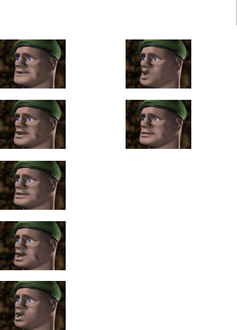
Morpher Modifier 731
F,V
C, D, G, J, K, N, S, T, Y, Z
L,T
O
U
W,Q
M,B,P (This target can be the same shape as the "at rest" base
object)
Morph Targets for Expression
Create as many expression targets as necessary
for the character. Joy, sadness, surprise, evil can
all have their own targets. Depending on the
personality of the character, certain targets, like
a terror target, may not be necessary. Targets
like nostril flare, jaw-muscle bunching, temple
twitching can be effective to give a character an
edge. Each morph channel can contain a material
aswell:asyoumorphthebrowsup,abumpmap
can crease the forehead, for example.
Save time and create targets as the need arises; if
theaudiofileorsceneyouareworkingonrequires
a look of surprise, create the "surprise" target while
the mood of the scene is with you.
If the character has teeth, copy the teeth and the
base head to create a new target. The teeth act as a
guide to shape and position the lips.
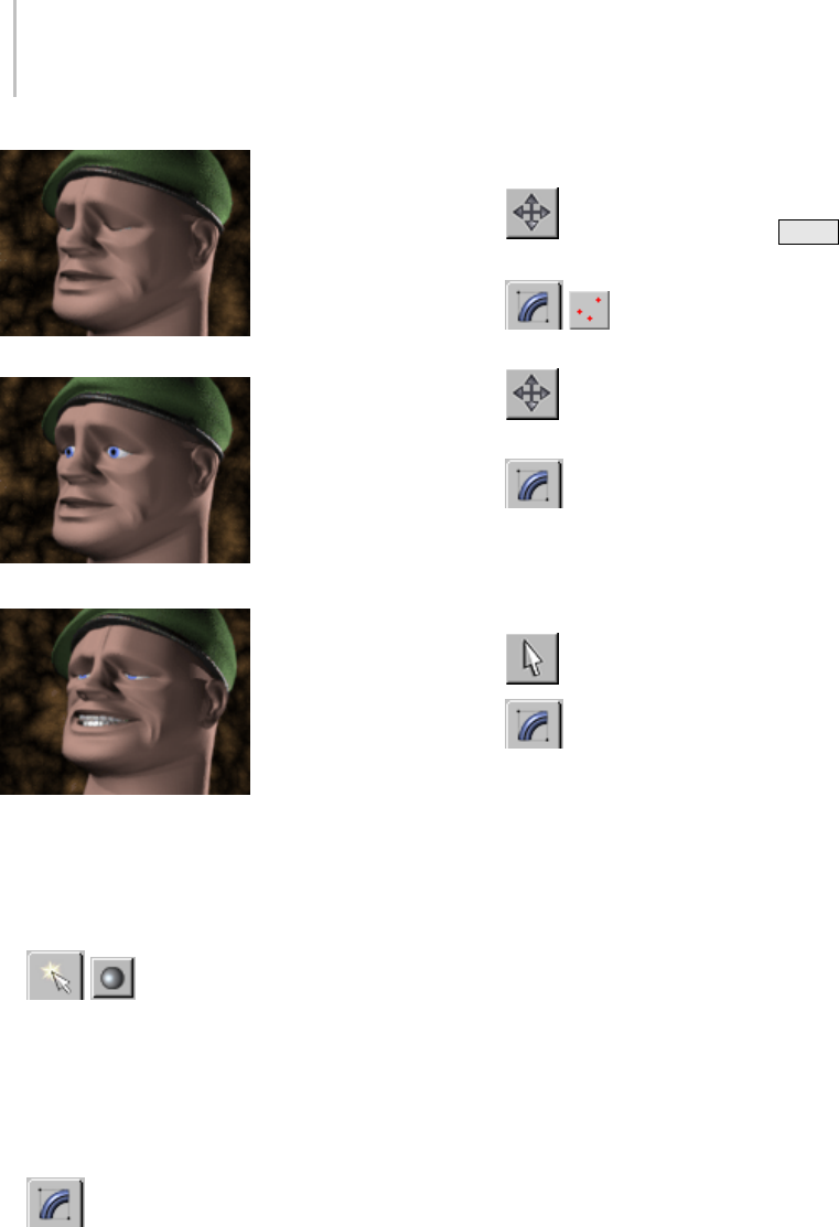
732 Chapter 8: Modifiers
Blink
Brows up
A blend of the Pain, Blink, and Brows targets
Procedures
Example: To add the morpher modifier to an object
and assign a morph target to a channel:
1. OntheCreatepa
nel, click
Geometry.
2. Onthedrop-downlist,choosePatchGrids.
3. OntheObjectTyperollout,clickQuadPatch.
4. In the Top viewport, click and drag to create
apatchgrid.
5. On the Modify panel, on the modifier
stack display, right-click Quad Patch and
chooseConvertTo:EditablePatchfromthe
right-click menu.
ThebaseobjectisnowanEditablePatch.
6. In the Top viewport, use Shift +Move
to create a copy of the patch object.
7. On the Modify panel, on the
Selection rollout, click Vertex.
8. IntheFrontviewport,movepatch
vertices to deform the patch surface.
9. In the stack display, choose Editable
Patchtogototheobject(top)level. (The
highlight should change from yellow to gray,
and the Vertex sub-object icon is no longer
displayedattherightofthestack.)
10. Select the first patch object.
11. On the Modify panel, choose Morpher
from the Modifier List.
The Morpher modifier is added to the modifier
stack.
12.On the Morpher modifier, on the Channel List
rollout, right-click the first channel (over the
word "empty").
A right-click menu displays.
13.Choose Pick from Scene on the right-click
menu, and click the deformed patch grid in the
viewports.
QuadPatch02 is listed in the channel as a morph
target.
14.Drag the Channel spinner, to the right of
QuadPatch02, up and down.
The flat patch grid "morphs" to the shape of
the target.
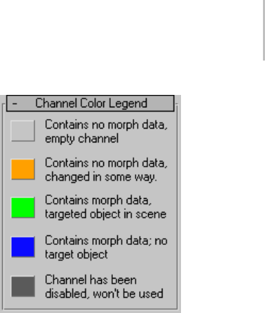
Morpher Modifier 733
To use progressive morphing:
1. Create starting and ending morph targets, and
oneormoreintermediatetargets.
2. Apply the Morpher modifier to the starting
morph target, and click Load Multiple Targets
to load the starting and ending morph targets.
3. In the Channel List rollout, select the channel
you want to be influenced by an intermediate
target.
4. In the Channel Parameters rollout, click Pick
Object from Scene, and select the intermediate
target.
5. In the Progressive Morph group Target List, set
the Target % to determine the degree to which
each target affects the channel.
6. Use the down arrow button to move the original
channel target to the bottom of the Target List.
Interface
Whatever is assigned as the default float controller
in the software will be assigned as the float
controller on the morph channels as well. Float
controllers handle the interpolation between keys;
Bezier is the default float controller. You can assign
the TCB float controller to the morph channels in
Track View, if you prefer.
For morphing, the Bezier controller allows you
to use function curves with vector handles on
the keys for smoothing and easing control of
interpolation in Track View. Default parameters
of the TCB controller, however, handles morph
interpolation with less overshoot. Try using both
controllers, to decide which one you prefer.
Gray—The channel is empty, and has not been
edited.
Orange—The channel has been changed in some
way but contains no morph data.
An artist may wish to name a channel and set up
its parameters before actually assigning a morph
target.
Green—The channel is live. The channel contains
morphdataandthetargetobjectstillexistsin
scene (the target is available for refresh).
Blue—The channel contains morph data but the
target has been deleted from the scene.
Dark Gray—The channel is disabled.
• There is a problem with the morph, the
topologyofthebaseobject,ortargets,have
changed and are no longer valid; for example,
thevertexcountmighthavechanged. The
channel cannot be used.
• The channel is not active. This is controlled
by the Channel is Active toggle in the Channel
Parameters rollout.
• Disabled channels are not included in the
morph result.
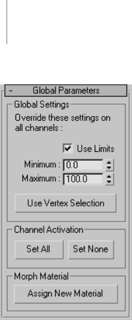
734 Chapter 8: Modifiers
Global Parameters rollout
Global Settings group
Use Limits—Use the minimum and maximum
limits for all channels.
You can turn off limits to double purpose a target.
Thetargetforasmilecanbeusedtoturnthe
corners of the mouth down using negative values
for example.
Minimum—Sets the minimum limit.
Maximum—Sets the maximum limit.
Use Vertex Selection—Turn on to limit morphing to
vertices selected in a modifier below the Morpher
modifier in the modifier stack.
If your are using Character Studio Physique, limit
morph animation on the base object to just the
head and exclude the neck, for example. Place the
Physique modifier above the Morpher modifier
and assign the head vertices as rigid (green) in the
Physique modifier.
Channel Activation group
Set All—Click to activate all channels.
Set None—Click to deactivate all channels.
Morph Material group
Assign New Material—Click to assign the Morpher
materialtothebaseobject(theobjecttowhichthe
Morpher modifier is applied).
Open the Material Editor to view and edit the
Morpher material. There is a direct correlation
between the Channel Material Maps and the
Channel list in the Morpher modifier (100
channels and 100 maps). For example, if channel
1containsabrowsuptargetandtheMorpher
material has a material assigned to map 1, then, as
thebrowsaremorphedsoisthematerial.
In the Morpher material, if a material is assigned
to a map or channel that has no morph target in
the Morpher modifier, then the channel spinner
in the Morpher modifier can be used to simply
morphthematerialonastaticobject.SeeMorpher
Material (page 2–1592).
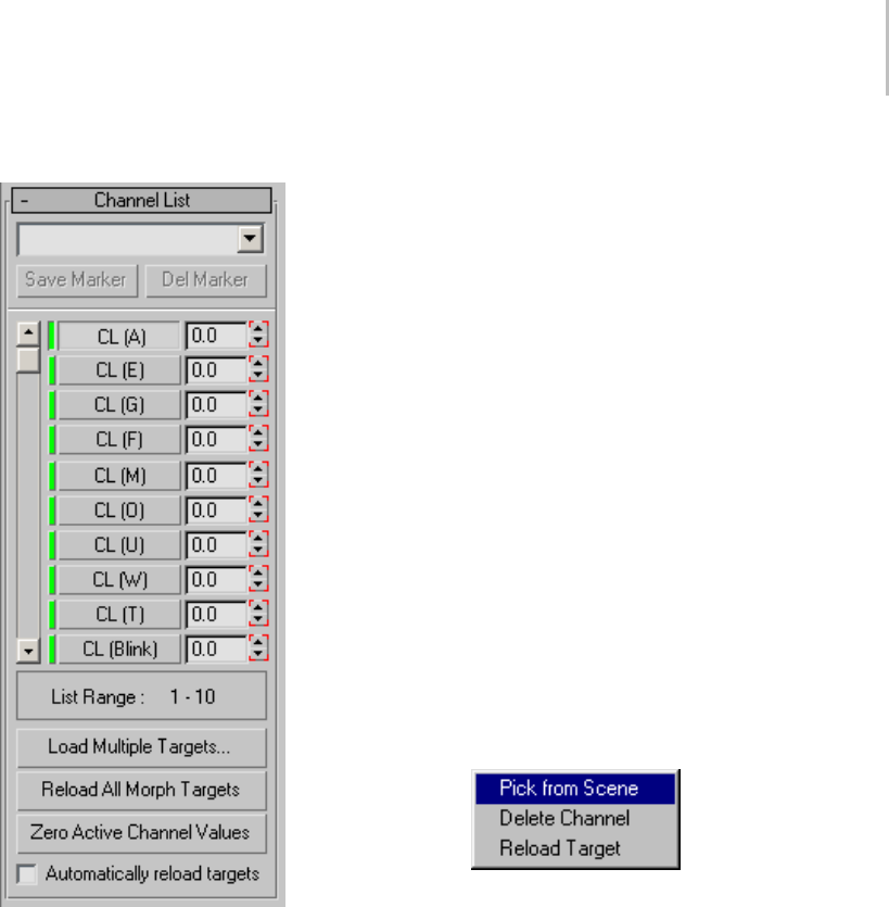
Morpher Modifier 735
Channel List rollout
The upper section of the Channel List rollout
contains controls for managing markers, which
designate different locations in the list of morph
targets. For example, channels 15 through 24
might contain all the emotion targets. Rather than
scrolling to display these tracks, you can choose a
marker from the list to display those channels.
[marker drop-down list]—Choose a previously
saved marker in the list, or enter a new name in
the text field and click Save Marker to create a new
marker.
For example, channel 15 through 24 might contain
all the emotion targets. Rather than scrolling to
display these tracks, you can choose a marker from
the list to display these channels in the list.
Save Marker—Movethescrollbartoframea
particular set of 10 channels, enter a name in the
text field, and then click Save Marker to store the
channel selection.
Delete Marker—Choose a marker name to delete
from the drop-down list, and then click Delete
Marker to delete it.
Channel List—The Morpher modifier provides
up to 100 morph channels. Scroll through the
channels using the slider. Once you’ve assigned
a morph target to a channel, the target’s name
appears in the channel list. Each channel has a
percentage value field and a spinner to change the
value.
You can change channel names and order in the
Channel Parameters (page 1–736) rollout.
Right-click a morph channel to display a
right-click menu:
Pick from Scene—Choose this command and select
an object in the viewports to assign a morph target
to the channel.
Delete Channel—Deletes the morph data, name
and parameters from the channel. Displays only
if the channel has data.
Reload Target—Retrieves morph data from the
target. Use this after editing a target.
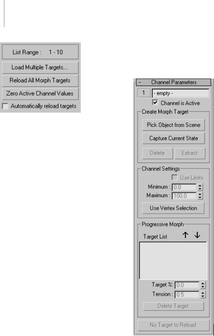
736 Chapter 8: Modifiers
List Range—Displays the range of visible channels
in the channel list.
Load Multiple Targets—Load multiple morph
targets into empty channels by selecting object
names in the selection dialog and clicking Load.
If there are more targets than empty channels,
a warning displays and the channels are not
assigned.
Reload All Morph Targets—Reloads all the morph
targets.
If the targets have been edited, the channels are
updated to reflect the changes. If a morph target
has been deleted from the scene, then the morpher
updates using the stored data in the channel,
functions using the last stored morph data.
Zero Active Channel Values—Click to create keys
with a value of 0 for all active morph channels, if
the Auto Key is on.
This is handy to prevent key interpolation from
distorting the model. First click Zero Active
Channel Values, and then set a particular channel
to the value you want; only the altered channel
affect the model.
Automatically reload targets—Turn this on to a l low
animated targets to be updated dynamically by the
Morphermodifier.Thereisaperformancepenalty
whenusingthisoption.
Channel Parameters rollout
The channel number button and channel name
field at the top of this rollout reflect the current
active channel in the channel list.
[channel number]—Click the number next to the
channel name to display a menu. Use commands
on the menu to group and organize channels, or
to locate a channel.
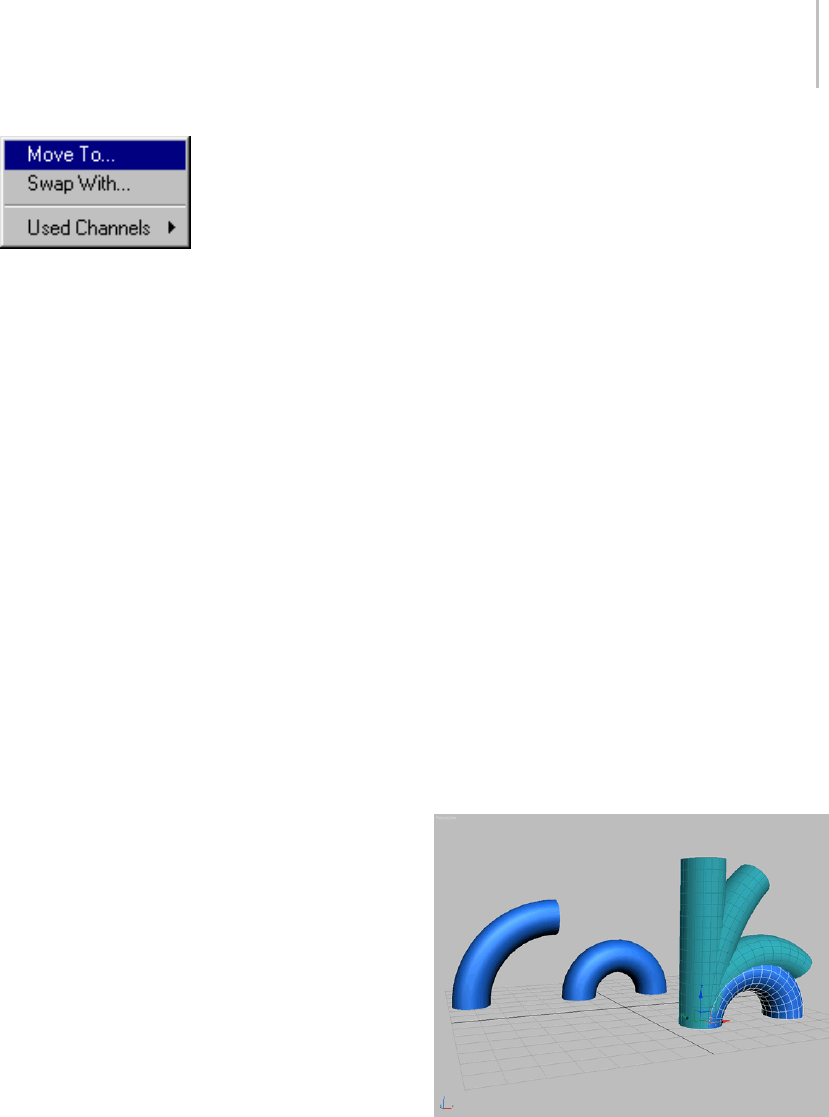
Morpher Modifier 737
Move To—Displays the Channel Operations dialog.
To move the current channel to the selected
channel, choose a channel from the list, and click
Move To.
Swap With—Displays the Channel Operations
dialog. To swap the current channel with the
selected channel, choose a channel from the list,
and click Swap With.
Used Channels—Displays a list of active channels.
Chooseachanneltoplaceitatthetopofthe
channel list display in the Channel List rollout.
Channel Name—Displaysthenameofthecurrent
target. Change the name of the target in the
text field if necessary. Parameter changes in the
Channel Parameters rollout affect the current
target.
Channel is Active—Toggles a channel on and off.
Inactive channels do not affect the morph result.
Use this control to turn off certain channels to
focus on animating other channels.
Create Morph Target group
Pick Object from Scene—Turn on and click an
object in the viewports to assign a morph target to
the current channel. Picking an object adds it to
the Progressive Morph list.
Capture Current State—Choose an empty channel
to activate this function. Click to create a target
using the current channel values.
The captured channel is always blue because there
is morph data but no specific geometry. Use
Extract to create a mesh copy of the captured state.
Delete—Deletes the target assignment for the
current channel.
Extract—Choose a blue channel and click this
option to create an object from the morph data.
If you have used Capture Current State to take a
snapshot of a group of channel values, but then
want to edit it, use Extract to make a new object,
pick it as the channel’s target, and then start
editing.
Channel Settings group
Use Limits—Turn on to use limits on the current
channel if Use Limits is turned off in the Global
Parameters rollout.
Minimum—Sets the lower limit.
Maximum—Sets the upper limit.
Use Vertex Selection—Morphs only selected
vertices on the current channel.
Progressive Morph group
Progressive morphing performs a tension-based
interpolation, similar to the TCB animation
controller, that creates smooth interpolation
througheachintermediarytargets.Thisprovides
the artist with an unprecedented amount of control
over the morph transformation.
Morphed object using multiple, intermediary targets
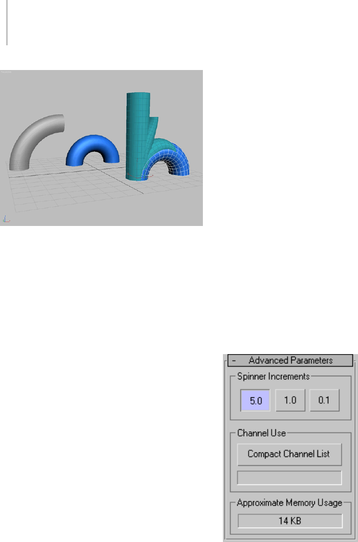
738 Chapter 8: Modifiers
Morphed object using a single target
When morphing from one target to another, the
object can sometimes pass through intermediary
stages that are not desirable. For example,
morphing a straight cylinder directly to a
bent cylinder causes the cylinder to squash at
intermediate stages.
You could get a better result by creating several
intermediate morph targets for the object, and
using them as channels. However, an easier
solution is to create fewer intermediate targets,
and use progressive morphing. With progressive
morphing, you do not use the intermediate targets
as channels; you use them to influence the end
targets.
Target List—Lists all intermediary morph targets
associated with the current channel. To add morph
targets to the list, click Pick Object from Scene.
Move Up—Moves the selected intermediary morph
target up in the list.
Move Down—Moves the selected intermediary
morphtargetdowninthelist.
Tip: For best results, move the original morph
target (the one in the channel) to the bottom of
the list.
Target %—Specifies how much the selected
intermediate morph target contributes to the
overall morph solution.
Tension—Specifies the overall linearity of the
vertex transformation between intermediary
morph targets. A value of 1.0 creates a “loose”
transition, causing the interpolation to overshoot
each target slightly. A value of 0.0 creates a direct,
linear transformation between each intermediary
target.
Delete Target—Deletes the selected intermediary
morph target from the target list.
Reload Morph Target—Reloads data from the
current target into the channel. Reload a target if it
has been adjusted or edited.
Iftheactivemorphtargetentryinthechannellist
is empty, this button is unavailable, and displays
the text “No Target to Reload.”
Advanced Parameters rollout
Spinner Increments—Specify fine or coarse
spinner increments. 5.0 is coarse and 0.1 is fine.
Default=1.0
Compact Channel List—Compact the channel list by
filling in any empty channels in between assigned
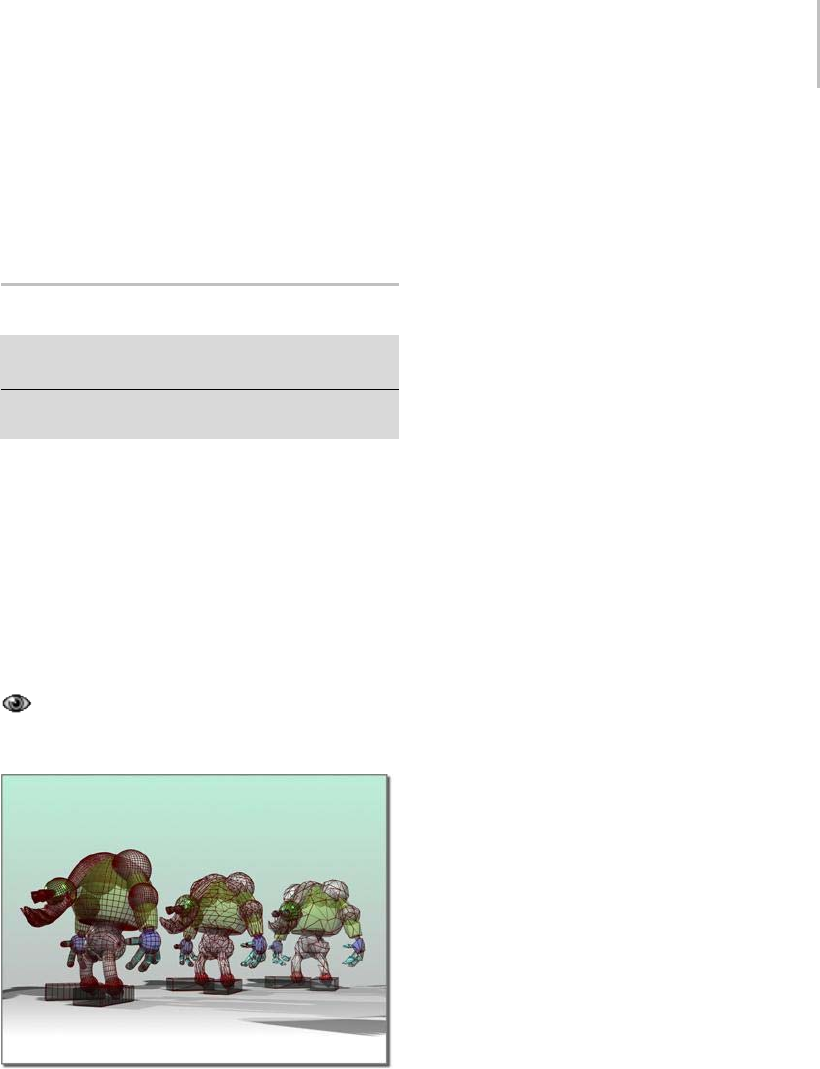
MultiRes Modifier 739
channels. The status window displays how many
channels were moved.
Approximate Memory Usage—Displays an
approximation of the current memory usage.
MultiRes Modifier
Select an object. > Modify panel > Modifiers List >
Object–Space Modifiers > MultiRes
Make a selection. > Modifiers menu > Mesh Editing >
MultiRes
The MultiRes modifier reduces the memory
overhead needed to render models by decreasing
the number of vertices and polygons. This is useful
not only within 3ds Max but for game and Web
content creators who export models for use outside
oftheprogram.MultiResoffersseveraladvantages
over the Optimize modifier, including faster
operation and the ability to specify reduction as an
exact percentage or vertex count.
The MultiRes modifier now supports the
preservation of map channels when face count is
increased or reduced.
Left: Original model
Center and right: Model progressively simplified by the
MultiRes modifier
Modeling Tips for MultiRes
The MultiRes multi-resolution mesh algorithms
are designed to be general-purpose, and yield
high-quality meshes on a wide variety of model
types. However, careful modeling can improve
the results of the algorithm. The following are
suggestions to yield high-quality multi-resolution
meshes:
• Avoid using complex model hierarchies with
MultiRes. For such models you should generate
an individual multi-resolution mesh for each
model component, or collapse the entire model
into a single mesh. In general, single-skin
meshes work best with animation engines like
Physique in character studio.MultiResworks
especially well with single-skin meshes.
• Avoid duplicating vertices. The presence of
extraverticesisanoften-overlookedartifact
of some modeling techniques. The Weld
function in the Edit Mesh modifier (page 1–634)
and Editable Poly (page 1–1022) is useful for
cleaning these up.
• Beconservativewithtextureandnormal
discontinuities. For example, an artist might
associate multiple texture coordinates with a
single vertex. MultiRes will seek to preserve
this discontinuity and the border between the
two texture mappings, but it might do so at the
expense of model shape.
• Create high-resolution models.
High-resolution models provide MultiRes with
more faces and vertices that describe the shape
of the model. The more initial information
MultiRes has about the shape of the model, the
better the decisions it makes in generating a
final multi-resolution mesh.
Procedures
To use the MultiRes modifier:
1. Select a model and apply the MultiRes modifier.

740 Chapter 8: Modifiers
2. In the Generation Parameters group in the
MultiRes Parameters rollout, click the Generate
button to initialize the mesh.
3. In the Resolution group, use the keyboard or
spinner controls to decrease the Vert Percent or
Vert Count value.
As the vertex and polygon counts decrease, the
meshupdatesinrealtimeintheviewports.
To maintain part of a mesh at full resolution while
reducing the rest:
1. Select a model and apply the MultiRes modifier.
2. In the modifier stack display, click the + icon
next to the MultiRes modifier to open the
sub-object hierarchy.
3. Click the Vertex label to access the Vertex
sub-object level.
4. Selecttheverticesinareaswhoseresolutionyou
want to maintain.
5. In the Generation Parameters group, turn on
Maintain Base Vertices.
6. Click the Generate button to initialize or
re-initialize the mesh.
Notice that the selected vertices look like
asterisks instead of standard ticks.
7. Reducetheresolutionasinthefirstprocedure.
The selected vertices are the last to be removed
during vertex reduction.
Note: You can change the base vertices at any
time by selecting a different group of vertices
and regenerating the mesh.
To merge vertices:
If there are gaps between vertices that you want
to close as vertex resolution decreases, use the
Vertex Merging feature of the MultiRes modifier.
With vertex merging, vertices within a given
threshold distance eventually collapse during
vertex reduction.
You can estimate the gap length by activating
the Select Object tool (page 1–61),movingthe
mouse cursor over the extents of the gap in the
active viewport (it might help to access the Vertex
sub-object level), and comparing the values
displayed in the X/Y/Z readouts in the status bar,
or use the Tape helper (page 2–24) object to get
an exact measurement. Enter the estimated gap
length value in the Threshold field.
1. Select a model and apply the MultiRes modifier.
2. Turn on Vertex Merging. This makes the Merge
Threshold and Within Mesh controls available.
3. Set the appropriate parameters:
• To define the maximum distance over which
vertices are merged, enter a value in Merge
Threshold.
• To merge boundaries of adjacent elements
and vertices within elements, turn on Within
Mesh.
4. Click the Generate button.
The effect of the change is displayed in the
object.
After the Generate button is clicked, a busy
cursor will display. If the merge threshold is too
largerelativetothedimensionsofthemodel,
the busy cursor may display for a long time. To
cancel the generation process at any time, press
the Esc key.
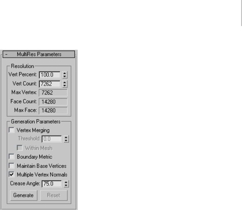
MultiRes Modifier 741
Interface
Resolution group
Use these controls to change the vertex count and
overall topology of the modified object.
Vert Percent—The modified object’s vertex count
as a percentage of the overall number of vertices in
the original mesh. Adjusting this setting alters the
Ve r t C o u n t v a l u e a s w e l l .
Note: After you enter a specific percentage, such as
30, you might find that the software changes the
value to a slightly lower one, such as 29.971. This is
due to the relationship between the overall number
of vertices in the model and the percentage
calculation. It is not a bug, but simply the closest
solution to your request.
Vert Count—The total number of vertices in
the modified object. Use this control to set the
maximum number of vertices in the output mesh.
AdjustingthissettingalterstheVertPercentvalue
as well.
Max Vertex—Displays the vertex count from the
original mesh that you applied MultiRes to. You
cannot enter values larger than this in the Vert
Count field.
Face Count—Displays the current face count. As
you adjust the Ve r t Pe r c e n t / Ve r t C o u nt settings, the
valueforthefacecountwillupdateonthefly.
Max Face—Displays the maximum face count.
Generation Parameters group
Vertex Merging—When on, lets MultiRes merge
vertices between discrete elements (page 3–933)
in a model.
For example, if you apply MultiRes to a teapot,
which comprises four separate elements, and
turn on Vertex Merging, as you adjust the vertex
resolution, the separate components will meld
together into one contiguous lower-resolution
object.
To control Vertex Merging, you can set a Merge
Threshold. This value determines the unit distance
within which vertices will merge at a higher rate.
Threshold—Sets the maximum distance in
3ds Max units between vertices in order for those
vertices to be considered for merging. Within this
distance, the vertices between elements are welded
together at a higher rate as the mesh is reduced in
complexity. Available only when Vertex Merging
is on.
Note: To eliminate only coincident vertices, set
Thresholdto0.0.ThisissimilartotheWeldVertex
function.
Within Mesh—When on, MultiRes merges the
boundaries of adjacent elements and vertices
within elements. Many objects can contain
multiple groups of vertices that don’t share
connectivity.AsimpleexampleofthisistheTea pot
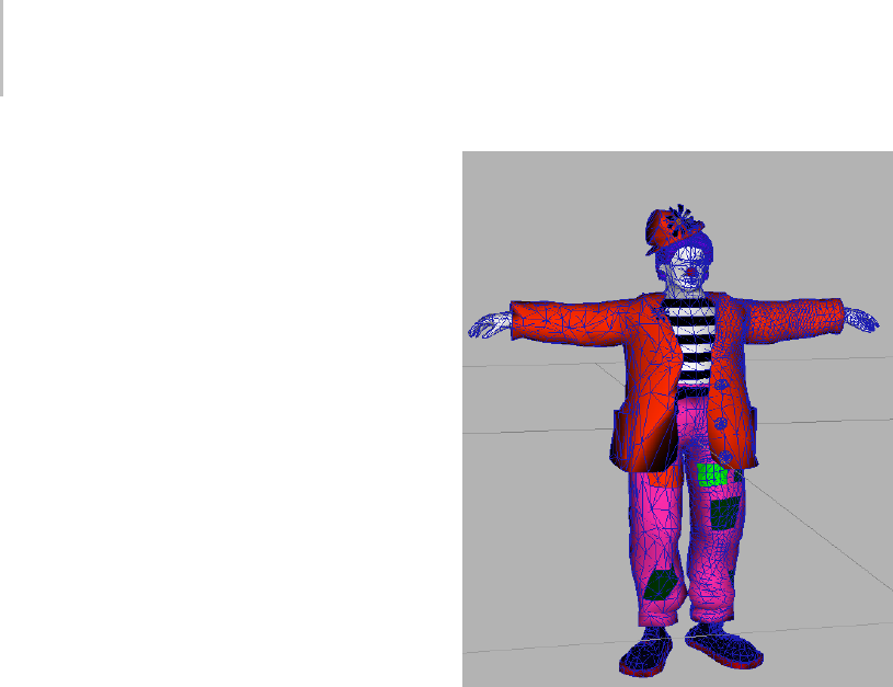
742 Chapter 8: Modifiers
object (page 1–183). It comprises four different
elements: the body, the handle, the spout, and the
lid. Normally, MultiRes optimizes each discrete
element in a mesh on its own.
The default behavior of the Vertex Merging option
is to merge vertices between elements. Turning on
Within Mesh causes vertices within elements to
be merged as well.
Boundary Metric—When on, MultiRes preserves
materials assigned to the selected model. The
material boundaries defined by Material IDs are
retained as long as possible, and are the last to be
eliminated at low vertex counts. Default=off.
Maintain Base Vertices—When on, overrides the
MultiRes optimization algorithms and preserves
any vertices selected at the MultiRes Vertex
sub-object level as "critical" ones. Use this feature
to retain critical features of an object or character
such as its fingers or claws, or other geometry
that might become unrecognizable if reduced too
severely.
To select vertices for use with this option, use
the MultiRes Vertex sub-object level. To access
this level, first go to the modifier stack display
and click the plus-sign icon next to the MultiRes
modifier. This opens its hierarchy, which consists
of the single Vertex sub-object level. Next, click
the Vertex entry. The MultiRes vertices appear on
the mesh as blue dots. You can select these using
any standard interactive method, but you cannot
transform them.
Important: After selecting MultiRes sub-object vertices
with Maintain Base Vertices turned on, regenerate the
mesh before changing the vertex resolution.
In the following illustration, the clown started out
as a high-resolution mesh. All of the MultiRes
vertices in the right half were selected, Maintain
Base Vertices was turned on, and then the vertices
were reduced.
Clown model with left half reduced, right half at original
resolution
Multiple Vertex Normals—When on, lets MultiRes
assign multiple normals for each vertex. By default,
MultiRes generates a single normal per vertex.
If multiple normals are generated, they are applied
as the vertex resolution is decreased and increased.
WhentheMultipleVertexNormalsoptionison,
the MultiRes modifier generates normal updates
when the geometry surrounding a vertex changes.
Yo u m u s t s p e c i f y a crease angle in degrees (0.0 -
180.0). The crease angle is the angle between the
face normals. It is used to decide when a normal
should be shared across an edge between two faces.
Forexample,inaplanedefinedasameshgridof
10 x 10 faces, any two adjacent faces have a crease
angle of zero. In a cube, adjacent faces have a
crease angle of 90 degrees. In general, crease angles
approaching 0 yield smoother shading. Crease
angles approaching 180 yield more visible corners.
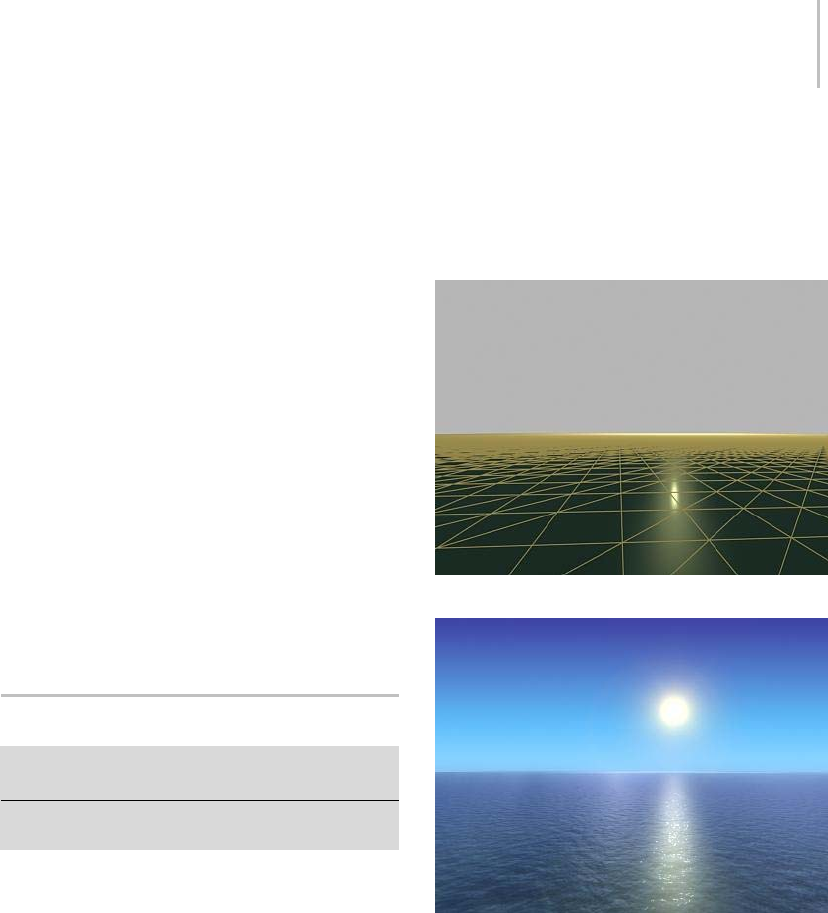
Noise Modifier 743
Crease Angle—Thevalueofthecreasenecessaryin
order to generate multiple normals. Available only
when Multiple Normals Per Vertex is on.
The optimal crease angle depends on the model;
setitinteractivelyandchecktheviewportand
rendered images for shading effects. While use of
Multiple Vertex Normals enables more accurate
shading, it can require more internal data.
Generate—AppliesthecurrentMultiRessettings
to the modified object. When you first apply
MultiRes to an object, you must use Generate to
initialize the mesh-optimizing algorithm before
you can change the vertex count.
Reset—Sets all Generation Parameters rollout
settings to their values as of the last time you used
Generate. Available only when one or more of
these settings has changed.
Use Reset to review the generation parameters as
of the last time you generated the mesh.
Noise Modifier
Modify panel > Make a selection. > Modifier List >
Object-Space Modifiers > Noise
Make a selection. > Modifiers menu > Parametric
Deformers > Noise
The Noise modifier modulates the position of an
object’s vertices along any combination of three
axes. This important animation tool simulates
random variations in an object’s shape.
Using a fractal setting, you can achieve random,
rippling patterns, like a flag in the wind. With
fractal settings, you can also create mountainous
terrain from flat geometry.
Yo u c a n a p p l y t h e N o i s e m o d i f i e r t o a n y k i n d o f
object. The Noise gizmo changes shape to help
you visualize the effects of changing parameter
settings. The results of the Noise modifier are most
noticeable on objects that have greater numbers
of faces.
Most of the Noise parameters have an animation
controller. The only keys set by default are for
Phase.
Plane with no noise applied
Adding texture to the plane creates a calm sea.
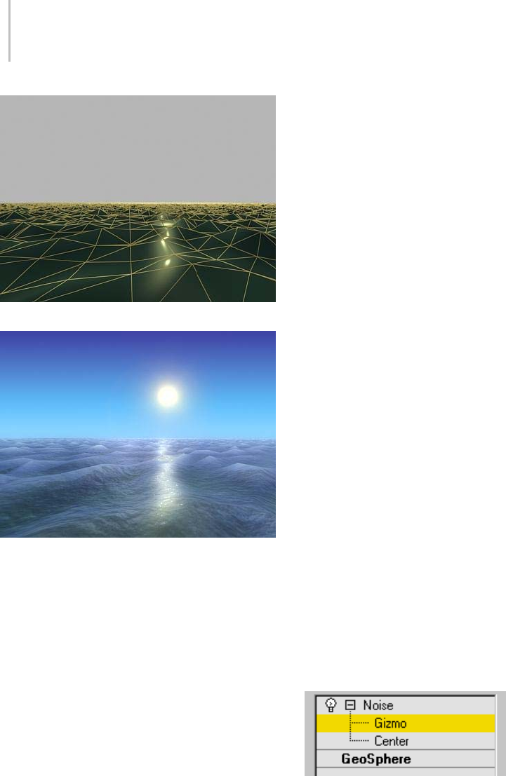
744 Chapter 8: Modifiers
Plane with fractal noise applied
Textured plane with noise creates a stormy sea.
Procedures
To apply noise to an object:
1. Select an object and apply the Noise modifier.
To animate, move to a nonzero frame and turn
on the Auto Key button.
2. In the Parameters rollout > Strength group,
increase Strength values along one or more of
the three axes.
You begin to see noise effects as the strength
goes up.
3. In the Noise group, adjust Scale. Lower values
increase the dynamics of the Strength settings,
makingtheeffectmoreobvious. SeeNoise
group, below, for other options.
If you’ve animated this procedure, you can
change parameters as the animation runs to see
the effects.
For another source of noise effects, go to the
sub-object level of the Noise modifier and
transform the gizmo and center of the modifier.
To create terrain effects:
When set for Fractal, the Noise modifier produces
a random fractal noise that creates a variety of
topological and terrain effects. You can animate
these effects or use them to model static landscapes
and other complex forms.
The following steps assume you begin with a broad
object like a multi-segment box lying on the XY
plane.
1. Apply the Noise modifier to the object.
2. In the Parameters rollout > Noise group, turn
on Fractal.
Roughness and Iterations settings are now
available.
3. Increase Strength on the Z axis and adjust other
parameters.
Once you have a base terrain, you can select
sub-objectswithEditMeshandapplyNoiseto
grow mountains in a smaller region. You can
also apply a second Noise modifier to amplify
the first one.
Interface
Modifier Stack
Gizmo/Center—Yo u c a n m o v e , r o t a t e , o r s c a l e t h e
gizmoandcentersub-objectstoaffectthenoise.
You can also animate the sub-object transforms.
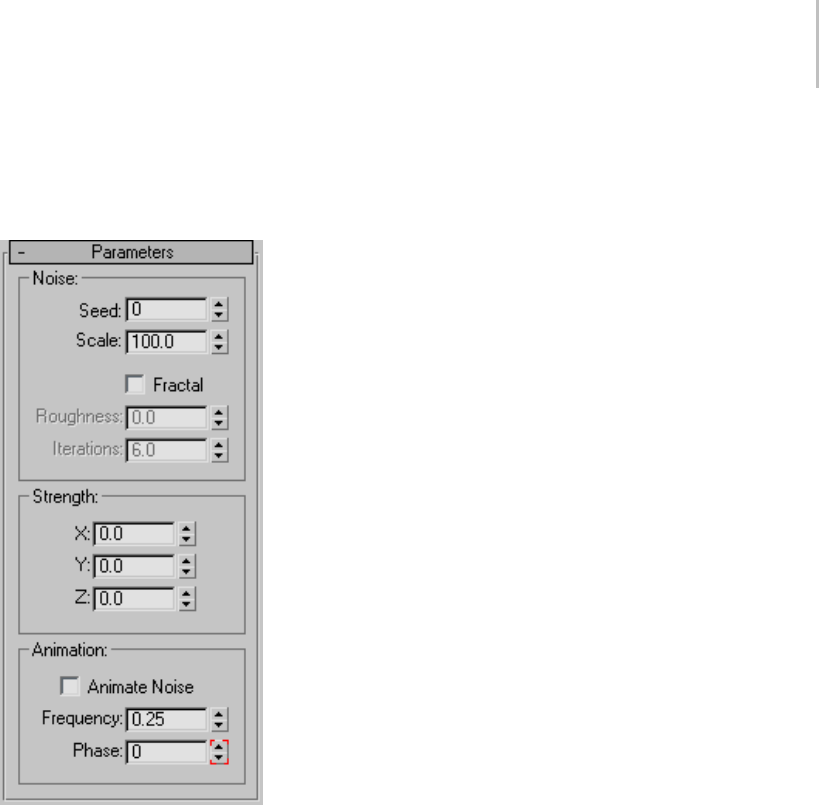
Noise Modifier 745
For more information on the stack display, see
Modifier Stack (page 3–760).
Parameters rollout
Noise group
Controls the appearance of the noise, and thus its
effect on the physical deformations of the object.
By default, the controls are inactive until you
change the settings.
Seed—Generates a random start point from the
number you set. Especially useful in creating
terrain, because each setting can produce a
different configuration.
Scale—Setsthesizeofthenoiseeffect(not
strength). Larger values produce smoother noise,
lower values more jagged noise. Default=100.
Fractal—Produces a fractal effect based on current
settings. Default=off.
IfyouturnonFractal,thefollowingoptionsare
available:
Roughness—Determines the extent of fractal
variation. Lower values are less rough than higher
values. Range=0 to 1.0. Default=0.
Iterations—Controls the number of iterations
(or octaves) used by the fractal function. Fewer
iterations use less fractal energy and generate
a smoother effect. An iteration of 1.0 is the
same as turning Fractal off. Range=1.0 to 10.0.
Default=6.0.
Strength group
Controls the magnitude of the noise effect. No
noise effect occurs until some strength is applied.
X, Y, Z—Set the strength of the noise effect along
each of three axes. Enter a value for at least
oneoftheseaxestoproduceanoiseeffect.
Default=0.0,0.0,0.0.
Animation group
Controls the shape of the noise effect by overlaying
asinewaveforthenoisepatterntofollow.This
keeps the noise within bounds, dampening
random extremes. When Animate Noise is turned
on, these parameters influence the overall noise
effect. However, you can animate Noise and
Strength parameters independently; these do not
requireAnimateNoisetobeonduringanimation
or playback.
Animate Noise—Regulates the combined effect of
Noise and Strength parameters. The following
parameters adjust the underlying wave.
Frequency—Sets the periodicity of the sine wave.
Regulates the speed of the noise effect. Higher
frequencies make the noise quiver faster. Lower
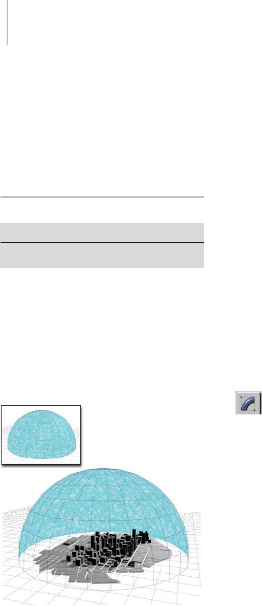
746 Chapter 8: Modifiers
frequencies produce a smoother and more gentle
noise.
Phase—Shifts the start and end points of the
underlying wave. By default, animation keys are
setateitherendoftheactiveframerange.Youcan
seetheeffectofPhasemoreclearlybyeditingthese
positions in Track View. Select Animate Noise to
enable animation playback.
Normal Modifier
Select an object. > Modify panel > Modifier List > Normal
Select an object. > Modifiers menu > Mesh Editing >
Normal Modifier
The Normal modifier allows you to unify or flip
the normals of an object without applying an Edit
Mesh modifier.
For example, if you wanted to fly inside of a
procedural object, such as a sphere or a cylinder,
and wanted to retain control over the radius and
number of segments, you couldn’t collapse the
object to an Editable Mesh and maintain the
procedural nature of the primitive.
Flipping the normals of a sphere creates a sky dome over a city.
Tip: If you are animating the creation of a complex
object such as a nested Boolean or a loft, and you
think the operation might result in inconsistent
faces, apply Normal to the result and turn on Unify.
Tip: The Lathe modifier sometimes creates an
objectwithnormalspointinginward. Usethe
Normal modifier with both Unify and Flip turned
on to fix "inside-out" lathe objects. The Normal
modifier allows whole-object manipulations of
normals to be performed quickly without using
an Edit Mesh modifier.
Patches
As of 3ds Max 4, patch objects coming up the
modifier stack are not converted to a mesh by this
modifier. A patch object input to the Material
modifier retains its patch definition. Files that
contain patch objects with the Material modifier
from previous versions of the software will be
converted to meshes to maintain backward
compatibility.
Procedure
To use the normal modifier:
1. Select an object, then on the Modify
panel, choose Mesh Editing > Normal from the
Modifier List.
The object appears to turn inside-out, since
FlipNormalsisonbydefault.
2. If the object has some faces pointing inward
and others outward, turn on Unify Normals to
make all the faces point similarly.
Tip: To flip or unify normals on portions of
objects, convert to Editable Mesh and select
Faces or Polygons. On the Surface Properties
rollout in the Normals group, use the Flip and
Unify buttons.
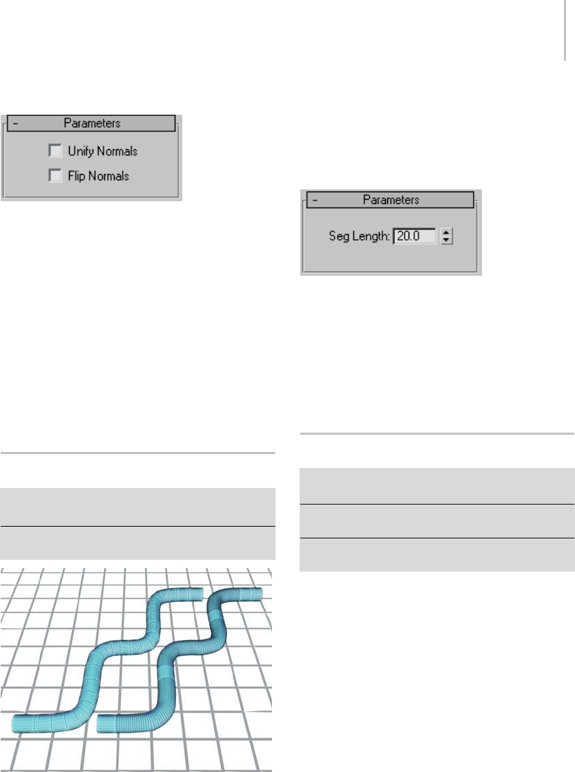
Normalize Spline Modifier 747
Interface
Unify Normals—Unifiesthenormalsofanobjectby
flipping the normals so that they all point in the
same direction, usually outward. This is useful
for restoring an object’s faces to their original
orientations. Sometimes normals of scenes that
have come into 3ds Max as part of a DWG or DXF
file are irregular, depending on the methods used
to create the scene. Use this option of the modifier
to correct them.
Flip Normals—Reverses the direction of all the
surface normals of the faces of the selected object
or objects. Default=on.
Normalize Spline Modifier
Select a spline object. > Modify panel > Modifier List
> Normalize Spl.
Select a spline object. > Modifiers menu > Patch/Spline
Editing > Normalize Spline
The spline on the left has been normalized.
The Normalize Spline modifier adds new control
points in the spline at regular intervals. Use
Normalize Spline to produce splines for motion
paths that require constant velocity.
Note: This feature is not animatable.
Interface
Seg Length—Sets the length of the spline’s
segments, in 3ds Max units. The positions of the
original vertices are discarded, and vertices are set
to regular intervals. Segment length determines
how many control points are added: shorter
segments result in more control points, longer
segments result in fewer. Default=20.0 units.
NSurf Sel Modifier
Select a NURBS curve or surface object. > Modify panel
> Modifier List > NSurf Sel
Select a NURBS curve or surface object. > Modifiers menu
> Selection Modifiers > NURBS Surface Select
Select a NURBS curve or surface object. > Modifiers menu
> NURBS Editing > Surface Select
The NSurf Sel (NURBS Surface Selection)
modifier lets you place a NURBS (page 1–1078)
sub-object selection on the modifier stack. This
letsyoumodifyonlytheselectedsub-objects.
Also, selected curve sub-objects are shape objects
that you can use as paths and motion trajectories.
If a NURBS surface object is nonrelational (page
1–1116),NSurfSelcan’tselectthesub-objectlevels
Curve, Curve CV, or Point. NURBS surfaces are
nonrelational by default. You can make the surface
relational by turning on Relational Stack on the
object’s General rollout.
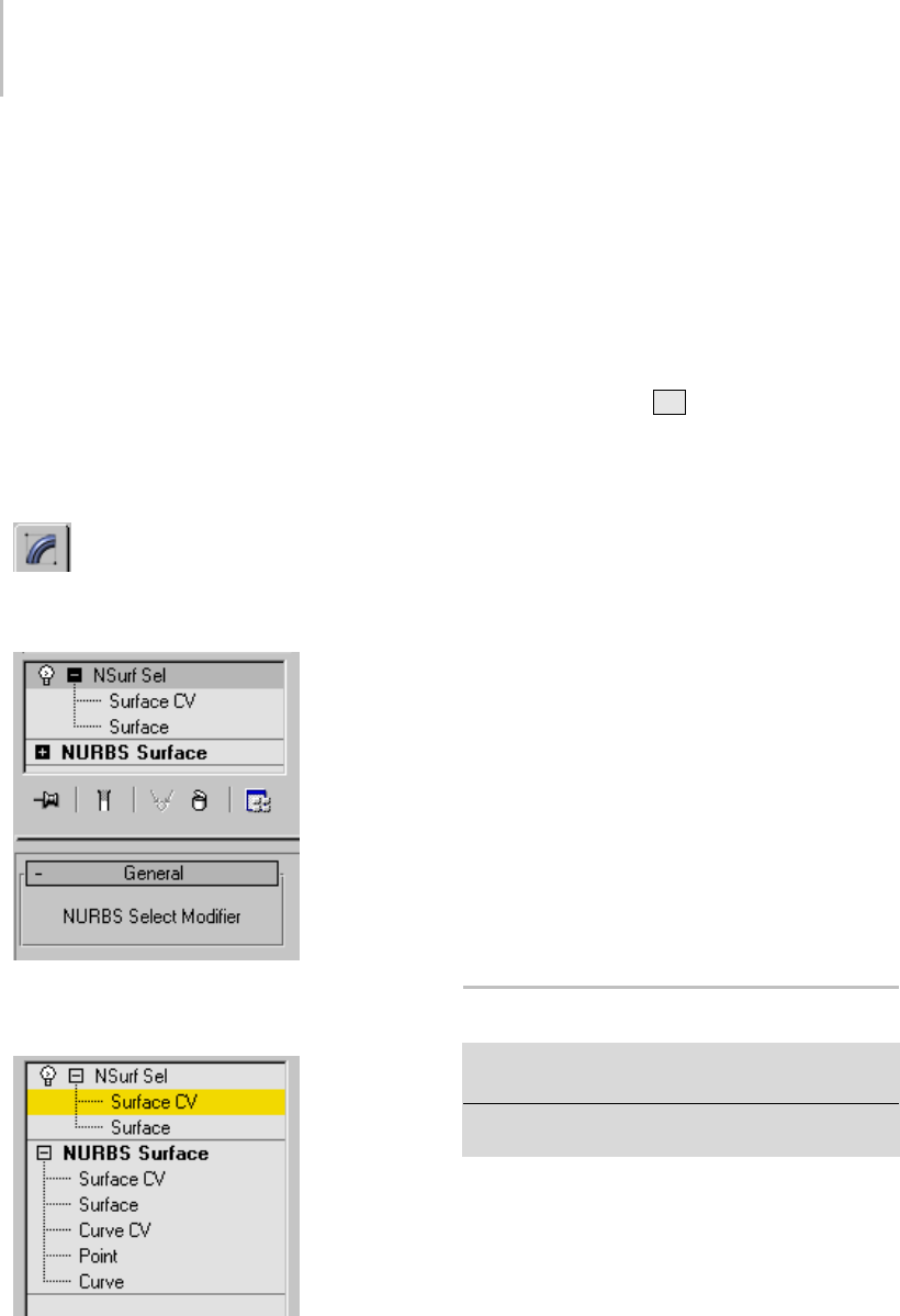
748 Chapter 8: Modifiers
NSurf Sel can select any kind of NURBS
sub-objects except imports. Each sub-object
selection is of one particular sub-object level only.
Note: The NSurf Sel modifier doesn’t support
copying and pasting selections as Mesh Select (page
1–719) does. Copying and pasting mesh selections
is based on vertex indexes. NURBS selections are
based on object IDs, which are unique to each
model.
Procedure
To use the NSurf Sel (NURBS Surface Selection)
modifier:
1. With a NURBS object selected in the
Modify command panel, apply NSurf Sel.
Thismodifierhasnocontrolsatthetoplevel.
2. In the stack display, choose a sub-object level
from the list.
NSurf Sel has the same selection controls you
see for NURBS surfaces, except that selecting
connectedcurvesorsurfacesisnotavailable.
For more information on the stack display, see
Modifier Stack (page 3–760).
While applying the modifier, you can also select
NURBS sub-objects by name. Turn on the
Keyboard Shortcut Override toggle (page 3–872)
and then press the Hkey. This displays a
version of the Select Objects dialog (page 1–78)
that lists only sub-objects at the current level.
Chooseoneormoreobjectsinthelist,and
then click Select.
3. Usetheselectioncontrolstocreateaselection
set of the chosen sub-object type.
With NSurf Sel, the selection can be of surface
CV or surface sub-objects. If you turn on
Relational Stack for the NURBS object, you
can also select point, curve, and curve CV
sub-objects.
4. At the Surface CV sub-object level, adjust Soft
Selectioncontrolsasyouwish.Thesecontrols
arethesameasthoseintheSoft Selection rollout
(page 1–1147) for NURBS curves and surfaces,
exceptthattheSameTypeOnlytoggleisabsent.
Once you’ve used the modifier to create the
selection, you can apply other modifiers to it.
Optimize Modifier
Select an object. > Modify panel > Modifier List >
Optimize
Select an object. > Modifiers menu > Mesh Editing >
Optimize
The Optimize modifier lets you reduce the number
of faces and vertices in an object. This simplifies
the geometry and speeds up rendering while
maintaining an acceptable image. A Before/After
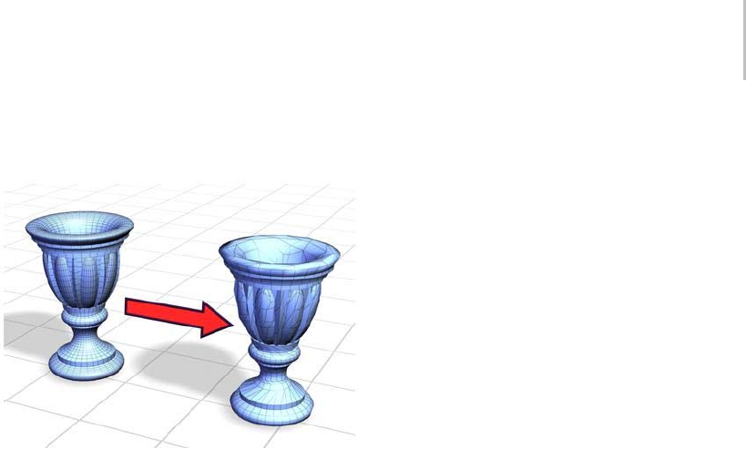
Optimize Modifier 749
readout gives you exact feedback on the reduction
as you make each change.
Optimize simplifies a smooth model with a high number of
faces without greatly changing the model’s appearance.
Tip: Because Optimize makes decisions based on
angles between faces, it’s sometimes best to apply
it to selected face sub-objects rather than to an
entire object. Avoid applying Optimize to areas
where you want to preserve geometric detail.
Applying Optimize
When you first apply Optimize, you might not
seeanychangeintheviewports.AdjusttheFace
Threshold setting to obtain the best optimization.
IntheLastOptimizeStatusgroup,youcanseehow
the object or faces were optimized. Watch these
values while you adjust the Optimize parameters,
until you have the best possible result.
Setting Level of Detail
Optimize lets you maintain two levels of
optimization detail. You might set a lower
optimization level, with fewer faces, to speed up
your viewport work, and a higher level for final
output in the renderer. However, you can render at
either level. You can also switch to the higher level
in a viewport to get an idea of what the rendered
image will look like.
Procedures
To optimize manually:
1. Set up two viewports: one wireframe, one
smooth shaded.
2. Select an object and apply the Optimize
modifier.
The Parameters rollout for this modifier
appears.
3. Turn off Manual Update and then adjust the
Face Thresh value. Observe the result in the
viewports.
You can also choose to view the results of the
Optimize operation manually by leaving the
Manual Update check box turned on and
clickingtheUpdatebuttoneverytimeyouwish
to view a result.
4. In the Parameters rollout > Last Optimize
Status group, notice the Before/After count for
vertices and faces.
5. In the Optimize group, vary parameters to
continue reducing geometry.
Comparetheresultinthetwoviewportsagainst
the Before/After count.
To set the level of detail:
1. In the Parameters rollout > Level of Detail
group, choose Viewports L1.
2. Adjust parameters in the Optimize and
Preserve groups.
This sets the L1 level of optimization for both
the viewport and the renderer.
3. Repeat steps 1 and 2 for Viewports L2, adjusting
parameters for a different optimization.
To use level of detail:
• Switch between L1 and L2 for either Viewports
or Renderer.
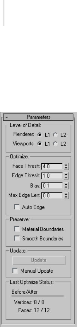
750 Chapter 8: Modifiers
You see the effect immediately in a smooth
shaded viewport. Do a test rendering to see the
effect on the renderer.
The following parameters are stored for each
level: Face Threshold, Edge Threshold, Bias, Max
Edge Len, Material Boundaries, and Smooth
Boundaries.
Interface
LevelofDetailgroup
Renderer L1, L2—Set the level of display for the
defaultscanlinerenderer. UseViewportsL1
and L2 to change the stored optimization level.
Default=L1.
Viewports L1, L2—Set the optimization level for
both viewport and renderer. Also toggles the level
of display for the viewport. Default=L1.
Optimize group
Adjusts the degree of optimization.
Face Thresh—Sets the threshold angle used
to determine which faces are collapsed. Low
values produce less optimization but better
approximations of the original shape. Higher
values improve optimization, but are more likely
to result in faces that render poorly (see Bias).
Default=4.0.
Edge Thresh—Sets a different threshold angle for
open edges (those that bound only one face). A
low value preserves open edges. At the same time
you can apply a high face threshold to get good
optimization. Default=1.0.
Bias—Helps eliminate the skinny or degenerate
triangles that occur during optimization, which
can cause rendering artifacts. Higher values keeps
triangles from becoming degenerate. The default
of 0.1 is enough to eliminate the skinniest triangles.
Range=0.0to1.0(a0valueturnsBiasoff).
Max Edge Len—Specifies the maximum length,
beyond which an edge cannot be stretched when
optimized. When Max Edge Len is 0, it has no
effect. Any value greater than 0 specifies the
maximum length of the edges. Default=0.0.
Along with Bias, this control helps you avoid
creating long skinny faces while optimizing.
Auto Edge—Tur ns e dges on a nd off fol low i ng
optimization. Turns on any open edges. Turns
off any edges between faces whose normals are
within the face threshold; such edges beyond the
threshold are not turned on. Default=off.

Patch Select Modifier 751
Preserve group
Maintains clean separation at the face level
between material and smoothness boundaries.
Material Boundaries—Prevents face collapse across
material boundaries. Default=off.
Smooth Boundaries—Optimizes an object and
maintain its smoothing. When turned on, allows
only faces that share at least one smoothing group
to collapse. Default=off.
Update group
Update—Updates the viewports with the current
optimization settings. Available only when Manual
Update is turned on.
Manual Update—Enables the Update button. When
turned off, Optimize works as it does by default,
updating the viewport display dynamically.
Note: When using Manual Update, if you make any
changes that cause the reevaluation of the stack,
the existing optimization display disappears. Click
theUpdatebuttonagaintorestoreit.
The Renderer ignores the optimization display
in the viewport, using the Optimize settings,
regardless of the state of the Manual Update.
Last Optimize Status group
Displays numerical results of optimization with
exact before-and-after counts for vertices and
faces.
Patch Select Modifier
Make a selection. > Modify panel > Modifier List > Patch
Select
Make a selection. > Modifiers menu > Selection Modifiers
>PatchSelect
The Patch Select modifier lets you pass a
sub-object selection up the stack to subsequent
modifiers. It provides a superset of the selection
functions available in the Edit Patch modifier (page
1–638). You can select vertices, edges, patches,
and elements. You can also change the selection
from sub-object level to object level.
Note: When you apply the Patch Select modifier
and then go to any sub-object level, the
select-and-transform buttons in the toolbar
are unavailable, and the Select Object button is
automatically activated.
Using XForm Modifiers to Animate a
Patch Selection
When you apply a Patch Select modifier, there
are no animation controllers assigned to the
sub-object selection. This means that the selection
has no way to "carry" the transform information
needed for animation.
To animate a sub-object selection using Patch
Select, apply either an XForm or Linked XForm
modifier to the selection. These modifiers provide
the necessary controllers for animating the effects
of transforms. In a sense, they give "whole-object
status" to the sub-object selection.
•XForm (page 1–959)
Animates transforms directly on a sub-object
selection. Creates a gizmo and center for the
sub-object selection. You can animate both,
with the center acting as a pivot point for the
selection.
•Linked XForm (page 1–712)
Lets you choose another object to control the
animation. The sub-object selection is linked to
the "control object." When you transform the
control object, the sub-object selection follows
accordingly.
Procedure
To use the patch select modifier:
1. Create or select a patch object.
752 Chapter 8: Modifiers
2. Go to the Modify panel and choose
Patch Select from the modifier list.
3. Selectvertices,handles,edges,patches,or
elements.
4. Add another modifier to affect only the
selection from step 3.
Interface
Modifier Stack
Vertex—Selects vertices.
Handle—Selects handles.
Edge—Selects edges.
Patch—Selects patches.
Element—Selects elements.
For more information on the stack display, see
Modifier Stack (page 3–760).
Parameters rollout
Provides buttons for turning different sub-object
modes on and off, working with named selections
and handles, display settings, and information
about selected entities.
TheiconsatthetopoftheSelectionrolloutletyou
specify the method of face selection. Clicking a
button here is the same as selecting a sub-object
type in the modifier stack. Click the button again
to turn it off and return to the object selection
level.
Vertex—Selects a vertex beneath the cursor;
region selection selects vertices within the region.
Handle—Selects a handle beneath the cursor;
region selection selects multiple handles within
the region.
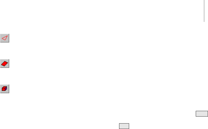
Patch Select Modifier 753
Edge—Selects an edge beneath the cursor;
region selection selects multiple edges within the
region.
Patch—Selects a patch beneath the cursor;
region selection selects multiple patches within
the region.
Element—Selects all contiguous faces in an
object; region selection selects the same.
Select By Vertex—Selects any sub-objects at the
current level that use a vertex you click. Applies
to all sub-object levels except Vertex. Also works
with Region Select.
Ignore Backfaces—Selects only those edges,
patches, or elements whose normals make them
visible in the viewport. When turned off (the
default), selection includes all sub-objects,
regardless of the direction of their normals.
Note: ThestateoftheBackfaceCullsettinginthe
Display panel doesn’t affect sub-object selection.
Thus, if Ignore Backfacing is turned off, you can
select sub-objects even if you can’t see them.
Note: The state of the Ignore Backfaces check box
also affects edge selection at the Edge sub-object
selection level.
Get from Other Levels group
Appliesselectionsfromonesub-objectlevelto
another.
Get Vertex Selection—Selects edges, patches,
or elements based on the last vertex selection.
The selection is added to the current selection.
Available only when Vertex is not the current
sub-object level.
Get Edge Selection—Selects vertices, patches, or
elements based on the last edge selection. Selects
those vertices, patches, or elements that contain
theedge. AvailableonlywhenEdgeisnotthe
currentsub-objectlevel.
Get Patch Selection—Selects vertices, edges,
or elements based on the last patch selection.
This selection is added to the current selection.
Available only when Patch is not the current
sub-object level.
Select by Material ID group
Selects faces based on their material ID.
ID—Set the spinner to the ID number you want to
select, and then click the Select button. Press Ctrl
whileclickingtoaddtothecurrentselection,or
press Alt to remove from the current selection.
Named Selection Sets group
Thesefunctionsareprimarilyforcopying
named selection sets (page 1–83) of sub-objects
between similar objects, and between comparable
modifiers and editable objects. For example, you
canapplyapatchselectmodifiertoasphere,
create a named selection set of edges, and then
copy the selection to a different sphere that’s been
converted to an editable patch object. You can
even copy the selection set to a different type of
object, because the selection is identified by the
entities’ ID numbers.
The standard procedure is to create a selection set,
name it, and then use Copy to duplicate it into the
copy buffer. Next, select a different object and/or
modifier,gotothesamesub-objectlevelasyou
were in when you copied the set, and click Paste.
Note: Because sub-object ID numbers vary from
object to object, the results of copying named
selection sets between different objects can be
unexpected. For example, if the buffered set
contains only entities numbered higher than any
that exist in the target object, no entities will be
selected when the set is pasted.

754 Chapter 8: Modifiers
Copy—Places a named selection into the copy
buffer.
Paste—Pastes a named selection from the copy
buffer.
Select Open Edges—Selects all edges with only one
face. In most objects, this will show you where
missing patches exist. Available only at the Edge
sub-object level.
Selection Info
At the bottom of the Patch Select Parameters
rollout is a text display giving you information
about the current selection. If 0 or more than one
sub-object is selected, the text gives the number
and type selected. If one sub-object is selected, the
text gives the ID number and type of the selected
item.
Note: When the current sub-object type is Patch or
Element,selectioninformationisgiveninPatches.
Soft Selection rollout
See Soft Selection Rollout (page 1–963) for
informationontheSoftSelectionrolloutsettings.
PatchDeform Modifier
Select an object. > Modify panel > Modifiers List >
Object-Space Modifiers > PatchDeform
Select an object. > Modifiers menu > Animation Modifiers
>PatchDeform
The PatchDeform modifier deforms an object
based on the contours of a patch object. This
modifier works similarly to the PathDeform
modifier (page 1–755),butusesaquad-based patch
object instead of a spline shape or NURBS curve
path.
To use the PatchDeform modifier, apply it to the
object you want to deform, click the Pick Patch
button, and then select a patch object. Deform
the object by manipulating the patch object or
adjusting the various controls in the Patch Deform
panel.
Not all objects can be used with PatchDeform.
Objects that are valid PatchDeform targets include:
Plane, Cylinder, Cone and Torus.
This modifier is also similar to the SurfDeform
modifier (page 1–848),exceptthatitusesapatch
surface instead of a NURBS Point or CV surface.
There’s also a world-space version of the
PatchDeform modifier. See PatchDeform (WSM)
(page 1–552). Generally, the PatchDeform
object-space modifier leaves the object in place
while moving the patch to the object, while the
PatchDeform world-space modifier leaves the
patch in place while moving the object to the
patch. Also, the WSM version has a Move to Patch
button, while the object-space version does not.
Procedure
To use the PatchDeform modifier:
1. Select an object.
2. Apply PatchDeform.
3. On the Parameters rollout, click Pick Patch.
4. Select a patch object.
Deform the object by adjusting the controls in
the Patch Deform panel and by manipulating
the patch object.
Interface
Modifier Stack
Gizmo—At this sub-object level, you can
transform and animate the gizmo like any other
object, altering the effect of the modifier. The
PatchDeform gizmo is a representation of the
deforming patch object, so transforming it
determines which part of the patch affects the
modified object.
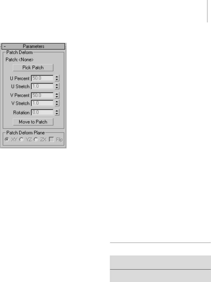
PathDeform Modifier 755
Parameters rollout
Patch Deform group
Provides controls that let you pick the patch and
adjust the object’s position and deformation along
the gizmo copy of the patch.
Patch—Displays the name of the selected patch
object.
Pick Patch—Click this button, and then select the
patch object you want to use for the deformation.
A gizmo is created for the object that matches
the patch. Once you assign the patch gizmo, you
can adjust the deformation using the remaining
controls in this rollout.
Note: Patch Deform can be used only with a
rectangular quad patch form. The software makes
no distinction between quad-style patches and
certain primitive meshes. Examples of suitable
patches are the primitive quad patch object (page
1–994), the primitive cylinder (page 1–177),and
the primitive torus (page 1–180).(Thecylinder
actually has tri-patches at each end, but since they
are at the end of the list of patches, PatchDeform
just ignores these extra faces.)
UPercent—MovestheobjectalongtheU
(horizontal) axis of the gizmo patch, based on a
percentage of the U distance. This spinner defaults
to a setting of 50 percent, which places the object
atthecenterofthegizmopatch. Asettingof0
percent places the object at the left edge of the
gizmo patch, as seen from the viewport where the
patch was created.
UStretch—Scales the object along the U
(horizontal) axis of the gizmo patch.
VPercent—Moves the object along the V (vertical)
axis of the gizmo patch, based on a percentage of
the V distance. A setting of 0 percent places the
object at the bottom of the gizmo patch.
VStretch—Scales the object along the V (vertical)
axis of the gizmo patch.
Rotation—Rotates the modified object with respect
to the gizmo patch.
Move To Patch—Clicking this button moves the
object from its original position to the patch object
you are using for deformation. This button is only
available with the PatchDeform (WSM).
Patch Deform Plane group
XY/YZ/ZX—Choose a two-axis plane of the object
to make parallel with the XY plane of the gizmo
patch.
Flip—Reverses the gizmo direction.
PathDeform Modifier
Select an object. > Modify panel > Modifier List >
Object–Space Modifiers > PathDeform
Select an object. > Modifiers menu > Animation Modifiers
>PathDeform
The PathDeform modifier deforms an object
using a spline or NURBS curve as a path. You can
moveandstretchtheobjectalongthepath,and
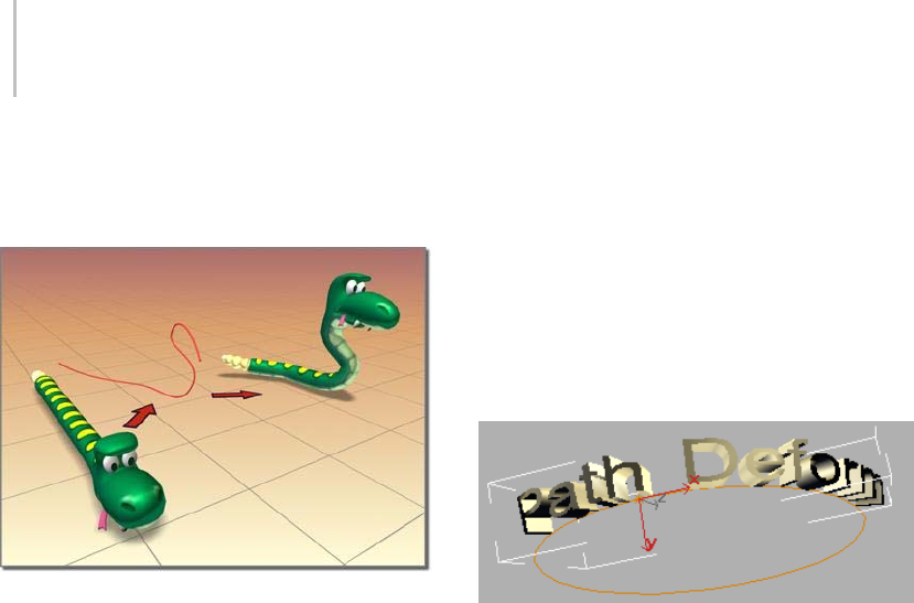
756 Chapter 8: Modifiers
rotate and twist it about the path. There’s also a
world-space modifier version. See PathDeform
(WSM) (page 1–552).
PathDeform creates a wiggle for the snake.
Using a Path to Deform an Object
Generally, you use the PathDeform modifier
when you want to keep an object in place while
deforming to a path. Use the PathDeform
world-space modifier when you want to move an
object to a path while keeping the path in the same
world space.
The PathDeform (WSM) modifier replaces the
space-warp version that shipped with previous
versions of 3ds Max, and is incompatible with
previous versions. See PathDeform (WSM) (page
1–552) for details on how to fix incompatibilities
from the previous version.
To use the PathDeform modifier, you apply it, then
click the Pick Path button and select a shape or
curve consisting of a single open or closed spline.
Once the object is assigned to the path, you can
adjust the parameters to deform or animate the
object along a gizmo copy of the path.
Procedures
To use the PathDeform modifier:
1. Select an object.
2. Apply PathDeform.
3. On the Parameters rollout, click Pick Path.
4. Select a spline or NURBS curve.
Deform the object by adjusting the various
controls in the Path Deform panel and by
editing the path object.
Example: To use the PathDeform modifier to curve
text:
1. IntheTopviewport,createacirclewitharadius
of 100 units.
2. In the Front viewport, create a text shape with
six or seven letters, and a size of 25. (You can
use the default "MAX Text".)
3. Apply an Extrude modifier (page 1–680) to the
textshapeandsetAmountto-5.0.
4. On the main toolbar, set the Reference
Coordinate System to Local.
Looking at the axis tripod for the extruded text
object, you can see that its Z axis runs from
back to front, relative to world space.
5. Apply a PathDeform object-space modifier to
the text object, click the Pick Path button, and
then select the circle.
A circular gizmo is displayed. The circle
runs through the local Z axis of the text
object. Because of its orientation, its effect is
minimal, but you can see a slight wedge-shaped
deformation from the top view.
6. InthePathDeformAxisgroup,choosetheY
option, and then the X option.
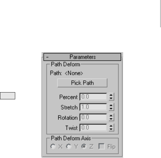
PathDeform Modifier 757
The circle gizmo rotates to run through the
specified axes, deforming the text object
differentlywitheachchange.
7. Adjust the Percent spinner to view its effect,
and then set it to 0.TrythesamewithStretch,
Rotation, and Twist, and then restore them to
their original values. (Tip: Use the Ctrl key
with Twist to amplify the effect.)
8. Turn Flip on and off to switch the direction of
the path.
9. In the stack display, choose the Gizmo
sub-object level, and move the gizmo path
around.
The text object is further deformed by its
relative position to the gizmo.
10.In the stack display, turn off sub-object
selection by selecting the original circle shape.
11.Adjust the circle’s radius.
The deformation of the text object changes
because its gizmo is an instance of the shape
object.
Interface
Modifier Stack
Gizmo—At this sub-object level, you can transform
and animate the gizmo like any other object,
altering the effect of the modifier. The PathDeform
gizmo is a representation of the deforming path
object, so transforming it determines which part
of the path affects the modified object.
Parameters rollout
Path Deform group
Provides controls that let you pick a path and
adjust an object’s position and deformation along
the path.
Path—Displaysthenameoftheselectedpath
object.
Pick Path—Click this button and then select a spline
or NURBS curve to use as the path. The gizmo
that appears is shaped like the path and is aligned
with the local Z axis of the object. Once you assign
the path, you can adjust the deformation of the
object using the remaining controls in this rollout.
The path you pick should contain a single, open or
closed curve. If you use a path object consisting of
multiple curves, only the first one is used.
Percent—Movestheobjectalongthegizmopath
based on a percentage of the path length.
Stretch—Scales the object along the gizmo path,
using the object’s pivot point as the base of the
scale.
Rotation—Rotates the object about the gizmo path.
Twist—Twists the object about the path. The twist
angle is based on the rotation of one end of the
overall length of the path. Typically, the deformed

758 Chapter 8: Modifiers
object takes up only a portion of the path, so the
effect can be subtle.
Path Deform Axis group
X/Y/Z—Chooseonetorotatethegizmopathto
align with a specified local axis of the object.
Flip—Reverses the gizmo path 180 degrees about
the specified axis.
Point Cache Modifier
Select an object. > Modify panel > Modifier List >
Object–Space Modifiers > Point Cache
Select an object. > Modifiers menu > Cache Tools > Point
Cache
The Point Cache modifier lets you store modifier
andsub-objectanimationtoadiskfilethatrecords
only changes in vertex positions, and then play
back the animation using the information in the
disk file instead of the modifier keyframes. This is
useful when the computation required for vertex
animation becomes so excessive that it causes
animation playback to run slowly or drop frames.
Anotheruseforthismodifieristoapplythesame
animation to a number of objects, varying the
Start Time and Strength settings for each so they
don’t all move identically.
The Point Cache modifier is also available in a
world-space version, for which usage is the same.
Special Features in Point Cache
Both versions of the Point Cache modifier provide
enhanced animation capabilities, including:
• Adjustable playback ranges and a playback
graph, to animate which cache frame is played
back. This lets you load a cache and then
animate it, slowing down, stopping, reversing,
etc.
•Nth-framesampling,soyoucansampleevery
few frames to save disk space if sampling
every frame is unnecessary, or record multiple
samples per frame for improved motion
blurring.
•The"strength"isadjustableinAbsolutemode,
so you can easily blend the cache with what is
below in the stack.
•Improvedcachefilemanagement.
• Pre-loaded caches to speed up playback.
Procedure
To use the Point Cache modifier:
1. Use one or more modifiers to animate an
object. For example, you might apply a Bend
modifier (page 1–560), and then set keyframes
for the Angle parameter to make the object
bend back and forth.
2. Click Play Animation.
If the animation is a good candidate for caching,
the playback will drop many frames with Real
Time Playback turned on, and will run slowly
with Real Time Playback turned off.
3. From the Modify panel > Modifier List,
choose Object-Space Modifiers > Point Cache.
4. On the Parameters rollout > Record group, set
frame numbers for Start Time and End Time.
5. If you plan to render the cached animation
usingmotionblur,decreasetheSampleRate
setting.
6. Click the Record button, and use the Save
Cache dialog to specify a cache file.
The software records the animation to the
cachefile.Whenfinished,thecachefilename
appears in the Cache File group.
7. IntheRecordgroup,clickDisableModifiers
Below.
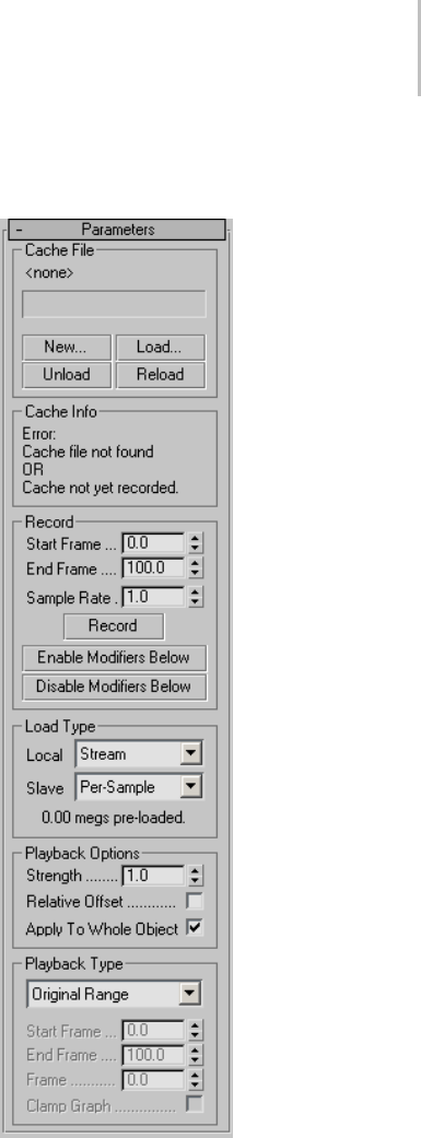
Point Cache Modifier 759
This turns off all the object’s modifiers below
Point Cache so that only the cached vertex
animationwillappearwhenyouplaybackthe
animation.
8. Click Play Animation again.
This time the animation plays back quickly and
smoothly.
Interface
Parameters rollout
Cache File group
Contains settings for recording vertex animation.
[file name]—After you record or load a cache file,
its name appears in this field.

760 Chapter 8: Modifiers
New—Creates a new, empty cache file. After setting
a new file, use Record to create the cache data.
Load—Loads a vertex animation from a cache
file on disk into the Point Cache modifier. If the
number of vertices in the cache file does not match
the number of vertices in the object, a warning
appears, but no error occurs.
Unload—Temporarily frees the current cache file,
so it can be edited or deleted externally.
Reload—Reopens the current cache file, if
previously unloaded.
Cache Info group
Displays cache statistics in read-only format,
including the point count, sample rate, sample
count, start/end frames, and errors, if any.
Record group
Contains settings for recording cached animation.
Start Frame—Sets the first frame for recording the
vertex animation. Default=first frame of the active
time segment.
Using decimal fractions lets you start at a
sub-frame setting when using a Frame:Ticks time
display. Default=0.0.
End Frame—Sets the last frame for recording the
vertex animation. Default=last frame of the active
time segment.
Using decimal fractions lets you start at a
sub-frame setting when using a Frame:Ticks time
display. Default=0.0.
Sample Rate—Sets the number of frames between
each recorded sample. When rendering with
motion blur, which uses sub-frame sampling,
decrease this value. Default=1.0.
At the default value of 1.0, Point Cache records
one sample per frame. Increasing the value causes
asampletoberecordedeveryNthframe. For
example, a value of 10.0 records every tenth frame.
Decreasing the value causes multiple samples to
be recorded for each frame. For example, if you
setSampleRateto0.1,PointCacherecords10
samples per frame at evenly spaced intervals.
Record—Stores the vertex animation to a disk
file. If no cache file is specified, or the specified
filedoesn’texist,activatestheSavePointsdialog,
which lets you specify a path and file name for
the cache file. Click Save to record the file, and
then load it into the Point Cache modifier, ready
for playback.
Tip: Tochangethepathorfilename,useCacheFile
group>Newandspecifyadifferentcachefile.
Enable Modifiers Below—Tur ns on a ll s tack
modifiersbelowthePointCachemodifier.Usethis
when you want to change modifier settings.
Disable Modifiers Below—Tu rns off all the obj ec t’s
stack modifiers below Point Cache so that only the
cached vertex animation appears when you play
back the animation.
Load Type group
Local—The method the modifier uses to load the
cache file. The options are:
•Stream—Keepsthecachefileopenforfast
access,butloadsonlyasingleframeatatimeto
conserve memory. This is the default mode.
•Per-Sample—Opens the cache file, reads a single
frame, and then immediately closes the file.
This is slower than the Stream method, but is
useful if many users are reading/writing the
same set of cache files since the cache files won’t
be locked open as you read from them.
•Pre-Load—Loads the entire cache file into
memory for fast access, and then closes the
file. This is particularly useful in networked
situations, or when a few cache files are used by
many objects in one scene. In the latter case,

Point Cache Modifier 761
usingthisoptionpreventseachobjectfrom
thrashing the disk on playback.
Be conservative in using this, as it can consume
a great deal of memory. However, if one cache
file is used by several objects, the cache is
loaded into memory only once.
Slave—These options apply if 3ds Max is running
as a network-rendering client; see the preceding
for details. In this situation, only Per-Sample and
Pre-Load are available, and the default option is
Per-Sample, so the clients don’t lock files.
[label]—This read-only field displays the size of the
pre-loaded data when Local is set to Pre-Load.
Playback Options group
Strength—Affects the motion relative to the
original animation. Applies only when Relative
Offset is on. Default=1.0. Range=-10.0 to 10.0.
At 1.0, the animation plays back the same as
recorded. With strengths between 0.0 and 1.0, the
animation is relatively restrained. At strengths
greater than 1, the animation is exaggerated. With
negative Strength settings, the motion is reversed.
Relative Offset—Enables offsetting the animated
vertex positions relative to their positions
as recorded, based on the Strength setting.
Default=off.
Note: WhenyouturnonRelativeOffsetandplay
back a cached animation with the modifiers turned
on, the cached vertex positions are calculated
relative to their positions as calculated by the
modifiers. For example, if you record a Bend
animation to a cache file, and then play it back
with both Relative Offset and the Bend modifier
on and Strength=1.0, all vertex positions are
doubled, resulting in exaggerated motion.
Apply To Whole Object—When off, only the active
vertex selection is animated. In this case, for the
cacheanimationtobevisible,theselectionmust
includeatleastsomeoftheoriginallyanimated
vertices.
Playback Type group
Playback Type—Specifies how playback occurs:
•Original Range—Plays back the cache over
the range it was originally recorded, so the
animation will always be the same as the
original.
•Custom Start—Plays back the cache from a
custom start time, set by Start Frame, but the
animation length and playback speed will be
the same as the original animation.
•Custom Range—Lets you set start and end
frames within which the current cache plays
back. Using a range that is smaller than the
original record range plays the cache back
faster, while specifying a larger range plays the
cache back slower.
•Playback Graph—Lets you animate which cache
frame is played at any given time.
For example, if you record a cache from frames
0 to 100 and then want it to play back twice
as fast forward and then in reverse, choose
thisoption,turnonAutoKey,settheFrame
parameter to 0.0 at frame 0, 100.0 at frame 50,
and then back to 0.0 at frame 100. The function
curve of this parameter in Track View shows
how the cache is played back. Animating the
Frame value lets you achieve unusual effects
such as slowing a cache down over time,
creating a ping-pong effect during playback,
etc.
Start Frame—The frame number at which the
cached animation starts playing back. Using
decimal fractions lets you start at a sub-frame
setting when using a Frame:Ticks time display.
Available only when Playback Type is set to
Custom Start or Custom Range. Default=0.0.

762 Chapter 8: Modifiers
End Frame—The frame number at which the
cached animation starts playing back. Using
decimal fractions lets you start at a sub-frame
setting when using a Frame:Ticks time display.
Available only when Playback Type is set to
Custom Range. Default=0.0.
Frame—Lets you animate playback of the cache;
for details, see Playback Graph, above.
Clamp Graph—Controls what gets loaded when
thePlaybackGraphframeisoutoftheoriginal
recorded range.
Take an example in which the playback frame is set
to 105, but the original cache was recorded over
frames 0-100. With Clamp Graph on, the loaded
frame will be 100. If it’s off (the default), the cache
will"wraparound"andloadframe5.
This lets you loop caches more easily. In the
aboveexample,youcouldsimplyhaveatwo-key
playbackgraph.Thefirstkeywouldbeatframe
0withavalueof0.0,andthesecondwouldbe
at frame 100 with a value of 100.0. You would
then set the out-of-range type (page 2–551) for the
Frame parameter (Playback Frame in Track View)
to Linear, and the cache would loop back smoothly
to the beginning at frame 101.
Poly Select Modifier
Make a selection. > Modify panel > Modifier List > Poly
Select
Make a selection. > Modifiers menu > Selection Modifiers
> Poly Select
The Poly Select modifier lets you pass a sub-object
selection up the stack to subsequent modifiers.
It provides a superset of the selection functions
available in Editable Poly (page 1–1022).Youcan
selectvertices,edges,borders,polygons,and
elements. You can change the selection from
sub-object level to object level.
When you apply the Poly Select modifier
and then go to any sub-object level, the
select-and-transform buttons in the toolbar
are unavailable, and the Select Object button is
automatically activated.
Using XForm Modifiers to Animate a Poly
Selection
When you apply a Poly Select modifier, there
are no animation controllers assigned to the
sub-object selection. This means that the selection
has no way to "carry" the transform information
needed for animation.
To animate a sub-object selection using Poly
Select, apply either an XForm or Linked XForm
modifier to the selection. These modifiers provide
the necessary controllers for animating the effects
of transforms. In a sense, they give "whole-object
status" to the sub-object selection.
•XForm (page 1–959)
Animates transforms directly on a sub-object
selection. Creates a gizmo and center for the
sub-object selection. You can animate both,
with the center acting as a pivot point for the
selection.
•Linked XForm (page 1–712)
Lets you choose another object to control the
animation. The sub-object selection is linked to
the "control object." When you transform the
control object, the sub-object selection follows
accordingly.
Procedure
To use the Poly Select modifier:
1. Create or select an object.
Note: Applying a Poly Select modifier to an
object other than a polymesh type will convert
the object to a polymesh object. If you want
more control over the conversion, add a Tu r n
To Poly modifier (page 1–874) before applying
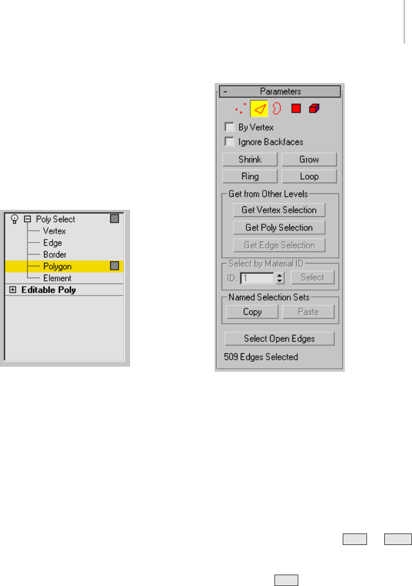
Poly Select Modifier 763
the Poly Select modifier. The Turn To Poly
modifier provides conversion options that
aren’t available with the Poly Select modifier.
2. Apply the Poly Select modifier.
3. Select vertices, faces, or polygons.
4. Add another modifier to affect only the
selection from step 3.
Interface
Modifier Stack
Vertex—Selects vertices.
Edge—Selects edges.
Border—Selects borders.
Polygon—Selects polygons.
Element—Selects elements.
For more information on the stack display, see
Modifier Stack (page 3–760).
Parameters rollout
Provides buttons for accessing different sub-object
levels, working with named selections and handles,
display settings, and information about selected
entities.
TheiconsatthetopoftheSelectionrolloutletyou
specify the method of face selection.
Clickingabuttonhereisthesameaschoosinga
sub-object type in the modifier stack. Click the
button again to turn it off and return to the Object
selection level.
Note: You can convert sub-object selections in two
different ways with the use of the Ctrl and Shift
keys:
• Clicking a sub-object button in the Selection
rollout with Ctrl held down converts the
current selection to the new level, selecting
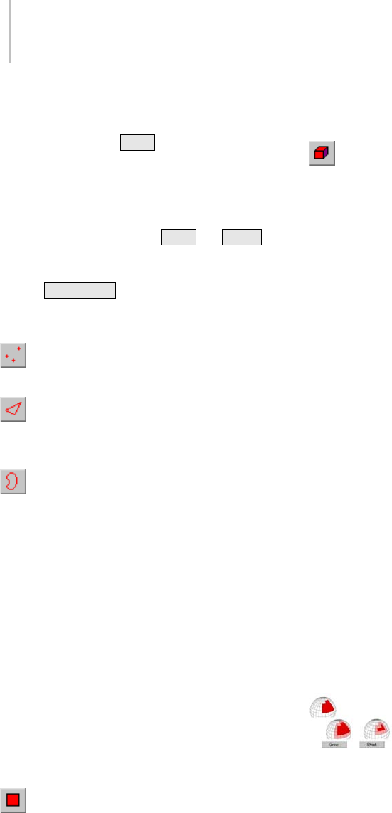
764 Chapter 8: Modifiers
all sub-objects in the new level that touch the
previous selection. For example, if you select
avertex,andthen Ctrl +click the Polygon
button, all polygons that use that vertex are
selected.
• To convert the selection to only sub-objects
all of whose source components are originally
selected, hold down both Ctrl and Shift
as you change the level. For example, if you
convert a vertex selection to a polygon selection
with Ctrl+Shift +click, the resultant selection
includes only those polygons all of whose
vertices were originally selected.
Vertex—Selects a vertex beneath the cursor;
region selection selects vertices within the region.
Edge—Selects a polygon edge beneath the
cursor; region selection selects multiple edges
within the region.
Border—Tu r ns o n B o rd e r s u b- o bj e c t mo d e,
which lets you select an area on a mesh that can
generally be described as a hole. Areas like this are
usually sequences of edges with faces on only one
side. For example, a box doesn’t have a border, but
the Teapot object has several of them: on the lid,
on the body, on the spout, and two on the handle.
If you create a cylinder, then delete the top face,
the top row of edges forms a border.
When the Border sub-object level is active, you
can’t select edges that aren’t on borders. Clicking a
single edge on a border selects that whole border.
Borders can be capped (either in editable poly or
by applying the cap holes modifier). They can also
be connected to another object (compound object
connect).
Polygon—Selects all coplanar polygons
beneath the cursor. Usually, a polygon is the area
you see within the visible wire edges. Region
selection selects multiple polygons within the
region.
Element—Selects all contiguous polygons in
an object; region selection selects the same.
By Vertex—Selects any sub-objects at the current
level that use a vertex you click. Applies to all
sub-object levels except Vertex. Also works with
Region Select.
Ignore Backfaces—Selecting sub-objects selects
only those whose normals make them visible in the
viewport. When turned off (the default), selection
includes all sub-objects, regardless of the direction
of their normals.
Note: The state of the Display properties (page 1–55)
> Backface Cull setting doesn’t affect sub-object
selection. Thus, if Ignore Backfacing is turned off,
you can select sub-objects even if you can’t see
them.
Note: ThestateoftheIgnoreBackfacescheckbox
alsoaffectsedgeselectionattheEdgesub-object
selection level.
Shrink—Reduces the sub-object selection area
by deselecting the outermost sub-objects. If
the selection size can no longer be reduced, the
remaining sub-objects are deselected.
Grow—Expands the selection area outward in all
available directions.
Forthisfunction,aborderisconsideredtobean
edge selection.
With Shrink and Grow, you can add or remove neighboring
elements from the edges of your current selection. This works
at any sub-object level.
Ring—Expandsanedgeselectionbyselectingall
edges parallel to the selected edges. Ring applies
only to edge and border selections.
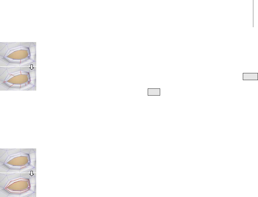
Poly Select Modifier 765
Ring selection adds to the selection all the edges that are
parallel to the ones selected originally.
Loop—Expandstheselectionasfaraspossible,in
alignment with selected edges.
Loop applies only to edge and border selections,
and propagates only through four-way junctions.
Loop selection extends your current edge selection by adding
all the edges aligned to the ones selected originally.
Get from Other Levels group
Appliesselectionsfromonesub-objectlevelto
another.
Get Vertex Selection—Selects faces based on the
last vertex selection. Selects all faces shared by
any selected vertex. The selection is added to the
current selection. Available only when the current
sub-object level is not Vertex.
Get Poly Selection—Selectsverticesbasedonthe
last polygon/element selection. This selection
is added to the current selection. Available only
when the current sub-object level is not Polygon
or Element.
Get Edge Selection—Selects faces based on the last
edge selection. Selects those faces that contain the
edge. Available only when the current sub-object
level is not Edge or Border.
Select by Material ID group
Selects faces based on their material ID.
ID—Set the spinner to the ID number you want to
select, and then click the Select button. Press Ctrl
whileclickingtoaddtothecurrentselection,or
press Alt to remove from the current selection.
Named Selection Sets group
Thesefunctionsareprimarilyforcopying
named selection sets (page 1–83) of sub-objects
between similar objects, and between comparable
modifiers and editable objects. For example,
you can apply a Poly Select modifier to a sphere,
create a named selection set of edges, and then
copy the selection to a different sphere that’s been
converted to an editable mesh object. You can
even copy the selection set to a different type of
object, because the selection is identified by the
entities’ ID numbers.
The standard procedure is to create a selection set,
name it, and then use Copy to duplicate it into the
copy buffer. Next, select a different object and/or
modifier,gotothesamesub-objectlevelasyou
were in when you copied the set, and click Paste.
Note: Because sub-object ID numbers vary from
object to object, the results of copying named
selection sets between different objects can be
unexpected. For example, if the buffered set
contains only entities numbered higher than any
that exist in the target object, no entities will be
selected when the set is pasted.
Copy—Places a named selection into the copy
buffer.
Paste—Pastes a named selection from the copy
buffer.
Select Open Edges—Selectsalledgeswithonlyone
face. In most objects, this will show you where
missing faces exist. Available only at the Edge or
Border sub-object level.

766 Chapter 8: Modifiers
Selection Info
At the bottom of the Parameters rollout for Mesh
Select is a text display giving you information
about the current selection. If 0 or more than one
sub-object is selected, the text gives the number
and type selected. If one sub-object is selected, the
text gives the ID number and type of the selected
item.
Note: When the current sub-object type is Element,
selectioninformationisgiveninpolygonsWhen
the current sub-object type is Border, selection
information is given in edges.
Soft Selection rollout
Soft Selection controls affect the action of
sub-object Move, Rotate, and Scale functions.
When these are on, 3ds Max applies a spline curve
deformation to unselected vertices surrounding
the transformed selected sub-object. This provides
a magnet-like effect with a sphere of influence
around the transformation.
For more information, see Soft Selection Rollout
(page 1–963).
Preserve Modifier
Modify panel > Make a selection. > Modifier List >
Object-Space Modifiers > Preserve
Make a selection. > Modifiers menu > Parametric
Deformers > Preserve
The Preserve modifier lets you retain, as much as
possible,theedgelengths,faceangles,andvolume
of an edited and deformed mesh object using
an unmodified copy of the object before it was
deformed. When you push and pull vertices at the
sub-object level, the process typically stretches the
edges and often alters the face angles, resulting
in irregular topology. You can use the Preserve
modifier to generate more regular edge lengths,
and a "cleaner" mesh.
Procedures
Using the Preserve modifier:
1. Create an object. Before you edit it, create a
copy.
2. Edit the copy at the sub-object level, pushing
and pulling vertices, faces, and so on.
3. Apply the Preserve modifier to the copy, click
the Pick Original button, and then select the
original, unmodified object.
4. Adjust controls in the Preserve modifier to
fine-tune the mesh.
Example: Use the Preserve modifier on a geosphere:
1. Create a GeoSphere (page 1–176) and use
Shift +Movetomakeacopyofit.
Tip: If you want to see the effect of Preserve on
mapping, apply a checker-mapped material to
thesphereanddisplayitintheviewportsbefore
making the copy.
2. Convert the copy to an editable mesh (page
1–996).
3. At the Vertex sub-object level, select a third of
the vertices at the top of the sphere, and move
them upward (as seen from the front) about
one radius in distance.
Notice the stretched edges between the moved
vertices and the remaining vertices.
4. While still at the Vertex sub-object level, apply
thePreservemodifier.
5. Click the Pick Original button, and then select
the original (unedited) sphere.
The selected vertices move back toward the
sphere in an attempt to maintain the original
volume and edge lengths.
6. Tur n on Inver t Select ion.
The selected vertices return to their moved
position, and the unselected vertices (the
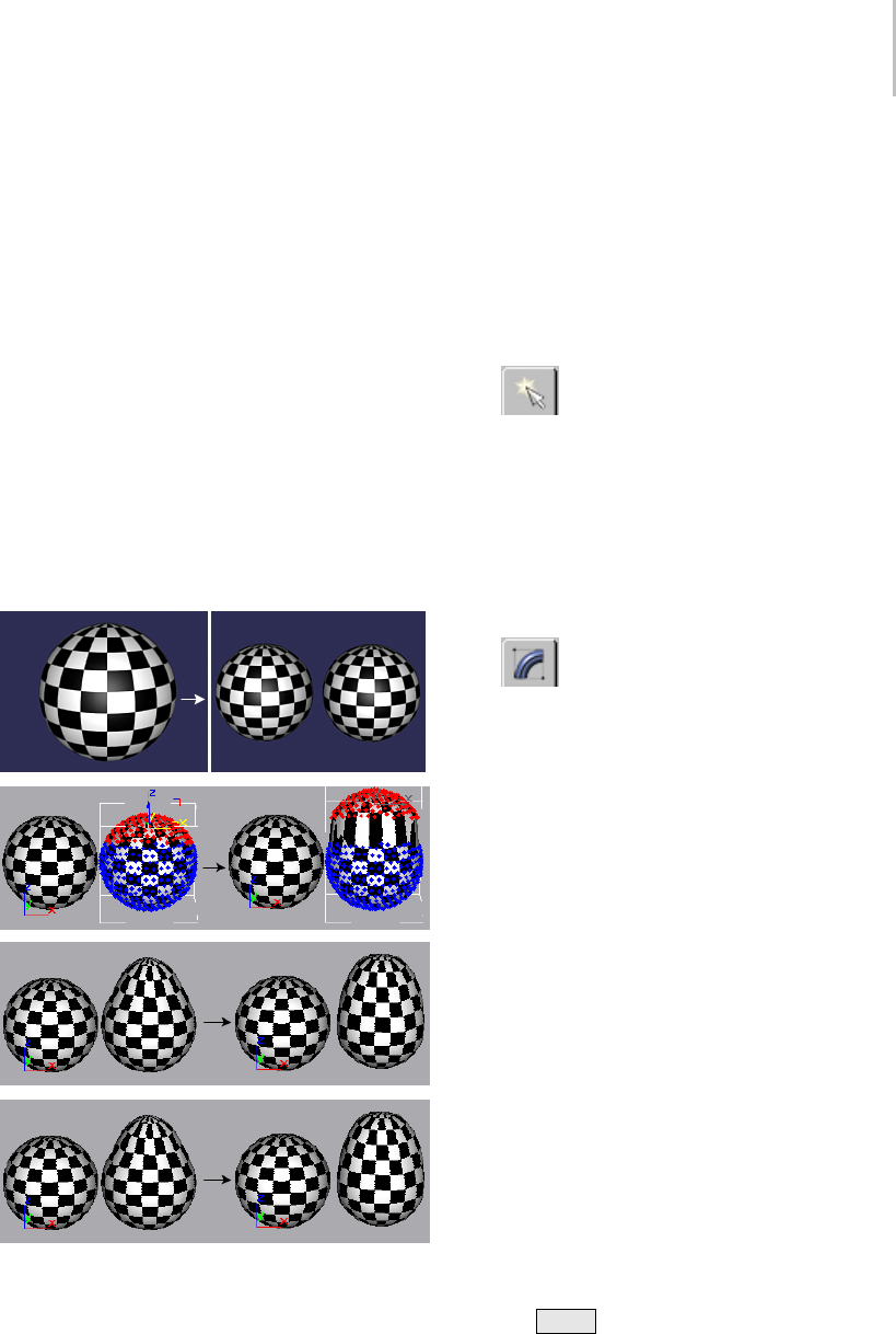
Preserve Modifier 767
inverted selection) move up toward the selected
vertices.
7. Turn off Invert Selection and slowly reduce the
Iterations to 0.
The object now looks as it did before you
applied Preserve.
8. Increase Iterations to the default 25, and then
increase it to approximately 75.
The object is now almost completely spherical
again.
9. Set Iterations back to 25, and then try different
Edge Lengths, Face Angles, and Volume
settings. (You can restore the defaults by
settings Edge Lengths to 1.0, and Face Angles
and Volume to 0.3.
StepsinapplyingthePreservemodifiertoageosphere
Example: Animating a preserved object:
You can animate the Preserve parameters, but the
following procedure shows you how to use Morph
and Preserve together.
1. RemovethePreservemodifierfromthecopied
sphere, and go to object level (instead of
sub-object level).
2. Withthecopied(anddeformed)sphere
still selected, choose Create panel > Compound
Objects > Morph to make it into a Morph
object.
3. Make sure Instance is chosen in the Pick Targets
rollout.
4. At frame 0, click Pick Target, and then select
the original sphere.
5. In the Modify panel, go to frame 100,
select sphere02 in the Morph Targets list, and
click Create Morph Key.
Theobjectnowmorphsfromaspheretoa
deformed sphere.
6. Apply Preserve to the morph object.
7. Click Pick Original, and select the original
sphere.
The object now morphs from the sphere to
apreservedanddeformedsphere. Notethat
because the object selection is passed up the
stack, the Preserve effect is applied to the entire
sphere.
8. Choose Selected Verts Only in the Selection
group.
Now, only the selected vertices are affected by
Preserve. The morph still works, however.
Example: Using the Selection check boxes:
1. Reset the program, create a box, and convert
it to an editable mesh.
2. Use Shift +Movetomakeacopy.
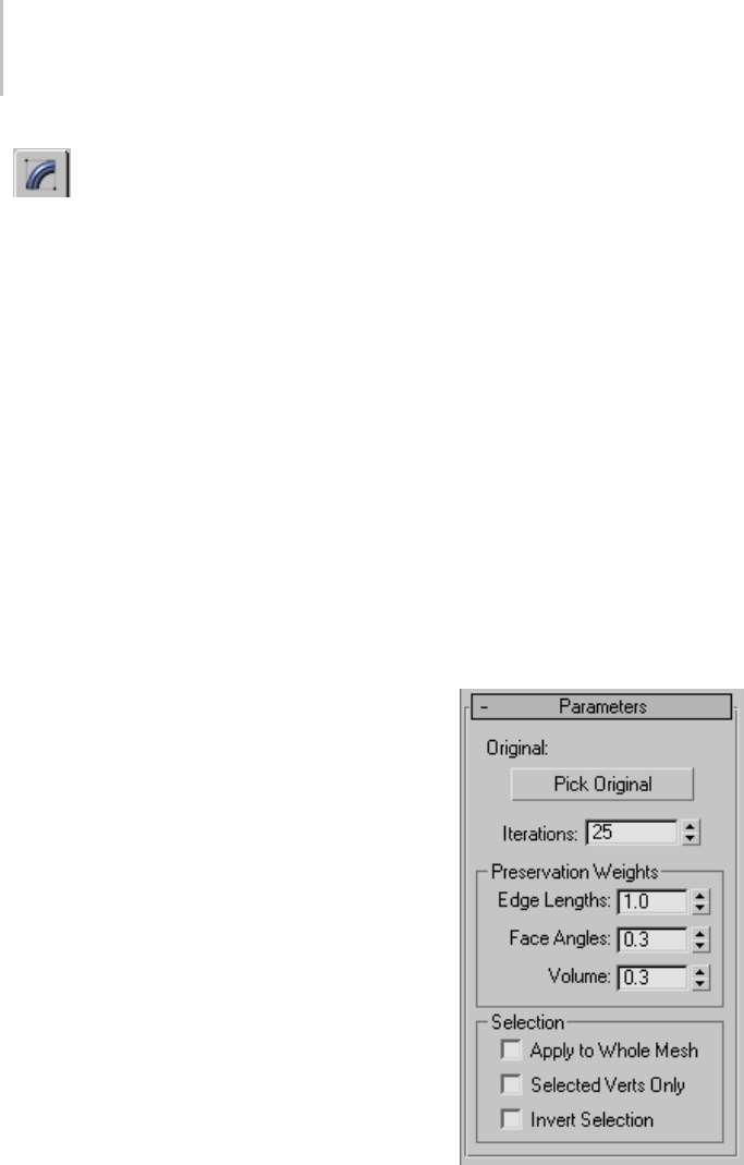
768 Chapter 8: Modifiers
3. Use the Modify panel to select the top
four vertices in the second box. Move them
upward in Z, making the copied box taller than
the original.
4. Apply Preserve, and pick the first box as the
original.
The selected vertices move down to match the
original edge lengths.
5. Set Iterations to 0to move the vertices back up,
then turn on Invert Selection, and set iterations
back up to 25.
The selected vertices stay in their original
locations, but the unselected vertices move
upward to restore the original edge lengths.
6. Tur n Ite rat io ns ba ck dow n to 0.TurnonApply
To Whole Mesh (Invert Selection becomes
unavailable), and then turn Iterations back up
to 25.
Preserve is now applied to the whole mesh.
Sinceallverticesareaffected,thetopand
bottom of the box approach each other.
7. Tur n off Apply To Whole Mesh.
All vertices are translated, but maintain the
same positions relative to each other.
8. Turn off Invert Selection and turn on Selected
Ve r t s O n l y.
You’re back to the original effect. You can move
the Iterations spinner up and down to see that
you’re affecting only the selected vertices.
Example: Simulating cloth:
1. Reset the program, create a Quad Patch Grid,
and convert it to an editable mesh.
2. Makeacopy,andthenmakeareferenceofthe
copy.
You should have a total of three objects in the
scene.
3. Apply Preserve to the third patch, using the
first as the original.
4. Select Selected Verts Only and Invert Selection.
5. Set Iterations to 100.
6. Selectthesecondpatchandgotothe
Sub-Object > Vertex level.
7. Select a single vertex in the middle of the patch
andmoveitupwardinZ.
The third patch becomes a floating
handkerchief.
8. Undo the vertex move.
9. Select the far two corner vertices of the second
patch, and drag them upward in Z.
Now, you’ve got the beginnings of a sheet
hanging on the line.
Interface
Original—Displaysthenameoftheselected
original object. (Note that the so-called "original"
object doesn’t actually have to be the original.
It’s simply a copy of the object that represents its
unmodified topology.)

Projection Modifier 769
Pick Original—Click this, and then select an
unmodified copy of the current object. You
should pick an object with the same topology as
the current object, which has the same number
of vertices. While you can select a completely
different object with equal vertices, the results are
unpredictable.
Iterations—Specifies the number of calculations
toward the solution. The higher this number, the
closer the object comes to matching the original
object and the slower the process. When this is set
to zero, the original object has no effect, as if the
Preserve modifier were never applied.
Preservation Weights group
Edge Lengths, Face Angles, Volumes—Adjusts the
relative importance of the three components you’re
attempting to preserve: edge lengths, face angles,
and volume. In most cases, you’d leave these at
their default settings, but you can achieve some
interesting effects by altering them. Higher face
angles, for example, produce stiffer meshes.
Selection group
Provides options that let you specify which
selection level to take from previous selection
modifiers in the stack. The Preserve modifier acts
on the specified selection.
Apply to Whole Mesh—Applies Preserve to the
entire object, regardless of the selection passed
from previous levels of the stack. Disables the
other two check boxes.
Selected Verts Only—Uses previous sub-object
vertexselections. Notethatitdoesn’tmatterif
the Vertex sub-object level is active in a previous
stack item. As long as vertices have been selected,
Preserve will use that selection.
Invert Selection—Inverts the selection passed up
the stack.
Note: If all of the check boxes are turned off,
Preserve uses whatever active selection is passed
up the stack. Thus, if a Mesh Select modifier is
set to the Vertex level, then that vertex selection is
used. If the same Mesh Select modifier is set to the
top (object) level, then the entire object is affected.
Projection Modifier
Select an object. > Modify panel > Modifier List >
Object-Space Modifiers > Projection
The Projection modifier is used primarily to
manage objects for producing normal bump maps
(page 3–150). You apply it to the low-resolution
object, and then pick a high-resolution object as
thesourcefortheprojectednormals.Whenyou
use the Render To Texture dialog (page 3–156) to
s e t u p p r oj e c t i o n , R e n d e r To Te x t u r e a p p l i e s t h e
Projection modifier to the low-resolution object
automatically. You can also explicitly apply the
Projection modifier to set up the projection before
you use Render To Texture.
Note: The low-resolution object requires UV
coordinates, but the high-resolution source object
does not need to have them. When the normals
mapisrendered,youcanchoosetohaveRender
To Te x t u r e a p pl y a n “Automatic Flatten UVs”
(Unwrap UVW) modifier (page 1–878) to the top of
the low-res object’s stack; or you can use existing
mapping, if such exists.
You can apply more than one instance of the
Projection modifier to the same object, and you
can instance it across multiple objects.
The Projection modifier is a topology-dependent
modifier (page 3–1023),sowhenyouselectan
item in the stack that is lower than the Projection
modifier,youseeawarningdialogthatasksif

770 Chapter 8: Modifiers
youwanttoproceed. (Thesameistrueofthe
Automatic Flatten UVs modifier.)
Projection and Sub-Object Selections
You can match geometry to sub-object selections.
Therearetwowaystodoso:matchingmaterial
IDs, or matching named selections of sub-object
geometry.
Matching Material IDs
Here is a sample workflow for using material IDs
to match portions of the low-res object to different
high-res objects:
1. At the level of the low-res object itself,
assign differing material IDs to different face
selections.
To d o s o , t h e l o w - r e s o bj e c t mu s t b e a s u r f a c e
model; that is, an editable mesh, editable
poly, editable patch, or NURBS surface. Use
the Surface Properties rollout to change the
material ID of sub-object selections.
2. For the high-res target objects, assign
corresponding material IDs.
AneasywaytodothisistoapplytheMaterial
modifier (page 1–714).
3. In the Resolve Hit group of the Projection
Options dialog (page 3–165),turnonHitOnly
Matching Material ID.
4. Render to texture.
Thetextureforfacesofthelow-resobject
receive texture element information only from
thesourceobjectthathadthecorresponding
material ID.
Matching Selected Geometry
Here is a sample workflow for using sub-object
selections to match portions of the low-res object
to different high-res objects.
1. IntheProjectionmodifier,gototheFaceor
Element sub-object level.
See Selection Rollout (Projection Modifier) (page
1–771).
2. Make a sub-object selection, then on the
Reference Geometry rollout (page 1–772),enter
a descriptive name in the Name field.
3. Click the Add button or press Enter .
Thenameofthesub-objectselectionsetis
added to the list.
4. Click in the list to highlight the selection-set
name, click Pick or Pick List, and then select
the high-res source object to associate with the
sub-object selection.
5. Repeat steps 2 through 4 to associate different
sub-object selections with different source
objects.
6. Choose Rendering > Render To Texture.
The Render To Texture dialog appears.
7. In the Projection group of the Objects To Bake
rollout (page 3–158), turn off Object Level and
turn on Sub-Object Levels.
8. Click Render.
Render To Texture renders a separate texture
for each of the named sub-object selections
contained in the Projection modifier.
Interface
TheinterfacetotheProjectionmodifierincludes
these rollouts:
Selection Rollout (Projection Modifier) (page
1–771)
Soft Selection Rollout (page 1–963)
Reference Geometry Rollout (Projection Modifier)
(page 1–772)
Cage Rollout (Projection Modifier) (page 1–773)
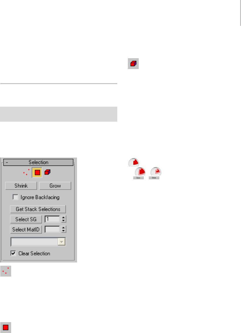
Selection Rollout (Projection Modifier) 771
Selection Check Rollout (Projection Modifier) (page
1–775)
Projection Rollout (Projection Modifier) (page
1–776)
Selection Rollout (Projection
Modifier)
Select an object. > Modify panel > Modifier List >
Object-Space Modifiers > Projection > Selection rollout
The Projection modifier’s Selection rollout is for
managing sub-object selections.
Interface
Cage—ClicktoturnontheCagesub-object
level.
TheCageisthesurfacefromwhichnormals
are projected. At the Cage sub-object level, you
can adjust the cage manually by transforming
sub-object selections of cage vertices.
Face—ClicktoturnontheFacesub-object
level.
The Face sub-object level lets you assign different
source geometry to different portions of a surface.
Element—Click to turn on the Element
sub-object level.
The element sub-object level lets you assign
different source geometry to individual elements.
(An element is a group of contiguous faces.)
Shrink—Reduces the sub-object selection area
by deselecting the outermost sub-objects. If
the selection size can no longer be reduced, the
remaining sub-objects are deselected.
Grow—Expands the selection area outward in all
available directions.
With Shrink and Grow, you can add or remove neighboring
elements from the edges of your current selection. Shrink and
Grow work at any sub-object level.
Ignore Backfacing—When on, selection of
sub-objects affects only those facing you. When
off, you can select any sub-objects under the
mouse cursor, regardless of visibility or facing. If
multiple sub-objects lie under the cursor, repeated
clicking cycles through them. Likewise, with
Ignore Backfacing off, region selection includes all
sub-objects, regardless of the direction they face.
Default=off.
Get Stack Selections—Click to collect sub-object
selections from modifiers that are below the
Projection modifier on the stack.
Select SG—To select by smoothing group value,
usethespinnertosetthenumberofthesmoothing
group, and then click Select SG.
Select MatID—To select by material ID, use the
spinner to set the ID number, and then click Select
MatID.
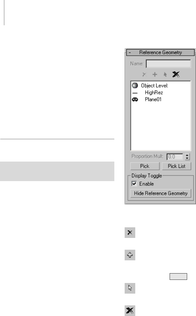
772 Chapter 8: Modifiers
•Sub-material drop-down list—When a
multi/sub-object material is applied to the
low-resobject,thislistshowsthenamesand
numbers of sub-materials that are assigned
tofacesorelementsoftheobject.Whenyou
have selected by material ID, the corresponding
sub-material appears in the field above the list.
Clear Selection—Whenon,eachstack,smoothing
group, or material ID selection you make replaces
the previous selection. When off, each new
selection is added to the previous selection set.
Default=on.
Reference Geometry Rollout
(Projection Modifier)
Select an object. > Modify panel > Modifier List >
Object-Space Modifiers > Projection > Reference
Geometry rollout
On the Reference geometry rollout, you can create
named sub-object selection sets, and associate
them with high-resolution geometry.
Interface
Name—Lets you enter a name for the current set
of selected sub-objects.
Delete—Click to delete the sub-object
selectionsetwhosenameishighlightedinthelist.
Add—Click to add the named sub-object
selection set to the list.
Keyboard shortcut: Enter .
Select—Click to select the sub-objects in the
selectionsetwhosenameishighlightedinthelist.
Delete All—Click to delete all named
sub-object selection sets in the list.
Reference geometry window—This window shows
a list of named sub-object selection sets, and the
high-resolution source geometry with which

Cage Rollout (Projection Modifier) 773
they’reassociated.Ifyouhavepickedahigh-res
object at the object level, it also shows “Object
Level” followed by the name of the source object.
Proportion Multiplier—When Proportional is
chosen for sub-object normal bump mapping in
the Projection Mapping group of the Objects To
Bake rollout (page 3–158) for Render To Texture,
this value multiplies the default size of the normal
bump map. Range=0.0 to 2.0. Default=1.0.
For example, if Proportional rendering of a
sub-object were to render a sub-object selection
at 16 x 16 pixels, changing Proportion Multiplier
to2.0wouldchangethesizeofthenormalbump
map to 32 x 32 pixels.
This control is unavailable unless a sub-object
selection is active.
Pick—To a s s o c i a t e h i g h - r e s g e o m e t r y w i t h t h e
current selection, click Pick to turn it on, then
click a source object in a viewport.
Pick List—To a s s o c i a t e h i g h - r e s g e o m e t r y w i t h
the current selection, click Pick List, then use
the Select Objects dialog (page 1–78) to choose a
source object.
Display Toggle group
The Display Toggle group is useful when you
want to compare the hi—res to your low-res
geometry. You can quickly toggle between your
low-res geometry and your hi-res geometry to
compare versions. You can show selected or all
hi-res geometry.
Enable—When on, makes it possible to show or
hide reference geometries. Default=off.
Hide Reference Geometry/Hide Working
Geometry—When Enabled is on, click Hide
Reference Geometry to hide your hi-res geometry.
Conversely, click Hide Working Geometry to hide
your low-res geometry. You can also selectively
show and hide high-res geometries in your Pick
List. Click Off to hide a geometry. Click Hide
to show a geometry.
Cage Rollout (Projection Modifier)
Select an object. > Modify panel > Modifier List >
Object-Space Modifiers > Projection > Cage rollout
These settings adjust the cage and its display.
The cage is the nonrenderable geometry that the
Projection modifier uses as the surface from which
it ray-traces normals.
Note: Special export/import functionality
available on this rollout lets you convert the cage
intostandardgeometryofthesametypeand
topologyasthecageandmodifiedobject,which
you can edit using standard methods and then use
to define a new shape for the cage. This provides
access to the full range of mesh-editing tools
available in 3ds Max for shaping the cage to your
precise requirements. For example, with editable
poly, you can take advantage of tools such as
Loop,Ring,Grow,andShrink,andquicklyswitch
among sub-object levels such as Face and Vertex.
Procedure
To use Export and Import with a cage:
1. Create a cage:
1. Create low-resolution and high-resolution
objects. In most cases, for best results they
should be arranged concentrically.
2. Apply the Projection modifier to the
low-resolution object.
This creates the cage with the same shape
and position as the low-resolution object.
3. UsetheReferenceGeometryrolloutcontrols
to specify one or more high-resolution
objects.
4. On the Cage rollout, click Update.
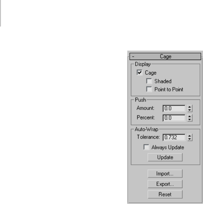
774 Chapter 8: Modifiers
This reshapes the cage, roughly enveloping
the high-resolution object(s).
2. OntheCagerollout,clickExport.
This creates a separate geometrical object in the
same shape as the cage, with the same type and
topology as the low-resolution object. We’ll call
this the cage object.
For example, if the low-resolution object is an
editable poly, or has an Edit Poly modifier at
the top of the modifier stack, the resultant cage
object is of editable poly type.
3. Use standard object-editing tools to modify the
cage object’s shape. Do not alter its topology
by adding or removing vertices, edges, etc.,
because that would invalidate its usage for
reshaping the cage. Also, for best results, do
not move the cage object. If you wish, you can
temporarily hide any overlapping objects.
4. Select the low-resolution object.
5. OntheCagerollout,clickImportandthen
selectthecageobject.
Ifthecageobjecttypeandtopologyare
the same as the low-resolution object, the
software reshapes the cage to match the cage
object’s shape. Alternatively, if the cage object
canbeconvertedtothesametypeasthe
low-resolution object without a change in
topology, it is also accepted. If not, a warning
appears and no reshaping takes place.
Important: The resultant cage matches the
imported cage object’s shape, position, orientation,
and size exactly.
If the import is successful, the cage object can
bedeleted,orretainedforpossiblefuturecage
modification.
Interface
Display group
Cage—When on, the cage is displayed. When off,
the cage is hidden except at the Cage sub-object
level. Default=on.
ThecageisalwaysdisplayedattheCagesub-object
level, regardless of this toggle’s setting. See
Selection Rollout (Projection Modifier) (page
1–771).
•Shaded—When on, the cage is shaded with
atransparentgray. Whenoff,thecageis
displayed as a blue lattice. Default=off.
The Shaded option can be useful when you
need to tell whether or not high-resolution
source geometry is within the cage, and when
you need to expand the cage to include more
geometry.
•Point to Point—When on, additional lines
connect vertices in the cage to points on the

Selection Check Rollout (Projection Modifier) 775
target object, showing how the projection will
be done. Default=off.
Push group
These controls let you adjust the size of the cage
as a whole, or on a sub-object selection if one is
currently chosen (see Reference Geometry Rollout
(Projection Modifier) (page 1–772)).
Amount—Changetoadjustthesizeofthecage
in 3ds Max units. Positive values increase the
size of the cage; negative values decrease the size.
Default=0.0.
Percent—Changetoadjustthesizeofthecage
as a percentage. Positive values increase the size
of the cage; negative values decrease the size.
Default=0.0.
Auto-Wrap group
By default, the Projection modifier does not
automatically create a cage that wraps around the
geometry. To change the cage, use the settings
in this group or the Push group, or adjust cage
vertices manually at the Cage sub-object level.
Tolerance—Thedistancein3dsMaxunits,
between the cage and the target geometry. Positive
values are outside the high-res source geometry;
negative values are inside the source geometry.
Default=varies, depending on the geometry.
Always Update—When on, the cage automatically
expandsaroundhigh-resgeometryasitisaddedto
the list (see Reference Geometry Rollout (Projection
Modifier) (page 1–772)). When off, the initial cage
is not updated automatically. Default=off.
Update—Click to update the cage. Use this when
Always Update is off.
Import—Lets you specify a mesh object to
define the cage shape. This is typically an object
that was created with Export (see following)
and then modified using standard mesh-editing
methods. After clicking Import, select the object
to import. After importing the object, the cage
conforms to its shape. You can then delete the
imported object if you wish.
Important: Theimportedobjectshouldbeofthesame
type (for example, editable mesh) as the projection
object(thatis,theobjectwiththeProjectionmodifier),
or be convertible to that type without topology change,
and must have the identical topology. If it doesn’t
meet either or both of those criteria, an alert appears
requesting that you select an object of the same type
and identical topology.
Export—Creates a geometry object from
thecage,withthesametypeandtopologyas
the modified object. Clicking Export causes the
Export Cage dialog to open. Accept the default
“Export as” object name or enter a new one, and
then click OK.
For a detailed description of the export/import
process, see To use Export and Import with a cage:
(page 1–773).
Reset—Click to reset the cage to a wrapping
that is the same size as the low-resolution target
geometry.
Selection Check Rollout
(Projection Modifier)
Select an object. > Modify panel > Modifier List >
Object-Space Modifiers > Projection > Selection Check
rollout
This rollout lets you check selections to see if any
are overlapping; that is, if a material ID or a face or
element is assigned to more than one selection.
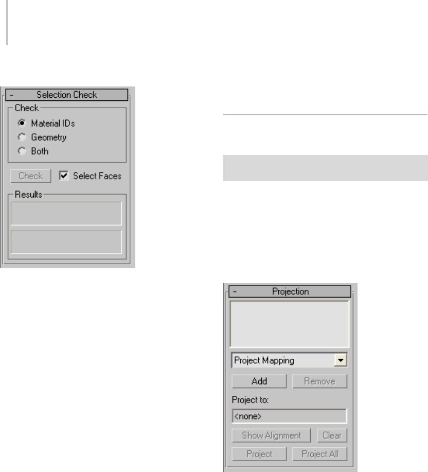
776 Chapter 8: Modifiers
Interface
Check group
•Material IDs—Checks for material IDs being
assigned to more than one selection.
•Geometry—Checks for faces or elements being
assigned to more than one selection.
•Both—(The default.) Checks for both material
ID and sub-object overlap.
Check—Click to run the check.
Select Faces—When on, if running the selection
check detects “bad” selections, the “bad” faces are
selected by the Projection modifier automatically.
When off, “bad” selections are not selected
automatically. Default=on.
Results group
After you click Check, the fields in this group
display the results. The first field is for material
IDs, and the second is for sub-object selections.
If there is no conflict, the first field says “No
conflicting Mat IDs detected,” and the second says
“No conflicting face selections detected.” If there
is a conflict, the results say something such as, “6
Mat IDs are assigned to more than one selection.”
Projection Rollout (Projection
Modifier)
Select an object. > Modify panel > Modifier List >
Object-Space Modifiers > Projection > Projection rollout
The Projection rollout has controls for projecting
data from the object with the Projection modifier
to adifferentobject.Thisdataflowisthereverse
of what it is when you project normals from a
high-resolution object to a low-resolution object.
Interface
Projector list—Shows the active projector plug-ins.
Projector plug-in drop-down list—Lets you choose
a projector plug-in. Only one projector, Project
Mapping, is provided with 3ds Max. See Project
Mapping Rollout (Projection Modifier) (page
1–777). Additional projectors might be available
from third-party sources.
Note: Multiple instances of the Project Mapping
plug-in can be active.
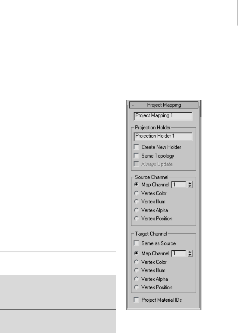
Project Mapping Rollout (Projection Modifier) 777
Add—Addsaprojectorofthetypechoseninthe
drop-down list.
Remove—Removes the projector that is currently
highlighted in the projector list.
Project to—Shows the name of the geometry to
which you’re projecting. To choose this geometry,
use the Reference Geometry rollout (page 1–772).
Show Alignment—Click to display the faces of the
geometry selection that will project to the selected
faces of the object that has the Projection modifier.
This shows which hi-res faces will be projected to
the selected low-res faces.
This works only for selected faces, not selected
vertices: you can lock a face selection and
then make adjustments to the cage, then click
Show Alignment to see the effects of the cage
modification.
This button is unavailable if no selection has been
made in the Reference Geometry rollout.
Clear—Click to turn off the Show Alignment
display.
Project—Click to perform the projection.
Project All—Click to perform all projections that
are in the projector list.
Project Mapping Rollout
(Projection Modifier)
Select an object. > Modify panel > Modifier List >
Object-Space Modifiers > Projection > Projection rollout
> Choose Project Mapping in the plug-in drop-down
list (this is the only available choice unless third-party
plug-ins have been installed). > Click Add > Project
Mapping rollout.
Select an object. > Modify panel > Modifier List >
Object-Space Modifiers > Projection > Projection rollout
> Highlight a Project Mapping projector in the Projector
list. > Project Mapping rollout.
The Project Mapping rollout contains controls
for the Project Mapping projector plug-in. This
rollout is visible when a Project Mapping instance
is highlighted in the Projector list on the Projection
rollout (page 1–776). Use Project Mapping to
project a map channel value, material IDs, or
vertex attributes from the object that has the
Projection modifier applied, onto other geometry.
Interface
Projector name field—Shows the name of the
Project Mapping projector. If you edit this field,
thechangeisreflectedontheProjection rollout
(page 1–776).

778 Chapter 8: Modifiers
Projection Holder group
Projection Holder name field—Shows the name
of the Projection Holder modifier. If you edit
thisfield,thechangeisreflectedinthetarget
object’s stack, but not until you click Project on
the Projection rollout.
Create New Holder—When you click the Project
button in the Project rollout, a Projection Holder
modifier is added to the geometry selection. When
Create New Holder is on, 3ds Max creates and adds
a new modifier each time you click Project. When
Create New Holder is off, clicking Project simply
updates the data in the existing Projection Holder;
it creates a new Projection Holder modifier only if
none was present, before. Default=off.
Same Topology—When on, the source object’s
topology is transferred to the target object.
Default=off.
Important: You need to turn on Same Topology when
you project to the target object’s Vertex Position.
Always Update—When on, changing the object
with the Projection modifier automatically
re-projects and updates the Projection Holder
modifiers on the geometry selections. When off,
projection is recalculated only when you click
Project. Default=off.
ThistoggleisavailableonlywhenCreateNew
Holder is off and Same Topology is on.
When Always Update is on, changes to the
geometry with the Projection modifier can
manipulate UVW channels or animate vertex
colors of the objects with the Projection Holder
modifiers.
Source Channel group
•Map Channel—(The default.) Projects a map
channel (page 3–966) value.
Usethespinnertosetthechannelvalue.
•Vertex Color—Projects vertex color values.
•Vertex Illum—Projects vertex illumination
(grayscale) values.
•Vertex Alpha—Projects vertex alpha values.
•Vertex Position—Projects vertex positions.
Target Channel group
Same as Source—When on, the radio buttons in
this group are disabled, and the Project Mapping
projector projects to the same channel that is
chosen in the Source Channel group. When
off, the radio buttons in this group are enabled.
Default=on.
Theradiobuttonsarethesameastheonesinthe
Source Channel group. When Same As Source is
off, the chosen map channel or vertex data of the
target geometry derives its value from the channel
or vertex data chosen in the Source Channel group.
The projection does not take place until you click
Project or Project All on the Projection rollout.
Project Material IDs—When on, projects material
ID values. Default=off.
The projection does not take place until you click
Project or Project All on the Projection rollout.
Projection Holder Modifier
Select an object. > Modify panel > Modifier List >
Object-Space Modifiers > Projection modifier > Geometry
rollout > Choose target geometry > Projection rollout >
Click Add. > Click Project. > Projection Holder is applied
to the target geometry.
The Projection Holder modifier appears for objects
being used by the Projection modifier’s Project
Mapping feature (page 1–776).Itcontainsthe
data generated by the Project Mapping operation,
much as UVW Mapping Add or UVW Mapping
Clear do for Channel Info manipulations.
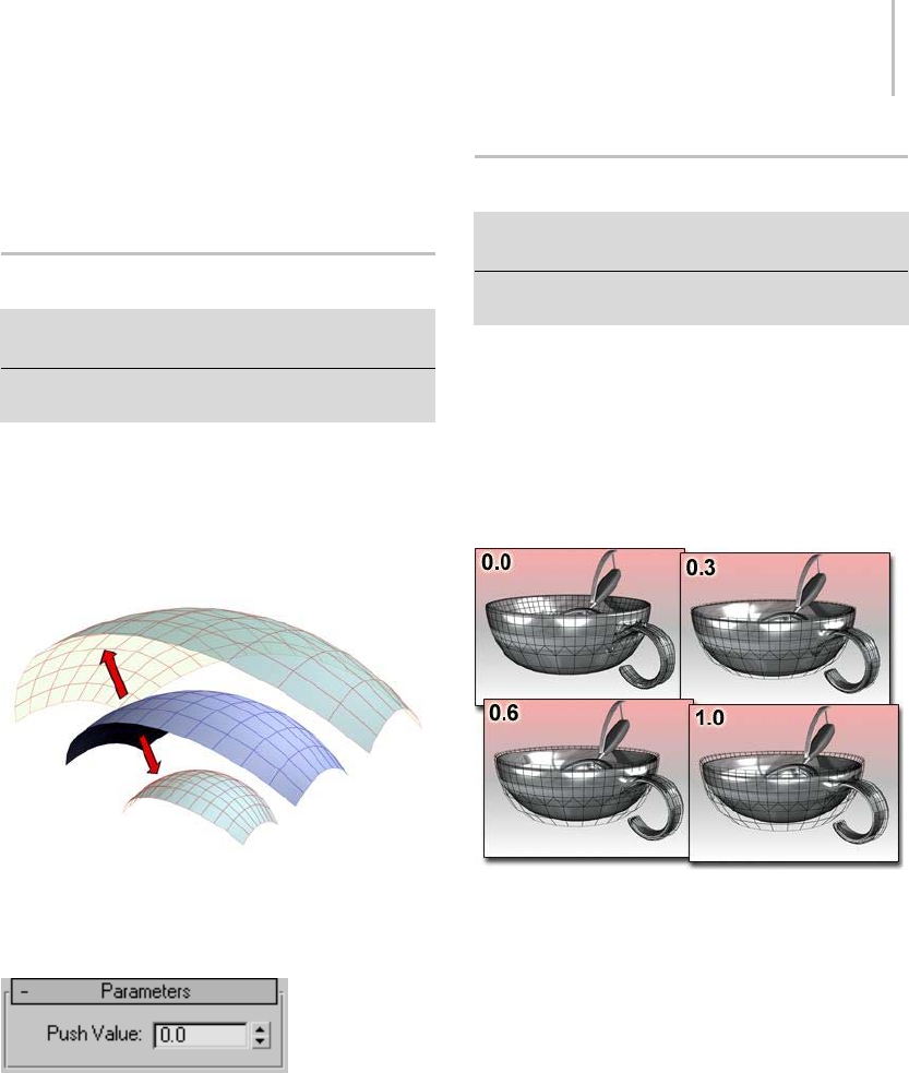
Push Modifier 779
Interface
The Projection Holder modifier has no parameters.
Push Modifier
Modify panel > Make a selection. > Modifier List >
Object-Space Modifiers > Push
Make a selection. > Modifiers menu > Parametric
Deformers > Push
The Push modifier lets you "push" object vertices
outward or inward along the average vertex
normals. This produces an "inflation" effect that
you can’t otherwise obtain.
Positive and negative amounts of push applied to an object.
Interface
Push Value—Sets the distance in world units by
whichverticesaremovedwithrespecttothe
object center. Use a positive value to move vertices
outward, or a negative value to move vertices
inward.
Relax Modifier
Modify panel > Make a selection. > Modifier List >
Object-Space Modifiers > Relax
Make a selection. > Modifiers menu > Parametric
Deformers > Relax
The Relax modifier changes the apparent surface
tensioninameshbymovingverticescloserto,or
away from, their neighbors. The typical result is
that the object gets smoother and a little smaller
astheverticesmovetowardanaveragedcenter
point. You can see the most pronounced effects on
objectswithsharpcornersandedges.
Relax moves the bowl away from its original contours.
When you apply Relax, each vertex is moved
toward the average position of its neighboring
vertices. A neighboring vertex is one that shares a
visible edge with the current vertex.
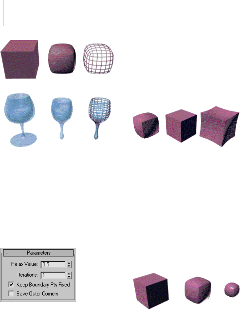
780 Chapter 8: Modifiers
Original objects compared to relaxed objects
Patches
As of version 4, a patch object coming up the
modifier stack is not converted to a mesh by
this modifier. A patch object input to the Relax
modifier retains its patch definition. If a file
created by a previous version of 3ds Max contains
a patch object applied with the Relax modifier, it
will be converted to a mesh to maintain backward
compatibility.
Interface
Relax Value—Controls how far a vertex moves for
each iteration. The value specifies a percentage
of the distance from the original location of a
vertex to the average location of its neighbors.
Range=-1.0 to 1.0. Default=0.5.
• Positive Relax values move each vertex in closer
to its neighbors. The object becomes smoother
and smaller.
•WhentheRelaxvalue=0.0,verticesdonot
move and Relax has no affect on the object.
• Negative Relax values move each vertex away
from its neighbors. The object becomes more
irregular and larger.
Relax Values=1.0, 0.0, -1.0
Iterations=1 (default)
Iterations—Sets how many times to repeat the
Relax process. For each iteration, average locations
arerecalculatedandtheRelaxValueisreappliedto
every vertex. Default=1.
• For 0 iterations, no relaxation is applied.
• IncreasingiterationsforpositiveRelaxValue
settings smooths and shrinks an object. With
very large iteration values, the object shrinks
to a point.
• Increasing iterations for negative Relax Value
settings exaggerates and expands an object.
With relatively few iterations, the object
becomes jumbled and almost unusable.
Iterations=0, 10, 50
Relax Value=0.5 (default)
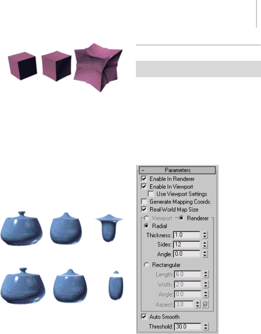
Renderable Spline Modifier 781
Iterations=0,1, 5
Relax Value=-0.5
Keep Boundary Pts Fixed—Controls whether
vertices at the edges of open meshes are moved.
Default=on.
When Keep Boundary Pts Fixed is on, boundary
verticesdonotmovewhiletherestoftheobject
is relaxed. This option is particularly useful
when working with multiple objects, or multiple
elements within a single object, that share open
edges.
When this check box is off, all vertices of the object
are relaxed.
Keep Boundary Pts Fixed=on
Iterations=0, 10, 50
Keep Boundary Pts Fixed=off
Iterations=0, 10, 50
Save Outer Corners—Preserves the original
positions of vertices farthest away from the object
center.
Renderable Spline Modifier
Select a shape. > Modify panel > Modifier List >
Renderable Spline
TheRenderableSplinemodifierletsyousetthe
renderable properties of a spline object, without
collapsingthesplinetoaneditablespline.Thisis
particularly useful with splines you have linked
to from AutoCAD. It also lets you apply the same
rendering properties to multiple splines at once.
Note: This modifier cannot be applied to NURBS
curves.
Interface
Enable In Renderer—When on, the shape is
rendered as a 3D mesh using the Radial or
Rectangular parameters set for Renderer. In
previous versions of the program, the Renderable
switch performed the same operation.

782 Chapter 8: Modifiers
Enable In Viewport—When on, the shape is
displayedintheviewportasa3Dmeshusingthe
Radial or Rectangular parameters set for Renderer.
In previous versions of the program, the Display
Render Mesh performed the same operation.
Use Viewport Settings—Lets you set different
parameters for viewport display and rendering,
anddisplaysthemeshgeneratedbytheViewport
settings in the viewports. Available only when
Enable in Viewport is turned on.
Generate Mapping Coords—Tur n t hi s on to a pp ly
mapping coordinates. Default=off.
3ds Max generates the mapping coordinates in
the U and V dimensions. The U coordinate
wraps once around the spline; the V coordinate is
mappedoncealongitslength.Tilingisachieved
using the Tiling parameters in the applied material.
For more information, see Mapping Coordinates
(page 2–1405).
Real-World Map Size—Controls the scaling method
used for texture mapped materials that are applied
totheobject. Thescalingvaluesarecontrolled
by the Use Real-World Scale settings found in
the applied material’s Coordinates rollout (page
2–1625).Default=on.
Viewport—Choose this to specify Radial or
Rectangular parameters for the shape as it will
display in the viewport when Enable In Viewport
is on. Available only when Use Viewport Settings
is on
Renderer—Choose this to specify Radial or
Rectangular parameters for the shape as it will
display when rendered or displayed in the viewport
when Enable in Viewport is turned on.
Radial—Displaysthesplineasa3Dobjectwitha
circular cross-section.
•Thickness—Specifies the cross-section diameter.
Default=1.0. Range=0.0 to 100,000,000.0.
•Sides—Sets the number of sides for the spline
mesh in the viewports or renderer. For example,
a value of 4 produces a square cross-section.
•Angle—Adjust the rotational position of the
cross section in the viewports or renderer. For
example, if you have a square cross section you
canuseAngletopositiona“flat”sidedown.
Rectangular—Displaysthesplineasa3Dobject
with a rectangular cross-section.
•Length—Specifies the size of the cross–section
along the local Yaxis.
•Width—Specifies the size of the cross–section
along the local Xaxis.
•Angle—Adjusts the rotational position of the
cross-section in the viewport or renderer. For
example, if you have a square cross-section you
can use Angle to position a "flat" side down.
•Aspect—Sets the aspect ratio for rectangular
cross-sections. The Lock check box lets you
lock the aspect ratio. When Lock is turned
on, Width is locked to Depth that results in a
constant ratio of Width to Depth.
Auto Smooth—When on, the spline is
auto-smoothed using the smoothing angle
specified by the Threshold setting. Auto Smooth
sets the smoothing based on the angle between
spline segments. Any two adjacent segments are
put in the same smoothing group if the angle
betweenthemislessthanthethresholdangle.
Note: Turning Auto Smooth on for every situation
doesnotalwaysgiveyouthebestsmoothing
quality. AlteringtheThresholdanglemaybe
necessary or turning Auto Smooth off may
produce the best results.
Threshold—Specifies the threshold angle in
degrees. Any two adjacent spline segments are
placed in the same smoothing group if the angle
betweenthemislessthanthethresholdangle.
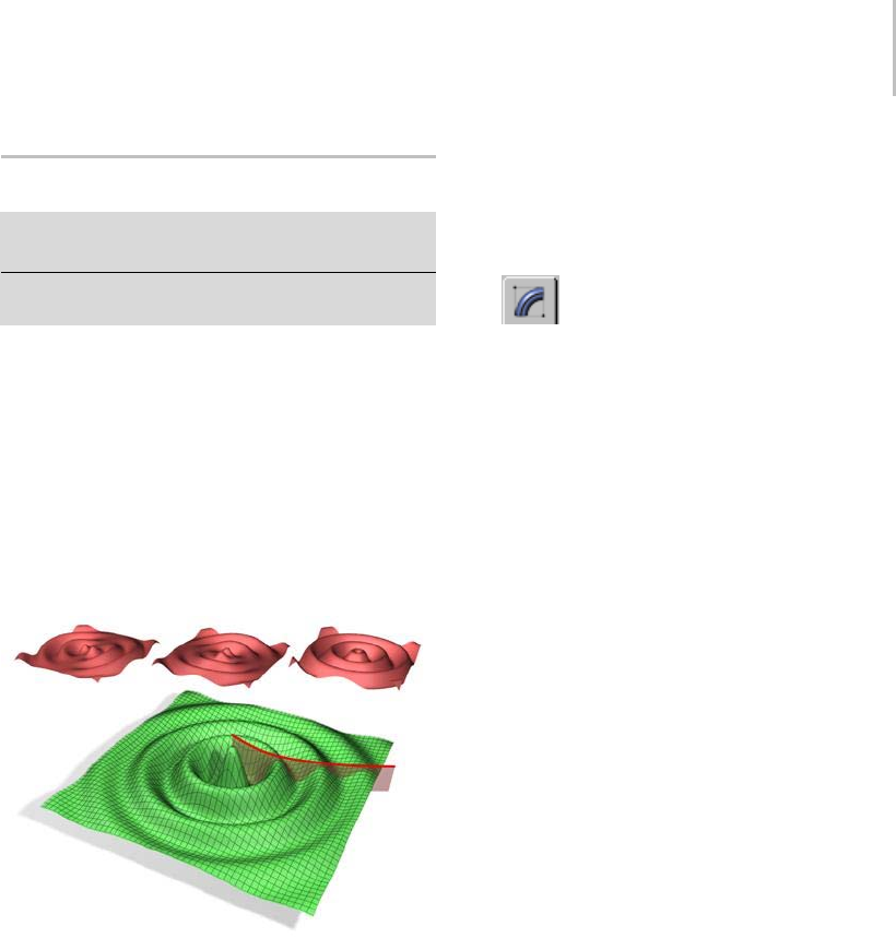
Ripple Modifier 783
Ripple Modifier
Modify panel > Make a selection. > Modifier List >
Object-Space Modifiers > Ripple
Make a selection. > Modifiers menu > Parametric
Deformers > Ripple
The Ripple modifier lets you produce a concentric
rippling effect in an object’s geometry. You can
seteitheroftworipplesoracombinationofboth.
Rippleusesastandardgizmoandcenter,which
you can transform to increase the possible ripple
effects.
The Ripple (page 2–102) space warp has similar
features. It is useful for applying effects to a large
number of objects.
An object with the Ripple modifier applied.
Top (from left to right): Amplitude 1 only, Amplitude 2 only and
both amplitudes.
Bottom: Both amplitudes with the Decay effect.
See also
Wave Modifier (page 1–957)
Procedure
Example: To use the Ripple modifier:
1. Start with an empty scene, and add a Plane
object (page 1–185) in the Perspective viewport.
SetLengthandWidthbothto100.0,andset
Length Segs and Width Segs both to 10.
The Plane object is useful as the basis for the
surface of a body of water in which ripples form.
2. Go to the Modify panel, click Modifier
List,and,fromtheObject-SpaceModifierslist,
choose Ripple.
This applies the modifier to the Plane object.
3. On the Parameters rollout, set Amplitude 1 to
10.0.
A large ripple forms in the Plane object.
You can change the horizontal scale by adjusting
thewavelength.
4. Set Wave Length to 20.0.Thewavesbecome
smaller, but now it’s apparent that the Plane
object needs greater geometric resolution to
properly display the number of waves.
5. In the modifier stack, click the Plane item, and
then set Length Segs and Width Segs both to 30.
The smaller waves become more apparent. The
Ripple modifier needs a relatively high number
of subdivisions in the geometry it’s applied to
in order to work properly.
YoucanusetheAmplitude2parametertoadd
complexity to the wave forms created by Ripple.
6. ReturntotheRipplelevelofthemodifierstack,
andthenclickandholdontheAmplitude2and
drag downward.
As you drag, a new set of wave forms are
combined with the existing ones. The farther
youdrag,themoredominantthesecondset
becomes. Using a negative value for Amplitude
2 (or a positive one if Amplitude 1 is negative)
produces more of an interference effect between
the two sets of waves.
You can animate the waves with the Phase
control.
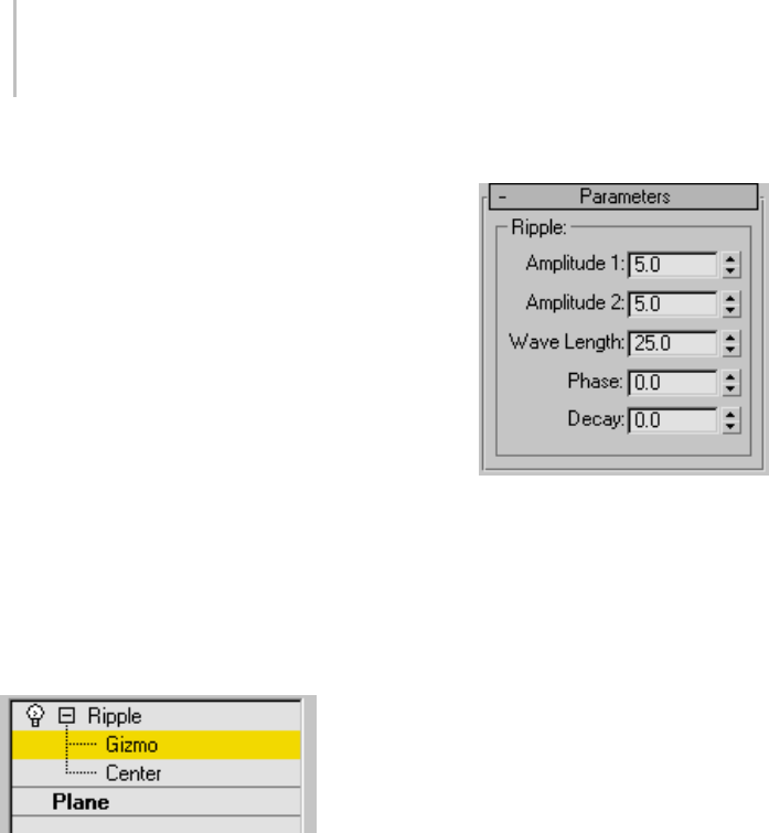
784 Chapter 8: Modifiers
7. Drag slowly upward or downward on the Phase
spinner.
Increasing the Phase value moves the waves
inward, and decreasing it moves the outward.
To a n i m at e t h e w av e s , c r e at e keyframes (page
3–717) for the Phase value.
To simulate an object dropping in liquid, use
the Decay setting.
8. Drag slowly upward on the Decay spinner.
Thefartheryoudrag,themorethewavesizes
decrease with the distance from the center of
the effect. This is the effect you get when an
object perturbs the water surface, and the waves
lose energy as they move away from the point
of impact.
Interface
Modifier Stack
Gizmo—At this sub-object level, you can transform
and animate the gizmo like any other object,
altering the effect of the Ripple modifier.
Trans lat ing the g izmo trans late s its center an equa l
distance. Rotating and scaling the gizmo takes
place with respect to its center.
Center—At this sub-object level, you can translate
and animate the center of the ripple effect, and
thus the shape and positions of the ripples.
For more information on the stack display, see
Modifier Stack (page 3–760).
Parameters rollout
Amplitude 1/ Amplitude 2—Amplitude 1 produces
arippleacrosstheobjectinonedirection,while
Amplitude 2 creates a similar ripple at right angles
to the first (that is, rotated 90 degrees about the
vertical axis).
Wave Length—Specifies the distance between the
peaks of the wave. The greater the length, the
smootherandmoreshallowtherippleforagiven
amplitude. Default=50.0.
Phase—Shiftstheripplepatternovertheobject.
Positive numbers move the pattern inward, while
negativenumbersmoveitoutward. Thiseffect
becomes especially clear when animated.
Decay—Limits the effect of the wave generated
from its center.
The default value of 0.0 means that the wave will
generate infinitely from its center. Increasing
theDecayvaluecausesthewaveamplitudesto
decrease with distance from the center, thus
limiting the distance over which the waves are
generated.
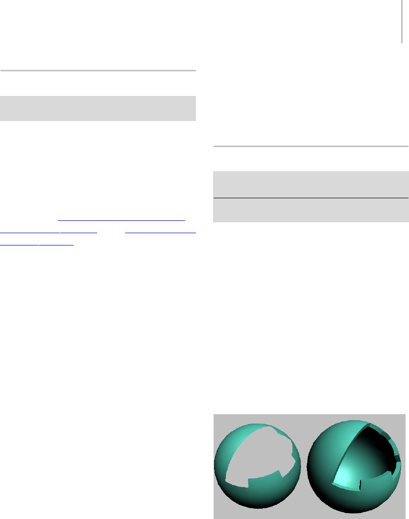
Select By Channel Modifier 785
Select By Channel Modifier
Select an object. > Modify panel > Modifier List > Select
By Channel
The Select By Channel modifier works in
conjunction with the Channel Info utility (page
2–1738). After you store a vertex selection into a
subcomponent with Channel Info, use Select By
Channel to quickly access the selection.
You can find an advanced example of using Select
By Channel in alesson about allowing objects to
survive topology changes,intheUsing the Channel
Info Utility tutorial.
Procedure
To use Select By Channel:
1. UseChannelInfotostoreoneormorevertex
selections in a map channel subcomponent.
2. Apply the Select By Channel modifier to the
object with the stored vertex selection(s).
3. Choose the selection type.
4. Choose the selection channel.
5. To “bake” the new selection into the object,
collapse the stack.
Interface
Selection Type—Lets you choose how to combine
the stored vertex selection with an existing vertex
selection.
•Replace—Replaces the existing selection with
the stored selection.
•Add—Adds the stored selection to the existing
selection.
•Subtract—Subtracts the stored selection from
the existing selection. Has no effect if there’s no
overlap between the stored selection and the
existing selection.
Selection Channel—Lets you choose which stored,
named vertex-selection channel to apply to the
modified object. Click the arrow to the right of the
name field to open the drop-down list, and then
click a channel in the list.
Shell Modifier
Modify panel > Make a selection. > Modifier List >
Object-Space Modifiers > Shell
Make a selection. > Modifiers menu > Parametric
Deformers > Shell
The Shell modifier “solidifies” or gives thickness
to an object by adding an extra set of faces facing
the opposite direction of existing faces, plus edges
connecting the inner and outer surfaces wherever
faces are missing in the original object. You can
specify offset distances for the inner and outer
surfaces, characteristics for edges, material IDs,
and mapping types for the edges.
Also, because the Shell modifier doesn’t have
sub-objects, you can use the Select options to
specify a face selection for passing up the stack to
other modifiers. Please note that the Shell modifier
doesn’t recognize existing sub-object selections,
nordoesitpasssuchselectionsupthestack.
Left: Sphere with part of surface removed; Right: Sphere with
Shell applied
You’d typically use Shell on an object with part of
its surface removed, such as a sphere with several
deleted vertices or faces, as illustrated above. For
best results, the original polygons should face

786 Chapter 8: Modifiers
outward. If an object has no faces with at least one
free edge, Shell will not create any edges.
Examples of Shell Usage
Following are some examples of modeling tasks
forwhichtheShellmodifierwouldbeappropriate:
• Anartistismodelingavehiclesuchasacar,a
tank,or,inthiscase,ahelicopter.Theartist
builds a solid external shell as the body of the
copter. When done, the modeler breaks up his
model: he selects window areas and detaches
them as new objects, followed by the area for
the doors (also detached as new objects). The
modeler now has open objects representing
the body, windows, and doors. The modeler
applies Shell to the body, and sets it to extrude
both outward and inward a set number of units,
setting the inward extrusion to be greater than
the outward. Shell is applied to the windows
next; these are set to extrude inward only. The
modeler then copies the Shell modifier from
the body to the doors, and reduces the doors’
outward extrusion somewhat. The result is
a solid body with an interior that can accept
additional modeling, inset windows, and doors
that are slightly less thick than the shell of the
helicopter.
• A designer is modeling a manufactured object
thatwillneedtobeshowninanexploded
view. It might be a cell phone, an engine, a
mouse, shaped glass, or something similar;
this example will use part of a cell phone.
When working on the phone keypad area, if the
modeler builds with detail in mind, she might
accurately model the shell with a moderately
dense mesh, using ShapeMerge (page 1–336)
to create the shapes for the holes where the
keys will poke through, and then deleting those
faces. When satisfied, the modeler applies the
Shell modifier, sets Segments to 2, and then
turns on the Bevel Edges option to use a curve
for the profile of the holes’ edges. She then
applies a MeshSmooth modifier on top. The
extra segment helps control the curve of the
edges where the outer surface curves down to
the keypad holes. The modeler then goes back
to the cage portion of the stack and refines the
base mesh details to her liking.
• A modeler is creating a suit of futuristic armor
for a character. The modeler copies a selection
of polygons from the character mesh to a new
object; for example, the polygons that make up
the arm. The modeler deletes some faces from
the copied arm, and perhaps cuts some holes
fromit. HethenappliestheShellmodifier,
followed by a MeshSmooth modifier, resulting
in form-fitting armor.
Procedure
To solidify an object:
1. Create an object to solidify. The object should
have some holes in its surface. For example,
start with a primitive sphere, convert it to
Editable Poly, and delete some vertices or
polygons.
2. Optionally create an open spline to serve as
theprofilefortheedgesconnectingtheinner
and outer surfaces. For example, go to Create
panel > Shapes and click Line. Then, in the
To p v i e w p o r t , d r a w t h e s p l i n e i n t h e To p
viewport from top to bottom. Where the spline
protrudes to the right, the edge surface will be
convex, and where it protrudes to the left, the
surface will be concave.
3. Apply the Shell modifier to the object from step
1.
4. To use custom edges, turn on Bevel Edges, click
the Bevel Spline button, and then select the
spline from step 2.
5. By default, Shell keeps the material IDs of
the new surfaces consistent with those of the
original object. To change these, turn on the
different Override options, specify appropriate
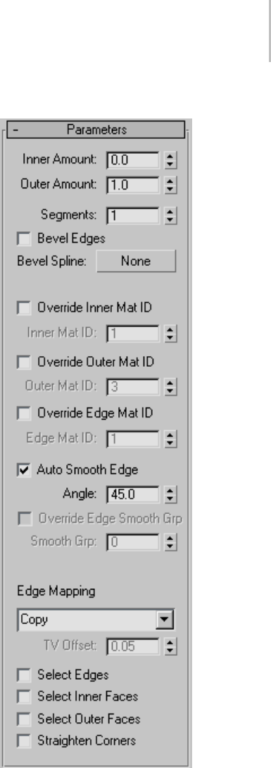
Shell Modifier 787
material IDs, and apply a Multi/Sub-Object
material (page 2–1594).
6. Likewise, Shell keeps the texture coordinates
of the new surfaces consistent with those of
the original object. To change these on the
new edges, change the Edge Mapping choice,
and with the Strip and Interpolate choices,
optionally change the TV Offset setting.
Interface
Inner/Outer Amount—Distance in 3ds Max generic
units by which the inner surface is moved inward
and the outer surface is moved outward from their
original positions. Defaults=0.0 / 1.0.
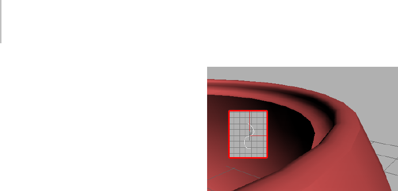
788 Chapter 8: Modifiers
The sum of the two Amount settings determines
thethicknessoftheobject’sshell,aswellasthe
default width of the edges. If you set both to 0, the
resultant shell has no thickness, and resembles an
object set to display as 2-sided.
Segments—The number of subdivisions across
each edge. Default=1.
Change this setting if you need greater resolution
ontheedgeforusebysubsequentmodelingor
modifiers.
Note: When you use a Bevel Spline, the spline’s
properties override this setting.
Bevel Edges—When on, and you specify a Bevel
Spline,thesoftwareusesthesplinetodefinethe
edges’ profile and resolution. Default=off.
After you define a Bevel Spline, use Bevel Edges
to switch between a flat edge whose resolution
is defined by the Segments setting and a custom
profile defined by the Bevel Spline.
Bevel Spline—Click this button and then select
an open spline to define the edge shape and
resolution.ClosedshapessuchasCircleorStar
will not work.
TheoriginalsplineisinstancedtotheBevelSpline,
so changing the spline’s shape and properties are
reflected in the Bevel Spline. With non-corner
vertices, you can change the edge resolution with
the spline’s Interpolation rollout settings.
A bevel spline as viewed from the top (inset) and the resulting
bevel
Tip: Forbestresults,createthesplineintheTop
viewport, and draw it from top to bottom. The
toppointonthesplineisappliedtotheoutside
edge, and the bottom point to the inside edge.
Displacements to the right will create outward
protrusions on the edge profile, and displacements
totheleftcreateinwardprotrusions.
Override Inner Mat ID—Tur n on t o s pe cif y a
material ID for all of the inner surface polygons
using the Inner Mat ID parameter. Default=off.
If you don’t specify a material ID, the surface uses
thesamematerialIDorIDsastheoriginalfaces.
Inner Mat ID—Specifies the material ID for inner
faces. Available only when Override Inner MatID
is on.
Override Outer Mat ID—Tu r n on to s pe ci f y a
material ID for all of the outer surface polygons
using the Outer Mat ID parameter. Default=off.
If you don’t specify a material ID, the surface uses
thesamematerialIDorIDsastheoriginalfaces.
Outer Mat ID—Specifies the material ID for outer
faces. Available only when Override Outer MatID
is on.
Override Edge Mat ID—Tur n o n t o s pe cif y a
material ID for all of the new edge polygons using
theEdgeMatIDparameter.Default=off.

Shell Modifier 789
If you don’t specify a material ID, the surface uses
thesamematerialIDorIDsastheoriginalfaces
from which the edges are derived.
Edge Mat ID—Specifies the material ID for edge
faces. Available only when Override Edge MatID
is on.
Auto Smooth Edge—Applies automatic,
angle-based smoothing across the edge faces using
the Angle parameter. When off, no smoothing is
applied. Default=on.
This doesn’t apply smoothing across the junction
between the edge faces and the outer/inner surface
faces.
Angle—Specifies the maximum angle between
edge faces that will be smoothed by Auto Smooth
Edge. Available only when Auto Smooth Edge is
on. Default=45.0.
Faces that meet at an angle greater than this value
will not be smoothed.
Override Smooth Group—Lets you specify a
smoothing group (page 3–1013) for the new edge
polygons using the Smooth Grp setting. Available
only when Auto Smooth Edge is off. Default=off.
Smooth Grp—Sets the smoothing group for the
edge polygons. Available only when Override
Smooth Group is on. Default=0.
When Smooth Grp is set to the default value of
0, no smoothing group is assigned to the edge
polygons. To specify a smoothing group, change
the value to a number between 1 and 32.
Note: When Auto Smooth Edge and Override
Smooth Group are both off, the software assigns
smoothing group 31 to the edge polygons.
Edge Mapping—Specifies the type of texture
mappingthatisappliedtothenewedges.Choose
a mapping type from the drop-down list:
•Copy—Each edge face uses the same UVW
coordinates as the original face from which it’s
derived.
•None—Each edge face is assigned a U value of 0
and a V value of 1. Thus, if a map is assigned,
the edges will take the color of the upper-left
pixel.
•Strip—Theedgesaremappedinacontinuous
strip.
•Interpolate—Theedgemappingisinterpolated
from the mapping of the adjacent inner and
outer surface polygons.
TV Offset—Determinesthespacingofthetexture
vertices across the edges. Available only with
the Edge Mapping choices Strip and Interpolate.
Default=0.05.
Increasing this value increases the repetition of the
texturemapacrosstheedgepolygons.
Select Edges—Selects the edge faces. This
selection is passed up the stack to other modifiers.
Default=off.
Select Inner Faces—Selects the inner faces. This
selection is passed up the stack to other modifiers.
Default=off.
Select Outer Faces—Selects the outer faces. This
selection is passed up the stack to other modifiers.
Default=off.
Straighten Corners—Adjusts corner vertices to
maintain straight-line edges.
If you apply Shell to a subdivided object with
straight edges, such as a box set to 3x3x3 segments,
you might find that the corner vertices don’t stay
in a straight line with the other edge vertices. This
givestheedgesabulginglook.Toresolvethis,turn
on Straighten Corners.
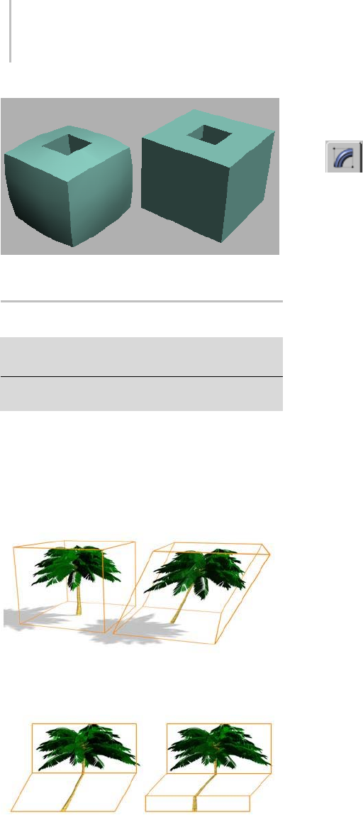
790 Chapter 8: Modifiers
Box with Straighten Corners off (left) and on (right)
Skew Modifier
Modify panel > Make a selection. > Modifier List >
Object-Space Modifiers > Skew
Make a selection. > Modifiers menu > Parametric
Deformers > Skew
The Skew modifier lets you produce a uniform
offset in an object’s geometry. You can control the
amount and direction of the skew on any of three
axes.Youcanalsolimittheskewtoasectionof
the geometry.
Skew modifier applied
Effect of moving modifier center with limits set
Procedures
To skew an object:
1. Select an object, go to the Modify panel,
and choose Skew from modifier list.
2. On the Parameters rollout, set the axis of the
skew to X, Y, or Z. This is the axis of the Skew
gizmo, not the axis of the selected object.
You can change the axis at any time, but only
one axis setting is carried with the modifier.
3. Set the amount of the skew. The amount is an
offset in current units parallel with the axis.
The object skews to this amount beginning at
the lower limit, by default the location of the
modifier’s center.
4. Set the direction of the skew.
Theobjectswivelsaroundtheaxis.
You can reverse the amount and direction by
changing a positive value to a negative value.
To limit the skew:
1. Turn on Limits group > Limit Effect.
2. Set values for the upper and lower limits. These
are distances in current units above and below
the modifier’s center, which is at zero on the
gizmo’s Z axis. The upper limit can be zero or
positive, the lower limit zero or negative. If the
limits are equal, the result is the same as turning
off Limit Effect.
The skew offset is applied between these limits.
The surrounding geometry, while unaffected
by the skew itself, is moved to keep the object
intact.
3. At the sub-object level, you can select and move
the modifier’s center.
The limit settings remain on either side of the
center as you move it. This lets you relocate the
skew area to another part of the object.
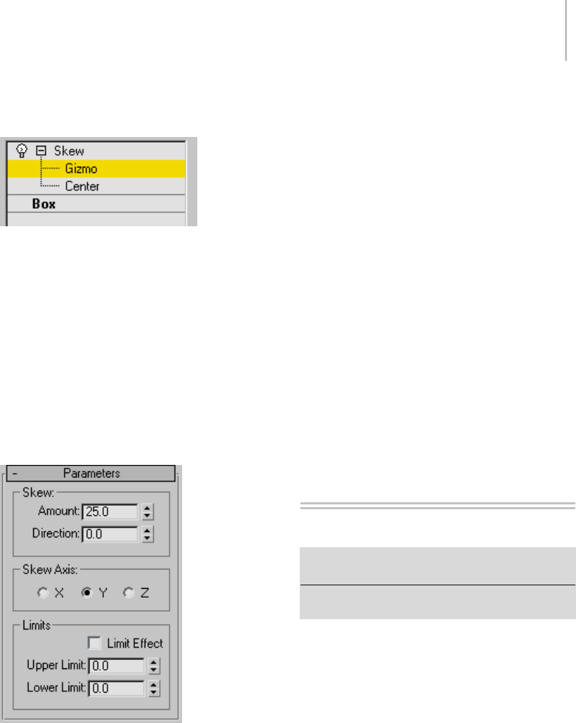
Skin Modifier 791
Interface
Modifier Stack
Gizmo—At this sub-object level, you can transform
and animate the gizmo like any other object,
altering the effect of the Skew modifier. Translating
the gizmo translates its center an equal distance.
Rotating and scaling the gizmo take place with
respect to its center.
Center—At this sub-object level, you can translate
and animate the center of the Skew effect.
For more information on the stack display, see
Modifier Stack (page 3–760).
Parameters rollout
Skew group
Amount—Sets the angle to skew from the vertical
plane.
Direction—Sets the direction of the skew relative
to the horizontal plane.
Skew Axis group
X/Y/Z—Specify the axis that will be skewed. Note
that this axis is local to the Skew gizmo and not
related to the selected entity. Default=Z.
Limits group
Limit Effect—Applies limit constraints to the Skew
modifier.
Upper Limit—Sets the upper limit boundaries in
world units from the skew center point, beyond
which the skew no longer affects the geometry.
Default=0.
Lower Limit—Sets the lower limit boundaries in
world units from the skew center point, beyond
which the skew no longer affects the geometry.
Default=0.
Skin Modifier
Select a mesh, patch, or NURBS object. > Modify panel >
Modifier List > Object-Space Modifiers > Skin
Select a mesh, patch, or NURBS object. > Modifiers menu
>AnimationModifiers>Skin
The Skin modifier is a skeletal deformation tool
that lets you deform one object with another
object. Mesh, patch, or NURBS objects can be
deformed by bones, splines, and other objects.
Applying the Skin modifier and then assigning
bones gives each bone a capsule-shaped
"envelope." Vertices of the modified object within
these envelopes move with the bones. Where
envelopes overlap, vertex motion is a blend
between the envelopes.
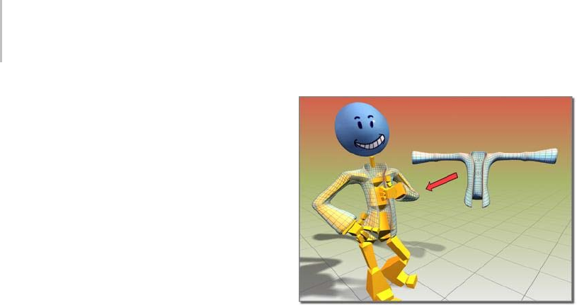
792 Chapter 8: Modifiers
By default, each vertex that’s affected by a single
bone is given a weight value of 1.0, which means
it’s affected by that bone only. Vertices within
the intersection of two bones’ envelopes have two
weight values: one for each bone. And you can
use Skin modifier toolsets such as the Weight Tool
dialog (page 1–807) to arbitrarily assign vertices
toanynumberofbones.Theratioofavertex’s
weightvalues,whichalwaystotal1.0,determine
therelativeextenttowhicheachbone’smotion
affects the vertex. For example, if a vertex’s weight
with respect to bone 1 is 0.8 and its weight with
respect to bone 2 is 0.2, then the motion of bone 1
will have four times greater influence on the vertex
than will the motion of bone 2.
The initial envelope shape and position depends
onthetypeofboneobject.Bonescreatealinear
envelope that extends along the longest axis of the
bone geometry. Spline objects create envelopes
that follow the curve of the spline. Primitive
objectscreateanenvelopethatfollowsthelongest
axis of the object.
You can also deform the mesh based on the angle
of the bones. Three deformers let you shape the
mesh based on bone angles:
• The Joint and Bulge Angle deformers use a
lattice similar to an FFD lattice (page 1–683) to
shape the mesh at a specific angle.
• The Morph Angle Deformer morphs the mesh
at specified angles. Morph targets are created
by using modifiers above the Skin modifier
in the stack, or by using the Snapshot tool
(page 1–453) to create a copy of the mesh and
deforming the mesh using standard tools.
Yo u c a n a p p l y t h e S k i n m o d i f i e r t o s e v e r a l o b j e c t s
at the same time.
Jacket object deformed using the Skin modifier
In 3ds Max you can mirror envelope and vertex
assignments from one side of the mesh to the other
with commands on the Mirror Parameters rollout.
Procedures
To use the Skin modifier:
1. Prepare the skin (mesh or patch object) and
skeleton (bones or other objects). Carefully
place the skeleton inside the mesh or patch
objectsothatitselementsareabletoinfluence
polygons or patches in their immediate vicinity.
2. Select the mesh or patch object and apply the
Skin modifier.
3. In the Parameters rollout, click Add and choose
the skeleton objects.
4. Click Edit Envelopes and select an envelope
tomodifythevolumeinwhicheachbonecan
influence the surrounding geometry.
To weight vertices manually:
1. On the Parameters rollout, turn on Vertices.
2. Onthemesh,selecttheverticesyouwouldlike
to weight manually.
Each selected vertex is surrounded by a small
white rectangle.
3. highlight the name of the bone for which you
want to change the vertex weights.
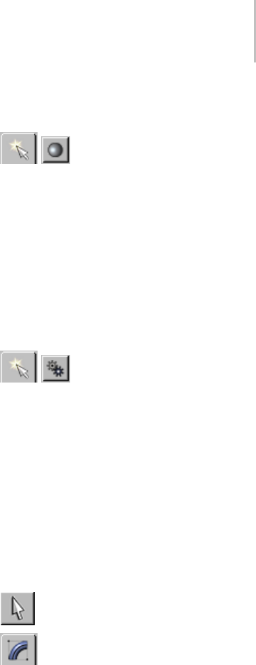
Skin Modifier 793
4. In the Weight Properties group, change the Abs.
Effect parameter to the new vertex weight.
To mirror envelope or vertex weight settings:
1. Adjust envelopes and vertex weights on one
side of the mesh.
2. On the Mirror Parameters rollout, click Mirror
Mode.
The mirror plane appears at the position and
orientation of the mesh’s pivot point.
3. If the mirror plane is not at the center of the
mesh, change the Mirror Offset parameter to
movetheplanetothecenter.
4. If some vertices in the left or right side of the
mesh are red rather than blue or green, increase
the Mirror Thresh value until all vertices are
blue or green.
5. On the Mirror Parameters rollout, click the
appropriate Paste button to paste green or blue
envelopes or vertex weights to the other side
of the mesh.
To adjust the skin and/or bones without affecting
the envelopes:
1. Save the scene.
This is a potentially destructive operation, so
it’s best not to take any chances with your data.
2. Select the object to which the Skin modifier is
applied.
3. In the Advanced Parameters rollout, turn off
Always Deform.
4. Apply any necessary transforms to the
mesh/patch object or bones objects.
5. Turn Always Deform back on.
To adjust the bones only, you can also use skin
pose (page 1–116).
Example: To apply the Skin modifier to a cylinder
with a bones skeleton:
1. OntheCreatepanel,under
Standard Primitives, click Cylinder.
2. InthemiddleoftheTopviewport,clickand
drag20unitstocreatethebaseofthecylinder.
3. Releasethemousebuttonanddragup130units
to establish the height of the cylinder.
4. On the parameters rollout, set Height Segments
to 20.
This provides mesh detail for a smooth surface
deformation.
5. OntheCreatepanel,under
Systems, click Bones.
Make sure an IK Solver is chosen in the IK
Solver list. Turn on Assign To Children. (This
should turn on Assign To Root as well.)
6. In the Front viewport, click successively three
times: below the cylinder, in the middle of the
cylinder, and above the top of the cylinder.
7. Right-click to end Bones creation.
Three bones display. Two of them are within
the middle of the cylinder.
8. Select the cylinder.
9. OntheModifypanel,chooseSkinfrom
the Modifier List.
10.On the Skin modifier’s Parameters rollout, click
Add, and use the Select Bones dialog to select
the three bones.
Thenamesofthebonesarenowdisplayedin
the list.
11.In the Front viewport, select the bone end
effector (IK Chain01) and move it around.

794 Chapter 8: Modifiers
The cylinder deforms to follow the bones.
To adjust envelopes to refine the surface
deformation, choose the Skin modifier’s
Envelope sub-object level, and use the Edit
Envelopescontrolstoresizeenvelopesand
change vertex weights.
Example: To use a morph angle deformer:
Create the cylinder and bones from the preceding
procedurebeforeyoucontinuewiththis
procedure.
1. Atframe50,animatebone2sothatbones1
and 2 represent a 90-degree angle.
2. Atframe0,thebonesshouldbestraightat
about a 180-degree angle.
3. Move to frame 0.
4. Turn on Edit Envelopes in the Parameters
rollout.
5. Select the child bone (bone 2) in the modifier’s
list of bones.
6. IntheSelectgroup,turnonVertices.
This allows you to select vertices.
7. In the viewports, region-window select a good
portion of the vertices that are controlled by
both bones.
8. In the Gizmos rollout, select the Morph Angle
Deformer in the drop-down list, and then click
Add Gizmo.
The Deformer Parameters rollout displays. A
base morph target is the first and only target
in the list.
Tip: if the Deformer doesn’t assign, make sure
that bone 2 and not bone 1 is selected in the list.
9. Scrub the Time Slider to frame 50.
10.Add an Edit Mesh modifier above the Skin
modifier in the modifier stack.
11.Turn on Vertex and Soft Selection in the Edit
Mesh modifier.
12.Editthemeshtotheshapeyouwant.
13.Go back down in the stack to the Skin modifier.
If the topology warning dialog appears, click
Ye s .
14.In the Deformer Parameters rollout, click Add
From Stack.
A new morph target is added at about 90
degrees.
15.Delete the Edit Mesh modifier from the stack.
There is a doubling effect of the morph if
you don’t delete or deactivate the Edit Mesh
modifier.
16.Scrub the time slider. The mesh morphs as the
bone angle changes.
Interface
The Skin Modifier interface includes the following
rollouts:
•Parameters rollout (page 1–795)
•Mirror Parameters rollout (page 1–799)
•Display rollout (page 1–800)
•Advanced Parameters rollout (page 1–801)
•Gizmos rollout (page 1–802)
•Deformer Parameters rollout (page 1–804)
•Joint Angle and Bulge Angle parameters (page
1–804)
Some of the Skin modifier commands are also
available from the quad menu (page 3–694).
Modifier Stack
Envelope—Turn on this sub-object level to work
on envelopes and vertex weights.
Tip: Yo u c a n u s e t h e q u a d m e n u t o c h o o s e t h i s
sub-object level.
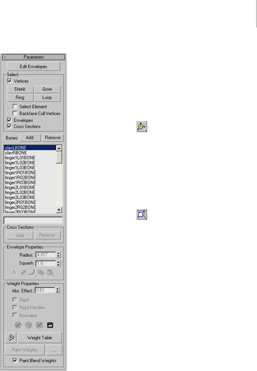
Skin Modifier 795
Parameters rollout Edit Envelopes—Use this sub-object level to work
on envelopes and vertex weights.
Select group
The following filtering options are grouped
together to help you work on a particular task,
by preventing you from accidentally selecting the
wrong item in the viewports.
Vertices—Turn on for vertex selection.
You can rotate around selected vertices using
Arc Rotate SubObject (page 3–744) from the Arc
Rotate flyout (page 3–744).Youcanalsorotate
around a selected envelope as long as no vertices
are selected, as they have precedence.
Note: Yo u m u s t c h o o s e Use Selection Center (page
1–447) from the User Center flyout (page 1–445) to
center on your selection. If you choose Use Pivot
Point Center (page 1–446), arc rotate is centered on
the selected bone/cross section.
You can zoom on selected vertices using
Zoom Extents Selected (page 3–740) from the
Zoom Extents flyout. You can also zoom on an
envelope if no vertices are selected.
•Shrink—Modifies the current vertex selection
by progressively subtracting the outermost
vertices from the selected object. Has no effect
if all the vertices from an object are selected.
•Grow—Modifies the current vertex selection by
progressively adding neighborhood vertices of
the selected object. You must start with at least
onevertextobeabletogrowyourselection.
•Ring—Expands the current vertex selection to
include all vertices part of parallel edges.
Note: Youmustselectatleasttwoverticestouse
the Ring selection.
•Loop—Expands the current vertex selection to
include all vertices part of continuing edges.
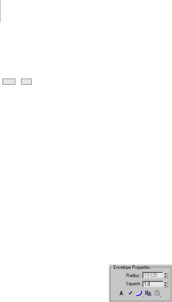
796 Chapter 8: Modifiers
Note: Youmustselectatleasttwoverticestouse
the Ring selection.
•Select Element—When on, selects all vertices of
the element you select, as long as you select at
least one vertex from that element.
Tip: Yo u c a n e d i t y o u r s e l e c t i o n b y h o l d i n g
Ctrl or Alt , and then select vertices. This
adds or removes, respectively, vertices to or
from your selection.
•Backface Cull Vertices—When on, you cannot
select vertices pointing away from the current
view (on the other side of the geometry).
Envelopes—Turn on for envelope selection.
Cross Sections—Turn on for cross-section
selection.
The first step, after applying the Skin modifier to
an object, is to determine which bones participate
in the object’s weighting. Every bone you choose
influences the weighted object with its envelope,
which you can configure in the Envelope Properties
group (page 1–796).
Add—Click to add one or more bones from the
Select Bones dialog.
Remove—Choose a bone in the list, and then click
Remove to remove it.
[list window]—Lists all bones in the system.
Highlighting a bone in the list displays that
bone’s envelope and the vertices influenced by the
envelope.
An horizontal scroll bar appears if a bone’s name
is longer than the window’s width.
Note: If an older scene containing long bone names
is loaded in 3ds Max, its name is truncated to fit in
the window. You can overwrite this by setting the
MAXScript shortenBoneNames property of your
Skin modifier to false.
Example:
$’Sphere01’.modifiers[#Skin].shortenBoneNames
=false
For detailed information about the MAXScript
utility, open the MAXScript Reference, available
from Help menu > MAXScript Reference.
[bonenametype-infield]—Enter a bone name to
highlight it in the bone list above. The highlighting
goes to the first matching bone.
Use these methods for finding bone names faster:
• Narrow the list by typing the first few characters
inthenameoftheboneyouwanttohighlight.
•Usethewildcard(*)key.Forexample,youcan
find Robot R Index Finger by typing *RIn
Cross Sections group
By default, each envelope has two round, lateral
cross sections, one at each end of the envelope.
These options add and remove cross sections from
envelopes.
Add—Choose a bone in the list, click Add, and
click a position on the bone in a viewport to add a
cross section.
Remove—Select an envelope cross section and
click Remove to delete it.
Before you can select a cross section, the Cross
Sections option in the Select group must be on.
You can delete only extra cross sections that you
have added; not the default cross sections.
Envelope Properties group
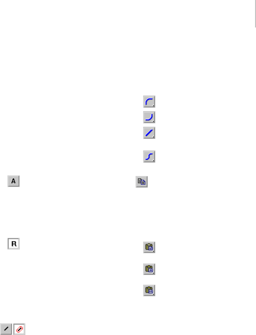
Skin Modifier 797
Radius—Select an envelope cross section, and
useRadiustoresizeit.Inordertoselectacross
section, the Cross Sections option in the Select
group must be checked.
You can also click and drag a cross section control
point in a viewport to resize it.
Squash—A squash multiplier for bones that stretch.
This is a single value that reduces or increases the
amount of squash applied to a bone when it is
stretchedwithFreezeLengthoff,andSquashon.
Note: You can set Freeze Length and Squash in the
Bone Tools dialog (page 1–414).
Absolute/Relative—This toggle determines how
vertex weights are calculated for vertices between
inner and outer envelopes.
•Absolute—A vertex must merely fall
inside the brown outer envelope to have 100%
assignment weight to that particular bone.
A vertex falling inside more than one outer
envelope will be assigned multiple weights
summing to 100% based on where it falls in the
gradients of each envelope.
•Relative—A vertex falling only within an
outer envelope will not receive 100% weighting.
A vertex must either fall inside two or more
outer envelopes whose gradients sum to 100%
or greater or the vertex must fall within a red
inner envelope to have 100% weight. Any
points within a red inner envelope will be 100%
locked to that bone. Vertices falling within
multiple inner envelopes will receive weighting
distributed over those bones.
Envelope Visibility—Determines the
visibility of unselected envelopes. Choose a bone
in the list and click Envelope Visibility, then
choose another bone in the list. The first bone
selected remains visible. Use this to work on two
or three envelopes.
Falloff Flyouts—Choose a falloff curve for the
displayed envelopes.
Weight falls off in the area between the inner and
outer envelope boundaries if envelopes overlap
andAbsoluteisturnedon.Thissettingletsyou
specify how the falloff is handled:
•Falloff Fast Out—Weight falls off quickly.
•Falloff Slow Out—Weight falls off slowly.
•Falloff Linear—Weight falls off in a linear
way.
•Falloff Sinual—Weight falls off in a
sinusoidal way.
Copy—Copies the currently selected envelope
size and shape to memory. Turn on sub-object
Envelopes, choose one bone in the list, click Copy,
then choose another bone in the list and click Paste
to copy an envelope from one bone to another.
Paste commands are on a flyout with the following
options:
•Paste—Pastes the copy buffer to the
current selected bone.
•Paste to All Bones—Pastes the copy buffer
to all bones in the modifier.
•PastetoMultipleBones—Pastes the copy
buffer to selected bones. A dialog allows you to
choose the bones to paste to.
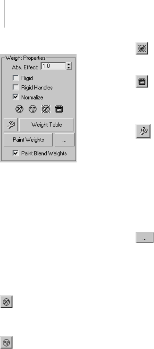
798 Chapter 8: Modifiers
Weight Properties group
Abs. Effect—Enter an absolute weight for the
selected bone to selected vertices.
Choose the Envelope sub-object level, turn on
Vertices in the Parameters rollout > Select group,
select a vertex or vertices, and then use the Abs.
Effect spinner to assign weight. Selected vertices
move in the viewports as their weight changes.
Rigid—Causes selected vertices to be influenced
only by one bone, the one with the most influence.
Rigid Handles—Causes the handles of selected
patch vertices to be influenced by only one bone,
the one with the most influence.
Normalize—Forces the total weights of each
selected vertex to add up to 1.0.
Exclude Selected Verts—Adds the currently
selected vertices to the exclusion list for the current
bone. Any vertices in this exclusion list will not
be affected by this bone.
Include Selected Verts—Ta ke s t h e s el e c t e d
vertices out of the exclusion list for the selected
bone. The bone can then affect these vertices.
Select Excluded Verts—Selects all vertices
excluded from the current bone (see Exclude
Selected Verts, preceding).
Bake Selected Verts—Click to bake the
current vertex weights. Baked weights are not
affected by envelope changes, only by changes to
Abs. Effect or weights in the We ight Table ( page
1–810).
Weight Tool—Displays the Weight Tool dialog
(page 1–807), which offers control tools to help
you assign and blend weights on selected vertices.
Weight Table—Displays a table for viewing and
changing weights for all bones in the skeletal
structure. See Weight Table (page 1–810).
Paint Weights—Click and drag the cursor over
vertices in the viewports to brush on weights for
the selected bone.
Tip: Streamline the painting process by using the
Brush Presets tools (page 3–690).
Painter Options [ellipsis]—Opens the
Painter Options dialog (page 1–960),whereyou
can set parameters for weight painting.
Paint Blend Weights—When on, blends painted
values by averaging the weights of neighboring
vertices and then applying the average weight
based on the brush strength. Default=on.
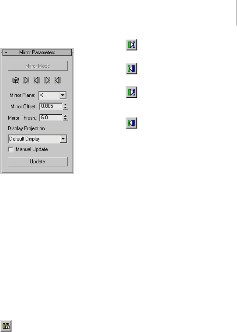
Skin Modifier 799
Mirror Parameters rollout
Mirror Mode—Activates Mirror mode, which lets
you mirror the envelopes and vertex assignments
from one side of the mesh to the other. This mode
is available only at the Envelope sub-object level.
Mirror mode uses the Mirror Plane setting to
determinethe“leftside”and“rightside”ofthe
mesh. When you turn on Mirror Mode, the
verticesontheleftsideofthemirrorplaneturn
blue, while the vertices on the right turn green.
Vertices that are neither left nor right turn red,
including vertices at the mirror plane. If vertices
don’t change color appropriately, you might have
to increase the Mirror Thresh value to expand the
range used to determine the left and right sides.
If you select vertices or bones, the selected vertices
or bones turn yellow, and the corresponding match
on the other side of the mesh turns a brighter blue
or green. This can help you check for matches.
Mirror Paste—Pastes selected envelope and
vertex assignments to the opposite side of the body.
Paste Green to Blue Bones—Pastes the
envelope settings from green bones to blue.
Paste Blue to Green Bones—Pastes the
envelope settings from blue bones to green.
Paste Green to Blue Verts—Pastes the
individual vertex assignments from all green
vertices to the corresponding blue vertices.
Paste Blue to Green Verts—Pastes the
individual vertex assignments from all blue
vertices to the corresponding green vertices.
Mirror Plane—Determines the plane that will
be used to determine the left and right sides.
The plane appears in the viewport at the mesh’s
pivot point when you turn on Mirror mode. The
selected mesh’s local axes are used as the basis
for the plane. If several objects are selected, one
object’s local axes are used. Default=X.
Tip: For the easiest workflow with mirroring tools
for the Skin modifier, set the pivot points for
character meshes to align with the World before
applying Skin.
Mirror Offset—Shifts the mirror plane along the
Mirror Plane axis.
Mirror Thresh—Sets the relative distance the
mirroring tools will look when setting vertices as
left or right. If some vertices in the mesh (other
than those at the mirror plane) are not colored
blue or green when you turn on Mirror mode,
increase the Mirror Thresh value to include a
larger area of the character. You can also increase
this value to compensate for lack of symmetry in
asymmetrical models.
Display Projection—When Display Projection is
set to Default Display, selecting vertices on one
side of the mirror plane automatically projects the
selection to the opposite side. The Positive and
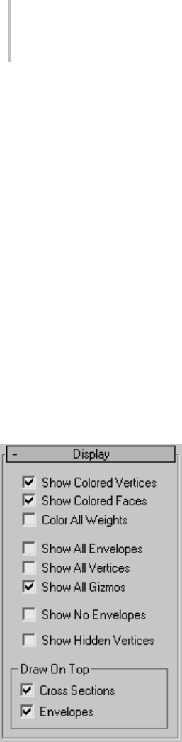
800 Chapter 8: Modifiers
Negative options allow selection of vertices on
onesideofthecharacteronly.TheNoneoption
does not project selected vertices to either side.
Default=Default Display.
Tip: You can use the Positive and Negative options
to temporarily project the display of one side’s
vertices to the other side so you can see how
the vertices align. This can be helpful when
determining the correct Mirror Plane settings for
an asymmetrical mesh.
Manual Update—When on, you can update the
displaymanuallyratherthanautomaticallyafter
each mouse-up.
Update—When Manual Update is on, use this
button to update the display with your new
settings.
Display rollout
Show Colored Vertices—Colors vertices in
viewports according to their weights.
Show Colored Faces—Colors faces in viewports
according to their weights.
Color All Weights—Assigns a color to every bone
in the envelope. The vertex weighting blends the
colors together.
Tip: You can toggle this feature to get a global view
of all weight regions across your model at once.
Tip: You can also assign a color to unweighted
vertices: Open the Customize User Interface dialog
and, on the Colors panel, choose Skin Colors from
the Elements drop-down list.
Show All Envelopes—Displays all envelopes at the
same time.
Show All Vertices—Draws a small tick at every
vertex. On a patch surface, it will also draw all the
handles.
Show All Gizmos—Displays all the gizmos in
addition to the currently selected gizmo.
Show No Envelopes—Causes no envelopes to be
displayedevenwhenanenvelopeisselected.
Show Hidden Vertices—When on, hidden vertices
are visible. Otherwise, they remain hidden until
youenabletheoptionorgointotheobject’s
modifier (Editable Mesh (page 1–996) or Editable
Poly (page 1–1029)), and then click Unhide All
on the Selection rollout or Edit Geometry rollout,
respectively. Default=off.
Draw On Top group
Theseoptionsdeterminewhichelementswillbe
drawnontopofallotherobjectsinviewports.
Cross Sections—Forces cross sections to be drawn
on top.
Envelopes—Forces envelopes to be drawn on top.
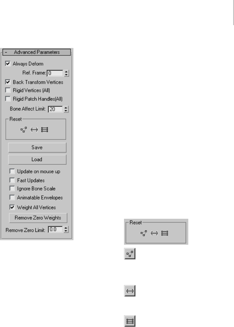
Skin Modifier 801
Advanced Parameters rollout
Always Deform—A toggle useful for editing the
transformation relationship between bones
and the controlled points. This relationship is
initially set when Skin is applied. To change
the relationship the user can deactivate Always
Deform, move the object or the bones and
reactivate. The new transformation relationship is
now used.
Ref. Frame—Setstheframewherethebonesand
the mesh are in a reference position.
Normally this is frame 0. Start your animation at
frame 1 or later if frame 0 is the reference frame.
If bones need to be adjusted relative to the mesh,
movethetimeslidertoframe0;turnoffAlways
Deform, move the bones into the correct position
and turn on Always Deform.
Back Transform Vertices—Allows you to link the
meshtothebonestructure.Ordinarily,whenyou
do this, any movement of the bones causes the
mesh to move twice as far as it should, because
it moves once with the bones and once with the
link.Checkingthisoptionpreventsthemeshfrom
moving twice under these circumstances.
Rigid Vertices (All)—Causes vertices to have
assignments to only one bone as if weighted 100%
tothebonewhoseenvelopehasthemostinfluence.
Vertices will not have weight distributed over more
than one bone and the deformation of the skinned
object is rigid. This is mainly used for games that
do not support weighted point transformation.
Rigid Patch Handles (All)—On a patch model, forces
patch handle weights to equal the knots weights.
Bone Affect Limit—Limits the number of bones
that can affect one vertex.
Reset group
Reset Selected Verts—Resets the weight of
selected vertices to the envelope defaults. After
manually changing vertex weight, use this to reset
weights if necessary.
Reset Selected Bone—Resets associated vertex
weights back to the original weights calculated for
the selected bone’s envelope.
Reset All Bones—Resets all vertex weights
back to the original weights calculated for all
bone’s envelopes.
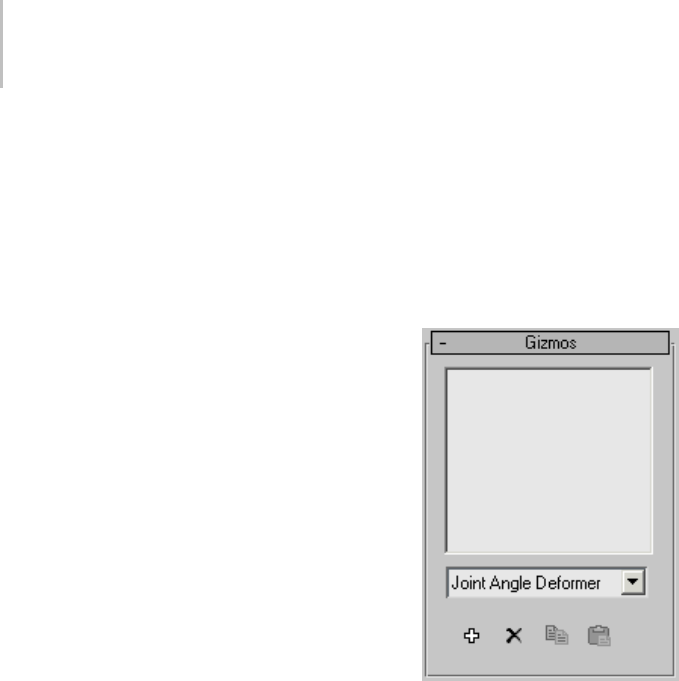
802 Chapter 8: Modifiers
Save/Load—Allows you to save and load the
envelope position and shape, as well as the vertex
weights. If you load a saved file onto a different
system of bones, you can use the Load Envelopes
dialog (page 1–805) to match the incoming bones
to the current bones.
Update on mouse up—When on and the mouse
button is pressed down, no updates take place.
When the mouse button is released, updates occur.
This option helps keep workflow moving quickly
by avoiding unnecessary updates.
Fast Updates—Tu r ns of f v ie w p or t d is pl ay o f
weighted deformation and gizmos and uses rigid
deformation when not rendering.
Ignore Bone Scale—Turn this option on to leave
a skinned mesh unaffected by a scaled bone.
Default=off.
Note: To scale a bone’s length, you first need to
turn off its Freeze Length option on the Object
Properties rollout (page 1–414) of the Bone Tools
floater dialog (page 1–411).
Animatable Envelopes—Toggles the possibility
of creating keys on all animatable envelope
parameters while Auto Key is active. Default=off.
Note: This does not affect keyable track settings.
Weight All Vertices—When on, forces all vertices
thatarenotunderthecontrolofanenvelopeto
beweightedtotheboneclosesttothem. Has
no effect on vertices that are manually weighted.
Default=on.
Tip: Ifyouwanttorevertverticestotheiroriginal
weight value, click Reset Selected Verts (in the
Reset group) or open the We ight Table (p age
1–810), and change the Modified weight status
(M) of your selected vertices.
Remove Zero Weights—Strips a vertex from its
weight if it is less than the Remove Zero Limit
value. Thishelpsmakingyourskinnedmodel
lighter (in games for instance) because less
unnecessary data is stored in the geometry. Also
accessible from the Weight Table.
Remove Zero Limit—Sets the weight threshold that
determines if a vertex is stripped of its weight when
you click Remove Zero Weights. Default=0.0.
Gizmos rollout
Controls in the Gizmos rollout allow you to deform
the mesh according to the angle of the joint, and
to add gizmos to selected points on the object.
The rollout consists of a list box containing all the
gizmos for this modifier, a drop-down list of the
current types of gizmos, and four buttons (Add,
Remove, Copy and Paste).
The workflow for adding a gizmo is to select the
vertices that you want to affect, select the bones
that will drive the deformation, and then click the
Add button.
There are three deformers available:
• The Joint Angle deformer has a lattice that can
deform vertices on the parent and child bones.
• The Bulge Angle deformer has a lattice that
onlyworksonverticesontheparentbone.
• The Morph Angle deformer works on vertices
of the parent and child bones.
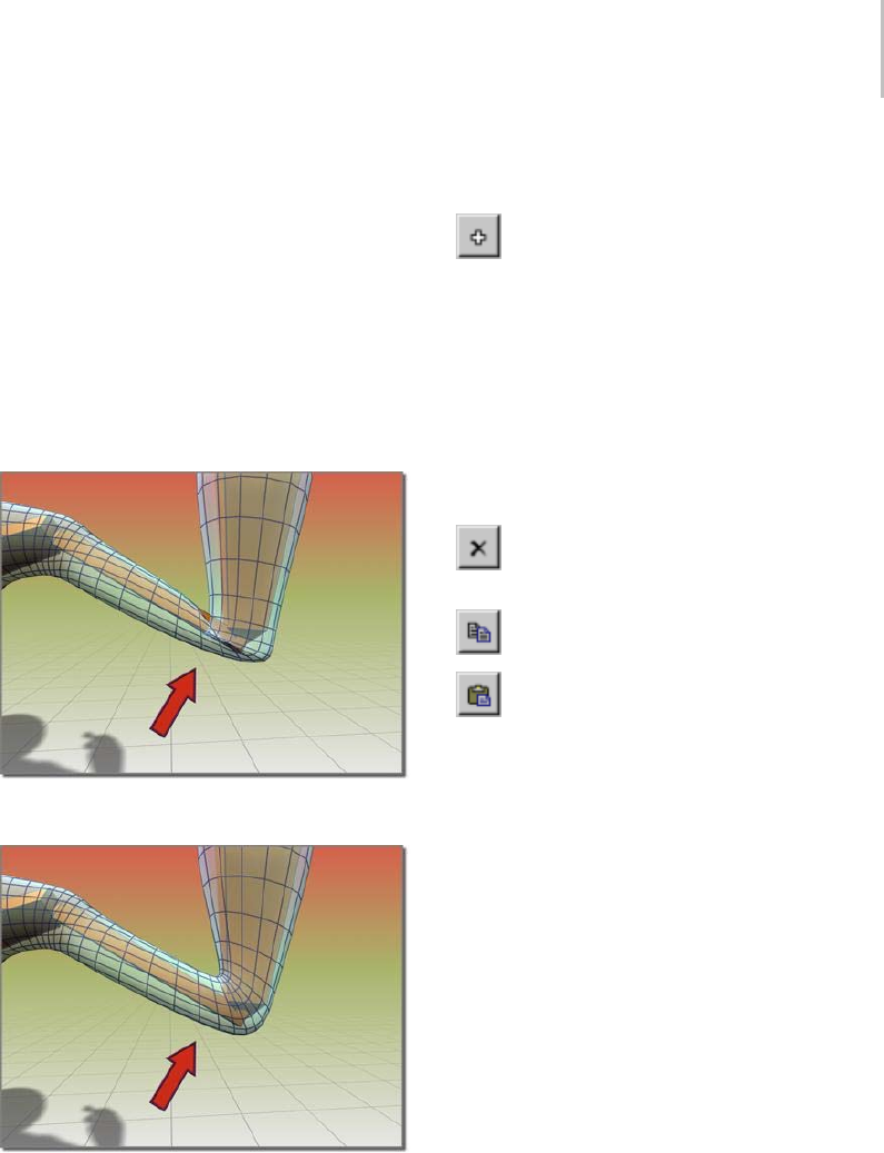
Skin Modifier 803
Keep these distinctions in mind when you
select vertices to deform. For example, if you
want to use the Joint Angle deformer, then
select vertices close to the joint that will drive
the deformation. If you want the parent bone
vertices to deform like a biceps muscle, then
select vertices that are only assigned to the
parent bone before adding the Bulge Angle
deformer. If all the vertices of the parent and
child bone must deform, then select all of the
verticesandaddtheMorphAngledeformer.
Bending the arm without the Morph Angle deformer causes
thesleevetocrumple.
Using the Morph Angle deformer creates a smooth bend
in the sleeve.
Gizmo List Window—Lists the current Angle
Deformers.
The Deformer Parameters rollout changes
depending on the type of gizmo selected.
Deformer drop-down list—Lists the available
deformers.
Add Gizmo—Adds the current Gizmo to the
selected vertices.
To add a gizmo, you must first select the child
bone for the joint you want to deform. Then you
must select the vertices that you want to deform.
Yo u c a n t h e n a d d a g i z m o .
Afteragizmoisadded,aDeformerParameters
rollout displays that contains gizmo parameters
that you can adjust.
Remove Gizmo—Remove the selected gizmo
from the list.
Copy Gizmo—Copy the selected gizmo.
Paste Gizmo—Paste the gizmo.
The Paste button pastes the current copy buffer
into the currently selected gizmo. You can only
paste to like gizmos. For instance, you can’t paste
from a bulge gizmo to a joint gizmo.
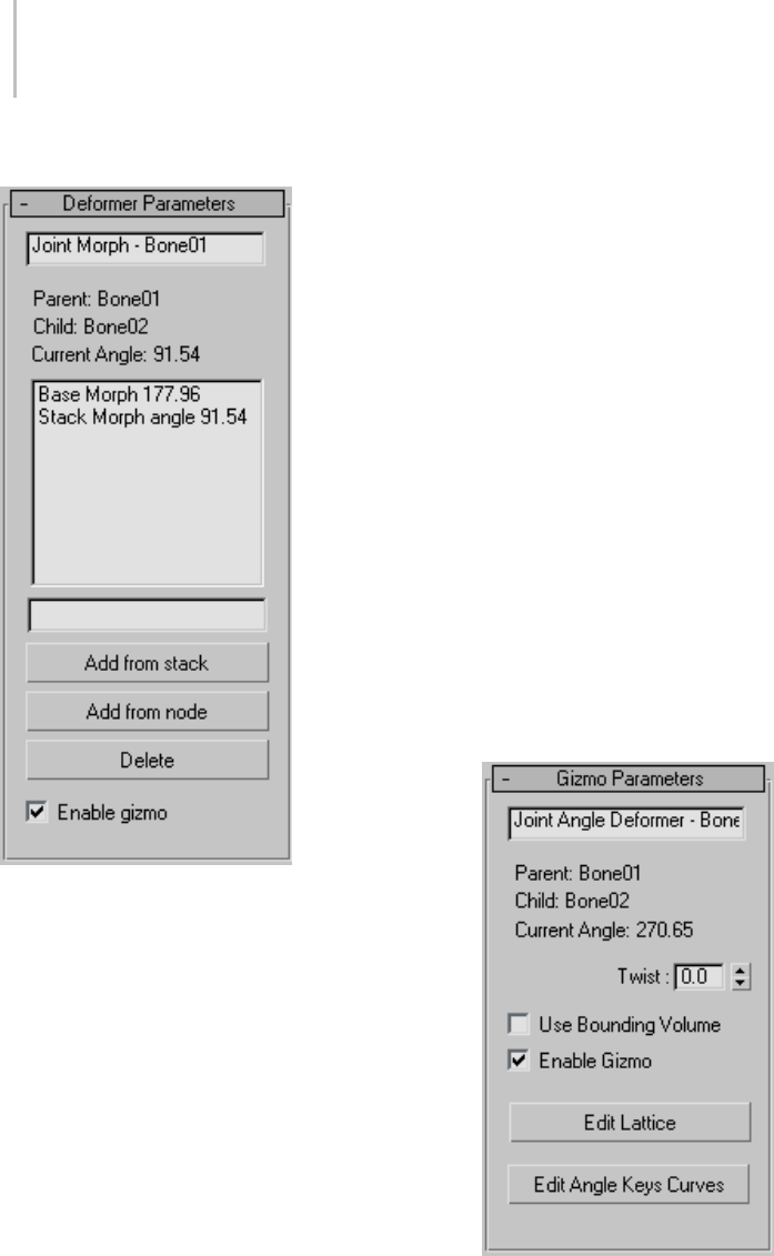
804 Chapter 8: Modifiers
Deformer Parameters rollout
The following parameters are for the Morph Angle
deformer. One way to create morph targets, after
the morph gizmo is added, is to add an Edit Mesh
modifier to the stack above the Skin modifier. Use
the vertex controls in the Edit Mesh modifier to
shape the geometry. Then go back in the stack
to the Skin modifier and click Add From Stack.
Yo u c a n t h e n d e l e t e t h e E d i t M e s h m o d i f i e r. A d d
From Stack looks at the last modifier in the stack
to get the morph target. Note that when you go
backdowntotheSkinmodifier,themorpheffect
is doubled; you can rectify this by deleting or
deactivating the Edit Mesh modifier.
Joint Field—Displays the type of Deformer and the
associated bone.
List Window—Contains the current morph targets
andassociatedboneangles.
Naming Field—Select a morph target and rename
it in this field.
Add from stack—Uses the current state of the stack
to get the morph target. Ideally, you have put an
Edit Mesh modifier on top of the stack and done
your edits before you click Add From Stack.
Add from node—Uses another object as your
morph target for this angle. This is like a regular
morph target, but instead of being driven by a
field, it is driven by the joint angle.
Tip: You can use Snap Shot on the main toolbar to
create a new target for morphing.
Delete—Deletes the currently selected morph
target from the list.
Enable gizmo—Toggles the effect of the gizmo.
Joint Angle and Bulge Angle parameters
ThefollowingparametersarefortheJointAngle
and Bulge Angle deformers. These two deformers
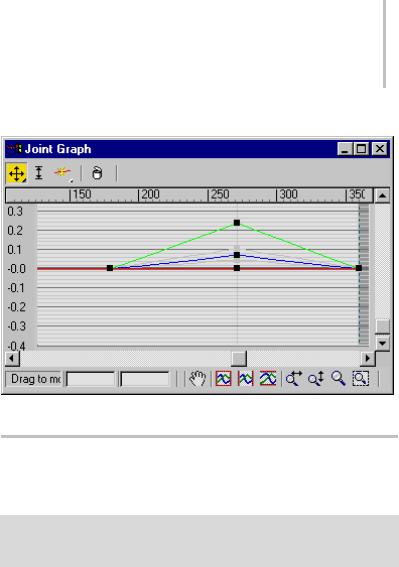
Load Envelopes Dialog (Skin Modifier) 805
arealmostidenticalinthewaytheyoperate.The
differenceisthattheBulgeAngledeformeronly
worksonverticesoftheparentbone,whilethe
Joint Angle deformer works on vertices on both
the child and parent bone.
To apply either of these deformers, first select the
child link, then select vertices on the mesh, and
then apply the deformer. Remember to turn on
Vertices in the Parameters rollout > Select group
before region-selecting vertices in the viewports.
Once the deformer is applied, turn on Edit
Lattice and move the lattice control points in the
viewports to deform the mesh at different bone
angles.
Name Field—Allows you to change the name of
the deformer.
Twist—Allowsyoutospinthegizmoaroundthe
mesh to place control points appropriately.
Use Bounding Volume—Turn this on if you plan to
change the geometry, like increasing segments on
a cylinder. If the geometry changes, the mesh will
still deform inside the lattice if this is turned on.
Enable Gizmo—Toggles the effect of the gizmo on
and off.
Edit Lattice—Allowsyoutomovethelatticecontrol
points in the viewports.
Edit Angle Keys Curves—Brings up a curve editor
that lets you manipulate the shape of the lattice at a
particular angle. This curve is position vs. angle.
It will show you the curves of the current selected
points. The red curves are X, green curves are Y,
and blue curves are Z.
Load Envelopes Dialog (Skin
Modifier)
Select a mesh, patch, or NURBS object. > Apply Skin
modifier. > Advance Parameters rollout > Load button
The Load Envelopes dialog associated with the
Skin modifier (page 1–791) allows you to load
saved envelopes to specific bones. This resizable
dialog shows the current envelopes in your scene
and the incoming envelopes. Use the controls to
manipulate the incoming envelopes so they align
with the current envelopes.
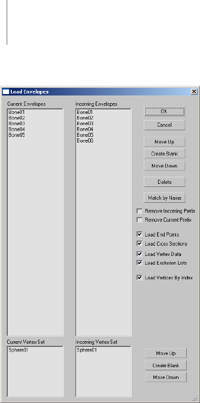
806 Chapter 8: Modifiers
Interface
OK—Accepts any changes and closes the dialog.
Cancel—Discards any changes and closes the
dialog.
Move Up/Down—Movethecurrentselectioninthe
incoming list up or down.
Create Blank—Creates space in the Incoming list.
Usethiswhenloadingdataontoaskeletonthatis
not identical as the one from which the data was
saved.Forexample,ifyouroriginalskeletonhad
three fingers and the new one has only two fingers,
you might need to add spaces in the list to line up
the fingers correctly.
Delete—Removes the current selected incoming
envelopes.
Match by Name—Resorts the Incoming list and
matches any bones that have the same name in the
list of current envelopes.
Remove Incoming Prefix—Removes any prefixes on
the names of the incoming envelopes.
Remove Current Prefix—Removes any prefixes on
the names of the current envelopes.
Load End Points—Loads the envelope end point
positions.
Load Cross Sections—Loads the envelope cross
sections.
Load Vertex Data—When on, loads weights at the
vertex level. Normally only the envelope data is
loaded so any manual adjustments to the vertex
data are lost. This option lets you load those
manual edits.
Load Exclusion Lists—Lets you also load
user-generated exclusion-list data, which specifies
that certain vertices should not be affected by
certain bones. See Exclude Selected Verts and Show
Exclusions.
Load Vertices By Index—Lets you load vertices
by index rather than vertex position. You would
typically use this option with identical meshes that
have not undergone any type of topology change.
This should be off if you’ve changed the topology,
by,forinstance,deletingoraddingverticesor
changing their order.
Current Incoming Vertex Set
When Load Vertex Data is on, use these controls to
match vertex sets in cases where the Skin modifier
is instanced. In such cases you might need to set
up several vertex sets.
TheMoveUp/CreateBlank/MoveDownbuttons
havethesamefunctionsasintheEnvelopeslists.
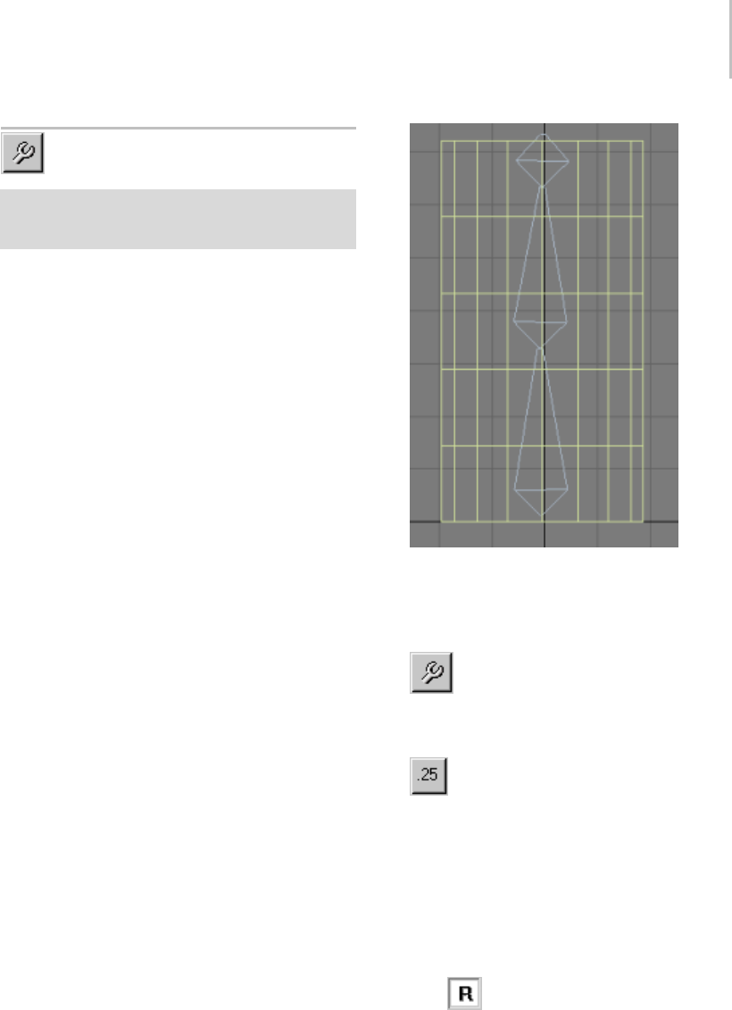
Weight Tool Dialog 807
Weight Tool Dialog
Select an object that has the Skin modifier applied to it.
> Modify panel > Skin modifier > Parameters rollout >
Weight Properties group > Weight Tool button
This dialog is launched from the Skin modifier
(page 1–791) and provides tools to select vertices
and assign them weights. You can also copy, paste,
and blend weights between vertices. Each vertex
youselectdisplaystheobjectscontributingtoits
weighting in the dialog list.
To use these tools, Parameters rollout > Edit
Envelopesmustbeon,Parametersrollout>Select
group > Vertices must be on, and at least one
vertex must be selected.
Important: The controls on this dialog adjust vertex
weighting with respect to the active bone; that is, the
object highlighted in the Bones list on the Parameters
rollout. When you select a vertex and then change
its weighting, if the active bone does not already
influence the vertex, the bone is added to the list of
bones influencing the vertex. You can ensure that bone
assignments don’t change by highlighting the bone in
the Weight Tool dialog list after selecting the vertex and
before changing weighting.
Also, the total weighting for all bones influencing a
vertex is always 1.0, so if multiple bones influence
a vertex and you change the weight value for one
bone, the weight values for the others change as
well.
Procedures
Example: To Set and Blend Weights on Selected
Vertices:
1. Prepare a cylinder skinned to a bone chain.
2. On Parameters rollout of the Modify panel,
turn on Edit Envelopes.
3. Turn on Vertices in the Select group.
4. In the Weight Properties group, click
We i g ht To o l.
The Weight Tool dialog opens.
5. Select a few vertices and then click the
.25 weight button.
The selected vertices are weighted at 0.250 for
theactivebone(highlightedintheParameters
rollout list), coloring them yellow.
Note: Theactiveboneisaddedtothelistof
bones influencing each of the selected vertices,
if necessary.
Note: You might need to toggle the vertex
weighting to Relative in the Envelope Properties
group (page 1–791).
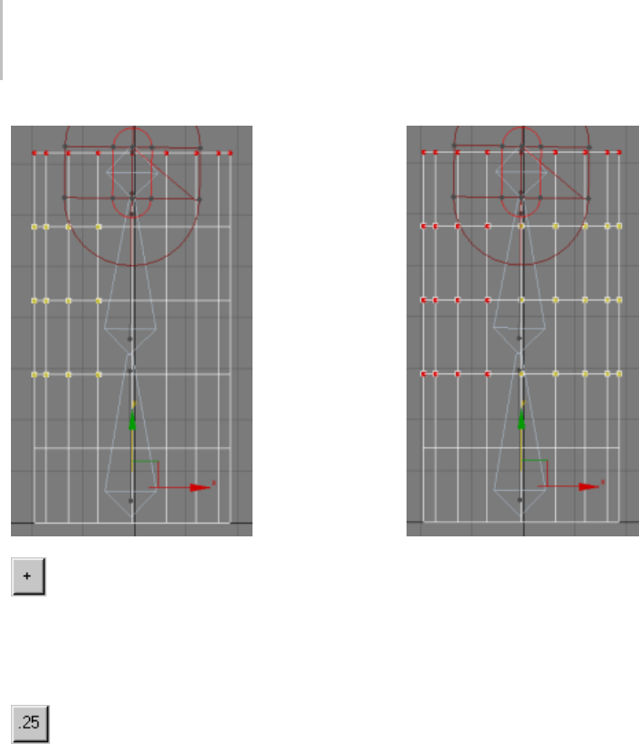
808 Chapter 8: Modifiers
6. Click the + button directly under the .9
weight button repeatedly until the vertices are
red (that is, the weight is 1.0).
As you increase the vertices’ weight, they
gradually change color.
7. Select a few other vertices, and assign
them a weight of 0.250.
The left vertices are weighted 1.0 and the right vertices are
weighted 0.25.
8. Select all weighted vertices and repeatedly click
Blend.
Every time you click Blend, each vertex’s
weight is adjusted to blend with other selected
neighborhood weights. This creates a smooth
weighting transition among all selected vertices.
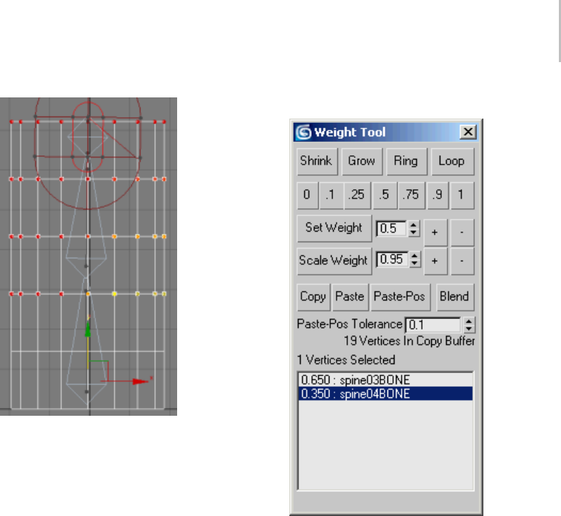
Weight Tool Dialog 809
The two separate colors blend into a smooth gradient.
Interface
Shrink—Modifies the current vertex selection by
progressively subtracting the outermost vertices
from the selection. Has no effect if all vertices in
an object are selected.
Grow—Modifies the current vertex selection by
progressively adding neighborhood vertices of the
selected object. You must start with at least one
vertex to be able to grow your selection.
Ring—Expands the current vertex selection to
include all vertices in parallel edges.
Note: You must select at least two vertices to use
the Ring selection.
Loop—Expands the current vertex selection to
include all vertices in continuing edges.
Note: You must select at least two vertices to use
the Loop selection.
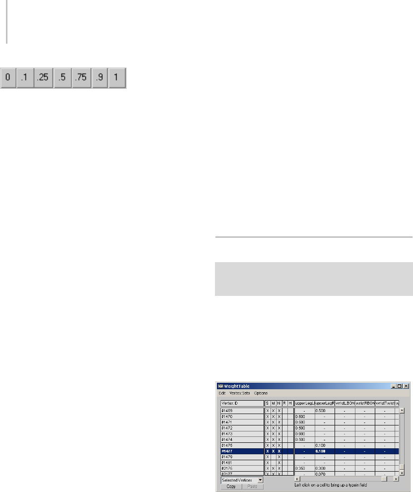
810 Chapter 8: Modifiers
[specific weight
values]—Assigns an absolute weight value between
0and1fortheactivebonetotheselectedvertices.
Note: When you click one of these buttons, the
active bone is added to the list of bones influencing
each of the selected vertices, if necessary.
Set Weight—Sets an absolute weight based on the
field value. Default=0.5.
Note: The spinner increments the field value by
steps of 0.05.
+/-—Increases/decreases each selected vertex’s
weight by 0.05.
Scale Weight—Multiplies each selected vertex’s
weight value by the field value, resulting in a
relative weight change. Default=0.95.
Note: The spinner increments the field value in
steps of 0.05.
+/-—Increases/decreases each selected vertex’s
weight by five percent.
Copy—Stores the current weight value(s) in the
copy buffer.
Paste—Retrieves the weight values from the copy
buffer and assigns them to the selected vertices.
Paste-Pos—Assigns the weight values currently in
the copy buffer to the selected vertices based on
the distance between them and the copied vertices,
which is determined by the Paste-Pos Tolerance
value.
This is useful when you need to match weights
between two juxtaposed skinned meshes sharing
the a common bone.
Blend—Modifies the selected weight values to
smooth out the transition between them and their
surrounding vertices.
Paste-Pos Tolerance—Determines the radius
influence of the Paste-Pos. Default=0.1.
Vertex information
Below the Paste-Pos Tolerance field is a text display
displayinginformationontheamountofcopied
andselectedvertices.
[First Vertex Weight list]—Displays the selected
vertex weight along with the bone envelopes
contributing to its weighting. You can select
individual envelopes in the current viewport by
highlightingtherespectiveboneinthelist.
Note: If you select multiple vertices, the list only
displays the weighting of the first selected vertex.
Weight Table (Skin Modifier)
Select an object that has the Skin modifier applied to it. >
Modify panel > Skin modifier > Weight Properties group
>WeightTable
The weight table for the Skin modifier is used
to change vertex weights for several vertices and
bones at a time. This table appears when you click
the Weight Table button.
Interface
Vertex numbers appear down the left column,
while bone names appear across the top. Vertex
weights for each bone are displayed in the chart.
You can change vertex weights in a number of
ways:
• Click and drag a vertex weight to the left or
right.
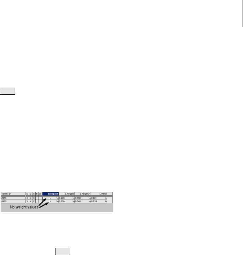
Weight Table (Skin Modifier) 811
• Highlight a weight and type in a new weight.
• Select vertices by dragging over vertex IDs,
then click and drag one weight to change all
selected weights for the bone.
• Right-click to enter a value of 0.
•Ctrl +right-click to enter a value of 1.0.
Menu options:
Edit menu—Copy/paste vertex weights, and choose
vertices to edit.
•Copy: Copies weights for highlighted vertices.
•Paste: Pastes the copied weights.
•Remove Zero Weights: All vertices with a
weight less than the Remove Zero Limit field
value are stripped from their weight. Also
available on the Advanced Parameters rollout
(page 1–801).
•Select All/None/Invert: Changes the selection
of vertices.
Vertex Sets menu—Select vertices in the left
column by holding down Ctrl while clicking
vertices. Create a named selection set, which can
then be picked from the drop-down menu at the
lower left of the dialog.
Options menu—Customizes the weight table
display.
•Flip UI: Flips the UI to show vertex IDs across
the top and bone names down the left side.
•Update On Mouse Up: When the mouse button
is pressed down, no updates will take place.
When the mouse button is released, updates
will occur. This option helps keep workflow
movingquicklybyavoidingunnecessary
updates.
•Show Affected Bones: Displays only bones
that affect the displayed vertices.
•Show Attributes: Toggles display of the
S/M/N/R/H attributes.
•Show Exclusions: Toggles display of small
check box areas in each vertex weight field.
Clicking the check box toggles exclusion of the
vertex from the bone (a red X appears in the
check box when the exclusion is in effect).
•Show Global: Showsvaluesforalldisplayed
vertices.
•Show Set Sets UI: Displays info about vertex
sets.
Dialog options
Vertex ID—Vertices are displayed by number down
the left column of the weight table. Double-click
a vertex number to cause the vertex to display
in pink in viewports. To display only selected
vertices, choose Selected Vertices from the
drop-down menu at the bottom left of the dialog.
S—Indicates vertex is selected.
M—Indicates vertex weight has been modified.
N—Indicates vertex weights are normalized (total
of all vertex weights is always 1.0).
R—Indicates vertex is rigid (affected only by one
bone, the one with the most influence).
H—Indicatespatchhandlesarerigid(affectedonly
by one bone, the one with the most influence).
Vertex selection drop-down—Choose to display all
vertices, selected vertices or only vertices affected
by the selected bone.
Copy—Copies weights for highlighted vertices.
Paste—Pastes copied weights.

812 Chapter 8: Modifiers
Skin Morph Modifier
The Skin Morph modifier lets you use a bone’s
rotation to drive a morph; that is, a deformation
of the object mesh. Skin Morph is intended for
use with a Skin or comparable modifier (e.g.,
Physique); add the Skin Morph modifier after
the skin-type modifier. You create the morph at
the frame in which the effect should be greatest,
andthenSkinMorphautomaticallyanimatesthe
affected vertices into and out of the morph, based
on the rotation of the bone that drives the morph.
This lets you fine-tune mesh deformation at any
frame, using a bone to drive the morph that is
fixing a problem area. Typically, when animating a
character with bones, an artist has to create extra
bones to handle problem areas such as armpits and
groinareas.WithSkinMorph,insteadofusing
extra bones, you can simply create a morph, and
then transform vertices into the exact shape you
want. Skin Morph lets you easily create muscle
bulges and many other effects.
Note: When working with Skin Morph, it’s
important to be familiar with the concept of
delta.Theframeatwhichyouapplythemodifier
determines the base position for each vertex that’s
used in a morphing animation controlled by Skin
Morph.Afterapplyingthemodifier,gotoaframe
at which the bone driving the morph is rotated an
amount that will cause the greatest deformation,
and then transform vertices to produce the morph.
Theamountbywhichyoutransformthevertices
is called the delta: the difference between the base
pose and the morphed position.
Procedure
To use Skin Morph (basic usage):
1. Create an animated character with bones and
askinnedbodymesh,usingamodifiersuchas
Skin (page 1–791) or Physique (page 2–834).
2. Go to the “pose frame” and apply the Skin
Morph modifier.
Theposeframecontainstheinitialpose;
typically a standing character with arms
outstretched and legs apart. This is often
frame0,butitcanbeanyframe,evena
negative-numbered one. This is the frame from
which the modifier measures delta: the change
in the vertex position between this pose and
the morph.
3. Determine which bones are driving
deformations that you want to modify with
Skin Morph.
For example, bending an arm might cause the
inside of the elbow to indent too far, or you
mightwanttoaddabulgingbicep.Inthiscase,
the forearm bone is driving the deformation.
4. UseAddtobindthedeformation-drivingbones
to the modifier.
The modifier overlays an orange line along the
length of each bone you add.
5. Go to the frame where you wish to create the
morph. Using the arm-bending example, this
might be the frame where the forearm is at a
90-degree angle to the upper arm.
6. In the list box, click one of the bones.
Intheviewport,theorangelinerepresenting
the bone becomes a thicker yellow line to
indicate that this bone will drive the morph.
7. On the Local Properties rollout, click Create
Morph.
The modifier adds a morph to the highlighted
bone and sets the morph to 100% at this frame,
as reflected by the number next to the morph’s
name in the list.
8. On the Local Properties rollout, click Edit.
This temporarily freezes the skin deformation
at the current frame.
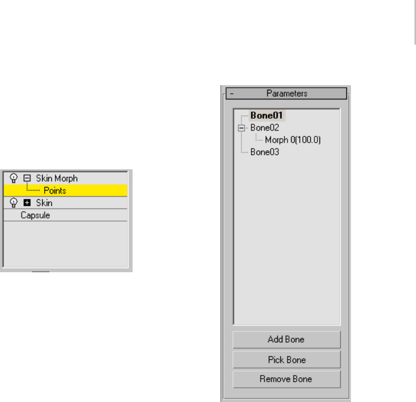
Skin Morph Modifier 813
9. Move vertices to where they should be at the
current frame.
10.Click Edit again to exit this mode, and then test
the animation.
Interface
Skin Morph modifier stack
Points sub-object level—At the Points sub-object
level, you can view and select vertices on the
skin mesh. However, you can transform these
vertices only when Edit mode is on. The ability
toselectpointswhennotinEditmodeletsyou
make the selection when the points are more easily
accessible, and then go to the pose to transform
them in Edit mode.
Parameters rollout
[list window]—Listsallattachedbonesandtheir
morphs in a hierarchical view. You can expand or
contract a bone’s morph listing by clicking the +
or - box next to its name in the list. The number
in parentheses next to the morph name shows its
relative influence as a percentage at the current
frame.
Highlighting a bone in the list highlights the bone
in the viewports as a yellow line, and lets you create
a morph for it. Alternatively, you can select the
bone in the viewport while the modifier’s Points
sub-object level is active by clicking the orange
line through its center.
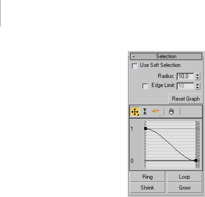
814 Chapter 8: Modifiers
Highlighting a morph in the list lets you edit the
morph. To change the morph’s name, edit the
Local Properties rollout > Morph Name field.
Add Bone—Click to add one or more bones from
the Select Bones dialog.
Tip: To keep things simple, add only bones that
will drive morphs. There’s no point in adding any
other bones.
Pick Bone—Lets you add bones by selecting them
in a viewport.
Click Pick Bone, and then select bones in any
viewport. While Pick Bone is active, the cursor
resemblesacrosswiththewordsADDBONE
attached. To exit Pick Bone mode, right-click the
activeviewportorclickPickBoneagain.
Remove Bone—Removes a bone and its morphs
from the list. Click a bone name in the list, and
then click Remove.
If a morph name is highlighted when you click
Remove, its bone is removed. To remove the
morph only, highlight it and then click Local
Properties rollout > Delete Morph.
Selection rollout
Use Soft Selection—Enables soft selection for
editing vertices.
Soft Selection in Skin Morph works much like Soft
Selection (page 1–963) in other parts of 3ds Max,
except that instead of Pinch and Bubble settings
you can adjust the graph shape directly, and it uses
a Radius setting instead of Falloff to determine the
extent of the soft-selection area.
Radius—Determines the extent of the soft-selection
area in system units.
Edge Limit—When on, Skin Morph uses the Edge
Limit numeric setting to determine the extent of
thesoft-selectionareaintermsofthenumberof
edges from the selected vertex or vertices.
Reset Graph—Sets the soft-selection graph to
default values. Use this if a vertex or handle is no
longer visible and thus cannot be manipulated.
[graph]—Skin Morph provides a small,
full-functioned curve graph for editing
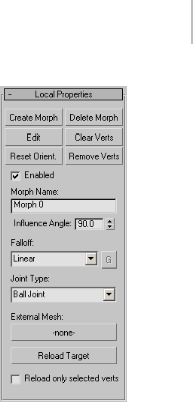
Skin Morph Modifier 815
soft-selection characteristics globally; it works
much like other such graphs in 3ds Max, such as
Curve Editor (page 2–507).Thetoolbarabovethe
graph offers functions for moving and scaling
points on the graph, as well as inserting new ones.
The same functions are available by right-clicking
the graph: If you right-click a graph point, you
can set it to Corner or one of two different Bezier
types. If you select a Bezier point, you can reshape
the curve by moving its handles.
Ring—Expands a vertex selection by first
converting the selection to an edge selection,
selecting all edges parallel to the selected edges,
and then converting the new edge selection back
to a vertex selection. Use of Ring requires that a
qualifying vertex selection exist; that is, at least
two vertices on the same edge.
Loop—Expands a vertex selection by first
converting the selection to an edge selection,
selecting all aligned edges, and then converting the
new edge selection back to a vertex selection. Use
of Loop requires that a qualifying vertex selection
exist; that is, at least two vertices on the same edge.
Shrink—Reducesthevertexselectionareaby
deselecting the outermost vertices. If the selection
size can no longer be reduced, the remaining
vertices are deselected.
Grow—Expands the vertex selection area outward
in all available directions.
Local Properties rollout
This rollout contains functions for creating and
editing individual morphs. The settings, such as
Morph Name and Influence Angle, are specific to
each morph.
Create Morph—Sets a morph at the current frame
for the highlighted bone. Also sets the “pose” for
this morph, using the bone’s current orientation,
and sets the bone to 100%, as shown in the list
window hierarchical view. When you edit the
morph, the skinned object returns to and stays at
this orientation.
When you create a morph, the modifier displays,
in orange, all vertices that are part of the current
pose (that is, they’re offset from the initial pose).
Also, the modifier creates a default name for the

816 Chapter 8: Modifiers
morph and adds it as a child to the highlighted
bone in the list window.
Tip: By default, the Show Edges switch is on,
which might make it difficult to see the vertices
themselves. To see only the vertices, turn off
Options rollout > Show Edges.
Tip: To help keep track of morphs, use the Local
Properties rollout to rename each morph as you
create it.
Delete Morph—Deletes the highlighted morph,
removing it from its parent bone in the list window.
Available only when a morph is highlighted.
Edit—Lets you shape the current morph by
transformingvertices.ToexitEditmode,clickthe
Edit button again.
Trans for min g a vertex in Ed it mode creates a
morph target. Each transformed vertex moves
into the morph target position (or orientation or
scale) as the morph value increases to 100.0, and
then out of it as the morph value decreases, based
ontheangleofthebonedrivingthemorph.
TransformingavertexinEditmodealsochanges
itscolorfromorangetoyellow.Thisletsyoueasily
seewhichverticesarepartofthecurrentmorph.
Choosing Edit places the skinned object at the
100% “pose” orientation for this morph (see
Create Morph, above). It also activates the Points
sub-object level so you can transform vertices
using the standard 3ds Max transform tools.
Clear Verts—Keeps selected vertices in the morph,
but resets their deltas (changes from the initial
pose) to 0.
Reset Orient(ation)—Sets the morph orientation to
current orientation of the bone that controls the
morph.
Thisletsyouchangetheangleatwhichthemorph
has its greatest effect. For example, if you create a
bulging bicep at frame 120, and later decide that
themuscleshouldbelargestatframe150instead,
go to frame 150, choose the morph in the list box,
and then click Reset Orientation.
Remove Verts—Removes selected vertices from
the current morph, which deletes any animation
applied as part of the morph.
Use this command to save memory by removing
vertices not part of the morph animation.
Enabled—When on, the morph is active; when off,
the morph doesn’t appear in the animation, and is
indicated in the list box with the text “Disabled.”
Default=on.
The ability to enable and disable each morph
individually lets you isolate the effect of each or
test them in combination.
Morph Name—Displays and lets you change the
name of the current morph.
Influence Angle—Theanglearoundthebone’s
current orientation within which the morph takes
place. Default=90.0.
This is an important parameter. Think of the
influence angle as a cone around the bone at
its orientation when you create the morph.
Consider an example in which Influence Angle
is set to the default value of 90.0 degrees. If the
bone starts its rotation beyond 45 degrees away
from the orientation at which the morph was
created, the morph has no effect at that time.
As the bone moves from 45 degrees away to the
morph orientation, the morph increases to its full
value. As the bone then rotates away, the morph
gradually decreases until, at 45 degrees or more
away from the morph orientation, the morph no
longer appears.
Tip: Influence Angle is useful for isolating morphs;
that is, to prevent overlapping of different morphs
onthesamebone. Reducethevalueuntilone
morph’scontributionpercentvalue(showninthe
list box) falls off to 0.0 before the next one begins.
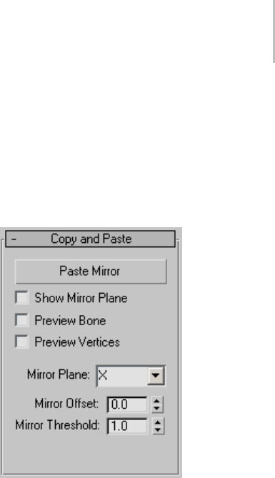
Skin Morph Modifier 817
Falloff—Determinestherateofchangeofthe
morphasthebonemoveswithintheinfluence
angle. Use the drop-down list to choose one of
four different falloff types: Linear, Sinual, Fast, or
Slow. If you choose Custom Falloff, you can then
click the G (for Graph) button and edit the falloff
using standard curve-graph controls.
Note: The default graph, displayed when you first
access the falloff graph, shows the Sinual falloff
type.
Joint Type—Determines how the modifier tracks
the angular motion of the bone. This is a per-bone
setting, not per-morph. Default=Ball Joint.
•Ball Joint—Tr acks all rotation of the bone. Use
this setting in most cases.
•Planar Joint—Tracks rotation of the bone only
in the plane of its parent bone.
External Mesh—Lets you use a different mesh
asamorphtarget. Clickthebutton(default
label=-none-) and then select the target object.
Thetargetobjectshouldhavethesamemesh
structure as the Skin Morph object. After
specifying an external mesh, its name appears on
the button.
Using an external mesh makes it easier to set
upmorphtargetsinatargetmeshthatusesa
reference pose, rather than the skinned, animated
mesh of which sections might be interpenetrating,
making it difficult to select the specific vertices to
be morphed. In this situation, it’s probably best to
turn Reload Only Selected Verts.
Note: The external-mesh connection is not live; if
you edit vertices in the external mesh, Skin Morph
doesn’t automatically recognize the changes.
To update the vertex positions after editing the
external mesh, use Reload Target (see following).
Reload Target—Updates the Skin Morph object
with edited vertex positions from the external
mesh.
Reload only selected verts—When on, Reload
Target copies only the positions of vertices selected
in the Skin Morph mesh from the target mesh.
When off, Reload Target copies the positions of
all vertices. Default=off.
Copy and Paste rollout
These functions let you copy all morph targets for
a specific bone from one side of the object to the
other. Indicate the morphs to copy by highlighting
the bone or any of its morphs in the Parameters
rollout > list box.
Paste Mirror—Copies the morphs from the
highlighted bone to the target on the other side of
the mirror gizmo. A qualified target bone must
existandbepresentinthelistbox.
Note: This copies the morph data only; the rotation
ofthetargetbonemustbecomparabletothatof
the source bone for the morphing to appear in the
animation.
Show Mirror Plane—Displays the mirror plane as
a red, rectangular gizmo in the viewports. The
target bone must be on the opposite side of the
mirror plane from the highlighted bone, and must
be present in the Parameters rollout > list box.
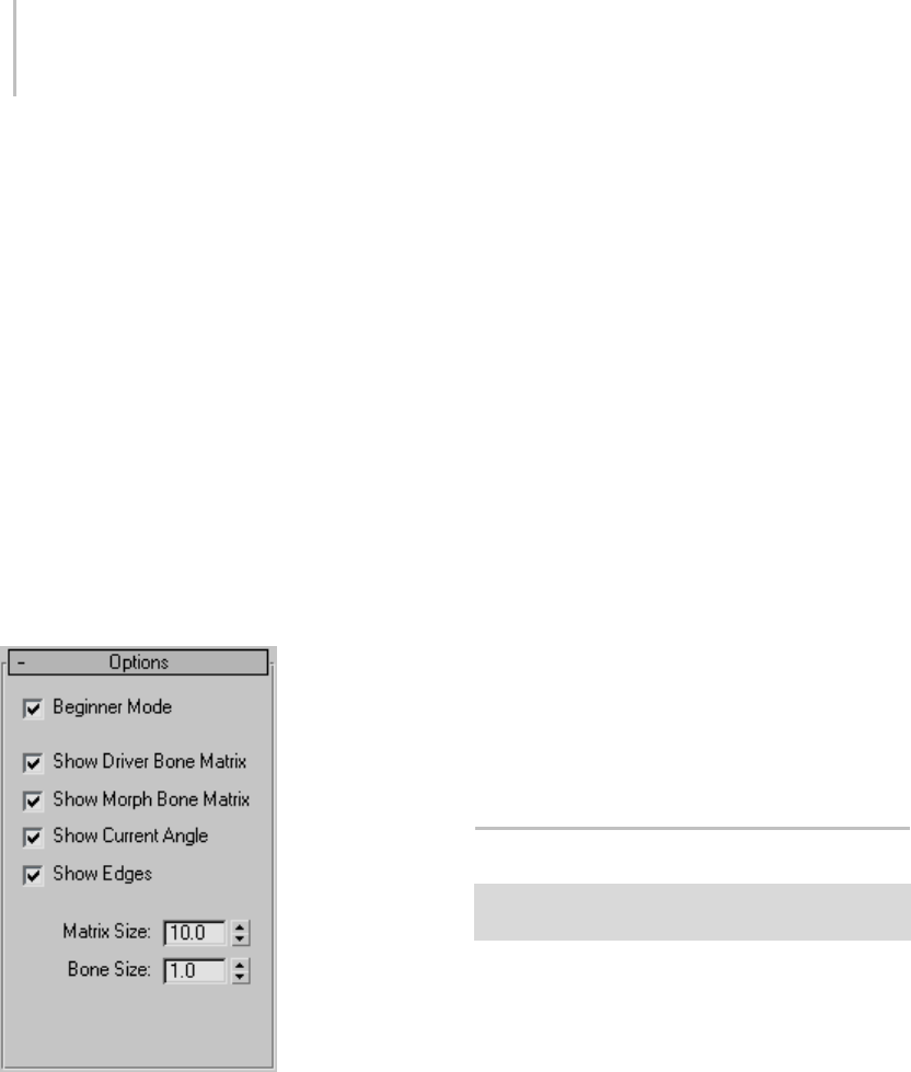
818 Chapter 8: Modifiers
Preview Bone— Highlights the target bone in red
in the viewports.
Preview Vertices—Displays the morphing-qualified
vertices in red in the viewports, as well as any
animation present in the source vertices.
Mirror Plane—The axis for the mirror plane. The
plane is perpendicular to the indicated axis.
Default=X.
Mirror Offset—Thepositionforthemirrorplane
on the Mirror Plane axis. Default=0.0.
Mirror Threshold—The radius, in system units,
within which Skin Morph looks for a qualifying
target bone on the other side of the mirror plane.
Default=1.0.
Options rollout
Beginner Mode—When on, you must use the
Create Morph button to create a morph and the
Edit button to edit a morph.
When off, you can create and edit morphs on
the fly. In this mode, when you select and move
vertices at the Points sub-object level, the software
first determines whether a morph exists for the
selected bone at 100%; if so, all edits will go to that
morph. Otherwise, the software creates a new
morph automatically and applies the edits to that
morph.
Show Driver Bone Matrix—Shows the matrix tripod
of the current bone.
Show Morph Bone Matrix—Shows the tripod of the
orientation of the active morph.
Show Current Angle—Shows pie wedges depicting
the angles between the driver bone matrix and the
morphbonematrix.Thesearecolorcoded:redfor
theangleabouttheXaxis;bluefortheangleabout
the Y axis; and green for the angle about the Z axis.
Show Edges—Highlights the edges connected to
morphable vertices in orange.
This is useful when a tessellating modifier such as
MeshSmooth is applied to the skinned mesh above
the Skin Morph modifier, to see the actual mesh
being affected by Skin Morph.
Matrix Size—Thesizeofeachtripod.
Bone Size—Thesizeofthebonedisplay.
Skin Wrap Modifier
Make a selection. > Modify panel > Modifier List >
Object-Space Modifiers > Skin Wrap
The Skin Wrap modifier allows one or more objects
to deform another. While Skin Wrap is flexible
enough to serve a variety of needs, it’s primarily
intended for animating a high-resolution object,
such as a character mesh, with a low-resolution
one.
The low-resolution object doing the deforming
is called a control object,andthehigh-resolution
object it’s affecting (that is, the one with the Skin
Wrap modif ier) is the base object.Abaseobject
can be any type of deformable object. Also, in
this topic, control vertex refers to a vertex on the

Skin Wrap Modifier 819
control object, and point refers to a vertex on the
base object.
With Skin Wrap, you can modify the structure and
topology of the high-resolution object after setting
up the animation. The animation remains intact
because it is actually contained in the control
object.
In most cases, when using Skin Wrap, the control
object is positioned near the modified base object,
and then bound to the latter using the modifier’s
Add function. By default, moving a vertex in
the control object affects nearby vertices in the
base object. Additional options allow faces in
the control object to affect the nearest points in
the base object instead (Blend To Base Object).
Conversely, points in the control object can affect
faces in the base object (Face Deformation).
Skin Wrap offers a great deal of control in that
youcansetadifferentstrengthvalueforeach
control vertex, as well as the shape of its volume
of influence. You can also convert the Skin Wrap
effect to a Skin modifier applied to the high-res
model, suitable for use with game engines. And
theabilitytoanimatewithmultiplecontrolobjects
lets a technical director assign animation of
different parts of a complex character mesh to
various artists.
Tip: If you use a control object to which
non-uniform scaling has been applied, its vertices
will have non-spherical volumes of influence,
which can lead to unexpected results. In such
a case, before adding the control object to the
modifier, apply Reset XForm (page 1–438) and
then collapse the stack.
See also
Skin Wrap Patch Modifier (page 1–824)
Procedure
To use Sk in Wrap (basic method):
1. Create a high-resolution base object and one or
more low-resolution control objects, which will
deformthebaseobject.Ingeneral,eachcontrol
object should have an overall shape similar to
the part of the base object that it will deform,
and be positioned near that part of the base
object.
2. Apply Skin Wrap to the high-resolution base
object. The modifier transfers animation or
modeling from the control object to the base
object.
3. On the Skin Wrap > Parameters rollout, use
Add to assign the control object(s).
4. Choose a deformation engine: Vertex or Face.
5. Set global parameters as desired. These
parameters affect all control vertices, and
include Deformation Engine, Falloff, Distance
Influence, and Face Limit.
6. To set local parameters, including strength and
influence distances, access the Control Vertices
sub-object level of the Skin Wrap. Select one
or more control vertices, and then change the
settings as necessary.
7. Edit or animate the control object with
modifiers and/or sub-object transforms;
the high-resolution (base) object deforms
accordingly.
8. Repeat steps 5, 6, and 7 as necessary.
Occasionally you might need to reset the
modifier as well, by clicking the Reset
button. Before doing so, always return to a
non-deformed point (or “skin pose”) in the
animation; typically, frame 0.
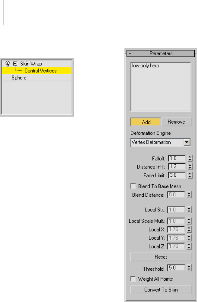
820 Chapter 8: Modifiers
Interface
Skin Wrap modifier stack
Control Vertices sub-object level—At the Control
Vertices sub-object level, you can view and select
vertices on the control object(s), and set local
parameters (page 1–821) for any selected vertices.
By default, each selected vertex is surrounded
by loops that depict its volume of influence.
This sub-object level also uses color coding on
affected points in the base object to show each
selected vertex’s relative effect on points within
the volume of influence. Colors range from orange
for the strongest influence to blue for the weakest
influence. Red is for vertices that are within its
range of influence but that it’s not influencing.
By default, at this level, control vertices appear
as small orange squares. To prevent this, turn
off Display Parameters rollout > Display Control
Ve r t i c e s .
Parameters rollout
[control object list]—Lists object(s) that deform
the modified object. Use the Add and Remove
functions to edit the list contents.
Add—Adds control objects to the list. Click Add,
and then click each control object in turn. To stop

Skin Wrap Modifier 821
adding, right-click in the viewport or click Add
again.
You can use as a control object anything that can
be converted to a triangle mesh, such as a mesh,
patch, or a NURBS object. However, avoid using
objects that change topology, such as a deforming
NURBS object with adaptive tessellation.
Remove—Removes control objects from the list.
Click an object in the list, and then click Remove.
Deformation Engine—Determines which engine
drives the deformation. Default=Vertex
Deformation.
• The Vertex Deformation engine is a weighted
engine; it uses vertex proximity to drive the
deformation. That is, each vertex in the
control object affects nearby points in the
high-resolution (base) mesh.
• With the Face Deformation engine, each
control vertex is tied to the closest face in the
base object. Face deformation can use falloff,
orbearigiddeformationbysettingFalloffto
0.001, the lowest possible value.
Falloff—Determines the extent to which the control
vertices affect nearby points in the base object.
This is a global setting. Default=1.0. Range=0.001
to 10.0.
Higher values pull nearby points closer to the
control vertex. In Face Deformation mode, setting
Falloff to the lowest value, 0.001, causes rigid
deformation so that there’s no falloff; the control
vertex either affects the base-object face or it
doesn’t. For best results, use Falloff values between
1.0 and 2.0, or with Face Deformation, 0.001 for
rigid mode.
Distance Infl(uence)—Determines the distance of
influence, in system units, of control vertices in
the control object. This is a global setting, and
is available only in Vertex Deformation mode.
Default=1.2. Range=0.001 to 10.0.
Distance Influence is a multiplier. It looks at the
length of each edge that touches each control
vertex. For each vertex, it averages all the lengths
and then multiplies the average by the Distance
Influence value. This lets vertices that are touching
only small faces to affect a small area, and
vice-versa. The higher the influence value, the
smoother the deformation, but the less individual
control each vertex has. For best results, keep this
value between 1.0 and 2.0.
Face Limit—Determines the extent of influence,
in control-object faces, of control vertices in
the control object. This is a global setting, and
is available only in Vertex Deformation mode.
Default=3. Range=0 to 10.
Beyond this limit, no base-object points can be
influenced by the control vertex, even if they’re
within the Distance Influence radius.
Face Limit is useful for preventing the
control-object influence from bridging gaps in the
mesh; for example, between fingers in a character
mesh.
Blend To Base Mesh—Causes the modifier to base
deformationonthedistancefromeachaffected
point to the closest face in the control object.
TurningonthisoptionmakestheBlendDistance
setting available.
Blend Distance—Determinestherelativedistance
between control-object faces and vertices in
thebaseobjectfordeformationtotakeeffect.
Available only when Blend To Base Mesh is on.
Default=5.0.
Increasing this setting effectively causes a stronger
deformationeffectandbroadenstheareaonthe
control that affects the base object.
[local parameters]
TheLocalparametersareavailableonlyatthe
Control Vertices sub-object level (see Skin Wrap
modifier stack (page 1–820)), and affect only

822 Chapter 8: Modifiers
selected points. If you select a single point, the
numeric fields reflect its current parameter values.
If you select multiple points, 3ds Max displays
only those values common to all selected points;
parameters with differing values are blank. With
multiple points selected, changing a value sets all
selected points to that value.
Local Str(ength)—Determines the power and
direction by which the control-object vertex affect
points under its influence in the base object. A
positive value pulls the points toward the vertex; a
negative value pushes them away. Default=1.0.
Local Scale Mult(iplier)—Scales each selected
control-object vertex’s volume of influence
uniformly. Default=1.0.
Usethescalesettingstoincreaseordecreasethe
area of the base object that the selected control
vertex affects.
Local X/Y/Z—Scales each selected control-object
vertex’s volume of influence along the indicated
axis. Default=1.0.
Change these parameters to produce a
non-spherical volume of influence.
Reset—Resets all control-object vertices’ local
values to 1.0 and resamples the mesh. It
recalculates the control vertices’ influence on the
base object using the current modifier settings.
Use Reset if you alter a parameter but don’t see any
change in the deformation. For example, always
use Reset after changing the Threshold value. Or,
if you want the control object to affect a different
part of the base object, move the former, and
then use Reset so the modifier accounts for the
change in positional relationship between the two.
You might also need to reset after changing the
topology of the base object or a control object.
Important: Use Reset at a point in the animation where
no deformation is in effect; typically, frame 0.
Threshold—Determines the distance in system
units that the software uses to find the closest
face to a control vertex. The greater the distances
by which the control object’s and base object’s
surfaces deviate, the higher the Threshold value
needs to be. Default=5.0.
Note: Thresholdisrecomputedonlywhenyouadd
abasemeshorclickReset.
Warning: Be careful about increasing this setting.
High values can result in excessive computation times,
especially with complex base objects.
Weight All Points—Forces all base-object points
to have weights. Each weight is calculated from a
combination of three factors: control vertex scale,
control vertex strength, and base-object point
position.
By default, not all base-object points are
necessarily influenced by the control object.
Turning on Weight All Vertices causes all points to
beinfluencedbyoneormorecontrolvertices.Ifa
largenumberofbase-objectpointsareunassigned,
this can take a long time to calculate.
Convert To Skin—Applies a new Skin modifier
(page 1–791) tothebaseobjectthatreplicatesthe
animation in the Skin Wrap modifier. Using this
function requires that a Skin modifier already be
applied to each control object.
Basically, Convert To Skin intelligently “bakes” the
animation from skinned low-res control objects to
thehigh-resbaseobject.TheSkinmodifierthatit
createscontainsalltheboneassignmentsfromthe
original Skin modifier, but with completely rebuilt
weight settings based on the base-object weights
created by the Skin Wrap modifier.
This function is useful in game-development
settings where the game engine recognizes the Skin
modifier settings but not the Skin Wrap modifier.
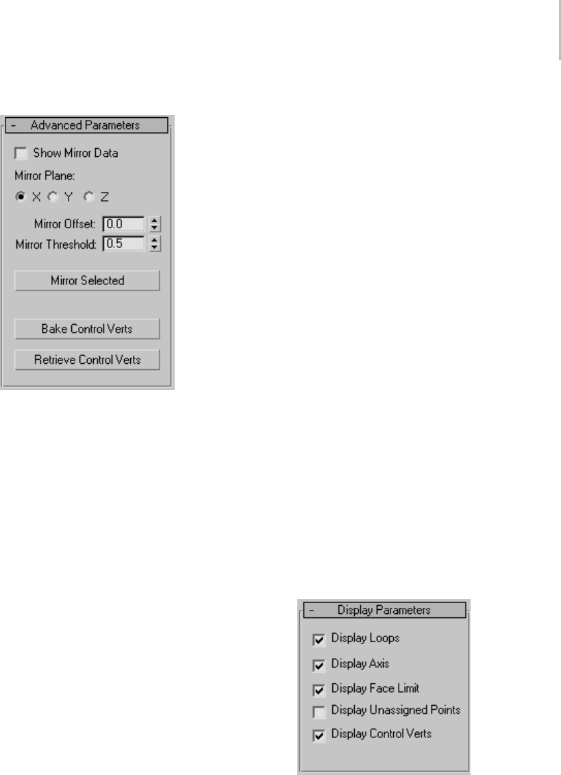
Skin Wrap Modifier 823
Advanced Parameters rollout
The Mirror tools in Skin Wrap let you apply
local settings (Strength and Scale) from control
vertices on one side of a control object to the other,
mirroringthemacrossaplanealignedwiththeX,
Y, or Z axis. This is useful for setting up character
meshes.
Note: Mirror copies only Skin Wrap settings from
control vertices; it doesn’t copy animation data.
Thus, when using Skin Wrap with a character
model, first make local settings for control vertices
on one side of the control object, select the vertices
to copy, mirror them, and then animate the control
object.
The Bake/Retrieve Control Vertices functions let
you store control-vertex settings into the base
object and then retrieve them. This is useful for
sharing data among artists working on the same
project.
Show Mirror Data—Tu rns on d isp lay of t he m ir ror
plane gizmo as well as a small circle showing the
projected location for each selected control vertex.
Movethegizmoandtheprojectedlocationswith
the Mirror Offset control (see following).
Note: Formirrordatatobevisible,theSkinWrap
> Control Vertices sub-object level must be active.
Mirror Plane—ChoosetheX,Y,orZaxisfor
mirroring.
Mirror Offset—Movesthemirrorplaneaswellasall
mirrored vertices.
Mirror Threshold—Sets the distance, in system
units, that Skin Wrap uses to find a control vertex
near a projected vertex. Increase this if vertex
locations are not the same on either side of the
mirror plane.
Mirror Selected—Copies the local settings from
each selected control vertex to any control vertices
within the threshold distance of its projected
location on the other side of the mirror plane.
Bake Control Verts—Stores the Local Strength/Scale
and the global Falloff, Distance Infl., and Face
Limit settings on the control objects for later
retrieval with Retrieve Control Vertices.
Note: This data is static; any changes to the
base-object topology invalidates it.
Retrieve Control Verts—Ta ke s a ny c o nt r o l - ve r t ex
data stored on the control objects with Bake
Control Vertices and copies them into the modifier.
Display Parameters rollout
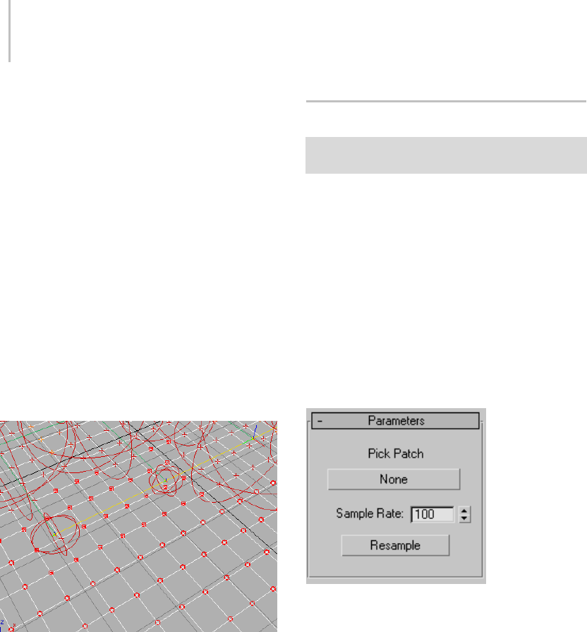
824 Chapter 8: Modifiers
These settings determine whether or not the
software displays different elements in the Skin
Wrap mo difie r.
Display Loops—Displays volumes of influence for
selected control vertices as red loops. Default=on.
Display Axis—Displays the axis tripods for selected
control vertices. Default=on.
Display Face Limit—Shows all base-object points
that the selected control vertex or vertices can
affect. This is a visualization of the Face Limit
setting.Default=on.
Display Unassigned Points—Draws a red circle
around each base-object point that the system
did not find a closest face for and draws a red box
around each point that has a closest face but is not
weighted by any control vertex. Default=off.
Unassigned points: The circled points (bottom) have no closest
face, while the points with red boxes (center) have a closest
face but aren’t weighted by control vertices.
This is an important debugging tool because any
vertex that is not assigned a closest face will never
be weighted. To do so, you need to increase the
Threshold value and click Reset, or turn on Weight
All Points. Any points that are not weighted to a
control vertex can be fixed by increasing the Local
Scale of a control vertex near that point.
Display Control Verts—Toggles display of all control
vertices. Default=on.
Skin Wrap Patch Modifier
Make a selection. > Modify panel > Modifier List >
Object-Space Modifiers > Skin Wrap Patch
Skin Wrap Patch is a simple modifier that allows
apatchobjecttodeformameshobject. It’svery
easy to use: just assign the modifier to a mesh
object, and then use the modifier to specify a
deforming patch object. Each point on the patch
object influences a surrounding volume of points
on the mesh object.
See also
Skin Wrap Modifier (page 1–818)
Interface
Pick Patch—Click this button, labeled “None” by
default, and then select a patch object to deform
the mesh object. After picking the patch object, its
name appears on the button.
Sample Rate—Determines the accuracy with which
the modifier samples the patch object. The higher
therate,themoreaccuratetheresultinganimation
will be, but the longer it will take to calculate.
Resample—Forces the system to resample the date.
This should be done at a point in the animation at
which no deformation takes place; typically, frame
0.
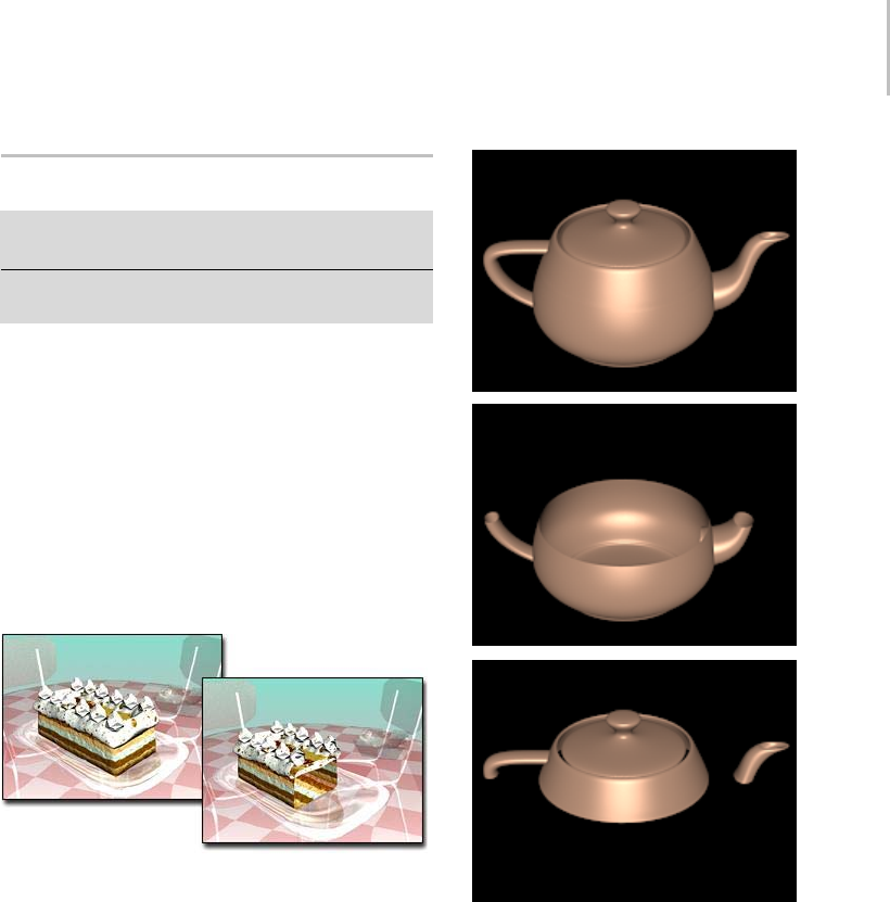
Slice Modifier 825
Slice Modifier
Select an object. > Modify panel > Modifier List >
Object-Space Modifiers > Slice
Select an object. > Modifiers menu > Parametric
Deformers > Slice
The Slice modifier lets you create a cutting plane
that slices through a mesh, creating new vertices,
edgesandfacesbasedonthelocationoftheslice
plane gizmo. The vertices can either refine or split
the mesh according to the selected options.
The Slice modifier slices through groups, selected
objects or sub-object selections of faces. It works
similarly to the Editable mesh > Edge > Slice
function but does not require the objects to be
editable meshes.
Slicecutsthroughthecake.
You can animate the cutting plane, changing its
position and rotation over time. You can also use
theRemoveTopandRemoveBottomoptions
tocreatetheappearanceanddisappearanceof
objects by animating the Slice Plane gizmo.
Top: Original object
Middle: Object without top
Bottom: Object without bottom, respectively
Multiple Slices
To create multiple slices in an object you need to
apply multiple Slice modifiers. If the geometry
doesn’t need to remain parametric, you can
collapse it into an editable mesh and use the Slice
tool available under Editable Mesh (Edge) (page
1–1006). This tool is easier to use when you need
to make multiple slices in an object, but it does not
stay parametric.
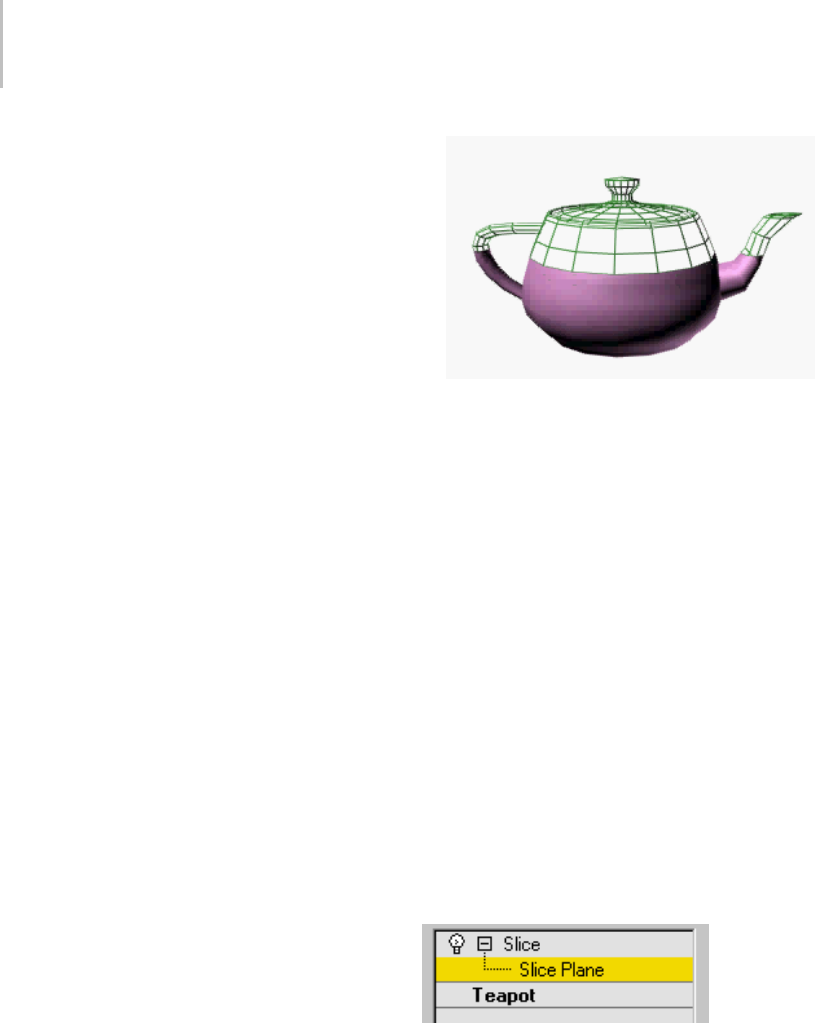
826 Chapter 8: Modifiers
Warning: Slice and Sub-Object
Selections
You can use Slice on sub-object selection sets
by slicing or removing only the selected faces.
However, because selected faces are sliced and
unselected adjacent faces are not, there may be
"holes"inthemeshontheedgewheretheslice
occurs. These holes can be problematic, creating
discontinuities in smoothing and rendering. Holes
are created only when Operate On Faces is on.
Procedure
Example: To animate the appearance of a teapot
using the Slice modifier:
1. Create a teapot (page 1–183) primitive. Set the
viewport to wireframe.
2. Apply a Slice modifier.
TheSlicePlanegizmoappearsatthebaseofthe
teapot.
3. On the stack display, choose the Slice Plane
gizmo.
4. Turn on the Auto Key button, and move the
time slider to frame 100.
5. MovetheSlicePlanegizmoabovethetopofthe
teapot. Play the animation to verify that the
slice plane is animated.
6. Change the Slice type from Refine Mesh (the
default) to Remove Top. Play the animation
again.
7. Makeacopyoftheteapotinthesameposition
(chooseEditmenu>CloneandclickOKto
accept the default settings).
8. PutaWireframematerialonthecloneand
change the Slice type on the clone to Remove
Bottom.
9. Play the animation.
The wireframe teapot magically becomes a fully
shaded one.
Example: To slice vertically through an object:
1. Create a teapot (page 1–183) primitive.
2. Apply a Slice modifier.
TheSlicePlanegizmoappearsatthebaseofthe
teapot.
3. On the stack display, open the Slice modifier
and choose the Slice Plane gizmo.
4. MovetheSlicePlanegizmosoitintersectsthe
middle of the teapot.
5. Rotate the Slice Plane gizmo so it is vertical.
6. Tur n on Re move Top.
The back of the teapot is sliced away.
7. Tur n on Remove B ottom.
The front half of the teapot is sliced away.
Interface
Modifier Stack
Slice Plane—At this sub-object level, you can
transform and animate the gizmo like any other
object to determine where the slice occurs. Scaling
the gizmo has no effect, because its extents are
effectively infinite. If you need to limit the extent
of the slice, use it on a sub-object selection set of
faces, rather than on the entire object.
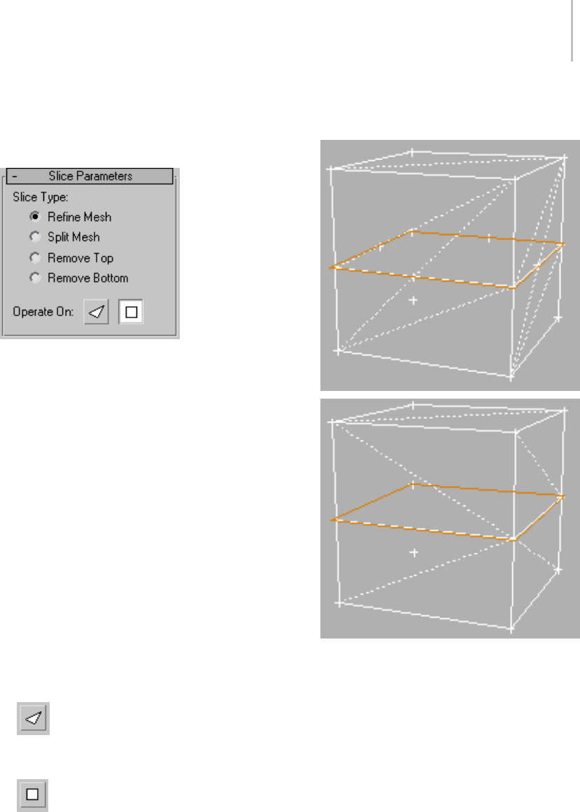
Slice Modifier 827
For more information on the stack display, see
Modifier Stack (page 3–760).
Slice Parameters rollout
Slice Type—Defineshowthesliceplanewillaffect
the geometry to which it has been applied.
•Refine Mesh—Adds new vertices and edges
along the intersection of the geometry with
the slicing plane. Faces cut by the plane are
subdivided into new faces.
•Split Mesh—Adds a double set of vertices and
edges along the plane boundary producing two
separate meshes (one on either side of the slice
plane), which you can modify differently if
desired. Use this to break a mesh in two.
•Remove Top—Deletes all the faces and vertices
abovetheSlicePlane.
•Remove Bottom—Deletes all the faces and
vertices below the Slice Plane.
Operate On—Choose one of these buttons to
specify how the slice handles quads and other
polygons.
•Faces—Treats the selection set as a set
of triangular faces, slicing each one in turn.
Outputs a mesh-type object (page 1–996).
•Polygons—Converts the object to
a polygon mesh based on visible edges,
eliminating hidden edges. Outputs a
polymesh-type object (page 1–1022).
Operate On Face vs. Operate On Polygon
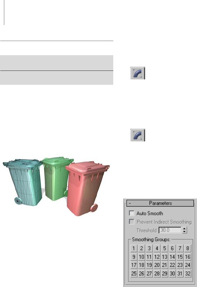
828 Chapter 8: Modifiers
Smooth Modifier
Select an object. > Modify panel > Modifier List >
Object-Space Modifiers > Smooth
Select an object. > Modifiers menu > Mesh Editing >
Smooth
The Smooth modifier provides auto-smoothing
based on the angle of adjacent faces. You can apply
new smoothing groups to objects.
Smoothingeliminatesthefacetsongeometryby
grouping faces into smoothing groups. At render
time, faces in the same smoothing group appear as
asmoothsurface.
Curved surfaces gradually smoothed:
Left: No smoothing
Center: Smoothing but some edges on the corners
Right: Full smoothing
Patches
As of 3ds Max 4, patch objects coming up the
modifier stack are not converted to a mesh by this
modifier. A patch object input to the Material
modifier retains its patch definition. Files that
contain patch objects with the Material modifier
from previous versions of the software will be
converted to meshes to maintain backward
compatibility.
Procedures
To smooth an object:
1. Select the object to be smoothed.
2. On the Modifiers menu, choose Mesh
Editing > Smooth.
3. Tur n on Auto Smo ot h an d adjust the Th re sh old
for the desired smoothing effect.
To apply smoothing groups manually:
1. Select an object.
2. Use a Mesh Select modifier (page 1–719)
to select the faces to be smoothed.
3. Click a numbered button to apply the
corresponding smoothing group to the selected
faces.
Interface
Parameters rollout
Auto Smooth—If Auto Smooth is selected, the
object is auto-smoothed using the (animatable)
threshold specified by the Threshold setting below
it. Auto Smooth sets the smoothing groups based
on the angle between faces. Any two adjacent faces
areputinthesamesmoothinggroupiftheangle
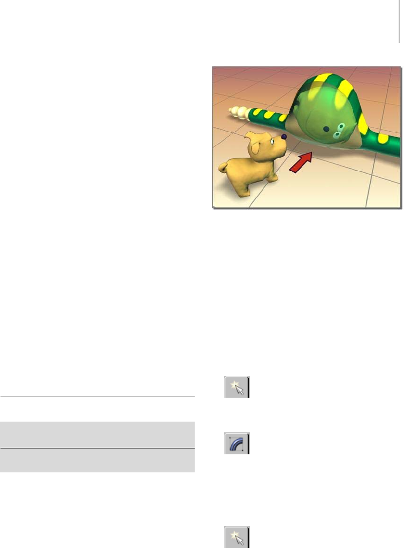
Spherify Modifier 829
between their normals is less than the threshold
angle.
Prevent Indirect Smoothing—Tur n on to prevent
smoothing ’leaks" when using Auto Smooth. If
you apply Auto Smooth to an object, and portions
of that object that should not be smoothed
becomesmoothed,thenturnonPreventIndirect
Smoothing to see if it corrects the problem.
Note: This option has an effect only when Auto
Smooth is selected. The problem it corrects is rare,
and turning on Prevent Indirect Smoothing slows
the Auto Smooth process. Don’t use this option
unless you see something wrong with your existing
smoothing.
Threshold—Specifies the threshold angle in
degrees. Any two adjacent faces are put in the
same smoothing group if the angle between their
normalsislessthanthethresholdangle.
Smoothing Groups group
The grid of 32 buttons shows which smoothing
groups are used by the selected faces, and are used
to assign smoothing groups manually to selected
faces.
Spherify Modifier
Select an object. > Modify panel > Modifier List >
Object–Space Modifiers > Spherify
Select an object. > Modifiers menu > Parametric
Deformers > Spherify
The Spherify modifier distorts an object into
a spherical shape. This modifier has only one
parameter: a Percent spinner that deforms the
object, as much as possible, into a spherical shape.
Spherify shapes the dog inside the snake.
Thesuccessoftheoperationdependsonthe
topology of the geometry to which it’s applied. For
example, a cylinder with no height segments will
result in little change. Adding height segments
will result in a barrel at 100 percent. Adding cap
segments will produce a sphere.
Tr y this on a teapot (page 1–183).
Procedures
Example: To use the spherify modifier to distort a
teapot:
1. Click Create > Geometry > Standard
Primitives > Teapot.
2. Create a teapot in the viewports.
3. OntheModifypanel,chooseSpherify
from the Modifier List.
The teapot should now look like a sphere.
4. Adjust the Percent setting to less than 100%.
Example: To animate spherifying a teapot:
1. Click Create >Geometry > Standard
Primitives > Teapot.
2. Create a teapot in the viewports.
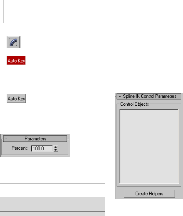
830 Chapter 8: Modifiers
3. OntheModifypanel,chooseSpherify
from the Modifier List.
4. Turn the Auto Key button on.
5. Set the Spherify Percent to 0.
6. Movethetimeslideraheadtoframe30.
7. SettheSpherifyPercentto100.
8. Turn the Auto Key button off.
9. Dragthetimeslidertoplaytheanimation,or
click Play.
Interface
Percent—Setsthepercentageofspherical
distortion to apply to an object.
Spline IK Control Modifier
Select a spline or NURBS curve > Modify panel > Modifier
List > Spline IK Control
When the Spline IK Control modifier is applied to
a spline, you can select and transform its vertices
without having to access the vertex sub-object
level. It can also place helpers at each vertex
location to aid in moving vertices.
The Spline IK Control modifier works by placing
knots (control points) at each vertex. The knots
canthenbeusedtocontrolvertices,whichinturn
reshape the spline.
This modifier also works on NURBS curves,
placing a knot at each control point or control
vertex (CV).
Use the Spline IK Control modifier to prepare a
spline or NURBS curve for use with the Spline IK
Solver.
See also
Spline IK (page 2–473)
Interface
Control Objects—When helpers are created, knot
numbers and their corresponding names appear
here. Knot #1 is placed at the first vertex (page
3–941) on the spline, and additional knots are
numbered in sequence.
Create Helpers—Places a helper at each knot, and
displays knot numbers and helper names in the
Control Objects area. Helper display is based on
selections in the Helper Display group. Helpers are
linked upon creation if a linking option is selected
in the Link Types group.
Note: Click Create Helpers only once. Clicking this
option more than once will create extra helpers at
each knot, making it difficult to control the spline.
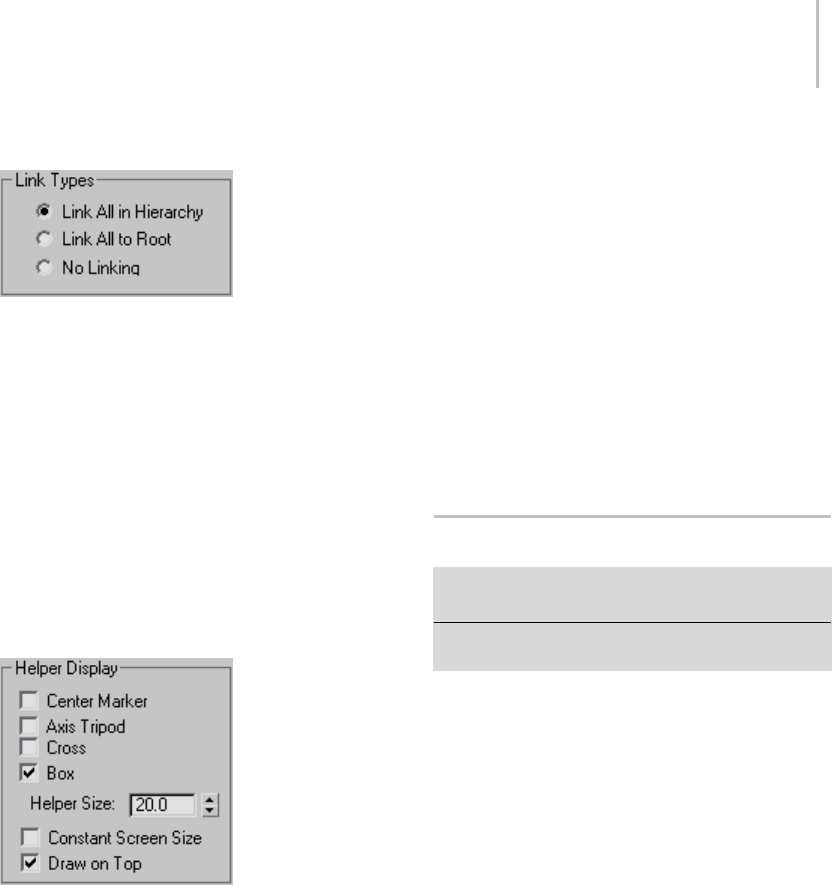
Spline Select Modifier 831
Link Types group
These options cause helpers to be linked upon
creation.
Link All in Hierarchy—Links each helper to its
immediately previous helper. For example, the
helper at knot #3 is linked to the helper at knot #2,
while the helper at knot #2 is linked to the helper
at knot #1.
Link All to Root—Links each helper to the helper
at knot #1.
No Linking—Helpers are not linked.
Helper Display
When you click Create Helpers, the software can
place one or more Point helper objects at each
knot, making it easier to move and animate the
knots. You can enable more than one type of
helper.
Center Marker—Places a small X-shaped Point
helper at each knot.
Axis Tripod—Places a small tripod-axis-shaped
Pointhelperateachknot.
Cross—Places a small cross-shaped Point helper at
each knot.
Box—Places a small box-shaped Point helper at
each knot.
Size—Setsthesizeforhelpers.
Constant Screen Size—Keepsthesizesofhelpers
constant regardless of the zoom extent of the
viewports.
Draw On Top—Displays the helpers on top of all
other objects in the scene for improved visibility
in busy scenes.
Tip: To change the display of helpers after creation,
select each helper and change selections on the
Modify panel.
Spline Select Modifier
Select a shape. > Modify panel > Modifier List >
Object–Space Modifiers > Spline Select
Select a shape. > Modifiers menu > Selection Modifiers
> Spline Select
TheSplineSelectmodifierpassesasub-object
selection of shapes up the stack to subsequent
modifiers. Itprovidesmuchofthesamesetof
selection functions available in the Edit Spline
modifier (page 1–680). You can select vertices,
segments, or splines, and you can change the
selection from sub-object level to object level.
This modifier is similar to the Mesh Select (page
1–719) and Poly Select modifiers (page 1–762),
except for the type of sub-object components.
Procedure
To use the Spline Select modifier:
1. Create a multi-spline shape.
2. Apply a Spline Select modifier.
By default, the Vertex sub-object level is active.
3. Ifyouwishtoworkatadifferentsub-object
level, use the modifier stack display to choose it.
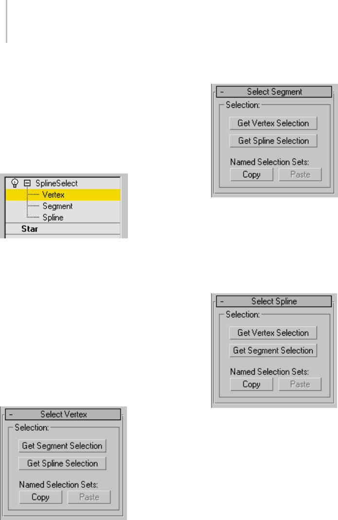
832 Chapter 8: Modifiers
4. In the viewports, select vertices, segments, or
splines.
Tip: You can transform the selection using an
XForm modifier (page 1–959) or Linked XForm
modifier (page 1–712).
Interface
Modifier Stack
The sub-object level you choose for the spline
select modifier determines which rollout appears.
(There are no parameters at the top, object level.)
Vertex—Creates a sub-object selection of vertices.
Segment—Creates a sub-object selection of
segments.
Spline—Creates a sub-object selection of splines.
For more information on the stack display, see
Modifier Stack (page 3–760).
Select Vertex rollout
Get Segment Selection, Get Spline Selection—Select
vertices based on the last Segment or Spline
selection. This selection is added to the current
selection. Available only when Vertex is not the
current sub-object level.
Select Segment rollout
Get Vertex Selection, Get Spline Selection—Select
segments based on the last vertex or spline
selection. The selection is added to the current
selection. Available only when Segment is not the
currentsub-objectlevel.
Select Spline rollout
Get Vertex Selection, Get Segment Selection—Select
splines based on the last vertex or segment
selection. The selection is added to the current
selection. Available only when Spline is not the
currentsub-objectlevel.
Copy/Paste Selection controls (all rollouts)
Copy—Places a named selection into the copy
buffer.
Paste—Pastes a named selection from the copy
buffer.
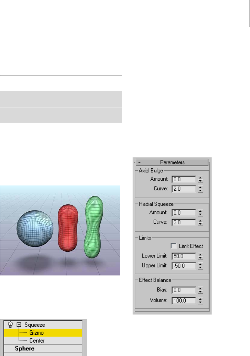
Squeeze Modifier 833
You can copy a named selection from one object
to another or one modifier to another. You must
copy and paste in the same sub-object level.
Squeeze Modifier
Modify panel > Make a selection. > Modifier List >
Object-Space Modifiers > Squeeze
Make a selection. > Modifiers menu > Parametric
Deformers > Squeeze
The Squeeze modifier lets you apply a squeezing
effect to objects, in which the vertices closest to
the object’s pivot point (page 3–995) move inward.
The squeeze is applied around the Squeeze gizmo’s
local Z axis. You can also use Squeeze to create
a bulge on the vertical axis, to accentuate the
squeeze effect.
Left: Original object
Middle and Right: Varying squeeze amounts
Interface
Modifier Stack
Gizmo—At this sub-object level, you can transform
and animate the gizmo like any other object,
alteringtheeffectoftheSqueezemodifier.
Translating the gizmo translates its center an equal
distance. Rotating and scaling the gizmo takes
place with respect to its center.
Center—At this sub-object level, you can translate
and animate the center, altering the Squeeze
gizmo’s shape, and thus the shape of the squeezed
object.
For more information on the stack display, see
Modifier Stack (page 3–760).
Parameters rollout
Axial Bulge group
These controls let you apply a bulge effect along
the Squeeze gizmo’s local Z axis, which is aligned
by default with the object’s local Z axis.
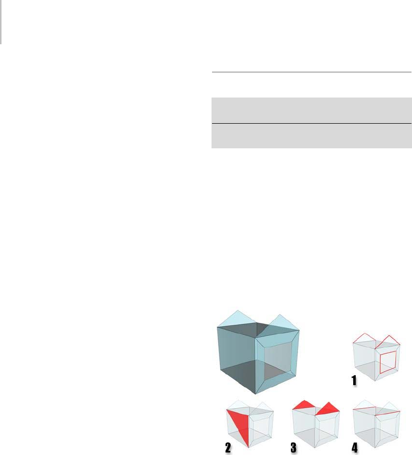
834 Chapter 8: Modifiers
Amount—Controls the magnitude of the bulging
effect. Higher values effectively elongate the object
and cause the ends to curve outward.
Curve—Sets the degree of curvature on the bulging
ends. You can use this to control whether the bulge
is smooth or pointy.
Radial Squeeze group
These controls let you apply a squeeze effect
around the Squeeze gizmo’s local Z axis, which is
aligned by default with the object’s local Z axis.
Amount—Controls the magnitude of the squeezing
action. Values larger than zero tend to constrict
the "waist" of the object, and values less than zero
tend to bulge the waistline out, as if the object had
been stepped on.
Curve—Sets the degree of curvature into the
squeeze. Low values cause a sharp squeezing
effect, while high values create a gradual, less
pronounced squeeze.
Limits group
These controls let you limit the squeeze effect’s
extents along the local Z axis.
Limit Effect—Limits the extent of the squeeze effect
as defined by the Lower and Upper Limit settings.
Lower Limit—Sets the limit in the positive direction
along the Z axis.
Upper Limit—Sets the limit in the negative
direction along the Z axis.
Effect Balance group
Bias—Changes the relative amounts of bulge and
squeeze while retaining a constant object volume.
Volume—Increases or decreases the effects of both
SqueezeandBulgeinparallel.
STL Check Modifier
Select an object. > Modify panel > Modifier List > STL
Check
Select an object. > Modifiers menu > Mesh Editing > STL
check
The STL Check modifier checks an object
to see if it’s correct for exporting to an STL
(stereolithography) file format (page 3–588).
Stereolithography files are used by specialized
machines to produce prototype physical models
based on the data in the STL file.
Tocreateaphysicalmodel,anSTLfilemusthave
a complete and closed surface. Using STL Check
to test your geometry before you export it can save
timeandmoneywhenthefileisusedtocreatethe
physical model.
STL Check errors.
1. Open edges
2. Double face
3. Spikes
4. Multiple edges
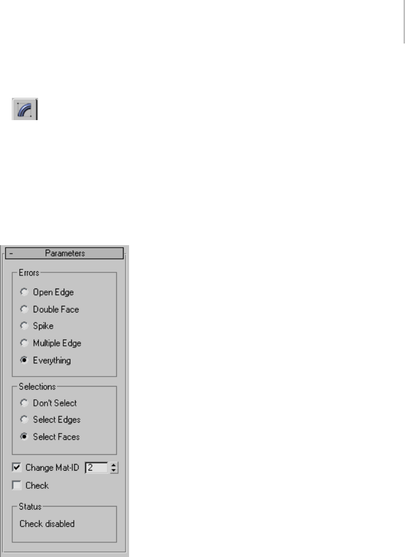
STL Check Modifier 835
Procedure
To check an object for STL compatibility:
1. Select the object, then on the Modify
panel, choose Mesh Editing > STL Check from
the Modifier List.
2. Tur n on C he ck .
ThemessageintheStatusgroupshowsiferrors
are found. STL Check indicates errors by
selecting the problem geometry, assigning it a
special material ID, or both.
Interface
Errors group
Choosing one of these options selects incorrect
geometry specific to the choice, and selects it
depending on the option chosen in the Selections
group.
Open Edge—Checks for open edges (holes).
Double Faces—Checks for faces that share the same
3D space.
Spike—Checks for spikes, which are isolated faces
that share only one edge with the object.
Multiple Edges—Checks for faces that share more
than one edge.
Everything—Checks for all of the above.
Tip: While checking Everything takes the longest
amount of time, it is recommended if you plan to
usetheSTLfileforgeneratingaphysicalmodel.
Selections group
These options specify the level of incorrect
geometry that’s selected, based on the settings in
the Errors group.
Don’t Select—When on, STL Check doesn’t select
any part of objects in error.
Select Edges—When on, STL Check marks the
edges of faces in error by selecting them. The
selection of erroneous edges is visible in viewports.
Select Faces—When on, STL Check marks the
faces of any object in error by selecting them. The
selectionoferroneousfacesisvisibleinviewports.
Change Mat-ID—When on (the default), STL
Check also marks faces in error by assigning them
a unique material ID. Use the spinner to choose
thevalueofthematerialIDthatSTLCheckuses.
Check—Turn on to perform the STL check. For
complex models, expect a pause between the time
youturnthison,andthetimeyouseethereported
errors in the Status group. Default=off.
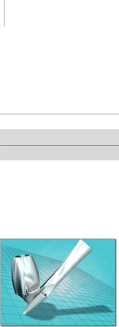
836 Chapter 8: Modifiers
Status—Displays the number of errors when Check
is on.
Tip: IfSelectEdgesisturnedoff,youcansee
faces in error by applying an Edit Mesh modifier
(page 1–634) and selecting by material ID at
theFacesub-objectlevel.Youcanalsoassigna
Multi/Sub-Object material (page 2–1594) to the
object to help you see where the errors are.
Stretch Modifier
Select an object. > Modify panel > Modifiers List >
Object–Space Modifiers > Stretch
Select an object. > Modifiers menu > Parametric
Deformers > Stretch
The Stretch modifier simulates the traditional
animation effect of "squash-and-stretch." Stretch
applies a scale effect along a specified stretch axis
and an opposite scale along the two remaining
minor axes.
Theamountofoppositescalingontheminoraxes
varies, based on distance from the center of the
scale effect. The maximum amount of scaling
occurs at the center and falls off toward the ends.
Applying a Stretch modifier to the object on the left creates
the object on the right.
Procedures
To stretch an object:
1. Select an object.
2. Apply Stretch.
3. On the Parameters rollout > Stretch Axis group,
choose X, Y, or Z.
4. On the Parameters rollout > Stretch group,
enter a value in the Stretch field.
5. Adjust the Parameters rollout > Stretch group >
Amplify setting to change the amount of scaling
along the minor axes.
To limit a stretch:
1. Apply a Stretch modifier to an object and
specify the stretch amounts and stretch axis.
2. On the Parameters rollout > Limits group, turn
on Limit Effect.
3. Set values for the Upper and Lower Limits to
define the Stretch boundaries on either side of
the Stretch center.
4. In the stack display, choose the Center
sub-object level, and move the center to locate
the limited stretch effect.
Interface
Modifier stack
Gizmo—At this sub-object level, you can transform
and animate the gizmo like any other object,
altering the effect of the Stretch modifier.
Translating the gizmo translates its center an equal
distance. Rotating and scaling the gizmo takes
place with respect to its center.
Center—At this sub-object level, you can translate
and animate the center, altering the Stretch gizmo’s
shape, and thus the shape of the stretched object.
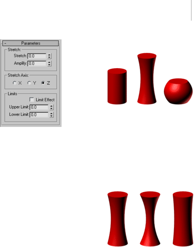
Stretch Modifier 837
Parameters rollout
Use options in the Parameters rollout to set the
following:
•Amountofstretch
•Majorstretchaxis
• Area affected by the stretch
Stretch group
The Stretch group of the Parameters rollout has
two fields that control the amount of stretch
scaling applied.
Stretch—Setsthebasescalefactorforallthreeaxes.
The scale factor derived from the Stretch value
varies according to the sign of the value.
• Positive stretch values define a scale factor
equal to Stretch+1. For example, a stretch value
of 1.5 yields a scale factor of 1.5+1=2.5, or 250
percent.
• Negative stretch values define a scale factor
equal to -1/(Stretch-1). For example, a
stretch value of -1.5 yields a scale factor of
-1/(-1.5-1)=0.4, or 40 percent.
The calculated scale factor is applied to the
selected stretch axis and the inverse scale is
applied to the minor axes.
Stretch values of 0.0, 0.5, and -0.5
Amplify—Changes the scale factor applied to the
minor axes. Amplify generates a multiplier using
thesametechniqueasstretch.Themultiplieris
then applied to the Stretch value before the scale
factorfortheminoraxesiscalculated.
Amplify values affect scaling along the minor axes
in the following way:
• A value of 0 has no effect. It uses the default
scale factor calculated from the Stretch amount.
• Positive values exaggerate the effect.
• Negative values reduce the effect.
Stretched objects with Amplify values of 0.0, 1.0, and -1.0.
Stretch Axis group
You select which of the object’s local axes is the
Stretch Axis using options in the Stretch Axis
group of the Parameters rollout.
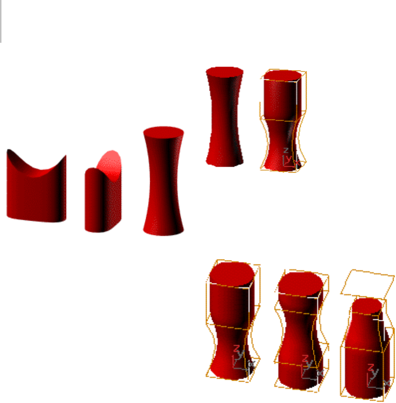
838 Chapter 8: Modifiers
• The scale factor calculated from the Stretch
Amount is applied to the Stretch Axis.
• The inverse scale factor is applied to the
remaining minor axes.
Effects of changing the Stretch axis
Limits group
You can apply the stretch effect to the entire object,
or limit it to a portion of the object, using controls
in the Limits group of the Parameters rollout. The
limits restrict the stretch effect along the positive
and negative Stretch Axis as measured from the
modifier’s center.
Limit Effect—Limits the stretch effect. When Limit
Effect is turned off, values in the Upper and Lower
Limit fields are ignored.
Upper Limit—Sets the boundary of the stretch
effect along the positive Stretch Axis. The Upper
Limit can be 0 or any positive number.
Lower Limit—Sets the boundary of the stretch
effect along the negative Stretch Axis. The Lower
Limit can be 0 or any negative number.
Limiting the effect of Stretch
Click Sub-Object and move the modifier’s center
to change the location of the limited stretch areas.
The Upper and Lower Limit boundaries move with
the modifier center to maintain their specified
distances.
Effects of moving the Stretch center
Note: You can also limit the stretch effect by using
an Edit or Select modifier, defining a sub-object
selection, and then applying Stretch. If the
modifier’s Sub-Object button is active, only the
selected sub-objects will be stretched.
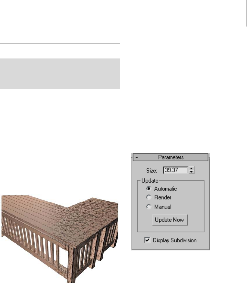
Subdivide Modifier 839
Subdivide Modifier
Make a selection. > Modify panel > Modifier List >
Subdivide
Make a selection. > Modifiers menu > Radiosity Modifiers
> Subdivide
The Subdivide modifier provides an algorithm
forcreatingmeshesusedforradiosity (page 3–51)
processing. Processing radiosity requires meshes
that have elements shaped as close as possible to
equilateral triangles. The density of the mesh
also needs to be considered in determining the
resolution of the lighting details that need to be
captured. The denser the mesh is, the finer the
lighting detail and accuracy will be. The trade-off
is a larger memory requirement and slower
rendering times. The Subdivide modifier works
on a whole object and does not work on selected
facesinamesh.
Subdivide modifier breaks flat surfaces into meshes.
Although it is primarily developed for increasing
the quality of radiosity solutions, the Subdivide
modifier can also be used by any application
that requires well-formed meshes. For example,
irregular mesh elements generated for Ter rai n
(page 1–347) compound objects can be improved.
The modifier has world space and object space
variants. In the world space modifier the size limit
is on the mesh after it is transformed into world
spacecoordinates. Theobjectspacemodifier
limitsthesizeinobjectspacecoordinates.
Note: Typically, the Subdivide modifier is applied
automatically to objects in the scene when
a radiosity solution is processed. Meshing
parameters can be set on a global basis in the
radiosity control panel (page 3–61) or for individual
objects in the Object Properties dialog (page
1–117).
Tip: When you are satisfied with the subdivision
settings on one object, you can drag the modifier
to other objects to propagate it.
Interface
Size—Controlsthesizeoftrianglesinthe
subdivided mesh. The length of the longest edge
ofanytrianglewillnotexceedthesquarerootof
2 times the size in the Subdivide modifier. The
square root of 2 factor is used, so that a square
whoseedgesarethesizewillnotbesubdivided.
Update group
The radio buttons in the Update group control
when the meshing is done.
Automatic—Updates immediately when changes
aremadetothecontrolsorthemesh.
Render—Updates only for rendering.
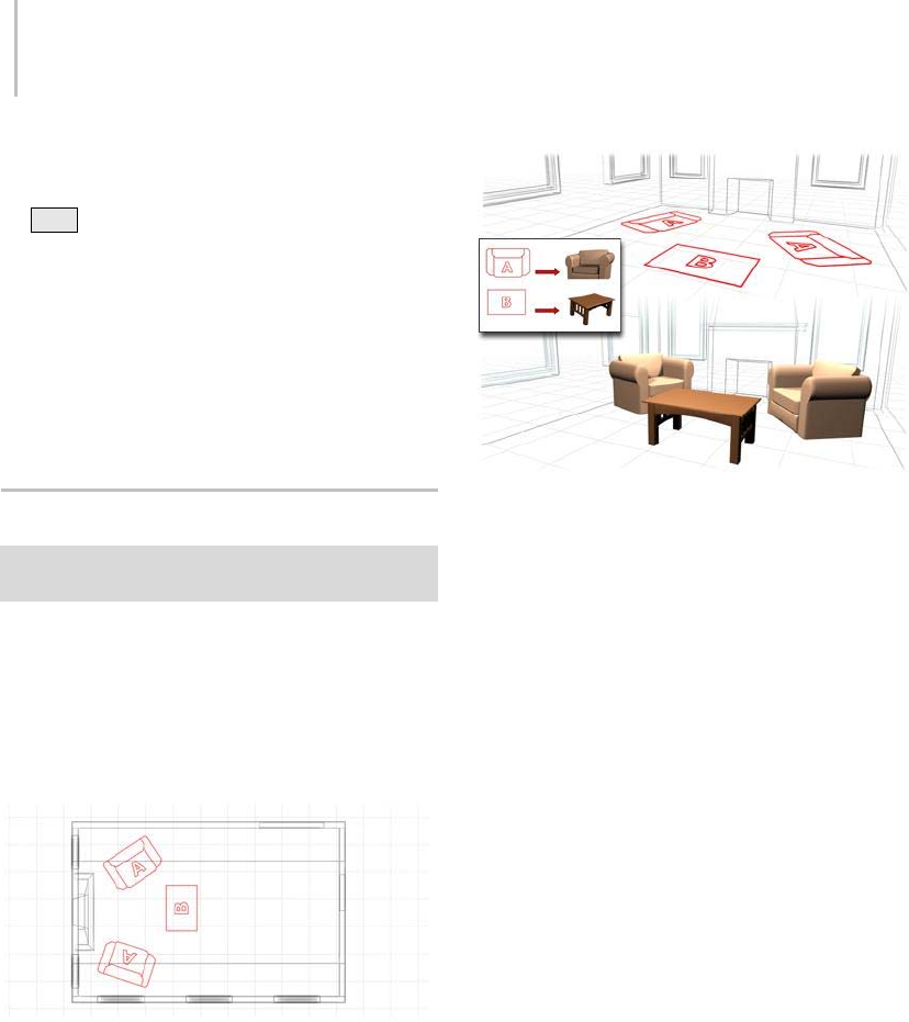
840 Chapter 8: Modifiers
Manual—Updates only when Update Now is
pressed. Subdivision can be interrupted using
the Esc key. If the subdivision is interrupted the
Update mode is changed to Manual.
Update Now—Updates the mesh when Manual is
turned on.
Display Subdivision—Controls whether all of the
triangles are visible, or only the edges where face
properties are changing. Allows you to reduce the
visibletrianglesinthesceneifitappearscluttered.
Substitute Modifier
Make a selection. > Modify panel > Modifier List >
Object-Space Modifiers > Substitute
Typically, designers use two-dimensional shapes
to represent objects, such as furniture, in their
AutoCAD designs. However, when they link
their DWG files (page 3–931) into 3ds Max for
visualization, they want to see how the objects will
look in their design.
Top view of 2D symbols used to represent 3D objects
The Substitute modifier lets you quickly replace
one or more objects with another in the viewports
or at render time. The substitute object can
be instanced from the current scene or can be
referenced from an external file.
The Substitute modifier replaces the 2D objects with their 3D
counterparts.
To get rid of the substitute object, simply remove
the modifier from the stack. This frees up the
memory required to store it.
Tip: When you file link to a DWG file, the file
is imported to 3ds Max as groups of VIZBlocks
(page 3–1031). If the pivot points of the VIZBlock
andthesubstitutedgeometrydonotmatch,you
may not obtain the desired results. Adjust the
pivot point of the VIZBlock object using the
Adjust Geometry button to align the substituted
geometry correctly.
See also
XRef Objects (page 3–394)
XRef Scene (page 3–407)
Procedures
To use an object from the current scene as a
substitute:
1. Select an object, and then apply the Substitute
modifier.
2. Click Pick Scene Object, and then in the
viewport, select an object to substitute for the
selection.
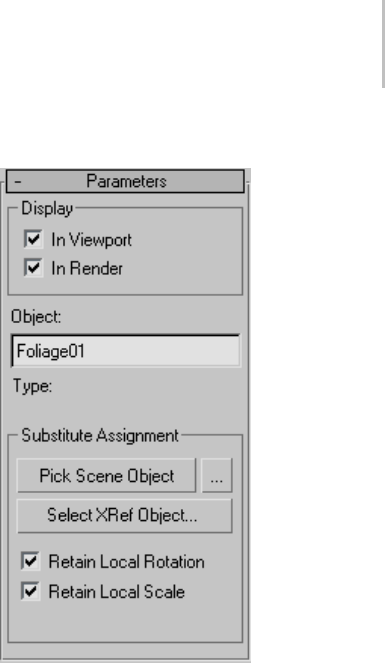
Substitute Modifier 841
Alternatively, click the ... button to the right of
Pick Scene Object and select an object from the
dialog that is displayed.
The original object is replaced by an instance of
thesubstituteobject.
3. To see the original object in the viewport, turn
off In Viewport. To see the original object in
the final rendering, turn off In Render. To
permanently disable the substitution, delete the
modifier.
To use an externally referenced object as a
substitute:
1. Select an object, and then apply the Substitute
modifier.
2. Click Select XRef Object.
3. Use the Open File dialog to designate the file
thatcontainsthesubstituteobjectyouwantto
use.
4. Use the XRef Merge dialog (page 3–406) to
designatetheobjecttouseasasubstitute.
The original object is replaced by an instance of
thesubstituteobject.
To see the original object in the viewport, turn
off Display group > In Viewport. To see the
original object in the final rendering, turn off
Display group > In Render. To permanently
disable the substitution, delete the modifier.
Interface
Modifier Stack
Substitute Object—At this sub-object level, you can
transform the substitute object without affecting
the original, changing the offset distance between
them. Otherwise, transforming the substitute
object affects both equally.
Parameters rollout
Display group
In Viewport—Replaces the original object with the
substitute in the viewports.
In Render—Replaces the original object with the
substitute when you render the scene.
Object—This editable text field displays the name
of the substitute object and lets you rename it.
Note: The name, if changed, appears only on the
Modifypanelatthecurrentstacklevel. Thatis,
the name is local to the current application of the
Substitute modifier.
Type (label)—Displays the type of object used as
a substitute. If you use a scene object, the type is
shown as Instance. If you use an XRef object, the
type is shown as XRef Object. Appears only after
you designate a substitute object.
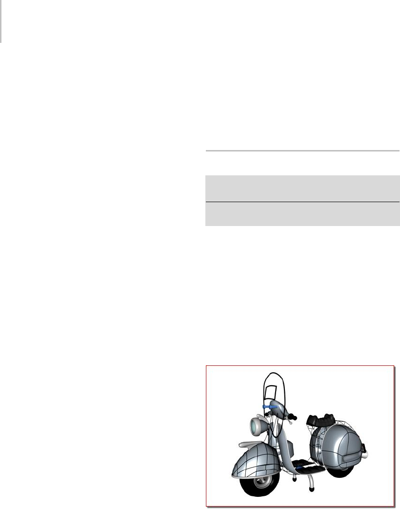
842 Chapter 8: Modifiers
Substitute Assignment group
Pick Scene Object—Lets you choose an object from
thecurrentscenetobeinstancedasasubstitutefor
the selected object. Click Pick Scene Object, and
then select the object from a viewport to use as a
substitute.IfInViewportisonandRetainCurrent
Position is off (the default settings), an instance
(page 3–957) of the substitute object appears in the
place of the original object.
The mouse cursor changes to a plus sign (+) when
over an object that can be used as a substitute.
You cannot use an object to which the Substitute
modifier is applied as a substitute object.
Use the button labeled "..." to the right of Pick
Scene Object to select a substitute object using the
Select Objects dialog (page 1–78), which in this case
is titled Select Substitute Object. From the dialog’s
list window, click the object to use as a substitute,
and then click Select.
Select XRef Object—Lets you specify an object to
be instanced from an external scene file as the
substitute. Click Select XRef Object, and then, in
theOpenFiledialog,openthefilecontainingthe
substitute object. On the XRef Merge dialog (page
3–406), select the substitute object and then click
OK. Objects to which the Substitute modifier is
applied don’t appear in the list.
Note: Because the object used as a substitute is
referenced from an external file, any changes
totheobjectinthatfileapplytothesubstitute
after reloading. For example, if you apply a Bend
modifiertothesubstituteobjectintheexternal
file, then the next time you load the file containing
the object with the Substitute modifier, it appears
bent.
Retain Local Rotation/Scale—When on, rotates or
scalesthenewobjectinstanceinthesameplaceas
the substitute object you select. In this case, the
two objects coincide in space, and you must move
one to see both. When off, 3ds Max positions the
instanced substitute object in the same place as the
objectcontainingtheSubstitutemodifier.
Yo u m u s t s p e c i f y t h e R e t a i n L o c a l R o t a t i o n / S c a l e
settingbeforedesignatingthesubstituteobject.
Changing this setting afterward has no effect.
Surface Modifier
Select a spline object. > Modify panel > Modifier List >
Object-Space Modifiers > Surface
Select a spline object. > Modifiers menu > Patch/Spline
Editing > Surface
Procedures (page 1–846) Interface (page 1–847)
The Surface modifier generates a patch surface
based on the contours of a spline network. A patch
is created wherever the segments of the interwoven
splines form a three- or four-sided polygon.
The Surface modifier and the CrossSection
modifier, taken together, are referred to as Surface
Tools. They allow you to create complex or
organic surfaces, like the fuselage of a plane, or a
three-dimensional character.
Applying the Surface modifier to create a patch surface.
The CrossSection modifier (page 1–623) can be
applied before the Surface modifier to connect
splines representing cross-sections. Once the basic
spline network is created and the Surface modifier
is applied, the model can be adjusted by editing

Surface Modifier 843
the splines using an Edit Spline modifier below the
Surface modifier in the modifier stack. Since the
Surface modifier creates a Patch surface, further
refinements can be made to the patch model by
adding an Edit Patch modifier above the Surface
modifier.
The bulk of the work in using Surface tools to
model lies in creating and editing splines in an
Editable Spline or Edit Spline modifier. One of
the benefits to modeling using splines and Surface
Tools is the ease of editing the model. At almost
any stage of modeling, you can add a nostril, ear,
limb or body by simply adding splines. This lends
itself to a free-form approach to organic modeling:
you have a mental image of what you want, then
youcreateandeditthesplinenetworkuntilyou
are satisfied.
Note: 3ds Max offers a simplified workflow for this
modeling technique, using Edit/Editable Spline
and the Edit Patch modifier. For details, see To
create a patch object using the Cross Section and
Spline Surface tools: (page 1–639).
Surface Modifier Basics
1. Create a spline object.
2. MakesurethattheSplineverticesformvalid
three-sided or four-sided, closed regions.
Vertices on splines that cross one another
should be coincident.
To make spline vertices coincident, drag
vertices over each other with 3D Snap turned
on. 3D Snap must have the Vertex or End Point
option turned on. With 3D Snap turned on,
you can snap to vertices on existing splines
as you create new splines. You can also select
vertices and use the Fuse option in an Editable
Spline to make vertices co-incident.
3. Use the CrossSection modifier to connect
spline cross-sections, unless you plan on
manually creating the splines that connect the
model’s cross-sections.
4. Apply the Surface modifier, then adjust the weld
threshold to generate a patch object. Ideally all
spline vertices that will form a patch surface
are coincident; the Threshold parameter allows
patchcreationevenifverticesarenotquite
coincident.
5. Optionally, add an Edit Patch modifier to edit
the patch surface.
Tip: Make a reference copy of the spline object,
then add the Surface modifier to the copy and
edit the original. As you edit the original spline
object, patches appear on the reference copy
as splines form three-or four-sided shapes.
This allows you to view a shaded surface as you
model.
You can take this a step further and add a
Mirror modifier to the reference copy. As you
createsplinesforonesideofaheadorbody,the
reference copy displays an entire model.
Modeling with Surface Tools
There are two primary methods of using the
Surface modifier to create patch models.
• Create splines that represent a model’s cross
sections, add the CrossSection modifier to
connect the cross sections, and apply the
Surface modifier to create the patch surface.
This approach works for models like the body
of an airplane.
Alternatively, use the editable spline Cross
Section function to connect the cross sections,
and then use the editable patch Spline Surface
tools to create the surface.
• Create a network of splines manually, and then
apply the Surface modifier or editable patch
Spline Surface tools to create the patch surface.
This approach works for modeling a face or
body of a character.
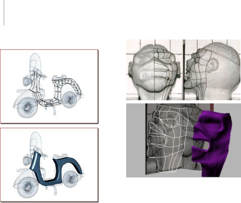
844 Chapter 8: Modifiers
Modeling Examples
Scooter: Splines form cross sections of the body
One method of using Surface Tools is to create
splines that represent a model’s cross sections,
then the CrossSection and Surface modifiers are
applied to create the patch surface.
Face: Spline network based on front and profile reference
images
Two intersecting texture-mapped polygons are
used as a reference to create a network of splines
manually. Drawing lines on the physical sculpture
is used as an added visual aid to position the
splines in this case. The CrossSection modifier
is not necessary if you create the spline network
manually.
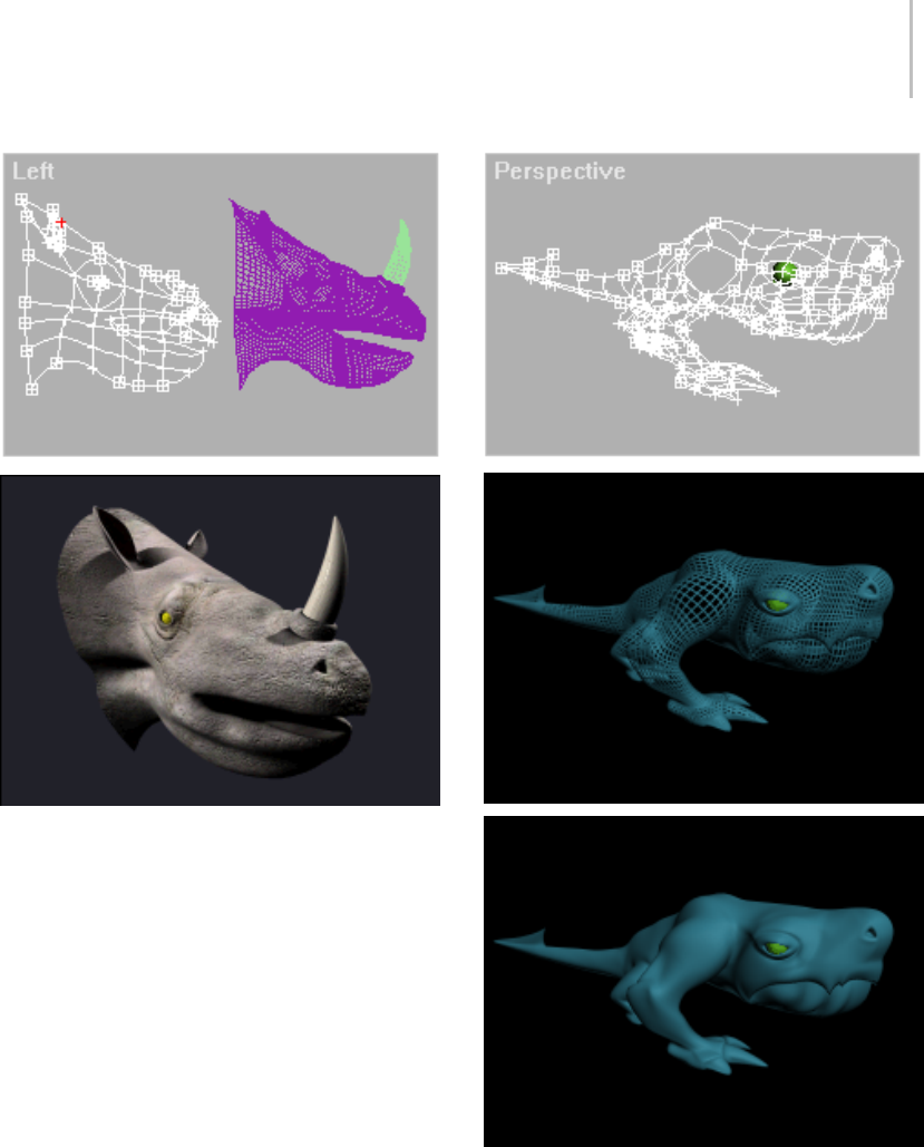
Surface Modifier 845
Rhino head: Spline network begins with the profile.
In the top image, the head of a rhinoceros is
modeled by creating a network of splines. The
first spline created is the profile of the rhino;
other splines are added and edited to complete
the model. In this case, a reference copy of the
spline model was created and a Surface modifier
was added to the copy.
As the spline network is edited, the patch surface
of the reference copy is updated dynamically.
This allows you to view a shaded patch model as
you manipulate the spline network, any surface
anomalies can be spotted and corrected. Sequence of images showing the spline network, the patches
created by the Surface modifier, and a shaded view of an alien
character.
Additional Details
• Splines are initially created using the tools in
Create panel > Shapes > Splines > Object Type
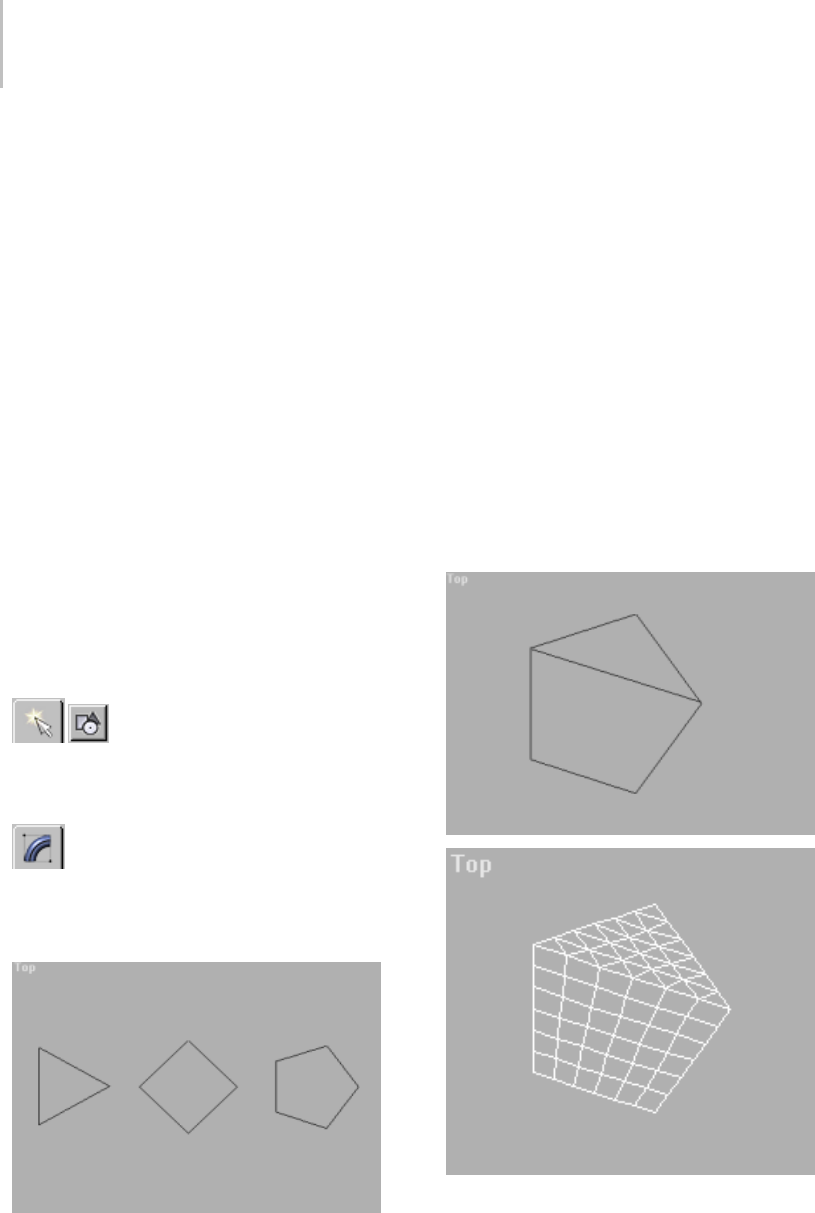
846 Chapter 8: Modifiers
rollout, such as Line (page 1–270),Circle (page
1–273),Arc (page 1–274),andSection (page
1–282). Splines can also be created using the
Create Line command in an Editable Spline or
and Edit Spline modifier.
• Splines are edited by applying an Edit Spline
modifier to the selected spline object or editing
parameters in an Editable Spline. Editing
splines changes the patch surface created by the
Surface modifier.
• To add splines to a spline object, use the Attach
command in the Edit Spline modifier.
• Within a spline object, splines need not be
continuous. A spline object may consist of
ten splines, for example. As long as the spline
vertices are coincident, or close enough for the
Threshold parameter in the Surface modifier to
weld them together, a surface will be generated.
Procedures
Example: Understanding valid splines:
1. In the Top viewport, use Create
panel > Shape > NGon to create three NGons:
a three-sided, four-sided, and five-sided NGon,
each about 100 units wide.
2. Make sure that all the splines form one
object. DothisbyapplyinganEditSpline
modifier to one of the NGons and using Attach
to add the remaining NGon objects.
3. Choose Modifiers menu > Patch/Spline Editing
> Surface from the Modifier List.
Notice that the three- and four-sided splines
formed patches but the five-sided NGon did
not. Thefive-sidedsplinedoesnotforma
three- or four-sided closed region. To make it
a valid spline, a line must bisect the NGon to
form a three- and four-sided region.
4. In the stack display, choose the Edit Spline
modifier again. Turn on Create Line on the
Geometry rollout, and create a line that bisects
the five-sided NGon.
Thestartandendpointsofthelineshould
overlap the vertices on the NGon. Being exact
is not critical; the Threshold parameter fuses
spline vertices based on their proximity.
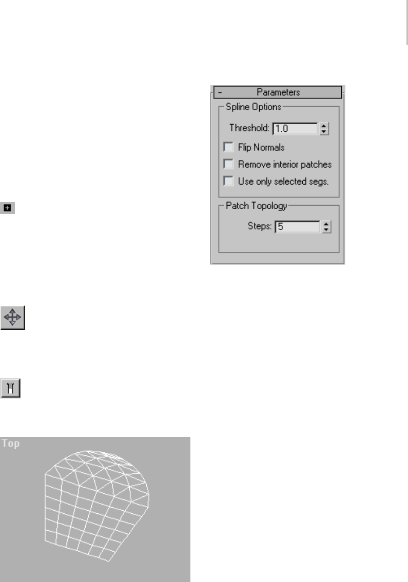
Surface Modifier 847
5. In the stack display, choose the Surface modifier
again. Now the five-sided NGon is a patch
object, consisting of a quad patch and a tri
patch.
Note: Ifthesplineobjectdidnotturninto
a patch, increase the Surface modifier’s
Threshold parameter until the patches appear.
Example continued: Adjusting the shape of the
spline:
1. In the stack display, expand the Edit Spline
modifier’s hierarchy, and choose the Vertex
sub-object level.
2. In the Top viewport, select the top vertex of the
five-sided NGon.
Two vector handles are displayed. These
handles can be moved on any axis.
3. Tur n on Sel ect and Move on the to olbar,
then drag the handles around in the Top
viewport.
Theshapeofthesplinechanges.
4. Belowthestackdisplay,turnontheShow
End Result On/Off Toggle button.
The patch changes shape to fit the spline.
Interface
Spline Options group
Threshold—Determines the overall distance that is
used to weld the vertices of the spline object. All
vertices/vectors within the threshold of each other
are treated as one. Threshold uses units set in the
Units Setup dialog (page 3–848).
Note: Spline control handles are also treated as
vertices, so setting high Threshold levels can
produce unexpected results.
Flip Normals—Flips the normal direction of the
patch surface.
Remove Interior Patches—Removes interior faces
of an object that you would not normally see.
Thesearethefacescreatedwithinthecapsor
otherinteriorpatchesofthesametypeofaclosed
polygon.
Use only selected segs—Only segments selected in
theEditSplinemodifierwillbeusedbytheSurface
modifier to create patches.
Note: SegmentSub-Objectdoesnothavetobeleft
onintheEditSplinemodifier.
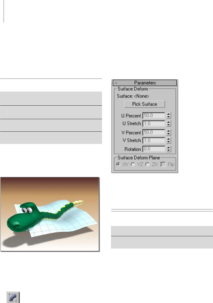
848 Chapter 8: Modifiers
Patch Topology group
Steps—The steps field spinner determines how
many steps are used between each vertex. The
higher the step count, the smoother the curve you
will get between vertices.
SurfDeform Modifier
Select an object. > Modify panel > Modifiers List >
Object–Space Modifiers > SurfDeform
Select an object. > Modify panel > Modifiers List >
World–Space Modifiers > SurfDeform
Select an object. > Modifiers menu > Animation Modifiers
>SurfDeform
Select an object. > Modifiers menu > Animation Modifiers
> SurfDeform (WSM)
The SurfDeform modifier works the same way as
the PatchDeform modifier (page 1–754),except
that it uses a NURBS Point or CV surface instead
of a patch surface to apply surface deformation.
SurfDeform shapes how the snake rests.
Procedure
To use the SurfDeform modifier:
1. Select an object.
2. From the Modify panel > Modifier List,
choose Object–Space Modifiers > SurfDeform.
3. On the Parameters rollout, click Pick Surface.
4. Select a NURBS Point or CV surface.
5. Deform the object by adjusting the controls in
the Surface Deform group.
Interface
See PatchDeform modifier (page 1–754) for a
description of the user interface.
Sweep Modifier
Modify panel > Select a 2D shape. > Modifier List > Sweep
Select a 2D shape. > Modifiers menu > Patch/Spline
Editing > Sweep
The Sweep modifier is used to extrude a
cross-section along an underlying spline or
NURBS curve path. It is similar to the Loft
compoundobjectbutisamoreefficientmethod.
The Sweep modifier allows you to work with a
series of pre-made cross-sections such as angles,
channels and wide flanges. You can also use your
ownsplinesorNURBScurvesascustomsections
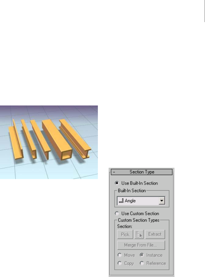
Sweep Modifier 849
that you create in 3ds Max or import from other
MAX files.
Note: This modifier is similar to the Extrude
modifier in that once the Sweep is applied to a
spline, the end result is a 3D mesh object. Both
sections and paths can contain multiple splines or
multiple NURBS curves.
This modifier is very useful for creating structural
steel details, molding details, or in any situation
where you need to extrude a section along a spline.
Examples of extrusions created with the Sweep modifier
Procedure
To apply the Sweep modifier to a line:
1. Create a line in the perspective viewport.
2. Apply the Sweep modifier to the line.
Thelinetakesontheshapeofanangled
extrusion.
3. OpentheBuilt-InSectionlistandchoosea
different section.
Thelinenowhasthenewsectionsweptalong
its length.
To use a custom section with the Sweep modifier:
1. CreatealineandasixsidedNGoninthe
perspective viewport.
2. Apply the Sweep modifier to the line.
Thelinetakesontheshapeofanangled
extrusion.
3. Click the Use Custom Section radio button.
The line displays as a line again.
4. Click the Pick button in the Custom Section
Types g roup and choose the NGon in the
viewport.
Thehexagonalshapeissweptalongtheline’s
length.
Note: If you find that you need to rescale
the Custom Section shape, the effects of
using a transform like Select and Squash or
Non-Uniform Scale will not be reflected when
swept. You need to apply an XForm modifier
(page 1–959) to the section and then rescale the
XForm modifier’s gizmo.
Interface
Section Type rollout
Use Built-In Section—Choose this to use one of the
included stock sections.
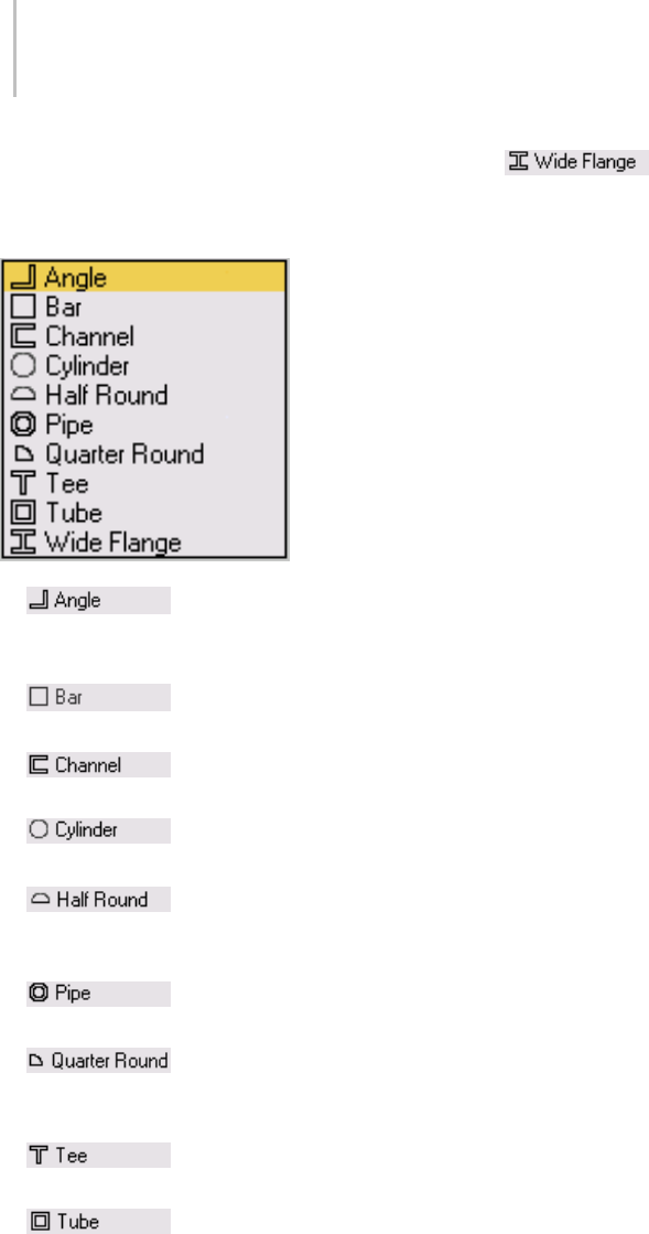
850 Chapter 8: Modifiers
Built-In Section group
Built-In Section list—Clicking the arrow button for
this list displays common structural sections.
•Angle section—Sweeps a
structural angle section along the spline.
Default section=Angle.
•Bar section—Sweeps a 2D
rectangular section along the spline.
•Channel section—Sweeps a
structural channel section along the spline.
•Cylinder section—Sweeps a
solid 2D circle section along the spline.
•Half Round section—This
section produces a half round extrusion along
the spline.
•Pipe section—Sweeps a
circular hollow tube section along the spline.
•Quarter Round section—Useful
for molding details; this section produces a
quarter round extrusion along the spline.
•Tee section—Sweeps a
structural tee section along the spline.
•Tube section—Based on a
square, this sweeps a hollow tube section along
the spline. Similar to the Pipe section.
•Wide Flange section—Sweeps a
structural wide flange section along the spline.
Use Custom Section—Choose this if you’ve created
your own section or there is another shape in the
current scene or in another MAX file that you’d
like to use as your section.
Note: Using a 2D shape as the Sweep modifier’s
custom section will yield the most predictable
results. If using a 3D shape as the custom section,
forthemostpredictableresultsthebaseobject
shouldbeastraightlineorsmoothpathlikea
circle or an arc. The same applies to custom
sections made up of multiple splines. You’ll get the
bestresultsattainedbyinsuringthatallverticesin
all the shapes are coplanar.
Custom Section Types group
Section—Displaysthenameofthecustomshape
you’ve selected. This area is blank until you select
acustomshape.
Note: You can switch from a custom section to
a built-in section and back without having to
pickthecustom-sectionshapeagainfromthe
viewports.
Pick—If the custom shape you want to use is visible
in the viewport, click the Pick button and then
pick the shape directly from the scene.
Pick Shape—Click the Pick Shape button to open
the Pick Shape dialog (page 1–857).Thisdialog
shows only valid shapes that are currently in the
scene.
Extract—Lets you create a new shape in the scene
that is either a copy, instance, or reference of the
current custom section. Opens the Extract Shape
dialog (page 1–858).
Merge From File—Lets you choose a section that is
stored in another MAX file. Opens the Merge File
dialog (page 1–859).
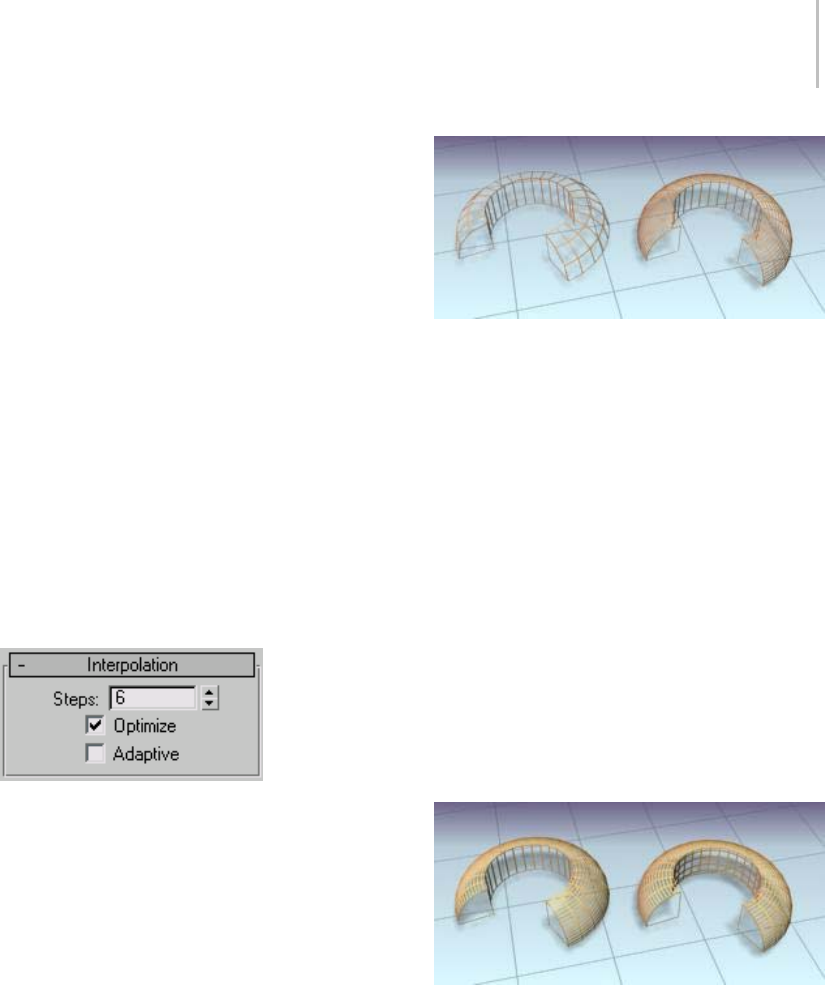
Sweep Modifier 851
Note: When you use the Merge from File option,
you will not be able to Undo your work.
Move—Sweeps the custom section along the
specified spline. Unlike the Instance, Copy and
Referenceswitches,theselectedsectionismoved
to the spline. Editing the original shape in the
viewports has no effect on the Sweep mesh.
Copy—Sweeps a copy of the selected section along
the specified spline.
Instance—Sweeps an instance (page 3–957) of the
selected section to the specified spline.
Reference—Sweeps a reference (page 3–1002) of the
selected section along the specified spline.
Note: When using Instance or Reference, adding
modifiers to or editing the original section in the
viewports will change the Sweep mesh.
Interpolation rollout (Sweep modifier)
The controls in the Interpolation rollout of the
Sweep modifier work exactly as they do for any
other spline. However, the controls affect only the
built-in section you’ve chosen, not the spline that
the section is swept along.
Note: If you want to change the interpolation
settings of the underlying spline path, you need to
select the path object in the modifier stack.
In general, all spline curves are divided into small
straight lines that approximate a true curve. The
number of divisions between each vertex on the
spline are called steps. The more steps used, the
smoother the curve appears.
Note: The Interpolation rollout is only active when
built-in sections are used.
Left: The quarter-round section is set to zero steps.
Right: The same section on the right is set to four steps.
Steps—Sets the number of divisions, or steps,
the program uses between each built-in section’s
vertices. Splines with tight curves require many
steps to look smooth while gentle curves require
fewer steps. Range=0 to 100.
Spline steps can be either adaptive or manually
specified. The method used is set by the state of
theAdaptiveswitch. Themainuseformanual
interpolation is to create splines for morphing
or other operations where you must have exact
control over the number of vertices created.
Optimize—When on, removes unneeded steps
from straight segments in the spline. Default=on.
Note: Optimize is not available when Adaptive is
on.
Left: Optimize is on for the left-hand sweep.
Right: Optimize is off for the right-hand sweep.
Adaptive—When on, automatically sets the
number of steps for each spline to produce a
smooth curve. Straight segments always receive
0 steps. When off, enables manual interpolation
control using Optimize and Steps. Default=off.
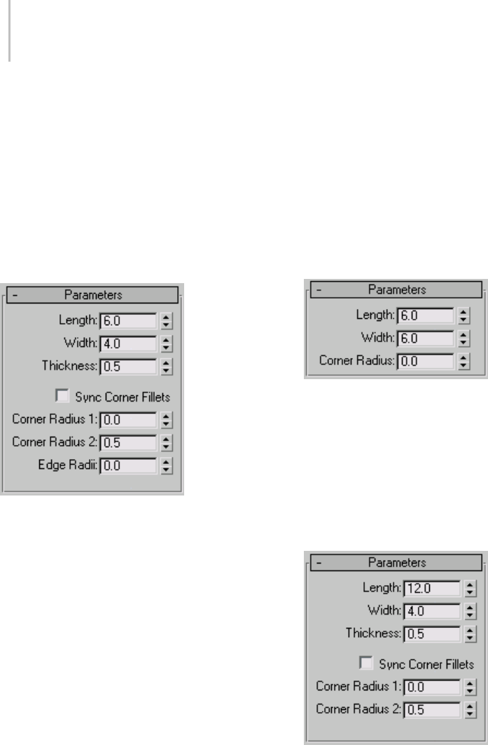
852 Chapter 8: Modifiers
Parameters rollout
The Parameters rollout is context-sensitive and
displays different settings depending upon the
built-in section you’ve chosen to sweep along a
spline. For example, more complex sections such
as the Angle have seven settings that you can
change whereas the Quarter-Round has only one
setting.
Parameters rollout – Angle
Length—Controls the height of the vertical leg of
the angle section. Default=6.0.
Width—Controls the width of the horizontal leg of
the angle section. Default=4.0.
Thickness—Controls the thickness of both legs of
the angle. Default=0.5.
Sync Corner Fillets—When turned on, Corner
Radius 1 controls the radius of both the interior
and exterior corners between the vertical and
horizontal legs. It also maintains the thickness of
the section. Default=off.
Corner Radius 1—Controls the exterior radius
between the vertical and horizontal legs of the
angle section. Default=0.0.
Corner Radius 2—Controls the interior radius
between the vertical and horizontal legs of the
angle section. Default=0.5.
Edge Radii—Controls the interior radius at the
outermost edges of the vertical and horizontal
legs. Default=0.0.
Note: Be cautious when adjusting these settings.
There are no constraining relationships between
them. Therefore, it’s possible to set an inside
radius(CornerRadius2)thatisgreaterthanthe
length or width of the legs of the angle.
Parameters rollout – Bar
Length—Controls the height of the bar section.
Default=6.0.
Width—Controls the width of the bar section.
Default=6.0.
Corner Radius—Controls the radius of all four
corners of the section. Default=0.0.
Parameters rollout – Channel
Length—Controls the height of the vertical web of
the channel section. Default=12.0.
Width—Controls the width of the top and bottom
horizontal legs of the channel section. Default=4.0.
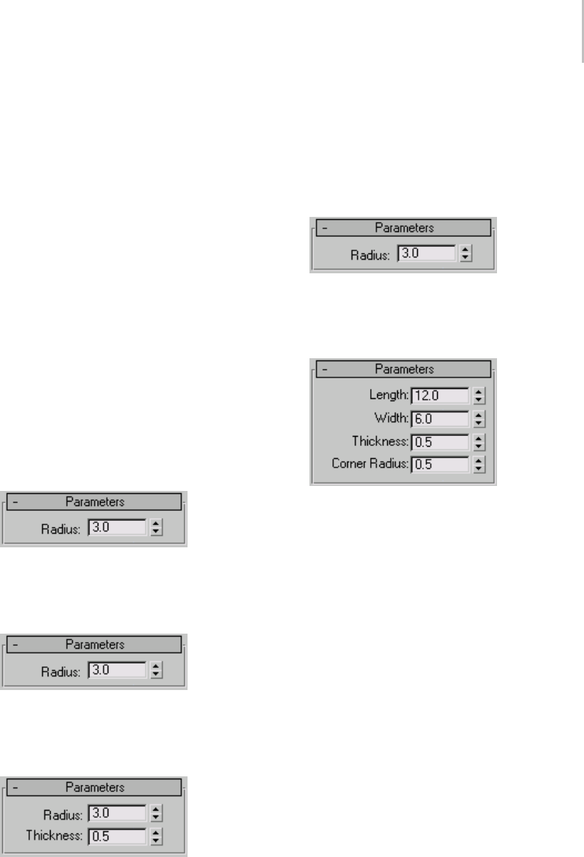
Sweep Modifier 853
Thickness—Controls the thickness of both legs of
the channel. Default=0.5.
Sync Corner Fillets—When on, Corner Radius 1
controls the radius of both the interior and exterior
corners between the vertical web and horizontal
legs. It also maintains the thickness of the section.
Default=off.
Corner Radius 1—Controls the exterior radius
between the vertical web and horizontal legs of the
channel. Default=0.0.
Corner Radius 2—Controls the interior radius
between the vertical web and horizontal legs of the
channel. Default=0.5.
Note: Be cautious when adjusting these settings.
There are no constraining relationships between
them. Therefore, it’s possible to set an inside
radius(CornerRadius2)thatisgreaterthanthe
length of the web or width of the legs.
Parameters rollout – Cylinder
Radius—Controls the radius of the cylinder
section. Default=3.0.
Parameters rollout – Half-Round
Radius—Controls the radius of the half round
section. Default=3.0.
Parameters rollout – Pipe
Radius—Controls the exterior radius of the pipe
section. Default=3.0.
Thickness—Controlsthethicknessofthewallof
the pipe. Default=0.5.
Parameters rollout – Quarter-Round
Radius—Controls the radius of the quarter round
section. Default=3.0.
Parameters rollout – Tee
Length—Controls the height of the vertical web of
the tee section. Default=12.0.
Width—Controls the width of the flange crossing
the tee section. Default=6.0.
Thickness—Controlsthethicknessoftheweband
flange. Default=0.5.
Corner Radius—Controls the radius of the two
interior corners between the vertical web and
horizontal flange of the section. Default=0.5.
Note: Be cautious when adjusting these settings.
There are no constraining relationships between
them. Therefore, it’s possible to set a radius
(Corner Radius) that is greater than the length of
the web or width of the flange.
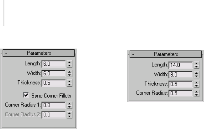
854 Chapter 8: Modifiers
Parameters rollout – Tube
Length—Controls the height of the tube section.
Default=6.0.
Width—Controlsthewidthofthetubesection.
Default=6.0.
Thickness—Controls the thickness of the walls of
the tube. Default=0.5.
Sync Corner Fillets—When turned on, Corner
Radius 1 controls the radius of both the interior
and exterior corners of the tube. It also maintains
the thickness of the section. Default=on.
Corner Radius 1—Controls the radius of all four
interior and exterior corners of the section.
Default=0.8.
IfSyncCornerFilletsisturnedoff,CornerRadius
1 controls the radius of the four exterior corners
of the tube.
Corner Radius 2—Controls the radius of the four
interior corners of the tube. Default=0.0.
Corner Radius 2 is only available when Sync
Corner Fillets is turned off.
Note: Take care when adjusting these settings.
There are no constraining relationships between
them. Therefore, it’s possible to set an inside
radius(CornerRadius2)thatisgreaterthanthe
length and width of the sides.
Parameters rollout – Wide Flange
Length—Controls the height of the vertical web of
thewideflangesection.Default=14.0.
Width—Controls the width of the horizontal
flanges crossing the section. Default=8.0.
Thickness—Controlsthethicknessoftheweband
flanges. Default=0.5.
Corner Radius—Controls the radius of the four
interior corners between the vertical web and
horizontal flanges. Default=0.5.
Note: Be cautious when adjusting these settings.
There are no constraining relationships between
them. Therefore, it’s possible to set a radius
(Corner Radius) that is greater than the length of
the web or width of the flanges.
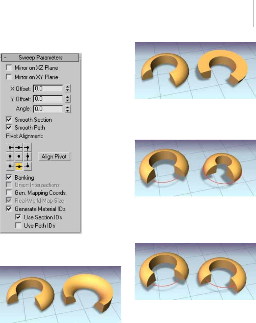
Sweep Modifier 855
Sweep Parameters rollout
Mirror On XZ Plane—When turned on, the section
is flipped vertically in relation to the spline to
which the Sweep modifier is applied. Default=off.
Left: The object shows the default state.
Right: The object has Mirror On XZ Plane turned on.
Mirror On XY Plane—When turned on, the section
is flipped horizontally in relation to the spline to
which the Sweep modifier is applied. Default=off.
Left: The object shows the default state.
Right: The object has Mirror On XY Plane turned on.
XOffset—Lets you shift the horizontal position of
the section relative to the underlying spline.
Left: The section is in the default position.
Right: The section is offset –10 relative to the underlying spline
path (red).
YOffset—Lets you shift the vertical position of the
section relative to the underlying spline.
Left: The section is in the default position.
Right: The section is offset –10 relative to the underlying spline
path (red).
Note: The X and Y Offsets let you fine tune the
section position while the Pivot Alignment settings
allow for a quick initial adjustment.
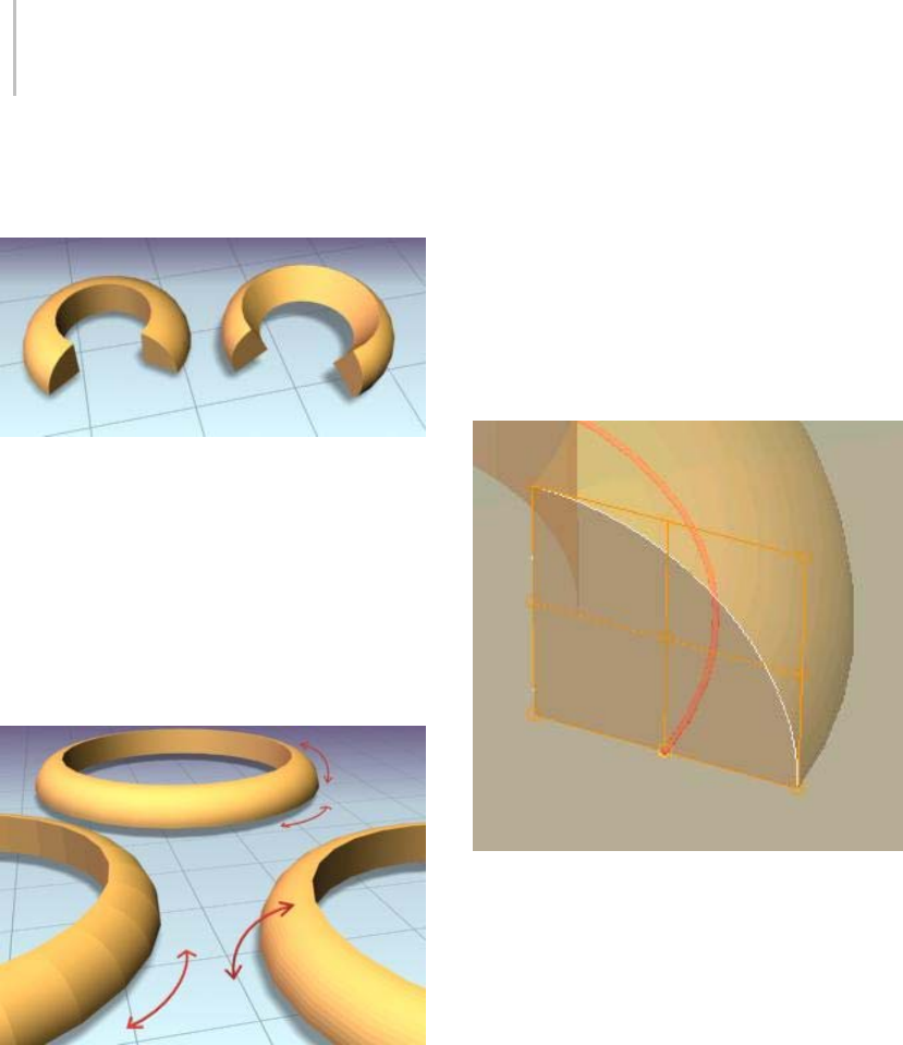
856 Chapter 8: Modifiers
Angle—Allows you to rotate the section relative
to the plane on which the underlying spline is
located.
Left: The section is in the default position.
Right: The section is rotated 30 degrees.
Smooth Section—Provides a smooth surface
around the perimeter of the section that is swept
along the underlying spline. Default=on.
Smooth Path—Provides a smooth surface along
the length of the underlying spline. This type
of smoothing is useful when for curved paths.
Default=off.
Left: Smoothing the path
Right: Smoothing the section
Rear: Smoothing both path and section
Pivot Alignment—This is 2D grid that helps
youalignthesectiontotheunderlyingspline
path. Selecting one of the nine buttons shifts the
section’s pivot around the spline path.
Note: When none of the Pivot Alignment buttons
is depressed the pivot point of the section is used
as the alignment point.
Align Pivot—When turned on, a 3D representation
of the Pivot Alignment grid appears in the
viewport. You only see the 3x3 alignment grid,
the section and the underlying spline path. Once
you’re satisfied with the alignment, turn off the
Align Pivot button or right-click to see the sweep.
Align Pivot grid showing control points (in orange)
superimposed over a duplicate sweep.
Banking—When on, sections rotate about the
spline path whenever the path bends and changes
height in the path’s local Z axis. Banking is ignored
ifthesplinepathis2D.Whenoff,shapesdonot
rotateabouttheirZaxisastheytraversea3Dpath.
Default=on.
Union Intersections—If working with multiple
intersecting splines, like a grid, turn this switch
on to produce cleaner intersections with fewer
artifacts.
Note: Union Intersections takes additional time to
compute the intersections, so leave this switch off if
you don’t have intersecting splines. Furthermore,
this setting will only calculate intersections of
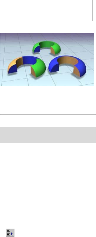
Pick Shape Dialog 857
separate splines contained in one shape object.
So a figure X (separate, intersecting splines) will
be properly intersected, but a figure 8 (a single,
self-intersecting spline) will not.
Gen. Mapping Coords—Applies mapping
coordinates to the extruded object. Default=off.
Real-World Map Size—Controls the scaling method
used for texture mapped materials that are applied
totheobject. Thescalingvaluesarecontrolled
by the Use Real-World Scale settings found in
the applied material’s Coordinates rollout (page
2–1625).Default=on.
Generate Mapping IDs—Assigns different material
IDstothesidesandthecapsofthesweep.
Specifically, if both Use Section IDs and Use Path
IDs are both turned off the sides receive ID 3, the
front cap receives ID 1, and the rear cap receives
ID 2. Default=on.
Use Section IDs—Uses the material ID values
assigned to segments of the section that is swept
along the underlying spline (page 1–266) or
NURBS (page 1–1078) curve. Default=on.
By applying an Edit Spline modifier (page 1–680)
to a Custom Section, different material IDs can
be assigned to each segment that makes up the
section.
Note: Built-in sections do not benefit from the Use
Section IDs switch.
Use Path IDs—Uses the material ID values assigned
to segments of the underlying spline or curve
sub-objects in the underlying curve.
By applying an Edit Spline modifier to the
underlying spline, each segment can be assigned
its own material ID.
Note: Use Section IDs and Use Path IDs does not
control the material IDs of the front and rear caps
of the sweep.
Left: Materials set by path IDs
Right: Materials set by section IDs
Rear: Section and Path IDs turned off
Pick Shape Dialog
Select a shape that already has a Sweep modifier applied.
> Modify Panel > Section Type rollout > Turn on Use
Custom Section > Click Pick Shape.
The Pick Shape dialog is displayed when you select
a custom shape in the scene. This shape can be any
of the splines, extended splines or NURBS curves.
Procedure
To pick a custom section using the Pick Shape dialog:
1. In the viewport, pick a shape you want to use as
the underlying path of the sweep.
2. From the Modifiers menu, open the
Patch/Spline Editing menu and choose Sweep.
3. OntheModifypanel,turnonUseCustom
SectionintheSectionTypesrollout.
4. Click the Pick Shape button.
The Pick Shape dialog is displayed.
5. Select a shape in the list and click the Pick
button.
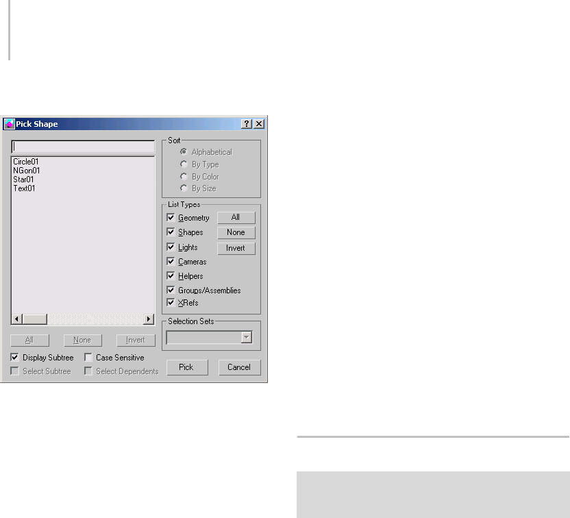
858 Chapter 8: Modifiers
Interface
If the scene contains multiple shapes, you can
chooseonlyoneshapetobesweptalongthe
underlying spline in your scene.
All/None/Invert—Thesebuttonsareunavailablein
the Pick Shape dialog.
Display Subtree—Displays the shapes in the list in
an indented format. Turn this switch off to activate
the Sort group options.
Select Subtree—Unavailable in the Pick Shape
dialog.
Case Sensitive—When on, distinguishes between
uppercaseandlowercaseforitemnames.
Sort group
Options allow you to sort the list on the left.
When Display Subtree is on, these options are not
available.
Alphabetical—Sorts from A at the top to Z at the
bottom.
By Type—Whilethisswitchisavailable,ithasno
effect because only shapes are listed in the Pick
Shape dialog.
By Color—Sorts by object wireframe color. The
sorting order is arbitrary; shapes of the same color
are grouped together.
By Size—This switch is available but has no effect
on sorting.
List Types group
Because this dialog is specifically designed to work
with the Sweep modifier, the List Type group is
locked to only display Shapes. Shapes is the only
switch in this group that affects what is displayed.
All/None/Invert—These buttons alter the pattern of
activation of the List Types options.
Selection Sets group
The Selection Sets group is unavailable in the Pick
Shape dialog.
Extract Shape Dialog
Select a shape that already has a Sweep modifier using a
Custom Section applied. > Modify Panel > Section Type
rollout > Click Extract.
The Extract functionality allows you to recover
custom cross-sections that may have been deleted
from the scene. As long as you have a sweep in
thescenethatusesthedeletedshapeasacustom
cross-section, Extract can be used to restore it to
the scene.
In a large scene that has many objects and shapes,
you can also use Extract if you want to quickly
duplicate a section used by the sweep instead of
searching for the original shape you used as the
section.
Procedures
To extract a section from a sweep:
1. In the viewport, pick a swept shape.
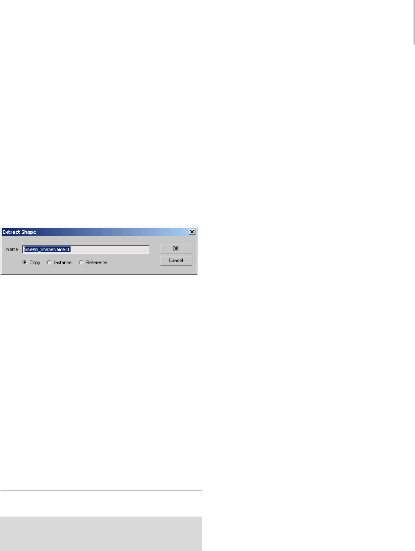
Merge File (Sweep Modifier) 859
2. Open the Modify panel and click the Extract
button from the Custom Section Types group
of the Section Types rollout.
The Extract Shapes dialog is displayed.
3. Enteranewnamefortheextractedsectionif
you want.
4. Specify the type of cloned shape you want
extracted; a copy, an instance or a reference.
5. Click OK.
Interface
Name—This field shows the default name that
will be given to the extracted section. By
default, it always has the naming convention of
Sweep_ShapeName01,Sweep_ShapeName02,etc.
For example, if your missing section was named
Roman-Ogee, the extracted shape will be named
Sweep_Roman-Ogee01.
Copy—Places a copy of the extracted section at the
global origin (0,0,0).
Instance—Places an instance of the extracted
section at the global origin.
Reference—Places a reference of the extracted
section at the global origin.
MergeFile(SweepModifier)
Select a shape that already has a Sweep modifier using a
Custom Section applied. > Modify Panel > Section Type
rollout > Click Merge From File.
The Merge File dialog for the Sweep modifier
appears when you click the Merge From File
button. Merge From File allows you to bring
shapes or section profiles from other scene files
into the current scene.
Automatic Unit Conversion
When Respect System Units in Files is turned on in
the Units Setup dialog (page 3–848) in the System
Unit Scale group, merged objects from a file with
a different scene-unit scale are scaled to maintain
their correct size in the new scene.
Note: If Respect System Units is off (which is
not recommended), a 10–foot square tube that
was created in a 1 unit = 1 foot scene becomes a
10-inch square tube in a 1 unit = 1 inch scene.
Resolving Conflicts When Merged
Shapes Have the Same Name
When an incoming shape has the same name as a
shape in the scene, an alert gives you the following
options:
Merge—Merges the incoming shape using the
nameinthefieldattheright. Toavoidhaving
two shapes with the same name, type a new name
before proceeding.
Skip—This button is unavailable when Merge
From File is used in the Sweep modifier.
Delete Old—This button is unavailable when Merge
From File is used in the Sweep modifier.
Auto Rename—The merged shape’s name is left
intact except it is given a numeric suffix that is one
number higher than any duplicates found in the
scene.
Cancel—Cancels the merge operation.
Interface
Inthestandardfileselectordialog,selectthescene
file to merge. You can only merge MAX files.
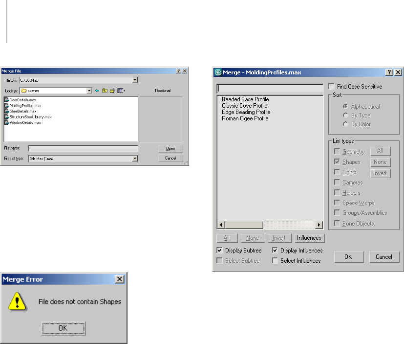
860 Chapter 8: Modifiers
This dialog has the same functionality as the
Merge File dialog (page 3–463) that appears when
youchooseFilemenu>Mergewithoneminor
exception.
IfyouchooseaMAXfilethatdoesnotinclude
a valid 2D shape that can be used as a custom
section, you will receive a warning.
Once the scene file is selected, you can choose the
shape or section profile that you want the Sweep
modifier to use.
If the scene file you selected contains multiple
shapes, keep in mind that you can only choose one
shapetobesweptalongthesplineinyourcurrent
scene.
All/None/Invert—Thesebuttonsareunavailable
when Merge From File is used in the Sweep
modifier.
Display Subtree—Displays the shapes in the list in
an indented format. Turn off this option to activate
the Sort group options.
Select Subtree—This switch is unavailable when
Merge From File is used in the Sweep modifier.
Case Sensitive—Distinguishes between uppercase
and lowercase for item names.
Sort group
Options allow you to sort the list on the left. If
theDisplaySubtreeswitchison,theseoptionsare
not available.
Alphabetical—Sorts from A at the top to Z at the
bottom.
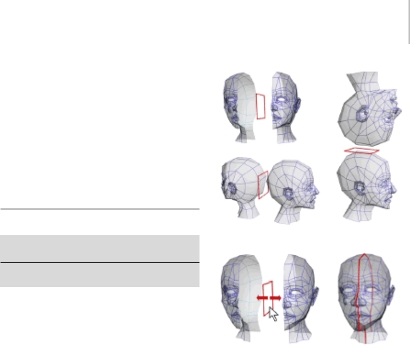
Symmetry Modifier 861
By Type—This switch is unavailable when Merge
From File is used in the Sweep modifier.
By Color—Sorts by object wireframe color.
List Types group
Because this dialog is specifically designed to work
with the Sweep modifier, the List Type group
is locked to display only Shapes. None of the
switches or buttons in this group can be activated.
Symmetry Modifier
Modify panel > Make a selection. > Modifier List >
Symmetry
Make a selection. > Modifiers menu > Mesh Editing >
Symmetry
The Symmetry modifier is especially useful when
modeling characters or building ships or aircraft.
This modifier is unique in that it allows you to
perform three common modeling tasks:
• Mirror a mesh about the X, Y, or Z plane.
• Slice a mesh, removing parts if necessary.
• Automatically weld vertices along a common
seam.
Examples of using Symmetry with different mirror axes or by
moving the mirror gizmo
You can apply the Symmetry modifier to any
geometry, and you can animate the mirror or
slicing effect by animating the modifier’s gizmo.
When the Symmetry modifier is applied to a mesh,
any edits you make to the original half of the mesh
below the Symmetry modifier in the stack also occur
interactively to the other half. For an example, see
the second procedure, below.
Note: The Symmetry modifier converts patch and
NURBS objects to mesh format in the modifier
stack; editable poly and editable mesh objects
remain in their original format.
Procedure
Example: To apply the Symmetry modifier to an
object:
1. Create a teapot in the Perspective viewport.
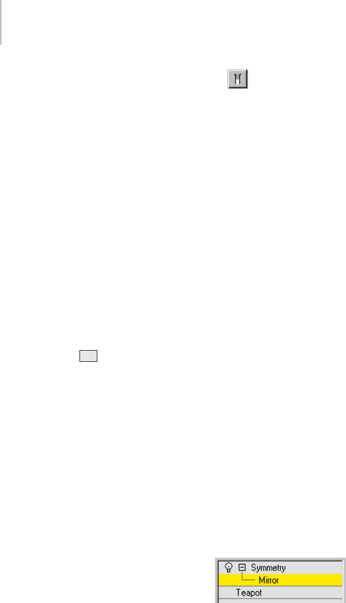
862 Chapter 8: Modifiers
2. Apply the Symmetry modifier.
The teapot appears to have two spouts.
3. In the modifier stack, click the +button to see
the Mirror gizmo, and then select Mirror.
The mirror gizmo acts as a slice plane when it is
within the boundaries of the object
4. With Mirror Axis set to X, click and drag the
mirror gizmo along the X axis.
Dragging right slices more of the teapot until
there is nothing visible. Dragging left causes
a second teapot to appear. When the mirror
gizmo is moved beyond the boundaries of the
original mesh, it acts as a mirror plane showing
you two complete teapots.
Example: To perform box modeling with the
Symmetry modifier:
1. Create a box primitive in the Perspective
viewport, and then convert it to Editable Poly
or apply the Edit Poly modifier.
2. If necessary, press F4 to activate Edged Faces
display mode in the Perspective viewport.
3. Apply the Symmetry modifier.
Other than the new edge loop created by the
modifier, the box’s appearance doesn’t change,
because it’s already symmetrical.
4. In the modifier stack, click the +button to see
the Mirror gizmo, and then click Mirror.
5. In the Front viewport, with Mirror Axis set to
X, drag the Mirror gizmo in either direction
on the X axis.
Onlytheleft-handboxmoves;thisisthecopy
createdbytheSymmetrymodifier.
6. Position the Mirror near the left side of the
originalbox,sothetwocopiesaremerged.
7. Inthemodifierstack,gototheEdit/Editable
Poly level and access the Vertex sub-object level.
If you no longer see the Symmetry copy of
thebox,turnonShowEndResult.
With Show End Result on, you might see an
orange wireframe “cage” that shows the edges
of original object. This is on by default for
editable poly objects, but off by default for
theEditPolymodifier.TheShowCagetoggle
for editable poly objects is on the Subdivision
Surface rollout, and for Edit Poly it’s on the Edit
Poly Mode rollout.
You can also see that only the vertices of the
original object are visible; the vertices of the
symmetry object can’t be transformed directly.
8. Moveoneofthevisibleverticesontheright
side of the box.
As you do so, its counterpart on the symmetry
object moves symmetrically in real time.
As you can see, the Symmetry modifier not
only creates a mirror image of an object for
you, but also lets you manipulate both sides in
tandem in an intuitive way.
9. Now move one of the vertices on the left side of
the box, where it overlaps the symmetry box.
Because you’re also moving its counterpart
vertex, which is invisible, the apparent result
is motion of the corresponding point on the
plane of symmetry. This isn’t as intuitive as
moving a non-overlapping point, so for best
results, position the Mirror gizmo so as to cause
as little overlap as possible; that way you can
edit the center vertices directly on the plane of
symmetry.
Interface
Modifier Stack
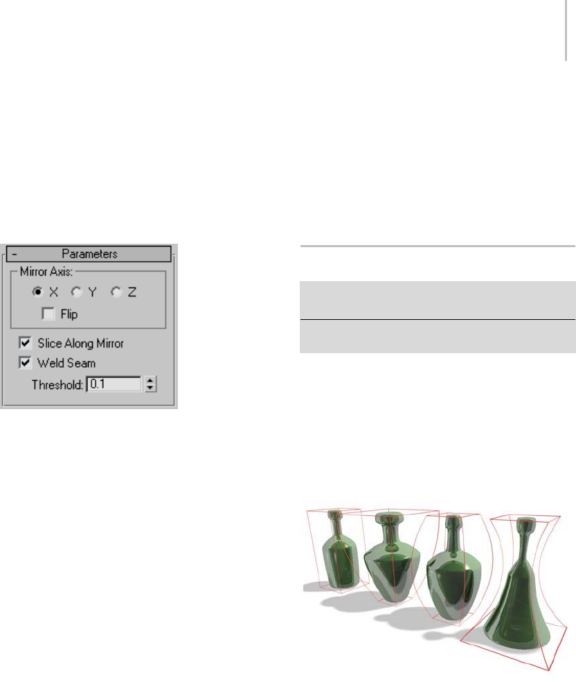
Taper Modifier 863
Mirror—The placement of the mirror gizmo
delegateshowtheobjectwillbeaffectedby
symmetry. You can move or rotate, as well as
animate the gizmo.
For more information on the stack display, see
Modifier Stack (page 3–760).
Parameters rollout
Mirror Axis group
X, Y, Z—Specify the axis about which the symmetry
takes place. You can see the effect in the viewport
as you select the axis.
Flip—Turn on Flip if you want to flip the direction
of the symmetry effect. Default=off.
Slice Along Mirror—TurningonSliceAlongMirror
causes the mirror gizmo to act as a slice plane
when it in located inside the boundaries of a mesh.
When the gizmo is outside the boundaries of a
mesh, the symmetrical reflection is still treated as
part of the originating mesh. If Slice Along Mirror
is turned off, the symmetrical reflection is treated
as a separate element of the originating mesh.
Default=on.
Weld Seam—Turning on Weld Seam assures
that the vertices along the mirror axis will be
automaticallyweldediftheyarewithinthe
Threshold. Default=on.
Threshold—The value of the Threshold setting
delegates how close vertices can be before being
automatically welded together. Default=0.1.
Note: Setting the Threshold value too high may
result in some distortion of the mesh, especially
when the mirror gizmo is outside the boundaries
of the originating mesh.
Taper Modifier
Modify panel > Make a selection. > Modifier List >
Object-Space Modifiers > Taper
Make a selection. > Modifiers menu > Parametric
Deformers > Taper
The Taper modifier produces a tapered contour
by scaling both ends of an object’s geometry; one
endisscaledup,andtheotherisscaleddown.You
can control the amount and curve of the taper on
twosetsofaxes.Youcanalsolimitthetapertoa
section of the geometry.
Examples of default tapers
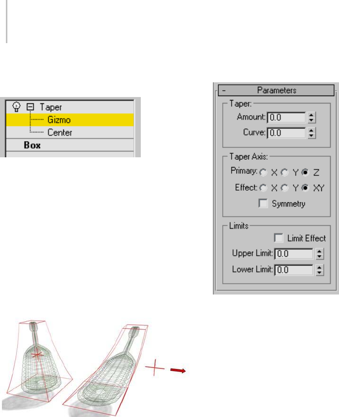
864 Chapter 8: Modifiers
Interface
Modifier Stack
Gizmo—At this sub-object level, you can
transform and animate the gizmo like any other
object, altering the effect of the Taper modifier.
Trans lat ing the g izmo trans late s its center an equa l
distance. Rotating and scaling the gizmo takes
place with respect to its center.
Center—At this sub-object level, you can translate
and animate the center, altering the Taper gizmo’s
shape, and thus the shape of the tapered object.
For more information on the stack display, see
Modifier Stack (page 3–760).
Moving the modifier’s center changes the gizmo shape.
Parameters rollout
The Taper modifier provides two sets of axes and a
symmetry setting in the Taper Axis group box of
the Parameters rollout. As with other modifiers,
these axes refer to the Taper gizmo, not the object
itself.
Taper group
Amount—Theextenttowhichtheendsarescaled.
Amount is a relative value with a maximum of 10.
Curve—Applies a curvature to the sides of the Taper
gizmo, thus affecting the shape of the tapered
object. Positive values produce an outward curve
along the tapered sides, negative values an inward
curve.At0,thesidesareunchanged.Default=0.
Taper Axis group
Primary—Thecentralaxisorspineofthetaper:X,
Y, or Z . Defau lt=Z .
Effect—The axis, or pair of axes, indicating the
direction of the taper from the primary axis. The
available choices are determined by the choice of
primary axis. The effect axis can be either of the
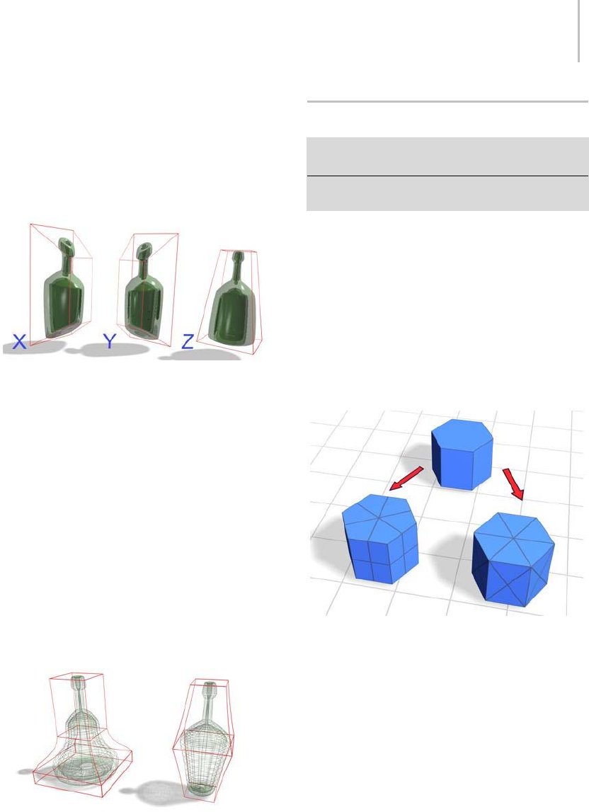
Tessellate Modifier 865
two remaining axes, or their combination. If the
primaryaxisisX,theeffectaxiscanbeY,Z,orYZ.
Default=XY.
Symmetry—Produces a symmetrical taper around
theprimaryaxis.Ataperisalwayssymmetrical
around the effect axis. Default=off.
Changing the effect axis changes the effects of the modifier.
Limits group
The taper offset is applied between the upper and
lower limits. The surrounding geometry, while
unaffected by the taper itself, is moved to keep the
object intact.
Limit Effect—Enables upper and lower limits for
the taper effect.
Upper Limit—Sets the upper limit boundaries in
world units from the taper center point, beyond
whichthetapernolongeraffectsthegeometry.
Lower Limit—Sets the lower limit boundaries in
world units from the taper center point, beyond
whichthetapernolongeraffectsthegeometry.
Left: Limiting the effect of the taper.
Right: Using symmetry.
Tessellate Modifier
Modify panel > Make a selection. > Modifier List >
Object-Space Modifiers > Tessellate
Make a selection. > Modifiers menu > Mesh Editing >
Tessellate
The Tessellate modifier subdivides faces in the
current selection. It’s particularly useful for
smoothing curved surfaces for rendering, and
creating additional mesh resolution for other
modifiers to act on. If no sub-object selection has
been passed up the stack, then the entire object
is tessellated. This modifier lets you tessellate
polygonal faces; the tessellation available in an
editable mesh (page 1–1009) does not (it works on
faces, even at the Polygon selection level).
Top: Original mesh object
Lower left: Tessellation applied to polygonal facets
Lower right: Tessellation applied to triangular faces
Warning: Tessellating an object retains any UVW
mapping that exists in the stack before the Tessellate
modifier. However, in some cases, the mapping might
be altered, depending on the type of mapping and the
tessellation settings. Typically, this happens when the
applied mapping uses extreme compound angles.
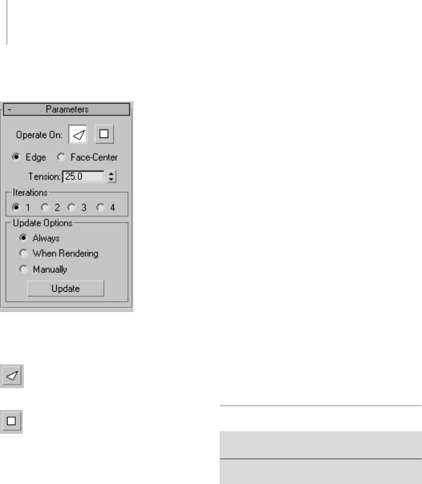
866 Chapter 8: Modifiers
Interface
Parameters rollout
Operate On—Specifies whether to perform the
tessellationonthetriangularfacesoronthe
polygonal facets (the areas bound by visible edges).
Faces—Treats the selection as a set of
triangular faces.
Polygons—Divides the polygonal facets.
For example, using the polygonal method on the
side of a box results in cross-shaped edges using
the Edge method, and X-shaped edges using the
Face-Center method.
Edge—Divides the face or polygon from its center
tothemiddleofeachedge. Whenappliedtoa
triangular face, it also divides unselected faces that
share edges with the selected faces.
Face-Center—Select this to divide the face from the
center to the vertex corners.
Tension—Determines if the new faces are flat,
concave, or convex after Edge tessellation. A
positive value rounds faces by pushing vertices
outward. A negative value creates concave faces
by pulling vertices inward. A setting of 0 keeps
the faces flat. Also works with the Edge/Polygon
method. Default=25.
Iterations group
Iterations—Specifieshowmanytimesthe
tessellation is applied. For example, setting
Iterations to 2 is similar to clicking the Tessellation
button twice in an editable mesh, except that you
can easily back out at any time while using the
Tessellate modifier. If you want more than four
iterations, apply another Tessellate modifier.
Update Options group
Always—Tessellation is updated whenever the base
geometry changes.
When Rendering—Tessellation is updated only
when the object is rendered.
Manually—Tessellation is updated only when the
user clicks Update.
Update—Click to update tessellation. Has no effect
unlessManuallyistheactiveupdateoption.
Trim/Extend Modifier
Select a shape. > Modify panel > Modifier List >
Object-Space Modifiers > Trim/Extend
Select a shape. > Modifiers menu > Patch/Spline Editing
>Trim/Extend
The Trim/Extend modifier is used primarily
to clean up overlapping or open splines in a
multi-spline shape so that lines meet at a single
point. As with the Fillet/Chamfer modifier, this
modifier operates on the splines at the sub-object
level in the shape. When applied to a selection of
multiple splines, Trim/Extend works as it does on
a single spline.
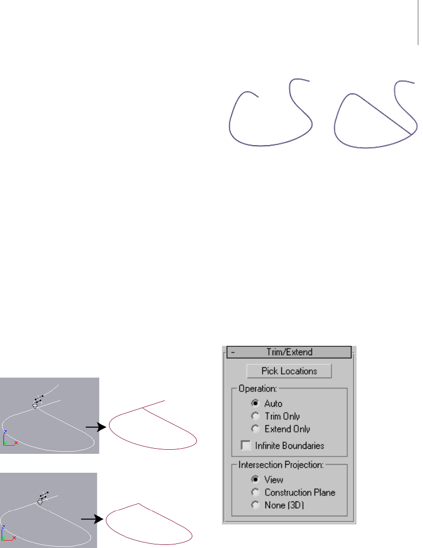
Trim/Extend Modifier 867
To trim, you need intersecting splines. Click
the portion of the spline you want to remove.
Thesplineissearchedalongitslengthuntilit
hits an intersecting spline, and deleted up to
theintersection.Ifthesectionintersectsatboth
ends, the entire section is deleted up to the two
intersections. If the section is open on one end and
intersects at the other, the entire section is deleted
uptotheintersectionandtheopenend. Ifthe
section is not intersected, nothing happens.
To extend, you need an open spline. The end of
thesplinenearestthepickedpointisextended
until it reaches an intersecting spline. If there is
no intersecting spline, nothing happens. Curved
splines extend in a direction tangent to the end of
the spline. If the end of a spline lies directly on a
boundary (an intersecting spline), then it looks for
an intersection further along.
Note: As of version 3 of 3ds Max, Edit/Editable
Spline (page 1–289) includes interactive
trim/extend functions. The only reason to use this
modifier is to apply it at a specific location on the
stack.
Before and after initial use of Trim
Before and after second use of Trim on above spline
Before and after using Extend
Procedure
To trim a shape using the Trim/Extend modifier:
1. Create an open Line shape (page 1–270) in the
form of roughly concentric overlapping circles.
2. Apply the Trim/Extend modifier.
3. Click Pick Locations.
4. Click the inner spline sections of the concentric
shape to trim them away, or click the open
spline segment to extend the spline.
Interface
Pick Locations—Click to turn on Pick mode.
While in this mode, the mouse cursor changes in
appearance when over part of the spline that can
be affected by the Trim/Extend modifier. Click
to either trim or extend the spline, based on the
settings below. Default=Auto.

868 Chapter 8: Modifiers
Operation group
Specifies the type of operation that’s performed on
the selected spline.
Auto—When this is chosen, a Trim is first looked
for and, if not found, an Extend is attempted. In
most cases, a Trim will occur when Auto is chosen.
An Extend can occur, however, in cases where
an open spline exists without intersecting other
splines.
Trim Only—Performs only trims. Turn on Pick
Locations, and then click the spline section you
want to trim.
Extend Only—Performs only extends. Click Pick
Locations, and then select the open spline section
you want to extend.
Infinite Boundaries—For the purposes of
calculating intersections, turn this on to treat open
splines as infinite in length. For example, this lets
you trim one linear spline against the extended
length of another line that it doesn’t actually
intersect.
Note: As the number of open splines in the shape
increases, the chance of finding an intersection,
when using Infinite Boundaries, increases as well.
This can produce results you might not have
expected because of projected spline intersections
you hadn’t considered, particularly if you’re in
Auto mode. For predictable results, avoid using
Auto mode when using Infinite Boundaries.
Intersection Projection group
These options specify how the Trim and Extend
functions determine a valid intersection.
View—Projectsthelinesontotheactiveviewport,
andjudgestheintersectionsaccordingly. These
are the intersections as you see them in the active
viewport.
Construction Plane—Projects the lines onto the
current construction plane.
None (3D)— Considers only true intersections as
the splines exist in 3D space. They must physically
intersect to be considered.
TurboSmooth Modifier
Make a selection. > Modify panel > Modifier List >
Object-Space Modifiers > TurboSmooth
The TurboSmooth modifier, like MeshSmooth
(page 1–722), smoothes geometry in your scene.
The differences between the two are as follows:
•TurboSmoothisconsiderablyfasterand
more memory-efficient than MeshSmooth.
TurboSmooth also has an option for Explicit
Normals, unavailable in MeshSmooth. See
Explicit Normals.
• TurboSmooth provides a limited subset of
MeshSmooth functionality. In particular,
TurboSmooth uses a single smoothing method
(NURMS), can be applied only to an entire
object, has no sub-object levels, and outputs a
triangle-mesh object.
TurboSmooth lets you subdivide the geometry
whileinterpolatingtheanglesofnewfacesat
corners and edges, and apply a single smoothing
group to all faces in the object. The effect of
TurboSmooth is to round over corners and edges
asiftheyhadbeenfiledorplanedsmooth.Use
TurboSmooth parameters to control the size and
number of new faces, and how they affect the
surface of the object.
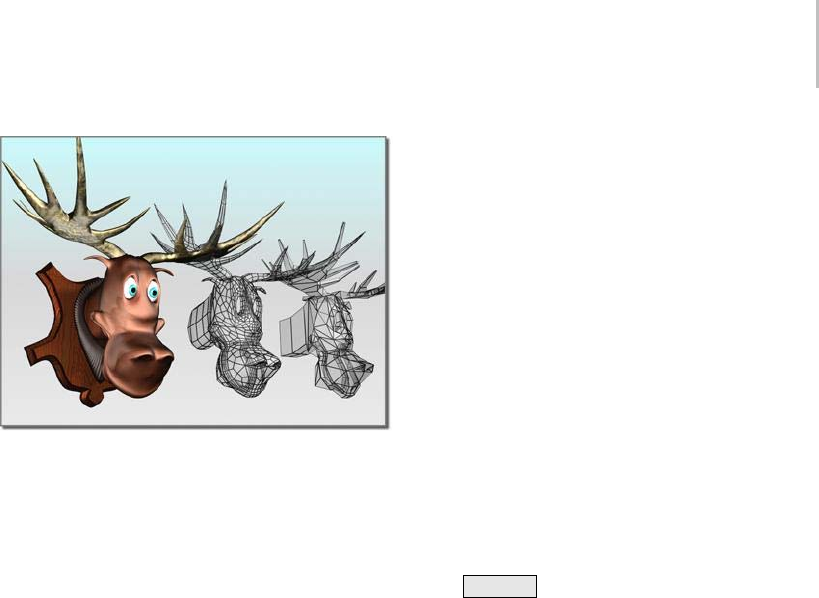
TurboSmooth Modifier 869
Angular model (shown on the right) changed to a smooth
model with TurboSmooth
Yo u u s e Tu r b o S m o o t h t o p r o d u c e a N o n - Un i f o r m
Rational MeshSmooth object (NURMS for short).
A NURMS object is similar to a NURBS object in
that you can set different weights for each control
vertex.
TurboSmooth’seffectismostdramaticonsharp
corners and least visible on rounded surfaces.
Use TurboSmooth on boxes and geometry with
crisp angles. Avoid using it on spheres and similar
objects.
Tip: To better understand TurboSmooth, create
a sphere and a cube and apply TurboSmooth to
both. The cube’s sharp corners become rounded,
while the sphere’s geometry becomes more
complex without changing shape significantly.
Procedures
To apply TurboSmooth to an object:
1. Select an angular object.
2. Apply the TurboSmooth modifier.
3. Set TurboSmooth parameters.
Example: To compare the speeds of TurboSmooth
and MeshSmooth:
1. Create a Box primitive with Length/Width/
Height Segs=3.Converttheboxtoeditable
poly format.
2. Apply MeshSmooth.
3. Set Iterations=5.
This creates a heavily subdivided mesh.
4. Go to the Editable Poly > Vertex sub-object
level,andturnonShowEndResult.
5. Move one of the corner vertices outward.
There is a significant delay before you see the
result of the Move operation.
6. Perform a few more Move operations on
vertices, observe the delays, and then undo
(Ctrl+Z ) repeatedly until the MeshSmooth
modifier goes away.
7. Apply TurboSmooth.
8. Set Iterations=5.
This creates a heavily subdivided mesh.
9. Go to the Editable Poly > Vertex sub-object
level,andturnonShowEndResult.
10.Move one of the corner vertices outward.
Theresponseismuchfaster.
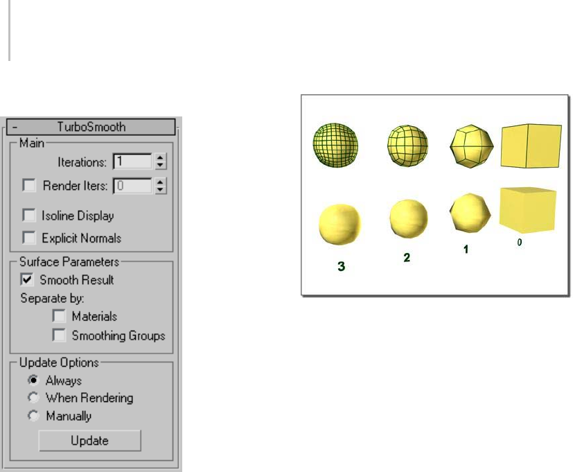
870 Chapter 8: Modifiers
Interface
Main group
Lets you set the basic parameters for TurboSmooth.
Iterations—Sets the number of times the mesh is
subdivided. When you increase this value, each
new iteration subdivides the mesh by creating
smoothly interpolated vertices for every vertex,
edge, and face from the iteration before. The
modifier then subdivides the faces to use these
new vertices. Default=1. Range=0 to 10.
From right to left, effect of increasing the number of iterations
Note: Be cautious when increasing the number of
iterations. The number of vertices and faces in an
object (and thus the calculation time) can increase
as much as four times for each iteration. Applying
four iterations to even a moderately complex
object can take a long time to calculate.
Render Iter(ation)s—Lets you choose a different
number of smoothing iterations to be applied to the
object at render time. Turn on Render Iters, and
then use the field to its right to set the number of
render iterations.
Isoline Display—When on, the software displays
only isolines: the object’s original edges, before
smoothing. The benefit of using this option is
a less cluttered display. When off, the software
displays all faces added by TurboSmooth; thus,
higher Iterations values result in a greater number
of lines. Default=off.
Warning: If you’re going to collapse the model or apply
further modifiers after the TurboSmooth, you should
first turn off Isoline Display. Unlike in MeshSmooth,
isoline display is achieved by making all the edges
"invisible," joining large groups of faces together in
single "polygons." This can be especially problematic
if you apply a PolyObject-based modifier afterwards,
because all vertices in the interior of these "polygons"
will be lost.

Turn To Mesh Modifier 871
Explicit Normals—Lets the TurboSmooth modifier
compute normals for its output, which is
faster than the standard method 3ds Max uses
to compute normals from the mesh object’s
smoothing groups. Default=off.
Consequently, if the TurboSmooth result is used
directly for display or rendering, it will generally be
faster with this option turned on. Also, the quality
of the normals will be slightly higher. However, if
you apply any topology-affecting modifiers, such
as Edit Mesh, above the TurboSmooth modifier,
these normals will be lost and new ones computed,
potentially affecting performance adversely. So
it’simportanttoremembertoturnonExplicit
Normals only if no modifiers change the object
topology after TurboSmooth takes effect.
Surface Parameters group
Lets you apply smoothing groups to the object and
restrict the smoothing effect by surface properties.
Smooth Result—Applies the same smoothing
group to all faces.
Separate by Materials—Prevents the creation of
new faces for edges between faces that do not share
Material IDs.
Separate by Smoothing Groups—Prevents the
creation of new faces at edges between faces that
don’tshareatleastonesmoothinggroup.
Update Options group
Setsmanualorrender-timeupdateoptions,for
situations where the complexity of the smoothed
object is too high for automatic updates. Note that
you can also set a greater degree of smoothing to
be applied only at render time, in the Main group.
Always—Updates the object automatically
whenever you change any TurboSmooth settings.
When Rendering—Updates the viewport display of
theobjectonlyatrendertime.
Manually—Tur ns on manual up dating . When
manual updating is selected, any settings you
changedon’ttakeeffectuntilyouclicktheUpdate
button.
Update—Updates the object in the viewport
to match the current TurboSmooth settings.
Works only when you choose When Rendering
or Manually.
Turn To Mesh Modifier
Make a selection. > Modify panel > Modifier list >
Object-Space Modifiers > Turn to Mesh
Make a selection. > Modifiers menu > Conversion > Turn
to Mesh
The Turn To Mesh modifier lets you apply object
conversions in the modifier stack. As another
example, you could use this modifier on a
sophisticated patch model to which you might
want to apply a tool that applies only to meshes,
or convert the object to a mesh. Also, when you
apply general-purpose modifiers such as Normal,
Material, or UVW Map, it can be helpful to
explicitly control the type of object beforehand.
Note: Converting from one object type to another
causes a complete caching in the modifier stack.
When you have large objects in your scene, this
can take up a lot of space. For example, an object
that starts as a mesh, converts to a patch, and then
back to a mesh takes three times as much space as
ameshthatjusthasordinarymodifierslikeBend
or UVW Map applied.
Tip: Turn To Mesh can be useful on meshes,
allowing you to invert a selection or change the
selection level in a modifier that doesn’t depend
on topology.
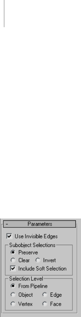
872 Chapter 8: Modifiers
Procedure
Example: To translate a patch sub-object selection
to a polygon sub-object selection:
1. Select a patch model and turn on wireframe
mode.
2. In the stack display, choose the Patch sub-object
level.
3. Select a patch on the model.
4. Apply the Turn To Mesh modifier from the
Modifier list.
5. In the stack display, right-click the Turn To
MeshmodifierandchooseCollapseAll.
6. Click Yes in the dialog that warns you about the
possibility of undesirable topological effects.
7. In the stack display (or in the selection rollout),
choose the Polygon sub-object mode. The
original patch selection has been preserved.
Interface
Parameters rollout
Use Invisible Edges—When on, uses invisible
edges to represent polygons. When off, produces
a completely triangulated mesh with all visible
edges. Default=on.
Sub-object Selections group
These options control the selection of sub-objects.
Preserve—Passes the sub-object selection up the
stack. For example, if you have an object that you
have converted to an editable mesh, and you’ve
selectedapolygon,thenwhenyouapplyaTurn
To Mesh modifier, the polygon remains selected.
Default=on.
Clear—Clears the sub-object selection so that
nothing is selected. Default=off.
Invert—Inverts the sub-object selection. All
sub-objects not currently selected are selected, and
all sub-objects currently selected are deselected.
Default=off.
Include Soft Selection—Affects the action of
sub-object Move, Rotate, and Scale functions.
When these are on, 3ds Max applies a spline curve
deformation to unselected vertices surrounding
the transformed selected sub-object. This provides
a magnet-like effect, with a sphere of influence
around the transformation. Use this when you
want to preserve the soft selection from beneath.
Forexample,ifUseSoftSelectionisonwhenyou
select vertices on an editable poly, and you apply
Turn To Mesh with Include Soft Selection on, then
the same soft selection will apply to the mesh
vertices. Default=on.
For more information, see Soft Selection Rollout
(page 1–963).
Selection Level group
These options set the sub-object selection level for
passing up the rest of the stack.
From Pipeline—Uses the equivalent of whatever
the input object uses (patch level becomes face
level, and so on). For example, if you create a box,
convert it to an editable patch in patch mode, and
apply a Turn To Mesh modifier to it, 3ds Max
passes a sub-object selection in patch mode up
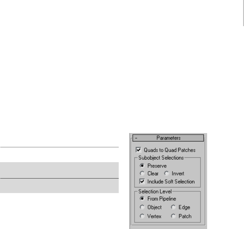
Turn To Patch Modifier 873
the stack. The Turn To Mesh modifier takes the
sub-object patch selection into account and selects
the mesh faces that derive from the patch selection.
Object—Uses Object as the selection level for
passing up the rest of the stack.
Edge—Uses Edge as the sub-object selection level
for passing up the rest of the stack.
Vertex—Uses Vertex as the sub-object selection
level for passing up the rest of the stack.
Face—Uses Face as the sub-object selection level
for passing up the rest of the stack.
Turn To Patch Modifier
Make a selection. > Modify panel > Modifier List >
Object-Space Modifiers > Turn to Patch
Make a selection. > Modifiers menu > Conversion > Turn
to Patch
The Turn To Patch modifier lets you apply object
conversions in the modifier stack. Using the
Turn To Patch modifier, you can fine-tune the
conversion process such as turning quads into
quad patches.
Note: Converting from one object type to another
causes a complete caching in the modifier stack.
When you have large objects in your scene, this
can take up a lot of space. For example, an object
that starts as a mesh, converts to a patch, and then
back to a mesh takes 3 times as much space as a
mesh which just has ordinary modifiers like Bend
or UVW Map applied.
Tip: Turn To Patch can be useful on patches,
allowing you to invert a selection or change the
selectionlevelinamodifierthatdoesn’tdepend
on topology.
Procedure
Example: To collapse to quad patches:
1. Create a chamfer box in wireframe: Create
panel > Geometry > Extended Primitives >
Object Type rollout > ChamferBox button.
2. Apply a Turn To Patch modifier: Modify panel
> Modifier List > Turn To Patch.
3. Right-click the stack display and choose
Collapse All.
Interface
Quads to Quad Patches—Turns quad faces i n
meshes or polymeshes into quad patches.
Note: Whenyouturnthisoptionoff,3dsMax
triangulates quads when the Turn To Patch
modifier is applied to a mesh or poly object.
Sub-object Selections group
These options control the selection of sub-objects.
Preserve—Passes the sub-object selection up the
stack. For example, if you have an object that you
have converted from an editable mesh, and you’ve
selectedapolygon,thenwhenyouapplyaTurn
To Patch modifier, the patch, which is derived
from the selected polygon, remains selected.
Default=on.

874 Chapter 8: Modifiers
Clear—Clears the sub-object selection so that
nothing is selected. Default=off.
Invert—Inverts the sub-object selection. All
sub-objects not currently selected are selected, and
all sub-objects currently selected are deselected.
Default=off.
Include Soft Selection—When these are on,
3ds Max applies a spline curve deformation to
unselected vertices surrounding the transformed
selectedsub-object.Thisprovidesamagnet-like
effect, with a sphere of influence around the
transformation. Use this when you want to
preserve the soft selection from beneath. For
example, if Use Soft Selection is on when you select
vertices on an editable mesh, and you apply Turn
ToPatchwithIncludeSoftSelectionon,thenthe
same soft selection will apply to the patch vertices.
Default=on.
For more information, see Soft Selection Rollout
(page 1–963).
Selection Level group
These options set the sub-object selection level for
passing up the rest of the stack.
From Pipeline—Uses the equivalent of whatever
the input object uses (patch level becomes face
level, and so on.). For example, if you create a
box,convertittoaneditablemeshinfacemode,
and apply a Turn To Patch modifier to it, 3ds Max
passes a sub-object selection in patch mode up
the stack. The Turn To Patch modifier takes the
sub-object face selection into account and selects
the patches that derive from the face selection.
Object—Uses object as the selection level for
passing up the rest of the stack.
Edge—Uses edge as the sub-object selection level
for passing up the rest of the stack.
Vertex—Uses vertex as the sub-object selection
level for passing up the rest of the stack.
Patch—Uses patch as the sub-object selection level
for passing up the rest of the stack.
Turn To Poly Modifier
Make a selection. > Modify panel > Modifier List >
Object-Space Modifiers > Turn to Poly
Make a selection. > Modifiers menu > Conversion > Turn
to Poly
The Turn To Poly modifier lets you apply object
conversions in the modifier stack. Also, when
you apply the general-purpose modifiers, such as
Normal,Material,orUVWMap,itcanbehelpful
to explicitly control the type of object beforehand.
When you use Turn To Poly, you’re joining
triangles into polygons, so you might need to
have restrictions on polygon convexity, size, and
planarity. All conversions from patches produce
quadsandtriangles.Conversionsfrommeshescan
producearbitrarilylargepolygons.Meshpolygons
are controlled as usual by joining together faces
that are separated by invisible edges.
Note: Converting from one object type to another
causes a complete caching in the modifier stack.
When you have large objects in your scene, this
can take up a lot of space. For example, an object
that starts as a mesh, converts to a patch, and then
back to a mesh takes three times as much space as
a mesh that has only ordinary modifiers like Bend
or UVW Map applied.
Tip: TurnToPolycanbeusefulonpolymeshes,
allowing you to invert a selection or change the
selection level in a modifier that doesn’t depend
on topology.
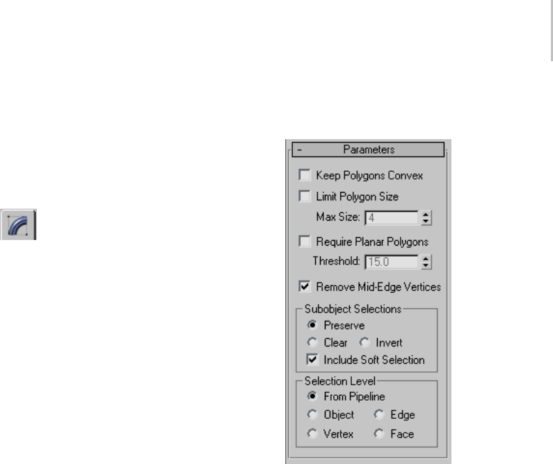
Turn To Poly Modifier 875
Procedure
Example: To prevent interior vertices from being
passed up the stack:
1. Create an NGon in wireframe mode: Create
panel>Shapes>Splines>ObjectTyperollout
>NGon.
2. Open the Modify panel and convert the
NGon to an editable mesh by right-clicking
the stack display and choosing Convert to >
Editable Mesh.
3. In the stack display (or in the Selection rollout),
choose the Polygon sub-object mode.
4. Choose Edit > Object Properties to display the
Object Properties dialog.
5. Turn on Vertex Ticks. Choose OK to close the
dialog.
6. Click Cut under the Edit Geometry rollout, and
makeacutfromonesideoftheNGontothe
other. Notice that an interior vertex now exists.
Note: DoingthisonanNGondoesn’talways
generate an interior vertex.
7. Apply the Turn To Poly modifier: Modify panel
> Modifier List > Turn To Poly. Notice the
interior vertex clears.
Interface
Parameters rollout
Keep Polygons Convex—Does not join across edges
if the resulting polygon would not be convex.
"Convex" means that you can connect any two
points in the polygon with a line that doesn’t go
outside the polygon. A polygon is not convex if
you can draw a line between vertices and that line
lays outside of the polygon.
Problems that can occur with non-convex
polygons include the fact that changes in the
geometry of the input object can result in a
different topology for the Turn To Poly result.
For instance, in a box, if you drag one of the top
cornersacrossthemiddleofthetopface,thebox
becomes non-convex. Turn To Poly would then
seethisastwotrianglesinsteadofonequad,and
the number of points in the result would change.
Limit Polygon Size—Limits the number of sides to a
polygon so that the surface is better defined. For
example, you might want to produce a polymesh
of triangles and quads, or one composed of all

876 Chapter 8: Modifiers
triangles, rather than joining together more than
two triangles into pentagons, hexagons, and so on.
Max Size—The maximum number of sides to a
polygon.
Require Planar Polygons—Creates polygons
composed of flat planes. Does not join faces
togetheracrossanedgeiftheedgehasasharper
angle than the threshold listed.
Threshold—Controls the threshold of the angle
between polygonal planes.
Remove Mid-Edge Vertices—Eliminates divisions
that result from intersections with invisible edges.
Sub-object Selections group
These options control the selection of sub-objects.
Preserve—Passes the sub-object selection up the
stack. For example, if you have an object that you
have converted to an editable mesh, and you’ve
selected a polygon, then when you apply a Turn
To Poly modifier, the polygon remains selected.
Default=on.
Clear—Clears the sub-object selection so that
nothing is selected. Default=off.
Invert—Inverts the sub-object selection. All
sub-objects not currently selected are selected, and
all sub-objects currently selected are deselected.
Default=off.
Include Soft Selection—Affects the action of
sub-object Move, Rotate, and Scale functions.
When these are on, 3ds Max applies a spline curve
deformation to unselected vertices surrounding
the transformed selected sub-object. This provides
a magnet-like effect, with a sphere of influence
around the transformation. Use this when you
want to preserve the soft selection from beneath.
Forexample,ifUseSoftSelectionisonwhenyou
select vertices on an editable mesh, and you apply
Turn To Poly with Include Soft Selection on, then
thesamesoftselectionwillapplytothepolymesh
vertices. Default=on.
For more information, see Soft Selection Rollout
(page 1–963).
Selection Level group
These options set the sub-object selection level for
passing up the rest of the stack.
From Pipeline—Uses the equivalent of whatever
the input object uses (patch level becomes face
level, and so on). For example, if you create a box,
convertittoaneditablemeshinfacemode,and
apply a Turn To Poly modifier to it, 3ds Max passes
a sub-object selection in face mode up the stack.
The Turn To Poly modifier takes the sub-object
face selection into account and selects the polygons
that derive from the face selection.
Object—Uses object as the selection level for
passing up the rest of the stack.
Edge—Uses edge as the sub-object selection level
for passing up the rest of the stack.
Vertex—Uses vertex as the sub-object selection
level for passing up the rest of the stack.
Face—Uses face as the sub-object selection level
for passing up the rest of the stack.
Twist Modifier
Modify panel > Make a selection. > Modifier List >
Object-Space Modifiers > Twist
Make a selection. > Modifiers menu > Parametric
Deformers > Twist
The Twist modifier produces a twirling effect (like
wringingoutawetrag)inanobject’sgeometry.
You can control the angle of the twist on any of
three axes, and set a bias that compresses the twist
effect relative to the pivot point. You can also limit
the twist to a section of the geometry.
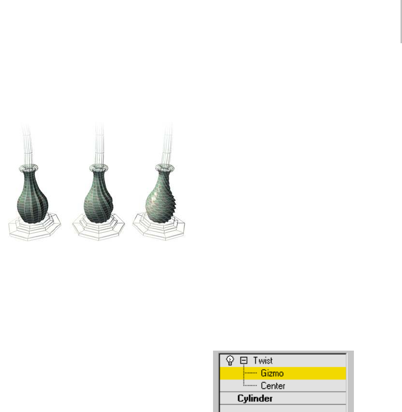
Twist Modifier 877
Note: When you apply the Twist modifier, the Twist
gizmo’scenterisplacedattheobject’spivotpoint,
and the gizmo lines up with the object’s local axis.
Left: Original model
Middle: A moderate twist
Right: An extreme twist
Procedures
To twist an object:
1. Select an object and apply Twist.
2. On the Parameters rollout, set Twist Axis to
X, Y, or Z. This refers to the axis of the Twist
gizmo, not the axis of the selected object.
You can switch between axes at any time,
but only one axis setting is carried with the
modifier.
3. Set the angle of the twist. Positive values
produceaclockwisetwist,negativevalues
acounterclockwisetwist. Anangleof360
produces a complete revolution.
Theobjecttwiststothisamountbeginningat
the lower limit (by default, the location of the
modifier’s center).
4. Set the bias of the twist.
A positive value compresses the twist at the
end away from the pivot point, a negative value
toward the pivot point.
To limit the twist:
1. Turn on Limits group > Limit Effect.
2. Set values for the upper and lower limits. These
are distances in current units above and below
the modifier’s center, which is at zero on the
gizmo’s Z axis. The upper limit can be zero or
positive, the lower limit zero or negative. If the
limits are equal, the result is the same as turning
off Limit Effect.
The twist offset is applied between these limits.
The surrounding geometry, while unaffected
by the twist itself, is moved to keep the object
intact.
3. At the sub-object level, you can select and move
the modifier’s center.
The limit settings remain on either side of the
center as you move it. This lets you relocate the
twist area to another part of the object.
Interface
Modifier Stack
Gizmo—You can transform and animate the
gizmo like any other object at this sub-object
level, altering the effect of the Twist modifier.
Translating the gizmo translates its center an equal
distance. Rotating and scaling the gizmo takes
place with respect to its center.
Center—You can translate and animate the center
at this sub-object level, altering the Twist gizmo’s
shape, and thus the shape of the twisted object.
For more information on the stack display, see
Modifier Stack (page 3–760).
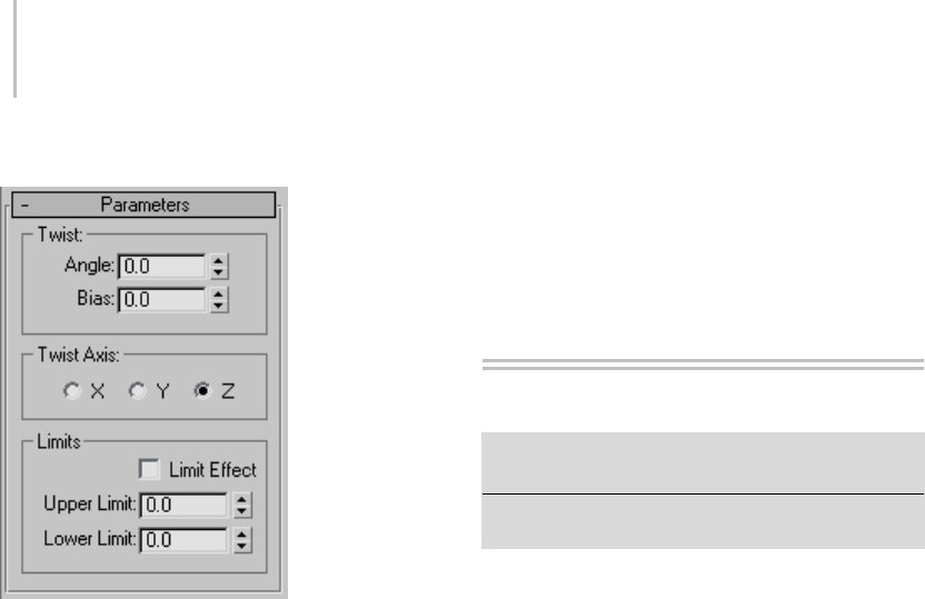
878 Chapter 8: Modifiers
Twist Parameters rollout
Twist group
Angle—Determines the amount of twist around
the vertical axis. Default=0.0.
Bias—Causes the twist rotation to bunch up at
either end of the object. When the parameter is
negative, the object twists closer to the gizmo
center. When the value is positive, the object twists
more away from the gizmo center. When the
parameter is 0, the twisting is uniform. Range=100
to -100. Default=0.0.
Twist Axis group
X/Y/Z—Specify the axis along which the twist will
occur. This is the local axis of the Twist gizmo.
Default=Z.
Limits group
Applies the twist effect only to vertices that lie
between the lower and upper limits. The two
spinners represent distance along the gizmo’s Z
axis (Z=0 is at the gizmo’s center). When they are
equal, it is the same as disabling the twist effect.
Limit Effect—ApplieslimitconstraintstotheTwist
modifier.
Upper Limit—Sets the upper limit for the twist
effect. Default=0.
Lower Limit—Sets the lower limit for the twist
effect. Default=0.
Unwrap UVW Modifier
Select an object. > Modify panel > Modifier List >
Object-Space Modifiers > Unwrap UVW
Select an object. > Modifiers menu > UV Coordinates >
Unwrap UVW
The Unwrap UVW modifier is used to assign
planar maps to sub-object selections, and to edit
the UVW coordinates of those selections. Existing
UVW coordinates on an object can be unwrapped
andeditedaswell.Mapscanbeadjustedtothe
proper fit on a Mesh, Patch, Polygon, HSDS, or
NURBS model.
The Unwrap UVW modifier can be used as
a self-contained UVW mapper and UVW
coordinate editor, or in conjunction with the
UVW Map modifier (page 1–922).Ifyouuse
Unwrap UVW in conjunction with the UVW
Map modifier, it is usually so you can use a
mapping method unavailable in Unwrap UVW,
such as Shrink Wrap. You can animate UVW
coordinates by turning on the Auto Key button and
transforming the coordinates at different frames.
Note: After applying the Unwrap UVW modifier,
open mapping edges, or seams, appear on the
modified object in the viewports. This helps you
visualize the locations of mapping clusters on the
object surface. You can toggle this feature and set
thelinethicknesswiththeDisplay setting (page
1–885).
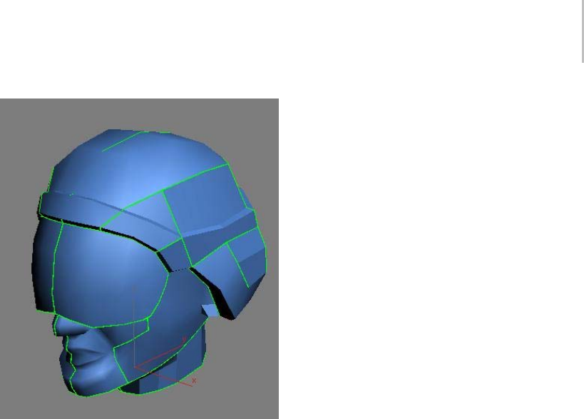
Unwrap UVW Modifier 879
Open UVW mapping edges (seams) shown on head model in
viewport
Self-Contained Mapper and UVW
Coordinate Editor
Rather than creating a large modifier stack by
first making a sub-object selection of faces and
then adding a UVW Map modifier to specify the
type of mapping, you can use the Unwrap UVW
modifier to do both. You can select sub-object
vertices,edges,orfaces/patches,storesub-object
selections as named selections, map them using
planar and other methods, and then edit the UVW
coordinates for each sub-object selection, all from
within the Unwrap UVW modifier. For example,
to map a character’s face using three planar maps,
you could create three sub-object selections of
the front and sides of the face, planar-map the
selections individually, and then edit the UVW
coordinates for each selection, all without leaving
the Unwrap UVW modifier.
What Happens to Existing UVW
Coordinates
When you apply the Unwrap UVW modifier, it
stores the object’s current mapping coordinates
in the modifier. If the object has no mapping
coordinates, the modifier creates new ones by
applying planar mapping. If the incoming data on
the stack is a face-level or polygon-level sub-object
selection, then only the UVWs for the selected
faces are brought into the modifier, and the
modifier’s sub-object levels are unavailable.
When the modifier is evaluated, its UVWs are
reassigned to the object flowing down the pipeline.
So if the UVWs upstream are changed, the changes
won’tmakeitpasttheUnwrapUVWmodifier.If
the Unwrap modifier is operating on a selection of
faces, then upstream changes to unselected faces
willstillbeabletoflowpasttheUnwrapmodifier.
Native Support for HSDS, Polygon
Object, and Patch mapping
Unwrap UVW supports polygon faces and Bezier
quad and tri patch faces in addition to triangles
and quads.
Below is a sample of what the various face types
look like based on the incoming type. For HSDS
and Poly surfaces, the basic interface remains the
same, except that the maximum number of sides
per polygon increases from 4 to over two billion.
HSDS supports only one level of detail: the level at
which the mapping was. Patches have handles on
nonlinear vertices. These handles work just like
regular patch handles.
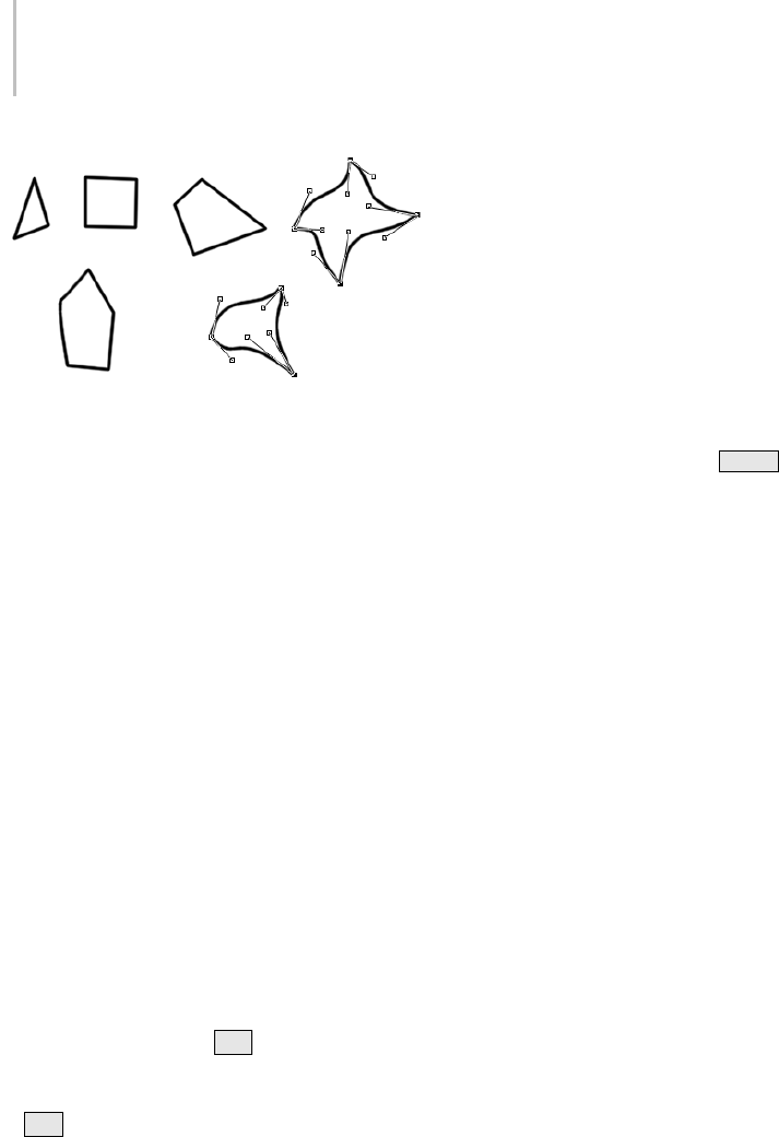
880 Chapter 8: Modifiers
Pinning Textures
Although not its primary purpose, you can use the
Unwrap UVW modifier to freeze UVWs. You can
apply mapping after an animated deformation and
have the mapping stick to the object. For example,
you can apply Unwrap UVW above a Morpher
modifier in the modifier stack, apply planar maps
and edit the UVW coordinates. The mapping will
follow the morphing geometry.
Procedures
To use Unwrap UVW with the non-Pelt mapping
methods:
This is a general overview of using the basic
Unwrap UVW tools available on the Modify panel
and the Edit UVWs dialog (page 1–888).Unwrap
UVW provides many additional tools, particularly
in the editor.
1. Apply the modifier and a texture-mapped
material to an object. Set the material to display
in the viewports, set at least one viewport to
be shaded (e.g., press F3 to toggle between
Wireframe and Smooth+Highlights), and, if
necessary, turn off Shade Selected Faces (press
F2 ) for that viewport so the texture mapping
is visible.
2. GototheFacesub-objectleveloftheUnwrap
modifier and make a selection of contiguous
faces. You’ll use a single mapping type on this
selection.
Within the single modifier, you can apply as
many different mappings as you like to different
face selections.
3. It is recommended that you name the selection
using the Named Selection Sets (page 1–83)
function on the main toolbar. This makes it easy
to return to the selection set in the viewports
for subsequent mapping adjustments. For
example, if you’re working on a character mesh,
you could use names such as right arm.
Important: Be sure to press Enter after typing the
selection set name.
4. On the Map Parameters rollout, click the
appropriate mapping type button (Planar, Box,
etc.) and then adjust the gizmo using any
combination of the transform tools (Move,
Rotate, Scale) in the viewports and the Align
buttons (Align X, etc.) on the Map Parameters
rollout.
Tip: Youcanoftensavetimebystartingwith
the Best Align command and then adjusting
manually from there.
After each adjustment of the mapping gizmo,
the texture display in the viewports updates to
reflect the mapping changes, as do the green
seam lines on the object that show where the
open edges lie (depending on the object shape
and mapping type; the seam lines don’t change
with Planar mapping). To cause the viewports
to update in real time, turn on Edit UVWs
dialog > Constant Update.
You can also open the editor (Parameters
rollout>Edit)toviewthechangesinthe
generated texture coordinates as you adjust the
gizmo.
5. Click the mapping type button again to turn it
off and exit mapping for this face selection.
6. Continue making and naming selections and
applying mapping until the entire mesh is
mapped. Use the green seam display lines
Unwrap UVW Modifier 881
as a guide. If you don’t see them, make sure
Parameters rollout > Display Group > Thin
Seam Display or Thick Seam Display is active.
7. Open the Edit UVWs dialog (page 1–888)
(Parameters rollout > Edit).
By default, the editor displays a checkered
background. To view the map in the material
on the object, you need to change a setting.
8. At the right end of the editor upper toolbar,
click the drop-down list that currently reads
CheckerPattern (Checker) and choose the map
that’s applied to the material.
The map appears as the background.
By default, all the UVW clusters display. To
work on one cluster at a time, you need to filter
the UVWs.
9. On the Edit UVWs dialog > lower toolbar,
click Filter Selected Faces.
At this point, only faces you select in the
viewport will appear in the editor. You can
select them directly, or choose a named
selection set. In the next step, you’ll use the
latter method.
10.On the main toolbar, open the Named Selection
Sets drop-down list, and choose one of your
named selection sets.
The viewports show the selection as active, and
the UVW coordinates for the selection appear
in Edit UVWs window.
11. In the Edit UVWs window, select and
move a UVW face.
In the viewports, the texture slides around the
selected portion of the object mesh.
12.Choose a different selection set and edit its
UVW coordinates.
Again, the viewport display reflects the editing
changes.
13.Inaviewport,dragtoselectagroupoffaces
by region.
The faces’ UVW coordinates display in the
Edit UVWs window. This is another way of
choosing what you want to work on.
As you can see, from within the Unwrap UVW
modifier you can assign multiple mapping
typestodifferent,namedfaceselections,and
then edit the UVW coordinates to fine-tune
map placement on the geometry.
To perform quick planar mapping:
You’ll find the Quick Planar Map controls on the
Map Parameters rollout of the Unwrap UVW
modifier.
1. Apply Unwrap UVW to an object.
2. Go to the Face sub-object level.
3. Select the faces to map.
The Quick Map gizmo appears juxtaposed over
thefaceselection,showingthedefaultAveraged
Normals mapping.
4. If you prefer a different orientation for the
mapping, choose X, Y, or Z.
5. Click Quick Planar Map to apply the mapping.
To map additional faces, proceed from step 3.
To use Pelt mapping:
Pelt mapping is useful for mapping organic models
such as characters and creatures. This feature gives
you a special editor with a virtual stretcher and
springs that let you easily “pull” a complex UVW
mapflat. Theresultmorecloselyapproximates
the actual shape of the object than other mapping
methods, making it easier to create convincing
texture maps.
1. Apply Unwrap UVW to the object.
2. Makeanedgeselectionthatyoucanlater
converttopeltseams. It’snotabsolutely
necessary to do this at this point, but the

882 Chapter 8: Modifiers
Edge sub-object level of the modifier gives
you handy Ring and Loop tools as well as
buttonstoexpandandshrinktheedgeselection
automatically.
Tip: Creating the pelt seams is more art than
exact science. Visualize the way the mesh
should lie flat, and then select edges so the UVs
can split in a natural way.
3. Go to the Face sub-object level of the modifier
andselectthefacestopeltmap. Toselect
all faces, press Ctrl+A .Ifyou’renot
pelt-mappingtheentiremesh,youcanskipthis
step.
4. Ifyoumadeanedgeselectioninstep2,click
Map Parameters rollout > Edge Sel To Pelt
Seams. Thiscopiestheedgeselectiontopelt
seams. If you didn’t specify the pelt seams at
theEdgesub-objectlevelofthemodifier,turn
on Edit Seams or Point To Point Seam and then
specify seams in the viewports.
Thepeltseamsappearonthemeshasbluelines.
5. If you’re not pelt-mapping the entire mesh, you
probably want to map a region enclosed by a
peltseam.Clickafacewithintheregiontomap
and then click Exp. Face Sel to Pelt Seams.
This expands the face selection to the full size
of the region defined by the pelt seam.
Note: Yo u c a n p e l t m a p o n l y o n e s u c h r e g i o n
at a time.
6. Turn on Pelt, and then adjust the planar
mapgizmothewayyouwant.Youcandoso
manually or automatically with one of the Align
buttons on the Map Parameters rollout. For a
vertical humanoid character facing the Y axis,
try using the Align X button. The ideal result in
theEditUVWsdialog(seestep7)isanoutline
of the object as viewed from the front or back.
Tip: For best results with cylindrical areas such
as limbs, align the plane at right angles to the
seam of the area to pelt map. For example, if the
seam runs down the back side of a leg, orient
the plane along a line running from the right
side to the left side of the leg.
7. On the Map Parameters rollout, click Edit Pelt
Map.
This opens the Edit UVWs dialog, if necessary,
and displays the pelt UVWs and the stretcher
in the editor window. By default, the stretcher
appearsasacircleofpointscenteredonthe
pelt UVWs, with only the stretcher vertices
selected. Also, springs, represented as dashed
lines, connect the stretcher points and the
pelt-seam vertices.
8. If necessary, rotate the Pelt UVs so that the
mapping coordinates are oriented correctly,
and rotate the stretcher so that the springs form
a symmetrical pattern. Typically you’re looking
for left-right symmetry.
Tip: Using Ctrl +click adds to the existing
selection, as in the viewports.
9. On the Pelt Map Parameters dialog, click
Simulate Pelt Pulling.
Thespringscontract,pullingthepeltseam
vertices toward the stretcher points. The
internal UV vertices are also affected by this
action. You can adjust the extent to which
they’re affected with the Decay setting.
10.Continue adjusting the stretcher points,
mapping vertices, dialog settings, etc., and
re-running the solution until you get the
desired results. If things get out of hand, simply
undo, or click Reset Stretcher and start over.
To export texture coordinates to a paint program:
1. Apply the Unwrap UVW modifier to your
object and use the modifier tools to set up the
mapping. Texture-coordinate clusters that will
use the same texture area should overlap.
2. FromtheEditUVWsdialogmenubar,choose
Tools > Render UVW Template.
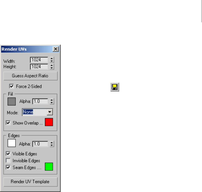
Unwrap UVW Modifier 883
This opens the Render UVs dialog:
3. Set the Width and Height values to the output
resolution you want in the rendered template.
You’ll usually get good results by setting the
desired width and then clicking Guess Aspect
Ratio.
Tip: When creating texture maps for gaming and
other real-time 3D engines, be sure to set both
dimensions to powers of 2: 256, 512, 1024, etc.
4. Change the remaining values as needed. By
default,thetemplateisrenderedwiththe
edgesaswhiteandopaque(alpha=1.0),
andbackgroundisemptyandtransparent
(background alpha=0.0), but you have a variety
of choices here, as detailed in Render UVs
Dialog (page 1–914).
5. At the bottom of the dialog, click Render UV
Te m p l at e .
This opens a new rendered frame window (page
3–5) containing the rendered template as a
bitmap. Inspect the output, and if changes
are necessary, make them on the Render UVs
dialog and re-render.
6. When you’re satisfied with the results, click
Save Bitmap on the rendered frame window
toolbar,andthenusethefiledialogtospecify
thefiletypeandname.ClickSavetoexport
the file.
If you want to use the rendered transparency
information in the paint program, be sure
tosaveinaformatthatsupportsthealpha
channel, such as TIF or Targa.
7. Opentheexportedimageinapaintprogram
andusetherenderededgesasaguidefor
painting the texture map. Save the image when
done.
Be sure to paint over or erase all the edges so
they don’t appear in the final texture.
8. Backin3dsMax,createamaterial,setthe
Diffuse map to Bitmap, and open the file from
the previous step.
9. Apply the material to your mesh object.
The painted texture map follows the outlines
set up by the exported UVs.
Interface
After applying the modifier, its panel appears,
consisting of the modifier stack plus two rollouts:
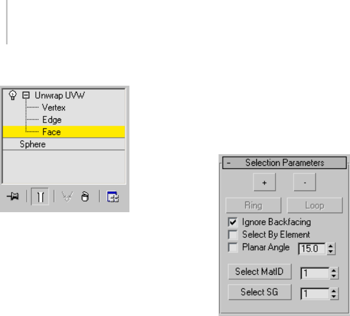
884 Chapter 8: Modifiers
Modifier Stack display
Normally, when you apply Unwrap UVW to
an object, the modifier stack provides access to
Vertex, Edge, and Face sub-object levels. These
are synchronized with the corresponding selection
modes on the Edit UVWs dialog (page 1–888).The
Vertex and Edge sub-object levels are useful for
making UVW vertex and edge selections in the
viewports, where texture mapping on the object
surfaceismorereadilyvisible,andtheEdgelevelis
also useful for setting up edge selections that you
can later convert to pelt seams.
If you apply Unwrap UVW to an active face
selection of an Editable/Edit Mesh/Poly object,
or to an active patch selection of an Editable/Edit
Patch object, no sub-object levels are available in
the Unwrap UVW modifier. You can use Unwrap
UVW to edit only the selection that was active
when you applied the modifier. Changing the
sub-objectselectionintheobjectdoesn’taffectthe
Unwrap modifier contents, because the modifier
obtains the face selection when you first apply it.
All three sub-object levels are synchronized
between the modifier stack and the Selection
Modes group (page 1–893) on the Edit UVWs
dialog. When you activate a sub-object level in
one, it’s also activated in the other. Similarly,
selecting sub-objects in a viewport selects them in
the editor and vice-versa.
Selection Parameters rollout
Use these settings to make or modify a sub-object
selection for use by the modifier. If you’ve passed
afaceselectionupthestack,forexamplefrom
the Poly Select modifier, Unwrap UVW uses that
instead, and makes these controls unavailable.
+ button—Expands the selection by selecting all
faces adjacent to selected faces.
-button—Reduces the selection by deselecting all
faces adjacent to non-selected faces.
Ring—Expandsanedgeselectionbyselectingall
edges parallel to the selected edges. Ring applies
only to edge selections.
Loop—Expands the selection as far as possible, in
alignment with selected edges. Loop applies only
to edge selections, and propagates only through
junctions of even numbers of edges.
Ignore Backfacing—When region selecting,
prevents the selection of faces not visible in the
viewport.
Select By Element—Lets you select elements (page
3–933).
Planar Angle—Lets you select contiguous coplanar
faces with one click. Turn this on, and then set the
threshold angle value that determines which faces
are coplanar. Then click a face to select it and all
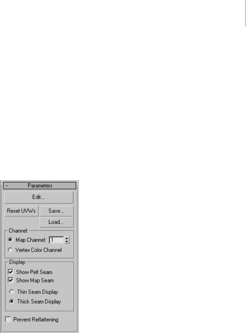
Unwrap UVW Modifier 885
contiguous faces whose angles are less than the
threshold value.
Planar Angle is available only at the Face
sub-object level.
Select MatID—Enables face selection by material
ID (page 3–969). Specify the material ID to select,
and then click Select MatID.
Select MatID is available only at the Face
sub-object level.
Select SG—Enables face selection by smoothing
group (page 3–1013).Specifythesmoothinggroup
to select, and then click Select SG.
Select SG is available only at the Face sub-object
level.
Parameters rollout
Edit—Displays the Edit UVWs dialog (page 1–888).
Reset UVWs—Resets the UVW coordinates in the
Edit UVWs dialog.
Clicking this is almost the same as removing
and reapplying the modifier, except that a map
assignedintheEditUVWsdialogisnotdeleted.
For example, if you forgot to turn on the Generate
Mapping Coordinates check box for an object,
and then applied the Unwrap UVW modifier, the
modifierwouldhavenoUVWcoordinatestouse
and its settings would be wrong. If you then go
backintheStackandturnonGenerateMapping
Coordinates, you’d need to click the Reset UVWs
button. When you click this button, an alert warns
you that you’re losing any edits you’ve made.
Save—Saves the UVW coordinates to a UVW
(.uvw)file.
Load—Loads a previously saved UVW file.
Channel group
This option lets you choose a specific map channel
bynumber,orthevertexcolorchannel.Formore
information, see UVW Map modifier > Channel
group (page 1–931).
When you change channels, you should reset your
edits, since the edits for one channel usually won’t
work for the next channel. An alert appears that
lets you choose between resetting the coordinates
or leaving them as they are. In almost all cases, it’s
best to reset them.
Display group
Thissettingdetermineswhetherandhowpelt
seamsandmappingclusterboundaries,also
known as map seams, appear in the viewports:
Show Pelt Seam—When on, pelt boundaries appear
in the viewports as blue lines.
Show Map Seam—When on, mapping cluster
boundaries appear in the viewports as green lines.
The display thickness setting applies to both pelt
seams and map seams:
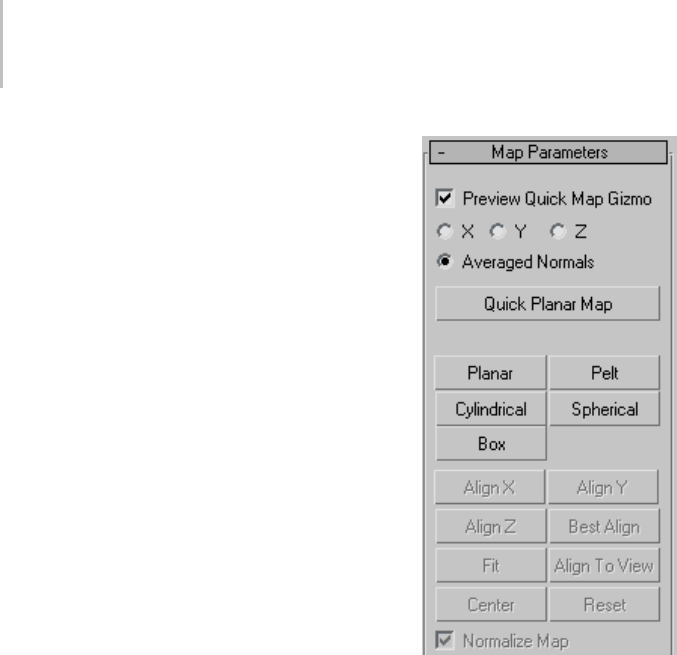
886 Chapter 8: Modifiers
•Thin Seam Display—Displays map seams and
peltseamsonobjectsurfacesintheviewports
with relatively thin lines. The line thickness
remains constant as you zoom the view in and
out. Uses the Display seams color.
•Thick Seam Display—Displays map seams and
peltseamsonobjectsurfacesintheviewports
with relatively thick lines. The line thickness
increases when you zoom the view in and
decreases when you zoom out. Uses the Display
seams color. This is the default choice.
Prevent Reflattening—This option is used mainly
for texture baking. When turned on, the version of
the Unwrap UVW modifier automatically applied
by Render To Texture (page 3–144),named,by
default, Automatic Flatten UVs, will not reflatten
the faces. Also, make sure that both Render To
Textureandthemodifierareusingthesamemap
channel.
Map Parameters rollout
You can apply any map type to selected faces,
patches, or surfaces, and align the mapping gizmo
in any of a variety of ways.
The mapping controls on the upper part of the
rollout are available only at the Face sub-object
level.Also, the Quick Map controls are available
only when no mapping mode button (Planar, Pelt,
etc.) is active. However, the Pelt controls (page
1–888) are available at all sub-object levels.
Note: When a mapping type button is active, you
cannot change the selection without first exiting
the mapping operation.
Preview Quick Map Gizmo—When on, a rectangular
planar mapping gizmo, applicable to the Quick
Planar Map tool only, appears juxtaposed over the
faceselectionintheviewports.Thisgizmoisnot
manually adjustable, but you can use the following
control to reorient it.
X/Y/Z/Averaged Normals—Choose the alignment
forthequickmapgizmo:perpendiculartothe
object’slocalX,Y,orZaxis,orbasedonthefaces’
average normals.
Quick Planar Map—Applies planar mapping to
thefaceselectionbasedontheorientationofthe
Quick Map gizmo.
Planar—Applies planar mapping to the selected
faces.
Make the selection, click Planar, adjust the
mapping using the transform tools and Align
buttons on the Map Parameters panel, and then
click Planar again to exit.

Unwrap UVW Modifier 887
Pelt—Applies pelt mapping to the selected faces.
Clicking this button activates Pelt mode, in which
you can adjust the mapping and edit the pelt map.
Note: Peltmappingalwaysusesasingleplanar
mapping for the entire pelt. If you’ve applied a
different type of mapping, such as Box, and then
switch to Pelt, the previous mapping is lost.
Cylindrical—Applies cylindrical mapping to the
currently selected faces.
Make the selection, click Cylindrical, adjust the
cylinder gizmo using the transform tools and
Align buttons on the Map Parameters panel, and
then click Cylindrical again to exit.
Note: When you apply Cylindrical mapping to a
selection, the software maps each face to the side
of the cylinder gizmo that most closely matches
its orientation. For best results, use Cylindrical
mapping with cylinder-shaped objects or object
parts.
Spherical—Applies spherical mapping to the
currently selected faces.
Make the selection, click Spherical, adjust the
sphere gizmo using the transform tools and Align
buttons on the Map Parameters panel, and then
click Spherical again to exit.
Box—Appliesboxmappingtothecurrently
selected faces.
Make the selection, click Box, adjust the box gizmo
using the transform tools and Align buttons on the
Map Parameters panel, and then click Box again
to exit.
Note: When you apply Box mapping to a selection,
the software maps each face to the side of the box
gizmothatmostcloselymatchesitsorientation.
For best results, use Box mapping with box-shaped
objects or object parts.
Align X/Y/Z—Aligns the gizmo to the X, Y, or Z axis
of the object’s local coordinate system.
Best Align—Adjusts the mapping gizmo’s position,
orientation, and scale to fit that of the face
selection, based on the selection’s extents and
average normals.
Fit—Scales the gizmo to the extents of the selection
and centers it on the selection. Does not change
the orientation.
Align To View—Reorientsthemappinggizmoto
facetheactiveviewportandadjustsitssizeand
position as necessary to fit the extents of the
selection.
Center—Moves the mapping gizmo so that its pivot
coincides with the center of the selection.
Reset—Scales the gizmo to fit the selection and
aligns it with the object’s local space.
Normalize Map—When on, scales the mapping
coordinates to fit into the standard coordinate
mapping space: 0 to 1. When off, the mapping
coordinatesarethesamesizeastheobject. The
mapisalwaystiledonceinthe0-1coordinate
space; the part of the map based on its Offset and
Tiling values on
Forexample,ifyoutakeasphereof25unitsthat’s
planar mapped from the top, and then apply
Unwrap UVW and turn off Normalize Map, then
when you open the editor, the radius of the sphere’s
mapping coordinates is 25 units. As a result, the
texture map is tiled onto the sphere surface many
times. With Normalize Map on, both the sphere
and the map fit into the 0-1 coordinate space, so
they’re the same size.
In general, for best results, leave Normalize Map
on. One reason to turn it off would be to turn it off
is if you want to map several elements of different
proportions with a texture of a specific aspect
ratio, such as brick, keeping the texture the same
size on each object.
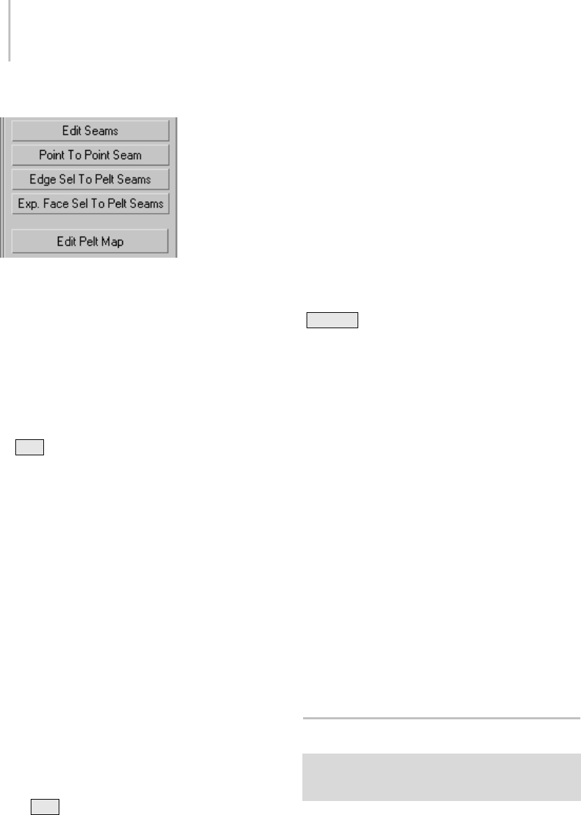
888 Chapter 8: Modifiers
[Pelt controls]
These tools, which give you different ways of
specifying pelt seams, are available at all sub-object
levels of the modifier.
Edit Seams—Lets you specify a pelt seam by
selecting edges with the mouse in the viewports.
This process is similar but not identical to standard
edge selection:
• Click an edge to add it to the current selection.
•Alt +click an edge to remove it from the
current selection.
•Dragtoselectaregion.
Point To Point Seam—Lets you specify pelt seams by
selecting vertices with the mouse in the viewports.
Pelt seams specified with this tool are always added
to the current seam selection.
In this mode, after you click a vertex, a
rubber-band line extends from the vertex you
clicked to the mouse cursor. Click a different
vertex to create a pelt seam, and then continue
clicking vertices to create a seam from each vertex
to the previous one. To start at a different point in
this mode, right-click, and then click a different
vertex. To stop drawing seams, click the button
againtoturnitoff.
Note: While Point To Point Seam is active, you
can pan, rotate, and zoom the viewport at any
time using contextual controls (middle-button
drag, Alt +middle-button drag, turn mouse
wheel, respectively) to access a different part of
themeshsurface. Afterdoingso,thesoftware
still remembers the last vertex you clicked and
draws an accurate seam at the next click. Similarly,
you can adjust the viewport using the viewport
control buttons (page 3–729) and then return to
selecting the seam. If the control requires more
than a single click, such as Pan, exiting the control
by right-clicking in the viewport restores the
rubber-band line, extending from the last vertex
you clicked.
Tip: The algorithm Point To Point Seam uses to
calculate a path might create a different seam than
what you have in mind. If this happens, undo
(Ctrl+Z ) and specify the desired path by plotting
points closer together.
Edge Sel To Pelt Seams—Converts the current edge
selection to pelt seams. These seams are added to
any existing seams.
Exp(and) Face Sel to Pelt Seams—Expands the
current face selection to meet the pelt seam
border(s). If multiple seam outlines contain
selected faces, the expansion takes place only for
the last-selected face; all others are deselected.
Edit Pelt Map—Opens the Edit UVWs dialog in a
special Pelt mode, with the Pelt Map Parameters
dialog (page 1–909) active. This command also
initializes the mapping coordinates according to
the pelt seams. Available only when Pelt mapping
mode is active.
WhentheeditorisopeninPeltmodeyoucanuse
the editor and dialog controls to “stretch” out the
mapping coordinates, resulting in coordinates that
are easier to texture map.
Edit UVWs Dialog
Select an object. > Modify panel > Modifier List >
Object-Space Modifiers > Unwrap UVW > Edit button (on
Parameters rollout)
TheheartoftheEditUVWsdialogisawindow
that displays a lattice made up of UVW faces and
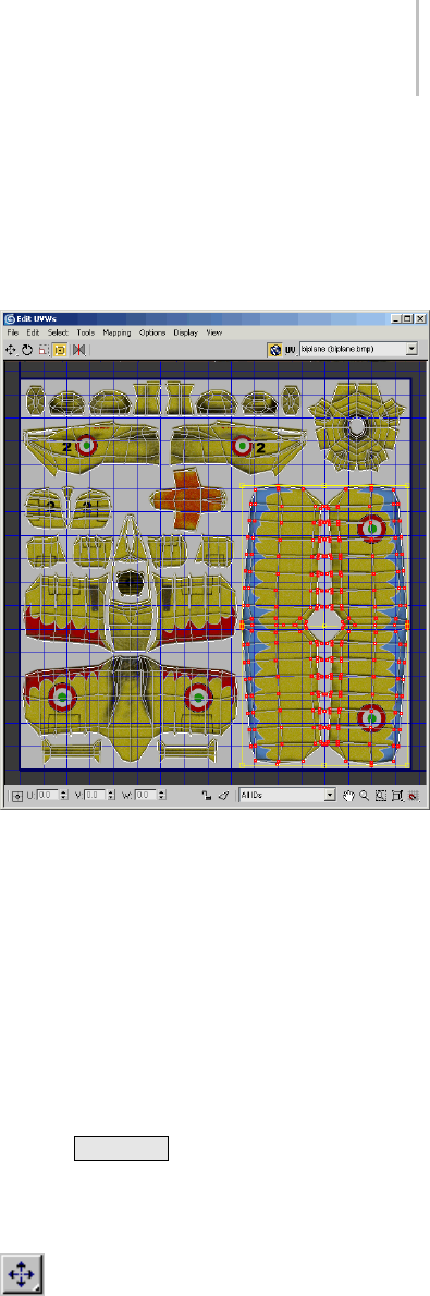
Edit UVWs Dialog 889
UVW vertices. Each UVW face, which has three or
more vertices, corresponds to a face in the mesh.
The view window displays the UVWs in the
2D-image space of the map, superimposed over
a grid. Thicker grid lines show the boundaries
of a texture map as it would appear in image
space; the lower-left corner of the rectangle has
the coordinates (0,0) and the upper-right has
the coordinates (1,1). Within this window, you
manipulate the UVW coordinates relative to the
map (or mesh) by selecting the lattice vertices,
edges, or faces (collectively known as sub-objects),
and transforming them.
ThestateoftheEditUVWsdialog,including
buttons and selected options, is stored and recalled
thenexttimeyouopentheEditdialog.
Note: You can edit patch object texture coordinates
as well as mesh coordinates in the Edit UVWs
dialog. When editing a patch object, you can also
edit the vertex handles. In addition, you can edit
the manual interior handles. However, you must
enable the manual interior handles before applying
the Unwrap UVW modifier. To do so, at the
Patch sub-object level, select one or more patches,
right-click a selected patch, and then, from the
quad menu > tools 1 quadrant, choose Manual
Interior. The manual interior handles appear in
the editor window as isolated vertices.
Note: Certain modeling operations can leave
unused (isolated) map vertices that show up in the
editor window, but cannot be used for mapping. If
the model is an Editable Poly or Edit Poly object,
you can use the Remove Unused Map Verts button
at the Vertex sub-object level to automatically
delete these vertices.
Tip: The editor can display the number of selected
sub-objects. This option is available as an Unwrap
UVW shortcut (page 1–900) as Show Subobject
Counter.
Interface
Besides the window, the editor interface consists
of a menu bar, a toolbar, a lower toolbar, and,
docked below the main dialog, the Options panel
(page 1–893).
Menu bar
The menu bar provides access to a wide range
of Edit UVWs functions. See Edit UVWs Dialog
Menu Bar (page 1–895).
Toolbar
Contains all the controls for manipulating the
texture sub-objects in the view window, navigating
within the window, and setting other options.
When transforming with Rotate and Scale,
pressing Ctrl+Alt will allow you to transform
the selection from the point of the mouse click,
instead of the selection center. The initial click
specifies the center of the transform.
Move—Lets you select and move sub-objects.
Flyout options are Move, Move Horizontal, and
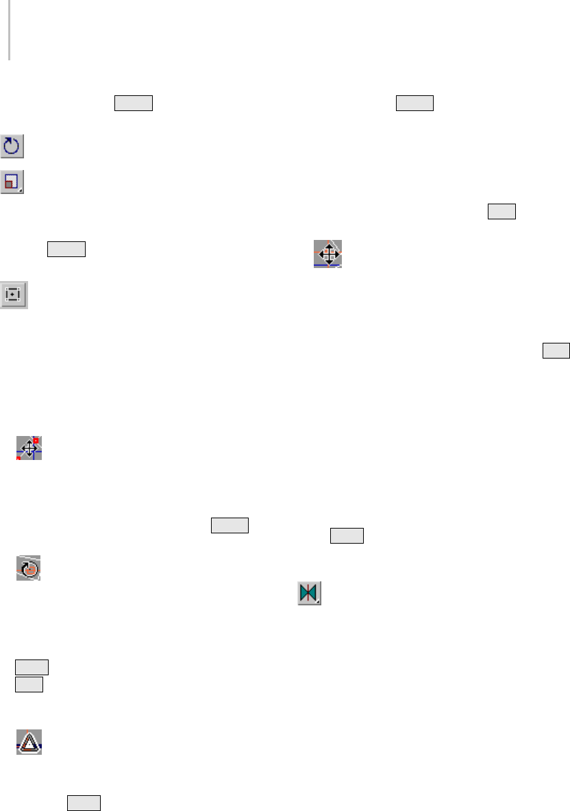
890 Chapter 8: Modifiers
Move Vertical. Press Shift to constrain the
movement to a single axis.
Rotate—Lets you select and rotate sub-objects.
Scale—Lets you select and scale sub-objects.
Flyout options are Scale, Scale Horizontal, and
Scale Vertical.
Pressing Shift as you scale constrains the
transform to a single axis.
Freeform Mode—Lets you select and move,
rotate,orscalevertices,dependingonwhereyou
drag. Afteryoumakeaselection,theFreeform
gizmo appears as a rectangular bounding box
around the selected vertices. As you move the
cursor over the gizmo’s various elements and
inside the gizmo, the cursor’s appearance, and the
result of starting to drag in this location, change:
•Move—Position the cursor anywhere
inside the gizmo and then drag to move the
selection. To constrain movement to the
vertical or horizontal axis, depending on how
you begin dragging, press and hold Shift
before dragging.
•Rotate—Positionthecursoroveragizmo
edge center point, and then drag to rotate the
selection about the pivot. As you drag, the
amount of rotation is shown in the center of the
gizmo.
Ctrl +drag to rotate in five-degree increments;
Alt +dragtorotateinone-degreeincrements.
Freeform rotation respects the angle snap (page
2–37) status.
•Scale—Positionthecursoroveragizmo
corner and then drag to scale the selection. By
default, scaling is non-uniform; if you press
and hold Ctrl before dragging, scaling is
uniform on the horizontal and vertical axes.
Press and hold Shift before dragging to
constrain scaling to the vertical or horizontal
axis, depending on how you begin dragging.
By default, scaling takes place about the gizmo
center. If you’ve moved the pivot (see following
item), you can scale about the transform center
instead by pressing and holding Alt before
dragging.
•Move pivot—Position the cursor over the
pivot, a wireframe cross that appears by default
at the center of the gizmo. When this cursor
appears, drag to move the pivot. Rotation
always occurs about the pivot; scaling takes
placeaboutthepivotifyoupressandhold Alt
before dragging.
Tip: By default, the pivot always resets to the
center of the gizmo when you make a new
selection. If you prefer to retain the offset from
selection to selection, you can toggle this feature
with the Reset Pivot On Selection command.
This command is not available in the editor
interfacebydefault;youmustusetheCustomize
User Interface dialog (page 3–792) to add it.
If you Ctrl +select one or more vertices outside
the gizmo, the gizmo expands to encompass the
entire selection.
Mirror—Mirrors selected vertices and flips
UVs. Flyout options are Mirror Vertical, Mirror
Horizontal, Flip Horizontal, and Flip Vertical.
Flip first detaches the selection along its boundary
edges and then applies a Mirror Horizontal or
Vertical depending on the mode.
Turn on Target Weld, and then drag one vertex
to another vertex, or one edge to another edge.
As you drag, the cursor changes in appearance to
cross hairs when it’s over a valid sub-object. While
this command is active, you can continue welding
sub-objects, and change the sub-object level. To
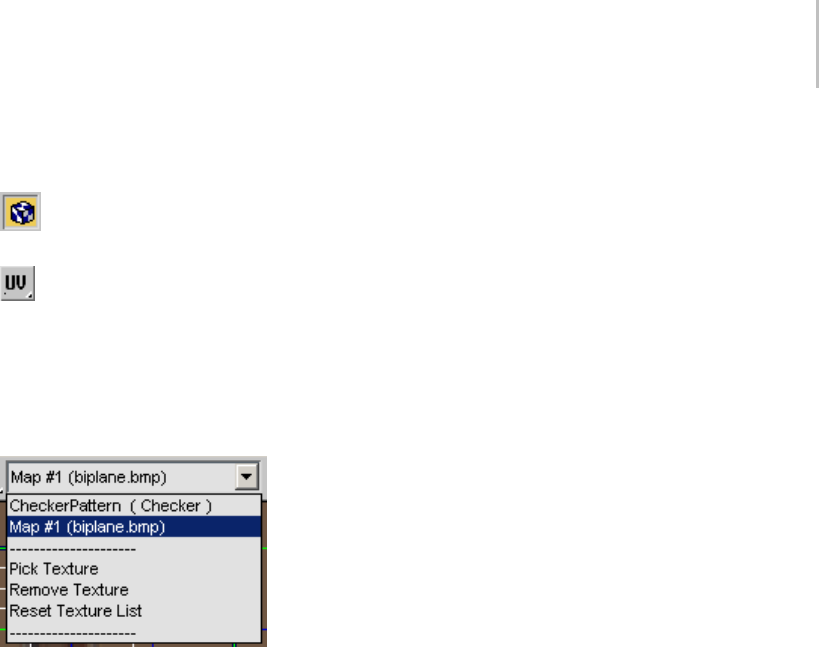
Edit UVWs Dialog 891
exit Target Weld mode, right-click in the editor
window.
Show Map—Toggles the display of the map in
the editor window.
UV/VW/UW—By default, the UV portion of
theUVWcoordinatesisdisplayedintheview
window. However, you can switch the display to
edit the UWs or the VWs.
[texture list drop-down]—Contains all the maps of
the material assigned to the object.
ThenamesofthemapsassignedintheMaterial
Editor and in the Edit UVWs dialog (via Pick
Texture) appear in the list.
Below the map names are several commands:
•Pick Texture—Lets you use the Material/Map
Browser to add and display textures that are not
in the object’s material.
•Remove Texture—Eliminates the currently
displayed texture from the editor.
•Reset Texture List—Returns the texture list
to the current state of the applied material,
removing any added textures and restoring any
removed textures that were part of the original
material, if they still exist in the material. This
command also adds any new maps in the
material, so it essentially updates the UVW
editortothecurrentstateofthematerial.
Choose a map you want to use in the view window.
Forexample,youmightuseabumportexture
map as a reference to move UVW vertices.
A checker texture named CheckerPattern
(Checker), useful for checking for distorted areas
of the texture mapping, is built in to the Edit
UVWs dialog. By default, this texture appears as
the background texture when you first open the
editor after applying Unwrap UVW to an object.
To cause the pattern to appear on the object in
viewports set to display textures, choose it from
the drop-down list, even if it’s already active in
the editor.
Edit UVWs window
The Edit UVWs window allows you to edit UVW
sub-objectstoadjustthemappingonamodel.For
example, a texture map might contain the side, top,
and front views of a car. By first planar mapping
the top, side, and front faces of the model at the
Face sub-object level, you can adjust the texture
coordinates for each selection to fit the different
parts of texture map to the corresponding areas
on the car.
To edit the UVW vertices, first choose a transform
tool and sub-object mode, make a selection, and
then click and drag in the window to transform
the selection.
Quad menu—Right-click in the window to display
the quad menu, which provides access to all the
transform tools, as well as a number of editor
commands.
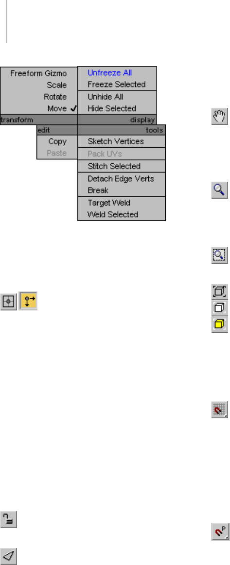
892 Chapter 8: Modifiers
Commands to freeze and hide selected sub-objects
and unfreeze/unhide all sub-objects are found
only in the quad menu.
Lower Toolbar
Absolute/Offset Mode—When this is off,
the software treats values you enter into the U, V,
andWfields(seefollowing)asabsolutes.When
this is on, the software applies transform values
you enter as relative to current values; that is, as
offsets. Default=off.
U, V, and W—ThesefieldsdisplaytheUVW
coordinates for the current selection. Use the
keyboard or the spinners to edit them.
These fields are active at all sub-object levels, but
they always apply to vertices. With a single vertex
selected, they display the current coordinates.
With multiple vertices (or one or more edges
or faces) selected, they display any coordinates
the vertices belonging to the selection have in
common; otherwise, they’re blank.
Lock Selection—Locks selection. You can
move selected sub-objects without touching them.
Filter Selected Faces—Displays UVW vertices
of the object’s selected faces in the viewport, and
hides the rest.
All ID’s (drop-down)—Filters the object’s material
IDs. Displays texture faces that match the ID
drop-down.
Pan—Click Pan, and then drag in the window
to change the visible portion.
Tip: Withathree-buttonmouse,youcanalsopan
the window by dragging with the middle mouse
button held down.
Zoom—Click Zoom, and then click+drag to
zoom the window.
Tip: With a wheel mouse, you can also zoom by
turning the wheel.
Zoom Region—Click Zoom Region, and then
region-selectpartofthewindowtozoomin.
Zoom Extents—Zooms in or out to fit the
texture coordinates in the window. The flyout
buttons, from top to bottom, let you zoom to all
texture coordinates, to the current selection, and
to all clusters/elements containing any selected
sub-objects.
Grid Snap—When on, moving sub-objects
tends to snap the vertex closest to the mouse
cursor, which is highlighted by a square outline, to
the nearest grid line or intersection.
This is the default tool on this flyout; Pixel Snap is
also available.
You can set the snap strength in the Unwrap
Options dialog.
Pixel Snap—Snaps to the nearest pixel corner
when you have a bitmap in the background.
Available from the Grid Snap flyout.
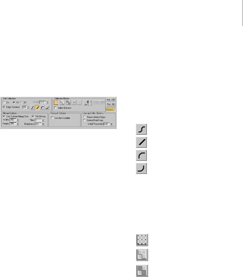
Edit UVWs Dialog 893
Combine this with Center Pixel Snap to snap to the
center of pixels rather than the corner.
Note: With multiple vertices selected, all vertices
snap to the nearest pixel, relatively; this can slightly
alter the spatial relationships among them.
Options panel
By default, the Options panel, docked to the
bottom of the Edit UVWs dialog, provides
controls for using soft selection, specifying
selection modes, and rotating the selection. The
Options button lets you toggle the display of
additional settings for bitmaps, viewports, and
the editor.
Soft Selection group
The Soft Selection controls make a sub-object
selection behave as if surrounded by a "magnetic
field." Unselected sub-objects within the field
are drawn along smoothly while you transform
the sub-object selection, the effect diminishing
with distance. You can adjust this distance, or
“falloff,” whether it applies to object space, texture
space, or edge space, and the formula by which it
diminishes.
First, set a value that encompasses sub-objects
to be moved or scaled, and then transform
sub-objects with a falloff effect.
On—Activates or deactivates soft selection.
XY/UV—Specifies object or texture space for the
falloff distance. XY selects object space, UV selects
texture space.
Falloff—Sets the falloff distance. As values increase,
unselected vertex colors change gradually from the
selected vertex to reflect the area of influence.
Edge Distance—Turn on to limit the falloff region
by the specified number of edges between the
selection and the affected vertices. The affected
region is measured in terms of "edge-distance"
spaceratherthanabsolutedistance.
Falloff Type—Transforming with soft selection
affects non-selected vertices within the falloff area
based on the falloff type.
The icons depict how their buttons affect falloff.
The options are:
•Smooth
•Linear
•Slow Out
•Fast Out
Selection Modes group
[sub-object mode]—Specifies the type of sub-object
that you can select by clicking or dragging in the
window. Default=Vertex.
Oneofthethreesub-objectmodescanbeactive
at a time:
•Ve r t e x
•Edge
•Face
Note: Selected sub-objects are colored red by
default. Also, in Edge and Face sub-object modes,
any shared edges are blue by default. A shared
edge is one both of whose endpoints are shared
by a selected edge or face; thus, it is, in effect,
also selected. You can change these colors using
Customize User Interface > Colors panel (page
3–799).
The three sub-object levels are synchronized
between the modifier stack (page 1–884) of the

894 Chapter 8: Modifiers
Unwrap UVW modifier and the Selection Modes
group. When you choose a sub-object level in one,
it’s also activated in the other. Similarly, selecting
sub-objects in a viewport selects them in the editor
and vice-versa.
Expand Selection—Adds sub-objects to the
selection.
Vertex and face expansion proceeds outwards in
all available directions. Edge expansion proceeds
along available UV paths. For example, to select
a cluster outline, select one outer edge, and then
click Expand Selection repeatedly.
Contract Selection—Shrinks the selection by
deselecting the outermost sub-objects.
Paint Select Mode—Lets you “paint” a
sub-object selection by dragging in the editor
window. After activating this mode, move the
cursor into the editor window, and then drag to
select sub-objects. To exit Paint Select mode,
right-click or choose a transform tool.
Paint mode selects only sub-objects that are fully
insidetheselectionbrush. Thedottedcircle
attached to the mouse shows the size of the brush.
Use the +/- buttons next to the paintbrush button
to change its size.
+/-—Increases and decreases the size of the Paint
Select mode “brush”: the circle attached to the
mouse cursor.
Edge Loop—Expandsanexistingedgeselectionto
select all edges in the loop attached to the selected
edges. Select one or more edges, and then click
Edge Loop.
Edge Loop uses a “center-path” method to
calculateloopselection. Tobeabletoexpand
a selection, there must be an odd number of
edges attached to either end of a selected edge
intheeditorwindow.Thesoftwarethenselects
the middle connected edge, and then continues
selectingaslongasitcanusingeachnewlyselected
edge. Whenitencountersanedgeconnectedto
an even number of edges, or to which the middle
edge is already selected, it stops.
Select Element—Selecting a sub-object in a cluster
causes the entire cluster to become selected. Works
in all sub-object modes.
Rot(ate) +90—Rotates the selection 90 degrees
about its center.
Rot(ate) -90—Rotates the selection -90 degrees
about its center.
Bitmap Options group
Click the Options Button to make this group
available.
Use Custom Bitmap Size—When turned on, scales
the bitmap texture to the values specified by Width
and Height. You can adjust these settings to scale
andreproportionthebitmaptextureinrelationto
the texture coordinates. This scaling doesn’t affect
the bitmap in the material, but only as viewed in
the editor.
Tip: When working with large textures, reduce
the bitmap size for faster feedback. And when
working with disproportionate textures, setting
the dimensions closer to each other in the editor
can make it easier to work.
Width—Scales the bitmap along the horizontal
axis.
Height—Scales the bitmap along the vertical axis.
Tile Bitmap—When turned on, you can repeat the
bitmap in the editor, displaying tiling set in the
material. You can use any part of the tiled image
for setting texture coordinates. This is helpful
whenthesectionsofthetextureimagearepacked
tightly together and the mesh contains many
different areas to map.

Edit UVWs Dialog Menu Bar 895
Tiles—Thenumberoftimesthetextureimageis
repeated, counting outward in eight directions
(the four corners and the four sides).
With Tiles=1, the result is a 3 x 3 grid. With
Tiles=2,theresultisa5x5grid,andsoon.
Brightness—Sets the brightness of the tiled bitmap.
At 1.0, the brightness equals that of the original
image; at 0.5 it’s half the brightness; and at 0, it’s
black.
Tip: Turning off Affect Center Tile, available in the
Unwrap Options dialog (page 1–920) >Display
Preferences group, prevents the Brightness setting
fromaffectingthecentertile,soit’seasiertofindif
you’ve turned down the brightness.
Viewport Options group
Constant Update—When on, the viewports
update in real-time, reflecting any changes to the
texture coordinates as you make them. When
off, the viewports update only after you finish
transforming texture coordinates (that is, when
you release the mouse button).
Unwrap Editor Options group
Show Hidden Edges—To g g l e s t h e d i s p l a y o f f a c e
edges. When turned off, only faces appear. When
turned on, all mesh geometry appears.
Center Pixel Snap—When Pixel Snap is turned on,
snaps to the center of pixels of the background
images instead of pixel edges.
Weld Threshold—Sets the radius within which
welding using Weld Selected takes effect. The
setting is in UV-space distance. Default=0.01.
Range=0 to 10.
Edit UVWs Dialog Menu Bar
Select an object. > Modify panel > Modifier List >
Object-Space Modifiers > Unwrap UVW > Edit button (on
Parameters rollout) > Menu bar
The Edit UVWs dialog (page 1–888) menu
bar provides access to a number of important
editing commands. Some of these commands
are replicated on the dialog toolbar and the
Unwrap UVW command panel; others, such as
the Mapping, Stitch, and Sketch tools, are available
only from the menus.
Tip: Several commands are not available in the
editor interface by default; you can use the
Customize User Interface dialog (page 3–792) to
add them.
Interface
File menu
Load UVs—Loads a previously saved UVW (texture
coordinates) file.
Save UVs—Saves the UVW coordinates to a UVW
file.
Reset All—Restores the UVW coordinates to their
original status.
Reset All has almost the same effect as removing
and reapplying the modifier, except that a map
assignedintheEditUVWsdialogisnotdeleted.
For example, if you forgot to turn on the Generate
Mapping Coordinates check box for an object,
and then applied the Unwrap UVW modifier, the
modifierwouldhavenoUVWcoordinatestouse
and its settings would be wrong. If you then go
back in the modifier stack and turn on Generate
Mapping Coordinates, you’d need to choose the
Reset All command. When you do so, an alert
warns you that you’re losing any edits you’ve made.

896 Chapter 8: Modifiers
Edit menu
Thesecommandsprovideaccesstothedifferent
transform functions, and copy and paste
selections.
Copy—Copies the current selection (i.e., texture
coordinates) into the paste buffer.
Paste—Applies the texture mapping coordinates
in the paste buffer to the current selection. Using
Paste repeatedly with the same target coordinates
causes the coordinates to rotate by 90 degrees each
time.
UseCopyandPastetoapplythesamemapping
coordinates (i.e., image) to a number of different
geometry faces. A typical example of usage would
be in designing a game level, where you’re working
with a multi-image texture map, part of which is
a door image. You might want to apply the same
door image to several different door polygons.
First, you would select one of the door polys and
positionitoverthedoorimage. Next,useCopy
toplaceitstexturecoordinatesinthepastebuffer.
Then select another door poly and choose Paste or
PasteWeld.Thedoor’stexturecoordinatesmove
tothesamelocationastheoriginalpoly.Continue
selectingotherdoorpolysandpastinguntilallthe
doors are mapped.
Tip: For best results, use comparable sets of texture
coordinates for the source and destination. For
example, copy a single four-sided face, and then
paste another four-sided face.
Paste Weld—Applies the contents of the paste
buffer to the current selection and then welds
coincident vertices, effectively fusing the source
and destination selections together.
Usethisfunctiontoendupwithasinglesetof
texture coordinates that’s applied to multiple
geometry elements. Adjusting these texture
coordinates changes the mapping for all geometry
to which they’re applied.
Move Mode—Lets you select and move sub-objects.
Rotate Mode—Lets you select and rotate
sub-objects.
Scale Mode—Lets you select and scale sub-objects.
Freeform Gizmo—Lets you select and transform
vertices. See Freeform Mode.
Select menu
These commands let you copy a viewport selection
to the editor, and transfer selections among the
three different sub-object modes.
Convert Vertex to Edge—Converts the current
vertex selection to an edge selection and places
you in Edge sub-object mode. For an edge to be
selected, both of its vertices must be selected.
Convert Vertex to Face—Converts the current
vertex selection to a face selection and places you
in Face sub-object mode. For a face to be selected,
all of its vertices must be selected.
Convert Edge to Vertex—Converts the current edge
selection to a vertex selection and places you in
Ve r t e x s u b - o b j e c t m o d e .
Convert Edge to Face—Converts the current edge
selection to a face selection and places you in
Face sub-object mode. For a face to be selected,
the current edge selection must include all of its
vertices. For example, if two opposite edges of a
four-sidedfaceareselected,theedgeselection
includes all four of the face’s vertices, so this
command will select the face.
Convert Face to Vertex—Converts the current face
selection to a vertex selection and places you in
Ve r t e x s u b - o b j e c t m o d e .
Convert Face to Edge—Converts the current face
selectiontoanedgeselectionandplacesyouin
Edge sub-object mode.

Edit UVWs Dialog Menu Bar 897
Select Inverted Faces—Selectsanyfacesfacingaway
from the current mapping. Available only in Face
selection mode.
This is useful in complex models for finding faces
on a surface that folds in under itself, thus causing
potential problems with bump mapping.
For example, add a sphere, turn off Generate
Mapping Coords, and them apply Unwrap UVW.
This causes the modifier to apply planar mapping
from the top down, so that all faces on the bottom
half of the sphere are “inverted”; that is, they face
away from the mapping. In the modifier stack
display, highlight the Select Face sub-object level,
andthenclicktheEditbuttontoopentheUVW
editor. Choose the Face selection mode, and then
choose Select > Select Inverted Faces. In the
viewports, the bottom half of the sphere turns red
to indicate that the inverted faces are now selected.
Select Overlapped Faces—Selects any faces that
overlap other faces. If no face is selected, this
selects all overlapping faces. If a face selection
exists, this selects only overlapping faces within the
selection. Available only in Face selection mode.
When working with complex meshes, it’s common
for texture-coordinate faces to overlap one
another, with the result that they use the same
portion of the texture map. Use this command to
find overlapping faces in order to separate them
as needed.
Tools menu
Toolsonthismenuletyouflipandmirrortexture
coordinates, weld vertices, combine and separate
sets of texture coordinates, and sketch outlines for
multiple selected vertices.
Flip Horizontal/Vertical—Detaches the selected
sub-objects along their boundary edges and then
applies Mirror Horizontal or Vertical, depending
on the mode.
Mirror Horizontal/Vertical—Reverses the direction
of selected sub-objects along the indicated axis
and flips UVs accordingly.
Weld Selected—Welds selected sub-objects to a
single vertex, based on the Weld Threshold setting.
You can set the threshold on the Options panel
> Unwrap Editor Options group, as well as on
the Unwrap Options dialog (page 1–920) >Misc.
Preferences group.
Target Weld—Welds pairs of vertices or edges. Not
available at the Face sub-object level.
Turn on Target Weld, and then drag one vertex
to another vertex, or one edge to another edge.
As you drag, the cursor changes in appearance to
cross hairs when it’s over a valid sub-object. While
this command is active, you can continue welding
sub-objects, and change the sub-object level. To
exit Target Weld mode, right-click in the editor
window.
Break—Applies to the current selection; works
differently in the three sub-object modes. At
the Vertex sub-object level, Break replaces each
shared vertex with two vertices. With edges,
Break requires at least two contiguous edges to be
selected, and separates each edge into two. With
faces, Break splits the selection off from the rest
of the mesh into a new element, exactly as does
Detach Edge Verts.
Detach Edge Verts—Tries to s plit off the cur rent
selection into a new element. Any invalid vertices
or edges are removed from the selection set before
the detach.
Stitch Selected—For the current selection, finds all
the texture vertices that are assigned to the same
geometric vertex, brings them all to the same spot,
and welds them together. With this tool you can
automatically connect faces that are contiguous in
theobjectmeshbutnotintheeditor.
To use Stitch Selected, first select sub-objects
along an edge you want to connect (by default, this

898 Chapter 8: Modifiers
causes the shared edges to highlight), and then
choose the command. In the Stitch Tool dialog
(page 1–918),adjustthesettings,andthenclick
OK to accept or Cancel to abort.
Pack UVs—Distributes all texture-coordinate
clusters through the texture space using one of two
methods and spacing you specify. This is useful
if you have several overlapping clusters and wish
to separate them.
Choosing Pack UVs opens the Pack dialog (page
1–909).
Sketch Vertices—Lets you draw outlines for vertex
selections with the mouse. This is useful for
matching coordinate cluster outlines to sections of
the texture map en masse, without having to move
vertices one at a time.
Choosing Sketch Vertices opens the Sketch Tool
dialog (page 1–916).SketchVerticesisavailable
only in the Vertex sub-object mode.
Relax Dialog—Opens the non-modal Relax Tool
dialog (page 1–912), which lets you change the
apparent surface tension in a selection of texture
vertices by moving vertices closer to, or away from,
their neighbors. Relaxing texture vertices can
make them more evenly spaced, resulting in easier
texture mapping. Available at all sub-object levels.
Note: This command, as well as a Relax command
that lets you apply the default settings to the
current selection without opening the dialog, are
available as assignable keyboard shortcuts (page
1–900).
Render UVW Template—Opens the Render UVs
dialog (page 1–914), which lets you export texture
mapping data as an image file that you can then
import into 2D paint software.
Mapping menu
Lets you apply one of three different types of
automatic, procedural mapping methods to a
model. Each method provides settings so you can
adjustthemappingtothegeometryyou’reusing.
With each method, the mapping is applied to the
current face selection; if there is no face selection it
is applied to the entire mesh.
Here’s a quick overview of the three methods:
• Flatten mapping prevents overlap of mapping
clusters, but can still cause texture distortion.
• Normal mapping is the most straightforward
method,butcanresultinevengreatertexture
distortion than with Flatten mapping.
• Unfold mapping eliminates texture distortion,
but can result in overlapping coordinate
clusters.
Tip: In many cases, one of the automatic mapping
functions will provide useful results. But with
certain custom or complex objects, you might
get the best results with manual mapping; use a
variation of the basic procedure (page 1–880),or
use a procedural method as a starting point for
custom mapping.
Flatten Mapping—Applies planar maps to groups
of contiguous faces that fall within a specified
angle threshold.
Choosing Flatten Mapping opens the Flatten
Mapping dialog (page 1–907).
Normal Mapping—Applies planar maps based on
different vector-projection methods.
Choosing Normal Mapping opens the Normal
Mapping dialog (page 1–908).
Unfold Mapping—Unfolds the mesh so you get no
face distortion, but does not guarantee that faces
will not overlap.
Choosing Unfold Mapping opens the Unfold
Mapping dialog (page 1–919).

Edit UVWs Dialog Menu Bar 899
Options menu
Load Defaults—Loads the editor settings from the
file unwrapuvw.ini in the plugcfg directory.
Save Current Settings as Default—Saves the editor
settings to the file unwrapuvw.ini in the plugcfg
directory. Settings saved in this way persist
between sessions.
Always Bring Up The Edit Window—When on,
selecting an object with the Unwrap UVW
modifier active automatically opens the Edit
UVWs dialog. By default, this is off, so you must
click the Parameters rollout > Edit button to open
the dialog.
Preferences—Opens the Unwrap Options dialog
(page 1–920).
Display menu
Hide Selected—Hides all selected sub-objects and
associated faces.
Unhide All—Reveals any hidden sub-objects.
Unfreeze All—Unfreezes any frozen sub-objects.
Note: You can freeze a sub-object selection with
Freeze Selected, available from the right-click
menu > Display quadrant.
Filter Selected Faces—When on, the editor displays
UVW vertices of the viewport selection at the Face
sub-object level of the modifier, and hides the rest.
This is a quick way to work on a limited selection
of the texture coordinates of a complex mesh
while ignoring the rest. You can turn this on, go
totheFacesub-objectleveloftheUnwrapUVW
modifier, and select the portion of the object
whose texture coordinates you want to edit; only
those coordinates appear in the editor, and remain
visibleevenwhenyouchangethesub-objectlevel.
To work on a different portion, return to the Face
level and change the selection in the viewport;
the editor window updates to the new selection
automatically.
Show Hidden Edges—Toggles the display of hidden
face edges.
Show Edge Distortion—Uses a green-to-red color
range to depict distortion: how far in length
textureedgesarefromtheircorresponding
geometry edges. The greater the disparity in
lengths (that is, the greater the distortion), the
redder the edge appears in the Edit UVW dialog
window. Also draws end segments of edges that
are too long as white, showing the difference in
length from that of the geometry edge.
Left: Texture edges the same as or very close to geometry edges
in length are green.
Center: Texture edges slightly different from geometry edges in
length are brown.
Right: Texture edges very different from geometry edges in
length are red.
When texture edges are longer than geometry edges, white
end segments depict length disparity.
Use this display as a way to view where the areas of
greatest distortion are in your texture mesh. If an
edge is brown or red but doesn’t have white end
segments, it’s too short. If it’s brown or red and
has white end segments, it’s too long, by the total
length of the white segments.
Show Vertex Connections—In Vertex sub-object
mode, toggles the display of numeric labels for all
selected vertices. Shared vertices are indicated by
the appearance of multiple same-numbered labels.
Show Shared Sub-objects—When turned on, for the
current selection, highlights any shared vertices
and/or edges. You can change the highlight color
on the Unwrap Options dialog (page 1–920).

900 Chapter 8: Modifiers
View menu
Pan—ActivatesthePantool,whichletsyoumove
horizontally and vertically in the window by
dragging the mouse.
As with the viewports, if you use a three-button
mouse, you can also pan by middle-button
dragging.
Zoom—Choose Zoom, and then drag downward
in the editor window to zoom out and upward to
zoom in. Zooming is centered about the point you
click before dragging.
If you have a wheel mouse, you can also turn the
wheel to zoom. Zooming is centered about the
mouse cursor location.
Zoom Region—To z o om t o a s p e ci f ic a r ea , c h o os e
Zoom Region, and then drag a rectangle in the
editor window.
Zoom Extents—Zooms in or out to fit all UVW
vertices in the editor window.
Zoom Extents Selected—Zooms in or out to fit all
selected UVW vertices in the editor window.
Zoom To Gizmo—Zooms the active viewport to the
current selection.
Zoom Extents Selected—Zooms in or out to fit all
selected UVW vertices in the window.
Show Grid—Displaysagridinthebackgroundof
the editor window. Default=on.
Show Map—Displays a texture map in the
background of the editor window. Set the image
via the drop-down list at the right end of the editor
toolbar.
Update Map—Causes the displayed texture map to
reflect any changes to the texture, such as tiling
settings or a different bitmap.
Unwrap UVW Shortcuts
To u s e ke y b o a rd s h o r t c uts for t he Unw r a p U V W
modifier, the Keyboard Shortcut Override Toggle
(page 3–872) must be on.
See also
Unwrap UVW Modifier (page 1–878)
Keyboard Shortcuts (page 3–871)
Keyboard Panel (page 3–793)
Customize User Interface Dialog (page 3–792)
In general, this table includes only functions that
have default keyboard shortcuts and functions
with descriptions that are not documented in the
Unwrap UVW reference topics.
Unwrap UVW
Function
Keyboard
Shortcut
Description
Allow Selections
Inside Transform
Gizmo
Lets you select
vertices inside
the gizmo by
CTRL+clicking
or ALT+clicking
a vertex. When
turned on, you
can move only
by dragging over
empty space.
Always Bring Up
The Edit Window
When on, the
Edit UVWs dialog
automatically
opens when you
access the Unwrap
UVW modifier.
Blend Tiles To
Background
Lets you blend the
image in the Edit
UVWs dialog with
the background
color. At 0 the
image will be
hidden while at
1itwillbeatfull
intensity.
Box Map

Unwrap UVW Shortcuts 901
Unwrap UVW
Function
Keyboard
Shortcut
Description
Break Selected
Vertices
Ctrl+B Breaks selected
vertices so no face
shares them; the
same as breaking
avertexinEdit
Mesh.
Brightness Affects
Center Tile
The brightness
control for the tile
of image at 0,0
of the Edit UVWs
dialog.
Contract Geom.
Faces
Shrinks the face
selection in the
viewport.
Copy Copies the current
face selection
texture data into
the paste buffer.
Cylindrical Map
Detach Edge
Vertices
D,CTRL+D Detaches the
selected vertices
into a separate
element.
Display Seams Highlights edges
that are seams
in texture space
in the Edit UVWs
dialog. A seam
is an edge that
has only one face
attached to it.
Edge Sel to Pelt
Seam (Add)
Converts the edge
selection to pelt
seams, adding to
the current pelt
seams.
Edge Sel to Pelt
Seam (Replace)
Converts the edge
selection to pelt
seams, replacing
the current pelt
seams.
Edge Snap
Edge to Face
Select
Converts an edge
selection into a
face selection.
Edge to Vertex
Select
Converts an edge
selection into a
vertex selection.
Unwrap UVW
Function
Keyboard
Shortcut
Description
Edit UVWs Ctrl+E Opens the Edit
UVWs dialog.
Expand Geom.
Faces
Grows the face
selection in the
viewport.
Face to Edge
Select
Converts a face
selection into an
edge selection.
Face to Vertex
Select
Converts a face
selection into a
vertex selection.
Filter Selected
Faces
Alt+F When on, only
faces that are
selected in the
viewport will be
displayed in the
Edit UVWs dialog.
Flatten Map Lays out the UV
space so that
no texture faces
overlap.
Flatten Map
Dialog
Opens the
dialog for Flatten
Mapping settings.
Flip Horizontal Detaches the
current selection
and then mirrors it
in the U direction.
Flip Vertical Detaches the
current selection
and then mirrors it
in the V direction.
Freeform Mode Toggles freeform
editing tool in the
Edit UVWs dialog.
Freeze Selected Ctrl+F Locks the current
selection so you
cannot select it
anymore.
Geom. Edge Loop
Selection
Geom. Edge Ring
Selection

902 Chapter 8: Modifiers
Unwrap UVW
Function
Keyboard
Shortcut
Description
Geom. Element
Select Mode
Puts you in an
element-select
mode for selecting
faces in the
viewport.
Get Face Selection
From Stack
Alt+Shift+Ctrl+F Copies the face
selection from the
modifier stack into
the face selection
that Unwrap UVW
uses.
Get Selection
From Faces
Alt+Shift+Ctrl+P Transfers the face
selection in the
viewport to the
selection in the
Edit UVWs dialog.
Grid Snap Turns on grid
snapping.
Grid Visible Toggles grid
visibility.
Hide Selected Ctrl+H Hides the current
selection in the
Edit UVWs dialog.
Ignore Back Faces When on you can
select only faces in
the viewport that
are facing you.
Load Defaults Loads the UI
defaults from an
.ini file.
Load UVW Alt+Shift+Ctrl+L Lets you load a
.uvw file onto a
mesh. The mesh
must have similar
topology as the
source.
Lock Selected
Vertices
Spacebar Locks the selection
so you cannot add
to or remove from
it.
Mapping Align
Normals
Mapping Align To
View
Unwrap UVW
Function
Keyboard
Shortcut
Description
Mapping Align X Aligns the
mapping gizmo
to the X axis of
the object’s local
coordinate system.
Mapping Align Y Aligns the
mapping gizmo
to the Y axis of
the object’s local
coordinate system.
Mapping Align Z Aligns the
mapping gizmo
to the Z axis of
the object’s local
coordinate system.
Mapping Center Moves the
mapping gizmo
so that its pivot
coincides with
the center of the
selection.
Mapping Fit Scales the gizmo
to the extents of
the selection and
centers it on the
selection. Does
not change the
orientation.
Mapping Reset Scales the gizmo
to fit the selection
and aligns it with
the object’s local
space.
Mirror Horizontal Alt+Shift+Ctrl+N Mirrors the current
selection along the
Uaxis.
Mirror Vertical Alt+Shift+Ctrl+MMirrors the current
selection along the
Vaxis.
Move Horizontal Alt+Shift+Ctrl+J
Move Vertical Alt+Shift+Ctrl+K
Normal Map This creates a
mapping based on
thefacenormals.

Unwrap UVW Shortcuts 903
Unwrap UVW
Function
Keyboard
Shortcut
Description
Normal Map
Dialog
Opens a dialog for
making Normal
Mapping settings.
Open Edge Mode When turned on,
selecting an open
edge selects all
attached open
edges.
Open Edge Select Selects all open
edges connected
to the current
selection.
Pack Lays out all
selected elements
so they don’t
overlap.
Pack Dialog Opens the Pack
dialog.
Paint Select
Decrement Cursor
Size
Applies to the
Sketch tool.
Paint Select
Increment Cursor
Size
Applies to the
Sketch tool.
Paint Select Mode Applies to the
Sketch tool.
Pan Ctrl+P
Paste Pastes the contents
of the paste buffer
onto the selection.
For best results the
source and target
should have similar
topology.
Paste Instance The pasted and
source UVs will
share the same
vertices.
Unwrap UVW
Function
Keyboard
Shortcut
Description
Pelt Always Show
Seams
Toggles display of
the pelt seams in
the viewports.
Pelt Dialog Opens the Pelt
Map Parameters
dialog
Pelt Dialog Mirror
Stretcher
Mirrors the
stretcher points
from one side of
the mirror axis to
the other.
Pelt Dialog Relax
Simulation Heavy
Causes a
relatively strong
normalization
of the distances
between mapping
vertices.
Pelt Dialog Relax
Simulation Light
Causes a
relatively weak
normalization
of the distances
between mapping
vertices.
Pelt Dialog Reset
Stretcher
Returns the
stretcher and the
pelt UVs to their
default shape and
orientation.

904 Chapter 8: Modifiers
Unwrap UVW
Function
Keyboard
Shortcut
Description
Pelt Dialog Run
Simulation
Runs the
simulation, pulling
the pelt seam
vertices towards
the stretcher
points.
Pelt Dialog Select
Pelt UVs
Selects all pelt UVs.
Pelt Dialog Select
Stretcher
Selects all stretcher
UVs.
Pelt Dialog Snap
Seams
Aligns all the
stretcher points
totheedgeseams
on the pelt UVs.
Pelt Dialog
Straighten
Stretcher
Lets you specify a
polygonal outline
for the stretcher by
moving points.
Pelt Edit Seams Lets you specify
a pelt seam by
selecting edges
with the mouse in
the viewports.
Unwrap UVW
Function
Keyboard
Shortcut
Description
Pelt Expand
Selection To
Seams
Expands the
current face
selection to meet
the pelt seam
border(s).
Pelt Map Activates
pelt-mapping
mode.
Pelt Seam to Edge
Sel (Add)
Converts the pelt
seam to an edge
selection, adding
to the current edge
selection.
Pelt Seam to Edge
Sel (Replace)
Converts the
pelt seam to an
edge selection,
replacing the
current edge
selection.
Pivot Snap ... (nine
shortcuts)
Snaps the
Freeform gizmo
pivot to the
specified gizmo
edge.
Planar Map
Faces/Patches
Enter Applies a planar
map to the current
selection.
Planar Threshold Turns on the
Modify panel >
Planar Angle check
box.
Point to Point
Edge Selection
Lets you specify
pelt seams by
selecting vertices
with the mouse in
the viewports.

Unwrap UVW Shortcuts 905
Unwrap UVW
Function
Keyboard
Shortcut
Description
Polygon Mode Applies only to
triangle meshes.
When turned on
(the default), if you
select a triangular
face, the software
will select all faces
that belong to the
poly that owns that
face.
Polygon Select Expands the
current face
selection to the
poly.
Prevent
Reflattening
When on, keeps
Render To Texture
from reflattening
the mapping.
Relax Applies the default
Relax Tool settings
to the current
texture vertex
selection.
Relax Dialog Opens the Relax
Tool dialog.
Render UVW
Template
Renders the UVW
coordinates to a
bitmap.
Reset Pivot On
Selection
When turned on
(the default), the
Freeform gizmo
pivot is reset
to the center
every time the
selection changes,
otherwise the
pivot maintains
its offset.
Reset UVWs Sets texture
coordinates to
the original values
before Unwrap
was applied.
Save Current
Settings As
Default
Saves current
UI values to the
default .ini file.
Unwrap UVW
Function
Keyboard
Shortcut
Description
Save UVW Lets you save the
UVW data to disk
as a .uvw file, which
canbereadinlater
or onto another
mesh if they have
similar topology.
Scale Horizontal Scales the
selection along
the U axis.
Scale Vertical Scales the
selection along
the V axis.
Select Inverted
Faces
Selects any faces
in the Edit UVWs
dialog that are not
facing you.
Select
Overlapped Faces
Selects
overlapping faces
in the Edit UVWs
dialog.
Show Edge
Distortion
Uses a green-to-
red color range to
depict distortion.
Show Hidden
Edges
Toggles display of
all edges.
Show Map Toggles display of
the image map.
Show Seams in
Viewport
Alt+E Toggles display
of cluster seams
in the viewport.
Works only when
Edit UVWs dialog
has focus.
Show Shared
Sub-objects
Shows sub-objects
that share
edges/vertices.
Show Subobject
Counter
Displays the
number of
selected objects in
the editor window.
Show Vertex
Connections
Tags all texture
vertices that
share the same
geometry vertex
with a unique ID.
906 Chapter 8: Modifiers
Unwrap UVW
Function
Keyboard
Shortcut
Description
Sketch Activates Sketch
Vertices.
Sketch Dialog
Sketch Reverse
Vertex Order
Reverses the order
of the selected
vertices for Sketch
mode. Applies to
the Use Current
Selection option
for Sketch.
Snap Ctrl+S Toggles snapping.
Snap to Grid/
Vertex/Edge
Sets the snap type.
Soft Selection
Edge Distance
Equivalent to
turning on Edge
Distance.
Soft Selection
Edge Distance
Range 1
Set Edge Distance
to the specified
value.
Soft Selection
Edge Distance
Range 2
Set Edge Distance
to the specified
value.
Soft Selection
Edge Distance
Range 3
Set Edge Distance
to the specified
value.
Soft Selection
Edge Distance
Range 4
Set Edge Distance
to the specified
value.
Soft Selection
Edge Distance
Range 5
Set Edge Distance
to the specified
value.
Soft Selection
Edge Distance
Range 6
Set Edge Distance
to the specified
value.
Soft Selection
Edge Distance
Range 7
Set Edge Distance
to the specified
value.
Soft Selection
Edge Distance
Range 8
Set Edge Distance
to the specified
value.
Spherical Map Applies spherical
mapping.
Stitch Stitches together
shared edges of a
polygon.
Unwrap UVW
Function
Keyboard
Shortcut
Description
Stitch Dialog Opens the
properties for the
Stitch command.
Sync Selection
Mode
Same as Sync to
Viewport
Sync Texture
Selection to
Viewport
Synchronizes the
selection in the
Edit UVWs dialog
to the selection in
the viewport.
Sync Viewport
Selection to
Texture
Synchronizes the
selection in the
viewport to the
selection in the
Edit UVWs dialog.
Texture Vertex
Contract
Selection
-(minus sign),
-(on numeric
keypad)
Shrinks the
selection in the
Edit UVWs dialog.
Texture Vertex
Expand Selection
=(equal sign),
+(on numeric
keypad)
Grows the
selection in the
Edit UVWs dialog.
Texture Vertex
Move Mode
QLets you move
vertices in editor.
Texture Vertex
Rotate Mode
Ctrl+R Lets you rotate
vertices in editor.
Texture Vertex
Scale Mode
Lets you scale
vertices in editor.
Texture Vertex
Weld Selected
Ctrl+W Welds selected
vertices in editor.
Texture Vertex
Target Weld
Ctrl+T Lets you target-
weld selected
vertices in editor.
TV Edge
Sub-object Mode
TV=Texture Vertex
TV Element Mode TV=Texture Vertex
TV Face Sub-
object Mode
TV=Texture Vertex
TV Vertex
Sub-object Mode
TV=Texture Vertex
Unfold Map
Unfold Map
Dialog
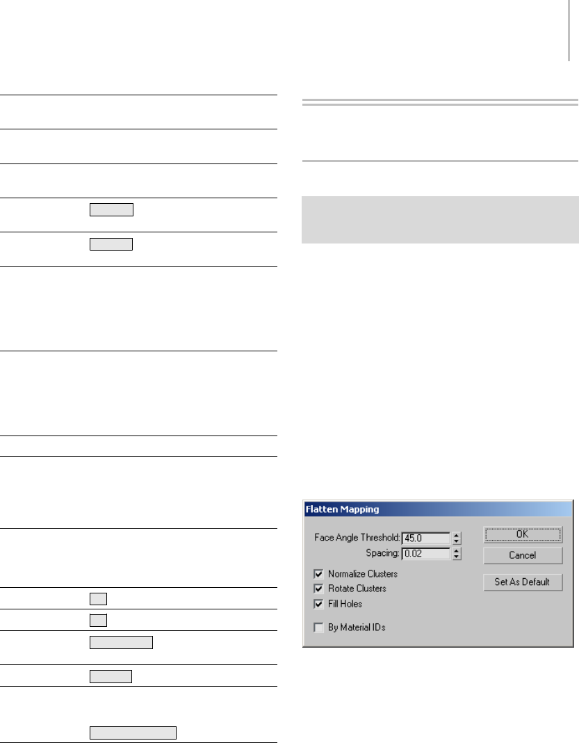
Flatten Mapping Dialog 907
Unwrap UVW
Function
Keyboard
Shortcut
Description
Unfreeze All Unfreezes all
frozen elements.
Unhide All Unhides all hidden
elements.
Unwrap Options Ctrl+O (letter
"o")
Update Map Ctrl+U Updates map in
editor.
UV Edge Mode When on, selecting
an edge expands
the selection to
include all edges in
its loop. See Edge
Loop.
UV Edge Select Expands an
existing edge
selection to
include all edges in
its loop. See Edge
Loop.
Vertex Snap
Vertex To Edge
Select
Converts vertex
selection to an
edge selection and
puts you in Edge
mode.
Vertex To Face
Select
Converts vertex
selection to a face
selection and puts
you in Face mode.
Zoom Z
Zoom Extents X
Zoom Extents
Selected
Alt+Ctrl+Z
Zoom Region Ctrl+X
Zoom Selected
Element
Zoom to Gizmo Shift+Spacebar
UVW Editor Dialogs
Flatten Mapping Dialog
Select an object. > Modify panel > Modifier List >
Object-Space Modifiers > Unwrap UVW > Edit button (on
Parameters rollout) > Mapping menu > Flatten Mapping
The Flatten Mapping method of procedural
mapping applies planar maps to groups of
contiguous faces that fall within a specified angle
threshold. It prevents overlap of mapping clusters,
but can still cause texture distortion. The Flatten
Mappingdialogletsyoucontrolhowclustersare
defined and mapped.
See also
Normal Mapping Dialog (page 1–908)
Unfold Mapping Dialog (page 1–919)
Interface
Face Angle Threshold—The angle used to determine
theclusterstobemapped.
As the Flatten Map gathers faces to be mapped, it
uses this parameter to determine which faces get
put in a cluster. This is the maximum angle that
can exist between faces in a cluster.
Thehigherthisnumber,thelargertheclusters
will be, with consequently greater distortion
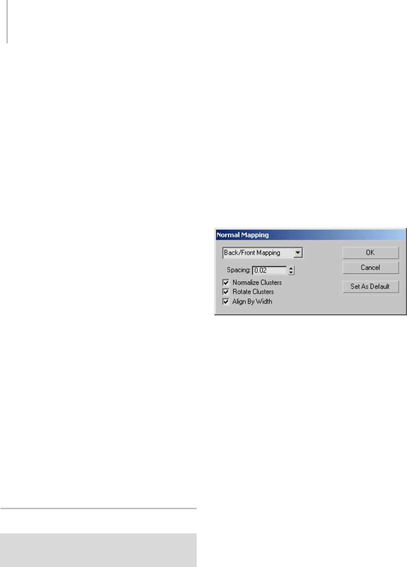
908 Chapter 8: Modifiers
introduced as a result of texture faces’ proportions
deviating from their geometry-equivalent faces.
Spacing —Controls the amount of space between
clusters.
The higher this setting, the larger the gap that
appears between clusters.
Normalize Clusters— Controls whether the final
layout will be scaled down to 1.0 unit to fit within
the standard editor mapping area. If this is turned
off,thefinalsizeoftheclusterswillbeinobject
space, and they’ll probably be much larger than
the editor mapping area. For best results, leave this
turned on.
Rotate Clusters—Controls whether clusters are
rotated to minimize the size of their bounding
box. For instance, the bounding box of a rectangle
rotated 45 degrees occupies more area than one
rotated 90 degrees.
Fill Holes—When turned on, smaller clusters will
be placed in empty spaces within larger clusters to
take the most advantage of the available mapping
space.
By Material IDs—When on, ensures that no
cluster contains more than one material ID after
flattening.
OK—Accepts the settings, closes the dialog, and
performs the mapping as specified.
Cancel—Undoes any changes and closes the dialog.
Set As Default—Makesthecurrentsettingsthe
defaults for the current session.
Normal Mapping Dialog
Select an object. > Modify panel > Modifier List >
Object-Space Modifiers > Unwrap UVW > Edit button (on
Parameters rollout) > Mapping menu > Normal Mapping
The Normal Mapping method of procedural
mapping applies planar maps based on different
vector-projection methods. It is the most
straightforward method, but can result in even
greater texture distortion than with Flatten
mapping (page 1–907).TheNormalMapping
dialog lets you control how clusters are defined
and mapped.
See also
Flatten Mapping Dialog (page 1–907)
Unfold Mapping Dialog (page 1–919)
Interface
(drop-down)—Sets the mapping method:
•Back/Front
•Left/Right
•Top/Bottom
•BoxNoTop
•Box
•Diamond
Spacing—Controls the amount of space between
clusters.
The higher this setting, the larger the gap that
appears between clusters.
Normalize Clusters— Controls whether the final
layout will be scaled down to 1.0 unit to fit within
the standard editor mapping area. If this is turned
off,thefinalsizeoftheclusterswillbeinobject
space, and they’ll probably be much larger than
the editor mapping area. For best results, leave this
turned on.
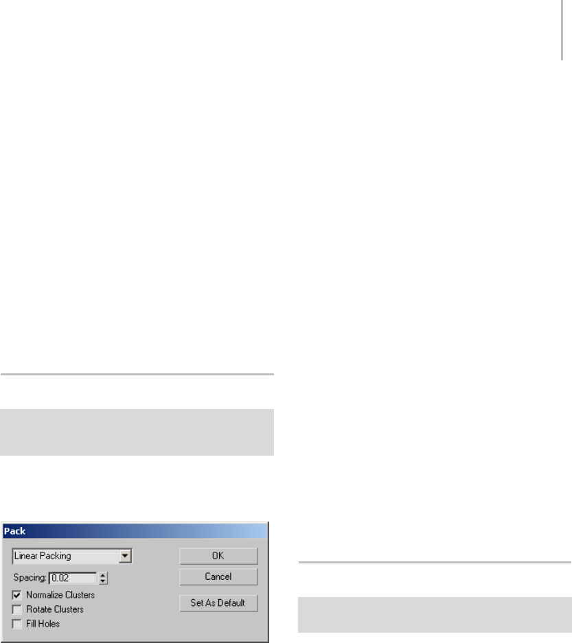
Pack UVs Dialog 909
Rotate Clusters—Controls whether clusters are
rotated to minimize the size of their bounding
box. For instance, the bounding box of a rectangle
rotated 45 degrees occupies more area than one
rotated 90 degrees.
Align By Width—Controlswhetherthewidthorthe
height of the clusters is used to control the layout
of the clusters.
OK—Accepts the settings, closes the dialog, and
performs the mapping as specified.
Cancel—Undoes any changes and closes the dialog.
Set As Default—Makesthecurrentsettingsthe
defaults for the current session.
Pack UVs Dialog
Select an object. > Modify panel > Modifier List >
Object-Space Modifiers > Unwrap UVW > Edit button (on
Parameters rollout) > Tools menu > Pack UVs
The Pack UVs dialog contains controls for clusters.
Interface
(drop-down)—Sets the packing method:
•Linear Packing—Uses a linear method to lay
out the faces. This method is fast but not very
efficient, and tends to leave a lot of unused UV
space.
•Recursive Packing—Slower than the Linear
method, but packs the faces more efficiently.
Spacing —Controls the amount of space between
clusters.
The higher this setting, the larger the gap that
appears between clusters.
Normalize Clusters— Controls whether the final
layout will be scaled down to 1.0 unit to fit within
the standard editor mapping area. If this is turned
off,thefinalsizeoftheclusterswillbeinobject
space, and they’ll probably be much larger than
the editor mapping area. For best results, leave this
turned on.
Rotate Clusters—Controls whether clusters are
rotated to minimize the size of their bounding
box. For instance, the bounding box of a rectangle
rotated 45 degrees occupies more area than one
rotated 90 degrees.
Fill Holes—When turned on, smaller clusters will
be placed in empty spaces within larger clusters to
take the most advantage of the available mapping
space.
OK—Accepts the settings, closes the dialog, and
performs the packing as specified.
Cancel—Undoes any changes and closes the dialog.
Set As Default—Makes the current settings the
defaults for the current session.
Pelt Map Parameters Dialog
Unwrap UVW Modifier > Face sub-object level > Map
Parameters rollout > Pelt > Edit Pelt Map
The primary function of the Pelt Map Parameters
dialog is to let you stretch out the UVW
coordinates into a flat, unified map that you can
then use for texturing. When the dialog is open,
the stretcher appears in the Edit UVWs dialog
window as a circle of points, each of which is
attached to a vertex on a pelt seam. You can
manipulate these vertices exactly as any other
vertex in the editor, selecting, rotating, moving,
etc. Other special functions available on the dialog
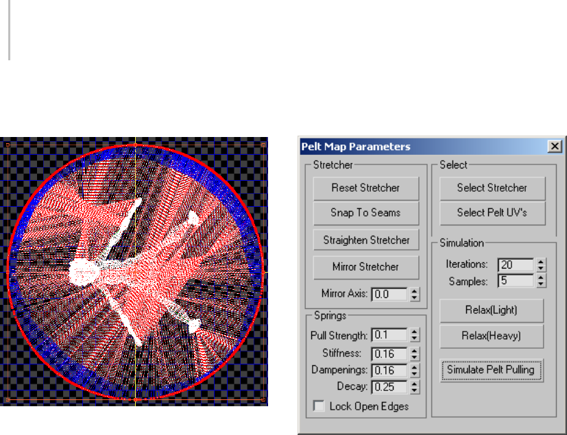
910 Chapter 8: Modifiers
let you straighten out stretcher vertices, snap them
to the pelt seams, and so on.
The stretcher points surround the pelt UVs in the Edit UVWs
dialog window.
The lines connecting the stretcher vertices to the
pelt-seamverticesfunctionasspringsthatpullthe
pelt seams outward in an animated simulation.
After you set up the pelt UVs and the stretcher
shape, you run the simulation by clicking the
Simulate Pelt Pulling button. Depending on the
results, further adjustment and simulation might
be required.
WhilePeltmodeisactiveandtheEditUVWs
dialog is open, most standard UVWs editing
functions are also available. So, for example,
instead of stretching the entire pelt, you could
select a subset of UVs to stretch. To access any
commands that are unavailable in Pelt mode, such
as Mapping menu commands, simply close the
Pelt Map Parameters dialog.
Interface
The primary Pelt Map commands are activated
via the buttons in the Simulation group. Other
functionsonthisdialogletyouadjustvarious
stretching parameters.
Stretcher group
These tools help adjust the stretcher shape.
Reset Stretcher—Returns the stretcher and the
pelt UVs to their default shape and orientation,
losing any stretching or editing of the stretcher or
mapping coordinates.
Snap To Seams—Aligns all the stretcher points to
theedgeseamsonthepeltUVs. Thiscausesthe
stretcher to take on the pelt outline.
For best results, use this command only after
stretching.
Straighten Stretcher—Lets you specify a polygonal
outline for the stretcher by moving points. When
this mode is active, move one stretcher vertex,
and then move a second, non-adjacent point to
line up all intervening vertices in a straight line
between the two. This process is fully interactive;
as you move the second vertex, the intervening
vertices continually change position to maintain

Pelt Map Parameters Dialog 911
the straight line. Continue moving vertices to
create a polygonal outline; to quit, click Straighten
Stretcher again.
Note: While Straighten Stretcher is active, you
can pan and zoom the editor window at any time
using contextual controls (middle-button drag
or turn mouse wheel, respectively) to access a
differentpartofthewindow. Afterdoingso,
the software still remembers the last vertex you
dragged and draws a straight line between it and
the next one you drag. Similarly, you can adjust
the window using the control buttons and then
return to straightening the stretcher. If the control
requires more than a single click, such as Pan, exit
the control by right-clicking in the window and
then return to straightening the stretcher.
Tip: To create a symmetrical outline for the
stretcher,createtheoutlineononesideandthen
use Mirror Stretcher (following).
Mirror Stretcher—Mirrors the stretcher points
fromonesideofthemirroraxis(seefollowing)to
the other. By default, Mirror Stretcher mirrors the
points from the right side to the left.
Mirror Axis—Lets you specify the orientation of
themirroraxis.Theaxistakestheformofthree
yellow lines forming a T. The leg of the T indicates
thesidethatwillbemirroredwhenyouuse
Mirror Stretcher (see preceding), and the crossbar
indicates the axis across which the mirroring will
occur. Default=0.0. Range=0.0 to 360.0.
Select group
These commands let you select all the stretcher
points or the pelt UVs. As with other selection
methods, you can press and hold Ctrl when you
use either of these to add to the current selection.
That is, to select all stretcher points and pelt UVs,
click one button, press and hold Ctrl ,andthen
click the other button.
Select Stretcher—Selects all stretcher points.
Select Pelt UVs—Selects all pelt UVs.
Springs group
Theseparameterscontrolthespringsthatareused
to stretch the pelt. In most cases you won’t need
to change these values, except possibly for Pull
Strength.
Pull Strength—The magnitude of the stretching
action when you click Simulate Pelt Pulling.
Default=0.1. Range=0.0 to 0.5.
Ifthestretchingistoogradual,increasePull
Strength for a more forceful stretching action.
Stiffness—Sets the rate at which the springs pull.
The higher the Stiffness value, the more abrupt the
pulling action. Default=0.16. Range=0.0 to 0.5.
Dampening—Appliesadampeningorinhibiting
factor to the pulling action. The higher the
Dampening value, the greater the inhibition of the
stretcher. Default=0.16. Range=0.0 to 0.5.
Decay—Therateoffalloffoftheinfluenceof
each pelt-seam vertex on the other mapping
vertices. Higher Decay values typically result in
significantly greater stretching, or undesirable
results. For best results, keep the Decay value low.
Default=0.25. Range=0.0 to 0.5.
Lock Open Edges—Locks the open edges in place.
This typically applies to using the stretcher on a
partial selection of mapping vertices in the pelt
region. WhenLockOpenEdgesison,selected
vertices next to unselected vertices tend to stay in
place during stretching. When Lock Open Edges
is off, the selected vertices tend to pull away from
the unselected vertices.
Simulation group
These are the main controls for the simulation, in
which the springs attached to the stretcher pull the
pelt seam vertices out, flattening the UVs. For best

912 Chapter 8: Modifiers
results, alternate between running the simulation
(click Simulate Pelt Pulling) and relaxing the mesh.
Iterations—Thenumberoftimesthesimulation
will run through when you click Simulate Pelt
Pullings. Default=20. Range=1 to 100.
Often, you’ll need to run repeated simulations to
get the desired result.
Samples—The number of samples around each
pelt-seam point used in the simulation. A higher
value results in a greater pulling effect. Default=5.
Range=1 to 50.
Relax (Light)—Causes a relatively weak
normalization of the distances between mapping
vertices.
Relax (Heavy)—Causes a relatively strong
normalization of the distances between mapping
vertices.
Simulate Pelt Pulling—Runs the simulation, pulling
the pelt seam vertices towards the stretcher points.
To abort the simulation process, press Esc .
Relax Tool Dialog
Select an object. > Modify panel > Modifier List >
Object-Space Modifiers > Unwrap UVW > Edit button
(on Parameters rollout) > Edit UVWs dialog > Make a
selection. > Tools menu > Relax Dialog
The Relax Tool dialog offers an advanced toolset
for modifying the spacing of selected texture
coordinates parametrically, for the purpose of
eliminating or minimizing distortion in texture
maps. The dialog provides three different
methodsforrelaxingvertices,plusseveralnumeric
parameters and two check boxes. You can use
Relax to separate texture vertices that are too
close together to texture easily, and to resolve
overlapping areas.
Thedialogisnon-modal,whichmeansthatyou
can work directly in the editor while keeping
the dialog open. You can make a selection of
texture vertices, apply relaxation, make a different
selection, apply relaxation, and so on, without
having to close the Relax Tool dialog.
Tip: When using Relax with complex objects, you
mightfindthatverticesininteriorsectionsofthe
texture mesh don’t relax properly because they
have nowhere to go. In such cases, try making
a seam: Select an edge loop or part of a loop,
and then use the Break function to separate the
mesh at the seam. Alternatively, you could make
a face selection and then use Detach Edge Verts.
For example, Select Overlapped Faces > Expand
Selection > Detach Edge Verts will break the
selection away from the mesh into a new UV
element.
Tip: EffectiveuseoftheRelaxtoolsrequires
thatthegeometryandtextureverticesbeinthe
same order. If you get unexpected results using
Relax, try mirroring the texture vertices to reverse
their order.
Procedures
To relax texture coordinates:
1. Use the Edit UVWs dialog to select the
texture-coordinate vertices to relax.
You can make this selection at any sub-object
level (Vertex, Edge, or Face), but Relax always
works on vertices.
2. On the Tools menu, choose Relax Dialog.
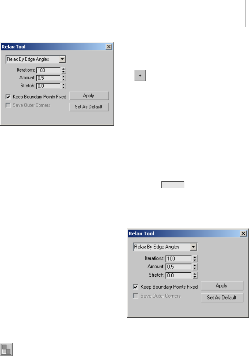
Relax Tool Dialog 913
This opens the Relax Tool dialog.
3. Choose the relax method. Three are available
from the drop-down list:
•RelaxByFaceAngles
•RelaxByEdgeAngles
•RelaxByCenters
ThedefaultmethodisRelaxByEdgeAngles;
this most often gives the best results.
4. Set the other options and then click Apply.
As the relaxing progresses, a message appears
showing you which frame is being processed. A
frame is equivalent to an iteration.
The appropriate method and other settings
to use depend on a variety of conditions,
including the complexity and topology of the
mesh, so experimentation is usually required.
Relaxing is undoable, so if one method doesn’t
work, undo and try another.
To use Relax to fix overlapping faces:
This procedure provides general guidelines for
resolving overlapping texture faces. It might not
work in every case, but it should give you a starting
point for correcting most situations.
1. Open the Edit UVWs dialog and in the
Selection Modes group, click Face Sub-object
Mode.
2. From the Edit UVWs dialog > Select menu,
choose Select Overlapping Faces.
Only the overlapping faces are selected.
3. Click Expand Selection to select faces
surroundingtheoverlappingfaces.
Thisgivestheoverlappingfacesalargerarea
in which to spread out.
4. From the Tools menu, choose Relax Dialog.
5. On the Relax Tool dialog, set Stretch to an
intermediate value. If the overlapping is
considerable, use 0.5 or higher. If it’s relatively
small, try 0.1 to 0.3.
6. Click Apply.
If this seems to be helping, continue clicking
Apply until the overlapping is resolved. If
not, undo ( Ctrl+Z )andtryusingRelaxBy
Face Angles instead, or increase the Amount
value, or change the Stretch value, or use
combinations of the above.
Interface
[relax method]—Themethodusedtorelaxthe
texture vertices. Choose from the drop-down list:
•Relax By Face Angles—Relaxes the vertices based
on the shape of the faces. It tries to align the
geometric shape of the face to the UV face. This
algorithm is mainly used to remove distortion

914 Chapter 8: Modifiers
and not so much to remove overlap, and is best
suited for simpler shapes.
•Relax By Edge Angles—This default method is
similar to Relax By Face Angles except that it
usestheedgesthatareattachedtothevertices
as the shape to match. It typically works better
than Relax By Face Angles but tends to take
longer to reach a solution. This method is
bested suited for more complex shapes.
•Relax By Centers—The original Relax method
from previous versions of 3ds Max. It relaxes
vertices based off the centroids (centers of
mass) of their faces. It does not take into
account the face or edge shapes/angles so it is
mainly useful for removing overlap or for faces
that are mostly rectangular.
Iterations—The number of times the Relax settings
are applied when you click Apply. Each iteration is
applied successively, to the results of the previous
iteration. Range=0 to 100000. Default=100.
Amount—The strength of the relaxation applied
per iteration. Range=0.0 to 1.0. Default=0.1.
Stretch—Theamountofstretchingthatcanoccur.
Stretching is useful mainly to resolve overlapping
texture vertices, at the cost of reintroducing
distortion into the texture mesh. Range=0.0 to
1.0. Default=0.0.
Keep Boundary Points Fixed—Controls whether
vertices at the outer edges of the texture
coordinates are moved. Default=off.
When off, the outer edge of the texture mesh
can float, allowing a wider range of the available
texture-mapping space to be used. Typically
you would keep this off when relaxing an entire
element or cluster, so the software can minimize
distortion by moving the edges.
When relaxing an interior subset of vertices, it
is recommended you turn this on to prevent the
selected vertices from overlapping unselected
vertices. For Relax By Edge and Face Angles, turn
this off until you get a good solution for the outer
boundaries of the mesh and then turn it on to
resolve the interior sections.
Save Outer Corners—Preserves the original
positions of texture vertices farthest away from the
center. Available only with the Relax By Centers
method.
Apply—Begins the relaxation process using the
current settings. As relaxation takes place, a
textual progress indicator appears at the bottom of
the dialog, showing the current iteration (Process
frame) and the total number of iterations being
processed.
To abort the relaxation process, press Esc .You
canthenuseUndo(Ctrl+Z )toreturntothe
prior state, if necessary.
Set As Default—Savesallcurrentsettingsasthe
Relax defaults, so they are recalled from session
to session.
Render UVs Dialog
Unwrap UVW modifier > Edit button (on Parameters
rollout) > Tools menu > Render UVW Template
The Render UVs dialog, part of the Unwrap UVW
editor (page 1–888), lets you export a model’s
texture mapping data as a template; a bitmapped
image file. you can then import this template into
a 2D paint program, apply color as needed, and
thenbringitbackinto3dsMaxasatexturemapto
applytothemodel.Theexportedfilelookslikea
screen shot of the editor window, but without any
background texture, and has the added options of
setting color and alpha options for both the edges
and the area they cover.
For a procedure that covers usage of this dialog, see
To export texture coordinates to a paint program:
(page 1–882).
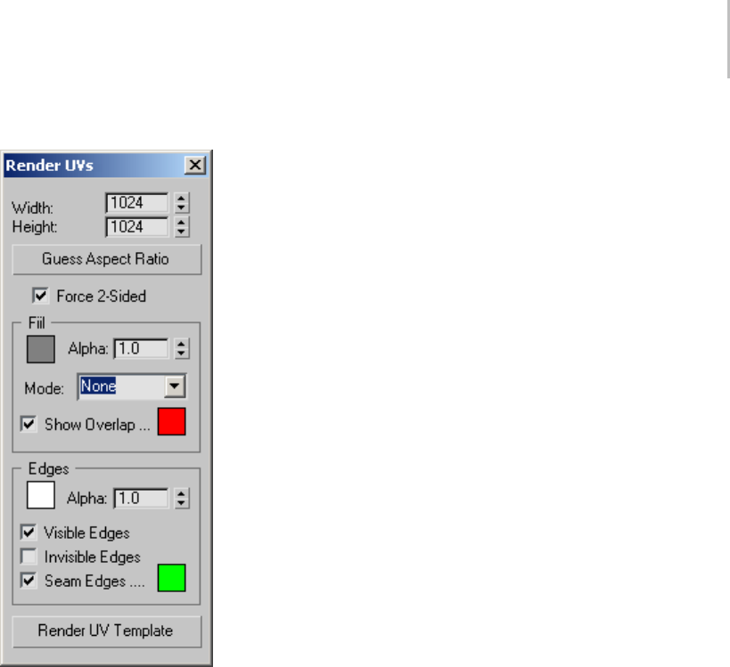
Render UVs Dialog 915
Interface
Width/Height—The horizontal and vertical
dimensions of the output (rendered) template
image in pixels.
Guess Aspect Ratio—Adjusts the Height value to
produce an output aspect ratio based on the Width
valueandthedimensionsoftheUVgrid.
For instance, if a rectangular UV grid measures
20 x 100 units and you click Guess Aspect Ratio,
it would try to keep the bitmap at the 1:5 aspect
ratio. This makes painting on the bitmap easier
because the bitmap is at the correct aspect ratio
for the mesh.
Warning: Using this function can result in Height value
that is not a power of 2. If your mesh is destined for a
real-time renderer, adjust the resulting Height value to
the nearest power of 2 after using Guess Aspect Ratio.
For example, if it sets Height to 650, change it to 512
before rendering the template.
Force 2-Sided—When on, all UV edges are
rendered into the template. When off, only UV
edges of faces facing the viewer are included; edges
of back-facing faces are not rendered.
Fill group
Fill is the coloring applied to the rendered bitmap
in the face areas between edges. By default, there’s
no fill; the bitmap color is black, and the alpha
channel is fully transparent. You can change this
to a solid color or to shading derived from the
mesh and lighting in the scene, or from the normal
directions.
Note: The overlap color overrides the fill color. For
example, if Show Overlap is on and all visible faces
overlap other faces, all faces will show the overlap
color, ignoring the fill color.
[color swatch]—Shows the fill color used for faces
when Mode is set to Solid. To change the color,
click the swatch.
Alpha—Sets the alpha-channel value for the fill
areas when Mode=Solid, Normal, or Shaded.
When Mode=None, the fill alpha is always 0.0
(transparent). Range=0.0 (transparent) to 1.0
(opaque). Default=1.0.
The alpha channel is included with the rendered
image only when you save in a format that supports
transparency, such as TIF or Targa.
Mode—Specifies the method used for filling faces
in the rendered template.
•None: No fill is rendered. This setting ignores
the Alpha value, and sets fill alpha to 0.0; that
is, fully transparent.
916 Chapter 8: Modifiers
•Solid:Rendersfacesusingthefillcolor
specified by the swatch at the top of the Fill
group.
•Normal: Renders each vertex’s normals into
thebitmap.Theresultlookssimilartoanormal
map.
•Shaded: Uses a simple lighting setup to render
shadingacrosstheUVsurface.
Show Overlap—When on, fills faces that overlap
otherfaceswiththeoverlapcolor,showninthe
color swatch to the right. Default=on.
To change the overlap color, click the color swatch.
Edges group
[color swatch]—Shows the color used for rendered
edges. To change the color, click the swatch.
Alpha—Sets the alpha-channel value for edges.
Range=0.0 (transparent) to 1.0 (opaque).
Default=1.0.
The alpha channel is included with the rendered
image only when you save in a format that supports
transparency, such as TIF or Targa.
Visible Edges—When on, edges are rendered using
the specified edge color. Default=on.
Invisible Edges—When on, hidden edges
are rendered using the specified edge color.
Default=off.
Hidden edges are most often found dividing mesh
polygons into triangles. They aren’t present in
polygon objects.
Seam Edges—When on, seam (outside) edges
are rendered using the specified seam color.
Default=on.
To change the seam color, click the color swatch.
Thedefaultcolor(green)isthesameasthatused
for seam edges in the Edit UVWs dialog, but the
two can be changed separately.
Render UV Template—Renders the template bitmap
in a new rendered frame window (page 3–5).
To save the rendered frame, click the Save
Bitmap button.
Note: This command renders the normalized UV
space, from (0,0) to (1,1), as depicted in the editor
by a dark blue outline. For best results, make sure
the texture UVs fill this space but don’t exceed its
bounds.
Tip: To turn off the background texture,
which tends to obscure the UV space outline, click
the Show Map button on the upper toolbar.
Sketch Tool Dialog
Select an object. > Modify panel > Modifier List >
Object-Space Modifiers > Unwrap UVW > Edit button (on
Parameters rollout) > Tools menu > Sketch Vertices
If you need to match a contiguous selection of
texture vertices to an outline in a bitmap, whether
an irregular shape, a straight line, or a geometric
shape, you can use the Sketch tool to perform
the operation quickly, rather than dragging the
vertices one at a time.
Procedure
Example: To sketch texture vertices free form:
You can start with the vertices already selected, or
use the Sketch tool to select them. In this example,
we’ll assume the latter.
1. Choose Sketch Vertices.
2. In the Sketch Tool dialog, next to Select By,
choose Drag Selection, if necessary.
3. Next to Align To, choose Free Form, if
necessary.
4. Make sure Show Vertex Order and Interactive
Mode are turned on. Leave Drag Cursor Size
at the default setting.
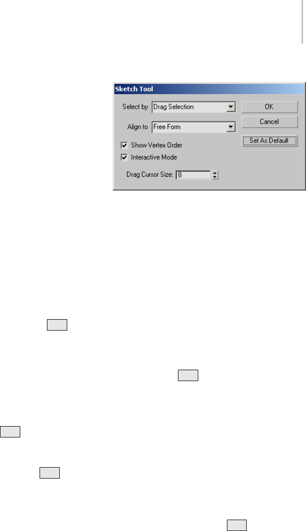
Sketch Tool Dialog 917
5. Click OK to close the dialog.
The mouse cursor takes the form of a circle,
which means you’re in “drag select” mode.
6. In the editor window, drag the cursor over the
vertices to select, and then release the mouse
button.
As you drag, each vertex is assigned a
consecutive number. When you release the
mouse button, the cursor turns into a pencil,
which means you’re in “sketch” mode.
Note: Before you start sketching, each successive
mouse click alternates between drag and sketch
modes.
7. In the editor window, drag a wavy line.
The selected vertices follow the line in numeric
order, spreading out evenly over its length. To
start the sketch over, release the mouse button,
and then drag again.
Alternatively, if you press and hold Alt ,and
thenpressandreleasethemousebutton,you’ll
draw a straight line by moving the mouse. Click
andmoveagaintodrawconnectedstraight-line
segments.
You can combine free-form and straight-line
sketching freely:
• To append a free-form line to a straight-line
segment, release the Alt key and then begin
dragging.
• To append a straight-line segment to a
free-form line, press and hold Alt as you
drag, and then release the mouse button and
move the mouse.
8. To exit the Sketch tool, right-click in the editor
window.
Interface
Select by—Lets you choose how to select the
vertices to sketch:
•Pick Selection—Lets you pick the vertices one by
one. When you click OK, a Pick cursor appears
comprising a + sign and the letter P; when the
cursor is over a vertex, the + sign becomes
larger. To finish picking, right-click, and then
drag to sketch. After sketching, you return to
Pick mode, and so on. To exit, right-click.
•Drag Selection—Lets you pick multiple vertices
by dragging. When you click OK, the mouse
cursorappearsasacircle. Afteryoudragto
select vertices, release the mouse button, and
then drag (or Alt +click) to sketch. As with
Pick Selection, the mouse cursor continues
to alternate between Select and Sketch modes
until you right-click to exit.
•Use Current Selection—Uses the current
selection; you cannot change the selection
whileusingthetool.Ifthecurrentselectionis
edges or faces, Sketch uses all vertices attached
to selected sub-objects.
Align To—Lets you choose how to sketch:
•Free Form—Drag to sketch free form (like
drawing with a pencil), or Alt +click to sketch
connected
•Line—Drag to sketch a single, straight line
segment.
•Box—Drag diagonally to sketch a rectangle.
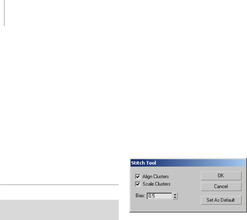
918 Chapter 8: Modifiers
•Circle—Drag outward to sketch a circle, and
then move the mouse in a circle to rotate the
circle.
Show Vertex Order—Displays numbered labels that
indicate the order in which vertices were selected
andwillspreadoutduringsketching.
Interactive Mode—Shows vertex positioning as you
sketch. Turn off for faster feedback.
Drag Cursor Size—Sets the size of the mouse
cursor used while dragging a selection.Default=8.
Range=1 to 15.
OK—Accepts the changes and closes the dialog.
Cancel—Undoes any changes and closes the dialog.
Set As Default—Makesthecurrentsettingsthe
defaults for the current session.
Stitch Tool Dialog
Select an object. > Modify panel > Modifier List >
Object-Space Modifiers > Unwrap UVW > Edit button (on
Parameters rollout) > Tools menu > Stitch Selected
After you’ve separated your object’s UVW
coordinates into clusters, either manually or
using one of the automatic tools on the Mapping
menu (page 1–898),youcanusetheStitch
tool to recombine specific clusters by merging
corresponding edges.
Note: You can stitch together only two clusters at a
time. If the current sub-object selection is shared
by more than one cluster, then “majority rules”:
Stitch attaches the cluster that shares the most
sub-objects. If the number of sub-objects shared
bymultipleotherclustersisthesame,thesoftware
attachestheclusterwhosesharedsub-objectswere
chosen first.
Procedure
To stitch two clusters together:
1. In the “source” cluster, select sub-objects along
an edge you want to connect.
By default, this causes the shared edges to
highlight in the “target” object(s).
2. Choose Stitch Selected.
The clusters are connected.
3. Adjust the settings on the Stitch Tool dialog.
Feedback takes place in real time.
4. ClickOKtoacceptorCanceltoabort.
Interface
Align Clusters—Moves the target cluster to the
source cluster, and rotates the target cluster into
place if necessary. When off, the target cluster
remains in its original position and orientation.
Default=on.
Tip: If your clusters overlap after stitching with
Align Clusters turned on, cancel the stitching, and
then position and align them as you want them
after stitching. Then use the Stitch tool with Align
Clusters turned off.
Scale Clusters—Resizes the target cluster to a size
comparable to that of the source cluster. Takes
effect only when Align Clusters is on. Default=on.
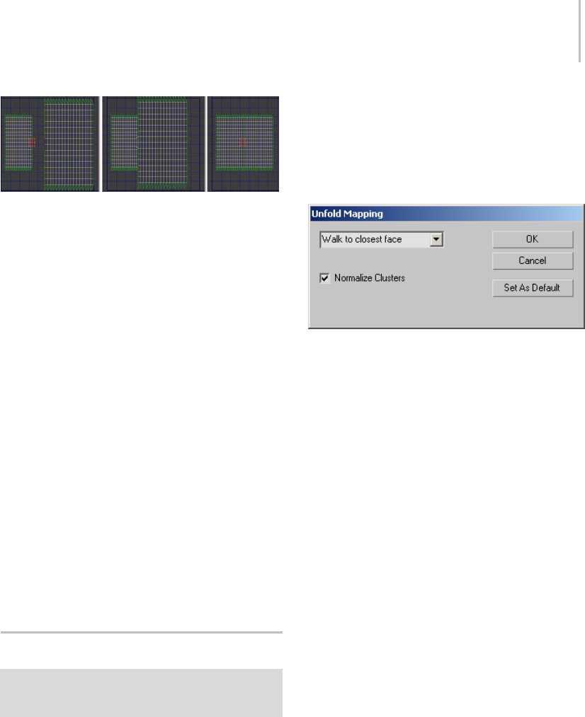
Unfold Mapping Dialog 919
Edges chosen to stitch (left); Clusters aligned (center); Clusters
aligned and scaled, with Bias=0 (right)
Bias—When Scale Clusters is off, Bias sets the
extent to which attached sub-objects are moved
from their original positions. At Bias=0, the
sub-objectsremainintheiroriginalpositionsin
thesourcecluster.AtBias=1,sub-objectsremain
in their original positions in the target cluster. At
in-between settings, their positions are averaged
between the two.
WhenScaleClustersison,Biassetswherethe
software derives the scaling of the target cluster(s).
At Bias=0, the scale is fully derived from the
stitched edges on the source. At Bias=1, the scale is
fully derived from the stitched edges on the target.
At in-between settings, the scaling is averaged
between the two.
OK—Accepts the changes and closes the dialog.
Cancel—Undoes any changes and closes the dialog.
Set As Default—Makesthecurrentsettingsthe
defaults for the current session.
Unfold Mapping Dialog
Select an object. > Modify panel > Modifier List >
Object-Space Modifiers > Unwrap UVW > Edit button (on
Parameters rollout) > Mapping menu > Unfold Mapping
The Unfold Mapping method of procedural
mapping eliminates texture distortion, but can
result in overlapping coordinate clusters. The
Unfold Mapping dialog lets you control how faces
are unfolded.
See also
Flatten Mapping Dialog (page 1–907)
Normal Mapping Dialog (page 1–908)
Interface
(drop-down)—Sets the unfold method by
specifying whether the software will start
unfolding with the closest or farthest face angle,
with respect to distance. In almost all cases, you’ll
get better results with Walk To Closest Face.
•Wa l k To Cl o s es t Fa ce
•Wa l k t o Fa r t h es t F ace
Normalize Clusters— Controls whether the final
layout will be scaled down to 1.0 unit to fit within
the standard editor mapping area. If this is turned
off,thefinalsizeoftheclusterswillbeinobject
space, and they’ll probably be much larger than
the editor mapping area. For best results, leave this
turned on.
OK—Accepts the settings, closes the dialog, and
performs the mapping as specified.
Cancel—Undoes any changes and closes the dialog.
Set As Default—Makes the current settings the
defaults for the current session.
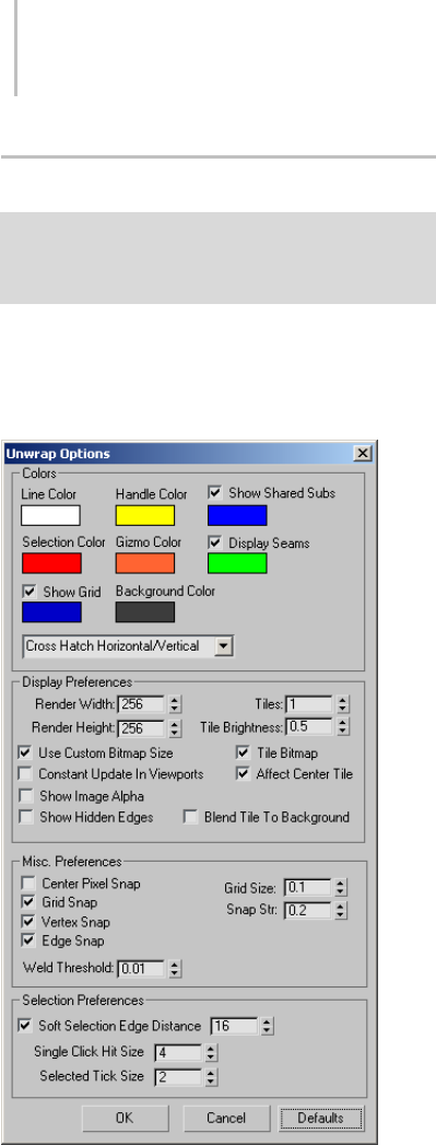
920 Chapter 8: Modifiers
Unwrap Options Dialog
Select an object. > Modify panel > Modifier List >
Object-Space Modifiers > Unwrap UVW > Edit button (on
Parameters rollout) > Edit UVWs dialog > Options menu
>AdvancedOptions
Set preferences for the Unwrap UVW editor using
controls in the Unwrap Options dialog.
Interface
Colors group
Contains color swatches to customize the display
of the UVW lattice. With certain maps, the default
colors may become difficult to see. Use these
swatches to choose colors that work better for your
specific map.
To change a color, click its swatch, and then use the
Color Selector (page 1–161) to choose a new one.
Line Color—Specifies the color of the UVW lattice
lines. Default=white.
Handle Color—The color assigned to patch handles.
Default=yellow.
Show Shared Subs—When turned on, non-selected
sub-objects shared by the current selection are
highlighted in this color. In most cases, the shared
sub-objects are edges. With a single vertex, the
shared sub-objects are vertices. Defaults=on, blue.
Selection Color—Specifies the color of selected
UVW sub-objects. Default=red.
Gizmo Color—The color assigned to the Freeform
gizmo. Default=orange.
Display Seams—When on, lets you assign a
distinctive color to coordinate clusters’ boundaries
that appears in the viewports. Defaults=on, green.
Show Grid—When on, the grid lines are visible.
Defaults=on, dark blue.
Yo u c a n a l s o s e t t h e grid size.
Background Color—The color assigned to the
backgroundwherethetexturemapisn’tdisplayed.
Default=dark gray.
(drop-down)—Lets you assign a fill pattern
to selected faces. Default=Cross Hatch
Horizontal/Vertical.
Display Preferences group
Contains controls affecting the map display in the
view window.
Render Width—Specifies the width resolution of
the image displayed in the view window. This
does not change the size of the image, but only the
resolution.

Unwrap Options Dialog 921
Render Height—Specifies the height resolution.
Use Custom Bitmap Size—When turned on, scales
the bitmap texture to the values specified by Width
and Height. You can adjust these settings to scale
and reproportion the bitmap texture in relation to
the texture coordinates. This scaling doesn’t affect
the bitmap in the material, but only as viewed in
the editor.
Tip: When working with large textures, reduce
the bitmap size for faster feedback. And when
working with disproportionate textures, setting
the dimensions closer to each other in the editor
can make it easier to work.
Tiles—Thenumberoftimesthetextureimageis
repeated, counting outward in eight directions
(the four corners and the four sides).
With Tiles=1, the result is a 3 x 3 grid. With
Tiles=2,theresultisa5x5grid,andsoon.
YoucantogglethetilingfeaturewiththeTile
Bitmap check box, described below.
Tile Brightness—Sets the brightness of the tiled
bitmap. At 1.0, the brightness equals that of the
original image; at 0.5 it’s half the brightness; and
at 0, it’s black.
This is the same setting as Brightness in the UVWs
editor > Bitmap Options group (available with
Show Options).
Tile Bitmap—When turned on, you can repeat the
bitmap in the editor, displaying tiling set in the
material.
You can use any part of the tiled image for setting
texturecoordinates. Thisishelpfulwhenthe
sections of the texture image are packed tightly
together and the mesh contains many different
areas to map.
Affect Center Tile—When turned on, the Brightness
setting affects all tiles equally. When off, the center,
or “home,” tile always remains at full brightness,
so you can easily distinguish the home tile from
the copies.
Constant Update in Viewports—Affects the
adjusting of UVW vertices in the viewport while
you move the mouse. Default=off (the effect of
adjusting the UVW vertices does not appear in the
viewport until you release the mouse).
Show Image Alpha—Displays the alpha channel of
the background image in the editor, if it exists.
Show Hidden Edges—Toggles the display of face
edges. When turned off, only faces appear. When
turned on, all mesh geometry appears.
Blend Tile to Background—Affects the color to
which tiles set to Brightness less than 1.0 blend.
When turned off, tiles blend to black. When
turned on, tiles blend to the background color.
Misc. Preferences
Center Pixel Snap—When turned on, snaps to the
center of pixels of the background images instead
of pixel edges.
Grid Snap—When on, snaps to grid edges and
intersections.
Vertex Snap—When on, snaps to
texture-coordinate vertices.
Edge Snap—When on, snaps to texture-coordinate
edges.
Weld Threshold—Sets the radius within which
welding using Weld Selected takes effect. The
setting is in UV-space distance. Default=0.01.
Range=0 to 10.
Grid Size—Sets the spacing of horizontal and
vertical grid lines. Default=0.1.
Setting Grid Size to 0 effectively turns off the grid.
At the highest value, 1.0, the grid is the same size
as the texture.
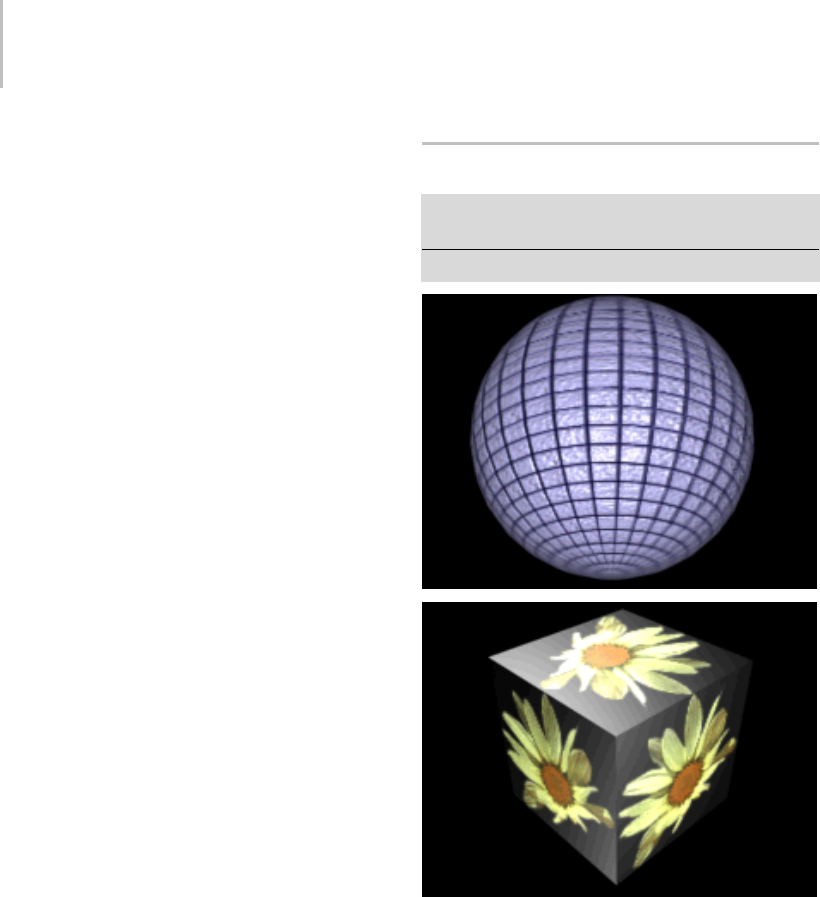
922 Chapter 8: Modifiers
Snap Str(ength)—Sets the grid snap strength.
Default=0.2. Range=0 to 0.5.
Setting the strength to 0 effectively turns off
snapping. At values less than 0.3, grid snapping
tendstogotogridedges.Atthehighestvalue,0.5,
grid snapping goes only to grid intersections.
Selection Preferences
Soft Selection Edge Distance—When Soft Selection
(page 1–893) is turned on, limits the falloff region
by the specified number of edges between the
selection and the affected vertices. The affected
region is measured in terms of "edge-distance"
space rather than absolute distance. Default=16.
Single Click Hit Size—Sets how far away you can
click from a sub-object to select it. Default=4.
Range=1 to 10.
Selected Tick Size—Sets the size of the square
icon the editor window uses to indicate selected
vertices. Default=2. Range=1 to 10.
OK/Cancel/Defaults—Click OK to accept, or Cancel
to cancel the changes in the dialog. Click Defaults
to restore all settings in this dialog to default values.
UVW Map Modifier
Select an object. > Modify panel > Modifier List > UVW
Map
Select an object. > Modifiers menu > UVW Map
Mapping a sphere and a box.
By applying mapping coordinates to an object, the
UVW Map modifier controls how mapped and
procedural materials appear on the surface of an
object. Mapping coordinates specify how bitmaps
are projected onto an object. The UVW coordinate
system is similar to the XYZ coordinate system.
The U and V axes of a bitmap correspond to the X
and Y axes. The W axis, which corresponds to the
Zaxis,isgenerallyonlyusedforproceduralmaps.
A bitmap’s coordinate system can be switched in
the Material Editor to VW or WU, in which case
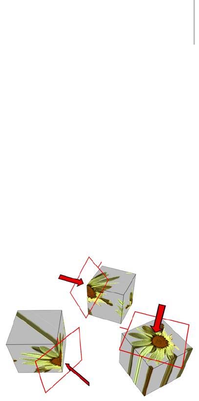
UVW Map Modifier 923
the bitmap is rotated and projected so that it is
perpendicular to the surface.
Primitive objects, like spheres and boxes, can
generate their own mapping coordinates, as
can loft objects and NURBS surfaces. Scanned,
imported, or hand-constructed polygonal or patch
models do not have mapping coordinates until a
UVW Map modifier is applied.
Note: Drawings that are imported or linked from
Autodesk Architectural Desktop and Autodesk
Revit do retain the mapping coordinates that were
assigned to objects by those products.
If you apply a UVW Map modifier to an object
with built-in mapping coordinates, the applied
coordinatestakeprecedenceifmap channel (page
3–966) 1 in the UVW Map modifier is used. The
Generate Mapping Coordinates option, available
during the creation of primitives, uses map
channel 1 by default.
You use the UVW Map modifier to:
• Apply one of the seven types of mapping
coordinates to an object on a specified map
channel. A diffuse map on map channel 1 and a
bump map on map channel 2 can have different
mapping coordinates and can be controlled
separately by using two UVW Map modifiers
in the modifier stack
• Transform the mapping gizmo to adjust map
placement. Objects with built-in mapping
coordinates lack a gizmo.
• Apply mapping coordinates to an object with
no mapping coordinates, an imported mesh,
for example.
• Apply mapping at the sub-object level.
Map Channels
You can control the type of mapping coordinates
and the placement of the mapping gizmo for each
bitmap in a material that uses multiple bitmaps by
assigning explicit map channels to the bitmaps. In
the Material Editor you assign each map a different
channel number, then you add multiple UVW
Map modifiers to the object’s modifier stack,
each UVW Map modifier is set to a different map
channel. To change the type of mapping or gizmo
placement for a particular bitmap, you select
one of the UVW Map modifiers in the modifier
stack and change the parameters. You can change
the name of a UVW Map modifier in the Edit
Modifier Stack dialog to correlate the modifier to
the bitmap.
Transforming UVW Map Gizmos
Changing a map’s location by moving the gizmo.
The UVW Map gizmo projects mapping
coordinates onto an object. You can position,
rotate, or scale a gizmo to adjust map coordinates
on an object; you can also animate the gizmo.
Gizmo transformations remain in effect if you
select a new map type. For example, if you scale
a spherical mapping gizmo and then switch to
planar mapping, then the planar mapping gizmo
is also scaled.
Gizmo Display for Different Map Types
For planar, spherical, cylindrical and shrink wrap
maps, a short yellow line indicates the top of the
map. Thegreenedgeofthegizmoindicatesthe
right side of the map. On a spherical or cylindrical
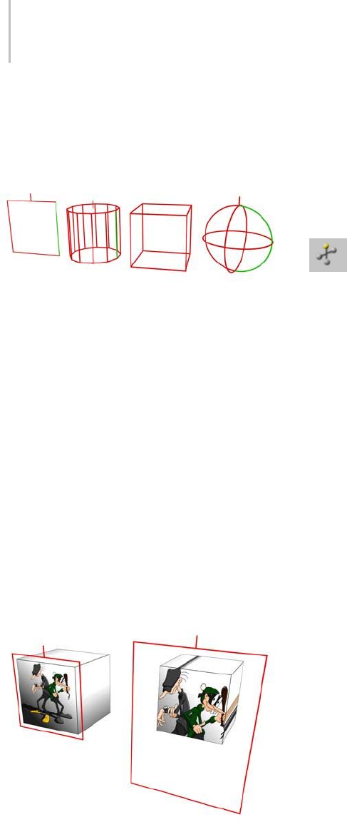
924 Chapter 8: Modifiers
mapthegreenedgeistheseamwheretheleftand
rightedgemeet. Gizmomustbeselectedinthe
modifier display hierarchy to display the gizmo.
Gizmos for different projection types
Left to right: planar, cylindrical, box, and spherical
Effects of Transforming the UVW Map Gizmo
Moving the gizmo changes the center of projection
and affects all types of mapping. Rotating the
gizmo changes the orientation of the map, which
affects all types of mapping. Uniform scaling does
not affect spherical or shrink-wrap mapping.
Non-uniform scaling affects all types of mapping.
If you scale a gizmo smaller than the geometry,
thenatilingeffectiscreated,unlessscalinghas
no effect on the map type in use. Tiling based on
gizmo size is in addition to tiling values set in the
Material Editor Coordinates rollout for the map or
the UVW Map modifier tile controls.
Thesizeofthegizmoaffectshow the mapping is applied to
an object.
Manipulators for UVW Map
The UVW Map modifier has graphic manipulators
to help you adjust the mapping dimensions and
tiling when Real-World Map Size is off. When
Real-World Map Size is on, you can adjust
positioning only for the Planar and Box mapping
types.
Manipulators are visible and usable while
the Select And Manipulate button (page 2–15)
isactive. Thisbuttonisonthedefaulttoolbar
(page 3–685). When you move the mouse over a
manipulator, the manipulator turns red to show
that dragging or clicking it will have an effect.
Also, a tooltip appears, showing the object name,
the parameter, and its value.
For more information on using the UVW Map
manipulators, see the Procedures section (page
1–925).
UV width/length manipulators—In a viewport, drag
the edges of the UVW Map gizmo to change the
width or height.
UV tiling manipulators—In a viewport, drag the
smallcirclenexttotheUedgeorVedgetoadjust
the tiling in that dimension.
Tile Controls
UsetheUVWTilecontrolsifyouwantamapto
repeat. Tiled maps are useful for bricks on a wall,
or tiles on a floor. Rather than creating one large
map, seamless maps can be tiled to surface a large
area without visible seams, to give the illusion of a
large map.
Tiling in the UVW Map modifier affects only the
objects that use this modifier. Tiling a map in the
Material Editor affects tiling on all the objects that
use the material.
Material and UVW Map tiling are multiplied. If a
map in the Material Editor has a tile value of 2 on

UVW Map Modifier 925
one axis, and a UVW Map modifier has a tiling
valueof3onthesameaxis,thentheresultisa
tiling value of 6.
Objects with No Mapping Coordinates
If you render an object that doesn’t have mapping
coordinates or a UVW Map modifier, and the
object uses a material with 2D bitmaps or 3D
procedural maps that use explicit map channels,
then a Missing Map Coordinates (page 2–1623)
alert is displayed. The alert lists both the name of
the object and the UVW channels or Vertex Color
channels that are missing the coordinates. For
example: (UVW 2): Torus01.
Mapping Selection Sets or Grouped
Objects
You can apply one UVW Map modifier to a
selection of objects. One large mapping gizmo will
encompass the entire selection unless the Use Pivot
Points option is turned on in the modifiers rollout
before applying the UVW Map modifier. If the
Use Pivot Points option is used then each object is
encompassed with its own mapping gizmo.
If any of the objects in the selection has had its
pivot point shifted in the Hierarchy > Pivot panel,
and you use the Use Pivot Points option with the
UVW Map modifier, then the mapping gizmos are
centered to the pivot points rather than the object
center and the mapping may be tricky to position
the way you want.
Real-World Mapping
The idea behind real-world mapping is to simplify
theuseoftexturemappedmaterialswhichare
scaled correctly with the geometry in the scene.
This feature gives you the ability to create a
material and specify the actual width and height of
a2Dtexturemapinthematerialeditor.Whenyou
assign that material to an object in the scene, the
texture map appears in the scene with the correct
scaling.
There are two parts to the equation in order for
real-world mapping to work. First, the correct
style of UV texture coordinates must be assigned
tothegeometry.Basically,thesizeoftheUVspace
needs to correspond to the size of the geometry.
Therefore, a new switch, called Real-World Map
Size, has been added to many of the dialogs
and rollouts where you can generate texture
coordinates. Any dialog or rollout in which you
havetheoptiontoturnonGenerate Mapping
Coords,alsohasaswitchwhereyoucanturnon
Real-World Map Size.
Note: There are a few primitive objects that do not
have a Real-World Map Size switch. These are
Torus Knot, Hedra, Prism and RingWave.
The other part of the equation is in the material
editor. When you create a material and use a 2D
texture map, you now see a new switch in the
Coordinates rollout called Use Real-World Scale.
When this switch is turned on, the default, the
Width and Height spinners are enabled that let
you specify the horizontal/vertical offsets and size
of the texture map in current display units (page
3–848).
Note: Autodesk VIZ scenes with objects using
real-world mapping coordinates will display
differentlywhenopenedin3dsMax. Thisis
because real-world mapping coordinates is not the
default method of generating mapping coordinates
in 3ds Max.
Procedures
To apply the UVW Map modifier:
1. Assign a mapped material to an object.
2. OntheModifypanel,chooseUVW
Map from the Modifier List.
3. Adjust the mapping parameters.

926 Chapter 8: Modifiers
By default, the UVW Map modifier uses planar
mapping on map channel 1. You can change the
type of mapping and the map channel to suit
your needs. There are seven types of mapping
coordinates, ninety-nine map channels, tiling
controls, and controls to size and orient the
mapping gizmo in the UVW Map modifier.
Note: If a UVW Map modifier is applied to
multiple objects, the UVW Map gizmo is
defined by the selection, and the mapping that
resultsisappliedtoalltheobjects.
To use multiple UVW channels in the same object:
1. Assign Map channel 1 to an object. You can do
this by either turning on Generate Mapping
Coordinates in the Parameters rollout of
anyprimitive,orbyassigningaUVWMap
modifier with channel 1 chosen.
Generate Mapping Coordinates uses map
channel 1 by default.
2. Assign a UVW Map modifier (or a second one,
if you’re using the first to assign channel 1).
Choose channel 2 for this modifier.
Both coordinate channels are now assigned
to the geometry. The next step is to assign a
mapped material that uses both channels.
3. Createamaterialwithtwomaps. Youcando
this using a Composite map, or a Blend material
with two maps, or you can have one map
assigned to Diffuse and another assigned to
Bump. Perhaps the easiest way to see the effect
is to composite two maps, with the second map
containing an alpha channel.
4. Go to the level of one of the maps and, in the
Mapping list, choose Explicit Map Channel 2.
The other map is already assigned channel 1
by default.
5. Assign the mapped material to the object.
You can switch between viewing the maps in
theviewportusingtheShowMapInViewport
control in the Material Editor. You can adjust
the mapping of channel 2 without altering the
mappingofchannel1ifyou’veassignedtwo
UVW Map modifiers. Render the scene to see
the effect.
To use the XYZ to UVW option:
TheXYZtoUVWoptionisusedtomakea
3D procedural texture, like Cellular, follow the
animated surface of an object. If the object
stretches, so does the 3D procedural texture.
Currently, it cannot be used with NURBS objects
and is unavailable if a NURBS object is selected.
1. IntheTopviewport,createabox.
2. Create a material with a Cellular diffuse
map.
3. In the Material Editor, on the Coordinates
rollout of the Cellular map, open the Source
drop-down list, and choose Explicit Map
Channel.
On the Coordinates rollout, the Map Channel
parameter activates, leave the value at 1.
4. Assign the material to the box.
5. OntheModifypanel,chooseUVW
Map from the Modifier List.
6. On the UVW Map modifier, turn on XYZ to
UVW.
By default, the Map Channel value is 1.
7. Render the Front viewport.
The cellular pattern renders normally on the
surface of the box.
8. Right-click over the object and choose Convert
To: > Convert to Editable Mesh from the
Transform (lower-right) quadrant of the quad
menu.
Theboxisconvertedtoaneditablemesh.
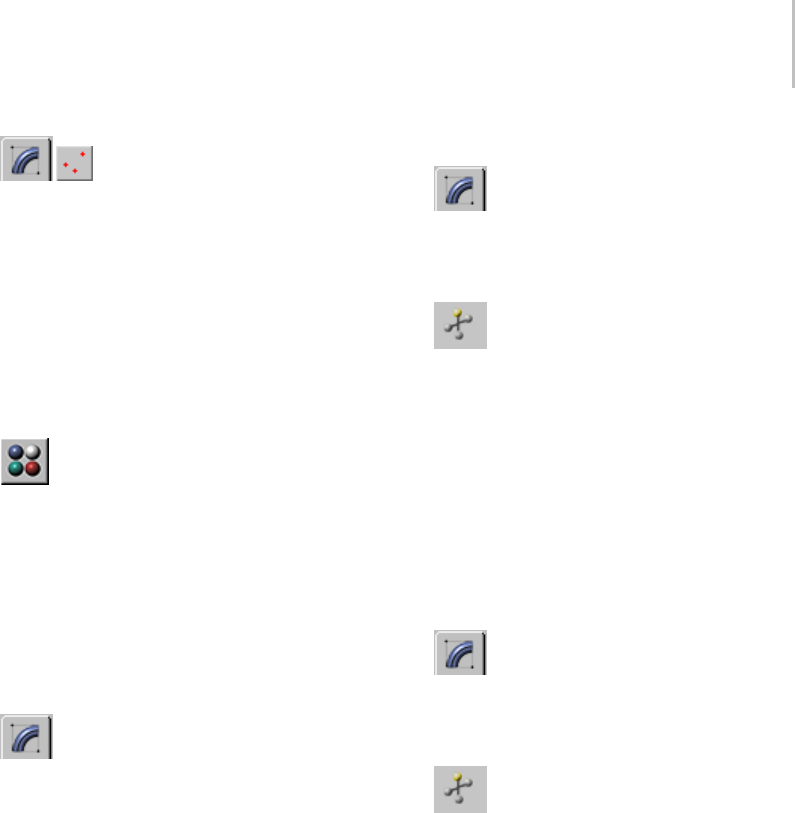
UVW Map Modifier 927
9. On the Modify panel, click to turn
on Vertex on the Selection rollout.
10.In the Front viewport, select the top vertices of
the box, and move them up.
11.Render the Front viewport again.
The cellular pattern stretches with the box.
This effect is enabled by the XYZ to UVW
option. To see the difference, we will change
theSourceoptionintheCoordinatesrollout
in the Material Editor.
12. In the Material Editor, locate the diffuse
Cellular material.
13.On the Coordinates rollout of the Cellular
diffuse map, open the Source drop-down list
and choose Object XYZ.
14.Render the Front viewport.
The cellular pattern is no longer stretched.
To transform the UVW Map gizmo:
1. OntheModifypanel,choosetheUVW
Map modifier in the stack display.
2. In the stack display, choose the Gizmo
sub-object level.
The gizmo changes to a yellow color, with one
green edge.
The green edge indicates the right edge of the
texture.
3. Move,scale,orro
tate the gizmo in the
viewports, or use the Length and Width
controls in the UVW Map modifier.
Transforming the map gizmo shifts the bitmap,
allowing you to orient and move the map on
the object’s surface.
To use manipulators to control the width and length:
1. OntheModifypanel,choosetheUVW
Map modifier in the stack display.
Yo u c a n a l s o b e a t t h e G i z m o l e v e l o f t h e
modifier.
2. On the default main toolbar, click to
turn on Select And Manipulate.
The UVW Map modifier’s gizmo turns green,
showing it is now a manipulator. Also, two
small circles appear next to two of the gizmo’s
edges.
3. Drag an edge of the gizmo to adjust the width
or length.
Atooltipshowsthenewwidthorlengthvalue.
To use manipulators to control tiling:
1. OntheModifypanel,choosetheUVW
Map modifier in the stack display.
Yo u c a n a l s o b e a t t h e G i z m o l e v e l o f t h e
modifier.
2. On the default main toolbar, click to
turn on Select And Manipulate.
The UVW Map modifier’s gizmo turns green,
showing it is now a manipulator. Also, two
small circles appear next to two of the gizmo’s
edges.
3. Drag one of the circles to adjust tiling in the U
or V dimension.
Atooltipshowswhichdimensionyouare
adjusting, and the new tiling value in that
dimension.
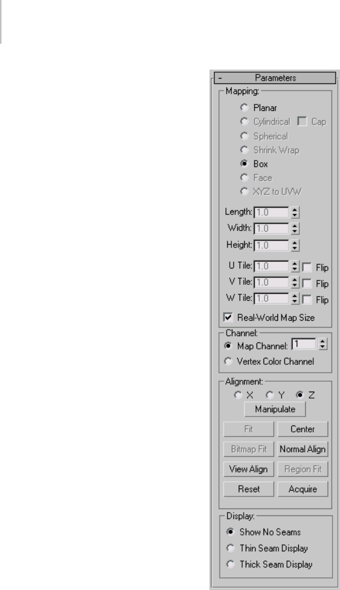
928 Chapter 8: Modifiers
Interface
Modifier Stack
Gizmo sub-object level—Enables gizmo
transformations. At this sub-object level you can
move,scale,androtatethegizmointheviewports
to position the mapping. In the Material Editor,
youturnontheShowMapinViewportoptionto
makethemapvisibleinashadedviewport,the
map moves on the surface of the object as you
transform the gizmo.
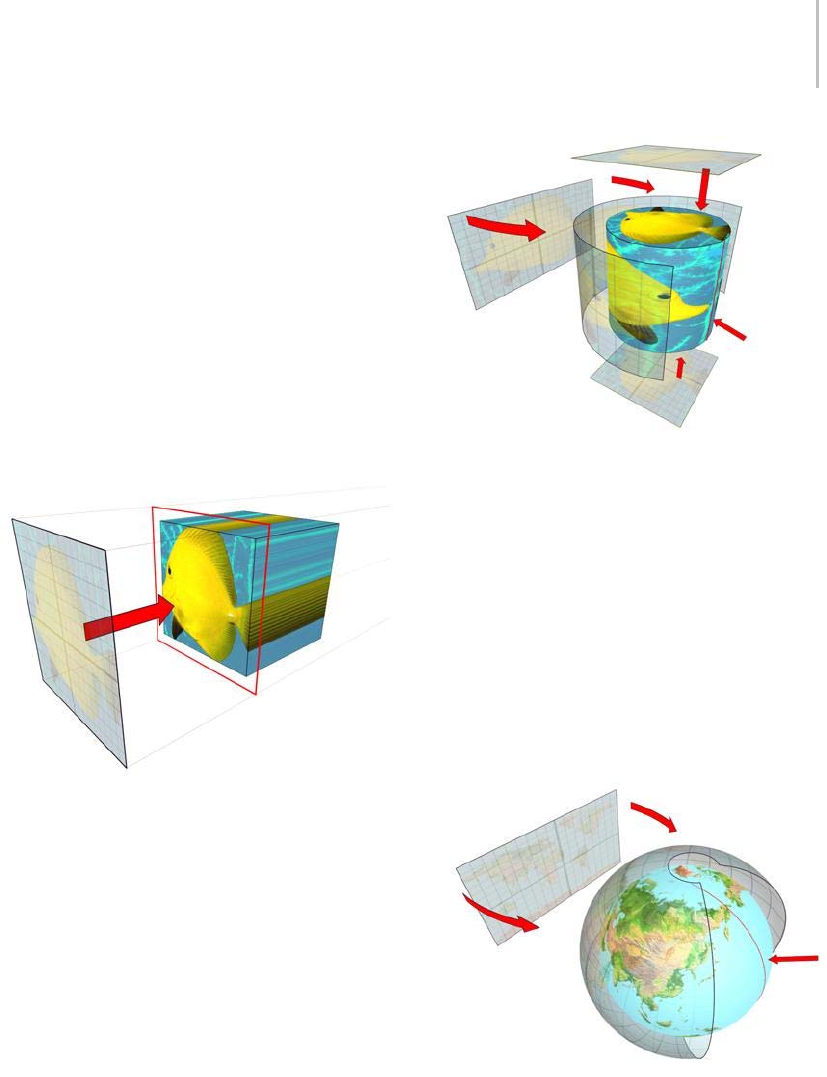
UVW Map Modifier 929
Mapping group
Determinesthetypeofmappingcoordinatesused.
Different kinds of mapping are distinguished by
how the map is geometrically projected onto the
object and how the projection interacts with the
object’s surfaces.
Planar—Projects the map from a single plane flat
against the object, somewhat like projecting a slide.
Planar projection is useful when only one side of
an object needs to be mapped. It is also useful
for obliquely mapping multiple sides, and for
mappingtwosidesofasymmetricalobject.
Planar map projection
Cylindrical—Projects the map from a cylinder,
wrapping it around an object. Seams where the
edges of the bitmap meet are visible unless a
seamless map is used. Cylindrical projection is
useful for objects that are roughly cylindrical in
shape.
Cylindrical map projection
Cap—Applies planar mapping coordinates to the
caps of the cylinder.
Note: Iftheendsoftheobjectgeometryarenotat
right angles to the sides, the Cap projection bleeds
onto the sides of the object.
Spherical—Surrounds the object by projecting the
map from a sphere. You see a seam and mapping
singularities at the top and bottom of the sphere
where the bitmap edges meet at the sphere’s poles.
Spherical mapping is useful for objects that are
roughly spherical in shape.
Spherical map projection
Shrink Wrap—Uses spherical mapping, but
truncates the corners of the map and joins them
all at a single pole, creating only one singularity.
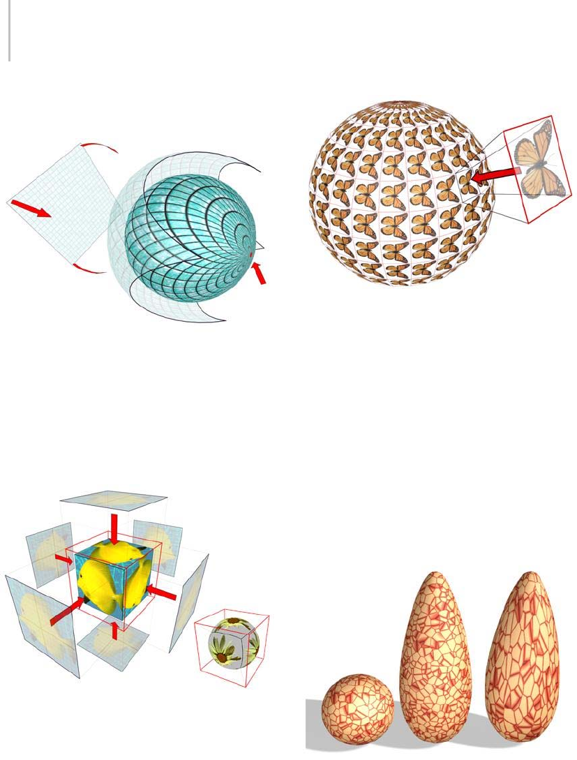
930 Chapter 8: Modifiers
Shrink-wrap mapping is useful when you want to
hide the mapping singularity.
Shrink-wrap projection
Box—Projects the map from the six sides of a box.
Each side projects as a planar map, and the effect
on the surface depends on the surface normal.
Each face is mapped from the closest box surface
whose normal most closely parallels its own
normal.
Boxprojection(shownonaboxandonasphere)
Face—Appliesacopyofthemaptoeveryfaceof
an object. Pairs of faces sharing a hidden edge are
mapped with the full rectangular map. Single faces
with no hidden edge are mapped with a triangular
portion of the map.
Face projection
XYZ to UVW—Maps 3D procedural coordinates to
UVW coordinates. This "sticks" the procedural
texture to the surface. If the surface stretches, so
does the 3D procedural map. Use this option with
procedural textures, like Cellular (page 2–1664)
Currently, XYZ to UVW cannot be used with
NURBS objects and is disabled if a NURBS object
is selected.
Note: In the Material Editor’s Coordinates rollout
for the map, set Source to Explicit Map Channel.
Use the same map channel in the material and
UVW Map modifier.
A sphere with a 3D procedural texture is copied, and the copies
are stretched.
Right: Using XYZ to UVW on the object enables the 3D
procedural texture to stick and stretch with the surface.

UVW Map Modifier 931
Length, Width, Height—Specify the dimensions of
the UVW Map gizmo. The default scale of the
mapping icon is defined by the largest dimension
of the object when you apply the modifier. You can
animate the projection at the gizmo level. Note the
following facts about these spinners:
• The dimensions are based on a bounding box
of the gizmo.
TheHeightdimensionisunavailableforthe
Planar gizmo: It does not have depth. Likewise,
the dimensions for Cylindrical, Spherical,
and Shrink Wrap mapping all display the
dimensions of their bounding box and not their
radiuses. No dimensions are available for the
Face map: Each face on the geometry contains
theentiremap.
• The three dimensions are set to 1 or 2,
depending on map type and dimensions, when
you load files created in Autodesk VIZ or
earlierversionsof3dsMax.(Thismaintains
compatibility with files from previous releases,
in which gizmos were scaled non-uniformly to
adjust their dimensions.).
The dimensions essentially become scale
factors rather than measurements. You can
reset the values to dimensions by clicking the
Fit or Reset buttons, which will lose the original
non-uniform scaling.
U Tile, V Tile, W Tile—Let you specify the
dimensions of the UVW map, for tiling the image.
These are floating-point values, which you can
animate to displace the map’s tiling over time.
Flip—Reverses the image about the given axis.
Real-World Map Size—Controls the scaling method
used for texture mapped materials that are applied
totheobject. Thescalingvaluesarecontrolled
by the Use Real-World Scale settings found on
the applied material’s Coordinates rollout (page
2–1625).Default=on.
Whenon,theLength,Width,HeightandTiling
spinners are unavailable.
Channel group
Each object can have up to 99 UVW mapping
coordinate channels. The default mapping (from
the Generate Mapping Coordinates toggle) is
always channel 1. The UVW Map modifier can
send coordinates to any channel. This lets you
have many different sets of coordinates on the
same face simultaneously.
Map Channel—Sets the map channel. The UVW
Map modifier defaults to channel 1, so mapping
behaves in the default fashion (and in the fashion
of earlier software releases) unless you explicitly
change to another channel. Default=1. Range=1
to 99
To use the additional channels, you must not only
choose a channel in the UVW Map modifier, but
also assign an explicit map channel at the map level
of the material assigned to the object. You can use
many UVW Map modifiers in the modifier stack,
each one controlling the mapping coordinates of
different maps in a material.
Vertex Color Channel—Define the channel as a
vertex color channel by choosing this option.
Be sure to match any material mapping in the
coordinates rollout to be Vertex Color as well,
or by using the Assign Vertex Colors utility (page
2–1734).
The Map channels are accessed in various places
in the software, as follows:
•Generate Mapping Coords—This check box, in
the creation parameters of most objects, assigns
Map channel 1 when turned on.
•UVW Map Modifier—Contains options for
channels 1 through 99. This lets you specify
which UVW coordinates are used by this UVW
Map modifier. The modifier stack can pass
these channels simultaneously for any face.

932 Chapter 8: Modifiers
•UVW XForm and Unwrap UVWs—These two
modifiers also contain Channel option buttons.
•Material Editor Channel Assignment—Yo u
assign the channel to be used by a map in the
Coordinates rollout at the map level in the
Material Editor.
• The assignment varies depending on the type
of map:
2D Maps—In the Mapping list for the Texture
option, you can choose Explicit Map channel,
Vertex Color Channel, Planar from Object
XYZ, or Planar from World XYZ.
3D Maps—At the top of the Coordinates rollout,
thereisaSourcelistwhereyoucanchoosean
Explicit Map Channel, Vertex Color Channel,
Object XYZ, or World XYZ. Use the Map
Channel spinner to define the channel number.
•NURBS Surface Objects and Sub-Objects—Let
you specify which Map channel the surface
uses.
Alignment group
X/Y/Z—Select one of these to flip the alignment of
the mapping gizmo. Each specifies which axis of
the gizmo is aligned with the local Z axis of the
object.
Note: These options aren’t the same as the Flip
check boxes beside the U/V/W Tile spinners. The
Alignment option buttons actually flip the gizmo
orientation, while the Flip check boxes flip an
assigned map’s orientation.
Manipulate—When on, a gizmo appears on the
object that lets you change parameters in the
viewport. When Real-World Map Size is on,
Manipulate is available only with the Planar and
Box mapping types. For more information, see
Manipulators for UVW Map (page 1–924).
Tip: Turn on snapping to adjust the mapping
precisely.
Fit—Fits the gizmo to the extents of the object and
centersitsothatit’slockedtotheobject’sextents.
Unavailable when Real-World Map Size is on.
Center—Moves the gizmo so that its center
coincides with the center of the object.
Bitmap Fit—Displays the standard bitmap file
browsersothatyoucanpickanimage.Unavailable
when Real-World Map Size is on.
For planar mappings, the map icon is set to the
aspect ratio of the image. For cylindrical mapping,
the height (rather than the radius of the gizmo) is
scaled to match the bitmap. For best results, first
usetheFitbuttontomatchtheradiusoftheobject
and gizmo, and then use Bitmap Fit.
Normal Align—Click and drag on the surface of the
object to which the modifier is applied. The origin
of the gizmo is placed at the point on the surface
wherethemouseispointing;theXYplaneofthe
gizmo is aligned to the face. The X axis of the
gizmo lies in the object’s XY plane.
Normal Align respects smoothing groups and uses
the interpolated normal based on face smoothing.
As a result, you can orient the mapping icon to any
part of the surface, rather than having it "snap" to
face normals.
View Align—Reorients the mapping gizmo to
face the active viewport. The size of the icon is
unchanged.
Region Fit—Activates a mode in which you can
drag in the viewports to define the region of the
mapping gizmo. The orientation of the gizmo is
not affected. Unavailable when Real-World Map
Size is on.
Reset—Deletes the current controller controlling
the gizmo and plugs in a new one initialized using
the Fit function. Any animation to the gizmo is
lost. As with all the alignment options, you can
cancel the reset operation by clicking Undo.
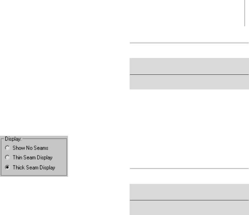
UVW Mapping Add Modifier 933
Acquire—Effectively copies the UVW coordinates
from other objects When you pick an object
from which you want to acquire UVWs, a dialog
prompts you whether the acquire should be done
in an absolute or relative fashion.
IfyouchooseAbsolute,theacquiredmapping
gizmo is positioned exactly on top of the mapping
gizmo you pick. If you choose Relative, the
acquired mapping gizmo is positioned over the
selected object.
Display group
Thissettingdetermineswhetherandhowmapping
discontinuities, also known as seams, appear in
the viewports. The seams appear only when the
Gizmo sub-object level is active. The default seam
color is green; to change it, go to Customize menu
> Customize User Interface > Colors tab, and then
fromtheElementsdrop-downlist,chooseUVW
Map.
The options are:
•Show No Seams—Mappingboundariesdon’t
appear in the viewports. This is the default
choice.
•Thin Seam Display—Displays mapping
boundaries on object surfaces in the viewports
with relatively thin lines. The line thickness
remains constant as you zoom the view in and
out.
•Thick Seam Display—Displays mapping
boundaries on object surfaces in the viewports
with relatively thick lines. The line thickness
increases when you zoom the view in and
decreases when you zoom out.
UVW Mapping Add Modifier
Select an object. > Modify panel > Modifier List > UVW
Mapping Add
Select an object. > Channel Info (page 2–1738) >Adda
channel.
The UVW Mapping Add modifier is added to an
object’s modifier stack when you add a channel
in the Channel Info utility (page 2–1738).Youcan
also add the modifier explicitly by choosing it from
the Modifier List. It has no user interface.
To merge the results of the add operation into the
object’s geometry, collapse the modifier stack after
adding.
UVW Mapping Clear Modifier
Select an object. > Modify panel > Modifier List > UVW
Mapping Clear
Select an object. > Channel Info (page 2–1738) >Cleara
channel.
The UVW Mapping Clear modifier is added to an
object’s modifier stack when you clear a channel
with the Channel Info utility (page 2–1738).You
can also add the modifier explicitly by choosing it
from the Modifier List.
To merge the results of the deletion into the
object’s geometry, collapse the modifier stack after
deleting.
Interface
Map Channel—Specifies the map channel to clear.
This is equivalent to clearing a specific channel
in the Channel Info utility. If the specified map
channel doesn’t exist, the modifier has no effect.
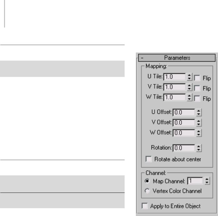
934 Chapter 8: Modifiers
UVW Mapping Paste Modifier
Select an object. > Channel Info (page 2–1738) >Copy
and then paste a channel.
The UVW Mapping Paste modifier is added to an
object’s modifier stack when you paste a channel
in the Channel Info utility (page 2–1738).Itisn’t
available from the modifier list, and has no user
interface.
To merge the results of the paste operation (for
example, a vertex selection) into the object’s
geometry, collapse the modifier stack after pasting.
UVW XForm Modifier
Modify panel > Make a selection. > Modifier List >
Object-Space Modifiers > UVW XForm
Select an object. > Modifiers menu > UV Coordinates >
UVW XForm
Use the UVW XForm modifier to adjust tiling
and offset in existing UVW coordinates (page
3–1028).Ifyouhaveanobjectwithcomplex
UVW coordinates already applied (such as a Loft
object, or a parametric object with generated
coordinates), you can apply this modifier to adjust
those coordinates further.
For example, if you create a torus and turn
on Generate Mapping Coordinates, the UVW
coordinates work perfectly with the torus, but
ifyouwanttotileormovethecoordinates,you
would previously have needed to do it at the
material/map level. Now you can apply a UVW
XForm modifier to alter the built-in coordinates.
You can use a Mesh Select or Edit Mesh modifier
toapplyaUVWAdjusttosub-objectselections,
as well. This is handy if you want to rotate the
mappingonaparticularportionofanobject.
Interface
Mapping group
U Tile, V Tile, W Tile—Alter the tiling along any of
the three coordinate axes.
Flip—Reversesthedirectionofthemapalongthe
specified axis.
U Offset, V Offset, W Offset—Move the map in the
direction of the specified axis coordinate.
Rotation—Rotates the map.
Rotate About Center—When active, the map rotates
about the center of the object. If this is applied to
a sub-object selection, it uses the center of that
selection.
When this is turned off, the map rotates about the
corner of the U and V coordinate gizmo.
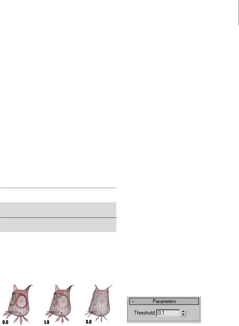
Vertex Weld Modifier 935
Channel group
Specifies whether to apply the transform to a
mapping channel or a vertex color channel, and
which channel to use. For more information on
these channels, see UVW Map Modifier (page
1–922).
Map Channel—Specifies a UVW channel to use for
the mapping, and use the spinner to its right to set
the channel number.
Vertex Color Channel—Uses the vertex color
channel for the mapping.
Apply To Entire Object—If the UVW Xform
modifier is applied to an active sub-object
selection, such as face or patch, this switch controls
whether the settings of the UVW Xform modifier
affect only the original sub-object selection or
affect the entire object.
Vertex Weld Modifier
Select a mesh, patch, or PolyMesh object. > Modify panel
> Modifier List > Vertex Weld
Select a mesh, patch, or PolyMesh object. > Modifiers
menu > Mesh Editing > Vertex Weld
The Vertex Weld modifier behaves like the Weld
featureinEditableMeshorEditablePatchand
welds all vertices that fall within the threshold
setting. Vertex Weld is very useful for cleaning
up meshes that have vertices that are close or
overlapping, but not welded.
The results of three Vertex Weld threshold settings
Procedure
Example: To apply the Vertex Weld modifier to a
mesh:
1. Create a box with Length, Width, and Height
set to 40.
2. Right-click the box and choose Convert to >
Convert to Editable Poly.
3. Set the sub-object mode to polygon, and select
Polygon 6.
Tip: Watch the listing at the bottom of the
Selection rollout to see which polygon is
selected.
4. Delete polygon 6.
By deleting the polygon, you create an open
mesh.
5. Apply a Turn To Poly modifier, and set the
Selection Level to Object.
6. Apply a Mirror modifier, and set Mirror Axis
to X.
7. Turn on Copy, and set Offset to –40.
The reflection of the box shares a common
seam but the vertices along the seam are not
welded.
8. Apply a Vertex Weld modifier to cement the
two boxes into one element.
Note: This combination of steps can be streamlined
by using the Symmetry modifier (page 1–861),
which will mirror the mesh and weld it in a single
operation.
Interface
Threshold—The value of the Threshold setting
delegates how close vertices can be before they are
automatically welded together. Default=0.1
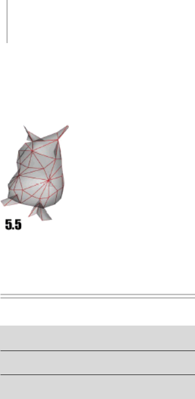
936 Chapter 8: Modifiers
Note: A higher threshold setting will result in
welding more vertices, thus removing smaller
faces and details. If the threshold is set too high,
the mesh will begin to deform.
A threshold setting of 5.5 removes all detail, making the model
unrecognizable.
VertexPaint Modifier
Select an object. > Modify panel > Modifier List >
VertexPaint
Select an object. > Modifiers menu > Mesh Editing >
Vertex Paint
Select an object. > Utilities panel > More > Assign Vertex
Colors > Click Assign To Selected. > Modify panel
The VertexPaint modifier lets you paint vertex
colors onto an object. You’re not restricted to only
vertex-level painting. Using sub-object selection,
you can also control which vertices get painted,
face-by-face. All faces sharing a vertex have the
adjacent corner shaded as well. The resulting
painted object receives a coarse gradient across
each face.
The amount of color that 3ds Max applies to a
vertex depends on the distance of the vertex from
the position of the paint cursor on the face. The
more you select a face, the more it changes to the
new color. The Opacity button also controls the
strength of the color. 3ds Max shades the color, so
if you have one green vertex and two white vertices
for one face, for example, you’ll see a gradient on
that face.
VertexPaint modifier also lets you paint values for
the vertex alpha and illumination channels. These
channels affect the transparency and shading of
vertex colors, respectively.
Tip:
Tip:
Notes and Tips
For best results with VertexPaint, keep the
following in mind:
• To render vertex colors, assign a Ve r t e x C o l o r
map (page 2–1693), as described in To re n d e r
vertex colors (page 1–938).
• If you select faces using the selection tools of the
VertexPaint modifier, you restrict your painting
to the selected faces, as opposed to all faces.
This allows you to sharply define the edges of
your painted selection.
• You can streamline the painting process by
using the Brush Presets tools (page 3–690).
• Each VertexPaint modifier works internally
to itself, and cannot modify existing vertex
coloring. To paint over existing coloring, use
the Condense to single layer function.
About Map Channels and Vertex Color,
Vertex Alpha, and Vertex Illum
When using vertex paint, it is helpful to
understand how 3ds Max manages vertex color,
alpha, illumination, and map channels. The
software stores and manages all of these different
pieces of information using the same underlying
system.
The map channels are defined as triple-value
channels (tuples) with a unique integer ID number
ranging from -2 to 99. The first five map channels
have specific and familiar usages:

VertexPaint Modifier 937
•Channel (2): UVW “second pass” texture
mapping coordinates
•Channel (1): UVW standard texture mapping
coordinates
•Channel (0): RGB vertex color
•Channel (-1): FLOAT vertex alpha (really only
1 value needed)
•Channel (-2): RGB vertex illumination
Every geometric vertex of a mesh or poly object
can be assigned up to 102 channel values (99 + 3).
The negative numbering scheme for vertex alpha,
and illumination is actually historic: it was done
to preserve the meaning of existing map-channel
data in older scene files before vertex alpha and
illumination were added.
You can paint on any arbitrary channel, and to use
one or more channels for any arbitrary meaning
for a given vertex. It is useful in development
of content for games to paint on arbitrary map
channels numbered higher than those used for
texture mapping (such as channels 3, 4, 5). These
can be used to store logical information about a
vertex, whether it is “slippery” or “explosive”, for
example.
A single vertex can be assigned a stack of map
channels that carry different meanings. When the
modifier stack is collapsed, these map channels
are preserved.
The new VertexPaint modifier takes this into
consideration through its simple exposure of map
channel IDs for display and painting.
About Painting in Layers
The layer system allows you to paint changes on a
single layer, then make another layer on top of that,
and paint additional changes. This can be used to
store different versions or variations of your vertex
color painting.
Every layer has a blending mode that it uses to
determine how it combines with the other layers.
You can assign vertex colors using the Assign
Vertex Colors utility (page 2–1734),thenadd
another layer, change the layer mode operator
to Lighten, and paint with a white paintbrush
to lighten up areas. Fifteen different modes are
available, and many tasks can be accomplished
using paint layers.
OneoftheprimaryadvantagesofVertexPaint
is its use of the modifier stack as a kind of
image-composite stack. Each VertexPaint modifier
serves as a single layer in the composite. You can
move layers up and down the stack, enable and
disablethem,andflattenthestackusingCondense
to single layer.
Backward Compatibility
If you load an older file that uses a previous version
of the VertexPaint modifier, then the legacy
modifier will be loaded when the file is opened.
The legacy modifier has not been changed, and
the two modifiers are not inherently compatible
in terms of their data format during loading and
saving.
If you have vertex color data in a legacy VertexPaint
modifier, you can use the Condense to single layer
tool of the new modifier to migrate the vertex
colors into the new modifier.
Procedures
To add scene lighting into an object’s vertex color:
1. Select the objects in the scene that you want to
color.
2. OntheModifypanel,chooseVertexPaintfrom
the modifier list.
The floating Paintbox (page 1–941) appears,
docked to the left edge of the viewports.
3. Open the Assign Vertex Colors rollout.
938 Chapter 8: Modifiers
Note: This rollout provides the same tools as
found in the Assign Vertex Colors utility.
4. IntheLightModelgroup,turnonLighting.
5. In the Shadows group, turn on Calculate
Shadows, if you want shadows added.
Tip: Turn on S haded and choos e Use Map s if
you want to mix the texture map information
with the lighting and shades.
6. Click Assign To Selected
7. On the Vertex Paintbox, turn on Vertex
Color Display Shaded to see the vertex lighting
in the vertex color map.
To paint vertex colors on an object:
1. Select the scene objects to paint.
2. On the Modify panel, choose
VertexPaint from the Modifier List.
TheVertexPaintboxappears.
3. Choose the color you want to paint with
by clicking the large color swatch below the
Paintbrush button. This opens the Color
Selector.
4. Change the color using controls on the Color
Selector.
5. Adjust the strength of the color by entering a
percentage value in the Opacity field.
6. Click Vertex Color Display Unshaded to
see the vertex colors without shading.
7. Click the Paint button and move the cursor over
the selected object in the viewport.
8. When the cursor displays over the object, press
andholddowntheleftmousebuttonanddrag
to paint the object.
Tip: Thecursordisplaysthesizeofthebrush.
Use the Size spinner to change to a larger or
smaller brush.
To see vertex colors in a viewport:
1. Right-click the object with painted vertices,
and choose Properties from the quad menu.
2. In the Display Properties group, turn on the
toggle for Vertex Color.
Vertex Color is one item on a drop-down list.
The other items are Vertex Illumination, Vertex
Alpha, Map Channel Color (which uses the
spinner immediately below the list), and Soft
SelectionColor. Viewportscandisplayonly
one of these vertex channels at a time.
3. Click OK.
To render vertex colors:
1. Open the Material Editor, and apply a
Standard material to the object.
2. Click the map button for the Diffuse
component.
3. In the Material/Map Browser, choose Vertex
Color as the map, and then click OK.
Now, when you render the scene, the rendering
shows the painted vertices.
To animate the opacity of a vertex color layer
1. Choose the layer youwishtoanimate,by
highlighting the Vertex Paint modifier in the
stack that corresponds to that layer.
2. Turn on the Auto Key button.
3. On the floating vertex paintbox, in the Layer
group move the Opacity slider.
This sets a key for the opacity.
4. Movethetimesli
der to another frame and
again change the value using the Opacity slider.
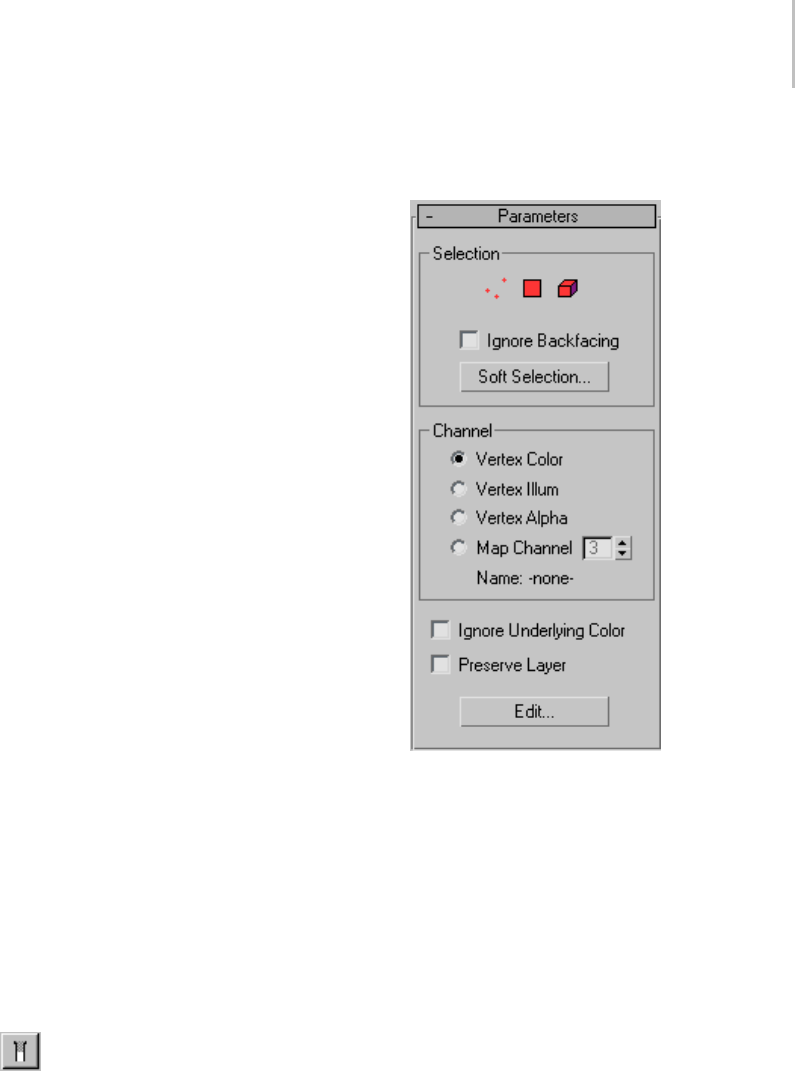
VertexPaint Modifier 939
5. Click Play to see the animated opacity in the
viewport.
To animate vertex color using UVW XForm modifier:
Yo u c a n u s e t h e U V W X F o r m m o d i f i e r i n
conjunction with a specific vertex paint layer to
modulate vertex color effects in the viewport.
1. Apply a UVW XForm modifier directly above
the VertexPaint layer (modifier) you want to
modulate.
2. Set the Channel type on the UVW XForm
modifier to Vertex color.
3. Animate the U, V, and W spinners using
identical values. For example, animate UVW
from 1 to 0 over the length of the animation.
This will attenuate the RGB values of the
underlying vertex color results uniformly. It
will effectively dim out the vertex color result
directly below the UVW XForm modifier.
Note: Any additional vertex paint layers applied
abovetheUVWXFormmodifierinthestack
for the selected object(s) will be unaffected
Tip: Yo u c a n a d d m u l t i p l e U V W X F o r m
modifiers in your stack in this way, giving some
progressive control over modulated vertex
colors. The effect is always additive, however,
and cannot be weight-blended.
To paint under an existing layer and view the result:
1. Select an object that has several VertexPaint
modifiers displayed in the stack.
2. In the modifier stack, activate the VertexPaint
modifier that is the layer you want to paint on.
3. Tur n on t he Show End Resu lt to gg l e.
Now, when you paint on the layer, you will see
the painting taking place under the top layer.
Interface
Parameter rollout
Selection group
Thecontrolsinthisgroupareidenticaltothe
selection controls found in the Selection group
(page 1–945) of the Paintbox rollout.
Channel group
These controls specify which channel type the
vertex paint layer will affect, and which map
channelnumberyou’llpainton.
•Vertex Color—Choose this to paint on a vertex
color layer.
•Vertex Illum—Choose this to paint on a vertex
illumination layer.
•Vertex Alpha—Choose this to paint on a vertex
transparency layer.

940 Chapter 8: Modifiers
•Map Channel—Choose this to paint on a
specifically named or numbered map channel.
Map channel spinner—Specifies the channel
number. Available only when Map Channel is
chosen.
Note: Ifyouhavepaintedonalayerandthenchange
the channel setting, the painted information will
be moved to the new channel. For example if you
select Vertex Color and paint, then turn on Vertex
Illum, the painted information will be removed
from the Vertex Color channel and applied to the
Vertex Illum channel instead.
Name—If a channel has a name defined it will
appear here. Channels can be named using the
Channel Info Utility (page 2–1738).
Ignore underlying color—When turned on,
VertexPaint ignores whatever vertex colors it
receives from below it on the stack. As a result,
you will see the layer’s raw colors on an otherwise
whiteobject. Theblendmodehasnoeffect(it
behaves like Normal mode) because the base
color is considered transparent, so the layer is not
blended with anything.
Thepurposeofthistoggleistoisolatealayer
from the colors below, to help the user visualize
the layer’s raw data. The layer is not completed
isolated when this is on, because layers above it
can still affect the result. The user needs to disable
those layers or turn off Show End Result to see the
current layer in complete isolation.
The Ignore Base Color toggle should only be
needed when the object at the bottom of the
stack already has some vertex colors baked in. In
other cases, you can just disable the paint layers
or whichever modifiers are adding vertex colors
to the object. In that case, the active paint layer
would not receive any vertex colors from below
itself on the stack. As a result, it treats all base color
as transparent and the layer colors are displayed in
the raw (not blended with anything).
Note: Per-vertex layer opacity is not passed up
the stack. A paint layer modifier makes a yes/no
decision about whether an object below it has
vertex colors or not, and will subsequently treat
allbasecolorsastransparentorallasopaque.
So if you paint even a single vertex using Edit
Mesh, for example, the object is considered to have
vertex colors, and a paint layer will blend its colors
with the (predominantly white) mesh instead of
treating the mesh as transparent.
Preserve Layer—When on, the modifier will not
be deleted by any Condense To Single Layer
operation. SinceCondenseToSingleLayer
performs two independent actions (creating a new
baked-color modifier and then deleting existing
modifiers), this option allows access to only the
firstpartofthefunctionalitywhennecessary.
That is, you can bake colors into a new paint layer,
without being forced to have the old modifiers
deleted.
Edit—Displays the Ve r t e x P ai nt b o x f l o a t e r ( p a g e
1–941) if it has been closed.
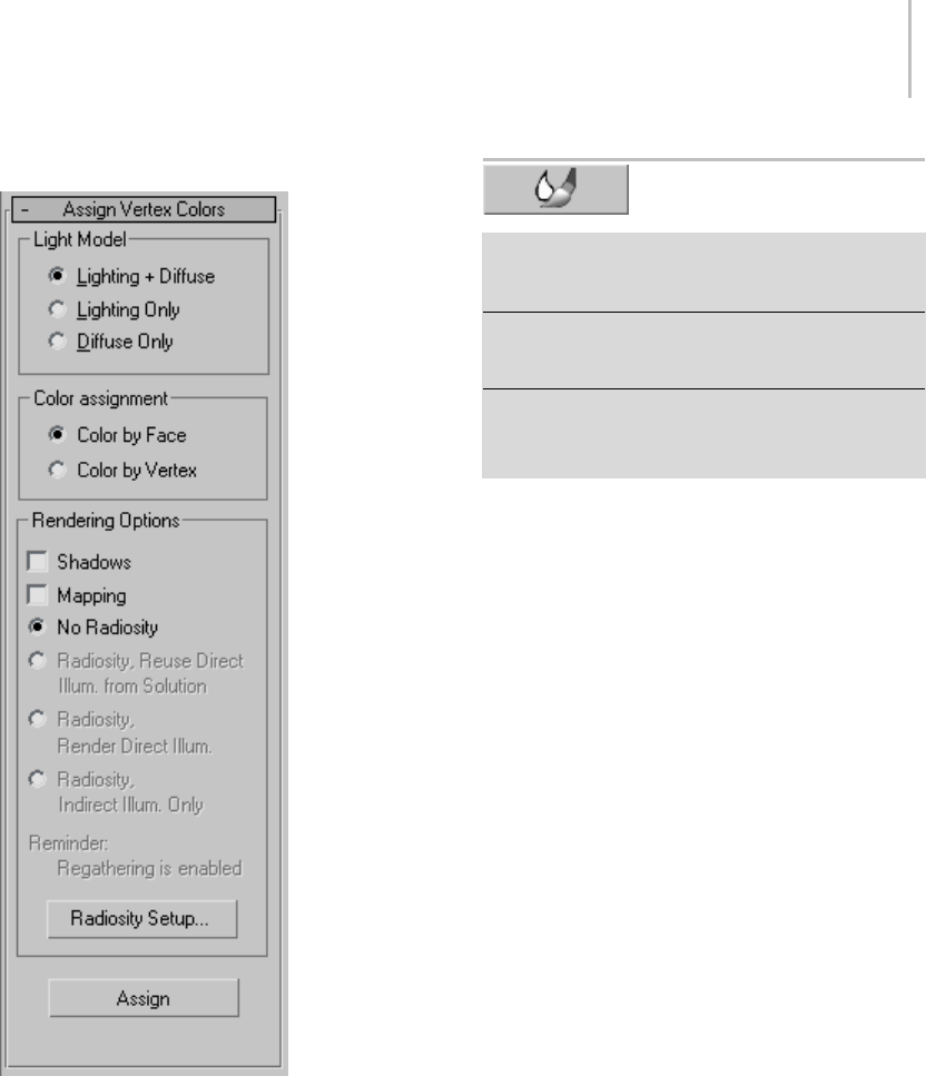
VertexPaint Paintbox 941
Assign Vertex Color rollout
This rollout gives you access to the same controls
found in the Assign Vertex Colors utility (page
2–1734). They let you take the scene lighting
information and bake it into the vertex channel
system.
VertexPaint Paintbox
Select an object. > Modify panel > Modifier List >
VertexPaint > Paintbox dialog (Click Edit in the Parameters
rolloutifitisn’tdisplayed.)
Select an object. > Modifiers menu > Mesh Editing
> Vertex Paint > Paintbox dialog (Click Edit in the
Parameters rollout if it isn’t displayed.)
Select an object. > Utilities panel > More > Assign Vertex
Colors > Click Assign To Selected > Modify panel >
Modifier List > VertexPaint > Paintbox dialog (Click Edit in
the Parameters rollout if it isn’t displayed.)
The VertexPaint modifier’s Paintbox is a floating
toolbox with various vertex painting tools. The
Paintbox is launched automatically after the
VertexPaint modifier (page 1–936) has been applied
to one or more objects. You can close the Paintbox
by clicking the X button in the upper-right corner
of its window. To open it again, click the Edit
button in the Parameters rollout of the VertexPaint
Modifier
Note: If a VertexPaint modifier is assigned to
the object, you can also display the Paintbox by
clicking Edit in the Assign Vertex Color utility.
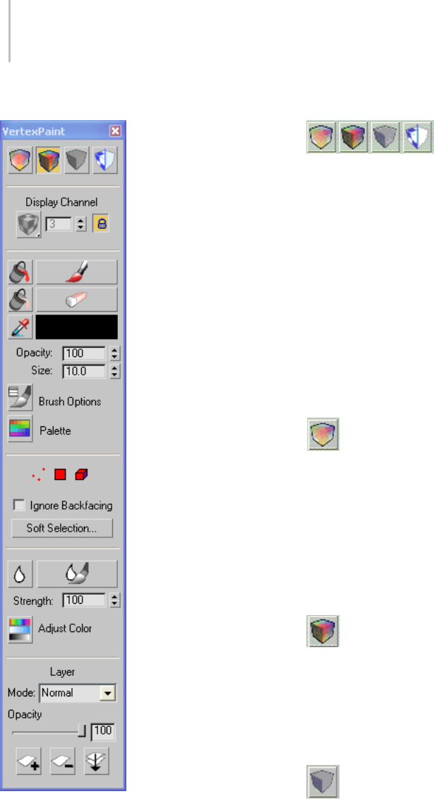
942 Chapter 8: Modifiers
Interface Vertex Color Display controls
Control the display of the vertex paint in the
viewport by using the four icons at the top of the
floating panel. You can easily switch between
shaded and unshaded vertex color modes, or turn
offthedisplayofvertexcolorandortexturemaps.
Note: The first three of these buttons stay
highlighted when you click them, to indicate which
shadingmodeisactive. ToggleTextureDisplay
simply performs the action without becoming
highlighted.
Note: Thesecontrolshavenoeffectonwireframe
viewports, but work for all shaded viewports,
including Lit Wireframe.
Vertex color display – unshaded —Displays
the currently selected object in vertex color display
mode. Thismodeisidenticaltotheoneoffered
bytheObjectPropertiesmenu(rightclickon
object, select Properties > Turn On Vertex Color
in the Display Properties group, making sure that
Shaded is off.)
This has no effect on wireframe, but works on lit
wireframe and all other shaded display modes.
Vertex color display – shaded —Displays the
currently selected object in vertex color display
mode, with viewport lighting (shading). his
mode is identical to the one offered by the Object
Properties menu (right click on object, select
Properties>TurnOnVertexColorintheDisplay
Properties group, making sure that Shaded is on.
Disable vertex color display—Displays the
currently selected object in its current shading
mode without showing vertex colors.
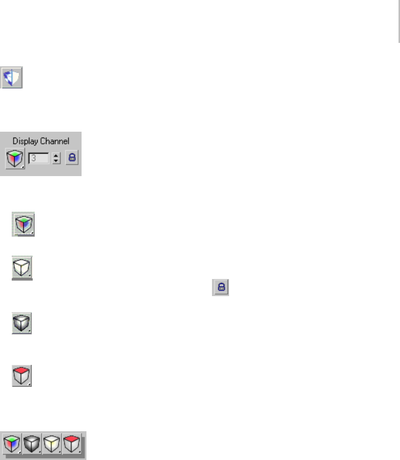
VertexPaint Paintbox 943
Toggle texture display —Displays or hides
texture maps on the currently selected object.
Viewport Channel Display selector
This menu allows you to select which one of the
map channels to paint on:
•Vertex colors—Choosing this lets you
display the vertex color channel in the viewport.
•Vertex alpha—Choosing this lets you
display and paint the vertex transparency
channel in the viewport.
•Vertex Illum—Choosing this lets you
display and paint the vertex lighting channel
in the viewport.
•Map Channel—Choosingthisletsyou
define a numbered map channel to paint on.
Define the channel ID number with the Map
Channel Display spinner.
Map channel display in viewport flyout
What you see is what you paint, so whatever you
select will both be displayed and activated for
painting.
Note: You cannot paint on all channels
simultaneously as you could in the previous
version of the vertex paint modifier.
Map Channel Display Spinner —This control lets
you to numerically select a channel other than
the 3 conventional ones listed above, for display
only. If the channel you select is currently used for
mapping coordinates, you’ll see red/yellow/green
colors corresponding to the UVW values.
Yo u m i g h t c h o o s e m a p c h a n n e l s a b o v e t h e
standard channel 1, 2, 3 that do typically get
used for texture mapping. But you will need to
keep track of your own conventions, and/or use
the Channel Info utility to track what has been
allocated for each object.
The Map Channel Display Spinner is only available
when the Map Channel display button. If you
assign a new vertex paint modifier or create a
new layer and choose a particular numeric map
channel, then select Map Channel display, the
spinner will become available.
Lock button—The Lock button makes
the Display Channel setting unavailable, and
automatically sets Display Channel to whatever
channel you choose on the Modify panel >
Channel rollout. Keep this turned on, to ensure
that you’re always displaying what you’re painting.
If you want to glance at another channel without
stopping your current paint session, turn off the
lock and then switch the display channel. When
you are finished, switch back and turn the lock
back on.
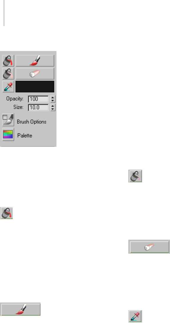
944 Chapter 8: Modifiers
Vertex Paintbrush group
Vertex paint controls
Here are the controls that let you access the
paintbrush and the paint. You can choose color
to paint with, from a color selector or from the
scene. Choose to adjust the brush size or envelope,
or launch advanced paintbrush options such as
pressure sensitivity.
Paint All—Performs a traditional paint fill
operation on the current object or sub-object
selection. In the case of sub-object selections
(vertices, faces, elements) the fill will honor those
selections. In the case of soft-selections Paint
all will do a “faded” fill, slowly tapering off the
opacity based on the soft selection settings.
As with the Paint button, this will either paint
on the current layer, if one is open in the Modify
panel, or else it will create a new vertex paint layer
instanced across the selected objects.
Paint—Starts the painting
process. Once it is turned on, you can start
painting on the current selection, by moving the
cursor into the viewport and over the object.
If there is a Vertex Paint modifier highlighted in
the Modify panel, you will be painting into that
layer. But if the selected objects do not currently
have a vertex paint layer highlighted in the modify
panel, then a dialog appears letting you create a
new modifier. This will be instanced across all the
selected objects.
You will not see the results of your brush strokes,
unless the proper display mode is set (above) Be
sure your display mode and your paint target
match. For example – if you are painting on the
alpha channel, be sure you are displaying the alpha
channel. If you are painting on the color channel,
display the color channel. Brush strokes will use
the color specified in the color swatch directly
below the Paint button.
See Painter Options Dialog (page 1–960) for more
painting options.
Erase all—Erases all painting applied to
the currently selected objects via the current
VertexPaint modifier. This allows you to see
through the underlying color of the object’s
vertices. This underlying color might come from
the object’s original vertex color, or from another
vertex paint layer directly below it in the modifier
stack. This supports soft selection as well.
Erase—Tur ns the brush into an
eraser that will remove paint from the currently
selected objects. Erase mode will actually erase
any painting applied to the currently selected
objects for the current layer of paint (allowing the
true color of the original objects vertices to be
seen, or the vertex paint layer immediately below
the current one).
Pick color from object—Allows you to choose
a color from the currently selected objects. The
color is taken from a single vertex; region selection
is not supported. The choice must occur near a
vertex, or no color will be chosen. You can drag
across a vertex of interest to pick up its color.
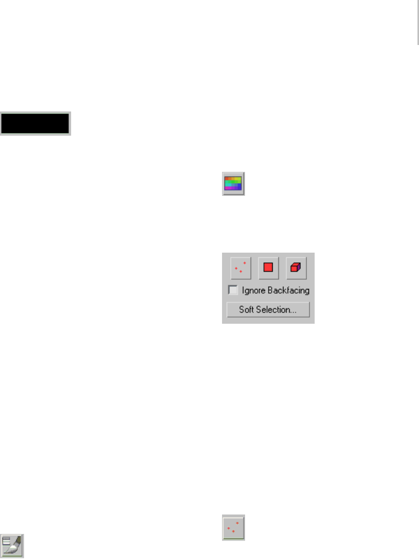
VertexPaint Paintbox 945
Because this button enters a mode, it must be
clicked to leave the mode, or you can choose
another mode to turn it off.
Color swatch—The color swatch
indicates the current color that will be used when
painting begins. Clicking the swatch launches
the standard color selector. Here you can change
the color that will be used on the next brush
stroke. It provides standard Hue, Saturation, and
Brightness selection, along with Red, Green, and
Blue selection and numerical entry.
Opacity—Controls the opacity of paint being
applied to the currently selected objects in a single
paint stroke (actually, any time before mouse up).
This value represents the percentage of new paint
that will blend into the color already applied to
the selected objects. Successive paint strokes will
continue to add this color until it overpowers the
underlying color completely. The maximum value
is 100% and 0% is the minimum value. A value of
50 percent will blend equally with the underlying
vertex color in a single stroke (before mouse up).
The brush opacity serves to clamp the effect of
each brush stroke, taken as a whole. If you pick
a low opacity amount, then a single brush stroke
will have only a small effect, no matter how much
youscrub.Thisallowsimprovedcontroloverthe
density of a glaze of color, with an even glazing
across all the painted vertices.
Size—Controls the diameter of the brush, as seen
in the viewport. Size values range from zero to
9,999,999 and must be chosen appropriately for the
size and resolution of geometry you are painting.
Brush Options —Opens the Painter Options
dialog (page 1–960),whereyoucanaccess
advanced paintbrush controls. These are the
standard set of Painter Interface options. The
same options can be seen, for example in the Skin
modifier, for painting weights.
Here you will find a rich selection of brush
configuration tools that change the way your
brush strokes apply color to the selection. Includes
tools for mirror painting mode and using pressure
sensitivity.
Palette—Click to display the Color Palette
(page 1–950), which lets you create, edit, and
manage custom palettes for use with VertexPaint.
Selection group
Toolsinthisgroupletyouchoosesub-object
selection levels. You can select vertices, faces or
elements. Includes the option to ignore backfacing
so you can limit your selection to sub-objects
that face toward you, and also provides access to
standard soft selection options.
This creates a mask that will lets you determine
what is being affected by your paint strokes, and
any other operations you might apply, such as
blurring or color adjustment. Erase functionality
will also honor this mode selection.
Note: Soft Selection is supported on the various
sub-object selection modes.
Select vertex—Allows you to select vertices
from the currently selected objects. Once selected,
onlytheseverticeswillbeavailableforpainting.
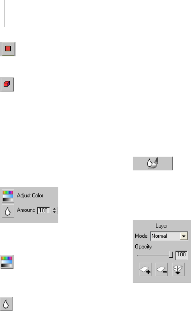
946 Chapter 8: Modifiers
Select face —Allows you to select faces in
the currently selected objects. Once selected, only
these faces will be available for painting.
Select element —Allows you to select
elements in the currently selected objects. Once
selected, only these elements will be available for
painting.
Ignore Backfacing—When this is on, prevents you
from mistakenly selecting sub-objects facing away
from the user.
Soft Selection—The same soft-selection options
(page 1–963) found in Editable Mesh and Editable
Poly are available by clicking this button.
Image Adjustment group
Toolsinthisgroupallowyoutoperformoverall
coloradjustmentorimageblurringwithoutusing
the paint brush in the viewport.
Adjust Color—Displays the Adjust Color
dialog (page 1–949),whereyoucanfindsliders
foradjustingHLSorRGBvalues,previewthe
adjustment effect, and apply it.
Blur —Smoothes the pixels in the image so
thereislesscontrastandcolordifference.Usethis
to get rid of harsh edges such as shadows created
by the Assign Vertex Colors utility.
Blur Amount spinner—Blurs currently selected
channel values (for example, vertex color, alpha)
for the currently selected objects. Also supports
sub-object selection of vertices, faces, and
elements. With soft selections, the final blurred
value is computed, and then combined with the
original color according the selection; a 50 percent
soft selection means that a vertex will become a
fifty-fifty combination of its original color and
the blurred color. Successive clicks of the Blur
button will succesively blur the previous results,
eventually washing out painting effects entirely.
Blur is useful for softening vertex color lighting
information that is automatically generated by
the Assign Vertex Color utility or rollout. Assign
Vertex Color computes intensities per vertex. This
is especially useful for low-resolution geometry
and high-frequency lighting changes.
Blur Brush—Lets you apply
blurring by using the same brush techniques and
settings that you use to apply color. The Blur Brush
respects sub-object selection and the Blur Strength
setting.
Layers group
Mode—The layer mode drop-down list allows you
to select a specific operator for this paint layer.
The operator selected affects base color, alpha,
illumination, and other information coming up
from layers below it, or from the base object itself.
Thechosenoperatorcontrolshowtheincoming
color is combined with any newly painted colors
for the current level.
This mode is changeable at any time, without
destroying previously painted information in

VertexPaint Paintbox 947
layers above, below, or in the current paint layer.
The following modes are supported per paint layer:
•Normal—The layer color completely overwrites
thebasecolor.
•Overlay—The color cast is shifted towards the
layer color and contrast might be increased.
It’s useful when you want to make an object
appear a different color but in the same lighting
conditions. A fully bright or dark channel is
never affected however, so if Red=100% and
Green=0% in the base color, then neither the
red nor green channels can be affected by the
layer color.
•Screen—Each RGB channel is moved towards
full brightness, depending on the layer color.
The result is at least as bright (never darker)
than the original. Black is transparent in this
mode.
•Multiply—Each RGB channel is moved towards
zero, depending on the layer color. The result
is at least as dark (never brighter) than the
original. White is transparent in this mode.
•Lighten—Whichever color is brighter, the layer
or the base, is used as the output. It operates on
the whole color, and not channel-by-channel.
•Darken—Whichever color is darker, the layer or
the base, is used as the output. It operates on
the whole color, and not channel-by-channel.
•Color dodge—Emulates the effect of "dodging"
acolorprintinadarkroom;theresultisatleast
as bright (never darker) than the original.
For each RGB channel, if the layer is at full value
in that channel, the output channel will be at
full value. Even if the layer value is less then full
value, the output is still strongly brightened in
that channel. For example, a medium-red layer
color will add a significant red brightness to the
output.
•Color burn—Emulates the effect of "burning"
a color print in a darkroom; the result is at
least as dark (never brighter) than the original.
For each RGB channel, if the layer is zero in
that channel, the output channel will be zero.
Even if the layer value is above zero, the output
is still be strongly darkened in that channel.
For example, a medium red layer color will
significantly reduce blue and green brightness
in the output.
The next four Light modes essentially offer
compromises between the destructive effect of
Normal Mode and the toning effect of Overlay
mode. Try using medium-value desaturated layer
colors, since the light modes can be too destructive
with bright, vivid layer colors. A neutral grey layer
color is transparent in any of the light modes.
•Soft light—Ve r y s i m i l a r t o O v e r l a y, b u t e v e n
more gentle, and it does not tend to increase
contrast as much.
•Hard light—More like Normal mode than
Overlay, it will change color cast somewhat. It is
fairly destructive like Normal mode, especially
with bright layer colors.
•Vivid light—Brighter layer colors produce a
Color Dodge effect, while darker layer colors
produce a Color Burn effect, although the effect
is generally weaker than Dodge or Burn.
•Linear light—For each RGB channel, if the layer
color is more than 50 percent bright in that
channel,theoutputwillbebrightened,and
if the layer is less then 50 percent bright, the
output will be darkened. As an example, if
you want the top of your image to be twice as
bright,andthebottomtobehalfasbright,use
a gradient from 75 percent gray to 25 percent
gray, top to bottom.
The next four modes are used to control the HSV
channel values of the image instead of using RGB
channel value.

948 Chapter 8: Modifiers
•Hue—The output color has the saturation and
value of the base color, with the hue of the layer
color.
•Saturation—Theoutputhasthehueandvalue
ofthebasecolor,andthesaturationofthelayer
color.
•Color —Theoutputhasthevalueofthebase
color, and the hue and saturation of the layer
color.
•Luminosity —Theoutputhasthehueand
saturation of the base color, and the brightness
value of the layer color.
Note: Usingtheshowendresultbuttoninthe
modifier stack for the current paint layer will allow
you to interactively paint under any over laying
paint layers (vertex paint modifiers that are above
thecurrentoneintheobject’smodifierstack).
This allows you to see the final results of your paint
strokes for any paint layer in the stack.
Opacity Slider—Allows you to set the opacity of the
current vertex paint layer, from 0 to 100 percent.
100 percent Opacity means that the current layer is
entirely opaque: you cannot see through it to the
layer directly under it or to the base vertex colors
of the objects being painted.
The opacity of a layer is animatable. Simply turn
on Auto Key, move the time slider and adjust the
spinner value. This will set a keyframe.
Note: If you painted on the layer with a brush
opacity less than 100 percent, then colors stored
in the layer can already be less than full opacity,
and the final opacity at any vertex is a product of
the two values. If you vertex had only 50 percent
opacity worth of paint applied to it, and the layer is
50 percent opaque, then the vertex will appear 25
percent opaque overall.
Be aware that the paint opacity is different from
the vertex alpha channel. Values less than 100
percent incrementally reveal any vertex color,
alpha information, and so on, coming from vertex
paint layers beneath it, or the base object’s original
information. Opacity values can be changed for
the current layer at any time. Since vertex paint
layersarepreservedinthemodifierstackyoucan
return to a particular layer at any time and adjust
its opacity to tune an object’s final appearance.
Note: The opacity for a specific paint layer should
not be confused with “alpha” information for
a given vertex. Opacity controls the mixing of
painted information in the modifier stack for the
currently active map channel (whether it be color
information, alpha, illumination, or any arbitrary
map channel from 1 to 99). Alpha Channel
information (by convention) is intended to be
used specifically to indicate the transparency of all
combined color information for a given vertex.
Another way to think about the opacity slider
is that it is identical to the amount spinner. The
difference between them is that opacity is for the
entire layer, where as amount is for the current
brush stroke (between a mouse down and mouse
up period when painting). Changing the amount
spinner after painting does not affect what is
already displayed on the screen; where changing
the opacity layer does. In the end, the current
vertex paint layer being applied generates a final
colorthatisthecombineresultofamountand
opacity. The whole concept should be quite
natural to any Adobe Photoshop user. However,
Photoshop is able to display a light grey and dark
grey quilt as a background to give a visual cue
about layer opacity, whereas 3ds Max does not
support this same display cue. So in 3ds Max, more
attention is required of the artist to understand the
opacity of each vertex on each layer.
Opacity numeric entry field—Allows you to
enter an opacity amount. Range=0 (completely
transparent) to 100 (totally opaque).
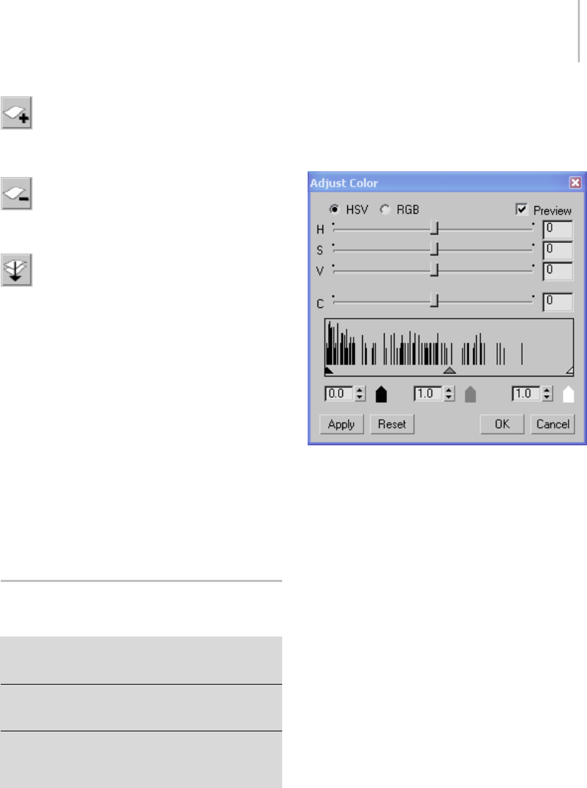
Adjust Color Dialog (VertexPaint Modifier) 949
New Layer—Click to create a new VertexPaint
layer. Clicking new layer displays a New Layer
dialog.
Delete Layer—Click to delete the current
VertexPaint layer. This removes the modifier from
the stack.
Condense to single layer—Click to condense
all vertex coloring into a single layer in the current
VertexPaint modifier. Use this to modify existing
vertex coloring within the current modifier.
Condensing layers is a two-part operation: First
3ds Max adds a new VertexPaint modifier to the
stack, combining vertex coloring applied directly
with Editable Mesh/Polygon and from previous
VertexPaint layers according to the settings
described above. Second, it deletes any prior
VertexPaint modifiers.
If Preserve Layer has been turned on for a
particular VertexPaint layer, then its colors are
“baked” into the new VertexPaint modifier, but the
preserved layer isn’t deleted from the stack.
Adjust Color Dialog (VertexPaint
Modifier)
Select an object. > Modify panel > Modifier List >
VertexPaint > VertexPaint Paintbox > Click the Adjust
Color button.
Select an object. > Modifiers menu > Mesh Editing >
Vertex Paint > VertexPaint Paintbox > Click the Adjust
Color button.
Select an object. > Utilities panel > More > Assign Vertex
Colors > Click Assign to Selected > Modify panel >
Modifier List > VertexPaint > VertexPaint Paintbox > Click
the Adjust Color button.
The Adjust Color dialog lets you adjust the color
of currently selected vertices. If there is no active
vertex sub-object selection, it affects all vertices
equally.
Interface
•HSV—(The default.) When chosen, the first
three sliders are labeled HSV, and adjust the
colors’ hue, saturation, and value.
•RGB—When chosen, the first three sliders are
labeled RGB, and adjust the colors’ red, blue,
and green components.
See Red, Green, Blue / Hue, Saturation, Value (page
3–1001).
Preview—When on, vertex color adjustments
are previewed interactively in shaded viewports
(provided that on the Paintbox, Vertex Color
Display - Unshaded or Vertex Color Display -
Shaded is active). Default=on.
Contrast slider—Lets you adjust the contrast of the
vertex colors.
Histogram and Input-Level Spinners
Histogram—Graphically shows the distribution of
colors in the vertex selection, as well as the current
shadow, gamma, and highlight input levels.

950 Chapter 8: Modifiers
The shadow, gamma, and highlight input levels
can help you adjust 3ds Max viewport color to
better match your target hardware display (such
as a game engine).
Shadow level—Adjusts the level of shadow display.
Gamma level—Adjusts the gamma display. This
value is a gamma correction (page 3–948) value.
Highlight level—Adjusts the level of highlight
display.
When you adjust a level, the corresponding arrow
moves on the histogram, to indicate the current
setting. (However, you can’t graphically drag the
arrows.)
Apply—Click to apply the current settings to vertex
colors, without closing the dialog.
Reset—Click to restore dialog settings to their
defaults.
Color Palette (VertexPaint
Modifier)
Select an object. > Modify panel > Modifier List >
VertexPaint > VertexPaint Paintbox > Click the Palette
button.
Select an object. > Modifiers menu > Mesh Editing >
Vertex Paint > VertexPaint Paintbox > Click the Palette
button.
Select an object. > Utilities panel > More > Assign Vertex
Colors > Click Assign to Selected > Modify panel >
Modifier List > VertexPaint > VertexPaint Paintbox > Click
the Palette button.
The VertexPaint modifier’s Color Palette lets you
create and maintain color palettes for use with
vertex paints. You can save or load palettes as
Color Clipboard (CCB) files, which are also used
by the Color Clipboard utility (page 1–165).
Note: The Palette remembers the last palette you
used. This is not affected by File > Reset. However,
the active palette is saved in the file 3dsmax.ini
(page 1–18) so deleting the INI file causes the
palette to revert to the default grayscale palette.
Procedures
Tousethepalettetochooseacolor:
• On the List or Swatch panel, click the color.
The color appears as the active color on the
VertexPaint Paintbox, in the swatch just below
the Erase button.
To change the color of a color swatch:
1. Double-click the swatch.
AColor Selector (page 1–161) appears.
2. UsetheColorSelectortochangetheswatch’s
color.
This version of the Color Selector is modeless
(page 3–973), so after choosing a color you
caneithercloseit,orleaveitopentochange
another swatch.
To use the color picker:
1. In the Palette’s List panel, highlight the name
of a color.
2. ClicktheColorPickerbuttontoturniton.
The cursor changes to an eyedropper icon.
3. Without depressing the mouse button, drag to
an area where you want to pick a color.
You can obtain colors from viewports, the
3ds Max user interface, or anywhere on the
Windows desktop.
4. When you depress the mouse button, the picker
obtains the color below the cursor. You can
dragwhilethemousebuttonisdepressed.
While you do, the color swatch in the palette
and the larger swatch on the Paintbox update.
5. Release the mouse to pick the color you want.
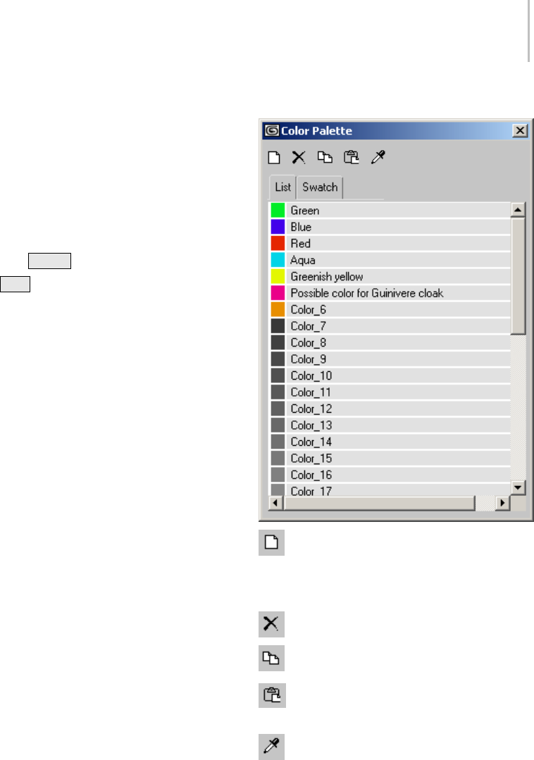
Color Palette (VertexPaint Modifier) 951
The color in the Palette and the active color in
the Paintbox are both updated.
To change a color’s name:
1. In the List panel, click the name twice (more
slowlythanadouble-click).
Thenamechangestoaneditablefield.
2. Enteranewnameoredittheexistingone,and
then press Enter .
Press Esc tocancelthenamechange.
To save a palette to a file:
1. Right-click the List panel or the Swatch panel.
The Palette’s pop-up menu (page 1–952)
appears.
2. Choose Save As from the menu.
ASaveColorClipboardFiledialogappears.
3. Use the dialog to give the palette a name (and
optionally, a directory location other than the
default), and then click OK to save the CCB file.
To load a palette from a file:
1. Right-click the List panel or the Swatch panel.
The Palette’s pop-up menu (page 1–952)
appears.
2. Choose Load from the menu.
A Load Color Clipboard File dialog appears.
3. ChoosetheCCBpalettefileyouwanttoload,
and then click OK.
Interface
New—Clicktoaddanewcolortothepalette.
Theonlylimittothenumberofcolorsapalette
can have is a file size or memory limitation.
Delete—Click to delete the active color.
Copy—Click to copy the active color.
Paste—Click to paste a copied color to the
active swatch.
Color Picker—Highlight a color in the palette,
turn this button on to activate the picker, then drag
anywhere on the Windows desktop. The color
is picked when you release the mouse.(Seethe
procedure“Tousethecolorpicker,”above.)
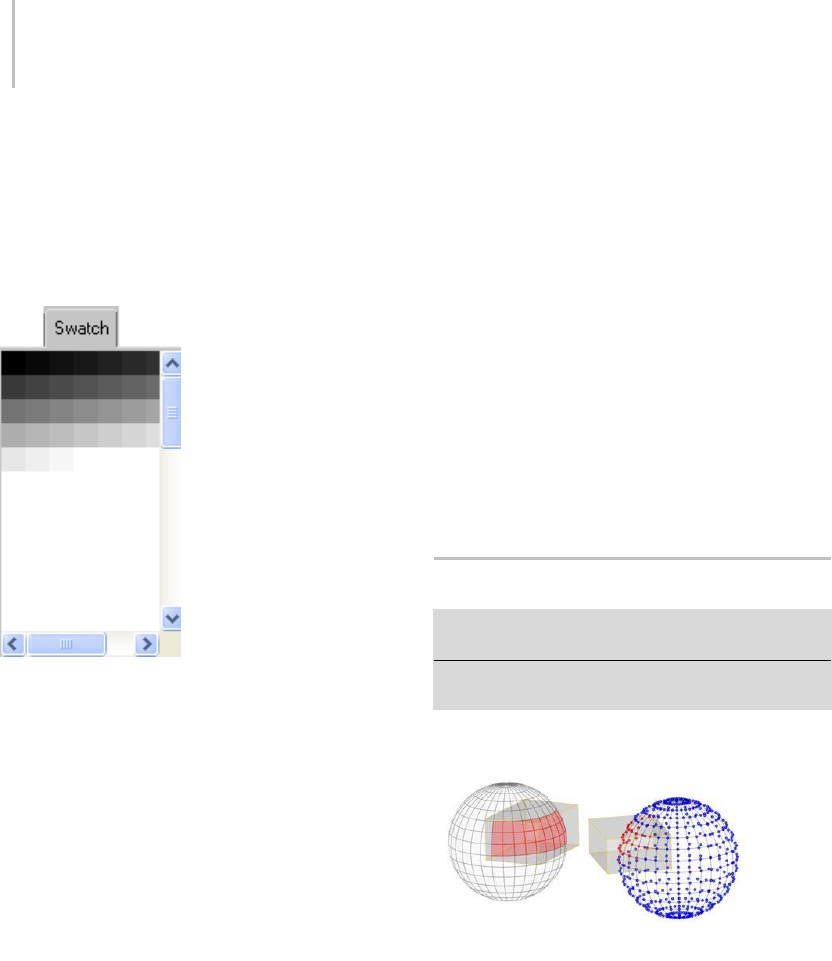
952 Chapter 8: Modifiers
List panel—Displays the colors in the palette, along
with their names.
Swatch panel—Displays the colors in the active
palette. The swatch panel doesn’t list the names of
colors, but each color’s name appear as a tooltip
when the mouse is over the swatch.
Swatch panel showing default grayscale palette
List and Swatch Panel Right-Click Menu
When you right-click the List panel or the Swatch
panel, a pop-up menu appears.
Copy—Copiestheactivecolor.
ThisisthesameasclickingCopy.
Paste—Pastesacolortotheactiveswatch.
ThisisthesameasclickingPaste.
New—Adds a color to the palette.
ThisisthesameasclickingNew.
Delete—Deletes the active color.
ThisisthesameasclickingDelete.
Save As—Displays a Save As dialog (page 3–391)
that lets you enter a name for the CCB file, then
save it.
By default, Color Clipboard files are saved in
the \images directory below the 3ds Max root
directory.
Load—Displaysafileopendialogthatletsyou
choose a CCB palette file to load.
View—Displays a text-editor window with the
current CCB palette file. If no CCB file has been
loaded or saved, choosing View has no effect.
The first 12 lines of a CCB file contain integer RGB
values. This part of the file is used by the Color
Clipboard utility (page 1–165) and ignored by the
Color Palette dialog. The remaining lines of the
file include floating-point RGB values and color
names.
Volume Select Modifier
Modify panel > Make a selection. > Modifier List > Vol.
Select
Make a selection. > Modifiers menu > Selection Modifiers
> Volume Select
Faces and vertices selected using box volumes.
TheVolumeSelectmodifierletsyoumakea
sub-object selection of vertices or faces for passing
up the stack to another modifier or modifiers. The
sub-object selection is completely separate from
the underlying parametric geometry of the object.
Like other selection methods, Volume Select works
with single or multiple objects.
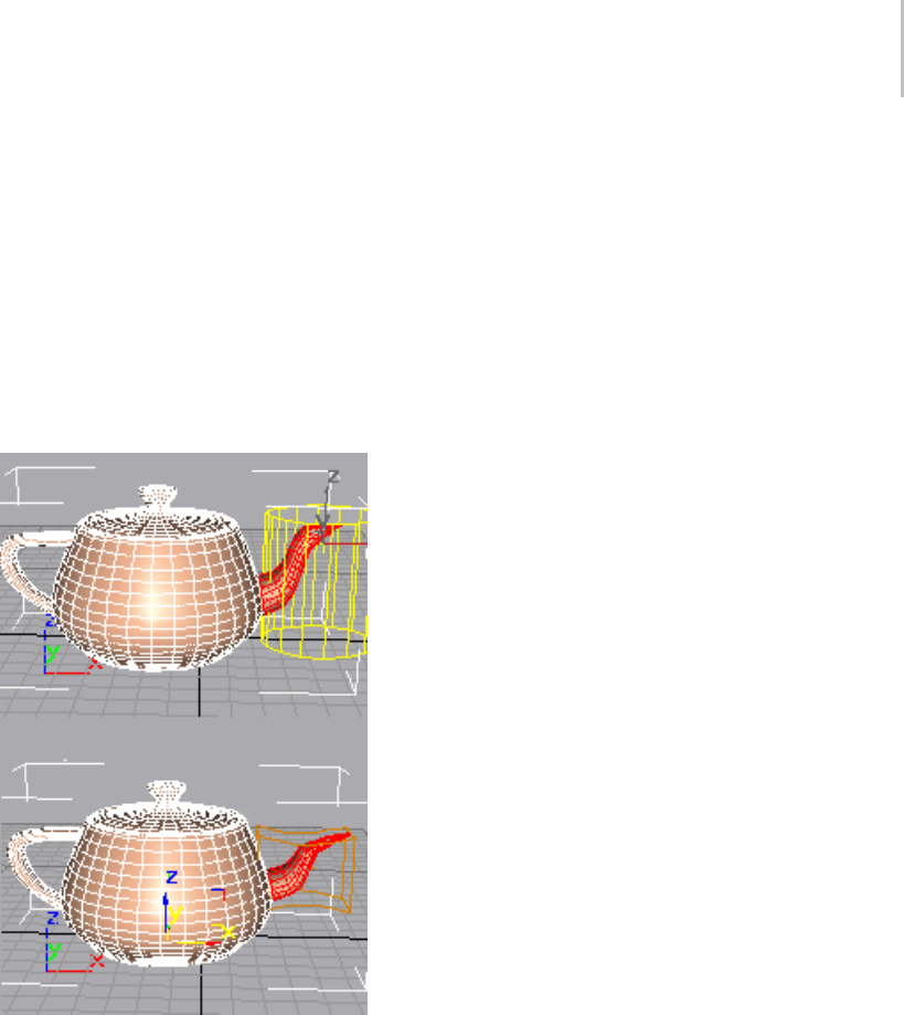
Volume Select Modifier 953
Volume Select lets you use one of three gizmos
or another object to define a volume of space as
the selection area, to which you can then apply
modifiers. You can move the selection over an
object and animate it.
When applied, Volume Select begins with the
current geometry in the object’s stack, whether
it’sawholeobjectorasub-objectselection(for
example, from an Edit Mesh (page 1–634) or
another Volume Select modifier).
Top: Original mesh with select gizmo showing
Bottom: Modification made after applying Volume Select
modifier
Patches
As of version 4, patch objects coming up the
modifier stack are not converted to a mesh by
this modifier. A patch object input to the Volume
Select modifier retains its patch definition. Files
that contain patch objects with the Volume Select
modifier from previous versions of the software
will be converted to meshes to maintain backward
compatibility.
Scaling Compatibility
The Volume Select gizmo scales along with
its object. Thus, if you apply a Volume Select
modifier, and then change the scale of your object
(with the toolbar Scale function (page 1–441))the
selection doesn’t change. In other words, all three
transforms affect the Volume Select gizmo and its
object identically.
Volume Select Center
The Volume Select modifier has a center as
wellasagizmo. Thisletsyoualterthecenter
for non-animated transforms. However, if you
animate a rotation about the offset center, you
achieve animation of both rotation and translation.
Procedures
To apply and use volume selection:
1. Select an object and apply the Vol. Select
modifier.
The Parameters rollout appears.
2. In the Stack Selection Level group, choose
Object, Vertex, or Face to specify the kind of
geometry you want to work with.
3. In the Select By group, choose one of the four
volume types: Box, Sphere, Cylinder, or Mesh
Object.
If you choose Mesh Object, you should then
click the None button and select an object to
use as the selection volume.
4. Choose a selection method and type (defined
inthefollowingInterfacesection). Youcan
change these choices as you work, depending
on the particular selection you’re trying to
make.
5. Once the selection is complete, you can do the
following:
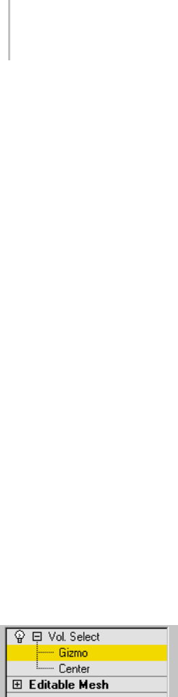
954 Chapter 8: Modifiers
•Applymodifierstotheselection.
• TransformtheVolumeSelectgizmoatthe
sub-object level, changing the selection in
the process.
• Combine these options. See the following
example.
Example: To animate a volume selection:
1. Apply Volume Select to an object.
2. Make a sub-object selection of the object’s
geometry at Face or Vertex level, and apply a
geometric modifier, such as Bend (page 1–560),
to the selection.
3. Move to a nonzero frame and begin animation.
Adjust parameters on the geometric modifier,
then move to another frame.
4. In the stack, return to the Volume Select
modifier. Choose the Volume Select gizmo
sub-object. Move the gizmo and its geometry
selection to another part of the object.
5. Repeat this process on other frames. Optionally,
you can return to the geometric modifier and
change its parameters at any frame.
During playback, you see the effect of an animated
geometric modifier moving over the object.
Interface
Modifier Stack
Gizmo sub-object—You can transform and animate
the gizmo to change the selection. Translating
the gizmo translates its center an equal distance.
Rotating and scaling the gizmo takes place with
respect to its center.
Center sub-object—You can translate and animate
the center, which affects rotation or scaling of the
Vo l u m e S e l e c t m o d i f i e r ’ s g i z m o .
For more information on the Stack Display, see
Modifier Stack (page 3–760).
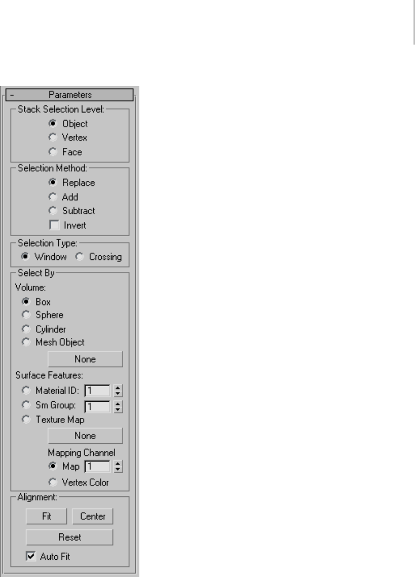
Volume Select Modifier 955
Parameters rollout Stack Selection Level group
Object/Vertex/Face—Vo l u m e S e l e c t p r ov i d e s t h r e e
selection levels. Vertex and Face levels put the
modifier stack in sub-object selection. You can
make one sub-object selection for each Volume
Selectmodifier. Youcanthentoggletheone
selection between Face and Vertex level to send
either up the stack. Object (top) level lets you
modify the whole object while retaining any
sub-object selection.
Selection Method group
Replace—Clears any selection passed up the stack
to the Volume Select modifier, and then selects
geometry within the volume.
Add—Selects all geometry within the volume,
adding to any previous selection.
Subtract—Deselects all geometry within the
volume.
Invert—Reversestheentireselectionset.Geometry
that was unselected becomes selected, and vice
versa.
Selection Type group
Lets you determine whether selected faces are
wholly or partially within the defined volume
when you set Stack Selection Level to Face.
Window—Selects only faces with all three vertices
within the selection volume.
Crossing—Selects faces with only one vertex within
the selection volume.
Select By group
These controls let you define the selection
with a primitive, a mesh object, or by surface
characteristics.
Volume: Box/Sphere/Cylinder—To defi n e t he
selection space using a standard primitive-shaped
gizmo, choose one of these. You can then scale,

956 Chapter 8: Modifiers
rotate, or move the gizmo anywhere around the
object.
Volume: Mesh Object—Choose this option to use
another object to define the selection space. After
choosing Mesh Object, click the button below it
(labeled "None" by default), and then select an
object to use as the volume.
Besides mesh objects, you can use patch objects
and NURBS objects. In addition, if you turn on
Soft Selection rollout > Use Soft Selection, you can
usesplineobjectsandparticlesystemstodefine
the selection. This latter option is quite powerful
because the selection changes as the particles
move.
Mesh object button—Click this button, then select
an object to define the selection space. You don’t
need to choose Mesh Object first, but you do
need to choose Mesh Object to use the object as
a volume. After you select an object, its name
appears on the button.
This button is labeled "None" if no object has been
chosen.
Note: The selection depends on a volume
intersecting the object. If a gizmo or object is
scaled down and moved inside an object, no
selection occurs because no geometry is within
the volume of the gizmo.
Surface Features—Defines the selection by surface
characteristics instead of a geometric volume.
While this doesn’t have much to do with volume, it
was added because Volume Select is a procedural
modifier, whereas Mesh Select (page 1–719) is
explicit. Now, even if your topology changes,
Volume Select will consistently select the faces or
vertices using a particular material or smoothing
group.
Indicate which type of surface characteristic to
base selection on by choosing one of the following:
Material ID—Specifies a material ID. All faces or
vertices using the ID indicated by the spinner
value are selected.
Sm Group—Specifies a smoothing group. All faces
or vertices using the ID indicated by the spinner
value are selected.
Texture Map—Specifies a texture map from the
scene. Click the map button (labeled "None"
by default) to choose a texture map to use for
selection. All faces or vertices using that texture
map will be selected. When using the Texture Map
option, you can also specify a mapping channel
or the vertex color channel using the Map/Vertex
Color radio buttons and spinner.
Note: Yo u m u s t a p p l y m a p p i n g t o t h e o b j e c t
below Vol. Select in its stack for the Texture Map
selection to work. That is, the Vol. Select modifier
must have mapping coordinates passed up the
stack so it can use a texture map for selection.
Note: If you set Selection Type to Window, vertices
will be selected if all the faces they touch use the
specified material or smoothing group. If you
set Selection Type to Crossing, vertices will be
selected if they touch any face using the specified
material or smoothing group.
Alignment group
These controls are generally used when the
gizmo has been transformed out of its original
orientation to the object.
Fit—Resizes the gizmo to fit around the object
or previous selection in the stack. Maintains any
previous rotation.
Center—Recenters the gizmo on the object or
previous selection in the stack. Maintains any
previous scale or rotation.
Reset—Returnsthegizmotoitsdefaultsizeand
orientation. Cancels the effect of all previous
transforms.
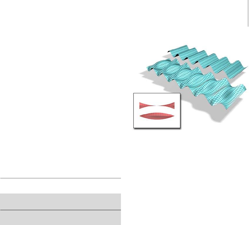
Wave Modifier 957
Auto Fit—When on, automatically adjusts the
gizmosizeandshapetofittheobjectasyou
change the underlying topology (for example,
transforming vertices).
Soft Selection rollout
These controls, available only at the Vertex stack
selection level, let you set a gradual falloff of
influence between selected and unselected vertices.
See Soft Selection Rollout (Edit/Editable Mesh)
(page 1–963).
Note: Soft Selection does not apply to materials or
smoothing groups. However, if there was already a
weighted selection passed up the stack, a Volume
Select set to Material or Smoothing Group mode
and not set to Replace will preserve the selection.
Wave Modifier
Modify panel > Make a selection. > Modifier List >
Object-Space Modifiers > Wave
Make a selection. > Modifiers menu > Parametric
Deformers > Wave
The Wave modifier produces a wave effect in an
object’s geometry. You can use either of two waves,
or combine them. Wave uses a standard gizmo
and center, which you can transform to increase
thepossiblewaveeffects.
The Wave (page 2–100) space warp has similar
features, and is useful for applying effects to a large
number of objects.
An object with the Wave modifier applied. Amplitude 1 and 2
can be changed, creating different profiles.
See also
Ripple Modifier (page 1–783)
Procedures
To mak e an object wavey:
1. Select an object and apply the Wave modifier.
Tip: To se e t he ef fe c t c lea r ly, ap ply Wave to a
broad, flat object that has many segments.
2. Set one or both values for amplitude, or the
verticalheightofthewaveincurrentunits.
Amplitude1producesasinewavefromone
edge to the other, while Amplitude 2 creates a
wave between the opposite edges. Switching
a value from positive to negative reverses the
position of peaks and troughs.
3. Setthelengthofthewaveandthedistancein
current units between crests of both waves.
Thegreaterthelength,thesmootherandmore
shallow the wave for a given amplitude.
To add a phase effect:
• Set a phase value to shift the wave pattern over
the object. Positive numbers move the pattern
in one direction, while negative numbers move
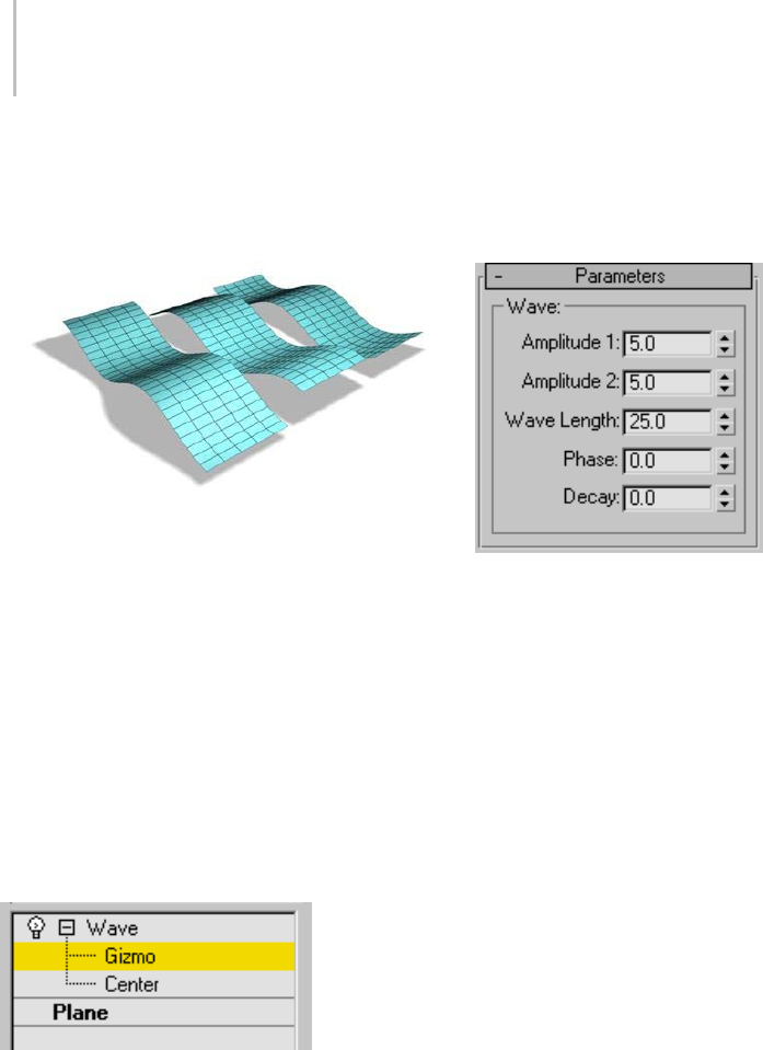
958 Chapter 8: Modifiers
them in the other. This effect is especially clear
when animated.
Phase effect on a wave
To add a decay effect:
• Set a decay value to increase or decrease the
amplitude.
A decay value decreases the amplitude as the
distance from the center increases. As the
Decay value increases, the wave is concentrated
at the center and flattens until it disappears
(completely decays).
Interface
Modifier Stack
Gizmo—At this sub-object level, you can transform
and animate the gizmo like any other object,
altering the effect of the Wave modifier. Translating
the gizmo translates its center an equal distance.
Rotating and scaling the gizmo takes place with
respect to its center.
Center—At this sub-object level, you can translate
and animate the center, altering the Wave gizmo’s
shape, and thus the shape of the wavy object.
For more information on the stack display, see
Modifier Stack (page 3–760).
Parameters rollout
Amplitude 1/Amplitude 2—Amplitude 1 produces
asinewavealongthegizmo’sYaxis,while
Amplitude2createsawavealongtheXaxis
(although peaks and troughs appear in the same
direction with both). Switching a value from
positive to negative reverses the positions of peaks
and troughs.
Wave Length—Specifies the distance in current
units between the crests of both waves.
Phase—Shiftsthewavepatternovertheobject.
Positive numbers move the pattern in one
direction, while negative numbers move it in the
other. This effect is especially clear when animated.
Decay—Limits the effect of the wave generated
from its origin. A decay value decreases the
amplitude at increasing distance from the center.
As this value increases, the wave is concentrated
at the center and flattened until it disappears
(completely decays).

XForm Modifier 959
XForm Modifier
Modify panel > Make a selection. > Modifier List >
Object-Space Modifiers > XForm
Make a selection. > Modifiers menu > Parametric
Deformers > XForm
Use the XForm (short for Transform) modifier to
apply transformations (Move, Rotate, Scale) to
objects. The XForm has two main functions:
• To animate transformations of a sub-object
selection. You can also animate the position of
the modifier’s center.
• To transform an object at any point in the stack.
Note: The Linked XForm modifier (page 1–712)
is a variant of XForm. Linked XForm has no
gizmo or center of its own. Instead, a given
selection is "linked" to another object, which
supplies its gizmo and center. Using Linked
XForm, you can link a sub-object selection
directly to the coordinate system of another
object.
Using XForm
XForm provides a gizmo and center for any
geometry it receives from the stack whether it’s a
sub-object selection or the whole object. XForm
has no parameters. When you move the XForm
modifier gizmo, the center moves with it, along
with the geometry.
Yo u c a n r e p o s i t i o n t h e X F o r m c e n te r s e p a r a t e l y
from the gizmo.
Offsetting XForm Center
At the XForm Center sub-object selection level,
onlytheMovetransformisavailable. Thislets
you reposition the center. When you return to the
Gizmo level, you can rotate or scale the selection
around the offset center. The center position and
gizmo transformations are all animatable.
Scaling with XForm
When you scale an object with a toolbar Scale tool,
the software applies the effect to the object after
all the modifiers in the stack. In some cases you
might want to squash or stretch an object before
applying geometric or edit modifiers. XForm
makesthispossible.
By applying XForm and scaling its gizmo, you can
place the scaling operation anywhere in the stack.
Using XForm with Volume Select
Yo u c a n c o m b i n e t h e X F o r m a n d Vo l u m e S e l e c t
modifiers (page 1–952) to animate sub-object
selections. This combination makes it possible
to animate both the effect of a modifier on the
selection (Volume Select) and a transformation of
that selection (XForm).
Procedures
To use the XForm modifier:
1. Choosealocationinanobject’sstackandapply
the XForm modifier.
The Gizmo sub-object level is automatically
activated. All transform buttons are available
on the toolbar.
2. Move to a nonzero frame and turn on
Auto Key to animate the next step.
3. Trans for m the gizmo.
As you transform the gizmo, the selected
geometry is transformed with it.
To use XForm as a scaling modifier:
1. Apply XForm to an object or a sub-object
selection.
2. Scale the gizmo.
The rescaled geometry becomes "part of the
stack" because the scale transform is carried
with XForm, instead of being applied after the
modifiers.
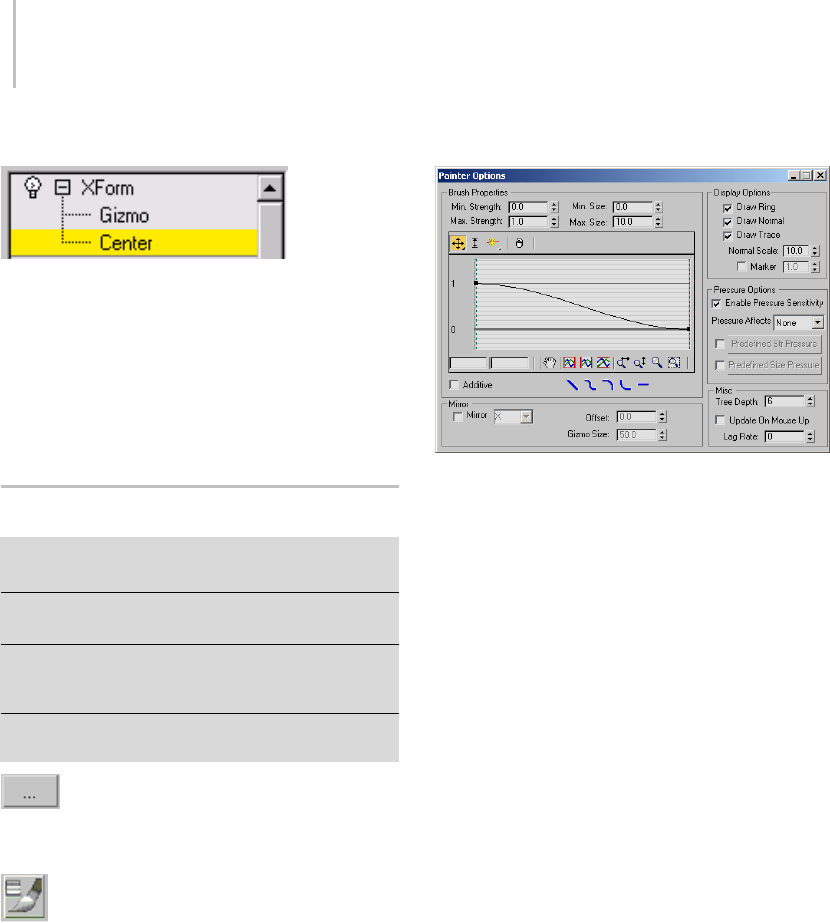
960 Chapter 8: Modifiers
Interface
This modifier has no parameters, but you can
transform the XForm gizmo and the XForm center.
If you switch the selection level to the XForm
center, only the Move transform is available. This
lets you offset the center and transform the gizmo
around it. Both offset and gizmo transformations
are animatable.
Painter Options Dialog
Modify panel > Skin modifier > Parameters rollout >
Weight Properties group > Painter Options button
VertexPaint modifier > Floating Vertex Paintbox > Brush
Options button
Edit/Editable Poly object or Poly Select modifier > Soft
Selection rollout > Paint Soft Selection group > Brush
Options button
Edit/Editable Poly object > Paint Deformation rollout >
Brush Options button
ThePainterOptionsdialogfortheSkin
modifier appears when you click the Painter
Options button.
This same dialog is used by the VertexPaint
modifier to control the brush envelope, use
pressure sensitivity, or enter mirror painting
mode. The dialog is accessed through the Brush
Options button on the floating Vertex Paintbox.
ThedialogisalsousedbythePaintSoftSelection
and Paint Deformation tools available for poly
objects.
Interface
Brush Properties group
Min. Strength—Sets the minimum vertex weight
to paint.
Max. Strength—Sets the maximum vertex weight
to paint.
Min. Size—Sets the minimum size for the paint
gizmo.
Max. Size—Sets the maximum size for the paint
gizmo.
Brushstrengthfalloffcurve—This graph
determines how the brush weight falls off as the
distance increases from the center of the brush.
Thecontrolsonthisgrapharesimilartothoseona
loft deformation dialog (page 1–368).
Additive—When on, brush strokes add to existing
vertex weights.
Quick Brush Falloff Types—Set the brush falloff to
linear, smooth, slow, fast, or flat.
Display Options group
The options in this group determine the
appearance of the paint gizmo.
Draw Ring—A ring appears as part of the paint
gizmo.

Painter Options Dialog 961
Draw Normal—A normal arrow appears as part of
the paint gizmo.
Draw Trace—Draws a trace (temporary mark) that
shows the path of the brush stroke on the surface.
Normal Scale—Sets the scale of the normal arrow
in the paint gizmo.
Marker—Displays a circular marker at the end of
the normal arrow. The value next to Marker sets
the height of the marker.
Pressure Options group
Enable Pressure Sensitivity—Tu r ns on pre ssure
sensitivity for the paint gizmo brush.
Pressure Affects—Selects the brush parameter to
be affected by pressure sensitivity. Choose from
four options: None, Strength, Size, or both size
and strength (Size/Str).
Predefined Str Pressure—Turn this opt ion on to use
a predefined strength pressure. Click the button to
view and edit the falloff curve for the strength.
Predefined Size Pressure—Tur n th is op tion on to
use a predefined size pressure. Click the button to
view and edit the falloff curve for the size.
Mirror group
Mirror—Turn this option on to mirror the paint
gizmo on the other side of the object. Choose an
axis from the drop-down menu. The paint gizmo
is mirrored about the selected axis in the world
coordinate system.
Offset—Offsetsthemirrorplanebythevalueyou
specify.
Gizmo Size—Changes the mirror gizmo size to a
value you specify.
Misc group
Tree Depth—Determines the size of the quad tree
used for hit testing. Tree Depth relates to the
amount of memory set aside for weight painting.
Larger values mean faster interaction but more
memory use.
Update On Mouse Up—Prevents the system from
updating viewports when the mouse button is
pressed. This can save time in your workflow.
Lag Rate—Determines how often the stroke
updates the painted surface. Higher values update
the surface less often.

962 Chapter 8: Modifiers

Surfacemodelingismorefreeformthangeometric
(parametric) modeling. Although you can create
Patch and NURBS primitives from the Create
panel, more often a surface model begins when you
use the quad menu (page 3–694) or the modifier
stack (page 3–760) to “collapse” a parametric
modeltosomeformofeditablesurface.Onceyou
have done so, a variety of tools let you shape the
surface. A lot of surface modeling work is done by
editing sub-objects (page 3–1017) of the surface
object.
See also
Patch Grids (page 1–993)
Editable Patch Surface (page 1–968)
Editable Mesh Surface (page 1–996)
Editable Poly Surface (page 1–1022)
NURBS Modeling (page 1–1078)
Subdivision Surfaces (page 1–963)
Tools for Low-Polygon Modeling (page 1–1252)
Subdivision Surfaces
A subdivision surface is a surface that has been
dividedintomorefaceswhileretainingtheobject’s
general shape. You perform subdivision to add
more detail to an object, or to smooth it out.
You can create a subdivision surface by applying a
modifier to an object. 3ds Max supports two kinds
of subdivision surfaces:
•TheHSDS modifier (page 1–701) provides
hierarchical subdivision surfaces.
•TheMeshSmooth modifier (page 1–722) and
TurboSmooth modifier (page 1–868) provide
smoothing.
Both these modifiers work best as finishing tools
for models.
The Interface (page 1–1061) for an Editable
Poly object (page 1–1022) allows you to add a
subdivision surface to this type of object without
the use of a modifier.
Soft Selection Rollout
Select an editable patch, editable mesh, editable poly,
editable spline, an object that has an Edit Mesh, Edit
Patch, or Edit Spline modifier applied to it, or an object
that has a comparable Select modifier applied to it.
> Modify panel > Choose a sub-object level. > Soft
Selection rollout
The Soft Selection controls allow you to partially
select sub-objects in the vicinity of an explicit
selection. This causes the explicit selection to
Surface Modeling
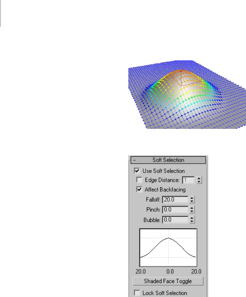
964 Chapter 9: Surface Modeling
behave as if surrounded by a "magnetic field."
Partially selected sub-objects within the field
are drawn along smoothly as you transform the
sub-object selection; the effect diminishes with
distance or the “strength” of the partial selection.
This falloff is visible in the viewports as a color
gradient surrounding the selection, conforming
to the first part of the standard color spectrum:
ROYGB (red, orange, yellow, green, blue).
Red sub-objects are those you select explicitly.
The highest-value soft-selected sub-objects are
reddish-orange; they have the same selection
value as red sub-objects, and respond the same
way to manipulation. Orange sub-objects have
aslightlylowerselectionvalue,andrespond
to manipulation a bit less strongly than do red
and reddish-orange vertices. Yellow-orange
sub-objectshaveanevenlowerselectionvalue,
and then yellow, green-yellow, and so on. Blue
sub-objects are effectively unselected and don’t
respond to manipulation, except as required by
neighboring soft-selected sub-objects.
Normally, you designate a soft selection
procedurally, by setting parameters and then
selecting sub-objects. You can also “paint” a soft
selectionexplicitlyonpolyobjects.SeePaint Soft
Selection group (page 1–966).
By default, the soft-selection region is spherical
without regard to geometric structure.
Alternatively, you can use the Edge Distance option
to limit the selection to vertices in contiguous
faces.
If a sub-object selection is passed up the modifier
stack, and Use Soft Selection is on, the results of
modifiers that deform the object, such as Bend
and XForm, are affected by the Soft Selection
parameter values.
ThecontrolsinthisdialogletyoumodifySoft
Selection parameters. All sub-object levels share
thesameSoftSelectionparametervalues. Soft
Selection is available for NURBS, mesh, poly,
patch, and spline objects.
Soft selection colors and effect on the surrounding area
Interface
Use Soft Selection—Affects the action of Move,
Rotate, and Scale functions at sub-object levels
oftheeditableobjectorEditmodifier,aswellas
the action of deformation modifiers applied to
the object if they are operating on a sub-object
selection (the latter also applies to the Select
modifiers). When on, the software applies a spline
curve deformation to the unselected sub-objects
surrounding the selection you transform. To

Soft Selection Rollout 965
take effect, this check box must be on before
transforming or modifying the selection.
Edge Distance—When on, limits the soft-selection
region to the specified number of edges between
where you select and the maximum extent of the
soft selection. The affected region is measured in
terms of "edge-distance" space, along the surface,
rather than real space.
This option is useful in cases where you want to
select only contiguous sections of geometry. For
example, if a bird’s wing is folded back against its
body, selecting the wing tip with Soft Selection
would affect body vertices as well. But if you turn
on Edge Distance, set the numeric value to the
distance (in edges) along the wing that you wish to
affect, and then set Falloff to an appropriate value,
selectingandthenmovingthewingtipwould
move only the wing geometry.
Affect Backfacing—When on, deselected faces
whosenormalsfaceintheoppositedirectionto
the average normal of the selected sub-objects are
affected by the soft-selection influence. In the case
of vertices and edges, this applies to the normals
of faces to which they’re attached. Turn off Affect
Backfacing when you want to manipulate faces of
athinobject,suchasathinbox,butdon’twantto
affect faces on the other side of the object.
Note: Affect Backfacing is not available when
editing splines.
Falloff—Distance in current units from the center
totheedgeofaspheredefiningtheaffectedregion.
Usehigherfalloffsettingstoachievemoregradual
slopes, depending on the scale of your geometry.
Default=20.
Note: The region specified by the Falloff setting
is depicted graphically in the viewports as a
color gradient in vertices and/or edges (or, with
editable polys and patches, optionally in faces).
The gradient ranges from the selection color
(normally red) to the non-selected sub-object
color (normally blue). In addition, this gradient
isupdatedinrealtimeasyouchangetheFalloff
setting.
Note: If Edge Distance is on, the Edge Distance
settinglimitsthemaximumfalloffamount.
Pinch—Raises and lowers the top point of the
curve along the vertical axis. Sets the relative
"pointedness" of the region. When negative, a
crater is produced instead of a point. At a setting
of 0, Pinch produces a smooth transition across
this axis. Default=0.
Bubble—Expands and contracts the curve along
the vertical axis. Sets the relative "fullness" of
the region. Limited by Pinch, which sets a fixed
starting point for Bubble. A setting of 0 for Pinch
and 1.0 for Bubble produces the smoothest bulge.
NegativevaluesforBubblemovethebottomofthe
curvebelowthesurface,creatinga"valley"around
thebaseoftheregion.Default=0.
(soft selection curve)—Graphically displays how
Soft Selection will work. You can experiment with
a curve setting, undo it, and try another setting
with the same selection.
Shaded Face Toggle—Displays a color gradient
corresponding to the soft selection weights on
faces within the soft selection range. Available
only when editing patch and poly objects.
If the Ve r t e x C o l o r d i s p l a y p ro p e r t y of an editable
poly or editable patch object is off, clicking the
ShadedFaceTogglebuttonwillturnonSoft
Selection Color shading. If the object already has
an active Vertex Color setting, clicking the Shaded
Face Toggle overrides the previous setting and
changes it to Soft Selection Color.
Note: Use the Undo command if you do not want
to change your vertex color shading properties.
Lock Soft Selection—Locks the soft selection
inordertopreventchangestotheprocedural
selection.
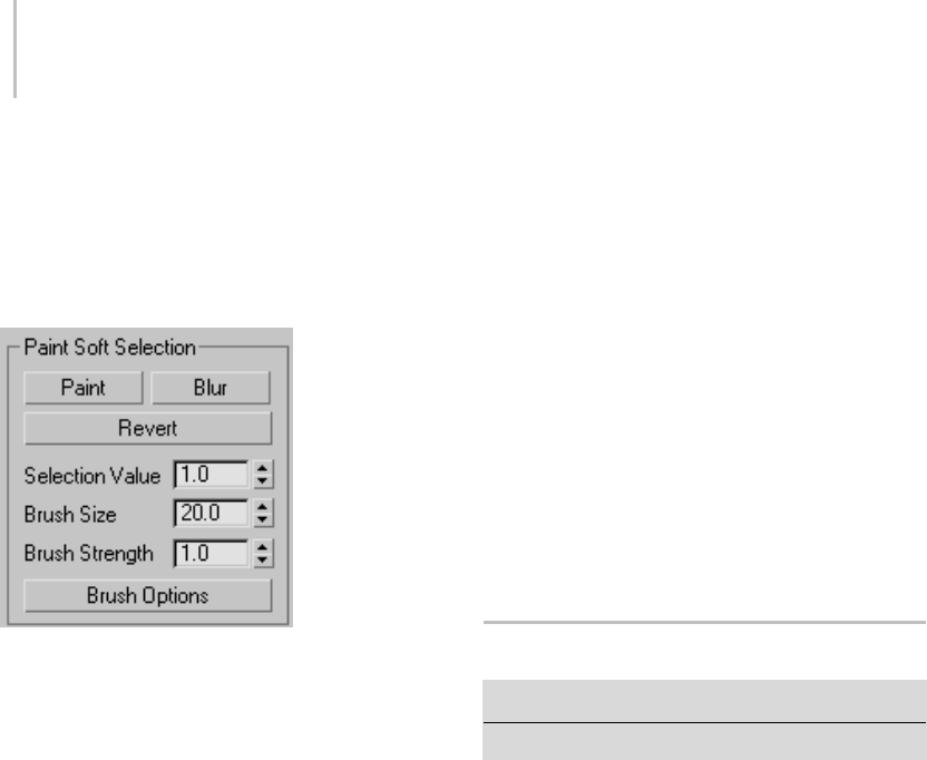
966 Chapter 9: Surface Modeling
Using Paint Soft Selection (see following) turns on
Lock Soft Selection automatically. If you turn it off
after using Paint Soft Selection, the painted soft
selection is lost. You can restore it with Undo.
Paint Soft Selection group
Paint Soft Selection lets you specify a soft selection
explicitly by dragging the mouse over the selection.
The Paint Soft Selection functionality is available
at sub-object levels with Editable Poly objects,
as well as with objects with the Edit Poly or Poly
Select modifier applied. You can work in one of
three painting modes: Paint, Revert, and Blur.
Tip: You can streamline the painting process by
using the Brush Presets tools (page 3–690).
Paint—Lets you paint a soft selection on the
active object using the current settings. Drag the
mousecursorovertheobjectsurfacetopaintthe
selection.
Blur—Lets you paint to soften the outlines of an
existing painted soft selection.
Revert—Lets you paint to reverse a soft selection
ontheactiveobjectusingthecurrentsettings.
Drag the mouse cursor over the object surface to
reverse the selection.
Note: Revert affects only a painted soft selection,
not a soft selection made by normal means. Also,
Revert uses only the Brush Size and Brush Strength
settings, not the Selection Value setting.
Selection Value—The maximum relative selection
of the painted or reverted soft selection. The
values of surrounding vertices within the brush
radius fall off towards a value of 0. Default=1.0.
Brush Size—The radius of the circular brush used
for painting the selection.
Brush Strength—The rate at which painting a
soft selection sets the painted sub-objects to the
maximum value. A high Strength value reaches
the full value quickly, while a low value requires
repeated applications to reach full value.
Brush Options—Opens the Painter Options dialog
(page 1–960),withsettingsforbrush-related
properties.
Collapse Utility
Utilities panel > Utilities rollout > Collapse button
Menu bar > Modify > Collapse
TheCollapseutilityletsyoucombinethestack
operations of one or more selected objects into
an Editable Mesh (page 1–996) or the stack result,
and, optionally, perform a Boolean (page 1–338)
operationonthematthesametime.
Important: You can’t undo the results of using the
Collapse utility. Before you use it, save a copy of your
work file, or use Hold (page 1–95).
Note: You can also collapse an object’s stack from
the modifier stack right-click menu (page 3–766),
and convert a selection to editable surfaces (page
1–963) with the transform quadrant of the quad
menu (page 3–694).Thesechangesare undoable.
Procedures
To collapse the stack of an object into an editable
mesh:
1. On the Utilities panel, click the Collapse button.
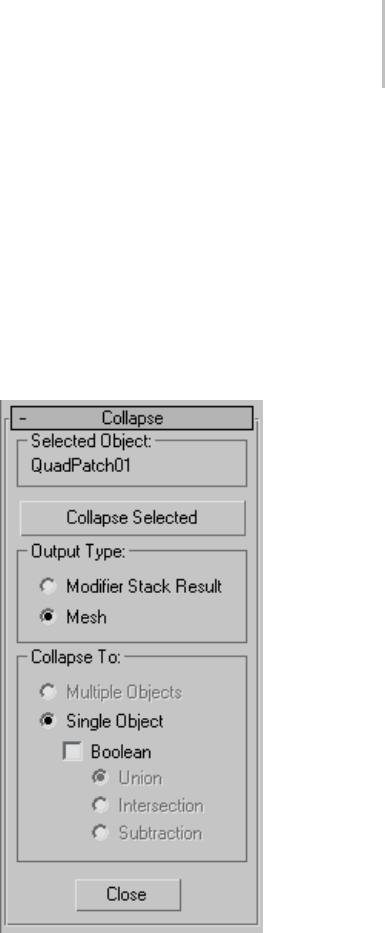
Collapse Utility 967
2. Select the object or objects that you want to
collapse.
3. Click the Collapse Selected button.
All modifiers are removed from the modifier
stack and the object becomes an editable mesh.
To collapse the stack of an object into an editable
surface other than mesh:
1. On the Utilities panel, click the Collapse button.
2. OntheCollapserollout,setOutputTypeto
Modifier Stack Result.
3. Select the object or objects that you want to
collapse.
4. Apply a modifier that outputs the desired
ultimate surface type, such as Tur n To Poly
(page 1–874) or Turn To Patch (page 1–873).
5. Click the Collapse Selected button.
All modifiers are removed from the modifier
stack and the object becomes an editable
surface of the type indicated by the modifier.
To subtract multiple objects from another object:
The Boolean compound object restricts you to
combining objects one at a time. With the Collapse
utility, you can perform Boolean operations on
several objects simultaneously.
1. For the purposes of this procedure, we’ll call the
object to have shapes subtracted from Main.
Create and arrange Main and the objects to
subtract from it. For example, you might have
several boxes penetrating a sphere (Main)in
different places; subtracting them will produce
box-shaped cutouts in the sphere’s surface.
2. Select Main, and then select the objects to be
subtracted from it.
Thefirstobjectyouselectbeforecollapsingis
the one from which the others are subtracted.
3. On the Utilities panel, click the Collapse button.
4. OntheCollapserollout,setOutputTypeto
Mesh, if necessary.
5. IntheCollapseTogroup,chooseSingleObject.
6. Turn on Boolean, and then choose Subtraction.
7. Click the Collapse Selected button.
All objects you selected after Main, the first
object, are subtracted from Main.
Interface
Selected Object group
Displaysthenameofthecurrentselection.Ifmore
than one object is selected, "[Number] Objects
Selected.” displays.
Collapse Selected—Collapses the selected objects.
The method of collapse depends on the settings of
the options below this button.

968 Chapter 9: Surface Modeling
Output Type group
Specifies the type of object that results from the
collapse.
Modifier Stack Result—The resultant object will be
thesameasifyouhadcollapseditsstack.Inmost
cases, this results in a mesh object, as when using
theMeshoption.However,iftheobjecthasanEdit
Patch modifier so that its stack produces a patch,
then the result will be a patch object rather than a
mesh. Likewise, a shape with Edit Spline modifiers
becomes an editable spline. When this option is
used, the Collapse To options are unavailable, and
all selected objects remain independent objects.
Mesh—All selected objects become editable
meshes regardless of their type before they were
collapsed.
Collapse To group
Specifies how the selected objects are combined.
Theseoptionsareavailableonlywhenyouchoose
the Mesh option.
Multiple Objects—Collapses each object in the
selectionbutmaintainseachasanindependent
object. When this option is selected, the Boolean
options are disabled.
Single Object—Collapses all selected objects into a
single, editable mesh object.
Boolean—Performs Boolean operations on the
selected objects. During the Boolean calculation, a
progress bar appears along with a Cancel button.
If any objects in the Boolean operation fail, that
object is skipped, but the Collapse proceeds. The
result is not a Boolean compound object, but
asingleeditablemesh. ThetypeofBooleanis
specified by the following option.
Union—Combines the several objects, removing
intersecting geometry.
Intersection—Removes all but the intersecting
geometry.
Subtraction—Maintains the first object selected
while subtracting the subsequently selected
objects. For example, to subtract several cylinders
from a box, click to select the box, hold down
Ctrl , and region-select the cylinders.
Close—Exits the Collapse utility.
Editable Patches
Create or select an object > Modify panel > Right-click
object’s entry in the stack display > Convert To: Editable
Patch
Create or select an object > Right-click the object >
Transform (lower-right) quadrant of the quad menu >
Convert To: > Convert to Editable Patch
EditablePatchprovidescontrolsformanipulating
an object as a patch object and at five sub-object
levels: vertex, handle, edge, patch, and element.
Editable Patch objects provide the same basic
functionality as the Edit Patch modifier (page
1–638). Because working with them requires less
processing and memory, we recommend you use
Editable Patch objects rather than the Edit Patch
modifier whenever possible.
When you convert an object to Editable Patch
format or apply an Edit Patch modifier, 3ds Max
converts the object’s geometry into a collection of
separate Bezier patches (page 3–991),eachpatch
made up of a framework of vertices and edges,
plus a surface.
•Theframework of control points and connecting
tangents defines the surface. Transforming the
components of this framework is the primary
technique in patch modeling. The framework
does not appear in scanline renderings.
•Thesurface is the Bezier patch surface, whose
shapeiscontrolledbytheverticesandedges.

Editable Patch Surface 969
Thesurfaceistherenderablegeometryofthe
object.
Prior to version 3 of the software, some patch
objects contained a lattice that appeared separate
fromthesurface. Thisisnolongerthecase:
The control framework conforms exactly to the
surface, making it easier to visualize the results of
patch modeling.
The output of the Surface modifier (page 1–842) is a
patchsurface.Ifyouaremodelingwithsplinesand
are using the Surface modifier to generate a patch
surface from the spline cage, you can use an Edit
Patch modifier (page 1–638) for further modeling.
Show End Result
Tur n on Show End Result on t he Mo dif y
panel if you have modifiers above the Editable
Patch modifier and want to see the result of all the
modifiers in the modifier stack. This function will
remain on until you turn it off.
See also
Edit Modifiers and Editable Objects (page 1–506)
Modifying at the Sub-Object Level (page 1–506)
Modifier Stack Controls (page 3–760)
Procedures
To work at a sub-object level:
1. In the modifier stack display, choose a selection
level: Element, Patch, Edge, or Vertex.
2. Select the sub-object geometry you want to edit.
To attach an object using Edit Patch:
1. Select an editable patch object, or an object
with the Edit Patch modifier applied.
2. IntheModifypanel>Geometryrollout>
To p o l o g y g r o u p, c l i c k At t a c h .
3. Turn off Reorient, if necessary.
4. Select an object to attach.
The object takes on a patch structure and stays
in its original location.
The attached object is now part of the editable
patch object. The Tessellation settings for the
original object affect attached objects as well.
To attach and reorient an object:
• Turn on Reorient before attaching the object.
The object is both attached and moved to align
with the patch object. The pivot of the attached
object matches the pivot of the Edit Patch
object.
To detach a patch surface:
1. Make a selection at the Patch sub-object level.
2. Ifyouwanttoreorientthedetachedsurface,
turn on Reorient.
3. Click Detach.
A Detach dialog appears.
4. Name the detached surface.
The detached surface remains in place if you
chose not to reorient it. It is deselected and
assigned a different color.
To copy a patch surface:
1. Make a selection at the Patch sub-object level.
2. In the Geometry rollout > Topology group,
turn on Copy.
3. If you want to reorient the copied surface, turn
on Reorient.
4. Click Detach.
A Detach dialog appears.
5. Name the patch copy.
The copied object remains in place if you chose
nottoreorientit.

970 Chapter 9: Surface Modeling
To delete patches:
1. Make a selection at the Patch sub-object level.
2. Click Delete.
The patches disappear.
To subdivide a patch:
1. Make a selection at the Patch sub-object level.
2. Turn on Propagate to maintain surface
continuity.
3. Click Subdivide.
The patch selection is subdivided, increasing
the number of patches.
You can repeat this process, subdividing
multiple times. Each subdivision increases the
number of patches, which become increasingly
smaller. The following figure is an example of
modeling a highly subdivided surface.
To subdivide an edge:
1. AttheEdgesub-objectlevel,makeanedge
selection.
Asingleedgeisindicatedbyitscoordinateaxis
or transform gizmo at the center of the edge.
For multiple edges, the axis icon is at the center
of the selection set.
2. Optionally,turnonPropagatetomaintain
surface continuity.
3. Click Subdivide.
The edge selection is subdivided. Each new
edge is on the boundary of a new, smaller patch.
To add a patch:
1. AttheEdgesub-objectlevel,selectanopen
edge (one that bounds a single patch, and
therefore is not shared with another patch).
2. ClickAddTriorAddQuad.
A new patch is added to the surface.
To unlock interior edges of selected patches:
1. At the Patch sub-object level, select one or more
patches.
2. Right-click the selection and choose Manual
Interior from the pop-up menu.
The check mark moves from Auto Interior, the
default, to Manual Interior. Interior edges and
their vertices are now unlocked. If you now
transform the patch, the interior edges remain
static. To transform the interior vertices, see the
following procedure.
To transform interior vertices:
1. At the Patch sub-object level, select one or more
patches.
2. Right-click the selection and choose Manual
Interior from the pop-up menu.
The check mark moves from Auto Interior, the
default, to Manual Interior.
3. Switch to Handle level.
The interior vertices appear as yellow squares.
4. Transform the interior vertices of the selected
patches.
To anchor a patch:
By default, the welding process shifts the geometry
of both patches to a common center. You can
anchor one patch so that the other patch moves to
its location when the weld occurs.
1. At the Patch (Patch) level, before you begin the
weld, select the patch you want anchored.
2. Return to Vertex level and weld the vertices.

Selection Rollout (Editable Patch) 971
When the weld occurs, the anchor patch
remains fixed while the other patch moves to
make the weld.
To create a new element, do one of the following:
•Shift +drag one or more patches.
•Shift +extrude one or more patches.
•Shift +extrude one or more edges.
•Shift +drag an element.
Interface
Selection rollout
For information about these settings, see Selection
Rollout (Editable Patch) (page 1–971).
Soft Selection rollout
For information on the Soft Selection rollout
settings, see Soft Selection Rollout (page 1–963).
Geometry and Surface Properties rollouts
The Geometry rollout (page 1–986) provides
functions for editing a patch object and its
sub-objects,andtheSurfacePropertiescontrolslet
you modify the object’s rendering characteristics.
For detailed information on sub-object-specific
controls, select any of the links below:
Editable Patch (Object) (page 1–974)
Editable Patch (Vertex) (page 1–975)
Editable Patch (Handle) (page 1–979)
Editable Patch (Edge) (page 1–980)
Editable Patch (Patch) (page 1–981)
Selection Rollout (Editable Patch)
Create or select an object > Modify panel > Right-click
object’s entry in the stack display > Convert To: Editable
Patch>Selectionrollout
Create or select an object > Right-click the object >
Transform (lower-right) quadrant of the quad menu >
Convert To: > Convert to Editable Patch > Selection
rollout
The Selection rollout provides buttons for
selecting the sub-object level, working with named
selections, display and filter settings, and displays
information about selected entities.
Editable Patch has five levels of sub-object editing:
Vertex, Handle, Edge, Patch, and Element. The
selection you make at each level appears in the
viewport as a component of the patch object. Each
level maintains its own sub-object selection. When
you return to a level, the selection reappears.
Clicking a sub-object level button here is the same
as clicking a sub-object type in the Modifier Stack
rollout. Click the button again to turn it off and
return to the object selection level.
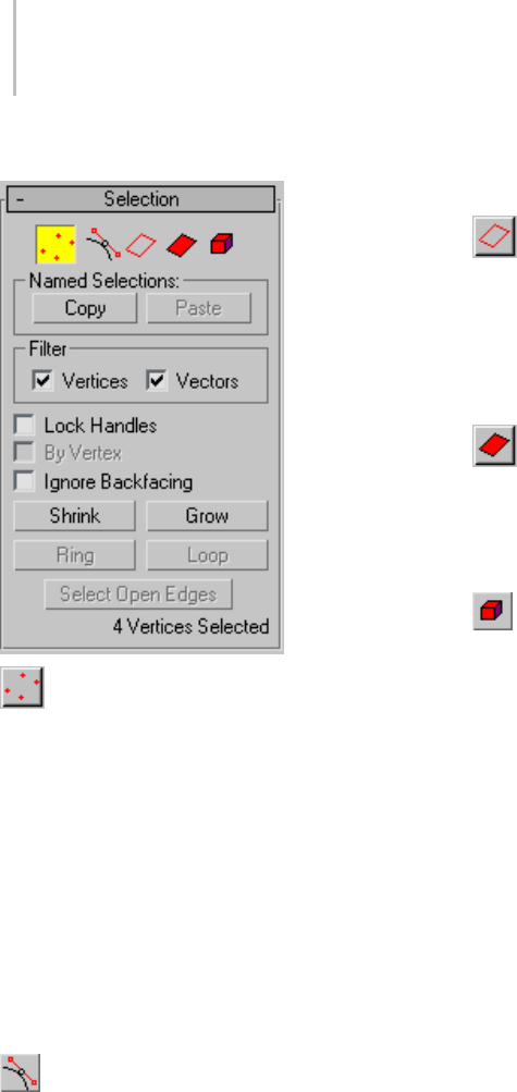
972 Chapter 9: Surface Modeling
Interface
Vertex—Lets you select vertex control points
and their vector handles on a patch object. At this
level, vertices can be welded and deleted.
By default, a transform gizmo or axis tripod
appears at the geometric center of the selected
vertices. If you turn on Gizmo Preferences (page
3–832) >AllowMultipleGizmos,however,gizmos
or tripods appear at all selected vertices.
Vector handles appear as small green squares
around selected vertices. Also, with certain objects
you may see interior vertices represented as yellow
squares.
Handle—Lets you select vector handles
associated with each vertex. This level lets you
manipulate the handles without needing to deal
with vertices.
ATransformgizmooraxistripodappearsatthe
geometric center of the selected handles.
At this level, vector handles appear as small green
squares around all vertices. Also, with certain
objects you may see interior vertices represented
as yellow squares.
Edge—Selects a bounding edge of the patch
object. At this level, edges can be subdivided, and
new patches added to open edges.
A Transform gizmo or axis tripod appears in the
middle of a single selected edge. For multiple
selected edges, the icon is at the selection center.
Patch—Selectsanentirepatch.Atthislevel,
apatchcanbedetached,deleted,oritssurface
subdivided. When a patch is subdivided, the
surface is broken into smaller patches, each with
its own vertices and edges.
Element—Select and edit an entire element.
An element has contiguous faces.
Tip: You can highlight selected patches in a shaded
displaybyturningonShadeSelectedFacesinthe
Viewport Properties dialog. Right-click over the
viewportnameandchooseConfigureinthemenu
to display the Viewport Properties dialog. You
can also use the default keyboard shortcut, F2,to
toggle this feature.
Named Selections group
These functions work with named sub-object
selection sets. To create a named sub-object
selection, make the selection, and then enter
anameintheNamedSelectionSetsfieldon
the toolbar. For more information, see Named
Selection Sets (page 1–83).
Copy—Places a named sub-object selection into
the copy buffer. After clicking this button, choose
the named sub-object selection from the Copy
Named Selection dialog that appears.
Paste—Pastes the named sub-object selection from
the copy buffer.

Selection Rollout (Editable Patch) 973
YoucanuseCopyandPastetocopysub-object
selections between different objects.
Filter group
These two check boxes, available only at the Vertex
sub-object level, let you select and transform
vertices, vectors (handles on the vertices), or both.
When a check box is turned off, you can’t select the
corresponding element type. Thus, for example, if
youturnoffVertices,youcanmanipulatevectors
without accidentally moving a vertex.
Tip: Foreasiereditingofvectorsonly,usethe
Handle sub-object level (page 1–979).
Yo u c a n’ t t u r n o f f b o t h c h e c k b o x e s . W h e n y o u
turn off either check box, the other one becomes
unavailable. At that point, you can manipulate the
element corresponding to the check box that’s on,
butyoucan’tturnitoff.
Vertices—When on, you can select and move
vertices.
Vectors—When on, you can select and move
vectors.
Lock Handles—Affects only Corner vertices. Locks
the tangent vectors together so that when you
move one, you move them all. Available only at the
Vertex sub-object level.
By Vertex—When you click a vertex, any handles,
edges, or patches that use that vertex, depending
on the current sub-object level, are selected.
Available only at the Handle, Edge, and Patch
sub-object levels.
This also works with Region Select.
Ignore Backfacing—When on, selection of
sub-objects selects only those sub-objects whose
normals are visible in the viewport. When off
(the default), selection includes all sub-objects,
regardless of the direction of their normals. Use
this on a complex patch model where you want to
select only visible patches.
Note: ThestateoftheBackfaceCullsettinginthe
Display panel does not affect sub-object selection.
Thus, if Ignore Backfacing is off, you can still select
sub-objects, even if you can’t see them.
Shrink—Reduces the sub-object selection area
by deselecting the outermost sub-objects. If
the selection size can no longer be reduced, the
remaining sub-objects are deselected. Unavailable
at the Handle sub-object level.
Grow—Expands the selection area outward in all
available directions. Unavailable at the Handle
sub-object level.
Ring—Expandsanedgeselectionbyselectingall
edges parallel to the selected edges. Available only
attheEdgesub-objectlevel.
Loop—Expands the selection as far as possible, in
alignment with selected edges. Available only at
theEdgesub-objectlevel.
Select Open Edges—Selectsalledgesthatareused
by only one patch. Available only at the Edge
sub-object level.
You can use this to troubleshoot a surface; open
edges will be highlighted.
Selection Information—At the bottom of
the Selection rollout is a text display giving
information about the current selection. If
multiple sub-objects are selected, or none is
selected, the text gives the number and type
selected. If one sub-object is selected, the text gives
the identification number and type of the selected
item.
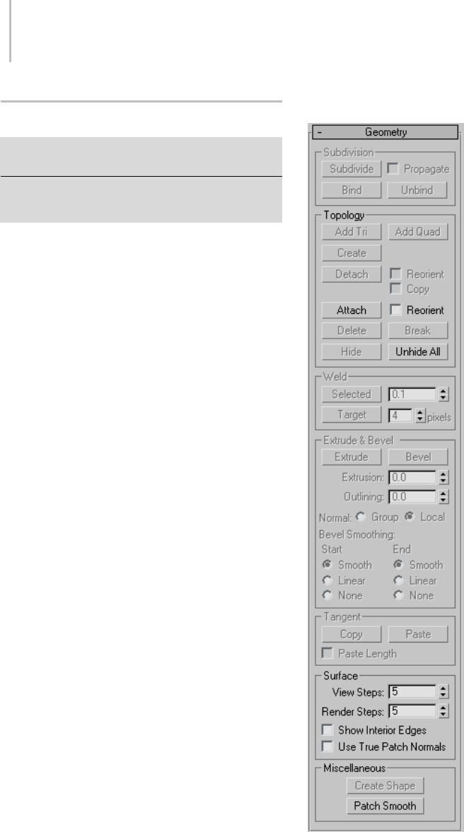
974 Chapter 9: Surface Modeling
Editable Patch (Object)
Select an editable patch > Modify panel > Editable patch
(not a sub-object level) selected in the modifier stack
Select an editable patch > Right-click the patch > Tools
1 (upper-left) quadrant of the quad menu > Sub-objects
> Top-level
The functions available at the editable patch object
level (that is, when no sub-object level is chosen)
are also available at all sub-object levels, and work
exactly the same at each level.
Interface
Selection rollout
For information on these settings, see Editable
Patch Surface (page 1–968).
Geometry rollout
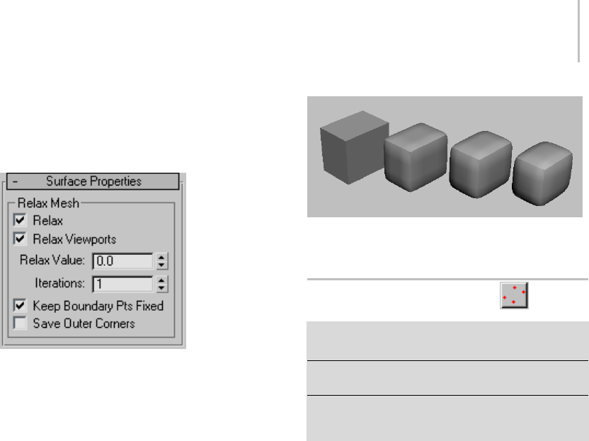
Editable Patch (Vertex) 975
See Geometry Rollout (Patch) (page 1–986) for
detailed descriptions of these controls.
Surface Properties rollout
TheRelaxMeshcontrolsontheSurfaceProperties
rollout change the apparent surface tension by
moving vertices closer to, or away from, their
neighbors. The typical result is that the object gets
smoother and a little smaller as the vertices move
toward an averaged center point. You can see the
most pronounced effects on objects with sharp
corners and edges.
Relax—Turnsontherelaxfunctionforrenderings.
Relax Viewports—Tur ns on t he relax function for
viewports.
Relax Value—Sets the distance a vertex moves as a
percentage of the distance between a vertex and
the average location of its neighbors. Range=-1.0
to 1.0. Default=0.5.
Iterations—SetshowmanytimesRelaxisrepeated.
Each iteration recalculates average vertex locations
based on the result of the previous iteration.
Default=1.
Keep Boundary Points Fixed—Ve r t i c e s a t t h e e d g e
of open patches do not relax. Default=on.
Save Outer Corners—Preserves the original
positions of vertices farthest away from the object
center.
A patch box with Relax off (left), and Relax Value=1.0, with 1, 2,
and 3 iterations (left to right)
Editable Patch (Vertex)
Select an editable patch > Modify panel > Expand Editable
Patchinthestackdisplay>Vertexsub-objectlevel
Select an editable patch > Modify panel > Selection
rollout > Vertex button
Select an editable patch > Right-click the patch > Tools
1 (upper-left) quadrant of the quad menu > Sub-objects
>Vertex
AttheEditablePatch(Vertex)level,youcanselect
single and multiple vertices and move them using
standard methods. You can also move and rotate
vector handles (page 3–1029),thusaffectingthe
shapes of any patches connected to the vertex.
Procedures
To transform either vertices or vectors:
1. At Patch (Vertex) level, with Selection rollout >
Filter group > Vertices turned on, select vertices
in the patch object you want to transform.
Vertices and their vectors both appear.
2. Turn off one of the filters, leaving the other on,
and choose a transform.
A transform cursor appears when you move
onto a vertex or vector in the selection set.
You can toggle between filters to alternatively
transform either component.
To switch vertex types:
1. Right-click a patch vertex.
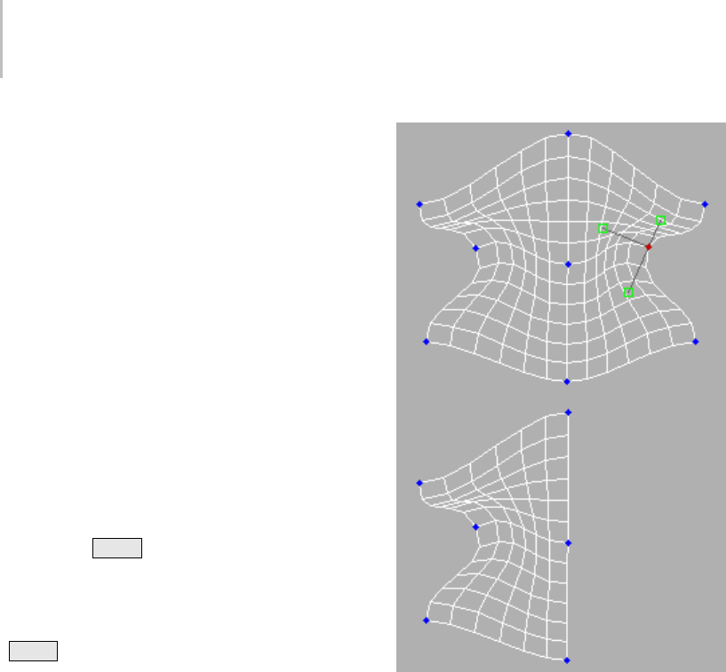
976 Chapter 9: Surface Modeling
2. Choose from commands on the quad menu.
The Tools 1 (upper-left) quadrant includes two
options specific to patch vertices:
•Coplanar: If you set a patch control point’s
property to be coplanar, it’s like locking the
handle of the outgoing vector for that point.
Moving a handle attached to a coplanar
vertexcausestheoppositevectorstoadjust
their positions to maintain a coplanar
surface. This option is the default and gives
smooth transitions between patches.
•Corner: If you set a patch control point’s
property to be corner, it unlocks the handle
of the outgoing vector, so you can create a
discontinuous break in the patch surface.
To switch vertex types from Coplanar to Corner, do
one of the following:
1. Hold down Shift as you move a handle of a
Coplanar vertex.
This switches the vertex type to Corner.
IfLockHandlesisoff(thedefault),
Shift +Move "breaks" the handle, allowing it
to move independently.
IfLockHandlesison,thehandlesremain
locked in their coplanar relationship. However,
the vertex is still switched to Corner, and
turningoffLockHandlesletsyoumovethe
handles separately.
2. Right-click the vertex, and choose Corner from
the quad menu.
To delete a vertex:
1. At Patch (Vertex) level, select a vertex.
2. Click Delete.
The vertex and all patches sharing this control
point are deleted.
Deleting vertices
To weld vertices:
1. At Patch (Vertex) level, select two valid vertices
on different patches.
2. Set Weld Threshold to a value at least equal to
the distance between the selected vertices.
3. Click Selected.
The two vertices move together and join.
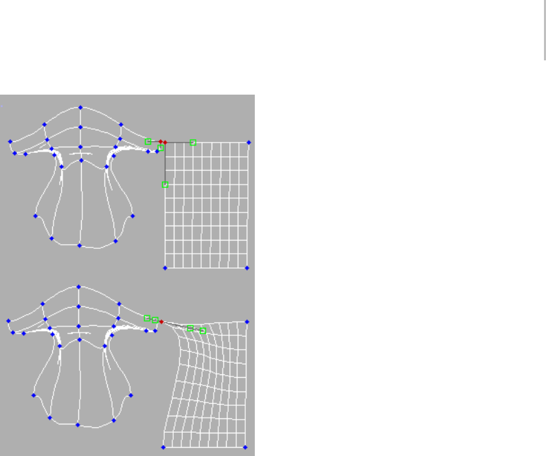
Editable Patch (Vertex) 977
Welding vertices
To transform interior vertices:
Using program defaults, you can select only
vertices and vectors on the outer edge or boundary
of a patch. This default is known as Auto Interior.
In some cases, you might want to move the interior
vertices. For example, you might want to tweak a
patch’s curvature without having to subdivide the
patch.
•AtPatch level (page 1–981),youcanchange
the default on a patch-by-patch basis by
right-clicking a patch and choosing Manual
Interior from the shortcut menu. This lets
you select and transform individual interior
vertices. These vertices appear as yellow
squares in the viewports.
Warning: If you return a patch to the default,
changes due to Manual Interior are lost.
Note: Certain objects are automatically set
to Manual Interior when converted to patch
objects. In such cases, you can see all interior
vertices when you go to the Vertex sub-object
level.
Interface
Selection rollout
For information on the controls in this rollout, see
Selection Rollout (Editable Patch) (page 1–971).
Soft Selection rollout
See Soft Selection Rollout (page 1–963) for
information on the Soft Selection rollout settings.
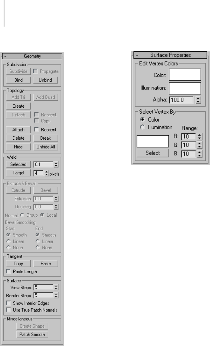
978 Chapter 9: Surface Modeling
Geometry rollout
See Geometry Rollout (Patch) (page 1–986) for
detailed descriptions of these controls.
Surface Properties rollout
Edit Vertex Colors group
Use these controls to assign the color, illumination
color (shading), and alpha (transparency) values
of selected vertices.
Color—Click the color swatch to change the color
of selected vertices.
Illumination—Click the color swatch to change the
illumination color of selected vertices. This lets
you change the color of shadows without changing
the vertex colors.
Alpha—Lets you assign an alpha (transparency)
value to selected vertices.
The spinner value is a percentage; zero is
completely transparent and 100 is completely
opaque.
Select Vertex By group
Color and Illumination radio buttons—These
buttons determine whether to select vertices by
vertex color values or vertex illumination values.
Color Swatch—Displays the Color Selector, where
you can specify a color to match.
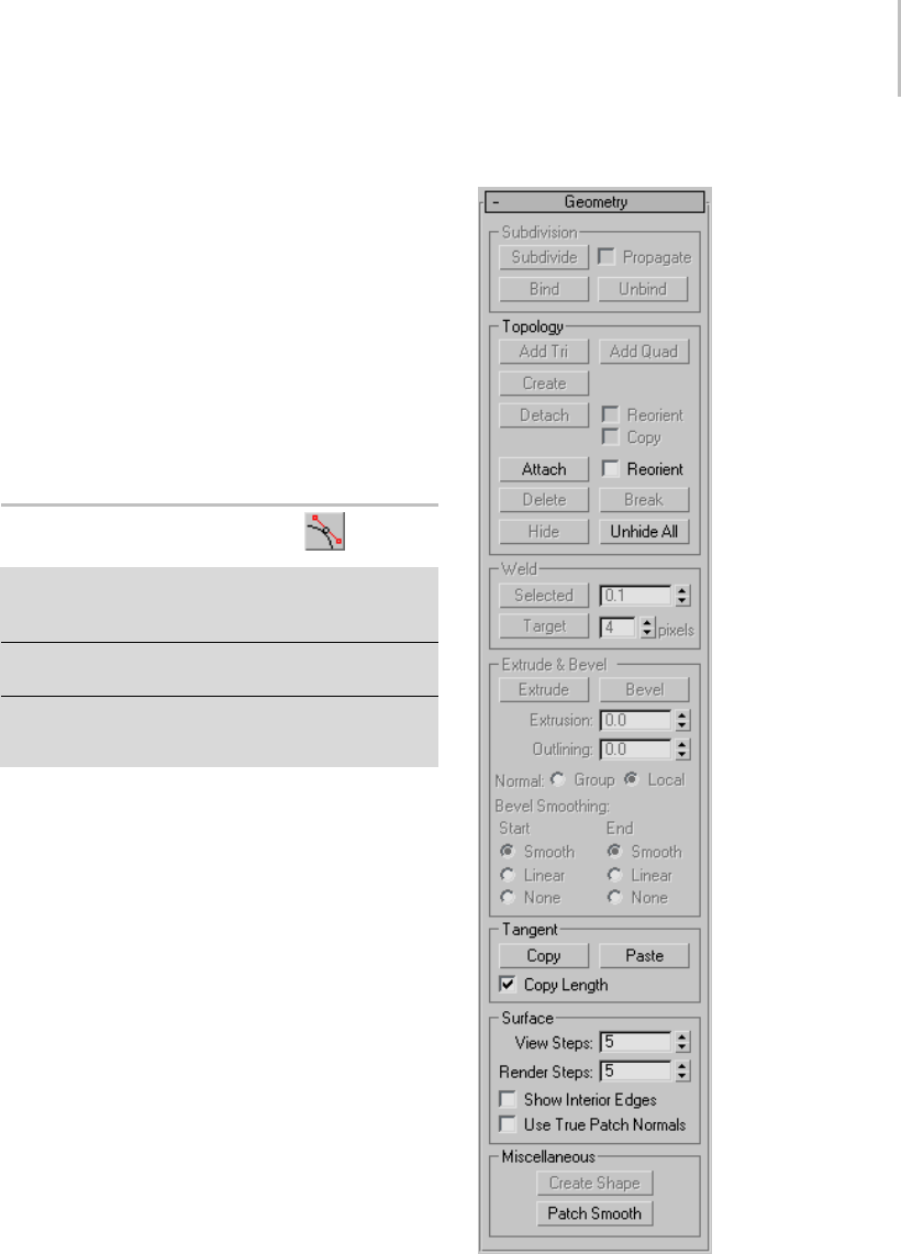
Editable Patch (Handle) 979
Select—Depending on which radio button is
selected, selects all vertices whose vertex color or
illumination values either match the color swatch,
or are within the range specified by the RGB
spinners.
Range—Specifies a range for the color match.
All three RGB values in the vertex color or
illumination must either match the color specified
by the Color swatch in Select By Vertex Color, or
be within plus or minus the values in the Range
spinners. Default=10.
Editable Patch (Handle)
Select an editable patch > Modify panel > Expand the
editable patch in the stack display > Handle sub-object
level
Select an editable patch > Modify panel > Selection
rollout > Handle button
Select an editable patch > Right-click the patch > Tools
1 (upper-left) quadrant of the quad menu > Sub-objects
>Handle
The Handle sub-object level in Editable Patch
provides direct access to vertex handles, or vectors,
without going through the Vertex sub-object level.
Handles are still accessible at the Vertex sub-object
level, but the Handle level provides enhanced
functionality as follows:
• The ability to select multiple handles for
transformation and application of operations
such as Patch Smooth to them.
•Usageofthetransformgizmowhen
manipulating handles.
• Elimination of the possibility of inadvertently
transforming vertices.
• Support for named selection sets of handles.
• Copying and pasting handles.
•UsetheAlign tool (page 1–462) for aligning
handles.
Interface
See Geometry Rollout (Patch) (page 1–986) for
detailed descriptions of these controls.
980 Chapter 9: Surface Modeling
Editable Patch (Edge)
Select an editable patch > Modify panel > Expand the
editable patch in the stack display > Edge sub-object level
Select an editable patch > Modify panel > Selection
rollout > Edge button
Select an editable patch > Right-click the patch > Tools 1
(upper-left) quadrant of the quad menu > Sub-objects >
Edge
An edge is the portion of a patch object between
two adjacent vertices. When at the Editable Patch
(Edge) level, you can select single and multiple
segments and move, rotate, and scale them using
standard methods. You can also hold down the
Shift key and drag an edge to create a new
patch. Holding down the Shift key during edge
extrusion creates a new element.
Procedure
To unlock interior edges:
When you move an outer or boundary edge of
a patch, the adjacent interior edges are normally
“locked” so that they move in parallel with the
boundary edge. This is often useful, because it
provides a uniform transition across the patch.
This default is known as Auto Interior.
•AtPatch level (page 1–981),youcanchange
the default on a patch-by-patch basis by
right-clicking a patch and choosing Manual
Interior from the Tools 1 (upper-left) quadrant
of the quad menu. Thereafter, when you move a
boundary edge, interior edges are affected in a
nonlinear way. The interior edges are no longer
locked to the boundary edge.
Warning: If you return a patch to the default,
changes caused by Manual Interior are lost.
Interface
Selection rollout
Select Open Edges—Selectsalledgesthatareused
by only one patch. You can use this to troubleshoot
a surface; open edges will be highlighted.
For information on the other controls in this
rollout, see Selection Rollout (Editable Patch) (page
1–971).
Soft Selection rollout
See Soft Selection Rollout (page 1–963) for
information on the Soft Selection rollout settings.
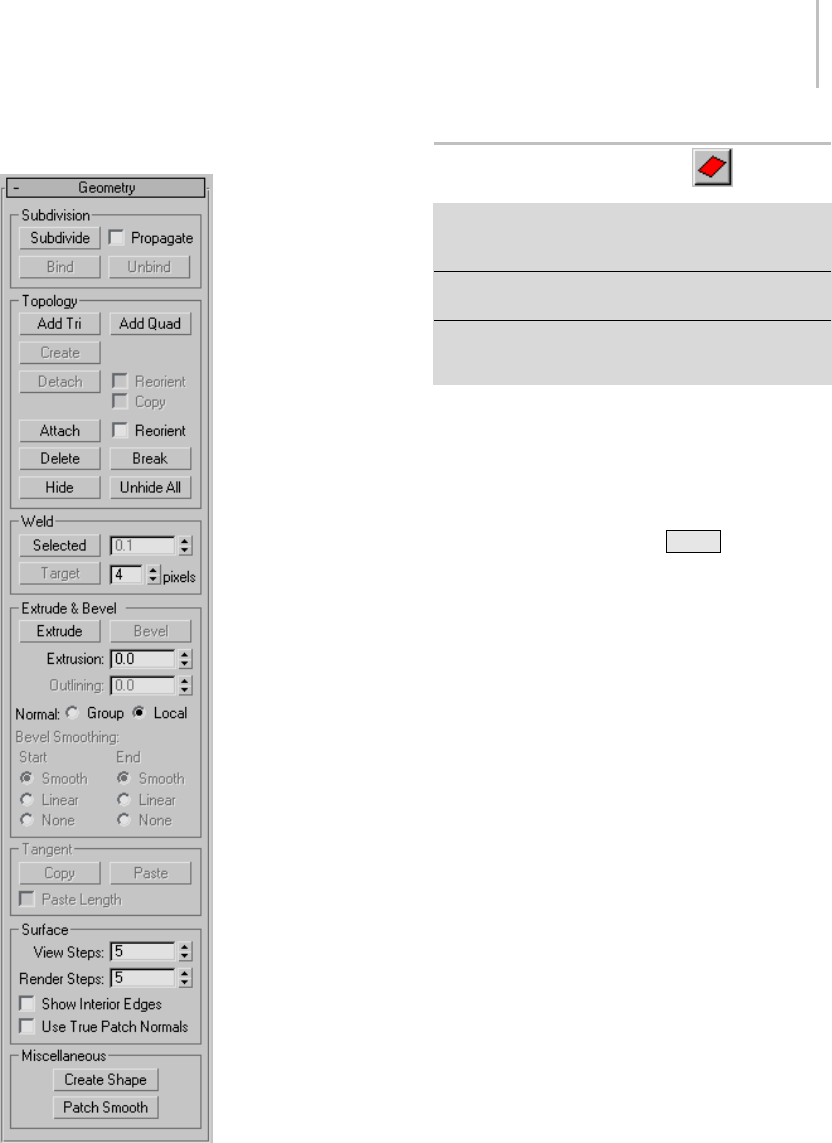
Editable Patch (Patch) 981
Geometry rollout
See Geometry Rollout (Patch) (page 1–986) for
detailed descriptions of these controls.
Editable Patch (Patch)
Select an editable patch > Modify panel > Expand the
editable patch in the stack display > Patch sub-object
level
Select an editable patch > Modify panel > Selection
rollout > Patch button
Select an editable patch > Right-click the patch > Tools 1
(upper-left) quadrant of the quad menu > Sub-objects >
Patch
A patch is an area of a patch object, defined by
threeorfoursurroundingedgesandvertices.
Controls described in this topic let you manipulate
a patch object at the patch level. As well as moving
and rotating patches, you can create a separate
element by holding down the Shift key during a
move operation. This creates a separate element
of the selected patches.
Texture Mapping Patches: Interpolation
in Curved Space
Patches can now be mapped in curved space; this
means simplified texture mapping for patches. A
planar map on a complex patch object will not be
distorted. At the Patch sub-object level there is a
parameter in the right-click quad menu (Tools
1 quadrant) called Linear Mapping. If you leave
Linear Mapping off, then textures are interpolated
in curved space and behave much like texture
mapping a mesh object, predictably.
In the old method, patch mapping is interpolated
between the knot points. This works well with
procedural maps but not so well with bitmaps,
since each patch is linear in UV space.
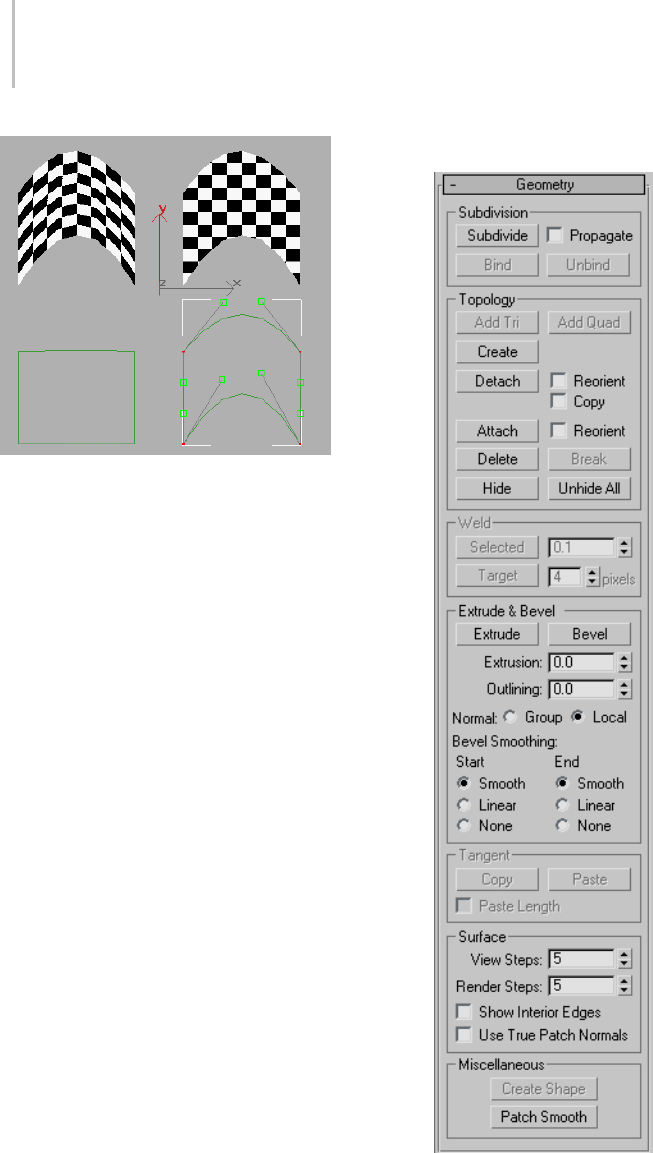
982 Chapter 9: Surface Modeling
A complex patch (on right) no longer deforms a bitmap
The two leftmost patches show Linear patch
mapping.Thetopleftpatchisapatchwithplanar
mappingandthebottomleftshowsitsUVW
spacerepresentation.Thepatchontherightisa
curved projection where the vectors are used in
UVW space projection. Notice the bottom right
represents the UVW space and notice how the
handles and knots contribute to the shape of the
UVW space.
In short, leave the Linear option off for predictable
planar maps. Leave the linear mapping option on
for backward compatibility.
Note: The Unwrap UVW modifier now supports
the new patch curve mapping. Spline handles can
be manipulated in the Edit dialog in the Unwrap
UVW modifier.
Interface
Selection rollout
For information on the controls in this rollout, see
Selection Rollout (Editable Patch) (page 1–971).
Soft Selection rollout
See Soft Selection Rollout (page 1–963) for
informationontheSoftSelectionrolloutsettings.
Geometry rollout
See Geometry Rollout (Patch) (page 1–986) for
detailed descriptions of these controls.
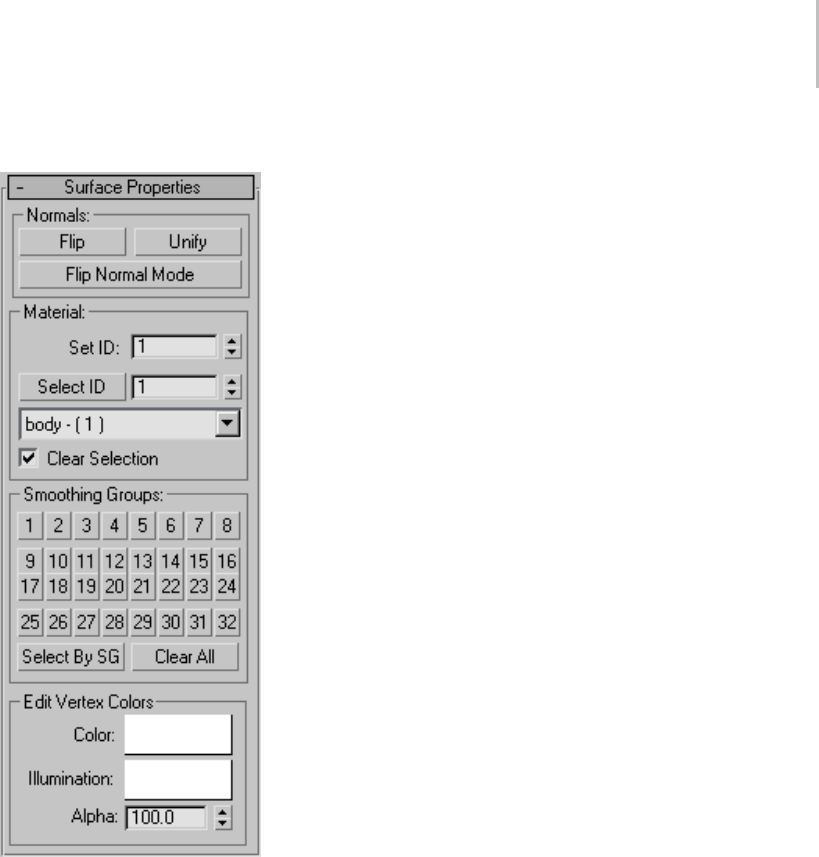
Editable Patch (Patch) 983
Surface Properties rollout
These controls let you work with patch normals,
material IDs, smoothing groups and vertex colors.
Normals group
Flip—Reverses the direction of the surface normals
of the selected patches.
Unify—Flips the normals of an object so that they
all point in the same direction, usually outward.
This is useful for setting an object’s patches
to appropriate orientations, thus eliminating
apparent holes in the object surface.
Flip Normal Mode—Flips the normal of any patch
you click. To exit, click this button again or
right-click anywhere in the program interface.
Tip: ThebestwaytouseFlipNormalMode
is to set up your viewport to display with
Smooth+Highlight and Edged Faces on. If you use
Flip Normal Mode with default settings, you’ll be
able to flip a patch away from you, but you won’t be
able to flip it back. For best results, turn off Ignore
Backfacing in the Selection rollout. This lets you
click any patch and flip the direction of its normal,
regardless of its current direction.
Material group
These controls let you use multi/sub-object
materials (page 2–1594) with patches.
Set ID—Lets you assign a particular material ID
(page 3–969) number to selected patches for
use with multi/sub-object materials and other
applications. Use the spinner or enter the number
fromthekeyboard.Thetotalnumberofavailable
IDs is 65,535.
Select ID—Selects patches or elements
corresponding to the Material ID specified in
theadjacentIDfield.Typeorusethespinnerto
specify an ID, then click the Select ID button.
[Select By Name]—This drop-down list shows
the names of sub-materials if an object has a
Multi/Sub-Object material assigned to it. Click the
drop arrow and choose a sub-material from the
list. The patches or elements that are assigned that
material are selected. If an object does not have
aMulti/Sub-Objectmaterialassigned,thename
list is unavailable. Likewise, if multiple objects
areselectedthathaveanEditPatch,EditSpline,
or Edit Mesh modifier applied, the name list is
inactive.
Note: Sub-material names are those specified in the
Name column on the material’s Multi/Sub-Object
Basic Parameters rollout; these are not created by
984 Chapter 9: Surface Modeling
default, and must be specified separately from any
material names.
Clear Selection—When on, choosing a new ID or
material name deselects any previously selected
patches or elements. When off, selections are
cumulative, so new ID or sub-material name
selections add to the existing selection set of
patches or elements. Default=on.
Smoothing Groups group
Use these controls to assign selected patches to
different smoothing groups (page 3–1013),andto
select patches by smoothing group.
To assign patches to one or more smoothing
groups, select the patches, and then click the
number(s) of the smoothing group(s) to assign
them to.
Select by SG (Smoothing Group)—Displays a dialog
that shows the current smoothing groups. Select
a group by clicking the corresponding numbered
button and clicking OK.
Clear All—Removesanysmoothinggroup
assignments from selected patches.
Edit Vertex Colors group
Use these controls to assign the color, illumination
color (shading), and alpha (transparency) values
of vertices on the selected patch(es).
Color—Click the color swatch to change the color
of vertices on the selected patch(es).
Illumination—Click the color swatch to change
the illumination color of vertices on the selected
patch(es). This lets you change the color of
shadows without changing the vertex colors.
Alpha—Lets you assign an alpha (transparency)
value to vertices on the selected patch(es).
The spinner value is a percentage; zero is
completely transparent and 100 is completely
opaque.
Editable Patch (Element)
Select an editable patch > Modify panel > Expand the
editable patch in the stack display > Element sub-object
level
Select an editable patch > Modify panel > Selection
rollout > Element button
Select an editable patch > Right-click the patch > Tools 1
(upper-left) quadrant of the quad menu > Sub-objects >
Element
Use the Element sub-object level when you
want to select and work on all contiguous faces
in an element. The Element sub-object level
is essential when you are Shift +cloning and
Shift +extruding patches, because doing so
creates separate elements. For example, if you
select a patch, hold down the Shift key, and
move the patch to a new location, a new element
is created separate from the original. This also
applies to extrusion. If you hold the Shift key
down while you extrude, a new element is created.
Note: In some cases, you might find that moving
a patch element causes parts of it to move by
differing amounts. This typically occurs because
the object is set to Manual Interior. It happens, for
instance, when you convert a sphere primitive to
an editable patch object. To remedy this, select
the element, and then right-click it to display the
quad menu, and in the Tools1 quadrant, choose
Auto Interior.
Interface
Selection rollout
For information on the controls in this rollout, see
Selection Rollout (Editable Patch) (page 1–971).
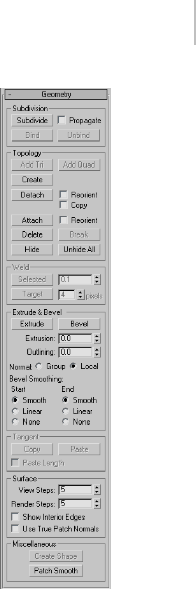
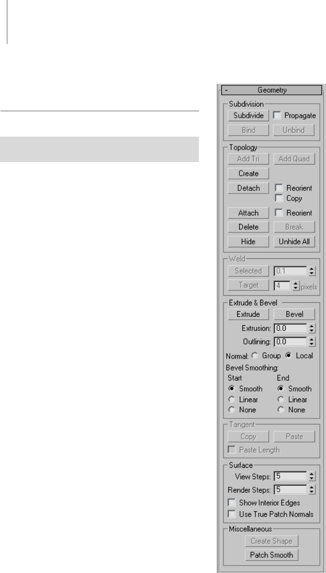
986 Chapter 9: Surface Modeling
See Geometry Rollout (Patch) (page 1–986) for
detailed descriptions of these controls.
Geometry Rollout (Patch)
Select an editable patch > Modify panel > Geometry
rollout
The Geometry rollout for Patches contains most
of the controls that let you alter the geometry of
the patch, at either the Object (top) level, or one of
the sub-object levels. The controls that the rollout
displayscanvary,dependingonwhichlevelis
active; if a control is not available for the active
level, it might be grayed out, or simply might not
appear at all. The descriptions below indicate the
levels at which controls are available.
Interface
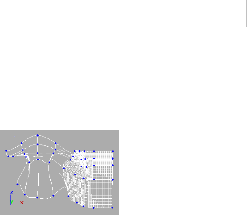
Geometry Rollout (Patch) 987
Subdivision group (Vertex, Edge, Patch, and
Element levels only)
Bind (Vertex level only)—Lets you create a seamless,
gapless connection between two patch edges
that have unequal numbers of vertices. The two
patches must belong to the same object, and the
vertex need not be selected first. Click Bind, then
dragalinefromanedge-basedvertex(nota
corner vertex) to the edge you want to bind it to.
The cursor turns into a white cross when over a
legal edge.
Binding patch edges
To exit Bind mode, click the Bind button again, or
right-click in the active viewport.
Tip: When connecting two patches edge-to-edge,
first line up as many pairs of vertices as possible,
and use Weld to connect them. Then use Bind to
connect the remaining vertices. Bound vertices
cannot be manipulated directly, although their
handles can.
Note: Bind is useful for connecting patch objects
with different patch resolutions, such as a head
andaneck,withouttheneedtocreateadditional
patches in the lower-resolution object.
Unbind (Vertex level only)—Disconnects a vertex
connected to a patch with Bind. Select the vertex,
and then click Unbind.
Subdivide (Edge, Patch, and Element levels
only)—Subdivides the selected sub-objects.
•Propagate—When on, extends the subdivision
to neighboring patches. Propagating the
subdivisions along all contiguous patches
prevents patch cracks where you have attached
patches together.
Topology group
Add Tri / Add Quad (Edge level only)—Yo u c a n a d d
Tri and Quad patches to any op en ed ge of an
object. On closed objects such as spheres, you can
delete one or more existing patches to create open
edges, and then add new patches.
The new patches adapt to the existing geometry.
For example, when you add a patch to a curved
edge, the new patch follows that curve and
seamlessly extends it.
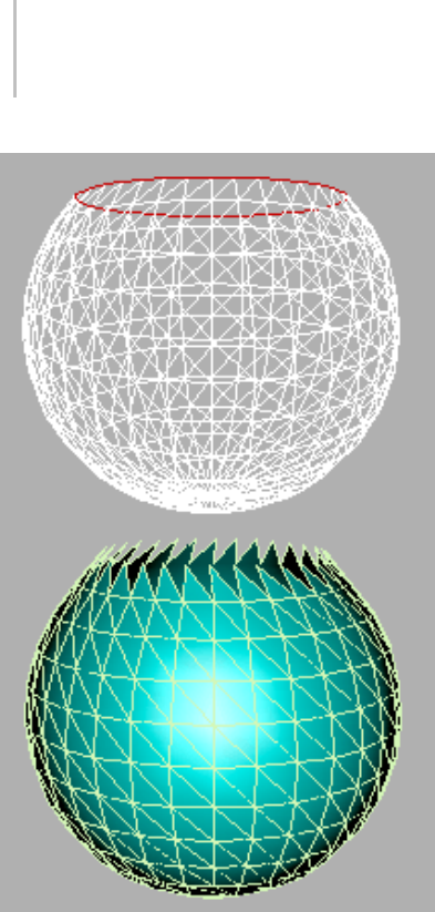
988 Chapter 9: Surface Modeling
Original patch with edges selected (top) and three-sided
patches added (bottom)
Add Tri adds a three-sided patch to each selected
edge. Select one or more edges, then click Add Tri
to add the patch or patches.
Add Quad adds a four-sided patch to each selected
edge. Select one or more edges, and then click Add
Quad to add the patch or patches.
Create (Vertex, Patch, and Element levels only)—Lets
you add geometry to the patch object. Available at
Vertex, Patch, and Element sub-object levels only.
At the Vertex sub-object level, turn on Create and
then click anywhere to add vertices to the object.
At the Patch and Element levels, you can add
three- and four-sided patches. The cursor changes
to white cross hairs when over an existing patch
vertex. Select an existing vertex by clicking it.
Click in free space to create a new vertex at that
location;thisvertexisincludedinthesequenceof
vertices for the new patch.
•To create a Tri Patch:Clickthreetimesin
free space or on existing vertices. Right-click
anywhere, or left-click one of the vertices in the
current sequence to complete the creation of a
Tri Patch.
•To create a Quad Patch:Clickfourtimesinfree
space or on existing vertices. The Quad Patch is
automatically created at the fourth click.
No operation takes place if you right-click or select
a vertex in the current sequence with only one or
two vertices in the sequence.
Detach (Patch and Element levels only)—Lets you
select one or more patches or elements within the
current object and then detach them (or copy
them) to form a separate patch object.
•Reorient—When on, the detached patch or
element copies the position and orientation
of the source object’s Local coordinate system
(when the source object was created). The new
detached object is moved and rotated so that
its Local coordinate system is positioned and
aligned with the origin of the current active
grid.
•Copy—When on, the detached patches or
elements are copied to a new patch object,
leaving the originals intact.
Attach—Lets you attach an object to the currently
selected patch object. Click the object you want to
attach to the currently selected patch object.
If you attach a non-patch object, the object is
converted to a patch object.
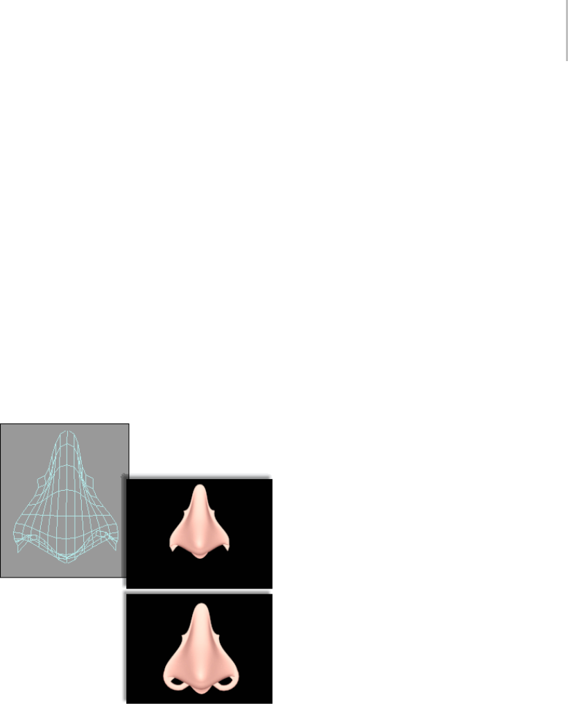
Geometry Rollout (Patch) 989
When you attach an object, the materials of the
two objects are combined in the following way:
• If the object being attached does not have a
material assigned, it inherits the material of the
object it is being attached to.
• Likewise if the object you’re attaching to doesn’t
have a material, it inherits the material of the
object being attached.
• If both objects have materials, the resulting new
material is a multi/sub-object material (page
2–1594) that encompasses the input materials.
A dialog appears offering three methods of
combining the objects’ materials and material
IDs. For more information, see Attach Options
Dialog (page 1–1018).
Attach remains active in all sub-object modes, but
always applies to objects.
Top: Original patch object with rendering
Bottom: Rendering with another patch attached
Reorient—When on, reorients the attached element
so that each patch’s creation local coordinate
system is aligned with the creation local coordinate
system of the selected patch.
Delete (Vertex, Edge, Patch, and Element levels
only)—Deletes the selected sub-objects.
Warning: Delete vertices or edges with caution.
Deleting a vertex or edge also deletes the patches that
share them. For example, if you delete the single vertex
at the top of a spherical patch, the top four patches are
also deleted.
Break (Vertex and Edge levels only)—For vertices,
breaks a vertex into multiple vertices. Use this
ifyouneedtosplitopenanedgetoaddanother
patch or for general modeling operations. Select
a vertex, and then click Break. After the break,
select the individual vertices and move them to
separate the edges.
For edges, splits an edge. Use this if you need
to split open an edge for general modeling
operations. Select one or more edges, and then
click Break. After the break, move the handles of
adjacent vertices to create a gap in the patch.
Hide (Vertex, Edge, Patch, and Element levels
only)—Hides the selected sub-objects. For vertices
and edges, Hide also hides the patches that are
attached to them.
Note: At least one patch in the object must remain
visible.
Unhide All—Restores any hidden sub-objects to
visibility.
Weld group (Vertex and Edge levels only)
Selected—Welds selected vertices that fall within
the tolerance specified in the Weld Threshold
spinner (to the right of the Weld button). Select
the vertices you want to weld between two different
patches, set the spinner to a sufficient distance,
and click Selected.
At the Edge sub-object level, clicking Selected
welds two edges that share vertices. You can use
this to eliminate gaps on a surface.
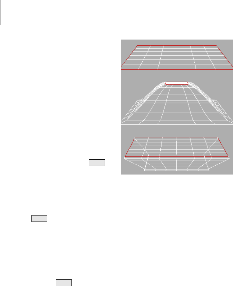
990 Chapter 9: Surface Modeling
Target (Vertex level only)—Tur n on and drag f rom
one vertex to another to weld the vertices together.
The dragged vertex fuses to the target vertex.
The pixels spinner to the right of the Target
button sets the maximum distance in screen pixels
between the mouse cursor and the target vertex.
Extrude & Bevel group (Edge, Patch, and
Element levels only)
These controls let you extrude and bevel edges,
patches, or elements. Extruding patches moves
them along a normal and creates new patches that
form the sides of the extrusion, connecting the
selection to the object. Beveling adds a second
step that lets you scale the extruded patches. You
can extrude and bevel patches by dragging or by
direct entry. You can also hold down the Shift
key during extrusion, which creates a separate
element.
Note: Sides created by beveling or extrusion are
assigned to smoothing group 1.
Extrude—Click this button, and then drag any
edge, patch, or element to extrude it interactively.
Hold down the Shift keyduringthisoperation
to create a new element.
When the mouse cursor is over a selected patch or
element, it changes to an Extrude cursor.
Bevel (Patch and Element levels only)—Click this
button, and then drag any patch or element to
extrude it interactively, then click and release
the mouse button, and drag again to bevel the
extrusion. Hold down the Shift key during this
operation to create a new element.
When the mouse cursor is over a selected element,
it changes to a Bevel cursor.
Original patch (top) and inward and outward extrusions
Note: In some cases, particularly with closed objects (objects with
no holes or open edges), the second bevel step might not produce
visible results.
Extrusion—This spinner sets whether the extrusion
is outward or inward, depending on whether the
value is positive or negative.
Outlining (Patch and Element levels only)—This
spinner lets you scale selected patches or elements
bigger or smaller, depending on whether the value
is positive or negative. It is normally used after an
extrusion for beveling the extruded patches.
Normal—If Normal is set to Local (the default),
extrusion takes place along the normal of each
selected edge, patch, or individual patch in an
element. If normal is set to Group,extrusion
takes place along the averaged normal of each
contiguous group in a selection. If you extrude
multiples of such groups, each group moves along
its own averaged normal.
Bevel Smoothing (Patch and Element levels
only)—These settings let you set the shape of
Geometry Rollout (Patch) 991
the intersection between the surface created
by a beveling operation and the neighboring
patches. The shapes are determined by the handle
configurations of vertices at the intersections.
Start refers to the intersection between the sides
and the patches surrounding the beveled patch.
Finish refers to the intersection between the sides
andthebeveledpatchorpatches. Thefollowing
settings are available for each:
•Smooth—Vertex handles are set so the angles
between the new patches and their neighbors
are relatively small.
•Linear—Vertex handles are set to create linear
transitions.
•None—Vertex handles are not modified.
Warning: Set Bevel Smoothing before the bevel is
performed; changing the setting has no effect on
existing beveled patches.
Tangent group (Vertex and Handle levels only)
These controls let you copy orientation, and
optionally length, between handles on the same
object, or on different objects applied with
instances of the same Edit Patch modifier. The tool
doesn’t support copying handles from one patch
object to another, or between spline and patch
objects.
Copy—Copies a patch handle’s transform settings
to a copy buffer.
When you click Copy, 3ds Max displays all handles
on the selected object. When the mouse cursor is
over a handle end, the cursor image changes to the
one shown below. Click a handle end to copy its
direction and length to the paste buffer; this also
exits Copy mode.
Paste—Pastes orientation information from the
copy buffer to a vertex handle. If Paste Length is
on, it also pastes the length of the copied handle.
When you click Paste, the software displays all
handles on the selected object. When the mouse
cursor is over a handle end, the cursor image
changes to the one shown below. Click a handle
end to paste the information from the buffer to the
handle. You can continue clicking other handle
ends to paste the information repeatedly. To exit
Paste mode, right-click in the viewport or click the
Paste button.
Copy Length / Paste Length—When on and you
useCopy,thelengthofthehandleisalsocopied.
When on and you use Paste, the length of the
originally copied handle is pasted as well as its
orientation. When off, only the orientation is
copied or pasted.
Surface group
View Steps—Controls the grid resolution of the
patch model surface as depicted in the viewports.
Range=0 to 100. Default=5.
Render Steps—Controls the grid resolution of the
patch model surface when rendered. Range=0 to
100. Default=5.
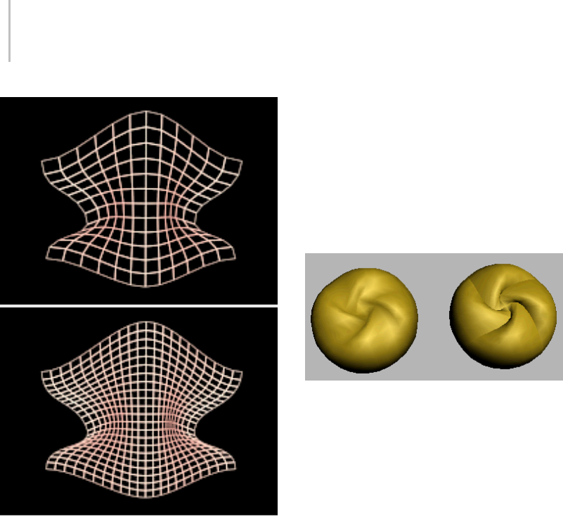
992 Chapter 9: Surface Modeling
Original mesh display of model (top) and with increased steps
(bottom)
Show Interior Edges—Enables the display of the
patch object’s interior edges in wireframe views.
When off, only the object’s outline is visible. Turn
on to simplify the display for faster feedback.
Use True Patch Normals—Determines how the
software smoothes the edges between patches.
Default=off.
When the check box is off, the software computes
the surface normals from the smoothing groups
of the mesh object to which the patch object is
converted before rendering. These normals are not
accurate, especially with a low View/Render Steps
setting. When the check box is on, the software
computes true patch normals directly from the
patchsurfaces,whichcangeneratemoreaccurate
shading.
In the illustration below, a sphere was converted
to Editable Patch format, and then a vertex was
moved toward the center and rotated. The sphere
onthelefthasUseTruePatchNormalsturnedoff,
and the one on the right has it turned on. In both
cases, View Steps was set to 8.
A patch sphere with Use True Patch Normals off (left) and on
(right).
Miscellaneous group
Create Shape (Edge level only)—Creates splines
based on the selected edges. If no edges are
selected, then splines are created for all the patch
edges.3dsMaxpromptsyouforaname:typeina
name for the new shape object, and then click OK.
Each patch edge forms an individual spline. You
can use this to create a spline cage based on
patchedges.Thisisusefulforsplinemodelingor
working with surface tools.
Patch Smooth—At the sub-object level, adjusts
the tangent handles of the vertices of selected
sub-objects to smooth the surface of the patch
object. At the object level, adjusts all tangent
handles to smooth the surface.
PatchSmoothsetsthehandlestoabsolute
positions based on the patch object geometry;
repeated applications have no effect.
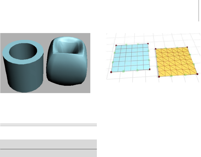
Patch Grids 993
A patch tube before smoothing (left) and after using Patch
Smooth (right)
Patch Grids
Create panel > Geometry > Patch Grids
Create menu > Patch Grids
Yo u c a n c r e a t e t w o k i n d s o f p a t c h s u r f a c e s i n g r i d
form:QuadPatchandTriPatch.Patchgridsbegin
as flat plane objects but can be modified into
arbitrary 3D surfaces by either using an Edit Patch
modifier or collapsing the grid’s modifier stack
down to an Editable Patch in the Modify panel.
Patch grids provide convenient "building material"
for custom surfaces and objects, or for adding
patch surfaces to existing patch objects.
You can animate the surface of a Patch object using
various modifiers such as the Flex and Morph
modifiers. Control vertices and tangent handles of
a patch surface can be animated with an Editable
Patch modifier.
Surface Tools
The output of the Surface modifier (page 1–842)
is a Patch object. Patch objects offer a flexible
alternative to mesh and NURBS modeling and
animation.
Quad patch and tri patch
Editable Patches
You can convert a basic patch grid to an editable
patch object (page 1–968).Theeditablepatchhasa
variety of controls that let you directly manipulate
it and its sub-objects. For example, at the Vertex
sub-object level, you can move vertices or adjust
their Bezier handles. Editable patches let you
create surfaces that are less regular, more free-form
than the basic, rectangular patches.
When you convert a patch to an editable patch,
you lose the ability to adjust or animate its creation
parameters.
See also
Edit Modifiers and Editable Objects (page 1–506)
Modifying at the Sub-Object Level (page 1–506)
Modifier Stack Controls (page 3–760)
Procedure
To create a patch grid:
1. On the Create panel > Geometry > Patch Grids
> Object Type rollout, click either Quad Patch
or Tri Patch.
2. Drag over any viewport to create a patch.
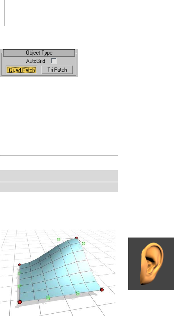
994 Chapter 9: Surface Modeling
Interface
AutoGrid—Uses surface normals as a plane to
create patches. Click a patch type and then click
and drag the cursor over a face in the viewports.
Detailed information about the two patch grid
typesisavailableinthesetopics:
Quad Patch (page 1–994)
Tri Patch (page 1–995)
Quad Patch
Create panel > Geometry > Patch Grids > Quad Patch
Create menu > Patch Grids > Quad Patch
QuadPatchcreatesaflatgridwithadefaultof36
visiblerectangularfacets.Ahiddenlinedivides
each facet into two triangular faces for a total of
72 faces.
Quad Patch
Procedures
To create a patch grid:
1. On the Create panel > Geometry > Patch Grids
> Object Type rollout, click either Quad Patch
or Tri Patch.
2. Drag over any viewport to define a length and
width for the patch.
To edit a Quad Patch:
1. Select a Quad Patch.
2. On the Modify panel, right-click Quad Patch in
stack view and choose Editable Patch.
The Quad Patch collapses to an Editable Patch.
3. On the Editable Patch Selection rollout, click
Ve r t e x .
4. In any viewport, select a vertex on the patch
object,andmovethevertextochangethe
surface topology.
Vertices and vectors can be animated with an
Editable Patch modifier.
Atthesub-objectEdgelevel,youcanaddpatches
along any edge. You can create complex patch
models beginning from a single patch.
An ear is created by adding patches and editing patch vertices
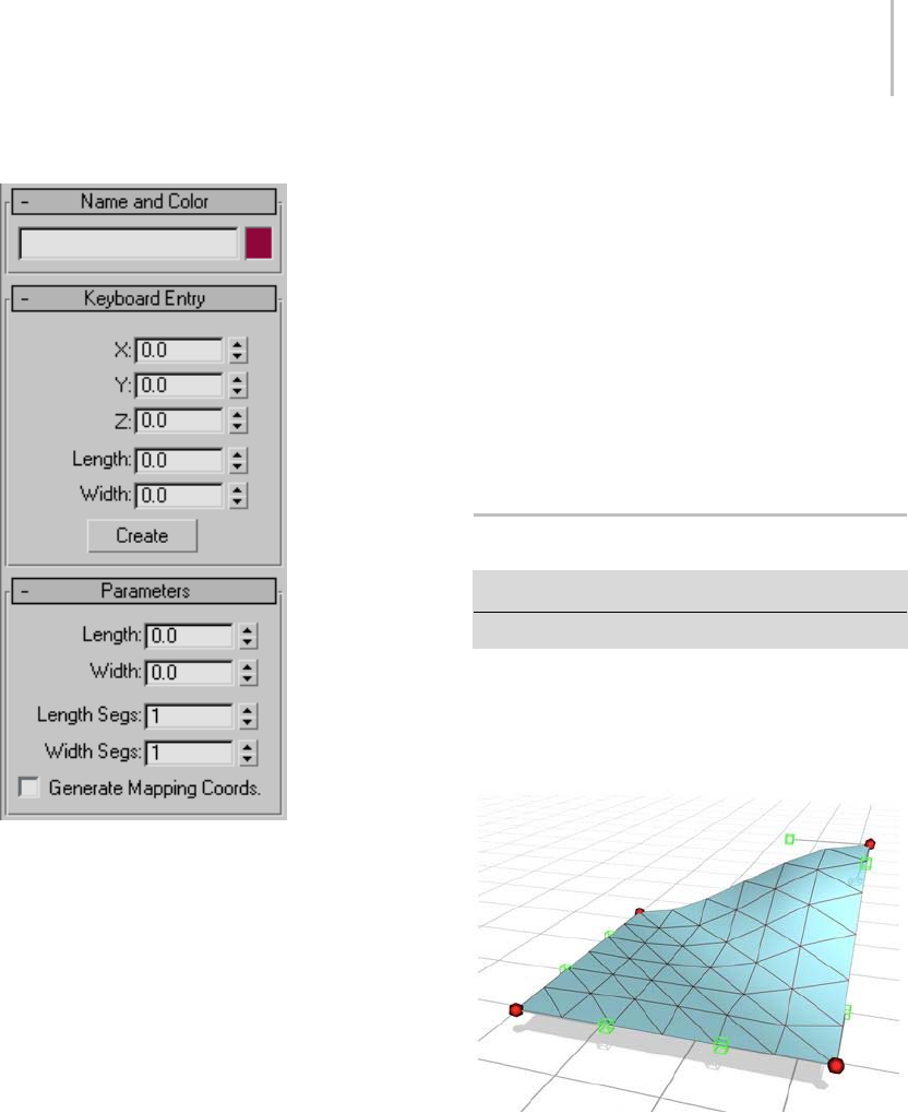
Tri Patch 995
Interface
Name and Color rollout
The Name and Color rollout (page 3–757) lets you
rename objects and change their wireframe color.
Keyboard Entry rollout
X/Y/Z—Sets the patch center.
Length—Sets the patch length.
Width—Sets the patch width.
Create—Creates a patch based on the XYZ, Length,
and Width values.
Parameters rollout
Length, Width—Sets the grid dimensions in current
units.
Length, Width Segments—Determines the number
of facets along the length and width of the grid.
Default=1.
The density of a Quad Patch rises sharply as
you increase the segments. A Quad Patch of
two segments on a side contains 288 faces. The
maximum is 100 segments. High segment values
can slow performance.
Generate Mapping Coordinates—Creates map
coordinates for applying mapped materials.
Default=off.
Tri Patch
Create panel > Geometry > Patch Grids > Tri Patch
Create menu > Patch Grids > Tri Patch
Tri Patch creates a flat grid with 72 triangular
faces. The face count remains at 72, regardless of
its size. The faces become larger to fill the area as
youincreasethesizeofthegrid.
Tri Patch
Procedures
To create a Tri Patch:
1. On the Create panel > Geometry > Patch Grids
>ObjectTyperollout,clickTriPatch.
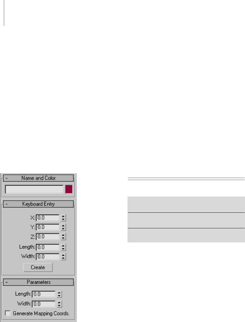
996 Chapter 9: Surface Modeling
2. Drag over any viewport to create the patch.
To edit a Tri Patch:
1. Select a Tri Patch.
2. On the Modify panel, right-click TriPatch in
stackview,andchooseEditablePatch.
The Tri Patch collapses to an Editable Patch.
3. In the Editable Patch Selection rollout, click
Ve r t e x .
4. In any viewport, select a vertex on the patch
object and move the vertex to change the
surface topology.
You can animate vertices and vectors with an
Editable Patch modifier.
Interface
Name and Color rollout
The Name and Color rollout (page 3–757) lets you
rename objects and change their wireframe color.
Keyboard Entry rollout
X/Y/Z—Sets the patch center.
Length—Sets the patch length.
Width—Sets the patch width.
Create—Creates a patch based on the XYZ, Length,
and Width values.
Parameters rollout
Length, Width—Sets dimensions of grid in current
units.
Generate Mapping Coordinates—Creates map
coordinates for applying mapped materials.
Default=off.
Meshes
Create or select an object. > Quad menu > Transform
quadrant > Convert To: submenu > Editable Mesh
Create or select an object. > Modify panel > Right-click
the base object in the stack. > Convert to: Editable Mesh
Create or select an object. > Utilities panel > Collapse
button > Collapse Selected button
Editable Mesh (page 3–932),liketheEditMesh
modifier, provides controls for manipulating a
meshobjectmadeupoftriangularfacesasan
object and at three sub-object levels: vertex, edge
and face. You can convert most objects in 3ds Max
to editable meshes, but for open spline objects,
only vertices are available, because open splines
have no faces or edges when converted to meshes.
Tomakeasub-objectselectiononanon-editable
mesh object (for example, a primitive) for passing
up the stack to a modifier, use the Mesh Select
modifier (page 1–719).
OnceyoumakeaselectionwithEditableMesh,
you have these options:

Editable Mesh Surface 997
• UsetheoptionssuppliedontheEditGeometry
rollout to modify the selection. Later topics
discuss these options for each of the mesh
components.
•Transformor
Shift +clone the selection, as
with any object.
• Passtheselectiontoalatermodifierinthe
stack. You can apply one or more standard
modifiers to the selection.
• Use the options on the Surface Properties
rollout to alter the surface characteristics of
selected mesh components.
Note: Because Edit Mesh modifier functionality is
almost identical to that of editable mesh objects,
features described in the Editable Mesh topics also
apply to objects with Edit Mesh applied, except
as noted.
Tip: Editable Poly (page 1–1022) is similar to
Editable Mesh, but lets you work with polygons of
four or more sides, and provides a greater range of
functionality.
Tip: You can exit most Editable Mesh command
modes, such as Extrude, by right-clicking in the
active viewport.
See also
Edit Modifiers and Editable Objects (page 1–506)
Modifying at the Sub-Object Level (page 1–506)
Modifier Stack Controls (page 3–760)
Procedure
Toproduceaneditablemeshobject:
Firstselecttheobject,andthendooneofthe
following:
• Right-click the object and choose Editable
Mesh from the Convert To submenu in the
transform quadrant.
•Use the Collapse utility (page 1–966).
• Apply a modifier to a parametric object that
turns the object into a mesh object in the stack,
and then collapse the stack. (For example, you
canapplyaMeshSelectmodifier.)
•Importanon-parametricobject,suchasthat
found in a 3DS file.
Converting an object to an editable mesh removes
all parametric controls, including the creation
parameters. For example, you can no longer
increase the number of segments in a box, slice a
circular primitive, or change the number of sides
on a cylinder. Any modifiers you apply to an
object are collapsed as well. After conversion, the
only entry left on the stack is "Editable Mesh."
Maintaining an object’s creation parameters:
As described in the above procedure, you can
convertanexistingobjecttoaneditablemesh,
which replaces the creation parameters in the stack
with "Editable Mesh." The creation parameters are
no longer accessible or animatable. If you want to
maintain the creation parameters, you can use the
following modifiers:
•Edit Mesh Modifier (page 1–634)
•Mesh Select Modifier (page 1–719)
•Delete Mesh Modifier (page 1–626)
•Tessellate Modifier (page 1–865)
•Face Extrude Modifier (page 1–682)
•Affect Region Modifier (page 1–557)
Interface
Modifier Stack display
Show End Result—Normally, if you apply a
modifier such as Twist to an editable-mesh object
andthenreturntotheEditableMeshstackentry,
you cannot see the effect of the modifier on the
object’s geometry. But if you turn on Show End

998 Chapter 9: Surface Modeling
Result while in sub-object level, you can see the
original sub-object selection as a yellow mesh,
thefinalobjectasawhitemesh,andtheoriginal
editable mesh as an orange mesh.
Selection rollout
See Selection Rollout (Editable Mesh) (page 1–999).
Named Selections
Copy—Places a named selection into the copy
buffer.
Paste—Pastes a named selection from the copy
buffer.
For more information, see Named Selection Sets
(page 1–67).
Selection Information
At the bottom of the Selection rollout is a
text display giving information about the
current selection. If no objects or more than
one sub-object are selected, the text gives the
numberofobjectsandthetypeselected. Ifa
single sub-object is selected, the text gives its
identification number and type.
Note: When the current sub-object level is Polygon
or Element, selection information is given in faces.
Soft Selection rollout
Soft Selection controls affect the action of
sub-object Move, Rotate, and Scale functions.
When these are on, 3ds Max applies a spline curve
deformation to unselected vertices surrounding
the transformed selected sub-object. This provides
a magnet-like effect with a sphere of influence
around the transformation.
For more information, see Soft Selection Rollout
(page 1–963).
Edit Geometry rollout
The Edit Geometry rollout (page 1–1011) provides
various controls for editing an editable mesh object
and its sub-objects. For information specific to the
different sub-object levels, click any of the links
below:
Editable Mesh (Object) (page 1–1001)
Editable Mesh (Vertex) (page 1–1003)
Editable Mesh (Edge) (page 1–1006)
Editable Mesh (Face/Polygon/Element) (page
1–1009)
WorkingwithMeshSub-Objects
This topic describes how to work with sub-object
selections when you are editing an Editable Mesh
(page 1–996).
See also
Edit Modifiers and Editable Objects (page 1–506)
Modifying at the Sub-Object Level (page 1–506)
Modifier Stack Controls (page 3–760)
Editable Mesh (page 3–932)
Editable Poly (page 3–933)
Selecting and Transforming
In selecting and transforming sub-object
geometry, you use standard techniques:
• Clicking any vertex, edge, or
face/polygon/element selects it.
•Holdingdown
Ctrl lets you add to or subtract
from the selection with single clicks.
•Holdingdown
Alt lets you a subtract from
the selection with single clicks, or with
Window/Crossing selections.

Selection Rollout (Editable Mesh) 999
• Beginning a selection outside the object starts a
region selection. Holding down Ctrl during
region selection lets you add to the selection.
Once you’ve made a sub-object selection, you can
use the Spacebar to lock the selection while
you’re working with it.
Using Sub-Object Selection
With either an editable mesh (or Edit Mesh
modifier) or a Mesh Select modifier, you can
store three separate sub-object selections: one
for each selection level (vertex, face, and edge).
Theseselectionsetsaresavedwiththefile.With
sub-object selections, you have these options:
• Choose one of the selection sets to pass
geometry up the stack to other modifiers. Only
one selection set is active at a time.
• Change to one of the other selection sets at any
time.
•Usenamed selection sets (page 1–83) for
sub-object geometry you want to reuse.
In modeling a head, for example, you might
have a number of different vertex selections for
forehead, nose, and chin. Such selections can
be difficult to re-create, so named sets give you
easy access to the original selection when you
want to rework a particular area.
Cloning Sub-Object Geometry
Using Shift +transform with a selection of
vertices or faces displays the Clone Part Of Mesh
dialog. This lets you determine whether you want
to "Clone To Object" or "Clone To Element." Click
the desired option, optionally giving the cloned
object a new name, then click OK.
• If you choose Clone To Object, the cloned copy
becomes a plain mesh object, entirely separate
from the original object. The new object is
given the name in the field to the right of the
Clone To Object radio button.
• If you choose Clone To Element, the selection
is cloned in its new position and remains part
of the original object.
Animating Sub-Object Geometry
When you work with an editable mesh, you can
directly transform and animate a sub-object
selection. In effect, the selection works like any
other object.
Selection Rollout (Editable Mesh)
The Selection rollout provides buttons for turning
different sub-object levels on and off, working with
named selections and handles, display settings,
and information about selected entities.
When you first access the Modify panel with
an editable mesh selected, you’re at the Object
level, with access to several functions available as
described in Editable Mesh (Object) (page 1–1001).
You can toggle the various sub-object levels, and
access relevant functions by clicking the buttons at
the top of the Selection rollout.
Clickingabuttonhereisthesameasselecting
asub-objecttypeintheModifierStackdisplay.
Click the button again to turn it off and return to
the Object selection level.
The Selection rollout also allows you to display
and scale vertex or face normals (page 3–980)
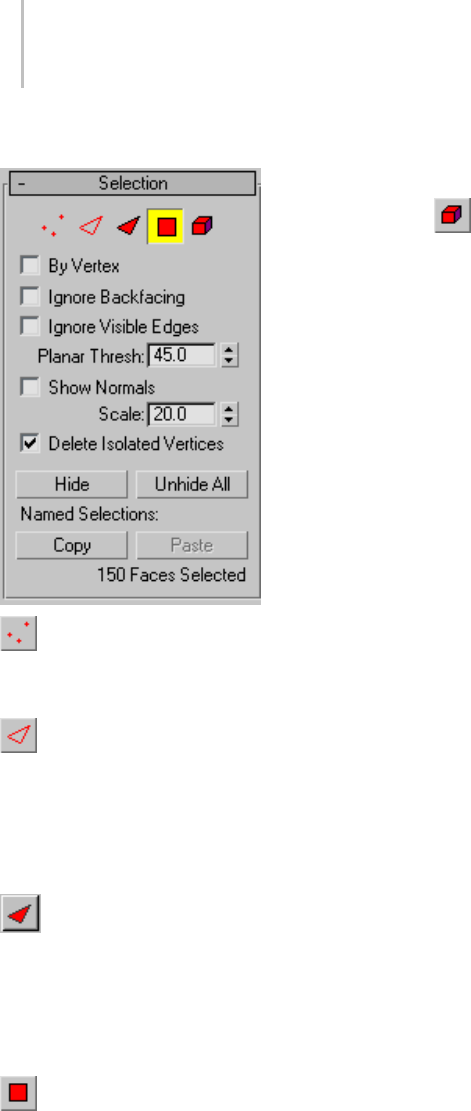
1000 Chapter 9: Surface Modeling
Interface
Vertex—Turns on Vertex sub-object level,
which lets you select a vertex beneath the cursor;
region selection selects vertices within the region.
Edge—Tur ns on Ed ge sub -obje ct level, w hich
lets you select the edge of a face or polygon beneath
the cursor; region selection selects multiple edges
withintheregion.AttheEdgesub-objectlevel,
selected hidden edges are displayed as dashed
lines, allowing for more precise selection.
Face—Turns on Face sub-object level, which
lets you select a triangular face beneath the cursor;
region selection selects multiple triangular faces
within the region. If a selected face has a hidden
edge and Shade Selected Faces isoff,theedgeis
displayed as a dashed line.
Polygon—Turns on Polygon sub-object level,
which lets you select all coplanar faces (defined by
the value in the Planar Threshold spinner) beneath
the cursor. Usually, a polygon is the area you see
within the visible wire edges. Region selection
selectsmultiplepolygonswithintheregion.
Element—Turns on Element sub-object level,
which lets you select all contiguous faces in an
object. Region selection lets you select multiple
elements.
By Vertex—When on, and you click a vertex, any
sub-objects (at the current level) that use that
vertex are selected. Also works with Region Select.
Note: When By Vertex is on, you can select
sub-objectsonlybyclickingavertex,orbyregion.
Ignore Backfacing—When on, selection of
sub-objects selects only those sub-objects whose
normals are visible in the viewport. When off
(the default), selection includes all sub-objects,
regardless of the direction of their normals.
Note: ThestateoftheBackfaceCullsettinginthe
Display panel does not affect sub-object selection.
Thus, if Ignore Backfacing is off, you can still select
sub-objects, even if you can’t see them.
Ignore Visible Edges—This is enabled when the
Polygon face selection method is chosen. When
Ignore Visible Edges is off (the default), and you
click a face, the selection will not go beyond the
visible edges no matter what the setting of the
Planar Thresh spinner. When this is on, face
selection ignores the visible edges, using the Planar
Threshsettingasaguide.
Generally, if you want to select a "facet" (a coplanar
collection of faces), you set the Planar Threshold
to 1.0. On the other hand, if you’re trying to select
a curved surface, increase the value depending on
the amount of curvature.
•Planar Thresh—(Planar Threshold) Specifies the
threshold value that determines which faces are
coplanar for Polygon face selection.
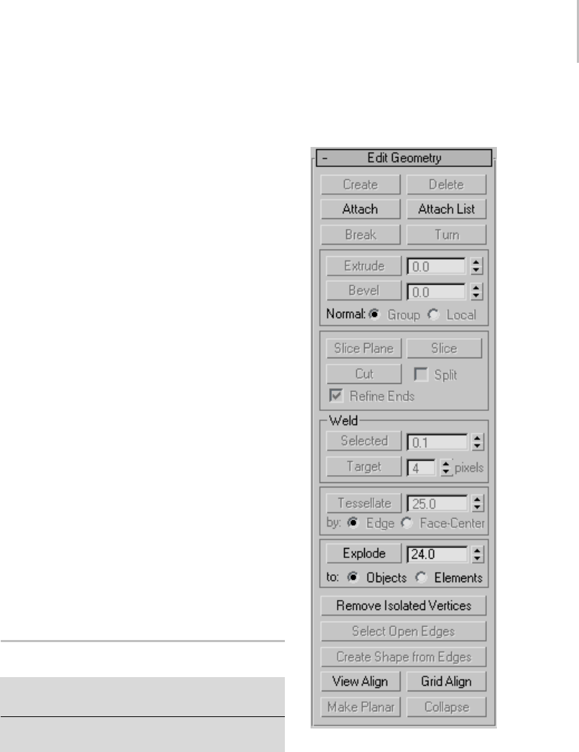
Editable Mesh (Object) 1001
Show Normals—When on, the program displays
normals (page 3–980) in the viewports. Normals
are displayed as blue lines.
ShownormalsisnotavailableinEdgemode.
•Scale—Specifies the size of the normals
displayed in the viewport when Show is on.
Delete Isolated Vertices—When on, 3ds Max
eliminates any isolated vertices when you delete
a contiguous selection of sub-objects. When
off, deleting a selection leaves all vertices intact.
Not Available at the Vertex sub-object level.
Default=on.
An isolated vertex is one that has no associated face
geometry. For example, if Delete Isolated Vertices
is off and you delete a rectangular selection of four
polygons, all clustered about a single central point,
the point remains, suspended in space.
Hide—Hides any selected sub-objects. Edges and
entire objects cannot be hidden.
Tip: The Select Invert command on the 3ds Max
Edit menu is useful for selecting faces to hide.
Select the faces you want to focus on, choose Edit
> Select Invert, then click the Hide button.
Unhide All—Restores any hidden objects to
visibility. Hidden vertices can be unhidden only
when in Vertex sub-object level.
Editable Mesh (Object)
Select an editable mesh object or object with the Edit
Mesh modifier applied. > Modify panel
Select an editable mesh object. > Quad menu > Tools 1
quadrant > Top-Level
Editable Mesh (Object) controls are available when
no sub-object levels are active. These controls are
also available at all sub-object levels, and work
the same at each level, except as noted in Edit
Geometry Rollout (Mesh) (page 1–1011).
Interface
Edit Geometry rollout
See Edit Geometry Rollout (Mesh) (page 1–1011)
for detailed descriptions of these controls.
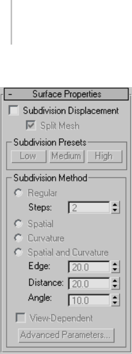
1002 Chapter 9: Surface Modeling
Surface Properties rollout
Specifies surface approximation settings for
subdividing the editable mesh. These controls
work like the surface approximation settings for
NURBS surfaces (page 1–1078).Theyareused
when you apply a displacement map (page 2–1511)
totheeditablemesh.
Note: The Surface Properties rollout is available
only for editable mesh objects; it does not appear
in the Modify panel for an object to which
the Edit Mesh modifier is applied. With Edit
Mesh-modified objects, you can use the Disp
Approx modifier (page 1–628) tothesameeffect.
Subdivision Displacement—When on, faces are
subdivided to accurately displace the mesh,
usingthemethodandsettingsyouspecifyinthe
Subdivision Presets and Subdivision Method
group boxes. When off, the mesh is displaced by
moving existing vertices, the way the Displace
modifier (page 1–629) does. Default=off.
Split Mesh—Affects the seams of displaced mesh
objects; also affects texture mapping. When on,
the mesh is split into individual faces before it is
displaced; this helps preserve texture mapping.
When off, the mesh is not split and an internal
method is used to assign texture mapping.
Default=on.
Tip: This parameter is required because of an
architectural limitation in the way displacement
mapping works. Turning Split Mesh on is usually
the better technique, but it can cause problems for
objects with clearly distinct faces, such as boxes,
or even spheres. A box’s sides might separate as
they displace outward, leaving gaps. And a sphere
might split along its longitudinal edge (found in
the rear for spheres created in the Top view) unless
you turn off Split Mesh. However, texture mapping
works unpredictably when Split Mesh is off, so
you might need to add a Displace Mesh modifier
(page 1–514) and make a snapshot (page 1–453)
of the mesh. You would then apply a UVW Map
modifier (page 1–922) andthenreassignmapping
coordinates to the displaced snapshot mesh.
Subdivision Presets group & Subdivision
Method group
The controls in these two group boxes specify how
the displacement map is applied when Subdivision
Displacement is on. They are identical to the
Surface Approximation controls (page 1–1239) used
for NURBS surfaces.

Editable Mesh (Vertex) 1003
Editable Mesh (Vertex)
Select an editable mesh object. > Modify panel >
Selection rollout > Vertex
Select an editable mesh object. > Modify panel > Modifier
Stack display > Expand Editable Mesh. > Vertex
Select an editable mesh object. > Quad menu > Tools
1quadrant>Vertex
Vertices are points in space: they define the
structure of faces. When vertices are moved or
edited, the faces they form are affected as well.
Vertices can also exist independently; such isolated
vertices can be used to construct faces but are
otherwise invisible when rendering.
At the Editable Mesh (Vertex) sub-object level, you
can select single and multiple vertices and move
them using standard methods.
See also
Editable Mesh Surface (page 1–996)
Procedures
To weld mesh vertices:
Yo u c a n u s e e i t h e r o f t w o m e t h o d s t o c o m b i n e
severalverticesintoone,alsoknownaswelding.If
theverticesareveryclosetogether,usetheWeld
function. You can also use Weld to combine a
number of vertices to the average position of all
of them.
Alternatively, to combine two vertices that are far
apart, resulting in a single vertex that’s in the same
position as one of them, use Target Weld.
Tip: Weldingverticesisconsiderablyeasierwith
poly objects. See this procedure: To w e l d p o ly g o n
vertices: (page 1–1029)
1. To u s e We l d :
1. On the Selection rollout, turn on Ignore
Backfacing, if necessary. This ensures that
you’reweldingonlyverticesyoucansee.
2. Select the vertices to weld.
3. If the vertices are very close together, go to
the Edit Geometry rollout > Weld group
and click Selected. If that doesn’t work (you
get a “No vertices within weld threshold.”
message), proceed to the next step.
4. Increase the numeric value to the right of
the Selected button.
This is the threshold value; the minimum
distance that vertices can be apart from each
other to be welded.
5. Click Selected again.
At this point, one of three things happens:
None, some, or all of the vertices are welded.
Ifthelatter,you’redone. Ifeitherofthe
others occurs, proceed to the next step.
6. Continue increasing the threshold value and
clicking Selected until all of the vertices are
welded.
2. To u s e Ta r g e t We l d :
1. On the Selection rollout, turn on Ignore
Backfacing, if necessary. This ensures that
you’reweldingonlyverticesyoucansee.
2. Find two vertices you want to weld, and
determine the ultimate location of the
resulting vertex. You can weld any two
vertices, but for best results the two should
be contiguous; that is, they should be
connected by a single edge.
For this example, we’ll call the vertices A and
B, and the resulting vertex will be at vertex
B’s location.
3. Click the Target button.
The button stays highlighted, to indicate that
you’re now in Target Weld mode.
4. Drag vertex A to Vertex B.
Whileyou’redragging,themousecursor
image is a four-headed, +-shaped arrow.

1004 Chapter 9: Surface Modeling
When over an eligible target vertex, the
cursor changes to a crosshairs.
Tip: If you have trouble dragging in the
proper direction, open the Axis Constraints
toolbar (page 3–687) and click the XY
button.
5. Releasethemousebutton.
The pair is welded. The resulting vertex
remains at vertex B’s position, and you exit
Ta rg et We ld m o de .
Tip: If you have trouble combining the two
vertices, try increasing the Pixels value with
the spinner to the right of the Target button.
You remain in Target Weld mode, and can
continue to weld pairs of vertices.
6. Exit Target mode by right-clicking in the
active viewport or clicking the Target button
again.
To select vertices by color:
1. On the Surface Properties rollout, click the
Existing Color swatch, and specify the color of
vertex you want in the Color Selector.
2. Specify ranges in the RGB Range spinners.
This lets you select vertices that are close to the
specified color, but don’t match exactly.
3. Click the Select button.
All vertices matching the color, or within the
RGB range, are selected.
Yo u c a n a d d t o t h e s e l e c t i o n b y h o l d i n g Ctrl
as you click the Select button, and you can
subtract from the selection by holding the Alt
key.
Tip: You can select all vertices of the same color
by first selecting the vertex you want matched,
dragging a copy of the Edit Color swatch to the
Existing Color swatch, and then clicking the
Select button. (If you want an exact match, be
sure to set the RGB Range spinners to 0 first.)
Interface
Selection rollout
For information on the Selection rollout settings,
see Editable Mesh (page 1–998).
Soft Selection rollout
Soft Selection controls affect the action of
sub-object Move, Rotate, and Scale functions.
When these are on, the program applies a
spline curve deformation to unselected vertices
surrounding the transformed selected sub-object.
This provides a magnet-like effect with a sphere of
influence around the transformation.
For more information, see Soft Selection Rollout
(page 1–963).
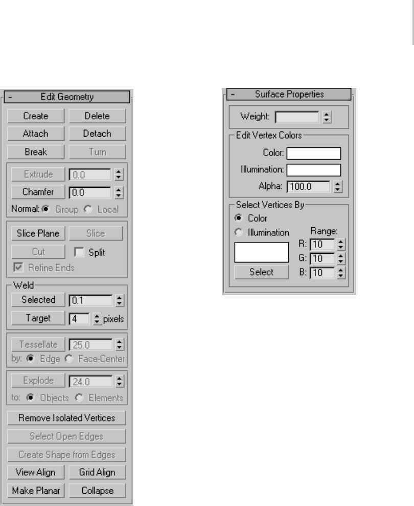
Editable Mesh (Vertex) 1005
Edit Geometry rollout
See Edit Geometry Rollout (Mesh) (page 1–1011)
for detailed descriptions of these controls.
Surface Properties rollout
These controls let you set the weight and color for
vertices.
Weight—Displays and lets you change vertex
weights for NURMS operations (see MeshSmooth
Modifier (page 1–722)).
Edit Vertex Colors group
Use these controls to assign the color, illumination
color (shading), and alpha (transparency) values
of selected vertices.
Color—Click the color swatch to change the color
of selected vertices.
Illumination—Click the color swatch to change the
illumination color of selected vertices. This lets
you change the illumination of a vertex without
changing the vertex’s color.
Alpha—Lets you assign an alpha (transparency)
value to selected vertices.
The spinner value is a percentage; zero is
completely transparent and 100 is completely
opaque.

1006 Chapter 9: Surface Modeling
Select Vertices By group
Color/Illumination—These radio buttons let you
choose to select vertices by vertex color value or
vertex illumination value. Set the desired options
and then click Select.
Color Swatch—Displays the current color to match.
Click to open the Color Selector, where you can
specify a different color.
Select—Depending on which radio button is
selected, selects all vertices whose vertex color or
illumination values either match the color swatch,
or are within the range specified by the RGB
spinners.
Range—Specifies a range for the color match.
All three RGB values in the vertex color or
illuminationcolormusteithermatchthecolor
specified by the Color swatch in Select By Vertex
Color, or be within a range determined by adding
and subtracting the Range values from the
displayed color. Default=10.
For example, if you’ve chosen Color and set the
color swatch to medium gray (R=G=B=128), and
are using the default Range values of 10,10,10,
then clicking the Select button selects only vertices
set to RGB color values between 118,118,118 and
138,138,138.
Editable Mesh (Edge)
Select an editable mesh object. > Modify panel >
Selection rollout > Edge
Select an editable mesh object. > Modify panel > Modifier
Stack display > Editable Mesh rollout > Edge
Select an editable mesh object. > Quad menu > Tools 1
quadrant > Edge
An edge is a line, visible or invisible, forming the
side of a face and connecting two vertices. Two
faces can share a single edge.
At the Editable Mesh (Edge) sub-object level, you
can select single and multiple edges and transform
them using standard methods.
See also
Editable Mesh Surface (page 1–996)
Procedure
To create a shape from one or more edges:
1. Selecttheedgesyouwanttomakeintoshapes.
2. On the Edit Geometry rollout, click Create
Shape From Edges.
3. Make changes, as needed, on the Create Shape
dialog that appears.
• Enter a curve name or keep the default.
• ChooseSmoothorLinearastheShapeType.
• TurnonIgnoreHiddenEdgestoexclude
hidden edges from the calculation, or turn
this feature off.
4. Click OK.
The resulting shape consists of one or more
splines whose vertices are coincident with the
vertices in the selected edges. The Smooth
option results in vertices using smooth values,
while the Linear option results in linear splines
with corner vertices.
When you region-select edges, all edges are
highlighted, including hidden edges, which
are displayed as dashed lines. As a default,
the Create Shape function ignores the hidden
edges, even though they’re selected. Turn off
Ignore Hidden Edges if you want to include the
hidden edges in the calculation.
If the selected edges are not continuous, or if
they branch, the resulting shape will consist
of more than one spline. When the Create
Shape function runs into a branching ’Y’ in
the edges, it makes an arbitrary decision as to
which edge produces which spline. If you need
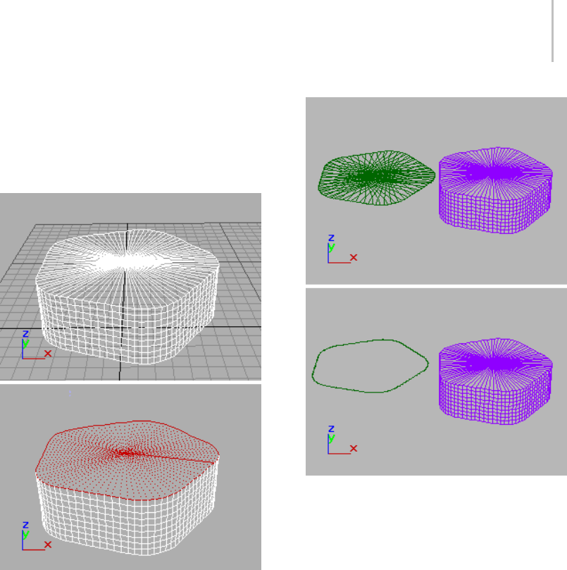
Editable Mesh (Edge) 1007
to control this, select only those edges that will
result in a single spline, and perform Create
Shaperepeatedlytomakethecorrectnumber
of shapes. Finally, use Attach in the Editable
Spline to combine the shapes into one.
Top: Original object
Bottom: Object with edges selected
Top: Selected edges removed from original object
Bottom: Unwanted edges removed
Interface
Selection rollout
See Editable Mesh (page 1–998) for information on
the Selection rollout settings.
Soft Selection rollout
Soft Selection controls affect the action of
sub-object Move, Rotate, and Scale functions.
When these are on, the software applies a
spline curve deformation to unselected vertices
surrounding the transformed selected sub-object.
This provides a magnet-like effect with a sphere of
influence around the transformation.
For more information, see Soft Selection Rollout
(page 1–963).
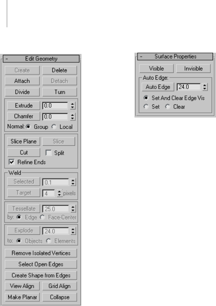
1008 Chapter 9: Surface Modeling
Edit Geometry rollout
See Edit Geometry Rollout (Mesh) (page 1–1011)
for detailed descriptions of these controls.
Surface Properties rollout
These controls affect the visibility of the edges.
Invisible edges (also called construction lines)
appear in the viewports when Edges Only is turned
off in the Display command panel, or when you’re
editing at the Edge sub-object level. The visibility
ofedgesisprimarilyofimportancewhenanobject
is being rendered using a wireframe material.
Visible—Makes selected edges visible.
Invisible—Makes selected edges invisible, so they
won’t be displayed in Edges Only mode.
Auto Edge group
Auto Edge—Automatically determines edge
visibility based on the angle between the faces that
sharetheedge,withtheanglesetbytheThreshold
spinner to its right.
ClickingAutoEdgecanhaveoneofthreeeffects,
dependingonwhichradiobuttonisactive(Set
means to make an invisible edge visible; Clear
meanstomakeavisibleedgeinvisible):
•Set and Clear Edge Vis—Can change the
visibility of all selected edges depending on the
Threshold setting.
•Set—Makes previously invisible edges visible
only if they exceed the Threshold setting; does
not clear any edges.
•Clear—Makes previously visible edges invisible
only if they are less than the Threshold setting;
does not make any edges visible.
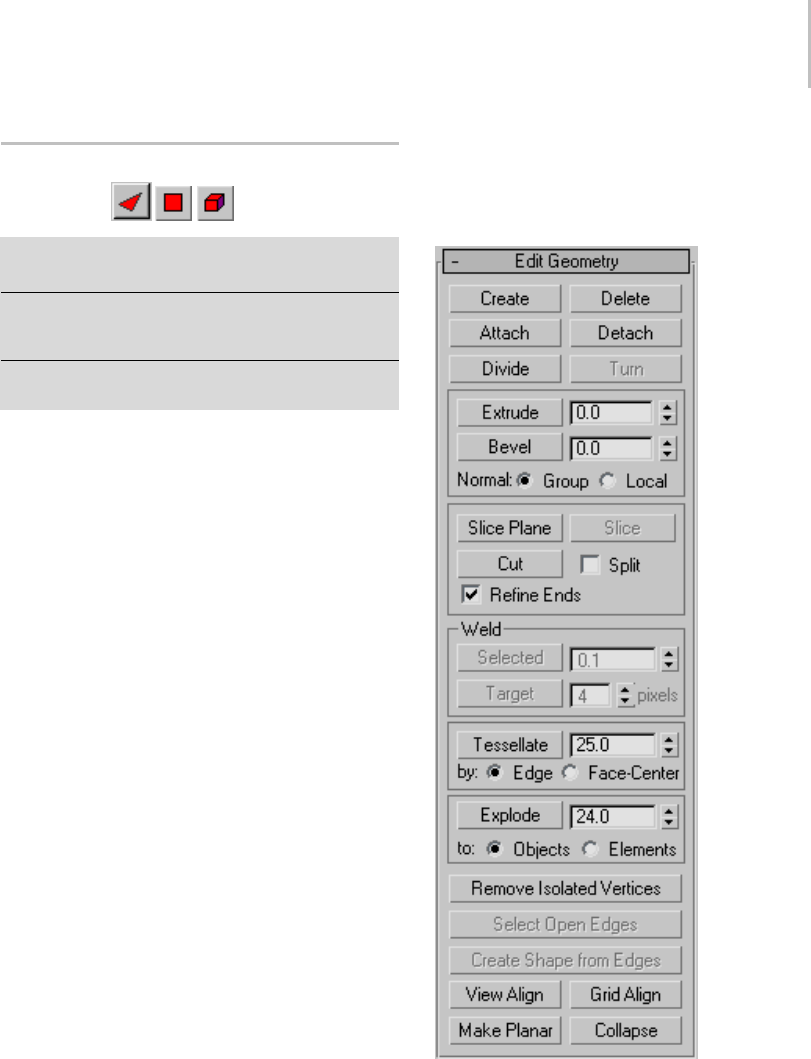
Editable Mesh (Face/Polygon/Element) 1009
Editable Mesh (Face/Polygon/
Element)
Select an editable mesh object. > Modify panel >
Selection rollout > Face/Polygon/Element
Select an editable mesh object. > Modify panel >
Modifier Stack display > Editable Mesh rollout >
Face/Polygon/Element
Select an editable mesh object. > Quad menu > Tools 1
quadrant > Face/Polygon/Element
Aface is the smallest possible mesh object: a
triangle formed by three vertices. Faces provide
the renderable surface of an object. While a vertex
can exist as an isolated point in space, a face cannot
exist without vertices.
At the Editable Mesh (Face) level, you can select
single and multiple faces and transform them
using standard methods. This is also true for the
Polygon and Element sub-object levels; for the
distinctions between face, polygon, and element,
see Editable Mesh > Selection rollout (page 1–998).
See also
Editable Mesh Surface (page 1–996)
Interface
Selection rollout
For information on the Selection rollout settings,
see Editable Mesh (page 1–998).
Soft Selection rollout
Soft Selection controls affect the action of
sub-object Move, Rotate, and Scale functions.
When these are on, 3ds Max applies a spline curve
deformation to unselected vertices surrounding
the transformed selected sub-object. This provides
a magnet-like effect with a sphere of influence
around the transformation.
For more information, see Soft Selection Rollout
(page 1–963).
Edit Geometry rollout
See Edit Geometry Rollout (Mesh) (page 1–1011)
for detailed descriptions of these controls.
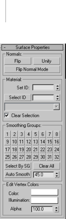
1010 Chapter 9: Surface Modeling
Surface Properties rollout
These controls let you work with face normals,
material IDs, smoothing groups and vertex colors.
Normals group
Flip—Reverses the direction of the surface normals
of the selected faces.
Unify—Flips the normals of an object so that they
all point in the same direction, usually outward.
This is useful for restoring an object’s faces to
their original orientations. Sometimes normals of
objectsthathavecomeinto3dsMaxaspartofa
DXF file are irregular, depending on the methods
used to create the objects. Use this function to
correct them.
Flip Normal Mode—Flips the normal of any face you
click. To exit, click this button again or right-click
anywhere in the program interface.
Tip: ThebestwaytouseFlipNormalmode
is to set up your viewport to display with
Smooth+Highlight and Edged Faces on. If you use
Flip Normal mode with default settings, you’ll be
able to flip a face away from you, but you won’t be
able to flip it back. For best results, turn off Ignore
Backfacing in the Selection rollout. This lets you
click any face and flip the direction of its normal,
regardless of its current direction.
Material group
Set ID—Lets you assign a particular material ID
(page 3–969) number to selected sub-objects for
use with multi/sub-object materials (page 2–1594)
and other applications. Use the spinner or enter
the number from the keyboard. The total number
of available IDs is 65,535.
Select ID—Selectssub-objectscorrespondingto
the Material ID specified in the adjacent ID field.
Type or use the spinner to specify an ID, then click
the Select ID button.
[Select By Name]—This drop-down list shows
the names of sub-materials if an object has a
Multi/Sub-Object material assigned to it. Click
the drop arrow and choose a sub-material from
the list. The sub-objects that are assigned that
material are selected. If an object does not have
aMulti/Sub-Objectmaterialassigned,thename
list is unavailable. Likewise, if multiple objects
areselectedthathaveanEditPatch,EditSpline,
or Edit Mesh modifier applied, the name list is
inactive.
Note: Sub-material names are those specified in the
Name column on the material’s Multi/Sub-Object
Basic Parameters rollout; these are not created by

Edit Geometry Rollout (Mesh) 1011
default, and must be specified separately from any
material names.
Clear Selection—When on, choosing a new ID or
material name deselects any previously selected
sub-objects. When off, selections are cumulative,
so new ID or sub-material name selections add to
the existing selection set of patches or elements.
Default=on.
Smoothing Groups group
Use these controls to assign selected faces to
different smoothing groups (page 3–1013),andto
select faces by smoothing group.
To assign faces to one or more smoothing groups,
select the faces, and then click the number(s) of
the smoothing group(s) to assign them to.
Select by SG (Smoothing Group)—Displays a dialog
that shows the current smoothing groups. Select
a group by clicking the corresponding numbered
button and clicking OK. If Clear Selection is on,
any previously selected faces are first deselected. If
Clear Selection is off, the new selection is added to
any previous selection set.
Clear All—Removesanysmoothinggroup
assignments from selected faces.
Auto Smooth—Sets the smoothing groups based
on the angle between faces. Any two adjacent
faceswillbeputinthesamesmoothinggroupif
theanglebetweentheirnormalsislessthanthe
threshold angle, set by the spinner to the right of
this button.
Threshold—This spinner (to the right of Auto
Smooth) lets you specify the maximum angle
between the normals of adjacent faces that
determines whether those faces will be put in the
same smoothing group.
Edit Vertex Colors group
Use these controls to assign the color, illumination
color (shading), and alpha (transparency) values
of vertices on the selected face(s).
Color—Click the color swatch to change the color
of vertices on the selected face(s). Assigning vertex
colors at the face level prevents blending across the
face(s).
Illumination—Click the color swatch to change
the illumination color of vertices on the selected
face(s). This lets you change the illumination
without changing the vertex’s color.
Alpha—Lets you assign an alpha (transparency)
value to vertices on the selected face(s).
The spinner value is a percentage; zero is
completely transparent and 100 is completely
opaque.
Edit Geometry Rollout (Mesh)
Select an editable mesh object. > Modify panel >
Selection rollout > Choose any sub-object level.
Select an editable mesh object. > Modify panel > Modifier
Stack display > Expand Editable Mesh. > Choose any
sub-object level.
Select an editable mesh object. > Quad menu > Tools 1
quadrant > Choose any sub-object level.
The Edit Geometry rollout for Meshes contains
most of the controls that let you alter the geometry
of the mesh, at either the Object (top) level, or
one of the sub-object levels. The controls that the
rollout displays can vary, depending on which level
is active; if a control is not available for the active
level, it might be grayed out, or simply might not
appear at all. The descriptions below indicate the
levels at which controls are available.
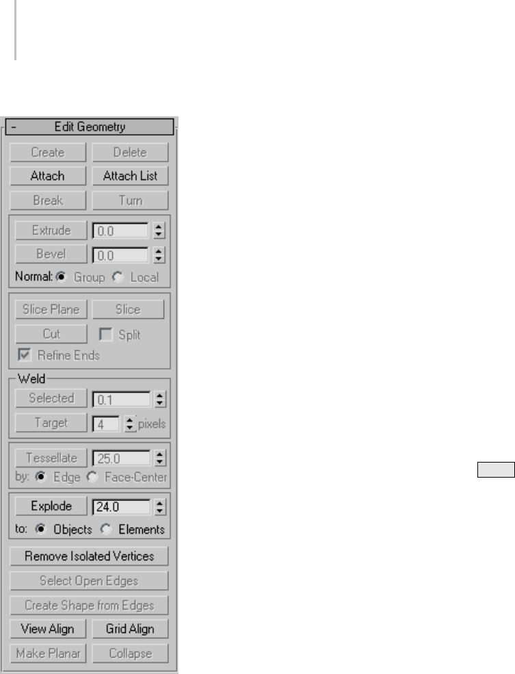
1012 Chapter 9: Surface Modeling
Interface
Editing buttons
Create—Lets you add sub-objects to a single
selected mesh object. Select an object, choose a
sub-object level, click Create, and then click to add
sub-objects. Available only at the Vertex, Face,
Polygon, and Element levels only.
For example, at the Vertex sub-object level,
Create lets you add free-floating vertices to the
object. The new vertices are placed on the active
construction plane.
To create faces at the Face, Polygon, or Element
level, click Create. All vertices in the object are
highlighted, including isolated vertices left after
deleting faces. Click three existing vertices in
succession to define the shape of the new face.
(The cursor changes to a cross when it is over a
vertex that can legally be part of the face.)
You can also create new faces at the Polygon and
Element sub-object levels. At the Face and Element
sub-object levels, a new face is created after every
thirdclick.AtthePolygonsub-objectlevel,you
can continue clicking as many times as you like to
addverticestothenewpolygon.Tofinishdrawing
anewpolygon,clicktwice,orclickagainonany
existing vertex in the current polygon.
At the Face, Polygon, and Element levels, you can
add vertices while Create is on by Shift +clicking
in an empty space; these vertices are incorporated
intothefaceorpolygonyou’recreating.
You can start creating faces or polygons in any
viewport, but all subsequent clicks must take place
inthesameviewport.
Tip: For best results, click vertices in
counterclockwise (preferred) or clockwise
order. If you use clockwise order, the new polygon
will be facing away from you, and you won’t be
abletoseeitunlessyou’veturnedonForce2-Sided
or are using a two-sided material.
Delete (sub-object levels only)—Deletes selected
sub-objects and any faces attached to them.
Attach—Lets you attach another object in the scene
to the selected mesh. You can attach any type
of object, including splines, patch objects, and
NURBS surfaces. Attaching a non-mesh object
converts it to a mesh. Click the object you want to
attach to the currently selected mesh object.
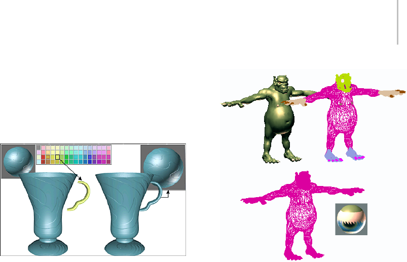
Edit Geometry Rollout (Mesh) 1013
When you attach an object, the materials of the
two objects are combined in the following way:
• If the object being attached does not have a
material assigned, it inherits the material of the
object it is being attached to.
• Likewise, if the object you’re attaching to
doesn’thaveamaterial,itinheritsthematerial
of the object being attached.
• If both objects have materials, the resulting new
material is a multi/sub-object material (page
2–1594) that encompasses the input materials.
A dialog appears offering three methods of
combining the objects’ materials and material
IDs. For more information, see Attach Options
Dialog (page 1–1018).
Shaded view of model (upper left); wireframe view of model
(upper right); model with objects attached (lower left); and
subsequent multi/sub-object material (lower right)
Attach remains active in all sub-object levels,
but always applies to objects.
Attach List (Object level only)—Lets you attach
other objects in the scene to the selected mesh.
Click to display a Select Objects dialog (page 1–78)
where you choose multiple objects to attach.
Detach (Vertex and Face/Polygon/Element levels
only)—Detaches the selected sub-object as a
separate object or element. All faces attached to
the sub-object are detached as well.
A dialog appears, prompting you to enter a name
for the new object. The dialog has a Detach As
Clone option that copies the faces rather than
moving them.
Detached faces leave a hole in the original object
when you move them to a new position.
Break (Vertex level only)—Creates a new vertex for
each face attached to selected vertices, allowing
thefacecornerstobemovedawayfromeachother
where they were once joined at the original vertex.
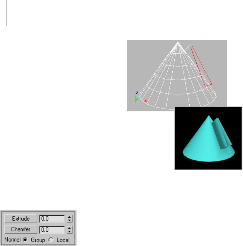
1014 Chapter 9: Surface Modeling
If a vertex is isolated or used by only one face, it
is unaffected.
Turn (Edge level only)—Rotates the edge within
its bounding. All mesh objects in 3ds Max are
composed of triangular faces, but by default, most
polygons are depicted as quadrilaterals, with a
hidden edge dividing each quad into two triangles.
Turn lets you change the direction in which the
hidden edge (or any other) runs, thus affecting
how the shape changes when you transform
sub-objects directly, or indirectly with a modifier.
Divide (Face/Polygon/Element levels
only)—Subdivides faces into three smaller
faces. This function applies to faces even if you’re
at the Polygon or Element sub-object level. Click
Divide,andthenselectafacetobedivided.Each
face is subdivided where you click it. You can click
as many faces as you want divided, in sequence.
To stop dividing, click Divide again to turn it off,
or right-click.
Extrude, Chamfer, and Bevel group
The Extrude controls let you extrude edges or
faces. Edge extrusion works in a fashion similar
to face extrusion. You can apply extrusion
interactively (by dragging on sub-objects) or
numerically (using spinners).
Extruded edges seen in viewport and rendered image
Extrude (Edge and Face/Polygon/Element levels
only)—Click this button and then either drag to
extrude the selected edges or faces, or adjust the
Extrude spinner to perform the extrusion. You
can select different sub-objects to extrude while
Extrude is active.
•Extrude Amount—This spinner (to the right of
the Extrude button) lets you specify the amount
to extrude the edge. Select one or more edges,
and then adjust the spinner.
The Chamfer controls are available only at the
Vertex and Edge sub-object levels. They let you
bevel object corners using a chamfer function. You
can apply this effect interactively (by dragging
vertices) or numerically (using the Chamfer
spinner).
Chamfer (Vertex and Edge levels only)—Click this
button, and then drag vertices or edges in the
active object. The Chamfer Amount spinner
updates to indicate the chamfer amount as you
drag.

Edit Geometry Rollout (Mesh) 1015
If you drag one or more selected vertices or edges,
all selected sub-objects are chamfered identically.
If you drag an unselected vertex or edge, any
selected sub-objects are first deselected.
A chamfer "chops off " the selected sub-objects,
creating a new face connecting new points on all
visible edges leading to the original sub-object.
Chamfer Amount specifies the exact distance from
the original vertex along each of these edges. New
chamfer faces are created with the material ID of
one of the neighboring faces (picked at random)
and a smoothing group that is an intersection of all
neighboring smoothing groups.
For example, if you chamfer one corner of a
box, the single corner vertex is replaced by three
vertices moving along the three visible edges that
lead to the corner. The software rearranges and
splits the adjacent faces to use these three new
vertices, and creates a new triangle at the corner.
•Chamfer Amount—Adjust this spinner (to the
right of the Chamfer button) to apply a chamfer
effect to selected vertices.
•Normal (Edge and Face/Polygon/Element levels
only)—Determines how a selection of more
thanoneedgeisextruded.WithNormalset
to Group (the default), extrusion takes place
along the averaged normal of each continuous
group (line) of edges. If you extrude multiples
of such groups, each group moves along its own
averaged normal. If you set Normal to Local,
extrusion takes place along each selected edge’s
normal.
Beveling, available only at the Face/Polygon/
Element levels, is a second step to extrusion: it lets
you scale the faces you have just extruded.
Tip: AsimilaroperationisInset,whichEditable
Poly has but Editable Mesh doesn’t. When you
inset a polygon, you create another, smaller
polygon of the same proportions inside the
borders of an original polygon, in the plane of the
original. Essentially, it’s a bevel with no height.
YoucanachievethisinEditableMeshwiththe
following procedure:
1. Select the polygon to inset.
2. Right-click the spinner all the way to the right
of the Extrude button. This performs an
extrusion with no height, thus creating a new
polygonplusconnectingpolygonsinthesame
position as the original.
3. Set a negative Bevel value using the numeric
field or the spinner. This insets the new polygon
created by the extrusion without changing its
height.
Chamfer box showing extruded face
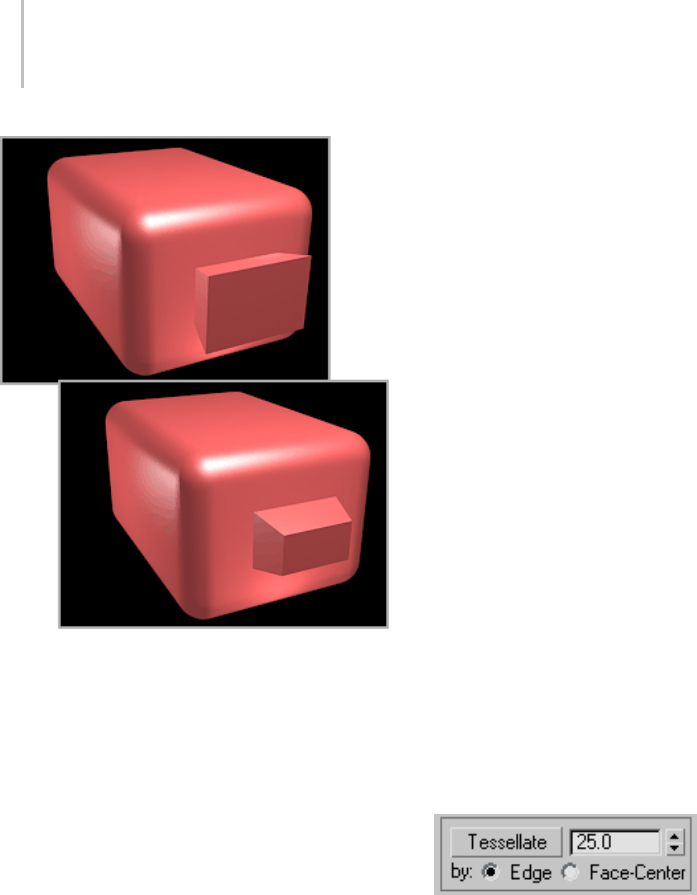
1016 Chapter 9: Surface Modeling
Extruded face beveled in two different directions
You can bevel faces by dragging or by using
keyboard/spinner entry.
Bevel (Face/Polygon/Element levels only)—Click
this button, and then drag vertically on any face to
extrudeit.Releasethemousebuttonandmove
the mouse vertically to bevel the extrusion. Click
to finish.
• When over a selected face, the mouse cursor
changes to a Bevel cursor.
• With multiple faces selected, dragging on any
one bevels all selected faces equally.
• Youcandragotherfacesinturntobevelthem
while the Bevel button is active. Click Bevel
again or right-click to end the operation.
Outlining—This spinner (to the right of the Bevel
button) lets you scale selected faces bigger or
smaller, depending on whether the value is positive
or negative. It is normally used after an extrusion
for beveling the extruded faces.
Cut and Slice group
Lets you subdivide edges with either cut or slice
tools to create new vertices, edges, and faces. For
details, see Cut and Slice (page 1–1019).
Note: At the Vertex sub-object level, Slice is
available but Cut is not.
Weld group (Vertex level only)
Selected—Welds selected vertices that fall within
the tolerance specified in the Weld Threshold
spinner (to the button’s right). All line segments
become connected to the resulting single vertex.
Target—Enters weld mode, which allows you to
select vertices and move them around. While
moving, the cursor changes to the Move cursor as
usual, but when you position the cursor over an
unselected vertex the cursor changes to a + cursor.
Releasethemouseatthatpointtoweldallselected
vertices to the target vertex they were dropped on.
The pixels spinner to the right of the Target
button sets the maximum distance in screen pixels
between the mouse cursor and the target vertex.
Tessellate group (Face/Polygon/Element levels
only)
Use these controls to tessellate (subdivide) selected
faces. Tessellation is useful for increasing local
mesh density while modeling. You can subdivide
any selection of faces. Two tessellation methods
are available: Edge and Face-Center.
Tessellate—Click to tessellate selected faces, based
on the Edge, Face-Center, and Tension (spinner)
settings.
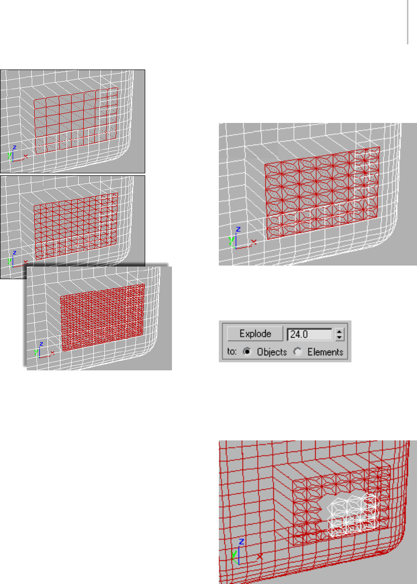
Edit Geometry Rollout (Mesh) 1017
Top: Original selection
Middle: Tessellated once
Bottom: Tessellated twice
Tension—(Active only when Tessellate by Edge is
active.) This spinner, to the right of the Tessellate
button, lets you increase or decrease the Edge
tension value. A negative value pulls vertices
inward from their plane, resulting in a concave
effect. A positive value pulls vertices outward from
their plane, resulting in a rounding effect.
By Edge/Face-Center—Edgeinsertsverticesin
themiddleofeachedgeanddrawsthreelines
connecting those vertices. As a result, four faces
arecreatedoutofoneface. (Toseethisatthe
Polygon or Element sub-object level, turn off
Display panel > Display Properties rollout > Edges
Only.)
Face-Center adds a vertex to the center of each
face and draws three connecting lines from that
vertex to the three original vertices. As a result,
three faces are created out of one face.
Set of polygons showing Face-Center tessellation
Explode group (Object and Face/Polygon/
Element levels only)
Explode—Breaks up the current object into
multiple elements or objects based on the angles
ofitsedges. ThisfunctionisavailableinObject
mode as well as all sub-object levels except Vertex
and Edge.
Exploded faces (white) removed from tessellated faces

1018 Chapter 9: Surface Modeling
The angle threshold spinner, to the right of the
Explode button, lets you specify the angle between
faces below which separation will not occur. For
example, all sides of a box are at 90-degree angles
toeachother.Ifyousetthespinnerto90orabove,
exploding the box changes nothing. However, at
any setting below 90, the sides all become separate
objects or elements.
To Objects/Elements—Specifies whether the
exploded faces become the separate objects or
elements of the current object.
Remove Isolated Vertices—Deletes all isolated
vertices in the object regardless of the current
selection.
Select Open Edges (Edge level only)—Selects all
edges with only one face. In most objects, this
showsyouwheremissingfacesexist.
Create Shape from Edges (Edge level only)—After
selecting one or more edges, click this button to
create a spline shape from the selected edges. A
Create Shape dialog appears, letting you name
the shape, set it to Smooth or Linear, and ignore
hidden edges. The new shape’s pivot is placed at
the center of the mesh object.
View Align—Aligns all vertices in selected objects
or sub-objects to the plane of the active viewport.
If a sub-object level is active, this function affects
only selected vertices or those belonging to
selected sub-objects.
Inthecaseoforthographic viewports (page 3–986),
usingViewAlignhasthesameeffectasaligning
to the construction grid when the home grid is
active. When aligning to a perspective viewport
(including camera and light views), the vertices are
reoriented to be aligned to a plane that is parallel
to the camera’s viewing plane. This plane is
perpendicular to the view direction that is closest
to the vertices’ average position.
Grid Align—Aligns all vertices in selected objects
or sub-objects to the plane of the current view. If
a sub-object level is active, function aligns only
selected sub-objects.
This function aligns the selected vertices to the
current construction plane. The current plane is
specified by the active viewport in the case of the
home grid. When using a grid object, the current
plane is the active grid object.
Make Planar (sub-object levels only)—Forces all
selected sub-objects to become coplanar. The
plane’snormalistheaveragesurfacenormalofall
faces attached to the selected sub-objects.
Collapse (sub-object levels only)—Collapses
selected sub-objects into an averaged vertex.
Attach Options Dialog
Select an editable mesh object. > Modify panel > Attach
button
The Attach Options dialog appears when you
attach two or more objects to which materials have
been assigned. It provides three different methods
ofcombiningthesub-materialsandthematerial
IDs in the two objects.
Interface
Match Material IDs to Material—The number
of material IDs in the attached objects are
modified so they are no greater than the number
of sub-materials assigned to those objects.
For example, if you have a box with only two
sub-materials assigned to it, and you attach it to

Cut and Slice 1019
another object, the box will have only two material
IDs, instead of the six it was assigned on creation.
Match Material to Material IDs—Maintains the
original ID assignment in the attached objects
by adjusting the number of sub-materials
in the resulting multi/sub-object material.
For example, if you attach two boxes, both
assigned single materials, but with their default
assignment of 6 material IDs, the result would be
a multi/sub-object material with 12 sub-materials
(six containing instances of one box’s material,
and six containing instances of the other box’s
material). Use this option when it’s important to
maintain the original material ID assignments in
your geometry.
Note: If you want to make the instanced
sub-materials unique, select them in Track View,
andclicktheMakeUniquebuttonontheTrack
View toolbar. You can also make them unique
one at a time with the Make Unique button (page
2–1442) in the Material Editor.
Do Not Modify Mat IDs or Material—Does not adjust
the number of sub-materials in the resulting
sub-object material. Note that, if the number of
materialIDsinanobjectisgreaterthanthenumber
of sub-materials in its multi/sub-object material,
then the resulting face-material assignment might
be different after the attach.
Condense Material IDs—Affects the Match Material
IDs To Material option. When this is on, duplicate
sub-materials or sub-materials that aren’t used in
the objects are removed from the multi/sub-object
material that results from the attach operation.
Default=on.
Tips
• In most cases, use the first option (Match
Material IDs to Material) while keeping
Condense Material IDs selected. This
maintains the appearance of the objects, and
results in the fewest additional sub-materials
or IDs.
•Usethesecondoption(MatchMaterialto
Material IDs) when you need to maintain the
original material ID assignments.
• Avoid using the third option, unless you need
to repeat a 3ds Max version 1 attachment for
compatibility with a previous project.
• Leave Condense Material IDs selected unless
you have an unassigned sub-material that you
want to keep for future assignment.
• Perform Edit menu > Hold before performing
the attach.
Cut and Slice
Select an editable mesh object. > Modify panel >
Selection rollout > (Optional: Choose a sub-object level.)
> Edit Geometry rollout > Cut and Slice group box
ThetoolsavailableintheCutandSlicegroup
let you subdivide edges and faces to create new
vertices, edges, and faces. You can slice an editable
mesh object at any sub-object level; the Cut tool
is available at every sub-object level except the
Vertex sub-object level.
Procedures
To create a new face using Cut:
1. Convert the geometry to an editable mesh.
2. On the Modify panel, choose the
object’s Edge (or Face, Polygon, or Element)
sub-object level.
3. On the Selection rollout, turn on Ignore
Backfacing.
4. On the Edit Geometry rollout, in the Cut and
Slicegroup,clicktheCutbutton.
5. Click the first edge you want to subdivide, and
then move your cursor toward the second edge.
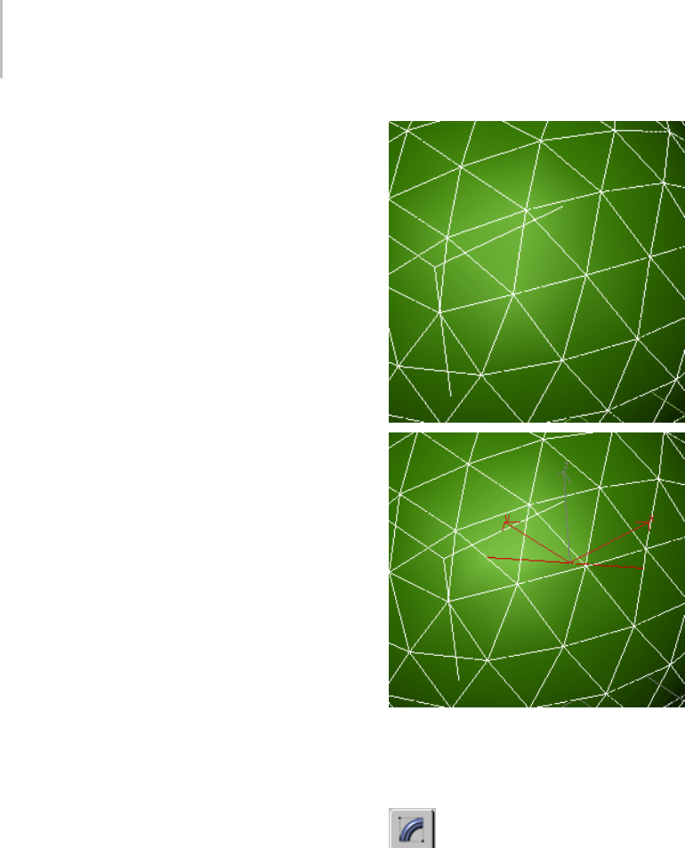
1020 Chapter 9: Surface Modeling
The cursor changes to a plus sign when over
an edge, and a dotted line connects the initial
pointwheretheedgewasclickedwiththe
current cursor location.
6. Click the second edge. This edge can be
anywhere, cutting across as many faces as you
like. A new visible edge appears.
7. At this point, a new dotted line is connected
to the mouse cursor, originating from the last
point you clicked.
8. Continueclickingedgestocut.Tostartfroma
different point, right-click, and then select the
new start point. To finish cutting, right-click
twice.
Yo u c a n u s e Snaps (page 2–35) with Cut. To
divide an edge in half, set Snaps to midpoint.
To start or end a cut at a vertex, set snap to
vertex or endpoint.
Before and after applying Cut to faces
To create multiple slices:
1. Select an editable mesh.
2. On the Modify panel, choose the
object’s Edge (or Face, Polygon, or Element)
sub-object level.
3. Select one or more sub-objects. Slice affects
only selected sub-objects.
4. In the Cut And Slice group box, click the Slice
Plane button.
5. PositionandrotatetheSlicePlanegizmoto
where you want the first slice.
6. ClicktheSlicebutton.Theobjectissliced.
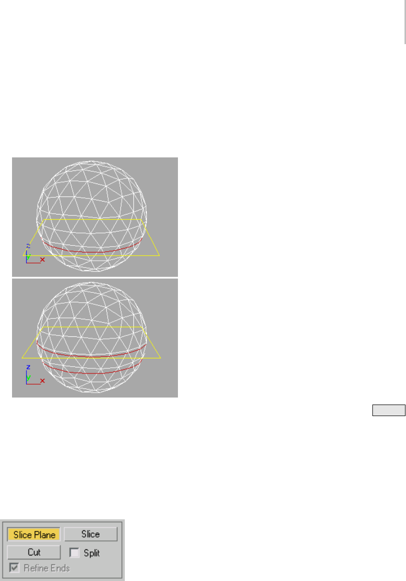
Cut and Slice 1021
7. If you want, move the Slice Plane to a second
position and click the Slice button again.
8. Click the Slice Plane button again to turn it off
and see the results.
9. To better understand what has happened, turn
off Edges Only in the Display panel.
Slice gizmo placed for first slice (top) and second slice
(bottom)
Interface
Note: The keyboard shortcuts listed here require
that the Keyboard Shortcut Override Toggle (page
3–872) be on.
Cut and Slice group
Slice Plane—Creates a gizmo for a slice plane that
can be positioned and rotated where you want to
slice the edges. Also enables the Slice button.
Slice—Performs the slice operation at the location
of the slice plane. The Slice button is available only
whentheSlicePlanebuttonishighlighted.This
tool slices the mesh just like the Slice modifier (page
1–825) in “Operate On: Face” mode.
Note: Slice works only on a sub-object selection.
Make the selection before activating Slice Plane.
Cut—Lets you divide a edge at any point, then
divide a second edge at any point, creating a new
edge or edges between the two points. Clicking
the first edge sets the first vertex. A dotted line
tracks the cursor movement until you click a
second edge. A new vertex is created at each edge
division. Alternately, double-clicking an edge
simply divides that edge at the point clicked, with
invisible edges on either side.
You can use Cut to cut across any number of faces,
even across an entire object. Click one edge to
start the cut, and a second edge to end the cut.
Use Snaps (page 2–35) with Cut for precision. Cut
supports Midpoint, Endpoint, and Vertex snaps.
Yo u c a n a l s o u s e t h e k e y b o a r d s h o r t c u t Alt+C to
toggle Cut mode.
Important: When using the Cut tool to add new edges,
you should work in a non-Perspective viewport, such
as Front or User. If you use Cut while working in a
Perspective viewport, you may find that the created
edges appear to jump or aren’t placed correctly. Using
an orthogonal viewport will allow the cuts to appear
where you click.
Tip: WhenperformingaCut,turnonSelection
rollout > Ignore Backfacing to avoid accidentally
selectingedgesonthebacksideofthemesh.
Split—When on, the Slice and Cut operations
create double sets of vertices at the points where
the edges are divided. This lets you easily delete

1022 Chapter 9: Surface Modeling
thenewfacestocreateholes,oranimatethenew
faces as separate elements.
Refine Ends—When on, adjacent faces at the ends
of the cut are also divided by additional vertices,
so that the surface stays contiguous. When Refine
Ends is off, the surface will have a seam where
the new vertex meets the adjacent face. For this
reason, it’s a good idea to keep Refine Ends turned
on, unless you are sure that you don’t want the
extra vertices created.
Refine Ends affects only Cut. It does not affect
Slice.
Polymeshes
Create or select an object. > Quad menu > Transform
quadrant > Convert To submenu > Convert to Editable
Poly
Create or select an object. > Modify panel > Right-click
thebaseobjectinthestack. >ChooseConvertto:
Editable Poly.
Editable Poly (page 3–933) is an editable object
with five sub-object levels: vertex, edge, border,
polygon, and element. Its usage is similar to that of
an editable mesh object (page 1–996),withcontrols
for manipulating an object as a polygon mesh at
various sub-object levels. Rather than triangular
faces, however, the poly object’s faces are polygons
with any number of vertices.
Editable Poly gives you these options:
•Transformor
Shift +Clone the selection, as
with any object.
• UsetheoptionssuppliedontheEditrollouts
to modify the selection or object. Later topics
discuss these options for each of the polymesh
components.
•Passasub-objectselectiontoamodifier
higher in the stack. You can apply one or more
standard modifiers to the selection.
• Use the options on the Interface (page 1–1061)
to alter surface characteristics.
Tip: You can exit most Editable Poly command
modes, such as Extrude, by right-clicking in the
active viewport.
Editable Poly Workflow
Sub-object-specific functions in the Editable Poly
user interface appear on their own rollouts, leaving
the Edit Geometry rollout (page 1–1055) with
functions that you can apply at most sub-object
levels, as well as at the object level.
Also, many commands are accompanied by a
Settings button, which gives you a second way to
use the command:
• In Direct Manipulation mode, activated by
clicking the command button, you apply the
command by manipulating sub-objects directly
in the viewport. An example of this is Extrude.
Note: Some buttons, such as Tessellate, operate
on the mesh immediately, with no viewport
manipulation required.
•Interactive Manipulation mode is well suited
to experimentation. You activate this mode
by clicking the command’s Settings button.
Thisopensanon-modalsettingsdialogand
places you in preview mode, where you can set
parameters and see the results immediately in
the viewport. You can then accept the results by
clicking OK, or reject them by clicking Cancel.
You can also use this mode to apply the same or
different settings to several different sub-object
selections in a row. Make the selection,
optionally change the settings, click Apply, and
then repeat with a different selection.

Editable Poly Surface 1023
Important: When you click Apply, the settings are
“baked into” the selection, and then applied again
to the selection as a preview. If you then click OK to
exit, you will have applied the settings twice. If your
intention is to apply them only once, simply click OK
the first time, or click Apply, and then Cancel.
Note: Changes implemented in Interactive
Manipulation mode cannot be animated.
See also
Edit Poly Modifier (page 1–640)
Poly Select Modifier (page 1–762)
Turn To Poly Modifier (page 1–874)
Procedure
Toproduceaneditablepolyobject:
First select an object, and then do one of the
following:
• If no modifiers are applied to the object, In
the Modify panel, right-click in the modifier
stackdisplayandchooseEditablePolyfromthe
ConvertTolistonthepop-upmenu.
• Right-clicktheobjectandchooseConvertTo
Editable Poly from the Convert To submenu in
the Transform quadrant of the quad menu.
• Apply a modifier to a parametric object that
turns the object into a poly object in the
stack display, and then collapse the stack. For
example, you can apply a Tu r n To Po ly mo di fi er
(page 1–874).
To collapse the stack, use the Collapse utility
(page 1–966) and set Output Type to Modifier
Stack Result, or right-click the object’s modifier
stack and then choose Collapse All.
Converting an object to Editable Poly format
removes all parametric controls, including the
creation parameters. For example, you can no
longer increase the number of segments in a box,
slice a circular primitive, or change the number
of sides on a cylinder. Any modifiers you apply
to an object are merged into the mesh as well.
After conversion, the only entry left on the stack
is "Editable Poly."
To maintain an object’s creation parameters:
• As noted in the previous procedure, if
you convert an existing object to editable
poly format, 3ds Max replaces the creation
parameters in the stack with "Editable Poly."
The creation parameters are no longer
accessible or animatable. If you want to
maintain the creation parameters, you can use
the Edit Poly modifier (page 1–640) or the Tur n
To Poly modifier (page 1–874).
Interface
Stack Display
For more information on the Stack Display, see
Modifier Stack (page 3–760).
Show End Result—Normally, if you apply a
modifier such as Symmetry (page 1–861) to an
editable poly object and then return to the Editable
Poly stack entry, you cannot see the effect of the
modifier on the object’s geometry. But if you turn
on Show End Result while in sub-object level,
you can see the final object as a white mesh, the
original sub-object selection as a yellow mesh, and
the original editable polymesh as an orange mesh.
Selection rollout
Lets you access the different sub-object levels. See
Selection Rollout (Polymesh) (page 1–1024).
Soft Selection rollout
Soft Selection controls apply a smooth falloff
between selected sub-objects and unselected
ones.WhenUseSoftSelectionison,unselected
sub-objectsnearyourselectionaregivenpartial
selection values. These values are shown in the
viewports by means of a color gradient on the

1024 Chapter 9: Surface Modeling
vertices, and optionally on the faces. They affect
most types of sub-object deformations, such as
theMove,Rotate,andScalefunctionsandany
deformation modifiers (such as Bend) applied to
the object. This provides a magnet-like effect with
a sphere of influence around the selection.
For more information, see Soft Selection Rollout
(page 1–963).
Edit (sub-object) rollout
The Edit (sub-object) rollout provides
sub-object-specific functions for editing an
editable poly object and its sub-objects. For
specific information, click any of the links below:
Edit Vertices rollout (page 1–1031)
Edit Edges rollout (page 1–1039)
Edit Borders rollout (page 1–1044)
Edit Polygons/Elements rollout (page 1–1048)
Edit Geometry rollout
The Edit Geometry rollout provides global
functions for editing an editable poly object and
its sub-objects. For specific information, click any
of the links below:
Editable Poly (Object) (page 1–1029)
Editable Poly (Vertex) (page 1–1034)
Editable Poly (Edge) (page 1–1043)
Editable Poly (Border) (page 1–1047)
Editable Poly (Polygon/Element) (page 1–1053)
Subdivision Surface rollou
Controls on this rollout apply subdivision to the
polymesh in the style of the MeshSmooth modifier.
See Subdivision Surface Rollout (Polymesh) (page
1–1060).
Subdivision Displacement rollout
Specifies surface approximation for subdividing
the polymesh. See Subdivision Displacement
Rollout (Polymesh) (page 1–1063).
Subdivision Presets group & Subdivision
Method group
The controls in these two group boxes specify
how the program applies the displacement map
when Subdivision Displacement is on. They are
identical to the Surface Approximation controls
(page 1–1239) used for NURBS surfaces.
Paint Deformation rollout
Paint Deformation lets you stroke elevated and
indented areas directly onto object surfaces. For
more information, see Paint Deformation Rollout
(page 1–1064).
Selection Rollout (Polymesh)
Create or select an editable poly object. > Modify panel >
Selection rollout
The Selection rollout provides tools for accessing
different sub-object levels and display settings and
for creating and modifying selections, and displays
information about selected entities.
When you first access the Modify panel with
an editable poly selected, you’re at the Object
level, with access to several functions available as
described in Editable Poly (Object) (page 1–1028).
You can toggle the various sub-object levels, and
access relevant functions, by clicking the buttons
at the top of the Selection rollout.
Clickingabuttonhereisthesameaschoosing
a sub-object type in the modifier stack display.
Click the button again to turn it off and return to
the Object selection level.
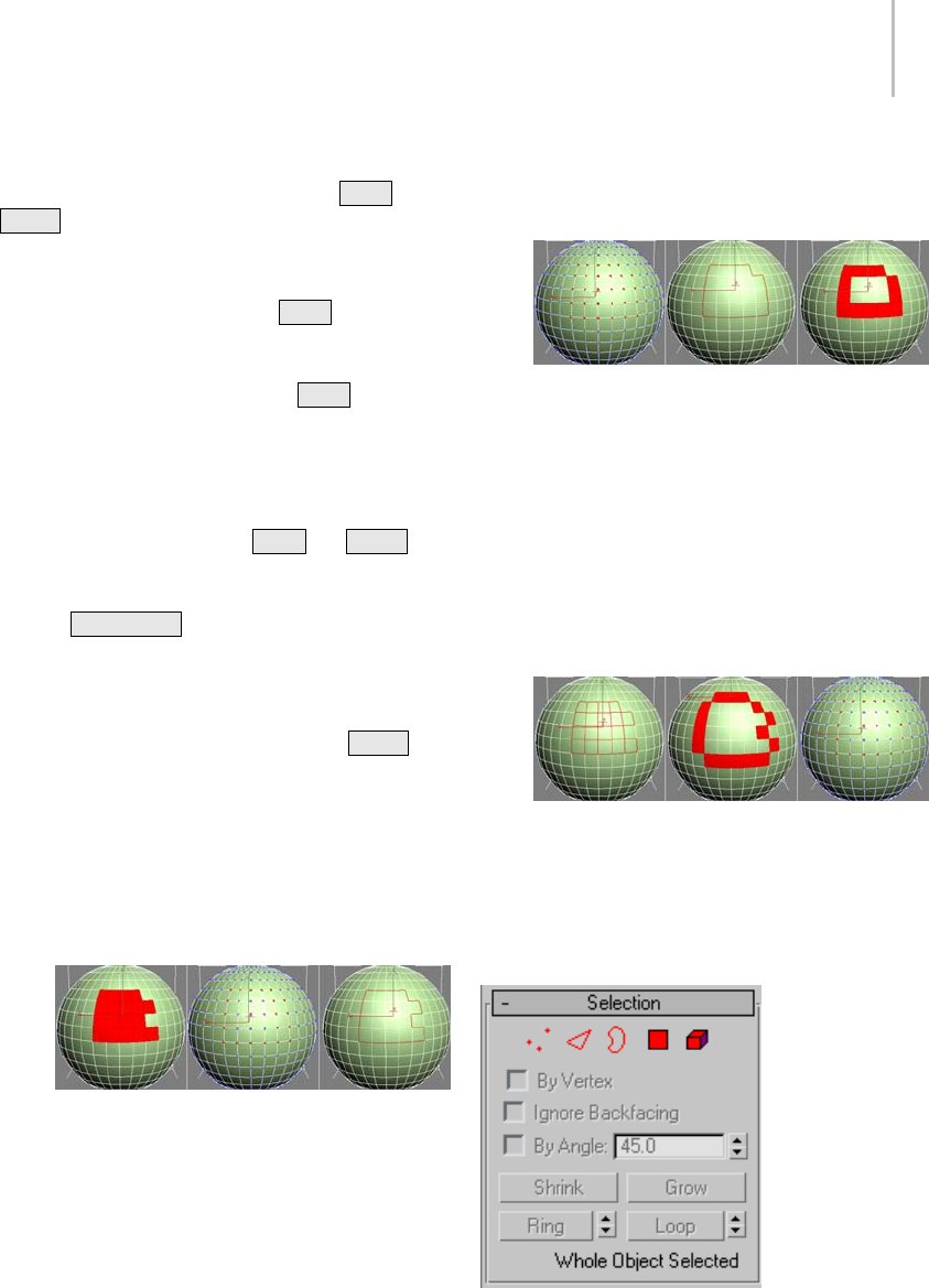
Selection Rollout (Polymesh) 1025
Note: You can convert sub-object selections in
three different ways with the use of the Ctrl and
Shift keys:
•Toconvertthecurrentselectiontoadifferent
sub-object level, clicking a sub-object button
on the Selection rollout with Ctrl held down.
This selects all sub-objects at the new level that
touch the previous selection. For example,
if you select a vertex, and then Ctrl +click
the Polygon button, all polygons that use that
vertex are selected.
• To convert the selection to only sub-objects
all of whose source components are originally
selected, hold down both Ctrl and Shift
as you change the level. For example, if you
convert a vertex selection to a polygon selection
with Ctrl+Shift +click, the resultant selection
includes only those polygons all of whose
vertices were originally selected.
• To convert the selection to only sub-objects
that border the selection, hold down Shift as
you change the level. The selection conversion
is inclusive, meaning:
• When you convert faces, the resulting
selection of edges or vertices all belong to
selected faces that bordered unselected faces.
Only the edges or vertices that bordered
unselected faces are selected.
Face selection (left) converted to vertex border (center)
and edge border (right)
• When you convert vertices to faces, the
resulting selection of faces had all of their
vertices selected and bordered unselected
faces. When you convert vertices to edges,
the resulting selection contains only edges
all of whose vertices were previously selected
andonlyedgesoffacesthatdidnothaveall
vertices selected; that is, of faces around the
border of the vertex selection.
Vertex selection (left) converted to edge border (center)
and face border (right)
• When you convert edges to faces, the
resulting selection of faces had some but
not all of their edges selected, and were
next to faces with no edges selected. When
you convert edges to vertices, the resulting
vertices are on previously selected edges,
butonlyatintersectionswherenotalledges
were selected.
Edge selection (left) converted to face border (center)
and vertex border (right)
Conversion commands are also available from the
quad menu.
Interface

1026 Chapter 9: Surface Modeling
Vertex—Turns on Vertex sub-object level,
which lets you select a vertex beneath the cursor;
region selection selects vertices within the region.
Edge—Tur ns on Ed ge sub -obje ct level, w hich
lets you select a polygon edge beneath the cursor;
region selection selects multiple edges within the
region.
Border—Turns on Border sub-object level,
which lets you select a sequence of edges that
borders a hole in the mesh. Borders are always
composed of edges with faces on only one side of
them,andarealwayscompleteloops.Forexample,
a box doesn’t have a border, but the teapot object
has a couple of them: on the lid, on the body, on
the spout, and two on the handle. If you create
a cylinder, then delete one end, the row of edges
around that end forms a border.
When Border sub-object level is active, you can’t
select edges that aren’t on borders. Clicking a
single edge on a border selects that whole border.
You can cap a borders, either in Editable Poly or by
applying the Cap Holes modifier (page 1–569).You
can also connect borders between objects with the
Connect compound object (page 1–328).
Polygon—Turns on Polygon sub-object level,
which lets you select polygons beneath the cursor.
Region selection selects multiple polygons within
the region.
Element—Turns on Element sub-object level,
which lets you select all contiguous polygons in an
object. Region selection lets you select multiple
elements.
By Vertex—When on, you can select sub-objects
only by selecting a vertex that they use. When you
click a vertex, all sub-objects that use the selected
vertex are selected.
Ignore Backfacing—When on, selection of
sub-objects affects only those facing you. When
off (the default), you can select any sub-object(s)
under the mouse cursor, regardless of their
visibility or facing. If there are more than one
sub-object under the cursor, repeated clicking
cyclesthroughthem. Likewise,withIgnore
Backfacing off, region selection includes all
sub-objects, regardless of the direction they face.
Note: ThestateoftheBackfaceCullsettinginthe
Display panel does not affect sub-object selection.
Thus, if Ignore Backfacing is off, you can still select
sub-objects, even if you can’t see them.
By Angle—When on and you select a polygon,
the software also selects neighboring polygons
basedontheanglesettingtotherightofthecheck
box. This value determines the maximum angle
between neighboring polygons to select. Available
only at the Polygon sub-object level.
For example, if you click a side of a box and the
angle value is less than 90.0, only that side is
selected, because all sides are at 90-degree angles
to each other. But if the angle value is 90.0 or
greater, all sides of the box are selected. This
function speeds up selection of contiguous areas
made up of polygons that are at similar angles to
one another. You can select coplanar polygons
with a single click at any angle value.
Shrink—Reduces the sub-object selection area
by deselecting the outermost sub-objects. If
the selection size can no longer be reduced, the
remaining sub-objects are deselected.
Grow—Expands the selection area outward in all
available directions.
Forthisfunction,aborderisconsideredtobean
edge selection.
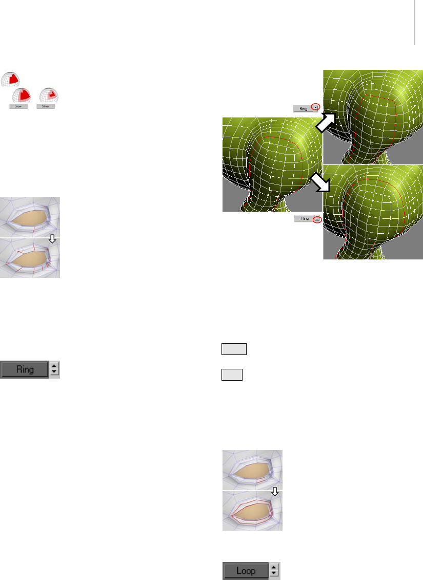
Selection Rollout (Polymesh) 1027
With Shrink and Grow, you can add or remove neighboring
elements from the edges of your current selection. This works
at any sub-object level.
Ring—Expands an edge selection by selecting all
edges parallel to the selected edges. Ring applies
only to edge and border selections.
Ring selection adds to the selection all the edges that are
parallel to the ones selected originally.
Tip: After making a ring selection, you can use
Connect to subdivide the associated polygons into
new edge loops.
[Ring Shift]—The spinner next to
the Ring button lets you move the selection in
either direction to other edges in the same ring;
thatis,toneighboring,paralleledges.Ifyouhave
a loop selected, you can use this function to select
a neighboring loop. Applies only to Edge and
Border sub-object levels.
Left: Original loop selection
Upper right: Ring Shift up moves selection outward (from
center of model).
Lower right: Ring Shift down moves selection inward (toward
center of model).
To expand the selection in the chosen direction,
Ctrl +click the up or down spinner button. To
shrink the selection in the chosen direction,
Alt +click the up or down spinner button.
Loop—Expands the selection as far as possible, in
alignment with selected edges.
Loop applies only to edge and border selections,
and propagates only through four-way junctions.
Loop selection extends your current edge selection by adding
all the edges aligned to the ones selected originally.
[Loop Shift]—The spinner next to
the Loop button lets you move the selection in
either direction to other edges in the same loop;
that is, to neighboring, aligned edges. If you have a
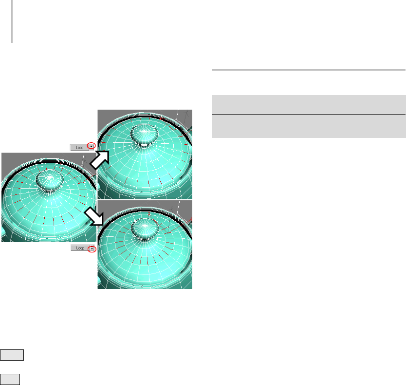
1028 Chapter 9: Surface Modeling
ring selected, you can use this function to select a
neighboring ring. Applies only to Edge and Border
sub-object levels.
Left: Original ring selection
Upper right: Loop Shift up moves selection outward.
Lower right: Loop Shift down moves selection inward.
To expand the selection in the chosen direction,
Ctrl +click the up or down spinner button. To
shrink the selection in the chosen direction,
Alt +click the up or down spinner button.
Selection Information
At the bottom of the Selection rollout is a text
display giving information about the current
selection. If 0 or more than one sub-object is
selected, the text gives the number and type
selected. If one sub-object is selected, the text gives
the identification number and type of the selected
item.
Editable Poly (Object)
Select an editable poly object. > Modify panel
Select an editable poly object. > Quad menu > Tools 1
quadrant > Top-level
Editable Poly (Object) functions are available
when no sub-object levels are active. These
functions are also available at all sub-object levels,
and work the same in each mode, except as noted
below.
Use the Selection rollout (page 1–1025) or
modifier stack (page 3–760) to access the different
sub-object levels.
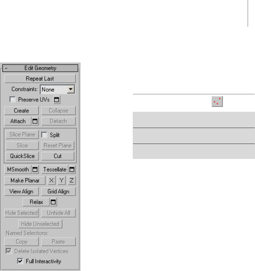
Editable Poly (Vertex) 1029
Interface
Edit Geometry rollout
See Edit Geometry Rollout (Polymesh) (page
1–1055) for detailed descriptions of these controls.
Subdivision Surface rollout
See Interface (page 1–1061) for information on the
Subdivision Surface rollout settings.
Subdivision Displacement rollout
See Interface (page 1–1063) for information on the
Subdivision Displacement rollout settings.
Paint Deformation rollout
Paint Deformation lets you stroke elevated and
indented areas directly onto object surfaces. For
more information, see Paint Deformation Rollout
(page 1–1064).
Editable Poly (Vertex)
Select an editable poly object. > Modify panel > Selection
rollout > Vertex
Select an editable poly object. > Modify panel > Modifier
Stack display > Expand Editable Poly. > Vertex
Select an editable poly object. > Quad menu > Tools
1quadrant>Vertex
Vertices are points in space: they define the
structure of other sub-objects that make up the
poly. When vertices are moved or edited, the
geometry they form is affected as well. Vertices
can also exist independently; such isolated vertices
can be used to construct other geometry but are
otherwise invisible when rendering.
At the Editable Poly (Vertex) sub-object level, you
can select single and multiple vertices and move
them using standard methods. This topic covers
the Edit Geometry, Edit Vertices, and Vertex
Properties rollouts; for other controls, see Editable
Poly (page 1–1022).
Procedures
To weld polygon vertices:
You can use either of two methods to combine
several vertices into one, also known as welding. If
the vertices are very close together, use the Weld
function. You can also use Weld to combine a
number of vertices to the average position of all
of them.
Alternatively, to combine two vertices that are far
apart, resulting in a single vertex that’s in the same
position as one of them, use Target Weld.
1030 Chapter 9: Surface Modeling
1. To u s e We l d :
1. On the Selection rollout, turn on Ignore
Backfacing, if necessary. This ensures that
you’reweldingonlyverticesyoucansee.
2. Select the vertices to weld.
3. If the vertices are very close together, simply
click Weld. If that doesn’t work, proceed to
the next step.
4. Click the Settings button to the right of
the Weld button.
This opens the Wel d Ver t ice s d ialo g (p ag e
1–1077).
5. Increase the Weld Threshold value gradually
using the spinner (click and hold on the
up-down arrow buttons to the right of the
numeric field and then drag upward). If you
need the value to change more quickly, hold
down the Ctrl key as you drag.
When the threshold equals or exceeds
the distance between two or more of the
vertices, the weld occurs automatically, and
the resulting vertex moves to their average
location.
6. If not all the vertices are welded, continue
increasing the Weld Threshold value until
they are.
7. Click OK to exit.
2. To u s e Ta r g e t We l d :
1. On the Selection rollout, turn on Ignore
Backfacing, if necessary. This ensures that
you’reweldingonlyverticesyoucansee.
2. Find two vertices you want to weld, and
determine the ultimate location of the
resulting vertex. The two vertices must be
contiguous; that is, they must be connected
by a single edge.
For this example, we’ll call the vertices A and
B, and the resulting vertex will be at vertex
B’s location.
3. Click the Target Weld button.
The button stays highlighted, to indicate that
you’re now in Target Weld mode.
4. Click vertex A and then move the mouse.
A rubber-band line connects the vertex and
the mouse cursor.
5. Position the cursor over vertex B, whereupon
the cursor image changes from an arrow
to a crosshairs. Reminder: Only vertices
connected to the first vertex by a single edge
qualify for target welding.
6. Click to weld the two.
The resulting vertex remains at vertex B’s
position, and you exit Target Weld mode.
To select vertices by color:
1. In the Vertex Properties rollout > Select Vertices
By group, click the color swatch, and specify the
color of vertex you want in the Color Selector
(page 1–161).
2. Specify ranges in the RGB Range spinners.
This lets you select vertices that are close to the
specified color, but don’t match exactly.
3. Click the Select button.
All vertices matching the color, or within the
RGB range, are selected.
You can add to the selection by holding Ctrl as
youclicktheSelectbutton,andsubtractfrom
the selection by holding the Alt key.
Tip: You can select all vertices of the same color
by first selecting the vertex you want matched,
dragging a copy of the Edit Color swatch to the
Existing Color swatch, and then clicking the
Select button. (If you want an exact match, be
sure to set the RGB Range spinners to 0 first.)
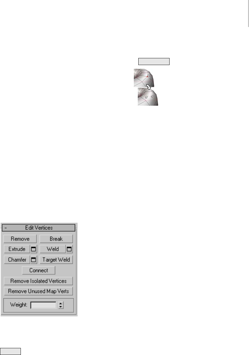
Editable Poly (Vertex) 1031
Interface
Selection rollout
See Editable Poly (page 1–1025) for information on
the Selection rollout settings.
Soft Selection rollout
Soft Selection controls apply a smooth falloff
between selected sub-objects and unselected
ones. When Use Soft Selection is on, unselected
sub-objectsnearyourselectionaregivenpartial
selectionvalues. Thesevaluesareshowninthe
viewports by means of a color gradient on the
vertices, and optionally on the faces. They affect
most types of sub-object deformations, such as the
Move, Rotate, and Scale functions, as well as any
deformation modifiers (such as Bend) applied to
the object. This provides a magnet-like effect with
a sphere of influence around the selection.
For more information, see Soft Selection Rollout
(page 1–963).
Edit Vertices rollout
This rollout includes commands specific to vertex
editing.
Note: To delete vertices, select them and press the
Delete key. This can create one or more holes
in the mesh. To delete vertices without creating
holes, use Remove (see below).
Remove—Deletes selected vertices and combines
the polygons that use them. The keyboard shortcut
is Backspace .
Removing one or more vertices deletes them and retriangulates
the mesh to keep the surface intact. If you use Delete instead,
the polygons depending on those vertices are deleted as well,
creating a hole in the mesh.
Warning: Use of Remove can result in mesh shape
changes and non-planar polygons.
Break—Creates a new vertex for each polygon
attached to selected vertices, allowing the polygon
corners to be moved away from each other where
they were once joined at each original vertex. If a
vertex is isolated or used by only one polygon, it
is unaffected.
Extrude—Lets you extrude vertices manually via
direct manipulation in the viewport. Click this
button, and then drag vertically on any vertex to
extrude it.
Extruding a vertex moves it along a normal and
creates new polygons that form the sides of the
extrusion, connecting the vertex to the object.
The extrusion has the same number of sides as
the number of polygons that originally used the
extruded vertex.
Following are important aspects of vertex
extrusion:
• When over a selected vertex, the mouse cursor
changes to an Extrude cursor.
• Drag vertically to specify the extent of the
extrusion, and horizontally to set the size of the
base.
• With multiple vertices selected, dragging on
any one extrudes all selected vertices equally.
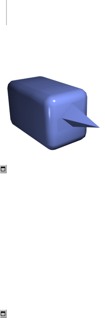
1032 Chapter 9: Surface Modeling
• You can drag other vertices in turn to extrude
them while the Extrude button is active. Click
Extrude again or right-click in the active
viewport to end the operation.
Chamfer box showing extruded vertex
Extrude Settings—Opens the Extrude Vertices
dialog (page 1–1073),whichletsyouperform
extrusion via interactive manipulation.
If you click this button after performing a manual
extrusion, the same extrusion is performed on the
current selection as a preview and the dialog opens
with Extrusion Height set to the amount of the last
manual extrusion.
Weld—Combines contiguous, selected vertices
that fall within the tolerance specified in Weld
dialog (page 1–1077). All edges become connected
to the resulting single vertex.
Weld is best suited to automatically simplifying
geometry that has areas with a number of vertices
that are very close together. Before using Weld,
set the Weld Threshold via the Weld dialo g (page
1–1077). To weld vertices that are relatively far
apart, use Ta rg e t We l d instead.
Weld Settings—Opens the Weld di alog (page
1–1077), which lets you specify the weld threshold.
Chamfer—Click this button and then drag
verticesintheactiveobject.Tochamfervertices
numerically, click the Chamfer Settings button and
use the Chamfer Amount value.
If you chamfer multiple selected vertices, all of
them are chamfered identically. If you drag an
unselected vertex, any selected vertices are first
deselected.
Each chamfered vertex is effectively replaced by
a new face that connects new points on all edges
leading to the original vertex. These new points
are exactly <chamfer amount> distance from the
original vertex along each of these edges. New
chamfer faces are created with the material ID of
one of the neighboring faces (picked at random)
and a smoothing group which is an intersection of
all neighboring smoothing groups.
Forexample,ifyouchamferonecornerofabox,
thesinglecornervertexisreplacedbyatriangular
face whose vertices move along the three edges
that led to the corner. Outside faces are rearranged
and split to use these three new vertices, and a new
triangle is created at the corner.
Alternatively, you can create open space around
the chamfered vertices; for details, see Chamfer
Vertices dialog (page 1–1070).
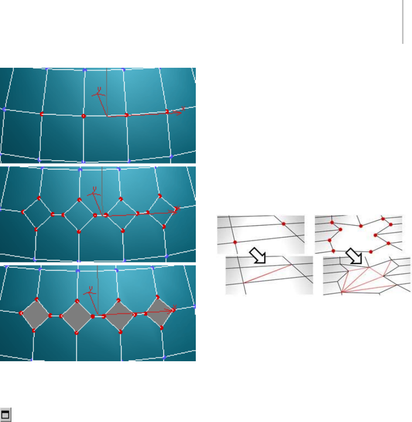
Editable Poly (Vertex) 1033
Top: The original vertex selection
Center: Vertices chamfered
Bottom: Vertices chamfered with Open on
Chamfer Settings—Opens the Chamfer Vertices
dialog (page 1–1070),whichletsyouchamfer
vertices via interactive manipulation and toggle
the Open option.
If you click this button after performing a manual
chamfer, the same chamfer is performed on the
current selection as a preview and the dialog opens
with Chamfer Amount set to the amount of the
last manual extrusion.
Target Weld—Allows you to select a vertex and
weld it to a neighboring target vertex. Target Weld
works only with pairs of contiguous vertices; that
is, vertices connected by a single edge.
In Target Weld mode, the mouse cursor, when
positioned over a vertex, changes to a + cursor.
Click and then move the mouse; a dashed,
rubber-band line connects the vertex to the
mousecursor.Positionthecursoroveranother,
neighboring vertex and when the + cursor appears
again, click the mouse. The first vertex is moved to
the position of the second, the two are welded, and
Target Weld mode is automatically exited.
Connect—Creates new edges between pairs of
selected vertices.
Connectwillnotletthenewedgescross.Thus,
for example, if you select all four vertices of a
four-sided polygon and then click Connect, only
two of the vertices will be connected. In this case,
to connect all four vertices with new edges, use
Cut.
Remove Isolated Vertices—Deletes all vertices that
don’t belong to any polygons.
Remove Unused Map Verts—Certain modeling
operations can leave unused (isolated) map
vertices that show up in the Unwrap UVW editor
(page 1–888),butcannotbeusedformapping.
You can use this button to automatically delete
these map vertices.
Weight—Sets the weight of selected vertices. Used
by the NURMS subdivision option and by the
MeshSmooth modifier (page 1–722).Increasinga
vertex weight tends to pull the smoothed result
toward the vertex.
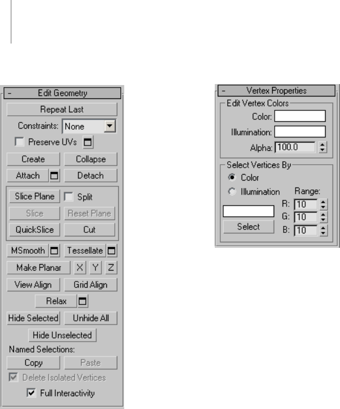
1034 Chapter 9: Surface Modeling
Edit Geometry rollout
See Edit Geometry Rollout (Polymesh) (page
1–1055) for detailed descriptions of these controls.
Vertex Properties rollout
Edit Vertex Colors group
Use these controls to assign the color, and
illumination color (shading) of selected vertices.
Color—Click the color swatch to change the color
of selected vertices.
Illumination—Click the color swatch to change the
illumination color of selected vertices. This lets
you change the illumination without changing the
vertex’s color.
Alpha—Lets you set specific alpha values of selected
vertices. These alpha values are maintained by
thepipelineandcanbeusedinconjunctionwith
vertex color to provide full RGBA data for export.
Select Vertices By group
Color/Illumination—Determines whether to
selectverticesbyvertexcolorvaluesorvertex
illumination values.
Color Swatch—Displays the Color Selector (page
1–161), where you can specify a color to match.
Select—Dependingonwhichradiobuttonis
chosen, selects all vertices whose vertex color or
illumination values either match the color swatch,
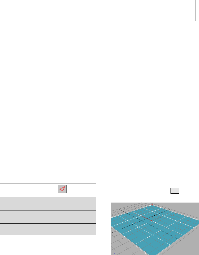
Editable Poly (Edge) 1035
or are within the range specified by the RGB
spinners.
Range—Specifies a range for the color match.
All three RGB values in the vertex color or
illumination must either match the color specified
by the color swatch in Select By Vertex Color, or
be within plus or minus the values in the Range
spinners. Default=10.
Subdivision Surface rollout
See Interface (page 1–1061) for information on the
Subdivision Surface rollout settings.
Subdivision Displacement rollout
See Interface (page 1–1063) for information on the
Subdivision Displacement rollout settings.
Paint Deformation rollout
Paint Deformation lets you stroke elevated and
indented areas directly onto object surfaces. For
more information, see Paint Deformation Rollout
(page 1–1064).
Editable Poly (Edge)
Select an editable poly object. > Modify panel > Selection
rollout > Edge
Select an editable poly object. > Modify panel > Modifier
Stack display > Expand Editable Poly. > Edge
Select an editable poly object. > Quad menu > Tools 1
quadrant > Edge
An edge is a line connecting two vertices that forms
thesideofapolygon.Anedgecan’tbesharedby
more than two polygons. Also, the normals of the
two polygons should be adjacent. If they aren’t,
you wind up with two edges that share vertices.
AttheeditablepolyEdgesub-objectlevel,youcan
select single and multiple edges and transform
them using standard methods. This topic covers
the Edit Geometry and Edit Edges rollouts; for
other controls, see Editable Poly (page 1–1022).
Note: Besidesedges,eachpolygonhasoneormore
internal diagonals (page 3–928) that determine
how the polygon is triangulated by the software.
Diagonals can’t be manipulated directly, but you
can use the Tur n and Edit Triangulation functions
to change their positions.
Procedure
Example: To use the Cut and Turn features:
3ds Max provides a convenient function for
turning edges, which, along with the Cut feature,
streamlines the custom modeling process
considerably. Specifically, cutting a new polygon
into existing geometry minimizes the number of
extra visible edges, typically adding none or one.
And after using cut, the new Turn function lets you
adjust any diagonal with a single click.
1. In the Perspective viewport, add a Plane object.
This object is available from the Create panel >
Standard Primitives > Object Type rollout.
By default, the Plane object is divided into 4 x
4 polygons. If you don’t see the polygons in
the Perspective viewport, press F4 to activate
Edged Faces view mode.
2. ConvertthePlaneobjecttoEditablePoly
format. If you’re not sure how, continue in
this step; otherwise, skip to the next step after
converting.
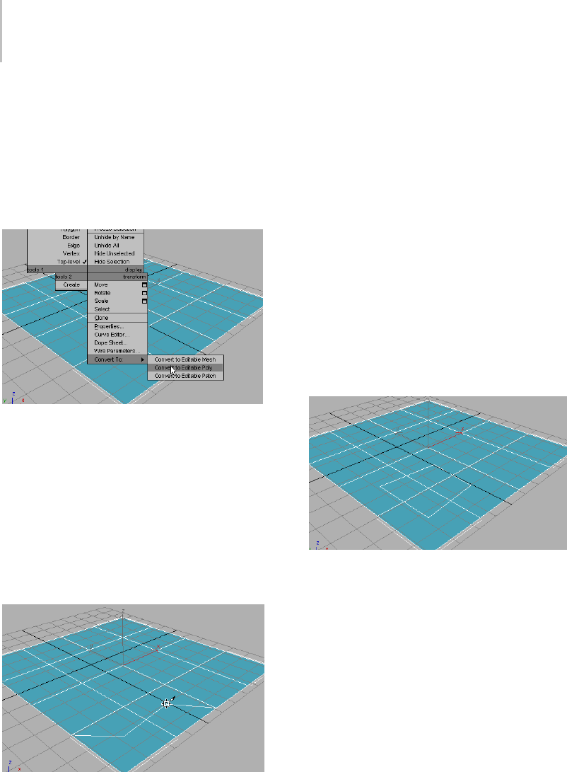
1036 Chapter 9: Surface Modeling
To convert the object, right-click once in the
Perspectiveviewporttoexitcreatemode.
This leaves the object selected. Right-click
again in the Perspective viewport, and then
at the bottom of the Transform quadrant,
choose Convert To > Convert To Editable Poly.
Alternatively, apply the Edit Poly modifier.
The object is now an editable poly and the
command panel switches to the Modify panel.
3. Cutisavailableattheobjectlevelaswellasat
every sub-object level. On the Edit Geometry
rollout, find the Cut button, and then click it.
4. In the Perspective viewport, position the mouse
cursor in the center of a corner polygon, such
as the one closest to you, click once, and then
move the mouse around the viewport.
Two or three lines appear and move as you
move the mouse. One line connects the mouse
cursor to the original click location, and
indicates where the next cut will appear when
you click the mouse button. Another connects
to a corner of the polygon; this connection
changes depending on the mouse position.
And, if the cursor isn’t over an edge or a vertex
(it changes appearance if it is, depending on
which), a third line connects the mouse cursor
to another vertex.
This demonstrates one aspect of the new Cut
functionality; in previous versions, the first
click in a Cut operation connected to two
corners of the polygon.
5. Continue cutting in a rectangular pattern,
clicking once at the center of a different
polygon, finish by clicking once more at the
starting point, and then right-click to exit Cut
mode.
The result is a rectangle across four polygons,
without any connecting visible edges. In
previous versions, you would have had eight
connecting visible edges: two in each of the
original polygons. Note that all the edges you
created are selected, and ready for further
transformation or editing.
6. Cut a rectangle into the center of a single
polygon.
In this case you end up with a single, additional
visibleedgeinsteadofseven,asinprevious
versions. The edge connects corner of the
new polygon with a corner of the original one.
Thisnewedgeisnotselected,buttheonesyou
created explicitly are.
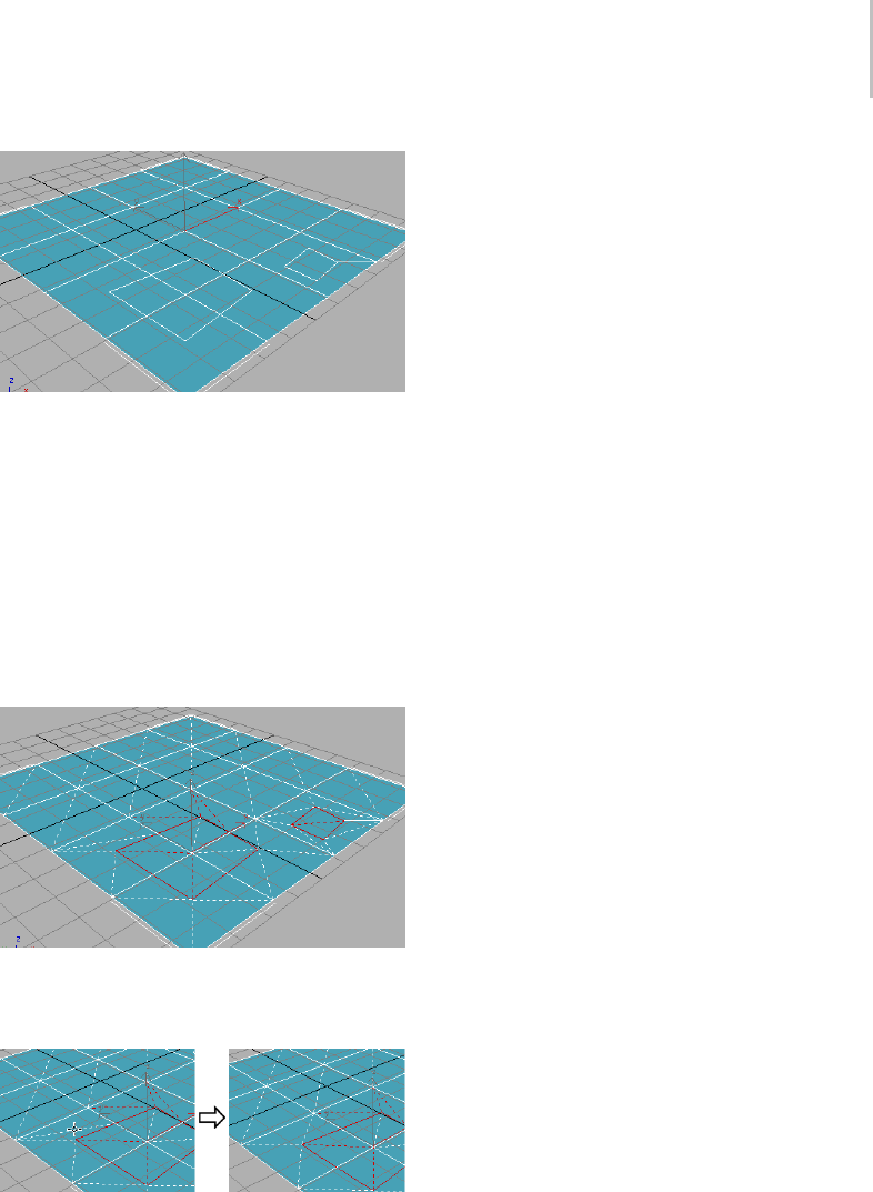
Editable Poly (Edge) 1037
Connecting the remaining corners are a
number of diagonals (page 3–928),whichserve
to fully triangulate the polygons. The new Turn
function lets you manipulate each of these with
asingleclick.
7. Go to the Edge sub-object level, and then, on
the Edit Edges rollout, click Turn.
All diagonals, including those created from the
Cut operations, appear as dashed lines.
8. Click a diagonal to turn it, and then click it
againtoreturnittoitsoriginalstatus.
In Turn mode, click a diagonal (dashed line) once to turn it.
Each diagonal has only two different available
positions, given no changes in any other
diagonals’ or edges’ positions.
Compare this with the Edit Triangulation tool,
with which you must click two vertices to
change a diagonal’s position.
This simple demonstration shows how, when
manually subdividing a polygon mesh for
modeling and animation purposes, you can
save a good deal of time by using the Cut and
Tur n to ols in 3 ds Max.
To create a shape from one or more edges:
1. Selecttheedgesyouwanttomakeintoshapes.
2. On the Edit Edges rollout, click Create Shape
From Selection.
3. Make changes, as needed, on the Create Shape
dialog that appears.
• Enter a curve name or keep the default.
• Choose Smooth or Linear as the shape type.
4. Click OK.
The resulting shape consists of one or more
splines whose vertices are coincident with the
vertices in the selected edges. The Smooth
option results in vertices using smooth values,
while the Linear option results in linear splines
with corner vertices.
If the selected edges are not continuous, or if
they branch, the resulting shape will consist
of more than one spline. When the Create
Shape function runs into a branching ’Y’ in
the edges, it makes an arbitrary decision as to
which edge produces which spline. If you need
to control this, select only those edges that will
result in a single spline, and perform a Create
Shape operation repeatedly to make the correct
number of shapes. Finally, use Attach (page
1–308) in the Editable Spline to combine the
shapes into one.
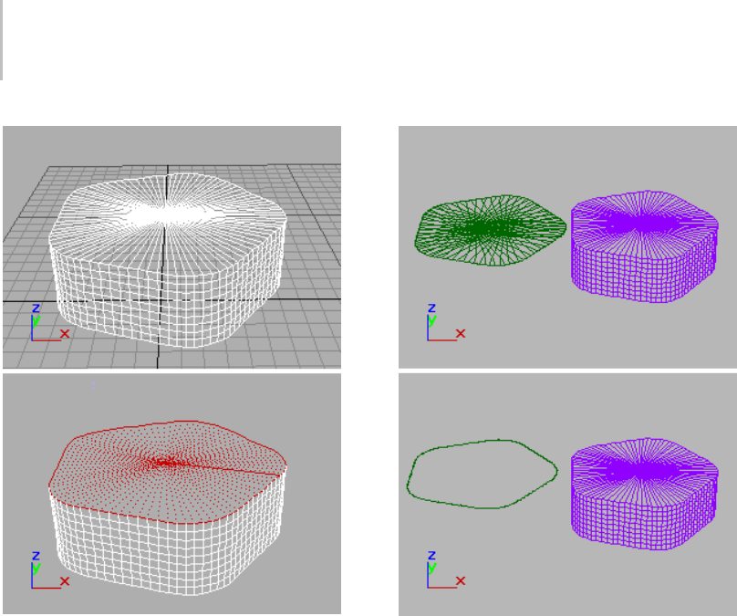
1038 Chapter 9: Surface Modeling
Above: Original object
Below: Object with edges selected
Above: Selected edges removed from original object
Below: Unwanted edges removed
Interface
Selection rollout
See Editable Poly (page 1–1025) for information on
the Select rollout settings.
Soft Selection rollout
Soft Selection controls apply a smooth falloff
between selected sub-objects and unselected
ones.WhenUseSoftSelectionison,unselected
sub-objectsnearyourselectionaregivenpartial
selection values. These values are shown in the
viewports by means of a color gradient on the
vertices, and optionally on the faces. They affect
most types of sub-object deformations, such as the
Move, Rotate, and Scale functions, as well as any
deformation modifiers (such as Bend) applied to
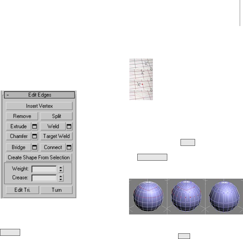
Editable Poly (Edge) 1039
the object. This provides a magnet-like effect with
a sphere of influence around the selection.
For more information, see Soft Selection Rollout
(page 1–963).
Edit Edges rollout
This rollout includes commands specific to edge
editing.
Note: To delete edges, select them and press the
Delete key. This deletes all selected edges and
attached polygons, which can create one or more
holes in the mesh. To delete edges without creating
holes, use Remove.
Insert Vertex—Lets you subdivide visible edges
manually.
After turning on Insert Vertex, click an edge to
add a vertex at that location. You can continue
subdividing polygons as long as the command is
active.
To stop inserting edges, right-click in the viewport,
or click Insert Vertex again to turn it off.
Note: In previous versions of the software, this
command was called Divide.
Remove—Deletes selected edges and combines the
polygons that use them.
Removing one edge is like making it invisible. The mesh is
affected only when all or all but one of the edges depending
on one vertex are removed. At that point, the vertex itself is
deleted and the surface is retriangulated.
To delete the associated vertices when you remove
edges, press and hold Ctrl while executing
a Remove operation, either by mouse or with
the Backspace key. This option, called Clean
Remove, ensures that the remaining polygons are
planar.
Left: The original edge selection
Center: Standard Remove operation leaves extra vertices.
Right: Clean Remove with Ctrl +Remove deletes the extra
vertices.
Edges with the same polygon on both sides usually
can’t be removed.
Warning: Use of Remove can result in mesh shape
changes and non-planar polygons.
Split—Divides the mesh along the selected edges.
This does nothing when applied to a single edge in
themiddleofamesh. Theverticesattheendof
affected edges must be separable in order for this
option to work. For example, it would work on a
single edge that intersects an existing border, since
the border vertex can be split in two. Additionally,
twoadjacentedgescouldbesplitinthemiddleofa
grid or sphere, since the shared vertex can be split.
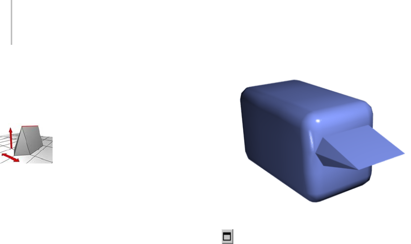
1040 Chapter 9: Surface Modeling
Extrude—Lets you extrude edges manually via
direct manipulation in the viewport. Click this
button, and then drag vertically on any edge to
extrude it.
When extruding a vertex or edge interactively in the viewport,
you set the extrusion height by moving the mouse vertically
and the base width by moving the mouse horizontally.
Extruding an edge moves it along a normal and
creates new polygons that form the sides of the
extrusion, connecting the edge to the object. The
extrusion has either three or four sides; three if the
edgewasonaborder,orfourifitwassharedby
two polygons. As you increase the length of the
extrusion, the base increases in size, to the extent
of the vertices adjacent to the extruded edge’s
endpoints.
Following are important aspects of edge extrusion:
• When over a selected edge, the mouse cursor
changes to an Extrude cursor.
• Drag vertically to specify the extent of the
extrusion, and horizontally to set the size of the
base.
• With multiple edges selected, dragging on any
one extrudes all selected edges equally.
• Youcandragotheredgesinturntoextrude
them while the Extrude button is active. Click
Extrude again or right-click in the active
viewport to end the operation.
Chamfer box showing extruded edge
Extrude Settings—Opens the Extrude Edges
dialog (page 1–1073),whichletsyouperform
extrusion via interactive manipulation.
If you click this button after performing a manual
extrusion,thesameextrusionisperformedonthe
current selection as a preview and the dialog opens
with Extrusion Height set to the amount of the last
manual extrusion.
Weld—Combines selected edges that fall within the
threshold specified in Weld dialog (page 1–1077).
You can weld only edges that have one polygon
attached; that is, edges on a border. Also, you
cannot perform a weld operation that would result
in illegal geometry (e.g., an edge shared by more
than two polygons). For example, you cannot weld
opposite edges on the border of a box that has a
side removed.
Weld Settings—Opens the Weld dialog (page
1–1077), which lets you specify the weld threshold.
Chamfer—Click this button and then drag edges in
the active object. To chamfer vertices numerically,
click the Chamfer Settings button and change the
Chamfer Amount value.
If you chamfer multiple selected edges, all of
them are chamfered identically. If you drag an
unselected edge, any selected edges are first
deselected.

Editable Poly (Edge) 1041
An edge chamfer "chops off " the selected edges,
creating a new polygon connecting new points on
all visible edges leading to the original vertex. The
new edges are exactly <chamfer amount> distance
fromtheoriginaledgealongeachoftheseedges.
New chamfer faces are created with the material ID
of one of the neighboring faces (picked at random)
and a smoothing group which is an intersection of
all neighboring smoothing groups.
For example, if you chamfer one edge of a box,
each corner vertex is replaced by two vertices
moving along the visible edges that lead to the
corner. Outside faces are rearranged and split
to use these new vertices, and a new polygon is
created at the corner.
Alternatively, you can create open space around
the chamfered edges; for details, see Chamfer Edges
dialog (page 1–1070).
Chamfer Settings—Opens the Chamfer Edges
dialog (page 1–1070),whichletsyouchamferedges
via interactive manipulation and toggle the Open
option.
If you click this button after performing a manual
chamfer, the same chamfer is performed on the
current selection as a preview and the dialog opens
with Chamfer Amount set to the amount of the
last manual chamfer.
Target Weld—Allows you to select an edge and
weld it to a target edge. When positioned over an
edge, the cursor changes to a + cursor. Click and
move the mouse and a dashed line appears from
the vertex with an arrow cursor at the other end
of the line. Position the cursor over another edge
and when the + cursor appears again, click the
mouse. The first edge is moved to the position of
the second, and the two are welded.
You can weld only edges that have one polygon
attached; that is, edges on a border. Also, you
cannot perform a weld operation that would result
in illegal geometry (e.g., an edge shared by more
than two polygons). For example, you cannot weld
opposite edges on the border of a box that has a
side removed.
Bridge—Connects border edges on an object with
a polygon “bridge.” Bridge connects only border
edges; that is, edges that have a polygon on only
one side. This tool is particularly useful when
creating edge loops or profiles.
TherearetwowaystouseBridgeinDirect
Manipulation mode (that is, without opening the
BridgeEdgessettingsdialog):
• Select two or more border edges on the object,
and then click Bridge. This immediately creates
the bridge between the pair of selected borders
using the current Bridge settings, and then
deactivates the Bridge button.
• If no qualifying selection exists (that is, two or
more selected border edges), clicking Bridge
activatesthebuttonandplacesyouinBridge
mode. First click a border edge and then move
the mouse; a rubber-band line connects the
mouse cursor to the clicked edge. Click a
second edge on a different border to bridge the
two. This creates the bridge immediately using
the current Bridge settings; the Bridge button
remains active for connecting more edges.
To exit Bridge mode, right-click the active
viewport or click the Bridge button.
Note: Bridge always creates a straight-line
connection between edges. To make the bridge
connection follow a contour, apply modeling
toolsasappropriateafter creating the bridge. For
example, bridge two edges, and then use Bend
(page 1–560).
Bridge Settings—Opens the Bridge Edges
dialog (page 1–1068),whichletsyouadd
polygons between pairs of edges via interactive
manipulation.
Connect—Creates new edges between pairs of
selected edges using the current Connect Edges
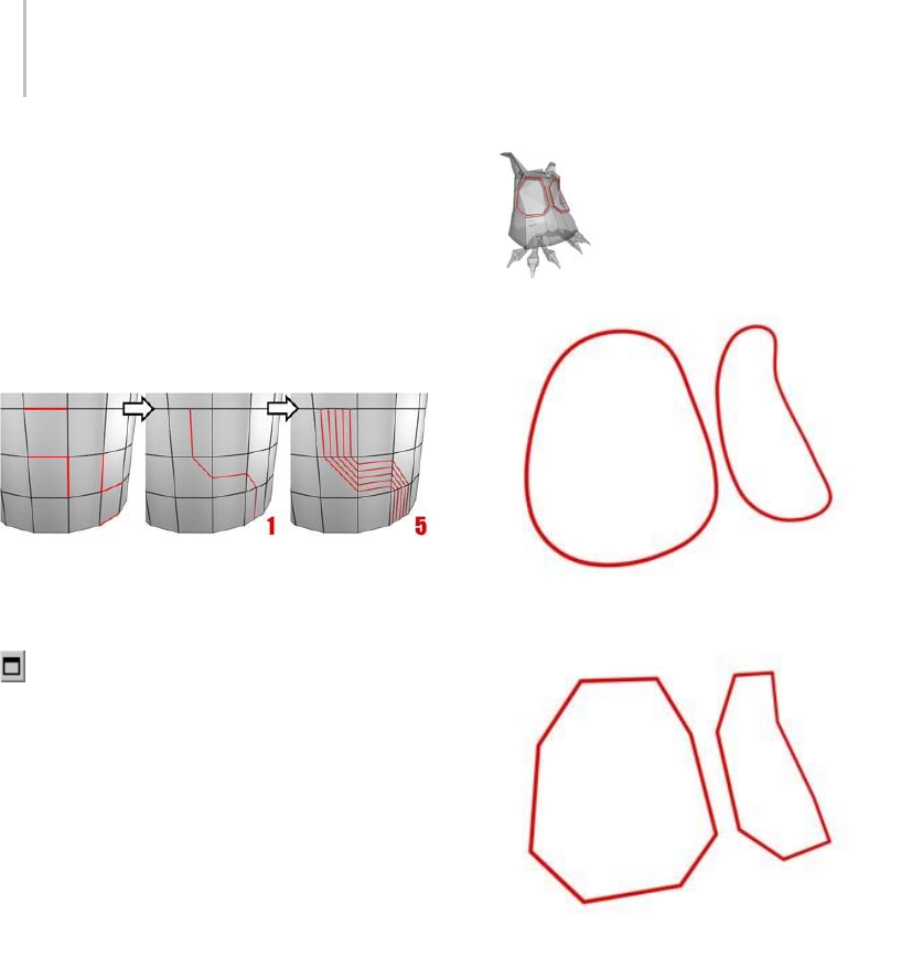
1042 Chapter 9: Surface Modeling
dialog settings. Connect is particularly useful for
creating or refining edge loops.
Note: You can connect only edges on the same
polygon. Also, Connect will not let the new edges
cross. For example, if you select all four edges of a
four-sided polygon and then click Connect, only
neighboring edges are connected, resulting in a
diamond pattern.
Connecting two or more edges using the Settings dialog
creates equally spaced edges. The number of edges is set in the
dialog. When you click the Connect button, the current dialog
settings are applied to the selection.
Connect Settings—Opens the Connect Edges
dialog (page 1–1070),whichletsyoupreview
the Connect results, specify the number of edge
segments created by the operation, and set spacing
and placement for the new edges.
Create Shape From Selection—After selecting one
or more edges, click this button to create a spline
shape from the selected edges. A Create Shape
dialog appears, letting you name the shape and set
it to Smooth or Linear. The new shape’s pivot is
placed at the center of the poly object. An edge selection (top); a smooth shape (center); a linear
shape (bottom)
Weight—Sets the weight of selected edges. Used
by the NURMS subdivision option and by the
MeshSmooth modifier (page 1–722).
Increasing an edge weight tends to push the
smoothed result away.
Crease—Specifies how much creasing is performed
ontheselectededgeoredges.UsedbytheNURMS
subdivision option and by the MeshSmooth modifier
(page 1–722).
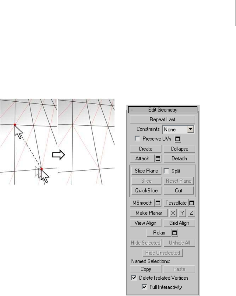
Editable Poly (Edge) 1043
At low settings, the edge is relatively smooth. At
higher settings, the crease becomes increasingly
visible. At 1.0, the highest setting, the edge
becomes a hard crease.
Edit Tri[angulation]—Lets you modify how
polygons are subdivided into triangles by drawing
internal edges, or diagonals (page 3–928).
In Edit Triangulation mode, you can see the current
triangulation in the viewport, and change it by clicking two
vertices on the same polygon.
To edit triangulation manually, turn on this
button. The hidden edges appear. Click a polygon
vertex. A rubber-band line appears, attached to
the cursor. Click a non-adjacent vertex to create a
new triangulation for the polygon.
Tip: For easier editing of triangulation, use the
Turn command instead (see following).
Turn—Lets you modify how polygons are
subdivided into triangles by clicking diagonals.
When you activate Turn, the diagonals (page
3–928) become visible as dashed lines in wireframe
and edged-faces views. In Turn mode, click a
diagonal to change its position. To exit Turn mode,
right-click in the viewport or click the Turn button
again.
Each diagonal has only two available positions
at any given time, so clicking a diagonal twice in
succession simply returns it to its original position.
But changing the position of a nearby diagonal
can make a different alternate position available
to a diagonal.
For more information on how to use Turn with
the enhanced Cut tool, see this procedure (page
1–1035).
Edit Geometry rollout
See Edit Geometry Rollout (Polymesh) (page
1–1055) for detailed descriptions of these controls.
Subdivision Surface rollout
See Interface (page 1–1061) for information on the
Subdivision Surface rollout settings.
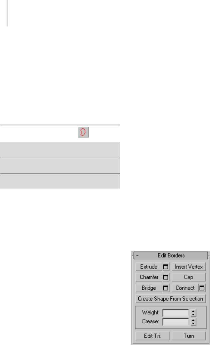
1044 Chapter 9: Surface Modeling
Subdivision Displacement rollout
See Interface (page 1–1063) for information on the
Subdivision Displacement rollout settings.
Paint Deformation rollout
Paint Deformation lets you stroke elevated and
indented areas directly onto object surfaces. For
more information, see Paint Deformation Rollout
(page 1–1064).
Editable Poly (Border)
Select an editable poly object. > Modify panel > Selection
rollout > Border
Select an editable poly object. > Modify panel > Modifier
Stack display > Expand Editable Poly. > Border
Select an editable poly object. > Quad menu > Tools
1quadrant>Border
Aborderisalinearsectionofameshthatcan
generallybedescribedastheedgeofahole.Thisis
usually a sequence of edges with polygons on only
one side. For example, a box doesn’t have a border,
but the teapot object has several: on the lid, on the
body, on the spout, and two on the handle. If you
create a cylinder, and then delete an end polygon,
the adjacent row of edges forms a border.
At the editable poly Border sub-object level,
you can select single and multiple borders and
transform them using standard methods. This
topic covers the Edit Geometry and Edit Borders
rollouts; for other controls, see Editable Poly (page
1–1022).
Procedure
To create a polygon that closes the surface at the
selected border:
1. At the Border sub-object level, select any open
edge.
This selects the entire closed loop of continuous
open edges that make up the border selection.
2. Click Cap.
Interface
Selection rollout
See Editable Poly (page 1–1025) for information on
the Selection rollout settings.
Soft Selection rollout
Soft Selection controls apply a smooth falloff
between selected sub-objects and unselected
ones.WhenUseSoftSelectionison,unselected
sub-objectsnearyourselectionaregivenpartial
selection values. These values are shown in the
viewports by means of a color gradient on the
vertices, and optionally on the faces. They affect
most types of sub-object deformations, such as the
Move, Rotate, and Scale functions, as well as any
deformation modifiers (such as Bend) applied to
the object. This provides a magnet-like effect with
a sphere of influence around the selection.
For more information, see Soft Selection Rollout
(page 1–963).
Edit Borders rollout
This rollout includes commands specific to editing
borders.

Editable Poly (Border) 1045
Note: To delete a border, select it and press the
Delete key. This deletes the border and all
attached polygons.
Extrude—Lets you extrude a border manually via
direct manipulation in the viewport. Click this
button, and then drag vertically on any border to
extrude it.
Extrudingabordermovesitalonganormaland
creates new polygons that form the sides of the
extrusion, connecting the border to the object.
The extrusion can form a varying number of
additional sides, depending on the geometry
near the border. As you increase the length of the
extrusion, the base increases in size, to the extent
of the vertices adjacent to the extruded border’s
endpoints.
Following are important aspects of border
extrusion:
• When over a selected border, the mouse cursor
changes to an Extrude cursor.
• Drag vertically to specify the extent of the
extrusion, and horizontally to set the size of the
base.
• With multiple borders selected, dragging on
any one extrudes all selected borders equally.
• Youcandragotherbordersinturntoextrude
them while the Extrude button is active. Click
Extrude again or right-click in the active
viewport to end the operation.
Extrude Settings—Opens the Extrude Edges
dialog (page 1–1073),whichletsyouperform
extrusion via interactive manipulation.
If you click this button after performing a manual
extrusion, the same extrusion is performed on the
current selection as a preview and the dialog opens
with Extrusion Height set to the amount of the last
manual extrusion.
Insert Vertex—Lets you subdivide border edges
manually.
After turning on Insert Vertex, click a border edge
to add a vertex at that location. You can continue
subdividing border edges as long as the command
is active.
To stop inserting vertices, right-click in the
viewport, or click Insert Vertex again to turn it off.
Note: In previous versions of the software, this
command was called Divide.
Chamfer—Click this button and then drag a border
in the active object. The border need not be
selected first.
If you chamfer multiple selected borders, all of
them are chamfered identically. If you drag an
unselected border, any selected borders are first
deselected.
A border chamfer essentially “frames” the border
edges, creating a new set of edges paralleling the
border edges, plus new diagonal edges at any
corners. These new edges are exactly <chamfer
amount> distance from the original edges. New
chamfer faces are created with the material ID of
one of the neighboring faces (picked at random)
and a smoothing group which is an intersection of
all neighboring smoothing groups.
Alternatively, you can create open space around
the chamfered borders, essentially cutting away
at the open edges; for details, see Chamfer Edges
dialog (page 1–1070).
Chamfer Settings—Opens the Chamfer Edges
dialog (page 1–1070), which lets you chamfer
borders via interactive manipulation and toggle
the Open option.
If you click this button after performing a manual
chamfer, the same chamfer is performed on the
current selection as a preview and the dialog opens

1046 Chapter 9: Surface Modeling
with Chamfer Amount set to the amount of the
last manual chamfer.
Cap—Caps an entire border loop with a single
polygon.
Select the border, and then click Cap.
Bridge—Connectstwobordersonanobjectwitha
polygon “bridge.” There are two ways to use Bridge
in Direct Manipulation mode (that is, without
opening the Bridge Settings dialog):
• Selectanevennumberofbordersontheobject,
and then click Bridge. This immediately creates
the bridge between each pair of selected borders
using the current Bridge settings, and then
deactivates the Bridge button.
• If no qualifying selection exists (that is, two
or more selected borders), clicking Bridge
activatesthebuttonandplacesyouinBridge
mode. First click a border edge and then move
the mouse; a rubber-band line connects the
mouse cursor to the clicked edge. Click a
second edge on a different border to bridge the
two. This creates the bridge immediately using
the current Bridge settings; the Bridge button
remains active for connecting more pairs of
borders. To exit Bridge mode, right-click the
active viewport or click the Bridge button.
Note: Bridge always creates a straight-line
connection between border pairs. To make
thebridgeconnectionfollowacontour,apply
modelingtoolsasappropriateafter creating the
bridge. For example, bridge two borders, and then
use Bend (page 1–560).
Bridge Settings—Opens the Bridge dialog (page
1–1067), which lets you connect pairs of borders
via interactive manipulation.
Connect—Creates new edges between pairs of
selected border edges. The edges are connected
from their midpoints.
You can connect only edges on the same polygon.
Connectwillnotletthenewedgescross.Thus,for
example, if you select all four edges of a four-sided
polygon and then click Connect, only neighboring
edges are connected, resulting in a diamond
pattern.
Connect Settings—Lets you preview the
Connect and specify the number of edge segments
created by the operation. To increase the mesh
resolution around the new edge, increase the
Connect Edge Segments setting.
Create Shape From Selection—After selecting one
or more borders, click this button to create a spline
shape from the selected edges. A Create Shape
dialog appears, letting you name the shape and set
it to Smooth or Linear. The new shape’s pivot is
placed at the center of the poly object.
Weight—Sets the weight of selected borders. Used
by the NURMS subdivision option.
Increasing an edge weight tends to push the
smoothed result away.
Crease—Specifies how much creasing is performed
on the selected border or borders. Used by the
NURMS subdivision option.
At low settings, the border is relatively smooth. At
higher settings, the crease becomes increasingly
visible. At 1.0, the highest setting, the border is
notsmoothedatall.
Edit Tri[angulation]—Lets you modify how
polygons are subdivided into triangles by drawing
internal edges, or diagonals (page 3–928).
To edit triangulation manually, turn on this
button. The hidden edges appear. Click a polygon
vertex. A rubber-band line appears, attached to
the cursor. Click a non-adjacent vertex to create a
new triangulation for the polygon.
Tip: For easier editing of triangulation, use the
Turn command instead (see following).
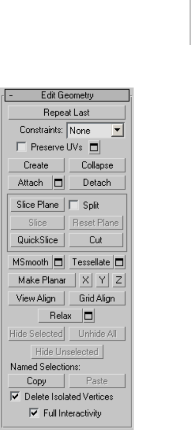
Editable Poly (Border) 1047
Turn—Lets you modify how polygons are
subdivided into triangles by clicking diagonals.
When you activate Turn, the diagonals (page
3–928) become visible as dashed lines in wireframe
and edged-faces views. In Turn mode, click a
diagonal to change its position. To exit Turn mode,
right-click in the viewport or click the Turn button
again.
Each diagonal has only two available positions
at any given time, so clicking a diagonal twice in
succession simply returns it to its original position.
But changing the position of a nearby diagonal
can make a different alternate position available
to a diagonal.
For more information on how to use Turn with
the enhanced Cut tool, see this procedure (page
1–1035).
Edit Geometry rollout
See Edit Geometry Rollout (Polymesh) (page
1–1055) for detailed descriptions of these controls.
Subdivision Surface rollout
See Interface (page 1–1061) for information on the
Subdivision Surface rollout settings.
Subdivision Displacement rollout
See Interface (page 1–1063) for information on the
Subdivision Displacement rollout settings.
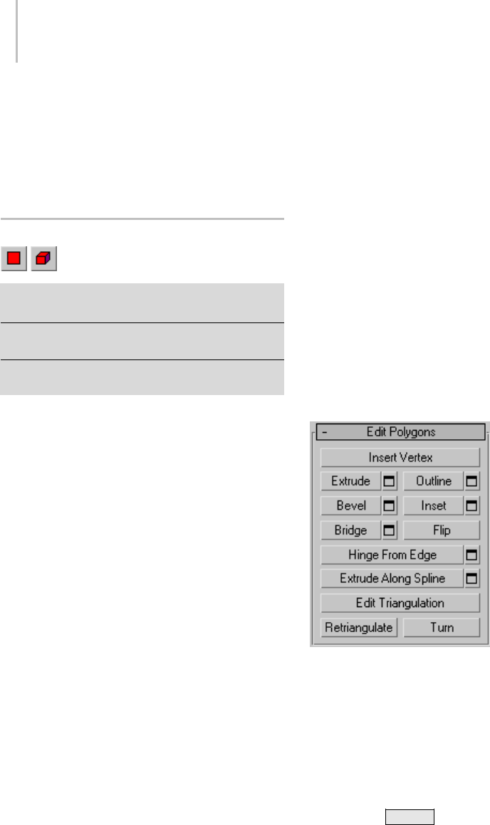
1048 Chapter 9: Surface Modeling
Paint Deformation rollout
Paint Deformation lets you stroke elevated and
indented areas directly onto object surfaces. For
more information, see Paint Deformation Rollout
(page 1–1064).
Editable Poly (Polygon/Element)
Select an editable poly object. > Modify panel > Selection
rollout > Polygon or Element
Select an editable poly object. > Modify panel > Modifier
Stack display > Expand Editable Poly. > Polygon/Element
Select an editable poly object. > Quad menu > Tools 1
quadrant > Polygon or Element
Apolygon is a closed sequence of three or more
edges connected by a surface. Polygons provide
the renderable surface of editable poly objects.
At the Editable Poly (Polygon) sub-object level,
you can select single and multiple polygons and
transform them using standard methods. This is
also true for the Element sub-object level; for the
distinctions between polygon and element, see
Editable Poly > Selection rollout (page 1–1025).
This topic covers the Edit Polygons/Elements
rollout and Edit Geometry rollout functions for
these sub-object types; for other controls, see
Editable Poly (page 1–1022).
Note: Workflow enhancements in the Editable Poly
userinterfacegiveyouachoiceofeditingmethods.
See Editable Poly Workflow (page 1–1022) for more
information.
Interface
Selection rollout
See Editable Poly > Selection rollout (page 1–1025)
for information on the Selection rollout settings.
Soft Selection rollout
Soft Selection controls apply a smooth falloff
between selected sub-objects and unselected
ones.WhenUseSoftSelectionison,unselected
sub-objectsnearyourselectionaregivenpartial
selection values. These values are shown in the
viewports by means of a color gradient on the
vertices, and optionally on the faces. They affect
most types of sub-object deformations, such as the
Move, Rotate, and Scale functions, as well as any
deformation modifiers (such as Bend) applied to
the object. This provides a magnet-like effect with
a sphere of influence around the selection.
For more information, see Soft Selection Rollout
(page 1–963).
Edit Polygons/Elements rollout
At the element sub-object level, this rollout
includes commands that are common to both
polygons and elements. At the polygon level, it
contains those as well as a number more that are
unique to polygons. The commands available at
both levels are Insert Vertex, Edit Triangulation,
Retriangulate, and Flip.
Note: To delete polygons or elements, select them
and press the Delete key. A dialog might appear
asking if you want to delete isolated vertices, which
are vertices that are used only by polygons or
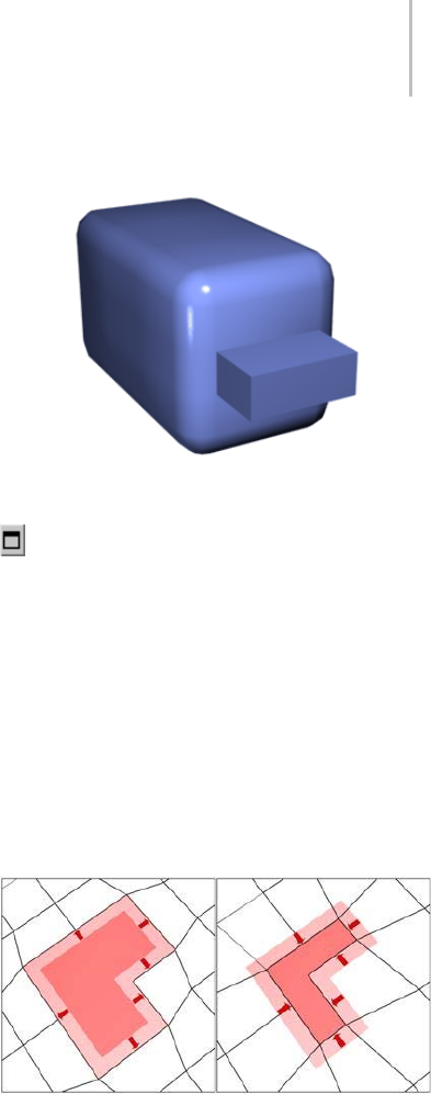
Editable Poly (Polygon/Element) 1049
elements that are to be deleted. Click Yes to delete
them; click No to retain them.
Insert Vertex—Lets you subdivide polygons
manually. Applies to polygons, even if at the
element sub-object level.
After turning on Insert Vertex, click a polygon to
add a vertex at that location. You can continue
subdividing polygons as long as the command is
active.
To stop inserting vertices, right-click in the
viewport, or click Insert Vertex again to turn it off.
Note: In previous versions of the software, this
command was called Divide.
Extrude—Lets you perform manual extrusion via
direct manipulation in the viewport. Click this
button, and then drag vertically on any polygon
to extrude it.
Extrudingpolygonsmovesthemalonganormal
and creates new polygons that form the sides of the
extrusion, connecting the selection to the object.
Following are important aspects of polygon
extrusion:
• When over a selected polygon, the mouse
cursor changes to an Extrude cursor.
• Drag vertically to specify the extent of the
extrusion, and horizontally to set the size of the
base.
• With multiple polygons selected, dragging on
any one extrudes all selected polygons equally.
• You can drag other polygons in turn to extrude
them while the Extrude button is active. Click
Extrude again or right-click in the active
viewport to end the operation.
Chamfer box showing extruded polygon
Extrude Settings—Opens the Extrude Faces
dialog (page 1–1072),whichletsyouperform
extrusion via interactive manipulation.
If you click this button after performing an
extrusion,thesameextrusionisperformedonthe
current selection as a preview and the dialog opens
with Extrusion Height set to the amount of the last
manual extrusion.
Outline—Lets you increase or decrease the
outside edge of each contiguous group of selected
polygons.
Outline is often used after an extrusion or bevel to
adjustthesizeoftheextrudedfaces.Itdoesn’tscale
the polygons; only changes the size of the outer
edge. For example, in the following illustration,
note that the sizes of the inner polygons remain
constant.
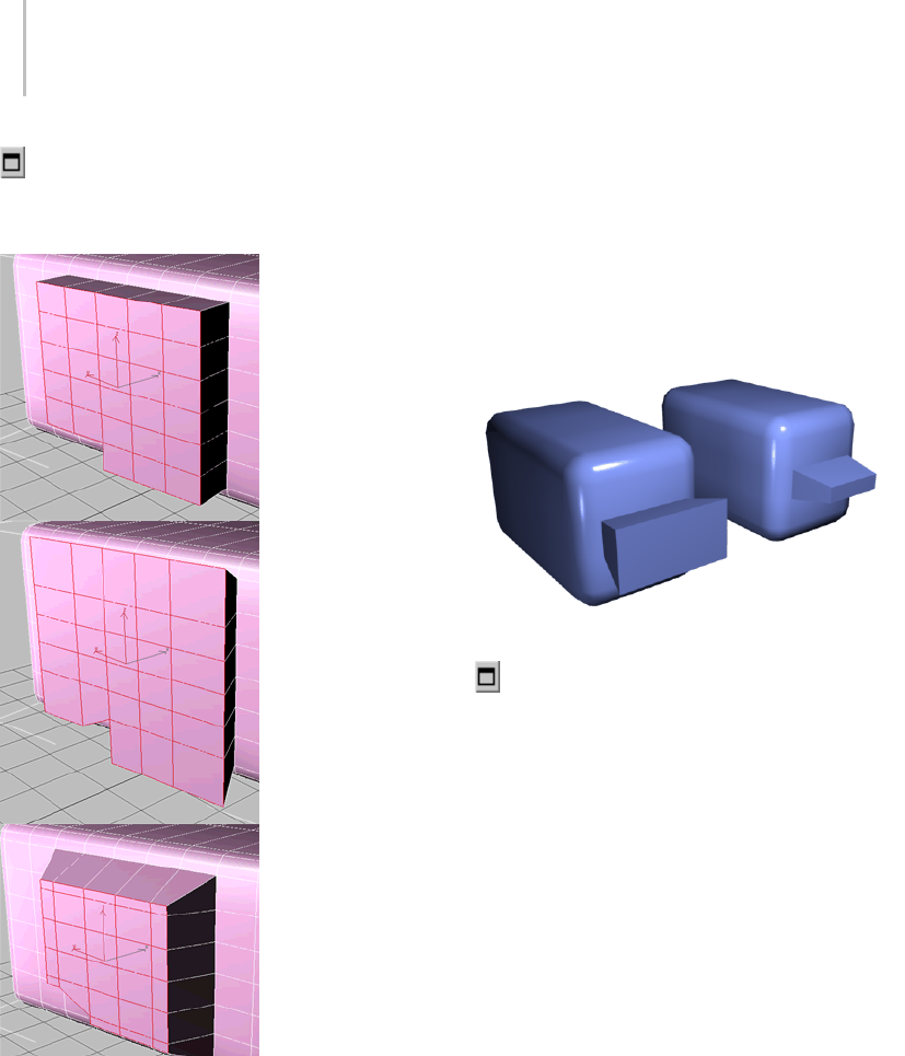
1050 Chapter 9: Surface Modeling
Click the Outline Settings button to open the
Outline Selected Faces dialog, which lets you
perform outlining by a numeric setting.
Extruded polygons (top), outline expanded (middle), outline
reduced (bottom)
Note that size of inner polygons doesn’t change.
Bevel—Lets you perform manual beveling via
direct manipulation in the viewport. Click this
button, and then drag vertically on any polygon
toextrudeit.Releasethemousebuttonandthen
move the mouse vertically to outline the extrusion.
Click to finish.
• When over a selected polygon, the mouse
cursor changes to a Bevel cursor.
• With multiple polygons selected, dragging on
any one bevels all selected polygons equally.
• You can drag other polygons in turn to bevel
them while the Bevel button is active. Click
Bevel again or right-click to end the operation.
Polygon beveled outward (left) and inward (right)
Bevel Settings—Opens the Bevel Selection
dialog (page 1–1066),whichletsyouperform
beveling via interactive manipulation.
If you click this button after performing a bevel,
thesamebevelisperformedonthecurrent
selection as a preview and the dialog opens with
thesamesettingsusedforthepreviousbevel.
Inset—Performs a bevel with no height; that is,
within the plane of the polygon selection. Click
this button, and then drag vertically on any
polygon to inset it.
• When over a selected polygon, the mouse
cursor changes to an Inset cursor.
• With multiple polygons selected, dragging on
any one insets all selected polygons equally.
• You can drag other polygons in turn to inset
them while the Inset button is active. Click
Inset again or right-click to end the operation.
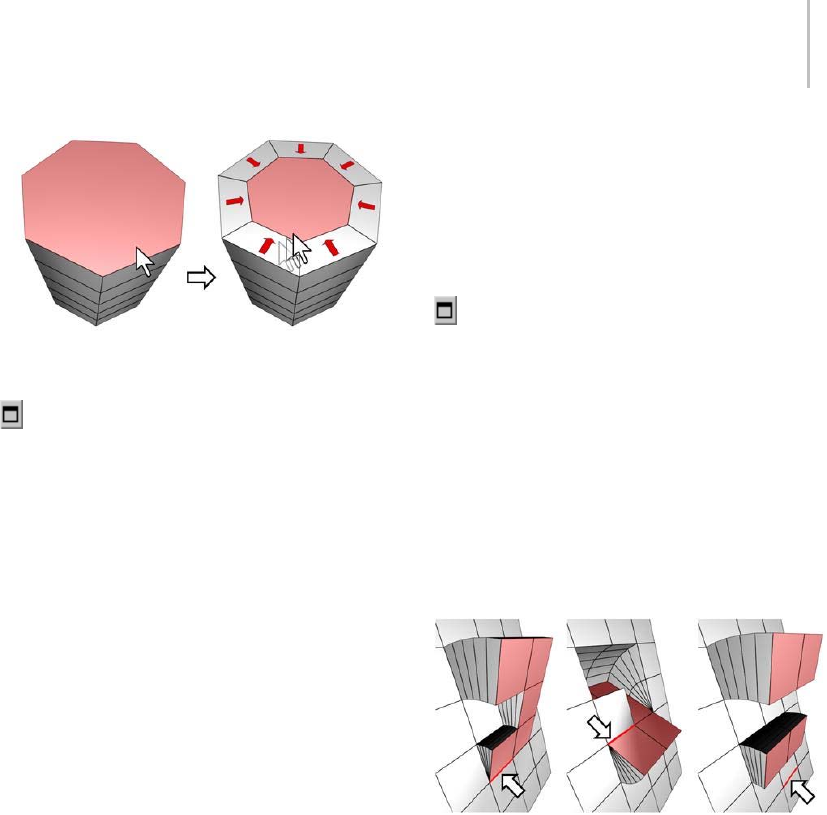
Editable Poly (Polygon/Element) 1051
Inset works on a selection of one or more polygons. As with
Outline, only the outer edges are affected.
Inset Settings—Opens the Inset Selected Faces
dialog (page 1–1074),whichletsyouinsetpolygons
via interactive manipulation.
If you click this button after performing a manual
inset, the same inset is performed on the current
selection as a preview and the dialog opens with
InsetAmountsettotheamountofthelastmanual
inset.
Bridge—Connects two polygons or polygon
selections on an object with a polygon “bridge.”
TherearetwowaystouseBridgeinDirect
Manipulation mode (that is, without opening the
Bridge Settings dialog):
• Maketwoseparatepolygonselectionsonthe
object, and then click Bridge. This creates the
bridge immediately using the current Bridge
settings, and then deactivates the Bridge button.
• If no qualifying selection exists (that is, two
or more discrete polygon selections), clicking
Bridge activates the button and places you in
Bridge mode. First click a polygon and move
the mouse; a rubber-band line connects the
mouse cursor to the clicked polygon. Click a
second polygon to bridge the two. This creates
thebridgeimmediatelyusingthecurrentBridge
settings; the Bridge button remains active for
connecting more pairs of polygons. To exit
Bridge mode, right-click the active viewport or
click the Bridge button.
Note: Bridge always creates a straight-line
connection between polygon pairs. To make
thebridgeconnectionfollowacontour,apply
modelingtoolsasappropriateafter creating the
bridge. For example, bridge two polygons, and
then use Bend (page 1–560).
Bridge Settings—Opens the Bridge dialog (page
1–1067),whichletsyouconnectpairsofpolygon
selections via interactive manipulation.
Flip—Reverses the directions of the normals of
selected polygons, hence their facing.
Hinge From Edge—Lets you perform a manual
hinge operation via direct manipulation in the
viewport. Make a polygon selection, click this
button, and then drag vertically on any edge to
hinge the selection. The mouse cursor changes to
a cross when over an edge.
The hinge edge needn’t be part of the selection. It can be any
edge of the mesh. Also, the selection needn’t be contiguous.
Hingingpolygonsrotatesthemaboutanedge
and creates new polygons that form the sides of
the hinge, connecting the selection to the object.
It’s essentially an extrusion with rotation, with
the exception that, if the hinge edge belongs to a
selected polygon, that side is not extruded. The
manual version of Hinge From Edge works only
with an existing polygon selection.
Tip: Turn on Ignore Backfacing to avoid
inadvertently hinging about a backfacing edge.
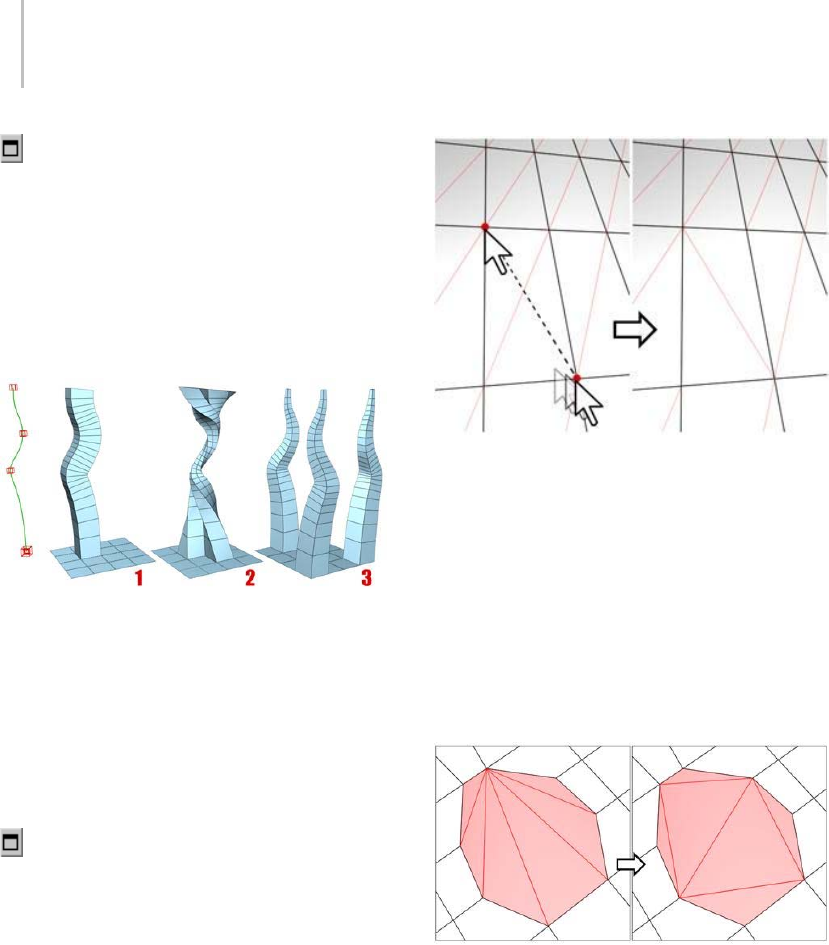
1052 Chapter 9: Surface Modeling
Hinge Settings—Opens the Hinge From Edge
dialog (page 1–1073),whichletsyouhinge
polygons via interactive manipulation.
If you click this button after performing a manual
hinge, the dialog opens with Angle set to the extent
of the last manual hinge.
Extrude Along Spline—Extrudes the current
selection along a spline.
You can extrude a single face (1) or a selection of contiguous
(2) or non-contiguous faces (3). Extrusion 2 uses Taper Curve
and Twist. Extrusion 3 uses Taper Amount; each extrusion has
a different curve rotation.
Make a selection, click this button, and the select a
spline in the scene. The selection is extruded along
the spline, using the spline’s current orientation,
but as though the spline’s start point were moved
to the center of each polygon or group.
Extrude Along Spline Settings—Opens the
Extrude Polygons Along Spline dialog (page
1–1071),whichletsyouextrudealongsplinesvia
interactive manipulation.
Edit Triangulation—Lets you modify how polygons
are subdivided into triangles by drawing internal
edges.
In Edit Triangulation mode, you can see the current
triangulation in the viewport, and change it by clicking two
vertices on the same polygon.
To manually edit triangulation, turn on this
button. The hidden edges appear. Click a polygon
vertex. A rubber-band line appears, attached to
the cursor. Click a non-adjacent vertex to create a
new triangulation for the polygon.
Retriangulate—Lets the software automatically do
its best triangulation on the polygon or polygons
currently selected.
Retriangulate attempts to optimize how selected polygons are
subdivided into triangles.
Turn—Lets you modify how polygons are
subdivided into triangles by clicking diagonals.
When you activate Turn, the diagonals (page
3–928) become visible as dashed lines in wireframe
and edged-faces views. In Turn mode, click a
diagonal to change its position. To exit Turn mode,
right-click in the viewport or click the Turn button
again.
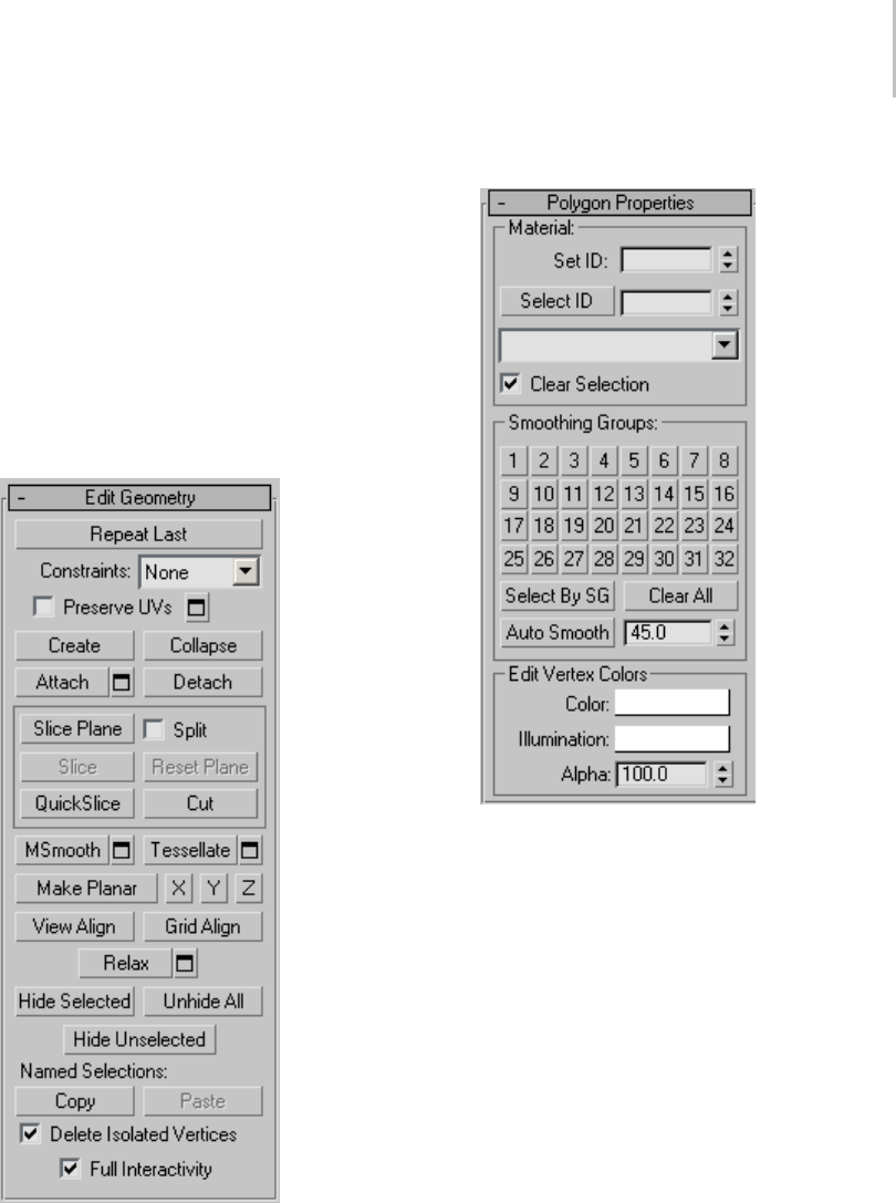
Editable Poly (Polygon/Element) 1053
Each diagonal has only two available positions
at any given time, so clicking a diagonal twice in
succession simply returns it to its original position.
But changing the position of a nearby diagonal
can make a different alternate position available
to a diagonal.
For more information on how to use Turn with
the enhanced Cut tool, see this procedure (page
1–1035).
Edit Geometry rollout
See Edit Geometry Rollout (Polymesh) (page
1–1055) for detailed descriptions of these controls.
Polygon Properties rollout
These controls let you work with material IDs,
smoothing groups, and vertex colors.
Material group
Set ID—Lets you assign a particular material ID
(page 3–969) number to selected sub-objects for
use with multi/sub-object materials (page 2–1594)
and other applications. Use the spinner or enter
the number from the keyboard. The total number
of available IDs is 65,535.
Select ID—Selectssub-objectscorrespondingto
the Material ID specified in the adjacent ID field.
Type or use the spinner to specify an ID, then click
the Select ID button.
[Select By Name]—This drop-down list shows
the names of sub-materials if an object has a
Multi/Sub-Object material assigned to it. Click

1054 Chapter 9: Surface Modeling
the drop arrow and choose a sub-material from
the list. The sub-objects that are assigned that
material are selected. If an object does not have
a Multi/Sub-Object material assigned, the name
list is unavailable. Likewise, if multiple objects
areselectedthathaveanEditPatch,EditSpline,
orEditMeshmodifierapplied,thenamelistis
inactive.
Note: Sub-material names are those specified in the
Name column on the material’s Multi/Sub-Object
Basic Parameters rollout; these are not created by
default, and must be specified separately from any
material names.
Clear Selection—When on, choosing a new ID or
material name deselects any previously selected
sub-objects. When off, selections are cumulative,
so new ID or sub-material name selections add to
the existing selection set of patches or elements.
Default=on.
Smoothing Groups group
Use these controls to assign selected polygons to
different smoothing groups (page 3–1013),andto
select polygons by smoothing group.
To assign polygons to one or more smoothing
groups, select the polygons, and then click the
number(s) of the smoothing group(s) to assign
them to.
Select By SG (Smoothing Group)—Displays a dialog
that shows the current smoothing groups. Select
a group by clicking the corresponding numbered
button and clicking OK. If Clear Selection is
on, any previously selected polygons are first
deselected. If Clear Selection is off, the new
selection is added to any previous selection set.
Clear All—Removesanysmoothinggroup
assignments from selected polygons.
Auto Smooth—Sets the smoothing groups based
on the angle between polygons. Any two adjacent
polygons will be put in the same smoothing group
if the angle between their normals is less than the
threshold angle, set by the spinner to the right of
this button.
Threshold—This spinner (to the right of Auto
Smooth) lets you specify the maximum angle
betweenthenormalsofadjacentpolygonsthat
determines whether those polygons will be put in
the same smoothing group.
Edit Vertex Colors group
Use these controls to assign the color, illumination
color (shading), and alpha (transparency) values
of vertices on selected polygons or elements.
Color—Click the color swatch to change the color
of vertices on selected polygons or elements.
Illumination—Click the color swatch to change the
illumination color of vertices on selected polygons
or elements. This lets you change the illumination
without changing the vertex’s color.
Alpha—Lets you assign an alpha (transparency)
value to vertices on selected polygons or elements.
The spinner value is a percentage; zero is
completely transparent and 100 is completely
opaque.
Subdivision Surface rollout
See Interface (page 1–1061) for information on the
Subdivision Surface rollout settings.
Subdivision Displacement rollout
See Interface (page 1–1063) for information on the
Subdivision Displacement rollout settings.
Paint Deformation rollout
Paint Deformation lets you stroke elevated and
indented areas directly onto object surfaces. For
more information, see Paint Deformation Rollout
(page 1–1064).
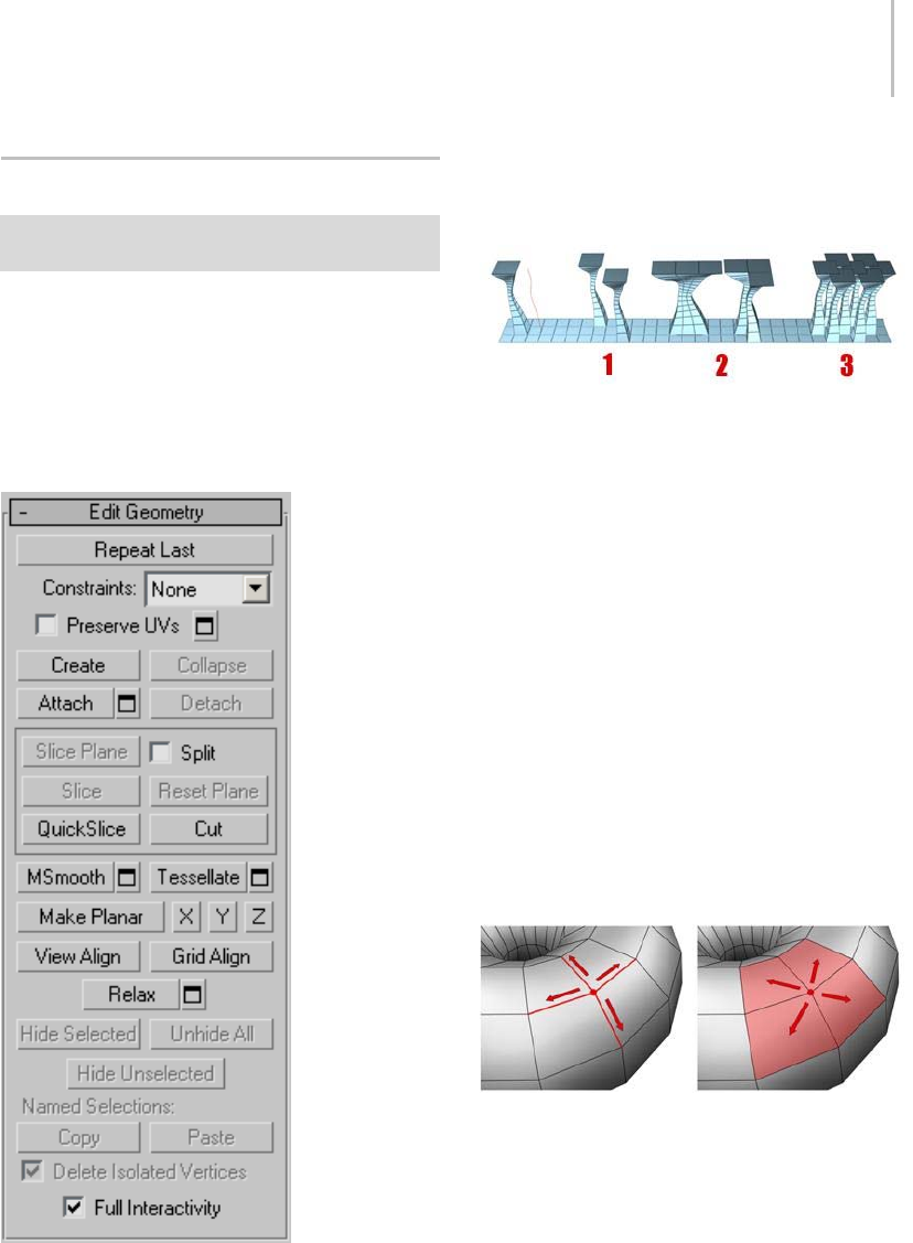
Edit Geometry Rollout (Polymesh) 1055
Edit Geometry Rollout (Polymesh)
Create or select an editable poly object. > Modify panel >
Edit Geometry rollout
The Edit Geometry rollout provides global
controls for changing the geometry of the
polymesh, at either the top (Object) level or the
sub-object levels. The control are the same at all
levels, except as noted in the descriptions below.
Interface
Repeat Last—Repeats the most recently used
command.
For example, if you extrude a polygon, and want to
apply the same extrusion to several others, select
the others, and then click Repeat Last.
You can apply a spline extrusion of a single polygon (left)
repeatedly to other single polygons (1) or to multiple polygon
selections, contiguous (2) or not (3).
Note: Repeat Last does not repeat all operations.
For example, it does not repeat transforms. To
determine which command will be repeated when
you click the button, check the button’s tooltip. If
no tooltip appears, nothing will happen when it is
clicked.
Constraints—Lets you use existing geometry to
constrain sub-object transformation. Use the
drop-down list to choose the constraint type:
•None: No constraints.
•Edge: Constrains vertex transformations to
edge boundaries.
•Face: Constrains vertex transformations to face
surfaces.
When set to Edge, moving a vertex will slide it along one
of the existing edges, depending on the direction of the
transformation. If set to Face, the vertex moves only on the
polygon’s surface.
Note: You can set constraints at the Object level, but
their use pertains primarily to sub-object levels.
The Constraints setting persists at all sub-object
levels.
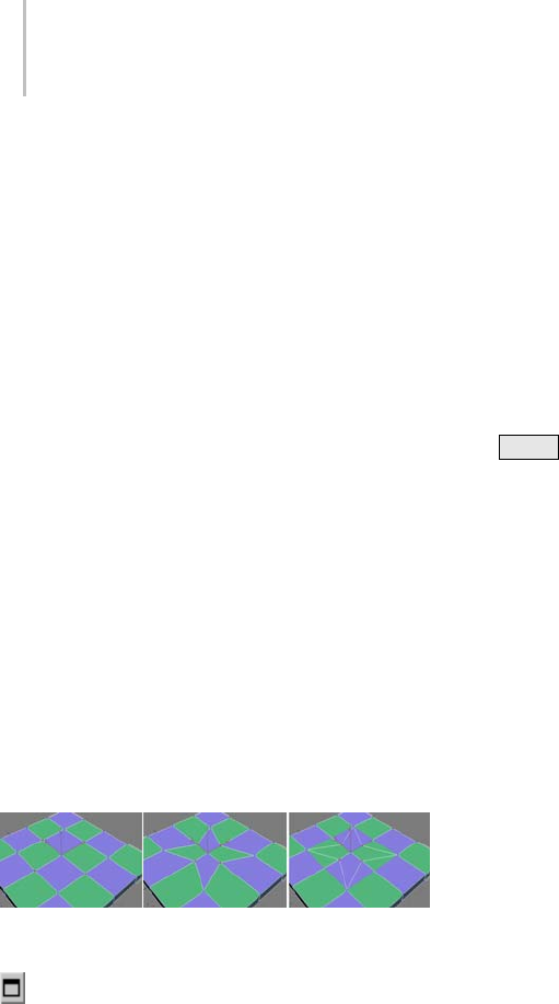
1056 Chapter 9: Surface Modeling
Preserve UVs—When on, you can edit sub-objects
without affecting the object’s UV mapping. You
can choose any of an object’s mapping channels
to preserve or not; see Preserve UVs Settings,
following. Default=off.
Without Preserve UVs, there is always a direct
correspondence between an object’s geometry
and its UV mapping. For example, if you map an
objectandthenmovevertices,thetexturemoves
along with the sub-objects, whether you want it
toornot.IfyouturnonPreserveUVs,youcan
perform minor editing tasks without changing
the mapping.
Tip: For best results with Preserve UVs at the
vertex level, use it for limited vertex editing. For
example, you’ll usually have no trouble moving
avertexwithinedgeorfaceconstraints. Also,
it’s better to perform one big move than several
smallermoves,asmultiplesmallmovescanbegin
to distort the mapping. If, however, you need
to perform extensive geometry editing while
preserving mapping, use the Channel Info utility
(page 2–1738) instead.
Original object (left); Scaled vertices with Preserve UVs off
(center); Scaled vertices with Preserve UVs on (right)
Preserve UVs Settings—Opens the Preserve Map
Channels dialog (page 1–1075),whichletsyou
specify which vertex color channels and/or texture
channels (map channels) to preserve. By default,
all vertex color channels are off (not preserved),
andalltexturechannelsareon(preserved).
Create—Lets you create new geometry. How this
button behaves depends on which level is active.
•Object, Polygon, and Element levels—Lets you
create polygons from isolated vertices and
border vertices. All vertices in the object are
highlighted. Click three or more existing
vertices in succession to define the shape of the
new polygon. (The cursor changes to a cross
when it is over a vertex that can legally be part
of the polygon.) To finish polygon creation,
double-click the last vertex. You can also finish
creating the polygon by clicking any vertex
of the new polygon a second time. You can
also create new polygons at the Polygon and
Element sub-object levels.
Youcanaddverticesinthismodeby
Shift +clickinginanemptyspace;these
vertices are incorporated into the polygon
you’re creating.
Youcanstartcreatingpolygonsinanyviewport,
but all subsequent clicks must take place in the
same viewport.
Tip: For best results, click vertices in
counterclockwise (preferred) or clockwise
order. If you use clockwise order, the new
polygon will face away from you.
•Vertex level—Lets you add vertices to a single
selected poly object. After selecting the object
and clicking Create, click anywhere in space
to add free-floating (isolated) vertices to the
object. The new vertices are placed on the active
construction plane unless object snapping is
on. For example, with face snapping on, you
can create vertices on object faces.
•Edge and Border levels—Lets you create an edge
betweenapairofnon-adjacentverticesonthe
same polygon. Click Create, click a vertex,
and then move the mouse. A rubber-band line
extends from the vertex to the mouse cursor.
Click a second, non-adjacent vertex on the
same polygon to connect them with an edge.
Repeat,or,toexit,right-clickintheviewport
or click Create again.
Edges you create separate the polygons.
For example, by creating an edge inside a
quadrilateral polygon, you turn it into two
triangles.
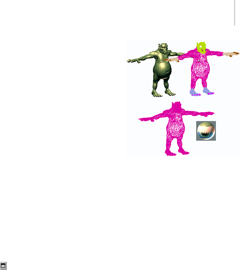
Edit Geometry Rollout (Polymesh) 1057
Collapse (Vertex, Edge, Border, and Polygon levels
only)—Collapsesgroupsofcontiguousselected
sub-objects by welding their vertices to a vertex
at the selection center.
Attach—Lets you attach another object in the scene
to the selected editable poly. You can attach any
type of object, including splines, patch objects,
and NURBS surfaces. Attaching a non-mesh
object converts it to editable-poly format. Click
the object you want to attach to the currently
selected poly object.
When you attach an object, the materials of the
two objects are combined in the following way:
• If the object being attached does not have a
material assigned, it inherits the material of the
object it is being attached to.
• Likewise, if the object you’re attaching to
doesn’thaveamaterial,itinheritsthematerial
of the object being attached.
• If both objects have materials, the resulting
new material is a multi/sub-object material
(page 2–1594) that includes the input materials.
A dialog appears offering three methods of
combining the objects’ materials and material
IDs. For more information, see Attach Options
Dialog (page 1–1018).
Attach remains active in all sub-object levels,
but always applies to objects.
Attach List—Lets you attach other objects in
thescenetotheselectedmesh.Clicktodisplaya
Select Objects dialog (page 1–78) where you choose
multiple objects to attach.
Shaded view of model (upper left); wireframe view of model
(upper right); model with objects attached (lower left); and
subsequent multi/sub-object material (lower right)
Detach (sub-object levels only)—Detaches the
selected sub–objects and the polygons attached to
them as a separate object or element. The Detach
AsCloneoptioncopiesthesub-objectsratherthan
moving them.
You’re prompted to enter a name for the new
object. Detached faces leave a hole in the original
object when you move them to a new position,
unless you use the Detach As Clone option.
Cut and Slice group
Theseknife-liketoolsletyousubdividethepoly
mesh along a plane (Slice) or in a specific area
(Cut). Also see Full Interactivity.
Slice Plane (sub-object levels only)—Creates a
gizmoforasliceplanethatyoucanpositionand
rotate to specify where to slice. Also enables the
Slice and Reset Plane buttons.
If snapping is turned off, you see a preview of the
slice as you transform the slice plane. To perform
the slice, click the Slice button.
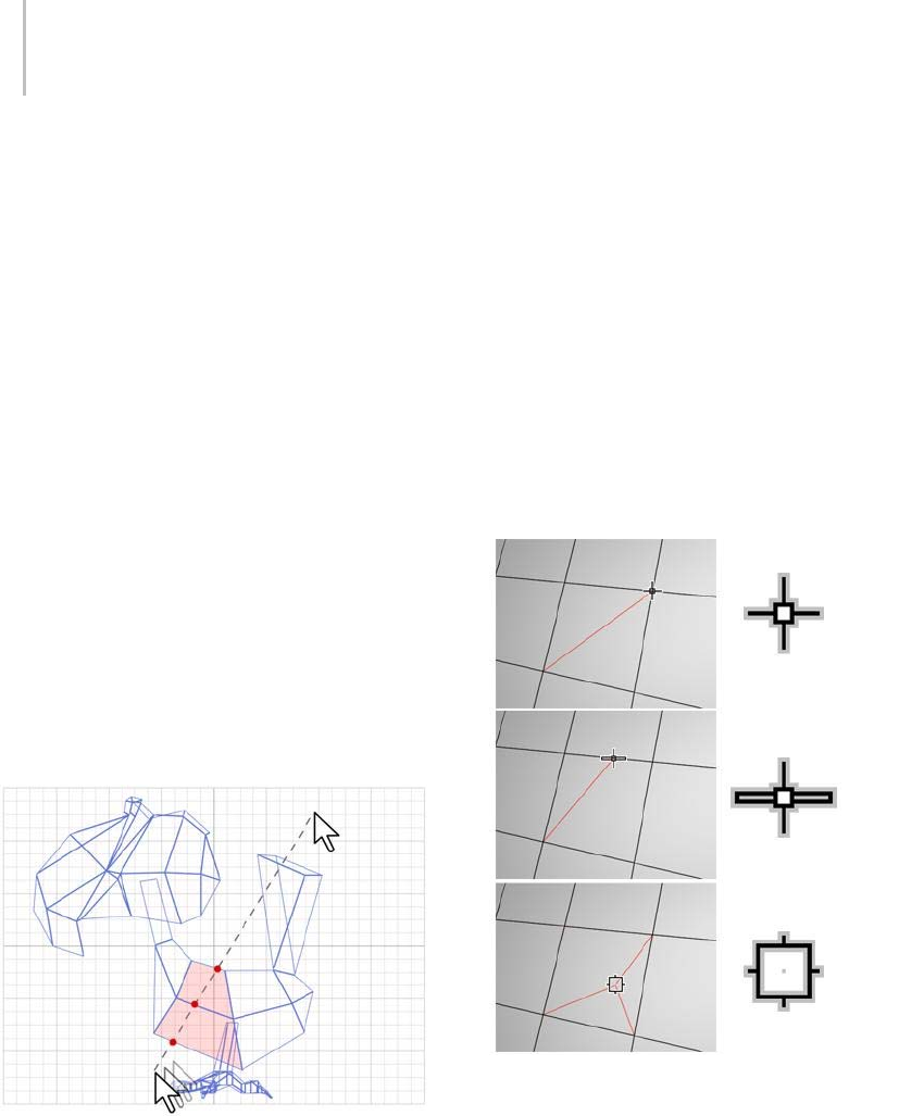
1058 Chapter 9: Surface Modeling
Split—When on, the QuickSlice and Cut
operations create double sets of vertices at the
points where the edges are divided. This lets you
easily delete the new polygons to create holes, or
animatethenewpolygonsasseparateelements.
Slice (sub-object levels only)—Performs the slice
operation at the location of the slice plane.
Available only when Slice Plane is on. This tool
slicesthepolyjustlikethe“OperateOn:Polygons”
mode of the Slice modifier (page 1–825).
Reset Plane (sub-object levels only)—Returns the
Slice plane to its default position and orientation.
Available only when Slice Plane is on.
QuickSlice—Lets you quickly slice the object
without having to manipulate a gizmo. Make a
selection, click QuickSlice, and then click once
at the slice start point and again at its endpoint.
You can continue slicing the selection while the
command is active.
To stop slicing, right-click in the viewport, or click
QuickSlice again to turn it off.
With Quickslice on, you can draw a line across your mesh in
any viewport, including Perspective and Camera views. The
mesh is sliced interactively as you move the line endpoint.
Note: At the Object level, QuickSlice affects the
entire object. To slice only specific polygons, use
QuickSliceonapolygonselectionatthePoly
sub-object level.
Note: At the Polygon or Element sub-object level,
QuickSlice affects only selected polygons. To
slice the entire object, use QuickSlice at any other
sub-object level, or at the object level.
Cut—Lets you create edges from one polygon to
another or within polygons. Click at the start
point, move the mouse and click again, and
continue moving and clicking to create new
connected edges. Right-click once to exit the
current cut, whereupon you can start a new one,
or right-click again to exit Cut mode.
Cutting to a vertex (top); cutting an edge (center); cutting a
polygon (bottom). Cut is available at the object level and all
sub-object levels.
Note: You can use Cut with Turn for enhanced
productivity. For more information, see this
procedure (page 1–1035).
MSmooth—Smoothes the object using the current
settings. This command uses subdivision
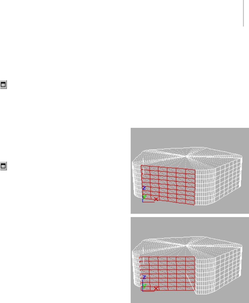
Edit Geometry Rollout (Polymesh) 1059
functionality similar to that of the MeshSmooth
modifier (page 1–722) with NURMS Subdivision,
but unlike NURMS Subdivision, it applies the
smoothing instantly to the selected area of the
control mesh.
MSmooth Settings—Opens the MeshSmooth
Selection dialog (page 1–1074),whichletsyou
specify how smoothing is applied.
Tessellate—Subdivides all polygons in the object
based on the Tessellation settings (page 1–1077).
Tessellation is useful for increasing local mesh
density while modeling. You can subdivide any
selection of polygons. Two tessellation methods
are available: Edge and Face.
Tessellate Settings—Opens the Tess el l ate
Selection dialog (page 1–1077),whichletsyou
specify how smoothing is applied.
Make Planar—Forces all selected sub-objects to be
coplanar. The plane’s normal is the average surface
normal of the selection.
At the Object level, forces all vertices in the object
to become coplanar.
Tip: One application for Make Planar is making a
flat side on an object. Normally, you would use a
contiguous selection set. If the selection includes
vertices on various parts of the object, the vertices
are still made planar, but with distorting effects on
the rest of the geometry.
X/Y/Z—Makes all selected sub-objects planar and
aligns the plane with the corresponding plane
in the object’s local coordinate system. The
planeusedistheonetowhichthebuttonaxisis
perpendicular; so, for example, clicking the X
button aligns the object with the local YZ axis.
At the Object level, makes all vertices in the object
planar.
View Align—Aligns all vertices in the object to the
planeoftheactiveviewport.Ifasub-objectmode
is active, this function affects only selected vertices
or those belonging to selected sub-objects. In the
case of orthographic viewports, using View Align
has the same effect as aligning to the construction
gridwhenthehomegridisactive.Whenaligning
to a perspective viewport (including camera and
light views), the vertices are reoriented to be
aligned to a plane that is parallel to the camera’s
viewing plane. This plane is perpendicular to
the view direction that is closest to the vertices’
average position.
Above: Selected polygons in Perspective view
Below: Same polygons aligned to Front view
Grid Align—Aligns all vertices in the selected object
to the plane of the current view. If a sub-object
mode is active, function aligns only selected
sub-objects. This function aligns the selected
vertices to the current construction plane. The

1060 Chapter 9: Surface Modeling
current plane is specified by the active viewport
in the case of the home grid. When using a grid
object, the current plane is the active grid object.
Relax—Applies the Relax function to the current
selection, using the Relax dialog settings (see
following). Relax normalizes mesh spacing by
moving each vertex toward the average location of
itsneighbors.ItworksthesamewayastheRelax
modifier (page 1–779).
Note: At the object level, Relax applies to the entire
object. At any sub-object level, Relax applies only
to the current selection.
Relax Settings—Opens the Relax dialog (page
1–1076), which lets you specify how the Relax
function is applied.
Hide Selected (Vertex, Polygon, and Element levels
only)—Hides any selected sub-objectgs.
Unhide All (Vertex, Polygon, and Element levels
only)—Restores any hidden sub-objects to
visibility.
Hide Unselected (Vertex, Polygon, and Element
levels only)—Hides any unselected sub-objects.
Named Selections (sub-object levels only)
Lets you copy and paste named selection sets of
sub-objects between objects. Start by creating one
ormorenamedselectionsets,copyone,selecta
different object, go to the same sub-object level,
and then paste the set.
Note: This function uses sub-object IDs, so if the
target object’s geometry differs from that of the
source object, the pasted selection will probably
comprise a different set of sub-objects.
For more information, see Named Selection Sets
(page 1–67).
Copy—Opens a dialog that lets you specify a
named selection set to place into the copy buffer.
Paste—Pastes the named selection from the copy
buffer.
Delete Isolated Vertices (Edge, Border, Polygon, and
Element levels only)—When on, deletes isolated
vertices when you delete a selection of contiguous
sub-objects. When off, deleting sub-objects leaves
all vertices intact. Default=on.
Full Interactivity—Toggles the level of feedback for
theQuickSliceandCuttools,aswellasallsettings
dialogs.
When on (the default), the final result is always
visibleasyouusethemousetomanipulatethe
tool or change a numeric setting. With Cut and
QuickSlice, when Full Interactivity is turned off,
only the rubber-band line is visible until you click.
Similarly, with numeric settings in dialogs, the
final result is visible only when you release the
mouse button after changing the setting.
The state of Full Interactivity doesn’t affect
changing a numeric setting from the keyboard.
Whether it’s on or off, the setting takes effect only
when you exit the field by pressing Ta b or Enter ,
or by clicking a different control in the dialog.
Subdivision Surface Rollout
(Polymesh)
Create or select an editable poly object. > Modify panel >
Subdivision Surface rollout
Applies subdivision to the object in the style of
MeshSmooth (page 1–722), so you can work on a
lower-resolution "cage" mesh and simultaneously
see a smoother, subdivided result. This rollout is
available at all sub-object levels, as well as at the
object level, and always affects the entire object.
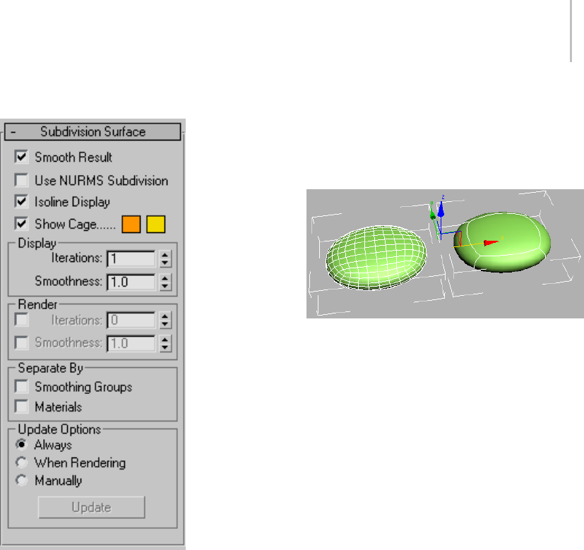
Subdivision Surface Rollout (Polymesh) 1061
Interface
Smooth Result—Applies the same smoothing
group to all polygons.
Use NURMS Subdivision—Applies smoothing
via the NURMS method. See NURMS.The
difference between NURMS in Editable Poly and
MeshSmooth is that the latter gives you access to
control vertices, but the former does not.
Youcontrolthedegreeofsmoothingwiththe
Iterations controls in the Display and Render
groups.
Note: The remaining controls on this rollout take
effect only when Use NURMS Subdivision is on.
Isoline Display—When on, the software displays
only isolines: the object’s original edges, before
smoothing. The benefit of using this option is
a less cluttered display. When off, the software
displays all faces added by NURMS Subdivision;
thus,higherIterationssettings(seeDisplay group
(page 1–1062)) result in a greater number of lines.
Default=on.
Smoothed box with Isoline Display off (left) and Isoline Display
on (right).
Note: Applying a modifier to an Editable Poly
object cancels the effect of the Isoline Display
option; the wireframe display reverts to showing
allpolygonsintheobject. Thisisnot,however,
always the case with the MeshSmooth modifier.
Most deformation and mapping modifiers
maintain the isoline display, but others, such as the
selection modifiers (except Volume Select) and the
Turn To ... modifiers, cause the interior edges to
be displayed.
Show Cage—Toggles the display of a two-color
wireframethatshowstheeditablepolyobject
before modification or subdivision. The cage
colors are shown as swatches to the right of the
check box. The first color represents unselected
sub-objects, and the second color represents
selected sub-objects. Change a color by clicking
its swatch.
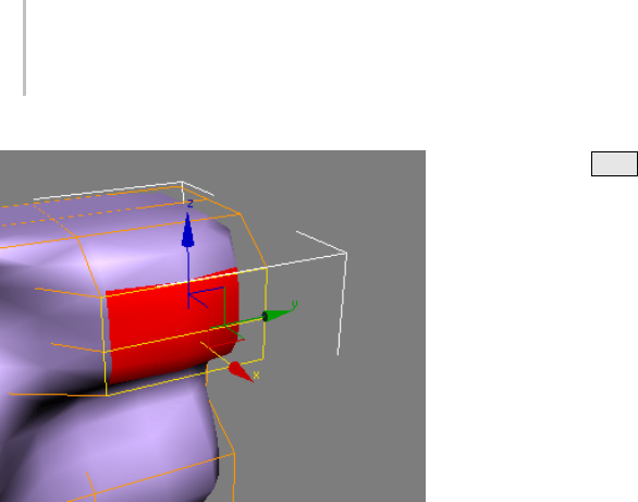
1062 Chapter 9: Surface Modeling
Thecagedisplaystheoriginalstructureoftheeditedobject.
Typically this feature is used in conjunction with
the NURMS Subdivision feature, or with the
MeshSmooth modifier (page 1–722),becauseitlets
you easily toggle visibility of the unsmoothed base
object while simultaneously viewing the smoothed
result, but it works with any modifier. When used
with a modifier, turn on Show End Result to make
Show Cage available.
Tip: Show Cage is particularly helpful when used
with the Symmetry modifier (page 1–861).
Display group
Iterations—Sets the number of iterations used to
smooth the poly object. Each iteration generates
allpolygonsusingtheverticescreatedfromthe
previous iteration. Range=0 to 10.
WhentheIterationscheckboxintheRendergroup
(see below) is off, this setting controls iterations
both in the viewports and at render time. When
thecheckboxison,thissettingcontrolsiterations
only in the viewports.
Tip: Use caution when increasing the number of
iterations. The number of vertices and polygons
in an object (and thus the calculation time) can
increase as much as four times for each iteration.
Applying four iterations to even a moderately
complex object can take a long time to calculate.
Yo u c a n p r e s s Esc to stop calculation and revert
to the previous iteration setting.
Smoothness—Determines how sharp a corner
must be before polygons are added to smooth it. A
value of 0.0 prevents the creation of any polygons.
A value of 1.0 adds polygons to all vertices even if
theylieonaplane.
When the Smoothness check box in the Render
group(seebelow)isoff,thissettingcontrols
smoothness both in the viewports and at render
time. When the check box is on, this setting
controls smoothness only in the viewports.
Render group
Applies a different number of smoothing iterations
and/or a different Smoothness value to the object
at render time.
Tip: Use a low number of iterations and/or a lower
Sharpness value for modeling, and higher values
for rendering. This lets you work quickly with
a low-resolution object in the viewports, while
producing a smoother object for rendering.
Iterations—Lets you choose a different number of
smoothingiterationstobeappliedtotheobjectat
rendertime.TurnonIterations,andthenusethe
spinnertoitsrighttosetthenumberofiterations.
Smoothness—Lets you choose a different
Smoothness value to be applied to the object at
rendertime.TurnonSmoothness,andthenuse
the spinner to its right to set the smoothness value.
Separate By group
Smoothing Groups—Prevents the creation of new
polygons at edges between faces that don’t share at
least one smoothing group.
Materials—Prevents the creation of new polygons
for edges between faces that do not share Material
IDs.
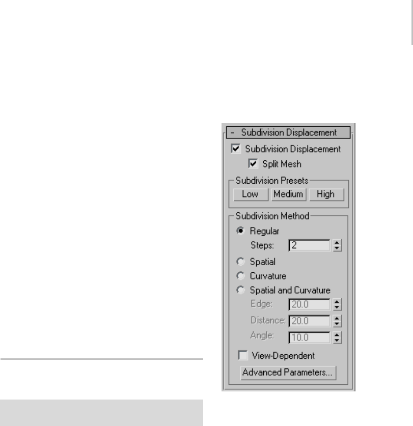
Subdivision Displacement Rollout (Polymesh) 1063
Update Options group
Setsmanualorrender-timeupdateoptions,for
situations where the complexity of the smoothed
object is too high for automatic updates. Note that
you can also choose Iterations under the Render
group to set a greater degree of smoothing to be
applied only at render time.
Always—Updates the object automatically
whenever you change any MeshSmooth settings.
When Rendering—Updates the viewport display of
theobjectonlyatrendertime.
Manually—Tur ns on m anua l upd at ing . Wh en
manual updating is selected, any settings you
change don’t take effect until you click the Update
button.
Update—Updates the object in the viewport to
matchthecurrentMeshSmoothsettings.Works
only when you choose When Rendering or
Manually.
Subdivision Displacement Rollout
(Polymesh)
Create or select an editable poly object. > Modify panel
>SubdivisionDisplacementrollout
Specifies surface approximation settings for
subdividing the editable poly. These controls work
like the surface approximation settings for NURBS
(page 1–1078) surfaces. They are used when you
apply a displacement map (page 2–1511) to the
editable poly.
Note: These settings differ from the Subdivision
Surface settings in that, while the latter are applied
at the same modifier-stack level as the mesh,
subdivision displacement is always applied at
the top of the stack, when the mesh is used for
rendering. Thus, a Symmetry modifier applied to
an object using surface subdivision would affect
thesubdividedmesh,butwouldnotaffectan
object that uses subdivision displacement only.
Interface
Subdivision Displacement—When on, polygons are
subdivided to accurately displace the poly object,
usingthemethodandsettingsyouspecifyinthe
Subdivision Presets and Subdivision Method
group boxes. When off, the poly is displaced by
moving existing vertices, the way the Displace
modifier (page 1–629) does. Default=off.
Split Mesh—Affects the seams of displaced poly
objects; also affects texture mapping. When on,
the poly object is split into individual polygons
before it is displaced; this helps preserve texture
mapping. When off, the poly is not split and an
internal method is used to assign texture mapping.
Default=on.
Tip: This parameter is required because of an
architectural limitation in the way displacement

1064 Chapter 9: Surface Modeling
mapping works. Turning Split Mesh on is usually
the better technique, but it can cause problems for
objects with clearly distinct faces, such as boxes,
or even spheres. A box’s sides might separate as
they displace outward, leaving gaps. And a sphere
might split along its longitudinal edge (found in
the rear for spheres created in the Top view) unless
you turn off Split Mesh. However, texture mapping
works unpredictably when Split Mesh is off, so
you might need to add a Displace Mesh modifier
(page 1–514) and make a snapshot (page 1–453)
of the poly. You would then apply a UVW Map
modifier (page 1–922) and then reassign mapping
coordinates to the displaced snapshot poly.
Subdivision Presets group & Subdivision
Method group
Thecontrolsinthesetwogroupboxesspecify
how the program applies the displacement map
when Subdivision Displacement is on. They are
identical to the Surface Approximation controls
(page 1–1239) used for NURBS surfaces.
Paint Deformation Rollout
Edit/Editable Poly object > Paint Deformation rollout
Paint Deformation lets you push, pull, or
otherwise affect vertices by dragging the mouse
cursor over the object surface. At the object
level, Paint Deformation affects all vertices in the
selected object. At sub-object levels, it affects only
selected vertices (or vertices that belong to selected
sub-objects), and recognizes soft selection.
By default, deformation occurs in the normal (page
3–980) direction of each vertex. 3ds Max continues
to use a vertex’s original normal for the direction
of deformation, but you can opt to use the altered
normal direction for a more dynamic modeling
process, or even deform along a specific axis.
Note: Paint Deformation cannot be animated.
Tip: You can streamline the painting process by
using the Brush Presets tools (page 3–690).
Procedure
To paint deformation onto a mesh object:
1. Apply an Edit Poly modifier (page 1–640) to
an object, or convert the object to Editable
Poly (page 1–1022) format. Paint Deformation
uses existing geometry, so the object should
have enough mesh resolution for the desired
deformation.
2. Do either of the following:
• To deform anywhere on the object, remain
at the object level, or work at a sub-object
level with no sub-objects selected.
• To deform only specific areas of an object,
go to a sub-object level and then select the
sub-objects in the area to deform.
3. On the Paint Deformation rollout, click
Push/Pull.
4. Set Push/Pull value to a negative value to push
into the object surface, or to a positive value
topullthesurfaceoutward. Thehigherthe
absolute value, the greater the effect.
5. Set Brush Size and Brush Strength.
6. Position the mouse cursor over the surface to
be deformed.
As you move the mouse, the “brush” reorients
dynamically to show the normal direction of
the portion of the mesh currently under the
cursor. You can use the normal direction of
deformed surfaces as the push/pull direction by
choosing Deformed Normals.
7. Press the mouse button and drag to deform the
surface. If you paint in the same spot repeatedly
without lifting the mouse button, the effect
is cumulative up to the maximum Push/Pull
Va l u e s e t t i n g .
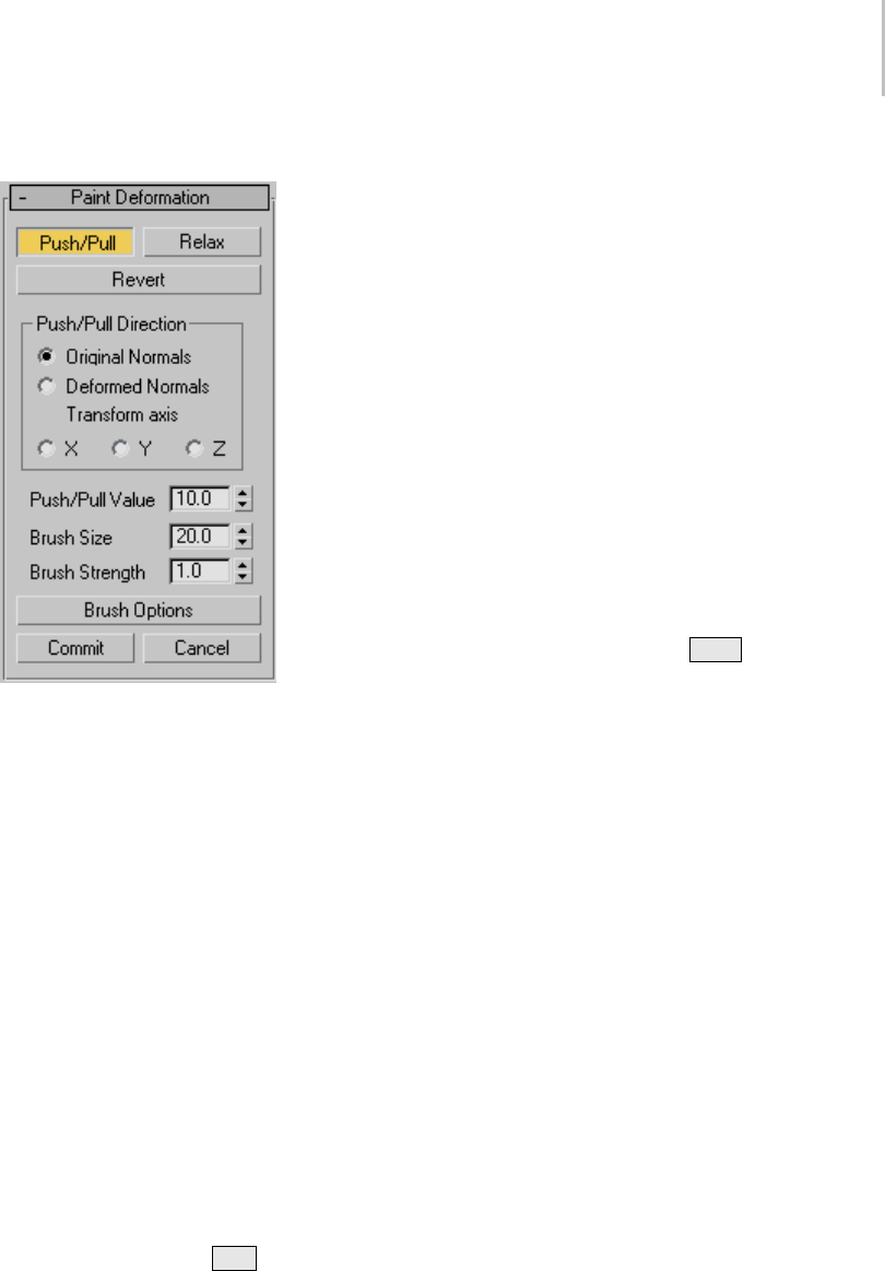
Paint Deformation Rollout 1065
Interface
PaintDeformationhasthreemodesofoperation:
Push/Pull, Relax, and Revert. Only one of these
modes can be active at a time. The remaining
settings control the effect of the active deformation
mode.
For any mode, choose the mode, change settings
as necessary, and then drag the cursor over the
object to paint the deformation.
To paint deformation anywhere on the object,
remain at the object level, or work at a sub-object
level with no sub-objects selected. To deform only
specific areas of an object, go to a sub-object level
and select the sub-objects in the area to deform.
Push/Pull—Moves vertices into the object surface
(push) or out of the surface (pull). The direction
and extent of pushing or pulling is determined by
thePush/PullValuesetting.
Tip: To reverse the Push/Pull direction while
painting, press and hold Alt .
Note: Push/Pull supports soft selection in that
effective strength falls off with the selection value
of soft-selected sub-objects.
Relax—Normalizes the distances between vertices
by moving each vertex to a position calculated
from the average of its neighbors. Relax uses the
same method as the Relax modifier (page 1–779).
Use Relax to push apart vertices that are too close
together,ortopulltogetherverticesthataretoo
far apart.
Revert—Lets you gradually “erase” or reverse the
effects of Push/Pull or Relax by painting. Affects
only vertices deformed since the most recent
Commit operation. If no vertices qualify for
reversion, the Revert button is unavailable.
Tip: You can switch to Revert mode temporarily by
pressing and holding the Ctrl key while painting
deformationinPush/PullorRelaxmode.
Push/Pull Direction group
This setting lets you specify whether pushing or
pulling vertices occurs with respect to surface
normals, original or deformed, or along a specific
axis. Default=Original Normals.
Painting deformations with Original Normals
typically moves vertices perpendicular to the
original surface; using Deformed Normals
tendstomoveverticesoutwardaftertheirinitial
deformation, resulting in a “puffy” effect.
Original Normals—When chosen, pushing or
pulling a vertex moves it in the direction of its
normal before deformation. Repeated applications
of Paint Deformation always move each vertex in
thesamedirectionitmovedoriginally.
Deformed Normals—When chosen, pushing or
pulling a vertex moves it in the current direction of
the normal; that is, after deformation.
Transform axis X/Y/Z—When chosen, pushing or
pulling a vertex moves it along the specified axis,
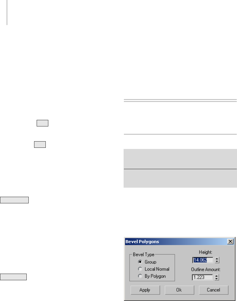
1066 Chapter 9: Surface Modeling
using the current reference coordinate system (page
1–443).
Push/Pull Value—Determines the direction and
maximum extent of a single application of the
push/pull operation. Positive values “pull” vertices
out of the object surface, and negative values
“push” vertices into the surface. Default =10.0.
A single application is defined as painting (that
is,draggingonceormoreoverthesamearea)
without lifting the mouse button.
Tip: Yo u c a n u s e Alt to switch between pushing
and pulling with the same value while painting.
For example, if you’re pulling with a value of 8.5,
press and hold Alt to start pushing with a value
of -8.5.
Brush Size—Sets the radius of the circular brush.
Onlyverticesinsidethebrushcirclearedeformed.
Default=20.0.
Tip: To change the brush radius interactively,
release the mouse button, press and hold
Shift+Ctrl +left mouse button, and then drag
the mouse. This also works with all other
painter-interface features in 3ds Max such as Skin
> Paint Weights and VertexPaint.
Brush Strength—Sets the rate at which the brush
applies the Push/Pull value. A low Strength value
applies the effect more slowly than a high value.
Range=0.0 to 1.0. Default=1.0.
Tip: To change the brush strength interactively,
release the mouse button, press and hold
Shift+Alt +left mouse button, and then drag
the mouse. This also works with all other
painter-interface features in 3ds Max such as Skin
> Paint Weights and VertexPaint.
Brush Options—Click this button to open the
Painter Options dialog (page 1–960),whereyou
can set various brush-related parameters.
Commit—Makes any deformation changes
permanent, “baking” them into the object
geometry. After using Commit, you can no longer
apply Revert to changes up to that point.
Cancel—Eliminates all changes since the initial
application of Paint Deformation or the most
recent Commit operation.
Editable Poly Settings
Dialogs
Bevel Polygons Dialog
Select an Edit Poly or editable poly object. > Modify panel
> Polygon sub-object level > Edit Polygons rollout > Bevel
Settings button
Select an Edit Poly or editable poly object. > Polygon
sub-object level > Quad menu > tools 2 quadrant > Bevel
Settings button
Beveling involves first extruding and then scaling
the extruded polygon(s). Use these settings for
beveling polygons in Interactive Manipulation
mode.
Interface
Bevel Type group
Group—Beveling takes place along the average
normal of each contiguous group of polygons. If
you bevel multiples of such groups, each group
moves along its own averaged normal.
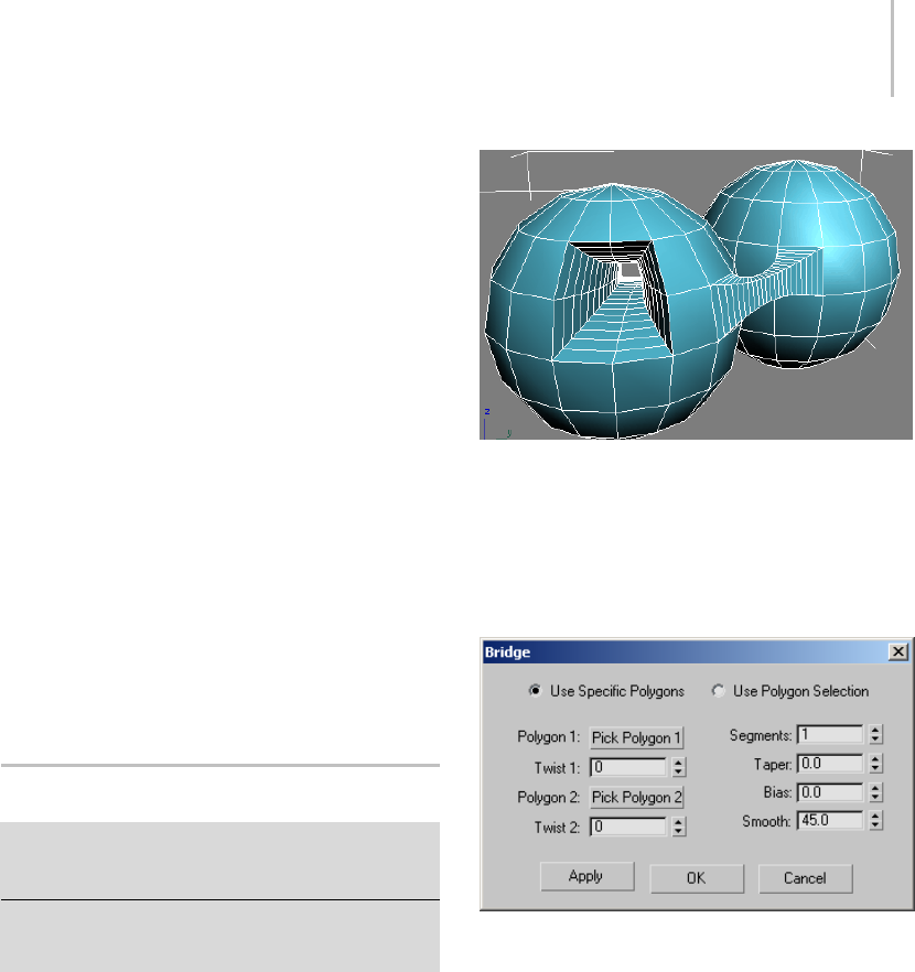
Bridge Borders/Polygons Dialog 1067
Local Normal—Beveling takes place along each
selected polygon’s normal.
By Polygon—Bevels each polygon individually.
Height—Specifies the extent of the extrusion in
scene units. You can extrude selected polygons
outward or inward, depending on whether the
value is positive or negative.
Outline Amount—Makes the outer border of
selected polygons bigger or smaller, depending on
whether the value is positive or negative.
Apply—Applies the settings to the current
selection, retaining them if you then make another
selection.
OK—Applies the settings to the current selection
and closes the dialog.
Cancel—Closes the dialog without applying the
settings to the current selection. Does not reverse
previous uses of Apply.
Bridge Borders/Polygons Dialog
Select an Edit Poly or editable poly object. > Modify panel
> Polygon or Border sub-object level > Edit Polygons
rollout > Bridge Settings button
Select an Edit Poly or editable poly object. > Polygon or
Border sub-object level > Quad menu > tools 2 quadrant
> Bridge Settings button
Use these settings for bridging pairs of polygons,
polygon selections, or borders in Interactive
Manipulation mode.
Note: Bridge calculates which way the bridge
polygons should face. If you bridge two
sub-objects so that the bridge goes through the
object, the bridge polygons face inward. But if you
create a bridge that goes through empty space,
such as when connecting sub-objects between two
elements, the polygons face outward. To make
thebridgepolygonsfacedifferently,usetheFlip
function.
Examples of an internal bridge (left) and an external bridge
(right), the latter connecting two elements
Note: Bridging two elements makes them
contiguous, combining them into a single element.
Interface
Bridge lets you use existing poly/border selections,
or pick them from the dialog. Choose one of the
following:
Use Specific Polygons/Borders—In this mode, use
the Pick buttons to designate polygons or borders
for bridging.
Use Polygon/Border Selection—If one or more
qualifying selection pairs exist, choosing this
option connects them immediately. If not, you can
select pairs of sub-objects in a viewport to connect
them.
Ifyoumakemorethantwoqualifyingselections,
Bridge connects them in increasing order of ID.

1068 Chapter 9: Surface Modeling
For example, if you select polygon 12, 35, and 89,
Bridge connects polygons 12 and 35. But if you
then deselect polygon 35, Bridge then connects
polygons 12 and 89.
Polygon/Edge 1/2—Click each Pick button in turn,
andthenclickapolygonorborderedgeina
viewport. At the Border sub-object level, clicking
anyedgeonaborderdesignatestheentireborder
for bridging. Also, the edges you pick on each
border are connected directly, and the remaining
edges are connected in consecutive order. You can
change the order of the edge correspondences with
the Twist settings. Available only in Use Specific
mode.
After clicking a sub-object, the Pick button shows
its ID number. You can change the selection at
anytimebyclickingaPickbuttonandpickinga
different sub-object.
Twist 1/2—Rotates the order of connection
between the edges of the two selections. The two
controlsletyousetadifferenttwistamountfor
each end of the bridge.
Segments—Specifies the number of polygons
along the length of the bridge connection. This
setting also applies to manually bridged polygons.
Tip: When using Taper, set Segments to a value
greater than 1.
Taper—Sets the extent to which the bridge width
becomes smaller or larger toward its center.
Negative settings taper the bridge center smaller;
positive settings taper it larger.
Note: To change the location of maximum taper,
use the Bias setting.
Bias—Determines the location of maximum taper
amount.
The range of the Bias value is -99.0 to 99.0. At the
default value of 0.0, the taper amount is greatest
at the center of the bridge. At -99.0, the taper
amount is greatest near the first selected polygon
or border; at 99.0, it’s greatest near the second
selected polygon or border.
Smooth—Determines the maximum angle between
columnsacrosswhichsmoothingcanoccur. A
column is a string of polygons extending along the
length of the bridge.
Apply—Applies the settings to the current
selection, retaining them if you then make another
selection.
OK—Applies the settings to the current selection
and closes the dialog.
Cancel—Closes the dialog without applying the
settings to the current selection. Does not reverse
previous uses of Apply.
Bridge Edges Dialog
Select an Edit Poly or editable poly object. > Modify panel
> Polygon or Border sub-object level > Edit Polygons
rollout > Bridge Settings button
Select an Edit Poly or editable poly object. > Polygon or
Border sub-object level > Quad menu > tools 2 quadrant
> Bridge Settings button
Use these settings for bridging pairs of edges in
Interactive Manipulation mode.
Note: Bridge calculates which way the bridge
polygons should face. If you bridge two edges
so that the bridge goes through the object, the
bridge polygons face inward. But if you create a
bridge that goes through empty space, such as
when connecting edges between two elements,
the polygons face outward, in general. To make
thebridgepolygonsfacedifferently,usetheFlip
function.
Note: Bridging edges of two elements makes them
contiguous, combining them into a single element.
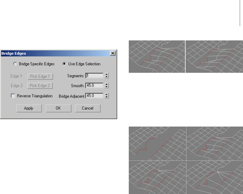
Bridge Edges Dialog 1069
Interface
Bridge lets you use existing edge selections, or pick
them from the dialog. Choose one of the following:
Bridge Specific Edges—In this mode, use the Pick
buttons to designate polygons or borders for
bridging.
UseEdgeSelection—If one or more qualifying
selection pairs exist, choosing this option connects
them immediately. If not, you can select pairs of
sub-objects in a viewport to connect them.
Edge 1/Edge 2—Click each Pick button in turn, and
then click a border edge in a viewport. Available
only in Bridge Specific Edges mode.
After clicking an edge, the Pick button shows its ID
number. You can change the selection at any time
by clicking a Pick button and picking a different
sub-object.
Segments—Specifies the number of polygons
along the length of the bridge connection. This
setting also applies to manually bridged edges.
Smooth—Specifies the maximum angle between
columnsacrosswhichsmoothingcanoccur. A
column is a string of polygons extending along the
length of the bridge.
Reverse Triangulation—When bridging two
edge selections each of which contains different
numbers of edges, two ways of triangulating the
bridge polygons are possible. This check box lets
you toggle between them.
Left: Reverse Triangulation on
Right: Reverse Triangulation off
Bridge Adjacent—Specifies the minimum angle
between adjacent edges across which bridging
can occur. Edges less than this angle will not be
bridged, and instead will be skipped.
Top Left: Edge selections before bridging
Top Right: Segments=2, Bridge Adjacent<83.0
Bottom Left: Bridge Adjacent=83.0
Bottom Right: Bridge Adjacent=126.5
Note: The above illustration shows, among other
things, how setting Bridge Adjacent too high can
cause overlapping polygons (left side of the two
bottom images), which is undesirable.
Apply—Applies the settings to the current
selection, retaining them if you then make another
selection.
OK—Applies the settings to the current selection
and closes the dialog.
Cancel—Closes the dialog without applying the
settings to the current selection. Does not reverse
previous uses of Apply.
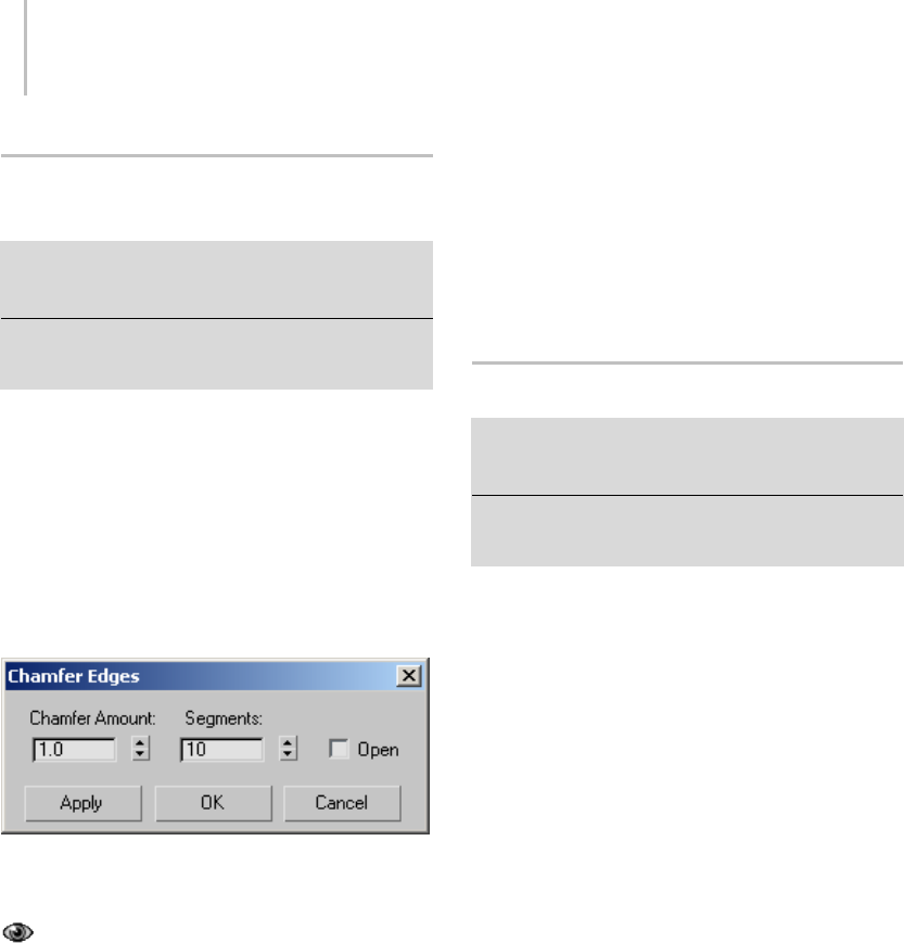
1070 Chapter 9: Surface Modeling
Chamfer Vertices/Edges/Borders
Dialog
Select an Edit Poly or editable poly object. > Modify
panel > Vertex/Edge/Border sub-object level > Edit
Vertices/Edges/Borders rollout > Chamfer Settings button
Select an Edit Poly or editable poly object. >
Vertex/Edge/Border sub-object level > Quad menu >
tools 2 quadrant > Chamfer Settings button
Chamfering creates new faces around the
chamfered entity, along with connecting edges.
Or,withtheOpenoption,youcancreateanopen
(empty)areainstead.Thisdialogisthesamefor
chamfering vertices, edges, and borders of poly
objects.Youcanuseittosetthechamferamount
numerically, and to toggle the Open option.
Interface
Chamfer Amount—The extent of the chamfer.
Default=1.0.
Segments—(edges only) Adds edges and
polygons over the area of the chamfer, and, with
single chamfered edges, rounds off the chamfer. By
default, the chamfer uses a single segment, which
covers the chamfered area with a new polygon
positioned diagonally with respect to the original
corner. The higher the Segments value you use,
the more the chamfer is rounded off.
If you chamfer two or more adjacent, open edges
at a time, the rounding off takes place only at open
ends of the edges. No rounding takes place where
the edges meet.
Open—When on, the chamfered area is deleted,
leaving open space. Default=off.
This setting stays active during the current session.
IfyouturnonOpenandthenlaterchamfer
sub-objects interactively, the Open option remains
in effect.
Connect Edges Dialog
Select an Edit Poly or editable poly object. > Modify panel
> Edge sub-object level > Edit Edges rollout > Connect
Settings button
Select an Edit Poly or editable poly object. > Edge
sub-object level > Quad menu > tools 2 quadrant >
Connect Settings button
Connecting edges creates new edges between
adjacent pairs of selected edges. The Connect
Edgesdialogsettingsletyouspecifythenumberof
new edges, the amount of separation from each
other, and their general location.
Tip: Connecting edges, and in particular the Slide
function, work best with ring selections.
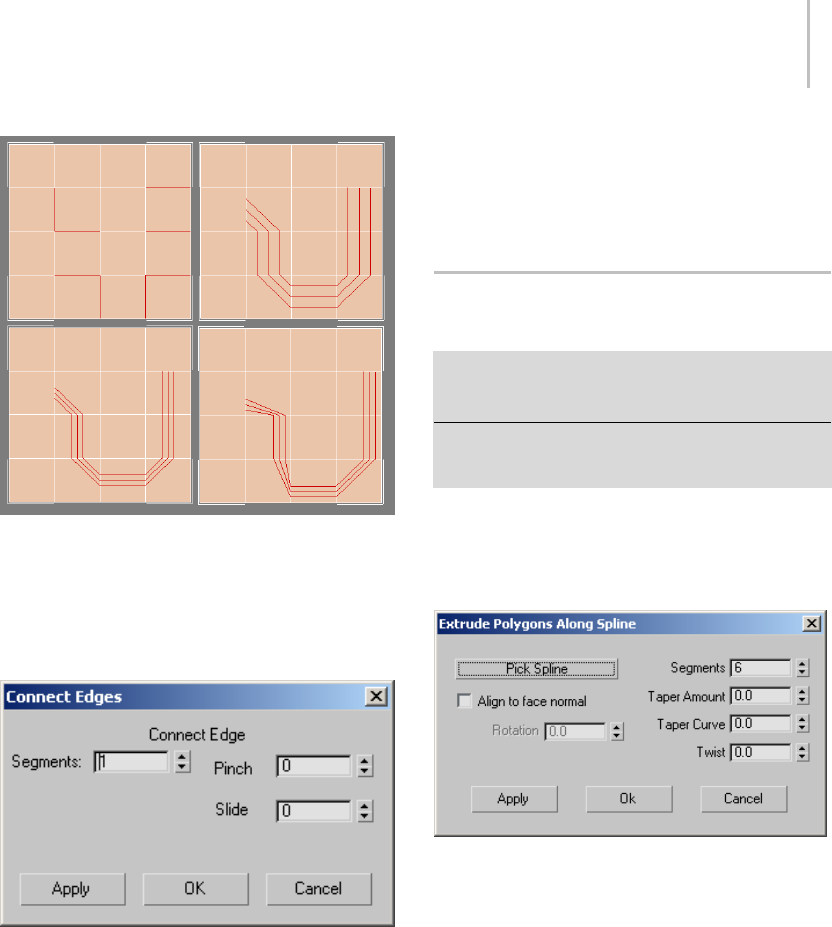
Extrude Polygons Along Spline Dialog 1071
Top left: Original edge selection
Top right: Segments=3, Pinch=Slide=0
Bottom left: Segments=3, Pinch=-50, Slide=0
Bottom right: Segments=3, Pinch=-50, Slide=–200
Interface
Segments—The number of new edges between
each adjacent pair of selected edges. Default=1.
Pinch—Therelativespacingbetweenthenew,
connecting edges. Negative values move the edges
closer together; positive values move them farther
apart. Default=0.
If Segments=1, the Pinch setting has no effect.
Slide—Therelativepositioningofthenewedges.
Default=0.
By default, the new edges are centered. Positive
values move them in one direction, while negative
values move them in the opposite direction. The
new edges cannot move beyond existing edges.
Extrude Polygons Along Spline
Dialog
Select an Edit Poly or editable poly object. > Modify panel
> Polygon sub-object level > Edit Polygons rollout >
Extrude Along Spline Settings button
Select an Edit Poly or editable poly object. > Polygon
sub-object level > Quad menu > tools 2 quadrant >
Extrude Along Spline Settings button
Use these settings for extruding polygons along
splines in Interactive Manipulation mode.
Interface
Pick Spline—Click this button and then select a
spline along which to extrude in the viewport. The
spline object’s name then appears on the button.
If you open this dialog after performing a manual
Extrude Along Spline, the name of the spline you
used appears on the button.
Align to face normal—Aligns the extrusion with
the face normal, which, in most cases, makes it
perpendicular to the extruded polygon(s). When
turned off (the default), the extrusion is oriented
thesameasthespline.
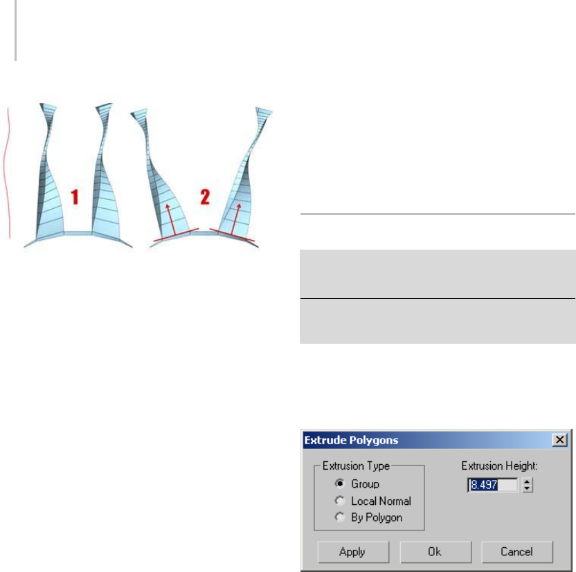
1072 Chapter 9: Surface Modeling
WithAlignToFaceNormal,theextrusiondoesnotfollowthe
original orientation of the spline (1); it’s reoriented to match
the face normals (2), or averaged normals for contiguous
selections. The Rotation option is available only when Align
To Face Normal is on.
Rotation—Sets the rotation of the extrusion.
Available only when Align To Face Normal is on.
Default=0. Range=-360 to 360.
Segments—Specifies the number of polygons
into which each extruded side is subdivided.
This setting also applies to manually extruded
polygons.
Taper Amount—Sets the extent to which the
extrusion becomes smaller or larger along its
length. Negative settings taper the extrusion
smaller; positive settings taper it larger.
Taper Curve—Setstherateatwhichthetapering
proceeds. Lower settings result in a more gradual
taper;largesettingsresultinamoreabrupttaper.
TaperCurveaffectsthethicknessoftheextrusion
between its endpoints, but not the size of the ends.
Twist—Applies a twist along the length of the
extrusion.
When using this option, increasing the number
of segments will improve the smoothness of the
extrusion.
Apply—Applies the settings to the current
selection, retaining them if you then make another
selection.
OK—Applies the settings to the current selection
and closes the dialog.
Cancel—Closes the dialog without applying the
settings to the current selection. Does not reverse
previous uses of Apply.
Extrude Polygons Dialog
Select an Edit Poly or editable poly object. > Modify
panel > Polygon sub-object level > Edit Polygons rollout
> Extrude Settings button
Select an Edit Poly or editable poly object. > Polygon
sub-object level > Quad menu > tools 2 quadrant >
Extrude Settings button
Use these settings for extruding polygons in
Interactive Manipulation mode.
Interface
Extrusion Type group
Group—Extrusion takes place along the average
normal of each contiguous group of polygons. If
you extrude multiples of such groups, each group
moves along its own averaged normal.
Local Normal—Extrusion takes place along each
selected polygon’s normal.
By Polygon—Extrudes or bevels each polygon
individually.
Extrusion Height—Specifies the amount of the
extrusioninsceneunits.Youcanextrudeselected
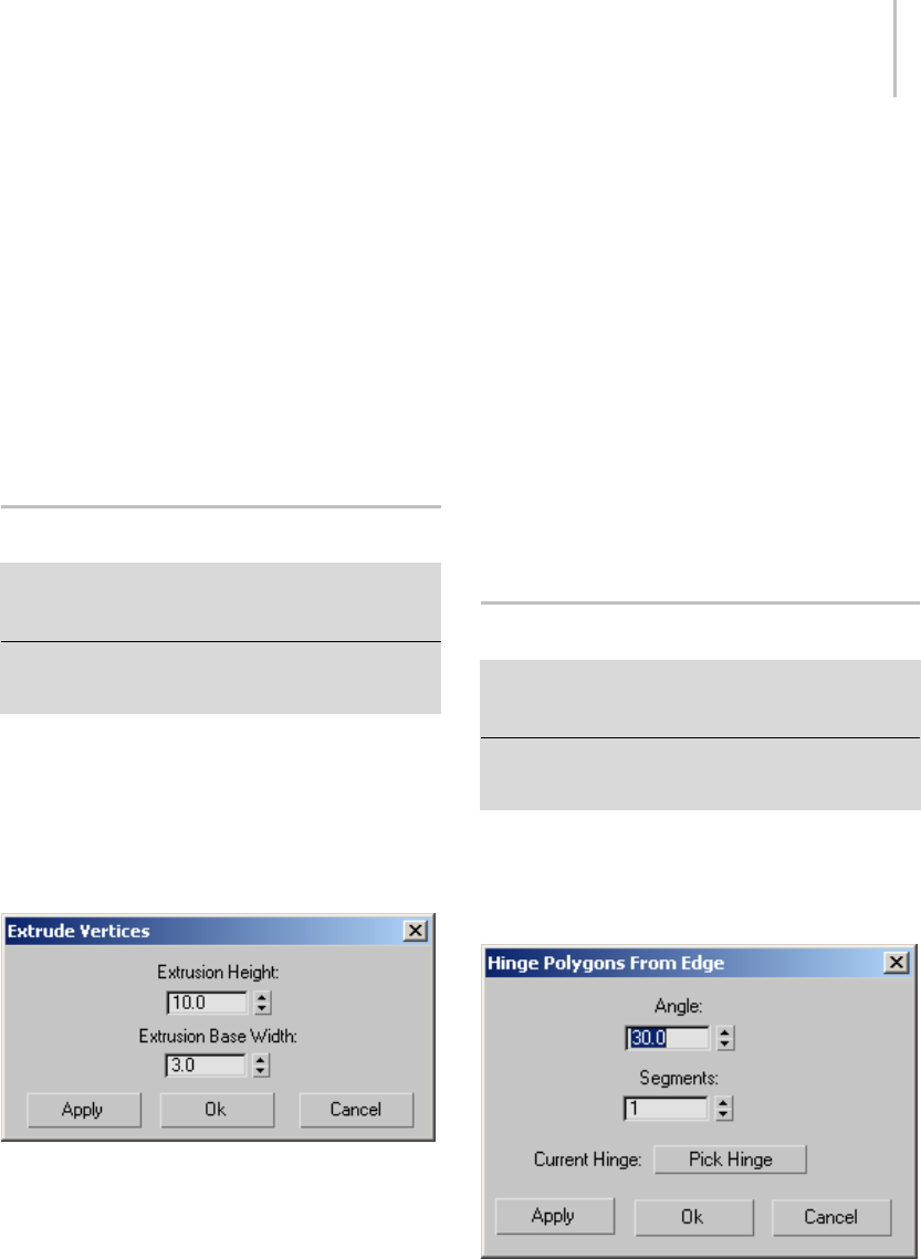
Extrude Vertices/Edges Dialog 1073
polygons outward or inward, depending on
whether the value is positive or negative.
Apply—Applies the settings to the current
selection, retaining them if you then make another
selection.
OK—Applies the settings to the current selection
and closes the dialog.
Cancel—Closes the dialog without applying the
settings to the current selection. Does not reverse
previous uses of Apply.
Extrude Vertices/Edges Dialog
Select an Edit Poly or editable poly object. > Modify
panel > Vertex/Edge/Border sub-object level > Edit
Vertices/Edges/Borders rollout > Extrude Settings button
Select an Edit Poly or editable poly object. >
Vertex/Edge/Border sub-object level > Quad menu >
tools 2 quadrant > Extrude Settings button
Use this dialog for extruding vertices, edges, and
borders in Interactive Manipulation mode.
Note: At the Border sub-object level, this dialog is
named Extrude Edges.
Interface
Extrusion Height—Specifies the amount of the
extrusioninsceneunits.
You can extrude sub-objects outward or inward,
depending on whether the value is positive or
negative.
Extrusion Base Width—Specifies the size of the
extrusionbaseinsceneunits.
Youcansetthisashighasyouwant,buttheactual
size cannot extend beyond the vertices adjacent to
the extruded sub-object(s).
Apply—Applies the settings to the current
selection, retaining them if you then make another
selection.
OK—Applies the settings to the current selection
and closes the dialog.
Cancel—Closes the dialog without applying the
settings to the current selection. Does not reverse
previous uses of Apply.
Hinge Polygons From Edge Dialog
Select an Edit Poly or editable poly object. > Modify
panel > Polygon sub-object level > Edit Polygons rollout
> Hinge From Edge Settings button
Select an Edit Poly or editable poly object. > Polygon
sub-object level > Quad menu > tools 2 quadrant > Hinge
From Edge Settings button
Use these settings for hinging polygons in
Interactive Manipulation mode.
Interface
Angle—Quantifies the rotation about the hinge.
You can hinge selected polygons outward or
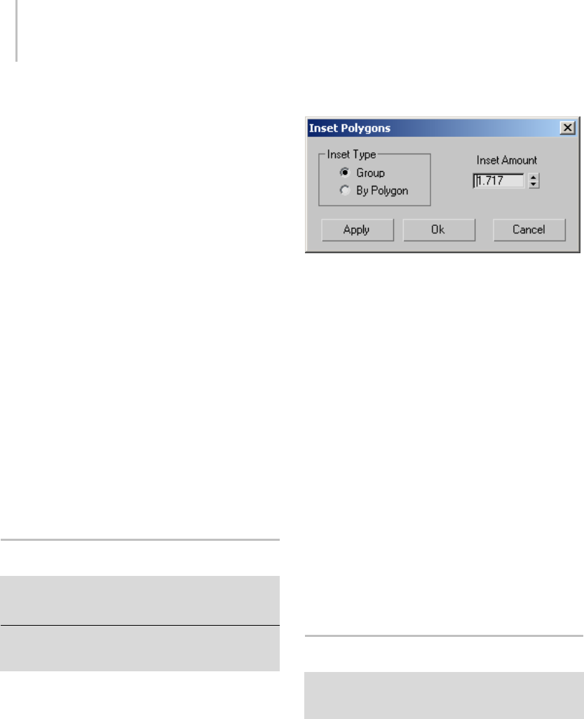
1074 Chapter 9: Surface Modeling
inward, depending on whether the value is positive
or negative.
Segments—Specifies the number of polygons into
which each extruded side is subdivided. This
setting also applies to manually hinged polygons.
Current Hinge—Click Pick Hinge, and then click an
edge to be the hinge. After you designate a hinge,
the “Pick Hinge” button text is replaced with “Edge
#”where#istheIDnumberofthehingeedge.
All subsequent hinge operations created via the
dialog will use this hinge. To hinge multiple
polygons, each from one of its own sides, you must
reselect the hinge each time.
Apply—Applies the settings to the current
selection, retaining them if you then make another
selection.
OK—Applies the settings to the current selection
and closes the dialog.
Cancel—Closes the dialog without applying the
settings to the current selection. Does not reverse
previous uses of Apply.
Inset Polygons Dialog
Select an Edit Poly or editable poly object. > Modify panel
> Polygon sub-object level > Edit Polygons rollout > Inset
Settings button
Select an Edit Poly or editable poly object. > Polygon
sub-object level > Quad menu > tools 2 quadrant > Inset
Settings button
Use these settings for insetting polygons in
Interactive Manipulation mode.
Interface
Inset Type group
This setting affects how Inset works with selections
of more than one polygon.
Group—The inset takes place across multiple,
contiguous polygons.
By Polygon—Insets each polygon individually.
Inset Amount—Specifies the amount of the inset
in scene units.
Apply—Applies the settings to the current
selection, retaining them if you then make another
selection.
OK—Applies the settings to the current selection
and closes the dialog.
Cancel—Closes the dialog without applying the
settings to the current selection. Does not reverse
previous uses of Apply.
MeshSmooth Selection Dialog
Select an Edit Poly or editable poly object. > Modify panel
> Polygon sub-object level > Edit Geometry rollout >
MSmooth Settings button
This dialog lets you specify how mesh smoothing
affects editable poly and Edit Poly objects.
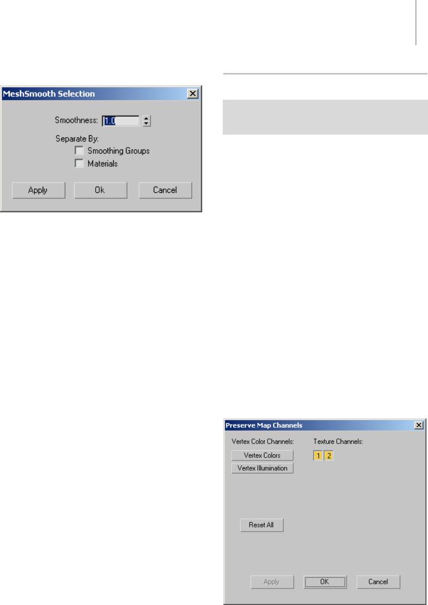
Preserve Map Channels Dialog 1075
Interface
Smoothness—Determines how sharp a corner
must be before polygons are added to smooth it.
Smoothness is calculated as the average angle of
all edges connected to a vertex. A value of 0.0
prevents the creation of any polygons. A value of
1.0addspolygonstoallverticeseveniftheylieon
aplane.
Separate by Smoothing Groups—Prevents the
creation of new polygons at edges between
polygons that don’t share at least one smoothing
group.
Separate by Materials—Prevents the creation of
new polygons for edges between polygons that do
not share Material IDs.
Apply—Applies the settings to the current
selection, retaining them if you then make another
selection.
OK—Applies the settings to the current selection
and closes the dialog.
Cancel—Closes the dialog without applying the
settings to the current selection. Does not reverse
previous uses of Apply.
Preserve Map Channels Dialog
Select an Edit Poly or editable poly object. > Modify panel
> any sub-object level > Edit Geometry rollout > Preserve
UVs button
Use these settings for specifying which map
channels to preserve when editing sub-objects
with the Preserve UVs option on. A preserved
map channel doesn’t respond to minor editing that
changes vertex locations, but a channel whose UVs
aren’t preserved allows mapping to be changed by
changes in vertex locations.
Interface
Thedialogcontainsbuttonsforallavailable,
data-containing vertex color channels and texture
channels. The number and type of buttons
displayed vary depending on the state of the
object; they can be changed, for example, with the
VertexPaint modifier (page 1–936) and the Channel
Info utility (page 2–1738).
Click a button to toggle its state. When off, a
button is gray and appears higher than the dialog
surface. When on, a button is orange and appears
pressed in.
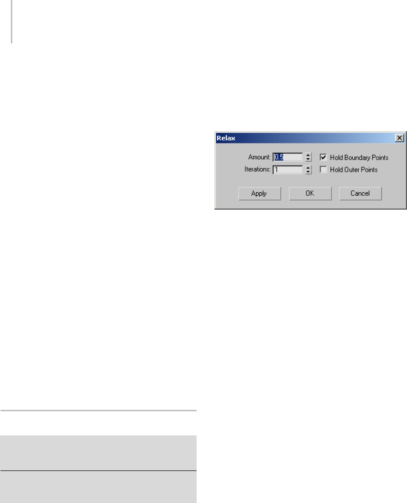
1076 Chapter 9: Surface Modeling
Vertex Color Channels—Displays buttons for any
vertex-color channels that contain data. These can
be Vertex Colors, Vertex Illumination, and Vertex
Alpha. By default, all vertex-color buttons are off,
so that associated UVs are affected by sub-object
editing. To prevent a channel from being affected
by sub-object editing, click its button.
Texture Channels—Displays buttons for any texture
(mapping)channelsthatcontaindata.Theseare
identified by number. By default these are on, so
that associated UVs are not affected by sub-object
editing. To allow a channel to be affected by
sub-object editing, click its button.
Reset All—Returns all channel buttons to their
default states: all vertex color channels off, all
texture channels on.
Apply—Applies the settings to the current
selection, retaining them if you then make another
selection.
OK—Applies the settings to the current selection
and closes the dialog.
Cancel—Closes the dialog without applying the
settings to the current selection. Does not reverse
previous uses of Apply.
Relax Dialog
Select an Edit Poly or editable poly object. > Modify panel
> object level or any sub-object level > Edit Polygons
rollout > Relax Settings button
Select an Edit Poly or editable poly object. > object level
or any sub-object level > Quad menu > tools 2 quadrant
> Relax Settings button
Use these settings for relaxing vertices in
Interactive Manipulation mode. Relax in
Edit/Editable Poly works much like the Relax
modifier (page 1–779): It normalizes the distance
between each affected vertex and its neighbors by
moving the vertex toward the average position of
its neighbors.
Note: At the object level, Relax applies to the entire
object. At any sub-object level, Relax applies to
selected sub-objects only.
Interface
Amount—Controls how far a vertex moves for each
iteration. The value specifies a percentage of the
distance from the original location of a vertex to
the average location of its neighbors. Range=-1.0
to 1.0. Default=0.5.
Iterations—Sets how many times to repeat the
Relax process. For each iteration, average locations
arerecalculatedandtheRelaxValueisreappliedto
every vertex. Default=1.
Hold Boundary Points—Controls whether
vertices at the edges of open meshes are moved.
Default=on.
When on, boundary vertices do not move while
the rest of the object is relaxed. This option is
particularly useful when working with multiple
elements within a single object that share open
edges.
When this check box is off, all vertices of the object
are relaxed.
Hold Outer Points—When on, preserves the
original positions of vertices farthest away from
the object center.
Apply—Applies the settings to the current
selection, retaining them if you then make another
selection.
OK—Applies the settings to the current selection
and closes the dialog.
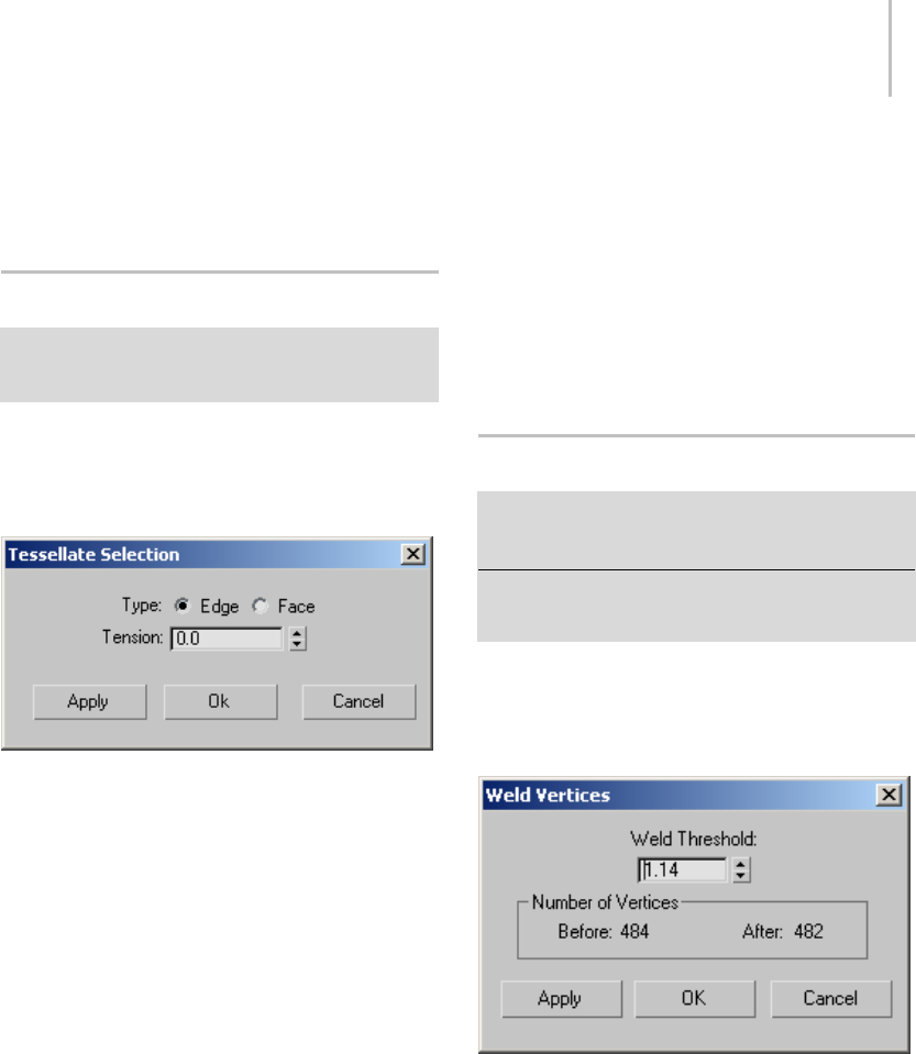
Tessellate Selection Dialog 1077
Cancel—Closes the dialog without applying the
settings to the current selection. Cancel does not
reverse previous uses of Apply.
Tessellate Selection Dialog
Select an Edit Poly or editable poly object. > Modify panel
> Polygon sub-object level > Edit Polygons rollout >
Tessellate Settings button
This dialog lets you specify how Tessellate should
subdivide polygons.
Interface
Edge—Inserts vertices in the middle of each edge
and draws lines connecting those vertices. The
number of polygons created will equal the number
of sides of the original polygon.
Face—Adds a vertex to the center of each polygon
and draws connecting lines from that vertex to the
original vertices. The number of polygons created
will equal the number of sides of the original
polygon.
Tension—Lets you increase or decrease the Edge
tension value. Available only when Type: Edge is
active.
A negative value pulls vertices inward from their
plane, resulting in a concave effect. A positive
value pulls vertices outward from their plane,
resultinginaroundingeffect.
Apply—Applies the settings to the current
selection, retaining them if you then make another
selection.
OK—Applies the settings to the current selection
and closes the dialog.
Cancel—Closes the dialog without applying the
settings to the current selection. Does not reverse
previous uses of Apply.
Weld Vertices/Edges Dialog
Select an Edit Poly or editable poly object. > Modify panel
> Vertex or Edge sub-object level > Edit Vertices/Edges
rollout > Weld Settings button
Select an Edit Poly or editable poly object. > Vertex or
Edge sub-object level > Quad menu > tools 2 quadrant >
Weld Settings button
Use this dialog for setting the weld threshold for
vertices and edges.
Interface
Weld Threshold—Specifies the maximum distance,
in scene units, within which selected sub-objects
will be welded.
Any vertex or edge that lies outside this threshold
(that is, it’s farther than this from the nearest
vertex or edge) will not be welded.
Number of Vertices—Shows the number of vertices
before and after the weld.
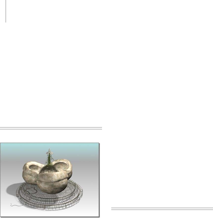
1078 Chapter 9: Surface Modeling
The After quantity updates dynamically as you
change the setting with the spinner.
Apply—Applies the settings to the current
selection, retaining them if you then make another
selection.
OK—Applies the settings to the current selection
and closes the dialog.
Cancel—Closes the dialog without applying the
settings to the current selection. Does not reverse
previous uses of Apply.
NURBS
Fountain created as a NURBS model
3dsMaxprovidesNURBSsurfacesandcurves.
NURBS stands for Non-Uniform Rational
B-Splines.NURBShavebecomeanindustry
standard for designing and modeling surfaces.
They are especially suited for modeling surfaces
with complicated curves. The tools for modeling
with NURBS do not require an understanding
of the mathematics that produces these objects.
NURBS are popular because they are easy
to manipulate interactively, and because the
algorithms that create them are both efficient and
numerically stable.
You can also model surfaces using polygonal
meshes or patches. Compared to NURBS surfaces,
meshes and patches have these shortcomings:
• Using polygons can make it more difficult to
create complicated curved surfaces.
• Because meshes are faceted, facets appear at the
edge of rendered objects. You must have a large
number of small faces to render a smoothly
curved edge.
NURBS surfaces, on the other hand, are
analytically generated. They are more efficient to
calculate, and you can render a NURBS surface
that appears to be seamless. (A rendered NURBS
surface is actually approximated by polygons,
but the NURBS approximation can be very fine
grained.)
NURBS Models: Objects and Sub-Objects (page
1–1078)
NURBS and Modifiers (page 1–1089)
NURBS and Animation (page 1–1091)
NURBS Concepts (page 1–1091)
Working with NURBS
Models
Like Shape (page 1–262) objects, a NURBS
model can be an assemblage of multiple NURBS
sub-objects. For example, a NURBS object might
contain two surfaces that are separate in space.
NURBS curves and NURBS surfaces are controlled
by either point or control vertex (CV) sub-objects.
Points and CVs behave somewhat like the vertices
of spline objects, but there are differences.
The parent object in a NURBS model is either a
NURBS surface or a NURBS curve. Sub-objects
canbeanyoftheobjectslistedhere. ANURBS

Creating NURBS Models 1079
curve remains a Shape object unless you add a
surfacesub-objecttoitwhenyouconvertittoa
NURBS surface (without changing its name).
Surfaces—There are two kinds of NURBS surfaces.
Apoint surface (page 1–1102) is controlled by
points, which always lie on the surface. A CV
surface (page 1–1103) is controlled by control
vertices (CVs). Instead of lying on the surface, CVs
form a control lattice (page 3–923) that surrounds
the surface. (This is similar to the lattice used by
the FFD [free-form deformation] modifiers.)
See Creating Surface Sub-Objects (page 1–1177)
and Editing Surface Sub-Objects (page 1–1141).
Curves—There are also two kinds of NURBS
curves. These correspond exactly to the two
kinds of surfaces. A point curve (page 1–1106) is
controlled by points, which always lie on the curve.
ACV curve (page 1–1110) is controlled by CVs,
which don’t necessarily lie on the curve.
See Creating Surface Sub-Objects (page 1–1177)
and Editing Curve Sub-Objects (page 1–1135).
Points—Point surfaces and point curves have point
(page 1–1219) sub-objects. You can also create
separate point sub-objects that are not part of a
surface or a curve.
See Creating and Editing Point Sub-Objects (page
1–1219).
CVs—CV surfaces and CV curves have CV
sub-objects. Unlike points, CVs are always part
of a surface or a curve.
See Editing Curve CV Sub-Objects (page 1–1127)
and Editing Surface CV Sub-Objects (page 1–1130).
Imports—Imports are 3ds Max objects, including
other NURBS objects. Within the NURBS model,
they render as NURBS; but they retain their
original parameters and modifiers.
See Attaching and Importing 3ds Max Objects (page
1–1120).
Sub-objects can be dependent (page 1–1087)
sub-objects whose geometry is related to the
geometry of other sub-objects.
See also
Creating NURBS Models (page 1–1079)
Working with NURBS Models (page 1–1080)
Modifying NURBS Models and Creating
Sub-Objects (page 1–1081)
Sub-Object Selection (page 1–1084)
CV Sub-Objects and Point Sub-Objects (page
1–1085)
Rigid Surfaces (page 1–1089)
Dependent Sub-Objects (page 1–1087)
Nonrelational NURBS Surfaces (page 1–1116)
Creating NURBS Models
There are a variety of ways to create NURBS
models. This is a summary of how you create a
top-level, parent NURBS object:
•YoucancreateaNURBS curve (page 1–1106)
on the Shape (page 1–262) panel of the Create
panel.
•YoucancreateaNURBS surface (page 1–1101)
on the Geometry (page 1–153) panel of the
Create panel. When you use this technique, the
NURBS surface is initially a flat rectangle. You
can alter it using the Modify panel.
• Youcanturnastandard geometry primitive
(page 1–170) into a NURBS object.
•Youcanturnatorus knot (page 1–189) into a
NURBS object.
•Youcanturnaprism (page 1–205) extended
primitive into a NURBS object.
• Youcanturnaspline (page 1–266) object
(Bezier spline) into a NURBS object.

1080 Chapter 9: Surface Modeling
• Youcanturnapatch grid (page 1–993) object
(Bezier patch) into a NURBS object.
• Youcanturnaloft (page 1–352) object into a
NURBS object.
To turn objects other than NURBS curves and
surfaces into NURBS objects, use the Modify
panel. Right-click the object’s name in the stack
display (see Modifier Stack (page 3–760))and
choose Convert To: NURBS.
In viewports, the quad menu (page 3–694) also
lets you convert objects to NURBS. Select and
then right-click the object, and in the Transform
(lower-right) quadrant, choose Convert To: >
Convert to NURBS.
• In addition, the modifiers Extrude (page 1–680)
and Lathe (page 1–707) let you choose NURBS
output, which creates a NURBS object.
Working with NURBS Models
When you work with NURBS models, usually you
follow these overall steps:
• Create one NURBS object as the "starter"
object. This can be a surface object, a curve
object, or a converted geometry primitive, as
described in Creating NURBS Models (page
1–1079).
Often modelers like to identify a single, master
surface as the main component of the model.
Converted geometry primitives are good if you
wantthestartersurfacetobecomethemaster
surface. See Creating NURBS Surfaces from
Geometric Primitives (page 1–1116).Pointand
CV surfaces are good as starters for rectangular
surfaces.
•OntheModifypanel,youcanedittheoriginal
object, or you can create additional sub-objects.
See Using the NURBS Toolbox to Create
Sub-Objects (page 1–1083).
You might even choose to delete the original,
starter object once you have built a model from
newer sub-objects.
Going immediately to the Modify panel avoids the
problem of creating additional top-level NURBS
objects, which you can’t use to build relational,
dependent sub-objects. (The exception is using
curves for loft and sweep surfaces. See ULoft
Surface (page 1–1196),UV Loft Surface (page
1–1200),1-Rail Sweep Surface (page 1–1204),or
2-Rail Sweep Surface (page 1–1209).)
Two general references for modeling with NURBS
are Curves and Surfaces for Computer-Aided
Geometric Design: A Practical Guide by Gerald
Farin (Academic Press, fourth edition 1996) and
Interactive Curves and Surfaces: A Multimedia
Tutor ial on Com puter Aided Gra phi c Desig n by
Alyn Rockwood and Peter Chambers (Morgan
Kaufman Publishers, 1996).
Surface Trimming
To trim a surface is to use a curve on the surface
tocutawaypartofthesurface,ortocutaholein
the surface.
Before you trim a surface, you must create a curve
onthatsurface.Thesearethekindsofcurvesthat
can trim surfaces:
•U iso and V iso curves (page 1–1168)
•Surface-surface intersection curve (page 1–1166)
•Normal projected curve (page 1–1169)
•Vector projected curve (page 1–1171)
•CV curve on surface (page 1–1172)
•Point curve on surface (page 1–1175)
Once you’ve created the curve, you trim the surface
by turning on Trim in the curve sub-object’s
parameters. A Flip Trim control inverts the trim
direction.
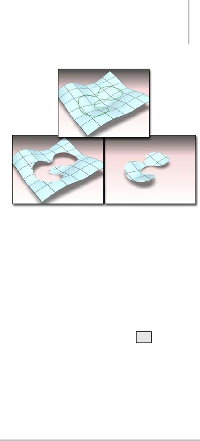
Modifying NURBS Models and Creating Sub-Objects 1081
The direction of the curve determines the
initial direction of the trim. For example, a
closed curve on surface created in a clockwise
direction trims inward, creating a hole in the
surface; while a closed curve on surface created
in a counterclockwise direction trims outward,
creating a curve-shaped portion of the surface.
When a surface is trimmed, its untrimmed version
is still present in the 3ds Max scene. You can select
itforthepurposesofeditingit,orreplacingitasa
parent to a dependent sub-object (page 1–1087).To
do so, use the Select Objects dialog. See Sub-Object
Selection (page 1–1084).
Procedures
Example: To cut a hole in a CV surface:
1. Create a CV surface in the Top viewport.
2. Create a closed CV curve sub-object that lies on
top of (or above) the surface.
3. In the toolbox, turn on Normal Projected
Curve, then in the Top viewport select first the
CV curve, then the surface.
This creates a projection of the CV curve that
lies on the surface, and can trim it.
4. In the normal projected curve’s parameters,
click to turn on Trim.
Aholeappearsinthesurface. Dependingon
the orientation of the Normal Projected curve,
you might see everything but the hole.
5. UsetheFlipTrimtoggletoinvertthetrim.
Note: Trims aren’t displayed in viewports if the
NURBS surface’s Surface Trims toggle is turned
off on the General rollout’s Display group box.
Above: CV curve on surface
Below left: Using the curve to trim the surface
Below right: Using Flip Trim to change the trimming
direction
To select an untrimmed surface:
1. Make sure the Keyboard Shortcut Override
toggle (page 3–872) is on.
2. At the appropriate sub-object level or during a
replace parent operation, press H.ASelect
Objects dialog (page 1–78) appears.
3. If the untrimmed version is selectable at this
level, the trimmed version appears as a "tree,"
with a plus sign next to it. Click the plus sign to
expandthetree. Thechildistheuntrimmed
version. Highlight its name to select it.
Modifying NURBS Models and
Creating Sub-Objects
You can edit NURBS immediately when you
enter the Modify panel. You don’t have to apply
a modifier, as you do for most kinds of 3ds Max
objects.
WhileyouareeditingaNURBSobjectonthe
Modify panel, you can create sub-objects "on the
fly," without having to go back to the Create panel.
This is an exception to the way you usually use
3ds Max. The Modify panel for NURBS curve and
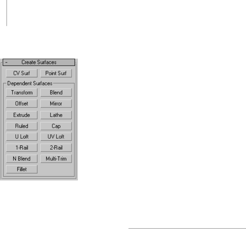
1082 Chapter 9: Surface Modeling
NURBSsurfaceobjectsincludesrolloutsthatlet
you create new NURBS sub-objects.
Example: Rollout for creating NURBS surface sub-objects
Tip: Another way to create curve and surface
sub-objects is to use the NURBS Creation Toolbox
(page 1–1083).
This is a summary of how to create sub-objects:
• An individual point sub-object is either an
independent point or a dependent point tied to
other NURBS geometry.
• Curve sub-objects are either independent point
curves or CV curves, or they are dependent
(page 3–928) curves whose geometry is based
on other curves or surfaces already present in
the model. For example, a blend curve is a
dependent curve sub-object that connects the
endpoints of two other curves.
• Surface sub-objects are either independent
point surfaces or CV surfaces, or they are
dependent (page 3–928) surfaces whose
geometry is based on other surfaces or curves
already present in the model. For example, a
blend surface is a dependent surface sub-object
thatconnectstheedgesoftwoothersurfaces.
• You can attach 3ds Max objects. If the attached
object is not already a NURBS object, it is
converted to NURBS geometry. You can attach
a NURBS curve, another NURBS surface, or
aconvertible3dsMaxobject. Theattached
object becomes one or more curve or surface
sub-objects.
• You can import 3ds Max objects. The imported
object retains its parameters. While it is part
oftheNURBSobjectitrendersasaNURBS,
but you can still edit it parametrically at the
Imports sub-object level. At this sub-object
level,viewportsdisplayitsusualgeometry,
not its NURBS form. A NURBS curve can
import NURBS curves or spline curves. A
NURBS surface can import curves, surfaces, or
convertible 3ds Max objects.
Note: Yo u c a n d e t a c h a N U R B S s u b - o bj e c t t o
make it a new, top-level NURBS object, and
you can extract an imported object to create an
independent, top-level object once again.
Quad Menu for NURBS Objects
While a NURBS object is selected and the Modify
panel is active, the quad menu (page 3–694)
displays two quadrants that are specifically for
NURBS editing.
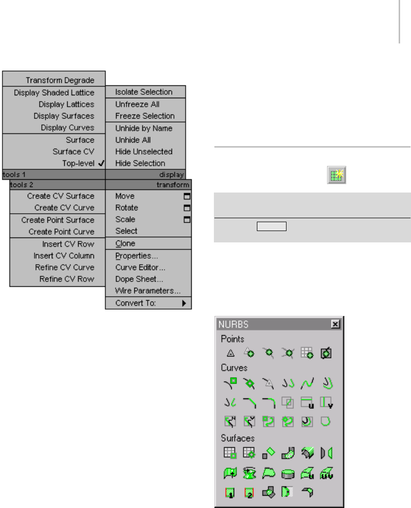
Using the NURBS Toolbox to Create Sub-Objects 1083
Quad menu for modifying NURBS models
Tools 1 (upper-left) Quadrant
These options are general display and sub-object
level shortcuts.
Transform Degrade—To g g l e s Degradation Override
(page 1–34).
Display Shaded Lattice, Display Lattices, Display
Surfaces, and Display Curves—See Display Controls
for NURBS Models (page 1–1117).
Sub-objects—Displays the sub-object choices for
the selected object, as well as a Top-level choice.
Tools 2 (lower-left) Quadrant
Theseoptionsarecreationandeditingshortcuts.
Create CV Surface, Create CV Curve, Create Point
Surface, Create Point Curve—Thesecreateanew
NURBS sub-object.
Insert CV Row, Insert CV Column, Refine CV Curve,
Refine CV Row—These add CVs to a CV Surface
sub-object by inserting or refining. For the
difference between inserting and refining, see
Editing Surface CV Sub-Objects (page 1–1130).
See NURBS Concepts (page 1–1091) for more
information about refining.
Using the NURBS Toolbox to
Create Sub-Objects
Modify panel > Select NURBS object. > General rollout >
NURBS Creation Toolbox button
Keyboard > Ctrl+T (Keyboard Shortcut Override Toggle
must be on.)
Besides using rollouts at the NURBS object
level, you can use the NURBS toolbox to create
sub-objects.
Interface
Toolbox for NURBS objects
The toolbox contains buttons for creating NURBS
sub-objects. In general, the toolbox behaves like
this:
• While the button is on, the toolbox is visible
whenever a NURBS object or sub-object is

1084 Chapter 9: Surface Modeling
selected and you are on the Modify panel. It
disappears whenever you deselect the NURBS
object or make a different panel active. When
you return to the Modify panel and select a
NURBS object, it reappears.
• You can use the toolbox to create sub-objects
from either the top, object level, or from any
NURBS sub-object level.
• When you turn on a toolbox button, you go into
creation mode, and the Modify panel changes
to show the parameters (if there are any) for the
kind of sub-object you are creating.
Other NURBS rollouts aren’t displayed while
you create the new sub-object. This differs from
using the NURBS object’s Create rollouts or the
NURBS right-click menu (page 1–1082).
• If you are at the top, object level and use the
toolbox to create a sub-object, you must then
go to the sub-object level to edit the new
sub-object. (This is the same as using the
buttons on the rollouts.)
• Ifyouareatasub-objectlevelandusethe
toolbox to create an object of the same
sub-object type, you can edit it immediately
after you turn off the create button (or
right-click to end object creation).
• Ifyouareatasub-objectlevelandusethe
toolbox to create an object of a different
sub-object type, you must change to that
sub-object level before you can edit the new
sub-object.
The individual creation buttons are described in
these topics:
Creating and Editing Point Sub-Objects (page
1–1219)
Creating Curve Sub-Objects (page 1–1151)
Creating Surface Sub-Objects (page 1–1177)
Sub-Object Selection
When you work with NURBS models, you often
work with sub-objects. While you are at the
sub-object level, you use the usual selection
techniques, such as clicking, dragging a region,
or holding down Ctrl , to choose one or more
sub-objects.
You can also select NURBS point, curve, and
surface sub-objects by name. Turn on the
Keyboard Shortcut Override Toggle (page 3–872),
go to a NURBS sub-object level, and then press the
Hkey. This displays a Select Objects dialog (page
1–78) that lists only sub-objects at the current
level.Chooseoneormoreobjectsinthelist,and
then click Select. You can assign your own names
to NURBS sub-objects (aside from CVs) that you
want to edit frequently.
Press Ctrl+H to have the Select Sub-Objects
dialog list only sub-objects directly beneath the
mouse cursor.
The Hshortcut is also a convenient way to choose
parent objects while you’re creating dependent
sub-objects.
Workflow Tips
When you work with NURBS, you switch
frequently between the object and sub-object
levels, or from one sub-object level to another.
Keyboard shortcuts and pop-up menus can help
you do this.
• The Sub-Object Selection Toggle (default:
Ctrl+B ) switches between object and
sub-object levels.
• The Cycle Sub-Object Level shortcut (default:
Insert )switchesfromonesub-objectlevelto
another.
• When you right-click in a viewport while a
NURBS object is selected and the Modify
panel is active, the quad menu lets you switch
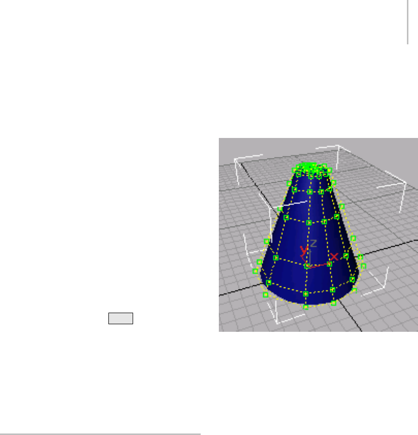
CV Sub-Objects and Point Sub-Objects 1085
between various levels of the NURBS model:
Top Level, Surface CV Level, Surface Level,
Curve CV Level, Point Level, Curve Level, and
Imports Level.
• The command panel’s right-click popup menu
(available whenever the mouse cursor becomes
a pan hand) helps you navigate the rollouts on
the current command panel.
If you have a three-button or wheel mouse,
rolling the wheel scrolls the command panel.
• Sub-object selection sets are persistent. If you
go to a different sub-object level, when you
return to the previous level, your selection is
still available. However, refining or inserting
points or CVs makes the sub-object selection
sets invalid for that object.
• You can move a sub-object selection set among
sub-objects at the active level of the NURBS
model by holding down Ctrl while you press
the arrow keys.
• When you select surface CV sub-objects that are
"on top of" each other in a 3D view, sometimes
all the selected CVs fail to highlight. To fix this,
choose Customize > Viewport Configuration
(page 3–853),andturnonZ-bufferWireframe
Objects.
CV Sub-Objects and Point
Sub-Objects
Independent curves and independent surfaces
both come in two varieties: they are either CV
sub-objects or point sub-objects. This topic
describes the differences between the two.
CV Curves and CV Surfaces
CV curves and CV surfaces have control vertices
(CVs)asdosplines. ThepositionoftheCVs
controls the shape of the curve or the surface.
However, unlike spline vertices, CVs don’t
necessarilylieonthecurveorsurfacetheydefine.
The CVs define a control lattice (page 3–923) that
connects the CVs and surrounds the NURBS
curve or surface. The control lattice displays in
lines that are yellow by default.
Cone-shaped NURBS surface with its control lattice (CVs are
displayed as green squares)
Tip: When you use Zoom Extents, the entire extents
of a NURBS object are displayed, including its
control lattice. Because CVs can be located some
distance from an object, the curve or surface itself
(the object’s renderable geometry) is sometimes
hard to see. If this happens, use Zoom Region or
Field of View to zoom in.
YoucanmoveaCVattheCurveCVorSurface
CV sub-object level on the Modify panel. Other
transforms, rotate and scale, work as well. Rotate
and scale are useful mainly when you have selected
multiple CVs.
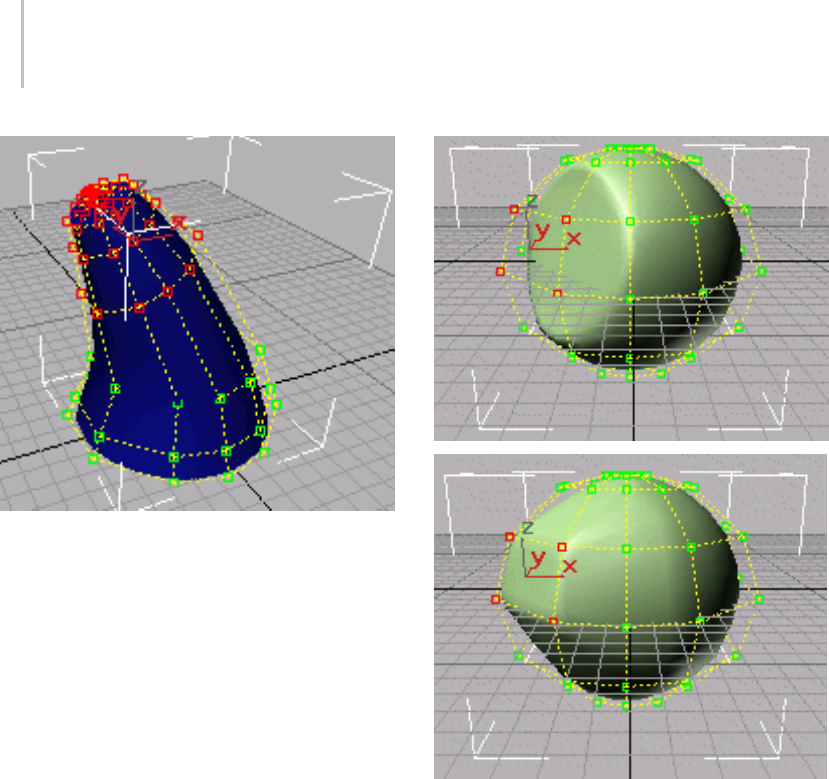
1086 Chapter 9: Surface Modeling
Moving and rotating CVs to change a surface (selected CVs are
displayed in red)
Each CV also has a weight, which you can use
toadjusttheCV’seffectonthecurveorsurface.
Increasing the weight pulls the surface toward the
CV. Decreasing the weight relaxes the surface away
from the CV.
Above: Weights=0.0
Below: Weights=40.0
Changing a spherical surface by decreasing or increasing the
weight of four CVs (selected CVs are at the left, in red)
We i g ht s c a n b e a u s e f u l w ay t o " t u ne " t h e
appearance of a NURBS curve or surface.
The weight value of a CV is rational (as in a
"rational number"). That is, it is relative to other
CVs in the curve or surface. Changing the weight
of all CVs at once has no effect, because it doesn’t
change the ratio between weights.
Points,PointCurves,andPointSurfaces
PointcurvesandpointsurfacesaresimilartoCV
curves and surfaces, but the points that control
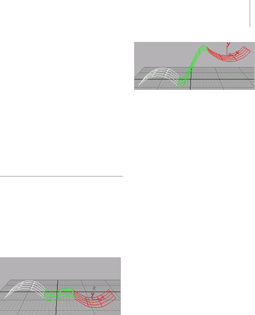
Dependent Sub-Objects 1087
them are required to lie on the curve or surface.
Unlike CVs, points do not have a weight.
Point curves and point surfaces can be more
intuitive to create and work with. However,
workingwithpointsub-objectsisslowerthan
working with CV sub-objects. You can think of a
point curve or point surface as being dependent
on the points to which it fits.
Points that you create individually are the same as
the points on point curves and surfaces, except that
initially they aren’t part of a curve or surface. You
cancreateapointcurvebyfittingittopointsthat
you select. When you fit the new point curve, you
can use points that are part of curves or surfaces,
and individual point sub-objects.
Dependent Sub-Objects
NURBS sub-objects are either independent or
dependent. A dependent sub-object is based on
the geometry of other sub-objects. For example,
a blend surface smoothly connects two other
surfaces. Transforming or animating either of
the original, parent surfaces causes the shape of
the blend to change as it maintains a connection
between the parents.
Moving a parent surface changes the blend surface (the blend
surface is displayed in green)
The immediate, interactive relation between the
parent and dependent sub-objects is known as
relational modeling. Relational modeling is one of
the reasons NURBS models can be particularly
easy to change or to animate.
Important: Dependent sub-objects must have
parents that are also sub-objects of the same NURBS
model. Dependent relationships can’t exist between
object-level NURBS curves or surfaces. If you want to use
a top-level NURBS object to create a dependent object,
first you must attach or import the top-level object. See
Attaching and Importing 3ds Max Objects (page 1–1120).
You have the option of making a dependent
sub-object independent. After you do so, the
sub-object is no longer related to its parents.
Changestotheformerparentsdon’taffectit,but
you can edit and transform it as an independent
sub-object in its own right.
At the appropriate sub-object level, dependent
NURBS are displayed in green in wireframe
viewports. (You can change the display color using
the Colors panel of the Customize User Interface
dialog (page 3–792).)
Relational modeling does add computation time to
a model, so when you transform or edit dependent
sub-objects in other ways, often you will notice
aslowdowninperformance. Onceadependent
surface sub-object has the shape you want, you
can improve performance by making it into a rigid
surface (page 1–1089).
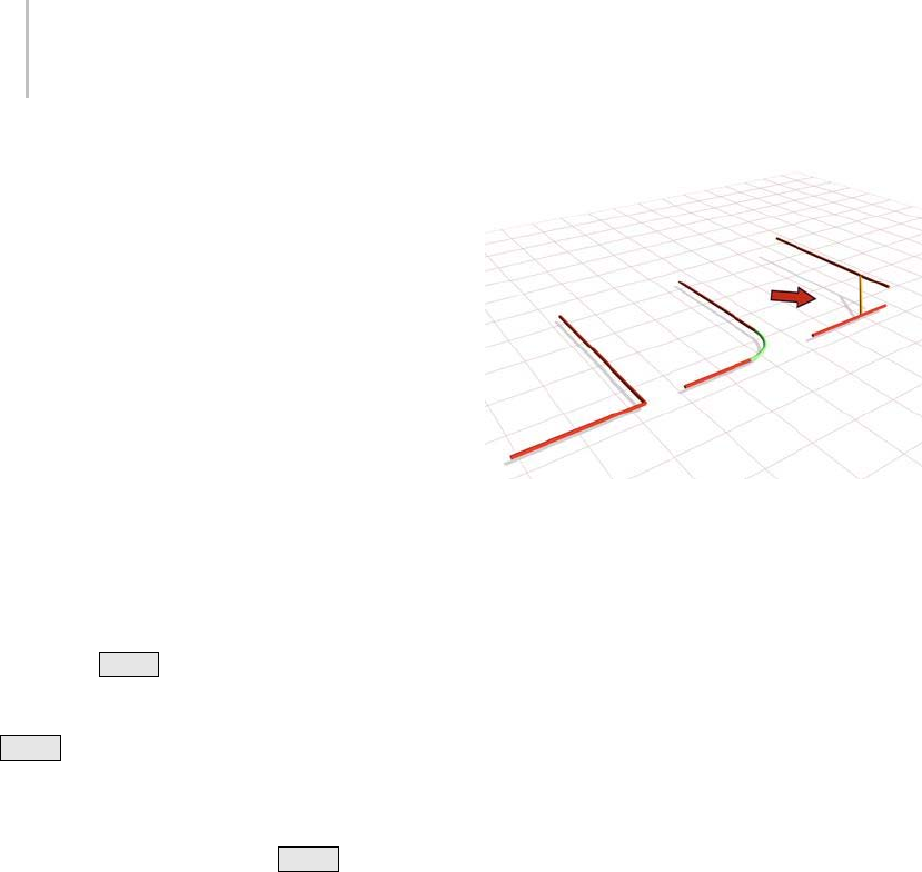
1088 Chapter 9: Surface Modeling
Transforming Dependent Sub-Objects
In general, you can select and transform
dependent sub-objects, but the effect of the
transform depends on the sub-object type. Some
dependent objects have a gizmo, similar to the
gizmo used with modifiers. Sub-objects that don’t
havegizmoscan’tchangerelativetotheirparent
objects. For these kinds of sub-objects, transforms
apply equally to the sub-object and its parents.
For example, moving a blend sub-object moves its
parentsaswell.Sub-objectsthathavegizmoscan
change relative to their parent objects. In this case,
as with modifiers that use gizmos, you are really
transforming the gizmo. For example, rotating a
mirror sub-object changes the mirror axis, and
therefore the mirror’s position relative to its parent
curve or surface.
When you Shift +Clone (page 1–1237) a
dependent NURBS sub-object, by default the
parent objects are also cloned. For example, if you
Shift +Clone a UV loft, all the lofting curves are
copied as well. This means that the new object has
thesametypeastheoriginalobject.Thecloned
object keeps its parents, so you can edit it just as
you do the original. When you Shift +Clone a
NURBS sub-object, you can also choose to remove
dependencies in order to improve performance.
Error Condition for Dependent
Sub-Objects
Sometimes changes you make to the parent objects
make it no longer possible to correctly update
the dependent object’s geometry. For example, a
fillet between two curves requires the curves to be
coplanar. If you move one curve (or its CVs or
points)sothatthecurvesarenolongercoplanar,
thefilletcannotupdatecorrectly.Inthiscase,the
dependent object’s geometry reverts to a default
position, and it is displayed in orange to indicate
an error condition. (You can change the error
color using the Colors panel (page 3–799) of the
Customize User Interface dialog (page 3–792).)
The arrow points to the segment indicating an error condition.
Seed Values
Some kinds of dependent sub-objects depend on
geometrythatmighthavemorethanonesolution.
For example, if you want to create a surface-curve
intersection point, and the curve intersects the
surfacemorethanonce,thesoftwaremustdecide
which intersection is to be the location of the point.
For these kinds of objects, seed value (page 3–1008)
parameters control the decision. The seed location
is on a parent object, and the software chooses the
location nearest to the seed value that satisfies the
creation condition. You can alter the seed value
whenyoueditthesedependentsub-objects.The
seed location is displayed as a yellow square.
For example, the seed location for a surface-curve
intersection point is a U position along the length
oftheparentcurve.Thesurface-curveintersection
closest to the seed is chosen as the location of the
dependent point.
TheseedlocationforasurfaceisapairofUV
coordinates in the surface’s parameter space (page
3–988).
Replacing Parent Sub-Objects
Dependent sub-objects have controls that let
you replace the object or objects on which they
depend. For example, Offset Surface has a button

Rigid Surfaces 1089
called Replace Base Surface. You can click this
button and then click a different surface to act as
thebaseoftheoffset.
This capability lets you replace a trimmed surface
with its untrimmed version, or vice versa. To
do so, you need to use the Select Objects dialog
(page 1–78). For example, select the trimmed
surface sub-object and turn on the Keyboard
Shortcuts Override toggle (page 3–872).Clickthe
replacement button, press the Hkey, expand the
surface’s tree, and then highlight the name of the
untrimmed version.
Rigid Surfaces
To i m p ro ve p e r f or m a n c e , y o u c a n m a k e a n y k i n d
of surface sub-object into a rigid surface. The only
editing allowed on a rigid surface is to transform
it at the Surface sub-object level. You can’t move
arigidsurface’spointsorCVs,orchangethe
number of points or CVs.
Rigid surfaces reduce the amount of memory
used by the NURBS model. Making surfaces rigid
improves performance, especially for large and
complex models.
When a surface is rigid, you can’t see its points
or CVs when you are at the Point or Surface CV
sub-object levels. If the model has only rigid
surfaces and no point curves, the Point and Surface
CV sub-object levels aren’t available at all.
Tomakearigidsurfaceeditableagain,clickMake
Point, Make Independent, Make Loft, or Convert
Surface.
NURBS and Modifiers
In general, you can apply modifiers to NURBS
modelsasyoudotootherobjects.
Yo u c a n a p p l y Edit Patch (page 1–638) and Edit
Mesh (page 1–634) modifiers to NURBS surface
objects.
Tip: To improve performance while you animate
your scene, make the surfaces in your NURBS
model nonrelational surfaces (page 1–1116).
Modifiers treat nonrelational surfaces as if they
were independent CV surfaces: you can animate
the scene more efficiently, and then turn relational
modeling back on before you render.
Deforming NURBS Objects
Deform modifiers such as Bend (page 1–560)
and Twist (page 1–876) operate on CV and point
sub-objects. They don’t change the NURBS model
into an editable mesh object. This means that
youcanuseadeformmodifier,collapsethestack,
and still have a NURBS object that you can edit
further. However, because the deform modifiers
directly affect CVs and points (and not the mesh
approximation of the NURBS model), they can
produce unexpected results. For example, a Ripple
(page 1–783) modifier does not ripple the surface
if the CVs are farther apart than the wavelength
of the ripples. If you want the modifier to affect
the mesh approximation instead of the CVs, you
can apply a Mesh Select (page 1–719) modifier
first. Then when you collapse the stack, you get an
editable mesh, not a NURBS object.
These are the deform modifiers that collapse to
NURBS:
• Modifiers in the Parametric Modifiers set,
except for Lattice (which collapses to an
editable mesh) and Slice (which collapses to an
editable poly or an editable mesh).
• Modifiers in the Animation Modifiers set,
except for the world space modifier versions of
PatchDeform, PathDeform, and SurfDeform
(which don’t collapse).
Tip: While they will collapse to a NURBS object,
the Morpher and Skin modifiers are meant to

1090 Chapter 9: Surface Modeling
be used with their own controls, and lose their
usefulness when you collapse them.
The modifiers with Soft Selection controls treat
NURBSmodelsthesamewaytheytreateditable
meshes. As with editable mesh vertices, CVs are
colored proportionally according to how severely
the region affects them.
If Relational Stack is turned off (see Nonrelational
NURBS Surfaces (page 1–1116)), the Affect
Neighbors toggle can affect all surface CVs, curve
CVs, and points in neighboring sub-objects.
If Relational Stack is on, Soft Selection affects
neighboring sub-objects only if they are at the
same sub-object level.
Soft Selection works with Scale and Rotate as well
aswiththeMovetransform.
NURBS Objects and the UVW Map
Modifier
When you apply a UVW Map (page 1–922)
modifier, it affects the NURBS object the same way
it affects a mesh. If you then collapse the stack,
UVW mapping is still in effect. However, you
can override the mapper for individual surface
sub-objects. Todoso,turnonthesurface’s
Generate Mapping Coords check box, if necessary.
Whenthecheckboxison,yougetthenatural
mapping of the surface; when it is off, you get the
mapping from the collapsed UVW modifier.
Tip: Don’t use UVW Map to assign a texture to
an animated surface. The texture will shift as the
surface animates.
NURBS Selection Modifier
The NURBS Surface Selection (NSurf Sel) (page
1–747) lets you place a NURBS sub-object
selectiononthemodifierstack. Thisletsyou
modify only the selected sub-objects. Also,
selected curve sub-objects are Shape (page 1–262)
objects that you can use as paths and motion
trajectories.
NSurf Sel can select any kind of NURBS sub-object
except imports. Each sub-object selection is of one
sub-object level only.
Procedure
To use a NURBS select modifier:
1. With a NURBS object selected, go to the
Modify panel and apply NSurf Sel.
The selection modifier has no controls at the
object level.
2. Click to open the modifier’s hierarchy, and
choose a sub-object level.
The selection modifier has the same selection
controls you see for the corresponding
sub-object type.
While applying the modifier, you can also select
NURBS sub-objects by name. Turn on the
Keyboard Shortcut Override Toggle button on
the status bar, and then press the Hkey. This
displays a version of the Select Objects dialog
(page 1–78) that lists only sub-objects at the
current level. Choose one or more objects in
the list, and then click Select. Press Ctrl+H to
have the Select Objects dialog list only objects
directly beneath the mouse cursor.
3. Usetheselectioncontrolstocreateaselection
set of the chosen sub-object type.
With the NSurf Sel modifier, you can select
NURBS sub-objects at any level except imports.
Note: To select point, curve, or curve CV
sub-objects,youmustgototheNURBSobjectand
turn on Relational Stack.
Once you have used the modifier to create the
selection, you can apply other modifiers to it. If
the selected sub-object is a curve, you can also use
it as a path or trajectory.

NURBS and Animation 1091
Note: NSurf Sel doesn’t support copy and paste
of selections as Mesh Select does. Copying and
pastingmeshselectionsisbasedonvertexindexes.
NURBS selections are based on object IDs, which
areuniquetoeachmodel.
NURBS and Animation
In general, you animate NURBS curves and
NURBS surfaces by turning on the Auto Key
button and transforming sub-object attributes
such as CV or point positions, by animating
the parameters that control dependent NURBS
objects, and so on. You can’t animate NURBS
object creation or creation parameters, or
fundamental changes to NURBS geometry such
as adding or deleting CVs or points, attaching
objects, and so on.
Tip: Toimproveperformancewhileyouanimate
your scene, make the surfaces in your NURBS
model nonrelational surfaces (page 1–1116).
Modifierstreatnonrelationalsurfacesasifthey
were independent CV surfaces: you can animate
the scene more efficiently, and then turn relational
modeling back on before you render.
Some NURBS editing operations remove
animation controllers.
Operations that Remove Animation
The following operations remove animation from
a NURBS object or sub-object:
•MakeIndependent
This operation removes the animation of
anything directly dependent on the object.
• Break,Extend,JoinandZip,Refine,Delete,
Rebuild, Reparameterize, Close, Make Loft,
Convert Curve, and Convert Surface
Any operation that changes the number of
points or CVs in a curve or surface removes the
animation of all points or CVs that are lost.
•Fuse
The animation of the point or CV being fused
to the other point or CV (the second one
chosen) is lost. The first point or CV acquires
the animation of the second.
NURBS Concepts
NURBS curves and surfaces did not exist in the
traditional drafting world. They were created
specifically for 3D modeling using computers.
Curves and surfaces represent contours or shapes
within a 3D modeling space. They are constructed
mathematically. NURBS mathematics is complex,
and this section is simply an introduction to some
NURBS concepts that might help you understand
what you are creating, and why NURBS objects
behave as they do. For a comprehensive
description of the mathematics and algorithms
involved in NURBS modeling, see The NURBS
Book by Les Piegl and Wayne Tiller (New York:
Springer, second edition 1997).
Definition and Parameter Space
The term NURBS stands for Non-Uniform
Rational B-Splines. Specifically:
•Non-Uniform means that the extent of a control
vertex’s influence can vary. This is useful when
modeling irregular surfaces.
•Rational means that the equation used to
represent the curve or surface is expressed as a
ratio of two polynomials, rather than a single
summed polynomial. The rational equation
provides a better model of some important
curves and surfaces, especially conic sections,
cones, spheres, and so on.
•AB-spline (for basis spline) is a way to construct
a curve that is interpolated between three or
more points.

1092 Chapter 9: Surface Modeling
Shape curves such as the Line tool and other
ShapetoolsareBeziercurves,whicharea
special case of B-splines.
The non-uniform property of NURBS brings up
an important point. Because they are generated
mathematically, NURBS objects have a parameter
space (page 3–988) in addition to the 3D geometric
space in which they are displayed. Specifically, an
array of values called knots (page 3–961) specifies
the extent of influence of each control vertex (CV)
on the curve or surface. Knots are invisible in 3D
space and you can’t manipulate them directly,
but occasionally their behavior affects the visible
appearance of the NURBS object. This topic
mentions those situations. Parameter space is
one-dimensional for curves, which have only a
single U dimension topologically, even though
they exist geometrically in 3D space. Surfaces have
two dimensions in parameter space, called U and
V.
NURBS curves and surfaces have the important
properties of not changing under the standard
geometric affine transformations (Transforms), or
under perspective projections. The CVs have local
control of the object: moving a CV or changing
its weight does not affect any part of the object
beyond the neighboring CVs. (You can override
this property by using the Soft Selection (page
1–1147) controls.) Also, the control lattice that
connects CVs surrounds the surface. This is
known as the convex hull (page 3–924) property.
Degree and Continuity
All curves have a degree (page 3–927).Thedegree
of a curve is the highest exponent in the equation
used to represent it. A linear equation is degree 1;
a quadratic equation is degree 2. NURBS curves
typically are represented by cubic equations and
have a degree of 3. Higher degrees are possible,
but usually unnecessary.
Curves also have continuity (page 3–923).A
continuouscurveisunbroken.Therearedifferent
levels of continuity (page 3–923).Acurvewithan
angle or cusp is C0continuous: that is, the curve
is continuous but has no derivative at the cusp.
A curve with no such cusp but whose curvature
changes is C1continuous. Its derivative is also
continuous, but its second derivative is not. A
curve with uninterrupted, unchanging curvature
is C2continuous. Both its first and second
derivatives are also continuous.
Levels of curve continuity:
Left: C0, because of the angle at the top
Middle: C1, at the top a semicircle joins a semicircle of smaller
radius
Right: C2, the difference is subtle but the right side is not
semicircular and blends with the left
A curve can have still higher levels of continuity,
but for computer modeling these three are
adequate. Usually the eye can’t distinguish
betweenaC
2continuous curve and one with
higher continuity.
Continuity and degree are related. A degree 3
equation can generate a C2continuous curve.
This is why higher-degree curves aren’t generally
needed in NURBS modeling. Higher-degree
curves are also less stable numerically, so using
them isn’t recommended.
Different segments of a NURBS curve can have
different levels of continuity. In particular, by
placing CVs at the same location or very close
together, you reduce the continuity level. Two
coincident CVs sharpen the curvature. Three
coincident CVs create an angular cusp in the
curve. This property of NURBS curves is known as
multiplicity (page 3–977).Ineffect,theadditional
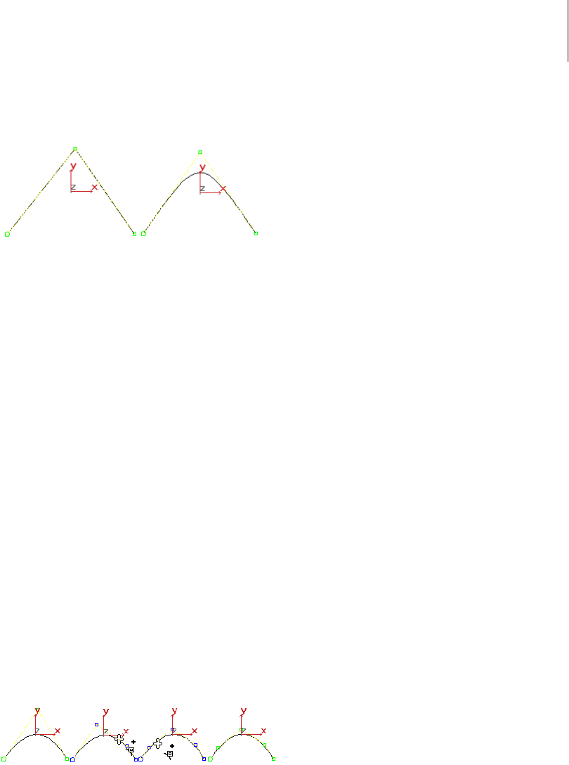
NURBS Concepts 1093
one or two CVs combine their influence in that
vicinity of the curve.
Effects of multiplicity: there are three CVs at the apex on the
left, two CVs at the apex on the right.
By moving one CV away from the other, you
increase the curve’s continuity level again.
Multiplicity also applies when you fuse CVs. Fused
CVs create a sharper curvature or a cusp in the
curve. Again, the effect goes away if you unfuse the
CVs and move one away from the other.
Degree, continuity, and multiplicity apply to
NURBSsurfacesaswellastocurves.
Refining Curves and Surfaces
Refining a NURBS curve means adding more CVs.
Refining gives you finer control over the shape of
the curve. When you refine a NURBS curve, the
software preserves the original curvature. In other
words, the shape of the curve doesn’t change,
but the neighboring CVs move away from the
CV you add. This is because of multiplicity: if
the neighboring CVs didn’t move, the increased
presence of CVs would sharpen the curve. To
avoid this effect, first refine the curve, and then
change it by transforming the newly added CVs,
or adjusting their weights.
Refining a NURBS curve.
NURBS surfaces have essentially the same
properties as NURBS curves, extended from
a one-dimensional parameter space to two
dimensions.
Reparameterizing CV Curves and
Surfaces
When you refine a NURBS curve or surface, it is a
good idea to reparameterize it. Reparameterizing
adjusts the parameter space so the curve or surface
willbehavewellwhenyouedititinviewports.
There are two ways to reparameterize:
•Chord-length
Chord-length reparameterization spaces knots
in parameter space based on the square root of
the length of each curve segment.
•Uniform
Uniform reparameterization spaces knots
uniformly. A uniform knot vector has the
advantage that the curve or surface changes
only locally when you edit it.
CVcurveandsurfacesub-objectsgiveyou
the option of reparameterizing automatically
whenever you edit the curve or surface.
Point Curve and Surface Concepts
You can work with point curves and point surfaces
as well as with CV curves and surfaces. The
points that control these objects are constrained
to lie on the curve or surface. There is no control
lattice, and no weight control. This is a simpler
interface that you might find easier to work
with. Also, point-based objects give you the
ability to construct curves based on dependent
(constrained) points, and then use these to
construct dependent surfaces.
You can think of point curves and surfaces as an
interface to CV curves and surfaces, which are
thefullydefinedNURBSobjects.Theunderlying
representation of the curve or surface is still
constructed using CVs.

1094 Chapter 9: Surface Modeling
You can also think of a point curve or surface as
dependent on its points. You can use the Convert
Curve button to convert a point curve or surface to
the CV form, or vice versa.
NURBS Tips and Techniques
These topics contain suggestions on how to work
with NURBS. They include tips collected from
various NURBS modeling users.
How to Make Objects with NURBS Modeling (page
1–1094)
How to Fix NURBS Objects (page 1–1098)
How to Improve Performance (page 1–1099)
Animation, Textures, and Rendering (page 1–1099)
How to Make Objects with NURBS
Modeling
These are tips on using NURBS to create models.
Objects and Sub-Objects
• In 3ds Max, a NURBS model is a single,
top-level NURBS object (page 1–1078) that can
contain a variety of sub-objects. Get in the
habit of creating a single object at the top level,
then going immediately to the Modify panel
andaddingsub-objectsbyusingrolloutsorthe
NURBS Creation Toolbox (page 1–1083).
• Sub-objects are either independent or
dependent. Dependent sub-objects (page
1–1087) use relational modeling to build
NURBS geometry that is related to other
geometry. However, understand that the
more dependencies a model has, the slower
interactive performance becomes.
• In general, point curves and surfaces are
slower than CV curves and surfaces. Trims are
the slowest kind of dependency, and texture
surfaces are the slowest kind of dependent
sub-object.
• If a dependent sub-object doesn’t change
during animation, you can help performance
by making the sub-object independent after
you finish creating it.
•YoucanuseNSurf Sel (page 1–747) to apply
modifiers to a sub-object selection. However,
beforeyoudosomakesurethatRelational
Stack is on; Relational Stack (page 1–1116) is
on the General rollout for NURBS models.
Otherwise, NSurf Sel can select only the Surface
and Surface CV sub-object levels.
Converting Other Objects to NURBS
•Rememberthatyoucancollapsesplines (page
1–266) to NURBS objects. A spline Shape or a
NURBS curve can be a good starter object for
aNURBSmodel.
• Shapes with sharp angles collapse to multiple
NURBS curves. You can control this before
NURBS conversion by first converting the
Shape to an editable spline (page 1–289).
Modify the editable spline so that all its vertices
are Bezier or Smooth vertices. Then when you
collapsethesplinetoaNURBScurve,you
obtain a single curve.
• If you want a single NURBS curve, don’t change
vertices to Bezier Corner vertices. These always
convert to a junction between two different
NURBS curves.
•Collapsingaprimitive (page 1–170) into a
NURBSobjectisoneofthequickestwaysto
start building a NURBS model. After collapsing
the primitive, you can select various CVs and
transform them. Other objects you can convert
to NURBS are prisms (page 1–205),torus knots

How to Make Objects with NURBS Modeling 1095
(page 1–189),lofts (page 1–352),andpatch grids
(page 1–993).
• You can also change the NURBS surface by
applying modifiers. The modifiers act on the
points or CVs of the surface, and not on the
surface itself. After applying the modifiers,
collapse the modifier stack (page 3–760).This
removes the modifiers from the stack without
changing the position of the modified points or
CVs,makingforasimplerandquickermodel.
•AnotherwaytocreateaNURBSsurfaceobject
is to apply a Lathe (page 1–707) or Extrude
(page 1–680) modifier to a NURBS curve. Set
themodifier’sOutputTypetoNURBS,and
then collapse when you’re done adjusting the
parameters.
(TherearealsoNURBSlatheandextrude
surface sub-object types, which you can apply
to curve sub-objects.)
Shortcuts, Snaps, and User Interface Tips
•RemembertoturnonthePlug-In Keyboard
Shortcut Toggle (page 3–872).Whileitison,
youcanusealltheNURBSkeyboardshortcuts.
•OneofthemostusefulNURBSkeyboard
shortcuts is H,whichdisplaysaSelect Objects
dialog (page 1–78).Youcanuse Hduring
sub-object creation as well as sub-object
selection. This is handy when sub-objects are
crowdedorhardtosee.
Avariantis Ctrl+H ,whichalsodisplays
the Select Objects dialog, but lists only those
NURBS sub-objects beneath the mouse cursor
position.
• There are special NURBS Snaps in the Grid and
Snap Settings dialog (page 2–41) (right-click
the 3D Snap toggle to display this). When
you use NURBS snaps, turn off Options/Axis
Constraints; otherwise, snaps work only in the
current axis.
Also, remember that snaps work in a viewport
onlywhenyouhavemadetheviewportactive.
And choosing your snap settings does not turn
on snaps. You must also turn on the 3D Snap
Toggle button (page 2–35) (on the status bar).
Snaps are especially important when you create
the curves for building 1-rail (page 1–1204) and
2-rail (page 1–1209) sweep surfaces.
• Remember that without leaving the viewport,
you can right-click to display a quad menu
(page 3–694) with shortcuts for changing the
sub-object level, creating some sub-objects,
and using some other edit commands.
• When you work with NURBS, there are a lot
of rollouts in the Modify panel. Minimize
the rollouts you don’t need. For example,
minimizing the Modifiers rollout helps unless
you’re applying Modifiers, and minimizing the
Surface Common rollout is useful when you’re
creating U loft, UV loft, and 1-rail or 2-rail
sweep surfaces.
• Don’t set viewports to display edged faces.
Displayingedgesisalmosttwiceasslowas
displaying a simple shaded viewport.
Creating Curves
• When drawing a CV curve, click three times
to get a sharp corner.
Be aware, however, that multiple CVs increase
the amount of calculation and therefore reduce
the performance and stability of your model.
However, if you want to use the curve to
construct a U Loft, and so on, this is the best
technique.
• Youcanalsocreatesharpcornersbyfusingthe
ends of two separate NURBS curve sub-objects.
This is the recommended method if you aren’t
using the curves to construct a surface.
• Whilecreatingcurves,youcanturnonthe
Draw in All Viewports toggle. This lets you

1096 Chapter 9: Surface Modeling
draw curves in 3D. Begin drawing a curve in
one viewport, go to another viewport, and
continue drawing.
Ifyourmousehasamiddlemousebutton,
Alt +middle mouse button lets you use arc
rotate (page 3–744) to change a viewport’s
orientation while you are creating the curve.
• To create a transform curve along a specific
axis,turnontheappropriateaxisconstraints,
and then Shift +moveacopyofthetransform
curve.
Curves and Direction
• NURBS curves show their direction in
viewports. A small circle indicates the first
vertex.Ifthecurveisclosed,aplussign(+)
indicates the direction of the curve.
Beawareofcurvedirectionwhenyouuse
curves to construct blend surfaces (page
1–1183),U loft (page 1–1196) and UV loft (page
1–1200) surfaces, and 1-rail (page 1–1204) and
2-rail (page 1–1209) sweeps. If the curves don’t
have the same direction, you can get strange
twisting. Makesurecurveshavethesame
direction before you construct the surface.
On the Curve Common rollout, the controls
Reverse and Make First let you control the
direction of the curve, and where its starting
point or CV is located.
Another good way to make sure curves are
aligned is to draw one curve and then use
Shift +Clone to create the others. After
creating the aligned curves, you can transform
CVs to vary the curves on which the surface
will be based.
Curves for Sweeps
• Besides expecting cross-section curves to be all
in the same direction, 1-rail (page 1–1204) and
2-rail (page 1–1204) sweep surfaces work best if
the cross sections intersect the rail or rails. To
achieve this, draw the rails first, then draw the
crosssectionsusingtheNURBSSnaps (page
2–41) Curve End and Curve Edge turned on.
• 2-rail sweeps have the additional requirement
that the endpoints of the first cross section
intersect the endpoints of the rails. Again,
NURBS Snaps help you do this.
If the endpoints of the first cross-section don’t
coincide with the rail endpoints, the resulting
surface might not follow the rails.
• While you’re editing a sweep, the Edit Curve
button lets you directly transform the CVs of
a rail or cross section, without changing the
sub-object level. Edit Curve also gives you
access to all the rollouts that control the curve.
YoucanuseRefineorMakeFirst,forexample,
without changing levels.
Curves on Surfaces and Projected Curves
• You can use a viewport to draw a curve on a
surface (page 1–1172) (COS), but this works
only for visible portions of the surface. To see
theentiresurfaceandthecurveorcurvesonit
projected into a flat plane, use Edit Curve.
Ifyourmousehasamiddlemousebutton,
Alt +middle mouse button lets you use arc
rotate (page 3–744) to change a viewport’s
orientation while you draw the curve on
surface.
• Neither curves on surfaces nor projected curves
cancrosstheedgeofasurface.Thisincludes
the seam on surfaces with fused CVs. If you
try to project across the seam, only part of the
curve’sprojectioniscreated.
Creating Blend Surfaces
• Youcanblendbetweencurvesorbetween
surface edges. (You can’t blend from a trimmed
edge. In that situation, you are blending from
the curve that trimmed the surface.)

How to Make Objects with NURBS Modeling 1097
• If you want a controllable tangent or tension,
you must blend to a surface edge or a curve on a
surface. Adjusting tension changes the flatness
or "bulginess" of that end of the blend.
When a curve and a surface (or two surfaces)
are near each other, sometimes it can be hard to
tellwhichedgeyouareselecting.Toassistyou,
the currently selected surface turns yellow, and
theedgethatwillbeusedfortheblendturns
blue. Make sure you have selected the right
surfacebeforeyouchoosetheedge.
• Iftheedgesyouareblendinghavedifferent
numbers of points (usually due to different
surface approximation settings), then
sometimesrenderingshowsgapsbetweenthe
blend and the original surface. If this happens,
go to the Surface Approximation rollout (page
1–1239) and increase the value of Merge until
the gaps disappear when you render.
The Merge setting affects only the production
renderer. It has no effect on viewport display.
Lofts
• If you need a surface between only two curves,
use a ruled surface (page 1–1193) instead of a U
loft. Thisisfaster.
• Ifloftcreationseemsslow,makesurethe
Display While Creating check box (in the U
Loft Surface rollout (page 1–1196))isturnedoff.
• If the U loft doesn’t come out as you expected,
try reparameterizing the curves. Click
Reparam. at the Curve sub-object level. This
button is on the CV Curve rollout. In the
Reparameterize dialog (page 1–1237),choose
Chord Length reparameterization.
If a curve is dependent or a point curve, first
youwillhavetomakeitindependent(thisalso
improves performance).
Curves that are made of two joined curves
have this problem more often than others.
Ifyouhaveajoinedcurveasoneofthe
curves to construct the loft, reparameterize it
before you create the loft, or set the curves to
reparameterize automatically.
•TheEditCurvebuttonletsyoudirectly
transform the CVs of a curve within a U loft
or UV loft (page 1–1200),withoutchanging
the sub-object level. Edit Curve also gives you
access to all the rollouts that control the curve.
YoucanuseRefineorMakeFirst,forexample,
without changing levels.
• To close a UV loft, you can pick the first V
curveagaintomakeitthelastcurveintheloft.
Sometimes a seam is visible at this location in
the UV loft.
Multisided Blend Surfaces
•Iftheprogramdoesn’tcreatethemultisided
blend (page 1–1213), fuse the CVs at the three
or four corners. Snapping CVs to each other
doesn’t always succeed, because of rounding
off.
Multicurve Trimmed Surfaces
• Multicurve trimmed surfaces are the only way
to create a trimmed hole that contains sharp
angles.
Displacement Mapping
• In general, the default tessellation settings
aren’t suitable for displaced surfaces. With
these default settings, displacement mapping
can create an extremely high face count,
which performs very slowly. Change the
surface approximation to the lowest necessary
resolution. A good rule of thumb is to start
with Spatial approximation and an Edge value
of 20. If that is too low, reduce the Edge value
untilthemodellooksasitshould.
•UsetheDisplace NURBS world space modifier
(page 1–515) to convert the displacement map

1098 Chapter 9: Surface Modeling
into an actual displaced mesh so you can see the
effect of displacement in viewports. To make a
displaced mesh copy of the NURBS model, use
Snapshot (page 1–453).
Connecting an Arm to a Shoulder
• The easiest approach is to create a CV curve on
surface (page 1–1172) or normal projected curve
(page 1–1169) on the shoulder. Then create the
arm as a U loft (page 1–1196).Forthelastcurve
oftheUloft,selecttheCVcurveonsurfaceor
the normal projected curve. Then turn on Use
COS Tangents, which makes the loft surface
tangent to the other surface where the arm joins
the shoulder.
• If the blend appears twisted, use the Start Point
spinner to change the location of the first point
of the curves that make up the U loft surface.
• Another way to connect a U loft to another
surfaceistoprojectthelastcurveintheU
loft onto the other surface. Click Make COS
to convert the projected curve into a curve on
surface, and then on the U Loft Surface rollout
click Insert to make the new curve on surface
the last curve in the U loft. You can scale the
curve on surface or move its CVs to get the
curvature and blending you want.
How to Fix NURBS Objects
These are tips on fixing problems with NURBS
models.
• Ifyoucreateasurfacebutitisn’tvisiblein
viewports, click Flip Normals. Flip Normals is
availableonthesurface’screationrollout,or
at the Surface sub-object level on the Surface
Common rollout.
•Ifyoucreateablend surface (page 1–1183) and
it looks like a bow tie, use Flip End 1 or Flip
End 2 to correct the twist.
•IfaCVcurvegivesyouunexpectedorincorrect
results, try reparameterizing it. Click Reparam.
at the Curve sub-object level. This button is on
the CV Curve rollout. In the Reparameterize
dialog (page 1–1237), choose Chord Length
reparameterization.
If the curve still gives you trouble, try rebuilding
it. The Rebuild button is on the same rollout.
• If a blend between a surface and a curve
gives you unexpected or incorrect results, try
reparameterizing the parent surface. Click
Reparam. at the Surface sub-object level. This
button is on the CV Surface rollout. In the
Reparameterize dialog (page 1–1237),choose
Chord Length reparameterization.
• If you see a seam in a shaded viewport, render
the viewport first before you try to fix the seam.
What you see in viewports might not be what
you get in a render, and the viewport shader
is less accurate than the production renderer.
Seamsinviewportscanalsoresultfrom
different surface approximation settings (page
1–1239) for the viewport and the renderer, so
check these as well.
• If you see gaps between faces in the rendered
model, increase the Merge value for the
renderer in the surface approximation settings.
• Sometimes gaps between faces appear after
you convert a NURBS model into a mesh. (For
example, by using Mesh Select (page 1–719).)
If this happens, increase the Merge value for
the renderer in the surface approximation (page
1–1239) settings.
• If you see odd twists in a 1-rail (page 1–1204)
or 2-rail (page 1–1209) sweep, add more cross
sections at the areas of change in the surface.
Forexample,ifyourraillookslikeaboxwith
rounded corners, placing cross sections at the
corners helps to control the shape of the sweep.
On the other hand, you don’t need more cross

How to Improve Performance 1099
sections for a rail shaped like an ’S’, because the
curvatureismoreconstant.
• If a U loft or UV loft doubles back on itself
unexpectedly, make sure that all the curves are
going in the same direction. Click Reverse to
change a curve’s direction. Use the Start Point
spinner to align the curve’s initial points.
How to Improve Performance
These are tips on improving the performance of
your NURBS models.
• Avoid using point curves and point surfaces.
These are slower than CV curves and CV
surfaces. Use the point forms only when you
need them for construction; for example,
when you use Curve Fit to create a curve that
interpolates specific points.
•Usethenonrelational stack (page 1–1116)
feature in conjunction with the Shaded Lattice
toggle to improve performance while you
animate your NURBS model.
• Use Transform Degrade to hide surfaces while
you are moving, rotating, and scaling NURBS
sub-objects. The shortcut Ctrl+X toggles this
option.
Yo u c a n u s e Ctrl+X in the middle of a
transform, to turn on degradation if things are
happening slowly.
• Turn off the display of dependent surfaces
whileyouarecreatingnewdependentsurfaces
or moving, rotating, or scaling NURBS
sub-objects. The shortcut Ctrl+D toggles
dependent surface display.
• Trim holes only when you need to. For example,
when you connect an arm to a torso, you don’t
need to create a hole beneath the arm, as it
won’t be visible anyway.
You can also speed up performance by turning
off the Display Trims toggle. The shortcut
Shift+Ctrl+T toggles trim display. The trims
still appear in renderings.
• For symmetrical models, create only half the
geometry, and then mirror it. You can then use
ablend (page 1–1183) surface or ruled (page
1–1193) surface to connect the two halves.
• Restart 3ds Max when performance begins
to slow down. If your NURBS model needs
to page, then working with it for a long time
causes performance to slow. If you notice this,
save your work, close 3ds Max, and then restart.
• Convert point surfaces to CV surfaces whenever
possible.
• When you use texture surfaces, use the Edit
Texture Surface dialog (page 1–1230) (click
Edit Texture Surface on the Material Properties
rollout (page 1–1149)) to rebuild the texture
surface with the minimum necessary number
of UV rows and columns.
• U lofts are faster than UV lofts.
• Every type of surface is faster if you can make it
independent.
•Setthesurface approximation (page 1–1239) for
viewports to use the lowest possible resolution.
Set the renderer to use higher resolution, and
turn on View Dependent for the renderer
so objects far from the camera render more
quickly.
• You can customize and save surface
approximation (page 1–1239) presets by
using the Surface Approximation utility (page
1–1245).Thisutilityalsoletsyousetsurface
approximation values for a selection set of
multiple NURBS models.
Animation, Textures, and
Rendering
These are tips about animating NURBS models
and using textures with animated NURBS models.

1100 Chapter 9: Surface Modeling
• An easy way to animate a growing surface is to
put a curve point (page 1–1220) with trimming
onacurve,thenanimatetheUpositionofthe
curvepoint,andthenusethiscurveastherail
of a 1-rail sweep (page 1–1204). As the trimmed
rail grows, so does the sweep surface. (You
must trim the curve before you create the sweep
surface.)
• If you see gaps between surfaces in rendered
images, increase the value of Merge for the
renderer in the surface approximation (page
1–1239) settings.
• If a texture slides around on the surface during
animation, this is because you are using the
default Chord-Length parameterization of the
texture surface. Select the surface, then on
the Material Properties rollout (page 1–1149)
change the parameterization to User Defined.
Now the texture should stick to the surface
better.
•Don’tusetheUVW Map modifier (page 1–922)
to apply a texture to an animated NURBS
surface.
• If a surface seems to glitter or jump around
as you move toward it in an animation, this
is because View Dependent tessellation is on
(on the Surface Approximation rollout (page
1–1239)) so the tessellation is constantly
changing. Usually View Dependent creates no
visible changes, but if it does, turn it off.
• If a surface seems to glitter or jump around
while it changes during animation, this
is because the tessellation is changing as
the surface animates. Changing surface
approximation (on the Surface Approximation
rollout) to Regular fixes this in all cases.
Parametric tessellation also solves this problem
for every kind of surface except Ulofts(page
1–1196) and UV lofts (page 1–1200).
• If the View Dependent setting doesn’t seem
to be doing much, change the tessellation
(ontheSurfaceApproximationrollout)from
Curvature to Spatial. You will then get a much
more drastic change in face count.
•Togetamaptosmoothlycovertwoormore
surface without tiling, create another surface
whose shape covers and roughly conforms to
the original surfaces. Apply the texture to the
larger surface. In the Material Properties rollout
(page 1–1149) for the original surfaces, set
Texture Surface to Projected, click Pick Source
Surface, and pick the larger surface. Adjust the
larger surface to fine-tune the map projection.
Hide the larger surface before you render.
• To have different maps on a surface sub-object,
use different mapping coordinates (page 3–967),
and multiple map channels (page 3–966).On
the Material Properties rollout (page 1–1149),
change the Map Channel value and then turn
on Generate Mapping Coordinates. (Each
map channel requires its own set of mapping
coordinates.)
NURBS surface sub-objects let you set the map
channel directly, and don’t require you to apply
UVWMapmodifiersasotherobjectsdo.
•Ifamapdoesn’taligntoasurfacesub-objectthe
way you want it to, on the Material Properties
rollout (page 1–1149) choose User Defined as
the Texture Surface, and then use Edit Texture
Points or the Edit Texture Surface dialog to
movethepointsofthetexturesurface.
• To adjust how the map aligns to the edges of
a surface sub-object, use the Texture Corner
settings on the Material Properties rollout (page
1–1149).

NURBS Surfaces 1101
NURBS Surface Primitives
Create panel > Geometry > NURBS Surfaces
Create menu > NURBS > CV Surface/Point Surface
NURBS (page 3–980) surface objects are the basis
ofNURBSmodels.Theinitialsurfaceyoucreate
usingtheCreatepanelisaplanarsegmentwith
points or CVs. It is meant simply to be "raw
material" for creating a NURBS model. Once
you have created the initial surface, you can
modify it on the Modify panel by moving CVs or
NURBS points, attaching other objects, creating
sub-objects, and so on.
There are two kinds of NURBS surfaces:
Point Surface (page 1–1102)
CV Surface (page 1–1103)
Yo u c a n a l s o create a NURBS surface from a
geometric primitive (page 1–1116).
NURBS surfaces can contain multiple sub-objects,
including NURBS points, NURBS curves, and
other NURBS surfaces. These sub-objects are
either dependent or independent.
Creating Curve Sub-Objects (page 1–1151)
Creating Surface Sub-Objects (page 1–1177)
Creating and Editing Point Sub-Objects (page
1–1219)
Common Sub-Object Controls (page 1–1122)
Editing Point Sub-Objects (page 1–1123)
Editing Curve CV Sub-Objects (page 1–1127)
Editing Surface CV Sub-Objects (page 1–1130)
Editing Curve Sub-Objects (page 1–1135)
Editing Surface Sub-Objects (page 1–1141)
Yo u c a n a l s o c r e a t e N U R B S s u r f a c e s u b - o b j e c t s b y
attaching or importing other 3ds Max objects (page
1–1120).
Both NURBS curves and NURBS surfaces have a
Display area in the General rollout on the Modify
panel. These controls affect which portions of
theNURBSgeometryaredisplayed.Nexttothe
Display area is the button that turns on the toolbox
for creating sub-objects.
Display Controls for NURBS Models (page 1–1117)
Warning: When you move CV sub-objects, the effect
must be calculated over a region of the surface.
Although the calculations are optimized, this is a more
involved process than simply moving vertices in an
editable mesh. Because of this, if you manipulate large
numbers of a NURBS surface’s CVs by transforming,
animating, applying modifiers, and so on, you will notice
adropininteractiveperformance.
Yo u c a n u s e M A X S c r i p t t o c o nt r o l N U R B S o b j e c t s .
See "Working with NURBS in MAXScript" in the
MAXScripthelpfile.ChooseHelp>Additional
Help, and then choose MAXScript from the list
of additional help files.
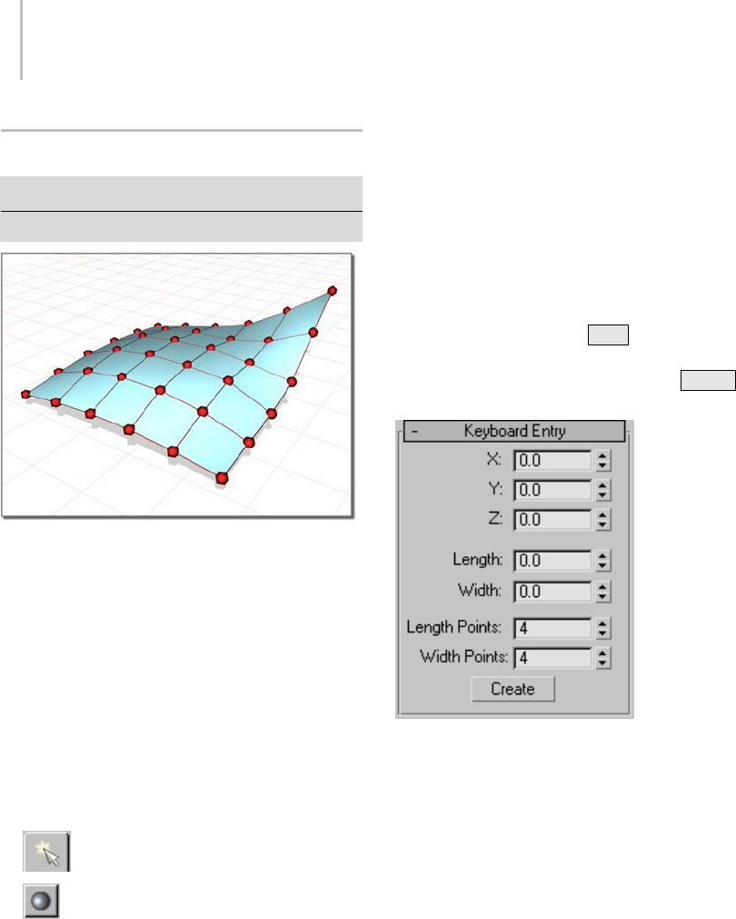
1102 Chapter 9: Surface Modeling
Point Surface
Create panel > Geometry > NURBS Surfaces > Point Surf
Createmenu>NURBS>PointSurface
Points shape the surface they lie on.
Point surfaces are NURBS surfaces (page 1–1101)
whose points are constrained to lie on the surface.
Because an initial NURBS surface is meant to
be edited, the surface creation parameters do
not appear on the Modify panel. In this respect,
NURBS surface objects are different from other
objects. The Modify panel provides other ways to
change the values you set in the Create panel.
Procedure
To create a point surface:
1. Go to the Create panel.
2. Turn on Geometry, and choose NURBS
Surfaces from the drop-down list.
3. Tur n on Point Su rf.
4. In a viewport, drag to specify the area of the
planar segment.
5. Adjust the surface’s creation parameters.
Interface
Thecreationparametersarethesameforboth
pointsurfacesandCVsurfaces,exceptthatthe
labels indicate which kind of basic NURBS surface
you are creating.
Keyboard Entry rollout
The Keyboard Entry rollout lets you create a point
surfacebytyping. Usethe Tab key to move
between the controls on this rollout. To click the
Create button from the keyboard, press Enter
while the button is active.
X, Y, and Z—Let you enter the coordinates of the
center of the surface.
Length and Width—Let you enter the dimensions
of the surface in current 3ds Max units.
Length Points—Lets you enter the number of points
along the length of the surface (this is the initial
number of point columns).
Width Points—Lets you enter the number of points
along the width of the surface (this is the initial
number of point rows).
Create—Creates the surface object.
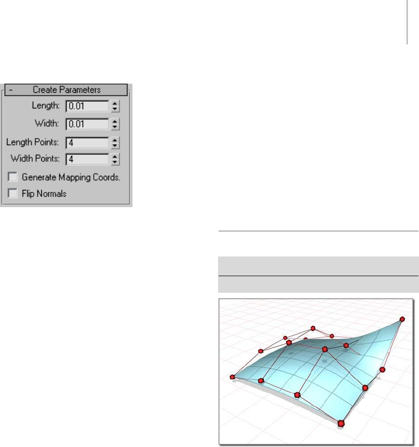
CV Surface 1103
Create Parameters rollout
Length—The length of the surface in current
3ds Max units.
Width—Thewidthofthesurfaceincurrent
3ds Max units.
On the Modify panel, the Length and Width
spinners are no longer available. You can change
the length or width of the surface by scaling the
surfaceattheSurfacesub-objectlevel. Moving
point sub-objects also alters the length and width
of the surface.
Length Points—The number of points along the
length of the surface. In other words, the initial
number of point columns in the surface. Range=2
to 50. Default=4.
Width Points—The number of points along the
width of the surface. In other words, the initial
number of point rows in the surface. Range=2 to
50. Default=4.
On the Modify panel, the point Length and Width
spinners are no longer available. You can change
thenumberofrowsandcolumnsbydeleting
existing rows and columns, or by adding new rows
and columns using the Refine controls at the Point
sub-object level.
Generate Mapping Coordinates—Generates
mapping coordinates so you can apply mapped
materials to the surface.
The Generate Mapping Coordinates control is
present on the Modify panel. It is at the Surface
sub-object level.
Flip Normals—Turn on to reverse the direction of
the surface normals.
The Flip Normals control is present on the Modify
panel. It is at the Surface sub-object level.
When you modify a point surface, a rollout lets
you change its surface approximation settings (page
1–1239).
CV Surface
Create panel > Geometry > NURBS Surfaces > CV Surf
Createmenu>NURBS>CVSurface
The CVs in a control lattice shape the surface it defines.
CV surfaces are NURBS surfaces (page 1–1101)
controlled by control vertices (CVs (page 3–926)).
TheCVsdon’tlieonthesurface. Theydefine
acontrol lattice (page 3–923) that encloses the
surface. Each CV has a weight that you can adjust
to change the shape of the surface.
Because an initial NURBS surface is meant to
be edited, the surface creation parameters do
not appear on the Modify panel. In this respect,
NURBS surface objects are different from other
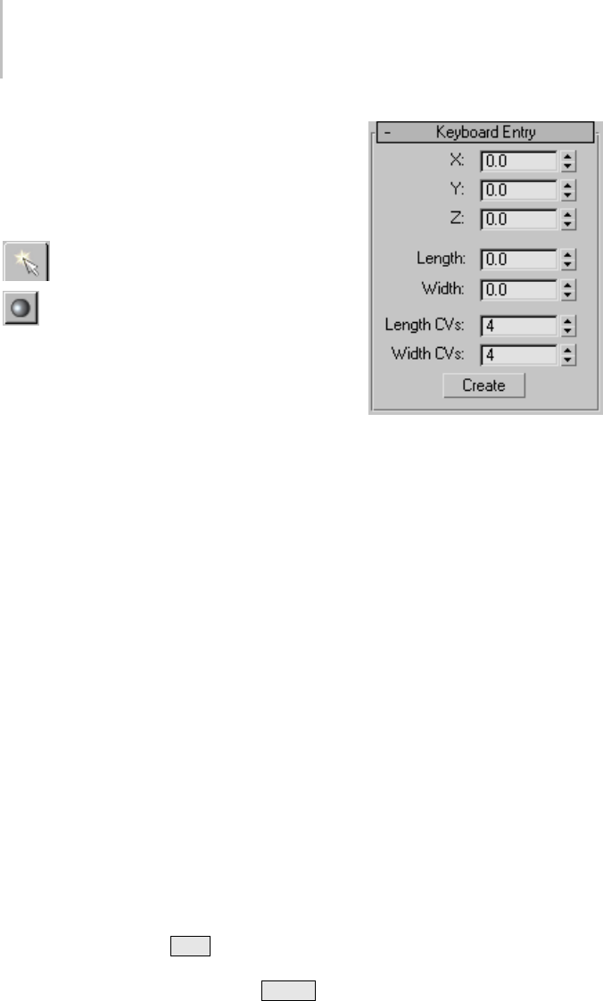
1104 Chapter 9: Surface Modeling
objects. The Modify panel provides other ways to
change the values you set in the Create panel.
Procedure
To create a CV surface:
1. Go to the Create panel.
2. Turn on Geometry, and choose NURBS
Surfaces from the drop-down list.
3. Turn on CV Surf.
4. In a viewport, drag to specify the area of the
planar segment.
5. Adjust the surface’s creation parameters.
Note: When you edit a CV surface you can add
or move CVs so that more than one CV is at
thesamelocation(orclosetoit)toincrease
the influence of the CVs in that region of the
surface. Two coincident CVs sharpen the
curvature. Three coincident CVs create an
angular peak in the surface. This technique can
help you shape the surface. However, if you
later move the CVs individually, you lose this
effect. (You can also obtain the influence of
multiple CVs by fusing (page 3–946) CVs.)
Interface
Thecreationparametersarethesameforboth
pointsurfacesandCVsurfaces,exceptthatthe
labels indicate which kind of basic NURBS surface
you are creating.
Keyboard Entry rollout
The Keyboard Entry rollout lets you create a CV
surface by typing. Use the Tab key to move
betweenthecontrolsonthisrollout.Toclickthe
Create button from the keyboard, press Enter
while the button is active.
X, Y, and Z—Let you enter the coordinates of the
center of the surface.
Length and Width—Let you enter the dimensions
of the surface, in current 3ds Max units.
Length CVs—Lets you enter the number of CVs
along the length of the surface (this is the initial
number of CV columns).
Width CVs—Lets you enter the number of CVs
along the width of the surface (this is the initial
number of CV rows).
Create—Creates the surface object.
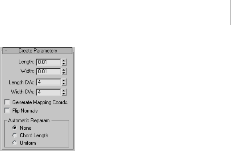
CV Surface 1105
Create Parameters rollout
Length—The length of the surface in current
3ds Max units.
Width—Thewidthofthesurfaceincurrent
3ds Max units.
On the Modify panel, the Length and Width
spinners are no longer available. You can change
the length or width of the surface by scaling the
surface at the Surface sub-object level. Moving CV
sub-objectsalsoaltersthelengthandwidthofthe
surface.
Length CVs—The number of CVs along the length
of the surface. In other words, the initial number
ofCVcolumnsinthesurface.Canrangefrom4
to 50.
Width CVs—The number of CVs along the width of
the surface. In other words, the initial number of
CV rows in the surface. Can range from 4 to 50.
On the Modify panel, the CV Length and Width
spinners are no longer available. You can change
thenumberofrowsandcolumnsbydeleting
existing rows and columns, or by adding new
rows and columns using the Refine controls at the
Surface CV sub-object level.
Generate Mapping Coordinates—Generates
mapping coordinates so you can apply mapped
materials to the surface.
The Generate Mapping Coordinates control is
present on the Modify panel. It is at the Surface
sub-object level.
Flip Normals—Turn on to reverse the direction of
the surface normals.
The Flip Normals control is present on the Modify
panel. It is at the Surface sub-object level.
When you modify a CV surface, a rollout lets you
change its surface approximation settings (page
1–1239).
Automatic Reparameterization group
The radio buttons in this group box let you
choose automatic reparameterization. With
reparameterization, the surface maintains
its parameterization as you edit it. Without
reparameterization, the surface’s parameterization
doesn’t change as you edit it, and can become
irregular.
None—Do not reparameterize.
Chord Length—Chooses the chord-length
algorithm for reparameterization.
Chord-length reparameterization spaces knots (in
parameter space (page 3–988)) based on the square
rootofthelengthofeachcurvesegment.
Chord-length reparameterization is usually the
best choice.
Uniform—Spaces the knots uniformly.
A uniform knot vector has the advantage that the
surface will change only locally when you edit it.
With the other two forms of parameterization,
moving any CV can change the entire surface.

1106 Chapter 9: Surface Modeling
NURBS Curve Primitives
Create panel > Shapes button > NURBS Curves
NURBS (page 3–980) curves are Shape objects
(page 1–262),andyoucanusethemasyou
dosplines. YoucanusetheExtrudeorLathe
modifiers to generate a 3D surface based on a
NURBS curve. You can use NURBS curves as
thepathortheshapeofaloft. (Loftscreated
using NURBS curves are loft objects, not NURBS
objects.)
You can also use NURBS curves as Path Constraint
and Path Deform paths or as motion trajectories.
You can assign thickness to a NURBS curve so it
rendersasacylindricalobject. (Thethickened
curve renders as a polygonal mesh, not as a
NURBS surface.)
Acurveandthesamecurverenderedwiththickness
There are two kinds of NURBS curve objects:
Point Curve (page 1–1106)
CV Curve (page 1–1110)
Like other Shape objects, NURBS curves can
contain multiple sub-objects, which are either
dependent or independent.
Creating Curve Sub-Objects (page 1–1151)
Creating Surface Sub-Objects (page 1–1177)
Creating and Editing Point Sub-Objects (page
1–1219)
Common Sub-Object Controls (page 1–1122)
Editing Point Sub-Objects (page 1–1123)
Editing Curve CV Sub-Objects (page 1–1127)
Editing Surface CV Sub-Objects (page 1–1130)
Editing Curve Sub-Objects (page 1–1135)
Editing Surface Sub-Objects (page 1–1141)
Note: Like an object-level NURBS surface (page
1–1101), an object-level NURBS curve is a
top-level NURBS model (page 3–980) that can
contain NURBS curve, NURBS surface, and
NURBS point sub-objects. A NURBS curve
remainsaShapeobjectunlessyouaddasurface
sub-objecttoit;ifyoudo,itconvertstoaNURBS
surface (without changing its name).
Creating Independent Surfaces from NURBS Curve
Objects (page 1–1114)
Yo u c a n a l s o c r e at e N U R B S c u r v e s u b - o bj e c t s b y
attachingorimportingotherobjectssuchasother
NURBS curves or spline shapes.
Attaching and Importing 3ds Max Objects (page
1–1120)
Display Controls for NURBS Models (page 1–1117)
Both NURBS curves and NURBS surfaces have a
DisplayareaintheModifypanel.Thesecontrols
affect which portions of the NURBS geometry are
displayed. Next to the Display area is the button
that turns on the toolbox for creating sub-objects.
Point Curve
Create panel > Shapes button > NURBS Curves > Point
Curve button
Createmenu>NURBS>PointCurve
Point curves are NURBS curves (page 1–1106)
whose points are constrained to lie on the curve.
ApointcurvecanbethebasisofafullNURBS
model (page 3–980).
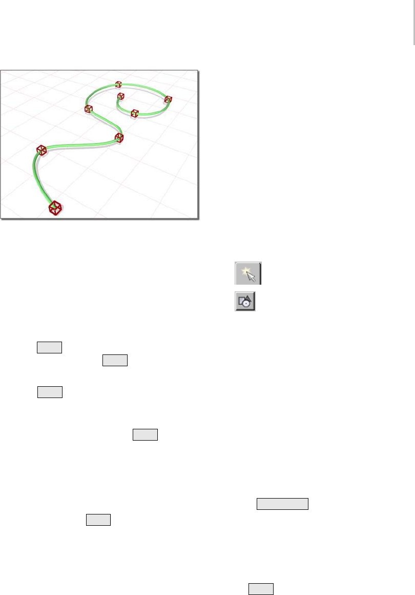
Point Curve 1107
Points lie on the curve they define.
Drawing Three-Dimensional Curves
When you create a point curve, you can draw it in
threedimensions.Therearetwowaystodothis:
• Draw In All Viewports: This toggle lets you use
any viewport to draw the curve, enabling you
to draw three dimensionally.
•Using
Ctrl to drag points: While you draw a
curve, you can use the Ctrl key to drag a point
offoftheconstructionplane.
With the Ctrl –key method, further mouse
movement lifts the latest point off the construction
plane.Therearetwowaystousethis:
•Click-drag.Ifyouholddown
Ctrl and also
hold down the mouse button, you can drag
to change the height of the point. The point’s
location is set when you release the mouse
button.
This method is probably more intuitive.
• Click-click. If you Ctrl +click and then release
the mouse button, the height changes as you
drag the mouse. Clicking the mouse a second
time sets the point’s location.
This method is less prone to repetitive stress
injury.
Whileyouareoffsettingthepoint,areddotted
line is drawn between the original point on the
construction plane and the actual point offset
fromtheplane.Youcanmovethemouseintoan
inactive viewport, in which case the software sets
the height of the point using the point’s Z axis in
the inactive viewport. This lets you set the height
of the point with accuracy.
Snaps (page 2–41) also work when you change the
height of a point. For example, if you turn on Point
snapping, you can set a point to have the same
height as another point by snapping to that other
point in an inactive viewport.
Procedure
To create a NURBS point curve:
1. Go to the Create panel.
2. Turn on Shapes, and choose NURBS
Curves from the drop-down list.
3. Tur n on Point Cu r ve.
4. In a viewport, click and drag to create the first
point, as well as the first curve segment. Release
the mouse button to add the second point. Each
subsequent location you click adds a new point
to the curve. Right-click to end curve creation.
Note: If you begin the curve by clicking without
dragging, this also creates the curve’s first point.
However, if you release the mouse button more
than five pixels away from where you initially
pressed it, this creates an additional point.
Whileyouarecreatingapointcurve,youcan
press Backspace to remove the last point you
created, and then previous points in reverse
order.
If Draw In All Viewports is on, you can draw in
any viewport, creating a 3D curve.
To lift a point off the construction plane, use
the Ctrl key as described earlier in this topic
under "Drawing Three-Dimensional Curves."
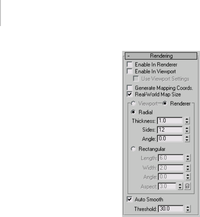
1108 Chapter 9: Surface Modeling
As with splines, if you click over the curve’s
initial point, a Close Curve dialog (page 1–1235)
is displayed. This dialog asks whether you
want the curve to be closed. Click No to keep
the curve open or Yes to close the curve. (You
canalsocloseacurvewhenyouedititatthe
Curve sub-object level.) When a closed curve
isdisplayedattheCurvesub-objectlevel,the
initial point is displayed as a green circle, and a
green tick mark indicates the curve’s direction.
5. Adjust the curve’s creation parameters.
6. (Optional.) To add a new NURBS curve
sub-object,youcanturnofftheStartNew
Shape check box, and then repeat the preceding
steps.
Interface
Thecreationparametersarethesameforboth
point curves and CV curves.
Rendering rollout
Lets you turn on and off the renderability of the
curve, specify its thickness in the rendered scene,
and apply mapping coordinates.
Render parameters can be animated. For example,
you can animate the number of sides.
Enable In Renderer—When on, the shape is
rendered as a 3D mesh using the Radial or
Rectangular parameters set for Renderer. In
previous versions of the program, the Renderable
switch performed the same operation.
Enable In Viewport—When on, the shape is
displayedintheviewportasa3Dmeshusingthe
Radial or Rectangular parameters set for Renderer.
In previous versions of the program, the Display
Render Mesh performed the same operation.

Point Curve 1109
Use Viewport settings—Lets you set different
rendering parameters, and displays the mesh
generated by the Viewport settings. Available only
when Enable in Viewport is turned on.
Generate Mapping Coords—Tur n t hi s on to a pp ly
mapping coordinates. Default=off.
The U coordinate wraps once around the thickness
of the spline; the V coordinate is mapped once
along the length of the spline. Tiling is achieved
using the Tiling parameters in the material itself.
Real-World Map Size—Controls the scaling method
used for texture mapped materials that are applied
totheobject. Thescalingvaluesarecontrolled
by the Use Real-World Scale settings found in
the applied material’s Coordinates rollout (page
2–1625).Default=on.
Viewport—Turn this on to specify Radial or
Rectangular parameters for the shape as it will
display in the viewport when Enable in Viewport
is turned on.
Renderer—Turn this on to specify Radial or
Rectangular parameters for the shape as it will
displaywhenrenderedorviewedintheviewport
when Enable in Viewport is turned on.
Radial—Displays the 3D mesh as a cylindrical
object.
Thickness—Specifies the diameter of the viewport
or rendered spline mesh. Default=1.0. Range=0.0
to 100,000,000.0.
Splines rendered at thickness of 1.0 and 5.0, respectively
Sides—Sets the number of sides (or facets) for
thesplinemeshntheviewportorrenderer.For
example, a value of 4 results in a square cross
section.
Angle—Adjusts the rotational position of the
cross-section in the viewport or renderer. For
example, if the spline mesh has a square cross
section you can use Angle to position a "flat" side
down.
Rectangular—Displays the spline’s mesh shape as
rectangular.
Aspect—Sets the aspect ratio for rectangular
cross-sections. The Lock check box lets you lock
the aspect ratio. When Lock is turned on, Width
is locked to Depth that results in a constant ratio
of Width to Depth.
Length—Specifies the size of the cross–section
along the local Yaxis.
Width—Specifies the size of the cross–section
along the local Xaxis.
Angle—Adjusts the rotational position of the
cross-section in the viewport or renderer. For
example, if you have a square cross-section you
can use Angle to position a "flat" side down.
Auto Smooth—If Auto Smooth is turned on, the
spline is auto-smoothed using the threshold
specified by the Threshold setting below it. Auto
Smooth sets the smoothing based on the angle
between spline segments. Any two adjacent
segmentsareputinthesamesmoothinggroupif
the angle between them is less than the threshold
angle.
Threshold—Specifies the threshold angle in
degrees. Any two adjacent spline segments are put
inthesamesmoothinggroupiftheanglebetween
them is less than the threshold angle.
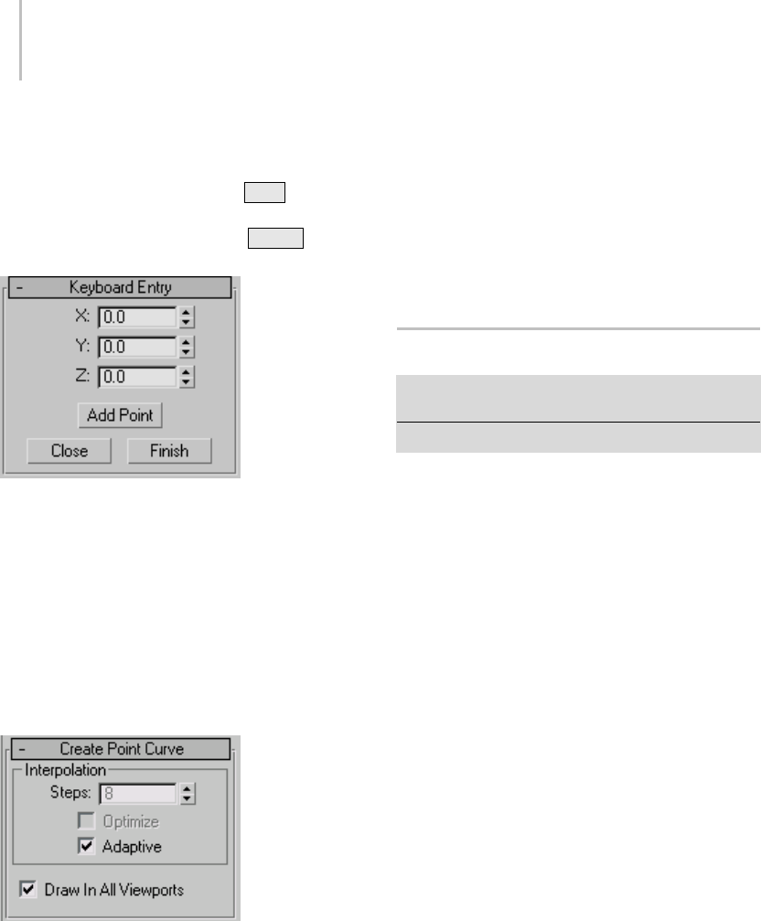
1110 Chapter 9: Surface Modeling
Keyboard Entry rollout
The Keyboard Entry rollout lets you create a
NURBS curve by typing. Use the Ta b key to
move between the controls in this rollout. To click
a button from the keyboard, press Enter while
the button is active.
X, Y, and Z—Let you enter the coordinates of the
next point to add.
Add Point—Adds the point to the curve.
Close—Ends creation of the curve and creates
a segment between the last point and the initial
point to close the curve.
Finish—Ends creation of the curve, leaving it open.
Create Point Curve rollout
This rollout contains the controls for curve
approximation.
Interpolation group
Thecontrolsinthisgroupboxchangetheaccuracy
and type of curve approximation (page 1–1238)
used to generate and display the curve.
Draw In All Viewports—Lets you use any viewport
whileyouaredrawingthecurve.Thisisoneway
to create a 3D curve. When off, you must finish
drawing the curve in the viewport where you
began it. Default=on.
WhileDrawInAllViewportsison,youcanalso
use snaps (page 2–41) in any viewport.
CV Curve
Create panel > Shapes button > NURBS Curves > CV
Curve button
Create menu > NURBS > CV Curve
CV curves are NURBS curves (page 1–1106)
controlled by control vertices (CVs (page 3–926)).
TheCVsdon’tlieonthecurve. Theydefinea
control lattice (page 3–923) that encloses the curve.
Each CV has a weight that you can adjust to change
the curve.
Whileyou’recreatingaCVcurveyoucanclick
to create more than one CV at the same location
(or close to it), increasing the influence of the
CVsinthatregionofthecurve. Creatingtwo
coincidentCVssharpensthecurvature.Creating
three coincident CVs creates an angular corner
in the curve. This technique can help you shape
the curve; however, if you later move the CVs
individually, you lose this effect. (You can also
obtain the influence of multiple CVs by fusing
(page 3–946) CVs.)
ACVcurvecanbethebasisofafullNURBS model
(page 3–980).
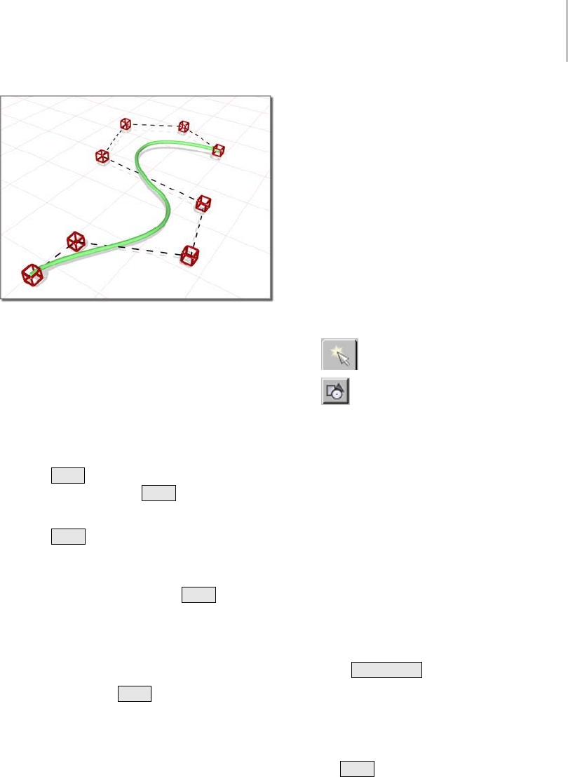
CV Curve 1111
CVs shape the control lattice that defines the curve.
Drawing Three-Dimensional Curves
WhenyoucreateaCVcurve,youcandrawitin
threedimensions.Therearetwowaystodothis:
• Draw In All Viewports: This toggle lets you use
any viewport to draw the curve, enabling you
to draw three dimensionally.
•Using
Ctrl to drag CVs: While you draw a
curve, you can use the Ctrl key to drag a CV
offoftheconstructionplane.
With the Ctrl –key method, further mouse
movement lifts the latest CV off the construction
plane.Therearetwowaystousethis:
•Click-drag.Ifyouholddown
Ctrl and also
hold down the mouse button, you can drag to
change the height of the CV. The CV’s location
is set when you release the mouse button.
This method is probably more intuitive.
• Click-click. If you Ctrl +click and then release
the mouse button, the height changes as you
drag the mouse. Clicking the mouse a second
time sets the CV’s location.
This method is less prone to repetitive stress
injury.
WhileyouareoffsettingtheCV,areddotted
line is drawn between the original CV on the
construction plane and the actual CV offset
fromtheplane.Youcanmovethemouseintoan
inactive viewport, in which case the software sets
the height of the CV using the CV’s Z axis in the
inactive viewport. This lets you set the height of
the CV with accuracy.
Snaps (page 2–41) also work when you change the
height of a CV. For example, if you turn on CV
snapping, you can set a CV to have the same height
as another CV by snapping to that other CV in an
inactive viewport.
Procedure
To create a NURBS CV curve:
1. Go to the Create panel.
2. Turn on Shapes, and choose NURBS
Curves from the drop-down list.
3. Tur n on CV Cur ve .
4. In a viewport, click and drag to create the
first CV, as well as the first curve segment.
ReleasethemousetoaddthesecondCV.Each
subsequent location you click adds a new CV to
the curve. Right-click to end curve creation.
Note: If you begin the curve by clicking without
dragging, this also creates the curve’s first CV.
However, if you release the mouse more than
five pixels away from where you initially pressed
it, this creates an additional CV.
While you are creating a CV curve, you can
press Backspace to remove the last CV you
created, and then previous CVs in reverse order.
If Draw In All Viewports is on, you can draw in
any viewport, creating a 3D curve.
To lift a CV off the construction plane, use
the Ctrl key as described earlier in this topic
under "Drawing Three-Dimensional Curves."
As with splines, if you click over the curve’s
initial CV, a Close Curve dialog (page 1–1228)
is displayed. This dialog asks whether you
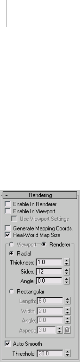
1112 Chapter 9: Surface Modeling
want the curve to be closed. Click No to keep
the curve open or Yes to close the curve. (You
canalsocloseacurvewhenyouedititatthe
Curve sub-object level.) When a closed curve
isdisplayedattheCurvesub-objectlevel,the
initial CV is displayed as a green circle, and a
green tick mark indicates the curve’s direction.
5. Adjust the curve’s creation parameters.
6. (Optional) To add a new NURBS curve
sub-object,youcanturnofftheStartNew
Shape check box, and then repeat the preceding
steps.
Interface
Thecreationparametersarethesameforboth
point curves and CV curves.
Rendering rollout
Enable In Renderer—When on, the shape is
rendered as a 3D mesh using the Radial or
Rectangular parameters set for Renderer. In
previous versions of the program, the Renderable
switch performed the same operation.
Enable In Viewport—When on, the shape is
displayedintheviewportasa3Dmeshusingthe
Radial or Rectangular parameters set for Renderer.
In previous versions of the program, the Display
Render Mesh performed the same operation.
Use Viewport settings—Lets you set different
rendering parameters, and displays the mesh
generated by the Viewport settings. Available only
when Enable in Viewport is turned on.
Generate Mapping Coords—Tur n this on to apply
mapping coordinates. Default=off.
The U coordinate wraps once around the thickness
of the spline; the V coordinate is mapped once
along the length of the spline. Tiling is achieved
using the Tiling parameters in the material itself.
Real-World Map Size—Controls the scaling method
used for texture mapped materials that are applied
totheobject. Thescalingvaluesarecontrolled
by the Use Real-World Scale settings found in
the applied material’s Coordinates rollout (page
2–1625).Default=on.
Viewport—Turn this on to specify Radial or
Rectangular parameters for the shape as it will
display in the viewport when Enable in Viewport
is turned on.
Renderer—Turn this on to specify Radial or
Rectangular parameters for the shape as it will
displaywhenrenderedorviewedintheviewport
when Enable in Viewport is turned on.
Radial—Displays the 3D mesh as a cylindrical
object.
Thickness—Specifies the diameter of the viewport
or rendered spline mesh. Default=1.0. Range=0.0
to 100,000,000.0.
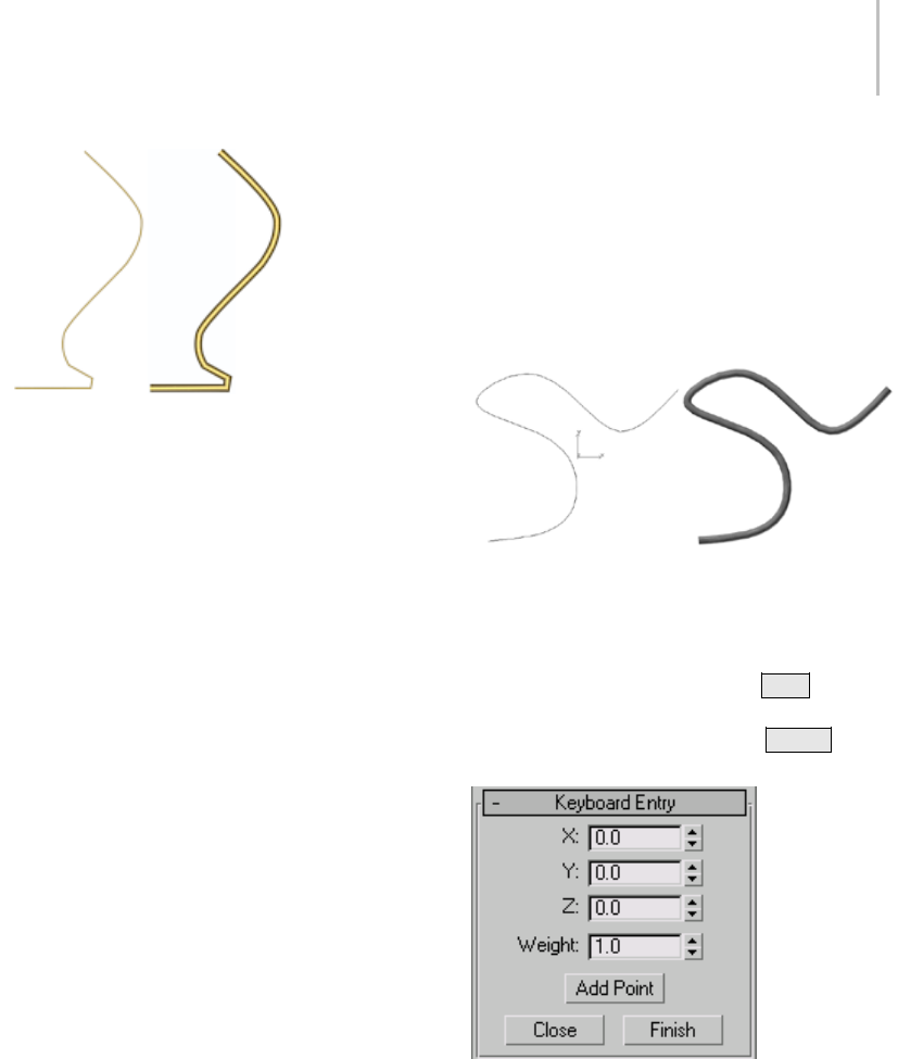
CV Curve 1113
Splines rendered at thickness of 1.0 and 5.0, respectively
Sides—Sets the number of sides (or facets) for
thesplinemeshntheviewportorrenderer. For
example, a value of 4 results in a square cross
section.
Angle—Adjusts the rotational position of the
cross-section in the viewport or renderer. For
example, if the spline mesh has a square cross
section you can use Angle to position a "flat" side
down.
Rectangular—Displays the spline’s mesh shape as
rectangular.
Aspect—Sets the aspect ratio for rectangular
cross-sections. The Lock check box lets you lock
the aspect ratio. When Lock is turned on, Width
is locked to Depth that results in a constant ratio
of Width to Depth.
Length—Specifies the size of the cross–section
along the local Yaxis.
Width—Specifies the size of the cross–section
along the local Xaxis.
Angle—Adjusts the rotational position of the
cross-section in the viewport or renderer. For
example, if you have a square cross-section you
canuseAngletopositiona"flat"sidedown.
Auto Smooth—If Auto Smooth is turned on, the
spline is auto-smoothed using the threshold
specified by the Threshold setting below it. Auto
Smooth sets the smoothing based on the angle
between spline segments. Any two adjacent
segmentsareputinthesamesmoothinggroupif
the angle between them is less than the threshold
angle.
Threshold—Specifies the threshold angle in
degrees. Any two adjacent spline segments are put
inthesamesmoothinggroupiftheanglebetween
them is less than the threshold angle.
A curve and the same curve rendered with thickness
Keyboard Entry rollout
The Keyboard Entry rollout lets you create a
NURBS curve by typing. Use the Tab key to
move between the controls in this rollout. To click
a button from the keyboard, press Enter while
the button is active.
X, Y, and Z—Let you enter the coordinates of the
next CV to add.
Add Point—Adds the CV to the curve.
Weight—EnteraweightfortheCV.
Close—Ends creation of the curve and creates a
segment between the last CV and the initial CV, to
make the curve a closed curve.
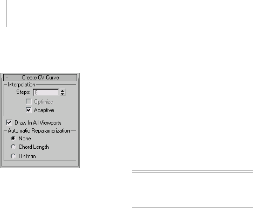
1114 Chapter 9: Surface Modeling
Finish—Ends creation of the curve, leaving it open
ended.
Create CV Curve rollout
This rollout contains the controls for curve
approximation.
Interpolation group
Thecontrolsinthisgroupboxchangetheaccuracy
andkindofcurve approximation (page 1–1238)
used to generate and display the curve.
Draw In All Viewports—Lets you use any viewport
whileyouaredrawingthecurve.Thisisoneway
to create a 3D curve. When off, you must finish
drawing the curve in the viewport where you
began it. Default=On.
WhileDrawInAllViewportsison,youcanalso
use snaps (page 2–41) in any viewport.
Automatic Reparameterization group
The controls in this group box let you specify
automatic reparameterization. They are similar
to the controls in the Reparameterize dialog (page
1–1237), with one addition: all choices except
for None tell the software to reparameterize the
curve automatically; that is, whenever you edit it
by moving CVs, refining, and so on.
None—Do not reparameterize automatically.
Chord Length—Chooses the chord-length
algorithm for reparameterization.
Chord-length reparameterization spaces knots (in
parameter space (page 3–988)) based on the square
rootofthelengthofeachcurvesegment.
Chord-length reparameterization is usually the
best choice.
Uniform—Spaces the knots uniformly.
A uniform knot vector has the advantage that the
curve or surface changes only locally when you edit
it. With the other two forms of parameterization,
moving any CV can change the entire sub-object.
Creating NURBS Curve and
Surface Objects
Creating Independent Surfaces
from NURBS Curve Objects
To create independent surfaces from top-level
NURBS curve objects, use the Extrude (page
1–680) and Lathe (page 1–707) modifiers. Extrude
adds height to the curve, creating a shape by
sweepingitalongthecurve’slocalZaxis.Lathe
createsasurfaceofrotation,revolvingtheshape
along a specified axis. You can also use the Bevel
(page 1–562) and Bevel Profile (page 1–565)
modifiers on NURBS curves.
These modifiers treat NURBS curves the same way
they treat shapes (page 1–262).Theadvantageof
using NURBS curves instead of shapes is in the
different possible shapes that NURBS geometry
and editing provide.
Tip: Whenyoucreateacomplicatedsurface,
especially with the Lathe modifier, you often want
to render both sides of the surface. Turn on Force
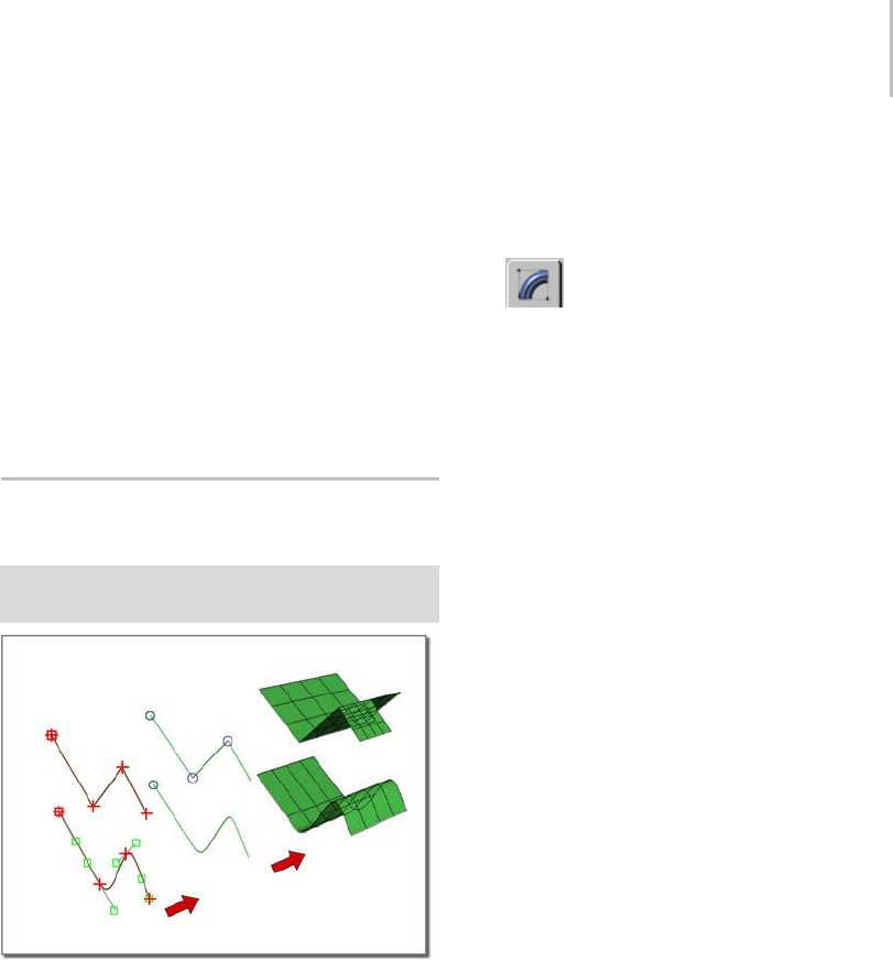
Creating NURBS Curves from Splines 1115
2-Sided in the Render Scene dialog to see both
sides of the extruded or lathed surface. To see both
sidesinviewports,turnonForce2-Sidedinthe
Viewport Configuration dialog.
By default, an object with Extrude or Lathe
collapses to an editable mesh (page 1–996) object.
To have Extrude or Lathe output collapse to a
NURBS object, change the setting to NURBS in the
Output group box of the Extrude or Lathe rollout,
and then collapse the modifier stack (page 3–760).
Creating NURBS Curves from
Splines
Select Spline object. > Modify panel > Right-click the
spline name. > Convert To: NURBS
Splines become NURBS curves that then become NURBS
surfaces.
Yo u c a n t u r n a spline (page 1–266) into a NURBS
object formed of CV curves (page 1–1106).Once
converted, you can no longer edit the spline shape
parametrically, but you can edit it as a NURBS
object, moving CVs and so on.
When you convert a spline circle (page 1–273)
to a NURBS curve, the direction of the curve is
reversed. This facilitates using the curve to trim a
surface: if the direction weren’t reversed, usually
the circle would trim outward instead of inward.
Procedure
To turn a spline into NURBS curves:
1. Create the spline.
2. Go to the Modify panel.
3. In the stack display, right-click the name of the
spline.
4. On the pop-up menu, choose Convert To:
NURBS.
ThesplineisconvertedtooneormoreCV
curves.
Smoothly curved splines, such as circles and
arcs, convert to a single CV curve.
Splineswithsharpangles,suchasrectangles
and stars, convert to multiple CV curves whose
endpointsareattheanglesintheoriginal
spline. These endpoints are fused except for the
initial CV in the spline (for a star, the initial
segment is unfused at both ends).
"Sharp angles" doesn’t apply to smooth splines
to which you have given angles by changing
vertex tangents using the Edit Spline (page
1–680) modifier. These still convert to a single
NURBS curve.
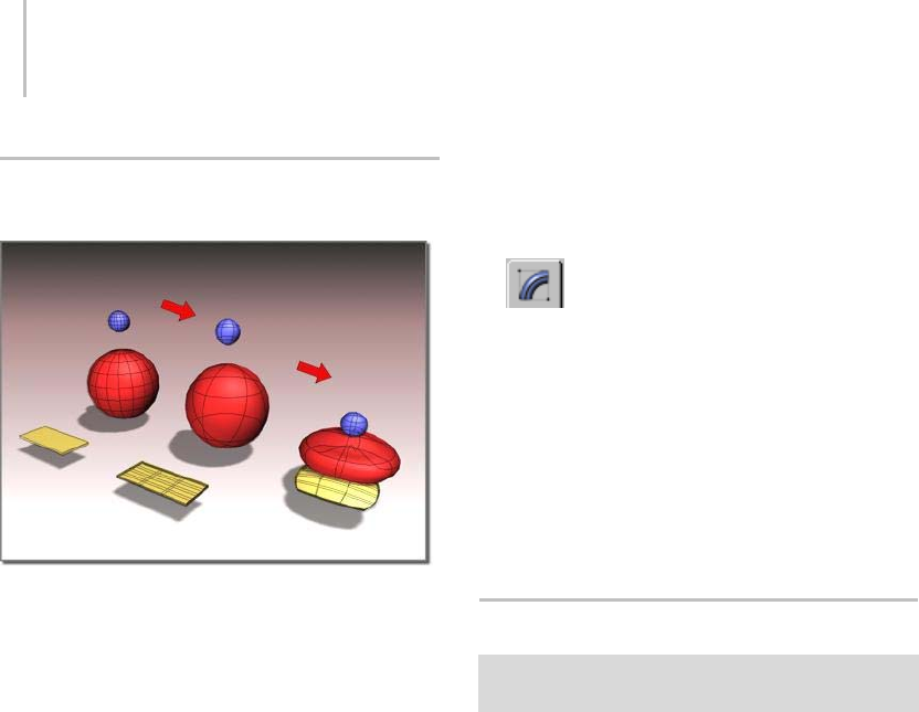
1116 Chapter 9: Surface Modeling
Creating NURBS Surfaces from
Geometric Primitives
Primitive objects become NURBS surfaces that you can then
edit in various ways.
Yo u c a n t u r n a standard primitive (page 1–170)
into a NURBS object formed of CV surfaces (page
1–1179). Once converted, you can no longer edit
theobjectparametrically,butyoucanedititasa
NURBS object, moving CVs and so on.
Youcan’tconvertmostextendedprimitiveobjects
in this way, but you can convert the torus knot
(page 1–189) and prism (page 1–205) extended
primitives to NURBS objects.
Yo u c a n a l s o c o n v e r t patch (page 1–993) objects
and loft (page 1–352) compound objects.
Tips
• Geospheres are good for creating rounded
models with no sharp edges.
• Boxes are good for creating models that have
sharp edges.
• Flattened cones work well for models whose
contours are roughly triangular.
If the primitive is closed, the converted surface is
a closed CV surface, which has no visible seams.
Also, relational cap surfaces (page 1–1195) are used
tocapsurfacesthataren’tclosed.
Procedure
To turn a primitive into a NURBS object:
1. Create the primitive object.
2. Go to the Modify panel.
3. In the stack display, right-click the name of the
object.
4. On the pop-up menu, choose Convert To:
NURBS.
The object is converted to one or more CV
surfaces. The surfaces can be independent
surface sub-objects, or dependent surface
sub-objectssuchasLathe.
Nonrelational NURBS Surfaces
Select NURBS object. > Modify panel > General rollout >
Relational Stack toggle
Nonrelational NURBS surfaces provide a way
to improve the performance of NURBS with
modifiers. These are controlled by the Relational
Stack toggle on the General rollout for NURBS
objects.
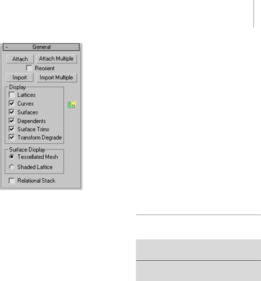
Display Controls for NURBS Models 1117
When Relational Stack is on, NURBS maintain full
relational modeling on the modifier stack (page
3–760). When this toggle is off (the default),
then using the modifier stack converts surfaces
into independent CV surfaces before applying
modifiers. Surfaces on the stack behave in a
nonrelational way. If your NURBS model contains
no dependent surfaces, then it behaves the same on
the stack regardless of the Relational Stack setting.
However, the results are still faster if Relational
Stack is turned off.
When Relational Stack is off, there is no overhead
of copying the data from the relational model,
and no need to compute the relational surfaces,
so performance is faster.
Tip: To improve performance still further, display
surfaces as shaded lattices (see Display Controls for
NURBS Models (page 1–1117)). With Relational
Stack off and Shaded Lattice chosen, NURBS
objects perform on the stack about as well as mesh
objects do.
Procedure
To use nonrelational NURBS surfaces:
1. Make sure Relational Stack is off and Shaded
Lattice is chosen.
2. Set up your modifiers and animation.
3. If your model has only independent CV
surfaces,youcanrenderitnow. Ifithas
relational surfaces such as blends or lofts, then
before you render, choose the NURBS model at
the bottom of the stack, and turn on Relational
Stack.
When you return to the top of the modifier
stack, performance is slower but dependent
surfaces are accurate. The modified NURBS
modellooksdifferentthanitdidwiththe
nonrelational stack. Usually the difference in
appearance isn’t great, but the nonrelational
stack can show anomalies such as cracks
between Blend surfaces.
Display Controls for NURBS
Models
Modify panel > Select NURBS object. > General rollout
> Display group, Surface Display group, and NURBS
Creation Toolbox button
Modify panel > Select NURBS object. > Right-click in
viewport. > Display commands on the Tools 1 (upper-left)
quadrant of the quad menu
The check boxes on the General rollout for a
NURBS curve or surface control how the object
is displayed in viewports. If all check boxes are
turned off, the NURBS object is invisible (except
for the white bounding-box indicators displayed
in shaded viewports when the object is selected).
An additional rollout, Display Line Parameters
(page 1–1119), contains controls for how surfaces
display in viewports.
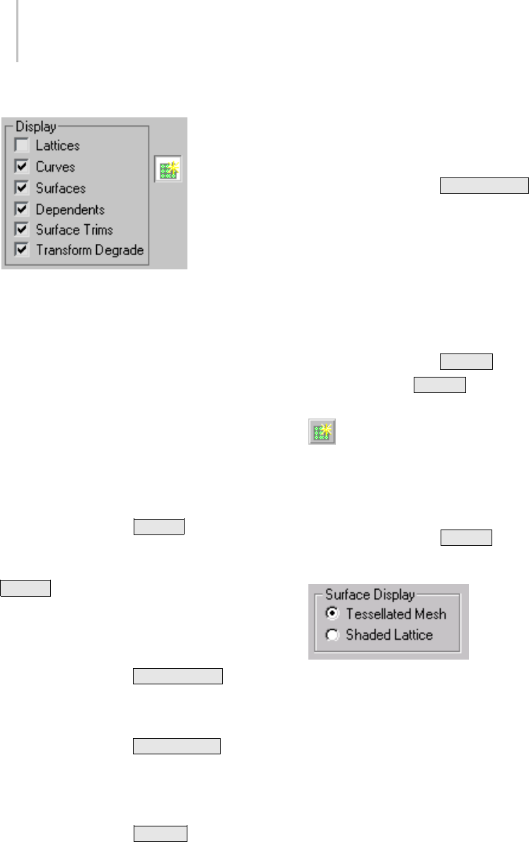
1118 Chapter 9: Surface Modeling
Interface
Display group
Lattices—When on, displays control lattices in
yellow lines. (You can change the lattice color using
the Colors panel (page 3–799) of the Customize
User Interface dialog.) The Curve CV and Surface
CV sub-object levels also have a local Display
Lattice toggle, which overrides this global setting
at the sub-object level. The Curve CV and Surface
CV settings are independent. In other words, at
the sub-object level you can turn on the lattice for
an object’s curves but not its surfaces, or vice versa.
Keyboard shortcut (while Keyboard Shortcut
Override Toggle is on): Ctrl+L
Attheobjectlevel,thisshortcutisequivalentto
turning Lattice on or off. At the sub-object level,
Ctrl+L overrides the setting of Lattice, toggling
the local Display Lattice setting.
Curves—When on, displays curves.
Keyboard shortcut (while Keyboard Shortcut
Override Toggle is on): Ctrl+Shift+C
Surfaces—When on, displays surfaces.
Keyboard shortcut (while Keyboard Shortcut
Override Toggle is on): Ctrl+Shift+S
Dependents—When on, displays dependent
sub-objects.
Keyboard shortcut (while Keyboard Shortcut
Override Toggle is on): Ctrl+D
Surface Trims—When on, displays surface trimming
(page 1–1080). When turned off, displays the
entire surface, even if it’s trimmed.
Keyboard shortcut (while Keyboard Shortcut
Override Toggle is on): Ctrl+Shift+T
Transform Degrade—When on, transforming a
NURBS surface can degrade its display in shaded
viewports, to save time. This is similar to the
Degradation Override (page 1–34) button for
playing animations. You can turn off this toggle so
surfaces are always shaded while you transform
them, but transforms can take longer.
Keyboard shortcut (while Keyboard Shortcut
Override Toggle is on): Ctrl+X
Tip: You can toggle Ctrl+X during a transform,
as well as before you begin the transform.
NURBS Creation Toolbox—Tu rn on to dis play
the NURBS sub-object creation toolbox. See Using
the NURBS Toolbox to Create Sub-Objects (page
1–1083).
Keyboard shortcut (while Keyboard Shortcut
Override Toggle is on): Ctrl+T
Surface Display group
This group box, for surfaces only, lets you choose
how to display surfaces in viewports.
Tessellated Mesh—When chosen, NURBS surfaces
displayasfairlyaccuratetessellatedmeshesin
shaded viewports. In wireframe viewports,
they appear as either iso curves or wire meshes,
depending on the settings you’ve chosen on the
Display Line Parameters rollout (page 1–1119).
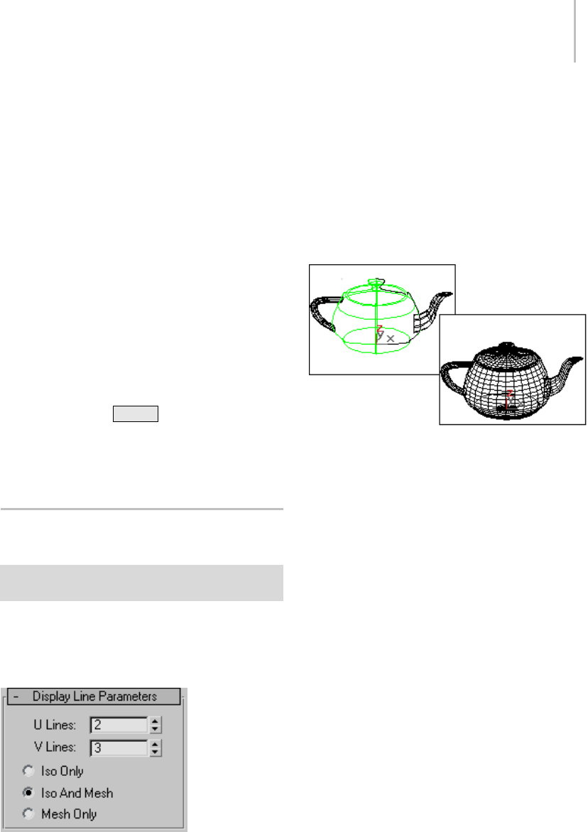
Display Line Parameters for NURBS Surfaces 1119
Shaded Lattice—When chosen, NURBS surfaces
appear as shaded lattices in shaded viewports.
Wireframe viewports display the surface’s lattice
without shading. A shaded lattice shades the CV
control lattice (page 3–923) of the NURBS surface.
This displays more quickly than a tessellated mesh.
The shading is not accurate. It gives you a fairly
goodideaoflofts,butislessaccurateforfree-form
surfaces. Theshadingisalwaysaslargeorlarger
than the actual surface, because of the convex hull
property (page 3–924).
Shaded lattice display doesn’t show surface
trimming (page 1–1080) or texture mapping.
Tip: Shaded Lattice is a good option to choose
when you use the modifier stack with nonrelational
NURBS surfaces (page 1–1116).
Keyboard shortcut: Alt+L
(You can use this keyboard shortcut without
having to turn on the Keyboard Shortcut Override
To g g l e . )
Display Line Parameters for
NURBS Surfaces
Select NURBS object. > Modify panel > Display Line
Parameters rollout
These parameters are contained on a single rollout
at the top level of a NURBS object.
Interface
ULinesandVLines—The number of lines used to
approximate the NURBS surface in viewports,
along the surface’s local U and V dimensions,
respectively. Reducing these values can speed up
thedisplayofthesurface,butreduceaccuracy
of the display. Increasing these values increases
accuracy at the expense of time. Setting one of
these values to 0 displays only the edge of the
object in the corresponding dimension.
Iso and mesh displays of a NURBS teapot
Iso Only—When chosen, all viewports display iso
line (page 3–959) representations of the surface.
Iso(parametric) lines are similar to contour lines.
ThelinesshowwheretheNURBSsurfacehas
a constant U value or V value or both. Iso line
representations can be less crowded and easier to
visualizethanwiremeshrepresentations.
Iso and Mesh—(The default.) When chosen,
wireframe viewports display iso line
representations of the surface, and shaded
viewports display the shaded surface.
Mesh Only—When chosen, wireframe viewports
display the surface as a wire mesh, and shaded
viewports display the shaded surface. In wireframe
viewports, this option lets you see the surface
approximation (page 1–1239) used for viewports.

1120 Chapter 9: Surface Modeling
Creating and Editing NURBS
Sub-Objects
Attaching and Importing 3ds Max
Objects
Modify panel > Select NURBS object. > General rollout >
Attach button, Import button, and related controls
There are two ways to bring other 3ds Max objects
into a NURBS object:
•Attach,whichworkslikeAttachformeshes
and splines. It converts the attached object to
NURBS format. Once the object is attached,
you can edit it as a NURBS surface or curve.
However, the attached object’s history is lost.
Note: For NURBS surfaces, you can attach
other NURBS objects, standard primitive (page
1–170) objects, or quad patch (page 1–994) and
tri patch (page 1–995) surfaces. The patch is
converted to a NURBS surface. Quad patches
convert more successfully than Tri Patches. A
converted Tri Patch has a collapsed internal
edge, which gives irregular results when you
manipulate its mesh.
When you convert a spline circle (page 1–273)
to a NURBS curve, the direction of the curve
is reversed. This facilitates using the curve to
trim a surface: if the direction weren’t reversed,
usually the circle would trim outward instead
of inward.
• Import, which works somewhat like the
operand of a Boolean (page 1–338).Theobject
is brought into the NURBS object without
losing its history. You can select the imported
object as a sub-object.
Using Imports
Here are reasons to use Import instead of Attach:
• To maintain parametric control over primitives.
For example, if you import a sphere, you can
change its radius directly, which you can’t do
after using Attach.
• TouseBeziersplinesasNURBScurves.
For example, if you want to use a Bezier spline
asacurveinaNURBSmodel,importit.This
allows you to edit it as a Bezier spline, and not
as a NURBS curve.
Surfaces and curves created by an import are
available in the NURBS model. For example, if
youimportabox,youcancreateablendsurface
between one of its polygons and another surface
in your NURBS object.
Once you have imported an object, the NURBS
object has an Imports sub-object level. When you
select an import, it is highlighted in red.
It is an error to apply a modifier to an import when
the modifier converts the import into something
that can’t be converted to a NURBS object. For
example, if you import a sphere and apply a Bend
(page 1–560) to it, the sphere converts to an
editable mesh, which can’t automatically convert
to a NURBS surface. In this case, the import
sub-object is in an error state, and it is displayed in
the error color (orange by default).
Imports are displayed in two different ways.
WhileyouworkattheNURBSobjectlevelorata
sub-object level other than Imports, imports are
displayed as NURBS curves or surfaces, and use
the NURBS object’s mesh tessellation (see Surface
Approximation (page 1–1239)). However, at the
Imports sub-object level, the selected import is
displayed using its native display format. In other
words, it displays as it would if it were a top-level
object.Thisisbecausethedisplaymustletyouedit
the imported object. For example, an imported
Bezier spline needs to display its tangent handles.
Thiswouldn’tbepossibleifitweredisplayedas
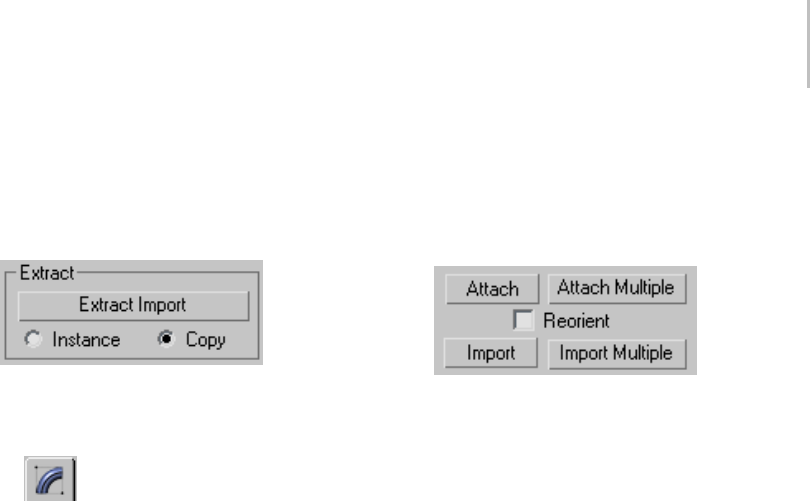
Attaching and Importing 3ds Max Objects 1121
a converted NURBS curve. Leaving the Imports
sub-object level returns to NURBS-style display.
You can extract an imported object. This creates
an independent, top-level object again.
Procedures
To attach or import an object to a NURBS object:
1. Select the NURBS object and go to the
Modify panel.
2. (Optional.) TurnonReorientifyouwantto
reorient and align the import with the center
of the NURBS object.
3. Tur n on At ta ch or Imp or t.
Note: At this step, you can click Attach Multiple
or Import Multiple instead. These buttons
display a Select Objects dialog (page 1–78) so
you can choose multiple objects to attach or
import.
4. Click the object to attach or import.
The mouse cursor changes shape to indicate
avalidobject.Youcanattachcurves,NURBS
surfaces, or objects convertible to NURBS.
To extract an imported object:
1. Go to the Imports sub-object level and select
the object to extract.
2. Click Extract Import on the Import sub-object
rollout.
If Copy is set (the default), the extracted object
is a top-level copy of the imported object.
If Instance is set, the extracted object is an
instance of the imported object. Initially the
extracted object occupies the same space as the
imported object: you must move either the
extracted object, the import sub-object, or the
whole NURBS model before you can see the
extracted object.
Interface
Attach and Import controls
Attach—Lets you attach another object to the
NURBS object. Click to turn on Attach, and
then click the object to attach. If the object
you’re attaching isn’t already a NURBS object, it
is converted to one or more NURBS curves or
surfaces that are sub-objects of the object you’re
modifying.
Attach Multiple—Lets you attach multiple objects
to the NURBS surface. Displays a version of the
Select Objects dialog (page 1–78), listing the objects
that can be attached. Use the dialog controls to
selectoneormoreobjectsbyname,andthenclick
Attach.
Reorient—Movesandreorientstheobjectyou
are attaching or importing so its creation local
coordinate system is aligned with the creation
local coordinate system of the NURBS object.
Import—Lets you import another object to the
NURBS object. Works the same way Attach does,
but the imported object retains its parameters and
modifiers.
Import Multiple—Lets you import multiple objects.
Works the same way Attach Multiple does, but
the imported objects retain their parameters and
modifiers.

1122 Chapter 9: Surface Modeling
Common Sub-Object Controls
Many controls are common to the various kinds of
sub-objects in NURBS models (with the exception
of Imports (page 1–1120)). This topic introduces
the controls that are common to most NURBS
sub-objects.
See also
Editing Point Sub-Objects (page 1–1123)
Editing Curve CV Sub-Objects (page 1–1127)
Editing Surface CV Sub-Objects (page 1–1130)
Editing Curve Sub-Objects (page 1–1135)
Editing Surface Sub-Objects (page 1–1141)
Transforming Sub-Objects
One way to alter a NURBS model is to transform
its sub-objects. Transforming lets you interactively
changethemodel’scurvatureandshape.
Transforming points or CVs is especially useful for
adjusting the shape of a NURBS curve or surface.
Yo u c a n a l s o Shift +Clone most kinds of
sub-objects, except CVs. For curves and surfaces,
Shift +Cloning displays a Sub-Object Clone
Options dialog (page 1–1237),whichletsyou
reduce relational dependencies to improve
performance.
Selection Controls
There is a Selection group box on the rollout for all
NURBS sub-objects except Imports. The buttons
in this group let you control which sub-objects
to select. The selection buttons let you select
sub-objects individually, or multiple sub-objects at
once. For example, Surface CV selection buttons
give you the option of selecting individual CVs, or
selecting a row of CVs on the surface, and so on.
Note: There is no delete modifier for NURBS
curves as there is for splines. There is a NURBS
selection modifier, NSurf Sel (page 1–747).See
NURBS and Modifiers (page 1–1089).
Selection controls also include a Name field that
lets you customize the name of individual NURBS
sub-objects other than CVs. (The Name field is
the only selection control for Import sub-objects.)
Visibility
You can hide or unhide NURBS sub-objects as
you do other objects. Hidden sub-objects are
invisible in viewports, but remain renderable.
(Atthesub-objectlevel,hidingdoesn’taffectthe
renderer.) You can’t select hidden sub-objects.
Hide and unhide by name is available for curve
and surface sub-objects.
Make Independent
You can make a dependent point, curve, or surface
sub-object independent.
Warning: When you make an object independent,
you lose the animation controllers for all objects that
depend on it in turn. When you make point objects
independent, you lose the animation controllers for all
points on the curve or surface. Also, if you make a curve
that trims a surface independent, you lose the trimming
of the surface.
Remove Animation
All sub-object rollouts have a Remove Animation
button. This removes animation controllers from
the selected sub-objects.
Detach and Copy
You can create a new curve or surface object by
detaching a curve or surface sub-object from
a NURBS model. To do so, select the curve
or surface and then click Detach. A dialog is
displayed, which lets you enter a name for the new
NURBS object. The new object is no longer part of
the original NURBS object.
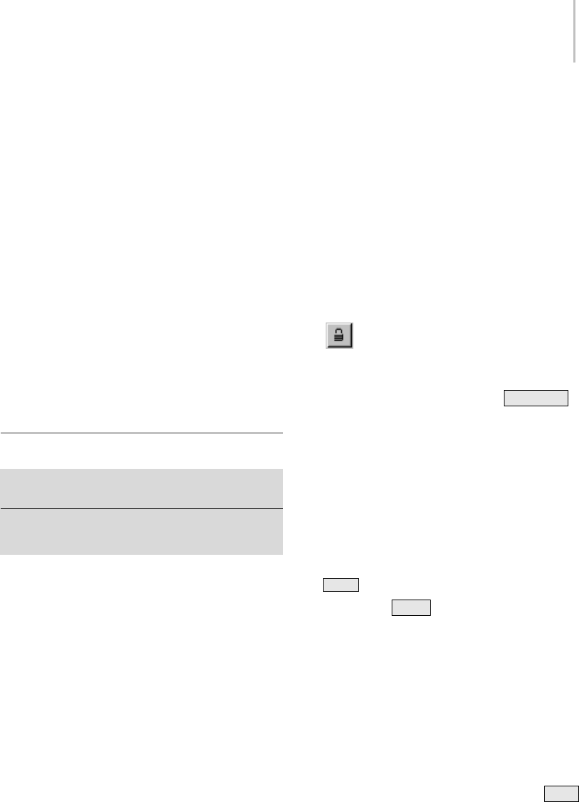
Editing Point Sub-Objects 1123
You can also use the Detach button to create a new
NURBSobjectthatisacopyofacurveorsurface
sub-object.Todoso,selectthecurveorsurface,
and click to turn on Copy before you click Detach.
Adialogisdisplayed,whichletsyouenteraname
for the new object. The original curve or surface
sub-objectremainspartoftheNURBSobjectyou
were editing, but the copied curve or surface is
now a NURBS object of its own.
Relational—This toggle affects dependent objects.
When off, detaching a dependent sub-object
makes it an independent object. For example,
detachingaUloftconvertsittoaCVsurface.
When on, detaching a dependent sub-object also
detaches the objects it depends on, so the object
remains dependent. For example, detaching a U
loft also detaches the curves that define it.
Editing Point Sub-Objects
Modify panel > Select NURBS object or sub-object. >
Point sub-object level > Select point sub-objects.
Modify panel > Select NURBS object or sub-object. >
Right-click. > Tools 1 (upper-left) quadrant > Sub-objects
> Point > Select point sub-objects.
This topic describes the controls for point
sub-objects. A rollout labeled Point contains the
point sub-object controls for NURBS models. In
addition to the Point rollout described here, the
Point sub-object level displays the Soft Selection
rollout (page 1–1147).
Procedures
To transform point sub-objects:
1. At the Point sub-object level, select one or more
points.
Thesub-objectselectiontoolsarethesameas
for other kinds of sub-objects. You can also use
the Hkey while the Keyboard Shortcut Override
toggle (page 3–872) is on. See Sub-Object
Selection (page 1–1084).
The Selection group box, described under
"Interface" later in this topic, provides
some additional options for selecting Point
sub-objects.
2. Turn on Move or another transform and then
drag in a viewport to transform the selection.
Theshapeofthemodelchangesasyou
interactively transform the points.
Rotate and Scale are useful only when you’ve
selected multiple points.
Tips
•The Lock Selection Set button is useful
when you transform NURBS point sub-objects.
You can make a selection in one viewport, click
Lock Selection Set (or press the Spacebar ),
andthentransformtheselectioninadifferent
viewport.
•Whenyoumovepointsub-objects,movethem
as systematically as possible to avoid "getting
lost."
• Onsurfaces,avoidmovingpointssotheycross
over or under adjacent points. This can create
odd-looking warps or overlaps in the surface.
To Shift +Clone a point sub-object:
•HolddownShift while you transform the
point.
This works only for points that lie on curves
or surfaces, independent point (page 1–1219)
sub-objects, and curve point (page 1–1220) or
surface point (page 1–1222) sub-objects that
lie on the curve or surface (that is, that aren’t
displaced).
To use the keyboard to select point sub-objects:
Yo u c a n s e l e c t p o i n t s u b - o b j e c t s u s i n g t h e Ctrl
key and the arrow keys. The arrows traverse the
sub-objects in the order they were created. To do
so, follow these steps:
1124 Chapter 9: Surface Modeling
1. Tur n on t he Ke y bo ard Shor tc ut
Override Toggle.
2. Click or drag to select points.
3. Hold down Ctrl and use the arrow keys to
move among the point sub-objects.
For points on curves, the arrow keys traverse
the point selection along the length of the
curve. Thearrowkeysdon’tmovebetween
curve sub-objects.
Forpointsonsurfaces,theleftandrightarrow
keys traverse the U dimension of a surface,
while the up and down arrow keys traverse the
V dimension of the surface. The arrow keys
don’t move between surface sub-objects.
Thearrowkeysdon’ttraverseindividually
createdpointsthataren’tpartofacurveor
surface.
You can also use the Hkeyboard shortcut (while
theKeyboardShortcutOverrideToggleison)
todisplayadialogandselectpointsbyname.
Ctrl+H displays only the names of points directly
beneath the mouse cursor.
To remove a point from a curve:
1. Select a point.
2. In the Delete group box, click Point.
Keyboard shortcut: Delete
Thepointisdeletedandtheshapeofthecurve
is updated.
Note: An open point curve must have at least
two endpoints.
To remove points from a surface:
1. Selectapoint,row,orcolumn.
TheappropriateDeletebuttonsareenabled.
2. IntheDeletegroupbox,clickPoint,Row,or
Col.
Thepoint,row,orcolumnisdeleted.Deletinga
"single" point actually deletes both the row and
column to which the point belongs.
To add a point to a curve:
1. IntheRefinegroupbox,turnonCurve.
2. Click the curve where you want to add the
point.
A point is added at the location you clicked.
The curvature can change.
To add a point and extend the length of a curve:
1. ClicktoturnonExtend.
2. Move the mouse over a point curve. The curve
ishighlightedinblue,andoneofthecurve’s
ends displays a box to show where the curve
will be extended.
3. Drag from the highlighted end point, and then
release the mouse button.
A new point is added beyond the original
length of the curve.
To add points to a point surface:
1. IntheRefinegroupbox,clickSurfRow,Surf
Col., or Surf Row & Col.
2. Click the surface.
Arow,acolumn,orbothareaddedcloseto
thepointwhereyouclickedthesurface.The
new points are placed on the surface so they
preserve the surface’s curvature. The curvature
can change, but only slightly.
To fuse two points:
1. Tur n on Fu se.
2. Click a point without releasing the mouse
button. Drag to another point, and then release
the mouse button.
The first point you choose acquires the position
of the second point, and becomes dependent to
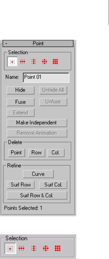
Editing Point Sub-Objects 1125
it. If the first point has an animation controller,
the controller is discarded. If the second point
has an animation controller, the first point
acquires it too.
Fused points display in purple by default.
To unfuse fused points:
1. Select the fused point.
2. Click Unfuse.
Now you can move and edit the two points
independently.
To transform a region:
1. Using sub-object selection, select one or more
points for the center of transformation.
2. Tur n on S of t Sele cti on.
3. Trans for m the point.
A region around the selected point is
transformed accordingly.
Move is the most common transform to use.
Rotate and Scale can be used with a non-local
transform center.
Tip: If Soft Selection appears not to be working,
theFalloffvaluemightbetoosmallforthesize
of your surface. On the Soft Selection rollout
(page 1–1147),increasethevalueofFalloffsoit
encompasses other points.
Interface
In addition to the Point rollout described here,
the Point sub-object level also displays the Soft
Selection rollout (page 1–1147).
Selection group
Point sub-object selection controls
Single Point—(The default.) When on, you can
select individual points by clicking, or groups of
points by dragging a region.
Row of Points—When on, clicking a point selects
theentirerowthepointbelongsto. Dragging
selects all rows in the region.
If the point is on a curve, Row of Points selects all
points in the curve.

1126 Chapter 9: Surface Modeling
Column of Points—When on, clicking a point
selects the entire column the point belongs to.
Draggingselectsallcolumnsintheregion.
If the point is on a curve, Column of Points selects
only a single point.
Row and Column of Points—When on, clicking a
point selects both the row and column the point
belongs to. Dragging selects all rows and columns
in the region.
All Points—When on, clicking or dragging selects
all the points in the curve or surface.
Tip: Rows and columns are easily visible when
theNURBSsurfaceisplanar,ornearlyso.When
the surface has a complicated curvature, rows
and columns can be more difficult to see. The
Row, Column, and Row/Column buttons can be
especially useful in this situation.
Name—Shows the name of the currently selected
point. It is disabled if you have selected multiple
points.
By default, the name is "Point" followed by a
sequence number. You can use this field to give the
point a name that you choose.
Hide—Click to hide the currently selected points.
Unhide All—Click to unhide all hidden points.
Fuse—Fuses a point to another point. (You can’t
fuse a CV to a point, or vice versa.) This is one way
to connect two curves or surfaces. It is also a way
to change the shape of curves and surfaces.
Fusing points does not combine the two point
sub-objects. They are connected but remain
distinct sub-objects that you can unfuse later.
Fused points behave as a single point until you
unfuse them.
Fused points are displayed in a distinct color. The
default is purple. (You can change this color using
the Colors panel (page 3–799) of the Customize
User Interface dialog (page 3–792).)
Unfuse—Unfuses the fused points.
Extend—Extends a point curve. Drag from the end
of a curve to add a new point and extend the curve.
Warning: When you add points with Extend, you lose
the animation controllers for all points on the curve or
surface.
Make Independent—Disabled if the point is
independent. If the point is dependent, clicking
this button makes it independent.
Warning: When you make a point independent, you
lose the animation controllers for all objects that depend
on it in turn.
Remove Animation—Removes animation
controllers from the selected points.
Delete group
The buttons in this group box delete one or more
points.
Point—Deletes a single point (on a curve) or a row
and column of points (on a surface).
Row—Deletes a row from a surface.
Col.—Deletes a column from a surface.
Warning: When you delete points, you lose the
animation controllers for all points on the curve or
surface.
Refine group
The buttons in this box refine point curves or
surfaces by adding points to them.
Curve—Adds points to a point curve.
Surf Row—Addsarowofpointstoapointsurface.
Surf Col.—Addsacolumnofpointstoapoint
surface.
Editing Curve CV Sub-Objects 1127
Surf Row & Col.—Adds both a row and a column
to a point surface; their intersection is where you
click the surface.
Warning: When you add points, you lose the animation
controllers for all points on the curve or surface.
Points Selected—This text field shows how many
points are currently selected.
Editing Curve CV Sub-Objects
Modify panel > Select NURBS object or sub-object. >
Stack display > Curve CV sub-object level > Select CV
sub-objects.
Modify panel > Select NURBS object or sub-object. >
Right-click. > Tools 1 (upper-left) quadrant > Sub-objects
> Curve CV > Select CV sub-objects.
This topic describes the controls for CV
sub-objects that lie on curves. A rollout labeled CV
contains the CV sub-object controls for NURBS
models. In addition to the CV rollout described
here, the Curve CV sub-object level displays the
Soft Selection rollout (page 1–1147).
In you can edit the CVs in CV curves on surfaces
(page 1–1172) as you edit other kinds of curve
CVs. You can transform CVs in CV curves on
surfaces, but you can’t move the CVs off the
surface. Using the Curve CV sub-object level is an
alternativetoeditingtheseCVsbyusingtheEdit
Curve on Surface (page 1–1229) dialog.
Procedures
To transform curve CV sub-objects:
1. At the Curve CV sub-object level, select one or
more CVs.
The sub-object selection tools are the same
as for other kinds of sub-objects. You can
also use the Hkey while the Keyboard
Shortcut Override toggle (page 3–872) is on. See
Sub-Object Selection (page 1–1084).
The Selection group box, described under
"Interface" later in this topic, provides some
additional options for selecting CV sub-objects.
2. Turn on Move or another transform and then
drag in a viewport to transform the selection.
Theshapeofthemodelchangesasyou
interactively transform the CVs.
Rotate and Scale are useful only when you’ve
selected multiple CVs.
Tips
•When you transform NURBS CV
sub-objects, the Lock Selection Set button can
beuseful. Youcanmakeaselectioninone
viewport, click Lock Selection Set (or press the
Spacebar ), and then transform the selection
in a different viewport.
•WhenyoumoveCVsub-objects,movethemas
systematically as possible to avoid "getting lost."
TousethekeyboardtoselectcurveCVsub-objects:
Yo u c a n s e l e c t c u r v e C V s u b - o b j e c t s u s i n g t h e
Ctrl key and the arrow keys. The arrows traverse
the sub-objects in the order they were created. To
do so, follow these steps:
1. Tur n on t he Ke y bo ard S hor tc ut
Override Toggle.
2. Click or drag to select CVs.
3. Hold down Ctrl and use the arrow keys to
move among the CV sub-objects.
For CVs on curves, the arrow keys traverse the
CV selection along the length of the curve.
The arrow keys don’t move between curve
sub-objects.
Yo u c a n a l s o u s e t h e Hkeyboard shortcut (while
theKeyboardShortcutOverrideTogglebuttonis
on)todisplayadialogandselectCVsbyname.

1128 Chapter 9: Surface Modeling
Ctrl+H displays only the names of CVs directly
beneath the mouse cursor.
To remove a CV from a curve:
1. Select a CV.
2. Click Delete.
Keyboard shortcut: Delete
TheCVisdeletedandtheshapeofthecurve
is updated.
Note: A CV curve must have at least one more
CV than the degree (page 3–927) of the curve.
To add a CV to a curve:
1. Tur n on Re fine.
2. Click the curve where you want to add the CV.
A CV is added at the location you clicked.
Neighboring CVs move away from the new CV
in order to preserve the original curvature.
ToaddCVsandextendthelengthofacurve:
1. ClicktoturnonExtend.
2. Move the mouse over a CV curve. The curve is
highlighted in blue, and one of the curve’s ends
displays a box to show where the curve will be
extended.
3. Drag from the highlighted end CV, and then
release the mouse button.
NewCVsareaddedbeyondtheoriginallength
of the curve.
To fuse two CVs:
1. Tur n on Fu se.
2. Click a CV without releasing the mouse button.
Drag to another CV, and then release the mouse
button.
ThefirstCVyouchooseacquirestheposition
of the second CV, and becomes dependent to it.
If the first CV has an animation controller, the
controller is discarded. If the second CV has
an animation controller, the first CV acquires
it too.
Fused CVs display in purple by default.
To unfuse fused CVs:
1. Select the fused CV.
2. Click Unfuse.
Now you can move and edit the two CVs
independently.
To transform a region:
1. Using sub-object selection, select one or more
CVs for the center of transformation.
2. Turn on Soft Selection.
3. Trans for m the CV.
A region around the selected CV is transformed
accordingly.
Move is the most common transform to use.
Rotate and Scale can be used with a non-local
transform center.
Tip: If Soft Selection appears not to be working,
the Falloff value might be too small for the size
of your surface. On the Soft Selection rollout
(page 1–1147), increase the value of Falloff so it
encompasses other points or CVs.
Interface
In addition to the CV rollout described here, the
Curve CV sub-object level also displays the Soft
Selection rollout (page 1–1147).
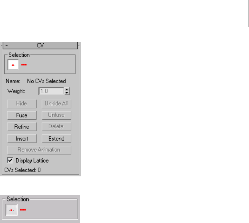
Editing Curve CV Sub-Objects 1129
Selection group
Curve sub-object selection controls
Single CV—(The default.) When on, you can select
individual CVs by clicking, or groups of CVs by
dragging a region.
All CVs—When on, clicking or dragging selects all
the CVs in the curve.
Name—Showseither"NoCVsselected","Multiple
CVs selected", or "CurveName(index)", where
"CurveName" is the name of the CV’s parent
curve, and "index" is the CV’s U location along the
length of the curve. You can’t edit the Name field
to customize the names of CVs.
If CVs are fused, the Name field shows the name
of the first CV.
Weight—Adjusts the weight of the selected CVs.
Yo u c a n u s e a C V ’ s weight to adjust the CV’s effect
on the curve. Increasing the weight pulls the curve
toward the CV. Decreasing the weight relaxes the
curve away from the CV.
Increasingweightisawaytohardenacurve;that
is, to sharpen its curvature at a particular location.
By default, the weight is 1.0 for the CVs of NURBS
objects that you create on the Create panel or the
NURBS sub-object creation rollouts. The weight
of CVs in geometry that you convert to NURBS
canvary,dependingontheobject’soriginalshape.
You can change the weight when multiple CVs are
selected. Using the Weight field or spinner while
multiple CVs are selected assigns all of them the
value you choose. Because weights are relative to
each other (rational), using the Weight control
when all CVs are selected has no visible effect.
Hide—Click to hide the currently selected CVs.
Unhide All—Click to unhide all hidden CVs.
Fuse—Fuses a CV to another CV. (You can’t fuse a
CV to a point, or vice versa.) This is one way to
connecttwocurves.Itisalsoawaytochangethe
shape of curves.
Fusing CVs does not combine the two CV
sub-objects. They are connected but remain
distinct sub-objects that you can unfuse later.
Fused CVs behave as a single CV until you unfuse
them. Fused CVs behave similar to a single point,
but the property of multiplicity for coincident CVs
also applies. (See NURBS Concepts (page 1–1091)
and CV Curve (page 1–1110).) The fused CVs
have proportionally more influence on the curve.
The curve can become sharper in the fused CVs’
vicinity, or even angular if more than two CVs are
fused together.
Fused CVs are displayed in a distinct color. The
default is purple. (You can change this color using
the Colors panel (page 3–799) of the Customize
User Interface dialog (page 3–792).)
Unfuse—Unfuses the fused CVs.
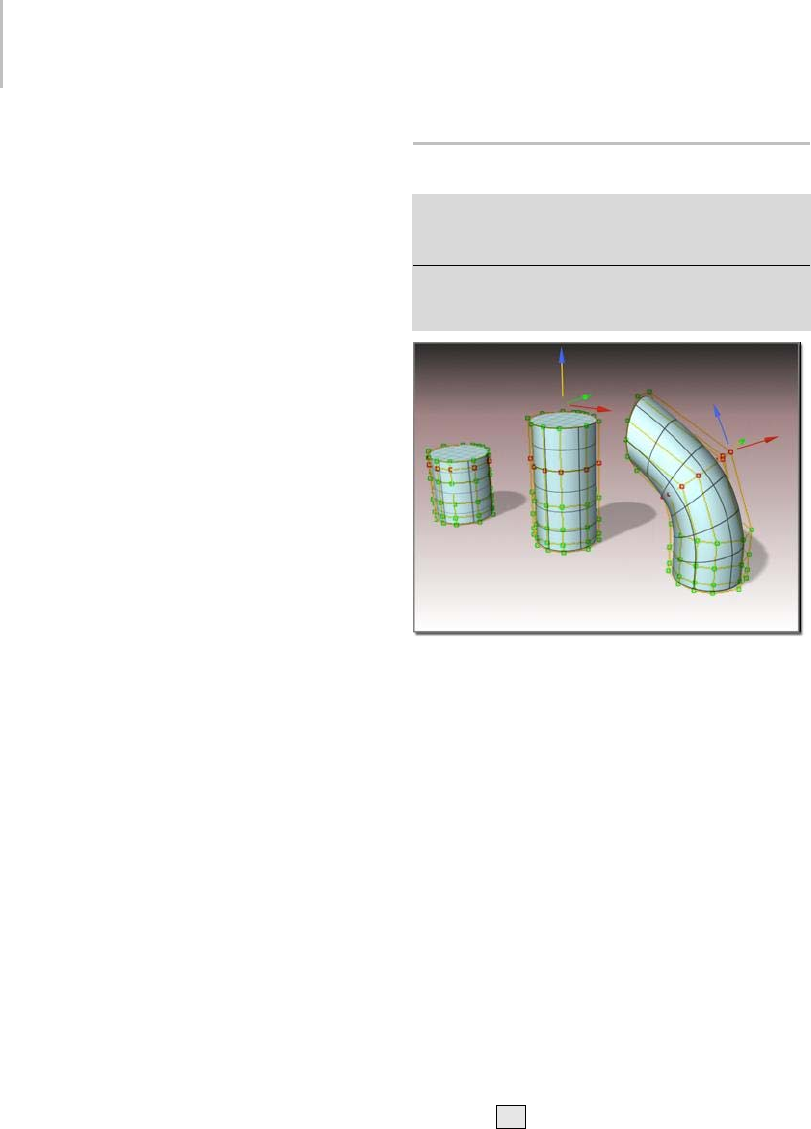
1130 Chapter 9: Surface Modeling
Refine—Refines the curve by adding CVs.
Warning: When you add CVs with Refine, you lose the
animation controllers for all CVs on the curve.
As you move the mouse over the CV curve, a
preview of the CVs that will be added, and their
locations, is displayed in blue.
Tip: It is a good idea to reparameterize after you
have added CVs to a curve by refining. See Editing
Curve Sub-Objects (page 1–1135).
Delete—Deletes the selected CVs.
Insert—Inserts CVs into the curve. Click Insert
and then click the curve where you want to insert
the new CV. Inserting CVs is similar to refining
with CVs, except that other CVs in the curve do
not move. This means that the shape of the curve
changes when you insert.
Inserting CVs does not remove animation from
thecurve,asrefiningdoes.
Tip: It is a good idea to reparameterize after you
have added CVs to a curve by inserting. See
Editing Curve Sub-Objects (page 1–1135).
Extend—Extends a CV curve. Drag from the end
of a curve to add a new CV and extend the curve.
Warning: When you add points with Extend, you lose
the animation controllers for all points on the curve.
Remove Animation—Removes animation
controllers from the selected CVs.
Display Lattice—When on, displays the control
lattice (page 3–923) that surrounds CV curves.
When off, the control lattice isn’t shown in
viewports. Default=on.
CVs Selected—This text field shows how many CVs
are currently selected.
Editing Surface CV Sub-Objects
Modify panel > Select NURBS object or sub-object. >
Stack display > Surface CV sub-object level > Select CV
sub-objects.
Modify panel > Select NURBS object or sub-object. >
Right-click a viewport. > Tools 1 (upper-left) quadrant >
Sub-objects > Surface CV > Select CV sub-objects.
Transforming CVs changes the shape of the surface.
Procedures (page 1–1130)
Interface (page 1–1132)
This topic describes the controls for CV
sub-objects that lie on surfaces. A rollout labeled
CV contains the CV sub-object controls for
NURBS models. In addition to the CV rollout
described here, the Curve CV sub-object level
displays the Soft Selection rollout (page 1–1147).
Procedures
To transform surface CV sub-objects:
1. At the Surface CV sub-object level, select one
or more CVs.
The sub-object selection tools are the same as
for other kinds of sub-objects. You can also
use the Hkey while the Keyboard Shortcut
Override Toggle (page 3–872) button is on. See
Sub-Object Selection (page 1–1084).
Editing Surface CV Sub-Objects 1131
The Selection group box, described under
"Interface" later in this topic, provides
additional options for selecting CV sub-objects.
2. Turn on Move or another transform and then
drag in a viewport to transform the selection.
Theshapeofthemodelchangesasyou
interactively transform the CVs.
Rotate and Scale are useful only when you’ve
selected multiple CVs.
Tips
•The Lock Selection Set button is useful
when you transform NURBS CV sub-objects.
You can make a selection in one viewport, click
Lock Selection Set (or press the Spacebar ),
andthentransformtheselectioninadifferent
viewport.
• When you move CV sub-objects, move them as
systematically as possible to avoid "getting lost."
•Onsurfaces,avoidmovingCVssotheycross
over or under adjacent points. This can create
odd-looking warps or overlaps in the surface.
To Shift +clone surface sub-objects:
•HolddownShift while you transform the
surface selection.
The Sub-Object Clone Options (page 1–1237)
dialog appears. This dialog provides various
waystoclonethesurfaces,someofwhich
reduce relational dependencies to improve
performance.
To use the keyboard to select surface CV sub-objects:
You can select surface CV sub-objects using the
Ctrl key and the arrow keys. The arrows traverse
the sub-objects in the order they were created. To
do so, follow these steps:
1. Tur n on t he Ke y bo ard S hor tc ut
Override Toggle.
2. Click or drag to select CVs.
3. Hold down Ctrl and use the arrow keys to
move among the CV sub-objects.
For CVs on surfaces, the left and right arrow
keys traverse the U dimension of a surface,
while the up and down arrow keys traverse the
V dimension of the surface. The arrow keys
don’t move between surface sub-objects.
Yo u c a n a l s o u s e t h e Hkeyboard shortcut (while
theKeyboardShortcutOverrideTogglebuttonis
on)todisplayadialogandselectCVsbyname.
Ctrl+H displays only the names of CVs directly
beneath the mouse cursor.
To remove CVs from a surface:
1. Select a row, column, or a row and column.
TheappropriateDeletebuttonsareenabled.
2. IntheDeletegroupbox,clickRow,Col.,or
Both.
The row, the column, or both are deleted.
Note: Yo u c a n’ t d e l e t e a s i n g l e C V f r o m a C V
surface. Nor can you delete a row or column if
thatwouldmakethesurfacehavefewerthan
four rows or columns.
To add CVs to a CV Surface:
1. IntheRefinegroupbox,clickRow,Col.,or
Both.
2. Click the surface.
Arow,acolumn,orbothareaddedclose
to the point where you clicked the surface.
Neighboring CVs move away from the new
CVs in order to preserve the surface’s original
curvature.
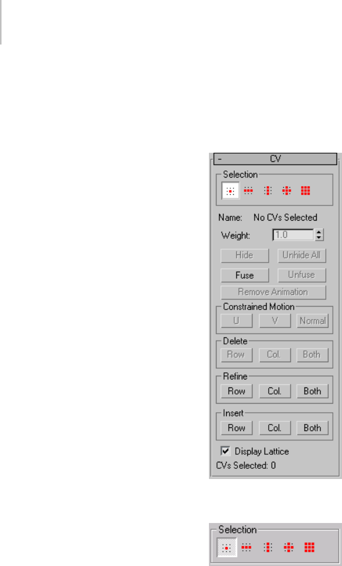
1132 Chapter 9: Surface Modeling
To fuse two CVs:
1. Tur n on Fu se.
2. Click a CV without releasing the mouse button.
Drag to another CV, and then release the mouse
button.
ThefirstCVyouchooseacquirestheposition
of the second CV, and becomes dependent to it.
If the first CV has an animation controller, the
controller is discarded. If the second CV has
an animation controller, the first CV acquires
it too.
Note: Fused CVs display in purple by default.
To unfuse fused CVs
1. Select the fused CV.
2. Click Unfuse.
NowyoucanmoveandeditthetwoCVs
independently.
To transform a region:
1. Using sub-object selection, select one or more
CVs for the center of transformation.
2. Tur n on S of t Sele cti on.
3. Trans for m the C V.
A region around the selected CV is transformed
accordingly.
Move is the most common transform to use.
Rotate and Scale can be used with a non-local
transform center.
Tip: If Soft Selection appears not to be working,
theFalloffvaluemightbetoosmallforthesize
of your surface. On the Soft Selection (page
1–1147) rollout, increase the value of Falloff so it
encompasses other CVs.
Interface
In addition to the CV rollout described here, the
Surface CV sub-object level also displays the Soft
Selection rollout (page 1–1147).
CV rollout
Surface CV sub-object rollout
Selection group
Surface CV sub-object selection controls

Editing Surface CV Sub-Objects 1133
Single CV—(The default.) When on, you can select
individual CVs by clicking, or groups of CVs by
dragging a region.
Row of CVs—Whenon,clickingaCVselectsthe
entire row the CV belongs to. Dragging selects all
rows in the region.
Column of CVs—When on, clicking a CV selects the
entire column the CV belongs to. Dragging selects
all columns in the region.
Row and Column of CVs—When on, clicking a CV
selects both the row and column the CV belongs
to. Dragging selects all rows and columns in the
region.
All CVs—When on, clicking or dragging selects all
the CVs in the surface.
Name—Showseither"NoCVsselected","Multiple
CVs selected", or "SurfaceName(uIndex,vIndex)",
where "SurfaceName" is the name of the CV’s
parent surface, and "uIndex,vIndex" is the CV’s
UV location on the surface. You can’t edit the
Name field to customize the names of CVs.
If CVs are fused, the Name field shows the name
of the first CV.
Weight—Adjusts the weight of the selected CVs.
Yo u c a n u s e a C V ’ s weight to adjust the CV’s effect
on the surface. Increasing the weight pulls the
surface toward the CV. Decreasing the weight
relaxes the surface away from the CV.
Increasingweightisawaytohardenasurface:that
is, to sharpen its curvature at a particular location.
By default, the weight is 1.0 for the CVs of NURBS
objects that you create on the Create panel or the
NURBS sub-object creation rollouts. The weight
of CVs in geometry that you convert to NURBS
can vary, depending on the object’s original shape.
You can change the weight when multiple CVs are
selected. Using the Weight field or spinner while
multiple CVs are selected assigns all of them the
value you choose. Because weights are relative to
each other (rational), using the Weight control
when all CVs are selected has no visible effect.
Tip: You can increase the curvature of an
indentation in a surface by increasing the weight
of the CVs surrounding the indented area. This is
easier and often more effective than moving the
indented area’s CVs.
Hide—Click to hide the currently selected CVs.
Unhide All—Click to unhide all hidden CVs.
Fuse—Fuses a CV to another CV. (You can’t fuse a
CV to a point, or vice versa.) This is one way to
connecttwosurfaces.Itisalsoawaytochangethe
shape of surfaces.
Fusing CVs does not combine the two CV
sub-objects. They are connected but remain
distinct sub-objects that you can unfuse later.
Fused CVs behave as a single CV until you unfuse
them. Fused CVs behave similar to a single point,
but the property of multiplicity for coincident CVs
also applies. (See NURBS Concepts (page 1–1091)
and CV Curve (page 1–1110).) The fused CVs have
proportionally more influence on the curve, which
can become sharper in the fused CVs’ vicinity,
or even angular if more than two CVs are fused
together.
Fused CVs are displayed in a distinct color. The
default is purple. (You can change this color using
the Colors panel (page 3–799) of the Customize
User Interface dialog (page 3–792).)
Unfuse—Unfuses the fused CVs.
Remove Animation—Removes animation
controllers from the selected CVs.
Constrained Motion group
These buttons constrain CV motion. They are
enabled when you select one or more CVs. When

1134 Chapter 9: Surface Modeling
you finish dragging the CV selection, the active
constraint button turns off.
U—Constrains the CV selection to move in the
surface’s U dimension.
Keyboard shortcut (Keyboard Shortcut Override
Toggle must be on): Alt+U
V—Constrains the CV selection to move in the
surface’s V dimension.
Keyboard shortcut (Keyboard Shortcut Override
Toggle must be on): Alt+V
Normal—Constrains the CV selection to move
normal to the original surface.
Keyboard shortcut (Keyboard Shortcut Override
Toggle must be on): Alt+N
Delete group
These buttons delete CVs from the surface. Select
one or more CVs, and then click Row, Col., or
Both.
You can’t delete surface CVs if the deletion would
givethesurfacefewerthanfourrowsorfewerthan
four columns. Aside from that restriction, these
buttons delete all rows, columns, or rows and
columns that contain selected CVs. This means
that you can’t delete after you make a selection
using the Row and Column or All selection
buttons: that would imply deleting the entire CV
surface.
Thesebuttonsareunavailableunlessthedeletion
is possible.
Warning: When you delete CVs, you lose the animation
controllers for all CVs on the surface.
Row—Deletes rows of CVs from the surface.
Col.—Deletes columns of CVs from the surface.
Both—DeletesbothrowsandcolumnsofCVs
from the surface.
Refine group
These buttons refine the surface by adding CVs.
Asyoumovethemouseoverthesurface,apreview
of the CVs that will be added, and their locations,
is displayed in blue.
Warning: When you add CVs with Refine, you lose the
animation controllers for all CVs on the surface.
Row—Adds a row of CVs to the surface.
Col.—Adds a column of CVs to the surface.
Both—Adds both a row and a column of CVs to
the surface.
Tip: It is a good idea to reparameterize after you
have added CVs to a surface by refining. See
Editing Surface Sub-Objects (page 1–1141).
Insert group
These buttons insert CVs into the curve. Click
to turn on one of these buttons and then click
thesurfacewhereyouwanttoinsertthenew
CVs. Inserting CVs is similar to refining with
CVs, except that other CVs in the surface do not
move. This means that the shape of the surface can
change when you insert.
Inserting CVs does not remove animation from
the surface the way refining does.
Row—Inserts a row of CVs into the surface.
Col.—InsertsacolumnofCVsintothesurface.
Both—InsertsbotharowandacolumnofCVs
into the surface.
Tip: It is a good idea to reparameterize after you
have added CVs to a surface by inserting. See
Editing Surface Sub-Objects (page 1–1141).
Display Lattice—When on, displays the control
lattice (page 3–923) that surrounds CV surfaces.
When off, the control lattice isn’t shown in
viewports. Default=on.
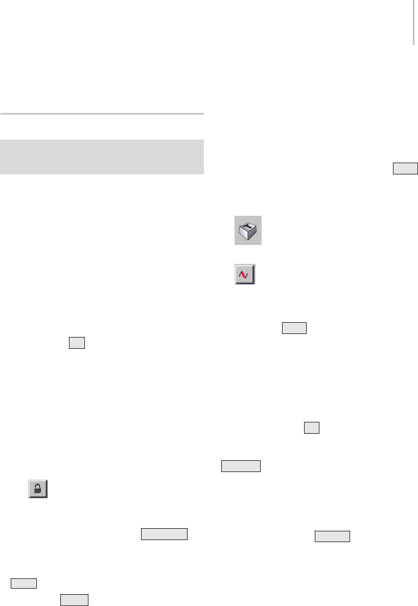
Editing Curve Sub-Objects 1135
CVs Selected—This text field shows how many CVs
are currently selected.
Editing Curve Sub-Objects
Modify panel > Stack display > Open the NURBS object’s
hierarchy. > Curve sub-object level > Select curve
sub-objects.
This topic describes the controls that are common
to point and CV curves. A rollout labeled Curve
Common contains the curve sub-object controls
for NURBS models.
Procedures
To transform curves:
1. At the Curve sub-object level, select one or
more curves.
The sub-object selection tools are the same
as for other kinds of sub-objects. You can
also press the Hkey when the Keyboard
Shortcut Override toggle (page 3–872) is on. See
Sub-Object Selection (page 1–1084).
The Selection group box, described under
"Interface" later in this topic, provides
additional options for selecting curves.
2. Turn on Move or another transform and then
drag in a viewport to transform the selection.
Theshapeofthemodelchangesasyou
interactively transform the curves.
Tip: The Lock Selection Set button is useful
when you transform NURBS curve sub-objects.
You can make a selection in one viewport, click
Lock Selection Set (or press the Spacebar ),
andthentransformtheselectioninadifferent
viewport.
To Shift +Clone curve sub-objects:
•HolddownShift while you transform the
curve selection.
The Sub-Object Clone Options (page 1–1237)
dialog is displayed. This dialog provides
variouswaystoclonethecurves,someofwhich
reduce relational dependencies to improve
performance.
Tousethekeyboardtoselectcurvesub-objects:
Yo u c a n s e l e c t c u r v e s u b - o b j e c t s u s i n g t h e Ctrl
key and the arrow keys. The arrows traverse the
sub-objects in the order they were created. To do
so, follow these steps:
1. Tur n on t he Ke y bo ard S hor tc ut
Override Toggle.
2. At the Curve sub-object level, set the
selectioncontrolstoselectcurvesindividually.
3. Click or drag to select curves.
4. Hold down Ctrl and use the arrow keys to
move among the curves in the current model.
At the Curve sub-object level, the left and
right arrow keys move forward and backward
through individual curves in the order they
were created. The up and down arrows are
equivalent to left and right.
Yo u c a n a l s o u s e t h e Hkeyboard shortcut (while
theKeyboardShortcutOverrideToggleison)
to display a dialog and select curves by name.
Ctrl+H displays only the names of curves
directly beneath the mouse cursor.
To delete a curve:
• Select the curve and then click Delete.
Keyboard shortcut: Delete
To turn a CV curve into a point curve:
1. Select the curve sub-object, and then click
Make Fit.
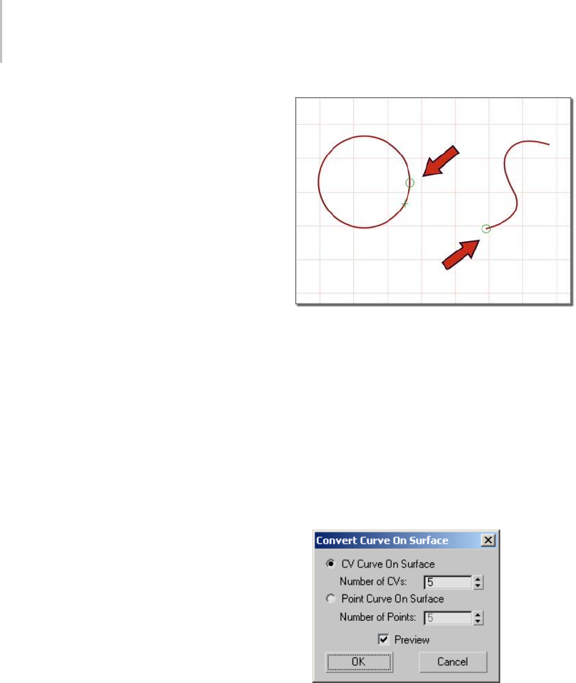
1136 Chapter 9: Surface Modeling
The Make Point Curve (page 1–1235) dialog is
displayed. This dialog asks how many points
the new point curve should have.
2. Change the number of points, and then click
OK.
Reducing the number of points can change the
shape of the curve.
If the selected curve is already a point curve, you
can use Make Fit to change the number of points
it has.
To select a first vertex on the curve:
• Select the curve sub-object, turn on Make First,
andthenclickalocationonthecurve.
If the curve is closed and there is a vertex where
you click, this vertex becomes the first vertex. If
the curve is closed and there is no vertex where
you click, a new vertex is created at the location
you click. It becomes the new first vertex, and
the curve’s points or CVs adapt to maintain the
curvature.
If the curve is open, clicking it has no effect.
Warning: Using Make First discards any animation
controllers for the points or CVs in the curve.
Ifthecurveisopen,thefirstvertexmustbeone
of the endpoints (by default, it is the first you
created). The Make First button has no effect,
butyoucanuseReversetochangethecurve’s
direction.
The small circle indicates the first vertex.
To turn a curve that lies on a surface into a Point
Curve on Surface:
1. Select the curve sub-object, and then click
Make COS.
Make COS is unavailable unless the curve
already lies on a surface; for example, it is a U
Iso curve.
2. The Convert Curve on Surface dialog (page
1–1226) is displayed.
Choose CV Curve on Surface to create a CV
curve, or Point Curve on Surface to create a
point curve. The Number of CVs or Number of
Points values let you specify the complexity and
accuracy of the new curve on surface. If Preview
is on, the new curve is previewed in viewports.
This can help you choose the number.
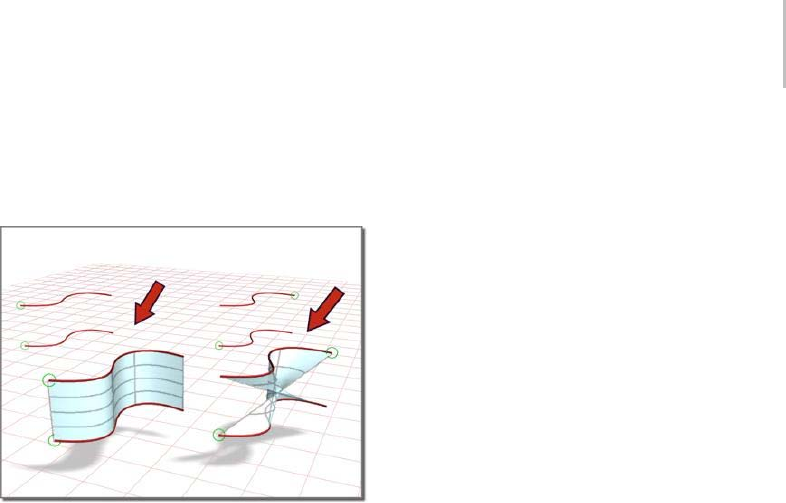
Editing Curve Sub-Objects 1137
To reverse a curve:
• Select a curve sub-object and then click
Reverse.
Reversing a curve affects the blend surface that depends
on it.
To join two curves:
1. In a NURBS object that contains two curve
sub-objects, turn on Join.
2. Click one curve near the end that you want
to connect. Drag to near the end of the other
curve, and then release the mouse.
The Join Curve dialog (page 1–1232) is
displayed. This dialog gives you a choice of
methods for joining the curves. Whichever
method you choose, the two original curves are
replaced by a single curve.
3. If the gap between the curves is small (less than
about30units),usetheJoinCurvedialogtoset
theTolerancevaluegreaterthanthedistance
of the gap.
To break a curve:
• TurnonBreakandthenclickacurve.
Thecurveissplitintotwoindependentcurve
sub-objects.Twocoincident(butindependent)
points or CVs are created at the location you
clicked: each is the endpoint of one part of the
original curve.
If the curve is a closed curve, Break creates a
single curve object, with its new start and end
points at the location you clicked. The new start
and end points are coincident but independent.
To close a curve:
• Select the curve and then click Close.
Thesoftwareclosesthecurvebyaddinga
segment between the curve’s endpoints. The
curvature of the new segment blends the
curvature of the previous end segments.
Closing a curve does not add points or CVs. The
curve retains its original number of points or CVs,
and increases its number of segments by one.
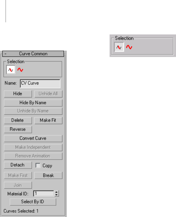
1138 Chapter 9: Surface Modeling
Interface
Curve Common rollout
The controls on this rollout apply to all curve
types. Depending on the type of curve, an
additional rollout is displayed with controls
specific to that type of curve.
Selection group
The selection buttons for curve sub-objects let you
select either individual curves, or curves that are
connected in space.
Curve sub-object selection controls
Single Curve—Clicking or transforming a curve
selects only a single independent curve sub-object.
All Connected Curves—Clicking or transforming
a curve selects all curve sub-objects that are
connected within the NURBS object. To be
connected, two curves must have fused points,
or one curve must be a connected dependent (a
blend, fillet, or chamfer) of the other.
Name—Shows the name of the currently selected
curve. It is disabled if you have selected multiple
curves.
Bydefault,thenameisthenameofthecurve
type ("CV Curve" or "Point Curve") followed by a
sequence number. You can use this field to give the
curve a name that you choose.
Hide—Click to hide the currently selected curves.
Unhide All—Click to unhide all hidden curves.
Hide by Name—Click to display a Select
Sub-Objects dialog that lists curves by name.
Select the curves to hide, then click Hide.
Unhide by Name—Disabled unless there are hidden
curves. Click to display a Select Sub-Objects
dialogthatlistscurvesbyname.Selectthecurves
to make visible, then click Unhide.
Delete—Deletes the selected curve sub-objects.
Make Fit—Tur ns a C V cu r ve i nto a p oi nt c ur ve .
This displays the Make Point Curve dialog (page
1–1235), which lets you set the number of points.
Forapointcurve,thisbuttonletsyouchangethe
number of points in the curve.

Editing Curve Sub-Objects 1139
Reverse—Reverses the order of the CVs or points
in a curve, so that the first vertex becomes the last,
and the last becomes the first.
The first point or CV is significant when you use
the NURBS curve like a spline: as a loft (page
1–352) path or shape, as a path constraint (page
2–398) path, or as a motion trajectory (page
2–301). For these purposes, the first vertex of the
curve is significant. If the curve is a closed curve,
you can use Make First to set the curve’s first
vertex.
The direction of the curve also determines the
initial direction of normals on surfaces based on
this curve.
Make COS—This button is enabled only for the
following kinds of curves:
•U iso curves (page 1–1168)
•V iso curves (page 1–1168)
•Normal projected curves (page 1–1169)
•Vector projected curves (page 1–1171)
•Surface-surface intersection curves (page
1–1166)
•Surface edge curves (page 1–1177)
•CV curves on surfaces (page 1–1172)
•Point curves on surfaces (page 1–1175)
This displays a Make Curve on Surface dialog
(page 1–1226), which turns the selected curve
into a CV or point curve on surface. Once
converted, you can edit the new curve on
surfaceusingthecurveonsurfacecontrols,
including the Edit Curve on Surface dialog (page
1–1229).
Ifthecurveisalreadyacurveonsurface,this
button lets you change it from a point to CV
curveonsurface,orviceversa.
The new Curve on Surface preserves the
trimming of the original curve.
Convert Curve—Click to display the Convert Curve
dialog (page 1–1225).Thisdialogprovidesamore
generalwaytoconvertaCVcurvetoapointcurve,
or a point curve to a CV curve. It also lets you
adjust a number of other curve parameters.
Make Independent—Disabled if the curve is
independent. If the curve is dependent, clicking
this button makes it independent.
Warning: When you make a curve independent, you
lose the animation controllers for all objects that depend
on it in turn. If you make a curve that trims a surface
independent, you lose the trimming of the surface.
Remove Animation—Removes animation
controllers from the selected curves.
Detach—Detaches the selected curve sub-object
from the NURBS model, making it a new top-level
NURBS curve (page 1–1106) object. The Detach
dialog (page 1–1228) is displayed, which lets you
name the new curve. The new object is no longer
part of the original NURBS model.
To create a new top-level NURBS curve that is a
copyoftheselectedcurve,turnonCopybefore
you click Detach.
Copy—When on, clicking Detach creates a copy of
the selected curve instead of detaching it from the
NURBS model. Default=off.
Make First—For a closed curve, lets you choose a
position that becomes the first vertex of the curve.
The first point or CV is significant when you use
theNURBScurvelikeaspline:asaloft (page
1–352) path or shape, as a path constraint (page
2–398) path, or as a motion trajectory (page
2–301). For these purposes, the first vertex of the
curve is significant. If the curve is a closed curve,
you can use Make First to set the curve’s first
vertex.
Break—Breaks a single curve into two curves.
Click in a viewport to choose the location to break
the curve.
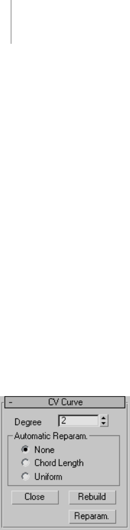
1140 Chapter 9: Surface Modeling
Warning: When you break a curve sub-object, you lose
the animation controllers for all points or CVs on the
curve.
Join—Joins two curve sub-objects together. After
you have joined the curves in a viewport, the Join
Curves dialog (page 1–1232) is displayed. This
dialog lets you choose the method for joining the
two curves.
Warning: When you join two curve sub-objects, you
lose the animation controllers for all points or CVs on
both curves.
Material ID—LetsyouassignamaterialIDvalue
to the curve. If the curve is renderable, material
IDs let you assign a material to the curve using
aMulti/Sub-Object (page 2–1594) material. In
addition, the Select by ID button lets you select a
curveormultiplecurvesbyspecifyingamaterial
ID number. Can range from 1 to 100. Default=1.
Select by ID—Displays a Select by Material ID (page
1–1238) dialog.
CV Curve rollout
This additional rollout is displayed when a CV
curve is selected.
Degree—Setsthedegreeofthecurve.Thehigher
the degree value, the greater the continuity. The
lower the degree, the more discontinuous the
curve segments become. The degree can’t be less
than one or greater than the number allowed by
the number of CVs in the curve. Degree 3 curves
are adequate to represent continuous curves, and
arestableandwellbehaved.Default=3.
Setting the degree greater than 3 isn’t
recommended because higher-degree curves are
slower to calculate and less stable numerically.
Higher-degree curves are supported primarily to
be compatible with models created using other
surface modeling programs.
The number of CVs in a CV curve must be at least
onegreaterthanthecurve’sdegree.
Automatic Reparameterization group
The controls in this group box let you specify
automatic reparameterization. They are similar
to the controls in the Reparameterize dialog (page
1–1237), with the addition that all choices except
for None tell the software to reparameterize the
curve automatically; that is, whenever you edit it
by moving CVs, refining, and so on.
None—Do not reparameterize automatically.
Chord Length—Chooses the chord-length
algorithm for reparameterization.
Chord-length reparameterization spaces knots (in
parameter space (page 3–988)) based on the square
rootofthelengthofeachcurvesegment.
Chord-length reparameterization is usually the
best choice.
Uniform—Spaces the knots uniformly.
A uniform knot vector has the advantage that the
curve or surface changes only locally when you edit
it. With chord-length parameterization, moving
any CV can potentially change the entire curve.
Close—Closesthecurve.Disabledifthecurveis
already closed.
Rebuild—Displays the Rebuild CV Curve dialog
(page 1–1236), which lets you specify how to
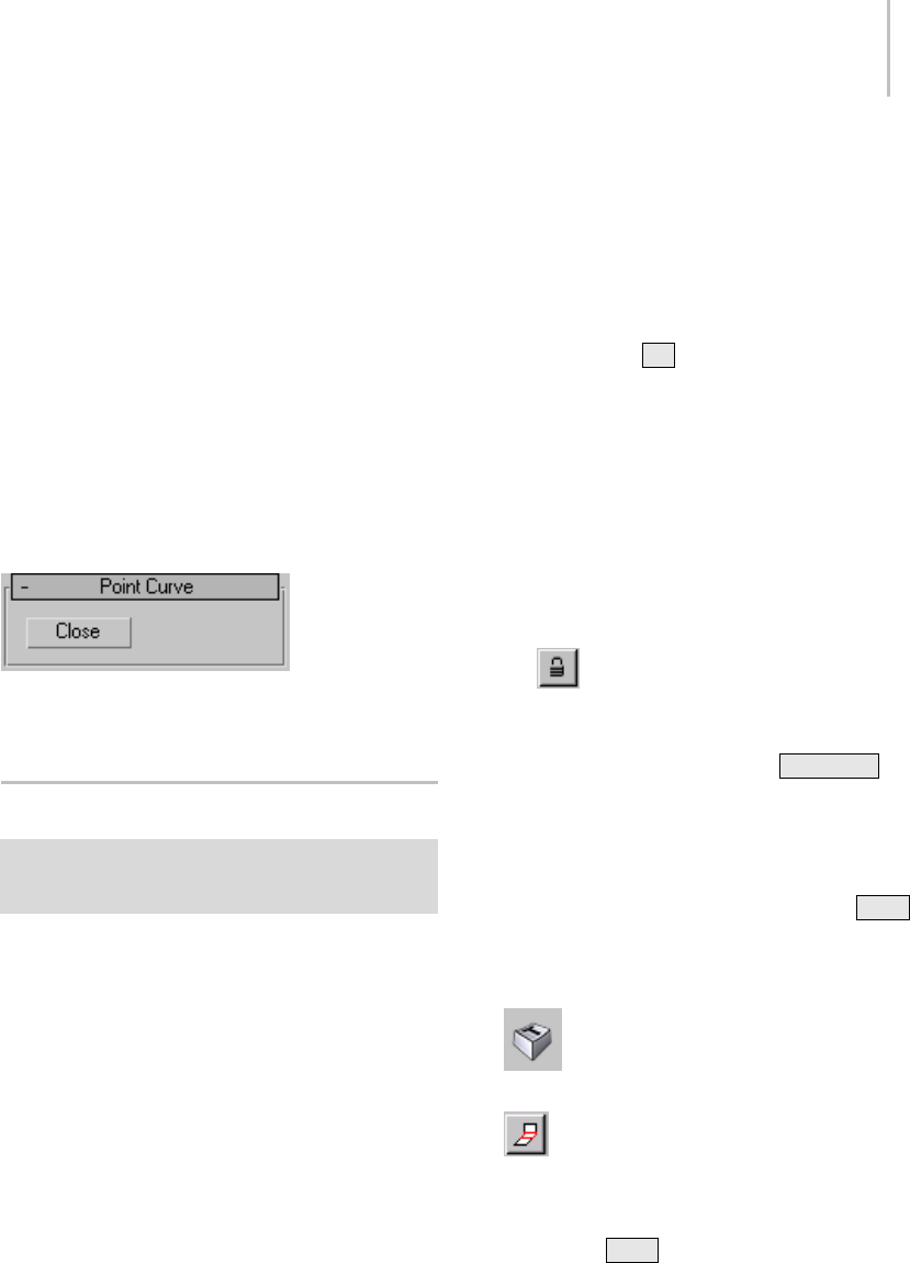
Editing Surface Sub-Objects 1141
rebuild the curve. Rebuilding the curve can change
its appearance.
Reparam.—Displays the Reparameterize dialog
(page 1–1237). Reparameterizing a curve changes
the curve’s parameter space (page 3–988) to
provide a better relation between control point
locations and the shape of the curve.
Tip: It is a good idea to reparameterize after
youhaveaddedCVstothecurvebyrefiningor
inserting.
Point Curve rollout
This additional rollout appears when a point curve
is selected.
Close—Closesthecurve.Disabledifthecurveis
already closed.
Editing Surface Sub-Objects
Modify panel > Stack display > Open the NURBS object’s
hierarchy. > Surface sub-object level > Select surface
sub-objects.
This topic describes controls that are common
to point surfaces, CV surfaces, and the various
dependent surface types. A rollout labeled Surface
Common contains the surface sub-object controls
for NURBS surfaces. Another rollout, Material
Properties (page 1–1149), controls mapping on
surface sub-objects, and is described in its own
topic. See Surface Approximation (page 1–1239)
for a description of that rollout. The final rollout
for surface sub-objects depends on the type of
surface selected.
Procedures
To transform surface sub-objects:
1. At the Surface sub-object level, select one or
more surface sub-objects.
The sub-object selection tools are the same as
for other kinds of sub-objects. In addition,
you can use the Hkey when the Keyboard
Shortcut Override toggle (page 3–872) is on. See
Sub-Object Selection (page 1–1084).
The Selection group box, described under
"Interface" later in this topic, provides
additional options for selecting surfaces.
2. Turn on Move or another transform and then
drag in a viewport to transform the selection.
Theshapeofthemodelchangesasyou
interactively transform the surfaces.
Tip: The Lock Selection Set button is useful
when you transform NURBS sub-objects. You
canmakeaselectioninoneviewport,click
Lock Selection Set (or press the Spacebar ),
andthentransformtheselectioninadifferent
viewport.
To use the keyboard to select surface sub-objects:
Yo u c a n s e l e c t s u r f a c e s u b - o b j e c t s u s i n g t h e Ctrl
key and the arrow keys. The arrows traverse the
sub-objects in the order they were created. To do
so, follow these steps:
1. Tur n on t he Ke y bo ard S hor tc ut
Override Toggle.
2. At the Surface sub-object level, set the
selectioncontrolstoselectsurfacesindividually.
3. Click or drag to select surfaces.
4. Hold down Ctrl and use the arrow keys to
move among surfaces in the current model.
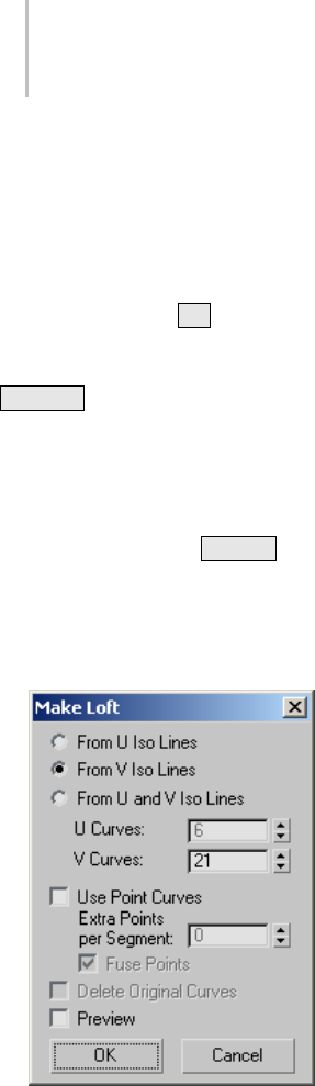
1142 Chapter 9: Surface Modeling
At the Surface sub-object level, the left and
right arrow keys move forward and backward
through individual surfaces in the order they
were created. The up and down arrows are
equivalent to left and right.
You can also use the Hkeyboard shortcut (while
theKeyboardShortcutOverrideToggleison)
todisplayadialogandselectsurfacesbyname.
Ctrl+H displays only the names of surfaces
directly beneath the mouse cursor.
To delete a surface:
• Select the surface and then click Delete.
Keyboard shortcut: Delete
Tomakeasurfacealoft:
1. Select the surface and then click Make Loft. A
Make Loft dialog (page 1–1234) is displayed.
2. Use the Make Loft dialog controls to choose the
settings for the new surface, and then click OK.
To break a surface:
1. TurnonBreakRow,BreakCol.,orBreakBoth,
and then drag over the surface.
One or two blue curves appear on the surface to
indicate where the break will occur.
2. When you have dragged to the location you
want to break, click the surface.
Note: If you break a dependent surface, the new
"broken" surfaces are made independent.
You cannot break a trimmed surface.
To extend a surface:
1. Tur n on E xte nd .
2. Move the mouse over the surface without
depressing the mouse button. The edge that
will be extended is highlighted in blue.
3. Whentheedgeyouwanttoextendis
highlighted, press the mouse button, and then
drag vertically to increase the length of the
surface.
The surface extension is invalid and disappears if it
would cause the surface to intersect itself or if the
edge of the surface touches itself but is not closed.
For example, you can’t extend the top of a cylinder.
To join two surfaces:
1. In a NURBS object that contains two surface
sub-objects, turn on Join.
2. If the gap between the surfaces is small (less
than about 30 units), set the Tolerance value
greater than the distance of the gap.
3. Click one surface near the edge that you want
to connect. The edge that will be connected is
highlighted in blue. Drag to choose the edge
you want to connect. Without releasing the
mouse button, drag to the other surface. The
edge of the other surface is also highlighted in
blue. Drag on the other surface to choose the
edge to connect, and then release the mouse
button.
The surface that owns the highlighted edge is
highlighted in yellow, to help you distinguish
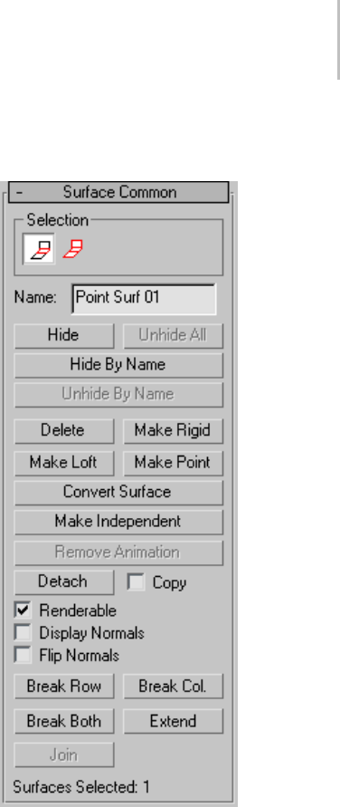
Editing Surface Sub-Objects 1143
whichedgeyouarechoosingwhentwosurfaces
have coincident edges.
The Join Surfaces dialog (page 1–1233) is
displayed, which gives you a choice of methods
for how to join the surfaces. Whichever method
youchoose,thesoftwarecreatesasinglesurface
that replaces the two original surfaces.
To close a surface:
• Select the surface sub-object and then click
Close Rows or Close Cols.
Interface
Surface Common rollout
Surface sub-object rollout
The controls on this rollout apply to all surface
types. Depending on the type of surface, an
additional rollout is displayed with controls
specific to that type of surface.
Selection group
The selection buttons for surface sub-objects let
you select either individual surfaces, or surfaces
that are connected in space.
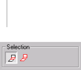
1144 Chapter 9: Surface Modeling
Surface sub-object selection controls
Single Surface—Clicking or transforming a surface
selects only a single surface sub-object.
All Connected Surfaces—Clicking or transforming
a surface selects all surface sub-objects that are
connected within the NURBS object. To be
connected, two surfaces must have all the CVs on
a shared edge fused between them, or one surface
must be a connected dependent of the other (for
example, a blend or a cap).
Name—Shows the name of the currently selected
surface. It is disabled if you have selected multiple
surfaces.
By default, the name is the name of the surface type
("CV Surface," "Point Surface," "Blend Surface,"
and so on) followed by a sequence number. You
canusethisfieldtogivethesurfaceanamethat
you choose.
Hide—Click to hide the currently selected surface.
Unhide All—Click to unhide all hidden surfaces.
Hide by Name—Click to display a Select
Sub-Objects dialog that lists surfaces by name.
Select the surfaces to hide, then click Hide.
Unhide by Name—Disabled unless there are hidden
surfaces. Click to display a Select Sub-Objects
dialogthatlistssurfacesbyname. Selectthe
surfaces to make visible, then click Unhide.
Delete—Deletes the selected surface sub-objects.
Make Rigid—Makes the surface rigid. The only
editing allowed on a rigid surface is to transform
it at the Surface sub-object level. You can’t move
arigidsurface’spointsorCVs,orchangethe
number of points or CVs.
Rigid surfaces reduce the amount of memory
used by the NURBS model. Making surfaces rigid
improves performance, especially for large and
complex models.
When a surface is rigid, you can’t see its points
or CVs when you are at the Point or Surface CV
sub-object levels. If the model has no nonrigid
surfaces and no point curves, the Point and Surface
CV sub-object levels aren’t available at all.
To make a surface no longer rigid, click Make
Point or Make Independent. Editing the surface
with Break, Join, and so on also makes it no longer
rigid.
Make Loft—Displays a Make Loft dialog (page
1–1234) to convert the surface sub-object to a
(dependent) U loft or UV loft surface. Can also
change the dimension used to construct a U loft
surface.
Youcan’tuseMakeLoftifthesurfacesub-object
is in an error condition.
Tip: Make Loft creates a loft with uniformly spaced
curves. To make a loft with adaptively spaced iso
curves, manually create the curves and then loft
them with U Iso Lines, V Iso Lines, or U and V
Iso Lines.
Make Point—Displays a Make Point dialog (page
1–1235) to convert any kind of surface to a point
surface. You can also use Make Point to change
thenumberofrowsandcolumnsifthesurfaceis
already a point surface.
Convert Surface—Click to display the Convert
Surface dialog (page 1–1227).Thisdialogprovides
ageneralwaytoconvertasurfacetoadifferent
type of surface. You can convert between lofts,
point ("fit") surfaces, and CV surfaces. The dialog
also lets you adjust a number of other surface
parameters.

Editing Surface Sub-Objects 1145
Make Independent—Disabled if the surface is
independent. If the surface is dependent, clicking
this button makes it independent.
Warning: When you make a surface independent, you
lose the animation controllers for all objects that depend
on it in turn.
Remove Animation—Removes animation
controllers from the selected surfaces.
Detach—Detaches the selected surface sub-object
from the NURBS model, making it a new top-level
NURBS surface object (page 1–1101).TheDetach
dialog (page 1–1228) is displayed, which lets you
name the new surface. The new object is no longer
part of the original NURBS model.
To create a new top-level NURBS surface that is a
copy of the selected surface, turn on Copy before
you click Detach.
Copy—When on, clicking Detach creates a copy of
the selected surface instead of detaching it from
the NURBS model. Default=off.
Renderable—When on, the surface renders. Turn
offtomakethesurfaceinvisibleinrenderings.
Default=on.
Display Normals—When on, the normal for each
selected surface is displayed. There is one normal
per surface sub-object. The normal is displayed at
the surface’s UV origin, so displaying normals can
help you see how materials will be mapped. On
the other hand, the normal can be hard to see if
you are zoomed out. Default=off.
Flip Normals—Turn on to reverse the direction of
the surface normals. Default=off.
Tip: The Flip Normals control is useful for viewing
a surface that is mostly concave or mostly convex.
With more complicated NURBS surfaces, you
often want to render both sides of the surface.
Tur n on Forc e 2-Side d in t he Render Scene dialog
(page 3–2) to see both sides of the surface. To see
both sides of the surfaces in viewports, turn on
Force 2-Sided in the Rendering Method panel of
the Viewport Configuration dialog (page 3–853),or
assign a Double-Sided Material (page 2–1591).
Break Row—Breaks the surface into two surfaces in
the direction of a row (the surface’s U axis).
Break Col.—Breaks the surface into two surfaces in
the direction of a column (the surface’s V axis).
Break Both—Breaks the surface into four surfaces
in both directions.
You cannot break a trimmed surface.
Extend—Extendsthesurfacebychangingits
length.
Warning: Extending a surface loses all animation
controllers for the surface and its points or CVs.
Join—Joins two surface sub-objects together. After
you have joined the surfaces in a viewport, the
Join Surfaces dialog (page 1–1233) is displayed.
This dialog lets you choose the method for joining
the two surfaces. You can join only original edges
of surfaces; you cannot join edges created by
trimming.
Warning: When you join two surface sub-objects, you
lose the animation controllers for all point or CVs on
both surfaces.
CV Surface rollout
This additional rollout is displayed when a CV
surface is selected.
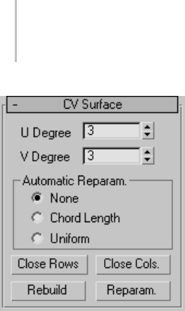
1146 Chapter 9: Surface Modeling
U Degree and V Degree—Letyousetthedegreeof
the surface in either the U or V dimension. The
higher the degree value, the greater the continuity.
Thelowerthedegree,themorediscontinuousthe
surface segments become. The degree can’t be less
than one or greater than the number allowed by the
number of CVs in the specified dimension. Degree
3 is adequate to represent continuous surfaces, and
is stable and well behaved. Default=3.
Setting the degree greater than 3 isn’t
recommended because higher-degrees are
slower to calculate and less stable numerically.
Higher-degrees are supported primarily to be
compatible with models created using other
surface modeling programs.
The number of CVs in a given dimension must be
at least one greater than that dimension’s degree.
Automatic Reparameterization group
The controls in this group box let you specify
automatic reparameterization. They are similar
to the controls in the Reparameterize dialog (page
1–1237), with the addition that all choices except
for None tell the software to reparameterize the
curve automatically; that is, whenever you edit it
by moving CVs, refining, and so on.
None—Do not reparameterize automatically.
Chord Length—Chooses the chord-length
algorithm for reparameterization.
Chord-length reparameterization spaces knots (in
parameter space (page 3–988)) based on the square
rootofthelengthofeachcurvesegment.
Chord-length reparameterization is usually the
best choice.
Uniform—Spaces the knots uniformly.
A uniform knot vector has the advantage that the
curve or surface changes only locally when you edit
it. With chord-length parameterization, moving
any CV can potentially change the entire surface.
The close controls let you close a surface. They
aredisplayedontheCVSurfacerolloutwhilean
independent CV surface sub-object is selected.
They are disabled if the surface is already closed in
that direction.
Close Rows—Closes the surface by joining the ends
of its rows.
Close Cols.—Closes the surface by joining the ends
of its columns.
Rebuild—Displays the Rebuild CV Surface dialog
(page 1–1236), which lets you specify how to
rebuild the surface. Rebuilding the surface can
change its appearance.
Warning: When you rebuild a surface, you lose the
animation controllers for all CVs on the surface.
Reparam.—Displays the Reparameterize dialog
(page 1–1237). Reparameterizing a surface
changes the surface’s parameter space (page 3–988)
to provide a better relation between control point
locationsandtheshapeofthesurface.
Tip: It is a good idea to reparameterize after you
have added CVs to the surface by refining or
inserting.
Warning: When you reparameterize a surface, you lose
the animation controllers for all CVs on the surface.
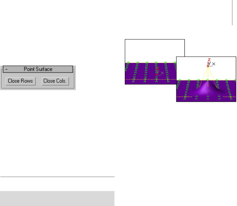
Soft Selection Rollout (NURBS) 1147
Point Surface rollout
This additional rollout appears when a point
surface is selected.
The close controls let you close a surface. They
appear on the Point Surface rollout while an
independentpointsurfacesub-objectisselected.
They have no effect if the surface is already closed
in that direction.
Close Rows—Closes the surface by joining the ends
of its rows.
Close Cols.—Closes the surface by joining the ends
of its columns.
Soft Selection Rollout (NURBS)
Modify panel > Select NURBS point or CV sub-objects. >
Soft Selection rollout
The soft selection controls for NURBS models
are like the soft selection controls for editable
mesh (page 1–996) objects. Soft selection controls
make a point or CV behave as if surrounded by a
"magnetic field." Unselected points or CVs within
thefieldaredrawnalongsmoothlywhileyoumove
the selected one.
With this feature, you can sculpt the points or CVs
of a curve or surface. For example, you can draw
asphereintoanegg,orgentlycurveaflatsurface
into hills and valleys.
With soft selection, transforming a single vertex can move
others.
The Soft Selection rollout for point and CV
sub-objectscontainsthecontrolsforthisfeature.
The Soft Selection check box is turned off by
default.
Before you begin, you might need to increase the
number of CVs or points on the surface. This
allows smoother and more complex reshaping
effects.
A single point or CV works well for many
purposes. Moving a point or CV along a single
axis is the most useful for smoothly raising and
lowering surfaces. For multiple points or CVs, you
can also use Rotate or Scale.
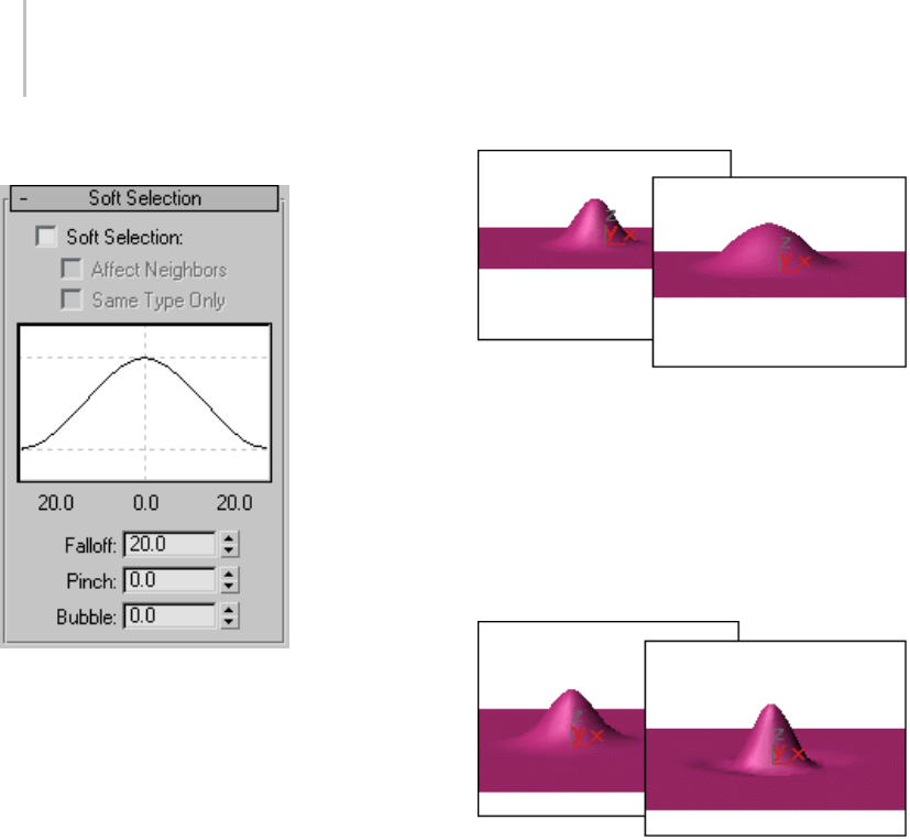
1148 Chapter 9: Surface Modeling
Interface
Soft Selection—When on, point or CV transforms
affectaregionofthecurveorsurface.
Affect Neighbors—When on, the transform affects
points or CVs not only on this curve or surface
but within the entire Falloff region of the NURBS
object.
Same Type Only—(for point curves and surfaces
only) When on, the transform affects only
neighboring points of the same type; that is, either
curvepoints,surfacepoints,orindependent
points.
Soft Selection Curve—This curve display shows
how Soft Selection will work. You can experiment
with a curve setting, undo it, and try another
setting with the same selection.
Falloff—Distance in current units from the center
totheedgeofaspheredefiningtheregion.Use
higher falloff settings to achieve more gradual
slopes, depending on the scale of your geometry.
Default=20.
Left: Falloff=20 (the default)
Right: Falloff=40
Pinch—Raises and lowers the top point of the
curve along the vertical axis. Sets the relative
"pointedness" of the region. When negative, a
crater is produced instead of a point. At a setting
of 0, Pinch produces a smooth transition across
this axis. Default=0.
Left: Pinch=.5
Right: Pinch=2
Falloff and Bubble have their default values.
Bubble—Expands and contracts the curve along
the vertical axis. Sets the relative "fullness" of
the region. Limited by Pinch, which sets a fixed
starting point for Bubble. A setting of 0 for Pinch
and 1.0 for Bubble produces a maximum smooth
bulge. Negative values for Bubble move the bottom
of the curve below the surface, creating a "valley"
around the base of the region. Default=0.
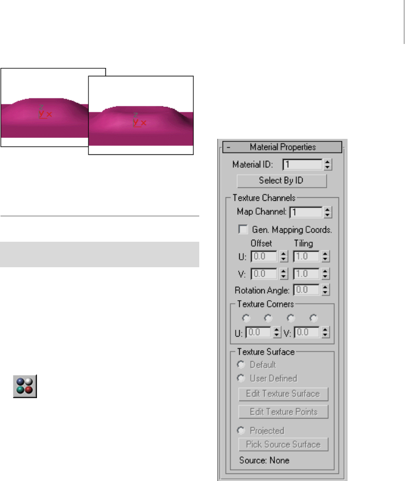
Material Properties Rollout 1149
Left: Bubble=1
Right: Bubble=6
Falloff and Pinch have their default values.
Material Properties Rollout
Modify panel > Select NURBS object. > Stack display >
Surface sub-object level > Material Properties rollout
This rollout controls material mapping onto a
NURBS surface sub-object.
Procedures
To apply a mapped material to a surface sub-object:
1. On the Material Properties rollout, turn on
Gen. Mapping Coordinates.
2. Use the Material Editor (page 2–1409) to
assign a mapped material to the surface.
Tousemultiplemapchannelsonasinglesurface
sub-object (example):
1. On the Material Properties rollout, turn on
Gen. Mapping Coordinates.
2. Change the Map Channel value to 2, and turn
on Gen. Mapping Coordinates.
3. Change the U and V tiling values for map
channel 2.
Now when you assign a mapped material, maps
on map channel 1 use the default UV tiling,
while maps on map channel 2 use the channel
2 tiling. An easy way to see this is to create a
checker (page 2–1638) map on channel 1, and
make one checker color another checker map
on channel 2.
Interface
Material Properties rollout
Material ID—Usethistochangethesurface’s
material ID number. Multiple material IDs
in a single NURBS object let you assign a
multi/sub-object material (page 2–1594) to the
NURBS object.
Select by ID—Displays a Select by Material ID
dialog (page 1–1238).

1150 Chapter 9: Surface Modeling
Texture Channels group
Thecontrolsinthisgroupboxsupportmaterials,
includingtilingandpositioningmapping
coordinates on the surface.
Map Channel—Chooses a UV coordinates map
channel (page 3–966). Range=1 to 99. A single
surfacecanuseupto99texturechannels.
Default=1.
Gen. Mapping Coordinates—Generates mapping
coordinates so you can apply mapped materials to
the surface. Each surface in a NURBS object has
its own set of mapping coordinates. Default=off.
U and V Offset—Offset mapping coordinates along
the surface’s local U axis or V axis. That is, at
0.0(thedefault),themapbeginsattheUorV
origin. Increasing an Offset value moves the map
forward along that axis, and decreasing it moves it
backward. These parameters are animatable.
U and V Tiling—Control the tiling of UV mapping
coordinates; that is, the number of times a mapped
material’s map is repeated in the surface’s local
UaxisorVaxis.Default=1.0forbothaxes(no
tiling). These parameters are animatable.
Rotation Angle—Letsyouspecifyarotationangle
for the texture. This parameter is animatable.
Texture Corners group
Thecontrolsinthisgroupboxletyouexplicitly
set which texture surface UV values to use at the
corners of a surface. These controls are especially
useful when you are matching the textures of
adjacent surfaces.
These controls are disabled unless Generate
Mapping Coordinates is on.
Corners radio buttons—The four buttons
correspond to the four corners of the currently
selected surface. When you choose a button, the
correspondingcornerishighlightedwithablue
box in 3D viewports, and the U and V spinners
are enabled.
UandV—Unavailableunlessyou’vechosenoneof
the Corners radio buttons. When available, you
use these spinners to set the U and V texture values
for the chosen corner.
By default, the U and V values for most surfaces
range from 0.0 to 1.0. For some kinds of geometry
converted to a NURBS surface, these ranges can
vary.
Texture Surface group
The controls in this group box let you choose
a method for mapping texture to the currently
selected NURBS surface sub-object, and to adjust
the parameters for some of the chosen methods.
These controls are available when Generate
Mapping Coordinates is on.
A texture surface is a surface associated with the
surface sub-object. The texture surface controls
how materials are mapped. In effect, changing
thetexturesurfacestretchesorotherwisechanges
the UV coordinates for the surface, altering the
mapping.
Mapscanshiftwithcertainsurfaceapproximation
methods. This effect is especially noticeable when
thesurfacehasanimatedCVs.Youcanreduceor
eliminate map shifting by changing the mapping
method to User Defined.
Tip: Don’t use the UVW Map modifier to apply a
texture to an animated NURBS surface.
Default—Automatically generates a texture
surface. This method evenly distributes the texture
and attempts to compensate for stretching of the
surface.
Thedefaulttexturesurfacemethodhasno
additional controls.

Creating Curve Sub-Objects 1151
User Defined—Generates a texture surface that you
can edit. You edit the user-defined texture surface
either by using an Edit Texture Surface dialog (as
you did in 3ds Max prior to v3), or by editing
texture points directly in viewports.
Edit Texture Surface—Click to display the Edit
Texture Surface dialog (page 1–1230),whichlets
you control UV mapping on this surface. This
button is available when you’ve chosen User
Defined as the texture surface method.
Edit Texture Points—Click to edit texture surface
points directly in viewports. This button available
when you’ve chosen User Defined as the texture
surface method.
While Edit Texture Points is on, the points of
the texture surface are displayed in viewports,
where you can adjust their positions by using the
selection and transform tools.
Projected—Generates the texture surface by
projecting the texture of another NURBS surface
sub-object in the NURBS model. The projection
travels along the direction of the normals of the
source surface.
Projected texture surfaces are relational: if you
updatethesourcesurface,thetextureupdateson
all the surfaces it projects onto.
Ifyouusethesamesourcesurfacetoprojecta
texture onto several other connected surfaces, the
textures will match along the boundaries where
the mapped surfaces touch.
Pick Source Surface—This button is available when
you’ve chosen Projected as the texture surface
method. To choose a source (projector) surface,
choose Projected, click to turn on this button, and
then click in a viewport to select another surface
sub-objectinthesameNURBSmodel.
Source text field—If Projected is the chosen texture
surface method and you have picked a surface to
project, this field displays the name of the projector
(source) surface. Otherwise, this field says "None."
Creating Curve Sub-Objects
Select NURBS object. > Modify panel > Create Curves
rollout
Select NURBS object. > Modify panel > NURBS toolbox
Keyboard > Ctrl+T to toggle NURBS toolbox display
(KeyboardShortcutOverrideTogglemustbeon)
Curvesub-objectsareeitherindependentpoint
and CV curves (similar to the top-level point
and CV curves described in Point Curve (page
1–1106) and CV Curve (page 1–1110)), or they are
dependent curves. Dependent curves are curve
sub-objects whose geometry depends on other
curves, points, or surfaces in the NURBS object.
When you change the geometry of the original,
parent sub-objects, the dependent curve changes
as well.
You create curve sub-objects using the Create
Curves rollout on the Modify command panel for
aNURBScurve.
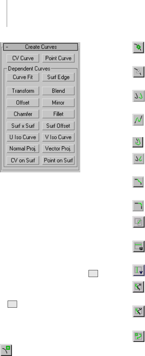
1152 Chapter 9: Surface Modeling
Tip: Lathe and extrude surface sub-objects can
be based on only a single curve; see Creating
Dependent Surfaces (page 1–1177).Ifyoucreate
dependent curves and then want to use the set
of curves (for example, two parents and a fillet
betweenthem)asthebasisofanextrudeorloft
surface, first go to the Curve sub-object level and
useJointoconnectthecurves.
Creation operations for dependent sub-objects
require you to select one or more parent objects.
In general, you can click and drag, or click and
then click again. You can also use the Hkeyboard
shortcut to display a Select Objects dialog (page
1–78) for choosing the parent. (The Keyboard
Shortcut Override Toggle (page 3–872) must be on
for Hto work this way.)
Toolbox Buttons for Creating Curves
These are the toolbox (page 1–1083) buttons for
creating curve sub-objects:
Create an independent CV curve sub-object
(page 1–1153).
Create an independent point curve sub-object
(page 1–1155).
Create a dependent fit curve (as with the
Curve Fit (page 1–1157) button).
Create a dependent transform curve (page
1–1157).
Create a dependent blend curve (page
1–1158).
Create a dependent offset curve (page 1–1159).
Create a dependent mirror curve (page
1–1160).
Create a dependent chamfer curve (page
1–1161).
Create a dependent fillet curve (page 1–1164).
Create a dependent surface-surface
intersection curve (page 1–1166).
Create a dependent U iso curve (page
1–1168).
Create a dependent V iso curve (page 1–1168).
Create a dependent normal projected curve
(page 1–1169).
Create a dependent vector projected curve
(page 1–1171).
Create a dependent CV curve on surface (page
1–1172).
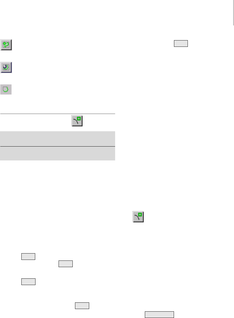
CV Curve Sub-Object 1153
Create a dependent point curve on surface
(page 1–1175).
Create a dependent surface offset curve (page
1–1167).
Create a dependent surface edge curve (page
1–1177).
CV Curve Sub-Object
Select NURBS object. > Modify panel > Create Curves
rollout > CV Curve button
Select NURBS object. > Modify panel > NURBS toolbox
>CreateCVCurvebutton
CV curve sub-objects are similar to object-level
CV curves (page 1–1110).Themaindifference
is that you can’t give CV curves a renderable
thickness at the sub-object level.
Drawing Three-Dimensional Curves
WhenyoucreateaCVcurve,youcandrawitin
threedimensions.Therearetwowaystodothis:
• Draw In All Viewports: This toggle lets you use
any viewport to draw the curve, enabling you
to draw three dimensionally.
•Using
Ctrl to drag CVs: While you draw a
curve, you can use the Ctrl key to drag a CV
offoftheconstructionplane.
With the Ctrl –key method, further mouse
movement lifts the latest point off the construction
plane.Therearetwowaystousethis:
•Click-drag.Ifyouholddown
Ctrl and also
hold down the mouse button, you can drag to
change the height of the CV. The CV’s location
is set when you release the mouse button.
This method is probably more intuitive.
•Click-click.Ifyou
Ctrl +click and then release
the mouse button, the height changes as you
dragthemouse.Clickingthemouseasecond
time sets the CV’s location.
This method is less prone to repetitive stress
injury.
WhileyouareoffsettingtheCV,areddotted
lineisdrawnbetweentheoriginalCVonthe
construction plane and the actual CV offset
fromtheplane.Youcanmovethemouseintoan
inactive viewport, in which case the software sets
the height of the CV using the CV’s Z axis in the
inactive viewport. This lets you set the height of
the CV with accuracy.
Snaps (page 2–41) also work when you change the
height of a CV. For example, if you turn on CV
snapping, you can set a CV to have the same height
as another CV by snapping to that other CV in an
inactive viewport.
Procedure
To create a CV curve sub-object:
1. Tur n on C V Cur ve.
2. In a viewport, click and drag to create the first
CV, as well as the first curve segment. Release
the mouse button to add the second CV. Each
subsequent location you click adds a new CV to
the curve. Right-click to end curve creation.
Note: If you begin the curve by clicking without
dragging, this also creates the curve’s first CV.
However, if you release the mouse button more
than five pixels away from where you initially
pressed it, this creates an additional CV.
While you are creating a CV curve, you can
press Backspace to remove the last CV you
created, and then previous CVs in reverse order.
If Draw In All Viewports is on, you can draw in
any viewport, creating a 3D curve.
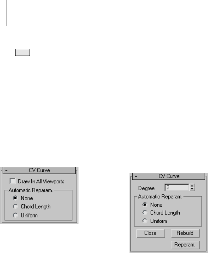
1154 Chapter 9: Surface Modeling
To lift a CV off the construction plane, use
the Ctrl key as described earlier in this topic
under "Drawing Three-Dimensional Curves."
As with splines, if you click over the curve’s
initial CV, a Close Curve dialog (page 1–1228)
is displayed. This dialog asks whether you
want the curve to be closed. Click No to keep
the curve open or Yes to close the curve. (You
canalsocloseacurvewhenyouedititatthe
Curve sub-object level.) When a closed curve
isdisplayedattheCurvesub-objectlevel,the
initial CV is displayed as a green circle, and a
green tick mark indicates the curve’s direction.
Interface
CV Curve rollout (creation time)
Draw In All Viewports—Lets you use any viewport
whileyouaredrawingthecurve.Thisisoneway
to create a 3D curve. When off, you must finish
drawing the curve in the viewport where you
began it. Default=on.
WhileDrawInAllViewportsison,youcanalso
use snaps (page 2–41) in any viewport.
Automatic Reparameterization group
The controls in this group box let you specify
automatic reparameterization. They are similar
to the controls in the Reparameterize dialog (page
1–1237), with one addition: all choices except
for None tell the software to reparameterize the
curve automatically; that is, whenever you edit it
by moving CVs, refining, and so on.
None—Do not reparameterize automatically.
Chord Length—Chooses the chord-length
algorithm for reparameterization.
Chord-length reparameterization spaces knots (in
parameter space (page 3–988)) based on the square
rootofthelengthofeachcurvesegment.
Chord-length reparameterization is usually the
best choice.
Uniform—Spaces the knots uniformly.
A uniform knot vector has the advantage that the
curve or surface changes only locally when you edit
it. With the other two forms of parameterization,
moving any CV can change the entire sub-object.
CV Curve rollout (modification time)
Degree—Setsthedegreeofthecurve.Thehigher
the degree value, the greater the continuity. The
lowerthedegree,themorediscontinuousthe
curve segments become. The degree can’t be less
than one or greater than the number allowed by
the number of CVs in the curve. Degree 3 curves
are adequate to represent continuous curves, and
arestableandwellbehaved.Default=3.
Setting the degree greater than 3 isn’t
recommended, because higher-degree curves are
slower to calculate and less stable numerically.
Higher-degree curves are supported primarily to
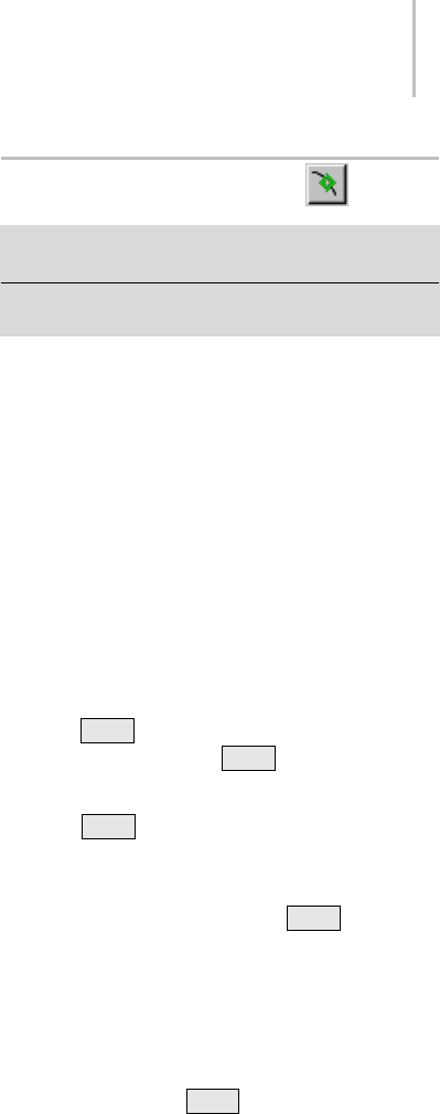
Point Curve Sub-Object 1155
be compatible with models created using other
surface modeling programs.
The number of CVs in a CV curve must be at least
one greater than the curve’s degree.
Automatic Reparameterization group
The controls in this group box let you specify
automatic reparameterization. They are similar
to the controls in the Reparameterize dialog (page
1–1237), with one addition: all choices except
for None tell the software to reparameterize the
curve automatically; that is, whenever you edit it
by moving CVs, refining, and so on.
None—Do not reparameterize automatically.
Chord Length—Chooses the chord-length
algorithm for reparameterization.
Chord-length reparameterization spaces knots (in
parameter space (page 3–988)) based on the square
root of the length of each curve segment.
Chord-length reparameterization is usually the
best choice.
Uniform—Spaces the knots uniformly.
A uniform knot vector has the advantage that the
curve or surface changes only locally when you edit
it. With the other two forms of parameterization,
moving any CV can change the entire sub-object.
Close—Closesthecurve.Disabledifthecurveis
already closed.
Rebuild—Displays the Rebuild CV Curve dialog
(page 1–1236) to let you rebuild the CV curve.
Reparam—Displays the Reparameterize dialog
(page 1–1237) to let you re parameterize the CV.
Point Curve Sub-Object
Select NURBS object. > Modify panel > Create Curves
rollout > Point Curve button
Select NURBS object. > Modify panel > NURBS toolbox >
Create Point Curve button
Point curve sub-objects are similar to object-level
point curves (page 1–1106). Points are constrained
tolieonthecurve.Themaindifferenceisthatyou
can’t give point curves a renderable thickness at
the sub-object level.
Drawing Three-Dimensional Curves
When you create a point curve, you can draw it in
threedimensions.Therearetwowaystodothis:
• Draw In All Viewports: This toggle lets you use
any viewport to draw the curve, enabling you
to draw three dimensionally.
•Using
Ctrl to drag points: While you draw a
curve, you can use the Ctrl key to drag a point
off of the construction plane.
With the Ctrl key method, further mouse
movement lifts the latest point off the construction
plane. There are two ways to use this:
•Click-drag.Ifyouholddown
Ctrl and also
hold down the mouse button, you can drag
to change the height of the point. The point’s
location is set when you release the mouse
button.
This method is probably more intuitive.
•Click-click.Ifyou
Ctrl +click and then release
the mouse button, the height changes as you
dragthemouse.Clickingthemouseasecond
time sets the point’s location.
This method is less prone to repetitive stress
injury.
Whileyouareoffsettingthepoint,areddotted
line is drawn between the original point on the
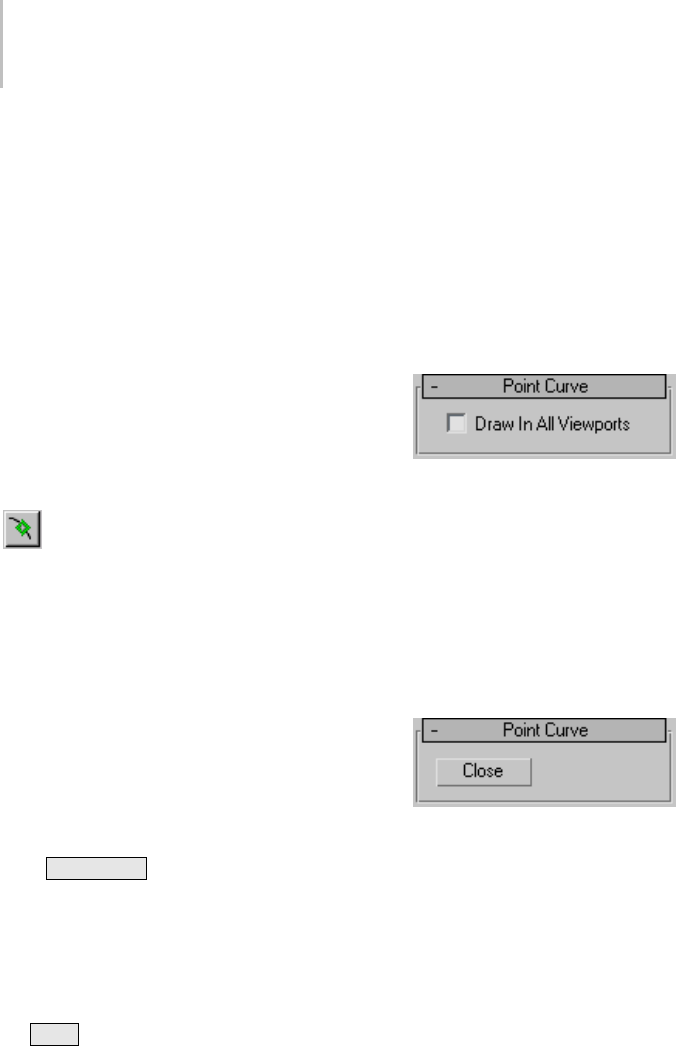
1156 Chapter 9: Surface Modeling
construction plane and the actual point offset
from the plane. You can move the mouse into an
inactive viewport, in which case the software sets
the height of the point using the point’s Z axis in
the inactive viewport. This lets you set the height
of the point with accuracy.
Snaps (page 2–41) also work when you change the
height of a point. For example, if you turn on Point
snapping, you can set a point to have the same
height as another point by snapping to that other
point in an inactive viewport.
Procedure
To create a point curve sub-object:
1. Tur n on Point Cur ve.
2. In a viewport, click and drag to create the first
point, as well as the first curve segment. Release
the mouse button to add the second point. Each
subsequent location you click adds a new point
to the curve. Right-click to end curve creation.
Note: If you begin the curve by clicking without
dragging, this also creates the curve’s first point.
However, if you release the mouse button more
than five pixels away from where you initially
pressed it, this creates an additional point.
Whileyouarecre
ating a point curve, you can
press Backspace to remove the last point you
created, and then previous points in reverse
order.
If Draw In All Viewports is on, you can draw in
any viewport, creating a 3D curve.
To lift a point off the construction plane, use
the Ctrl key as described earlier in this topic
under Drawing Three-Dimensional Curves
(page 1–1155).
As with splines, if you click over the curve’s
initial point, a Close Curve dialog (page 1–1235)
is displayed. Thisdialogaskswhetheryou
want the curve to be closed. Click No to keep
the curve open or Yes to close the curve. (You
canalsocloseacurvewhenyouedititatthe
Curve sub-object level.) When a closed curve
isdisplayedattheCurvesub-objectlevel,the
initial point is displayed as a green circle, and a
green tick mark indicates the curve’s direction.
Interface
Point Curve rollout (creation time)
Draw In All Viewports—Lets you use any viewport
whileyouaredrawingthecurve.Thisisoneway
to create a 3D curve. When off, you must finish
drawing the curve in the viewport where you
began it. Default=on.
WhileDrawInAllViewportsison,youcanalso
use snaps (page 2–41) in any viewport.
Point Curve rollout (modification time)
Close—Closesthecurve.Disabledifthecurveis
already closed.
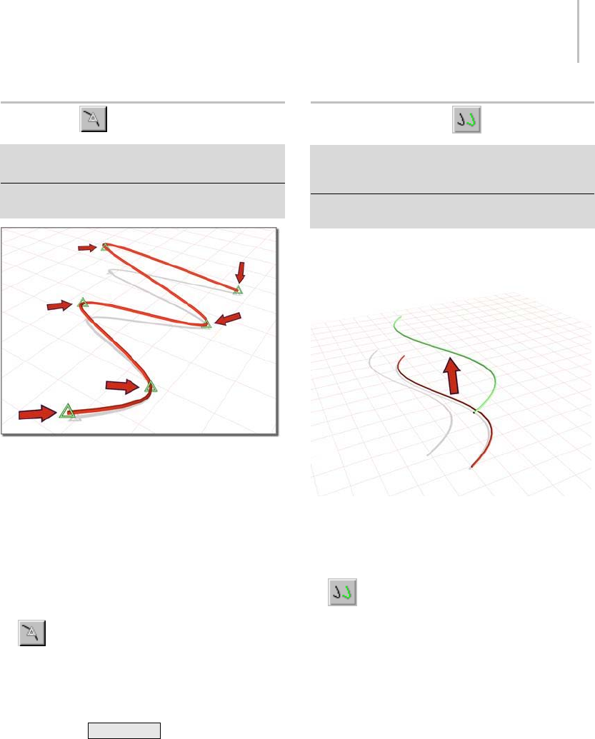
Curve Fit 1157
Curve Fit
Select NURBS object. > Modify panel > Create Curves
rollout > Dependent Curves group box > Curve Fit button
Select NURBS object. > Modify panel > NURBS toolbox
>CreateFitCurvebutton
Fitting a curve to selected points
This command creates a point curve fitted to
points you select. The points can be part of
previously created point curve and point surface
objects, or they can be point sub-objects you
created explicitly. They can’t be CVs.
Procedure
To create a point curve with Curve Fit:
1. Tur n on Cu r ve Fit .
2. Click to select two or more points.
Apointcurveiscreated. Itrunsthroughthe
points you select, in the order you select them.
Yo u c a n u s e Backspace to undo point
selectioninreverseorder.
3. Right-click to end creation.
Interface
There are no parameters for a point curve created
with Curve Fit.
Transform Curve
Select NURBS object. > Modify panel > Create Curves
rollout > Dependent Curves group box > Transform
button
Select NURBS object. > Modify panel > NURBS toolbox >
Create Transform Curve button
Atransformcurveisacopyoftheoriginalcurve
with a different position, rotation, or scale.
Curve used to create a transform curve
Procedure
To create a transform curve:
•In a NURBS object that contains at least
onecurve,turnonTransform.
To move the transform curve, click and drag
thecurveyouwanttoduplicate.Torotateor
scale the transform curve, click the parent
curve,clicktoturnonSub-Objectonthe
Modifier Stack rollout, choose Curve from the
drop-down list, and then use a transform to
rotate or scale the transform curve.
When you use Move to create the transform
curve, it simply copies the parent. (It doesn’t
exaggerate curvature as an offset curve does.)
Axis constraints don’t apply to the creation of
transform curves. You can click to create the
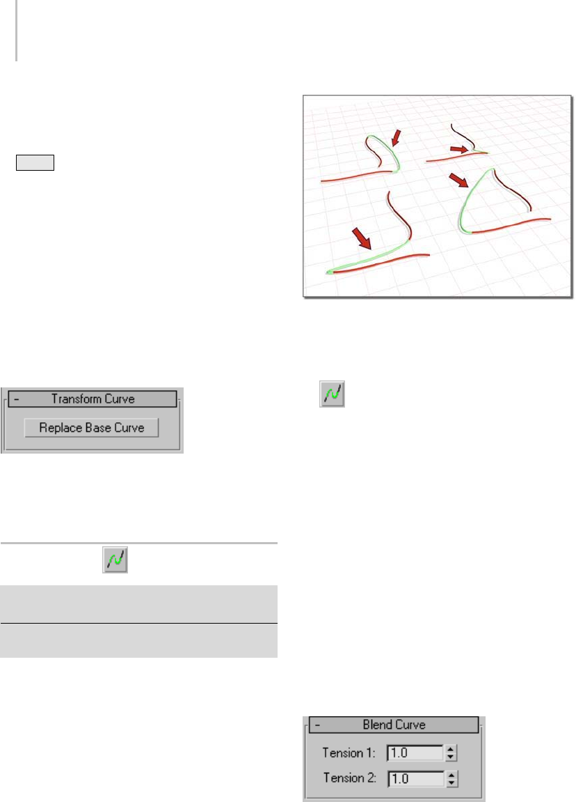
1158 Chapter 9: Surface Modeling
curveinplace;thenonceitiscreated,transform
it using constraints.
Tip: You can also use axis constraints by using
Shift +clone at the Curve sub-object level.
Interface
Creation time
At creation time, transform curves have no
parameters.
Transform Curve rollout (modification time)
At modification time, you can transform the
transform curve as a curve sub-object, and you can
animate curve sub-object transforms. Transform
curves also have one control in the Modify panel.
Replace Base Curve—Lets you replace the parent
curve. Click the button, then click the curve to
replace the original curve.
Blend Curve
Select NURBS object. > Modify panel > Create Curves
rollout > Dependent Curves group box > Blend button
Select NURBS object. > Modify panel > NURBS toolbox >
Create Blend Curve button
A blend curve connects the end of one curve to
the end of another, blending the curvature of
the parents to create a smooth curve between
them. You can blend curves of the same type, a
point curve with a CV curve (and vice versa), an
independent curve with a dependent curve, and
so on.
Blendcurvesconnectingoriginalcurves
Procedure
To create a blend curve:
1. In a NURBS object that contains two
curves,turnonBlend.
2. Click one curve near the end that you want
to connect. The end that will be connected
is highlighted. Without releasing the mouse
button, drag to the end of the other curve
that you want to connect. The other end is
highlighted as well. When the end that you
want to connect is highlighted, release the
mouse button.
After the blend curve is created, changing the
position or the curvature of either parent curve
changes the blend curve as well.
3. Adjust the blend parameters.
Interface
Blend Curve rollout (creation time)
"Tension" affects the tangent between a parent
curveandtheblendcurve.Thegreaterthetension
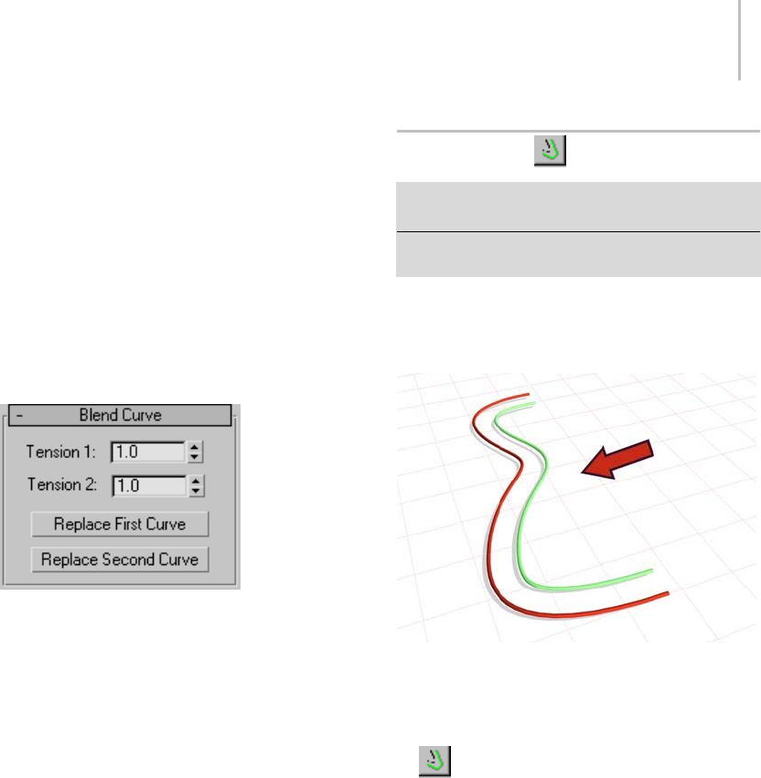
Offset Curve 1159
value,themorecloselythetangentparallelsthe
parent curve, and the smoother the transition. The
lowerthetension,thegreaterthetangentangle
and the sharper the transition between parent and
blend.
Tension 1—Controls tension at the edge of the first
curve you clicked.
Tension 2—Controls tension at the edge of the
second curve you clicked.
Blend Curve rollout (modification time)
"Tension" affects the tangent between a parent
curveandtheblendcurve.Thegreaterthetension
value,themorecloselythetangentparallelsthe
parent curve, and the smoother the transition. The
lowerthetension,thegreaterthetangentangle
and the sharper the transition between parent and
blend.
Tension 1—Controls tension at the edge of the first
curve you clicked.
Tension 2—Controls tension at the edge of the
second curve you clicked.
ReplaceFirstCurveandReplaceSecondCurve—Let
you replace the parent curves. Click the button,
then click the curve to replace the original first or
second curve.
Offset Curve
Select NURBS object. > Modify panel > Create Curves
rollout > Dependent Curves group box > Offset button
Select NURBS object. > Modify panel > NURBS toolbox >
Create Offset Curve button
An Offset curve is offset from the original, parent
curve. It is normal to the original. You can offset
both planar and 3D curves.
Curveusedtocreateanoffsetcurve
Procedure
To create an offset curve:
1. In a NURBS object that contains at least
onecurve,turnonOffset.
2. Click the curve you want to offset, and drag to
set the initial distance.
An offset curve is created.
3. Adjust the Offset parameter.
If the parent curve is not linear, increasing the
distance increasingly exaggerates the curvature
of the offset curve.
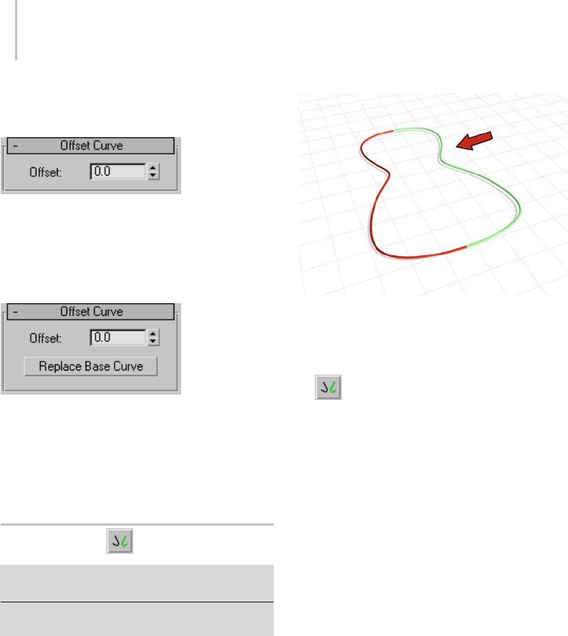
1160 Chapter 9: Surface Modeling
Interface
Offset Curve rollout (creation time)
Offset—Thedistancebetweentheparentcurve
and the offset curve, in 3ds Max units.
This parameter is animatable.
Offset Curve rollout (modification time)
Offset—Thedistancebetweentheparentcurve
and the offset curve, in 3ds Max units.
Replace Base Curve—Lets you replace the parent
curve. Click the button, then click the curve to
replace the original curve.
Mirror Curve
Select NURBS object. > Modify panel > Create Curves
rollout > Dependent Curves group box > Mirror button
Select NURBS object. > Modify panel > NURBS toolbox >
Create Mirror Curve button
A mirror curve is a mirror image of the original
curve.
Curveusedtocreateamirrorcurve
Procedure
To create a mirror curve:
1. In a NURBS object that contains at least
one curve, turn on Mirror.
2. On the Mirror Curve rollout, choose the axis or
plane you want to use.
3. Click the curve you want to mirror, and drag to
set the initial distance.
A mirror curve is created. A gizmo (yellow by
default) indicates the direction of mirroring.
Trans for ming the mirror curve’s gizmo changes
the orientation of the mirror, letting you mirror
along an axis that isn’t aligned with a local
coordinate axis.
4. Adjust the mirror parameters.
Interface
In viewports a gizmo (yellow by default) indicates
the mirror axis.
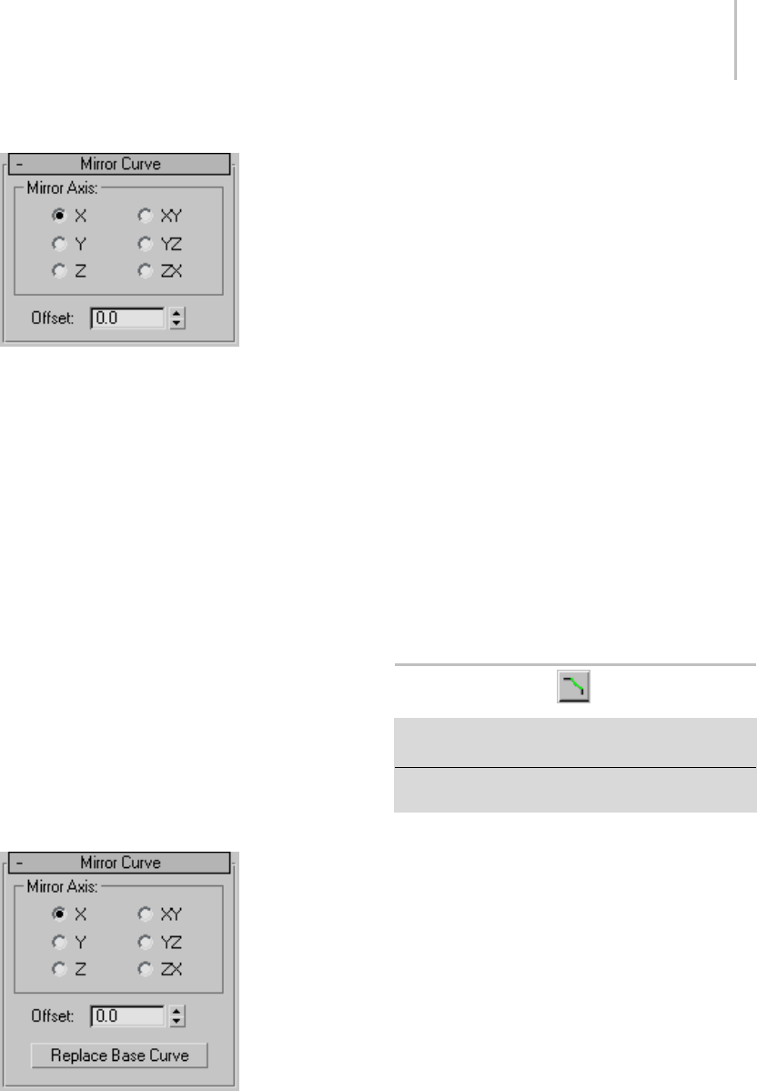
Chamfer Curve 1161
Mirror Curve rollout (creation time)
Mirror Axis group
The Mirror Axis buttons control the direction in
which the original curve is mirrored.
You can’t transform the mirror curve directly (that
would simply transform the mirror curve and its
parent curve at the same time). You transform it
by transforming its gizmo. By using transforms
you can mirror about an arbitrary axis, rather
than using one of the Mirror Axis presets. When
you transform a mirror curve, you are actually
transforming the mirror plane, so Rotate has the
effect of rotating the plane about which the curve
is mirrored. (This is like rotating the mirror gizmo
in the Mirror modifier.)
Offset—Controls the mirror’s distance from the
original curve.
This parameter is animatable.
Mirror Curve rollout (modification time)
Mirror Axis group
The Mirror Axis buttons control the direction in
which the original curve is mirrored.
You can’t transform the mirror curve directly (that
would simply transform the mirror curve and its
parent curve at the same time). You transform it
by transforming its gizmo. By using transforms
you can mirror about an arbitrary axis, rather
than using one of the Mirror Axis presets. When
you transform a mirror curve, you are actually
transforming the mirror plane, so Rotate has the
effect of rotating the plane about which the curve
is mirrored. (This is like rotating the mirror gizmo
in the Mirror modifier.)
Offset—Controls the mirror’s distance from the
original curve.
This parameter is animatable.
Replace Base Curve—Lets you replace the parent
curve. Click the button, then click the curve to
replace the original curve.
Chamfer Curve
Select NURBS object. > Modify panel > Create Curves
rollout>DependentCurvesgroupbox>Chamferbutton
Select NURBS object. > Modify panel > NURBS toolbox >
Create Chamfer Curve button
Chamfer creates a curve that is a straight bevel
between two parent curves.
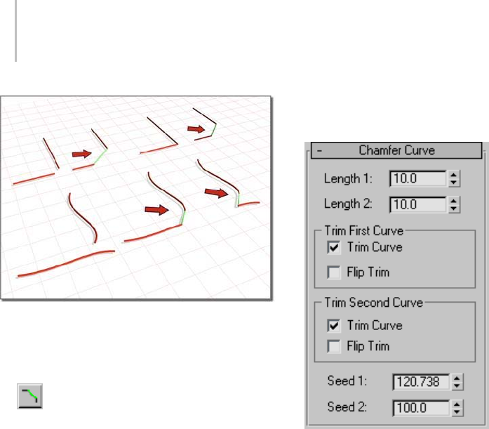
1162 Chapter 9: Surface Modeling
Creating chamfers between two original curves
Procedure
To create a chamfer curve:
1. In a NURBS object that contains at least
two curves, turn on Chamfer.
Tip: Make sure the curves intersect before you
begin to create thechamfer.
2. Click one curve near the end that you want
to connect. The end that will be connected
is highlighted. Without releasing the mouse
button, drag to the end of the other curve that
youwanttoconnect.Whentheendthatwill
be connected is highlighted, release the mouse
button.
Achamfercurveis created. Changing the
position or the curvature of either parent curve
can change the chamfer as well.
The parent curves must be coplanar. The
chamfer is not necessarily connected at the
endpoints of the parent curves: you can
adjust its position with the chamfer’s Length
parameters.
3. Adjust the chamfer parameters.
Interface
Chamfer Curve rollout (creation time)
The lengths are the distances from the intersection
(or apparent intersection) at which the chamfer
segment is drawn.
Length 1—Thedistancealongthefirstcurveyou
click.
This parameter is animatable.
Length 2—Thedistancealongthesecondcurve
you click.
This parameter is animatable.
Some length values make it impossible to construct
the chamfer. If you set the length to an invalid
value, the chamfer returns to a default position and
is displayed in the error color (orange by default).
TrimFirstCurveandTrimSecondCurvegroups
These two group boxes let you control how the
parent curves are trimmed. The controls are the
same in each. "First" and "second" refer to the
order in which you picked the parent curves.
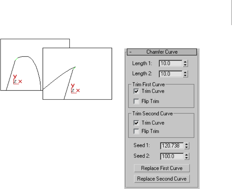
Chamfer Curve 1163
Flipping the direction of a trim
Trim Curve—When on (the default), trims the
parentcurveagainstthefilletcurve.Whenoff,the
parent isn’t trimmed.
Flip Trim—When on, trims in the opposite
direction.
Seed 1 and Seed 2—Change the U location of the
seed value on the first and second curves. If there
is a choice of directions, the direction indicated
by the seed points is the one used to create the
chamfer.
Chamfer Curve rollout (modification time)
The lengths are the distances from the intersection
(or apparent intersection) at which the chamfer
segment is drawn.
Length 1—Thedistancealongthefirstcurveyou
click.
Length 2—Thedistancealongthesecondcurve
you click.
Some length values make it impossible to construct
the chamfer. If you set the length to an invalid
value, the chamfer returns to a default position and
is displayed in the error color (orange by default).
TrimFirstCurveandTrimSecondCurvegroups
These two group boxes let you control how the
parent curves are trimmed. The controls are the
same in each. "First" and "second" refer to the
order in which you picked the parent curves.
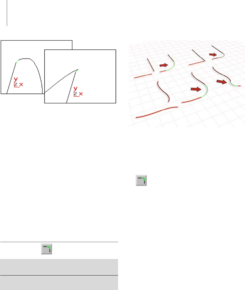
1164 Chapter 9: Surface Modeling
Flipping the direction of a trim
Trim Curve—When on (the default), trims the
parentcurveagainstthefilletcurve.Whenoff,the
parent isn’t trimmed.
Flip Trim—When on, trims in the opposite
direction.
Seed 1 and Seed 2—Change the U location of the
seed value on the first and second curves. If there
is a choice of directions, the direction indicated
by the seed points is the one used to create the
chamfer.
ReplaceFirstCurveandReplaceSecondCurve—Let
you replace the parent curves. Click the button,
then click the curve to replace the original first or
second curve.
Fillet Curve
Select NURBS object. > Modify panel > Create Curves
rollout > Dependent Curves group box > Fillet button
Select NURBS object. > Modify panel > NURBS toolbox >
Create Fillet Curve button
Fillet creates a curve that is a rounded corner
between two parent curves.
Above: Two simple fillets
Below: Flip Trim changes the direction of trimming and the
shape the fillet.
Procedure
To create a fillet curve:
1. In a NURBS object that contains at least
two curves, turn on Fillet.
2. Click one curve neartheendthatyouwant
to connect. The end that will be connected
is highlighted. Without releasing the mouse
button, drag to theendoftheothercurvethat
you want to connect. When the end that you
want to connect is highlighted, release the
mouse button.
Afilletcurveiscreated. It trims the ends of the
parentcurvetomatchthefillet. Thefilletis
not necessarily placed at the endpoints of the
parent curves: placement depends on the value
of the Radius parameter.
Changing the position or the curvature of either
parent curve can change the fillet as well.
The parent curves must be coplanar.
3. Adjust the fillet parameters.
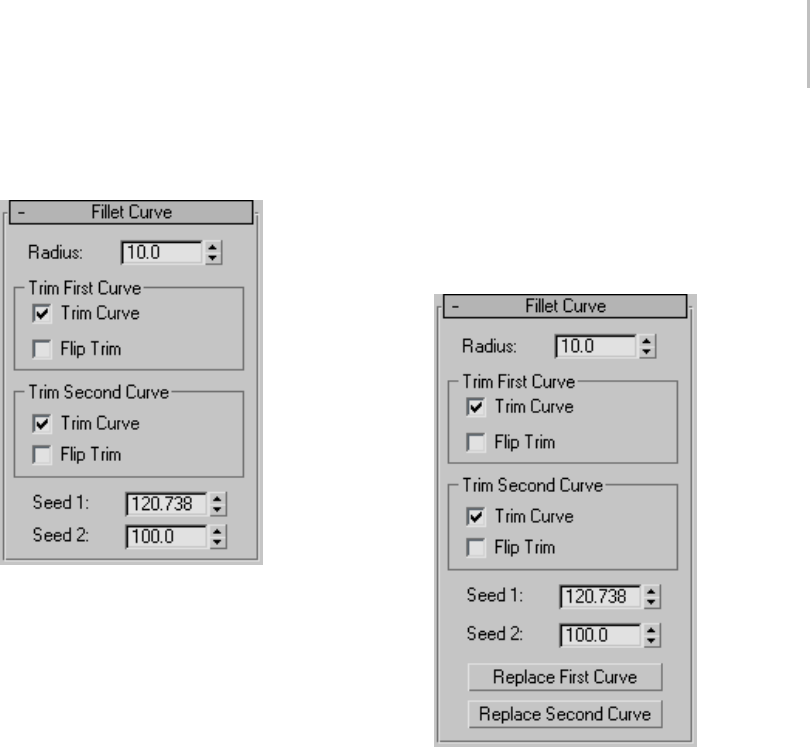
Fillet Curve 1165
Interface
Fillet Curve rollout (creation time)
Radius—The radius of the fillet arc in the current
3ds Max units. Default=10.0.
This parameter is animatable.
Tip: If the fillet you initially create is in an error
state,oftenthisisbecausetheradiusisnotlarge
enough to bridge the distance between the two
curves. Increasing the Radius value gives you a
correct fillet. The fillet becomes an arc displayed
in the dependent object color (green by default).
Whenthefilletisinanerrorstateitisdisplayedasa
straight line in the error color (orange by default).
TrimFirstCurveandTrimSecondCurvegroups
These two group boxes let you control how the
parent curves are trimmed. The controls are the
same in each. "First" and "second" refer to the
order in which you picked the parent curves.
Trim Curve—When on (the default), trims the
parentcurveagainstthefilletcurve.Whenoff,the
parent isn’t trimmed.
Flip Trim—When on, trims in the opposite
direction.
Seed 1 and Seed 2—Change the U location of the
seed value on the first and second curves. If there
is a choice of directions, the direction indicated by
the seed points is the one used to create the fillet.
Fillet Curve rollout (modification time)
Radius—The radius of the fillet arc in the current
3ds Max units. Default=10.0.
Tip: If the fillet you initially create is in an error
state,oftenthisisbecausetheradiusisnotlarge
enoughtobridgethedistancebetweenthetwo
curves. Increasing the Radius value gives you a
correct fillet. The fillet becomes an arc displayed
in the dependent object color (green by default).
Whenthefilletisinanerrorstateitisdisplayedasa
straight line in the error color (orange by default).
TrimFirstCurveandTrimSecondCurvegroups
These two group boxes let you control how the
parent curves are trimmed. The controls are the
same in each. "First" and "second" refer to the
order in which you picked the parent curves.
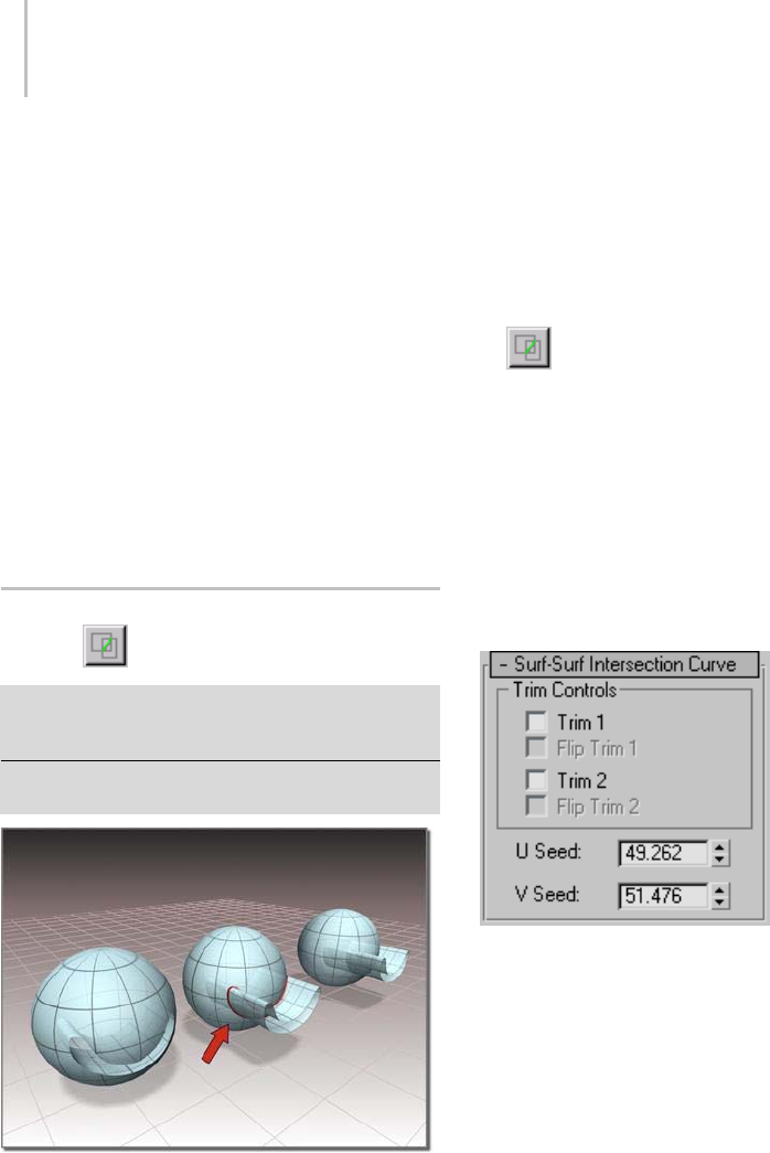
1166 Chapter 9: Surface Modeling
Trim Curve—When on (the default), trims the
parentcurveagainstthefilletcurve.Whenoff,the
parent isn’t trimmed.
Flip Trim—When on, trims in the opposite
direction.
Seed 1 and Seed 2—Change the U location of the
seed value on the first and second curves. If there
is a choice of directions, the direction indicated by
the seed points is the one used to create the fillet.
ReplaceFirstCurveandReplaceSecondCurve—Let
you replace the parent curves. Click the button,
then click the curve to replace the original first or
second curve.
Surface-Surface Intersection
Curve
Select NURBS object. > Modify panel > Create Curves
rollout > Dependent Curves group box > Surf x Surf
button
Select NURBS object. > Modify panel > NURBS toolbox >
Create Surface-Surface Intersection Curve button
Trimming a surface with a surface-surface intersection curve
This command creates a curve that is defined
by the intersection of two surfaces. You can use
surface-surface intersection curves for trimming
(page 1–1080).
If the surfaces intersect at two or more locations,
the intersection closest to the seed point is the one
that creates the curve.
Procedure
To create a surface-surface intersection curve:
1. Turn on Create Surface-Surface
Intersection Curve in the NURBS toolbox, or
Surf x Surf on the Create Curves rollout.
2. Click the first surface, then the second.
If the two surfaces intersect, a curve that lies
along their intersection is created.
Interface
Surf-Surf Intersection Curve rollout (creation
time)
Trim Controls group
Trim 1 and Trim 2—When on, trim a surface against
the intersectioncurve.Whenoff,thesurfaceisn’t
trimmed. Trim 1 trims the first parent surface
you clicked, and Trim 2 trims the second parent
surface.
If the intersection curve does not pass completely
across a surface, trimming is impossible, and the
affected surface is displayed in the error color
(orange by default).
Flip Trim 1 and Flip Trim 2—When on, trim the
associated surface in the opposite direction.
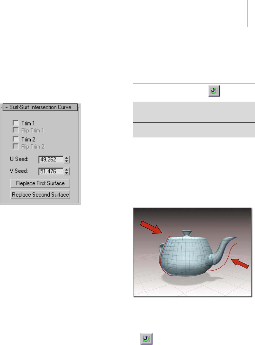
Surface Offset Curve 1167
U Seed and V Seed—Change the UV location of
theseedvalueonsurface1,thefirstsurfaceyou
clicked. If there is a choice of intersections, the
intersection closest to the seed point is the one
used to create the curve.
Surf-Surf Intersection Curve rollout
(modification time)
Trim Controls group
Trim 1 and Trim 2—When on, trim a surface against
the intersection curve. When off, the surface isn’t
trimmed. Trim 1 trims the first parent surface
you clicked, and Trim 2 trims the second parent
surface.
If the intersection curve does not pass completely
across a surface, trimming is impossible, and the
affected surface is displayed in the error color
(orange by default).
Flip Trim 1 and Flip Trim 2—When on, trim the
associated surface in the opposite direction.
U Seed and V Seed—Change the UV location of
theseedvalueonsurface1,thefirstsurfaceyou
clicked. If there is a choice of intersections, the
intersection closest to the seed point is the one
used to create the curve.
Replace First Surface and Replace Second
Surface—Let you replace the parent surfaces. Click
a button, then click the surface to replace the
original first or second surface.
Surface Offset Curve
Select NURBS object. > Modify panel > Create Curves
rollout>DependentCurvesgroupbox>SurfOffset
button
Select NURBS object. > Modify panel > NURBS toolbox >
Create Surface Offset Curve button
Thiscommandcreatesacurvethatisoffsetfrom
acurvethatliesonasurface.Inotherwords,the
parentcurvemusthaveoneofthefollowingtypes:
surface-surface intersection, U iso, V iso, normal
projected, vector projected, CV curve on surface,
or point curve on surface. The offset is normal to
thesurface.Thatis,thenewcurveiseitherabove
or below the surface by the offset amount.
Creating surface offset curves
Procedure
To create a surface offset curve:
1. In a NURBS object that contains at least
oneNURBSsurfacewithacurveonit,turn
on Create Surface Offset Curve in the NURBS
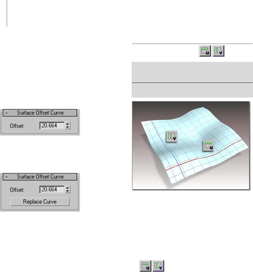
1168 Chapter 9: Surface Modeling
toolbox, or Surf Offset on the Create Curves
rollout.
2. Put the cursor over a curve that lies on a surface,
and drag to set the offset amount. Release the
mousebuttontoendcurvecreation.
Interface
Surface Offset Curve rollout (creation time)
Offset—The amount by which the curve is offset
from the surface on which the parent curve lies.
Surface Offset Curve rollout (modification time)
Offset—The amount by which the curve is offset
from the surface on which the parent curve lies.
This parameter is animatable.
Replace Curve—Lets you replace the parent curve.
Click the button, then click the curve to replace
the original parent curve.
UandVIsoCurves
Select NURBS object. > Modify panel > Create Curves
rollout>DependentCurvesgroupbox>UIsoCurve
button or V Iso Curve button
Select NURBS object. > Modify panel > NURBS toolbox >
Create U Iso Curve button or Create V Iso Curve button
Iso curves in the U and V dimensions
U and V iso curves are dependent curves created
from the iso (isoparametric) lines of a NURBS
surface. You can use U and V iso curves to trim
surfaces (page 1–1080).
Procedure
To create an iso curve:
•Tur n on U Is o Cu r ve or V Is o Cu r ve,
then drag over the surface.
The iso lines are highlighted in blue as you drag.
Click to create the curve from the highlighted
iso line.
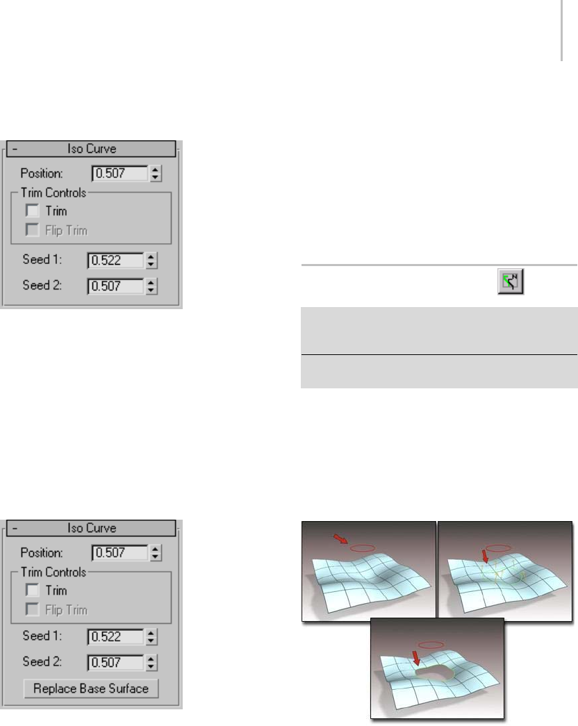
Normal Projected Curve 1169
Interface
Iso Curve rollout (creation time)
Position—Sets the iso curve’s position along the U
or V axis of the surface.
This parameter is animatable.
Trim Controls group
Trim—When on, trims the surface against the iso
curve.
Flip Trim—When on, flips the direction of the trim.
Iso Curve rollout (modification time)
Position—Sets the iso curve’s position along the U
or V axis of the surface.
This parameter is animatable.
Trim Controls group
Trim—When on, trims the surface against the iso
curve.
Flip Trim—When on, flips the direction of the trim.
ReplaceBaseSurface—Lets you replace the parent
surface. Click the button, then click the new
surfaceonwhichtobasetheisocurve.
Normal Projected Curve
Select NURBS object. > Modify panel > Create Curves
rollout > Dependent Curves group box > Normal Proj.
button
Select NURBS object. > Modify panel > NURBS toolbox >
Create Normal Projected Curve button
A normal projected curve lies on a surface. It is
based on an original curve, which is projected
onto the surface in the direction of the surface’s
normals.
You can use normal projected curves for trimming
(page 1–1080).
Trimmingasurfacewithanormalprojectedcurve
If the projection intersects the surface in two or
more locations, the intersection closest to the seed
pointistheonethatcreatesthecurve.
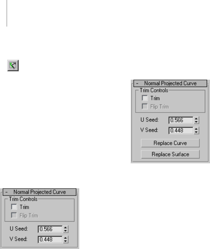
1170 Chapter 9: Surface Modeling
Procedure
To create a normal projected curve:
1. In a NURBS object that contains at least
onesurfaceandonecurvesub-object,turnon
Normal Projected Curve in the NURBS toolbox
or Normal Proj. on the Create Curves rollout.
2. Click the curve, then click the surface where
you want the normal projected curve to lie.
If the curve can be projected onto the surface in
the surface’s normal direction, the projected
curve is created. The original, parent curve can
go"offtheedgeofthesurface."Theprojected
curve is created only where the projection and
the surface intersect.
Interface
Normal Projected Curve rollout (creation time)
Trim Controls group
Trim—When on, trims the surface against the
curve. When off, the surface isn’t trimmed.
If it’s impossible to trim with this curve, the surface
is displayed in the error color (orange by default).
Forexample,thecurveisunusablefortrimmingif
it neither crosses the edge of the surface nor forms
aclosedloop.
Flip Trim—When on, trims the surface in the
opposite direction.
U Seed and V Seed—Change the UV location of
theseedvalueonthesurface.Ifthereisachoice
of projections, the projection closest to the seed
point is the one used to create the curve.
Normal Projected Curve rollout (modification
time)
Trim Controls group
Trim—When on, trims the surface against the
curve. When off, the surface isn’t trimmed.
If it’s impossible to trim with this curve, the surface
is displayed in the error color (orange by default).
For example, the curve is unusable for trimming if
it neither crosses the edge of the surface nor forms
aclosedloop.
Flip Trim—When on, trims the surface in the
opposite direction.
U Seed and V Seed—Change the UV location of
theseedvalueonthesurface.Ifthereisachoice
of projections, the projection closest to the seed
point is the one used to create the curve.
Replace Curve and Replace Surface—Let you replace
the parent sub-objects. Click a button, then click
a curve or surface to replace the original parent
object.
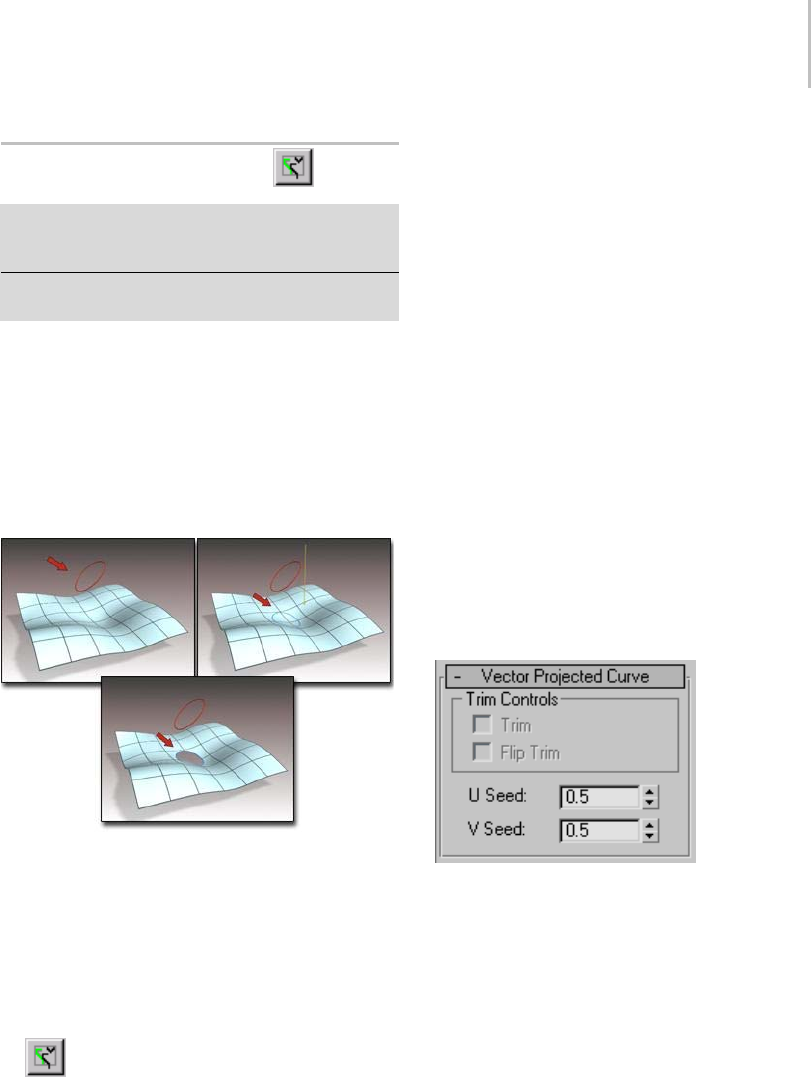
Vector Projected Curve 1171
Vector Projected Curve
Select NURBS object. > Modify panel > Create Curves
rollout > Dependent Curves group box > Vector Proj.
button
Select NURBS object. > Modify panel > NURBS toolbox >
Create Vector Projected Curve button
A Vector Projected curve lies on a surface. This
isalmostthesameasaNormalProjectedcurve,
except that the projection from the original curve
to the surface is in the direction of a vector that
you can control.
You can use vector projected curves for trimming
(page 1–1080).
Trimmingasurfacewithavectorprojectedcurve
If the projection intersects the surface in two or
more locations, the intersection closest to the seed
point is the one that creates the curve.
Procedure
To create a vector projected curve:
1. In a NURBS object that contains at least
onesurfaceandonecurvesub-object,clickto
turn on Vector Projected Curve in the NURBS
toolbox or Vector Proj. in the Create Curves
rollout.
2. Click the curve, then the surface where you
want the vector projection curve to lie.
Theinitialvectordirectionisintheview
direction. That is, the vector points away from
you as you look at the viewport. If the curve can
be projected onto the surface in this direction,
the projection curve is created. The original,
parentcurvecango"offtheedgeofthesurface."
The projection curve is created only where the
projection and the surface intersect.
Interface
In viewports a gizmo (yellow by default) indicates
the projection axis. Transforming the gizmo
changes the projection onto the surface. Rotating
the gizmo is the most useful transform. You can
use rotation to adjust the distortion caused by
projection.
Vector Projected Curve rollout (creation time)
Trim Controls group
Trim—When on, trims the surface against the
curve. When off, the surface isn’t trimmed.
If it’s impossible to trim with this curve, the surface
is displayed in the error color (orange by default).
For example, the curve is unusable for trimming if
it neither crosses the edge of the surface nor forms
aclosedloop.
Flip Trim—When on, trims the surface in the
opposite direction.
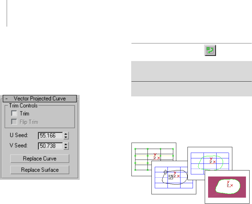
1172 Chapter 9: Surface Modeling
U Seed and V Seed—Change the UV location of
theseedvalueonthesurface.Ifthereisachoice
of projections, the projection closest to the seed
pointistheoneusedtocreatethecurve.
Vector Projected Curve rollout (modification
time)
Trim Controls group
Trim—When on, trims the surface against the
curve. When off, the surface isn’t trimmed.
If it’s impossible to trim with this curve, the surface
is displayed in the error color (orange by default).
Forexample,thecurveisunusablefortrimmingif
it neither crosses the edge of the surface nor forms
aclosedloop.
Flip Trim—When on, trims the surface in the
opposite direction.
U Seed and V Seed—Change the UV location of
theseedvalueonthesurface.Ifthereisachoice
of projections, the projection closest to the seed
pointistheoneusedtocreatethecurve.
Replace Curve and Replace Surface—Let you replace
the parent sub-objects. Click a button, then click
acurveorsurfacetoreplacetheoriginalparent
object.
CV Curve on Surface
Select NURBS object. > Modify panel > Create Curves
rollout>DependentCurvesgroupbox>CVonSurf
button
Select NURBS object. > Modify panel > NURBS toolbox >
Create CV Curve on Surface button
A CV curve on surface is similar to a plain CV
curve,butitliesonasurface. Youcreateitby
drawing rather than projecting from a different
curve. You can use this curve type for trimming
(page 1–1080) the surface on which it lies.
Trimming a surface with a CV curve on surface
There are two methods for drawing and editing
curves on surfaces: drawing in a viewport, or
using the Edit Curve on Surface dialog. The choice
is useful because you draw in two dimensions, with
a mouse or other pointing device, while the curve
on a surface can exist in three dimensions. The
more complex the 3D surface, the more effort it
can require to create and edit a curve on a surface.
Visual feedback can help you draw the curve. The
point whose surface you first click is shown as a
blue square, and the surface’s minimum UV point
is shown as a plus sign (+). As you draw the curve,
it is displayed interactively in viewports.
Drawing in a Viewport
When you click to position a CV, the click is
projected in the viewport’s Z dimension. That is,
your click is projected "through the screen" and
ontothesurface.Thisisastraightforwardwayto
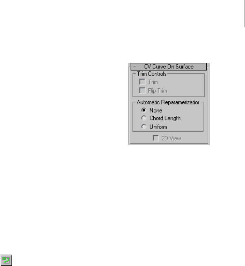
CV Curve on Surface 1173
create a curve on a surface if the portion of the
surfacewherethecurvewilllieisclearlyvisiblein
the viewport. However, this method doesn’t let
you place CVs on surface locations that are not
visible in the viewport (they are on back faces, lie
behind other geometry, and so on).
Using the Edit Curve on Surface Dialog
The Edit Curve on Surface dialog (page 1–1229)
letsyoueditcurvesonsurfacesasyoueditregular
curvesinaviewport.Themainpartofthedialog
is a two-dimensional view of the surface. The
controlsprovidetypicalcurveeditingfunctions.
WhileyouarecreatingaCVcurveonsurface,the
2D View toggle controls display of the Edit Curve
on Surface dialog.
You can edit the CVs in CV curves on surfaces at
the Curve CV sub-object level (page 1–1127),asyou
edit other kinds of curve CVs. You can transform
CVsinCVcurvesonsurfaces,butyoucan’tmove
the CVs off the surface. Using the Curve CV
sub-object level is an alternative to editing these
CVs by using the Edit Curve on Surface dialog.
Procedure
To create a CV curve on surface:
1. In a NURBS object that contains at least
onesurface,turnonCreateCVCurveon
Surface in the NURBS toolbox, or CV on Surf
ontheCreateCurvesrollout.
2. Do one of the following:
• Draw the curve in the viewport, using the
mouseabovethesurface.
• Turn on 2D View. This displays an Edit
Curve on Surface dialog, which lets you
create the curve in a two-dimensional (UV)
representation of the surface.
3. Right-click to end curve creation.
Interface
CV Curve on Surface rollout (creation time)
Trim Controls group
Trim—When on, trims the surface against the
curve. When off, the surface isn’t trimmed.
If it’s impossible to trim with this curve, the surface
is displayed in the error color (orange by default).
For example, the curve is unusable for trimming if
it doesn’t form a closed loop.
Flip Trim—When on, trims the surface in the
opposite direction.
Automatic Reparameterization group
The radio buttons in this group box let you
choose automatic reparameterization. With
reparameterization, the curve maintains its
parameterization as you edit it. Without
reparameterization, the curve’s parameterization
doesn’t change as you edit it, and can become
irregular.
None—Do not reparameterize.
Chord Length—Chooses the chord-length
algorithm for reparameterization.
Chord-length reparameterization spaces knots (in
parameter space (page 3–988)) based on the square
rootofthelengthofeachcurvesegment.
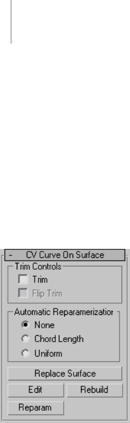
1174 Chapter 9: Surface Modeling
Chord-length reparameterization is usually the
best choice.
Uniform—Spaces the knots uniformly.
A uniform knot vector has the advantage that the
curve will change only locally when you edit it.
With the other two forms of parameterization,
moving any CV can change the entire curve.
2D View—When on, displays the Edit Curve on
Surface dialog (page 1–1229),whichletsyou
create the curve in a two-dimensional (UV)
representation of the surface.
CV Curve on Surface rollout (modification time)
Trim Controls group
Trim—When on, trims the surface against the
curve. When off, the surface isn’t trimmed.
If it’s impossible to trim with this curve, the surface
is displayed in the error color (orange by default).
Forexample,thecurveisunusablefortrimmingif
it doesn’t form a closed loop.
Flip Trim—When on, trims the surface in the
opposite direction.
Automatic Reparameterization group
The radio buttons in this group box let you
choose automatic reparameterization. With
reparameterization, the curve maintains its
parameterization as you edit it. Without
reparameterization, the curve’s parameterization
doesn’t change as you edit it, and can become
irregular.
None—Do not reparameterize.
Chord Length—Chooses the chord-length
algorithm for reparameterization.
Chord-length reparameterization spaces knots (in
parameter space (page 3–988)) based on the square
rootofthelengthofeachcurvesegment.
Chord-length reparameterization is usually the
best choice.
Uniform—Spaces the knots uniformly.
A uniform knot vector has the advantage that the
curvewillchangeonlylocallywhenyoueditit.
With the other two forms of parameterization,
moving any CV can change the entire curve.
Replace Surface—Lets you replace the parent
surface. Click a button, then click a surface to
replace the original parent surface.
Edit—Click to display the Edit Curve on Surface
dialog (page 1–1229), which lets you edit the curve
in a two-dimensional (UV) representation of the
surface.
To edit multiple curves on a surface, select more
than one CV curve sub-object on the same surface,
then click Edit.
Rebuild—Displays the Rebuild CV Curve dialog
(page 1–1236) to let you rebuild the CV curve on
surface.
Reparam—Displays the Reparameterize dialog
(page 1–1237) to let you reparameterize the CV
curve on surface.
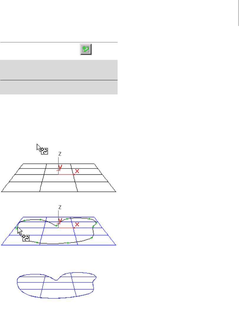
Point Curve on Surface 1175
Point Curve on Surface
Select NURBS object. > Modify panel > Create Curves
rollout > Dependent Curves group box > Point on Surf
button
Select NURBS object. > Modify panel > NURBS toolbox >
Create Point Curve on Surface button
Apointcurveonsurfaceissimilartoaplainpoint
curve,butitliesonasurface. Youcreateitby
drawing rather than projecting from a different
curve. You can use this curve type for trimming
(page 1–1080) the surface on which it lies.
Trimmingasurfacewithapointcurveonsurface
There are two methods for drawing and editing
curves on surfaces: drawing in a viewport, or
using the Edit Curve on Surface dialog. The choice
is useful because you draw in two dimensions, with
a mouse or other pointing device, while the curve
on a surface can exist in three dimensions. The
more complex the 3D surface, the more effort it
can require to create and edit a curve on a surface.
Visual feedback can help you draw the curve. The
point whose surface you first click is shown as a
blue square, and the surface’s minimum UV point
is shown as a plus sign (+). As you draw the curve,
it is displayed interactively in viewports.
Drawing in a Viewport
When you click to position a point, the click is
projected in the viewport’s Z dimension. That is,
your click is projected "through the screen" and
ontothesurface.Thisisastraightforwardwayto
create a curve on a surface if the portion of the
surfacewherethecurvewilllieisclearlyvisiblein
the viewport. However, this method doesn’t let
you place points on surface locations that are not
visible in the viewport (they are on back faces, lie
behind other geometry, and so on).
Using the Edit Curve on Surface Dialog
The Edit Curve on Surface dialog (page 1–1229)
letsyoueditcurvesonsurfacesasyoueditregular
curves in a viewport. The main part of the dialog
is a two-dimensional view of the surface. The
controls provide typical curve editing functions.
Whileyouarecreatingapointcurveonsurface,
the2DViewtogglecontrolsdisplayoftheEdit
Curve on Surface dialog.
You can edit the points in point curves on surfaces
at the Point sub-object level (page 1–1123),asyou
edit other kinds of points. You can transform
points in point curves on surfaces, but you can’t
move the points off the surface. Using the Point
sub-object level is an alternative to editing these
points by using the Edit Curve on Surface dialog.
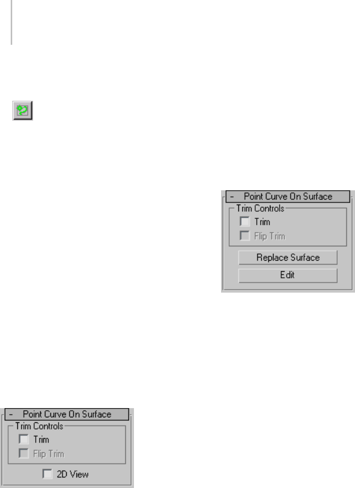
1176 Chapter 9: Surface Modeling
Procedure
To create a point curve on surface:
1. In a NURBS object that contains at least
onesurface,turnonCreatePointCurveon
Surface in the NURBS toolbox, or Point on Surf
ontheCreateCurvesrollout.
2. Do one of the following:
• Draw the curve in the viewport, using the
mouseabovethesurface.
• Turn on 2D View. This displays an Edit
Curve on Surface dialog, which lets you
create the curve in a two-dimensional (UV)
representation of the surface.
3. Right-click to end curve creation.
Interface
Pointcurvesonsurfaceshavepointsub-objects
that you can transform and edit in viewports as
you do with plain point curves.
(There is no special Move Surface Points button as
there was prior to 3ds Max 3.)
Point Curve on Surface rollout (creation time)
Trim Controls group
Trim—When on, trims the surface against the
curve. When off, the surface isn’t trimmed.
If it’s impossible to trim with this curve, the surface
is displayed in the error color (orange by default).
Forexample,thecurveisunusablefortrimmingif
it doesn’t form a closed loop.
Flip Trim—When on, trims the surface in the
opposite direction.
2D View—When on, displays the Edit Curve on
Surface dialog (page 1–1229),whichletsyou
create the curve in a two-dimensional (UV)
representation of the surface.
Point Curve on Surface rollout (modification
time)
Trim Controls group
Trim—When on, trims the surface against the
curve. When off, the surface isn’t trimmed.
If it’s impossible to trim with this curve, the surface
is displayed in the error color (orange by default).
For example, the curve is unusable for trimming if
it doesn’t form a closed loop.
Flip Trim—When on, trims the surface in the
opposite direction.
Replace Surface—Lets you replace the parent
surface. Click a button, then click a surface to
replace the original parent surface.
Edit—Click to display the Edit Curve on Surface
dialog (page 1–1229), which lets you edit the curve
in a two-dimensional (UV) representation of the
surface.
To edit multiple curves on a surface, select more
thanonepointcurvesub-objectonthesame
surface, then click Edit.
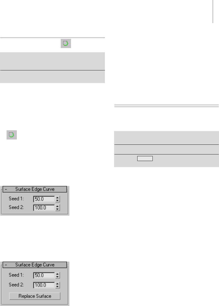
Surface Edge Curve 1177
SurfaceEdgeCurve
Select NURBS object. > Modify panel > Create Curves
rollout > Dependent Curves group box > Surf Edge
button
Select NURBS object. > Modify panel > NURBS toolbox >
Create Surface Edge Curve button
A surface edge curve is a dependent curve type that
lies on the boundary of the surface. It can be the
original boundary of the surface, or a trim edge.
Procedure
To create a surface edge curve:
1. Tur n on Su rf E dge.
2. Asyoumovethemouseinthescene,NURBS
surface edges are highlighted in blue. Click the
edge where you want to create the curve.
Interface
Surface Edge Curve rollout (creation time)
Seed 1 and Seed 2—The curve resides on the edge
closesttothetwose
ed values. Adjust the seed
values to change the edge on which the curve
resides.
Surface Edge Curve rollout (modification time)
Seed 1 and Seed 2—The curve resides on the edge
closest to the two seed values. Adjust the seed
valuestochangetheedgeonwhichthecurve
resides.
Replace Surface— This lets you replace the parent
surface. Click a button, then click a surface to
replace the original parent surface.
Creating Surface
Sub-Objects
Select NURBS object. > Modify panel > Create Surfaces
rollout
Select NURBS object. > NURBS toolbox
Keyboard > Ctrl+T to toggle NURBS toolbox display
(KeyboardShortcutOverrideTogglemustbeon.)
Surface sub-objects are either independent point
and CV surfaces (like the top-level point and
CV surfaces described in Point Surface and
CV Surface), or they are dependent surfaces.
Dependent surfaces are surface sub-objects whose
geometry depends on other surfaces or curves
intheNURBSmodel. Whenyouchangethe
geometry of the original, parent surface or curve,
the dependent surface changes as well.
Youcreatesurfacesub-objectsusingtheCreate
Surfaces rollout on the Modify panel for a NURBS
surface, or using the NURBS toolbox (page
1–1083).
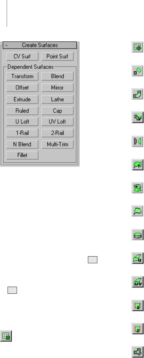
1178 Chapter 9: Surface Modeling
Tip: Lathe and extrude surface sub-objects can
be based on only a single curve. If you have
dependent curves and want to use the set of curves
(for example, two parents and a fillet between
them)asthebasisofanextrudeorlathesurface,
firstgototheCurvesub-objectlevelanduseJoin
to connect the curves.
Creation operations for dependent sub-objects
require that you select one or more parent objects.
In general, you can click and drag, or click and
then click again. You can also use the Hkeyboard
shortcut to display a Select Objects dialog (page
1–78) for choosing the parent. (The Keyboard
Shortcut Override Toggle (page 3–872) must be on
for Hto work this way.)
Toolbox Buttons for Creating Surfaces
These are the toolbox buttons for creating surface
sub-objects:
Create an independent CV surface sub-object
(page 1–1179).
Create an independent point surface
sub-object (page 1–1181).
Create a dependent transform surface (page
1–1182).
Create a dependent blend surface (page
1–1183).
Create a dependent offset surface (page
1–1186).
Create a dependent mirror surface (page
1–1187).
Create a dependent extrude surface (page
1–1188).
Create a dependent lathe surface (page
1–1190).
Create a dependent ruled surface (page
1–1193).
Create a dependent cap surface (page
1–1195).
Create a dependent Uloftsurface(page
1–1196).
Create a dependent UV loft surface (page
1–1200).
Create a dependent 1-rail sweep surface (page
1–1204).
Create a dependent 2-rail sweep surface (page
1–1209).
Create a dependent multisided blend surface
(page 1–1213).
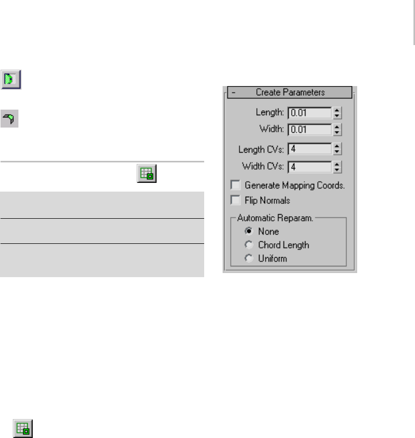
CV Surface Sub-Object 1179
Create a dependent multicurve trimmed
surface (page 1–1214).
Create a dependent fillet surface (page
1–1216).
CV Surface Sub-Object
SelectNURBSobject. >Modifypanel>CreateSurfaces
rollout > CV Surf
Select NURBS object. > Modify panel > NURBS toolbox >
Create CV Surface button
SelectNURBSobject. >Modifypanel>Right-clicka
viewport. > Tools 2 (lower-left) quadrant > Create CV
Surface
CV surface sub-objects are similar to object-level
CV surfaces (page 1–1103).
See also
Editing Surface Sub-Objects (page 1–1141)
Surface Approximation (page 1–1239)
Procedure
To create a CV surface sub-object:
1. InaNURBSobject,turnonCVSurf
ontheCreateSurfacesrolloutorCreateCV
Surface in the toolbox.
2. In a viewport, drag to specify the initial area
of the CV surface.
3. Adjust the CV surface’s creation parameters.
Interface
The parameters that appear when you create a CV
surface sub-object differ from those you see when
you modify it as a sub-object.
CV Surface rollout (creation time)
Length—The length of the surface in current
3ds Max units.
Width—The width of the surface in current
3ds Max units.
Length Points—The number of points along the
length of the surface. In other words, the initial
number of point columns in the surface. Range=2
to 50. Default=4.
Width Points—The number of points along the
width of the surface. In other words, the initial
number of point rows in the surface. Range=2 to
50. Default=4.
Generate Mapping Coordinates—Generates
mapping coordinates so you can apply mapped
materials to the surface.
Flip Normals—Turn on to reverse the direction of
the surface normals.
Automatic Reparameterization group
The radio buttons in this group box let you
choose automatic reparameterization. With
reparameterization, the surface maintains
its parameterization as you edit it. Without
reparameterization, the surface’s parameterization
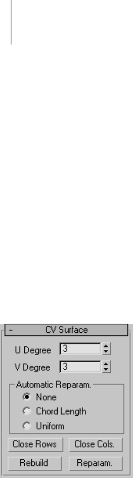
1180 Chapter 9: Surface Modeling
doesn’t change as you edit it, and can become
irregular.
None—Do not reparameterize.
Chord Length—Chooses the chord-length
algorithm for reparameterization.
Chord-length reparameterization spaces knots (in
parameter space (page 3–988)) based on the square
root of the length of each curve segment.
Chord-length reparameterization is usually the
best choice.
Uniform—Spaces the knots uniformly.
A uniform knot vector has the advantage that the
surface will change only locally when you edit it.
With the other two forms of parameterization,
moving any CV can change the entire surface.
CV Surface rollout (modification time)
U Degree and V Degree—Letyousetthedegreeof
the surface in either the U or V dimension. The
higher the degree value, the greater the continuity.
Thelowerthedegree,themorediscontinuousthe
surface segments become. The degree can’t be less
than one or greater than the number allowed by the
number of CVs in the specified dimension. Degree
3 is adequate to represent continuous surfaces, and
is stable and well behaved. Default=3.
Setting the degree greater than 3 isn’t
recommended, because higher degrees are slower
to calculate and less stable numerically. Higher
degrees are supported primarily to be compatible
with models created using other surface modeling
programs.
The number of CVs in a given dimension must be
at least one greater than that dimension’s degree.
Automatic Reparameterization group
The radio buttons in this group box let you
choose automatic reparameterization. With
reparameterization, the surface maintains
its parameterization as you edit it. Without
reparameterization, the surface’s parameterization
doesn’t change as you edit it, and can become
irregular.
None—Do not reparameterize.
Chord Length—Chooses the chord-length
algorithm for reparameterization.
Chord-length reparameterization spaces knots (in
parameter space (page 3–988)) based on the square
rootofthelengthofeachcurvesegment.
Chord-length reparameterization is usually the
best choice.
Uniform—Spaces the knots uniformly.
A uniform knot vector has the advantage that the
surface will change only locally when you edit it.
With the other two forms of parameterization,
moving any CV can change the entire surface.
The close controls let you close a surface. They
appear on the Point Surface rollout while an
independent point surface sub-object is selected.
They have no effect if the surface is already closed
in that direction.
Close Rows—Closes the surface by joining the ends
of its rows.
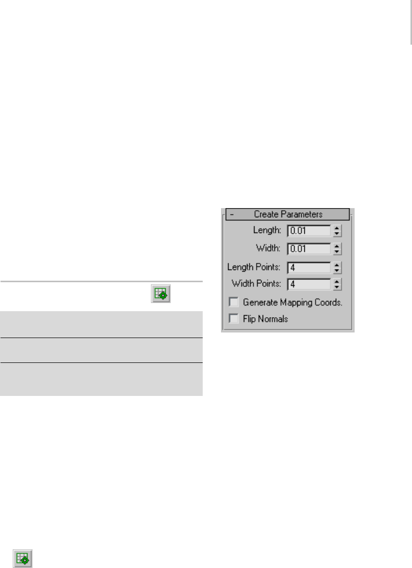
Point Surface Sub-Object 1181
Close Cols.—Closes the surface by joining the ends
of its columns.
Rebuild—Displays the Rebuild CV Surface dialog
(page 1–1236), which lets you specify how to
rebuild the surface. Rebuilding the surface can
change its appearance.
Reparameterize—Displays the Reparameterize
dialog (page 1–1237). Reparameterizing a surface
changes the surface’s parameter space (page 3–988)
to provide a better relation between control point
locations and the shape of the surface.
Tip: It is a good idea to reparameterize after you
have added CVs to the surface by refining or
inserting.
Point Surface Sub-Object
SelectNURBSobject. >Modifypanel>CreateSurfaces
rollout > Point Surf
Select NURBS object. > Modify panel > NURBS toolbox >
Create Point Surface button
SelectNURBSobject. >Modifypanel>Right-clicka
viewport. > Tools 2 (lower-left) quadrant > Create Point
Surface
Point surface sub-objects are similar to object-level
point surfaces (page 1–1102).Thepointsare
constrained to lie on the surface.
See also
Editing Surface Sub-Objects (page 1–1141)
Surface Approximation (page 1–1239)
Procedure
To create a point surface sub-object:
1. InaNURBSobject,turnonPointSurf
on the Create Surfaces rollout or Create Point
Surface in the toolbox.
2. In a viewport, drag to specify the initial area of
the point surface.
3. Adjust the point surface’s creation parameters.
Interface
The parameters that appear when you create a
point surface sub-object differ from those you see
when you modify it as a sub-object.
Point Surface rollout (creation time)
Length—The length of the surface in current
3ds Max units.
Width—The width of the surface in current
3ds Max units.
Length Points—The number of points along the
length of the surface. In other words, the initial
number of point columns in the surface. Range=2
to 50. Default=4.
Width Points—The number of points along the
width of the surface. In other words, the initial
number of point rows in the surface. Range=2 to
50. Default=4.
Generate Mapping Coordinates—Generates
mapping coordinates so you can apply mapped
materials to the surface.
Flip Normals—Turn on to reverse the direction of
the surface normals.
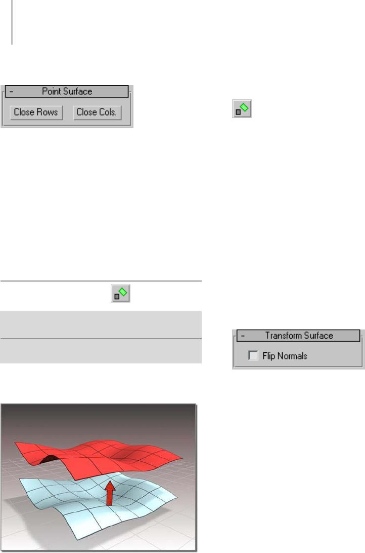
1182 Chapter 9: Surface Modeling
Point Surface rollout (modification time)
The close controls let you close a surface. They
appear on the Point Surface rollout while an
independentpointsurfacesub-objectisselected.
They have no effect if the surface is already closed
in that direction.
Close Rows—Closes the surface by joining the ends
of its rows.
Close Cols.—Closes the surface by joining the ends
of its columns.
Transform Surface
SelectNURBSobject. >Modifypanel>CreateSurfaces
rollout Dependent Surfaces group box > Transform
Select NURBS object. > Modify panel > NURBS toolbox >
Create Transform Surface button
A transform surface is a copy of the original
surface with a different position, rotation, or scale.
Surface created as a transform
Procedure
To create a transform surface:
•In a NURBS object that contains at least
one surface, turn on Transform.
To move the transform surface, click and drag
thesurfaceyouwanttoduplicate.Torotateor
scale the transform surface, click the parent
surface, click to turn on Sub-Object on the
Modifier Stack rollout, choose Surface from the
drop-down list, and then use a transform to
rotate or scale the transform surface.
When you use Move to create the transform
surface, it simply copies the parent. (It doesn’t
exaggeratecurvatureasanoffsetsurfacedoes.)
Axis constraints don’t apply to the creation
of transform surfaces. You can click to create
the surface in place; then once it is created,
transform it using constraints.
The Flip Normals control lets you flip the
surface normals at creation time. (After
creation, you canflipnormalsusingcontrolson
the Surface Common rollout.)
You can later transform the transform surface as a
surface sub-object, and you can animate surface
sub-object transforms.
Interface
Creation time
At creation time, transform surfaces have no
parameters.
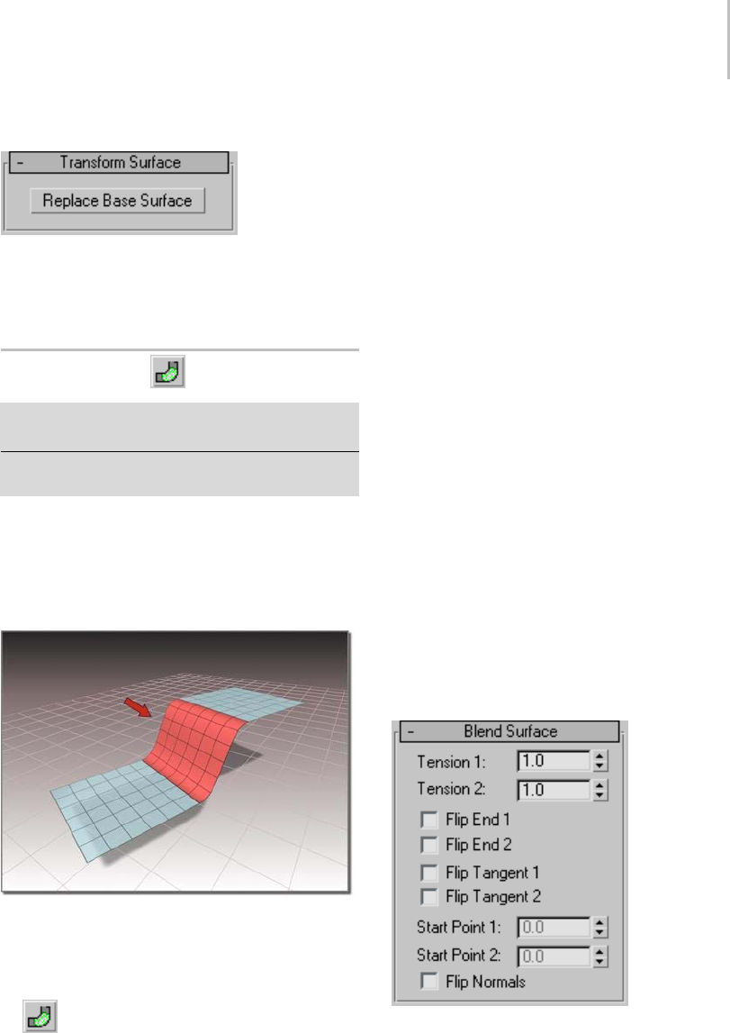
Blend Surface 1183
Transform Surface rollout (modification time)
Replace Base Surface—Lets you replace the parent
surface. Click the button, then click the surface to
replace the original surface.
Blend Surface
SelectNURBSobject. >Modifypanel>CreateSurfaces
rollout > Dependent Surfaces group box > Blend
Select NURBS object. > Modify panel > NURBS toolbox >
Create Blend Surface button
A blend surface connects one surface to another,
blending the curvature of the parent surfaces to
create a smooth surface between them. You can
also blend from a surface to a curve, or from a
curve to a curve.
Blend surface connecting two other surfaces
Procedure
To create a blend surface:
1. In a NURBS objectthatcontainstwo
surfaces, two curves, or a surface and a curve,
turn on Blend.
2. Click one surface near the edge that you want
to connect. The edge that will be connected is
highlighted in blue. Drag to choose the other
edge you want to connect. When the edge you
want is highlighted, click and then drag to the
other surface. The edge of the other surface
is also highlighted in blue. Drag on the other
surfacetochoosetheedgetoconnect,andthen
release the mouse button to create the blend
surface.
The surface that owns the highlighted edge is
highlighted in yellow, to help you distinguish
whichedgeyouarechoosingwhentwosurfaces
have coincident edges.
Theblendsurfaceiscreated. Changingthe
position or the curvature of either parent
surface will change the blend surface as well.
3. Adjust the blend parameters.
Interface
While a blend surface sub-object is selected, a
rollout with the blend parameters is displayed at
the bottom of the Modify panel.
Blend Surface rollout (creation time)
"Tension" affects the tangent between a parent
surface and the blend surface. The greater the
tension value, the more closely the tangent
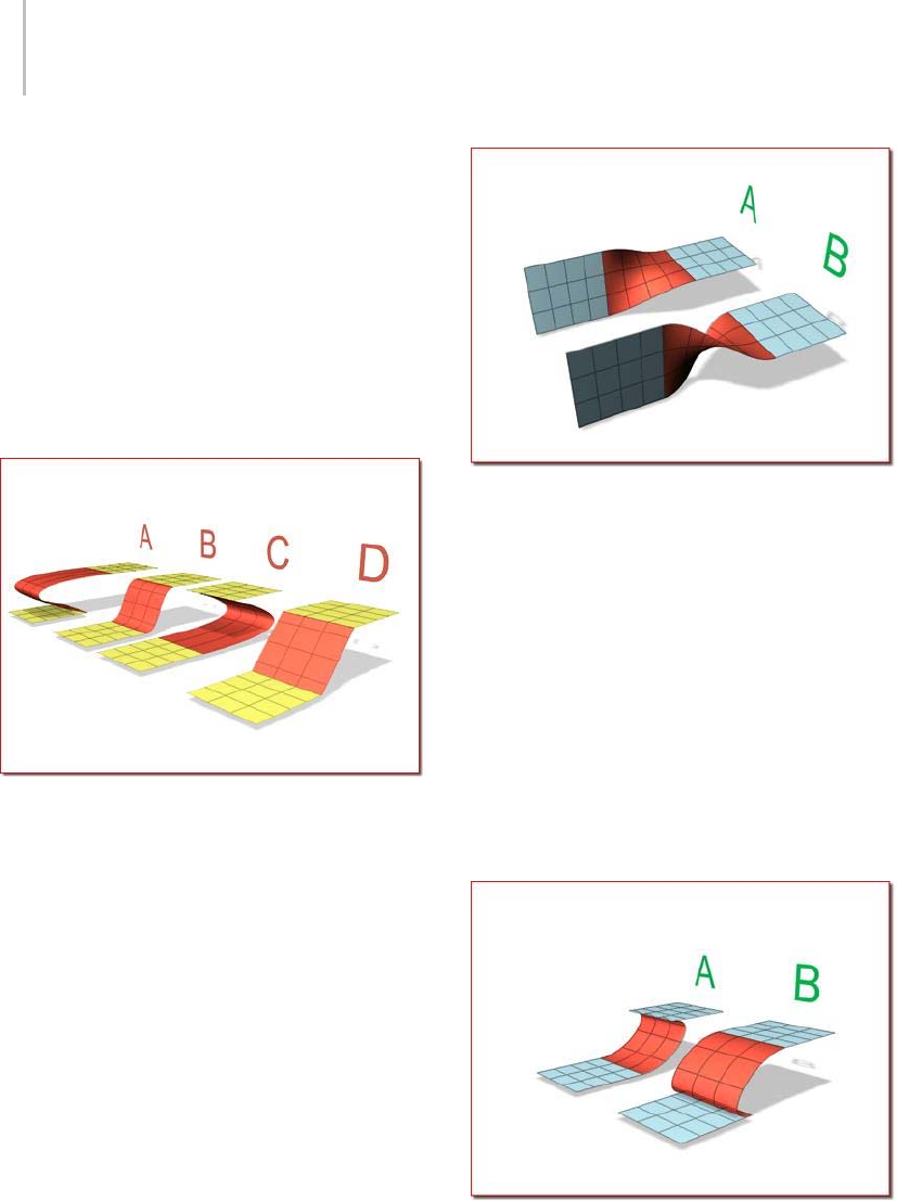
1184 Chapter 9: Surface Modeling
parallels the parent surface, and the smoother
thetransition.Thelowerthetension,thegreater
thetangentangleandthesharperthetransition
between parent and blend.
Tension 1—Controls tension at the edge of the first
surface you clicked. This value has no effect if the
edge is a curve.
Tension 2—Controls tension at the edge of the
second surface you clicked. This value has no
effectiftheedgeisacurve.
A. Tension 1=0, Tension 2=10
B. Tension 1=1, Tension 2=1
C. Tension 1=10, Tension 2=0
D. Tension 1=0, Tension 2=0
Flip End 1 and Flip End 2—Flip one of the normals
used to construct the blend. A blend surface is
created using the normals of the parent surfaces.
If the two parents have opposing normals, or
if a curve has the opposite direction, the blend
surface can be shaped like a bow tie. To correct
the situation, use Flip End 1 or Flip End 2 to
construct the blend using a normal opposite the
corresponding parent surface’s normal.
A. No flipping
B. End 2 is flipped.
Flip Tangent 1 and Flip Tangent 2—Flip the tangent
attheedgeofthefirstorsecondcurveorsurface.
Flipping the tangent reverses the direction in
which the blend surface approaches the parent
sub-object at that edge.
Flipping the tangent has no effect if the edge is a
curve, unless the curve is a curve on surface.
WhenyoublendtoaCVorpointcurveonsurface,
the new blend surface is tangent to the surface on
which the curve on surface lies. The Flip Tangent
controls are especially useful in this situation.
A. Tangent 1 flipped
B. Tangent 2 flipped
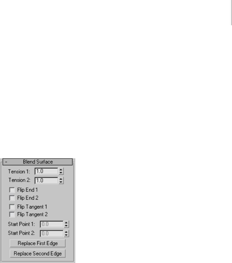
Blend Surface 1185
Start Point 1 and Start Point 2—Adjust the position
of the start point at the two edges of the blend.
Adjusting the start points can help eliminate
unwanted twists or "buckles" in the surface.
These spinners are unavailable if the edges or
curves are not closed.
While you’re adjusting start points, a dotted
blue line is displayed between them, to show the
alignment. The surface is not displayed, so it
doesn’t slow down adjustment. When you release
the mouse button, the surface reappears.
Flip Normals—Turn on to reverse the direction of
the blend surface normals.
Blend Surface rollout (modification time)
"Tension" affects the tangent between a parent
surface and the blend surface. The greater the
tension value, the more closely the tangent
parallels the parent surface, and the smoother
thetransition.Thelowerthetension,thegreater
thetangentangleandthesharperthetransition
between parent and blend.
Tension 1—Controls tension at the edge of the first
surface you clicked. This value has no effect if the
edge is a curve.
Tension 2—Controls tension at the edge of the
second surface you clicked. This value has no
effectiftheedgeisacurve.
Flip End 1 and Flip End 2—Flip one of the normals
used to construct the blend. A blend surface is
created using the normals of the parent surfaces.
If the two parents have opposing normals, or
if a curve has the opposite direction, the blend
surface can be shaped like a bow tie. To correct
the situation, use Flip End 1 or Flip End 2 to
construct the blend using a normal opposite the
corresponding parent surface’s normal.
Flip Tangent 1 and Flip Tangent 2—Flip the tangent
attheedgeofthefirstorsecondcurveorsurface.
Flipping the tangent reverses the direction in
which the blend surface approaches the parent
sub-object at that edge.
Flipping the tangent has no effect if the edge is a
curve, unless the curve is a curve on surface.
WhenyoublendtoaCVorpointcurveonsurface,
the new blend surface is tangent to the surface on
which the curve on surface lies. The Flip Tangent
controls are especially useful in this situation.
Start Point 1 and Start Point 2—Adjust the position
of the start point at the two edges of the blend.
Adjusting the start points can help eliminate
unwanted twists or "buckles" in the surface.
These spinners are unavailable if the edges or
curves are not closed.
While you’re adjusting start points, a dotted
blue line is displayed between them, to show the
alignment. The surface is not displayed, so it
doesn’t slow down adjustment. When you release
the mouse button, the surface reappears.
Replace First Edge and Replace Second Edge—Let
you replace the parent edges or curves. Click a
button, then click the edge to replace the original
firstorsecondedge.Theedgecanbeonthesame
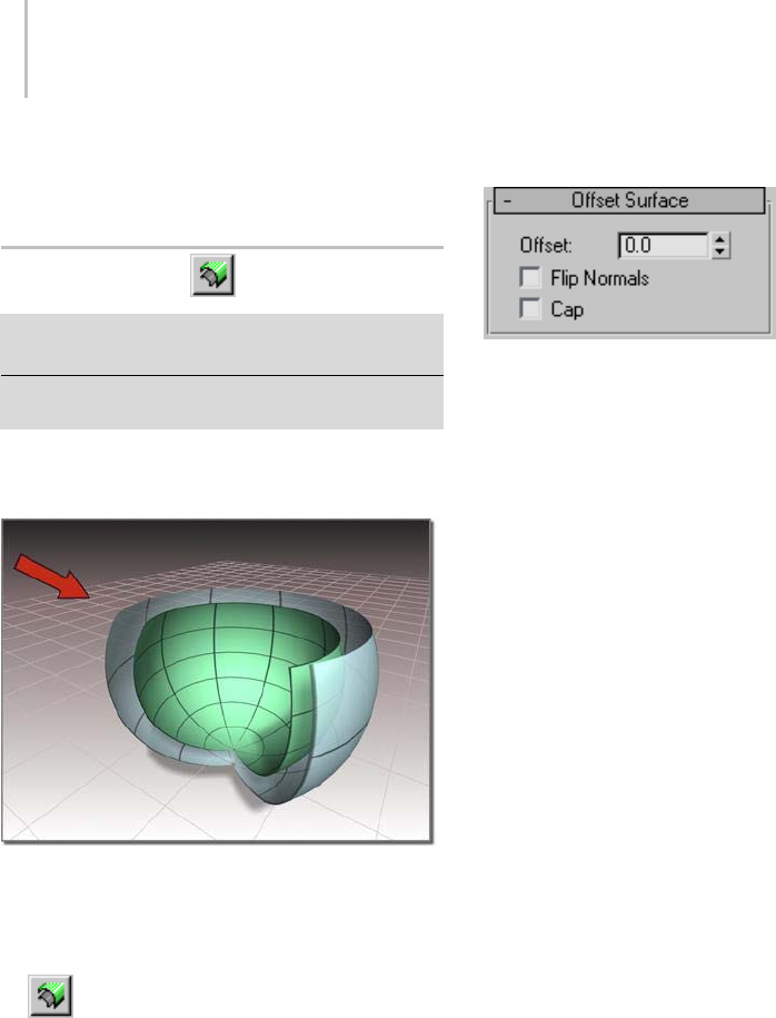
1186 Chapter 9: Surface Modeling
surface as the original edge, or on a different
surface.
Offset Surface
SelectNURBSobject. >Modifypanel>CreateSurfaces
rollout > Dependent Surfaces group box > Offset
Select NURBS object. > Modify panel > NURBS toolbox >
Create Offset Surface button
An Offset surface is offset a specified distance from
the original along the parent surface’s normals.
Surface created as an offset
Procedure
To create an offset surface:
1. In a NURBS object that contains at least
one surface, turn on Offset.
2. Click the surface you want to offset, and drag to
set the initial distance of the offset surface.
The offset surface is created.
3. Adjust the Offset parameter.
Interface
While an offset surface sub-object is selected,
a rollout with the offset Distance parameter is
displayed at the bottom of the Modify panel.
Offset Surface rollout (creation time)
Offset—Thedistancebetweentheparentsurface
and the offset surface, in 3ds Max units.
If the parent surface is planar, the appearance of
theoffsetsurfacedoesn’tchangewithdistance.If
the parent surface is curved, increasing the offset
value increasingly exaggerates the curvature of the
offset surface.
Flip Normals—Lets you flip the surface normals
at creation time. (After creation, you can flip
normals using controls on the Surface Common
rollout.)
Cap—When on, eight boundary curves are
generated (four at the four edges of each surface),
and then generates four ruled surfaces to connect
the two original surfaces. While they are present,
cap surfaces are maintained so they match the
dimensions of the offset and its parent.
The Cap check box appears only on the creation
rollout. If you want to remove the caps later,
simply select them as surface sub-objects and
delete them. Think of offset capping as a workflow
shortcut rather than a property (or parameter) of
offset surfaces.
To flip the normal of an offset cap, select it as a
surface sub-object and use the Flip Normals toggle
on the Surface Common rollout.
Note: If you trim the original surface, or make the
offset surface independent and then trim it, the
capping surfaces will look strange.
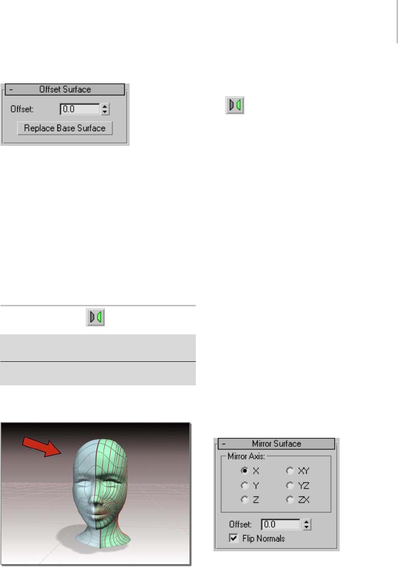
Mirror Surface 1187
Offset Surface rollout (modification time)
Offset—The distance between the parent surface
and the offset surface in 3ds Max units.
If the parent surface is planar, the appearance of
the offset surface doesn’t change with distance. If
the parent surface is curved, increasing the offset
value increasingly exaggerates the curvature of the
offset surface.
Replace Base Surface—Lets you replace the parent
surface. Click the button, then click the new
surface on which to base the offset.
Mirror Surface
SelectNURBSobject. >Modifypanel>CreateSurfaces
rollout > Dependent Surfaces group box > Mirror
Select NURBS object. > Modify panel > NURBS toolbox >
Create Mirror Surface button
A mirror surface is a mirror image of the original
surface.
Surface created as a mirror
Procedure
To create a mirror surface:
1. In a NURBS object that contains at least
one surface, turn on Mirror.
2. On the Mirror Surface rollout, choose the axis
or plane you want to use.
3. Click the surface you want to mirror, and drag
to set the initial distance of the mirror surface.
The mirror surface is created. A gizmo (yellow
by default) indicates the direction of mirroring.
Transforming the mirror surface’s gizmo
changes the orientation of the mirror, letting
you mirror along an axis that isn’t aligned with
alocalcoordinateaxis.
The Flip Normals control lets you flip the
surface normals at creation time. (After
creation, you can flip normals using controls on
the Surface Common rollout.)
4. Adjust the Offset parameter.
Interface
While a mirror surface sub-object is selected, the
Mirror Surface rollout appears at the bottom of the
Modify panel. Also, a gizmo (yellow by default)
indicates the mirror axis.
Mirror Surface rollout (creation time)
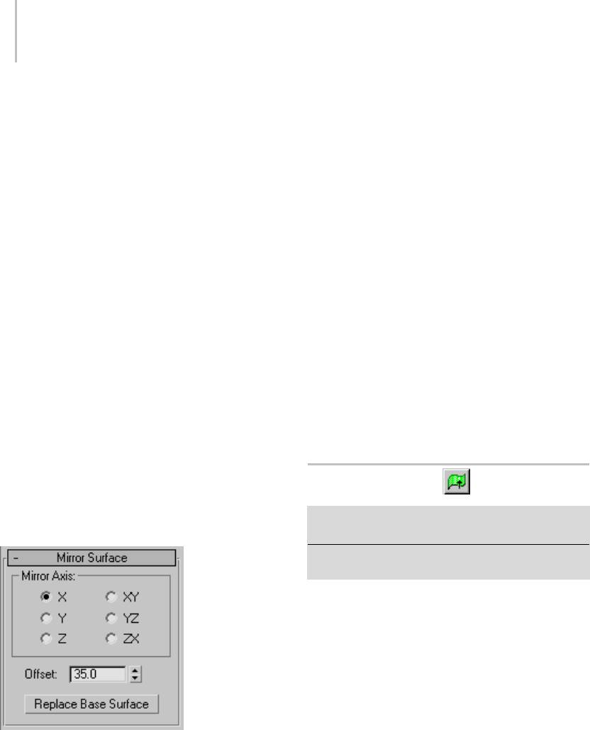
1188 Chapter 9: Surface Modeling
Mirror Axis group
The Mirror Axis buttons control the direction in
which the original surface is mirrored.
You can’t transform the mirror surface directly
(that would simply transform the mirror surface
and its parent surface at the same time). You
transform it by transforming its gizmo. By using
transforms you can mirror about an arbitrary axis,
rather than using one of the Mirror Axis presets.
When you transform a mirror surface, you are
actually transforming the mirror plane, so Rotate
has the effect of rotating the plane about which
the surface is mirrored. (This is like rotating the
mirror gizmo in the Mirror modifier.)
Tip: A convenient way to guarantee that a surface
is symmetrical is to create one side of the surface,
mirror that surface, and then create a blend
between the two sides.
Offset—Controls the mirror’s distance from the
original surface. This parameter is animatable.
Flip Normals—Lets you flip the surface normals.
Mirror Surface rollout (modification time)
Mirror Axis group
The Mirror Axis buttons control the direction in
which the original surface is mirrored.
You can’t transform the mirror surface directly
(that would simply transform the mirror surface
and its parent surface at the same time). You
transform it by transforming its gizmo. By using
transforms you can mirror about an arbitrary axis,
rather than using one of the Mirror Axis presets.
When you transform a mirror surface, you are
actually transforming the mirror plane, so Rotate
has the effect of rotating the plane about which
the surface is mirrored. (This is like rotating the
mirror gizmo in the Mirror modifier.)
Tip: A convenient way to guarantee that a surface
is symmetrical is to create one side of the surface,
mirror that surface, and then create a blend
between the two sides.
Offset—Controls the mirror’s distance from the
original surface. This parameter is animatable.
ReplaceBaseSurface—Lets you replace the parent
surface. Click the button, then click the new
surfaceonwhichtobasethemirror.
Extrude Surface
Select NURBS object. > Modify panel > Create Surfaces
rollout > Dependent Surfaces group box > Extrude
Select NURBS object. > Modify panel > NURBS toolbox >
Create Extrude Surface button
An extrude surface is extruded from a curve
sub-object. It is similar to a surface created with
the Extrude modifier. The advantage is that an
extrudesub-objectispartoftheNURBSmodel,so
you can use it to construct other curve and surface
sub-objects.
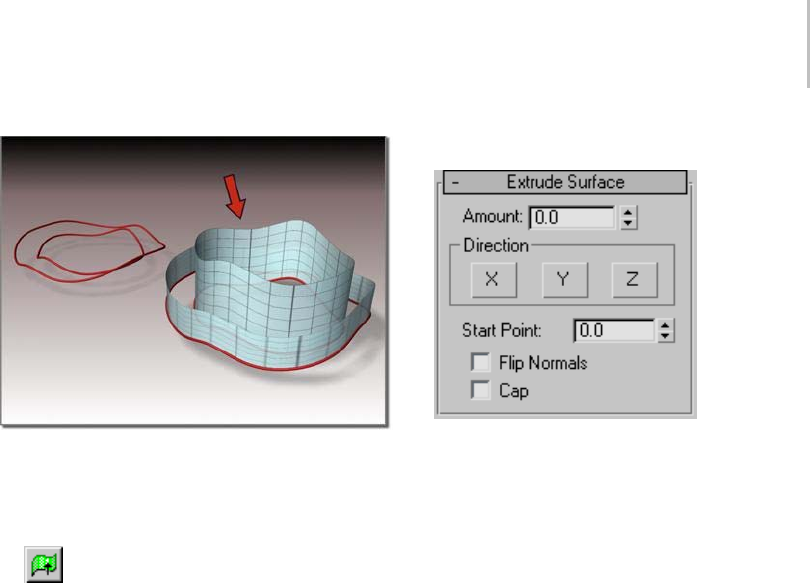
Extrude Surface 1189
Surface extruded from a curve
Procedure
To create an extrude surface:
1. In a NURBS object that contains at least
one curve, turn on Extrude.
2. Move the cursor over the curve to extrude, and
drag to set the initial amount.
By default, the surface extrudes along the
NURBS model’s local Z axis. A gizmo (yellow
by default) indicates the direction of extrusion.
Trans for min g the extrude surface’s gizmo
changes the direction of the extrude, letting you
extrude along an axis that isn’t aligned with a
local coordinate axis.
The Flip Normalscontrolletsyouflipthe
surface normals at creation time. (After
creation, you can flip normals using controls on
the Surface Common rollout.)
3. Adjust the extrusion parameters.
Interface
While an extrude sub-object is selected, a rollout
with the extrusion parameters is displayed at the
bottom of the Modify panel.
Extrude Surface rollout (creation time)
Amount—Thedistancethesurfaceisextruded
from the parent curve in current 3ds Max units.
This parameter is animatable.
Direction group
X, Y and Z—Choose the axis of extrusion.
Default=Z.
Start Point—Adjusts the position of the curve’s
start point. This can help eliminate unwanted
twists or "buckles" in the surface.
This control is disabled if the curve is not a closed
curve.
Thestartpointisdisplayedasabluecircle.
Flip Normals—Lets you flip the surface normals
at creation time. (After creation, you can flip
normals using controls in the Surface Common
rollout.)
Cap—When on, two surfaces are generated to close
theendsoftheextrusion.Whiletheyarepresent,
the cap surfaces are maintained so they match the
dimensions of the extrude surface. The parent
curvemustbeaclosedcurve.
The Cap check box appears only on the creation
rollout. If you want to remove the caps later, simply
select them as surface sub-objects and delete them.
Think of extrude capping as a workflow shortcut
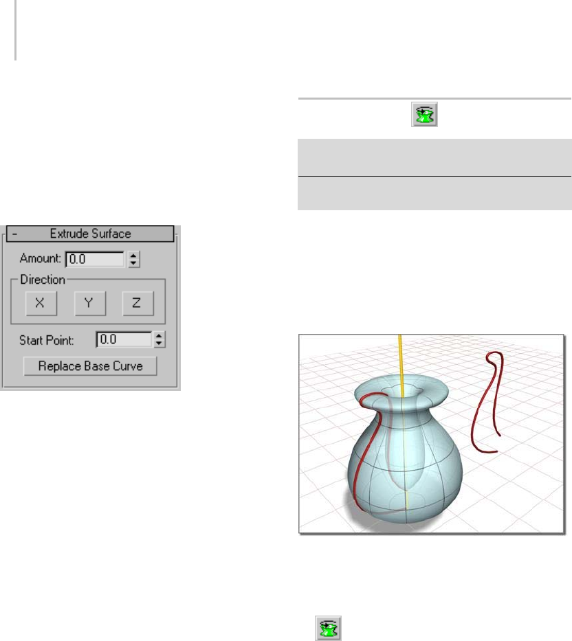
1190 Chapter 9: Surface Modeling
rather than a property (or parameter) of extrude
surfaces.
To f l i p t h e n o r m a l of a n e x t r u d e c a p, s e l e c t i t a s a
Surface sub-object and use the Flip Normals toggle
on the Surface Common rollout.
Extrude Surface rollout (modification time)
Amount—The distance the surface is extruded
fromtheparentcurveincurrent3dsMaxunits.
Direction group
X, Y and Z— Choose the axis of extrusion.
Default=Z.
Start Point—Adjusts the position of the curve’s
start point. This can help eliminate unwanted
twists or "buckles" in the surface.
Thiscontrolisdisabledifthecurveisnotaclosed
curve.
Thestartpointisdisplayedasabluecircle.
Replace Base Curve—Lets you replace the parent
curve. Click the button, then click the new curve
on which to base the extruded surface.
Lathe Surface
Select NURBS object. > Modify panel > Create Surfaces
rollout>DependentSurfacesgroupbox>Lathe
Select NURBS object. > Modify panel > NURBS toolbox >
Create Lathe Surface button
A lathe surface is generated from a curve
sub-object. It is similar to a surface created with
the Lathe modifier. The advantage is that a lathe
sub-object is part of the NURBS model, so you
can use it to construct other curve and surface
sub-objects.
Surface created by lathing a curve
Procedure
To create a lathe surface:
1. In a NURBS object that contains at least
one curve, turn on Lathe.
2. Click the curve to lathe.
The lathe surface rotates about the NURBS
model’s local Y axis. The initial lathe amount
is 360 degrees. A gizmo (yellow by default)
indicates the axis of the lathe. Transforming the
lathe surface’s gizmo changes the shape of the
lathe,andletsyoulathearoundanaxisthatisn’t
aligned with a local coordinate axis.
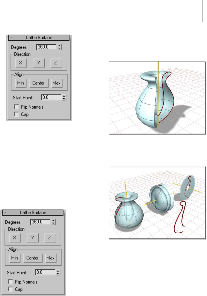
Lathe Surface 1191
The Flip Normals control lets you flip the
surface normals at creation time. (After
creation, you can flip normals using controls on
the Surface Common rollout.)
3. Adjust the lathe parameters.
Interface
While a lathe sub-object is selected, a rollout with
the lathe parameters is displayed at the bottom of
the Modify panel.
Lathe Surface rollout (creation time)
Degrees—Sets the angle of rotation. At 360 degrees
(the default), the surface completely surrounds
the axis. At lower values, the surface is a partial
rotation.
A partial lathe (degrees=225)
Direction group
X, Y, and Z—Choose the axis of rotation. Default=Y.
X, Y, and Z rotations of the same curve
Align group
Thesebuttonspositiontheaxisofrotationrelative
to the curve.
Min—(The default.) Locates the lathe axis at the
curve’s negative local X-axis boundary.
Center—Locatesthelatheaxisatthecurve’scenter.
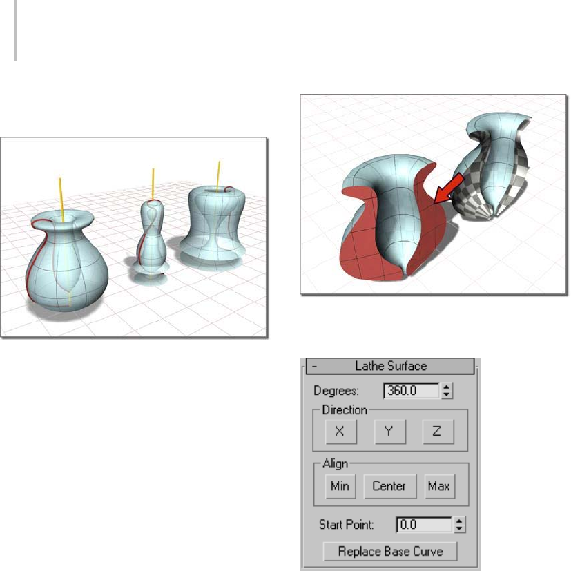
1192 Chapter 9: Surface Modeling
Max—Locatesthelatheaxisatthecurve’spositive
local X-axis boundary.
Min, Center, and Max lathes of the same curve
Start Point—Adjusts the position of the curve’s
start point. This can help eliminate unwanted
twists or "buckles" in the surface.
Thiscontrolisdisabledifthecurveisnotaclosed
curve.
Thestartpointisdisplayedasabluecircle.
Flip Normals—Lets you flip the surface normals
at creation time. (After creation, you can flip
normals using controls on the Surface Common
rollout.)
Cap—When on, two surfaces are generated to close
the ends of the lathe. While they are present, the
cap surfaces are maintained so they match the
dimensions of the lathe surface. The lathe must be
a 360-degree lathe.
The Cap check box appears only on the creation
rollout. If you want to remove the caps later,
simply select them as surface sub-objects and
delete them. Think of lathe capping as a workflow
shortcut rather than a property (or parameter) of
lathe surfaces.
Toflipthenormalofalathecap,selectitasa
Surface sub-object and use the Flip Normals toggle
on the Surface Common rollout.
Addingacaptoapartiallathe
Lathe Surface rollout (modification time)
Degrees—Sets the angle of rotation. At 360 degrees
(the default), the surface completely surrounds
the axis. At lower values, the surface is a partial
rotation.
Direction group
XYandZ—Choose the axis of rotation. Default=Y.
Align group
Thesebuttonspositiontheaxisofrotationrelative
to the curve.
Min—(The default.) Locates the lathe axis at the
curve’s negative local X-axis boundary.
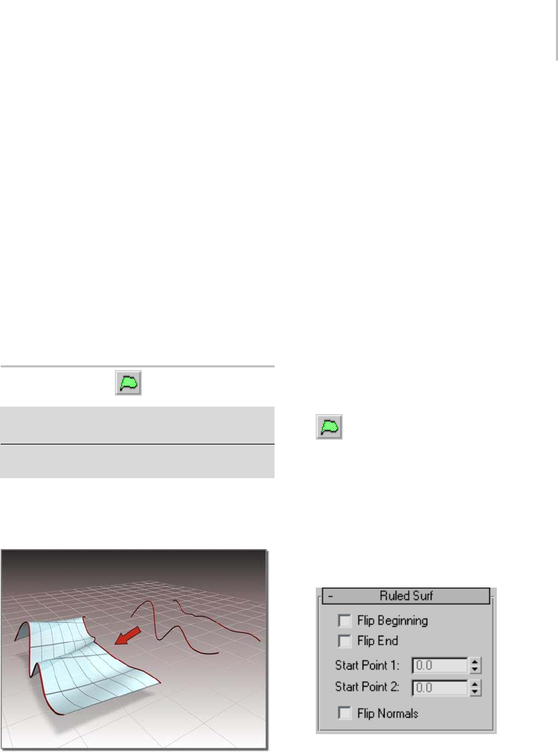
Ruled Surface 1193
Center—Locatesthelatheaxisatthecurve’scenter.
Max—Locatesthelatheaxisatthecurve’spositive
local X-axis boundary.
Start Point—Adjusts the position of the curve’s
start point. This can help eliminate unwanted
twists or "buckles" in the surface.
Thiscontrolisdisabledifthecurveisnotaclosed
curve.
Thestartpointisdisplayedasabluecircle.
Replace Base Curve—Lets you replace the parent
curve. Click the button, then click the new surface
on which to base the lathed surface.
Ruled Surface
SelectNURBSobject. >Modifypanel>CreateSurfaces
rollout > Dependent Surfaces group box > Ruled
Select NURBS object. > Modify panel > NURBS toolbox >
Create Ruled Surface button
A ruled surface is generated from two curve
sub-objects. It lets you use curves to design the
two opposite borders of a surface.
Using two curves to create a ruled surface
You can animate the parent curves or their CVs to
change the ruled surface.
Automatic Curve Attachment
When you create a ruled surface, you can select
curves that are not already sub-objects of the active
NURBS model. You can select another curve or
spline Splines object in the scene. When you select
that curve, it attaches to the current object as if you
hadusedtheAttach button (page 1–1120).
Warning: If the curve you attach is a sub-object of
anotherNURBSmodel,theentiremodel(thatis,the
curve’s parent NURBS object) is attached as well.
Asyoumovethemouseoveracurvethatisnot
part of the active NURBS object, the cursor
changes shape to indicate that you can pick the
curve, but the curve is not highlighted in blue.
Procedure
To create a ruled surface:
1. In a NURBS object that contains at least
two curves, turn on Ruled.
2. Drag from one curve to the other.
You can also click first one curve, then the other.
A dependent surface is generated, using the
twocurvesasthesurface’soppositeedges.
The perpendicular edges are generated
automatically.
The Flip Normals control lets you flip the
surface normals at creation time. (After
creation, youcanflipnormalsusingcontrolson
the Surface Common rollout.)
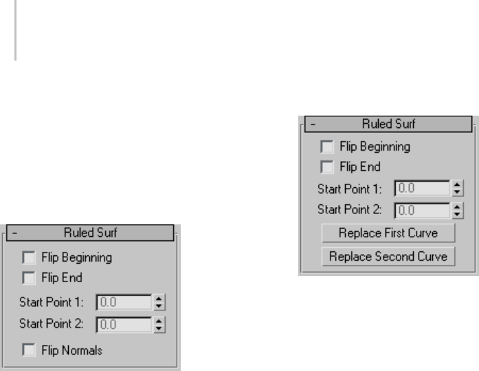
1194 Chapter 9: Surface Modeling
Interface
When you turn on the Ruled button, and while a
ruled surface sub-object is selected, a rollout with
the ruled surface parameters is displayed at the
bottom of the Modify panel.
Ruled Surf rollout (creation time)
Flip Beginning and Flip End—Flip one of the curve
directions used to construct the ruled surface.
A ruled surface is created using the directions
oftheparentcurves. Ifthetwoparentshave
opposing directions, the ruled surface can be
shaped like a bow tie. To correct the situation,
use Flip Beginning or Flip End to construct the
ruled surface using a direction opposite the
corresponding parent curve’s direction. These
controls eliminate the need to reverse the curve.
Start Point 1 and Start Point 2—Adjust the position
ofthestartpointatthetwocurvesthatspecify
the ruled surface. Adjusting the start points can
help eliminate unwanted twists or "buckles" in the
surface.
Thesespinnersaredisablediftheedgesorcurves
are not closed.
While you’re adjusting start points, a dotted
blue line is displayed between them, to show the
alignment. The surface is not displayed, so it
doesn’t slow down adjustment. When you release
the mouse button, the surface reappears.
Flip Normals—Turn on to reverse the direction of
the ruled surface’s normals.
Ruled Surf rollout (modification time)
Flip Beginning and Flip End—Flip one of the curve
directions used to construct the ruled surface.
A ruled surface is created using the directions
of the parent curves. If the two parents have
opposing directions, the ruled surface can be
shaped like a bow tie. To correct the situation,
use Flip Beginning or Flip End to construct the
ruled surface using a direction opposite the
corresponding parent curve’s direction. These
controls eliminate the need to reverse the curve.
Start Point 1 and Start Point 2—Adjust the position
of the start point at the two curves that specify
the ruled surface. Adjusting the start points can
help eliminate unwanted twists or "buckles" in the
surface.
These spinners are disabled if the edges or curves
are not closed.
While you’re adjusting start points, a dotted
blue line is displayed between them, to show the
alignment. The surface is not displayed, so it
doesn’t slow down adjustment. When you release
the mouse button, the surface reappears.
ReplaceFirstCurveandReplaceSecondCurve—Let
you replace the parent curves. Click a button,
then click the curve to replace the original first or
second curve.
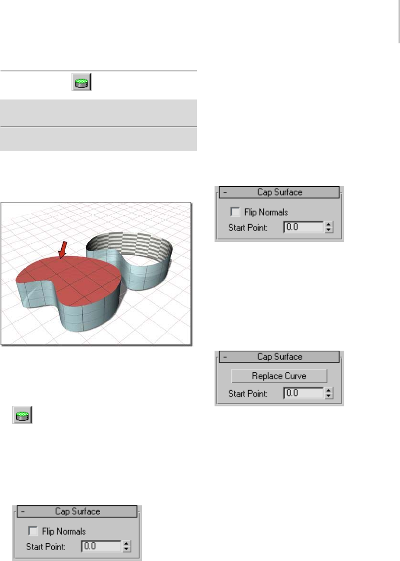
Cap Surface 1195
Cap Surface
SelectNURBSobject. >Modifypanel>CreateSurfaces
rollout > Dependent Surfaces group box > Cap
Select NURBS object. > Modify panel > NURBS toolbox >
Create Cap Surface button
Thiscommandcreatesasurfacethatcapsaclosed
curve or the edge of a closed surface. Caps are
especially useful with extruded surfaces.
Capping an extrude surface
Procedure
To create a cap surface:
1. In a NURBS object, turn on Cap.
2. Movethemouseovertheclosedcurveorthe
closed edge of a closed surface.
Ifthecapcanbecreated,thecurveoredgeis
highlighted in blue.
3. Click the highlighted curve or edge.
The Flip Normals control lets you flip the
surface normals at creation time. (After
creation, you can flip normals using controls on
the Surface Common rollout.)
Interface
While a cap surface sub-object is selected, a rollout
with cap surface controls is displayed at the bottom
of the Modify panel.
Cap Surface rollout (creation time)
Flip Normals—Turn on to reverse the direction of
the cap surface’s normals.
Start Point—Adjusts the position of the edge or
curve’s start point.
Thestartpointisdisplayedasabluecircle.
Cap Surface rollout (modification time)
Replace Curve—Lets you replace the parent curve
or edge. Click the button, then click the new curve
or edge on which to base the cap.
Start Point—Adjusts the position of the edge or
curve’s start point.
Thestartpointisdisplayedasabluecircle.
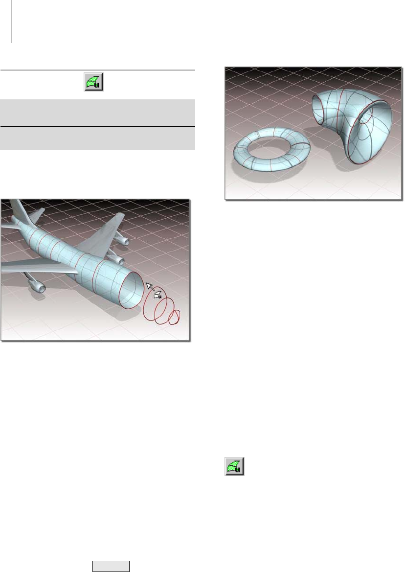
1196 Chapter 9: Surface Modeling
ULoftSurface
SelectNURBSobject. >Modifypanel>CreateSurfaces
rollout > Dependent Surfaces group box > U Loft
Select NURBS object. > Modify panel > NURBS toolbox >
Create U Loft Surface button
A U loft surface interpolates a surface across
multiple curve sub-objects. The curves become
U-axis contours of the surface.
UsingmultiplecurvestocreateaULoftsurface
Tips
• A U loft can be an extremely dense surface.
To i mp r ov e p e r f or m a n c e w h i l e w or k i n g w i t h
viewports, set the surface approximation (page
1–1239) for viewports to Curvature Dependent.
• You can speed up U loft creation by making
sure that the curves you loft have the same
number of CVs in the same order (that is, the
curves point in the same direction). Also, CV
curves have a performance advantage over
point curves.
• Turning off display of dependent sub-objects,
including the U loft itself, also speeds up
interactive performance when you create a U
loft. The default keyboard toggle for dependent
sub-object display is Ctrl+D (the Keyboard
Shortcut Override Toggle (page 3–872) button
must be on.)
Closed U lofts
Automatic Curve Attachment
When you create a U loft, you can select curves
that are not already sub-objects of the active
NURBS model. You can select another curve or
spline (page 1–266) object in the scene. When you
select that curve, it is automatically attached to the
currentobjectasifyouhadusedtheAttachbutton.
Warning: If the curve you attach is a sub-object of
anotherNURBSmodel,theentiremodel(thatis,the
curve’s parent NURBS object) is attached as well.
Asyoumovethemouseoveracurvethatisnot
part of the active NURBS object, the cursor
changes shape to indicate you can pick the curve,
but the curve is not highlighted in blue.
Procedures
To create a U loft surface:
1. In a NURBS object that contains at least
two curves, turn on U Loft.
2. Click the firstcurve.
3. Click additional curves in succession.
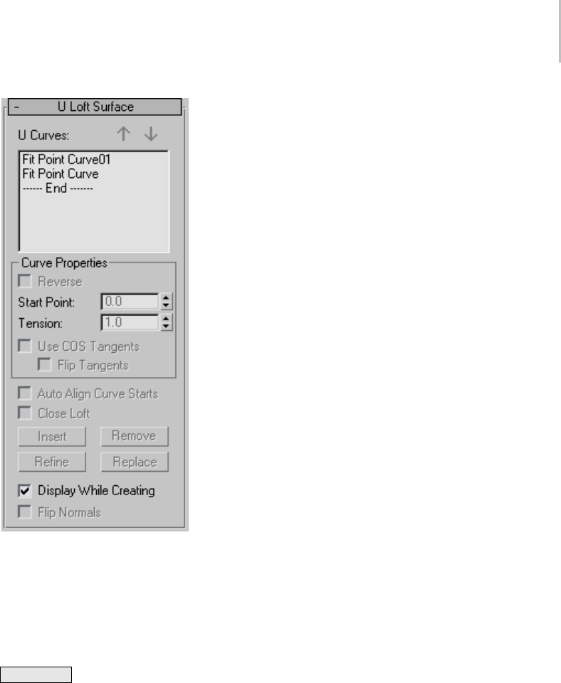
U Loft Surface 1197
The U loft is created. It is "stretched" across the
curves you click. The order in which you click
thecurvescanaffecttheshapeoftheUloft
surface.Thenamesofthecurvesappearinthe
U Loft Surface creation rollout.
While creating a U loft, you can press
Backspace to remove the last curve you
clicked from the list of U loft curves.
The Flip Normals control lets you flip the
surface normals at creation time. (After
creation, you can flip normals using controls on
the Surface Common rollout.)
4. Right-click to end U loft creation.
To create a U loft with automatic attach (example):
1. From the Create panel, create three or more
independent CV or Point NURBS curves.
2. Go to the Modify panel, and click to turn on U
Loft in the NURBS toolbox.
3. Select the curves in the appropriate order for
the loft.
The U loft is created. You don’t have to collapse
the curves to a NURBS surface, or attach them
to an existing NURBS model (page 1–1120).
Asyoumovethemouseoveracurvethatisnot
partoftheactiveNURBSobject,thecursor
changes shape to indicate you can pick the
curve, but the curve is not highlighted in blue.
Interface
While a U loft sub-object is selected, a rollout with
the U loft parameters is displayed at the bottom
of the Modify panel. This rollout appears only
when one Uloftsub-objectisselected. Itisn’t
possibletoeditmorethanoneUloftatatime,so
unlike some other NURBS sub-objects, the rollout
doesn’t appear when multiple U loft sub-objects
are selected.
When you create lofted and swept surfaces, you
have access to all the parameters, and some of the
editing operations, of the surface. You can reverse
and set start points on curves while you create
the surface. You can also use the arrow buttons
tochangetheorderofthecurves,andyoucan
remove a curve with the Remove button.
Tip: WhenyoueditaUloftsub-object,closethe
Surface Common rollout to see the U Loft Surface
rollout more easily.
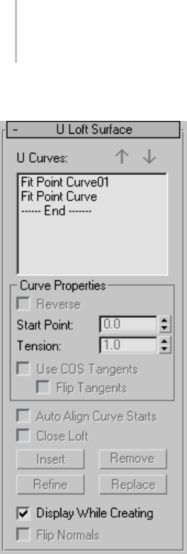
1198 Chapter 9: Surface Modeling
U Loft Surface rollout (creation time)
UCurves—This list shows the name of the curves
you click in the order you click them. You can
select curves by clicking their names. Viewports
display the selected curve in blue. Initially the first
curveistheoneselected.
You can also select more than one curve at a time.
This is useful when you use the Edit Curves button.
Arrow Buttons—Usethesetochangetheorderof
curves used to construct the U loft. Select a curve
in the list, and then use the arrows to move the
selection up or down.
Thesebuttonsareavailableatcreationtime.
Curve Properties group
These controls affect individual curves you select
in the U Curves list, as opposed to properties of the
loft surface in general. They are enabled only when
youhaveselectedacurveintheUCurveslist.
Reverse—When set, reverses the direction of the
selected curve.
Start Point—Adjusts the position of the curve’s
start point.
This control is disabled if the curve is not a closed
curve.
While you’re adjusting start points, a dotted
blue line is displayed between them, to show the
alignment. The surface is not displayed, so it
doesn’t slow down adjustment. When you release
the mouse button, the surface reappears.
Tension—Adjusts the tension of the loft where it
intersects that curve.
Use COS Tangents—If the curve is a curve on
surface,turningonthistogglecausestheUloftto
use the tangency of the surface. This can help you
blend a loft smoothly onto a surface. Default=off.
Thistoggleisdisabledunlessthecurveisapoint
or CV curve on surface.
Flip Tangents—Reverses the direction of the
tangents for that curve.
This toggle is disabled unless the curve is a point or
CV curve on surface and Use COS Tangents is on.
Auto Align Curve Starts—(Disabled.)
Close Loft—(Disabled.)
Insert—(Disabled.)
Remove—Removes a curve from the U loft surface.
Selectthecurveinthelist,andthenclickRemove.
This button is available at creation time.
Refine—(Disabled.)
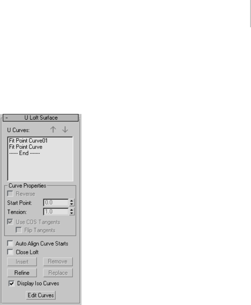
U Loft Surface 1199
Replace—(Disabled.)
Display While Creating—When on, the U loft
surfaceisdisplayedwhileyoucreateit.Whenoff,
the loft is created more quickly. Default=off.
Flip Normals—Reverses the direction of the U loft’s
normals.
U Loft Surface rollout (modification time)
UCurves—This list shows the name of the curves
you click, in the order you click them. You can
select curves by clicking their names in this list.
Viewports display the selected curve in blue.
Initially the first curve is the one selected.
You can also select more than one curve at a time.
This is useful when you use the Edit Curves button.
Arrow Buttons—Usethesetochangetheorderof
curves used to construct the U loft. Select a curve
in the list, and then use the arrows to move the
selection up or down.
Thesebuttonsareavailableatcreationtime.
Curve Properties group
These controls affect individual curves you select
in the U Curves list, as opposed to properties of the
loft surface in general. They are enabled only when
youhaveselectedacurveintheUCurveslist.
Reverse—When set, reverses the direction of the
selected curve.
Start Point—Adjusts the position of the curve’s
start point.
This control is disabled if the curve is not a closed
curve.
While you’re adjusting start points, a dotted
blue line is displayed between them, to show the
alignment. The surface is not displayed, so it
doesn’t slow down adjustment. When you release
the mouse button, the surface reappears.
Tension—Adjusts the tension of the loft where it
intersects that curve.
Use COS Tangents—If the curve is a curve on
surface,turningonthistogglecausestheUloftto
use the tangency of the surface. This can help you
blend a loft smoothly onto a surface. Default=off.
Thistoggleisdisabledunlessthecurveisapoint
or CV curve on surface.
Flip Tangents—Reverses the direction of the
tangents for that curve.
This toggle is disabled unless the curve is a point or
CV curve on surface and Use COS Tangents is on.
Auto Align Curve Starts—When on, aligns the start
points of all curves in the U loft. The software
chooses the location of the start points. Using
1200 Chapter 9: Surface Modeling
automatic alignment minimizes the amount of
twisting in the loft surface. Default=off.
Close Loft—If the loft was initially an open surface,
turning on this toggle closes it by adding a new
segmenttoconnectthefirstcurveandthelast
curve. Default=off.
Insert—Adds a curve to the U loft surface. Click
to turn on Insert, then click the curve. The curve
is inserted before the selected curve. To insert a
curve at the end, first highlight the "----End-----"
marker in the list.
Remove—Removes a curve from the U loft surface.
Selectthecurveinthelist,andthenclickRemove.
This button is available at creation time.
Refine—Refines the U loft surface. Click to turn
onRefine,thenclickaU-axisisocurveonthe
surface. (As you drag the mouse over the surface,
theavailablecurvesarehighlighted.)Thecurve
you click is converted to a CV curve and inserted
into the loft and the U Curves list. As when you
refineapointcurve,refiningaUloftcanchange
the curvature of the surface slightly. Once you’ve
refined the surface by adding a U curve, you can
useEditCurvetochangethecurve.
Replace—Replaces a U curve with a different
curve. Select a U curve, click to turn on Replace,
then click the new curve in a viewport. Available
curves are highlighted as you drag the mouse.
This button is enabled only when you’ve selected a
single curve in the U Curves list.
Display Iso Curves—When set, the U loft’s V-axis
isocurvesaredisplayedaswellastheU-axiscurves
used to construct the loft. The V-axis curves are
only for display. You can’t use them for surface
construction.
Edit Curve—Lets you edit the currently selected
curve without switching to another sub-object
level. ClicktoturnonEditCurve. Thepoints
or CVs of the curve are displayed, as well as the
control lattice if the curve is a CV curve. You can
now transform or otherwise change the points
or CVs as if you were at the Point or Curve CV
sub-object level. To finish editing the curve, click
to turn off Edit Curve.
WhenyouturnonEditCurves,allapplicable
rollouts for the selected curves are displayed,
including the Curve Common rollout, the CV
or Point rollout (depending on the curve type),
and the CV Curve or Point Curve rollout. These
rollouts appear beneath the U Loft rollout. They
let you edit the loft curves and their points or CVs
without having to switch sub-object levels.
Tip: WhenyoueditcurvesinaUloft,turningoff
displayoftheUloftitselfcanmakethecurves
easier to see and improve performance. Use
Ctrl+D (while the Keyboard Shortcut Override
Toggle button (page 3–872) is on) to toggle display
of dependent sub-objects, including U Lofts.
UV Loft Surface
Select NURBS object. > Modify panel > Create Surfaces
rollout > Dependent Surfaces group box > UV Loft
Select NURBS object. > Modify panel > NURBS toolbox >
Create UV Loft Surface button
A UV loft surface is similar to a U loft surface, but
has a set of curves in the V dimension as well as in
the U dimension. This can give you finer control
over the lofted shape, and require fewer curves to
achieve the result you want.
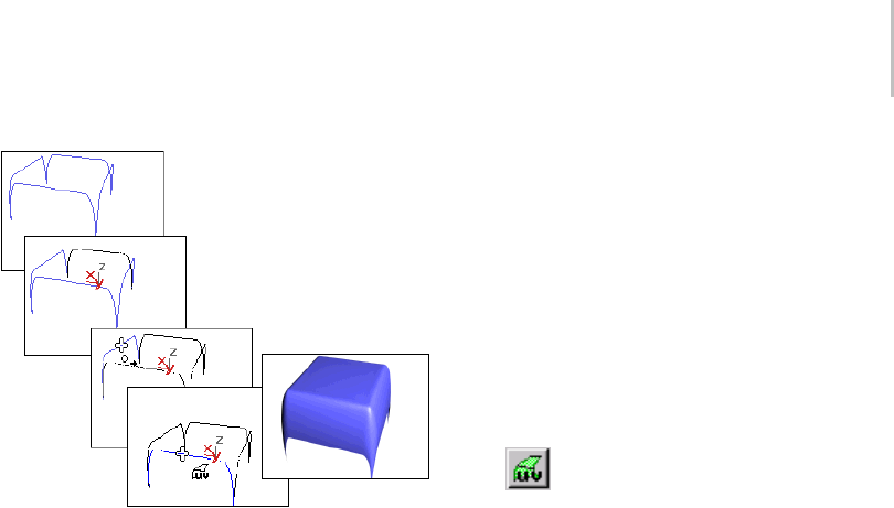
UV Loft Surface 1201
Using perpendicular curves to create a UV loft surface
If the U and V curves intersect, the UV loft
surfaceinterpolatesallthecurves.Ifthecurves
don’t intersect, the lofted surface lies somewhere
between the U and V curves. In general, UV loft
works best if the ends of all the curves in one
direction lie on the two end curves in the other
direction, as in the illustration. UV loft does not
work well if the curves in both directions are
closed.
Note: The Make Loft (page 1–1234) dialog
(displayedbytheMakeLoftbuttonontheSurface
Common rollout for surface sub-objects) now lets
youconvertasurfacetoaUVloftaswellasaU
loft. In addition, you can use point curves instead
of CV curves for the new loft lattice. If you use
point curves for a UV loft, turning on the Fuse
Points option guarantees that the U and V curves
intersect.
Automatic Curve Attachment
When you create a UV loft, you can select curves
that are not already sub-objects of the active
NURBS model. You can select another curve or
spline (page 1–266) object in the scene. When you
select that curve, it attaches to the current object as
if you had used the Attach button (page 1–1120).
Warning: If the curve you attach is a sub-object of
anotherNURBSmodel,theentiremodel(thatis,the
curve’s parent NURBS object) is attached as well.
Asyoumovethemouseoveracurvethatisnot
part of the active NURBS object, the cursor
changes shape to indicate that you can pick the
curve, but the curve is not highlighted in blue.
Procedures
To create a UV loft:
1. Create the curves that outline the surface
you want to create.
2. ClicktoturnonUVLoftinthetoolboxoron
theCreateSurfacesrollout.
3. Click each of the curves in the U dimension,
then right-click. Click each of the curves in
the V dimension, then right-click again to end
creation.
As you click curves, their names appear in the
lists on the UV Loft Surface creation rollout.
The order in which you click the curves can
affect the shape of the UV loft surface.
In either dimension, you can click the same
curvemorethanonc
e. This can help you create
aclosedUVloft.
To create a UV loft with automatic attach (example):
1. From the Create panel, create three or more
independent CV or point NURBS curves.
2. Go to the Modify panel, and click to turn on
UV Loft in the NURBS toolbox.
3. Select the curves in the appropriate order for
the loft.
The UV loft is created. You don’t need to
collapse the curves to a NURBS surface or
Attach them to an existing NURBS model.
Asyoumovethemouseoveracurvethatisnot
partoftheactiveNURBSobject,thecursor
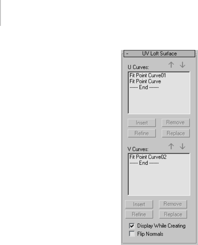
1202 Chapter 9: Surface Modeling
changes shape to indicate that you can pick the
curve, but the curve is not highlighted in blue.
Interface
While a UV Loft sub-object is selected, a rollout
with the UV loft parameters appears. This rollout
appears only when one UV loft sub-object is
selected. It isn’t possible to edit more than one
UV loft at a time, so unlike some other NURBS
sub-objects, the rollout doesn’t appear when
multiple UV loft sub-objects are selected.
Tip: When you edit a UV loft sub-object, close the
SurfaceCommonrollouttoseetheULoftSurface
rollout more easily.
UV Loft Surface rollout (creation time)
U Curves and V Curves—These lists show the names
of the curves you click, in the order you click them.
Youcanselectacurvebyclickingitsnameinalist.
Viewports display the selected curve in blue.
The two buttons above and the four below each list
are identical for both lists.
While you create the loft, in either dimension you
can click the same curve more than once. This can
help you create a closed UV loft.
Arrow Buttons—Usethesetochangetheorderof
curvesintheUCurveorVCurvelist. Selecta
curveinthelist,andthenusethearrowstomove
the selection up or down.
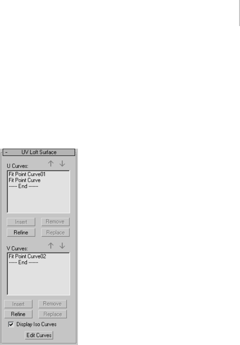
UV Loft Surface 1203
Insert—(Disabled.)
Remove—Removes a curve from the U list or V list.
Selectthecurveinthelist,andthenclickRemove.
Refine—(Disabled.)
Replace—(Disabled.)
Display While Creating—When on, the UV loft
surfaceisdisplayedwhileyoucreateit.Whenoff,
the loft can be created more quickly. Default=off.
Flip Normals—Reverses the direction of the UV
loft’s normals.
UV Loft Surface rollout (modification time)
U Curves and V Curves—These lists show the names
of the curves you click, in the order you click them.
Youcanselectacurvebyclickingitsnameinalist.
Viewports display the selected curve in blue.
The two buttons above and the four below each list
are identical for both lists.
Arrow Buttons—Usethesetochangetheorderof
curvesintheUCurveorVCurvelist. Selecta
curveinthelist,andthenusethearrowstomove
the selection up or down.
Insert—Adds a curve to the U list or V list. Click
to turn on Insert, then click the curve. The curve
is inserted before the selected curve. To insert a
curveattheend,firsthighlightthe"----End-----"
marker in the list.
Remove—Removes a curve from the U list or V list.
Selectthecurveinthelist,andthenclickRemove.
Refine—Refines the UV loft surface. Click to turn
on Refine, then click an iso curve on the surface.
(As you drag the mouse over the surface, the
available curves are highlighted.) The curve you
click is converted to a CV curve and inserted into
the loft and the U Curves or V Curves list. As when
you refine a point curve, refining a UV loft can
change the curvature of the surface slightly. Once
you’ve refined the surface by adding a U curve or
Vcurve,youcanuseEditCurvestochangethe
curve.
Replace—Lets you replace the selected curve.
Select a curve in the list, click this button, then
select the new curve.
Display Iso Curves—When set, the UV loft’s iso
curves are displayed as well as the U-axis and
V-axis curves used to construct the loft. The iso
curves are only for display. You can’t use them for
surface construction.
Edit Curves—Lets you edit the currently selected
curve without switching to another sub-object
level. ClicktoturnonEditCurve. Thepoints
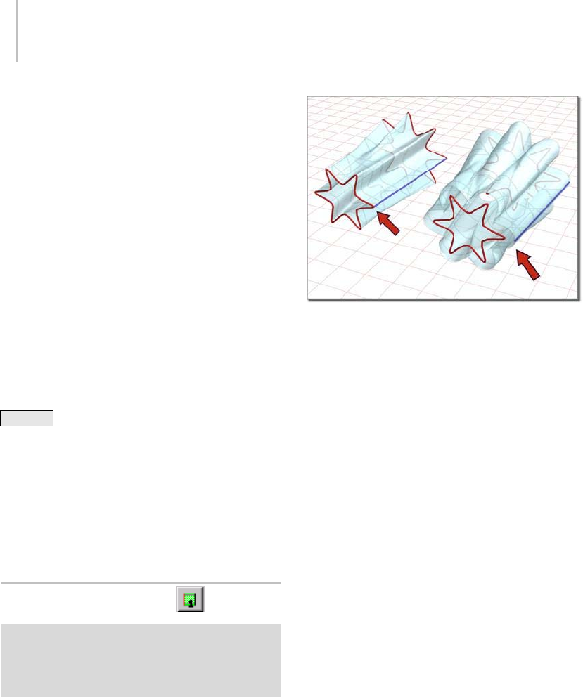
1204 Chapter 9: Surface Modeling
or CVs of the curve are displayed, as well as the
control lattice if the curve is a CV curve. You can
now transform or otherwise change the points
or CVs as if you were at the Point or Curve CV
sub-object level. To finish editing the curve, click
to turn off Edit Curves.
When you turn on Edit Curves, all applicable
rollouts for the selected curves are displayed,
including the Curve Common rollout, the CV
or Point rollout (depending on the curve type),
and the CV Curve or Point Curve rollout. These
rollouts appear beneath the U Loft rollout. They
let you edit the loft curves and their points or CVs
without having to switch sub-object levels.
Tip: When you edit curves in a UV loft, turning
off display of the UV loft itself can make the
curves easier to see and improve performance. Use
Ctrl+D (while the Keyboard Shortcut Override
Toggle button (page 3–872) is on) to toggle display
of dependent sub-objects, including UV lofts.
The UV loft surface can deviate from the curve
if you edit a curve in a UV loft by increasing the
weight of the curve CVs. You can work around
this by refining the curve at the point where the
surface deviates.
1-Rail Sweep Surface
SelectNURBSobject. >Modifypanel>CreateSurfaces
rollout > Dependent Surfaces group box > 1-Rail
Select NURBS object. > Modify panel > NURBS toolbox >
Create 1-Rail Sweep button
Sweep surfaces are constructed from curves. A
1-rail sweep surface uses at least two curves.
One curve, the "rail," defines one edge of the
surface. The other curves define the surface’s cross
sections.
1-rail sweep surface
Changing the position of the rail can change the shape of the
surface.
The cross-section curves should intersect the rail
curve. If the cross-sections don’t intersect the rail,
theresultingsurfaceisunpredictable.Inaddition,
the initial point of the rail and the initial point of
the first cross-section curve must be coincident.
Use NURBS Snaps (page 2–41) to accomplish this.
Automatic Curve Attachment
When you create a 1-rail sweep, you can select
curves that are not already sub-objects of the active
NURBS model. You can select another curve or
spline (page 1–266) object in the scene. When you
select that curve, it attaches to the current object as
if you had used the Attach button (page 1–1120).
Warning: If the curve you attach is a sub-object of
anotherNURBSmodel,theentiremodel(thatis,the
curve’s parent NURBS object) is attached as well.
Asyoumovethemouseoveracurvethatisnot
part of the active NURBS object, the cursor
changes shape to indicate that you can pick the
curve, but the curve is not highlighted in blue.
Procedures
To create a 1-rail sweep:
1. Createthecurvesthatdefinethesurfaceyou
want to create.
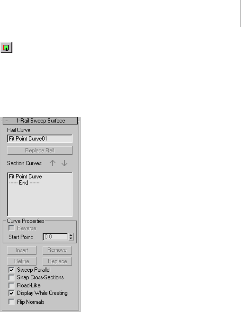
1-Rail Sweep Surface 1205
2. Clicktoturnon1RailSweepinthe
toolbox or on the Create Surfaces rollout.
3. Click the curve to use as the rail, then click each
of the cross-section curves. Right-click to end
creation.
The sweep is interpolated smoothly between
the cross sections, following the outline defined
by the rail.
As you click curves, their names appear in
the lists on the 1 Rail Sweep Surface creation
rollout. The order in which you click the curves
can affect the shape of the sweep surface.
Example: To create a 1-rail sweep with automatic
attach:
1. From the Create panel, create two independent
CV or Point NURBS curves.
2. Go to the Modify panel, and click to turn on
1-Rail Sweep in the NURBS toolbox.
3. Select the curves in the appropriate order for
the sweep.
The sweep is created. You don’t need to collapse
the curves to a NURBS surface or Attach them
to an existing NURBS model.
Asyoumovethemouseoveracurvethatisnot
partoftheactiveNURBSobject,thecursor
changes shape to indicate that you can pick the
curve, but the curve is not highlighted in blue.
Interface
While a 1-rail sweep sub-object is selected, a
rollout with the 1-rail sweep parameters appears.
This rollout appears only when one 1-rail sweep
sub-object is selected. It isn’t possible to edit more
than one 1-rail sweep at a time, so unlike some
other NURBS sub-objects, the rollout doesn’t
appear when multiple 1-rail sweep sub-objects are
selected.
Tip: When you edit a 1-rail sweep sub-object,
closetheSurfaceCommonrollouttoseethe1-rail
sweep Surface rollout more easily.
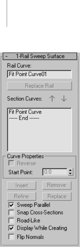
1206 Chapter 9: Surface Modeling
1-Rail Sweep Surface rollout (creation time)
Rail Curve—Shows the name of the curve you chose
to be the rail.
Replace Rail—(Disabled.)
Section Curves—Thislistshowsthenamesofthe
cross-section curves, in the order you click them.
You can select a curve by clicking its name in the
list. Viewports display the selected curve in blue.
Arrow Buttons—Usethesetochangetheorderof
section curves in the list. Select a curve in the list,
andthenusethearrowstomovetheselectionup
or down.
Curve Properties group
These controls affect individual curves you select
in the Section Curves list, as opposed to properties
of the sweep surface in general. They are enabled
onlywhenyouhaveselectedacurveintheSection
Curves list.
Reverse—When set, reverses the direction of the
selected curve.
Start Point—Adjusts the position of the curve’s
start point. This can help eliminate unwanted
twists or "buckles" in the surface.
This control is disabled if the curve is not a closed
curve.
While you’re adjusting start points, a dotted
blue line is displayed between them, to show the
alignment. The surface is not displayed, so it
doesn’t slow down adjustment. When you release
the mouse button, the surface reappears.
Insert—(Disabled.)
Remove—Removes a curve from the list. Select the
curve in the list, and then click Remove.
Refine—(Disabled.)
Replace—(Disabled.)
Sweep Parallel—When on, ensures that the sweep
surface’snormalisparalleltotherail.
Snap Cross-Sections—When on, cross-section
curves are translated so they intersect the rail.
The first cross section is translated to the start of
therail,andthelasttotheendoftherail. The
crosssectionsinthemiddlearetranslatedto
touch the rail at the closest point to the end of the
cross-section curves.
When Snap Cross-Sections is on, the sweep
followstherailcurveexactly.Thismakesiteasier
to construct 1-rail sweep surfaces.
Road-Like—When on, the sweep uses a constant
up-vector so the cross sections twist uniformly
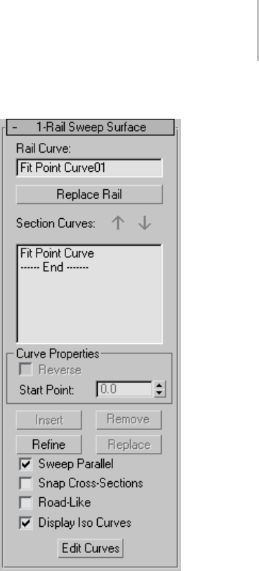
1-Rail Sweep Surface 1207
as they travel along the rail. In other words, the
crosssectionsbanklikeacarfollowingaroad,ora
camera following a path constraint (page 2–398).
Default=off.
Whenyoueditthesurface,youcancontrolthe
angle of banking. The up-vector is displayed
as a yellow gizmo (similar to the gizmo that
lathe surfaces (page 1–1190) useforthecenter
of rotation). To change the up-vector angle, use
Rotate (page 1–439) to change the gizmo’s angle.
Display While Creating—When on, the sweep
surface is displayed while you create it. When
off,thesweepcanbecreatedmorequickly.
Default=off.
Flip Normals—Reverses the direction of the sweep’s
normals.
1-Rail Sweep Surface rollout (modification time)
Rail Curve—Shows the name of the curve you chose
to be the rail.
Replace Rail—Lets you replace the rail curve. Click
this button, then in a viewport click the curve to
use as the new rail.
Section Curves—Thislistshowsthenamesofthe
cross-section curves, in the order you click them.
You can select a curve by clicking its name in the
list. Viewports display the selected curve in blue.
Arrow Buttons—Usethesetochangetheorderof
section curves in the list. Select a curve in the list,
and then use the arrows to move the selection up
or down.

1208 Chapter 9: Surface Modeling
Curve Properties group
These controls affect individual curves you select
in the Section Curves list, as opposed to properties
of the sweep surface in general. They are enabled
only when you have selected a curve in the Section
Curves list.
Reverse—When set, reverses the direction of the
selected curve.
Start Point—Adjusts the position of the curve’s
start point. This can help eliminate unwanted
twists or "buckles" in the surface.
Thiscontrolisdisabledifthecurveisnotaclosed
curve.
While you’re adjusting start points, a dotted
blue line is displayed between them, to show the
alignment. The surface is not displayed, so it
doesn’t slow down adjustment. When you release
the mouse button, the surface reappears.
Insert—Adds a curve to the section list. Click to
turn on Insert, then click the curve. The curve
is inserted before the selected curve. To insert a
curve at the end, first highlight the "----End-----"
marker in the list.
Remove—Removes a curve from the list. Select the
curve in the list, and then click Remove.
Refine—Refines the 1-rail sweep surface. Click
to turn on Refine, then click an iso curve on the
surface. (As you drag the mouse over the surface,
the available section curves are highlighted.) The
curve you click is converted to a CV curve and
inserted into the sweep and the section list. As
when you refine a point curve, refining a sweep
can change the curvature of the surface slightly.
Once you’ve refined the surface by adding a
cross-section curve, you can use Edit Curves to
change the curve.
Replace—Lets you replace the selected curve.
Select a curve in the list, click this button, and then
select the new curve.
Sweep Parallel—When on, ensures that the sweep
surface’snormalisparalleltotherail.
Snap Cross-Sections—When on, cross-section
curves are translated so they intersect the rail.
The first cross section is translated to the start of
therail,andthelasttotheendoftherail. The
crosssectionsinthemiddlearetranslatedto
touch the rail at the closest point to the end of the
cross-section curves.
When Snap Cross-Sections is on, the sweep
followstherailcurveexactly.Thismakesiteasier
to construct 1-rail sweep surfaces.
Road-Like—When on, the sweep uses a constant
up-vector so the cross sections twist uniformly
as they travel along the rail. In other words, the
crosssectionsbanklikeacarfollowingaroad,ora
camera following a path constraint (page 2–398).
Default=off.
When you edit the surface, you can control the
angle of banking. The up-vector is displayed
as a yellow gizmo (similar to the gizmo that
lathe surfaces (page 1–1190) useforthecenter
of rotation). To change the up-vector angle, use
Rotate (page 1–439) to change the gizmo’s angle.
Display Iso Curves—When set, the 1-rail sweep’s
V-axisisocurvesaredisplayedaswellasthe
U-axis curves used to construct the loft. The
V-axis curves are only for display. You can’t use
them for surface construction.
Edit Curves—Lets you edit the currently selected
curve without switching to another sub-object
level. ClicktoturnonEditCurve. Thepoints
or CVs of the curve are displayed, as well as the
control lattice if the curve is a CV curve. You can
now transform or otherwise change the points
or CVs as if you were at the Point or Curve CV
sub-object level. To finish editing the curve, click
to turn off Edit Curves.
Tip: When you edit curves in a 1-rail sweep,
turning off display of the sweep itself can make the
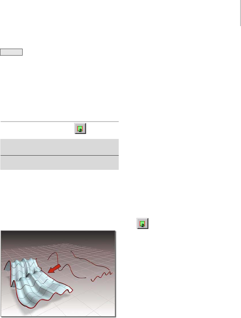
2-Rail Sweep Surface 1209
curves easier to see and improve performance. Use
Ctrl+D (while the Keyboard Shortcut Override
Toggle (page 3–872) is on) to toggle display of
dependent sub-objects, including sweeps.
Thesweepsurfacecandeviatefromthecurve
if you edit a curve in a sweep by increasing the
weight of the curve CVs. You can work around
this by refining the curve at the point where the
surface deviates.
2-Rail Sweep Surface
SelectNURBSobject. >Modifypanel>CreateSurfaces
rollout > Dependent Surfaces group box > 2-Rail
Select NURBS object. > Modify panel > NURBS toolbox >
Create 2-Rail Sweep button
Sweep surfaces are constructed from curves. A
2-rail sweep surface uses at least three curves.
Two curves, the "rails," define the two edges of
the surface. The other curves define the surface’s
crosssections.A2-railsweepsurfaceissimilarto
a 1-rail sweep. The additional rail gives you more
control over the shape of the surface.
Sweep surface created with two rails
The cross-section curves should intersect the rail
curves. If the cross sections don’t intersect the
rails, the resulting surface is unpredictable. In
addition, the initial points of the rails and the
endpoints of the first cross-section curve must be
coincident. Use NURBS Snaps to accomplish this.
Automatic Curve Attachment
When you create a 2-rail sweep, you can select
curves that are not already sub-objects of the active
NURBS model. You can select another curve or
spline object (page 1–266) in the scene. When you
select that curve, it attaches to the current object as
if you had used the Attach button (page 1–1120).
Warning: If the curve you attach is a sub-object of
anotherNURBSmodel,theentiremodel(thatis,the
curve’s parent NURBS object) is attached as well.
Asyoumovethemouseoveracurvethatisnot
part of the active NURBS object, the cursor
changes shape to indicate that you can pick the
curve, but the curve is not highlighted in blue.
Procedures
To create a 2-rail sweep:
1. Createthecurvesthatdefinethesurfaceyou
want to create.
2. Clicktoturnon2RailSweepinthe
toolbox or on the Create Surfaces rollout.
3. Clickthecurvetouseasthefirstrail,thenclick
the curve to use as the second rail. Click each of
the cross-section curves, and then right-click to
end creation.
The sweep is interpolated smoothly between
the cross sections, following the outlines
defined by the two rails.
As you click curves, their names appear in
the lists on the 2 Rail Sweep Surface creation
rollout. The order in which you click the curves
can affect the shape of the sweep surface.
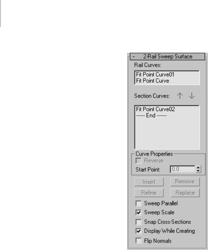
1210 Chapter 9: Surface Modeling
Example: To create a 2-rail sweep with automatic
attach:
1. FromtheCreatepanel,createthreeindependent
CV or Point NURBS curves.
2. Go to the Modify panel, and click to turn on
2-Rail Sweep in the NURBS toolbox.
3. Selectthecurvesintheappropriateorderfor
the sweep.
The sweep is created. You don’t need to collapse
the curves to a NURBS surface or Attach them
to an existing NURBS model.
Asyoumovethemouseoveracurvethatisnot
partoftheactiveNURBSobject,thecursor
changes shape to indicate that you can pick the
curve, but the curve is not highlighted in blue.
Interface
While a 2-rail sweep sub-object is selected, a
rollout with the 2-rail sweep parameters appears.
This rollout appears only and when one 2-rail
sweep sub-object is selected. It isn’t possible
to edit more than one 2-rail sweep at a time,
so unlike some other NURBS sub-objects, the
rollout doesn’t appear when multiple 2-rail sweep
sub-objects are selected.
Tip: When you edit a 2-rail sweep sub-object,
closetheSurfaceCommonrollouttoseethe2-rail
sweep surface rollout more easily.
2-Rail Sweep Surface rollout (creation time)
Rail Curves—Shows the names of the two curves
you chose to be the rails.
Section Curves—Thislistshowsthenamesofthe
cross-section curves, in the order you click them.
You can select a curve by clicking its name in the
list. Viewports display the selected curve in blue.
Arrow Buttons—Usethesetochangetheorderof
section curves in the list. Select a curve in the list,
and then use the arrows to move the selection up
or down.
Curve Properties group
These controls affect individual curves you select
in the Section Curves list, as opposed to properties

2-Rail Sweep Surface 1211
of the sweep surface in general. They are enabled
only when you have selected a curve in the Section
Curves list.
Reverse—When set, reverses the direction of the
selected curve.
Start Point—Adjusts the position of the curve’s
start point. This can help eliminate unwanted
twists or "buckles" in the surface.
Thiscontrolisdisabledifthecurveisnotaclosed
curve.
While you’re adjusting start points, a dotted
blue line is displayed between them, to show the
alignment. The surface is not displayed, so it
doesn’t slow down adjustment. When you release
the mouse button, the surface reappears.
Insert—(Disabled.)
Remove—Removes a curve from the list. Select the
curve in the list, and then click Remove.
Refine—(Disabled.)
Replace—(Disabled.)
Sweep Parallel—When off, the rail curves define
a ruled surface, and the cross sections describe
lofting from this base ruled surface. When on,
each cross section is associated with its best
fittingplane. Thisplanemovesalongtherails
and parallel to them. If the rails are curved, the
plane can rotate. If the spacing between the rails
changes, the section scales or stretches. In either
case, the surface is blended from section to section
along its entire length. Default=off.
Sweep Scale—Whenoff,thesizeoftheplaneis
scaled only in the direction across the rails. When
on, the plane is scaled uniformly in all directions.
Default=off.
Snap Cross-Sections—When on, cross-section
curves are translated and scaled so they intersect
both rails. The first cross section is translated
to the start of the rails, and the last to the end of
the rails. The cross sections in the middle are
translated to touch the rails at the closest point to
the ends of the cross-section curves. Default=off.
When Snap Cross-Sections is on, the sweep
follows the rail curves exactly. This makes it easier
to construct 2-rail sweep surfaces.
Display While Creating—When on, the sweep
surfaceisdisplayedwhileyoucreateit. When
off,thesweepcanbecreatedmorequickly.
Default=off.
Flip Normals—Reverses the direction of the sweep’s
normals.
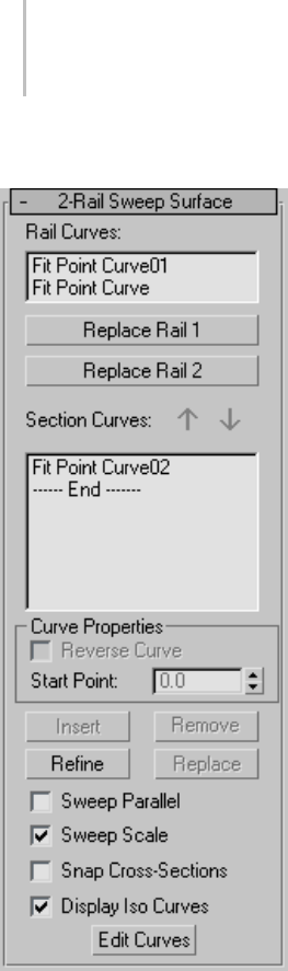
1212 Chapter 9: Surface Modeling
2-Rail Sweep Surface rollout (Modification time)
Rail Curves—Showsthenamesofthetwocurves
you chose to be the rails.
Replace Rail 1 and Replace Rail 2—Let you replace
therailcurves.Clickoneofthesebuttons,thenin
aviewportclickthecurvetouseasthenewrail.
Section Curves—Thislistshowsthenamesofthe
cross-section curves, in the order you click them.
You can select a curve by clicking its name in the
list. Viewports display the selected curve in blue.
Arrow Buttons—Usethesetochangetheorderof
section curves in the list. Select a curve in the list,
and then use the arrows to move the selection up
or down.
Curve Properties group
These controls affect individual curves you select
in the Section Curves list, as opposed to properties
of the sweep surface in general. They are enabled
onlywhenyouhaveselectedacurveintheSection
Curves list.
Reverse—When set, reverses the direction of the
selected curve.
Start Point—Adjusts the position of the curve’s
start point. This can help eliminate unwanted
twists or "buckles" in the surface.
This control is disabled if the curve is not a closed
curve.
While you’re adjusting start points, a dotted
blue line is displayed between them, to show the
alignment. The surface is not displayed, so it
doesn’t slow down adjustment. When you release
the mouse button, the surface reappears.
Insert—Adds a curve to the section list. Click to
turn on Insert, then click the curve. The curve
is inserted before the selected curve. To insert a
curveattheend,firsthighlightthe"----End-----"
marker in the list.
Remove—Removes a curve from the list. Select the
curve in the list, and then click Remove.
Refine—Refines the 2-rail sweep surface. Click
to turn on Refine, then click an iso curve on the
surface. (As you drag the mouse over the surface,
the available section curves are highlighted.) The
curve you click is converted to a CV curve and
inserted into the sweep and the section list. As
when you refine a point curve, refining a sweep
can change the curvature of the surface slightly.
Once you’ve refined the surface by adding a
cross-section curve, you can use Edit Curves to
change the curve.
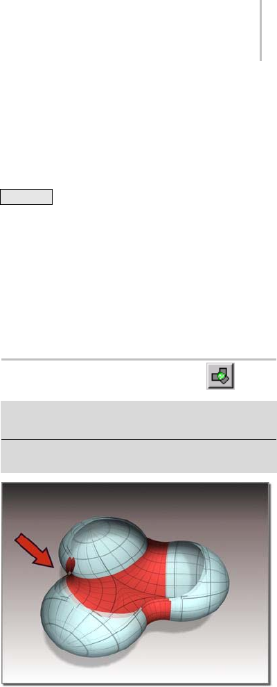
Multisided Blend Surface 1213
Replace—Lets you replace the selected curve.
Select a curve in the list, click this button, then
select the new curve.
Sweep Parallel—When off, the rail curves define
a ruled surface, and the cross sections describe
lofting from this base ruled surface. When on,
each cross section is associated with its best
fittingplane. Thisplanemovesalongtherails
and parallel to them. If the rails are curved, the
plane can rotate. If the spacing between the rails
changes, the section scales or stretches. In either
case, the surface is blended from section to section
along its entire length. Default=off.
Sweep Scale—Whenoff,thesizeoftheplaneis
scaled only in the direction across the rails. When
on, the plane is scaled uniformly in all directions.
Default=off.
Snap Cross-Sections—When on, cross-section
curves are translated and scaled so they intersect
both rails. The first cross section is translated
to the start of the rails, and the last to the end of
therails. Thecrosssectionsinthemiddleare
translated to touch the rails at the closest point to
the ends of the cross-section curves. Default=off.
When Snap Cross-Sections is on, the sweep
followstherailcurvesexactly.Thismakesiteasier
to construct 2-rail sweep surfaces.
Display Iso Curves—When set, the 2-Rail Sweep’s
V-axis iso curves are displayed as well as the
U-axis curves used to construct the sweep. The
V-axis curves are only for display. You can’t use
them for surface construction.
Edit Curves—Lets you edit the currently selected
curve without switching to another sub-object
level. ClicktoturnonEditCurve. Thepoints
or CVs of the curve are displayed, as well as the
control lattice if the curve is a CV curve. You can
now transform or otherwise change the points
or CVs as if you were at the Point or Curve CV
sub-object level. To finish editing the curve, click
to turn off Edit Curves.
Tip: When you edit curves in a 2-rail sweep, turning
off display of the sweep itself can make the curves
easier to see and improve performance as well. Use
Ctrl+D (while the Keyboard Shortcut Override
Toggle (page 3–872) is on) to toggle display of
dependent sub-objects, including sweeps.
Thesweepsurfacecandeviatefromthecurve
if you edit a curve in a sweep by increasing the
weight of the curve CVs. You can work around
this by refining the curve at the point where the
surface deviates.
Multisided Blend Surface
Select NURBS object. > Modify panel > Create Surfaces
rollout > Dependent Surfaces group box > N Blend
Select NURBS object. > Modify panel > NURBS toolbox >
Create a Multisided Blend Surface button
Multisided blend between three other surfaces
Amultisidedblendsurface"fillsin"theedges
defined by three or four other curve or surface
sub-objects. Unlike a regular, two-sided blend
surface, the curves’ or surfaces’ edges must form a
closed loop; that is, they must completely surround
the opening that the multisided blend will cover.
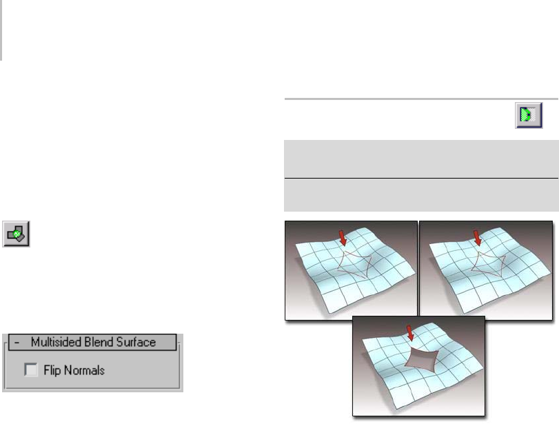
1214 Chapter 9: Surface Modeling
Tip: If the multisided blend surface can’t be created,
fuse the points or CVs at the corners where the
surfaces meet. Sometimes snapping the corners
doesn’t work, because of round-off error.
Procedure
To create a multisided blend:
1. Click to turn on Multisided Blend in the
toolbox or N Blend on the Create Surfaces
rollout.
2. In turn, click the three or four surface sides or
curves that surround the opening.
You can flip normals on the multisided blend
while creating it.
3. Right-click to end creation.
A new surface is created. It covers the opening.
Interface
Multisided Blend surfaces have no parameters
other than those on the Surface Common rollout
(page 1–1141).
Multicurve Trimmed Surface
Select NURBS object. > Modify panel > Create Surfaces
rollout > Dependent Surfaces group box > Multi-Trim
Select NURBS object. > Modify panel > NURBS toolbox >
Create a Multicurve Trimmed Surface button
Creating a multicurve trimmed surface
A multicurve trimmed surface is an existing
surface trimmed by multiple curves that form a
loop.
When you create a multicurve trimmed surface,
you create only one trimmed hole. If you want
to create multiple holes, first create holes in the
surface using other techniques, and as the final
step create the multicurve trim.
You can’t trim across the edge between two
surfaces, or across a "seam" where a surface
touches itself, as at the back of a spherical surface
created by converting a Sphere primitive.
Procedure
To create a multicurve trim:
1. Create a loop out of multiple curve sub-objects.
2. AttheCurveCVorPointsub-objectlevel,use
Fuse to connect the ends of the curves.
The curves must form a single closed loop, or
completely traverse the surface.
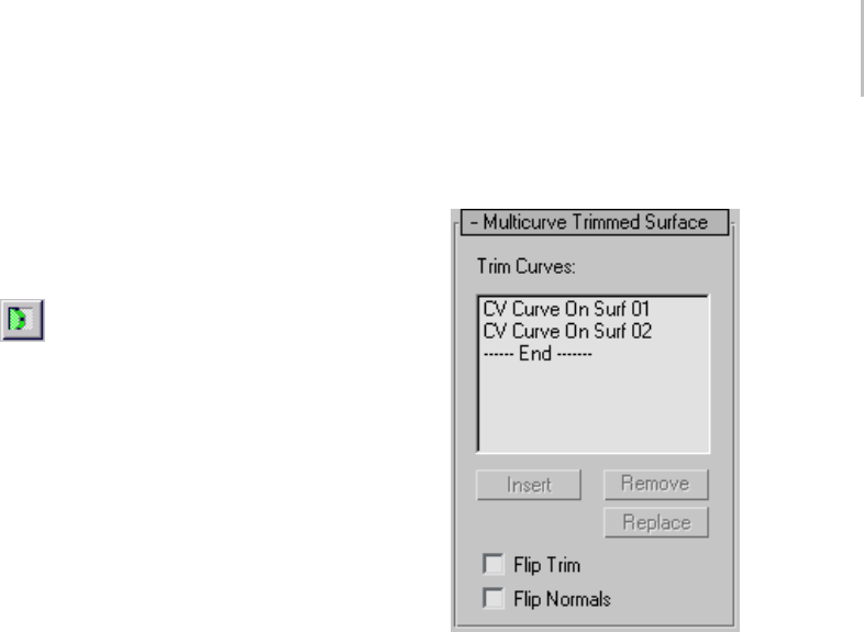
Multicurve Trimmed Surface 1215
3. Project the curves onto the surface by creating
a normal or vector projected curve for each
curve in the loop.
Tip: YoucanalsouseCVorpointcurveon
surface for these curves.
4. Tur n on Mu lt ic ur ve Tr im me d Su rfac e
in the toolbox or Multi-Trim on the Create
Surfaces rollout.
5. Click the surface to trim, then click each of the
curves in the loop. Right-click to end creation.
The Trim list shows the names of the curves
you select. Flip Trim inverts the direction of
trimming. Flip Normals lets you flip the surface
normals at creation time. (After you have
created the surface, you can flip normals using
controls on the Surface Common rollout.)
Interface
While a multicurve trimmed sub-object is selected,
a rollout with the multicurve trim parameters
appears. This rollout appears only when one
multicurve trimmed sub-object is selected. It
isn’tpossibletoeditmorethanonemulticurve
trimmedobjectatatime,sounlikesomeother
NURBS sub-objects, the rollout doesn’t appear
when multiple multicurve trimmed sub-objects
are selected.
Tip: When you edit a multicurve trimmed
sub-object, close the Surface Common rollout
toseetheMulticurveTrimSurfacerolloutmore
easily.
Multicurve Trimmed Surface rollout (creation
time)
Trim Curves—This list shows the names of the
curves used to trim the surface. You can select a
curve by clicking its name. Viewports display the
selected curve in blue.
Insert—(Disabled.)
Remove—Removes a curve from the list. Select the
curve in the list, and then click Remove.
Replace—(Disabled.)
Flip Trim—Reverses the direction of the trim.
Flip Normals—Turn on to reverse the direction of
the trimmed surface’s normals.
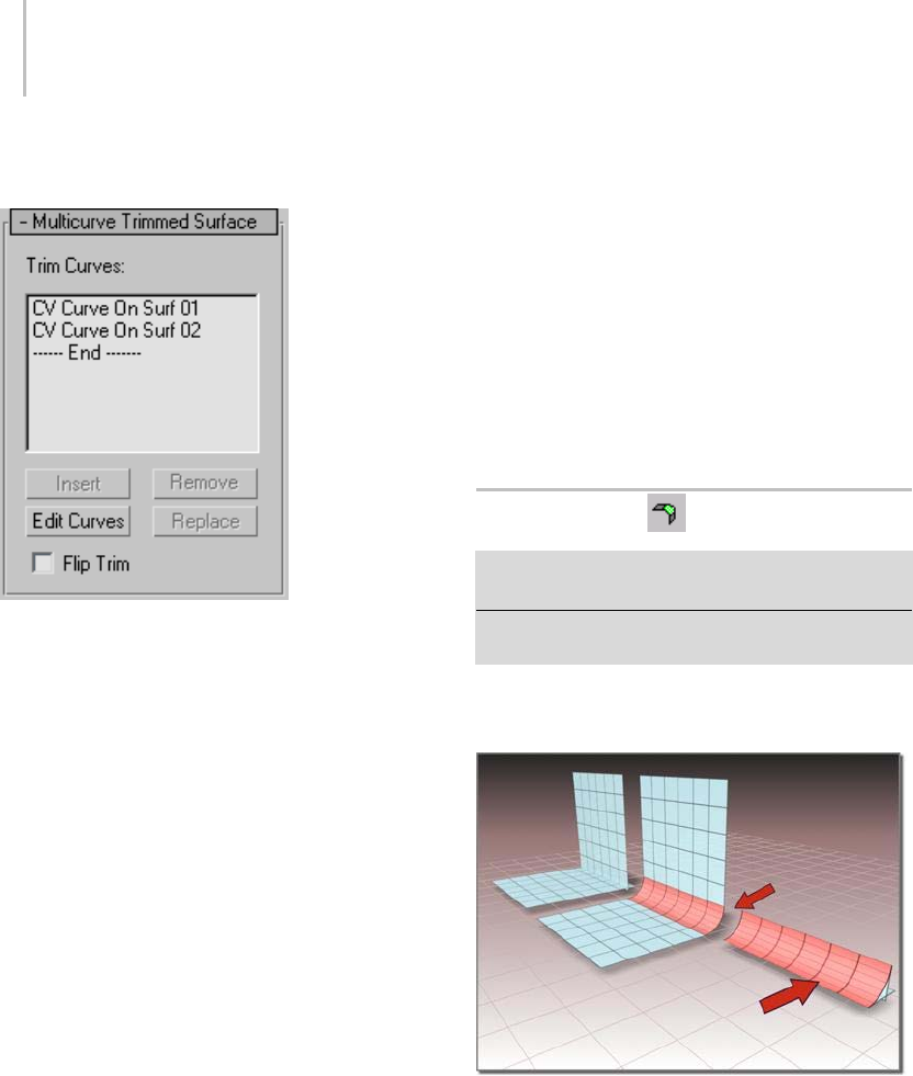
1216 Chapter 9: Surface Modeling
Multicurve Trimmed Surface rollout
(modification time)
Trim Curves—This list shows the names of the
curves used to trim the surface. You can select a
curve by clicking its name. Viewports display the
selected curve in blue.
Insert—Adds a curve to the Trim Curves list. Click
to turn on Insert, then click the curve. The curve
is inserted before the selected curve. To insert a
curve at the end, first highlight the "----End-----"
marker in the list.
Remove—Removes a curve from the list. Select the
curve in the list, and then click Remove.
Edit Curves—Lets you edit the currently selected
curve without switching to another sub-object
level. ClicktoturnonEditCurve. Thepoints
or CVs of the curve are displayed, as well as the
control lattice if the curve is a CV curve. You can
now transform or otherwise change the points
or CVs as if you were at the Point or Curve CV
sub-object level. To finish editing the curve, click
to turn off Edit Curves.
Don’teditthecurvesoyoubreaktheloop.Ifyou
do, the surface goes into an error condition.
Replace—Lets you replace the selected curve.
Select a curve in the list, click this button, and then
select the new curve.
Flip Trim—Reverses the direction of the trim.
Along with Edit Curves, the Insert, Remove, and
Replace buttons let you alter the curves that trim
the surface. While you are making changes, the
surfacewillgointoanerrorcondition(orange
displaybydefault)untilthecurvesyouareworking
on once again form a closed loop.
Fillet Surface
Select NURBS object. > Modify panel > Create Surfaces
rollout>DependentSurfacesgroupbox>FilletSurf
Select NURBS object. > Modify panel > NURBS toolbox >
Create Fillet Surface button
A fillet surface is a rounded corner connecting the
edges of two other surfaces.
Fillet surface created from two parent surfaces
Usually you use both edges of the fillet surface
to trim the parent surfaces, creating a transition
between the fillet and its parents.
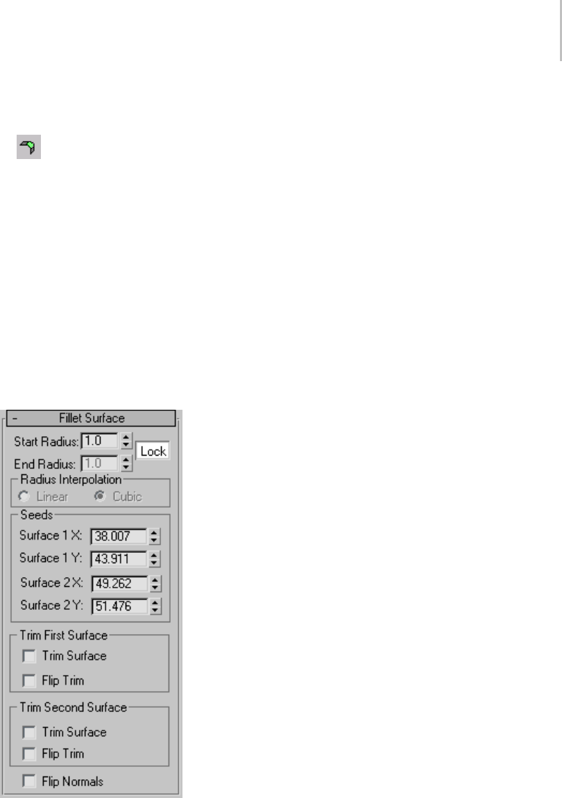
Fillet Surface 1217
Procedure
To create a fillet surface:
1. InaNURBSobject,turnonFilletonthe
Create Surfaces rollout or Create Fillet Surface
in the toolbox.
2. Click to choose the first parent surface, then
click to choose the second parent surface.
Potential parent surfaces are highlighted in blue
as you move the mouse in aviewport.
The fillet surface is created. If the fillet surface
can’tbecreated,adefaulterrorsurfaceis
displayed (by default, the error surface displays
as orange).
Interface
Fillet Surface rollout (creation time)
Start Radius and End Radius—Set the radius used
todefinethefilletatthefirstsurfaceyouchose
and the second surface you chose, respectively.
Theradiusescontrolthesizeofthefilletsurface.
Default=1.0.
Lock—LockstheStartandEndradiusvaluesso
they are identical. When on, the End Radius
setting is unavailable. Default=on.
Radius Interpolation group
This group box controls the radius of the fillet.
TheRadiusInterpolationsettinghasnoeffect
unlessoneorbothsurfacesthatdefinethefillet
have curvature to them.
Linear—When chosen (the default), the radius is
linear.
Cubic—When chosen, the radius is treated as a
cubic function, allowing it to change based on the
parent surface’s geometry.
Seeds group
These spinners adjust the seed values for the fillet
surface.Ifthereismorethanonewaytoconstruct
the fillet, the software uses the seed values to
choose the nearest edge for that surface.
Surface 1 X—Sets the local X coordinate of the seed
onthefirstsurfaceyouchose.
Surface 1 Y—Sets the local Y coordinate of the seed
onthefirstsurfaceyouchose.
Surface 2 X—Sets the local X coordinate of the seed
on the second surface you chose.
Surface 2 Y—Sets the local Y coordinate of the seed
on the second surface you chose.
Trim First Surface and Trim Second Surface
groups
For each of the parent surfaces, these controls
affect trimming.
Trim Surface—Trims the parent surface at the edge
of the fillet.
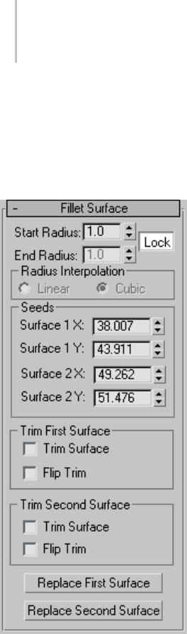
1218 Chapter 9: Surface Modeling
Flip Trim—Reverses the direction of the trim.
Flip Normals—Turn on to reverse the direction of
the fillet surface’s normals.
Fillet Surface rollout (modification time)
Start Radius and End Radius—Set the radius used
todefinethefilletatthefirstsurfaceyouchose
and the second surface you chose, respectively.
The radiuses control the size of the fillet surface.
Default=10.0.
Lock—LockstheStartandEndradiusvaluesso
they are identical. When on, the End Radius
setting is unavailable. Default=on.
Radius Interpolation group
This group box controls the radius of the fillet.
TheRadiusInterpolationsettinghasnoeffect
unlessoneorbothsurfacesthatdefinethefillet
have curvature to them.
Linear—When chosen (the default), the radius is
always linear.
Cubic—When chosen, the radius is treated as a
cubic function, allowing it to change based on the
parent surface’s geometry.
Seeds group
These spinners adjust the seed values for the fillet
surface.Ifthereismorethanonewaytoconstruct
the fillet, the software uses the seed values to
choose the nearest edge for that surface.
Surface 1 X—Sets the local X coordinate of the seed
onthefirstsurfaceyouchose.
Surface 1 Y—Sets the local Y coordinate of the seed
onthefirstsurfaceyouchose.
Surface 2 X—Sets the local X coordinate of the seed
on the second surface you chose.
Surface 2 Y—Sets the local Y coordinate of the seed
on the second surface you chose.
Trim First Surface and Trim Second Surface
groups
For each of the parent surfaces, these controls
affect trimming.
Trim Surface—Trims the parent surface at the edge
of the fillet.
Flip Trim—Reverses the direction of the trim.
Replace First Surface and Replace Second
Surface—Let you replace the parent surfaces. Click
a button, then click the surface to replace the
original first or second surface.
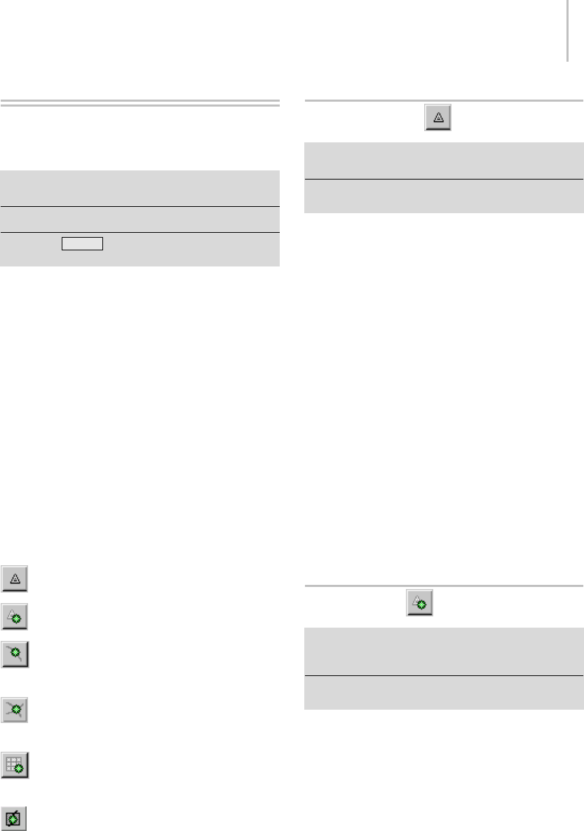
Creating and Editing Point Sub-Objects 1219
Creating and Editing Point
Sub-Objects
Select NURBS object. > Modify panel > Create Points
rollout
SelectNURBSobject.>Modifypanel>NURBStoolbox
Keyboard > Ctrl+T to toggle NURBS toolbox display
(Keyboard Shortcut Override Toggle must be on.)
In addition to the points that are an integral part of
point curve (page 1–1106) and point surface (page
1–1102) objects, you can create "freestanding"
points. Such points can help you construct point
curves by using the Curve Fit (page 1–1157)
button. You also use dependent points to trim
curves.
You create individual points as NURBS sub-objects
whileyouaremodifyingNURBS.Tocreatepoints
individually, use the Create Points rollout or the
NURBS toolbox (page 1–1083).
Toolbox Buttons for Creating Points
These are the toolbox buttons for creating point
sub-objects:
Create an independent point (page 1–1219).
Create a dependent offset point (page 1–1219).
Create a dependent curve point (page
1–1220).
Create a dependent curve-curve intersection
point (page 1–1223).
Create a dependent surface point (page
1–1222).
Create a dependent surface-curve intersection
point (page 1–1224).
Point (NURBS)
SelectNURBSobject. >Modifypanel>CreatePoints
rollout > Point button
Select NURBS object. > Modify panel > NURBS toolbox >
Create Point button
This command creates an independent,
freestanding point.
Procedure
To create a freestanding point:
1. Select a NURBS object.
2. In the Modify > Create Points rollout, turn on
Point.
3. Click a viewport to position the point.
Independent point sub-objects have no additional
parameters. You can use Curve Fit in the Create
Curves rollout to create a curve from multiple
freestanding points.
Interface
There are no additional controls for independent
points.
Offset Point
SelectNURBSobject. >Modifypanel>CreatePoints
rollout > Dependent Points group box > Offset Point
button
Select NURBS object. > Modify panel > NURBS toolbox >
Create Offset Point button
This command creates a dependent point that
is coincident to an existing point or at a relative
distance from an existing point.
Procedure
To create a dependent offset point:
1. Select a NURBS object
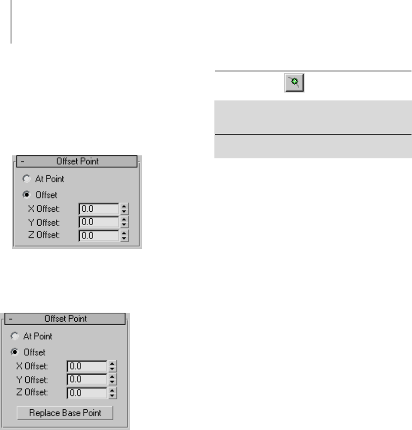
1220 Chapter 9: Surface Modeling
2. On the Modify > Create Points rollout, turn on
Offset Point.
3. Inaviewport,clickanexistingpoint.
4. In the Modify > Offset Points rollout, use the
Offset spinners to adjust the point’s position
relative to the original point.
Interface
While an offset point sub-object is selected, the
Offset Point rollout appears.
At Point—When chosen, the dependent point has
thesamelocationastheoriginal,parentpoint.
Offset—Enables point offset. Use the X,Y,Z Offset
spinners to set offset values (in object space
coordinates).
Replace Base Point—(Only at modification time.)
Lets you replace the parent point. Click the button,
then click the new point on which to base the offset
point.
Curve Point
SelectNURBSobject. >Modifypanel>CreatePoints
rollout>DependentPointsgroupbox>CurvePoint
button
Select NURBS object. > Modify panel > NURBS toolbox >
Create Curve Point button
This command creates a dependent point that lies
on a curve or relative to it.
Thepointcanbeeitheronthecurveoroffthe
curve. If it is on the curve, the U Position is
the only control of its location. The U Position
specifies a location along the curve (based on
thecurve’slocalUaxis). Therearethreeways
to displace the point’s location relative to the U
position.
Procedure
To create a dependent curve point:
1. Turn on Curve Point and then click along a
curve to position the point.
2. The curve and cursor position are highlighted
during this operation.
3. At the Point sub-object level, adjust the point’s
position relative to the curve by adjusting the
curve point parameters on the Curve Point
rollout.
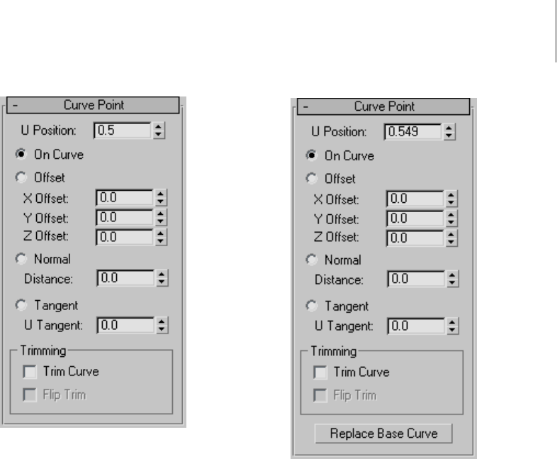
Curve Point 1221
4. Right-click to end operation.
Interface
While a curve point sub-object is selected, the
Curve Point rollout appears.
U Position—Specifies the point’s location on the
curveorrelativetothecurve.
On Curve—When on, the point lies on the curve
at the U Position.
Offset—Moves the point according to a relative
(object space) X,Y,Z location.
This is relative to the U Position.
X Offset, Y Offset, and Z Offset—Specify the object
space location of the offset curve point.
Normal—Moves the point along the direction of
the curve’s normal at the U Position.
Distance—Specifies the distance along the curve’s
normal. Negative values move the point opposite
to the normal.
Tangent—Moves the point along the tangent at the
UPosition.
UTangent—Specifies the distance from the curve
along the tangent.
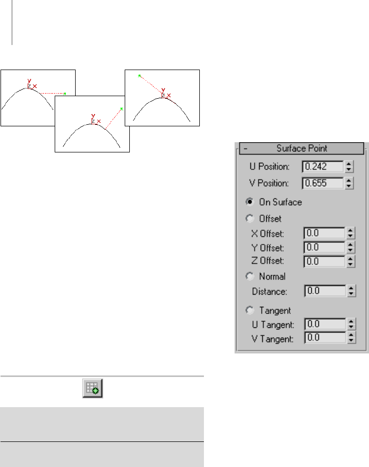
1222 Chapter 9: Surface Modeling
Offset, normal, and tangent displacement of a curve point
Trimming group box
Controls in this group box let you trim the parent
curve.
Trim Curve—When on, trims the parent curve
against the curve point’s U position. When off (the
default), the parent isn’t trimmed.
Flip Trim—When on, trims in the opposite
direction.
Replace Base Curve—(Only at modification time.)
Lets you replace the parent curve. Click the button,
then click the new curve on which to base the
curve point.
Surface Point
Select NURBS object. > Modify panel > Create Points
rollout > Dependent Points group box > Surface Point
button
Select NURBS object. > Modify panel > NURBS toolbox
>CreateSurfPointbutton
This command creates a dependent point that lies
on a surface or relative to it. This is enabled with a
NURBSobjectthatcontainsasurface.
Procedure
To create a dependent surface point:
1. Turn on Surf Point and then click over a
NURBS surface to position the point.
2. The surface cross-section and cursor are
highlighted during this operation.
3. Right-click to end the create operation.
4. At the Point sub-object level, adjust the point’s
position relative to the surface by adjusting the
surface point parameters in the Surface Point
rollout.
Interface
Whileasurfacepointsub-objectisselected,the
Surface Point rollout appears. These controls are
similar to the curve point controls.
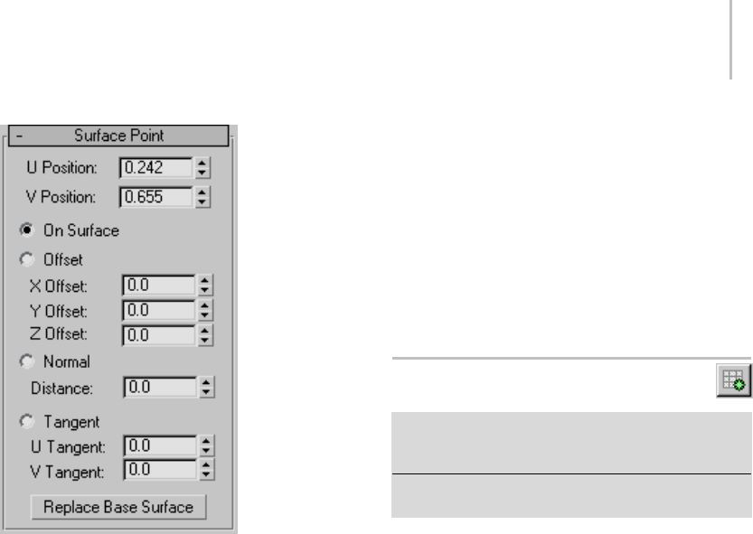
Curve-Curve Intersection Point 1223
U Position and V Position—If the point is on the
surface, these coordinates specify the point’s
location, based on the surface’s local UV
coordinates.
On Surface—Specifies that the point lies on the
surface, at the location specified by U Position and
V Position.
If the point lies on the surface, you can move it
using the Move transform. You can also move it
using the Move Surface Point button. See Editing
Point Sub-Objects (page 1–1123).Eitherway,this
updates the U Position and V Position values.
Offset—Moves the point according to a relative
(object space) X,Y,Z location.
X Offset, Y Offset, and Z Offset—Specify the object
space location of the offset surface point.
Normal—Moves the point along the direction of
the surface’s normal.
Distance—Specifies the distance from the surface,
along the normal. Negative values move the point
opposite to the normal.
Tangent—Moves the point along the tangent of the
UV position.
U Tangent and V Tangent—Specify the distance
from the surface along the tangents at U and V.
Replace Base Surface—(Only at modification
time.) Lets you replace the parent surface. Click
the button, then click the new surface on which to
base the surface point.
Curve-Curve Intersection Point
SelectNURBSobject. >Modifypanel>CreatePoints
rollout Dependent Points group box > Curve-Curve
button
Select NURBS object. > Modify panel > NURBS toolbox >
Create Curve-Curve Point button
This command creates a dependent point at the
intersection of two curves.
Procedure
To create a dependent curve-curve point:
1. Turn on Curve-Curve, then drag from the first
curve to the second.
If the curves do not intersect, the point is
orange, an invalid dependent point.
Thepointiscreatedatthenearestintersection
between the two curves. You can use the
curve-curve parameters to trim the parent
curves.
2. Right-click to end the create operation.
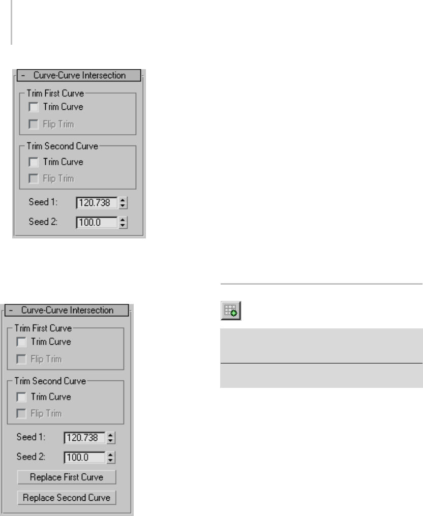
1224 Chapter 9: Surface Modeling
Interface
While a curve-curve point sub-object is selected,
the Curve-Curve Intersection rollout appears.
TrimFirstCurveandTrimSecondCurvegroups
These two groups let you control how the parent
curvesaretrimmed. Thecontrolsarethesame
in each. "First" and "second" refer to the order in
which you picked the parent curves.
Trim Curve—When on, the parent curve is trimmed
against the curve-curve point. When off (the
default), the parent isn’t trimmed.
Flip Trim—When on, trims in the opposite
direction.
Seed 1 and Seed 2—Change the U location of the
seed value on the first and second curves. If there is
a choice of intersections, the intersection closest to
the seed points is the one used to create the point.
ReplaceFirstCurveandReplaceSecond
Curve—(Only at modification time.) Let you
replace the parent curves. Click a button, then
click the curve to replace the original first or
second curve.
Surface-Curve Intersection Point
SelectNURBSobject. >Modifypanel>CreatePoints
rollout > Dependent Points group box > Surf-Curve
button
Select NURBS object. > Modify panel > NURBS toolbox >
Create Surface-Curve Point button
This command creates a dependent point at the
intersection of a surface and a curve.
Procedure
To create a dependent surface-curve point:
1. In a NURBS object that has a curve that passes
through a surface, click to turn on Create
Surface Curve Point in the NURBS toolbox or
Surf-CurveontheCreatePointsrollout.
2. Clickthecurve,thenclickthesurface.
Thepointiscreatedatthenearestintersection
between the curve and the surface that is nearest
the seed point. You can use the surface-curve
parameters to trim the parent curve.
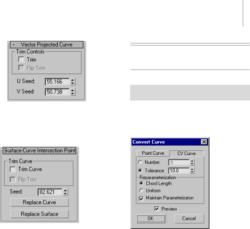
Convert Curve Dialog 1225
Interface
While a surface-curve intersection point
sub-object is selected, a rollout with its parameters
appears.
Trim Curve group
Trim—When on, trims the curve from the surface.
When off, the curve isn’t trimmed.
Flip Trim—When on, trims the curve in the
opposite direction.
Seed—Changes the U location of the seed value
on the curve. If there is a choice of intersections,
the intersection closest to the seed point is the one
used to create the point.
Replace Curve and Replace Surface— (Only at
modification time.) Let you replace the parent
sub-objects. Click a button, then click a curve or
surfacetoreplacetheoriginalparentobject.
NURBS Editing Dialogs
Convert Curve Dialog
Modify panel > Select NURBS curve sub-object. > Curve
Commonrollout>ConvertCurvebutton
This dialog is a general way to convert one kind of a
curve to another or to adjust a curve’s parameters.
Interface
Point Curve and CV Curve—Choose whether to
convert to a point curve or a CV curve. If the
curveisalreadyofthetypeyouchose,thesettings
in this dialog don’t convert it, but do change its
properties. Default=CV Curve.
CV Curve options
ThesearetheoptionswhenyouchooseCVCurve.
Number—When chosen, the spinner sets the
number of CVs in the CV curve.
Tolerance—When chosen, the software calculates
thenumberofCVs.Thisoptionrebuildsthecurve
according to accuracy. The lower the Tolerance
value,themoreaccuratetherebuild. Increasing
Tolerance enables the curve to be rebuilt using
fewer CVs.
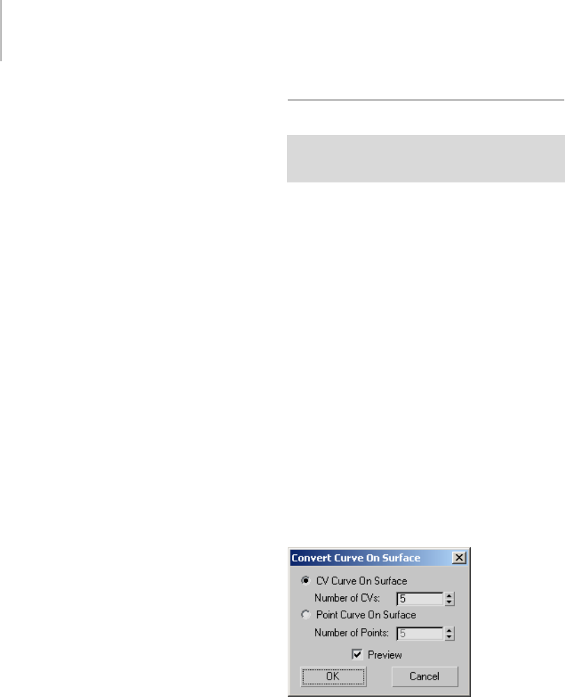
1226 Chapter 9: Surface Modeling
Reparameterization group
These controls let you reparameterize the CV
curve and turn on automatic reparameterization.
Chord Length—Chooses the chord-length
algorithm for reparameterization.
Chord-length reparameterization spaces knots (in
parameter space (page 3–988)) based on the square
root of the length of each curve segment.
Chord-length reparameterization is usually the
best choice.
Uniform—Spaces the knots uniformly.
A uniform knot vector has the advantage that the
curve changes only locally when you edit it. With
chord-length parameterization, moving any CV
canpotentiallychangetheentiresub-object.
Maintain Parameterization—When on, the curve is
automatically reparameterized as you edit it, using
the currently active method of reparameterization.
When off, no reparameterization happens
unless you use a dialog to specifically request it.
Default=on.
Point Curve options:
These are the options when you choose Point
Curve.
Number—Sets the number of points in the point
curve.
Tolerance—When chosen, the software calculates
the number of points. This option rebuilds the
curve according to accuracy. The lower the
Tolerance value, the more accurate the rebuild.
Increasing Tolerance enables the curve to be
rebuilt using fewer points.
Preview—When on, the effect of the conversion is
previewed in viewports. Default=on.
Convert Curve on Surface Dialog
Modify panel > Select NURBS object. > Stack display >
Curve sub-object level > Select curve sub-object. > Curve
Common rollout > Make COS button
This dialog converts a curve to a point curve on
surface (page 1–1175) or CV curve on surface (page
1–1172). The Make COS button that displays it is
enabled only for the following types of curves:
•U iso curves (page 1–1168)
•V iso curves (page 1–1168)
•Normal projected curves (page 1–1169)
•Vector projected curves (page 1–1171)
•Surface-surface intersection curves (page
1–1166)
•Surface edge curves (page 1–1177)
•CV curves on surfaces (page 1–1172)
•Point curves on surfaces (page 1–1175)
Ifthecurveisalreadyacurveonsurface,this
dialog lets you change its type.
Interface
CV Curve on Surface—Converts the curve to a CV
curve on surface.
Number of CVs—Specifies the number of CVs in
the new curve.
Point Curve on Surface—Converts the curve to a
point curve on surface.
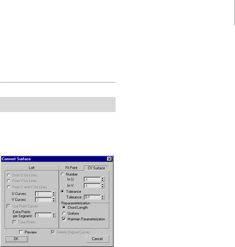
Convert Surface Dialog 1227
Number of Points—Specifies the number of points
in the new curve.
Preview—When on, previews the effect of the
conversion in viewports. Default=on.
Convert Surface Dialog
Modify panel > Select NURBS surface sub-object. >
Surface Common rollout > Convert Surface button
This dialog provides a general way to convert one
kind of a surface to another or to adjust a surface’s
parameters.
Interface
Loft tab
If the surface isn’t already a loft, this tab converts it
to the kind of loft you indicate.
ThecontrolsarecomparabletothoseintheMake
Loft dialog (page 1–1234).
From U Iso Lines—Usescurvesalongthesurface’sU
dimension to construct a U loft.
From V Iso Lines—Uses curves along the surface’s
V dimension to construct a U loft. If the surface
was already a U loft, set this to change the lofting
dimension.
From U and V Iso Lines—Uses curves from both the
U and V dimensions to construct a UV loft.
UCurves—Sets the number of curves in U.
VCurves—Sets the number of curves in V.
Use Point Curves—When on, constructs the loft
from point curves instead of the default CV curves.
Default=off.
Extra Points per Segment—This control is available
only for UV lofts (From U and V Iso Lines). Lets
you increase the number of points in each segment.
Fuse Points—This control is available only for
UV lofts (From U and V Iso Lines). When on,
fusespointsatcurveintersectionstoensurethat
the U and V curves continue to intersect when
you edit the surface, and that the surface remains
coincident with its parent curves. UV lofts
constructed from intersecting curves behave more
predictably. Default=on.
Fit Point tab
If the surface isn’t already a point surface, this tab
converts it to a point surface.
In U—Sets the number of point rows (in the
surface’s U axis).
In V—Sets the number of point columns (in the
surface’s V axis).
Tolerance—When chosen, the software calculates
the number of points. This option rebuilds the
surface according to accuracy. The lower the
Tolerancevalue,themoreaccuratetherebuild.
Increasing Tolerance enables the surface to be
rebuilt using fewer points.
CV Surface tab
If the surface isn’t already a CV surface, this tab
converts it to a CV surface.
This tab is the default.
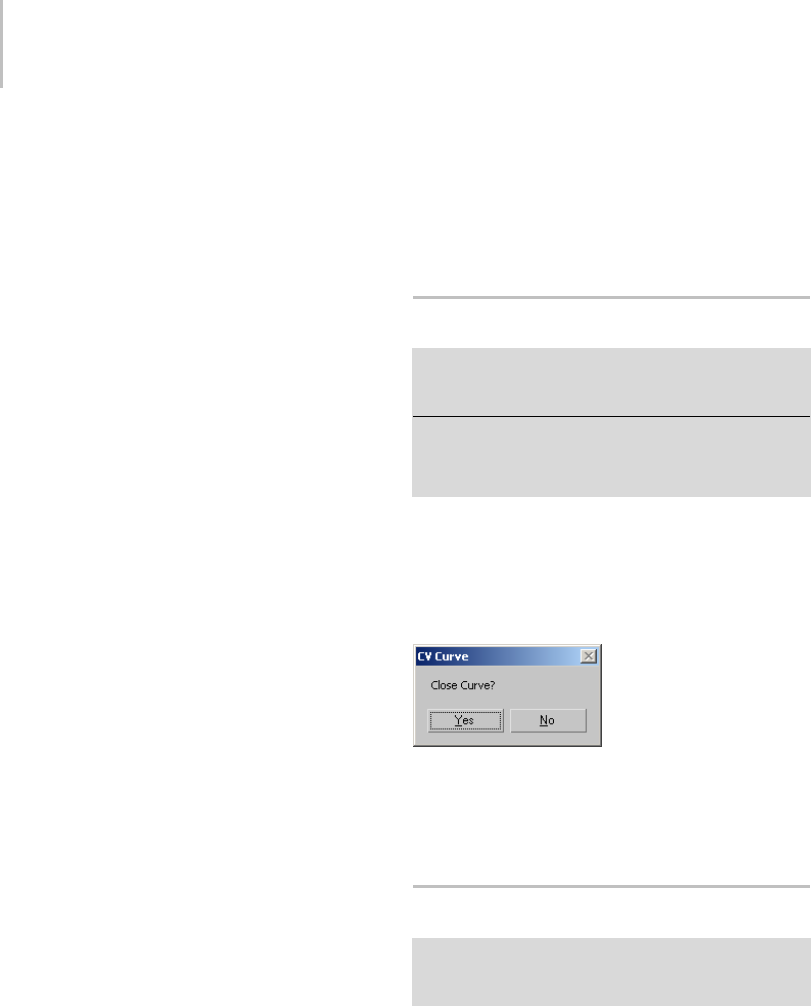
1228 Chapter 9: Surface Modeling
Number—When chosen, the spinners set the
number of CVs in the CV surface.
In U—Sets the number of CV rows (in the surface’s
U axis).
In V—Sets the number of CV columns (in the
surface’s V axis).
Tolerance—When chosen, the software calculates
thenumberofCVs. Thisoptionrebuildsthe
surface according to accuracy. The lower the
Tolerance value, the more accurate the rebuild.
Increasing Tolerance enables the surface to be
rebuilt using fewer CVs.
Reparameterization group
These controls let you reparameterize the CV
surface and turn on automatic reparameterization.
Chord Length—Chooses the chord-length
algorithm for reparameterization.
Chord-length reparameterization spaces knots (in
parameter space (page 3–988)) based on the square
root of the length of each segment.
Chord-length reparameterization is usually the
best choice.
Uniform—Spaces the knots uniformly.
A uniform knot vector has the advantage that the
surface changes only locally when you edit it. With
chord-length parameterization, moving any CV
can potentially change the entire surface.
Maintain Parameterization—When on, the
surface is automatically reparameterized
as you edit it, using the currently active
method of reparameterization. When off, no
reparameterizationhappensunlessyouusea
dialog to specifically request it. Default=on.
Preview—When on, viewports display a preview of
the conversion. Turning off this toggle can speed
up conversion, especially to lofts.
Delete Original Curves—This is available only if the
surface was already a U loft or UV loft. When on,
Convert Surface deletes the original loft curves
when you click OK. When off, the original curves
remain where they are. Default=off.
CV Curve: Close Curve Dialog
Create panel > Shapes button > CV Curve button > In
viewports, draw a CV curve and click to create a CV in the
same location as the first CV in the curve.
Modify panel > Select NURBS object. > NURBS toolbox
>CreateCVCurve>Inviewports,drawaCVcurve
sub-object and click to create a CV in the same location
as the first CV in the curve.
This dialog lets you create a closed CV curve when
you click to create a CV in the same location as the
curve’s first CV.
Interface
Yes—Closes the curve and ends curve creation.
No—Keeps the curve open and does not end curve
creation.
Detach Dialog (NURBS)
Modify panel > Select a NURBS sub-object. > Curve
Common or Surface Common rollout > (optional) Copy
toggle > Detach button
This dialog appears when you use Detach to
create a new top-level NURBS curve or surface
sub-object.
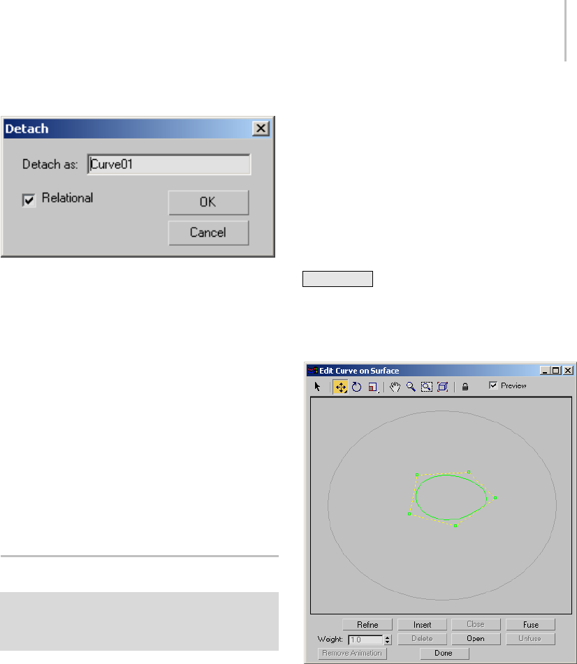
Edit Curve on Surface Dialog 1229
Interface
Detach as—Lets you assign a name to the new
object. By default, the name is "Curve" or "Surface"
followed by a sequence number.
This option is unavailable when Detach To
Element is on.
Relational —This toggle affects dependent objects.
When off, detaching a dependent sub-object
makes it an independent object. For example,
detachingaUloftconvertsittoaCVsurface.
When on, detaching a dependent sub-object also
detaches the objects on which it depends, so the
object remains dependent. For example, detaching
a U loft also detaches the curves that define it.
Default=on.
Edit Curve on Surface Dialog
Select NURBS object. > Modify panel > Stack display >
Curve sub-object level > Select NURBS curve on surface
sub-object. > CV Curve on Surface or Point Curve on
Surface rollout > Edit button
Thisdialogletsyoueditcurvesonsurfacesasyou
edit regular curves in a viewport. The main part
ofthedialogisatwo-dimensionalviewofthe
surface. The controls provide typical curve editing
functions.
This is a modeless dialog. You can use the main
3ds Max window while Edit Curve on Surface
remains open. However, if you select a different
kind of curve or a sub-object that isn’t a curve, the
dialog closes.
You can edit multiple CV on surface (page 1–1172)
or Point on surface (page 1–1175) curves, but you
can’t edit both types of curves at the same time.
The point whose surface you first click is shown as
a blue square in the dialog as well as in viewports.
As you draw the curve, it appears interactively in
viewportsandablueasterisk(*)showsthecurrent
mouselocationonthesurface.
Whileyouarecreatingacurve,youcanpress
Backspace to remove the last point or CV you
created, and then previous points or CVs in
reverse order.
Interface
Toolbar
Thetoolbarabovethesurfaceimageprovides
selection, transform and viewing controls. These
controls work the way their analogs do in the main
3ds Max viewports. The toolbar is disabled while
you create a new curve on surface.
Select—Selects one or more points. Drag a window
to select multiple points.

1230 Chapter 9: Surface Modeling
Move—Moves the selected points.
Move is a flyout. The alternative buttons constrain
texturepointstomoveeitherverticallyor
horizontally.
Rotate—Rotates the selected points.
Scale—Scales the selected points. This is a flyout
that lets you choose between uniform scale,
nonuniform scale in the surface’s U dimension, or
nonuniform scale in the surface’s V dimension.
Pan—Pans the surface view.
Zoom—Zooms in or out on the surface view.
Zoom Window—Zoomstoawindowyoudragon
the surface view.
Zoom Extents—Zooms to the extents of the surface.
Lock Selection—Locks the active selection set. You
can turn this on to keep from accidentally selecting
otherpointsorCVswhileyou’retransforminga
selection set.
Preview—When on (the default), edits you make
inthedialogarealsoshowninviewports.
Curve on Surface Image
Below the toolbar is a 2D image of the curve.
ThisimageshowsthepointsorCVsofthecurve,
allowingyoutoedititasyoueditsub-objectsin
viewports.
If you right-click while in the image, a pop-up
menu lets you switch between Select, Move,
Rotate, and Scale. This is an alternative to using
the toolbar.
If your mouse has a middle button, you can use it
topaninthiswindow.
Buttons and Weight
These controls are comparable to editing controls
on the rollouts for point sub-objects. (The Open
button works differently.) These controls are
disabled while you create a new curve on surface.
Refine—Addspointstothecurve.Thisdoesnot
change curvature. For point curves, the curvature
can change, but only slightly.
Insert—(Not available for point curves on
surfaces.)
Close—Closes the curve.
Fuse—Fuses two points.
Weight—(Not available for point curves on
surfaces.)
Delete—Deletes the selected points.
Open—Opens the curve by unfusing the points
wherethecurvewasoriginallyclosed.
Unfuse—Unfuses the selected points.
Remove Animation—Removes animation
controllers from the selected points or CVs.
Edit Texture Surface Dialog
Modify panel > Select NURBS surface sub-object. >
Material Properties rollout > Texture Channels group box
>TurnonGen.MappingCoords.>TextureSurfacegroup
box > Choose User-Defined. > Edit Texture Surface button
This dialog lets you edit the texture surface for a
surface sub-object. It is available when you have
chosen User Defined as the sub-object’s texture
surface method.
A texture surface is associated with the surface
sub-object. The texture surface is used to control
how materials are mapped. In effect, changing
thetexturesurfacestretchesorotherwisechanges
the UV coordinates for the surface, altering the
mapping.
The Edit Texture Surface dialog shows a 2D view of
the texture surface. You can also edit user-defined
texture surfaces directly in 3D viewports, using the
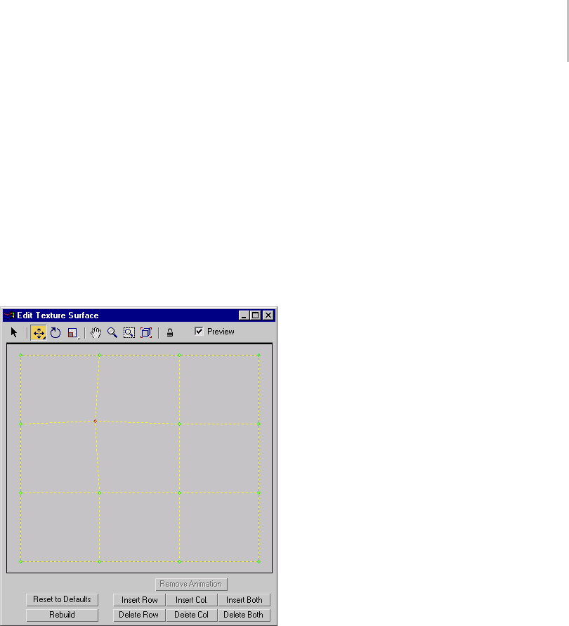
Edit Texture Surface Dialog 1231
Edit Texture Points button. See Material Properties
Rollout (page 1–1149).
Maps can shift with certain surface approximation
methods. This effect is especially noticeable when
thesurfacehasanimatedCVs.Youcanreduceor
eliminate map shifting by changing the mapping
method to User Defined.
Tip: Don’t use the UVW Map modifier to apply a
texture to an animated NURBS surface.
Interface
Toolbar
Thetoolbarabovethesurfaceimageprovides
selection, transform and viewing controls.
These controls work the way their analogs do in
viewports.
Note: You can animate transforms to the texture
surface points.
Select—Selects one or more points. Drag a window
to select multiple points or CVs.
Move—Moves the selected points.
Move is a flyout. The alternative buttons constrain
texturepointstomoveeitherverticallyor
horizontally.
Rotate—Rotates the selected points.
Scale—Scales the selected points. This is a flyout
that lets you choose between uniform scale,
nonuniform scale in the surface’s U dimension, or
nonuniform scale in the surface’s V dimension.
Pan—Pans the surface view.
Zoom—Zooms in or out on the surface view.
Zoom Window—Zooms to a window you drag on
the surface view.
Zoom Extents—Zooms to the extents of the surface.
Lock Selection—Locks the active selection set. You
can turn this on so you don’t accidentally select
other points while you’re transforming a selection
set.
Preview—When on (the default), your edits are
alsoshowninviewports.Inviewports,selected
texturepointsaredisplayedinred,andtheothers
are displayed in green.
Texture Surface Image
Below the toolbar is a 2D image showing the points
of the texture surface. You can edit the texture
surfaceasyoueditsub-objectsinviewports.
If you right-click while in the image, the popup
menu lets you switch between Select, Move,
Rotate, and Scale. This is an alternative to using
the toolbar.
If your mouse has a middle button, you can use it
topaninthiswindow.
Texture Surface Controls
The controls below the surface image edit the
texture surface.
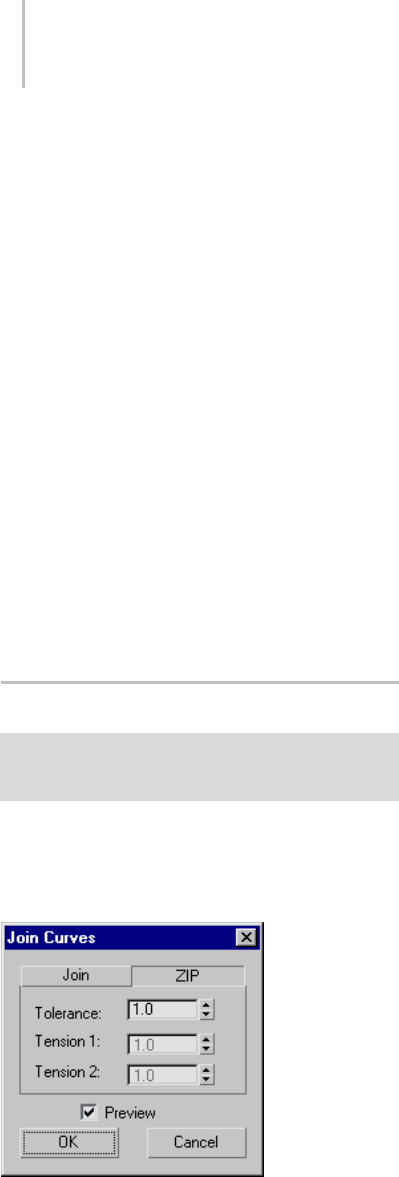
1232 Chapter 9: Surface Modeling
Remove Animation—Removes animation
controllers from the selected texture points.
Reset to Defaults—Resets user-defined mapping
to the default.
Rebuild—Displays the Rebuild Texture Surface
dialog (page 1–1236), which rebuilds the texture
surface and lets you change the number of CV
rows or columns.
Insert Row, Insert Col., Insert Both—Click one of
these buttons to insert a row or column of points,
or both at once, into the surface. Insertion adds
points without moving other rows and columns.
While you refine the surface, the operation is
previewed the same way Insert is previewed in 3D
viewports.
Delete Row, Delete Col., Delete Both—Click one of
these buttons to delete a row or column of points,
or both at once.
Join Curves Dialog
Modify panel > Select NURBS curve sub-object. > Curve
Common rollout > Join button > Join two curves in a
viewport.
This dialog lets you choose the way to join two
curves.
Interface
ZIP tab
This tab chooses the zip algorithm. Zipping
concatenates the CV lattices of the two original
curves. Zipping can change the shape of the
original curves, but usually it produces a better
result than joining.
By default, the ZIP tab is active.
If both curves are untrimmed point curves, the
result of zipping is a point curve. In all other cases,
the result is a CV curve.
Tolerance—Adistancein3dsMaxunits. Ifthe
ends of the two original curves are closer than this
distance, zipping deletes one of the points or CVs
in order to avoid creating coincident points or CVs
in the new zipped curve.
Tension 1—(Disabled.)
Tension 2—(Disabled.)
Join tab
This tab chooses the join algorithm. Joining first
creates a blend curve between the two original
curves, and then makes all three into a single
curve. Joining does not change the shape of the
two original curves.
If both curves are point curves, the result is a point
curve. If one or both curves are CV curves, the
result is a CV curve.
Tolerance—Adistancein3dsMaxunits. Ifthe
gapbetweenthecurvesyouarejoiningisgreater
than this value, the join is created by first creating
a blend curve and then joining the three parts. If
the gap is less than this value, or if the curves are
overlapping or coincident, the software doesn’t
create the blend.
Creating a blend and then joining the three curves
into a single curve is the better technique. The
result matches the parent curves well. Without the
blendstep,theresultingcurvecandeviatefromthe
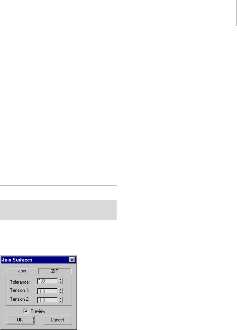
Join Surfaces Dialog 1233
parent curves, in order to maintain smoothness.
(The amount of deviation depends on how far
from tangent the two input curves were at the join.)
A problem arises when the gap is too small. In this
case, the software generates the blend but because
there isn’t enough room for it, the resulting curve
has a loop. To avoid having this loop, set the
Tolerance higher than the gap distance.
If you set the tolerance to 0.0, the software chooses
a value to use for the Tolerance.
Tension 1—Adjusts the tension of the new curve at
the end of the first curve you picked.
Tension 2—Adjusts the tension of the new curve at
the end of the second curve you picked.
Preview—When on, the effect of the zip or join is
previewed in viewports. Default=on.
Join Surfaces Dialog
Modify panel > Select NURBS surface sub-object. >
SurfaceCommonrollout>Joinbutton>Jointwo
surfaces in a viewport.
This dialog lets you choose the way to join two
surfaces.
Interface
ZIP tab
This tab chooses the zip algorithm. Zipping
concatenates the CV lattices of the two original
surfaces. Zipping can change the shape of the
original surfaces, but compared to joining it
usually produces a simpler surface that is easier
to edit.
By default, the ZIP tab is active.
If both curves are untrimmed point surfaces, the
result of zipping is a point surface. In all other
cases, the result is a CV surface.
Tolerance—Adistancein3dsMaxunits. Ifthe
edgesofthetwooriginalsurfacesarecloserthan
this distance, zipping deletes one row (or column)
of the points or CVs in order to avoid creating a
coincident point or CV row (or column) in the
new zipped surface.
Tension 1—(Disabled.)
Tension 2—(Disabled.)
Join tab
This tab chooses the join algorithm. (This method
was the only way to join surfaces in 3ds Max prior
to v3.) Joining first creates a blend surface between
the two original surfaces, and then makes all three
into a single surface. Joining does not change the
shape of the two original surfaces.
If both surfaces are point surfaces, the result is
a point surface. If one or both surfaces are CV
surfaces, the result is a CV surface.
Tolerance—Adistancein3dsMaxunits.Ifthegap
between the surfaces you are joining is greater
than this value, the join is created by first creating
a blend surface and then joining the three parts.
If the gap is less than this value, or if the surfaces
are overlapping or coincident, the software doesn’t
create the blend.
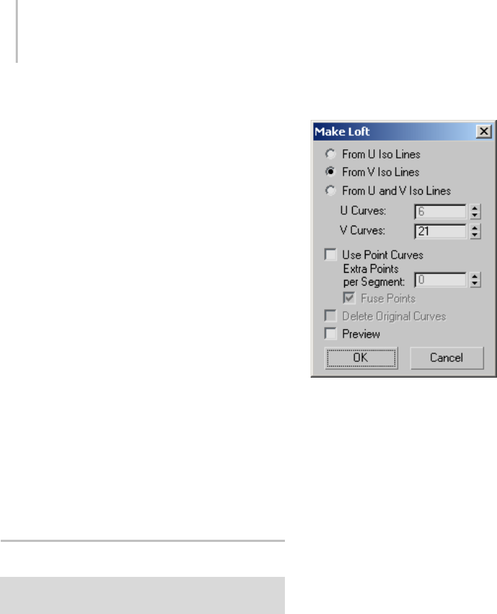
1234 Chapter 9: Surface Modeling
Creating a blend and then joining the three
surfaces into a single surface is the better
technique. The result matches the parent surfaces
well. Without the blend step, the resulting surface
can deviate from the parent surfaces, in order to
maintain smoothness. (The amount of deviation
depends on how far from tangent the two input
surfaces were at the join.)
A problem arises when the gap is too small. In this
case, the software generates the blend but because
there isn’t enough room for it, the resulting surface
has a loop. To avoid having this loop, set the
Tolerance higher than the gap distance.
If you set the tolerance to 0.0, the software chooses
a value to use for the Tolerance.
Tension 1—Adjusts the tension of the new surface
at the edge of the first surface you picked.
Tension 2—Adjusts the tension of the new surface
at the end of the second surface you picked.
Preview—When on, the effect of the zip or join is
previewed in viewports. Default=on.
Make Loft Dialog
Modify panel > Select NURBS surface sub-object. >
Surface Common rollout > Make Loft button
This dialog converts a surface sub-object to a
(dependent) U loft or UV loft surface. You can
also change the dimension used to construct a U
loft surface.
Interface
From U Iso Lines—Usescurvesalongthesurface’sU
dimensiontoconstructaUloft.
From V Iso Lines—Uses curves along the surface’s
V dimension to construct a U loft. If the surface
was already a U loft, set this to change the lofting
dimension.
From U and V Iso Lines—Uses curves from both the
U and V dimensions to construct a UV loft.
UCurves—Sets the number of curves in U.
VCurves—Sets the number of curves in V.
Use Point Curves—When on, constructs the loft
from point curves instead of the default CV curves.
Default=off.
Extra Points per Segment—This control is enabled
only for UV lofts (From U and V Iso Lines). Lets
you increase the number of points in each segment.
Fuse Points—This control is enabled only for UV
lofts (From U and V Iso Lines). When on, fuses
points at curve intersections to ensure that the
U and V curves continue to intersect when you
edit the surface, and that the surface remains
coincident with its parent curves. UV lofts
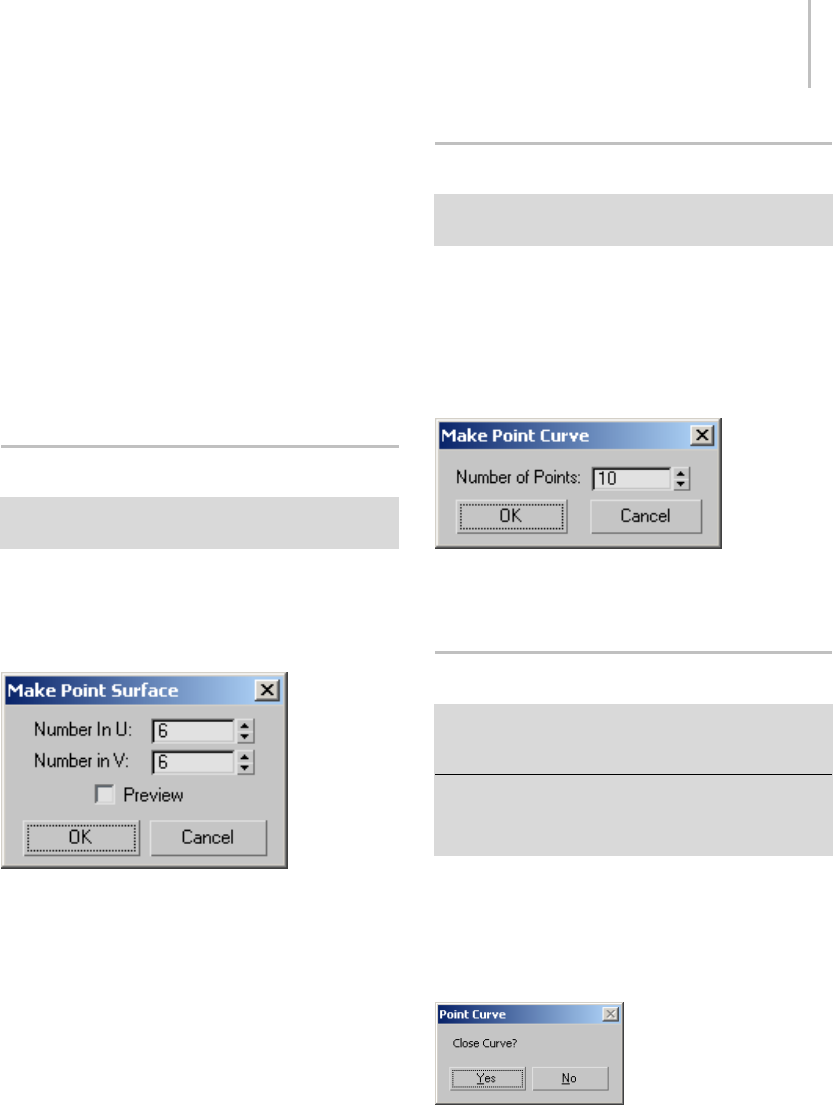
Make Point Dialog 1235
constructed from intersecting curves behave more
predictably. Default=on.
Delete Original Loft Curves—This is available only if
the surface was already a U loft or UV loft. When
on, Make Loft deletes the original loft curves when
you click OK. When off, the original curves remain
where they are. Default=off.
Preview—When on, displays a preview of the new
loft surface. Loft creation is faster when Preview
is off. Default=off.
Make Point Dialog
Modify panel > Select NURBS surface sub-object. >
Surface Common rollout > Make Point button
This dialog converts a CV surface sub-object to a
point surface sub-object.
Interface
Number in U—Sets the number of columns.
Number in V—Sets the number of rows.
Preview—When on, your changes are previewed in
viewports. Point surface conversion is faster when
Preview is off. Default=off.
Make Point Curve Dialog
Modify panel > Select NURBS curve sub-object. > Curve
Common rollout > Make Fit button
TheMakeFitbuttonforaNURBScurvesub-object
turns a CV curve into a point curve. For point
curves, it lets you change the number of points. It
displays this dialog.
Interface
Number of Points—Sets the number of points in
the point curve.
Point Curve: Close Curve Dialog
Create panel > Shapes button > Point Curve button > In
viewports, draw a point curve and click to create a point
in the same location as the first point in the curve.
Modify panel > Select NURBS object. > NURBS toolbox >
Create Point Curve > In viewports, draw a point curve
sub-object and click to create a point in the same location
as the first point in the curve.
This dialog lets you create a closed point curve
when you click to create a point in the same
location as the curve’s first point.
Interface
Yes—Closes the curve and ends curve creation.
No—Keeps the curve open and does not end curve
creation.
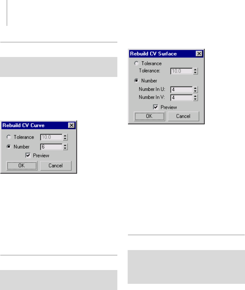
1236 Chapter 9: Surface Modeling
Rebuild CV Curve Dialog
Modify panel > Select NURBS object. > Stack display >
Curve sub-object level > Select an independent CV curve
sub-object. > CV Curve rollout > Rebuild button
TheRebuildbuttonforCVcurvesdisplaysthis
dialog. It lets you specify how to rebuild the curve.
Rebuildingthecurvecanchangeitsappearance.
Interface
Tolerance—Rebuilds the curve according to
accuracy. The lower the Tolerance value, the more
accurate the rebuild. Increasing Tolerance enables
the curve to be rebuilt using fewer CVs.
Number—(The default.) Lets you alter the number
of CVs in the curve.
Preview—When on (the default), your changes are
previewed in viewports.
Rebuild CV Surface Dialog
Modify panel > Select NURBS object. > Stack display >
Surface sub-object level > Select an independent CV
surface sub-object. > CV Surface rollout > Rebuild button
The Rebuild button for CV surfaces displays this
dialog. It lets you specify how to rebuild the
surface. Rebuilding the surface can change its
appearance.
Interface
Tolerance—Rebuilds the surface according to
accuracy. The lower the Tolerance value, the more
accurate the rebuild. Increasing Tolerance enables
the surface to be rebuilt using fewer CVs.
Number—(The default.) Lets you alter the number
of CVs in the surface. Number in U specifies the
number in the U dimension, and Number in V
specifies the number in the V dimension. These
values default to the numbers that already exist in
the surface.
Preview—When on (the default), your changes are
previewed in viewports.
Rebuild Texture Surface Dialog
Modify panel > Select NURBS surface sub-object. >
Surface sub-object level > Material Properties rollout >
Texture Channels group box > Turn on Gen. Mapping
Coords. > Texture Surface group box > Choose
User-Defined. > Edit Texture Surface button > Edit
Texture Surface dialog > Rebuild button
This dialog rebuilds the texture surface and lets
you change the number of CV rows or columns.
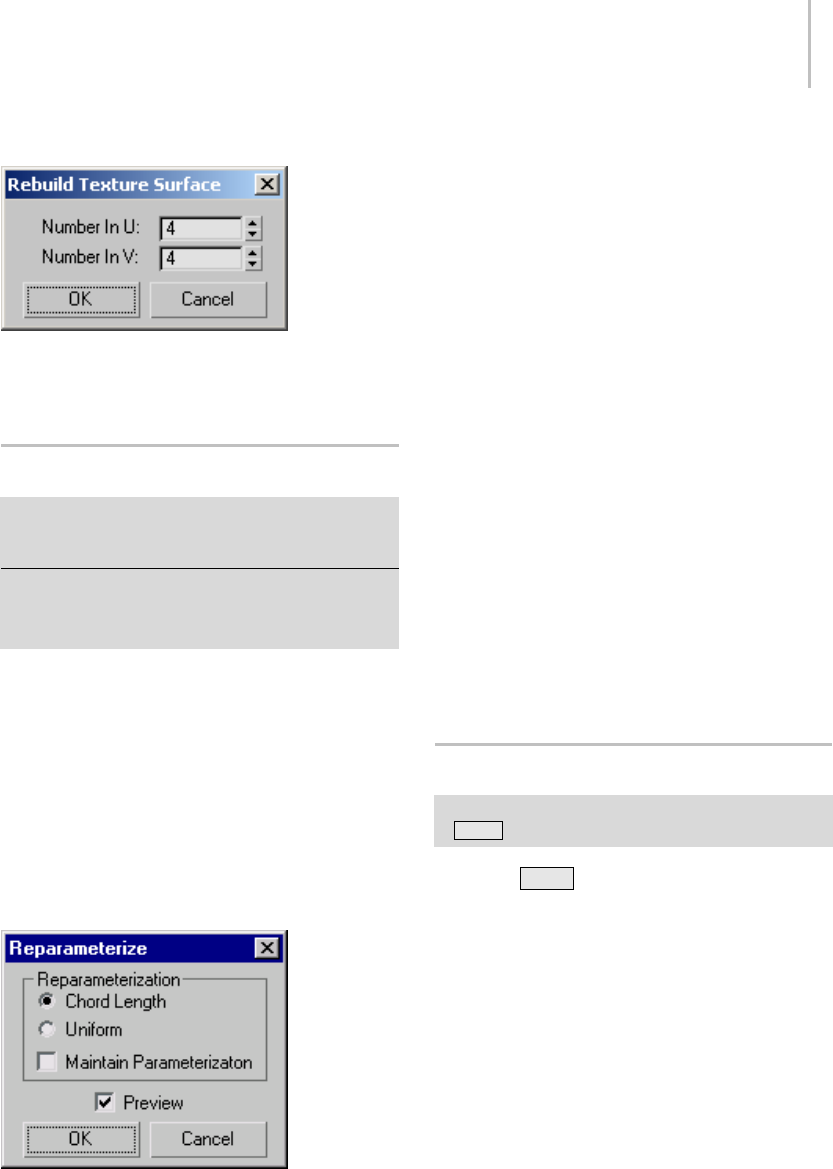
Reparameterize Dialog 1237
Interface
Number in U—Sets the number of CV columns.
Number in V—Sets the number of CV rows.
Reparameterize Dialog
Modify panel > Select NURBS object. > Stack display >
Curve sub-object level > Select an independent CV curve
sub-object. > CV Curve rollout > Reparam. button
Modify panel > Select NURBS object. > Stack display
> Curve sub-object level > Select an independent CV
surface sub-object. > CV Surface rollout > Reparam.
button
The Reparam. button for CV curves and surfaces
displays this dialog. Reparameterizing a CV
sub-object changes its parameter space (page
3–988) to provide a better relation between control
point locations and the shape of the sub-object.
Tip: It is a good idea to reparameterize after you
have added CVs to a curve or surface by refining
or inserting.
Interface
Chord Length—Chooses the chord-length
algorithm for reparameterization.
Chord-length reparameterization spaces knots (in
parameter space (page 3–988)) based on the square
rootofthelengthofeachcurvesegment.
Chord-length reparameterization is usually the
best choice.
Uniform—Spaces the knots uniformly.
A uniform knot vector has the advantage that
the curve or surface changes only locally when
you edit it. With chord-length parameterization,
moving any CV can potentially change the entire
sub-object.
Maintain Parameterization—When on, the curve is
automatically reparameterized as you edit it, using
the currently active method of reparameterization.
When off, no reparameterization happens unless
you use this dialog. Default=off.
Preview—Ifon(thedefault),displaystheeffectsof
reparameterizing in viewports.
Sub-Object Clone Options Dialog
Modify panel > Select NURBS surface or curve sub-object.
>Shift +Clone. > Clone Options dialog
When you Shift +Clone (page 1–478) asurface
orcurvesub-object,theCloneOptionsdialog
appears. This dialog asks whether you want the
clone to be a relational copy, an independent copy,
or a transform.
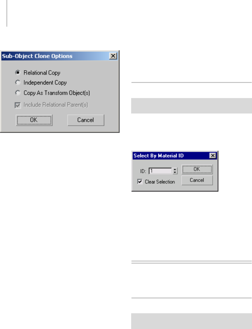
1238 Chapter 9: Surface Modeling
Interface
Relational Copy—The cloned object is the same
typeastheoriginal. Iftheoriginalobjectwasa
dependent object, the clone includes copies of the
parents. For example, when you clone a Blend
surface, the clone remains a Blend surface and its
two parent surfaces are copied along with it.
Because all related sub-objects are copied,
Relational Copy can be time-consuming.
Independent Copy—The cloned object is an
independent CV curve or CV surface. It has
thesameshapeastheoriginal,butitsrelational
dependencies aren’t copied. This method of
cloning uses less time and memory, although
you lose the relational properties. For example,
when you clone a Blend surface, the clone is an
independent CV surface.
Copy as Transform Object(s)—The "clone" is
actually a transform curve or transform surface,
based on the original object and still dependent
on it. This lets you create transform curves and
surfaces based on a rotation and scale as well as
on translation.
Include Parent(s)—(Available only for Independent
Copy or Copy as Transform Object(s).) Tells the
system whether or not to include the parents of
the dependent object. For example, if Include
Parent(s) is on when you clone a blend surface, the
two parent surfaces are also cloned as independent
CV surfaces. If Include Parent(s) is off, only the
onecurveorsurfaceiscloned.Cloningisslower
when Include Parent(s) is on, although quicker
than Relational Copy.
Select By Material ID Dialog
Modify panel > Select NURBS object. > Stack display >
Curve sub-object level > Select By ID button.
This dialog lets you select curve sub-objects by the
material ID number assigned to them.
Interface
ID—Specifies the material ID you want to select.
Clear Selection—When on, replaces the current
selection (if any) by the material ID selection.
When off, adds the material ID selection to the
current selection set.
Curve and Surface
Approximation
Curve Approximation
Modifypanel>Selecttop-levelNURBSobject.>Curve
Approximation rollout
Although NURBS curves are analytically
generated, in order to generate and display them
they must be approximated by line segments.
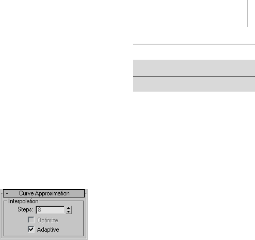
Surface Approximation 1239
Curve approximation controls are displayed in the
creation parameters for curve objects, and on a
Curve Approximation rollout for NURBS models
(top-level NURBS objects). At the model level,
approximation controls affect all curve sub-objects
in the model.
Curve approximation is accomplished by segments.
Oneormorelinesegments,orsteps, are used
to approximate each segment of the curve. For
point curves, a segment of a curve is the portion
between one point and the next. For CV curves,
the segment is determined by the CV’s parametric
knot (page 3–961). The transition from one CV
curve segment to another isn’t visible in viewports.
Curve approximation parameters aren’t
animatable.
Interface
Steps—The maximum number of line segments
used to approximate each curve segment. If the
curve displays or renders with angles, increase this
value. This control is unavailable when Adaptive
is on. Range=1 to 100.
Optimize—Tur n on this che ck box to opt imize t he
curve. When on, interpolation uses the specified
Steps value unless two segments are collinear, in
which case they are converted to a single segment.
This control is unavailable when Adaptive is on.
Adaptive—(The default.) Segments the curve
adaptively, based on its curvature. In other words,
the curve is assigned more segments where its
curvature is greatest, and fewer segments where
its curvature is less.
Surface Approximation
Modify panel > Select top-level NURBS object. > Surface
Approximation rollout
Modify panel > Select NURBS surface sub-object. >
Surface Approximation rollout
Although NURBS surfaces are analytically
generated, in order to generate and display them
they must be approximated by faces. You use the
controls described in this section to set the type of
approximation used and its parameters.
The Surface Approximation rollout controls how
surfacesub-objectsintheNURBSmodelare
approximated for purposes of rendering and
viewport display. NURBS can be approximated
differently in viewports and in the renderer.
Typicallyyouwantviewportdisplaytobeclear
and quick, while you want rendered display to be
smooth, accurate, and "realistic." However, the
approximation you choose for viewports creates a
mesh, and the kind of mesh you choose can affect
the behavior of modifiers that you later apply to
the NURBS model.
The first two controls on this rollout are radio
buttons for selecting the kind of display output,
viewport or renderer, these parameters control.
Surface approximation parameters are not
animatable.
Note: Ifthesizeorshapeofasurfacechanges
over time, the tessellation used to approximate it
can change (automatically) as well. This has the
advantage of improving render time in animations.
It has the disadvantage that you can’t apply image
motion blur (page 3–955) to NURBS objects
whose tessellation changes during animation. The
Regular method of tessellation is the exception:
it doesn’t change when animated, so you can use
image motion blur with Regular tessellation.
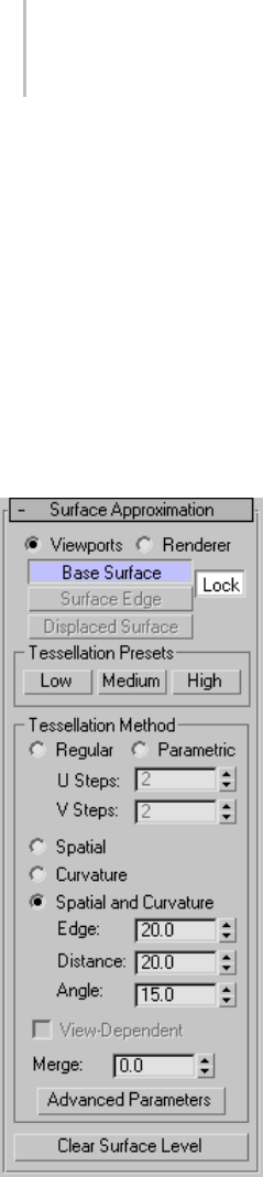
1240 Chapter 9: Surface Modeling
Surface Approximation Per Surface
By default, surface sub-objects use the same
approximationsettingsasthetop-levelNURBS
model. You can override these settings.
Each surface sub-object now has a Surface
Approximation rollout of its own. The controls
on this rollout are disabled unless you turn off
the Lock to Top Level toggle. With this toggle
turned off, you can choose approximation settings
specific to this surface sub-object.
Interface
Tessellation group
Viewports—When chosen, the rollout affects
how surfaces in the NURBS object are displayed
interactively in viewports, including shaded
viewports, and by the preview renderer.
The Viewports surface settings are also used when
youapplyameshmodifiersuchasMeshSelectto
the NURBS object. This is important because the
modifier can affect the scene’s geometry.
Renderer—When chosen, the rollout affects how
surfaces in the NURBS object are displayed by
the renderer, and by the draft renderer for Quick
Render.
The next cluster of buttons lets you choose which
portions of the geometry are affected by the
surface approximation settings.
Base Surface—Settingsaffecttheentiresurface.
This is the default.
Surface Edge—Turn on to set approximation values
fortessellatingsurfaceedgesthataredefinedby
trim curves. With Lock turned off, the surface and
edge tessellation values are independent of each
other.
For object-level surfaces, this is unavailable unless
Lock (described below) is turned off.
Displaced Surface—Tu rn on to se t a thi rd ,
independent approximation setting for surfaces
that have a displacement map (page 2–1511)
applied to them. Available only when Renderer is
chosen.
Using a preset approximation setting (in the
Presets group box) should give you faster results
for displaced surfaces.
Lock—(for object-level surfaces only) Locks the
BaseSurfacesettingstotheSurfaceEdgesettings.
In other words, surfaces and surface edges have a
relational tessellation setting unless Lock is turned
off. Default=on.

Surface Approximation 1241
Tessellation Presets group
Lets you choose a preset low, medium, or high
quality surface approximation. While a preset
is chosen, the values it uses are displayed on the
Tessellation Method rollout.
Preset values are saved in the 3dsmax.ini (page
1–18) file. You can customize the preset values
by using the Surface Approximation utility (page
1–1245).
Low—Selects a (comparatively) low-quality surface
approximation.Thesearethedefaultvalues:
Viewports, Base Surface:
Method=Spatial and Curvature Edge=50.0
Distance=50.0 Angle=50.0 Merge=0.0 Advanced
Parameters > Minimum=0, Maximum=3
Renderer, Base Surface:
Method=Spatial and Curvature Edge=20.0
Distance=20.0 Angle=15.0 Merge=0.01 Advanced
Parameters > Minimum=0, Maximum=3
Renderer, Displaced Surface:
Method=Spatial and Curvature Edge=20.0
Distance=20.0 Angle=10.0 Merge=(Unavailable)
Advanced Parameters > Minimum=0,
Maximum=2
Keyboard shortcut: Alt+1
Medium—(The default for both viewports and
rendering.) Selects a medium-quality surface
approximation.Thesearethedefaultvalues:
Viewports, Base Surface:
Method=Spatial and Curvature Edge=20.0
Distance=20.0 Angle=15.0 Merge=0.0 Advanced
Parameters > Minimum=0, Maximum=3
Renderer, Base Surface:
Method=Spatial and Curvature Edge=10.0
Distance=15.0 Angle=10.0 Merge=0.01 Advanced
Parameters > Minimum=0, Maximum=4
Renderer, Displaced Surface:
Method=Spatial and Curvature Edge=10.0
Distance=10.0 Angle=4.0 Merge=(Unavailable)
Advanced Parameters > Minimum=0,
Maximum=3
Keyboard shortcut: Alt+2
High—Selects a high-quality surface
approximation. These are the default values:
Viewports, Base Surface:
Method=Spatial and Curvature Edge=5.0
Distance=15.0 Angle=10.0 Merge=0.0 Advanced
Parameters > Minimum=0, Maximum=3
Renderer, Base Surface:
Method=Spatial and Curvature Edge=5.0
Distance=5.0 Angle=3.0 Merge=0.01 Advanced
Parameters > Minimum=0, Maximum=4
Renderer, Displaced Surface:
Method=Spatial and Curvature Edge=5.0
Distance=5.0 Angle=2.0 Merge=(Unavailable)
Advanced Parameters > Minimum=0,
Maximum=4
Keyboard shortcut: Alt+3
Note: The keyboard shortcuts for surface
approximation presets don’t require that the
KeyboardShortcutOverrideTogglebeon.You
can change the surface approximation of NURBS
objects by selecting them in a viewport, and then
using Alt+1 ,Alt+2 ,or Alt+3 .Thisworksfor
sub-objectsaswell,butthesurfacesub-object’s
Lock to Top Level toggle must be turned off.
Tessellation Method group
The controls in this group affect the display of the
NURBS surface in viewports if you have chosen
Viewports above, or by the renderer if you have
chosen Renderer above. You can choose between
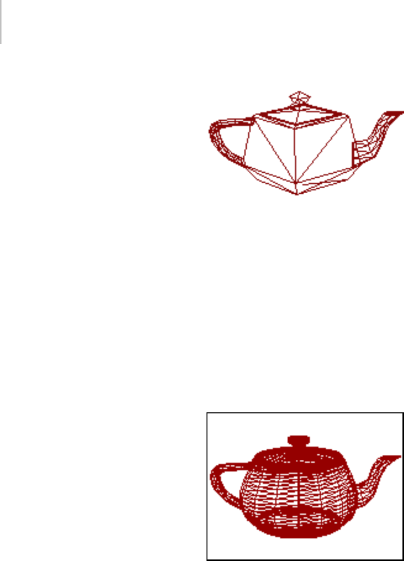
1242 Chapter 9: Surface Modeling
five algorithms. Each approximates NURBS
surfaces by tessellating them in a different way.
Generally speaking, if the preset values you have
chosen give good results, you don’t need to adjust
the controls on this rollout. Adjust them if you
encounter problems with the preset alternative.
Tips
• Viewport Tessellation: The tessellation method
creates the mesh. If you modify the NURBS
object with Mesh Select (page 1–719),choose
the method that gives the result you need. If
you use modifiers heavily, Spatial or Parametric
might be better than Curvature, because of
their regular tessellation. Curvature-dependent
tessellation can cause problems with some
modifiers.
• Renderer Tessellation: Spatial and Curvature
usually obtains the most accurate rendering.
Curvaturecanbethemoreefficientchoice
when you render animated surfaces.
Lock to Top Level—(for sub-object surfaces only)
When on, the surface sub-object uses the same
surface approximation settings as the top-level
NURBS model, and other controls on this rollout
are disabled. When turned off, you can set the
sub-object approximation to differ from the
top-level model. Default=on.
Regular—Generatesafixedtessellationacrossthe
surface based on U Steps by V Steps. Increasing
these parameters increases accuracy at a cost of
speed, and vice versa, but in general this can be the
quickest and least accurate way to approximate a
NURBS surface. Very low values for U and V Steps
using the Regular method usually doesn’t provide
good results. Model complexity increases slowly
as U and V Steps values increase.
Regular mesh of the NURBS teapot
Parametric—Generates an adaptive tessellation
based on U Steps by V Steps. Low values for U
and V Steps using the Parametric method often
provide good results. Model complexity increases
rapidlyasUandVStepsvaluesincrease,so
take care when you switch from Regular, which
generally requires higher U and V values, to
Parametric, where lower U and V values generally
suffice.
For example, if you convert a teapot to NURBS and
set the U and V steps to 15, the Regular method
generates 4470 faces but the Parametric method
generates 204960 faces.
Parametric mesh of the NURBS teapot
Spatial—Generates a uniform tessellation made
of triangular faces.
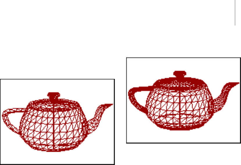
Surface Approximation 1243
The Edge parameter specifies the maximum
length of a triangular face in the tessellation. The
valueisapercentageoftheobject’sbounding
box. Decreasing this value increases accuracy but
increases rendering time.
Spatial mesh of the NURBS teapot
Curvature—(The default.) Generates a variable
tessellation based on the curvature of the surface.
The tessellation has a finer grain where the surface
is more curved. Changing surface curvature
dynamically changes the curvature tessellation.
The Distance parameter specifies how far the
approximation can deviate from the actual NURBS
surface. Distance is a percentage of the diagonal of
each surface’s bounding box. Each surface in an
object is tessellated based on its size, independently
of other surfaces. Scaling a surface doesn’t change
its tessellation. Decreasing this value increases
accuracy but increases rendering time. When
you set Distance to 0.0, the software ignores this
parameter and uses the Angle to control accuracy.
The Angle parameter specifies the maximum angle
between faces in the approximation. Decreasing
this value increases accuracy but increases
rendering time. When you set Angle to 0.0, the
softwareignoresthisparameterandusesDistance
to control accuracy.
When both Distance and Angle are 0.0, the
surfaces degenerate and can become flat surfaces.
Curvature mesh of the NURBS teapot
Spatial and Curvature—Combines the spatial
(edge-length) method and the curvature (distance
and angle) methods, using all three values.
TheEdgeparameterspecifiesthemaximum
length of a triangular face in the tessellation. The
valueisapercentageoftheobject’sbounding
box. Decreasing this value increases accuracy but
increases rendering time. When you set Edge
to 0.0, the effect is equivalent to the Curvature
method.
The Distance parameter specifies how far the
approximation can deviate from the actual
NURBS surface. Distance is a percentage of the
diagonal of each surface’s bounding box. Each
surface in an object is tessellated based on its size,
independently of other surfaces. Scaling a surface
doesn’t change its tessellation. Decreasing this
value increases accuracy but increases rendering
time. When you set Distance to 0.0, the software
ignores this parameter and uses the Edge and
Angle values to control accuracy.
The Angle parameter specifies the maximum angle
between faces in the approximation. Decreasing
this value increases accuracy but increases
rendering time. When you set Angle to 0.0, the

1244 Chapter 9: Surface Modeling
software ignores this parameter and uses the Edge
and Distance values to control accuracy.
When Distance, Angle, and Edge are all 0.0, the
surfaces degenerate and can become flat surfaces.
Spatial and Curvature mesh of the NURBS teapot
View-Dependent—(for the Renderer only) When
on, takes the object’s distance from the camera
into account while calculating tessellation. This
can improve rendering time by not generating
fine-grained tessellations for objects in the distance
of the rendered scene. The view-dependent effect
works only when you render camera or perspective
views. It doesn’t work in orthographic views. This
controlisdisabledwhileViewportsisactive.
For the Spatial, Curvature, and Spatial and
Curvature methods, the Distance and Edge values
specify pixels instead of 3ds Max units when
View-Dependent is on.
Note: When View-Dependent is on, tessellation
quickly reaches the maximum subdivision limit.
You might want to increase this value to 7 (the
greatest value allowed). See the description of
Advanced Parameters, below.
Merge (sub-object surfaces only)—Controls the
tessellation of surface sub-objects whose edges
are joined or very nearly joined. When input
to a modifier (such as Mesh Select) requires a
mesh, and when NURBS surfaces are tessellated
for production rendering, by default the software
adjusts the tessellation of adjoining surfaces to
match each other, in terms of the number of faces
along the edges. The Merge parameter controls
howthisisdone.IfMergeiszero,adjoiningfaces
are unchanged. Increasing the value of Merge
increases the distance the software uses to calculate
how edges should match, guaranteeing no gaps
between the surfaces when they are rendered.
Default=0.0.
In most cases, you don’t need to adjust Merge. If
rendering shows gaps between nearly adjoining
faces, increase Merge to eliminate them.
Technically,theMergevalueis0.1percentofthe
diagonal of the object’s bounding box. In other
words, a Merge value of 1.0 (higher than necessary
for most purposes) is 0.1 percent of the length
of the diagonal. Because Merge is based on the
object’s dimensions, you can scale the NURBS
model without affecting the Merge setting.
Advanced Parameters—Click to display the
Advanced Surface Approximation dialog (page
1–1245). The parameters in this dialog apply to
the Spatial, Curvature, and Spatial and Curvature
approximation methods.
Clear Surface Level—(Appears only for top-level
surfaces.) Clears all surface approximation
settings assigned to individual surface sub-objects.
When you click this button, all surface-specific
approximations are lost, and Lock to Top Level is
on for surface sub-objects.
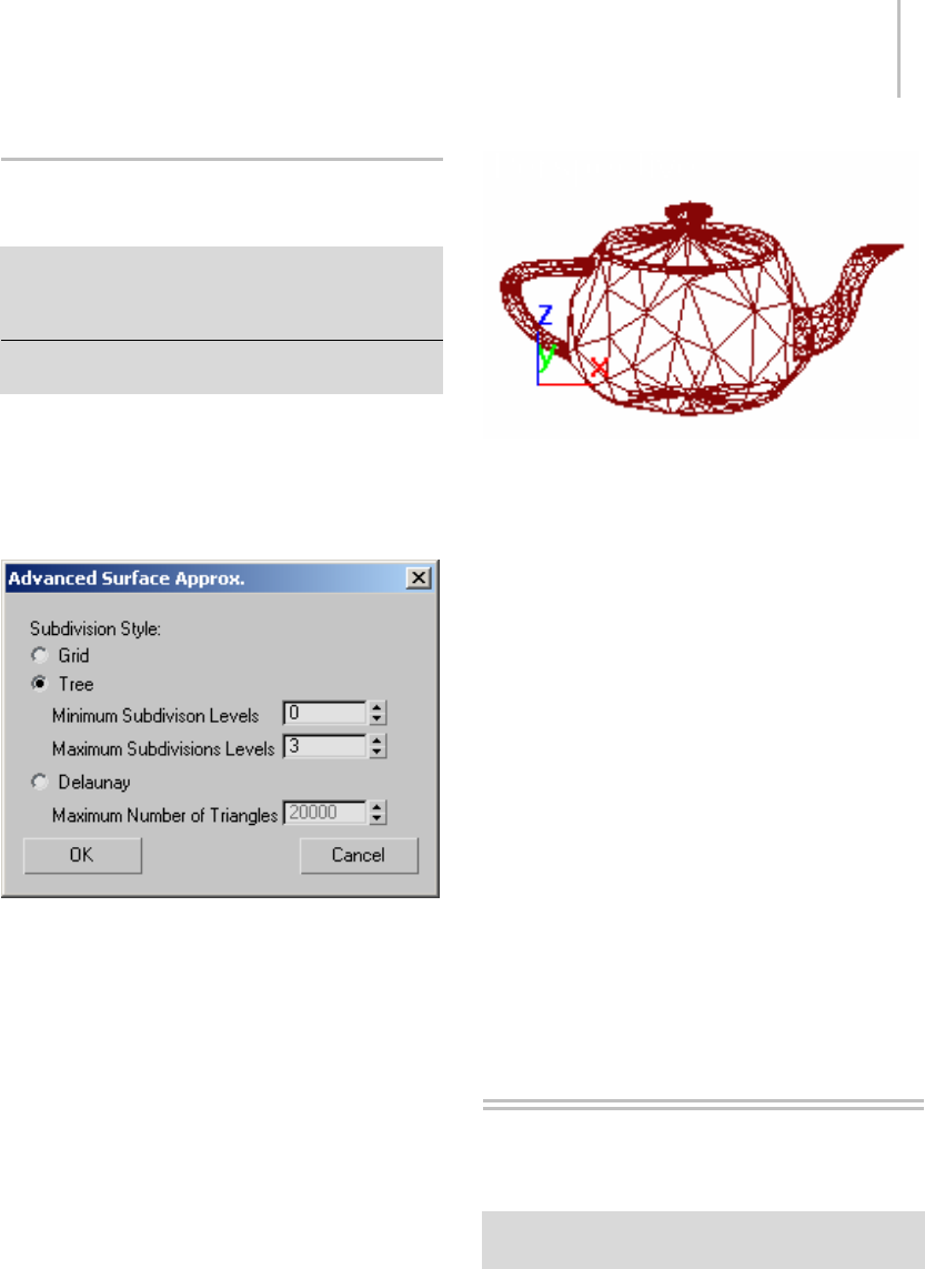
Advanced Surface Approximation Dialog 1245
Advanced Surface Approximation
Dialog
Modify panel > Select a NURBS surface object or
surface sub-object. > Surface Approximation rollout >
Tessellation Method group box > Turn off Lock to Top
Level > Advanced Parameters button
Select an editable mesh object. > Modify panel > Surface
Properties rollout > Advanced Parameters button
This dialog sets parameters that control the
tessellation used in the Spatial, Curvature, and
Spatial and Curvature approximation methods.
Interface
Subdivision Style
Chooses the method used to subdivide the surface:
Grid—Subdivides the surface using a regular grid.
Tree—(The default.) Subdivides the surface using
a binary tree.
Delaunay—Subdivides the surface using nearly
equilateral triangles.
Delauney surface subdivision style
Subdivision Limits
For Grid or Tree subdivisions, the limits control
the number of recursive decompositions that are
performed during tessellation.
Minimum Subdivision Levels—Sets the minimum
number of recursions. Default=0.
Maximum Subdivision Levels—Sets the maximum
number of recursions. The maximum can be no
greater than 7. Be careful: setting the maximum
greater than 5 can result in massive face counts
and poor performance. Default=3.
Maximum Number of Triangles
For Delaunay subdivision, the Maximum Number
ofTrianglesletsyouspecifythemaximumnumber
of triangles into which the surface will be divided.
Default=20000.
Surface Approximation
Utility
Utilities panel > Utilities rollout > More button > Utilities
dialog > Surface Approximation
The Surface Approximation utility lets you change
approximation and display settings without going
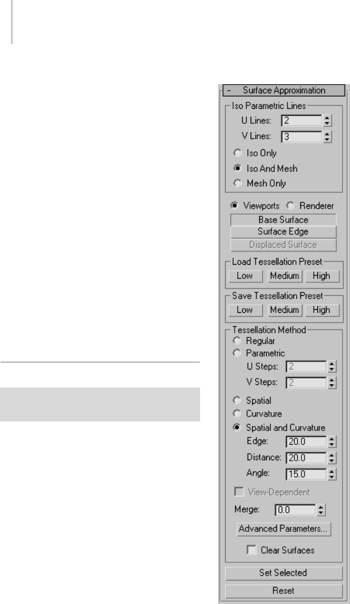
1246 Chapter 9: Surface Modeling
into the NURBS model, and is especially useful
for changing settings on multiple NURBS objects
at once.
It has two rollouts, one for surface approximation
and the other for surface display controls.
Surface Approximation Rollout (page 1–1246)
Surface Display Rollout (page 1–1252)
Procedure
To use the Surface Approximation utility:
1. On the Utilities panel, click the More button,
and choose Surface Approximation from the
list.
2. Set the desired options on the Surface
Approximation and Surface Display rollouts.
3. Select the NURBS objects to apply the settings
to.
4. On the Surface Display rollout, click Set
Selected to apply the settings.
Surface Approximation Rollout
Utilities panel > Utilities rollout > More button > Utilities
dialog > Surface Approximation > Surface Approximation
rollout
The controls in the Surface Approximation rollout
are the same as the surface approximation (page
1–1239) controls for NURBS (page 1–1078) surface
objects, with two additional buttons: Set Selected
and Reset.
Interface
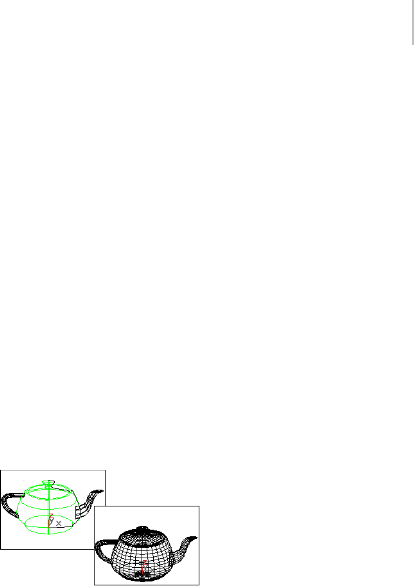
Surface Approximation Rollout 1247
Iso Parametric Lines group
Thecontrolsinthisgroupboxaffectthedisplayof
the NURBS surfaces in viewports.
ULinesandVLines—The number of lines used to
approximate the NURBS surfaces in viewports,
alongthesurface’slocalUandVdimensions,
respectively. Reducing these values can speed up
the display of the surface, but reduce accuracy
of the display. Increasing these values increases
accuracy at the expense of time. Setting one of
these values to 0 displays only the edge of the
object in the corresponding dimension.
Iso Only—When chosen, all viewports display iso
line (page 3–959) representations of the surface.
Iso (parametric) lines are similar to contour lines.
ThelinesshowwheretheNURBSsurfacehas
a constant U value or V value or both. Iso line
representations can be less crowded and easier to
visualize than wire mesh representations.
Iso and Mesh—(The default.) When chosen,
wireframe viewports display iso line
representations of the surface, and shaded
viewports display the shaded surface.
Mesh Only—When chosen, wireframe viewports
display the surface as a wire mesh, and shaded
viewports display the shaded surface.
In wireframe viewports, this option lets you see
the surface approximation used for viewports.
Iso and mesh displays of a NURBS teapot
Viewports—When chosen, the utility affects how
surfaces in the NURBS objects are displayed
interactively in viewports, including shaded
viewports, and by the preview renderer.
The Viewports surface settings are also used when
youapplyameshmodifiersuchasMeshSelectto
the NURBS objects. This is important because it
can affect the scene’s geometry.
Renderer—When chosen, the utility affects how
surfaces in the NURBS objects are displayed by
the renderer, and by the draft renderer for Quick
Render.
Base Surface—When on, settings affect entire
surfaces in the selection set. Default=on.
Surface Edge—When on, settings affect the
tessellation of surface edges that are defined by
trim curves.
Displaced Surface—Enabled only when Renderer
is chosen. Turn on to set a third, independent
approximation setting for surfaces that have a
displacement map (page 2–1511) or Displace (page
1–629) modifier applied to them.
Load Tessellation Preset group
Lets you choose a preset low, medium, or
high-quality level of surface approximation. While
a preset is chosen, the values it uses are displayed
in the Tessellation Method group box.
Preset values are saved in the 3dsmax.ini file.
You can customize the preset values by using
the buttons in the following group box, Save
Tessellation Preset.
Low—Selects a (comparatively) low-quality level
of surface approximation. These are the default
values:
Viewports, Base Surface:
Method=Spatial and Curvature
Edge=50.0

1248 Chapter 9: Surface Modeling
Distance=50.0
Angle=50.0
Merge=0.0
Advanced Parameters > Minimum=0,
Maximum=3
Renderer, Base Surface:
Method=Spatial and Curvature
Edge=20.0
Distance=20.0
Angle=15.0
Merge=0.01
Advanced Parameters > Minimum=0,
Maximum=3
Renderer, Displaced Surface:
Method=Spatial and Curvature
Edge=20.0 Distance=20.0
Angle=10.0 Merge=(Unavailable)
Advanced Parameters > Minimum=0,
Maximum=2
Medium—(The default for both viewports and
rendering.) Selects a medium-quality level of
surfaceapproximation. Thesearethedefault
values:
Viewports, Base Surface:
Method=Spatial and Curvature
Edge=20.0
Distance=20.0
Angle=15.0
Merge=0.0
Advanced Parameters > Minimum=0,
Maximum=3
Renderer, Base Surface:
Method=Spatial and Curvature
Edge=10.0
Distance=15.0
Angle=10.0
Merge=0.01
Advanced Parameters > Minimum=0,
Maximum=4
Renderer, Displaced Surface:
Method=Spatial and Curvature
Edge=10.0
Distance=10.0
Angle=4.0
Merge=(Unavailable)
Advanced Parameters > Minimum=0,
Maximum=3
High—Selects a high-quality level of surface
approximation. These are the default values:
Viewports, Base Surface:
Method=Spatial and Curvature Edge=5.0
Distance=15.0 Angle=10.0 Merge=0.0 Advanced
Parameters > Minimum=0, Maximum=3
Renderer, Base Surface:
Method=Spatial and Curvature
Edge=5.0
Distance=5.0
Angle=3.0
Merge=0.01
Advanced Parameters > Minimum=0,
Maximum=4
Renderer, Displaced Surface:

Surface Approximation Rollout 1249
Method=Spatial and Curvature
Edge=5.0
Distance=5.0
Angle=2.0
Merge=(Unavailable)
Advanced Parameters > Minimum=0,
Maximum=4
Save Tessellation Preset group
Click a button to save the current Tessellation
Method settings as a new Low, Medium, or High
preset. These values are saved in the 3dsmax.ini
file.
Note: There is a separate Low, Medium, and High
preset for Base Surface and Displaced Surface
approximation. Check whether Base Surface or
Displaced Surface is on before you use the buttons
in this group box to save a custom preset.
Customizingpresetvaluesoverwritesthedefault
presets. To restore the defaults, you can re-enter
the default preset values shown above, and then
save them with the corresponding button. You can
also restore defaults by editing the 3dsmax.ini file
to delete the custom preset values.
When you customize the preset values, there is no
necessary correlation between the button names
and the quality of surface approximation. The
software has no way of knowing how "good" a
tessellation is, and you can save a very high-quality
surfaceapproximationintheLowpreset,for
example.
Tessellation Method group
Thecontrolsinthisgroupboxaffectthedisplay
of the NURBS surfaces in either viewports,
ifViewportsischosen,orbytherenderer,if
Renderer is chosen. You can choose between five
algorithms. Each approximates NURBS surfaces
by tessellating them in a different way.
Note: When Viewports is chosen, you must also
choose Mesh Only in order to see the effect of the
Mesh Parameter settings in wireframe viewports.
Generally speaking, if the preset values you have
chosen give good results, you don’t need to adjust
thecontrolsinthisrolloutfurther.Usethemifyou
encounter problems with the preset alternative.
Tips
• Viewport Tessellation: The tessellation method
creates the mesh, so if you modify the NURBS
object with Mesh Select, choose the method
that gives the result you need. If you use
modifiers heavily, Spatial or Parametric might
be better than Curvature, because of their
regular tessellation. Curvature-dependent
tessellation can cause problems with some
modifiers.
• Renderer Tessellation: Spatial and Curvature
usually obtains the most accurate rendering.
Curvaturecanbethemoreefficientchoice
when you render animated surfaces.
Regular—Generatesafixedtessellationacrossthe
surface based on U Steps by V Steps. Increasing
these parameters increases accuracy at a cost of
speed, and vice versa, but in general this can be the
quickest and least accurate way to approximate a
NURBS surface. Very low values for U and V Steps
using the Regular method usually doesn’t provide
good results. Model complexity increases slowly
as U and V Steps values increase.
Parametric—Generates an adaptive tessellation
based on U Steps by V Steps. Low values for U
and V Steps using the Parametric method often
provide good results. Model complexity increases
rapidlyasUandVStepsvaluesincrease,so
take care when you switch from Regular, which
generally requires higher U and V values, to
Parametric, where lower U and V values generally
suffice.
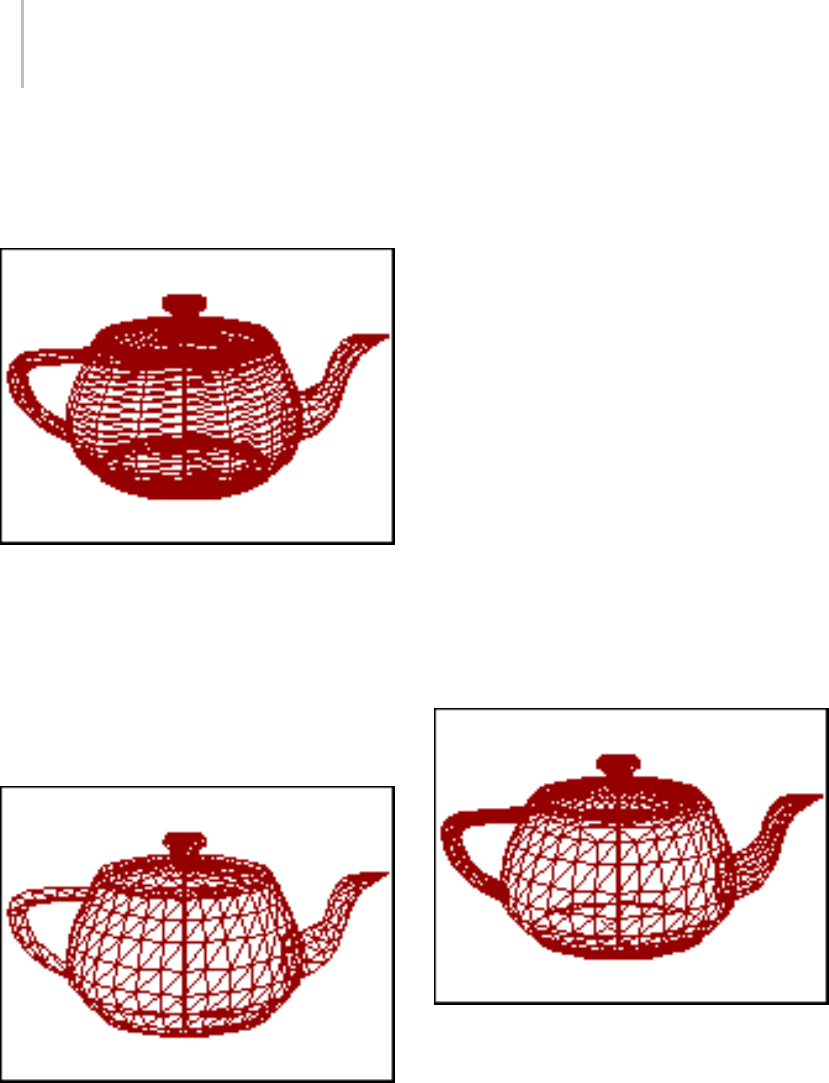
1250 Chapter 9: Surface Modeling
For example, if you convert a teapot to NURBS and
set the U and V steps to 15, the Regular method
generates 4470 faces but the Parametric method
generates 204960 faces.
Parametric mesh of the NURBS teapot
Spatial—Generates a uniform tessellation made
of triangular faces.
The Edge parameter specifies the maximum
length of a triangular face in the tessellation. The
valueisapercentageoftheobject’sbounding
box. Decreasing this value increases accuracy but
increases rendering time.
Spatial mesh of the NURBS teapot
Curvature—Generates a variable tessellation based
on the curvature of the surface. The tessellation
has a finer grain where the surface is more curved.
Changing surface curvature dynamically changes
the curvature tessellation.
The Distance parameter specifies how far the
approximation can deviate from the actual NURBS
surface. Distance is a percentage of the diagonal of
each surface’s bounding box. Each surface in an
object is tessellated based on its size, independently
of other surfaces, and scaling a surface doesn’t
change its tessellation. Decreasing this value
increases accuracy but increases rendering time.
When you set Distance to 0.0, the software ignores
this parameter and uses the Angle to control
accuracy.
The Angle parameter specifies the maximum angle
between faces in the approximation. Decreasing
this value increases accuracy but increases
rendering time. When you set Angle to 0.0, the
software ignores this parameter and uses the
Distance to control accuracy.
When both Distance and Angle are 0.0, the
surfaces degenerate and can become flat surfaces.
Curvature mesh of the NURBS teapot
Spatial and Curvature—(The default.) Combines
the spatial (edge-length) method and the
curvature (distance and angle) methods, using all
three values.
TheEdgeparameterspecifiesthemaximum
length of a triangular face in the tessellation. The

Surface Approximation Rollout 1251
valueisapercentageoftheobject’sbounding
box. Decreasing this value increases accuracy but
increases rendering time. When you set Edge
to 0.0, the effect is equivalent to the Curvature
method.
The Distance parameter specifies how far the
approximation can deviate from the actual NURBS
surface. Distance is a percentage of the diagonal of
each surface’s bounding box. Each surface in an
object is tessellated based on its size, independently
of other surfaces, and scaling a surface doesn’t
change its tessellation. Decreasing this value
increases accuracy but increases rendering time.
When you set Distance to 0.0, the software ignores
this parameter and uses the Edge and Angle values
to control accuracy.
The Angle parameter specifies the maximum angle
between faces in the approximation. Decreasing
this value increases accuracy but increases
rendering time. When you set Angle to 0.0, the
software ignores this parameter and uses the Edge
and Distance values to control accuracy.
When Distance, Angle, and Edge are all 0.0, the
surfaces degenerate and can become flat surfaces.
View-Dependent—(for the Renderer only):When
on, takes the object’s distance from the camera
into account while calculating its tessellation. This
can improve rendering time by not generating
fine-grained tessellations for objects that are
in the distance of the rendered scene. The
view-dependent effect only works when you
render camera or perspective views. It doesn’t
work in orthographic views. This control is
disabled while Viewports is active.
For the Spatial, Curvature, and Spatial and
Curvature methods, when View-Dependent is on,
the Distance and Edge values specify pixels instead
of the software’s default units.
Note: When View-Dependent is on, tessellation
very quickly reaches the maximum subdivision
limit. You might want to increase this value to 7
(the greatest value allowed). See the description of
Advanced Parameters, below.
Merge—Controls the tessellation of surface
sub-objectswhoseedgesarejoinedorverynearly
joined.Wheninputtoamodifier(suchasMesh
Select)thatrequiresamesh,andwhenNURBS
surfaces are tessellated for production rendering,
by default the software adjusts the tessellation of
adjoining surfaces to match each other, in terms of
the number of faces along the edges. The Merge
parameter controls how this is done. If Merge is
zero, adjoining faces are unchanged. Increasing
thevalueofMergeincreasesthedistancethe
software uses to calculate how edges should match,
guaranteeing no gaps between the surfaces when
they are rendered. Default=0.01.
In most cases, you don’t need to adjust Merge. If
rendering shows gaps between nearly adjoining
faces, increase Merge to eliminate them.
Technically, the Merge value is one tenth of one
percent of the diagonal of the object’s bounding
box. In other words, a Merge value of 1.0 (higher
than necessary for most purposes) is 0.1 percent
of the length of the diagonal. Because Merge is
based on the object’s dimensions, you can scale the
NURBS model without affecting the Merge setting.
Advanced Parameters—Click to display the
Advanced Surface Approximation dialog (page
1–1245). The parameters in this dialog apply to
the Spatial, Curvature, and Spatial and Curvature
approximation methods.
Clear Surfaces—When on, the settings you choose
in this utility override all sub-object specific
surface approximation settings in the selected
NURBS models. When off, the utility affects
top-level NURBS models but settings local to
individual surface sub-objects remain unaffected.
Default=Off.
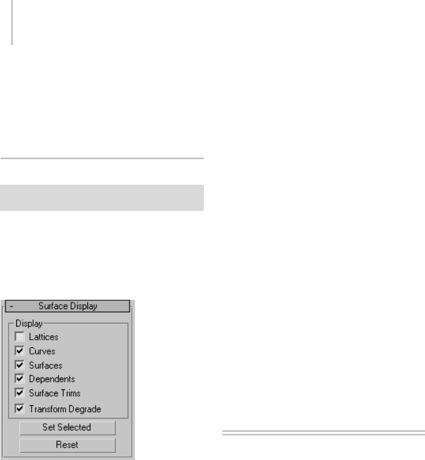
1252 Chapter 9: Surface Modeling
Set Selected—Applies the surface approximation
values active in the utility to all selected NURBS
objects.
Reset—Resets the values in the utility to the default
settings for a NURBS surface.
Surface Display Rollout
Utilities panel > Utilities rollout > More button > Utilities
dialog > Surface Approximation > Surface Display rollout
The controls in the Surface Display rollout are the
same as the display controls for NURBS surface
objects, with two additional buttons: Set Selected
and Reset.
Interface
Display group
Lattices—When on, displays control lattices, in
yellow lines. (You can change the lattice color
by using the Colors panel (page 3–799) of the
Customize User Interface dialog. The Curve CV
and Surface CV sub-object levels also have a local
Display Lattice toggle, which overrides this global
setting at the sub-object level. The Curve CV and
Surface CV settings are independent. In other
words,atthesub-objectlevel,youcanturnonthe
lattice for an object’s curves but not its surfaces,
or vice versa.
Curves—When on, displays curves.
Surfaces—When on, displays surfaces.
Dependents—When on, displays dependent
sub-objects.
Surface Trims—When on, displays surface
trimming. When turned off, displays all of a
surface even if it’s trimmed.
Transform Degrade—When on, transforming a
NURBS surface can degrade its display in shaded
viewports, to save time. This is similar to using
the Adaptive Degradation toggle for playing
animations. You can turn off this toggle so surfaces
are always shaded while you transform them, but
transforms can take longer to create.
Button set
Set Selected—Appliesthedisplaysettingsactivein
the utility to all selected NURBS objects.
Reset—Resets the values in the utility to the default
settings for a NURBS surface.
Tools for Low-Polygon
Modeling
Acoupleofutilitieshelpyoumanagethepolygon
countforscenesandanimationsthatmustnot
become too complex. Show Statistics, available
from the viewport right-click menu, lets you
monitor the number of polygons, vertices, etc.,
inthescene,aswellastheframespersecond
displayed. The Level of Detail utility, available
from the Utilities panel (page 3–778),letsyou
manage the complexity of an object in the scene.
For example, Level of Detail enables you to display
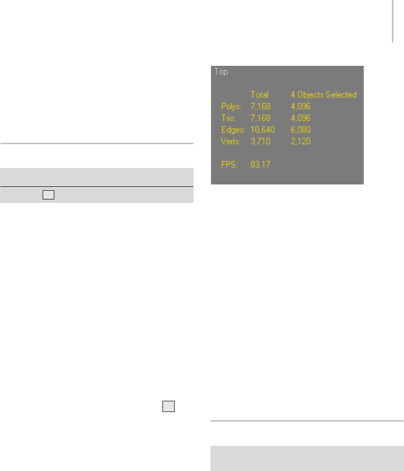
Show Statistics 1253
a complex object as simple geometry when the
object is at a distance from the camera.
Show Statistics (page 1–1253)
Level of Detail Utility (page 1–1253)
Show Statistics
Right-click a viewport label. > Show Statistics
Keyboard > 7
You can quickly access various statistics related to
your current selection and entire scene.
Note: These statistics are relevant primarily to mesh
and poly objects. Some statistics information
might be unavailable with certain other types of
object.
Procedure
To use the viewport statistics display:
1. Customize the statistics display on the
Customize menu > Viewport Configuration
dialog > Statistics panel.
2. Activate the viewport in which to display
statistics.
3. Toggle the statistics display by pressing 7or
right-clicking the viewport label and choosing
Show Statistics.
Interface
You can customize the viewport statistics by
turning on and off options on the Statistics (page
3–861) panel of the Viewport Configuration
dialog. The following statistics reflect all options
turned on.
The first column lists the statistics for the entire scene, while the
second only refers to the selected objects.
Polys —Displays the number of polygons in the
scene and selection.
Note: This is valid only for poly objects.
Tris —Displays the number of triangle faces in the
scene and selection.
Note: If you select a polygon in a poly object, this
option shows two or more triangles.
Edges —Displays the number of edges in the scene
and selection.
Verts —Displays the number of vertices in the
scene and selection.
FPS —The frames per second displayed in the
viewport.
LevelofDetailUtility
Utilities panel > Utilities rollout > More button > Utilities
dialog > Level of Detail
The Level Of Detail utility lets you construct an
object that alters its geometric complexity or level
of detail based on its size in the rendered image.
Youcreateseveralversionsofthesameobjecteach
with different levels of detail, group them as one,
and then run the Level Of Detail utility, which
automatically creates a special LOD controller as
a Visibility track. The LOD controller then hides

1254 Chapter 9: Surface Modeling
and unhides the objects in the group, depending
on their size in the rendered scene.
The main purpose of this utility is to save time in
renderingcomplexobjectsandinmanipulating
objects in the viewports. Since a portion of
rendering speed is directly related to the number
offacesthatmustberenderedinascene,usingthe
LevelOfDetailutilityletsyoureducethenumber
of rendered faces as an object reduces its apparent
size. In addition, you can use this utility to display
a simple stand-in for a more complex object in
the viewports. Since the stack is not calculated for
objects hidden in the viewports, you can speed
up viewport manipulation by using this utility
to substitute complex stack objects with simple
stand-ins.
Procedures
To set up an object for the Level Of Detail utility:
1. Create two or more objects that are identical
except for their complexity.
Note: It’s best to assign materials and mapping
coordinates, as well as all modifiers while the
objects are still separate.
2. Select all of the objects, and use the Align tool
to center all of them about a common center.
3. Group the objects.
4. Choose the Level Of Detail utility.
5. While the grouped object is selected, click the
Create New Set button.
Thenameoftheobjectswithinthegroup
appear in the Level Of Detail list, in order of
complexity; only the least complex object in the
group is displayed in the viewports, while all
otherobjectsaremadeinvisible.
6. UsethecontrolsintheLevelOfDetailrolloutto
adjust when the objects will switch their display
in the rendered scene.
To access an object’s stack:
1. Select the Level Of Detail object, and then
choose Group menu > Open.
2. In the Level Of Detail utility, choose the object
you want to access from the list window,
andthenturnonDisplayInViewports(or
double-click the object’s name in the list
window).
3. Select the object in the viewport.
4. Open the Modify panel to access that object’s
parameters.
5. When finished, choose Group menu > Close.
To assign materials within the group:
1. Select the grouped object.
2. Use Display In Viewports in the Level Of Detail
utility to display the grouped object you want
to assign the material to.
3. Drag the material from the Material Editor (or
the Browser) over to the object in the viewport.
4. Choose Assign To Object in the Assign Material
alert, and then click OK.
Note: Be sure and choose Assign To Object. If
you choose the default Assign To Selection, all
objectsinthegroupwillbeassignedthesame
material.
To dismantle a Level Of Detail object:
IfyoulookataLevelOfDetailobjectinTrack
View, you’ll see only the tracks for the sub-object
that’s currently displayed in the viewports. To see
all sub-objects in Track View, you need to turn off
Visible Objects.
If you need to dismantle a grouped Level Of
Detail object, and restore its sub-objects to their
independent states, follow these steps:
1. Open the Filters dialog in Track View, and turn
off Visible Objects in the Show Only group box.
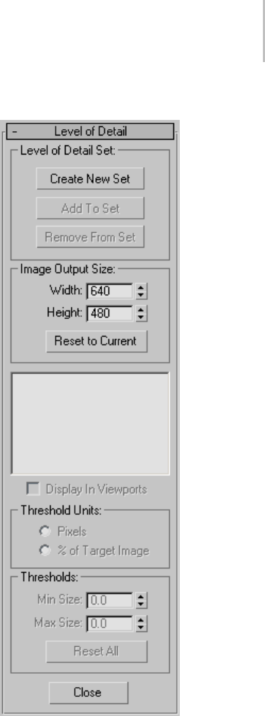
LevelofDetailUtility 1255
2. The tracks for all of the sub-objects in the Level
Of Detail object are now visible.
3. Open the hierarchy of each of the sub-objects,
and then select each of their Visibility tracks.
4. On the Track View toolbar, click the Delete
Controller button.
5. If you also want to remove the grouping, select
the grouped objects, and then choose Explode
in the Group menu.
Interface
LevelofDetailSetgroup
Lets you create a new set, and add or remove
objects from the current set.
Create New Set—Creates a new Level of Detail set
based on a currently selected group object.

1256 Chapter 9: Surface Modeling
Add To Set—Adds an object to the Level of Detail
set.Youmustfirstattachtheobjectyouwantto
add to the group object. To add an object to the
set, use Align to center the object with the group
object. Select the object you want to add, and then
choose Attach from the Group menu, and then
click the group object. Finally, click the Add to Set
button, and then click the object you want added.
Remove from Set—Removes the object highlighted
in the list window from the current set. Note that
the object then becomes visible in the viewports,
butisstillpartofthegroup.Toremovetheobject
from the group, choose Group menu > Open,
select the object you want removed, and choose
Group menu > Detach. Select the group object
again, and choose Group menu > Close.
Image Output Size group
Width/Height—The Width and Height spinners in
this area are set to the current rendering output
size each time you enter the Level of Detail utility.
Using the spinners, you can change this to any
resolution. If the percent of Target Image option is
selected, as you change the Target Image Size, the
thresholdvalueschangeaswell.
Reset to Current—Resets both spinners to the
current rendering output size.
List window—Lists all of the objects in the group by
complexity, with the least complex at the top of the
list. The numbers at the left of each object name
are the threshold values that indicate at what size
theobjectwillbedisplayedintherenderedscene.
The numbers can be one of two types of units,
pixels, or percentage of the target image. You set
thetypeofunitintheThresholdUnitsgroup.
Display in Viewports—Displays in the viewport the
object highlighted in the list window. Only one
object in the group is displayed in the viewports at
any time. As a default, the least complex object is
displayed, but you can look at the other objects
by highlighting them in the list and selecting this
item. Double-clicking the object name in the list
performsthesamefunction.
Threshold Units group
The options in this group box let you choose
between two types of threshold units. Switching
between these two options does not alter the
effect; it alters the method by which you set the
thresholds.
Pixels—The thresholds are determined by
specifying the maximum pixel size of the image
(measured diagonally). Use when you want to set
the transfer thresholds using absolute rather than
relative values.
%ofTargetImage—Sets the thresholds based on
thepercentageofthesizeoftheimage(measured
diagonally) relative to the size of the rendered
output.
Thresholds group
Min Size/Max Size—Sets the minimum size of the
object before it’s replaced by the less complex
object, and the maximum size of the object before
it’sreplacedbythemorecomplexobject. The
values vary depending on the current type of
Threshold Unit. The default threshold values are
initialized so that the most complex object is 100
percentoftheimageoutputsize.Theremaining
thresholds are set using an algorithm based on a
ratio of the number of faces between each object.
It assumes that all faces are the same size, and then
picks thresholds so that the faces would remain a
constant size as displayed on the screen. Usually,
this will provide the type of smooth transition you
need, but you can customize the threshold values.
The threshold values are interrelated between
the objects, so altering the minimum size of one
object, for example, will also alter the maximum
size of the next object.
Reset All—Resets all thresholds for all objects in
the list, using the previously described algorithm.

LevelofDetailUtility 1257
Tip: You can use the Level of Detail utility to create
objects that display very simple geometry in the
viewports, while displaying complex geometry
in the rendered scene. Create a grouped Level
of Detail object consisting of only two objects,
the complex object and the simple object. Select
thesimpleobjectinthelistwindowand,inthe
Thresholds are, set its Min Size and its Max Size
to 0. This will display the simple object in the
viewports, but the complex object will always
appear in the rendered scene, regardless of its
apparent size.
Close button
Close—Closes the utility.

1258 Chapter 9: Surface Modeling

index
Symbols & Numerics
1-rail sweep surface 1–1204
2 3 4 links 2–1111, 2–1150
2 feet down 2–988, 2–997
2.5D snap 2–35
2-point perspective 2–1392
2-rail sweep surface 1–1209
2-sided 3–855, 3–901
2D
2D coordinates rollout 2–1625
2D images 3–608
2D maps 2–1624
2D snap 2–35
2D map
glossary 3–901
32–bit floating-point output 3–613
3D
3D coordinates rollout 2–1663
3D maps 2–1662
3D snap 2–35
viewing and navigating 3D space 1–21
3D displacement shader (mental ray) 2–1714
3D DWF
exporting 3–555
glossary 3–901
3D map
glossary 3–902
3DS files
3DS import dialog 3–530
exporting 3–532
importing 3–530
3ds Max
bones 2–834, 2–1080
knowledge of 2–832
main window 1–9
materials 3–83
3dsmax.ini file 1–17 to 1–18
A
about
about MAXScript 1–xvii
buttons 2–1106
footstep animation 2–856
freeform animations 2–886
absolute 2–1150
absolute snap 2–35, 2–41
absolute/offset coordinate display 3–709
abut selected (video post) 3–329
acceleration (raytrace) 2–1531
acceleration techniques (raytracer) 2–1528
acceleration test (particle flow) 2–233
accuracy 2–120, 3–815
AccuRender materials
in 3ds Max 3–455
actions (particle flow) 2–141, 3–903
action recovery 2–121
adding 2–131
and order/priority 2–124
and time frames 2–141
editing parameters 2–131
order of 2–123, 2–130
activate all maps 1–50
activate options 2–974
activating
grid object 2–34
home grid 2–34
joint axes 2–485
maps 1–50
activating footsteps 2–865
active 2–1136
active link (glossary) 3–903
active time segment 2–286
active time segment (glossary) 3–904
active viewport 1–22
active/inactive footsteps 3–904
Index

1260 Index
ActiveShade 3–17
commands (quad menu) 3–22
floater 3–21
glossary 3–904
quick render 3–17
viewport 3–21
actual stride height 2–992, 2–995
actual stride length 2–992, 2–995, 2–997
actual stride width 2–992, 2–995, 2–997
adapt locks 2–871, 2–980, 3–905
adaptation 3–905
adapting
keyframes to edits 2–871
keys to footstep edits 2–871
adaptive antialiaser dialogs 2–1533 to 2–1534
adaptive control 1–167, 1–828, 2–1534, 2–1698
adaptive degradation
glossary 3–905
override 1–34
viewport configuration dialog 3–859
adaptive subdivision dialog 1–706
add
alpha compositor (video post) 3–381
atmosphere 2–1351, 3–304
contrast filter (video post) 3–343
cross fade compositor (video post) 3–381
default lights to scene 1–49
effect 2–1351
external event (video post) 3–340
fade filter (video post) 3–344
image alpha filter (video post) 3–344
image filter event (video post) 3–335
image input event (video post) 3–332
image layer event (video post) 3–337
image output event (video post) 3–339
lens effects filter (video post) 3–345
loop event (video post) 3–342
negative filter (video post) 3–345
note track (Track View) 2–552
pseudo alpha compositor (video post) 3–382
pseudo alpha filter (video post) 3–346
scene event (video post) 3–329
simple additive compositor (video post) 3–383
simple wipe compositor (video post) 3–383
simple wipe filter (video post) 3–347
starfield filter (video post) 3–347
time tag dialog 3–710
visibility track 2–556
add change option 2–1108
add keys
function curves 2–581
Track View toolbar 2–560
add layer 2–326, 2–334
add selection to current layer 3–667
add texture elements dialog 3–164
add to track set 2–591
add twist pose 2–950
add/edit DBR host dialog 3–128
adding
comments (particle system) 2–134
editablesplinevertices 1–297
footsteps 2–863
poses 2–1096
splines 1–303, 1–308
adding controllers to bipeds 2–896
additive opacity (glossary) 3–906
adjust animation range (track bar) 3–703
adjust color dialog
vertexpaint modifier 1–949
adjust pivot rollout 2–488
adjust talent pose option 2–1065
adjust transform rollout 2–489
adjusting
default envelope shape 2–1086
keys in Track View 2–875
link parameters 2–1091
normals and smoothing 1–166
object transforms 2–432
pivots 2–423
talent pose 2–1065, 3–906
Adobe Illustrator files
exporting 3–534
importing AI 88 format 3–533
advanced effects rollout 2–1341
advanced file link settings 3–431
advanced key info 2–306
advanced lighting
object properties 1–123
select advanced lighting rollout 3–44
advanced lighting override material 2–1601
advanced quad menu options 3–801
advanced ray-traced parameters rollout 2–1356
advanced rollout 1–791
advanced shaders rollout
mental ray material 2–1548
advanced surface approximation dialog 1–1245
AEC design elements 1–210
AEC extended 1–210
editing wall objects 1–228
foliage 1–214
railing 1–217
wall 1–223
affect region 1–557
soft selection rollout (EMesh) 1–963
soft selection rollout (NURBS) 1–1147
affine transformation (glossary) 3–906

Index 1261
after trajectory 2–944
age test 2–211
AI import dialog 3–524
airborne option 2–988, 2–995, 2–997
airborne periods 2–878, 3–906
aliasing/antialiasing
alias against background 3–826
and supersampling 2–1459
fast adaptive 2–1533
filters 1–567, 3–38
glossary 3–907
multiresolution adaptive 2–1534
align 1–462
align geometry dialog (edit poly) 1–679
and pivot point 2–488
camera 1–468
dialog 1–462
editable mesh objects 1–1011
editable mesh vertices 1–1011
flyout 1–462
grid to view 2–35
keys (Track View) 2–556
normals 1–465, 2–10
objects 2–8
selected left (video post) 3–328
selected right (video post) 3–328
to view (dialog) 1–468
to view (toolbar) 1–468
all bipeds 2–944
all links 2–1150
allow non-vertical jambs 1–210
alpha channel 3–272, 3–907
alpha compositor (video post) 3–381
alpha map (baking) 3–149
alternate 2–992, 2–995, 2–997
altitude (sunlight and daylight systems) 1–421
ambient
and diffuse map lock 2–1474
and raytrace materials 2–1514
color (glossary) 3–908
light 2–1276, 2–1279 to 2–1280, 3–908
lighting (rendered environment) 3–272
mapping 2–1497
ambient occlusion map (baking) 3–149
analysis of lighting 3–76
analyze errors 2–1017
analyze panel 2–1017
analyzing
Shockwave 3D files 3–585
W3D files 3–585
anatomy of biped 2–846
anchor (VRML97 helpers) 3–597
anchor patches 1–968
anchors 2–962
angle 1–286, 2–1070
transition editor 2–1051
angle of incidence 2–1276, 2–1279
angle separation 3–826
angle snap 2–37
angular dashpot 2–732
animatable IK attachments to 3ds Max objects 2–908
animated
bitmap 2–1450
material previews 2–1450
reference objects (particle flow) 2–178
texture 3–908
animating
a biped with footsteps 2–856
a tablecloth (FFD(cylinder) space warp) 2–95
attachment 2–433
cameras 2–1381
lens effects properties (video post) 3–349
lights 2–1282
links 2–430
materials 2–1449
NURBS models 1–1099
parameters 2–121
scene 1–8
shift+rotate 1–482
shift+scale 1–482
sub-object geometry 1–998
transforms 1–432
vertices 2–346
with applied IK 2–481
with IK solvers 2–446, 2–461, 2–472
with interactive IK 2–480
animating a quadruped 2–907
animating hair 1–520, 1–540, 1–545
animation
and particle system time frames 2–123
auto key mode 2–278
combining animations 2–1026
concepts 2–275 to 2–276
constraints 2–392
controllers 2–307, 3–909
dynamics & adaptation rollout 2–980
expanding tracks 2–886
glossary 3–909
hair and fur modifier 1–520, 1–540, 1–545
importing and exporting 2–921
importing from another scene 3–466
insert animation 1–114
layers 3–910
loading 3–474
mapping 3–478 to 3–479, 3–481
methods 2–275

1262 Index
NURBS 1–1091
preferences settings 3–828
previewing animations after attaching Physique 2–1084
sample animations in this release 2–920
saving 3–476
selecting and moving tracks 2–886
show ghosting 1–46
tips (NURBS) 1–1099
toggle animation mode 2–278
utilities 2–653
with radiosity 3–60
animation controls 3–716
animation layer weight 2–325 to 2–326
animation layers 2–325 to 2–326, 2–333 to 2–334, 3–690
animation layers toolbar 3–690
animation menu 3–681
bone tools 1–411
constraints 2–371, 2–392 to 2–393, 2–396, 2–398,
2–401, 2–406, 2–409
create bones 1–404
dummy 2–16
IK solvers 2–440, 2–473
make preview 3–168
parameter collector 1–138
parameter editor 1–129
previews 3–168
rename preview 3–170
view preview 3–170
wire parameters 2–411 to 2–412
animation mode
set key 2–280
animation modifiers 1–557
animationquadmenu 3–697
animation range
ignore 2–521
respect 2–521
animation workbench 2–1012
anisotropic highlights 2–1492
anisotropic shader
anisotropy mapping 2–1504
basic parameters rollout 2–1480
ankle attach option 2–846, 2–984
ankle tension 2–959
antialiasing 3–98, 3–939, 3–1005
append
.mfe file 2–1032
motion flow editor 2–1032
append footsteps 2–863, 2–936
applied ik
glossary 3–910
applied IK 2–439, 2–481, 2–491, 2–497
apply ease curve 2–584
apply ease or multiplier curve (Track View) 2–584
apply increment 2–962, 2–965
apply multiplier curve 2–584
applying materials 2–1405, 2–1409
arc 1–274
arc rotate 3–744
arch & design material
main reference 2–1549
overview 2–1562
tips & tricks 2–1569
architectural material 2–1535
advanced lighting override rollout 2–1540
and radiosity solution 2–1540
physical qualities rollout 2–1536
special effects rollout 2–1539
templates rollout 2–1536
archive
file menu 3–499
program (files preferences) 3–819
archiving scenes 1–19
area light rollout 2–1354
area light sampling rollout 2–1354
area lights 3–910
omni 2–1298
spotlight 2–1299
area omni light 2–1298
area shadows 3–911
area shadows rollout 2–1357
area spot light 2–1299
arms
arm link 2–984
resizing 2–852
turning on 2–846
array 1–450
arraying objects 1–484
button 1–450
creating 1–471
creating arrays 1–487, 1–489
dialog 1–450
flyout 1–448
using the array dialog 1–485
array dialog 1–450
array flyout 1–448
artificial light 2–1280
ASCII files: exporting 3–534
ASE files 3–534
aspect ratio 3–30, 3–911
assemblies
and groups 1–98
and selection sets 1–98
attach to 1–111
close 1–109
create 1–107
disassemble 1–110

Index 1263
explode 1–110
open 1–109
using 1–98
assembly commands 1–107
assembly heads helper objects 1–111
assembly menu
assemble 1–107
attach 1–111
detach 1–110
disassemble 1–110
explode 1–110
asset browser 3–504
internet download dialog 3–515
preferences 3–514
using 1–17
asset tracking
dialog 3–487
icons 3–498
open from vault 3–389
asset tracking dialog 2–920, 3–487
asset tracking dialog icons 3–498
asset tracking prompts 3–498
assign
controller (Track View) 2–546
controller rollout (motion panel) 3–774
material to selection 2–1441
object effects dialog 2–696
random colors 1–161
vertex colors utility 2–1734
assign controller rollout (character studio) 2–934
assign random colors 1–161
assign renderer rollout 3–35
assign to link 2–1089, 2–1150
assigning
colors to objects 1–159
controllers 2–292
materials 2–1405, 2–1409
associate bipeds with delegates 2–1199
associate objects with delegates 2–1196
assume skin pose 1–116
asterisk (in modifier stack) 1–508
atmospheres and effects
adding atmosphere 3–276
and raytracing 2–1528
atmospheric effect 3–272, 3–282, 3–284, 3–288
for atmospheric apparatus 3–304
for lights 2–1349
atmospheric apparatus 3–304
BoxGizmo 3–304
CylGizmo 3–306
SphereGizmo 3–307
attach
attach options 1–1018
attaching and importing 3ds Max objects 1–1120
controls dialog (block controller) 2–388
editable mesh edges 1–1011
editable mesh vertices 1–1011
editable patch object 1–986
object 1–968, 1–988
splines 1–295, 1–297, 1–308
to assembly 1–111
to groups 1–106
attach points/tendon 2–1147
attach to deforming mesh constraint 2–799
attach to node 2–1106
attach to rigid body constraint 2–798
attached links 2–1147
attaching
mesh to a biped using Physique 2–1106
tendon to another link 2–1096
attachment
animating 2–433
constraint 2–393
attachments (IK) 3–912
attenuation 2–1276, 2–1279, 3–912
and lights 3–821
parameters 2–1345
raytrace attenuation rollout 2–1706
attribute holder modifier 1–559
attributes (custom) 1–129
audio controller 2–309, 2–386
AudioClip (VRML97 helpers) 3–606
auto 2–1070
auto clip names 2–1027
auto expand
animated 2–527
base objects 2–527
keyable 2–527
materials 2–527
transforms 2–527
xyz components 2–527
auto key 2–278, 3–717
and set key 2–280
auto termination rollout 2–499
auto timing 2–992, 2–995, 2–997
AutoCAD
blocks 3–456 to 3–457
importing DWG and DXF files 3–536
importing DXF files 3–551
instanced objects 3–456
AutoCAD Architecture
files 3–444
materials 3–445
objects 3–444, 3–461
styles 3–461
AutoCAD blocks in 3ds Max 3–441

1264 Index
AutoCAD DWG/DXF import options dialog 3–536
AutoCAD, AutoCAD Architecture, and Revit
working with 3–440
autodesk inventor files
importing 3–552
Autodesk Vault 3–487
Autodesk VIZ files 3–525
autogrid 3–913
AutoGrid 2–7
automatic
auto archive 3–819
auto backup 1–19, 3–819
auto secondary (lens effects) 3–238
auto termination (IK) 2–499
automatic exposure control 3–295
unit conversion 3–815
automatic mapping rollout
rendering to texture 3–163
autoplay preview file 3–815
AVI files 3–168, 3–609
avoidance behavior 2–1164, 2–1211, 3–913
preventing collisions 2–1240
awning window 1–256
axis constraints 1–437, 3–687
and hierarchies 2–500
and rollouts 2–500
and snaps 2–41
axis constraints toolbar 3–687
axis order 2–916, 2–948
axis ordering 2–1012
axis tripod 1–45
and transform managers 1–433
and World Axis 1–424
axonometric views 1–24, 3–913
azimuth (sunlight and daylight system 1–421
B
B-spline (glossary) 3–913
backburner
network rendering 3–201, 3–208
Backburner 3–173
backburner command line control 3–215
backface cull on object creation 3–821
backfacing - ignore 1–996, 1–1011, 1–1019
background 1–44
and antialiasing 1–567, 3–38
color 3–272, 3–276
image 3–272
reset background transform 1–45
sample slot 2–1433
select background image 1–42
update viewport image 1–44
viewport 3–731
viewport background 1–38
VRML97 helpers 3–605
backlight (sample slot) 2–1432
backup
auto 3–819
backing up and archiving scenes 1–19
backup on save 3–819
files 3–819
recovered files 1–20
backward knees (creating characters with) 2–891
baked material rollout
rendering to texture 3–162
baking animation 2–120
baking textures 3–144
target map slot 3–150
texture elements 3–146
balance
animating 2–876 to 2–877
shifting 2–876
shifting for entire footstep animation 2–876
balance factor 2–876 to 2–877, 2–954, 3–914
balance parameters dialog 2–629
balance track 2–622
ballistic gait 2–878, 3–914
ballistic tension 2–846, 2–878, 2–945, 2–954, 3–914
barycentric
coordinates (glossary) 3–914
morph controller 2–300, 2–309
morph controller key info dialog 2–346
base layer 2–974
basic file link settings 3–429
basic key info 2–304
basic parameters rollout
materials 2–1470
PArray 2–258
basics
basic building blocks 1–155
creating and modifying objects 1–153
file linking 3–416
selecting objects 1–64
batch
rendering 3–201, 3–203, 3–208
batch file conversion (motion capture) 2–1065, 2–1075
batch rendering 3–201, 3–203, 3–208
backburner 3–201 to 3–202, 3–208
batch render dialog 3–203
batch render tool 3–203
cameras 3–201, 3–203, 3–208
error dialog 3–203
errors 3–203
network rendering 3–201, 3–203, 3–208
presets 3–203
quick start 3–201
scene states 3–201, 3–203, 3–208

Index 1265
using 3–202
batch rendering completed 3–203
before trajectory 2–944
behavior assignments and teams dialog 2–1200
behavior rollout 2–1211
behaviors 2–1159, 3–915
avoid 2–1211, 3–913
fabric 1–579
obstacle-avoidance 2–1164, 3–983
orientation 2–1214, 3–985
patch-based 3–991
path follow 2–1216, 3–992
repel 2–1218, 3–1003
scripted 2–1220, 3–1008
seek 2–1220, 3–1008
space warp 2–1221, 3–1013
speed vary 2–1222, 3–1015
surface arrive 2–1223, 3–1018
surface follow 2–1226, 3–1019
wall repel 2–1227, 3–1033
wall seek 2–1229, 3–1033
wander 2–1231, 3–1033
bend 2–990, 2–1136
bend links mode 2–895, 2–936, 2–952, 3–915
bend modifier 1–560
bend parameters (links) 2–1091
bending
center of mass track 2–914
footstep path 2–869
bevel
bevel modifier 1–562
bevel profile modifier 1–565
deformation 1–366
faces and polygons 1–1011
patches 1–986
types of beveling 1–366
bevel polygons dialog 1–1066
bezier
controllers 2–310
handle control 2–582
bezier curves 3–915
bias 2–950, 2–956, 2–1091, 2–1136
mental ray shadow maps 2–1360
bifold door 1–252
billboard (VRML97 helpers) 3–607
binding
objects 2–437, 2–461, 2–491
to space warp 2–58
vertices 1–297
BioVision motion capture data files 2–1065
BIP files 2–919 to 2–920, 2–1065, 2–1263, 3–916
adding to motion mixer 2–609
adjust time in motion mixer 2–615
adjustinginmotionmixer 2–611
combining motions 2–924
combining with mixer 2–604
export with motion mixer 2–624
filtering in motion mixer 2–612
loading 2–942
path 2–1041
saving 2–882, 2–941
transitions in motion mixer 2–616
biped 2–833, 3–916
add to motion mixer 2–607
and physique 2–834
assign controller rollout 2–934
body parameters 2–844, 2–846
center of mass 2–833
colored keys 2–1005
creating 2–844
display options 2–944
dummies 2–922
dynamics 2–833, 2–980
dynamics parameters 2–954
edit 2–1038
editing keys in Track View 2–875
figure files (.fig) 2–855
figure mode 2–847
IK key colors 2–1005
keyboard shortcuts 2–1006
layer 2–974
load motion file 2–936
moving keys 2–1004
naming 2–847
playback 2–936, 3–916
previewing motion 2–929
root object 2–846
select keys based on foot states 2–965
setting keys 2–904
shifting balance 2–876
structure 2–847
tracks in Track View 2–888
user interface 2–932
working with 2–843
biped apps rollout 2–935
biped balance, motion mixer 2–622
biped clips 2–649
biped colored keys 2–1005
Track View 2–1005
biped crowds 2–1172
biped dynamics 3–916
biped IK key colors 2–1005
biped links
selecting and rotating 2–895
biped object 2–636
biped playback 2–936

1266 Index
biped rollout 2–936
bipeds
and crowd simulation 2–1187
correcting posture 2–925
deleting 2–854
linking objects to 2–854
moving objects 2–890
posing 2–847
posing a biped 2–925
rotating objects 2–891
scaling after physique is applied 2–1099
visible in playback 2–944
bipeds dialog 2–643
birth event 3–916
birth operator 2–143
birthscriptoperator 2–145
bitmap map 2–1631
bitmap pager 3–828
bitmap pager statistics dialog 3–514
bitmap proxies 3–32
bitmap proxies dialog 3–496
bitmap/photometric path editor 3–510, 3–516
bitmaps
choosing 2–1635
display 3–840 to 3–841, 3–844
glossary 3–917
Material Editor 2–1631, 2–1635
path configuration 3–503, 3–811
path editor 3–510
blend
blend curve (NURBS) 1–1158
blend element parameters 3–140
blend material 2–1588
blend object (glossary) 3–917
blend surface (NURBS) 1–1183
blend from/to 2–1140
blend map (baking) 3–149
blend materials
limitations when baking textures 3–147
blend weight 1–807
blending
between links 2–1085, 2–1111, 2–1150
envelopes 2–1086
blending envelope display options dialog 2–1125, 2–1128
Blinn highlights 2–1493
Blinn shader basic parameters 2–1480
blizzard 2–251
BlobMesh object 1–331
block
controller 2–389 to 2–390, 2–392
block controller 2–313
block controllers (Track View) 2–1179
block reference 3–917
block/style parent 3–918
blocks 3–457
and linking to 3ds Max 3–918, 3–1031
AutoCAD 3–441, 3–456
AutoCAD and 3ds Max 3–438
material assignment 3–458
materials 3–458
multi-view 3–459
propagation 2–1432
blowup (render) 3–13
blue vertices 2–1150
blur
and blur offset (glossary) 3–918
particle motion blur 2–240
rendering effect 3–260
BMP files 3–610
body 2–960
horizontal tracks 2–846, 2–945
parameters (biped) 2–846
space 3–918
tracks 2–846
turning track 2–945
vertical tracks 2–846, 2–945
bomb space warp 2–105
bone tools 1–411
bone editing 1–411
fin adjustment 1–413
object properties 1–414
bones 1–404, 2–1080
and IK solvers 2–440, 2–472
bone base 2–944
bone tip 2–944
display 2–853
exporting 3–580
floating bones rollout (Physique) 2–1110
linking to follow objects 2–461
spline IK solver 2–477
stretch factor 1–415
used with physique 2–1079, 2–1082
using objects as 1–410, 2–440
using unlinked bones with Physique 2–1082
Boolean controller 2–316
Booleans
alignment 1–338
and editable splines 1–308
Boolean objects 1–338, 1–378, 1–388
Boolean operation (glossary) 3–919
colinear edges 1–338
combining objects that have materials 1–345
complexity between operands 1–338
coplanar faces 1–338
face normals 1–338
inverted meshes 1–338

Index 1267
material IDs 1–338
overlapping elements 1–338
surface topology 1–338
troubleshooting problems with 3–885
with maps and materials 1–338
bound vertex 1–297, 3–919
boundary conditions (and tendons) 2–1147
bounding box (and envelope creation) 2–1111
bounding box (glossary) 3–919
bounds (inner/outer) 2–1085
box
BoxGizmo 3–304
standard primitive 1–171
box caustics filter 3–106
box method 2–1242
box selected
render bounding box/selected dialog 3–16
branching events (particle flow) 2–123
break
spline at selected vertex 1–297
vertices 1–1011
breathe option (links) 2–1091, 2–1136
bricks 2–1658
bridge dialog 1–1067
bridge edges dialog 1–1068
brightness and contrast effect 3–265
browse 2–1070
browser
material/map 2–1412
browsing from 3ds Max 3–504
brush
styling hair with a 1–529
brush options 1–960
brush preset manager 3–692
brush presets 3–690
BSP method 3–129
BSP method, raytrace acceleration 3–1000
bubble motion rollout (PArray) 2–270
bubble motion with Particle Flow 2–123
bubble notification
communication center 3–716
buckets, distributed rendering 3–124
buffer mode 2–936
build face 1–1011
bulge angle display properties dialog 2–1127
bulge angles 2–1114, 2–1141, 3–920
adding 2–1095
changing 2–1095
choosing for editing 2–1095
color 2–1141
deleting 2–1095
parameters 2–1114
setting 2–1095
bulge editor 2–1096, 2–1106, 2–1114, 2–1135, 2–1141
bulge sub-object 2–1127, 2–1141
bulges 2–1111, 2–1113, 3–920
creating 2–1094
fine-tuning 2–1096
overview 2–1093
shaping 2–1096
workflow 2–1094
bump mapping 2–1506, 2–1539
bump shader (mental ray) 2–1716
button
2.5D snap 2–35
2D snap 2–35
3D snap 2–35
ActiveShade floater 3–21
align 1–462
align camera 1–468
align to view 1–468
angle snap 2–37
animate 3–717
arc rotate 3–744
array 1–450
auto key 3–717
bind to space warp 2–58
button sets (utilities) 3–779
clone and align tool 1–459
crossing 1–93
current frame 3–724
dolly camera 3–746
dolly light 3–751
dolly target 3–746, 3–751
edit current event 3–324
edit scene event (video post) 3–329
full screen 3–738
get material 2–1439
go forward to sibling 2–1447
go to end 3–724
go to frame 3–724
go to parent 2–1446
go to start 3–722
light falloff 3–753
light hotspot 3–752
lock selection 2–555
make unique (Material Editor) 2–1442
material and map type 2–1449
Material Editor 2–1427
Material Editor options 2–1436
maximize viewport 3–738
mirror 1–448
new sequence 3–323
next frame 3–724
normal align 1–465
open sequence 3–323

1268 Index
orbit/pan camera 3–749
orbit/pan light 3–755
pan (Track View) 2–595
pan (user interface) 3–743
percent snap 2–38
perspective 3–747
pick material from object 2–1448
place highlight 1–467
play/stop 3–723
previous frame 3–723
quick align 1–465
quick render 3–17
quick render (Production) 3–17
render scene 3–12
roll camera 3–747
roll light 3–753
save sequence 3–324
scale keys 2–559, 2–580
scale values 2–581
select and link 2–422
select and manipulate 2–15
select and move 1–439
select and rotate 1–439
select and uniform scale 1–441
select by material 2–1439
select by name 1–77
select object 1–77
selection center 1–447
selection lock 3–707
sets of modifiers 3–772
show curves 3–705
show end result 2–1446
snapshot 1–453
spacing tool 1–455
spinner snap 2–38
squash 1–442
transform coordinate center 1–447
truck camera 3–748
truck light 3–755
unlink selection 2–422
use pivot point center 1–446
zoom 3–739
zoom (Track View) 2–596
zoom all 3–740
zoom extents 3–740
zoom extents all 3–737
zoom extents all selected 3–737
zoom extents selected 3–740
zoom horizontal extents 2–595
zoom region 3–742
zoom region (Track View) 2–597
zoom selected object 2–588
zoom value extents 2–596
button appearance 3–803
BVH files 2–919, 2–1061, 2–1065, 2–1263, 3–920
by layer 3–920
bylayer 3–655
C
C-Ext 1–200
cache operator (particle flow) 2–197
CAL files 2–1070
calculation order (joint precedence) 2–467
calculator 1–12
calibrating marker files 2–1065
camera correction modifier 2–1392
camera effects rollout 3–101
camera map modifier
object space 1–567
world space 1–513
camera map per pixel map 2–1732
camera match
camera match helper 2–1391
camera match point 2–1391
camera match utility 2–1387
camera point 2–1391
CamPoint 2–1391
camera tracker
batch track rollout 2–678
camera tracker utility 2–667
error thresholds rollout 2–677
match move rollout 2–680
motion trackers rollout 2–673
move smoothing rollout 2–682
movie rollout 2–670
movie stepper rollout 2–676
movie window 2–671
object pinning rollout 2–683
position data rollout 2–679
requirements for camera tracking 2–669
troubleshooting 2–685
camera view
right-click menu 3–731
camera viewports 1–33, 3–745
cameras 2–1365, 2–1372
align camera button 1–468
animating 2–1381
camera object icons 2–1365
camera view 1–24
camera viewport controls 3–745
choosing for vertical views 2–1365
common parameters 2–1373
create camera from view 1–48
depth of field parameters (mental ray renderer) 2–1383
dolly or target 3–746
free 2–1370
match camera to view 1–468

Index 1269
multi-pass parameters 2–1383, 2–1386
orbit/pan 2–1381, 3–749
placing 1–7
roll 3–747
setting lens size 2–1373
target 2–1371
truck 3–748
using clipping planes to exclude geometry 2–1379
using horizon to match perspective 2–1380
using move and rotate to aim 2–1379
using transforms to aim 2–1379
with target 2–1371
zoom 2–1381
candela 3–965
canopy mode 1–214
cap holes modifier 1–569
cap surface 1–1195
capsule 1–195
capture viewport 1–35
car paint material and shader 2–1576
car-wheel constraint 2–757
cartoon shading 2–1605
casement window 1–257
category, hiding and unhiding objects by 1–72
caustics 3–92, 3–106
caustics (mental ray) 3–80
caustics and global illumination rollout 3–106
CCB files 1–950
cellular map 2–1664
center 1–435
center of mass 2–833, 2–933, 3–920
object 2–846
selecting tracks 2–888
shadow 2–846
shifting balance with 2–876
tracks in Track View 2–945
chains (kinematic) 2–471, 3–960
chamfer
and editable splines 1–297
chamfer curve (NURBS) 1–1161
ChamferBox 1–191
ChamferCyl 1–192
editable mesh edges 1–1011
glossary 3–920
chamfer dialog 1–1070
change of value over time 2–578
changed feature 1–334, 2–66, 2–543, 2–1546, 3–149,
3–398, 3–539
changing
biped body parameters 2–844
biped name 2–847
controller properties 2–291
initial biped anatomy 2–846
light objects 2–1282
link inheritance 2–434
smoothing 1–167
video system 2–1434
changing biped to bones 2–921
channel 1–285
channel (map) 3–966
channel info
skin utilities 2–700
channel info utility 2–1738
character 1–112
character assembly 1–102
and parameter wiring 1–104
create character 1–112
destroy character 1–115
insert animation 3–466
insert character 1–115
lock/unlock 1–115
save character 1–115
skin pose 1–116
character modeling 1–842
character studio
assign controller rollout 2–934
definition 2–831
file formats 2–1263
space warp behavior 2–1221
checker map 2–1638
child overlap 2–1130
children
don’t affect 2–489
choose directory dialog 3–808, 3–810
choose renderer dialog 3–36
choosing
child-to-parent precedence 2–469
colors for realism 2–1400
parent-to-child precedence 2–470
playback speed and frame rate 2–288
transform center 1–435
CIBSE files 3–921
cineon image file format dialog 3–610
circle 1–273
circular
falloff graph 3–254
circular arrays 1–489
circulating
materials 2–1432
clean multimaterial utility 2–1742
clean remove 1–1039
clear UVW mapping 1–933
clip
ratio 2–615
replace 2–634
timing 2–615

1270 Index
transition 2–1048
clip controllers 2–1179, 3–921
clip frame numbers
motion mixer 2–615
clip mode 2–1027
clip properties dialog 2–1027, 2–1045, 2–1059
clipping planes 2–1373, 2–1379, 3–921
clips 2–1045
combining 2–1026
create 2–1027
looping with motion-capture filtering 2–1061
menu 2–632
move 2–1027
path 2–1041
ClipState dialog 2–1253
clone 1–476
clone and align tool 1–459
clone options dialog (particle flow) 2–132, 2–136
cloning 1–476
clone 1–476
materials 2–1432
objects 1–453, 1–474, 1–483
shape sub-object selections 1–289
shift+move 1–479
shift+rotate 1–480
shift+scale 1–481
sub-object geometry 1–998
cloning characters 2–922
close
assembly 1–109
group (group menu) 1–105
close curve dialog 1–1228, 1–1235
cloth 2–778
cloth modifier 1–578
cloth simulation 1–571
collection 2–781
collision detection 1–572
dT messages during simulation 1–583
effect of geometry on 1–576
fabric behavior 1–579
garment maker modifier 1–607
how it works 1–576
mesh density 1–577
modifier 2–778
object properties 1–602
overview 1–571
troubleshooting and error codes in garment
maker 1–622
unitsofmeasure 1–579
cloth modifier 1–578
user interface 1–582
clothing design 1–575
CLR files 3–799
cmdjob.exe 3–215
codec (glossary) 3–921
cognitive controller 3–921
state dialog 2–1207
state transition dialog 2–1208
cognitive controller editor 2–1206
cognitive controllers 2–1170
coincident - making splines 1–842
collapse
collapse utility 1–966
stack 1–504, 1–966
vertices 1–1011
collapse controller tool (Track View) 2–522
collapse layer 2–326, 2–333
collapsing
animation tracks 2–886
layers 2–974
collections
cloth 2–781
creating and deleting 2–966
deforming mesh 2–794
loading and saving 2–966
rigid body 2–723
rope 2–792
soft body 2–788
collision 2–243
collision detection 2–891
cloth 1–572
collision tests (particle flow)
collision 2–212
collision spawn 2–215
collisions
storing and accessing 2–774
collisions rollout 2–810, 2–1240
color
and light 2–1276, 2–1279, 2–1331
and particle view display operator 2–131
and program state 1–12
and realism 2–1400
assigning to objects 1–159
balance (render effect) 3–265
bleeding 3–93
changing vertex color 1–1009
color bleeding 3–45
color selector 1–161
copying 1–165, 2–1452
display 1–52
illegal video colors 2–1434
name and color rollout 3–757
object color dialog 1–159
parameters 2–1345
selecting vertices by 1–652, 1–1029
temperature (light color) 2–1276

Index 1271
color clipboard files 1–950
color clipboard utility 1–165
color coding 2–945
color controls 2–1485
color modifier maps 2–1692
color palette
vertexpaint modifier 1–950
color RGB controller 2–317
color selector 1–161, 3–815
color space 3–1
colors
assign random 1–161
biped IK/FK keys 2–1005
biped keys in Track View 2–947
biped trajectories 2–1005
footsteps 2–869
in Track View 2–944
vertex type 2–1089
colors panel (customize UI) 3–799
COM 2–933
COM/DCOM server control utility 3–792
combining animations 2–1026
combining motions
motion mixer 2–604
combining objects 1–338, 1–378, 1–388
Combustion
adding workspace 3–135
combustion map 2–1639
combustion workspace file 3–611
command line
rendering 3–209, 3–211, 3–215
startup options 3–671
command panel
troubleshooting when missing 3–893
command panels
create 3–757
display 3–775
hierarchy 3–773
modify 3–758
motion 3–774
overview 3–756
utilities 3–778
command-line options (MAXScript) 3–783
command-line options (starting 3ds Max) 3–671
command-line rendering 3–209, 3–215
backburner command line 3–215
batch render 3–209
DOS 3–211
pre-render scripts 3–209, 3–215
commands provided only from the keyboard 3–669
comments
particle system 2–134, 2–206
comments on the documentation 3–874
common panel
render scene dialog 3–27
common parameters rollout 3–27
common procedures
video post 3–315
commonality 1–509
communication center 3–712 to 3–713
bubble notification 3–716
configure 3–713
new information 3–716
notifications 3–716
refresh content 3–715
settings 3–713
welcome wizard 3–713
compare dialog (loft objects) 1–374
compass helper object 2–27
complete map (baking) 3–147
component color - specular 3–1014
components
hair and fur feature 1–517
composite
glossary 3–922
map 2–1688
material 2–1589
composite materials
limitations when baking textures 3–147
compositor
compositor maps 2–1687
compound materials
glossary 3–922
kinds of 2–1587
compound objects 1–313
BlobMesh 1–331
Boolean 1–338, 1–378, 1–388
conform 1–324
connect 1–328
mesher 1–374
morph 1–314
ProBoolean 1–378
ProCutter 1–388
scatter 1–318
ShapeMerge 1–336
terrain 1–347
compound rigid bodies 2–722
concepts 3–88
cone 1–172
cone (spotlight) 2–1338
cone angle manipulator 2–27
cone caustics filter 3–106
configuration
network rendering 3–175
configuration settings 3–119

1272 Index
configure
communication center 3–713
Direct3D 3–844
driver 3–821, 3–840
key mode 3–725
modifier sets 3–772
OpenGL 3–841
presets (video post) 3–327
software display driver 3–840
system paths 3–810
time 3–725
track bar 3–703
user paths 3–808
utilities button sets 3–779
viewports 3–853
configure paths 3–808
configure preset dialog 3–33
configure system paths 3–810
plug-ins path configuration 3–814
configure user paths 3–808
bitmaps 3–189
external files 3–811
file i/o path configuration 3–810
FX files 3–811
using 3–189
conform
compound object 1–324
space warp 2–103
connect
to child link 2–1147
to parent link 2–1147
connect compound object 1–328
connect edges dialog 1–1070
connect parameter to shader dialog (mental ray) 2–1713
constant
coordinate system 3–815
facet shading 3–937
constrained point
glossary 3–922
constraint solver 2–736
constraint spaces 2–725
constraints 2–289, 2–392, 2–724
and bones 1–404
and cloth 1–580
angular dashpot 2–732
attachment 2–393
axis constraints 1–437, 3–687
breakable 2–735
car-wheel 2–757
concepts 2–725
constraint solver 2–736
constraint spaces 2–725
cooperative constraints 2–735
deformable constraints 2–795
hinge 2–747
linear dashpot 2–730
link 2–403
look-at 2–406
orientation 2–409
path 2–398
point-path 2–762
point-point 2–750
position 2–401
prismatic 2–754
rag doll 2–737
simple constraints 2–727
spring 2–727
surface 2–396
contact object (particle flow) 3–922
contacting us 1–xiv
containers (glossary) 3–922
continuity 2–956, 2–1091, 2–1136, 3–923
continuity level (glossary) 3–923
NURBS concepts 1–1091
continuous time frame 2–141
contour shading
mental ray 3–96
contrast filter (video post) 3–343
contrast sampling thresholds 3–98
control lattice (glossary) 3–923
control objects (IK) 2–435, 2–446
control points 2–1114, 2–1130, 2–1141, 2–1147, 3–923
and bulges 2–1096
and envelopes 2–1088
rotating 2–1088
control vertex (CV) 3–926
control vertex (glossary) 3–924
controller 3–924
controller menu, Track View 2–521
controller toolbar, Track View 2–540
controller type 2–333 to 2–334
controller window, Track View 2–512
controllers 2–295 to 2–297, 2–307, 2–375, 2–896
assigning 2–292
audio 2–309
barycentric morphing 2–309
bezier 2–310
block 2–313
Boolean 2–316
categories of 2–289
changing length 2–502
changing properties 2–291
changing range 2–502
collapsing procedural controllers 2–522
color RGB 2–317
copy 2–544

Index 1273
default settings 3–828
Euler XYZ rotation 2–318
expression 2–320
frame duration 2–502
general-purpose controllers 2–295
limit 2–335
linear 2–341
list 2–342
local euler XYZ rotation 2–344
look at 2–344
make unique 2–550
master point 2–346
morph 2–300
motion capture 2–347
noise 2–353
on/off 2–355
paste 2–545
point3 XYZ 2–317
position XYZ 2–356
properties 2–560
PRS 2–357
reaction 2–358
scale XYZ 2–371
script 2–372
slave 2–313
smooth rotation 2–374
specifying default 2–294
TCB 2–377
time duration 2–502
transform script 2–379
types of 2–289, 2–546
understanding 2–289
viewing types 2–289
waveform 2–381
working with 2–289
xref 2–383
controlling
colors 2–299
display performance 1–28
flipping on path 2–398
IK precision 2–463
object display 1–51
position 2–298
rotation 2–299
time 2–285
transforms 2–298
viewport rendering 1–27
controls
camera viewport 3–745
light viewport 3–750
perspective and orthographic 3–738
special 1–12
viewport 3–735
conversion modifier
turn to mesh 1–871
turn to patch 1–873
turn to poly 1–874
convert 2–936
between footstep and freeform animations 2–885
data in motion capture buffer 2–1065
from buffer 2–1065
to freeform 2–886
to freeform/footsteps dialogs 2–999
convert curve dialog 1–1225
convert surface dialog 1–1227
convert to mesh 2–206
converting
event-level selection to particle level 2–138
TRC into CSM 2–665
convex hull property (glossary) 3–924
cool (glossary) 3–924
cooperative constraints 2–735
coordinate display (mouse position) 3–708
coordinate space 3–924
coordinate system 1–443
coordinates
absolute/offset display 3–709
barycentric (glossary) 3–914
coordinate display 3–708
coordinate system 1–443
coordinates rollouts 2–1625, 2–1663
mapping 2–1405
copies 1–472
creating 1–471
overview 1–472
copy 2–1141, 2–1147
a material, map, bitmap, or color 2–1418
footsteps 2–990
pose 2–962
poses and postures 2–910
posture 2–962
selected cross section 2–1114
copy biped animation to clip dialog 2–635
copy controller 2–544
copy keys 2–579
copy layer 2–325 to 2–326
copy map dialog 2–1451
copy tangent handles 1–297
copy time (Track View) 2–568
copy tracks 2–926
copy/paste rollout 2–966
copying
actions, events (particle flow) 2–127, 2–132, 2–134
and pasting items/objects 2–575 to 2–576
colors 1–165, 2–1452
copy controller (Track View) 2–544

1274 Index
copy time (Track View) 2–568
copy track (Track View) 2–568
joint parameters 2–495
materials 2–1409, 2–1432
modifiers 2–544
patch surface 1–968
presets 3–437
splines 1–308
transform keys 2–283
CPY files 2–1263
crash recovery 1–20
crease
at link’s joint 2–1140
at parent’s joint 2–1140
create
clip 2–1027, 2–1045
envelopes 2–1111
footsteps 2–988
keys for inactive footsteps 2–865, 2–990
layer 2–974
random motion 2–1035, 2–1055
script 2–1030, 2–1048
separate tracks for biped arms 2–980
shared motion flow 2–1039, 2–1056
transition 2–1045, 2–1051
unified motion 2–1038
create assembly (assembly menu) 1–107
create assembly dialog 1–107
create biped rollout 2–844
create camera from view 1–48
create character 1–112
create key dialog 2–284
create layer 2–326, 2–334
create material preview dialog 2–1452
create menu 1–347, 3–675
AEC objects 1–214, 1–217, 1–223, 1–232, 1–235,
1–239, 1–243, 1–251 to 1–252, 1–256 to 1–261
cameras 2–1365, 2–1370 to 2–1371
compound objects 1–318, 1–328, 1–331, 1–336, 1–338,
1–352
extended primitives 1–186
lights 2–1272
NURBS 1–1102 to 1–1103, 1–1106, 1–1110
particles 2–237
patch grids 1–993 to 1–995
photometric lights 2–1302 to 2–1305, 2–1307, 2–1309
shapes 1–262, 1–270, 1–272 to 1–274, 1–276 to 1–278,
1–281 to 1–282, 1–284 to 1–288
standard lights 2–1288 to 2–1290, 2–1292 to 2–1293,
2–1295
standard primitives 1–170
create method rollout 2–1242
create multiple footsteps 2–988, 2–992
jump 2–988, 2–997
run 2–988, 2–995
walk 2–988, 2–992
create new layer 3–667
create new map files 2–332
create out of range keys 2–533
create out-of-range keys utility (Track View) 2–562
create panel 1–154, 3–757
cameras 2–1365
helpers 2–2
lights 2–1272, 2–1301
space warps 2–55
systems 1–404
create position lock key 2–310
create rotation lock key 2–310
create shape (editable patch) 1–988
creating
1-rail sweep surface 1–1204
2-rail sweep surface 1–1209
a script 2–1045
an object 1–157
animated material previews 2–1450
arrays 1–471
biped character 2–844
biped skin 2–1076
blend surface 1–1183
bulges 2–1094
cap surface 1–1195
chamfer curve 1–1161
circular and spiral arrays 1–489
copies 1–471
crowd system 2–1155
curve sub-objects 1–1151
custom sample object 2–1425
CV curve on surface 1–1172
CV curve sub-object 1–1153
CV surface 1–1103
CV surface sub-object 1–1179
dependent curve point 1–1220
dependent curve-curve point 1–1223
dependent curves 1–1151
dependent offset point 1–1219
dependent surface point 1–1222
dependent surface-curve point 1–1224
dependent surfaces 1–1177
editable mesh edges from shapes 1–1006
editable mesh vertices 1–1011
extrude surface 1–1188
faces 1–1011
fillet curve 1–1164
fillet surface 1–1216
footsteps 2–863

Index 1275
footsteps automatically 2–862
freeform animations 2–886
independent surfaces from NURBS curve
objects 1–1114
individual footsteps 2–863
iso curve 1–1168
lathe surface 1–1190
linear arrays 1–487
mirror curve 1–1160
mirror surface 1–1187
models with NURBS 1–1094
multicurve trim surface 1–1214
multiple footsteps 2–862
multiple slices 1–1019
multisided blend surface 1–1213
normal projected curve 1–1169
NURBS curves from splines 1–1115
NURBS CV curve 1–1110
NURBS models 1–1079
NURBS point curve 1–1106
NURBS sub-objects 1–1081
NURBS surfaces 1–1101, 1–1116
objects (basics) 1–153
offset curve 1–1159
offset surface 1–1186
particle emitter 2–239
particle system 2–238
particles 2–143, 2–145
physique links and envelopes 2–1111
physique modifier 2–1083
point curve on surface 1–1175
point curve sub-object 1–1155
point curve with curve fit 1–1157
point sub-objects 1–1078, 1–1219
point surface 1–1102
point surface sub-object 1–1181
primitives from the keyboard 1–169
ruled surface 1–1193
shapes 1–262
skin 2–1076
sub-objects 1–1177
surface edge curve 1–1177
surface offset curve 1–1167
surface sub-objects 1–1177
surface-surface intersection curve 1–1166
tendons 2–1096
transform curve 1–1157
transform surface 1–1182
U loft surface 1–1196
UV loft surface 1–1200
vector projected curve 1–1171
creation method rollout 1–354
creation parameters 2–844
glossary 3–925
cross fade compositor (video post) 3–381
cross section editor viewport options 2–1141
cross sections 1–282, 1–284 to 1–288, 1–623, 1–842,
2–1108, 2–1114, 2–1130, 2–1141, 2–1147, 3–925
and bulges 2–1096
and envelopes 2–1088
and tendons 2–1147
initialization 2–1125
parameters 2–1114
view (bulge editor) 2–1096
cross-hairs cursor 3–815
crossing selection 1–93
CrossSection modifier 1–623
crowd
behaviors 2–1159, 2–1164
creating crowd systems 2–1155
crowd object 2–1157
definition 3–925
delegate object 2–1159
keyboard shortcuts 2–1182
with bipeds 2–1172
crowd animation
and bipeds 2–1187
ClipState dialog 2–1253
motionclip parameters dialog 2–1252
orientation behavior 2–1214
path follow behavior 2–1216
repel behavior 2–1218
scripted behavior 2–1220
seek behavior 2–1220
speed vary behavior 2–1222
surface arrive behavior 2–1223
surface follow behavior 2–1226
synthesis dialog 2–1246
user interface 2–1182
vector field space warp 2–1241
wall repel behavior 2–1227
wall seek behavior 2–1229
wander behavior 2–1231
working with 2–1154
crowd behaviors
path follow 2–1162
seek 2–1162
wall seek 2–1162
crowd helper object 2–1187, 3–925
crowd object
associate bipeds with delegates dialog 2–1199
behavior assignments and teams dialog 2–1200
behavior rollout 2–1211
collisions rollout 2–1240
edit multiple delegates dialog 2–1197

1276 Index
geometry rollout 2–1240
global clip controller 2–1241
icon size 2–1240
object/delegate associations dialog 2–1196
priority rollout 2–1235
scatter objects dialog 2–1189
select behavior type dialog 2–1205
select delegates dialog 2–1205
set start frames dialog 2–1237
setup rollout 2–1188
smoothing rollout 2–1238
solve rollout 2–1232
state dialog 2–1207
state transition dialog 2–1208
crowd simulation
avoid behavior 2–1211
cognitive controller 2–1206
solving 2–1168
crowd system 3–925
CS amplitude option (links) 2–1091, 2–1136
CSM files 2–919, 2–1061, 2–1065, 2–1263, 3–925
cube method 2–1242
cubic morph controller 2–300
CUI files 3–804 to 3–806
current bulge angle 2–1114, 2–1141
current event (video post) 3–324
current frame 3–701, 3–724
current value editor 2–533, 2–565
currentdefaults.ini 3–790
currently assigned links only 2–1150
currently installed driver 3–821
curve editor 2–501, 2–507, 2–535, 2–1002
display menu 2–530
modes menu 2–521
curve view 3–925
curves
curve approximation 1–1238
curve fit 1–1157
curve point 1–1220
curve-curve intersection point 1–1223
curve-curve point 1–1223
freeze non-selected 2–587
function 2–837, 2–1008
curves menu
Track Vi ew 2–525
curves toolbar 2–535
custom attributes 1–129
custom grid 2–20
custom splash screen 1–17
custom UI and defaults switcher 3–789
custom UI scheme 3–804
customize
keyboard shortcut 2–1432
toolbar 2–1432
transitions 2–1034
customize menu 3–683
configure system paths 3–810
configure user paths 3–808
customize user interface 3–792
grid and snap settings 2–41
load custom UI scheme 3–805
lock UI layout 3–788
plug-in manager 3–788
preferences 3–815
revert to startup UI layout 3–807
save custom UI scheme 3–806
show UI 3–788
viewport configuration 3–853
customize user interface 3–792
colors 3–799
keyboard shortcuts 3–793
load UI scheme 3–805
lock UI layout 3–788
menus 3–798
overview 3–785
quad menus 3–795
revert to startup layout 3–807
save UI scheme 3–806
shortcuts 3–793
toolbars 3–794
customizing biped characters in figure mode 2–847
customizing user interface
Track View 2–599
cut
and slice 1–1011, 1–1019
and snaps 1–1019
time (Track View) 2–567
cut time (Track View) 2–567
cutout mapping 2–1540, 2–1542
cutting hair 1–529
CV 3–926
CV curve
CV curve 1–1110
CV curve (glossary) 3–926
CV curve on surface 1–1172
CV curve sub-object 1–1153
CV sub-objects 1–1085
CV surface
CV surface 1–1103
CV surface (glossary) 3–926
CV surface sub-object 1–1179
CWS file 3–135
CWS file (combustion workspace) 3–611
cycling
animation 2–551

Index 1277
cylinder
chamfer 1–192
CylGizmo 3–306
standard primitive 1–177
cylindrical area omni light 2–1298
D
damper 1–396, 2–66
damping joint action 2–466
dashpots
angular 2–732
linear 2–730
data files
path for 3–813
data management
asset tracking dialog 3–487
open from vault 3–389
daylight
IES sky 2–1312
IES sun 2–1309
DDS files (glossary) 3–611
deactivate all maps 1–50
deactivate footsteps 2–865, 2–990
decay 2–1345
default
controller settings 2–294, 3–828
controllers 2–294
heights 2–1
keyboard shortcuts 1–900, 2–140, 2–510, 2–1006,
2–1111, 2–1182, 3–871
lighting 2–1272, 2–1274
material settings 2–1442
tangent types 3–721
default color 2–1141
default scanline rollout 3–38
default tangent types 3–721
defaults
setting 3–790
setting and changing 1–17
switching 3–789
define
append 2–1048
inser below 2–1048
insert above 2–1048
script 2–1048
defining
search terms (HTML help viewer) 3–876
time tags 3–710
deflector space warp 2–90
deflector space warps
deflector 2–90
PDynaFlect 2–81
POmniFlect 2–78
SDeflector 2–87
SDynaFlect 2–85
SOmniFlect 2–84
UDeflector 2–89
UDynaFlect 2–86
UOmniFlect 2–85
deform
deform bevel 1–366
deform fit 1–367
deform scale 1–364
deform teeter 1–365
deform twist 1–364
deformable bodies 2–777
cloth 2–778
constraints 2–795
deforming meshes 2–793
ropes 2–789
soft bodies 2–783
soft selection 2–800
deformable constraints 2–795
attach to deforming mesh 2–799
attach to rigid body 2–798
fixing vertices 2–796
keyframe points 2–797
deformable envelopes 2–834, 2–1085, 2–1090, 2–1108,
2–1111, 2–1130, 3–927
deformation 2–1083, 3–927
deformation spline 2–1083, 2–1085, 2–1091, 2–1135,
3–927
deformations (and loft objects) 1–363, 1–368
deforming meshes 2–793
collection 2–794
degradation override 1–34
degree 1–1091, 3–927
degree of freedom and rotating links 2–891
delegate
adjusting parameters 2–1159
geometry parameters rollout 2–1183
motion parameters rollout 2–1183
delegates 2–1157
definition 3–928
helper objects 2–1183, 3–928
using bipeds with 2–1172
delete 1–95, 2–1141, 2–1147
biped 2–854
bulge angle 2–1114, 2–1141
bulge angles 2–1095
bulge cross sections 2–1096
clip/transition 2–1027, 2–1045
control points 2–1114
controller 2–549
cross section slice 2–1114
current event (video post) 3–324
footsteps 2–869, 2–990

1278 Index
key 2–904, 2–956, 2–962
keys 2–554, 3–703
layers 2–974
maps 2–1413
material 2–1413
mesh modifier 1–626
operator (particle flow) 2–146
patch modifier 1–627
Schematic View 3–652
script 2–1030, 2–1048
selected keys (track bar) 3–703
spline modifier 1–627
tendons 2–1096
time (Track View) 2–567
Track Vi ew 2–598
transition 2–1051
transitions 2–1034
delete keys 2–502, 2–554
delete selected animation 3–698
delete time (Track View) 2–567
delete Track View 2–598
delete twist pose 2–950
delete UVW mapping 1–933
deleting
blocks of time 2–567
editable mesh edges 1–1011
editable mesh vertices 1–1011
isolated editable mesh vertices 1–1011
particles 2–146
patch surfaces 1–968
splines 1–308
vertices 1–297
dent map 2–1667
dependencies (views menu) 1–47
dependent 3–928
dependent sub-objects 1–1087, 3–928
depot (particle view)
display of 2–129
glossary 3–928
depth of field 2–1383, 3–90, 3–101, 3–269
description panel (particle view)
display of 2–129
glossary 3–928
deselect all 1–88
Design Web Format 3–555
designing clothing (garment maker) 1–575
designing materials 2–1395
destination clip
transition editor 2–1051
destination directory 2–1075
destroy character 1–115
detach 2–1147
detach (assembly) 1–110
detach (group menu) 1–106
detach dialog (edit poly) 1–679
detach dialog (NURBS curve/surface) 1–1228
editable mesh vertices 1–1011
editable patches 1–986
patch surface 1–968
DGS material (mental ray) 2–1580
dgs material shader (mental ray) 2–1717
diagnostics
mental ray renderer 3–123
dialog
asset tracking 3–487
bevel polygons 1–1066
bitmap pager statistics 3–514
chamfer 1–1070
color selector 1–161
connect edges 1–1070
extrude polygons 1–1072
filter selected euler tracks (Track View) 2–564
flatten mapping 1–907
MAXScript debugger 3–783
mixer transition editor 2–638
normal mapping 1–908
pelt map parameters 1–909
pick nodes 2–641
pivot selection 2–959
prompts 3–498
relax tool 1–912
render UVs 1–914
shared motion flow 2–1039, 2–1056
track sets editor 2–591
unfold mapping 1–919
unwrap options 1–920
weight tool 1–807
XRef objects 3–397
dialogs
bitmap proxies 3–496
global settings and defaults for bitmap proxies 3–496
toggling 3–670
dielectric material shader (mental ray) 2–1719
different ambient and different diffuse materials
dialog 3–512
diffuse
diffuse color (glossary) 3–929
diffuse distribution 2–1323
diffuse level 2–1489
diffuse level mapping 2–1499
diffuse mapping 2–1498
roughness mapping 2–1500
diffuse map (baking) 3–147
diffuse parameters rollout 3–143
diffuse texture element rollout 3–143
direct manipulation mode 1–1022

Index 1279
Direct3D driver 3–838, 3–843 to 3–844
Direct3D driver setup dialog 3–843
directional parameters 2–1348
directories
for network rendering 3–187
mounting 3–188
sharing 3–188
DirectX 10 3–847
DirectX 9 shader material 2–1613
DirectX 9 shaders, FX file 3–946
DirectX shaders 2–1464, 2–1613 to 2–1614
disable layer 2–325 to 2–326
disable particle system 2–121
disabling playback 2–1084
disassemble 1–110
disc (circular) area light 2–1299
displace
disp approx modifier (OSM) 1–628
displace mesh (world space) 1–514
displace modifier (OSM) 1–629
displace NURBS (world space) 1–515
displace space warp 2–76
displacement mapping 1–628, 2–1511, 2–1539
displacement shading
mental ray renderer 3–96
display
backface cull 3–775
coordinate display 3–708
cross-hairs cursor 3–815
display controls for NURBS models 1–1117
display driver (specifying at startup) 3–671
display floater 3–775
display floater (Schematic View) 3–651
display image 3–502
display operator (particle flow) 2–202
display performance 1–28
display plane 2–6
display properties rollout 1–55
grid settings 3–709
hide/unhide (glossary) 3–951
hide/unhide objects 3–775
key bracket display 3–828
layer properties 3–656
line parameters for NURBS surfaces 1–1119
marker 2–1065
nth frame 3–821
NU scale warning 3–815
options/preferences 2–847, 2–853, 2–931, 2–944,
2–1090, 2–1130, 2–1141
properties 3–775
reflectance 2–1430
selection floaters 1–79
stack collapse warning 3–815
topology-dependence warning 3–815
track bar 3–707
trajectories 2–931
transmittance 2–1430
world axis 3–821
display color rollout 1–52
display driver setup dialog 3–838
display menu
curve editor 2–530
particle view 2–129
display menu (Schematic View) 3–644
display panel 3–775
display color rollout 1–52
display properties rollout 1–55
freeze rollout 1–54
hide by category rollout 1–52
hide rollout 1–53
link display rollout 1–58
object display 1–51
display rollout 1–791, 2–812
hair and fur modifier 1–549
display subtree 2–1130
display trajectories;trajectories,displaying 2–957
displaying
links 2–421
selected key statistics (Track View) 2–595
selected keys 2–594
distance
distance from origin (accuracy setting) 3–815
measuring 2–13, 2–15
distributed bucket rendering rollout 3–124
distributed maps 3–124
distributed rendering 3–124, 3–1001
distribution
materials 2–1432
dithering (glossary) 3–930
divide
edges 1–1019
editable mesh edges 1–1011
faces 1–1011
segments 1–303
divisions 2–1114, 2–1141
docking 3–930
documentation for 3ds Max 1–xiv
DOF 2–1383, 3–269
dolly
camera 3–746
light 3–751
target 3–746, 3–751
don’taffectchildren 2–489
donut 1–276
doors 1–210, 1–246
bifold 1–252

1280 Index
pivot 1–251
sliding 1–251
dope sheet 2–501, 2–507, 2–1002
modes menu 2–521
toolbars 2–538
Dope Sheet
editing footstep timing 2–869
DOS
command-line rendering 3–211
double support 2–988, 2–992, 3–930
double-sided 3–901
double-sided material 2–1591
download options (asset browser) 3–515
drag and drop
and copied/instanced maps 2–1451
and instanced objects 3–456
content from web pages 3–523
maps and materials 2–1423
modifier 1–499
sub-object material assignment 2–1424
with i-drop indicator 3–523
drag space warp 2–66
draw control points 2–1114
draw in profile view 2–1114
draw links as lines 3–821
drawing aids 2–1, 2–52
DRF files 3–527, 3–529
driver setup/configuration 3–838, 3–840 to 3–841, 3–844
dummies 2–922
dummy helper object 2–16
dummy object (glossary) 3–930
dummy objects
using 2–429
duplicate name dialog (material library) 2–1453
DWF
exporting 3–555
DWG files 3–931
exporting 3–550
importing 3–536
DWG/DXF import options dialog 3–536
geometry panel 3–539
layers panel 3–544
spline rendering panel 3–545
DXF files 3–931
exporting 3–552
importing 3–536, 3–551
dynaflectors 2–81, 2–85 to 2–86, 3–931
dynamic names (particle flow) 2–131
dynamics 2–122, 3–916, 3–932
and footsteps 2–1002
dynamics blend 2–945, 2–954, 3–932
hair and fur modifier 1–520, 1–540, 1–545
options 2–846
dynamics & adaptation rollout 2–980
dynamics deflectors 2–81, 2–85 to 2–86
dynamics objects 1–395
dynamics rollout
hair and fur modifier 1–545
dynamics utility 2–686
dynamics properties rollout (Material Editor) 2–686,
2–1479
edit object dialog 2–696
edit object list dialog 2–700
E
ease curve
applying 2–584
deleting 2–585
enable toggle 2–585
glossary 3–932
ease options
key info rollout 2–958
transition editor 2–1051
ease out-of-range types (Track View) 2–585
edge - definition 3–932
edge count 1–1253, 3–861
edge visibility threshold 1–1006
edges
aligning 1–1011
and rendering 3–826
attaching 1–1011
chamfer 1–1011
creating shapes from 1–1006
cut and slice 1–1011
deleting 1–1011
divide 1–1019
dividing 1–1011
extruding 1–1011
make planar 1–1011
rotating 1–1011
welding 1–1011
edit
alpha compositor (video post) 3–381
biped 2–1038
button appearance 3–803
clip 2–1048
contrast filter (video post) 3–343
cross fade compositor (video post) 3–381
current event (video post) 3–324
external event (video post) 3–340
fade filter (video post) 3–344
filter event (video post) 3–335
footsteps 2–936, 2–1000
freeform 2–1000
ghosts 2–1034
image alpha filter (video post) 3–344
image input event (video post) 3–332

Index 1281
layer event (video post) 3–337
lens effects filter (video post) 3–345
loop event (video post) 3–342
negative filter (video post) 3–345
normals 1–634
output image event (video post) 3–339
preset settings 3–438
pseudo alpha compositor (video post) 3–382
pseudo alpha filter (video post) 3–346
range bar (video post) 3–327
ranges (Track View) 2–573
scene event (video post) 3–329
simple additive compositor (video post) 3–383
simple wipe compositor (video post) 3–383
simple wipe filter (video post) 3–347
starfield filter (video post) 3–347
tag 3–711
time 2–566, 2–1002
time tag dialog 3–711
transition 2–1048
transitions 2–1034
edit commands 1–94, 2–1130
and envelopes 2–1088
edit curve on surface dialog 1–1229
edit geometry rollout
edit poly modifier 1–673
editable mesh 1–1011
editable poly 1–1055
edit keys 2–1002
edit keys (Track View) 2–528, 2–554, 2–559
edit keys mode 2–508
edit macro button dialog 3–803
edit menu 3–673
clone 1–476
delete 1–95
edit named selections 1–84
fetch 1–95
hold 1–95
move 1–439
object properties 1–117
particle view 2–127
region 1–92
rotate 1–439
scale 1–440
select all 1–87
select by 1–88
select by color 1–88
select by name 1–88
select invert 1–88
select none 1–88
select region crossing 1–93
select similar 1–88
selection method 1–92
transform type-in 1–431
undo/redo 1–94
edit menu (Schematic View) 3–642
edit modifiers
and editable objects 1–506
edit mesh modifier 1–634
edit patch modifier 1–638
edit poly modifier 1–640
edit spline modifier 1–680
edit multiple delegates dialog 2–1197
edit named selections 1–84
edit normals
edit normals modifier 1–634
edit object dialog 2–696
edit object list dialog 2–700
edit poly
align geometry dialog 1–679
bevel polygons dialog 1–1066
border 1–663
bridge borders/polygons dialog 1–1067
bridge edges dialog 1–1068
chamfer dialog 1–1070
connect edges dialog 1–1070
detach dialog 1–679
edge 1–656
extrude edges dialog 1–1073
extrude polygons along spline dialog 1–1071
extrude polygons dialog 1–1072
extrude vertices dialog 1–1073
hinge from edge dialog 1–1073
inset polygons dialog 1–1074
meshsmooth selection dialog 1–1074
object 1–651
paint deformation rollout 1–1064
polygon/element 1–666
preserve map channels dialog 1–1075
relax dialog 1–1076
tessellate selection dialog 1–1077
vertex 1–652
weld dialog 1–1077
weld edges dialog 1–1077
weld vertices dialog 1–1077
edit poly modifier 1–640
edit geometry rollout 1–673
selection rollout 1–647
edit ranges 2–573
edit ranges mode (Track View) 2–509, 2–528
edit texture surface dialog 1–1230
edit time mode (Track View) 2–528, 2–566
edit time tag 3–711
edit track set 2–591
edit UVWs dialog 1–888
menu bar 1–895

1282 Index
edit wire 2–412
editable mesh 1–996, 3–932
aligning 1–1011
edge 1–1006
edit geometry rollout 1–1011
element 1–1009
exploding 1–1011
face 1–1009
object 1–1001
polygon 1–1009
selection rollout 1–999
vertex 1–1003
editable objects and edit modifiers 1–506
editable patch 1–968
attach 1–986
changing vertex type 1–986
deleting vertices 1–986
detach 1–986
edge 1–980
element 1–984
geometry rollout 1–986
handle 1–979
object 1–974
patch 1–981
vector 1–979
vertex 1–975
visibility of 1–989
editable poly 1–1022
bevel polygons dialog 1–1066
border 1–1044
bridge borders/polygons dialog 1–1067
bridge edges dialog 1–1068
chamfer dialog 1–1070
connect edges dialog 1–1070
edge 1–1035
edit geometry rollout 1–1055
extrude edges dialog 1–1073
extrude polygons along spline dialog 1–1071
extrude polygons dialog 1–1072
extrude vertices dialog 1–1073
glossary 3–933
hinge from edge dialog 1–1073
inset polygons dialog 1–1074
meshsmooth selection dialog 1–1074
object 1–1028
paint deformation rollout 1–1064
polygon/element 1–1048
preserve map channels dialog 1–1075
relax dialog 1–1076
selection rollout 1–1024
subdivision displacement rollout 1–1063
subdivision surface rollout 1–1060
tessellate selection dialog 1–1077
vertex 1–1029
weld dialog 1–1077
weld edges dialog 1–1077
weld vertices dialog 1–1077
editable spline 1–289, 1–842
and overlapping vertices 1–289
attaching to 1–303
general rollout (for object and sub-objects) 1–289
identification numbers and 1–289
object 1–295
rendering options 1–289
segment 1–303
setting vertex type 1–297
spline 1–308
vertex 1–297
vertex area selection 1–289
editing
action parameters (particle view) 2–131
active footsteps in time 2–871
animation 2–304
bones 1–411, 1–413
curve cv sub-objects 1–1127
curve sub-objects 1–1135
fins (bones) 1–413
footstep placement 2–869
footsteps 2–988
footsteps in time 2–869
footsteps in Track View 2–869
modifier stack 1–504
named selection sets 1–67
point sub-objects 1–1123, 1–1219
strokes 3–865
surface cv sub-objects 1–1130
surface sub-objects 1–1141
time (Track View) 2–566
time tags 3–711
wall objects 1–228
editing track sets 2–590
editor
cognitive controller 2–1206
edtiable patch
selection rollout 1–971
effects 3–217
auto secondary lens effects 3–238
blur lens effects 3–260
brightness and contrast lens effects 3–265
color balance lens effects 3–265
depth of field lens effects 3–269
effects (rendering menu) 3–218
effects panel 3–219
environment and effects dialog 3–217
file output lens effects 3–266
film grain lens effects 3–268

Index 1283
glow lens effects 3–226
lens effects 3–223
manual secondary lens effects 3–242
merging from other files 3–220
ray lens effects 3–234
ringslenseffects 3–230
star lens effects 3–246
streak lens effects 3–250
elements 3–933
of rendered textures 3–146
rendering 3–130
ellipse 1–274
email notification
network rendering 3–196
rendering 3–33
emission rollout (particle view) 2–136
emit start/stop values, and frame rate 2–144
emitter (particle flow) 2–135, 3–933
empty flow operator 2–209
enable ease or multiplier curve toggle 2–585
enable layer 2–326
encapsulated PostScript files 3–612
end effector 2–1080
end effectors 2–437, 2–440, 2–463, 2–471, 3–933
animating 2–461
linking to parent 2–461
entering frames 2–594
entire link 2–1114, 2–1141
entities
AutoCAD 3–441
envelope parameters 2–1130
envelope sub-object 2–1125, 2–1128
exclude envelopes dialog 2–1126
envelopes 2–1130, 3–934
adjusting shapes 2–1086
and control points 2–1088
and cross sections 2–1088
and edit commands 2–1088
andweightedvertices 2–834
blending types 2–1086
choosing default fit 2–1083
choosing default types 2–1083
copying 2–1086
copying to mirrored link 2–1088
display options 2–1090
exclude for selected links 2–1126
excluding influence 2–1086
overview 2–1085
scaling size 2–1086
selecting 2–1086
types of 2–1085
updating display manually 2–1090
using transforms with 2–1086
working with 2–1090
working with both envelope types 2–1091
working with rigid 2–1091
environment 3–271
and raytrace materials 2–1514
environment map (glossary) 3–934
environment panel 3–272
exposure controls 3–293
environment and effects dialog 3–217
effects panel 3–219
environment panel 3–272
environment effect
fire 3–276
fog 3–282
volume fog 3–284
volume light 3–288
environment shader (mental ray) 2–1721
environments 3–217
environment and effects dialog 3–217
EPS files 3–612
error threshold (camera tracker) 2–677
errors 1–20
garment maker 1–622
euler filter 2–564
euler rotation 2–916, 2–948
controller 2–891
Euler XYZ rotation controller 2–318
euler/tangent 2–916
events (particle flow)
andactionsequence 2–123
branching 2–123
event display 2–131, 2–133, 3–936
event level 3–936
glossary 3–935
inputs 3–957
local 3–963
notating 2–206
properties 2–134
events (video post) 3–325
every step update script (particle flow) 2–139
exclude
excludeleftendpoint(TrackView) 2–570
exclude right end point (Track View) 2–571
exclude/include lights 2–1283, 2–1335
exclude envelopes dialog 2–1126
exclude left end point (Track View) 2–570
exclude option 2–1086, 2–1126
exclude right end point (Track View) 2–571
excluding layers 3–438
excluding particles from lighting 2–121
execute network rendering 3–182
execute sequence (video post) 3–325
exit command (file menu) 3–503

1284 Index
expanding animation tracks 2–886, 2–888
expert mode 1–51
explicit axis keys 2–297, 2–357
explode
assemblies 1–110
editable mesh objects/sub-objects 1–1011
explode angle threshold 1–1011
groups 1–106
objects into faces 2–105
particle system 2–68
splines 1–308
explode angle threshold 1–1011
exploding objects 2–68
explosion 2–68
explosions 2–120
export animation
motion mixer 2–624
export selected (file menu) 3–486
exporting
3D DWF 3–555
3DS files 3–532
Adobe Illustrator files 3–534
animation 2–921
ASCII files 3–534
bones 3–580
DWG files 3–550
DXF files 3–552
export (file menu) 3–486
FBX 3–558
HTR/HTR2 3–578
IGES files 3–562
m3g files 3–563, 3–565 to 3–566
MTL 3–590
OBJ 3–589
objects 3–486
selected objects 3–486
Shockwave 3D files 3–580 to 3–581
stereolithography 3–588
STL files 3–588
texture coordinates 1–914
to IGES 3–563
UVs 1–914
VRML97 files 3–591
W3D files 3–580 to 3–581
exporting materials 2–1407
expose transform
helper object 2–17
exposetm 2–17
helper object 2–17
exposure control 3–293
automatic 3–295
linear 3–296
logarithmic 3–297
pseudo color 3–300
expression controller 2–320, 2–324
expression evaluator 1–12
expression techniques 1–146
extended parameters rollout (materials) 2–1471
extended primitives 1–186
C-Ext 1–200
capsule 1–195
chamfer box 1–191
chamfer cylinder 1–192
gengon 1–199
hedra 1–187
hose 1–206
L-Ext 1–198
L-Extrusion 1–198
oil tank 1–194
prism 1–205
ringwave 1–202
spindle 1–196
torus knot 1–189
extended shapes
angle 1–286
channel 1–285
tee 1–287
wide flange 1–288
wrectangle 1–284
extended splines 1–266
extents
scene extents 3–1007
zoom extents (particle view) 2–129
extents (glossary) 3–936
external event (video post) 3–340
external reference 3–1037
external reference, AutoCAD (glossary) 3–1036
extraction tolerance 2–1070
extras dope sheet toolbar
Track View 2–541
extras toolbar 3–688
extrude
editable mesh edges 1–1011
extrude modifier 1–680
extrude surface (NURBS) 1–1188
faces 1–682
faces and polygons 1–1011
patches 1–986
extrude edges dialog 1–1073
extrude polygons along spline dialog 1–1071
extrude polygons dialog 1–1072
extrude vertices dialog 1–1073
extruded shapes 1–198, 1–200
eyedropper tool 2–1448
F
f-curves 2–837, 2–1008

Index 1285
f-stop 3–90, 3–101
face - definition 3–936
face extrude modifier 1–682
face/edge thresholds (optimize modifier) 1–748
faces
assigning to smoothing groups 1–1009
beveling and extruding 1–1011
creating 1–1011
dividing 1–1011
tessellating 1–1011
faceted (glossary) 3–937
facial animation 2–1100
facial expression 1–729
fade filter (video post) 3–344
fade in/out (lights) 2–1345
falloff 2–1111, 2–1130, 2–1136, 2–1338
falloff map 2–1670
glossary 3–954
light falloff 3–753
family elements
from Revit 3–457
rendering properties 3–457
fast adaptive antialiaser 2–1533
fast view display mode 3–853
favorite location dialog 3–516
favorites
asset browser 3–516
HTML help viewer 3–878
FBX
exporting 3–558
importing 3–558
FBX files 2–921
features
crowd 2–839
feedback about the documentation 1–xiv, 3–874
fence selection region 1–90
fetch (edit menu) 1–95
FFD soft bodies 2–786
FFD(box) space warp 2–91
FFD(cyl) space warp 2–95
FFDs 2–834, 3–937
and physique 2–1104
FFD 2x2x2 1–683
FFD 3x3x3 1–683
FFD 4x4x4 1–683
FFD modifier 1–683
FFD select modifier 1–689
FFD(box) modifier 1–685
FFD(box) space warp 2–91
FFD(cyl) modifier 1–685
FFD(cylinder) space warp 2–95
FGM files 3–937
field of view
flyout 3–741
glossary 3–937
field-of-view
field-of-view button 3–741
fields (glossary) 3–938
FIG (figure) files 2–936, 2–1070
saving and loading 2–855
FIG files 2–1263
loading 2–942
saving 2–941
figure mode 2–834, 2–936, 2–982, 2–984, 3–939
figure structure 2–1070
file corruption 3–883
file formats 2–919, 2–1263
file i/o path configuration 3–810
file link 3–903
advanced settings 3–431
basic settings 3–429
basics 3–416
excluding layers 3–438
file link settings dialog 3–428, 3–435
including layers 3–438
manager utility 3–422
presets 3–429, 3–431
tips for using 3–419
working with drawing files 3–417
xref resolution 3–439
file menu 3–386, 3–673
archive 3–499
exit 3–503
export 3–486
export selected 3–486
file link manager 3–422
file properties 3–500
import 3–485
load animation 3–474
merge 3–463
merge animation 3–466
new 3–386
open 3–387
open recent 3–390
replace 3–470
reset 3–387
save 3–390
save animation 3–476
save as 3–391
save copy as 3–392
save selected 3–392
summary info 3–499
view image file 3–502
XRef objects 3–394
XRef scene 3–407

1286 Index
file output 3–266
file properties 3–500
file types
BIP 2–920, 3–916
BVH 3–920, 3–969
CAL 2–1070
CSM 2–1065, 3–920, 3–925, 3–969
CWS 3–135
FIG 2–936, 2–1070
.mfe file 2–1045
MNM 2–1061, 2–1065
MOC 2–1065, 2–1070
PHY 2–1098, 2–1106, 3–994
STP 2–924
file-handling commands 3–386
files
backup and saving 3–819
compressed 3–819
finding 3–510
incremental saves 3–819
managing 1–15
mismatched units 3–852
motion flow editor 2–1041
preferences settings 3–819
recent in file menu 3–819
fillet
and editable splines 1–297
fillet curve 1–1164
fillet surface 1–1216
fillet/chamfer modifier 1–689
glossary 3–939
film grain effect 3–268
filter color mapping 2–1503
filter color/filter opacity (glossary) 3–939
filtering 2–837
euler tracks (Track View) 2–564
motion capture and marker data 2–1070
trackgroups 2–645
tracks in motion mixer 2–612
filtering bitmaps 3–939
filtering character animation 3–940
filters 3–98
add filter event (video post) 3–335
caustics 3–106
creating custom 1–68
edit filter event (video post) 3–335
environment backgrounds (viewports) 3–821
euler tracks (Track View) 2–564
filter (track bar) 3–703
filter combinations dialog 1–81
filtering selections 1–81
filters button (Track View) 2–541
filters dialog (Track View) 2–542
key 3–718
sampling 3–1005
filters panel 2–1023
final gather map (FGM file) 3–937
final gather rollout 3–111
final gathering 3–93, 3–111, 3–940
final step update script (particle flow) 2–139
find target test (particle flow) 2–218
finding errors 2–1012
fine-tuning envelopes 2–1088
fingers option 2–846
fins (bones) 1–404, 1–413
fire environment effect 3–276
first vertex 1–297, 3–941
fit 2–1130, 2–1147
fit (deformation) 1–367
fit to existing 2–1070
fix ambient utility 3–512
fix panel 2–1020
fix vertices constraint 2–796
fixed
transition editor 2–1051
fixed width text button 3–815
fixed window 1–258
fixing errors 2–837, 2–1012, 2–1020
fixing motion errors 2–1023
fixing problems 3–883
flag properties dialog (Material Editor) 2–1655
flag with black 3–826
flat mirror map 2–1695, 3–83, 3–942
flatten footsteps 2–1070
flatten mapping 1–898, 1–907
flatten sides 1–1011
flex modifier 1–691, 1–700
flexibility (neck and spine) 2–846
flip normals 1–166, 1–1009
float controllers 2–297
float limit controller 2–335
floaters 1–431, 3–775
bone tools 1–411
display floaters 3–775
Schematic View display floater 3–651
selection floaters 1–79
transform type-in 1–431
floating 3–930
floating bones 2–1082, 2–1110
flows (particle flow) 2–208
empty flow 2–209
glossary 3–942
standard flow 2–209
fluorescence (glossary) 3–942
flyouts 1–12
align 1–462

Index 1287
arc rotate 3–744
array 1–448
default tangent types 3–721
dolly camera/target 3–746
dolly light/target 3–751
field of view 3–741
flyout (glossary) 3–943
material ID channel 2–1444
orbit/pan light 3–755
quick render 3–17
select and scale 1–440
selection region 1–80
timing preferences 3–815
use center 1–445
zoom extents 3–740
zoom extents all 3–737
focus plane 3–90
fog
VRML97 helper 3–600
fog environment effect 3–282
folder
motion flow editor 2–1041
foliage 1–210, 1–214
follow object
binding to 2–461
glossary 3–943
follow/bank utility 2–653
foot states 2–833, 2–936, 2–965, 3–943
footcandle 3–955
footstep
adaptation 2–988
animation (glossary) 3–943
animation workflow 2–856
converting to freeform 2–885
creation 2–863
edge selection 2–1000
editing 2–988
keys 2–867
leg states 2–867
timing (gait parameters) 2–861
footstep creation 2–833, 2–936, 2–988
create multiple footsteps (jump) 2–997
create multiple footsteps (run) 2–995
footstep operations 2–990
footstep extraction 2–1070
using motion-capture filtering 2–1061
footstep keys
body horizontal 2–867
body turning/rotation 2–867
body vertical 2–867
footstep method 2–833
footstep mode 2–936, 2–988
footstep operations rollout 2–936, 2–990
footsteps 2–999
activating 2–865
airborne period 2–883
appending 2–863
bending path 2–869
convert to 2–999
creating 2–863
creating automatically 2–862
creating multiple 2–862
deleting 2–869
display 2–853
editing in time 2–869
editing placement 2–869
footstep mode dialog 2–1000
freeform period between 2–883
moving and rotating 2–869
saving 2–882
selecting in Dope Sheet mode 2–869
selecting in viewports 2–869
timing 2–869
timing gait parameters 2–861
footsteps method 3–943
force operator (particle flow) 2–204
force space warps
displace 2–76
drag 2–66
gravity 2–73
motor 2–61
path follow 2–71
PBomb 2–68
push 2–59
vortex 2–63
wind 2–75
forward kinematics 2–954, 3–944
and IK 2–435
manipulating hierarchies with 2–426
forward kinematics and bipeds 3–944
FOV
field-of-view button 3–741
fps 1–1253
fracture 2–770
tips 2–773
fragmentation (particle flow) 2–120
frame
transition editor 2–1051
frame rate 2–288, 3–725, 3–944
and emit start/stop values (particle flow) 2–144
frames (snapping) 2–554
frames per second 3–861
free area light 2–1309
free camera 2–1370
free key defaults 2–956

1288 Index
free lights
direct 2–1293
linear 2–1307
spot 2–1290
free-form deformation (FFD)
box 2–91
box/cyl modifier 1–685
cylinder 2–95
modifier 1–683
select modifier 1–689
freeform 2–999
animation 2–902
convert to 2–999
converting to footsteps 2–885
inserting period between footsteps 2–883
method 2–833
settingperiodinfootstepanimations 2–883
freeform animation 2–886, 2–1002, 3–945
freeform method 3–945
freeze
freeze rollout (display panel) 1–54
freeze/unfreeze (glossary) 3–945
freezing/unfreezing objects 1–70, 3–775
freeze non-selected curves (Track View) 2–587
frequently asked questions
reactor 2–821
frizz animation
hair and fur modifier 1–520, 1–540
frizz parameters rollout
hair and fur modifier 1–540
from z level 2–1070
full screen 3–738
function curve editor 2–507, 2–535
function curves 2–837, 2–1008, 2–1012
add keys mode 2–581
glossary 3–945
show tangents 2–582
Track Vi ew 2–578
funnel-like objects 2–63
fuse vertices 1–297, 1–303, 1–308
fusing (glossary) 3–946
FX files 3–946
G
G-buffer
glossary 3–946
layers (rendering preferences) 3–826
gait pattern 3–947
gait type 3–947
game engine - edit normals 1–634
gamma correction (glossary) 3–948
gamma preferences 3–824
garment maker
troubleshooting and error codes 1–622
garment maker modifier 1–607
user interface 1–613
using 1–575
general parameters (lights) 2–1331
general parameters rollout
hair and fur modifier 1–534
general preferences settings 3–815
general settings rollout
render to texture 3–157
generate colors 2–944
gengon 1–199
geographic location dialog 1–422
geometric primitives 3–948
geometric/deformable space warps
bomb 2–105
conform 2–103
FFD(box) 2–91
FFD(cyl) 2–95
ripple 2–102
wave 2–100
geometry
AutoCAD 3–441
AutoCADArchitectural Desktop 3–443
compound objects 1–313
doors 1–246
effect on cloth 1–576
extended primitives 1–186
file formats 3–523
geometric primitives 1–169
importing 3–524
loft object 1–352
standard primitives 1–170
types of 1–155
windows 1–253
geometry parameters rollout 2–1183
geometry rollout 2–1240
patch 1–986
GeoSphere 1–176
get material 2–1439
getting started 1–1
ghost
transition editor 2–1051
ghosts
ghost before/after current frame 3–821
ghost in wireframe 3–821
GI (global illumination) 3–51
GIF files 3–613
gizmo
box atmospheric apparatus 3–304
cylinder atmospheric apparatus 3–306
gizmo/center (glossary) 3–949
preferences 3–832
sphere atmospheric apparatus 3–307

Index 1289
tracker 2–671
types of 3–304
using transform gizmos 1–426
gizmos rollout 1–791
global and local exclude/include dialog (for raytraced maps
and materials) 2–1531
global clip 2–1179, 2–1246
global clip controller 2–1241, 3–950
global event (particle flow) 3–949
global illumination 3–51, 3–61, 3–93, 3–106, 3–940
global illumination (mental ray) 3–80
global lighting (rendered environment) 3–272
global motion clip 2–1179
global raytracer settings dialog 2–1528
global settings and defaults for bitmap proxies dialog 3–496
global shadow parameters (Track View) 2–512
glossary 3–901
glossiness mapping 2–1502, 3–950
glow
render effect 3–226
go to rotation test 2–224
go to settings
Material Editor 2–1446 to 2–1447
time 3–707, 3–722, 3–724
goal (and IK chain) 2–440
goniometric diagrams 2–1326
grab viewport 1–35
gradients
gradient map 2–1650
gradient mapping 2–195
gradient ramp map 2–1652
lens effects gradient colors (video post) 3–381
lens effects gradient options (video post) 3–378
lens effects gradient types (video post) 3–379
lens effects gradients (Video Post) 3–377
graph editors menu 3–682
delete schematic view 3–652
delete Track View 2–598
new schematic view 3–638, 3–652
new Track View 2–597
saved schematic views 3–638, 3–653
saved Track View 2–599
Track Vi ew 2–598
Track View - curve editor 2–501
Track View - dope sheet 2–501
graphics driver setup dialog 3–838
GravAccel (gravitational acceleration) 2–846, 2–878,
2–980, 3–950
gravity 3–950
computation 2–878
gravity space warp 2–73
green
line 2–1114
rigid vertices 2–1150
grid
autogrid 2–7
grid and snap settings 2–41
grid nudge distance 3–821
grid setting display 3–709
home grid settings 2–49
options 2–46
snap override 2–45
snaps 2–41
user grids settings 2–51
grid method 3–129
grid method, raytrace acceleration 3–1000
grids 2–33, 3–951
activating 2–34
align to view 2–35
aligning to 1–1011
and resolution of patch model surface 1–991
grid and snap settings 2–41
grid helper object 2–20
show home grid 2–34
using 2–4 to 2–5
viewing 2–6
ground plane (and collision detection) 2–891
group
script 2–1048
group menu 1–104, 1–109, 3–674
attach 1–106
close 1–105
detach 1–106
explode 1–106
group 1–104
open 1–105
ungroup 1–106
groups 1–96
and assemblies 1–98
and attaching physique 2–1083
and selection sets 1–96, 3–674
closingnestedgroups 1–105
detach from 1–110
explode 1–106
smoothing 1–167
using 1–96, 3–674
grow 1–809
growth objects
hair and fur modifier 1–517
guide hairs
hair and fur modifier 1–518, 1–526
H
hair
brush for styling 1–529
compositing method 3–222
cutting 1–529

1290 Index
light attributes 2–1351
shadows 3–223
styling 1–526
styling rollout 1–526
hair and fur
and lighting 1–519, 3–220
rendering options 3–221
hair and fur feature
components 1–517
hair and fur modifier 1–516
animation 1–520, 1–540, 1–545
display rollout 1–549
dynamics 1–520, 1–540, 1–545
dynamics rollout 1–545
frizz animation 1–520, 1–540
frizz parameters rollout 1–540
general parameters rollout 1–534
growth objects 1–517
guide hairs 1–518, 1–526
instanced hair 1–523
kink parameters rollout 1–542
material parameters rollout 1–537
mr parameters rollout 1–540
multi strand parameters rollout 1–544
quad menu 1–532
selection rollout 1–521
splines 1–517
styling hair 1–518, 1–526
styling rollout 1–526
surfaces 1–517
tools rollout 1–523
user interface 1–521
hair and fur render effect 3–220
hair and fur render element 3–140
hair light attributes 2–1351
handle display size 3–822
HD IK solver 2–440, 2–461, 2–467, 2–491 to 2–492, 2–494
to 2–496
HD solver 2–496
HD Solver 2–461, 2–463, 2–468, 2–471, 2–491 to 2–492,
2–494 to 2–495
HDR file format 3–613
HDRI files 3–613
head object 1–111
head object (glossary) 3–951
hedra 1–187
height map (baking) 3–148
height map displacement shader (mental ray) 2–1722
height option 2–846, 2–984
helix 1–281
help 3–873
about HTML help 3–874
contents 3–874
favorites tab 3–878
index 3–874
search 3–874
searching for help topics 3–876
help menu 3–684
helper object 3–951
helpers 2–2, 2–13
atmospheric apparatus 3–304
camera match 2–1391
compass 2–27
cone angle 2–27
dummy 2–16
expose transform 2–17
exposetm 2–17
grid 2–20
luminaire 1–111
manipulators 2–27
plane angle 2–29
point 2–23
protractor 2–26
reactor 2–715
slider 2–31
standard 2–16
tape 2–24
VRML97 3–597
HI IK solver 2–440, 2–446, 2–449
IK display options rollout 2–458
IK solver properties rollout 2–456
IK solver rollout 2–453
sliding and rotational joints 2–459
HI Solver 2–456
hide 1–53, 2–1150, 3–951
hide attached nodes 2–1108
hide by category 1–52
hide reference geometry 1–772
hide/show all 2–944
hiding and unhiding 1–53
by category 1–52, 1–72
by selection 1–70
edges 1–986
editablesplinevertices 1–297
hide rollout 1–53
hierarchical linkage 3–951
hierarchical subdivision surfaces 1–701
hierarchies
hierarchical linkage (glossary) 3–951
joint limits 2–421
navigating 2–425
terminology 2–416
using multiple 2–418
viewing 2–424
hierarchy of biped objects (Track View) 2–886

Index 1291
hierarchy panel 3–773
commands 2–487
IK 2–491
link info rollouts 2–499
pivot 2–487
hierarchy right-click menu (Track View) 2–516
hierarchy window (Track View)
placing selected objects 2–588
selecting by name 2–589
high dynamic range images 3–613, 3–621
high-resolution rendering 3–197
highlights
anisotropic 2–1492
Blinn 2–1493
metal 2–1494
multi-layer 2–1495
Oren-Nayar-Blinn 2–1493
Phong 2–1493
specular color 3–1014
hinge constraint 2–747
hinge polygons from edge dialog 1–1073
history list 3–390, 3–502, 3–641
history-dependent IK solver 2–440
history-independent IK solver 2–440, 2–446
hold (edit menu) 1–95
home grid 1–23
glossary 3–952
settings 2–49
using 2–4
views based on the world coordinate axes 1–23
hopping (dynamics of) 2–878
horizon (glossary) 3–953
horizontal (move key) 2–579
horizontal bezier handle control 2–582
horizontal text in vertical toolbar 3–815
hose 1–206
hosts file 3–124
hot (glossary) 3–953
hot keys 1–900, 2–140, 2–510, 2–1006, 2–1111, 2–1182,
3–871
hotspot 2–1338, 3–752, 3–954
how many 2–992, 2–995, 2–997
how to (NURBS)
fix objects 1–1098
improve performance 1–1099
make things 1–1094
how tos 2–1264
HSDS modifier 1–576 to 1–577, 1–701, 1–706
HSV (glossary) 3–1001
HTML help viewer
favorites tab 3–878
keyboard shortcuts 3–879
right-click menus 3–879
searching in 3–876
toolbar 3–878
using 3–874
HTR/HTR2
exporting 3–578
importing 3–576
hue/saturation/value (glossary) 3–1001
I
i-drop Indicator 3–523
IAM files
importing 3–552
ICB targa files (glossary) 3–633
icons
color scheme 3–806
path for additional 3–813
reactor 2–707
ID
material ID channel 2–1443
IES 2–1328
IES sky 2–1312
IES sun 2–1309
IFL files 3–616
and view file command 3–5, 3–502
IFL manager utility 3–619
image file list control dialog 3–618
IGES
and NURBS surfaces 3–558
export/import log file 3–560, 3–562
exporting to 3–563
file translation 3–558
glossary 3–954
history 3–558
IGES import dialog 3–560
import table to 3ds Max 3–561
log files 3–560
overview 3–558
temporary files 3–560
ignore animation range 2–549
ignore backfacing 1–996, 1–1011, 1–1019
IK
and control objects 2–435
and set key 2–281
animating with interactive IK 2–480
IK joints 2–437
IK solution (glossary) 3–955
overlapping chains 2–446
preferences 3–830
IK blend 2–959, 3–954
IK constraints 2–900, 2–902
IK limb solver 2–440, 2–472
IK object 2–954
IK only option 2–980

1292 Index
IK rollouts 2–491
auto termination 2–499
display options 2–458
IK solver rollout 2–453
inverse kinematics 2–497
object parameters 2–491
spline IK solver rollouts 2–478
IK solvers 2–440, 2–446, 2–453, 2–461, 2–472
illegal video colors 2–1434
illuminance 3–955
image alpha filter (video post) 3–344
imagefileformats 3–608
image file list
IFL control dialog 3–618
IFL manager utility 3–619
image filter event (video post) 3–335
image input event (video post) 3–332
image input options (video post) 3–334
image layer event (video post) 3–337
image motion blur (glossary) 3–955
image output event (video post) 3–339
image sequence 3–5
images (2D) 3–608
import
animations 3–466
file menu 3–485
IGES files 3–560 to 3–561
import options 3–586
merge animation 3–466
importing
3DS files 3–530
Adobe Illustrator 88 files 3–533
and attaching 3ds Max objects 1–1120
animation 2–921
DDF 3–571
DEM Models 3–571
DWG and DXF files 3–536
DXF files 3–551
FBX 3–558
HTR/HTR2 3–576
IAM files 3–552
IGES files 3–560
IPT files 3–552
landXML 3–571
marker file 2–1061
motion-capture file 2–1061
PRJ files 3–531
scenes 1–16
SHP files 3–533
STL files 3–586
TRC 3–577
VRML files 3–591
importing geometry 3–524
merge or replace scene 3–524
importing motion-capture data 2–925
IMSQ files 3–620
in
tangent 3–721
in place mode 2–930, 2–936, 3–956
using to adjust keyframes 2–930
include new bones 2–1111
include/exclude lights 2–1283
including layers 3–438
incremental saves 1–19, 3–819
independent 3–558, 3–956
index of refraction 2–1471, 2–1509, 2–1514, 2–1538,
2–1670, 2–1703
indirect illumination 3–106, 3–994
influence 1–78 to 1–79, 2–1114, 2–1141, 3–407, 3–465,
3–957
areasofandenvelopes 2–1085
influenced vertices 2–1147
inherit rollout 2–500
inheritance 2–434
initial graphics exchange specification (IGES) 3–558,
3–954
initial pose 2–1111, 2–1113, 2–1130, 2–1141, 2–1147,
2–1150, 3–957
initializing
and ActiveShade 3–904
initializing physique 2–1083, 3–957
ink ’n paint material 2–1605
inline (VRML VRML97 helpers) 3–608
inner envelope 2–1130
inner/outer bounds 2–1085
input devices for motion capture 2–655
inputs (particle flow) 3–957
insert 2–1141, 2–1147
actions, events (particle view) 2–133
bulge angle 2–1114, 2–1141
control points 2–1114
cross section slice 2–1114
insert animation 1–114
insert character 1–115
insert tracks dialog 3–466
time (Track View) 2–570
tracks 3–466
vertices 1–295, 1–308
insert keys 2–558
inset polygons dialog 1–1074
inside 2–1136
installing
3ds Max (for network rendering) 3–186
instance duplicate maps utility 2–1744

Index 1293
instanced hair
hair and fur modifier 1–523
instanced modifiers 1–511
instanced objects
AutoCAD 3–456
rendering properties 3–457
instances 1–472
glossary 3–957
make unique 2–575, 2–577
of maps 2–1451
overview 1–472
propagating materials 2–1432
propagation 2–1432
shape instance operator (particle flow) 2–178
instances in motion mixer 3–958
integration steps (particle flow) 2–139
intensity (light) 2–1276, 2–1279
intensity mapping 2–1539
intensity/color/attenuation parameters 2–1345
intensity/color/distribution rollout 2–1352
interactive IK 2–480
interactive manipulation mode 1–1022
interactive redraw 2–1141, 2–1147
interactive rendering 3–17, 3–21, 3–1030
interactive reshade 3–17, 3–22
interactive update (Track View) 2–526
internet
access 3–522
connection 3–504
internet download dialog 3–515
interparticle collision 2–243
interpolation 2–992, 2–995, 2–997, 3–958
stride 2–862
intersection 3–821
introduction
dynamics 2–707
inverse kinematics 2–435
NURBS modeling 1–1078
object selection 1–61
particle flow 2–109
physics 2–707
reactor 2–703
rendering effects 3–218
sub-object selection 1–74
to this reference 3–873
introduction to character studio 2–831
inventor files
importing 3–552
inverse kinematics 2–954
controlling precision 2–463
glossary 3–958
introduction 2–435
methods 2–439
preferences settings 3–830
rollout 2–497
terminology 2–437
inverse kinematics with bipeds 3–959
invert selection 1–88
IOR 2–1471, 2–1509, 2–1514, 2–1538, 2–1670, 2–1703
IPT files
importing 3–552
iso curves 1–1168
iso line (glossary) 3–959
isolate selection tool 1–73
isometric views 1–24
isotropic light distribution 2–1323
iteration setting (HD IK solver) 2–463
J
jambs 1–210
jitter (antialiasing control) 3–98, 3–1005 to 3–1006
job archives
network job assignment 3–199
network rendering 3–173
job dialogs (network rendering) 3–190
join dialogs (NURBS) 1–1232 to 1–1233
join to previous ik key option 2–960
joint intersections 2–1108
parameters 2–1094, 2–1098
joint intersections rollout 2–1140
joint rotation data (in BVH files) 2–1061
joints
activating joint axes 2–485
joint limits (hierarchies) 2–421
joint parameters 2–483, 2–495
joint precedence 2–467 to 2–468, 2–494
joint resistance and spring back 2–466
limiting joint action 2–486
path 2–483
rotational 2–483
setting joint precedence 2–467
setting joint resistance 2–466
setting parameters 2–483
sliding 2–483
sliding and rotational 2–496
surface 2–483
using default joint precedence 2–468
JPEG files (glossary) 3–620
JSR-184
editing parameters 3–566
export/import files 3–563, 3–565 to 3–566
log files 3–569
m3g player 3–570
texture parameters 3–565
JSR-184 player 3–570
jump 2–936, 2–988

1294 Index
jumping
dynamics of 2–878
parameters 2–861
K
KBD files 3–793, 3–804
keep apart operator 2–172
key filters 2–590, 3–718
key info
Bezier controllers 2–310
key info rollouts 2–304, 2–306
master track key info dialog 2–391
key info rollout 2–954
key interpolation 2–833
key mode 3–724
key modes (links) 2–430
key reduction
settings 2–1070
using motion-capture filtering 2–1061
key tangents toolbar 2–535
key tools toolbar 2–535
keyable icons 2–531
keyboard
additional commands 3–669
creating primitives from 1–169
keyboard entry rollout 1–169
keyboard panel (customize UI) 3–793
keyboard shortcuts 1–900, 2–140, 2–510, 2–1006, 2–1111,
2–1182, 3–793, 3–871
HTML help viewer 3–879
override toggle 3–872
keyframe interpolation 2–305
keyframe mode 3–717
glossary 3–960
keyframe vertices constraint 2–797
keyframes
adapting to edits 2–871
adjusting with in place mode 2–930
keyframing
the biped 2–833
keyframing tools 2–962
keys
adding 2–560
aligning 2–556
colors in Biped 2–947, 2–1005
create out of range 2–533
create out-of-range 2–562
default tangent types 3–721
delete 2–502, 2–554
editing 2–554
glossary 3–960
interpolating 2–305
key mode 3–724
key properties (track bar) 3–703
key statistics (Track View) 2–595
key time display (Track View) 2–594
master track 2–346
moving 2–558, 2–579
moving a group of 2–558
moving horizontal and vertical (Track View) 2–579
randomize 2–533
randomize utility 2–562
reducing 2–572
select 2–502
select by time 2–533, 2–563
soft selection manager 2–533
keys (setting) 2–904
keys menu
Track View 2–524
keys windows (Track View) 2–504
kinematic chains 2–437, 3–960
kink parameters rollout
hair and fur modifier 1–542
knot (glossary) 3–961
Kodak Cineon 3–610
L
L-Ext 1–198
L-Extrusion 1–198
l-type stair 1–232
landXML importer 3–571
landXML/DEM model import dialog 3–571
Large BSP method 3–129
lasso selection region 1–90
lateral ratio 2–622
lathe
lathe modifier 1–707
lathe surface (NURBS) 1–1190
lattice modifier 1–709
lattice parameters rollout 2–1242
launch script (glossary) 3–961
layer controller dialog 2–325
layer defaults 3–815
layer list 3–666
layer manager 3–656
layer properties 2–333
layer properties dialog 3–662
layer track 2–607
layers 1–117, 2–974, 3–655, 3–961
AutoCAD and 3ds Max 3–438
excluding in file linking 3–438
from AutoCAD 3–421
from Revit 3–421
glossary 3–961
including in file linking 3–438
layer event (video post) 3–337
layer list button 3–666
layer manager 3–656

Index 1295
layer properties dialog 3–662
select dialog 3–438
layers toolbar 3–688
add selection to current layer 3–667
create new layer 3–667
select objects in current layer 3–667
set current layer to selection’s layer 3–667
layout (viewports) 1–26, 3–856
layout menu (Schematic View) 3–643
layout mode
glossary 3–961
leg link 2–984
leg states 2–867
legacy DWG import 3–547
length 2–990
transition editor 2–1051
lens effects 3–223
auto secondary 3–238
blur 3–260
brightness and contrast 3–265
color balance 3–265
depth of field 3–269
file output 3–266
film grain effect 3–268
glow 3–226
gradients 3–377
manual secondary 3–242
ray 3–234
ring 3–230
star 3–246
streak 3–250
lens effects (video post)
animating properties 3–349
automatic secondary flare parameters 3–356
flare 3–350
flare glow parameters 3–355
flare inferno parameters 3–360
flare preferences 3–353
flare ray parameters 3–358
flare ring parameters 3–355
flare star parameters 3–359
flare streak parameters 3–360
focus 3–362
glow 3–364
glow inferno 3–368
glow preferences 3–367
glow properties 3–365
gradient colors 3–381
gradient options 3–378
gradient types 3–379
highlight 3–370
highlight geometry 3–374
highlight preferences 3–376
highlight properties 3–371
manual secondary flare parameters 3–357
lens effects filters (video post) 3–345
lens size (cameras) 2–1373
level of detail
utility 1–1253
VRML97 helpers (LOD) 3–602
lift 2–936, 2–965, 3–962
leg state 2–867
lift dynamics 2–878
light distribution
diffuse 2–1323
isotropic 2–1323
spotlight 2–1324
web 2–1325
light include/exclude tool 2–1283
light lister 2–1285
light map 3–962
light painting rollout (radiosity) 3–70
light parameters
mental ray indirect illumination rollout 2–1343
mental ray light shader rollout 2–1345
light shader rollout 2–1345
light shaders
mental ray 2–1345
light tracer 3–44 to 3–45
light viewports 1–24, 1–33, 3–750
lighting
exclude/include dialog 2–1335
general parameters 2–1331
guidelines 2–1280
hair and fur 1–519, 3–220
in 3ds Max 2–1279
lighting analysis 3–76, 3–300, 3–628
lighting analysis dialog 3–76
lighting data exporter utility 3–303
lighting exclusion 2–121
lighting map (baking) 3–148
lighting parameters rollout 3–141
lighting texture element rollout 3–141
lightmap shader 2–1614
lights 2–1272, 2–1301
add default lights to scene 1–49
advanced effects rollout 2–1341
and atmospheres 2–1351
and effects 2–1351
and materials 2–1399
and shading 2–1399
and shadows 2–1279
animating 2–1282
atmospheres and effects for 2–1349
dolly 3–751
free area 2–1309

1296 Index
free direct 2–1293
free linear 2–1307
free point 2–1304
free spotlight 2–1290
light falloff 3–753
light include/exclude tool 2–1283
light lister 2–1285
mental ray shadow maps 2–1360
mr sky 2–1318
mr sun 2–1319
name and color rollout 2–1273
omni 2–1295
orbit/pan 3–755
photometric lights 2–1301
placing 1–7
positioning 2–1282
properties of 2–1276
roll 3–753
standard 2–1288
target area 2–1307
target direct 2–1292
target linear 2–1305
target point 2–1303
target spotlight 2–1289
truck 3–755
types of 2–1272, 2–1301
using 2–1274
viewport controls 3–752 to 3–753
working with 2–1274
lights name and color rollout 2–1273
Lightscape
export 3–572
import 3–573
Lightscape import
Lightscape Materials utility 3–574
lightscape material 2–1604
Lightscape Materials utility 3–574
limit controller 2–335
limiting animation ranges 2–335
limiting joint action 2–486
line 1–270
linear arrays (creating) 1–487
linear controller 2–341
linear dashpot 2–730
linear exposure control 3–296
linear light rollout 2–1354
link 2–1130, 2–1141, 2–1147
bipedhandtoanobject 2–960
blending 2–1108
envelopes list (left side) 2–1126
length 2–1111
length as basis for envelope creation 2–1083
linking drawing files 3–1004
linking objects to biped 2–854
name 2–1150
scale 2–1091, 2–1136
sub-object 2–1135
to root attach node 2–1106
link constraint 2–403
link rollouts 1–58, 2–499
link info inherit 2–500
link info locks 2–500
link settings rollout 2–1136
link sub-object level
joint intersections rollout 2–1140
link settings rollout 2–1136
linkage, hierarchical 3–951
linked file states 3–422
linked objects
assigning materials to 3–445, 3–454
conversion settings 3–428, 3–435
selecting when file linking 3–440
linked XForm modifier 1–712
linking
and unlinking objects 2–421
animatable parameters 2–411 to 2–412
bones to follow objects 2–461
end effectors to parent 2–461
strategy 2–418
linking files 3–422
links 3–963
adding and deleting 2–430
adjusting parameters 2–1091
and joint settings 2–1111, 2–1113
and pivots 2–426
animating links 2–430
blending between 2–1083, 2–1085
changing link inheritance 2–434
displaying 2–421
link inheritance (selected) utility 2–435
main toolbar 2–422
moving 2–890
parameters 2–1091
radial scale parameters 2–1091
rotating 2–891
scaling 2–851
setting parameters 2–1091
sliding parameters 2–1091
twist parameters 2–1091
lip sync 1–729
list
layers 3–666
list controller 2–342
named selection sets 1–83
selection filter 1–81
transformation axis coordinate system 1–443

Index 1297
list views (Schematic View) 3–645
listener
listener window (glossary) 3–963
MAXScript listener 3–781
load 2–1070
buffer only 2–1065, 2–1070
file option 2–936
marker name file 2–1065
.mfe file 2–1032
motion capture file 2–1065
motion flow editor 2–1032
parameters 2–1070
specification 2–1106, 2–1123
load animation 3–474
load custom UI scheme 3–805
load envelopes 1–805
load/save presets rollout (PArray) 2–274
loading
BIP files 2–942
biped figure files 2–855
biped step files 2–924
FIG files 2–942
motion files 2–920
STP files 2–942
loading animation 3–472
local
working folder 3–487
local biped curve 2–1012
local center during animate 3–828
local coordinate system (glossary) 3–963
local euler XYZ rotation controller 2–344
local event (particle flow) 3–963
local illumination 3–51
locate vertical center of mass keys 2–945
lock
character 1–115
lock selection 2–555
lock time tag 3–710
lock UI layout 3–788
locking object transforms 2–433
selection lock 3–707
lock assignments 2–1089, 2–1150
lock com keying 2–945
lock selection
status bar 3–707
Track Vi ew 2–555
locks rollout 2–500
LOD
level of detail utility 1–1253
thresholds 1–1256
VRML97 helpers 3–602
loft object 1–352
creation method rollout 1–354
deform bevel 1–366
deform fit 1–367
deform scale 1–364
deform teeter 1–365
deform twist 1–364
deformation dialog 1–368
deformations 1–363
path commands 1–372
path parameters rollout 1–356
shape commands 1–373
skin parameters rollout 1–358
surface parameters rollout 1–354
lofting
glossary 3–964
shapes 1–262
log file 3–124, 3–964
log files
IGES 3–560
logarithmic exposure control 3–297
LogLUV format (TIFF files) 3–303
look at controller 2–344
look at object (particle flow) 3–964
look-at constraint 2–406
loop 1–809
looping 2–1061, 2–1070
animation 2–551
animation (Track View) 2–570 to 2–571
loop event (video post) 3–342
low res environment background 3–821
low-polygon modeling 1–1252
lower bound 2–1147
LS colors 1–550
LS colors modifier 1–550
LS mesh modifier 1–713
LTLI files 3–964
lume shaders 2–1713
lumen 3–965
LumeTools shaders 2–1713
luminaire helper object 1–111
luminance 3–964
luminous flux (glossary) 3–965
luminous intensity (glossary) 3–965
LUT preferences 3–824
lux 3–955
LZF files 3–965
LZG files 3–965
LZH files 3–965
LZO files 3–965
LZV files 3–965
M
m3g files 3–563
m3g player 3–570
macro recorder (MAXScript) 3–782

1298 Index
macros
path for additional 3–813
MACUtilities 2–665
main toolbar 3–686
main window 1–9
make absolute 3–809
make controller/object unique (Track View) 2–550
make curve on surface dialog 1–1226
make loft dialog 1–1234
make material copy 2–1442
make point curve dialog 1–1235
make point dialog 1–1235
make preview 2–1434, 3–168
make relative 3–809
make selected same size (video post) 3–328
make unique 1–504, 1–511, 2–577, 3–770
Material Editor 2–1442
particle view 2–127, 2–133
manage scene states 3–518
manage scene states dialog 3–520
manager
brush presets 3–692
manager (network rendering) 3–182
managers (transform) 1–433
managing
files 1–15
scenes and projects 3–385
manipulator 2–27
manipulator helper objects
cone angle 2–27
plane angle 2–29
slider 2–31
manipulators
built-in 2–15
select and manipulate 2–15
manual secondary flares 3–242
manual update (envelopes) 2–1130
map animation 3–478
map track to track rollout 3–481
motion mapping parameters rollout 3–479
retargeting rollout 3–481
map channel info dialog 2–1738
map track to track rollout 3–481
mapped material
glossary 3–967
mapping
ambient color 2–1497
anisotropy 2–1504
bump 2–1506
coordinates (glossary) 3–967
cutout 2–1542
diffuse color 2–1498
diffuse level 2–1499
diffuse roughness 2–1500
displacement 2–1511
filter color 2–1503
flatten 1–907
glossiness 2–1502
map network drive dialog 3–188
mapping coordinates 2–1405
mapping operator (particle flow) 2–195
metalness 2–1506
normal 1–908
opacity 2–1503
orientation 2–1505
reflection 2–1508
refraction 2–1509
self-illumination 2–1502
shininess 2–1502
shininess strength 2–1501
specular color 2–1500
specular level 2–1501
unfold 1–919
mapping biped motion 2–921
maps 2–1662, 3–124, 3–503
2D 2–1624
3D 2–1662
activate all 1–50
camera map per pixel 2–1732
cellular 2–1664
checker 2–1638
color modifier 2–1692
combustion 2–1639
composite 2–1688
compositor maps 2–1687
custom 3ds Max mental ray shaders 2–1711, 2–1714,
2–1716 to 2–1717, 2–1719, 2–1721 to 2–1724,
2–1728 to 2–1730
cutout mapping 2–1542
deactivate all 1–50
deleting 2–1413
dent 2–1667
dragging and dropping 2–1423
falloff 2–1670
flat mirror 2–1695
glossary 3–968
gradient 2–1650
gradient ramp 2–1652
hierarchy (glossary) 3–970
light map 3–962
lume shaders 2–1713
map bias (glossary) 3–966
map channel (glossary) 3–966
map types 2–1617
mapped materials 2–240, 2–1445
maps rollout 2–1474

Index 1299
marble 2–1673
mask 2–1689
mental ray shaders 2–1712
mix 2–1689
noise 2–1674
normal bump 2–1731, 3–150
”other” (in the material/map browser) 2–1695, 2–1698
to 2–1699, 2–1703, 2–1711 to 2–1714, 2–1716 to
2–1717, 2–1719, 2–1721 to 2–1724, 2–1728 to
2–1732
output 2–1692
particle age 2–1675
particle MBlur 2–1676
Perlin marble 2–1677
planet 2–1678
procedural 3–997
projected 2–1341
raytrace 2–1698
reflect/refract 2–1699
reflection and refraction 2–1695
RGB multiply 2–1691
RGB tint 2–1693
show in viewport 2–1445
smoke 2–1679
speckle 2–1680
splat 2–1681
stucco 2–1682
swirl 2–1656
thin wall refraction 2–1703
tiles 2–1658
to enhance material 2–1403
transparency 2–1542
type button (Material Editor) 2–1449
vertex color 2–1693
waves 2–1683
wood 2–1684
MapScaler object-space modifier 1–713
MapScaler world-space modifier 1–551
marble map 2–1673
marker data 2–1061, 3–969
marker display dialog 2–1075
marker files 2–1065, 3–920, 3–969
importing 2–1061
name files 2–1061
marker name file dialog 2–1061
market-specific defaults 3–790
marking a contact object (particle flow) 2–183
mask map 2–1689
mask viewport to safe region 3–821
master block parameters dialog (block controller) 2–390
master clip 2–1179
master motion clip 2–1179, 3–969
master object 1–494
master point controller 2–346, 2–391
material
xref material 2–1616
material assignment
blocks 3–458
material attach options dialog (Boolean objects) 1–345
Material Editor 2–1409
bitmap 2–1631
dynamics properties rollout 2–1479
maps rollout 2–1474
material ID channel 2–1443
menu bar 2–1428
morpher material 2–1592
options dialog 2–1436
tools 2–1427
type button 2–1449
material ID
and attaching objects 1–1018
and Booleans 1–338
and editable meshes 1–1009
and editable patches 1–981
and editable splines 1–308
and particles 2–190
changing (particle flow) 2–191
glossary 3–969
material ID channel
flyout 2–1444
Material Editor 2–1443
material operators
dynamic 2–191
frequency 2–189
static 2–187
material parameters rollout
hair and fur modifier 1–537
material propagation 2–1432
material shaders rollout
mental ray material 2–1544
material to shader 2–1723
material xml exporter utility 2–1407
material/map browser 2–1412
material/map navigator 2–1447
materialbyelement modifier 1–716
materials 2–1395, 2–1400, 3–83
adding to library 2–1406
advanced lighting override 2–1601
and attaching objects 1–1018
and blocks 3–457
and particle array 2–239
and particle system events 2–124
and particle systems 2–240, 2–242
and set key 2–281
and styles 3–461
animating 2–1449

1300 Index
applying in particle flow 2–186
applying to an object 2–1405
applying to objects 2–1409
arch & design (mental ray) 2–1549
architectural 2–1535
Architectural Desktop 3–446
assign to selection 2–1441
assigning 3–445, 3–454
AutoCAD Architecture 3–445
blend 2–1588
blocks 3–458
car paint (mental ray) 2–1576
changing 3–446, 3–454
combined when attaching objects/splines 1–295,
1–1011
components 2–1399
composite 2–1589
compound materials 2–1587
copying 2–1409
default material settings 2–1442
deleting 2–1413
designing 2–1395
DGS material (mental ray) 2–1580
DirectX 9 shader 2–1613
double-sided 2–1591
dragging and dropping 2–1423
editable 2–1535
exporting 2–1407
get 2–1439
getting from library 2–1409
glass (mental ray) 2–1582
glossary 3–971
hierarchy (glossary) 3–970
ID channel 2–1443
ink ’n paint 2–1605
lightscape 2–1604
loading from scene 2–1409
make copy 2–1442
material blending (morpher material) 2–1592
material modifier 1–714
material name field 2–1448
material properties rollout (NURBS) 1–1149
matte/shadow 2–1584
mental ray 2–1544
morpher 2–1592
multi/sub-object 2–1594
name 2–1396, 2–1409
pick from object 2–1448
propagation 2–1432
put to library 2–1443
put to scene 2–1440
raytrace 2–1512
Revit 3–453 to 3–454
saving 2–1406, 2–1409
scene 2–1440
select by 2–1439
shell 2–1600
shellac 2–1597
show end result 2–1446
SSS materials (mental ray) 2–1583
standard 2–1465
subsurface scattering (SSS) materials (mental
ray) 2–1583
top-bottom 2–1599
type 2–1397, 2–1457
type button (Material Editor) 2–1449
types of 2–1457
updating 2–1440
using 1–6
using maps to enhance 2–1403
matte object (glossary) 3–971
matte parameters rollout 3–141
matte texture element rollout 3–141
matte/shadow material 2–1584
max clips 2–649
MAX file finder utility 3–510
MAX files and Autodesk VIZ 3–525
max object
add to motion mixer 2–607
maxobjectstomixdialog 2–642
maximum angular/positional deviation for a track 2–1070
MAXScript 2–120
about MAXScript 1–xvii
and particle flow 2–208, 2–229
command-line 3–783
glossary 3–972
listener 3–781
MAXScript listener 3–781
menu 3–684, 3–780
mini listener 3–699
open MAXScript 3–781
preferences settings 3–834
run script 3–781
visual MAXScript utility 3–783
MAXScript debugger dialog 3–783
MAXScript menu 3–684, 3–780
macro recorder 3–782
MAXScript listener 3–781
new script 3–781
open script 3–781
run script 3–781
maxstart.cui file 1–12, 1–17
maxstart.max file 1–17
measure distance 2–15
measuring 2–13, 2–24, 2–52
melt modifier 1–717

Index 1301
memory management 3–514
memory use 3–129
mental ray
add/edit DBR host dialog 3–128
arch & design material 2–1549, 2–1562, 2–1569
car paint material and shader 2–1576
DGS material 2–1580
distributed bucket rendering 3–128
distributed bucket rendering rollout 3–124
glass material 2–1582
material 2–1544
object properties 1–126
satellite processors 3–128
satellites 3–124
subsurface scattering materials 2–1583
mental ray Connection rollout 2–1461
mental ray indirect illumination rollout 2–1343
mental ray light shader rollout 2–1345
mental ray material
advanced shaders rollout 2–1548
material shaders rollout 2–1544
mental ray materials 2–1543
mental ray messages 3–124
mental ray renderer 3–78, 3–940
contour shading 3–96
diagnostic tools 3–123
displacement shading 3–96
feature enhancements 3–84
FGM file 3–937
final gather map 3–937
materials 2–1543
messages window 3–87
MI files 3–972
object properties 1–126
PASS file 3–990
photon map 3–994
preferences 3–837
processing panel 3–86
shadow map rollout 2–1360
volume shading 3–95
mental ray shaders 2–1461, 2–1710, 2–1712
3D displacement 2–1714
bump shader 2–1716
car paint shader 2–1576
connect parameter to shader dialog 2–1713
custom 3ds Max shaders 2–1711
dgs material shader 2–1717
dielectric material shader 2–1719
environment shader 2–1721
height map displacement 2–1722
material to shader 2–1723
mr physical sky 2–1321
shader list 2–1723
third-party shaders 2–1711
uv coordinate 2–1728
uv generator 2–1724
uv generator parameters rollout 2–1725
uv generator shaders rollout 2–1727
XYZ coordinate 2–1730
XYZ generator 2–1729
XYZ generator parameters rollout 2–1729
XYZ generator shaders rollout 2–1730
menu bar
curve editor 2–521
dope sheet 2–521
Material Editor 2–1428
particle view 2–126
Track View 2–521
menus
animation 3–681
controller 2–521
create 3–675
customize 3–683
edit 3–673
file 3–673
graph editors 3–682
group 3–674
help 3–684
material editor copy and paste 2–1418
MAXScript 3–684, 3–780
menu bar 3–672
menus panel (customize UI) 3–798
modifiers 3–678
particle view 2–126
reactor 2–706, 3–681
rendering 3–683
Schematic View 3–642
tools 3–674
views 3–675
merge 3–463
animation (file menu) 3–466
custom sections 1–859
effects 3–220
insert tracks command 3–466
merge dialogs 2–1453 to 2–1454, 3–406, 3–463, 3–465
scenes 1–16
shapes 1–859
merge from file
sweep modifier 1–859
merge xref controller 2–383
merging characters 2–922
mesh
editable mesh 1–996
mesh select modifier 1–719
meshsmooth modifier 1–722
skin morph modifier 1–812

1302 Index
skin wrap modifier 1–818
skin wrap patch modifier 1–824
turbosmooth modifier 1–868
workingwithmeshsub-objects 1–998
mesh - definition 3–972
mesh conversion 2–206
mesh density, and cloth 1–577
mesh editing 1–935
mesh object (as Physique skin) 2–1076
mesh size (reducing) 2–1099
mesher object 1–374
meshing parameters rollout (radiosity) 3–67
meshsmooth modifier 1–722
MeshSmooth modifier and cloth 1–576
meshsmooth selection dialog 1–1074
messages 3–124
meta-operators
cache 2–197
metaballs 1–331, 3–972
metal bump shader 2–1614
metal highlights 2–1494
metal shader 2–1481
metalness mapping 2–1506
methods (IK) 2–439
.mfe file
append 2–1032
file types 2–1045
load 2–1032
save 2–1032
MFE files 2–652, 2–919, 2–1263
folder 2–1041
MI file 3–119, 3–124
MI files 3–972
middle button pan/zoom (viewports preferences) 3–821
MIDI time slider control (animation preferences) 3–828,
3–847
mini listener (MAXScript) 3–699
mini Track View (track bar) 3–703
minimum key spacing 2–1070
mirror 1–448, 2–913, 2–962, 2–1130, 2–1141, 2–1147
main toolbar 1–448
mirror curve (NURBS) 1–1160
mirror dialog 1–448
mirror modifier 1–728
mirror surface (NURBS) 1–1187
mirroring joint parameters 2–495
mirroring objects 1–491
splines 1–308
mirror dialog 1–448
mirror parameters rollout 1–791
mirror selected cross section 2–1114
mirrored link
copying envelope settings to 2–1088
mirrored UVs 3–155
mirroring 3–972
mirroring motion 2–913
missing external files dialog 3–503
missing map coordinates dialog 2–1623
missing XRef paths dialog 3–415
MIX files 2–935, 2–1263
mix map 2–1689
mix menu 2–629
mixdown 2–624
mixer
and BIP files 2–924
load mix 2–652
mode 2–652
rollout 2–652
save mix 2–652
mixer clip source options dialog 2–634
mixer transition editor dialog 2–636, 2–638
MNM file 3–973
MNM files 2–919, 2–1061, 2–1065, 2–1263
MNU files 3–795, 3–798, 3–804
mobile gaming
editing JSR-184 parameters 3–566
exporting JSR-184 files 3–563
MOC files 2–1065, 2–1070
modal (glossary) 3–973
mode
motion flow 2–1026, 2–1043
modeless (glossary) 3–973
modeling
objects 1–5, 1–842
modes 2–936, 2–982, 2–988
in place 2–930
mixer 2–652
rubber band 2–876
talent figure 2–1061
Track View 2–521
modes menu
curve editor and dope sheet 2–521
modifier list 3–758
modifier sets menu 3–771
modifier stack 3–760
collapsing 1–504
editing 1–504
glossary 3–973
modifier stack rollout 1–502
right-click menu 3–766
using 1–502
using at sub-object level 1–508
modifier-based space warps 2–107
modifiers 1–493, 1–497, 1–555, 1–557
affect region 1–557
and AutoCAD object transforms 3–442

Index 1303
and set key 2–281
and transforms 1–499
attribute holder 1–559
bend 1–560
bevel 1–562
bevel profile 1–565
camera correction 2–1392
camera map 1–513, 1–567
cap holes 1–569
cloth 1–578
conversion 1–871, 1–873 to 1–874
CrossSection 1–623
delete mesh 1–626
delete patch 1–627
delete spline 1–627
displace 1–629
displace mesh (world space) 1–514
displace NURBS (world space) 1–515
edit mesh 1–634
edit normals 1–634
edit patch 1–638
edit poly modifier 1–640
edit spline 1–680
extrude 1–680
face extrude 1–682
FFD 1–683, 1–685, 1–689
fillet/chamfer 1–689
flex 1–691
free-form deformation 1–683, 1–685, 1–689
garment maker 1–607
glossary 3–974
hair and fur 1–516
HSDS 1–701, 1–706
instanced 1–509, 1–511
lathe 1–707
lattice 1–709
linked XForm 1–712
list of 1–497
LS colors (world space) 1–550
LS mesh 1–713
make controller unique 2–550
MapScaler (object space) 1–713
MapScaler (world space) 1–551
material 1–714
materialbyelement 1–716
melt 1–717
mesh select 1–719
meshsmooth 1–722
mirror 1–728
morpher 1–729
multires 1–739
noise 1–743
normal 1–746
normalize spline 1–747
NSurf sel 1–747
object space 1–557
patch select 1–751
PatchDeform 1–552, 1–754
PathDeform 1–552, 1–755
point cache 1–555, 1–758
poly select 1–762
preserve 1–766
projection 1–769, 1–771 to 1–773, 1–775 to 1–777
projection holder 1–778
push 1–779
reactor cloth 2–778
reactor rope 2–789
reactor soft body 2–784
relax 1–779
renderable spline 1–781
ripple 1–783
select by channel 1–785
shell 1–785
skew 1–790
skin 1–791
skin morph 1–812
skin wrap 1–818
skin wrap patch 1–824
slice 1–825
smooth 1–828
spherify 1–829
spline IK control modifier 1–830
spline select 1–831
squeeze 1–833
STL check 1–834
stretch 1–836
substitute 1–840
surface 1–842
surface mapper (world space) 1–556
SurfDeform 1–557, 1–848
sweep 1–848, 1–857 to 1–858
symmetry 1–861
taper 1–863
tessellate 1–865
topology dependent 3–1023
trim/extend 1–866
turbosmooth 1–868
turn to mesh 1–871
turn to patch 1–873
turn to poly 1–874
turn-to modifiers 1–871, 1–873 to 1–874
twist 1–876
unwrap UVW 1–878
UVW map 1–922, 3–447, 3–455
UVW mapping add 1–933
UVW mapping clear 1–933

1304 Index
UVW mapping paste 1–934
UVW Xform 3–447, 3–455
UVW XForm 1–934
vertexpaint 1–936
volume select 1–952
wave 1–957
world space 1–512
WSM 1–512
XForm 1–959
modifiers menu 3–678
animation modifiers 1–557, 1–712, 1–754 to 1–755,
1–848
cache tools 1–758
free-form deformers 1–683, 1–685
mesh editing 1–569, 1–626, 1–634, 1–680, 1–682,
1–746, 1–748, 1–828, 1–834, 1–861, 1–865, 1–935
to 1–936
nurbs editing 1–557, 1–628, 1–848, 1–1101
parametric deformers 1–557, 1–560, 1–629, 1–709,
1–728, 1–743, 1–766, 1–779, 1–783, 1–790, 1–825,
1–829, 1–833, 1–863, 1–876, 1–957, 1–959
patch/spline editing 1–623, 1–627, 1–638, 1–680,
1–689, 1–707, 1–747, 1–842, 1–848, 1–857 to
1–858, 1–866
radiosity modifiers 1–555, 1–839
selection modifiers 1–719, 1–751, 1–831, 1–952
subdivision surfaces 1–722, 1–839
surface 1–628, 1–714, 1–716
UV coordinates 1–513, 1–551, 1–556, 1–567, 1–922,
1–934
modify child keys 2–529
modify child keys (Track View) 2–509
modify panel 1–499, 3–758
modify subtree (Track View) 2–509, 2–528
modifying
at sub-object level 1–506
multiple objects 1–509
NURBS models 1–1081
objects (basics) 1–153
morph 1–314
morph controllers 2–300
morpher material 2–1592
morpher modifier 1–729
morphing (glossary) 3–974
motion
combining BIP files 2–924
mapping 2–921
mirroring 2–913
Motion Analysis 2–665, 3–576 to 3–578
motion blending 3–975
motion blur 2–122, 2–240, 2–1386, 3–89, 3–101, 3–114,
3–269, 3–955, 3–981, 3–1007
and particle flow 2–191
motion capture 2–347, 2–655, 2–1059, 2–1064, 3–975
batch file conversion dialog 2–1075
buffer 2–1061, 2–1065, 2–1070
conversion parameters dialog 2–1070
converting data from buffer 2–1065
file 2–1070
importing files 2–1061
introduction to importing 2–925
rollout 2–1061, 2–1065
motion clip 2–1246, 3–975
motion clips
Track View pick dialog 2–1252
motion clips panel 2–1246
motion damper 2–66
motion editing 2–1012
motion files 2–919, 3–976
information saved in 2–920
loading motion files 2–920
samples 2–920
motion flow 2–837, 3–976
and BIP files 2–924
BIP file location 2–920
clip properties dialog 2–1045
compare with motion mixer 2–604
editor file 2–1045
graph 2–1027 to 2–1028, 2–1045
mode 2–936, 2–1026, 2–1030, 2–1043, 2–1045, 2–1048
optimize transition 2–1058
random motion 2–1035
random motion flow 2–1039, 2–1056
rollout 2–1045
script 2–1026 to 2–1027, 2–1048
shared 2–1056
shared motion flow 2–1039, 2–1056
transition 2–1028
unified motion 2–1038
workflow 2–1043
motion flow editor 3–976
append 2–1032
files 2–1041
load 2–1032
save 2–1032
motion flow graph
optimize 2–1058
motion flow mode 2–936
motion fow scripts 3–976
motion mapping parameters rollout 3–479
motion mixer 2–604
adding bipeds 2–607
adding max objects 2–607
adding tracks 2–607
adjusting balance 2–622
clip timing 2–615

Index 1305
cloning clips 2–611
compare with motion flow 2–604
editor 2–646
export animation 2–624
filtering biped parts 2–645
how to use 2–604
importing clips 2–609
menus 2–629
moving clips 2–611
optimize transition 2–641
preferences 2–651
replacing clips 2–611
reservoir 2–649
toolbar 2–642
trackgroups 2–612
transitions 2–616
user interface 2–628
weight curve 2–619
motion panel 2–301, 2–303 to 2–304, 2–306, 2–463, 2–933,
3–774
motion parameters rollout 2–1183
motion synthesis 2–1172, 3–977
global clip controller 2–1241
motionclip parameters dialog 2–1252
motor 2–765
motor space warp 2–61
mounting a directory (network rendering) 3–188
mouse sensitivity 3–821
MOV files 3–621
move 1–439, 2–936, 2–965
clip 2–1045
leg state 2–867
move keys (Track View)
curve editor 2–579
dope sheet 2–558
edit keys 2–558
function curves 2–579
moved pivot 2–959
movie window (camera tracker) 2–671
moving
actions, events (particle flow) 2–132
cameras 1–7
center of mass 2–876
keys 2–558
keys (biped) 2–1004
lights 1–7, 2–1282
links 2–890
through time 2–287
to first frame 3–722
to last frame 3–724
to next frame 3–724
to previous frame 3–723
to transform keyframes 3–724
moving biped keys 2–1004
MPEG files 3–621
mr parameters rollout
hair and fur modifier 1–540
mr physical sky shader 2–1321
MSP files 3–977
MTL
exporting 3–590
mtl files (wavefront) 3–588
multi strand parameters rollout
hair and fur modifier 1–544
multi-layer basic parameters 2–1481
multi-layer highlights 2–1495
multi-level shader 2–1504
multi-pass parameters (cameras)
depth of field 2–1383
motion blur 2–1386
multi-pass rendering effects 3–77
multi-pass rendering effects (cameras) 2–1382
multi/sub-object material 1–834, 2–242, 2–1594
multi-threading 3–826
multi-view
blocks 3–459
multicurve trim surface 1–1214
multiple biped links 2–895
selecting and rotating 2–895
multiple instanced objects 2–121
multiplicity (glossary) 3–977
multiplier (glossary) 3–977
multiplier curve
applying 2–584
deleting 2–585
enable toggle 2–585
glossary 3–978
multiplier out-of-range types (Track View) 2–586
MultiRes modifier 1–739
multiresolution adaptive antialiaser 2–1534
multisided blend surface 1–1213
multithreading and rendering 3–828
MVBlocks 3–459
N
N blend surface 1–1213
n links 2–1111, 2–1150
Nlinks 3–978
name
object name 3–757
name and color rollout 3–757
for lights 2–1273
named selection sets 1–67, 1–83 to 1–84, 1–508
names
material 2–1396
selecting by (Track View) 2–589
naming layers 3–655

1306 Index
naming materials 2–1409
natural light 2–1280
navigating
3D space 1–21
blocks 3–460
camera and light views 1–33
hierarchies 2–416, 2–425
rendered panorama 3–173
viewports 3–735
navigating the workbench 2–1010
navigator (material/map) 2–1447
NavInfo (VRML97 helpers) 3–599
neck link 2–984
negative filter (video post) 3–345
nested expressions (HTML help viewer) 3–876
net render control (common parameters rollout) 3–79
network
working folder 3–487
network plug-in configuration 3–814
network rendering 3–173, 3–175, 3–1001
advanced settings 3–199
Backburner 3–173
configuration 3–175
email notification 3–196
error messages 3–183
glossary 3–979
how it works 3–180
installing 3ds Max for 3–186
job dependencies 3–196
job dialogs 3–190
job handling 3–199
manager 3–978
per-job timeouts 3–199
pre-render MAXScript 3–199
pre-render scripts 3–173
server (glossary) 3–979
set up 3–175
single computer 3–202
starting 3–182
TCP post number 3–199
troubleshooting 3–183
new
new command (file menu) 3–386
new Schematic View 3–652
new script 3–781
new sequence (video post) 3–323
new Track View 2–597
new feature 1–88, 1–163, 1–446, 1–500, 1–775, 1–1070,
2–289, 2–291, 2–293, 2–301, 2–332, 2–414, 2–425,
2–518, 2–533, 2–543 to 2–544, 2–561, 2–564, 2–596,
2–959, 2–1005, 2–1414, 2–1447, 3–6, 3–426, 3–462,
3–474, 3–537, 3–556, 3–697, 3–761, 3–847
new preset 3–437
new settings preset dialog 3–437
new Track View 2–597
newton (glossary) 3–979
next frame 3–724
next key 3–724
next key-previous key 2–955
next transition
transition 2–1051
next/previous 2–1130, 2–1141
next/previous key;finding, next/previous key 2–955
NGon 1–277
no blending 2–1111, 2–1150
no footsteps 2–1070
no key reduction 2–1070
node (glossary) 3–979
node track (glossary) 3–979
noise
and terrain effects 1–744
noise controller 2–353
noise map 2–1674
noise modifier 1–743
noise rollout (2D) 2–1630
noise threshold 2–1650, 2–1652, 2–1674, 3–282, 3–288
non-biped object 2–638, 2–641
non-vertical jambs 1–210
nonrelational NURBS surfaces 1–1116
nonscaling object size 3–821
normal bump map 2–1731
normal bump maps 3–150
troubleshooting 3–151
normal mapping 1–898, 1–908
normal projected curve 1–1169
normalize spline modifier 1–747
normalized 2–1150
normals 1–166
adjusting 1–166
aligning 1–465, 2–10, 2–488
editing 1–634
flipping 1–166
normal modifier 1–746
scaling vertex and face 1–996
unifying 1–166
viewing and changing 1–166
normals map (baking) 3–148
note keys 2–552
note track 2–552 to 2–553
notes
adding 2–197, 2–206
notes operator 2–206
notes dialog (parameter collector) 1–145
NSurf sel modifier 1–747
nth serial numbering 3–826
NTSC 3–826, 3–980

Index 1307
numbers
of links that can affect a vertex 2–834
show/hide all 2–944
numeric calculator 1–12
numerical expression evaluator 1–12
NURBS 2–834
and animation 1–1091
and modifiers 1–1089
animation tips 1–1099
blend curve 1–1158
blend surface 1–1183
cap surface 1–1195
chamfer curve 1–1161
concepts 1–1091
creating models 1–1094
curve approximation 1–1238
curve fit 1–1157
curve point 1–1220
curve sub-objects 1–1135
CV curve 1–1110
CV surface 1–1103
definition 1–1091
extrude surface 1–1188
fixing problems with models 1–1098
glossary 3–980
improving performance 1–1099
introduction 1–1078
lathe surface 1–1190
mirror curve 1–1160
mirror surface 1–1187
offset curve 1–1159
offset surface 1–1186
point 1–1219
point curve 1–1106
point point 1–1219
point surface 1–1102
ruled surface 1–1193
sub-object clone options dialog 1–1237
surf point 1–1222
surface approximation 1–1239
tips 1–1094, 1–1099
transform curve 1–1157
transform surface 1–1182
U and V iso curves 1–1168
U loft surface 1–1196
using toolbox to create sub-objects 1–1083
working with models 1–1080
NURBS curve/surface
detach dialog 1–1228
NURBS curves 1–1106
creating from splines 1–1115
fillet 1–1164
glossary 3–980
NURBS models 1–1078
creating 1–1079
creating sub-objects 1–1081
dependent sub-objects 1–1087
display controls for 1–1117
glossary 3–980
modifying 1–1081
objects and sub-objects 1–1078
overview 1–1080
sub-object selection 1–1084
working with 1–1080
NURBS surfaces 1–1101
and IGES 3–558
creating from geometric primitives 1–1116
display line parameters 1–1119
glossary 3–981
making rigid imported surfaces independent 3–558
surface approximation 1–1239
NURMS 1–722, 1–1003
O
OBJ
exporting 3–589
obj files (wavefront) 3–588
object bounding box 2–1111
object color dialog 1–159
object data flow 1–494
object display 1–51
object display culling 1–58
object fragmentation (particle flow) 2–120
object instance 3–981
object motion blur (glossary) 3–981
object motion inheritance rollout (PArray) 2–269
object parameters rollout 2–491
copying/pasting/mirroring joint parameters 2–495
position/orientation/bind to follow 2–492
precedence 2–494
sliding and rotational joints 2–496
object properties 1–117, 3–80
advanced lighting panel 1–123
cloth 1–602
edit menu 1–117
general panel 1–117
mental ray panel 1–126
user defined panel 1–127
object selection (introduction) 1–61
object space 3–982
object space (biped) 3–983
object space modifiers 3–983
object transforms 2–432 to 2–433
object/delegate associations dialog 2–1196
object-layer relationships 3–655
object-space modifier 1–557
MapScaler 1–713

1308 Index
objects 1–153, 2–960, 2–1282
aligning 2–8
arraying 1–484
binding 2–461
color 1–159
combining 1–338, 1–378, 1–388
copies/instances/references 1–472
creating 1–157
exporting 3–486
freezing and unfreezing 1–70
glossary 3–981
make controller unique (Track View) 2–550
modeling 1–5
modifying multiple objects 1–509
object properties 1–117
select and manipulate 2–15
select and move 1–439
select and rotate 1–439 to 1–440
selecting 1–61, 1–77
selecting by material 2–1439
techniques for cloning 1–474
using as bones 1–410
objects to bake rollout 3–158
obsolete file alert 3–390, 3–819
obstacle avoidance 2–1164
obstacle parameters rollout 2–1242
obstacle-avoidance behavior 3–983
odd/even 3–826
offset
offset curve 1–1159
offset point 1–1219
offset surface 1–1186
offset/absolute coordinate display 3–709
oiltank (extended primitive object) 1–194
omni light 2–1295, 3–983
omnidirectional light 3–983
omniflector 2–78, 2–84 to 2–85, 3–984
on selected objects/on all objects 2–1075
on/off controller 2–355
once time frame 2–141
online help
usingHTMLhelpviewer 3–874
online reference
introduction 3–873
searching in 3–876
usingHTMLhelpviewer 3–874
only extract footsteps within tolerance 2–1070
opacity 2–1488
falloff (glossary) 3–984
mapping 2–1503
open
assembly 1–109
file (file menu) 3–387
from vault 3–389
group (group menu) 1–105
new bitmap file 2–1635
particle view dialog 2–136
script (MAXScript menu) 3–781
video post sequence 3–323
open dialog 2–942
open from vault 3–389
open physique file 2–1106
open physique file button 2–1098
open recent 3–390
OpenEXR files
format 3–621
opening 3–626
saving 3–623
OpenGL driver 3–838, 3–841
opening screen 1–17
operands 1–338, 1–378, 1–388, 3–985
operator icon 3–985
operators 2–142
birth 2–143
birth script 2–145
delete 2–146
display 2–202
empty flow 2–209
force 2–204
glossary 3–985
keep apart 2–172
mapping 2–195
material dynamic 2–191
material frequency 2–189
material static 2–187
notes 2–206
operator time frames 2–141
position icon 2–147
position object 2–148
render 2–206
rotation 2–153
scale 2–156
script 2–208
shape 2–176
shape facing 2–176
shape instance 2–178
shape mark 2–183
speed 2–159
speed by icon 2–162
speed by surface 2–167
spin 2–154
standard flow 2–209
opposite tracks 2–945
optical markers 3–985
optimizations rollout 2–1361

Index 1309
optimize
motion flow 2–1058
motion mixer 2–641
transition 2–641, 2–1058
optimize modifier 1–748
optimize transition
transition editor 2–1051
optimizing performance (particle flow) 2–120
options 3–828
grid and snap 2–46
Material Editor 2–1436
rendering 3–826
viewports 3–821
options menu
Track Vi ew 2–526
options menu (particle view) 2–130
options menus (Schematic View) 3–644 to 3–645
orbit/pan
camera 2–1381, 3–749
light 3–755
Oren-Nayar-Blinn basic parameters rollout 2–1482
Oren-Nayar-Blinn highlights 2–1493
organic surfaces 1–842
orientation
changing 1–423
constraint 2–409
mapping 2–1505
orientation bar 2–1114, 2–1141
orientation behavior 2–1214, 3–985
origin (glossary) 3–986
origin point helper 3–431
origin slider 3–815
ortho snapping mode 2–38
orthographic view 3–986
orthographic views 1–24
out
tangent 3–721
out-of-range
keys (Track View) 2–562
types 2–551, 2–585 to 2–586, 3–987
outdoor lighting 3–45
outer envelope 2–1130
outline 1–308
output image event (video post) 3–339
output map 2–1621, 2–1692
output rollout 2–1621, 3–160
outputs (particle flow) 3–987
outside 2–1136
overlap 2–1111
overlapping IK chains 2–446
overlapping vertices and editable rollout (for object and
sub-objects) 1–289
overlays
xref scenes 3–408, 3–412
overriding (degradation) 1–34
overshoot (glossary) 3–988
overview
cloth 1–571
clothing and pattern design 1–572
garment maker modifier 1–607
physique 2–834
workflow 2–839
overview of 3ds Max 1–1
P
pack UVs dialog 1–909
paint (vertexpaint modifier) 1–936
paint deformation rollout 1–1064
brush options 1–960
paint selection region 1–91
paint weights 1–960
paintbox
vertexpaint modfier 1–941
painter options 1–960
PAL 3–826, 3–988
palette
vertexpaint modifier 1–950
paletted 3–826
pan
panning views 1–29
particle view 2–129, 2–135
Track View 2–595
viewport controls 3–743
pan view 3–743
panels
create 3–757
customize UI 3–793 to 3–795, 3–798 to 3–799
display 3–775
hierarchy 3–773
modify (command panel) 1–499, 3–758
motion 3–774
render scene 3–61, 3–219
scripted utility 3–1008
utilities (command panel) 3–778
panorama exporter 3–170
render setup dialog 3–171
viewer 3–173
pants (cloth) 1–574
parallel projection 1–24
parameter (glossary) 3–989
parameter animation 2–121
parameter collector 1–138
menu bar 1–142
parameter collector menu bar 1–142
parameter collector notes dialog 1–145
parameter curve out-of-range types (Track View) 2–551

1310 Index
parameter editor 1–129
parameter space (glossary) 3–988
parameter wiring 1–104, 2–411 to 2–412
parameters
custom attributes 1–129
HD Solver 2–491
notes 1–145
parameter collector 1–138
parameter collector menu bar 1–142
parameter editor 1–129
wiring 2–411
parameters panel (particle view)
display of 2–129
glossary 3–988
parameters rollout 1–791
parametric (glossary) 3–989
parametric stride length 2–992, 2–995, 2–997
parametric stride width 2–992, 2–995, 2–997
parent overlap 2–1130
PArray 2–256, 2–258, 2–260, 2–262, 2–268 to 2–271, 2–274
partial blending 2–1092, 2–1130
particle age map 2–122, 2–191, 2–1675
particle collision 2–243
particle deflector
deflector 2–90
SDeflector 2–87
UDeflector 2–89
particle emission 2–145
particle flow
frequently asked questions 2–118
introduction 2–109
keyboard shortcuts 2–140
source 2–135
particle generation 2–145
particle level 3–990
particle MBlur map 2–122, 2–1676
particle motion blur 2–122
particle motion damper 2–66
particle rotation
rotation operator 2–153
spin operator 2–154
particle system 2–134, 2–209, 3–990
particle systems
blizzard 2–251
creating 2–238
glossary 3–990
overview 2–237
PArray 2–256
particle MBlur map 2–1676
PCloud 2–253
snow 2–246
spray 2–244
super spray 2–249
particle tests 2–210
age 2–211
collision 2–212
collision spawn 2–215
find target 2–218
go to rotation 2–224
scale 2–227
script 2–229
send out 2–230
spawn 2–230
speed 2–233
split amount 2–234
split selected 2–235
split source 2–236
particle view
depot 2–125
description panel 2–125
display tools 2–125
event display 2–131
introduction 2–109, 2–125
menu bar 2–126
open 2–136
parameters panel 2–125
particles
along a path 2–163
and age 2–146
and binding to space warps 2–121
and deflector space warps 2–212, 2–215
and materials 2–187, 2–189, 2–191
and particle flow 2–110
and stretch 2–122
appearance when selected 2–138
caching 2–197
creating particle systems 2–238
direction 2–123, 2–159, 2–162, 2–167, 2–172, 2–176,
2–178
display in viewports 2–202
emission 2–143
emission rate 2–145
generation 2–143
geometry type 2–176, 2–178
leaving a mark 2–183
limiting life span 2–146
mapping 2–195
MBlur map 2–191
motion blur 2–191
number of 2–119, 2–145
orientation 2–153
parent particle 3–989
particle age map 2–1675
particle diagram 3–989
particle emitter 2–239
particle generation rollout (PArray) 2–260

Index 1311
particle motion blur 2–240
particle spawn rollout (PArray) 2–271
particle type rollout (PArray) 2–262
positioning 2–147 to 2–148
rendered as 2–206
rotation 2–153
scaling 2–156
size 2–176
spawn particles 3–1014
speed 2–123, 2–159, 2–162, 2–167, 2–172
spinning 2–154
synchronize animated bitmap textures 2–121
testing particle scale 2–227
unexpected spawning 2–122
viewport display 2–202
PAS S f i l e
mental ray renderer 3–990
paste 2–1141, 2–1147
a material, map, bitmap, or color 2–1418
paste controller (Track View) 2–545
paste footsteps 2–990
paste from buffer 2–1065
paste layer 2–325 to 2–326
paste posture 2–962
paste posture opposite 2–962
paste selected cs 2–1114
paste skin data dialog 2–700
paste tangent handles 1–297
pastetime/track(TrackView) 2–568
paste-pos tolerance 1–807
pasting 2–910
pasting joint parameters 2–495
patch (glossary) 3–991
patch grids 1–993
quad patch 1–994
tri patch 1–995
patch select modifier 1–751
patch surfaces 1–842, 1–993
copying 1–968
deleting 1–968
patch-based objects 3–991
PatchDeform
object-space modifier 1–754
world-space modifier 1–552
path
motion flow 2–1041
path constraint 2–398
and particles 2–163
path follow behavior 2–1162, 2–1216, 3–992
path follow space warp 2–71
path joints 2–485 to 2–486
PathDeform
object-space modifier 1–755
world-space modifier 1–552
paths
and AutoCAD xrefs 3–431
and particles 2–122, 2–163
and XRefs 3–411, 3–415
configuring paths 1–15
configuring system paths 3–810, 3–814
configuring user paths 3–808, 3–810 to 3–812
glossary 3–991
moving a camera along 2–1381
path commands (loft objects) 1–372
path follow space warp 2–71
path parameters rollout 1–356
pattern background 2–1433
pattern design (cloth) 1–572
PBomb space warp 2–68
PCloud particle system 2–253
PDynaFlect space warp 2–81
pelt map parameters dialog 1–909
per-bitmap resolution for bitmap proxies dialog 3–496
per-pixel camera map 2–1732
per-pixel camera projection 2–1732
percent snap 2–38
perform footstep extraction 2–1070
performance 3–106, 3–129, 3–1000
and biped’s motion previewing 2–929
and weight painting 1–961
controlling display performance 1–28
improving in NURBS 1–1099
optimizing with physique 2–1099
while running 3ds Max 3–889
performance optimization (particle flow) 2–120
period 3–992
Perlin marble map 2–1677
perspective
and orthographic viewport controls 3–738
glossary 3–992
matching 2–1380
viewport control 3–747
perspective view 1–24
phases of leg motion 3–993
Phong highlights 2–1493
Phong shader 2–1480, 2–1482
photometric lights 1–7, 2–1272, 2–1301
area light sampling rollout 2–1354
common lamp values 2–1329
data file 2–1328 to 2–1329, 2–1355
example of photometric data file 2–1329
free area light 2–1309
free linear light 2–1307
free point light 2–1304
IES standard file format 2–1328
linear light rollout 2–1354

1312 Index
mr sky light 2–1318
mr sun light 2–1319
photometric webs 2–1326
preset lights 2–1302
target area light 2–1307
target linear light 2–1305
target point light 2–1303
web 2–1326
web parameters 2–1355
photometry 3–993
photon map 3–994
photon maps 3–93, 3–106
photorealistic renderer 3–38
PHY files 2–1098, 2–1106, 2–1263, 3–994
physical scale 3–295 to 3–297, 3–300
physique 2–834, 2–1080, 2–1083, 3–994
and changing geometry 2–1104
and FFDs 2–1104
and groups 2–1083
and other modifiers 2–1104
applying 2–1083
blending envelope display 2–1125, 2–1128
bulge angle display 2–1127
deformation spline 2–834, 2–1135
getting started with 2–1076
initializing 2–1083
joint intersections rollout 2–1140
keyboard shortcuts 2–1111
link settings rollout 2–1136
overview 2–834
reinitializing settings 2–1098
saving settings 2–1098
storing settings in PHY files 2–1098
tendon display 2–1128
user interface 2–1106
Physique
initialization 2–1123, 2–1125
physique initialization dialog 2–1083, 2–1111
physique level of detail rollout 2–1108
physique load specification dialog 2–1106, 2–1123
physique rollout 2–1106
Physique sub-objects 2–1129
PIC file format 3–613
PIC files 3–303, 3–628
pick material from object 2–1448
pick nodes dialog 2–641
pinch 2–1147
pinch bias 2–1147
ping-pong (playback direction setting) 3–723
pivot door 1–251
pivot points 2–487, 2–959
glossary 3–995
use pivot point center 1–446
using 1–509
pivot selection dialog 2–959
pivoted window 1–259
pivots
adjust pivot rollout 2–488
adjust transform rollout 2–489
adjusting 2–423
and links 2–426
resetting 2–423
pivots (IK extensions) 2–905
pixel 3–995
pixel data (rendered frame window) 3–7
place highlight 1–467, 2–1282
planar
constraints 1–437
make edges 1–1011
make vertices 1–1011
threshold 1–719, 1–996
plane 1–185, 2–764
plane angle manipulator 2–29
planet map 2–1678
plant 2–936, 2–965, 3–995
leg state 2–867
planted key defaults 2–956
plate match 3–38
plate match/MAX R2.5 antialiasing 1–567
play selected 3–723
playback 2–853, 2–936
real-time 2–197
playback speed 2–288
playing
animated material previews 2–1450
animation 3–723
preview 2–1434
plug-ins
colorselector(generalpreferences) 3–815
glossary 3–995
plug-in manager 3–788
sharing over a network 3–814
system path configuration 3–814
plugin.ini file 1–17
PMAP file 3–995
PNG file (glossary) 3–628
point 1–1219, 2–1070
glossary 3–995
helper object 2–23
sub-object 1–1085, 1–1219
point cache modifiers 1–555, 1–758
point curve 1–1106
glossary 3–996
on surface 1–1175
sub-object 1–1155
point point 1–1219

Index 1313
point surface 1–1102
glossary 3–996
sub-object 1–1181
point-path constraint 2–762
point-point constraint 2–750
point3 XYZ controller 2–317
polar snapping mode 2–39
poly select modifier 1–762
polygon - definition 3–936
polygon count 1–1253, 3–861
polyhedra 1–187
POmniFlect space warp 2–78
ponytails 2–984
pose
copying and pasting 2–966
pose adjustment 2–1070
poses 3–996
adding 2–1096
copying between bipeds 2–910
reference 2–1076
posing bipeds 2–847
position
changing 1–423
ranges (Track View) 2–574
position constraint 2–401
position data (in CSM files) 2–1061
position operators
position icon 2–147
position object 2–148
position ranges (Track View) 2–574
position XYZ controller 2–356
position/orientation/bind to follow object 2–492
position/rotation threshold (IK) 2–463
position/rotation/scale (PRS)
controller (Track View) 2–357
parameters (motion panel) 2–303
positional markers 3–996
posture
copying and pasting 2–966
postures 2–910
power 2–1114, 2–1141
pre-calculating particle motion 2–120
pre-render scripts
advanced settings 3–173
command-line rendering 3–211
network rendering 3–190
precedence 2–494
child-to-parent 2–469
glossary 3–997
parent-to-child 2–470
setting manually 2–471
precedence, and keyboard shortcuts 3–872
precision and drawing aids 2–1
preferences 3–815
animation 3–828
asset browser 3–514
files 3–819
gamma 3–824
general settings 3–815
gizmos 3–832
inverse kinematics 3–830
MAXScript preferences 3–834
mental ray renderer 3–837
MIDI time slider control 3–847
motion mixer 2–651
preference settings dialog 3–815
radiosity settings 3–836
rendering 3–826
Schematic View 3–646
strokes 3–862, 3–867
viewports 3–821
preferences (display) 2–931
premultiplied alpha (glossary) 3–633, 3–997
preserve map channels dialog 1–1075
preserve modifier 1–766
preset lights 2–1302
preset rendering options 3–23
preset views 1–24
presets 3–23, 3–437
brush 3–690
configure (video post) 3–327
rendering 3–23
preview
animated material previews 2–1450
make 2–1434
play 2–1434
renderings 3–168
save 2–1434
preview and animation rollout 2–806
preview window 2–815
previewing
biped motion 2–929
motion 2–1084
Shockwave 3D files 3–585
W3D files 3–585
previous frame 3–723
previous key 3–723
previous link/next link 2–1114, 2–1147
previous transition
transition 2–1051
primitives
creating with keyboard 1–169
extended 1–186
standard 1–170
print size wizard 3–25
priority of actions (particle flow) 2–124

1314 Index
priority rollout 2–1235
prism 1–205
prismatic constraint 2–754
PRJ files 3–531, 3–902
problems 3–883
problems caused by unit settings 3–891
ProBoolean 1–378
procedural maps
dent 2–1667
glossary 3–997
wood 2–1684
procedures 2–1264
process options rollout 3–124
processing panel
mental ray 3–86
processing parameters rollout (radiosity) 3–64
ProCutter 1–388
production render 3–17
productivity 2–833
profile 2–1141
profile view 2–1114
program window 1–9
progressive morphing 1–737
project file format 3–531
project folder 3–393
project mapping projector 1–777
project workflow in 3ds Max 1–1
projected window 1–260
projection - preferences 3–821
projection holder modifier 1–778
projection modifier 1–769, 3–150
cage rollout 1–773
project mapping rollout 1–777
projection rollout 1–776
reference geometry rollout 1–772
selection check rollout 1–775
selection rollout 1–771
projection options dialog 3–165
projector light 2–1341, 3–998
projectors
project mapping 1–777
projects - managing 3–385
prompt line 3–699
prop bone 2–1065, 3–998
propagate materials to instances 2–1432
propagation 2–622
blocks 2–1432
instances 2–1432
materials 2–1432
styles 2–1432
properties
animation controllers 2–519
changing layer properties 3–666
controller (Track View) 2–560
dialog (Track View) 2–519
file menu 3–500
of light 2–1276
particle system 2–134
rigid body 2–717
viewports 3–731
waveform controllers 2–519
properties (clips) 2–1027
motion flow 2–1045
properties rollout 2–815
props 2–898
using 2–898
protractor helper object 2–26
proximity test (particle flow) 2–218
ProxSensor (VRML97 helpers) 3–598
proxy object
XRef object 3–414
proxy object rollout
XRef object 3–414
PRS
PRS controller (Track View) 2–357
PRS parameters 2–303
PS files 3–612
PSD file (glossary) 3–629
pseudo alpha compositor (video post) 3–382
pseudo alpha filter (video post) 3–346
pseudo color exposure control 3–300
publish Shockwave 3–580
publishing to
3D DWF 3–555
pull 2–1147
pull bias 2–1147
pull/pinch/stretch options (tendons) 2–1147
push
modifier 1–779
space warp 2–59
put material to scene 2–1440
put to library 2–1443, 2–1455
pyramid 1–182
Q
QOP files 3–801, 3–804
quad menu
Schematic View 3–653
quad menus 1–1082, 2–534, 3–694, 3–696, 3–795, 3–801
animation 3–697
hair and fur modifier 1–532
reactor 2–707
quad meshing 1–392
quad patch 1–994
quadruped
animating a 2–907
quads panel (customize UI) 3–795

Index 1315
quadtree 3–999
quaternion rotation 2–916, 2–948
quaternion/tcb 2–916
quaternions 2–318
queue
video post 3–312
queue manager 3–999
queue monitor
client (glossary) 3–999
quick align 1–465
quick render
ActiveShade 3–17
flyout 3–17
production 3–17
quick start (batch rendering) 3–201
quickslice 1–676, 1–1058
QuickTime movies 3–621
R
radial dialogs
density 3–256
falloff 3–257
size 3–259
radial scale 2–1130, 2–1136
parameters (links) 2–1091
radiance file format 3–613
radiance map 3–613
radiance picture files 3–628
radiosity 2–1279, 3–51
and animation 3–60
and architectural materials 2–1540
choosing radiosity 3–44
controls 3–61
how it works 3–56
light painting rollout 3–70
lighting analysis 3–76
lighting analysis dialog 3–76
meshing parameters rollout 3–67
preferences settings 3–836
processing parameters rollout 3–64
rendering parameters rollout 3–71
skylight 2–1296
statistics rollout 3–75
workflows 3–57
radiosity solution 3–51, 3–56
radius 2–1147
rag doll constraint 2–737
railing 1–210, 1–217
RAM player 3–635, 3–637
random motion
create 2–1035, 2–1055
motion flow 2–1035
script 2–1035, 2–1055
transition 2–1035
random placement difficulty dialog 2–1195
randomize keys 2–533
randomize keys utility (Track View) 2–562
range bar (video post) 3–327
ranges
editing 2–573
positioning 2–574
realigning with keys 2–574
recoupling 2–574
ranges toolbar
Track View - dope sheet 2–541
ray
render effect 3–234
ray tracing 3–80, 3–116
ray-traced
reflections and refractions 3–88
shadows 3–89, 3–114, 3–1011
ray-traced shadows
glossary 3–1000
parameters 2–1363
ray-trace bias (glossary) 3–1000
RAYHOSTS file 3–124, 3–1001
specifying name and path 3–124
raytrace
acceleration parameters 2–1531
adaptive antialiaser dialogs 2–1533
attenuation rollout 2–1706
basic material extensions rollout 2–1707
basic parameters rollout 2–1514
dynamics properties rollout 2–1527
extended parameters rollout 2–1519
global settings 2–1528
map 2–1698
map and material 2–1531
maps rollout 2–1523
material 2–1512
messages 2–1528
raytracer controls rollout 2–1521
refractive material extensions rollout 2–1708
raytrace acceleration 3–116, 3–1000
parameters for BSP method 3–129
parameters for Grid method 3–129
parameters for Large BSP method 3–129
raytrace map 3–83
raytrace material 3–80, 3–83
raytracer parameters rollout 2–1704
raytracing acceleration parameters dialog 2–1531
re-attachment 2–1113
reaction controllers 2–358, 2–361
reaction manager
dialog 2–361
reaction manager dialog 2–361

1316 Index
reactor
analyze world 2–813
angular dashpot 2–732
car-wheel constraint 2–757
cloth 2–778
cloth collection 2–781
cloth modifier 2–778
collisions rollout 2–810
compound rigid bodies 2–722
constraint solver 2–736
constraints 2–724
cooperative constraints 2–735
create animation 2–806
deformable bodies 2–777
deformable constraints 2–795
deforming mesh collection 2–794
deforming meshes 2–793
display rollout 2–812
FFD soft bodies 2–786
fracture 2–770
frequently asked questions 2–821
gravity 2–808
hinge constraint 2–747
icons 2–707
introduction 2–703
linear dashpot 2–730
menu 2–706
motor 2–765
plane 2–764
point-path constraint 2–762
point-point constraint 2–750
preview 2–815
preview and animation rollout 2–806
prismatic constraint 2–754
properties rollout 2–815
quad menu 2–707
rag doll constraint 2–737
rag doll script 2–817
real-time preview 2–815
reduce keys 2–813
rigid bodies 2–716
rigid body collection 2–723
rope collection 2–792
rope modifier 2–789
ropes 2–789
scale 2–711
scripts 2–817
setup scripts 2–817
simple constraints 2–727
soft bodies 2–783
soft body collection 2–788
soft body modifier 2–784
solver 2–806
special features 2–712
spring 2–727
storing and accessing collisions 2–774
toolbar 2–706
toy car 2–766
troubleshooting 2–823
utilities 2–813
utility 2–805
utils rollout 2–813
water 2–801
water space warp 2–801
wind 2–803
world rollout 2–808
reactor helpers 2–715
reactor menu 3–681
real time (glossary) 3–1001
real-time playback 2–197, 2–1084
real-time preview 2–815
real-world map size 2–1619
real-world mapping 2–1619
reassign globally 2–1108
reassigning vertices 2–1089
rebuild dialogs
CV curve 1–1236
CV surface 1–1236
texture surface 1–1236
recorder (MacroRecorder) 3–782
recouple ranges (Track View) 2–574
_recover.max files 1–20
recovered file 1–20
rectangle 1–272
rectangular area light 2–1299
rectangular region 3–742
rectangular selection region 1–89
recursion depth 2–1528
red
deformable vertices 2–1150
line 2–1114
red/green/blue (glossary) 3–1001
redefine
script 2–1048
redo 1–36, 1–94
redraw all views 1–50
reduce keys (Track View) 2–572
reducing mesh size 2–1099
reference biped 2–974
reference coordinate system 1–435, 1–443, 3–815
reference objects 2–178, 3–1002
reference pose 2–1076
references 1–472, 2–577
glossary 3–1002
overview 1–472
using XRefs 3–393

Index 1317
refine
editablesplinesegments 1–303
editablesplinevertices 1–297
glossary 3–1002
refining curves and surfaces (concept) 1–1091
reflect/refract map 2–1699, 3–83
reflectance display 2–1430
reflection maps 2–1508, 2–1695
reflections 3–88
refraction maps 2–1509, 2–1695
refractions 3–88
refresh content
communication center 3–715
refreshviewportdisplay 1–50
regathering 3–61
region 1–65
selection 1–65, 1–80, 1–89 to 1–91
selection method (edit menu) 1–92
selection preferences 3–860
zoom region (particle view) 2–129
zoom region (viewport control) 3–742
region net render 3–197
reinitialize 3–1002
reinitialize (physique) 2–1098, 2–1106, 2–1113
reinitialize selected links 2–1091, 2–1136
relative scale 2–1150
relative snap 2–35, 2–41
relax dialog 1–1076
relax mesh 1–986
relax modifier 1–779
relax tool dialog 1–912
relaxing texture coordinates 1–912
remap locally 2–1108
remove
ease or multiplier curve (Track View) 2–585
note track (Track View) 2–553
remove from link 2–1089, 2–1150
remove from track set 2–591
remove note track 2–553
rename objects tool 1–128
rename preview 3–170
rename settings preset dialog 3–437
render
ActiveShade 3–17, 3–21
blowup 3–13
common parameters rollout 3–27
default scanline 3–38
dialogs 2–1455, 3–2, 3–9, 3–633
presets 3–23
render operator (particle flow) 2–206
render scene 3–2, 3–12
render type list (main toolbar) 3–13
rendered output 3–272
rendering elements separately 3–130
scripts rollout 3–34
selected objects 3–13
to texture 3–144
vertex coloring 2–1693
VUE files 3–130
render bounding box/selected dialog 3–16
render effects 2–512, 3–218 to 3–219, 3–223, 3–226, 3–230,
3–234, 3–238, 3–242, 3–246, 3–250, 3–260, 3–265 to
3–266, 3–268 to 3–269
hair and fur 3–220
render elements 3–130, 3–137 to 3–138
hair and fur 3–140
velocity 3–142
render scene dialog
advanced lighting panel 3–44
common panel 3–27
render panel 3–2
renderer panel 3–36
render shortcuts toolbar 3–689
render to texture 3–144, 3–146, 3–150, 3–158, 3–160,
3–162 to 3–165
normal bump mapping 3–150
render to texture dialog 3–156
add texture elements dialog 3–164
automatic mapping rollout 3–163
baked material rollout 3–162
general settings rollout 3–157
objects to bake rollout 3–158
output rollout 3–160
projection options dialog 3–165
render UVs dialog 1–914
render UVW Template 1–914
renderable spline modifier 1–781
rendered frame window 3–5
rendered output 3–173
renderer
configure preset dialog 3–33
renderer panel
render scene dialog 3–36
renderers 3–35 to 3–36, 3–38, 3–130
interactive 3–1030
panorama exporter 3–170
photorealistic 3–1006
scanline 3–1006
viewport 3–1030
rendering 3–1, 3–79
and multithreading 3–828
batch 3–201 to 3–202, 3–208
bones 1–404
command line 3–209, 3–211, 3–215
commands 3–11
don’t alias against background 3–826

1318 Index
elements separately 3–137
email notification 3–33
large images 3–828
on multiprocessor systems 3–828
portions of scene 2–1379
preferences settings 3–826
presets 3–23
reactor toolbar 3–688
render farms 3–180
render operator (particle flow) 2–206
rendering method 3–853
scene 1–9
shapes 1–262
to texture 3–144, 3–146, 3–150
with caustics (mental ray) 3–80
with global illumination (mental ray) 3–80
with motion blur 3–89
with shadow maps 3–89
rendering algorithms rollout 3–116
rendering commands
render last 3–25
rendering effects
multi-pass (cameras) 2–1382
rendering for print 3–197
rendering menu 3–683
ActiveShade floater 3–21
ActiveShade viewport 3–21
advanced lighting 3–44
effects 3–218
environment 3–271 to 3–272
lighting analysis 3–76
Material Editor 2–1409
material/map browser 2–1412
print size wizard 3–25
radiosity 3–61
RAM player 3–635
raytrace global exclude 2–1531
raytrace settings 2–1528
render 3–12
render scene 3–12
render to texture 3–156
show last rendering 3–25
video post 3–311
rendering parameters rollout (radiosity) 3–71
rendering properties
family elements 3–457
instanced objects 3–457
renderingmenu
panoramic exporter 3–170
reparameterize dialog 1–1237
repathing 3–487
repel behavior 2–1218, 3–1003
replace (file menu) 3–470
replace clip 2–634
replace dialogs 2–1456, 3–470
replace keys 2–579
replacing scenes 1–16
requirements
for camera tracking 2–669
system (see Installation Guide) 1–xiv
rescale world units utility 2–53
reservoir 2–626, 2–649
reservoir file groups dialog 2–635
reset 3–387
reset background transform (viewport image) 1–45
reset material settings to default 2–1442
reset XForm (transform) utility 1–438, 2–432
reset position 3–442
reset tangents 1–297
reshade 3–17, 3–22
resizing arms 2–852
resolution 2–1114, 2–1141, 2–1147
glossary 3–1003
resolve externally referenced file dialog 3–439
resource collector utility 3–512
resource information dialog 3–517
respect animation range 2–550
restore
active view (views menu) 1–37
to default settings (animation controllers) 3–828
restrict to axis buttons 1–437
restrict to x 1–437
restrict to xy plane 1–437
restrict to y 1–437
restrict to yz plane 1–437
restrict to z 1–437
restrict to zx plane 1–437
restructure biped to match file 2–936, 2–1065
retarget 2–974
retargeting rollout 3–481
reverse knees (creating characters with) 2–891
reversetime(TrackView) 2–569
revert to startup UI layout 3–807
reviewing and editing strokes 3–865
Revit
files 3–447
materials 3–453
objects 3–447
settings 3–450
workflow 3–452
Revit material
3ds Maxobjects 3–455
RGB (glossary) 3–1001
RGB files 3–633
RGB maps
multiply 2–1691

Index 1319
tint 2–1693
right-click menus 3–694
additional quad menus 3–696
animation 3–697
customize display 3–787
display option 3–821
display preference setting 3–821
event display (particle view) 2–133
HTML help viewer 3–879
material editor copy and paste 2–1418
modifier stack 3–766
morpher modifier 1–729
named selection sets 1–85
NURBS 1–1082
sample slot 2–1422
Schematic View selection 3–653
snaps 2–41
spinner 2–282
Track View 2–516, 2–534
Track View toolbar 2–603
viewports 3–731
XRef entities list (XRef object dialog) 3–405
XRef files list (XRef object dialog) 3–403
rigid bodies 2–716
basics 2–717
collection 2–723
compound 2–722
constraints 2–724
fracture 2–770
properties 2–717
storing and accessing collisions 2–774
rigid envelopes 2–834, 2–1085, 2–1091, 2–1108, 2–1111,
2–1130
rigid surfaces (NURBS) 1–1089
ring 1–809
render effect 3–230
ring array 1–415
ringwave 1–202
ripple
modifier 1–783
space warp 2–102
RLA files 3–630
RMAT materials
in 3ds Max 3–446
roll angle manipulator 2–1334
roll viewport controls
camera 3–747
light 3–753
rollout
distributed bucket rendering 3–124
twist poses 2–950
rollouts 1–12, 2–488, 2–491
inverse kinematics 2–497
maps 2–1474
materials 2–1470
paint deformation 1–1064
PArray rollouts 2–258, 2–260, 2–262, 2–268 to 2–271,
2–274
root name 2–847, 2–984
ropes 2–789
collection 2–792
modifier 2–789
rotate 1–439
rotating
curling fingers 1–446
editable mesh edges 1–1011
elbows and knees 2–891
hierarchy 1–446
lights 2–1282
links 2–891
multiple biped links 2–895
multiple linked objects 1–446
particles 2–153
spine 2–891
views 1–29
rotation
and collision rollout (PArray) 2–268
go to rotation test 2–224
increment (viewport preference) 3–821
rotation operator 2–153
rotational joints 2–486, 2–496
rotoscoping (glossary) 3–1003
roughness 2–1490
roughness mapping 2–1500
RPF files 3–631
RPS files 3–23
rubber band mode 2–852, 2–876, 2–936
rubber-band mode 3–1003
rubber-banding
arms and legs 2–852
ruled surface sub-object 1–1193
run 2–936, 2–988
run footstep 2–988, 2–995
run script 3–781
running
dynamics of 2–878
in place 2–930
parameters 2–861
RVT link 3–1004
S
safe frames 3–733, 3–857, 3–1030
safe video threshold 2–1434
sample object 2–1432
preview 2–1434
UV tiling 2–1433
video color check 2–1434

1320 Index
sample range (glossary) 3–1004
sample rate 3–98
sample slot 2–1420, 2–1422
active 2–1441
adding bitmap 2–1631
and material name 2–1396
background 2–1433
backlight 2–1432
cool 2–1442
default 2–1442
display adjustment 2–1436
hot 2–1442
right-click menu 2–1422
sample type
cube 2–1432
cylinder 2–1432
sphere 2–1432
sample UV tiling 2–1433
samples
animations 2–920
motion files 2–920
samples threshold (motion capture) 2–655
sampling 3–1005
filters 3–98
sampling quality rollout 3–98
thresholds 3–98
satellites 3–124
save
.mfe file 2–1032
motion flow editor 2–1032
save animation 3–476
save as dialog 2–941
save commands
hold 1–95
save (file menu) 3–390
save active view (views menu) 1–37
save as (file menu) 3–391
save character 1–115
save copy as (file menu) 3–392
save custom UI scheme 3–806
save preview (Material Editor) 2–1434
save selected (file menu) 3–392
save sequence (video post) 3–324
scene/settings in buffer 1–95
save copy as 3–392
save custom UI scheme 3–806
save file 2–936
save parameters 2–1070
save physique file 2–1106
save reservoir items dialog 2–650
save segment 2–936
save talent figure structure 2–1065
save talent pose adjustment 2–1065
saved schematic views 3–653
saving
backup on save 3–819
BIP files 2–920, 2–941
biped figure files 2–855
biped step files 2–924
compressed file 3–819
FIG files 2–941
files from previous versions 3–390
material 2–1406
materials 2–1409
physique data 2–1098
STP files 2–941
thumbnail image 3–819
UIconfigurationonexit 3–815
saving animation 3–472
scale 1–440, 2–990, 2–1141
a biped 2–1113
factor 2–1070
in reactor 2–711
stride 2–936, 3–1006
tail keys 2–965
scale operator (particle flow) 2–156
scale synchronization between AutoCAD and
3ds Max 3–422
scale test (particle flow) 2–227
scale values (Track View) 2–581
scale weight 1–810
scaling 1–441
a biped 2–984
a node 2–1091
and system units 2–1099
arm 2–852
changing 1–423
characters 2–1100
deformation 1–364
face and vertex normals 1–996
function curves 2–580
height 2–878
keys (Track View) 2–559, 2–580
links 2–851
particles 2–156
rendering preferences 3–826
scale XYZ controller 2–371
time (Track View) 2–570
values (Track View Curve Editor) 2–581
scaling objects 1–440
scanline renderer 3–38, 3–1006
scanline rendering 3–116
scatter 1–318
scatter objects dialog 2–1189
scene event (video post) 3–329
scene extents 3–1007

Index 1321
scene motion blur (glossary) 3–1007
scene state
camera properties 3–518
camera transforms 3–518
delete 3–520
environment 3–518
layer assignments 3–518
layer properties 3–518
light properties 3–518
light transforms 3–518
materials 3–518
object properties 3–518
rename 3–520
restore 3–520
save 3–520
selected parts 3–518
scenegraph 3–581
scenes 1–4
animating 1–8
archiving 1–19
backing up 1–19
importing 1–16
managing 3–385
merging 1–16
rendering 1–9
replacing 1–16
Schematic View
delete Schematic View 3–652
display floater 3–651
displaying in viewport 3–731
glossary 3–1007
list views 3–645
menus 3–642
new Schematic View 3–652
preferences dialog 3–646
right-click menu (selection) 3–653
saved schematic views 3–653
Schematic View window 3–638
selecting with 1–69
toolbars 3–649
using 3–640
screen 3–738
script
and scripting definitions 3–1008
motion flow 2–1026
random motion 2–1035, 2–1055
script controller (Track View) 2–372
shared motion flow 2–1039, 2–1056
script rollout (particle flow) 2–139
script wiring 2–134, 2–175
scripted behavior 2–1220, 3–1008
scripting
birth operator 2–145
script operator 2–208
script test 2–229
script wiring (particle flow) 2–175, 2–205
scripts 2–1030
and controlling particles 2–120
debugging 3–783
define script 2–1030
path for additional 3–813
start frame 2–1030
start position x 2–1030
start position y 2–1030
start position z 2–1030
start rotation 2–1030
scripts group
clip mode 2–1048
copy 2–1048
create 2–1048
cut 2–1048
define script 2–1048
delete script 2–1048
go to frame 2–1048
group 2–1048
paste 2–1048
random motion 2–1048
redefine 2–1048
start frame 2–1048
start position x 2–1048
start position y 2–1048
start position z 2–1048
start rotation 2–1048
unified motion 2–1048
scripts in motion flow 3–1008
scripts rollout 3–34
scrolling panels/toolbars 1–12
SDeflector space warp 2–87
SDynaFlect space warp 2–85
searching
defining search terms 3–876
for files 3–510
for help topics 3–876
usingnestedexpressions 3–876
section 1–282
section view 2–1114
sections 2–1141, 2–1147
seed value (glossary) 3–1008
seek behavior 2–1162, 2–1220, 3–1008
segment (glossary) 3–1009
segments 2–1114
segments shadow mode 3–114
select 1–442, 2–1150
and rotate control points 2–1114
and scale control points 2–1114
and translate cross section 2–1114

1322 Index
by link 2–1089, 2–1150
clip/transition 2–1027, 2–1045
multiple biped links 2–895
nearest bulge angle 2–1095, 2–1114, 2–1141
select all (edit menu) 1–87
select and link button 2–422
select and manipulate 2–15
select background image dialog 1–42
select bitmap image file dialog 2–1635
select invert (edit menu) 1–88
select keys by time (Track View) 2–563
select layers dialog 3–438
select linked objects dialog 3–440
select none (edit menu) 1–88
select object (main toolbar) 1–77
select objects dialog 1–77
select similar 1–88
select time (Track View) 2–566
selection floater 1–79
select and move 1–439
select and non-uniform scale 1–441
select and rotate 1–439
select and scale 1–440
select and squash 1–442
select and transform buttons
move 1–439
non-uniform scale 1–441
rotate 1–439
scale flyout 1–440
squash 1–442
uniform scale 1–441
select and uniform scale 1–441
select behavior type dialog 2–1205
select bitmap image file dialog 2–1635
select button 2–1089
select by 1–88
color 1–88
material 2–1439
material ID 1–303, 1–308, 1–981, 1–1009, 1–1238
name 1–77, 2–589
name (button) 1–77
name (edit menu) 1–88
select similar 1–88
smoothing group 1–981, 1–1009
time (Track View) 2–563
vertex color 1–1003
select by channel modifier 1–785
select delegates dialog 2–1205
select emitter objects dialog 2–151
select keys 2–502
select keys by time 2–533
select menu (particle view) 2–128
select menu (Schematic View) 3–643
select objects dialog 1–77
select objects in current layer 3–667
select pivot 2–959
select region
crossing 1–93
lasso 1–90
paint 1–91
window 1–92
window/crossing 1–93
select scale rotate control points 2–1114
select similar 1–88
select time (Track View) 2–566
select tool (particle view) 2–128
selected deformable/rigid envelope areas 2–1130
selecting
actions, events (particle flow) 2–132
and blocks 3–460
basics 1–64
by ID 1–303, 1–308, 1–981, 1–1009
by material 2–1439
by name 1–67
by particle event 2–138
by particle ID 2–138
by region 1–65
hierarchies 2–424
mesh sub-objects 1–998
named selection sets 1–67
objects 1–61, 1–64
open editable mesh edges 1–1011
particles 2–138
selection filters 1–68
shadow type 2–1331
shape sub-objects 1–289
successive vertices 1–297
time 2–566
with Schematic View 1–69
with Track View 1–69
selecting workbench tracks 2–1011, 2–1016
selection (particle view) 2–128
selection center (use center flyout) 1–447
selection commands 1–76
selection filter (main toolbar) 1–81
selection floater (tools menu) 1–79
selection list 3–718
selection lock toggle 3–707
selection region 1–80, 1–89 to 1–91
selection rollout
edit poly modifier 1–647
editable mesh 1–999
editable poly 1–1024
hair and fur modifier 1–521
selection sets 1–67, 1–81, 1–83, 1–511
selection statistics 1–1253

Index 1323
self-illumination 2–1480 to 2–1482, 2–1487
self-illumination (glossary) 3–1009
self-illumination mapping 2–1502
send out test 2–230
separate tracks options 2–888, 2–980, 2–1002
separating particles 2–172
server setup and managing (network rendering) 3–182
set all 2–1070
set as skin pose 1–116
set bulge angle 2–1114, 2–1141
set current layer to selection’s layer 3–667
set free key 2–956
set key 2–280, 2–904, 2–956, 2–962, 3–718
setloweststartingfootheighttoZ=0 2–936
set multiple keys 2–965
set parents 2–962
set planted key 2–956
set project folder 3–393
set sliding key 2–956
set start frames dialog 2–1237
set twist pose 2–950
set weight 1–810
setting keys 2–904
setting up
directories 3–187
rendering software 3–186
your scenes 1–4
settings
communication center 3–713
Revit 3–450
setup rollout 2–1188
setup rollout (particle view) 2–136
SGI image file formats (glossary) 3–633
shade selected (views menu) 1–47
shaded viewports 1–52
shader basic parameters rollout 2–1466
shader list 2–1723
shaders 2–1466, 2–1468, 2–1480 to 2–1484, 2–1504
car paint (mental ray) 2–1576
custom 3ds Max 2–1711
DirectX 2–1464
for standard materials 3–1010
lume 2–1713
LumeTools 2–1713
mental ray 2–1710 to 2–1712, 2–1723, 3–1009
mental ray (third party) 2–1711
mr physical sky 2–1321
viewport 2–1464
shading and lights 2–1399
shading type 2–1397 to 2–1398
shading, cartoon 2–1605
shadow (center of mass) 2–846, 2–933
shadow maps 2–1363, 3–1010
mental ray 2–1360
shadow parameters (lights) 2–1337
shadow types 2–1331, 3–45
shadows 3–89
shadow maps 3–89, 3–114, 3–1011, 3–1037
shadow modes 3–114
shadows rollout 3–114
shadows and rendering 2–1331
shadows from hair 3–223
shadows map (baking) 3–148
shape check utility 1–265
shape commands (loft objects) 1–373
shapeoperators(particleflow)
shape 2–176
shape facing 2–176
shape instance 2–178
shape mark 2–183
shape sub-objects
cloning selections 1–289
selecting 1–289
shape-file format 3–533
ShapeMerge object 1–336
shapes 1–262, 1–282, 3–1011
creating from edges 1–656, 1–1035
lofting 1–262
rendering 1–262
shared
motion flow 2–1056
shared motion flow
create 2–1039, 2–1056
dialog 2–1039, 2–1056
script 2–1039, 2–1056
sharing
materials 2–1432
sharing a directory (network rendering) 3–188
sharing plug-ins with a network 3–814
shell material 2–1600
shell modifier 1–785
shellac material 2–1597
shift+clone
animating 1–482
using 1–474, 1–478 to 1–481
shifting
center of mass 2–876
shininess 2–1537
shininess and shininess strength 2–1501 to 2–1502, 3–950
shirt (cloth) 1–573
Shockwave 3D files
analyzing 3–585
exporting 3–580 to 3–581
previewing 3–585

1324 Index
shortcuts 3–871
Biped 2–1006
Crowd 2–1182
particle flow 2–140
Physique 2–1111
shortcuts - default keyboard
Track Vi ew 2–510
unwrap UVW 1–900
show
show curves button 3–705
show dependencies (views menu) 1–47
show end result (Material Editor) 2–1446
show end result (modifier stack) 1–503
show frame numbers (viewports preference) 3–821
show ghosting (views menu) 1–46
show home grid (views menu) 2–34
show key times (views menu) 1–46
show last rendering (rendering menu) 3–25
show map in viewport (Material Editor) 2–1445
show safe frame 3–1030
show selected key statistics (Track View) 2–595
show tangents (Track View) 2–582
show UI 3–788
show vertices as dots (viewports preference) 3–821
transform gizmo 1–45
show buffer 2–1065
to show original motion 2–1061
trajectory 2–1065
show entire trajectory 2–944
show graph
motion flow 2–1045
show icon control 2–1298 to 2–1299
show markers 2–1065, 2–1075
show prop markers 2–1075
show recognized markers 2–1075
show safe frame 3–857
show selected key statistics (Track View) 2–595
show statistics 1–1253
show tangents (Track View) 2–582
show time 2–944
show unrecognized markers 2–1075
show/hide all 2–944
SHP files 3–533, 3–1012
shrink 1–809
shutter speed 3–101
sibling
go forward 2–1447
go to 2–1447
sides 2–1141
simple additive compositor (video post) 3–383
simple constraints 2–727
simple shadow mode 3–114
simple wipe compositor (video post) 3–383
simple wipe filter (video post) 3–347
simulation, cloth 1–571
single-axis constraints 1–437
size
of particle view icons 2–137
of particle view logo 2–137
or particles 2–156
size of grid square 3–709
size test (particle flow) 2–227
skeletal deformation tool 1–791
skeletons 2–833
and physique 2–1079
structure 2–834
used with physique 2–1082
sketch tool dialog 1–916
sketch UVWs 1–898
skew modifier 1–790
skin
attaching to skeleton 2–1076
creating 2–1076
defined 2–1076
deformable 2–1076
mesh 2–1099
optimizing 2–1099
rigid 2–1076
save/load envelopes 1–802
save/load vertex weights 1–802
sliding 2–1108
sliding parameters 2–1091
valid types 2–1076
skin modifier 1–791
paint weights 1–960
weight table 1–810
skin morph modifier 1–812
skin parameters rollout (loft objects) 1–358
skin pose commands 1–116
skin pose mode 1–116
skin utilities 2–700
skin wrap modifier 1–818
skin wrap patch modifier 1–824
skirt (cloth) 1–572
sky 2–1312
skylight 2–1296
radiosity 2–1296
skylight (glossary) 3–1012
slave controller 2–313
slave parameters dialog (block controller) 2–391
sleeves (cloth) 1–573
slice
editable mesh edges 1–1011
editable mesh vertices 1–1011
modifier 1–825
slide keys 2–558

Index 1325
slider manipulator 2–31
slider, time/frame 3–701
sliding 2–1136
angle 2–1070
distance 2–1070
footsteps 2–1064, 3–1013
parameters (links) 2–1091
sliding and rotational joints (HI IK solver) 2–459
sliding angle 2–1070
sliding distance 2–1070
sliding door 1–251
sliding joints 2–485 to 2–486, 2–496
sliding key defaults 2–956
sliding window 1–261
smart scale 1–440
smart select 1–77, 1–80
smoke map 2–1679
smooth 2–1111
smooth modifier 1–828
smooth rotation controller 2–374
smooth twist mode 2–952
smoothing groups 3–429, 3–1013
assigning faces to 1–1009
assigning patches to 1–981
viewing and changing 1–166 to 1–167
smoothing rollout 2–1238
SMPTE (glossary) 3–1013
snap frames (Track View) 2–554
snap options 2–12
snap set key 2–974
snaps
2D/2.5D/3D 2–35
and cuts 1–1019
grid and snap settings 2–41
options/settings 2–12, 2–46
setting standard 2–11
snap commands 2–35
snap override 2–45
snaps toggle
angle 2–37
percent 2–38
spinner 2–38
snaps toolbar 3–690
snapshot 1–453
cloning objects over time 1–483
dialog 1–453
snapshot dialog 1–453
snow 2–246
soft bodies 2–783
collection 2–788
FFD soft bodies 2–786
modifier 2–784
soft selection 2–525
soft selection manager 2–533
soft selection rollout
brush options 1–960
soft selection rollouts 1–963, 1–1147
software display driver 3–838, 3–840
solve rollout 2–1232
solver plane 2–472
SOmniFlect space warp 2–84
sort order (select objects dialog) 1–77
sort shadow mode 3–114
sound
options dialog (Track View) 2–520
sound plug-in (animation preference) 3–828
threshold 2–386
VRML97 helpers 3–601
source clip
transition editor 2–1051
source file selection 2–1075
source icon (particle flow) 2–135
source outputs (particle flow) 3–987
space warp (vector field) 2–1241
space warp behavior 2–1221, 3–1013
space warps 2–55
binding to 2–58
bomb 2–105
conform 2–103
deflector 2–90
displace 2–76
drag 2–66
FFD(box) 2–91
FFD(cyl) 2–95
glossary 3–1014
gravity 2–73
modifier-based 2–107
motor 2–61
path follow 2–71
PBomb 2–68
PDynaFlect 2–81
POmniFlect 2–78
push 2–59
reactor water 2–801
ripple 2–102
SDeflector 2–87
SDynaFlect 2–85
SOmniFlect 2–84
UDeflector 2–89
UDynaFlect 2–86
UOmniFlect 2–85
vortex 2–63
wave 2–100
wind 2–75
spacing tool 1–455, 1–491
spawned particles 2–242

1326 Index
spawning particles 2–215, 2–230, 3–1014
special controls 1–12
special-purpose controllers 2–296
specification 3–597, 3–954
specify conversion parameters once option 2–1075
specify parameters for each file option 2–1075
specifying
default controller values 2–294
default controllers 2–294
reference coordinate system 1–435
speckle map 2–1680
specular
color 3–1014
color mapping 2–1500
level mapping 2–1501
specular highlight 2–1481
specular highlights
anisotropic 2–1492
Blinn 2–1493
metal 2–1494
multi-layer 2–1495
Oren-Nayar-Blinn 2–1493
Phong 2–1493
specular map (baking) 3–147
speed 2–992, 2–995, 2–997
speed operators (particle flow)
keep apart 2–172
speed 2–159
speed by icon 2–162
speed by surface 2–167
speed test (particle flow) 2–233
speed vary behavior 2–1222, 3–1015
sphere
object 1–174
SphereGizmo helper 3–307
spherical area omni light 2–1298
spherical deflector 2–87
spherify modifier 1–829
spin operator (particle flow) 2–154
spindle 1–196
spine
flexibility 2–846
spine link 2–984
spinner right-click menu 2–282
spinners 1–12
spinner precision 3–815
spinner snap 2–38, 3–815
spiral stair 1–235
splash screen 1–17
splash.bmp file 1–17
splat map 2–1681
spline dynamics 2–833, 2–856, 2–980, 3–1015
spline IK
animating with spline IK solver 2–473
control modifier 1–830, 2–473
spline IK solver dialog 2–477
spline IK solver rollouts 2–478
spline select modifier 1–831
spline-based deformation in physique 2–1083
splines 1–266, 1–842
adding 1–303, 1–308
arc 1–274
attach 1–297, 1–308
circle 1–273
cleaning up segments 1–308
copying (outline) 1–308
deleting 1–308
donut 1–276
editable splines 1–289, 1–295, 1–297, 1–303, 1–308
ellipse 1–274
explode 1–308
glossary 3–1015
helix 1–281
line 1–270
making coincident 1–842
mirror 1–308
NGon 1–277
rectangle 1–272
star 1–277
text 1–278
used with physique 2–1082
split mesh 1–1011
split scan lines 3–197
split tests (particle flow)
split amount 2–234
split selected 2–235
split source 2–236
splitting particle stream 2–234 to 2–236
spotlights
parameters 2–1338
spotlight distribution (photometric lights) 2–1324
spray 2–244
spring 2–727
spring back - setting (IK) 2–466
spring controller 2–375
spring dynamics object 1–400
spring options (flex modifier) 1–700
squash 1–442
squeeze modifier 1–833
SSS materials (mental ray) 2–1583
stack 1–502, 1–504, 1–508, 3–973
stack updates 2–1104, 2–1108
stack.see modifier stack 3–760
stairs 1–210, 1–231
l-type 1–232

Index 1327
spiral 1–235
straight 1–239
u-type 1–243
standard flow operator 2–209
standard helpers 2–16
compass 2–27
dummy 2–16
expose transform 2–17
exposetm 2–17
grid 2–20
point 2–23
protractor 2–26
tape 2–24
standard lights 2–1272, 2–1288
skylight 2–1296
standard material 2–1465
standard materials
shaders (glossary) 3–1010
standard primitives 1–170
box 1–171
cone 1–172
cylinder 1–177
GeoSphere 1–176
plane 1–185
pyramid 1–182
sphere 1–174
teapot 1–183
torus 1–180
tube 1–179
standard snaps 2–11
standard user grids 2–20
star 1–277
lens effects 3–246
starfield filter (video post) 3–347
start after last footstep 2–992, 2–995, 2–997
start at current frame 2–992, 2–995, 2–997
start frame
scripts 2–1048
transition editor 2–1051
start left 2–992, 2–995, 2–997
start position x
scripts 2–1048
start position y
scripts 2–1048
start position z
scripts 2–1048
start right 2–992, 2–995, 2–997
start rotation
scripts 2–1048
starting
manager and server (network rendering) 3–182
network rendering 3–182
startup files 1–17
startup layout - return to 3–807
startup screen 1–17
startup script (glossary) 3–1015
startup scripts
path for additional 3–813
startup.ms file 1–17
state dialog 2–1207
state filters 2–965
state panel 2–1248
state transition dialog 2–1208
statistics 3–861
statistics rollout (radiosity) 3–75
status bar controls
main window 3–698, 3–701
Track View 2–588
video post 3–313
step files 2–924, 2–936
step update scripts (particle flow) 2–139
steps
and editable patch 1–986
and editable spline 1–289
stereolithography (STL) 3–586
stick 2–1070
stick figures
transition editor 2–1051
stitch tool dialog 1–918
stitch UVWs 1–897
STL
exporting files 3–588
importing files 3–586
STL check modifier 1–834
stop animation playback 3–723
STP files 2–919, 2–924, 2–1263
loading 2–942
saving 2–882, 2–941
straight stair 1–239
Strauss basic parameters rollout 2–1483
streak
render effect 3–250
strength 2–1130
stretch 2–1091, 2–1136, 2–1147
stretch bias 2–1147
stretch modifier 1–836
stretcher 1–909
strokes 3–868
defining 3–863
preferences 3–862, 3–867
reviewing and editing strokes 3–865
viewport preferences 3–821
structure rollout 2–982, 2–984
stucco map 2–1682
styles
and Architectural Desktop objects 3–461

1328 Index
propagation 2–1432
styling hair
hair and fur modifier 1–518, 1–526
styling rollout
hair and fur modifier 1–526
sub-materials 3–815
sub-object
chamfer curve (NURBS) 1–1161
common controls 1–1122
glossary 3–1017
material assignment 2–1424
selection 1–74, 1–506, 1–508, 1–998, 1–1084
sub-objects
Physique 2–1129
subanim controller 2–896
subdivide 1–986, 1–1011, 1–1019
subdivide modifier 1–839
subdivide modifier (world space) 1–555
subdivision displacement rollout
editable poly 1–1063
subdivision surface rollout
editable poly 1–1060
subdivision surfaces 1–701, 1–963
substeps 2–710
substitute modifier 1–840
subsurface scattering (SSS) materials (mental ray) 2–1583
subtractive opacity (glossary) 3–1017
subtree - modifying (Track View) 2–528
summary info 3–499
sun 2–1309
sunlight 1–418
sunlight (glossary) 3–1018
super black 3–826, 3–1018
super spray 2–249
superimposed material 2–1597
supersampling 2–1459, 3–1018
support period 3–1018
surf point 1–1222
surface approximation 1–1239, 1–1245 to 1–1246
surface arrive behavior 2–1223, 3–1018
surface constraint 2–396
surface follow behavior 2–1226, 3–1019
surface joints 2–485 to 2–486
surfaces
NURBS surfaces 1–1101
surface approximation (NURBS) 1–1239, 1–1245 to
1–1246, 1–1252
surface deform (SurfDeform) 1–557
surface edge curve 1–1177
surface mapper (world space) 1–556
surface modifier 1–623, 1–842
surface offset curve 1–1167
surface parameters (loft objects) 1–354
surface point 1–1222
surface properties rollout (editable objects) 1–308,
1–981, 1–1001, 1–1003, 1–1006, 1–1009
surface sub-objects - creating 1–1177
surface tools 1–623, 1–842
surface trimming 1–1080
surface-curve intersection point 1–1224
surface-surface intersection curve 1–1166
SurfDeform modifiers 1–848
SurfDeform modifiers 1–557, 1–848
swap
colors 2–1452
events (video post) 3–325
maps 2–1451
sweep modifier 1–848
extract 1–858
merge from file 1–859
pick shape 1–857
swirl map 2–1656
swivel angle 2–449, 2–472
symmetrical tracks 2–945
symmetry modifier 1–861
synchronizing animated bitmap with the scene 2–1450
synthesis control dialog 2–1179
synthesis dialog 2–1179
motion clips panel 2–1246
state panel 2–1248
synthesis panel 2–1250
synthesis panel 2–1250
synthesis/synthesize 3–1019
system paths 3–813
system unit
setup dialog 3–850
units mismatch dialog 3–852
system units and scaling 2–1099
systems 1–404
bones 1–404
daylight 1–418
ring array 1–415
sunlight 1–418
T
tags (time) 3–710
tails
adding 2–846
talent definition area 2–1070
talent figure mode 2–1061, 2–1065, 3–1019
tangent handles 1–297
tangent types 2–305
tangents
glossary 3–1019
locking 2–583
type of 2–310
tape helper object 2–24

Index 1329
taper modifier 1–863
targa files (glossary) 3–633, 3–997
target
and particles 2–218
camera 3–746
lights 2–1289, 2–1292, 2–1303 to 2–1305, 2–1307
target area light 2–1307
target camera 2–1371
target distance 3–90
target linear light 2–1305
target map slot 3–150
target objects - look at controller 2–344
target point light 2–1303
TCB 2–957
controllers 2–377
glossary 3–1020
TCB (biped) 3–1019
tcb rotation
controller 2–891
teapot 1–183
techniques
cloning objects 1–474
NURBS 1–1094
tee 1–287
teeter deformation 1–365
temp
path for 3–813
temporary
buffer 1–95
IGES files 3–560
tendon display options dialog 2–1128
tendons 2–1076, 2–1108, 2–1111, 2–1113, 2–1147, 3–1020
adding 2–1096
adjusting 2–1147
and fixed attach points 2–1147
attach points 2–1147
attached links 2–1147
attaching to another link 2–1096
attaching to link 2–1096
boundary conditions 2–1147
creating 2–1096
cross sections 2–1147
deleting 2–1096
inserting 2–1096
overview 2–1096
using 2–1096
workflow 2–1147
tendons sub-object 2–1128
tension/continuity/bias 2–956, 2–1135
tension/continuity/bias (glossary) 3–1020
tension/continuity/bias in biped 3–1020
terminating chains 2–471
terminators 2–437
terminology (inverse kinematics) 2–437
terrain 1–347
creating effects with noise modifier 1–744
glossary 3–1021
tessellate
and displace space warp 2–76
faces 1–1011
tessellate modifier 1–865
tessellate selection dialog 1–1077
test outputs (particle flow) 3–987
test time frames 2–141
tests (particle flow) 2–210, 3–1021
acceleration 2–233
age 2–211
circular travel 2–233
collision 2–212
collision spawn 2–215
distance from target 2–218
find target 2–218
go to rotation 2–224
scale 2–227
script 2–229
send out 2–230
size 2–227
spawn 2–230
speed 2–233
split amount 2–234
split selected 2–235
split source 2–236
time 2–211
velocity 2–233
texel 3–1021
text 1–278
texture
baked elements 3–146
baking 3–144
rendering to 3–144, 3–146, 3–150
target map slot 3–150
texture baking - shell material 2–1600
textures
and animated NURBS models 1–1099
and imported mask bitmaps 3–530
and material properties 1–1149
and NURBS models 1–1099
baking 3–156
disable texture map display 3–853
pick texture option (edit UVWs dialog) 1–888
pinning 1–878
TGA files (glossary) 3–633
thin wall refraction map 2–1703, 3–83
three-DOF limb 2–950
threshold 1–167, 1–828
adaptive control 2–1534, 2–1698

1330 Index
and HD IK solver 2–463
color 2–1681 to 2–1682
edge visibility 1–1006
error (camera tracker) 2–677
explode angle 1–1011
LOD 1–1253
motion capture samples 2–655
noise 2–1650, 2–1652, 2–1674, 3–282, 3–288
optimize 1–748
planar 1–719, 1–996
position/rotation (IK) 2–463
reduce keys 2–572
safe video 2–1434
sound 2–386
super black 3–826
supersampling 2–1459
use secondary (IK) 3–830
weld 1–297, 1–842, 1–888, 1–920, 1–1011, 3–542,
3–586
thumbnails
open file 3–387
viewport image 3–819
ticks (glossary) 3–1021
TIFF files 3–303, 3–634
tile/mirror (glossary) 3–1022
tiles map 2–1658
time 2–955
controlling 2–285
copy (Track View) 2–568
cutting 2–567
deleting 2–567
editing 2–566
fitting into 2–570
in particle flow 2–119
insert (Track View) 2–570
moving through 2–287
paste (Track View) 2–568
removing 2–570
rescaling active time segment 2–286
reverse (Track View) 2–569
scale (Track View) 2–570
selecting 2–566
setting time segments 2–286
specifying active time segment 2–286
time configuration button 3–725
time ruler (Track View) 2–510
time slider 2–510, 2–556, 3–701
time tags 3–710 to 3–711
time controls 3–716
time frames 2–141
time in the air 2–878
time menu, Track View 2–526
time paste (Track View) 2–568
time reverse (Track View) 2–569
time ruler (Track View) 2–510
time steps 2–709
time to next footstep 2–992, 2–995, 2–997
time warps 2–620
TimeSensor (VRML97 helpers) 3–604
timing parameters 2–988
tips
adjusting radiosity 2–1540
animation and textures (NURBS) 1–1099
camera correction 2–1393
copying keys between frames 3–703
flipping face normals 1–1010
magnifying camera adjustment 3–747
maintaining consistent camera lens size 2–1374
NURBS 1–1094
output size and rendering speed 3–28
playing animations in all viewports 3–723
propagating layer properties 3–657
radiosity and walkthroughs 3–60
selecting faces to hide 1–1001
testing radiosity 3–60
textures (NURBS) 1–1099
turning off material propagation 3–770
updating information in light lister 2–1285
using file link manager 3–419
VRML97 3–595
toes option 2–846
toggles
angle snap 2–37
animation mode 2–278, 3–717
auto key mode 2–278, 3–717
auto material propagation 2–1432
degradation override 1–34
enable ease or multiplier curve 2–585
full screen 3–738
key mode 3–724
maximize viewport 3–738
percent snap 2–38
selection lock 3–707
shortcut keys 3–872
spinner snap 2–38
window/crossing 1–93
toggling
events (particle view) 2–131
operators (particle view) 2–131
toggling dialogs 3–670
tolerance 2–1070
toolbars 3–685, 3–803
axis constraints 3–687
brush presets 3–690
controller toolbar 2–540
curve editor 2–535

Index 1331
displaying toolbars 3–787
dope sheet 2–538
extras 3–688
extras dope sheet toolbar 2–541
HTML help viewer 3–878
icon scheme 3–806
layers 3–688
main 3–686
ranges toolbar 2–541
reactor 2–706, 3–688
render shortcuts 3–689
Schematic View 3–649
snaps 3–690
toolbars panel (customize UI) 3–794
troubleshooting when missing 3–893
video post 3–323
toolbox (NURBS) 1–1083
tools
for low-polygon modeling 1–1252
Material Editor 2–1427
precision 2–1
rename objects 1–128
tools menu 3–674
align 1–462
align camera 1–468
align to view 1–468
array 1–450
camera match 2–1387
clone and align tool 1–459
color clipboard 1–165
display floater 3–775
floaters 3–775
grab viewport 1–35
isolate selection 1–73
light lister 2–1285
measure distance 2–15
mirror 1–448
normal align 1–465
open 1–109
place highlight 1–467
quick align 1–465
rename objects 1–128
selection floater 1–79
snapshot 1–453
spacing tool 1–455
tools rollout
hair and fur modifier 1–523
tooltips 2–133, 3–699
tooltips in viewports
preferences 3–815
toon shader 2–1605
top/bottom material 2–1599
topology (glossary) 3–1022
topology dependent modifier 3–1023
torus 1–180
torus knot 1–189
total statistics 1–1253
touch 2–936, 2–965, 3–1023
leg state 2–867
touch dynamics 2–878
TouchSensor (VRML97 helpers) 3–603
toy car 2–766
trace depth 3–106, 3–116, 3–994
track
copying 2–568
glossary 3–1024
note 2–552 to 2–553
track bar 3–703
track selection 2–945
using motion-capture filtering 2–1061
track selection in workbench 2–1016
track selection rollout 2–888
track set list 2–535, 2–538
track sets editor 2–591
track sets list 2–590
Track View 2–1000, 2–1002
assign controller 2–546
biped colored keys 2–1005
concepts 2–503
controller menu 2–521
controller toolbar 2–540
controller window 2–504, 2–512
curve editor 2–501, 2–507
curves menu 2–525
customization 2–599
delete Track View 2–598
dope sheet 2–501
editing biped keys 2–875
extras dope sheet toolbar 2–541
glossary 3–1023
hierarchy 2–512
hierarchy icons (glossary) 3–1024
hierarchy of biped objects 2–886
key time display 2–594
keys menu 2–524
keys window 2–504
menu bar 2–521
modes menu 2–521
new Track View 2–597
opening 2–886
Options menu 2–526
pan 2–595
pasting time 2–568
pick dialog 2–1252
pick dialog (block controller) 2–392
properties 2–560

1332 Index
ranges toolbar 2–541
selecting with 1–69
shortcuts 2–510
sound options 2–520
status bar/view controls 2–588
time menu 2–526
tracks menu 2–524
utilities 2–561 to 2–564
utilities menu 2–533
value display 2–594
view menu 2–532
working with 2–503
workspace 2–504
zoom 2–596
zoom horizontal extents 2–595
zoom region 2–597
zoom selected object 2–588
zoom value extents 2–596
Tr ac k Vi e w u ti l it i es
current value editor 2–565
tracker gizmo 2–671
trackgroup
filter 2–645
trackgroup filter dialog 2–631, 2–645
trackgroups
adjusting balance 2–622
creating and filtering 2–612
menu 2–631
tracks
adding to motion mixer 2–607
copying and pasting 2–966
menu 2–632
selecting workbench 2–1011
tracks menu, Track View 2–524
trajectories 2–957
display 2–853, 2–931
glossary 3–1025
motion panel 2–301
trajectories (biped) 3–1025
trajectory key editing 2–914
transform coordinates and coordinate center 1–442, 1–447
transform gizmo 3–1025
transform gizmos
preferences 3–832
show transform gizmo 1–45
using 1–426
transform script controller 2–379
transform tools 1–448
transform type-in 1–431, 3–709
transformation axis coordinate system list 1–443
transforms
adjusting 2–432
and envelopes 2–1086
and light objects 2–1282
and mesh sub-objects 1–998
and modifiers 1–499
animating 1–432
applying 1–423
commands 1–438
controllers (glossary) 3–909
curve 1–1157
curve sub-object 1–1157
glossary 3–1026
locking 2–433
locking axes 2–500
managers 1–433
resetting AutoCAD objects 3–442
surface 1–1182
surface sub-object 1–1182
transform tools 1–448
using 1–424
viewing and copying keys 2–283
transition 2–1028
clip 2–1048
create 2–1028
create all 2–1028
customize 2–1034
edit 2–1028, 2–1034, 2–1048
focus 2–616
motion mixer 2–616
optimize 2–616, 2–641
optimize transition 2–1058
random motion 2–1035
transition editor 2–1028
angle 2–1051
ease in 2–1051
ease out 2–1051
fixed 2–1051
frame 2–1051
length 2–1051
mixer 2–636, 2–638
optimize 2–1051
probability 2–1051
rolling 2–1051
start frame 2–1051
transition optimization dialog 2–1058
motion mixer 2–641
transition track 2–607
motion mixer 2–616
transitions
menu 2–633
state transition dialog 2–1208
translate only 3–124
translation file (specifying name and path) 3–124
translator options rollout 3–119

Index 1333
translucency 2–1491, 2–1538
glossary 3–1027
translucent highlights 2–1496
translucent shader 2–1484
transmittance display 2–1430
transparency 2–1537
TRC
convert into CSM 2–665, 3–577
importing 3–577
tri patch 1–995
triangle count 1–1253, 3–861
triangle pelvis 2–984
and physique 2–846
trigonometric functions 1–150
trim clips
motion mixer 2–615
trim overlapping segments 1–308
trim/extend modifier 1–866
troubleshooting 3–883
assertion failed errors 3–883
basic troubleshooting start point 3–896
Boolean objects 3–885
camera match 2–1387
camera tracker 2–685
creases or ridges in Boolean objects 3–885
Direct3D failed to initialize message 3–896
Direct3D reports a memory warning 3–896
dual monitor configuration 3–896
garment maker errors 1–622
large font problems 3–893
lost dialogs 3–893
merging corrupt files 3–883
missing command panel 3–893
missing gizmos 3–893
multiple or missing buttons on toolbars 3–893
network rendering 3–183
normal bump maps 3–151
objects disappear when the camera gets close 3–891
reactor 2–823
remember back up files 3–883
slow file opening 3–889
slow response to open or drag dialogs 3–889
slow startup time 3–889
sluggish command response 3–889
spanning across monitors 3–896
splines and Boolean operations 3–885
tips for successful Boolean operations 3–885
unit scale and movement resolution relationship 3–891
video post 3–314
viewport transparency 3–896
truck camera 3–748
truck light 3–755
true/false, setting test results (particle view) 2–132
truecolor 3–826, 3–1027
tube 1–179
turbosmooth modifier 1–868
turn to mesh modifier 1–871
turn to patch modifier 1–873
turn to poly modifier 1–874
turning on/off
actions, events (particle view) 2–133
particle system 2–136
tweens 2–276
twist 2–950, 2–1136
deformation 1–364
modifier 1–876
twist individual mode 2–952
twist links 2–855, 2–984
twist links mode 2–895, 2–952, 3–1028
twist parameters (links) 2–1091
twist poses 2–855
two-DOF limb 2–950
two-point perspective 2–1392
two-sided 3–855
type-in weights 2–1150
types of
dynamics objects 1–395
space warps 2–55
transforms 1–424
U
U and V iso curves 1–1168
U loft surface and sub-object 1–1196
u-type stair 1–243
UDeflector space warp 2–89
UDynaFlect space warp 2–86
UI 3–683, 3–785, 3–788, 3–792, 3–805 to 3–807, 3–853,
3–856
customizing 3–804
UI files 3–804
unbinding
objects 2–461, 2–491
vertices 1–297
UNC 3–1028
understanding
crowds 2–838
motion flow 2–837
motion mixer 2–604
workbench 2–837, 2–1008
understanding crowd behaviors 2–1159
undo 1–12, 1–36, 1–94
undo levels 3–815
unexpected particle spawning 2–122
unfold mapping 1–898, 1–919
unfreezing objects 1–70, 3–775
ungroup 1–106
unhide 1–53, 3–951

1334 Index
unhide all 2–1150
unified motion
create 2–1038
uniform scale 1–441
unify normals 1–166, 3–429
units
and display of mouse position 3–709
automatic unit conversion 3–387
file load units mismatch 3–852
mismatch 3–852
setup 3–848
synchronizing between programs 3–422
system setup 3–850
troubleshooting problems with 3–891
unit scale preference 3–815
using 2–2
universal deflector 2–89
universal naming convention (UNC) 3–1028
unlink selection 2–422
unlock
character 1–115
unlock assignments 2–1150
unlock interior edges (of selected patches) 1–968
unwrap UVW 1–878, 1–900
automatic mapping 1–898
Edit UVWs dialog 1–888
options dialog 1–920
pack UVs dialog 1–909
relax tool dialog 1–912
UOmniFlect space warp 2–85
up vector 2–1070
update 2–119
ActiveShade 3–904
background image 1–44
background while playing 3–821
during spinner drag 1–51
particle shape 2–182
scene materials 2–1457
update types (particle flow) 2–130
upper bound 2–1147
use center flyout 1–445
use pivot point center 1–446
use selection center 1–447
use transform coordinate center 1–447
use dual planes (viewport preference) 3–821
use key reduction 2–1070
use large toolbar buttons preference 3–815
use pivot point center 1–446
use pivot points 1–509
use planes (viewport preference) 3–821
use secondary threshold (IK) 3–830
use selection center 1–447
use soft select 2–525
use transform coordinate center 1–447
UseEnvironAlpha setting 3–934
user grids 2–20, 2–51
user interface
cloth modifier 1–582
customizing 3–785
garment maker modifier 1–613
hair and fur modifier 1–521
introduction 3–669
menu bar 3–672
problems and recovery 3–893
user reference 3–873
user views 1–24
user-defined object properties 1–127
using
assemblies 1–98
asset browser 1–17
auto key button 2–278
axis constraints 1–437
batch rendering 3–202
bend links mode 2–895
bipeds with crowd delegates 2–1172
clipping planes to exclude geometry 2–1379
configure paths 3–189
create panel 1–154
default joint precedence 2–468
dummy objects 2–429
grid objects 2–5
grids 2–4
groups 1–96, 3–674
help 3–873
home grid 2–4
horizon to match perspective 2–1380
HTML help viewer 3–874
IK keyframe parameters 2–900
inplacemodetoadjustkeyframes 2–930
interparticle collision 2–243
layers 2–913
lights 2–1274
mapped materials with Particle Systems 2–240
maps to enhance a material 2–1403
materials 1–6
materials with particle array 2–239
modifier stack 1–502
modifier stack at sub-object level 1–508
modify panel 1–499
move and rotate to aim 2–1379
multi/sub-object materials with particle systems 2–242
multiple computers 3–173
named selection sets 1–67
NURBS toolbox to create sub-objects 1–1083
online reference 3–873
Schematic View 3–640

Index 1335
select by name 1–67
selection filters 1–68
shapes 1–262
shift+clone 1–478
spawned particles 2–242
standard view navigation 1–29
transform gizmos 1–426
transforms 1–424
transforms to aim a camera 2–1379
units 2–2
using crowds
behaviors 2–1162
crowd helper 2–1157
delegate helper 2–1157
using props 2–898
using the track sets list 2–590
utilities
animation 2–653
asset browser 3–504
assign vertex colors 2–1734
camera match 2–1387
camera tracker 2–667
channel info 2–1738
clean multimaterial 2–1742
collapse 1–966
color clipboard 1–165
create out-of-range keys (Track View) 2–562
dialog 3–779
dynamics 2–686
3ds Max file finder 3–510
filter selected euler tracks (Track View) 2–564
fix ambient 3–512
follow/bank 2–653
IFL manager 3–619
instance duplicate maps 2–1744
level of detail 1–1253
lighting data exporter 3–303
Lightscape Materials 3–574
link inheritance (selected) 2–435
list of 3–778
LOD 1–1253
MACUtilities 2–665
material xml exporter 2–1407
MAXScript 3–684, 3–780
measure 2–52
motion capture 2–655
object display culling 1–58
panorama exporter 3–170
randomize keys (Track View) 2–562
rescale world units 2–53
reset XForm (transform) 1–438
resource collector 3–512
select keys by time (Track View) 2–563
shape check 1–265
skin utilities 2–700
strokes 3–868
surface approximation 1–1245
Track View 2–561
utilities menu, Track View 2–533
utilities panel 3–778
UVW remove utility 2–1408
visual MAXScript 3–783
utils rollout 2–813
UV
coordinates 2–1405
loft surface 1–1200
sample UV tiling 2–1433
uv coordinate shader (mental ray) 2–1728
uv generator shader (mental ray) 2–1724
uv generator shader parameters rollout (mental
ray) 2–1725
uv generator shaders rollout (mental ray) 2–1727
UVW
coordinates 2–1405
coordinates (glossary) 3–1028
edit UVWs dialog menu bar 1–895
map modifier 1–922
mappinginAutoCADArchitectureobjects 3–447
mapping in Revit objects 3–455
remove utility 2–1408
XForm modifier 1–934
UVW mapping add modifier 1–933
UVW mapping clear modifier 1–933
UVW mapping paste modifier 1–934
V
v command-line option 3–672
-v command-line option 3–672
value display 2–594
Vault 3–487
setting working folder 3–488
VDA targa files (glossary) 3–633
vector
editable patch handle sub-object 1–979
handles and editable patch vertex sub-objects 1–986
introduction 1–151
vector handles (glossary) 3–1029
vector projected curve 1–1171
vector field 3–1029
vector field space warp 2–1241, 3–1029
create method rollout 2–1242
lattice parameters rollout 2–1242
obstacle parameters rollout 2–1242
velocity element parameters rollout 3–142
velocity interpolation 3–1030
verbosity (messages) 3–124
versioning 3–487

1336 Index
vertex 2–1089
operations 2–1150
settings 2–1111, 2–1113
vertex sub-object 2–1150
vertex - definition 3–1030
vertex alpha 1–938
vertex color 1–936
rendering 2–1693
vertex color map 2–1693
vertex count 1–1253, 3–861
vertex display size 3–822
vertex illumination 1–938
vertex normals (scaling) 1–996
vertex to link assignment
initialization 2–1123
vertex type 1–975
vertex weld modifier 1–935
vertex-link assignments 2–1111, 2–1113
vertexpaint modifier 1–936
adjust color dialog 1–949
brush options 1–960
color palette 1–950
paintbox 1–941
palette 1–950
vertical (move key) 2–579
vertical motion
dynamics of 2–878
vertices
adding 1–297, 1–303
align 1–1011
attach/detach 1–1011
breaking 1–1011
changing type 2–1089
checking assignments 2–1089
checking for alignment in loft objects 1–374
choosing type 2–1089
creating 1–1011
deleting 1–297, 1–1011
inserting 1–295, 1–308
make planar 1–1011
making rigid 2–1089
manually assigning deformable blended 2–1089
manually overriding assignments 2–1089
painting 1–936
reassigning manually 2–1089
removing deformable 2–1089
selecting by color 1–652, 1–1029
slice 1–1011
weld 1–1003, 1–1011
working with 2–1089
video color check 2–1434
video driver and display problems 3–896
video post 3–311, 3–315
abut 3–329
add external event 3–340
add image input event 3–332
add layer event 3–337
add loop event 3–342
add output event 3–339
add scene event 3–329
align left 3–328
align right 3–328
alpha compositor 3–381
alpha filter 3–344
animating lens effects 3–349
automatic secondary flare parameters 3–356
common procedures 3–315
composite image sequences 3–315
compositesceneoverimagesequence 3–315
configure presets 3–327
contrast filter 3–343
create animation from still images 3–315
create starfield 3–315
cross fade compositor 3–381
edit current event 3–324
edit external event 3–340
edit image input event 3–332
edit layer event 3–337
edit loop event 3–342
edit output event 3–339
edit range bar 3–327
edit scene event 3–329
execute sequence 3–325
fade filter 3–344
flare glow parameters 3–355
flare inferno parameters 3–360
flare lens effect 3–350
flare preferences 3–353
flare ray parameters 3–358
flare ring parameters 3–355
flare star parameters 3–359
flare streak parameters 3–360
focuslenseffect 3–362
glow inferno 3–368
glow lens effect 3–364
glow preferences 3–367
glow properties 3–365
highlight geometry 3–374
highlight lens effect 3–370
highlight preferences 3–376
highlight properties 3–371
image input event 3–334
image input options 3–334
join two animations 3–315
lens effects 3–349

Index 1337
lens effects filters 3–345
lens effects gradient colors 3–381
lens effects gradient options 3–378
lens effects gradient types 3–379
make an object glow 3–315
make same size 3–328
manual secondary flare parameters 3–357
negative filter 3–345
new sequence 3–323
open sequence 3–323
pseudo alpha compositor 3–382
pseudo alpha filter 3–346
queue 3–312
render in reverse 3–315
resize images 3–315
save sequence 3–324
simple additive compositor 3–383
simple cross fade 3–315
simple wipe compositor 3–383
simple wipe filter 3–347
starfield filter 3–347
status bar 3–313
swap events 3–325
switch views 3–315
toolbar 3–323
troubleshooting 3–314
view controls 3–313
video post compositors
alpha compositor 3–381
cross fade compositor 3–381
pseudo alpha compositor 3–382
simple additive compositor 3–383
simple wipe compositor 3–383
video post filters
alpha filter 3–344
animating lens effects 3–349
automatic secondary flare parameters 3–356
contrast filter 3–343
fade filter 3–344
flare glow parameters 3–355
flare inferno parameters 3–360
flare lens effect 3–350
flare preferences 3–353
flare ray parameters 3–358
flare ring parameters 3–355
flare star parameters 3–359
flare streak parameters 3–360
focuslenseffect 3–362
glow inferno 3–368
glow lens effect 3–364
glow preferences 3–367
glow properties 3–365
highlight geometry 3–374
highlight lens effect 3–370
highlight preferences 3–376
highlight properties 3–371
lens effects 3–345, 3–349
lens effects gradient colors 3–381
lens effects gradient options 3–378
lens effects gradient types 3–379
manuarl secondary flare parameters 3–357
negative filter 3–345
pseudo alpha filter 3–346
simple wipe filter 3–347
starfield filter 3–347
video safe frame (glossary) 3–1030
view
align to view button 1–468
axonometric views 1–24
camera views 1–24
light views 1–24
navigation 1–29
perspective views 1–24
preset 1–24
view file dialog 3–502
view image file (file menu) 3–502
view preview (rendering menu) 3–170
view change 1–36
view controls
video post 3–313
view image file 3–502
view menu
Track View 2–532
view menu (Schematic View) 3–644
view samples 3–1005
view steps 1–991
view-handling commands 1–35
viewing
3D space 1–21
and changing normals 1–166
grid objects 2–6
portions of scene 2–1379
smoothing 1–167
transform keys 2–283
viewing sample biped animations 2–920
viewport clipping 2–1379, 3–731, 3–853
viewport configuration 3–853
adaptive degradation 3–859
layout 3–856
regions 3–860
rendering method 3–853
safe frames 3–857
viewport configuration dialog 3–853
viewport controls 3–735
viewport display, particles 2–202

1338 Index
viewport navigation
walkthrough 1–30, 3–738
viewport properties menu 3–731
viewport renderer (glossary) 3–1030
viewport rendering 3–853
viewport shaders 2–1464
lightmap 2–1614
metal bump 2–1614
viewport shading 3–853
viewports 1–22, 3–729
and display of modifier effect 3–760
arc rotate snap angle preference 3–821
background 1–38
configuring 3–853
controlling rendering 1–27
create snapshot of 1–35
DirectX manager rollout 2–1464
general concepts 1–22
grab 1–35
layout 3–856
navigating 3–735
preferences 3–821, 3–838, 3–840
prompt line 3–699
redraw all views 1–50
reset layout 3–785
right-click menu 3–731
setting layout 1–26
status line 3–701
tooltips 3–729
tooltips preference 3–815
viewport controls 3–735, 3–738, 3–745, 3–750
viewport renderer (glossary) 3–1030
views menu commands and 3–675
views menu 3–675
activate all maps 1–50
adaptive degradation toggle 3–859
add default lights to scene 1–49
create camera from view 1–48
deactivate all maps 1–50
expert mode 1–51
grids 2–33
redraw all views 1–50
reset background transform 1–45
restoreactiveview 1–37
save active view 1–37
shade selected 1–47
show dependencies 1–47
show ghosting 1–46
show key times 1–46
show transform gizmo 1–45
undo/redo 1–36
update background image 1–44
update during spinner drag 1–51
viewport image 1–44 to 1–45
virtual viewport 3–860
visibility tracks 2–549, 2–556
visible after/before 2–979
visible/invisible 1–1006
visual MAXScript utility 3–783
VIZ files
linked geometry 3–525
VIZBlock 3–525
VIZ Render files 3–527, 3–529
Linked Geometry 3–529
VIZBlock 3–1031
VIZBlocks
selecting when file linking 3–440
volume fog environment effect 3–284
volume light environment effect 3–288
volume select modifier 1–952
volume shading
mental ray 3–95
vortex space warp 2–63
voxel 2–1531
voxel size 3–129
VPX files 3–1031
VRML format 3–591
VRML97 3–595
exporting to 3–591, 3–594
helpers 3–597 to 3–608
specification 3–597
VST targa files (glossary) 3–633
VUE file
glossary 3–1031
renderer 3–130
W
W3D files
analyzing 3–585
exporting 3–580 to 3–581
previewing 3–585
walk 2–936, 2–988
footstep 2–988, 2–992
walking gait 3–1033
walking parameters 2–861
walkthrough button 1–30
walkthrough flyout 3–738
walkthrough navigation 1–30, 3–738
wall 1–210, 1–223
editing wall objects 1–228
wall behaviors
repel 2–1227, 3–1033
seek 2–1229, 3–1033
wall seek behavior 2–1162
wander behavior 2–1231, 3–1033
warning messages 3–819

Index 1339
water 2–801
rendering 2–803
space warp 2–801
wave
wave modifier 1–957
waveform controller 2–381
wave space warp 2–100
wavefront files (obj, mtl) 3–588
Wavefront material files 3–590
Wavefront object files 3–589
waves map 2–1683
web distribution 2–1325 to 2–1326
web distribution (photometric lights) 2–1355
web parameters rollout 2–1355
web site
getting content from 3–504
weight 2–1114, 2–1141, 2–1150
assignments (Skin modifier) 1–807
assignments (vertex) 2–1092
vertices (Skin modifier) 1–791
weight table 1–810
weight tool dialog 1–807
weighted vertices 2–834, 2–1130
weld 1–935
editable mesh edges 1–1011
editable mesh vertices 1–1003, 1–1011
threshold 1–297, 1–842, 1–888, 1–920, 1–1011, 3–542,
3–586
vertices 1–297
weld vertices/edges dialog 1–1077
what you should know to use character studio 2–832
white paper, swivel angle and HI IK solver 2–449
wide flange 1–288
width 2–990
wind 2–803
wind space warp 2–75
window/crossing toggle 1–93
windows 1–210, 1–253
3ds Max 1–9
awning 1–256
casement 1–257
fixed 1–258
pivoted 1–259
projected 1–260
sample preview 2–1420
sliding 1–261
wire editor 2–412
wire parameters 2–411 to 2–412
expression techniques 1–146
wireframe color 3–757
wireframes 1–46, 1–52, 3–1034
wiring
particle view 2–134
wiring (particle flow) 2–134, 3–1033
wiring parameters 2–411
wiringteststoevents(particleview) 2–131
wood map 2–1684
workbench 2–837, 2–1008
analyze panel 2–1017
analyzing curves 2–1011
animation 2–1012
curve view 3–925
filters panel 2–1023
fix panel 2–1020
fixing curves 2–1012
navigating 2–1010
select panel 2–1016
workflow 3–1035
and biped 2–843
applying physique 2–1083
creating bulges 2–1094
footstep animation 2–856
in character studio 2–839
motion capture 2–1061
motion flow 2–1043
procedures in this reference 2–1264
Revit 3–452
tendons 2–1147
workflows
designing materials 2–1395
edit poly 1–643
editable poly 1–1022
project workflow in 3ds Max 1–1
radiosity 3–57
set key 3–719
sub-object selection (NURBS) 1–1084
working folder 3–487 to 3–488
working with
crowd animation 2–1154
workbench 2–1008
working with AutoCAD, AutoCAD Architecture and Revit
files 3–440
working with biped 2–843
working with crowd animation 2–1154
working with drawing files 3–417
world axis 1–424
world coordinate system (glossary) 3–1035
world rollout 2–808
world space 2–959, 3–1036
world space (biped) 3–1036
world-space modifier 1–512
camera map 1–513
displace mesh 1–514
displace NURBS 1–515
glossary 3–1036
LS colors 1–550

1340 Index
MapScaler 1–551
PatchDeform 1–552
PathDeform 1–552
subdivide 1–555
surface mapper 1–556
SurfDeform 1–557
world-space tripod 3–729
wrap cursor near spinner 3–815
wrectangle 1–284
WSM modifier 1–512, 1–550
camera map 1–513
displace mesh 1–514
displace NURBS 1–515
MapScaler 1–551
PatchDeform 1–552
PathDeform 1–552
subdivide 1–555
surface mapper 1–556
SurfDeform 1–557
X
XAF files 3–472
adding to motion mixer 2–609
adjust time in motion mixer 2–615
adjusting in motion mixer 2–611
combining with mixer 2–604
filtering in motion mixer 2–612
transitions in motion mixer 2–616
XForm modifier 1–959
XLI files 3–560
XLO files 3–560, 3–562
XMM files 3–472
xref 2–918
add offset 2–383
xref biped 2–918
xref controller 2–298, 2–383
xref ik chain 2–436
xref material 2–1616
XRef object
proxy object 3–414
XRef objects dialog
entities list right-click menu 3–405
files list right-click menu 3–403
XRef objects dialog 3–397
xref scenes
overlays 3–408, 3–412
xref systems 1–404
Xrefs
glossary 3–1036
resolving in file linking 3–439
resolving paths 3–431
XRefs
and paths 3–411, 3–415
glossary 3–1037
scenes 3–411
user path configuration 3–812
using XRefs 1–16
XRef merge dialog 3–406
XRef objects 3–393 to 3–394, 3–397, 3–414
XRef scenes 3–393, 3–407
XYZ controllers 2–317 to 2–318, 2–344, 2–356, 2–371
XYZ coordinate shader (mental ray) 2–1730
XYZ generator shader (mental ray) 2–1729 to 2–1730
xyz position 2–958
XYZ to UVW option (UVW map modifier) 1–922
Y
YUV file (glossary) 3–635
Z
-z command-line option 3–672
z element parameters rollout 3–143
zero all 2–952
zero twist 2–952
zoom
about mouse point (preference) 3–821
no zoom (particle view) 2–129
region zoom (particle view) 2–135
zoom 3–739
zoom (particle view) 2–129, 2–135
zoom (Track View) 2–596
zoom all 3–740
zoom extents (particle view) 2–129
zoom extents all/all selected 3–737
zoom extents/extents selected 3–740
zoom horizontal extents/extents keys (Track
View) 2–595
zoom region (particle view) 2–129
zoom region (Track View) 2–597
zoom selected object (Track View) 2–588
zoom value extents (Track View) 2–596
zooming views 1–29
zoom selected object option (Track View) 2–886
zoom value extents (Track View) 2–596
zoom value extents range (Track View) 2–596
ZT file 3–1037
