Autodesk Advance Steel 2015 User’s Guide AS EN
User Manual: autodesk Advance Steel - 2015 - User’s Guide Free User Guide for Autodesk Advance Steel Software, Manual
Open the PDF directly: View PDF ![]() .
.
Page Count: 170 [warning: Documents this large are best viewed by clicking the View PDF Link!]
- WELCOME
- Chapter 1Installation
- Chapter 2The 3D Model
- Chapter 3Advance interface
- Chapter 4Creating a 3D Model
- Creating a building grid
- Creating beams
- Splitting / merging beams
- Creating plates
- Coordinate systems
- Beam and plate processing
- Changing Advance Steel objects
- Advance Steel command properties
- Representation Type – Snaps – Grips
- Bolt and Hole Patterns / Shear Studs / Anchors
- Welds
- Connections
- Working methods I
- Structural elements
- Joints and connection objects
- Special parts, special sections
- Working methods II
- Chapter 5Numbering
- Chapter 6Checking the model
- Chapter 7Lists / Bills of materials
- Chapter 8Creation of general arrangement and shop drawings
- Appendix
- Index

User’s Guide
Advance Steel
User's Guide
3
This document contains a brief description of the software functions and
is not a replacement for the training program. This guide includes infor-
mation about all the modules, including those that are optional. For de-
tailed information regarding the program's functions, refer to the help pro-
vided in Advance Steel.
In case of any discrepancy between the information given in this guide
and the information given in the software, the software is the most up to
date source.
The content of this guide is subject to change without notice. Any repro-
duction or distribution, even in partial, by any means - electronically or
mechanically - of the contents of the present guide and other supplied
documentation is strictly forbidden if made without Autodesk's explicit au-
thorization.
All rights reserved.
Windows and the Windows logo are trademarks of the Microsoft Group of
Companies.
DXF™ and AutoCAD® are trademarks or registered trademarks of Auto-
Desk Inc. San Rafael, CA.
All the other marks belong to their owners.

ADVANCE STEEL USER’S GUIDE
TABLE OF CONTENTS
WELCOME ............................................................................................................... 9
Introduction .................................................................................................................................. 10
Advance Steel .............................................................................................................................. 10
Specialized areas ......................................................................................................................... 11
Advance Steel and AutoCAD platform ......................................................................................... 11
Technology ................................................................................................................................... 12
Communication options ............................................................................................................... 12
Individual preferences .................................................................................................................. 12
Chapter 1 Installation ........................................................................................... 13
General ........................................................................................................................................ 14
System requirements ................................................................................................................... 14
License ......................................................................................................................................... 14
Installation .................................................................................................................................... 14
Converting databases (Merging).................................................................................................. 15
Chapter 2 The 3D Model ....................................................................................... 17
Elements of the 3D model ............................................................................................................ 18
Beam & Plate ..................................................................................................................... 18
Processing ......................................................................................................................... 18
Bolt patterns & welds ......................................................................................................... 19
Joints .................................................................................................................................. 20
Structural elements ............................................................................................................ 21
Auxiliary objects ................................................................................................................. 21
Special parts ...................................................................................................................... 22
3D Modeling workflow .................................................................................................................. 23
Chapter 3 Advance interface ............................................................................... 25
Starting Advance Steel ................................................................................................................ 26
Starting a new project ........................................................................................................ 26
Saving a project ................................................................................................................. 26
Advance Steel user interface ....................................................................................................... 27
Quick access toolbar ......................................................................................................... 27
The ribbon .......................................................................................................................... 28
Tool palettes ...................................................................................................................... 28
The drawing area ............................................................................................................... 28
Command line .................................................................................................................... 28
Status bar .......................................................................................................................... 28
Using Advance Steel .................................................................................................................... 29
Using Advance Steel ribbon .............................................................................................. 29
Using the tool palettes ....................................................................................................... 30
Starting an Advance Steel command ................................................................................ 31
Other important tools for using Advance Steel .................................................................. 31
Creating Advance Steel objects ................................................................................................... 31
Object properties ............................................................................................................... 32
Layer .................................................................................................................................. 32
Chapter 4 Creating a 3D Model ............................................................................ 33
Creating a building grid ................................................................................................................ 34
Creating beams ............................................................................................................................ 36
Straight beams ................................................................................................................... 37
Compound sections ........................................................................................................... 38
Curved beams ................................................................................................................... 39
5
ADVANCE STEEL USER’S GUIDE
Poly beams ........................................................................................................................ 40
Folded profile ..................................................................................................................... 41
Construction systems (Cold rolled profiles) ....................................................................... 42
Welded beams ................................................................................................................... 43
Splitting / merging beams............................................................................................................. 45
Creating plates ............................................................................................................................. 45
Rectangular plate ............................................................................................................... 46
Polygon plate ..................................................................................................................... 47
Splitting / merging - plates ................................................................................................. 48
Shrinking/enlarging polygon plate ...................................................................................... 49
Folded plate ....................................................................................................................... 49
Coordinate systems ..................................................................................................................... 51
Object Coordinate Systems ............................................................................................... 51
Coordinate systems at curved beams ............................................................................... 53
UCS at a bisecting line ...................................................................................................... 53
Defining a coordinate system ............................................................................................ 53
Beam and plate processing ......................................................................................................... 54
Beam processing ............................................................................................................... 55
Processing objects ............................................................................................................. 55
Rule-based beam processing ............................................................................................ 56
Process section and section contour ................................................................................. 56
Plate processing ................................................................................................................ 58
Changing Advance Steel objects ................................................................................................. 64
Changing objects using grips ............................................................................................. 64
Manipulating tools .............................................................................................................. 64
AutoCAD properties ........................................................................................................... 65
Advance Steel command properties ............................................................................................ 65
Representation Type – Snaps – Grips ......................................................................................... 66
Bolt and Hole Patterns / Shear Studs / Anchors .......................................................................... 68
Creating a bolt pattern ....................................................................................................... 69
Creating a hole pattern ...................................................................................................... 69
Creating shear studs .......................................................................................................... 70
Shifting a bolt/hole pattern ................................................................................................. 70
Splitting a bolt/hole pattern ................................................................................................ 71
Recalculating a grip length ................................................................................................ 71
Welds ........................................................................................................................................... 71
Connections ................................................................................................................................. 72
Changing connections ....................................................................................................... 72
Checking connections ........................................................................................................ 73
Working methods I ....................................................................................................................... 74
Selecting objects ................................................................................................................ 74
Object filter ......................................................................................................................... 74
Marking / Unmarking objects ............................................................................................. 75
Searching / Marking objects .............................................................................................. 76
Changing representation type ............................................................................................ 76
Views on the model............................................................................................................ 78
Structural elements ...................................................................................................................... 78
Portal frames ...................................................................................................................... 79
Flat frames ......................................................................................................................... 79
Single-span Bracings ......................................................................................................... 79
Purlins ................................................................................................................................ 80
Joists .................................................................................................................................. 80
Stairs .................................................................................................................................. 80
Joints and connection objects ...................................................................................................... 82
Using joints ........................................................................................................................ 83
Connection objects .......................................................................................................... 101
Special parts, special sections ................................................................................................... 102
Special parts .................................................................................................................... 102
User sections ................................................................................................................... 104
Working methods II .................................................................................................................... 107
Model Browser ................................................................................................................. 107
Model views ..................................................................................................................... 108
6

ADVANCE STEEL USER’S GUIDE
Advance Steel – copy / rotate / mirror ............................................................................. 109
Chapter 5 Numbering ......................................................................................... 111
Numbering tool ........................................................................................................................... 112
Starting the numbering ............................................................................................................... 113
Numbering options ..................................................................................................................... 114
Checking the results ........................................................................................................ 114
Numbering with standard parts ........................................................................................ 114
Deleting part marks .......................................................................................................... 115
Assigning / Changing a prefix .......................................................................................... 115
Prefix configuration .......................................................................................................... 115
Creating a main part .................................................................................................................. 116
Creating an assembly part ......................................................................................................... 116
Chapter 6 Checking the model .......................................................................... 117
Checking the model for errors .................................................................................................... 118
Collisions in the model ............................................................................................................... 119
Displaying checking results ............................................................................................. 119
Advance Steel Audit checking ......................................................................................... 120
Advance Steel audit checking (database) ....................................................................... 120
Steel construction checking ............................................................................................. 121
Defining the center of gravity ........................................................................................... 121
Updating defaults ............................................................................................................. 121
Numbering validation ................................................................................................................. 121
Displaying objects with identical part marks .................................................................... 122
Selecting objects with different part marks ...................................................................... 122
Marking the main part of assembly .................................................................................. 122
Marking loose parts ......................................................................................................... 123
Marking parts without marks ............................................................................................ 123
Checking for duplicate part marks ................................................................................... 123
Identifying objects with identical part marks .................................................................... 123
Differences between two objects ..................................................................................... 123
Chapter 7 Lists / Bills of materials .................................................................... 125
Creating lists .............................................................................................................................. 126
Creating a model extract ............................................................................................................ 126
Creating a structured BOM ........................................................................................................ 128
Document Management – Structured BOM ............................................................................... 129
Chapter 8 Creation of general arrangement and shop drawings ................... 131
Drawings .................................................................................................................................... 132
Model - Drawing principles .............................................................................................. 132
Drawing styles ................................................................................................................. 132
Drawing management ...................................................................................................... 133
Processes ........................................................................................................................ 133
Quick documents ............................................................................................................. 133
Drawing creation and CAD objects .................................................................................. 134
Creating drawings ............................................................................................................ 134
Prototype files .................................................................................................................. 135
General arrangement drawings ................................................................................................. 135
Drawing management ................................................................................................................ 137
Document management ............................................................................................................. 138
Document Manager - drawing details .............................................................................. 138
Registering/canceling drawing from model ...................................................................... 141
Drawing style management ............................................................................................. 141
Drawing layout ................................................................................................................. 142
Creating/changing project information ............................................................................. 142
Node details ............................................................................................................................... 143
Elevations ................................................................................................................................... 144
Single part drawings .................................................................................................................. 144
Tie beam .................................................................................................................................... 145
7

ADVANCE STEEL USER’S GUIDE
Columns ..................................................................................................................................... 145
Assembly drawings .................................................................................................................... 146
Special structural parts ............................................................................................................... 146
Special structural parts .................................................................................................... 147
Alternative drawing styles .......................................................................................................... 147
Processes .................................................................................................................................. 148
Drawing processes .......................................................................................................... 148
Cameras .......................................................................................................................... 150
Alternative drawing processes ......................................................................................... 152
Labeling and dimensioning ........................................................................................................ 152
Drawing cleanup ........................................................................................................................ 153
Appendix ............................................................................................................. 155
HSBasis ........................................................................................................................... 156
HSDetailing ...................................................................................................................... 160
HSConnection .................................................................................................................. 160
HSExtended ..................................................................................................................... 161
HSCollision ...................................................................................................................... 161
HSDetailingBasis ............................................................................................................. 161
HSDetailing ...................................................................................................................... 162
HSIFDSTVBOM ............................................................................................................... 162
HSIFDSTVNC .................................................................................................................. 162
HSIFPM (HSExtended) .................................................................................................... 163
HSSTAAD ........................................................................................................................ 163
Index .................................................................................................................... 165
8

WELCOME
In this chapter:
This user guide, dedicated to Advance Steel, is structured into 8
chapters describing a steel construction project from start to finish.
All software tools described in this guide and all remarks related to
the product pertain only to the Advance Steel suite and for reading
simplification the generic name Advance is used.
■ Introduction
■ Specialized areas
■ Advance Steel and AutoCAD plat-
form
■ Technology
■ Communication options
■ Individual preferences

ADVANCE STEEL USER’S GUIDE
Introduction
This user guide is an introduction to working with Advance Steel, describing the basic methodology with detailed
description of the most important tools.
The user guide can be used as a learning tool but is also useful as a basic reference for individual topics using
the index.
Since not all Advance Steel tools are described in detail in this guide, refer to the Help for more information on
all commands and parameters. The general work methodology is explained in this Introduction, including typi-
cal industry applications for Advance Steel, exchanging information and specific user software configuration.
The Creating a 3D model chapter explains the use of the most common Advance Steel construction elements
(i.e., beams, plates, connection elements, structural elements such as stairs) and joints. Using simple examples,
a general overview of the basic tools and methods used to create a model is presented.
The Numbering chapter describes the options provided by Advance Steel to automatically assign model ele-
ments with clear single part and assembly marks.
The various methods for Checking the model in Advance Steel will insure a correctly built 3D model and accu-
rate bills of materials. This chapter describes the tools for checking collisions in the model and correctness ex-
aminations.
The automated document creation such as bills of materials from the 3D model is presented in the Lists / Bills
of materials chapter.
The Creation of general arrangement and shop drawings chapter provides an overview of the diverse op-
tions for automatically creating general arrangement drawings, fabrication, and fitting drawings. It also demon-
strates detail drawing cleanup.
Advance Steel
Advance Steel is a leading edge steel construction application integrated into the latest AutoCAD® version un-
der the Windows operating system.
With intelligent objects, a three dimensional model is created and stored in a drawing (in DWG format).
The Advance Steel Model forms the basis of the 3D construction. It contains and manages objects (e.g.,
beams, plates, bolts, welds) including their features and relationships to each other. Complex structures are
created using structural elements (e.g., a portal frame or a stairway) with all the required features, joints, and
connections, within a command.
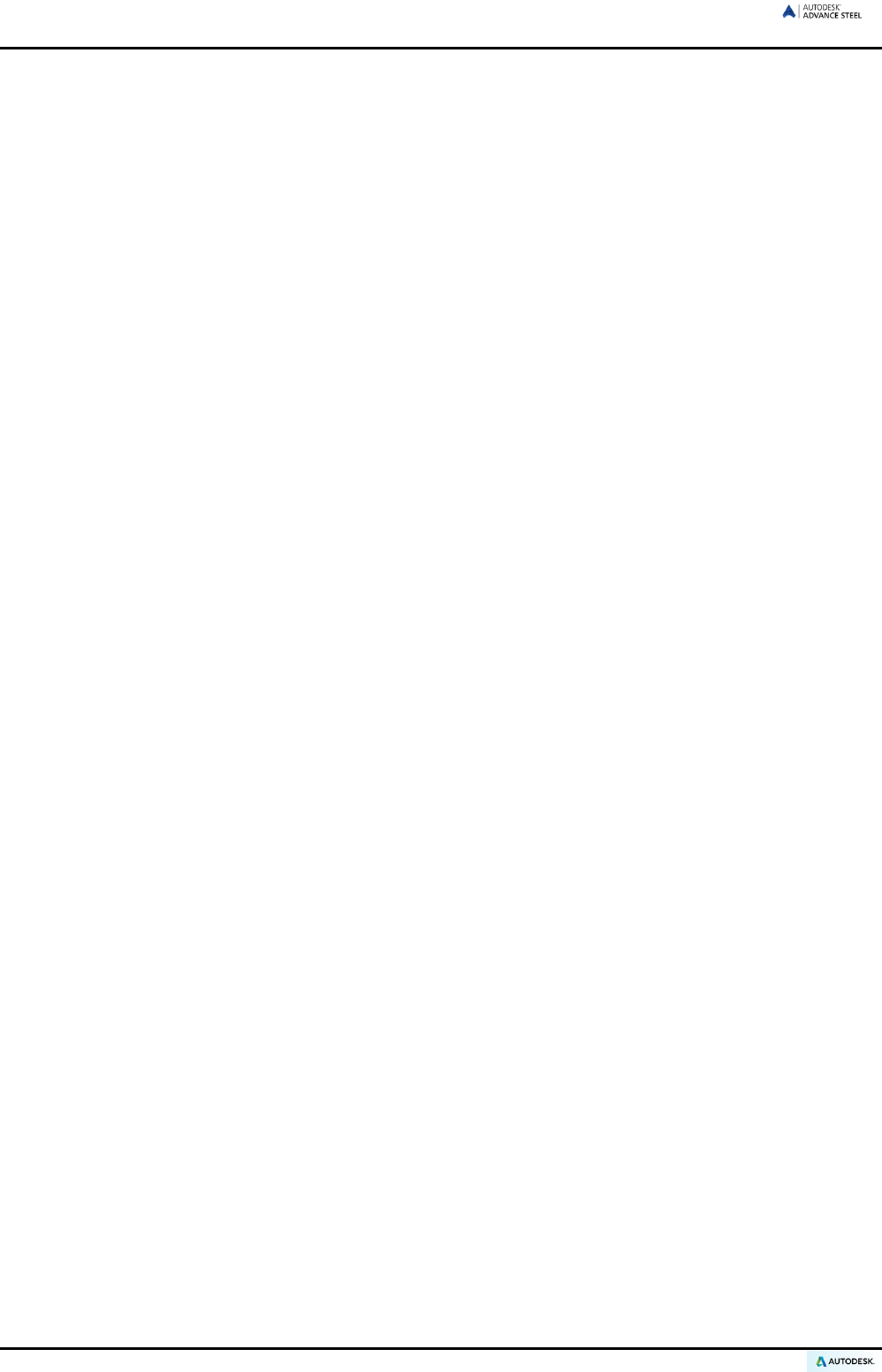
The Advance Steel model becomes the master reference for other tools.
• Dimensioned and labeled general arrangement and shop drawings are automatically created from the
model information. They are stored in separate DWGs using the user preferences for format, page setup
and drawing look and feel (the Advance Steel drawing style). It is also possible to create several details on
a single sheet.
• The general arrangement and shop drawings are created from the information contained in the model and
are managed by the Document Manager. The update tool in the Document Manager makes single click
drawing adjustments possible after model changes.
• Structured BOMs (bills of materials) and NC-information are also created from the model and include all
model information such as part marks and quantities. These documents are also managed by the Docu-
ment Manager. Bills of material/structured BOMs and NC-information are listed and previewed in the Doc-
ument Manager.
10
ADVANCE STEEL USER’S GUIDE
Figure 1: Document creation
Specialized areas
The Advance Steel 3D steel construction software is adapted to both standard and specialized construction. A
variety of cold rolled construction systems for purlins, side rails, accessories and cladding sections are available
in Advance Steel (i.e., Albion, Ayrshire, Canam Manac, Canfer, Fisher, HiSpan, Kingspan, Krupp, Metsec, SAB,
SADEF, Staba, StructuralSections, Ward, Zeta, etc.). Individual sections and other elements are easily set as
either user sections or special elements and stored in tables (libraries) for reuse.
The construction rules previously implemented are applicable for existing construction systems, Advance Steel
elements, and other elements.
Advance Steel and AutoCAD platform
The latest AutoCAD® version has been extended (through the ARX-Technology) with specific steel construction
elements such as beams, plates and bolts. Advance Steel elements are individual objects that are used like
standard AutoCAD® objects.
Advance Steel is completely integrated into AutoCAD® making it easy and intuitive to learn. Advance Steel
benefits from the latest AutoCAD® ARX Technology and makes the best use whenever possible of the existing
work methodology including manipulation tools on geometric elements, snaps and grips, etc. Therefore, users
are immediately familiar with the basic tools.
AutoCAD® serves both as a graphic engine and an object oriented database for Advance Steel. The complexity
of commands is reduced as Advance Steel objects are processed within AutoCAD® tools and all information is
stored in the DWG.
Advance Steel’s integration within the AutoCAD® user interface is fully optimized. All tools are grouped by type
in ribbon panels.
11
ADVANCE STEEL USER’S GUIDE
Technology
Advance Steel uses the latest standard industry technologies such as Windows and AutoCAD® for tight integra-
tion in the Microsoft Office environment. Advance Steel information, construction rules and tables (libraries) are
stored in MS-Access databases.
The ODBC technology links the model and drawings and provides quick communication for joint macros con-
struction rules.
The values entered in the Advance Steel user menus are directly converted to a graphic display on the screen
(through the MFC-user interface) so that the effects of a new value are viewed immediately.
The Facet modeler enables large model manipulation with high speed since the file size can be kept small.
Advance Steel is MDI (Multi Document Interface) capable. This means that several drawings with models and
linked detail drawings can be opened simultaneously within the same Advance Steel session. With this func-
tionality, elements are copied from one drawing to another using drag and drop.
Communication options
Advance Steel elements are saved as proxy-graphics with lines or surfaces. Therefore, Advance Steel DWGs
can also be viewed in standard AutoCAD®. The saved proxy-graphics can be clicked through a system varia-
ble.
From the Advance Steel model, information transfer files are created by PCS (Program system in the steel con-
struction) or PSS (Interface product of the steel construction).
Individual preferences
Advance Steel has default values for immediate creation without extensive configuration. Advance Steel is pre-
configured to use common profile sizes, standard plate thicknesses, standard bolt information, etc.
The default values are changed with the Management Tools.
The default intelligent joint settings based on section sizes are set to individual user requirements by saving the
information in an easy to use library.
Various drawing styles containing rules for dimensions, labeling and presentation of objects, are used for creat-
ing drawings from the model. Advance Steel contains a variety of preset drawing styles accessible for automatic
drawing creation: general arrangement drawings, single part shop drawings, assemblies and many more.
Moreover individual drawing styles can be user defined. The creation and editing of user defined drawing styles
is described in the Drawing Style Manager guide.
12

ADVANCE STEEL USER’S GUIDE
General
Read this user guide carefully. For additional information on individual topics, contact the Technical Support.
System requirements
To successfully install Advance Steel certain requirements have to be met. For more details, see
http://www.autodesk.com/adv-steel-systemreq-2015-enu.
License
A license is required to use the software. The license is activated based on the serial number and product key
provided by the dealer. These data are used during the installation process.
Once the license is successfully activated, the software can be used according to the license rights purchased.
For more details, see the Installation help.
Without the serial number, a trial version for 30 days may be installed.
Installation
Requirements for a successful installation:
• In your Windows session you must be logged in as administrator or must have administrator rights.
If you are not logged in as administrator or you do not have administrator rights, an error message appears
during the installation.
• The TCP/IP protocol is usually setup properly by Windows. If problems occur, verify the connection to the
license management software by using the ping command. This command tests the host name and the IP
address. If the IP address is confirmed and not the host name, there might be a problem with the name
server. If this is the case verify that the queried host name is in the local HOSTS file or in the DNS data-
base.
Note: Several Advance Steel versions can be installed on a computer at the same time.
14
ADVANCE STEEL USER’S GUIDE
Converting databases (Merging)
Old databases can be converted to new databases using the Management Tools. This might be required on a
new revision of Advance Steel or if users want to exchange information.
Notes: Only the database from a previous version can be converted.
The tables (libraries) cannot be converted if the structure of the tables (libraries) was changed.
A column with author information is a prerequisite for converting databases.
When upgrading to the new version of Advance Steel, almost all user settings from the previous version can be
merged and then used in the new version.
During the conversion operation any existing new entries in the source database are copied to the destination
database, also entries that exist in both databases are compared and updated in the destination databases if
any differences are found between them.
Examples of database changes that can be converted:
AstorBase.mdb:
• New materials or coatings
• New model roles
• Symbol configurations
AstorGratings.mdb:
• New or modified gratings
AstorRules.mdb:
• Configurations done to the accepted profile sizes / classes by joints like the Purlin structural element
• Saved joint library entries
AstorSettings.mdb:
• Modifications done to the default values
• AstorProfiles.mdb:
• New or modified profiles
Close the databases before converting them.
1. Start the Management Tools.
2. From the Settings category, select Convert Databases.
3. In the next window, click Open Database.
Figure 2: Management Tools – Opening database
15

ADVANCE STEEL USER’S GUIDE
4. Select the old versions of the databases (*.mdb files). For example, search for the database Astor-
Base.mdb then click Open.
The conversion tool will know automatically the equivalent Advance Steel 2015 database to which the
merge is done.
5. The database is loaded. Only the tables that can be converted are displayed.
6. Select the tables to convert and click Convert.
The tables are automatically converted and can be used with the new Advance Steel version.
Figure 3: Finishing the conversion
16

ADVANCE STEEL USER’S GUIDE
Elements of the 3D model
The Advance Steel 3D model is built from elements such as beams, plates, structural elements, bolts, welds,
features, and joints. Once the model is finished, checked and numbered, all output like structured BOM, NC
data, general arrangement and detail drawings can be completed.
3D-Modeling
Numbering
Drawings
BOMs / NC-Information
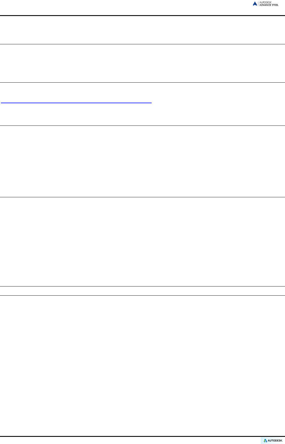
Beam & Plate
The 3D model is built mainly from Advance Steel basic objects:
• Beams created as section classes, simple sections, compound sections, or curved sections
• Plates as rectangular plates or as polygon plates with any contour
Beams and plates are created directly in the model and are displayed, by default, in the ‘wireframe’ mode.
Figure 4: Beam and Plate (standard representation)
Figure 5: Compound section and curved beam shown in the 'Hidden' representation
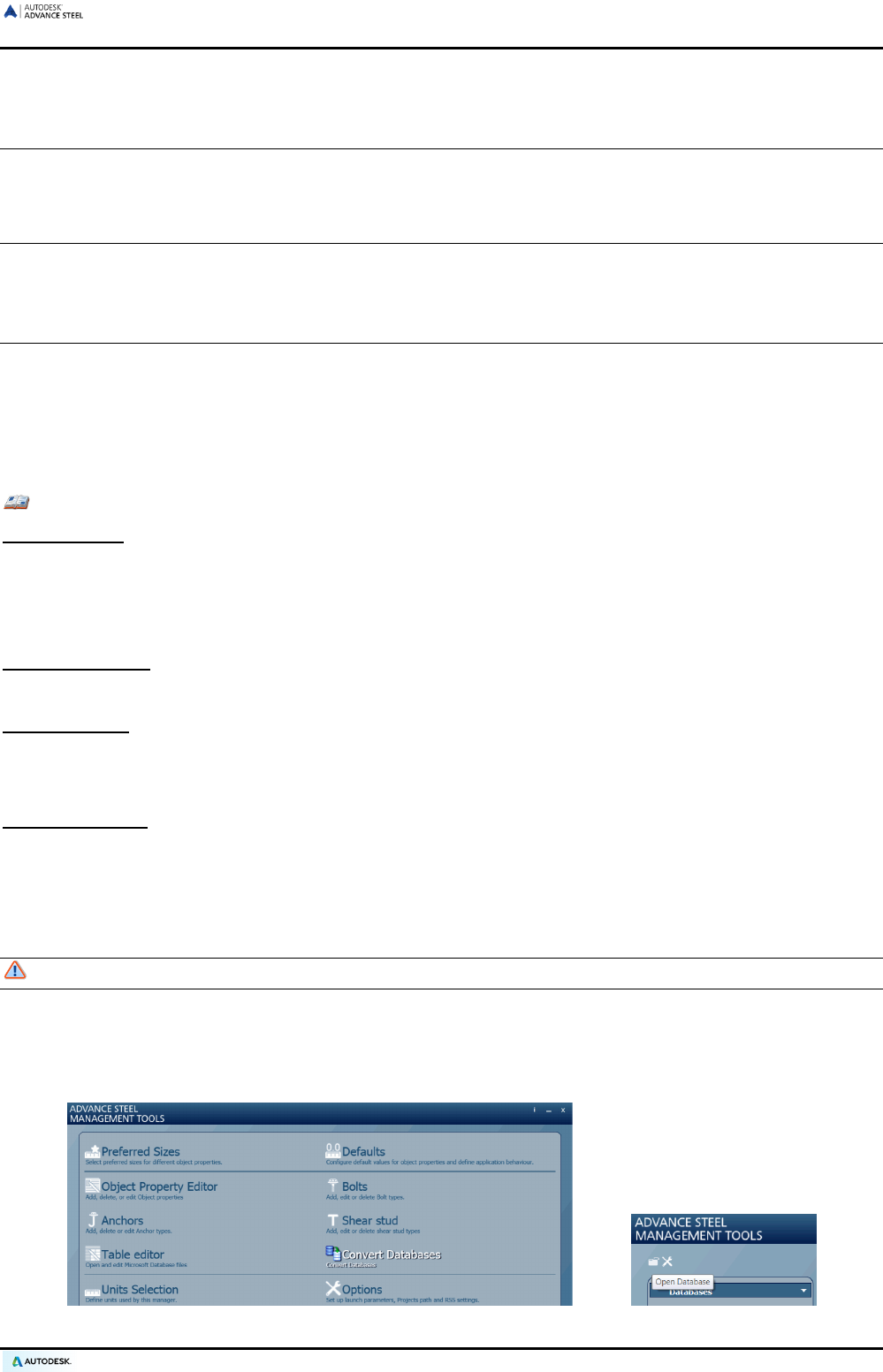
Processing
The basic objects (i.e., beams and plates) have available processing features.
Processing of existing basic objects (e.g., beam trimming and coping) is displayed as green processing con-
tours within the object. The processing objects cannot exist alone and are part of a basic element (i.e., beam or
plate). The object processing is edited as individual objects.
Various processing can be created:
• Beam processing: trimming, coping, miter cuts, rectangular and circular contour cuts, or any type of con-
tour.
• Plate processing: corner finishes, chamfers, outer plate contours and inner contours, etc.
18
ADVANCE STEEL USER’S GUIDE
Figure 6: Contour processing – cope and corner section
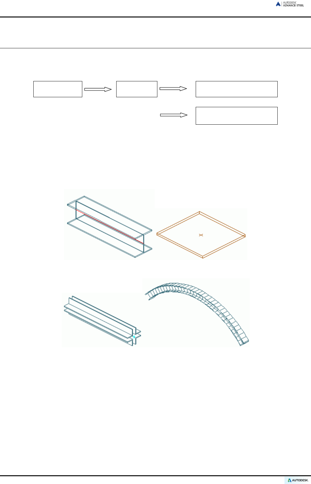
The variety of processing options in Advance Steel allows for almost any beam and plate contour.
Figure 7: Plate processing
If a basic element is deleted all processing objects will also be deleted.
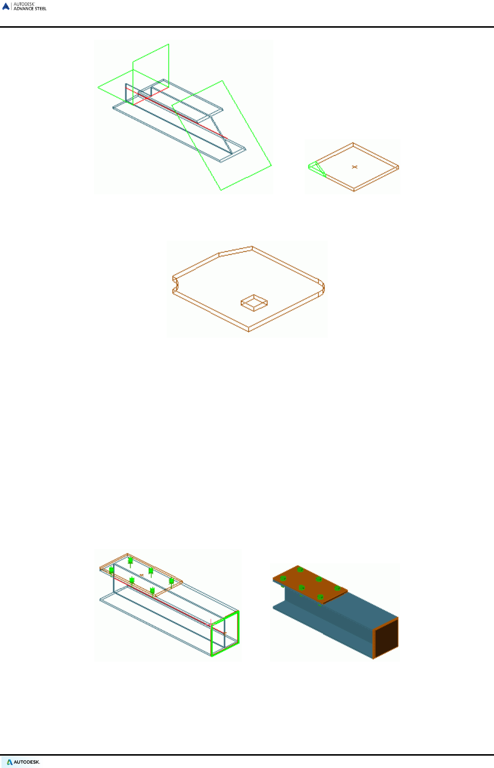
Bolt patterns & welds
The basic objects (i.e., beams and plates) can be connected with:
• Bolt patterns (or holes only)
• Welds
These objects establish a connection between objects (e.g., beams and plates). This information is stored on
the objects (i.e., beam or plate) including any bolt pattern (with its definition) or welds (with its relevant proper-
ties). Any individual element in the connection “knows” what holes, bolts, or welds it contains or with which ele-
ment it is connected.
A bolt pattern can describe one or several bolts, which are automatically created in any plane together with the
appropriate holes.
Figure 8: Bolt Pattern, Weld Point
Changes in the bolt pattern automatically update the holes.
19
ADVANCE STEEL USER’S GUIDE
The tools for creating bolt patterns are used for bolts in addition to:
• Holes, slotted holes, countersunk holes, blind holes, threaded holes and punch marks
• Shear studs
• Anchors
The above are all created with their respective properties or definitions.
It is also possible to create the various hole types as part of a bolt object and a separate hole object.
Weld points are displayed as crosses in the model.
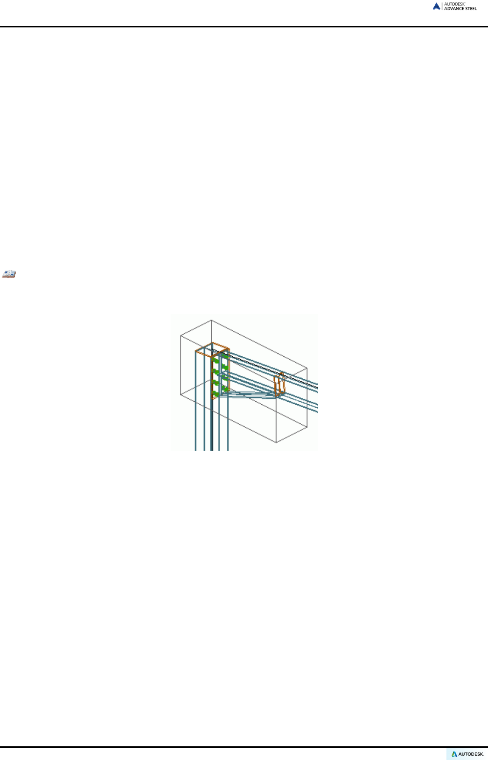
Joints
Another option for connecting the basic elements is the use of Advance Steel joints. Joints are complex ele-
ments that consist of basic elements and dependent elements that are controlled by a construction rule.
All individual elements in the joint, including their properties and processing objects, are held together and rep-
resented as a gray box (connection object).
All connection objects and definitions are included in the gray box.
Example: Haunch connection
A portal column and a rafter are connected with an intelligent rule-based joint. For example, this is a
haunch connection, including plates, stiffeners, and bolts.
Figure 9: Connection object (gray box)
The following joints are included in Advance Steel:
• Connections for North America: end plates, clip angle connections, base plate, flat bracings
• Frame corners
• Gable wall connections and pin-ended column connections
• Ridge connections and splices
• Platform connections, end plates, web connections, and shear plates
• Gusset plates and diagonal bracing
• Base plates and stiffeners
• Tube connections
• Turnbuckle bracing
• Pylon construction connections
The rules and structure of joints are stored in MS-Access tables (libraries). Adjustment of these rules to user
requirements (or creation of new rules) is possible with knowledge of Advance Steel’s macro programming lan-
guage.
In addition to the joints provided in the standard Advance Steel package, interactive (also called manual) joints
can be created, stored and reused.
20
ADVANCE STEEL USER’S GUIDE
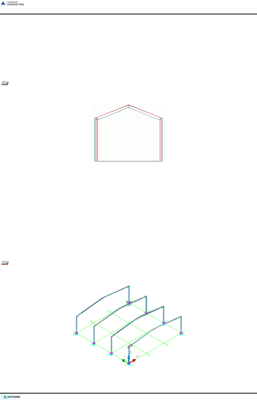
Structural elements
Structural elements are an intelligent group of basic elements and dependent elements classified as follows:
symmetrical goal post frames and portal frames, single-span bracings, purlin positions, various stairs, pylons,
joists, and half trusses.
These elements are created as a group of several basic elements with relationships to each other. Elements
and their relationships are held together and stored with a connection object. The structural frame is displayed
in the model as a white continuous line (Figure 10).
Example: Portal frame
A portal frame consists of four sections: two grouped columns and two grouped rafters connected using
a structural element macro.
Figure 10: Portal Frame
All changes to one element affect the entire group. If a rafter section is changed then the second rafter section
will also be changed. The column sections of the frame behave in the same way. A change in the total height or
the column height affects the entire structural element.
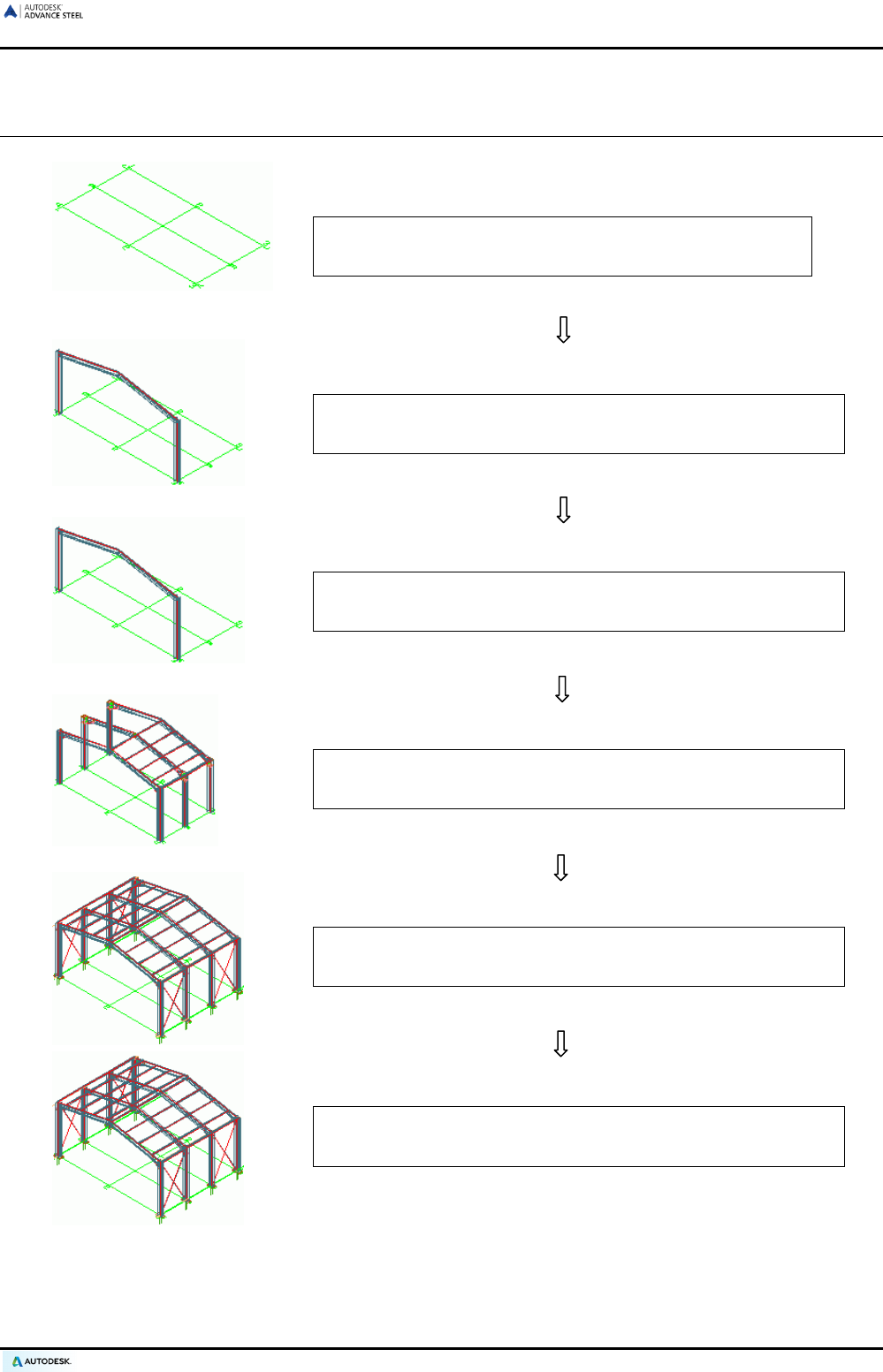
Auxiliary objects
Auxiliary objects are:
• Grid axes or
• Level symbols
These objects do not belong directly to the frame but support the construction process. Nevertheless, they are
important elements.
Example: Building grid
A building grid that corresponds to the dimensions of the construction forms the basis of 3D Modeling
and helps with orientation in three-dimensional space.
Figure 11: Building grid with portal frame
21

ADVANCE STEEL USER’S GUIDE
Special parts
Objects that are not Advance Steel standard objects can be created as special parts. When Advance Steel cre-
ates drawings and bills of material with special parts they are handled like standard objects. If these objects
(special parts) are to appear in the bill of material, they must be provided with Advance Steel properties. The
information that can be attached is:
• Weight
• Material
• Coating
• Name
• Commodity
• Lot/Phase
• Part mark (single part and assembly)
• Model Role
• Other
22
ADVANCE STEEL USER’S GUIDE
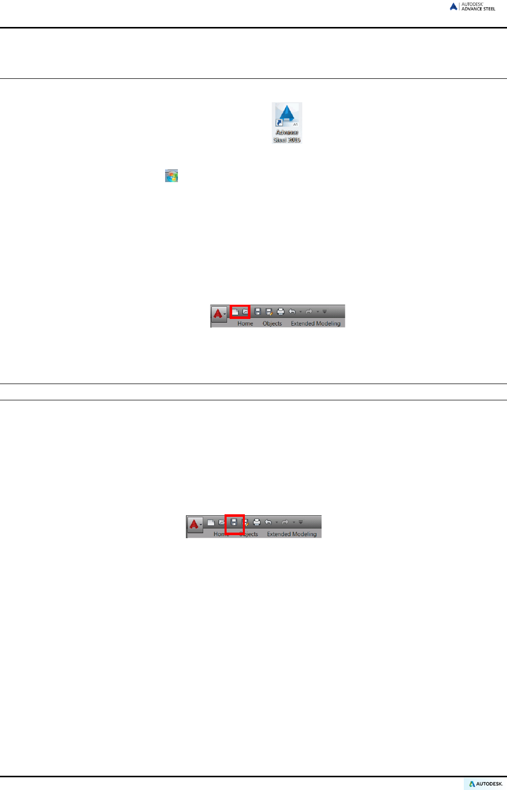
3D Modeling workflow
Create a building grid
Create beams, plates, structural elements
Edit beams / plates (processes)
Add Advance Steel elements with joints / interactive connections
Add other interconnecting members
Controls / checks for collisions and measurements
23

ADVANCE STEEL USER’S GUIDE
Starting Advance Steel
To start Advance Steel:
• Double click on the Advance Steel Icon on the desktop .
Or
• On the Windows task bar, click , then select All Programs > Autodesk > Advance Steel 2015 and click
the Advance Steel icon.
Starting a new project
Advance Steel projects consist of a master file – a .dwg file containing the model - and a set of derived files:
detail drawings, BOMs, NC files, etc.
When starting a new project, a template file is used. The template file contains important defaults like the cur-
rent coordinate system, the orientation, object snap settings, layer assignment and color definitions so that
modeling can immediately begin.
1. On the Quick Access Toolbar, click New.
Advance Steel automatically opens the folder where the templates are stored.
2. Select the template (.dwt file) and click Open.
Note: Always use the ASTemplate.dwt template to start the modeling project.
Advance Steel starts in a three-dimensional isometric view and the user interface appears. The User Coordinate
System (UCS) is active and set to the World Coordinate System (WCS). All coordinate entries refer to the UCS.
Saving a project
Save a project with an appropriate name in a DWG format. Use the Save button on the Quick Access Toolbar
in the upper left corner of the screen. Each project should be saved in its own folder for easier file management.
Figure 12: Save button on the Quick Access Toolbar
Among other features, template drawings and files for certain drawing formats are delivered with Advance Steel.
26
ADVANCE STEEL USER’S GUIDE
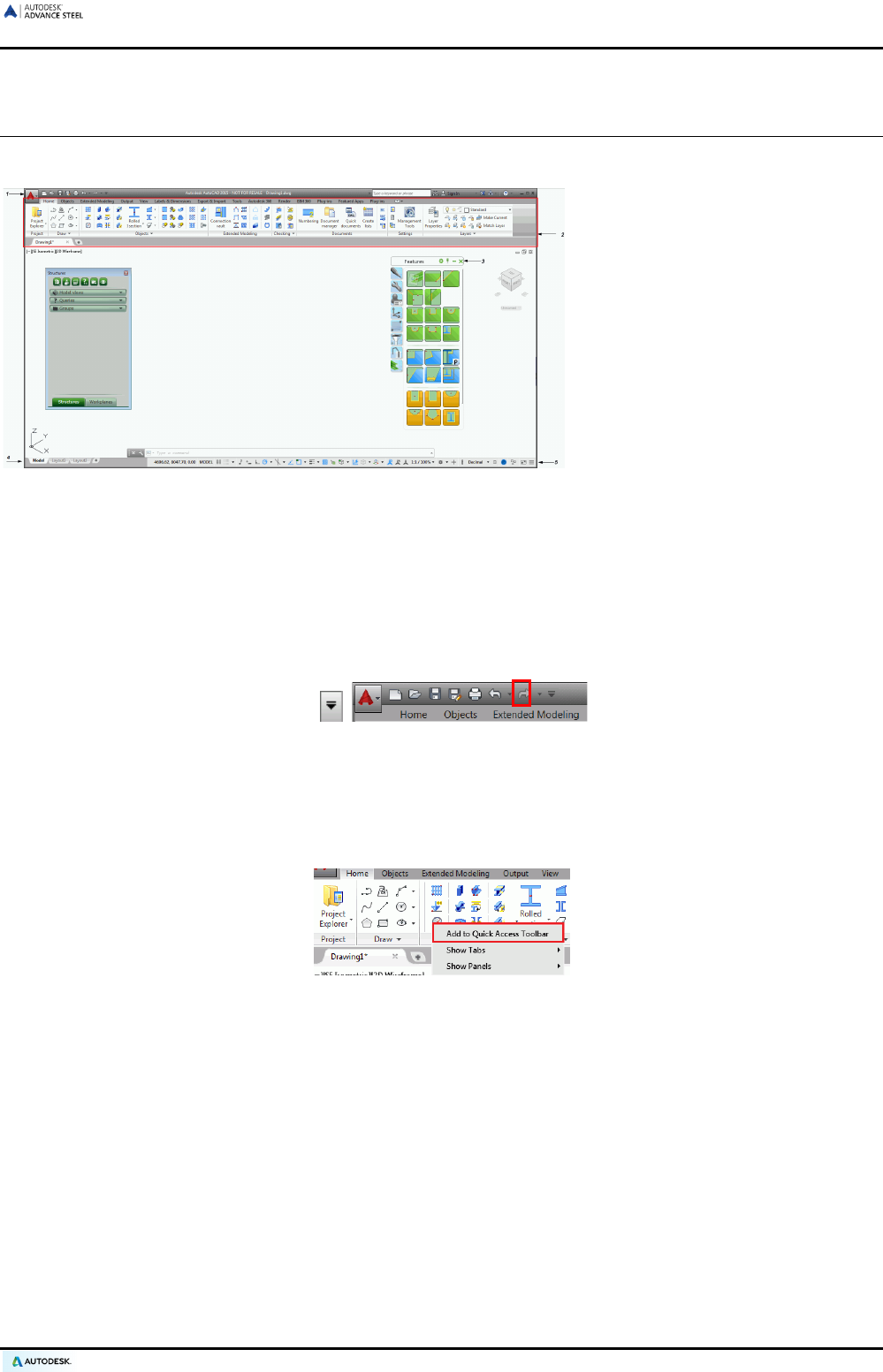
Advance Steel user interface
Advance Steel provides a complete environment for modeling and detailing steel structures.
1: Quick Access Toolbar
2: The ribbon
3: Tool palettes
4: Command line
5: Status bar
Figure 13: Advance Steel user interface
Quick access toolbar
The Quick Access Toolbar provides fast access to the most frequently used tools. The set of available tools can
be extended. The Quick Access Toolbar can be placed above or below the ribbon.
Adding Advance Steel buttons to the Quick Access Toolbar
1. On the Quick Access Toolbar, click .
2. Select More Commands from the displayed menu.
3. From the list displayed in the Customize User Interface dialog box select the tools to add to the Quick Ac-
cess Toolbar and click OK.
Another method to add a ribbon button to the Quick Access Toolbar is to right click the ribbon button and select
Add to Quick Access Toolbar.
Figure 14: Adding a button to the Quick Access Toolbar
27

ADVANCE STEEL USER’S GUIDE
The ribbon
The Advance Steel ribbon contains a collection of panels grouped on tabs, according to category of tasks. On
the panels, the buttons are grouped on different rows and include large buttons for the most frequently used
functionalities.
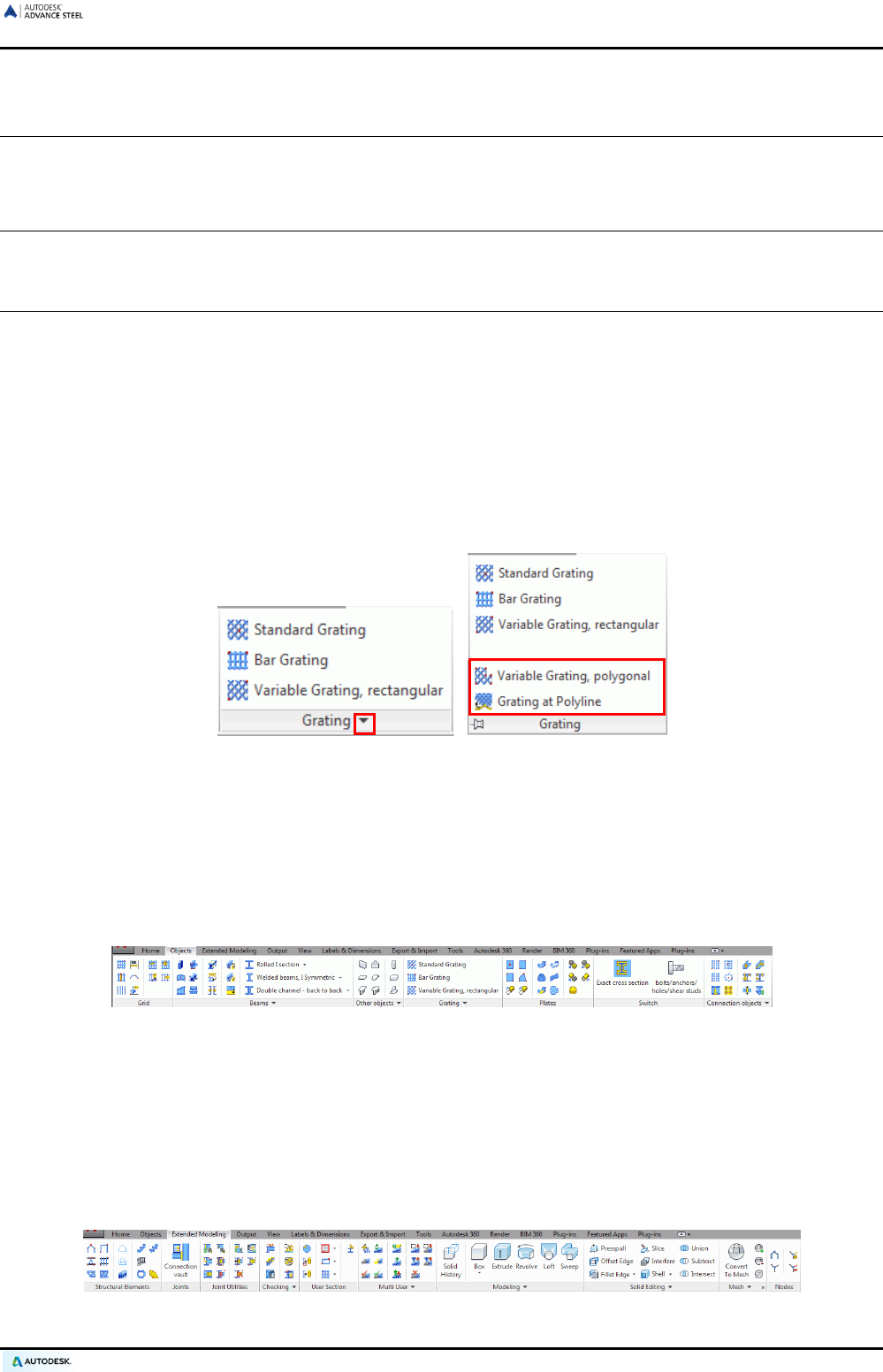
Some panels can be expanded by clicking the arrow on the bottom line.
Some panels contain buttons that are tools or call flyouts. The flyout buttons have a black triangle on the bot-
tom side. These flyouts automatically open when the button is pressed and held down.
Figure 15: Opening welded beam commands
Tool palettes
The tool palettes contain other tools, complementary to the functionalities available on the Advance Steel ribbon.
The drawing area
The drawing area is the main area of the application window where the objects are created and edited.
Command line
Advance Steel commands can be entered using the keyboard. Press <Enter> after each entry.
Status bar
The status bar displays information regarding the program status during different phases of the project. It also
contains buttons that provide access to the configuration of certain parameters: snap modes, object tooltips
content, current coordinate system, and working units.
28
ADVANCE STEEL USER’S GUIDE
Using Advance Steel
All Advance Steel commands can be accessed from the ribbon and from the tool palettes. The tool palettes
contain other tools, complementary to the functionalities available on the Advance Steel ribbon.
Tips The ribbon can be minimized, thus enlarging the drawing area.
The tool palettes can be docked to one side.
Using Advance Steel ribbon
The ribbon contains a collection of panels grouped on tabs, according to type. For easier access, the main tools
are placed on the Home tab.
On the panels, the buttons are grouped on different rows and include large buttons for the most frequently used
functionalities.
The ribbon can be minimized, thus enlarging the drawing area.
Some panels can be expanded by clicking the arrow on the bottom line.
Figure 16: Opening additional grid commands
Modeling tools
All modeling tools, essential for creating a three-dimensional model, are available on two ribbon tabs: Objects
and Extended Modeling tab.
• The Objects tab contains tools for creating basic Advance Steel elements: grids, beams, plates, gratings,
bolts, holes, shear studs, welds, and concrete elements.
Figure 17: Objects ribbon tab
• The Extended modeling tab contains tools for creating and modifying complex objects (such as structural
elements, stairs, railings, ladders), the Connection vault, the commands for handling joints and connection
objects, specific tools for working in a multi-user environment.
Important checking tools (i.e., collisions in the model and checking databases), which are required during
construction are placed on the Checking panel. The User sections panel includes all required commands
for creating custom sections (can be added directly in tables (libraries)).
Additionally, a large set of tools for creating and editing basic 3D solids are available.
Figure 18: Extended modeling ribbon tab
29
ADVANCE STEEL USER’S GUIDE
Detailing tools
All the tools necessary during the drawing creation process are grouped on two ribbon tabs:
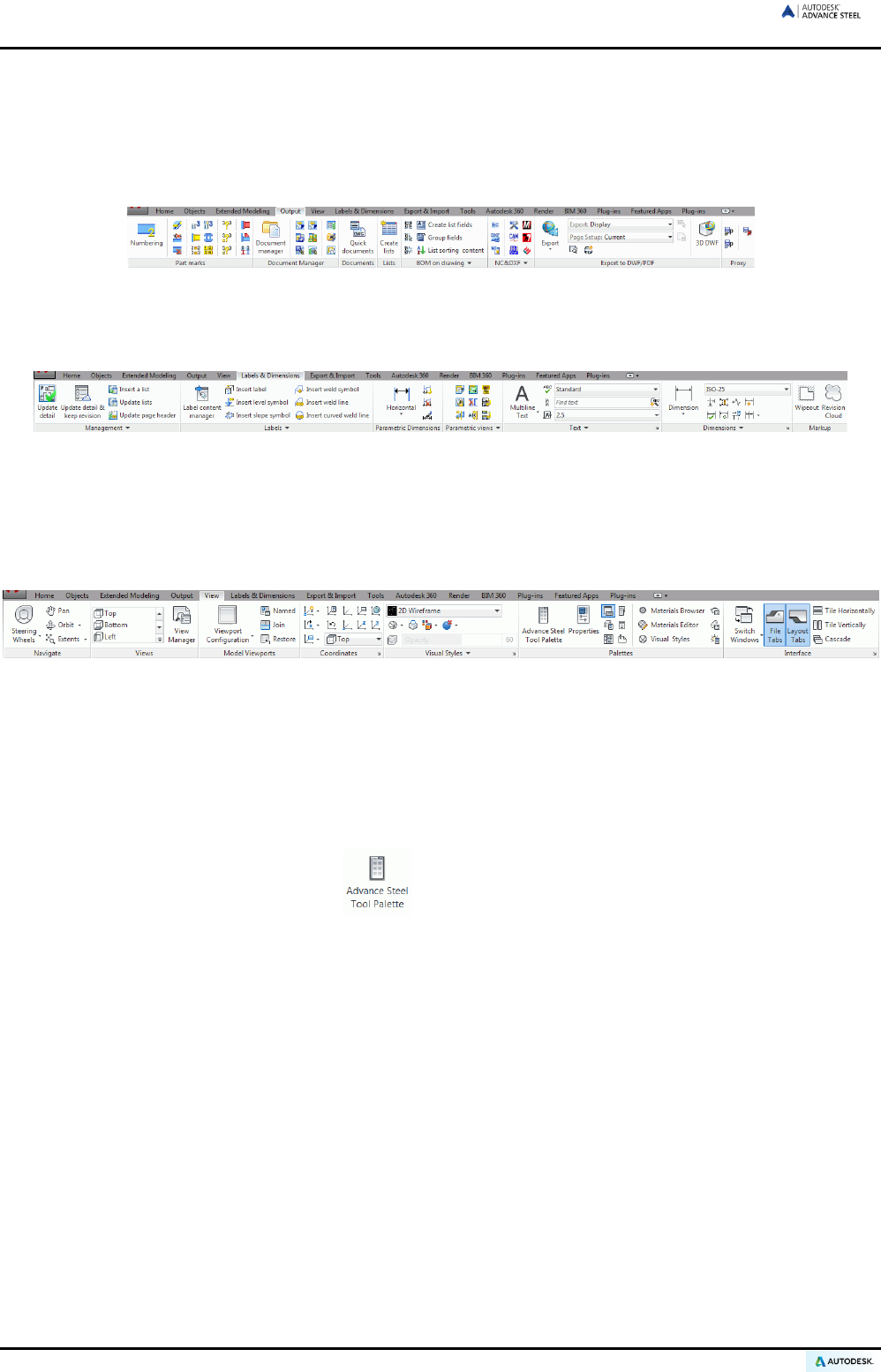
The Output tab contains all commands pertaining to numbering, drawing creation, automatic drawing creation
with processes, and the Document Manager.
Figure 19: Output tab
The Labels & Dimensions tab contains tools for managing the details and the revision process and for creating
additional dimensions, labels, level symbols etc.
Figure 20: Labels & Dimensions tab
Visualization tools
The View tab contains tools for manipulating the view in 2D and 3D, for displaying the model (change the visual
style) and displaying interface elements (tool palettes, windows, viewports).
Figure 21: View tab
Using the tool palettes
On the tool palette, special Advance Steel commands for copying, rotating and mirroring connections are in-
cluded.
To display the tool palette:
• On the View tab, Palettes panel: click . The tool palette appears.
The tool palette can be docked on one side of the application window.
30
ADVANCE STEEL USER’S GUIDE
Starting an Advance Steel command
Start an Advance Steel command by clicking a button on a ribbon panel or on the tool palette. The command
appears on the command line at the bottom of the screen.
Other important tools for using Advance Steel
• To cancel a command in Advance Steel, press the <Esc> key.
• The current command and prompts are displayed on the command line window at the bottom of the screen.
Press the <F2> key to open and close the command line window.
• The right mouse click behaves like the Enter key.
• When the cursor hovers over a button of a panel, the button's tooltip appears.
• The Undo command on the Quick access toolbar cancels one or several commands.
Figure 22: Undo command on the Quick Access Toolbar
• The Match properties command copies properties from one object to another. The transferred properties
are selected from a list.
Figure 23: Match properties command on the Clipboard panel
Creating Advance Steel objects
Advance Steel objects are created in 3D-space using the program tools. The object's orientation depends on the
current UCS (User Coordinate System).
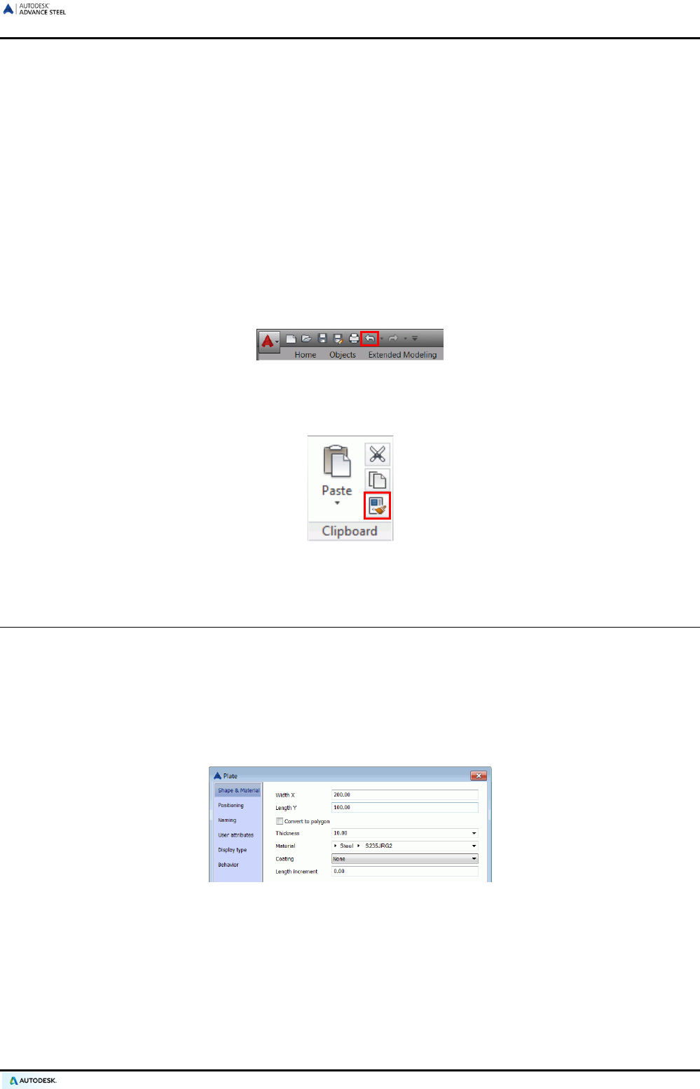
Points created by selecting or using coordinates determine the position and orientation of the object in space. A
dialog box will appear in which different settings (e.g., geometric sizes, etc.) and drawing styles can be
changed (e.g., dimension/label on the drawings).
The settings in the dialog box are sorted on different tabs that vary based on object type.
Figure 24: Plate dialog box
When a dialog box field (e.g., dimension, position, etc.) is changed the model updates instantly (model preview):
• By clicking the next field,
• By closing the window (click the X in the right upper corner),
• By using the <TAB> key to move to the next field or
• By using the Enter key to select the value in the current field.
31
ADVANCE STEEL USER’S GUIDE
Initial settings of an object (e.g., a plate) are stored and can always be recalled and updated using the same
dialog box.
Advance will recall the last dialog box values and preferences until the next time the same tool is used. After
restarting Advance Steel, the dialog boxes return to the default settings.
The default settings are restored using the system menu of the dialog box (right click the header line of the dia-
log box). By clicking Use defaults on this system menu, the dialog box entries return to the default settings.
Object properties
All created objects have default Properties that can be changed in the Advance Steel Properties dialog box,
which automatically appears upon creating an object.
Figure 25: Geometric and non-graphic properties
The object properties are classified as follows:
• Geometric Properties (i.e., position in the model and shape)
They are set on creation and can be changed afterwards using standard CAD commands (e.g., move, ro-
tate, copy, etc.) and grips.
• Properties specific to the used CAD platform
They are set in the property list and are changed using the Properties command.
• Technical properties
They are properties for the on-screen representation (e.g., representation of a beam with or without pro-
cessing) and non-graphic properties (e.g., material, name, etc.). This information goes in the structured
BOMs and drawings.
Figure 26: Beam “features” and “standard” representation
To open an object dialog box double click on the object.
Another way to access the properties is to select the object(s) and with a right mouse click select Advance
properties from the context menu.
Layer
Advance Steel objects are, by default, created on the active Layer but can also be placed automatically on spe-
cific layers with different properties. This feature is set in the ASTemplate.dwt DWG drawing template file using
the Autodesk Management Tool.
32

Chapter 4
Creating a 3D Model
In this chapter:
■ Creating a building grid
■ Creating beams
■ Creating plates
■ Coordinate systems
■ Beam and plate processing
■ Changing Advance Steel objects
■ Advance Steel command properties
■ Representation Type – Snaps –
Grips
■
Bolt and Hole Patterns / Shear
Studs / Anchors
■ Welds
■ Connections
■ Working methods I
■ Structural elements
■ Joints and connection objects
■ Special parts, special sections
■ Working methods II
ADVANCE STEEL USER’S GUIDE
Creating a building grid
The auxiliary object “building grid“ makes it easy to place Advance Steel objects within a construction design.
A building grid consists of axes in the X- and Y- directions. Grids facilitate placing of the construction elements
and for orientation in the 3D view. Placing a building grid is the first step of 3D modeling in Advance Steel.
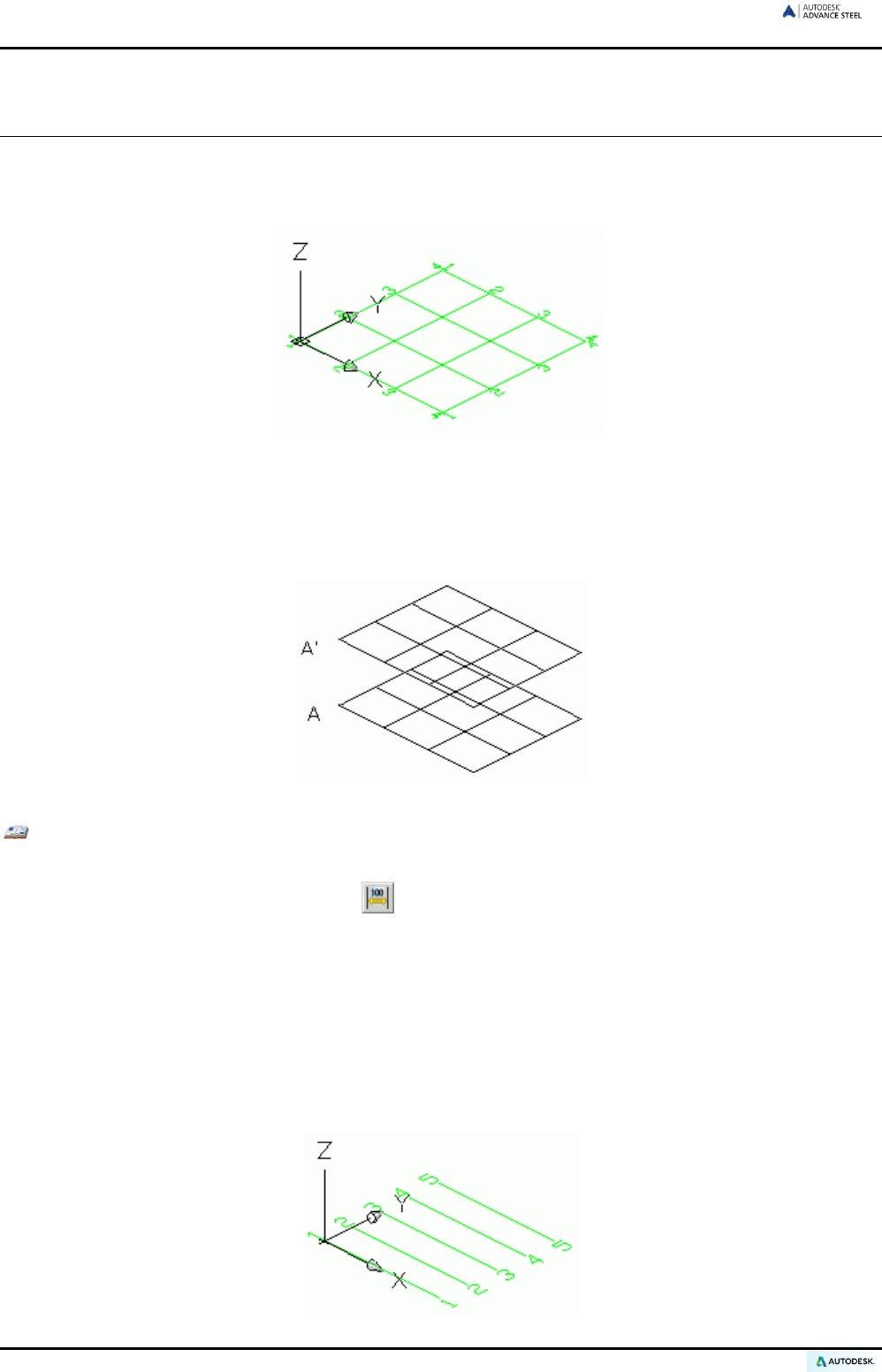
Figure 27: Building grid
A building grid is created in the X/Y-plane of the current coordinate system and consists of two independent axis groups.
Picking three points creates a curved single axis.
A building grid can be copied, for example upwards, several times if needed. For better recognition, the grids
can have different labels (A, A‘, A‘‘) on the various planes with a different color on a new layer (recommended).
Figure 28: Building grid
Example: Creating an axis group by setting the distance between axis
• Start Advance with the ASTemplate.dwt template file.
• On the Objects tab, Grid panel, click .
• Enter the starting point of the first grid line as (0,0,0) (please give end points of the grid line. starting
point: 0,0,0 Enter),
• Set the end point of the grid line by dragging the mouse pointer (with Ortho-mode on, F8) in the X-
direction and enter 8000 (end point: 8000 Enter).
• Determine the direction of the axis group by picking a point in the Y-direction on the screen (orientation
of the group: Enter).
• Next, enter 2000 for each distance between axes until the command line has a total value of 8000 and
then press Enter twice. The axes group in the X-direction is created and the Axes, parallel dialog box
appears.
Figure 29: Building grid: axes in X-direction
34
ADVANCE STEEL USER’S GUIDE
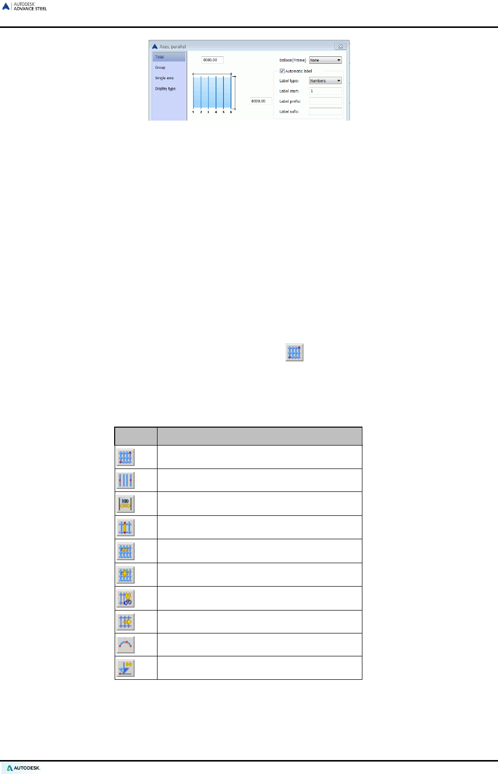
Figure 30: Axes, parallel dialog box
• On the Total tab of the dialog box, the length property (distance between the first and the last axis) and
width (length of the axes) can be changed. The axes are automatically labeled with numbers or letters.
• Close the dialog box by clicking on the cross (X) in the upper right corner.
• To create a complete building grid, repeat the same steps for an axis group in the Y-direction.
To change the axis group, select a group and select Advance Properties from the context menu.
When the Group tab is selected, the color of the selected group is changed to red. The number of single axes
or their distance within the total length is indicated.
The Single axis tab provides options for individual axis labeling (if automatic labeling is turned off on the Total
tab). The selected axis is displayed in red. An axis can be added to the right or left of a main axis with an option
to use a label containing the main axis name with a suffix and a prefix.
The grid axes can be hidden or switched to single axis representation on the Display type tab.
• To create a complete grid with a group of axes in both the X- and Y-directions, use the “Building grid” tool.
This building grid is created as a standard grid by clicking and right clicking twice or by giving specific
coordinates for the origin point and a second diagonally opposite point.
In both cases, the grid size, division and labeling can be modified using Advance Properties (double click the
grid). Since two axis grids are created in the course of this command a dialog box does not appear.
The Grid panel contains the following tools for creating and designing building grids:
Button Function
Create a complete grid by two points
Create grids by individual groups with 4 axes
Create grid groups with distances
Create an axis in a group
Create an axis from a group
Create a group of axes
Cut a group
Extend a group
Create a curved single axis
Create a level symbol
Detailed information on individual tools, representation types, snaps, grips, and object coordinate systems is
available in the Building grid chapter of the Advance Steel Help.
35
ADVANCE STEEL USER’S GUIDE
Creating beams
In Advance Steel, a variety of beams are preset such as rolled I sections, channels, angles, T-sections, tubes,
Zeds, flats, round bar, square bar, square/rectangular hollow sections, cold rolled sections, purlin sections, and
other section classes (Beams panel).
All types of beams are available from the listed sections and can be created as:
• Simple sections
• Compound sections
• Welded beams
• Tapered welded beams
• User sections
Beams can be drawn directly in the model according to the current coordinate system, or by converting a line.
All types of sections can be created as:
• Straight beams
• Curved beams
• Poly beams
Additionally, individual sections can be set as special sections (refer to the Special parts, special sections chap-
ter).
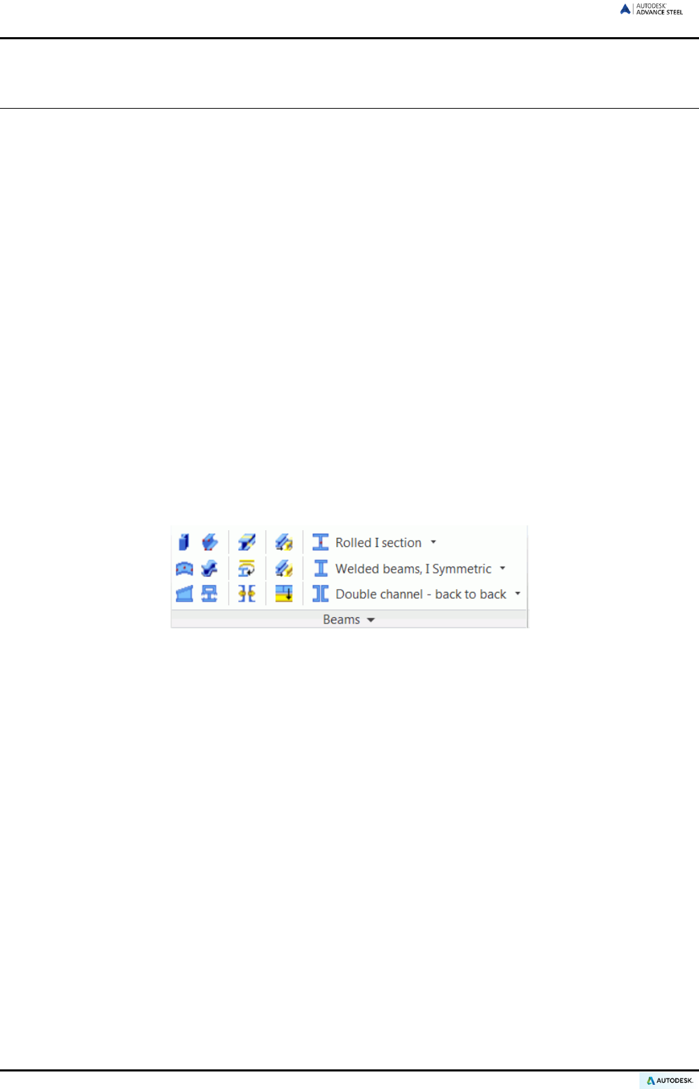
All tools for beam creation are available on the Beams panel:
Figure 31: Buttons for creating beams
• Creation of various types of beams: curved, polygonal, tapered, folded beams
• Splitting beams
• Creation of beams from polylines
• Creation/ explode of compound sections
• Creation of beams – section classes (flyout)
• Creation of beams (flyout)
• Creation of welded beams (flyout)
• Create sections from various cold rolled systems, such as CanamManac, Canfer, etc. (additional panel)
36
ADVANCE STEEL USER’S GUIDE
Straight beams
Straight beams are created in the Advance Steel 3D model relative to the current user coordinate system (UCS)
by entering one starting point and one end point.
The current user coordinate system (UCS) determines the position of the sections' main axes: the web of a
beam runs in the Z-direction of the UCS (i.e., the ‘top’ of the section is in the Z-direction).
Any section class can be created as straight beam.
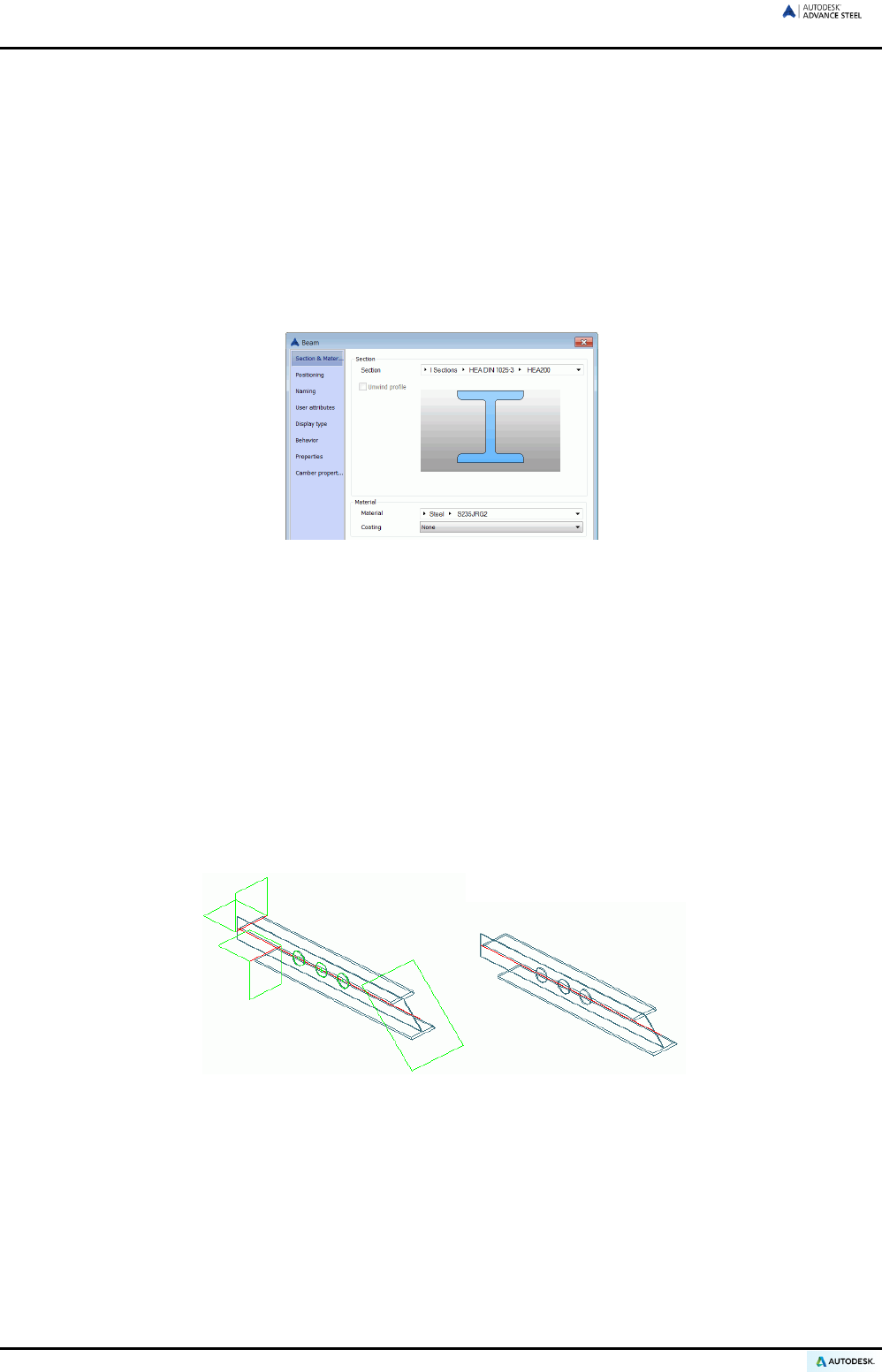
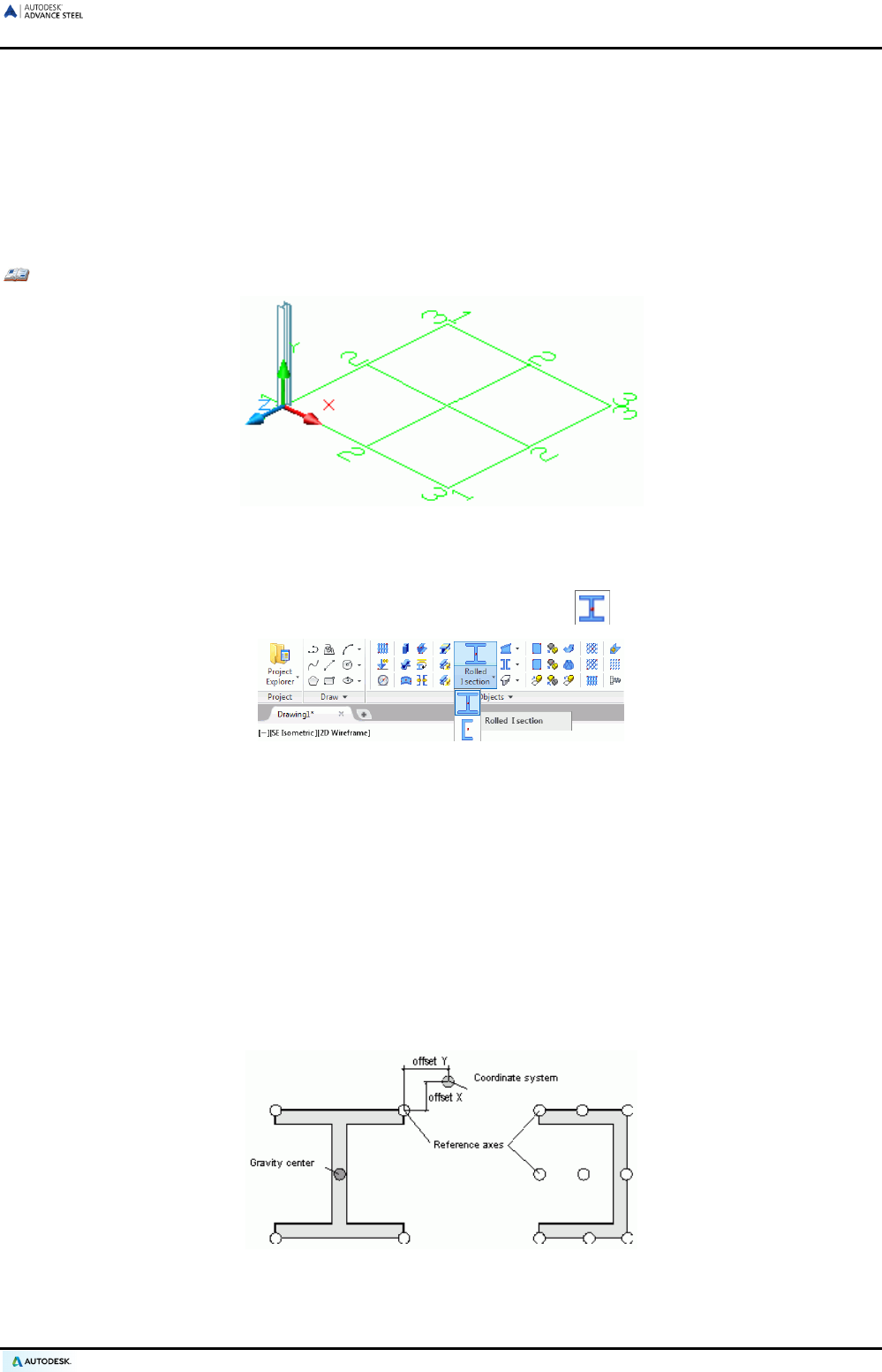
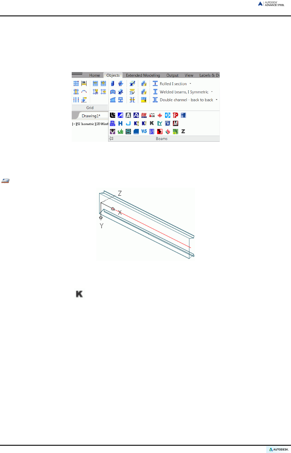
Example: Creating a straight beam HEA 400 x 4000 mm long
Figure 32: Beam HEA 400
• Select a suitable UCS (see Figure 32).
• On the Home tab, Objects panel, from the drop-down list, select .
Figure 33: Selecting the beam section
• Select a starting point at (0,0,0).
• Move the mouse pointer upwards in the Y-direction (the setting Ortho causes an exact orientation en-
try) and enter 4000. A standard I-section is created.
• The “Beam” dialog box appears. Select the section class (HEA) followed by the section (HEA 400).
For beam length and placement, three different object axes types are available:
• The insertion axis (system line) is an axis that has two points and forms the relation of a beam.
• Reference axes are important specific axes for sections such as edge lines or center lines.
• The gravity axis is the line of the cross-section areas of the center of gravity. Not all sections have the-
se lines (e.g., C-shaped profiles).
Figure 34: Axes of a beam
37

ADVANCE STEEL USER’S GUIDE
The standard insertion axis (system line) of a beam lies in the center of gravity. The beam is moved or rotated
relative to the insertion axis or reference axis by changing the values on the Positioning tab of the “Beam” dia-
log box.
A variety of other properties, such as entries for drawings style (type of dimensions and labels used in the au-
tomatic detailing by processes), material, or for behavior, are used for identification of identical parts, collision
test, and creation of BOMs.
During drawing creation the Model role, set on the Naming tab, will influence the output. An object, set as a
column, is dimensioned and labeled differently by the automatic detailing process than if the object is set as a
beam.
The Properties tab displays beam information such as weight and coating surface area, and also section val-
ues such as flange thickness, web thickness and height, etc.
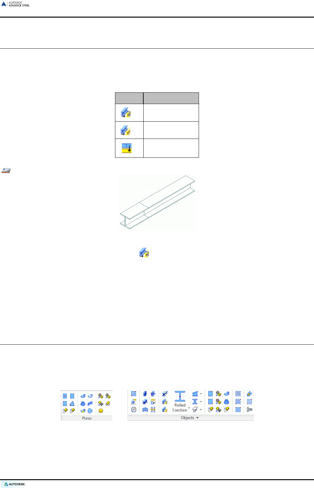
Compound sections
Two or four sections, as a combined section (named Compound sections), are created at a system line. The
sections are handled as a single section so that a trim will affect all sections.
Compound sections are created like simple sections by entering a start point and an end point according to
the current coordinate system.
Figure 35: Compound sections
To create Compound sections, use the corresponding flyout of the Beams panel on the Objects tab.
Figure 36: Compound sections flyout
The properties in the dialog box such as position, material, drawing-style, or representation type correspond to
those of the simple sections.
On the Shape & Material tab, the distances between the single profiles in the X- and Y-directions can be
changed.
The button of the Beams panel separates the assembly into single beams. Each beam then gets its own
system line. The single axes are overlapped and each beam has an offset value.
38
ADVANCE STEEL USER’S GUIDE
Before creating certain joints that can only be attached to single beams, compound sections must be separat-
ed into single beams.
Note: Before creating BOMs and drawings it is necessary to select if the compound section must be con-
sidered as one beam or several beams.
Figure 37: Selecting the compound section behavior
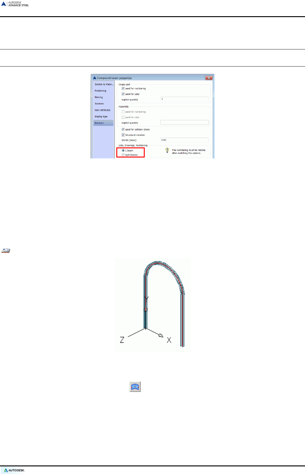
Curved beams
The section classes previously listed in this chapter can also be created as curved beams. To create a curved
beam, click the corresponding button and give a starting point and an end point for the length of the section,
followed by one circle point for the radius.
As in the case of straight beams, the current coordinate system determines the position of the main axes of the
beam. The curved beam web runs in the Z-direction of the current UCS (i.e., the ‘top’ of the section is in the Z-
direction). The created curved beam can be rotated 90° about its system line.
Example: Creating a curved beam HEA 240 between two columns (straight beams)
Figure 38: Curved beams
• Select a user coordinate system as shown in Figure 50.
• On the Home tab, Objects panel, click .
• Use the upper system line end points of the columns as the start point and end point.
• Define the radius of the curved beam with a circle point. The circle point must be defined in the X/Y-
plane of the coordinate system. Alternatively, pick a point at any radius and then specify the radius on
the Position tab of the dialog box. It is very important that the radius is set while the system line is at
the center point (center of gravity). The system line can then be set on one edge and the radius previ-
ously entered will then correspond to that edge. Note that the value for the radius in the dialog box will
then change since it displays the radius to the center of the section!
39
ADVANCE STEEL USER’S GUIDE
• The curved beam in this example must be rotated 90°. Rotate the beam on the Position tab of the
Beam dialog box.
All other beam properties are the same as those of straight beams. On the Position tab, in which the radius is
set, there is a tolerance field to set the circle representation accuracy.
Poly beams
A poly beam is a beam sequence (straight beams, curved beams or a combination of the two) created as a sin-
gle object.
Any section class can be created as poly beam.
To create poly beams, a polyline must be created. Any 2D or 3D polyline can be converted to a poly beam.
The position of the beam is independent of the coordinate system since the beam position is determined by the
position of the polyline.
There are two ways to draw a poly beam:
• Directly in the model by specifying the points (point by point). The beam is drawn in the X/Y plane of the
coordinate system
• By selecting a polyline. Any 2D or 3D polyline can be converted into a poly beam. In this case the beam
position is independent from the coordinate system since the beam position is determined by the position of
the polyline.
Additionally, any line or arc can be converted to a beam using the Beam from line tool.
Figure 39: Beam panel – Beam from line
Example: Creating a poly beam
Figure 40: 2D poly beam
• Draw a polyline in a suitable user coordinate system.
• On the Objects tab, Beams panel, click .
• Select the polyline.
• Confirm the selection by pressing Enter.
• The polyline can be kept or deleted.
• Type Y for Yes (or N for No) and finish by pressing Enter.
All other beam properties are the same as those of straight beams.
40
ADVANCE STEEL USER’S GUIDE
Folded profile
Folded profiles are created starting from a polyline that defines the section. The cross section is defined directly
inside the model by specifying the points (point by point) in the current UCS or by selecting a polyline. The fold-
ed plate can be an open or closed section.
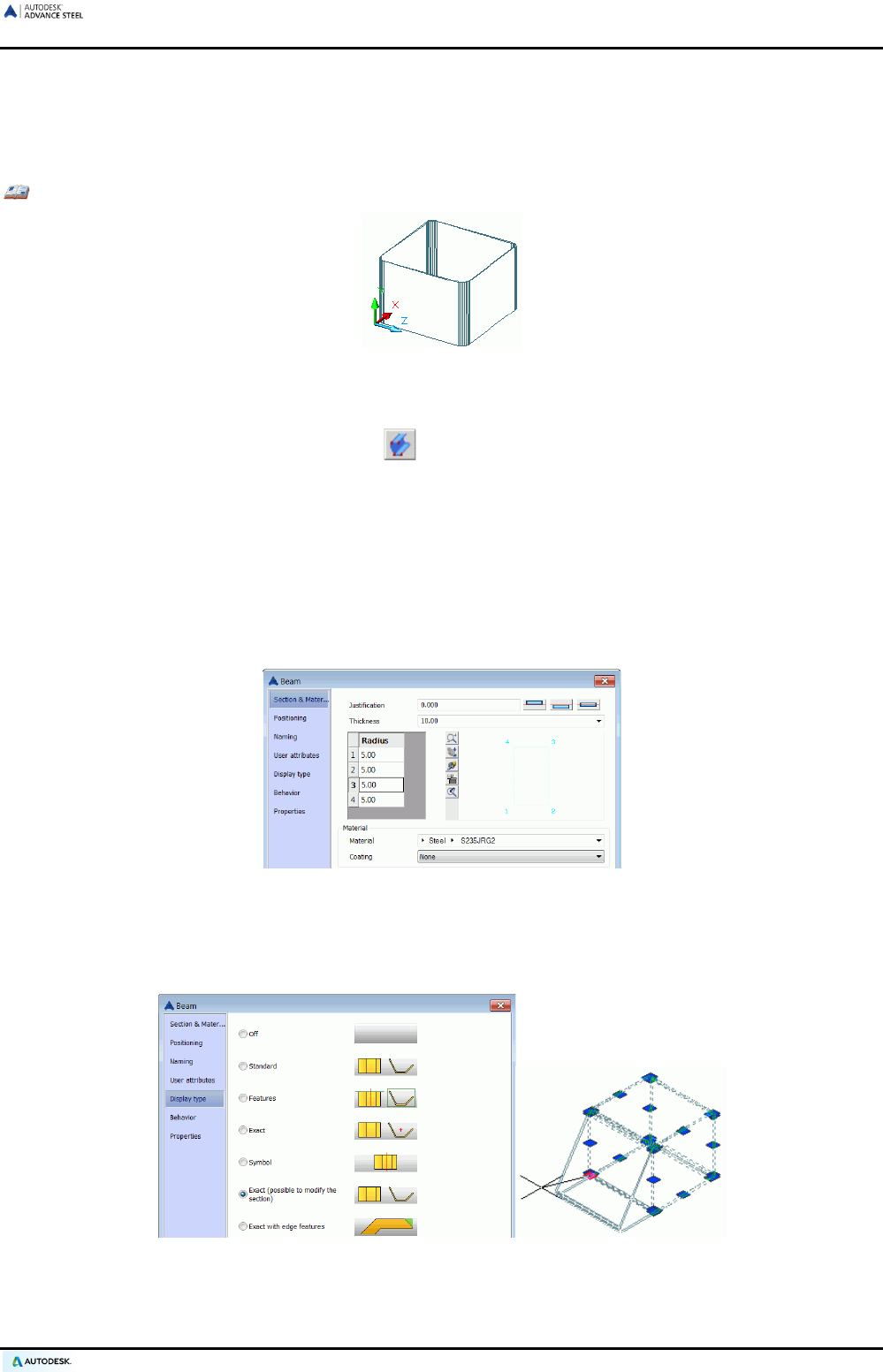
Example: Creating a closed folded profile in the current UCS
Figure 41: Closed folded profile (Z was vertical when created)
• Place a coordinate system with the X/Y-plane in the appropriate plate plane.
• On the Objects tab, Beams panel, click .
• Select the corner points one after another.
• End by pressing Enter.
• Click the start point of the system line.
• Click the end point of the system line.
• The folded profile is created.
The folded profile properties are set and changed in the dialog box. The thickness and the positioning are set on
the Section & Material tab of the properties dialog box. The radius of each corner can also be changed.
Figure 42: Section properties for the folded profile
Folded profiles have a specific representation type Exact (possible to modify the section). If the representa-
tion type is set to Exact (possible to modify the section), the shape of the folded plate is modified by moving
its grips.
Figure 43: Folded profile – Changing the section using grip points
41
ADVANCE STEEL USER’S GUIDE
Construction systems (Cold rolled profiles)
The additional panel of the Beams panel of the Objects tab contains a variety of construction systems. They
include cold rolled purlins, purlin accessories, side rails and curtain wall sections, etc., arranged by supplier:
AGBrown, Albion, Ayrshire, BW Industries, Canam Manac, Canfer, Fischer, HiSpan, Kingspan, Krupp, Metsec,
SAB, SADEF, Staba, StructuralSections, Ward, Zeta, etc. New systems are regularly added.
Figure 44: Cold Rolled Profiles additional panel
These elements are created in the same manner as the other sections by entering a starting point and an end
point. The rotation is dependent on the current user coordinate system.
Example: Creating a Krupp box channel ZR
Figure 45: Krupp box section
• Select a suitable user coordinate system (see Figure 45).
• Click the Krupp tool on the Cold Rolled Profiles panel.
• Select a starting point followed by an end point.
• The section is created.
42
ADVANCE STEEL USER’S GUIDE
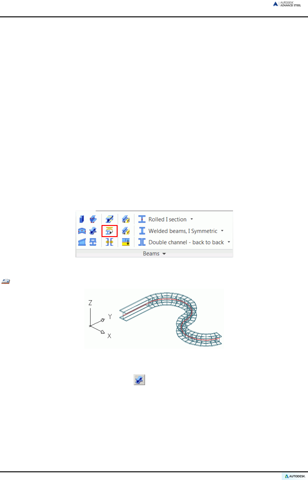
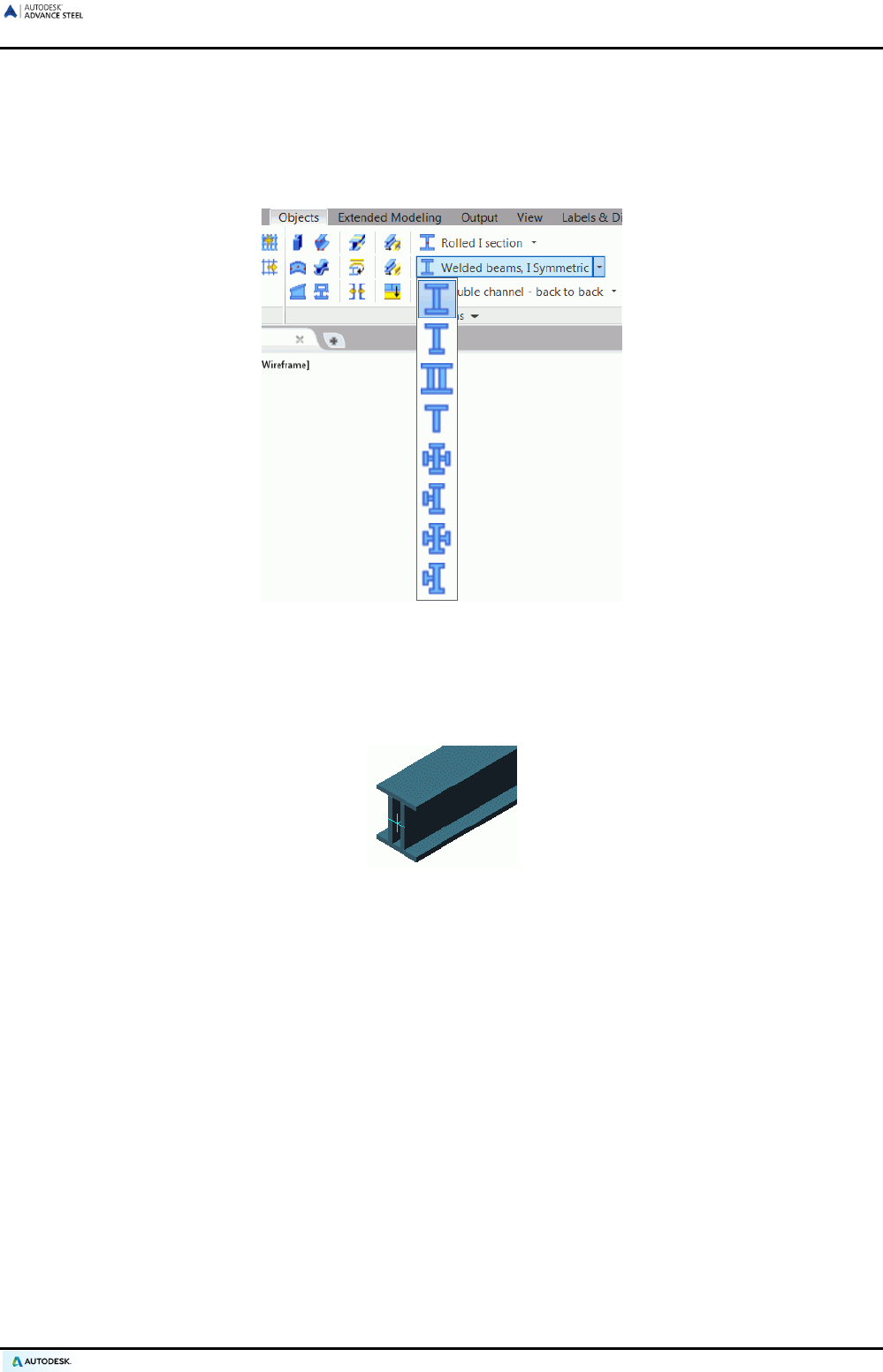
Welded beams
Several profiles welded to each other are created at a system line. The sections are handled as a single section
so that a trim affects all sections.
To create welded beams, use the flyout on the Beams panel of the Objects tab.
Figure 46: Welded beams flyout
Welded beams are created in the same manner as simple sections by entering a start point and an end point in
the current coordinate system. The current user coordinate system (UCS) determines the position of the sec-
tions main axes: the beam web runs in the Z direction of the UCS - or in other words, the top of the section is in
the Z direction.
Figure 47: Welded beam - Hollow
Welded beams properties
Using the Section & Material tab of the properties dialog box, you can control the section class and the section
of each individual element in the welded beam. Additionally, you can create custom welded sections and store
them in a library using Save and Save as.
43
ADVANCE STEEL USER’S GUIDE
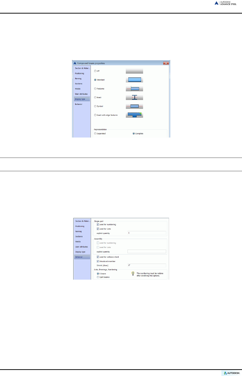
Welded beam representation type
Welded beams have two specific representation types:
• Complete: when the welded beam is cut, the entire section is cut.
• Separated: only the selected element of the welded beam is cut.
Figure 48: Compound beam properties – Representation type
Note: Most intelligent connections work on the welded beams. It is necessary to change the representation
type to Separated or Complete, depending on the connection type, before the creation.
Welded beam behavior
During the numbering process, in drawings and lists, the welded beams behave in two ways:
• As one profile, with a compound section
• As separate profiles
Figure 49: Compound beam properties - Behavior
44
ADVANCE STEEL USER’S GUIDE
Splitting / merging beams
Beams can be split into two or more beams by specifying the split points. Processings of the original beam are
transferred onto the newly created beams.
This tool can be used on straight and curved beams.
Button Function
Split beam
Merge beams
Merge all beams
Example: Splitting existing beams
Figure 50: Split beam
• On the Objects tab, Beams panel, click .
• Select the required beam and press Enter.
• Select the separation point(s) and press Enter,
• Enter a value for the gap that should be between the single beams. Note that a gap will shorten the sys-
tem lines and not apply shorten features.
Using the selected beam, two or more beams are created. Processings of the original beam are transferred onto
the newly created beams. When merging beams, the two or more beams to be merged must be selected.
Creating plates
Plates are created in Advance Steel in almost any shapes and sizes in any plane. The default plate thickness is
controlled by the Management Tools.
The tools to create plates are on the Plates panel of the Objects tab. For easier access, the most used plate
creation tools are grouped on the Objects panel, on the Home tab.
Figure 51: Plates panel
45
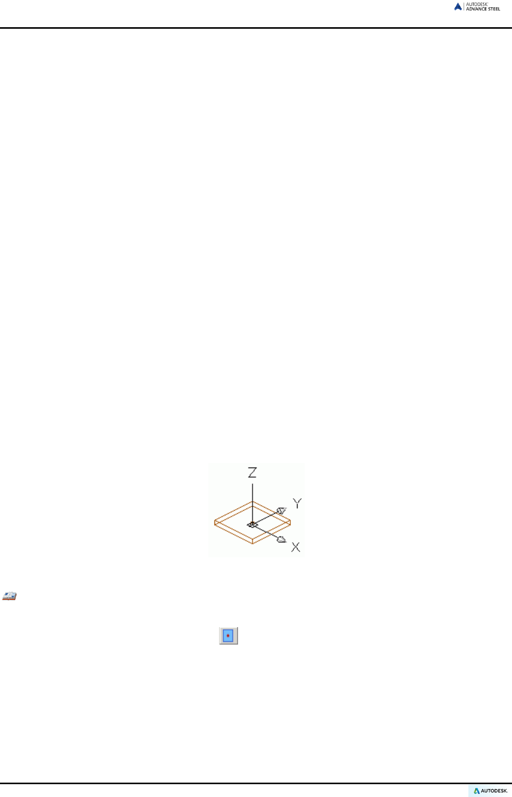
ADVANCE STEEL USER’S GUIDE
The tools allow creating the following shapes:
• Rectangular plates
Rectangular plates are created using a center point, using two diagonally opposite corner points, or using
three points that define a plane.
• Polygon plates
To create a polygon plate, pick the corner points directly or create a polyline that does not have to be
closed. Polygon plates can be resized.
• Folded plates
3D folded plates of any shape are created by joining different plates together.
• Conical and twisted folded plates
Any other shape of plates can be created by merging and modifying the basic plates.
All created plates can be moved and/or changed with AutoCAD® and Advance Steel commands.
• Existing plates can be merged into a single plate or can be divided using a polyline or two points.
• Processings can be used to obtain the desired shape. See the Beam and plate processings chapter.
• Polygon plates can be shrunk or enlarged.
Rectangular plate
Rectangular plates are placed in the X/Y-plane of the current coordinate system.
Rectangular plates are created using several methods:
• By a center point: The rectangular plates of a default size are placed in the X/Y plane of the current coordi-
nate system.
• By two diagonal points: The rectangular plates are placed in the X/Y plane of the current coordinate sys-
tem.
• By three points: Without a UCS in the right plane, a rectangular plate can be created by selecting three
points. The three points define the creation plane.
Figure 52: Rectangle plate, center
Example: Creating a rectangular plate using the center point
• Place a coordinate system with the X/Y-plane in the appropriate plate plane.
• On the Objects tab, Plates panel, click .
• Set a center point by selecting with an object snap or by entering coordinates.
• End by pressing Enter. The plate is created with a default length, width, and height.
46
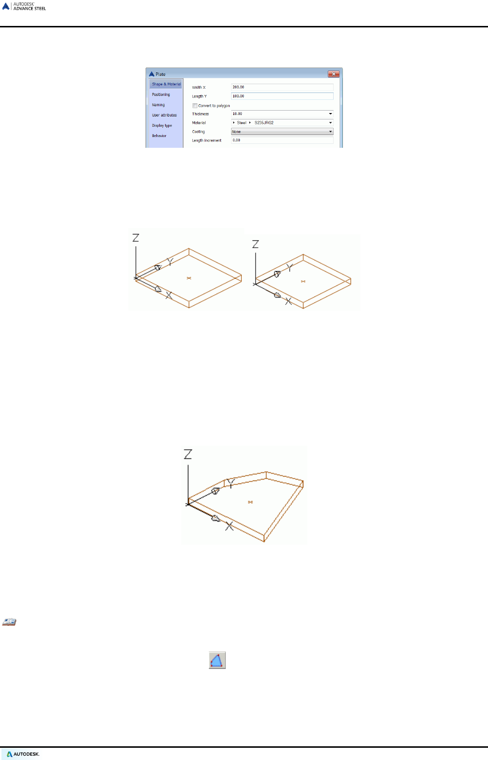
ADVANCE STEEL USER’S GUIDE
In the “Plate” dialog box that appears after object creation, a variety of plate properties such as the plate size
can be defined or changed on the Shape & Material tab (length X, width Y).
Figure 53: “Plate” dialog box – Shape & Material tab
On the Positioning tab, a reference point to the plate (e.g., center, center right, center left, bottom center, bot-
tom right, or bottom left) can be assigned. Also, it is useful for changing plate thickness from the bottom, center
or top of the plate. For example, when increasing the thickness starting at 0.5 (the default center), half the plate
thickness projects in the positive Z-direction and the other half projects into the negative Z-direction.
Figure 54: Plate thickness and plate position
The assigned reference point corresponds to the creation point. When changing the plate size on the Shape &
Material tab, this point remains in position.
Polygon plate
Polygon plates can be drawn directly in the model according to the current coordinate system, or by converting
a line.
• Entering the polygon corner points in the X/Y plane of the current coordinate system creates a polygon plate.
Figure 55: Polygon plate
• AutoCAD® lines and arcs can be converted to plates. The polyline does not have to be closed. In this case,
the position of the plate is independent of the coordinate system since the plate position is determined by
the position of the polyline.
Example: Creating a polygon plate using corner points
• Set a suitable coordinate system.
• On the Objects tab, Plates panel, click .
• Select the corner points one after another.
• End by pressing Enter. The contour of the plate is closed to a polygon plate.
The properties of the plate are set and changed in the dialog box; dimensions in the X/Y-plane are not available
for this plate type.
47
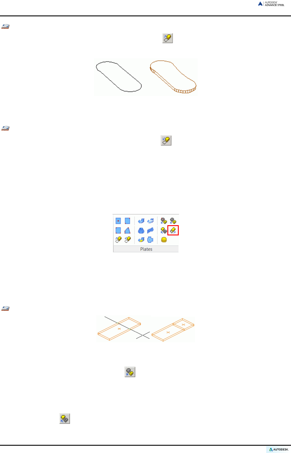
ADVANCE STEEL USER’S GUIDE
Example: Converting a polyline into a plate
• On the Objects tab, Plates panel, click “Plate on polyline” .
• Select a polyline and press Enter.
Figure 56: Polyline and created plate
Any plate can be converted to a polyline.
Example: Converting a plate into a polyline
• On the Objects tab, Plates panel, click “Plate to polyline” .
• Select the plate and press Enter. The plate can be kept or deleted.
• Type Y for Yes (or N for No) and press Enter.
• The plate is converted to a polyline and deleted.
The resulting polyline can be modified and converted back to a plate. The plate is created with its initial properties.
Polygon plates are enlarged or shrunk using the “Shrink/enlarge polygon plates” tool. This tool is frequently
used in curtain wall construction to fit created elements by entering a positive or negative value (e.g., for creat-
ing glazing inside a frame).
Figure 57: “Shrink/ enlarge polygon plates” tool
Splitting / merging - plates
Existing Advance Steel plates are divided into two or more plates using a polyline or two points. All plate pro-
cessings (e.g., contours, etc.) are kept.
Example: Dividing a rectangular plate on polylines
Figure 58: Plate divides on polyline(s)
• First create the polyline(s) on the existing plate at the dividing position.
• On the Objects tab, Plates panel, click .
• Select the plate / plates to divide (identify objects...) and press Enter.
• Select one or more polylines and press Enter.
• Enter a value for the required gap between the plates and press Enter.
To merge plates, click on the Plates panel of the Objects tab, select the plates to merge, and press Enter.
48
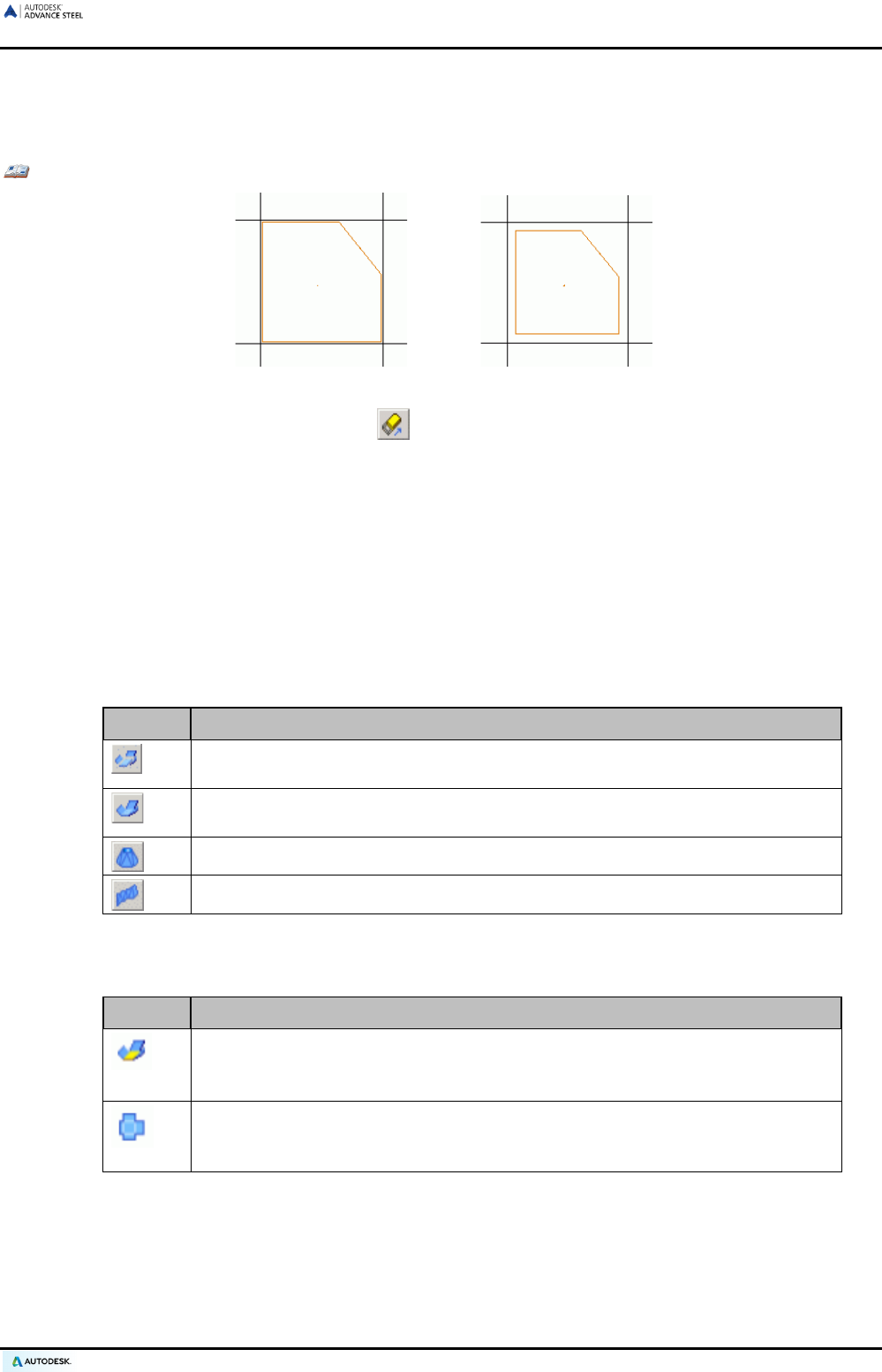
ADVANCE STEEL USER’S GUIDE
Shrinking/enlarging polygon plate
Polygon plates can be shrunk or enlarged. One or more plates must be identified and a dimension must be en-
tered to shrink or enlarge a plate. A negative value shrinks the plate while a positive value enlarges the plate.
Example: Shrinking a polygon plate
Figure 59: Polygon plate before and after shrinking
• On the Objects tab, Plates panel, click .
• Select the plate (one or more) to shrink and press Enter.
• Enter a dimension (e.g., 10). The plate edges move in a perpendicular direction by the entered dimension val-
ue.
Folded plate
3D folded plates of any shape can be created by joining different plates together.
A relation is created between the two joined plates. The relation is represented as a red line along the common
interval of the connected edges. Several different relations can be placed on one edge of a plate.
The tools for creating folded plates are grouped on the Plates panel of the Objects tab.
Button Function
The first selected plate is the main plate and the second selected plate is moved
to join the first one.
The two selected pl
ates are extended or cut along their bisector (intersection)
and become one.
Creates a conical folded plate starting from contours or from beams.
Creates a twisted folded plate from polylines or splines.
For detailing, it is important to define one of the plates as main element and to check if the created folded plate
can be correctly unfolded.
Button Function
Defines the folded plate main element. At creation, the first selected plate is the
main element of the folded plate. Any plate from the c
reated folded plate can be
set as the main plate.
Checks the unfolding.
After creating the folded plate it is necessary to check if
the created folded plate can be correctly unfolded in drawings and in BOMs.
Additionally, the unfolded representation can be displayed.
49
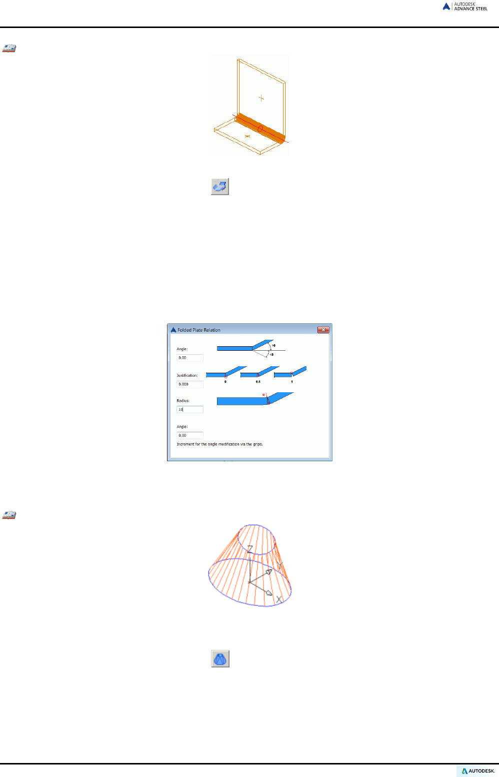
ADVANCE STEEL USER’S GUIDE
Example 1: Two joint plates
Figure 60: Folded plate
• On the Objects tab, Plates panel, click .
• Select the plate to connect near an edge.
• Select the second plate to connect near an edge.
• Set 90 for the angle.
• Press Enter.
• The two plates are joined.
The relation between the two plates can be modified in the “Folded Plate Relation” dialog box. Double
click the red relation symbol.
Figure 61: Bending properties for the folded plate
The angle, justification and radius values can be modified.
Example 2: Conical folded plate using previously drawn contours
Figure 62: Conical folded plate
• Draw two circles or ellipses in suitable user coordinate systems.
• On the Objects tab, Plates panel, click .
• Type C on the command line and press Enter to select the first contour.
• Select the first circle (or ellipse) and press Enter.
• Type C on the command line and press Enter to select the second contour.
• Select the second circle (or ellipse) and press Enter.
50
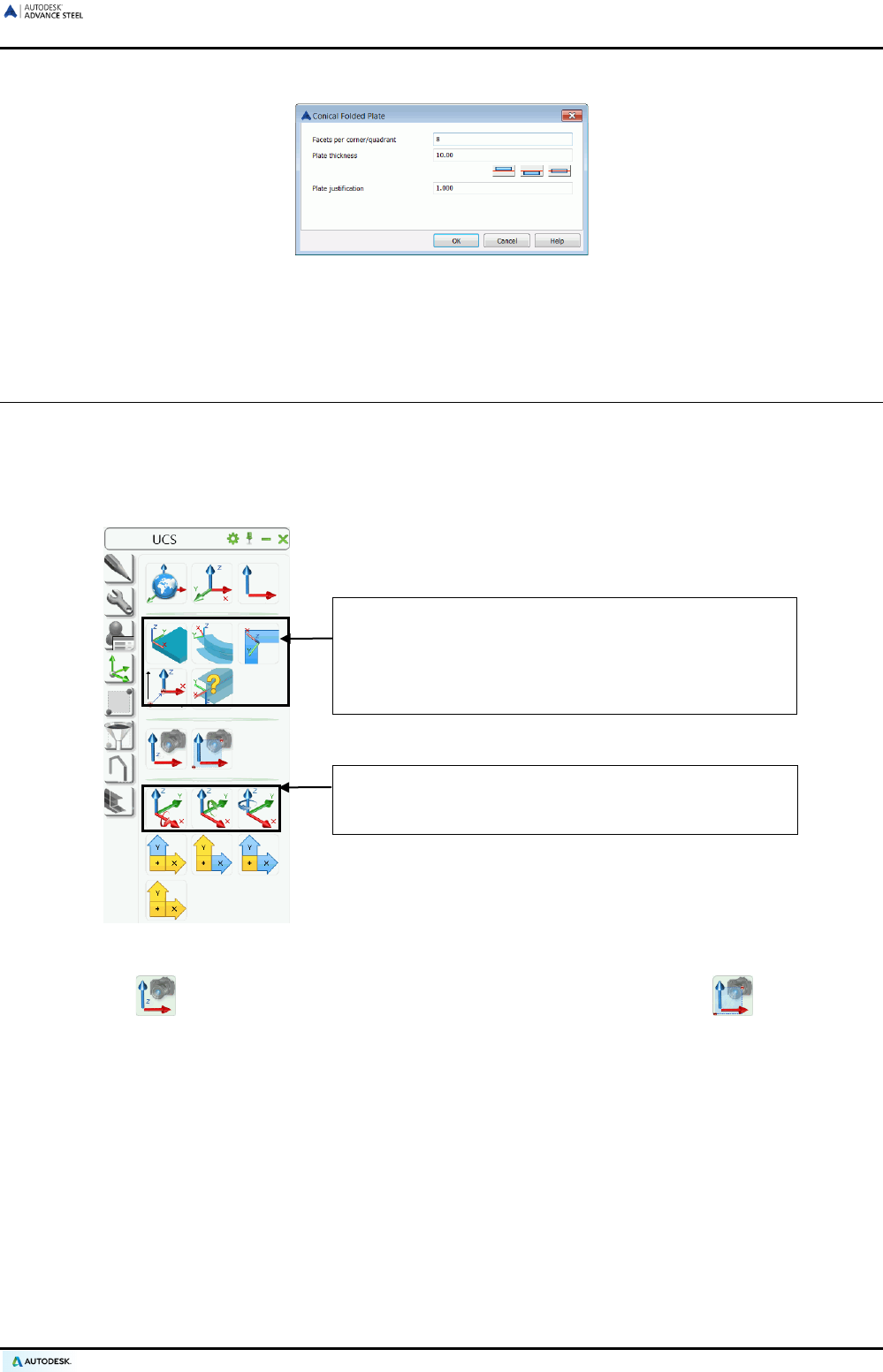
ADVANCE STEEL USER’S GUIDE
• In the “Conical folded plate” dialog box, set the number of facets, the plate thickness and the justification.
Figure 63: “Conical Folded Plate” dialog box
• The conical folded plate is created.
Coordinate systems
In Advance Steel the World Coordinate System (WCS) is fixed and the User Coordinate Systems (UCS) can be
moved/rotated. The UCS takes precedence in almost all cases except where a tool specifically refers to the
WCS (e.g., Define model view with 1 point in WCS).
The Advance Steel UCS tools are located on the UCS tool palette.
Tools for object coordinate systems, coordinate system
on curved beams, coordinate systems on a bisecting
line, and coordinate system definition.
A current UCS is moved to a new origin point, in which
the orientation of the axes remains the same.
The current UCS is rotated by 90° around the X-/Y-/Z-
axes of the current user coordinate system using these
three buttons.
Figure 64: UCS tools
“View on UCS“ sets a view in the Z-axis of the UCS and “Clipped view on UCS“ sets clipping to
improve the view area for the required construction.
Object Coordinate Systems
Advance Steel objects are always created relative to the current coordinate system.
Each Advance Steel object has its own object coordinate system. The X/Y plane of the object coordinate sys-
tem is perpendicular to the web (parallel to the flange) of a beam or to a plate surface. The Z coordinate points
to the TOP of a beam or represents the default direction for a plate thickness.
If processings or connection objects are to be created at beams or plates, it is recommended to set a UCS ori-
entation corresponding to a suitable object coordinate system. For example, an object coordinate system can be
activated in a plate plane if a contour processing will be created in this plane.
51
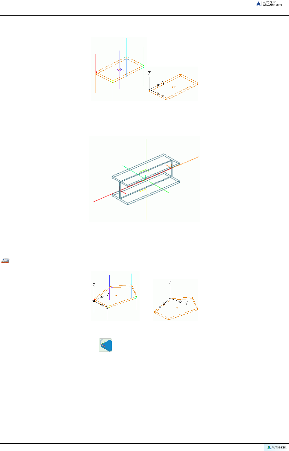
ADVANCE STEEL USER’S GUIDE
• Rectangular plates have ten object coordinate systems.
Figure 65: Plate with 10 object coordinate systems, current object coordinate system
• Beams have six basic object coordinate systems.
Figure 66: Beam with six object coordinate systems
Select an object coordinate system as a user coordinate system using the tool “UCS at object” on the UCS tool
palette.
Example: Activating an object coordinate system of a polygon plate as a UCS
Figure 67: Object coordinate system as UCS
• On the UCS tool palette, click .
• Select a polygon plate. The coordinate systems are displayed. The respective axis directions are dis-
played as lines with different lengths. The positive Z-axis is displayed as the longest line.
• Select one of these lines (e.g., the yellow line pointing upwards). A UCS is set corresponding to the se-
lected coordinate system.
52
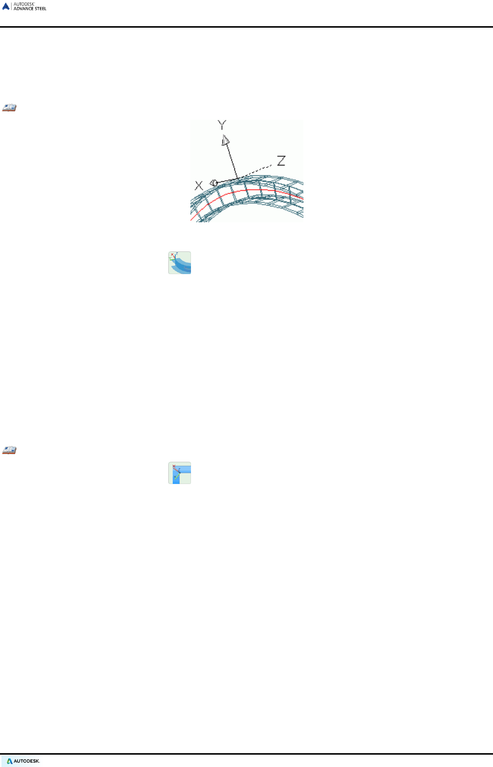
ADVANCE STEEL USER’S GUIDE
Coordinate systems at curved beams
A dedicated coordinate system tool is available for curved beams. Place an object coordinate system on any
point of a curved beam (Z-axis follows the radial line) using the “UCS at curved beam” tool.
Example: Creating a coordinate system at a curved beam
Figure 68: UCS at a curved beam (UCS has been subsequently rotated about the X-axis)
• On the UCS tool palette, click .
• Select a point on the curved beam.
• Select an additional creation point for the position of the coordinate system or press Enter.
• The coordinate system is created.
The additional point does not need to lie on the beam. Thus, a UCS can be set on a curved beam at the exact
location of an approaching beam for constructing a connection at this location.
UCS at a bisecting line
The “UCS to bisecting line” tool creates a user coordinate system at a bisecting line. This tool is suitable for
creating sections at the bisecting angle of two other beams (e.g., in facade construction).
Example: Creating a UCS at a bisecting angle
• On the UCS tool palette, click .
• Locate a point of origin for the UCS.
• Pick another point to define the Z direction.
• Pick a point to define the first bisecting plane.
• Pick a point to define the second bisecting plane.
• The X-axis of the new UCS bisects the 2 selected planes.
Defining a coordinate system
The “Initial coordinate system” tool is useful for placement on existing objects. The position and orientation of
the coordinate system corresponds to the coordinate system of the object at the time of creation. Thus, other
objects with identical positions and orientations can be created.
For plates, a coordinate system is created with the same orientations as when the plate was created.
For beams, a coordinate system is created at the beginning of the beam system line. This coordinate system
has an orientation that allows the creation of a new beam in the same orientation.
53
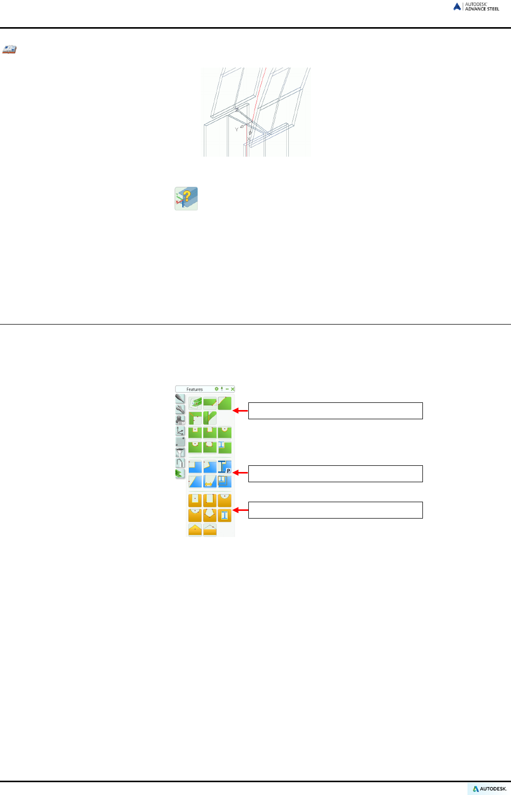
ADVANCE STEEL USER’S GUIDE
Example: Creating a coordinate system on an object
Figure 69: Initial coordinate system
• On the UCS tool palette, click .
• Select an object (the curved beam in this case). At the end of the beam a red coordinate system line
appears.
• Choose a red coordinate system line and with it a coordinate system.
• Press Enter. The coordinate system is created.
Beam and plate processing
Advance Steel processing creates almost any element (beam or plate) contour processing. A beam or a plate
can also be processed by another element (e.g., another beam).
All processing tools are located on the Features tool palette.
Processings on beams and plates
Processings on beams
Processings on plates
Figure 70: Tools for beam processing
54
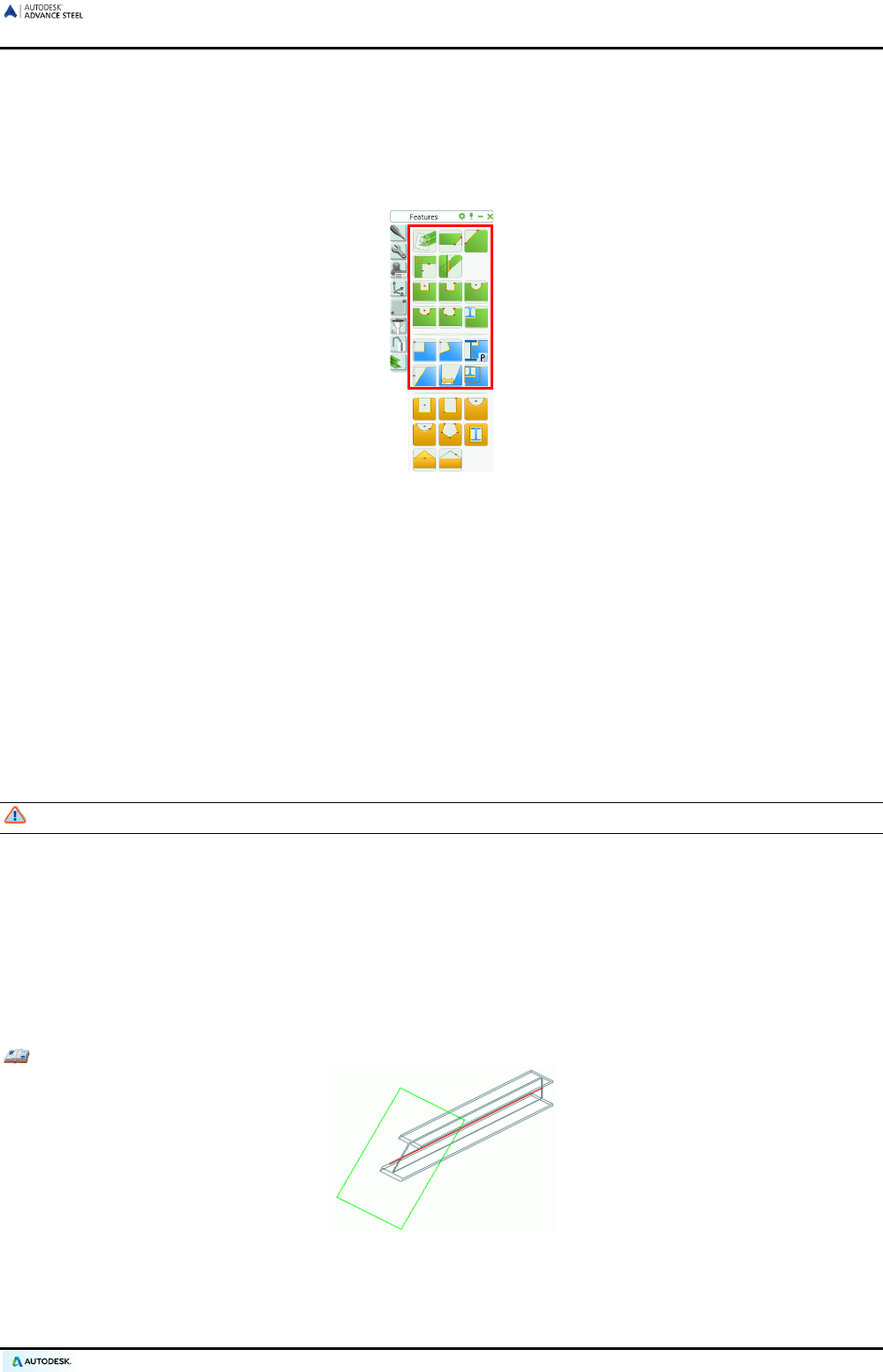
ADVANCE STEEL USER’S GUIDE
Beam processing
Advance Steel processing creates almost any beam contour processing. A beam can also be processed by
another element (e.g., another beam).
The processing tools are located on the Features tool palette.
Figure 71: Tools that can be used for beam processing
Select one of the icons and then click the beam end to process (e.g., trim, cope).
If two beams are individual, as for a miter cut, both beams must be identified after starting the tool. Follow the
command line prompts.
Processing is dependent on the UCS and is created parallel to the current coordinate system. A suitable coor-
dinate system must first be set up. It is recommended (especially for contour processing curved beams) to place
a user coordinate system at the beam before processing.
Some of the processing tools work independently of the current coordinate system. For example, trim and
cope tools are relative to the identified objects.
Some commands, such as creating a rectangular processing, a center point or two diagonally opposite points to
determine a contour must be entered after identifying the beam end.
To create diagonal points switch off the Ortho mode.
Upon creating a beam processing a dialog box for modifying other parameters appears.
Processing objects
Beams or plates are processed when creating a processing object. Processings are displayed as green con-
tours in the model. These features are Advance Steel Objects that cannot exist independently; they belong to a
basic object (e.g., beam or plate).
Processing objects are created on the same layer as the associated basic object and can be deleted separately.
Example: Object processing - beam trimming
Figure 72: Beam trimming, rotation of the end plane
To trim a beam or a plate, a “shorten” processing object is created into the same layer as the beam. By setting a
positive shorten value the beam is trimmed whereas setting a negative shorten value the beam is extended. The
object processing is displayed in green.
55
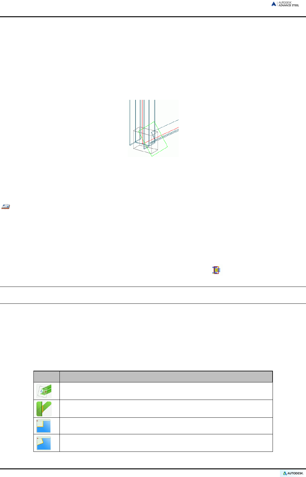
ADVANCE STEEL USER’S GUIDE
If a processing object is deleted, the beam trimming including the end plane rotation is undone.
If the beam is deleted, the processing object will also be deleted.
Rule-based beam processing
Some of the beam processings are based on rules (e.g., the “Cope, parametric” command.) This means that
when modifying a beam (e.g., a section) the processing is also modified.
As for joints, processings based on rules are controlled with a connection object, through which feature proper-
ties can be changed.
Figure 73: Connection object (dashed), processing object (rectangle)
The connection objects are represented in the model as gray objects (boxes) and by default are hidden.
Processings are displayed in the model using the “features” beam representation style. For joints that only create pro-
cessing objects, this representation style is required to display the connection object (box).
Example: Displaying a connection object of a rule-based beam processing:
• Select one of the processed objects.
• Right click and select Advance Properties from the context menu.
• On the Display type tab of the properties dialog box select the Features representation type.
All processings created by the rule are displayed.
• Select one of the features created by the rule.
• On the Extended Modeling tab, Joint utilities panel, click “Display” .
Tip: A quicker method to display the connection object of a rule-based processing is to right click the
feature (green frame) and to select Joint properties from the context menu.
Process section and section contour
The Features tool palette contains tools for processing the sections and section contours.
Process section
The following tools for processing the sections are available:
Button Function
Shorten at UCS for straight and curved beams
Cut at object – Rule: Beams are modified to other beams with a diagonal cut
Cope
Cope skewed
56
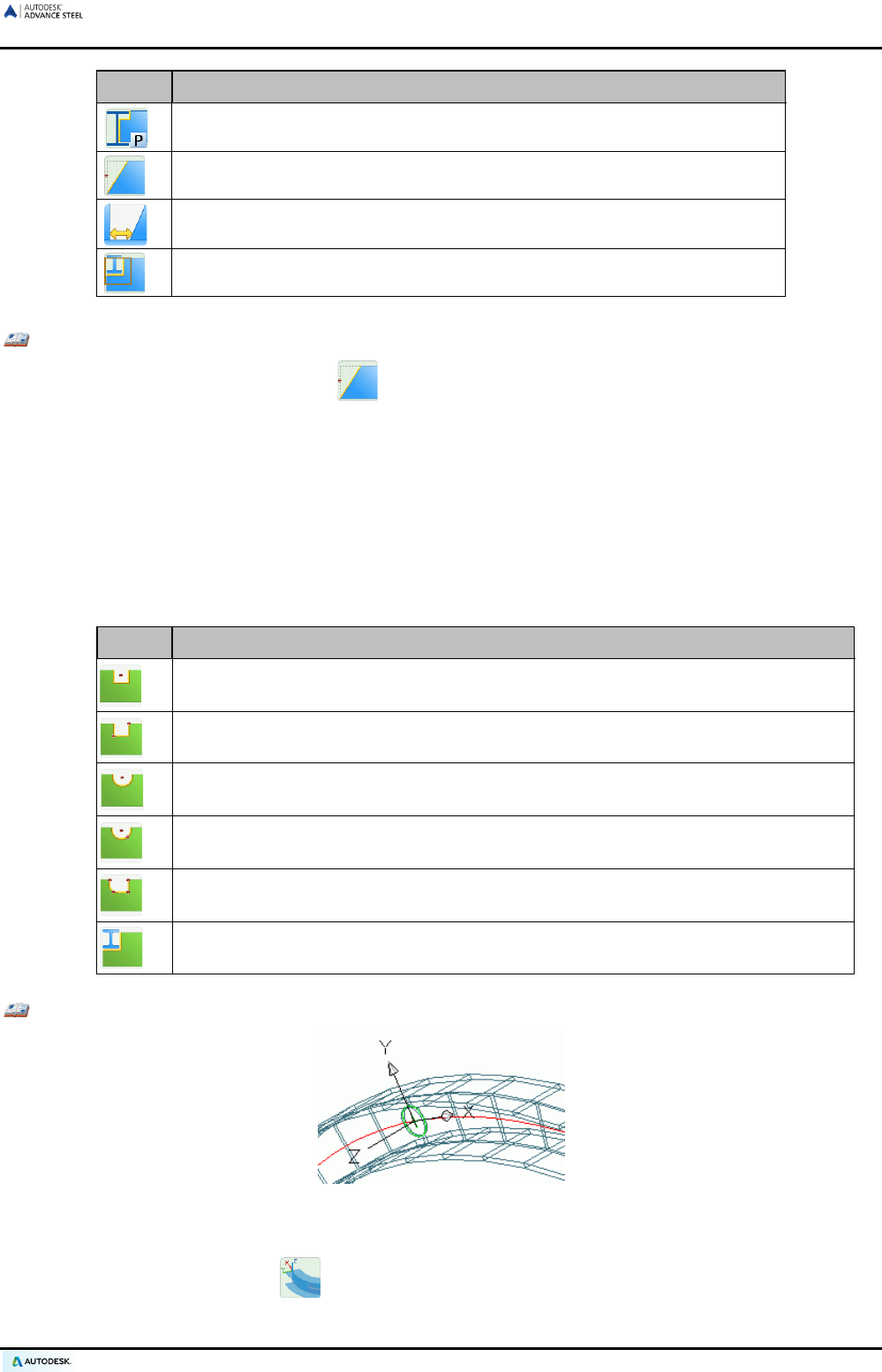
ADVANCE STEEL USER’S GUIDE
Button Function
Cope, parametric
Shorten for straight and curved beams
Beam clearance
Element contour
Example 1: Beam trimmed by 100 mm, beam end plane rotated by 30° (see Figure 82)
• On the Features tool palette, click .
• Select a beam at a reference end.
• The “Shorten beam” dialog box appears and the beam processing is represented as a green contour
using the default value.
• In the properties dialog box, input the rotation angle for the beam end plane. The reference point is
where the beam system line intersects the cutting plane. The beam end plane is rotated.
Section contour
The Features tool palette contains the following tools for creating section contours:
Button Function
Rectangular contour
, Center: A rectangular contour is cut from the beam. It can be
an outside (cope) or inside (hole) contour. The contour is created parallel to the UCS.
Rectangular contour, 2 Points: The processing can be assigned to a beam end to
keep its position if the length changes. The feature is created parallel to the UCS.
Circular contour, center, parallel to UCS
Circular contour, 2 Points
Polygon contour: Any contour
(polygonal, circular shape) can be cut from the beam.
For curved beams it is recommended to first set a UCS on the object.
Element contour
processing: A straight or curved beam is processed through the
geometry of another straight beam.
Example: Creating a circular processing in curved beams.
Figure 74: Circular processing in curved beams
• The processing tool is dependent on the current UCS. Therefore, set a beam coordinate system using
the “UCS at curved beam” tool (UCS tool palette); rotate, if needed, so that the X/Y-plane lies on
the web.
57
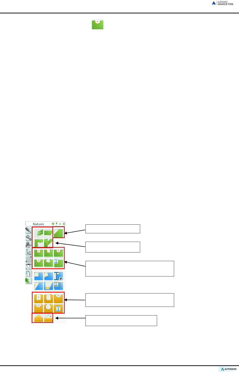
ADVANCE STEEL USER’S GUIDE
• On the Features tool palette, click .
• Select a beam at a reference end.
• Next, set the center point of the contour processing (0,0,0).
• The contour processing is created and the “Contour processing” dialog box appears.
• Radius, position, contours (gap, width), and grid values can be changed.
Miter cut
In a miter cut the intersection is created vertically or at the bisecting line. Each of the two beams gets a pro-
cessing object at their end. The sections insertion axes must lie in the same plane. For sections that intersect
the longer parts is cut to miter.
The feature is based on rules, so the properties can be modified through the connection object. To modify the
properties, display the connection object.
Beam processings are a very powerful feature. For further details refer to the Advance Steel Help.
Plate processing
The tools for plate processing are located on the Features tool palette.
Processing objects are classified as either independent or dependent on the current coordinate system, corner
finishes, or features for polygon plates.
Plate processings are created in the model as green contours. They are always perpendicular to the plate
plane. Features made using a diagonally passing element are trimmed in such a way that the processing edges
are perpendicular to the plate plane.
Advance Steel plate processing objects cannot exist independently; they exist only as objects attached to a
plate. The plate processings can be deleted as a separate object. If the processed plate is deleted the feature is
deleted as well. Processing objects are on the same layer as the associated plate but the color is set to green
for recognition. Combining individual processing objects can create any imaginable feature shape.
When creating a plate processing object a context sensitive dialog box appears. The various tabs contain addi-
tional processing options.
Corner finishes
Weld preparations
Plate processings dependent on the
current coordinate system
Plate processings independent on the
current coordinate system
Polygon plate processings
Figure 75: Tools for plate processings
58
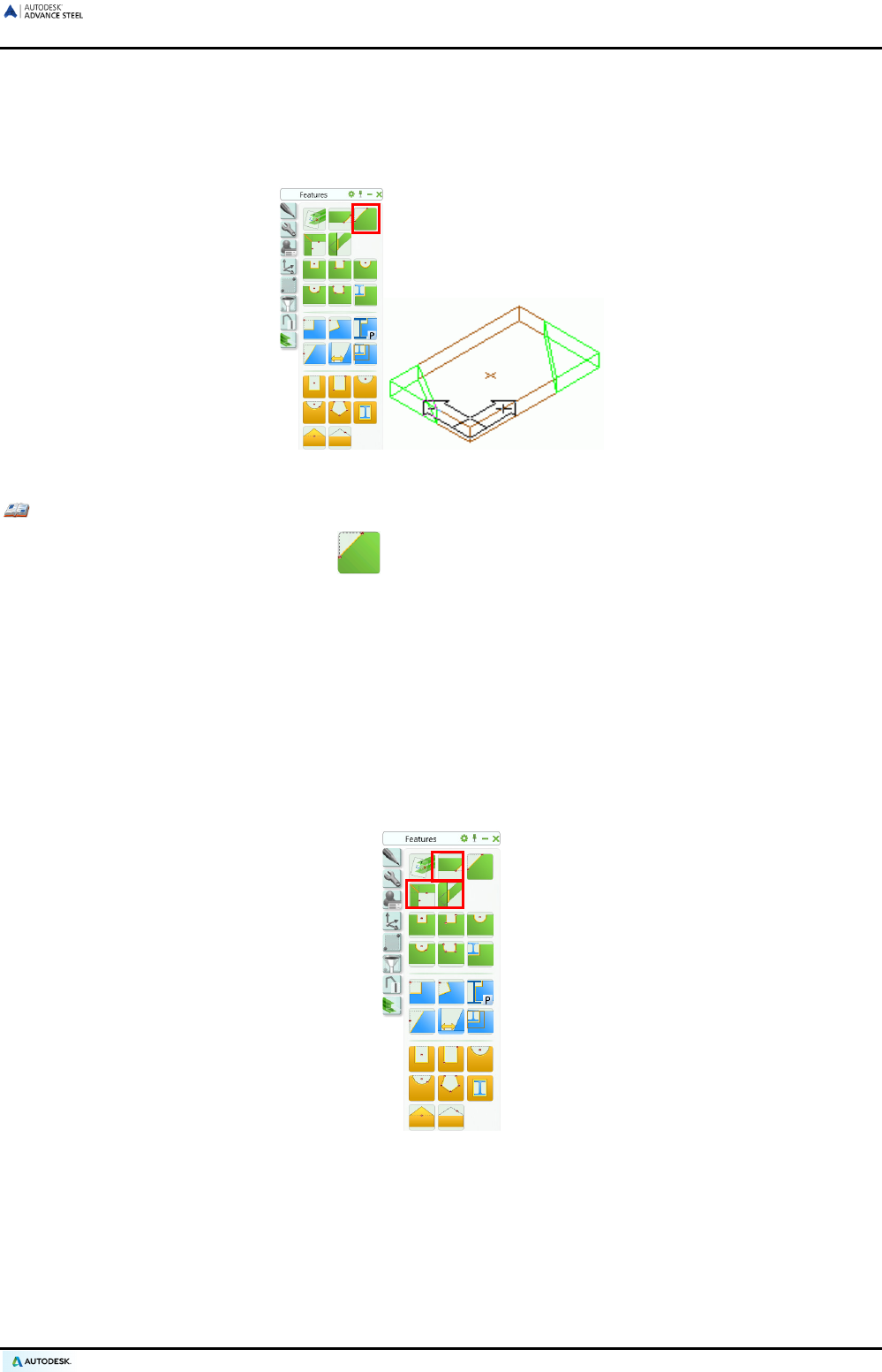
ADVANCE STEEL USER’S GUIDE
Corner processing
The Features tool palette also includes a command for corner processings and fillets of plates and beams.
Corner processing can be attached by defining one point on the side of the element to cut.
Figure 76: Corner processing on plate
Example: Corner processing on plate
• On the Features tool palette, click .
• Click the side of the plate at the corner to cut.
• The corner processing is created at the selected corner and is represented with a green contour pro-
cessing. The properties dialog box appears in which the length X and the width Y of the corner pro-
cessing can be changed. The first identified edge represents the X direction.
Weld preparations
The weld preparation tool sets weld preparations on plate edges and changes the plate front edges (in the Z-
direction) with bevels or fillets.
The Features tool palette contains the following weld preparation tools:
Figure 77: Weld preparation tools
59
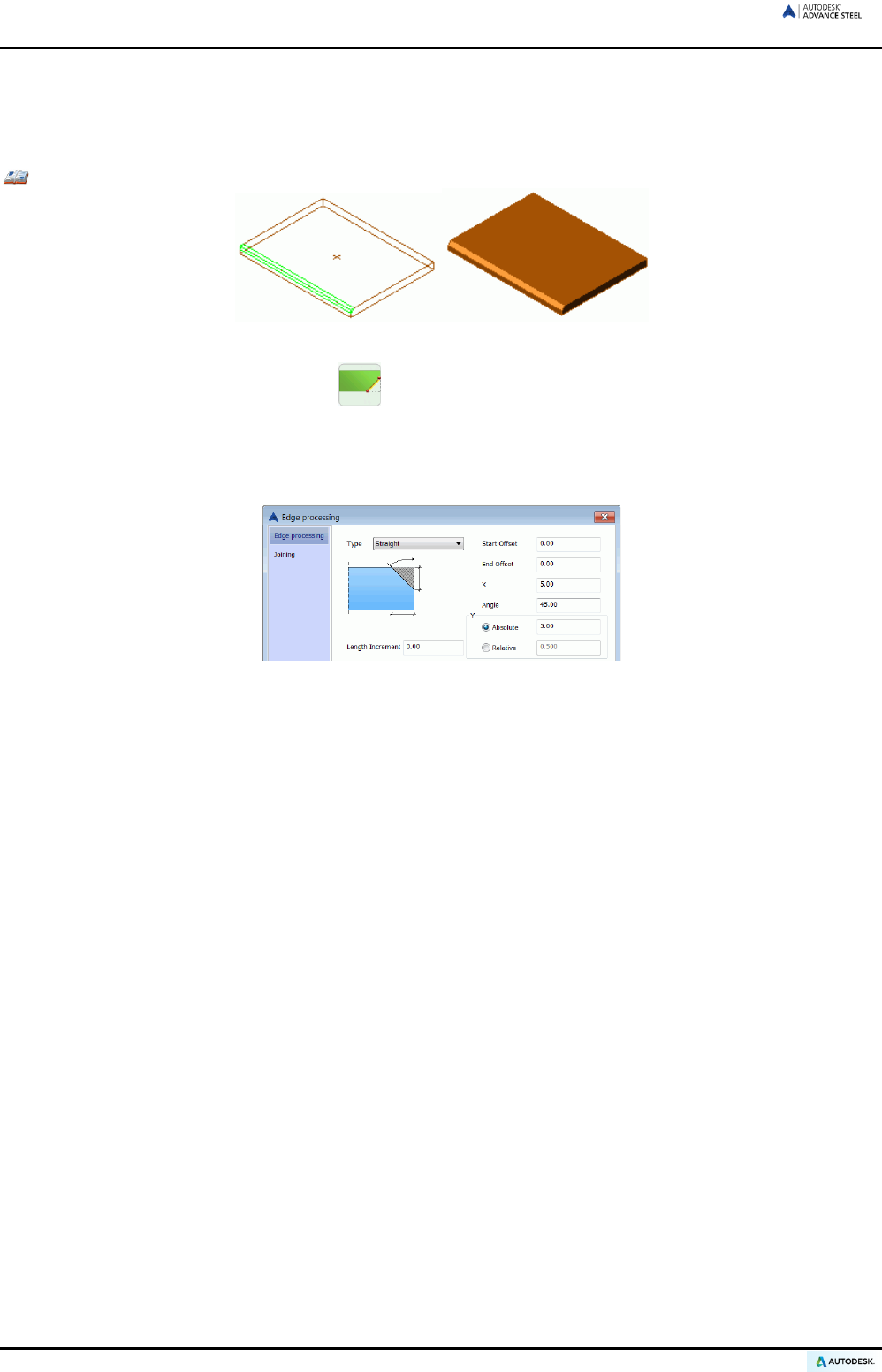
ADVANCE STEEL USER’S GUIDE
Weld seam preparations (Edge processings)
To create a weld preparation, a side that has straight edges must be selected. The Exact with weld prepara-
tion representation type shows the resulting exact shape with bevels or fillets at the edges. Weld preparations
are represented in green.
Example: Creating a bevel weld preparation on a plate
Figure 78: Plate with weld preparation
• On the Features tool palette, click .
• Select a plate at a reference edge.
• The weld preparation is created and the “Edge processing” dialog box appears. The type of processing
and the corresponding properties can be changed.
Figure 79: “Edge processing” dialog box
Since the bevel angle value and bevel width X of a straight processing are related, the second value is calcu-
lated automatically when one value is entered.
Available options for bevel height are relative or absolute.
The weld preparation is related to the edges such that it is updated if the plate contour is changed.
Miter
In a miter cut the intersection is created vertically or at the bisecting line. Each of the two plates gets a pro-
cessing object at their edge.
The feature is based on rules, so the properties can be modified through the connection object. To modify the
properties, display the connection object.
Cut at object
This command extends or cuts one plate to another and creates a chamfered edge processing (for weld preparation) at
the modified plate.
The feature is based on rules, so the properties can be modified through the connection object. To modify the
properties, display the connection object.
60
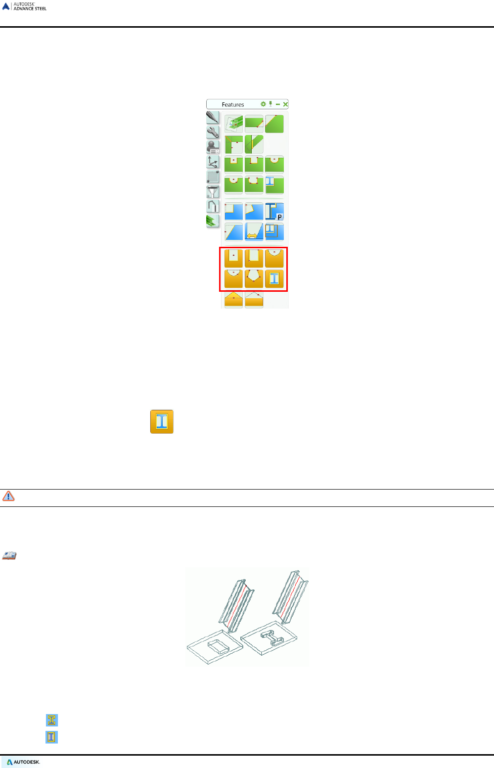
ADVANCE STEEL USER’S GUIDE
Plate processing – independent from the UCS
The Features tool palette contains also plate processing tools, which are used independent of the current user
coordinate system.
Figure 80: Features tool palette - Plate processing tools independent of the UCS
There are four basic processing styles:
• One or two points to determine rectangular processing.
• One center point or two points – (center point and radius point) creates a circular processing object.
• Any contour processing (selected through points) can be developed as inner or outer contours.
• Using the “Contour element” feature, a plate can be processed by a beam or by another plate.
To create a plate processing, the plate is identified near its corner. Then the program requests a center or se-
lected points that determine a processing contour.
To create points the Ortho mode must first be turned off.
A “Plate contour” dialog box appears, in which the form of the plate contour (length X, width Y), the position,
contour (gap width), grid value, and corner feature (radius, boring) can be specified.
Example: Plate contour element processing
Figure 81: Plate with casing and exact processing
• Select the type of processing with the switch on the Switch panel of the Objects tab.
Exact cross section
Casing cross section
61
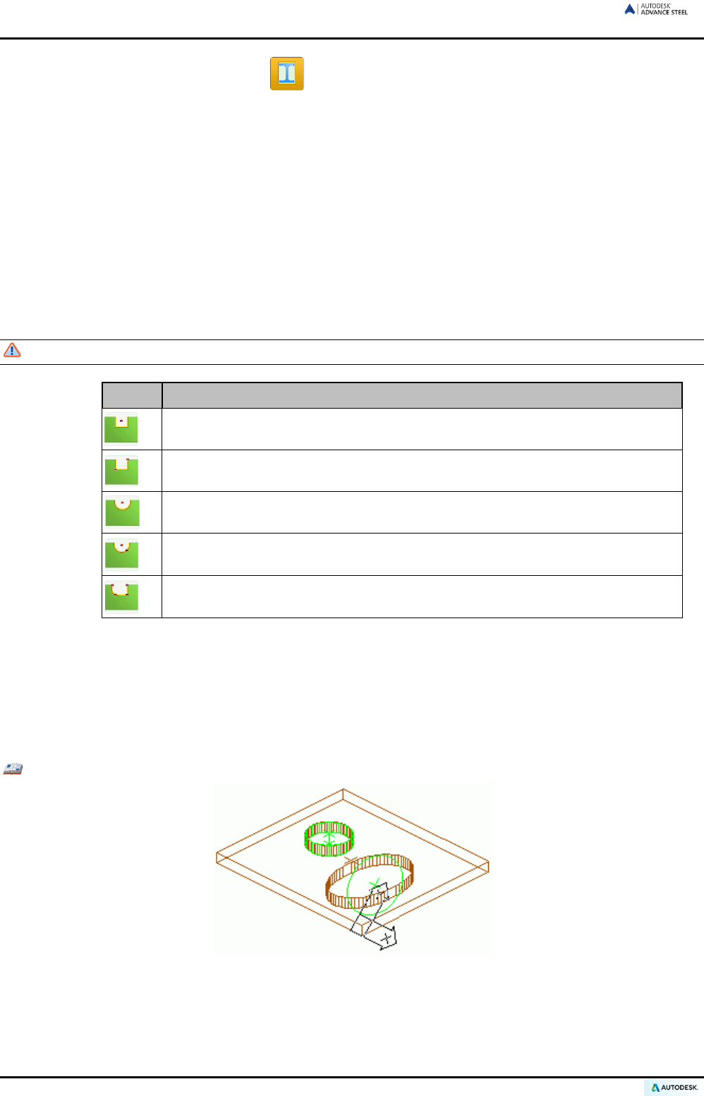
ADVANCE STEEL USER’S GUIDE
• On the Features tool palette, click .
• Click the plate to be modified.
• Click the element to cut to. The plate processing is performed.
• The “Contour processing” dialog box appears. The contour (gap width), grid (increment for modifying
the length by the grips), and corner finish (fillet, boring) can be specified.
Plate processing – dependent on the UCS
The following UCS dependent processing types are available on the Features tool palette:
• Rectangular processing determined by one or two points
• Circular processing determined by a center point or two points (center and radius point)
• Any contour processing selected by points
Verify that a suitable user coordinate system (UCS) is set before starting the feature tool.
Button Function
Rectangular contour, Center: A rectangular contour is cut from the plate
. The
contour is created parallel to the UCS.
Rectangular contour, 2 Points: A rectangular contour is cut from the plate
. The
contour is created parallel to the UCS.
Circular contour, center, parallel to UCS
Circular contour, 2 Points
Polygon contour: Any contour
(polygonal, circular shape) can be cut from the
beam. For curved beams it is recommended to first set a UCS on the object.
The procedure for creating a UCS dependent plate processing is identical to that of UCS-independent processing.
Some plate features, in addition to being independent, can also be dependent on the current user coordinate
system (UCS). For processings dependent on the UCS, the definition points of the object processing are placed
in the coordinate system plane and projected along the Z-direction onto the plate plane. The result is that the
length and width of the processing in the plate plane are distorted. For an independent processing, the definition
points and the object processing are placed directly in the plate plane.
Example: The plate processing circular contour and circular contour UCS
Figure 82: independent (circle) and dependent processing (ellipse) on the coordinate system
This example illustrates the effect of a UCS dependent circular processing. The circular processing lies in the
coordinate system. The circle is projected onto the plate plane and presents an oval feature. The processing
edges are always perpendicular to the plate plane.
62

ADVANCE STEEL USER’S GUIDE
Polygon plate processing
Polygon plates are processed using two commands of the Features tool palette. Corners can be added or de-
leted using these commands.
Figure 83: Features tool palette - Plate corner tools
Button Function
Creates an additional corner on the mid-point of the selected edge.
Deletes a corner so that a new edge is created between the adjacent corner points.
Example: Insert an additional corner in a polygon plate
• On the Features tool palette, click .
• Click the polygon plate to be modified at the edge that is to split.
• An additional corner is created on the mid-point of the selected edge. Its position can be modified using
the grip point.
Figure 84: Additional corner on a polygon plate
It can be modified in the same way as all other corners by using the grip point.
Figure 85: Changing the shape using the additional point
63
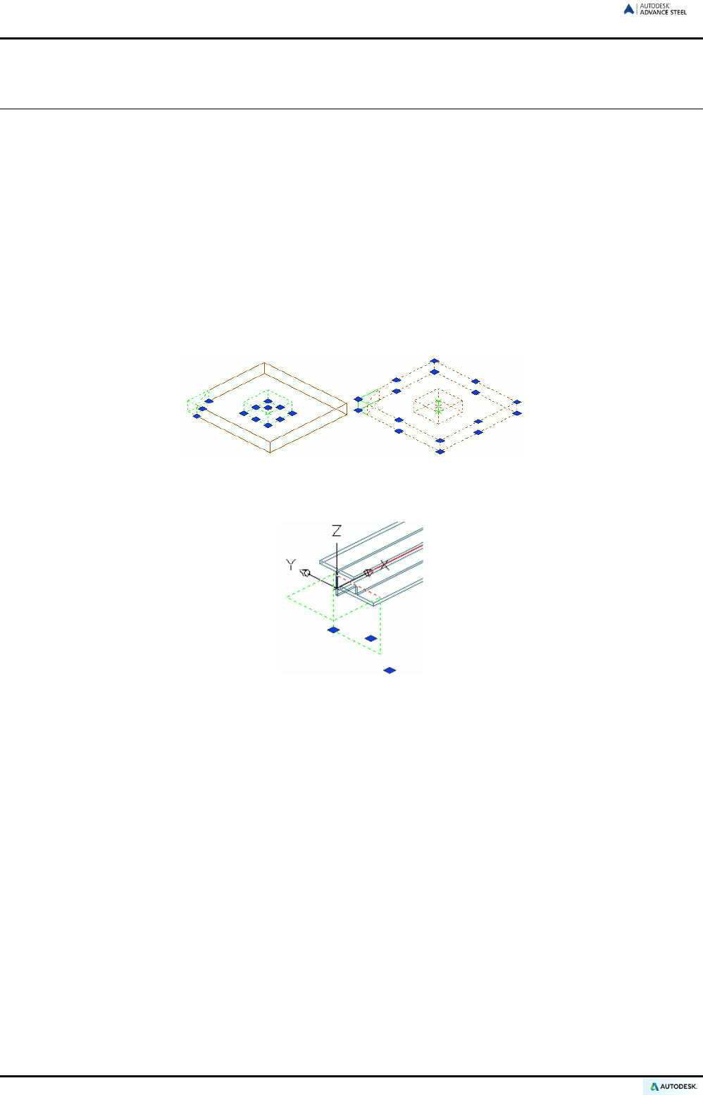
ADVANCE STEEL USER’S GUIDE
Changing Advance Steel objects
Position, geometry, and attributes of Advance Steel objects (e.g., beams, plates) can always be changed using:
• Advance Steel specific grips
• Manipulating tools: Moving, Rotating, Copying, Mirroring
• Properties command
• Advance Steel Properties command
Changing objects using grips
Grips are displayed by clicking on an element (e.g., a plate or its feature) and are activated by clicking on a grip.
The elements geometry or features are changed with grips as can their size or position by dragging a grip(s).
Changes using grips are limited to the X/Y-plane of the current coordinate system.
Figure 86: Grips for changing the plate processing / plate
For some manipulations the grips have no effect if modified outside the UCS X/Y-plane.
Figure 87: Advance Steel grips for changing the beam processing
In the above example, the grip is only moveable in the X-direction.
For some objects, it is also possible to assign grid values that are used when using the grips.
For example, a shortening can only be moved by the given grid value (increment) using the grips in the current
user coordinate system (UCS).
Grid values are always applied globally to all types of objects and are not stored per object. This means, if a
value was created for a plate feature, it is also applied to other plate features that are created. This also applies
for the gap between features and the objects that are to be processed.
Manipulating tools
For Advance Steel objects, the following Manipulating Tools are implemented:
• Move
• Rotate
• Array
• Mirror.
64
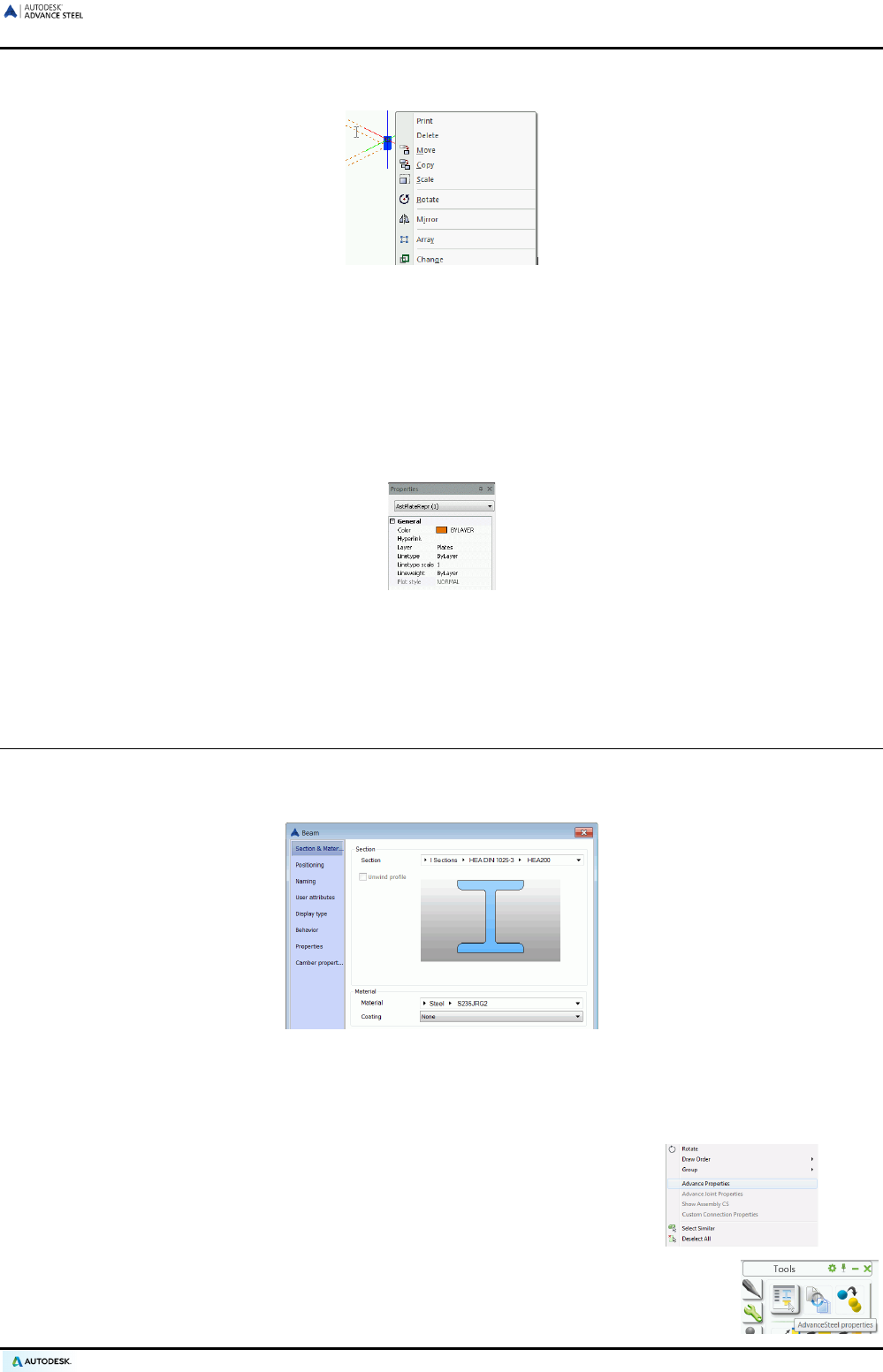
ADVANCE STEEL USER’S GUIDE
The standard manipulating tools such as “Move”, ”Rotate”, etc. are available by right mouse click. First, click a
grip (in red by default), then right click.
Figure 88: Manipulating Tools
The right click menu is context sensitive and only the available features/tools are displayed for an object.
When changing the object geometry using grips, the coordinates of the moving point are projected onto the
current coordinate system.
AutoCAD properties
To change the AutoCAD properties of an element such as layer, color, etc., right click on the object and select
Properties (not Advance Properties). Alternatively on the command line type the DDCHPROP command.
Figure 89: AutoCAD properties of a selected plate
Note that changing layers is simpler by selecting the objects to modify, then selecting the appropriate layer on
the Layers panel of the Home tab.
Advance Steel command properties
Each Advance Steel object has initial default properties. The properties are viewed and changed in the Advance
Properties dialog box.
Figure 90: Advance Steel Properties Beam dialog box, Section & Material tab
There are several ways to access the element properties:
• Double click the element
• Right click the element and select Advance Properties from the context menu.
• Select the required element and then click the “Properties” icon on the Tools tool palette.
65
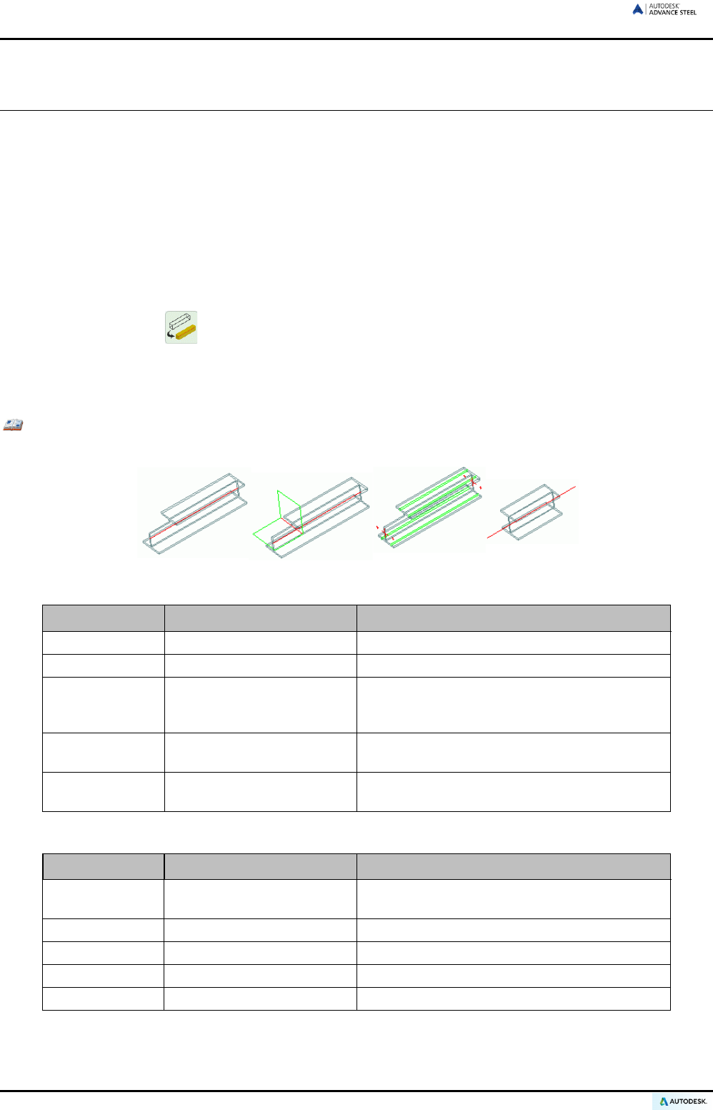
ADVANCE STEEL USER’S GUIDE
Representation Type – Snaps – Grips
To keep Advance Steel clear and simple in the different phases of construction, Advance Steel objects have
their own different representation types (e.g., “standard”, “features”, and “exact”).
Since the different representation types of objects normally correspond with different constructive courses, the
representation types in each case use different snaps and have grips.
The total construction of a model is clearest in the “standard” representation type, in which processing objects
are not shown.
When processing and connecting beams or plates, the “features” representation type is very useful, especially
since the required grips for changing the features are available.
• The representation types are changed for each object either in their dialog box (e.g., beams, plate, Display
type tab) or clicking on the Quick views tool palette (refer to the Changing representation type sec-
tion of this chapter).
The representation types (and available grips) are specific to each object. The examples use beam and plate
objects. Refer to the Advance Steel Help for more details.
Example: Beam representation
An Advance Steel beam is displayed in one of four representation styles:
Figure 91: Beams in the representation types “standard”, “features”, “exact”, and “symbol”
Beam Representation type Name
Representation 1
Standard
Section edges and creation axes of the beam
Representation 2
Features
Section edges and processing objects
Representation 3 Exact Section edges and gauge lines, crosses on end
points of the creation axis and four reference
points in the start and end planes
Representation 4 Symbol Creation axis and a
small part of the beam in
the center
Representation 5 Exact with edge features Exact section edges and all processing objects
(including edge processing)
The beam has different grips in each representation type:
Representation type Name
Representation 1 Standard
End point creation axis, reference point in
beam center
Representation 2 Features Grips to change the processing
Representation 3 Exact Reference and corner points of the beam
Representation 4 Symbol See standard representation type
Representation 5 Exact with edge features See standard representation type
A beam, in all representation types, is selected at the “mid point”, “center”, “node”, or “end point” snaps. The
snaps are different for each representation type.
66
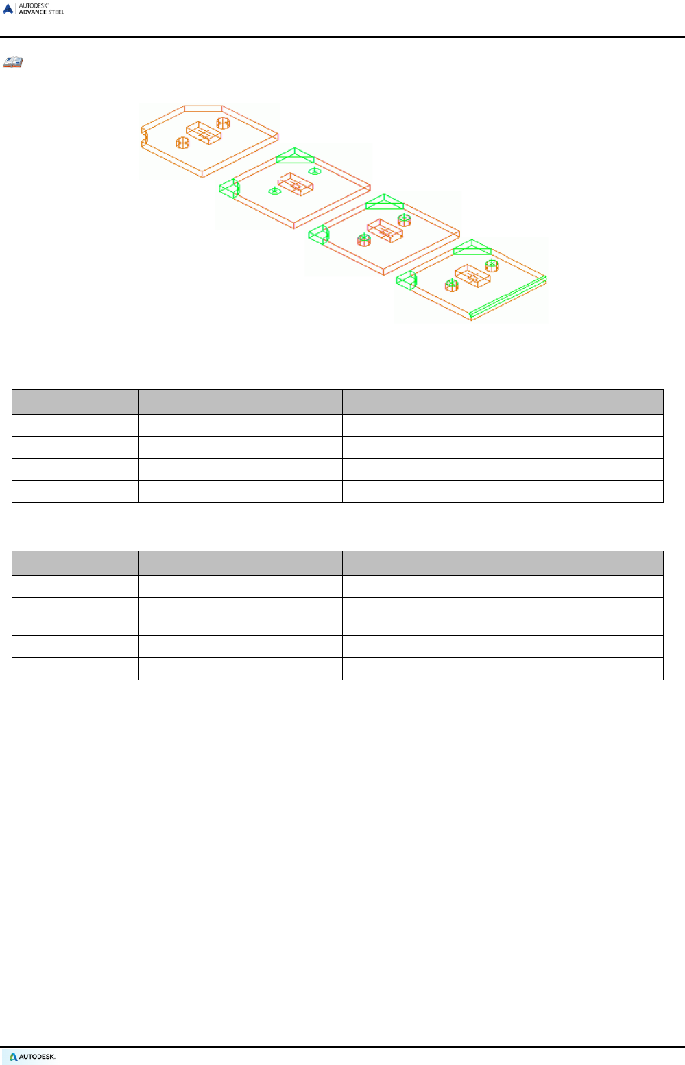
ADVANCE STEEL USER’S GUIDE
Example: Plate
For an Advance Steel plate, four representation types are available:
Figure 92: Plate in “standard”, “features”, “exact”, and “exact with weld preparation” representation types
Plate Representation type Name
Representation 1
Standard
Plate contour without processing
Representation 2
Processing
Plate contour with processing
Representation 3
Exact
Plate contour with processing and hole patterns
Representation 4
Exact with weld preparation
Same as Representation 3, with weld preparation
By changing the representation type of a plate, the following grip points are available:
Plate Representation type Name
Representation 1 Standard All corner points and midpoints of the edges
Representation 2 Processing
All corner points and midpoints of the edges, grips
for changing the processing
Representation 3
Exact
All corner points and midpoints of the edges
Representation 4
Exact with weld preparation
All corner points and midpoints of the edges
All corner points of the plates can be picked with the “End point” object snap.
67
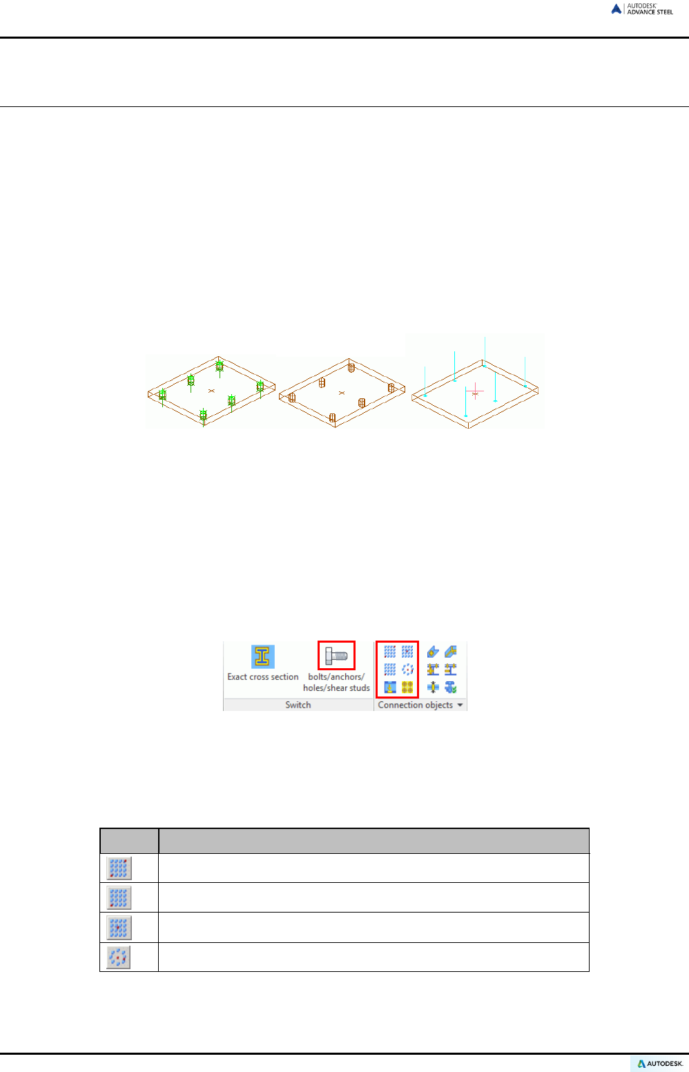
ADVANCE STEEL USER’S GUIDE
Bolt and Hole Patterns / Shear Studs / Anchors
Bolt/hole patterns, anchors and shear studs are created in any plane and are dependent on the current coordi-
nate system.
Bolt patterns create connections between individual Advance Steel objects (e.g., beam/plate or plate/plate). The
respective connection elements and properties are stored and managed by Advance Steel.
The structure formed by connected elements is displayed with a special Advance Steel command. Adding and
deleting elements to connections is simple. The connection is interpreted during the numbering so that it auto-
matically distinguishes between main parts and attached parts.
Bolts are created in a cyan color (by default) as individual Advance Steel elements and are changed with the
Advance Properties command.
Holes are automatically created when bolts or anchors are created. If a bolt/anchor pattern is deleted then the
hole pattern is also deleted.
Figure 93: Bolts, holes, and shear studs, all in the standard representation
A hole pattern without bolts is created with the following options: round holes, slotted holes, countersunk holes,
blind holes, threaded holes and punch marks.
Holes, like process features, are dependent objects that are displayed in green in the model. As with features, they are
only visible when the object, in which they are created, is displayed using the “features” or “exact” representation types.
Hole objects must be visible to change (with the Advance Properties command) or delete them.
Shear studs are created in the model exactly the same way (cyan) as bolts with the same options for displaying
and editing. Holes are dependent on their reference object for their representation type.
Bolt/hole patterns and shear studs have a Behavior property tab that describes if and how the element num-
bers are part of the structured BOM.
Figure 94: Tools for bolt/hole patterns
All four connection types (i.e., bolt patterns, hole patterns, anchor patterns and shear studs) are created with the
same commands. Click on the corresponding button to create the objects.
Bolt/hole patterns and shear studs are always created in a preset area with a certain creation point or created
on gauge lines. The following tools are available:
Button Function
Rectangular area, limited through diagonally opposite corner points
Rectangular area, unlimited, with corner creation point
Rectangular area, unlimited, with center creation point
Circular area with center creation point
Using other tools, bolt/hole patterns can be moved or separated into single bolts/holes. The “Calculate grip
length” tool recalculates the grip length.
68
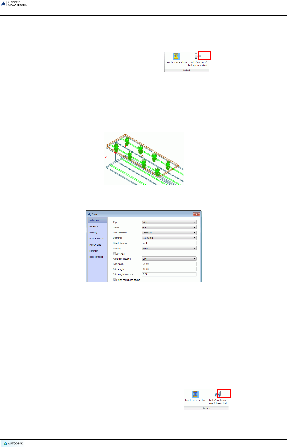
ADVANCE STEEL USER’S GUIDE
Creating a bolt pattern
• Set a suitable user coordinate system.
• On the Objects tab, Switch panel select the default “bolts” .
• Set the representation type if required. For example, for beams, use the exact representation type if a bolt
pattern should be created on a gauge line.
• Select the appropriate tool (based on the creation area) on the Connection objects panel.
• Select the elements to connect.
• Define a rectangular area using two diagonally opposite corner points (... bottom-left corner, ... top-right
corner) or one start point or one center point.
Figure 95: Bolt pattern on gauge line, “exact” beam representation, “solid” bolt representation
The bolt pattern is created and the “Bolts” dialog box appears.
Figure 96: “Bolts” dialog box, Definition tab
Important information that can be modified in the dialog box:
• Definition: Type, grade, diameter, etc.
• Size: Number of bolts in the X and Y-directions
• Distances: Distances in the X/Y-direction, edge distance (bolts distance minus the plate edge or beam edge)
• Representation Type: Standard, frame, solids
• Note: Assembly type (site, site drill, shop, etc.)
Creating a hole pattern
• Set a suitable user coordinate system.
• On the Objects tab, Switch panel, select the default “hole pattern” .
• Select the appropriate tool on the Connection objects panel based on the creation area.
• Select one end of a plate or beam.
69
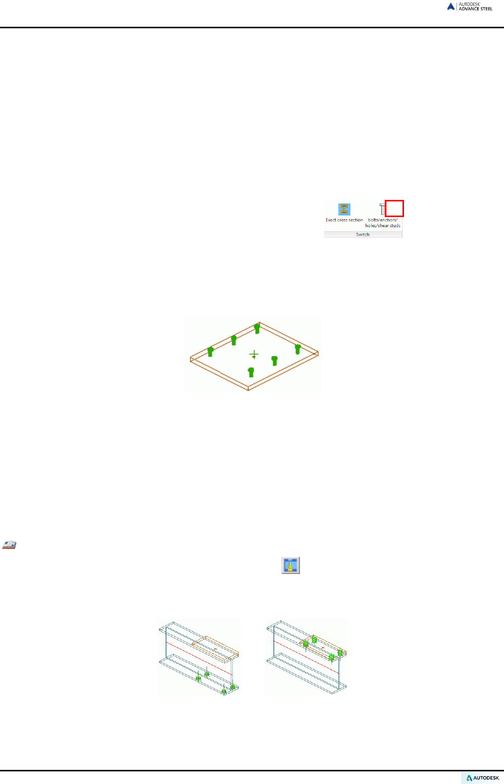
ADVANCE STEEL USER’S GUIDE
• Create a rectangular area using two diagonally opposite corner points (... bottom-left corner, ... top-right
corner) or one start point or one center point.
The hole pattern is created and a dialog box appears. Important information fields that can be modified:
• Hole definition: Type (e.g., slotted holes, countersunk holes, etc.)
• Arrangement: Number of holes in the X / Y-direction
• Distance: in the X / Y-direction, edge distances.
Hole representation types are dependent on their reference object.
Creating shear studs
• Set a suitable user coordinate system.
• On the Objects tab, Switch panel, select the default “Shear studs” .
• Set the representation type, if required.
• Select the appropriate tool (based on the creation area) on the Connection objects panel.
• Select the element that will have the shear studs.
• Define a rectangular area using two diagonally opposite corner points (... bottom-left corner, ... top-right
corner) or one start point or one center point.
Figure 97: Shear studs in the “solid” representation type
The shear studs are created. They are displayed in standard representation and connected to a beam / plate
through a weld point. A dialog box appears, in which the following information can be entered:
• Definition: Norm, diameter, coating, etc.
• Arrangement, distances and representation type (i.e., “standard” and “solids”).
Shifting a bolt/hole pattern
Bolts or holes on an incorrect surface of an object can be shifted along their axis to the correct face.
Example: Shifting an existing bolt pattern on the other flange of a beam
• On the Objects tab, Connection Objects panel, click .
• Select the bolt and/or hole pattern to move and press Enter.
• Next, select the beam by picking it at the new reference plane.
Figure 98: Shift Bolts/Holes
70
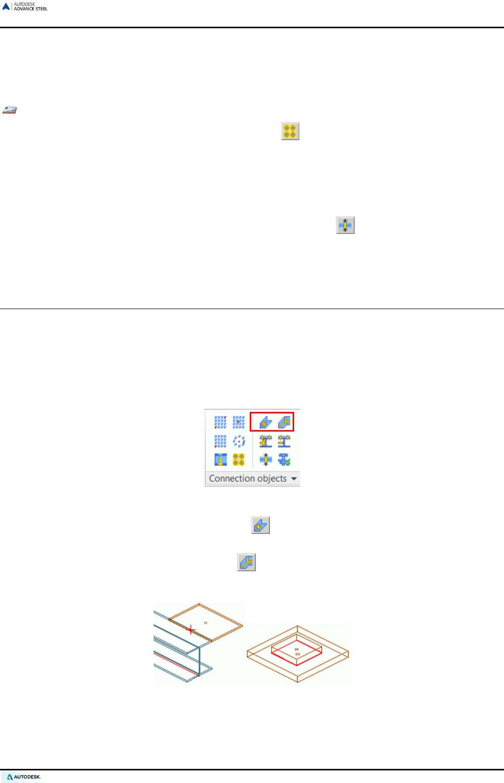
ADVANCE STEEL USER’S GUIDE
Splitting a bolt/hole pattern
Bolt patterns consisting of several bolts can be split into single bolts. These single bolts behave as bolt patterns
created with the “center” option.
Example: Splitting a bolt/hole pattern into single bolts/holes
• On the Objects tab, Connection Objects panel, click .
• Select the bolt and/or hole patterns to split.
• The bolt patterns are split into single bolts.
Recalculating a grip length
• To recalculate the grip length of bolts, click the “Calculate grip length” tool on the Connection Objects
panel of the Objects tab. Select the preferred bolt patterns and the element(s) to connect.
The grip length is recalculated.
Welds
Welds are created as weld points or weld lines. These objects contain not only the weld properties but also the
logical connection between connected structural parts.
With the Advance Steel ASTemplate.dwt standard template, weld points are created as individual elements in
the form of a pink cross whereas weld lines are represented in the model as thick polylines.
Weld patterns are created using the “Weld point” and “Weld line” tools the Connection Objects panel of the
Objects tab.
Figure 99: Weld patterns
• To create a weld point with its information, click on the Connection Objects panel of the Objects
tab. Select the objects to connect, press Enter, and enter the center point of the weld to be created.
• To create a weld line with its information, click on the Connection Objects panel of the Objects tab.
Select the objects to connect, press Enter, and enter the start point for the first weld line and one or more
end points.
Figure 100: Weld points and weld line
Weld objects can store information separately for the upper and lower weld: basic weld, surface shape, weld
design, weld thickness; weld definition: weld location, single length, circular (continuous); display type:
“Standard” or “Off” to hide the weld; “additional information” option to add weld text for additional information.
71
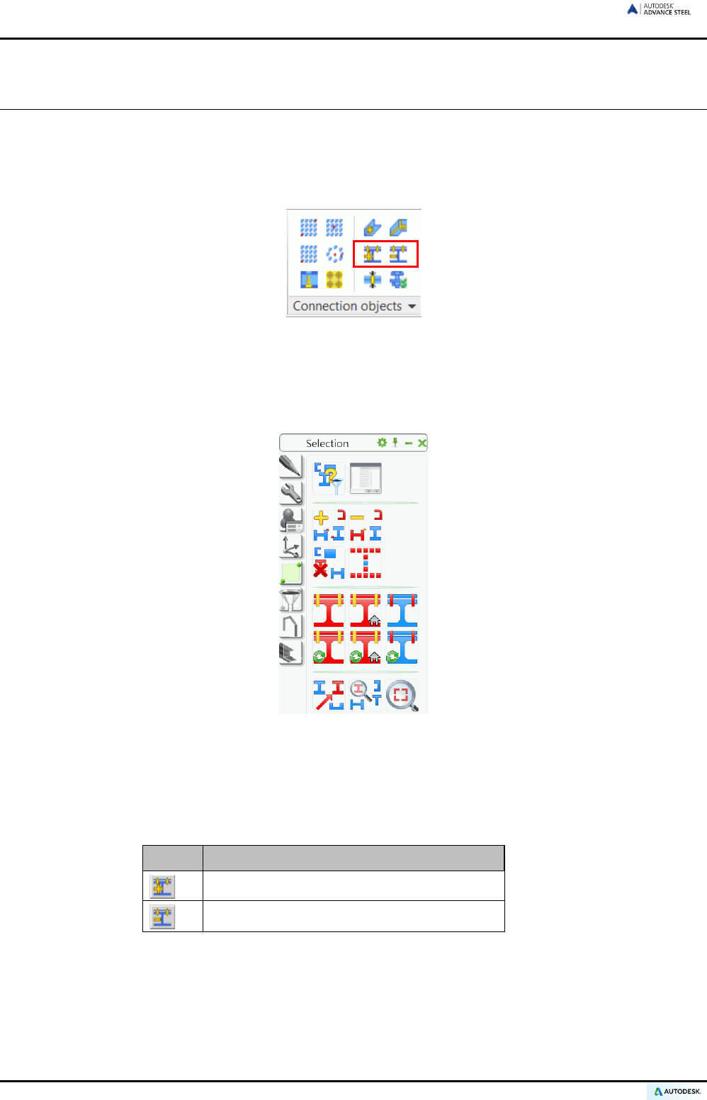
ADVANCE STEEL USER’S GUIDE
Connections
Advance Steel objects are added or deleted from the bolt or weld connection objects with Advance Steel tools.
At the same time, the grip length (and bolt length) is modified.
The tools on the Connection objects panel allow adding or deleting Advance Steel objects from a connection (change
connections).
Figure 101: Tools for adding and deleting elements from a connection
The check tools highlight the connected objects in red. Checking the bolt or weld connection objects is important
to insure that the correct parts are represented on shop drawings.
The tools for checking and highlighting the connected objects are located on the Selection tool palette.
Figure 102: Tools connections / check connections
Changing connections
To add or remove objects from a bolt or weld connection (with adjusting of grip and bolt length), use the tools on
the Connection objects panel of the Objects tab.
Button Function
Connection, add objects
Connection, disconnect objects
• Click the corresponding icon on the Connection objects panel.
• Select the connecting elements.
• Select the object to add or delete.
72
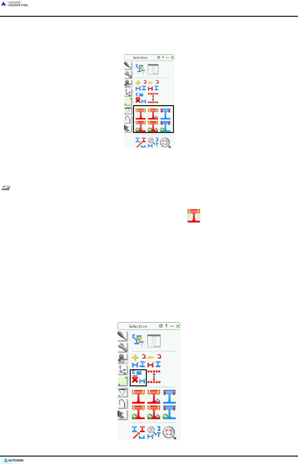
ADVANCE STEEL USER’S GUIDE
Checking connections
The following tools check the connections of the connected objects and highlight them in red.
Figure 103: Selection tool palette – Tools for checking connections
The “Display connected object” and “Remove marking + display connected objects” tools highlight objects with
both shop and site connections, including beams, plates, bolt patterns and welds.
Example: Checking a portal frame connection
• A portal frame consisting of two columns and two rafters was connected using various joints for the
apex, eaves and base plates.
• On the Selection tool palette, click the "Display connected object" .
• Select an element of the portal frame.
• The complete frame is highlighted in red, provided that all connections were applied correctly.
Using the “Display objects connected in shop” and “Remove marking + display objects connected in shop” tools,
the objects connected in the workshop are displayed, including beams, plates, bolt patterns and welds.
Using the “Display connecting elements” and “Remove marking + display connecting elements” tools, it is pos-
sible to examine an object with its connecting elements and identify them. For example, it can be determined
that a weld point lies far away from the object to be welded.
During the command the identified connection element objects are highlighted in red and their number displayed
in the text window.
• To clear the display of highlighted objects, click the “Clear marked objects” icon on the Selection tool pal-
ette.
Figure 104: Selection tool palette (Clipped), remove display
73
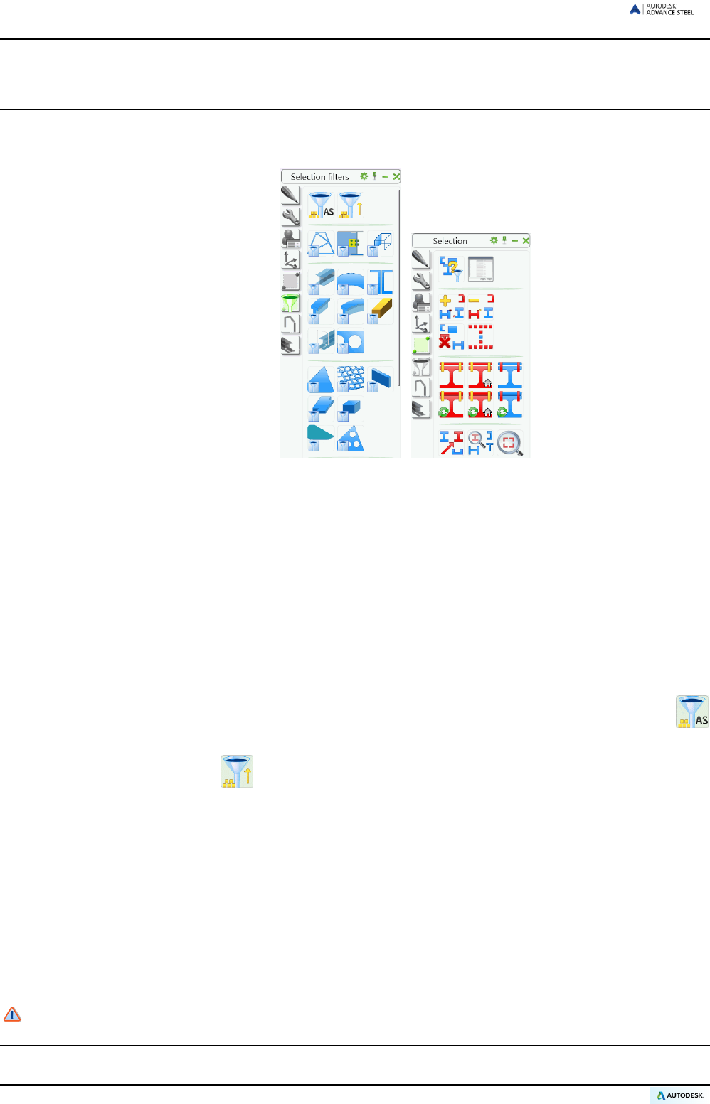
ADVANCE STEEL USER’S GUIDE
Working methods I
Advance Steel tools for selecting, filtering, and marking objects are available on the Selection filters and Se-
lection tool palettes.
Figure 105: Selection filters and Selection tool palettes
Selecting objects
Only certain Advance Steel elements can be selected for copying, numbering, exporting to a structured BOM,
etc.
There are different options for selecting objects.
• The elements can be clicked (single selection) or selected using simple selection tools like crossing win-
dows or enclosing windows.
• Alternatively, previously highlighted objects (in red - refer to the Check connections section of this chapter)
can be selected with the “Select highlighted objects” tool.
• Another option is to select all Advance Steel objects in a drawing with the “Select Advance Steel objects”
tool.
• With the “Reverse selection” tool, the selected objects are un-selected and the un-selected objects
are selected.
All these selection tools also apply to hidden objects or objects on frozen layers.
A very useful tool for selecting objects is the Advance Steel Search filter tool. This tool is particularly useful for
overlapping objects (e.g., selecting a line of a structural element that lies on the axis of a building grid), or for
selecting certain object types (e.g., plates) to put in standard representation, or for creating a structured BOM
for beams.
Object filter
To use a command in Advance Steel, select the elements first and the tool afterwards or vice versa.
The Advance Steel element filter is a selection before a command. The filter would cancel the com-
mand if called after it.
74

ADVANCE STEEL USER’S GUIDE
All selection filter tools are available on the Selection filter tool palette. The filter tool applies to the entire model
or to selected objects (if there are any).
The following object types are available as selection objects: Structural elements, connection objects, beams,
curved beams, beam – features, beam – holes, plate, plate – features, plate – holes, gratings, bolts, welds,
shear studs, level symbols, special parts, cameras, and grids.
Use the tools on the Selection filters tool palette to filter a certain object type from the Advance Steel model.
Figure 106: Selection Objects
Example: Filtering beams from the selected Advance Steel elements
• Select a group of Advance Steel objects. This is done by marking a group of objects connected with
weld or bolt objects using the “Display connected objects” tool (but may also be selected by other
means).
• Next, select the highlighted objects with the tool.
• On the Selection filter tool palette, click .
• The beams are filtered and the results are displayed in the text window.
Marking / Unmarking objects
Selected objects can be highlighted individually thus additional objects can be added to the current group of
highlighted objects.
Example: Selecting / marking beams + additional marking of plates
• Select all beams in a model using the corresponding filter tool from the Selection filter tool palette
(). All beams in the model are selected (shown dotted).
• On the Selection tool palette, click the “Add selected objects to marking” tool. All beams are high-
lighted in red.
• Repeat the above steps for plates so that all beams and plates in the model are highlighted red.
The selected objects can be deselected using the “Clear marked objects” tool on the Selection tool pal-
ette. Markings can be deleted from a group of highlighted objects.
• Filter all plates from the model and click “Remove selected object from the marking” . All selected
Advance Steel Objects (in this case plates) are deselected.
75
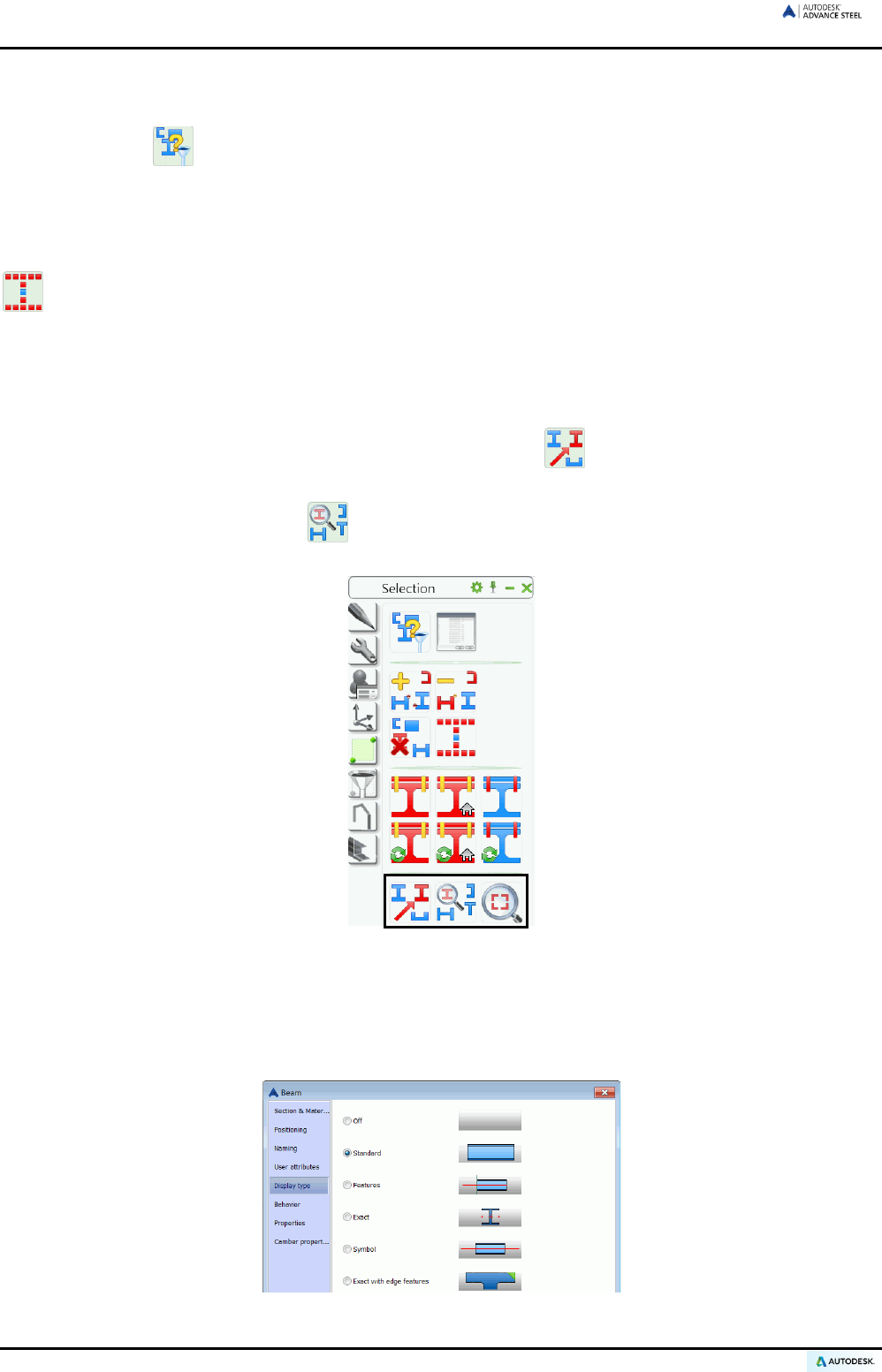
ADVANCE STEEL USER’S GUIDE
Searching / Marking objects
The “Search filter” tool on the Selection tool palette is used to select a group of elements that have the
same properties.
On calling this tool a dialog box appears in which search criteria, general or object specific, can be entered. By
clicking <OK>, the search will start. A listing of the found and highlighted objects is displayed in the text window.
The highlighted objects are put into a selection set (e.g., to copy them) with the “Select highlighted objects”
tool.
The selections will remain when other commands are called. It is of no importance how the selection was made.
Within a large model, highlighted objects (e.g., collision solids, connected objects) are not always easy to find.
The objects can be displayed with an arrow starting from the center of the viewport for easy identification. The
arrow can be deleted or hidden, just like any other object.
• On the Selection tool palette, click “Search highlighted objects” . An arrow pops up from the center of
the viewport to the highlighted object.
• The “Zoom to highlighted object” tool (Selection tool palette) zooms directly into an area at the ar-
rowhead by selecting the arrow.
Figure 107: Selection tool palette – Tools for locating the marked elements
Changing representation type
The representation types of the Advance Steel elements are changed on the Display type tab of the dialog
boxes of the single objects.
Figure 108: “Beam” dialog box – Display type tab
76
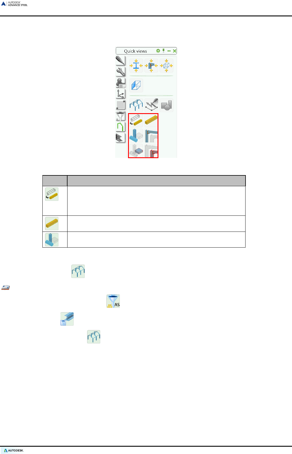
ADVANCE STEEL USER’S GUIDE
More tools for representation of objects are located on the Quick views tool palette. These tools, in contrast to
the dialog boxes, change the individual representation types faster and modify different object types (e.g.,
beams and plates) at the same time.
Figure 109: Quick views tool palette - Representation type
Button Function
“Change representation type” displays the individual representa-
tion types. For beams, the representation types are “standard”,
“features”, “exact” and “symbol” (refer to the beam ex
ample in the
Representation types – snaps – grips section of this chapter)
“Standard representation” directly sets the representation type to
“standard” irrespective of the current representation type.
“Selected objects off” hides objects on the screen representation
If an object was hidden on the screen representation it can only be selected using the object filter and then dis-
played with the “All visible” command on the Quick views tool palette.
Example: Selecting and displaying a hidden beam
• Select all Advance Steel objects tool on the Selection filter tool palette.
• Select “Beam” as the selection object. All beams including those that are hidden are selected.
• Selecting the “All visible” tool on the Quick views tool palette displays all the beams.
77
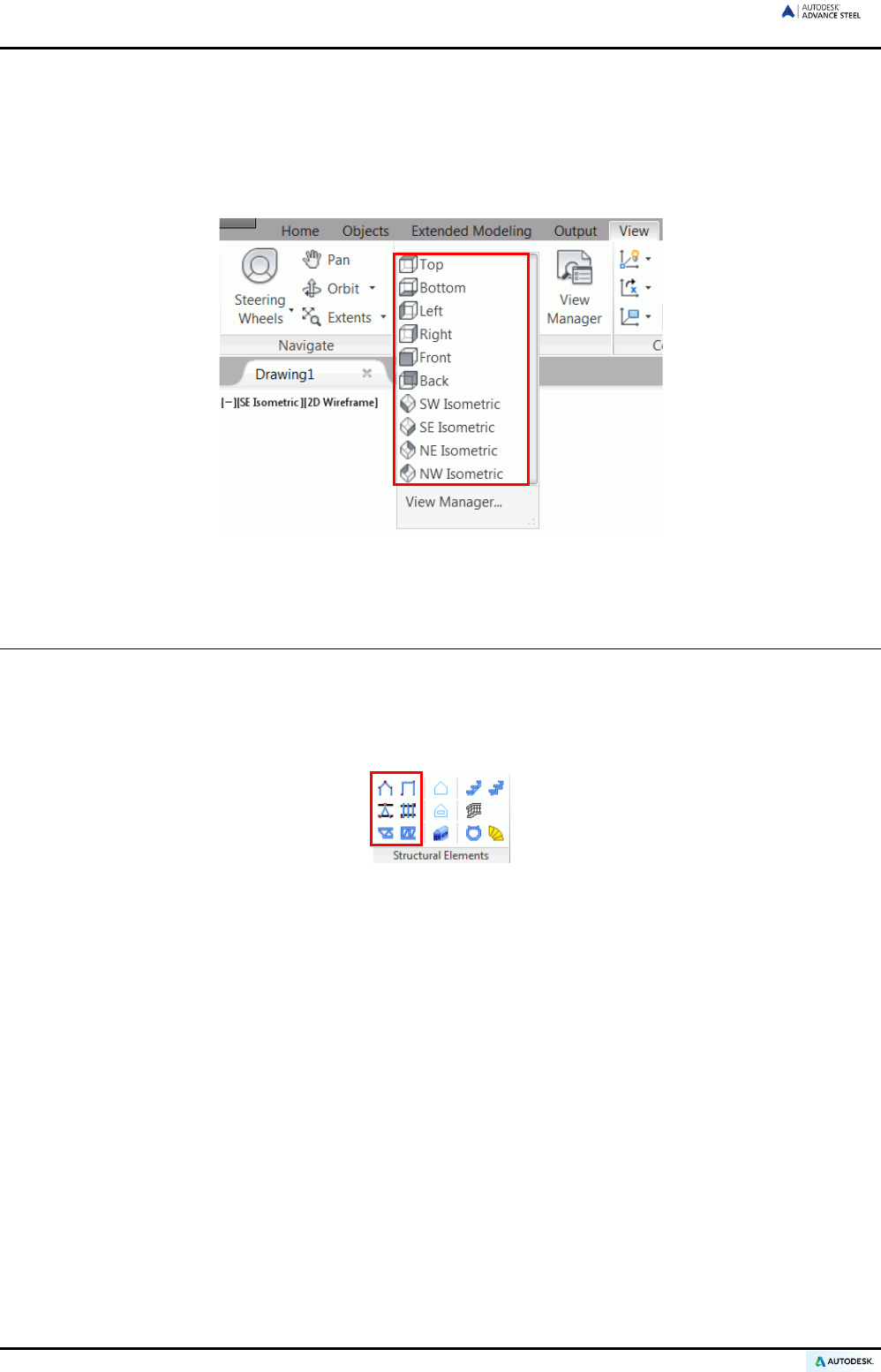
ADVANCE STEEL USER’S GUIDE
Views on the model
When working in 3D it is useful to view the model from different directions. The standard view directions can be
selected from the Viewpoints panel of the View tab. It should be noted that these tools create views on the
entire depth on the model and are not clipped to a specific plane. For more advanced view creation, refer to the
Working methods II chapter.
Figure 110: Standard views on the Viewpoints panel
Structural elements
Structural elements are grouped objects that consist of basic objects such as beams and other associated fea-
tures such as shortenings. These are held together and represented by a white structural frame shown as a
continuous line.
Structural elements of different shapes are on the Structural Elements panel of the Extended Modeling tab.
Figure 111: Structural Elements panel
• Symmetrical flat frames and portal frames
• Single-span bracings
• Purlins
• Pylons
• Joists
The basic objects, from which structural elements are created, have a Model Role within the structure that de-
termines their behavior. Basic objects with identical Model Roles are changed together (e.g., if a purlin size is
changed, all purlins in the structural element will change to the same size). Exploding the structural element
allows changes to individual members.
The creation dialog box is specific to the structural element type. For structural elements there is only one rep-
resentation type; they differ in the type and number of the snaps and grips, which are used to change the ge-
ometry (e.g., height, width, etc.).
Structural elements are created in the X/Y-plane of the current user coordinate system hence the first step for
creating a structural element is to set a correct UCS.
The gray structural frame bounding box calls the properties dialog box. If beams of a structural element are to
be changed, the corresponding beams must be selected.
78
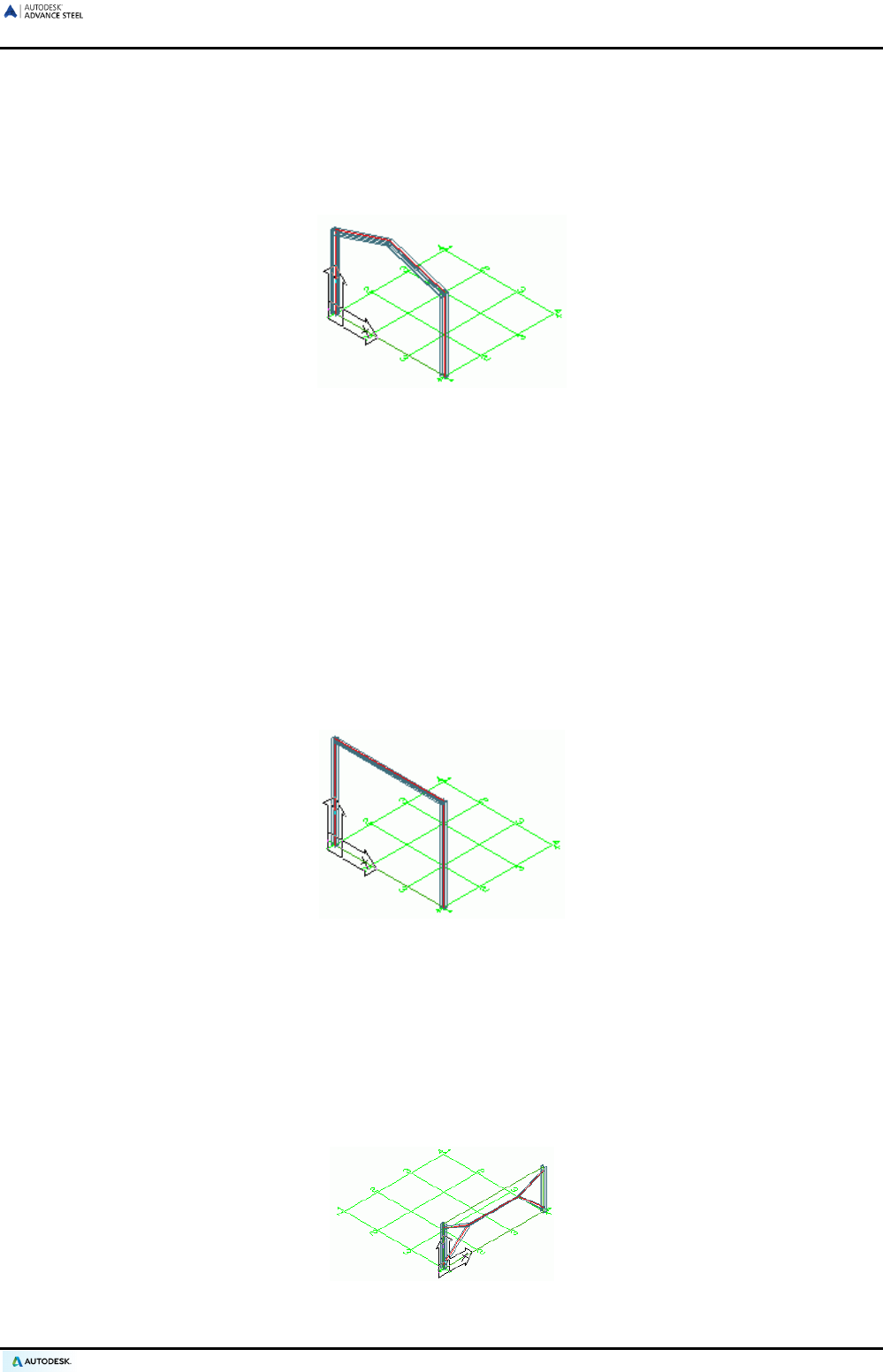
ADVANCE STEEL USER’S GUIDE
The “Select” tool on the Joint utilities panel looks for all elements belonging to a structural frame or connection
objects to copy, rotate, or mirror individual structural elements.
Some of the structural elements use the connection object technology: joists, purlins, and portal frames. The
connection object is represented as a gray box (3D bounding box).
Portal frames
Figure 112: Portal frame, columns centered – no cuts
A portal frame consists of two columns and two rafters. The four elements are created with a single command.
Of the four elements, two beams take the model role of column and the two beams take the model role of
rafter. Elements with the same model role form a group. It is not possible to directly change the properties of
individual columns or rafters.
The portal frame is created on the current UCS plane by entering two base points and one ridge point (or an-
gle), or simply by right clicking to accept the default height.
To modify portal frame properties, select the object’s (column or rafter) Advance Joint Properties from the
context menu. The Set out tab in the “Portal frame” dialog box has the width, height, total height and rafter an-
gle from horizontal. These properties are also changed in the “Structural element” dialog box.
There are two portal frame types available: frame and gable frame. The number of columns of a gable frame is
modified in the portal frame properties dialog box.
Flat frames
Figure 113: 2-hinged frame
This structural element is created on the current UCS plane by entering two base points and one ridge point for
the height, or by right clicking to accept the default height.
Flat frames are available in 3 types. A frame is created with a horizontal tie beam. The columns can be shifted
outwards or inwards.
Single-span Bracings
Diagonal members in the current X/Y-plane are created while entering a base point and a diagonal point.
Figure 114: Created single-span bracing
79
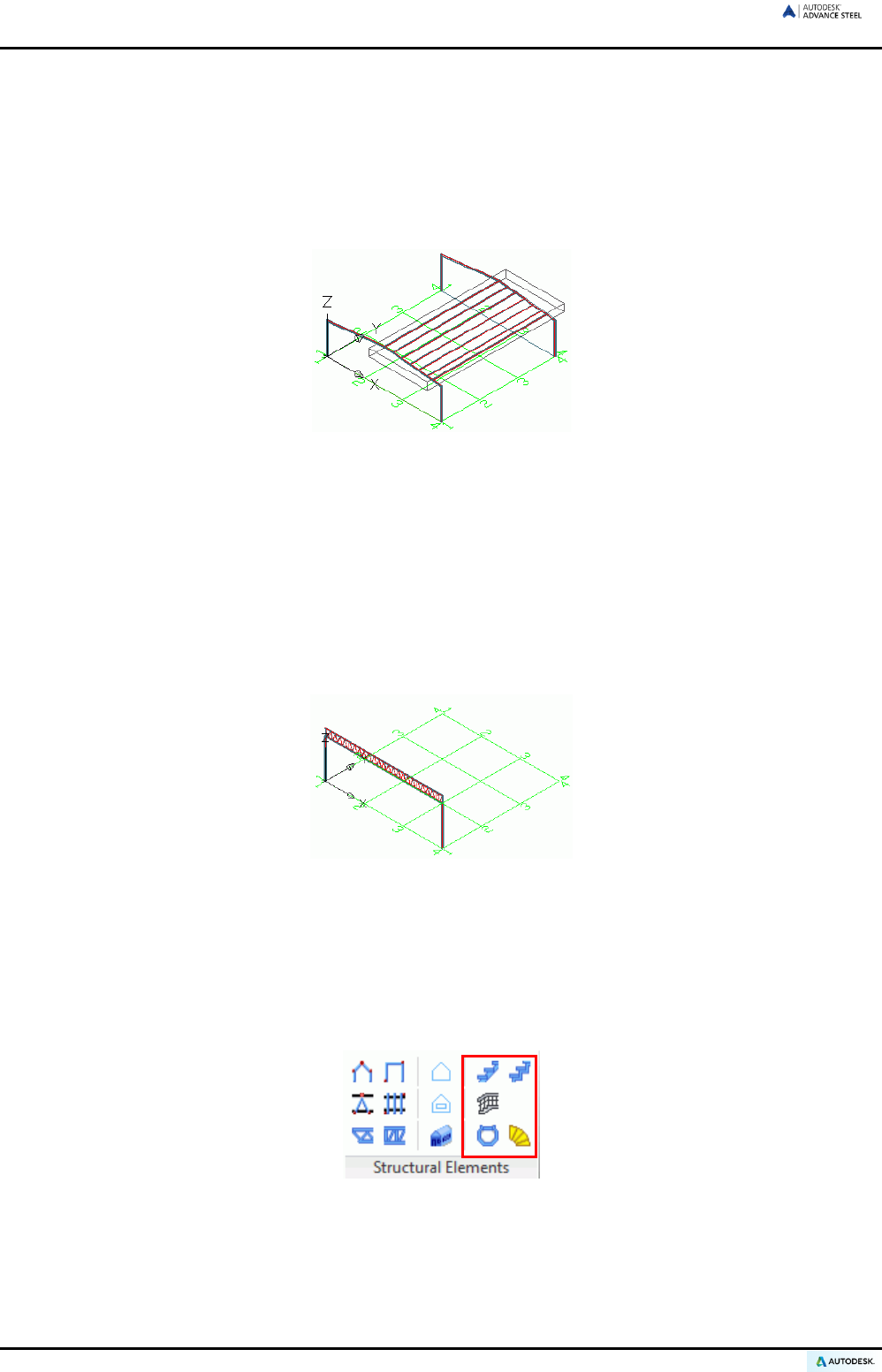
ADVANCE STEEL USER’S GUIDE
There are 3 bracing types: Created bracings, crossed bracings with or without angles in the same or opposite
direction, K-bracings and crossed flats. The bracings can have varying distances, above and below the selected
points, in the dialog box.
Purlins
This creates a set of regularly spaced members on the selected rafters. Simply select the rafters and the purlins
are automatically created. One option allows the selection of a column to position an optional eaves beam.
Figure 115: Purlins
The purlin properties are changed in the properties dialog box: purlin section, the projections at first and last
rafter, the extra purlin length, and the span type. The distances are modified on the Distances tab. The inter-
mediate distance can be changed and the number of purlins is modified accordingly.
An eaves beam can be added and the section type, position, offset and orientation can be selected.
Joists
To create a double angle joist, enter a start point and an end point to define the length. The third point deter-
mines the height and orientation of the joist.
Figure 116: Joist
Once created, the length or height is modified by using the grip points of the box or by changing the properties
in the properties dialog box.
Stairs
With Advance Steel, various types of stairs can be created.
Figure 117: Structural Elements panel – Stairs
80
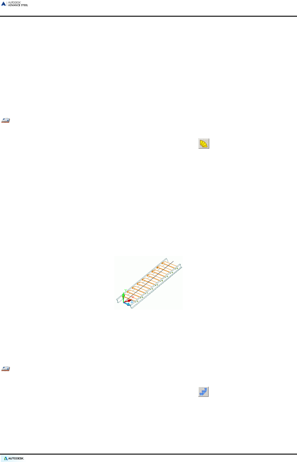
ADVANCE STEEL USER’S GUIDE
Spiral stair
The “Spiral stair” tool creates the central post, the handrail, the treads, the connection, and the handrail. Option-
ally a top cap plate can be added to the column.
Define three points and the first tread (or the last one) to create the stair. The first two points define the central
post height and position. The third point defines the direction of the first tread (or the last one) and its width.
There are two ways to create a spiral stair:
• From the bottom to the top: the user defines the first step; the last step position is calculated using the first
step position, the number or the height of the steps, and the rotation angle between them.
• From the top to the bottom: the user defines the last step.
Example: Creating a spiral stair
• Set an appropriate UCS.
• On the Extended Modeling tab, Structural Elements panel, click .
• Select the first point to define the spiral center: 0,0,0.
• Select the second point to define the spiral height: 0,0,2800. The stair height is on the Z-axis.
• Type F to create the first step (or L for the last one) and press Enter.
• Specify the third point to define the start direction of the step and the step width: 1500,0,0.
The spiral stair is created and a dialog box appears, in which information for column, stringer, treads, post, etc.
can be entered. The stair direction and the type of connection between the treads and the stringers (e.g., welds,
bolts, angle welded or bolted) can be selected. The preferred settings are stored in the table.
Straight stair
Two points defining the origin and the end of the stair run creates a straight stair.
Figure 118: Straight stair
Advance Steel creates the stringers and treads with their connections to the stringers.
The width and the offset are controlled in the properties dialog box.
The number of treads is created with the formula normally used to get the ergonomic height and width of the step.
Optionally, a lower and upper landing can be created.
Example: Creating a straight stair
• Set an appropriate UCS.
• On the Extended Modeling tab, Structural Elements panel, click .
• Select the first point to define the origin of the stair run.
• Select the second point to define the end of the stair run.
• Enter 1 to align the stair in the middle and press Enter.
The stair is created and a dialog box appears, in which information for treads and landings can be entered.
The dialog box to edit a stair element is accessed by selecting Advance Joint Properties on the context menu.
81
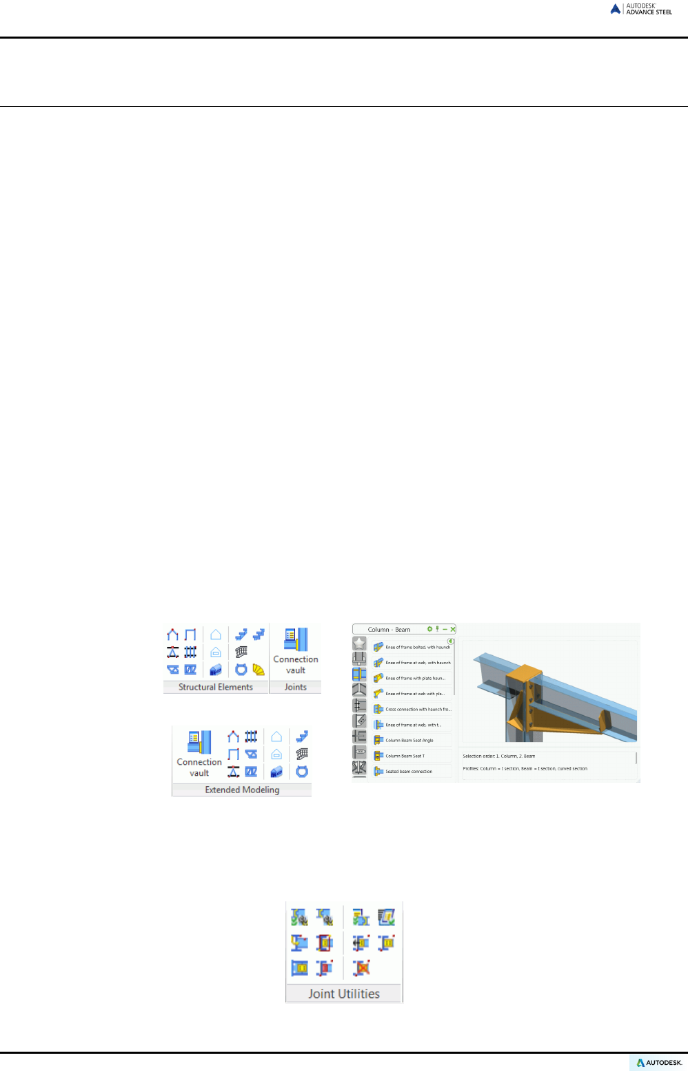
ADVANCE STEEL USER’S GUIDE
Joints and connection objects
Advance Steel contains a variety of preset parametric joints to connect Advance Steel elements. The joints con-
sist of several elements such as plates, stiffeners, beams, bolts, and welds. An Advance Steel joint is created
with all its parts, connection objects, and features using a single operation. At the same time, the existing con-
nected elements are processed (shortened, coped, etc.) and connection logic between the parts is established.
A joint is represented in the model by a gray box connection object that contains all the connection parts.
All joints are available in the Connection vault.
The joints on the whole, are classified according to the type of the individual members:
• Beam to column connections
• Cantilever beam to column connections
• Beam end to end connection
• Plate connections
• Clip angle connections
• Moment connections
• General bracing connection
• Tube connection
• Base plate connections
• Turnbuckle bracing
• Pylon connections
The Connection Vault is accessible from the Joints panel of the Extended Modeling tab. For easier access,
the Connection vault can be accessed from the Home tab.
The Connection vault provides quick access to all joints. The left panel of the window displays all joints ar-
ranged by individual element type.
Figure 119: Accessing Connection vault
The corresponding commands for handling joints and connection objects are arranged on the Joint Utilities
panel of the Extended modeling tab.
Figure 120: Joint utilities panel
82
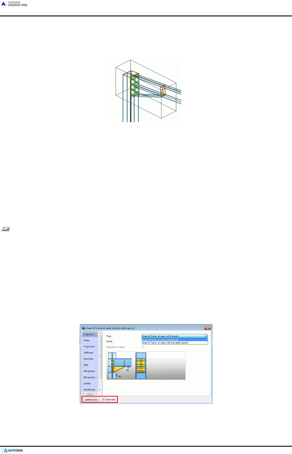
ADVANCE STEEL USER’S GUIDE
The connections are intelligent: If a beam connected using a connection is changed the connection automatical-
ly adapts to the new situation according to the set parameters.
These set parameters are stored in the connection object (the gray box) that is hidden (by default) when the
connection is created. It contains all information of the joint but not individual component properties.
Figure 121: Connection object box
To modify a joint, double click the connection object (gray box) that calls the properties dialog box. Connection
objects can be displayed, updated, entirely deleted, copied and changed. Their parameters can be transferred
to other existing joints. Objects of the connection can be selected.
Using joints
To create a joint, always start the Connection vault.
• Select the desired connection from the left pane and click Use.
• After clicking on a connection, select the members to connect by pressing Enter after each selection.
• A dialog box appears when a connection is created.
Example:
... passing main beam ... Enter ... beam to be connected ... Enter.
The joint is created and a dialog box with graphic explanations of the available parameters appears.
The tabs in the Joint dialog boxes vary according to the joint type. There are common tabs such as Properties,
Library and Bolts in almost all dialog boxes.
On the Properties tab, the Type pull down connections can be selected from one or more types (e.g., “Knee of
frame at web, with haunch” or “with one plate haunch”). The graphic representation changes according to the
selected type.
On each joint dialog box, there is a checkbox for the automatic updating of a joint if individual beams are modi-
fied and there is a button for manual update.
Figure 122: Joint dialog box, Properties tab – Update button
83
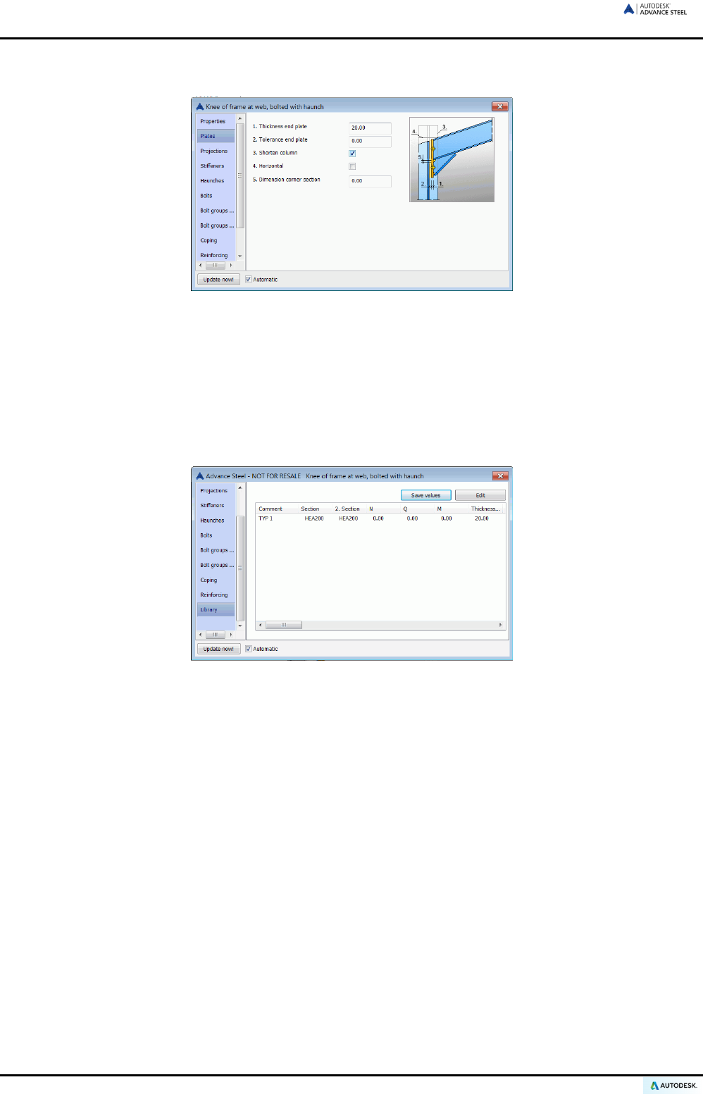
ADVANCE STEEL USER’S GUIDE
On the other tabs (e.g., for plates, bolts, bolt distances, etc.) the numbers in the sketches correspond to the
information entry boxes.
Figure 123: “Knee of frame at web, bolted with haunch” dialog box - Plates
The settings in the connection dialog box can be saved to a table. Company-specific connection settings for
certain beam combinations can be saved and reused in other projects.
• To save a connection to the table, make appropriate adjustments in the dialog box tabs.
• Click the Library tab and click Save values. Next, click Edit to open the table. Enter a comment to identify
the connection and fill in the appropriate section sizes.
• Click <OK> to confirm and return to the connection dialog box.
Figure 124: “Knee of frame with plate haunch” dialog box - Library
If the connected members correspond to an entry in the table, the connection is created using the entries in the
table (library). If there are no default values in the tables (libraries), a message is displayed as previously de-
scribed above.
84
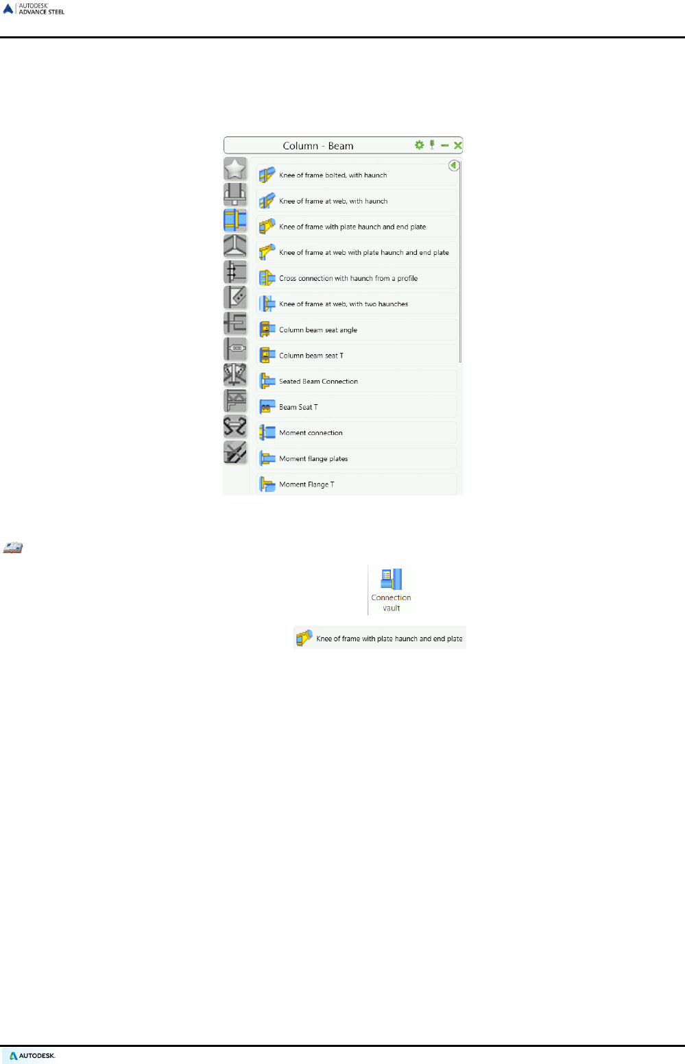
ADVANCE STEEL USER’S GUIDE
Beam to column joints
Joints that connect a tie beam to a column are available on the Column - Beam category of the Connection
vault. The tie beam ends at the column. Bolted and welded joints, with or without haunches are available.
Figure 125: Column - Beam category
Example: Creating a knee of frame with plate haunch and end plate
• On the Extended Modeling tab, Joints panel, click .
• In the Column - Beam category, select .
• Select the column, press Enter, select the tie beam, and press Enter.
• The connection with haunch is created at the flange of the column and the beam to be connected is
modified. The tie beam is connected at the flange of a column with a plate haunch. The haunch is con-
nected at the tie beam by end plates. The Properties dialog box appears.
• The tabs have options to set various graphically represented haunch parameters.
The “Knee of frame bolted, with haunch” tool creates a beam connection with haunch at the column flange. The
haunch is created from a beam cut or from plates. Different stiffener types are available. The haunch is de-
signed with or without a cover plate and the column is modified in length accordingly. Up to four different bolt
groups can be set. Each of these bolt groups can contain several horizontal bolt lines.
The “Knee of frame at web, with haunch” tool connects a tie beam with an end plate to a column web. This con-
nection is available “with beam haunch” or “with plate haunch”.
A knee of frame with two haunches is created using the “Knee of frame, with two haunches” tool.
85
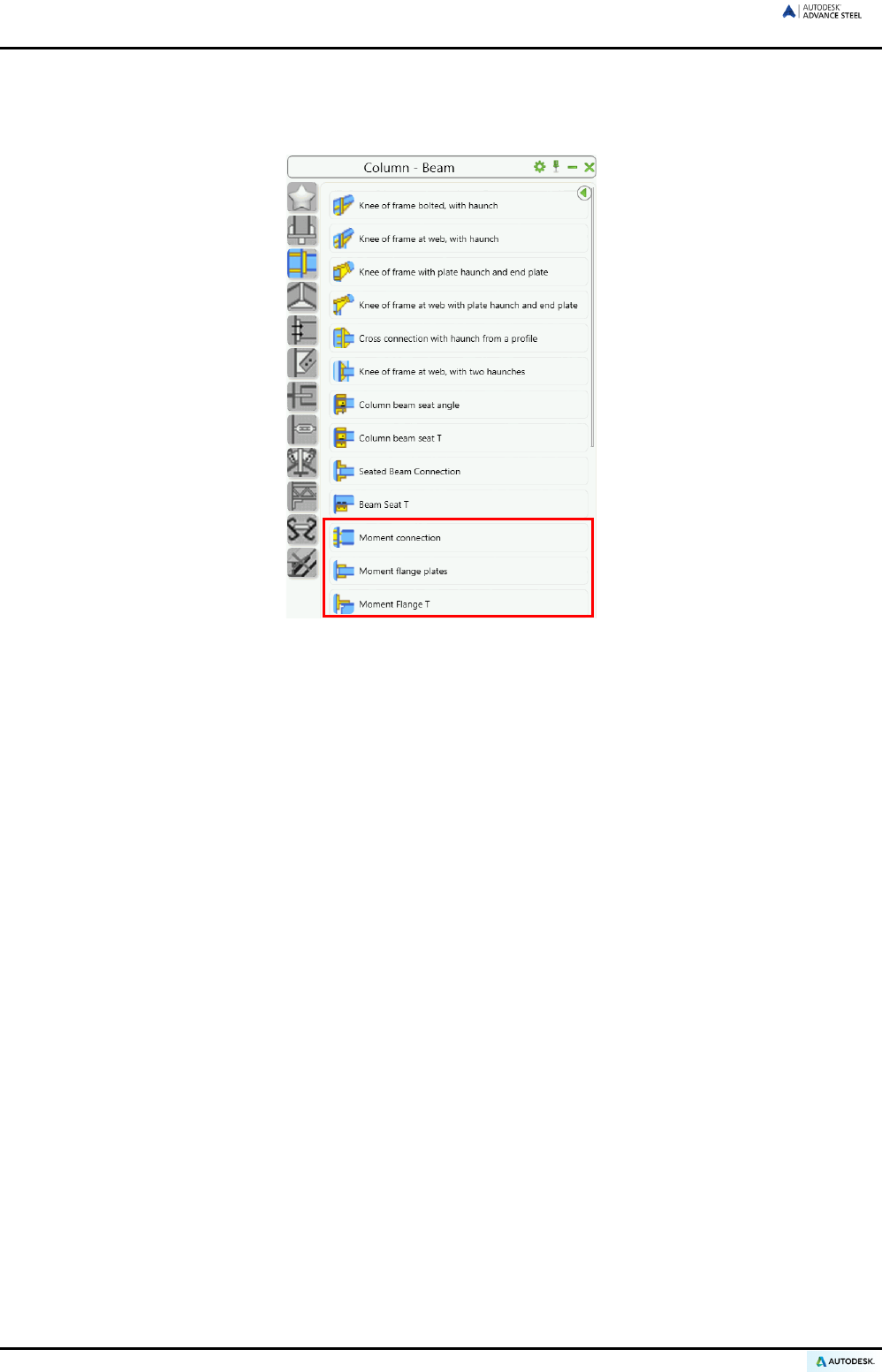
ADVANCE STEEL USER’S GUIDE
Moment joints
The moment connections are included in the Column - Beam category.
Figure 126: Column - Beam category - Moment joints
The “Moment connection” is used to connect a tie beam to a column as well as two floor beams. The moment
connection creates additional support (e.g., welds, plates, stiffeners) to the connection.
The “Moment flange plates” joint is created out of flange plates. The connection works on all possible combina-
tions of sections. Also it works for sloped and skewed situations.
The “Moment flange T” connection is created out of T-profiles and also works on all possible combinations of
sections.
86
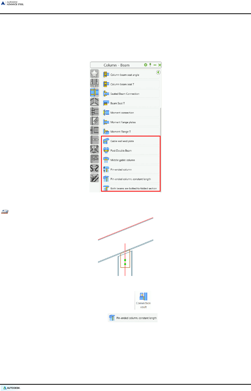
ADVANCE STEEL USER’S GUIDE
Joints cantilever beam to column
Gable columns/posts are connected to rafters/beams using tools from the Column - Beam category of the
Connection vault. The orientation of the columns is parallel or perpendicular to the rafters. The connection is
created using an end plate. Pin-ended columns are connected to fin plates welded to the rafter. The connection
can also be made using an end plate welded to a fin plate.
Figure 127: Column - Beam category - Cantilever beam to column group
Example: Pin-Ended Column, by Distance
Figure 128: Pin-Ended Column, by Distance
• On the Extended Modeling tab, Joints panel, click .
• In the Column - Beam category, select .
• Select the tie beam, press Enter, select the column, and press Enter.
• The pin-ended connection is created and a dialog box appears.
A pin-ended column is connected to a rafter using a simple fin plate (Properties tab, type: simple joint)
welded to the tie beam or using a fin plate and end plate (Properties tab, type: joint with cover plate).
Information for plate and bolts can be modified.
For a joint with an end plate, the end plate is modified in width to suit the rafter and the bolts are auto-
matically created on the rafter gauge lines.
87
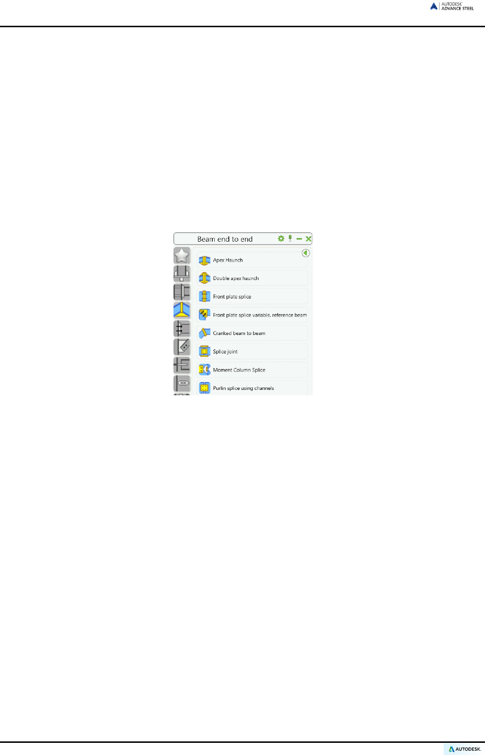
ADVANCE STEEL USER’S GUIDE
The distance between the column and the rafter (perpendicular to the rafter) can be set and the length
of column is changed accordingly.
The “Pin-ended column, constant length” must be modified by its system length in advance since the fin plate is
created at the end of the column system axis.
With “Middle gable column”, two rafters are connected to a column using two end plates. The end plates are
bolted to the rafters and welded to the double cut column.
With “Single beam on column plate”, a column is connected to a rafter using a cover plate, welded to the column
and bolted to the tie beam. The rafter can be cut vertically and the bolts in the tie beam are automatically placed
on the gauge lines. Stiffeners are created into the rafter running perpendicular to the rafter or parallel to the
column.
Joints beam end to end
The joints from the Beam end to end category connect spliced beams for a bolted apex with or without
haunches, an end plate splice, and a splice joint. Changing the parameters customizes these joints.
Figure 129: Beam end to end category
With “Apex haunch” with one or two haunches, two beams are spliced with bolted end plates. Up to four differ-
ent bolt groups can be set. Also, additional information for haunches and stiffeners can be entered.
With “Front plate splice”, two beams are spliced with end plates. It is possible to attach additional bolt lines
above or beneath.
With “Front plate splice, variable”, four separate bolt patterns are created and the plates are connected to the
beams with two weld points.
The “Cranked beam to beam”, two beams of any shape are welded to an end plate. The plate thickness is
specified in the dialog box. The intersection at the beam is set to either vertical (perpendicular) or at the bisect-
ing angle on the Type tab.
A “splice joint” can be created.
The “Moment column splice” connects two horizontal, vertical or sloped columns. It creates the moment cuts
and backing bar as well as a flange gusset plate.
The “Purlin splice” connects purlins with a C-shaped profile or flat steel. Section, spice plate, side and column
are specified on the Splice plate tab.
88

ADVANCE STEEL USER’S GUIDE
Clip angle joints
Clip angle joints connect floor beams to beams as well as a beam to a column by clip angles. Clip angle joints
are available in the Platform beam category of the Connection vault.
Figure 130: Platform beams category - Clip angle joints
Example: Creating a clip angle connection
Figure 131: Clip angle connection
• On the Extended Modeling tab, Joints panel, click .
• In the Platform beam category, select .
• Select the passing main beam and press Enter.
• Select the beam to connect and press Enter.
• The joint is created and a dialog box appears.
The “Clip angle” connects a floor beam to another beam as well as a column to a beam. The attached beam can
be sloped to the main one.
“Clip angle - Skewed” creates a similar connection with a folded clip angle. The attached beam can be sloped
and skewed to the main one.
“Double side clip angle” connects a floor beam and two beams as well as a column and two beams. The at-
tached beams can be sloped to the main one, as the clip angle is aligned at the main beam. The connection
works also for a curved passing beam or when the beams are compound or welded.
89
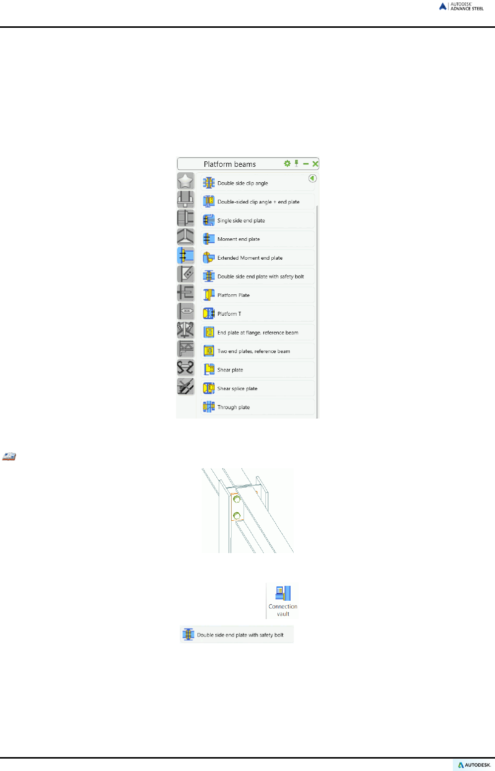
ADVANCE STEEL USER’S GUIDE
With “Double-sided clip angle + end plate”, opposite beams are connected to a main beam. The first beam is
connected to a double angle and the second one to an end plate.
The “Seated beam connection” uses welded or bolted angles to join two beams. The quantity and size of an-
gles are variable.
Plate joints
The tools from the Plate joints category of the Connection vault connect beams to beams. End plate and
moment end plate connections are also included.
Figure 132: Plate joints category
Example: Creating a double side end plate with safety bolts
Figure 133: Double-sided end plate connection
• On the Extended Modeling tab, Joints panel, click .
• In the Platform category, select .
• Select the passing main beam and press Enter. Select the first beam to connect and press Enter. Se-
lect the second beam to connect.
Two opposite beams are connected through a main beam by their end plates. If the connection is used
between floor beams then a cope is automatically created by default.
If the connection is used between a column (web) and two beams and the beams do not fit in the space
between the column flanges, then a trim is created on the left and right side of the flange (secondary
beam).
90
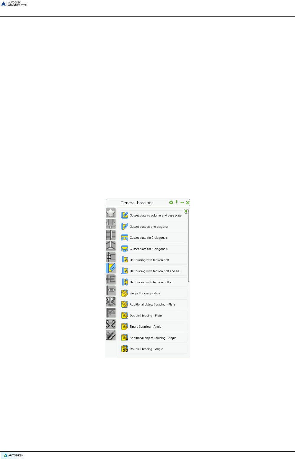
ADVANCE STEEL USER’S GUIDE
The cope parameters are set on four tabs of the joint properties dialog box. The plate size is calculated
using the bolts vertical and horizontal distances. The cope length at the top and bottom and the cope
depth can be set for both connected beams. The thickness of the weld line can be set separately for
each beam.
The “Single side end plate” connects two floor beams or a column to a beam. The secondary beam can be
sloped, skewed, or rotated.
With “Moment end plate” connection, projections are set at the top or bottom of the joint. Creation of a moment
end plate connection is used to connect a tie beam to a column. The projections can be specified at the top or
bottom in joints that support this feature.
The “Double side end plate with safety bolts” connects two beams to a floor beam or to a column. The attached
beams can be sloped to the main one and a safety bolt can be added.
The “Platform splices” (toe plates) are shear connections at a beam with end plates and stiffeners. In the ex-
tended version up to four bolt groups can be set.
The "Shear plate” connects two floor beams or one column and a floor beam.
The “Through plate” joint is similar to a shear plate except it connects two secondary beams to a column by a
plate. The plate goes through the column (main beam) and automatically creates a contour in the main beam. It
works for horizontal or sloped/skewed beams.
General bracing joints
The General bracing category of the Connection vault groups tools for connecting bracing members using
gusset plates and “lap” joints for flats and L angles.
Figure 134: General bracing category
The gusset plate connection is used on a column with a base plate or on other types of beams. The necessary
bolts and welds are automatically created.
91
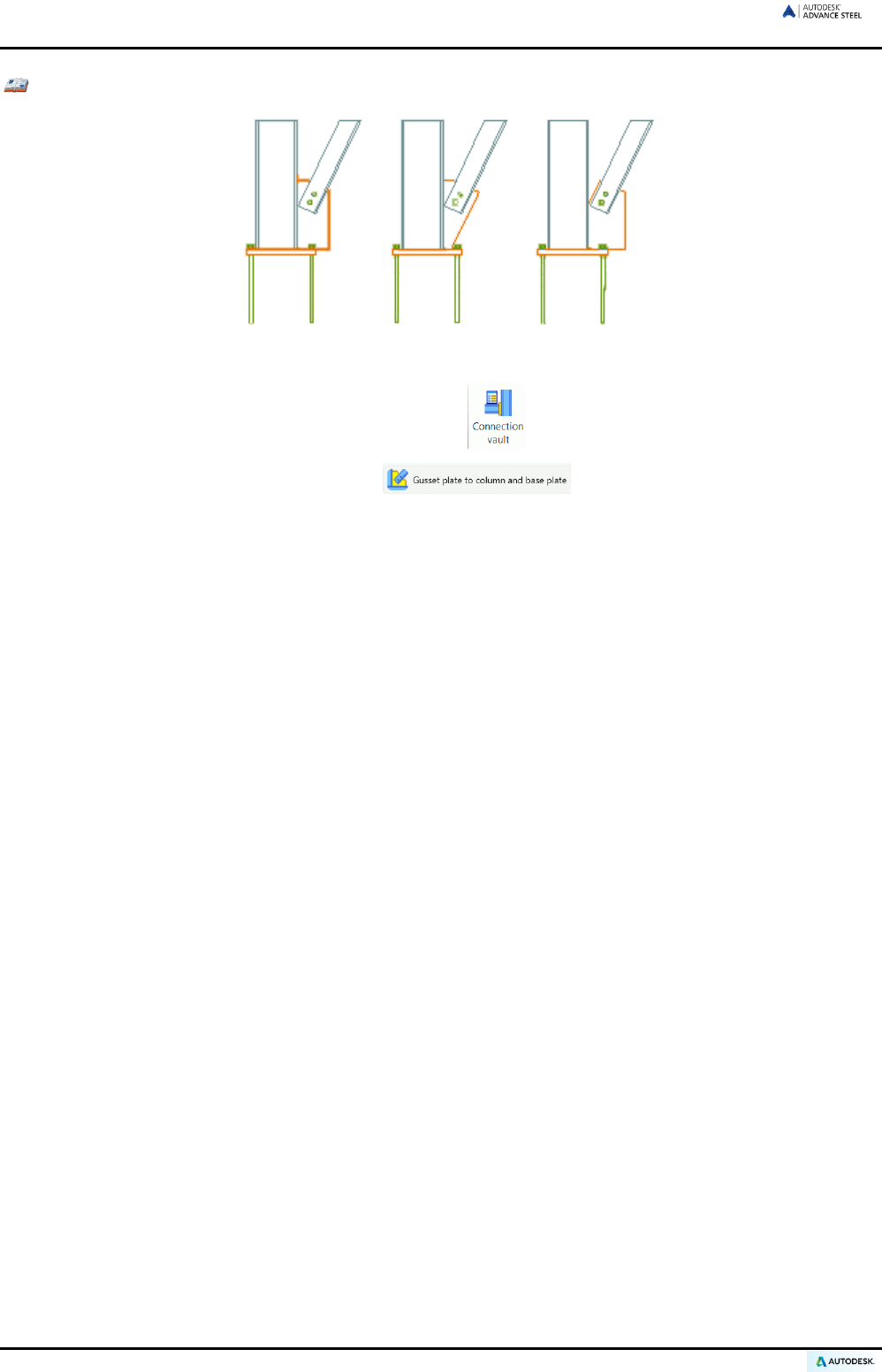
ADVANCE STEEL USER’S GUIDE
Example: Gusset plate at column and base plate
Figure 135: 3 Gusset plate types
• On the Extended Modeling tab, Joins panel, click .
• In the General bracing category, select .
• Select the column to connect and press Enter.
• Select the base plate to connect and press Enter.
• Select the diagonal to connect and press Enter.
• The gusset plate is created and a dialog box appears.
“Gusset plate to column and base plate” connects a column and a base plate to a diagonal. It can be used on
the column web or flange.
“Gusset plate at one diagonal” joins a single diagonal.
Shortening the diagonals and modifying distances from the main beams can connect two, three or four diagonals.
A “Gusset plate in center” can also connect two diagonals. In this case, one of the diagonals is continuous and
the two others are joined at the center point.
A diagonal can be connected to a beam by gusset plate and two angles. Distances, trimming of the diagonal,
and a variety of other specifications can be entered in the “Angle bracing” dialog box.
The “Diagonal bracing” connects a column, a longitudinal beam and a diagonal brace. Slotted butt straps are
bolted to the diagonal and welded to a gusset plate. The gusset plate is welded to the column and to the longi-
tudinal beam. The longitudinal beam is connected to the column using an end plate.
The “Angle bracing” creates and connects four bracing L-profiles to a plate. The bracing profiles are bolted to
the plate.
The “Overlapping angle” and “Overlapping flat” connects by bolts two overlapped L profiles, respectively flat.
The “Direct bolting” joint connects a secondary beam on the top of another beam by creating bolts at the gauge
lines intersection.
The “Flat bracing” connects a main beam and a flat diagonal using a plate.
92
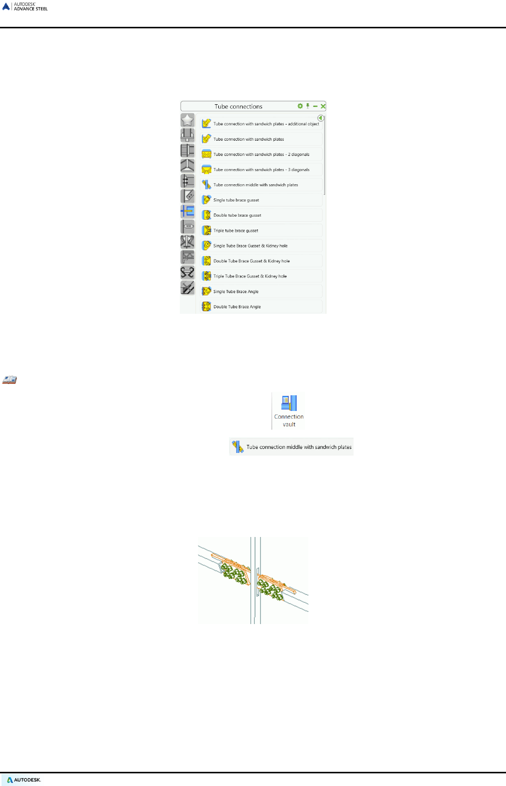
ADVANCE STEEL USER’S GUIDE
Tube joints
The Tube connection category of the Connection vault, groups the tools for connecting tube bracing mem-
bers.
Figure 136: Tube connections category
The gusset plate connection is used on a column with a base plate or on other types of beams. The necessary
bolts and welds are automatically created.
Example: Creating an tube middle connection with sandwich plates
• On the Extended Modeling tab, Joints panel, click .
• In the Tube connections category, select .
• Select the main beam to connect and press Enter.
• Select the first diagonal and press Enter.
• Select the second diagonal and press Enter.
• The joint is created and a dialog box appears.
Figure 137: Tube middle connection, with sandwich plates
“Tube connection” connects square, rectangular, or round tubes to beams with an angle, a shear plate, or a
folded cleat.
The “Tube connection with sandwich plates - additional object” connects a column, a base plate (or a beam),
and a diagonal.
The “Tube connection middle with sandwich plates” connects one main beam and two tubes.
Each joint category is available for one, two, respectively three diagonals.
93
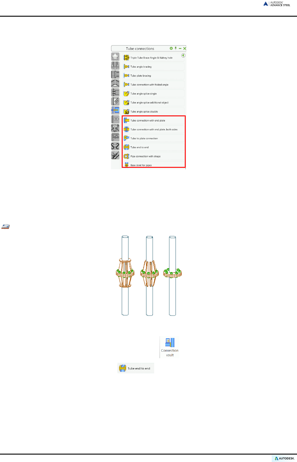
ADVANCE STEEL USER’S GUIDE
Joints pylon construction
The Connection vault contains also several joints for pylon construction.
Figure 138: Tube connection category – Joints for pylon construction
The connection between two tubes (collinear or not) is made using flange plates, the cross connection of two
tubes with straps, and the connection of a tubular diagonal with a bracket.
To create a pylon construction connection, select the first tube (passing), and then select the second (connect-
ing) tube.
Example 1: Connecting two tube ends with flanged connection
Figure 139: Tube ends with flanged connection
• On the Extended Modeling tab, Joints panel, click .
• In the Pylon joints category, select .
• Select the first pipe and press Enter.
• Next, select the second pipe and press Enter.
• In the message window, click <OK>.
The pipe connection is created and the “Tube end to end” dialog box appears.
In the dialog box, information for bolts, flange plates, stiffeners, ring plate 1, and ring plate 2 can be entered.
94
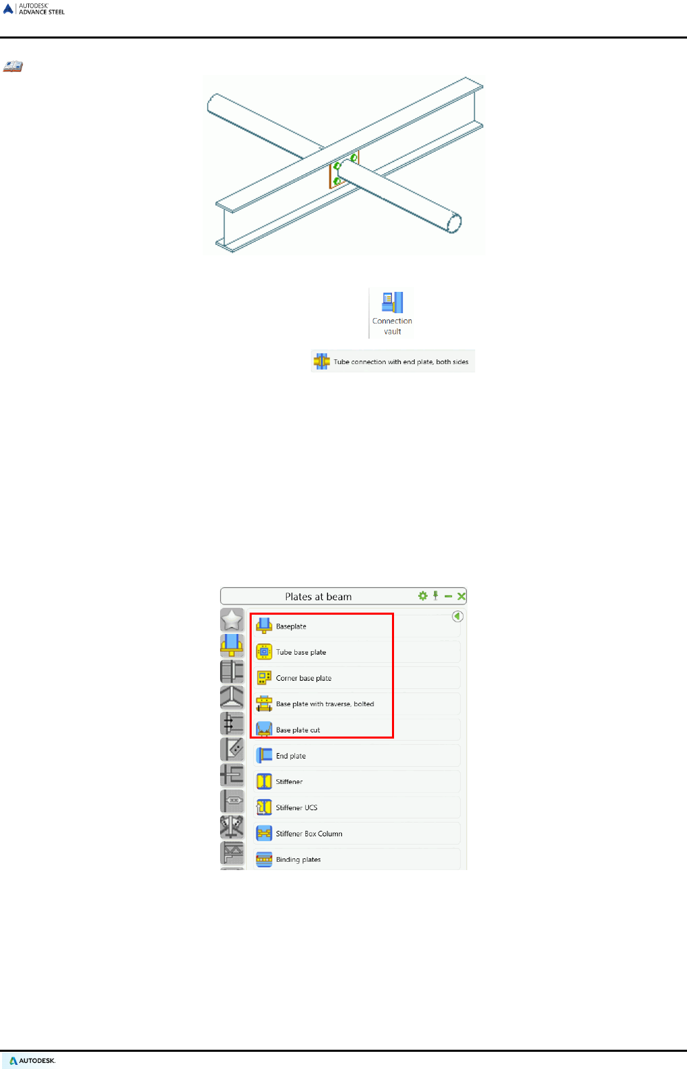
ADVANCE STEEL USER’S GUIDE
Example 2: Creating a compression pipe with end plate, double-sided
Figure 140: Compression pipe with end plate, double-sided
• On the Extended Modeling tab, Joints panel, click .
• In the Tube connections category, select .
• Select the beam and press Enter. Next select the tube and press Enter.
The connection is created and a dialog box appears.
“Pipe connection with straps” connects two tubes using an end plate with straps and optional stiffeners.
“Base joint for pipes” connects tubes using a cover plate, butt strap, and gusset plate. The incoming tube must
be square to the first tube.
Base plate joints
The Plates at beam category of the Connection Vault contains tools to create base plate connections, stiffen-
ers and binding plates.
Figure 141: Plates at beam category - Base plate joints
95
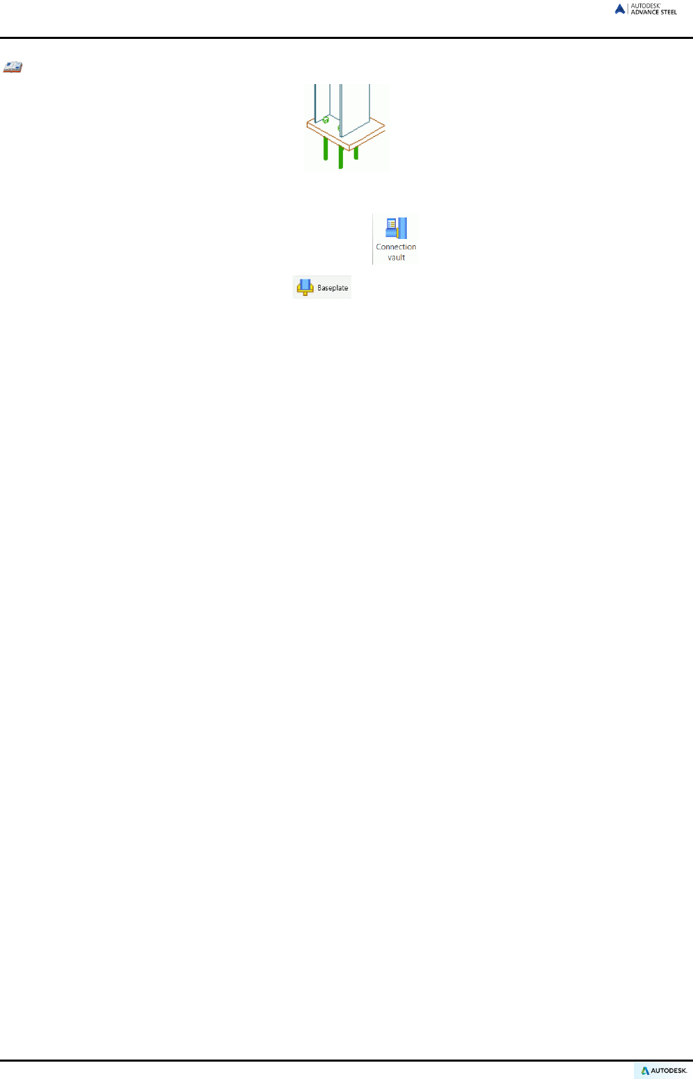
ADVANCE STEEL USER’S GUIDE
Example: Creating a base plate
Figure 142: Joints – asymmetrical base plate
• On the Extended Modeling tab, Joints panel, click .
• In the Plates at beam category, select .
• Select the column to which the base plate should be attached and press Enter.
• If connection settings have not been saved a warning appears (default values for the section cannot be
found, take the standard value of the joint.). Confirm by clicking <OK>.
A base plate with anchor bolts is created at the end of the column. The column is shortened by the plate
thickness and the plate is welded to the column. Different options for bolts and plate preferences are
available.
The base plate is either horizontal to the base or perpendicular to the column. Also, it can be rotated
around its center point.
A variety of parameters can be specified to determine the thrust anchor, stiffeners, and welds. The
graphically illustrated tabs in the dialog box assist in setting the parameters.
Corner column connections are created with “Corner base plate” joints. The base plate is an L shape and bolts
are created at different locations. The base plate can be created on all profile shapes (e.g., I, U, C, square hol-
low, rectangular hollow, round pipes) and on combined sections such as star angles and double channels.
The “Base plate with traverse" tool creates a base plate, which can be stretched at the end of a column. Cross
members (of a C-shaped profile) are bolted or welded to the flange of the column.
“End plates” are attached to the system end point of beams. The beam can be shortened by the plate thickness
and a construction gap can be created (“End plate variable” dialog box, Plate tab).
The “Stiffener” tool creates stiffeners perpendicular to a beam at a picked point according to the UCS. The
“Stiffener, UCS” tool places stiffeners in the plane of the coordinate system with the stiffener thickness in the
positive Z-direction of the current UCS. The distance between the full stiffener and flange inner sides can be set
in both cases.
The “Stiffener box Column” tool creates a stiffener plate in a square or rectangular tube. This joint also works on
welded hollow beams.
Two beams can be connected with “Binding plates” either on the inside or outside of the beams. These plates
are either welded or bolted to the beams.
96
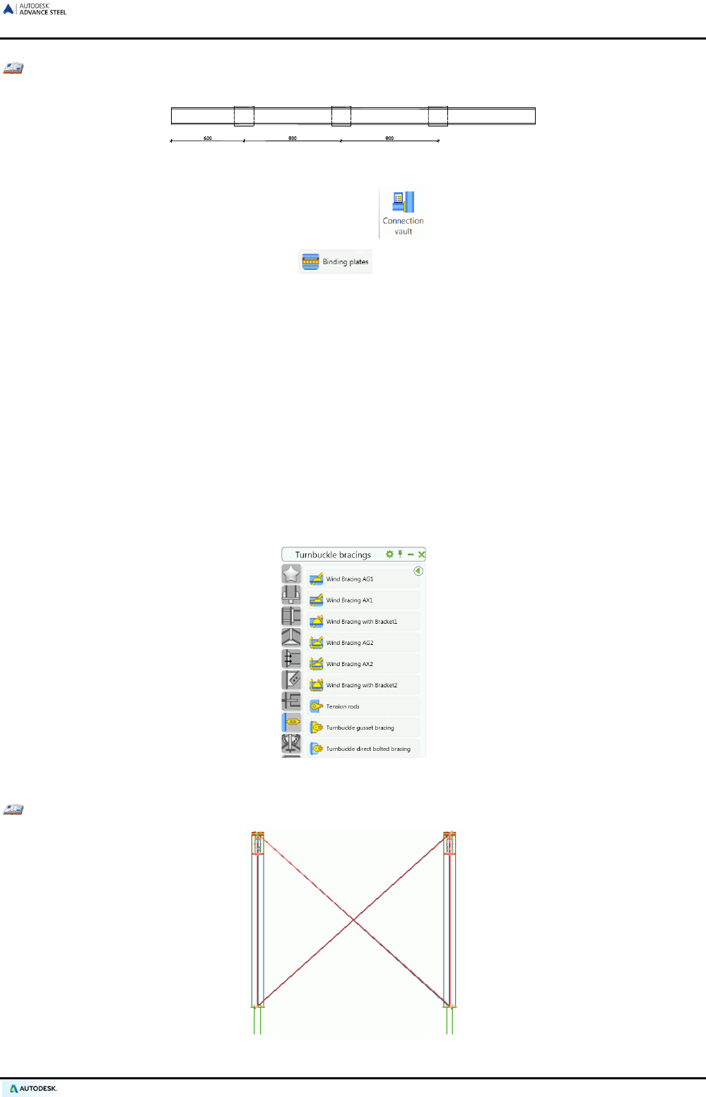
ADVANCE STEEL USER’S GUIDE
Example: Creating binding plates between two beams from start point
Figure 143: Binding plate between 2 points
• On the Extended Modeling tab, Joints panel, click .
• In the Plates at beam category, select .
• Select the first beam and press Enter. Next, select the second beam and press Enter.
• The binding plates are created with standard values and the “Binding plates joint” dialog box appears.
• On the Layout tab, select From start and specify the intermediate distance; the number of plates is au-
tomatically calculated.
• On the Plate tab, specify the size of the binding plates. The distance between the beams will determine
the thickness.
• The binding plates are welded to the beams that connect them. On the Connection tab, enter the
specification of the weld.
Turnbuckle bracings
The Turnbuckle bracings category of the Connection vault groups single bracing members and complete
cross bracings of round or flat steel. The bracings are welded to beams and/or plates.
Figure 144: Turnbuckle bracings category
Example: Turnbuckle bracing with steel spherical cap
Figure 145: Turnbuckle bracing with steel spherical cap
97
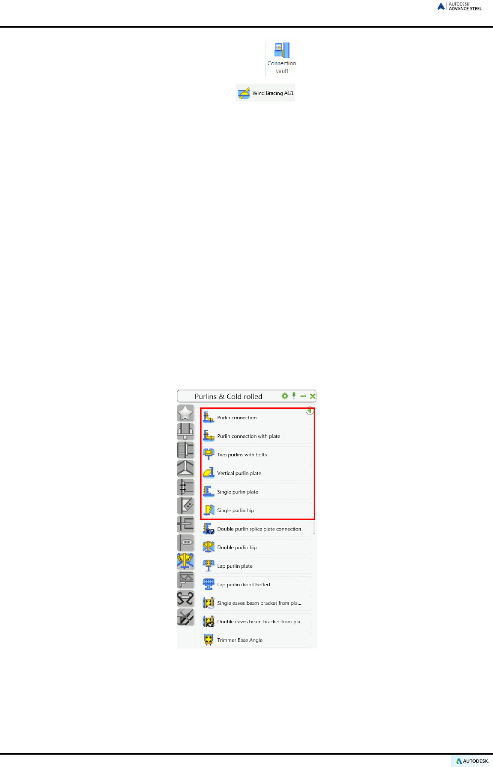
ADVANCE STEEL USER’S GUIDE
• On the Extended Modeling tab, Joints panel, click .
• In the Turnbuckle bracings category, select .
• Select the first column and press Enter.
• Select the second column and press Enter.
• Select the beginning of the system line of the 1st column (point 1).
• Select the end of the system line of the 2nd column (point 2).
• Select the beginning of the system line of the 2nd column (point 3).
• And finally, select the end of the system line of the 1st column (point 4).
The turnbuckle bracing is created. Individual settings such as moving the system lines in the Z-direction
to set the position of the bracing within the column are modified in the dialog box. These settings can be
made at the top and bottom of the bracings. Variants for bracings include “Bracing with tensioning tres-
tle” and “Bracing with bracket”. In a similar way, single bracings with a cast spherical cap, tensioning
trestle or plate bracket and pad can be created.
“Turnbuckle bracing with gusset plate” creates a bracing member with turnbuckle, a welded butt strap, and a
gusset plate welded to a beam. Both beams must be selected and then the start and end points of the bracing
member must be defined.
Purlin joints
Various joints are created at the upper flanges of beams using the Generic purlin joints category of the Connection
vault. The category includes connections for a single-span purlin at an end-span and at a splice, the attachment
of a continuous purlin to an upper flange, etc.
Figure 146: Generic purlin joints category
To create purlin connections, first select the beam to which the purlin is attached and press Enter. Then select
one or two purlins (according to the tool used), and press Enter each time.
98

ADVANCE STEEL USER’S GUIDE
Example: Creating single purlin connection
Figure 147: Single-span purlin, end-span
• On the Extended Modeling tab, Joints panel, click .
• From the Generic purlins category, select .
• Select the beam and press Enter.
• Select the purlin and press Enter.
• Click <OK> in the message window.
A folded beam is bolted or welded to the main member and the purlin is then bolted to it. In the “Purlin
connection element” dialog box, enter more details about the connection (i.e., bolted or welded connec-
tion, construction offset, length of sleeve, information for bolts, etc.).
User connections
The tools on the Custom connection tool palette, store, and reuse interactive connections.
Figure 148: Custom connections tool palette
Example: Creating a column-beam user connection for a column and a beam
• Create all joint elements: plates, welds, bolts (including bolt holes), cuts, etc.
• Save the .dwg file containing the joint elements in the Connection templates folder.
• On the Custom connections tool palette, click .
• From the dialog box, select 2 beams for the definition method.
Figure 149: Selecting the definition method
99
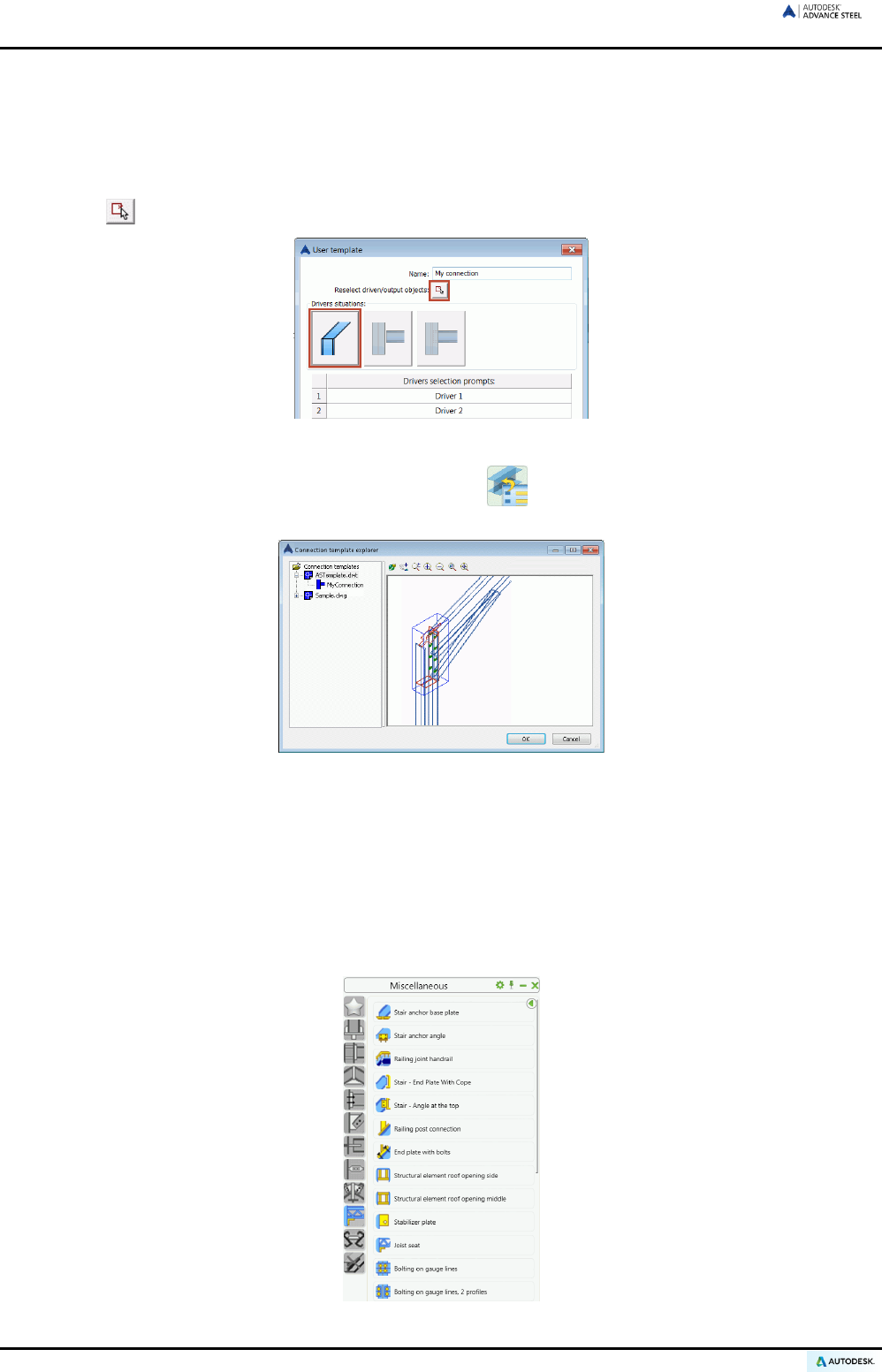
ADVANCE STEEL USER’S GUIDE
• Select the elements to be connected by the new connection:
− Select the column and press Enter.
− Select the beam and press Enter.
• Enter the name for the new template connection: MyConnection.
• Click , select all joint elements and press Enter. A blue connection object appears around the joint location.
Figure 150: User template connection properties
To recall a connection, use the “Insert connection template” tool from the Custom connection tool pal-
ette. The library dialog box has a visual preview of each stored connection for quick recognition.
Figure 151: User connection explorer
Select a joint and connect the beams by selecting them in the proper order. Saved joints only work if the orienta-
tion and the angle between the beams is the same as when the joint was stored.
Miscellaneous joints
The Miscellaneous joints category contains tools for creating various types of joints, such as: seated connec-
tions, bolts on gauge lines, side rail connections etc. Additional tools allow creating punch marks on a main el-
ement (beam or column) according to the position of a secondary element (beam or column).
Figure 152: Miscellaneous category
100
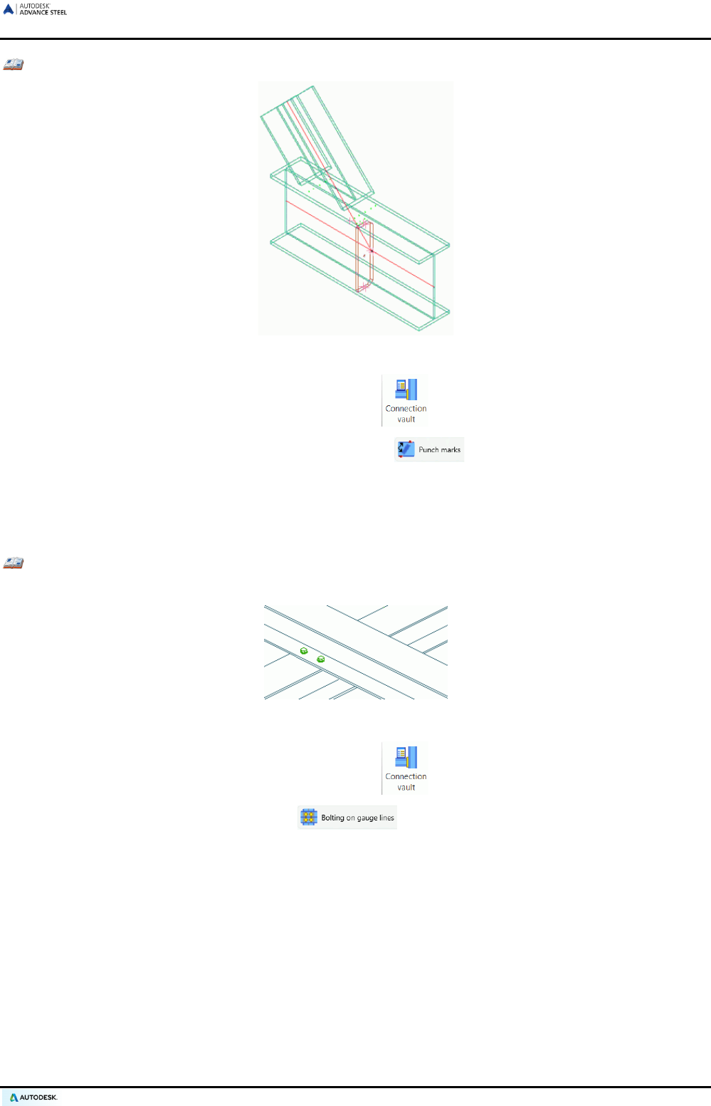
ADVANCE STEEL USER’S GUIDE
Example 1: Creating punch marks
Figure 153: Punch marks
• On the Extended Modeling tab, Joints panel, click .
• In the Miscellaneous category, select “Punch marks” .
• Select the main element and press Enter.
• Next, select the second element and press Enter.
• The punch marks are created and the “Punch mark joint” dialog box appears.
Example 2: Creating bolts on gauge lines
Bolts can be created on the gauge lines of the crossing sections (they must touch each other).
Figure 154: Bolts on gauge lines
• On the Extended Modeling tab, Joints panel, click .
• In the Miscellaneous category, select .
• First select the main beam, press Enter.
• Next select the main second element and press Enter.
The bolt patterns are created on the gauge lines of the two sections. A dialog box appears for modifying
the specifications for the bolts and positions.
Connection objects
If joints require a change, right click on the connection gray box and select Advance Properties. Another option
is to double-click the object.
Alternatively, right click only one part of the joint (e.g., a plate) and select Advance Joint Properties from the menu.
101
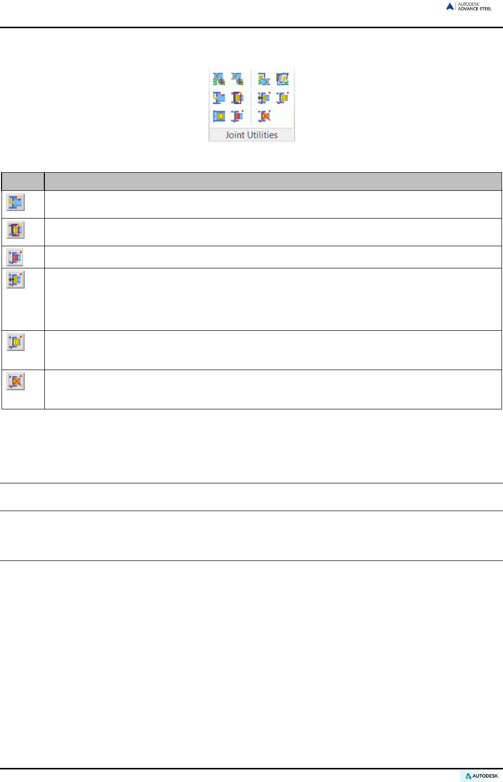
ADVANCE STEEL USER’S GUIDE
Tools for display, select, repeat, copy and transfer connection properties are on the Joint Utilities panel of the
Extended modeling tab.
Figure 155: Joint Utilities panel
Button Function
“Repeat rule”: Repeats the previously executed rule for joints. The elements are selected similarly to
the previously executed connection.
“Display”: Turns on invisible objects created with the connection. Click “Display” and select an ele-
ment of the connection.
“Select”: Identifies all elements in a connection by first selecting a connection object (gray box).
“Transfer properties”: Copies param
eters such as additional stiffeners or a changed haunch length
to another existing connection of the same type. The workflow of this command is to first select an
element from each connection to change (any number of joints may be selected) and then select the
connection whose properties will be transferred. All selected joints are updated to match the proper-
ties of the last selected connection.
“Update”: If a connection, whose automatic update has been switched off in the properties dialog
box, has been changed then the connection object is highlighted in red. The “Update” tool manually
corrects the connection object.
“Delete all”: By selecting one or more connection objects and clicking “Delete all”, the selected con-
nection objects are completely del
eted. Objects, other than connection objects, selected at the same
time will not be deleted.
The joints library contains most standard types and is continually growing. In particular cases where there is no
immediate direct solution, use the connection closest to the requirement, set the best parameters, and delete
the connection object to ‘explode’ the connection logic. Next, adjust the individual component's Advance prop-
erties and finally add or delete parts as required.
Note: When deleting the connection object the intelligence of the joint is eliminated and individual members
do not automatically update on a design change.
Special parts, special sections
Special parts
Parts used in the Advance Steel model and in the structured BOMs or drawings that cannot be created from
other Advance Steel objects are special parts (e.g., turnbuckles).
They must be designed in separate DWGs as solids and created as Advance Steel objects with the special part
tool.
102
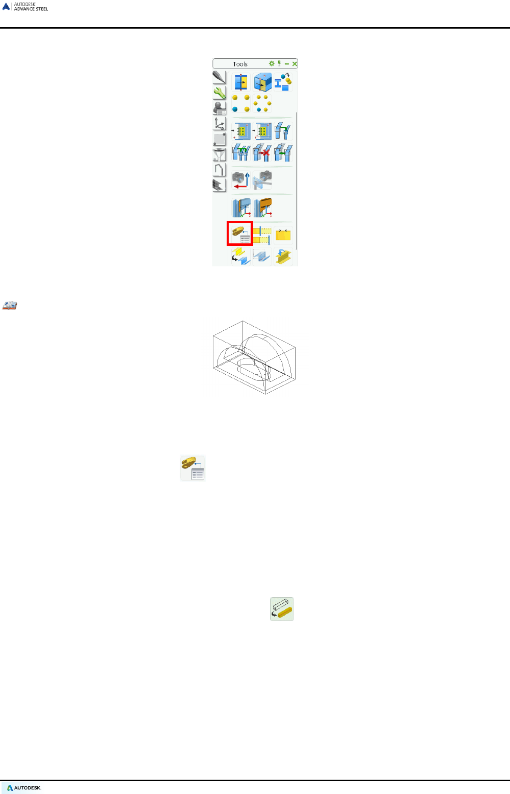
ADVANCE STEEL USER’S GUIDE
The “Advance Steel special part” tool is accessible on the Tools tool palette.
Figure 156: Special part tool
Example: Creating a cast steel spherical cap as a special part
Figure 157: Cast steel spherical cap as a special part
• Create a separate DWG, draw the part using solids, and then store and close the file. Verify that the
variable Insunits is set to the correct value for the units used in the models. For mm, set the value to 4.
• On the Tools tool palette, click .
• Indicate the creation point, which corresponds to the zero point of the DWG.
• The special part is created according to the current UCS and a dialog box appears, in which the name
of the special part (i.e., name of the DWG), scale, material, information for the structured BOM, and all
other preferences can be set.
As with the joints, the information for special parts is stored in the ‘bounding’ boxes. To move a special part, the
box must be selected. This is automatically done upon selecting a special part object.
The box of the special part can be made visible using the tool on the Quick views tool palette or on the
Display type tab in the Advance Steel properties dialog box for the special part.
A special part can be created at any scale. When Advance Steel checks for identical parts, different scales for
the same special part are not considered. This means that a special part can get the same position number at
different scales. It is therefore recommended to draw and create special parts at full size (1:1).
The information of special parts is exported to the structured BOM and is considered during drawing creation.
The defaults can be modified to define whether or not the special part should be included in a collision check.
Special parts can be created using joint rules as in the case of bracings with turnbuckles.
Special parts can be welded and bolted to other Advance Steel Objects. Bolt grip lengths cannot be calculated
for special parts unless the default is set to do so.
103
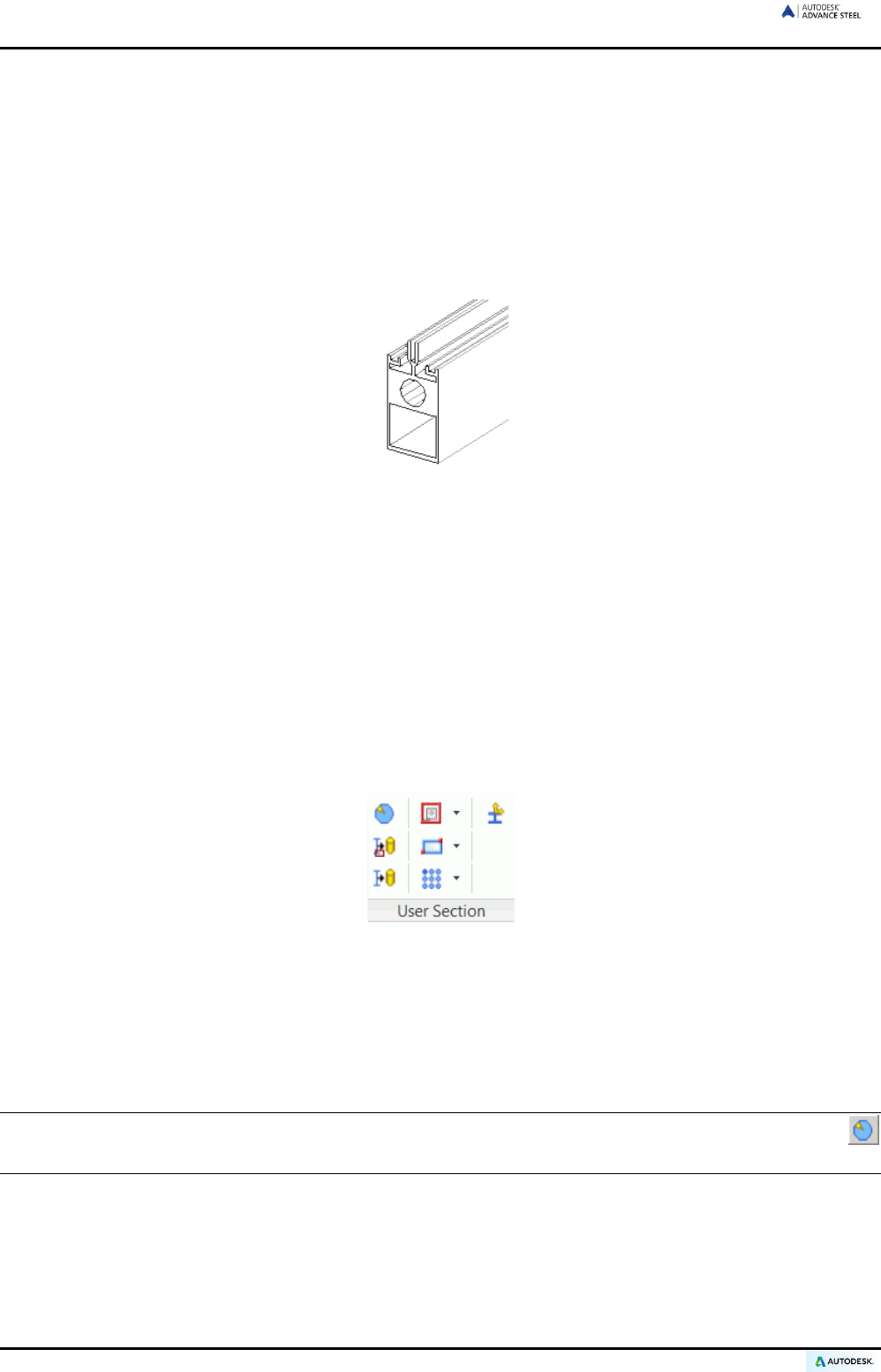
ADVANCE STEEL USER’S GUIDE
User sections
Non-standard profile cross sections are called User Sections. They can be set in Advance Steel and behave in
the same way as standard sections in the Advance Steel properties and functionalities.
All sections, including User Sections, are stored in MS-Access tables (libraries). The table structure for User
Sections differs from the structure of standard sections. Standard section tables contain parametric values
whereas User Sections include only the corner points of the cross section geometry.
User Sections are not manually entered in tables (libraries); they are drawn and transferred by means of the
Advance Steel User Section tool that identifies the profile cross section and enters the geometry into the MS-
Access tables (libraries).
Figure 158: User Sections
Definition of User Sections
Similar to the special parts, a ‘User Section’ is created in two steps.
First, the section (2D cross section) is drawn with CAD elements. Then, two texts must be created with the
name of the section (e.g., IPE 200) and the name of the section class (e.g., IPE).
The second step is the actual definition by a command and identification of the drawn elements. The information
is proofed (e.g., the contours are not permitted to overlap) and created in the database. The section is then
available in Advance Steel.
Exact conventions and information layers must be considered when drawing and labeling special sections. Sev-
eral User Section tools make this easier. These tools are available on the User sections panel, in flyouts.
Figure 159: User sections panel
The general workflow for drawing and defining a User Profile is as follows:
• Create a DWG and set the view direction to ‘top view’ based on the world coordinate system.
• For each User Section component set a corresponding layer. This can be done using the Change current
layer flyout.
Note: The special section definition is its own application (ARX). It is automatically loaded by clicking
on the User section panel.
104

ADVANCE STEEL USER’S GUIDE
Figure 160: Change current layer flyout
• “Section outer contour”: To create an exact and simple outer contour, choose the outer contour or exact
outer contour layer setting. The element MUST be created using a closed polyline (pline), a circle, or a
rectangle.
Figure 161: User Section outer contour - in standard and exact representation
• “Section inner contour”: The layer for inner contours (simple / exact) must be activated. Closed polylines
(pline), circles, and rectangles are allowed as elements.
• Place a section name and assign the section to a section class. This must be done using text created on
specific layers. The layer for the respective text must be created and activated as the current layer. Only
one-line texts are permitted. They must not have blanks and in the text for the section class no negative sign.
Figure 162: User Section labeling and frames
• The definition frame must contain the profile with all its information and is required to create the section.
Only a rectangle drawn on the appropriate layer is permitted for this.
• “Coordinate systems”: Advance Steel object surfaces can be selected to place the UCS. These surfaces
can also be used for User Sections. The coordinate systems at the top surface of the section are automati-
cally set. With “Add coordinates”, the surfaces can be set by selection. A symbol is created in the center of
the line segments.
105
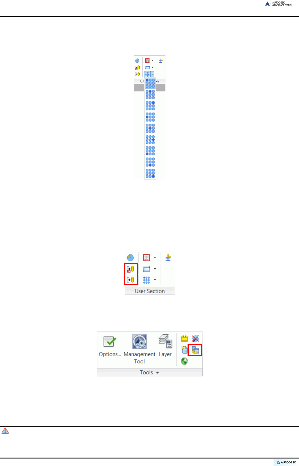
ADVANCE STEEL USER’S GUIDE
• Corner points of the section geometry can be set as position points of the creation axis (Reference axis or
System line). The position of the section can be moved according to these points. When creating the sec-
tion, the standard position is at the center of gravity. The position points of the reference axes are set with
the tools on the Add reference axis flyout of the User sections panel.
Figure 163: Add reference axis flyout
• Select the required position from the flyout, click on the screen so that the cursor becomes a crosshair, and
then pick the respective corners on the outer contour (using object snap!) or from another point. A symbol
is automatically created on the corresponding layer.
• “Creating Sections”: Sections are created from the geometric information and are saved in the database.
Click “Create selected section” or “Create all sections” (several special sections can be designed in one
drawing). Select the section to create by picking the frame. A message is displayed to indicate successful
creation of the section(s).
Figure 164: Special sections creation tools
• Once the database is loaded in Advance Steel (“Update defaults” icon on the Settings panel), the newly
created section is available for use.
Figure 165: Updating defaults
• If changes must be made to the geometry of existing User Sections, the geometry should be changed in
the 2D drawing and the section recreated. Advance Steel will replace the existing entries in the database
when auditing the section names.
Keep the drawings where the geometry of the sections is set, as there is no option (as yet) to locate
these sections if moved. All cross sections must be redrawn when databases are lost.
106
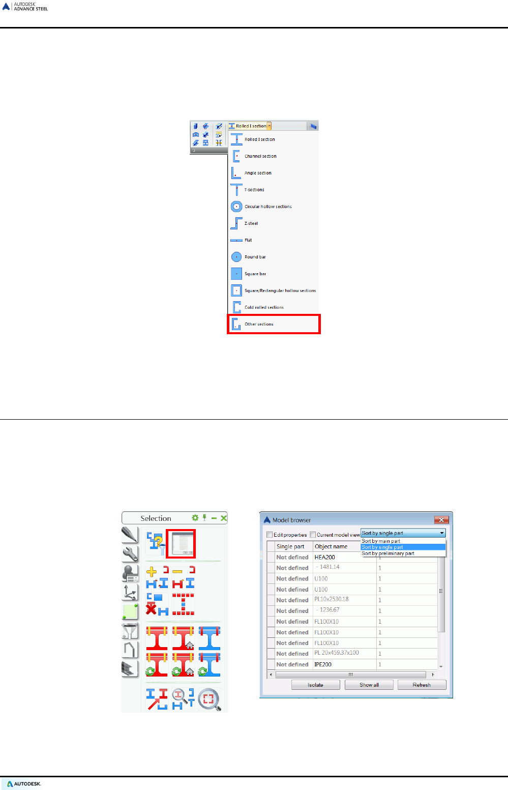
ADVANCE STEEL USER’S GUIDE
User Sections Creation
After creating a User Section it is ready for use.
• Click “Other section” (last icon) on the Section classes flyout of the Beams panel and select the desired
special section.
Figure 166: Create special section (1)
• The “Beam” dialog box appears. Choose the user section from the list under Section class and Section.
Working methods II
Model Browser
This tool provides complete control of all the elements of a model. At any time this tool can be accessed to show
up-to-date information on each object.
The model browser is accessible on the Selection tool palette.
Figure 167: Accessing the Model browser
Elements are sorted by main or single part mark. The element properties are displayed in the model browser by
creating or removing some additional columns:
107
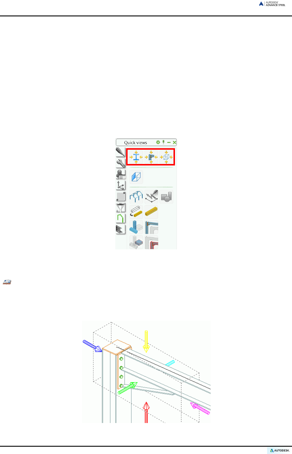
ADVANCE STEEL USER’S GUIDE
• Right click in the table.
• Select create column from the context menu. The list of properties appears.
• Select the properties to display in the model browser. The model browser displays the selected properties.
Properties are modified in the Model Browser. When Edit properties is checked some of the properties for the
selected lines of the Model Browser can be changed.
Model views
When constructing a large model with many elements an isometric view can be confusing.
The model view feature creates local view areas that show only those elements that lie within specific bounda-
ries. Slices are cut from the model for better visualization (e.g., to work on a single frame in a 2D-view).
The view direction can be set and nodes can also be viewed from 6 different directions at the same time.
The model view features are grouped on the Quick views tool palette.
Figure 168: Quick views tool palette
Using the appropriate tool it is possible to create a quick view on an object, an assembly or a joint.
Example: Creating a quick view on a joint
• On the Quick view tool palette select “Quick view on joint”.
• Select the connection object of the joint to display.
• Define the view direction for the joint selecting one of the displayed arrows and press Enter.
Figure 169: Selecting the view direction
108
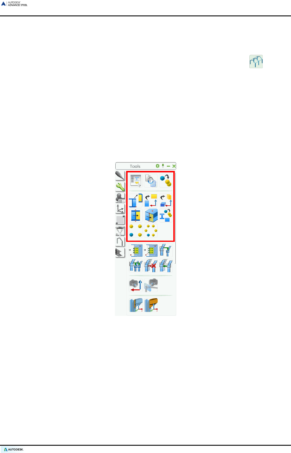
ADVANCE STEEL USER’S GUIDE
• Next, define the view box:
• Enter 1000 for the view depth.
• Enter 1000 for the view extension in the X and Y directions.
After creating a quick model view, the entire model can be displayed again using the “All visible” tool.
Advance Steel – copy / rotate / mirror
The construction process workflow often proceeds much like the creation of a portal frame with certain parts of a
model can be completed with all features and connections and then copied. In these cases use the commands
on the Tools tool palette to copy, rotate, mirror, or array.
On the Tools tool palette, there are a variety of Advance Steel tools (besides checking tools) to copy, rotate,
and mirror. These are supersets of the CAD platform commands that add support for copying connections and
linking selected objects with welds and bolts. Although the tools were designed for copying connections they
can also be used for copying several sections or other objects (e.g., holes, trimmings, contours) and in most
cases a multiple copy is possible.
The following Advance Steel commands for copy, rotate, and mirror are available on the Tools tool palette:
Figure 170: Tools tool palette
All elements to be selected for copy must be visible. This is also true for object features like shortens, copes, etc.
When copying all elements of a joint including the connected elements, the intelligence is also copied and re-
mains customizable. If all the elements are not copied the target copy will not have intelligence.
109
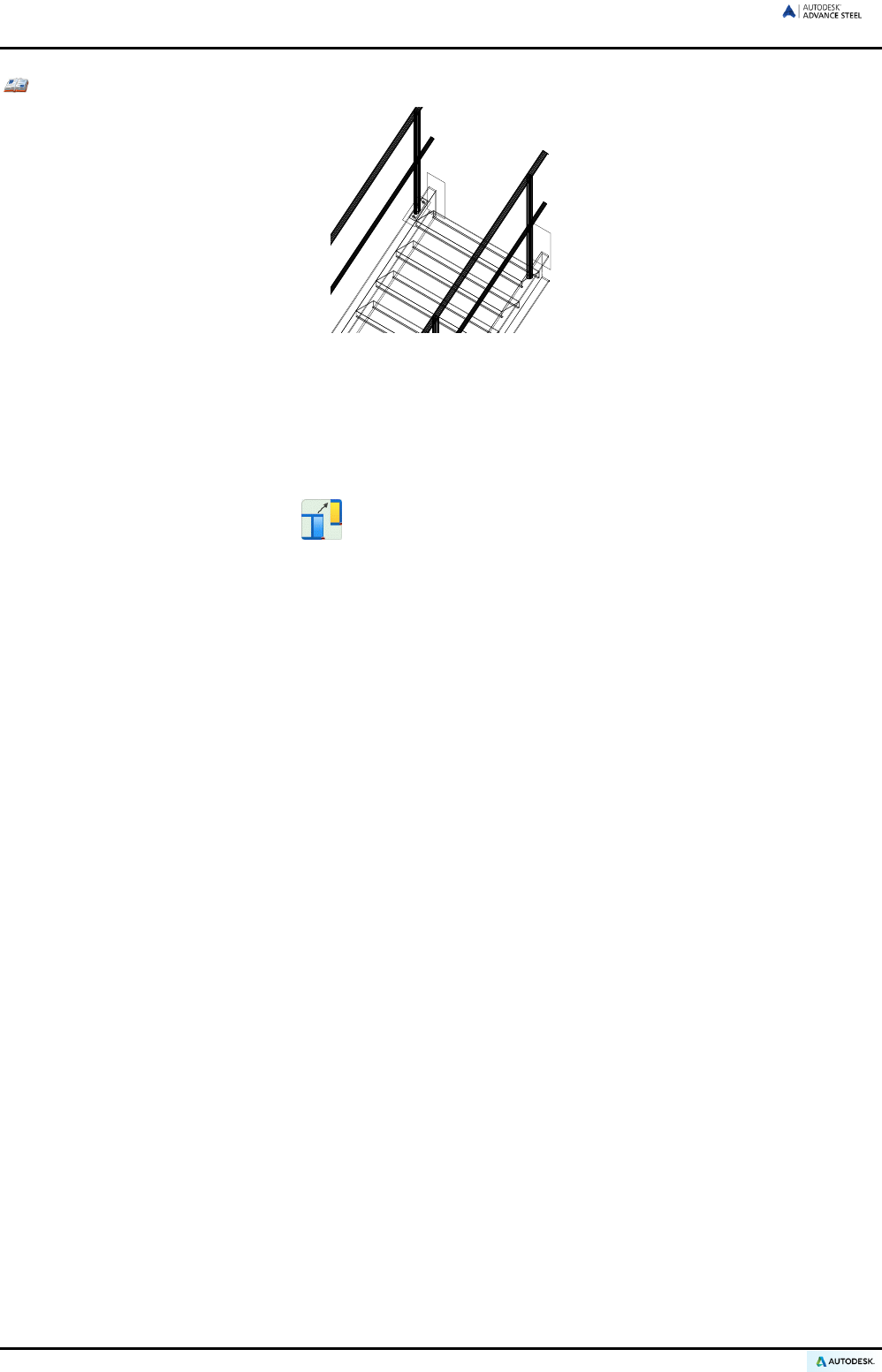
ADVANCE STEEL USER’S GUIDE
Example: Copying a simple connection
Figure 171: Stair
• The connection to be copied is a connection between a stair stringer and a handrail post with a base
plate. The stringer profile is connected to the base plate using two bolts; the handrail post is shortened
and welded to the base plate. This base detail must be copied to another handrail post. Verify that all
elements are visible including the processing object at the post (if necessary, change the setting on the
Display type tab of the corresponding dialog box).
• On the Tool tool palette, click .
• If a selection has not been made, select the elements to copy (i.e., base plate, two bolts, welds, trim-
ming) and press Enter.
• Enter the start and end points for copying. It is recommended to use the end of the system lines of the
posts (visible in the “Standard” representation).
• Next, enter the coordinates of the copy vectors. Press Enter for all coordinates (X, Y, Z).
• At the copy destination, the objects that correspond to the objects in the initial situation are requested.
The initial elements are highlighted with dotted lines. Select the object corresponding with the highlight-
ed one at the copy destination. This correctly assigns the connection objects.
• Other destination points can be entered for a multi copy. The tool is closed by pressing Enter or Esc.
With this Advance Steel copy tool, a complete detail with all features can be copied to another location.
110

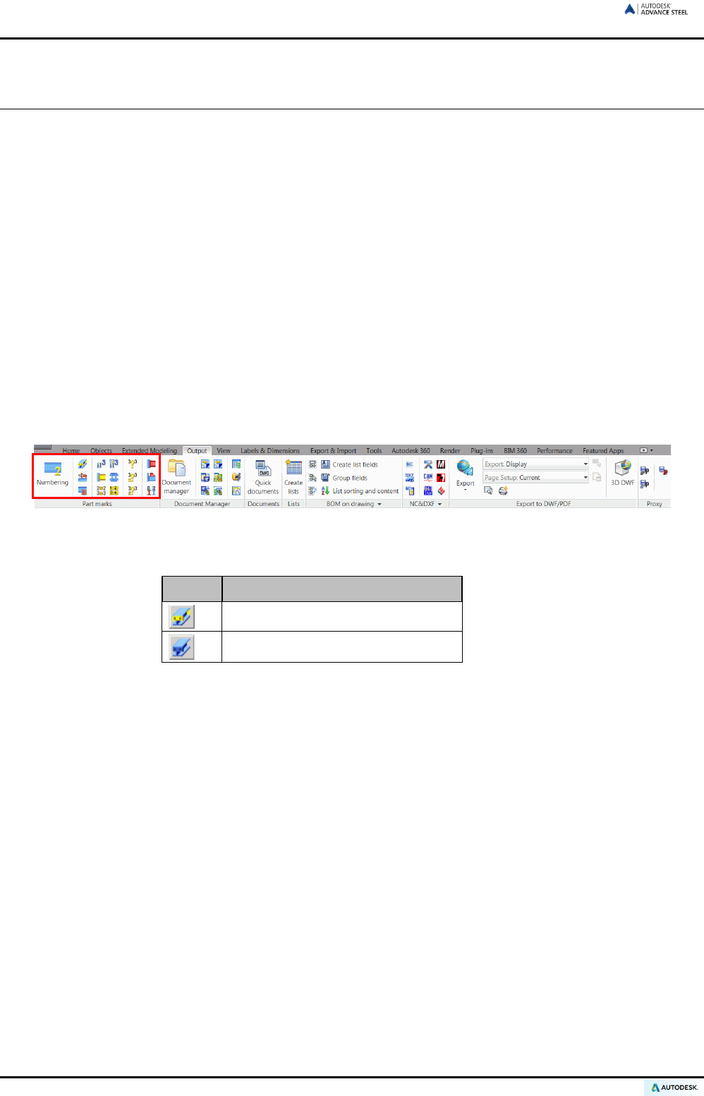
ADVANCE STEEL USER’S GUIDE
Numbering tool
The numbering tool automatically numbers Single Parts and Assemblies for the entire model. The basis for
numbering is finding identical parts that should have the same mark.
The elements are compared by geometry, material properties, coating, and commodity (and behavior). The
properties name and lot/phase are not considered for numbering. The Model Role is used by the prefix tool to
assign prefixes but it is not used directly for numbering.
At first, all structural parts should be numbered so start with single part marks.
The program then determines the assembly marks for parts connected in the shop. The biggest part of an as-
sembly is the main part and will get an assembly mark and all other parts are considered attached and will have
a single part mark.
During the numbering process beams and then plates are the first to be numbered. In each case, the group with
the most elements will get the lowest number.
If nothing is selected the entire model is numbered. When Advance Steel objects are selected only these items
are numbered. The results in either case are recorded in the text window (or recorded in a text file, using a de-
fault setting, and can be saved).
All numbering tools are available on the Part marks panel of the Output tab. A variety of tools allow checking
the numbering correctness.
Figure 172: Part marks panel
• It is possible to switch between Single Parts / Assemblies.
Button Function
Switch to Single Parts
Switch to Main Parts
• Using the switch position, the following numbering tools refer to single parts or to assemblies. Unless both
single part and assembly numbering are done together (recommended), then single part numbering MUST
be done first.
• The other icons on the panel allow:
− assigning and deleting single part and assembly marks
− defining part prefixes
− checking the numbering correctness
− creating main and assembly parts
112
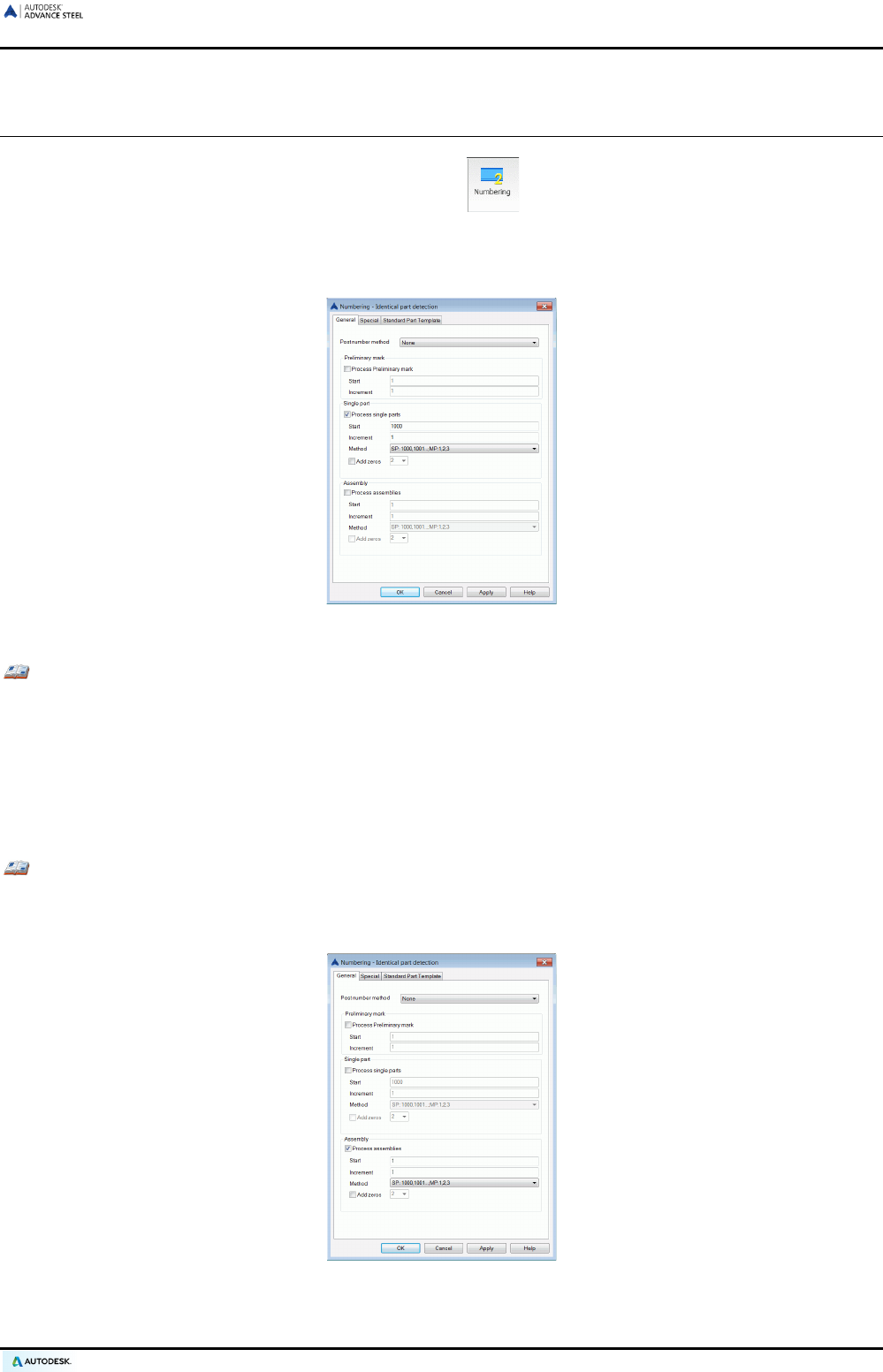
ADVANCE STEEL USER’S GUIDE
Starting the numbering
• Start the numbering process using the numbering tool on the Part marks panel of the Output tab.
• A dialog box appears. The numbering for single parts and assembly parts can be performed in one step or
separately. Unless both single part and assembly numbering are done together (recommended), then sin-
gle part numbering must be done first.
Figure 173: “Numbering” dialog box
Example 1: Single parts numbering
• Check the Process single parts option.
• By default, single parts marks begin with 1000 and increase by increments of 1.
• Select one of the available methods.
• Start the numbering process by clicking <OK> in the window.
The assigned marks are visible on the Naming tab of the object dialog boxes.
Example 2: Assembly numbering
• Check the Process assemblies option.
• By default, assembly marks begin with 1 and increase by increments of 1.
Figure 174: Assembly numbering
113
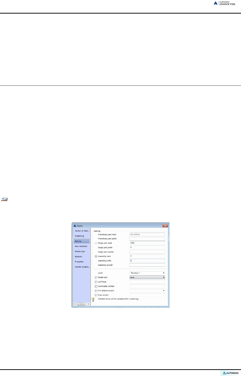
ADVANCE STEEL USER’S GUIDE
• Select one of the available numbering methods. For “with drawing number” numbering, define the prefix
automatically given by the drawing numbering process. At drawing creation, the first part gets the prefix
a001, then b001, etc.
• Start the numbering process by clicking <OK>. The result is displayed in the text window.
Note that regardless of the toggle switch setting, the “Single Part” and “Assembly” numbering can be turned
on/off using the checkboxes in the numbering dialog box. This can also be used to perform the recommended
simultaneous “Single Part” and “Assembly” numbering.
Numbering options
Several numbering options are available in the post number method list:
• Assembly group: The numbering automatically assigns the assembly mark to the single part mark of the
main part.
• SP No (for main part) = Assembly No: The single part mark for (usually) the biggest part of the assembly is
assigned the same value as the assembly mark instead of having an individual single part mark.
With this option the single part numbering and the assembly numbering MUST be done at the same time
and Advance Steel forces this by disabling the other checkboxes.
Once a numbering has been performed, it is not possible to change this option…
…UNLESS the “Ungroup identical parts” tool is used, which completely removes any numbering infor-
mation.
• SP No (for standalone part) = Assembly No: The single part mark for the standalone parts is assigned the
same value as the assembly mark instead of having an individual single part mark.
Checking the results
Example: Displaying the single part mark /assembly number of an object:
• Select the Advance Steel structural part by clicking it. Open the dialog box.
• Choose the Naming tab. The Single Part and Assembly marks are shown together with their prefixes.
Figure 175: Marks and prefixes
Numbering with standard parts
Standard parts are created in a template model using normal Advance Steel functionality and then assigned
required part marks. During a numbering process objects are compared to detect identical parts. Any part in the
current model that matches a Standard Part in the template will get the same mark.
114
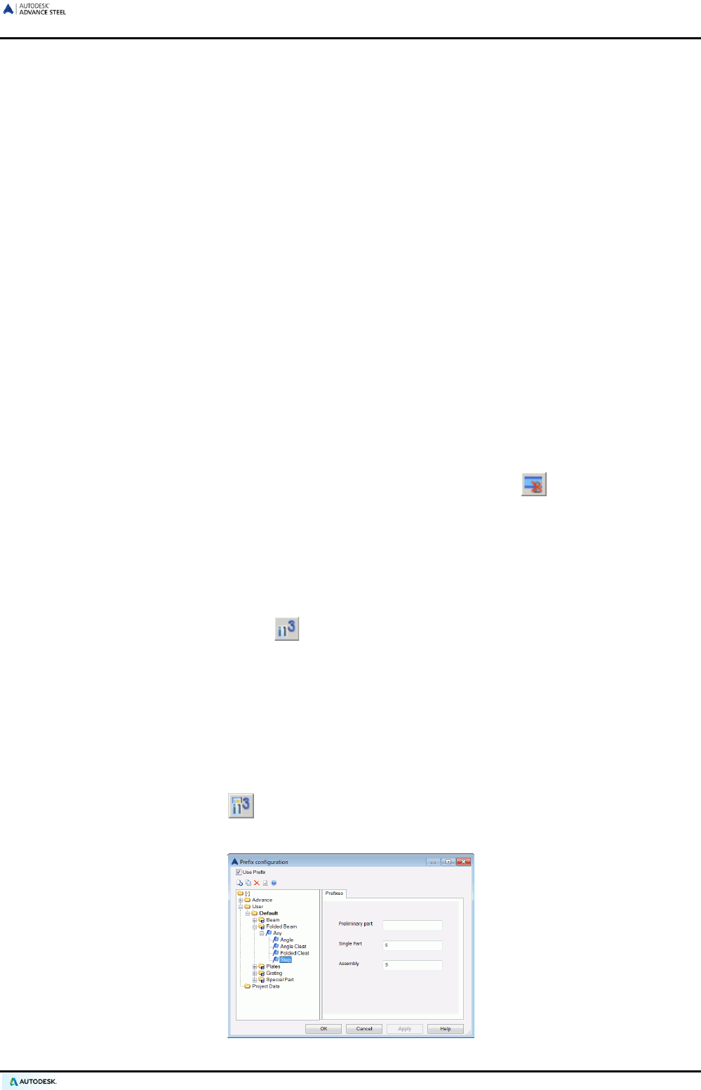
ADVANCE STEEL USER’S GUIDE
The folder
...\ProgramData\Autodesk\Advance Steel 2015\Shared\StandardPartTemplate
contains the standard part models.
The templates in this folder are listed on the Standard part template tab of the “Numbering - Identical part de-
tection” dialog box.
• Create a DWG model with standard parts.
• Run the numbering inside this drawing and manually set the standard part marks (and prefixes) as required.
• Save this drawing to:
...\ProgramData\Autodesk\Advance Steel 2015\Shared\StandardPartTemplate
• To run the numbering in another model, open the “Numbering - equal part detection” dialog box. Select the
Standard part template tab where all drawings from the above folder are displayed. Click New to attach a
reference model and check the option Singlepart or Assembly to use the template for single part number-
ing or assembly numbering.
• Several Standard Part Templates may contain the same objects but with different part marks. In this case
the part mark of the template with the highest priority is used. To change the sequence of the templates
use the arrow buttons on the toolbar.
Deleting part marks
This tool deletes the part marks.
• Select the structural parts whose part marks should be deleted and use the tool on the Part marks
panel of the Output tab.
On deleting the assembly marks only the mark is deleted, not the main part identification or its prefix.
Assigning / Changing a prefix
A text prefix, separate for single part and assembly marks, can be put in front of the part mark.
• Select the desired elements, use the tool on the Part marks panel and enter an appropriate prefix
without spaces or special characters.
The assigned prefix is displayed and changed on the Naming tab of the element dialog boxes. Prefixes are also
assigned in the dialog box.
Prefix configuration
The automatic prefixes for single part and assembly numbering can be configured. The prefix is based on the
model role.
• On the Part marks panel, click .
The prefix configuration dialog box appears.
Figure 176: Prefix configuration dialog box
115
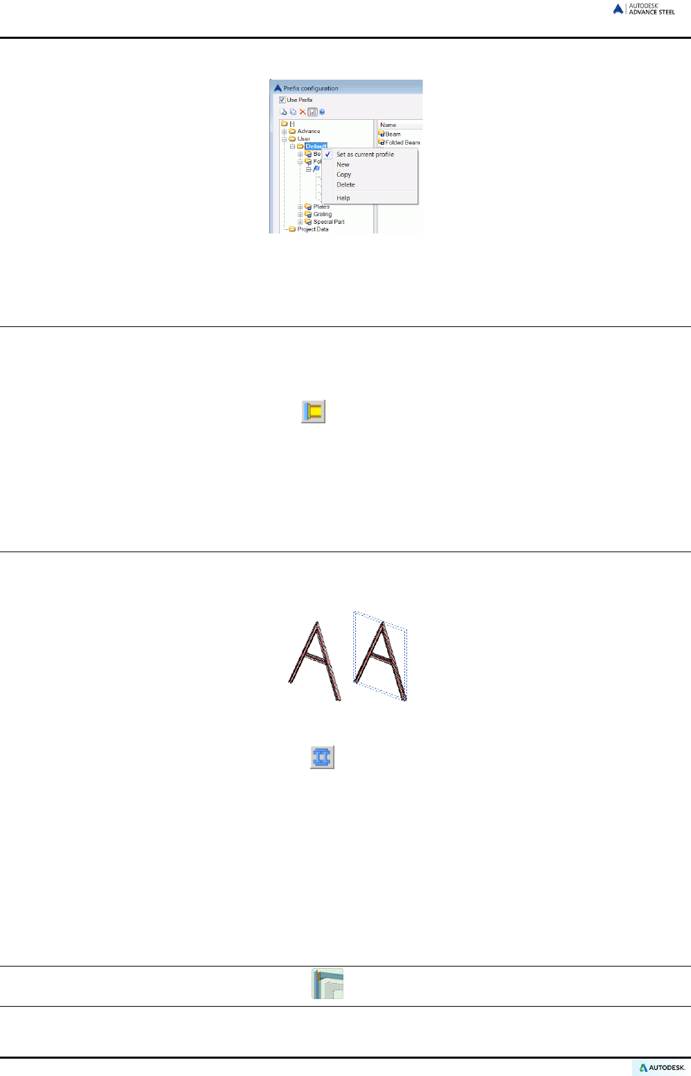
ADVANCE STEEL USER’S GUIDE
Different profiles for different jobs are set. The preferred profile should be set as current.
Figure 177: Prefix configuration – set current profile
Creating a main part
Main part assignment is either performed manually or by the numbering process using Create main part of
assembly that automatically detects attached parts. Alternatively, during assembly numbering, the biggest part
automatically becomes the main part.
• On the Output tab, Part marks panel, click .
• Select the part to make the main part. The object dialog box appears with the Naming tab selected.
• Enter the assembly mark and close the dialog box or just close the dialog box and run an automatic num-
bering.
Creating an assembly part
Connected parts (by shop welds or shop bolts) can be assigned to an assembly part.
Figure 178: Assembly part
• On the Output tab, Part marks panel, click . Select one of the connected parts and a dialog box ap-
pears.
• Enter an assembly mark and close the dialog box or just close the dialog box and run an automatic num-
bering.
A blue box object (the assembly part) is created around the connected parts and this becomes the main part of
the assembly. All other parts automatically become attached parts.
For example, stairs normally have one stringer as the main part and all other parts are attached parts thus iden-
tical stringers get different marks (depending on the numbering method). The “Create assembly part” tool cre-
ates an assembly part box that becomes the main part title in the structured BOM. All parts within the blue box
are attached parts and are listed with single part marks (i.e., both stringers will then have the same mark).
The assembly part object can be hidden using the tool on the Quick views tool palette.
116

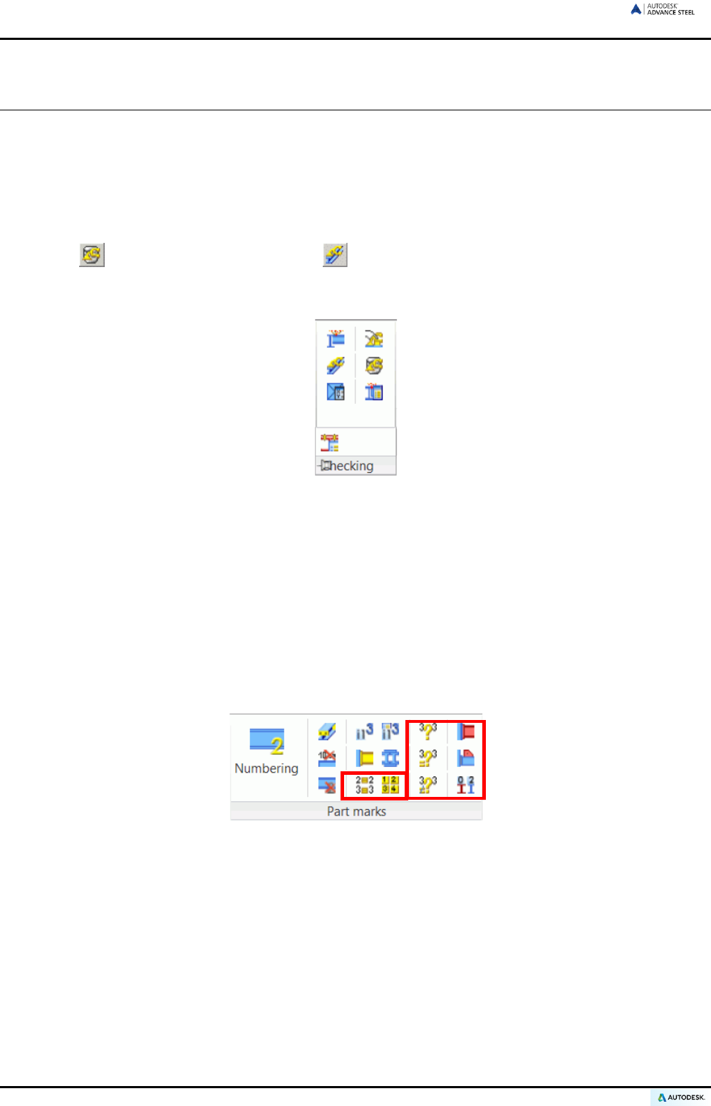
ADVANCE STEEL USER’S GUIDE
Checking the model for errors
Checks are required in various steps of the modeling process. Collision checks can help track down ‘overlap-
ping duplicate’ members, members with no connections, problem connections and general collision situations.
After numbering, it is recommended to carry out a series of error checks to correct elements with duplicate part
marks, un-marked elements, etc. With these tools, mistakes in the structured BOM and detail drawings (and the
associated costs) are avoided.
The Advance Steel database should also be maintained and checked from time to time with the “Audit checking
(database)” and “Steel construction checking” tools.
The checking tools are located on the Checking panel of the Extended modeling tab. For easier access, the
Checking panel is available also on the Home tab.
Figure 179: Checking panel
The Checking panel contains the following checking tools:
• Collisions in the model
• Display Checking Results
• Advance Steel AUDIT checking
• Advance Steel AUDIT checking (database)
• Steel construction technical checking
Feasibility checking is performed after numbering and the tools are located together with the numbering tools on
the Part marks panel of the Output tab.
Figure 180: Part marks panel: correctness checking
118
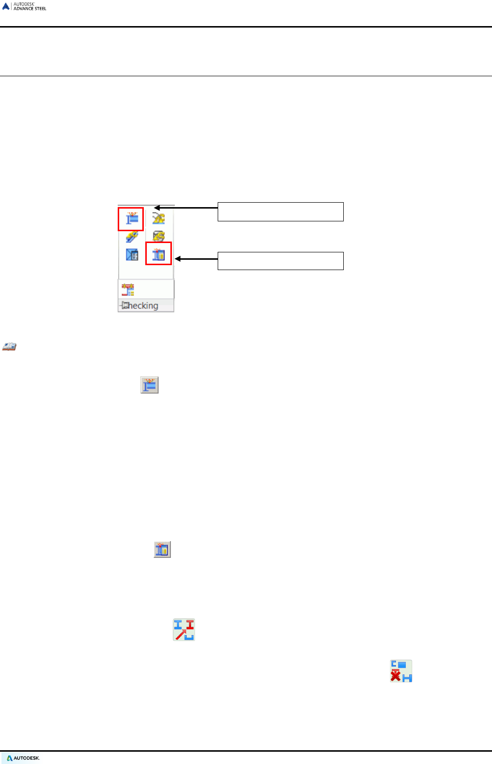
ADVANCE STEEL USER’S GUIDE
Collisions in the model
This tool checks for collisions in beams, plates, and bolts for either the entire model or a selection set.
The program performs various checks. Bolts are checked including the creation distance at the head and nut
and can be reversed in direction. Bolt patterns are checked against each other with verification for bolting tool
spacing. Holes and exact beam cross sections (including root radii) are checked, identical overlapping elements
(beams/plates copied on top of themselves) and incorrectly modified elements are recognized.
The tool compensates for geometric inaccuracies with a given minimum volume of the collision solids set in the
defaults. ACIS-solids are considered in the collision and collisions with a small volume are ignored.
On the Checking panel, the following tools are available:
Collision test
Display Checking Results
Figure 181: Checking tools
Example: Carrying out a collision check for selected elements
• Select the elements to check.
• Click the “Clash check” tool.
A dialog box displays the list of collisions with continuous index numbers.
Collision solids are not created directly since there can be many. The results can be displayed with the “Display
checking results” tool.
To display the collision solid, in the dialog box, double click the collision to display.
Displaying checking results
“Display checking results” displays the collision solids for a particular collision by entering its index number. The
index number is listed in the text window by the clash check.
• On the Checking panel, click . The index number of the desired object is requested in the text-window:
Please index of the object:_
• Enter the index number of the object on the command line. The collision solid is represented in red.
In complex models collision solids are hard to find.
• The “Search highlighted objects” command on the Selection tool palette creates a red arrow that
shows the location of the collision solids.
• Turn off collision solids and the marking arrow with the “Clear highlighted objects” command on the
Advance Steel Selection tool palette.
119
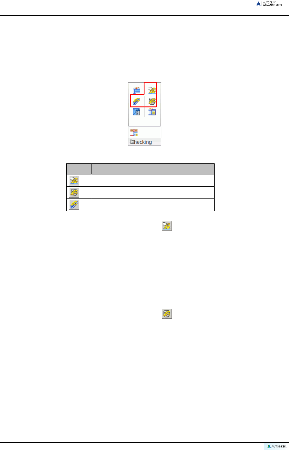
ADVANCE STEEL USER’S GUIDE
Advance Steel Audit checking
Advance Steel objects have special properties that will not be taken into consideration by the AutoCAD® audit
checking. The Advance Steel audit checking is specialized for Advance Steel objects and should be performed
once a day to validate coordinates of the objects (internal checking).
The following checking tools are grouped on the Checking panel of the Advance Steel Extended modeling
tab:
Figure 182: Checking panel – Checking tools
Button Function
Activate Advance Steel AUDIT checking
Advance Steel AUDIT checking (database)
Steel Construction Checking
• On the Extended modeling tab, Checking panel, click . The following message appears in the text
window:
Audit extended by Advance
• If you click the icon again, the activation is switched off. In the text window, the following message appears:
Audit by AutoCAD
Advance Steel audit checking (database)
This command checks the database. For example, the program can recognize and delete identical shortens of a
beam. To only show the errors, run audit checking without fixing them.
• On the Extended modeling tab, Checking panel, click . The following message appears in the text
window:
Audit extended by Advance
Repair detected errors? (Yes / No)
By entering no, a result list of the un-fixed errors is displayed.
Mark an incorrect object with the command _AstM4CommMarkObject, press Enter and enter h (handle). Enter
the handle number from the result list.
120
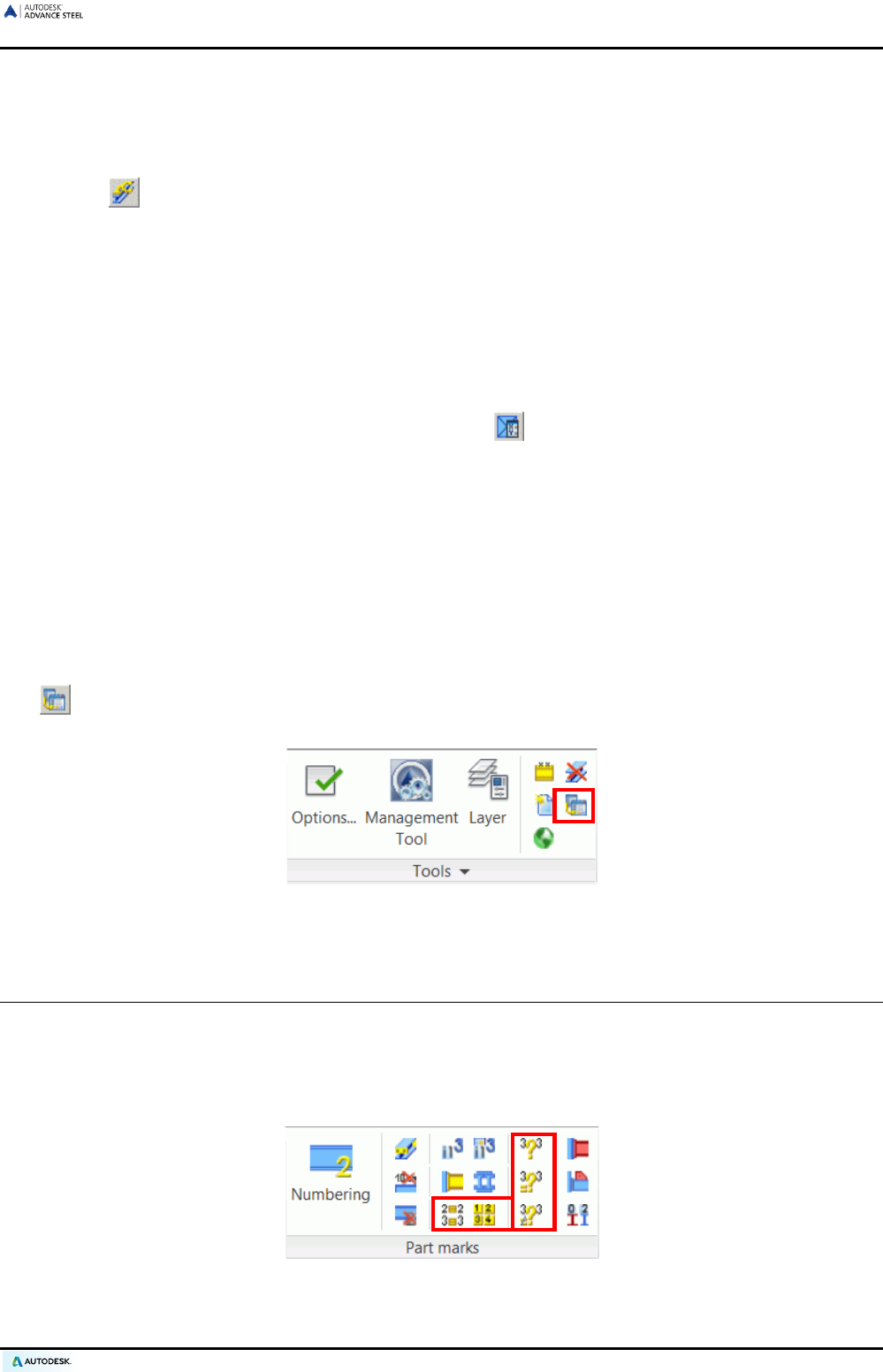
ADVANCE STEEL USER’S GUIDE
Steel construction checking
The “Steel construction checking” command (Checking panel) checks an object’s attribute values in the data-
base with particular emphasis on the distance between bolts within a pattern.
After clicking , the following request appears in the text window:
Should objects with serious errors be deleted ? (Yes No)
“Advance audit checking” checks attributes of an object in the database while “Steel construction checking”
checks the values.
Defining the center of gravity
The “Center of gravity and total weight” tool on the Checking panel calculates the center of gravity of a selected
group of Advance Steel objects.
• On the Extended modeling tab, Checking panel, click . Select the elements to use in the center of
gravity calculation.
The center of gravity position in relation to the world coordinate system and the total weight of the selected
structural parts are displayed in the text window.
A point is automatically created at the center of gravity.
Updating defaults
When starting Advance Steel the current system defaults are automatically loaded. If the default values are
changed while Advance Steel is active these changes will normally not take effect until Advance Steel is restart-
ed.
The tool sets new default settings without restarting Advance Steel. This tool imports the files again and a
restart is not necessary.
Figure 183: Updating defaults
Numbering validation
Various checks can be carried out after numbering the model. These are available on Part marks panel of the
Output tab.
Depending on how the Single Parts / Assemblies toggle switch is set, the other tools will change to single
parts or assemblies, respectively.
Figure 184: Part marks panel – tools for numbering validation
121
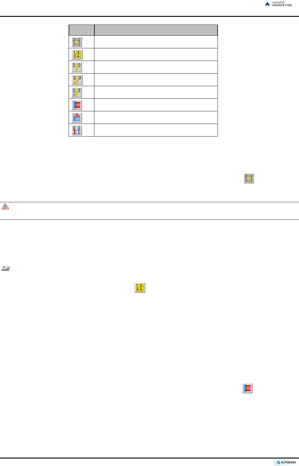
ADVANCE STEEL USER’S GUIDE
Button Function
Display objects with identical part marks
Select objects with different part marks
Check for duplicate part marks
Identify objects with identical part marks
Differences between two objects
Mark main part of assembly
Mark loose parts
Mark parts without marks
Displaying objects with identical part marks
All items with the same part mark, when selected, are highlighted in red. This tool can be meaningful if two ob-
jects are apparently different but show the same part mark.
• Select a structural part and click the “Display objects with identical position numbers” tool on the Part
marks panel. The found items are highlighted in red.
Objects that were previously highlighted in red will not be undone. To remove the highlight, use
“Clear marked objects” on the Selection tool palette.
Selecting objects with different part marks
A single object of each assembly or single part mark (depending on the “Single Parts / Assemblies” switch) is
selected and highlighted in red.
Example: Individual parts for each part mark should be selected for drawing creation if done manually rather
than by a process.
• On the Output tab, Part marks panel, click . An element for each part mark in the model is selected
and highlighted in red.
• If the “Drawing – Single Part” tool is called, a shop drawing for each position number group is created.
Without this command, each part is detailed as many times as the parts exist in the model if the system de-
fault is set to allow duplicate drawings.
• It should be noted that this command is not required if creating drawings using a drawing ’process‘ as the
process automatically filters out a single instance of each part mark.
Marking the main part of assembly
The “Mark main part of assembly” command highlights the main part of an assembly in blue and all attached
parts in red. A prerequisite is that the selected assembly has a main part previously identified.
• Select a part that belongs to an assembly and click the “Mark main part structure” tool on the Part
marks panel of the Output tab.
Main parts are presented in blue, attached parts in red, and connecting elements (bolts and welds) in green.
122
ADVANCE STEEL USER’S GUIDE
Marking loose parts
This tool searches the complete model for loose parts (i.e., parts that leave the workshop without any connec-
tion to other parts). Any objects that are found are highlighted in red.
• After calling the “Mark loose parts” tool on the Part marks panel of the Output tab, a window appears
displaying a message about the number of single parts found.
• Clicking <OK> marks the loose parts.
Marking parts without marks
This tool searches the entire model (depending on the Single Parts / Assemblies setting) for structural parts
that do not have a part mark (e.g., because they were created after the numbering).
Note that, if a part is not identified as a main part and the toggle switch is set to Assemblies, this tool will not find
any un-marked objects. Therefore newly added objects will typically only get detected if the switch is set to “Sin-
gle Parts”.
• On the Output tab, Part marks panel, click .
Any parts found are highlighted in red.
Checking for duplicate part marks
This tool is available on the Part marks panel of the Output tab.
All parts of a group with the same part mark are checked to see if they are still identical. If the parts are no long-
er identical, they need another part mark. This is the case if they were changed after the numbering.
• On the Output tab, Part marks panel, click .
If any errors are found, a list is displayed in the text window with the incorrect part marks.
Identifying objects with identical part marks
The model is searched for objects of a given part mark. If these objects are not identical they are highlighted in
different colors.
• On the Output tab, Part marks panel, click . The text window asks for the part mark.
• Enter the part mark to check, which was displayed by the “Check for duplicate part numbers” com-
mand. The mark must include the prefix if appropriate (which is case sensitive).
The corresponding parts are highlighted in color.
Differences between two objects
Two parts can be compared for differences.
• On the Output tab, Part marks panel, click and select two objects.
The program displays the differences in a window.
123

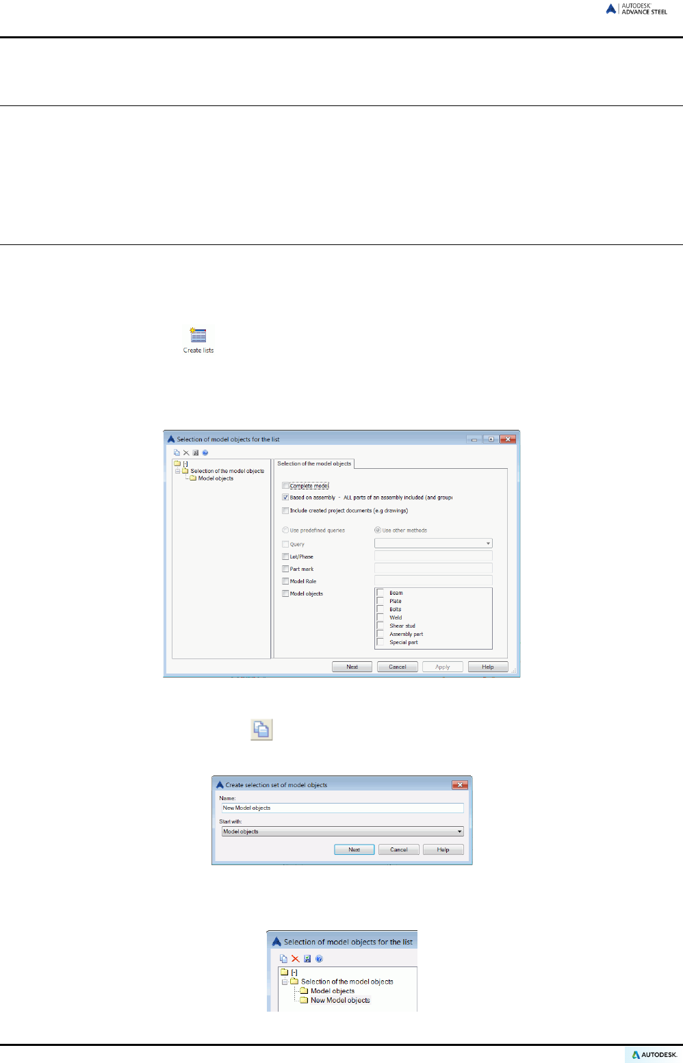
ADVANCE STEEL USER’S GUIDE
Creating lists
All model objects including their graphic and non-graphic properties, features, joints, and connections are stored
and managed by Advance Steel. Extracts are created from the numbered and saved models. The Advance
Steel List Template Wizard creates structured BOMs from the extracts. The created BOMs can be saved, print-
ed, or exported in various formats.
Creating a model extract
The current Advance Steel model must first be given single part and assembly marks and the DWG model must
be saved in a selected location.
From the model information an extract is created which is exported to the BOM module.
• On the Output tab, click .
A window appears where the model objects for the extract are selected.
In the left part of the window, different saved configurations of model objects can be selected. In the right
side of the window, different selections of the Model objects can be made for the current configuration.
Figure 185: Model objects for the structured BOM
• To save a selection set, click “New” on the dialog box toolbar.
• In the dialog box select a model object to start with from the list. Enter a name and click Next.
Figure 186: Set the name for the new Model object
The name is displayed in the left field.
Figure 187: The new Model object
126
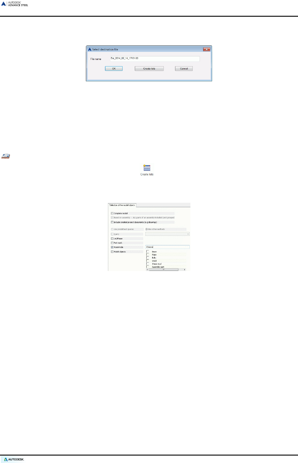
ADVANCE STEEL USER’S GUIDE
• The configuration is saved by clicking Apply. To continue, click Next.
• In the Select destination file dialog box, click <OK> to save the file.
Figure 188: Select destination file
If Create list is clicked, the information is stored and the List Template Wizard is started to create and print
the information list.
The complete model can be included in the extract or the Based on assembly option can be used to create
structured reports. No other entries are needed with these options.
Other selection options include: Lot/Phase, part mark, and model role. Enter the required Lot/Phase, part mark
(e.g., from 1-100), or the model role within the model (e.g., column, rafter, etc.).
Example: Structured BOM of the columns
• After numbering and saving the model, click on the Output tab.
• Check model role and enter column in the text input field.
• Click Apply and Next at the bottom edge of the dialog box to create the extract.
Figure 189: Selection window for structured BOM (clipped)
The Model objects option has other selection options (e.g., beam, plate, bolts, welds, shear studs, assembly
part, special part).
After clicking Apply and <OK>, the model information is selected using the given criteria. A model extract is
created and saved within a subfolder of the main model folder.
After each model change, it must be checked again, numbered, saved and its information re-extracted.
For each model, several model extracts for creating the structured BOM can be saved.
127
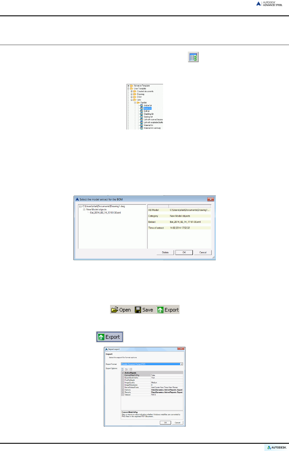
ADVANCE STEEL USER’S GUIDE
Creating a structured BOM
Start the Advance Steel List Template Wizard by clicking “BOM extract” on the Document Manager panel
of the Output tab.
In the “List – Template Wizard”, select the formatting and the structured BOM (report).
Figure 190: Template wizard – list of available BOM templates
An Advance Steel template may be selected or users can define their own templates starting from an existing
one.
• Select a BOM template.
• Click Use.
• A dialog box appears where the desired model extract is selected.
Figure 191: Model extract
• Click <OK> to finish the BOM creation.
The structured BOM appears in the window. This can be printed, saved, or exported to PDF (and other
formats) using the corresponding icons on the menu bar.
Figure 192: Menu bars of the BOM (clipped)
To export the created BOM file, click . Select the export format from the list.
Figure 193: Export formats
128

ADVANCE STEEL USER’S GUIDE
• Save the created BOM file. A file name is requested in a new window. The BOM file is saved as a Report in
the folder
..\[model folder]\[model name]\BOM\[BOMfilename]
Figure 194: Report window: Save the structured BOM
Figure 195: Example of BOM
Document Management – Structured BOM
The structured BOMs linked from the model are managed in the Document Manager as NC-data and drawing
details.
Figure 196: Document management – structured BOM, Properties
For a structured BOM selected from the Created documents, the information of the BOM file (e.g., file name,
state, title, path) is displayed on the Properties tab. If modifications in the model affect the BOM, the drawing
appears in the Update BOM branch.
129
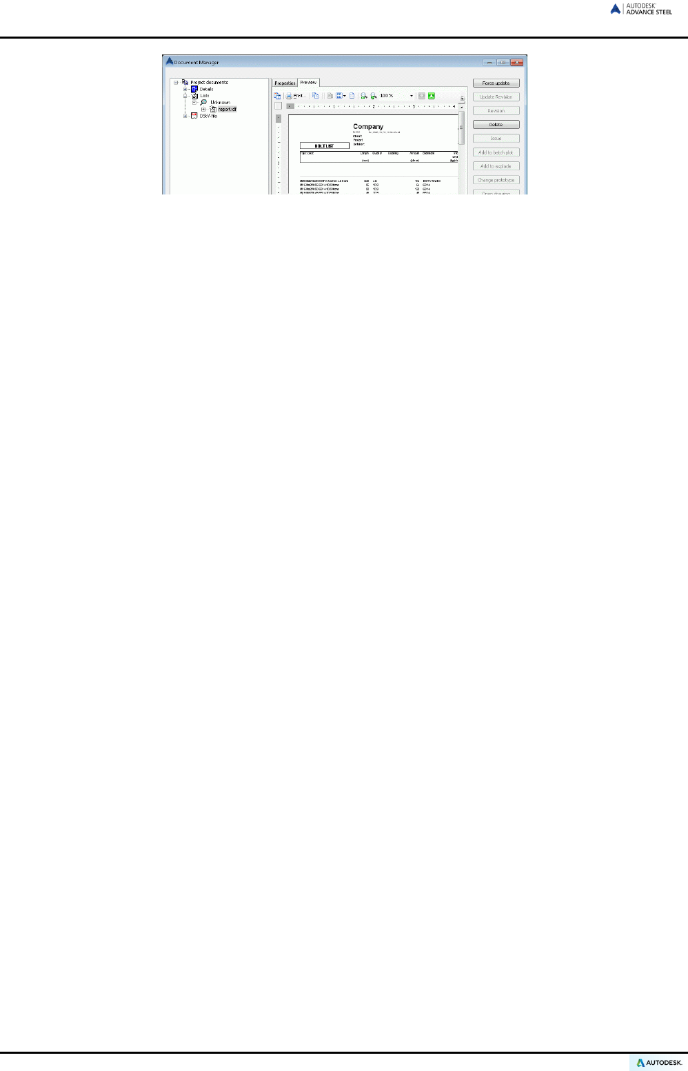
ADVANCE STEEL USER’S GUIDE
Figure 197: Document Manager – structured BOM, Preview
A preview of the structured BOM is displayed on the Preview tab of the Document Manager.
• The BOMs can also be printed directly from the Document Manager.
• Close the Document Manager by clicking <OK>.
Further details on the Document Manager are available in the Creation of general arrangement and shop draw-
ings chapter and in the Advance Steel Help.
130

Chapter 8
Creation of general arrangement and
shop drawings
In this chapter:
■ Drawings
■ General arrangement drawings
■ Drawing management
■ Document management
■ Node details
■ Elevations
■ Single part drawings
■ Tie beam
■ Columns
■ Assembly drawings
■ Special structural parts
■ Alternative drawing styles
■ Processes
■ Labeling and dimensioning
■ Drawing cleanup
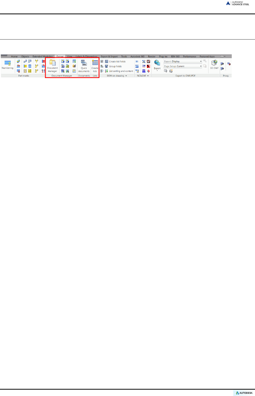
ADVANCE STEEL USER’S GUIDE
Drawings
Tools for managing, creating, and editing drawings are available on the Output tab.
Figure 198: Output tab – Drawing creation and management tools
Model - Drawing principles
Upon building a 3D-model, dimensioned and labeled 2D general arrangement and shop drawings can be auto-
matically created. The drawings are created in separate DWG files from the model, however they are linked to
track changes.
The model knows which drawings have been linked and checks if these drawings still correlate. Thus, the draw-
ings can be updated after any model modifications. This link is ‘one way’ and changing a drawing will not modify
the model.
A drawing may consist of several linked details, which are individual Advance Steel objects with their own prop-
erties.
Drawing styles
Advance Steel offers a variety of drawing styles for general arrangement drawings, sections, and shop draw-
ings in various designs. The drawing style is a group of instructions used to create a detail drawing and defines
the selection of the elements that are to be displayed including labeling and dimensioning preferences.
The drawing styles provide the option to automatically create drawings and to modify the layout exactly to user
requirements. Drawing styles are used in a similar way to standard CAD dimension styles, line styles, etc.
The styles are defined with various settings (e.g., parts to be displayed, view, dimensions, labeling, representa-
tion etc.) in MS-Access tables (libraries).
All Advance Steel predefined drawing styles are available in the Drawing Style Manager. The set of predefined
drawing styles varies according to installation. It is also possible to define custom drawing styles.
For fast access, the most used drawing styles are grouped in the “Quick documents” window.
The linked drawings (details) can be automatically dimensioned and labeled, but additional dimensions and
labels can be added later using Advance Steel’s special tools (refer to the Drawing Cleanup section of this
chapter).
132
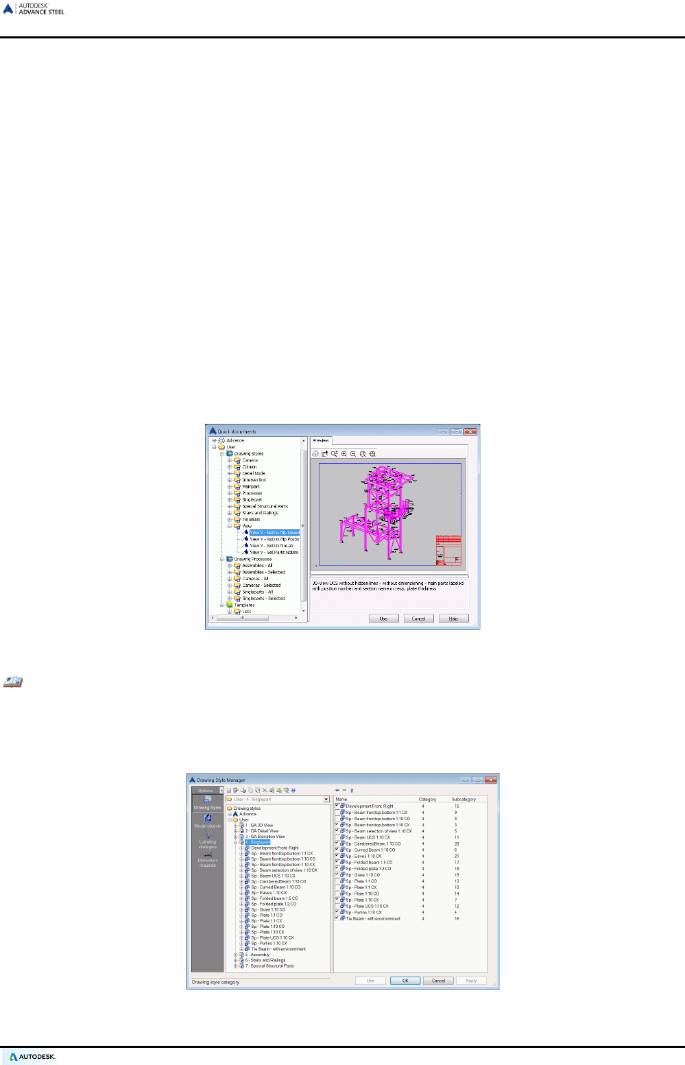
ADVANCE STEEL USER’S GUIDE
Drawing management
The Document Manager is used to preview, manage, and erase the linked details in separate drawings
(DWGs). If a DWG model or a DWG drawing is renamed, the relationship is broken but can be recreated (regis-
tered). Drawings can also be separated (unlinked) from the model.
The Document Manager interprets which detail drawings need updating after modifications to the 3D model.
The updating of drawings is also controlled in the Document Manager.
Processes
In addition to drawing styles Advance Steel has Processes, which automatically create drawings (using appro-
priate drawing styles) and arrange the linked details within a drawing (DWG) or across several drawings.
All processes are available in the Drawing Process Manager.
Quick documents
“Quick documents” provides quick access to a selected set of drawing styles, drawing processes and list tem-
plates. In the left panel, in each category, the items are grouped according to the element type.
The set of available drawing styles, drawing processes and templates can be customized from the Drawing
Styles Manager.
Figure 199: Quick documents
Example: Adding drawing styles to Quick documents
• Start the Drawing Styles Manager from the Output tab, Document manager panel.
• In the Drawing Style Manager’s window select the category from which to add a drawing style.
• From the right side of the window select the drawing styles to display in the Quick documents.
Figure 200: Selecting the preferred drawing styles
133
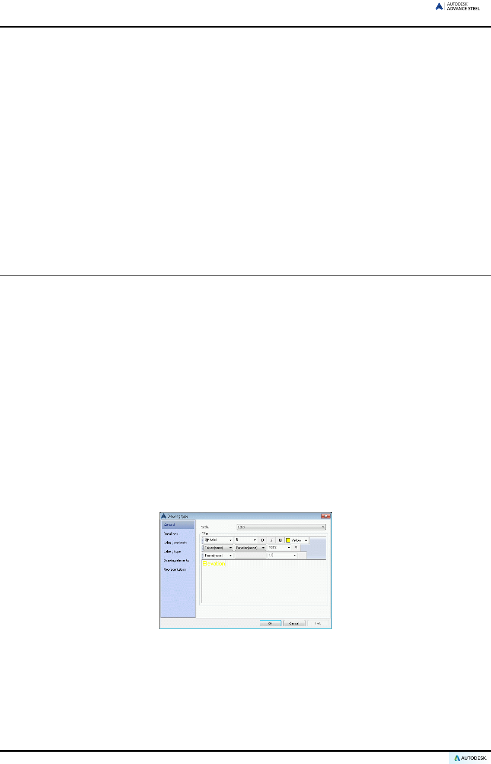
ADVANCE STEEL USER’S GUIDE
Drawing creation and CAD objects
The drawing creation in Advance Steel is optimized for processing Advance Steel Objects. Standard CAD ob-
jects (e.g., lines) can also be processed. This is done in two different ways:
• CAD elements in the 3D Model are used to create drawings. Like Advance Steel Objects they are automat-
ically included in a corresponding drawing view but as separately created block references. The ad-
vantage is that they are completely recognized and are modified using standard CAD commands. These
blocks will not be deleted during a detail update. When creating drawings CAD objects can be included by
all Advance Steel drawing commands by pre-selecting these objects before starting the drawing tool. This
selection is distinct and completely independent of special commands like selecting Advance Steel objects.
A practical example is the presentation of circular grid lines using CAD lines. When creating a plan view,
these objects can be displayed in the corresponding details.
• CAD objects can also be created directly in linked drawings. This is done using standard CAD drawing
commands in paper space. The geometry of the Advance Steel drawing objects is accessed with the END-
POINT, MIDDLE, and NODE snaps. When Advance Steel drawings are updated the objects created are
not deleted.
Complete information on drawing creation is available in the Advance Steel Help.
Creating drawings
Before creating any drawings, verify that in the model:
• No collisions occur
• All parts are correctly connected
• All parts have correct part marks
Create drawings with the following steps:
• Select any non-Advance Steel elements (e.g., CAD lines, solids, etc.) or objects with certain properties
(e.g., Assembly). If needed, use the search tools in Advance Steel to mark and select the objects or use
the standard CAD selection methods (e.g., picking, crossing window, etc).
• Start the Quick documents and select the appropriate drawing style from the corresponding category (e.g.,
floor plan, section, single part, etc.).
• Other elements may be required. Press Enter.
The “Drawing type” dialog box appears.
Figure 201: “Drawing type” dialog box – General
The various tabs provide entries for specifying drawing content.
• The General tab has options to specify the scale and the title of a view before its creation and to change
the labels within a drawing.
134
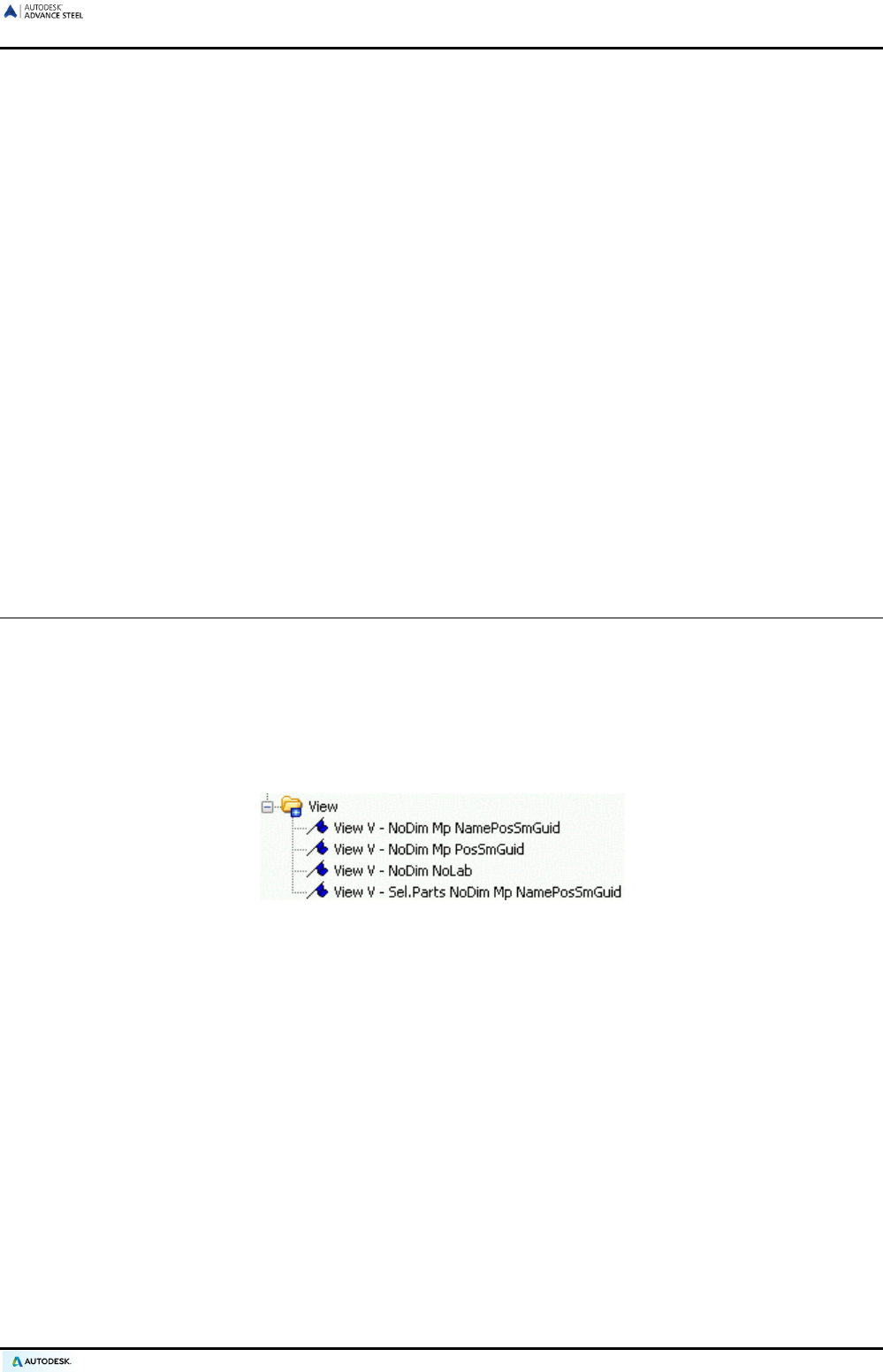
ADVANCE STEEL USER’S GUIDE
• On the Detail box tab, values for the Z-viewport can be entered if the view depth should be limited to the
front or the back (starting from origin in Z-direction of the UCS). The X/Y-viewport sets whether the entire
model, selected elements, or only a local clipped view should be linked. The height (Y-direction of UCS)
and the width (X-direction of UCS) can be set for the clipping.
• On the Label / contents tab, the various labeling types can be set for different structural parts. For exam-
ple, a section label can be set to include name, length, material, and part mark.
• On the Label / type tab, options for using the drawing style labels are available. These specify, for exam-
ple, the text orientation, the placement, etc.
• The Drawing elements tab includes switches for level symbols, weld symbols, and building grids. These
switches are only active in drawing styles that contain these elements. For example, the building grids can
be switched off for isometric views.
• The Representation tab contains switches for turning off hidden lines and the shorten representation
(Clipping). These switches are only active in drawing styles that contain the respective representations.
Clipping may be used in the intersection styles and in the drawing styles for main and single parts.
Prototype files
Template drawings for certain drawing formats, drawing frames, and title blocks are available in Advance Steel
and can be found in
..\ProgramData\Autodesk\Advance Steel 2015\Shared\Support\Prototypes\
General arrangement drawings
The View category of the Quick documents contains drawing styles that create isometric views of an entire
model.
The view direction of the linked view depends on the current user coordinate system (UCS) and runs against its
positive Z-axis.
The styles essentially differ by the type of labeling of the structural parts. The presentation in all styles is without
hidden lines.
Figure 202: View category
135
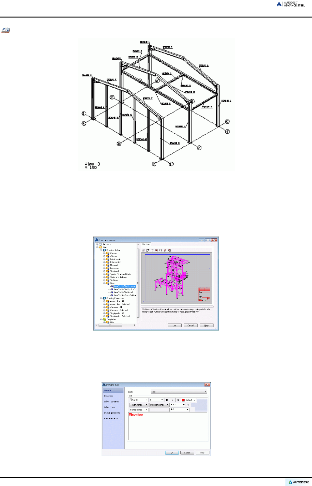
ADVANCE STEEL USER’S GUIDE
Example: Creating an isometric view at scale 1:50
Figure 203: Isometric view
• Verify that the single parts and main parts are numbered.
• To create an isometric view, set the UCS to the screen plane with the View UCS command on the UCS
tool palette.
• Select the desired drawing style from the View category of the Quick documents and click Use. The
“Drawing type” dialog box appears.
Figure 204: Selecting the drawing style
• Enter the scale 1:50 on the General tab. In the “Title” area, the title of the view (i.e., font type, style,
size, color, etc.) is assigned and the labels inside a drawing are changed. This is entered with the scale
in the lower left corner of the drawing (see description above of the drawing style). Other entries for
Drawing type are available on the other tabs.
Figure 205: View detail, “Drawing type” dialog box
136
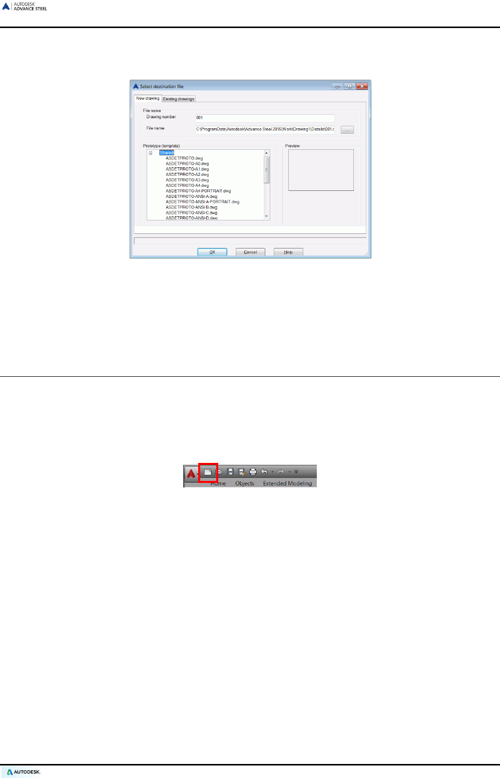
ADVANCE STEEL USER’S GUIDE
• Click <OK>. Another dialog box appears, in which the file name and the drawing number are entered.
The drawing number field is automatically filled with the next drawing number. A drawing prototype file
can be selected from the list.
Figure 206: Select a destination file for drawing details
• Click <OK>. This button is inactive if the drawing number or the filename is not unique.
The tool then starts and ACIS-solids can be selected.
• Press Enter. The view is created and saved in the specified DWG file.
Drawing management
During the drawing creation several details can be put on one sheet by entering the same file name. Moving
these views to another DWG file is possible without losing the link to the model.
Alternatively, each detail view can be specified on a new DWG at the time of creation.
• A drawing detail or a list of the created drawings is previewed using the Document Manager. To open a drawing,
use the Quick Access toolbar and enter the path name. The drawing can then be edited, printed, etc.
Figure 207: Open tool on the Quick Access toolbar
If a detail drawing is renamed or moved, it must be registered (or canceled) in the model so that the relationship
between the drawing and model can be managed correctly.
137
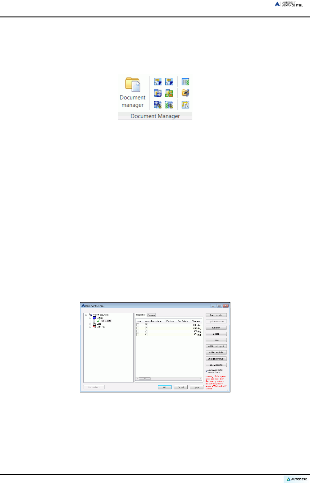
ADVANCE STEEL USER’S GUIDE
Document management
The tools for document management are accessible on the Document Manager panel (Output tab). The fol-
lowing tools are available:
Figure 208: Drawing Manager panel
• Document Manager
• Register drawing in model
• Cancel drawing from model
• Drawing Style Manager
• Drawing Process Manager
• Drawing Process Suite
• Necessary view wizard
• Edit prototypes
• Define drawing layout
Document Manager - drawing details
The Document Manager lists all created drawings, bill of materials / structured BOMs, and the NC-data created
from the model. The documents are displayed using the Preview tab.
The Document Manager manages and presents the connection between the model and the linked drawings.
The user can display, update, add a revision, flag the issue of drawings, add to batch plot or batch explode, and
delete the drawing details in the Document Manager.
Figure 209: Document Manager – Details
The Document Manager automatically checks if drawings require an update due to model modifications or the
drawings to be checked can be selected. Drawing updates are performed directly from the Document Manager.
It is also possible to display a drawing on the Preview tab although changes cannot be made to it.
138
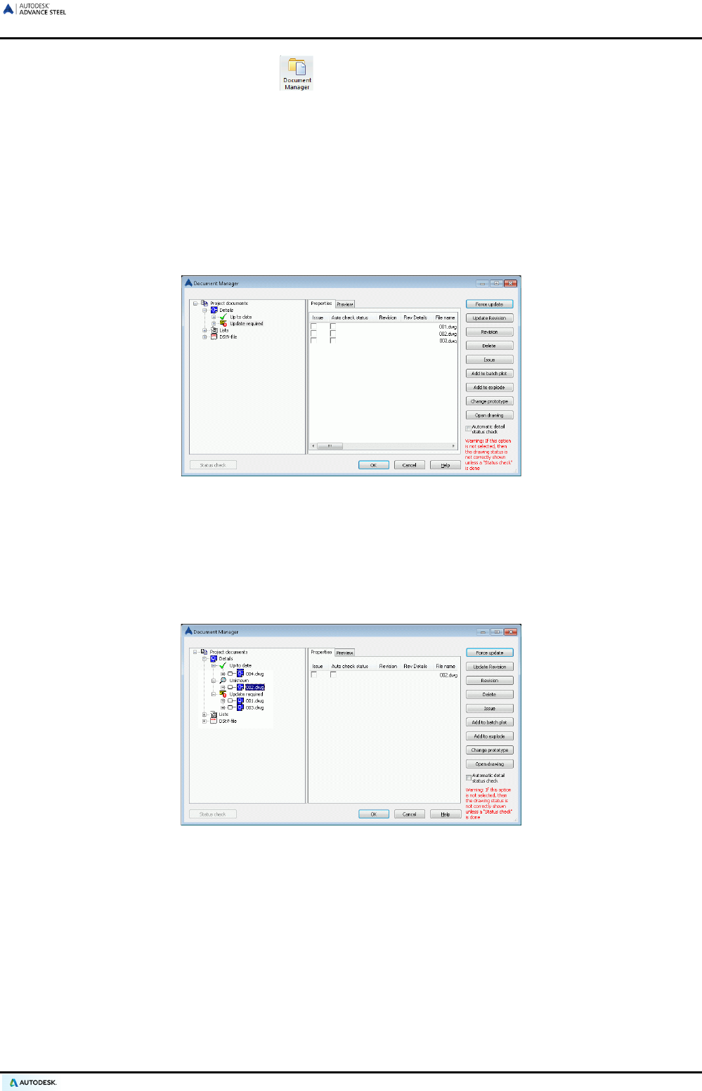
ADVANCE STEEL USER’S GUIDE
• Call the Document Manager by clicking on the Output tab.
• If Details is clicked under Project documents (in left half of the Document Manager), the created docu-
ments are listed (in right half of the Document Manager window). The current drawings are highlighted with
a green checkmark with the state Current. A yellow finger marks the detail drawings that require updating
due to model modifications (Force update in the right side of the Document Manager).
• The Properties and Preview tabs are available in the right side of the window. On the Properties tab, all
drawings properties such as name, title, state (current, deleted or update required), date of a change, draw-
ing style, process, etc. are displayed.
• On the Preview tab, a selected drawing is previewed. Changes cannot be made to the drawing. To edit a
drawing, open it with the Open button from the Quick Access toolbar and enter the path.
Figure 210: Document Manager, update required
Any drawings that are no longer current due to model modifications are highlighted with a yellow finger.
Drawings can be selected so that the state is automatically checked.
If the Auto check status option is not checked in the drawings properties, clicking Run check will check the
drawing state. The Force update tool is used to update the selected detail(s) with a single click. The drawings
are grouped in three categories: unknown, update required, and current.
Figure 211: Document Manager, categories: Current, Unknown, Update required
• By clicking Delete, the selected drawings are deleted without any warning/confirmation.
139
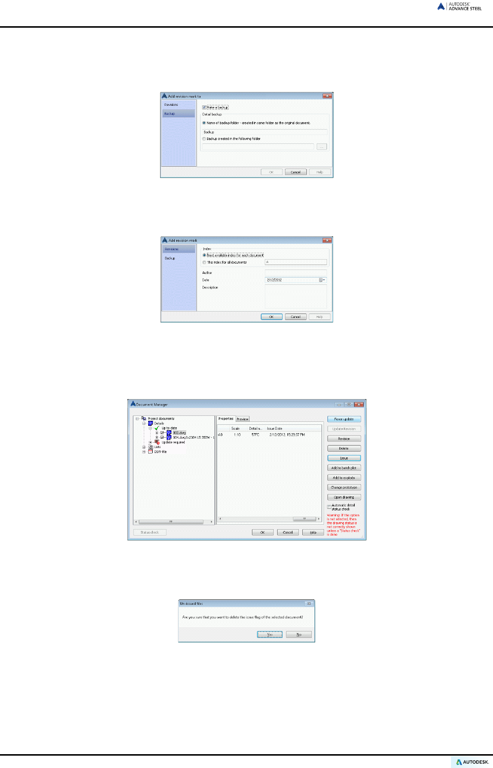
ADVANCE STEEL USER’S GUIDE
• Revision adds a revision mark to current drawing(s) or drawings that require updating. This mark is listed
on the drawing and users see the history of the drawings. The “Add revision mark” dialog box appears.
Click Add. On the Backup tab specify revision control options: make a backup of the document before it is
given a revision mark; specify a folder for the backup (relative to the document to be updated or absolute).
Figure 212: “Add revision mark” dialog box
If several detailed drawings must get a revision mark specify an index for all details or use the next availa-
ble one.
Figure 213: “Add revision mark” dialog box - multiple selection
Update revision updates a drawing to suit the model and automatically assigns a revision number or letter.
• Issue flags the drawing and sets the issue date and time. Checkmark boxes appear in front of the issued
drawings and the date and time appear in their properties.
Figure 214: Document Manager - issue date
• The selected issued drawings can be un-issued by clicking the checkmark box. A confirmation message
appears.
Figure 215: Confirmation message
140
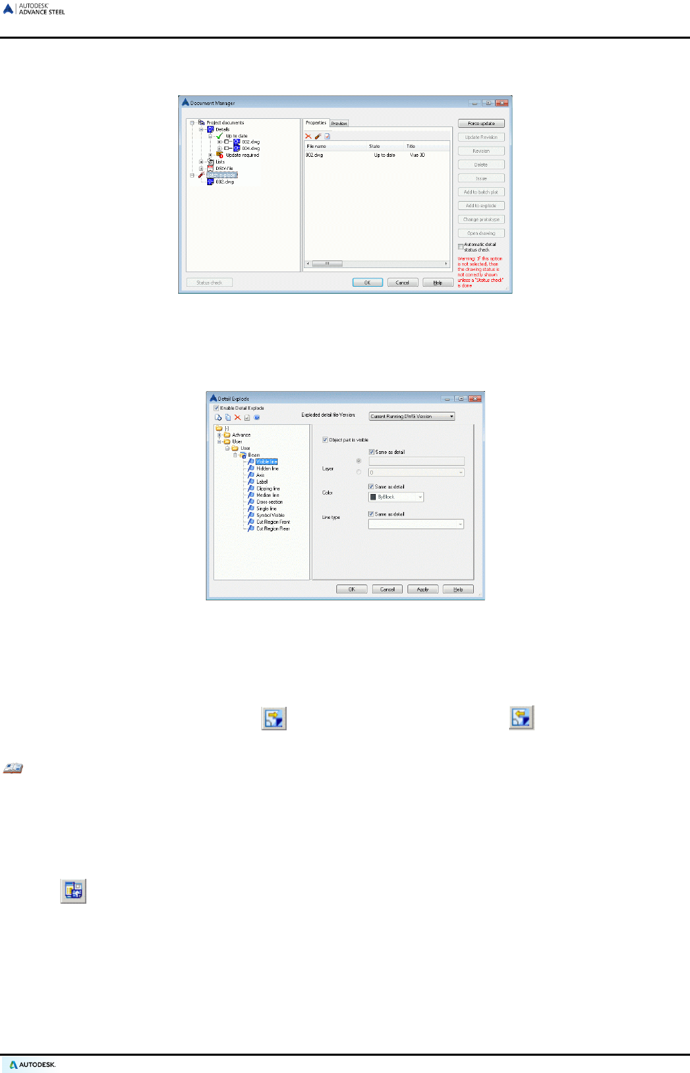
ADVANCE STEEL USER’S GUIDE
A batch explode can be run for all selected drawings. Select the drawing(s) and click Add to explode. The
drawings are copied to a new branch called “Batch explode”.
Figure 216: Document Manager - batch explode
Different profiles can be defined for detail explode settings using the Detail Explode Tool. Configure the
layer name, the color, and the line type to use for beams, plates, bolt holes, etc. This user configuration is
stored for reuse in future projects.
Figure 217: Detail explode
Close the Document Manager by clicking <OK>.
Registering/canceling drawing from model
• The “Register drawing in model” and “Cancel drawing from model” tools on the Document
manager panel (Output tab) register or cancel drawings from the model.
Example: Renaming drawings (DWGs) / moving to another folder
• Rename / move drawings with Windows Explorer.
• Re-register the renamed / moved detail drawings in the model.
Drawing style management
• The tool on the Document manager panel (Output tab) opens the Drawing Style Manager to create
custom drawing styles (refer to the Drawing Style Manager Guide).
141
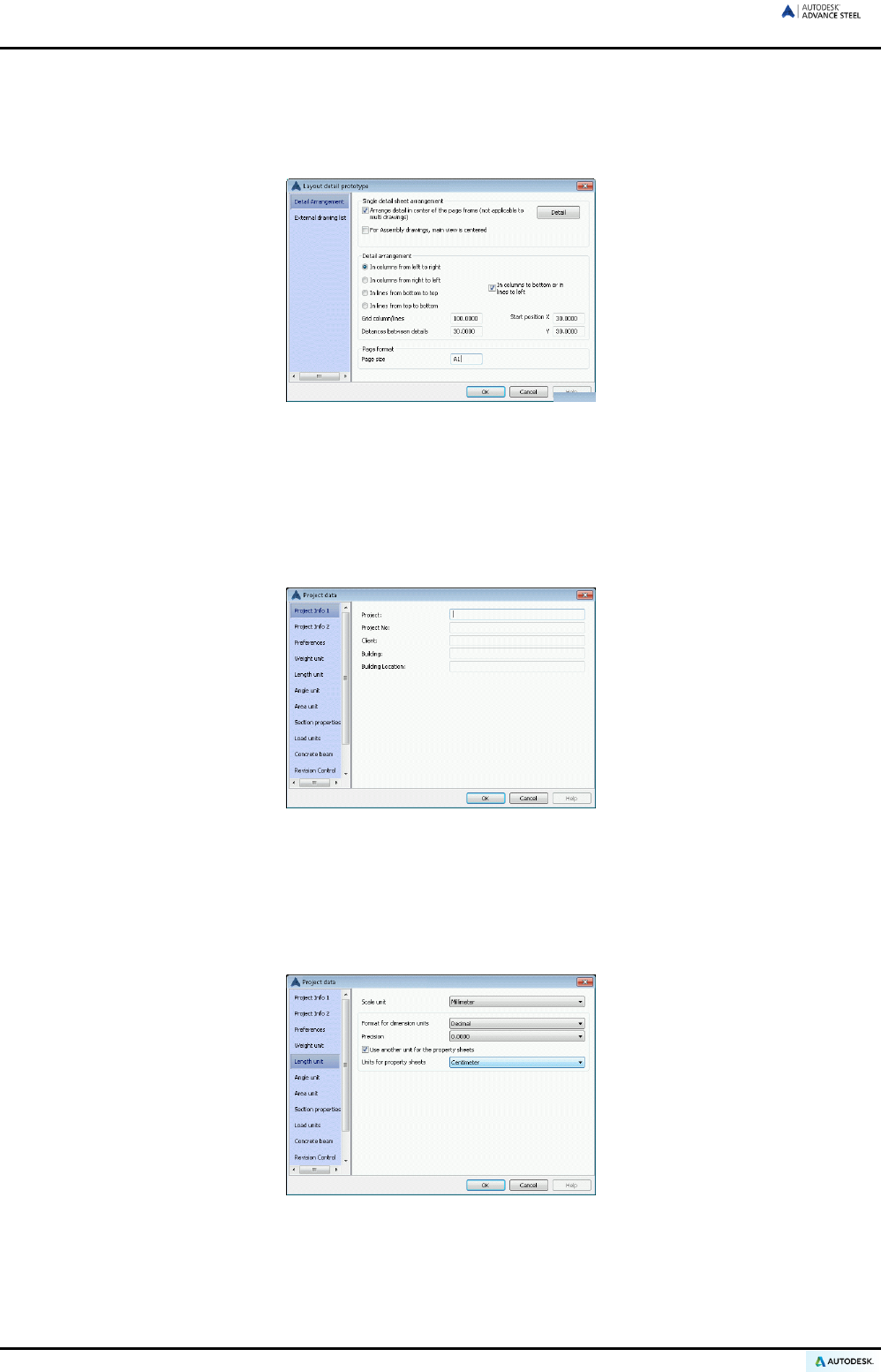
ADVANCE STEEL USER’S GUIDE
Drawing layout
• The “Define drawing layout” tool on the Document manager panel (Output tab) defines settings for indi-
vidual prototype files so that the arrangement of the details are determined when using drawing processes.
Figure 218: Drawing layout
Refer to the Processes section of this chapter.
Creating/changing project information
Project information can be set for the model and saved. The project information is used for the automatic filling
of a title block in the drawing creation (and BOMs).
Figure 219: Project information
On the Project info 2 tab, additional information such as contractor, designer, detailer, and date are entered.
On the Preferences tab, a country can be set for preferred section sizes, bolts types, etc., which are preset in
the Management Tools.
The Project unit tabs contain options for all standard units, including a field for the precision.
Figure 220: Project units
142
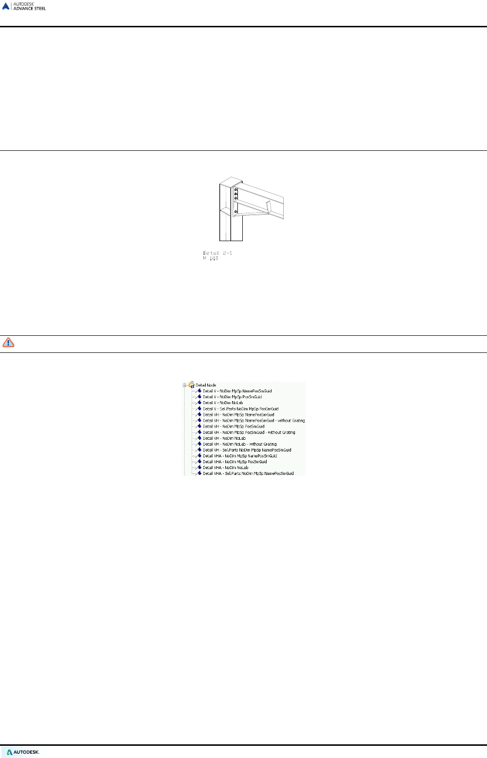
ADVANCE STEEL USER’S GUIDE
Filling in a title block
The title block is automatically placed and filled with project information in the linked drawing.
To automatically fill the title block it must have a particular name with set attributes. The name of the block for
the title block (in your prototype drawing) must be: HYPERSTEELPAGEHEADER.
Node details
With styles from the Detail node category, clippings can be created from the model (e.g., nodes of a frame).
Figure 221: Node detail
The view direction depends on the UCS and runs against the positive Z-direction. The size of a detail clipping is
selected during the course of the command using two points. Node representations can be created with or with-
out view depth.
Pay attention to the setting for Ortho and Object snap - off.
The default scale is 1:10 and dimensions are not automatically made. The clipping is switched off.
Figure 222: Detail node category
143
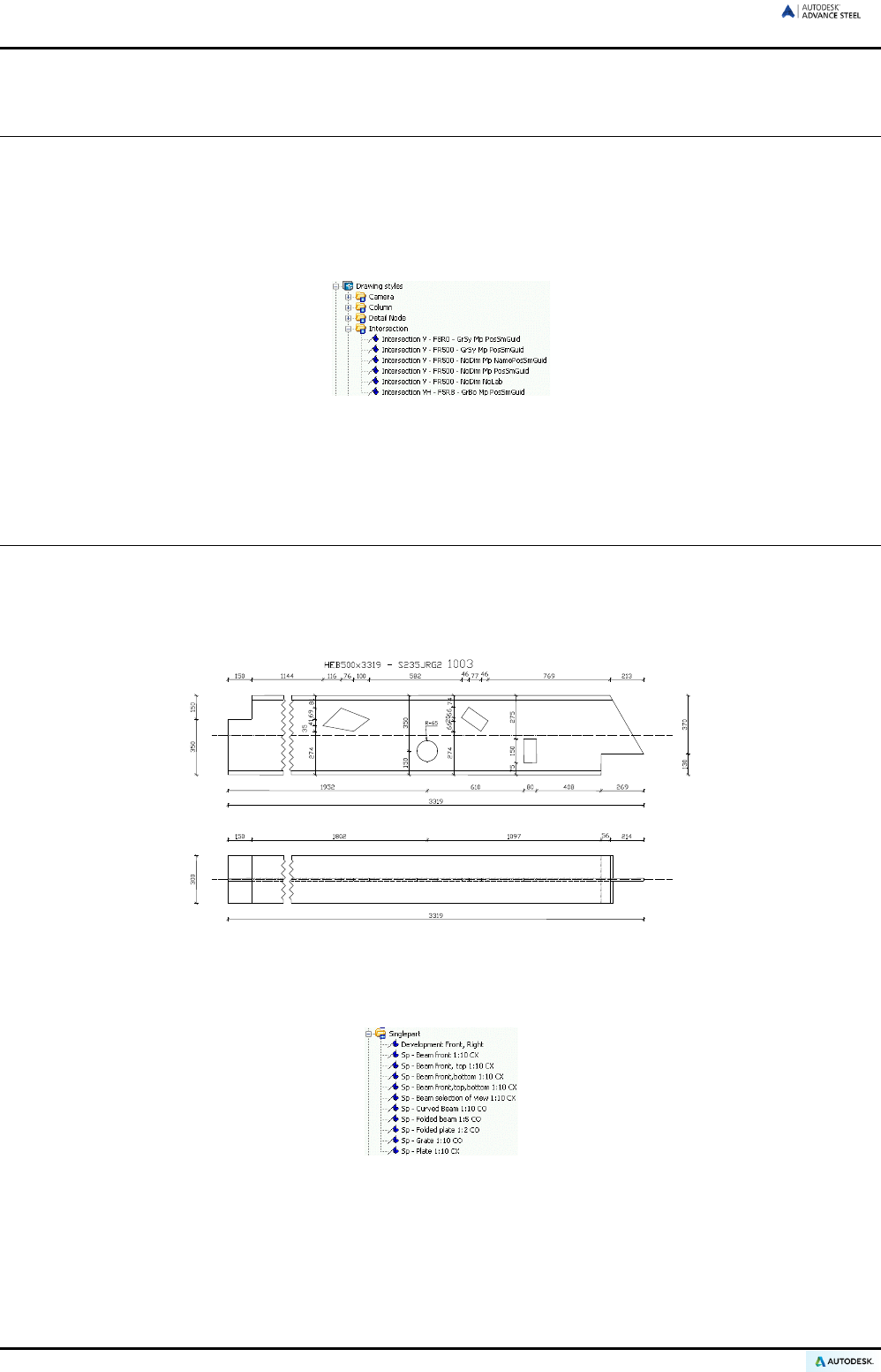
ADVANCE STEEL USER’S GUIDE
Elevations
With elevations, geometric clipping is created from the model. The view direction depends on the UCS and runs
against the positive Z-direction. The views are displayed with a default scale of 1:20. The shortened representa-
tion (clipping) is activated in the X- and Y-directions. The representation has a default view depth in 2D. ACIS
volume solids can also be selected.
Other types of intersection drawing styles are available and are described in the Advance Steel Help.
Figure 223: Intersection category
Other types of elevation drawing styles are available and are described in Advance Steel Help.
Single part drawings
The Single part category from the Quick documents contains drawing styles to create shop drawings of single
parts. The view direction does not depend on the UCS but corresponds to the internal coordinate system of the
selected element. The scale is 1:10. The details are automatically dimensioned and labeled. The clipping is only
activated for the X-direction.
Figure 224: Single part – beam front, top
The drawing styles for single parts differ, on the whole, by the view orientation. The following view orientations
are available:
Figure 225: Single Part category
• Single part – beam front
• Single part – beam front, top
• Single part – beam front, top, bottom
• Single part – beam front, bottom
144
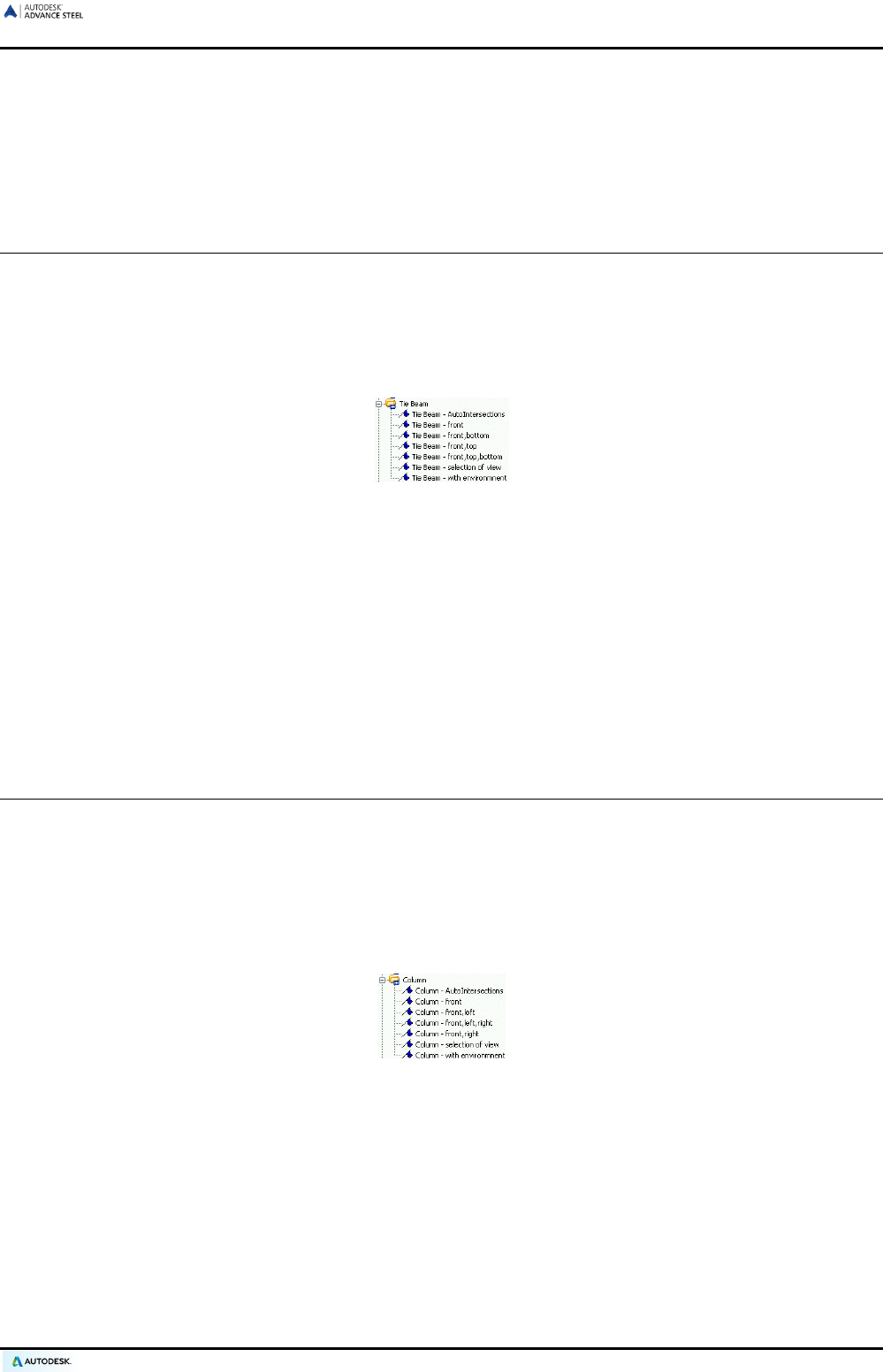
ADVANCE STEEL USER’S GUIDE
• Single part – beam selection of views. Up to six views of an element can be selected by clicking the con-
tours displayed in green in the model.
• A drawing style for single part representation of curved beams
• A drawing style for single part representation of plates (available for Czech Republic)
Tie beam
The drawing styles from the Tie beam category create shop drawings for non-vertical main parts. The view di-
rection does not depend on the UCS but corresponds to the internal coordinate system of the selected main
part. The labeled and dimensioned views are displayed with a default scale of 1:10. The clipping is activated in
the X-direction.
The drawing styles for tie beams differ, on the whole, by the assigned view orientation.
Figure 226: Tie Beam category
• Tie beam – front
• Tie beam – front, top
• Tie beam – front, top, bottom
• In the “Tie beam – selection of views” drawing style, up to 6 views can be selected. Click the contours dis-
played in green in the model.
• In the “Tie beam – with environment” drawing style, click one or more connected elements to display. Main
parts are displayed from the front and top, end plates from inside, and additional intersections from the right.
Columns
With the drawing style for columns, shop drawings for vertical elements can be created. The view direction does
not depend on the UCS but corresponds to the internal coordinate system of the selected main part. Columns
can be detailed similarly to tie beams but turned 90 degrees (i.e., vertically).
The default scale is 1:10 and automatic dimensioning and labeling is performed. The clipping is activated in the
X-direction.
The drawing styles for columns differ, on the whole, by the assigned view orientation.
Figure 227: Column category
• Column – front
• Column – front, left
• Column – front, left, right (available for Czech Republic)
• Column – front, right (available for Czech Republic)
• In the “Column – selection of views” drawing style, up to 6 views can be selected. Click the contours dis-
played in green in the model.
• In the “Column – with environment” drawing style, select one or more connected elements to display. Main
parts are displayed from the front and top, end plates from inside, and additional intersections from the right.
145
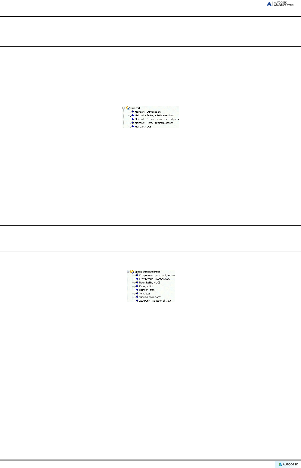
ADVANCE STEEL USER’S GUIDE
Assembly drawings
These styles create assembly shop drawings that depend on the current UCS orientation. The parts to be de-
tailed should be connected with shop connections. The scale is 1:10 and the details are automatically dimen-
sioned and labeled. The clipping is activated for the X-direction. Intersections at given places can be created by
selecting the green contours that are always perpendicular to the main part.
In the Main part category, several styles are implemented.
For example:
Figure 228: Main Part category
• “Main part – UCS" displays a main part so that it is orientated in the drawing as in the model (see example
above). Intersections can be selected with the green contours in the model; the view orientation runs
against the positive Z-axis of the UCS.
• The “Main part – Intersection of selected parts” style creates any cross section of the selected part at the
current UCS labeled with part marks and leader lines.
• The “Main part – curved beam” style creates a view for a curved beam with dimensioning and labeling. The
representation does not depend on the current UCS.
To obtain an automatic internal view of the end plate or cover plates these must have the Model Role cover,
base, or end plate (Advance Properties, Naming tab).
Special structural parts
The following styles are available in the Special Structural Parts category:
Figure 229: Special Structural Parts category
These styles are for elements that need a special representation or work with several Model Roles. The Model
Role property is created for each element on the Naming tab of its dialog box and is interpreted by the program
for functions such as drawing creation.
The “Static plan complete” and “Static plan clipping” drawing styles create model overviews with system lines.
146
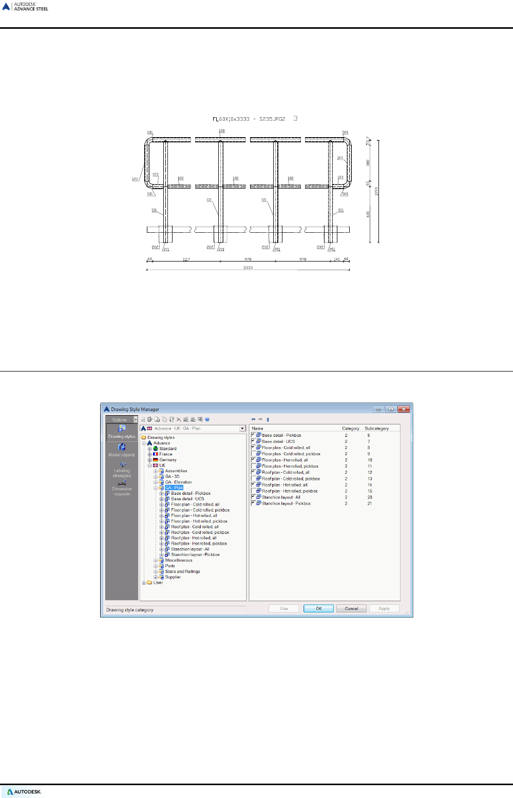
ADVANCE STEEL USER’S GUIDE
Special structural parts
The view direction does not depend on the UCS but corresponds to the internal coordinate system of the se-
lected main part. The default scale is 1:10 and automatic dimensioning and labeling is performed. The clipping
is activated in the X-direction.
Figure 230: Railing straight
This result can only be achieved if the following Model Roles are used in the model (on the Naming tab): Hand-
rail, newel, post, railing strip, railing end wing, pipe bend, and base plate.
Alternative drawing styles
Advance Steel includes also alternative drawing styles, specific for different countries (UK, France, etc.).
Figure 231: Alternative drawing styles for UK
The categories contain various arrangement drawing styles and include drawing styles categories such as:
• Foundation drawings - The details are automatically labeled and the clipping is switched off.
• Floor plan drawings contain drawing styles for plan views from the model. The views are displayed in a
default scale of 1:50 and they are automatically dimensioned and labeled.
• Roof plan drawings - The views are displayed in a default scale of 1:50 and the details are automatically
dimensioned and labeled. The clipping is switched off.
• 3D drawings contain drawing styles for 3D drawings of the entire model or of the selected part. The clipping
is switched off and the default scale is 1:50.
147

ADVANCE STEEL USER’S GUIDE
Processes
Advance Steel drawing processes are used to accelerate drawing creation by automatically assigning drawing
styles and layouts to the selected parts.
A process includes a number of sub processes: selection of parts, sorting, drawing style selection, rules for ar-
ranging details on the sheet, and rules to attach new sheets.
The processes are available in the Drawing Process Manager. The Drawing Process Manager is used to
create new processes and manage, modify, or delete the existing processes.
The most used processes are available in Quick documents.
Drawing processes
The following processes are available for several drawing size formats:
• All single parts
• All single parts plate
• All single parts beam
• All main parts
• All main parts plate
• All main parts beam
• All main parts with attached parts
• All cameras
• Selected single parts
• Selected single parts plate
• Selected single parts beam
• Selected main parts
• Selected main parts plate
• Selected main parts beam
• Selected main parts with attached parts
• Selected cameras.
For each different part mark, a detail is created so that duplicate drawings are not created.
Within a process, a specific sorting can be entered in the dialog box.
Advance Steel offers specific drawing styles that support fully automated drawing creation. These styles differ
mainly from other styles in that the title text includes the number of pieces in the model, or in the case of single
parts, the number of pieces on the main part are also displayed. Intersections are created automatically.
The drawing creation is managed by the Document Manager, which lists, displays, and, if required, updates,
and deletes drawings.
148
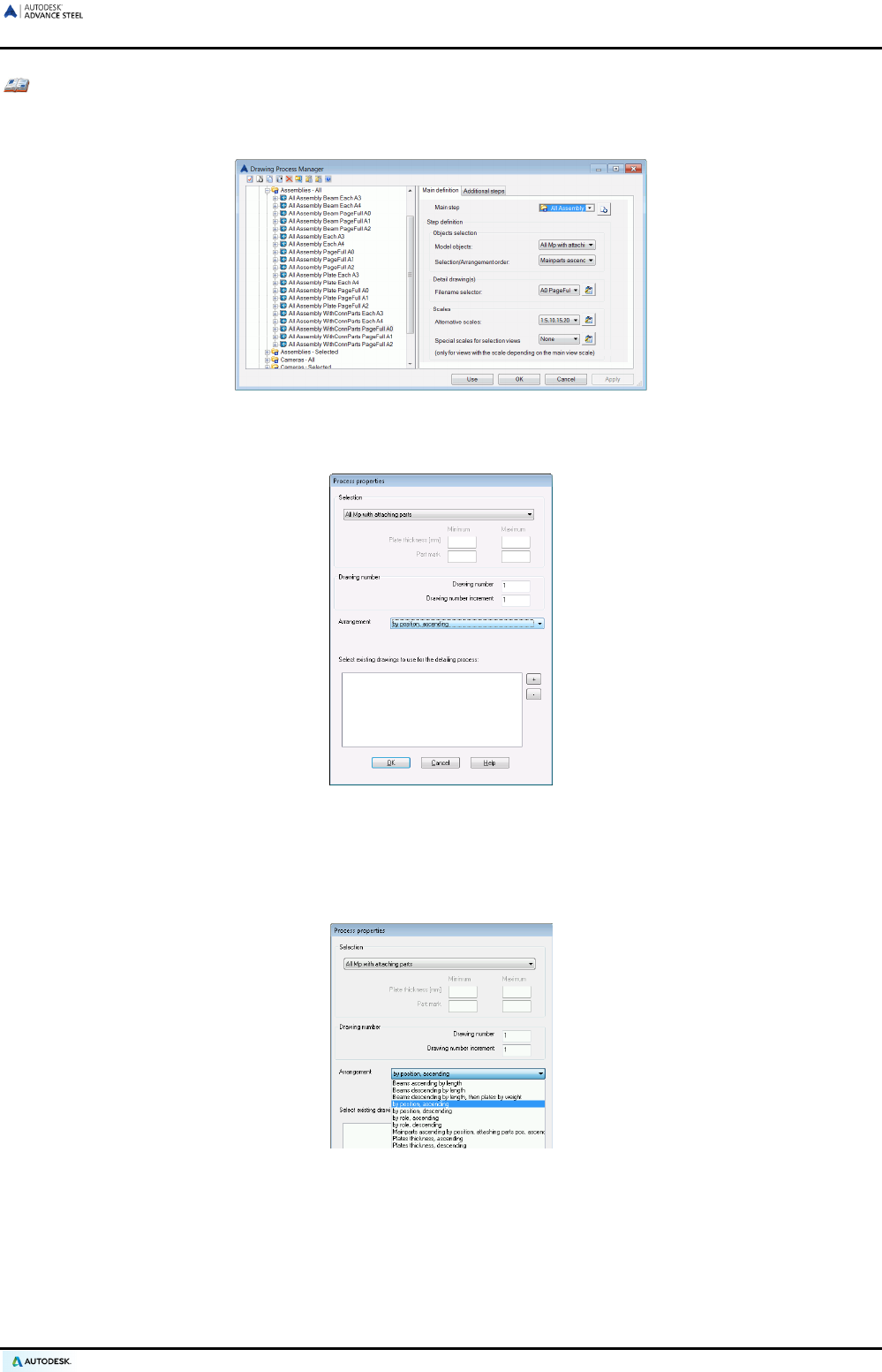
ADVANCE STEEL USER’S GUIDE
Example: Automatic detailing of all main parts in a model with attached parts (A0)
• After the model has been checked and numbered, start the automated detailing process for all main
parts (including their attached parts) using the “All Assembly WithConnParts” process.
Figure 232: Selecting the drawing process
The “Process properties” dialog box appears.
Figure 233: “Process properties” dialog box
• Set the drawing number options for the drawings created by the process: the first number and the in-
crement value.
• Besides the selection, information for arrangement can be entered. Choose a selection and press <OK>.
Figure 234: Drawing processes, sorting
149
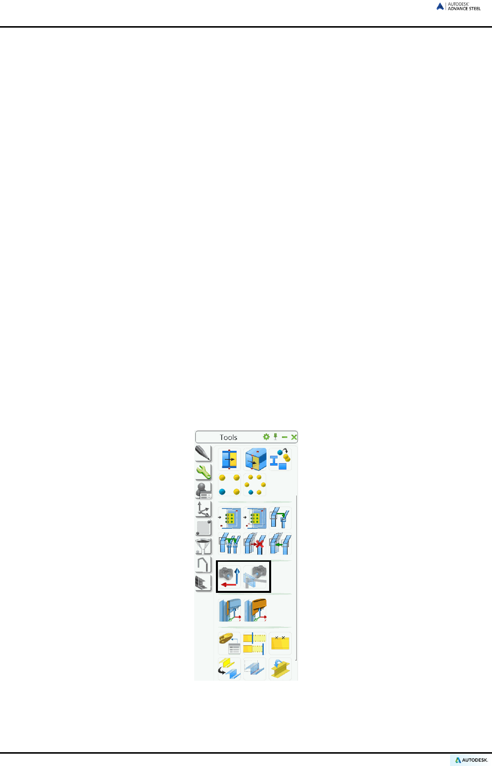
ADVANCE STEEL USER’S GUIDE
The details are created and placed in the drawing.
• The detail drawings for all beams are created automatically. In the Document Manager each linked
beam detail is listed and attached to the same DWG (e.g., ...\ProgramData\Autodesk\Advance Steel
2015\Work\Projectname\details\A0-Detail00001.dwg). When the drawing is full a new drawing A0 detail
00002 is attached.
• In the Preview field of the Document Manager detail drawings are previewed.
• Open a drawing (e.g., A0-Details 00001.dwg) using Open in the Quick Access Toolbar. Individual de-
tails will be seen together on the drawing and the drawings can be plotted or edited.
• Close the DWG and go back to the model.
With the A0, A1, A2 formats, many details are placed on the sheet until it is full. Then a new drawing is started.
With the formats A3 and A4 formats, the details are placed on individual sheets.
The details are automatically placed on the sheet by the process. Before starting the process the arrangement
direction can be changed on the sheet. This must be done in the prototype drawing using the “Define drawing
layout” tool on the Drawing management panel of the Output tab.
Cameras
The creation of drawing views and elevations has considerably improved and made faster by the Advance cam-
era design.
The camera is an object representing the location, angle, and depth of a view, allowing individual focus for au-
tomated detail drawing creation. With the camera's model views, elevations or overview settings and node de-
tails can be presented, named, and saved.
The cameras can also be used in processes for automatic detail creation. Two of the automated detailing pro-
cesses in Advance Steel refer to cameras:
• Create detail drawings from all cameras
• Create detail drawings of selected cameras
Tools for defining different cameras are accessible on the Tools tool palette.
Figure 235: Tools tool palette – tools for creating cameras
• Create camera, UCS: With this tool, elevations / views are set in the model for use in detailing.
• Create camera(s) at node: With the camera at node details, six cameras are set at joints. These corre-
spond to the six view directions of the details and can be set for use in detailing.
150
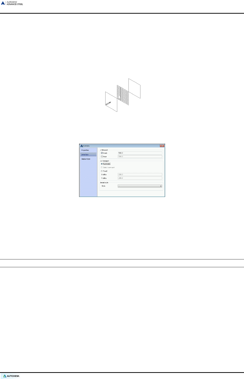
ADVANCE STEEL USER’S GUIDE
Creating a camera (UCS)
A camera is created using the current user coordinate system. The view direction runs against the Z-axis and
the size of the clipping is determined with a detail box with X/Y/Z-depth.
• To define a camera of this type, determine the view direction on the object by setting a corresponding UCS.
• Next, enter an origin for the camera.
• The “Camera” dialog box appears in which a camera type (i.e., no, node, overview) can be entered. This
information is important so that the camera process can distinguish between overview and node.
Figure 236: Create camera (UCS)
The grid is stretched around the set origin, which is at the center, and the size of the grid is determined by
the values in the detail box. The positive and negative Z-values refer to the clipping distance in front and
behind the grid on the UCS plane. The pencil-top shows the view direction against the positive Z-axis.
Figure 237: “Camera” dialog box
Creating a camera (s) at a node
The node camera tool is specifically modified for the Advance Steel joints and determines the orientation and
the size of node views.
For the detail presentation of a node, one or more cameras with different view directions are created at a con-
nection object. The user has a choice between six cameras with different colors.
Note: The connection object (gray box) must be visible so that it can be identified in the command course.
• To define one or more node cameras, display the connection object(s) and then start the “Create camera(s)
at node” tool.
• Six different colored cameras appear. They are created with a standard detail box size. The size of the box
and other properties can be changed later in the Properties dialog box of the created camera.
• Select one or more cameras on the screen and press Enter. The selected cameras are displayed in blue
and the others disappear.
The corresponding drawing processes can interpret the created cameras.
151
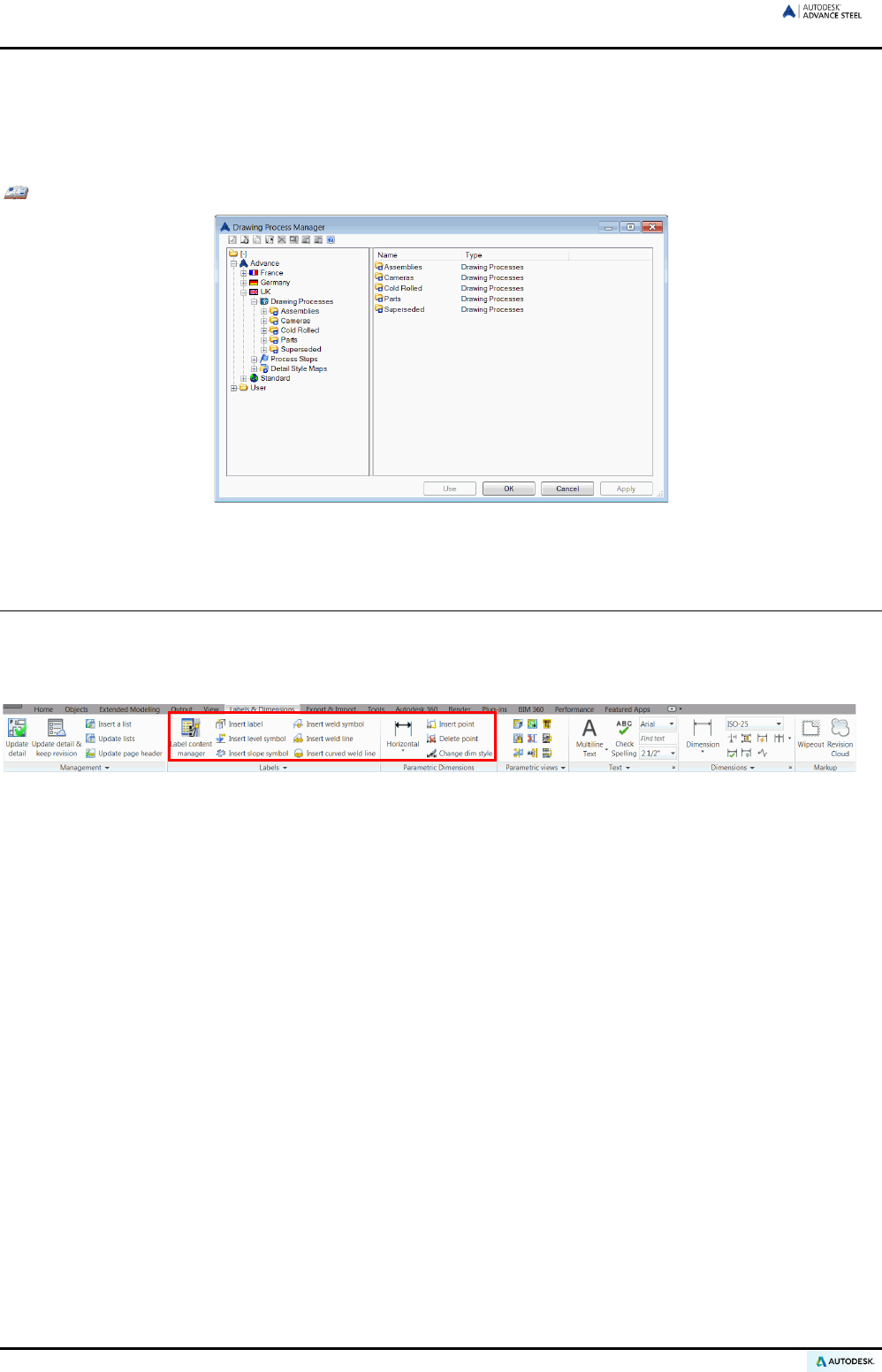
ADVANCE STEEL USER’S GUIDE
Alternative drawing processes
Alternative drawing process categories contain many additional processes for each country. The processes use
the drawing styles and prototypes from the corresponding country.
Examples:
Figure 238: Alternative drawing processes for UK
Labeling and dimensioning
In Advance Steel, the 3D model and the associated drawings are linked to each other. It is therefore possible to
create additional dimensions, labels, and level symbols in the linked drawings using the model information.
The following tools are available on the Labels & Dimensions tab.
Figure 239: Label & Dimensions tab
• Create a weld symbol, label, level symbol
• Create a slope symbol
• Create a dimension point, delete a dimension point
• Dimension chain (flyout)
• Change a dimension style, change a text style
• Hold menu
152
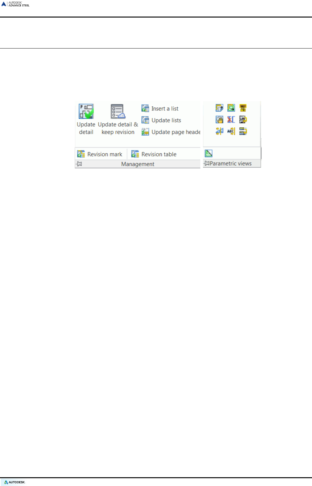
ADVANCE STEEL USER’S GUIDE
Drawing cleanup
First, open the drawing for editing. This can be done on the Quick Access toolbar using Open and entering the
file name (e.g., ..\ProgramData\Autodesk\Advance Steel 2015\Work\Details\Hall1\det1.dwg). In the preview of
the Document Manager, changes cannot be made.
The following tools are available on the Management and Parametric views panels of the Labels & Dimen-
sions tab:
Figure 240: Tools for finishing the drawings
• Update a detail and keep revision
• Update lists
• Update page header
• Insert a list
• Insert a revision mark
• Insert a revision table
• Rearrange all details
• Rearrange all views in a detail
• Change a detail
• Change a prototype file
• Update the page header
• Revision mark, revision table
• Move a view
• Delete a view
• Create a view / section
• Renumber cut views
• Create a BOM, update a BOM
• Explode a detail
• Detail explode settings
• Toggle the display of green frames around details
153

Appendix
ADVANCE STEEL USER’S GUIDE
HSBasis
Command Description
AstModelBrowser Access the Model Browser
AstM4CommProjectData Definition of the project information, units, and preferences
AstM5PrefixConfigurationExplorer Prefix configuration
AstDocCheck Start the Document Manager
AstM4About Displays the Advance Steel About dialog box
AstM4BeamContourNotchCircle1Dig Beam processing - Circular contour by center point
AstM4BeamContourNotchCircle2Dig Beam processing - Circular contour by two points
AstM4BeamContourNotchPolygon Beam processing - Polygonal contour
AstM4BeamContourNotchRect1Dig Beam processing - Rectangular contour cut
AstM4BeamContourNotchRect2Dig Beam processing - Rectangular contour by two points
AstM4Cecs UCS at object
AstM4ChangeBindingLength Calculate grip length
AstM4changerep Change the representation type
AstM4CommAstorToCIS2 Export CIS/2
AstM4CommAstorToIFC2x Export IFC
AstM5CommAstorToSDNF Export SDNF
AstM8CommAstorToPSS Export PSS
AstM4CommAudit Extend the audit checking to include Advance Steel objects
AstM4CommBatchErrorsMarkObject Display the checking results
AstM4CommBatchErrorsPrint Display the checking results again
AstM4CommCIS2ToAstor Import CIS/2
AstM4CommClipCrossSection Create a beam cross section
AstM4CommCrBeamBent Create a curved beam
AstM4CommCrBeamPoly Convert a polyline to a polybeam
AstM4CommCreateAssemblyMainPart Create an assembly part
AstM4CommCreateConnection
_AstM4CommCreateConnection INCL Connection, add objects
_AstM4CommCreateConnection EXCL Connections, disconnect objects
AstM4CommCreateMainPart Create main part of assembly
AstM4CommCrConicalFoldedPlate
Create a conical folded plate
AstM4CommCrTwistedFoldedPlate Create a twisted folded plate
AstM4CommCutPlateToPlate Miter plates
AstM4CommDSTVStaticIn
_AstM4CommDSTVStaticIn NORMAL Statics read
_AstM4CommDSTVStaticIn INVERT
Statics read, WCS inverted
AstM4CommExplodeCombiProfile Disassemble compound sections
AstM4CommGotoMark Zoom to highlighted object
AstM4CommGridAxes Create a group of four axes
AstM4CommGridAxesSequences
Create a group of axes specifying the distances
AstM4CommGridDeleteAxis Delete the selected axis from the grid
AstM4CommGridExtend Extend grid axis
156
ADVANCE STEEL USER’S GUIDE
Command Description
AstM4CommGridInsertSequence Create a group of axes after the selected axis
AstM4CommGridRectangle Create a building grid
AstM4CommGridSingleAxis Create a single axis
AstM4CommGridSingleCircleAxis Create a circular grid with single axis
AstM4CommGridTrimm Trims the building grid after a boundary object
AstM4GRTCLiveUpdate
Check for updates
AstM4CommHoleAssignData Change holes
AstM4CommHSVersion Display version and build number
AstM4CommIFC2xToAstor Import IFC
AstM4CommInsertPlateVertex
Add a corner to a polygonal plate
AstM4CommLine2Beam Convert a line to a beam
AstM4CommMarkConnMeans Display the connection means
AstM4CommMarkMainPart Mark the main part of an assembly
AstM4CommMarkObject Mark an object
AstM4CommMarkSelAdd Add selected objects to marking
AstM4CommMarkSelSub Remove selected objects from marking
AstM4CommModelSelection Search filter
AstM4CommMove2Plane
Move bolt or hole pattern
AstM4CommPlatesShrink Shrink or expand a polyplate
AstM4CommPlate2Pline Convert a plate to a polyline
AstM4CommPLine2Plate Create a plate at polyline
AstM4CommRemovePlateVertex
Remove a corner of a polygonal plate
AstM5CommRepPSS2Astor Import PSS
AstM4CommSaveWithFaceProxy Save with area Proxy-Graphics
AstM4CommSaveWithLineProxy Save with line Proxy-Graphics
AstM4CommSaveWithoutProxy Save without Proxy-Graphics
AstM5CommSDNFToAstor Import SDNF
AstM4CommSelectAllDscObjects Select all Advance Steel objects
AstM4CommSelectMarkedObjects Select highlighted objects
AstM4CommSeparateScrews Split a bolt group
AstM4CommShowLocalCS Define a coordinate system
AstM4CommShowMarkings Search highlighted objects
AstM4CommSpecialPartBlock Advance Steel special part
AstM4CommStandaloneParts
Mark loose parts
AstM4CommStructAsJoint Generic command for creating a structural element
AstM4CommStructAsJointVB Generic command for creating a structural element
AstM4CommUnmarkObjects Clear highlighted objects
AstM4CommWrite2DXF Save as DXF
AstM4ConnectAxes Connect single axes into one grid
AstM4CrAxis Create single axis
157
ADVANCE STEEL USER’S GUIDE
Command Description
AstM4CrBeamByClass Generic command for creating straight beams with specific section
class
_astm4crbeambyclass I Create a beam with a rolled I section
_astm4crbeambyclass U Create a beam with channel section
_astm4crbeambyclass W Create a beam with angle section
_astm4crbeambyclass T Create a beam with T-section
_astm4crbeambyclass O Create a beam with Circular hollow section
_astm4crbeambyclass Z Create a beam with Z section
_astm4crbeambyclass F Create a beam with flat section
_astm4crbeambyclass D Create a round bar
_astm4crbeambyclass Q Create a square bar
_astm4crbeambyclass H Create a square hollow section
_astm4crbeambyclass C Create a cold rolled section
_astm4crbeambyclass A Create other section
AstM4CrBeamContourNotch
Create a contour cope on a beam
AstM4CrBeamMFC
Create a beam
AstM4CrBeamMiterCut Miter cut for two beams
AstM4CrBeamNotch
Cope at a beam end
AstM4CrBeamShort
Create a beam shorten
AstM4CrBeamShortUCS Create a beam shorten at the UCS
AstM4CrCompBeam
Old compound section
AstM4CrCompoundBeam
_AstM4CrCompoundBeam WeldedISymmet-
ric Default
Create a welded beam I symmetric
_AstM4CrCompoundBeam WeldedIAsym-
metric Default
Create a welded beam I asymmetric
_AstM4CrCompoundBeam WeldedHollow
Default
Create a welded beam hollow
_AstM4CrCompoundBeam WeldedT Default
Create a welded beam T
_AstM4CrCompoundBeam WeldedColumn
Default
Create a welded beam, column
_AstM4CrConByVb TaperedBeam Create a tapered welded beam
AstM4Create1DigChamfer Create a chamfer with one point
AstM4Create2DigChamfer Create a chamfer with two points
AstM4CreateConcavFillet Create a concave corner finish
AstM4CreateConvexFillet Create a convex corner finish
AstM4CreatePolyPlate Create a polygon plate by specifying the corner points
AstM4CreateRect1DigPlate Create a rectangular plate by specifying the center point
AstM4CreateRect2DigPlate Create a rectangular plate by specifying two points
AstM4CrRaster Create a building grid
AstM4CrSequPar Create a parallel axis group
AstM4CrStruct3GFrameSymm Create a 3-hinged frame, symmetric
AstM4CrStructMultiFrame
_AstM4CrStructMultiFrame DEF
Create purlins
AstM4CrStructMultiTowerFrame
_AstM4CrStructMultiTowerFrame DEF
Create pylons
158
ADVANCE STEEL USER’S GUIDE
Command Description
AstM4CrStructSingleFrameBracing
_AstM4CrStructSingleFrameBracing DEF
Create a single-span bracing
AstM4CrStructSlopeFrame
_AstM4CrStructSlopeFrame DEF
Create a half truss
AstM4Database Statics write total
AstM4FoldedPlateCheckUnwinding Check unfolding
AstM4FoldedPlateExtend Create a folded plate
AstM4FoldedPlateSetMain Set folded plate main object
AstM4HeightKote Create a level symbol
AstM4HelpCommand Access help
AstM4NecessaryViewsRules Necessary views configuration
AstM4PlateContourNotch
_AstM4PlateContourNotch RECTANGLE Plate processing UCS - rectangular contour by center
_AstM4PlateContourNotch RECTAN-
GLE2DIG
Plate processing UCS - rectangular contour by two points
_AstM4PlateContourNotch CIRCLE Plate processing UCS - circular contour by center
_AstM4PlateContourNotch CIRCLE2DIG Plate processing UCS - circular contour by two points
_AstM4PlateContourNotch POLYGONE Plate processing UCS - polygonal contour
AstM4PlateInnerContour
_AstM4PlateInnerContour RECTANGLE Plate processing - rectangular contour by center
_AstM4PlateInnerContour RECTAN-
GLE2DIG
Plate processing - rectangular contour by two points
_AstM4PlateInnerContour CIRCLE Plate processing - circular contour by center
_AstM4PlateInnerContour CIRCLE2DIG Plate processing - circular contour by two points
_AstM4PlateInnerContour POLYGONE Plate processing - polygonal contour
AstM4PSSDirect Export Steelfab
AstM4RemoveHyperSteel Delete all AS objects from external dwg
AstM4ReopenDatabase Update defaults
AstM4SelectObjectByName Select Advance Steel objects
AstM4SsetDatabase Statics write selection
AstM4SwitchReprMode Hide or show objects
AstM4UndoSwitch Disable or enable UNDO
AstM4WeldSeam Generic command for the creation of welds
_AstM4WeldSeam POINT
Create a weld point
_AstM4WeldSeam STRAIGHT Create a weld line
AstM5BoltsHolesSwitchConnector Switch to shear studs
AstM5BoltsHolesSwitchHoles Switch to bolts / holes / shear studs
AstM5CommBoltsHolesAllSides Create bolt or hole rectangular pattern set by 2 points
AstM5CommBoltsHolesCircle Create bolt or hole circular pattern set by the center point
AstM5CommBoltsHolesLLSides Create a rectangular pattern set by the corner point
AstM5CommBoltsHolesRect Create a rectangular pattern set by the center point
AstM5CommCamera Create a camera, UCS
AstM5CommCameraNode Create camera(s) at node
AstM5CommEcsAtPickPoint UCS at curved beam
159
ADVANCE STEEL USER’S GUIDE
Command Description
AstM5CommEqualPartsOnePartOutOf Select objects with different part marks
AstM5CommEqualPartsWithoutNum Mark parts without a mark
AstM5CommSemanticCheck Steel construction technical checking
AstM5DetSetArranger Define a drawing layout
AstM5EqualPartsChangePrefix Assign or change the prefix
AstM5EqualPartsCheck Identify the objects with duplicate part marks
AstM5EqualPartsCheckGroups Check for duplicate part marks
AstM5EqualPartsDelNumber Delete part marks
AstM5EqualPartsDetect Numbering
AstM5EqualPartsMarkSame Display objects with identical part marks
AstM5EqualPartsReset Ungroup identical parts
AstM5EqualPartsShowDiff Differences between two objects (pos check)
AstM5EqualPartsSwitchMain Switch to main part numbering
AstM5EqualPartsSwitchSingle Switch to single part numbering
AstM4LoadSTEP Write SDDP
AstM4CrBisectorCS Set the UCS to the bisecting line
AstM4CommExplodeToAcis Explode object to ACIS
AstM4CommBevelWeldingPreparation Weld seam preparation, chamfer
AstM4CommFilletWeldingPreparation Weld seam preparation, fillet
AstM4CutPlateAtUcs Cut plate at UCS
AstM4CutPlateAtPlate Cut plate at an other plate
AstM4CommUserSectionBeam Create a folded beam
AstM4CommBillOfMaterial Create lists
AstM4CommStartConcrete Start Advance Concrete
AstM4UCSZFilter Switch for working 2D / 3D (for snap points)
AstProcessesSuite Drawing process suite
ASTransform Select the transformation type
ASTransformAndConnect Advance Steel Copy tools
HSDetailing
Command Description
AstM4DetRegist Register a detail to the model
AstM4DetDeregist Deregister a detail from a model
HSConnection
Command Description
AstM4CrConByRule Generic command for creating a joint
AstM4CrConByRule 1 ParamFit Cope parametric rule
AstM4CrConByRule 1 Saw_1 Cut at object – rule
AstM4CrConByRule 1 SawAngle_Asym Cut variable – rule
AstM4CrConByVB General command for creating a joint
AstM4CreateGussetPlate Create a gusset plate
AstM4TransferCons Create using template (intelligent connections)
160
ADVANCE STEEL USER’S GUIDE
Command Description
AstM4TransferParams Transfer properties (intelligent connections)
AstM4UpdateConOb
_AstM4UpdateConOb UPDATE Update a joint
_AstM4UpdateConOb DELETE Delete a joint
AstM4UserTemplateConn
_AstM4UserTemplateConn _c
Create a template connection
_AstM4UserTemplateConn _i Import a template connection
HSExtended
Command Description
AstM4CrBeamElemContNotch Element contour - exact cross section
AstM4PlateElementContourNotch Plate processing by element contour
AstM4CommMergeBeams CONVERT sections
AstM4CommMergePlates CONVERT plates
AstM4CommSeparateBeams Split beams
AstM4CommSeparatePlates Split plates at lines
AstM4CommSeparatePlate Split plates using two points
AstM4CommDeepExplode Explode a joint and all sub-joints
HSCollision
Command Description
AstM4Balancepoint Center of gravity and total weight calculation
AstM4CheckCollision Clash check between selected objects
HSDetailingBasis
Command Description
AstM4CommDetRevisionTable Revision table
AstM4DetChange Change detail
AstM4CommDetAddHorLinearDim Linear horizontal dimension
AstM4CommDetAddSlopeLinearDim Linear sloped dimension
AstM4CommDetAddVertLinearDim Linear vertical dimension
AstM4CommDetArrangeDetails Rearrange all details
AstM4CommDetArrangeViews Rearrange all views in detail
AstM4CommDetUpdateDetail Update detail
AstM4DetManualCut Create view / section
AstM4CommDetailRevision Revision mark
AstM4CommExplodeDetail Detail explode settings
AstDetCheck Check details status
AstM5DetailStylesExplorer Drawing Style Manager
AstM5DetailStylesManagerNew Start the new Drawing Style Manager
AstM4CommDetAddDim General dimension
AstM4CommDetAddDimSlope Create slope symbol
AstM4CommDetAddDimAngle Angle dimension
161
ADVANCE STEEL USER’S GUIDE
Command Description
AstM4CommDetAddDimArc Arc dimension
AstM4CommDetAddDimRadial Radial dimension
AstM4CommDetByStyle 3D view
AstM4CommDetailing Generic command for calling detail styles
AstM4CommDetailingProc Generic command for calling processes
AstM4CommDetCrHeightKote Create a level symbol
AstM4CommDetCrWeldSeam Create a weld symbol
AstM4CommDetAddAnnotation User label
AstM4CommDetInsertAnno Create a label
AstM4CommDetModDimAdd Create a dimension point
AstM4CommDetModDimRemove Delete a dimension point
AstM4CommDetModDimStyle Change a dimension style
AstM4CommDetModTextStyle Change a text style
AstM4CommDetUpdateBOM Update lists
AstM4CommDetSwitchHighlightState Toggle the display of green frames around details
AstM4DetViewDelete Delete a view
AstM4DetViewTransform Move a view
AstM5DetailProcessExplorer Start the Drawing Process Manager
AstM4CommDetAddHorLinearDim Linear horizontal dimension
AstM4CommDetAddSlopeLinearDim Linear sloped dimension
AstM4CommDetAddVertLinearDim Linear vertical dimension
AstM4CommDetInsertBom Create a list
HSDetailing
Command Description
AstM4CommDetAddDimArc
Arc dimension
AstM4DetProc Processes
AstM4CommDetInsertBom Create a list
AstM4CommChangePrototype Change prototype file
HSIFDSTVBOM
Command Description
AstM4CommPSSOut Write PSS
HSIFDSTVNC
Command Description
AstM4CommPSSOut Write PSS
AstM4CommCreateNCByStyle HSIFDSTVNC NC, DXF (plates), DXF (all objects)
AstM4NCSettings NC Settings
162
ADVANCE STEEL USER’S GUIDE
HSIFPM (HSExtended)
Command Description
AstM4CommPSSIn Read PSS
AstM4CommPSSOut Write PSS
AstM4Astor2RepPSS Export PSS
HSSTAAD
Command Description
AstM4CommAstorToSTD Export STD
AstM4CommSTDToAstor Import STD
163

Index
3D model, 18
Access databases, 12
Access tables, 20
Advance properties, 65
Angle connections, 20
Any contour, 57, 62
Any contour processing, 61, 62
Apex, 88
ARX-Technology, 11
Assembly marks, 112
Assembly part, 116
ASTemplate.dwt, 26
Audit checking, 120
Auxiliary objects, 21
Axis groups, 34
Base plate, 20
Basic objects, 18
Beam processing, 18, 55
Beam to column, 85
Beams, 18
Behavior, 38, 68
Bolt pattern, 19
Bolt patterns, 68
Bolts, 69
Building grid, 34
Buttons, 28
CAD platform, 32
CAD properties, 65
Camera, 150
Checks, 118, 121
Circular contour, 57, 62
Circular processing, 62
Circular processing object, 61
Collision check, 119
Collision solids, 119
Compound sections, 38
Connection, 72
Connection object, 56, 82, 102
Construction systems, 11, 42
Contour element, 61
Curved beams, 37, 39
Cut at object, 56
Default values, 12
Diagonal bracing, 20
Dialog box, 31
Display connected object, 73
Display connecting elements, 73
Display objects connected in shop, 73
Document Manager, 10, 133, 138
Drawing formats, 135
Drawing frames, 135
Drawing style, 132
Drawing styles, 12
Drawings, 132
DWG, 10
Dysplay type, 76
Element contour, 57
Elevations, 144
End plates, 20
Esc key, 31
Extract, 126
F2 key, 31
Features, 18
Flat bracings, 20
Flat frames, 78
Frame corners, 20
Gable columns/posts, 87
Gable wall connections, 20
Geometric Properties, 32
Gravity axis, 37
Grid axes, 21
Grid values, 64
Grips, 64, 66
Gusset plate connection, 91, 93
Gusset plates, 20
Hide objects, 77
Hole pattern, 68, 69
Holes, 19
Insertion axis, 37
Joints, 20, 82
Joists, 78
Layer, 32
Level symbols, 21
List Template Wizard, 126, 128
Main part, 116
Management Tools, 12
Manipulating Tools, 64
MDI, 12
MFC, 12
Model, 10
Model changes, 10
Model objects, 126, 127
Model role, 79
Moment end plate, 86
Moment end plate connection, 91
Node, 143
Non-vertical main parts, 145
Numbering, 112
Object coordinate system, 51
Objects, 10
ODBC, 12
PCS (Program system in the steel
construction), 12
Pin-Ended Column, 87
Pin-ended column connections, 20
Plate processing, 18, 58
Plate splice, 88
Plates, 18, 45
Platform connections, 20
Platform splices, 91
Poly beams, 40
PPS (Interface product of the steel
construction), 12
Processes, 133
Processing based on rules, 56
Processing contours, 18
Processing object, 55
Project information, 142
Properties, 32
Proxy-graphics, 12
Purlin, 78
Pylons, 78
ADVANCE STEEL USER’S GUIDE
Rectangular contour, 57, 62
Rectangular plates, 46
Rectangular processing, 61, 62
Reference axes, 37
Report, 129
Representation types, 66
Ridge connections, 20
Search filter, 76
Section classes, 36
Selecting objects, 74
Shear plates, 20
Shear studs, 68, 70
Shop drawings, 10, 145
Shorten at UCS, 56
Single part mark, 112
Single parts, 144
Single-span bracings, 78
Snaps, 66
Special parts, 22, 102
Splice joint, 88
Splices, 20
Steel construction checking, 121
Stiffeners, 20
Structural elements, 78
Structural frame, 21
Structured BOM, 128
Structured BOMs, 10
System line, 37
Technical properties, 32
Title block, 143
Title blocks, 135
Tube connections, 20
Turnbuckle bracing, 20
User Coordinate System (UCS), 51
User sections, 104
View, 135
Web connections, 20
Weld line, 71
Weld point, 71
Welds, 19
World Coordinate System (WCS), 51
167