Autodesk Auto CAD LT 2012 Command Reference Ref Enu V2
User Manual: autodesk AutoCAD LT - 2012 - Command Reference Free User Guide for Autodesk AutoCAD Software, Manual
Open the PDF directly: View PDF ![]() .
.
Page Count: 1804 [warning: Documents this large are best viewed by clicking the View PDF Link!]
- Contents
- Commands
- 3D Commands
- A Commands
- B Commands
- C Commands
- CAL
- Understand Syntax of Expressions
- Format Feet and Inches
- Format Angles
- Use Points and Vectors
- Use System Variables in Calculations
- Convert Units of Measurement
- Use Standard Numeric Functions
- Calculate a Vector from Two Points
- Calculate the Length of a Vector
- Obtain a Point by Cursor
- Obtain the Last-Specified Point
- Use Snap Modes in Arithmetic Expressions
- Convert Points Between UCS and WCS
- Calculate a Point on a Line
- Rotate a Point About an Axis
- Obtain an Intersection Point
- Calculate a Distance
- Obtain a Radius
- Obtain an Angle
- Calculate a Normal Vector
- Use Shortcut Functions
- CHAMFER
- CHANGE
- CHPROP
- CHSPACE
- CIRCLE
- CLASSICIMAGE
- CLASSICLAYER
- CLASSICXREF
- CLEANSCREENON
- CLEANSCREENOFF
- CLIP
- CLOSE
- CLOSEALL
- COLOR
- COMMANDLINE
- COMMANDLINEHIDE
- CONSTRAINTBAR
- CONSTRAINTSETTINGS
- CONTENTEXPLORER
- CONTENTEXPLORERCLOSE
- CONVERT
- CONVERTCTB
- CONVERTPSTYLES
- COPY
- COPYBASE
- COPYCLIP
- COPYHIST
- COPYLINK
- COPYTOLAYER
- CUI
- CUIEXPORT
- CUIIMPORT
- CUILOAD
- CUIUNLOAD
- CUSTOMIZE
- CUTCLIP
- CAL
- D Commands
- DATALINK
- DATALINKUPDATE
- DCDISPLAY
- DDEDIT
- DDPTYPE
- DDVPOINT
- DELAY
- DELCONSTRAINT
- DETACHURL
- DGNADJUST
- DGNATTACH
- DGNBIND (-DGNBIND)
- DGNCLIP
- DGNEXPORT
- DGNIMPORT
- DGNLAYERS
- DGNMAPPING
- DIM and DIM1
- DIMALIGNED
- DIMANGULAR
- DIMARC
- DIMBASELINE
- DIMBREAK
- DIMCENTER
- DIMCONTINUE
- DIMDIAMETER
- DIMDISASSOCIATE
- DIMEDIT
- DIMINSPECT
- DIMJOGGED
- DIMJOGLINE
- DIMLINEAR
- DIMORDINATE
- DIMOVERRIDE
- DIMRADIUS
- DIMREASSOCIATE
- DIMREGEN
- DIMROTATED
- DIMSPACE
- DIMSTYLE
- DIMTEDIT
- DIST
- DIVIDE
- DLINE
- DONUT
- DOWNLOADMANAGER
- DRAGMODE
- DRAWINGRECOVERY
- DRAWINGRECOVERYHIDE
- DRAWORDER
- DSETTINGS
- DWFADJUST
- DWFATTACH
- DWFCLIP
- DWFFORMAT
- DWFLAYERS
- DWGCONVERT
- DWGPROPS
- E Commands
- F Commands
- G Commands
- H Commands
- I Commands
- J Commands
- L Commands
- M Commands
- N Commands
- O Commands
- OBJECTSCALE
- OFFSET
- OLELINKS
- OLESCALE
- ONLINEDRAWINGS
- OOPS
- OPEN
- OPENDWFMARKUP
- OPENONLINE
- OPENSHEETSET
- OPTIONS
- Options Dialog Box
- Alternate Font Dialog Box
- Drawing Window Colors Dialog Box
- Command Line Window Font Dialog Box
- Thumbnail Preview Settings Dialog Box
- Plot Style Table Settings Dialog Box
- Right-Click Customization Dialog Box
- Field Update Settings Dialog Box
- Visual Effect Settings Dialog Box
- Ribbon Contextual Tab State Options Dialog Box
- Advanced Preview Options Dialog Box
- Transparency Dialog Box
- Hidden Message Settings Dialog Box
- InfoCenter Settings Dialog Box
- Default Scale List Dialog Box
- ORTHO
- OSNAP
- OVERKILL
- P Commands
- Q Commands
- R Commands
- S Commands
- SAVE
- SAVEAS
- SCALE
- SCALELISTEDIT
- SCALETEXT
- SCRIPT
- SECURITYOPTIONS
- SEEK
- SELECT
- SELECTSIMILAR
- SETBYLAYER
- SETENV
- SETVAR
- SHADE
- SHADEMODE
- SHARE
- SHAREWITHSEEK
- SHEETSET
- Sheet Set Manager
- Subset Properties Dialog Box
- Publish Sheets Dialog Box
- Select Layout as Sheet Template Dialog Box
- New Sheet Dialog Box
- Rename & Renumber Sheet Dialog Box
- Rename & Renumber View Dialog Box
- Import Layouts as Sheets Dialog Box
- Insert Sheet List Table Dialog Box
- Edit Sheet List Table Settings Dialog Box
- Sheet Set Properties Dialog Box
- Sheet Set Custom Properties Dialog Box
- Add Custom Property Dialog Box
- Resource Drawing Locations Dialog Box
- Sheet Properties Dialog Box
- New Sheet Selection Dialog Box
- Sheet Selections Dialog Box
- View Category Dialog Box
- List of Blocks Dialog Box
- Select Block Dialog Box
- SHEETSETHIDE
- SHOWPALETTES
- SIGVALIDATE
- SKETCH
- SNAP
- SOLID
- SPACETRANS
- SPELL
- SPLINE
- SPLINEDIT
- STRETCH
- STYLE
- STYLESMANAGER
- SUBTRACT
- SYSWINDOWS
- T Commands
- U Commands
- V Commands
- W Commands
- X Commands
- Z Commands
- Command Modifiers
- System Variables
- 3D System Variables
- A System Variables
- B System Variables
- C System Variables
- CALCINPUT
- CANNOSCALE
- CANNOSCALEVALUE
- CBARTRANSPARENCY
- CDATE
- CECOLOR
- CELTSCALE
- CELTYPE
- CELWEIGHT
- CENTERMT
- CETRANSPARENCY
- CHAMFERA
- CHAMFERB
- CHAMFERC
- CHAMFERD
- CHAMMODE
- CIRCLERAD
- CLASSICKEYS
- CLAYER
- CLEANSCREENSTATE
- CLISTATE
- CLIPBOARD
- CMDACTIVE
- CMDDIA
- CMDINPUTHISTORYMAX
- CMDNAMES
- CMLEADERSTYLE
- CONSTRAINTBARMODE
- CONSTRAINTNAMEFORMAT
- CONSTRAINTRELAX
- CONSTRAINTSOLVEMODE
- CONTENTEXPLORERSTATE
- COORDS
- COPYMODE
- CPLOTSTYLE
- CROSSINGAREACOLOR
- CTAB
- CTABLESTYLE
- CURSORSIZE
- CVPORT
- D System Variables
- DATALINKNOTIFY
- DATE
- DBLCLKEDIT
- DBMOD
- DCTCUST
- DCTMAIN
- DEFLPLSTYLE
- DEFPLSTYLE
- DELOBJ
- DGNFRAME
- DGNIMPORTMAX
- DGNIMPORTMODE
- DGNMAPPINGPATH
- DGNOSNAP
- DIASTAT
- DIGITIZER
- DIMADEC
- DIMALT
- DIMALTD
- DIMALTF
- DIMALTRND
- DIMALTTD
- DIMALTTZ
- DIMALTU
- DIMALTZ
- DIMANNO
- DIMAPOST
- DIMARCSYM
- DIMASSOC
- DIMASZ
- DIMATFIT
- DIMAUNIT
- DIMAZIN
- DIMBLK
- DIMBLK1
- DIMBLK2
- DIMCEN
- DIMCLRD
- DIMCLRE
- DIMCLRT
- DIMCONSTRAINTICON
- DIMDEC
- DIMDLE
- DIMDLI
- DIMDSEP
- DIMEXE
- DIMEXO
- DIMFRAC
- DIMFXL
- DIMFXLON
- DIMGAP
- DIMJOGANG
- DIMJUST
- DIMLDRBLK
- DIMLFAC
- DIMLIM
- DIMLTEX1
- DIMLTEX2
- DIMLTYPE
- DIMLUNIT
- DIMLWD
- DIMLWE
- DIMPOST
- DIMRND
- DIMSAH
- DIMSCALE
- DIMSD1
- DIMSD2
- DIMSE1
- DIMSE2
- DIMSOXD
- DIMSTYLE
- DIMTAD
- DIMTDEC
- DIMTFAC
- DIMTFILL
- DIMTFILLCLR
- DIMTIH
- DIMTIX
- DIMTM
- DIMTMOVE
- DIMTOFL
- DIMTOH
- DIMTOL
- DIMTOLJ
- DIMTP
- DIMTSZ
- DIMTVP
- DIMTXSTY
- DIMTXT
- DIMTXTDIRECTION
- DIMTZIN
- DIMUPT
- DIMZIN
- DISPSILH
- DISTANCE
- DONUTID
- DONUTOD
- DRAGMODE
- DRAGP1
- DRAGP2
- DRAWORDERCTL
- DRSTATE
- DTEXTED
- DWFFRAME
- DWFOSNAP
- DWGCHECK
- DWGCODEPAGE
- DWGNAME
- DWGPREFIX
- DWGTITLED
- DYNCONSTRAINTMODE
- DYNDIGRIP
- DYNDIVIS
- DYNINFOTIPS
- DYNMODE
- DYNPICOORDS
- DYNPIFORMAT
- DYNPIVIS
- DYNPROMPT
- DYNTOOLTIPS
- E System Variables
- F System Variables
- G System Variables
- H System Variables
- HALOGAP
- HANDLES
- HELPPREFIX
- HIDEPRECISION
- HIDETEXT
- HIGHLIGHT
- HPANG
- HPANNOTATIVE
- HPASSOC
- HPBACKGROUNDCOLOR
- HPBOUND
- HPBOUNDRETAIN
- HPCOLOR
- HPDLGMODE
- HPDOUBLE
- HPDRAWORDER
- HPGAPTOL
- HPINHERIT
- HPISLANDDETECTION
- HPISLANDDETECTIONMODE
- HPLAYER
- HPMAXAREAS
- HPMAXLINES
- HPNAME
- HPOBJWARNING
- HPORIGIN
- HPORIGINMODE
- HPQUICKPREVIEW
- HPQUICKPREVTIMEOUT
- HPSCALE
- HPSEPARATE
- HPSPACE
- HPTRANSPARENCY
- HYPERLINKBASE
- I System Variables
- L System Variables
- M System Variables
- N System Variables
- O System Variables
- P System Variables
- PALETTEOPAQUE
- PAPERUPDATE
- PDFFRAME
- PDFOSNAP
- PDMODE
- PDSIZE
- PEDITACCEPT
- PELLIPSE
- PERIMETER
- PERSPECTIVE
- PERSPECTIVECLIP
- PICKADD
- PICKAUTO
- PICKBOX
- PICKDRAG
- PICKFIRST
- PICKSTYLE
- PLATFORM
- PLINECONVERTMODE
- PLINEGEN
- PLINETYPE
- PLINEWID
- PLOTOFFSET
- PLOTROTMODE
- PLOTTRANSPARENCYOVERRIDE
- POINTCLOUDDENSITY
- POLARADDANG
- POLARANG
- POLARDIST
- POLARMODE
- POLYSIDES
- PREVIEWEFFECT
- PREVIEWFACEEFFECT
- PREVIEWFILTER
- PROJMODE
- PROPOBJLIMIT
- PROXYGRAPHICS
- PROXYNOTICE
- PROXYSHOW
- PROXYWEBSEARCH
- PSLTSCALE
- PSTYLEMODE
- PSTYLEPOLICY
- PUBLISHALLSHEETS
- PUBLISHCOLLATE
- PUBLISHHATCH
- PUCSBASE
- Q System Variables
- R System Variables
- S System Variables
- SAVEFIDELITY
- SAVEFILE
- SAVEFILEPATH
- SAVENAME
- SAVETIME
- SCREENSIZE
- SELECTIONANNODISPLAY
- SELECTIONAREA
- SELECTIONAREAOPACITY
- SELECTIONCYCLING
- SELECTIONPREVIEW
- SELECTSIMILARMODE
- SETBYLAYERMODE
- SHADEDGE
- SHADEDIF
- SHORTCUTMENU
- SHORTCUTMENUDURATION
- SHOWLAYERUSAGE
- SHOWPAGESETUPFORNEWLAYOUTS
- SIGWARN
- SKETCHINC
- SKPOLY
- SKTOLERANCE
- SNAPANG
- SNAPBASE
- SNAPISOPAIR
- SNAPMODE
- SNAPSTYL
- SNAPTYPE
- SNAPUNIT
- SORTENTS
- SPLDEGREE
- SPLFRAME
- SPLINESEGS
- SPLINETYPE
- SPLKNOTS
- SPLMETHOD
- SPLPERIODIC
- SSFOUND
- SSLOCATE
- SSMAUTOOPEN
- SSMPOLLTIME
- SSMSHEETSTATUS
- SSMSTATE
- STARTUP
- STATUSBAR
- SYSCODEPAGE
- T System Variables
- TABLEINDICATOR
- TABLETOOLBAR
- TABMODE
- TARGET
- TBSHOWSHORTCUTS
- TDCREATE
- TDINDWG
- TDUCREATE
- TDUPDATE
- TDUSRTIMER
- TDUUPDATE
- TEMPOVERRIDES
- TEXTED
- TEXTFILL
- TEXTOUTPUTFILEFORMAT
- TEXTQLTY
- TEXTSIZE
- TEXTSTYLE
- THICKNESS
- TILEMODE
- TIMEZONE
- TOOLTIPMERGE
- TOOLTIPS
- TOOLTIPSIZE
- TOOLTIPTRANSPARENCY
- TPSTATE
- TRACEWID
- TRACKPATH
- TRANSPARENCYDISPLAY
- TRAYICONS
- TRAYNOTIFY
- TRAYTIMEOUT
- TREEDEPTH
- TREEMAX
- TRIMMODE
- TSPACEFAC
- TSPACETYPE
- TSTACKALIGN
- TSTACKSIZE
- U System Variables
- V System Variables
- W System Variables
- X System Variables
- Z System Variables
- Utilities
- Index

AutoCAD LT 2012
Command Reference
February 2011
©2011 Autodesk, Inc. All Rights Reserved. Except as otherwise permitted by Autodesk, Inc., this publication, or parts thereof, may not be
reproduced in any form, by any method, for any purpose.
Certain materials included in this publication are reprinted with the permission of the copyright holder.
Trademarks
The following are registered trademarks or trademarks of Autodesk, Inc., and/or its subsidiaries and/or affiliates in the USA and other countries:
3DEC (design/logo), 3December, 3December.com, 3ds Max, Algor, Alias, Alias (swirl design/logo), AliasStudio, Alias|Wavefront (design/logo),
ATC, AUGI, AutoCAD, AutoCAD Learning Assistance, AutoCAD LT, AutoCAD Simulator, AutoCAD SQL Extension, AutoCAD SQL Interface,
Autodesk, Autodesk Intent, Autodesk Inventor, Autodesk MapGuide, Autodesk Streamline, AutoLISP, AutoSnap, AutoSketch, AutoTrack, Backburner,
Backdraft, Beast, Built with ObjectARX (logo), Burn, Buzzsaw, CAiCE, Civil 3D, Cleaner, Cleaner Central, ClearScale, Colour Warper, Combustion,
Communication Specification, Constructware, Content Explorer, Dancing Baby (image), DesignCenter, Design Doctor, Designer's Toolkit,
DesignKids, DesignProf, DesignServer, DesignStudio, Design Web Format, Discreet, DWF, DWG, DWG (logo), DWG Extreme, DWG TrueConvert,
DWG TrueView, DXF, Ecotect, Exposure, Extending the Design Team, Face Robot, FBX, Fempro, Fire, Flame, Flare, Flint, FMDesktop, Freewheel,
GDX Driver, Green Building Studio, Heads-up Design, Heidi, HumanIK, IDEA Server, i-drop, Illuminate Labs AB (design/logo), ImageModeler,
iMOUT, Incinerator, Inferno, Inventor, Inventor LT, Kynapse, Kynogon, LandXplorer, LiquidLight, LiquidLight (design/logo), Lustre, MatchMover,
Maya, Mechanical Desktop, Moldflow, Moldflow Plastics Advisers, MPI, Moldflow Plastics Insight, Moldflow Plastics Xpert, Moondust, MotionBuilder,
Movimento, MPA, MPA (design/logo), MPX, MPX (design/logo), Mudbox, Multi-Master Editing, Navisworks, ObjectARX, ObjectDBX, Opticore,
Pipeplus, PolarSnap, PortfolioWall, Powered with Autodesk Technology, Productstream, ProMaterials, RasterDWG, RealDWG, Real-time Roto,
Recognize, Render Queue, Retimer, Reveal, Revit, RiverCAD, Robot, Showcase, Show Me, ShowMotion, SketchBook, Smoke, Softimage,
Softimage|XSI (design/logo), Sparks, SteeringWheels, Stitcher, Stone, StormNET, StudioTools, ToolClip, Topobase, Toxik, TrustedDWG, U-Vis,
ViewCube, Visual, Visual LISP, Volo, Vtour, WaterNetworks, Wire, Wiretap, WiretapCentral, XSI.
All other brand names, product names or trademarks belong to their respective holders.
Disclaimer
THIS PUBLICATION AND THE INFORMATION CONTAINED HEREIN IS MADE AVAILABLE BY AUTODESK, INC. "AS IS." AUTODESK, INC. DISCLAIMS
ALL WARRANTIES, EITHER EXPRESS OR IMPLIED, INCLUDING BUT NOT LIMITED TO ANY IMPLIED WARRANTIES OF MERCHANTABILITY OR
FITNESS FOR A PARTICULAR PURPOSE REGARDING THESE MATERIALS.
Published by:
Autodesk, Inc.
111 McInnis Parkway
San Rafael, CA 94903, USA
Contents
Commands . . . . . . . . . . . . . . . . . . . . . . . . . . 1
Chapter 1 3D Commands . . . . . . . . . . . . . . . . . . . . . . . . . . . 3
3DCONFIG . . . . . . . . . . . . . . . . . . . . . . . . . . . . . . . . . 3
Performance Tuning Dialog Box . . . . . . . . . . . . . . . . . . . 3
Performance Tuner Log . . . . . . . . . . . . . . . . . . . . . . . . 5
-3DCONFIG . . . . . . . . . . . . . . . . . . . . . . . . . . . . . . 6
3DPOLY . . . . . . . . . . . . . . . . . . . . . . . . . . . . . . . . . . . 6
Chapter 2 A Commands . . . . . . . . . . . . . . . . . . . . . . . . . . . . 9
ABOUT . . . . . . . . . . . . . . . . . . . . . . . . . . . . . . . . . . . 9
ADCCLOSE . . . . . . . . . . . . . . . . . . . . . . . . . . . . . . . . 10
ADCENTER . . . . . . . . . . . . . . . . . . . . . . . . . . . . . . . . 10
DesignCenter Window . . . . . . . . . . . . . . . . . . . . . . . 11
Search Dialog Box . . . . . . . . . . . . . . . . . . . . . . . . . . 15
ADCNAVIGATE . . . . . . . . . . . . . . . . . . . . . . . . . . . . . . 18
ADDSELECTED . . . . . . . . . . . . . . . . . . . . . . . . . . . . . . 19
ADJUST . . . . . . . . . . . . . . . . . . . . . . . . . . . . . . . . . . 20
ALIGN . . . . . . . . . . . . . . . . . . . . . . . . . . . . . . . . . . . 22
ANNORESET . . . . . . . . . . . . . . . . . . . . . . . . . . . . . . . . 24
ANNOUPDATE . . . . . . . . . . . . . . . . . . . . . . . . . . . . . . 25
APERTURE . . . . . . . . . . . . . . . . . . . . . . . . . . . . . . . . . 25
ARC . . . . . . . . . . . . . . . . . . . . . . . . . . . . . . . . . . . . 26
iii
ARCHIVE . . . . . . . . . . . . . . . . . . . . . . . . . . . . . . . . . 30
Archive a Sheet Set Dialog Box . . . . . . . . . . . . . . . . . . . 31
Modify Archive Setup Dialog Box . . . . . . . . . . . . . . . . . . 35
Archive - Set Password Dialog Box . . . . . . . . . . . . . . . . . 38
-ARCHIVE . . . . . . . . . . . . . . . . . . . . . . . . . . . . . . 39
AREA . . . . . . . . . . . . . . . . . . . . . . . . . . . . . . . . . . . . 40
ARRAY . . . . . . . . . . . . . . . . . . . . . . . . . . . . . . . . . . . 43
-ARRAY . . . . . . . . . . . . . . . . . . . . . . . . . . . . . . . 44
ARRAYCLOSE . . . . . . . . . . . . . . . . . . . . . . . . . . . . . . . 47
ARRAYEDIT . . . . . . . . . . . . . . . . . . . . . . . . . . . . . . . . 48
Array Editor Ribbon Contextual Tab . . . . . . . . . . . . . . . . 51
ARRAYPATH . . . . . . . . . . . . . . . . . . . . . . . . . . . . . . . . 53
ARRAYPOLAR . . . . . . . . . . . . . . . . . . . . . . . . . . . . . . . 57
ARRAYRECT . . . . . . . . . . . . . . . . . . . . . . . . . . . . . . . . 60
ATTACH . . . . . . . . . . . . . . . . . . . . . . . . . . . . . . . . . . 62
-ATTACH . . . . . . . . . . . . . . . . . . . . . . . . . . . . . . 63
ATTACHURL . . . . . . . . . . . . . . . . . . . . . . . . . . . . . . . . 66
ATTDEF . . . . . . . . . . . . . . . . . . . . . . . . . . . . . . . . . . 67
Attribute Definition Dialog Box . . . . . . . . . . . . . . . . . . 67
-ATTDEF . . . . . . . . . . . . . . . . . . . . . . . . . . . . . . . 71
ATTDISP . . . . . . . . . . . . . . . . . . . . . . . . . . . . . . . . . . 74
ATTEDIT . . . . . . . . . . . . . . . . . . . . . . . . . . . . . . . . . . 75
Edit Attributes Dialog Box . . . . . . . . . . . . . . . . . . . . . 76
-ATTEDIT . . . . . . . . . . . . . . . . . . . . . . . . . . . . . . 77
ATTEXT . . . . . . . . . . . . . . . . . . . . . . . . . . . . . . . . . . 81
Attribute Extraction Dialog Box . . . . . . . . . . . . . . . . . . 81
-ATTEXT . . . . . . . . . . . . . . . . . . . . . . . . . . . . . . . 83
ATTIPEDIT . . . . . . . . . . . . . . . . . . . . . . . . . . . . . . . . . 84
ATTSYNC . . . . . . . . . . . . . . . . . . . . . . . . . . . . . . . . . 85
AUDIT . . . . . . . . . . . . . . . . . . . . . . . . . . . . . . . . . . . 86
AUTOCOMPLETE . . . . . . . . . . . . . . . . . . . . . . . . . . . . . 87
AUTOPUBLISH . . . . . . . . . . . . . . . . . . . . . . . . . . . . . . 88
Auto Publish Options Dialog Box . . . . . . . . . . . . . . . . . . 89
Chapter 3 B Commands . . . . . . . . . . . . . . . . . . . . . . . . . . . 91
BACTION . . . . . . . . . . . . . . . . . . . . . . . . . . . . . . . . . 91
BACTIONBAR . . . . . . . . . . . . . . . . . . . . . . . . . . . . . . . 95
BACTIONSET . . . . . . . . . . . . . . . . . . . . . . . . . . . . . . . 96
BACTIONTOOL . . . . . . . . . . . . . . . . . . . . . . . . . . . . . . 98
BASE . . . . . . . . . . . . . . . . . . . . . . . . . . . . . . . . . . . 104
BASSOCIATE . . . . . . . . . . . . . . . . . . . . . . . . . . . . . . . 104
BATTMAN . . . . . . . . . . . . . . . . . . . . . . . . . . . . . . . . 105
Block Attribute Manager . . . . . . . . . . . . . . . . . . . . . . 106
Edit Attribute Dialog Box . . . . . . . . . . . . . . . . . . . . . 108
Block Attribute Settings Dialog Box . . . . . . . . . . . . . . . . 113
BATTORDER . . . . . . . . . . . . . . . . . . . . . . . . . . . . . . . 114
iv | Contents
Attribute Order Dialog Box . . . . . . . . . . . . . . . . . . . . 114
BAUTHORPALETTE . . . . . . . . . . . . . . . . . . . . . . . . . . . 115
BAUTHORPALETTECLOSE . . . . . . . . . . . . . . . . . . . . . . . . 116
BCLOSE . . . . . . . . . . . . . . . . . . . . . . . . . . . . . . . . . . 116
BCONSTRUCTION . . . . . . . . . . . . . . . . . . . . . . . . . . . . 117
BCYCLEORDER . . . . . . . . . . . . . . . . . . . . . . . . . . . . . 118
Insertion Cycling Order Dialog Box . . . . . . . . . . . . . . . . 118
BEDIT . . . . . . . . . . . . . . . . . . . . . . . . . . . . . . . . . . . 120
Edit Block Definition Dialog Box . . . . . . . . . . . . . . . . . 121
Block Editor Ribbon Contextual Tab . . . . . . . . . . . . . . . 122
Block Editor . . . . . . . . . . . . . . . . . . . . . . . . . . . . 127
-BEDIT . . . . . . . . . . . . . . . . . . . . . . . . . . . . . . . 134
BESETTINGS . . . . . . . . . . . . . . . . . . . . . . . . . . . . . . . 134
Block Editor Settings Dialog Box . . . . . . . . . . . . . . . . . 135
BGRIPSET . . . . . . . . . . . . . . . . . . . . . . . . . . . . . . . . . 138
BHATCH . . . . . . . . . . . . . . . . . . . . . . . . . . . . . . . . . 138
BLEND . . . . . . . . . . . . . . . . . . . . . . . . . . . . . . . . . . 139
BLIPMODE . . . . . . . . . . . . . . . . . . . . . . . . . . . . . . . . 140
BLOCKICON . . . . . . . . . . . . . . . . . . . . . . . . . . . . . . . 141
BLOOKUPTABLE . . . . . . . . . . . . . . . . . . . . . . . . . . . . . 142
Property Lookup Table Dialog Box . . . . . . . . . . . . . . . . 142
Add Parameter Properties Dialog Box . . . . . . . . . . . . . . . 144
BLOCK . . . . . . . . . . . . . . . . . . . . . . . . . . . . . . . . . . 145
Block Definition Dialog Box . . . . . . . . . . . . . . . . . . . . 145
-BLOCK . . . . . . . . . . . . . . . . . . . . . . . . . . . . . . . 148
BMPOUT . . . . . . . . . . . . . . . . . . . . . . . . . . . . . . . . . 150
BOUNDARY . . . . . . . . . . . . . . . . . . . . . . . . . . . . . . . 151
Boundary Creation Dialog Box . . . . . . . . . . . . . . . . . . 152
-BOUNDARY . . . . . . . . . . . . . . . . . . . . . . . . . . . . 153
BPARAMETER . . . . . . . . . . . . . . . . . . . . . . . . . . . . . . 154
BREAK . . . . . . . . . . . . . . . . . . . . . . . . . . . . . . . . . . 161
BROWSER . . . . . . . . . . . . . . . . . . . . . . . . . . . . . . . . 163
BSAVE . . . . . . . . . . . . . . . . . . . . . . . . . . . . . . . . . . 164
BSAVEAS . . . . . . . . . . . . . . . . . . . . . . . . . . . . . . . . . 165
Save Block As Dialog Box . . . . . . . . . . . . . . . . . . . . . 165
BTABLE . . . . . . . . . . . . . . . . . . . . . . . . . . . . . . . . . . 166
Block Properties Table Dialog Box . . . . . . . . . . . . . . . . . 167
Add Parameter Properties Dialog Box . . . . . . . . . . . . . . . 169
BTESTBLOCK . . . . . . . . . . . . . . . . . . . . . . . . . . . . . . . 170
BVHIDE . . . . . . . . . . . . . . . . . . . . . . . . . . . . . . . . . 171
BVSHOW . . . . . . . . . . . . . . . . . . . . . . . . . . . . . . . . . 172
BVSTATE . . . . . . . . . . . . . . . . . . . . . . . . . . . . . . . . . 173
Visibility States Dialog Box . . . . . . . . . . . . . . . . . . . . 173
New Visibility State Dialog Box . . . . . . . . . . . . . . . . . . 174
-BVSTATE . . . . . . . . . . . . . . . . . . . . . . . . . . . . . . 175
Contents | v
Chapter 4 C Commands . . . . . . . . . . . . . . . . . . . . . . . . . . . 177
CAL . . . . . . . . . . . . . . . . . . . . . . . . . . . . . . . . . . . . 177
Understand Syntax of Expressions . . . . . . . . . . . . . . . . 178
Format Feet and Inches . . . . . . . . . . . . . . . . . . . . . . 179
Format Angles . . . . . . . . . . . . . . . . . . . . . . . . . . . 180
Use Points and Vectors . . . . . . . . . . . . . . . . . . . . . . . 181
Use System Variables in Calculations . . . . . . . . . . . . . . . 182
Convert Units of Measurement . . . . . . . . . . . . . . . . . . 183
Use Standard Numeric Functions . . . . . . . . . . . . . . . . . 183
Calculate a Vector from Two Points . . . . . . . . . . . . . . . . 185
Calculate the Length of a Vector . . . . . . . . . . . . . . . . . 186
Obtain a Point by Cursor . . . . . . . . . . . . . . . . . . . . . 186
Obtain the Last-Specified Point . . . . . . . . . . . . . . . . . . 187
Use Snap Modes in Arithmetic Expressions . . . . . . . . . . . . 187
Convert Points Between UCS and WCS . . . . . . . . . . . . . . 189
Calculate a Point on a Line . . . . . . . . . . . . . . . . . . . . 190
Rotate a Point About an Axis . . . . . . . . . . . . . . . . . . . 190
Obtain an Intersection Point . . . . . . . . . . . . . . . . . . . 191
Calculate a Distance . . . . . . . . . . . . . . . . . . . . . . . . 192
Obtain a Radius . . . . . . . . . . . . . . . . . . . . . . . . . . 193
Obtain an Angle . . . . . . . . . . . . . . . . . . . . . . . . . . 193
Calculate a Normal Vector . . . . . . . . . . . . . . . . . . . . . 195
Use Shortcut Functions . . . . . . . . . . . . . . . . . . . . . . 196
CHAMFER . . . . . . . . . . . . . . . . . . . . . . . . . . . . . . . . 197
CHANGE . . . . . . . . . . . . . . . . . . . . . . . . . . . . . . . . . 200
CHPROP . . . . . . . . . . . . . . . . . . . . . . . . . . . . . . . . . 203
CHSPACE . . . . . . . . . . . . . . . . . . . . . . . . . . . . . . . . . 205
CIRCLE . . . . . . . . . . . . . . . . . . . . . . . . . . . . . . . . . . 206
CLASSICIMAGE . . . . . . . . . . . . . . . . . . . . . . . . . . . . . 208
CLASSICLAYER . . . . . . . . . . . . . . . . . . . . . . . . . . . . . . 209
CLASSICXREF . . . . . . . . . . . . . . . . . . . . . . . . . . . . . . 209
CLEANSCREENON . . . . . . . . . . . . . . . . . . . . . . . . . . . . 210
CLEANSCREENOFF . . . . . . . . . . . . . . . . . . . . . . . . . . . 210
CLIP . . . . . . . . . . . . . . . . . . . . . . . . . . . . . . . . . . . 211
CLOSE . . . . . . . . . . . . . . . . . . . . . . . . . . . . . . . . . . 214
CLOSEALL . . . . . . . . . . . . . . . . . . . . . . . . . . . . . . . . 214
COLOR . . . . . . . . . . . . . . . . . . . . . . . . . . . . . . . . . . 215
Select Color Dialog Box . . . . . . . . . . . . . . . . . . . . . . 216
-COLOR . . . . . . . . . . . . . . . . . . . . . . . . . . . . . . 222
COMMANDLINE . . . . . . . . . . . . . . . . . . . . . . . . . . . . . 223
COMMANDLINEHIDE . . . . . . . . . . . . . . . . . . . . . . . . . . 224
CONSTRAINTBAR . . . . . . . . . . . . . . . . . . . . . . . . . . . . 224
CONSTRAINTSETTINGS . . . . . . . . . . . . . . . . . . . . . . . . . 226
Constraint Settings Dialog Box . . . . . . . . . . . . . . . . . . 226
+CONSTRAINTSETTINGS . . . . . . . . . . . . . . . . . . . . . 228
CONTENTEXPLORER . . . . . . . . . . . . . . . . . . . . . . . . . . 229
vi | Contents
CONTENTEXPLORERCLOSE . . . . . . . . . . . . . . . . . . . . . . . 229
CONVERT . . . . . . . . . . . . . . . . . . . . . . . . . . . . . . . . 230
CONVERTCTB . . . . . . . . . . . . . . . . . . . . . . . . . . . . . . 231
CONVERTPSTYLES . . . . . . . . . . . . . . . . . . . . . . . . . . . . 232
COPY . . . . . . . . . . . . . . . . . . . . . . . . . . . . . . . . . . . 234
COPYBASE . . . . . . . . . . . . . . . . . . . . . . . . . . . . . . . . 236
COPYCLIP . . . . . . . . . . . . . . . . . . . . . . . . . . . . . . . . 237
COPYHIST . . . . . . . . . . . . . . . . . . . . . . . . . . . . . . . . 238
COPYLINK . . . . . . . . . . . . . . . . . . . . . . . . . . . . . . . . 238
COPYTOLAYER . . . . . . . . . . . . . . . . . . . . . . . . . . . . . . 239
Copy To Layer Dialog Box . . . . . . . . . . . . . . . . . . . . . 240
-COPYTOLAYER . . . . . . . . . . . . . . . . . . . . . . . . . . 240
CUI . . . . . . . . . . . . . . . . . . . . . . . . . . . . . . . . . . . . 241
Customize User Interface Editor . . . . . . . . . . . . . . . . . . 242
Button Editor Dialog Box . . . . . . . . . . . . . . . . . . . . . 252
Image Manager Dialog Box . . . . . . . . . . . . . . . . . . . . 253
Find and Replace Dialog Box - CUI . . . . . . . . . . . . . . . . 255
CUIEXPORT . . . . . . . . . . . . . . . . . . . . . . . . . . . . . . . 256
CUIIMPORT . . . . . . . . . . . . . . . . . . . . . . . . . . . . . . . 257
CUILOAD . . . . . . . . . . . . . . . . . . . . . . . . . . . . . . . . 258
Load/Unload Customizations Dialog Box . . . . . . . . . . . . . 258
CUIUNLOAD . . . . . . . . . . . . . . . . . . . . . . . . . . . . . . . 260
CUSTOMIZE . . . . . . . . . . . . . . . . . . . . . . . . . . . . . . . 260
Customize Dialog Box . . . . . . . . . . . . . . . . . . . . . . . 261
CUTCLIP . . . . . . . . . . . . . . . . . . . . . . . . . . . . . . . . . 263
Chapter 5 D Commands . . . . . . . . . . . . . . . . . . . . . . . . . . . 265
DATALINK . . . . . . . . . . . . . . . . . . . . . . . . . . . . . . . . 265
Data Link Manager . . . . . . . . . . . . . . . . . . . . . . . . . 266
New Excel Data Link Dialog Box . . . . . . . . . . . . . . . . . 267
DATALINKUPDATE . . . . . . . . . . . . . . . . . . . . . . . . . . . 270
DCDISPLAY . . . . . . . . . . . . . . . . . . . . . . . . . . . . . . . 271
DDEDIT . . . . . . . . . . . . . . . . . . . . . . . . . . . . . . . . . 272
Edit Text Dialog Box . . . . . . . . . . . . . . . . . . . . . . . . 273
Edit Attribute Definition Dialog Box . . . . . . . . . . . . . . . 273
DDPTYPE . . . . . . . . . . . . . . . . . . . . . . . . . . . . . . . . . 274
Point Style Dialog Box . . . . . . . . . . . . . . . . . . . . . . . 275
DDVPOINT . . . . . . . . . . . . . . . . . . . . . . . . . . . . . . . . 276
Viewpoint Presets Dialog Box . . . . . . . . . . . . . . . . . . . 276
DELAY . . . . . . . . . . . . . . . . . . . . . . . . . . . . . . . . . . 278
DELCONSTRAINT . . . . . . . . . . . . . . . . . . . . . . . . . . . . 278
DETACHURL . . . . . . . . . . . . . . . . . . . . . . . . . . . . . . . 279
DGNADJUST . . . . . . . . . . . . . . . . . . . . . . . . . . . . . . . 279
DGNATTACH . . . . . . . . . . . . . . . . . . . . . . . . . . . . . . . 281
Attach DGN Underlay Dialog Box . . . . . . . . . . . . . . . . . 282
DGN Underlay Ribbon Contextual tab . . . . . . . . . . . . . . 284
Contents | vii
-DGNATTACH . . . . . . . . . . . . . . . . . . . . . . . . . . . 285
DGNBIND (-DGNBIND) . . . . . . . . . . . . . . . . . . . . . . . . . 287
DGNCLIP . . . . . . . . . . . . . . . . . . . . . . . . . . . . . . . . . 287
DGNEXPORT . . . . . . . . . . . . . . . . . . . . . . . . . . . . . . . 289
Export DGN Settings Dialog Box . . . . . . . . . . . . . . . . . 290
DGNEXPORT Conversion Table . . . . . . . . . . . . . . . . . . 294
-DGNEXPORT . . . . . . . . . . . . . . . . . . . . . . . . . . . 297
DGNIMPORT . . . . . . . . . . . . . . . . . . . . . . . . . . . . . . . 298
Import DGN Settings Dialog Box . . . . . . . . . . . . . . . . . 299
DGNIMPORT Conversion Table . . . . . . . . . . . . . . . . . . 303
DGNIMPORT Unit Mapping Table . . . . . . . . . . . . . . . . 305
-DGNIMPORT . . . . . . . . . . . . . . . . . . . . . . . . . . . 308
DGNLAYERS . . . . . . . . . . . . . . . . . . . . . . . . . . . . . . . 309
DGNMAPPING . . . . . . . . . . . . . . . . . . . . . . . . . . . . . . 310
DGN Mapping Setups Dialog Box . . . . . . . . . . . . . . . . . 311
New Mapping Setup Dialog Box . . . . . . . . . . . . . . . . . . 312
Modify DGN Mapping Setup Dialog Box . . . . . . . . . . . . . 314
Select Color Dialog Box . . . . . . . . . . . . . . . . . . . . . . 319
DIM and DIM1 . . . . . . . . . . . . . . . . . . . . . . . . . . . . . . 320
DIMALIGNED . . . . . . . . . . . . . . . . . . . . . . . . . . . . . . 322
DIMANGULAR . . . . . . . . . . . . . . . . . . . . . . . . . . . . . . 325
DIMARC . . . . . . . . . . . . . . . . . . . . . . . . . . . . . . . . . 328
DIMBASELINE . . . . . . . . . . . . . . . . . . . . . . . . . . . . . . 330
DIMBREAK . . . . . . . . . . . . . . . . . . . . . . . . . . . . . . . . 332
DIMCENTER . . . . . . . . . . . . . . . . . . . . . . . . . . . . . . . 334
DIMCONTINUE . . . . . . . . . . . . . . . . . . . . . . . . . . . . . 335
DIMDIAMETER . . . . . . . . . . . . . . . . . . . . . . . . . . . . . . 337
DIMDISASSOCIATE . . . . . . . . . . . . . . . . . . . . . . . . . . . 338
DIMEDIT . . . . . . . . . . . . . . . . . . . . . . . . . . . . . . . . . 339
DIMINSPECT . . . . . . . . . . . . . . . . . . . . . . . . . . . . . . . 341
Inspection Dimension Dialog Box . . . . . . . . . . . . . . . . . 342
-DIMINSPECT . . . . . . . . . . . . . . . . . . . . . . . . . . . 344
DIMJOGGED . . . . . . . . . . . . . . . . . . . . . . . . . . . . . . . 344
DIMJOGLINE . . . . . . . . . . . . . . . . . . . . . . . . . . . . . . . 346
DIMLINEAR . . . . . . . . . . . . . . . . . . . . . . . . . . . . . . . 347
DIMORDINATE . . . . . . . . . . . . . . . . . . . . . . . . . . . . . 351
DIMOVERRIDE . . . . . . . . . . . . . . . . . . . . . . . . . . . . . . 353
DIMRADIUS . . . . . . . . . . . . . . . . . . . . . . . . . . . . . . . 354
DIMREASSOCIATE . . . . . . . . . . . . . . . . . . . . . . . . . . . . 356
DIMREGEN . . . . . . . . . . . . . . . . . . . . . . . . . . . . . . . . 358
DIMROTATED . . . . . . . . . . . . . . . . . . . . . . . . . . . . . . 358
DIMSPACE . . . . . . . . . . . . . . . . . . . . . . . . . . . . . . . . 360
DIMSTYLE . . . . . . . . . . . . . . . . . . . . . . . . . . . . . . . . 361
Dimension Style Manager . . . . . . . . . . . . . . . . . . . . . 362
Create New Dimension Style Dialog Box . . . . . . . . . . . . . 365
New, Modify, and Override Dimension Style Dialog Boxes . . . . 366
viii | Contents
Compare Dimension Styles Dialog Box . . . . . . . . . . . . . . 396
-DIMSTYLE . . . . . . . . . . . . . . . . . . . . . . . . . . . . . 397
DIMTEDIT . . . . . . . . . . . . . . . . . . . . . . . . . . . . . . . . 400
DIST . . . . . . . . . . . . . . . . . . . . . . . . . . . . . . . . . . . 402
DIVIDE . . . . . . . . . . . . . . . . . . . . . . . . . . . . . . . . . . 404
DLINE . . . . . . . . . . . . . . . . . . . . . . . . . . . . . . . . . . 405
DONUT . . . . . . . . . . . . . . . . . . . . . . . . . . . . . . . . . . 407
DOWNLOADMANAGER . . . . . . . . . . . . . . . . . . . . . . . . . 408
DRAGMODE . . . . . . . . . . . . . . . . . . . . . . . . . . . . . . . 409
DRAWINGRECOVERY . . . . . . . . . . . . . . . . . . . . . . . . . . 410
Drawing Recovery Manager . . . . . . . . . . . . . . . . . . . . 410
DRAWINGRECOVERYHIDE . . . . . . . . . . . . . . . . . . . . . . . 412
DRAWORDER . . . . . . . . . . . . . . . . . . . . . . . . . . . . . . 412
DSETTINGS . . . . . . . . . . . . . . . . . . . . . . . . . . . . . . . . 414
Drafting Settings Dialog Box . . . . . . . . . . . . . . . . . . . . 414
Pointer Input Settings Dialog Box . . . . . . . . . . . . . . . . . 430
Dimension Input Settings Dialog Box . . . . . . . . . . . . . . . 431
Tooltip Appearance Dialog Box . . . . . . . . . . . . . . . . . . 432
DWFADJUST . . . . . . . . . . . . . . . . . . . . . . . . . . . . . . . 433
DWFATTACH . . . . . . . . . . . . . . . . . . . . . . . . . . . . . . . 434
Attach DWF Underlay Dialog Box . . . . . . . . . . . . . . . . . 435
Substitute DWF Name Dialog Box . . . . . . . . . . . . . . . . . 437
DWF Underlay Ribbon Contextual Tab . . . . . . . . . . . . . . 438
-DWFATTACH . . . . . . . . . . . . . . . . . . . . . . . . . . . 439
DWFCLIP . . . . . . . . . . . . . . . . . . . . . . . . . . . . . . . . . 440
DWFFORMAT . . . . . . . . . . . . . . . . . . . . . . . . . . . . . . 442
DWFLAYERS . . . . . . . . . . . . . . . . . . . . . . . . . . . . . . . 442
DWGCONVERT . . . . . . . . . . . . . . . . . . . . . . . . . . . . . 443
DWG Convert Dialog Box . . . . . . . . . . . . . . . . . . . . . 444
Conversion Setups Dialog Box . . . . . . . . . . . . . . . . . . . 446
New Conversion Setup Dialog Box . . . . . . . . . . . . . . . . 447
Modify Conversion Setup Dialog Box . . . . . . . . . . . . . . . 447
DWGPROPS . . . . . . . . . . . . . . . . . . . . . . . . . . . . . . . 451
Drawing Properties Dialog Box . . . . . . . . . . . . . . . . . . 452
Add Custom Property Dialog Box . . . . . . . . . . . . . . . . . 458
Chapter 6 E Commands . . . . . . . . . . . . . . . . . . . . . . . . . . . 459
EATTEDIT . . . . . . . . . . . . . . . . . . . . . . . . . . . . . . . . 459
Enhanced Attribute Editor . . . . . . . . . . . . . . . . . . . . . 460
ELEV . . . . . . . . . . . . . . . . . . . . . . . . . . . . . . . . . . . 464
ELLIPSE . . . . . . . . . . . . . . . . . . . . . . . . . . . . . . . . . . 466
ERASE . . . . . . . . . . . . . . . . . . . . . . . . . . . . . . . . . . . 469
ETRANSMIT . . . . . . . . . . . . . . . . . . . . . . . . . . . . . . . 470
Create Transmittal Dialog Box . . . . . . . . . . . . . . . . . . . 471
Transmittal Setups Dialog Box . . . . . . . . . . . . . . . . . . . 473
Modify Transmittal Setup Dialog Box . . . . . . . . . . . . . . . 474
Contents | ix
Transmittal - Set Password Dialog Box . . . . . . . . . . . . . . . 479
-ETRANSMIT . . . . . . . . . . . . . . . . . . . . . . . . . . . . 479
EXPLODE . . . . . . . . . . . . . . . . . . . . . . . . . . . . . . . . . 480
EXPORT . . . . . . . . . . . . . . . . . . . . . . . . . . . . . . . . . 482
-EXPORT . . . . . . . . . . . . . . . . . . . . . . . . . . . . . . 483
EXPORTDWF . . . . . . . . . . . . . . . . . . . . . . . . . . . . . . . 484
Save as DWF Dialog Box . . . . . . . . . . . . . . . . . . . . . . 485
Export to DWF/PDF Options Palette . . . . . . . . . . . . . . . 486
Page Setup Override Dialog Box . . . . . . . . . . . . . . . . . . 488
Precision Presets Manager . . . . . . . . . . . . . . . . . . . . . 489
Export to DWF/PDF Ribbon Panel . . . . . . . . . . . . . . . . . 491
EXPORTDWFX . . . . . . . . . . . . . . . . . . . . . . . . . . . . . . 492
Save as DWFx Dialog Box . . . . . . . . . . . . . . . . . . . . . 493
EXPORTLAYOUT . . . . . . . . . . . . . . . . . . . . . . . . . . . . . 494
Export Layout to Model Space Drawing Dialog Box . . . . . . . 495
EXPORTPDF . . . . . . . . . . . . . . . . . . . . . . . . . . . . . . . 496
Save as PDF Dialog Box . . . . . . . . . . . . . . . . . . . . . . 497
EXPORTSETTINGS . . . . . . . . . . . . . . . . . . . . . . . . . . . . 498
EXPORTTOAUTOCAD . . . . . . . . . . . . . . . . . . . . . . . . . . 498
EXTEND . . . . . . . . . . . . . . . . . . . . . . . . . . . . . . . . . 500
EXTERNALREFERENCES . . . . . . . . . . . . . . . . . . . . . . . . . 504
External References Palette . . . . . . . . . . . . . . . . . . . . 504
EXTERNALREFERENCESCLOSE . . . . . . . . . . . . . . . . . . . . . 512
Chapter 7 F Commands . . . . . . . . . . . . . . . . . . . . . . . . . . . 513
FIELD . . . . . . . . . . . . . . . . . . . . . . . . . . . . . . . . . . . 513
Field Dialog Box . . . . . . . . . . . . . . . . . . . . . . . . . . 514
FILL . . . . . . . . . . . . . . . . . . . . . . . . . . . . . . . . . . . . 517
FILLET . . . . . . . . . . . . . . . . . . . . . . . . . . . . . . . . . . 518
FILTER . . . . . . . . . . . . . . . . . . . . . . . . . . . . . . . . . . 521
Object Selection Filters Dialog Box . . . . . . . . . . . . . . . . 522
FIND . . . . . . . . . . . . . . . . . . . . . . . . . . . . . . . . . . . 524
Find and Replace Dialog Box - FIND . . . . . . . . . . . . . . . 525
Chapter 8 G Commands . . . . . . . . . . . . . . . . . . . . . . . . . . . 529
GEOGRAPHICLOCATION . . . . . . . . . . . . . . . . . . . . . . . . 529
Define Geographic Location Dialog Box . . . . . . . . . . . . . 530
Location Already Exists Dialog Box . . . . . . . . . . . . . . . . 530
Coordinate System Already Defined Dialog Box . . . . . . . . . 531
Geographic Location Dialog Box . . . . . . . . . . . . . . . . . 532
Location Picker Dialog Box . . . . . . . . . . . . . . . . . . . . 535
GETENV . . . . . . . . . . . . . . . . . . . . . . . . . . . . . . . . . 536
GETLINK . . . . . . . . . . . . . . . . . . . . . . . . . . . . . . . . . 536
Get Link Dialog Box . . . . . . . . . . . . . . . . . . . . . . . . 537
GOTOURL . . . . . . . . . . . . . . . . . . . . . . . . . . . . . . . . 538
x | Contents
GRADIENT . . . . . . . . . . . . . . . . . . . . . . . . . . . . . . . . 539
GRAPHSCR . . . . . . . . . . . . . . . . . . . . . . . . . . . . . . . . 539
GRID . . . . . . . . . . . . . . . . . . . . . . . . . . . . . . . . . . . 540
GROUP . . . . . . . . . . . . . . . . . . . . . . . . . . . . . . . . . . 541
-GROUP . . . . . . . . . . . . . . . . . . . . . . . . . . . . . . 542
GROUPEDIT . . . . . . . . . . . . . . . . . . . . . . . . . . . . . . . 543
Chapter 9 H Commands . . . . . . . . . . . . . . . . . . . . . . . . . . . 545
HATCH . . . . . . . . . . . . . . . . . . . . . . . . . . . . . . . . . . 545
Hatch and Gradient Dialog Box . . . . . . . . . . . . . . . . . . 546
Hatch Creation Ribbon Contextual Tab . . . . . . . . . . . . . . 558
Hatch Pattern Palette Dialog Box . . . . . . . . . . . . . . . . . 563
-HATCH . . . . . . . . . . . . . . . . . . . . . . . . . . . . . . 565
HATCHEDIT . . . . . . . . . . . . . . . . . . . . . . . . . . . . . . . 572
Hatch Edit Dialog Box . . . . . . . . . . . . . . . . . . . . . . . 573
Hatch Editor Ribbon Contextual Tab . . . . . . . . . . . . . . . 573
-HATCHEDIT . . . . . . . . . . . . . . . . . . . . . . . . . . . . 578
HATCHGENERATEBOUNDARY . . . . . . . . . . . . . . . . . . . . . 581
HATCHSETBOUNDARY . . . . . . . . . . . . . . . . . . . . . . . . . 582
HATCHSETORIGIN . . . . . . . . . . . . . . . . . . . . . . . . . . . 582
HATCHTOBACK . . . . . . . . . . . . . . . . . . . . . . . . . . . . . 583
HELP . . . . . . . . . . . . . . . . . . . . . . . . . . . . . . . . . . . 584
HIDE . . . . . . . . . . . . . . . . . . . . . . . . . . . . . . . . . . . 584
HIDEOBJECTS . . . . . . . . . . . . . . . . . . . . . . . . . . . . . . 586
HIDEPALETTES . . . . . . . . . . . . . . . . . . . . . . . . . . . . . . 586
HLSETTINGS . . . . . . . . . . . . . . . . . . . . . . . . . . . . . . . 587
Hidden Line Settings Dialog Box . . . . . . . . . . . . . . . . . 587
HYPERLINK . . . . . . . . . . . . . . . . . . . . . . . . . . . . . . . 590
Insert Hyperlink Dialog Box . . . . . . . . . . . . . . . . . . . . 591
Edit Hyperlink Dialog Box . . . . . . . . . . . . . . . . . . . . . 594
Select Place in Document Dialog Box . . . . . . . . . . . . . . . 595
-HYPERLINK . . . . . . . . . . . . . . . . . . . . . . . . . . . . 595
HYPERLINKOPTIONS . . . . . . . . . . . . . . . . . . . . . . . . . . 597
Chapter 10 I Commands . . . . . . . . . . . . . . . . . . . . . . . . . . . 599
ID . . . . . . . . . . . . . . . . . . . . . . . . . . . . . . . . . . . . . 599
IGESEXPORT . . . . . . . . . . . . . . . . . . . . . . . . . . . . . . . 600
IGESEXPORT Conversion Table . . . . . . . . . . . . . . . . . . 600
IGESIMPORT . . . . . . . . . . . . . . . . . . . . . . . . . . . . . . . 603
IGESIMPORT Conversion Table . . . . . . . . . . . . . . . . . . 603
IMAGE . . . . . . . . . . . . . . . . . . . . . . . . . . . . . . . . . . 606
-IMAGE . . . . . . . . . . . . . . . . . . . . . . . . . . . . . . . 607
IMAGEADJUST . . . . . . . . . . . . . . . . . . . . . . . . . . . . . . 609
Image Adjust Dialog Box . . . . . . . . . . . . . . . . . . . . . . 610
-IMAGEADJUST . . . . . . . . . . . . . . . . . . . . . . . . . . 611
Contents | xi
IMAGEATTACH . . . . . . . . . . . . . . . . . . . . . . . . . . . . . 612
Attach Image Dialog Box . . . . . . . . . . . . . . . . . . . . . 613
Image Ribbon Contextual tab . . . . . . . . . . . . . . . . . . . 615
IMAGECLIP . . . . . . . . . . . . . . . . . . . . . . . . . . . . . . . 616
IMAGEQUALITY . . . . . . . . . . . . . . . . . . . . . . . . . . . . . 618
IMPORT . . . . . . . . . . . . . . . . . . . . . . . . . . . . . . . . . 619
INSERT . . . . . . . . . . . . . . . . . . . . . . . . . . . . . . . . . . 620
Insert Dialog Box . . . . . . . . . . . . . . . . . . . . . . . . . . 621
-INSERT . . . . . . . . . . . . . . . . . . . . . . . . . . . . . . 624
INSERTOBJ . . . . . . . . . . . . . . . . . . . . . . . . . . . . . . . . 626
Insert Object Dialog Box . . . . . . . . . . . . . . . . . . . . . . 627
INTERSECT . . . . . . . . . . . . . . . . . . . . . . . . . . . . . . . . 628
ISOLATEOBJECTS . . . . . . . . . . . . . . . . . . . . . . . . . . . . 629
ISOPLANE . . . . . . . . . . . . . . . . . . . . . . . . . . . . . . . . 630
Chapter 11 J Commands . . . . . . . . . . . . . . . . . . . . . . . . . . . 633
JOIN . . . . . . . . . . . . . . . . . . . . . . . . . . . . . . . . . . . 633
JPGOUT . . . . . . . . . . . . . . . . . . . . . . . . . . . . . . . . . 635
JUSTIFYTEXT . . . . . . . . . . . . . . . . . . . . . . . . . . . . . . . 636
Chapter 12 L Commands . . . . . . . . . . . . . . . . . . . . . . . . . . . 639
LAYCUR . . . . . . . . . . . . . . . . . . . . . . . . . . . . . . . . . 639
LAYDEL . . . . . . . . . . . . . . . . . . . . . . . . . . . . . . . . . . 640
Delete Layers Dialog Box . . . . . . . . . . . . . . . . . . . . . 641
-LAYDEL . . . . . . . . . . . . . . . . . . . . . . . . . . . . . . 641
LAYER . . . . . . . . . . . . . . . . . . . . . . . . . . . . . . . . . . 642
Layer Properties Manager . . . . . . . . . . . . . . . . . . . . . 643
Layer Filter Properties Dialog Box . . . . . . . . . . . . . . . . . 652
Select Linetype Dialog Box . . . . . . . . . . . . . . . . . . . . 656
Lineweight Dialog Box . . . . . . . . . . . . . . . . . . . . . . . 656
Layer Transparency Dialog Box . . . . . . . . . . . . . . . . . . 658
Layer Settings Dialog Box . . . . . . . . . . . . . . . . . . . . . 658
Customize Layer Columns Dialog Box . . . . . . . . . . . . . . 661
-LAYER . . . . . . . . . . . . . . . . . . . . . . . . . . . . . . . 663
LAYERCLOSE . . . . . . . . . . . . . . . . . . . . . . . . . . . . . . . 666
LAYERP . . . . . . . . . . . . . . . . . . . . . . . . . . . . . . . . . . 666
LAYERPMODE . . . . . . . . . . . . . . . . . . . . . . . . . . . . . . 667
LAYERSTATE . . . . . . . . . . . . . . . . . . . . . . . . . . . . . . . 667
Layer States Manager . . . . . . . . . . . . . . . . . . . . . . . . 668
New Layer State to Save Dialog Box . . . . . . . . . . . . . . . . 671
Edit Layer State Dialog Box . . . . . . . . . . . . . . . . . . . . 672
Select Layers to Add to Layer State Dialog Box . . . . . . . . . . 673
Select Layer States Dialog Box . . . . . . . . . . . . . . . . . . . 674
LAYFRZ . . . . . . . . . . . . . . . . . . . . . . . . . . . . . . . . . . 675
LAYISO . . . . . . . . . . . . . . . . . . . . . . . . . . . . . . . . . . 676
xii | Contents
LAYLCK . . . . . . . . . . . . . . . . . . . . . . . . . . . . . . . . . . 678
LAYMCH . . . . . . . . . . . . . . . . . . . . . . . . . . . . . . . . . 678
Change to Layer Dialog Box . . . . . . . . . . . . . . . . . . . . 679
-LAYMCH . . . . . . . . . . . . . . . . . . . . . . . . . . . . . 680
LAYMCUR . . . . . . . . . . . . . . . . . . . . . . . . . . . . . . . . 680
LAYMRG . . . . . . . . . . . . . . . . . . . . . . . . . . . . . . . . . 681
Merge Layers Dialog Box . . . . . . . . . . . . . . . . . . . . . . 682
Merge to Layer Dialog Box . . . . . . . . . . . . . . . . . . . . . 683
-LAYMRG . . . . . . . . . . . . . . . . . . . . . . . . . . . . . . 683
LAYOFF . . . . . . . . . . . . . . . . . . . . . . . . . . . . . . . . . . 684
LAYON . . . . . . . . . . . . . . . . . . . . . . . . . . . . . . . . . . 685
LAYOUT . . . . . . . . . . . . . . . . . . . . . . . . . . . . . . . . . 686
LAYOUTWIZARD . . . . . . . . . . . . . . . . . . . . . . . . . . . . 688
Layout Wizard . . . . . . . . . . . . . . . . . . . . . . . . . . . 688
LAYTHW . . . . . . . . . . . . . . . . . . . . . . . . . . . . . . . . . 689
LAYULK . . . . . . . . . . . . . . . . . . . . . . . . . . . . . . . . . 690
LAYUNISO . . . . . . . . . . . . . . . . . . . . . . . . . . . . . . . . 690
LAYVPI . . . . . . . . . . . . . . . . . . . . . . . . . . . . . . . . . . 691
LAYWALK . . . . . . . . . . . . . . . . . . . . . . . . . . . . . . . . 693
LayerWalk Dialog Box . . . . . . . . . . . . . . . . . . . . . . . 693
LEADER . . . . . . . . . . . . . . . . . . . . . . . . . . . . . . . . . . 696
LENGTHEN . . . . . . . . . . . . . . . . . . . . . . . . . . . . . . . . 698
LIMITS . . . . . . . . . . . . . . . . . . . . . . . . . . . . . . . . . . 701
LINE . . . . . . . . . . . . . . . . . . . . . . . . . . . . . . . . . . . 702
LINETYPE . . . . . . . . . . . . . . . . . . . . . . . . . . . . . . . . 704
Linetype Manager . . . . . . . . . . . . . . . . . . . . . . . . . 705
Load or Reload Linetypes Dialog Box . . . . . . . . . . . . . . . 707
-LINETYPE . . . . . . . . . . . . . . . . . . . . . . . . . . . . . 708
LIST . . . . . . . . . . . . . . . . . . . . . . . . . . . . . . . . . . . . 710
LOGFILEOFF . . . . . . . . . . . . . . . . . . . . . . . . . . . . . . . 711
LOGFILEON . . . . . . . . . . . . . . . . . . . . . . . . . . . . . . . 711
LTSCALE . . . . . . . . . . . . . . . . . . . . . . . . . . . . . . . . . 712
LWEIGHT . . . . . . . . . . . . . . . . . . . . . . . . . . . . . . . . 713
Lineweight Settings Dialog Box . . . . . . . . . . . . . . . . . . 713
-LWEIGHT . . . . . . . . . . . . . . . . . . . . . . . . . . . . . 715
Chapter 13 M Commands . . . . . . . . . . . . . . . . . . . . . . . . . . 717
MANAGEUPLOADS . . . . . . . . . . . . . . . . . . . . . . . . . . . 717
Manage Uploads Dialog Box . . . . . . . . . . . . . . . . . . . . 718
MARKUP . . . . . . . . . . . . . . . . . . . . . . . . . . . . . . . . . 719
Markup Set Manager . . . . . . . . . . . . . . . . . . . . . . . . 719
MARKUPCLOSE . . . . . . . . . . . . . . . . . . . . . . . . . . . . . 725
MASSPROP . . . . . . . . . . . . . . . . . . . . . . . . . . . . . . . . 725
MATCHCELL . . . . . . . . . . . . . . . . . . . . . . . . . . . . . . . 729
MATCHPROP . . . . . . . . . . . . . . . . . . . . . . . . . . . . . . . 730
Property Settings Dialog Box . . . . . . . . . . . . . . . . . . . 731
Contents | xiii
MEASURE . . . . . . . . . . . . . . . . . . . . . . . . . . . . . . . . 734
MEASUREGEOM . . . . . . . . . . . . . . . . . . . . . . . . . . . . . 736
MESSAGES . . . . . . . . . . . . . . . . . . . . . . . . . . . . . . . . 740
MIRROR . . . . . . . . . . . . . . . . . . . . . . . . . . . . . . . . . 741
MLEADER . . . . . . . . . . . . . . . . . . . . . . . . . . . . . . . . 742
MLEADERALIGN . . . . . . . . . . . . . . . . . . . . . . . . . . . . . 745
MLEADERCOLLECT . . . . . . . . . . . . . . . . . . . . . . . . . . . 746
MLEADEREDIT . . . . . . . . . . . . . . . . . . . . . . . . . . . . . . 747
MLEADERSTYLE . . . . . . . . . . . . . . . . . . . . . . . . . . . . . 749
Multileader Style Manager . . . . . . . . . . . . . . . . . . . . . 749
Modify Multileader Style Dialog Box . . . . . . . . . . . . . . . 751
Create New Multileader Style Dialog Box . . . . . . . . . . . . . 757
MODEL . . . . . . . . . . . . . . . . . . . . . . . . . . . . . . . . . . 758
MOVE . . . . . . . . . . . . . . . . . . . . . . . . . . . . . . . . . . 758
MREDO . . . . . . . . . . . . . . . . . . . . . . . . . . . . . . . . . . 759
MSLIDE . . . . . . . . . . . . . . . . . . . . . . . . . . . . . . . . . . 760
MSPACE . . . . . . . . . . . . . . . . . . . . . . . . . . . . . . . . . 761
MTEDIT . . . . . . . . . . . . . . . . . . . . . . . . . . . . . . . . . 761
MTEXT . . . . . . . . . . . . . . . . . . . . . . . . . . . . . . . . . . 762
In-Place Text Editor . . . . . . . . . . . . . . . . . . . . . . . . 763
Text Formatting Toolbar . . . . . . . . . . . . . . . . . . . . . . 768
Text Editor Ribbon Contextual Tab . . . . . . . . . . . . . . . . 773
Paragraph Dialog Box . . . . . . . . . . . . . . . . . . . . . . . 778
Columns Menu . . . . . . . . . . . . . . . . . . . . . . . . . . 779
Column Settings Dialog Box . . . . . . . . . . . . . . . . . . . . 780
Background Mask Dialog Box . . . . . . . . . . . . . . . . . . . 781
Find and Replace Dialog Box - MTEXT . . . . . . . . . . . . . . 782
Stack Properties Dialog Box . . . . . . . . . . . . . . . . . . . . 784
AutoStack Properties Dialog Box . . . . . . . . . . . . . . . . . 786
-MTEXT . . . . . . . . . . . . . . . . . . . . . . . . . . . . . . 787
Symbols and Special Characters . . . . . . . . . . . . . . . . . . 791
MULTIPLE . . . . . . . . . . . . . . . . . . . . . . . . . . . . . . . . 794
MVIEW . . . . . . . . . . . . . . . . . . . . . . . . . . . . . . . . . . 794
Chapter 14 N Commands . . . . . . . . . . . . . . . . . . . . . . . . . . . 799
NAVBAR . . . . . . . . . . . . . . . . . . . . . . . . . . . . . . . . . 799
3Dconnexion Settings Dialog Box . . . . . . . . . . . . . . . . . 800
NAVSWHEEL . . . . . . . . . . . . . . . . . . . . . . . . . . . . . . . 801
NCOPY . . . . . . . . . . . . . . . . . . . . . . . . . . . . . . . . . . 801
NEW . . . . . . . . . . . . . . . . . . . . . . . . . . . . . . . . . . . 803
Create New Drawing Dialog Box . . . . . . . . . . . . . . . . . 804
Quick Setup Wizard . . . . . . . . . . . . . . . . . . . . . . . . 807
Advanced Setup Wizard . . . . . . . . . . . . . . . . . . . . . . 809
NEW Command Prompt . . . . . . . . . . . . . . . . . . . . . . 811
NEWSHEETSET . . . . . . . . . . . . . . . . . . . . . . . . . . . . . . 812
xiv | Contents
Chapter 15 O Commands . . . . . . . . . . . . . . . . . . . . . . . . . . . 813
OBJECTSCALE . . . . . . . . . . . . . . . . . . . . . . . . . . . . . . 813
Annotative Object Scale Dialog Box . . . . . . . . . . . . . . . . 814
Add Scales to Object Dialog Box . . . . . . . . . . . . . . . . . . 815
-OBJECTSCALE . . . . . . . . . . . . . . . . . . . . . . . . . . . 816
OFFSET . . . . . . . . . . . . . . . . . . . . . . . . . . . . . . . . . . 817
OLELINKS . . . . . . . . . . . . . . . . . . . . . . . . . . . . . . . . 819
Links Dialog Box . . . . . . . . . . . . . . . . . . . . . . . . . . 819
Convert Dialog Box . . . . . . . . . . . . . . . . . . . . . . . . 821
Change Icon Dialog Box . . . . . . . . . . . . . . . . . . . . . . 822
OLESCALE . . . . . . . . . . . . . . . . . . . . . . . . . . . . . . . . 823
OLE Text Size Dialog Box . . . . . . . . . . . . . . . . . . . . . 823
ONLINEDRAWINGS . . . . . . . . . . . . . . . . . . . . . . . . . . . 824
OOPS . . . . . . . . . . . . . . . . . . . . . . . . . . . . . . . . . . . 825
OPEN . . . . . . . . . . . . . . . . . . . . . . . . . . . . . . . . . . . 826
Standard File Selection Dialog Boxes . . . . . . . . . . . . . . . 826
Buzzsaw Location Shortcuts Dialog Box . . . . . . . . . . . . . . 831
Log In to Buzzsaw Dialog Box . . . . . . . . . . . . . . . . . . . 831
Create or Edit a Buzzsaw Location Shortcut Dialog Box . . . . . 832
Select a Buzzsaw Location Dialog Box . . . . . . . . . . . . . . . 833
Find Dialog Box . . . . . . . . . . . . . . . . . . . . . . . . . . 834
Add/Modify FTP Locations Dialog Box . . . . . . . . . . . . . . 836
OPEN Command Prompt . . . . . . . . . . . . . . . . . . . . . 838
OPENDWFMARKUP . . . . . . . . . . . . . . . . . . . . . . . . . . . 839
OPENONLINE . . . . . . . . . . . . . . . . . . . . . . . . . . . . . . 839
OPENSHEETSET . . . . . . . . . . . . . . . . . . . . . . . . . . . . . 840
OPTIONS . . . . . . . . . . . . . . . . . . . . . . . . . . . . . . . . . 841
Options Dialog Box . . . . . . . . . . . . . . . . . . . . . . . . 841
Alternate Font Dialog Box . . . . . . . . . . . . . . . . . . . . . 874
Drawing Window Colors Dialog Box . . . . . . . . . . . . . . . 875
Command Line Window Font Dialog Box . . . . . . . . . . . . 877
Thumbnail Preview Settings Dialog Box . . . . . . . . . . . . . 878
Plot Style Table Settings Dialog Box . . . . . . . . . . . . . . . . 879
Right-Click Customization Dialog Box . . . . . . . . . . . . . . 881
Field Update Settings Dialog Box . . . . . . . . . . . . . . . . . 883
Visual Effect Settings Dialog Box . . . . . . . . . . . . . . . . . 884
Ribbon Contextual Tab State Options Dialog Box . . . . . . . . 885
Advanced Preview Options Dialog Box . . . . . . . . . . . . . . 887
Transparency Dialog Box . . . . . . . . . . . . . . . . . . . . . 888
Hidden Message Settings Dialog Box . . . . . . . . . . . . . . . 889
InfoCenter Settings Dialog Box . . . . . . . . . . . . . . . . . . 890
Default Scale List Dialog Box . . . . . . . . . . . . . . . . . . . 891
ORTHO . . . . . . . . . . . . . . . . . . . . . . . . . . . . . . . . . . 892
OSNAP . . . . . . . . . . . . . . . . . . . . . . . . . . . . . . . . . . 893
OVERKILL . . . . . . . . . . . . . . . . . . . . . . . . . . . . . . . . 895
Delete Duplicate Objects Dialog Box . . . . . . . . . . . . . . . 896
Contents | xv
-OVERKILL . . . . . . . . . . . . . . . . . . . . . . . . . . . . . 898
Chapter 16 P Commands . . . . . . . . . . . . . . . . . . . . . . . . . . . 901
PAGESETUP . . . . . . . . . . . . . . . . . . . . . . . . . . . . . . . 901
Page Setup Manager . . . . . . . . . . . . . . . . . . . . . . . . 902
New Page Setup Dialog Box . . . . . . . . . . . . . . . . . . . . 904
Page Setup Dialog Box . . . . . . . . . . . . . . . . . . . . . . . 905
Changes to a Printer Configuration File Dialog Box (Page
Setup) . . . . . . . . . . . . . . . . . . . . . . . . . . . . . . . 912
Import Page Setups Dialog Box . . . . . . . . . . . . . . . . . . 913
PAN . . . . . . . . . . . . . . . . . . . . . . . . . . . . . . . . . . . . 914
Panning in Real Time . . . . . . . . . . . . . . . . . . . . . . . 915
-PAN . . . . . . . . . . . . . . . . . . . . . . . . . . . . . . . . 916
Pan Shortcut Menu . . . . . . . . . . . . . . . . . . . . . . . . 917
PARAMETERS . . . . . . . . . . . . . . . . . . . . . . . . . . . . . . . 917
Parameters Manager - Drawing Editor . . . . . . . . . . . . . . . 918
Parameters Manager - Block Editor . . . . . . . . . . . . . . . . 921
-PARAMETERS . . . . . . . . . . . . . . . . . . . . . . . . . . . 924
PARAMETERSCLOSE . . . . . . . . . . . . . . . . . . . . . . . . . . . 925
PASTEASHYPERLINK . . . . . . . . . . . . . . . . . . . . . . . . . . . 925
PASTEBLOCK . . . . . . . . . . . . . . . . . . . . . . . . . . . . . . . 926
PASTECLIP . . . . . . . . . . . . . . . . . . . . . . . . . . . . . . . . 926
PASTEORIG . . . . . . . . . . . . . . . . . . . . . . . . . . . . . . . . 927
PASTESPEC . . . . . . . . . . . . . . . . . . . . . . . . . . . . . . . . 928
Paste Special Dialog Box . . . . . . . . . . . . . . . . . . . . . . 929
PCINWIZARD . . . . . . . . . . . . . . . . . . . . . . . . . . . . . . 930
PDFADJUST . . . . . . . . . . . . . . . . . . . . . . . . . . . . . . . 931
PDFATTACH . . . . . . . . . . . . . . . . . . . . . . . . . . . . . . . 932
-PDFATTACH . . . . . . . . . . . . . . . . . . . . . . . . . . . . 933
Attach PDF Underlay Dialog Box . . . . . . . . . . . . . . . . . 934
PDF Underlay Ribbon Contextual tab . . . . . . . . . . . . . . . 936
PDFCLIP . . . . . . . . . . . . . . . . . . . . . . . . . . . . . . . . . 937
PDFLAYERS . . . . . . . . . . . . . . . . . . . . . . . . . . . . . . . . 939
PEDIT . . . . . . . . . . . . . . . . . . . . . . . . . . . . . . . . . . . 939
Multiple Selection (PEDIT) . . . . . . . . . . . . . . . . . . . . . 941
2D Polyline Selection (PEDIT) . . . . . . . . . . . . . . . . . . . 941
3D Polyline Selection (PEDIT) . . . . . . . . . . . . . . . . . . . 948
PKFSTGROUP . . . . . . . . . . . . . . . . . . . . . . . . . . . . . . 950
PLAN . . . . . . . . . . . . . . . . . . . . . . . . . . . . . . . . . . . 952
PLINE . . . . . . . . . . . . . . . . . . . . . . . . . . . . . . . . . . . 954
PLOT . . . . . . . . . . . . . . . . . . . . . . . . . . . . . . . . . . . 961
Plot Dialog Box . . . . . . . . . . . . . . . . . . . . . . . . . . 961
Add Page Setup Dialog Box . . . . . . . . . . . . . . . . . . . . 971
Changes to a Printer Configuration File Dialog Box . . . . . . . 972
Plot Job Progress Dialog Box . . . . . . . . . . . . . . . . . . . . 972
Update PC3 File with New Printer Dialog Box . . . . . . . . . . 973
xvi | Contents
-PLOT . . . . . . . . . . . . . . . . . . . . . . . . . . . . . . . . 975
PLOTSTAMP . . . . . . . . . . . . . . . . . . . . . . . . . . . . . . . 978
Plot Stamp Dialog Box . . . . . . . . . . . . . . . . . . . . . . . 979
User Defined Fields Dialog Box . . . . . . . . . . . . . . . . . . 981
Advanced Options Dialog Box . . . . . . . . . . . . . . . . . . . 982
-PLOTSTAMP . . . . . . . . . . . . . . . . . . . . . . . . . . . . 984
PLOTSTYLE . . . . . . . . . . . . . . . . . . . . . . . . . . . . . . . . 987
Current Plot Style Dialog Box . . . . . . . . . . . . . . . . . . . 988
Select Plot Style Dialog Box . . . . . . . . . . . . . . . . . . . . 989
-PLOTSTYLE . . . . . . . . . . . . . . . . . . . . . . . . . . . . 990
PLOTTERMANAGER . . . . . . . . . . . . . . . . . . . . . . . . . . . 991
Add-a-Plotter Wizard . . . . . . . . . . . . . . . . . . . . . . . . 991
Plotter Configuration Editor . . . . . . . . . . . . . . . . . . . . 992
Configure LPT Port Dialog Box . . . . . . . . . . . . . . . . . . 1005
Settings for COM Port Dialog Box . . . . . . . . . . . . . . . . 1006
Advanced Settings for COM Port Dialog Box . . . . . . . . . . 1007
PNGOUT . . . . . . . . . . . . . . . . . . . . . . . . . . . . . . . . 1008
POINT . . . . . . . . . . . . . . . . . . . . . . . . . . . . . . . . . . 1009
POLYGON . . . . . . . . . . . . . . . . . . . . . . . . . . . . . . . . 1011
PREVIEW . . . . . . . . . . . . . . . . . . . . . . . . . . . . . . . . 1013
PROPERTIES . . . . . . . . . . . . . . . . . . . . . . . . . . . . . . . 1014
Properties Palette . . . . . . . . . . . . . . . . . . . . . . . . . 1015
General Properties of Objects . . . . . . . . . . . . . . . . . . . 1017
Cell Border Properties Dialog Box . . . . . . . . . . . . . . . . 1018
Add Distance or Angle Value Dialog Box . . . . . . . . . . . . 1020
PROPERTIESCLOSE . . . . . . . . . . . . . . . . . . . . . . . . . . . 1020
PSETUPIN . . . . . . . . . . . . . . . . . . . . . . . . . . . . . . . . 1021
-PSETUPIN . . . . . . . . . . . . . . . . . . . . . . . . . . . . 1021
PSPACE . . . . . . . . . . . . . . . . . . . . . . . . . . . . . . . . . 1022
PUBLISH . . . . . . . . . . . . . . . . . . . . . . . . . . . . . . . . 1023
Publish Dialog Box . . . . . . . . . . . . . . . . . . . . . . . . 1024
Publish Options Dialog Box . . . . . . . . . . . . . . . . . . . 1028
Publish Block Template Dialog Box (Publish) . . . . . . . . . . 1030
Block Template Options Dialog Box (Publish) . . . . . . . . . . 1031
DWF Password Dialog Box . . . . . . . . . . . . . . . . . . . . 1032
Confirm DWF Password Dialog Box . . . . . . . . . . . . . . . 1032
Publish Job Progress Dialog Box . . . . . . . . . . . . . . . . . 1033
-PUBLISH . . . . . . . . . . . . . . . . . . . . . . . . . . . . . 1033
PUBLISHTOWEB . . . . . . . . . . . . . . . . . . . . . . . . . . . . 1034
Publish to Web Wizard . . . . . . . . . . . . . . . . . . . . . . 1035
PURGE . . . . . . . . . . . . . . . . . . . . . . . . . . . . . . . . . 1036
Purge Dialog Box . . . . . . . . . . . . . . . . . . . . . . . . . 1036
-PURGE . . . . . . . . . . . . . . . . . . . . . . . . . . . . . . 1039
Chapter 17 Q Commands . . . . . . . . . . . . . . . . . . . . . . . . . . 1041
QCCLOSE . . . . . . . . . . . . . . . . . . . . . . . . . . . . . . . . 1041
Contents | xvii
QDIM . . . . . . . . . . . . . . . . . . . . . . . . . . . . . . . . . . 1041
QKUNGROUP . . . . . . . . . . . . . . . . . . . . . . . . . . . . . . 1043
QLEADER . . . . . . . . . . . . . . . . . . . . . . . . . . . . . . . . 1043
Leader Settings Dialog Box . . . . . . . . . . . . . . . . . . . . 1045
QNEW . . . . . . . . . . . . . . . . . . . . . . . . . . . . . . . . . . 1049
QSAVE . . . . . . . . . . . . . . . . . . . . . . . . . . . . . . . . . . 1050
QSELECT . . . . . . . . . . . . . . . . . . . . . . . . . . . . . . . . 1051
Quick Select Dialog Box . . . . . . . . . . . . . . . . . . . . . 1051
QTEXT . . . . . . . . . . . . . . . . . . . . . . . . . . . . . . . . . 1054
QUICKCALC . . . . . . . . . . . . . . . . . . . . . . . . . . . . . . 1054
QuickCalc Calculator . . . . . . . . . . . . . . . . . . . . . . . 1055
Variable Definition Dialog Box . . . . . . . . . . . . . . . . . . 1057
Category Definition Dialog Box . . . . . . . . . . . . . . . . . 1059
QUICKCUI . . . . . . . . . . . . . . . . . . . . . . . . . . . . . . . 1060
QUICKPROPERTIES . . . . . . . . . . . . . . . . . . . . . . . . . . . 1060
QUIT . . . . . . . . . . . . . . . . . . . . . . . . . . . . . . . . . . 1061
QVDRAWING . . . . . . . . . . . . . . . . . . . . . . . . . . . . . . 1062
QVDRAWINGCLOSE . . . . . . . . . . . . . . . . . . . . . . . . . . 1062
QVLAYOUT . . . . . . . . . . . . . . . . . . . . . . . . . . . . . . . 1063
QVLAYOUTCLOSE . . . . . . . . . . . . . . . . . . . . . . . . . . . 1063
Chapter 18 R Commands . . . . . . . . . . . . . . . . . . . . . . . . . . 1065
RAY . . . . . . . . . . . . . . . . . . . . . . . . . . . . . . . . . . . 1065
RECOVER . . . . . . . . . . . . . . . . . . . . . . . . . . . . . . . . 1066
RECOVERALL . . . . . . . . . . . . . . . . . . . . . . . . . . . . . . 1067
RECTANG . . . . . . . . . . . . . . . . . . . . . . . . . . . . . . . . 1068
REDO . . . . . . . . . . . . . . . . . . . . . . . . . . . . . . . . . . 1070
REDRAW . . . . . . . . . . . . . . . . . . . . . . . . . . . . . . . . 1070
REFCLOSE . . . . . . . . . . . . . . . . . . . . . . . . . . . . . . . . 1071
REFEDIT . . . . . . . . . . . . . . . . . . . . . . . . . . . . . . . . . 1072
Edit Reference Ribbon Contextual Tab . . . . . . . . . . . . . . 1073
Reference Edit Dialog Box . . . . . . . . . . . . . . . . . . . . 1074
-REFEDIT . . . . . . . . . . . . . . . . . . . . . . . . . . . . . 1076
REFSET . . . . . . . . . . . . . . . . . . . . . . . . . . . . . . . . . 1077
REGEN . . . . . . . . . . . . . . . . . . . . . . . . . . . . . . . . . 1079
REGENALL . . . . . . . . . . . . . . . . . . . . . . . . . . . . . . . 1079
REGION . . . . . . . . . . . . . . . . . . . . . . . . . . . . . . . . . 1080
REINIT . . . . . . . . . . . . . . . . . . . . . . . . . . . . . . . . . 1081
Re-initialization Dialog Box . . . . . . . . . . . . . . . . . . . 1081
RENAME . . . . . . . . . . . . . . . . . . . . . . . . . . . . . . . . 1082
Rename Dialog Box . . . . . . . . . . . . . . . . . . . . . . . . 1083
-RENAME . . . . . . . . . . . . . . . . . . . . . . . . . . . . . 1084
RESETBLOCK . . . . . . . . . . . . . . . . . . . . . . . . . . . . . . 1084
RESUME . . . . . . . . . . . . . . . . . . . . . . . . . . . . . . . . . 1085
REVCLOUD . . . . . . . . . . . . . . . . . . . . . . . . . . . . . . . 1085
REVDATE . . . . . . . . . . . . . . . . . . . . . . . . . . . . . . . . 1087
xviii | Contents
REVERSE . . . . . . . . . . . . . . . . . . . . . . . . . . . . . . . . 1087
RIBBON . . . . . . . . . . . . . . . . . . . . . . . . . . . . . . . . . 1088
RIBBONCLOSE . . . . . . . . . . . . . . . . . . . . . . . . . . . . . 1088
ROTATE . . . . . . . . . . . . . . . . . . . . . . . . . . . . . . . . . 1089
RSCRIPT . . . . . . . . . . . . . . . . . . . . . . . . . . . . . . . . . 1090
Chapter 19 S Commands . . . . . . . . . . . . . . . . . . . . . . . . . . 1091
SAVE . . . . . . . . . . . . . . . . . . . . . . . . . . . . . . . . . . . 1091
SAVEAS . . . . . . . . . . . . . . . . . . . . . . . . . . . . . . . . . 1091
Template Options Dialog Box . . . . . . . . . . . . . . . . . . 1092
Saveas Options Dialog Box . . . . . . . . . . . . . . . . . . . . 1094
SAVEAS Command Prompts . . . . . . . . . . . . . . . . . . . 1096
SCALE . . . . . . . . . . . . . . . . . . . . . . . . . . . . . . . . . . 1096
SCALELISTEDIT . . . . . . . . . . . . . . . . . . . . . . . . . . . . . 1098
Edit Drawing Scales Dialog Box . . . . . . . . . . . . . . . . . 1098
Add Scale Dialog Box . . . . . . . . . . . . . . . . . . . . . . . 1100
Edit Scale Dialog Box . . . . . . . . . . . . . . . . . . . . . . . 1101
-SCALELISTEDIT . . . . . . . . . . . . . . . . . . . . . . . . . 1102
SCALETEXT . . . . . . . . . . . . . . . . . . . . . . . . . . . . . . . 1102
SCRIPT . . . . . . . . . . . . . . . . . . . . . . . . . . . . . . . . . 1104
SECURITYOPTIONS . . . . . . . . . . . . . . . . . . . . . . . . . . 1105
Security Options Dialog Box . . . . . . . . . . . . . . . . . . . 1105
SEEK . . . . . . . . . . . . . . . . . . . . . . . . . . . . . . . . . . . 1106
SELECT . . . . . . . . . . . . . . . . . . . . . . . . . . . . . . . . . 1107
SELECTSIMILAR . . . . . . . . . . . . . . . . . . . . . . . . . . . . 1110
Select Similar Settings Dialog Box . . . . . . . . . . . . . . . . 1111
SETBYLAYER . . . . . . . . . . . . . . . . . . . . . . . . . . . . . . 1112
SetByLayer Settings Dialog Box . . . . . . . . . . . . . . . . . . 1113
SETENV . . . . . . . . . . . . . . . . . . . . . . . . . . . . . . . . . 1114
SETVAR . . . . . . . . . . . . . . . . . . . . . . . . . . . . . . . . . 1114
SHADE . . . . . . . . . . . . . . . . . . . . . . . . . . . . . . . . . 1115
SHADEMODE . . . . . . . . . . . . . . . . . . . . . . . . . . . . . . 1116
SHARE . . . . . . . . . . . . . . . . . . . . . . . . . . . . . . . . . . 1116
Share Drawing Dialog Box . . . . . . . . . . . . . . . . . . . . 1117
SHAREWITHSEEK . . . . . . . . . . . . . . . . . . . . . . . . . . . . 1118
Share with Autodesk Seek Dialog Box . . . . . . . . . . . . . . 1119
SHEETSET . . . . . . . . . . . . . . . . . . . . . . . . . . . . . . . . 1120
Sheet Set Manager . . . . . . . . . . . . . . . . . . . . . . . . 1121
Subset Properties Dialog Box . . . . . . . . . . . . . . . . . . . 1128
Publish Sheets Dialog Box . . . . . . . . . . . . . . . . . . . . 1130
Select Layout as Sheet Template Dialog Box . . . . . . . . . . . 1131
New Sheet Dialog Box . . . . . . . . . . . . . . . . . . . . . . 1132
Rename & Renumber Sheet Dialog Box . . . . . . . . . . . . . 1133
Rename & Renumber View Dialog Box . . . . . . . . . . . . . 1135
Import Layouts as Sheets Dialog Box . . . . . . . . . . . . . . . 1135
Insert Sheet List Table Dialog Box . . . . . . . . . . . . . . . . 1137
Contents | xix
Edit Sheet List Table Settings Dialog Box . . . . . . . . . . . . . 1141
Sheet Set Properties Dialog Box . . . . . . . . . . . . . . . . . 1143
Sheet Set Custom Properties Dialog Box . . . . . . . . . . . . . 1144
Add Custom Property Dialog Box . . . . . . . . . . . . . . . . 1145
Resource Drawing Locations Dialog Box . . . . . . . . . . . . . 1146
Sheet Properties Dialog Box . . . . . . . . . . . . . . . . . . . 1147
New Sheet Selection Dialog Box . . . . . . . . . . . . . . . . . 1148
Sheet Selections Dialog Box . . . . . . . . . . . . . . . . . . . 1149
View Category Dialog Box . . . . . . . . . . . . . . . . . . . . 1150
List of Blocks Dialog Box . . . . . . . . . . . . . . . . . . . . . 1150
Select Block Dialog Box . . . . . . . . . . . . . . . . . . . . . . 1151
SHEETSETHIDE . . . . . . . . . . . . . . . . . . . . . . . . . . . . . 1152
SHOWPALETTES . . . . . . . . . . . . . . . . . . . . . . . . . . . . 1153
SIGVALIDATE . . . . . . . . . . . . . . . . . . . . . . . . . . . . . . 1153
Validate Digital Signatures Dialog Box . . . . . . . . . . . . . . 1154
Digital Signature Contents Dialog Box . . . . . . . . . . . . . . 1155
SKETCH . . . . . . . . . . . . . . . . . . . . . . . . . . . . . . . . . 1157
SNAP . . . . . . . . . . . . . . . . . . . . . . . . . . . . . . . . . . 1158
SOLID . . . . . . . . . . . . . . . . . . . . . . . . . . . . . . . . . . 1160
SPACETRANS . . . . . . . . . . . . . . . . . . . . . . . . . . . . . . 1161
SPELL . . . . . . . . . . . . . . . . . . . . . . . . . . . . . . . . . . 1162
Check Spelling Dialog Box . . . . . . . . . . . . . . . . . . . . 1163
Check Spelling Settings Dialog Box . . . . . . . . . . . . . . . 1165
Dictionaries Dialog Box . . . . . . . . . . . . . . . . . . . . . 1166
Manage Custom Dictionaries Dialog Box . . . . . . . . . . . . 1168
SPLINE . . . . . . . . . . . . . . . . . . . . . . . . . . . . . . . . . 1169
SPLINEDIT . . . . . . . . . . . . . . . . . . . . . . . . . . . . . . . 1173
STRETCH . . . . . . . . . . . . . . . . . . . . . . . . . . . . . . . . 1178
STYLE . . . . . . . . . . . . . . . . . . . . . . . . . . . . . . . . . . 1180
Text Style Dialog Box . . . . . . . . . . . . . . . . . . . . . . . 1181
-STYLE . . . . . . . . . . . . . . . . . . . . . . . . . . . . . . 1184
STYLESMANAGER . . . . . . . . . . . . . . . . . . . . . . . . . . . 1186
Add-a-Plot-Style-Table Wizard . . . . . . . . . . . . . . . . . . 1186
Plot Style Table Editor . . . . . . . . . . . . . . . . . . . . . . 1187
Edit Lineweights Dialog Box . . . . . . . . . . . . . . . . . . . 1194
SUBTRACT . . . . . . . . . . . . . . . . . . . . . . . . . . . . . . . 1195
SYSWINDOWS . . . . . . . . . . . . . . . . . . . . . . . . . . . . . 1197
Chapter 20 T Commands . . . . . . . . . . . . . . . . . . . . . . . . . . 1199
TABLE . . . . . . . . . . . . . . . . . . . . . . . . . . . . . . . . . . 1199
Insert Table Dialog Box . . . . . . . . . . . . . . . . . . . . . . 1200
Table Ribbon Contextual Tab . . . . . . . . . . . . . . . . . . . 1204
Manage Cell Content Dialog Box . . . . . . . . . . . . . . . . 1206
-TABLE . . . . . . . . . . . . . . . . . . . . . . . . . . . . . . 1208
TABLEDIT . . . . . . . . . . . . . . . . . . . . . . . . . . . . . . . . 1210
TABLEEXPORT . . . . . . . . . . . . . . . . . . . . . . . . . . . . . 1211
xx | Contents
TABLESTYLE . . . . . . . . . . . . . . . . . . . . . . . . . . . . . . 1211
Table Style Dialog Box . . . . . . . . . . . . . . . . . . . . . . 1212
Create New Table Style Dialog Box . . . . . . . . . . . . . . . . 1213
New and Modify Table Style Dialog Boxes . . . . . . . . . . . . 1214
Create New Cell Style Dialog Box . . . . . . . . . . . . . . . . 1219
Manage Cell Styles Dialog Box . . . . . . . . . . . . . . . . . . 1220
Table Cell Format Dialog Box . . . . . . . . . . . . . . . . . . 1221
Additional Format Dialog Box . . . . . . . . . . . . . . . . . . 1223
TABLET . . . . . . . . . . . . . . . . . . . . . . . . . . . . . . . . . 1224
TASKBAR . . . . . . . . . . . . . . . . . . . . . . . . . . . . . . . . 1228
TEXT . . . . . . . . . . . . . . . . . . . . . . . . . . . . . . . . . . 1229
Text Shortcut Menu . . . . . . . . . . . . . . . . . . . . . . . 1234
Special Unicode Characters . . . . . . . . . . . . . . . . . . . . 1234
Control Codes and Special Characters . . . . . . . . . . . . . . 1235
TEXTEDIT . . . . . . . . . . . . . . . . . . . . . . . . . . . . . . . . 1236
TEXTSCR . . . . . . . . . . . . . . . . . . . . . . . . . . . . . . . . 1237
TEXTTOFRONT . . . . . . . . . . . . . . . . . . . . . . . . . . . . . 1238
TIFOUT . . . . . . . . . . . . . . . . . . . . . . . . . . . . . . . . . 1238
TIME . . . . . . . . . . . . . . . . . . . . . . . . . . . . . . . . . . 1239
TIMELINE . . . . . . . . . . . . . . . . . . . . . . . . . . . . . . . . 1241
Timeline Dialog Box . . . . . . . . . . . . . . . . . . . . . . . 1241
TINSERT . . . . . . . . . . . . . . . . . . . . . . . . . . . . . . . . . 1243
Insert a Block in a Table Cell Dialog Box . . . . . . . . . . . . . 1243
TOLERANCE . . . . . . . . . . . . . . . . . . . . . . . . . . . . . . 1244
Geometric Tolerance Dialog Box . . . . . . . . . . . . . . . . . 1245
Symbol Dialog Box . . . . . . . . . . . . . . . . . . . . . . . . 1248
Material Condition Dialog Box . . . . . . . . . . . . . . . . . . 1250
TOOLBAR . . . . . . . . . . . . . . . . . . . . . . . . . . . . . . . . 1250
-TOOLBAR . . . . . . . . . . . . . . . . . . . . . . . . . . . . 1251
TOOLPALETTES . . . . . . . . . . . . . . . . . . . . . . . . . . . . . 1252
View Options Dialog Box . . . . . . . . . . . . . . . . . . . . . 1254
Tool Properties Dialog Box . . . . . . . . . . . . . . . . . . . . 1255
TOOLPALETTESCLOSE . . . . . . . . . . . . . . . . . . . . . . . . . 1256
TPNAVIGATE . . . . . . . . . . . . . . . . . . . . . . . . . . . . . . 1257
TRANSPARENCY . . . . . . . . . . . . . . . . . . . . . . . . . . . . 1257
TRAYSETTINGS . . . . . . . . . . . . . . . . . . . . . . . . . . . . . 1258
Tray Settings Dialog Box . . . . . . . . . . . . . . . . . . . . . 1259
TRIM . . . . . . . . . . . . . . . . . . . . . . . . . . . . . . . . . . 1259
Chapter 21 U Commands . . . . . . . . . . . . . . . . . . . . . . . . . . 1265
U . . . . . . . . . . . . . . . . . . . . . . . . . . . . . . . . . . . . 1265
UCS . . . . . . . . . . . . . . . . . . . . . . . . . . . . . . . . . . . 1266
UCSICON . . . . . . . . . . . . . . . . . . . . . . . . . . . . . . . . 1271
UCS Icon Dialog Box . . . . . . . . . . . . . . . . . . . . . . . 1273
UCSMAN . . . . . . . . . . . . . . . . . . . . . . . . . . . . . . . . 1275
UCS Dialog Box . . . . . . . . . . . . . . . . . . . . . . . . . . 1276
Contents | xxi
Orthographic UCS Depth Dialog Box . . . . . . . . . . . . . . 1280
UCS Details Dialog Box . . . . . . . . . . . . . . . . . . . . . . 1280
ULAYERS . . . . . . . . . . . . . . . . . . . . . . . . . . . . . . . . 1281
Underlay Layers Dialog Box . . . . . . . . . . . . . . . . . . . 1282
UNDO . . . . . . . . . . . . . . . . . . . . . . . . . . . . . . . . . . 1283
UNGROUP . . . . . . . . . . . . . . . . . . . . . . . . . . . . . . . 1286
UNION . . . . . . . . . . . . . . . . . . . . . . . . . . . . . . . . . 1286
UNISOLATEOBJECTS . . . . . . . . . . . . . . . . . . . . . . . . . . 1288
UNITS . . . . . . . . . . . . . . . . . . . . . . . . . . . . . . . . . . 1288
Drawing Units Dialog Box . . . . . . . . . . . . . . . . . . . . 1289
Direction Control Dialog Box . . . . . . . . . . . . . . . . . . 1291
-UNITS . . . . . . . . . . . . . . . . . . . . . . . . . . . . . . 1293
UPDATEFIELD . . . . . . . . . . . . . . . . . . . . . . . . . . . . . 1294
UPDATETHUMBSNOW . . . . . . . . . . . . . . . . . . . . . . . . . 1295
UPLOAD . . . . . . . . . . . . . . . . . . . . . . . . . . . . . . . . 1295
Upload Drawing Dialog Box . . . . . . . . . . . . . . . . . . . 1296
UPLOADFILES . . . . . . . . . . . . . . . . . . . . . . . . . . . . . 1297
Choose Files to Upload Dialog Box . . . . . . . . . . . . . . . 1298
Chapter 22 V Commands . . . . . . . . . . . . . . . . . . . . . . . . . . 1299
VIEW . . . . . . . . . . . . . . . . . . . . . . . . . . . . . . . . . . 1299
View Manager . . . . . . . . . . . . . . . . . . . . . . . . . . . 1300
New View Dialog Box . . . . . . . . . . . . . . . . . . . . . . . 1304
-VIEW . . . . . . . . . . . . . . . . . . . . . . . . . . . . . . . 1305
VIEWGO . . . . . . . . . . . . . . . . . . . . . . . . . . . . . . . . 1307
VIEWPLOTDETAILS . . . . . . . . . . . . . . . . . . . . . . . . . . 1307
Plot and Publish Details Dialog Box . . . . . . . . . . . . . . . 1308
Plot and Publish Status Bar Icon Shortcut Menu . . . . . . . . . 1310
VIEWRES . . . . . . . . . . . . . . . . . . . . . . . . . . . . . . . . 1311
VPCLIP . . . . . . . . . . . . . . . . . . . . . . . . . . . . . . . . . 1312
VPLAYER . . . . . . . . . . . . . . . . . . . . . . . . . . . . . . . . 1313
VPMAX . . . . . . . . . . . . . . . . . . . . . . . . . . . . . . . . . 1315
VPMIN . . . . . . . . . . . . . . . . . . . . . . . . . . . . . . . . . 1316
VPOINT . . . . . . . . . . . . . . . . . . . . . . . . . . . . . . . . . 1317
VPORTS . . . . . . . . . . . . . . . . . . . . . . . . . . . . . . . . . 1318
Viewports Dialog Box . . . . . . . . . . . . . . . . . . . . . . . 1319
-VPORTS . . . . . . . . . . . . . . . . . . . . . . . . . . . . . 1322
VSLIDE . . . . . . . . . . . . . . . . . . . . . . . . . . . . . . . . . 1326
VTOPTIONS . . . . . . . . . . . . . . . . . . . . . . . . . . . . . . . 1327
View Transitions Dialog Box . . . . . . . . . . . . . . . . . . . 1327
Chapter 23 W Commands . . . . . . . . . . . . . . . . . . . . . . . . . . 1329
WBLOCK . . . . . . . . . . . . . . . . . . . . . . . . . . . . . . . . 1329
Write Block Dialog Box . . . . . . . . . . . . . . . . . . . . . . 1330
-WBLOCK . . . . . . . . . . . . . . . . . . . . . . . . . . . . . 1332
xxii | Contents
WHOHAS . . . . . . . . . . . . . . . . . . . . . . . . . . . . . . . . 1333
WIPEOUT . . . . . . . . . . . . . . . . . . . . . . . . . . . . . . . . 1334
WMFIN . . . . . . . . . . . . . . . . . . . . . . . . . . . . . . . . . 1335
WMFOPTS . . . . . . . . . . . . . . . . . . . . . . . . . . . . . . . 1338
WMF In Options Dialog Box . . . . . . . . . . . . . . . . . . . 1338
WMFOUT . . . . . . . . . . . . . . . . . . . . . . . . . . . . . . . . 1339
WORKSPACE . . . . . . . . . . . . . . . . . . . . . . . . . . . . . . 1339
WSSAVE . . . . . . . . . . . . . . . . . . . . . . . . . . . . . . . . . 1340
Save Workspace Dialog Box . . . . . . . . . . . . . . . . . . . 1340
WSSETTINGS . . . . . . . . . . . . . . . . . . . . . . . . . . . . . . 1341
Workspace Settings Dialog Box . . . . . . . . . . . . . . . . . . 1341
Chapter 24 X Commands . . . . . . . . . . . . . . . . . . . . . . . . . . 1343
XATTACH . . . . . . . . . . . . . . . . . . . . . . . . . . . . . . . . 1343
Attach External Reference Dialog Box . . . . . . . . . . . . . . 1344
External Reference Ribbon Contextual Tab . . . . . . . . . . . 1347
XBIND . . . . . . . . . . . . . . . . . . . . . . . . . . . . . . . . . 1348
Xbind Dialog Box . . . . . . . . . . . . . . . . . . . . . . . . . 1348
-XBIND . . . . . . . . . . . . . . . . . . . . . . . . . . . . . . 1349
XCLIP . . . . . . . . . . . . . . . . . . . . . . . . . . . . . . . . . . 1350
XLINE . . . . . . . . . . . . . . . . . . . . . . . . . . . . . . . . . . 1352
XOPEN . . . . . . . . . . . . . . . . . . . . . . . . . . . . . . . . . 1355
Open Reference Files Dialog Box . . . . . . . . . . . . . . . . . 1355
XPLODE . . . . . . . . . . . . . . . . . . . . . . . . . . . . . . . . . 1357
XREF . . . . . . . . . . . . . . . . . . . . . . . . . . . . . . . . . . 1358
Bind Xrefs/DGN Underlays Dialog Box . . . . . . . . . . . . . 1359
-XREF . . . . . . . . . . . . . . . . . . . . . . . . . . . . . . . 1360
Chapter 25 Z Commands . . . . . . . . . . . . . . . . . . . . . . . . . . 1363
ZOOM . . . . . . . . . . . . . . . . . . . . . . . . . . . . . . . . . . 1363
Zoom Shortcut Menu . . . . . . . . . . . . . . . . . . . . . . . 1367
Chapter 26 Command Modifiers . . . . . . . . . . . . . . . . . . . . . . 1369
Coordinate Filters (Command Modifier) . . . . . . . . . . . . . . . . 1369
Direct Distance Entry (Command Modifier) . . . . . . . . . . . . . . 1370
FROM (Command Modifier) . . . . . . . . . . . . . . . . . . . . . . 1370
MTP (Command Modifier) . . . . . . . . . . . . . . . . . . . . . . . 1371
TRACKING (Command Modifier) . . . . . . . . . . . . . . . . . . . 1371
Object Snaps (Command Modifier) . . . . . . . . . . . . . . . . . . 1372
Selection Modes (Command Modifier) . . . . . . . . . . . . . . . . . 1373
System Variables . . . . . . . . . . . . . . . . . . . . . 1375
Contents | xxiii
Chapter 27 3D System Variables . . . . . . . . . . . . . . . . . . . . . . 1377
3DSELECTIONMODE . . . . . . . . . . . . . . . . . . . . . . . . . . 1377
Chapter 28 A System Variables . . . . . . . . . . . . . . . . . . . . . . . 1379
ADCSTATE . . . . . . . . . . . . . . . . . . . . . . . . . . . . . . . 1379
AFLAGS . . . . . . . . . . . . . . . . . . . . . . . . . . . . . . . . . 1380
ANGBASE . . . . . . . . . . . . . . . . . . . . . . . . . . . . . . . . 1380
ANGDIR . . . . . . . . . . . . . . . . . . . . . . . . . . . . . . . . . 1381
ANNOALLVISIBLE . . . . . . . . . . . . . . . . . . . . . . . . . . . 1381
ANNOAUTOSCALE . . . . . . . . . . . . . . . . . . . . . . . . . . . 1382
ANNOTATIVEDWG . . . . . . . . . . . . . . . . . . . . . . . . . . . 1383
APBOX . . . . . . . . . . . . . . . . . . . . . . . . . . . . . . . . . 1383
APERTURE . . . . . . . . . . . . . . . . . . . . . . . . . . . . . . . 1384
APPLYGLOBALOPACITIES . . . . . . . . . . . . . . . . . . . . . . . 1384
APSTATE . . . . . . . . . . . . . . . . . . . . . . . . . . . . . . . . 1385
ARRAYEDITSTATE . . . . . . . . . . . . . . . . . . . . . . . . . . . . 1385
AREA . . . . . . . . . . . . . . . . . . . . . . . . . . . . . . . . . . 1386
ARRAYTYPE . . . . . . . . . . . . . . . . . . . . . . . . . . . . . . . 1386
ATTDIA . . . . . . . . . . . . . . . . . . . . . . . . . . . . . . . . . 1387
ATTIPE . . . . . . . . . . . . . . . . . . . . . . . . . . . . . . . . . 1387
ATTMODE . . . . . . . . . . . . . . . . . . . . . . . . . . . . . . . 1388
ATTMULTI . . . . . . . . . . . . . . . . . . . . . . . . . . . . . . . 1389
ATTREQ . . . . . . . . . . . . . . . . . . . . . . . . . . . . . . . . . 1389
AUDITCTL . . . . . . . . . . . . . . . . . . . . . . . . . . . . . . . 1390
AUNITS . . . . . . . . . . . . . . . . . . . . . . . . . . . . . . . . . 1390
AUPREC . . . . . . . . . . . . . . . . . . . . . . . . . . . . . . . . . 1391
AUTOCOMPLETEDELAY . . . . . . . . . . . . . . . . . . . . . . . . 1391
AUTOCOMPLETEMODE . . . . . . . . . . . . . . . . . . . . . . . . 1392
AUTODWFPUBLISH . . . . . . . . . . . . . . . . . . . . . . . . . . 1392
AUTOMATICPUB . . . . . . . . . . . . . . . . . . . . . . . . . . . . 1393
AUTOSNAP . . . . . . . . . . . . . . . . . . . . . . . . . . . . . . . 1394
Chapter 29 B System Variables . . . . . . . . . . . . . . . . . . . . . . . 1395
BACKGROUNDPLOT . . . . . . . . . . . . . . . . . . . . . . . . . . 1395
BACTIONBARMODE . . . . . . . . . . . . . . . . . . . . . . . . . . 1396
BACTIONCOLOR . . . . . . . . . . . . . . . . . . . . . . . . . . . . 1396
BCONSTATUSMODE . . . . . . . . . . . . . . . . . . . . . . . . . . 1397
BDEPENDENCYHIGHLIGHT . . . . . . . . . . . . . . . . . . . . . . 1397
BGRIPOBJCOLOR . . . . . . . . . . . . . . . . . . . . . . . . . . . . 1398
BGRIPOBJSIZE . . . . . . . . . . . . . . . . . . . . . . . . . . . . . 1398
BLIPMODE . . . . . . . . . . . . . . . . . . . . . . . . . . . . . . . 1399
BLOCKEDITLOCK . . . . . . . . . . . . . . . . . . . . . . . . . . . 1399
BLOCKEDITOR . . . . . . . . . . . . . . . . . . . . . . . . . . . . . 1400
BLOCKTESTWINDOW . . . . . . . . . . . . . . . . . . . . . . . . . 1400
xxiv | Contents
BPARAMETERCOLOR . . . . . . . . . . . . . . . . . . . . . . . . . . 1401
BPARAMETERFONT . . . . . . . . . . . . . . . . . . . . . . . . . . . 1401
BPARAMETERSIZE . . . . . . . . . . . . . . . . . . . . . . . . . . . 1402
BPTEXTHORIZONTAL . . . . . . . . . . . . . . . . . . . . . . . . . 1402
BTMARKDISPLAY . . . . . . . . . . . . . . . . . . . . . . . . . . . . 1403
BVMODE . . . . . . . . . . . . . . . . . . . . . . . . . . . . . . . . 1403
Chapter 30 C System Variables . . . . . . . . . . . . . . . . . . . . . . . 1405
CALCINPUT . . . . . . . . . . . . . . . . . . . . . . . . . . . . . . 1405
CANNOSCALE . . . . . . . . . . . . . . . . . . . . . . . . . . . . . 1405
CANNOSCALEVALUE . . . . . . . . . . . . . . . . . . . . . . . . . . 1406
CBARTRANSPARENCY . . . . . . . . . . . . . . . . . . . . . . . . . 1406
CDATE . . . . . . . . . . . . . . . . . . . . . . . . . . . . . . . . . 1407
CECOLOR . . . . . . . . . . . . . . . . . . . . . . . . . . . . . . . . 1407
CELTSCALE . . . . . . . . . . . . . . . . . . . . . . . . . . . . . . . 1408
CELTYPE . . . . . . . . . . . . . . . . . . . . . . . . . . . . . . . . 1408
CELWEIGHT . . . . . . . . . . . . . . . . . . . . . . . . . . . . . . 1409
CENTERMT . . . . . . . . . . . . . . . . . . . . . . . . . . . . . . . 1409
CETRANSPARENCY . . . . . . . . . . . . . . . . . . . . . . . . . . . 1410
CHAMFERA . . . . . . . . . . . . . . . . . . . . . . . . . . . . . . . 1411
CHAMFERB . . . . . . . . . . . . . . . . . . . . . . . . . . . . . . . 1411
CHAMFERC . . . . . . . . . . . . . . . . . . . . . . . . . . . . . . . 1411
CHAMFERD . . . . . . . . . . . . . . . . . . . . . . . . . . . . . . . 1412
CHAMMODE . . . . . . . . . . . . . . . . . . . . . . . . . . . . . . 1412
CIRCLERAD . . . . . . . . . . . . . . . . . . . . . . . . . . . . . . . 1412
CLASSICKEYS . . . . . . . . . . . . . . . . . . . . . . . . . . . . . . 1413
CLAYER . . . . . . . . . . . . . . . . . . . . . . . . . . . . . . . . . 1413
CLEANSCREENSTATE . . . . . . . . . . . . . . . . . . . . . . . . . . 1414
CLISTATE . . . . . . . . . . . . . . . . . . . . . . . . . . . . . . . . 1414
CLIPBOARD . . . . . . . . . . . . . . . . . . . . . . . . . . . . . . . 1415
CMDACTIVE . . . . . . . . . . . . . . . . . . . . . . . . . . . . . . 1415
CMDDIA . . . . . . . . . . . . . . . . . . . . . . . . . . . . . . . . 1416
CMDINPUTHISTORYMAX . . . . . . . . . . . . . . . . . . . . . . . 1417
CMDNAMES . . . . . . . . . . . . . . . . . . . . . . . . . . . . . . 1417
CMLEADERSTYLE . . . . . . . . . . . . . . . . . . . . . . . . . . . 1418
CONSTRAINTBARMODE . . . . . . . . . . . . . . . . . . . . . . . . 1418
CONSTRAINTNAMEFORMAT . . . . . . . . . . . . . . . . . . . . . 1419
CONSTRAINTRELAX . . . . . . . . . . . . . . . . . . . . . . . . . . 1420
CONSTRAINTSOLVEMODE . . . . . . . . . . . . . . . . . . . . . . 1420
CONTENTEXPLORERSTATE . . . . . . . . . . . . . . . . . . . . . . 1421
COORDS . . . . . . . . . . . . . . . . . . . . . . . . . . . . . . . . 1421
COPYMODE . . . . . . . . . . . . . . . . . . . . . . . . . . . . . . 1422
CPLOTSTYLE . . . . . . . . . . . . . . . . . . . . . . . . . . . . . . 1422
CROSSINGAREACOLOR . . . . . . . . . . . . . . . . . . . . . . . . 1423
CTAB . . . . . . . . . . . . . . . . . . . . . . . . . . . . . . . . . . 1424
CTABLESTYLE . . . . . . . . . . . . . . . . . . . . . . . . . . . . . . 1424
Contents | xxv
CURSORSIZE . . . . . . . . . . . . . . . . . . . . . . . . . . . . . . 1424
CVPORT . . . . . . . . . . . . . . . . . . . . . . . . . . . . . . . . . 1425
Chapter 31 D System Variables . . . . . . . . . . . . . . . . . . . . . . . 1427
DATALINKNOTIFY . . . . . . . . . . . . . . . . . . . . . . . . . . . 1427
DATE . . . . . . . . . . . . . . . . . . . . . . . . . . . . . . . . . . 1428
DBLCLKEDIT . . . . . . . . . . . . . . . . . . . . . . . . . . . . . . 1428
DBMOD . . . . . . . . . . . . . . . . . . . . . . . . . . . . . . . . . 1429
DCTCUST . . . . . . . . . . . . . . . . . . . . . . . . . . . . . . . . 1430
DCTMAIN . . . . . . . . . . . . . . . . . . . . . . . . . . . . . . . . 1430
DEFLPLSTYLE . . . . . . . . . . . . . . . . . . . . . . . . . . . . . . 1432
DEFPLSTYLE . . . . . . . . . . . . . . . . . . . . . . . . . . . . . . 1432
DELOBJ . . . . . . . . . . . . . . . . . . . . . . . . . . . . . . . . . 1433
DGNFRAME . . . . . . . . . . . . . . . . . . . . . . . . . . . . . . . 1433
DGNIMPORTMAX . . . . . . . . . . . . . . . . . . . . . . . . . . . 1434
DGNIMPORTMODE . . . . . . . . . . . . . . . . . . . . . . . . . . 1435
DGNMAPPINGPATH . . . . . . . . . . . . . . . . . . . . . . . . . . 1435
DGNOSNAP . . . . . . . . . . . . . . . . . . . . . . . . . . . . . . . 1436
DIASTAT . . . . . . . . . . . . . . . . . . . . . . . . . . . . . . . . 1436
DIGITIZER . . . . . . . . . . . . . . . . . . . . . . . . . . . . . . . 1437
DIMADEC . . . . . . . . . . . . . . . . . . . . . . . . . . . . . . . . 1437
DIMALT . . . . . . . . . . . . . . . . . . . . . . . . . . . . . . . . . 1438
DIMALTD . . . . . . . . . . . . . . . . . . . . . . . . . . . . . . . . 1438
DIMALTF . . . . . . . . . . . . . . . . . . . . . . . . . . . . . . . . 1439
DIMALTRND . . . . . . . . . . . . . . . . . . . . . . . . . . . . . . 1439
DIMALTTD . . . . . . . . . . . . . . . . . . . . . . . . . . . . . . . 1440
DIMALTTZ . . . . . . . . . . . . . . . . . . . . . . . . . . . . . . . 1440
DIMALTU . . . . . . . . . . . . . . . . . . . . . . . . . . . . . . . . 1441
DIMALTZ . . . . . . . . . . . . . . . . . . . . . . . . . . . . . . . . 1442
DIMANNO . . . . . . . . . . . . . . . . . . . . . . . . . . . . . . . 1442
DIMAPOST . . . . . . . . . . . . . . . . . . . . . . . . . . . . . . . 1443
DIMARCSYM . . . . . . . . . . . . . . . . . . . . . . . . . . . . . . 1443
DIMASSOC . . . . . . . . . . . . . . . . . . . . . . . . . . . . . . . 1444
DIMASZ . . . . . . . . . . . . . . . . . . . . . . . . . . . . . . . . . 1445
DIMATFIT . . . . . . . . . . . . . . . . . . . . . . . . . . . . . . . . 1445
DIMAUNIT . . . . . . . . . . . . . . . . . . . . . . . . . . . . . . . 1446
DIMAZIN . . . . . . . . . . . . . . . . . . . . . . . . . . . . . . . . 1447
DIMBLK . . . . . . . . . . . . . . . . . . . . . . . . . . . . . . . . . 1447
DIMBLK1 . . . . . . . . . . . . . . . . . . . . . . . . . . . . . . . . 1449
DIMBLK2 . . . . . . . . . . . . . . . . . . . . . . . . . . . . . . . . 1450
DIMCEN . . . . . . . . . . . . . . . . . . . . . . . . . . . . . . . . 1450
DIMCLRD . . . . . . . . . . . . . . . . . . . . . . . . . . . . . . . . 1451
DIMCLRE . . . . . . . . . . . . . . . . . . . . . . . . . . . . . . . . 1451
DIMCLRT . . . . . . . . . . . . . . . . . . . . . . . . . . . . . . . . 1452
DIMCONSTRAINTICON . . . . . . . . . . . . . . . . . . . . . . . . 1452
DIMDEC . . . . . . . . . . . . . . . . . . . . . . . . . . . . . . . . 1453
xxvi | Contents
DIMDLE . . . . . . . . . . . . . . . . . . . . . . . . . . . . . . . . . 1453
DIMDLI . . . . . . . . . . . . . . . . . . . . . . . . . . . . . . . . . 1454
DIMDSEP . . . . . . . . . . . . . . . . . . . . . . . . . . . . . . . . 1454
DIMEXE . . . . . . . . . . . . . . . . . . . . . . . . . . . . . . . . . 1455
DIMEXO . . . . . . . . . . . . . . . . . . . . . . . . . . . . . . . . 1455
DIMFRAC . . . . . . . . . . . . . . . . . . . . . . . . . . . . . . . . 1455
DIMFXL . . . . . . . . . . . . . . . . . . . . . . . . . . . . . . . . . 1456
DIMFXLON . . . . . . . . . . . . . . . . . . . . . . . . . . . . . . . 1456
DIMGAP . . . . . . . . . . . . . . . . . . . . . . . . . . . . . . . . 1457
DIMJOGANG . . . . . . . . . . . . . . . . . . . . . . . . . . . . . . 1457
DIMJUST . . . . . . . . . . . . . . . . . . . . . . . . . . . . . . . . 1458
DIMLDRBLK . . . . . . . . . . . . . . . . . . . . . . . . . . . . . . 1458
DIMLFAC . . . . . . . . . . . . . . . . . . . . . . . . . . . . . . . . 1459
DIMLIM . . . . . . . . . . . . . . . . . . . . . . . . . . . . . . . . . 1460
DIMLTEX1 . . . . . . . . . . . . . . . . . . . . . . . . . . . . . . . 1460
DIMLTEX2 . . . . . . . . . . . . . . . . . . . . . . . . . . . . . . . 1461
DIMLTYPE . . . . . . . . . . . . . . . . . . . . . . . . . . . . . . . 1461
DIMLUNIT . . . . . . . . . . . . . . . . . . . . . . . . . . . . . . . 1461
DIMLWD . . . . . . . . . . . . . . . . . . . . . . . . . . . . . . . . 1462
DIMLWE . . . . . . . . . . . . . . . . . . . . . . . . . . . . . . . . 1463
DIMPOST . . . . . . . . . . . . . . . . . . . . . . . . . . . . . . . . 1463
DIMRND . . . . . . . . . . . . . . . . . . . . . . . . . . . . . . . . 1464
DIMSAH . . . . . . . . . . . . . . . . . . . . . . . . . . . . . . . . . 1464
DIMSCALE . . . . . . . . . . . . . . . . . . . . . . . . . . . . . . . 1465
DIMSD1 . . . . . . . . . . . . . . . . . . . . . . . . . . . . . . . . . 1465
DIMSD2 . . . . . . . . . . . . . . . . . . . . . . . . . . . . . . . . . 1466
DIMSE1 . . . . . . . . . . . . . . . . . . . . . . . . . . . . . . . . . 1466
DIMSE2 . . . . . . . . . . . . . . . . . . . . . . . . . . . . . . . . . 1467
DIMSOXD . . . . . . . . . . . . . . . . . . . . . . . . . . . . . . . . 1467
DIMSTYLE . . . . . . . . . . . . . . . . . . . . . . . . . . . . . . . 1468
DIMTAD . . . . . . . . . . . . . . . . . . . . . . . . . . . . . . . . 1468
DIMTDEC . . . . . . . . . . . . . . . . . . . . . . . . . . . . . . . . 1469
DIMTFAC . . . . . . . . . . . . . . . . . . . . . . . . . . . . . . . . 1470
DIMTFILL . . . . . . . . . . . . . . . . . . . . . . . . . . . . . . . . 1470
DIMTFILLCLR . . . . . . . . . . . . . . . . . . . . . . . . . . . . . . 1471
DIMTIH . . . . . . . . . . . . . . . . . . . . . . . . . . . . . . . . . 1471
DIMTIX . . . . . . . . . . . . . . . . . . . . . . . . . . . . . . . . . 1472
DIMTM . . . . . . . . . . . . . . . . . . . . . . . . . . . . . . . . . 1472
DIMTMOVE . . . . . . . . . . . . . . . . . . . . . . . . . . . . . . . 1473
DIMTOFL . . . . . . . . . . . . . . . . . . . . . . . . . . . . . . . . 1473
DIMTOH . . . . . . . . . . . . . . . . . . . . . . . . . . . . . . . . 1474
DIMTOL . . . . . . . . . . . . . . . . . . . . . . . . . . . . . . . . . 1474
DIMTOLJ . . . . . . . . . . . . . . . . . . . . . . . . . . . . . . . . 1475
DIMTP . . . . . . . . . . . . . . . . . . . . . . . . . . . . . . . . . 1475
DIMTSZ . . . . . . . . . . . . . . . . . . . . . . . . . . . . . . . . . 1476
DIMTVP . . . . . . . . . . . . . . . . . . . . . . . . . . . . . . . . . 1476
Contents | xxvii
DIMTXSTY . . . . . . . . . . . . . . . . . . . . . . . . . . . . . . . 1477
DIMTXT . . . . . . . . . . . . . . . . . . . . . . . . . . . . . . . . . 1477
DIMTXTDIRECTION . . . . . . . . . . . . . . . . . . . . . . . . . . 1478
DIMTZIN . . . . . . . . . . . . . . . . . . . . . . . . . . . . . . . . 1478
DIMUPT . . . . . . . . . . . . . . . . . . . . . . . . . . . . . . . . . 1479
DIMZIN . . . . . . . . . . . . . . . . . . . . . . . . . . . . . . . . . 1479
DISPSILH . . . . . . . . . . . . . . . . . . . . . . . . . . . . . . . . 1480
DISTANCE . . . . . . . . . . . . . . . . . . . . . . . . . . . . . . . 1481
DONUTID . . . . . . . . . . . . . . . . . . . . . . . . . . . . . . . . 1481
DONUTOD . . . . . . . . . . . . . . . . . . . . . . . . . . . . . . . 1482
DRAGMODE . . . . . . . . . . . . . . . . . . . . . . . . . . . . . . 1482
DRAGP1 . . . . . . . . . . . . . . . . . . . . . . . . . . . . . . . . . 1483
DRAGP2 . . . . . . . . . . . . . . . . . . . . . . . . . . . . . . . . . 1483
DRAWORDERCTL . . . . . . . . . . . . . . . . . . . . . . . . . . . 1484
DRSTATE . . . . . . . . . . . . . . . . . . . . . . . . . . . . . . . . 1485
DTEXTED . . . . . . . . . . . . . . . . . . . . . . . . . . . . . . . . 1485
DWFFRAME . . . . . . . . . . . . . . . . . . . . . . . . . . . . . . . 1486
DWFOSNAP . . . . . . . . . . . . . . . . . . . . . . . . . . . . . . . 1486
DWGCHECK . . . . . . . . . . . . . . . . . . . . . . . . . . . . . . 1487
DWGCODEPAGE . . . . . . . . . . . . . . . . . . . . . . . . . . . . 1488
DWGNAME . . . . . . . . . . . . . . . . . . . . . . . . . . . . . . . 1488
DWGPREFIX . . . . . . . . . . . . . . . . . . . . . . . . . . . . . . 1489
DWGTITLED . . . . . . . . . . . . . . . . . . . . . . . . . . . . . . 1489
DYNCONSTRAINTMODE . . . . . . . . . . . . . . . . . . . . . . . 1489
DYNDIGRIP . . . . . . . . . . . . . . . . . . . . . . . . . . . . . . . 1490
DYNDIVIS . . . . . . . . . . . . . . . . . . . . . . . . . . . . . . . . 1491
DYNINFOTIPS . . . . . . . . . . . . . . . . . . . . . . . . . . . . . 1491
DYNMODE . . . . . . . . . . . . . . . . . . . . . . . . . . . . . . . 1492
DYNPICOORDS . . . . . . . . . . . . . . . . . . . . . . . . . . . . . 1493
DYNPIFORMAT . . . . . . . . . . . . . . . . . . . . . . . . . . . . . 1493
DYNPIVIS . . . . . . . . . . . . . . . . . . . . . . . . . . . . . . . . 1494
DYNPROMPT . . . . . . . . . . . . . . . . . . . . . . . . . . . . . . 1495
DYNTOOLTIPS . . . . . . . . . . . . . . . . . . . . . . . . . . . . . 1495
Chapter 32 E System Variables . . . . . . . . . . . . . . . . . . . . . . . 1497
EDGEMODE . . . . . . . . . . . . . . . . . . . . . . . . . . . . . . 1497
ELEVATION . . . . . . . . . . . . . . . . . . . . . . . . . . . . . . . 1498
ERHIGHLIGHT . . . . . . . . . . . . . . . . . . . . . . . . . . . . . 1498
ERSTATE . . . . . . . . . . . . . . . . . . . . . . . . . . . . . . . . . 1499
EXEDIR . . . . . . . . . . . . . . . . . . . . . . . . . . . . . . . . . 1499
EXPERT . . . . . . . . . . . . . . . . . . . . . . . . . . . . . . . . . 1500
EXPLMODE . . . . . . . . . . . . . . . . . . . . . . . . . . . . . . . 1501
EXPORTEPLOTFORMAT . . . . . . . . . . . . . . . . . . . . . . . . 1501
EXPORTMODELSPACE . . . . . . . . . . . . . . . . . . . . . . . . . 1502
EXPORTPAPERSPACE . . . . . . . . . . . . . . . . . . . . . . . . . . 1502
EXPORTPAGESETUP . . . . . . . . . . . . . . . . . . . . . . . . . . 1503
xxviii | Contents
EXTMAX . . . . . . . . . . . . . . . . . . . . . . . . . . . . . . . . 1503
EXTMIN . . . . . . . . . . . . . . . . . . . . . . . . . . . . . . . . . 1504
EXTNAMES . . . . . . . . . . . . . . . . . . . . . . . . . . . . . . . 1504
Chapter 33 F System Variables . . . . . . . . . . . . . . . . . . . . . . . 1507
FACETRES . . . . . . . . . . . . . . . . . . . . . . . . . . . . . . . . 1507
FIELDDISPLAY . . . . . . . . . . . . . . . . . . . . . . . . . . . . . 1507
FIELDEVAL . . . . . . . . . . . . . . . . . . . . . . . . . . . . . . . 1508
FILEDIA . . . . . . . . . . . . . . . . . . . . . . . . . . . . . . . . . 1509
FILLETRAD . . . . . . . . . . . . . . . . . . . . . . . . . . . . . . . 1509
FILLETRAD3D . . . . . . . . . . . . . . . . . . . . . . . . . . . . . . 1510
FILLMODE . . . . . . . . . . . . . . . . . . . . . . . . . . . . . . . 1510
FONTALT . . . . . . . . . . . . . . . . . . . . . . . . . . . . . . . . 1511
FONTMAP . . . . . . . . . . . . . . . . . . . . . . . . . . . . . . . . 1511
FRAME . . . . . . . . . . . . . . . . . . . . . . . . . . . . . . . . . 1512
FRAMESELECTION . . . . . . . . . . . . . . . . . . . . . . . . . . . 1513
FULLPLOTPATH . . . . . . . . . . . . . . . . . . . . . . . . . . . . 1513
Chapter 34 G System Variables . . . . . . . . . . . . . . . . . . . . . . . 1515
GEOLATLONGFORMAT . . . . . . . . . . . . . . . . . . . . . . . . 1515
GEOMARKERVISIBILITY . . . . . . . . . . . . . . . . . . . . . . . . 1516
GFANG . . . . . . . . . . . . . . . . . . . . . . . . . . . . . . . . . 1516
GFCLR1 . . . . . . . . . . . . . . . . . . . . . . . . . . . . . . . . . 1517
GFCLR2 . . . . . . . . . . . . . . . . . . . . . . . . . . . . . . . . . 1517
GFCLRLUM . . . . . . . . . . . . . . . . . . . . . . . . . . . . . . . 1518
GFCLRSTATE . . . . . . . . . . . . . . . . . . . . . . . . . . . . . . 1518
GFNAME . . . . . . . . . . . . . . . . . . . . . . . . . . . . . . . . 1519
GFSHIFT . . . . . . . . . . . . . . . . . . . . . . . . . . . . . . . . . 1519
GLOBALOPACITY . . . . . . . . . . . . . . . . . . . . . . . . . . . . 1520
GRIDDISPLAY . . . . . . . . . . . . . . . . . . . . . . . . . . . . . . 1521
GRIDMAJOR . . . . . . . . . . . . . . . . . . . . . . . . . . . . . . 1521
GRIDMODE . . . . . . . . . . . . . . . . . . . . . . . . . . . . . . . 1522
GRIDSTYLE . . . . . . . . . . . . . . . . . . . . . . . . . . . . . . . 1522
GRIDUNIT . . . . . . . . . . . . . . . . . . . . . . . . . . . . . . . 1523
GRIPBLOCK . . . . . . . . . . . . . . . . . . . . . . . . . . . . . . . 1523
GRIPCOLOR . . . . . . . . . . . . . . . . . . . . . . . . . . . . . . 1524
GRIPCONTOUR . . . . . . . . . . . . . . . . . . . . . . . . . . . . . 1524
GRIPDYNCOLOR . . . . . . . . . . . . . . . . . . . . . . . . . . . . 1525
GRIPHOT . . . . . . . . . . . . . . . . . . . . . . . . . . . . . . . . 1525
GRIPHOVER . . . . . . . . . . . . . . . . . . . . . . . . . . . . . . 1525
GRIPMULTIFUNCTIONAL . . . . . . . . . . . . . . . . . . . . . . . 1526
GRIPOBJLIMIT . . . . . . . . . . . . . . . . . . . . . . . . . . . . . 1527
GRIPS . . . . . . . . . . . . . . . . . . . . . . . . . . . . . . . . . . 1527
GRIPSIZE . . . . . . . . . . . . . . . . . . . . . . . . . . . . . . . . 1528
GRIPTIPS . . . . . . . . . . . . . . . . . . . . . . . . . . . . . . . . 1528
Contents | xxix
GROUPDISPLAYMODE . . . . . . . . . . . . . . . . . . . . . . . . . 1529
Chapter 35 H System Variables . . . . . . . . . . . . . . . . . . . . . . . 1531
HALOGAP . . . . . . . . . . . . . . . . . . . . . . . . . . . . . . . . 1531
HANDLES . . . . . . . . . . . . . . . . . . . . . . . . . . . . . . . . 1531
HELPPREFIX . . . . . . . . . . . . . . . . . . . . . . . . . . . . . . 1532
HIDEPRECISION . . . . . . . . . . . . . . . . . . . . . . . . . . . . 1532
HIDETEXT . . . . . . . . . . . . . . . . . . . . . . . . . . . . . . . 1533
HIGHLIGHT . . . . . . . . . . . . . . . . . . . . . . . . . . . . . . 1533
HPANG . . . . . . . . . . . . . . . . . . . . . . . . . . . . . . . . . 1534
HPANNOTATIVE . . . . . . . . . . . . . . . . . . . . . . . . . . . . 1534
HPASSOC . . . . . . . . . . . . . . . . . . . . . . . . . . . . . . . . 1535
HPBACKGROUNDCOLOR . . . . . . . . . . . . . . . . . . . . . . . 1535
HPBOUND . . . . . . . . . . . . . . . . . . . . . . . . . . . . . . . 1536
HPBOUNDRETAIN . . . . . . . . . . . . . . . . . . . . . . . . . . . 1536
HPCOLOR . . . . . . . . . . . . . . . . . . . . . . . . . . . . . . . . 1537
HPDLGMODE . . . . . . . . . . . . . . . . . . . . . . . . . . . . . . 1538
HPDOUBLE . . . . . . . . . . . . . . . . . . . . . . . . . . . . . . . 1538
HPDRAWORDER . . . . . . . . . . . . . . . . . . . . . . . . . . . . 1539
HPGAPTOL . . . . . . . . . . . . . . . . . . . . . . . . . . . . . . . 1540
HPINHERIT . . . . . . . . . . . . . . . . . . . . . . . . . . . . . . . 1540
HPISLANDDETECTION . . . . . . . . . . . . . . . . . . . . . . . . . 1541
HPISLANDDETECTIONMODE . . . . . . . . . . . . . . . . . . . . . 1541
HPLAYER . . . . . . . . . . . . . . . . . . . . . . . . . . . . . . . . 1542
HPMAXAREAS . . . . . . . . . . . . . . . . . . . . . . . . . . . . . 1542
HPMAXLINES . . . . . . . . . . . . . . . . . . . . . . . . . . . . . . 1543
HPNAME . . . . . . . . . . . . . . . . . . . . . . . . . . . . . . . . 1543
HPOBJWARNING . . . . . . . . . . . . . . . . . . . . . . . . . . . . 1544
HPORIGIN . . . . . . . . . . . . . . . . . . . . . . . . . . . . . . . 1544
HPORIGINMODE . . . . . . . . . . . . . . . . . . . . . . . . . . . . 1544
HPQUICKPREVIEW . . . . . . . . . . . . . . . . . . . . . . . . . . . 1545
HPQUICKPREVTIMEOUT . . . . . . . . . . . . . . . . . . . . . . . 1546
HPSCALE . . . . . . . . . . . . . . . . . . . . . . . . . . . . . . . . 1546
HPSEPARATE . . . . . . . . . . . . . . . . . . . . . . . . . . . . . . 1547
HPSPACE . . . . . . . . . . . . . . . . . . . . . . . . . . . . . . . . 1547
HPTRANSPARENCY . . . . . . . . . . . . . . . . . . . . . . . . . . . 1548
HYPERLINKBASE . . . . . . . . . . . . . . . . . . . . . . . . . . . . 1548
Chapter 36 I System Variables . . . . . . . . . . . . . . . . . . . . . . . 1549
IMAGEFRAME . . . . . . . . . . . . . . . . . . . . . . . . . . . . . 1549
IMAGEHLT . . . . . . . . . . . . . . . . . . . . . . . . . . . . . . . 1550
INDEXCTL . . . . . . . . . . . . . . . . . . . . . . . . . . . . . . . 1550
INETLOCATION . . . . . . . . . . . . . . . . . . . . . . . . . . . . 1551
INPUTHISTORYMODE . . . . . . . . . . . . . . . . . . . . . . . . . 1551
INSBASE . . . . . . . . . . . . . . . . . . . . . . . . . . . . . . . . . 1552
xxx | Contents
INSNAME . . . . . . . . . . . . . . . . . . . . . . . . . . . . . . . . 1552
INSUNITS . . . . . . . . . . . . . . . . . . . . . . . . . . . . . . . . 1553
INSUNITSDEFSOURCE . . . . . . . . . . . . . . . . . . . . . . . . . 1554
INSUNITSDEFTARGET . . . . . . . . . . . . . . . . . . . . . . . . . 1556
INTELLIGENTUPDATE . . . . . . . . . . . . . . . . . . . . . . . . . 1557
INTERSECTIONCOLOR . . . . . . . . . . . . . . . . . . . . . . . . . 1557
INTERSECTIONDISPLAY . . . . . . . . . . . . . . . . . . . . . . . . 1558
ISAVEBAK . . . . . . . . . . . . . . . . . . . . . . . . . . . . . . . . 1559
ISAVEPERCENT . . . . . . . . . . . . . . . . . . . . . . . . . . . . . 1559
ISOLINES . . . . . . . . . . . . . . . . . . . . . . . . . . . . . . . . 1560
Chapter 37 L System Variables . . . . . . . . . . . . . . . . . . . . . . . 1561
LARGEOBJECTSUPPORT . . . . . . . . . . . . . . . . . . . . . . . . 1561
LASTANGLE . . . . . . . . . . . . . . . . . . . . . . . . . . . . . . . 1561
LASTPOINT . . . . . . . . . . . . . . . . . . . . . . . . . . . . . . . 1562
LATITUDE . . . . . . . . . . . . . . . . . . . . . . . . . . . . . . . . 1562
LAYEREVAL . . . . . . . . . . . . . . . . . . . . . . . . . . . . . . . 1563
LAYEREVALCTL . . . . . . . . . . . . . . . . . . . . . . . . . . . . . 1564
LAYERFILTERALERT . . . . . . . . . . . . . . . . . . . . . . . . . . 1564
LAYERMANAGERSTATE . . . . . . . . . . . . . . . . . . . . . . . . 1565
LAYERNOTIFY . . . . . . . . . . . . . . . . . . . . . . . . . . . . . 1566
LAYLOCKFADECTL . . . . . . . . . . . . . . . . . . . . . . . . . . . 1567
LAYOUTCREATEVIEWPORT . . . . . . . . . . . . . . . . . . . . . . 1568
LIMCHECK . . . . . . . . . . . . . . . . . . . . . . . . . . . . . . . 1568
LIMMAX . . . . . . . . . . . . . . . . . . . . . . . . . . . . . . . . 1569
LIMMIN . . . . . . . . . . . . . . . . . . . . . . . . . . . . . . . . . 1569
LOCALE . . . . . . . . . . . . . . . . . . . . . . . . . . . . . . . . . 1570
LOCALROOTPREFIX . . . . . . . . . . . . . . . . . . . . . . . . . . 1570
LOCKUI . . . . . . . . . . . . . . . . . . . . . . . . . . . . . . . . . 1571
LOGFILEMODE . . . . . . . . . . . . . . . . . . . . . . . . . . . . . 1571
LOGFILENAME . . . . . . . . . . . . . . . . . . . . . . . . . . . . . 1572
LOGFILEPATH . . . . . . . . . . . . . . . . . . . . . . . . . . . . . 1572
LONGITUDE . . . . . . . . . . . . . . . . . . . . . . . . . . . . . . 1573
LTSCALE . . . . . . . . . . . . . . . . . . . . . . . . . . . . . . . . 1573
LUNITS . . . . . . . . . . . . . . . . . . . . . . . . . . . . . . . . . 1574
LUPREC . . . . . . . . . . . . . . . . . . . . . . . . . . . . . . . . . 1574
LWDEFAULT . . . . . . . . . . . . . . . . . . . . . . . . . . . . . . 1575
LWDISPLAY . . . . . . . . . . . . . . . . . . . . . . . . . . . . . . . 1575
LWUNITS . . . . . . . . . . . . . . . . . . . . . . . . . . . . . . . . 1576
Chapter 38 M System Variables . . . . . . . . . . . . . . . . . . . . . . . 1577
MAXACTVP . . . . . . . . . . . . . . . . . . . . . . . . . . . . . . . 1577
MAXSORT . . . . . . . . . . . . . . . . . . . . . . . . . . . . . . . . 1577
MAXTOUCHES . . . . . . . . . . . . . . . . . . . . . . . . . . . . . 1578
MBUTTONPAN . . . . . . . . . . . . . . . . . . . . . . . . . . . . . 1578
Contents | xxxi
MEASUREINIT . . . . . . . . . . . . . . . . . . . . . . . . . . . . . 1579
MEASUREMENT . . . . . . . . . . . . . . . . . . . . . . . . . . . . 1579
MENUBAR . . . . . . . . . . . . . . . . . . . . . . . . . . . . . . . 1580
MENUECHO . . . . . . . . . . . . . . . . . . . . . . . . . . . . . . 1580
MIRRHATCH . . . . . . . . . . . . . . . . . . . . . . . . . . . . . . 1581
MIRRTEXT . . . . . . . . . . . . . . . . . . . . . . . . . . . . . . . 1581
MLEADERSCALE . . . . . . . . . . . . . . . . . . . . . . . . . . . . 1582
MODEMACRO . . . . . . . . . . . . . . . . . . . . . . . . . . . . . 1583
MSLTSCALE . . . . . . . . . . . . . . . . . . . . . . . . . . . . . . . 1583
MSMSTATE . . . . . . . . . . . . . . . . . . . . . . . . . . . . . . . 1584
MSOLESCALE . . . . . . . . . . . . . . . . . . . . . . . . . . . . . . 1584
MTEXTCOLUMN . . . . . . . . . . . . . . . . . . . . . . . . . . . . 1585
MTEXTED . . . . . . . . . . . . . . . . . . . . . . . . . . . . . . . . 1585
MTEXTFIXED . . . . . . . . . . . . . . . . . . . . . . . . . . . . . . 1586
MTEXTTOOLBAR . . . . . . . . . . . . . . . . . . . . . . . . . . . . 1586
MTJIGSTRING . . . . . . . . . . . . . . . . . . . . . . . . . . . . . 1587
MYDOCUMENTSPREFIX . . . . . . . . . . . . . . . . . . . . . . . . 1587
Chapter 39 N System Variables . . . . . . . . . . . . . . . . . . . . . . . 1589
NAVBARDISPLAY . . . . . . . . . . . . . . . . . . . . . . . . . . . . 1589
Chapter 40 O System Variables . . . . . . . . . . . . . . . . . . . . . . . 1591
OBJECTISOLATIONMODE . . . . . . . . . . . . . . . . . . . . . . . 1591
OBSCUREDCOLOR . . . . . . . . . . . . . . . . . . . . . . . . . . . 1592
OBSCUREDLTYPE . . . . . . . . . . . . . . . . . . . . . . . . . . . . 1592
OFFSETDIST . . . . . . . . . . . . . . . . . . . . . . . . . . . . . . . 1594
OFFSETGAPTYPE . . . . . . . . . . . . . . . . . . . . . . . . . . . . 1594
OLEFRAME . . . . . . . . . . . . . . . . . . . . . . . . . . . . . . . 1595
OLEHIDE . . . . . . . . . . . . . . . . . . . . . . . . . . . . . . . . 1595
OLEQUALITY . . . . . . . . . . . . . . . . . . . . . . . . . . . . . . 1596
OLESTARTUP . . . . . . . . . . . . . . . . . . . . . . . . . . . . . . 1597
OPENPARTIAL . . . . . . . . . . . . . . . . . . . . . . . . . . . . . 1597
OPMSTATE . . . . . . . . . . . . . . . . . . . . . . . . . . . . . . . 1598
ORTHOMODE . . . . . . . . . . . . . . . . . . . . . . . . . . . . . 1598
OSMODE . . . . . . . . . . . . . . . . . . . . . . . . . . . . . . . . 1599
OSNAPCOORD . . . . . . . . . . . . . . . . . . . . . . . . . . . . . 1600
OSNAPNODELEGACY . . . . . . . . . . . . . . . . . . . . . . . . . 1601
OSOPTIONS . . . . . . . . . . . . . . . . . . . . . . . . . . . . . . . 1601
Chapter 41 P System Variables . . . . . . . . . . . . . . . . . . . . . . . 1603
PALETTEOPAQUE . . . . . . . . . . . . . . . . . . . . . . . . . . . . 1603
PAPERUPDATE . . . . . . . . . . . . . . . . . . . . . . . . . . . . . 1604
PDFFRAME . . . . . . . . . . . . . . . . . . . . . . . . . . . . . . . 1605
PDFOSNAP . . . . . . . . . . . . . . . . . . . . . . . . . . . . . . . 1605
xxxii | Contents
PDMODE . . . . . . . . . . . . . . . . . . . . . . . . . . . . . . . . 1606
PDSIZE . . . . . . . . . . . . . . . . . . . . . . . . . . . . . . . . . 1606
PEDITACCEPT . . . . . . . . . . . . . . . . . . . . . . . . . . . . . 1607
PELLIPSE . . . . . . . . . . . . . . . . . . . . . . . . . . . . . . . . 1607
PERIMETER . . . . . . . . . . . . . . . . . . . . . . . . . . . . . . . 1608
PERSPECTIVE . . . . . . . . . . . . . . . . . . . . . . . . . . . . . . 1608
PERSPECTIVECLIP . . . . . . . . . . . . . . . . . . . . . . . . . . . 1609
PICKADD . . . . . . . . . . . . . . . . . . . . . . . . . . . . . . . . 1609
PICKAUTO . . . . . . . . . . . . . . . . . . . . . . . . . . . . . . . 1610
PICKBOX . . . . . . . . . . . . . . . . . . . . . . . . . . . . . . . . 1611
PICKDRAG . . . . . . . . . . . . . . . . . . . . . . . . . . . . . . . 1611
PICKFIRST . . . . . . . . . . . . . . . . . . . . . . . . . . . . . . . . 1612
PICKSTYLE . . . . . . . . . . . . . . . . . . . . . . . . . . . . . . . 1612
PLATFORM . . . . . . . . . . . . . . . . . . . . . . . . . . . . . . . 1613
PLINECONVERTMODE . . . . . . . . . . . . . . . . . . . . . . . . . 1613
PLINEGEN . . . . . . . . . . . . . . . . . . . . . . . . . . . . . . . 1614
PLINETYPE . . . . . . . . . . . . . . . . . . . . . . . . . . . . . . . 1614
PLINEWID . . . . . . . . . . . . . . . . . . . . . . . . . . . . . . . 1615
PLOTOFFSET . . . . . . . . . . . . . . . . . . . . . . . . . . . . . . 1615
PLOTROTMODE . . . . . . . . . . . . . . . . . . . . . . . . . . . . 1616
PLOTTRANSPARENCYOVERRIDE . . . . . . . . . . . . . . . . . . . 1617
POINTCLOUDDENSITY . . . . . . . . . . . . . . . . . . . . . . . . 1617
POLARADDANG . . . . . . . . . . . . . . . . . . . . . . . . . . . . 1618
POLARANG . . . . . . . . . . . . . . . . . . . . . . . . . . . . . . . 1619
POLARDIST . . . . . . . . . . . . . . . . . . . . . . . . . . . . . . . 1619
POLARMODE . . . . . . . . . . . . . . . . . . . . . . . . . . . . . . 1619
POLYSIDES . . . . . . . . . . . . . . . . . . . . . . . . . . . . . . . 1620
PREVIEWEFFECT . . . . . . . . . . . . . . . . . . . . . . . . . . . . 1621
PREVIEWFACEEFFECT . . . . . . . . . . . . . . . . . . . . . . . . . 1621
PREVIEWFILTER . . . . . . . . . . . . . . . . . . . . . . . . . . . . 1622
PROJMODE . . . . . . . . . . . . . . . . . . . . . . . . . . . . . . . 1622
PROPOBJLIMIT . . . . . . . . . . . . . . . . . . . . . . . . . . . . . 1623
PROXYGRAPHICS . . . . . . . . . . . . . . . . . . . . . . . . . . . 1623
PROXYNOTICE . . . . . . . . . . . . . . . . . . . . . . . . . . . . . 1624
PROXYSHOW . . . . . . . . . . . . . . . . . . . . . . . . . . . . . . 1624
PROXYWEBSEARCH . . . . . . . . . . . . . . . . . . . . . . . . . . 1625
PSLTSCALE . . . . . . . . . . . . . . . . . . . . . . . . . . . . . . . 1626
PSTYLEMODE . . . . . . . . . . . . . . . . . . . . . . . . . . . . . . 1626
PSTYLEPOLICY . . . . . . . . . . . . . . . . . . . . . . . . . . . . . 1627
PUBLISHALLSHEETS . . . . . . . . . . . . . . . . . . . . . . . . . . 1628
PUBLISHCOLLATE . . . . . . . . . . . . . . . . . . . . . . . . . . . 1628
PUBLISHHATCH . . . . . . . . . . . . . . . . . . . . . . . . . . . . 1629
PUCSBASE . . . . . . . . . . . . . . . . . . . . . . . . . . . . . . . . 1630
Chapter 42 Q System Variables . . . . . . . . . . . . . . . . . . . . . . . 1631
QCSTATE . . . . . . . . . . . . . . . . . . . . . . . . . . . . . . . . 1631
Contents | xxxiii
QPLOCATION . . . . . . . . . . . . . . . . . . . . . . . . . . . . . 1631
QPMODE . . . . . . . . . . . . . . . . . . . . . . . . . . . . . . . . 1632
QTEXTMODE . . . . . . . . . . . . . . . . . . . . . . . . . . . . . . 1633
QVDRAWINGPIN . . . . . . . . . . . . . . . . . . . . . . . . . . . . 1633
QVLAYOUTPIN . . . . . . . . . . . . . . . . . . . . . . . . . . . . . 1634
Chapter 43 R System Variables . . . . . . . . . . . . . . . . . . . . . . . 1635
RASTERDPI . . . . . . . . . . . . . . . . . . . . . . . . . . . . . . . 1635
RASTERPERCENT . . . . . . . . . . . . . . . . . . . . . . . . . . . . 1635
RASTERPREVIEW . . . . . . . . . . . . . . . . . . . . . . . . . . . . 1636
RASTERTHRESHOLD . . . . . . . . . . . . . . . . . . . . . . . . . . 1636
RECOVERAUTO . . . . . . . . . . . . . . . . . . . . . . . . . . . . 1637
RECOVERYMODE . . . . . . . . . . . . . . . . . . . . . . . . . . . 1637
REFEDITNAME . . . . . . . . . . . . . . . . . . . . . . . . . . . . . 1638
REGENMODE . . . . . . . . . . . . . . . . . . . . . . . . . . . . . . 1638
REMEMBERFOLDERS . . . . . . . . . . . . . . . . . . . . . . . . . . 1639
REPORTERROR . . . . . . . . . . . . . . . . . . . . . . . . . . . . . 1640
RIBBONBGLOAD . . . . . . . . . . . . . . . . . . . . . . . . . . . . 1640
RIBBONCONTEXTSELECT . . . . . . . . . . . . . . . . . . . . . . . 1641
RIBBONCONTEXTSELLIM . . . . . . . . . . . . . . . . . . . . . . . 1642
RIBBONDOCKEDHEIGHT . . . . . . . . . . . . . . . . . . . . . . . 1642
RIBBONICONRESIZE . . . . . . . . . . . . . . . . . . . . . . . . . . 1643
RIBBONSELECTMODE . . . . . . . . . . . . . . . . . . . . . . . . . 1643
RIBBONSTATE . . . . . . . . . . . . . . . . . . . . . . . . . . . . . 1644
ROAMABLEROOTPREFIX . . . . . . . . . . . . . . . . . . . . . . . . 1644
ROLLOVEROPACITY . . . . . . . . . . . . . . . . . . . . . . . . . . 1645
ROLLOVERTIPS . . . . . . . . . . . . . . . . . . . . . . . . . . . . . 1646
RTDISPLAY . . . . . . . . . . . . . . . . . . . . . . . . . . . . . . . 1646
Chapter 44 S System Variables . . . . . . . . . . . . . . . . . . . . . . . 1647
SAVEFIDELITY . . . . . . . . . . . . . . . . . . . . . . . . . . . . . 1647
SAVEFILE . . . . . . . . . . . . . . . . . . . . . . . . . . . . . . . . 1648
SAVEFILEPATH . . . . . . . . . . . . . . . . . . . . . . . . . . . . . 1648
SAVENAME . . . . . . . . . . . . . . . . . . . . . . . . . . . . . . . 1648
SAVETIME . . . . . . . . . . . . . . . . . . . . . . . . . . . . . . . . 1649
SCREENSIZE . . . . . . . . . . . . . . . . . . . . . . . . . . . . . . . 1649
SELECTIONANNODISPLAY . . . . . . . . . . . . . . . . . . . . . . . 1650
SELECTIONAREA . . . . . . . . . . . . . . . . . . . . . . . . . . . . 1650
SELECTIONAREAOPACITY . . . . . . . . . . . . . . . . . . . . . . . 1651
SELECTIONCYCLING . . . . . . . . . . . . . . . . . . . . . . . . . 1651
SELECTIONPREVIEW . . . . . . . . . . . . . . . . . . . . . . . . . . 1652
SELECTSIMILARMODE . . . . . . . . . . . . . . . . . . . . . . . . . 1653
SETBYLAYERMODE . . . . . . . . . . . . . . . . . . . . . . . . . . . 1654
SHADEDGE . . . . . . . . . . . . . . . . . . . . . . . . . . . . . . . 1654
SHADEDIF . . . . . . . . . . . . . . . . . . . . . . . . . . . . . . . 1655
xxxiv | Contents
SHORTCUTMENU . . . . . . . . . . . . . . . . . . . . . . . . . . . 1655
SHORTCUTMENUDURATION . . . . . . . . . . . . . . . . . . . . . 1656
SHOWLAYERUSAGE . . . . . . . . . . . . . . . . . . . . . . . . . . 1657
SHOWPAGESETUPFORNEWLAYOUTS . . . . . . . . . . . . . . . . . 1657
SIGWARN . . . . . . . . . . . . . . . . . . . . . . . . . . . . . . . . 1658
SKETCHINC . . . . . . . . . . . . . . . . . . . . . . . . . . . . . . . 1659
SKPOLY . . . . . . . . . . . . . . . . . . . . . . . . . . . . . . . . . 1659
SKTOLERANCE . . . . . . . . . . . . . . . . . . . . . . . . . . . . . 1660
SNAPANG . . . . . . . . . . . . . . . . . . . . . . . . . . . . . . . . 1660
SNAPBASE . . . . . . . . . . . . . . . . . . . . . . . . . . . . . . . . 1660
SNAPISOPAIR . . . . . . . . . . . . . . . . . . . . . . . . . . . . . . 1661
SNAPMODE . . . . . . . . . . . . . . . . . . . . . . . . . . . . . . . 1661
SNAPSTYL . . . . . . . . . . . . . . . . . . . . . . . . . . . . . . . . 1662
SNAPTYPE . . . . . . . . . . . . . . . . . . . . . . . . . . . . . . . . 1662
SNAPUNIT . . . . . . . . . . . . . . . . . . . . . . . . . . . . . . . 1663
SORTENTS . . . . . . . . . . . . . . . . . . . . . . . . . . . . . . . 1663
SPLDEGREE . . . . . . . . . . . . . . . . . . . . . . . . . . . . . . . 1664
SPLFRAME . . . . . . . . . . . . . . . . . . . . . . . . . . . . . . . 1665
SPLINESEGS . . . . . . . . . . . . . . . . . . . . . . . . . . . . . . . 1665
SPLINETYPE . . . . . . . . . . . . . . . . . . . . . . . . . . . . . . . 1666
SPLKNOTS . . . . . . . . . . . . . . . . . . . . . . . . . . . . . . . 1666
SPLMETHOD . . . . . . . . . . . . . . . . . . . . . . . . . . . . . . 1667
SPLPERIODIC . . . . . . . . . . . . . . . . . . . . . . . . . . . . . . 1667
SSFOUND . . . . . . . . . . . . . . . . . . . . . . . . . . . . . . . . 1668
SSLOCATE . . . . . . . . . . . . . . . . . . . . . . . . . . . . . . . . 1668
SSMAUTOOPEN . . . . . . . . . . . . . . . . . . . . . . . . . . . . 1669
SSMPOLLTIME . . . . . . . . . . . . . . . . . . . . . . . . . . . . . 1669
SSMSHEETSTATUS . . . . . . . . . . . . . . . . . . . . . . . . . . . 1670
SSMSTATE . . . . . . . . . . . . . . . . . . . . . . . . . . . . . . . . 1671
STARTUP . . . . . . . . . . . . . . . . . . . . . . . . . . . . . . . . 1671
STATUSBAR . . . . . . . . . . . . . . . . . . . . . . . . . . . . . . . 1672
SYSCODEPAGE . . . . . . . . . . . . . . . . . . . . . . . . . . . . . 1673
Chapter 45 T System Variables . . . . . . . . . . . . . . . . . . . . . . . 1675
TABLEINDICATOR . . . . . . . . . . . . . . . . . . . . . . . . . . . 1675
TABLETOOLBAR . . . . . . . . . . . . . . . . . . . . . . . . . . . . 1675
TABMODE . . . . . . . . . . . . . . . . . . . . . . . . . . . . . . . 1676
TARGET . . . . . . . . . . . . . . . . . . . . . . . . . . . . . . . . . 1677
TBSHOWSHORTCUTS . . . . . . . . . . . . . . . . . . . . . . . . . 1677
TDCREATE . . . . . . . . . . . . . . . . . . . . . . . . . . . . . . . 1678
TDINDWG . . . . . . . . . . . . . . . . . . . . . . . . . . . . . . . 1678
TDUCREATE . . . . . . . . . . . . . . . . . . . . . . . . . . . . . . 1679
TDUPDATE . . . . . . . . . . . . . . . . . . . . . . . . . . . . . . . 1679
TDUSRTIMER . . . . . . . . . . . . . . . . . . . . . . . . . . . . . . 1679
TDUUPDATE . . . . . . . . . . . . . . . . . . . . . . . . . . . . . . 1680
TEMPOVERRIDES . . . . . . . . . . . . . . . . . . . . . . . . . . . . 1680
Contents | xxxv
TEXTED . . . . . . . . . . . . . . . . . . . . . . . . . . . . . . . . . 1681
TEXTFILL . . . . . . . . . . . . . . . . . . . . . . . . . . . . . . . . 1681
TEXTOUTPUTFILEFORMAT . . . . . . . . . . . . . . . . . . . . . . 1682
TEXTQLTY . . . . . . . . . . . . . . . . . . . . . . . . . . . . . . . 1682
TEXTSIZE . . . . . . . . . . . . . . . . . . . . . . . . . . . . . . . . 1683
TEXTSTYLE . . . . . . . . . . . . . . . . . . . . . . . . . . . . . . . 1683
THICKNESS . . . . . . . . . . . . . . . . . . . . . . . . . . . . . . . 1684
TILEMODE . . . . . . . . . . . . . . . . . . . . . . . . . . . . . . . 1684
TIMEZONE . . . . . . . . . . . . . . . . . . . . . . . . . . . . . . . 1684
TOOLTIPMERGE . . . . . . . . . . . . . . . . . . . . . . . . . . . . 1689
TOOLTIPS . . . . . . . . . . . . . . . . . . . . . . . . . . . . . . . . 1689
TOOLTIPSIZE . . . . . . . . . . . . . . . . . . . . . . . . . . . . . . 1690
TOOLTIPTRANSPARENCY . . . . . . . . . . . . . . . . . . . . . . . 1690
TPSTATE . . . . . . . . . . . . . . . . . . . . . . . . . . . . . . . . . 1691
TRACEWID . . . . . . . . . . . . . . . . . . . . . . . . . . . . . . . 1691
TRACKPATH . . . . . . . . . . . . . . . . . . . . . . . . . . . . . . 1692
TRANSPARENCYDISPLAY . . . . . . . . . . . . . . . . . . . . . . . . 1692
TRAYICONS . . . . . . . . . . . . . . . . . . . . . . . . . . . . . . . 1693
TRAYNOTIFY . . . . . . . . . . . . . . . . . . . . . . . . . . . . . . 1693
TRAYTIMEOUT . . . . . . . . . . . . . . . . . . . . . . . . . . . . . 1694
TREEDEPTH . . . . . . . . . . . . . . . . . . . . . . . . . . . . . . . 1694
TREEMAX . . . . . . . . . . . . . . . . . . . . . . . . . . . . . . . . 1695
TRIMMODE . . . . . . . . . . . . . . . . . . . . . . . . . . . . . . . 1696
TSPACEFAC . . . . . . . . . . . . . . . . . . . . . . . . . . . . . . . 1696
TSPACETYPE . . . . . . . . . . . . . . . . . . . . . . . . . . . . . . 1697
TSTACKALIGN . . . . . . . . . . . . . . . . . . . . . . . . . . . . . 1697
TSTACKSIZE . . . . . . . . . . . . . . . . . . . . . . . . . . . . . . . 1698
Chapter 46 U System Variables . . . . . . . . . . . . . . . . . . . . . . . 1699
UCS2DDISPLAYSETTING . . . . . . . . . . . . . . . . . . . . . . . . 1699
UCSAXISANG . . . . . . . . . . . . . . . . . . . . . . . . . . . . . . 1700
UCSBASE . . . . . . . . . . . . . . . . . . . . . . . . . . . . . . . . 1700
UCSFOLLOW . . . . . . . . . . . . . . . . . . . . . . . . . . . . . . 1701
UCSICON . . . . . . . . . . . . . . . . . . . . . . . . . . . . . . . . 1701
UCSNAME . . . . . . . . . . . . . . . . . . . . . . . . . . . . . . . 1702
UCSORG . . . . . . . . . . . . . . . . . . . . . . . . . . . . . . . . 1703
UCSORTHO . . . . . . . . . . . . . . . . . . . . . . . . . . . . . . . 1703
UCSSELECTMODE . . . . . . . . . . . . . . . . . . . . . . . . . . . 1704
UCSVIEW . . . . . . . . . . . . . . . . . . . . . . . . . . . . . . . . 1704
UCSXDIR . . . . . . . . . . . . . . . . . . . . . . . . . . . . . . . . 1705
UCSYDIR . . . . . . . . . . . . . . . . . . . . . . . . . . . . . . . . 1705
UNDOCTL . . . . . . . . . . . . . . . . . . . . . . . . . . . . . . . 1706
UNDOMARKS . . . . . . . . . . . . . . . . . . . . . . . . . . . . . . 1706
UNITMODE . . . . . . . . . . . . . . . . . . . . . . . . . . . . . . . 1707
UOSNAP . . . . . . . . . . . . . . . . . . . . . . . . . . . . . . . . 1707
UPDATETHUMBNAIL . . . . . . . . . . . . . . . . . . . . . . . . . . 1708
xxxvi | Contents
USERI1-5 . . . . . . . . . . . . . . . . . . . . . . . . . . . . . . . . 1709
USERNAME . . . . . . . . . . . . . . . . . . . . . . . . . . . . . . . 1709
USERR1-5 . . . . . . . . . . . . . . . . . . . . . . . . . . . . . . . . 1710
Chapter 47 V System Variables . . . . . . . . . . . . . . . . . . . . . . . 1711
VERSION . . . . . . . . . . . . . . . . . . . . . . . . . . . . . . . . 1711
VIEWCTR . . . . . . . . . . . . . . . . . . . . . . . . . . . . . . . . 1711
VIEWDIR . . . . . . . . . . . . . . . . . . . . . . . . . . . . . . . . 1712
VIEWMODE . . . . . . . . . . . . . . . . . . . . . . . . . . . . . . . 1712
VIEWSIZE . . . . . . . . . . . . . . . . . . . . . . . . . . . . . . . . 1713
VIEWTWIST . . . . . . . . . . . . . . . . . . . . . . . . . . . . . . . 1713
VISRETAIN . . . . . . . . . . . . . . . . . . . . . . . . . . . . . . . 1714
VPLAYEROVERRIDES . . . . . . . . . . . . . . . . . . . . . . . . . . 1714
VPLAYEROVERRIDESMODE . . . . . . . . . . . . . . . . . . . . . . 1715
VPMAXIMIZEDSTATE . . . . . . . . . . . . . . . . . . . . . . . . . 1716
VPROTATEASSOC . . . . . . . . . . . . . . . . . . . . . . . . . . . . 1716
VSMAX . . . . . . . . . . . . . . . . . . . . . . . . . . . . . . . . . 1717
VSMIN . . . . . . . . . . . . . . . . . . . . . . . . . . . . . . . . . 1717
VTDURATION . . . . . . . . . . . . . . . . . . . . . . . . . . . . . 1718
VTENABLE . . . . . . . . . . . . . . . . . . . . . . . . . . . . . . . 1718
VTFPS . . . . . . . . . . . . . . . . . . . . . . . . . . . . . . . . . . 1719
Chapter 48 W System Variables . . . . . . . . . . . . . . . . . . . . . . . 1721
WHIPARC . . . . . . . . . . . . . . . . . . . . . . . . . . . . . . . . 1721
WINDOWAREACOLOR . . . . . . . . . . . . . . . . . . . . . . . . . 1721
WMFBKGND . . . . . . . . . . . . . . . . . . . . . . . . . . . . . . 1722
WMFFOREGND . . . . . . . . . . . . . . . . . . . . . . . . . . . . . 1723
WORKSPACELABEL . . . . . . . . . . . . . . . . . . . . . . . . . . . 1723
WORLDUCS . . . . . . . . . . . . . . . . . . . . . . . . . . . . . . 1724
WORLDVIEW . . . . . . . . . . . . . . . . . . . . . . . . . . . . . . 1724
WSAUTOSAVE . . . . . . . . . . . . . . . . . . . . . . . . . . . . . 1725
WSCURRENT . . . . . . . . . . . . . . . . . . . . . . . . . . . . . . 1725
Chapter 49 X System Variables . . . . . . . . . . . . . . . . . . . . . . . 1727
XCLIPFRAME . . . . . . . . . . . . . . . . . . . . . . . . . . . . . . 1727
XDWGFADECTL . . . . . . . . . . . . . . . . . . . . . . . . . . . . 1728
XEDIT . . . . . . . . . . . . . . . . . . . . . . . . . . . . . . . . . . 1728
XFADECTL . . . . . . . . . . . . . . . . . . . . . . . . . . . . . . . 1729
XLOADCTL . . . . . . . . . . . . . . . . . . . . . . . . . . . . . . . 1729
XLOADPATH . . . . . . . . . . . . . . . . . . . . . . . . . . . . . . 1730
XREFCTL . . . . . . . . . . . . . . . . . . . . . . . . . . . . . . . . 1731
XREFNOTIFY . . . . . . . . . . . . . . . . . . . . . . . . . . . . . . 1731
XREFTYPE . . . . . . . . . . . . . . . . . . . . . . . . . . . . . . . . 1732
Contents | xxxvii
Chapter 50 Z System Variables . . . . . . . . . . . . . . . . . . . . . . . 1733
ZOOMFACTOR . . . . . . . . . . . . . . . . . . . . . . . . . . . . . 1733
ZOOMWHEEL . . . . . . . . . . . . . . . . . . . . . . . . . . . . . 1733
Chapter 51 Utilities . . . . . . . . . . . . . . . . . . . . . . . . . . . . . 1735
Attach Digital Signatures . . . . . . . . . . . . . . . . . . . . . . . . 1735
Attach Digital Signatures Dialog Box . . . . . . . . . . . . . . . 1735
Search Folders Dialog Box . . . . . . . . . . . . . . . . . . . . 1737
SLIDELIB . . . . . . . . . . . . . . . . . . . . . . . . . . . . . . . . 1738
Index . . . . . . . . . . . . . . . . . . . . . . . . . . . . . . 1741
xxxviii | Contents
Commands
You can start a command by using one of the following methods:
■Click the command name on a ribbon, menu, toolbar, status bar, tool palette, or shortcut
menu.
■Enter the command name or command alias at the Command prompt and press Enter or
Spacebar.
The acadlt.pgp file lists the command aliases.
To access the acadlt.pgp, on the Tools menu, click Customize ➤ Edit Program Parameters
(acadlt.pgp).
In this Command Reference, near the beginning of each command description is a command
access section that lists the specific ways you can start that command.
1
2
3D Commands
3DCONFIG
Quick Reference
See also:
■Performance Tuning
Sets hardware acceleration on or off and provides a method to check for driver
updates
Summary
Displays the Performance Tuning dialog box on page 3.
If you enter -3dconfig at the Command prompt, options are displayed.
Performance Tuning Dialog Box
Quick Reference
See also:
■Performance Tuning
Sets hardware acceleration on or off and provides a method to check for driver
updates
1
3

Summary
This dialog box can also be accessed from the Performance Settings button
on the System tab of the Options dialog box.
List of Options
The following options are displayed.
Hardware and Performance Tuning
Specifies hardware settings and performance tuning. The performance tuner
reads your system and decides whether to use software or hardware acceleration
for features that support both. Features that work with your system are turned
on, and features that cannot work with your system are turned off. A log file
displays the results.
Enable hardware acceleration for better performance
When checked, hardware acceleration is enabled.
View Tune Log
Displays the Performance Tuner log on page 5.
Check for Updates
Checks for updated versions of the graphics card and driver database that is
used for performance tuning.
4 | Chapter 1 3D Commands
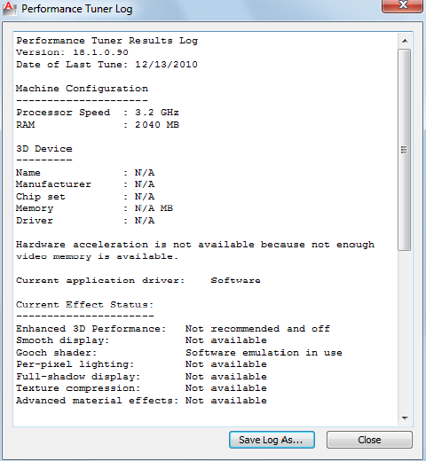
Remind Me When a New Driver Is Available
Specifies that a notification bubble is displayed when a new driver is available.
Performance Tuner Log
Quick Reference
See also:
■Control Performance
Lists the features that have been disabled, if any.
Summary
Information includes the system configuration, 3D graphics device, driver,
and if any features have been disabled. If your 3D device shows as certified,
Autodesk tested AutoCAD LT with this specific hardware.
Performance Tuner Log | 5
List of Options
The following options are displayed.
Save Log As
Displays a standard file selection dialog box.
-3DCONFIG
Quick Reference
See also:
■Performance Tuning
Controls Hardware Acceleration from the command line.
List of Prompts
The following prompts are displayed.
Enter option:[acceLeration on page 6/eXit] <acceleration>:
Acceleration
Specifies whether to use software or hardware acceleration.
Hardware Specifies hardware acceleration. The hardware graphics card
performs most of the drawing tasks to increase performance.
Software Specifies software acceleration. The software graphics system performs
all of the drawing tasks in 3D.
3DPOLY
Quick Reference
See also:
■Draw Polylines
Creates a 3D polyline.
6 | Chapter 1 3D Commands
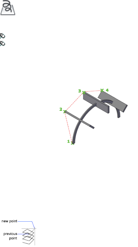
Access Methods
Button
Ribbon: Home tab ➤ Draw panel ➤ 3D Polyline.
Menu: Draw ➤ 3D Polyline
Summary
A 3D polyline is a connected sequence of straight line segments created as a
single object. 3D polylines can be non-coplanar; however, they cannot include
arc segments.
List of Prompts
The following prompts are displayed.
Specify start point of polyline: Specify a point (1)
Specify endpoint of line or [Undo]: Specify a point or enter an option
Specify endpoint of line or [Undo]: Specify a point or enter an option
Specify endpoint of line or [Close/Undo]: Specify a point or enter an option
Endpoint of Line Draws a straight line from the previous point to the specified
new point. The prompt is repeated until you press Enter to end the command.
Undo Deletes the last line created. You can continue drawing from the previous
point.
3DPOLY | 7
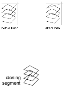
Close Draws a closing line from the endpoint back to the first point, and then
ends the command. To be closed, a 3D polyline must contain at least two
lines.
8 | Chapter 1 3D Commands

A Commands
ABOUT
Quick Reference
See also:
■Start a Drawing
Displays information about AutoCAD LT.
Access Methods
Menu: Help ➤ About
Command entry: 'about for transparent use
Summary
Copyright information and product information is displayed. Product
information includes the version number and service pack, serial number, license
type and expiration date, and the text of the license agreement. You can save
the product information as a text file.
2
9
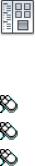
ADCCLOSE
Quick Reference
See also:
■Overview of DesignCenter
Closes DesignCenter.
Summary
Closes the DesignCenter™ window.
ADCENTER
Quick Reference
See also:
■Overview of DesignCenter
Manages and inserts content such as blocks, xrefs, and hatch patterns.
Access Methods
Button
Ribbon: Insert tab ➤ Content panel ➤ DesignCenter
Toolbar: Standard
Menu: Tools ➤ Palettes ➤ DesignCenter
Summary
The DesignCenter is displayed.
10 | Chapter 2 A Commands
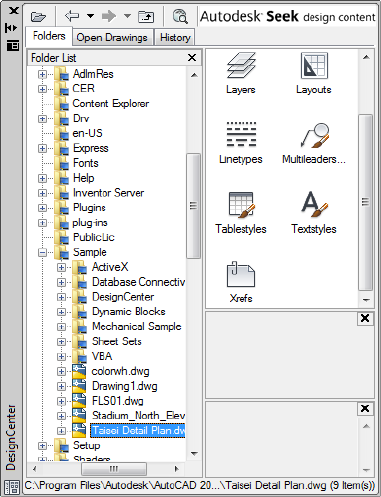
DesignCenter Window
Quick Reference
See also:
■Understand the DesignCenter Window
Browses, finds, and previews content, and inserts content, which includes
blocks, hatches, and external references (xrefs).
Summary
Use the buttons in the toolbar at the top of DesignCenter for display and
access options.
When you click the Folders tab or the Open Drawings tab, the following two
panes are displayed from which you can manage drawing content:
■Content area (right pane) on page 12
DesignCenter Window | 11

■Tree view (left pane) on page 14
NOTE The DesignCenter Online (DC Online tab) is disabled by default. You
can enable it from the CAD Manager Control utility.
List of Options
The following options are displayed.
Content Area (DesignCenter) Displays the content of the "container" currently
selected in the tree view. A container is a network, computer, disk, folder, file,
or web address (URL) containing information accessible by DesignCenter.
Depending on the container selected in tree view, the content area typically
displays the following:
■Folders containing drawings or other files
■Drawings
■Named objects contained in drawings (named objects include blocks, xrefs,
layouts, layers, dimension styles, table styles, multileader styles, and text
styles)
■Images or icons representing blocks or hatch patterns
■Web-based content
■Custom content developed by third-party applications
From the content area, you can insert blocks or hatch patterns or attach
external references in a drawing by dragging, by double-clicking, or by
right-clicking and choosing Insert Block, Attach Xref, or Copy. You can drag
or right-click to add other content to drawings, such as layers, dimension
styles, and layouts. You can drag blocks and hatches from DesignCenter to
tool palettes.
NOTE You can access relevant content area and tree view options on a shortcut
menu by right-clicking in the tree view or the content area.
Load Displays the Load dialog box (a standard file selection dialog box). Use
Load to navigate to files on local and network drives or on the Web, and then
to select content to load in the content area.
Back Returns to the most recent location in the history list.
Forward Returns to the next later location in the history list.
12 | Chapter 2 A Commands

Up Displays the contents of the container one level above the current
container.
Stop (DC Online tab) Stops the current transfer.
Reload (DC Online tab) Reloads the current page.
Search Displays the Search dialog box, where you can specify search criteria
to locate drawings, blocks, and nongraphical objects within drawings.
Favorites Displays the contents of the Favorites folder in the content area. The
Favorites folder contains shortcuts to items you access often. You can add items
to Favorites either by right-clicking the content area or right-clicking an item
in the tree view, and then clicking Add to Favorites. To delete an item from
Favorites, use the Organize Favorites option on the shortcut menu and then
use the Refresh option on the shortcut menu.
NOTE The DesignCenter folder is automatically added to Favorites. This folder
contains drawings with discipline-specific blocks that you can insert in drawings.
Home Returns DesignCenter to your home folder. On installation, the home
folder is set to ...\Sample\DesignCenter. Change the home folder using the
shortcut menu in the tree view.
Tree View Toggle Displays and hides the tree view. Hide the tree view if you
need more space in your drawing area. When the tree view is hidden, you can
use the content area to navigate to containers and to load content.
The Tree View Toggle button is not available while you're using the History
list in the tree view.
Preview Displays and hides a preview of the selected item in a pane below
the content area. If there is no preview image saved with the selected item,
the Preview area is empty.
Description Displays and hides a text description of the selected item in a
pane below the content area. If a preview image is also displayed, the
description is displayed below it. If there is no description saved with the
selected item, the Description area is empty.
Views
Provides different display formats for the content that is loaded in the content
area. You can select a view from the Views list or click the Views button
repeatedly to cycle through the display formats. The default view varies for
the type of content currently loaded in the content area.
Large Icon Displays the names of the loaded content in large icon format.
DesignCenter Window | 13

Small Icon Displays the names of the loaded content in small icon format.
List View Displays the names of the loaded content in a list.
Detail View Displays additional information about the loaded content. You
can sort the items by name, size, type, and other properties, depending on
the type of content that is loaded in the content area.
Refresh (Shortcut Menu Only) Refreshes the display in the content area to
reflect any changes you have made. Right-click the content area background
and click Refresh on the shortcut menu.
Autodesk Seek Design Content Opens a web browser and displays the
Autodesk Seek (SEEK on page 1106) home page. Product design information
available on Autodesk Seek depends on what content providers, both corporate
partners and individual contributors, publish to Autodesk Seek
(SHAREWITHSEEK on page 1118). Such content could include 3D models, 2D
drawings, specifications, brochures, or descriptions of products or components.
Tree View (DesignCenter)
Displays the hierarchy of files and folders on your computer and network
drives, a list of open drawings, and a history of the last locations you accessed.
Select an item in the tree view to display its contents in the content area.
NOTE In the sample\designcenter folder are drawings containing discipline-specific
blocks that you can insert in drawings. These drawings are called symbol library
drawings.
Use the buttons in the toolbar at the top of DesignCenter to access tree view
options.
Folders Displays the hierarchy of files and folders on your computer and
network drives, including My Computer and Network Neighborhood.
You can use ADCNAVIGATE to navigate to a specific file name, directory
location, or network path in the DesignCenter tree view. See ADCNAVIGATE
on page 18.
Open Drawings Displays all drawings open in the current work session,
including drawings that are minimized.
History Displays a list of the files that you opened most recently in
DesignCenter. With the history displayed, right-click a file to display
information about the file or to delete the file from the History list.
DC Online Accesses the DesignCenter Online web page. When you establish
a web connection, two panes are viewed on the Welcome page. The left side
displays folders containing symbol libraries, manufacturer sites, and additional
14 | Chapter 2 A Commands
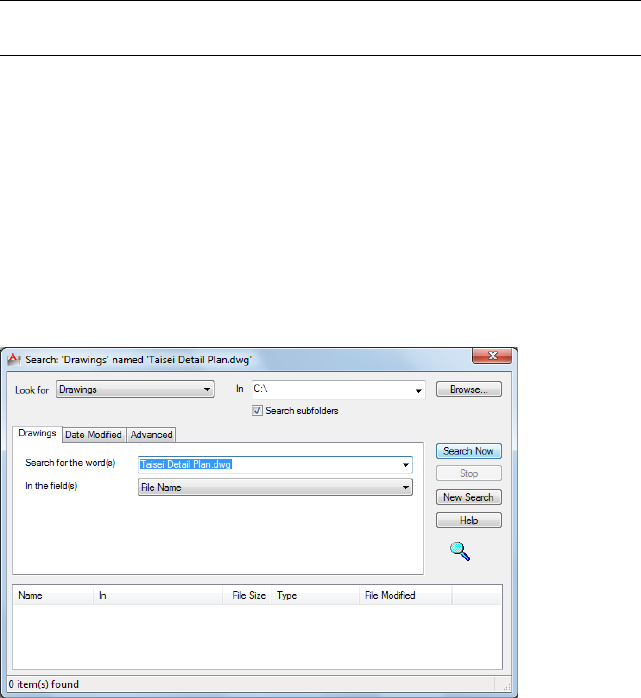
content libraries. When a symbol is selected, it is displayed on the right side
and can be downloaded into your drawing.
NOTE The DesignCenter Online (DC Online tab) is disabled by default. You can
enable it from the CAD Manager Control utility.
Search Dialog Box
Quick Reference
See also:
■Overview of DesignCenter
Searches for content such as drawings, hatch patterns, and blocks.
List of Options
The following options are displayed.
Look For
Specifies the type of content to search for. The content type you specify
determines which tabs are displayed in the Search dialog box and the search
fields it provides. The Date Modified and Advanced tabs are displayed only
when the Drawings option is selected in Look For.
In
Search Dialog Box | 15
Specifies a search path name. To enter multiple paths, separate them with
semicolons. Use Browse to select a path from a tree view list.
Browse
Displays a tree view in the Browse for Folder dialog box, in which you can
specify the drives and folders to search.
Search Subfolders
Includes subfolders in the search path.
Search Now
Starts the search based on criteria you specify.
Stop
Stops the search and displays the accumulated results in the Search Results
panel.
New Search
Clears the Search For the Word(s) box and places the cursor in the box.
Search Results Panel
Displays the results of the search in resizable columns at the bottom of the
window. Double-click an item to load it into DesignCenter.
Search Tabs (Search Dialog Box)
Display search fields relevant to the type of content specified in the Look For
list. The name of the tab reflects the content type. You can use wild-card
characters to extend or limit your search patterns.
Search for the Word(s)
Specifies the text string to look for in the field you specify. Use the asterisk
and question mark wild-card characters to broaden your search.
■* (Asterisk): Matches any string and can be used anywhere in the search
string.
■? (Question mark): Matches any single character; for example, ?BC matches
ABC, 3BC, and so on.
This option is available on the Drawings tab.
In the Field(s)
16 | Chapter 2 A Commands
Specifies the property fields to search. For drawings, all fields other than File
Name are derived from the information entered in the Drawing Properties
dialog box (DWGPROPS on page 451).
This option is available on the Drawings tab.
Search for the Name
Specifies the name of the drawing, block, layer, xref, or other content type
that you want to find.
This option is available on all tabs except Drawings.
Date Modified Tab (Search Dialog Box)
Finds content that was created or modified during a certain time period.
All Files Finds all the files that match the criteria you specify on other tabs,
regardless of creation date or date modified. This is the default setting.
Find All Files Created or Modified Finds files created or modified during a
specific time period. The search locates files that match the criteria you specify
on this and other tabs.
Between
Searches for files created or modified between the dates you specify.
During the Previous Month(s)
Searches for files created or modified within the number of months you specify.
During the Previous Day(s)
Searches for files created or modified within the number of days you specify.
Advanced Tab (Search Dialog Box)
Finds content within drawings; this tab is available only when you select
Drawings in Look For.
Containing
Specifies the type of text in a drawing that you want to search for. For example,
you can search for text contained within a block attribute, such as a
manufacturer's catalog number.
Containing Text
Specifies the text you want to search for.
Size Is
Search Dialog Box | 17
Specifies a minimum or maximum file size. Select At Least or At Most, and
enter a value in KB.
ADCNAVIGATE
Quick Reference
See also:
■Access Content with DesignCenter
Loads a specified DesignCenter drawing file, folder, or network path.
Summary
The path or drawing file name you specify is loaded in the tree view of the
DesignCenter Folders tab.
ADCNAVIGATE supports remote domains or workgroups if you have the target
domain or workgroup mapped to a drive letter.
List of Prompts
The following prompts are displayed.
Enter pathname <current>:
At the prompt, you can enter a path in any of the following formats:
■Folder path: c:\project files\electrical
■Folder path and a file name: c:\project files\electrical\circuit2.dwg
■UNC (universal naming convention) network path: \\server1\campus_project
DesignCenter is displayed, with the Folder tab active, and the path or drawing
file that you specified is loaded.
18 | Chapter 2 A Commands
ADDSELECTED
Quick Reference
See also:
■Copy, Array, Offset, or Mirror Objects
Creates a new object based on the object type and general properties of a
selected object.
Access Methods
Button
Toolbar: Draw
Shortcut menu: Select a single object, right-click, and click Add Selected.
Summary
Differs from COPY by duplicating only the general properties on page 1017 of
an object. For example, creating an object based on a selected circle adopts
the general properties of the circle, such as its color and layer, but prompts
you for the new circle’s center point and radius.
With the ADDSELECTED command, you can create a new object with the
same object type as a selected object. Certain objects have special properties
that are supported in addition to its general properties, as shown in the
following table.
Special properties supported by ADDSELEC-
TED
Object type
Gradient name, Color 1, Color 2, Gradient Angle,
Centered
Gradient
Text Style, HeightText, MText, Attribute
Definition
Dim Style, Dim ScaleDimensions (Linear,
Aligned, Radial, Diamet-
ADDSELECTED | 19
Special properties supported by ADDSELEC-
TED
Object type
ric, Angular, Arc Length,
and Ordinate)
Dim StyleTolerance
Dim Style, Dim ScaleLeader
Multileader Style, Overall ScaleMultileader
Table StyleTable
Pattern, Scale, RotationHatch
NameBlock Reference, External
Reference
NameUnderlays (DWF, DGN,
Image, and PDF)
List of Prompts
The following prompt is displayed.
Select object: Use an object selection method
The prompts vary by object type.
ADJUST
Quick Reference
See also:
■Adjust Underlay Contrast, Fade, Monochrome, and Colors for the
Background
Adjusts the fade, contrast and monochrome settings of the selected underlay
(DWF, DWFx, PDF, or DGN), or image.
20 | Chapter 2 A Commands

Access Methods
Button
Ribbon: Insert tab ➤ Reference panel ➤ Adjust
Summary
With the ADJUST command, you can control several display settings for
selected images and underlays (DWF, DWFx, PDF, and DGN underlays). To
confirm the settings, use the Properties palette.
List of Prompts
The following prompts are displayed.
The list of prompts depends on whether you select one or more images, or
one or more underlays.
Images
Fade Controls the fade effect in the image. Values range from 0 through 100.
The greater the value, the lighter that the image appears. This setting works
indirectly with the contrast effect; a higher contrast value blends the image
into the background when fade is set to a higher value.
Contrast Controls the contrast, and indirectly the fading effect in the image.
Values range from 0 through 100. The greater the value, the stronger the
contrast.
Brightness Controls the brightness, and indirectly, the contrast in the image.
Values range from 0 through 100. The greater the value, the brighter the image
and the more pixels that become white when you increase contrast.
Underlays
Fade Controls the fade effect in the underlay. Values range from 0 through
100. The greater the value, the lighter that the linework in the underlay
appears. This setting works indirectly with the contrast effect; a higher contrast
value blends the underlay into the background when fade is set to a higher
value.
Contrast Controls the contrast, and indirectly the fading effect in the underlay.
Values range from 0 through 100. The greater the value, the stronger the
contrast.
ADJUST | 21
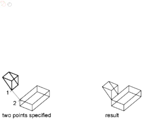
Monochrome Controls the color saturation of all areas while maintaining
the luminance. When turned on, the underlay appears in shades of gray
starting at black if the background color luminance is 50 percent or more. If
the background color luminance is less than 50 percent, then the colors are
inverted, with the darkest areas displaying as white, and the lightest areas
displaying as black.
ALIGN
Quick Reference
See also:
■Align Objects
Aligns objects with other objects in 2D and 3D.
Summary
Either one, two, or three pairs of source points and definition points can be
specified to move, rotate, or tilt the selected objects, aligning them with points
on another object.
List of Prompts
The following prompts are displayed.
Select objects: Select the objects to align and press Enter
ALIGN Using One Pair of Points When you select only one source point and
destination point pair, the selected objects move in 2D or 3D from the source
point (1) to the destination point (2).
22 | Chapter 2 A Commands
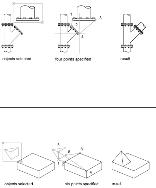
ALIGN Using Two Pairs of Points When you select two point pairs, you can
move, rotate, and scale the selected objects in 2D or 3D to align with other
objects.
The first set of source and destination points defines the base point for the
alignment (1, 2). The second set of points defines the angle of rotation (3, 4).
After you enter the second set of points, you are prompted to scale the object.
The distance between the first and second destination points (2, 4) is used as
the reference length to which the object is scaled. Scaling is available only
when you are aligning objects using two point pairs.
NOTE If you use two source and destination points to perform a 3D alignment
on nonperpendicular working planes, you get unpredictable results.
ALIGN Using Three Pairs of Points When you select three point pairs, you
can move and rotate the selected objects in 3D to align with other objects.
The selected objects move from the source point (1) to the destination point
(2).
The selected object is rotated (1 and 3) so that it aligns with the destination
object (2 and 4).
ALIGN | 23
The selected object is then rotated again (3 and 5) so that it aligns with the
destination object (4 and 6).
ANNORESET
Quick Reference
See also:
■Add and Modify Scale Representations
Resets the locations of all alternate scale representations of the selected
annotative objects.
Access Methods
Button
Ribbon: Annotate tab ➤ Annotation Scaling panel ➤ Sync Scale Positions
Menu: Modify ➤ Annotative Object Scale ➤ Synchronize Multiple-Scale
Positions
Shortcut menu: Select an annotative object. Right-click and choose
Annotative Object Scale ➤ Synchronize Multiple-Scale Positions.
Summary
The location of each scale representation of an annotative object can be
adjusted using grips. For each selected annotative object, all alternate scale
representations are returned to the location of the object’s current scale
representation.
24 | Chapter 2 A Commands

ANNOUPDATE
Quick Reference
See also:
■Work with Annotative Styles
Updates existing annotative objects to match the current properties of their
styles.
Summary
When a non-annotative text object is updated to an annotative text style, the
object becomes annotative and supports the current annotation scale. If the
text style has a fixed Paper Height, the object is set to that height. If the text
style’s Paper Height is set to 0, the size of the text does not change. The Paper
Height value is inferred by dividing the model height by the current annotation
scale.
If an annotative object is updated to a non-annotative style, the object becomes
non-annotative and any alternate scale representations are removed.
APERTURE
Quick Reference
See also:
■Use Object Snaps
Controls the size of the object snap target box.
Access Methods
Command entry: aperture (or 'aperture for transparent use)
Summary
Object snap applies only to objects inside or crossing the object snap target
box. The APBOX on page 1383 system variable controls whether the object snap
target box is displayed. The number of pixels you enter using APERTURE
ANNOUPDATE | 25

controls the size of the object snap box. The higher the number, the larger
the target box.
You can also change this setting in the Options dialog box, Drafting tab.
APERTURE controls the object snap target box, not the pickbox displayed at
the Select Objects prompt. The object selection pickbox is controlled by the
PICKBOX on page 1611 system variable.
ARC
Quick Reference
See also:
■Draw Arcs
Creates an arc.
Access Methods
Button
Ribbon: Home tab ➤ Draw panel ➤ Arc drop-down ➤ 3-Point
Menu: Draw ➤ Arc
Toolbar: Draw
Summary
To create an arc, you can specify combinations of center, endpoint, start point,
radius, angle, chord length, and direction values.
List of Prompts
The following prompts are displayed.
Specify start pointof arc or [Center]: Specify a point, enter c, or press ENTER to
start tangent to last line, arc, or polyline
26 | Chapter 2 A Commands
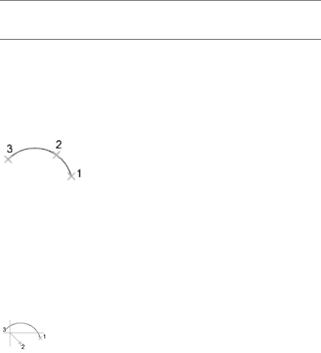
Start Point
Specifies the starting point of the arc.
NOTE If you press ENTER without specifying a point, the endpoint of the last
drawn line or arc is used and you are immediately prompted to specify the endpoint
of the new arc. This creates an arc tangent to the last drawn line, arc, or polyline.
Specify second point of arc or [Center/End]:
Second Point
Draws an arc using three specified points on the arc's circumference. The first
point is the start point (1). The third point is the endpoint (3). The second
point (2) is a point on the circumference of the arc.
Specify end point of arc: Specify a point (3)
You can specify a three-point arc either clockwise or counterclockwise.
Center
Specifies the center of the circle of which the arc is a part.
Specify center point of arc:
Specify end point of arc or [Angle/chord Length]:
End Point Using the center point (2), draws an arc counterclockwise from
the start point (1) to an endpoint that falls on an imaginary ray drawn from
the center point through the third point (3).
The arc does not necessarily pass through this third point, as shown in the
illustration.
Angle Draws an arc counterclockwise from the start point (1) using a center
point (2) with a specified included angle. If the angle is negative, a clockwise
arc is drawn.
Specify included angle: Specify an angle
ARC | 27
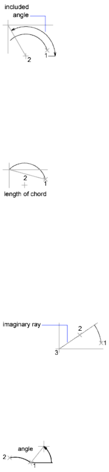
Chord Length Draws either a minor or a major arc based on the distance of
a straight line between the start point and endpoint.
If the chord length is positive, the minor arc is drawn counterclockwise from
the start point. If the chord length is negative, the major arc is drawn
counterclockwise.
Specify length of chord: Specify a length
End
Specifies the endpoint of the arc.
Specify end point of arc:
Specify center point of arc or [Angle/Direction/Radius]:
Center Point Draws an arc counterclockwise from the start point (1) to an
endpoint that falls on an imaginary ray drawn from the center point (3)
through the second point specified (2).
Angle Draws an arc counterclockwise from the start point (1) to an endpoint
(2), with a specified included angle. If the angle is negative, a clockwise arc is
drawn.
Specify included angle: Enter an angle in degrees or specify an angle by moving the
pointing device counterclockwise
Direction Begins the arc tangent to a specified direction. It creates any arc,
major or minor, clockwise or counterclockwise, beginning with the start point
28 | Chapter 2 A Commands
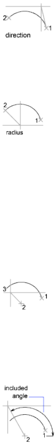
(1), and ending at an endpoint (2). The direction is determined from the start
point.
Specify tangent direction for the start point of arc:
Radius Draws the minor arc counterclockwise from the start point (1) to the
endpoint (2). If the radius is negative, the major arc is drawn.
Specify radius of arc:
Center
Specifies the center of the circle of which the arc is a part.
Specify center point of arc:
Specify start point of arc:
Specify end point of arc or [Angle/chord Length]:
End Point Draws an arc counterclockwise from the start point (2) to an
endpoint that falls on an imaginary ray drawn from the center point (1)
through a specified point (3).
Angle Draws an arc counterclockwise from the start point (2) using a center
point (1) with a specified included angle. If the angle is negative, a clockwise
arc is drawn.
Specify included angle:
ARC | 29
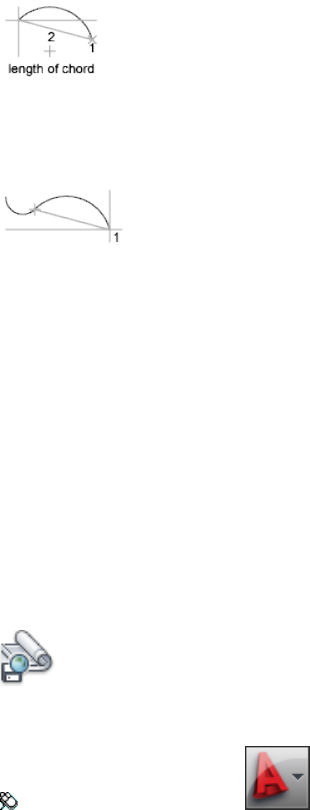
Chord Length Draws either a minor or a major arc based on the distance of
a straight line between the start point and endpoint.
If the chord length is positive, the minor arc is drawn counterclockwise from
the start point. If the chord length is negative, the major arc is drawn
counterclockwise.
Specify length of chord:
Tangent to Last Line, Arc, or Polyline
Draws an arc tangent to the last line, arc, or polyline drawn when you press
ENTER at the first prompt.
Specify end point of arc: Specify a point (1)
ARCHIVE
Quick Reference
See also:
■Publish, Transmit, and Archive Sheet Sets
Packages the current sheet set files for archive.
Access Methods
Button
Menu: Application menu ➤ Publish ➤ Archive
30 | Chapter 2 A Commands

Summary
The Archive a Sheet Set dialog box is displayed.
If you enter -archive at the Command prompt, options are displayed.
Archive a Sheet Set Dialog Box
Quick Reference
See also:
■Publish, Transmit, and Archive Sheet Sets
Packages the current sheet set files for archive.
Summary
The Sheets tab lists the sheets to be included in the archive package in sheet
order and according to subset organization. The Files Tree tab lists the files to
be included in the package in a hierarchical tree format. The Files Table tab
displays the files to be included in the package in a table format.
All files to be included in the archive package are indicated by a check mark
next to the file name. To remove a file from the archive package, select the
check box. Right-click in the file display area to display a shortcut menu, from
which you can clear all check marks or apply check marks to all files.
NOTE Make sure that the files to be archived are not currently open in any
application.
List of Options
The following options are displayed.
Sheets Tab
Lists the sheets to be included in the archive package in sheet order and
according to subset organization. A sheet set must be open in the Sheet Set
Manager. Archive can be selected from the shortcut menu displayed when
the top-level sheet set node is right-clicked, or archive can be entered at the
Command prompt.
Archive a Sheet Set Dialog Box | 31
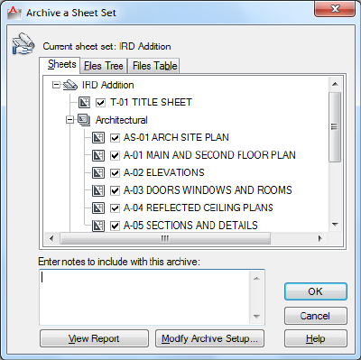
Files Tree Tab
Lists the files to be included in the archive package in a hierarchical tree
format. By default, all files associated with the current drawing (such as related
xrefs, plot styles, and fonts) are listed. You can add files to the archive package
or remove existing files. Related files that are referenced by URLs are not
included in the archive package.
Included
Reports the number of files included in the package and the size of the package.
32 | Chapter 2 A Commands
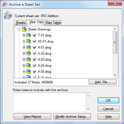
Files Table Tab
Displays the files to be included in the archive package in a table format. By
default, all files associated with the current drawing (such as related xrefs, plot
styles, and fonts) are listed. You can add files to the archive package or remove
existing files. Related files that are referenced by URLs are not included in the
archive package.
■Included on page 32
Archive a Sheet Set Dialog Box | 33
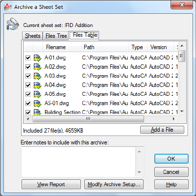
Add a File
Opens a standard file selection dialog box, in which you can select an
additional file to include in the archive package. This button is available on
both the Files Tree tab and the Files Table tab.
Enter Notes to Be Included with This Archive
Provides a space where you can enter notes related to the archive package.
The notes are included in the archive report. You can specify a template of
default notes to be included with all your archive packages by creating an
ASCII text file called archive.txt. This file must be saved to a location specified
by the Support File Search Path option on the Files tab in the Options dialog
box.
View Report
Displays report information that is included with the archive package. Includes
any archive notes that you entered. If you have created a text file of default
notes, the notes are also included in the report.
Save As Opens a File Save dialog box, in which you can specify a location in
which to save a report file. Note that a report file is automatically included
with all archive packages that you generate; by choosing Save As, you can
save an additional copy of a report file for reference purposes.
Modify Archive Setup
Displays the Modify Archive Setup dialog box, in which you can specify options
for the archive package.
34 | Chapter 2 A Commands
Modify Archive Setup Dialog Box
Quick Reference
See also:
■Publish, Transmit, and Archive Sheet Sets
List of Options
The following options are displayed.
Archive Type and Location
Specifies the type and location of archive package created.
Archive Package Type
Specifies the type of archive package created.
DescriptionArchive Package Type
Creates an archive package of uncom-
pressed files in a new or existing folder.
Folder
Creates an archive package of files as a
compressed, self-extracting executable file.
Self-Extracting Executable
Double-clicking the resulting EXE file de-
compresses the archive package and re-
stores the files.
Creates an archive package of files as a
compressed ZIP file. To restore the files,
Zip
you need a decompression utility such as
the shareware application PKZIP or WinZip.
File Format
Specifies the file format to which all drawings included in the archive package
will be converted. You can select a drawing file format from the drop-down
list.
Archive File Folder
Modify Archive Setup Dialog Box | 35

Specifies the location in which the archive package is created. Lists the last
nine locations in which archive packages were created. To specify a new
location, click Browse and navigate to the location you want.
If this field is left blank, the archive file is created in the folder containing the
sheet set data (DST) file.
Archive File Name
Specifies the method for naming the archive package. Displays the default file
name for the archive package. This option is not available if the archive
package type is set to Folder.
DescriptionArchive File Name Type
Displays a standard file selection dialog box
where you can enter the name of the
archive package.
Prompt for a File Name
Uses a logical default file name. If the file
name already exists, the existing file is
automatically overwritten.
Overwrite if Necessary
Uses a logical default file name. If the file
name already exists, a number is added to
Increment File Name if Ne-
cessary
the end. This number is incremented each
time a new archive package is saved.
Path Options
Provides options for the archive.
Use Organized Folder Structure
Duplicates the folder structure for the files being transmitted. The root folder
is the top-level folder within a hierarchical folder tree.
The following considerations apply:
■Relative paths remain unchanged. Relative paths outside the source root
folder retain up to one level of the folder path above them, and are placed
in the root folder.
■Absolute paths within the root folder tree are converted to relative paths.
Absolute paths retain up to one level of the folder path above them, and
are placed in the root folder.
36 | Chapter 2 A Commands
■Absolute paths outside the root folder tree are converted to No Path and
are moved to the root folder or to a folder within the root folder tree.
■A Fonts folder is created, if necessary.
■A PlotCfgs folder is created, if necessary.
■A SheetSets folder is created to hold all support files for sheet sets, if
necessary. The sheet set data (DST) file, however, is placed in the root
folder.
This option is not available if you're saving an archive package to an Internet
location.
Source Root Folder
Defines the source root folder for relative paths of drawing-dependent files,
such as xrefs. This option determines the source root folder for the Use
Organized Folder Structure option.
The source root folder also contains the sheet set data (DST) file when a sheet
set is archived.
Place All Files in One Folder
All files are installed to a single, specified target folder when the archive
package is created.
Keep Files and Folders As Is
Preserves the folder structure of all files in the archive package. This option is
not available if you're saving an archive package to an Internet location.
Actions
Specifies the actions applicable to the archive package.
Set Default Plotter to 'None'
Changes the printer/plotter setting in the archive package to None.
Prompt for Password
Opens the Archive—Set Password dialog box, where you can specify a password
for your archive package.
Purge Drawings
Does a complete purge of all the drawings in the archive.
Modify Archive Setup Dialog Box | 37

NOTE As the purge is done in silent mode, you will not receive any notifications
when the drawings have been removed.
Include Options
Specifies the various options available with the archive package.
Include Fonts
Includes any associated font files (TXT and SHX) with the archive package.
Include Files from Data Links
Adds external files referenced by a data link to the transmittal package.
Include Textures from Materials
Includes textures with materials that are attached to objects or faces.
Include Photometric Web Files
Includes photometric web files that are associated with web lights in the
drawing.
Include Unloaded File References
Includes all unloaded external file references. The unloaded file references are
listed in the Files Tree and Files Table and report under their appropriate
category.
Include Sheet Set Data and Files
Includes the sheet set data (DST) file, label block drawing files, callout block
drawing files, and drawing template (DWT) files with the archive package.
Archive - Set Password Dialog Box
Quick Reference
See also:
■Publish, Transmit, and Archive Sheet Sets
List of Options
The following options are displayed.
38 | Chapter 2 A Commands
Password for Compressed Archive Package
Provides a space for an optional password for the archive package. When
others attempt to open the archive package, they must provide this password
to access the files. Password protection cannot be applied to folder archive
packages.
Password Confirmation
Provides a space to confirm the password that you entered in the Password
field. If the two passwords do not match, you are prompted to reenter them.
-ARCHIVE
Quick Reference
See also:
■Publish, Transmit, and Archive Sheet Sets
List of Prompts
The following prompts are displayed.
Sheet Set name or [?] <current>: Enter a predefined sheet set name, enter ? to display
a list of sheet sets, or press ENTER
Sheet Set Name
Specifies a sheet set to use for the archive package. This option is available
only when a sheet set is open.
Create Archive Package Creates the archive package from the specified sheet
set.
Report Only Opens a File Save dialog box, in which you can specify a location
in which to save a report file. Note that a report file is automatically included
with all archive packages that you generate; by choosing Save As, you can
save an additional copy of a report file for reference purposes.
Password You are only prompted for a password if you selected Prompt for
Password in the archive setup.
-ARCHIVE | 39
AREA
Quick Reference
See also:
■Obtain Area and Mass Properties Information
Calculates the area and perimeter of objects or of defined areas.
Summary
Several commands are available to provide area information including AREA,
MEASUREGEOM on page 736, and MASSPROP on page 725. Alternatively, use
BOUNDARY on page 151 to create a closed polyline or region. Then use LIST
on page 710 or the Properties palette on page 1015 to find the area.
List of Prompts
The following prompts are displayed.
Specify first corner point on page 40 or [Object on page 41/Add Area on page
41/Subtract Area on page 42] <Object>: Select an option
The area and perimeter of the specified object displays at the Command prompt
and in the tooltip.
Specify Corner Points
Calculates the area and perimeter defined by specified points. All points must
lie in a plane parallel to the XY plane of the current user coordinate system
(UCS).
A rubberband line from the first specified point to the cursor is displayed.
Once the second point is specified, a line segment and a polygon with green
fill are displayed.
Continue to specify points to define a polygon and then press ENTER to
complete the definition of the perimeter. The area to be calculated is
highlighted in green.
If you do not close the polygon, the area is calculated as if a line were drawn
from the last point entered to the first. When the perimeter is calculated, that
line length is added.
40 | Chapter 2 A Commands
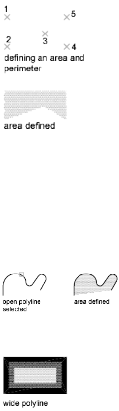
Object
Calculates the area and perimeter of a selected object. You can calculate the
area of circles, ellipses, splines, polylines, polygons, regions, and solids.
Select object:
If you select an open polyline, the area is calculated as if a line were drawn
from the last point entered to the first. When the perimeter is calculated that
line length is ignored.
The centerline of a wide polyline is used to make area and perimeter
calculations.
The centerline of a wide polyline is used to make area and perimeter (or length)
calculations.
Add Area
Turns on Add mode and keeps a running balance of the total area as you
continue to define areas. You can use the Add Area option to calculate
individual areas and perimeters of defined areas and objects and the total area
of all defined areas and objects.
AREA | 41
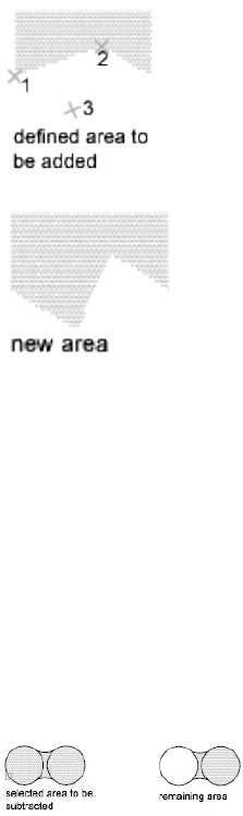
You can also select to specify the points. A rubberband line from the first
specified point to the cursor is displayed
Specify points to define a polygon (3). The area to be added is highlighted in
green. Press ENTER. AREA calculates the area and perimeter and returns the
total area of all the areas defined by selecting points or objects since Add mode
was turned on.
If you do not close the polygon, the area is calculated as if a line were drawn
from the last point entered to the first. When the perimeter is calculated, that
line length is added.
Subtract Area
Similar to the Add Area option, but subtracts areas and perimeters. You can
use the Subtract Area option to subtract a specified area from a total area.
You can also specify the area to be subtracted with points. A rubberband line
from the first specified point to the cursor is displayed.
The specified area to be subracted is highlighted in red.
The total area and perimeter displays at the Command prompt and in the
tooltip.
42 | Chapter 2 A Commands
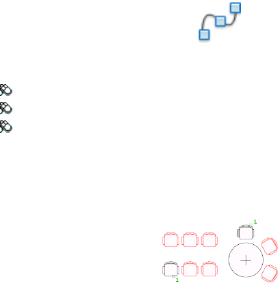
ARRAY
Quick Reference
See also:
■Array Objects
Creates copies of objects arranged in a 2D or 3D pattern.
Access Methods
Button
Ribbon: Home tab ➤ Modify panel ➤ Array.
Toolbar: Modify
Menu: Modify ➤ Array.
Summary
You can create copies of objects in a regularly spaced rectangular, polar, or
path array.
The DELOBJ on page 1433 system variable controls whether the source objects
of the array are deleted or retained after the array is created.
If you enter -array at the Command prompt, options are displayed.
List of Prompts
The following prompts are displayed.
Select objects: Use an object selection method
Enter array type [Rectangular on page 44/PAth on page 44/POlar on page 44]
<Rectangular>: Enter an option or press Enter
ARRAY | 43
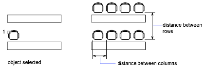
Rectangular (ARRAYRECT on page 60) Distributes object copies into any
combination of rows, columns, and levels.
Path (ARRAYPATH on page 53) Evenly distributes object copies along a path
or a portion of a path.
Polar (ARRAYPOLAR on page 57) Evenly distributes object copies in a circular
pattern around a center point or axis of rotation.
-ARRAY
Quick Reference
See also:
■Array Objects
Maintains legacy command line behavior for creating nonassociative, 2D
rectangular or polar arrays.
List of Prompts
The following prompts are displayed.
Select objects: Use an object selection method
Enter the type of array [Rectangular/Polar] <current>: Enter an option or press
ENTER
Rectangular
Creates an array of rows and columns of copies of the selected objects.
Enter the number of rows (---) <1>:Enter a nonzero integer or press ENTER
Enter the number of columns (|||) <1>:Enter a nonzero integer or press ENTER
If you specify one row, you must specify more than one column and vice
versa.
44 | Chapter 2 A Commands
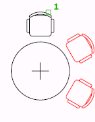
The selected object, or cornerstone element, is assumed to be in the lower-left
corner, and generates the array up and to the right.
The specified distance between the rows and columns includes the
corresponding lengths of the object to be arrayed.
Enter the distance between rows or specify unit cell (---):
To add rows downward, specify a negative value for the distance between
rows. ARRAY skips the next prompt if you specify two points for the opposite
corners of a rectangle.
Specify the distance between columns (|||):
To add columns to the left, specify a negative value for the distance between
columns. Rectangular arrays are constructed along a baseline defined by the
current snap rotation. This angle is normally 0, so the rows and columns are
orthogonal with respect to the X and Y drawing axes. The Rotate option of
the SNAP on page 1158 command changes the angle and creates a rotated array.
The SNAPANG on page 1660 system variable stores the snap rotation angle.
If you specify a large number of rows and columns for the array, it might take
a while to create the copies. By default, the maximum number of array
elements that you can generate in one command is 100,000. You can change
the maximum number of array elements by setting the MaxArray system
registry variable using the SETENV command.
Polar
Creates an array by copying the selected objects around a specified center
point.
Specify center point of array or [Base]: Specify a point or enter b to specify a new
base point
Center Point Creates an array defined by a center point.
-ARRAY | 45
Base Specifies a new reference (base) point relative to the selected objects that
will remain at a constant distance from the center point of the array as the
objects are arrayed.
Enter the number of items in the array: Enter a positive integer or press ENTER
If you enter a value for the number of items, you must specify either the angle
to fill or the angle between items. If you press ENTER (and do not provide the
number of items), you must specify both.
Specify the angle to fill (+=ccw, -=cw) <360>: Enter a positive integer for a
counterclockwise rotation or a negative integer for a clockwise rotation
You can enter 0 for the angle to fill only if you specify the number of items.
If you specify an angle to fill without providing the number of items, or if
you specify the number of items and enter 0 as the angle to fill or press ENTER,
the following prompt is displayed:
Angle between items: Specify an angle
If you specified the number of items and entered 0 as the angle to fill or pressed
ENTER, ARRAY prompts for a positive or negative value to indicate the
direction of the array:
Angle between items (+=ccw, -=cw): Enter a positive integer for a counterclockwise
rotation or a negative integer for a clockwise rotation
ARRAY determines the distance from the array's center point to a reference
point on the last object selected. The reference point used is the center point
of a circle or arc, the insertion base point of a block, the start point of text,
and one endpoint of a line.
Rotate arrayed objects? <Y>: Enter y or n, or press ENTER
In a polar array, the reference point of the last object in the selection set is
used for all objects. If you defined the selection set by using window or crossing
selection, the last object in the selection set is arbitrary. Removing an object
from the selection set and adding it back forces that object to be the last object
selected. You can also make the selection set into a block and replicate it.
46 | Chapter 2 A Commands
ARRAYCLOSE
Quick Reference
See also:
■Array Objects
Saves or discards changes made to an array’s source objects and exits the array
editing state.
Access Methods
Panel
Ribbon: <current tab> ➤ Edit Array contextual panel
Summary
The Soure option of ARRAYEDIT on page 48 activates an editing state in which
you can edit the source objects of a selected array item. While the editing state
is active, an Edit Array contextual tab is displayed on the ribbon. Save or
discard changes to exit the editing state.
List of Prompts
The following prompts are displayed.
Save changes to array [Yes on page 47/No on page 48] <Yes>: Enter an option
Save Changes
Button
<current tab> ➤ Edit Array contextual panel ➤ Save Changes
Saves all changes made to the source object or to a replacement item of the
array.
ARRAYCLOSE | 47
Discard Changes
Button
<current tab> ➤ Edit Array contextual panel ➤ Discard Changes
Discards any changes made; the source object or replacement item in the array
is returned to its original state.
ARRAYEDIT
Quick Reference
See also:
■Edit Associative Arrays
Edits associative array objects and their source objects.
Access Methods
Button
Ribbon: Home tab ➤ Modify panel ➤ Edit Array
Toolbar: Modify II
Summary
Modify associative arrays by editing the array properties, editing source objects,
or replacing items with other objects.
When you edit source objects, an editing state is activated. Save or discard
changes (ARRAYCLOSE on page 47) to exit the editing state.
When you select and edit a single array object, the Array Editor ribbon
contextual tab on page 51 is displayed. The array properties available on the
Array Editor ribbon contextual tab depend on the type of the selected array.
48 | Chapter 2 A Commands
List of Prompts
The following prompt is displayed.
Select array: Use an object selection method
The array type determines the remainig prompts.
For rectangular arrays:
Enter an option [Source on page 49/REPlace on page 49/Base point on page
50/Rows on page 50/Columns on page 50/Levels on page 50/RESet on page
51/eXit on page 51] <eXit>:
For path arrays:
Enter an option [Source/REPlace/Method on page 50/Base point/Items on
page 50/Rows/Levels/Align items on page 51/Z direction on page
51/RESet/eXit] <eXit>:
For polar arrays:
Enter an option [Source/REPlace/Base point/Items/Angle between on page
51/Fill angle on page 51/Rows/Levels/ROTate items on page 51/RESet/eXit]
<eXit>:
Source
Activates an editing state in which you can edit the source objects (or
replacement source objects) for a selected item.
All changes (including the creation of new objects) are instantly applied to
all items that reference the same source objects.
While the editing state is active, an Edit Array contextual tab is displayed on
the ribbon and automatic saving is disabled. Save or discard changes
(ARRAYCLOSE on page 47) to exit the editing state.
When the source objects are modified, the changes are dynamically reflected
on the array block.
Replace
Replaces the source objects for selected items or for all items referencing the
original source objects.
Replacement Objects Selects the new source objects.
Base Point Specifies a base point for the replacement objects.
ARRAYEDIT | 49
Item in Array Selects the item whose source objects are to be replaced, and
continues to prompt for additional items.
■Source objects. Replaces the original set of source objects in the array,
which updates all items that have not been previously replaced.
Base Point
Redefines the base point of the array.
Path arrays are repositioned relative to the new base point.
Rows
Specifies the number and spacing of rows, and the incremental elevation
between them.
Expression Derives a value using a mathematical formula or equation.
Total Specifies the total distance between the first and last rows.
Columns (Rectangular Arrays)
Specifies the number and spacing of columns.
Expression on page 50
Total Specifies the total distance between the first and last columns.
Levels
Specifies the number and spacing of levels.
Expression on page 50
Total Specifies the total distance between the first and last levels.
Method (Path Arrays)
Controls how to distribute items when the path or number of items is edited.
■Divide. Redistributes items to divide evenly along the length of the path.
■Measure. Maintains current spacing when the path is edited, or when the
number of items is edited through grips or the Properties palette. When
the number of items is edited using ARRAYEDIT, you are prompted to
redefine the distribution method.
Items (Path and Polar Arrays)
Specifies the number of items in the array.
For path arrays whose Method property is set to Measure, you are prompted
to redefine the distribution method. The same prompts are available from
ARRAYPATH on page 53.
50 | Chapter 2 A Commands

Align Items (Path Arrays)
Specifies whether to align each item to be tangent to the path direction.
Alignment is relative to the orientation of the first item (ARRAYPATH,
Orientation option).
Z Direction (Path Arrays)
Controls whether to maintain the original Z direction of the items or to
naturally bank the items along a 3D path.
Angle Between (Polar Arrays)
Specifies the angle between items.
Expression on page 50
Fill Angle (Polar Arrays)
Specifies the angle between the first and last item in the array.
Expression on page 50
Rotate Items (Polar Arrays)
Controls whether items are rotated as they are arrayed.
Reset
Restores erased items and removes any item overrides.
Exit
Exits the command.
Array Editor Ribbon Contextual Tab
Quick Reference
See also:
■Edit Associative Arrays
Edits associative array objects and their source objects.
Access Methods
Button
Array Editor Ribbon Contextual Tab | 51

Ribbon: Home tab ➤ Modify panel ➤ Edit Array
Toolbar: Modify II
List of Options
The following options are displayed.
Columns Panel (Rectangular Arrays)
Column Count Specifies the number of columns.
Column Spacing Specifies the spacing of columns.
Total Column Distance Specifies the total distance between the first and last
columns.
Items Panel (Path and Polar Arrays)
Item Count Specifies the number of items.
Item Spacing Specifies the spacing of items.
Total Item Distance Specifies the total distance between the first and last
items.
Rows Panel
Row Count Specifies the number of rows.
Row Spacing Specifies the spacing of rows.
Total Row Distance Specifies the total distance between the first and last
rows.
Incremental Elevation Specifies the incremental elevation between rows.
Levels Panel
Level Count Specifies the number of levels.
Level Spacing Specifies the spacing of levels.
Total Level Distance Specifies the total distance between the first and last
levels.
Properties Panel
Base Point Redefines the base point of the array.
Path arrays are repositioned relative to the new base point.
Measure (Path Arrays) Maintains current item spacing when the path is
edited, or when the number of items is edited through grips, or the Properties
palette.
52 | Chapter 2 A Commands
Divide (Path Arrays) Redistributes items to divide evenly along the length
of the path.
Align Items (Path Arrays) Controls the whether to maintain the starting
orientation or continue reorienting items along the path, relative to the starting
orientation.
Z Direction (Path Arrays) Controls whether to maintain the original Z
direction of the items or to naturally bank the items along a 3D path.
Rotate Items (Polar Arrays) Controls whether items are rotated as they are
arrayed.
Options Panel
Edit Source Activates an editing state in which you can edit the source objects
(or replacement source objects) for a selected item.
Replace Item Replaces the source objects for selected items or for all items
referencing the original source objects.
Reset Array Restores erased items and removes any item overrides.
ARRAYPATH
Quick Reference
See also:
■Create Path Arrays
Evenly distributes object copies along a path or a portion of a path.
Access Methods
Button
Ribbon: Home tab ➤ Modify panel ➤ Array dropdown ➤ Path Array
Menu: Modify ➤ Array ➤ Path Array
Toolbar: Modify
ARRAYPATH | 53

Summary
This command is equivalent to the Path option in ARRAY on page 43.
The path can be a line, polyline, 3D polyline, spline, helix, arc, circle, or ellipse.
List of Prompts
The following prompts are displayed.
Select objects: Use an object selection method
Select path curve on page 54: Use an object selection method
Enter number of items on page 54 along path or [Orientation on page
54/Expression on page 55] <Orientation>: Specify the number of items or enter
an option
Specify base point on page 55 or [Key point on page 55] <end of path curve>:
Specify a base point or enter an option
Specify direction to align with path or [2Points/Normal] <current>: Press Enter
or select and option
Specify the distance between items on page 55 along path or [Divide on page
56/Total on page 56/Expression on page 55] <Divide evenly along path>:
Specify a distance or enter an option
Press Enter to accept or [ASsociative on page 56/Base point/Items on page
56/Rows on page 56/Levels on page 56/Align items on page 56/Z direction
on page 57/eXit on page 57]<eXit>: Press Enter or select an option
Path Curve
Specifies the object to use for the path of the array. Select a line, polyline, 3D
polyline, spline, helix, arc, circle, or ellipse.
Number of Items
Specifies the number of items in the array.
Orientation Controls whether the selected objects are reoriented (rotated)
relative to the starting direction of the path before being moved to the start
point of the path.
■2 Points. Specifies two points to define the direction to be aligned with
the starting direction of the path.
54 | Chapter 2 A Commands
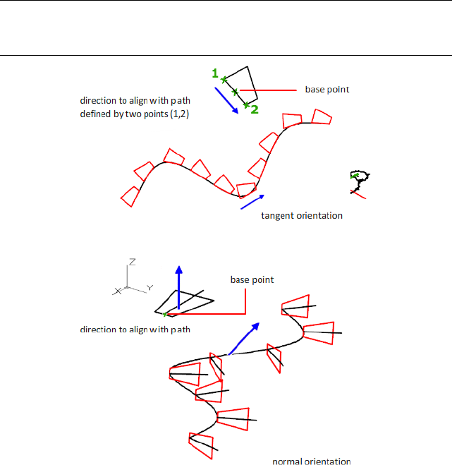
■Normal. Objects are aligned to be normal to the starting direction of the
path.
NOTE The Align Items on page 56 option controls the whether to maintain the
starting orientation or continue reorienting items along the path, relative to the
starting orientation.
Expression Derives a value using a mathematical formula or equation.
Base Point
Specifies a base point for the array.
Key Point For associative arrays, specifies a valid constraint point (or key point)
on the source objects to use as the base point. If you edit the source objects
of the resulting array, the base point of the array remains coincident with the
key point of the source objects.
Distance Between Items
Specifies the distance between items.
ARRAYPATH | 55
Divide Divides items evenly along the entire length of the path.
Total Specifies the total distance between the first and last items.
Expression on page 55
Associative
Specifies whether to create items in the array as an associative array object,
or as independent objects.
■Yes. Contains array items in a single array object, similar to a block. This
allows you to quickly propagate changes by editing the properties and
source objects of the array.
■No. Creates array items as independent objects. Changes to one item do
not affect the other items.
Items
Edits the number of items in the array.
If the Method property is set to Measure, you are prompted to redefine the
distribution method (Distance Between Items on page 55, Divide on page 56,
and Total on page 56 options).
Rows
Specifies the number and spacing of rows in the array, and the incremental
elevation between them.
Expression on page 55
Total Specifies the total distance between the first and last rows.
Levels
Specifies the number and spacing of levels in the array.
Expression on page 55
Total Specifies the total distance between the first and last levels.
Align Items
Specifies whether to align each item to be tangent to the path direction.
Alignment is relative to the first item’s orientation (Orientation on page 54
option).
56 | Chapter 2 A Commands
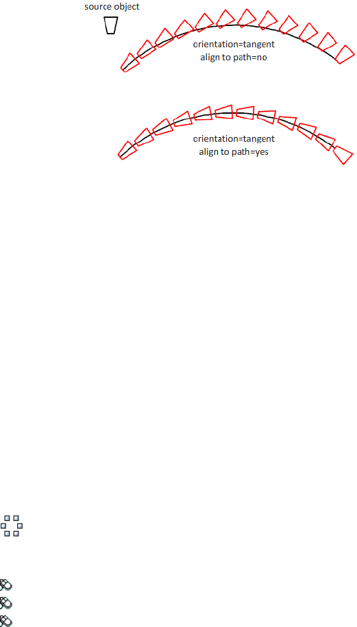
Z Direction
Controls whether to maintain the items’ original Z direction or to naturally
bank the items along a 3D path.
Exit
Exits the command.
ARRAYPOLAR
Quick Reference
See also:
■Create Polar Arrays
Evenly distributes object copies in a circular pattern around a center point or
axis of rotation.
Access Methods
Button
Ribbon: Home tab ➤ Modify panel ➤ Array dropdown ➤ Polar Array
Menu: Modify ➤ Array ➤ Polar Array
Toolbar: Modify
Summary
This command is equivalent to the Polar option in ARRAY on page 43.
ARRAYPOLAR | 57
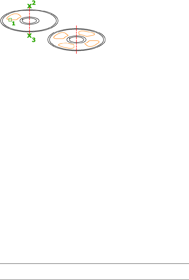
Creates an array by copying the selected objects around a specified center
point or axis of rotation.
List of Prompts
The following prompts are displayed.
Select objects: Use an object selection method
Specify center point on page 58 of array or [Base point on page 58/Axis of
rotation on page 58]: Specify a center point, or enter an option
Enter number of items on page 58 or [Angle between on page 59/Expression
on page 58] <last count>: Specify the number of items or enter an option
Specify the angle to fill on page 59 (+=ccw, -=cw) or [Expression]: Enter a fill
angle or enter an option
Press Enter to accept or [ASsociative on page 59/Base point/Items/Angle
between/Fill angle/ROWs on page 59/Levels on page 59/ROTate items on page
59/eXit on page 59]<eXit>: Press Enter or select an option
Center Point
Specifies the point around which to distribute the array items. The axis of
rotation is the Z axis of the current UCS.
Base Point
Specifies a base point for the array.
Key Point For associative arrays, specifies a valid constraint (or key point) on
the source objects to use as the base point. If you edit the source objects of
the resulting array, the base point of the array remains coincident with the
key point of the source objects.
Axis of Rotation
Specifies a custom axis of rotation defined by two specified points.
Items
Specifies the number of items in the array.
Expression Derives a value using a mathematical formula or equation.
NOTE When defining the fill angle in an expression, the (+ or -) mathematical
symbol in the resultant value does not affect the direction of the array.
58 | Chapter 2 A Commands
Angle Between
Specifies the angle between items.
Expression on page 58
Fill Angle
Specifies the angle between the first and last item in the array.
Expression on page 58
Associative
Specifies whether to create items in the array as an associative array object,
or as independent objects.
■Yes. Contains array items in a single array object, similar to a block. This
allows you to quickly propagate changes by editing the properties and
source objects of the array.
■No. Creates array items as independent objects. Changes to one item do
not affect the other items.
Rows
Edits the number and spacing of rows in the array, and the incremental
elevation between them.
Expression on page 58
Total Sets the total distance between the first and last rows.
Levels
Specifies the number and spacing of levels in the array.
Expression on page 58
Total Specifies the total distance between the first and last levels.
Rotate Items
Controls whether items are rotated as they are arrayed.
Exit
Exits the command.
ARRAYPOLAR | 59
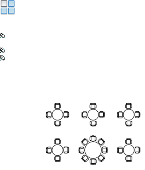
ARRAYRECT
Quick Reference
See also:
■Create Rectangular Arrays
Distributes object copies into any combination of rows, columns, and levels.
Access Methods
Button
Ribbon: Home tab ➤ Modify panel ➤ Array dropdown ➤ Rectangular
Array
Menu: Modify ➤ Array ➤ Rectangular Array
Toolbar: Modify
Summary
This command is equivalent to the Rectangular option in ARRAY on page 43.
Creates an array of rows and columns of copies of the selected object.
List of Prompts
The following prompts are displayed.
Select objects: Use an object selection method
60 | Chapter 2 A Commands
Specify opposite corner for number of items on page 61 or [Base point on page
61/Angle on page 61/Count on page 61] <Count>: Enter an option or press Enter
Press Enter to accept or [ASsociative on page 61/Base point/Rows on page
62/Columns on page 62/Levels on page 62/eXit on page 62] <eXit>: Press Enter
or select an option
Items
Specifies the number of items in the array. Use the preview grid to specify a
point that reflects the desired configuration.
Count Specifies the row and column values individually.
■Expression on page 62
Space Items
Specifies the row and column spacing. Use the preview grid to specify a point
that reflects the desired configuration.
Spacing Specifies the row and column spacing individually.
■Expression on page 62
Base Point
Specifies a base point for the array.
Key Point For associative arrays, specifies a valid constraint (or key point) on
the source objects to use as the base point. If you edit the source objects of
the resulting array, the base point of the array remains coincident with the
key point of the source objects.
Angle
Specifies the angle of rotation for the row axis. The row and column axes
remain orthogonal to each other. For associative arrays, you can later edit the
individual row and column angles.
You can change the measurement conventions for angles using UNITS on
page 1288. The ANGBASE on page 1380 and ANGDIR on page 1381 system variables
affect the angle of arrays.
Associative
Specifies whether to create items in the array as an associative array object,
or as independent objects.
■Yes. Contains array items in a single array object, similar to a block. This
allows you to quickly propagate changes by editing the properties and
source objects of the array.
■No. Creates array items as independent objects. Changes to one item do
not affect the other items.
ARRAYRECT | 61

Rows
Edits the number and spacing of rows in the array, and the incremental
elevation between them.
Expression Derives a value using a mathematical formula or equation.
Total Sets the total distance between the first and last rows.
Columns
Edits the number and spacing of columns.
Expression on page 62
Total Specifies the total distance between the first and last columns.
Levels
Specifies the number and spacing of levels.
Expression on page 62
Total Specifies the total distance between the first and last levels.
Exit
Exits the command.
ATTACH
Quick Reference
See also:
■Attach Files as Underlays
■Attach and Detach Referenced Drawings
■Attach Raster Image Files
Inserts an external reference, raster image, or underlay (DWF, DWFx, PDF, or
DGN files) in the current drawing.
Access Methods
Button
62 | Chapter 2 A Commands

Ribbon: Insert tab ➤ Reference panel ➤ Attach
Summary
The Select Reference File dialog box (a standard file selection dialog box) is
displayed. To select multiple DWG files for attach, set the Files of Type to
Drawing. You can select one file only for all other file formats.
-ATTACH
Quick Reference
See also:
■Attach Files as Underlays
Inserts an external reference, raster image, or underlay (DWF, DWFx, PDF, or
DGN files) in the current drawing.
Summary
Attach an external reference, image, or underlay (DWF, DWFx, PDF, or DGN)
file from the command line.
List of Prompts
The list of prompts differs depending on whether you are attaching an
underlay, an image, or an external reference.
DWF and DWFx Underlay Prompts
Path to File Enters the location of the DWF or DWFx file including the file
name.
Sheet name Enters a sheet name.
?Enters multiple sheets.
*Lists sheets available in the DWF or DWFx file.
Insertion point Specify the location of the lower, left-hand corner of the
underlay by clicking on screen or entering the X,Y coordinates.
Base Image Size Displays the underlay’s height and width in units
-ATTACH | 63
Scale Factor Resizes the underlay. For example, if the base image size is 36 x
24 and you enter a scale factor of 2, the underlay will display at 72 x 48.
Rotation Sets an angle of rotation for the underlay.
PDF Underlay Prompts
Path to File Enters the location of the PDF file including the file name.
Page Number Enters a page number.
?Enters multiple pages.
*Lists pages available in the PDF file.
Insertion Point Specifies the location of the lower, left-hand corner of the
underlay by clicking on screen or entering the X,Y coordinates.
Base Image Size Displays the underlay’s height and width in units
Scale Factor Resizes the underlay. For example, if the base image size is 36 x
24 and you enter a scale factor of 2, the underlay will display at 72 x 48.
Rotation Sets an angle of rotation for the underlay.
DGN Underlay Prompts
Path to File Enters the location of the DGN file including the file name.
Name of Model Enters a model name.
?Enters multiple models.
*Lists pages available in the DGN file.
Insertion Point Specifies the location of the lower, left-hand corner of the
underlay by clicking on screen or entering the X,Y coordinates.
Base Image Size Displays the underlay’s height and width in units
Scale Factor Resizes the underlay. For example, if the base image size is 36 x
24 and you enter a scale factor of 2, the underlay will display at 72 x 48.
Rotation Sets an angle of rotation for the underlay.
Image Prompts
Path to File Enters the location of the image file including the file name.
Insertion Point Specifies the location of the lower, left-hand corner of the
image by clicking on screen or entering the X,Y coordinates.
Base Image Size Displays the image’s height and width in units
64 | Chapter 2 A Commands

Scale Factor Resizes the image. For example, if the base image size is 36 x 24
and you enter a scale factor of 2, the underlay will display at 72 x 48.
Rotation Sets an angle of rotation for the underlay.
External Reference Prompts
Path to File Enters the location of the external reference file including the
file name.
Reference Type Selects whether to attach this file as an underlay or an overlay.
Press Enter to attach the file as an underlay (attachment).
NOTE Unlike attached external references, overlaid external references are not
included when the drawing is attached or overlaid as an external reference to
another drawing.
Insertion Point Specifies the location of the lower, left-hand corner of the
external reference by clicking on screen or entering the X,Y coordinates.
Scale Sets the scale factor for the X,Y, and Z axes. The scale for the Z axis is
the absolute value of the specified scale factor.
■Specify scale factor for XYZ axes: Enter a nonzero value
■Specify insertion point:
■Specify rotations angle <0>:
X, Y, Z Sets the X, Y, and Z scale factor.
■Specifies scale factor for XYZ axes: Enter a nonzero value
■Specifies insertion point:
■Specifies rotations angle <0>:
Rotate Sets the rotation angle for both the individual blocks and the entire
array.
PScale Sets the scale factor for the X, Y, and Z axes to control the display of
the block as it is dragged into position.
PX, PY, PZ Sets the scale factor for the X, Y, and Z axes to control the display
of the block as it is dragged into position.
PRotate Sets the rotation angle of the block as it is dragged into position.
Base Image Size Displays the external reference’s height and width in units
-ATTACH | 65
Scale Factor Resizes the external reference. For example, if the base image
size is 36 x 24 and you enter a scale factor of 2, the external reference will
display at 72 x 48.
Unit Changes the type of units to scale the external reference.
ATTACHURL
Quick Reference
See also:
■Overview of Using Hyperlinks in a Drawing
Attaches hyperlinks to objects or areas in a drawing.
List of Prompts
The following prompts are displayed.
Enter hyperlink insert option [Area/Object] <Object>: Enter a or press ENTER
Area
Creates the URLLAYER layer, draws a polyline on that layer, and attaches a
URL to the polyline.
The polyline that represents the area is displayed in the color assigned to
URLLAYER. The default color is red. When you move the cursor over the area
in the drawing, the cursor changes to a hyperlink cursor to indicate that a
URL is attached to the area.
Object
Attaches a URL to the selected object.
When you move the cursor over the object in the drawing, the cursor changes
to a hyperlink cursor to indicate that a URL is attached to the object.
66 | Chapter 2 A Commands
ATTDEF
Quick Reference
See also:
■Define Block Attributes
Creates an attribute definition for storing data in a block.
Access Methods
Button
Ribbon: Insert tab ➤ Attributes panel ➤ Define Attributes.
Menu: Draw ➤ Block ➤ Define Attributes
Summary
The Attribute Definition dialog box is displayed.
If you enter -attdef at the Command prompt, options are displayed.
An attribute is an object that is created and included with a block definition.
Attributes can store data such as part numbers, product names, and so on.
Attribute Definition Dialog Box
Quick Reference
See also:
■Define Block Attributes
Defines the mode; attribute tag, prompt, and value; insertion point; and text
settings for an attribute.
ATTDEF | 67

List of Options
The following options are displayed.
Mode
Sets options for attribute values associated with a block when you insert the
block in a drawing.
The default values are stored in the AFLAGS on page 1380 system variable.
Changing the AFLAGS setting affects the default mode for new attribute
definitions and does not affect existing attribute definitions.
Invisible
Specifies that attribute values are not displayed or printed when you insert
the block. ATTDISP on page 74 overrides Invisible mode.
Constant
Gives attributes a fixed value for block insertions.
Verify
Prompts you to verify that the attribute value is correct when you insert the
block.
Preset
Sets the attribute to its default value when you insert a block containing a
preset attribute.
68 | Chapter 2 A Commands

Lock Position
Locks the location of the attribute within the block reference. When unlocked,
the attribute can be moved relative to the rest of the block using grip editing,
and multiline attributes can be resized.
Multiple Lines
Specifies that the attribute value can contain multiple lines of text. When this
option is selected, you can specify a boundary width for the attribute.
NOTE In a dynamic block, an attribute's position must be locked for it to be
included in an action's selection set.
Attribute
Sets attribute data.
Tag
Identifies each occurrence of an attribute in the drawing. Enter the attribute
tag using any combination of characters except spaces. Lowercase letters are
automatically changed to uppercase.
Prompt
Specifies the prompt that is displayed when you insert a block containing this
attribute definition. If you do not enter a prompt, the attribute tag is used as
a prompt. If you select Constant in the Mode area, the Prompt option is not
available.
Default
Specifies the default attribute value.
Multiline Editor Button
When Multiple Line mode is selected, displays an in-place text editor with a
text formatting toolbar and ruler. Depending on the setting of the ATTIPE on
page 1387 system variable, the Text Formatting toolbar displayed is either the
abbreviated version, or the full version.
For more information, see the In-Place Text Editor.
NOTE Several options in the full In-Place Text Editor are grayed out to preserve
compatibility with single-line attributes.
Insertion Point
Specifies the location for the attribute. Enter coordinate values or select Specify
On-screen and use the pointing device to specify the placement of the attribute
in relation to the objects that it will be associated with.
Attribute Definition Dialog Box | 69
Specify On-Screen
Displays a Start Point prompt when the dialog box closes. Use the pointing
device to specify the placement of the attribute in relation to the objects that
it will be associated with.
X
Specifies the X coordinate of the attribute's insertion point.
Y
Specifies the Y coordinate of the attribute's insertion point.
Z
Specifies the Z coordinate of the attribute's insertion point.
Text Settings
Sets the justification, style, height, and rotation of the attribute text.
Justification
Specifies the justification of the attribute text. See TEXT on page 1229 for a
description of the justification options.
Text Style
Specifies a predefined text style for the attribute text. Currently loaded text
styles are displayed. To load or create a text style, see STYLE on page 1180.
Annotative
Specifies that the attribute is . If the block is annotative, the attribute will
match the orientation of the block. Click the information icon to learn more
about annotative objects.
Text Height
Specifies the height of the attribute text. Enter a value, or choose Height to
specify a height with your pointing device. The height is measured from the
origin to the location you specify. If you select a text style that has fixed height
(anything other than 0.0), or if you select Align in the Justification list, the
Height option is not available.
Rotation
Specifies the rotation angle of the attribute text. Enter a value, or choose
Rotation to specify a rotation angle with your pointing device. The rotation
angle is measured from the origin to the location you specify. If you select
Align or Fit in the Justification list, the Rotation option is not available.
70 | Chapter 2 A Commands
Boundary Width
Specifies the maximum length of the lines of text in a multiple-line attribute
before wrapping to the next line. A value of 0.000 means that there is no
restriction on the length of a line of text.
Not available for single-line attributes.
Align Below Previous Attribute Definition
Places the attribute tag directly below the previously defined attribute. If you
have not previously created an attribute definition, this option is not available.
-ATTDEF
Quick Reference
See also:
■Define Block Attributes
List of Prompts
The following prompts are displayed.
Current attribute modes: Invisible=current Constant=current Verify=current
Preset=current Lock position=current Annotative =current Multiple line =current
Enter an option to change [Invisible/Constant/Verify/Preset/Lock
position/Annotative/Multiple lines] <done>:
Enter attribute tag name: Enter any characters except spaces or exclamation points
Enter attribute value: Enter the appropriate text or press ENTER (this prompt is
displayed only if you turned on Constant mode)
Enter attribute prompt: Enter the text for the prompt line or press ENTER (this
prompt is not displayed if you turned on Constant mode)
Enter default attribute value: Enter the appropriate text or press ENTER (this prompt
is not displayed if you turned on Constant mode)
Specify location of multiline attribute: Specify a point (this prompt is displayed
only if you turned on Multiple line mode)
Specify opposite corner: Specify a point or enter an option (this prompt is displayed
only if you turned on Multiple line mode)
Attribute Modes
The current value line indicates the current settings for each attribute mode
(either Y for on or N for off). Entering i, c, v, p, l, a, or m toggles the modes
on or off. Press ENTER when you have finished adjusting the mode settings.
-ATTDEF | 71

The AFLAGS on page 1380 system variable stores the current mode settings and
can be used to set the default modes.
Invisible Specifies that attribute values are displayed when you insert the
block. ATTDISP on page 74 overrides Invisible mode.
Constant Gives attributes a fixed value for block insertions.
Verify Prompts for verification that the attribute value is correct when you
insert the block.
Preset Sets the attribute to its default value when you insert a block containing
a preset attribute.
Lock Position Locks the location of the attribute within the block reference.
When unlocked, the attribute can be moved relative to the rest of the block
using grip editing, and multiline attributes can be resized.
NOTE In a dynamic block, an attribute's position must be locked for it to be
included in an action's selection set.
Annotative Specifies that the attribute is .
Multiple Lines Specifies that the attribute value can contain multiple lines
of text. When this option is selected, you can specify a boundary width for
the attribute.
Attribute Tag Name
Specifies the attribute tag, which identifies each occurrence of an attribute in
the drawing. The tag can contain any characters except spaces or exclamation
marks (!). Lowercase letters are automatically changed to uppercase.
Attribute Prompt
Specifies the prompt that is displayed when you insert a block containing this
attribute definition. If you press ENTER, the attribute tag is used as the prompt.
If you turn on Constant mode, this prompt is not displayed.
NOTE For single-line attributes, you can enter up to 256 characters. If you need
leading blanks in the prompt or the default value, start the string with a backslash
(\). To make the first character a backslash, start the string with two backslashes.
Default Attribute Value
Specifies the default attribute value. The default attribute value appears when
a block is inserted into your drawing. A default value is not required. If you
turn on Constant mode, the Attribute Value prompt is displayed instead.
When Multiple Line mode is off, -ATTDEF then displays the same prompts as
the TEXT command, using the attribute tag instead of requesting a text string.
72 | Chapter 2 A Commands

Current text style: "Standard" Text height: 0.2000
Specify start point of text or [Justify / Style]: Enter an option or press ENTER
Specify paper text height <current>: Specify a height, or press ENTER
The Specify Paper Text Height prompt is displayed only if the current text
style is .
For a description of each option, see TEXT on page 1229.
NOTE For single-line attributes, you can enter up to 256 characters. If you need
leading blanks in the prompt or the default value, start the string with a backslash
(\). To make the first character a backslash, start the string with two backslashes.
When Multiple Line mode is on, -ATTDEF then displays several of the prompts
used by the MTEXT command. For a description of each option, see MTEXT
on page 762.
Attribute Value (Constant Mode)
Specifies the value for a constant attribute. This prompt is displayed only if
you turn on Constant mode.
ATTDEF then displays the same prompts as the TEXT command, using the
attribute tag instead of requesting a text string. For a description of each
option, see TEXT on page 1229.
When Multiple Line mode is on, -ATTDEF then displays several of the prompts
used by the MTEXT command. For a description of each option, see MTEXT
on page 762.
Location of Multiline Attribute (Multiple Line Mode)
Specifies the first corner of the bounding box for the multiple-line text. This
location is used as the starting point for the attribute.
Opposite Corner (Multiple Line Mode)
As you drag the pointing device to specify the opposite corner, a rectangle is
displayed to show the location and width of the multiple-line text. The arrow
within the rectangle indicates the direction of the text flow.
-ATTDEF | 73
ATTDISP
Quick Reference
See also:
■Define Block Attributes
Controls the visibility overrides for all block attributes in a drawing.
Access Methods
Button
Ribbon: Home tab ➤ Block panel dropdown ➤ Retain Attribute Display
Menu: View ➤ Display ➤ Attribute Display
Command entry: 'attdisp for transparent use
Summary
74 | Chapter 2 A Commands

The drawing is regenerated after you change the visibility settings. The current
visibility of attributes is stored in the ATTMODE on page 1388 system variable.
List of Prompts
The following prompts are displayed.
Enter attribute visibility setting [Normal/ON/OFF] <current>:
Normal Restores the visibility settings of each attribute. Visible attributes are
displayed. Invisible attributes are not displayed.
On Makes all attributes visible, overriding the original visibility settings.
Off Makes all attributes invisible, overriding the original visibility settings.
ATTEDIT
Quick Reference
See also:
■Attach Data to Blocks (Block Attributes)
Changes attribute information in a block.
Access Methods
Button
Ribbon: Insert tab ➤ Block panel ➤ Edit Attribute.
Menu: Modify ➤ Object ➤ Attribute ➤ Single
Summary
The Edit Attributes dialog box is displayed to edit attribute values for a specific
block.
If you enter -attedit at the Command prompt, options are displayed to edit
attribute values and properties independent of a block.
ATTEDIT | 75
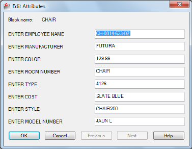
Edit Attributes Dialog Box
Quick Reference
See also:
■Attach Data to Blocks (Block Attributes)
Changes attribute information in a block.
Summary
To change attribute properties such as position, height, and style, use
-ATTEDIT.
List of Options
The following options are displayed.
Block Name
Indicates the name of the selected block. The value of each attribute contained
in the block is displayed in this dialog box.
List of Attributes
Displays the first eight attributes contained in the block. Edit the attribute
values. If the block contains additional attributes, click Previous or Next to
navigate through the list. You cannot edit attribute values on locked layers.
Multiple-line attributes display the In-Place Text Editor on page 763 with the
Text Formatting toolbar and the ruler. Depending on the setting of the ATTIPE
76 | Chapter 2 A Commands
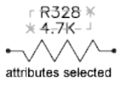
on page 1387 system variable, the Text Formatting toolbar displayed is either
the abbreviated version, or the full version.
Previous
Displays the previous eight attribute values. Previous is available only if the
selected block contains more than eight attributes and you used Next to display
the additional attributes.
Next
Displays the next eight attribute values. If the block contains no additional
attributes, Next is unavailable.
-ATTEDIT
Quick Reference
See also:
■Modify Blocks
List of Prompts
If you enter -attedit at the Command prompt, the following prompts are
displayed.
Edit attributes one at a time? [Yes/No] <Y>: Enter y or press Enter to edit attributes
one at a time, or enter n to edit attributes globally
The following prompts filter the attributes to be changed based on attribute
tag, current value, or object selection.
Yes
Edits attributes one at a time. Attributes to be edited one at a time must be
visible and parallel to the current UCS.
Attribute values are case sensitive.
-ATTEDIT | 77
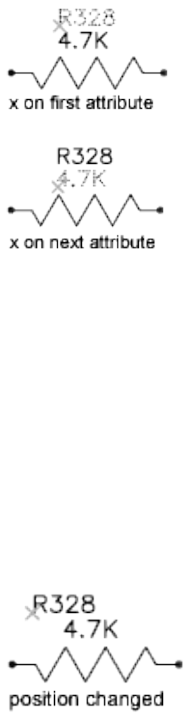
The first attribute in the selection set is marked with an X. You can change
any properties of the attribute you select.
Enter an option [Value/Position/Height/Angle/Style/Layer/Color/Next] <N>:
Enter the property to change, or press Enter for the next attribute
If the original attribute was defined with aligned or fit text, the prompt does
not include Angle. The Height option is omitted for aligned text. For each of
the options except Next, ATTEDIT prompts for a new value. The X remains
on the current attribute until you move to the next attribute.
Value
Changes or replaces an attribute value.
Enter type of value modification [Change/Replace]: Enter c or r or press Enter
Change Modifies a few characters of the attribute value.
Either string can be null. The ? and * characters are interpreted literally, not
as wild-card characters.
Replace Substitutes a new attribute value for the entire attribute value.
If you press Enter, the attribute value is empty (null).
Position
Changes the text insertion point.
If the attribute is aligned, ATTEDIT prompts for both ends of a new text
baseline.
78 | Chapter 2 A Commands
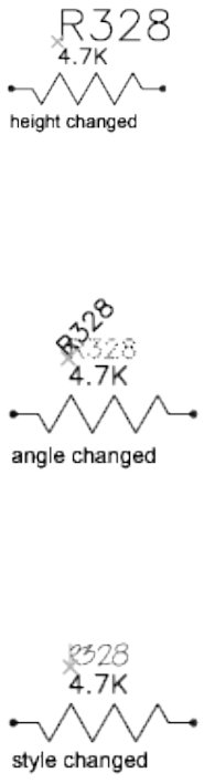
Height
Changes the text height.
When you specify a point, the height becomes the distance between the
specified point and the start point of the text.
Angle
Changes the rotation angle.
If you specify a point, the text is rotated along an imaginary line between the
specified point and the start point of the text.
Style
Changes the style setting.
Layer
Changes the layer.
Color
Changes the color.
You can enter a color from the AutoCAD Color Index (a color name or
number), a true color, or a color from a color book.
You can enter a color name, a color number between 1 and 255, or bylayer
or byblock.
-ATTEDIT | 79
True Color Specifies a true color to be used for the selected object.
Color Book Specifies a color from a loaded color book to be used for the
selected object.
If you enter a color book name, you are prompted to enter the color name in
the color book, such as PANTONE® 573.
Next
Moves to the next attribute in the selection set. If there are no more attributes,
ATTEDIT ends.
No
Edits more than one attribute at a time. Global editing applies to both visible
and invisible attributes.
Editing attributes globally limits you to replacing a single text string with
another text string. If you edit attributes one at a time, you can edit any or
all of the attributes.
Yes Edits only visible attributes.
Attribute values are case sensitive. To select empty (null) attributes, which
normally are not visible and cannot be selected, enter a backslash (\).
Select the attribute you want to change.
Either string can be empty (null). The ? and * characters are interpreted literally,
not as wild-card characters.
No Edits attributes whether they are visible or not. Changes to attributes are
not reflected immediately. The drawing is regenerated at the end of the
command.
Attribute values are case sensitive. To select empty (null) attributes, which
normally are not visible, enter a backslash (\).
The attributes that match the specified block name, attribute tag, and attribute
value are selected.
Either string can be empty (null). The ? and * characters are interpreted literally,
not as wild-card characters.
80 | Chapter 2 A Commands
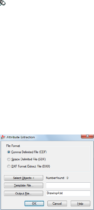
ATTEXT
Quick Reference
See also:
■Attach Data to Blocks (Block Attributes)
Extracts attribute data, informational text associated with a block, into a file.
Access Methods
Menu: Tools ➤ Attribute Extraction
Summary
The Attribute Extraction dialog box is displayed.
If you enter -attext at the Command prompt, options are displayed.
Attribute Extraction Dialog Box
Quick Reference
See also:
■Attach Data to Blocks (Block Attributes)
Extracts attribute data, informational text associated with a block, into a file.
ATTEXT | 81
Summary
Specifies the file format for the attribute information, the objects from which
you want to extract information, and the template and output file names for
the information.
List of Options
The following options are displayed.
File Format
Sets the format for the file into which you are extracting the attribute data.
Comma Delimited File (CDF)
Generates a file containing one record for each block reference in the drawing
that has at least one matching attribute tag in the template file. Commas
separate the fields of each record. Single quotation marks enclose the character
fields.
Space Delimited File (SDF)
Generates a file containing one record for each block reference in the drawing
that has at least one matching attribute tag in the template file. The fields of
each record have a fixed width; therefore, field separators or character string
delimiters are not appropriate.
DXF Format Extract File (DXX)
Produces a subset of the AutoCAD Drawing Interchange File format containing
only block reference, attribute, and end-of-sequence objects. DXF™ format
extraction requires no template. The file name extension .dxx distinguishes
the output file from normal DXF files.
Select Objects
Closes the dialog box so you can use the pointing device to select blocks with
attributes. When the Attribute Extraction dialog box reopens, Number Found
shows the number of objects you selected.
Number Found
Indicates the number of objects you selected using Select Objects.
Template File
Specifies a template extraction file for CDF and SDF formats. Enter the file
name in the box, or choose Template File to search for existing template files
using a standard file selection dialog box. The default file extension is .txt. If
you select DXF under File Format, the Template File option is not available.
82 | Chapter 2 A Commands
Output File
Specifies the file name and location for the extracted attribute data. Enter the
path and file name for the extracted attribute data, or choose Output File to
search for existing template files using a standard file selection dialog box.
The .txt file name extension is appended for CDF or SDF files and the .dxx file
name extension for DXF files.
-ATTEXT
Quick Reference
See also:
■Attach Data to Blocks (Block Attributes)
List of Prompts
Enter extraction type or enable object selection [Cdf/Sdf/Dxf/Objects] <C>:
Enter an option or press Enter
CDF: Comma-Delimited File Generates a file containing one record for each
block reference in the drawing. Commas separate the fields of each record.
Single quotation marks enclose the character fields.
In the Select Template File dialog box, enter the name of an existing attribute
extraction template file.
In the Create Extract File dialog box, enter the name for the output file. The
extract file's file name extension is .txt for CDF or SDF format.
SDF: Space-Delimited File Generates a file containing one record for each
block reference in the drawing. The fields of each record have a fixed width;
therefore, field separators or character string delimiters are not used.
In the Select Template File dialog box, enter the name of an existing attribute
extraction template file.
In the Create Extract File dialog box, enter the name for the output file. The
extract file's file name extension is .txt for CDF or SDF format.
DXF: Drawing Interchange File Produces a subset of the AutoCAD Drawing
Interchange File format containing only block reference, attribute, and
end-of-sequence objects. DXF-format extraction requires no template. The file
name extension .dxx distinguishes the output file from normal DXF files.
In the Create Extract File dialog box, enter the name for the output file. The
extract file's file name extension is .dxx for DXF format.
-ATTEXT | 83

Objects Selects objects whose attributes you want to extract.
ATTIPEDIT
Quick Reference
See also:
■Modify a Block Attribute Definition
Changes the textual content of an attribute within a block.
Summary
If you select a single-line attribute, displays the In-Place Text Editor on page
763 without the Text Formatting toolbar and the ruler. Right-click to display
options.
If you select a multiple-line attribute, displays the In-Place Text Editor on page
763 with the Text Formatting toolbar and the ruler. Depending on the setting
of the ATTIPE on page 1387 system variable, the Text Formatting toolbar
displayed is either the abbreviated version shown, or the full version.
Use the abbreviated version for compatibility with previous AutoCAD LT
releases and editing operations. Use the full version for additional text
formatting options.
NOTE Not all MTEXT formatting options are available for multiline attributes even
with the full In-Place Editor.
List of Prompts
The following prompts are displayed.
Select attribute to edit: Select an attribute within a block
84 | Chapter 2 A Commands
ATTSYNC
Quick Reference
See also:
■Modify a Block Attribute Definition
Updates block references with new and changed attributes from a specified
block definition.
Access Methods
Button
Ribbon: Home tab ➤ Block panel ➤ Synchronize Attributes
Toolbar: Modify II
Summary
You are prompted for the names of blocks you want to update with the current
attributes defined for the blocks.
Use this command to update all instances of a block containing attributes
that was redefined using the BLOCK or BEDIT commands. ATTSYNC does not
change any values assigned to attributes in existing blocks.
NOTE Use the ATTREDEF command to redefine and update blocks in one
command.
Entering ? displays a list of all block definitions in the drawing. Enter the
name of the block you want to update.
Pressing ENTER allows you to use your pointing device to select the block
whose attributes you want to update.
If a block you specify does not contain attributes or does not exist, an error
message is displayed, and you are prompted to specify another block.
ATTSYNC | 85
WARNING ATTSYNC removes any format or property changes made with the
ATTEDIT or EATTEDIT commands. It also deletes any extended data associated
with the block, and might affect dynamic blocks and blocks created by third-party
applications.
AUDIT
Quick Reference
See also:
■Repair a Damaged Drawing File
Evaluates the integrity of a drawing and corrects some errors.
Access Methods
Button
Menu: Application menu ➤ Drawing Utilities ➤ Audit
Summary
For easy access, AUDIT places all objects for which it reports errors in the
Previous selection set. However, editing commands affect only the objects
that belong to the current paper space or model space.
If you set the AUDITCTL on page 1390 system variable to 1, AUDIT creates a
text file describing problems and the action taken and places this report in
the same folder as the current drawing, with the file extension .adt.
If a drawing contains errors that AUDIT cannot fix, use RECOVER on page
1066 to retrieve the drawing and correct its errors.
86 | Chapter 2 A Commands

AUTOCOMPLETE
Quick Reference
See also:
■The Command Line Window
Controls what types of automated keyboard features are available at the
Command prompt.
Access Methods
Command entry: Right-click within the Command Window ➤
AutoComplete ➤ option
Summary
Entering a command or system variable at the Command prompt is assisted
with several features that list or complete the commands and system variables
as they are being typed. The AUTOCOMPLETE command controls which of
the features are turned on.
List of Prompts
The following prompts are displayed.
Append Controls whether commands and system variables are automatically
completed as you type.
List Controls whether a list of valid commands and system variables is
displayed as you type.
Icon Controls whether the corresponding icon for a command is displayed
in the list. The same icon is used for all system variables.
System variables Controls whether system variables are also included with
the Append and List features.
Delay Sets a time delay in seconds before the Append and List features take
effect.
On Enables the operation of the AUTOCOMPLETE features that are currently
turned on.
AUTOCOMPLETE | 87
Off Suppresses the operation of AUTOCOMPLETE features without changing
their settings.
AUTOPUBLISH
Quick Reference
See also:
■Set Publish Options
Publishes drawings to DWF, DWFx, or PDF files automatically to a specified
location.
Access Methods
Menu: Application menu ➤ Options ➤ Plot and Publish tab
Shortcut menu: Right-click in the command window, or (with no commands
active and no objects selected) right-click in the drawing area, and choose
Options. Select the Plot and Publish tab.
Command entry: options
Summary
Publishes a drawing to a DWF, DWFx, or PDF file. The file format (DWF,
DWFx, or PDF) is specified in the Auto Publish dialog box on page 89.
To view information about the published drawings, click the Plotting Details
Report Available icon in the tray on the right side of the status bar. Clicking
this icon opens the Plot and Publish Details dialog box, which provides
information about your completed plot and publish jobs. This information
is also saved to the Plot and Publish log file. The shortcut menu for this icon
also provides an option to view the most recently published DWF, DWFx, or
PDF file.
List of Prompts
The following prompts are displayed.
AutoPublish DWF Automatically publishes the drawing to a DWF, DWFx, or
PDF file. The file format (DWF, DWFx, or PDF) is specified in the Auto Publish
dialog box on page 89.
88 | Chapter 2 A Commands
Location Specifies a directory where the published drawings are stored. Opens
Select a Folder for Generated Files dialog box (a standard file selection dialog
box on page 826).
Auto Publish Options Dialog Box
Quick Reference
See also:
■Set Publish Options
Publishes drawings to DWF, DWFx, or PDF files automatically to a specified
location.
Summary
Specifies options for publishing drawings to DWF, DWFx, or PDF files when
you save or close a drawing file, or issue the AUTOPUBLISH on page 88
command.
List of Options
The following options are displayed.
Auto-Publish Options
Specifies where DWF or PDF files are saved when you publish drawing sheets.
Publish on Specifies when the publishing takes place.
■Save (Publishes when the drawing is saved)
■Close (Publishes when the drawing is closed)
■Prompt on Save (Publishes when the drawing is prompted to save)
■Prompt on Close (Publishes when the drawing is prompted to close)
Location Specifies a directory where exported files are saved when you publish
drawings by selecting the following options in the list:
■Drawing folder
■DWF and PDF (sub-folder relative to Drawing folder)
■Previously selected location
Auto Publish Options Dialog Box | 89

Click the [...] button to specify a new location to save the published drawings.
Include Specifies whether to publish the model, the layouts or both the model
and layouts are saved when you publish drawings.
General DWF/PDF options
Specifies options for creating a single-sheet or multi-sheet DWF, DWFx, and
PDF files.
File Format Specifies whether the DWG should be published as a DWF, DWFx,
or PDF file.
Type Specifies that a single-sheet or a multi-sheet is generated for all the sheets
listed in the Publish dialog box.
Layer Information Specifies whether layer information is included in the
published DWF, DWFx, or PDF file.
NOTE Layer information for 3D DWF entries does not get published.
Merge Control Specifies whether overlapping lines overwrite (the top line
hides the bottom line) or merge (the colors of the lines blend together).
DWF Data Options
Lists and allows you to specify the data that you can optionally include in the
published file.
Password Protection Specifies options for protecting DWF, DWFx, or PDF
files with passwords.
Block Information Specifies whether block property and attribute information
is included in the published DWF, DWFx, or PDF files.
NOTE You must set block information to Include in order for block template file
information to be available.
Block Template File Allows you to create a new block template (DXE) file,
edit an existing block template file, or use the settings of a previously created
block template file.
Create opens the Publish Block Template dialog box on page 1030, in which
you can create a new block template.
Edit opens the Select Block Template dialog box (a standard file selection
dialog box on page 826), in which you can select an existing block template
to modify.
90 | Chapter 2 A Commands
B Commands
BACTION
Quick Reference
See also:
■Overview of Actions
Adds an action to a dynamic block definition.
Summary
This command is available only in the Block Editor on page 127. Actions define
how the geometry of a dynamic block reference moves or changes when the
custom properties of a block reference are manipulated in a drawing. You
associate actions with parameters.
List of Prompts
The following prompts are displayed.
Select parameter: Select a parameter in the block definition with which to associate
the action
You can associate parameters with the following types of actions.
Array
Adds an array action to the current dynamic block definition. An array action
can be associated with a linear, polar, or XY parameter. Specifies that the
selection set of objects arrays when the action is triggered in a dynamic block
reference.
3
91
Select Objects Defines the objects that will be included in the action when
modified.
Enter Distance Between Columns When a linear or polar parameter is
selected, specifies the distance between the selected objects when the array
action is modified. To specify the distance, use the mouse pointer.
■Specify opposite corner.
Enter Distance Between Rows or Specify Unit Cell When an XY parameter
is selected, specifies the distance between the selected objects when the array
action is modified. To specify the distance, use the mouse pointer. To specify
unit cell, enter two values separated by a comma for each of the two points.
Specify Action Location When BACTIONBARMODE on page 1396 is set to 0,
determines where the action is placed within the Block Editor.
Lookup
The lookup action displays the Property Lookup Table dialog box on page 142
where you can create a lookup table for the block reference.
Flip
A set of objects is flipped around the reflection line of the flip parameter when
the action is triggered in the block reference.
A flip action can only be associated with a flip parameter.
Specify Selection Set Determines the objects that will be mirrored about the
flip parameter reflection line.
Move
Specifies that the selection set of objects moves when the action is triggered
in a dynamic block reference. A move action can be associated with a point,
linear, polar, or XY parameter.
Select Objects Select Objects on page 92
Specify Action Location Specify Action Location on page 92
Specify Parameter Point When a linear or polar parameter is selected,
determines whether the start or end point of the parameter is used to determine
the base point of the action.
When an XY parameter is selected, determines which corner of the parameter
will be associated with the action. The objects selected for the action will be
moved relative to this point.
Multiplier When BACTIONBARMODE on page 1396 is set to 0 and the action
is triggered, changes the associated parameter value by the specified distance.
92 | Chapter 3 B Commands
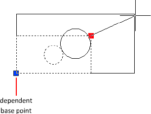
Offset When BACTIONBARMODE on page 1396 is set to 0 and the action is
triggered, increases or decreases the angle of the selected parameter by the
specified value.
XY When an XY parameter is selected, specifies whether the distance applied
to the action is the parameter's X distance, Y distance, or XY distance from the
parameter's base point.
Rotate
Specifies that the selection set of objects rotates when the action is triggered
in a dynamic block reference. A rotate action can only be associated with a
rotation parameter.
Specify Selection Set Determines the objects that will be rotated about the
parameter base point.
Scale
Specifies that the selection set of objects scales relative to the defined base
point when the action is triggered in a dynamic block reference. A scale action
can only be associated with a linear, polar, or XY parameter.
Select Objects Select Objects on page 92
Specify Action Location Specify Action Location on page 92
Base Type Specifies whether the base point for the action is dependent or
independent of the associated parameter’s base point.
Dependent Scales or moves selected objects relative to the base point of the
associated parameter.
Independent Scales or moves selected objects relative to a base point defined
separately from that of the associated parameter.
BACTION | 93
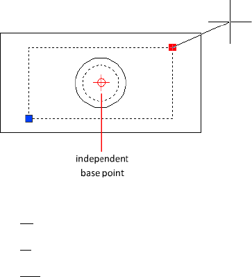
XY When an XY parameter is selected, sets the Scale Type custom property.
■X. Scales the selected object only along the X-axis of the XY parameter.
■Y. Scales the selected object only along the Y-axis of the XY parameter.
■XY. Scales the selected object along both the X- and Y-axes of the XY
parameter.
Stretch
Specifies that the selection set of objects will stretch or move when the action
is triggered in a dynamic block reference. A stretch action can be associated
with a point, linear, polar, or XY parameter.
Specify Parameter Point When a linear or polar parameter is selected,
determines whether the start or end point of the parameter is used to determine
the base point of the action.
When an XY parameter is selected, determines which corner of the parameter
will be associated with the action. The objects selected for the action will be
stretched relative to this point.
Specify Stretch Frame Creates a box that represents the boundary area for
the action when modified.
■Specify opposite corner.
■Specify objects.
CPolygon Creates a polygon that represents the boundary area for the action
when modified.
■First polygon point.
■Specify endpoint.
94 | Chapter 3 B Commands

Specify Action Location Specify Action Location on page 92
■Multiplier on page 92
■Offset on page 93
■XY on page 93
Select Objects Select Objects on page 92
Polar Stretch
Specifies that the selection set of objects stretches or moves when the action
is triggered in a dynamic block reference. A polar stretch action can only be
associated with a polar parameter.
Specify Parameter Point Determines whether the start or end point of the
parameter is used to determine the base point of the action.
Specify Stretch Frame Specify Stretch Frame on page 94
■CPolygon on page 94
Specify Objects to Rotate Only Determines the objects in the selection that
will rotate and not stretch.
Specify Action Location Specify Action Location on page 92
■Multiplier on page 92
■Offset on page 93
BACTIONBAR
Quick Reference
See also:
■Overview of Actions and Parameters
Displays or hides action bars for a selection set of parameter objects.
Access Methods
BACTIONBAR | 95

Ribbon: Block Editor contextual tab ➤ Action Parameters panel ➤ Show
All Actions
Ribbon: Block Editor contextual tab ➤ Action Parameters panel ➤ Hide
All Actions
Command entry: bedit ➤ bactionbar
Summary
You can only use the BACTIONBAR command in the Block Editor on page
127 and when in Action Bar mode (BACTIONBARMODE on page 1396 system
variable is set to 1). The BACTIONBAR command controls the display of action
bars for parameter objects in the Block Editor. An action bar is a toolbar-like
element that displays the actions associated with a parameter object.
On the ribbon, you can also show or hide all action bars for all parameter
objects.
List of Prompts
The following prompts are displayed.
Enter an option [Show on page 96/Hide on page 96/Reset] <Show all>: Specify
a parameter to show or hide the action bars
Show
Displays the action bars for the selected parameter objects in the Block Editor.
Hide
Hides the action bars for the selected parameter objects in the Block Editor.
Reset
Displays all action bars for the parameter objects in the Block Editor and resets
to the default position relative to the parameters they are associated with.
BACTIONSET
Quick Reference
See also:
■Modify Dynamic Block Definitions
Specifies the selection set of objects associated with an action in a dynamic
block definition.
96 | Chapter 3 B Commands
Access Methods
Command entry: bedit ➤ bactionset
Shortcut menu: Select an action in the block definition. Right-click in the
Block Editor drawing area. Click Action Selection Set, and then click an option.
Summary
Re-specifies the selection set of objects associated with an action by creating
a new selection set or by adding to or removing objects from the existing
selection set. You can only use the BACTIONSET command in the Block Editor
on page 127.
NOTE The BACTIONSET command is disabled when the BACTIONBARMODE on
page 1396 system variable is set to 1.
List of Prompts
The following prompts are displayed.
Select action: Select an action in the current dynamic block definition
Specify Selection Set
Creates a new selection set for the selected action, or modifies an existing
selection set.
Select objects Defines the objects that will be included in the action when
modified.
Remove Removes objects from the original selection set associated with the
selected action.
Specify Stretch Frame Creates a box that represents the boundary area for
the action when modified.
■Specify opposite corner.
■Specify objects.
CPolygon Creates a polygon that represents the boundary area for the action
when modified.
■First polygon point.
■Specify endpoint.
Specify Objects to Rotate Only Determines the objects in the selection that
will rotate and not stretch.
BACTIONSET | 97
BACTIONTOOL
Quick Reference
See also:
■Overview of Actions
Adds an action to a dynamic block definition.
Access Methods
Panel
Ribbon: Block Editor contextual tab ➤ Action Parameters panel
Command entry: bedit ➤ bactiontool
Summary
Actions define how the geometry of a dynamic block reference moves or
changes when the custom properties of a block reference are manipulated in
a drawing. You associate actions with parameters. The BACTIONTOOL
command is used in the Block Editor on page 127 either on the ribbon or by
action tools on the Actions tab of the Block Authoring palettes.
List of Prompts
The following prompts are displayed.
Select action type [Array/Lookup/Flip/Move/Rotate/Scale/sTretch/Polar stretch]:
Array
Button
Block Editor contextual tab ➤ Action Parameters panel ➤ Actions drop-down
➤ Array
98 | Chapter 3 B Commands

Specifies that the selection set of objects arrays when the action is triggered
in a dynamic block reference. An array action can be associated with a linear,
polar, or XY parameter.
Select Parameter Select a parameter to associate with the action.
Select Objects Defines the objects that will be included in the action when
modified.
Enter Distance Between Columns When a linear or polar parameter is
selected, specifies the distance between the selected objects when the array
action is modified. To specify the distance, use the mouse pointer.
■Specify opposite corner.
Enter Distance Between Rows or Specify Unit Cell When an XY parameter
is selected, specifies the distance between the selected objects when the array
action is modified. To specify the distance, use the mouse pointer. To specify
unit cell, enter two values separated by a comma for each of the two points.
Specify Action Location When BACTIONBARMODE on page 1396 is set to 0,
determines where the action is placed within the Block Editor.
Lookup
Button
Block Editor contextual tab ➤ Action Parameters panel ➤ Actions drop-down
➤ Lookup
The lookup action displays the Property Lookup Table dialog box where you
can create a lookup table for the block reference.
Flip
Button
Block Editor contextual tab ➤ Action Parameters panel ➤ Actions drop-down
➤ Flip
A set of objects is flipped around the reflection line of the flip parameter when
the action is triggered in the block reference. A flip action can only be
associated with a flip parameter.
BACTIONTOOL | 99

Specify Selection Set Determines the objects that will be mirrored about the
flip parameter reflection line.
Move
Button
Block Editor contextual tab ➤ Action Parameters panel ➤ Actions drop-down
➤ Move
Specifies that the selection set of objects moves when the action is triggered
in a dynamic block reference. A move action can be associated with a point,
linear, polar, or XY parameter.
Select Parameter Select Parameter on page 99
Select Objects Select Objects on page 99
Specify Action Location Specify Action Location on page 99
Specify Parameter Point When a linear or polar parameter is selected,
determines whether the start or end point of the parameter is used to determine
the base point of the action.
When an XY parameter is selected, determines which corner of the parameter
will be associated with the action. The objects selected for the action will be
moved relative to this point.
Multiplier When BACTIONBARMODE on page 1396 is set to 0 and the action
is triggered, changes the associated parameter value by the specified distance.
Offset When BACTIONBARMODE on page 1396 is set to 0 and the action is
triggered, increases or decreases the angle of the selected parameter by the
specified value.
XY When an XY parameter is selected, specifies whether the distance applied
to the action is the parameter's X distance, Y distance, or XY distance from the
parameter's base point.
Rotate
Button
Block Editor contextual tab ➤ Action Parameters panel ➤ Actions drop-down
➤ Rotate
100 | Chapter 3 B Commands

Specifies that the selection set of objects rotates when the action is triggered
in a dynamic block reference. A rotate action can only be associated with a
rotation parameter.
Select Parameter Select Parameter on page 99
Select Objects Select Objects on page 99
Specify Action Location Specify Action Location on page 99
Base Type Specifies whether the base point for the action is dependent or
independent of the associated parameter’s base point.
Dependent Scales or moves selected objects relative to the base point of the
associated parameter.
Independent Scales or moves selected objects relative to a base point defined
separately from that of the associated parameter.
Scale
Button
BACTIONTOOL | 101
Block Editor contextual tab ➤ Action Parameters panel ➤ Actions drop-down
➤ Scale
Specifies that the selection set of objects scales relative to the defined base
point when the action is triggered in a dynamic block reference. A scale action
can only be associated with a linear, polar, or XY parameter.
Select Parameter Select Parameter on page 99
Select Objects Select Objects on page 99
Specify Action Location Specify Action Location on page 99
Base Type Base Type on page 101
■Dependent on page 101
■Independent on page 101
XY When an XY parameter is selected, sets the Scale Type custom property.
■X. Scales the selected object only along the X-axis of the XY parameter.
■Y. Scales the selected object only along the Y-axis of the XY parameter.
■XY. Scales the selected object along both the X- and Y-axes of the XY
parameter.
Stretch
Button
Block Editor contextual tab ➤ Action Parameters panel ➤ Actions drop-down
➤ Stretch
Specifies that the selection set of objects will stretch or move when the action
is triggered in a dynamic block reference. A stretch action can be associated
with a point, linear, polar, or XY parameter.
Select Parameter Select Parameter on page 99
Specify Parameter Point When a linear or polar parameter is selected,
determines whether the start or end point of the parameter is used to determine
the base point of the action.
When an XY parameter is selected, determines which corner of the parameter
will be associated with the action. The objects selected for the action will be
stretched relative to this point.
102 | Chapter 3 B Commands

Specify Stretch Frame Creates a box that represents the boundary area for
the action when modified.
■Specify opposite corner.
■Specify objects.
CPolygon Creates a polygon that represents the boundary area for the action
when modified.
■First polygon point.
■Specify endpoint.
Specify Action Location Specify Action Location on page 99
■Multiplier on page 100
■Offset on page 100
■XY on page 100
Select Objects Select Objects on page 99
Polar Stretch
Button
Block Editor contextual tab ➤ Action Parameters panel ➤ Actions drop-down
➤ Polar Stretch
Specifies that the selection set of objects stretches or moves when the action
is triggered in a dynamic block reference. A polar stretch action can only be
associated with a polar parameter.
Select Parameter Select Parameter on page 99
Specify Parameter Point Determines whether the start or end point of the
parameter is used to determine the base point of the action.
Specify Stretch Frame Specify Stretch Frame on page 103
■CPolygon on page 103
Specify Objects to Rotate Only Determines the objects in the selection that
will rotate and not stretch.
BACTIONTOOL | 103
Specify Action Location Specify Action Location on page 99
■Multiplier on page 100
■Offset on page 100
BASE
Quick Reference
See also:
■Insert Blocks
Sets the insertion base point for the current drawing.
Access Methods
Button
Ribbon: Insert tab ➤ Block panel ➤ Set Base Point
Menu: Draw ➤ Block ➤ Base
Command entry: base (or 'base for transparent use)
Summary
The base point is expressed as coordinates in the current UCS. When you
insert or externally reference the current drawing into other drawings, this
base point is used as the insertion base point.
BASSOCIATE
Quick Reference
See also:
■Modify Dynamic Block Definitions
104 | Chapter 3 B Commands

Associates an action with a parameter in a dynamic block definition.
Summary
Associates an orphaned action with a parameter. You can only use the
BASSOCIATE command in the Block Editor on page 127. An action becomes
orphaned when the parameter with which it is associated is removed from
the block definition.
NOTE The BASSOCIATE command is disabled when the BACTIONBARMODE on
page 1396 system variable is set to 1.
List of Prompts
The following prompts are displayed.
Select action object: Select an action in the current block definition that is not
associated with a parameter
Select parameter to associate with action: Select a parameter to associate with
the action (if you selected a lookup action, you can select one or more lookup
parameters)
If you selected an action and parameter combination that requires that the
action be associated with a key point on the parameter, prompts are displayed
to select the parameter point to associate with the action.
BATTMAN
Quick Reference
See also:
■Modify a Block Attribute Definition
Manages the attributes for a selected block definition.
Access Methods
Button
BATTMAN | 105
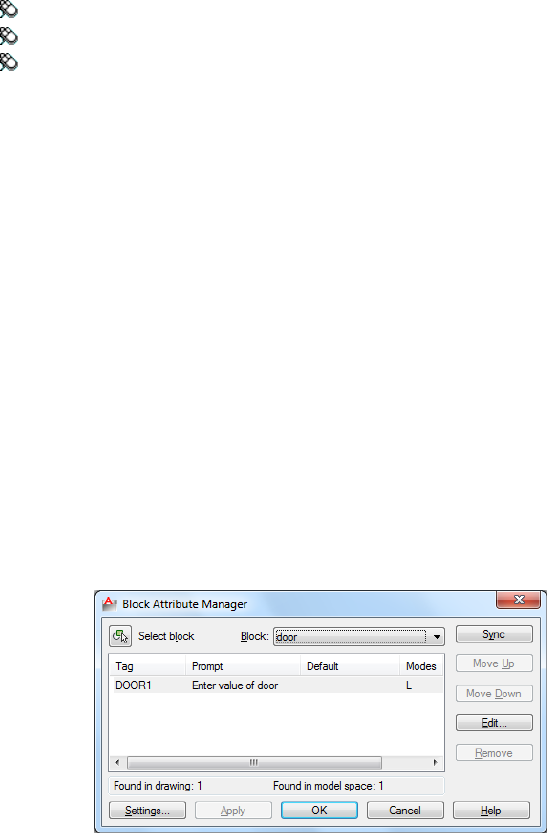
Ribbon: Insert tab ➤ Block Definition panel ➤ Manage Attributes
Menu: Modify ➤ Object ➤ Attribute ➤ Block Attribute Manager
Toolbar: Modify II
Summary
The Block Attribute Manager is displayed.
If the current drawing does not contain any blocks with attributes, a message
is displayed.
This command controls all attribute properties and settings of a selected block
definition. Any changes to the attributes in a block definition are reflected in
the block references.
Block Attribute Manager
Quick Reference
See also:
■Modify a Block Attribute Definition
Manages the attribute definitions for blocks in the current drawing.
Summary
You can edit the attribute definitions in blocks, remove attributes from blocks,
and change the order in which you are prompted for attribute values when
inserting a block.
106 | Chapter 3 B Commands
Attributes of the selected block are displayed in the attribute list. By default,
Tag, Prompt, Default, Mode, and Annotative attribute properties are displayed
in the attribute list. For each selected block, a description below the attribute
list identifies the number of its instances in the current drawing and in the
current layout.
You can specify which attribute properties you want displayed in the list by
choosing Settings.
Double-click an attribute to display the Edit Attribute dialog box, where you
can modify attribute properties.
List of Options
The following options are displayed.
Select Block
You can use your pointing device to select a block from the drawing area.
When you choose Select Block, the dialog box closes until you select a block
from the drawing or you cancel by pressing ESC.
If you modify attributes of a block and then select a new block before you
save the attribute changes you made, you are prompted to save the changes
before selecting another block.
Block
Lists all block definitions in the current drawing that have attributes. Select
the block whose attributes you want to modify.
List of Attributes
Displays the properties of each attribute in the selected block.
Blocks Found in Drawing
Reports the total number of instances of the selected block in the current
drawing.
Blocks Found in Current Space
Reports the number of instances of the selected block in the current model
space or layout.
Sync
Updates all instances of the selected block with the attribute properties
currently defined. This does not affect any values assigned to attributes in
each block.
Block Attribute Manager | 107
Move Up
Moves the selected attribute tag earlier in the prompt sequence. The Move Up
button is not available when a constant attribute is selected.
Move Down
Moves the selected attribute tag later in the prompt sequence. The Move Down
button is not available when a constant attribute is selected.
Edit
Opens the Edit Attribute dialog box, where you can modify attribute properties.
Remove
Removes the selected attribute from the block definition. If Apply Changes
to Existing References is selected in the Settings dialog box before you choose
Remove, the attribute is removed from all instances of the block in the current
drawing. The Remove button is not available for blocks with only one attribute.
Settings
Opens the Block Attribute Settings dialog box, where you can customize how
attribute information is listed in the Block Attribute Manager.
Apply
Applies the changes made and leaves the dialog box open.
Edit Attribute Dialog Box
Quick Reference
See also:
■Modify a Block Attribute Definition
Allows you to edit attributes for a block definition.
Summary
The Edit Attribute dialog box contains the following tabs:
■Attribute on page 109
■Text Options on page 110
108 | Chapter 3 B Commands
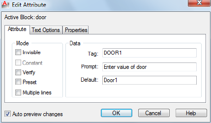
■Properties on page 112
List of Options
The following options are displayed.
Block Name
Displays the name of the block whose attributes are to be edited.
Auto Preview Changes
Controls whether or not the drawing area is immediately updated to display
any visible attribute changes you make. If Auto Preview Changes is selected,
changes are immediately visible. If Auto Preview Changes is cleared, changes
are not immediately visible.
Clearing Auto Preview Changes results in a small improvement in performance.
Auto Preview Changes is not available if Apply Changes to Existing References
is not selected.
Attribute Tab (Edit Attribute Dialog Box)
Defines how a value is assigned to an attribute and whether or not the assigned
value is visible in the drawing area, and sets the string that prompts users to
enter a value. The Attribute tab also displays the tag name that identifies the
attribute.
Mode
Mode options determine whether and how attribute text appears.
Invisible
Displays or hides the attribute in the drawing area. If selected, hides the
attribute value in the drawing area. If cleared, displays the attribute value.
Constant
Edit Attribute Dialog Box | 109
Identifies whether the attribute is set to its default value. You cannot change
this property. If a check mark is shown in the check box, the attribute is set
to its default value and cannot be changed. If the check box is empty, you
can assign a value to the attribute.
Verify
Turns value verification on and off. If selected, prompts you to verify the
values you assign to the attribute when inserting a new instance of the block.
If this option is cleared, verification is not performed.
Preset
Turns default value assignment on and off. If selected, sets the attribute to its
default value when the block is inserted. If cleared, ignores the attribute's
default value and prompts you to enter a value when inserting the block.
Lock Location Locks the location of the attribute within the block reference.
When unlocked, the attribute can be moved relative to the rest of the block
using grip editing, and multiline attributes can be resized.
Multiple Lines
Indicates whether the attribute was defined as a Multiple Lines attribute and
can contain multiple lines of text.
Data
Data options set the attribute text that is displayed.
Tag
Sets the identifier assigned to the attribute.
Prompt
Sets the text for the prompt that is displayed when you insert the block.
Default
Sets the default value assigned to the attribute when you insert the block.
Text Options Tab (Edit Attribute Dialog Box)
Sets the properties that define the way an attribute's text is displayed in the
drawing. Change the color of attribute text on the Properties tab.
110 | Chapter 3 B Commands
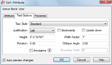
Text Style
Specifies the text style for attribute text. Default values for this text style are
assigned to the text properties displayed in this dialog box.
Justification
Specifies how attribute text is justified.
Height
Specifies the height of the attribute text.
Rotation
Specifies the rotation angle of the attribute text.
Annotative
Specifies that the attribute is .
Backwards
Specifies whether or not the text is displayed backwards.
Upside Down
Specifies whether or not the text is displayed upside down.
Width Factor
Sets the character spacing for attribute text. Entering a value less than 1.0
condenses the text. Entering a value greater than 1.0 expands it.
Oblique Angle
Specifies the angle that attribute text is slanted away from its vertical axis.
Edit Attribute Dialog Box | 111
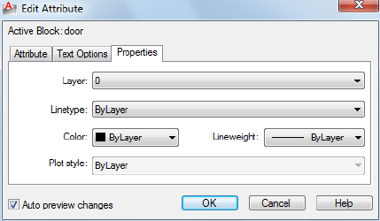
Properties Tab (Edit Attribute Dialog Box)
Defines the layer that the attribute is on and the color, lineweight, and linetype
for the attribute's line. If the drawing uses plot styles, you can assign a plot
style to the attribute using the Properties tab.
Layer
Specifies the layer that the attribute is on.
Linetype
Specifies the linetype of attribute text.
Color
Specifies the attribute's text color.
Lineweight
Specifies the lineweight of attribute text.
Changes you make to this option are not displayed if the LWDISPLAY on page
1575 system variable is off.
Plot Style
Specifies the plot style of the attribute.
If the current drawing uses color-dependent plot styles, the Plot Style list is
not available.
112 | Chapter 3 B Commands
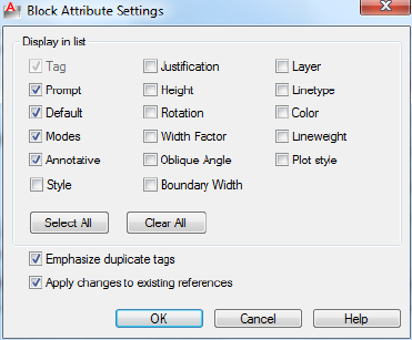
Block Attribute Settings Dialog Box
Quick Reference
See also:
■Modify a Block Attribute Definition
Controls the appearance of the attribute list in the Block Attribute Manager.
List of Options
The following options are displayed.
Display in List
Specifies the properties to be displayed in the attribute list. Only the selected
properties are displayed in the list. The Tag property is always selected.
Select All
Selects all properties.
Clear All
Clears all properties.
Emphasize Duplicate Tags
Turns duplicate tag emphasis on and off. If this option is selected, duplicate
attribute tags are displayed in red type in the attribute list. If this option is
cleared, duplicate tags are not emphasized in the attribute list.
Block Attribute Settings Dialog Box | 113
Apply Changes to Existing References
Specifies whether or not to update all existing instances of the block whose
attributes you are modifying. If selected, updates all instances of the block
with the new attribute definitions. If cleared, updates only new instances of
the block with the new attribute definitions.
You can choose Sync in the Block Attribute Manager to apply changes
immediately to existing block instances. This temporarily overrides the Apply
Changes to Existing References option.
BATTORDER
Quick Reference
See also:
■Attach Data to Blocks (Block Attributes)
Specifies the order of attributes for a block.
Summary
Displays the Attribute Order dialog box, which controls the order in which
attributes are listed and prompted for when you insert or edit a block reference.
You can only use the BATTORDER command in the Block Editor on page 127.
Attribute Order Dialog Box
Quick Reference
See also:
■Attach Data to Blocks (Block Attributes)
Specifies the order in which attributes are listed and prompted for when you
insert or edit a block reference.
List of Options
The following options are displayed.
114 | Chapter 3 B Commands
Attribute Definitions
Lists the attribute definitions in the current block.
Move Up
Moves the selected attribute definition up in the list.
Move Down
Moves the selected attribute definition down in the list.
BAUTHORPALETTE
Quick Reference
See also:
■Create Custom Block Authoring Tools
Opens the Block Authoring Palettes window in the Block Editor.
Access Methods
Button
Ribbon: Block Editor contextual tab ➤ Manage panel ➤ Authoring
Palettes
Summary
Displays the Block Authoring Palettes window in the Block Editor. You can
open the Block Authoring Palettes window only from the Block Editor.
The Block Authoring Palettes window contains the following tabs:
■Parameters tab
■Actions tab
■Parameter Sets tab
BAUTHORPALETTE | 115

BAUTHORPALETTECLOSE
Quick Reference
See also:
■Create Custom Block Authoring Tools
Closes the Block Authoring Palettes window in the Block Editor.
Summary
You can close the Block Authoring Palettes window only from the Block Editor.
BCLOSE
Quick Reference
See also:
■Overview of the Block Editor
■Define Blocks
■Modify Blocks
Closes the Block Editor.
Access Methods
Button
Ribbon: Block Editor contextual tab ➤ Close panel ➤ Close Block Editor
Shortcut menu: In the Block Editor, right-click in the drawing area. Click
Close Block Editor
116 | Chapter 3 B Commands

Summary
Closes the Block Editor. If you have modified the block definition since it was
last saved, you are prompted to save or discard the changes.
BCONSTRUCTION
Quick Reference
See also:
■Create Construction Geometry Within a Block
Converts geometry into construction geometry.
Access Methods
Button
Ribbon: Block Editor contextual tab ➤ Manage panel ➤ Construction
Summary
The BCONSTRUCTION command is used in the Block Editor on page 127 to
convert geometry into construction geometry. This command also controls
the display of construction geometry and changes construction geometry back
to regular geometry.
Construction geometry is not displayed in the block reference; in the Block
Editor it is displayed with a gray dashed linetype. You cannot modify the
color, linetype, or layer of the construction geometry.
List of Prompts
The following prompts are displayed.
Select objects or [Show all on page 118/Hide all on page 118]: Select objects to
convert or revert geometry
Enter an option [Convert/Revert] <Convert>: Specify an option
BCONSTRUCTION | 117
Convert
Converts the valid selected objects into construction geometry and displays
the number of objects converted. Authoring objects are not converted.
Revert
Changes the selected objects back to regular geometry. The geometry is set to
the current layer.
Show All
Displays all construction geometry.
Hide All
Hides all construction geometry.
BCYCLEORDER
Quick Reference
See also:
■Insert Blocks
Changes the cycling order of grips for a dynamic block reference.
Summary
Displays the Insertion Cycling Order dialog box. The BCYCLEORDER command
is available only in the Block Editor on page 127.
Insertion Cycling Order Dialog Box
Quick Reference
See also:
■Insert Blocks
Specifies the grip-cycling order for the insertion point of a dynamic block
reference.
118 | Chapter 3 B Commands
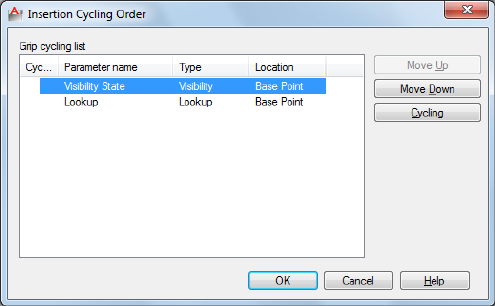
Summary
When you insert a dynamic block reference in a drawing, you can use the Ctrl
key to cycle through the grips that have cycling turned on in the block
definition. The grip you select as you cycle is used as the insertion point for
the block reference.
List of Options
The following options are displayed.
Grip Cycling List
Lists the grips in the dynamic block definition. A check mark in the cycling
column indicates that cycling is turned on for that grip.
Move Up
Moves the selected grip up in the cycling order for the dynamic block reference.
Move Down
Moves the selected grip down in the cycling order for the dynamic block
reference.
Cycling
Turns cycling on or off for the selected grip. A check mark in the cycling
column indicates that cycling is turned on for that grip.
Insertion Cycling Order Dialog Box | 119

BEDIT
Quick Reference
See also:
■Define Blocks
■Modify Blocks
■Modify Dynamic Block Definitions
Opens the block definition in the Block Editor.
Access Methods
Button
Ribbon: Home tab ➤ Block panel ➤ Block Editor
Menu: Tools ➤ Block Editor
Toolbar: Standard
Shortcut menu: Select a block reference. Right-click in the drawing area.
Click Block Editor.
Summary
The Edit Block Definition dialog box on page 121 is displayed. Select a block
definition to edit or enter a name for a new block definition to create, then
click OK to open the Block Editor.
If the ribbon is active, the Block Editor ribbon contextual tab on page 122 is
displayed. Otherwise, the Block Editor toolbar is displayed.
When the BLOCKEDITLOCK system variable is set to 1, the Block Editor cannot
be opened.
The Block Editor is a separate environment for creating and changing block
definitions for the current drawing. You can also use it to add dynamic
behavior to blocks.
120 | Chapter 3 B Commands

Edit Block Definition Dialog Box
Quick Reference
See also:
■Define Blocks
■Modify Blocks
■Modify Dynamic Block Definitions
Select from a list of block definitions that are saved in the drawing to edit in
the Block Editor. You can also enter a name for a new block definition to
create in the Block Editor.
Summary
When you click OK, the Edit Block Definition dialog box closes, and the Block
Editor is displayed.
■If you selected a block definition from the list, that block definition is
displayed and is available for editing in the Block Editor.
■If you entered a name for a new block definition, the Block Editor is
displayed, and you can start adding objects to the block definition.
List of Options
The following options are displayed.
Block to create or edit
Edit Block Definition Dialog Box | 121
Specifies the name of the block to edit or create in the Block Editor. If you
select <Current Drawing>, the current drawing is opened in the Block Editor.
After you add dynamic elements to the drawing, you can then save it and
insert it as a dynamic block reference in a drawing.
Name List
Displays a list of block definitions that are saved in the current drawing. When
you select a block definition from the list, the name is displayed in the Name
box.
When you click OK, this block definition is opened in the Block Editor. When
you select <Current Drawing>, the current drawing is opened in the Block
Editor.
Preview
Displays a preview of the selected block definition. A lightning bolt icon
indicates that the block is a dynamic block.
Description
Displays the description of the selected block definition.
Block Editor Ribbon Contextual Tab
Quick Reference
See also:
■Modify Dynamic Block Definitions
List of Options
The following options are displayed.
Open/Save Panel
Edit Block Opens the block definition in the Block Editor.
Save Block Saves the current block definition.
Test Block Displays a window within the Block Editor to test a dynamic block.
Save Block As Saves a copy of the current block definition under a new name.
122 | Chapter 3 B Commands
Geometric Panel
Auto Constrain Applies geometric constraints to a selection set of objects
based on orientation of the objects relative to one another.
Coincident (GEOMCONSTRAINT) Constrains two points together or a point
to a curve (or an extension of a curve).
Colinear (GEOMCONSTRAINT) Causes two or more line segments to lie
along the same line.
Concentric (GEOMCONSTRAINT) Constrains two arcs, circles, or ellipses to
the same center point.
Fix (GEOMCONSTRAINT) Locks points and curves in position.
Parallel (GEOMCONSTRAINT) Causes selected lines to lie parallel to each
other.
Perpendicular (GEOMCONSTRAINT) Causes selected lines to lie 90 degrees
to one another.
Horizontal (GEOMCONSTRAINT) Causes lines or pairs of points to lie parallel
to the X axis of the current coordinate system.
Vertical (GEOMCONSTRAINT) Causes lines or pairs of points to lie parallel
to the Y axis of the current coordinate system.
Tangent (GEOMCONSTRAINT) Constrains two curves to maintain a point
of tangency to each other or their extensions.
Smooth (GEOMCONSTRAINT) Constrains a spline to be contiguous and
maintain G2 continuity with another spline, line, arc, or polyline.
Symmetric (GEOMCONSTRAINT) Causes selected objects to become
symmetrically constrained about a selected line.
Equal (GEOMCONSTRAINT) Resizes selected arcs and circles to the same
radius, or selected lines to the same length.
Show Constraints Displays constraint bars for the selected objects with
geometric constraints applied to them.
Show All Displays all geometric constraints in the drawing.
Hide All Hides all geometric constraints in the current drawing.
Constraint Settings Controls the display of geometric constraints on constraint
bars.
Block Editor Ribbon Contextual Tab | 123
Dimensional Panel
Linear (BCPARAMETER) Creates a horizontal or vertical constraint parameter
based on the locations of the extension line origins and the location of the
dimension line similar to the DIMLINEAR command.
Horizontal (BCPARAMETER) Creates a horizontal constraint parameter by
picking two constraint points. Valid objects include lines and polyline
segments.
Vertical (BCPARAMETER) Creates a vertical constraint parameter by picking
two constraint points. Valid objects include lines and polyline segments.
Aligned (BCPARAMETER) Creates an aligned constraint parameter using one
of the following ways.
■Selects a point and a line object. The aligned constraint controls the
distance between a point and the closest point on a line.
■Selects two line objects. The lines are made parallel and the aligned
constraint controls the distance between the two lines.
Radius (BCPARAMETER) Creates a radial constraint parameter for a circle,
arc, or polyline arc segment.
Diameter (BCPARAMETER) Creates a diameter constraint parameter for a
circle, arc, or polyline arc segment.
Angular (BCPARAMETER) Creates an angular constraint parameter by picking
two lines or polyline segments or an arc. It is similar to an angular dimension.
Convert (BCPARAMETER) Converts the dimensional constraints to constraint
parameters.
Block Table Displays a dialog box to define variations of a block.
Constraint Settings Sets preferences in behavior when displaying dimensional
constraints.
Manage Panel
Delete Constraints Removes all geometric and dimensional constraints from
a selection set of objects.
Construction Geometry Converts geometry into construction geometry.
Block Constraint Status Turns the constraint display status on and off and
controls the shading of objects based on their constraint level.
124 | Chapter 3 B Commands
Parameters Manager Opens the Parameters Manager palette that includes all
dimensional constraint parameters, reference parameters, and user variables
in the current drawing.
Authoring Palettes Opens the Block Authoring Palettes window in the Block
Editor.
Block Editor Settings Displays the Block Editor Settings dialog box.
Action Parameters Panel
Point (BPARAMETER on page 154) Defines custom X and Y properties for the
block reference.
Linear (BPARAMETER on page 154) Defines the distance between two key
points in the block definition.
Polar (BPARAMETER on page 154) Defines a distance and angle for two key
points in the block definition.
XY (BPARAMETER on page 154) Defines an X and Y distance from the base
point of a block definition.
Rotation (BPARAMETER on page 154) Defines an angle for the block reference.
Flip (BPARAMETER on page 154) Mirrors objects or the entire block reference
about a reflection line.
Alignment (BPARAMETER on page 154) Rotates the block reference about a
point to align with other objects in the drawing.
Visibility (BPARAMETER on page 154) Defines objects that will either display
or not display within the block definition.
Lookup (BPARAMETER on page 154) Defines user parameters that are
determined by a lookup table.
Basepoint (BPARAMETER on page 154) Defines a changeable base point for
the dynamic block reference in relation to the geometry in the block.
Move (BACTIONTOOL on page 98) Specifies that the selection set of objects
moves when the action is triggered in a dynamic block reference. A move
action can be associated with a point, linear, polar, or XY parameter.
Stretch (BACTIONTOOL on page 98) Specifies that the selection set of objects
will stretch or move when the action is triggered in a dynamic block reference.
A stretch action can be associated with a point, linear, polar, or XY parameter.
Block Editor Ribbon Contextual Tab | 125
Polar Stretch (BACTIONTOOL on page 98) Specifies that the selection set
of objects stretches or moves when the action is triggered in a dynamic block
reference. A polar stretch action can only be associated with a polar parameter.
Scale (BACTIONTOOL on page 98) Specifies that the selection set of objects
scales relative to the defined base point when the action is triggered in a
dynamic block reference. A scale action can only be associated with a linear,
polar, or XY parameter.
Rotate (BACTIONTOOL on page 98) Specifies that the selection set of objects
scales relative to the defined base point when the action is triggered in a
dynamic block reference. A scale action can only be associated with a linear,
polar, or XY parameter.
Flip (BACTIONTOOL on page 98) A set of objects is flipped around the
reflection line of the flip parameter when the action is triggered in the block
reference. A flip action can only be associated with a flip parameter.
Array (BACTIONTOOL on page 98) Specifies that the selection set of objects
arrays when the action is triggered in a dynamic block reference. An array
action can be associated with a linear, polar, or XY parameter.
Lookup (BACTIONTOOL on page 98) A set of objects is flipped around the
reflection line of the flip parameter when the action is triggered in the block
reference. A flip action can only be associated with a flip parameter.
Attribute Definition Creates an attribute definition for storing data in a block.
Show All Actions (BACTIONBAR on page 95) Displays all action bars for
the parameter objects in the Block Editor.
Hide All Actions (BACTIONBAR on page 95) Hides all action bars for the
parameter objects in the Block Editor.
Visibility Panel
Visibility States Creates, sets, or deletes a visibility state in a dynamic block.
Visibility Mode (BVMODE) Controls how objects that are made invisible for
the current visibility state are displayed in the Block Editor.
Make Visible (BVSHOW) Makes objects visible in the current visibility state
or all visibility states in a dynamic block definition.
Make Invisible (BVHIDE) Makes objects invisible in the current visibility
state or all visibility states in a dynamic block definition.
Block Visibility States Specifies the current visibility state displayed in the
Block Editor.
126 | Chapter 3 B Commands
Close Panel
Close Block Editor Closes the Block Editor.
Block Editor
Quick Reference
See also:
■Define Blocks
■Modify Blocks
■Modify Dynamic Block Definitions
The Block Editor contains a special authoring area in which you can draw and
edit geometry as you would in the drawing area.
Summary
You use the Block Editor to define the objects and behavior for a block
definition.
In the Block Editor, you add parameters and actions, which define custom
properties and dynamic behavior.
The following commands are used for editing blocks and are available only
in the Block Editor:
■BACTION
■BACTIONBAR on page 95
■BACTIONSET
■BACTIONTOOL
■BASSOCIATE
■BATTORDER
■BAUTHORPALETTE
■BAUTHORPALETTECLOSE
■BCLOSE
Block Editor | 127

■BCYCLEORDER
■BCONSTRUCTION on page 117
■BGRIPSET
■BLOOKUPTABLE
■BPARAMETER
■BSAVE
■BSAVEAS
■BTABLE on page 166
■BTESTBLOCK on page 170
■BVHIDE
■BVSHOW
■BVSTATE
When the BLOCKEDITLOCK system variable is set to 1, the Block Editor cannot
be opened.
The Block Editor also provides a Block Editor toolbar and Block Authoring
palettes that contain tools for creating dynamic blocks. The Block Authoring
Palettes window contains the following tabs:
■Parameters tab on page 129
■Actions tab on page 131
■Parameter Sets tab on page 132
Block Editor Toolbar
Provides tools for working in the Block Editor, creating dynamic blocks, and
working with visibility states.
The Block Editor toolbar is displayed when the ribbon is not active. It is also
displayed only when you enter the Block Editor with the ribbon closed.
Edit or Create Block Definition Displays the Edit Block Definition dialog
box.
128 | Chapter 3 B Commands
Save Block Definition Saves the current block definition.
Save Block As Saves a copy of the current block definition under a new name.
Name Displays the name of the current block definition.
Test Block (BTESTBLOCK on page 170) Displays a window within the Block
Editor to test a dynamic block.
Display / Hide Constraints Bar (CONSTRAINTBAR on page 224) Displays
or hides the geometric constraints on an object.
Parameter (BPARAMETER) Adds a parameter with grips to a dynamic block
definition.
Action (BACTION) Adds an action to a dynamic block definition.
Define Attribute (Attribute Definition Dialog Box)Creates an attribute
definition for storing data in a block.
Authoring Palettes (BAUTHORPALETTE on page 115) Opens the Block
Authoring Palettes window in the Block Editor.
Parameters Manager (PARAMETERS on page 917) Opens the Parameters
Manager palette that includes all dimensional constraint parameters, reference
parameters, and user variables in the current drawing.
Close Block Editor (BCLOSE on page 116) Closes the Block Editor.
Visibility Mode (BVMODE) Controls how objects that are made invisible for
the current visibility state are displayed in the Block Editor.
Make Visible (BVSHOW) Makes objects visible in the current visibility state
or all visibility states in a dynamic block definition.
Make Invisible (BVHIDE) Makes objects invisible in the current visibility
state or all visibility states in a dynamic block definition.
Manage Visibility States (Visibility States Dialog Box on page 173) Creates,
sets, or deletes a visibility state in a dynamic block.
Visibility State Specifies the current visibility state displayed in the Block
Editor.
Parameters Tab (Block Authoring Palettes Window)
Provides tools for adding parameters to a dynamic block definition in the
Block Editor. Parameters specify positions, distances, and angles for geometry
in the block reference. When you add a parameter to a dynamic block
definition, it defines one or more custom properties for the block.
Block Editor | 129
Point Parameter (BPARAMETER) Adds a point parameter to the dynamic
block definition and defines custom X and Y properties for the block reference.
A point parameter defines an X and Y location in the drawing. In the Block
Editor, a point parameter looks similar to an ordinate dimension.
Linear Parameter (BPARAMETER) Adds a linear parameter to the dynamic
block definition and defines a custom distance property for the block reference.
A linear parameter shows the distance between two anchor points. A linear
parameter constrains grip movement along a preset angle. In the Block Editor,
a linear parameter looks similar to an aligned dimension.
Polar Parameter (BPARAMETER) Adds a polar parameter to the dynamic
block definition and defines custom distance and angle properties for the
block reference. A polar parameter shows the distance between two anchor
points and displays an angle value. You can use both grips and the Properties
palette to change both the distance value and the angle. In the Block Editor,
a polar parameter looks similar to an aligned dimension.
XY Parameter (BPARAMETER) Adds an XY parameter to the dynamic block
definition and defines custom horizontal and vertical distance properties for
the block reference. An XY parameter shows the X and Y distances from the
base point of the parameter. In the Block Editor, an XY parameter displays as
a pair of dimensions (horizontal and vertical). These dimensions share a
common base point.
Rotation Parameter (BPARAMETER) Adds a rotation parameter to the
dynamic block definition and defines a custom angle property for the block
reference. A rotation parameter defines an angle. In the Block Editor, a rotation
parameter displays as a circle.
Alignment Parameter (BPARAMETER) Adds an alignment parameter to the
dynamic block definition. An alignment parameter defines an X and Y location
and an angle. An alignment parameter always applies to the entire block and
needs no action associated with it. An alignment parameter allows the block
reference to automatically rotate around a point to align with other objects
in the drawing. An alignment parameter affects the angle property of the block
reference. In the Block Editor, an alignment parameter looks like an alignment
line.
Flip Parameter (BPARAMETER) Adds a flip parameter to the dynamic block
definition and defines a custom flip property for the block reference. A flip
parameter flips objects. In the Block Editor, a flip parameter displays as a
reflection line. Objects can be flipped about this reflection line. A flip parameter
displays a value that shows if the block reference has been flipped or not.
130 | Chapter 3 B Commands
Visibility Parameter (BPARAMETER) Adds a visibility parameter to the
dynamic block definition and defines a custom visibility property for the block
reference. With visibility parameter, you can create visibility states and control
the visibility of objects in the block. A visibility parameter always applies to
the entire block and needs no action associated with it. In a drawing, you
click the grip to display a list of visibility states available for the block reference.
In the Block Editor, a visibility parameter displays as text with an associated
grip.
Lookup Parameter (BPARAMETER) Adds a lookup parameter to the dynamic
block definition and defines custom lookup properties for the block reference.
A lookup parameter defines a custom property that you can specify or set to
evaluate to a value from a list or table you define. It can be associated with a
single lookup grip. In the block reference, you click the grip to display a list
of available values. In the Block Editor, a lookup parameter displays as text.
Base Point Parameter (BPARAMETER) Adds a base point parameter to the
dynamic block definition. A base point parameter defines a base point for the
dynamic block reference relative to the geometry in the block. A base point
parameter cannot be associated with any actions, but can belong to an action's
selection set. In the Block Editor, a base point parameter displays as a circle
with crosshairs
Actions Tab (Block Authoring Palettes Window)
Provides tools for adding actions to a dynamic block definition in the Block
Editor. Actions define how the geometry of a dynamic block reference move
or change when the custom properties of a block reference are manipulated
in a drawing. You associate actions with parameters.
Move Action (BACTIONTOOL) Adds a move action to the dynamic block
definition when you associate the action with a point, linear, polar, or XY
parameter. A move action is similar to the MOVE command. In a dynamic
block reference, a move action causes objects to move a specified distance and
angle.
Scale Action (BACTIONTOOL) Adds a scale action to the dynamic block
definition when you associate the action with a linear, polar, or XY parameter.
A scale action is similar to the SCALE command. In a dynamic block reference,
a scale action causes its selection set to scale when the associated parameter
is edited by moving grips or by using the Properties palette.
Stretch Action (BACTIONTOOL) Adds a stretch action to the dynamic block
definition when you associate the action with a point, linear, polar, or XY
parameter. A stretch action causes objects to move and stretch a specified
distance in a specified location.
Block Editor | 131
Polar Stretch Action (BACTIONTOOL) Adds a polar stretch action to the
dynamic block definition when you associate the action with a polar parameter.
A polar stretch action rotates, moves, and stretches objects a specified angle
and distance when the key point on the associated polar parameter is changed
through a grip or the Properties palette
Rotate Action (BACTIONTOOL) Adds a rotate action to the dynamic block
definition when you associate the action with a rotation parameter. A rotate
action is similar to the ROTATE command. In a dynamic block reference, a
rotate action causes its associated objects to rotate when the associated
parameter is edited through a grip or the Properties palette.
Flip Action (BACTIONTOOL) Adds a flip action to the dynamic block
definition when you associate the action with a flip parameter. With a flip
action you can flip a dynamic block reference about a specified axis called a
reflection line.
Array Action (BACTIONTOOL) Adds an array action to the dynamic block
definition when you associate the action with a linear, polar, or XY parameter.
An array action causes its associated objects to copy and array in a rectangular
pattern when the associated parameter is edited through a grip or the Properties
palette.
Lookup Action (BACTIONTOOL) Adds a lookup action to the dynamic block
definition. When you add a lookup action to a dynamic block definition and
associate it with a lookup parameter, it creates a lookup table. You can use a
lookup table to assign custom properties and values to a dynamic block.
Parameter Sets Tab (Block Authoring Palettes Window)
Provides tools for adding a parameter and at least one action at the same time
to a dynamic block definition in the Block Editor. When you add a parameter
set to a dynamic block, the actions are automatically associated with the
parameter. After you add a parameter set to a dynamic block, you double-click
the yellow alert icon (or use the BACTIONSET command) and follow the
Command prompts to associate the action with a selection set of geometry.
Point Move Automatically adds a move action associated with the point
parameter.
Linear Move Automatically adds a move action associated with the endpoint
of the linear parameter.
Linear Stretch Automatically adds a stretch action associated with the linear
parameter.
132 | Chapter 3 B Commands
Linear Array Automatically adds an array action associated with the linear
parameter.
Linear Move Pair Automatically adds a two move action, one associated with
the base point and one associated with the endpoint of the linear parameter.
Linear Stretch Pair Automatically adds two stretch actions, one associated
with the base point and one associated with the endpoint of the linear
parameter.
Polar Move Automatically adds a move action associated with the polar
parameter.
Polar Stretch Automatically adds a stretch action associated with the polar
parameter.
Polar Array Automatically adds an array action associated with the polar
parameter.
Polar Move Pair Automatically adds two move actions, one associated with
the base point and one associated with the endpoint of the polar parameter.
Polar Stretch Pair Automatically adds two stretch actions, one associated
with the base point and one associated with the endpoint of the polar
parameter.
XY Move Automatically adds a move action associated with the endpoint of
the XY parameter.
XY Move Pair Automatically adds two move actions, one associated with the
base point and one associated with the endpoint of the XY parameter.
XY Move Box Set Automatically adds four move actions, one associated with
each key point on the XY parameter.
XY Stretch Box Set Automatically adds four stretch actions, one associated
with each key point on the XY parameter.
XY Array Box Set Automatically adds an array action associated with the XY
parameter.
Rotation Set Automatically adds a rotation action associated with the rotation
parameter.
Flip Set Automatically adds a flip action associated with the flip parameter.
Visibility Set Adds a visibility parameter to the dynamic block definition and
allows visibility states to be defined. No action is necessary with the visibility
parameter.
Block Editor | 133
Lookup Set Automatically adds a lookup action associated with the lookup
parameter.
-BEDIT
Quick Reference
See also:
■Define Blocks
■Modify Blocks
■Modify Dynamic Block Definitions
Summary
If you select a block in a drawing and enter -bedit at the Command prompt,
the selected block is opened in the Block Editor on page 127. If nothing is
selected, the following prompt is displayed:
List of Prompts
The following prompts are displayed
Enter block name on page 134 or [? on page 134]: Enter a name or ?
Block Name
Specifies the name of a block saved in the current drawing to open in the
Block Editor or specifies the name of a new block to create.
?—List Previously Defined Blocks
Lists the block names in the text window.
Enter block(s) to list <*>: Enter a name list or press Enter
BESETTINGS
Quick Reference
See also:
■Create and Edit Dynamic Blocks
134 | Chapter 3 B Commands
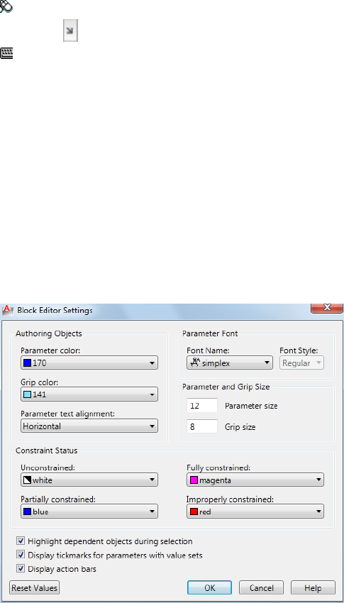
Displays the Block Editor Settings dialog box.
Access Methods
Ribbon: Block Editor contextual tab ➤ Manage panel ➤ Dialog Box
Launcher
Command entry: besettings
Summary
The Block Editor Settings dialog box on page 135 is displayed.
Block Editor Settings Dialog Box
Quick Reference
See also:
■Create and Edit Dynamic Blocks
Block Editor Settings Dialog Box | 135
Summary
Controls the environment settings of the Block Editor.
List of Options
The following options are displayed.
Authoring Objects
Controls the color of parameter and grip objects and specifies the orientation
of the parameter text.
Parameter Color
Sets the color of parameters in the Block Editor.
(BPARAMETERCOLOR on page 1401 system variable)
Grip Color
Sets the color of grips in the Block Editor.
(BGRIPOBJCOLOR on page 1398 system variable)
Parameter Text Alignment
Forces the text displayed for action parametes and constraint parameters in
the Block Editor to be horizontal.
(BPTEXTHORIZONTAL on page 1402 system variable)
Parameter Font
Sets the font for the authoring objects.
Font Name
Sets the font used for parameters and actions in the Block Editor.
(BPARAMETERFONT on page 1401 system variable)
Font Style
Specifies font character formatting for the authoring objects, such as italic,
bold, or regular.
Parameter and Grip Size
Controls the size of the parameter and grip objects.
Parameter Size
Sets the size of parameter text and features in the Block Editor relative to the
screen display.
(BPARAMETERSIZE on page 1402 system variable)
Grip Size
136 | Chapter 3 B Commands
Sets the display size of custom grips in the Block Editor relative to the screen
display.
(BGRIPOBJSIZE on page 1398 system variable)
Constraint Status
Specifies the color overrides for objects in the Block Editor to show constraint
status.
Unconstrained
Sets the color of the unconstrained objects.
Partially Constrained
Sets the color of the partially constrained objects.
Fully Constrained
Sets the color of the fully constrained objects.
Improperly Constrained
Sets the color of the over-constrained objects.
Highlight Dependent Objects During Selection
Automatically highlights all objects that are dependent on the currently
selected authoring objects. Use this option when you need to confirm or
change dependent objects.
Display Tickmarks for Parameters With Value Sets
Controls whether or not value set markers are displayed for dynamic block
references.
(BTMARKDISPLAY on page 1403 system variable)
Display Action Bars
Indicates whether the action bars or the legacy action objects are displayed
in the Block Editor.
(BACTIONBARMODE on page 1396 system variable)
Reset Values
Resets the Block Editor settings to default values.
Block Editor Settings Dialog Box | 137
BGRIPSET
Quick Reference
See also:
■Specify Grips for Dynamic Blocks
Creates, deletes, or resets grips associated with a parameter.
Access Methods
Shortcut menu: Select a parameter in the block definition. Right-click in
the Block Editor drawing area. Click Grip Display, and then click an option.
Summary
Specifies the number of grips displayed for a parameter. Also resets the position
of grips for a parameter to their default location. You can only use the
BGRIPSET command in the Block Editor on page 127.
List of Prompts
The following prompts are displayed.
Select parameter: Select a parameter in the current dynamic block definition
Enter number of grip objects for parameter or reset position
[0/1/2/4/Reposition]: Enter the number of grips to display for the parameter (the
number of grips available will vary depending on the type of parameter you selected)
or enter reposition to reposition the existing grips in the block definition to their
default locations
BHATCH
Quick Reference
See also:
■Overview of Hatch Patterns and Fills
Fills an enclosed area or selected objects with a hatch pattern or gradient fill.
138 | Chapter 3 B Commands

Summary
The BHATCH command has been renamed to HATCH. If you enter bhatch,
the Hatch and Gradient dialog box on page 546is displayed. If you enter -bhatch
or -hatch, Command prompts are displayed.
BLEND
Quick Reference
See also:
■Draw Splines
Creates a spline in the gap between two selected lines or curves.
Access Methods
Button
Ribbon: Home tab ➤ Modify panel ➤ Blend
Menu: Modify ➤ Blend Curves
Summary
Select each object near an endpoint. The shape of the resulting spline depends
on the specified continuity. The lengths of the selected objects remain
unchanged.
Valid objects include lines, arcs, elliptical arcs, helixes, open polylines, and
open splines.
BLEND | 139

List of Prompts
The following prompts are displayed.
Select first object or [CONtinuity]: Select a line or open curve near the end where
the spline should start
Select second object: Select another line or open curve near the end where the spline
should end
Continuity
Specify one of two types of blends.
Tangent Creates a degree 3 spline with tangency (G1) continuity to the selected
objects at their endpoints.
Smooth Creates a degree 5 spline with curvature (G2) continuity to the selected
objects at their endpoints.
If you use the Smooth option, do not switch the display from control vertices
to fit points. This action changes the spline to degree 3, which will change
shape of the spline.
BLIPMODE
Quick Reference
See also:
■Customize Object Selection
Controls the display of marker blips.
Obsolete
Marker blips have been removed from the product.
Access Methods
Command entry: 'blipmode for transparent use
Summary
When Blip mode is on, a temporary mark in the shape of a plus sign (+) appears
where you specify a point. BLIPMODE is off by default.
140 | Chapter 3 B Commands
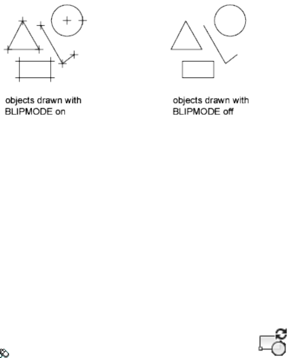
To remove marker blips, use REDRAW, REGEN, ZOOM, PAN, or other
commands that redraw or regenerate the drawing.
BLOCKICON
Quick Reference
See also:
■Overview of Blocks
Generates preview images for blocks displayed in DesignCenter.
Access Methods
Menu: File ➤ Drawing Utilities ➤ Update Block Icons
Summary
Use this command to generate icons for blocks created with an earlier release.
You can enter a series of comma-delimited block names or wild-card characters.
For example, enter b1,?2, to specify that block B1 and all two-character blocks
ending with 2 should be updated.
After you enter the block names, a message is displayed describing the process
as it proceeds. Press ESC at any time to stop.
BLOCKICON | 141

BLOOKUPTABLE
Quick Reference
See also:
■Lookup Actions
Displays or creates a lookup table for a dynamic block definition.
Summary
When a lookup action is applied to a lookup parameter on page 160, the
Property Lookup Table dialog box is automatically displayed.
If a table is already defined for the lookup action, then that table is displayed
in the dialog box.
NOTE The BLOOKUPTABLE command is disabled when the BACTIONBARMODE
on page 1396 system variable is set to 1.
Property Lookup Table Dialog Box
Quick Reference
See also:
■Lookup Actions
Creates and modifies a lookup table for custom properties within the dynamic
block definition.
142 | Chapter 3 B Commands
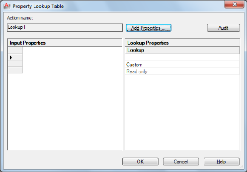
Summary
The lookup table assigns custom property values to the dynamic block
reference. If Reverse Lookup is selected for a lookup property, the block
reference displays a lookup grip with a list of properties that change the display
of the dynamic block reference.
The lookup table also allows the values of lookup parameters to be controlled
by the values of other parameters (input properties).
List of Options
The following options are displayed.
Action Name
Displays the associated lookup action name, which you can edit in the
Properties palette.
Add Properties
Displays the Add Parameter Properties dialog box on page 144.
Audit
Checks the data to ensure that each row is unique.
Input Properties
Displays the parameters you select in the Add Parameter Properties dialog box
on page 144 as columns. When a parameter value matches the input property
column, the corresponding lookup property is assigned to the block reference.
Property Lookup Table Dialog Box | 143
Lookup Properties
Displays the custom value assigned to the input properties. Click the bottom
of a lookup column to make the lookup property read-only or to allow reverse
lookup. Allow Reverse Lookup enables a drop-down list associated with the
lookup grip that changes the block reference to match the input property
values in the table.
Add Parameter Properties Dialog Box
Quick Reference
See also:
■Lookup Actions
Adds parameter properties to a lookup table.
List of Options
The following options are displayed.
Parameter Properties
Displays a list of parameters not yet added to the lookup table. Select a
parameter and click OK to add it to the lookup table.
Property Type
Specifies the type of property to add to the lookup table.
Add Input Properties
Displays the available custom properties in parameters you’ve already added
to the block definition.
Add Lookup Properties
Displays the available lookup property parameters that can be added to the
lookup table.
144 | Chapter 3 B Commands

BLOCK
Quick Reference
See also:
■Define Blocks
Creates a block definition from selected objects.
Access Methods
Button
Ribbon: Insert tab ➤ Block Definition panel ➤ Create Block
Menu: Draw ➤ Block ➤ Make
Toolbar: Draw
Summary
The Block Definition dialog box is displayed.
If you enter -block at the Command prompt, options are displayed.
You create a block definition by selecting objects, specifying an insertion
point, and giving it a name.
Block Definition Dialog Box
Quick Reference
See also:
■Define Blocks
Defines and names a block.
BLOCK | 145
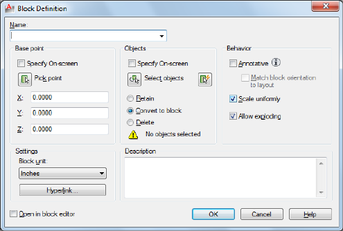
List of Options
The following options are displayed.
Name
Names the block. The name can have up to 255 characters and can include
letters, numbers, blank spaces, and any special character not used by the
operating system or the program for other purposes.
The block name and definition are saved in the current drawing.
Preview
If an existing block is selected under Name, displays a preview of the block.
Base Point
Specifies an insertion base point for the block. The default value is 0,0,0.
Specify On-Screen
Prompts you to specify the base point when the dialog box is closed.
Pick Insertion Base Point
Temporarily closes the dialog box so that you can specify an insertion base
point in the current drawing.
X
Specifies the X coordinate value.
Y
Specifies the Y coordinate value.
146 | Chapter 3 B Commands
Z
Specifies the Z coordinate value.
Objects
Specifies the objects to include in the new block and whether to retain or
delete the selected objects or convert them to a block instance after you create
the block.
Specify On-Screen
Prompts you to specify the objects when the dialog box is closed.
Select Objects
Closes the Block Definition dialog box temporarily while you select the objects
for the block. When you finish selecting objects, press Enter to return to the
dialog box.
Quick Select
Displays the Quick Select dialog box, which defines a selection set.
Retain
Retains the selected objects as distinct objects in the drawing after you create
the block.
Convert to Block
Converts the selected objects to a block instance in the drawing after you
create the block.
Delete
Deletes the selected objects from the drawing after you create the block.
Objects Selected
Displays the number of selected objects.
Behavior
Specifies the behavior of the block.
Annotative
Specifies that the block is .
Match Block Orientation to Layout
Block Definition Dialog Box | 147
Specifies that the orientation of the block references in paper space viewports
matches the orientation of the layout. This option is unavailable if the
Annotative option is cleared.
Scale Uniformly
Specifies whether or not the block reference is prevented from being
non-uniformly scaled.
Allow Exploding
Specifies whether or not the block reference can be exploded.
Settings
Specifies settings for the block.
Block Unit
Specifies the insertion units for the block reference.
Hyperlink
Opens the Insert Hyperlink dialog box, which you can use to associate a
hyperlink with the block definition.
Description
Specifies the text description of the block.
Open in Block Editor
Opens the current block definition in the Block Editor on page 127 when you
click OK.
-BLOCK
Quick Reference
See also:
■Define Blocks
If you enter -block at the Command prompt, the following prompts are
displayed.
148 | Chapter 3 B Commands
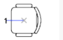
List of Prompts
The following prompts are displayed.
Enter block name or [?]: Enter a name or ?
Block Name
Names the block. The name can have up to 255 characters and can include
letters, numbers, blank spaces, and any special character not used by the
operating system and the program for other purposes if the system variable
EXTNAMES is set to 1.
If you enter the name of an existing block, you are prompted as follows:
Redefine Block Reference By redefining a block, you automatically update
all references to that block. Attributes attached to existing block references
remain unchanged in the drawing. However, new insertions of the block do
not prompt for attributes unless the attribute definitions are included in the
new block definition.
Specify Insertion Base Point The point specified as the base point is used
for subsequent insertions of the block. Typically, a base point is the center of
the block or its lower-left corner. The base point is also the point about which
you can rotate the block during insertion. A block with 0 rotation is oriented
according to the UCS in effect when it was created. Entering a 3D point inserts
the block at a specific elevation. Omitting the Z coordinate uses the current
elevation.
■Annotative:
Enter a to create an block.
If you enter yes, the block becomes annotative.
Match Orientation to Layout in Paper Space Viewports If you enter yes,
the block’s orientation in paper space viewports will match the orientation
of the layout.
Select Objects If you specify the insertion base point, you are prompted to
select the objects.
The program defines a block using the objects selected, the insertion base
point, and the name provided, and then erases the selected objects from the
drawing. You can restore the deleted objects by entering the OOPS command
immediately after BLOCK.
-BLOCK | 149

The insertion base point becomes the origin of the block's coordinate system,
which is parallel to the UCS in effect at the time that you define the block.
When you insert the block into a drawing, its coordinate system is aligned
parallel to the current UCS. Thus, you can insert a block at any orientation
in space by setting the UCS first.
?—List Previously Defined Blocks
Lists the block names in the text window.
Enter Blocks to List In the list, external references (xrefs) are indicated with
the notation Xref: resolved.
In addition, externally dependent blocks (blocks in an xref) are indicated with
the notation xdep: XREFNAME, where xrefname is the name of an externally
referenced drawing. The following terms are used in the list:
■User Blocks: Number of user-defined blocks in the list.
■External References: Number of xrefs in the list.
■Dependent Blocks: Number of externally dependent blocks in the list.
■Unnamed Blocks: Number of unnamed (anonymous) blocks in the drawing.
BMPOUT
Quick Reference
See also:
■Export Raster Files
Saves selected objects to a file in device-independent bitmap format.
150 | Chapter 3 B Commands
Summary
The Create Raster File dialog box (a standard file selection dialog box) is
displayed. Enter the file name in the dialog box.
A bitmap file that contains the objects you select is created. The file reflects
what is displayed on the screen. Light glyphs that are displayed in the drawing
appear in the new file, even if the Plot Glyph property of the lights is set to
No.
NOTE When the FILEDIA system variable is set to 0 (Off), Command prompts are
displayed.
BOUNDARY
Quick Reference
See also:
■Create and Combine Areas (Regions)
Creates a region or a polyline from an enclosed area.
Access Methods
Button
Ribbon: Home tab ➤ Draw panel ➤ Boundary
Menu: Draw ➤ Boundary
Summary
The Boundary Creation dialog box is displayed.
If you enter -boundary at the Command prompt, options are displayed.
Each point that you specify identifies the surrounding objects and creates a
separate region or polyline.
BOUNDARY | 151
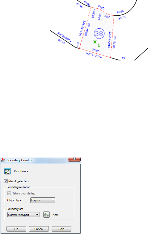
Boundary Creation Dialog Box
Quick Reference
See also:
■Create and Combine Areas (Regions)
Defines the object type, boundary set, and island detection method for creating
a region or polyline using a specified point within an area enclosed by objects.
List of Options
The following options are displayed.
Pick Points
Determines a boundary from existing objects that form an enclosed area
around the specified point.
Island Detection
Controls whether boundary detects internal closed boundaries, called islands.
152 | Chapter 3 B Commands
Object Type
Controls the type of the new boundary object. boundary creates the boundary
as a region or a polyline object.
Boundary Set
Defines the set of objects boundary analyzes when defining a boundary from
a specified point.
Current Viewport Defines the boundary set from everything in the current
viewport extents. Selecting this option discards any current boundary set.
New Prompts you to select the objects that define the boundary set. boundary
includes only the objects that can be used to create a region or closed polyline
when it constructs the new boundary set.
For more information about the options in this dialog box, see HATCH.
-BOUNDARY
Quick Reference
See also:
■Create and Combine Areas (Regions)
If you enter -boundary at the Command prompt, the following prompts are
displayed.
Specify internal point or [Advanced options]: Specify a point or enter a
Internal Point
Creates a region or polyline from existing objects that form an enclosed area.
Specify a point inside the area.
Advanced Options
Sets the method BOUNDARY uses to create the boundary.
Enter an option [Boundary set/Island detection/Object type]: Enter an option
or press Enter to return to the previous prompt
Boundary Set Defines the set of objects boundary analyzes when it creates a
boundary from a specified point. For information about defining a boundary
set at the Command prompt, see the HATCH Command prompt option.
-BOUNDARY | 153
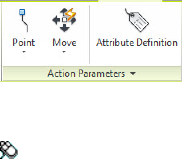
Island Detection Specifies whether boundary uses objects within the outermost
boundary as boundary objects. For information about specifying island
detection at the Command prompt, see the HATCH Command prompt option.
Object Type Specifies the type of object that boundary creates.
■Region
■Polyline
BPARAMETER
Quick Reference
See also:
■Add Parameters to Dynamic Blocks
Adds a parameter with grips to a dynamic block definition.
Access Methods
Panel
Ribbon: Block Editor contextual tab ➤ Action Parameters panel
Summary
You can use the bparameter command only in the Block Editor on page 127.
A parameter defines custom properties for the block reference. After you add
a parameter, you must associate an action with the parameter to make the
block dynamic.
List of Prompts
The following prompts are displayed.
Enter parameter type [Alignment/Base on page
155/pOint/Linear/Polar/XY/Rotation/Flip/“Visibility”/looKup] <last>: Enter a
parameter type
154 | Chapter 3 B Commands

Alignment
Button
Block Editor contextual tab ➤ Action Parameters panel ➤ Action Parameters
drop-down ➤ Alignment
Rotates the block reference about a point to align with other objects in the
drawing.
Specify Base Point of Alignment Specifies the grip about which the block
reference will rotate to align with another object in the drawing.
Name Sets the Name custom property for this parameter.
Specify Alignment Direction Determines the angle of alignment for the
block reference.
Type Determines whether the block reference will align tangent or
perpendicular to objects in the drawing.
Base
Button
Block Editor contextual tab ➤ Action Parameters panel ➤ Action Parameters
drop-down ➤ Basepoint
Defines a changeable base point for the dynamic block reference in relation
to the geometry in the block.
Specify Parameter Location Determines the default location of the basepoint
for the block definition. This will be the location of the basepoint grip in the
block reference.
Point
Button
Block Editor contextual tab ➤ Action Parameters panel ➤ Action Parameters
drop-down ➤ Point
Defines custom X and Y properties for the block reference.
BPARAMETER | 155

Specify Parameter Location Determines the X and Y location of the point
parameter in the block definition. This will be the location of the point grip
in the block reference.
Name Name on page 155
Label Defines a custom descriptive label for the location of the parameter.
Chain Determines whether the parameter is included in the selection set of
an action that is associated with a different parameter.
■Yes. A change to an action associated with this parameter will also trigger
other actions associated with this parameter, just as if you had edited the
parameter through a grip or custom property.
■No. Associated actions are not triggered.
Description Defines an extended description of the Label on page 156 custom
property. When the block reference is inserted, this description is displayed
at the bottom of the Properties palette.
Palette Specifies whether the Label custom property is displayed in the
Properties palette when the block reference is selected in a drawing.
Linear
Button
Block Editor contextual tab ➤ Action Parameters panel ➤ Action Parameters
drop-down ➤ Linear
Defines the distance between two key points in the block definition.
Specify Start Point/Endpoint Specifies the key points for the parameter in
the block definition.
Name Name on page 155
Label Label on page 156
Chain Chain on page 156
Description Description on page 156
156 | Chapter 3 B Commands

Base Specifies the Base Location property for the parameter.
■Startpoint. The start point of the parameter remains fixed when the
endpoint of the parameter is edited in the block reference.
■Midpoint. The midpoint of the parameter remains fixed, and the start
point and endpoint of the parameter move simultaneously equal distances
from the midpoint.
Palette Palette on page 156
Value Set Limits the available values for the parameter to the values specified
in the set.
■List. Specifies a list of available values for the parameter in a block reference.
■Increment. Specifies a value increment and minimum and maximum values
for the parameter in the block reference.
Specify Label Location Specifies the location of the parameter label on page
156 in the block definition.
Enter Number of Grips Determines the number of grips that will display in
the block reference.
■0. No grips will be displayed in the block reference. Rather, the selected
geometry can be edited in the Properties palette or a lookup table on page
142.
■1. A grip will be displayed at just the endpoint of the parameter.
■2. A grip will be displayed at both the start point and endpoint of the
parameter.
Polar
Button
Block Editor contextual tab ➤ Action Parameters panel ➤ Action Parameters
drop-down ➤ Polar
Defines a distance and angle for two key points in the block definition.
Specify Base Point Determines the point in the block definition relative to
which the grip will be placed.
Name Name on page 155
BPARAMETER | 157

Label Label on page 156
Chain Chain on page 156
Description Description on page 156
Palette Palette on page 156
Value Set Value Set on page 157
Specify Endpoint Determines the distance and angle from the base point.
The distance and angle are custom properties in the Properties palette.
Specify Label Location Specify Label Location on page 157
Enter Number of Grips Enter Number of Grips on page 157
XY
Button
Block Editor contextual tab ➤ Action Parameters panel ➤ Action Parameters
drop-down ➤ XY
Defines an X and Y distance from the base point of a block definition.
Specify Base Point Determines the maximum X distance for the parameter.
Name Name on page 155
Label Label on page 156
Chain Chain on page 156
Description Description on page 156
Palette Palette on page 156
Value Set Value Set on page 157
Specify Endpoint Determines the maximum Y distance for the parameter.
Specify Number of Grips Determines the number of grips that will display
in the block reference.
■0. on page 157
■1. A grip will be displayed at the endpoint of the Y distance.
■2. A grip will be displayed at both endpoints.
158 | Chapter 3 B Commands

■4. Grips will be displayed at all four corners of the parameter.
Rotation
Button
Block Editor contextual tab ➤ Action Parameters panel ➤ Action Parameters
drop-down ➤ Rotation
Defines an angle for the block reference.
Specify Base Point Determines the point about which the selected block
geometry will be rotated.
Name Name on page 155
Label Label on page 156
Chain Chain on page 156
Description Description on page 156
Palette Palette on page 156
Value Set Value Set on page 157
Specify Radius of Parameter Determines the distance between the base point
of the parameter and the grip.
Specify Default Rotation Angle Determines the location of the grip in the
block reference.
Base Angle Specifies a base angle other than 0 for the parameter grip.
Flip
Button
Block Editor contextual tab ➤ Action Parameters panel ➤ Action Parameters
drop-down ➤ Flip
Mirrors objects or the entire block reference about a reflection line.
Specify Base Point Determines the first point for the line of reflection. The
parameter grip will be displayed at this point.
BPARAMETER | 159

Name Name on page 155
Label Label on page 156
Description Description on page 156
Palette Palette on page 156
Specify Endpoint of Reflection Line Determines the endpoint of the
reflection line.
Specify Label Location Specify Label Location on page 157
Visibility
Button
Block Editor contextual tab ➤ Action Parameters panel ➤ Action Parameters
drop-down ➤ Visibility
Defines objects that will either display or not display within the block
definition.
Specify Parameter Location Determines a location for the parameter grip.
The parameter can be placed anywhere within the block definition.
Name Name on page 155
Label Label on page 156
Description Description on page 156
Palette Palette on page 156
Lookup
Button
Block Editor contextual tab ➤ Action Parameters panel ➤ Action Parameters
drop-down ➤ Lookup
Defines user parameters that are determined by a lookup table.
Specify Parameter Location Specify Parameter Location on page 160
Name Name on page 155
160 | Chapter 3 B Commands

Label Label on page 156
Description Description on page 156
Palette Palette on page 156
BREAK
Quick Reference
See also:
■Break and Join Objects
Breaks the selected object between two points.
Access Methods
Button
Ribbon: Home tab ➤ Modify panel ➤ Break
Ribbon: Home tab ➤ Modify panel ➤ Break at Point
Menu: Modify ➤ Break
Toolbar: Modify
Summary
You can create a gap between two specified points on an object, breaking it
into two objects. If the points are off of an object, they are automatically
projected on to the object. break is often used to create space for a block or
text.
BREAK | 161
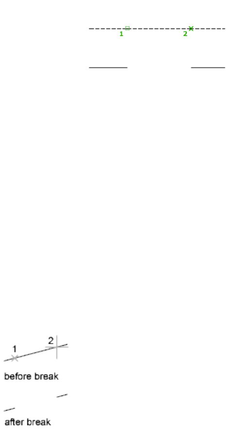
List of Prompts
The following prompts are displayed.
Select object: Use an object selection method, or specify the first break point (1) on
an object
The prompts that are displayed next depend on how you select the object. If
you select the object by using your pointing device, the program both selects
the object and treats the selection point as the first break point. At the next
prompt, you can continue by specifying the second point or overriding the
first point.
Specify second break point or [First point]: Specify the second break point (2) or
enter f
Second Break Point Specifies the second point to use to break the object.
First Point Overrides the original first point with the new point that you
specify.
Specify first break point:
Specify second break point:
The portion of the object is erased between the two points that you specify.
If the second point is not on the object, the nearest point on the object is
selected; therefore, to break off one end of a line, arc, or polyline, specify the
second point beyond the end to be removed.
162 | Chapter 3 B Commands
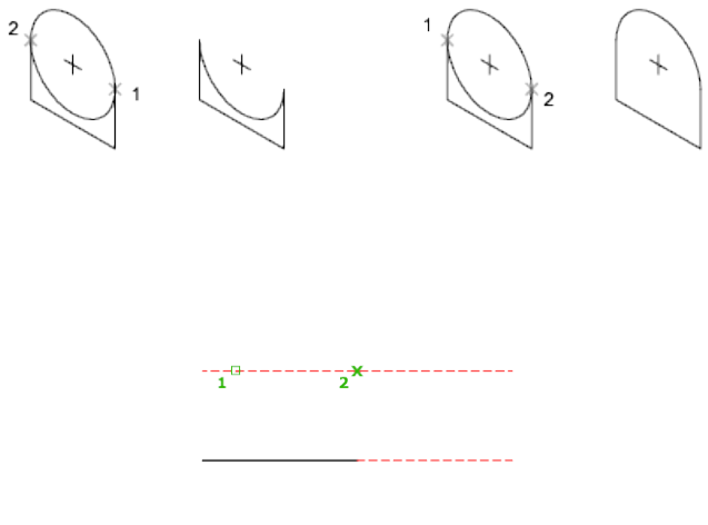
To split an object in two without erasing a portion, enter the same point for
both the first and second points. You can do this by entering @ to specify the
second point.
Lines, arcs, circles, polylines, ellipses, splines, donuts, and several other object
types can be split into two objects or have one end removed.
The program converts a circle to an arc by removing a piece of the circle
starting counterclockwise from the first to the second point.
You can also break selected objects at a single point with the Break at Point
tool.
Valid objects include lines, open polylines, and arcs. Closed objects such as
circles cannot be broken at a single point.
BROWSER
Quick Reference
See also:
■Get Started with Internet Access
Launches the default web browser defined in your system's registry.
BROWSER | 163

Access Methods
Button
Toolbar: Web
Summary
Pressing Enter displays your web browser, which automatically connects to
the location you specify. Because browser does not append “http://” to web
locations, you can specify an FTP or file location to your default web browser.
BSAVE
Quick Reference
See also:
■Create Blocks Within a Drawing
Saves the current block definition.
Access Methods
Button
Ribbon: Block Editor contextual tab ➤ Open/Save panel ➤ Save Block
Summary
Saves changes to the current block definition.
You can only use the BSAVE command in the Block Editor on page 127.
164 | Chapter 3 B Commands

BSAVEAS
Quick Reference
See also:
■Create Blocks Within a Drawing
Saves a copy of the current block definition under a new name.
Access Methods
Button
Ribbon: Block Editor contextual tab ➤ Open/Save panel ➤ Save Block As
Summary
Displays the Save Block As dialog box on page 165.
You can only use the BSAVEAS command in the Block Editor on page 127.
Save Block As Dialog Box
Quick Reference
See also:
■Create Blocks Within a Drawing
Saves a copy of the current block definition under a new name.
List of Options
The following options are displayed.
Block Name
BSAVEAS | 165

Specifies a new name under which to save a copy of the current block
definition.
Block List
Displays a list of block definitions that are saved in the current drawing.
Preview
Displays a preview of the selected block definition.
Description
Displays the description saved with the block definition.
Save Block Definition to Drawing File
Saves the block definition as a drawing file. Selecting a pre-existing drawing
file overwrites the saved file. By default, the block name specified is taken as
the drawing file name.
BTABLE
Quick Reference
See also:
■Define User Parameters in Dynamic Blocks
Displays a dialog box to define variations of a block.
Access Methods
Button
Ribbon: Block Editor contextual tab ➤ Dimensional panel ➤ Block Table
Summary
You can only use the btable command in the Block Editor on page 127. The
Block Properties Table dialog box on page 167 is displayed after you specify a
location point. The location point determines where the grip and table icon
166 | Chapter 3 B Commands
are located in the block definition. The grip location determines where the
grip appears in the block reference and displays a context menu based on the
contents of the block properties table. The type of properties that can be
included in the block properties table include legacy parameters, parameter
constraints, user parameters, and attributes. The legacy action parameters that
are added to the lookup tables cannot be added to the Block Properties Table.
Each row in the table defines a different variation of the block reference, and
can be accessed by the lookup grip.
If a block table is already created in the block editor, entering the btable
command directly displays the Block Properties Table dialog box (see
BLOOKUPTABLE on page 142 command).
List of Prompts
The following prompts are displayed.
Specify parameter location or [Palette]: Specify a location point
Palette
Specifies whether the block table item is displayed in the Properties palette
for the block reference.
Block Properties Table Dialog Box
Quick Reference
See also:
■Define User Parameters in Dynamic Blocks
Defines the variations for a set of user-defined properties in the block definition
through a grid control.
Block Properties Table Dialog Box | 167
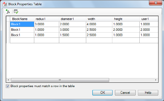
Summary
You can press Shift+Enter to add a new line for a multiline attribute value in
the grid in the Block Properties Table dialog box.
List of Options
The following options are displayed.
Add Properties
Displays the Add Parameter Properties dialog box on page 169 where you can
add parameters already defined in the Block Properties Table.
Audit
Checks the Block Properties Table for errors.
Grid Control Displays the name of parameters added to the table. You can
also modify the properties of the table.
Block Properties Must Match A Row In The Table
Specifies whether the properties added to the grid control can be modified
individually for a block reference.
Default Value When Properties Do Not Match Table
Displays the default values when other properties are changed without
matching a row.
168 | Chapter 3 B Commands
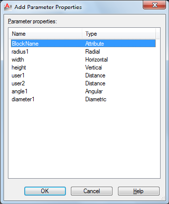
Add Parameter Properties Dialog Box
Quick Reference
See also:
■Define User Parameters in Dynamic Blocks
Adds parameter properties to the block properties table.
List of Options
The following options are displayed.
Parameter Properties
Displays a list of dimensional constraint parameters, user parameters, legacy
parameters, and attribute definitions.
Name
Displays the names of parameters available to add to the block properties
table.
Type
Identifies the type of the parameter.
Add Parameter Properties Dialog Box | 169

BTESTBLOCK
Quick Reference
See also:
■Test Blocks Within the Block Editor
Displays a window within the Block Editor to test a dynamic block.
Access Methods
Button
Ribbon: Block Editor contextual tab ➤ Open/Save panel ➤ Test Block
Summary
You can only use the btestblock command in the Block Editor on page 127.
With the Test Block window you can test a dynamic block without closing
the Block Editor. You can select the block reference and test the grips or display
the Properties palette and test the behavior when changing the properties.
You can also insert additional copies of the block to test the inserting behavior.
You can make changes and test the block without saving the changes to the
block definition.
In the Test Block window, all AutoCAD commands operate the same way
except the BEDIT on page 120, SAVE on page 1091, SAVEAS on page 1091, and
QSAVE on page 1050 commands. The bedit command is not available in Test
Block window. The save, saveas, and qsave commands remove the Test Block
status from the window and the Test Block window becomes an open drawing.
A Close Test Block Window contextual panel is added to the ribbon when you
are in the Test Block mode.
In the Block Editor, the BCLOSE on page 116, BTESTBLOCK on page 170, and
CLOSE on page 214 commands automatically close the Test Block window and
discard the temporary file. The btestblock command closes the current Test
Block window and opens a new window with the current definition.
170 | Chapter 3 B Commands
NOTE Please ensure that there are entities present in the block being tested before
running the btestblock command.
BVHIDE
Quick Reference
See also:
■Control the Visibility of Objects in a Block
Makes objects invisible in the current visibility state or all visibility states in
a dynamic block definition.
Access Methods
Button
Ribbon: Block Editor contextual tab ➤ Visibility panel ➤ Make Invisible
Shortcut menu: Select objects to hide for visibility states. Right-click in the
Block Editor drawing area. Click Object Visibility ➤ Hide for Current State
or click Object Visibility ➤ Hide for All States
Summary
Makes objects invisible for the current visibility state. You can only use the
bvhide command in the Block Editor on page 127.
List of Prompts
The following prompts are displayed.
Select objects to hide: Select objects to hide for the current visibility state or all
visibility states
Hide for current state or all visibility states [Current/All] <Current>: Enter
current to hide the selected objects for the current visibility state or enter all to hide
the selected objects for all visibility states in the block definition
BVHIDE | 171

BVSHOW
Quick Reference
See also:
■Control the Visibility of Objects in a Block
Makes objects visible in the current visibility state or all visibility states in a
dynamic block definition.
Access Methods
Button
Ribbon: Block Editor contextual tab ➤ Visibility panel ➤ Make Visible
Shortcut menu: Select objects to make visible for visibility states. Right-click
in the Block Editor drawing area. Click Object Visibility ➤ Show for Current
State or click Object Visibility ➤ Show for All States
Summary
Allows you to make objects visible for visibility states. You can only use the
bvshow command in the Block Editor on page 127.
List of Prompts
The following prompts are displayed
Select objects to make visible: Select objects to make visible for the current visibility
state or all visibility states
Make visible for current state or all visibility states [Current/All] <Current>:
Enter current to make the selected objects visible for the current visibility state or enter
all to make the selected objects visible for all visibility states in the block definition
172 | Chapter 3 B Commands

BVSTATE
Quick Reference
See also:
■Control the Visibility of Objects in a Block
Creates, sets, or deletes a visibility state in a dynamic block.
Access Methods
Button
Ribbon: Block Editor contextual tab ➤ Visibility panel ➤ Visibility States
Summary
Displays the Visibility States dialog box on page 173. You can only use the
BVSTATE command in the Block Editor on page 127 after a visibility parameter
has been added to the block definition.
Visibility States Dialog Box
Quick Reference
See also:
■Control the Visibility of Objects in a Block
Creates or modifies visibility states.
List of Options
The following options are displayed.
Visibility States
BVSTATE | 173
Lists the available visibility states for the current dynamic block definition.
The order of this list is reflected in the dynamic block reference when the grip
is clicked to display the list of visibility states. The state at the top of the list
is the default state for the block reference.
Set Current
Sets the selected visibility state as the current state to display in the Block
Editor. Does not change the default visibility state that is displayed when the
block is inserted in a drawing, nor does it change the displayed visibility state
for block references already inserted and edited in the drawing.
New
Displays the New Visibility State dialog box. on page 174
Rename
Renames the selected visibility state.
Delete
Deletes the selected visibility state.
Move Up
Moves the selected visibility state up in the list.
Move Down
Moves the selected visibility state down in the list.
New Visibility State Dialog Box
Quick Reference
See also:
■Control the Visibility of Objects in a Block
Creates a new visibility state.
List of Options
The following options are displayed.
Visibility State Name
174 | Chapter 3 B Commands

Specifies the name for the new visibility state.
Visibility Options for New States
Displays options for the new visibility state.
Hide All Existing Objects in New State
Specifies that all objects in the block definition will be hidden in the new
visibility state.
Show All Existing Objects in New State
Specifies that all objects in the block definition will be shown in the new
visibility state.
Leave Visibility of Existing Objects Unchanged in New State
Specifies that the visibility of objects in the new visibility state will be the
same as in the current visibility state on which the new state is based.
-BVSTATE
Quick Reference
See also:
■Control the Visibility of Objects in a Block
Access Methods
Command entry: bedit ➤ -bvstate
List of Prompts
The following prompts are displayed.
Current visibility state: <Name of current visibility state>
Enter an option [New on page 175/Set on page 176/Delete on page 176] <New>:
Enter an option or press Enter
New
Creates a new visibility state.
Hide All
Specifies that all objects in the block definition will be hidden in the new
visibility state.
-BVSTATE | 175
Show All
Specifies that all objects in the block definition will be shown in the new
visibility state.
Current Visibility
Specifies that the visibility of objects in the new visibility state will be the
same as in the current visibility state on which the new state is based.
Set
Specifies the visibility state to set as current.
Delete
Deletes a visibility state.
176 | Chapter 3 B Commands

C Commands
CAL
Quick Reference
See also:
■Use the Command Prompt Calculator
Evaluates mathematical and geometric expressions.
Access Methods
Command entry: 'cal for transparent use
Summary
CAL is an online geometry calculator that evaluates point (vector), real, or
integer expressions. The expressions can access existing geometry using the
object snap functions such as CEN, END, and INS.
You can use these arithmetic and vector expressions in any command that
expects points, vectors, or numbers.
4
177

Understand Syntax of Expressions
Quick Reference
See also:
■Use the Command Prompt Calculator
CAL evaluates expressions according to standard mathematical rules of
precedence:
■Expressions in parentheses first, starting with the innermost set
■Operators in standard order: exponents first, multiplication and division
second, and addition and subtraction last
■Operators of equal precedence from left to right
Numeric Expressions
Numeric expressions are real integer numbers and functions combined with
the operators in the following table.
Numeric operators
OperationOperator
Groups expressions( )
Indicates exponentiation^
Multiplies, divides* , /
Adds, subtracts+, -
The following are examples of numeric expressions:
3
3 + 0.6
(5.8^2) + PI
178 | Chapter 4 C Commands
Vector Expressions
A vector expression is a collection of points, vectors, numbers, and functions
combined with the operators in the following table.
Vector operators
OperationOperator
Groups expressions( )
Determines the vector product of vectors (as a vector)&
[a,b,c]&[x,y,z] = [ (b*z) - (c*y) , (c*x) - (a*z) , (a*y) - (b*x) ]
Determines the scalar product of vectors (as a real number)*
[a,b,c]*[x,y,z] = ax + by + cz
Multiplies, divides a vector by a real number*, /
a*[x,y,z] = [a*x,a*y,a*z]
Adds, subtracts vectors (points)+ , -
[a,b,c] + [x,y,z] = [a+x,b+y,c+z]
The following are examples of vector expressions:
A+[1,2,3] provides the point located [1,2,3] units relative to point A.
The expression
[2<45<45] + [2<45<0] - [1.02, 3.5, 2]
adds two points and subtracts a third point. The first two points are expressed
in spherical coordinates.
Format Feet and Inches
Quick Reference
See also:
■Use the Command Prompt Calculator
Enter feet and inches using the following format:
feet'-inches" or feet' inches" or feet'inches"
Format Feet and Inches | 179

You can separate feet, inches, and fractional inches with a dash, a space, or
nothing. You can use any of the following syntax cases to enter valid feet-inch
formatted values:
■5' or 60”
■5'-9” or 5' 9” or 5'9”
■5'-1/2” or 5' 1/2” or 5'1/2”
■5'-9-1/2” or 5' 9-1/2” or 5'9-1/2”
■5'-9 1/2” or 5' 9 1/2” or 5'9 1/2”
To designate inches for linear calculations, entering double quotes (“) is
optional. For example, instead of entering 5'9-1/2”, you could enter 5'9-1/2.
WARNING With imperial units, CAL interprets a minus or a dash (-) as a unit
separator rather than a subtraction operation. To specify subtraction, include at
least one space before or after the minus sign. For example, to subtract 9” from
5', enter 5' -9” rather than 5'-9”.
Format Angles
Quick Reference
See also:
■Use the Command Prompt Calculator
The default units for angles are decimal degrees. Enter angles using the
following format:
<degrees>d<minutes>'<seconds>”
You must enter 0d when entering an angle that is less than 1 degree (minutes
and seconds only). You can omit the minutes or seconds if they are zero.
Enter a number followed by r to enter angles in radians. Enter a number
followed by g to enter angles in grads.
The following examples show ways of entering angles:
5d10'20"
0d10'20"
180 | Chapter 4 C Commands
124.6r
14g
Angles entered in any format are converted to decimal degrees.
Pi radians is equal to 180 degrees, and 100 grads is equal to 90 degrees.
Use Points and Vectors
Quick Reference
See also:
■Use the Command Prompt Calculator
Both points and vectors are pairs or triples of real numbers. A point defines a
location in space, but a vector defines a direction (or translation) in space.
Some CAL functions, such as pld and plt, return a point. Other functions,
such as nor and vec, return a vector.
Formatting Points and Vectors
A point or vector is a set of three real expressions enclosed in brackets ([ ]):
[r1,r2,r3]
The notation p1, p2, and so forth designates points. The notation v1, v2, and
so forth designates vectors. In drawings, points are displayed as dots, and
vectors are displayed as lines with arrows.
CAL supports points expressed in all formats.
Point formats
Point formatCoordinate system
[dist<angle]Polar
[dist<angle,z]Cylindrical
[dist<angle1<angle2]Spherical
Uses the @ prefix [@x,y,z]Relative
Use Points and Vectors | 181
Point formats
Point formatCoordinate system
Uses the * prefix [*x,y,z]WCS (instead of UCS)
You can omit the following components of a point or vector: coordinate values
of zero and a comma immediately preceding the right bracket (]).
The following are valid points:
[1,2] is the same as [1,2,0]
[,,3] is the same as [0,0,3]
[ ] is the same as [0,0,0]
In the following example, the point is entered in the relative spherical
coordinate system with respect to the (WCS). The distance is 1+2=3; the angles
are 10+20=30 degrees and 45 degrees, 20 minutes.
[ *1+2<10+20<45d20"]
The following is a valid point that contains arithmetic expressions as its
components:
[2*(1.0+3.3),0.4-1.1,2*1.4]
The following example uses the Endpoint object snap and the vector [2,0,3]
to calculate a point that is offset from a selected endpoint:
end + [2,,3]
The calculated point is offset 2 units in the X direction and 3 units in the Z
direction relative to the selected endpoint.
Use System Variables in Calculations
Quick Reference
See also:
■Use the Command Prompt Calculator
You can use the getvar function to read the value of a system variable.
The syntax is
182 | Chapter 4 C Commands
getvar(variable_name)
The following example uses getvar to obtain the point that is the center of
the view in the current viewport.
getvar(viewctr)
With this method, you can also access the user system variables, USERI1-5
and USERR1-5. For example, to retrieve the value stored in USERR2, enter the
following:
getvar(userr2)
Convert Units of Measurement
Quick Reference
See also:
■Use the Command Prompt Calculator
The cvunit function converts either a number or a point from one unit of
measurement to another. See the acadlt.unt file for a list of units that you can
convert. The syntax is
cvunit(value, from_unit, to_unit)
The following example converts the value 1 from inches to centimeters:
cvunit(1,inch,cm)
Use Standard Numeric Functions
Quick Reference
See also:
■Use the Command Prompt Calculator
Convert Units of Measurement | 183
CAL supports the standard numeric functions in the following table.
Numeric functions
DescriptionFunction
Sine of the anglesin(angle)
Cosine of the anglecos(angle)
Tangent of the angletang(angle)
Arcsine of the number; the number must be between -1 and 1asin(real)
Arccosine of the number; the number must be between -1 and 1acos(real)
Arctangent of the numberatan(real)
Natural log of the numberln(real)
Base-10 log of the numberlog(real)
Natural exponent of the numberexp(real)
Base-10 exponent of the numberexp10(real)
Square of the numbersqr(real)
Square root of the number; the number must be nonnegativesqrt(real)
Absolute value of the numberabs(real)
Number rounded to the nearest integerround(real)
Integer portion of the numbertrunc(real)
Angles in radians converted to degrees; for example, r2d(pi) converts
the pi radians to 180 degrees
r2d(angle)
Angles in degrees converted to radians; for example, d2r(180) con-
verts 180 degrees to radians and returns the value of pi
d2r(angle)
The constant pipi
184 | Chapter 4 C Commands
Calculate a Vector from Two Points
Quick Reference
See also:
■Use the Command Prompt Calculator
The functions vec and vec1 calculate a vector from two points.
vec(p1,p2) Provides the vector from point p1 to point p2.
vec1(p1,p2) Provides the unit vector from point p1 to point p2.
The following example uses CAL to move selected objects 3 units in the
direction from the center of one selected circle to the center of another selected
circle:
Command: move
Select objects
Specify base point or displacement: 'cal
>> Expression: 3*vec1(cen,cen)
Select entity for CEN snap: Specify a circle or an arc
Specify second point of displacement or <use first point as displacement>:
Specify a point or press Enter
The following examples illustrate the meaning of vector and point calculations.
Examples of vector and point calculations
MeaningExpression
Determines vector translation from point a to point b.vec(a,b)
Determines unit vector direction from point a to point b.vec1(a,b)
Determines vector of length L in the direction from point a
to point b.
L*vec1(a,b)
Determines point b, which is a translation of the point a
through vector v.
a+v
Determines point b located 5 units away from point a at an
angle of 20 degrees. Note that [5<20] is a vector in polar co-
ordinates.
a+[5<20]
Calculate a Vector from Two Points | 185
Calculate the Length of a Vector
Quick Reference
See also:
■Use the Command Prompt Calculator
The abs function calculates the length of a vector.
abs(v) Calculates the length of vector v, a nonnegative real number.
In spherical coordinates (dist<ang<ang), the dist is the length of the vector.
The following example calculates the length of the vector [1,2,3]:
abs([1,2,3])
Obtain a Point by Cursor
Quick Reference
See also:
■Use the Command Prompt Calculator
To enter a point using the pointing device, use the cur function. The program
prompts you to specify a point and uses the coordinate values of the point in
the expression. The point coordinate values are expressed in terms of the
current UCS. The cur function sets the value of theLASTPOINT system variable.
The following example adds the vector [3.6,2.4,0]—the result of 1.2*[3,2]—to
the point you select. This expression produces a point that is offset from the
selected point.
cur+1.2*[3,2]
186 | Chapter 4 C Commands
Obtain the Last-Specified Point
Quick Reference
See also:
■Use the Command Prompt Calculator
Use the character in the expression to obtain the coordinate of the last point,
as shown in the following example:
Command: line
Specify first point: 'cal
>> Expression: cen+[0,1]
>> Select entity for CEN snap: Select a circle or an arc
Specify next point or [Close/Undo]: 'cal
>> Expression: +3*vec1(cen,cen)
The first point of the line is 1 unit in the Y direction from the center of the
first selected circle. The second point of the line is 3 units away from the first
point. The direction of the line is from the center of the first selected circle
to the center of the second selected circle.
Use Snap Modes in Arithmetic Expressions
Quick Reference
See also:
■Use the Command Prompt Calculator
You can use Snap modes as parts of arithmetic expressions. The program
prompts you to select an object and returns the coordinate of the appropriate
snap point. Using arithmetic expressions with Snap modes greatly simplifies
entering coordinates relative to other objects.
Obtain the Last-Specified Point | 187
When you use these Snap modes, enter only the three-character name. For
example, when you use the Center Snap mode, enter cen. CAL Snap modes
set the value of the LASTPOINT system variable.
CAL Snap modes
Snap modeAbbreviation
ENDPOINTEND
INSERTINS
INTERSECTIONINT
MIDPOINTMID
CENTERCEN
NEARESTNEA
NODENOD
QUADRANTQUA
PERPENDICULARPER
TANGENTTAN
The following example uses the Center and Endpoint Snap modes in a CAL
expression:
(cen+end)/2
CAL prompts for a circle or arc and an object. It then determines the midpoint
between the center of the circle or arc and the end of the selected object.
Using the Midpoint Snap mode, in the following example CAL prompts for
an object and returns a point 1 unit in the Y direction from the midpoint of
the selected object:
mid+[,1]
The following example uses the Endpoint Snap mode to calculate the centroid
of a triangle defined by three endpoints:
(end+end+end)/3
188 | Chapter 4 C Commands
Convert Points Between UCS and WCS
Quick Reference
See also:
■Use the Command Prompt Calculator
Normally, the program assumes all coordinates to be relative to the current
UCS. The following functions convert points between UCS and WCS.
w2u(p1) Converts point p1 expressed in the WCS to the current UCS.
u2w(p1) Converts point p1 expressed in the current UCS to the WCS.
You can use w2u to find the WCS origin in terms of the current UCS:
w2u([0,0,0])
Filtering the X, Y, and Z Components of a Point or Vector
The following functions filter the X, Y, and Z components of a point or vector.
Point-filter functions
DescriptionFunction
X and Y components of a point; Z component is set to 0.0xyof(p1)
X and Z components of a point; Y component is set to 0.0xzof(p1)
Y and Z components of a point; X component is set to 0.0yzof(p1)
X component of a point; Y and Z components are set to 0.0xof(p1)
Y component of a point; X and Z components are set to 0.0yof(p1)
Z component of a point; X and Y components are set to 0.0zof(p1)
X component of a pointrxof(p1)
Y component of a pointryof(p1)
Z component of a pointrzof(p1)
Convert Points Between UCS and WCS | 189
The following example provides the Z component of a point expressed in
spherical coordinates:
zof([2<45<45])
The following example provides a point whose X and Y coordinate values are
taken from point a and the Z coordinate value from point b:
xyof(a)+zof(b)
Calculate a Point on a Line
Quick Reference
See also:
■Use the Command Prompt Calculator
The plt and pld functions return a point on a given line. You can specify the
location of the point on the line either by its distance from the first point or
parametrically by a t parameter.
pld(p1,p2,dist) Calculates a point on the line passing through points p1 and
p2. The parameter dist defines the distance of the point from the point p1.
plt(p1,p2,t) Calculates a point on the line passing through points p1 and p2.
The parameter t defines the parametric location of the point on the line.
The following are examples of the parameter t:
If t=0 the point is p1
If t=0.5 the point is the midpoint between p1 and p2
If t=1 the point is p2
Rotate a Point About an Axis
Quick Reference
See also:
■Use the Command Prompt Calculator
190 | Chapter 4 C Commands
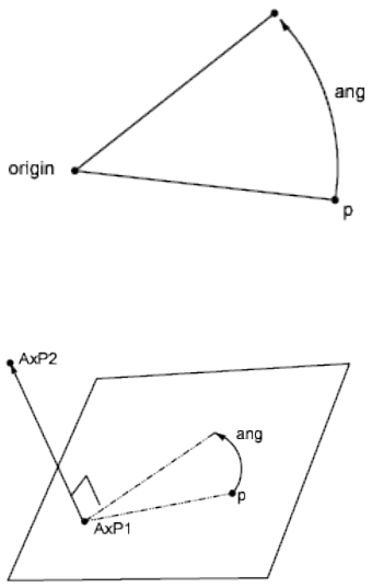
The rot function rotates a point about an axis and returns the resulting point.
rot(p,origin,ang) Rotates point p through angle ang about the Z axis passing
through the point origin, as shown in the following example:
rot(p,AxP1,AxP2,ang) Rotates point p through an angle ang about the axis
passing through points AxP1 and AxP2, as shown in the following example.
The axis is oriented from the first point to the second point.
Obtain an Intersection Point
Quick Reference
See also:
■Use the Command Prompt Calculator
The ill and ilp functions determine intersection points.
ill(p1,p2,p3,p4) Determines the intersection point between two lines (p1,p2)
and (p3,p4). All points are considered three-dimensional.
Obtain an Intersection Point | 191
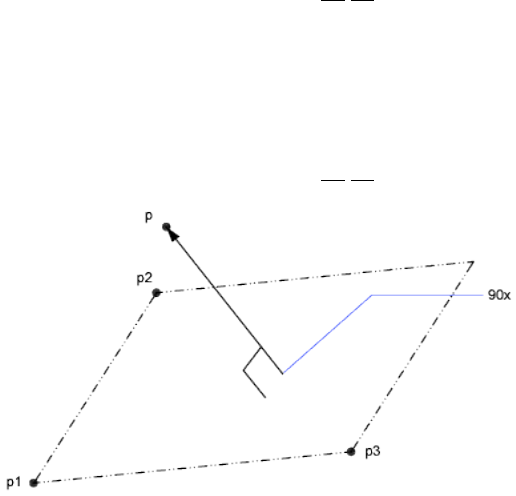
ilp(p1,p2,p3,p4,p5) Determines the intersection point between a line (p1,p2)
and a plane passing through three points (p3,p4,p5).
Calculate a Distance
Quick Reference
See also:
■Use the Command Prompt Calculator
dist(p1,p2) Determines the distance between two points, p1 and p2. This is
the same as the vector expression abs(p1-p2).
dpl(p,p1,p2) Determines the shortest distance between point p and the line
passing through points p1 and p2.
dpp(p,p1,p2,p3) Determines the distance from a point p to a plane defined
by three points (p1,p2,p3).
dist(p1,p2) Determines the distance between two points, p1 and p2. This is
the same as the vector expression abs(p1-p2).
The following example returns half the distance between the centers of two
selected objects:
dist(cen,cen)/2
The following example finds the distance between the point 3,2,4 and a plane
you define by selecting three endpoints:
192 | Chapter 4 C Commands
dpp([3,2,4],end, end, end)
Obtain a Radius
Quick Reference
See also:
■Use the Command Prompt Calculator
The rad function determines the radius of a selected object.
rad Determines the radius of a selected object. The object can be a circle, an
arc, or a 2D polyline arc segment.
The following example uses rad with the CIRCLE command. The radius of
the new circle is two-thirds of the radius of the selected polyline arc segment:
Command: circle
Specify center point for circle or [3P/2P/Ttr (tangent tangent radius)]: cen
of Select the circle
Specify radius of circle or [Diameter] <last>: 'cal
>> Expression: 2/3*rad
>> Select circle, arc or polyline segment for RAD function: Select the circle
Obtain an Angle
Quick Reference
See also:
■Use the Command Prompt Calculator
The ang function determines the angle between two lines. Angles are measured
counterclockwise with respect to either the X axis, in the two-dimensional
case, or to a user-specified axis, in the three-dimensional case.
ang(v) Determines the angle between the X axis and vector v. The vector v is
considered 2D, projected on the XY plane of the current UCS.
Obtain a Radius | 193

ang(p1,p2) Determines the angle between the X axis and the line (p1,p2),
oriented from p1 to p2. The points are considered 2D, projected on the XY
plane of the current UCS.
ang(apex,p1,p2) Determines the angle between lines (apex,p1) and (apex,p2).
The points are considered 2D, projected on the XY plane of the current UCS.
ang(apex,p1,p2,p) Determines the angle between lines (apex,p1) and (apex,p2).
The lines are considered 3D. The last parameter, point p, is used to define the
orientation of the angle. The angle is measured counterclockwise with respect
to the axis going from apex to p.
The following examples show how angles are measured.
You can determine the angle between the two sides of a triangle using the
ang function, as shown in the following example:
Command: cal
>> Expression: ang(end,end,end)
Select the apex of the angle, and then select the two opposite vertices.
194 | Chapter 4 C Commands
Calculate a Normal Vector
Quick Reference
See also:
■Use the Command Prompt Calculator
The nor function calculates the unit normal vector (a vector perpendicular to
a line or plane), not a point. The vector defines the direction of the normal,
not a location in space. You can add this normal vector to a point to obtain
another point.
nor Determines the three-dimensional unit normal vector of a selected circle,
arc, or polyline arc segment. This normal vector is the Z coordinate of the
object coordinate system (OCS) of the selected object.
nor(v) Determines the two-dimensional unit normal vector to vector v. Both
vectors are considered 2D, projected on the XY plane of the current UCS. The
orientation of the resulting normal vector points to the left of the original
vector v.
nor(p1,p2) Determines the 2D unit normal vector to line p1,p2. The line is
oriented from p1 to p2. The orientation of the resulting normal vector points
to the left from the original line (p1,p2).
nor(p1,p2,p3) Determines the 3D unit normal vector to a plane defined by
the three points p1, p2, and p3. The orientation of the normal vector is such
that the given points go counterclockwise with respect to the normal.
The following illustrations show how normal vectors are calculated:
Calculate a Normal Vector | 195
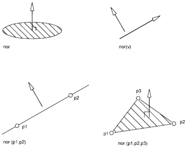
The following example sets the view direction perpendicular to a selected
object. The program displays the object in plan view and does not distort the
object by the parallel projection.
Command: vpoint
Current view direction: VIEWDIR=current
Specify a view point or [Rotate] <display compass and tripod>: 'cal
>> Expression: nor
>> Select circle, arc or polyline for NOR function:
Use Shortcut Functions
Quick Reference
See also:
■Use the Command Prompt Calculator
196 | Chapter 4 C Commands
The functions in the table are shortcuts for commonly used expressions that
combine a function with the Endpoint Snap mode.
Shortcut functions
DescriptionShortcut forFunction
Distance between two endpointsdist(end,end)dee
Intersection of two lines defined by four
endpoints
ill(end,end,end,end)ille
Midpoint between two endpoints(end+end)/2mee
Unit vector in the XY plane and normal to
two endpoints
nor(end,end)nee
Point at a distance along a line determined
by two endpoints (see pld)
pld(d,end,end)pldee (d)
Point at a parametric location on a line de-
termined by two endpoints (see plt)
plt(t,end,end)pltee (t)
Vector from two endpointsvec(end,end)vee
Unit vector from two endpointsvec1(end,end)vee1
CHAMFER
Quick Reference
See also:
■Create Chamfers
Bevels the edges of objects.
CHAMFER | 197
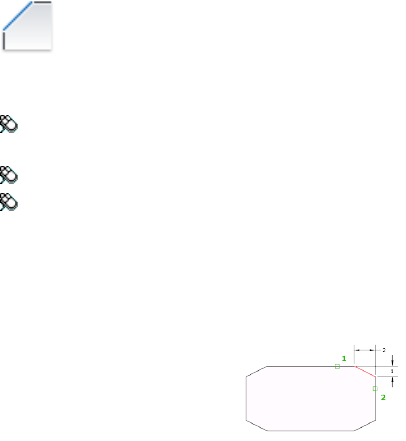
Access Methods
Button
Ribbon: Home tab ➤ Modify panel ➤ Chamfer and Fillet drop-down
➤ Chamfer
Menu: Modify ➤ Chamfer
Toolbar: Modify
Summary
The distances and angles that you specify are applied in the order that you
select the objects.
You can chamfer lines, polylines, rays, and xlines.
List of Prompts
The following prompts are displayed.
(TRIM mode) Current chamfer Dist1 = current, Dist2 = current
Select first line on page 198 or [Undo on page 199/Polyline on page 199/Distance
on page 199/Angle on page 199/Trim on page 200/mEthod on page 200/Multiple
on page 200]: Use an object selection method or enter an option
First Line
Specifies the first of two edges required to define a 2D chamfer.
If you select lines or polylines, their lengths adjust to accommodate the
chamfer line. You can hold down Shift while selecting the objects to override
the current chamfer distances with a value of 0.
If the selected objects are line segments of a 2D polyline, they must be adjacent
or separated by no more than one segment. If they're separated by another
polyline segment, CHAMFER deletes the segment that separates them and
replaces it with the chamfer.
Enter Surface Selection Option
Edge
198 | Chapter 4 C Commands
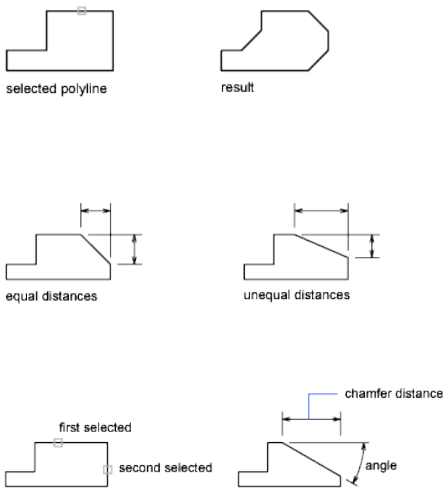
Loop
Undo
Reverses the previous action in the command.
Polyline
Chamfers an entire 2D polyline.
The intersecting polyline segments are chamfered at each vertex of the polyline.
Chamfers become new segments of the polyline.
If the polyline includes segments that are too short to accommodate the
chamfer distance, those segments are not chamfered.
Distance
Sets the distance of the chamfer from the endpoint of the selected edge.
If you set both distances to zero, CHAMFER extends or trims the two lines so
they end at the same point.
Angle
Sets the chamfer distances using a chamfer distance for the first line and an
angle for the second line.
CHAMFER | 199

Trim
Controls whether CHAMFER trims the selected edges to the chamfer line
endpoints.
NOTE Trim sets the TRIMMODE system variable to 1; No Trim sets TRIMMODE
to 0.
If the TRIMMODE system variable is set to 1, CHAMFER trims the intersecting
lines to the endpoints of the chamfer line. If the selected lines do not intersect,
CHAMFER extends or trims them so that they do. If TRIMMODE is set to 0,
the chamfer is created without trimming the selected lines.
Method
Controls whether CHAMFER uses two distances or a distance and an angle to
create the chamfer.
Multiple
Chamfers the edges of more than one set of objects.
Expression
Controls the chamfer distance with a mathematical expression. See Control
Geometry with the Parameters Manager for a list of operators and functions
allowed.
CHANGE
Quick Reference
See also:
■Display and Change the Properties of Objects
Changes the properties of existing objects.
List of Prompts
The following prompts are displayed
Select objects:
Specify change point or [Properties]: Specify a new point, or press Enter to enter
new values
Specify Objects
If you select lines and other changeable objects in the same selection set, you
get varying results depending on the object selection sequence. The easiest
200 | Chapter 4 C Commands

way to use CHANGE is to select only lines in a selection set or select only
objects other than lines in a selection set.
Except for zero-thickness lines, the objects selected must be parallel to the
current user coordinate system (UCS).
Change Point or Values
Changes the selected objects. The result depends on the type of objects you
select.
Lines Moves the endpoints of the selected lines that are closest to the change
point to the new point, unless Ortho mode is on. If Ortho mode is on, the
selected lines are modified so that they become parallel to either the X or the
Y axis; their endpoints are not moved to the specified coordinate.
Circles Changes the circle radius. If you selected more than one circle, the
prompt is repeated for the next circle.
Text Changes text location and other properties.
Specify New Text Insertion Point Relocates the text.
Attribute Definitions Changes the text and text properties of an attribute
that is not part of a block.
Blocks Changes the location or rotation of a block.
Specifying a new location relocates the block. Pressing Enter leaves the block
in its original location.
CHANGE | 201

Properties
Modifies properties of existing objects.
NOTE The Plotstyle option is displayed only when you are using named plot styles.
You can change several properties at a time. The Enter Property to Change
prompt is redisplayed after each option is completed.
Color Changes the color of the selected objects.
For example, to change a color to red, enter red or 1. If you enter bylayer, the
object assumes the color of the layer on which it is located. If you enter
byblock, the object inherits the color of the block of which it is a component.
■True Color. Specifies a true color to be used for the selected object. The
integer values range from 0 to 255 seperated by commas.
■Color Book. Specifies a color from a loaded color book to be used for the
selected object.
Elev Changes the Z-axis elevation of 2D objects.
You can change the elevation of an object only if all its points have the same
Z value.
Layer Changes the layer of the selected objects.
Ltype Changes the linetype of the selected objects.
If the new linetype is not loaded, the program tries to load it from the standard
linetype library file, acadlt.lin. If this procedure fails, use LINETYPE to load the
linetype.
Ltscale Changes the linetype scale factor of the selected objects.
Lweight Changes the lineweight of the selected objects. Lineweight values
are predefined values. If you enter a value that is not a predefined value, the
closest predefined lineweight is assigned to the selected objects.
Thickness Changes the Z-direction thickness of 2D objects.
202 | Chapter 4 C Commands

Changing the thickness of a 3D polyline, dimension, or layout viewport object
has no effect.
Transparency Changes the transparency level of selected objects.
Set the transparency to ByLayer or ByBlock, or enter a value from 0 to 90.
Material Changes the material of the selected objects if a material is attached.
Annotative Changes the property of the selected objects.
CHPROP
Quick Reference
See also:
■Display and Change the Properties of Objects
Changes the properties of an object.
List of Prompts
The following prompts are displayed.
Select objects:
Enter property to change [Color on page 203/LAyer on page 204/LType on page
204/ltScale on page 204/LWeight on page 204/Thickness on page 204/TRansparency
on page 204/Material on page 204/Annotative on page 204]:
NOTE The Plotstyle option is displayed only when you are using named plot styles.
If you select several objects with different values for the property you want
to change, varies is displayed as the current value.
Color
Changes the color of the selected objects.
For example, to change a color to red, enter red or 1. If you enter bylayer, the
object assumes the color of the layer on which it is located. If you enter
byblock, the object inherits the color of the block of which it is a component.
CHPROP | 203
True Color Specifies a true color to be used for the selected object.
Color Book Specifies a color from a loaded color book to be used for the
selected object.
Layer
Changes the layer of the selected objects.
Ltype
Changes the linetype of the selected objects.
If the new linetype is not loaded, the program tries to load it from the standard
linetype library file, acadlt.lin. If this procedure fails, use LINETYPE to load the
linetype.
Ltscale
Changes the linetype scale factor of the selected objects.
Lweight
Changes the lineweight of the selected objects. Lineweight values are
predefined values. If you enter a value that is not a predefined value, the
closest predefined lineweight is assigned to the selected objects.
Thickness
Changes the Z-direction thickness of 2D objects.
Changing the thickness of a 3D polyline, dimension, or layout viewport object
has no effect.
Transparency
Changes the transparency level of selected objects.
Set the transparency to ByLayer or ByBlock, or enter a value from 0 to 90.
Material
Changes the material of the selected objects if a material is attached.
Annotative
Changes the property of the selected objects.
204 | Chapter 4 C Commands
CHSPACE
Quick Reference
See also:
■Move Objects
Moves objects between model space and paper space.
Access Methods
Button
Ribbon: Home tab ➤ Modify panel ➤ Change Space
Menu: Modify ➤ Change Space
Summary
The moved object is scaled appropriately in the new space.
When transferring objects to paper space, the SOURCE viewport that you click
determines the paper space location of the transferred objects. When
transferring objects to model space, the TARGET viewport that you click
determines the model space location of the transferred objects.
List of Prompts
The following prompts are displayed.
Select objects:
Set the SOURCE viewport active and press Enter to continue:
Returns prompts similar to the following:
N object(s) changed from MODEL space to PAPER space.
Objects were scaled by a factor of n to maintain visual appearance.
CHSPACE | 205
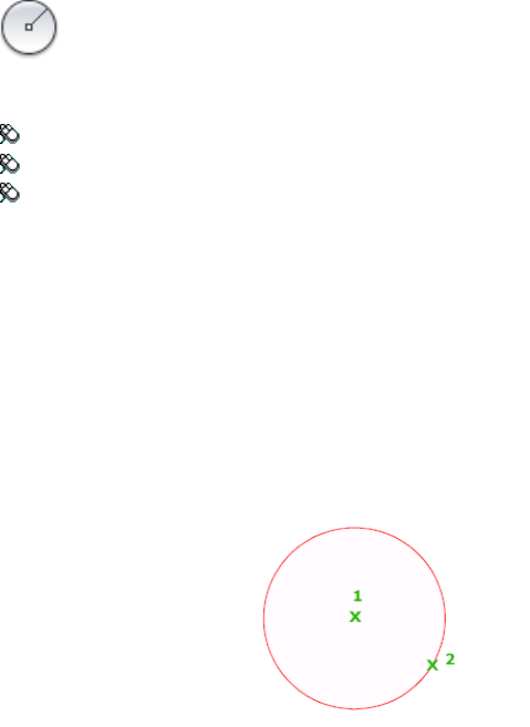
CIRCLE
Quick Reference
See also:
■Draw Circles
Creates a circle.
Access Methods
Button
Ribbon: Home tab ➤ Draw panel ➤ Circle drop-down ➤ Center, Radius
Menu: Draw ➤ Circle ➤ Center, Radius
Toolbar: Draw
List of Prompts
The following prompts are displayed.
Specify center point on page 206 for circle or [3P on page 207/2P on page 207/Ttr
(tan tan radius) on page 208]: Specify a point or enter an option
Center Point
Draws a circle based on a center point and a diameter or a radius.
Radius Defines the radius of the circle. Enter a value, or specify a point.
For example:
206 | Chapter 4 C Commands
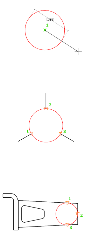
Diameter Defines the diameter of the circle. Enter a value, or specify a second
point.
For example:
3P (Three Points)
Draws a circle based on three points on the circumference.
For example:
Tan, Tan, Tan
Creates a circle tangent to three objects.
For example:
2P (Two Points)
Draws a circle based on two endpoints of the diameter.
For example:
CIRCLE | 207
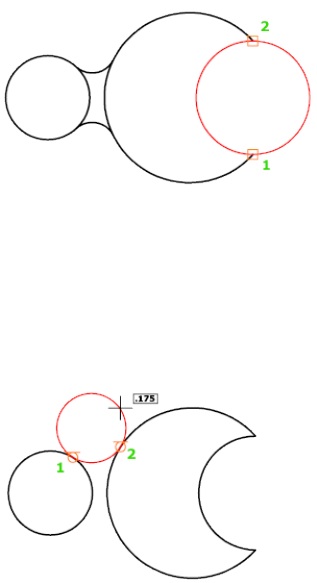
TTR (Tangent, Tangent, Radius)
Draws a circle with a specified radius tangent to two objects.
Sometimes more than one circle matches the specified criteria. The program
draws the circle of the specified radius whose tangent points are closest to the
selected points.
For example:
CLASSICIMAGE
Quick Reference
See also:
■Manage Raster Images
Manages referenced image files in the current drawing.
Summary
The legacy Image Manager is displayed. The IMAGE command now displays
the External References palette.
208 | Chapter 4 C Commands

NOTE This command will be removed in future releases.
CLASSICLAYER
Quick Reference
See also:
■Use Layers to Manage Complexity
Opens the legacy Layer Properties Manager.
Summary
The legacy Layer Properties Manager is displayed. The LAYER command
displays the current Layer Properties Manager.
NOTE This command will be removed in future releases.
CLASSICXREF
Quick Reference
See also:
■Attach and Detach Referenced Drawings
Manages referenced drawing files in the current drawing.
Summary
The legacy Xref Manager is displayed. The EXTERNALREFERENCES on page
504 command displays the current External References palette.
NOTE This command will be removed in future releases.
CLASSICLAYER | 209

CLEANSCREENON
Quick Reference
See also:
■Control the Display of Toolbars
Clears the screen of toolbars and dockable windows, excluding the command
window.
Access Methods
Menu: View ➤ Clean Screen
Command entry: Ctrl+0
Toolbar: Status bar ➤ Clean Screen
Summary
The screen displays only the menu bar, the Model and layout tabs at the
bottom of the drawing, the status bars, and the command line. Use
CLEANSCREENOFF to restore the display of interface items that were hidden
by CLEANSCREENON.
CLEANSCREENOFF
Quick Reference
See also:
■Control the Display of Toolbars
Restores the state of the display before CLEANSCREENON was used.
Access Methods
Menu: View ➤ Clean Screen
Command entry: Ctrl+0
Toolbar: Status bar ➤ Clean Screen
210 | Chapter 4 C Commands

Summary
Restores the state of the display before CLEANSCREENON was used. Use
CLEANSCREENON to clear the screen of most AutoCAD user interface
elements.
CLIP
Quick Reference
See also:
■Clip Underlays
Crops a selected external reference, image, viewport, or underlay (DWF, DWFx,
PDF, or DGN) to a specified boundary.
Access Methods
Button
Ribbon: Insert tab ➤ Reference panel ➤ Clip
Summary
The clipping boundary determines a portion of an image, underlay, viewport,
or external reference to hide. The visibility of the clipping boundary is
controlled by the FRAME on page 1512 system variable.
List of Prompts
The list of prompts varies depending on whether you are clipping an underlay,
image, external reference, or viewport.
Underlay and Image Prompts
The following prompts are displayed.
On Turns on clipping and displays the underlay clipped to the previously
defined boundary.
Off Turns off clipping and displays the entire PDF underlay and frame.
CLIP | 211

If you clip the underlay again while clipping is off, clipping automatically
turns on. You are prompted to delete the old boundary even when clipping
is off and the clipping boundary is not visible.
Delete Removes a predefined clipping boundary and redisplays the full original
underlay.
New Boundary Defines a rectangular or polygonal clipping boundary, or
generates a polygonal clipping boundary from a polyline.
NOTE You can only create a new clipping boundary for an underlay when the
old boundary is deleted.
Select Polyline Defines the boundary with the selected polyline. The polyline
can be open but must consist of straight line segments and cannot intersect
itself.
Polygonal Defines a polygonal clipping boundary with three or more points
that you specify for the vertices of a polygon.
Rectangular Defines a rectangular boundary with the points that you specify
for opposite corners.
Invert Clip Inverts the mode of the clipping boundary: objects are clipped
either outside the boundary or inside the boundary.
External Reference Prompts
The following prompts are displayed.
Select objects: Use an object selection method and press Enter when you finish
selecting objects
Enter clipping option [ON on page 1351/OFF on page 1351/Clipdepth on page
1351/Delete on page 1351/generate Polyline on page 1352/New boundary on page
1352] <New>: Select an option or press Enter
On Displays the clipped portion of the external reference or block in the
current drawing.
Off Displays all of the geometry of the external reference or block in the
current drawing, ignoring the clipping boundary.
Clipdepth Sets the front and back clipping planes on an xref or block. Objects
outside the volume defined by the boundary and the specified depth are not
displayed. Regardless of the current UCS, the clip depth is applied parallel to
the clipping boundary.
■Front Clip Point. Creates a clipping plane passing through and
perpendicular to the clipping boundary.
212 | Chapter 4 C Commands

■Distance. Creates a clipping plane the specified distance from and parallel
to the clipping boundary.
■Remove. Removes both the front and back clipping planes.
Delete Removes a clipping boundary for the selected xref or block. To
temporarily turn off a clipping boundary, use the Off option. Delete erases
the clipping boundary and the clipdepth. The ERASE on page 469 command
cannot be used to delete clipping boundaries.
Generate Polyline Automatically draws a polyline coincident with the clipping
boundary. The polyline assumes the current layer, linetype, lineweight, and
color settings. Use this option when you want to modify the current clipping
boundary using PEDIT on page 939 and then redefine the clipping boundary
with the new polyline. To see the entire xref while redefining the boundary,
use the Off option.
New Boundary Defines a rectangular or polygonal clipping boundary, or
generates a polygonal clipping boundary from a polyline.
NOTE You can only create a new clipping boundary for a selected XREF underlay
when the old boundary is deleted.
■Select Polyline. Defines the boundary with the selected polyline. The
polyline can be open but must consist of straight line segments and cannot
intersect itself.
■Polygonal. Defines a polygonal clipping boundary with three or more
points that you specify for the vertices of a polygon.
■Rectangular. Defines a rectangular boundary with the points that you
specify for opposite corners.
■Invert Clip. Inverts the mode of the clipping boundary: objects are clipped
either outside the boundary or inside the boundary.
Viewport Prompts
NOTE You cannot clip a viewport in model space. You must be in paper space.
Clipping Object Select the viewport to clip.
Polygonal Draws a clipping boundary. You can draw line segments or arc
segments by specifying points.
The descriptions of the Next Point, Arc, Close, Length, and Undo options
match the descriptions of the corresponding options in the PLINE command.
CLIP | 213
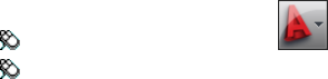
Delete Deletes the clipping boundary of a selected viewport. This option is
available only if the selected viewport has already been clipped. If you clip a
viewport that has been previously clipped, the original clipping boundary is
deleted, and the new clipping boundary is applied.
CLOSE
Quick Reference
See also:
■Open a Drawing
Closes the current drawing.
Access Methods
Menu: Application menu ➤ Close ➤ Current Drawing
Menu: File ➤ Close
Summary
The current drawing is closed. If you modified the drawing since it was last
saved, you are prompted to save or discard the changes.
You can close a file that has been opened in read-only mode if you have made
no changes or if you are willing to discard changes. To save changes to a
read-only file, you must use the SAVEAS command.
CLOSEALL
Quick Reference
See also:
■Open a Drawing
Closes all currently open drawings.
214 | Chapter 4 C Commands
Access Methods
Menu: Application menu ➤ Close ➤ All Drawings
Menu: Window ➤ Close All
Summary
All open drawings are closed. A message box is displayed for each unsaved
drawing, in which you can save any changes to the drawing before closing it.
COLOR
Quick Reference
See also:
■Set the Current Color
Sets the color for new objects.
Access Methods
Button
Ribbon: Home tab ➤ Properties panel ➤ Object Color
Menu: Format ➤ Color
Command entry: 'color for transparent use
Summary
The Select Color dialog box is displayed.
If you enter -color at the Command prompt, options are displayed.
COLOR | 215
Select Color Dialog Box
Quick Reference
See also:
■Set the Current Color
Defines the color of objects.
Summary
You can select from the 255 AutoCAD Color Index (ACI) colors, true colors,
and Color Book colors.
List of Tabs
The following tabs are displayed.
■Index Color
■True Color
■Color Books
Index Color Tab (Select Color Dialog Box)
Quick Reference
See also:
■Set the Current Color
Specifies color settings using the 255 AutoCAD Color Index (ACI) colors.
216 | Chapter 4 C Commands

List of Options
The following options are displayed.
AutoCAD Color Index (ACI) Palettes Specifies a color from the AutoCAD
Color Index. If you hover over a color, the number of the color and its red,
green, blue value are displayed below the palette. Click a color to select it, or
enter the color number or name in the Color box.
The large palette displays colors 10 through 249.
The second palette displays colors 1 through 9; these colors have names as
well as numbers.
The third palette displays colors 250 through 255; these colors are shades of
gray.
Index Color Indicates the ACI color number when you hover over a color.
Red, Green, Blue Indicates the RGB color value when you hover over a color.
Bylayer
Specifies that new objects assume the color assigned to the layer on which
you create them. When BYLAYER is selected, the color of the current layer is
displayed in the Old and New color swatches.
Byblock
Specifies that new objects use the default color (white or black, depending on
your background color) until you group the objects into a block and insert
Select Color Dialog Box | 217
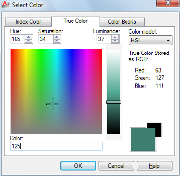
the block. When you insert the block into a drawing, the objects in the block
inherit the current Color setting.
Color
Specifies a color name, BYLAYER or BYBLOCK color, or an AutoCAD Color
Index (ACI) number of 1 through 255. The New color swatch shows the most
recently selected color.
Old Color Swatch
Displays the previously selected color.
New Color Swatch
Displays the currently selected color.
True Color Tab (Select Color Dialog Box)
Quick Reference
See also:
■Set the Current Color
Specifies color settings using true colors.
218 | Chapter 4 C Commands
Summary
Specifies color settings using true colors (24-bit color) with either the Hue,
Saturation, and Luminance (HSL) color model or the Red, Green, and Blue
(RGB) color model. Over sixteen million colors are available when using true
color functionality. The options available on the True Color tab are dependent
on whether the HSL or RGB color model is specified.
List of Options
The following options are displayed.
HSL Color Model
Specifies the HSL color model for selecting colors.
Hue, saturation, and luminance are properties of colors. By manipulating the
values of these properties, you can specify a wide range of colors.
Hue (H)
Specifies the hue of a color. Hues represent a specific wavelength of light
within the visible spectrum. To specify a hue, use the color spectrum or specify
a value in the Hue box. Adjusting this value affects the RGB value. Valid hue
values are from 0 to 360 degrees.
Saturation (S)
Specifies the purity of a color. High saturation causes a color to look more
pure while low saturation causes a color to look washed-out. To specify color
saturation, use the color spectrum or specify a value in the Saturation box.
Adjusting this value affects the RGB value. Valid saturation values are from 0
to 100%.
Luminance (L)
Specifies the brightness of a color. To specify color luminance, use the color
slider or specify a value in the Luminance box. Valid luminance values are
from 0 to 100%. A value of 0% represents the color black, 100% represents
white, and 50% represents the optimal brightness for the color. Adjusting this
value also affects the RGB value.
Color Spectrum Specifies the hue and purity of a color. To specify a hue,
move the crosshairs from side to side over the color spectrum. To specify color
saturation, move the crosshairs from top to bottom over the color spectrum.
Color Slider Specifies the brightness of a color. To specify color luminance,
adjust the bar on the color slider or specify a value in the Luminance box.
Select Color Dialog Box | 219
RGB Color Model
Specifies the RGB color model for selecting colors. The options available on
the True Color tab are dependent on whether the HSL or RGB color model is
specified.
Colors can be broken down into components of red, green, and blue. The
values specified for each component represent the intensity of the red, green,
and blue components. The combination of these values can be manipulated
to create a wide range of colors.
Red (R)
Specifies the red component of a color. Adjust the slider on the color bar or
specify a value from 1 to 255 in the Red box. If this value is adjusted, it will
be reflected in the HSL color mode values.
Green (G)
Specifies the green component of a color. Adjust the slider on the color bar
or specify a value from 1 to 255 in the Green box. If this value is adjusted, it
will be reflected in the HSL color mode values.
Blue (B)
Specifies the blue component of a color. Adjust the slider on the color bar or
specify a value from 1 to 255 in the Blue box. If this value is adjusted, it will
be reflected in the HSL color mode values.
Color
Specifies the RGB color value. This option is updated when changes are made
to HSL or RGB options. You can also edit the RGB value directly using the
following format: 000,000,000.
True Color Stored as RGB
Indicates the value for each RGB color component.
Old Color Swatch
Displays the previously selected color.
New Color Swatch
Displays the currently selected color.
220 | Chapter 4 C Commands
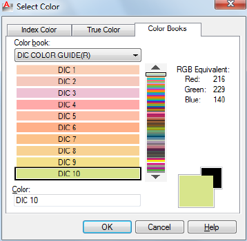
Color Books Tab (Select Color Dialog Box)
Quick Reference
See also:
■Set the Current Color
Specifies colors using third-party color books or user-defined color books.
Summary
Once a color book is selected, the Color Books tab displays the name of the
selected color book.
List of Options
The following options are displayed.
Color Book
Specifies the color book to be used when selecting colors.
The list consists of all the color books that are found in the Color Book
Locations specified in the Options dialog box, Files tab.
Displays the pages of the selected color book and the colors and color names
on each page. Color books containing up to ten colors per page are supported.
If a color book is not paginated, the colors are organized into pages containing
Select Color Dialog Box | 221
seven colors per page. To view color book pages, select an area on the color
slider or use the up and down arrows to browse.
RGB Equivalent Indicates the value for each RGB color component.
Color
Indicates the currently selected color book color. You can search for a specific
color in a color book by entering the number of the color swatch and pressing
Tab. This action updates the New color swatch with the requested color
number. If the specified color is not found in the color book, the closest
number match is displayed.
Old Color Swatch
Displays the previously selected color.
New Color Swatch
Displays the currently selected color.
-COLOR
Quick Reference
See also:
■Set the Current Color
If you enter -color at the Command prompt, the following prompts are
displayed.
Enter default object color [Truecolor on page 223/COlorbook on page 223]
<BYLAYER>: Enter a color, enter t, enter co, or press Enter
You can enter a color from the AutoCAD Color Index (a color name or
number), a true color, or a color from a color book.
You can enter the color number (1 through 255) or the color name (the names
for the first seven colors). For example, you can specify the color red by
entering the ACI number 1 or the ACI name red.
You can also enter bylayer or byblock. If you enter byblock, all new objects
are drawn in the default color (white or black, depending on your background
color) until they are grouped into a block. When you insert the block in a
drawing, the objects in the block inherit the current setting of COLOR.
222 | Chapter 4 C Commands
WARNING If you used a mixture of color methods to draw the objects that make
up a block, inserting that block or changing its color produces complex results.
If you enter bylayer, new objects assume the color assigned to the layer on
which you create them. See the LAYER command for information about
assigning a color to a layer.
List of Prompts
The following prompts are displayed.
True Color Specifies a true color to be used for the selected object. Enter three
integer values from 0 to 255 separated by commas to specify a true color
Color Book Specifies a color from a loaded color book to be used for the
selected object. Enter the name of a color book that has been installed.
If you enter a color book name, you are prompted to enter the color name in
the color book.
COMMANDLINE
Quick Reference
See also:
■Dock, Resize, and Hide the Command Window
Displays the Command Line window.
Access Methods
Button
Ribbon: View tab ➤ Palettes panel ➤ Command Line
Menu: Tools ➤ Command Line
Summary
Displays the command line when it has been hidden.
COMMANDLINE | 223
You can display commands, system variables, options, messages, and prompts
in a dockable and resizable window called the Command Line.
COMMANDLINEHIDE
Quick Reference
See also:
■Dock, Resize, and Hide the Command Window
Hides the Command Line window.
Access Methods
Button
Ribbon: View tab ➤ Palettes panel ➤ Command Line
Menu: Tools ➤ Command Line
Summary
Hides the Command Line. When the Command Line is hidden, you can still
enter commands with dynamic prompts turned on.
CONSTRAINTBAR
Quick Reference
See also:
■Display and Verify Geometric Constraints
Displays or hides the geometric constraints on an object.
224 | Chapter 4 C Commands

Access Methods
Button
Ribbon: Parametric tab ➤ Geometric panel ➤ Show/Hide
Menu: Parametric ➤ Constraints Bars ➤ Select Objects
Toolbar: Parametric
Summary
The selection preview behavior for constraint bars is as follows:
■Placing the cursor over an icon on a constraint bar highlights related
geometry.
■Placing the cursor over a constrained object (while constraint bars are
displayed) highlights the constraint icons associated with the selected
object.
The CONSTRAINTBARMODE system variable or the CONSTRAINTSETTINGS
command controls the display of geometric constraints on constraint bars,
when constraint bar are displayed.
On the ribbon, you can also show or hide all constraint bars for all constrained
geometries.
List of Prompts
The following prompts are displayed.
Select objects: Select objects with constraint bars
Enter an option [Show on page 225/Hide on page 225/Reset on page 226]
<Show>:Enter the appropriate value to show or hide constraint bars in the drawing.
Show
Displays constraint bars for the selected objects with geometric constraints
applied to them.
Hide
Hides constraint bars for the selected objects with geometric constraints applied
to them.
CONSTRAINTBAR | 225
Reset
Displays constraint bars for all objects with geometric constraints applied to
them and resets them to their default locations relative to their associated
parameters.
CONSTRAINTSETTINGS
Quick Reference
See also:
■Overview of Constraints
Controls the display of geometric constraints on constraint bars.
Access Methods
Button
Ribbon: Parametric tab ➤ Geometric panel ➤ Dialog Box Launcher
Menu: Parametric ➤ Constraint Settings
Toolbar: Parametric
Summary
The Constraint Settings dialog box is displayed.
Constraint Settings Dialog Box
Quick Reference
See also:
■Overview of Constraints
226 | Chapter 4 C Commands
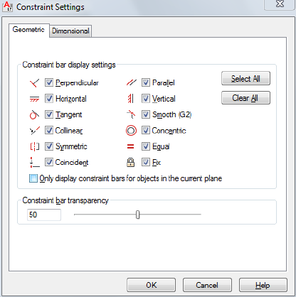
Allows you to control the geometric constraints and dimensional constraints
settings.
List of Options
The following options are displayed.
The Constraint Settings dialog box includes the following:
■Geometric Tab
■Dimensional Tab
Geometric Tab
Controls the display of constraint types on constraint bars.
Constraint Bar Display Settings Controls the display of constraint bars or
constraint point markers for objects in the drawing editor.
For example, you can hide the display of constraint bars for Horizontal and
Vertical constraints.
Select All Selects the geometric constraint types.
Clear All Clears the selected geometric constraint types.
Only Display Constraint Bars for Object in the Current Plane Displays
constraint bars for geometrically constrained objects only on the current plane.
Constraint Settings Dialog Box | 227

Sets the transparency level of constraint bars in a drawing.
Dimensional Tab
Sets preferences in behavior when displaying dimensional constraints.
Dimensional Constraint Format Sets the display of the dimensional name
format and lock icon.
Dimension Name Format Specifies the format for the text displayed when
dimensional constraints are applied.
Set the name format to display: Name, Value, or Name and Expression.
For example: Width=Length/2
Show Lock Icon for Annotational Constraints Displays a lock icon against
an object that has an annotational constraint applied (DIMCONSTRAINTICON
on page 1452 system variable).
Show Hidden Dynamic Constraints for Selected Objects Displays dynamic
constraints that have been set to hide when selected.
+CONSTRAINTSETTINGS
Quick Reference
See also:
■Overview of Constraints
Controls the tab that is displayed by default when the Constraint Settings
dialog box is invoked.
Tab DisplayedTab Index
Geometric tab0
Dimensional tab1
228 | Chapter 4 C Commands

CONTENTEXPLORER
Quick Reference
See also:
■Understand the Content Explorer Window
■DesignCenter
■Use Autodesk Seek to Add and Share Drawings
Finds and inserts content such as drawing files, blocks, and styles.
Access Methods
Button
Ribbon: Plug-ins tab ➤ Content Panel ➤ Explore
Summary
With Content Explorer you can index design content for quick access, catalog
the objects in each file, and search for content in local folders, network folders,
and the Autodesk Seek Library.
CONTENTEXPLORERCLOSE
Quick Reference
See also:
■Understand the Content Explorer Window
CONTENTEXPLORER | 229
Closes the Content Explorer window.
Access Methods
Button
Ribbon: Plug-ins tab ➤ Content Panel ➤ Explore
CONVERT
Quick Reference
See also:
■Use Drawings from Different Versions and Applications
Optimizes 2D polylines and associative hatches created in AutoCAD LT 95 or
earlier.
Sumary
Hatches are not updated automatically when a drawing from a previous release
is opened in AutoCAD LT 97 or later. Information about the rotation of a
hatch pattern may not be updated properly if you have changed the UCS since
creating the hatch. When updating hatches with CONVERT, it is recommended
that you use the Select option so that you can check your results.
In most cases, you do not need to update polylines with CONVERT. By default,
the PLINETYPE system variable specifies that polylines are updated
automatically when you open an older drawing. Polylines may be created in
the old format by third-party applications, and they may be contained in an
older drawing that was inserted as a block and then exploded.
230 | Chapter 4 C Commands

NOTE Polylines containing curve-fit or splined segments always retain the old
format, as do polylines that store extended object data on their vertices. Editing
commands make no distinction between the two formats.
List of Prompts
The following prompts are displayed.
Enter type of objects to convert [Hatch/Polyline/All] <All>: Enter h for hatches,
p for polylines, or a for both
Hatch Converts all hatches in the drawing.
Polyline Converts all polylines in the drawing.
All Converts all polylines and hatches in the drawing.
CONVERTCTB
Quick Reference
See also:
■Switch the Type of Plot Style Table
Converts a color-dependent plot style table (CTB) to a named plot style table
(STB).
Summary
Displays the Select File dialog box (a standard file selection dialog box), where
you can select the color-dependent plot style table file you want to convert.
The Save As dialog box is then displayed. If necessary, specify a new location
or name for the converted plot style table file.
CONVERTCTB saves a copy of a color-dependent plot style table as a named
plot style table, which you can then attach to drawings that use named plot
styles. The original color-dependent plot style table is not affected by
CONVERTCTB. The default location for the new named plot style table file is
in the Plot Styles folder. The default name for the new named plot style table
file is the same as the color-dependent plot style table name.
CONVERTCTB creates one named plot style for each color that has unique
plot properties, one named plot style for each group of colors that are assigned
the same plot properties, and a default named plot style called NORMAL.
CONVERTCTB | 231
For example, if all the colors in a color-dependent plot style table have the
same plot properties, CONVERTCTB creates only two named plot styles in the
named plot style table: NORMAL, the default plot style, and STYLE 1, which
assumes the plot properties that were assigned to all the colors in the
color-dependent plot style table. However, suppose that all the colors in a
color-dependent plot style table have the same plot properties except for two
colors, BLUE and GREEN. If these colors each have unique plot properties,
CONVERTCTB creates four named plot styles in the named plot style table:
NORMAL, the default plot style; STYLE 1, which assumes the plot properties
of GREEN; STYLE 2, which assumes the plot properties of BLUE; and STYLE
3, which assumes the plot properties that were assigned to all the other colors.
CONVERTCTB gives the plot styles in the new named plot style table generic
names such as STYLE 1, STYLE 2. You can modify these generic plot style
names in the Plot Style Table Editor. Click the Edit button on the Plot Device
tab in the Page Setup dialog box. If you want to rename the plot styles, you
must do so before applying them to drawing layouts.
CONVERTPSTYLES
Quick Reference
See also:
■Switch the Type of Plot Style Table
Converts the current drawing to either named or color-dependent plot styles.
Summary
A drawing can use either named or color-dependent plot styles, but not both.
CONVERTPSTYLES converts a currently open drawing from color-dependent
plot styles to named plot styles, or from named plot styles to color-dependent
plot styles, depending on which plot style method the drawing is currently
using.
When you convert a drawing, CONVERTPSTYLES sets the PSTYLEMODE
system variable to the appropriate setting (0 = named, 1= color-dependent).
For example, a drawing using color-dependent plot styles assigns plot properties
to objects and layers by color. In other words, all objects with the same color
have the same plot properties. CONVERTPSTYLES converts the drawing to
use named plot styles that can be applied to objects or layers independent of
232 | Chapter 4 C Commands
color assignment. In other words, all objects with the same color can have
different plot properties.
Converting Drawings from Color-Dependent to Named Plot
Styles
A dialog box advises you to convert the drawing's plot style tables before
converting the drawing. You can convert the color-dependent plot style tables
assigned to the drawing to named plot style tables using CONVERTCTB.
The Select File dialog box (a standard file selection dialog box) is displayed,
where you select the named plot style table file to attach to the converted
drawing.
CONVERTPSTYLES requires you to select a named plot style table that was
converted using CONVERTCTB or created from a PC2 or PCP file. Normally
you should select the named plot style table that was converted from the
color-dependent plot style table that was assigned to the same drawing.
CONVERTPSTYLES attaches the selected named plot style table to model space
and to all layouts. Drawing layers are each assigned a named plot style (from
the converted plot style table) that has the same plot properties that their
color-dependent plot style had.
■Drawing objects that had the same color-dependent plot style as their layer
are assigned the named plot style BYLAYER.
■Drawing objects that had a color-dependent plot style that was different
from their layer are assigned a named plot style that has the same properties
that their color-dependent plot style had.
After a drawing is converted to named plot styles, you can change the named
plot style table assignment or assign other named plot styles tables to model
space or layouts. You can also assign individual plot styles to drawing objects.
Converting Drawings from Named to Color-Dependent Plot
Styles
A dialog box advises you that the named plot styles attached to objects and
named plot style tables attached to model space and layouts will be detached.
After a drawing is converted to color-dependent plot styles, you can assign a
color-dependent plot style table. Plot styles will be applied by color.
CONVERTPSTYLES | 233
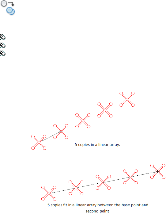
COPY
Quick Reference
See also:
■Copy Objects
Copies objects a specified distance in a specified direction.
Access Methods
Button
Ribbon: Home tab ➤ Modify panel ➤ Copy
Menu: Modify ➤ Copy
Toolbar: Modify
Shortcut menu: Select the objects to copy, and right-click in the drawing
area. Click Copy Selection.
Summary
234 | Chapter 4 C Commands
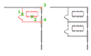
With the COPYMODE on page 1422 system variable, you can control whether
multiple copies are created automatically.
List of Prompts
The following prompts are displayed.
Select objects: Use an object selection method and press Enter when you finish
Specify base point or [Displacement/mOde/Multiple] <Displacement>: Specify
a base point or enter an option
Specify second point or [Array] <use first point as displacement>: Specify a
second point or enter an option
Displacement
Specifies a relative distance and direction using coordinates.
The two points you specify define a vector that indicates how far from the
original the copied objects are to be placed and in what direction.
If you press Enter at the Specify Second Point prompt, the first point is
interpreted as a relative X,Y,Z displacement. For example, if you specify 2,3
for the base point and press Enter at the next prompt, the objects are copied
2 units in the X direction and 3 units in the Y direction from their current
location.
Mode
Controls whether the command repeats automatically (COPYMODE system
variable).
Single Creates a single copy of selected objects and ends the command.
Multiple Overrides the Single mode setting. The COPY command is set to
repeat automatically for the duration of the command.
Array
Arranges a specified number of copies in a linear array.
Number of Items to Array Specifies the number of items in the array,
including the original selection set.
COPY | 235

Second Point Determines a distance and direction for the array relative to
the base point. By default, the first copy in the array is positioned at the
specified displacement. The remaining copies are positioned in a linear array
beyond that point using the same incremental displacement.
Fit Positions the final copy in the array at the specified displacement. The
other copies are fit in a linear array between the original selection set and the
final copy.
Fit
Redefines the array to use the specified displacement as the location of the
last copy rather than the first copy, fitting the other copies between the original
selection set and the final copy.
COPYBASE
Quick Reference
See also:
■Cut, Copy, and Paste with the Clipboard
Copies selected objects to the Clipboard along with a specified base point.
Access Methods
Button
Menu: Edit ➤ Copy with Base Point
Shortcut menu: End any active commands, right-click in the drawing area,
and choose Clipboard ➤ Copy with Base Point.
Summary
The selected objects are copied to the Clipboard.
■Use PASTECLIP to move the copied objects from the Clipboard to a location
in the same document or to another document.
236 | Chapter 4 C Commands
■When you paste an object copied with COPYBASE, it is placed relative to
the specified base point.
COPYCLIP
Quick Reference
See also:
■Cut, Copy, and Paste with the Clipboard
Copies selected objects to the Clipboard.
Access Methods
Button
Ribbon: Home tab ➤ Clipboard panel ➤ Copy Clip
Menu: Edit ➤ Copy
Toolbar: Standard
Shortcut menu: End any active commands, right-click in the drawing area,
and choose Clipboard ➤ Copy.
Command entry: Ctrl+C
Summary
COPYCLIP copies all objects you select to the Clipboard. You can paste the
contents of the Clipboard into a document or drawing.
NOTE If the cursor is in the drawing area, the selected objects are copied to the
Clipboard. If the cursor is on the command line or in the text window, the selected
text is copied to the Clipboard.
When you copy objects to the Clipboard, information is stored in all available
formats. When you paste the Clipboard contents into a drawing, the format
that retains the most information is used. You can also use Copy and Paste
to transfer objects between drawings.
COPYCLIP | 237
COPYHIST
Quick Reference
See also:
■Navigate and Edit Within the Command Window
Copies the text in the command line history to the Clipboard.
Summary
The text is copied to the Clipboard.
COPYLINK
Quick Reference
See also:
■Edit OLE Objects in Drawings
Copies the current view to the Clipboard for linking to other OLE applications.
Access Methods
Button
Menu: Edit ➤ Copy Link
Summary
You can copy the current view to the Clipboard and then paste the contents
of the Clipboard into another document as a linked OLE object.
238 | Chapter 4 C Commands
COPYTOLAYER
Quick Reference
See also:
■Use Layers to Manage Complexity
Copies one or more objects to another layer.
Access Methods
Button
Ribbon: Home tab ➤ Layers panel ➤ Copy Objects to New Layer
Menu: Format ➤ Layers ➤ Copy Objects to New Layer
Toolbar: Layers II
Summary
Creates duplicates of selected objects on a layer that you specify. You can also
specify a different location for the duplicated objects.
If you enter -copytolayer at the Command prompt, options are displayed.
List of Prompts
The following prompts are displayed.
Select objects to copy:
Select object on destination layer or [Name] <Name>: Select an object or enter
n
Select Object on Destination Layer
Specifies the layer on which the selected objects are placed.
Specify Base Point Specifies the base point of the copied objects.
Displacement Enters coordinate values that specify a relative distance and
direction.
COPYTOLAYER | 239
Name
Enter or select Name to display the Copy to Layer dialog box on page 240.
■Specify Base Point on page 239
■Displacement on page 239
Copy To Layer Dialog Box
Quick Reference
See also:
■Use Layers to Manage Complexity
Specifies the layer on which the selected objects are placed.
List of Options
The following options are displayed.
Destination Layer
Displays a list of layers that you can select as the destination layer. You can
also enter a name to create a new layer. The new layer inherits the properties
(on/off, freeze/thaw, locked/unlocked, etc.) of the current layer.
-COPYTOLAYER
Quick Reference
See also:
■Use Layers to Manage Complexity
List of Prompts
The following prompts are displayed.
Select objects to copy:
Specify the destination layer name or [?/= (select object)] <0>: Select an object
on the destination layer, enter ?, or enter =
240 | Chapter 4 C Commands
Specify the Destination Layer Name
Displays a list of layers that you can select as the destination layer. You can
also enter a name to create a new layer. The new layer inherits the properties
(on/off, freeze/thaw, locked/unlocked, etc.) of the current layer
? (List Layers)
Enter layer name(s) to list <*>: *
= (Select Object)
Selects a destination layer by selecting an object on that layer.
CUI
Quick Reference
See also:
■Understand User Interface Customization
Manages the customized user interface elements in the product.
Access Methods
Button
Ribbon: Manage tab ➤ Customization panel ➤ User Interface
Menu: Tools ➤ Customize ➤ Interface
Summary
User interface elements such as workspaces, toolbars, menus, ribbon panels,
shortcut menus, and keyboard shortcuts are all managed from this dialog box.
The Customize User Interface Editor is displayed.
NOTE The XML-based CUIx file replaces the CUI file used in AutoCAD 2006
through AutoCAD LT 2009, and both the legacy menu (MNS) and legacy menu
template (MNU) files used in releases prior to AutoCAD 2006.
CUI | 241
For information about customizing the different user interface elements found
in the Customize User Interface dialog box, see User Interface Customization
in the Customization Guide.
Customize User Interface Editor
Quick Reference
See also:
■Understand User Interface Customization
Manages customized user interface elements such as workspaces, toolbars,
menus, shortcut menus, and keyboard shortcuts.
List of Tabs
■Customize
■Transfer
For more information, see User Interface Customization in the Customization
Guide.
Customize Tab (Customize User Interface Editor)
Quick Reference
See also:
■Basics of Customization Files
Manages customized user interface elements such as workspaces, toolbars,
menus, shortcut menus, and keyboard shortcuts.
242 | Chapter 4 C Commands
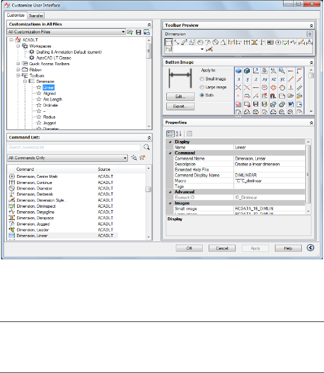
Summary
Provides an interface for customizing workspaces, toolbars, menus, ribbon
panels, shortcut menus, and other user interface elements.
NOTE When the Customize User Interface Editor is displayed using the Customize
Commands option from the Tool Palettes window or the Customize option from
the Quick Access toolbar or a toolbar, the Customizations In pane is collapsed and
the Command List pane is expanded.
List of Options
The following options are displayed.
Customizations In Pane
Displays a tree structure of user interface elements that can be customized,
such as workspaces, toolbars, menus, ribbon panels, partial CUIx files, and so
on.
List box Displays a list of CUIx files that are loaded and an Open option.
Customize User Interface Editor | 243
Available Customizations In toolbar Contains Load Partial Customization
File and Save All Current Customization Files buttons.
Load Partial Customization File Loads a CUIx file that you can add to the
acadlt.cuix file.
Save All Current Customization Files Saves changes to all loaded CUIx files.
Image Manager Displays the Image Manager on page 253, in which you can
import, export, and delete images stored in a loaded CUIx file.
Tree View Displays the current customization file in a structured view so you
can add and modify the user interface elements.
Dynamic Display Pane
Displays content specific to the user interface element you select in the tree
view in the left pane.
Information Describes selected user interface elements that do not have
properties (such as the Toolbars node, Menus node, and Shortcut Menus node).
Properties Displays the properties of user interface elements or items selected
in the tree view. Elements or items that display properties include specific
menus, menu commands, toolbars, and toolbar buttons.
Button Image Displays the images that can be assigned to a command. You
can create new and edit existing images with the Button Editor on page 252.
Shortcuts Displays a list of shortcut key names and temporary override names,
their corresponding shortcut key combinations, keyboard shortcut type
(shortcut key or temporary override), and the source CUIx file name.
Toolbar Preview Displays a preview of the selected toolbar.
Panel Preview Displays a preview of the selected ribbon panel.
Quick Properties Displays a list of object types and associated properties. You
can specify which object types and properties are enabled to use with the
Quick Properties panel and rollover tooltips.
Command List Pane
Displays a list of commands that are loaded in the program.
Categories Displays filters for the command list, including All Commands,
<Product> Commands, User Defined, Toolbar Control Elements, or Ribbon
Control Elements. You can also filter the list to display commands within a
specific CUIx file.
244 | Chapter 4 C Commands
Find Command or Text Searches the current CUIx for a selected command
or matching text string. Displays the Find and Replace dialog box.
Create a New Command Creates a new command. You can add or change
properties and create or edit a button.
Properties Pane
Displays user interface properties that you can view, edit, or delete.
General Displays the name and description of a command or user interface
element.
■Name - Displays the name of the user interface element. The name you
enter is the label or tooltip name displayed in the program.
■Description - Displays the description for the user interface element. The
description you enter is displayed in the status bar or in a tooltip.
Properties for Ribbon Tabs and Panels:
■Display Text - Displays the name of the ribbon tab or panel.
Properties for Ribbon Tabs:
■Contextual Display Type - Specifies whether the ribbon tab replaces all
ribbon tabs on the ribbon or is merged with the ribbon tabs already
displayed on the ribbon. (Full or Merged)
Display Determines which user interface elements are displayed after start up
or when a workspace is set current.
■Start On - Specifies if the Model tab or last used layout is set current.
(Model, Layout, or Do Not Change)
■Menu Bar - Specifies the display of the menu bar. (Off or On)
■Status Bar - Specifies the display of the application and drawing status
bars. (Application Only, All Off, All On, or Drawing Status Bar Only)
■Model/Layout Tabs - Specifies the display of the Model and layout tabs
along the bottom of the drawing window. (Off, On, or Do Not Change)
■Scroll Bars - Specifies the display of the scroll bars in the drawing window.
(Off, On, or Do Not Change)
Customize User Interface Editor | 245
Partial File Behavior Controls how ribbon tabs are displayed when in a CUIx
file that is being loaded as a partial customization file.
■Default Display - Specifies whether the ribbon tab is displayed on the ribbon
when in a CUIx file that is loaded as a partial customization file. (Do Not
Add to Workspaces or Add to Workspaces)
■Workspace Behavior - Specifies how the ribbon tab is merged or added to
the ribbon when this CUIx file is loaded as a partial customization file.
(Add Tab Only, Merge Tab Only, or Merge or Add Tab)
Appearance Controls the appearance of toolbars, ribbon panels, commands
on a ribbon panel, and ribbon tabs.
Properties for Ribbon Panels:
■Resize Style - Specifies the resize style for a ribbon panel when the ribbon
is reduced in size. (Collapse as Needed, Never Collapse, or Collapse Last)
Properties for Ribbon Panels on Fold Panels and Sub-Panel:
■Top Justify - Specifies the vertical justification for contents within
sub-panels, or for fold panels of different heights.
■Resize - Specifies whether the panel can be resized.
■Resize Priority - Specifies the resizing priority of panels. When the ribbon
is compressed, panels with lower values resize first. When a ribbon is
expanded, panels with higher values resize first.
Properties for a Command on Ribbon Panels:
■Button Style - Specifies the orientation, size, and label display of the
command. (Large With Text (Vertical), Large With Text (Horizontal),
SmallWithText, SmallWithoutText, or LargeWithoutText)
■Group Name - Specifies the group name for the command when grouping
is enabled for a drop-down.
Properties for Drop-downs on Quick Access Toolbars and Ribbon Panels:
■Behavior - Specifies if the button executes a command or displays a list of
commands. (Drop Down Menu with Recent, Drop Down Menu, Split with
Recent, Split, or Split with Recent (Static))
246 | Chapter 4 C Commands
■SplitButtonListStyle - Specifies how the commands on the drop-down will
be displayed. (Icon, IconText, or Descriptive)
■Button Style - Specifies the orientation, size, and label display of the button
for the drop-down. (Large With Text (Vertical), Large With Text
(Horizontal), SmallWithText, SmallWithoutText, or LargeWithoutText)
■Grouping - Specifies whether commands under a drop-down are grouped
together using their assigned group names. (Yes or No)
Properties for Toolbars:
■Default Display - Specifies whether the toolbar is displayed when in a CUIx
file that is loaded as a partial customization file. (Do Not Add to Workspaces
or Add to Workspaces)
■Orientation - Specifies the location of the toolbar. (Floating, Top, Bottom,
Left, or Right)
■Default X Location - Specifies the X location of the toolbar when floating.
■Default Y Location - Specifies the Y location of the toolbar when floating.
■Rows - Specifies the number of rows the items on the toolbar are displayed
in when the toolbar is floating.
Properties for a Separator on Ribbon Panels:
■Separator Style - Specifies the style for the separator. (Line or Spacer)
Access Controls the key combination assigned to a shortcut key.
■Key(s) - Specifies the key combination assigned to a shortcut key.
■KeyTip - Specifies the keytip character to access a command or control
from the ribbon.
Properties for Drop-downs on Quick Access Toolbars Ribbon Panels:
■ToolTip Title - Specifies the alternate title for the tooltip of a drop-down
when its Behavior property is set to Drop Down Menu.
Resize Style
■Hide Text - Specifies that the text is never removed.
■Wrap - Specifies that the content does not wrap inside the panel.
Customize User Interface Editor | 247

■Shrink - Specifies the width of Row Panel never decreases below the default
size.
Properties for Ribbon Fold Panels:
■Default Size - Specifies the size of the panel contents in a floating panel.
■Minimum Size - Specifies the smallest size each control in the panel
collapses.
■Maximum Size - Specifies the largest size each control in the panel expands.
IMPORTANT Maximum Size must be greater than or equal to the Default Size,
and Default Size must be greater than or equal to Minimum Size.
Size Controls the size of a tablet menu.
■Rows - Specifies the number of rows for a tablet menu.
■Columns - Specifies the number of columns for a tablet menu.
Slide Specifies the slide library and slide to use for a command in an image
menu.
■Slide library - Specifies the slide library for the slide used for the command
in an image menu.
■Slide label - Specifies the slide to use for the command in an image menu.
Shortcut Controls the key combination and macros assigned to a temporary
override key.
■Key(s) - Specifies the key combination for the temporary override.
Click the [..] button to display the Shortcut Keys dialog box. Click in the
Press New Shortcut Key text box and assign the desired key combination.
■Macro 1 (Key Down) - Displays the macro to execute when the key
combination is pressed.
■Macro 2 (Key Up) - Displays the macro to execute when the key
combination is released.
Command Displays the properties assigned to a command.
■Name - Displays the name of the command. The name you enter is the
label or tooltip name displayed in the program.
248 | Chapter 4 C Commands
■Description - Displays the description for the command. The description
you enter is displayed in the status bar or in a tooltip.
■Extended Help File - Displays the file name and ID from the extended help
file that should be displayed when the cursor continues to hover over a
toolbar, panel button, or menu item for a specified period of time.
Click the [..] button to display the Select Extended Help File dialog box.
Select a XAML file that contains tooltip definitions and then select the
tooltip content to display from the Select Help ID dialog box.
■Command Display Name - Displays the command line text string that is
shown in the command tooltip.
■Macro - Displays the macro assigned to a selected command. You can
create a macro or edit an existing macro.
Click the [..] button to display the Long String Editor dialog box and the
full contents of the macro.
■Tags - Displays the user-defined keywords that are associated with a
command. Tags can be used to search for commands in the menu browser.
Click the [..] button to display the Tag Editor dialog box. Click the Tags
text box to add, modify or remove tags. Each tag must be separated by a
comma and the total number of characters for all the tags and separators
cannot be more than 256 characters.
Advanced Displays the aliases and element IDs that you can define for each
user interface element.
■Aliases - Specifies a unique value for a user interface element that is used
to programmatically reference the user interface element.
Click the [..] button to display the Aliases dialog box. Click in the text box
and edit the list of assigned aliases.
■Object Name - Specifies the object type associated with a double click
action.
■Element ID - Displays the tag that uniquely identifies a command or user
interface element.
Images Determines which images are assigned to a command when displayed
on a user interface element.
■Small Image - Specifies the small image file to use when a command is
added to a toolbar, menu, or ribbon panel.
■Large Image - Specifies the large image file to use when a command is
added to a toolbar or ribbon panel.
Customize User Interface Editor | 249
Quick Properties Pane
Displays a list of object types and the properties associated to the selected
object type.
Edit Object Type List Controls which object types are used with the Quick
Properties panel or rollover tooltips. Displays the Edit Object Type List dialog
box.
Object Type List Displays a list of the object types you can use with Quick
Properties panel or rollover tooltips.
General Displays the general properties that are available for all object types
in the Properties list.
Properties List Displays the properties for the selected object type or the
general properties available for all object types.
Reset Overrides Overrides the selected general properties for all object types.
Transfer Tab (Customize User Interface Editor)
Quick Reference
See also:
■Transfer and Migrate Customization
Transfers user interface elements to or from a main or partial customization
(CUIx) file, where your interface element data is stored.
250 | Chapter 4 C Commands
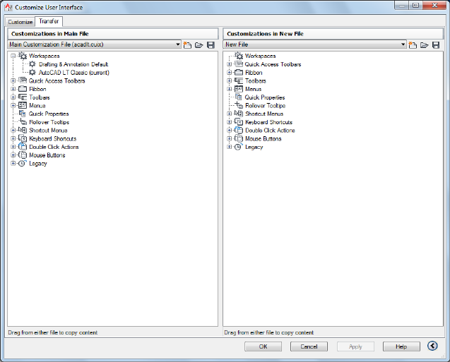
Summary
You open a CUIx, CUI, MNS, or MNU file to import or export user interface
data. When you open CUI, MNU, or MNS files, they are not converted
automatically to a CUIx file format until you save the new file that is created.
The original CUI, MNU, or MNS file is not modified.
List of Options
Customizations In panes When you enter cuiimport at the Command prompt,
the main CUIx file is displayed (acadlt.cuix by default) in the right pane. You
open a CUIx or legacy customization file in the left pane to transfer data.
When you enter cuiexport at the Command prompt, the main CUIx file is
displayed in the left pane. You open another CUIx or legacy customization
file in the right pane to transfer data.
Customize User Interface Editor | 251
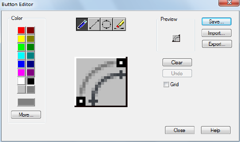
Button Editor Dialog Box
Quick Reference
See also:
■Create Custom Images for Commands
Modifies or creates custom images used for commands.
List of Options
The following options are displayed.
Color Palette
Sets the current color used by the editing tools.
Standard Color Swatches Color swatches used to set of the standard 16 colors
current.
More Opens the Select Color dialog box.
Editing Tools
Provides tools for editing a custom image.
Pencil Edits one pixel at a time using the current color.
Line Creates lines using the current color. Click and drag to set the start point
and draw the line. Release to complete the line.
Circle Creates circles using the current color. Click to set the center and drag
to set the radius. Release to complete the circle.
252 | Chapter 4 C Commands

Erase Sets pixels to white. Click and drag over colored pixels to change them
to white.
Editing Area
Provides a close-up view of the image for editing.
Preview
Displays a preview of the image currently being edited. The preview displayed
shows the actual size of the image.
Clear
Clears the editing area.
Undo
Undoes the last editing action.
Grid
Displays a grid in the editing area. Each grid square represents a single pixel.
Save
Displays the Save Image dialog box, which allows you to save the customized
image to the working customization file.
Import
Imports an externally stored image for editing. Images are stored in the working
customization file as bitmap (BMP) files.
Export
Exports the customized image to an external local or network storage location.
NOTE When exporting an image, the Create File dialog box defaults to the folder
defined under Custom Icon Location of the Files tab in the Options dialog box.
Images that are located in this folder can be migrated with the Migrate Custom
Settings dialog box.
Image Manager Dialog Box
Quick Reference
See also:
■Manage, Import, and Export Custom Images
Manages the images that are in the selected customization file.
Image Manager Dialog Box | 253
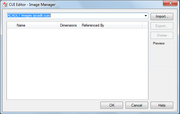
List of Options
The following options are displayed.
Loaded Customization Files List Lists the customization files that are
currently loaded.
Custom Images List Lists the images that are stored in the customization file
selected from the Loaded Customization Files list.
Import Imports an externally stored image into the selected customization
file from the Loaded Customization Files list.
Export Exports the selected custom images from the Custom Images list to
an external local or network storage location.
Delete Permanently deletes the selected image from the Custom Images list
and the customization file.
Preview Displays a preview of the selected image in the Custom Images list.
254 | Chapter 4 C Commands
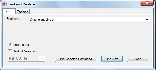
Find and Replace Dialog Box - CUI
Quick Reference
See also:
■Find and Replace Commands and Text in a CUIx File
Finds a search string in a command or command property in either the
Command List pane or the Available Customizations in <file name> pane, or
replaces a search string with a new search string
Summary
Locates and replaces commands or command properties (command names,
descriptions, or macros). Use the Find tab to locate a specified text string, and
the Replace tab to locate and replace a specified text string.
List of Options
The following options are displayed.
Common
Find What Displays the search string you want to locate. If you select a
command in the Command List pane, this box displays that string. You can
also enter a string. Any previous strings entered in this box are stored in the
drop-down list.
Ignore Case Locates all commands or command properties regardless of their
case (for example, the program would search for both LINE and line).
Find and Replace Dialog Box - CUI | 255
Restrict Search To Limits the search to the CUIx file you select from the
drop-down list. By default, the main CUIx file (acadlt.cuix by default) is
searched.
Find Next Locates the next instance of the search string in the Name,
Description, or Macros box in the Properties pane. If you search in the
Command List pane, only commands in the list are located. If you search in
the tree view in the Customizations In pane, the search starts in the tree view
and continues to the commands in the Command List pane.
Find Tab
Find Selected Command When a command is selected in the Command List
pane, locates the next interface element in the tree view that references the
selected command.
Replace Tab
Replace With Displays the string that will replace the string you searched for.
Replace Replaces a single instance of the search string. In the Customize User
Interface dialog box, the location of the search string is displayed in the
Command List pane, tree view, and Properties pane.
Replace All Replaces all instances where the search string is found. You cannot
undo this operation.
CUIEXPORT
Quick Reference
See also:
■Transfer and Migrate Customization
Exports customized settings from the main CUIx file to an enterprise or partial
CUIx file.
Access Methods
Button
Ribbon: Manage tab ➤ Customization panel ➤ Export
256 | Chapter 4 C Commands

Menu: Tools ➤ Customize ➤ Export Customizations
Summary
Customization information can be transferred between the main and partial
CUIx files.
Opens with the Transfer Tab (Customize User Interface Editor) opened by
default. The main CUIx file (acadlt.cuix) is open in the left pane. You can drag
items from one CUIx file to the other. Click Apply to save the changes and
view the updated CUIx file.
CUIIMPORT
Quick Reference
See also:
■Transfer and Migrate Customization
Imports customized settings from an enterprise or partial CUIx file to the main
CUIx file.
Access Methods
Button
Ribbon: Manage tab ➤ Customization panel ➤ Import
Menu: Tools ➤ Customize ➤ Import Customizations
Summary
Customization information can be transferred between the main and partial
CUIx files.
Opens with the Transfer Tab (Customize User Interface Editor) opened by
default. You can drag items from one CUIx file to the other. Click Apply to
save the changes and view the updated CUIx file.
CUIIMPORT | 257

CUILOAD
Quick Reference
See also:
■Create and Manage Customization Files
Loads a CUIx file.
Summary
Opens the Load/Unload Customizations dialog box, where you can locate and
load a CUIx file to customize or transfer user interface settings.
When FILEDIA is set to 0 (off), CUILOAD displays the following Command
prompt.
Enter name of customization file to load: Enter a file name
NOTE The Legacy Menu (MNS), Legacy Menu Template (MNU), and
Customization (CUI) files used in past releases have been replaced with just one
file type, the XML-based CUIx file.
Load/Unload Customizations Dialog Box
Quick Reference
See also:
■Create and Manage Customization Files
Controls the display of customization groups and interface elements.
258 | Chapter 4 C Commands
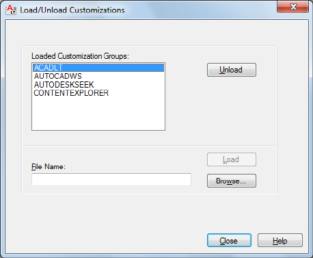
List of Options
The following options are displayed.
Loaded Customization Groups
Lists the currently loaded customization files.
File Name
Specifies the file to load when you choose Load. You can either enter the file
name or choose Browse to display the Select Customization File dialog box (a
standard file selection dialog box).
Unload
Unloads the customization group selected in the Customization Groups list.
Load
Loads the file specified under File Name.
Browse
Displays the Select Menu File dialog box (a standard file selection dialog box),
in which you can select a menu file to load.
Load/Unload Customizations Dialog Box | 259
CUIUNLOAD
Quick Reference
See also:
■Create and Manage Customization Files
Unloads a CUIx file.
Summary
Opens the Load/Unload Customizations dialog box, which has the same
options as CUILOAD. The only difference between the two commands is in
the Command prompts.
When FILEDIA is set to 0 (off), CUIUNLOAD displays the following Command
prompt.
NOTE The Legacy Menu (MNS), Legacy Menu Template (MNU), and
Customization (CUI) files used in past releases have been replaced with just one
file type, the XML-based CUIx file.
CUSTOMIZE
Quick Reference
See also:
■Organize Tool Palettes
Customizes tool palettes and tool palette groups.
Access Methods
Button
Ribbon: Manage tab ➤ Customization panel ➤ Tool Palettes
260 | Chapter 4 C Commands
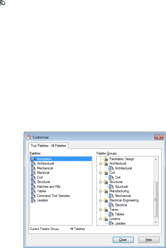
Menu: Tools ➤ Customize ➤ Tool Palettes
Shortcut menu: Right-click any tool palette and click Customize Palettes.
Summary
The Customize dialog box is displayed.
Customize Dialog Box
Quick Reference
See also:
■Organize Tool Palettes
Creates, modifies, and organizes tool palettes and tool palette groups. Imports
and exports tool palette files.
Summary
The Tool Palettes window displays only the tool palettes for the current group
or displays all tool palettes if no group is current.
In the Customize dialog box, right-click to display shortcut menus. Click and
drag items to move them.
Customize Dialog Box | 261

List of Options
The following options are displayed.
Palettes Lists all available tool palettes.
Right-click a tool palette to display a shortcut menu with the following options:
■Rename. Changes the name of an existing tool palette.
■New Palette. Creates a new empty tool palette.
■Delete. Removes the tool palette from AutoCAD LT and the associated file
on disk.
NOTE A tool palette cannot be recovered after it is deleted. Export the tool
palette to an XTP file before deleting it if you want to access it later.
■Export. Saves the tool palette to an XTP file.
■Import. Merges the tool palette from an XTP file with the other tool palettes
in AutoCAD LT.
Palette Groups Displays a tree view of your tool palette groups and the tool
palettes contained in each.
Right-click a tool palette group to display a shortcut menu with the following
options:
■New Group. Creates a new tool palette group.
■Rename. Changes the name of an existing tool palette group.
■Delete. Removes the tool palette group from AutoCAD LT and the current
user profile.
NOTE A tool palette group cannot be recovered after it is deleted. Export the
tool palette group to an XPG file before deleting it if you want to access it later.
■Set Current. Sets a tool palette group current in the Tool Palettes window.
■Export. Saves the tool palette group to an XPG file.
■Export All. Saves all tool palette groups to an XPG file.
■Import. Merges the tool palette groups from an XPG file with the other tool
palette groups in AutoCAD LT.
262 | Chapter 4 C Commands
NOTE Import all tool palettes (XTP files) before importing tool palette groups
(XPG files).
Right-click a tool palette to display a shortcut menu with the following options:
■New Group. Creates a new tool palette group.
■Remove. Deletes the reference to the tool palette from the tool palette group
only; the tool palette is not removed from AutoCAD LT and the tool palette
file on disk is not deleted.
Current Palette Group
Displays the name of the tool palette group that is current in the Tool Palettes
window.
CUTCLIP
Quick Reference
See also:
■Cut, Copy, and Paste with the Clipboard
Copies selected objects to the Clipboard and removes them from the drawing.
Access Methods
Button
Ribbon: Home tab ➤ Clipboard panel ➤ Cut
Menu: Edit ➤ Cut
Toolbar: Standard
Shortcut menu: End any active commands, right-click in the drawing area,
and choose Clipboard ➤ Cut.
Command entry: Ctrl+X
CUTCLIP | 263
Summary
CUTCLIP copies selected objects to the Clipboard, removing them from the
drawing.
You can paste the contents of the Clipboard into a document or drawing as
an embedded OLE object (see PASTECLIP and PASTESPEC). CUTCLIP does
not create OLE link information.
When you want to use objects from a drawing file in another application, you
can cut these objects to the Clipboard and then paste them into another
application. You can also use Cut and Paste to transfer objects between
drawings.
264 | Chapter 4 C Commands
D Commands
DATALINK
Quick Reference
See also:
■Link a Table to External Data
Displays the Data Link dialog box.
Access Methods
Button
Ribbon: Insert tab ➤ Linking & Extraction panel ➤ Data Link
Menu: Tools ➤ Data Links ➤ Data Link Manager
Summary
A table can be linked to data in a Microsoft Excel (XLS, XLSX, or CSV) file. You
can link to an entire spreadsheet, individual row, column, cell, or cell range in
Excel.
The Data Link Manager on page 266 is displayed.
5
265
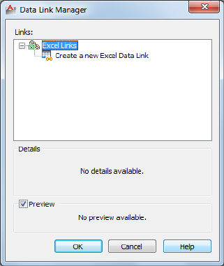
Data Link Manager
Quick Reference
See also:
■Link a Table to External Data
Creates, edits, and manages data links.
List of Options
The following options are displayed.
Data Link Tree View
Displays links contained within the drawing. Also gives options for creating
new data links.
Excel Links
Lists the Microsoft Excel data links within the drawing. If the icon displays a
linked chain, then the data link is valid. If the icon displays a broken chain,
then the data link is broken.
266 | Chapter 5 D Commands
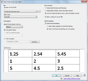
Create a New Excel Data Link Launches a dialog box where you enter the
name for a new data link. Once a name has been created, the New Excel Data
Link dialog box on page 267 is displayed.
Details
Lists information for the data link selected in the tree view above.
Preview
Displays a preview of the linked data as it would appear in the drawing table.
When a data link is not currently selected then no preview is displayed.
New Excel Data Link Dialog Box
Quick Reference
See also:
■Link a Table to External Data
Links data from a spreadsheet created in Microsoft Excel to a table within your
drawing.
List of Options
The following options are displayed.
File
Specifies the file and file path from which to create a data link.
New Excel Data Link Dialog Box | 267
Choose an Excel File
Allows you to choose an established Microsoft XLS, XLSX, or CSV file to link
to your drawing. At the bottom of this drop-down list, you can select a new
XLS, XLSX, or CSV file from which to create a data link.
Click the [...] button to browse for another Microsoft Excel file on your
computer.
Path Type Determines the path that will be used to find the file specified
above. There are three path options: full path, relative path, and no path.
■Full Path. Uses the full path of the file specified above, including the root
directory and all subdirectories that contain the linked Microsoft Excel
file.
■Relative Path. Uses the file path relative to the current drawing file to
reference the linked Microsoft Excel file. To use a relative path, the linked
file must be saved.
■No Path. Uses only the filename of the linked Microsoft Excel file for
referencing.
Link Options
Specifies the data in your Excel file to link to your drawing.
Select the Excel Sheet to Link to
Displays the names of all sheets within the specified XLS, XLSX, or CSV file.
The link options specified below are applied to the sheet you choose here.
Link Entire Sheet
Links the entire specified sheet within your Excel file to a table in your drawing.
Link to a Named Range
Links a named range of cells already contained within your Excel file to a table
in your drawing.
Clicking the arrow displays the available named ranges found in the linked
spreadsheet.
Link to Range
Specifies a range of cells in your Excel file to link to a table in your drawing.
In the text box, enter the range of cells you want linked to your drawing. Valid
ranges include
■Rectangular regions (for example, A1:D10)
268 | Chapter 5 D Commands

■Entire columns (for example, A:A)
■Sets of columns (for example, A:D)
Click the button to the right of the text box to preview the linked range.
Preview Window
Displays a preview of your table using the options you have applied.
More Options
Displays more options. This button becomes available when you use an existing
Excel file or browse for a new one.
Cell Contents
Options in this box will determine how data is imported into your drawing
from your external source.
Keep Data Formats and Formulas
Imports data with formulas and supported data formats attached.
Keep Data Formats, Solve Formulas in Excel
Imports data formats. Data is calculated from formulas in Excel.
Convert Data Formats to Text, Solve Formulas in Excel
Imports Microsoft Excel data as text with data calculated from formulas in
Excel (supported data formats not attached).
Allow Writing to Source File
Specifies that the DATALINKUPDATE on page 270 command can be used to
upload any changes made to linked data in your drawing to the original
external spreadsheet.
Cell Formatting
Use Excel Formatting
Specifies that any formatting specified in the original XLS, XLSX, or CSV file
will be brought into your drawing. When this option is not selected, the table
style on page 1201 formatting specified in the Insert Table dialog box on page
1200 is applied.
Keep Table Updated to Excel Formatting
If the option above is selected, updates any changed formatting when the
DATALINKUPDATE on page 270 command is used.
New Excel Data Link Dialog Box | 269
Start With Excel Formatting, Do Not Update
Imports the formatting specified in the original XLS, XLSX, or CSV file into
your drawing, but any changes made to the formatting are not included when
the DATALINKUPDATE on page 270 command is used.
DATALINKUPDATE
Quick Reference
See also:
■Link a Table to External Data
Updates data to or from an established external data link.
Access Methods
Button
Ribbon: Annotate tab ➤ Tables panel ➤ Download from Source
Menu: Tools ➤ Data Links ➤ Update Data Links
Summary
Updates changes to linked data between a table in a drawing and an external
data file.
List of Prompts
The following prompts are displayed.
Select an option [Update data link/Write data link] <Update data link>:
Update Data Link
Updates the linked data in a table in your drawing with data that has been
changed in the external source file.
Select Objects Updates selected tables containing data links with data that
has been changed in the external source file.
270 | Chapter 5 D Commands

Data Link Specifies the name of a data link to update with data that has been
changed in the external source file.
Entering [?] lists the data links in the current drawing.
All Data Links Updates all data links in all tables in the drawing with data
that has been changed in the external source file.
Write Data Link
Updates the linked data in an external file with data that has been changed
in a table in your drawing.
A table that contains data links displays indicators around linked cells. If you
hover your cursor over the data link, information about the data link is
displayed.
Select Objects Uploads data that has been changed from the original linked
content to the source file.
DCDISPLAY
Quick Reference
Displays or hides the dynamic constraints associated with a selection set of
objects.
Access Methods
Button
Ribbon: Parametric tab ➤ Dimensional panel ➤ Show/Hide
Menu: Parametric ➤ Dynamic Dimensions ➤ Select Objects
Toolbar: Parametric
List of Prompts
The following prompts are displayed.
Select objects: Select objects to display or hide the dimensional constraints
Enter an option [Show on page 272/Hide on page 272] <Show>: Enter the
appropriate value to show or hide dynamic constraints for the selection set of objects
DCDISPLAY | 271

Show
Displays the dynamic dimensional constraints for any selection set of objects.
Hide
Hides the dynamic dimensional constraints for any selection set of objects.
DDEDIT
Quick Reference
See also:
■Change Text
Edits single-line text, dimension text, attribute definitions, and feature control
frames.
Access Methods
Button
Menu: Modify ➤ Object ➤ Text ➤ Edit
Toolbar: Text
Shortcut menu: Select a text object, right-click in the drawing area, and
click Edit.
Pointing device: Double-click a text object.
List of Prompts
The following prompts are displayed.
Select an annotation object or [Undo]:
Object Selection Displays the appropriate editing method for the type of text
you select:
■When the TEXTED system variable is set to 0 or 2, text created using TEXT
on page 1229 displays the In-Place Text Editor without the Text Formatting
toolbar and the ruler. Right-click to display options on page 1234.
■Text created using MTEXT on page 762 displays the In-Place Text Editor.
272 | Chapter 5 D Commands
■Attribute definitions (not part of a block definition) display the Edit
Attribute Definition dialog box.
■Feature control frames display the Geometric Tolerance dialog box.
DDEDIT repeats the prompt until you press Enter to end the command.
Undo Returns the text or attribute definition to its previous value. You can
use this option immediately after editing.
Edit Text Dialog Box
Quick Reference
See also:
■Change Text
Edits a single-line text object.
Summary
When the TEXTED system variable is set to 1, modifies text created with TEXT
on page 1229. Enter the new text and click OK.
Edit Attribute Definition Dialog Box
Quick Reference
See also:
■Change Text
Edits an attribute text object.
List of Options
The following options are displayed.
Tag
Edit Text Dialog Box | 273

Specifies the attribute tag, which identifies the attribute in the drawing. The
tag can contain exclamation marks (!). The case change is not immediately
displayed in the tag field.
Prompt
Specifies the attribute prompt that is displayed when you insert a block
containing this attribute definition.
Default
Specifies the default attribute value.
DDPTYPE
Quick Reference
See also:
■Draw Reference Points
Specifies the display style and size of point objects.
Access Methods
Button
Ribbon: Home tab ➤ Utilities panel dropdown ➤ Point Style
Menu: Format ➤ Point Style
Command entry: 'ddptype for transparent use
Summary
The Point Style dialog box is displayed.
274 | Chapter 5 D Commands

Point Style Dialog Box
Quick Reference
See also:
■Draw Reference Points
Shows the current point style and size. Change the point style by selecting an
icon.
List of Options
The following options are displayed.
Point Display Images
Specifies the image used to display point objects. The point style is stored in
the PDMODE on page 1606 system variable.
Point Size
Sets the point display size. The value you enter can be relative to the screen
or in absolute units. The point display size is stored in the PDSIZE system
variable. Subsequent point objects that you draw use the new value.
Set Size Relative to Screen Sets the point display size as a percentage of the
screen size. The point display does not change when you zoom in or out.
Set Size in Absolute Units Sets the point display size as the actual units you
specify under Point Size. Points are displayed larger or smaller when you zoom
in or out.
Point Style Dialog Box | 275

DDVPOINT
Quick Reference
See also:
■Control the 3D Projection Style
Sets the 3D viewing direction.
Access Methods
Menu: View ➤ 3D Views ➤ Viewpoint Presets
Summary
The Viewpoint Presets dialog box is displayed.
Viewpoint Presets Dialog Box
Quick Reference
See also:
■Control the 3D Projection Style
Defines 3D view settings.
276 | Chapter 5 D Commands

List of Options
The following options are displayed.
Set Viewing Angles
Sets the direction of the view relative to either the world coordinate system
(WCS) or a user coordinate system (UCS).
Absolute to WCS Sets the view direction relative to the WCS.
Relative to UCS Sets the view direction relative to the current UCS.
From
Specifies viewing angles.
X Axis Specifies the angle from the X axis.
XY Plane Specifies the angle from the XY plane.
You can also use the sample image to specify viewing angles. The black arm
indicates the new angle. The gray arm indicates the current angle. Specify an
angle by selecting the inner region of the circle or half-circle. Selecting the
bounded outer regions rounds off the angle to the value displayed in that
Viewpoint Presets Dialog Box | 277

region. If you select the inner arc or an area inside it, the angle is not rounded
off, and the result may be a fractional number.
Set to Plan View
Sets the viewing angles to display the plan view (XY plane) relative to the
selected coordinate system.
DELAY
Quick Reference
See also:
■Run Slide Shows from Scripts
Provides a timed pause within a script.
Access Methods
Command entry: 'delay for transparent use
Summary
Specifies the duration of a pause. Entering delay 1000 in your script delays
the start of execution of the next command for about one second. The longest
delay available is 32767, which is slightly less than 33 seconds.
DELCONSTRAINT
Quick Reference
See also:
■Modify Objects with Dimensional Constraints Applied
Removes all geometric and dimensional constraints from a selection set of
objects.
278 | Chapter 5 D Commands
Access Methods
Button
Ribbon: Parametric tab ➤ Manage panel ➤ Delete Constraints
Menu: Parametric ➤ Delete Constraints
Toolbar: Parametric
Summary
The number of constraints removed are displayed on the command line.
Removes all geometric and dimensional constraints from the selected objects.
DETACHURL
Quick Reference
See also:
■Add Hyperlinks to a Drawing
Removes hyperlinks in a drawing.
Summary
Hyperlinks are removed from the selected objects. If an area is selected, the
polyline is deleted. You can use PURGE to remove the URLLAYER layer.
DGNADJUST
Quick Reference
See also:
■Adjust Underlay Contrast, Fade, Monochrome, and Colors for the
Background
DETACHURL | 279

Adjust the fade, contrast, and monochrome settings of a DGN underlay.
Access Methods
Ribbon: DGN Underlay contextual tab ➤ Adjust panel
Summary
You can change the default values for Fade, Contrast, and Monochrome for
a single or multiple DGN underlays. To confirm the settings on a selected
DGN underlay, use the Properties palette.
NOTE You can also use the ADJUST on page 20 command to change the fade,
contrast, and monochrome settings for DGN underlays as well as DWF, DWFx and
PDF underlays or the fade, contrast and brightness for images.
List of Prompts
The following prompts are displayed.
Select DGN underlay: Select one or more DGN underlays
Enter DGN underlay option [Fade/Contrast/Monochrome] <Fade>:
Enter fade value (0-100): Enter a value
Enter contrast value (0-100): Enter a value
Monochrome? [Yes/No]: Enter yes or no and then press Enter
Fade
Controls the fade effect of the underlay. Values range from 0 through 100.
The greater the value, the more transparent the underlay appears against the
background. The lesser the value, the less transparent and closer to opaque
the underlay appears. A value of 0 makes the underlay appear fully opaque.
Contrast
Controls the contrast, and indirectly, the fading effect of the underlay. Values
range from 0 through 100. The greater the value, the more each pixel is forced
to its primary or secondary color.
Monochrome
Controls the color saturation of all linework while maintaining the luminance.
When turned on, the linework appears in varying shades of gray starting at
black if the background color luminance is 50 percent or more. If the
background color luminance is less than 50 percent, then the colors are
inverted, with the darkest linework displaying in white, and the lightest
linework displaying in black.
280 | Chapter 5 D Commands
DGNATTACH
Quick Reference
See also:
■Attach Files as Underlays
Insert a DGN file as an underlay into the current drawing.
Access Methods
Button
Ribbon: Insert tab ➤ Reference panel ➤ Attach
Menu: Insert ➤ DGN Underlay
Toolbar: Insert
Summary
When you attach a DGN file as an underlay, you link that referenced file to
the current drawing. Any changes to the referenced file are displayed in the
current drawing when it is opened or reloaded.
The Select Reference File dialog box (a standard file selection dialog box) is
displayed. Once you select a DGN file, the Attach DGN Underlay dialog box
is displayed. After the file is attached, you can adjust and clip the underlay
through the DGN Underlay Ribbon Contextual tab on page 284.
NOTE DGNATTACH is not limited to files with .dgn extensions. It supports all
DGN files, even those that do not have a .dgn extension.
If you enter -dgnattach at the Command prompt, options are displayed.
NOTE When a DGN file is attached as an underlay, its levels structure (layers) are
combined into a single layer. The DGN underlay is placed on the current layer.
To hide the DGN attachment, freeze the layer on which it was attached.
DGNATTACH | 281
Attach DGN Underlay Dialog Box
Quick Reference
See also:
■Attach Files as Underlays
Names, locates, and defines the insertion point, scale, and rotation when
attaching DGN underlays.
List of Options
The following options are displayed.
Name
Identifies the DGN file you have selected to attach.
Browse
Opens the Select Reference File dialog (a standard file selection dialog box on
page 826).
Select a design model from the DGN file
Displays all of the design models that are found in the DGN file. If the DGN
file only contains a single design model, that model is listed.
If the DGN file contains multiple design models, only a single model can be
selected for attachment. The first model in the list is selected by default.
Conversion Units
Matches the DWF files’s drawing units to the master units and sub-units
specified in the DGN file. For example, if the DGN file has master units set to
meters, and sub-units set to millimeters, and you want the DWG to be set to
millimeters, select sub-units in the Attach DGN Underlay dialog box.
Master Units Matches the DWG drawing units to the master units set in the
DGN file.
Sub Units Matches the DWG drawing units to the sub- units set in the DGN
file.
Path Type
Selects the full (absolute) path, the relative path to the DGN file, or No Path,
the name of the DGN file (the DGN file must be located in the same folder as
the current drawing file).
282 | Chapter 5 D Commands
Insertion Point
Specifies the insertion point for the selected DGN file. Specify On-Screen is
the default. The default insertion point is 0,0,0.
Specify On-Screen Directs input at the Command prompt or the pointing
device. If Specify On-Screen is cleared, enter the insertion point in X, Y, and
Z.
XSets the X coordinate value.
YSets the Y coordinate value.
ZSets the Z coordinate value.
Scale
Specifies the scale factor of the selected DGN underlay.
If INSUNITS is set to “unitless” or if the underlay does not contain resolution
information, the scale factor becomes the underlay width in AutoCAD units.
If INSUNITS has a value such as millimeters, centimeters, inches, or feet, and
the underlay has resolution information, the scale factor is applied after the
true width of the underlay in AutoCAD units is determined.
Specify On-screen Allows you to input at the Command prompt or the
pointing device. If Specify On-Screen is cleared, enter a value for the scale
factor. The default scale factor is 1.
Scale Factor Field Enters a value for the scale factor. The default scale factor
is 1.
Rotation
Specifies the rotation angle of the selected DGN underlay.
Specify on-screen If Specify On-Screen is selected, you may wait until you
exit the dialog box to rotate the object with your pointing device or enter a
rotation angle value at the Command prompt.
Angle If Specify On-Screen is cleared, enter the rotation angle value in the
dialog box. The default rotation angle is 0.
Show Details
Displays the DGN file path.
Found In Displays the path where the DGN file is located.
Saved Path Displays the path that is saved with the drawing when the DGN
file is attached. The path is dependent upon the Path Type setting.
Attach DGN Underlay Dialog Box | 283
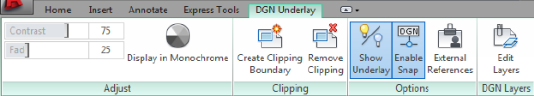
DGN Underlay Ribbon Contextual tab
Quick Reference
See also:
■Work with Underlays
Change DGN underlay display, clip, layer, and osnap options.
Summary
When you select a DGN underlay in a drawing, the DGN Underlay Contextual
tab is displayed on the ribbon.
List of Options
The following options are displayed.
Adjust Panel
Contrast Controls the contrast and the fading effect of the underlay. The
greater the value, the more each pixel is forced to its primary secondary color.
Fade Controls the appearance of the linework. The greater the value, the
lighter the linework in the underlay appears.
Display in Monochrome Displays the underlay in black and white.
Clipping Panel
Create Clipping Boundary (DGNCLIP on page 287) Crops the display of a
selected DGN underlay to a specified boundary.
Create Clipping Boundary (DGNCLIP on page 287) Deletes the clipping
boundary.
Options Panel
Show Underlay Hides or displays the underlay.
Enable Snap Determines whether object snapping is active for geometry in
the DGN underlay.
284 | Chapter 5 D Commands

External References (EXTERNALREFERENCES on page 504) Opens the
External References palette.
DGN Layers Panel
Edit Layers (ULAYERS on page 1281) Controls the display of layers in a DWF,
DWFx, PDF, or DGN underlay.
-DGNATTACH
Quick Reference
See also:
■Attach Files as Underlays
Attach a DGN underlay from the command line.
Summary
When you attach a DGN file as an underlay, you link that referenced file to
the current drawing. Any changes to the referenced file are displayed in the
current drawing when it is opened or reloaded.
NOTE DGNATTACH is not limited to files with *.dgn extensions. It supports all
DGN files, even those that do not have a .dgn extension.
List of Prompts
The following prompts are displayed.
TIP You can drag a DGN file onto the drawing window to start the DGNATTACH
command.
Path to DGN File to Attach Enters the full path name to the DGN underlay
file. The file name can include up to 255 characters and contain letters, digits,
spaces, and any special characters not used by Microsoft Windows or this
program.
Entering a tilde (~) displays the Select DGN File dialog box (a standard file
selection dialog box).
To avoid errors when entering a file name, it is recommended that you specify
both the DGN file and path as follows:
path name\filename.dgn
-DGNATTACH | 285
or
“path name\filename.dgn”
If you enter a valid DGN file name without a file extension, the program adds
the extension and searches for the file.
Enter Name of Model or ? Enter a model name. For a list of models, enter?.
Enter Model(s) to list <*> Lists the design models available in the DGN file
in a separate text window.
Conversion Units Matches the DWF file’s drawing units to the master units
and sub-units specified in the DGN file. For example, if the DGN file has
master units set to meters, and sub-units set to millimeters, and you want the
DWG to be set to millimeters, select sub-units in the Attach DGN Underlay
dialog box.
■Master Units - Matches the DWG drawing units to the master units set in
the DGN file.
■Sub Units - Matches the DWG drawing units to the sub- units set in the
DGN file.
Insertion Point Specifies the insertion point for the selected DGN file. Enter
the X, Y, and Z coordinates at the command prompt, or click onscreen.
Scale Factor Specifies the scale factor of the selected DGN underlay and the
scale factor units. You can enter a scale factor at the command prompt or click
onscreen with the mouse.
If INSUNITS is set to “unitless” or if the underlay does not contain resolution
information, the scale factor becomes the underlay width in AutoCAD units.
If INSUNITS has a value such as millimeters, centimeters, inches, or feet, and
the underlay has resolution information, the scale factor is applied after the
true width of the underlay in AutoCAD units is determined.
Rotation Specifies the rotation angle of the selected DGN underlay by entering
an angle value at the command prompt or by clicking onscreen.
286 | Chapter 5 D Commands

DGNBIND (-DGNBIND)
Quick Reference
See also:
■Attach Files as Underlays
Binds DGN underlays to the current drawing.
Summary
Converts a specified DGN reference into a block, making it a permanent part
of the drawing. The DGN-dependent named objects (such as layer names) of
the former DGN reference are added to your drawing. In each DGN-dependent
named object, the vertical bar (|) is replaced with three new characters: a
number (usually 0) between two dollar signs ($). The number is increased if
the same name already exists in the current drawing.
List of Prompts
The following prompt is displayed.
Enter DGN underlay name(s) to bind: Enter one or more DGN underlay names
DGNCLIP
Quick Reference
See also:
■Clip External References and Blocks
Crops the display of a selected DGN underlay to a specified boundary.
Access Methods
Button
DGNBIND (-DGNBIND) | 287
Ribbon: DGN Underlay contextual tab ➤ Clipping panel ➤ Create
Clipping Boundary
Shortcut menu: Select a DGN underlay to clip, right-click in the drawing
area, and click DGN Clip
Summary
The clipping boundary determines the portion of a DGN underlay outside the
boundary that is hidden. The visibility of the clipping boundary is controlled
by the DGNFRAME on page 1433 system variable.
The boundary you specify must be in a plane parallel to the DGN underlay.
TIP Use the generic CLIP on page 211 command to clip images, external references,
viewports, and underlays.
List of Prompts
The following prompts are displayed.
On
Turns on clipping and displays the DGN underlay clipped to the previously
defined boundary.
Off
Turns off clipping and displays the entire DGN underlay.
If you reclip the DGN underlay while clipping is turned off, clipping is
automatically turned back on. You are prompted to delete the old boundary
even when clipping is turned off and the clipping boundary is not visible.
Delete
Removes a predefined clipping boundary and displays the entire DGN underlay.
New Boundary
Defines a rectangular or polygonal clipping boundary, or generates a polygonal
clipping boundary from a polyline.
Specify clipping boundary or select invert option: [Select
polyline/Polygonal/Rectangular/Invert clip] <Rectangular>:
Select Polyline Defines the boundary with the selected polyline. The polyline
can be open but must consist of straight line segments and cannot intersect
itself.
Polygonal Defines a polygonal clipping boundary with three or more points
that you specify for the vertices of a polygon.
288 | Chapter 5 D Commands
Rectangular Defines a rectangular boundary with the points that you specify
for opposite corners.
Invert Clip Inverts the mode of the clipping boundary: objects are clipped
either outside the boundary or inside the boundary.
NOTE You can only create a new clipping boundary for a selected DGN underlay
when the old boundary is deleted.
DGNEXPORT
Quick Reference
See also:
■Export MicroStation DGN Files
Creates one or more DGN files from the current drawing.
Access Methods
Button
Menu: Application menu ➤ Export ➤ DGN File
Summary
The Export DGN File dialog box (a standard file selection dialog box) is
displayed. Once you specify a DGN file name, the Export DGN Settings dialog
box is displayed. You can export a V8 or V7 file using DGNEXPORT.
If you enter -dgnexport at the Command prompt, options are displayed on
page 297.
See the DGNEXPORT Conversion Table on page 294 specific details about the
scope of exporting DWG objects and other data to DGN files.
DGNEXPORT | 289
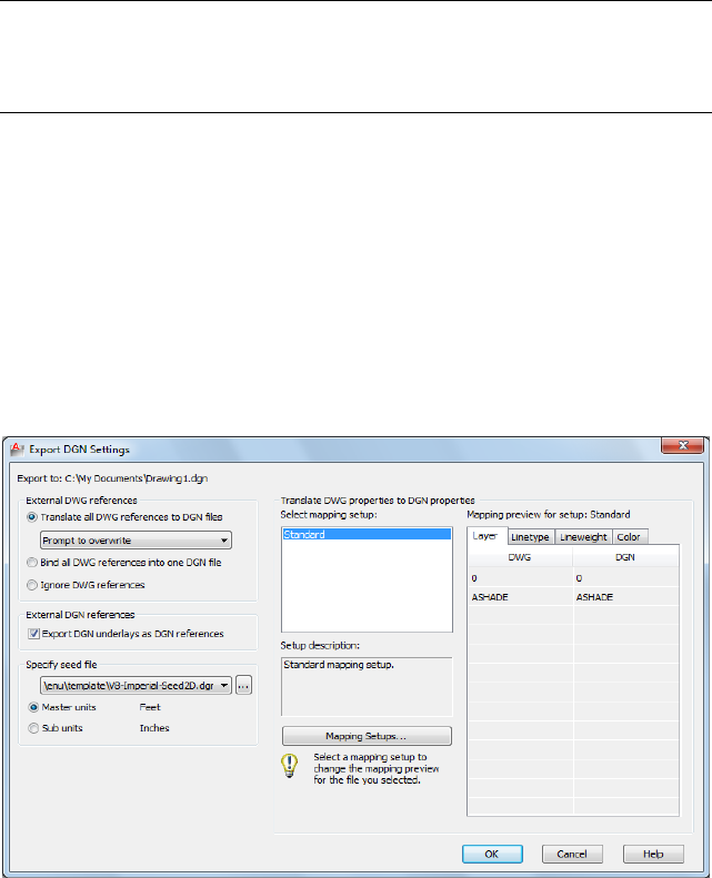
WARNING Some programs that work with DGN files do not support extended
characters that the Windows operating system considers valid for file names. Thus,
it is recommended that you do not use accented or Asian characters in file names
when using DGNEXPORT.
Export DGN Settings Dialog Box
Quick Reference
See also:
■Export MicroStation DGN Files
Controls how objects are processed when exporting them to a DGN file.
List of Options
The following options are displayed.
External DWG References
Controls how xrefs are processed.
Translate All DWG References to DGN Files
290 | Chapter 5 D Commands

All referenced DWG files, including nested DWG references, are converted
into DGN files. The resulting DGN files use the same file name as the DWG
files, but use a .dgn file extension.
With the following set of options, you can choose whether or not to overwrite
DGN reference files
■Prompt to Overwrite
■Overwrite without Prompting
■Do Not Overwrite
Bind All DWG References into One DGN file
The parent DWG file and all referenced DWG files are combined into a single
DGN file. The referenced DWG files are converted to cells as part of the primary
DGN file.
Ignore DWG References
Referenced DWG files are not included in the resulting DGN file.
External DGN References
Controls whether DGN underlays in the DWG file are exported as DGN
references of the resulting DGN file.
Export DGN Underlays as DGN References
When checked, any DGN underlays are exported as DGN references along
with the base drawing. When cleared, DGN underlays are not exported.
NOTE Do not export drawings that include V8 DGN underlays to a V7 DGN format
file. The V8 DGN references cannot display in a V7 DGN file because the V8 DGN
file format is not a valid design file for the resulting V7 DGN file.
Specify Seed File
A seed file for a DGN file is similar to a drawing template (DWT) file that
contains default settings and attributes, such as working units. Selecting the
appropriate DGN seed file (imperial, metric, or user-defined), and conversion
units is critical to the translation from DWG to DGN. In addition, the seed
file contains settings that are not present in a DWG file, and therefore inherited
in the exported DGN.
These settings include working units and resolution as well as whether the
file is 2D or 3D.
Export DGN Settings Dialog Box | 291
Conversion Units
Select the appropriate conversion units for the translation. The DGN seed file
contains working units (imperial or metric) called master units and sub-units.
One DWG unit is converted to either one master unit or one sub-unit.
Master Units
Specifies that one DWG drawing unit will convert to one master unit of the
specified DGN seed file.
Sub Units
Specifies that one DWG drawing unit will convert to one sub-unit of the
specified DGN seed file.
NOTE The master units and the sub-units of the selected DGN seed file are
displayed next to the buttons for reference.
Filename drop-down list
Specify the name of the DGN seed file. Several sample seed files are provided
upon installation.
Browse button Displays the Select Seed File dialog box (a Standard File
Selection Dialog Boxes on page 826), in which you can select the DGN seed
file.
See the DGNEXPORT Conversion Table on page 294 specific details about the
scope of exporting DWG objects and other data to DGN files.
Sample DGN Seed Files
The following table lists the default DGN seed files and their settings. You
may need to edit these settings or obtain the appropriate seed file to suit your
conversion requirements.
ResolutionSub Unit (label)Master Unit
(label)
DGN Seed File Name
12”/1’ and 8000
POS
Inches (“)Feet (‘)V7-Imperial-Arch01-
Seed2D.dgn
12”/1’ and 8000
POS
Inches (“)Feet (‘)V7-Imperial-Arch01-
Seed3D.dgn
12”/1’ and 1000
POS
Inches (“)Feet (‘)V7-Imperial-Arch02-
Seed2D.dgn
292 | Chapter 5 D Commands

ResolutionSub Unit (label)Master Unit
(label)
DGN Seed File Name
12”/1’ and 1000
POS
Inches (“)Feet (‘)V7-Imperial-Arch02-
Seed3D.dgn
10tn/1’ and 100
POS
Tenths (tn)Feet (‘)V7-Imperial-Civil01-
Seed2D.dgn
10tn/1’ and 100
POS
Tenths (tn)Feet (‘)V7-Imperial-Civil01-
Seed3D.dgn
10tn/1’ and 1000
POS
Tenths (tn)Feet (‘)V7-Imperial-Civil02-
Seed2D.dgn
10tn/1’ and 1000
POS
Tenths (tn)Feet (‘)V7-Imperial-Civil02-
Seed3D.dgn
1000mm/1m and 1
POS
Millimeters (mm)Meters (m)V7-Metric-Seed2D.dgn
1000mm/1m and 1
POS
Millimeters (mm)Meters (m)V7-Metric-Seed3D.dgn
304800 per footInches (“)Feet (‘)V8-Imperial-Seed2D.dgn
304800 per footInches (“)Feet (‘)V8-Imperial-Seed3D.dgn
1000mm per milli-
meter
Millimeters (mm)Meters (m)V8-Metric-Seed2D.dgn
1000mm per milli-
meter
Millimeters (mm)Meters (m)V8-Metric-Seed3D.dgn
Translate DWG Properties to DGN Properties
Selects and manages the mapping setup used on the current DGN export.
Select Mapping Setup
Displays the currently defined mapping setups.
Standard is the default mapping setup which extracts data from the drawing
being exported and applies an automatic mapping to DGN layers, linetypes,
lineweights, and colors, as shown in the mapping preview.
Export DGN Settings Dialog Box | 293
Setup Description
Displays the description of the selected mapping setup.
Mapping Setups
Opens the DGN Mapping Setups dialog box on page 311 where new mapping
setups can be created and existing mapping setups can be renamed, modified,
or deleted (see DGNMAPPING on page 310).
Mapping Preview for Setup
Lists all properties of both the exported DWG file in the DWG column and
the selected mapping setup in the DGN column.
NOTE The reference properties are not listed in the preview, but any properties
that apply to those references that are shown in the mapping preview are applied
to the references as well.
DGNEXPORT Conversion Table
Quick Reference
See also:
■Export MicroStation DGN Files
The following table lists the DGN objects and features that are supported for
export, and notes on the scope of the translation.
DWG to DGN Conversion Table
NotesMicroStationAutoCAD LT
The following DWG objects are translated into
DGN elements: line, xline, ray, polyline, arc,
Geometric Ele-
ments
Geometric Ob-
jects
circle, spline (NURBS), ellipse, elliptical arc,
point, donut, mline, hatch (including gradient
fills), and wipeout. Variable width polylines
maintain only their starting width when
translated into SmartLines.
Invalid DWG characters in layer names are
converted to spaces.
LevelsLayers
294 | Chapter 5 D Commands
DWG to DGN Conversion Table
NotesMicroStationAutoCAD LT
Colors are matched as closely as possible.
Colors set with the ACI (AutoCAD Color In-
ColorsColors
dex) are translated directly to the DGN color
index. If TrueColor is used and a direct match
of RGB values is available in the DGN color
index, the colors are also mapped directly. If
a TrueColor match is not available, an RGB
value is added to the DGN color index.
Custom linetypes are unsupported and could
produce unexpected results.
Line StylesLinetypes
Blocks are exported as shared cells. Dynamic
blocks are also exported as cells and lose their
CellsBlocks
dynamic behavior. Invisible, Constant, Verify,
and Preset attributes are all converted into
tags.
The visual integrity of multiline text is main-
tained. However, if exported multiline text
Text, Text Nodes,
Text Styles
Single-line Text
Objects, Multiline
objects are edited in MicroStation, the
formatting is lost.
TrueType and SHX fonts in AutoCAD are ex-
ported to MicroStation V7 as Engineering.
This can result in many visual differences.
Text Objects,
Text Styles
Table objects are exported as cell elements
composed of lines and text.
TablesTables
In general, fields are translated as static text.
The exceptions are fields that behave
FieldsFields
identically in both products. This includes the
Date fields CreateDate, SaveDate, and Plot-
Date, and the Document property fields Au-
thor, Filename, and Filesize.
NOTE Use the MicroStation Key-in utility to
update text containing fields (field update
all).
DGNEXPORT Conversion Table | 295

DWG to DGN Conversion Table
NotesMicroStationAutoCAD LT
The size, spacing, style, and shape of dimen-
sions may vary slightly. Dimension associativ-
Dimensions, Di-
mension Styles
Dimensions, Di-
mension Styles
ity is maintained whenever possible, and the
correct dimension values are always main-
tained.
These image file types are supported: .bmp,
.cal, .tif, .png, .tga, .jpg, .gif, .rlc, .bil, and .pcx.
All other image file types are discarded.
Raster ImagesRaster Images
Depending on the export option specified,
all referenced DWG files, including nested
DGN ReferencesDWG References
DWG references, are either converted into
DGN files, combined into a single DGN file
as cells, or discarded.
NOTE MicroStation V7 does not support
nested references to references that are
merged into the host file.
The model in a DWG file is converted into a
DGN file.
DGN Design Mod-
el
DWG Model
When exporting to V8, any initialized layouts
are converted into sheet models in the DGN
file.
DGN Sheet ModelDWG Layout
V7 only supports one model. For V7, several
DGN files can be exported: one for the model
and the other DGN files for any initialized
layouts in the DWG file. The layout names get
appended to the exported DGN file <file-
name> - Layout1.dgn.
AEC objects are not supported. Use the EX-
PORTTOAUTOCAD on page 498 command to
AEC Objects
convert AEC objects to base ACAD objects
before exporting to DGN.
296 | Chapter 5 D Commands

-DGNEXPORT
Quick Reference
See also:
■Export MicroStation DGN Files
If you enter -dgnexport at the Command prompt, the following prompts are
displayed.
List of Prompts
The following prompts are displayed.
Enter DGN file format on page 297 [V7/V8] <V8>: Specify whether the file is DGN
V7 or V8
Enter filename on page 297 for DGN export <default path\filename>: Specify
path and filename of DGN file
Specify conversion units on page 297 [Master/Sub] <Master>: Specify m or s, or
press Enter
Specify mapping setup on page 298 or [?] <Standard>: Specify mapping setup or
? to specify filter of mapping setup
Specify seed file on page 298 or [?] <default path\filename>: Specify path and
filename of seed file
TIP Create a script using -DGNEXPORT to batch process exporting drawings to
DGN files.
File Format Specifies the file format of the DGN file being exported.
Filename The file name can include up to 255 characters and contain letters,
digits, spaces, and any special characters not used by Microsoft Windows or
this program.
To avoid errors when entering a file name, it is recommended that you specify
both the DGN file and path as follows:
path\filename
or
“path\filename”
Specify the path and file name of DGN file.
Units Specifies a drawing-units value for scaling the DGN file.
-DGNEXPORT | 297
Mapping Setups Specifies the mapping setup of the selected design model.
?After specifying a filter, a list of available export mapping setups that match
the filter is displayed and will re-prompt.
Seed File Specify a seed file that matches the existing behavior of other
commands with filters.
?Enter * to display a list of available seed files in the AutoCAD Text Window.
DGNIMPORT
Quick Reference
See also:
■Import MicroStation DGN Files
Imports the data from a DGN file into a new DWG file or the current DWG
file, depending on the DGNIMPORTMODE system variable.
Access Methods
Button
Menu: Application menu ➤ Open ➤ DGN
Summary
The Import DGN File dialog box (a standard file selection dialog box) is
displayed. Once you select a DGN file, the Import DGN Settings dialog box is
displayed.
If you enter -dgnimport at the Command prompt, options are displayed on
page 308.
See the DGNIMPORT Conversion Table on page 303 for specific details about
the scope of importing MicroStation objects and other data.
See the DGNIMPORT Unit Mapping Table on page 305 for specific details about
unit conversions when importing MicroStation objects.
298 | Chapter 5 D Commands
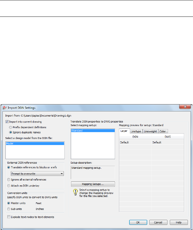
NOTE The type of plot style drawing (Color-dependent or Named) is based on
the value of PSTYLEPOLICY on page 1627.
Import DGN Settings Dialog Box
Quick Reference
See also:
■Import MicroStation DGN Files
Specifies the import settings for a DGN file.
List of Options
The following options are displayed.
Import into Current Drawing
Inserts the contents of the DGN file into the current DWG file.
Prefix Dependent Definitions Adds the DGN file and model name as a prefix
to the incoming object’s name. If the prefixed name results in a new name
conflict, then an incremental number is appended to the name.
Import DGN Settings Dialog Box | 299

Ignore Duplicate Names Ignores any duplicate named objects, such as layer
names or dimension styles, in the DGN file and gives precedence to the existing
definition for duplicates.
You can also control the default settings using the DGNIMPORTMODE system
variable.
NOTE For the correct display of linetypes, the MicroStation RSC (resource file)
that is referenced by the DGN file must be available on your computer in a valid
AutoCAD Support File Search Path when you import or attach the DGN file. If the
resource file is not found, you will get an error message. You can define a search
path location in the OPTIONS command, Files tab. You can add a path to the
AutoCAD Support File Search Path node. You can also copy the RSC file to an
existing Support File Search Path.
Select a Design Model from the DGN file
The DGN design model that you select is imported into the model space of
your current DWG file.
V8 DGN files might contain multiple design and sheet models. A DGN design
model is equivalent to model space, and a DGN sheet model is equivalent to
paper space. Because a DWG file can have only one model space, you need
to select the design model in the DGN file that you want to import.
If a design model is selected and is referenced into a sheet model, then the
sheet model is also converted as one or more layouts in the DWG file. Only
the sheet models that reference the primary design model are imported. These
sheet models are translated to paper space layouts, and will include layout
viewports that display each reference to the primary design model.
External DGN References
Controls how DGN references are handled in a DWG environment.
Any DGN files are supported as references. These file types include, but not
limited to, these extensions: .dgn, .dwg,.cel,.s,.h, .cgm,.rdl,.d files. However, DXF
files are not supported and are ignored.
Translate References to Blocks or Xrefs
Converts DGN references to blocks when importing into a current drawing
and to xrefs when importing into a new drawing.
All referenced DGN design models, including nested references, are converted
into blocks or attached as xrefs in model space.
The relationship of nested references is maintained. Nested references within
a DGN design model that reference the primary file are called circular
300 | Chapter 5 D Commands
references. AutoCAD resolves these circular references by creating a block and
insering it into the original primary DGN file.
Design model references to sheet models, and sheet model references to other
sheet models are not supported and are ignored. Unique names for references
are generated by appending the model name to the design file name separated
with a dash (-). If necessary, the resulting block names are truncated and one
or more of the last characters might be replaced with numerals to make the
file name unique.
With the following set of options, you can choose whether or not to overwrite
external reference files:
■Prompt to Overwrite
■Overwrite without Prompting
■Do Not Overwrite
NOTE If the folder that contains the DGN file is read-only, then any DWG xrefs
will be created in the My Documents (Windows XP) or Documents (Windows Vista
and Windows 7) folder.
NOTE If you are importing a DGN file that uses custom line styles and those line
styles are defined in an external .rsc file, then the .rsc file needs to be included in
the AutoCAD support path.
Ignore All External References
Referenced DGN and DWG files that are external to the specified DGN file are
not included in the resulting DWG file.
If the DGN file has self references or references to other design models
contained within the DGN file, these references are included.
Attach as DGN Underlay
All DGN external references in the DGN file are imported as DGN underlays
in the resulting DWG file. Referenced DWG files remain xrefs when imported.
NOTE New DWG files are created in this process. These new DWGs are not
automatically deleted.
Conversion Units
Select the appropriate conversion units for the translation. The imported DGN
file contains working units (imperial or metric) called master units and sub-units.
The selected working units (master units or sub-units) are converted
one-for-one into DWG units.
Import DGN Settings Dialog Box | 301

Master Units
Specifies that one master unit of the imported DGN file converts to one DWG
drawing unit.
Sub Units
Specifies that one sub-unit of the imported DGN file converts to one DWG
drawing unit.
NOTE The master units and the sub-units of the selected DGN file are displayed
next to the buttons for reference.
Explode Text Node to Text Elements
Text node elements in a DGN file are multiple lines of text stored as one element,
and are similar to MTEXT objects. Check this option to maintain text which
follows a path.
When cleared, multiple lines of text are maintained as a single multiline text
object.
When checked, multiple lines of text are separated into individual text objects.
Select this option to maintain visual fidelity when you import a DGN file that
includes text created along a curved path. The first character determines the
location and rotation of the text object.
Translate DGN Properties to DWG Properties
Selects and manages the mapping setup used on the current DGN import.
Select Mapping Setup
Displays the currently defined mapping setups.
Standard is the default mapping setup which extracts data from the drawing
being exported and applies an automatic mapping to DGN layers, linetypes,
lineweights, and colors, as shown in the mapping preview.
Setup Description
Displays the description of the selected mapping setup.
Mapping Setups
Opens the DGN Mapping Setups dialog box on page 311 where new mapping
setups can be created and existing mapping setups can be renamed, modified,
or deleted (see DGNMAPPING on page 310).
Mapping Preview for Setup: Standard
302 | Chapter 5 D Commands
Lists all properties of both the imported DGN file in the DGN column and
the selected mapping setup in the DWG column.
NOTE External reference files properties are not listed in a mapping preview.
See the DGNIMPORT Conversion Table on page 303 for specific details about
the scope of importing MicroStation objects and other data.
See the DGNIMPORT Unit Mapping Table on page 305 for specific details about
unit conversions when importing MicroStation objects.
DGNIMPORT Conversion Table
Quick Reference
See also:
■Import MicroStation DGN Files
The following table lists the DGN objects and features that are supported for
import, and notes on the scope of the translation.
DGN to DWG Conversion Table
NotesAutoCAD LTMicroStation
The following DGN elements are translated
into DWG objects: line, SmartLine, LineString,
Geometric Ob-
jects
Geometric Ele-
ments
multiline, shape, complex chain, complex
shape, arc, ellipse, curve, B-spline curve, and
pattern. Pattern elements are limited to simple
pattern styles. Bitonal gradient properties are
also supported.
DGN levels are mapped automatically into
the equivalent DWG layers. Invalid DGN
LayersLevels
characters in level names are converted to
spaces.
All colors are translated using RGB values
either to the ACI (AutoCAD Color Index) or
TrueColor index as appropriate.
ColorsColors
DGNIMPORT Conversion Table | 303
DGN to DWG Conversion Table
NotesAutoCAD LTMicroStation
For the correct display of linetypes, the Micro-
Station .rsc (resource file) that is referenced
LinetypesLine Styles
by the DGN file must be available on your
computer in a valid AutoCAD Support File
search path when you import or attach the
DGN file.
Dynamically scaled line styles (Standard DGN
Line Styles 1-7) are converted into fixed-scale
linetypes. The resulting linetypes take into
account the current zoom factor in a view in
the DGN file when they are imported or at-
tached as a DGN file into AutoCAD.
NOTE To import standard V7 line styles cor-
rectly, you must “Fit View” and “Save Set-
tings” in MicroStation first.
Cells are converted into blocks. Tags that are
associated with cells are converted into con-
stant-mode block attributes.
BlocksCells
Missing SHX text fonts are converted into the
AutoCAD LT text font specified in the FONT-
Single-line Text
Objects, Multiline
Text Elements,
Text Styles
ALT system variable. The aclt.fmp file can beText Objects,
Text Styles used to map SHX text fonts to DGN text
fonts.
TrueType fonts and SHX fonts in AutoCAD
are exported to MicroStation V7 as Engineer-
ing. This can result in many visual differences.
Cells that represent tables in DGN are impor-
ted as blocks.
TablesTables
The size, spacing, style, and shape of dimen-
sions may vary slightly. Dimension associativ-
Dimensions, Di-
mension Styles
Dimensions, Di-
mension Styles
ity is maintained whenever possible, and the
correct dimension values are always main-
tained.
304 | Chapter 5 D Commands
DGN to DWG Conversion Table
NotesAutoCAD LTMicroStation
In general, fields are translated as static text.
The exceptions are fields that behave
FieldsFields
identically in both products. This includes the
Date fields CreateDate, SaveDate, and Plot-
Date, and the Document property fields Au-
thor, Filename, and Filesize.
Fields are converted to text when “Explode
Text Nodes to Text Elements” is checked in
the Import DGN Settings dialog box.
These image file types: .bmp, .cal, .tif, .png,
.tga, .jpg, .pcx, .gif, .rlc, .bil, and .pct are sup-
ported. All other image file types are not.
Raster ImagesRaster Images
.dwg and .dgn file types are supported. Other
non-DGN file types such as .cel, .h, .s, .d, .rdl,
and .cgm are also supported.
DWG ReferencesDGN References
The selected design model in a DGN file is
converted into a DWG file.
DWG ModelDGN Design Mod-
el
Only the sheet models that reference the
primary design model are imported. DGN
DWG LayoutDGN Sheet Model
sheet models are translated as layouts in a
DWG file.
DGNIMPORT Unit Mapping Table
Quick Reference
See also:
■Import MicroStation DGN Files
DGNIMPORT Unit Mapping Table | 305

The following table lists the linear units used in the resulting DWG file as
determined by the master units, sub-units, and unit precision of the DGN file
being imported.
DGN to DWG Unit Mapping Table
NotesDWG UnitsDGN Preci-
sion
DGN Sub
Units
DGN Master
Units
Engineer-
ing
DecimalInchesFeet
Architectur-
al
FractionalInchesFeet
Engineer-
ing
DecimalInchesInches
Architectur-
al
FractionalInchesInches
Master Units se-
lected in the Im-
Engineer-
ing
DecimalAny Other
Unit
Inches
port DGN Set-
tings dialog
box.
Sub Units selec-
ted in the Im-
DecimalDecimalAny Other
Unit
Inches
port DGN Set-
tings dialog
box.
Master Units se-
lected in the Im-
Architectur-
al
FractionalAny Other
Unit
Inches
port DGN Set-
tings dialog box
Sub Units selec-
ted in the Im-
FractionalFractionalAny Other
Unit
Inches
port DGN Set-
tings dialog box
306 | Chapter 5 D Commands
DGN to DWG Unit Mapping Table
NotesDWG UnitsDGN Preci-
sion
DGN Sub
Units
DGN Master
Units
DecimalDecimalAny Other
Unit
Inches
FractionalFractionalAny Other
Unit
Any Other Unit
For import of a V7 file, Master unit label will be read and will use the following
table to set the Master units based on the unit translation table. The Resolution
value will be used to set the Sub units.
NOTE Unknown labels will be treated as “meters” and “decimeters.”
V7 DGN Unit Translation Table
NameDGN LabelNameDGN Label
milesmikilometerskm
yardydmetersm
feetftdecimetersdc
inchesincentimeterscm
1/10 feettnmillimetersmm
1/10 inchestimicronsum
micro inchesui
feet‘
inches“
feet‘
DGNIMPORT Unit Mapping Table | 307

-DGNIMPORT
Quick Reference
See also:
■Import MicroStation DGN Files
If you enter -dgnimport at the Command prompt, the following prompts are
displayed.
List of Prompts
The following prompts are displayed.
Enter filename on page 308 for DGN Import: Specify path and filename of DGN
file
Enter name of model or [? on page 308] <Default>: Enter the name of the design
model in the DGN file, enter ? to list all design models, or press Enter
Specify conversion units on page 309 [Master/Sub] <Master>: Specify m or s, or
press Enter
Specify mapping setup on page 309 or [?] <Standard>: Specify mapping setup or
? to specify filter command
TIP Create a script using -DGNIMPORT to batch process importing of DGN files.
Filename
The file name can include up to 255 characters and contain letters, digits,
spaces, and any special characters not used by Microsoft Windows or this
program.
To avoid errors when entering a file name, it is recommended that you specify
both the DGN file and path as follows:
path\filename.dgn
or
“path\filename.dgn”
If you enter a valid DGN file name without a file extension, the program adds
the extension and search for the file.
? - List of Design Models
Lists all design models contained in the DGN file.
308 | Chapter 5 D Commands
Units
Specifies a drawing-units value for scaling the DGN file.
Mapping Setups
Specifies the mapping setup of the selected design model.
?After specifying a filter, a list of available import mapping setups that match
the filter is displayed and will re-prompt.
DGNLAYERS
Quick Reference
See also:
■Control the Display of Layers in an Underlay
Controls the display of layers in a DGN underlay.
Access Methods
Ribbon: Insert tab ➤ Reference panel ➤ Underlay Layers
Shortcut menu: Select a DGN underlay, right-click in the drawing area, and
choose DGN Layers.
Summary
After selecting the DGN underlay, the Underlay Layers dialog box on page
1282 is displayed.
NOTE The ULAYERS on page 1281 command allows you to manage the layers of
all underlays in the current document: DWF, DWFx, PDF, and DGN.
DGNLAYERS | 309
DGNMAPPING
Quick Reference
See also:
■Import MicroStation DGN Files
Allows users to create and edit user-defined DGN mapping setups.
Summary
The DGN Mapping Setups dialog box on page 311 is displayed. It can also be
accessed from the Import DGN Settings and Export DGN Settings dialog boxes.
The import/export process translates basic DGN/DWG data into the
corresponding DWG/DGN data. The Standard (default) mapping translation
is used to map DGN levels, linestyles, lineweights, and colors to equivalent
DWG layers, linetypes, lineweights, and colors.
The DGNMAPPING command allows you to create, modify, rename, or delete
mapping translations based on your company’s CAD standards such as:
■Change DGN level names to appropriate DWG layer names
■Remap unsupported DGN linestyles to DWG linetypes
■Remap lineweights and adjust color mapping
Therefore, you can streamline the import/export process while minimizing
the need for more extensive editing.
The list of translation mapping setups is sorted by mapping type, based on
where it was accessed from. The Standard mapping setup is always on the top
of the list. This mapping setup is the default translation based on the file being
imported or exported. It is not editable.
310 | Chapter 5 D Commands
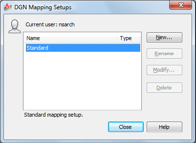
DGN Mapping Setups Dialog Box
Quick Reference
See also:
■Import MicroStation DGN Files
Creates new mapping setups, renames mapping setups, modifies mapping
setups, and deletes mapping setups.
List of Options
The following options are displayed.
Current User
Displays the user’s login name.
Name
Lists all mapping setups. If the setup name is too long to be completely
displayed, an ellipsis (...) is shown at the end.
Type Specifies the mapping setup type: import or export.
Description Displays the description of the selected mapping setup.
New
Displays the New Mapping Setup dialog box on page 312, in which you can
define a new mapping setup.
DGN Mapping Setups Dialog Box | 311

Rename
Starts in-place editing of the currently selected mapping setup (direct editing
in the list).
NOTE The Rename button is disabled when the Standard mapping setup is
selected.
Modify
Displays the Modify DGN Mapping Setup dialog box on page 314, in which
you can modify the currently selected mapping setup.
NOTE The Modify button is disabled when the Standard mapping setup is selected.
Delete
Deletes the currently selected mapping setup. After deletion, the mapping
setup directly below the one deleted is selected. If there is none below, the
one directly above it is selected.
NOTE The Delete button is disabled when the Standard mapping setup is selected.
New Mapping Setup Dialog Box
Quick Reference
See also:
■Import MicroStation DGN Files
Names the new mapping setup, sets the mapping setup on which to start the
new one, and indicates the mapping types to which you want the new style
to apply.
312 | Chapter 5 D Commands
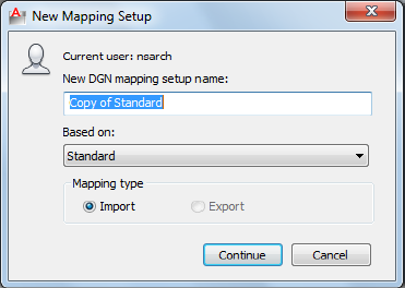
List of Options
The following options are displayed.
Current User
Displays the user’s login name.
New DGN Mapping Setup Name
Specifies the new mapping setup name.
Based On
Sets a mapping setup to use as a basis for the new one. For the new mapping
setup, you change only the properties that differ from the properties you start
with.
Mapping Type
Specifies what type of mapping setup to create.
Import
Specifies an import mapping type.
Export
Specifies an export mapping type.
Continue button
Opens the Modify DGN Mapping Setup dialog box on page 314. Depending
on the mapping type selected (Import or Export), the appropriate import/export
dialog box is displayed.
New Mapping Setup Dialog Box | 313
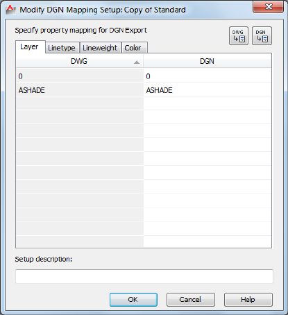
Modify DGN Mapping Setup Dialog Box
Quick Reference
See also:
■Export MicroStation DGN Files
■Import MicroStation DGN Files
Sets the properties for the selected mapping setup.
Summary
When you choose Continue in the New Mapping Setup dialog box, the Modify
DGN Mapping Setup dialog box is displayed. You define the properties for
the new mapping setup in this dialog box. The dialog box initially displays
the properties of the mapping setup that you selected.
314 | Chapter 5 D Commands
List of Options
The Modify DGN Mapping Setup dialog box includes the following tabs:
■Layer on page 315
■Linetype on page 315
■Lineweight on page 316
■Color on page 317
Layer
The corresponding cells are automatically filled with the default mapping.
The properties are added depending on which of the following mapping setups
you are currently working on. Whenever the target cell is blank (right-hand
column), the default system mapping is used. You can only make changes to
the right-hand column of the Layer tab. The left-hand column is not editable.
Use the Add Properties buttons to add layers/levels to the current mapping
setup.
New mapping setup: If you have accessed the Modify DGN Mapping Setup
dialog box by creating a new mapping setup from the Import/Export DGN
Settings dialog boxes, the rows are populated with all defined levels in the
imported DGN file or all defined layers in the current drawing file.
Existing mapping setup: If you are editing an existing mapping setup (even
if you are editing a setup other than Standard from the Import (or Export)
DGN Settings dialog box), the properties listed in the mapping table are not
derived from the imported DGN file or the exported drawing file.
Linetype
You can map linetypes and linestyles by editing the right-hand column of the
Linetype tab. Select a cell in the right-hand column, and click the drop-down
list to select a linetype or linestyle that the property in the left-hand column
should be mapped to. Linetypes can be loaded for use in the mapping setup
by selecting Other from the drop-down list. The left-hand column is not
editable. Use the Add Properties buttons to add linetypes/linestyles to the
current mapping setup.
Export mapping setup: If you have accessed the Modify DGN Mapping Setups
dialog box by creating a new setup from the Export DGN Settings dialog box,
the DWG column includes all defined linetypes in the current drawing file.
Whenever the target cell is blank (right-hand column), we will use the default
system mapping.
Modify DGN Mapping Setup Dialog Box | 315
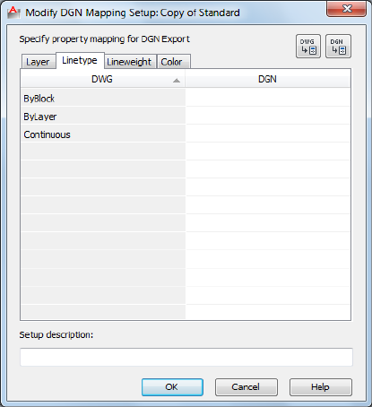
You can directly type DGN linestyle names in the cells in the right column.
If unknown linestyle names are added to the right column of the mapping
table, they are ignored and default to Continuous.
Import mapping setup: If you are in the Modify DGN Mapping Setup dialog
box by creating a new setup from the Import DGN Settings dialog box, the
DGN column includes all defined DGN linestyles in the imported DGN file,
as well as the DGN seed file used when the DGN file was created.
When remapping linetypes in the DWG column, only linetypes from the
acad.lin and acadiso.lin files are supported (depending on Units or
Measurement type of file). Linetypes stored in custom LIN files are not
supported.
Lineweight
A predefined set of lineweights is displayed which provides the best match
between lineweights used in DGN and DWG files. You can copy and paste
single or multiple lineweights using the right-click menu in the right-hand
column. You can only make changes on the right-hand column of the
Lineweight tab. The left-hand column is not editable.
316 | Chapter 5 D Commands
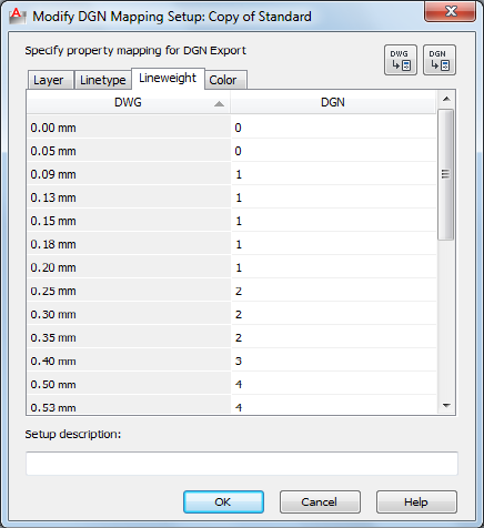
Color
You can map color values between DGN to DWG files. By default the Color
tab is blank and the default color mapping is used. Color translations between
DGN color values is done to the closest AutoCAD color values and AutoCAD
color values are mapped to the closest DGN color values. The Color tab is the
only tab that allows editing in both columns. Values in the left-hand column
must be unique. To remap colors, right-click either column and select Add
Color from the right-click menu.
Modify DGN Mapping Setup Dialog Box | 317
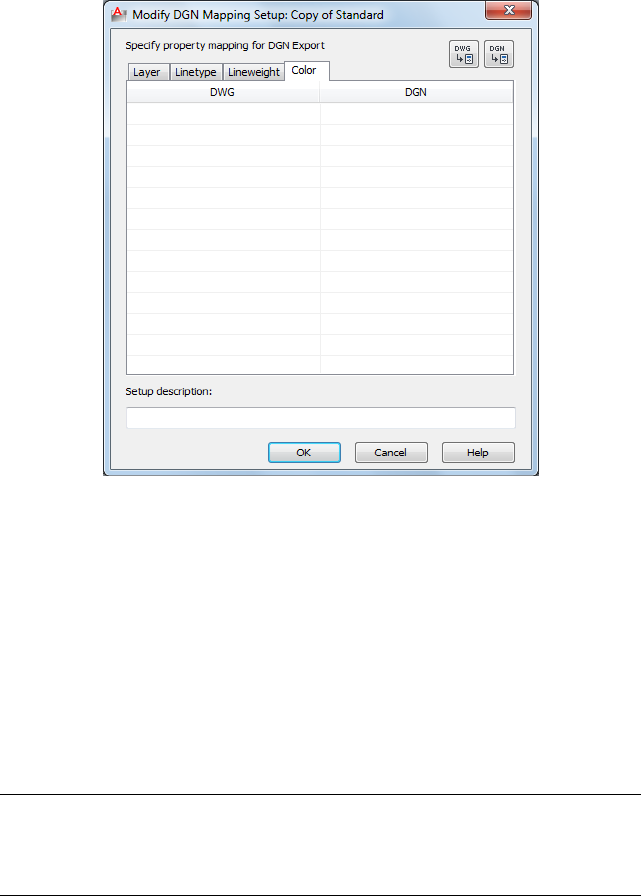
DGN column: Selecting Add Color… from the right-click menu allows you to
add a valid DGN color value to the cell. Valid colors include 0-255, ByLevel
and ByCell. The DWG column is automatically populated with the equivalent
RGB value. You can modify a DGN color by double-clicking the cell and typing
a different value.
DWG column: Selecting Add Color… from the right-click menu brings up the
Select Color dialog box on page 319. You can add ACI colors, true colors or
color from a Color Book. The DGN column is automatically populated with
the DGN equivalent color value. You can modify a DWG color by clicking
the cell and selecting an option from the drop-down list. The drop-down list
displays the standard color list as well as a list of colors previously added to
the DWG column and the Select Color option.
NOTE The AutoCAD Color Index Values are used to populate the DGN Column
on DGNEXPORT only because Microstation users can use their own color table
values which map differently. (On DGNIMPORT, you can read the DGN color
index value directly from the file).
Add Properties from DGN File
Opens the Add Properties from DGN File dialog box (a standard file selection
dialog box). The level and linestyle properties from the chosen DGN file are
318 | Chapter 5 D Commands

added to the DGN columns in the Modify DGN Mapping Setups dialog box
table.
In Files of Type, the drop-down list includes MicroStation DGN (*.dgn) and
All DGN Files (*.*) to recognize DGN files that have other extensions.
NOTE Only unique properties are added to the list in the Layer and Linetype tabs
when adding properties from files.
Add Properties from Drawing File
Opens the Add Properties from Drawing File dialog box (a standard file
selection dialog box). The layer and linetype properties from the chosen
DWT/DWG/DWS files are added to the DWG columns in the Modify DGN
Mapping Setups dialog box table.
In Files of Type, the drop-down list includes the following:
■Drawing template (*.dwt)
■Drawing (*.dwg)
■Standards (*.dws)
Setup Description
Specifies a mapping setup description. You can also edit the description for
an existing mapping setup.
NOTE Only unique properties are added to the list in the Layer and Linetype tabs
when adding properties from files.
Select Color Dialog Box
Quick Reference
See also:
■Import MicroStation DGN Files
The Select Color dialog box is displayed when you click Select Color from the
color drop-down list.
Select Color Dialog Box | 319
Summary
■Index Color on page 216
■True Color on page 218
■Color Books on page 221
DIM and DIM1
Quick Reference
See also:
■Overview of Dimensioning
Accesses Dimensioning mode commands.
Summary
The Dim prompt indicates that you're in Dimensioning mode, in which you
can use a special set of dimensioning commands on page 320. (DIM and DIM1
are provided only for compatibility with previous releases.)
Use DIM to remain in Dimensioning mode after you have used a dimensioning
command. Use DIM1 to execute a dimensioning command and immediately
return to the Command prompt. To exit Dimensioning mode, enter e or exit,
or press Esc.
List of Prompts
The following prompts are displayed.
Dim: Enter a Dimensioning mode command
Dimensioning Mode Commands
The following commands are available at the DIM prompt.
Dimensioning mode commands
DescriptionCommand
Exits Dimensioning mode and returns to the Command prompt.
You can also press Esc to exit Dimensioning mode.
EXIT
Redraws the current viewport.REDRAW
320 | Chapter 5 D Commands

Dimensioning mode commands
DescriptionCommand
Changes the current text style.STYLE
Erases the most recently created dimension objects and cancels any
new dimension system variable setting. When you exit Dimensioning
UNDO or U
mode, UNDO reverses the effects of the entire dimensioning session.
The following table shows which AutoCAD LT commands are equivalent to
the rest of the Dimensioning mode commands. For information about these
Dimensioning mode commands, see the equivalent AutoCAD LT command.
Dimensioning mode command equivalents
Equivalent
command
Dimensioning mode
command
DIMALIGNEDALIGNED
DIMANGULARANGULAR
DIMBASELINEBASELINE
DIMCENTERCENTER
DIMCONTINUECONTINUE
DIMDIAMETERDIAMETER
DIMEDIT HomeHOMETEXT
DIMLINEAR HorizontalHORIZONTAL
LEADERLEADER
DIMJOGGEDJOG
DIMEDIT NewNEWTEXT
DIMEDIT ObliqueOBLIQUE
DIMORDINATEORDINATE
DIM and DIM1 | 321

Dimensioning mode command equivalents
Equivalent
command
Dimensioning mode
command
DIMOVERRIDEOVERRIDE
DIMRADIUSRADIUS
-DIMSTYLE RestoreRESTORE
DIMLINEAR RotatedROTATED
-DIMSTYLE SaveSAVE
-DIMSTYLE StatusSTATUS
DIMTEDITTEDIT
DIMEDIT RotateTROTATE
-DIMSTYLE ApplyUPDATE
-DIMSTYLE VariablesVARIABLES
DIMLINEAR VerticalVERTICAL
DIMALIGNED
Quick Reference
See also:
■Create Aligned Dimensions
Creates an aligned linear dimension.
322 | Chapter 5 D Commands
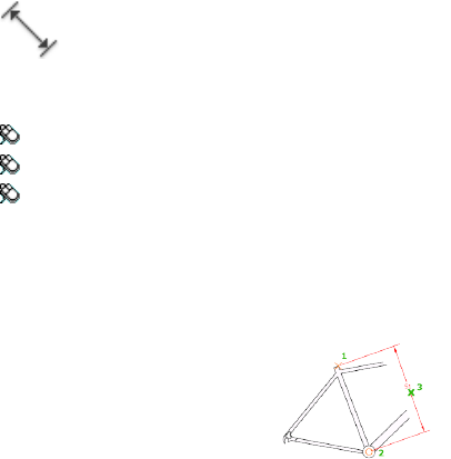
Access Methods
Button
Ribbon: Annotate tab ➤ Dimensions panel ➤ Aligned
Menu: Dimension ➤ Aligned
Toolbar: Dimension
Summary
Creates a linear dimension that is aligned with the origin points of the
extension lines.
List of Prompts
The following prompts are displayed.
Specify first extension line origin or <select object>: Specify a point for manual
extension lines, or press Enter for automatic extension lines
After you specify either manual or automatic extension lines, the following
prompt is displayed:
Specify dimension line location on page 324or [Mtext/Text/Angle]: Specify a
point or enter an option
Extension Line Origin Specifies the first extension line origin (1). You are
prompted to specify the second one.
Object Selection Automatically determines the origin points of the first and
second extension lines after you select an object.
For polylines and other explodable objects, only the individual line and arc
segments are dimensioned. You cannot select objects in a nonuniformly scaled
block reference.
If you select a line or an arc, its endpoints are used as the origins of the
extension lines. The extension lines are offset from the endpoints by the
distance specified in Offset from Origin on the Lines and Arrows tab of the
DIMALIGNED | 323
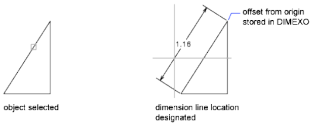
New, Modify, and Override Dimension Style dialog boxes (see DIMSTYLE).
This value is stored in the DIMEXO system variable.
If you select a circle, the endpoints of its diameter are used as the origins of
the extension line. The point used to select the circle defines the origin of the
first extension line.
Dimension Line Location Specifies the placement of the dimension line and
determines the direction to draw the extension lines. After you specify the
location, the DIMALIGNED command ends.
Mtext Displays the In-Place Text Editor, which you can use to edit the
dimension text. The generated measurement is represented with angle brackets
(< >). To add a prefix or a suffix to the generated measurement, enter the prefix
or suffix before or after the angle brackets. Use control codes and Unicode
character strings to enter special characters or symbols. See Control Codes
and Special Characters on page 1235.
To edit or replace the generated measurement, delete the angle brackets, enter
the new dimension text, and then click OK. If alternate units are not turned
on in the dimension style, you can display them by entering square brackets
([ ]). For more information, see “Select and Modify Objects”.
The current dimension style determines the appearance of the generated
measurements.
Text Customizes the dimension text at the command prompt. The generated
dimension measurement is displayed within angle brackets.
Enter the dimension text, or press Enter to accept the generated measurement.
To include the generated measurement, use angle brackets (< >) to represent
the generated measurement. If alternate units are not turned on in the
dimension style, you can display alternate units by entering square brackets
([ ]).
324 | Chapter 5 D Commands

Dimension text properties are set on the Text tab of the New, Modify, and
Override Dimension Style dialog boxes.
Angle Changes the angle of the dimension text.
DIMANGULAR
Quick Reference
See also:
■Create Angular Dimensions
Creates an angular dimension.
Access Methods
Button
Ribbon: Annotate tab ➤ Dimensions panel ➤ Angular
Menu: Dimension ➤ Angular
Toolbar: Dimension
DIMANGULAR | 325

Summary
Measures the angle between selected objects or 3 points. Objects that can be
selected include arcs, circles, and lines, among others.
List of Prompts
The following prompts are displayed.
Select arc, circle, line, or <specify vertex>: Select an arc, circle, or line, or press
Enter to create the angular dimension by specifying three points
After you define the angle to dimension, the following prompt is displayed:
Specify dimension arc line location or [Mtext/Text/Angle/Quadrant]:
Arc Selection Uses points on the selected arc as the defining points for a
three-point angular dimension. The center of the arc is the angle vertex. The
arc endpoints become the origin points of the extension lines.
The dimension line is drawn as an arc between the extension lines. The
extension lines are drawn from the angle endpoints to the intersection of the
dimension line.
Circle Selection Uses the selection point (1) as the origin of the first extension
line. The center of the circle is the angle vertex.
The second angle endpoint is the origin of the second extension line and does
not have to lie on the circle.
326 | Chapter 5 D Commands
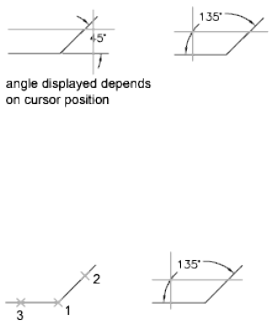
Line Selection Defines the angle using two lines.
The program determines the angle by using each line as a vector for the angle
and the intersection of the lines for the angle vertex. The dimension line spans
the angle between the two lines. If the dimension line does not intersect the
lines being dimensioned, extension lines are added as needed to extend one
or both lines. The arc is always less than 180 degrees.
Three-Point Specification Creates a dimension based on three points you
specify.
The angle vertex can be the same as one of the angle endpoints. If you need
extension lines, the endpoints are used as origin points.
The dimension line is drawn as an arc between the extension lines. The
extension lines are drawn from the angle endpoints to the intersection of the
dimension line.
Dimension Arc Line Location Specifies the placement of the dimension line
and determines the direction to draw the extension lines.
Mtext Displays the In-Place Text Editor, which you can use to edit the
dimension text. To add a prefix or a suffix, enter the prefix or suffix text before
or after the generated measurement. Use control codes and Unicode character
strings to enter special characters or symbols. See Control Codes and Special
Characters on page 1235.
For more information, see “Select and Modify Objects”.
The current dimension style determines the appearance of the generated
measurements.
Text Customizes the dimension text at the Command prompt. The generated
dimension measurement is displayed within angle brackets.
To include the generated measurement, use angle brackets (< >) to represent
the generated measurement.
DIMANGULAR | 327
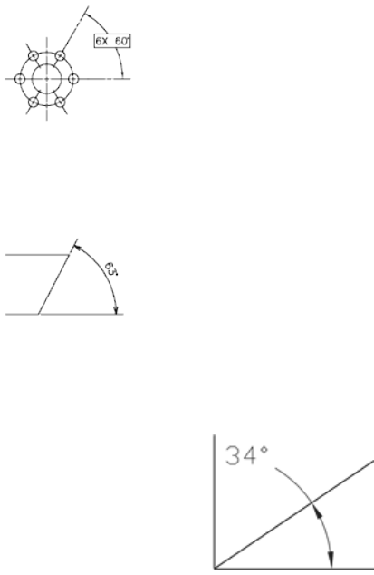
Dimension text properties are set on the Text tab of the New, Modify, and
Override Dimension Style dialog boxes.
Angle Changes the angle of the dimension text.
Quadrant Specifies the quadrant that the dimension should be locked to.
When quadrant behavior is on, the dimension line is extended past the
extension line when the dimension text is positioned outside of the angular
dimension.
DIMARC
Quick Reference
See also:
■Create Arc Length Dimensions
Creates an arc length dimension.
328 | Chapter 5 D Commands

Access Methods
Button
Ribbon: Annotate tab ➤ Dimensions panel ➤ Arc Length
Menu: Dimension ➤ Arc Length
Toolbar: Dimension
List of Prompts
The following prompts are displayed.
Select arc or polyline arc segment: Use an object selection method
Specify arc length dimension location or [Mtext/Text/Angle/Partial/Leader]:
Specify a point or enter an option
Arc length dimensions measure the distance along an arc or polyline arc
segment. The extension lines of an arc length dimension can be orthogonal
or radial. An arc symbol is displayed either above or preceding the dimension
text.
Arc Length Dimension Location Specifies the placement of the dimension
line and determines the direction of the extension lines.
DIMARC | 329
Mtext Displays the In-Place Text Editor, which you can use to edit the
dimension text. Use control codes and Unicode character strings to enter
special characters or symbols. See Control Codes and Special Characters on
page 1235.
If alternate units are not turned on in the dimension style, you can display
them by entering square brackets ([]). For more information, see “Select and
Modify Objects”.
The current dimension style determines the appearance of the generated
measurements.
Text Customizes the dimension text at the Command prompt. The generated
dimension measurement is displayed within angle brackets.
To include the generated measurement, use angle brackets (< >) to represent
the generated measurement. If alternate units are not turned on in the
dimension style, you can display alternate units by entering square brackets
([ ]).
Dimension text properties are set on the Text tab of the New, Modify, and
Override Dimension Style dialog boxes.
Angle Changes the angle of the dimension text.
Partial Reduces the length of the arc length dimension.
Leader Adds a leader object. This option is displayed only if the arc (or arc
segment) is greater than 90 degrees. The leader is drawn radially, pointing
towards the center of the arc being dimensioned.
No Leader Cancels the Leader option before the leader is created.
To remove a leader, delete the arc length dimension and recreate it without
the leader option.
DIMBASELINE
Quick Reference
See also:
■Create Baseline and Continued Dimensions
Creates a linear, angular, or ordinate dimension from the baseline of the
previous or selected dimension.
330 | Chapter 5 D Commands
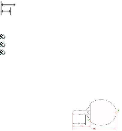
Access Methods
Button
Ribbon: Annotate tab ➤ Dimensions panel ➤ Baseline
Menu: Dimension ➤ Baseline
Toolbar: Dimension
Summary
The default spacing between baseline dimensions can be set from the
Dimension Style Manager, Lines tab, Baseline Spacing (DIMDLI on page 1454
system variable).
If no dimension was created in the current session, you are prompted to select
a linear, ordinate, or angular dimension to use as the base for the baseline
dimension.
List of Prompts
The following prompts are displayed.
Select base dimension: Select a linear, ordinate, or angular dimension
Otherwise, the program skips this prompt and uses the dimension object that
was last created in the current session. If the base dimension is linear or
angular, the following prompt is displayed:
Specify a second extension line origin on page 331 or [Undo/Select] <Select>:
Specify a point, enter an option, or press Enter to select a base dimension
If the base dimension is ordinate, the following prompt is displayed:
Specify feature location on page 332 or [Undo/Select] <Select>:
To end the command, press Enter twice, or press Esc. The current dimension
style determines the appearance of the text.
Second Extension Line Origin By default, the first extension line of the base
dimension is used as the extension line origin for the baseline dimension. To
DIMBASELINE | 331
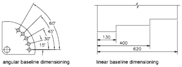
override this default behavior, explicitly select the base dimension; the
extension line origin becomes the extension line of the base dimension closest
to the pick point of the selection. When you select a second point, the baseline
dimension is drawn and the Specify a Second Extension Line Origin prompt
is redisplayed. To end the command, press Esc. To select another linear,
ordinate, or angular dimension to use as the basis for the baseline dimension,
press Enter.
Feature Location Uses the endpoint of the base dimension as the endpoint
for the baseline dimension; you are prompted for the next feature location.
When you select a feature location, the baseline dimension is drawn and the
Specify Feature Location prompt is redisplayed. To select another linear,
ordinate, or angular dimension to use as the basis for the baseline dimension,
press Enter.
Undo Undoes the last baseline dimension entered during this command
session.
Select Prompts you to select a linear, ordinate, or angular dimension to use
as the base for the baseline dimension.
DIMBREAK
Quick Reference
See also:
■Break a Dimension Line
Breaks or restores dimension and extension lines where they cross other objects.
332 | Chapter 5 D Commands
Access Methods
Button
Ribbon: Annotate tab ➤ Dimensions panel ➤ Break.
Menu: Dimension ➤ Dimension Break
Toolbar: Dimension
Summary
Dimension breaks can be added to linear, angular, and ordinate dimensions,
among others.
List of Prompts
The following prompts are displayed.
Select a dimension to add/remove break or [Multiple on page 333]: Select a
dimension, or enter m and press Enter
After you select a dimension, the following prompt is displayed:
Select object to break dimension or [Auto/Manual/Remove] <Auto>: Select an
object that intersects the dimension or extension lines of the selected dimension, enter
an option, or press Enter
After you select an object to break the dimension with, the following prompt
is displayed:
Select object to break dimension: Select an object that passes through the dimension
or press Enter to end the command
NOTE Dimension breaks can be added to dimensions for objects that do not
intersect the dimension or extension lines using the by Manual option.
Multiple Specifies multiple dimensions to add breaks to or remove breaks
from.
Auto Places dimension breaks automatically at all the intersection points of
the objects that intersect the selected dimension. Any dimension break created
using this option is updated automatically when the dimension or an
intersecting object is modified.
When a new object is drawn over the top of a dimension that has any
dimension breaks, no new dimension breaks are automatically applied at the
DIMBREAK | 333
intersecting points along the dimension object. To add the new dimension
breaks, must be run the command again.
Remove Removes all dimension breaks from the selected dimensions.
Manual Places a dimension break manually. You specify two points on the
dimension or extension lines for the location of the break. Any dimension
break that is created using this option is not updated if the dimension or
intersecting objects are modified. You can only place a single manual
dimension break at a time with this option.
DIMCENTER
Quick Reference
See also:
■Create Radial Dimensions
Creates the center mark or the centerlines of circles and arcs.
Access Methods
Button
Ribbon: Annotate tab ➤ Dimensions panel ➤ Center Mark
Menu: Dimension ➤ Center Mark
Toolbar: Dimension
Summary
The default sizes of the center mark components can be set from the Dimension
Style Manager, Symbols and Arrows tab, Center Marks (DIMCEN system
variable).
You can choose between center marks and centerlines and specify their size
when you set up the dimension style. See DIMSTYLE. You can also change
center mark settings using the DIMCEN system variable.
334 | Chapter 5 D Commands
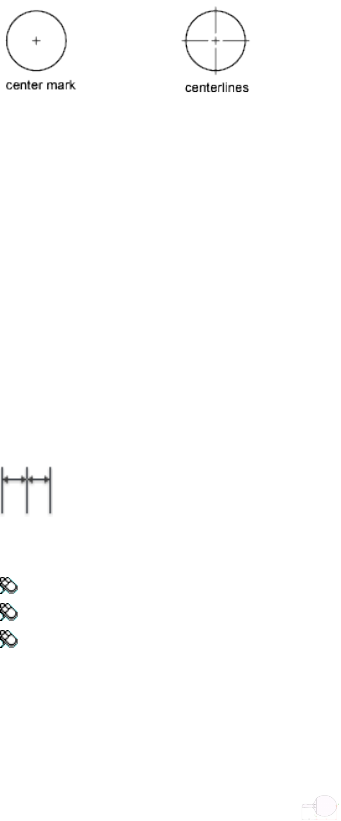
DIMCONTINUE
Quick Reference
See also:
■Create Baseline and Continued Dimensions
Creates a dimension that starts from an extension line of a previously created
dimension.
Access Methods
Button
Ribbon: Annotate tab ➤ Dimensions panel ➤ Continue
Menu: Dimension ➤ Continue
Toolbar: Dimension
Summary
Automatically continues creating additional dimensions from the last linear,
angular, or ordinate dimension created, or from a selected extension line. The
dimension lines are lined up automatically.
If no dimension was created in the current session, you are prompted to select
a linear, ordinate, or angular dimension to use as the base for the continued
dimension.
List of Prompts
The following prompts are displayed.
DIMCONTINUE | 335
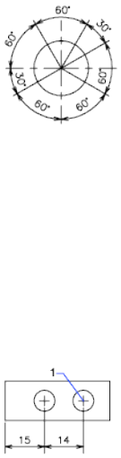
Select continued dimension: Select a linear, ordinate, or angular dimension
Otherwise, the program skips this prompt and uses the dimension object that
was last created in the current session. If the base dimension is linear or
angular, the following prompt is displayed:
Specify a second extension line origin or [Undo/Select] <Select>: Specify a point,
enter an option, or press Enter to select a base dimension
If the base dimension is ordinate, the following prompt is displayed:
Specify feature location or [Undo/Select] <Select>:
To end the command, press Enter twice, or press Esc. The current dimension
style determines the appearance of the text.
Second Extension Line Origin Uses the second extension line origin of the
continued dimension for the first extension line origin of the next dimension.
The current dimension style determines the appearance of the text.
After you select a continued dimension, the Specify a Second Extension Line
Origin prompt is redisplayed. To end the command, press Esc. To select another
linear, ordinate, or angular dimension to use as the basis for the continued
dimension, press Enter.
Select continued dimension: Select a linear, ordinate, or angular dimension
Select a base dimension, or press Esc to end the command.
Feature Location Uses the endpoint of the base dimension as the endpoint
for the continued dimension; you are prompted for the next feature location.
When you select a feature location, the continued dimension is drawn and
the Specify Feature Location prompt is redisplayed. To end the command,
press Esc. To select another linear, ordinate, or angular dimension to use as
the basis for the continued dimension, press Enter.
Select continued dimension: Select a linear, ordinate, or angular dimension
336 | Chapter 5 D Commands
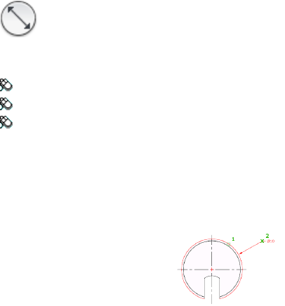
Select a base dimension, or press Esc to end the command.
Undo Undoes the last continued dimension entered during the command
session.
Select Prompts you to select a linear, ordinate, or angular dimension to use
as the continued dimension. After you select a continued dimension, the
Specify a Second Extension Line Origin prompt or the Specify Feature Location
prompt is redisplayed. To end the command, press Esc.
DIMDIAMETER
Quick Reference
See also:
■Create Radial Dimensions
Creates a diameter dimension for a circle or an arc.
Access Methods
Button
Ribbon: Annotate tab ➤ Dimensions panel ➤ Diameter
Menu: Dimension ➤ Diameter
Toolbar: Dimension
Summary
Measures the diameter of a selected circle or arc, and displays the dimension
text with a diameter symbol in front of it. You can use grips to easily reposition
the resulting diameter dimension.
DIMDIAMETER | 337
List of Prompts
The following prompts are displayed.
Select arc or circle:
Specify dimension line location on page 338 or [Mtext/Text/Angle]: Specify a
point or enter an option
Dimension Line Location Determines the angle of the dimension line and
the location of the dimension text. If the dimension is placed off of an arc
resulting in the dimension pointing outside the arc, AutoCAD LT automatically
draws an arc extension line.
Mtext Displays the In-Place Text Editor, which you can use to edit the
dimension text. Use control codes and Unicode character strings to enter
special characters or symbols. See Control Codes and Special Characters on
page 1235.
If alternate units are not turned on in the dimension style, you can display
them by entering square brackets ([]). For more information, see “Select and
Modify Objects”.
The current dimension style determines the appearance of the dimension text.
Text Customizes the dimension text at the Command prompt. The generated
dimension measurement is displayed within angle brackets.
To include the generated measurement, use angle brackets (< >) to represent
the generated measurement. If alternate units are not turned on in the
dimension style, you can display alternate units by entering square brackets
([ ]).
Dimension text properties are set on the Text tab of the New, Modify, and
Override Dimension Style dialog boxes.
Angle Changes the angle of the dimension text.
DIMDISASSOCIATE
Quick Reference
See also:
■Change Dimension Associativity
Removes associativity from selected dimensions.
338 | Chapter 5 D Commands
Summary
DIMDISASSOCIATE filters the selection set to include only associative
dimensions that are not on locked layers, and that are not in a different space
than the current space (for example, if model space is active, associative
dimensions in paper space are excluded). DIMDISASSOCIATE then disassociates
these dimensions and reports the number of dimensions that are filtered out
and the number that are disassociated.
DIMEDIT
Quick Reference
See also:
■Modify Dimension Text
Edits dimension text and extension lines.
Access Methods
Button
Ribbon: Annotate tab ➤ Dimensions panel ➤ Oblique
Menu: Dimension ➤ Oblique
Toolbar: Dimension, Oblique
Summary
Rotates, modifies, or restores dimension text. Changes the oblique angle of
extension lines. The companion command that moves text and the dimension
line is DIMTEDIT on page 400.
List of Prompts
The following prompts are displayed.
Enter type of dimension editing [Home/New/Rotate/Oblique] <Home>: Enter
an option or press Enter
Home Moves rotated dimension text back to its default position.
DIMEDIT | 339
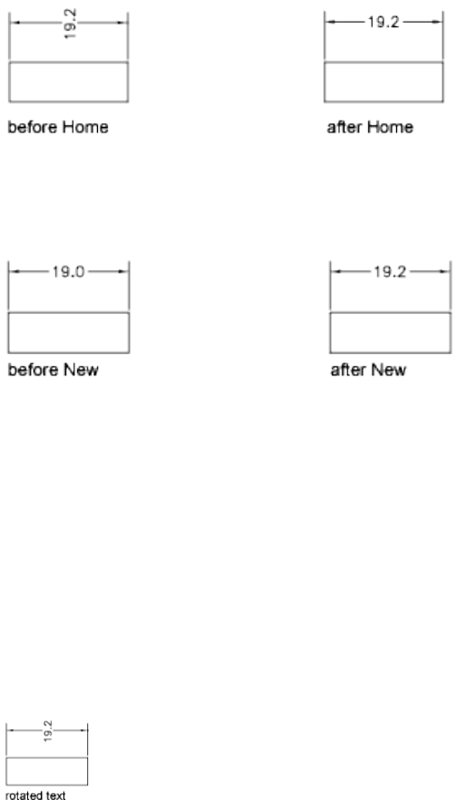
The selected dimension text is returned to its default position and rotation as
specified in its dimension style.
New Changes dimension text using the In-Place Text Editor.
The generated measurement is represented with angle brackets (< >). Use
control codes and Unicode character strings to enter special characters or
symbols. See Control Codes and Special Characters on page 1235.
To edit or replace the generated measurement, delete the angle brackets, enter
the new dimension text, and then choose OK. If alternate units are not turned
on in the dimension style, you can display them by entering square brackets
([ ]). For more information, see “Select and Modify Objects”.
Rotate Rotates dimension text. This option is similar to the Angle option of
DIMTEDIT.
Entering 0 places the text in its default orientation, which is determined by
the vertical and horizontal text settings on the Text tab of the New, Modify,
and Override Dimension Style dialog boxes. See DIMSTYLE. The DIMTIH and
DIMTOH system variables control this orientation.
Oblique
The Oblique option is useful when extension lines conflict with other features
of the drawing. The oblique angle is measured from the X axis of the UCS.
340 | Chapter 5 D Commands
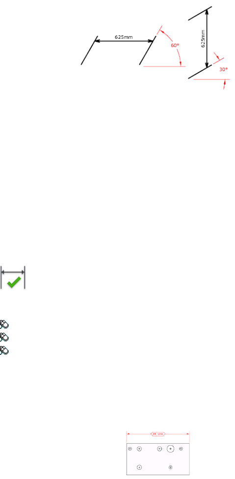
DIMINSPECT
Quick Reference
See also:
■Convert Dimensions into Inspection Dimensions
Adds or removes inspection information for a selected dimension.
Access Methods
Button
Ribbon: Annotate tab ➤ Dimensions panel ➤ Inspect
Menu: Dimension ➤ Inspection
Toolbar: Dimension
Summary
Inspection dimensions specify how frequently manufactured parts should be
checked to ensure that the dimension value and tolerances of the parts are
within the specified range.
DIMINSPECT | 341

The Inspection Dimension Dialog Box is displayed and allows you to add or
remove inspection dimensions from an existing dimension. Inspection
dimensions allow you to effectively communicate how frequently
manufactured parts should be checked to ensure that the dimension value
and tolerances of the parts are within the specified range.
If you enter -diminspect at the Command prompt, options are displayed.
Inspection Dimension Dialog Box
Quick Reference
See also:
■Convert Dimensions into Inspection Dimensions
Allows you to add or remove an inspection dimension from selected
dimensions.
Summary
Use the Shape and Inspection Label/Rate settings to the appearance of the
frame of the inspection dimension and the inspection rate value.
List of Options
The following options are displayed.
342 | Chapter 5 D Commands
Select Dimensions
Specifies the dimensions that an inspection dimension should be added to or
removed from.
Remove Inspection
Removes the inspection dimension from the selected dimension.
Shape
Controls the shape of the frame that is drawn around the label, dimension
value, and inspection rate of the inspection dimension.
Round
Creates a frame with semi-circles on the two ends; the fields within the frame
are separated by vertical lines.
Angular
Creates a frame with lines that form a 90-degree angle on the two ends; the
fields within the frame are separated by vertical lines.
None
Specifies that no frame is drawn around the values; the fields are not separated
by vertical lines.
Label/Inspection Rate
Specifies the label text and inspection rate for an inspection dimension.
Label
Turns the display of the label field on and off.
Label Value
Specifies the label text.
The label is displayed in the leftmost section of the inspection dimension
when the Label check box is selected.
Inspection Rate
Turns the display of the rate field on and off.
Inspection Rate Value
Specifies how frequently a part should be inspected.
Inspection Dimension Dialog Box | 343
The value is expressed as a percentage, and the valid range is 0 to 100. The
inspection rate is displayed in the rightmost section of the inspection
dimension when the Inspection Rate check box is selected.
-DIMINSPECT
Quick Reference
See also:
■Convert Dimensions into Inspection Dimensions
List of Prompts
The following prompts are displayed.
Add inspection data on page 344 or [Remove on page 344] <Add>: Enter an option
or press Enter
Add
Adds an inspection dimension to the selected dimensions.
Round Creates a frame with semi-circles on the two ends; the fields within
the frame are separated by vertical lines.
Angular Creates a frame with lines that form a 90-degree angle on the two
ends; the fields within the frame are separated by vertical lines.
None Specifies that no frame is drawn around the values; the fields are not
separated by vertical lines.
None No label is displayed with the inspection dimension.
Remove
Removes the inspection dimension from the selected dimensions.
DIMJOGGED
Quick Reference
See also:
■Create Radial Dimensions
344 | Chapter 5 D Commands
Creates jogged dimensions for circles and arcs.
Access Methods
Button
Ribbon: Annotate tab ➤ Dimensions panel ➤ Jogged
Menu: Dimension ➤ Jogged
Toolbar: Dimension
Summary
DIMJOGGED measures the radius of the selected object and displays the
dimension text with a radius symbol in front of it. The origin point of the
dimension line can be specified at any convenient location.
NOTE Jogged radius dimensions are also called foreshortened radius dimensions.
Creates jogged radius dimensions when the center of an arc or circle is located
off the layout and cannot be displayed in its true location. The origin point
of the dimension can be specified at a more convenient location called the
center location override.
List of Prompts
The following prompts are displayed.
Select arc or circle: Select an arc, circle, or polyline arc segment
Specify center location override: Specify a point
Accepts a new center point for a jogged radius dimension that takes the place
of the true center point of the arc or circle.
Specify dimension line location on page 345 or [Mtext/Text/Angle]: Specify a
point or enter an option
Dimension Line Location Determines the angle of the dimension line and
the location of the dimension text. If the dimension is placed off of an arc
resulting in the dimension pointing outside the arc, AutoCAD LT automatically
draws an arc extension line.
Mtext Displays the In-Place Text Editor, which you can use to edit the
dimension text. Use control codes and Unicode character strings to enter
DIMJOGGED | 345
special characters or symbols. See Control Codes and Special Characters on
page 1235.
If alternate units are not turned on in the dimension style, you can display
them by entering square brackets ([ ]). For more information, see “Select and
Modify Objects”.
The current dimension style determines the appearance of the generated
measurements.
Text Customizes the dimension text at the Command prompt. The generated
dimension measurement is displayed within angle brackets.
To include the generated measurement, use angle brackets (< >) to represent
the generated measurement. If alternate units are not turned on in the
dimension style, you can display alternate units by entering square brackets
([ ]).
Dimension text properties are set on the Text tab of the New, Modify, and
Override Dimension Style dialog boxes.
Angle Changes the angle of the dimension text.
Also determines the angle of the dimension line and the location of the
dimension text.
Specify Jog Location Locates the middle point of the jog. The transverse
angle of the jog is determined by the Dimension Style Manager.
DIMJOGLINE
Quick Reference
See also:
■Dimension Jog
Adds or removes a jog line on a linear or aligned dimension.
Access Methods
Button
Ribbon: Annotate tab ➤ Dimensions panel ➤ Dimension, Dimjogline
346 | Chapter 5 D Commands
Menu: Dimension ➤ Jogged Linear
Toolbar: Dimension
Summary
Jog lines in a dimension indicate a break in the objects being dimensioned.
The dimension value represents the actual distance, rather than the measured
distance in the drawing.
List of Prompts
The following prompts are displayed.
Select dimension to add jog on page 347 or [Remove on page 347]: Select a linear
or aligned dimension
Add Jog Specifies the linear or aligned dimension to which to add a jog. You
are prompted for the location of the jog.
Press Enter to place the jog at the midpoint between the dimension text and
the first extension line or the midpoint of the dimension line based on the
location of the dimension text
Remove Specifies the linear or aligned dimension from which to remove the
jog.
DIMLINEAR
Quick Reference
See also:
■Create Linear Dimensions
Creates a linear dimension.
Access Methods
Button
DIMLINEAR | 347
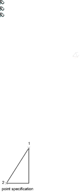
Ribbon: Annotate tab ➤ Dimensions panel ➤ Linear
Menu: Dimension ➤ Linear
Toolbar: Dimension
Summary
Creates a linear dimension with a horizontal, vertical, or rotated dimension
line. This command replaces the DIMHORIZONTAL and DIMVERTICAL
commands.
List of Prompts
The following prompts are displayed.
Specify first extension line origin or <select object>: Specify a point or press Enter
to select an object to dimension
After you specify the extension line origin points or the object to dimension,
the following prompt is displayed:
Specify dimension line location or
[Mtext/Text/Angle/Horizontal/Vertical/Rotated]: Specify a point or enter an option
First Extension Line Origin
Prompts for the origin point of the second extension line after you specify
the origin point of the first.
Dimension Line Location
Uses the point you specify to locate the dimension line and determines the
direction to draw the extension lines. After you specify the location, the
dimension is drawn.
348 | Chapter 5 D Commands
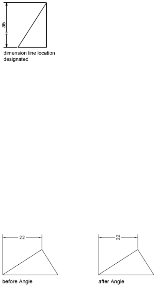
Mtext
Displays the In-Place Text Editor, which you can use to edit the dimension
text. Use control codes and Unicode character strings to enter special characters
or symbols. See Control Codes and Special Characters on page 1235.
If alternate units are not turned on in the dimension style, you can display
them by entering square brackets ([ ]). For more information about formatting
dimension text, see “Select and Modify Objects”.
The current dimension style determines the appearance of the generated
measurements.
Text
Customizes the dimension text at the Command prompt. The generated
dimension measurement is displayed within angle brackets.
To include the generated measurement, use angle brackets (< >) to represent
the generated measurement. If alternate units are not turned on in the
dimension style, you can display alternate units by entering square brackets
([ ]).
Dimension text properties are set on the Text tab of the New, Modify, and
Override Dimension Style dialog boxes.
Angle
Changes the angle of the dimension text.
DIMLINEAR | 349
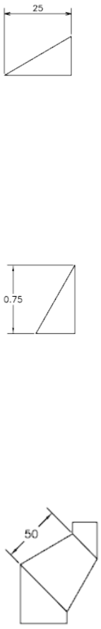
Horizontal
Creates horizontal linear dimensions.
Dimension Line Location Uses the point you specify to locate the dimension
line.
■Mtext on page 349
■Text on page 349
■Angle on page 349
Vertical
Creates vertical linear dimensions.
Dimension Line Location Dimension Line Location on page 348
■Mtext on page 349
■Text on page 349
■Angle on page 349
Rotated
Creates rotated linear dimensions.
350 | Chapter 5 D Commands
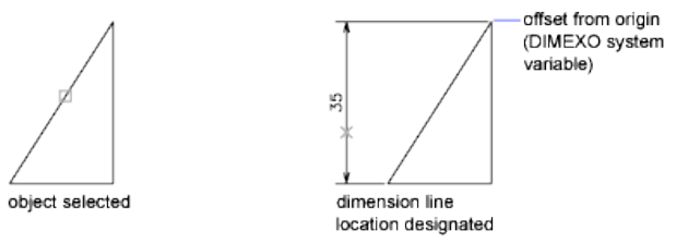
Object Selection
Automatically determines the origin points of the first and second extension
lines after you select an object.
For polylines and other explodable objects, only the individual line and arc
segments are dimensioned. You cannot select objects in a non-uniformly
scaled block reference.
If you select a line or an arc, the line or arc endpoints are used as the origins
of the extension lines. The extension lines are offset from the endpoints by
the distance you specify in Offset from Origin in the Lines and Arrows tab of
the New, Modify, and Override Dimension Style dialog boxes. See DIMSTYLE.
This value is stored in the DIMEXO system variable.
If you select a circle, the diameter endpoints are used as the origins of the
extension line. When the point used to select the circle is close to the north
or south quadrant point, a horizontal dimension is drawn. When the point
used to select the circle is close to the east or west quadrant point, a vertical
dimension is drawn.
DIMORDINATE
Quick Reference
See also:
■Create Ordinate Dimensions
Creates ordinate dimensions.
DIMORDINATE | 351
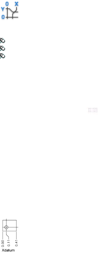
Access Methods
Button
Ribbon: Annotate tab ➤ Dimensions panel ➤ Ordinate
Menu: Dimension ➤ Ordinate
Toolbar: Dimension
Summary
Ordinate dimensions measure the horizontal or vertical distance from an
origin point called the datum to a feature, such as a hole in a part. These
dimensions prevent escalating errors by maintaining accurate offsets of the
features from the datum.
List of Prompts
The following prompts are displayed.
Specify feature location: Specify a point or snap to an object
Specify leader endpoint or [Xdatum/Ydatum/Mtext/Text/Angle]: Specify a point
or enter an option
Leader Endpoint Specification Uses the difference between the feature
location and the leader endpoint to determine whether it is an X or a Y ordinate
dimension. If the difference in the Y ordinate is greater, the dimension
measures the X ordinate. Otherwise, it measures the Y ordinate.
Xdatum Measures the X ordinate and determines the orientation of the leader
line and dimension text. The Leader Endpoint prompt is displayed, where you
can specify the endpoint.
Ydatum Measures the Y ordinate and determines the orientation of the leader
line and dimension text. The Leader Endpoint prompts are displayed, where
you can specify the endpoint.
352 | Chapter 5 D Commands
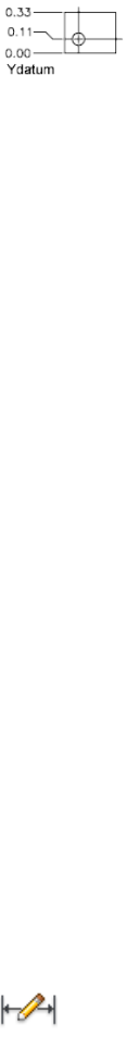
Mtext Displays the In-Place Text Editor, which you can use to edit the
dimension text. Use control codes and Unicode character strings to enter
special characters or symbols. See Control Codes and Special Characters on
page 1235.
If alternate units are not turned on in the dimension style, you can display
them by entering square brackets ([ ]). For more information about formatting
dimension text, see “Select and Modify Objects”.
The current dimension style determines the appearance of the generated
measurements.
Text Customizes the dimension text at the Command prompt. The generated
dimension measurement is displayed within angle brackets.
To include the generated measurement, use angle brackets (< >) to represent
the generated measurement. If alternate units are not turned on in the
dimension style, you can display alternate units by entering square brackets
([ ]).
Dimension text properties are set on the Text tab of the New, Modify, and
Override Dimension Style dialog boxes.
Angle Changes the angle of the dimension text.
DIMOVERRIDE
Quick Reference
See also:
■Override a Dimension Style
Controls overrides of system variables used in selected dimensions.
Access Methods
Button
DIMOVERRIDE | 353

Ribbon: Annotate tab ➤ Dimensions panel ➤ Override
Menu: Dimension ➤ Override
Summary
Overrides a specified dimensioning system variable for selected dimensions,
or clears the overrides of selected dimension objects, returning them to the
settings defined by their dimension style.
List of Prompts
The following prompts are displayed.
Enter dimension variable name to override or [Clear overrides]: Enter the name
of a dimension variable, or enter c
Dimension Variable Name to Override Overrides the value of the
dimensioning system variable you specify.
Clear Overrides Clears any overrides on selected dimensions.
The dimension objects return to the settings defined by their dimension style.
DIMRADIUS
Quick Reference
See also:
■Create Radial Dimensions
Creates a radius dimension for a circle or an arc.
Access Methods
Button
Ribbon: Annotate tab ➤ Dimensions panel ➤ Radius
Menu: Dimension ➤ Radius
Toolbar: Dimension
354 | Chapter 5 D Commands
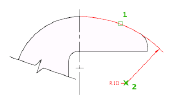
Summary
Measures the radius of a selected circle or arc and displays the dimension text
with a radius symbol in front of it. You can use grips to reposition the resulting
radius dimension easily.
List of Prompts
The following prompts are displayed.
Select arc or circle:
Specify dimension line location or [Mtext/Text/Angle]: Specify a point or enter
an option
Dimension Line Location Determines the angle of the dimension line and
the location of the dimension text. If the dimension is placed off of an arc
resulting in the dimension pointing outside the arc, AutoCAD LT automatically
draws an arc extension line.
Mtext Displays the In-Place Text Editor, which you can use to edit the
dimension text. Use control codes and Unicode character strings to enter
special characters or symbols. See Control Codes and Special Characters on
page 1235.
If alternate units are not turned on in the dimension style, you can display
them by entering square brackets ([ ]). For more information about formatting
dimension text, see “Select and Modify Objects”.
The current dimension style determines the appearance of the generated
measurements.
Text Customizes the dimension text at the Command prompt. The generated
dimension measurement is displayed within angle brackets.
To include the generated measurement, use angle brackets (< >) to represent
the generated measurement. If alternate units are not turned on in the
dimension style, you can display alternate units by entering square brackets
([ ]).
Dimension text properties are set on the Text tab of the New, Modify, and
Override Dimension Style dialog boxes.
Angle Changes the angle of the dimension text.
DIMRADIUS | 355
DIMREASSOCIATE
Quick Reference
See also:
■Change Dimension Associativity
Associates or reassociates selected dimensions to objects or points on objects.
Access Methods
Button
Ribbon: Annotate tab ➤ Dimensions panel ➤ Reassociate
Menu: Dimension ➤ Reassociate Dimensions
Summary
Each selected dimension is highlighted in turn, and prompts for association
points appropriate for the selected dimension are displayed.
A marker is displayed for each association point prompt.
■If the definition point of the current dimension is not associated to a
geometric object, the marker appears as an X
■if the definition point is associated, the marker appears as an X inside a
box.
NOTE The marker disappears if you pan or zoom with a wheel mouse.
List of Prompts
The following prompts are displayed.
Select dimensions to reassociate...
Select objects or [Disassociated]: Select the dimension objects to reassociate or press
D to select all disassociated dimensions.
356 | Chapter 5 D Commands

Press Esc to terminate the command without losing the changes that were
already specified. Use UNDO to restore the previous state of the changed
dimensions.
The prompts for the different types of dimensions are:
Linear Specify first extension line origin or [Select object] <next>: Specify an
object snap location, enter s and select a geometric object, or press Enter to skip to
the next prompt
Specify second extension line origin <next>: Specify an object snap location, or
press Enter to skip to the next dimension object, if any
Aligned Specify first extension line origin or [Select object] <next>: Specify an
object snap location, enter s and select a geometric object, or press Enter to skip to
the next prompt
Specify second extension line origin <next>: Specify an object snap location, or
press Enter to skip to the next dimension object, if any
Angular (Three Point) Specify angle vertex or [Select arc or circle] <next>:
Specify an object snap location, enter s and select an arc or a circle, or press Enter to
skip to the next prompt
Specify first angle endpoint <next>: Specify an object snap location or press Enter
to skip to the next prompt
Specify second angle endpoint <next>: Specify an object snap location or press
Enter to skip to the next dimension object, if any
Angular (Two Line) Select first line <next>: Select a line, or press Enter to skip
to the next prompt
Select second line <next>: Select another line, or press Enter to skip to the next
dimension object, if any
Diameter Select arc or circle <next>: Select an arc or a circle, or press Enter to
skip to the next dimension object, if any
Leader Specify leader association point <next>: Specify an object snap location,
or press Enter to skip to the next dimension object, if any
Ordinate Specify feature location <next>: Specify an object snap location, or press
Enter to skip to the next dimension object, if any
Radius Select arc or circle <next>: Select an arc or a circle, or press Enter to skip
to the next dimension object, if any
NOTE DIMREASSOCIATE does not change the setting of DIMLFAC in a dimension.
Use DIMOVERRIDE to clear dimension linear factors in legacy drawings.
DIMREASSOCIATE | 357

DIMREGEN
Quick Reference
See also:
■Associative Dimensions
Updates the locations of all associative dimensions.
Summary
The locations of all associative dimensions in the current drawing are updated.
Associative dimensions need to be updated manually with DIMREGEN in the
following cases:
■After panning or zooming with a wheel mouse in a layout with model
space active; update associative dimensions created in paper space.
■After opening a drawing containing external references that are
dimensioned in the current drawing; update associative dimensions if the
associated external reference geometry has been modified.
NOTE After opening a drawing that has been modified with a previous version,
the association between dimensions and objects or points may need to be updated.
You can use the DIMREASSOCIATE on page 356 command to reassociate modified
dimensions with the objects or points that they dimension.
DIMROTATED
Quick Reference
See also:
■Create Linear Dimensions
Creates a rotated linear dimension.
358 | Chapter 5 D Commands
Summary
Creates a linear dimension with a rotated dimension line.
List of Prompts
The following prompts are displayed.
Specify angle of dimension line <0>: Specify an angle or press Enter to accept the
default value
Specify first extension line origin or <select object>: Specify a point or press Enter
to select an object to dimension
After you specify the extension line origin points or the object to dimension,
the following prompt is displayed:
Specify dimension line location or [Mtext/Text/Angle]: Specify a point or enter
an option
First Extension Line Origin
Prompts for the origin point of the second extension line after you specify
the origin point of the first.
Dimension Line Location
Uses the point you specify to locate the dimension line and determines the
direction to draw the extension lines. After you specify the location, the
dimension is drawn.
Mtext
Displays the In-Place Text Editor, which you can use to edit the dimension
text. Use control codes and Unicode character strings to enter special characters
or symbols. See Control Codes and Special Characters on page 1235.
If alternate units are not turned on in the dimension style, you can display
them by entering square brackets ([ ]). For more information about formatting
dimension text, see “Select and Modify Objects”.
The current dimension style determines the appearance of the generated
measurements.
Text
Customizes the dimension text at the Command prompt. The generated
dimension measurement is displayed within angle brackets.
To include the generated measurement, use angle brackets (< >) to represent
the generated measurement. If alternate units are not turned on in the
dimension style, you can display alternate units by entering square brackets
([ ]).
DIMROTATED | 359

Dimension text properties are set on the Text tab of the New, Modify, and
Override Dimension Style dialog boxes.
Angle
Changes the angle of the dimension text.
Object Selection
Automatically determines the origin points of the first and second extension
lines after you select an object.
For polylines and other explodable objects, only the individual line and arc
segments are dimensioned. You cannot select objects in a non-uniformly
scaled block reference.
If you select a line or an arc, the line or arc endpoints are used as the origins
of the extension lines. The extension lines are offset from the endpoints by
the distance you specify in Offset from Origin in the Lines and Arrows tab of
the New, Modify, and Override Dimension Style dialog boxes. See DIMSTYLE.
This value is stored in the DIMEXO system variable.
If you select a circle, the location of the origins for the extension lines is
calculated based on the center of the circle and the angle of the rotated
dimension line.
DIMSPACE
Quick Reference
See also:
■Adjust Dimension Spacing
Adjusts the spacing between linear dimensions or angular dimensions.
Access Methods
Button
Ribbon: Annotate tab ➤ Dimensions panel ➤ Adjust Space
Menu: Dimension ➤ Dimension Space
Toolbar: Dimension
360 | Chapter 5 D Commands

Summary
The spacing between parallel dimension lines is made equal. You can also
make the dimension lines of a series of linear or angular dimensions line up
by using a spacing value of 0.
Spacing is applied only to parallel linear dimensions or to angular dimensions
that share a common vertex.
List of Prompts
The following prompts are displayed.
Select base dimension: Select a parallel linear or angular dimension
Select dimensions to space: Select a parallel linear or angular dimension to equally
space from the base dimension and press Enter
Enter value on page 361 or [Auto on page 361] <Auto>: Specify a spacing distance
or press Enter
Enter Spacing Value Applies a spacing value to the selected dimensions from
the base dimension. For example, if you enter a value of 0.5000, all selected
dimensions will be separated by a distance of 0.5000.
You can use a spacing value of 0 (zero) to align the dimension lines of selected
linear and angular dimensions end to end.
Auto Calculates the spacing distance automatically based on the text height
specified in the dimension style of the selected base dimension. The resulting
spacing value is twice the height of the dimension text.
DIMSTYLE
Quick Reference
See also:
■Use Dimension Styles
Creates and modifies dimension styles.
DIMSTYLE | 361
Access Methods
Button
Ribbon: Annotate tab ➤ Dimensions panel ➤ ➤ Dimension Style
Menu: Format ➤ Dimension Style
Toolbar: Styles
Summary
The Dimension Style Manager is displayed.
A dimension style is a named collection of dimension settings that control
the appearance of dimensions. You create dimension styles to specify the
format of dimensions quickly, and to ensure that dimensions conform to
standards.
If you enter -dimstyle at the Command prompt, options are displayed.
Dimension Style Manager
Quick Reference
See also:
■Use Dimension Styles
Creates new styles, sets the current style, modifies styles, sets overrides on the
current style, and compares styles.
362 | Chapter 5 D Commands
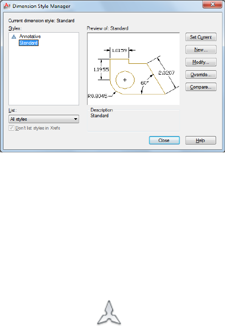
List of Options
The following options are displayed.
Current Dimension Style
Displays the name of the dimension style that is current. The default dimension
style is STANDARD. The current style is applied to dimensions you create.
Styles
Lists dimension styles in the drawing. The current style is highlighted.
Right-click in the list to display a shortcut menu with options to set the current
style, rename styles, and delete styles. You cannot delete a style that is current
or in use in the current drawing. A icon before the style name indicates
that the style is .
Unless you select Don't List Styles in Xrefs, dimension styles are displayed in
externally referenced drawings using the syntax for externally referenced
named objects. (See “Overview of Referenced Drawings (Xrefs)”.) Although
you cannot change, rename, or make current externally referenced dimension
styles, you can create new styles based on them.
The item selected in List controls the dimension styles displayed.
List
Controls the display of styles in the Styles list. Select All Styles if you want to
see all dimension styles in a drawing. Select Styles in Use if you want to see
only the dimension styles currently used by dimensions in the drawing.
Dimension Style Manager | 363
Don’t List Styles in Xrefs
When selected, suppresses display of dimension styles in externally referenced
drawings in the Styles list.
Preview
Shows a graphic representation of the style selected in the Styles list.
Description
Describes the style selected in the Styles list relative to the current style. If the
description is longer than the space provided, you can click in the pane and
use arrow keys to scroll down.
Set Current
Sets the style selected under Styles to current. The current style is applied to
dimensions you create.
New
Displays the Create New Dimension Style dialog box on page 365, in which
you can define a new dimension style.
Modify
Displays the Modify Dimension Styles dialog box on page 366, in which you
can modify dimension styles. Dialog box options are identical to those in the
New Dimension Style dialog box.
Override
Displays the Override Current Style dialog box on page 366, in which you can
set temporary overrides to dimension styles. Dialog box options are identical
to those in the New Dimension Style dialog box. Overrides are displayed as
unsaved changes under the dimension style in the Styles list.
Compare
Displays the Compare Dimension Styles dialog box, in which you can compare
two dimension styles or list all the properties of one dimension style.
364 | Chapter 5 D Commands
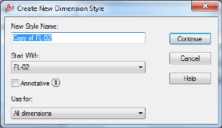
Create New Dimension Style Dialog Box
Quick Reference
See also:
■Use Dimension Styles
Names the new dimension style, sets the style on which to start the new one,
and indicates the dimension types to which you want the new style to apply.
List of Options
The following options are displayed.
New Style Name
Specifies the new dimension style name.
Start With
Sets a style to use as a basis for the new one. For the new style, you change
only the properties that differ from the properties you start with.
Annotative
Specifies that the dimension style is . Click the information icon to learn more
about annotative objects.
Use For
Creates a dimension substyle that applies only to specific dimension types.
For example, you could create a version of the STANDARD dimension style
to be used only for diameter dimensions.
Continue
Create New Dimension Style Dialog Box | 365
Displays the New Dimension Style dialog box, in which you define the new
dimension style properties.
New, Modify, and Override Dimension Style Dialog Boxes
Quick Reference
See also:
■Use Dimension Styles
Set properties for dimension styles.
Summary
When you choose Continue in the Create New Dimension Style dialog box,
the New Dimension Style dialog box is displayed. You define the properties
for the new style in this dialog box. The dialog box initially displays the
properties of the dimension style that you selected to start the new style in
the Create New Dimension Style dialog box.
Choosing either Modify or Override in the Dimension Style Manager displays
the Modify Dimension Style or the Override Dimension Style dialog box. The
content of these dialog boxes is identical to the New Dimension Style dialog
box, although you are modifying or overriding an existing dimension style
rather than creating a new one.
The sample image on each tab displays the effects of each option.
List of Tabs
■Lines on page 367
■Symbols and Arrows on page 371
■Text on page 375
■Fit on page 380
■Primary Units on page 385
■Alternate Units on page 389
■Tolerances on page 392
366 | Chapter 5 D Commands
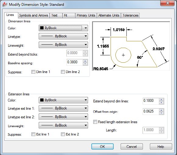
Lines Tab
Quick Reference
See also:
■Use Dimension Styles
Sets the format and properties for dimension lines, extension lines, arrowheads,
and center marks.
Summary
Sets the dimension line properties.
List of Options
The following options are displayed.
Dimension Lines
Color
New, Modify, and Override Dimension Style Dialog Boxes | 367

Displays and sets the color for the dimension line. If you click Select Color
(at the bottom of the Color list), the Select Color dialog box is displayed. You
can also enter a color name or number. (DIMCLRD system variable)
Linetype
Sets the linetype of the dimension line. (DIMLTYPE system variable)
Lineweight
Sets the lineweight of the dimension line. (DIMLWD system variable)
Extend Beyond Ticks
Specifies a distance to extend the dimension line past the extension line when
you use oblique, architectural, tick, integral, and no marks for arrowheads.
(DIMDLE system variable)
Baseline Spacing
Sets the spacing between the dimension lines of a baseline dimension. Enter
a distance. For information about baseline dimensions, see DIMBASELINE.
(DIMDLI system variable)
Suppress
Suppresses display of dimension lines. Dim Line 1 suppresses the first
dimension line; Dim Line 2 suppresses the second dimension line. (DIMSD1
and DIMSD2 system variables)
368 | Chapter 5 D Commands
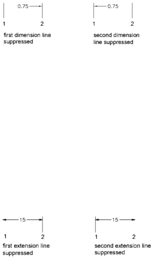
Extension Lines
Controls the appearance of the extension lines.
Color
Sets the color for the extension line. If you click Select Color (at the bottom
of the Color list), the Select Color dialog box is displayed. You can also enter
a color name or number. (DIMCLRE system variable.)
Linetype Ext Line 1
Sets the linetype of the first extension line. (DIMLTEX1 system variable)
Linetype Ext Line 2
Sets the linetype of the second extension line. (DIMLTEX2 system variable)
Lineweight
Sets the lineweight of the extension line. (DIMLWE system variable)
Suppress
Suppresses the display of extension lines. Ext Line 1 suppresses the first
extension line; Ext Line 2 suppresses the second extension line. (DIMSE1 and
DIMSE2 system variables)
Extend Beyond Dim Lines
Specifies a distance to extend the extension lines above the dimension line.
(DIMEXE system variable)
New, Modify, and Override Dimension Style Dialog Boxes | 369
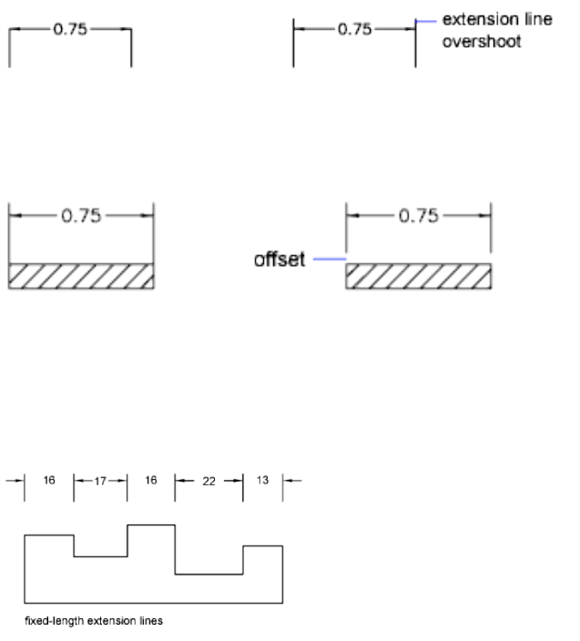
Offset From Origin
Sets the distance to offset the extension lines from the points on the drawing
that define the dimension. (DIMEXO system variable)
Fixed Length Extension Lines
Enables fixed length extension lines. (DIMFXLON system variable)
Length
Sets the total length of the extension lines starting from the dimension line
toward the dimension origin. (DIMFXL system variable)
Preview
Displays sample dimension images that show the effects of changes you make
to dimension style settings.
370 | Chapter 5 D Commands
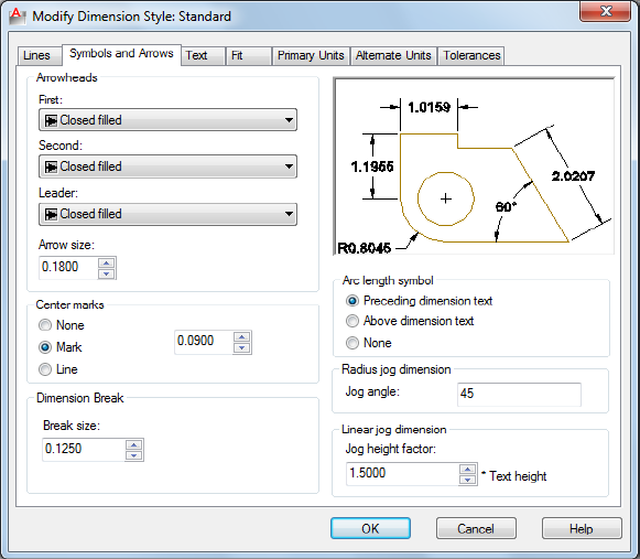
Symbols and Arrows Tab
Quick Reference
See also:
■Use Dimension Styles
Sets the format and placement for arrowheads, center marks, arc length
symbols, and jogged radius dimensions.
Summary
Controls the appearance of the dimension arrowheads.
List of Options
The following options are displayed.
Arrowheads
First
New, Modify, and Override Dimension Style Dialog Boxes | 371

Sets the arrowhead for the first dimension line. When you change the first
arrowhead type, the second arrowhead automatically changes to match it.
(DIMBLK1 system variable)
To specify a user-defined arrowhead block, select User Arrow. The Select
Custom Arrow Block dialog box is displayed. Select the name of a user-defined
arrowhead block. (The block must be in the drawing.)
Second
Sets the arrowhead for the second dimension line. (DIMBLK2 system variable)
To specify a user-defined arrowhead block, select User Arrow. The Select
Custom Arrow Block dialog box is displayed. Select the name of a user-defined
arrowhead block. (The block must be in the drawing.)
Leader
Sets the arrowhead for the leader line. (DIMLDRBLK system variable)
To specify a user-defined arrowhead block, select User Arrow. The Select
Custom Arrow Block dialog box is displayed. Select the name of a user-defined
arrowhead block. (The block must be in the drawing.)
Arrow Size
Displays and sets the size of arrowheads. (DIMASZ system variable)
NOTE blocks cannot be used as custom arrowheads for dimensions or leaders.
Center Marks
Controls the appearance of center marks and centerlines for diameter and
radial dimensions. The DIMCENTER, DIMDIAMETER, and DIMRADIUS
commands use center marks and centerlines. For DIMDIAMETER and
DIMRADIUS, the center mark is drawn only if you place the dimension line
outside the circle or arc.
Type
Sets the type of center mark or line to use.
None
Creates no center mark or centerline. The value is stored as 0 in the DIMCEN
system variable.
Mark
Creates a center mark. The size of the center mark is stored as a positive value
in the DIMCEN system variable.
372 | Chapter 5 D Commands
Line
Creates a centerline. The size of the centerline is stored as a negative value in
the DIMCEN system variable.
Size
Displays and sets the size of the center mark or centerline. (DIMCEN system
variable)
Dimension Break
Controls the gap width of dimension breaks.
Break Size
Displays and sets the size of the gap used for dimension breaks.
Arc Length Symbol
Controls the display of the arc symbol in an arc length dimension.
(DIMARCSYM system variable)
Preceding Dimension Text
Places arc length symbols before the dimension text. (DIMARCSYM system
variable)
Above Dimension Text
Places arc length symbols above the dimension text. (DIMARCSYM system
variable)
None
Suppresses the display of arc length symbols. (DIMARCSYM system variable)
Radius Jog Dimension
Controls the display of jogged (zigzag) radius dimensions.
Jogged radius dimensions are often created when the center point of a circle
or arc is located off the page.
New, Modify, and Override Dimension Style Dialog Boxes | 373

Jog Angle
Determines the angle of the transverse segment of the dimension line in a
jogged radius dimension. (DIMJOGANG system variable)
Linear Jog Dimension
Controls the display of the jog for linear dimensions.
Jog lines are often added to linear dimensions when the actual measurement
is not accurately represent by the dimension. Typically the actual measurement
is smaller than the desired value.
Jog Height Factor
Determines the height of the of the jog, which is determined by the distance
between the two vertices of the angles that make up the jog.
Preview
Displays sample dimension images that show the effects of changes you make
to dimension style settings.
374 | Chapter 5 D Commands

Text Tab
Quick Reference
See also:
■Use Dimension Styles
Sets the format, placement, and alignment of dimension text.
List of Options
The following options are displayed.
Text Appearance
Controls the dimension text format and size.
Text Style
Lists the available text styles.
New, Modify, and Override Dimension Style Dialog Boxes | 375
Text Style Button
Displays the Text Style Dialog Box on page 1181 where you can create or modify
text styles. (DIMTXSTY system variable)
Text Color
Sets the color for the dimension text. If you click Select Color (at the bottom
of the Color list), the Select Color dialog box is displayed. You can also enter
color name or number. (DIMCLRT system variable)
Fill Color
Sets the color for the text background in dimensions. If you click Select Color
(at the bottom of the Color list), the Select Color dialog box is displayed. You
can also enter color name or number. (DIMTFILL and DIMTFILLCLR system
variables)
Text Height
Sets the height of the current dimension text style. Enter a value in the text
box. If a fixed text height is set in the Text Style (that is, the text style height
is greater than 0), that height overrides the text height set here. If you want
to use the height set on the Text tab, make sure the text height in the Text
Style is set to 0. (DIMTXT system variable)
Fraction Height Scale
Sets the scale of fractions relative to dimension text. This option is available
only when Fractional is selected as the Unit Format on the Primary Units tab.
The value entered here is multiplied by the text height to determine the height
of dimension fractions relative to dimension text. (DIMTFAC system variable)
Draw Frame Around Text
When selected, draws a frame around dimension text. Selecting this option
changes the value stored in the DIMGAP system variable to a negative value.
Text Placement
Controls the placement of dimension text.
Vertical
Controls the vertical placement of dimension text in relation to the dimension
line. (DIMTAD system variable)
Vertical position options include the following:
■Centered: Centers the dimension text between the two parts of the
dimension line.
376 | Chapter 5 D Commands
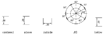
■Above: Places the dimension text above the dimension line. The distance
from the dimension line to the baseline of the lowest line of text is the
current text gap. See the Offset from Dim Line option.
■Outside: Places the dimension text on the side of the dimension line farthest
away from the first defining point.
■JIS: Places the dimension text to conform to a Japanese Industrial Standards
(JIS) representation.
■Below: Places the dimension text under the dimension line. The distance
from the dimension line to the baseline of the lowest line of text is the
current text gap. See the Offset from Dim Line option.
Horizontal
Controls the horizontal placement of dimension text along the dimension
line, in relation to the extension lines. (DIMJUST system variable)
Horizontal position options include the following:
■Centered: Centers the dimension text along the dimension line between
the extension lines.
■At Ext Line 1: Left-justifies the text with the first extension line along the
dimension line. The distance between the extension line and the text is
twice the arrowhead size plus the text gap value. See Arrowheads and Offset
from Dim Line.
■At Ext Line 2: Right-justifies the text with the second extension line along
the dimension line. The distance between the extension line and the text
is twice the arrowhead size plus the text gap value. See Arrowheads and
Offset from Dim Line.
New, Modify, and Override Dimension Style Dialog Boxes | 377

■Over Ext Line 1: Positions the text over or along the first extension line.
■Over Ext Line 2: Positions the text over or along the second extension line.
View Direction
Controls the dimension text viewing direction. (DIMTXTDIRECTION system
variable)
View Direction includes the following options:
■Left-to-Right: Places the text to enable reading from left to right.
■Right-to-Left: Places the text to enable reading from right to left.
Offset from Dim Line
Sets the current text gap, which is the distance around the dimension text
when the dimension line is broken to accommodate the dimension text.
This value is also used as the minimum length required for dimension line
segments.
Text is positioned inside the extension lines only if the resulting segments are
at least as long as the text gap. Text above or below the dimension line is
placed inside only if the arrowheads, dimension text, and a margin leave
enough room for the text gap. (DIMGAP system variable)
378 | Chapter 5 D Commands
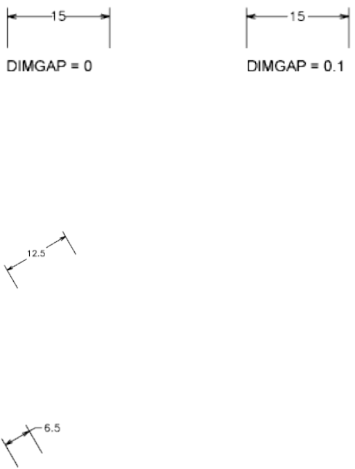
Text Alignment
Controls the orientation (horizontal or aligned) of dimension text whether it
is inside or outside the extension lines. (DIMTIH and DIMTOH system
variables)
Horizontal
Places text in a horizontal position.
Aligned with Dimension Line
Aligns text with the dimension line.
ISO Standard
Aligns text with the dimension line when text is inside the extension lines,
but aligns it horizontally when text is outside the extension lines.
Preview
Displays sample dimension images that show the effects of changes you make
to dimension style settings.
New, Modify, and Override Dimension Style Dialog Boxes | 379
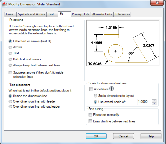
Fit Tab
Quick Reference
See also:
■Use Dimension Styles
Controls the placement of dimension text, arrowheads, leader lines, and the
dimension line.
List of Options
The following options are displayed.
Fit Options
Controls the placement of text and arrowheads based on the space available
between the extension lines.
380 | Chapter 5 D Commands
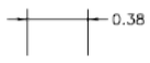
When space is available, text and arrowheads are placed between the extension
lines. Otherwise, text and arrowheads are placed according to the Fit options.
(DIMATFIT, DIMTIX, and DIMSOXD system variables)
Either Text or Arrows (Best Fit)
Moves either the text or the arrowheads outside the extension lines based on
the best fit (DIMATFIT system variable).
■When enough space is available for text and arrowheads, places both
between the extension lines. Otherwise, either the text or the arrowheads
are moved based on the best fit.
■When enough space is available for text only, places text between the
extension lines and places arrowheads outside the extension lines.
■When enough space is available for arrowheads only, places them between
the extension lines and places text outside the extension lines.
■When space is available for neither text nor arrowheads, places them both
outside the extension lines.
Arrows
Moves arrowheads outside the extension lines first, then text (DIMATFIT
system variable).
■When enough space is available for text and arrowheads, places both
between the extension lines.
■When space is available for arrowheads only, places them between the
extension lines and places text outside them.
■When not enough space is available for arrowheads, places both text and
arrowheads outside the extension lines.
Text
Moves text outside the extension lines first, then arrowheads (DIMATFIT
system variable).
■When space is available for text and arrowheads, places both between the
extension lines.
New, Modify, and Override Dimension Style Dialog Boxes | 381
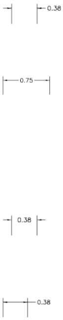
■When space is available for text only, places the text between the extension
lines and places arrowheads outside them.
■When not enough space is available for text, places both text and
arrowheads outside the extension lines.
Both Text and Arrows
When not enough space is available for text and arrowheads, moves both
outside the extension lines (DIMATFIT system variable).
Always Keep Text Between Ext Lines
Always places text between extension lines. (DIMTIX system variable)
Suppress Arrows If They Don't Fit Inside Extension Lines
Suppresses arrowheads if not enough space is available inside the extension
lines. (DIMSOXD system variable)
Text Placement
Sets the placement of dimension text when it is moved from the default
position, that is, the position defined by the dimension style. (DIMTMOVE
system variable)
Beside the Dimension Line
If selected, moves the dimension line whenever dimension text is moved.
(DIMTMOVE system variable)
Over the Dimension Line, with Leader
If selected, dimension lines are not moved when text is moved. If text is moved
away from the dimension line, a leader line is created connecting the text to
382 | Chapter 5 D Commands
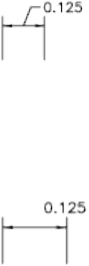
the dimension line. The leader line is omitted when text is too close to the
dimension line. (DIMTMOVE system variable)
Over the Dimension Line, Without Leader
If selected, dimension lines are not moved when text is moved. Text that is
moved away from the dimension line is not connected to the dimension line
with a leader. (DIMTMOVE system variable)
Scale for Dimension Features
Sets the overall dimension scale value or the paper space scaling.
Annotative
Specifies that the dimension is . Click the information icon to learn more
about annotative objects.
Scale Dimensions To Layout
Determines a scale factor based on the scaling between the current model
space viewport and paper space. (DIMSCALE system variable)
When you work in paper space, but not in a model space viewport, or when
TILEMODE is set to 1, the default scale factor of 1.0 is used or the DIMSCALE
system variable.
Use Overall Scale Of
Sets a scale for all dimension style settings that specify size, distance, or spacing,
including text and arrowhead sizes. This scale does not change dimension
measurement values. (DIMSCALE system variable)
Fine Tuning
Provides additional options for placing dimension text.
Place Text Manually
Ignores any horizontal justification settings and places the text at the position
you specify at the Dimension Line Location prompt. (DIMUPT system variable)
Draw Dim Line Between Ext Lines
New, Modify, and Override Dimension Style Dialog Boxes | 383
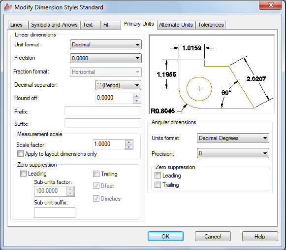
Draws dimension lines between the measured points even when the
arrowheads are placed outside the measured points. (DIMTOFL system variable)
Preview
Displays sample dimension images that show the effects of changes you make
to dimension style settings.
Primary Units Tab
Quick Reference
See also:
■Use Dimension Styles
Sets the format and precision of primary dimension units and sets prefixes
and suffixes for dimension text.
384 | Chapter 5 D Commands
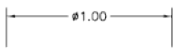
List of Options
The following options are displayed.
Linear Dimensions
Sets the format and precision for linear dimensions.
Unit Format
Sets the current units format for all dimension types except Angular.
(DIMLUNIT system variable)
The relative sizes of numbers in stacked fractions are based on the DIMTFAC
system variable (in the same way that tolerance values use this system variable).
Precision
Displays and sets the number of decimal places in the dimension text.
(DIMDEC system variable)
Fraction Format
Sets the format for fractions. (DIMFRAC system variable)
Decimal Separator
Sets the separator for decimal formats. (DIMDSEP system variable)
Round Off
Sets rounding rules for dimension measurements for all dimension types
except Angular. If you enter a value of 0.25, all distances are rounded to the
nearest 0.25 unit. If you enter a value of 1.0, all dimension distances are
rounded to the nearest integer. The number of digits displayed after the decimal
point depends on the Precision setting. (DIMRND system variable)
Prefix
Includes a prefix in the dimension text. You can enter text or use control
codes to display special symbols. For example, entering the control code %%c
displays the diameter symbol. When you enter a prefix, it overrides any default
prefixes such as those used in diameter and radius dimensioning. (DIMPOST
system variable)
If you specify tolerances, the prefix is added to the tolerances as well as to the
main dimension.
New, Modify, and Override Dimension Style Dialog Boxes | 385
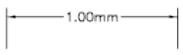
For more information, see Control Codes and Special Characters on page 1235.
Suffix
Includes a suffix in the dimension text. You can enter text or use control codes
to display special symbols. For example, entering the text mm results in
dimension text similar to that shown in the illustration. When you enter a
suffix, it overrides any default suffixes. (DIMPOST system variable)
If you specify tolerances, the suffix is added to the tolerances as well as to the
main dimension.
For more information, see Control Codes and Special Characters on page 1235.
Measurement Scale
Defines linear scale options. Applies primarily to legacy drawings.
Scale Factor
Sets a scale factor for linear dimension measurements. It is recommended that
you do not change this value from the default value of 1.00. For example, if
you enter 2, the dimension for a 1-inch line is displayed as two inches. The
value does not apply to angular dimensions and is not applied to rounding
values or to plus or minus tolerance values. (DIMLFAC system variable)
Apply to Layout Dimensions Only
Applies the measurement scale factor only to dimensions created in layout
viewports. Except when using nonassociative dimensions, this setting should
remain unchecked. (DIMLFAC system variable)
Zero Suppression
Controls the suppression of leading and trailing zeros and of feet and inches
that have a value of zero. (DIMZIN system variable)
Leading
Suppresses leading zeros in all decimal dimensions. For example, 0.5000
becomes .5000. Select leading to enable display of dimension distances less
than one unit in sub units.
Sub-units factor
386 | Chapter 5 D Commands
Sets the number of sub units to a unit. It is used to calculate the dimension
distance in a sub unit when the distance is less than one unit. For example,
enter 100 if the suffix is m and the sub-unit suffix is to display in cm.
Sub-unit suffix
Includes a suffix to the dimension value sub unit. You can enter text or use
control codes to display special symbols. For example, enter cm for .96m to
display as 96cm.
Trailing
Suppresses trailing zeros in all decimal dimensions. For example, 12.5000
becomes 12.5, and 30.0000 becomes 30.
0 Feet
Suppresses the feet portion of a feet-and-inches dimension when the distance
is less than one foot. For example, 0'-6 1/2" becomes 6 1/2".
0 Inches
Suppresses the inches portion of a feet-and-inches dimension when the
distance is an integral number of feet. For example, 1'-0" becomes 1'.
Angular Dimensions
Displays and sets the current angle format for angular dimensions.
Units Format
Sets the angular units format. (DIMAUNIT system variable)
Precision
Sets the number of decimal places for angular dimensions. DIMADEC system
variable)
Zero Suppression
Controls the suppression of leading and trailing zeros. (DIMAZIN system
variable)
Leading
Suppresses leading zeros in angular decimal dimensions. For example, 0.5000
becomes .5000.
You can also display dimension distances less than one unit in sub units.
Trailing
New, Modify, and Override Dimension Style Dialog Boxes | 387
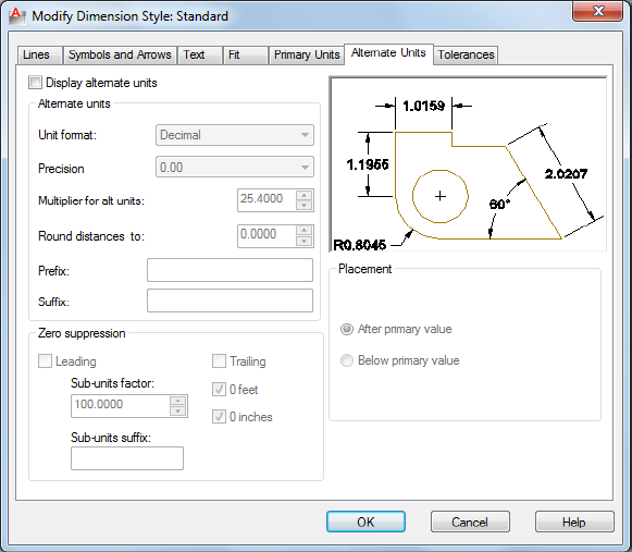
Suppresses trailing zeros in angular decimal dimensions. For example, 12.5000
becomes 12.5, and 30.0000 becomes 30.
Preview
Displays sample dimension images that show the effects of changes you make
to dimension style settings.
Alternate Units Tab
Quick Reference
See also:
■Use Dimension Styles
Specifies display of alternate units in dimension measurements and sets their
format and precision.
388 | Chapter 5 D Commands
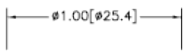
List of Options
The following options are displayed.
Display Alternate Units
Adds alternate measurement units to dimension text. Sets the DIMALT system
variable to 1.
Alternate Units
Displays and sets the current alternate units format for all dimension types
except Angular.
Unit Format
Sets the unit format for alternate units. (DIMALTU system variable)
The relative sizes of numbers in stacked fractions are based on DIMTFAC (in
the same way that tolerance values use this system variable).
Precision
Sets the number of decimal places for alternate units. (DIMALTD system
variable)
Multiplier for Alt Units
Specifies the multiplier used as the conversion factor between primary and
alternate units. For example, to convert inches to millimeters, enter 25.4. The
value has no effect on angular dimensions, and it is not applied to the rounding
value or the plus or minus tolerance values. (DIMALTF system variable)
Round Distances To
Sets rounding rules for alternate units for all dimension types except Angular.
If you enter a value of 0.25, all alternate measurements are rounded to the
nearest 0.25 unit. If you enter a value of 1.0, all dimension measurements are
rounded to the nearest integer. The number of digits displayed after the decimal
point depends on the Precision setting. (DIMALTRND system variable)
Prefix
Includes a prefix in the alternate dimension text. You can enter text or use
control codes to display special symbols. For example, entering the control
code %%c displays the diameter symbol. (DIMAPOST system variable)
For more information, see Control Codes and Special Characters on page 1235.
New, Modify, and Override Dimension Style Dialog Boxes | 389

Suffix
Includes a suffix in the alternate dimension text. You can enter text or use
control codes to display special symbols. For example, entering the text cm
results in dimension text similar to that shown in the illustration. When you
enter a suffix, it overrides any default suffixes. (DIMAPOST system variable)
For more information, see Control Codes and Special Characters on page 1235.
Zero Suppression
Controls the suppression of leading and trailing zeros and of feet and inches
that have a value of zero. (DIMALTZ system variable)
Leading
Suppresses leading zeros in all decimal dimensions. For example, 0.5000
becomes .5000.
Sub-units factor
Sets the number of sub units to a unit. It is used to calculate the dimension
distance in a sub unit when the distance is less than one unit. For example,
enter 100 if the suffix is m and the sub-unit suffix is to display in cm.
Sub-unit suffix
Includes a suffix to the dimension value sub unit. You can enter text or use
control codes to display special symbols. For example, enter cm for .96m to
display as 96cm.
Trailing
Suppresses trailing zeros in all decimal dimensions. For example, 12.5000
becomes 12.5, and 30.0000 becomes 30.
0 Feet
Suppresses the feet portion of a feet-and-inches dimension when the distance
is less than 1 foot. For example, 0'-6 1/2" becomes 6 1/2".
0 Inches
Suppresses the inches portion of a feet-and-inches dimension when the
distance is an integral number of feet. For example, 1'-0" becomes 1'.
390 | Chapter 5 D Commands
Placement
Controls the placement of alternate units in dimension text.
After Primary Value
Places alternate units after the primary units in dimension text.
Below Primary Value
Places alternate units below the primary units in dimension text.
Preview
Displays sample dimension images that show the effects of changes you make
to dimension style settings.
Tolerances Tab
Quick Reference
See also:
■Use Dimension Styles
Specifies the display and format of dimension text tolerances.
New, Modify, and Override Dimension Style Dialog Boxes | 391
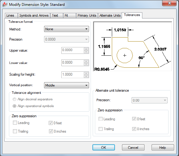
List of Options
The following options are displayed.
Tolerance Format
Controls the tolerance format.
Method
Sets the method for calculating the tolerance. (DIMTOL system variable)
■None: Does not add a tolerance. The DIMTOL system variable is set to 0.
■Symmetrical: Adds a plus/minus expression of tolerance in which a single
value of variation is applied to the dimension measurement. A
plus-or-minus sign appears after the dimension. Enter the tolerance value
in Upper Value. The DIMTOL system variable is set to 1. The DIMLIM
system variable is set to 0.
392 | Chapter 5 D Commands
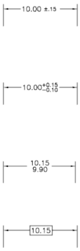
■Deviation: Adds a plus/minus tolerance expression. Different plus and minus
values of variation are applied to the dimension measurement. A plus sign
(+) precedes the tolerance value entered in Upper Value, and a minus sign
(-) precedes the tolerance value entered in Lower Value. The DIMTOL
system variable is set to 1. The DIMLIM system variable is set to 0.
■Limits: Creates a limit dimension. A maximum and a minimum value are
displayed, one over the other. The maximum value is the dimension value
plus the value entered in Upper Value. The minimum value is the
dimension value minus the value entered in Lower Value. The DIMTOL
system variable is set to 0. TheDIMLIM system variable is set to 1.
■Basic: Creates a basic dimension, which displays a box around the full
extents of the dimension. The distance between the text and the box is
stored as a negative value in the DIMGAP system variable.
Precision
Sets the number of decimal places. (DIMTDEC system variable)
Upper Value
New, Modify, and Override Dimension Style Dialog Boxes | 393
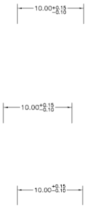
Sets the maximum or upper tolerance value. When you select Symmetrical in
Method, this value is used for the tolerance. (DIMTP system variable)
Lower Value
Sets the minimum or lower tolerance value. (DIMTM system variable)
Scaling for Height
Sets the current height for the tolerance text. The ratio of the tolerance height
to the main dimension text height is calculated and stored in the DIMTFAC
system variable.
Vertical Position
Controls text justification for symmetrical and deviation tolerances.
■Top: Aligns the tolerance text with the top of the main dimension text.
When you select this option, the DIMTOLJ system variable is set to 2.
■Middle: Aligns the tolerance text with the middle of the main dimension
text. When you select this option, the DIMTOLJ system variable is set to
1.
■Bottom: Aligns the tolerance text with the bottom of the main dimension
text. When you select this option, the DIMTOLJ system variable is set to
0.
Tolerance Alignment
Controls the alignment of upper and lower tolerance values when stacked
Align Decimal Separators
Values are stacked by their decimal separators.
Align Operational Symbols
394 | Chapter 5 D Commands
Values are stacked by their operational symbols.
Zero Suppression
Controls the suppression of leading and trailing zeros and of feet and inches
that have a value of zero. (DIMTZIN system variable)
Leading
Suppresses leading zeros in all decimal dimensions. For example, 0.5000
becomes .5000.
Trailing
Suppresses trailing zeros in all decimal dimensions. For example, 12.5000
becomes 12.5, and 30.0000 becomes 30.
0 Feet
Suppresses the feet portion of a feet-and-inches dimension when the distance
is less than 1 foot. For example, 0'-6 1/2" becomes 6 1/2".
0 Inches
Suppresses the inches portion of a feet-and-inches dimension when the
distance is an integral number of feet. For example, 1'-0" becomes 1'.
Alternate Unit Tolerance
Formats alternate tolerance units.
Precision
Displays and sets the number of decimal places. (DIMALTTD system variable)
Zero Suppression
Controls the suppression of leading and trailing zeros and of feet and inches
that have a value of zero. (DIMALTTZ system variable)
Leading
Suppresses leading zeros in all decimal dimensions. For example, 0.5000
becomes .5000.
Trailing
Suppresses trailing zeros in all decimal dimensions. For example, 12.5000
becomes 12.5, and 30.0000 becomes 30.
0 Feet
New, Modify, and Override Dimension Style Dialog Boxes | 395
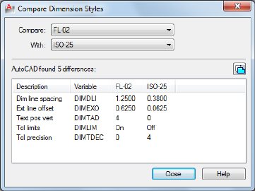
Suppresses the feet portion of a feet-and-inches dimension when the distance
is less than 1 foot. For example, 0'-6 1/2" becomes 6 1/2".
0 Inches
Suppresses the inches portion of a feet-and-inches dimension when the
distance is an integral number of feet. For example, 1'-0" becomes 1'.
Preview
Displays sample dimension images that show the effects of changes you make
to dimension style settings.
Compare Dimension Styles Dialog Box
Quick Reference
See also:
■Use Dimension Styles
Compares the properties of two dimension styles or displays all properties of
one style.
Summary
You can output the results of the comparison to the Clipboard, and then paste
to other applications.
396 | Chapter 5 D Commands
List of Options
The following options are displayed.
Compare
Specifies the first dimension style for the comparison.
With
Specifies the second dimension style for the comparison. If you set the second
style to <none> or to the same style as the first, all the properties of the
dimension style are displayed.
Comparison results are displayed automatically under the following headings:
■Description of the dimension style property
■System variable that controls the property
■System variable values of style properties that differ for each dimension
style
Results
Displays the results of the dimension style comparison. If you compare two
different styles, the properties that differ are displayed. If you set the second
style to <none> or to the same style as the first, all the properties of the
dimension style are displayed.
Copy to Clipboard button
Copies the results of the comparison to the Clipboard. You can then paste the
results to other applications, such as word processors and spreadsheets.
-DIMSTYLE
Quick Reference
See also:
■Use Dimension Styles
Creates and modifies dimension styles.
-DIMSTYLE | 397
Summary
You can save or restore dimensioning system variables to a selected dimension
style.
List of Prompts
The following prompts are displayed.
Current dimension style: <current> Annotative: <current>
Enter a dimension style option
[ANnotative on page 398/Save on page 398/Restore on page 398/STatus on page
399/Variables on page 399/Apply on page 399/? on page 399] <Restore>: Enter an
option or press Enter
Annotative
Creates an dimension style.
Save
Saves the current settings of dimensioning system variables to a dimension
style.
Name Saves the current settings of dimensioning system variables to a new
dimension style using the name you enter. The new dimension style becomes
the current one.
If you enter the name of an existing dimension style, the following prompts
are displayed:
That name is already in use, redefine it? <N>: Enter y or press Enter
If you enter y, associative dimensions that use the redefined dimension style
are regenerated.
To display the differences between the dimension style name you want to
save and the current style, enter a tilde (~) followed by the style name at the
Enter Name for New Dimension Style prompt. Only settings that differ are
displayed, with the current setting in the first column, and the setting of the
compared style in the second column.
?—List Dimension Styles Lists the named dimension styles in the current
drawing.
Restore
Restores dimensioning system variable settings to those of a selected dimension
style.
Name Makes the dimension style you enter the current dimension style.
To display the differences between the dimension style name you want to
restore and the current style, enter a tilde (~) followed by the style name at
the Enter Dimension Style Name prompt. Only settings that differ are
398 | Chapter 5 D Commands
displayed, with the current setting in the first column, and the setting of the
compared style in the second column. After the differences are displayed, the
previous prompt returns.
?—List Dimension Styles Lists the named dimension styles in the current
drawing.
Select Dimension Makes the dimension style of the selected object the current
dimension style.
Status
Displays the current values of all dimension system variables.
Variables
Lists the dimension system variable settings of a dimension style or selected
dimensions without modifying the current settings.
Name Lists the settings of dimension system variables for the dimension style
name you enter.
To display the differences between a particular dimension style and the current
style, enter a tilde (~) followed by the style name at the Enter Dimension Style
Name prompt. Only settings that differ are displayed, with the current setting
in the first column, and the setting of the compared style in the second
column.
?—List Dimension Styles Lists the named dimension styles in the current
drawing.
Select Dimension Lists the dimension style and any dimension overrides for
the dimension object you select.
Apply
Applies the current dimensioning system variable settings to selected
dimension objects, permanently overriding any existing dimension styles
applied to these objects.
The dimension line spacing between existing baseline dimensions is not
updated (see the DIMDLI system variable); dimension text variable settings
do not update existing leader text.
?—List Dimension Styles
Lists the named dimension styles in the current drawing.
-DIMSTYLE | 399
DIMTEDIT
Quick Reference
See also:
■Modify Dimension Text
Moves and rotates dimension text and relocates the dimension line.
Access Methods
Button
Ribbon: Annotate tab ➤ Dimensions panel ➤ Text Angle
Menu: Dimension ➤ Align Text ➤ Angle
Toolbar: Dimension
Summary
The companion command that edits the dimension text and changes the
extension line angle is DIMEDIT.
List of Prompts
The following prompts are displayed.
Select dimension: Select a dimension object
You are prompted for the new location of the dimension text.
Specify new location for dimension text or [Left/Right/Center/Home/Angle]:
Specify a point or enter an option
Location for Dimension Text Updates the location of the dimension text
dynamically as you drag it. To determine whether text appears above, below,
or in the middle of the dimension line, use the Text tab in the New, Modify,
and Override Dimension Style dialog box.
Left Left-justifies the dimension text along the dimension line.
This option works only with linear, radius, and diameter dimensions.
400 | Chapter 5 D Commands
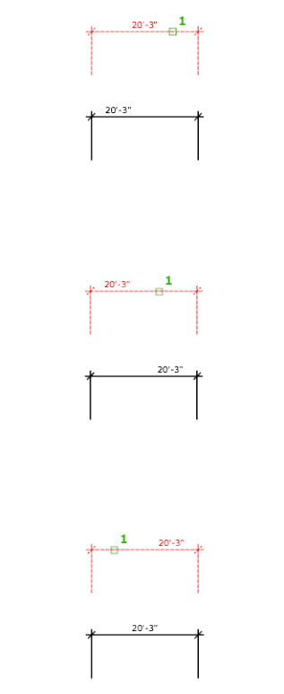
Right Right-justifies the dimension text along the dimension line.
This option works only with linear, radius, and diameter dimensions.
Center Centers the dimension text on the dimension line.
This option works only with linear, radius, and diameter dimensions.
Home Moves the dimension text back to its default position.
For example:
DIMTEDIT | 401
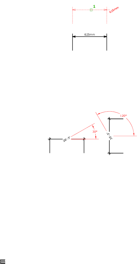
Angle Changes the angle of the dimension text.
The center point of the text does not change. If the text moves or the
dimension is regenerated, the orientation set by the text angle is retained.
Entering an angle of 0 degrees puts the text in its default orientation.
The text angle is measured from the X axis of the UCS.
DIST
Quick Reference
See also:
■Obtain Distances, Angles, and Point Locations
Measures the distance and angle between two points.
Access Method
Command entry: 'dist for transparent use
402 | Chapter 5 D Commands
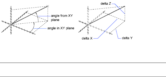
Summary
In general, the DIST command reports 3D distances in model space and 2D
distances on a layout in paper space.
In model space, changes in X, Y, and Z component distances and angles are
measured in 3D relative to the current UCS.
In paper space, distances are normally reported in 2D paper space units.
However, when using object snaps on model space objects that are displayed
in a single viewport, distances are reported as 2D model space distances
projected onto a plane parallel to your screen.
List of Prompts
The following prompts are displayed.
Specify first point: Specify a point
Specify second point or <Multiple points>: Specify a second point
The distance is displayed in the current units format.
DIST assumes the current elevation for the first or second point if you omit
the Z coordinate value.
NOTE When using the DIST command for 3D distances, it is recommended that
you switch to model space.
Multiple Points If you specify multiple points, a running total of the distance
based on the existing line segments and the current rubberband line is
displayed in the tooltip. A dynamic dimension is also displayed. The distance
is updated as you move the cursor.
DIST | 403

DIVIDE
Quick Reference
See also:
■Divide an Object into Equal Segments
Creates evenly spaced point objects or blocks along the length or perimeter
of an object.
Access Methods
Button
Ribbon: Home tab ➤ Draw panel ➤ Divide
Menu: Draw ➤ Point ➤ Divide
List of Prompts
The following prompts are displayed.
Select object to divide: Use an object selection method
Enter number of segments on page 404 or [Block]: Enter a value from 2 through
32,767, or enter b
Number of Segments
Places point objects at equal intervals along the selected objects.
Use DDPTYPE on page 274 to set the style and size of all point objects in a
drawing.
404 | Chapter 5 D Commands
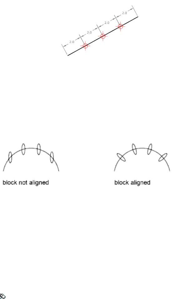
Block
Places blocks at equal intervals along the selected object. If the block has
variable attributes, these attributes are not included.
Yes Specifies that the X axes of the inserted blocks be tangent to, or collinear
with, the divided object at the dividing points.
No Aligns the blocks according to their normal orientation.
The illustration shows an arc divided into five equal parts using a block
consisting of a vertically oriented ellipse.
DLINE
Quick Reference
See also:
■Draw Double Lines
Creates a double line using straight line segments and arcs.
Access Method
Menu: Draw ➤ Double Line
DLINE | 405
List of Prompts
The following prompts are displayed.
Specify start point or [“Break”/“Caps”/“Dragline”/“Snap”/“Width”]: Specify a
point, enter an option, or press Enter
Break
Determines whether a double line breaks when it intersects another double
line, a single line, or an arc.
Caps
Specifies the placement of endcaps on a double line.
The specified ends are capped, whether or not they snap to an object.
Both Places endcaps on both the start point and endpoint of a double line.
End Places an endcap only on the endpoint of a double line.
None Places no endcaps on either the start point or the endpoint of a double
line.
Start Places endcaps only on the start point of a double line.
Auto Breaks an arc or line, including another double line, at the intersection.
Otherwise, places endcaps on both ends of the double line.
Dragline
Draws a double line by locating points centered on or offset from the double
line. You can also draw along the left and right legs of the double line.
A negative value offsets the double line to the left of the located points, the
rubber-band line. A positive number offsets the double line to the right of the
located points.
Snap
Starts or ends a double line by snapping to an existing object. When the Snap
option is on, the Break option determines whether to break the object at the
intersection of the double line.
The Size option specifies the size of a search area, in pixels. The double line
starts or terminates by snapping to the object it finds within the search area
and adjusts each of its legs to form a clean junction with the object. Selecting
the Size option displays the following prompt:
Width
Sets the width of a double line. The width is the perpendicular distance from
one leg of the double line to the other.
406 | Chapter 5 D Commands

DONUT
Quick Reference
See also:
■Draw Donuts
Creates a filled circle or a wide ring.
Access Methods
Button
Ribbon: Home tab ➤ Draw panel ➤ Donut
Menu: Draw ➤ Donut
Summary
A donut consists of two arc polylines that are joined end-to-end to create a
circular shape. The width of the polylines is determined by the specified inside
and outside diameters. To create solid-filled circles, specify an inside diameter
of zero.
List of Prompts
The following prompts are displayed.
Specify inside diameter of donut <current>: Specify a distance or press Enter
If you specify an inside diameter of 0, the donut is a filled circle.
Specify outside diameter of donut <current>: Specify a distance or press Enter
Specify center of donut or <exit>: Specify a point (1) or press Enter to end the
command
DONUT | 407
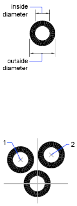
The location of the donut is set based on the center point. After you specify
the diameters, you are prompted for the locations at which to draw donuts.
A donut is drawn at each point specified (2). How the interior of a donut is
filled depends on the current setting of the FILL command.
DOWNLOADMANAGER
Quick Reference
See also:
■Browse Material Libraries
Reports the status of the of the current download.
Summary
If a download was previously interrupted, it provides an opportunity to
continue downloading. Currently, this command applies only to downloading
the Autodesk Medium Image Library.
List of Prompts
No prompts are displayed.
408 | Chapter 5 D Commands
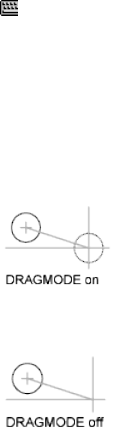
DRAGMODE
Quick Reference
See also:
■Set Up the Drawing Area
Controls the way dragged objects are displayed.
Access Method
Command entry: 'dragmode for transparent use
List of Prompts
The following prompts are displayed.
Enter new value [ON/OFF/Auto] <current>: Enter an option or press Enter
On Permits dragging, but you must enter drag where appropriate in a drawing
or editing command to initiate dragging.
Off Ignores all dragging requests, including those embedded in menu items.
Auto Turns on dragging for every command that supports it. Dragging is
performed whenever it is possible. Entering drag each time is not necessary.
DRAGMODE | 409
DRAWINGRECOVERY
Quick Reference
See also:
■Recover from a System Failure
Displays a list of drawing files that can be recovered after a program or system
failure.
Access Methods
Button
Menu: Application menu ➤ Drawing Utilities ➤ Open the Drawing
Recovery Manager
Menu: File ➤ Drawing Utilities ➤ Drawing Recovery
Summary
Opens the Drawing Recovery Manager.
Drawing Recovery Manager
Quick Reference
See also:
■Recover from a System Failure
Displays a list of all drawing files that were open at the time of a program or
system failure.
410 | Chapter 5 D Commands
Summary
You can preview and open each drawing or backup file to choose which one
should be saved as the primary DWG file.
List of Options
The following options are displayed.
Backup Files
Displays the drawings that may need to be recovered after a program or system
failure. A top-level drawing node contains a set of files associated with each
drawing. If available, up to four files are displayed including
■The recovered drawing file saved at the time of a program failure (DWG,
DWS)
■The automatic save file, also called the “autosave” file (SV$)
■The drawing backup file (BAK)
■The original drawing file (DWG, DWS)
Once a drawing or backup file is opened and saved, the corresponding top-level
drawing node is removed from the Backup Files area.
Details
Provides the following information about the currently selected node in the
Backup Files area:
■When a top-level drawing node is selected, information about each
available drawing or backup file associated with the original drawing is
displayed.
■When an individual drawing or backup file is selected, additional
information about that file is displayed.
Preview
Displays a thumbnail preview of the currently selected drawing or backup file.
Shortcut Menu Options
Right-click a drawing node, drawing or backup file, or a blank area in the
Backup Files area to display a shortcut menu with relevant options.
Open All Opens all the drawing and backup files associated with the selected,
top-level drawing node.
Remove Removes the selected, top-level drawing node.
Drawing Recovery Manager | 411
Open Opens the selected drawing or backup file for drawing recovery. You
can select multiple files using Shift and Ctrl.
Properties Displays the File Properties dialog box from Windows Explorer for
the selected drawing or backup file.
Expand All Expands all top-level drawing nodes. Access this option by
right-clicking a blank area in the Backup Files area.
Collapse All Collapses all top-level drawing nodes. Access this option by
right-clicking a blank area in the Backup Files area.
DRAWINGRECOVERYHIDE
Quick Reference
See also:
■Recover from a System Failure
Closes the Drawing Recovery Manager.
Summary
Closes the Drawing Recovery Manager.
DRAWORDER
Quick Reference
See also:
■Control How Overlapping Objects Are Displayed
Changes the draw order of images and other objects.
412 | Chapter 5 D Commands
Access Methods
Button
Ribbon: Home tab ➤ Modify panel ➤ Bring to Front
Menu: Tools ➤ Draw Order ➤ Bring to Front
Toolbar: Draw Order
Shortcut menu: Select an object, right-click, and then click Draw Order.
Summary
Use the DRAWORDERCTL system variable to control the default display
behavior of overlapping objects. In addition, the TEXTTOFRONT command
brings all text and dimensions in a drawing in front of other objects, and the
HATCHTOBACK command sends all hatch objects behind other objects.
List of Prompts
The following prompts are displayed.
Select objects: Use an object selection method
Enter object ordering option [Above objects/Under objects/Front/Back] <Back>:
Enter an option or press Enter
Above Objects Moves the selected object above the specified reference objects.
Under Objects Moves the selected objects below the specified reference objects.
Front Moves the selected objects to the top of the order of objects in the
drawing.
Back Moves the selected objects to the bottom of the order of objects in the
drawing.
When you change the draw order (display and plotting order) of multiple
objects, the relative draw order of the selected objects is maintained.
By default, when you create new objects from existing ones (for example,
FILLET or PEDIT), the new objects are assigned the draw order of the original
object you selected first. By default, while you edit an object (for example,
MOVE or STRETCH), the object is displayed on top of all objects in the drawing.
When you are finished editing, your drawing is partially regenerated so that
the object is displayed according to its correct draw order. This can result in
DRAWORDER | 413

some edit operations taking slightly longer. You can use DRAWORDERCTL
to change the default draw order settings.
DSETTINGS
Quick Reference
See also:
■Use Precision Tools
Sets grid and snap, polar and object snap tracking, object snap modes, Dynamic
Input, and Quick Properties.
Access Methods
Menu: Tools ➤ Drafting Settings
Shortcut menu: Right-click Snap, Grid, Polar, Osnap, Otrack, Dyn or Quick
Properties on the status bar. Click Settings.
Summary
The Drafting Settings dialog box is displayed.
Drafting Settings Dialog Box
Quick Reference
See also:
■Use Precision Tools
Specifies drafting settings organized for drawing aids.
Summary
The following categories are available.
■Snap and Grid on page 415
■Polar Tracking on page 418
414 | Chapter 5 D Commands

■Object Snap on page 420
■Dynamic Input on page 424
■Quick Properties on page 426
■Selection Cycling on page 428
List of Options
The following options are displayed.
Snap and Grid Tab (Drafting Settings Dialog Box)
Specifies Snap and Grid settings.
Snap On
Turns Snap mode on or off. You can also turn Snap mode on or off by clicking
Snap on the status bar, by pressing F9, or by using the SNAPMODE system
variable.
Snap Spacing
Controls an invisible, rectangular grid of snap locations that restricts cursor
movement to specified X and Y intervals.
Snap X Spacing
Drafting Settings Dialog Box | 415
Specifies the snap spacing in the X direction. The value must be a positive real
number. (SNAPUNIT system variable)
Snap Y Spacing
Specifies the snap spacing in the Y direction. The value must be a positive real
number. (SNAPUNIT system variable)
Equal X and Y Spacing
Forces the X and Y spacing to the same values for snap spacing and for grid
spacing. The snap spacing intervals can be different from the grid spacing
intervals.
Polar Spacing
Controls the PolarSnap™ increment distance.
Polar Distance
Sets the snap increment distance when PolarSnap is selected under Snap Type
& Style. If this value is 0, the PolarSnap distance assumes the value for Snap
X Spacing. The Polar Distance setting is used in conjunction with polar tracking
and/or object snap tracking. If neither tracking feature is enabled, the Polar
Distance setting has no effect. (POLARDIST system variable)
Snap Type
Sets the snap style and snap type.
Grid Snap
Sets the snap type to Grid. When you specify points, the cursor snaps along
vertical or horizontal grid points. (SNAPTYPE system variable)
Rectangular Snap:
Sets the snap style to standard Rectangular snap mode. When the snap type
is set to Grid snap and Snap mode is on, the cursor snaps to a rectangular snap
grid. (SNAPSTYL system variable)
Isometric Snap
Sets the snap style to Isometric snap mode. When the snap type is set to Grid
snap and Snap mode is on, the cursor snaps to an isometric snap grid.
(SNAPSTYL system variable)
PolarSnap
Sets the snap type to Polar. When Snap mode is on and you specify points
with polar tracking turned on, the cursor snaps along polar alignment angles
416 | Chapter 5 D Commands

set on the Polar Tracking tab relative to the starting polar tracking point.
(SNAPTYPE system variable)
Grid On
Turns the grid on or off. You can also turn grid mode on or off by clicking
Grid on the status bar, by pressing F7, or by using the GRIDMODE on page
1522 system variable.
Grid Style
Sets the grid style in 2D contexts. You can also set grid style by using the
GRIDSTYLE on page 1522 system variable.
2D Model Space
Sets the grid style to dotted grid for 2D model space. (GRIDSTYLE on page 1522
system variable)
Block Editor
Sets the grid style to dotted grid for the Block Editor. (GRIDSTYLE on page
1522 system variable)
Sheet/Layout
Sets the grid style to dotted grid for sheet and layout. (GRIDSTYLE on page
1522 system variable)
Grid Spacing
Controls the display of a grid that helps you visualize distances.
NOTE The limits of the grid are controlled by the LIMITS command and the
GRIDDISPLAY system variable.
Grid X Spacing
Specifies the grid spacing in the X direction. If this value is 0, the grid assumes
the value set for Snap X Spacing. (GRIDUNIT system variable)
Grid Y Spacing
Specifies the grid spacing in the Y direction. If this value is 0, the grid assumes
the value set for Snap Y Spacing. (GRIDUNIT system variable)
Major Line Every
Specifies the frequency of major grid lines compared to minor grid lines. Grid
lines rather than grid dots are displayed when SHADEMODE is set to Hidden.
(GRIDMAJOR system variable)
Drafting Settings Dialog Box | 417
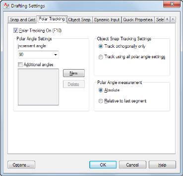
Grid Behavior
Controls the appearance of the grid lines that are displayed when SHADEMODE
is set to Hidden.
Adaptive Grid
Limits the density of the grid when zoomed out. (GRIDDISPLAY system
variable)
Allow Subdivision Below Grid Spacing:
Generates additional, more closely spaced grid lines when zoomed in. The
frequency of these grid lines is determined by the frequency of the major grid
lines. (GRIDDISPLAY and GRIDMAJOR system variables)
Display Grid Beyond Limits
Displays the grid beyond the area specified by the LIMITS command.
(GRIDDISPLAY system variable)
Polar Tracking Tab (Drafting Settings Dialog Box)
Controls the AutoTrack settings.
Polar Tracking On
Turns polar tracking on and off. You can also turn polar tracking on or off by
pressing F10 or by using the AUTOSNAP system variable.
Polar Angle Settings
Sets the alignment angles for polar tracking. (POLARANG system variable)
418 | Chapter 5 D Commands

Increment Angle
Sets the polar increment angle used to display polar tracking alignment paths.
You can enter any angle, or select a common angle of 90, 45, 30, 22.5, 18, 15,
10, or 5 degrees from the list. (POLARANG system variable)
Additional Angles
Makes any additional angles in the list available for polar tracking. The
Additional Angles check box is also controlled by the POLARMODE system
variable, and the list of additional angles is also controlled by the
POLARADDANG system variable.
NOTE Additional angles are absolute, not incremental.
List of Angles
If Additional Angles is selected, lists the additional angles that are available.
To add new angles, click New. To remove existing angles, click Delete.
(POLARADDANG system variable)
New
Adds up to 10 additional polar tracking alignment angles.
NOTE Before adding fractional angles, you must set the AUPREC system variable
to the appropriate decimal precision to avoid undesired rounding. For example,
if the value of AUPREC is 0 (the default value), all fractional angles you enter are
rounded to the nearest whole number.
Delete
Deletes selected additional angles.
Object Snap Tracking Settings
Sets options for object snap tracking.
Track Orthogonally Only
Displays only orthogonal (horizontal/vertical) object snap tracking paths for
acquired object snap points when object snap tracking is on. (POLARMODE
system variable)
Track Using All Polar Angle Settings
Applies polar tracking settings to object snap tracking. When you use object
snap tracking, the cursor tracks along polar alignment angles from acquired
object snap points. (POLARMODE system variable)
Drafting Settings Dialog Box | 419

NOTE Clicking Polar and Otrack on the status bar also turns polar tracking and
object snap tracking on and off.
Polar Angle Measurement
Sets the basis by which polar tracking alignment angles are measured.
Absolute
Bases polar tracking angles on the current user coordinate system (UCS).
Relative to Last Segment
Bases polar tracking angles on the last segment drawn.
Object Snap Tab (Drafting Settings Dialog Box)
Controls running object snap settings. With running object snap settings, also
called Osnap, you can specify a snap point at an exact location on an object.
When more than one option is selected, the selected snap modes are applied
to return a point closest to the center of the aperture box. Press TAB to cycle
through the options.
Object Snap On
Turns running object snaps on and off. The object snaps selected under Object
Snap Modes are active while object snap is on. (OSMODE system variable)
Object Snap Tracking On
Turns object snap tracking on and off. With object snap tracking, the cursor
can track along alignment paths based on other object snap points when
420 | Chapter 5 D Commands
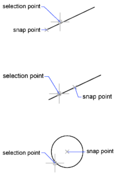
specifying points in a command. To use object snap tracking, you must turn
on one or more object snaps. (AUTOSNAP system variable)
Object Snap Modes
Lists object snaps that you can turn on as running object snaps.
Endpoint
Snaps to the closest endpoint of an arc, elliptical arc, line, polyline segment,
spline, region, or ray.
Midpoint
Snaps to the midpoint of an arc, ellipse, elliptical arc, line, polyline segment,
region, spline, or xline.
Center
Snaps to the center of an arc, circle, ellipse, or elliptical arc.
Node
Snaps to a point object, dimension definition point, or dimension text origin.
Drafting Settings Dialog Box | 421
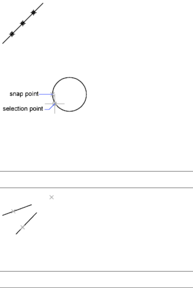
Quadrant
Snaps to a quadrant point of an arc, circle, ellipse, or elliptical arc.
Intersection
Snaps to the intersection of an arc, circle, ellipse, elliptical arc, line, polyline,
ray, region, spline, or xline. Extended Intersection is not available as a running
object snap.
Intersection and Extended Intersection do not work with edges or corners of
3D solids created in AutoCAD.
NOTE You might get varying results if you have both the Intersection and Apparent
Intersection running object snaps turned on at the same time.
Extension
Causes a temporary extension line or arc to be displayed when you pass the
cursor over the endpoint of objects, so you can specify points on the extension.
NOTE When working in perspective view, you cannot track along the extension
line of an arc or elliptical arc.
Insertion
422 | Chapter 5 D Commands
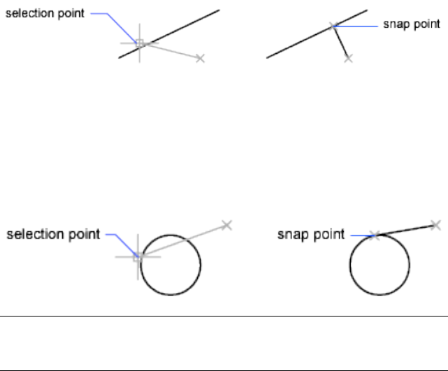
Snaps to the insertion point of an attribute, a block, or text.
Perpendicular
Snaps to a point perpendicular to an arc, circle, ellipse, elliptical arc, line,
polyline, ray, region, 2D solid, spline, or xline.
Deferred Perpendicular snap mode is automatically turned on when the object
you are drawing requires that you complete more than one perpendicular
snap. You can use a line, arc, circle, polyline, ray, or xline as an object from
which to draw a perpendicular line. You can use Deferred Perpendicular to
draw perpendicular lines between such objects. When the aperture box passes
over a Deferred Perpendicular snap point, an AutoSnap™ tooltip and marker
are displayed.
Tangent
Snaps to the tangent of an arc, circle, ellipse, elliptical arc, or spline. Deferred
Tangent snap mode is automatically turned on when the object you are
drawing requires that you complete more than one tangent snap. You can use
Deferred Tangent to draw a line or xline that is tangent to arcs, polyline arcs,
or circles. When the aperture box passes over a Deferred Tangent snap point,
a marker and an AutoSnap tooltip are displayed.
NOTE When you use the From option in conjunction with the Tangent snap mode
to draw objects other than lines from arcs or circles, the first point drawn is tangent
to the arc or circle in relation to the last point selected in the drawing area.
Nearest
Snaps to the nearest point on an arc, circle, ellipse, elliptical arc, line, point,
polyline, ray, spline, or xline.
Apparent Intersection
Drafting Settings Dialog Box | 423

Snaps to the visual intersection of two objects that do not intersect in 3D
space but may appear to intersect in the current view.
Extended Apparent Intersection snaps to the imaginary intersection of two
objects that would appear to intersect if the objects were extended along their
natural paths. Apparent and Extended Apparent Intersection do not work
with edges or corners of 3D solids created in AutoCAD.
NOTE You might get varying results if you have both the Intersection and Apparent
Intersection running object snaps turned on at the same time.
Parallel
Constrains a line segment, polyline segment, ray or xline to be parallel to
another linear object. After you specify the first point of a linear object, specify
the parallel object snap. Unlike other object snap modes, you move the cursor
and hover over another linear object until the angle is acquired. Then, move
the cursor back toward the object that you are creating. When the path of the
object is parallel to the previous linear object, an alignment path is displayed,
which you can use to create the parallel object.
NOTE Turn off ORTHO mode before using the parallel object snap. Object snap
tracking and polar snap are turned off automatically during a parallel object snap
operation. You must specify the first point of a linear object before using the parallel
object snap.
Select All
Turns on all object snap modes.
Clear All
Turns off all object snap modes.
Dynamic Input Tab (Drafting Settings Dialog Box)
Controls pointer input, dimension input, dynamic prompting, and the
appearance of drafting tooltips.
424 | Chapter 5 D Commands

Enable Pointer Input
Turns on pointer input. When pointer input and dimensional input are both
turned on, dimensional input supersedes pointer input when it is available.
(DYNMODE system variable)
Pointer Input
Displays the location of the crosshairs as coordinate values in a tooltip near
the cursor. When a command prompts you for a point, you can enter
coordinate values in the tooltip instead of in the Command window.
Preview Area
Shows an example of pointer input.
Settings
Displays the Pointer Input Settings dialog box.
Enable Dimension Input
Turns on dimensional input. Dimensional input is not available for some
commands that prompt for a second point. (DYNMODE system variable)
Dimension Input
Displays a dimension with tooltips for distance value and angle value when
a command prompts you for a second point or a distance. The values in the
Drafting Settings Dialog Box | 425
dimension tooltips change as you move the cursor. You can enter values in
the tooltip instead of on the command line.
Preview Area
Shows an example of dimensional input.
Settings
Displays the Dimension Input Settings dialog box.
Dynamic Prompts
Displays prompts in a tooltip near the cursor when necessary in order to
complete the command. You can enter values in the tooltip instead of on the
command line.
Preview Area
Shows an example of dynamic prompts.
Show Command Prompting and Command Input near the Crosshairs
Displays prompts in Dynamic Input tooltips. (DYNPROMPT system variable)
Show Additional Tips with Command Prompting
Controls whether tips for using Shift and Ctrl for grip manipulation are
displayed. (DYNINFOTIPS system variable)
Drafting Tooltip Appearance
Displays the Tooltip Appearance dialog box.
Quick Properties Tab (Drafting Settings Dialog Box)
Specifies the settings for displaying the Quick Properties palette.
426 | Chapter 5 D Commands
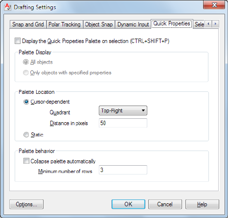
Enable Quick Properties Palette
Displays the Quick Properties palette when you select objects, depending on
the object type. (QPMODE on page 1632 system variable)
The PICKFIRST on page 1612 system variable must be turned on to display the
Quick Properties palette. Alternatively, you can enter the QUICKPROPERTIES
on page 1060 command to select objects.
Palette Display
Sets the display settings of the Quick Properties palette. See Quick Properties
for more information.
All Objects
Sets the Quick Properties palette to display for any selection of objects, not
just the object types specified in the Customize User Interface (CUI) editor to
display properties.
Only Objects with Specified Properties
Sets the Quick Properties palette to display only the object types that are
specified in the Customize User Interface (CUI) editor to display properties.
Palette Location
Controls where the Quick Properties palette is displayed.
Drafting Settings Dialog Box | 427
Cursor-Dependent
The Quick Properties palette displays in a location relative to the cursor.
(QPLOCATION on page 1631 system variable)
Quadrant:
Specifies which of four quadrants relative to the cursor to display the Quick
Properties palette relative to the cursor location. The default location is above
and to the right of the cursor.
Distance in Pixels:
Specifies the distance in pixels from the cursor to display the Quick Properties
palette. You can specify integer values from 0 to 400.
Static
Displays the Quick Properties palette in a fixed location. You can specify a
new location by dragging the palette. (QPLOCATION on page 1631 system
variable)
Palette Behavior
Sets the behavior of the Quick Properties palette.
Collapse Palette Automatically
The Quick Properties palette displays only the specified number of properties.
The palette expands when the cursor rolls over it.
Minimum Number of Rows:
Sets the number of properties that the Quick Properties palette displays when
it is collapsed. You can specify integer values from 1 to 30.
Selection Cycling Tab (Draft Settings Dialog Box)
Selection cycling allows you to select objects that are overlapping. You can
configure the display settings of the selection cycling list box. To filter the
type of subobjects displayed (vertices, edges, or faces) use the
SUBOBJSELECTIONMODEsystem variable.
428 | Chapter 5 D Commands

Allow Selection Cycling
You can also set this option with the SELECTIONCYCLING on page 1651 system
variable.
Display Selection Cycling List Box
Displays the Selection Cycling List box.
Cursor Dependent
Moves the list box relative to the cursor.
Quadrant
Specifies in which quadrant of the cursor to position the list box.
Distance in Pixels
Specifies the distance between the cursor and the list box.
Static
The list box does not move with the cursor and remains in the same position.
To change the position of the list box, click and drag.
Show Title Bar
To save screen space, turn the title bar off.
Drafting Settings Dialog Box | 429
Pointer Input Settings Dialog Box
Quick Reference
See also:
■Use Dynamic Input
Controls the settings of pointer input tooltips.
List of Options
The following options are displayed.
Format
Controls coordinate format in the tooltips that are displayed when pointer
input is turned on.
Polar Format
Displays the tooltip for the second or next point in polar coordinate format.
Enter a comma (,) to change to Cartesian format. (DYNPIFORMAT system
variable)
Cartesian Format
Displays the tooltip for the second or next point in Cartesian coordinate
format. Enter an angle symbol (<) to change to polar format. (DYNPIFORMAT
system variable)
Relative Coordinates
Displays the tooltip for the second or next point in relative coordinate format.
Enter a pound sign (#) to change to absolute format. (DYNPICOORDS system
variable)
Absolute Coordinates
Displays the tooltip for the second or next point in absolute coordinate format.
Enter an at sign ( ) to change to relative format. Note that you cannot use the
direct distance method when this option is selected. (DYNPICOORDS system
variable)
Visibility
Controls when pointer input is displayed. (DYNPIVIS system variable)
As Soon As I Type Coordinate Data
430 | Chapter 5 D Commands
When pointer input is turned on, displays tooltips only when you start to
enter coordinate data. (DYNPIVIS system variable)
When a Command Asks for a Point
When pointer input is turned on, displays tooltips whenever a command
prompts you for a point. (DYNPIVIS system variable)
Always—Even When Not in a Command
Always displays tooltips when pointer input is turned on. (DYNPIVIS system
variable)
Dimension Input Settings Dialog Box
Quick Reference
See also:
■Use Dynamic Input
Controls the settings of dimension input tooltips.
List of Options
The following options are displayed.
Visibility
Controls which tooltips are displayed during grip stretching when dimensional
input is turned on. (DYNDIVIS system variable)
Show Only 1 Dimension Input Field at a Time
Displays only the length change dimensional input tooltip when you are using
grip editing to stretch an object. (DYNDIVIS system variable)
Show 2 Dimension Input Fields at a Time
Displays the length change and resulting dimensional input tooltips when
you are using grip editing to stretch an object. (DYNDIVIS system variable)
Show the Following Dimension Input Fields Simultaneously
When you are using grip editing to stretch an object, displays the dimensional
input tooltips that are selected below. (DYNDIVIS and DYNDIGRIP system
variables)
Dimension Input Settings Dialog Box | 431
Resulting Dimension
Displays a length dimensional tooltip that is updated as you move the grip.
Length Change
Displays the change in length as you move the grip.
Absolute Angle
Displays an angle dimensional tooltip that is updated as you move the grip.
Angle Change
Displays the change in the angle as you move the grip.
Arc Radius
Displays the radius of an arc, which is updated as you move the grip.
Tooltip Appearance Dialog Box
Quick Reference
See also:
■Use Dynamic Input
Controls the appearance of tooltips.
Summary
Use the TOOLTIPMERGE system variable to combine drafting tooltips into a
single tooltip.
For more information about tooltips, see Set Interface Options.
List of Options
The following options are displayed.
Previews
Displays an example of the current tooltip appearance settings.
Colors
432 | Chapter 5 D Commands

Displays the Drawing Window Colors dialog box, where you can specify a
color for drafting tooltips and their backgrounds in a specified context.
Size
Specifies a size for tooltips. The default size is 0. Use the slider to make tooltips
larger or smaller.
Transparency
Controls the transparency of tooltips. The lower the setting, the less transparent
the tooltip. A value of 0 sets the tooltip to opaque.
Apply To
Specifies whether the settings apply to all drafting tooltips or only to Dynamic
Input tooltips. (DYNTOOLTIPS system variable)
Override OS Settings for All Drafting Tooltips
Applies the settings to all tooltips, overriding the settings in the operating
system.
Use Settings Only for Dynamic Input Tooltips
Applies the settings only to the drafting tooltips used in Dynamic Input.
DWFADJUST
Quick Reference
See also:
■Adjust Underlay Contrast, Fade, Monochrome, and Colors for the
Background
Adjust the fade, contrast, and monochrome settings of a DWF or DWFx
underlay.
Access Methods
Button
Ribbon: DWF Underlay contextual tab ➤ Adjust panel
DWFADJUST | 433

Summary
You can change the default values for Fade, Contrast, and Monochrome for
a single or multiple DWF and DWFx underlays. To confirm the settings on a
selected DWF or DWFx underlay, use the Properties palette.
NOTE You can also use the ADJUST on page 20 command to change the fade,
contrast, and monochrome settings for DWF underlays as well as DWF, DWFx and
PDF underlays or the fade, contrast and brightness for images.
To adjust colors in the DWF or DWFx underlay, open the Properties palette
for the DWF or DWFx underlay. For more information, see Adjust Underlay
Contrast, Fade, Monochrome, and Colors for the Background.
List of Prompts
The following prompts are displayed.
Fade
Controls the fade effect of the underlay. Values range from 0 through 100.
The greater the value, the lighter the linework in the underlay appears. Works
indirectly with the contrast effect; a higher contrast value blends the underlay
into the background when fade is set to a higher value.
Contrast
Controls the contrast, and indirectly, the fading effect, of the underlay. Values
range from 0 through 100. The greater the value, the more each pixel is forced
to its primary or secondary color.
Monochrome
Controls the color saturation of all linework while maintaining the luminance.
When turned on, the linework appears in varying shades of gray starting at
black if the background color luminance is 50 percent or more. If the
background color luminance is less than 50 percent, then the colors are
inverted, with the darkest linework displaying in white, and the lightest
linework displaying in black.
DWFATTACH
Quick Reference
See also:
■Attach Files as Underlays
434 | Chapter 5 D Commands

Insert a DWF or DWFx file as an underlay into the current drawing.
Access Methods
Button
Ribbon: Insert tab ➤ Reference panel ➤ Attach
Menu: Insert ➤ DWF Underlay
Toolbar: Insert
Summary
The Select DWF File dialog box (a standard file selection dialog box) is
displayed. Once you select a DWF or DWFx file, the Attach DWF Underlay
dialog box is displayed. After the file is attached, you can adjust and clip the
underlay through the DWF Underlay Ribbon Contextual Tab on page 438.
When you attach a DWF or DWFx file as an underlay, you link that referenced
file to the current drawing. Any changes to the referenced file are displayed
in the current drawing when it is opened or reloaded.
Attach DWF Underlay Dialog Box
Quick Reference
See also:
■Attach Files as Underlays
Sets options such as rotation and scale when you attach a DWF underlay.
Summary
Names, locates, and defines the insertion point, scale, and rotation of attached
DWF or DWFx underlays.
List of Options
The following options are displayed.
Attach DWF Underlay Dialog Box | 435
Name
Identifies the DWF or DWFx file you have selected to attach.
Browse
Opens the Select Reference File dialog (a standard file selection dialog box on
page 826).
Select one of more sheets from the DWF file
Displays all of the sheets that are found in the DWF file. If the DWF file only
contains a single sheet, that sheet is listed. You can select multiple sheets by
holding the Shift key or the Ctrl key while selecting the sheets to attach. If
you hover over the preview, the file name displays.
Path Type
Select the full (absolute) path, the relative path to the DWF file, or No Path,
the name of the DWF file (the DWF file must be located in the same folder as
the current drawing file).
Insertion Point
Specifies the insertion point for the selected DWF file. Specify On-Screen is
the default. The default insertion point is 0,0,0.
Specify On-Screen Directs input at the Command prompt or the pointing
device. If Specify On-Screen is cleared, enter the insertion point in X, Y, and
Z.
Scale
Specifies the scale factor of the selected DWF underlay.
If INSUNITS is set to “unitless” or if the underlay does not contain resolution
information, the scale factor becomes the underlay width in AutoCAD units.
If INSUNITS has a value such as millimeters, centimeters, inches, or feet, and
the underlay has resolution information, the scale factor is applied after the
true width of the underlay in AutoCAD units is determined.
Specify On-screen Allows you to input at the Command prompt or the
pointing device. If Specify On-Screen is cleared, enter a value for the scale
factor. The default scale factor is 1.
Scale Factor Field Enter a value for the scale factor. The default scale factor
is 1.
Rotation
Specifies the rotation angle of the selected DWF underlay.
Specify on-screen If Specify On-Screen is selected, you may wait until you
exit the dialog box to rotate the object with your pointing device or enter a
rotation angle value at the Command prompt.
436 | Chapter 5 D Commands
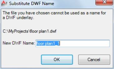
Angle If Specify On-Screen is cleared, enter the rotation angle value in the
dialog box. The default rotation angle is 0.
Show Details
Displays the DWF file path.
Found In Displays the path where the DWF file is located.
Saved Path Displays the path that is saved with the drawing when the DWF
file is attached. The path is dependent upon the Path Type setting.
Substitute DWF Name Dialog Box
Quick Reference
See also:
■Attach Files as Underlays
Allows you to rename a DWF underlay if the name is not unique.
Summary
The names of DWF or DWFx references you attach must be unique. Attempts
to attach two DWF or DWFx references that have the same name displays the
Substitute DWF Name dialog box.
New DWF Name
Enter a unique name for the DWF or DWFx underlay you are attempting to
attach.
Once a new name is supplied, you can continue with the attachment process.
Substitute DWF Name Dialog Box | 437
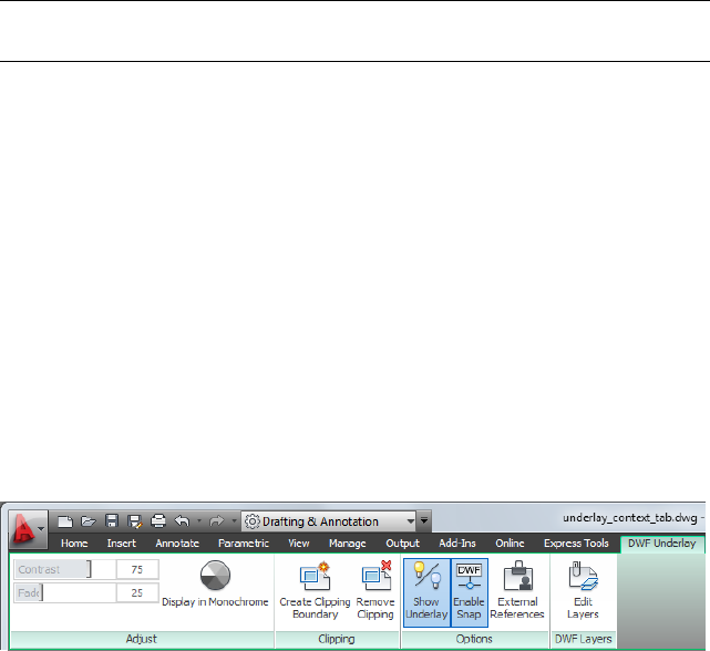
NOTE This only changes the name of the DWF or DWFx reference when it is
attached. It does not affect the name of the DWF or DWFx file.
DWF Underlay Ribbon Contextual Tab
Quick Reference
See also:
■Work with Underlays
Change DWF underlay display, clip, layer, and osnap options.
Summary
When you select a DWF underlay in a drawing, the DWF Underlay Contextual
tab is displayed on the ribbon.
List of Panels
Adjust Panel
Contrast Controls the contrast and the fading effect of the underlay. The
greater the value, the more each pixel is forced to its primary or secondary
color.
Fade Controls the appearance of linework. The greater the value, the lighter
the linework in the underlay appears.
Display in Monochrome Displays the underlay in black and white.
Clipping Panel
Create Clipping Boundary Deletes the old clipping boundary (if one exists)
and creates a new one.
Remove Clipping Deletes the clipping boundary.
438 | Chapter 5 D Commands

Options Panel
Show Underlay Hides or displays the underlay.
Enable Snap Determines whether object snapping is active for geometry in
the DWF underlay.
External References Displays the External References palette.
DWF Layers Panel
Edit Layers Controls the display of layers in a DWF Underlay.
-DWFATTACH
Quick Reference
See also:
■Attach Files as Underlays
Attach a DWF underlay from the command line.
Summary
When you attach a DWF or DWFx file as an underlay, you link that referenced
file to the current drawing. Any changes to the referenced file are displayed
in the current drawing when it is opened or reloaded.
List of Prompts
The following prompts are displayed.
TIP You can drag a DWF file onto the drawing window to start the DWFATTACH
command.
Path to DWF File to Attach Enters the full path name to the DWF underlay
file. The file name can include up to 255 characters and contain letters, digits,
spaces, and any special characters not used by Microsoft Windows or this
program.
Entering a tilde (~) displays the Select DWF File dialog box (a standard file
selection dialog box).
To avoid errors when entering a file name, it is recommended that you specify
both the DWF file and path as follows:
path name\filename.dgn
-DWFATTACH | 439

or
“path name\filename.dgn”
If you enter a valid DWF file name without a file extension, the program adds
the extension and searches for the file.
Enter Name of Sheet or ? Enter a sheet name. For a list of sheets, enter ?.
Enter Sheet(s) to list <*> Lists the sheets available in the DWF file in a separate
text window.
Insertion Point Specifies the insertion point for the selected DWF file.
Scale Factor Specifies the scale factor of the selected DWF underlay and the
scale factor units.
If INSUNITS is set to “unitless” or if the underlay does not contain resolution
information, the scale factor becomes the underlay width in AutoCAD units.
If INSUNITS has a value such as millimeters, centimeters, inches, or feet, and
the underlay has resolution information, the scale factor is applied after the
true width of the underlay in AutoCAD units is determined.
Rotation Specifies the rotation angle of the selected DWF underlay by entering
an angle value at the Command prompt or by clicking onscreen.
DWFCLIP
Quick Reference
See also:
■Clip External References and Blocks
Crops the display of a selected DWF or DWFx underlay to a specified boundary.
Access Methods
Button
Ribbon: DWF Underlay contextual tab ➤ Clipping panel ➤ Create
Clipping Boundary
Shortcut menu: Select a DWF or DWFx underlay to clip, right-click in the
drawing area, and click DWF Clip
440 | Chapter 5 D Commands

Summary
The clipping boundary determines the portion of an image outside the
boundary that is hidden. The visibility of the clipping boundary is controlled
by the DWFFRAME on page 1486 system variable.
The boundary you specify must be in a plane parallel to the DWF or DWFx
underlay.
TIP Use the generic CLIP on page 211 command to clip images, external references,
viewports, and underlays.
List of Prompts
The following prompts are displayed.
On
Turns on clipping and displays the DWF underlay clipped to the previously
defined boundary.
Off
Turns off clipping and displays the entire DWF or DWFx underlay and frame.
If you reclip the DWF or DWFx underlay while clipping is turned off, clipping
is automatically turned back on. You are prompted to delete the old boundary
even when clipping is turned off and the clipping boundary is not visible.
Delete
Removes a predefined clipping boundary and displays the full original
underlay.
New Boundary
Defines a rectangular or polygonal clipping boundary, or generates a polygonal
clipping boundary from a polyline.
Select Polyline Defines the boundary with the selected polyline. The polyline
can be open but must consist of straight line segments and cannot intersect
itself.
Polygonal Defines a polygonal clipping boundary with three or more points
that you specify for the vertices of a polygon.
Rectangular Defines a rectangular boundary with the points that you specify
for opposite corners.
Invert Clip Inverts the mode of the clipping boundary: objects are clipped
either outside the boundary or inside the boundary.
DWFCLIP | 441

NOTE You can only create a new clipping boundary for a selected DWF underlay
when the old boundary is deleted.
DWFFORMAT
Quick Reference
See also:
■Publish Drawings
Sets the default format to DWF or DWFx for output in specific commands.
Summary
The latest version of Autodesk’s Design Web Format (DWF) is DWFx. DWFx
uses Microsoft’s XML Paper Specification (XPS) to provide viewing and
publishing capabilities that are independent from Autodesk software.
DWFx files can be opened directly within Microsoft’s XPS Viewer, which is
automatically installed with the Microsoft Vista and Windows 7 operating
systems, bundled with .NET 3.0, and is available as an optional download for
Windows XP users.
Use the PUBLISH command to create DWFx files from DWG drawing files.
DWFLAYERS
Quick Reference
See also:
■Control the Display of Layers in an Underlay
Controls the display of layers in a DWF or DWFx underlay.
Access Methods
Button
442 | Chapter 5 D Commands
Ribbon: Insert tab ➤ Reference panel ➤ Underlay Layers
Shortcut menu: Select a DWF or DWFx underlay, right-click in the drawing
area, and choose DWF Layers
Summary
After selecting the DWF underlay, the Underlay Layers dialog box on page 1282
is displayed.
The ULAYERS on page 1281 command allows you to manage the layers of all
underlays in the current document: DWF, DWFx, PDF, and DGN.
DWGCONVERT
Quick Reference
See also:
■Convert Drawing File Formats
■Open a Drawing
Converts drawing format version for selected drawing files.
Access Methods
Button
Menu: Application menu ➤ Save As ➤ DWG Convert
Menu: File ➤ DWG Convert
Summary
Opens the DWG Convert dialog box on page 444. All files to be converted are
indicated by a check mark next to the file name. Right-click in the file display
area to display a shortcut menu with several options.
DWGCONVERT | 443
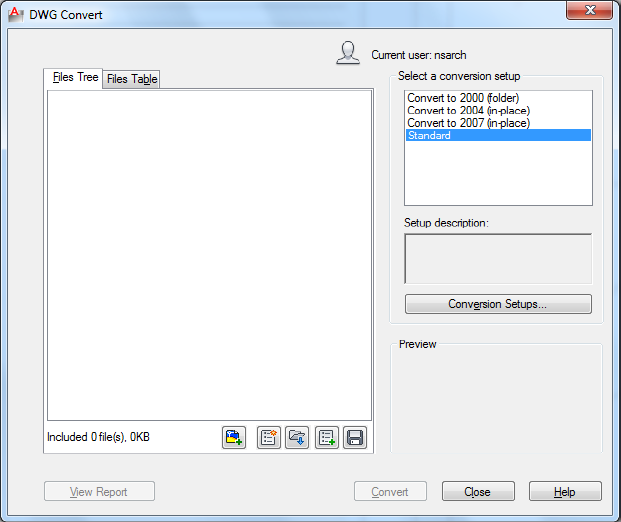
DWG Convert Dialog Box
Quick Reference
See also:
■Convert Drawing File Formats
Change drawings from one AutoCAD drawing type to another.
Displays a list of drawing files that you want to convert. All files to be converted
are indicated by a checkmark next to the file name. Right-click in the file
display area to display a shortcut menu with several options.
List of Options
The dialog box contains the following options
Files Tree Tab Displays a list of drawing files selected for conversion. Includes
the drawing name and path, current format, and conversion status. You can
444 | Chapter 5 D Commands
add drawing files by clicking the Add button or by dragging a file. You can
sort the order of the drawings by clicking a column heading.
Files Table Tab Displays the list of drawing files to be converted in a table
format. By default, all files associated with the drawing (such as related external
references) are listed.
Add File Button Opens a standard file selection dialog box, in which you
can select drawing files to add to the conversion list. This button is available
on both the Files Tree tab and the Files Table tab.
New List Button Clears the list of all drawings so you can select a new list of
drawings for conversion. If the list has changed, you are prompted to save the
current list.
Open List Button Opens a standard file selection dialog box, in which you
can select a batch convert list file (BCL file), and then click Open to open the
file.
Append List Button Opens a standard file selection dialog box, in which you
can select a batch convert list file (BCL file) to append to an existing list of
drawings in the conversion list.
Save List Button Opens a standard file selection dialog box. Select a batch
convert list file (BCL file), or enter a new file name.
Select a Conversion Setup group Lists previously saved conversion setups.
The default conversion setup is named Standard. Click to select a different
conversion setup, if multiple setups are present. To create a new conversion
setup or to modify an existing one in the list, click Conversion Setups.
Right-click to display a shortcut menu with several options.
If a conversion setup has been given a description when it was created or when
modified, the description will appear in the Setup Description field. Click the
Conversion Setups button to access the Conversion Setups dialog box on page
446.
Preview group Displays a thumbnail image of a drawing that is currently
shown in the list of drawings to convert.
DWG Convert Dialog Box | 445

Conversion Setups Dialog Box
Quick Reference
See also:
■Convert Drawing File Formats
Creates, renames, modifies, and deletes conversion setups.
List of Options
Conversion Setups Displays a list of previously saved conversion setups as
well as the default setup; Standard.
New Opens the New Conversion Setup dialog box on page 447, where you can
add a new conversion setup based on an existing conversion setup.
Rename Renames a conversion setup that appears in the list. Only conversion
setups that you have created can be renamed. The Standard conversion setup
cannot be renamed.
Modify Displays the Modify Conversion Setup dialog box on page 447, in
which you can specify options for the selected drawing conversion.
Delete Removes the currently highlighted conversion setup. The Standard
conversion setup cannot be deleted.
446 | Chapter 5 D Commands
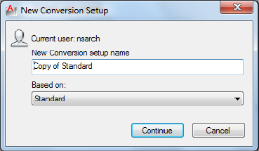
New Conversion Setup Dialog Box
Quick Reference
See also:
■Convert Drawing File Formats
Creates a new conversion setup
List of Options
New Conversion Setup Name Enter the name of the new conversion setup.
Based On Select an existing conversion setup that the new one will use as its
basis.
Modify Conversion Setup Dialog Box
Quick Reference
See also:
■Convert Drawing File Formats
Specifies the type of conversion package associated with the selected conversion
setup along with its location and unique options.
New Conversion Setup Dialog Box | 447
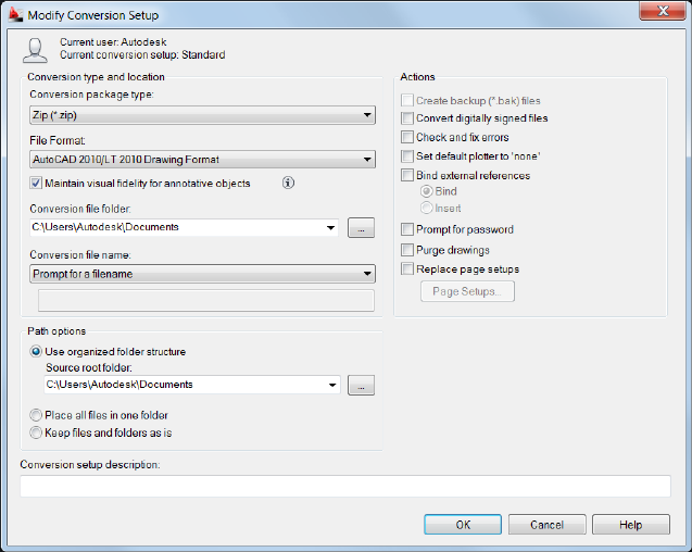
List of Options
Conversion Package Type Specifies the type and location of the selected
conversion setup.
In-place (Overwrite Files) Creates a conversion package of uncompressed
files that overwrite the existing files in the original folder.
Folder (Set of Files) Creates a conversion package of uncompressed files in a
new or existing folder.
Self-extracting Executable (*.exe) Creates a conversion package of files as a
compressed, self-extracting executable file. Double-clicking the resulting EXE
file decompresses the conversion package and restores the files to the folder
location that you specify.
Zip (*.zip) Creates a conversion package of files as a compressed ZIP file.
File Format Specifies the file format to which all drawings included in a
conversion package will be converted. You can select a drawing file format
from the drop-down list.
Maintain Visual Fidelity for Annotative Objects Specifies whether or not
drawings are saved with visual fidelity for annotative objects. Annotative
448 | Chapter 5 D Commands
objects may have multiple scale representations. Annotative objects are
decomposed and scale representations are saved to separate layers, which are
named based on their original layer and appended with a number.
Conversion File Folder Specifies the location in which the conversion package
is created. Lists the last nine locations in which conversion packages were
created. To specify a new location, click Browse and navigate to the location
you want. If this field is left unchanged, the conversion file is created in the
folder containing the first specified drawing file. In a sheet set context, the
conversion file is created in the folder containing the sheet set data (DST) file.
Browse [...] Opens a standard file selection dialog box, in which you can
navigate to a location where you create the conversion package.
Conversion File Name Specifies the method for naming the conversion
package. Displays the default file name for the conversion package. This option
is not available if the conversion package type is set to Folder.
Prompt for a File Name Displays a standard file selection dialog box where
you can enter the name of the conversion package.
Overwrite if Necessary Uses a logical default file name. If the file name already
exists, the existing file is automatically overwritten.
Increment File Name if Necessary Uses a logical default file name. If the file
name already exists, a number is added to the end. This number is incremented
each time a new conversion package is saved.
Path Options Provides options for organizing the files and folders that are
included in the conversion package.
Use Organized Folder Structure Duplicates the folder structure for the files
being converted. The root folder is the top-level folder within a hierarchical
folder tree.
The following the considerations apply:
■Relative paths remain unchanged. Relative paths outside the source root
folder retain up to one level of the folder path above them, and are placed
in the root folder.
■Full (absolute) paths within the root folder tree are converted to relative
paths. Full paths outside the source root folder retain up to one level of
the folder path above them, and are placed in the root folder.
■Full paths outside the root folder tree are converted to No Path and are
moved to the root folder or to a folder within the root folder tree.
Modify Conversion Setup Dialog Box | 449

■A Fonts folder is created, if necessary.
■A PlotCfgs folder is created, if necessary.
■A SheetSets folder is created to hold all support files for sheet sets, if
necessary. The sheet set data (DST) file, however, is placed in the root
folder.
NOTE This option is not available if you're saving a conversion package to an
Internet location.
Source Root Folder Defines the source root folder for relative paths of
drawing-dependent files, such as external references. The source root folder
also contains the sheet set data (DST) file when a sheet set is converted.
Browse [...] Opens a standard file selection dialog box, in which you can
navigate to a location where you create the conversion package.
Place All Files in One Folder All files are installed to a single, specified target
folder when the conversion package is installed.
Keep Files and Folders As Is Preserves the folder structure of all files in the
conversion package, facilitating ease of installation on another system. This
option is not available if you're saving a conversion package to an Internet
location.
Actions
Create backup (*.bak) Files Backup (.bak) files of are created during the
conversion. This option is only active when the Conversion Package Type is
set to In-place (Overwrite Files).
Convert Digitally Signed Files Controls whether digitally signed drawings
are converted.
Check and Fix Errors When active, drawings are checked for the presence of
errors. Drawings are automatically recovered if errors are found. Set Default
Plotter to ‘None’ Changes the printer/plotter setting in the conversion package
to None. Your local printer/plotter settings are usually not relevant to the
recipient.
Bind External References Opens a standard file selection dialog box, in which
you can navigate to a location where you create the conversion package.
Prompt for Password Opens the Archive - Set Password dialog box, before
completing the conversion, where you can specify a password for your
conversion package.
450 | Chapter 5 D Commands
Replace Page Setups Page setups specified in drawings you want to convert
can be replaced with a page setup from another drawing. When active, the
Page Setups button is made available.
Page Setups Opens the Page Setups dialog box where you can select a drawing
that contains a page setup to apply to the converted drawings.
Conversion Setup Description Enter a description for the conversion setup.
This description is displayed in the DWG Convert dialog box and the
Conversion Setups dialog box below the list of conversion file setups. You can
select any conversion setup in the list to display its description.
DWGPROPS
Quick Reference
See also:
■Add Identifying Information to Drawings
Sets and displays the file properties of the current drawing.
Access Methods
Button
Menu: Application menu ➤ Drawing Utilities ➤ Drawing Properties
Menu: File ➤ Drawing Properties
Summary
The Drawing Properties dialog box is displayed.
General information, keywords, and custom properties can be created and
stored with a drawing file. These file properties are accessible from the Desktop
or a folder view, can be used to help identify drawing files.
DWGPROPS | 451
Drawing Properties Dialog Box
Quick Reference
See also:
■Add Identifying Information to Drawings
Displays read-only statistics or general information about your drawing, assigns
summary properties, and assigns names and values to custom properties. These
custom properties can help you identify your drawing.
Summary
Document properties are displayed in the list of field names in the Field dialog
box on page 514.
■General on page 452
■Summary on page 454
■Statistics on page 455
■Custom on page 457
General Tab (Drawing Properties Dialog Box)
Quick Reference
See also:
■Add Identifying Information to Drawings
Displays read-only information about the drawing file. This data is derived
from the operating system.
452 | Chapter 5 D Commands
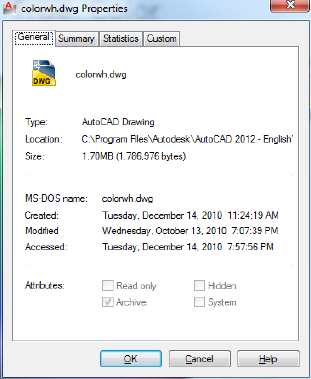
List of Options
The following options are displayed.
File Name
Shows the file icon and the file name.
File Type, Location, Size
Shows the file type, the file location, and the size of the file.
MS-DOS Name, Created, Modified, Accessed
Shows MS-DOS name, when the file was created, and the date and time it was
last modified and last accessed.
Attributes
Shows system-level file attributes. These values can be modified in Windows
Explorer.
Read-Only
Indicates that the file is read-only; it cannot be changed or deleted accidentally.
Archive
Indicates that this file should be archived. This setting is used to determine
which files should be backed up.
Hidden
Drawing Properties Dialog Box | 453
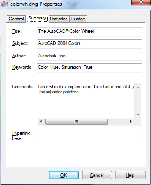
Indicates that the file is hidden; you cannot see or use it unless you know its
name.
System
Indicates that the file is a system file. A drawing cannot have the System
attribute set.
Summary Tab (Drawing Properties Dialog Box)
Quick Reference
See also:
■Add Identifying Information to Drawings
Displays properties such as author, title, and subject that are predefined. For
example, you can add keywords to all your drawing files and then use
DesignCenter™ to search for all drawing files with a particular keyword.
List of Options
The following options are displayed.
Title
454 | Chapter 5 D Commands

Specifies the title you want to use when searching for this drawing. The title
can be different from the drawing file name.
Subject
Specifies the subject of the drawing. You can use the subject name to group
drawings that have the same subject.
Author
Specifies the author of the drawing. The author name can only be entered or
changed by the user. To change the author, delete the existing name and enter
a new one.
Keywords
Specifies the keywords you want to use to locate the drawing.
Comments
Provides a space to add comments to the drawing.
Hyperlink Base
Specifies the base address that is used for all relative links inserted within the
drawing. You can specify an Internet location, for example,
http://www.autodesk.com, or a path to a folder on a network drive.
Statistics Tab (Drawing Properties Dialog Box)
Quick Reference
See also:
■Add Identifying Information to Drawings
Displays data such as the dates the drawing was created and last modified.
These file properties are automatically maintained for you and can help you
search for drawings created or modified during a specific period.
NOTE If the drawing was last saved using an application other than Autodesk®
software, a warning message is displayed. Display of the warning message is
controlled by the DWGCHECK system variable.
Drawing Properties Dialog Box | 455
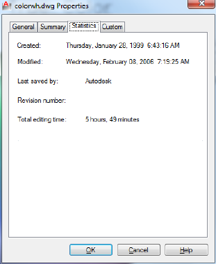
List of Options
The following options are displayed.
Created
Displays the date and time the drawing was created. This value is stored in
the TDCREATE system variable.
Modified
Displays the date and time the drawing was last modified. This value is stored
in the TDUPDATE system variable.
Last Saved By
Displays the name of the last person who modified the file.
Revision Number
Displays the revision number. This value is not accessible. To track revisions,
create a custom property on the Custom tab.
Total Editing Time
Displays the total amount of editing time in the drawing. This value is stored
in the TDINDWG system variable.
456 | Chapter 5 D Commands

Custom Tab (Drawing Properties Dialog Box)
Quick Reference
See also:
■Add Identifying Information to Drawings
Assigns custom properties to the drawing.
Summary
For example, you could create a custom property called Project and assign the
actual project name as the value. To assign the same custom properties to a
group of drawings, create the custom properties in a drawing template file.
List of Options
The following options are displayed.
Custom Properties
Lists names and values of custom properties for the current drawing.
Add
Drawing Properties Dialog Box | 457

Displays the Add Custom Property dialog box, where you can enter a name
and a value for the new custom property. The name must be unique. The
value can be left blank.
Delete
Deletes the custom property that is selected in the list.
NOTE If you delete a custom property that is used in a field, the field displays
#### the next time it is updated.
Add Custom Property Dialog Box
Quick Reference
See also:
■Add Identifying Information to Drawings
Adds a custom property to the drawing file.
List of Options
The following options are displayed.
Custom Property Name
Specifies a unique name for the custom property. The name can contain up
to 255 characters. The following characters are not permitted: asterisk (*),
equal sign (=), less-than and greater-than signs (< >), slash (/), backslash (\),
quotation marks ("), reverse quote (`), pipe sign (|), colon (:), and semicolon
(;).
Value
Specifies a value for the property. The value can be left blank.
458 | Chapter 5 D Commands
E Commands
EATTEDIT
Quick Reference
See also:
■Modify a Block Attribute Definition
Edits attributes in a block reference.
Access Methods
Button
Ribbon: Home tab ➤ Block panel ➤ Edit Single Attribute
Menu: Modify ➤ Object ➤ Attribute ➤ Single
Toolbar: Modify II
Summary
Edits the values, text options, and properties of each attribute in a block.
List of Prompts
The following prompts are displayed.
Select a block:
6
459
After you select a block with attributes, the Enhanced Attribute Editor is
displayed.
Enhanced Attribute Editor
Quick Reference
See also:
■Modify a Block Attribute Definition
Lists the attributes in a selected block instance and displays the properties of
each attribute.
Summary
The Enhanced Attribute Editor contains the following tabs:
■Attribute
■Text Options
■Properties
List of Options
The following options are displayed.
Block
Name of the block whose attributes you are editing.
Tag
Tag identifying the attribute.
Select Block
Temporarily closes the dialog box while you select a block with your pointing
device.
Apply
Updates the drawing with the attribute changes you have made, and leaves
the Enhanced Attribute Editor open.
460 | Chapter 6 E Commands
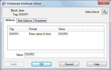
Attribute Tab (Enhanced Attribute Editor)
Displays the tag, prompt, and value assigned to each attribute. You can change
only the attribute value.
List
Lists the attributes in the selected block instance and displays the tag, prompt,
and value for each attribute.
Value
Assigns a new value to the selected attribute.
Multiple-line attributes include a button with an ellipsis. Click to open the
In-Place Text Editor with the Text Formatting toolbar and the ruler. Depending
on the setting of the ATTIPE system variable, the Text Formatting toolbar
displayed is either the abbreviated version, or the full version
To use a field as the value, right-click and click Insert Field on the shortcut
menu to display the Field dialog box.
Text Options Tab (Enhanced Attribute Editor)
Sets the properties that define the way an attribute's text is displayed in the
drawing. Change the color of attribute text on the Properties tab.
Enhanced Attribute Editor | 461
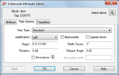
Text Style
Specifies the text style for the attribute text. Default values for this text style
are assigned to the text properties displayed in this dialog box.
Justification
Specifies how the attribute text is justified (left-, center-, or right-justified).
Height
Specifies the height of the attribute text.
Rotation
Specifies the rotation angle of the attribute text.
Annotative
Specifies that the attribute is . Click the information icon to learn more about
annotative objects.
Backwards
Specifies whether or not the attribute text is displayed backwards. Not available
for multiple-line attributes.
Upside Down
Specifies whether or not the attribute text is displayed upside down. Not
available for multiple-line attributes.
Width Factor
Sets the character spacing for the attribute text. Entering a value less than 1.0
condenses the text. Entering a value greater than 1.0 expands it.
Oblique Angle
462 | Chapter 6 E Commands
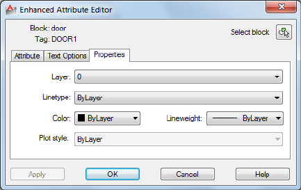
Specifies the angle that the attribute text is slanted away from its vertical axis.
Not available for multiple-line attributes.
Boundary Width
Specifies the maximum length of the lines of text in a multiple-line attribute
before wrapping to the next line. A value of 0.000 means that there is no
restriction on the length of a line of text. Not available for single-line attributes.
Properties Tab (Enhanced Attribute Editor)
Defines the layer that the attribute is on and the lineweight, linetype, and
color for the attribute text. If the drawing uses plot styles, you can assign a
plot style to the attribute using the Properties tab.
Layer
Specifies the layer that the attribute is on.
Linetype
Specifies the linetype of the attribute.
Color
Specifies the color of the attribute.
Lineweight
Specifies the lineweight of the attribute.
Changes you make to this option are not displayed if the LWDISPLAY on page
1575 system variable is off.
Plot Style
Specifies the plot style of the attribute.
Enhanced Attribute Editor | 463

If the current drawing uses color-dependent plot styles, the Plot Style list is
not available.
Edit PGP
Quick Reference
See also:
■Enter Commands on the Command Line
Opens the Program Parameters (PGP) text file that defines command
abbreviations
Access Methods
Button
Ribbon: Tools tab ➤ Customization panel ➤ Edit Aliases.
Menu: Tools ➤ Customize ➤ Customize, Edit Command Aliases
Summary
Commands can have abbreviated names called command aliases that you can
enter at the Command prompt. Command aliases are defined in the PGP file.
If you edit the PGP file while the program is running, enter REINIT to use the
revised file. You can also restart program to reload the file automatically.
ELEV
Quick Reference
See also:
■Control the User Coordinate System (UCS)
■Add 3D Thickness to Objects
464 | Chapter 6 E Commands
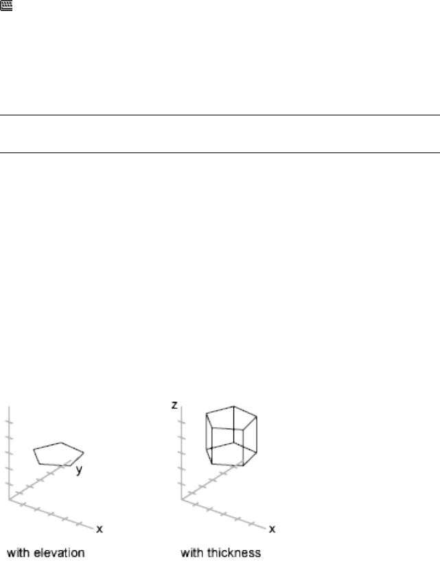
Sets elevation and extrusion thickness of new objects.
Access Methods
Command entry: 'elev for transparent use
Summary
The ELEV command sets the default Z value for new objects above or below
the XY plane of the current UCS. This value is stored in the ELEVATION system
variable.
NOTE Generally, it is recommended that you leave the elevation set to zero and
control the XY plane of the current UCS with the UCS on page 1266 command.
ELEV controls only new objects; it does not affect existing objects. The
elevation is reset to 0.0 whenever you change the coordinate system to the
world coordinate system (WCS).
List of Prompts
The following prompts are displayed.
Specify New Default Elevation The current elevation is the default Z value
for new objects when you specify only X and Y values for a 3D point.
Specify New Default Thickness The thickness sets the distance to which a
2D object is extruded above or below its elevation. A positive value is extruded
along the positive Z axis; a negative value is extruded along the negative Z
axis.
ELEV | 465
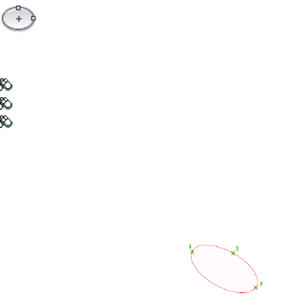
ELLIPSE
Quick Reference
See also:
■Draw Ellipses
Creates an ellipse or an elliptical arc.
Access Methods
Button
Ribbon: Home tab ➤ Draw panel ➤ Ellipse drop-down ➤ Center
Menu: Draw ➤ Ellipse ➤ Center
Toolbar: Draw
Summary
The first two points of the ellipse determine the location and length of the
first axis. The third point determines the distance between the center of the
ellipse and the end point of the second axis.
List of Prompts
The following prompts are displayed.
Specify axis endpoint on page 466 of ellipse or [Arc on page 467/Center on page
468/Isocircle on page 469]: Specify a point or enter an option
Axis Endpoint
Defines the first axis by its two endpoints. The angle of the first axis determines
the angle of the ellipse. The first axis can define either the major or the minor
axis of the ellipse.
466 | Chapter 6 E Commands
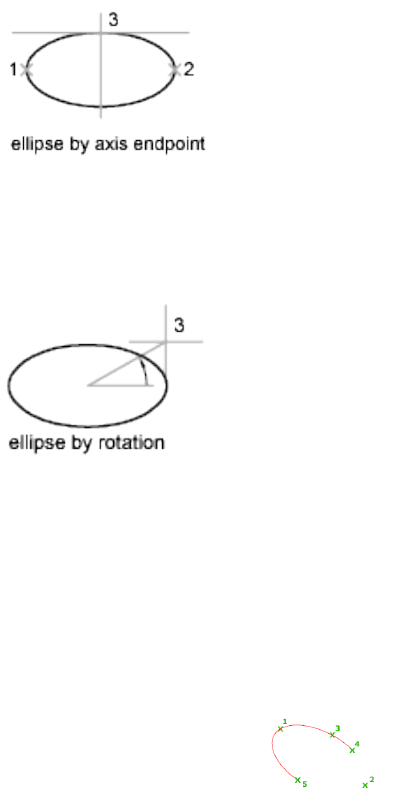
Distance to Other Axis Defines the second axis using the distance from the
midpoint of the first axis to the endpoint of the second axis (3).
Rotation Creates the ellipse by appearing to rotate a circle about the first axis.
Move the crosshairs around the center of the ellipse and click. If you enter a
value, the higher the value, the greater the eccentricity of the ellipse. Entering
0 defines a circular ellipse.
Arc
Creates an elliptical arc.
The angle of the first axis determines the angle of the elliptical arc. The first
axis can define either the major or the minor axis depending on its size.
The first two points of the elliptical arc determine the location and length of
the first axis. The third point determines the distance between the center of
the elliptical arc and the endpoint of the second axis. The fourth and fifth
points are the start and end angles.
Axis Endpoint Defines the start point of the first axis.
Rotation Defines the major to minor axis ratio of the ellipse by rotating a
circle about the first axis. The higher the value from 0 through 89.4 degrees,
the greater the ratio of minor to major axis. Values between 89.4 degrees and
ELLIPSE | 467
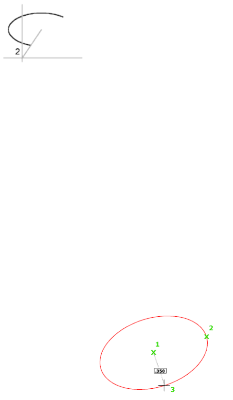
90.6 degrees are invalid because the ellipse would otherwise appear as a straight
line. Multiples of these angle values result in a mirrored effect every 90 degrees.
Start Angle Defines the first endpoint of the elliptical arc. The Start Angle
option toggles from Parameter mode to Angle mode. The mode controls how
the ellipse is calculated.
Parameter Requires the same input as Start Angle, but creates the elliptical
arc using the following parametric vector equation:
p(u) = c + a * cos(u) + b * sin(u)
where c is the center of the ellipse and a and b are its major and minor axes,
respectively.
■End Parameter: Defines the end angle of the elliptical arc by using a
parametric vector equation. The Start Parameter option toggles from Angle
mode to Parameter mode. The mode controls how the ellipse is calculated.
■Angle: Defines the end angle of the elliptical arc. The Angle option toggles
from Parameter mode to Angle mode. The mode controls how the ellipse
is calculated.
■Included Angle: Defines an included angle beginning at the start angle.
Center
Creates an ellipse using a center point, the endpoint of the first axis, and the
length of the second axis. You can specify the distances by clicking a location
at the desired distance or by entering a value for the length.
468 | Chapter 6 E Commands
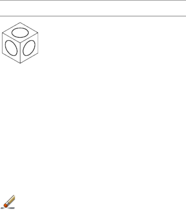
Distance to Other Axis Defines the second axis as the distance from the center
of the ellipse, or midpoint of the first axis, to the point you specify.
Rotation Creates the ellipse by appearing to rotate a circle about the first axis.
Move the crosshairs around the center of the ellipse and click. If you enter a
value, the higher the value, the greater the eccentricity of the ellipse. Entering
0 defines a circle.
Isocircle
Creates an isometric circle in the current isometric drawing plane.
NOTE The Isocircle option is available only when you set the Style option of SNAP
to Isometric.
Radius Creates a circle using a radius you specify.
Diameter Creates a circle using a diameter you specify.
Specify diameter of isocircle: Specify a distance
ERASE
Quick Reference
See also:
■Erase Objects
Removes objects from a drawing.
Access Methods
Button
ERASE | 469

Ribbon: Home tab ➤ Modify panel ➤ Erase
Menu: Modify ➤ Erase
Toolbar: Modify
Shortcut menu: Select the objects to erase, right-click in the drawing area,
and click Erase.
Summary
You can erase selected objects from the drawing. This method does not move
objects to the Clipboard, where they can then be pasted to another location.
Instead of selecting objects to erase, you can enter an option, such as L to erase
the last object drawn, p to erase the previous selection set, or ALL to erase all
objects. You can also enter ? to get a list of all options.
ETRANSMIT
Quick Reference
See also:
■Package a Set of Files for Internet Transmission
Packages a set of files for Internet transmission.
Access Methods
Button
Menu: Application Menu ➤ Publish ➤ eTransmit
Menu: File ➤ eTransmit
470 | Chapter 6 E Commands
Summary
The Create Transmittal dialog box is displayed.
If you enter -etransmit at the Command prompt, options are displayed.
When you select a set of drawing files in a transmittal package, it automatically
includes all related dependent files such as xrefs and font files.
Create Transmittal Dialog Box
Quick Reference
See also:
■Package a Set of Files for Internet Transmission
Packages a set of files for Internet transmission.
Summary
All files to be included in the transmittal package are indicated by a check
mark next to the file name. Right-click in the file display area to display a
shortcut menu with several options.
List of Options
The following options are displayed.
Files Tree Tab
Lists the files to be included in the transmittal package in a hierarchical tree
format. By default, all files associated with the current drawing (such as related
xrefs, plot styles, and fonts) are listed. You can add files to the transmittal
package or remove existing files. Related files that are referenced by URLs are
not included in the transmittal package.
The drawings to be transmitted are listed under the following categories:
■Current Drawing. Lists the files associated with the current drawing.
■User Added Files. Lists the files that have been added manually with the
Add File option.
Create Transmittal Dialog Box | 471
Files Table Tab
Displays the files to be included in the transmittal package in a table format.
By default, all files associated with the current drawing (such as related xrefs,
plot styles, and fonts) are listed. You can add files to the transmittal package
or remove existing files. Related files that are referenced by URLs are not
included in the transmittal package.
Add File
Opens a standard file selection dialog box, in which you can select an
additional file to include in the transmittal package. This button is available
on both the Files Tree tab and the Files Table tab.
Enter Notes to Be Included with This Transmittal Package
Provides a space where you can enter notes related to a transmittal package.
The notes are included in the transmittal report. You can specify a template
of default notes to be included with all your transmittal packages by creating
an ASCII text file called etransmit.txt. This file must be saved to a location
specified by the Support File Search Path option on the Files tab in the Options
dialog box.
Select a Transmittal Setup
Lists previously saved transmittal setups. The default transmittal setup is
named STANDARD. To create a new transmittal setup or to modify an existing
one in the list, click Transmittal Setups.
Transmittal Setups
Displays the Transmittal Setups dialog box, in which you can create, modify,
and delete transmittal setups.
View Report
Displays report information that is included with the transmittal package.
Includes any transmittal notes that you entered and distribution notes
automatically generated that detail what steps must be taken for the transmittal
package to work properly. For example, if SHX fonts are detected in one of
the transmittal drawings, you are instructed where to copy these files so that
they can be detected on the system where the transmittal package is being
installed. If you have created a text file of default notes, the notes are also
included in the report.
Save As Opens a File Save dialog box, in which you can specify a location in
which to save a report file. Note that a report file is automatically included
with all transmittal packages that you generate; by choosing Save As, you can
save an additional copy of a report file for archival purposes.
472 | Chapter 6 E Commands
Transmittal Setups Dialog Box
Quick Reference
See also:
■Package a Set of Files for Internet Transmission
Creates, modifies, and deletes transmittal setups.
List of Options
The following options are displayed.
Transmittal Setups
Lists transmittal setups.
New
Creates a new transmittal setup.
New Transmittal Setup Name
Enter the name of the new transmittal setup.
Based On
Select an existing transmittal setup from which the new one will be created.
Rename
Renames the currently highlighted transmittal setup.
Modify
Displays the Modify Transmittal Setup dialog box, in which you can specify
options for the transmittal package.
Delete
Removes the currently highlighted transmittal setup.
Import
Transmittal Setups Dialog Box | 473
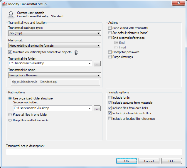
Modify Transmittal Setup Dialog Box
Quick Reference
See also:
■Package a Set of Files for Internet Transmission
List of Options
The following options are displayed.
Transmittal Type and Location
Specifies the type and path to the transmittal package created.
Transmittal Package Type
474 | Chapter 6 E Commands

Specifies the type of transmittal package created.
DescriptionTransmittal Package Type
Creates a transmittal package of uncom-
pressed files in a new or existing folder.
Folder
Creates a transmittal package of files as a
compressed, self-extracting executable file.
Self-Extracting Executable
Double-clicking the resulting EXE file de-
compresses the transmittal package and
restores the files to the folder location that
you specify.
Creates a transmittal package of files as a
compressed ZIP file. To restore the files to
Zip
the folder location that you specify, you
need a decompression utility such as the
shareware application PKZIP or WinZip.
File Format
Specifies the file format to which all drawings included in a transmittal package
will be converted. You can select a drawing file format from the dropdown
list.
Maintain Visual Fidelity for Annotative Objects
Specifies whether or not drawings are saved with visual fidelity for objects.
Click the information icon to learn more about saving drawings with visual
fidelity.
Annotative objects may have multiple . Annotative objects are decomposed
and scale representations are saved to separate layers, which are named based
on their original layer and appended with a number.
Transmittal File Folder
Specifies the location in which the transmittal package is created. Lists the
last nine locations in which transmittal packages were created. To specify a
new location, click Browse and navigate to the location you want.
Transmittal File Name
Modify Transmittal Setup Dialog Box | 475

Specifies the method for naming the transmittal package. Displays the default
file name for the transmittal package. This option is not available if the
transmittal package type is set to Folder.
DescriptionTransmittal File Type Property
Displays a standard file selection dialog box
where you can enter the name of the
transmittal package.
Prompt for a File Name
Uses a logical default file name. If the file
name already exists, the existing file is
automatically overwritten.
Overwrite if Necessary
Uses a logical default file name. If the file
name already exists, a number is added to
Increment File Name if Necessary
the end. This number is incremented each
time a new transmittal package is saved.
Path Options
Provides options for organizing the files and folders that are included in the
transmittal package.
Use Organized Folder Structure
Duplicates the folder structure for the files being transmitted. The root folder
is the top-level folder within a hierarchical folder tree.
The following considerations apply:
■Relative paths remain unchanged. Relative paths outside the source root
folder retain up to one level of the folder path above them, and are placed
in the root folder.
■Full (absolute) paths within the root folder tree are converted to relative
paths. Full paths outside the source root folder retain up to one level of
the folder path above them, and are placed in the root folder.
■Full paths outside the root folder tree are converted to No Path and are
moved to the root folder or to a folder within the root folder tree.
■A Fonts folder is created, if necessary.
■A PlotCfgs folder is created, if necessary.
476 | Chapter 6 E Commands
This option is not available if you're saving a transmittal package to an Internet
location.
Source Root Folder
Defines the source root folder for relative paths of drawing-dependent files,
such as xrefs.
Place All Files in One Folder
All files are installed to a single, specified target folder when the transmittal
package is installed.
Keep Files and Folders As Is
Preserves the folder structure of all files in the transmittal package, facilitating
ease of installation on another system. This option is not available if you're
saving a transmittal package to an Internet location.
Actions
Provides options for organizing the actions that can be associated with the
transmittal package.
Send E-mail with Transmittal
Launches the default system email application when the transmittal package
is created so that you can send an email that includes the transmittal package
as an attachment.
Set Default Plotter to 'None'
Changes the printer/plotter setting in the transmittal package to None. Your
local printer/plotter settings are usually not relevant to the recipient.
Bind External References
Binds all AutoCAD drawing file (DWG) external references to the files to which
they were attached.
Bind
Binds the selected DWG external reference to the current drawing.
Insert
Binds the DWG external reference to the current drawing in a way similar to
detaching and inserting the reference drawing.
Prompt for Password
Opens the Transmittal - Set Password dialog box, where you can specify a
password for your transmittal package.
Modify Transmittal Setup Dialog Box | 477

Purge Drawings
Does a complete purge of all the drawings in the transmittal package.
NOTE As the purge is done in silent mode, you will not receive any notifications
when purged items in the drawings have been removed.
Include Options
Provides a means for including additional options with the transmittal package.
Include Fonts
Includes any associated font files (TTF and SHX) with the transmittal package.
NOTE Because TrueType fonts are proprietary, you should make sure that the
recipient of the transmittal package also owns the TrueType fonts. If you are not
sure whether the recipient owns the TrueType fonts, clear this option. If any
required TrueType fonts are not available to the recipient, the font specified by
the FONTALT system variable is substituted.
Include Textures from Materials
Includes textures from materials that are attached to objects or faces.
Include Files from Data Links
Adds external files referenced by a data link to the transmittal package.
Include Photometric Web Files
Includes photometric web files that are associated with web lights in the
drawing.
Include Unloaded File References
Includes all unloaded external references, images, and underlays. The unloaded
file references are listed in the Files Tree and Files Table and report under their
appropriate category.
Transmittal Setup Description
Enter a description for the transmittal setup. This description is displayed in
the Create Transmittal dialog box below the list of transmittal file setups. You
can select any transmittal setup in the list to display its description.
478 | Chapter 6 E Commands
Transmittal - Set Password Dialog Box
Quick Reference
See also:
■Package a Set of Files for Internet Transmission
List of Options
The following options are displayed.
Password for Compressed Transmittal Provides a space for an optional
password for the transmittal package. When others attempt to open the
transmittal package, they must provide this password to access the files.
Password protection cannot be applied to folder transmittal packages.
Password Confirmation Provides a space to confirm the password that you
entered in the Password field.
-ETRANSMIT
Quick Reference
See also:
■Package a Set of Files for Internet Transmission
List of Prompts
The following prompts are displayed.
Enter an option [Create transmittal package/Report only/CUrrent setup/CHoose
setup> <Report only>: Enter an option
Create Transmittal Package Packages a set of files according to the transmittal
setups on page 472 for Internet transmission. Drawing files in the transmittal
package automatically include all related dependent files such as xrefs and
font files.
Report Only Creates a report (TXT) file without creating a transmittal package.
This report file is based on the current transmittal setup.
Transmittal - Set Password Dialog Box | 479
Current Setup
Displays the name of the current transmittal setup.
Choose Setup Specifies the transmittal setup to use for the transmittal package.
EXPLODE
Quick Reference
See also:
■Disassociate Compound Objects (Explode)
Breaks a compound object into its component objects.
Access Methods
Button
Ribbon: Home tab ➤ Modify panel ➤ Explode
Menu: Modify ➤ Explode
Toolbar: Modify
Summary
Explodes a compound object when you want to modify its components
separately. Objects that can be exploded include blocks, polylines, and regions,
among others.
The color, linetype, and lineweight of any exploded object might change.
Other results differ depending on the type of compound object you're
exploding. See the following list of objects that can be exploded and the results
for each.
To explode objects and change their properties at the same time, use XPLODE.
480 | Chapter 6 E Commands

2D Polyline Discards any associated width or tangent information. For wide
polylines, the resulting lines and arcs are placed along the center of the
polyline.
3D Polyline Explodes into line segments. Any linetype assigned to the 3D
polyline is applied to each resulting line segment.
3D Solid (AutoCAD drawings) Explodes solids into surfaces and regions.
Annotative Objects Explodes the current scale representation into its
constituent parts which are no longer . Other scale representations are
removed.
Arc If within a nonuniformly scaled block, explodes into elliptical arcs.
Block Removes one grouping level at a time. If a block contains a polyline or
a nested block, exploding the block exposes the polyline or nested block object,
which must then be exploded to expose its individual objects.
Blocks with equal X, Y, and Z scales explode into their component objects.
Blocks with unequal X, Y, and Z scales (nonuniformly scaled blocks) might
explode into unexpected objects.
Exploding a block that contains attributes deletes the attribute values and
redisplays the attribute definitions.
Blocks inserted with external references (xrefs) and their dependent blocks
cannot be exploded.
Body (AutoCAD drawings) Explodes into a single-surface body (nonplanar
surfaces), regions, or curves.
Circle If within a nonuniformly scaled block, explodes into ellipses.
Leaders Explodes into lines, splines, solids (arrow heads), block inserts (arrow
heads, annotation blocks), multiline text, or tolerance objects, depending on
the leader.
Multiline Text Explodes into text objects.
Multiline (AutoCAD drawings) Explodes into lines and arcs.
Polyface Mesh (AutoCAD drawings) Explodes one-vertex meshes into a point
object. Two-vertex meshes explode into a line. Three-vertex meshes explode
into 3D faces.
Region Explodes into lines, arcs, or splines.
EXPLODE | 481
EXPORT
Quick Reference
See also:
Saves the objects in a drawing to a different file format.
Access Methods
Button
Menu: File ➤ Export
Summary
The Export Data dialog box (a standard file selection dialog box) is displayed.
If you do not see the file format that you need in the Files of Type drop-down
list, also check the PLOT command for other file types, including PDF.
NOTE The Export Data dialog box records the last used file format selection and
stores it for use during the current drawing session and between drawing sessions.
The following output types are available:
■Block (*.dwg): Drawing file (see WBLOCK)
■IGES (*.iges): IGES file (see IGESEXPORT on page 600)
■IGES (*.igs): IGES file (see IGESEXPORT on page 600)
■Metafile (*.wmf): Microsoft Windows® Metafile (see WMFOUT)
■V7 DGN (*.dgn): MicroStation DGN file (see DGNEXPORT)
■V8 DGN (*.dgn): MicroStation DGN file (see DGNEXPORT)
482 | Chapter 6 E Commands

-EXPORT
Quick Reference
See also:
■Export DWF and DWFx Files
■Export FBX Files
Creates a DWF, DWFx, or PDF file from the command line.
Summary
The command prompt version of EXPORTDWF, EXPORTDWFX, and
EXPORTPDF provides an interface for publishing drawing sheets that can be
controlled by a script.
List of Prompts
The following prompts are displayed.
File Format
Select DWF, DWFx, or PDF as the output file type.
Plot Area
Specify the area of the drawing to export:
Display Exports the view in the current viewport in Model space.
Extents Exports the portion of the current space of the drawing that contains
objects in Model space. All geometry in the current space is exported.
Window Exports any portion of the drawing you specify in Model space.
Click the Window button to use the mouse to specify opposite corners of the
area to be exported, or enter coordinate values.
Current Layout/All Layouts If you are exporting from paper space, specify
to export the current layout or all layouts.
Detailed Plot Configuration?
Specifies detailed page settings for the Model tab or layout tab you are plotting.
NOTE If you enter No, the Save As dialog appears if FILEDIA is set to 1. If FILEDIA
is set to 0, you are prompted to enter a file name at the command prompt.
-EXPORT | 483

Paper Size Enter the paper size or enter ? to view a list of paper sizes defined
for the default plotter driver.
Paper Units Specify Inches or Millimeters as the paper size unit.
NOTE This prompt does not display if you are exporting a raster image, such as
a BMP or TIFF file, because the size of the plot defaults to pixels.
Drawing Orientation Specify if the output displays in portrait or landscape.
Plot Scale Specify how to scale the drawing in the DWF, DWFx, or PDF file.
■Plotted Inches=Drawing Units: Calculates the plot scale based on the inches
or millimeters to drawing units that you specify. You can also enter a real
number as a fraction (for example, you can enter 1=2 or.5).
■Fit: Automatically calculates the scale to fit the area on the paper size
specified earlier.
Plot with Plot Styles? Specify whether to export using the plot styles applied
to objects and defined in the plot style table.
■Yes: If you enter Yes (plot with plot styles), enter the plot style table name,
press Enter for none or enter ? to list to view plot style tables.
■No: If you select No, enter . at the next prompt to select none.
Plot Style Table Name All style definitions with different property
characteristics are stored in the current plot style table and can be attached
to the geometry.
Plot with Lineweights Specifies whether or not to use the lineweight
(measured in pixels) specified in the PC3 driver.
EXPORTDWF
Quick Reference
See also:
■Export DWF and DWFx Files
Creates a DWF file and allows you to set individual page setup overrides on a
sheet by sheet basis.
484 | Chapter 6 E Commands
Access Methods
Button
Ribbon: Output tab ➤ Export to DWF/PDF panel ➤ Export drop-down
➤ DWF
Menu: Application Menu ➤ Export ➤ DWF
Summary
When you create DWF files with the EXPORTDWF command, you can quickly
override the device driver’s page setup options, add a plot stamp, and change
file options. You can change these settings in the Save as DWF dialog box.
To include layer information, change file location, add password-protection,
and other file options, use the Export to DWF/PDF Options palette.
Save as DWF Dialog Box
Quick Reference
See also:
■Export DWF and DWFx Files
Sets file options such as file name and location when you create a DWFx file.
Summary
When you export your drawing to a DWF file, the Save As DWF dialog box
appears. This dialog box allows you to specify the file name and location, but
also allows you to change export, page setup, and plot stamp settings.
List of Options
The following options are displayed.
Save as DWF Dialog Box | 485
Options
Opens the Export to DWF/PDF Options palette where you can change DWF
file settings such as file location, password-protection, and layer information.
Output Controls
Open in Viewer When Done Opens the DWF file in the default viewer after
export.
Include Plot Stamp Adds user-defined information such as drawing name,
date and time, or plot scale in the DWF file. To edit the plot stamp, click the
Plot Stamp button to open the Plot Stamp dialog box.
Export
Selects which part of the drawing to export. If you are in paper space, you can
select the current layout or all layouts. If you are in model space, you can
select the objects currently displayed, the drawing extents, or a selected area.
Window Selection button
Selects a window area to export from model space.
Page Setup
Exports the DWF file using the settings in the Page Setup Manager or choose
to override these settings.
Page Setup Override
Overrides the page settings. Click the Page Setup Override button to display
the Page Setup Override dialog box on page 488.
Export to DWF/PDF Options Palette
Quick Reference
See also:
■Export DWF and DWFx Files
Specifies the general export options for the DWF, DWFx, or PDF file, such as
file location, password protection, and whether or not to include layer
information.
List of Options
The following options are displayed.
486 | Chapter 6 E Commands
General DWF/PDF options
Changes general settings for DWF, DWFx, and PDF files.
Location Specifies where the DWF, DWFx, or PDF files are saved when you
export drawings.
Type Specifies whether to export single sheets or multiple sheets from the
drawing.
Override Precision Selects a precision preset that offers the best file resolution
for your field or creates a new precision preset by selecting Manage Precision
Presets. This dpi setting overrides the dpi settings in the DWF, DWFx, or PDF
driver.
Naming Names multi-sheet files, prompts for name during export, or specifies
the name before export.
Layer Information Includes layer information in the DWF, DWFx, or PDF
file.
Merge control Specifies whether overlapping lines merge (the colors of the
lines blend together into a third color) or overwrite (the last plotted line
obscures the line beneath it).
DWF Data Options
Changes settings that are only available for DWF and DWFx files.
Password protection Provides password protection for the DWF, DWFx, or
PDF file. You decide whether or not to prompt for the new password during
export or to specify the password in this dialog box.
Password Enters the password for the DWF, DWFx, or PDF file.
Block Information Specifies block property and attribute information in the
DWF, DWFx, or PDF file
Block Template File Provides options for creating a new block template (DXE)
file, editing an existing block template file, or using the settings of a previously
created block template file.
Export to DWF/PDF Options Palette | 487

Page Setup Override Dialog Box
Quick Reference
See also:
■Export DWF and DWFx Files
Allows you to override individual settings when you export a file.
Access Methods
Button
Ribbon: Output tab ➤ Export to DWF/PDF ➤ Page Setup
Summary
You can override the regular page settings applied to the layout through the
Page Setup dialog box. The override settings remain until you exit the
application. So, you do not have to reset the overrides every time you export
to a DWF, DWFx, or PDF file.
List of Options
The following options are displayed.
Paper Size
Select the paper size from the drop-down list of paper sizes defined for the
default plotter driver.
Plot Style Table (Pen Assignments)
Plot Style Name Select a plot style table from the drop-down list to apply to
all layouts.
Plot Style Table Editor Click to open the Plot Style Table Editor.
Drawing Orientation
Specify if the output displays in portrait or landscape.
488 | Chapter 6 E Commands

Plot Scale
Fit to Paper Select to automatically scale the selection to fit the area on the
paper size specified earlier.
Scale Specify a scaling ratio for the drawing. This ratio varies depending on
whether you select inches or millimeters as the measurement units.
Scale Lineweights Scales lineweights in proportion to the plot scale.
Lineweights normally specify the linewidth of plotted objects and are plotted
with the linewidth size regardless of the plot scale.
Precision Presets Manager
Quick Reference
See also:
■Export DWF and DWFx Files
Allows you to override dpi settings on a sheet-by-sheet basis when you export
and publish digital files.
Access Methods
Button
Ribbon: Output tab ➤ Export to DWF/PDF panel ➤ Export to DWF/PDF
Options
In the Export to DWF/PDF Options window, under General DWF/PDF Options,
select Override Precision. Then, from Override Precision drop-down, click
Manage Precision Presets.
Summary
With the Precision Presets Manage you can override the PC3 file’s dpi setting
and automatically adjusts the dpi on a sheet-by-sheet basis during export and
publish. The override calculation uses both the desired precision and the sheet
scale to optimize the DWF, DWFx, and PDF file resolution. There are predefined
settings for Manufacturing, Architecture, and Civil Engineering, or you can
create your own.
Precision Presets Manager | 489
List of Options
The following options are displayed.
Current Preset
Lists the preset currently in use.
Name
The name of the selected preset.
Description
You can add a description to track presets.
Scale Dependent Properties
Unit Sets the format for units of measure: Imperial or Metric.
Desired Precision Sets the number of decimal places or fractional size displayed
for linear measurments.
Non-Scale Dependent Properties
Gradient Resolution Sets the resolution for gradients in the DWF, DWFx, or
PDF file. The default setting is 200 dpi. This setting cannot exceed the current
vector resolution setting.
Color and Grayscale Resolutions Sets the resolution for color and grayscale
raster images in the DWF, DWFx, or PDF file. The default is 200 dpi. This
setting cannot exceed the current vector resolution setting.
Black and White Resolution Sets the resolution for black and white raster
images in the DWF, DWFx, and PDF file. The default setting is 200 dpi. This
setting cannot exceed the current vector resolution setting.
New Precision Preset Dialog Box
Quick Reference
See also:
■Export DWF and DWFx Files
Allows you to name and describe a custom precision preset.
Access Methods
From the Export to DWF/PDF Options Palette, select Manage Precision Presets
in Override Precision and click New.
490 | Chapter 6 E Commands
List of Options
The following options are displayed.
Name Assign a name for the custom precision preset.
Description (Optional) Enter a description for what this preset applies to.
Import Precision Preset Dialog Box
Quick Reference
See also:
■Export DWF and DWFx Files
Imports precision presets from an existing sheet set
Summary
You can import precision presets from an existing sheet set (DSD file). The
Select List of Sheets dialog opens (a standard file selection dialog box).
To open the Import Precision Preset dialog box, click Import in the Precision
Presets Manager.
Export to DWF/PDF Ribbon Panel
Quick Reference
See also:
■Export DWF and DWFx Files
Creates a DWFx file where you can set individual page setup overrides on a
sheet-by-sheet basis.
Summary
With the Export DWF/PDF panel, you can quickly create DWF, DWFx, and
PDF files and override page setup options without changing the default PC3
driver or resetting page setup options.
Export to DWF/PDF Ribbon Panel | 491
List of Options
The following options are displayed.
Export
Selects which part of the drawing to export to the DWF, DWFx, or PDF file.
Display Exports objects in the current display. This option is available only
in model space.
Extents Exports the objects in the drawing extents. This option is available
only in model space.
Window Exports the objects in the window. This option is available only in
model space.
Window Selection Button Selects a window area to export from model space.
Current Layout Exports only the current layout. This option is available only
in paper space.
All Layouts Exports all layouts. This option is available only in paper space.
Page Setup
Exports the objects to a DWF, DWFx, or PDF file using the drawings page
setup options or overrides the current options.
Page Setup Override Button Allows you to override the page settings on page
488.
Preview
Displays the objects in a Preview window before you export.
Options
Opens the Export to DWF/PDF Options palette where you can change DWF,
DWFx, and PDF file settings such as file location, password-protection, and
layer information.
EXPORTDWFX
Quick Reference
See also:
■Export DWF and DWFx Files
492 | Chapter 6 E Commands
Creates a DWFx file where you can set individual page setup overrides on a
sheet-by-sheet basis.
Access Methods
Button
Ribbon: Output tab ➤ Export to DWF/PDF panel ➤ Export drop-down
➤ DWFx
Menu: Application Menu ➤ Export ➤ DWFx
Summary
When you create DWFx files with the EXPORTDWFX command, you can
quickly override the device driver’s page setup options, add a plot stamp, and
change file options. You can change these settings in the Save as DWFx dialog
box.
To include layer information, change file location, add password-protection,
and other file options, use the Export to DWF/PDF Options palette.
Save as DWFx Dialog Box
Quick Reference
See also:
■Export DWF and DWFx Files
Sets file options such as file name and location when you create a DWFx file.
Summary
When you export your drawing to a DWFx file, the Save As DWFx dialog box
appears. This dialog box allows you to specify the file name and location, but
also allows you to change export, page setup, and plot stamp settings.
Save as DWFx Dialog Box | 493
List of Options
The following options are displayed.
Options
Opens the Export to DWF/PDF Options palette where you can change DWFx
file settings such as file location, password-protection, and layer information.
Output Controls
Open in Viewer when Done The DWFx file will open in the default viewer
after the export completes when this option is selected.
Include Plot Stamp Select to include user-defined information such as drawing
name, date and time, or plot scale in the DWFx file. To edit the plot stamp,
click the Plot Stamp button to open the Plot Stamp dialog box.
Export
Selects which part of the drawing to export. If you are in paper space, you can
select the current layout or all layouts. If you are in model space, you can
select the objects currently displayed, the drawing extents, or a selected area.
Window Selection button
Select a window area to export from model space.
Page Setup
Export the DWFx file using the settings in the Page Setup Manager or choose
to override these settings.
Page Setup Override
Allows you to override the page settings.
EXPORTLAYOUT
Quick Reference
See also:
■Export a Layout to Model Space
Creates a visual representation of the current layout in the model space of a
new drawing.
494 | Chapter 6 E Commands
Access Methods
Button
Menu: Application menu ➤ Save As ➤ Save Layout as a Drawing
Shortcut menu: Right-click the layout tab and click Export Layout to Model.
Summary
Exported objects are duplicated visually in the new drawing and, as a result,
they might be trimmed, scaled, copied, or exploded.
The Export Layout to Model Space Drawing dialog box is displayed.
Select the location and file name for the new exported drawing. All drawings
are exported as Drawing (*.dwg).
NOTE The EXPORTLAYOUT command is only available in a layout. The command
is not available from the Model tab, while in the block editor, during reference
editing, or while using a maximized viewport.
Export Layout to Model Space Drawing Dialog Box
Quick Reference
See also:
■Export a Layout to Model Space
Saves all visible objects from the current layout to the model space of a new
drawing. Also exports objects that are outside the boundaries of the “paper”
in the layout.
Summary
The Export Layout to Model Space Drawing dialog box is displayed. You can
specify a file name and location. The default location is the location of the
Export Layout to Model Space Drawing Dialog Box | 495
current drawing. The default file name is the concatenation of the name of
the current drawing and the current layout name.
The Export Layout to Model Space Drawing dialog box is a standard file
selection dialog box. However, on the Tools drop-down list, Options is not
displayed.
EXPORTPDF
Quick Reference
See also:
■Export PDF Files
Creates a PDF filewhere you can set individual page setup overrides on a
sheet-by-sheet basis.
Access Methods
Button
Ribbon: Output tab ➤ Export to DWF/PDF panel ➤ Export drop-down
➤ PDF
Menu: Application Menu ➤ Export ➤ PDF
Summary
When you create PDF files with the EXPORTPDF command, you can quickly
override the device driver’s page setup options, add a plot stamp, and change
file options. You can change these settings in the Save as PDF dialog box.
To include layer information, change file location, add password-protection,
and other file options, use the Export to DWF/PDF Options palette.
496 | Chapter 6 E Commands
Save as PDF Dialog Box
Quick Reference
See also:
■Export DWF and DWFx Files
Sets file options such as file name and location when you create a PDF file.
Summary
When you export your drawing to a PDF file, the Save As PDF dialog box is
displayed. This dialog box allows you to specify the file name and location,
but also allows you to change export, page setup, and plot stamp settings.
List of Options
The following options are displayed.
Options
Opens the Export to DWF/PDF Options palette where you can change PDF
file settings such as file location, password-protection, and layer information.
Output Controls
Open in Viewer when Done The PDF file will open in the default viewer after
the export completes when this option is selected.
Include Plot Stamp Select to include user-defined information such as drawing
name, date and time, or plot scale in the PDF file. To edit the plot stamp, click
the Plot Stamp button to open the Plot Stamp dialog box.
Export
Selects which part of the drawing to export. If you are in paper space, you can
select the current layout or all layouts. If you are in model space, you can
select the objects currently displayed, the drawing extents, or a selected area.
Window Selection button
Select a window area to export from model space by selecting the area with
the mouse or entering the X, Y coordinates.
Page Setup
Export the PDF file using the settings in the Page Setup Manager or choose to
override these settings.
Save as PDF Dialog Box | 497
Page Setup Override
Allows you to override the page settings.
EXPORTSETTINGS
Quick Reference
See also:
■Export DWF and DWFx Files
Adjusts the page setup and drawing selection when exporting to a DWF, DWFx,
or PDF file.
List of Prompts
The following prompts are displayed.
Preview Opens the area you want to export in a preview window.
Options Opens the Export to DWF/PDF Options palette.
Page Setup Opens the Page Setup Override dialog box.
Window Select Allows you to define a rectangular area to export by specifying
two diagonal points. Only the objects visible in this area will be exported.
Export Window Exports the area defined by the Window Select option.
You can change export options such as file location and export options in the
Save As dialog box. The default file format (DWF, DWFx, or PDF) set in
EXPORTEPLOTFORMAT on page 1501, determines which dialog box appears:
the Save as DWF dialog, the Save as DWFx dialog box, or the Save as PDF
dialog box.
EXPORTTOAUTOCAD
Quick Reference
See also:
■Work with Custom and Proxy Objects
498 | Chapter 6 E Commands

Creates a new DWG file with all AEC objects exploded.
Access Methods
Command entry: -exporttoautocad or aectoacad
Summary
You can create a new version of a drawing file with all proxy AEC objects
exploded into basic AutoCAD LT objects. The new version of the drawing
loses the intelligence of the custom AEC objects, but the resulting basic objects
can be displayed and accessed in earlier versions of AutoCAD LT when object
enablers are not available for those versions.
NOTE Any subsequent changes you make to this new drawing file do not affect
the original drawing file.
List of Prompts
The following prompts are displayed.
Export options [Format/Bind/bind Type/Maintain/Prefix/Suffix/?] <Enter for
filename>: Enter an option or press Enter to specify a file name
Enter for Filename
Creates a new drawing file with the specified name.
NOTE You can use the Prefix option to create a unique file name for this drawing
and to prevent overwriting the existing drawing file.
Format
Determines the drawing file format for the resulting drawing file.
Bind
Determines how xrefs are treated when creating the new drawing.
Yes Binds all xrefs to the drawing. Layers and other xref-dependent named
objects are merged into the new drawing.
No Maintains the xrefs as links to other drawings.
Bind Type
Determines how xref-dependent objects are treated when the Bind option is
turned on.
Bind Maintains the names of layers and other xref-dependent objects when
binding xrefs.
EXPORTTOAUTOCAD | 499
Insert Merges the names of xref-dependent objects into the new drawing
without including the original file name.
Maintain
Determines how blocks within custom AEC objects are treated.
Yes Explodes all block instances within custom AEC objects into basic
AutoCAD LT objects. The resulting basic objects revert to their original
properties rather than the properties of the block definitions.
No Does not explode any block instances within custom AEC objects. The
properties of the block instances are determined in the usual way, depending
on how the objects in the blocks were created and the property settings of the
layers on which the blocks are inserted.
Prefix
Specifies the prefix to be added to the current drawing file name.
Suffix
Specifies the suffix to be added to the current drawing file name.
? List Settings
Lists the current settings for the command.
EXTEND
Quick Reference
See also:
■Trim or Extend Objects
Extends objects to meet the edges of other objects.
Access Methods
Button
Ribbon: Home tab ➤ Modify panel ➤ Extend
Menu: Modify ➤ Extend
Toolbar: Modify
500 | Chapter 6 E Commands

Summary
To extend objects, first select the boundaries. Then press Enter and select the
objects that you want to extend. To use all objects as boundaries, press Enter
at the first Select Objects prompt.
List of Prompts
The following prompts are displayed.
Current settings: Projection = current, Edge = current
Select boundary edges...
Select objects or <select all>: Select one or more objects and press Enter, or press
Enter to select all displayed objects
Select object to extend or shift-select to trim or
[Fence/Crossing/Project/Edge/Undo]: Select objects to extend, or hold down SHIFT
and select an object to trim, or enter an option
Boundary Object Selection
Uses the selected objects to define the boundary edges to which you want to
extend an object.
Object to Extend
Specifies the objects to extend. Press Enter to end the command.
Shift-Select to Trim
Trims the selected objects to the nearest boundary rather than extending
them. This is an easy method to switch between trimming and extending.
Fence
Selects all objects that cross the selection fence. The selection fence is a series
of temporary line segments that you specify with two or more fence points.
The selection fence does not form a closed loop.
Crossing
Selects objects within and crossing a rectangular area defined by two points.
NOTE Some crossing selections of objects to be extended are ambiguous. EXTEND
resolves the selection by following along the rectangular crossing window in a
clockwise direction from the first point to the first object encountered.
Project
Specifies the projection method used when extending objects.
EXTEND | 501
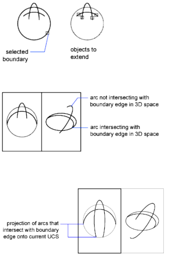
None Specifies no projection. Only objects that intersect with the boundary
edge in 3D space are extended.
UCS Specifies projection onto the XY plane of the current user coordinate
system (UCS). Objects that do not intersect with the boundary objects in 3D
space are extended.
View Specifies projection along the current view direction.
502 | Chapter 6 E Commands
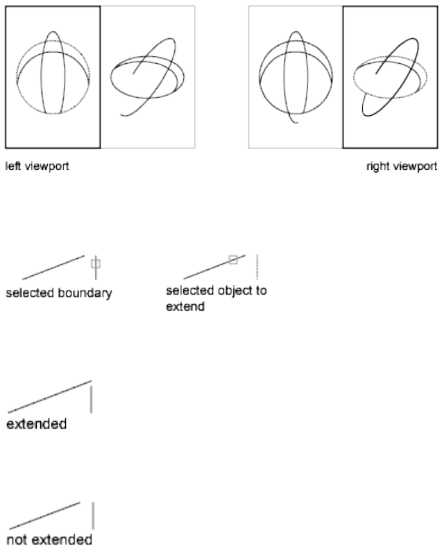
Edge
Extends the object to another object's implied edge, or only to an object that
actually intersects it in 3D space.
Extend Extends the boundary object along its natural path to intersect another
object or its implied edge in 3D space.
No Extend Specifies that the object is to extend only to a boundary object
that actually intersects it in 3D space.
Undo
Reverses the most recent changes made by EXTEND.
EXTEND | 503
EXTERNALREFERENCES
Quick Reference
See also:
■Attach and Detach Referenced Drawings
Opens the External References palette.
Access Methods
Button
Ribbon: Insert tab ➤ Reference panel ➤ ➤ External References
Menu: Insert ➤ External References
Toolbar: Reference
Summary
The EXTERNALREFERENCES command opens the External References palette
if the palette is inactive. If the External References palette is active but hidden,
executing EXTERNALREFERENCES will open the palette. If you click anywhere
outside of the External References palette, the palette returns to its auto-hidden
state.
NOTE The FILEDIA system variable is ignored when attaching files from the External
References palette.
External References Palette
Quick Reference
See also:
■Attach and Detach Referenced Drawings
504 | Chapter 6 E Commands

Manage external references attached to the current drawing.
Summary
The External References palette organizes, displays, and manages referenced
files, such as DWG files (xrefs), DWF, DWFx, PDF, or DGN underlays, and
raster images.
Only DWG, DWF, DWFx, PDF, and raster image files can be opened directly
from the External References palette.
The External References palette contains several buttons, and is split into two
panes. The upper pane, called the File References Pane, can display file
references in a list or in a tree structure. Shortcut menus and function keys
provide options for working with the files. The lower pane, called the Details
/ Preview Pane, can display properties for the selected file references or it can
display a thumbnail preview of the selected file reference.
NOTE When using the External References palette, it is recommended that you
turn on the Auto-hide feature or anchor the palette. The palette will then hide
automatically when you move the cursor away from the palette.
External References Palette Buttons
Quick Reference
See also:
■Attach and Detach Referenced Drawings
Use the buttons at the top of the External References palette to choose the
types of files to attach to the drawing and to refresh the status of file references
that you already have attached.
List of Options
The following options are displayed.
Attach (file type) Button
The Attach button displays a list of file types that you can attach. The following
options are displayed:
■Attach DWG. Starts the XATTACH command.
External References Palette | 505
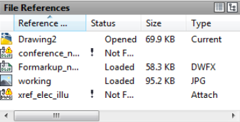
■Attach Image. Starts the IMAGEATTACH command.
■Attach DWF. Starts the DWFATTACH command.
■Attach DGN. Starts the DGNATTACH command
■Attach PDF. Starts the PDFATTACH command
Refresh/Reload All References Button
The following options are available:
Refresh Synchronizes the status data of referenced drawing files with the data
in memory.
Reload All References Updates all file references to ensure that the most
current version is used. Updating also occurs when you first open a drawing
that contains file references.
File References List View / Tree View Pane
Quick Reference
See also:
■Attach and Detach Referenced Drawings
The upper File References pane displays a list of all file references in the current
drawing. You can display these file references in a list or in a tree structure.
List of Options
The following options are displayed.
506 | Chapter 6 E Commands

List View
The listed information includes the reference name, status, file size, file type,
creation date and saved path.
Reference Name The reference name column always displays the current
drawing as the first entry, followed by additional attached files that are listed
in the order they were attached.
Status The status of the referenced file:
■Loaded - The referenced file is currently attached to the drawing.
■Unloaded - The referenced file is marked to be unloaded from the drawing.
■Not Found - The referenced file is no longer exists in the valid search paths.
■Unresolved - The referenced file cannot be read.
■Orphaned - The referenced file is attached to another file that has an
Unresolved status.
■Unreferenced - The referenced file is removed by either the delete or erase
tool instead of detach.
Size The size of the attached file reference.
Type The file type of the referenced file. Drawing (Xref) files display as
attachments or overlays, raster images show their file format; and DWF, DWFx,
DGN, and PDF underlays are listed as their respective file types.
Date The date when the referenced file was created or last saved.
Saved Path Displays the path that is saved with the drawing when the
referenced file is attached.
Tree View
The top level of the tree view always shows the current drawing. Referenced
files appear at the next level. Referenced files that contain their own nested
file references can be opened to show deeper levels. When making selections
in tree view, only one file reference can be selected at a time.
External References Palette | 507
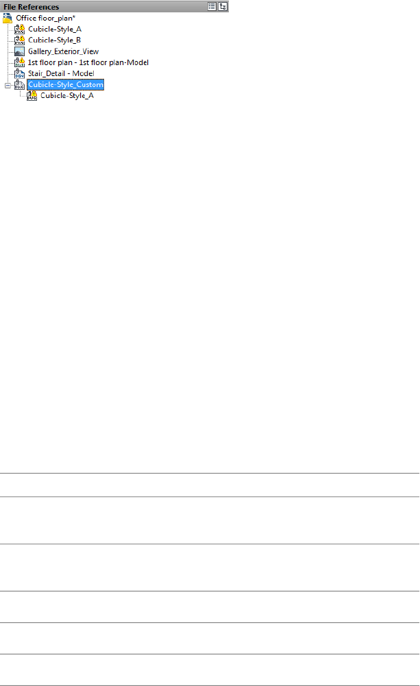
File References Pane Shortcut Menus and Function Keys
Quick Reference
See also:
■Attach and Detach Referenced Drawings
When working in the File References pane, there are several shortcut menus
that can be displayed when you right-click on file references or empty areas
of the pane. The following tables show the shortcut menu items that you are
presented under certain conditions.
No Reference Selected
When no file references are selected, the shortcut menu presents the following
functions:
DescriptionMenu Item
Reloads all referenced files. (Unavailable if no file references
are attached)
Reload All References
Selects all file references, excluding the current drawing.
This item is not displayed in tree view.
Select All
Starts the XATTACH command.Attach DWG
Starts the IMAGEATTACH command.Attach Image
Starts the DWFATTACH command.Attach DWF
508 | Chapter 6 E Commands
DescriptionMenu Item
Starts the DGNATTACH command.Attach DGN
Starts the PDFATTACH command.Attach PDF
Starts the -DGNBIND on page 287command.Bind DGN
Modifies the tooltip that appears when you hover over an
item in the list view of the palette.
Tooltip Style
Turns the display of the Preview/Details pane off and on.Preview/Details Pane
Closes the External References palette.Close
Reference Selected
When you select a file reference, the shortcut menu presents the following
functions:
Reference StatusDescriptionMenu Item
Available only for file refer-
ences with a Loaded status
Opens the selected reference file in
the original application in which it was
Open
- Unavailable when Un-created (specified by the operating
system). loaded, Not Found or Unre-
solved.
Always available - status has
no affect on this function.
Allows you to change settings such as
scale, insertion point, and path type.
Attach
You can also attach a different page
from the attached PDF file, a different
sheet from an attached DWF file, or a
different model name from an at-
tached DGN file.
Always available - status has
no affect on this function.
Unloads the selected file references.Unload
Always available - status has
no affect on this function.
Reloads the selected file references.Reload
Available for all file refer-
ences except data link.
Detaches the selected file references.Detach
External References Palette | 509
Reference StatusDescriptionMenu Item
Available only for file refer-
ences with a Loaded status
Displays the Bind Xrefs dialog box.
Only available for referenced DWG
Bind
- Unavailable when Un-files. This is not available for images
and underlays. loaded, Not Found or Unre-
solved.
Details / Preview Pane
Quick Reference
See also:
■Attach and Detach Referenced Drawings
The lower data pane of the External References palette can be set to display
file reference properties or a preview image of the selected file reference.
List of Options
The following options are displayed.
Details Pane
When displaying the Details mode, properties for the selected file reference
are reported. Each file reference has a core set of properties and some file
references, like referenced images, display properties specific to the file type.
The core set of details include the reference name, status, file size, file type,
creation date, saved path and found at path. Some of the properties can be
edited.
Reference Name Displays the file reference name. This property can be edited
only if single file references are selected. The reference name shows *Varies* if
multiple file references are selected. This property is editable for all the file
references.
510 | Chapter 6 E Commands
Status Shows whether the file reference is loaded, unloaded or not found.
This property cannot be edited.
Size Shows the file size of the selected file reference. The size is not displayed
for file references that are unloaded or not found. This property cannot be
edited.
Type Indicates whether the file reference is an attachment or overlay, the
type of image file, a DWF/DWFx underlay, DGN underlay, or PDF underlay.
This property cannot be edited.
However, if the file reference is a DWG xref, the Attach or Overlay property
can be toggled.
Date Displays the last date the file reference was modified. This date is not
displayed if the file reference is unloaded or not found. This property cannot
be edited.
Saved Path Shows the saved path of the selected file reference (this is not
necessarily where the file reference is found). This property cannot be edited.
Found At Displays the full path of the currently selected file reference. This
is where the referenced file is actually found and is not necessarily the same
as the saved path. Clicking the […] button displays the Select Image File dialog
box where you can select a different path or file name. You can also type
directly into the path field. These changes are stored to the Saved Path property
if the new path is valid.
File Version File Version property defined by the Vault client. This property
is only displayed when you are logged into the Vault.
Specific Image Properties
If you select a referenced image, additional properties are displayed. None of
the added image properties can be edited.
Color System Displays the color system.
Color Depth The amount of information that is stored in each pixel of a raster
image. Higher color depth values produce smoother degrees of shading.
Pixel Width The width of the raster image measured in pixels.
Pixel Height The height of the raster image measured in pixels.
Resolution The width and height resolution in dots per inch (dpi).
Default Size (in AutoCAD units) The width and height of the raster image
measured in AutoCAD units.
External References Palette | 511
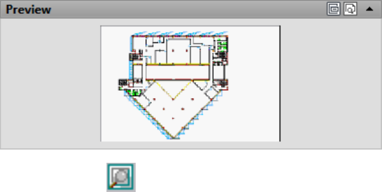
Preview Pane
The preview image is displayed only when a single file reference is selected
from the File References pane. There are no other controls for this data pane.
When no reference file is selected, the preview pane displays a solid grey field.
If there is no preview available, the text “Preview not available” is displayed
in the center of the pane.
Messaging Field
Below the Details / Preview pane is a messaging field that supplies information
about certain selected file references. When you select one or more nested
references, information is displayed regarding the file references. Messages
also appear if you decide the change the name of a file reference.
EXTERNALREFERENCESCLOSE
Quick Reference
See also:
■Attach and Detach Referenced Drawings
Closes the External References palette.
Summary
The EXTERNALREFERENCESCLOSE command closes the External References
palette when currently displayed, either in an auto-hidden state or open state.
512 | Chapter 6 E Commands
F Commands
FIELD
Quick Reference
See also:
■Use Fields in Text
Creates a multiline text object with a field that can be updated automatically
as the field value changes.
Access Methods
Button
Ribbon: Insert tab ➤ Data panel ➤ Field
Menu: Insert ➤ Field
Shortcut menu: Right-click while editing text in an in-place text editor, and
click Insert Field.
Summary
Fields can be inserted in any kind of text except tolerances. The FIELDEVAL
system variable and the UPDATEFIELD command determine how fields are
updated.
7
513
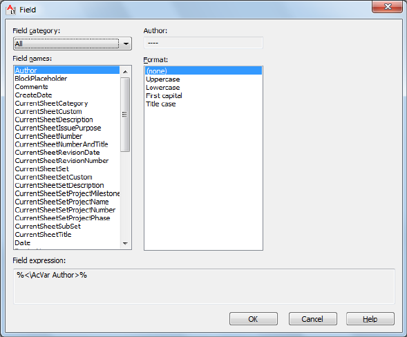

Field Category Sets the types of fields to be listed under Field Names (for
example, Date & Time, Document, and Objects).
Field Names Lists the fields that are available in a category. Select a field name
to display the options available for that field.
Field Value Displays the current value of the field, or displays an empty string
(----) if the field value is invalid.
The label for this item changes with the field name. For example, when
Filename is selected in the Field Names list, the label is Filename and the value
is the name of the current drawing file. The label is Property for object fields.
Exception: when a date field is selected, the selected date format is displayed;
for example, M/d/yyyy.
Format List Lists options for display of the value of the field. For example,
date fields can display the name of the day or not, and text strings can be
uppercase, lowercase, first capital, or title case. The value displayed in the
Fields dialog box reflects the format that you select.
Field Expression Displays the expression that underlies the field. The field
expression cannot be edited, but you can learn how fields are constructed by
reading this area.
Options for Sheet Set and Sheet View Fields
Sheet Set Specifies the name of the sheet set.
Sheet Navigation Tree Displays a tree view of sheets or sheet views from the
Sheet Set Manager, from which you can select an item for the field.
Property Displays the properties available as fields for the item selected in
the tree.
Associate Hyperlink Adds a hyperlink to the field when it is created. You
can use Ctrl + click to jump to the sheet or view. This option is not available
for the ViewportScale field.
NOTE If you recreate the field, because the sheet is already in a sheet set, you
should use a sheet set property field, not a placeholder field.
Sheet set fields (fields that were selected from the sheet set category) behave
differently than other types of fields. By default, other types of fields update
automatically when you save the drawing or when you use REGEN. In contrast,
sheet set fields store the last values that were used, and they display these
stored values if the information referenced by the sheet set field is not
accessible. To update the value in a sheet set field, use UPDATEFIELD
command.
Field Dialog Box | 515

NOTE If the information referenced by sheet set field is not accessible, the value
for the field will be displayed as “####.”
Options for BlockPlaceholder Fields
BlockPlaceholder fields are only available for insertion in the Attribute
Definition dialog box when the Block Editor is open.
Block Name Displays the name of the current block definition.
Temporary Value Displays the value for the placeholder field in the selected
format.
Block Reference Properties Displays a list of block reference properties for
the current block definition.
Options for SheetSetPlaceholder Fields
Placeholder Type Displays a list of available placeholder fields.
Temporary Value Displays the value for the placeholder field in the selected
format.
For example, with SheetSet Placeholder selected in the Field Names list,
SheetTitle selected in the Placeholder Type list, and Uppercase selected in the
Format list, Temporary Value displays SHEETTITLE. When the drawing is
placed in a sheet set, this field displays the title of the sheet.
Options for Fields in the Objects Field Category
Named Object Type/Object Type When NamedObject is selected in Field
Names, lists the types of named objects in the drawing. When Object is
selected, displays the type of object selected. Use the Select Object button to
temporarily close the dialog box and select an object in the drawing.
Property/Name When NamedObject is selected in Field Names, lists the
names of all the objects in the drawing of the selected type. When Object is
selected in Field Names, lists the properties of the selected object that are
available as fields. When a block with attributes is selected, the attribute names
are displayed in the list of properties.
Formula
When Formula is selected in Field Names, provides a place for creating a
formula to insert in text or in a table cell.
Average/Sum/Count When Formula is selected in Field Names, closes the
Field dialog box temporarily while you specify table cells. The result is
appended to the formula.
516 | Chapter 7 F Commands
Cell When Formula is selected in Field Names, closes the Field dialog box
temporarily while you specify a table cell. The cell address is appended to the
formula.
Precision Specifies precision for fields based on the selected format. Select
Current Precision to use the current setting of the LUPREC on page 1574 system
variable.
Additional Format Displays the Additional Format dialog box.
Evaluate Updates the value in Preview when you have manually changed the
text in Formula.
Display Value for Block Reference Specifies that the object property fields
in a block reference evaluate the properties of nested objects relative to the
block reference's size and orientation within the drawing, not within the block
definition.
FILL
Quick Reference
See also:
■Control the Display of Polylines, Hatches, Gradient Fills, Lineweights, and
Text
Controls the filling of objects such as hatches, 2D solids, and wide polylines.
List of Prompts
The following prompts are displayed.
Enter mode [ON/OFF] <current>: Enter on or off, or press Enter
On Turns on Fill mode. For the filling of a 3D object to be visible, its extrusion
direction must be parallel to the current viewing direction, and hidden lines
must not be suppressed.
FILL | 517
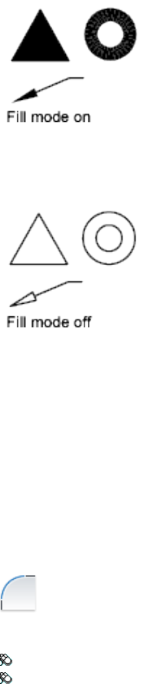
Off Turns off Fill mode. Only the outlines of objects are displayed and plotted.
Changing Fill mode affects existing objects after the drawing is regenerated.
The display of lineweights is not affected by the Fill mode setting.
FILLET
Quick Reference
See also:
■Create Fillets
Rounds and fillets the edges of objects.
Access Methods
Button
Ribbon: Home tab ➤ Modify panel ➤ Fillet.
Menu: Modify ➤ Fillet
518 | Chapter 7 F Commands
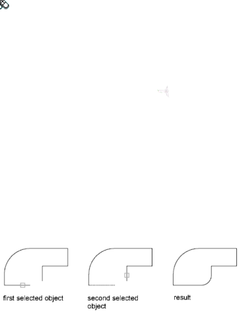
Toolbar: Modify
Summary
In the example, an arc is created that is tangent to both of the selected lines.
The lines are trimmed to the ends of the arc. To create a sharp corner instead,
enter a radius of zero.
You can fillet arcs, circles, ellipses, elliptical arcs, lines, polylines, rays, splines,
and xlines.
List of Prompts
The following prompts are displayed.
Current settings: Mode = current, Radius = current
Select first object or [Undo/Polyline/Radius/Trim/Multiple]: Use an object
selection method or enter an option
First Object
Selects the first of two objects required to define a 2D fillet.
Select second object or shift-select to apply corner: Use an object selection method
or hold down Shift and select an object to create a sharp corner
If you select lines, arcs, or polylines, their lengths adjust to accommodate the
fillet arc. You can hold down Shift while selecting the objects to override the
current fillet radius with a value of 0.
If the selected objects are straight line segments of a 2D polyline, they can be
adjacent or separated by one other segment. If they are separated by another
polyline segment, FILLET deletes the segment that separates them and replaces
it with the fillet.
More than one fillet can exist between arcs and circles. Select the objects close
to where you want the endpoints of the fillet.
FILLET | 519
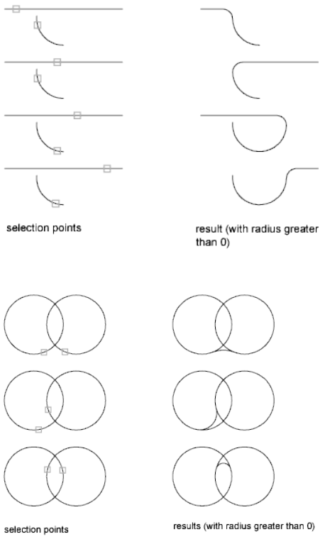
FILLET does not trim circles; the fillet arc meets the circle smoothly.
Loop
Specifies a loop of edges on the face of a solid. For any edge, there are two
possible loops. After selecting a loop edge, you are prompted to Accept the
current selection, or choose the Next loop.
Undo
Reverses the previous action in the command.
Polyline
Inserts fillet arcs at each vertex of a 2D polyline where two line segments meet.
520 | Chapter 7 F Commands
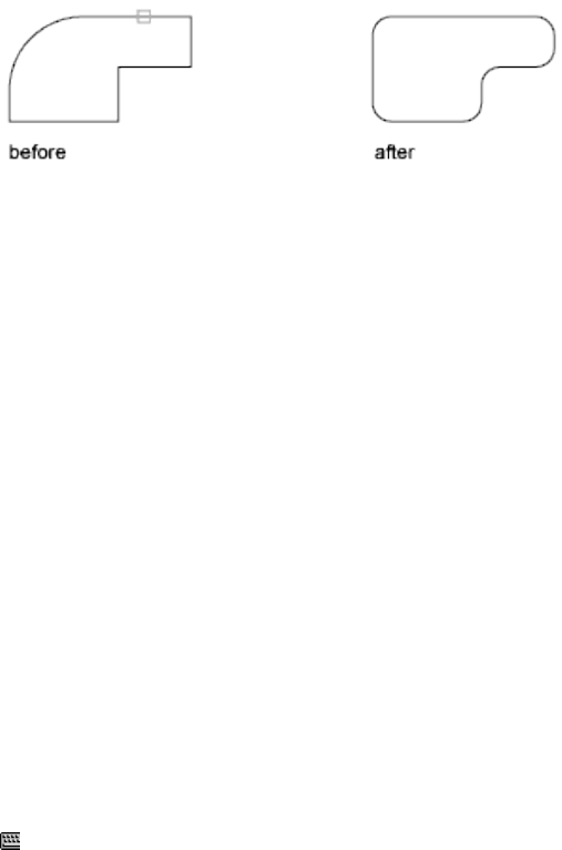
Select 2D polyline:
If one arc segment separates two line segments that converge as they approach
the arc segment, FILLET removes the arc segment and replaces it with a fillet
arc.
Radius
Defines the radius of the fillet arc.
The value you enter becomes the current radius for subsequent FILLET
commands. Changing this value does not affect existing fillet arcs.
Trim
Controls whether FILLET trims the selected edges to the fillet arc endpoints.
Multiple
Rounds the edges of more than one set of objects.
FILTER
Quick Reference
See also:
■Select Objects by Properties
Creates a list of requirements that an object must meet to be included in a
selection set.
Access Methods
Command entry: 'filter for transparent use
Summary
The Object Selection Filters dialog box is displayed.
FILTER | 521
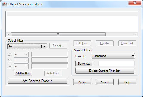
Object Selection Filters Dialog Box
Quick Reference
See also:
■Select Objects by Properties
Selects, edits, and names filters for object selection.
List of Options
The following options are displayed.
Filter Property List
Displays a list of the filter properties that compose the current filter. The
current filter is the filter that you select in Current in the Named Filters area.
Select Filter
Adds filter properties to the current filter.
Object Types and Logical Operators Lists object types that you can filter and
logical operators (AND, OR, XOR, and NOT) for grouping the filter expressions.
522 | Chapter 7 F Commands
If you use logical operators, make sure that you pair and balance them correctly
in the filter list. The number of operands you can enclose depends on the
operation.
Logical operators
Ending operatorEnclosesStarting operator
End ANDOne or more operandsBegin AND
End OROne or more operandsBegin OR
End XORTwo operandsBegin XOR
End NOTOne operandBegin NOT
For example, the following filter selects all circles except the ones with a radius
greater than or equal to 1.0:
Object =Circle
**Begin NOT
Circle Radius >= 1.00
**End NOT
X, Y, Z Parameters Define additional filter parameters depending on the
object. For example, if you select Line Start, you can enter the X, Y, and Z
coordinate values that you want to filter.
In the filter parameters, you can use relative operators such as < (less than) or
> (greater than). For example, the following filter selects all circles with center
points greater than or equal to 1,1,0 and radii greater than or equal to 1:
Object = Circle
Circle Center X >= 1.0000 Y >= 1.0000 Z >= 0.0000
Circle Radius >= 1.0000
Select Displays a dialog box listing all items of the specified type in the
drawing. Select the items to filter. For example, if you select the object type
Color, Select displays a list of colors to choose for the filter.
Add to List Adds the current Select Filter property to the filter list. Filter
properties that you add to the unnamed filter remain available during the
current work session unless you manually delete them.
Substitute Replaces the filter property selected in the filter property list with
the one displayed in Select Filter.
Object Selection Filters Dialog Box | 523

Add Selected Object Adds one selected object in the drawing to the filter list.
Edit Item
Moves the selected filter property into the Select Filter area for editing. The
edited filter replaces the selected filter property.
Delete
Deletes a selected filter property from the current filter.
Clear List
Deletes all the listed properties from the current filter.
Named Filters
Displays, saves, and deletes filters.
Current Displays saved filters. Select a filter list to make it current. The named
filter and its list of properties are loaded from the default file, filter.nfl.
Save As Saves a filter and its list of properties. The filter is saved in the filter.nfl
file. Names can contain up to 18 characters.
Delete Current Filter List Deletes a filter and all its properties from the default
filter file.
Apply
Exits the dialog box and displays the Select Objects prompt, where you create
a selection set. The current filter is used on the objects you select.
FIND
Quick Reference
See also:
■Find and Replace Text
Finds the text that you specify, and can optionally replace it with other text.
Access Methods
Button
524 | Chapter 7 F Commands

Ribbon: Annotate tab ➤ Text panel ➤ Find Text
Menu: Edit ➤ Find
Toolbar: Text Formatting
Shortcut menu: With no commands active, right-click in the drawing area
and click Find.
Summary
The Find and Replace dialog box is displayed.
Find and Replace Dialog Box - FIND
Quick Reference
See also:
■Find and Replace Text
Specifies the text you want to find, replace, or select and controls the scope
and results of the search.
List of Options
The following options are displayed.
Find and Replace Dialog Box - FIND | 525
Find What
Specifies the text string you want to find. Enter a text string, including any
wild-card characters, or choose one of the six most recently used strings from
the list.
For more information on wild-card searches, see Find and Replace Text in the
User’s Guide.
Replace With
Specifies the text string you want to use to replace the found text. Enter a
string, or choose one of the most recently used strings from the list.
Find Where
Specifies whether to search the entire drawing, the current layout, or the
currently-selected object. If an object is already selected, then Selected Objects
is the default value. If no object is selected, then Entire Drawing is the default
value. You can use the Select Objects button to temporarily close the dialog
box and create or modify the selection set.
Select Objects Button
Closes the dialog box temporarily so that you can select objects in your
drawing. Press Enter to return to the dialog box.
When you select objects, Find Where displays Selected Objects by default.
List Results
Lists results in a table displaying the location (model or paper space), object
type, and text. The resulting table can be sorted by column.
Advanced Find Options
Displays options to define the type of objects and words that you want to
find.
Replace
Replaces found text with the text that you enter in Replace With.
Replace All
Finds all instances of the text that you enter in Find What and replaces it with
the text in Replace With.
The Find Where setting controls whether to find and replace text in the entire
drawing or text in the currently selected object or objects.
Zoom to Highlighted Result
526 | Chapter 7 F Commands
Zooms to the selected object in the list. You can also zoom to a result when
you double-click the selected object.
Create Selection Set (Highlighted)
Creates a selection set from the objects that contain the text highlighted on
the list of results. The selected objects must all be located either in model
space or in a single layout.
Create Selection Set (All)
Creates a selection set from all the objects that contain the text on the list of
results. The objects must all be located either in model space or in a single
layout.
Find
Finds the text that you enter in Find What. If you have not entered text in
Find What, this option is not available. Found text is zoomed to or displayed
in the List Results table. Once you find the first instance of the text, the Find
option becomes Find Next, which you can use to find the next instance.
Search Options
Defines the type of objects and words to be found.
Match Case
Includes the case of the text in Find What as part of the search criteria.
Find Whole Words Only
Finds only whole words that match the text in Find What. For example, if
you select Find Whole Words Only and search for “Front Door,” FIND does
not locate the text string “Front Doormat.”
Use Wildcards
Allows the use of wild-card characters in searches.
For more information on wild-card searches, see Find and Replace Text in the
User’s Guide.
Search XRefs
Includes text in externally referenced files in search results.
Search Blocks
Includes text in blocks in search results.
Ignore Hidden Items
Find and Replace Dialog Box - FIND | 527
Ignores hidden items in search results. Hidden items include text on layers
that are frozen or turned off, text in block attributes created in invisible mode,
and text in visibility states within dynamic blocks.
Match Diacritics
Matches diacritical marks, or accents, in search results.
Match Half or Full Width Forms
Matches half- and full-width characters in search results.
Text Types
Specifies the type of text objects you want to include in the search. By default,
all options are selected.
Block Attribute Value
Includes block attribute text values in search results.
Dimension or Leader Text
Includes dimension and leader object text in search results.
Single-Line or Multiline Text
Includes text objects such as single-line and multiline text in search results.
Table Text
Includes text found in AutoCAD LT table cells in search results.
Hyperlink Description
Includes text found in hyperlink descriptions in search results.
Hyperlink
Includes hyperlink URLs in search results.
528 | Chapter 7 F Commands

G Commands
GEOGRAPHICLOCATION
Quick Reference
See also:
■Specify the Geographic Location of a Drawing
Specifies the geographic location information for a drawing file.
Access Methods
Button
Menu: Tools ➤ Geographic Location
Summary
Appears only if a geographic location does
not exist, and the drawing does not con-
tain a foreign coordinate system.
Define Geographic Location Dialog Box on
page 530
Appears if a geographic location exists, and
the drawing does not contain a foreign
coordinate system.
Location Already Exists Dialog Box on page
530
8
529

Appears if an alternate coordinate system
is found.
Coordinate System Already Defined Dialog
Box on page 531
Define Geographic Location Dialog Box
Quick Reference
See also:
■Specify the Geographic Location of a Drawing
Defines a geographic location.
List of Options
The following options are displayed.
Import a .kml or a .kmz File Displays the Import a .kml or .kmz file dialog
box.
Import the Current Location from Google Earth Retrieves location
information from a specific location in Google Earth.
NOTE Google Earth should be installed and open with the location selected.
Enter the Location Values Displays the Geographic Location Dialog Box,
where you can enter the location information manually.
See also:
■Geographic Location Dialog Box
Location Already Exists Dialog Box
Quick Reference
See also:
■Specify the Geographic Location of a Drawing
530 | Chapter 8 G Commands
Enables you to edit, redefine, or remove an existing location.
List of Options
The following options are displayed.
Edit Current Geographic Location Displays the Geographic Location Dialog
Box on page 532, where you can edit the existing location information.
Redefine Geographic Location Displays the Define Geographic Location
Dialog Box on page 530, where you can redefine the geographic location.
Remove Geographic Location Displays a confirmation dialog box before
removing the geographic location.
Coordinate System Already Defined Dialog Box
Quick Reference
See also:
■Specify the Geographic Location of a Drawing
Provides an option to convert the alternate coordinate system to the LL84
coordinate system used by AutoCAD.
List of Options
The following options are displayed.
Leave existing coordinate system Does not convert the alternate coordinate
system to the LL84 coordinate system.
Convert to AutoCAD’s coordinate system Converts the alternate coordinate
system to AutoCAD’s LL84 coordinate system.
Coordinate System Already Defined Dialog Box | 531
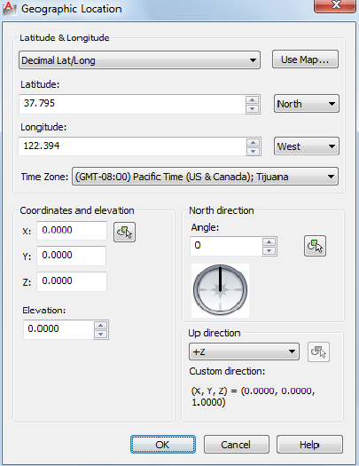
Geographic Location Dialog Box
Quick Reference
See also:
■Specify the Geographic Location of a Drawing
Sets the latitude, longitude, and north direction of a geographic location in
a drawing.
List of Options
The following options are displayed.
Latitude and Longitude
Displays or sets latitude, longitude, and direction in decimal values.
Decimal Lat / Long
532 | Chapter 8 G Commands
Sets the format of the latitude and longitude representation in the drawing.
Use Map Displays the Location Picker Dialog Box on page 535.
Specifies a location by using the pointing device.
The latitude and longitude values are updated when you select a location.
If you enter latitude and longitude values, then the map displays the updated
location.
Latitude
Sets the latitude of the current location. You can enter a value or select a
location on the map.
The valid range is -90 and +90 as a floating point number.
(LATITUDE on page 1562 system variable).
North/South
Controls whether a positive value is north of the equator or a positive value
is south of the equator.
Longitude
Displays the longitude of the current location. You can enter a value or select
a location on the map.
The valid range is -180 to +180 as a floating point number.
(LONGITUDE on page 1573 system variable).
East/West
Controls whether a positive value is west of the Prime Meridian or a positive
value is east of the Prime Meridian.
Time Zone
Specifies the time zone. Time zones are estimated by reference to the location.
You can set the time zone directly.
TIMEZONE on page 1684 (system variable).
Coordinates and Elevation
Sets the values for the World Coordinate System (WCS), X,Y,Z, and the
elevation.
X
Sets the X component of the world coordinate system for the geographic
location.
Geographic Location Dialog Box | 533
Y
Sets the Y component of the world coordinate system for the geographic
location.
Z
Sets the Z component of the world coordinate system for the geographic
location.
Pick Point
Specifies the X, Y, and Z values of the Geographic Location marker based on
the World Coordinate System (WCS).
Elevation
Sets the relative height along the specified up-direction defined for a geographic
location.
North Direction
By default, north is the positive Y direction in the World Coordinate System
(WCS).
Angle
Specifies the angle from 0 for the north direction
Pick Point
Specifies the north angle based on the direction vector specified. A rubber
band line appears denoting the north direction.
Interactive North Direction Preview
Specifies the north angle. The range is 0-359.9.
Up Direction
By default, the up direction is the positive Z-axis (0,0,+1). The Up direction
and the north direction are always constrained such that they are perpendicular
to each other.
Up Direction
Sets the up direction.
Pick Point
Specifies the up direction (from the current WCS coordinate) based on the
direction vector specified.
Enabled only if the up direction is set to Custom.
534 | Chapter 8 G Commands
Location Picker Dialog Box
Quick Reference
See also:
■Specify the Geographic Location of a Drawing
Sets the latitude and longitude of the selected location.
List of Options
The following options are displayed.
Map
Specifies a location on the map.
Region
Specifies a region of the world.
Nearest City
Specifies a city in the selected region.
Time Zone
Time zones are estimated by reference to the location. You can set the time
zone directly (TIMEZONE on page 1684 system variable).
Nearest Big City
Uses the latitude and longitude values for the nearest big city that you select.
See also:
■Geographic Location Dialog Box on page 532
Location Picker Dialog Box | 535
GETENV
Quick Reference
See also:
■Overview of Hatch Patterns and Fills
Shows values of specified system registry variables.
Summary
The values of system registry variables can be displayed with GETENV. Use
GETENV to view the registry settings of the MaxArray and MaxHatch registry
variables.
GETENV is case sensitive, so MaxArray and MaxHatch must be entered exactly
as shown. For example, to display the current value for MaxHatch, enter
List of Prompts
The following prompts are displayed.
Enter variable name: Enter the variable name
Command: getenv
Enter variable name: MaxHatch
10000
GETLINK
Quick Reference
See also:
■Use AutoCAD WS for Drawing File Collaboration
Generates a URL to the AutoCAD WS online copy of the current drawing.
536 | Chapter 8 G Commands
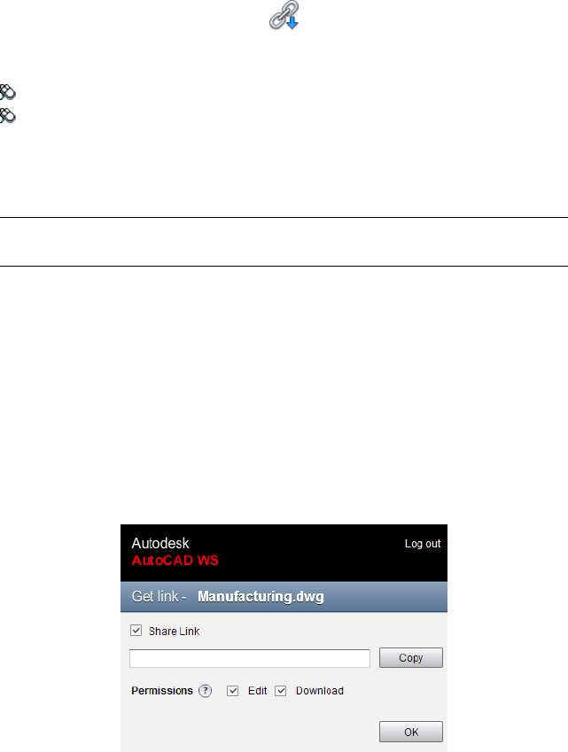
Access Methods
Button
Ribbon: Online tab ➤ Share panel ➤ Get Link
Menu: File ➤ AutoCAD WS ➤ Get Link
Summary
The Get Link dialog box on page 537 is displayed.
NOTE You may first be prompted to log in to AutoCAD WS. If you do not have
an account, click Create an Account and follow the on-screen instructions.
Get Link Dialog Box
Quick Reference
See also:
■Use AutoCAD WS for Drawing File Collaboration
Generates a URL to the AutoCAD WS online copy of the current drawing.
Summary
A public URL is provided to the online copy of the current drawing. Clicking
the generated link opens the drawing in a new AutoCAD WS Editor in a
Get Link Dialog Box | 537
browser. You can control whether recipients can edit the drawing online or
download a local copy. Use this link to allow recipients without AutoCAD WS
accounts to view or edit the drawing online.
List of Options
The following options are displayed.
Share Link Generates a link to an online copy of the current drawing.
Distribute this link to recipients so they may access the online file.
Copy Copies the link to the clipboard.
Permissions Defines the access permissions for each recipient.
■Edit. Allows recipients to edit any object in the shared drawing. When this
option is cleared, recipients can mark up and add to the drawing, but they
cannot change existing objects.
■Download. Allows recipients to download a copy of the drawing.
GOTOURL
Quick Reference
See also:
■Use a Hyperlink to Access a File or a Web Page
Opens the file or web page associated with the hyperlink attached to an object.
Summary
Select an object that has an attached hyperlink. The file or web page (URL)
that is associated with the hyperlink opens.
538 | Chapter 8 G Commands
GRADIENT
Quick Reference
See also:
■Choose a Hatch Pattern or Fill
Fills an enclosed area or selected objects with a gradient fill.
Access Methods
Button
Ribbon: Home tab ➤ Draw panel ➤ Gradient
Menu: Draw ➤ Gradient
Toolbar: Draw
Summary
When the ribbon is active, the Hatch Creation contextual tab on page 558 is
displayed. When the ribbon is off, the Hatch and Gradient dialog box on page
546 is displayed.
A gradient fill creates a smooth transition between one or two colors.
GRAPHSCR
Quick Reference
See also:
■Navigate and Edit Within the Command Window
Switches from the text window to the drawing area.
GRADIENT | 539
Access Methods
Command entry: 'graphscr for transparent use
Summary
GRAPHSCR closes the text window. You can also press F2 to open or close the
text window. This command is ignored on dual-screen systems.
GRID
Quick Reference
See also:
■Adjust Grid and Grid Snap
Displays a grid pattern in the current viewport.
Access Methods
Menu: Tools ➤ Drafting Settings
Toolbar: Status bar ➤ Grid
List of Prompts
The following prompts are displayed.
Specify grid spacing(X) or [ON/OFF/Snap/Major/aDaptive/Limits/Follow/Aspect]
<current>: Specify a value or enter an option
Grid Spacing (X) Sets the grid to the specified value. Entering x after the value
sets the grid spacing to the specified value multiplied by the snap interval.
On Turns on the grid using the current spacing.
Off Turns off the grid.
Snap Sets the grid spacing to the snap interval specified by the SNAP
command.
Major Specifies the frequency of major grid lines compared to minor grid
lines. Grid lines rather than grid dots are displayed when SHADEMODE is set
to Hidden. (GRIDMAJOR system variable)
540 | Chapter 8 G Commands

Adaptive Controls the density of grid lines when zoomed in or out.
■Adaptive Behavior. Limits the density of grid lines or dots when zoomed
out. This setting is also controlled by the GRIDDISPLAY system variable.
■Allow Subdivision Below Grid Spacing. If turned on, generates additional,
more closely spaced grid lines or dots when zoomed in. The frequency of
these grid lines is determined by the frequency of the major grid lines.
Limits Displays the grid beyond the area specified by the LIMITS command.
Follow Changes the grid plane to follow the XY plane of the dynamic UCS.
This setting is also controlled by the GRIDDISPLAY system variable.
Aspect Changes the grid spacing in the X and Y directions, which can have
different values.
Entering x following either value defines it as a multiple of the snap interval
rather than the drawing units.
The Aspect option is not available when the current snap style is Isometric.
GROUP
Quick Reference
See also:
■Group Objects
Creates and manages saved sets of objects called groups.
Access Methods
Button
Ribbon: Home tab ➤ Groups panel ➤ Group
Menu: Tools ➤ Group
Toolbar: Group
If you enter -group at the Command prompt, options are displayed.
GROUP | 541
-GROUP
Related procedures:
■Group Objects
Creates and manages saved sets of objects called groups.
List of Prompts
The following prompts are displayed.
Enter a group option [?—List Groups on page 542/Order on page 542/Add on
page 542/Remove on page 542/Explode on page 542/REName on page
542/Selectable on page 542/Create on page 543] <Create>: Enter an option or press
Enter
?—List Groups
Lists names and descriptions of groups defined in the drawing.
Order
Changes the numerical order of objects within a group. Reordering is useful
when creating tool paths. For example, you can change the cut order for the
horizontal and vertical lines of a tool path pattern.
Position Number
Reverse Order
Add
Adds objects to a group.
Remove
Removes objects from a group.
If you remove all the group's objects, the group remains defined. You can
remove the group definition from the drawing by using the Explode option.
Explode
Deletes a group definition by exploding the group into its component objects.
Rename
Assigns a new name to an existing group.
Selectable
Specifies whether a group is selectable. When a group is selectable, selecting
one object in the group selects the whole group. Objects on locked or frozen
layers are not selected.
542 | Chapter 8 G Commands
Create
Creates a group.
Group names can be up to 31 characters long and can include letters, numbers,
and special characters dollar sign ($), hyphen (-), and underscore (_) but not
spaces. The name is converted to uppercase characters.
GROUPEDIT
Quick Reference
See also:
■Group Objects
Adds and removes objects from the selected group, or renames a selected
group.
Access Methods
Button
Ribbon: Home tab ➤ Groups panel ➤ Group Edit
Toolbar: Group
Summary
For existing groups, add or remove objects; or rename a group.
The following prompts are displayed.
Select group or [Name]:
In the drawing area, select a group or enter the name of a group. If a selected
object is not included in a group, you are prompted again.
List of Options
When a group is selected, the following options are displayed.
Enter an option [Add objects on page 544/Remove objects on page 544/REName
on page 544]:
GROUPEDIT | 543
Add Objects Select objects to add to the current group.
Remove Objects Select grouped objects to remove from the current group.
Rename Name or rename the current group.
544 | Chapter 8 G Commands
H Commands
HATCH
Quick Reference
See also:
■Overview of Hatch Patterns and Fills
Fills an enclosed area or selected objects with a hatch pattern, solid fill, or
gradient fill.
Access Methods
Button
Ribbon: Home tab ➤ Draw panel ➤ Hatch
Menu: Draw ➤ Hatch
Toolbar: Draw
Summary
When the ribbon is active, the Hatch Creation contextual tab on page 558 is
displayed. When the ribbon is off, the Hatch and Gradient dialog box on page
546 is displayed.
If you enter -hatch at the Command prompt, options are displayed on page 565.
9
545
NOTE To prevent the creation of an enormous number of hatch lines, the
maximum number of hatch lines created in a single hatch operation is limited.
This limit prevents memory and performance problems. However, you can change
the maximum number of hatch lines with the HPMAXLINES on page 1543 system
variable.
Choose from several methods to specify the boundaries of a hatch.
■Specify a point in an area that is enclosed by objects.
■Select objects that enclose an area.
■Specify boundary points using the -HATCH Draw option.
■Drag a hatch pattern into an enclosed area from a tool palette or
DesignCenter.
Hatch and Gradient Dialog Box
Quick Reference
See also:
■Overview of Hatch Patterns and Fills
Defines the boundaries, pattern, or fill properties, and other parameters for
hatches and fills.
List of Options
■Hatch tab on page 551
■Gradient tab on page 553
■More Options section on page 555
■Add: Pick Points on page 547
546 | Chapter 9 H Commands

■Add: Select Objects on page 547
■Remove Boundaries on page 548
■Recreate Boundary on page 549
■View Selections on page 549
■Select Boundary Objects on page 549
■Options on page 549
■Inherit Properties on page 550
■Preview on page 550
Add: Pick Points
Determines a boundary from existing objects that form an enclosed area
around the specified point.
Pick Internal Point While specifying internal points, you can right-click in
the drawing area at any time to display a shortcut menu that contains several
options.
If you turn on Island Detection, objects that enclose areas within the outermost
boundary are detected as islands. How HATCH detects objects using this option
depends on which island detection method is specified.
NOTE Red circles are displayed at unconnected endpoints of boundary objects
to identify gaps in the hatch boundary. These circles are temporary and can be
removed with REDRAW on page 1070 or REGEN on page 1079.
Add: Select Objects
Determines a boundary from selected objects that form an enclosed area.
Hatch and Gradient Dialog Box | 547
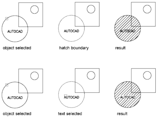
Select Objects Interior objects are not automatically detected. You must select
the objects within the selected boundary to hatch or fill those objects according
to the current island detection style.
Each time you click Select Objects, HATCH clears the previous selection set.
While selecting objects, you can right-click at any time in the drawing area
to display a shortcut menu. You can undo the last selection or all selections,
change the selection method, change the island detection style, or preview
the hatch or fill.
Remove Boundaries
Removes from the boundary definition any of the objects that were added
previously.
Select Objects Removes objects from the boundary definition.
548 | Chapter 9 H Commands
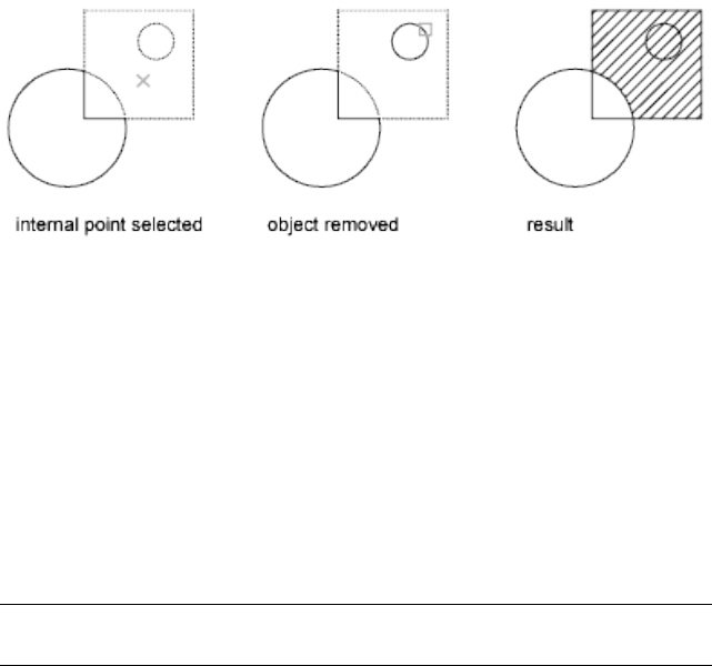
Add Boundaries Adds objects to the boundary definition.
Recreate Boundary
Creates a polyline or region around the selected hatch or fill, and optionally
associates the hatch object with it.
View Selections
Displays the currently defined boundaries with the current hatch or fill settings.
This option is available only when a boundary has been defined.
Select Boundary Objects
Selects the objects that form the boundaries of the selected associative hatch
object. Use the displayed grips to modify the hatch boundaries.
NOTE This option is available only in the Hatch Edit dialog box on page 573and
replaces the View Selections option.
When you select an associative hatch, a single, circular grip called the control
grip is displayed. No boundary grips are displayed because the boundaries of
an associative hatch can be modified only by changing its associated boundary
objects. Use the Select Boundary Objects option to select and grip-edit the
boundary objects.
To modify the boundaries of a nonassociative hach, you modify the boundaries
of the hatch object itself. Thus, when you select a nonassociative hatch, both
the control grip and the boundary grips are displayed.
Options
Controls several commonly used hatch or fill options.
Annotative
Specifies that the hatch is . This property automates the process of scaling
annotations so that they plot or display at the correct size on the paper.
(HPANNOTATIVE on page 1534 system variable)
Hatch and Gradient Dialog Box | 549
Associative
Specifies that the hatch or fill is associative. A hatch or fill that is associative
is updated when you modify its boundary objects. (HPASSOC system variable)
Create Separate Hatches
Controls whether a single hatch object or multiple hatch objects are created
when several separate closed boundaries are specified. (HPSEPARATE system
variable)
Draw Order
Assigns a draw order to a hatch or fill. You can place a hatch or fill behind all
other objects, in front of all other objects, behind the hatch boundary, or in
front of the hatch boundary. (HPDRAWORDER system variable)
Layer
Assigns new hatch objects to the specified layer, overriding the current layer.
Select Use Current to use the current layer. (HPLAYER on page 1542 system
variable)
Transparency
Sets the transparency leve for new hatch or fills, overriding the current object
transparency. Select Use Current to use the current object transparency setting.
(HPTRANSPARENCY on page 1548 system variable)
Inherit Properties
Hatches or fills specified boundaries using the hatch or fill properties of a
selected hatch object.
After selecting the hatch object whose properties you want the hatch to inherit,
right-click in the drawing area and use the options on the shortcut menu to
switch between the Select Objects and Pick Internal Point options.
The HPINHERIT system variable controls whether the hatch origin of the
resulting hatch is determined by HPORIGIN or by the source object.
Preview
Displays the currently defined boundaries with the current hatch or fill settings.
Click in the drawing area or press Esc to return to the dialog box. Right-click
or press Enter to accept the hatch or fill.
More Options
Expands the Hatch and Gradient dialog box to display more options on page
555.
550 | Chapter 9 H Commands
Hatch Tab (Hatch and Gradient Dialog Box)
Quick Reference
See also:
■Overview of Hatch Patterns and Fills
Defines the appearance of the hatch pattern to be applied.
List of Options
The following options are displayed.
Type and Pattern
Specifies the hatch’s type, pattern, color, and background color.
Type
Specifies whether to create a predefined, user-defined, or custom hatch pattern.
Predefined patterns are stored in the aclt.pat or acltiso.pat files supplied with
the program.
User-defined patterns are based on the current linetype in your drawing. A
custom pattern is a pattern that is defined in any custom PAT files that you
have added to the search path.
Pattern
Displays a selection of ANSI, ISO, and other industry-standard hatch patterns.
Select SOLID to create solid fill. The Pattern option is available only when
Type is set to Predefined. (HPNAME system variable)
[ ] Button
Displays the Hatch Pattern Palette dialog box on page 563, in which you can
preview images for all predefined patterns.
Color
Overrides the current color with a specified color for hatch patterns and solid
fills. (HPCOLOR on page 1537 system variable)
Background Color
Hatch and Gradient Dialog Box | 551
Specifies the background color for new hatch objects. Choose None to turn
off the background color. (HPBACKGROUNDCOLOR on page 1535 system
variable)
Swatch
Displays a preview of the selected pattern. Click the swatch to display the
Hatch Pattern Palette dialog box on page 563.
Custom Pattern
Lists the available custom patterns. The most recently used custom patterns
appear at the top of the list. The Custom Pattern option is available only when
Type is set to Custom. (HPNAME system variable)
[ ] Button
Displays the Hatch Pattern Palette dialog box on page 563, in which you can
preview images for all custom patterns.
Angle and Scale
Specifies an angle and scale for the selected hatch pattern.
Angle
Specifies an angle for the hatch pattern relative to the X axis of the current
UCS. (HPANG system variable)
Scale
Expands or contracts a predefined or custom pattern. This option is available
only when Type is set to Predefined or Custom. (HPSCALE system variable)
Double
For user-defined patterns, draws a second set of lines at 90 degrees to the
original lines, creating a crosshatch. This option is available only when Type
is set to User Defined. (HPDOUBLE system variable)
Relative to Paper Space
Scales the hatch pattern relative to paper space units. This allows you to display
hatch patterns at a scale that is appropriate for your named layout. This option
is available only from a named layout.
Spacing
Specifies the spacing of lines in a user-defined pattern. This option is available
only when Type is set to User Defined. (HPSPACE system variable)
ISO Pen Width
552 | Chapter 9 H Commands
Scales an ISO predefined pattern based on the selected pen width. This option
is available only when Type is set to Predefined and Pattern is set to one of
the available ISO patterns.
Hatch Origin
Controls the starting location of hatch pattern generation. Some hatches,
such as brick patterns, are meant to be aligned with a point on the hatch
boundary. By default, all hatch origins correspond to the current UCS origin.
Use Current Origin
Uses the hatch origin point stored in the HPORIGIN on page 1544 system
variable.
Specified Origin
Assigns a new hatch origin using the following options.
Click to Set New Origin
Specifies the new hatch origin point directly.
Default to Boundary Extents
Calculates a new origin based on the rectangular extents of the boundary for
the hatch object. Choices include each of the four corners of the extents and
its center. (HPORIGINMODE system variable)
Store as Default Origin
Stores the value of the new hatch origin in the HPORIGIN system variable.
Gradient Tab (Hatch and Gradient Dialog Box)
Quick Reference
See also:
■Overview of Hatch Patterns and Fills
Defines the appearance of the gradient fill to be applied.
List of Options
The following options are displayed.
Hatch and Gradient Dialog Box | 553
Color
Specifies whether to fill the hatch boundary with a monochormatic or
two-color blend.
One Color
Specifies a fill that uses a smooth transition between a color and a specified
tint (the color mixed with white) or between a color and a specified shade
(the color mixed with black). (GFCLRSTATE on page 1518 system variable)
Two Color
Specifies a fill that uses a smooth transition between two colors. (GFCLRSTATE
on page 1518 system variable)
Color Swatches
Specifies the colors for the gradient fill (either one color or two colors). Click
the Browse button [ ] to display the Select Color dialog box, where you can
select an AutoCAD Color Index (ACI) color, true color, or color book color.
(GFCLR1 on page 1517 and GFCLR2 on page 1517 system variables)
Shade and Tint Slider
Specifies the tint (the selected color mixed with white) or shade (the selected
color mixed with black) of a color to be used for a gradient fill of one color.
(GFCLRLUM on page 1518 system variable)
Gradient Patterns
Displays fixed patterns for gradient fills. These patterns include linear sweep,
spherical, and parabolic.
Orientation
Specifies the angle of the gradient and whether it is symmetrical.
Centered
Specifies a symmetrical gradient configuration. If this option is not selected,
the gradient fill is shifted up and to the left, creating the illusion of a light
source to the left of the object. (GFSHIFT on page 1519 system variable)
Angle
Specifies the angle of the gradient fill. The specified angle is relative to the
current UCS. This option is independent of the angle specified for hatch
patterns. (GFANG on page 1516 system variable)
554 | Chapter 9 H Commands
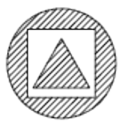
More Options (Hatch and Gradient Dialog Box)
Quick Reference
See also:
■Overview of Hatch Patterns and Fills
Controls the operation of islands and boundaries.
List of Options
The following options are displayed.
Islands
Specifies the method used to hatch or fill boundaries within the outermost
boundary.
Island Detection
Controls whether internal closed boundaries, called islands, are detected.
(HPISLANDDETECTIONMODE on page 1541 system variable)
Normal
Hatches or fills inward from the outer boundary. If an internal island is
encountered, hatching or filling is turned off until another island within the
island is encountered. (HPISLANDDETECTION on page 1541 system variable)
Outer (Recommended)
Hatches or fills inward from the outer boundary. This option hatches or fills
only the specified area and leaves the internal islands unaffected.
(HPISLANDDETECTION on page 1541 system variable)
Hatch and Gradient Dialog Box | 555
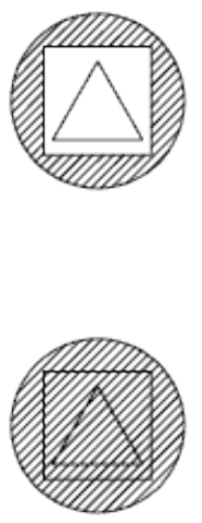
Ignore
Ignores all internal objects and hatches or fills through them.
(HPISLANDDETECTION on page 1541 system variable)
The Normal, Outer, and Ignore options are also available from a shortcut
menu by right-clicking in the drawing area while you specify points or select
objects to define your boundaries.
Boundary Retention
Specifies whether to create an object that encloses the hatch.
Retain Boundaries
Creates an object that encloses each hatch object. (HPBOUNDRETAIN on page
1536 system variable)
Object Type
Controls the type of the new boundary object. The resulting boundary object
can be either a polyline or a region object. This option is available only when
Retain Boundaries is selected. (HPBOUND on page 1536 system variable)
For more information about regions, see “Create and Combine Areas
(Regions)”.
556 | Chapter 9 H Commands
Boundary Set
Defines the set of objects analyzed when defining a boundary from a specified
point. The selected boundary set has no effect when you use Select Objects
to define a boundary.
By default, when you use the Add: Pick Point option to define a boundary,
HATCH analyzes all objects in the current viewport extents. By redefining the
boundary set, you can disregard certain objects when defining boundaries
without having to hide or remove those objects. For large drawings, redefining
the boundary set can also produce the boundary faster because HATCH
examines fewer objects.
Current Viewport Defines the boundary set from all objects within the extents
of the current viewport.
Existing Set Defines the boundary set from the objects selected with the New
option.
New
Specifies a limited set of objects for evaluation by the pick point when creating
the hatch.
Gap Tolerance
Sets the maximum size of gaps that can be ignored when objects are used as
a hatch boundary. The default value, 0, specifies that the objects must enclose
the area with no gaps.
Enter a value, in drawing units, from 0 to 5000 to set the maximum size of
gaps that can be ignored when the objects serve as a hatch boundary. Any
gaps equal to or smaller than the value you specify are ignored, and the
boundary is treated as closed. (HPGAPTOL system variable)
Inherit Options
Controls whether to inherit the hatch origin when you create a hatch with
the Inherit Properties option. (HPINHERIT on page 1540 system variable)
Use Current Origin Uses the current hatch origin setting.
Use Source Hatch Origin Uses the hatch origin of the source hatch.
Hatch and Gradient Dialog Box | 557
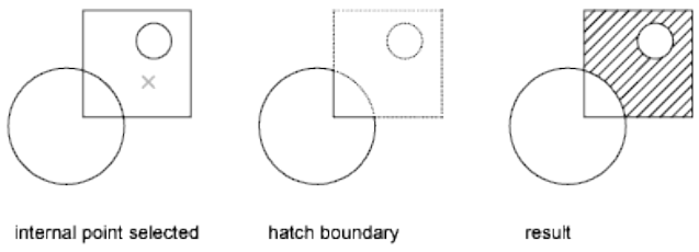
Hatch Creation Ribbon Contextual Tab
Quick Reference
See also:
■Overview of Hatch Patterns and Fills
Defines the boundaries, pattern or fill properties, and other parameters for
hatch and fills.
List of Options
The following options are displayed.
Boundaries Panel
Pick Points Determines a boundary from existing objects that form an enclosed
area around the specified point.
While specifying internal points, you can right-click in the drawing area at
any time to display a shortcut menu that contains several options.
Select Determines a boundary from selected objects that form an enclosed
area.
When you use the Select Objects option, HATCH does not automatically detect
interior objects. You must select the objects within the selected boundary to
hatch or fill those objects according to the current island detection style.
558 | Chapter 9 H Commands
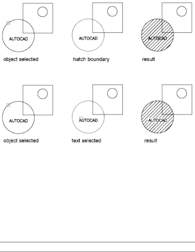
Each time you click Select Objects, HATCH clears the previous selection set.
While selecting objects, you can right-click at any time in the drawing area
to display a shortcut menu. You can undo the last selection or all selections,
change the selection method, change the island detection style, or preview
the hatch or fill.
Remove Removes from the boundary definition any of the objects that were
previously added .
Recreate Creates a polyline or region around the selected hatch or fill, and
optionally associates the hatch object with it.
Display Boundary Objects Selects the objects that form the boundaries of
the selected associative hatch object. Use the displayed grips to modify the
hatch boundaries.
NOTE This option is available only when editing a hatch.
When you select an associative hatch, a single, circular grip called the control
grip is displayed. No boundary grips are displayed because the boundaries of
an associative hatch can be modified only by changing its associated boundary
objects. Use the Select Boundary Objects option to select and grip-edit the
boundary objects.
Hatch Creation Ribbon Contextual Tab | 559
To modify the boundaries of a nonassociative hach, you modify the boundaries
of the hatch object itself. Thus, when you select a nonassociative hatch, both
the control grip and the boundary grips are displayed.
Retain Boundary Objects
Specifies whether to create an object that encloses the hatch.
Don’t Retain Boundaries Does not create a separate object that encloses the
hatch object. (HPBOUNDRETAIN on page 1536 system variable)
Retain Boundaries - Polyline Creates a polyline that encloses the hatch
object. (HPBOUND on page 1536 system variable)
Retain Boundaries - Region Creates a region object that encloses the hatch
object. (HPBOUND on page 1536 system variable)
For more information about regions, see “Create and Combine Areas
(Regions)”.
Select New Boundary Set Specifies a limited set of objects, called a boundary
set, for evaluation by the pick point when creating the hatch.
Specify Boundary Set
Defines the set of objects analyzed when defining a boundary.
Use Current Viewport Defines the boundary set from all objects within the
extents of the current viewport.
Use Boundary Set Defines the boundary set from the objects that you selected
with Select New Boundary Set.
Pattern Panel
Displays preview images for all predefined and custom patterns.
Properties Panel
Hatch Type Specifies whether to create a solid fill, a gradient fill, a predefined
hatch pattern, or a user-defined hatch pattern.
Predefined patterns are stored in the aclt.pat or acltiso.pat files supplied with
the program.
User-defined patterns are based on the current linetype in your drawing. A
custom pattern is a pattern that is defined in any custom PAT files that you
have added to the search path.
Hatch Color or Gradient Color 1 Overrides the current color for solid fills
and hatch patterns, or specifies the first of two gradient colors. (HPCOLOR
on page 1537 or GFCLR1 on page 1517 system variables)
Background Color or Gradient Color 2 Specifies the color for hatch pattern
backgrounds, or the second gradient color. When Hatch Type is set to Solid,
560 | Chapter 9 H Commands
Gradient Color 2 is not available. (HPBACKGROUNDCOLOR on page 1535 or
GFCLR2 on page 1517 system variables)
Transparency Sets the transparency level for new hatches or fills, overriding
the current object transparency. Select Use Current to use the current object
transparency setting. (HPTRANSPARENCY on page 1548 system variable)
Angle Specifies an angle for the hatch or fill relative to the X axis of the current
UCS. Valid values are from 0 to 359. (HPANG system variable)
Scale Expands or contracts a predefined or custom hatch pattern. This option
is available only when Hatch Type is set to Pattern. (HPSCALE system variable)
Spacing Specifies the spacing of lines in a user-defined pattern. This option
is available only when Hatch Type is set to User Defined. (HPSPACE system
variable)
Tint Slider Specifies the tint (the selected color mixed with white) or shade
(the seledted color mixed with black) of a color to be used for a gradient fill
of one color. This option is available only when Hatch Type is set to Gradient.
(GFCLRLUM on page 1518 system variable)
Layer Name Assigns new hatch objects to the specified layer, overriding the
current layer. Select Use Current to use the current layer. (HPLAYER on page
1542 system variable)
Relative to Paper Space Scales the hatch pattern relative to paper space units.
This allows you to display hatch patterns at a scale that is appropriate for your
layout. This option is available only from a layout.
Double For user-defined patterns, draws a second set of lines at 90 degrees to
the original lines, creating a crosshatch. This option is available only when
Hatch Type is set to User Defined. (HPDOUBLE on page 1538 system variable)
ISO Pen Width Scales an ISO predefined pattern based on the selected pen
width. This option is available only when an ISO pattern has been specified.
Origin
Controls the starting location of hatch pattern generation. Some hatches,
such as brick patterns, are meant to be aligned with a point on the hatch
boundary. By default, all hatch origins correspond to the current UCS origin.
Set Origin Specifies the new hatch origin point directly.
Bottom Left Sets the hatch origin at the bottom-left corner of the rectangular
extents of the hatch boundary.
Bottom Right Sets the hatch origin at the bottom-right corner of the
rectangular extents of the hatch boundary.
Hatch Creation Ribbon Contextual Tab | 561
Top Left Sets the hatch origin at the top-left corner of the rectangular extents
of the hatch boundary.
Top Right Sets the hatch origin at the top-right corner of the rectangular
extents of the hatch boundary.
Center Sets the hatch origin at the center of the rectangular extents of the
hatch boundary.
Use Current Origin Sets the hatch origin to the defaoult location stored in
the HPORIGIN on page 1544 system variable.
Store as Default Origin Stores the value of the new hatch origin in the
HPORIGIN system variable.
Options
Controls several commonly used hatch or fill options.
Associative
Annotative Specifies that the hatch is . This property automates the process
of scaling annotations so that they plot or display at the correct size on the
paper. (HPANNOTATIVE on page 1534 system variable)
Match Properties
Use Current Origin Sets the properties of a hatch with a selected hatch object,
except the hatch origin.
Use Source Hatch Origin Sets the properties of a hatch with a selected hatch
object, including the hatch origin.
Gap Tolerance Sets the maximum size of gaps that can be ignored when
objects are used as a hatch boundary. The default value, 0, specifies that the
objects must enclose the area with no gaps.
Move the slicer or enter a value, in drawing units, from 0 to 5000 to set the
maximum size of gaps that can be ignored when the objects serve as a hatch
boundary. Any gaps equal to or smaller than the value you specify are ignored,
and the boundary is treated as closed. (HPGAPTOL system variable)
Create Separate Hatches Controls whether a single hatch object or multiple
hatch objects are created when several separate closed boundaries are specified.
(HPSEPARATE system variable)
Islands
Normal Island Detection Hatches or fills inward from the outer boundary.
If an internal island is encountered, hatching or filling is turned off until
another island within the island is encountered. (HPISLANDDETECTION on
page 1541 system variable)
562 | Chapter 9 H Commands
Outer Island Detection Hatches or fills inward from the outer boundary. This
option hatches or fills only the specified area and leaves the internal islands
unaffected. (HPISLANDDETECTION on page 1541 system variable)
Ignore Island Detection Ignores all internal objects and hatches or fills
through them. (HPISLANDDETECTION on page 1541 system variable)
No Island Detection Turns off island detection.
Draw Order Assigns a draw order to a hatch or fill. You can place a hatch or
fill behind all other objects, in front of all other objects, behind the hatch
boundary, or in front of the hatch boundary. (HPDRAWORDER system
variable)
Close Panel
Close Hatch Creation Exits HATCH and closes the contextual tab.
You can also press Enter or Esc to exit HATCH.
Hatch Pattern Palette Dialog Box
Quick Reference
See also:
■Overview of Hatch Patterns and Fills
Displays preview images for all predefined and custom patterns.
Hatch Pattern Palette Dialog Box | 563
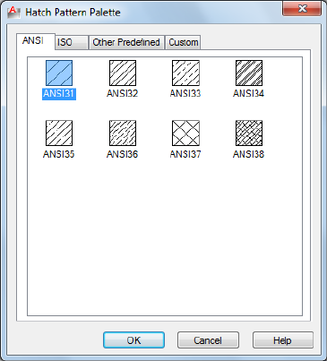
Summary
Organizes patterns on four tabs, with images arranged alphabetically on each
tab. Click an image to select a pattern and click OK.
List of Options
The following options are displayed.
ANSI Displays all ANSI patterns shipped with the program.
ISO Displays all ISO patterns shipped with the program.
Other Predefined Displays all patterns other than ANSI and ISO shipped with
the program.
Custom Displays a list of custom PAT files that you have added to the Support
File Search Path of the program.
Preview
Displays a preview image of the selected custom pattern.
564 | Chapter 9 H Commands
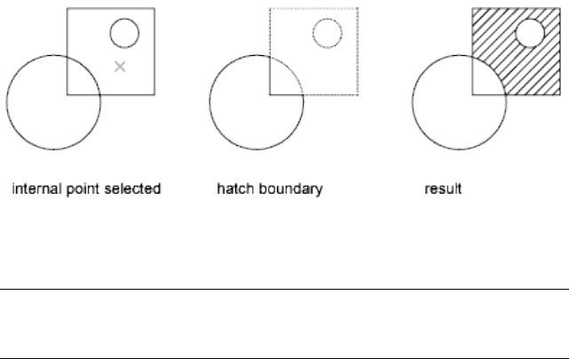
-HATCH
Quick Reference
See also:
■Overview of Hatch Patterns and Fills
Uses command prompts to fill an enclosed area or selected objects with a
hatch pattern, solid fill, or gradient fill.
List of Prompts
The following prompts are displayed.
Specify internal point or [Properties/Select objects/draW boundary/remove
Boundaries/Advanced/DRaw order/Origin/ANnotative/hatch COlor on page
571/LAyer on page 571/Transparency on page 571]: Specify a point or enter an option
Internal Point
Determines a boundary from existing objects that form an enclosed area
around the specified point.
Pick Internal Point While specifying internal points, you can right-click in
the drawing area at any time to display a shortcut menu that contains several
options.
If you turn on Island Detection, objects that enclose areas within the outermost
boundary are detected as islands. How HATCH detects objects using this option
depends on which island detection method is specified.
NOTE Red circles are displayed at unconnected endpoints of boundary objects
to identify gaps in the hatch boundary. These circles are temporary and can be
removed with REDRAW on page 1070 or REGEN on page 1079.
-HATCH | 565

Properties
Specifies new hatch pattern properties to apply.
Pattern Name—Predefined or Custom Specifies a predefined pattern in the
acadlt.pat or acadltiso.pat file or a custom pattern in its own PAT file.
Enter the pattern name followed by an optional hatch style code. Precede the
pattern name with an asterisk (*) to fill the area with individual lines instead
of a hatch object.
?—List Pattern Names Lists and describes the hatch patterns defined in the
acadlt.pat file.
Solid Specifies a solid fill and redisplays the first HATCH prompt, where you
can define a boundary.
User Defined Specifies a user-defined pattern. Enter u, followed by an optional
hatch style code. Precede the u with an asterisk (*) to fill the area with
individual lines instead of a hatch object.
Double Hatch Area Specifies a second set of lines to be drawn at 90 degrees
to the original lines.
Select Objects
Determines a boundary from selected objects that form an enclosed area.
Select Objects Interior objects are not automatically detected. You must select
the objects within the selected boundary to hatch or fill those objects according
to the current island detection style.
Each time you click Select Objects, HATCH clears the previous selection set.
566 | Chapter 9 H Commands

While selecting objects, you can right-click at any time in the drawing area
to display a shortcut menu. You can undo the last selection or all selections,
change the selection method, change the island detection style, or preview
the hatch or fill.
Draw Boundary
Uses specified points to define the boundary of a hatch or fill.
The options that are available as you specify points are also available in PLINE.
When you complete the polyline boundary, press Enter. You can then create
additional polyline boundaries, or press Enter to twice to apply the hatch.
NOTE To enclose an area completely, use the Close option. Do not make the first
and last points coincident.
Remove Boundaries
Removes from the boundary definition any of the objects that were previously
added.
Select Objects Removes objects from the boundary definition.
Add Boundaries Adds objects to the boundary definition.
Advanced
Sets the method used to create the hatch boundary.
Boundary Set
Specifies a limited set of objects, called a boundary set, for evaluation by the
pick point of the hatch
New Creates a boundary set from the selected objects.
Everything Creates a boundary set from everything visible in the current
viewport. Selecting this option discards any current boundary set and uses
everything visible in the drawing or in the current viewport.
Retain Boundary
Creates an object that encloses each hatch object.
-HATCH | 567
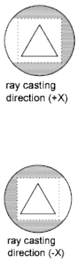
Island Detection
Specifies whether to use objects within the outermost boundary as boundary
objects.
Specifying no island detection prompts for the ray casting method.
Nearest Runs a line from the point you specify to the nearest object and then
traces the boundary in a counterclockwise direction.
+X Runs a line in the positive X direction from the point you specify to the
first object encountered and then traces the boundary in a counterclockwise
direction.
-X Runs a line in the negative X direction from the point you specify to the
first object encountered and then traces the boundary in a counterclockwise
direction.
+Y Runs a line in the positive Y direction from the point you specify to the
first object encountered and then traces the boundary in a counterclockwise
direction.
568 | Chapter 9 H Commands
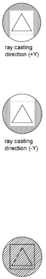
-Y Runs a line in the negative Y direction from the point you specify to the
first object encountered and then traces the boundary in a counterclockwise
direction.
Angle Runs a line at the specified angle from the point you specify to the first
object encountered and then traces the boundary in a counterclockwise
direction.
Style
Specifies the method used to hatch or fill objects within the outermost hatch
boundary. If you have selected no internal objects, a hatching style has no
effect. Because you can define a precise set of boundaries, it's often best to use
the Normal style.
Ignore Ignores all internal objects and hatches or fills through them.
Outer (Recommended) Hatches or fills inward from the outer boundary.
HATCH turns hatching or filling off if it encounters an internal island. This
-HATCH | 569
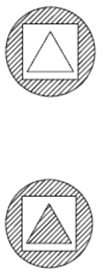
option hatches or fills only the outermost level of the structure and leaves the
internal structure blank.
Normal Hatches or fills inward from the outer boundary. If HATCH encounters
an internal island, it turns off hatching or filling until it encounters another
island within the island.
Associativity
Specifies that the new hatch pattern is updated when its boundaries are
modified.
A new hatch pattern's associativity is set by the HPASSOC system variable.
Changing the associativity setting here also changes the setting in the
HPASSOC system variable.
Gap Tolerance
Sets the maximum size of gaps that can be ignored when objects are used as
a hatch boundary. The default value, 0, specifies that the objects must enclose
the area with no gaps.
Any gaps equal to or smaller than the value you specify in the gap tolerance
are ignored, and the boundary is treated as closed.
Separate Hatches
Controls whether the command creates a single hatch object or multiple hatch
objects when several separate closed boundaries are specified.
Draw Order
Assigns the draw order to a hatch or fill. You can place a hatch or fill behind
all other objects, in front of all other objects, behind the hatch boundary, or
in front of the hatch boundary.
570 | Chapter 9 H Commands
Origin
Controls the starting location of hatch pattern generation. Some hatches,
such as brick patterns, are meant to be aligned with a point on the hatch
boundary. By default, all hatch origins correspond to the current UCS origin.
Use Current Origin Sets the value of the HPORIGINMODE on page 1544 system
variable. The last 5 options listed below correspond to the values 1-5.
Set New Origin Specifies the new hatch origin point directly.
Default to Boundary Extents Calculates a new origin based on the rectangular
extents of the hatch. Choices include each of the four corners of the extents
and its center. You can also store the value of the new hatch origin in the
HPORIGIN on page 1544 system variable.
Annotative
Specifies that the hatch is . This property automates the process of scaling
annotations so that they plot or display at the correct size on the paper.
Hatch Color
Overrides the current color with a specified color for hatch patterns and solid
fills. The color value is stored in the HPCOLOR on page 1537 system variable.
When Hatch Type is set to Pattern, you can also specify a new background
color. The background color value is stored in the HPBACKGROUNDCOLOR
on page 1535 system variable.
To set the hatch color back to the current color for objects, enter “.” or Use
Current. To turn off the background color, enter “.” or none.
Default Object Color Enter the color number (1 through 255) or the color
name (the names for the first seven colors). For example, you can specify the
color red by entering the ACI (AutoCAD Color Index) number 1 or the ACI
name red. You can also set the hatch color to ByLayer or ByBlock.
Truecolor Specify an RGB color expressed as values from 0 to 255, such as
210,155,95.
Colorbook Specify a custom color from a color book installed on your system.
Layer
Assigns new hatch objects to the specified layer, overriding the current layer.
Enter Use Current or “.” to use the current layer. (HPLAYER on page 1542 system
variable)
Transparency
Sets the transparency level for new hatches or fills, overriding the current
object transparency. Enter Use Current or “.” to use the current object
transparency setting. (HPTRANSPARENCY on page 1548 system variable)
-HATCH | 571
HATCHEDIT
Quick Reference
See also:
■Modify Hatches and Fills
Modifies an existing hatch or fill.
Access Methods
Button
Ribbon: Home tab ➤ Modify panel ➤ Edit Hatch
Menu: Modify ➤ Object ➤ Hatch
Toolbar: Modify II
Shortcut menu: Select a hatch object to edit. Right-click in the drawing area
and click Hatch Edit.
Summary
Modifies hatch-specific properties, such as pattern, scale, and angle for an
existing hatch or fill.
List of Options
The following options are displayed.
Select hatch object: Use an object selection method
When the ribbon is active, the Hatch Editor contextual tab on page 573 is
displayed. When the ribbon is off, the Hatch Edit dialog box is displayed.
If you enter -hatchedit at the Command prompt, the associated options are
displayed in the command line.
572 | Chapter 9 H Commands
Hatch Edit Dialog Box
Quick Reference
See also:
■Modify Hatches and Fills
Modifies hatch-specific properties, such as pattern, scale and angle for an
existing hatch or fill.
Summary
The options in the Hatch Edit dialog box are the same as the options for the
Hatch and Gradient dialog box on page 546. Certain options are available only
when creating hatches.
Hatch Editor Ribbon Contextual Tab
Quick Reference
See also:
■Overview of Hatch Patterns and Fills
Modifies hatch-specific properties, such as pattern, scale and angle for an
existing hatch or fill.
List of Options
The following options are displayed.
Boundaries Panel
Pick Points Determines a boundary from existing objects that form an enclosed
area around the specified point.
While picking internal points, you can right-click in the drawing area at any
time to display a shortcut menu that contains several options.
Hatch Edit Dialog Box | 573
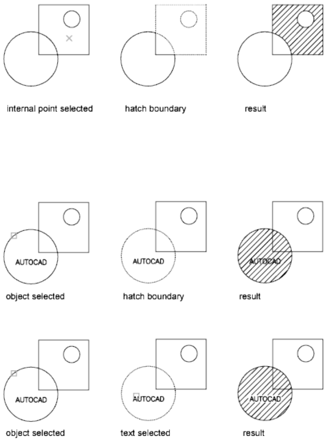
Select Determines a boundary from selected objects that form an enclosed
area.
When you use the Select Objects option, interior objects are not detected
automatically. You must select the objects within the selected boundary to
hatch or fill those objects according to the current island detection style.
Each time you click Select Objects, HATCH clears the previous selection set.
While selecting objects, you can right-click at any time in the drawing area
to display a shortcut menu. You can undo the last selection or all selections,
change the selection method, change the island detection style, or preview
the hatch or gradient fill.
574 | Chapter 9 H Commands
Remove Removes from the boundary definition any of the objects that were
added previously.
Recreate Creates a polyline or region around the selected hatch or fill, and
optionally associates the hatch object with it.
Display Boundary Objects
Displays the boundary grip controls for the selected hatch that you can use
to grip-edit both the boundary and the hatch object.
When you select or use the Display Boundary Objects option to select a
non-associative hatch, the hatch boundary grips are displayed.
When you select an associative hatch, it displays only a single grip point of
the hatch. To display the boundary grip controls of the objects associated to
the hatch, use the Display Boundary Objects option. You can only edit an
associative hatch by grip-editing the associated boundary objects.
Don’t Retain Boundaries Do not create a separate object that encloses the
hatch object. This option is available only during hatch creation.
Retain Boundaries - Polyline Creates a polyline that encloses the hatch
object. This option is available only during hatch creation.
Retain Boundaries - Region Creates a region object that encloses the hatch
object. This option is available only during hatch creation.
For more information about regions, see “Create and Combine Areas (Regions)”
in the User's Guide.
Select New Boundary Set Specifies a limited set of objects, called a boundary
set, for evaluation by the pick point when creating the hatch.
Use Current Viewport Defines the boundary set from all objects within the
extents of the current viewport. This option is available only during hatch
creation.
Use Boundary Set Defines the boundary set from the objects that you selected
with Define Boundary Set. This option is available only during hatch creation.
Pattern Panel
Displays preview images for all predefined and custom patterns.
Properties Panel
Hatch Type Specifies whether to create a solid fill, a gradient fill, a predefined
hatch pattern, or a user-defined hatch pattern.
Predefined patterns are stored in the aclt.pat or acltiso.pat files supplied with
the product.
Hatch Editor Ribbon Contextual Tab | 575
User-defined patterns are based on the current linetype in your drawing. A
custom pattern is a pattern that is defined in any custom PAT files that you
have added to the search path.
Hatch Color or Gradient Color 1 Specifies the color for solid fills, hatch
patterns, or as the first of two gradient colors.
Background Color or Gradient Color 2 Specifies the color for hatch pattern
backgrounds or as a second gradient color. When Hatch Type is set to Solid,
Gradient Color 2 is not available.
Transparency Sets the level of transparency for new hatch objects, overriding
the default object transparency.
Angle Specifies an angle for Gradient and Pattern hatch objects relative to
the X axis of the current UCS. Set a hatch angle between 0 to 359 degrees using
the slider.
Scale Expands or contracts a predefined or custom hatch pattern.
Spacing When Hatch Type is set to User Defined, this option specifies the
spacing of lines in a user-defined pattern.
Tint Slider When Hatch Type is set to Gradient, this option specifies the tint
(the selected color mixed with white) of a color to be used for a gradient fill
of one color.
Layer Name Specifies the layer to which hatch objects are added.
Relative to Paper Space Scales the hatch pattern relative to paper space units.
Using this option, you can easily display hatch patterns at a scale that is
appropriate for your layout. This option is available only from a layout.
Double For user-defined patterns, draws a second set of lines at 90 degrees to
the original lines, creating a crosshatch. This option is available only when
Hatch Type is set to User Defined.
ISO Pen Width Scales an ISO predefined pattern based on the selected pen
width. This option is available only when an ISO pattern has been specified.
Origin
Controls the starting location of hatch pattern generation. Some hatches,
such as brick patterns, are meant to be aligned with a point on the hatch
boundary. By default, all hatch origins correspond to the current UCS origin.
Set Origin Specifies the new hatch origin point directly.
Bottom Left Sets the hatch origin at the bottom-left corner of the rectangular
extents of the hatch boundary.
576 | Chapter 9 H Commands
Bottom Right Sets the hatch origin at the bottom-right corner of the
rectangular extents of the hatch boundary.
Top Left Sets the hatch origin at the top-left corner of the rectangular extents
of the hatch boundary.
Top Right Sets the hatch origin at the top-right corner of the rectangular
extents of the hatch boundary.
Center Sets the hatch origin at the center of the rectangular extents of the
hatch boundary.
Use Current Origin Sets the hatch origin to the defaoult location stored in
the HPORIGIN on page 1544 system variable.
Store as Default Origin Stores the value of the new hatch origin in the
HPORIGIN system variable.
Options
Controls several commonly used hatch or fill options.
Associative Specifies that the hatch or fill is associative. A hatch or fill that
is associative is updated when you modify its boundary objects. (HPASSOC
system variable)
Annotative Specifies that the hatch is . This property automates the process
of scaling annotations so that they plot or display at the correct size on the
paper. (HPANNOTATIVE system variable)
Match Properties
Use Current Origin Sets the properties of a hatch with a selected hatch object,
except the hatch origin.
Use Source Hatch Origin Sets the properties of a hatch with a selected hatch
object, including the hatch origin.
Gap Tolerance Sets the maximum size of gaps that can be ignored when
objects are used as a hatch boundary. The default value, 0, specifies that the
objects must enclose the area with no gaps.
Move the slicer or enter a value, in drawing units, from 0 to 5000 to set the
maximum size of gaps that can be ignored when the objects serve as a hatch
boundary. Any gaps equal to or smaller than the value you specify are ignored,
and the boundary is treated as closed. (HPGAPTOL system variable)
Create Separate Hatches Controls whether a single hatch object or multiple
hatch objects are created when several separate closed boundaries are specified.
(HPSEPARATE system variable)
Hatch Editor Ribbon Contextual Tab | 577
Islands
Normal Island Detection Hatches or fills inward from the outer boundary.
If an internal island is encountered, hatching or filling is turned off until
another island within the island is encountered. (HPISLANDDETECTION
system variable)
Outer Island Detection Hatches or fills inward from the outer boundary. This
option hatches or fills only the specified area and leaves the internal islands
unaffected. (HPISLANDDETECTION system variable)
Ignore Island Detection Ignores all internal objects and hatches or fills
through them. (HPISLANDDETECTION system variable)
No Island Detection Turns off island detection.
Draw Order Assigns a draw order to a hatch or fill. You can place a hatch or
fill behind all other objects, in front of all other objects, behind the hatch
boundary, or in front of the hatch boundary. (HPDRAWORDER system
variable)
Close Panel
Close Hatch Editor Exits the Hatch Editor and closes the contextual tab.
The ENTER and ESC keys can also be used to exit the Hatch Editor.
-HATCHEDIT
Quick Reference
See also:
■Modify Hatches and Fills
Uses command prompts to modify hatch-specific properties, such as pattern,
scale, and angle for an existing hatch or fill.
List of Prompts
The following prompts are displayed.
Select hatch object:
Enter hatch option [DIsassociate/Style/Properties/DRaw order/ADd
boundaries/Remove boundaries/recreate Boundary/ASsociate/separate
Hatches/Origin on page 580/ANnotative/hatch COlor/LAyer/Transparency]
<Properties>: Enter an option or press Enter
578 | Chapter 9 H Commands
Disassociate
Removes the associative quality from an associative hatch or fill.
Style
Specifies the method used to hatch or fill boundaries within the outermost
boundary.
Ignore Ignores all internal objects and hatches or fills through them.
Outer (Recommended) Hatches or fills inward from the outer boundary.
HATCH turns hatching or filling off if it encounters an internal island. This
option hatches or fills only the outermost level of the structure and leaves the
internal structure blank.
Normal Hatches or fills inward from the outer boundary. If HATCH encounters
an internal island, it turns off hatching or filling until it encounters another
island within the island.
Properties
Specifies new hatch properties for the selected hatch. For an explanation of
setting pattern and fill properties at the Command prompt, see -HATCH on
page 565.
Draw Order
Assigns a draw order to a hatch or fill. You can place a hatch or fill behind all
other objects, in front of all other objects, behind the hatch boundary, or in
front of the hatch boundary. (HPDRAWORDER system variable)
Add Boundaries
Modifies the boundaries of a hatch or fill by adding boundaries.
For more information, see Add: Pick Points or Add: Select Objects.
Remove Boundaries
Modifies the boundaries of a hatch or fill by removing boundaries.
For more information, see Remove Boundaries.
Recreate Boundary
Creates a polyline or region around the selected hatch or fill, and optionally
associates the hatch object with it.
For more information, see Recreate Boundary.
Associate
Specifies that the hatch or fill is associative. A hatch or fill that is associative
is updated when you modify its boundary objects.
-HATCHEDIT | 579
Specify Internal Point Determines a boundary from existing objects that
form an enclosed area around the specified point, and associates the selected
hatch with the boundary objects.
Select Objects Determines a boundary from selected objects that form an
enclosed area, and associates the selected hatch with the boundary objects.
Separate Hatches
Controls whether a single hatch object or multiple hatch objects are created
when several separate closed boundaries are specified.
Origin
Controls the starting location of hatch pattern generation. Some hatches,
such as brick patterns, are meant to be aligned with a point on the hatch
boundary. By default, all hatch origins correspond to the current UCS origin.
Use Current Origin Sets the value of the HPORIGINMODE on page 1544 system
variable. The last 5 options listed below correspond to the values 1-5.
Set New Origin Specifies the new hatch origin point directly.
Default to Boundary Extents Calculates a new origin based on the rectangular
extents of the hatch. Choices include each of the four corners of the extents
and its center. You can also store the value of the new hatch origin in the
HPORIGIN on page 1544 system variable.
Annotative
Specifies that the hatch is . This property automates the process of scaling
annotations so that they plot or display at the correct size on the paper.
Hatch Color
Overrides the current color with a specified color for hatch patterns and solid
fills. The color value is stored in the HPCOLOR on page 1537 system variable.
When Hatch Type is set to Pattern, you can also specify a new background
color. The background color value is stored in the HPBACKGROUNDCOLOR
on page 1535 system variable.
To set the hatch color back to the current color for objects, enter “.” or Use
Current. To turn off the background color, enter “.” or none.
Default object color Enter the color number (1 through 255) or the color
name (the names for the first seven colors). For example, you can specify the
color red by entering the ACI (AutoCAD Color Index) number 1 or the ACI
name red. You can also set the hatch color to ByLayer or ByBlock.
Truecolor Specify an RGB color expressed as values from 0 to 255, such as
210,155,95.
580 | Chapter 9 H Commands
Colorbook Specify a custom color from a color book installed on your system.
Layer
Assigns new hatch objects to the specified layer, overriding the current layer.
Enter Use Current or “.” to use the current layer.
Transparency
Sets the transparency level for new hatches or fills, overriding the current
object transparency. Enter Use Current or “.” to use the current object
transparency setting.
HATCHGENERATEBOUNDARY
Quick Reference
See also:
■Set Property Overrides for Hatches and Fills
■Control How Overlapping Objects Are Displayed
Creates a non-associated polyline around a selected hatch.
Access Methods
Shortcut menu: Select a hatch object. Right-click and choose Generate
Boundary.
Summary
Creates a new non-associative polyline boundary around the selected hatch.
List of Prompts
The following prompts are displayed.
Select hatch objects: Use an object selection method and press ENTER.
HATCHGENERATEBOUNDARY | 581
HATCHSETBOUNDARY
Quick Reference
See also:
■Set Property Overrides for Hatches and Fills
■Control How Overlapping Objects Are Displayed
Redefines a selected hatch or fill to conform to a different closed boundary.
Access Methods
Shortcut menu: Select a hatch object. Right-click and choose Set Boundary.
Summary
Trims a selected hatch to within a selected boundary or geometry.
List of Prompts
The following prompts are displayed.
Select hatch object: Select hatch object to be trimmed.
Select objects to be used for the new boundary: Select the new boundary or
geometry and press ENTER.
HATCHSETORIGIN
Quick Reference
See also:
■Set Property Overrides for Hatches and Fills
■Control How Overlapping Objects Are Displayed
Controls the starting location of hatch pattern generation for a selected hatch.
Access Methods
Shortcut menu: Select a hatch object. Right-click and choose Set Origin.
582 | Chapter 9 H Commands

Summary
Controls the hatch origin location point for solid and gradient hatches. You
can select and change multiple hatch objects and change their hatch origin
for multiple hatches at the same time.
List of Prompts
The following prompts are displayed.
Select hatch object: Select the hatch object.
Select new hatch origin: Click inside the hatch to change the origin point.
HATCHTOBACK
Quick Reference
See also:
■Set Property Overrides for Hatches and Fills
■Control How Overlapping Objects Are Displayed
Sets the draw order for all hatches in the drawing to be behind all other objects.
Access Methods
Ribbon: Home tab ➤ Modify panel ➤ Draw Order ➤ Send Hatches to Back
Menu: Tools ➤ Draw Order ➤ Send Hatches to Back
Toolbar: Draw Order
Summary
Selects all hatches in the drawing, including hatch patterns, solid fills, and
gradient fills, and sets their draw order to be behind all other objects. Hatch
objects on locked layers are also modified.
HATCHTOBACK | 583

HELP
Quick Reference
See also:
■Find the Information You Need
Displays Help.
Access Methods
Button
Menu: Help ➤ Help
Toolbar: Standard
Command entry: ? (or 'help for transparent use)
Summary
Pressing F1 while a tooltip or command is active displays Help for that
command. Choosing the Help button in a dialog box displays Help for that
dialog box.
HIDE
Quick Reference
See also:
■Hide Lines in 3D Objects
Regenerates a 3D wireframe model with hidden lines suppressed.
Access Methods
Button
584 | Chapter 9 H Commands
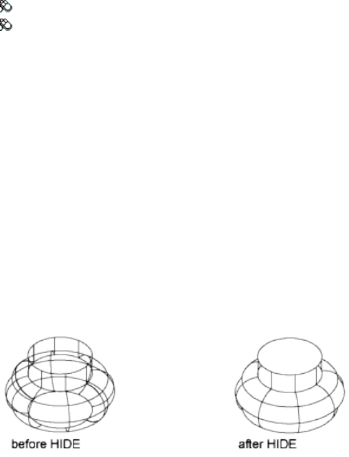
Ribbon: View tab ➤ Visual Styles panel ➤ Hide
Menu: View ➤ Hide
Summary
When you use VPOINT or VIEW to create a 3D view of your drawing, a
wireframe is displayed in the current viewport. All lines are present, including
those hidden by other objects. HIDE eliminates the hidden lines from the
screen.
HIDE considers the following to be opaque surfaces that hide objects: circles,
text, regions, wide polyline segments, the extruded edges of objects with
nonzero thickness, 2D solids, and (when working with AutoCAD drawings)
3D solids, traces, 3D faces, and polygon meshes.
If they are extruded, circles, solids, traces, and wide polyline segments are
treated as solid objects with top and bottom faces. You cannot use HIDE on
objects whose layers have been frozen; however, you can use HIDE on objects
whose layers have been turned off.
To hide text created with MTEXT or TEXT, the HIDETEXT system variable
must be set to 1 or the text must be assigned a thickness value.
When using the HIDE command, if the INTERSECTIONDISPLAY system
variable is on, face-to-face intersections of 3D surfaces are displayed as
polylines.
If the DISPSILH system variable is on, HIDE displays 3D solid objects with
silhouette edges only. It won't show the internal edges produced by objects
that have facets.
If the HIDETEXT system variable is off, HIDE ignores text objects when
producing the hidden view. Text objects are always displayed regardless of
whether they are obscured by other objects, and objects obscured by text
objects are unaffected.
HIDE | 585
HIDEOBJECTS
Quick Reference
See also:
■Control the Display of Objects
Hides selected objects.
Access Methods
Button
Menu: Tools ➤ Isolate ➤ Hide Objects
Shortcut menu: Right-click in the drawing area and click Isolate ➤ Hide
Objects.
Summary
Temporarily hides selected objects in the current view. All other objects are
visible.
List of Prompts
The following prompt is displayed.
Select objects: Use an object selection method
HIDEPALETTES
Quick Reference
See also:
■Specify the Behavior of Dockable Windows
Hides all currently displayed palettes, including the command window.
586 | Chapter 9 H Commands

Access Methods
Command entry: Ctrl+Shift+H
Summary
Hides all currently displayed palettes such as the Command Line, DesignCenter,
and Properties.
HLSETTINGS
Quick Reference
See also:
■Hide Lines or Shade 3D Objects
Changes the display properties of hidden lines.
Summary
The Hidden Line Settings dialog box on page 587 is displayed.
Sets the display properties of hidden lines. These settings are visible only when
HIDE is used and SHADEMODE is set to 2D Wireframe.
Hidden Line Settings Dialog Box
Quick Reference
See also:
See also:
■Hide Lines or Shade 3D Objects
Summary
Sets the display properties of hidden lines. These settings are visible only when
HIDE is used and SHADEMODE is set to 2D Wireframe.
HLSETTINGS | 587
List of Options
The following options are displayed.
Obscured Lines
Specifies the linetype and color of obscured lines. An obscured line is a hidden
line that is made visible by changing its color and linetype.
Linetype
Lists the available linetypes to apply to obscured lines. Unlike regular linetypes,
obscured linetypes are not affected by zoom level. (OBSCUREDLTYPE system
variable)
Color
Lists the available colors to apply to obscured lines. (OBSCUREDCOLOR system
variable)
Halo Gap Percentage
Specifies the distance to shorten a haloed line. A haloed line is shortened at
the point where it will be hidden. The distance is specified as a percentage of
1 inch and is not affected by zoom level. (HALOGAP system variable)
Include Text in HIDE Operations
Specifies whether text objects created by TEXT or MTEXT are included during
a HIDE command. (HIDETEXT system variable)
Face Intersections
Specifies the display and color of intersection polylines. An intersection
polyline is displayed at the face-to-face intersection of 3D surfaces.
588 | Chapter 9 H Commands
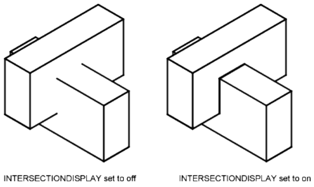
Display Intersections
Specifies the display of intersection polylines. (INTERSECTIONDISPLAY system
variable)
Color
Lists the available colors to apply to intersection polylines.
(INTERSECTIONCOLOR system variable)
Hide Precision
Controls the accuracy of hides and shades. Hides can be set to either low
(single) precision or high (double) precision. (HIDEPRECISION system variable)
Low (single)
Sets the hide precision to low (single), which uses less memory.
High (double)
Sets the hide precision to high (double), which produces more precise hides,
but also uses more memory and can affect performance.
Hidden Line Settings Dialog Box | 589

HYPERLINK
Quick Reference
See also:
■Add Hyperlinks to a Drawing
Attaches a hyperlink to an object or modifies an existing hyperlink.
Access Methods
Button
Ribbon: Insert tab ➤ Data panel ➤ Hyperlink
Menu: Insert ➤ Hyperlink
Shortcut menu: To edit a hyperlink, select an object that contains a
hyperlink, right-click in the drawing area, and choose Hyperlink ➤ Edit
Hyperlink.
Summary
Hyperlinks in a drawing provide jumps to associated files. For example, a
hyperlink can launch a word processing program and open a specified file,
another hyperlink can launch a web browser and display a specified web page.
List of Prompts
The following prompts are displayed.
Select objects: Use an object selection method
One of the following dialog boxes is displayed:
■Insert Hyperlink dialog box (for graphical objects that do not already
contain hyperlinks) on page 591
■Edit Hyperlink dialog box (for graphical objects that already contain
hyperlinks) on page 594
590 | Chapter 9 H Commands
After you insert a hyperlink, the hyperlink icon is displayed when you move
the cursor over the attached object. To open the hyperlink, right-click the
selected object and choose Hyperlink. The PICKFIRST system variable must
be set to 1 to open files associated with hyperlinks.
If you enter -hyperlink at the Command prompt, options are displayed,
including an option to define an area to associate with a hyperlink.
Insert Hyperlink Dialog Box
Quick Reference
See also:
■Add Hyperlinks to a Drawing
Attaches a specified hyperlink to a selected object.
Summary
Attaches hyperlinks to graphical objects.
List of Options
The following options are displayed.
Text to Display
Specifies a description for the hyperlink. This is useful when the file name or
URL is not helpful in identifying the contents of the linked file.
Existing File or Web Page Tab (Insert Hyperlink Dialog Box)
Creates a hyperlink to an existing file or web page.
Insert Hyperlink Dialog Box | 591
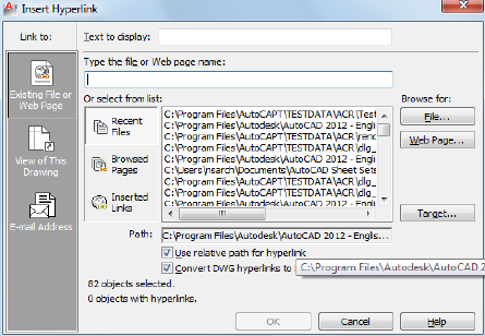
Type the File or Web Page Name
Specifies the file or web page to associate with the hyperlink. The file can be
stored locally, on a network drive, or on an Internet or intranet location.
Recent Files
Displays a list of recently linked files, from which you can select one to link
to.
Browsed Pages Displays a list of recently browsed web pages, from which you
can select one to link to.
Inserted Links Displays a list of recently inserted hyperlinks, from which you
can select one to link to.
File
Opens the Browse the Web - Select Hyperlink dialog box (a standard file
selection dialog box), in which you can navigate to the file that you want to
associate with the hyperlink.
Web Page
Opens the browser, in which you can navigate to a web page that you want
to associate with the hyperlink.
Target
Opens the Select Place in Document dialog box, in which you can select a
named location in a drawing to link to.
Path
592 | Chapter 9 H Commands
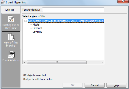
Displays the path to the file associated with the hyperlink. If Use Relative Path
for Hyperlink is selected, only the file name is listed. If Use Relative Path for
Hyperlink is cleared, the full path and the file name are listed.
Use Relative Path for Hyperlink
Sets a relative path for hyperlinks. If you select this option, the full path to
the linked file is not stored with the hyperlink. The relative path is set to the
value specified by the HYPERLINKBASE system variable or, if no value is
specified for HYPERLINKBASE, to the current drawing path. If this option is
cleared, the full path to the associated file is stored with the hyperlink.
Convert DWG Hyperlinks to DWF
Specifies that the DWG hyperlink will convert to a DWF file hyperlink when
you publish or plot the drawing to a DWF file.
View of This Drawing Tab (Insert Hyperlink Dialog Box)
Specifies a named view in the current drawing to link to.
Select a View of This
Displays an expandable tree view of the named views within the current
drawing, from which you can select one to link to.
E-mail Address Tab (Insert Hyperlink Dialog Box)
Specifies an email address to link to. When the hyperlink is executed, a new
email is created using the default system email program.
Insert Hyperlink Dialog Box | 593
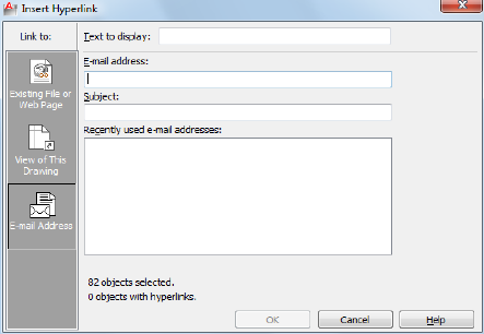
E-mail Address
Specifies an email address.
Subject
Specifies a subject for the email.
Recently Used E-mail Addresses
Lists recently used email addresses, from which you can select one to use for
the hyperlink.
Edit Hyperlink Dialog Box
Quick Reference
See also:
■Add Hyperlinks to a Drawing
Edits hyperlinks.
Summary
The Edit Hyperlink dialog box is a modified version of the Insert Hyperlink
dialog box, with one additional option.
594 | Chapter 9 H Commands
List of Options
The following options are displayed.
Remove Link
Deletes the hyperlink from the selected objects.
Select Place in Document Dialog Box
Quick Reference
See also:
■Add Hyperlinks to a Drawing
Navigates to a view or layout within a drawing.
Summmary
The named location that you select is the initial view that is restored when
the hyperlink is executed.
List of Options
The following options are displayed.
Select an Existing Place in the Document
Provides an expandable tree view of the named locations within the linked
drawing, from which you can select a named location to link to.
-HYPERLINK
Quick Reference
See also:
■Add Hyperlinks to a Drawing
The Command prompt version of HYPERLINK inserts hyperlinks to areas or
to selected objects and also removes hyperlinks.
Select Place in Document Dialog Box | 595

List of Prompts
The following prompts are displayed.
Enter an option [Remove/Insert] <Insert>: Enter an option or pressENTER
Remove
Removes the hyperlink from the selected objects. If a selection set does not
exist, you are prompted to create one.
Select objects: Select graphical objects in the drawing
If the selection set contains more than one hyperlink, the hyperlinks that
were found are listed at the Command prompt.
Enter number, hyperlink, or * for all: Enter the number or name of the hyperlink,
or enter*to remove all hyperlinks in the selection set
The number of removed hyperlinks is displayed at the Command prompt.
Insert
Attaches a hyperlink to an object or an area.
Enter hyperlink insert option [Area/Object] <Object>: Select a method for
attaching a hyperlink
Area Defines a bounding rectangle and places it on a layer called URLLAYER.
If this layer doesn't exist in the current drawing, it is created.
NOTE To turn off the display of hyperlink bounding rectangles in the drawing
area or in your drawing plots, you must freeze the URLLAYER layer. See “Use Layers
to Manage Complexity” in the User's Guide.
First corner: Specify the start point of the rectangle
Other corner: Specify the end point of the rectangle
Enter the path to the file you want associated with the hyperlink.
Enter hyperlink <current drawing>: Enter the full path to a local file or the complete
URL to an Internet file, or press ENTER to create a hyperlink to a named view in the
current drawing
Enter a named location for the hyperlink, such as a view in a drawing or a
bookmark in a word processing file.
Enter named location <none>: Enter the named location, or press ENTER to create
the hyperlink without one
Enter description <none>: Enter a description, or press ENTER to create the hyperlink
without one
Object Specifies graphical objects to attach the hyperlink to.
Select objects: Select graphical objects in the drawing
596 | Chapter 9 H Commands
Enter the path to the file you want associated with the hyperlink.
Enter hyperlink <current drawing>: Enter the full path to a local file or the complete
URL to an Internet file, or press ENTER to create a hyperlink to a named view in the
current drawing
Enter a named location for the hyperlink, such as a view in a drawing or a
bookmark in a word processing file.
Enter named location <none>: Enter the named location, or press ENTER to create
the hyperlink without one
Enter description <none>: Enter a descriptive name for the hyperlink, or press ENTER
to create the hyperlink without one
HYPERLINKOPTIONS
Quick Reference
See also:
■Use a Hyperlink to Access a File or a Web Page
Controls the display of the hyperlink cursor, tooltips, and shortcut menu.
Summary
Controls the display of hyperlink cursor, tooltip, and shortcut menu.
List of Prompts
The following prompts are displayed.
Display hyperlink cursor, tooltip, and shortcut menu? [Yes/No] <Yes>:
HYPERLINKOPTIONS | 597
598
I Commands
ID
Quick Reference
See also:
■Obtain Distances, Angles, and Point Locations
Displays the UCS coordinate values of a specified location.
Access Methods
Button
Ribbon: Home tab ➤ Utilities panel ➤ ID Point.
Menu: Tools ➤ Inquiry ➤ ID Point
Toolbar: Inquiry
Command entry: 'id for transparent use
Summary
ID lists the X, Y, and Z values of the specified point and stores the coordinate
of the specified point as the last point. You can reference the last point by
entering @ at the next prompt that requests a point.
10
599
List of Prompts
The following prompts are displayed.
Specify Point: Use the pointing device to specify a point
The UCS coordinate values of the location are displayed at the Command
prompt.
If you snap to an object in 3D space, the Z coordinate value is the same as
that of the selected feature of the object.
IGESEXPORT
Quick Reference
See also:
■Export IGES files
Saves selected objects in the current drawing to a new IGES (*.igs, *.iges) file.
Summary
Displays the Export File dialog box (a standard file selection dialog box) to
enable you to name the IGES file and specify the path to it. Thereafter you
must specify what objects to export.
Once processing is complete, a notification bubble is displayed.
IGESEXPORT Conversion Table
Quick Reference
See also:
■Export IGES files
600 | Chapter 10 I Commands
The following table lists the AutoCAD LT entities tabulated against the
corresponding IGES entities they are translated to.
DWG to IGES Conversion Table
IGES EntityAutoCAD LT Entity
NameFormType
NothingPoint
Line0110Line
Rational B-spline curve0126Circle
Rational B-spline curve0126Arc
Rational B-spline curve0126Ellipse
Copious data12106Polyline (lightweight)
Copious data121062d Polyline
Copious data121063d Polyline
NothingPolyface mesh
NothingPolygon mesh
Line0110SubD mesh
Line0110Trace
Line0110Solid (2D)
Nothing3D Face
NothingDimensions
NothingLeader
NothingMleader
NothingText
IGESEXPORT Conversion Table | 601
DWG to IGES Conversion Table
IGES EntityAutoCAD LT Entity
NameFormType
NothingMtext
Line0110Hatch
Treats the block reference as
though it was exploded and
Block Reference
translates each object within
the block separately.
Rational B-spline surface,
trimmed surface
128/144Surface
Treats the 3D solid as though
it were exploded to surfaces
3D Solid
and translates each surface
separately.
Rational B-spline surface,
trimmed surface
128/144Region
Rational B-spline surface,
trimmed surface
128/144Body
NothingTable
NothingFCF
NothingOLE
NothingImage
NothingXref
NothingMline
NothingXline
NothingRay
602 | Chapter 10 I Commands
IGESIMPORT
Quick Reference
See also:
■Import IGES Files
Imports data from an IGES (*.igs or *.iges) file into the current drawing.
Summary
Displays the Select IGES File dialog box (a standard file selection dialog box)
to enable you to locate and select the IGES file to import.
If import takes longer than 5 seconds, the IGES file is processed in the
background and the Import icon is displayed in the status bar. Hence, you
can continue to work on the drawing while the IGES file is processed. You
can check the status of the import process by placing the cursor over the
Import status bar icon and inspecting the tooltip that is displayed.
Once processing is done, a notification bubble is displayed on the Import
icon. Click the link in the notification bubble to insert the imported IGES
data in the current drawing.
IGESIMPORT Conversion Table
Quick Reference
See also:
■Import IGES Files
The following table lists the IGES entities that are supported for import.
IGES to DWG Conversion Table
AutoCAD LT EntityIGES Entity
NameFormType
Splinecircular arc0100
IGESIMPORT | 603
IGES to DWG Conversion Table
AutoCAD LT EntityIGES Entity
NameFormType
Splinecomposite curve0102
Splineconic arc, ellipse, parabola,
hyperbola
0-3104
Splinecopious data1106
Splinecopious data2106
Splinecopious data11106
Splinecopious data12106
Splineclosed area63106
Surfaceplane0108
Surfacebounded plane+/- 1108
Splineline0110
Splineparametric curve0112
Surfaceparametric surface0114
Nothingpoint0116
Surfaceruled surface0-1118
Surfacesurface of revolution0120
Surfacetabulated cylinder0122
Nothingdirection0123
Nothingtransformation matrix0124
Splinerational B-spline curve0-5126
604 | Chapter 10 I Commands
IGES to DWG Conversion Table
AutoCAD LT EntityIGES Entity
NameFormType
Surfacerational B-spline surface0-9128
Splineoffset curve0130
Surfaceoffset surface0140
Nothingboundary entity0141
Surface (with trimming ap-
plied, not associative)
boundary suface0143
Surface (with trimming ap-
plied, not associative)
trimmed surface0144
Surface (can be converted to
solid with CONVTOSOLID)
Manifold Solid BRep Object
(MSBO)
186
Applied when processing en-
tity type 186.
plane surface0,1190
Applied when processing en-
tity type 186.
right circular cylindrical sur-
face
192
Applied when processing en-
tity type 186.
right circular conical surface194
Applied when processing en-
tity type 186.
toroidal surface198
Applied when processing en-
tity type 408 (Subfigure)
subfigure definition0308
Ignored (as though entities
weren't related in a group).
associativity instance7, 9402
Individual entities (like an ex-
ploded block reference).
singular subfigure instance0408
IGESIMPORT Conversion Table | 605
IGES to DWG Conversion Table
AutoCAD LT EntityIGES Entity
NameFormType
Applied when processing en-
tity type 186.
vertex list502
Applied when processing en-
tity type 186.
edge list504
Applied when processing en-
tity type 186.
loop508
Applied when processing en-
tity type 186.
face510
Applied when processing en-
tity type 186.
shell514
IMAGE
Quick Reference
See also:
■Attach Raster Images
Displays the External References palette.
Access Methods
Button
Ribbon: Insert tab ➤ Reference panel ➤ Attach
Menu: File ➤ Attach
Menu: Insert ➤ External References
Toolbar: Reference
606 | Chapter 10 I Commands
Shortcut menu: Select an image. Right-click in the drawing area and choose
Image ➤ External References.
Summary
The External References palette is displayed.
If you enter -image at the Command prompt, options are displayed.
-IMAGE
Quick Reference
See also:
■Attach Raster Images
Attaches a raster image to the drawing.
List of Prompts
The following prompts are displayed.
Enter image option [?/Detach/Path/Reload/Unload/Attach] <Attach>: Enter an
option or press Enter
?—List Images
Lists the images by name in alphabetical order, the number of times each is
attached to the drawing, and the path where the image is stored. Images are
listed in alphabetical order, regardless of the setting of the MAXSORT system
variable.
Detach
Detaches the named image from the drawing, marks it for deletion, and erases
all occurrences of the image.
Path
Updates the path name (including file name) associated with a particular
image. This option is useful if you change the location of an image file, rename
the file, or replace an old image file with a new file; for instance, you can
update image01.png and save it as image02.png.
If you enter an asterisk (*), the following prompt is displayed:
Old path: Lists the current path name for each image
-IMAGE | 607
Enter New path: Enter the new path name for the specified image
Reload
Reloads the selected images, making that information available for display
and plotting.
Unload
Removes image data from working memory so that the images are not
displayed, thus improving performance. All information associated with the
image remains stored with the drawing. The image frame of each attached
image remains visible.
Attach
Attaches a new image or a copy of an attached image to the current drawing.
The Select Image File dialog box (a standard file selection dialog box) is
displayed.
The file name without the extension is assigned as the image name. Image
names can include up to 255 characters and contain letters, digits, spaces, and
any special characters not used by the operating system or this program. If
the file name is not a valid name for a nongraphical object, the Substitute
Image Name dialog box is displayed. A valid image name is generated from
the file name and an underscore and number are appended to the name.
If a definition with the same name and path exists in the drawing, the
following prompts are displayed and the image is inserted as a copy:
Image file name has already been loaded.
Use IMAGE Reload to update its definition.
Specify insertion point <0,0>: Specify an insertion point
Base image size: Width: current width, Height: current height, current unit
Specify scale factor: Enter a value or press Enter
Specify rotation angle <0>: Enter a value or press Enter
If the FILEDIA system variable is set to 0, the following prompt is displayed
instead of the dialog box:
Enter image file name to attach <last>: Enter an image name
The last image name attached to the drawing during the current session is the
default. To avoid errors when entering an image name, it is recommended
that you specify both the image name and the file name as follows:
imagename=path name\long file name.bmp
or
608 | Chapter 10 I Commands

imagename="path name\long file name.bmp"
If you enter a valid image name without a file extension, the program searches
for the file in this order: first, an existing image definition in the drawing,
and second, an image file in the folders in order of the search path. The
program searches for all the image files with the specified name, regardless of
extension, and uses the first name found. If no image name or image file is
found, the message “Image Not Found” is displayed and the prompt is repeated.
To specify a long file name that does not conform to this program's naming
rules, enter the name as follows:
"imagename=filename"
You can use a dialog box to search for image files but still enter the
imagename=filename convention at the Command prompt. Enter a tilde (~) at
the Enter Image File Name to Attach prompt. If you press Esc after the dialog
box opens, the Enter Image Name prompt is displayed.
IMAGEADJUST
Quick Reference
See also:
■Change Raster Image Brightness, Contrast, and Fade
Controls the image display of the brightness, contrast, and fade values of
images.
Access Methods
Button
Menu: Modify ➤ Object ➤ Image ➤ Adjust
Toolbar: Reference
Shortcut menu: Select an image to adjust, right-click in the drawing area,
and choose Image ➤ Adjust.
IMAGEADJUST | 609
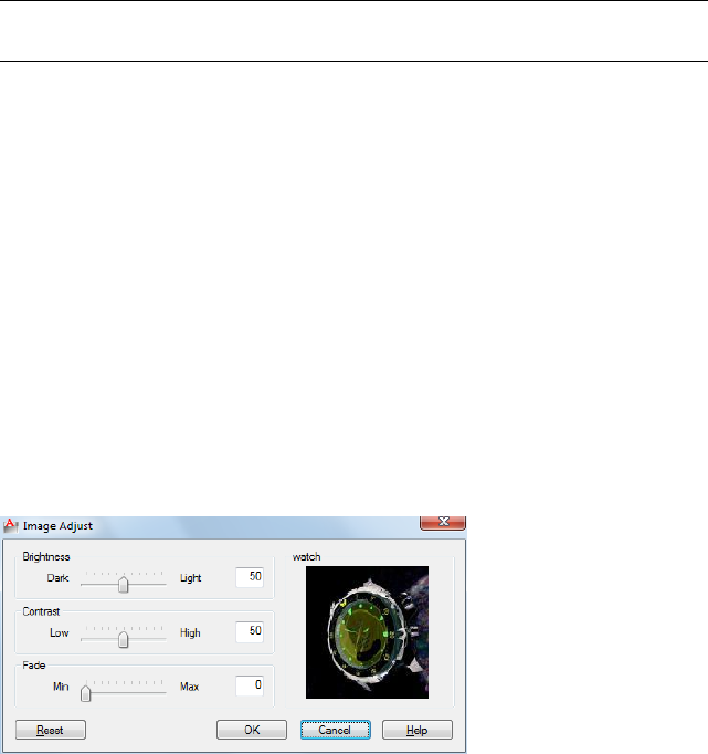
Summary
You can change the default values for Brightness, Contrast, and Fade for
attached images. To confirm the settings of a selected image, open the
Properties palette.
NOTE You can also use the ADJUST command to change an image’s brightness,
contrast, and fade settings.
The Image Adjust dialog box is displayed when you enter the IMAGEADJUST
command.
If you enter -imageadjust at the Command prompt, options are displayed.
Image Adjust Dialog Box
Quick Reference
See also:
■Change Raster Image Brightness, Contrast, and Fade
Controls how the image is displayed by adjusting the brightness, contrast,
and fade settings of the selected image.
Summary
Adjusting these values changes the display of the image but does not change
the image file itself.
List of Options
The following options are displayed.
610 | Chapter 10 I Commands
Brightness
Controls the brightness, and indirectly the contrast, of the image. The greater
the value, the brighter the image and the more pixels that become white when
you increase contrast.
Contrast
Controls the contrast, and indirectlyd the fading effect of the image. The
greater the value, the more each pixel is forced to its primary or secondary
color.
Fade
Controls the fading effect of the image. The greater the value, the more the
image blends with the current background color. A value of 100 blends the
image completely into the background. Changing the screen background color
causes the image to fade to the new color. In plotting, the background color
for fade is white.
Image Preview
Displays a preview of the selected image. The preview image updates
dynamically to reflect changes to the brightness, contrast, and fade settings.
Reset
Resets values for brightness, contrast, and fade to default settings (50, 50, and
0, respectively).
-IMAGEADJUST
Quick Reference
See also:
■Change Raster Image Brightness, Contrast, and Fade
Controls the image display of the brightness, contrast, and fade values of
images.
Summary
With the Command prompt version of IMAGEADJUST, you can select more
than one image to adjust.
-IMAGEADJUST | 611
List of Prompts
The following prompts are displayed.
If you select a single image, the default values for Brightness, Contrast, and
Fade are the current property settings of the image. If you select multiple
images, the default values for Brightness, Contrast, and Fade are 50, 50, and
0, respectively.
Contrast Controls the contrast, and indirectly, the fading effect of the image.
The greater the value, the more each pixel is forced to its primary or secondary
color.
Brightness Controls the brightness, and indirectly the contrast, of the image.
The greater the value, the brighter the image and the more pixels that become
white when you increase contrast.
Fade Controls the fading effect of the image. The greater the value, the more
the image blends with the current background color. A value of 100 blends
the image completely into the background. Changing the screen background
color causes the image to fade to the new color. In plotting, the background
color for fade is white.
IMAGEATTACH
Quick Reference
See also:
■Attach Raster Images
Inserts a reference to an image file.
Access Methods
Button
Ribbon: Insert tab ➤ Reference panel ➤ Attach
Menu: Insert ➤ Raster Image Reference
Toolbar: Reference
612 | Chapter 10 I Commands

Summary
When you attach an image file, you link that referenced file to the current
drawing. Any changes to the referenced file are displayed in the current
drawing when it is opened or reloaded.
The Select Reference File dialog box (a standard file selection dialog box) is
displayed. Once you select an image file, the Attach Image Dialog Box on page
613 is displayed.
After the file is attached, you can adjust and clip the underlay through the
Image Ribbon Contextual tab.
TIP Use the generic CLIP command to clip images, external references, viewports,
and underlays.
Attach Image Dialog Box
Quick Reference
See also:
■Attach Raster Images
Locates, inserts, names, and defines the parameters and details of attached
images.
List of Options
The following options are displayed.
Name
Identifies the image you have selected to attach.
Browse
Opens the Select Reference File dialog (a standard file selection dialog box on
page 826).
Preview
Displays the image that you have selected to attach.
Attach Image Dialog Box | 613
Path Type
Select the full (absolute) path, the relative path to the image file, or No Path,
the name of the image file (the image file must be located in the same folder
as the current drawing file).
Insertion Point
Specifies the insertion point for the selected image file. Specify On-Screen is
the default. The default insertion point is 0,0,0.
Specify On-Screen
Directs input at the Command prompt or the pointing device. If Specify
On-Screen is cleared, enter the insertion point in X, Y, and Z.
X
Sets the X coordinate value.
Y
Sets the Y coordinate value.
Z
Sets the Z coordinate value.
Scale
Specifies the scale factor of the selected image.
If INSUNITS is set to “unitless” or if the image does not contain resolution
information, the scale factor becomes the image width in AutoCAD units. If
INSUNITS has a value such as millimeters, centimeters, inches, or feet, and
the image has resolution information, the scale factor is applied after the true
width of the image in AutoCAD units is determined.
Specify On-Screen
Allows you to input at the Command prompt or the pointing device. If Specify
On-Screen is cleared, enter a value for the scale factor. The default scale factor
is 1.
Scale Factor Field
Enter a value for the scale factor. The default scale factor is 1.
Rotation
Specifies the rotation angle of the selected image.
Specify On-Screen
614 | Chapter 10 I Commands
If Specify On-Screen is selected, you may wait until you exit the dialog box
to rotate the object with your pointing device or enter a rotation angle value
at the Command prompt.
Angle
If Specify On-Screen is cleared, enter the rotation angle value in the dialog
box. The default rotation angle is 0.
Show Details
Displays details about the selected image file.
Resolution
Displays the number of horizontal and vertical pixels per the current unit
measurement in AutoCAD LT.
Unit
Displays the current AutoCAD LT unit.
Image Size in Pixels
Displays the width and height of the raster image measured in pixels.
Image Size in Units
Displays the width and height of the raster image measured in AutoCAD LT
units.
Path
Found In Displays the path where the image file is located.
Saved Path Displays the path that is saved with the drawing when the image
file is attached. The path is dependent upon the Path Type setting.
Image Ribbon Contextual tab
Quick Reference
See also:
■Modify Raster Images and Image Boundaries
Summary
When you select a raster image that is attached to a drawing, the Image
Contextual tab appears on the ribbon.
Image Ribbon Contextual tab | 615
List of Options
The following options are diaplayed.
Adjust Panel
Controls the brightness and the contrast of the image. The greater
the value, the brighter the image.
Brightness
Controls the contrast and the fading effect of the image. The
greater the value, the more the image fades.
Contrast
Controls the fading of an image. The greater the value, the more
the image blends with the current background color.
Fade
Clipping Panel
Deletes the old clipping boundary (if one exists) and creates a new
one.
Create Clipping
Boundary
Deletes the clipping boundary.Remove Clipping
Options Panel
Hides or displays the image.Show Image
Turns transparency on so that objects beneath the image are visible.Transparency
Displays the External References Palette.External Refer-
ences
IMAGECLIP
Quick Reference
See also:
■Clip Raster Images
Crops the display of a selected image to a specified boundary.
616 | Chapter 10 I Commands
Access Methods
Button
Ribbon: Image contextual tab ➤ Clipping panel ➤ Create Clipping
Boundary.
Menu: Modify ➤ Clip ➤ Image
Toolbar: Reference
Shortcut menu: Select an image to clip. Right-click in the drawing area and
choose Image ➤ Clip.
Summary
The clipping boundary determines the portion of a raster image that is hidden,
either outside or inside the boundary. The visibility of the clipping boundary
is controlled by the IMAGEFRAME system variable. The boundary you specify
must be in a plane parallel to the image object.
When you select an image, the ribbon Image contextual tab on page 615
displays options for creating and deleting clipping boundaries.
TIP Use the CLIP command to clip any type of referenced file: images, external
references, viewports, and DWF, DWFx, PDF, and DGN underlays.
List of Prompts
The following prompts are displayed.
On
Turns on clipping and displays the image clipped to the previously defined
boundary.
Off
Turns off clipping and displays the entire image and frame.
If you reclip the image while clipping is turned off, clipping is automatically
turned back on. You are prompted to delete the old boundary even when
clipping is turned off and the clipping boundary is not visible.
Delete
Removes a predefined clipping boundary and redisplays the full original image.
IMAGECLIP | 617
New Boundary
Defines a rectangular or polygonal clipping boundary, or generates a polygonal
clipping boundary from a polyline.
NOTE You can only create a new clipping boundary for a selected IMAGE underlay
after the old boundary is deleted.
Select Polyline Defines the boundary with the selected polyline. The polyline
can be open but must consist of straight line segments and cannot intersect
itself.
Polygonal Defines a polygonal clipping boundary with three or more points
that you specify for the vertices of a polygon.
Rectangular Defines a rectangular boundary with the points that you specify
for opposite corners.
Invert Clip Inverts the mode of the clipping boundary: objects are clipped
either outside the boundary or inside the boundary.
IMAGEQUALITY
Quick Reference
See also:
■Improve the Display Speed of Raster Images
Controls the display quality of images.
Access Methods
Button
Menu: Modify ➤ Object ➤ Image ➤ Quality
Toolbar: Reference
618 | Chapter 10 I Commands

Summary
The quality setting affects display performance; high-quality images take
longer to display. Changing the setting updates the display immediately
without causing a regeneration of the drawing.
NOTE Images are always plotted using a high-quality setting.
List of Prompts
The following prompts are displayed.
High Produces a high-quality display of the image.
Draft Produces a lower-quality display of the image.
IMPORT
Quick Reference
See also:
■Import Other File Formats
Imports files of different formats into the current drawing.
Access Methods
Button
Menu: File ➤ Import
Toolbar: Insert
Summary
You can import data files, other than DWG files, that were created with other
applications into the current drawing. The import process translates data into
the corresponding DWG file data.
The Import File dialog box (a standard file selection dialog box) is displayed.
IMPORT | 619

In Files of type, select the file format to import. In File Name, select the file
name to import. The file is imported into the drawing. The following formats
are available for import:
■FBX files (*.fbx): Autodesk® FBX files (see FBXIMPORT)
■Metafile (*.wmf): Microsoft Windows® Metafile (see WMFIN on page 1335)
■MicroStation DGN (*.dgn): MicroStation DGN files (see DGNIMPORT on
page 298)
■All DGN files (*.*): DGN files with user-specified file extensions such as .sed
for seed files (see DGNIMPORT on page 298)
For the WMF file type, selecting Options on the Tools menu in this dialog
box displays the WMF In Options dialog box. You can display this dialog box
directly by using WMFOPTS.
If FILEDIA = 0, the following prompt is displayed:
Enter import file name: Enter path and file name
INSERT
Quick Reference
See also:
■Insert Blocks
Inserts a block or drawing into the current drawing.
Access Methods
Button
Ribbon: Insert tab ➤ Block panel ➤ Insert
Menu: Insert ➤ Block
Toolbar: Insert
620 | Chapter 10 I Commands
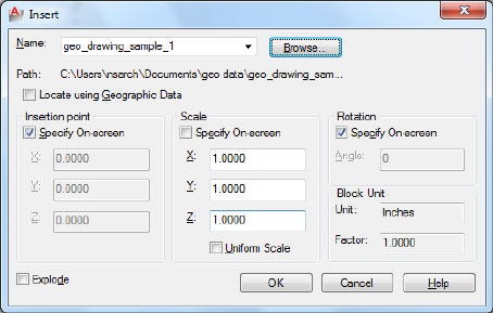
Summary
The Insert dialog box is displayed.
If you enter -insert at the Command prompt, options are displayed.
A good practice is to insert a block from a block library. A block library can
be a drawing file that stores related block definitions or it can be a folder that
contains related drawing files, each of which can be inserted as a block. With
either method, blocks are standardized and accessible to multiple users.
You can insert your own blocks or use the blocks provided in the DesignCenter
or tool palettes.
Select one model
Lists the models found in the *.exp file. Select the model to import and click
OK.
Insert Dialog Box
Quick Reference
See also:
■Insert Blocks
Specifies the name and position of the block or drawing to insert.
Insert Dialog Box | 621

Summary
The position of the inserted block depends on the orientation of the UCS.
Name
Specifies the name of a block to insert, or the name of a file to insert as a block.
Browse
Opens the Select Drawing File dialog box (a standard file selection dialog box)
where you can select a block or drawing file to insert.
Path
Specifies the path to the block.
Locate Using Geographic Data
Inserts drawing using geographic data as the reference.
Specifies if the current and attached drawing contain geographic data. This
option is available only if both drawings have geographic data.
Description Displays the description that was saved with the block.
Preview
Displays a preview of the specified block to insert. A lightning bolt icon in
the lower-right corner of the preview indicates that the block is dynamic. A
icon indicates that the block is .
Insertion Point
Specifies the insertion point for the block.
Specify On-Screen
Specifies the insertion point of the block using the pointing device.
Input Coordinates Allows you to manually enter the X, Y, and Z coordinate
value for the insertion point of the block.
X
Sets the X coordinate value.
Y
Sets the Y coordinate value.
622 | Chapter 10 I Commands
Z
Sets the Z coordinate value.
Scale
Specifies the scale for the inserted block. Specifying negative values for the X,
Y, and Z scale factors inserts a mirror image of a block.
Specify On-Screen
Specifies the scale of the block using the pointing device.
Input Scale Factor Allows you to manually enter a scale factor for the block.
X
Sets the X scale factor.
Y
Sets the Y scale factor.
Z
Sets the Z scale factor.
Uniform Scale
Specifies a single scale value for X, Y, and Z coordinates.
Rotation
Specifies the rotation angle for the inserted block in the current UCS.
Specify On-Screen
Specifies the rotation of the block using the pointing device.
Input Angle Allows you to manually enter an angle of rotation for the block.
Angle
Sets a rotation angle for the inserted block.
Block Unit
Displays information about the block units.
Unit
Specifies the INSUNITS value for the inserted block.
Insert Dialog Box | 623
Factor
Displays the unit scale factor, which is calculated based on the INSUNITS value
of the block and the drawing units.
Explode
Explodes the block and inserts the individual parts of the block. When Explode
is selected, you can specify a uniform scale factor only.
Component objects of a block drawn on layer 0 remain on that layer. Objects
having color BYBLOCK are white. Objects with linetype BYBLOCK have the
CONTINUOUS linetype.
-INSERT
Quick Reference
See also:
■Insert Blocks
Inserts a block or drawing into the current drawing.
List of Prompts
The following prompts are displayed.
Enter block name or [?] <last>: Enter a name, enter ?, enter ~, or press Enter
Units: <INSUNITS specified for inserted block> Conversion: <conversion scale>
Specify insertion point or [Basepoint/Scale/X/Y/Z/Rotate/Geographic]: Specify
a point or enter an option
Block Name
Grouped objects in an inserted drawing are inserted as unnamed groups. You
can list unnamed groups by selecting Include Unnamed Groups in the “Group
Manager”.
Entering a tilde (~) displays the Select Drawing File dialog box (a standard file
selection dialog box).
624 | Chapter 10 I Commands
You can control block insertion behavior in response to the Enter Block Name
prompt by following the listed examples.
■Inserting Exploded Blocks: Preceding the name of the block with an asterisk
(*) explodes the block and inserts the individual parts of it. The block
definition is not added to the drawing.
■Updating a Block Path: If you enter a block name without a path name,
INSERT searches the current drawing data for an existing block definition
by that name. You can replace an existing block definition with an external
file by entering the following at the Enter Block Name prompt:
block name=file name
■Updating a Block Definition: If you make changes to a block file that is inserted
in your drawing and you want to change the existing block definition
without creating a new block insertion, enter the following at the Specify
Insertion Point prompt (following the Enter Block Name prompt):
block name=
If you enter = after the block name, the following prompt is displayed:
Block "current" already exists. Redefine it? [Yes/No] <No>: Enter y, enter n,
or press Enter
If you choose to redefine the block, the existing block definition is replaced
with the new block definition. The drawing is regenerated, and the new
definition is applied to all existing insertions of the block definition. Press
Esc when prompted for the insertion point if you do not want to insert a
new block into the drawing.
?—List Block Names
Lists the blocks currently defined in the drawing.
Insertion Point
Specifies a location for the block or drawing.
Scale Factor All X and Y dimensions of the block or drawing are multiplied
by the X and Y scale factors. The block or drawing is rotated by the specified
angle, using the insertion point as the center of rotation.
Corner Defines the X and Y scale factors at the same time, using the insertion
point and another point as the corners of a box. The X and Y dimensions of
the box become the X and Y scale factors. The insertion point is the first corner.
XYZ Sets X, Y, and Z scale factors.
■X Scale Factor: Defines X, Y, and Z scale factors for the block or drawing.
-INSERT | 625

■Corner: Defines the X and Y scales at the same time, using the insertion
point and another point as the corners of a box, and then defines the Z
scale.
Basepoint
Temporarily drops the block in the drawing where it is currently positioned
and allows you to specify a new base point for the block reference as it is
dragged into position. This does not affect the actual base point defined for
the block reference.
Scale
Sets the scale factor for the X, Y, and Z axes. The scale for the Z axis is the
absolute value of the specified scale factor.
X
Sets the X scale factor.
Y
Sets the Y scale factor.
Z
Sets the Z scale factor.
Rotate
Sets the angle of insertion for the block.
Geographic
Sets the geographic location of the attached file as reference.
INSERTOBJ
Quick Reference
See also:
■Import OLE Objects
Inserts a linked or embedded object.
Access Methods
Button
626 | Chapter 10 I Commands

Ribbon: Insert tab ➤ Data panel ➤ OLE Object
Menu: Insert ➤ OLE Object
Toolbar: Insert
Summary
The Insert Object dialog box is displayed.
■Linked information from another document can be updated when it
changes in the source document.
■Embedded information from another document is not updated when it
changes in the source document.
Insert Object Dialog Box
Quick Reference
See also:
■Import OLE Objects
Inserts a linked or embedded object.
List of Options
The following options are displayed.
Create New
Opens the application that's highlighted in the Object Type list so that you
can create a new object to insert.
Object Type Lists available applications that support linking and embedding.
To create an object to embed, double-click an application to open it.
On the application's File menu, the Save option is replaced with a new Update
option. Choosing Update inserts the object into the drawing or updates it.
Display as Icon Displays the source application's icon in the drawing.
Double-clicking the icon displays the embedded information.
Create from File
Specifies a file to link or embed.
File Specifies the path and name of the file to be embedded or linked.
Insert Object Dialog Box | 627

Browse Displays the Browse dialog box (a standard file selection dialog box),
in which you select a file to link or embed.
Link Creates a link to the selected file rather than embedding it.
Display as Icon Displays the source application's icon in the drawing.
Double-clicking the icon displays the linked or embedded information.
INTERSECT
Quick Reference
See also:
■Create and Combine Areas (Regions)
Creates a 2D region from selected overlapping regions.
Access Methods
Button
Menu: Modify ➤ Region ➤ Intersect
Summary
With INTERSECT, you can create a 2D region object from the overlapping
area of two or more existing regions. You can select only regions for use with
INTERSECT.
You can intersect regions only with other regions that are on the same plane.
However, you can perform simultaneous INTERSECT operations by selecting
sets of regions on different planes. Separate, intersected regions are then
produced on each plane.
628 | Chapter 10 I Commands

ISOLATEOBJECTS
Quick Reference
See also:
■Control the Display of Objects
Displays selected objects across layers; unselected objects are hidden.
Access Methods
Menu: Tools ➤ Isolate ➤ Isolate Objects
Shortcut menu: Right-click in the drawing area and click Isolate ➤ Isolate
Objects.
Summary
Displays selected objects in the current view. All other objects are temporarily
hidden.
List of Prompts
The following prompt is displayed.
Select objects: Use an object selection method
ISOLATEOBJECTS | 629
ISOPLANE
Quick Reference
See also:
■Set Isometric Grid and Snap
Specifies the current isometric plane.
Access Methods
Command entry: 'isoplane for transparent use
Summary
The isometric plane affects the cursor movement keys only when Snap mode
is on and the snap style is Isometric. If the snap style is Isometric, Ortho mode
uses the appropriate axis pair even if Snap mode is off. The current isometric
plane also determines the orientation of isometric circles drawn by ELLIPSE.
You can cycle through the isometric planes by pressing Ctrl+E or F5.
List of Prompts
The following prompts are displayed.
Enter isometric plane setting [Left/Top/Right] <Top>: Enter an option or press
Enter
Left
Selects the left-hand plane, defined by the 90-degree and 150-degree axis pair.
630 | Chapter 10 I Commands
Top
Selects the top face of the cube, called the top plane, defined by the 30-degree
and 150-degree axis pair.
Right
Selects the right-hand plane, defined by the 90-degree and 30-degree axis pair.
ISOPLANE | 631
632

J Commands
JOIN
Quick Reference
See also:
■Break and Join Objects
Joins the endpoints of linear and curved objects to create a single object.
Access Methods
Button
Ribbon: Surface Modeling tab ➤ Curves panel ➤ Join
Menu: Modify ➤ Join
Toolbar: Modify
Summary
Combines a series of finite linear and open curved objects at their common
endpoints to create a single 2D or 3D object. The type of object that results
depends on the types of objects selected, the type of object selected first, and
whether the objects are coplanar.
11
633
NOTE Construction lines, rays, and closed objects cannot be joined.
List of Prompts
The following prompts are displayed.
Select source object or multiple objects to join as once: Select lines, polylines,
3D polylines, arcs, elliptical arcs, or splines.
Source Object
Specifies a single source object to which you can join other objects. Press Enter
after selecting the source object to begin selecting the objects to join. The
following rules apply for each type of source object:
Line Only line objects can be joined to the source line. The line objects must
all be collinear, but can have gaps between them.
Polyline Lines, polylines, and arcs can be joined to the source polyline. All
objects must be contiguous and coplanar. The resulting object is a single
polyline.
3D Polyline Any linear or curved object can be joined to the source 3D
polyline. All the objects must be contiguous, but can be noncoplanar. The
resulting object is either a single 3D polyline or a single spline, depending on
whether you are joining to a linear or a curved object respectively.
Arc Only arcs can be joined to the source arc. All the arc objects must have
the same radius and center point, but can have gaps between them. The arcs
are joined in a counterclockwise direction starting from the source arc.
The Close option converts the source arc into a circle.
Elliptical Arc Only elliptical arcs can be joined to the source elliptical arc.
The elliptical arcs must be coplanar and have the same major and minor axes,
but can have gaps between them. The elliptical arcs are joined counterclockwise
starting from the source elliptical arc.
The Close option converts the source elliptical arc into an ellipse.
634 | Chapter 11 J Commands
Helix Any linear or curved object can be joined to the source helix. All objects
must be contiguous, but can be noncoplanar. The resulting object is a single
spline.
Spline Any linear or curved object can be joined to the source spline. All
objects must be contiguous, but can be noncoplanar. The resulting object is
a single spline.
Multiple Objects to Join at Once
Joins multiple objects without specifying a source object. The rules and
resulting object types are as follows:
■A line object results from joining collinear lines. The lines can have gaps
between their endpoints.
■An arc or circle object results from joining coplanar arcs with the same
center point and radius. The arcs can have gaps between their endpoints.
Lengthening occurs in a counterclockwise direction. A circle object results
if the joined arcs form a complete circle.
■A spline object results from joining splines or elliptical arcs together, or
to other objects. The objects can be noncoplanar.
■A polyline object results from joining coplanar lines, arcs, polylines, or 3D
polylines.
■A 3D polyline results from joining noncoplanar objects other than curved
objects.
JPGOUT
Quick Reference
See also:
■Export Raster Files
Saves selected objects to a file in JPEG file format.
Summary
The Create Raster File dialog box (a standard file selection dialog box) is
displayed. Enter the file name in the dialog box.
JPGOUT | 635
List of Prompts
The following prompts are displayed.
Select objects or <all objects and viewports>: Press Enter to select all objects and
viewports or use an object selection method and press Enter
A JPEG file is created that contains the objects you select. Shade Plot options
are preserved in the file when you use this command. Light glyphs that are
displayed in the drawing appear in the new file, even if the Plot Glyph property
of the lights is set to No.
NOTE When the FILEDIA system variable is set to 0 (Off), command prompts are
displayed.
JUSTIFYTEXT
Quick Reference
See also:
■Change Text Scale and Justification
Changes the justification point of selected text objects without changing their
locations.
Access Methods
Button
Ribbon: Annotate tab ➤ Text panel ➤ Justify
Menu: Modify ➤ Object ➤ Text ➤ Justify
Toolbar: Text
Summary
The justification point options shown above are described in the TEXT
command. The justification point options for single line text are similar to
those for multiline text except that the Align, Fit, and Left text options are
equivalent to the bottom left (BL) multiline text attachment point.
636 | Chapter 11 J Commands
List of Prompts
The following prompts are displayed.
Select objects: Use an object selection method and press ENTER when you finish
You can choose single line text objects, multiline text objects, leader text
objects, and attribute objects.
Enter a justification option
[Left/Align/Fit/Center/Middle/Right/TL/TC/TR/ML/MC/MR/BL/BC/BR]<Existing>:
Specify a location to serve as the new justification point
JUSTIFYTEXT | 637
638

L Commands
LAYCUR
Quick Reference
See also:
■Use Layers to Manage Complexity
Changes the layer property of selected objects to the current layer.
Access Methods
Button
Ribbon: Home tab ➤ Layers panel ➤ Change to Current Layer
Menu: Format ➤ Layer Tools ➤ Change to Current Layer
Toolbar: Layers II
Summary
If you find objects that were created on the wrong layer, you can quickly change
them to be on the current layer.
List of Prompts
The following prompts are displayed.
12
639
Select objects to be changed to the current layer: Use an object selection method
and press Enter when you are finished
N object(s) changed to layer X (the current layer).
LAYDEL
Quick Reference
See also:
■Use Layers to Manage Complexity
Deletes all objects on a layer and purges the layer.
Access Methods
Button
Ribbon: Home tab ➤ Layers panel ➤ Delete
Menu: Format ➤ Layer Tools ➤ Layer Delete
Summary
This command also changes block definitions that use the layer to be deleted.
Objects on that layer are also deleted from all block definitions and the affected
blocks are redefined.
List of Prompts
The following prompts are displayed.
Select object on layer to delete or [Name]: Select an object or enter n to display
the Delete Layers dialog box
If you enter -laydel at the Command prompt, options are displayed on page
641.
Select Object on Layer to Delete Select an object on the layer you want to
delete.
Name Displays the Delete Layers dialog box on page 641.
640 | Chapter 12 L Commands
Delete Layers Dialog Box
Quick Reference
See also:
■Use Layers to Manage Complexity
Displays layers available for deletion.
List of Options
The following options are displayed.
Layers to Delete Displays a list of layers that you can delete. Press Shift or
Ctrl to select more than one layer. Layers that cannot be deleted include the
current layer, layer 0, locked layers, and xref-dependent layers.
-LAYDEL
Quick Reference
See also:
■Use Layers to Manage Complexity
List of Prompts
The following prompts are displayed.
Select object on layer to delete or [Name]: Select an object or enter n.
Select object on layer to delete or [Name/Undo]: Select an object, enter n, or
enter u
Select Object on Layer to Delete Select an object on the layer you want to
delete.
Name Select a layer to delete.
Delete Layers Dialog Box | 641

LAYER
Quick Reference
See also:
■Use Layers to Manage Complexity
■CLASSICLAYER on page 209
Manages layers and layer properties.
Access Methods
Button
Ribbon: Home tab ➤ Layers panel ➤ Layer Properties Manager
Menu: Format ➤ Layer
Toolbar: Layer
Command entry: 'layer for transparent use
Summary
The Layer Properties Manager is displayed.
If you enter -layer at the Command prompt, options are displayed.
Use layers to control the visibility of objects and to assign properties such as
color and linetype. Objects on a layer normally assume the properties of that
642 | Chapter 12 L Commands
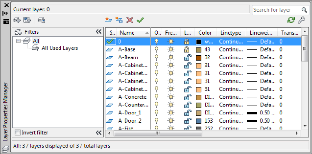
layer. However, you can override any layer property of an object. For example,
if an object’s color property is set to BYLAYER, the object displays the color
of that layer. If the object’s color is set to Red, the object displays as red,
regardless of the color assigned to that layer.
Layer Properties Manager
Quick Reference
See also:
■Work with Layers
■CLASSICLAYER on page 209
Displays a list of the layers in the drawing and their properties.
Summary
You can add, delete, and rename layers, change their properties, set property
overrides for layout viewports, or add layer descriptions and apply changes
in realtime. You do not need to click Ok or Apply to view property changes.
Layer filters control which layers are displayed in the list and can also be used
to make changes to more than one layer at a time.
When switching space (model space to layout space or layout to viewport),
the Layer Properties Manager is updated and displays the current state of the
layer properties and filter selection in the current space.
Layer Properties Manager | 643

List of Options
The following options are displayed.
New Property Filter
Displays the Layer Filter Properties dialog box, where you can create a layer
filter based on one or more properties of the layers.
New Group Filter
Creates a layer filter that contains layers that you select and add to the filter.
Layer States Manager
Displays the Layer States Manager on page 668, in which you can save the
current property settings for layers in a named layer state and then restore
those settings later.
New Layer
Creates a new layer. The list displays a layer named LAYER1. The name is
selected so that you can enter a new layer name immediately. The new layer
inherits the properties of the currently selected layer in the layer list (color,
on or off state, and so on).
The new layer is created below the last currently selected layer.
New Layer Frozen VP In All Viewports
Creates a new layer and freezes it in all existing layout viewports. This button
is accessible from the Model tab or layout tabs.
Delete Layer
Deletes selected layers. You can delete only unreferenced layers. Referenced
layers include layers 0 and DEFPOINTS, layers containing objects (including
objects in block definitions), the current layer, and xref-dependent layers.
NOTE Be careful about deleting layers if you are working on a drawing in a shared
project or one based on a set of layering standards.
Set Current
Sets the selected layer as the current layer. Objects that you create are drawn
on the current layer. (CLAYER system variable)
Current Layer
Displays the name of the current layer.
644 | Chapter 12 L Commands
Search for Layer
Filters the layer list by name quickly as you enter characters. This filter is not
saved when you close the Layer Properties Manager.
Status Line
Shows the name of the current filter, the number of layers displayed in the
list view, and the number of layers in the drawing.
Invert Filter
Displays all layers that do not meet the criteria in the selected layer property
filter.
Indicate Layers in Use
Displays icons in the list view to indicate whether layers are in use. In a
drawing with many layers, clear this option to improve performance.
(SHOWLAYERUSAGE system variable)
Refresh
Refreshes the layer usage information by scanning all the entities in the
drawing.
Settings
Displays the Layer Settings dialog box on page 658, in which you can set new
layer notification settings, if layer filter changes are applied to the Layer
toolbar, and change the background color for layer property overrides.
Apply Applies changes that have been made to layers and filters but does not
close the dialog box.
The Layer Properties Manager has the following two panes:
■Tree view on page 645
■List view on page 648
Tree View
Displays a hierarchical list of layers and filters in the drawing. The top node,
All, displays all layers in the drawing. Filters are displayed in alphabetical
order. The All Used Layers filter is read-only.
Expand a node to see nested filters. Double-click a property filter to open the
Layer Filter Properties dialog box and view the definition of the filter.
Layer Properties Manager | 645
The Hide/Show Layer Filters button controls the display of the Layer Filters
pane of the Layer Properties Manager. When the Layer Filter pane is collapsed,
the Layer Filter button is displayed adjacent to Layer Filter status text. The
Layer Filter button gives you access to the filters when the full Layer Filter
pane is closed.
If there are xrefs attached to the drawing, an xref node displays the names of
all the xrefs in the drawing and the layers in each xref. Layer filters defined
in xref files are not displayed.
If there are layers that contain property overrides, a Viewport Overrides node
is automatically created and displays those layers and the properties that
contain overrides. The Viewport Overrides filter displays only when the Layer
Properties Manager is accessed from a layout tab.
If there are new layers that have been added to the drawing since the layer
list was last evaluated (depending on how the LAYERNOTIFY system variable
is set), an Unreconciled New Layers filter is automatically created and displays
new layers that need to be reconciled.
Tree View Shortcut Menu
Provides commands for items selected in the tree view.
Visibility Changes the visibility state of all the layers in the selected filter (or
All or All Used Layers, if selected).
■On: Objects on the layer are displayed, plotted, and regenerated and hide
other objects when you use HIDE.
■Off: Objects on the layer are not displayed and not plotted but do hide
other objects when you use HIDE. The drawing is not regenerated when
you turn the layer on.
■Thawed: Objects on the layer are displayed and plotted, and hide other
objects when you use HIDE.
■Frozen: Objects on the layer are not displayed and not plotted but do hide
other objects when you use HIDE. The drawing is regenerated when you
thaw the layer.
Lock Controls whether the objects on the layers in the selected filter can be
modified.
■Lock: None of the objects on the layer can be modified. You can still apply
object snaps to objects on a locked layer and perform other operations
that do not modify those objects.
■Unlock: Objects on the layer can be modified.
646 | Chapter 12 L Commands
Viewport In the current layout viewport, controls the VP Freeze setting of
the layers in the selected layer filter. This option is not available for model
space viewports.
■Freeze: Sets VP Freeze for layers in the filter. In the current viewport, objects
on the layer are not displayed and not plotted but do hide other objects
when you use HIDE. The drawing is regenerated when you thaw the layer.
■Thaw: Clears VP Freeze for layers in the filter. In the current viewport,
objects on the layer are displayed and plotted and hide other objects when
you use HIDE. This option does not thaw layers that are set to Off or Frozen
in the drawing.
Isolate Group Turns off all layers not in the selected filter. The layers that are
visible are the layers in the filter.
■All Viewports: In all viewports in a layout, sets VP Freeze for all layers that
are not in the selected filter. In model space, turns off all layers that are
not in the selected filter.
■Active Viewport Only: In the current layout viewport, sets VP Freeze for all
layers that are not in the selected filter. In model space, turns off all layers
that are not in the selected filter.
New Properties Filter Displays the Layer Filter Properties dialog box, where
you can create a new layer filter based on layer names and settings; for example,
on or off, color, or linetype.
New Group Filter Creates a new layer group filter named GROUP FILTER1
and adds it to the tree view. Enter a new name. Select the All filter or any
other layer filter in the tree view to display layers in the list view, and then
drag layers from the list view into the new layer group filter in the tree view.
Convert to Group Filter Converts the selected layer property filter to a layer
group filter. Changing the properties of the layers in a layer group filter has
no effect on the filter.
Rename Renames the selected filter. Enter a new name.
Delete Deletes the selected layer filter. You cannot delete the All, All Used
Layers, or Xref filters. This option deletes the layer filter but not the layers in
the filter.
Properties Displays the Layer Filter Properties dialog box, where you can
modify the definition of the selected layer property filter. This option is
available only when a layer property filter is selected.
Layer Properties Manager | 647
Select Layers Temporarily closes the Layer Filter Properties dialog box so that
you can select objects in the drawing. This option is available only when a
layer group filter is selected.
■Add: Adds the layers of the selected objects to the layer group filter that is
selected in the tree view.
■Replace: Replaces the layers of the selected layer group filter with the layers
of the objects that are selected in the drawing.
List View
Displays layers and layer filters and their properties and descriptions.
If a layer filter is selected in the tree view, the list view displays only the layers
in that layer filter. The All filter in the tree view displays all layers and layer
filters in the drawing. When a layer property filter is selected and there are
no layers that fit its definition, the list view is empty. To modify a property
of a selected layer or of all layers in a selected filter, click the icon for that
property. When a mixed icon or “Varies” is displayed for a layer filter, the
property is not the same for all layers in the filter.
Status Indicates the type of item: layer filter, layer in use, empty layer, or
current layer.
Name Displays the name of the layer or filter. Press F2 to enter a new name.
On Turns the selected layers on and off. When a layer is on, it is visible and
available for plotting. When a layer is off, it is invisible and not plotted, even
if Plot is on.
Freeze Freezes the selected layers in all viewports, including the Model tab.
You can freeze layers to speed up ZOOM, PAN, and many other operations;
improve object selection performance; and reduce regeneration time for
complex drawings.
Objects on frozen layers are not displayed, plotted, hidden, or regenerated.
Freeze the layers you want to be invisible for long periods. If you plan to switch
visibility settings frequently, use the On/Off setting to avoid regenerating the
drawing. You can freeze a layer in all viewports, in the current layout viewport,
or in new layout viewports as they are created.
Lock Locks and unlocks the selected layers. Objects on a locked layer cannot
be modified.
Color Changes the color associated with the selected layers. Clicking the color
name displays the Select Color dialog box.
648 | Chapter 12 L Commands
Linetype Changes the linetype associated with the selected layers. Clicking
the linetype name displays the Select Linetype dialog box.
Lineweight Changes the lineweight associated with the selected layers.
Clicking the lineweight name displays the Lineweight dialog box.
Transparency Controls the visibility of all objects on the selected layer. When
transparency is applied to individual objects, the objects’ transparency property
overrides the transparency setting of the layer. Clicking the Trasparency value
displays the Layer Transparency dialog box on page 658.
Plot Style Changes the plot style associated with the selected layers. If you
are working with color-dependent plot styles (the PSTYLEPOLICY system
variable is set to 1), you cannot change the plot style associated with a layer.
Clicking the plot style displays the Select Plot Style dialog box.
Plot Controls whether the selected layers are plotted. If you turn off plotting
for a layer, the objects on that layer are still displayed. Layers that are off or
frozen are not plotted, regardless of the Plot setting.
VP Freeze (available only from a layout tab) Freezes selected layers in the
current layout viewport. You can freeze or thaw layers in the current viewport
without affecting layer visibility in other viewports.
VP Freeze is an override to the Thaw setting in the drawing. That is, you can
freeze a layer in the current viewport if it's thawed in the drawing, but you
can't thaw a layer in the current viewport if it's frozen or off in the drawing.
A layer is not visible when it is set to Off or Frozen in the drawing.
New VP Freeze Freezes selected layers in new layout viewports. For example,
freezing the DIMENSIONS layer in all new viewports restricts the display of
dimensions on that layer in any newly created layout viewports but does not
affect the DIMENSIONS layer in existing viewports. If you later create a
viewport that requires dimensions, you can override the default setting by
changing the current viewport setting.
VP Color (available only from a layout tab) Sets an override for the color
associated with the selected layer for the active layout viewport.
VP Linetype (available only from a layout tab) Sets an override for the
linetype associated with the selected layer for the active layout viewport.
VP Lineweight (available only from a layout tab) Sets an override for the
lineweight associated with the selected layer for the active layout viewport.
VP Transparency (available only from a layout tab) Sets an override for
transparency associated with the selected layer for the active layout viewport.
Layer Properties Manager | 649
VP Plot Style (available only from a layout tab) Sets an override for the plot
style associated with the selected layer for the active layout viewport. Override
settings are not visible in the viewport or plotted when the visual style in the
drawing is set to Conceptual or Realistic. If you are working with
color-dependent plot styles (the PSTYLEPOLICY system variable is set to 1),
you cannot set a plot style override.
Description (Optional) Describes the layer or the layer filter.
List View Shortcut Menu
Provides options for modifying the list and modifying selected layers and layer
filters.
Column Label Shortcut Menu
Column Names Lists all columns by name. Columns that are checked indicate
they are displayed. Hidden column names are not checked. VP Freeze, VP
Color, VP Linetype, VP Lineweight, and VP Plot Style are available only when
a layout viewport is active.
Customize Displays the Customize Layer Columns dialog box on page 661,
where you can specify which columns are hidden or displayed.
Maximize All Columns Maximizes all columns to the width of the column
headers and the data content. This option is available on the shortcut menu
that is displayed when you right-click a column heading.
Maximize Column Changes the width of the column to maximize display
of the column content. This option is available on the shortcut menu that is
displayed when you right-click a column heading.
Optimize all columns Changes the width of all columns to maximize display
of the column content. This option is available on the shortcut menu that is
displayed when you right-click a column heading.
Optimize column Changes the width of a column to maximize display of
the column content. This option is available on the shortcut menu that is
displayed when you right-click a column heading.
Freeze column (or Unfreeze column) Freezes (or unfreezes) the column and
any columns to the left. This option is available on the shortcut menu when
you right-click a column heading.
Restore All Columns to Defaults Restores all columns to their default display
and width settings. This option is available on the shortcut menu when you
right-click a column heading.
650 | Chapter 12 L Commands

Layer Shortcut Menu
Show Filter Tree Displays the tree view. Clear this option to hide the tree
view.
Show Filters in Layer List Displays filters at the top of the list view. The filters
are listed in alphabetical order. Clear the check mark to display only layers in
the list view.
Set Current Sets the selected layer as the current layer. (CLAYER system
variable)
New Layer Creates a new layer. The list displays a layer named LAYER1. You
can edit this layer name immediately. The new layer inherits the properties
of the currently selected layer in the layer list (color, on or off state, and so
on).
Rename Layer Renames the layer.
Delete Layer Deletes selected layers from the drawing file definition. You can
delete only unreferenced layers. Referenced layers include layers 0 and
DEFPOINTS, layers containing objects (including objects in block definitions),
the current layer, and xref-dependent layers.
NOTE Be careful about deleting layers if you are working on a drawing in a shared
project or one based on a set of layering standards.
Change Description Adds a description or changes the text in the description
for the selected layer or filter. The description for a filter is added to the filter
and to all layers in the filter.
Remove from Group Filter Removes the selected layers from the group layer
filter that is selected in the tree view.
Reconcile Layer Removes new layers from the Unreconciled New Layers filter.
Available only when one or more unreconciled layers is selected.
Remove Viewport Overrides For Removes a single override property or all
property overrides on selected layers (or all layers) for the current viewport or
all viewports. Different options display in a flyout menu depending on where
the cursor is located when the shortcut menu is accessed. To remove a single
property override, right-click the property override. This option is only
available on the layout tab.
New Layer Frozen in All Viewports Creates a new layer and freezes it in all
existing layout viewports and new viewports.
VP Freeze Layer in All Viewports Freezes the selected layer in all existing
layout viewports and new viewports.
Layer Properties Manager | 651
VP Thaw Layer in All Viewports Thaws the selected layer in all existing
layout viewports and new viewports.
Select All Selects everything displayed in the list view.
Clear All Removes selection from all items in the list view except the most
recently selected layer or filter.
Select All but Current Selects everything displayed in the list view except the
current layer.
Invert Selection Selects everything displayed in the list view except the items
that are currently selected.
Invert Layer Filter Displays all layers that do not meet the criteria in the
selected layer property filter.
Layer Filters Displays a list of layer filters, including All and All Used Layers.
Click a filter to apply it to the list view.
Save Layer States Displays the dialog box on page 671, in which you save the
layer state and layer property settings of all layers in a drawing.
Restore Layer State Displays the Layer States Manager on page 668, in which
you can select a named layer state to restore settings of all layers in the drawing.
Restores only those layer state and property settings that were selected when
the named layer state was saved.
Layer Filter Properties Dialog Box
Quick Reference
See also:
■Work with Layers
Filters layers based on criteria you select.
Summary
When a layer filter is selected in the tree view of the Layer Properties Manager,
layers that match the filter criteria are displayed in the list view.
652 | Chapter 12 L Commands
List of Options
The following options are displayed.
Filter Name
Provides a space to enter a name for the layer properties filter.
Show Example
Displays the examples of layer property filter definitions in “Layer Filter
Examples”.
Filter Definition
Displays the properties of layers. You can use one or more properties to define
the filter. For example, you can define a filter that displays all layers that are
either red or blue and in use. To include more than one color, linetype, or
lineweight, duplicate the filter on the next line and select a different setting.
Status Click the In Use icon or the Not In Use icon.
Name Use wild-card characters to filter layer names. For example, enter *mech*
to include all layers with the letters mech in the name.
All the wild-card characters are listed in the table in Filter and Sort the List of
Layers in the User's Guide.
On Click the On or the Off icon.
Freeze Click the Freeze or the Thaw icon.
Lock Click the Lock or the Unlock icon.
Color Click the [...] button to display the Select Color dialog box.
Linetype Click the [...] button to display the Select Linetype dialog box.
Lineweight Click the [...] button to display the Lineweight dialog box.
Transparency Click the field to display the Layer Transparency dialog box.
Plot Style Click the [...] button to display the Select Plot Style dialog box.
Plot Click the Plot icon or the Do Not Plot icon.
VP Freeze Click the Freeze icon or the Thaw icon.
New VP Freeze Click the Freeze icon or the Thaw icon.
VP Color Click the [...] button to display the Select Color dialog box.
VP Linetype Click the [...] button to display the Select Linetype dialog box.
Layer Filter Properties Dialog Box | 653
VP Lineweight Click the [...] button to display the Lineweight dialog box.
VP Transparency Click the field to display the Layer Transparency dialog
box.
VP Plot Style Click the [...] button to display the Select Plot Style dialog box.
Filter Preview
Displays the results of the filter as you define it. The filter preview shows which
layers will be displayed in the layer list in the Layer Properties Manager when
you select this filter.
Layer Filter Examples
Quick Reference
See also:
■Work with Layers
Each example shows a layer filter definition that is set up in the Layer Filter
Properties dialog box.
Example 1
The filter named “[ANNO]” displays layers that meet all of the following
criteria:
■Are in use
■Have a name that contains the letters anno
■Are on
654 | Chapter 12 L Commands
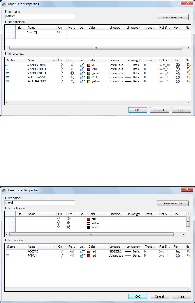
Example 2
The filter named “RYW” displays layers that meet all of the following criteria:
■Are on
■Are frozen
■Are red or yellow or white
Layer Filter Properties Dialog Box | 655
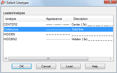
Select Linetype Dialog Box
Quick Reference
See also:
■Work with Layers
Displays linetypes available in the current drawing.
List of Options
The following options are displayed.
Loaded Linetypes
Displays the list of linetypes loaded in the current drawing.
Load
Displays the Load or Reload Linetypes dialog box, in which you can load
selected linetypes into the drawing and add them to the list of linetypes.
Lineweight Dialog Box
Quick Reference
See also:
■Work with Layers
656 | Chapter 12 L Commands
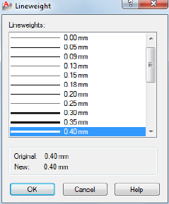
Displays the lineweight values available.
Summary
You can customize your lineweights to plot at other values by using the Plot
Style Table Editor. See “Control Plotted Lineweight and Linetype” in the User's
Guide.
List of Options
The following options are displayed.
Lineweights
Displays the available lineweights to be applied. Available lineweights consist
of fixed values that are most commonly used in drawings. Select a lineweight
to apply it.
Original
Displays the previous lineweight. The default lineweight assigned when a layer
is created is DEFAULT (which plots to a default value of 0.01 inches or 0.25
mm). (LWDEFAULT system variable)
New
Displays the new lineweight assigned to the layer.
Lineweight Dialog Box | 657

Layer Transparency Dialog Box
Quick Reference
See also:
■Work with Layers
Sets the transparency level for the selected layer(s) in the current drawing.
Access Methods
Button
Ribbon: Home tab ➤ Layers panel ➤ Layer Properties Manager
Menu: Format ➤ Layer
Toolbar: Layer
Command entry: layer (or 'layer for transparent use)
Summary
Select or enter a transparency level to apply to selected layers in the current
drawing.
Layer Settings Dialog Box
Quick Reference
See also:
■Use New Layer Notification
Displays new layer notification, isolate layer, and dialog settings.
658 | Chapter 12 L Commands

Summary
Click on the Layer Properties Manager on page 643.
Controls when notification occurs for new layers and if layer filters are applied
to the Layers toolbar; also controls the background color of viewport overrides
in the Layer Properties Manager.
List of Options
The following options are displayed.
New Layer Notification
Controls the evaluation and notification of new layers based on the
LAYEREVAL settings in the DWG file.
Layer Settings Dialog Box | 659

NOTE There should be no filter (Unreconciled Layer filter) displayed when
LAYEREVALCTL = 0. If one is currently displayed, it will be turned off. You can set
the unreconciled new layers filter active and select the layers in that filter. With
the unreconciled layer selected, you can right-click and click Reconcile Layer.
Evaluate New Layers Added to Drawing
Checks for new layers that have been added to the drawing. (LAYEREVAL =
0)
Evaluate New Xref Layers Only
Checks for new layers that have been added to attached xrefs. (LAYEREVAL
= 1)
Evaluate All New Layers
Checks for new layers that have been added to the drawing, including new
layers added to attached xrefs. (LAYEREVAL = 2)
Notify when New Layers Are Present
Turns on new layer notification. (LAYERNOTIFY = 0)
Open
Displays new layer notification when new layers are present when you use
the OPEN command. (LAYERNOTIFY = 2)
Attach/Reload Xrefs
Displays new layer notification when new layers are present when you are
attaching or reloading xrefs. (LAYERNOTIFY = 4)
Restore Layer State
Displays new layer notification when you are restoring layer states.
(LAYERNOTIFY = 8)
Save
Displays new layer notification when new layers are present when you use
the SAVE command. (LAYERNOTIFY = 16)
Insert
Displays new layer notification when new layers are present when you use
the INSERT command. (LAYERNOTIFY = 32)
Display Alert for Plot When New Layers are Present
660 | Chapter 12 L Commands
Displays new layer notification when new layers are present when you use
the PLOT command. (LAYERNOTIFY = 1)
Isolate Layer Settings
Setting for layers not isolated:
Lock and Fade
Selects Lock and Fade as isolation method.
Off
Sets non-selected layers to Off.
Off
Sets non-selected layers to Off (in paper space).
VP Freeze
Sets non-selected layers to Viewport Freeze (in paper space).
Dialog Settings
Apply Layer Filter to Layer Toolbar
Controls the display of layers in the list of layers on the Layers toolbar and
Layers panel on the ribbon by applying the current layer filter.
Indicate Layers in Use
Displays icons in the list view to indicate whether layers are in use. In a
drawing with many layers, clear this option to improve performance.
Viewport Override Background Color Displays a list of colors and the Select
Color dialog box where you can select a background color for viewport
overrides.
Customize Layer Columns Dialog Box
Quick Reference
See also:
■Work with Layers
Controls the display and order of columns in the Layer Properties Manager.
Customize Layer Columns Dialog Box | 661
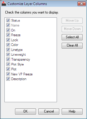
List of Options
The following options are displayed.
Check the Columns you want to Display
Lists all columns that display depending on whether the Layer Properties
Manager was accessed from Model space or a layout tab. Checked columns
are displayed in the Layer Properties Manager.
Move Up
Moves the checked layer to the left in the Layer Properties Manager.
Move Down
Moves the checked layer to the right in the Layer Properties Manager.
Select All
Checks all columns in the list.
Clear All
Unchecks all columns in the list.
662 | Chapter 12 L Commands

-LAYER
Quick Reference
See also:
■Use Layers to Manage Complexity
Manages layers and layer properties.
List of Prompts
The following prompts are displayed.
Current layer: <"current">
Enter an option
[?/Make/Set/New/Rename/ON/OFF/Color/Ltype/LWeight/TRansparency on
page
664/MATerial/Plot/PStyle/Freeze/Thaw/LOck/Unlock/stAte/Description/rEconcile]:
NOTE The Pstyle option is available only when you are using named plot styles.
?—List Layers
Displays a list of the currently defined layers, showing their names, states,
color numbers, linetypes, lineweights, and whether they are externally
dependent layers.
Make
Creates a layer and makes it current. New objects are drawn on the current
layer.
If no layer exists for the name you enter, a new layer with that name is created.
The new layer is on and assumes the following properties by default: color
number 7, the CONTINUOUS linetype, and a lineweight of DEFAULT.
If the layer exists but is turned off, it is turned on.
Set
Specifies a new current layer but does not create the layer if it does not already
exist. If the layer exists but is turned off, it is turned on and made current. A
frozen layer cannot be made current.
New
Creates layers. You can create two or more layers by entering names separated
by commas.
-LAYER | 663
Rename
Renames an existing layer.
On
Makes selected layers visible and available for plotting.
Off
Makes selected layers invisible and excludes them from plotting.
Color
Changes the color associated with a layer. Enter a color name or a number
from 1 through 255.
True Color Specifies a true color to be used for the selected object. Enter three
integer values from 0 to 255 separated by commas to specify a true color.
Color Book Specifies a color from a loaded color book, guide, or set to use for
the selected object. Enter the name of a color book that has been installed,
such as "DIC COLOR GUIDE(R)$DIC 43".
The color is assigned to the layer or layers, and the layers are turned on. To
assign a color but turn off the layer, precede the color with a minus sign (-).
Ltype
Changes the linetype associated with a layer.
Lweight
Changes the lineweight associated with a layer.
If you enter a valid lineweight, the current lineweight is set to the new value.
If you enter a lineweight that is not valid, the current lineweight is set to the
nearest fixed lineweight value. If you would like to plot an object with a
custom width not found in the list of fixed lineweight values, you can use the
Plot Style Table Editor to customize plotted lineweights.
Transparency
Changes the transparency level associated with a layer. Enter a value from 0
to 90.
After specifying a transparency value, the following prompt is displayed:
Enter name list of layer(s) for transparency specified value% <0>: Enter the names
of the layers to which to apply this transparency level, or press Enter to apply it to the
current layer only
Material
Attaches a material to a layer. The material must be available in the drawing
before it can be assigned to a layer.
664 | Chapter 12 L Commands
Plot
Controls whether visible layers are plotted. If a layer is set to plot but is
currently frozen or turned off, the layer is not plotted.
Pstyle
Sets the plot style assigned to a layer. This option is not available if you are
using color-dependent plot styles in the current drawing (the PSTYLEPOLICY
system variable is set to 1). See “Use Plot Styles to Control Plotted Objects” in
the User's Guide.
If you select a plot style other than NORMAL, the following prompt is
displayed:
Enter name list of layer(s) for plot style current <current>: Enter the names of the
layers to use this plot style, or press Enter to apply the style to the current layer only
Freeze
Freezes layers, making them invisible and excluding them from regeneration
and plotting.
Thaw
Thaws frozen layers, making them visible and available for regeneration and
plotting.
Lock
Locks layers, preventing editing of objects on those layers.
Unlock
Unlocks selected locked layers, permitting editing of objects on those layers.
State
Saves and restores the state and property settings of the layers in a drawing.
?—List Named Layer States Lists the named layer state (LAS) files in the
support path for the drawing.
Save Saves the state and properties settings of the layers in a drawing under
a specified layer state name. When saving a layer state, you specify which
layer settings are affected when the layer state is later restored.
Restore Restores the state and property settings of all layers to previously
saved settings. Restores only those layer state and property settings that were
selected when the layer state was saved.
Edit Changes the saved layer settings for a specified layer state. When the
layer state is restored, the specified settings are used.
Name Changes the name of a saved layer state.
Delete Removes a saved layer state.
-LAYER | 665
Import Loads a previously exported layer state (LAS) file, or layers states from
a file (DWG, DWS, DWT) into the current drawing. Additional layers may be
created as a result of importing a layer state file.
Export Saves a selected named layer state to a layer state (LAS) file.
Description
Sets the description property value of the existing layer.
A warning prompt is displayed when you enter a description to a layer with
an existing description.
Reconcile
Sets the unreconciled property of an unreconciled layer.
? - Name List of Layers Displays a list of all unreconciled layers.
LAYERCLOSE
Quick Reference
See also:
■Work with Layers
Closes the Layer Properties Manager.
Summary
Closes the Layer Properties Manager if it is open.
LAYERP
Quick Reference
See also:
■Change Layer Settings and Layer Properties
Undoes the last change or set of changes made to layer settings.
666 | Chapter 12 L Commands

Access Methods
Button
Ribbon: Home tab ➤ Layers panel ➤ Previous
Menu: Format ➤ Layer Tools ➤ Layer Previous
Summary
When you use Layer Previous, it undoes the most recent change using either
the Layer control, Layer Properties Manager, or -LAYER command. Every
change you make to layer settings is tracked and can be undone by Layer
Previous.
LAYERPMODE
Quick Reference
See also:
■Change Layer Settings and Layer Properties
Turns on and off the tracking of changes made to layer settings.
Summary
When Layer Previous mode is on, changes made to layers are tracked. When
Layer Previous mode is off, changes made to layers are no longer tracked.
LAYERSTATE
Quick Reference
See also:
■Work with Layer States
LAYERPMODE | 667

Saves, restores, and manages named layer states.
Access Methods
Button
Ribbon: Home tab ➤ Layers panel ➤ Layer State drop-down ➤ Manage
Layer States
Menu: Format ➤ Layer States Manager
Toolbar: Layers
Summary
The Layer States Manager on page 668 is displayed.
Saves the layer settings in a drawing as a named layer state. Named layer states
can then be restored, edited, imported, and exported for use in other drawings.
Layer States Manager
Quick Reference
See also:
■Work with Layer States
Create or edit layer states.
668 | Chapter 12 L Commands
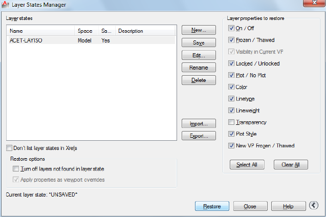
Summary
Displays a list of saved layer states in the drawing. You can create, rename,
edit, and delete layer states.
List of Options
The following options are displayed.
Layer States
Lists the named layer states that have been saved in the drawing, the space
in which they were saved (model space, layout, or xref), whether the layer list
is the same as in the drawing, and an optional description.
Don’t List Layer States in Xrefs
Controls whether layer states in xrefs are displayed.
New
Displays the New Layer State to Save dialog box on page 671, where you can
provide a name and a description for the new named layer state.
Save
Saves the selected named layer state.
Edit
Layer States Manager | 669
Displays the Edit Layer State dialog box on page 672, where you can modify a
selected named layer state.
Rename
Allows in-place editing of the layer state name.
Delete
Removes the selected named layer state.
Import
Displays a standard file selection dialog box, where you can load a previously
exported layer state (LAS) file into the current drawing. Layer states in files
(DWG, DWS, or DWT) can be imported. Additional layers may be created as
a result of importing a layer state file. When a DWG, DWS, or DWT file is
selected, the Select Layer States dialog box on page 674 is displayed where you
can select layer states to import.
Export
Displays a standard file selection dialog box, where you can save the selected
named layer state to a layer state (LAS) file.
Restore
Restores state and property settings of all layers in a drawing to their previously
saved settings. Restores only those layer state and property settings that you
specify with the check boxes.
Close
Closes the Layer States Manager and saves changes.
Restore Options
Turn Off Layers Not Found in Layer State
When a layer state is restored, turns off new layers for which settings were
not saved so that the drawing looks the same way it did when the named layer
state was saved.
Apply Properties as Viewport Overrides
Applies layer property overrides to the current viewport. This option is available
when the Layer States Manager is accessed when a layout viewport is active.
670 | Chapter 12 L Commands

More Options
Controls the display of additional options in the Layer States Manager dialog
box.
Layer Properties to Restore
Restores the selected layer settings and properties to their previously saved
state.
The Visibility in Current Viewport option is available only for layout viewports,
while the On/Off and Frozen/Thawed options are available only for Model
space viewports.
Select All
Selects all the settings.
Clear All
Removes selection from all the settings.
See also:
■Layer Properties Manager on page 643
New Layer State to Save Dialog Box
Quick Reference
See also:
■Work with Layer States
Specifies a name and a description for the layer state defined in the Layer
States Manager.
List of Options
The following options are displayed.
New Layer State Name
Specifies a name for the new layer state to be saved.
Description
New Layer State to Save Dialog Box | 671
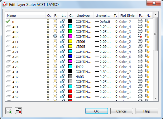
(Optional) Provides a description of the layer state that is displayed in the
Layer States Manager.
Edit Layer State Dialog Box
Quick Reference
See also:
■Save, Restore, and Edit Layer States
Summary
Modifies the selected layer state. Displays all the layers and their properties
that are saved in the selected layer state except for viewport override properties.
List of Options
The following options are displayed.
Layer List Displays a list of layers in the selected layer state and their
properties.
Delete Removes the selected layers from the layer state.
Add
672 | Chapter 12 L Commands
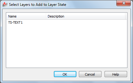
Displays the Select Layers to Add to Layer States dialog box on page 673, in
which you can add layers from the current drawing that are not defined in
the layer state.
Select Layers to Add to Layer State Dialog Box
Quick Reference
See also:
■Save, Restore, and Edit Layer States
Summary
Displays layers by name and includes descriptions that are not defined in the
selected named layer state.
Multiple layers can be selected. Clicking OK displays the selected layers in the
Edit Layer State dialog box on page 672.
List of Option
The following option is available in this dialog box.
Layer List
Displays layers by name and description.
Select Layers to Add to Layer State Dialog Box | 673
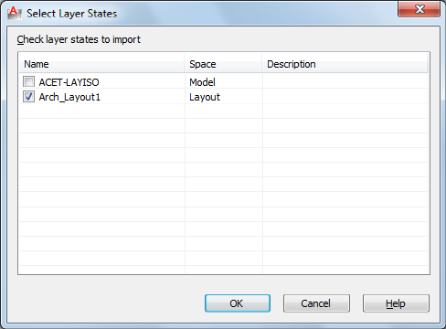
Select Layer States Dialog Box
Quick Reference
See also:
■Import and Export Layer States
Displays a list of layer states to be imported from a drawing file into the current
drawing.
List of Option
The following option is available in this dialog box.
Check Layer States to Import
Displays a list of layer states, the space (model tab or layout tab) in which the
layer state was saved, and a description.
The layer state names in the selected file (DWG, DWS, DWT) are compared
to the layer state names in the current drawing. Duplicate layer state names
are not checked by default. When a duplicate layer state name is checked, a
prompt displays if you want to overwrite the existing layer state.
674 | Chapter 12 L Commands
NOTE If the layer state to be imported contains linetypes or plot styles that do
not exist in the current drawing, they are imported from the DWG, DWS or DWT
file.
LAYFRZ
Quick Reference
See also:
■Use Layers to Manage Complexity
Freezes the layer of selected objects.
Access Methods
Button
Ribbon: Home tab ➤ Layers panel ➤ Freeze
Menu: Format ➤ Layer Tools ➤ Layer Freeze
Toolbar: Layers II
Summary
Objects on frozen layers are invisible. In large drawings, freezing unneeded
layers speeds up operations involving display and regeneration. In a layout,
you can freeze layers in individual layout viewports.
List of Prompts
The following prompts are displayed.
Current settings: Viewports=current, Block nesting level=current
Select an object on a layer to be frozen on page 675 or [Settings/Undo]: Select
an object or enter s or u
Layer <layer name> has been frozen.
Select an Object on a Layer to be Frozen
Specifies the layer to be frozen.
Layer “<layer name>” has been frozen.
LAYFRZ | 675
Settings
Displays settings for viewports and block definitions. The setting you choose
persists from session to session.
Enter setting type for [Viewports/Block selection]:
Viewports Displays settings for viewports.
In paper space viewport use [Freeze/Vpfreeze] <Vpfreeze>: Enter f to freeze objects
in all viewports or v to freeze an object in the current viewport only
Block Selection Displays settings for block definitions.
■Block. If a selected object is nested in a block, freezes the layer of that block.
If a selected object is nested in an xref, freezes the layer of the object.
■Entity. Freezes the layers of selected objects even if they are nested in an
xref or a block.
■None. If a block or an xref is selected, freezes the layer containing that
block or xref.
Undo
Cancels the previous layer selection.
LAYISO
Quick Reference
See also:
■Use Layers to Manage Complexity
Hides or locks all layers except those of the selected objects.
Access Methods
Button
Ribbon: Home tab ➤ Layers panel ➤ Isolate
Menu: Format ➤ Layer Tools ➤ Layer Isolate
Toolbar: Layers II
676 | Chapter 12 L Commands

Summary
All layers except the layers of the selected objects are either turned off, frozen
in the current layout viewport, or locked, depending on the current setting.
The layers that remain visible and unlocked are called isolated.
List of Prompts
The following prompts are displayed.
Current setting: <current settings>
Select objects on the layer(s) to be isolated or [Settings]: Select objects or enter
s
Select Objects on the Layer(s) to be Isolated
After selecting one or more objects, all layers except the layers of the selected
objects are either turned off, frozen in the current layout viewport, or locked,
depending on the current setting. The layers that remain visible and unlocked
are termed isolated.
NOTE Locked layers are faded by default. You can specify the percent of the fading
from the Lock option in this command. You can later change the value with the
LAYLOCKFADECTL system variable.
If you make changes to layers within a session and you want to restore the
layers to the state they were in immediately before you entered the LAYISO
command, use the LAYUNISO command.
Settings
Controls whether layers are turned off, frozen in the current layout viewports,
or locked.
Off Turns off or freezes all layers except the layers of the selected objects.
Vpfreeze In a layout, freezes all but the selected layers in the current layout
viewport only. Other layout viewports in the drawing are unchanged.
If not in a layout, all other layers are turned off instead.
Off Turns off all but the selected layers in all viewports.
Lock and Fade
Locks all layers except the layers of the selected objects, and sets the fading for
locked layers.
LAYISO | 677

LAYLCK
Quick Reference
See also:
■Prevent Objects from Being Selected
Locks the layer of a selected object.
Access Methods
Button
Ribbon: Home tab ➤ Layers panel ➤ Lock
Menu: Format ➤ Layer Tools ➤ Layer Lock
Toolbar: Layers II
Summary
Using this command, you can prevent objects on a layer from being
accidentally modified. You can also fade the objects on a locked layer using
the LAYLOCKFADECTL system variable.
LAYMCH
Quick Reference
See also:
■Use Layers to Manage Complexity
Changes the layer of a selected object to match the destination layer.
678 | Chapter 12 L Commands

Access Methods
Button
Ribbon: Home tab ➤ Layers panel ➤ Match
Menu: Format ➤ Layer Tools ➤ Layer Match
Toolbar: Layers II
Summary
If you enter -laymch at the Command prompt, options are displayed on page
680.
List of Prompts
The following prompts are displayed.
Select objects to be changed: Select an object to change its layer
Select object on destination layer on page 679 or [Name on page 679]: Select an
object or enter n to open the Change to Layer dialog box
Select Object on Destination Layer Select an object on the destination layer.
Name Displays the Change to Layer dialog box on page 679.
If you create an object on the wrong layer, you can change its layer to the one
you want using LAYMCH.
Change to Layer Dialog Box
Quick Reference
See also:
■Use Layers to Manage Complexity
Displays a list of layers to choose as the destination layer. You can also create
a new destination layer.
List of Options
The following options are displayed.
Change to Layer Dialog Box | 679
Current Layer Displays the currently selected layer. Create a new layer name
by entering a name.
Destination Layer list Displays a list of layers in the drawing.
-LAYMCH
Quick Reference
See also:
■Use Layers to Manage Complexity
Changes the layer of a selected object to match the destination layer.
List of Prompts
The following prompts are displayed.
Select objects to be changed:
Select objects: Select an object to change its layer
After you select the object(s) to change, the following prompt is displayed:
Select object on destination layer on page 680 or [Name on page 680]: Select an
object or enter n to enter a layer name
Select Object on Destination Layer Select an object on the destination layer.
Name Displays the Change to Layer dialog box on page 679.
If you create an object on the wrong layer, you can change its layer to the one
you want using LAYMCH.
LAYMCUR
Quick Reference
See also:
■Use Layers to Manage Complexity
Sets the current layer to that of a selected object.
680 | Chapter 12 L Commands

Access Methods
Button
Ribbon: Home tab ➤ Layers panel ➤ Make Object’s Layer Current
Menu: Format ➤ Layer Tools ➤ Make Object’s Layer Current
Toolbar: Layers
Summary
You can change the current layer by selecting an object on that layer. This is
a convenient alternative to specifying the layer name in the Layer Properties
Manager.
LAYMRG
Quick Reference
See also:
■Use Layers to Manage Complexity
Merges selected layers into a target layer, removing the previous layers from
the drawing.
Access Methods
Button
Ribbon: Home tab ➤ Layers panel ➤ Merge
Menu: Format ➤ Layer Tools ➤ Layer Merge
LAYMRG | 681
Summary
You can reduce the number of layers in a drawing by merging them. Objects
on merged layers are moved to the target layer, and the original layers are
purged from the drawing.
List of Prompts
The following prompts are displayed.
Select object on layer to merge on page 682or [Name on page 682]: Select an
object or enter n to select a layer in the Merge Layers dialog box
After you selected the layer(s) to merge, the following prompt is displayed:
Select object on target layer on page 682or [Name on page 682]: Select an object
or enter n to select a layer in the Merge to Layer dialog box
The layer you selected to merge into the target layer is deleted.
If you enter -laymrg at the Command prompt, options are displayed on page
683.
Select Object on Layer to Merge Select an object on the layer you want to
merge.
Name Displays the Merge Layers dialog box on page 682.
Select Object on Target Layer Select an object on the destination layer.
Name Displays the Merge to Layer dialog box on page 683.
Merge Layers Dialog Box
Quick Reference
See also:
■Use Layers to Manage Complexity
List of Option
The following prompt is displayed in this dialog box.
Merge Layer list Displays a list of layers to merge.
682 | Chapter 12 L Commands
Merge to Layer Dialog Box
Quick Reference
See also:
■Use Layers to Manage Complexity
Displays a list of layers onto which the selected layers or objects can be merged.
List of Options
The following options are displayed.
Target Layer Displays the first layer in an alphabetical list of the layers in the
current drawing.
Target Layer list Displays an alphabetical list of the layers onto which you
can merge the selected layers or objects.
-LAYMRG
Quick Reference
See also:
■Use Layers to Manage Complexity
Summary
The layer you selected to merge into the target layer is deleted.
List of Prompts
The following prompts are displayed.
Select object on layer to merge on page 684or [Name on page 684]: Select an
object or enter n to select a layer from a list of layers
After you selected the layer(s) to merge, the following prompt is displayed:
Select object on target layer on page 684or [Name on page 684]: Select an object
or enter n to select a target layer from a list of layers
Merge to Layer Dialog Box | 683

Select Object on Layer to Merge
Select an object on the destination layer.
Name
Displays a list of layers, where you can select layers to merge.
Select Object on Target Layer
Select an object on the target layer.
Name
Displays a list of layers onto which you can merge the selected object or layer.
LAYOFF
Quick Reference
See also:
■Use Layers to Manage Complexity
Turns off the layer of a selected object.
Access Methods
Button
Ribbon: Home tab ➤ Layers panel ➤ Off
Menu: Format ➤ Layer Tools ➤ Layer Off
Toolbar: Layers II
Summary
Turning off the layer of a selected object makes that object invisible. This
command is useful if you need an unobstructed view when working in a
drawing or if you don’t want to plot details such as reference lines.
List of Prompts
The following prompts are displayed.
Current settings: Viewports=current, Block nesting level=current
684 | Chapter 12 L Commands
Select an object on the layer to be turned off or [Settings/Undo]: Select an
object, enter s, or enter u
Select an Object on the Layer to be Turned Off
Selects one or more objects whose layers you want to turn off.
Settings
Displays the Viewports and Block Definition setting types. The setting you
choose persists from session to session.
Viewports Displays the Viewports setting types.
Returns the following prompt:
■Vpfreeze: In paper space, freezes the layer selected in the current viewport.
■Off: In paper space, turns off selected layers in all viewports.
Block Selection Displays the Block Selection setting types, where you can
freeze layers of selected objects.
■Block: Turns off the layers of selected objects. If a selected object is nested
in a block, the layer containing that block is turned off. If a selected object
is nested in an xref, the layer of the object is turned off.
■Entity: Turns off layers of selected objects even if they are nested in an xref
or a block.
■None: Turns off the layers of selected objects. If a block or an xref is
selected, the layer containing that block or xref is turned off.
Undo
Cancels the previous layer selection.
LAYON
Quick Reference
See also:
■Use Layers to Manage Complexity
Turns on all layers in the drawing.
LAYON | 685

Access Methods
Button
Ribbon: Home tab ➤ Layers panel ➤ On
Menu: Format ➤ Layer Tools ➤ Turn All Layers On
Toolbar: Layers II
Summary
All layers that were previously turned off are turned back on. Objects created
on those layers become visible, unless the layers are also frozen.
LAYOUT
Quick Reference
See also:
■Create Multiple-View Drawing Layouts (Paper Space)
Creates and modifies drawing layouts.
Access Methods
Button
Menu: Insert ➤ Layout ➤ New Layout
Menu: Insert ➤ Layout ➤ Layout from Template
Toolbar: Layouts
List of Prompts
The following prompts are displayed.
Enter layout option [Copy/Delete/New/Template/Rename/SAveas/Set/?] <set>:
686 | Chapter 12 L Commands

NOTE Many of these options are available by right-clicking a layout tab name.
Copy Copies a layout. If you do not provide a name, the new layout assumes
the name of the copied layout with an incremental number in parentheses.
The new tab is inserted before the copied layout tab.
Delete Deletes a layout. The most current layout is the default.
The Model tab cannot be deleted. To remove all the geometry from the Model
tab, you must select all geometry and use the ERASE command.
New Creates a new layout tab. Up to 255 layouts can be created in a single
drawing.
Layout names must be unique. Layout names can be up to 255 characters long
and are not case sensitive. Only the first 31 characters are displayed on the
tab.
Template Creates a new layout tab based on an existing layout in a template
(DWT), drawing (DWG), or drawing interchange (DXF) file. If the FILEDIA
system variable is set to 1, a standard file selection dialog box is displayed for
selecting a DWT, DWG, or DXF file. After you select a file, the Insert Layouts
dialog box is displayed, which lists the layouts saved in the selected file. After
you select a layout, the layout and all objects from the specified template or
drawing file are inserted into the current drawing.
Rename Renames a layout. The last current layout is used as the default for
the layout to rename.
Layout names must be unique. Layout names can be up to 255 characters long
and are not case sensitive.
NOTE Only the first 31 characters are displayed on the tab.
Saveas Saves a layout as a drawing template(DWT) file without saving any
unreferenced symbol table and block definition information. You can then
use the template to create new layouts in your drawings without having to
eliminate unnecessary information. See “Reuse Layouts and Layout Settings”
in the User's Guide.
The last current layout is used as the default for the layout to save as a template.
If the FILEDIA system variable is set to 1, a standard file selection dialog box
is displayed in which you can specify the template file in which to save the
layout.
The default layout template directory is specified in the Options dialog box.
Set Makes a layout current.
LAYOUT | 687

?—List Layouts Lists all the layouts defined in the drawing.
LAYOUTWIZARD
Quick Reference
See also:
■Use the Layout Wizard to Specify Page Setups
Creates a new layout tab and specifies page and plot settings.
Access Methods
Menu: Insert ➤ Layout ➤ Create Layout Wizard
Summary
The Layout wizard is displayed.
Layout Wizard
Quick Reference
See also:
■Use the Layout Wizard to Specify Page Setups
Summary
The Layout wizard contains a series of pages that step you through the process
of creating a new layout. You can choose to create a new layout from scratch
or use an existing layout template on which to base your new layout.
Depending on which plotting device is currently configured, you can select
a paper size from those available. You can select a predefined title block to
apply to your new layout. The Preview area displays a preview image of the
title block you select.
688 | Chapter 12 L Commands
When you've finished using the wizard to specify your layout settings, you
can modify any of the settings using the PAGESETUP command from within
the new layout.
LAYTHW
Quick Reference
See also:
■Use Layers to Manage Complexity
Thaws all layers in the drawing.
Access Methods
Button
Ribbon: Home tab ➤ Layers panel ➤ Thaw
Menu: Format ➤ Layer tools ➤ Thaw All Layers
Summary
All layers that were previously frozen are unfrozen. Objects created on those
layers become visible, unless the layers are also turned off or have been frozen
in individual layout viewports. Layers that are frozen in individual layout
viewports must be thawed layer by layer.
NOTE LAYTHW does not thaw layers in a viewport. Use the VPLAYER on page 1313
command to thaw layers in a viewport.
LAYTHW | 689
LAYULK
Quick Reference
See also:
■Prevent Objects from Being Selected
Unlocks the layer of a selected object.
Access Methods
Button
Ribbon: Home tab ➤ Layers panel ➤ Unlock
Menu: Format ➤ Layer Tools ➤ Layer Unlock
Toolbar: Layers II
Summary
When you move the cursor over objects on locked layers, the locked icon is
displayed.
You can select an object on a locked layer and unlock that layer without
specifying the name of the layer. Objects on unlocked layers can be selected
and modified.
LAYUNISO
Quick Reference
See also:
■Use Layers to Manage Complexity
Restores all layers that were hidden or locked with the LAYISO command.
690 | Chapter 12 L Commands

Access Methods
Button
Ribbon: Home tab ➤ Layers panel ➤ Unisolate
Menu: Format ➤ Layer Tools ➤ Layer Unisolate
Toolbar: Layers II
Summary
Reverses the effects of the previous LAYISO command. Any additional changes
made to layer settings after you use the LAYISO command will be retained.
LAYUNISO restores layers to the state they were in just before you entered the
LAYISO command. Changes to layer settings after LAYISO is used are retained
when you enter the LAYUNISO command. If LAYISO was not used, LAYUNISO
does not restore any layers.
LAYVPI
Quick Reference
See also:
■Use Layers to Manage Complexity
Freezes selected layers in all layout viewports except the current viewport.
Access Methods
Button
Ribbon: Home tab ➤ Layers panel ➤ VP Freeze in All Viewports Except
Current
Menu: Format ➤ Layer Tools ➤ VP Freeze in All Viewports Except Current
LAYVPI | 691

Summary
Isolates the layer of a selected object in the current viewport by freezing the
layer in all but the current viewport. You can choose to isolate all layouts or
only the current layout.
This command automates the process of using VP Freeze in the Layer Properties
Manager. You select an object on each layer to be frozen in other layout
viewports.
NOTE LAYVPI works only when TILEMODE is set to 0 and when two or more paper
space viewports are defined.
List of Prompts
The following prompts are displayed.
Current settings: Layouts= , Block nesting level=
Select objects on the layer to be isolated in viewport on page 692 or
[Settings/“Undo”]: Select objects or enter an option
Select Objects on the Layer to be Isolated in Viewport
Selects an object whose layer you want to isolate in a viewport.
Settings
Displays the Viewports and Block Definition setting types. The setting you
choose persists from session to session.
Layouts Displays layout options for isolating layers.
■All Layouts: In all layouts, isolates layers of selected objects in all but the
current viewport
■Current Layout: In the current layout, isolates layers of selected objects in
all but the current viewport. This option persists from session to session.
Block Selection Displays the Block Selection setting types, where you can
freeze layers of selected objects.
■Block: Isolates the layers of selected objects. If a selected object is nested
in a block, the layer containing that block is isolated. If a selected object
is nested in an xref, the layer of the object is isolated.
■Entity: Isolates layers of selected objects even if they are nested in an xref
or a block.
■None: Isolates the layers of selected objects. If a block or an xref is selected,
the layer containing that block or xref is isolated.
692 | Chapter 12 L Commands

LAYWALK
Quick Reference
See also:
■Use Layers to Manage Complexity
Displays objects on selected layers and hides objects on all other layers.
Access Methods
Button
Ribbon: Home tab ➤ Layers panel ➤ Walk
Menu: Format ➤ Layer Tools ➤ Layer Walk
Toolbar: Layers II
Summary
The LayerWalk dialog box is displayed.
Displays a dialog box with a list of all layers in the drawing. For drawings with
a large number of layers, you can filter the list of layers that are displayed in
the dialog box.Use this command to review the objects on each layer and to
purge unreferenced layers.
By default, the effect is temporary and layers are restored when you close the
dialog box.
LayerWalk Dialog Box
Quick Reference
See also:
■Use Layers to Manage Complexity
LAYWALK | 693
Dynamically displays objects on layers that you select in the Layer list.
Summary
The number of layers in the drawing are displayed in the dialog box title. You
can change the current layer state when you exit, save layer states, and purge
layers that are not referenced.
You can use the Layer Walk dialog box in a paper space viewport to select
layers to turn on and thaw in the layer table and the current viewport. Any
layer that is not selected in the Layer list is frozen in the current viewport.
You can change the display of one viewport without altering the display of
another viewport.
List of Options
The following options are displayed.
Filter
Turns an active filter on and off. When this check box is selected, the list
displays only those layers that match the active filter. When this check box
is cleared, the full list of layers is displayed. (This option is available only when
there is an active filter.) To turn on an active filter, in the filter list, either
enter a wildcard and press Enter, or select a saved filter.
Layer List
If a filter is active, displays a list of layers defined in that filter. If no filter is
active, displays a list of layers in the drawing. Double-click a layer to set it to
Always Show (an asterisk to the left of the layer is displayed). Right-click in
the layer list to display more options.
In the layer list, you can
■Click a layer name to display the contents of a layer.
■Double-click a layer name to turn the Always Show option on or off.
■Press Ctrl and click layers to select multiple layers.
■Press Shift and click to select layers in a sequence.
■Press either Ctrl or Shift and double-click in the layer list to turn the Always
Show option on or off.
■Click and drag in the layer list to select multiple layers.
For more options in the layer list, right-click to access the Layer List shortcut
menu.
694 | Chapter 12 L Commands
Layer List Shortcut Menu Options
Displays a list of options for the layers selected in the Layer list.
Hold Selection Turns on the Always Show option for selected layers. An
asterisk (*) is displayed to the left of each layer held.
Release Selection Turns off the Always Show option for selected layers.
Release All Turns off the Always Show option for all layers.
Select All Selects and displays all layers.
Clear All Clears all layers.
Invert Selection Clears current layers and selects and displays all other layers.
Select Unreferenced Selects all unreferenced layers. Use with the Purge button
to remove unused layers.
Save Layer State Saves the current selection of layers as a layer state that can
be used by the Layer States Manager.
Inspect Displays the number of layers in the drawing, the number of layers
selected, and the number of objects on the selected layers.
Copy as Filter Displays the name of the selected layer in the Filter text box.
Can be used to create wildcards.
Save Current Filter Saves the current filter so that it is available in the Filter
list for reuse.
Delete Current Filter Removes the current filter from the filter list.
Select Objects
Selects objects and their layers.
Filter List
Filters the layer list. Enter a wildcard and press Enter to display and highlight
only those layers whose names match the wildcard. Right-click to save and
delete filters. The filter list displays saved filters only.
For more information about wild-card characters, see the Wild-Card Characters
section of Filter and Sort the List of Layers.
Purge
When selected layers are not referenced, purges them from the drawing. For
a list of layers that can be purged, right-click anywhere in the Layer list and
LayerWalk Dialog Box | 695
click Select Unreferenced. In the Layer list, the unreferenced layers are
highlighted. You can purge those layers.
Restore on Exit
Returns layers to their previous state when you exit the dialog box. If the
check box is cleared, any changes you made are saved.
LEADER
Quick Reference
See also:
■Create Leaders
■Modify Leaders Using Grips
Creates a line that connects annotation to a feature.
Summary
It is recommended that you use the workflow available through the MLEADER
on page 742 command to create leader objects.
List of Prompts
The following prompts are displayed.
Specify leader start point:
Specify next point:
A leader line segment is drawn and prompts for points and options are
displayed.
Specify next point or [Annotation/Format/Undo] <Annotation>: Specify a point,
enter an option, or press Enter
Point Specification
Draws a leader line segment to the point specified and continues to prompt
you for points and options.
Annotation
Inserts an annotation at the end of the leader line. The annotation can be
single or multiple lines of text, a feature control frame containing geometric
tolerances, or a block.
696 | Chapter 12 L Commands
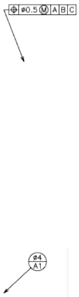
If you press Enter at the Annotation prompt without entering text first, the
following options are displayed:
Tolerance Creates a feature control frame containing geometric tolerances
using the Geometric Tolerance dialog box (see TOLERANCE).
You can create datum indicators and basic dimension notation in these dialog
boxes. After you specify the geometric tolerance, LEADER ends.
Copy Copies text, a multiline text object, a feature control frame with
geometric tolerances, or a block and connects the copy to the end of the leader
line. The copy is associated with the leader line, meaning that if the copied
object moves, the end of the leader line moves with it. The display of the hook
line depends on the object copied.
The value of the current text gap (see DIMSTYLE or the DIMGAP system
variable) determines where the text and multiline text objects are inserted.
Blocks or feature control frames with geometric tolerances are attached to the
end of the leader line.
Block Inserts a block at the end of the leader line. The prompts are the same
as for INSERT on page 620. The block reference is inserted at an offset from the
end of the leader line and is associated to the leader line, meaning that if the
block moves, the end of the leader line moves with it. No hook line is
displayed.
None Ends the command without adding any annotation to the leader line.
Mtext Creates text using the In-Place Text Editor when you specify an insertion
point and a second point for the text boundary.
Enter the characters for the text. Enclose format strings for prefixes and suffixes
in angle brackets (< >). Enclose format strings for alternate units in square
brackets ([ ]). For more information about adding a prefix or suffix, see “Control
the Display of Dimension Units” in the User's Guide.
LEADER | 697
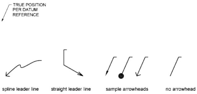
The units settings and the current text style determine how the text is
displayed. The multiline text is vertically centered and horizontally aligned
according to the X axis direction of the last two vertices of the leader line. The
text is offset from the hook line by the distance specified under Offset from
Dim Line on the Text tab of the New, Modify, or Override Dimension Style
dialog box. If the offset specified is negative, the multiline text is enclosed in
a box as a basic dimension.
Format
Controls the way the leader is drawn and whether it has an arrowhead.
Spline Draws the leader line as a spline. The vertices of the leader line are the
control points, each of equal unit weight.
Straight Draws the leader line as a set of straight line segments.
Arrow Draws an arrowhead at the start point of the leader line.
None Draws a leader line with no arrowhead at the start point.
Undo
Undoes the last vertex point on the leader line. The previous prompt is
displayed.
LENGTHEN
Quick Reference
See also:
■Resize or Reshape Objects
698 | Chapter 12 L Commands
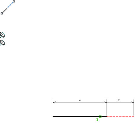
Changes the length of objects and the included angle of arcs.
Access Methods
Button
Ribbon: Home tab ➤ Modify panel ➤ Lengthen
Menu: Modify ➤ Lengthen
Summary
You can specify changes as a percentage, an increment, or as a final length or
angle. LENGTHEN is an alternative to using TRIM or EXTEND.
List of Prompts
The following prompts are displayed.
Select an object or [DElta/Percent/Total/DYnamic]: Select one object or enter an
option
Object Selection
Displays the length and, where applicable, the included angle of the object.
LENGTHEN does not affect closed objects. The extrusion direction of the
selected object need not be parallel to the Z axis of the current user coordinate
system (UCS).
Delta
Changes the length of an object by a specified increment, measured from the
endpoint that is closest to the selection point. Delta also changes the angle
of an arc by a specified increment, measured from the endpoint that is closest
to the selection point. A positive value extends the object; a negative value
trims it.
LENGTHEN | 699
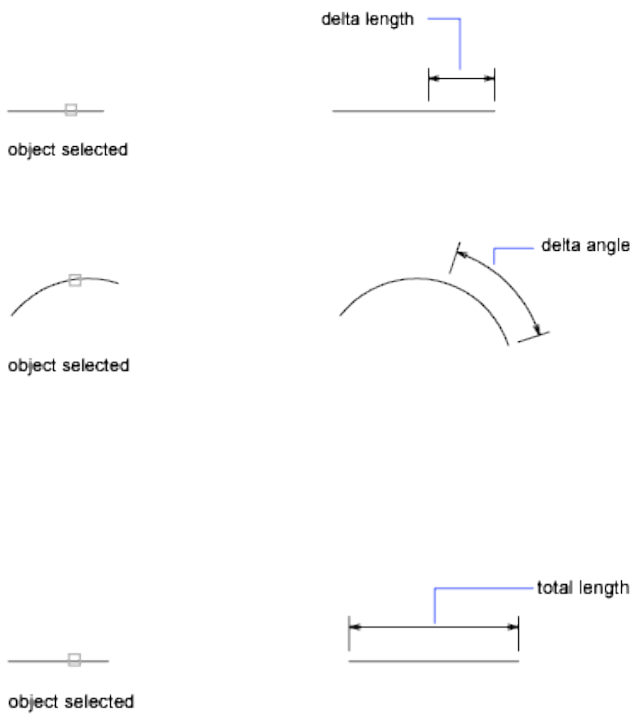
Delta Length Changes the length of the object by the specified increment.
Angle Changes the included angle of the selected arc by the specified angle.
Percent
Sets the length of an object by a specified percentage of its total length.
Total
Sets the length of a selected object by specifying the total absolute length from
the fixed endpoint. Total also sets the included angle of a selected arc by a
specified total angle.
Total Length Lengthens the object to the specified value from the endpoint
that is closest to the selection point.
Angle Sets the included angle of the selected arc.
700 | Chapter 12 L Commands
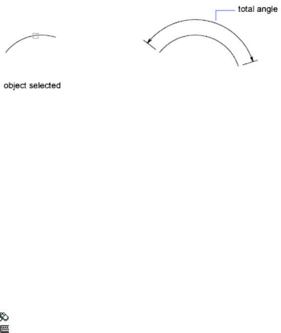
Dynamic
Turns on Dynamic Dragging mode. You change the length of a selected object
by dragging one of its endpoints. The other end remains fixed.
LIMITS
Quick Reference
See also:
■Adjust Grid and Grid Snap
Sets and controls the limits of the grid display in the current Model or named
layout.
Access Methods
Menu: Format ➤ Drawing Limits
Command entry: 'limits for transparent use
List of Prompts
The following prompts are displayed.
Specify lower left corneror [ON/OFF] <current>: Specify a point, enter on or off,
or press Enter
Lower-Left Corner Specifies the lower-left corner for the grid limits.
LIMITS | 701
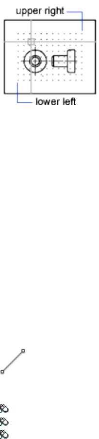
On Turns on limits checking. When limits checking is on, you cannot enter
points outside the grid limits. Because limits checking tests only points that
you enter, portions of objects such as circles can extend outside the grid limits.
Off Turns off limits checking but maintains the current values for the next
time you turn on limits checking.
LINE
Quick Reference
See also:
■Draw Lines
Creates straight line segments.
Access Methods
Button
Ribbon: Home tab ➤ Draw panel ➤ Line
Menu: Draw ➤ Line
Toolbar: Draw
702 | Chapter 12 L Commands
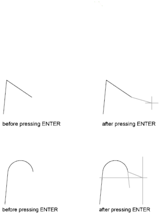
Summary
With LINE, you can create a series of contiguous line segments. Each segment
is a line object that can be edited separately.
List of Prompts
The following prompts are displayed.
Specify first point: Specify a point or press Enter to continue from the last drawn
line or arc
Specify next point or [Close/Undo]:
Continue Continues a line from the endpoint of the most recently drawn
line.
If the most recently drawn object is an arc, its endpoint defines the starting
point of the line, and the line is drawn tangent to the arc.
Close Ends the last line segment at the beginning of the first line segment,
which forms a closed loop of line segments. You can use Close after you have
drawn a series of two or more segments.
LINE | 703
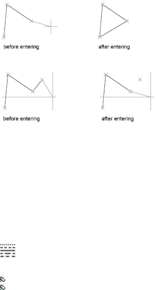
Undo Erases the most recent segment of a line sequence.
Entering u more than once backtracks through line segments in the order you
created them.
LINETYPE
Quick Reference
See also:
■Work with Linetypes
Loads, sets, and modifies linetypes.
Access Methods
Button
Ribbon: Home tab ➤ Properties panel ➤ Linetype
Menu: Format ➤ Linetype
704 | Chapter 12 L Commands
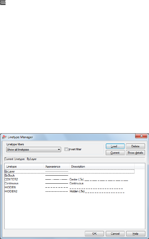
Command entry: 'linetype for transparent use
Summary
The Linetype Manager is displayed.
If you enter -linetype at the Command prompt, options are displayed.
Linetype Manager
Quick Reference
See also:
■Work with Linetypes
Loads linetypes and sets the current linetype.
List of Options
The following options are displayed.
Linetype Filters
Determines which linetypes to display in the linetype list. You can filter
linetypes based on whether they are xref-dependent, or whether they are
referenced by objects.
Linetype Manager | 705

Invert Filter
Displays linetypes based on the opposites of the criteria you select. Linetypes
that fit the inverse filter criteria are displayed in the linetype list.
Load
Displays the Load or Reload Linetypes dialog box, in which you can load into
the drawing selected linetypes from the acadlt.lin file and add them to the
linetype list.
Current
Sets the selected linetype to be the current linetype. Setting the current linetype
to BYLAYER means that an object assumes the linetype that is assigned to a
particular layer. Setting the linetype to BYBLOCK means that an object assumes
the CONTINUOUS linetype until it is grouped into a block. Whenever the
block is inserted, all objects inherit the block's linetype. The CELTYPE system
variable stores the linetype name.
Delete
Deletes selected linetypes from the drawing. You can delete only unused
linetypes. The BYLAYER, BYBLOCK, and CONTINUOUS linetypes cannot be
deleted.
NOTE Be careful about deleting linetypes if you are working on a drawing in a
shared project or one based on a set of layering standards. The deleted linetype
definition remains stored in the acadlt.lin or acadltiso.lin file and can be reloaded.
Show Details or Hide Details
Controls whether the Details section of the Linetype Manager is displayed.
Current Linetype
Displays the current linetype name.
List of Linetypes
Displays the loaded linetypes according to the option specified in Linetype
Filters. To quickly select all or clear all linetypes, right-click in the linetype
list to display the shortcut menu.
Linetype Displays names of loaded linetypes. To rename a linetype, select it
and then click it again and enter a new name. BYLAYER, BYBLOCK,
CONTINUOUS, and xref-dependent linetypes cannot be renamed.
Appearance Displays a sample of selected linetypes.
706 | Chapter 12 L Commands
Description Displays descriptions of the linetypes, which can be edited in
the Details area.
Details
Provides alternative access to properties and additional settings.
Name
Displays the selected linetype name, which can be edited.
Description
Displays the description of the selected linetype, which can be edited.
Use Paper Space Units for Scaling
Scales linetypes in paper space and model space identically. Useful when
working with multiple viewports. (PSLTSCALE system variable)
Global Scale Factor
Displays the global scale factor for all linetypes. (LTSCALE system variable)
Current Object Scale
Sets linetype scale for newly created objects. The resulting scale is the global
scale factor multiplied by the object's scale factor. (CELTSCALE system variable)
ISO Pen Width
Sets the linetype scale to one of a list of standard ISO values. The resulting
scale is the global scale factor multiplied by the object's scale factor.
Load or Reload Linetypes Dialog Box
Quick Reference
See also:
■Work with Linetypes
Loads a linetype whose definition exists in a linetype library (LIN) file.
Load or Reload Linetypes Dialog Box | 707
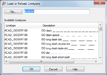
Summary
The acadlt.lin file contains the standard linetypes.
List of Options
The following options are displayed.
File Button
Displays the Select Linetype File dialog box, in which you can select a different
linetype (LIN) file.
File Name
Displays the name of the current LIN file. You can enter the name of another
LIN file or click the File button to select a file from the Select Linetype File
dialog box.
Available Linetypes
Displays the linetypes available to load. To select or clear all of the linetypes
on the list, right-click and choose Select All or Clear All.
-LINETYPE
Quick Reference
See also:
■Work with Linetypes
708 | Chapter 12 L Commands
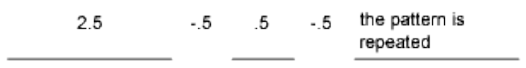
Loads, sets, and modifies linetypes.
List of Prompts
The following prompts are displayed.
Enter an option [?/Create/Load/Set]:
?—List Linetypes Displays the Select Linetype File dialog box (a standard file
selection dialog box). After you select an LIN file, the linetypes available in
the file are listed.
Create Creates a new linetype and stores it in an LIN file.
The Create or Append Linetype File dialog box (a standard file selection dialog
box) is displayed. Specify the file to which you want the linetype added.
Descriptive Text Enter a linetype description up to 47 characters long. The
description can be a comment or a series of underscores, dots, dashes, and
spaces to show a simple representation of the linetype pattern.
Linetype Pattern Enter a pattern definition as a series of numbers separated
by commas. Enter positive values to specify lengths of dashes, and enter
negative values to specify lengths of spaces. Use a zero to represent a dot.
The “A” in the pattern definition prompt specifies the pattern alignment used
at the ends of individual lines, circles, and arcs. Only A-type alignment is
supported. With A-type alignment, lines and arcs are guaranteed to start and
end with a dash. The A is automatically included in the definition. If you use
a text editor to create a linetype, you must enter a at the beginning of the
definition.
After creating a linetype, you must load it to make it accessible.
Load Loads a linetype whose definition exists in a file. The acadlt.lin file
contains the standard linetypes.
The Select Linetype File dialog box (a standard file selection dialog box) is
displayed. Enter or select the file in which the linetype you want to load is
stored.
Set Sets the current linetype for objects that will be drawn subsequently. You
can control the linetype of objects individually or by layer.
The linetype you enter becomes the current linetype. All new objects are drawn
with this linetype, regardless of the current layer. If the linetype you request
is not loaded, the program searches for its definition in the acadlt.lin file. If
-LINETYPE | 709

the linetype is neither loaded nor in acadlt.lin, the program displays a message
and returns you to the Command prompt.
Enter ? to list all loaded linetype names. If you enter bylayer, new objects
inherit the linetype associated with the layer on which the object is drawn.
If you enter byblock, new objects are drawn using the CONTINUOUS linetype
until they are grouped into a block. Whenever you insert that block, the objects
inherit the linetype of the block.
LIST
Quick Reference
See also:
■Display and Change the Properties of Objects
Displays property data for selected objects.
Access Methods
Button
Ribbon: Home tab ➤ Properties panel ➤ List
Menu: Tools ➤ Inquiry ➤ List
Toolbar: Inquiry
Summary
You can use LIST to display and then copy the properties of selected objects
to a text file.
The text window displays the object type, object layer, and the X,Y,Z position
relative to the current user coordinate system (UCS) and whether the object
is in model space or paper space.
LIST also reports the following information:
■Color, linetype, lineweight, and transparency information, if these
properties are not set to BYLAYER.
710 | Chapter 12 L Commands
■The thickness of an object, if it is nonzero.
■Elevation (Z coordinate information).
■Extrusion direction (UCS coordinates), if the extrusion direction differs
from the Z axis (0,0,1) of the current UCS.
■Additional information related to the specific object type. For example,
for dimensional constraint objects, LIST displays the constraint type
(annotation or dynamic), reference type (yes or no), name, expression,
and value.
LOGFILEOFF
Quick Reference
See also:
■Navigate and Edit Within the Command Window
Closes the command history log file opened by LOGFILEON.
Summary
The program stops recording the text window contents and closes the log file.
Each drawing saves a log file (with the extension .log) that may need periodic
deletion as the number of log files continues to grow.
You can also control the log file with the OPTIONS on page 841 command.
Use the Maintain a Log File option on the Open and Save tab on page 850 in
the Options dialog box to turn the log file off and on. Use the Files tab on
page 842 to change the location of the log file.
LOGFILEON
Quick Reference
See also:
■Navigate and Edit Within the Command Window
LOGFILEOFF | 711
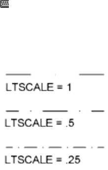
Writes the contents of the command history to a file.
Summary
The contents of the text window are recorded in the log file until you exit the
program or use the LOGFILEOFF command.
Each drawing saves a log file (with the extension .log) that may need periodic
deletion as the number of log files continues to grow.
You can also control the log file with the OPTIONS on page 841 command.
Use the Maintain a Log File option on the Open and Save tab on page 850 in
the Options dialog box to turn the log file off and on. Use the Files tab on
page 842 to change the location of the log file.
LTSCALE
Quick Reference
See also:
■Control Linetype Scale
Sets the global linetype scale factor.
Access Methods
Command entry: 'ltscale for transparent use
Summary
Use LTSCALE to change the scale factor of linetypes for all objects in a drawing.
Changing the linetype scale factor causes the drawing to be regenerated.
712 | Chapter 12 L Commands

LWEIGHT
Quick Reference
See also:
■Overview of Lineweights
Sets the current lineweight, lineweight display options, and lineweight units.
Access Methods
Button
Ribbon: Home tab ➤ Properties panel ➤ Lineweight
Menu: Format ➤ Lineweight
Shortcut menu: Right-click Show/Hide Lineweight on the status bar and
choose Settings.
Command entry: 'lweight for transparent use
Summary
The Lineweight Settings dialog box is displayed.
If you enter -lweight at the Command prompt, options are displayed.
Lineweight Settings Dialog Box
Quick Reference
See also:
■Overview of Lineweights
Sets the current lineweight, sets the lineweight units, controls the display and
display scale of lineweights, and sets the DEFAULT lineweight value for layers.
LWEIGHT | 713

Summary
For a table of valid lineweights, see “Overview of Lineweights” in the User's
Guide.
List of Options
The following options are displayed.
Lineweights
Displays the available lineweight values. Lineweight values consist of standard
settings including BYLAYER, BYBLOCK, and DEFAULT. The DEFAULT value
is set by the LWDEFAULT system variable, which has an initial value of 0.01
inches or 0.25 mm. All new layers use the default setting. The lineweight value
of 0 plots at the thinnest lineweight available on the specified plotting device
and is displayed at one pixel wide in model space.
Current Lineweight
Displays the current lineweight. To set the current lineweight, select a
lineweight from the lineweight list and choose OK.
Units for Listing
Specifies whether lineweights are displayed in millimeters or inches. You can
also set Units for Listing by using the LWUNITS system variable.
Millimeters (mm)
Specifies lineweight values in millimeters.
Inches (in.)
Specifies lineweight values in inches.
714 | Chapter 12 L Commands
Display Lineweight
Controls whether lineweights are displayed in the current drawing. If this
option is selected, lineweights are displayed in model space and paper space.
You can also set Display Lineweight by using the LWDISPLAY system variable.
Regeneration time increases with lineweights that are represented by more
than one pixel. Clear Display Lineweight if performance slows down when
working with lineweights turned on in a drawing. This option does not affect
how objects are plotted.
Default
Controls the DEFAULT lineweight for layers. The initial DEFAULT lineweight
is 0.01 inches or 0.25 mm. (LWDEFAULT system variable)
Adjust Display Scale
Controls the display scale of lineweights on the Model tab. On the Model tab,
lineweights are displayed in pixels. Lineweights are displayed using a pixel
width in proportion to the real-world unit value at which they plot. If you
are using a high-resolution monitor, you can adjust the lineweight display
scale to better display different lineweight widths. The Lineweight list reflects
the current display scale.
Objects with lineweights that are displayed with a width of more than one
pixel may increase regeneration time. If you want to optimize performance
when working in the Model tab, set the lineweight display scale to the
minimum value or turn off lineweight display altogether.
-LWEIGHT
Quick Reference
See also:
■Overview of Lineweights
Sets the current lineweight, lineweight display options, and lineweight units.
List of Prompts
The following prompts are displayed.
Current lineweight: current
-LWEIGHT | 715

Enter default lineweight for new objects or [?]: Enter a valid lineweight or enter
?
The current lineweight value is displayed; if the value is not BYLAYER,
BYBLOCK or DEFAULT, the value is displayed in millimeters or inches.
Default Lineweight Sets the current default lineweight. Lineweight values
consist of fixed settings, including BYLAYER, BYBLOCK, and DEFAULT. Values
are calculated in either inches or millimeters; millimeters are the default. If
you enter a valid lineweight value, the current default lineweight is set to the
new value. If you enter any other value, the default is set to the nearest valid
value.
To plot an object with a lineweight that is not found in the list of fixed
lineweight values, you can use plot styles to control plotted lineweights. See
“Control Plotted Lineweight and Linetype” in the User's Guide. The DEFAULT
value is set by the LWDEFAULT system variable and has an initial value of
0.01 inches or 0.25 mm. The lineweight value of 0 plots at the thinnest
lineweight available on the specified plotting device and is displayed at a value
of one pixel in model space.
?—List Lineweights Displays a list of valid lineweight values in the current
lineweight units.
NOTE If you save a drawing using the AutoCAD Release 14, or earlier, format, the
drawing preview displays lineweights even though the drawing saved in the earlier
format does not display lineweights.
716 | Chapter 12 L Commands
M Commands
MANAGEUPLOADS
Quick Reference
See also:
■Use AutoCAD WS for Drawing File Collaboration
Manages the uploading of files stored on the AutoCAD WS server.
Access Methods
Ribbon: Online tab ➤ Upload panel ➤ Manage Uploads
Menu: File ➤ AutoCAD WS ➤ Manage Uploads
Summary
The Manage Uploads dialog box on page 718 is displayed.
NOTE You may first be prompted to log in to AutoCAD WS. If you do not have an
account, click Create an Account and follow the on-screen instructions.
13
717
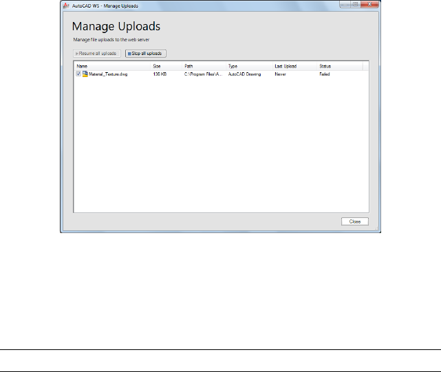
Manage Uploads Dialog Box
Quick Reference
See also:
■Use AutoCAD WS for Drawing File Collaboration
Manages the uploading of files stored on the AutoCAD WS server.
Summary
View the status of your current file uploads and control whether drawings are
automatically uploaded each time the local drawing is saved. Use the check
boxes to resume or stop the uploading process for a specific drawing. To remove
a file from the list, right-click the file and click Remove from This List.
NOTE Removing a file from the list does not remove the file from the server.
List of Options
The following options are displayed.
Resume All Uploads Uploads the latest version of all drawing files in the list
and enables automatic uploads.
Stop All Uploads Cancels any uploads that are in progress, and disables all
automatic uploads.
718 | Chapter 13 M Commands

MARKUP
Quick Reference
See also:
■View Markups
Opens the Markup Set Manager.
Access Methods
Button
Ribbon: View tab ➤ Palettes panel ➤ Markup Set Manager
Menu: Tools ➤ Palettes ➤ Markup Set Manager
Toolbar: Standard
Summary
When submitting designs for review, you can publish a drawing as a DWF or
DWFx file. The reviewer can open the file in Autodesk Design Review, mark
it up, and then send the file back to you.
Opens the Markup Set Manager.
Markup Set Manager
Quick Reference
See also:
■View Markups
Displays information about loaded markup sets and their status.
MARKUP | 719

Summary
You can show or hide markups and their originating drawing files in your
drawing area. You can change the status of individual markups and add notes
and comments to them.
List of Options
The following options are displayed.
Markup Set List Control
The Markup Set List control displays the name of the markup set, or, if no
markup sets are open, the Open option.
Names of Open Markup Sets Lists all open markup sets, if any. A check is
displayed next to the current markup set. The current markup set is the open
markup set that is displayed in the Markup Set Manager window.
Recent Displays a list of recently opened markup sets.
Open Displays the Open Markup DWF dialog box (a standard file selection
dialog box), in which you can select a DWF or DWFx file that contains
markups. When you click Open, the markups in the selected DWF or DWFx
file are loaded into the Markup Set Manager.
NOTE When opening a digitally signed DWFx file, a message box is displayed
that warns you about saving a new version of the file will invalidate the attached
digital signature.
Republish Markup DWF
Provides options for republishing the marked-up DWF or DWFx file. If any
sheets were added to the DWF or DWFx file in Autodesk® Design Review,
those sheets will not be included in the republished DWF or DWFx file.
Republish All Sheets Republishes all sheets in the marked-up DWF or DWFx
file. Opens the Select DWF File dialog box (a standard file selection dialog
box), in which you can select the previously published DWF or DWFx to
overwrite it, or you can enter a new name for the DWF or DWFx file. When
you click Select, the previously published DWF file is overwritten or a new
DWF or DWFx file is created that contains any changes you made to the
drawing file geometry and the status of the markups.
Republish Markup Sheets Republishes only those sheets in the marked-up
DWF or DWFx file that have associated markups. Opens the Select DWF File
dialog box (a standard file selection dialog box), in which you can select the
previously published DWF or DWFx to overwrite it, or you can enter a new
name for the DWF or DWFx file. When you click Select, the previously
published DWF or DWFx file is overwritten or a new DWF or DWFx file is
720 | Chapter 13 M Commands
created that contains any changes you made to the drawing file geometry and
the status of the markups.
View Redline Geometry
Displays or hides redline markup geometry in the drawing area.
View DWG Geometry
Displays or hides the originating drawing file in the drawing area.
View DWF Geometry
Displays or hides the DWF or DWFx file geometry in the drawing area.
Markups
Displays loaded markup sets. Any sheets that were added to the DWF or DWFx
file in Autodesk Design Review are listed in italics. The icon associated with
each markup represents the status of the markup.
Markup Set Node Indicates the currently loaded markup set.
Drawing Sheet Node Indicates a drawing sheet that has one or more associated
markups.
<None> Indicates an individual markup that does not yet have an assigned
status. This is the default status for new markups.
Question Indicates an individual markup that has an assigned status of
Question. When you open and view a markup, you can change the status to
Question if you need additional information about the markup.
For Review Indicates an individual markup that has an assigned status of For
Review. When you implement a markup, you can change the status to For
Review to indicate that the markup creator should review the changes to the
drawing sheet and the status of the markup.
Done Indicates an individual markup that has an assigned status of Done.
When a markup has been implemented and reviewed, you can change the
status to Done.
Markup Shortcut Menu Options (Markup Set Node)
Right-clicking a markup set node in the Markups area displays the following
shortcut menu options.
Open Markup DWF Opens the Open Markup DWF dialog box (a standard
file selection dialog box), in which you can select a DWF or DWFx file that
contains markups. When you click Open, the markups in the selected DWF
or DWFx file are loaded into the Markup Set Manager.
Markup Set Manager | 721

NOTE When opening a digitally signed DWFx file, a message box is displayed
that warns you about saving a new version of the file will invalidate the attached
digital signature.
Close Markup DWF Closes the selected marked-up DWF or DWFx and removes
it from the Markup Set Manager.
Save Markup History Changes Saves changes to the status of markups and
added comments to the marked-up DWF or DWFx file.
NOTE Saving a DWFx file that contains a digital signature will invalidate the
attached digital signature.
Markup Shortcut Menu Options (Drawing Sheet Node)
Right-clicking a drawing sheet node in the Markups area displays the following
shortcut menu options.
Open Sheet Opens the originating drawing file for that drawing sheet and
makes that layout the active layout in the drawing area.
Republish All Sheets Opens the Specify DWF File dialog box. Use this dialog
box to overwrite the previously published DWF or DWFx files, or create a
DWF or DWFx file.
Republish Markup Sheets Opens the Specify DWF File dialog box. Use this
dialog box to overwrite the previously published DWF or DWFx files, or create
a DWF or DWFx file.
The DWF or DWFx file created contains changes you make to the drawing file
geometry and the status of the markups.
Markup Shortcut Menu Options (Markup Node)
Right-clicking an individual markup node in the Markups area displays the
following shortcut menu options.
Open Markup Opens the originating drawing file for the drawing sheet
associated with the selected markup and makes that layout the active layout
in the drawing area. The associated markup DWF or DWFx file is also opened
as a read-only reference in the drawing area.
Markup Status Displays a shortcut menu that provides a list of status options.
A check mark precedes the currently assigned status for the selected markup.
■<None>: Indicates that the markup does not yet have an assigned status.
This is the default status for new markups.
■Question: After you open and view a markup, you can change its status to
Question if you need additional information about the markup.
722 | Chapter 13 M Commands
■For Review: After you have implemented a markup, you can change the
status to For Review to indicate that the markup creator should review the
changes to the drawing sheet and the status of the markup.
■Done: After a markup has been implemented and reviewed, you can change
its status to Done.
Restore Initial Markup View If you panned or zoomed the selected markup,
or rotated the view in model space, restores the original view of the selected
markup.
Republish All Sheets Opens the Specify DWF File dialog box. Use this dialog
box to overwrite the previously published DWF or DWFx files, or create a
DWF or DWFx file.
Republish Markup Sheets Opens the Specify DWF File dialog box. Use this
dialog box to overwrite the previously published DWF or DWFx files, or create
a DWF or DWFx file.
The DWF or DWFx file created contains changes you make to the drawing file
geometry and the status of the markups.
Show All Sheets/Hide Non-Markup Sheets
Displays all sheets in the marked-up DWF or DWFx file in the tree view of the
Markup Set Manager, or hides the sheets that do not have associated markups.
Markup Details
Provides information about the currently selected node (markup set, drawing
sheet, or individual markup) in the Markups area.
When an individual markup is selected in the Markups area, Markup Details
displays the status of the markup.
The Markup History area (in the lower portion of the Markup Details area)
provides a noneditable history log of the selected markup in reverse
chronological order. In the Notes area, just below the Markup History area,
you can add notes and comments that are automatically saved with the
markup.
Preview Changes the Markup Details area to the Markup Preview area and
displays a thumbnail image of the selected drawing sheet or markup. You can
click the Details button to change the area back to the Markup Details area.
Details Changes the Markup Preview area to the Markup Details area, which
provides information about the selected node in the Markups area. You can
click the Preview button to change the area back to the Markup Preview area.
Markup Set Manager | 723
Markup Preview
Displays a thumbnail preview of the currently selected drawing sheet or
markup.
Details Changes the Markup Preview area to the Markup Details area, which
provides information about the selected node in the Markups area. You can
click the Preview button to change the area back to the Markup Preview area.
Preview Changes the Markup Details area to the Markup Preview area and
displays a thumbnail image of the selected drawing sheet or markup. You can
click the Details button to change the area back to the Markup Details area.
Markup Set Manager Settings
The following shortcut menu options are available when you right-click the
title bar.
Move Displays a four-headed arrow cursor that you can use to move the
dialog box. The dialog box does not dock.
Size Displays a four-headed arrow cursor that you can use to drag an edge or
a corner to make the smaller or larger.
Close Closes the Markup Set Manager.
Allow Docking Toggles the ability to dock or anchor Markup Set Manager.
If this option is selected, a window can be docked when you drag it over a
docking area at the side of a drawing. A docked window adheres to the side
of the application window and causes the drawing area to be resized. Selecting
this option also makes Anchor Right and Anchor Left available.
Anchor Right/ Anchor Left Attaches the Markup Set Manager to an anchor
tab base at the right or left side of the drawing area. An anchored palette
cannot be set to stay open.
Auto-hide Causes a floating palette to roll open and closed as the cursor
moves across it.
Transparency Displays the Transparency dialog box.
724 | Chapter 13 M Commands

MARKUPCLOSE
Quick Reference
See also:
■Respond to Markups
Closes the Markup Set Manager.
Access Methods
Button
Ribbon: View tab ➤ Palettes panel ➤ Markup Set Manager
Menu: Tools ➤ Palettes ➤ Markup Set Manager
Toolbar: Standard
Summary
The Markup Set Manager window closes.
MASSPROP
Quick Reference
See also:
■Obtain Area and Mass Properties Information
Calculates the mass properties of regions or AutoCAD 3D solids.
Access Methods
Button
MARKUPCLOSE | 725
Menu: Tools ➤ Inquiry ➤ Region/Mass Properties
Toolbar: Inquiry
Summary
Refer to the Help system for a complete list of definitions for each of the region
or mass properties computed.
List of Prompts
The following prompts are displayed.
Select objects: Use an object selection method
If you select multiple regions, only those that are coplanar with the first
selected region are accepted.
MASSPROP displays the mass properties in the text window, and then asks if
you want to write the mass properties to a text file (.mpr).
The properties that MASSPROP displays depend on whether the selected objects
are regions, and whether the selected regions are coplanar with the XY plane
of the current user coordinate system (UCS), or 3D solids. For a list of the
parameters that control the MASSPROP units, see Calculations Based on the
Current UCS.
Regions
The following table shows the mass properties that are displayed for all regions.
Mass properties for all regions
DescriptionMass property
The surface area of AutoCAD 3D solids or the enclosed area of regions.Area
The total length of the inside and outside loops of a region. The
perimeter of a 3D solid is not calculated.
Perimeter
The two coordinates that define the bounding box. For regions that
are coplanar with the XY plane of the current user coordinate system,
Bounding box
the bounding box is defined by the diagonally opposite corners of a
rectangle that encloses the region. For regions that are not coplanar
with the XY plane of the current UCS, the bounding box is defined
by the diagonally opposite corners of a 3D box that encloses the re-
gion.
726 | Chapter 13 M Commands

Mass properties for all regions
DescriptionMass property
A 2D or 3D coordinate that is the center of area for regions. For re-
gions that are coplanar with the XY plane of the current UCS, this
Centroid
coordinate is a 2D point. For regions that are not coplanar with the
XY plane of the current UCS, this coordinate is a 3D point.
If the regions are coplanar with the XY plane of the current UCS, the additional
properties shown in the following table are displayed.
Additional mass properties for coplanar regions
DescriptionMass property
A value used when computing the distributed loads, such as fluid
pressure on a plate, or when calculating the forces inside a bending
Moments of in-
ertia
or twisting beam. The formula for determining area moments of iner-
tia is
area_moments_of_inertia = area_of_interest * radius2
The area moments of inertia has units of distance to the fourth power.
Property used to determine the forces causing the motion of an object.
It is always calculated with respect to two orthogonal planes. The
formula for product of inertia for the YZ plane and XZ plane is
Products of iner-
tia
product_of_inertiaYZ,XZ = mass * distcentroid_to_YZ * distcentroid_to_XZ
This XY value is expressed in mass units times the length squared.
Another way of indicating the moments of inertia of a 3D solid. The
formula for the radii of gyration is
Radii of gyra-
tion
gyration_radii = (moments_of_ inertia/body_mass)1/2
Radii of gyration are expressed in distance units.
Calculations that are derived from the products of inertia and that
have the same unit values. The moment of inertia is highest through
Principal mo-
ments and
a certain axis at the centroid of an object. The moment of inertia isX,Y,Z directions
about centroid lowest through the second axis that is normal to the first axis and
that also passes through the centroid. A third value included in the
results is somewhere between the high and low values.
MASSPROP | 727

3D Solids
The following table shows the mass properties that are displayed for solids.
Mass properties for solids
DescriptionMass property
The measure of inertia of a body. Because a density of one is used,
mass and volume have the same value.
Mass
The amount of 3D space that a solid encloses.Volume
The diagonally opposite corners of a 3D box that encloses the solid.Bounding box
A 3D point that is the center of mass for solids. A solid of uniform
density is assumed.
Centroid
The mass moments of inertia, which is used when computing the
force required to rotate an object about a given axis, such as a wheel
rotating about an axle. The formula for mass moments of inertia is
Moments of in-
ertia
mass_moments_of_inertia = object_mass * radiusaxis2
Mass moments of inertia unit is mass (grams or slugs) times the dis-
tance squared.
Property used to determine the forces causing the motion of an object.
It is always calculated with respect to two orthogonal planes. The
formula for product of inertia for the YZ plane and XZ plane is
Products of iner-
tia
product_of_inertiaYZ,XZ = mass * distcentroid_to_YZ * distcentroid_to_XZ
This XY value is expressed in mass units times the length squared.
Another way of indicating the moments of inertia of a solid. The for-
mula for the radii of gyration is
Radii of gyra-
tion
gyration_radii = (moments_of_inertia/body_mass)1/2
Radii of gyration are expressed in distance units.
Calculations that are derived from the products of inertia and that
have the same unit values. The moment of inertia is highest through
Principal mo-
ments and
a certain axis at the centroid of an object. The moment of inertia isX,Y,Z directions
about centroid lowest through the second axis that is normal to the first axis and
that also passes through the centroid. A third value included in the
results is somewhere between the high and low values.
728 | Chapter 13 M Commands
Calculations Based on the Current UCS
The following table shows the parameters that control the units in which
mass properties are calculated.
Parameters that control MASSPROP units
Used to calculateParameter
Mass of solidsDENSITY
Volume of solidsLENGTH
Area of regions and surface area of solidsLENGTH*LENGTH
Bounding box, radii of gyration, centroid, and
perimeter
LENGTH*LENGTH*LENGTH
Moments of inertia, products of inertia, and
principal moments
DENSITY*LENGTH*LENGTH
MATCHCELL
Quick Reference
See also:
■Add Text and Blocks to Tables
Applies the properties of a selected table cell to other table cells.
Access Methods
Shortcut menu: With a table selected and a cell selected, right-click and
click Match Cell.
Summary
All the properties of the source cell are copied to the destination cells except
for the cell type: text or block.
List of Prompts
The following prompts are displayed.
MATCHCELL | 729
Select source cell: Click inside a cell in a table whose properties you want to copy
Select destination cell: Click inside table cells to copy properties from the source cell,
and right-click or press Enter or Esc to exit
MATCHPROP
Quick Reference
See also:
■Copy Properties Between Objects
Applies the properties of a selected object to other objects.
Access Methods
Button
Ribbon: Home tab ➤ Properties panel ➤ Match Properties
Menu: Modify ➤ Match Properties
Toolbar: Standard
Command entry: painter (or 'matchprop for transparent use)
Summary
The types of properties that can be applied include color, layer, linetype,
linetype scale, lineweight, plot style, transparency, and other specified
properties.
List of Prompts
The following prompts are displayed.
Current active settings: Currently selected matchprop settings
Select destination object(s) or [Settings]: Enter s or select one or more objects to
copy properties to
Destination Object(s) Specifies the objects to which you want to copy the
properties of the source object.
730 | Chapter 13 M Commands
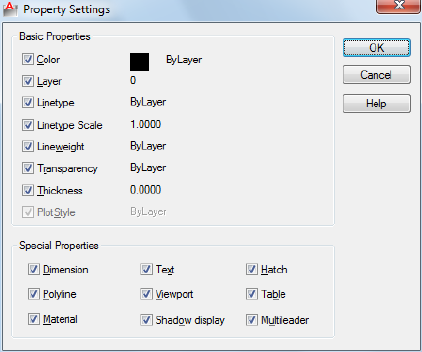
Settings Displays the Property Settings dialog box, in which you can control
which object properties to copy to the destination objects. By default, all
object properties are selected for copying.
Property Settings Dialog Box
Quick Reference
See also:
■Copy Properties Between Objects
Specifies the properties that are copied from the select source object to the
destination objects.
Summary
Specifies which basic properties and special properties to copy from the source
object to the destination objects.
List of Options
The following options are displayed.
Basic Properties
Color
Property Settings Dialog Box | 731
Changes the color of the destination object to that of the source object.
Available for all objects.
Layer
Changes the layer of the destination object to that of the source object.
Available for all objects.
Linetype
Changes the linetype of the destination object to that of the source object.
Available for all objects except attributes, hatches, multiline text, points, and
viewports.
Linetype Scale
Changes the linetype scale factor of the destination object to that of the source
object. Available for all objects except attributes, hatches, multiline text,
points, and viewports.
Lineweight
Changes the lineweight of the destination object to that of the source object.
Available for all objects.
Transparency
Changes the transparency of the of the destination object to that of the source
object. Available for all objects.
Thickness
Changes the thickness of the destination object to that of the source object.
Available only for arcs, attributes, circles, lines, points, 2D polylines, regions,
and text.
Plot Style
Changes the plot style of the destination object to that of the source object.
If you are working in color-dependent plot style mode (PSTYLEPOLICY is set
to 1), this option is unavailable. Available for all objects, except those with
the Jitter edge modifier applied.
Special Properties
Dimension
In addition to basic object properties, changes the dimension style and
properties of the destination object to that of the source object. Available only
for dimension, leader, and tolerance objects.
Polyline
732 | Chapter 13 M Commands
In addition to basic object properties, changes the width and linetype
generation properties of the destination polyline to those of the source
polyline. The fit/smooth property and the elevation of the source polyline are
not transferred to the destination polyline. If the source polyline has variable
width, the width property is not transferred to the destination polyline.
Text
In addition to basic object properties, changes the text style and properties of
the destination object to that of the source object. Available only for single-line
and multiline text objects.
Viewport
In addition to basic object properties, changes the following properties of the
destination paper space viewport to match those of the source viewport: on/off,
display locking, standard or custom scale, shade plot, snap, grid, and UCS
icon visibility and location.
The settings for clipping and the freeze/thaw state of the layers are not
transferred to the destination object.
Hatch
In addition to basic object properties, changes the hatch properties (including
its properties) of the destination object to that of the source object. To match
the hatch origin, use Inherit Properties in HATCH or HATCHEDIT. Available
only for hatch objects.
Table
In addition to basic object properties, changes the table style of the destination
object to that of the source object. Available only for table objects.
Multileader
In addition to basic object properties, changes the multileader style and
properties of the destination object to that of the source object. Available only
for multileader objects.
Property Settings Dialog Box | 733
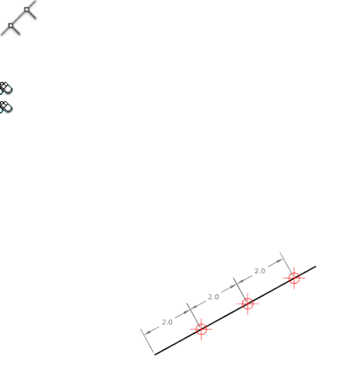
MEASURE
Quick Reference
See also:
■Specify Measured Intervals on Objects
Creates point objects or blocks at measured intervals along the length or
perimeter of an object.
Access Methods
Button
Ribbon: Home tab ➤ Draw panel ➤ Measure
Menu: Draw ➤ Point ➤ Measure
Summary
The resulting points or blocks are always located on the selected object and
their orientation is parallel to the XY plane of the UCS.
Use DDPTYPE to set the style and size of all point objects in a drawing.
The points or blocks are placed in the Previous selection set, so you can select
them all by entering p at the next Select Objects prompt. You can use the
Node object snap to draw an object by snapping to the point objects. You can
then remove the points by entering erase previous.
734 | Chapter 13 M Commands
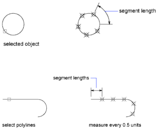
List of Prompts
The following prompts are displayed.
Select object to measure:
Specify length of segment or [Block]: Specify a distance or enter b
Length of Segment Places point objects at the specified interval along the
selected object, starting at the endpoint closest to the point you used to select
the object.
Measurement of closed polylines starts at their initial vertex (the first one
drawn).
Measurement of circles starts at the angle from the center set as the current
snap rotation angle. If the snap rotation angle is 0, then the measurement of
the circle starts to the right of center, on its circumference.
The illustration shows how MEASURE marks 0.5-unit distances along a
polyline, with the PDMODE on page 1606 system variable set to 35.
Block Places blocks at a specified interval along the selected object.
Align Block With Object
■Yes. The block is rotated about its insertion point so that its horizontal
lines are aligned with, and drawn tangent to, the object being measured.
■No. The block is always inserted with a 0 rotation angle.
MEASURE | 735
After you specify the segment length, the block is inserted at the specified
interval. If the block has variable attributes, these attributes are not included.
MEASUREGEOM
Quick Reference
See also:
■Obtain Area and Mass Properties Information
Measures the distance, radius, angle, area, and volume of selected objects or
sequence of points.
Access Methods
Button
Ribbon: Home tab ➤ Utilities panel ➤ Measure drop-down ➤ Distance
Menu: Tools ➤ Inquiry ➤ Distance
Toolbar: Inquiry, Measurement Tools
Summary
The MEASUREGEOM command performs many of the same calculations as
the following commands:
■AREA
■DIST
■MASSPROP
List of Prompts
The following prompts are displayed.
Enter an option [Distance/Radius/Angle/ARea/Volume] <Distance>: Specify
Distance, Radius, Angle, Area, or Volume
736 | Chapter 13 M Commands

Information displays at the Command prompt and in the tooltip in the current
units format.
Distance
Measures the distance between specified points. The following display at the
Command prompt and in the tooltip:
■The current UCS X axis
■Distance in X direction (Delta X)
■Distance in Y direction (Delta Y)
Multiple Points A running total of distance based on existing line segments
and the current rubber-band line is calculated. The total updates as you move
the cursor and displays in the tooltip.
If you enter Arc, Length, or Undo Options for Selecting Polylines display.
Radius
Measures the radius and diameter of a specified arc or circle.
Angle
Measures the angle of a specified arc, circle, line, or vertex.
Arc Measures the angle of an arc.
Circle Measures a specified angle within a circle. The angle updates as you
move the cursor.
Line Measures the angle between two lines.
Vertex Measures the angle of a vertex.
Area
Measures the area and perimeter of an object or defined area.
NOTE MEASUREGEOM cannot calculate the area of a self-intersecting object.
Specify Corner Points Calculates the area and perimeter defined by specified
points.
If you enter Arc, Length, or Undo, Options for Selecting Polylines display.
Add Area Turns on Add mode and keeps a running total of area as you define
areas. You can use the Add Area option to calculate the
■Individual areas of defined areas and objects
■Individual perimeters of defined areas and objects
MEASUREGEOM | 737
■Total area of all defined areas and objects
■Total perimeter of all defined areas and objects
Subtract Area Subtracts a specified area from the total area. The total area
and perimeter displays at the Command prompt and in the tooltip.
Volume
Measures the volume of an object or a defined area.
Object Measures the volume of an object or defined area.
You can select 2D objects. If you select a 2D object you must specify a height
for that object.
If you define an object by specifying points, you must specify at least three
points to define a polygon. All must lie on a plane parallel to the XY plane of
the UCS. If you do not close the polygon, an area will be calculated as if a line
existed between the first and last points entered.
If you enter Arc, Length, or Undo Options for Selecting Polylines display.
Add Volume Turns on Add mode and keeps a running total of volume as you
define areas.
Subtract Volume Turns on Subtract mode and subtracts a specified volume
from the total volume.
Options for Selecting Polylines
You can select polylines when using the Distance, Area, and Volume options.
Arc Adds arc segments to the polyline.
Endpoint of Arc Draws an arc segment. The arc segment is tangent to the
previous segment of the polyline.
Angle Specifies the included angle of the arc segment from the start point.
Entering a positive number creates counterclockwise arc segments. Entering
a negative number creates clockwise arc segments.
■Endpoint of Arc on page 955
Radius Specifies the radius of the arc segment.
Center Specifies the center of the arc segment.
■Endpoint of Arc on page 955
■Angle on page 955
738 | Chapter 13 M Commands
Length Specifies the chord length of the arc segment. If the previous segment
is an arc, the new arc segment is drawn tangent to the previous arc segment.
Close Draws an arc segment from the last point specified to the starting point,
creating a closed polyline. At least two points must be specified to use this
option.
Direction Specifies a starting direction for the arc segment.
■Endpoint of Arc on page 955
Half width Specifies the width from the center of a wide polyline segment
to one of its edges.
The starting half-width becomes the default ending half-width. The ending
half-width becomes the uniform half-width for all subsequent segments until
you change the half-width again. The starting and ending points of wide line
segments are at the center of the line.
Typically, the intersections of adjacent wide polyline segments are beveled.
No beveling is performed for nontangent arc segments or very acute angles
or when a dot-dash linetype is used.
Radius Specifies the radius of the arc segment.
■Endpoint of Arc on page 955
■Angle on page 955
Second Pt Specifies the second point and endpoint of a three-point arc.
■Endpoint of Arc on page 955
Width Specifies the width of the next arc segment.
The starting width becomes the default ending width. The ending width
becomes the uniform width for all subsequent segments until you change the
width again. The starting and ending points of wide line segments are at the
center of the line.
Typically, the intersections of adjacent wide polyline segments are beveled.
No beveling is performed for nontangent arc segments, very acute angles, or
when a dot-dash linetype is used.
Length Draws a line segment of a specified length at the same angle as the
previous segment. If the previous segment is an arc, the new line segment is
drawn tangent to that arc segment.
Undo Removes the most recent arc segment added to the polyline.
MEASUREGEOM | 739
Close Draws an arc segment from the last point specified to the starting point,
creating a closed polyline. At least two points must be specified to use this
option.
MESSAGES
Quick Reference
See also:
■Use AutoCAD WS for Drawing File Collaboration
Displays messages from your AutoCAD WS account.
Access Methods
Button
Ribbon: Online tab ➤ Share panel ➤ Messages
Menu: File ➤ AutoCAD WS ➤ Messages
Summary
The AutoCAD WS Messages section is displayed, where you can view recent
activities, such as new file uploads, meeting transcripts, and product news
and announcements. You can also view the recent activities of other users
with whom you have shared files.
NOTE You may first be prompted to log in to AutoCAD WS. If you do not have
an account, click Create an Account and follow the on-screen instructions.
740 | Chapter 13 M Commands
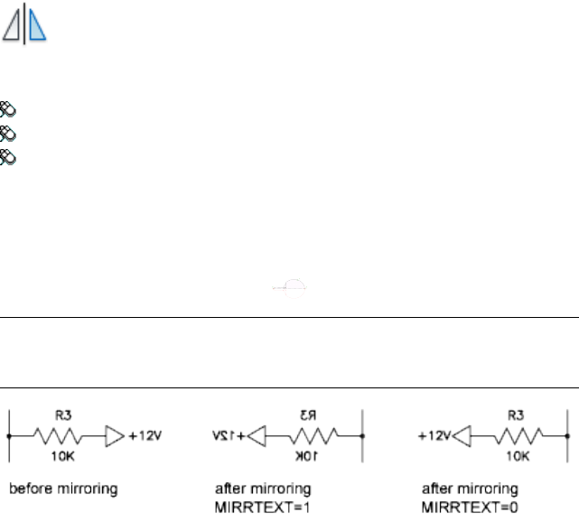
MIRROR
Quick Reference
See also:
■Mirror Objects
Creates a mirrored copy of selected objects.
Access Methods
Button
Ribbon: Home tab ➤ Modify panel ➤ Mirror
Menu: Modify ➤ Mirror
Toolbar: Modify
Summary
You can create objects that represent half of a drawing, select them, and mirror
them across a specified line to create the other half.
NOTE By default, when you mirror a text object, the direction of the text is not
changed. Set the MIRRTEXT on page 1581 system variable to 1 if you do want the
text to be reversed.
List of Prompts
The following prompts are displayed.
Select objects: Use an object selection method and press Enter to finish
MIRROR | 741
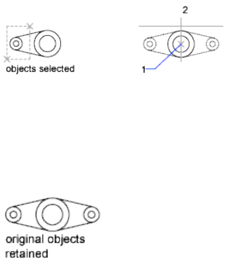
Specify first point of mirror line: Specify a point
Specify second point of mirror line: Specify a point
The two specified points become the endpoints of a line about which the
selected objects are mirrored. For mirroring in 3D, this line defines a mirroring
plane perpendicular to the XY plane of the user coordinate system (UCS)
containing the mirror line.
Erase source objects? [Yes/No] <N>: Enter y or n, or press Enter
Yes Places the mirrored image into the drawing and erases the original objects.
No Places the mirrored image into the drawing and retains the original objects.
MLEADER
Quick Reference
See also:
■Modify Leaders Using Grips
Creates a multileader object.
742 | Chapter 13 M Commands
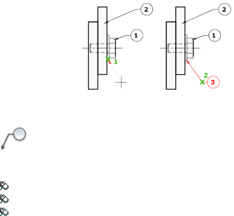
Access Methods
Button
Ribbon: Home tab ➤ Annotation panel ➤ Multileader
Menu: Dimension ➤ Multileader
Toolbar: Multileader
Summary
A multileader object typically consists of an arrowhead, a horizontal landing,
a leader line or curve, and either a multiline text object or a block.
Multileaders can be created arrowhead first, leader landing first, or content
first. If a multileader style has been used, then the multileader can be created
from that specified style.
List of Prompts
The following prompts are displayed.
Specify leader arrowhead location on page 743 or [leader Landing first/Content
first/Options] <Options>:
Leader Arrowhead First
Specifies a location for the arrowhead of the multileader object.
Leader Landing First
Specifies a location for the landing line of the multileader object.
Content First
Specifies a location for the text or block associated with the multileader object.
Options
Specifies options for placing the multileader object.
MLEADER | 743
Leader Type Specifies a straight, spline, or no leader line.
■Straight.
■Spline.
■None.
Leader Landing Changes the distance of the horizontal landing line
■Yes.
■No.
If you choose No at this point, then no landing line is associated with the
multileader object.
Content Type Specifies the type of content that will be used for the
multileader.
■Block on page 744
■Mtext on page 744
■None on page 744
Block Specifies a block within your drawing to associate with the new
multileader.
■Enter block name.
Mtext Specifies that multiline text is included with the multileader.
■Enter the multiline text.
None Specifies no content type.
Maxpoints Specifies a maximum number of points for the new leader line.
■Enter the maximum points for leader line.
■None.
First Angle Constrains the angle of the first point in the new leader line.
■Enter first angle constraint.
■None.
744 | Chapter 13 M Commands
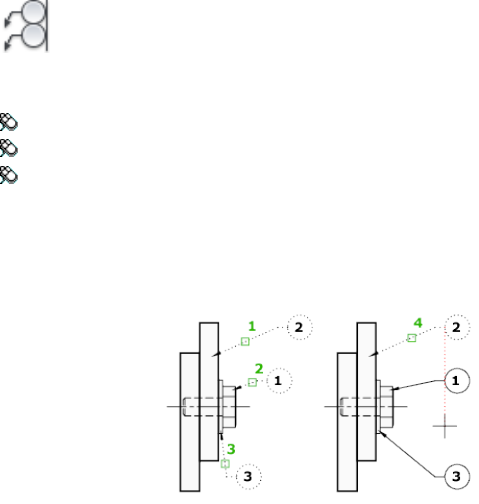
Second Angle Constrains the second angle in the new leader line.
■Enter second angle constraint.
■None.
MLEADERALIGN
Quick Reference
See also:
■Modify Leaders Using Grips
Aligns and spaces selected multileader objects.
Access Methods
Button
Ribbon: Annotate tab ➤ Multileaders panel ➤ Align
Menu: Modify ➤ Object ➤ Multileader ➤ Align
Toolbar: Multileader
Summary
After multileaders have been selected, specify the multileader to which all
others are aligned.
MLEADERALIGN | 745
List of Prompts
The following prompts are displayed.
Select multileader to align to or [Options on page 746]:
Options
Specifies options for aligning and spacing the selected multileaders.
Distribute Spaces content evenly between two selected points.
Make Leader Segments Parallel Places content so that each of the last leader
segments in the selected multileaders are parallel.
Specify Spacing Specifies spacing between the extents of the content of
selected multileaders.
Use Current Spacing Uses the current spacing between multileader content.
MLEADERCOLLECT
Quick Reference
See also:
■Modify Leaders Using Grips
Organizes selected multileaders that contain blocks into rows or columns, and
displays the result with a single leader.
Access Methods
Button
Ribbon: Annotate tab ➤ Multileaders panel ➤ Collect
Menu: Modify ➤ Object ➤ Multileader ➤ Collect
Toolbar: Multileader
Summary
After you select multileaders, you can specify their placement.
For example:
746 | Chapter 13 M Commands
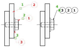
List of Prompts
The following prompts are displayed.
Specify collected multileader location on page 747 or [Vertical on page
747/Horizontal on page 747/Wrap on page 747]
Specify Collected Multileader Location Specifies the point for placing the
multileader collection in the upper-left corner of the collection.
Vertical Places the multileader collection in one or more columns.
Horizontal Places the multileader collection in one or more rows.
Wrap Specifies a width for a wrapped multileader collection.
■Specify wrap width.
■Number. Specifies a maximum number of blocks per row in the multileader
collection.
MLEADEREDIT
Quick Reference
See also:
■Modify Leaders Using Grips
Adds leader lines to, or removes leader lines from, a multileader object.
MLEADEREDIT | 747
Access Methods
Button
Ribbon: Annotate tab ➤ Multileaders panel ➤ Add Leader
Menu: Modify ➤ Object ➤ Multileader ➤ Add Leader
Toolbar: Multileader
Pointing device: Hover over Landing grip and choose Add Leader; hover
over leader endpoint grip and choose Remove Leader
List of Prompts
The following prompts are displayed.
Specify leader arrowhead location on page 748 or [Remove Leader on page 748]
Add Leader
Adds a leader line to a selected multileader object. The new leader line is added
to the left or right of the selected multileader, depending on the location of
the cursor.
Remove Leader Removes a leader line from a selected multileader object.
For example:
748 | Chapter 13 M Commands
MLEADERSTYLE
Quick Reference
See also:
■Work with Leader Styles
Creates and modifies multileader styles.
Access Methods
Button
Ribbon: Annotate tab ➤ Leaders panel ➤ ➤ Multileader Style
Menu: Format ➤ Multileader Style
Toolbar: Multileader, Styles
Summary
The Multileader Style Manager is displayed.
Multileader Style Manager
Quick Reference
See also:
■Work with Leader Styles
Creates and modifies styles that you can use to create multileader objects
MLEADERSTYLE | 749
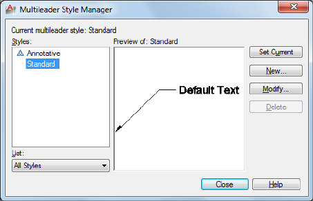
Summary
Sets the current multileader style and creates, modifies, and deletes multileader
styles.
The appearance of multileaders is controlled by multileader styles. These styles
specify formatting for landing lines, leader lines, arrowheads, and content.
List of Options
The following options are displayed.
Current Multileader Style
Displays the name of the multileader style that is applied to multileaders you
create. The default multileader style is Standard.
Styles
Displays a list of multileader styles. The current style is highlighted.
List
Controls the contents of the Styles list. Click All Styles to display all multileader
styles available in the drawing. Click Styles In Use to display only the
multileader styles that are referenced by multileaders in the current drawing.
Preview Of
Displays a preview image of the style that is selected in the Styles list.
Set Current
Sets the multileader style selected in the Styles list as the current style. All new
multileaders are created using this multileader style.
750 | Chapter 13 M Commands
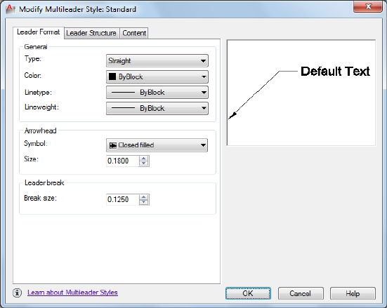
New
Displays the Create New Multileader Style dialog box, in which you can define
new multileader styles.
Modify
Displays the Modify Multileader Style dialog box, in which you can modify
multileader styles.
Delete
Deletes the multileader style selected in the Styles list. A style that is being
used in the drawing cannot be deleted.
Modify Multileader Style Dialog Box
Quick Reference
See also:
■Work with Leader Styles
Modifies an existing multileader style.
Modify Multileader Style Dialog Box | 751
Summary
Controls the general appearance of the multileader.
List of Options
The following options are displayed.
Preview
Displays a preview image of the style being modified.
List of Tabs
The following tabs are displayed.
■Leader Format Tab on page 752
■Leader Structure Tab on page 753
■Content Tab on page 754
Leader Format Tab
Quick Reference
See also:
■Work with Leader Styles
Controls the formatting of the leader lines and arrowheads for the multileader.
General
Controls the general settings of the arrowheads.
Type
Determines the type of leader line. You can choose a straight leader, a spline,
or no leader line.
Color
Determines the color of the leader line.
Linetype
Determines the linetype of the leader line.
752 | Chapter 13 M Commands
Lineweight
Determines the lineweight of the leader line.
Arrowhead
Controls the appearance of the multileader arrowheads.
Symbol
Sets the arrowhead symbol for the multileader.
Size
Displays and sets the size of arrowheads.
Leader Break
Controls the settings used when adding a dimension break to a multileader.
Break Size
Displays and sets the break size used for the DIMBREAK command when the
multileader is selected.
Leader Structure Tab
Quick Reference
See also:
■Work with Leader Styles
Controls the number of leader points, landing size, and scale for the
multilieader.
Constraints
Controls the constraints of the multileader.
Maximum Leader Points
Specifies a maximum number of points for the leader line.
First Segment Angle
Specifies the angle of the first point in the leader line.
Second Segment Angle
Modify Multileader Style Dialog Box | 753
Specifies the angle of the second point in the multileader landing line.
Landing Settings
Controls the landing settings of the multileader.
Automatically Include Landing
Attaches a horizontal landing line to the multileader content.
Set Landing Distance
Determines the fixed distance for the multileader landing line.
Scale
Controls the scaling of the multileader.
Annotative
Specifies that the multileader is annotative.
Scale Multileaders to Layout
Determines a scaling factor for the multileader based on the scaling in the
model space and paper space viewports.
This option is available when the multileader is not annotative.
Specify Scale
Specifies the scale for the multileader.
This option is available when the multileader is not annotative.
Content Tab
Quick Reference
See also:
■Work with Leader Styles
Controls the type of content attached to the multileader.
Multileader Type
Determines whether the multileader contains text or a block.
754 | Chapter 13 M Commands
MText: Text Options
Controls the appearance of the text for the multileader.
Default Text
Sets default text for the multileader content. The [...] button launches the
MTEXT In Place Editor.
Text Style
Lists the available text styles.
Text Style Button
Displays the Text Style dialog box where you can create or modify text styles.
Text Angle
Specifies the rotation angle of the multileader text.
Text Color
Specifies the color of the multileader text.
Text Height
Specifies the height of the multileader text.
Always Left Justify
Specifies that the multileader text is always left justified.
Frame Text
Frames the multileader text content with a text box.
Control the separation between the text and frame by modifying the Landing
Gap setting.
Mtext: Leader Connection
Controls the leader connection settings of the multileader.
Leaders can be connected horizontally or vertically.
Horizontal Attachment
Horizontal attachment inserts the leader to the left or right of the text content.
A horizontal attachment includes a landing line between the text and the
leader.
Left Attachment
Modify Multileader Style Dialog Box | 755
Controls the attachment of the landing line to the multileader text when the
text is to the right of the leader.
Right Attachment
Controls the attachment of the landing line to the multileader text when the
text is to the left of the leader.
Landing Gap
Specifies the distance between the landing line and the multileader text.
Extend Leader to Text
Extends the landing line to end at the edge of the text line where the leader
is attached, not at the edge of the multiline text box.
The length of the multiline text box is determined by the length of the longest
line of text, not the length of the bounding box.
Vertical Attachment
Inserts the leader at the top or bottom of the text content. A vertical
attachment does not include a landing line between the text and the leader.
Top Attachment
Attaches the leader to the top center of the text content. Click the drop-down
to insert an overline between the leader attachment and the text content.
Bottom Attachment
Attaches the leader to the bottom of the text content. Click the drop-down
to insert an underline between the leader attachment and the text content.
Landing Gap
Specifies the distance between the landing line and the multileader text.
Block: Block Options
Controls the properties of block content in a multileader object.
Source block
Specifies the block used for multileader content.
Attachment
Specifies the way the block is attached to the multileader object. You can
attach the block by specifying the insertion point of the block or the center
point of the block.
756 | Chapter 13 M Commands
Color
Specifies the color of the multileader block content. The Block color control
in the MLEADERSTYLE Content tab only takes effect if the object color
included in the block is set to ByBlock.
Scale
Specifies the scale of the block upon insertion. For example, if the block is a
1 inch square and the scale specified is 0.5000, then the block is inserted as a
1/2 inch square.
Create New Multileader Style Dialog Box
Quick Reference
See also:
■Work with Leader Styles
Specifies a name for the new multileader style and specifies the existing
multileader style on which the new multileader style will be based.
List of Options
The following options are displayed.
New Style Name
Names the new multileader style.
Start With
Specifies an existing multileader style whose settings are the default for the
new multileader style.
Annotative
Specifies that the multileader object is .
Continue
Displays the Multileader Style Manager, in which you define the new
multileader style.
Create New Multileader Style Dialog Box | 757

MODEL
Quick Reference
See also:
■Work with Model Space and Paper Space
Switches from a named (paper space) layout to the Model layout.
Access Methods
When a viewing a layout, enter model at the command prompt or click the
Model tab below the drawing window.
Summary
On the Model layout, you can create drawings in model space. The Model
layout automatically sets the TILEMODE on page 1684 system variable to 1, and
you can create model viewports to display various views of your drawing.
Once you have completed your drawing, you can choose a named (paper
space) layout to begin designing a layout environment from which to plot.
MOVE
Quick Reference
See also:
■Move Objects
Moves objects a specified distance in a specified direction.
Access Methods
Button
Ribbon: Home tab ➤ Modify panel ➤ Move
758 | Chapter 13 M Commands
Menu: Modify ➤ Move
Toolbar: Modify
Shortcut menu: Select the objects to move. Right-click in the drawing area
and click Move.
Summary
Use coordinates, grid snaps, object snaps, and other tools to move objects
with precision.
List of Prompts
The following prompts are displayed.
Select objects:
Specify base point or [Displacement]:
Specify second point or <use first point as displacement>:
The two points you specify define a vector that indicates how far the selected
objects are to be moved and in what direction.
If you press Enter at the Specify Second Point prompt, the first point is
interpreted as a relative X,Y,Z displacement. For example, if you specify 2,3
for the base point and press Enter at the next prompt, the objects move 2
units in the X direction and 3 units in the Y direction from their current
position.
Displacement Enter coordinates to represent a vector
The coordinate values that you enter specify a relative distance and direction.
MREDO
Quick Reference
See also:
■Correct Mistakes
Reverses the effects of several previous UNDO or U commands.
MREDO | 759

Access Methods
Button
Toolbar: Standard
List of Prompts
The following prompts are displayed.
Enter number of actions or [All/Last]:
Number of Actions Reverses the specified number of actions.
All Reverses all previous actions.
Last Reverses only the last action.
MSLIDE
Quick Reference
See also:
■Overview of Slides
Creates a slide file of the current model viewport or the current layout.
Summary
The Create Slide File dialog box (a standard file selection dialog box) is
displayed. Enter a file name or select a slide (SLD) file from the list. A slide file
is a raster image of a viewport.
In model space, MSLIDE makes a slide file of the current viewport only. In
paper space, MSLIDE makes a slide file of the paper space display, including
all viewports and their contents.
Off-screen portions of the drawing, or layers that are off or frozen, are not
included in the slide.
Use the VSLIDE command to view slides, or the SLIDELIB utility to create a
slide library.
760 | Chapter 13 M Commands
When you view slides of images shaded with the SHADE command in a larger
window or at a higher resolution than was used for creating the slide, black
lines may appear interspersed among the lines of the shaded image. To avoid
this situation, use a full screen that is set at the highest resolution when
creating slides.
MSPACE
Quick Reference
See also:
■Work with Model Space and Paper Space
In a layout, switches from paper space to model space in a layout viewport.
Access Methods
Pointing device: Double-click over a viewport on a named layout.
Double-click outside of a viewport on a named layout to return to paper space.
Summary
Commands operate in either model space or paper space. You use model space
(the Model layout) to do drafting and design work and to create
two-dimensional drawings or three-dimensional models. You use paper space
(a named layout) to create a finished layout of a drawing for plotting.
When you are in a layout, you can enter mspace at the Command prompt to
make the last viewport in the layout current, and then work in model space
in that viewport within the layout.
MTEDIT
Quick Reference
See also:
■Change Multiline Text
Edits multiline text.
MSPACE | 761

Access Methods
Pointing device: Double-click a multiline text object.
Summary
Displays either the multiline text tab on the ribbon or the In-Place Text Editor
to modify the formatting or content of the selected mtext object.
The In-Place Text Editor is displayed.
MTEXT
Quick Reference
See also:
■Overview of Multiline Text
Creates a multiline text object.
Access Methods
Button
Ribbon: Home tab ➤ Annotation panel ➤ Multiline Text
Menu: Draw ➤ Text ➤ Multiline Text
Toolbar: Draw
Summary
You can create several paragraphs of text as a single multiline text (mtext)
object. With the built-in editor, you can format the text appearance, columns,
and boundaries.
After you specify the point for the opposite corner when the ribbon is active,
the Text Editor ribbon contextual tab displays. If the ribbon is not active, the
in-place text editor is displayed.
762 | Chapter 13 M Commands
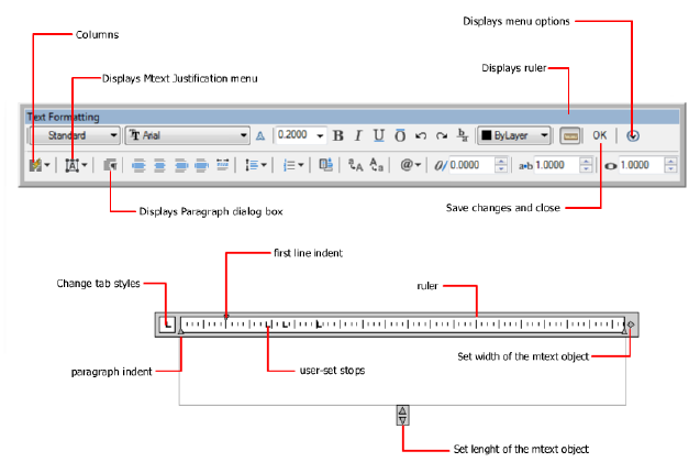
If you specify one of the other options, or if you enter -mtext at the Command
prompt, MTEXT bypasses the In-Place Text editor and displays additional
Command prompts.
See also:
■Symbols and Special Characters on page 791
In-Place Text Editor
Quick Reference
See also:
■Overview of Multiline Text
Creates or modifies single or multiline text objects.
Summary
You can import or paste text from other files to use in multiline text, set tabs,
adjust paragraph and line spacing and alignment, and create and modify
columns.
In-Place Text Editor | 763

The In-Place Text Editor includes
■Text Formatting toolbar on page 768
■Paragraph dialog box on page 778
■Column Settings dialog box on page 780
■Background Mask dialog box on page 781
■Columns menu on page 779
■Options menu
When a table cell is selected for editing, the In-Place Text Editor displays
column letters and row numbers.
NOTE Not all options available when creating single-line text.
List of Options
The following options are displayed.
Text Editor Shortcut Menu
Select All Selects all the text in the text editor.
Cut Copies the selected text and removes it from the text editor to the
clipboard.
Copy Copies the selected text from the text editor to the clipboard.
Paste Pastes the text in the clipboard to the cursor position in the text editor.
Paste Special Pastes the text in the clipboard to the cursor position in the
text editor while removing character, paragraph, or any formatting from the
text in the clipboard. (Not available for single-line text.)
Insert Field Displays the Field dialog box.
Symbol Displays a list of available symbols. You can also select a Non-breaking
space and open the Character Map dialog box for additional symbols.
Import Text Displays the Select File dialog box (a standard file selection dialog
box). Select any file that is in ASCII or RTF format. Imported text retains its
original character formatting and style properties, but you can edit and format
the imported text in the editor. After you select a text file to import, you can
replace either selected text or all text, or append the inserted text to text
selected within the text boundary. The file size for imported text is limited to
32 KB. (Not available for single-line text.)
764 | Chapter 13 M Commands

The editor automatically sets the text color to BYLAYER. When black characters
are inserted and the background color is black, the editor automatically changes
to white or the current color.
NOTE A Microsoft Excel spreadsheet imported into a drawing is truncated at 72
rows unless the spreadsheet was created in Microsoft Office 2002 with Service
Pack 2 installed. The same limitation applies when the drawing that contains the
OLE object is opened on a system with an earlier version of Microsoft Office
installed; the spreadsheet is truncated.
Paragraph Alignment Sets alignment for the multiline text object. You can
choose to align your text to the left, center, or right. You can justify your text,
or align the first and last characters of your text with the margins of your
mtext box, or center each line of text within the margins of your mtext box.
Spaces entered at the end of a line are included as part of the text and affect
the justification of the line. (Not available for single-line text.)
Paragraph Displays options for paragraph formatting. See the Paragraph dialog
box on page 778. (Not available for single-line text.)
Bullets and Lists Displays the options for numbering lists. (Not available for
single-line text.)
Displays options for creating lists. (Not available for table cells.) The list is
indented to align with the first selected paragraph.
■Off: When selected, removes letters, numbers, and bullets from selected
text that has list formatting applied. Indentation is not changed.
■Lettered: Applies list formatting that uses letters with periods for the items
in the list. If the list has more items than the alphabet has letters, the
sequence continues by using double letters.
■Numbered: Applies list formatting that uses numbers with periods for the
items in the list.
■Bulleted: Applies list formatting that uses bullets for the items in the list.
■Restart: Starts a new letter or number sequence in list formatting. If the
selected items are in the middle of a list, unselected items below them also
become part of the new list.
■Continue: Adds the selected paragraphs to the last list above and continues
the sequence. If list items rather than paragraphs are selected, unselected
items below the selected items continue the sequence.
■Allow Auto-list: Applies list formatting as you type. The following characters
can be used as punctuation after letters and numbers and cannot be used
In-Place Text Editor | 765
as bullets: period (.), comma (,), close parenthesis ()), close angle bracket
(>), close square bracket (]), and close curly bracket (}).
■Use Tab Delimiter Only: Limits the Allow Auto-list and Allow Bullets and
Lists options. List formatting is applied to text only when the space after
the letter, number, or bullet character was created by Tab, not Space.
■Allow Bullets and Lists: When this option is selected, list formatting is applied
to all plain text in the multiline text object that looks like a list. Text that
meets the following criteria is considered to be a list. The line begins with
(1) one or more letters or numbers or a symbol, followed by (2) punctuation
after a letter or number, (3) a space created by pressing Tab, and (4) some
text before the line is ended by Enter or Shift+Enter.
When you clear the check mark, any list formatting in the multiline text
object is removed and the items are converted to plain text. Allow Auto-list
is turned off, and all the Bullets and Lists options are unavailable except
Allow Bullets and Lists.
Columns Displays options for columns. See the Columns menu on page 779.
(Not available for single-line text.)
Find and Replace Displays the Find and Replace dialog box.
Change Case Changes the case of selected text. Options are Uppercase and
Lowercase.
AutoCAPS Converts all new and imported text to uppercase. AutoCAPS does
not affect existing text. To change the case of existing text, select the text and
right-click. Click Change Case.
Character Set Displays a menu of code pages. Select a code page to apply it
to the selected text. (Not available for single-line text.)
Combine Paragraphs Combines selected paragraphs into a single paragraph
and replaces each paragraph return with a space. (Not available for single-line
text.)
Remove Formatting Removes character formatting for selected characters,
paragraph formatting for a selected paragraph, or all formatting from a selected
paragraph. (Not available for single-line text.)
Background Mask Displays the Background Mask dialog box. (Not available
for table cells and single-line text.)
Stack Creates stacked text, for example, fractions, if the selected text contains
stack characters. Also, unstacks text if stacked text is selected. When the stack
766 | Chapter 13 M Commands

characters, carat (^), forward slash (/), and pound sign (#), are used, the text
to the left of the stack character is stacked on top of the text to the right.
By default, text that contains a carat converts to left-justified tolerance values.
Text that contains the forward slash converts to center-justified fractional
numbers; the slash is converted to a horizontal bar the length of the longer
text string. Text that contains the pound sign converts to a fraction separated
by a diagonal bar the height of the two text strings. The characters above the
diagonal fraction bar are bottom-right aligned; the characters beneath the
diagonal bar are top-left aligned.
Editor Settings Displays a list of options for the text editor. See Editor Settings
on page 767 for more information.
Editor Settings
Provides options for changing the behavior of the text editor and provides
additional editing options. Options are specific to the Editor Settings menu
and are not available elsewhere in the text editor.
NOTE Some options may not be available depending on what you are editing.
Always Display As WYSIWYG (What You See Is What You Get) Controls
display of the In-Place Text Editor and the text within it. When unchecked,
text that would otherwise be difficult to read (if it is very small, very large, or
is rotated) is displayed at a legible size and is oriented horizontally so that you
can easily read and edit it.
When this option is checked, the MTEXTFIXED system variable will be set to
0. Otherwise, MTEXTFIXED will be set to 2.
Show Toolbar Controls display of the Text Formatting toolbar. To restore
display of the toolbar, right-click in the text area of the editor, and click Editor
Settings ➤ Show Toolbar. This option is controlled by the MTEXTTOOLBAR
on page 1586 system variable
Show Options Expands the Text Formatting toolbar to show more options.
Show Rulers Controls the display of the ruler.
Opaque Background When selected, makes the background of the editor
opaque. (Not available for table cells.)
Check Spelling Determines whether As-You-Type spell checking is on or off.
Check Spelling Settings Displays the Check Spelling Settings dialog box,
where you can specify text options that will be checked for spelling errors
within your drawing.
In-Place Text Editor | 767

Dictionaries Displays the Dictionaries dialog box, where you can change the
dictionary that is checked against any found misspelled words.
Text Highlight Color Specifies the highlight color when text is selected.
Text Formatting Toolbar
Quick Reference
See also:
■Overview of Multiline Text
Formats the text of the current multiline text object.
Summary
Controls the text style for a multiline text object and character and paragraph
formatting for selected text.
NOTE Text that you paste from other word processing applications such as
Microsoft Word will retain most of its formatting. With the options in Paste Special,
you can strip out paragraph formatting such as paragraph-based alignment or
character formatting from the pasted text.
List of Options
Style Applies a text style to the multiline text object. The current style is saved
in the TEXTSTYLE on page 1683 system variable.
Character formatting for font, height, and bold or italic attributes is overridden
if you apply a new style to an existing multiline text object. Stacking,
underlining, and color attributes are retained in characters to which a new
style is applied.
Styles that have backward or upside-down effects are not applied. If a style
defined with a vertical effect is applied to an SHX font, the text is displayed
horizontally in the In-Place Text Editor.
Font Specifies a font for new text or changes the font of selected text. TrueType
fonts are listed by font family name. AutoCAD LT compiled shape (SHX) fonts
are listed by the name of the file in which the fonts are stored. Custom fonts
and third-party fonts are displayed in the editor with Autodesk-supplied proxy
fonts.
768 | Chapter 13 M Commands
A sample drawing (TrueType.dwg) showing each font is provided in the sample
directory.
Annotative Turns Annotative on or off for the current mtext object.
Text Height Sets the character height in drawing units for new text or changes
the height of selected text. If the current text style has no fixed height, the
text height is the value stored in theTEXTSIZE system variable. A multiline
text object can contain characters of various heights.
Bold Turns bold formatting on and off for new or selected text. This option
is available only for characters using TrueType fonts.
Italic Turns italic formatting on and off for new or selected text. This option
is available only for characters using TrueType fonts.
Underline Turns underlining on and off for new or selected text.
Overline Turns overline on and off for new or selected text.
Undo Undoes actions in the In-Place Text Editor, including changes to either
text content or text formatting.
Redo Redoes actions in the In-Place Text Editor, including changes to either
text content or text formatting.
Stack Creates stacked text, for example, fractions, if the selected text contains
stack characters. Also, unstacks text if stacked text is selected. When the stack
characters, carat (^), forward slash (/), and pound sign (#), are used, the text
to the left of the stack character is stacked on top of the text to the right.
By default, text that contains a carat converts to left-justified tolerance values.
Text that contains the forward slash converts to center-justified fractional
numbers; the slash is converted to a horizontal bar the length of the longer
text string. Text that contains the pound sign converts to a fraction separated
by a diagonal bar the height of the two text strings. The characters above the
diagonal fraction bar are bottom-right aligned; the characters beneath the
diagonal bar are top-left aligned.
Text Color Specifies a color for new text or changes the color of selected text.
You can assign text the color associated with the layer it is on (BYLAYER) or
the color of the block it is contained in (BYBLOCK). You can also select one
of the colors in the color list or click Other to open the Select Color dialog
box.
Ruler Displays a ruler at the top of the editor. Drag the arrows at the end of
the ruler to change the width of the mtext object. Also displays height and
column grips when column mode is active.
Text Formatting Toolbar | 769

You can also select tabs from the ruler. Clicking the Tab Selection button
changes tab styles from left, center, right, and decimal. Once you make your
selection, you adjust the corresponding tab in the ruler or in the Paragraph
dialog box.
OK Closes the editor and saves any changes that you made.
Options Displays a list of additional text options. See Text Editor Shortcut
Menu on page 764.
Columns Displays the column flyout menu, which provides three column
options: No Columns, Static Columns, and Dynamic columns. See Columns
menu on page 779.
MText Justification Displays the MText Justification menu with nine
alignment options available.
Paragraph Displays the Paragraph dialog box. See the Paragraph dialog box
on page 778 for a list of the options.
Left, Center, Right, Justified and Distributed Sets the justification and
alignment for the left, center, or right text boundaries of the current or selected
paragraph. Spaces entered at the end of a line are included and affect the
justification of a line.
Line Spacing Displays suggested line spacing options or the Paragraph dialog
box. Line spacing is set in the current or selected paragraph.
NOTE Line spacing is the distance between the bottom of the upper line and the
top of the lower line of text in a multiple line paragraph.
The predefined options are:
■1.0x, 1.5x, 2.0x, or 2.5x: Sets the line spacing at .5x increments in multiline
text.
■More: Displays the Paragraph dialog box, which provides additional options.
■Clear Paragraph Spacing: Removes line spacing settings from the selected or
current paragraph. The paragraph defaults to the mtext space setting.
Additional options in the Paragraph dialog box:
■Exact: Defines the space with an arbitrary unit value the user specifies.
Changing text height will not affect line spacing.
■Multiple: Instead of assigning a value to line spacing, you specify spacing
according to text height. When text height is not consistent in one line,
770 | Chapter 13 M Commands

the line space will be determined by the largest text height value in that
line.
■At least: Takes both the user specified arbitrary value and the text height
to determine spacing. If text height is smaller than the arbitrary value the
line space is determined by the user specified value. If the text height is
larger, the line spacing is equal to the text height value.
NOTE Not all of the new options for paragraph and paragraph line spacing are
supported in releases before AutoCAD LT 2008. See MTEXT Paragraph and
Paragraph Line Spacing in Previous Releases.
Numbering Displays the bullet and numbering menu.
Displays options for creating lists. (Not available for table cells.) The list is
indented to align with the first selected paragraph.
■Off: When selected, removes letters, numbers, and bullets from selected
text that has list formatting applied. Indentation is not changed.
■Lettered: Applies list formatting that uses letters with periods for the items
in the list. If the list has more items than the alphabet has letters, the
sequence continues by using double letters.
■Numbered: Applies list formatting that uses numbers with periods for the
items in the list.
■Bulleted: Applies list formatting that uses bullets for the items in the list.
■Restart: Starts a new letter or number sequence in list formatting. If the
selected items are in the middle of a list, unselected items below them also
become part of the new list.
■Continue: Adds the selected paragraphs to the last list above and continues
the sequence. If list items rather than paragraphs are selected, unselected
items below the selected items continue the sequence.
■Allow Auto-list: Applies list formatting as you type. The following characters
can be used as punctuation after letters and numbers and cannot be used
as bullets: period (.), comma (,), close parenthesis ()), close angle bracket
(>), close square bracket (]), and close curly bracket (}).
■Use Tab Delimiter Only: Limits the Allow Auto-list and Allow Bullets and
Lists options. List formatting is applied to text only when the space after
the letter, number, or bullet character was created by Tab, not Space.
Text Formatting Toolbar | 771
■Allow Bullets and Lists: When this option is selected, list formatting is applied
to all plain text in the multiline text object that looks like a list. Text that
meets the following criteria is considered to be a list. The line begins with
(1) one or more letters or numbers or a symbol, followed by (2) punctuation
after a letter or number, (3) a space created by pressing Tab, and (4) some
text before the line is ended by Enter or Shift+Enter.
When you clear the check mark, any list formatting in the multiline text
object is removed and the items are converted to plain text. Allow Auto-list
is turned off, and all the Bullets and Lists options are unavailable except
Allow Bullets and Lists.
Insert Field Displays the Field dialog box, where you can select a field to insert
in the text.
Uppercase Changes the selected text to uppercase.
Lowercase Changes the selected text to lowercase.
Symbol Inserts a symbol or a nonbreaking space at the cursor position. You
can also insert symbols manually. See Symbols and Special Characters on page
791.
Commonly used symbols are listed on the submenu, along with their control
code or Unicode string. Click Other to display the Character Map dialog box,
which contains the entire character set for each font available on your system.
Select a character and click Select to place it in the Characters to Copy box.
When you have selected all the characters that you want to use, click Copy
to close the dialog box. In the editor, right-click and click Paste.
Symbols are not supported in vertical text.
Oblique Angle Determines the forward or backward slant of the text. The
angle represents the offset from 90 degrees. Entering a value between -85 and
85 makes the text oblique. A positive obliquing angle slants text to the right.
A negative obliquing angle slants text to the left.
Tracking Decreases or increases the space between the selected characters.
The 1.0 setting is normal spacing. Set to more than 1.0 to increase spacing,
and set to less than 1.0 to decrease spacing.
Width Factor Widens or narrows the selected characters. The 1.0 setting
represents the normal width of the letter in this font. You can increase the
width (for example, use a width factor of 2 to double the width) or decrease
the width (for example, use a width factor of 0.5 for half the width).
772 | Chapter 13 M Commands
Text Editor Ribbon Contextual Tab
Quick Reference
See also:
■Overview of Multiline Text
Creates or modifies multiline text objects.
List of Options
The following options are displayed.
Style Panel
Applies a text style to the multiline text object. The Standard text
style is active by default
Style
Turns Annotative on or off for the current mtext object.Annotative
Sets the character height in drawing units for new text or changes
the height of selected text. If the current text style has no fixed
Text Height
height, the text height is the value stored in the TEXTSIZE system
variable. A multiline text object can contain characters of various
heights.
Formatting Panel
Turns bold formatting on and off for new or selected text. This op-
tion is available only for characters using TrueType fonts.
Bold
Turns italic formatting on and off for new or selected text. This op-
tion is available only for characters using TrueType fonts.
Italic
Turns underlining on and off for new or selected text.Underline
Turns overline on and off for new or selected text.Overline
Changes the selected text to uppercase.Make Uppercase
Changes the selected text to lowercase.Make Lowercase
Text Editor Ribbon Contextual Tab | 773

Specifies a font for new text or changes the font of selected text.
TrueType fonts are listed by font family name. AutoCAD LT compiled
Font
shape (SHX) fonts are listed by the name of the file in which the
fonts are stored. Custom fonts and third-party fonts are displayed
in the editor with Autodesk-supplied proxy fonts.
Specifies a color for new text or changes the color of selected text.Color
Displays the Background Mask dialog box. (Not available for table
cells.)
Background
Mask
Determines the forward or backward slant of the text. The angle
represents the offset from 90 degrees. Entering a value between -
Oblique Angle
85 and 85 makes the text oblique. A positive obliquing angle slants
text to the right. A negative obliquing angle slants text to the left.
Decreases or increases the space between the selected characters.
The 1.0 setting is normal spacing.
Tracking
Widens or narrows the selected characters. The 1.0 setting represents
the normal width of the letter in this font.
Width Factor
Paragraph Panel
Displays the MText Justification menu with nine alignment options
available. Top Left is the default.
MText Justification
Displays the Paragraph dialog box. See the Paragraph dialog box
for a list of the options.
Paragraph
Displays suggested line spacing options or the Paragraph dialog
box. Line spacing is set in the current or selected paragraph.
Line Spacing
NOTE Line spacing is the distance between the bottom
of the upper line and the top of the lower line of text in a
multiple line paragraph.
The predefined options are:
■1.0x, 1.5x, 2.0x, or 2.5x: Sets the line spacing at .5x increments
in multiline text.
■More: Displays the Paragraph dialog box, which provides ad-
ditional options.
774 | Chapter 13 M Commands

■Clear Paragraph Spacing: Removes line spacing settings from
the selected or current paragraph. The paragraph defaults to
the mtext space setting.
Additional options in the Paragraph dialog box:
■Exact: Defines the space with an arbitrary unit value the user
specifies. Changing text height will not affect line spacing.
■Multiple: Instead of assigning a value to line spacing, you
specify spacing according to text height. When text height is
not consistent in one line, the line space will be determined
by the largest text height value in that line.
■At least: Takes both the user specified arbitrary value and the
text height to determine spacing. If text height is smaller than
the arbitrary value the line space is determined by the user
specified value. If the text height is larger, the line spacing is
equal to the text height value.
NOTE Not all of the new options for paragraph and para-
graph line spacing are supported in AutoCAD 2007 and
previous releases. See MTEXT Paragraph and Paragraph
Line Spacing in Previous Releases in the User’s Guide.
Displays the bullet and numbering menu.Numbering
Displays options for creating lists. (Not available for table cells.)
The list is indented to align with the first selected paragraph.
■Off: When selected, removes letters, numbers, and bullets
from selected text that has list formatting applied. Indentation
is not changed.
■Lettered: Applies list formatting that uses letters with periods
for the items in the list. If the list has more items than the al-
phabet has letters, the sequence continues by using double
letters.
■Numbered: Applies list formatting that uses numbers with
periods for the items in the list.
■Bulleted: Applies list formatting that uses bullets for the items
in the list.
■Restart: Starts a new letter or number sequence in list
formatting. If the selected items are in the middle of a list,
unselected items below them also become part of the new
list.
Text Editor Ribbon Contextual Tab | 775
■Continue: Adds the selected paragraphs to the last list above
and continues the sequence. If list items rather than para-
graphs are selected, unselected items below the selected items
continue the sequence.
■Allow Auto-list: Applies list formatting as you type. The follow-
ing characters can be used as punctuation after letters and
numbers and cannot be used as bullets: period (.), comma
(,), close parenthesis ()), close angle bracket (>), close square
bracket (]), and close curly bracket (}).
■Use Tab Delimiter Only: Limits the Allow Auto-list and Allow
Bullets and Lists options. List formatting is applied to text only
when the space after the letter, number, or bullet character
was created by Tab, not Space.
■Allow Bullets and Lists: When this option is selected, list
formatting is applied to all plain text in the multiline text ob-
ject that looks like a list. Text that meets the following criteria
is considered to be a list. The line begins with (1) one or more
letters or numbers or a symbol, followed by (2) punctuation
after a letter or number, (3) a space created by pressing Tab,
and (4) some text before the line is ended by Enter or
Shift+Enter.
When you clear the check mark, any list formatting in the multiline
text object is removed and the items are converted to plain text.
Allow Auto-list is turned off, and all the Bullets and Lists options
are unavailable except Allow Bullets and Lists.
Sets the justification and alignment for the left, center, or right
text boundaries of the current or selected paragraph. Spaces
Left, Center, Right,
Justified and Dis-
tributed entered at the end of a line are included and affect the justification
of a line.
Insert Panel
Inserts a symbol or a nonbreaking space at the cursor position. You
can also insert symbols manually. See Symbols and Special Characters
on page 791.
Symbol
Commonly used symbols are listed on the submenu, along with their
control code or Unicode string. Click Other to display the Character
Map dialog box, which contains the entire character set for each font
available on your system. When you have selected all the characters
776 | Chapter 13 M Commands

that you want to use, click Copy to close the dialog box. In the editor,
right-click and click Paste.
Symbols are not supported in vertical text.
Displays the Field dialog box, where you can select a field to insert
in the text. When the dialog box closes, the current value of the field
is displayed in the text.
Insert Field
Displays the column flyout menu, which provides three column op-
tions: No Columns, Static Columns, and Dynamic columns. See
Columns menu on page 779.
Columns
Spell Check Panel
Determines whether As-You-Type spell checking is turned on or off.Spell Check
Displays the Dictionaries dialog box on page 1166, where you can
add or remove custom dictionaries for use during spell check.
Edit Dictionaries
Tools Panel
Displays the Find and Replace dialog box.Find and Replace
Displays the Select File dialog box (a standard file selection dialog
box). Select any file that is in ASCII or RTF format. Imported text
Import Text
retains its original character formatting and style properties, but
you can edit and format the imported text in the editor. After you
select a text file to import, you can replace either selected text or
all text, or append the inserted text to text selected within the text
boundary. The file size for imported text is limited to 32 KB.
The editor automatically sets the text color to BYLAYER. When black
characters are inserted and the background color is black, the editor
automatically changes to white or the current color.
NOTE A Microsoft Excel spreadsheet imported into a draw-
ing is truncated at 72 rows unless the spreadsheet was cre-
ated in Microsoft Office 2002 with Service Pack 2 installed.
The same limitation applies when the drawing that contains
the OLE object is opened on a system with an earlier version
of Microsoft Office installed; the spreadsheet is truncated.
Converts all new and imported text to uppercase. AutoCAPS does
not affect existing text. To change the case of existing text, select
the text and right-click.
AutoCAPS
Text Editor Ribbon Contextual Tab | 777

Options Panel
Undoes actions in the Text Editor ribbon contextual tab, including
changes to either text content or text formatting.
Undo
Redoes actions in the Text Editor ribbon contextual tab, including
changes to either text content or text formatting.
Redo
Displays a ruler at the top of the editor. Drag the arrows at the end
of the ruler to change the width of the mtext object. Also displays
height and column grips when column mode is active.
Ruler
You can also select tabs from the ruler. Clicking the Tab Selection
button changes tab styles from left, center, right, and decimal. Once
you make your selection, you adjust the corresponding tab in the
ruler or in the Paragraph dialog box.
Displays a list of additional text options. See Text Editor Shortcut
Menu on page 764.
More
Close Panel
Ends the MTEXT command and closes the Text Editor ribbon con-
textual tab.
Close Text Editor
Paragraph Dialog Box
Quick Reference
See also:
■Overview of Multiline Text
Sets indentation for paragraphs and the first lines of paragraphs.
Summary
Specifies tab stops, indents, controls paragraph alignment, paragraph spacing,
and paragraph line spacing.
NOTE Not all of the new options for paragraph and paragraph line spacing are
supported in AutoCAD LT 2007 and previous releases. See MTEXT Paragraph and
Paragraph Line Spacing in Previous Releases in the User’s Guide.
778 | Chapter 13 M Commands
List of Options
The following options are displayed.
Tab
Displays tab setting options, including adding and removing tabs. Options
include setting left, center, right, and decimal tabs. You can also set tabs from
the Tab selection button on the In-Place Editor’s ruler.
Decimal style
Sets the decimal style based on current user locale. Options include setting
the decimal style as period, comma, and space. This setting is preserved with
the drawing even if the locale setting is changed.
Left Indent
Sets the indent value for the first line or hanging indent to the selected or
current paragraphs.
Right Indent
Applies the indent to the entire selected or current paragraph.
Paragraph Alignment
Sets the alignment properties for the current or selected paragraphs.
Paragraph Spacing
Specifies the spacing before or after the current or selected paragraphs. The
distance between two paragraphs is determined by the total of the after
paragraph spacing value of the upper paragraph and the before paragraph
spacing value of the lower paragraph.
Paragraph Line Spacing
Sets the spacing between individual lines in the current or selected paragraphs.
Columns Menu
Quick Reference
See also:
■Overview of Multiline Text
Columns Menu | 779
Allows you to format an mtext object into multiple columns.
Summary
You can specify column and gutter width, height, and number of columns.
You can edit column width and height with grip-editing.
To create multiple columns you always start with a single column. Depending
on the column mode you choose, you have two different methods for creating
and manipulating columns – static mode or dynamic mode.
List of Options
The following options are displayed.
No Columns Specifies no columns for the current mtext object.
Dynamic Columns Sets dynamic columns mode to the current mtext object.
Dynamic columns are text driven. Adjusting columns affects text flow and
text flow causes columns to be added or removed. Auto height or Manual
height options are available.
Static Columns Sets static columns mode to the current mtext object. You
can specify the total width and height of the mtext object, and the number
of columns. All the columns share the same height and are aligned at both
sides.
Insert Column Break Alt+Enter Inserts a manual column break.
Column Settings Displays Column Settings dialog box on page 780.
Column Settings Dialog Box
Quick Reference
See also:
■Overview of Multiline Text
Displays options for setting up columns such as the type, number of columns,
height, and width, and gutter size.
780 | Chapter 13 M Commands
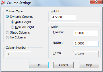
List of Options
The following options are displayed.
Column Type
Displays choices for the type of columns you want to create.
Column Number
Sets the number of columns. This is only active when you select Static
Columns.
Height
Displays mtext height when Auto Height with Dynamic or Static Columns is
selected.
Width
Displays and specifies control column and gutter width values. The gutter
value is five times the default mtext text height.
Also displays the total width value of the mtext object.
Background Mask Dialog Box
Quick Reference
See also:
■Overview of Multiline Text
Controls using an opaque background behind multiline text.
Background Mask Dialog Box | 781

List of Options
The following options are displayed.
Use Background Mask
Puts an opaque background behind the text.
NOTE When you apply a background mask to mtext multiple columns only the
column areas will be masked. The space between the columns commonly referred
to as gutters will be unmasked.
Border Offset Factor
Specifies the margin around the text for the opaque background. The value
is based on the text height. A factor of 1.0 exactly fits the multiline text object.
A factor of 1.5 extends the background by 0.5 times the text height.
Fill Color
Specifies the color for the background.
Use Background Drawing Color
Provides a background that is the same color as the background of the drawing.
Color
Specifies a color for the opaque background. You can select one of the colors
in the list or click Select Color to open the Select Color dialog box.
Find and Replace Dialog Box - MTEXT
Quick Reference
See also:
■Overview of Multiline Text
Searches for specified text strings and replaces them with new text.
782 | Chapter 13 M Commands
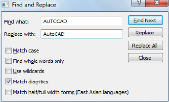
Access Methods
Shortcut menu: Select the Find and Replace icon in the text editor or from
the MTEXT shortcut menu
List of Options
The following options are displayed.
Find What Provides a space for you to type the text you want to find.
Replace With Provides a space for you to type the text you want to replace
the text you typed in Find What.
Find Next Finds the next instance of the text specified in Find What.
Replace Finds the next instance of the text specified in Find What and replaces
it with the text in Replace With.
Replace All Finds all instances of the text specified in Find What and replaces
it with the text in Replace With.
Match Case Finds only text with uppercase and lowercase characters as
specified in Find What.
The case of all characters in the text string must match the case of the text in
Find What. When this option is cleared, a match is found for specified text
strings regardless of case.
Match Whole Word Only Finds only whole words specified in Find What.
Text that is part of another word is ignored. When this option is cleared, a
match is found for text strings, whether they are single words or parts of other
words.
Use Wildcards Allows the use of wildcard characters in searches.
For more information on wildcard searches, see Find and Replace Text in the
User’s Guide.
Find and Replace Dialog Box - MTEXT | 783
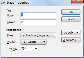
Match Diacritics Matches diacritical marks, or accents, in search results.
Match Half/Full Width Forms (East Asian Languages) Matches half- and
full-width characters in search results.
Stack Properties Dialog Box
Quick Reference
See also:
■Overview of Multiline Text
Edits the text, stack type, alignment, and size of stacked text.
Summary
To open the Stack Properties dialog box, select the stacked text, right-click,
and click Stack Properties on the shortcut menu.
You can edit the upper and lower text separately. The Appearance options
control the stack style, position, and text size of the stacked text.
List of Options
The following options are displayed.
Text
Changes the upper and lower numbers of a stacked fraction.
Upper
Edits the number in the upper part or first half of a stacked fraction.
Lower
784 | Chapter 13 M Commands
Edits the number in the lower part or second half of a stacked fraction.
Appearance
Edits the style, position, or text size of a stacked fraction.
Style
Specifies a style format for stacked text: horizontal fraction, diagonal fraction,
tolerance, and decimal.
Fraction (Horizontal) Stacks the selected text with the first number on top
of the second number separated by a horizontal line.
Fraction (Diagonal) Stacks the selected text with the first number on top of
the second number separated by a diagonal line.
Tolerance Stacks the selected text with the first number on top of the second
number. There is no line between the numbers.
Decimal A variation of the Tolerance style that aligns the decimal point of
both the upper and lower numbers of selected text.
Position
Specifies how fractions are aligned. Center alignment is the default. All stacked
text in an object uses the same alignment.
Top Aligns the top of the fraction with the top of the text line.
Center Centers the fraction vertically at the center of the text line.
Bottom Aligns the bottom of the fraction with the text baseline.
Text Size
Controls the size of the stacked text as a percentage of the size of the current
text style (from 25 to 125 percent).
Defaults
Saves the new settings as defaults or restores the previous default values to
the current stacked text.
AutoStack Button
Displays the AutoStack Properties dialog box. AutoStack only stacks numeric
characters immediately before and after the carat, slash, and pound characters.
To stack nonnumeric characters, or text that includes spaces, select the text
and choose Stack from the text editor shortcut menu.
Stack Properties Dialog Box | 785

AutoStack Properties Dialog Box
Quick Reference
See also:
■Overview of Multiline Text
Sets the defaults for automatically stacking characters.
Access Methods
Shortcut menu: Select stacked text in the text editor. Right-click and click
Stack Properties on the shortcut menu. In the Stack Properties dialog box,
click AutoStack.
List of Options
The following options are displayed.
Enable AutoStacking
Automatically stacks numeric characters entered before and after the carat,
slash, or pound character. For example, if you type 1#3 followed by a
nonnumeric character or space, the text is automatically stacked as a diagonal
fraction.
Remove Leading Blank
Removes blanks between a whole number and a fraction.
Convert It to a Diagonal Fraction
Converts the slash character to a diagonal fraction when AutoStack is on.
Convert It to a Horizontal Fraction
786 | Chapter 13 M Commands

Converts the slash character to a horizontal fraction when AutoStack is on.
NOTE Whether AutoStack is on or off, the pound character is always converted
to a diagonal fraction, and the carat character is always converted to a tolerance
format.
Don't Show This Dialog Again; Always Use These Settings
Suppresses display of the AutoStack Properties dialog box. The current property
settings are used for all stacked text. When this option is cleared, the AutoStack
Properties dialog box is automatically displayed if you type two numbers
separated by a slash, carat, or pound sign followed by a space or nonnumeric
character.
-MTEXT
Quick Reference
See also:
■Overview of Multiline Text
Creates a multiline text object.
List of Prompts
The following prompts are displayed.
Specify first corner.
Specify opposite corner or [Height/Justify/Line
spacing/Rotation/Style/Width/Columns].
Opposite Corner
As you drag the pointing device to specify the opposite corner, a rectangle is
displayed to show the location and size of the multiline text object. Arrows
within the rectangle indicate the direction of the paragraph's text flow.
Height
Specifies the text height to use for multiline text characters.
■Specify Height.
The Specify Height prompt is displayed only if the current text style is not .
■Specify Paper Text Height.
-MTEXT | 787
The Specify Paper Text Height prompt is displayed only if the current text
style is annotative.
The default height, if nonzero, is the height of the current style; otherwise, it
is the height stored in the TEXTSIZE on page 1683 system variable. Character
height is calculated in drawing units. Changing the height updates the value
stored in TEXTSIZE on page 1683.
Justify
Determines both text justification and text flow, for new or selected text, in
relation to the text boundary. The current justification is applied to new text.
The text is justified within the specified rectangle based on the justification
setting and one of nine justification points on the rectangle. The justification
point is based on the first point used to specify the rectangle. Text is center-,
left-, or right-justified with respect to the left and right text boundaries. Spaces
entered at the end of a line are included as part of the text and affect the
justification of the line. Text flow controls whether text is aligned from the
middle, the top, or the bottom of the paragraph with respect to the top and
bottom text boundaries.
Enter justification [TL/TC/TR/ML/MC/MR/BL/BC/BR] <TL>.
Justify Options
MeaningOption
Top LeftTL
Top CenterTC
Top RightTR
Middle LeftML
Middle CenterMC
Middle RightMR
Bottom LeftBL
Bottom CenterBC
Bottom RightBR
The following illustrations show each justification option.
788 | Chapter 13 M Commands
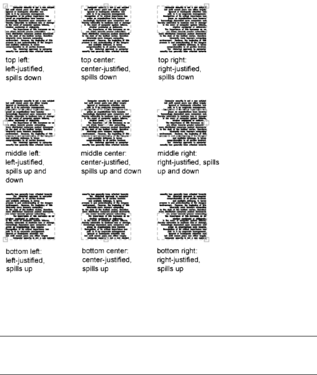
Line Spacing
Specifies line spacing for the multiline text object. Line spacing is the vertical
distance between the bottom (or baseline) of one line of text and the bottom
of the next line of text.
NOTE Exact spacing is recommended when you use MTEXT to create a table. Use
a smaller text height than the specified line spacing to ensure that text does not
overlap.
At Least Adjusts lines of text automatically based on the height of the largest
character in the line. When At Least is selected, lines of text with taller
characters have added space between lines.
Distance Sets the line spacing to an absolute value measured in drawing units.
Valid values must be between 0.0833 (0.25x) and 1.3333 (4x).
Exactly Forces the line spacing to be the same for all lines of text in the
multiline text object. Spacing is based on the text height of the object or text
style.
-MTEXT | 789
Spacing Factor Sets the line spacing to a multiple of single-line spacing.
Single spacing is 1.66 times the height of the text characters. You can enter a
spacing factor as a number followed by x to indicate a multiple of single
spacing. For example, specify single spacing by entering 1x, or specify double
spacing by entering 2x.
Rotation
Specifies the rotation angle of the text boundary.
■Specify rotation angle.
If you use the pointing device to specify a point, the rotation angle is
determined by the angle between the X axis and the line defined by the most
recently entered point (default 0,0,0) and the specified point.
The previous prompt is redisplayed until you specify the opposite corner of
the text boundary.
Style
Specifies the text style to use for multiline text.
Style Name Specifies a text style name. Text styles can be defined and saved
using the STYLE command.
?—List Styles Lists text style names and characteristics.
The previous prompt is redisplayed until you specify the opposite corner of
the text boundary.
Width
Specifies the width of the text boundary.
If you use the pointing device to specify a point, the width is calculated as
the distance between the start point and the specified point. Words within
each line of the multiline text object wrap to fit the width of the text boundary.
If you specify a width of 0, word wrap is turned off and the width of the
multiline text object is as wide as the longest line of text. You can end a line
of text at a specific point by typing the text and pressing Enter. To end the
command, press Enter at the MTEXT prompt.
Columns
Specifies the column options for an mtext object.
Static Specifies the total column width, the number of columns, the gutter
width (the space between the columns), and the height of columns.
790 | Chapter 13 M Commands
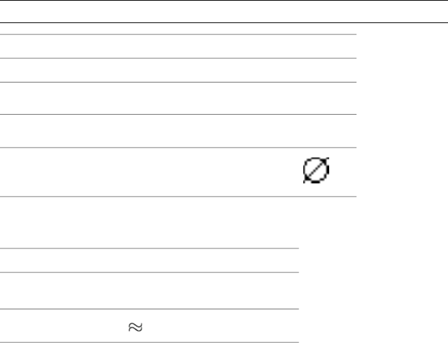
Dynamic Specifies column width, gutter width and column height. Dynamic
columns are text driven. Adjusting columns affect text flow and text flow
causes columns to be added or removed.
No columns Sets no column mode to current mtext object.
The default column setting is stored in the MTEXTCOLUMN system variable.
Symbols and Special Characters
Quick Reference
See also:
■Overview of Multiline Text
You can include special characters and symbols by entering a control code or
a Unicode string.
With the In-Place Text Editor on page 763, you can right-click and click Symbol
on the shortcut menu.
NOTE Symbols are not supported in vertical text.
Unicode strings and control codes
ResultUnicode StringsControl Codes
Degree symbol (°)\U+00B0%%d
Tolerance symbol ( )
\U+00B1%%p
Diameter symbol ( )
\U+2205%%c
To insert the following text symbols, click Symbol on the expanded Text
Formatting toolbar or enter the appropriate Unicode string:
Text symbols and Unicode strings
Unicode
String
SymbolName
\U+2248Almost equal
Symbols and Special Characters | 791
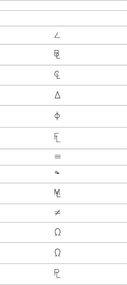
Text symbols and Unicode strings
Unicode
String
SymbolName
\U+2220Angle
\U+E100Boundary line
\U+2104Centerline
\U+0394Delta
\U+0278Electrical phase
\U+E101Flow line
\U+2261Identity
\U+E200Initial length
\U+E102Monument line
\U+2260Not equal
\U+2126Ohm
\U+03A9Omega
\U+214APlate/property line
792 | Chapter 13 M Commands
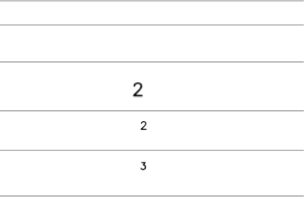
Text symbols and Unicode strings
Unicode
String
SymbolName
\U+2082Subscript 2
\U+00B2Squared
\U+00B3Cubed
These text symbols are available in the following True Type (TTF) and SHX
fonts:
■Simplex*
■Romans*
■gdt*
■amgdt*
■Isocp
■Isocp2
■Isocp3
■Isoct
■Isoct2
■Isoct3
■Isocpeur (TTF only)*
■Isocpeur italic (TTF only)
■Isocteur (TTF only)
■Isocteur italic (TTF only)
* These fonts also include the Initial Length symbol used for arc length
dimensions.
Symbols and Special Characters | 793
MULTIPLE
Quick Reference
See also:
■Enter Commands on the Command Line
Repeats the next command until canceled.
Summary
The command that you enter is repeated until you press Esc. Because
MULTIPLE repeats only the command name, any parameters must be specified
each time.
MULTIPLE does not repeat commands that display dialog boxes.
MVIEW
Quick Reference
See also:
■Create and Modify Layout Viewports
Creates and controls layout viewports.
Summary
In a layout, you can create as many viewports as you want, but only up to 64
viewports can be active at one time (see MAXACTVP). Objects in model space
are visible only in active viewports. Viewports that are not active are blank.
Use the On and Off options to control whether viewports are active.
List of Prompts
The following prompts are displayed.
Specify corner of viewportor
[ON/OFF/Fit/Shadeplot/Lock/Object/Polygonal/Restore/LAyer/2/3/4].
794 | Chapter 13 M Commands
Corner of Viewport
Specifies the first corner of a rectangular viewport.
On
Makes a selected viewport active. An active viewport displays objects in model
space. The MAXACTVP system variable controls the maximum number of
viewports that can be active at one time. If your drawing contains more
viewports than the number specified in MAXACTVP, you must turn one off
to make another one active.
Off
Makes a selected viewport inactive. Objects in model space are not displayed
in an inactive viewport.
Fit
Creates one viewport that fills the layout to the edges of the printable area.
When the paper background and printable area are turned off, the viewport
fills the display.
Shadeplot
Specifies how viewports in named (paper space) layouts are plotted.
As Displayed Specifies that a viewport is plotted the same way it is displayed.
Wireframe Specifies that a viewport is plotted wireframe regardless of the
current display.
Hidden Specifies that a viewport is plotted with hidden lines removed
regardless of the current display.
Lock
Prevents the zoom scale factor in the selected viewport from being changed
when working in model space.
Object
Specifies a closed polyline, ellipse, spline, region, or circle to convert into a
viewport. The polyline you specify must be closed and contain at least three
vertices. It can be self-intersecting, and it can contain an arc as well as line
segments.
MVIEW | 795
Polygonal
Creates an irregularly shaped viewport using specified points.
Arc Adds arc segments to the polygonal viewport.
For a description of the options for creating arc segments, see the Arc option
in PLINE.
Close Closes the boundary. If you press Enter after specifying at least three
points, the boundary is closed automatically.
Length Draws a line segment of a specified length at the same angle as the
previous segment. If the previous segment is an arc, the new line segment is
drawn tangent to that arc segment.
Undo Removes the most recent line or arc segment added to the polygonal
viewport.
Restore
Restores viewport configurations saved with the VPORTS command.
■Enter Viewport Configuration Name.
■?
First Corner Positions and sizes new viewports using the window selection
method; the viewports are fit into the selected area.
Fit Sizes the viewports to fill the drawing area.
Layer
Resets layer property overrides for the selected viewport to their global layer
properties.
■Reset Viewport Layer Property Overrides Back To Global Properties. Enter
Y to remove all layer property overrides.
■Select Viewports.
2
Divides the specified area horizontally or vertically into two viewports of equal
size.
■Enter Viewport Arrangement.
796 | Chapter 13 M Commands
First Corner Positions and sizes new viewports using the window selection
method; the viewports are fit into the selected area.
Fit Sizes the viewports to fill the drawing area.
3
Divides the specified area into three viewports.
The Horizontal and Vertical options split the specified area into thirds. The
other options split the area into three viewports: one large viewport and two
smaller ones. The Above, Below, Left, and Right options specify where the
larger viewport is placed.
■First Corner on page 797
■Fit on page 797
4
Divides the specified area horizontally and vertically into four viewports of
equal size.
MVIEW | 797

N Commands
NAVBAR
Quick Reference
See also:
■Use Navigation Bar
Provides access to navigation and orientation tools from a single interface.
Access Methods
Ribbon: View Tab ➤ Windows Panel ➤ User Interface drop-down ➤
Navigation Bar
Menu: View ➤ Display ➤ Navigation Bar
Summary
Provides access to the ViewCube tool, SteeringWheels, 3Dconnexion, and
product-specific navigation tools. Use these tools to navigate or reorient your
model. You can customize which tools are available on the navigation bar to
fit the way you work.
List of Prompts
The following prompts are displayed.
Enter an option [ON/OFF] <ON>:
On Displays the navigation bar.
14
799
Off Hides the navigation bar.
3Dconnexion Settings Dialog Box
Quick Reference
See also:
■Use 3Dconnexion 3D mouse to Navigate Views
Controls the settings of 3Dconnexion navigation tools.
Summary
Controls the settings for 3Dconnexion navigation tools which are available
from the navigation bar. Customize the speed and movements of the
3Dconnexion 3D mouse to manipulate the current view. These settings (except
Keep Scene Upright) are in synchronization with the 3Dconnexion Control
Panel settings of the 3Dconnexion 3D mouse driver.
List of Options
The following options are displayed.
Sensitivity
Controls the sensitivity of the 3Dconnexion 3D mouse controller cap.
Keep Scene Upright
Specifies whether the viewpoint of the model can be turned upside-down
while navigating.
Pan/Zoom
Controls pan and zoom navigation. When this option is disabled, you can
only rotate the model around the X,Y, and Z axes.
Tilt/Spin/Roll
Controls the rotation of the model around the X,Y, and Z axes. When this
option is disabled, you can only pan and zoom.
Restore Defaults
Restores the default settings of the 3Dconnexion Settings dialog box.
800 | Chapter 14 N Commands

NAVSWHEEL
Quick Reference
See also:
■Overview of SteeringWheel
Provides access to enhanced navigation tools that are quickly accessible from
the cursor.
Access Methods
Button
Menu: View ➤ SteeringWheels
Toolbar: Navigation Bar ➤ SteeringWheels
Shortcut menu: SteeringWheels
Summary
Selecting a tool on the wheel is different from the selection of a typical
command. Press on a wedge and drag to use the desired navigation tool.
Release the mouse button to return to the wheel and switch navigation tools.
The NAVSWHEEL command displays the 2D Navigation wheel.
NCOPY
Quick Reference
See also:
■Copy Objects
Copies objects that are contained in an xref, block, or DGN underlay.
NAVSWHEEL | 801
Access Methods
Button
Ribbon: Home tab ➤ Modify panel ➤ Copy Nested Objects
Summary
Instead of exploding or binding an xref, block, or DGN underlay to be able
to copy objects nested within them, you can copy the selected objects directly
into the current drawing.
List of Prompts
The following prompts are displayed.
Select nested objects to copy or [Settings]: Use an object selection method and
then press Enter
Specify base point or [Displacement/Multiple] <Displacement>: Specify a base
point or enter an option
Specify second point or [Array] <use first point as displacement>: Specify a
second point or enter an option
Specify second point or [Fit]: Specify a second point or enter an option
Settings
Controls whether named objects that are associated with the selected objects
are added to the drawing.
Insert
Duplicates the selected objects to the current layer without regard to named
objects. This option is similar to the COPY command.
Bind
Includes named objects such as blocks, dimension styles, layers, linetypes,
and text styles associated with the copied objects into the drawing.
Displacement
Specifies a relative distance and direction using coordinates.
The two points you specify define a vector that indicates how far from the
original the copied objects are to be placed and in what direction.
If you press Enter at the Specify Second Point prompt, the first point is
interpreted as a relative X,Y,Z displacement. For example, if you specify 2,3
802 | Chapter 14 N Commands

for the base point and press Enter at the next prompt, the objects are copied
2 units in the X direction and 3 units in the Y direction from their current
location.
Multiple
Controls whether multiple copies are created automatically as you specify
additional locations.
Array
Arranges a specified number of copies in a linear array using the first and
second copy as the spacing distance.
Number of Items to Array Specifies the number of sets of the selected objects
in the array, including the original selection set.
Second Point Determines a distance and direction for the array relative to
the base point. By default, the first copy in the array is located at the specified
displacement. The remaining copies are located in a linear array beyond that
point using the same incremental displacement.
Fit
Arranges a specified number of copies in a linear array using the first and last
copy as the total spacing distance.
Second Point Positions the last copy in the array at the specified displacement.
The other copies are fit in a linear array between the first copy and the last
copy.
NEW
Quick Reference
See also:
■Overview of Starting a New Drawing
Creates a new drawing.
Access Methods
Button
NEW | 803

Menu: File ➤ New
Summary
The behavior of the NEW command is determined by the STARTUP system
variable.
■1: NEW displays the Create New Drawing dialog box.
■0: NEW displays the Select Template dialog box (a standard file selection
dialog box).
If the FILEDIA system variable is set to 0 instead of 1, a Command prompt is
displayed. If you set FILEDIA to 0, this prompt is displayed regardless of the
Startup setting.
Create New Drawing Dialog Box
Quick Reference
See also:
■Overview of Starting a New Drawing
Summary
Defines the settings for a new drawing. Start from Scratch creates a new drawing
using either imperial or metric default settings. Use a Template creates a new
drawing using the settings defined in a drawing template you select. Use a
Wizard creates a new drawing using the settings you specify in either the
Quick or Advanced wizard. (The first option, Open a Drawing, is not available
from the NEW command. To open an existing drawing, use OPEN.)
List of Options
The following options are displayed.
Start from Scratch
Starts an empty drawing using default imperial or metric settings
(MEASUREINIT system variable). You can change the measurement system
for a given drawing by using the MEASUREMENT system variable. The
804 | Chapter 14 N Commands
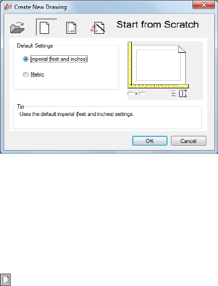
Drawing1.dwg that opens when you start the program is a drawing that is
started from scratch.
Imperial Starts a new drawing based on the imperial measurement system.
The default drawing boundary (the grid limits) is 12 by 9 inches.
Metric Starts a new drawing based on the metric measurement system. The
default drawing boundary (the grid limits) is 429 by 297 millimeters.
Tip
Displays a description of the selected measurement setting.
Use a Template
Starts a drawing based on a drawing template file. Template drawings store
all the settings for a drawing and may also include predefined layers, dimension
styles, and views. Template drawings are distinguished from other drawing
files by the .dwt file extension. They are normally kept in the template directory.
Several template drawings are included with this program. You can make
additional template drawings by changing the extensions of drawing file
names to .dwt. See “Use a Drawing Template File” in the User's Guide.
Create New Drawing Dialog Box | 805

Select a Template
Lists all DWT files that currently exist in the drawing template file location,
which is specified in the Options dialog box. Select a file to use as a starting
point for your new drawing.
Preview
Displays a preview image of the selected file.
Browse
Displays the Select a Template File dialog box (a standard file selection dialog
box), where you can access template files that are not available in the Select
a Template list.
Template Description
Displays a description of the selected template. If you create your own template,
you can use the Template Options dialog box on page 1092to specify the text
that you want to display here. See the SAVEAS command.
Use a Wizard
Sets up a drawing using a step-by-step guide. You can choose from two wizards:
Quick Setup and Advanced Setup.
806 | Chapter 14 N Commands

Quick Setup Displays the Quick Setup wizard, in which you can specify the
units and area for your new drawing. The Quick Setup wizard also changes
settings, such as text height and snap spacing, to an appropriate scale.
Advanced Setup Displays the Advanced Setup wizard, in which you can
specify the units, angle, angle measure, angle direction, and area for your new
drawing. The Advanced Setup wizard also changes settings, such as text height
and snap spacing, to an appropriate scale.
Wizard Description
Displays a description of the selected wizard.
Quick Setup Wizard
Quick Reference
See also:
■Overview of Starting a New Drawing
Defines the units and area of your drawing.
Quick Setup Wizard | 807
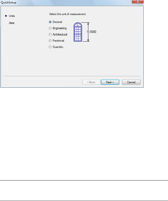
List of Options
The following options are displayed.
The Quick Setup wizard has two pages: Units and Area. As you work in this
wizard, choose Back and Next to switch between pages; choose Finish on the
last page to close the wizard and create the new drawing with the settings you
specified.
Units
Indicates the format in which you enter and in which the program displays
coordinates and measurements. Several formats are available. Engineering and
Architectural have a specific base unit (inches) assigned to them. You can
select from other measurement styles that can represent any convenient unit
of measurement.
NOTE You control the precision (the number of decimal places displayed in all
measurements) by using the Advanced Setup wizard or the UNITS command. The
default precision used by Quick Setup is four (0.0000).
Decimal Displays measurements in decimal notation.
Engineering Displays measurements in feet and decimal inches.
Architectural Displays measurements in feet, inches, and fractional inches.
Fractional Displays measurements in mixed-number (integer and fractional)
notation.
808 | Chapter 14 N Commands
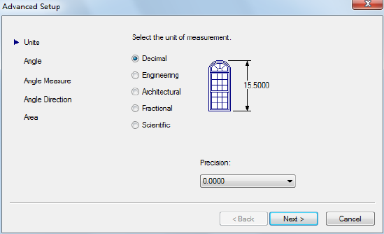
Scientific Displays measurements in scientific notation (numbers expressed
in the form of the product of a decimal number between 0 and 10 and a power
of 10).
Area
Indicates the width and length in full-scale units of what you plan to draw.
This setting limits the area of the drawing covered by grid dots when the grid
is turned on. When limits checking is turned on with the LIMITS command,
this setting also restricts the coordinates you can enter to within the rectangular
area. You can change the drawing area and turn limits checking on and off
with the LIMITS command.
Advanced Setup Wizard
Quick Reference
See also:
■Specify Units and Unit Formats
Defines the units, angle, angle measure, angle direction, and area of your new
drawing.
Advanced Setup Wizard | 809
Summary
List of Options
The following options are displayed.
The Advanced Setup wizard contains five pages: Units, Angle, Angle Measure,
Angle Direction, and Area. As you work in this wizard, choose Back and Next
to navigate between pages; choose Finish on the last page to close the wizard
and create the new drawing with the settings you specified.
You can later change units, angle, angle measure, and angle direction using
the UNITS command, and you can change area using the LIMITS command.
Units
Indicates the unit format and precision. The unit format is the format in which
you enter and in which the program displays coordinates and measurements.
The Units page of the Quick Setup wizard includes the same formats. See
Specify Units and Unit Formats for more information.
The unit precision specifies the number of decimal places or the fractional
size for displaying linear measurements.
Angle
Indicates the format in which you enter angles and in which the program
displays angles.
Decimal Degrees Displays partial degrees as decimals.
Deg/Min/Sec Displays partial degrees as minutes and seconds.
Grads Displays angles as grads.
Radians Displays angles as radians.
Surveyor Displays angles in surveyor's units.
Angle Measure
Indicates the direction of the 0 angle for the entry of angles. When you enter
an angle value, the angle is measured either counter-clockwise or clockwise
from the compass direction that you select on this page. You control the
counterclockwise/clockwise direction on the Angle Direction page.
East Specifies the compass direction east as the 0 angle.
North Specifies the compass direction north as the 0 angle.
West Specifies the compass direction west as the 0 angle.
South Specifies the compass direction south as the 0 angle.
810 | Chapter 14 N Commands
Other Specifies a direction other than east, north, west, or south. Enter a
specific compass angle to treat as the 0 angle.
Angle Direction
Indicates the direction from the 0 angle in which you enter and in which the
program displays positive angle values: counterclockwise or clockwise.
Area
Indicates the width and length in full-scale units of what you plan to draw.
This setting limits the area of the drawing covered by grid dots when the grid
is turned on. When limits checking is turned on with the LIMITS command,
this setting also restricts the coordinates you can enter to within the rectangular
area. You can change the drawing area and turn limits checking on and off
with the LIMITS command.
NEW Command Prompt
Quick Reference
See also:
■Overview of Starting a New Drawing
Summary
Enter a tilde (~) at the prompt to display the Select Template dialog box (a
standard file selection dialog box).
If you turned off the display of the Create New Drawing dialog box, or if
FILEDIA is set to 0, NEW displays the following prompt:
List of Prompts
The following prompts are displayed.
Enter template file name or [. (for none)] <current>: Enter a name, enter a period
(.), or press ENTER
NEW Command Prompt | 811
NEWSHEETSET
Quick Reference
See also:
■Create a Sheet Set
Creates a new sheet set data file that manages drawing layouts, file paths, and
project data.
Access Methods
Button
Menu: Application menu ➤ New ➤ Sheet Set
Menu: File ➤ New Sheet Set
Summary
The Create Sheet Set wizard contains a series of pages that step you through
the process of creating a new sheet set. You can choose to create a new sheet
set from existing drawings, or use an existing sheet set as a template on which
to base your new sheet set.
812 | Chapter 14 N Commands

O Commands
OBJECTSCALE
Quick Reference
See also:
■Set Annotation Scale
Adds or deletes supported scales for annotative objects.
Access Methods
Button
Ribbon: Annotate tab ➤ Annotation Scaling panel ➤ Add/Delete Scales
Menu: Modify ➤ Annotative Object Scale ➤ Add/Delete Scales
Shortcut menu: Select an annotative object. Right-click in the drawing area
and click Annotative Object Scale ➤ Add/Delete Scales.
Command entry: 'objectscale for transparent use
Summary
An annotative object can support several annotation scales for views at different
scales. You can add or delete scales from the list of scales assigned to the selected
annotative objects.
15
813
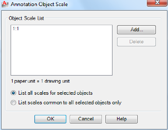
If you enter objectscale, you are prompted to select annotative objects.
The Annotative Object Scale dialog box on page 814 is displayed.
If you enter -objectscale at the Command prompt, options are displayed on
page 816.
Annotative Object Scale Dialog Box
Quick Reference
See also:
■Scale Views in Layout Viewports
Adds or deletes supported scales for the selected object.
List of Options
The following options are displayed.
Object Scale List
Displays the list of scales supported by the selected object.
List all scales for selected objects
Specifies that all scales supported by the selected objects are displayed in the
Object Scale List.
List scales common to all selected objects only
814 | Chapter 15 O Commands
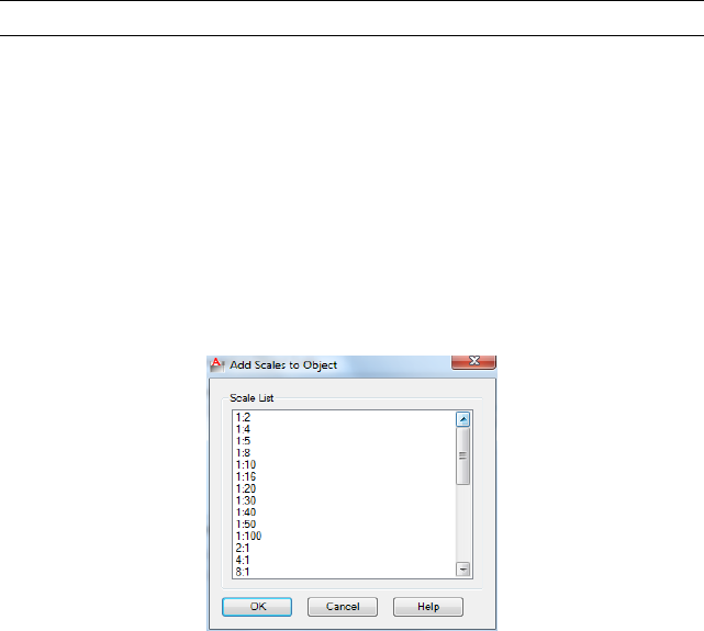
Specifies that only the supported scales that are common to all selected objects
are displayed in the Object Scale List.
Add
Displays the Add Scales to Object Dialog Box on page 815.
Delete
Removes the selected scale from the scale list.
NOTE The current scale or scales referenced by objects or views cannot be deleted.
Add Scales to Object Dialog Box
Quick Reference
See also:
■Scale Views in Layout Viewports
Adds a new scale to the selected object.
List of Options
The following option is displayed.
Scale List
Displays the list of scales that can be added to the selected annotative object.
Multiple scales can be selected by holding down the Shift or Ctrl key while
selecting the scales.
Add Scales to Object Dialog Box | 815
Use the SCALELISTEDIT on page 1098 command to add custom scales to this
list.
-OBJECTSCALE
Quick Reference
See also:
■Scale Views in Layout Viewports
List of Prompts
The following prompts are displayed.
Select annotative objects: Use an object selection method
Enter an option [Add on page 816/Delete on page 816/? on page 816] <Add>:
Enter a or d or press Enter
Add
Adds an annotation scale to the selected objects.
When created, an annotative object supports one annotation scale: the current
annotation scale. However, an annotative object can be updated to support
additional annotation scales for views at different scales.
■Enter named scale to add.
■? on page 816
?Displays the list of scales in the scale list.
Delete
Removes a specified current annotation scale from the selected objects.
If an annotative object supports a single scale, that scale cannot be deleted
from the object.
■Enter named scale to delete.
■? on page 816
?Displays the union of all scales of the selected objects.
816 | Chapter 15 O Commands
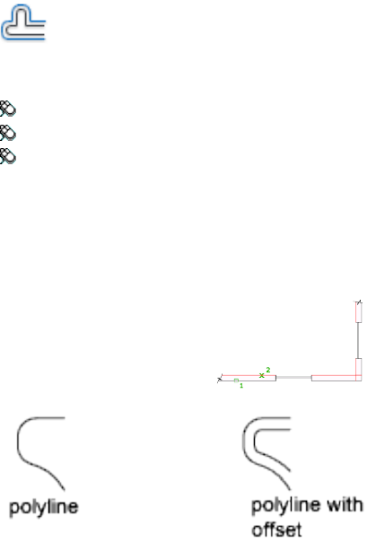
OFFSET
Quick Reference
See also:
■Offset an Object
Creates concentric circles, parallel lines, and parallel curves.
Access Methods
Button
Ribbon: Home tab ➤ Modify panel ➤ Offset
Menu: Modify ➤ Offset
Toolbar: Modify
Summary
You can offset an object at a specified distance or through a point. After you
offset objects, you can trim and extend them as an efficient method to create
drawings containing many parallel lines and curves.
The OFFSET command repeats for convenience. To exit the command, press
Enter.
OFFSET | 817
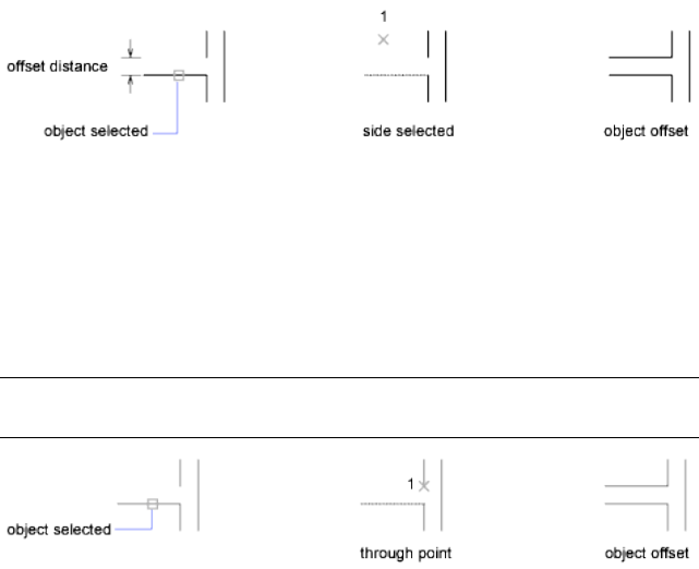
List of Prompts
The following prompts are displayed.
Current settings: Erase source = current Layer = current OFFSETGAPTYPE =
current
Specify Offset Distance on page 818 or [Through on page 818/Erase on page
818/Layer on page 819] <current>: Specify a distance, enter an option, or press Enter
Offset Distance
Creates an object at a specified distance from an existing object.
Exit Exits the OFFSET command.
Multiple Enters the Multiple offset mode, which repeats the offset operation
using the current offset distance.
Undo Reverses the previous offset.
Through
Creates an object passing through a specified point.
NOTE For best results when you offset a polyline with corners, specify the through
point near the midpoint of a line segment, not near a corner.
■Exit on page 818
■Multiple on page 818
■Undo on page 818
Erase
Erases the source object after it is offset.
818 | Chapter 15 O Commands

Layer
Determines whether offset objects are created on the current layer or on the
layer of the source object.
OLELINKS
Quick Reference
See also:
■Link OLE Objects in Drawings
Updates, changes, and cancels existing OLE links.
Access Methods
Menu: Edit ➤ OLE Links
Summary
The Links dialog box is displayed. If there is no existing OLE link in the
drawing, OLE Links is not available on the Edit menu and the Links dialog
box is not displayed. To specify a different source application for an embedded
object, right-click the embedded object and click Convert on the shortcut
menu to display the Convert dialog box.
See “Link and Embed Data (OLE)” in the User's Guide.
Links Dialog Box
Quick Reference
See also:
■Link OLE Objects in Drawings
Lists and modifies linked files and objects.
OLELINKS | 819

List of Options
The following options are displayed.
Links Lists information about linked objects. The information listed depends
on the type of link. To change information for a linked object, select the
object.
Source Displays the path name of the source file and the type of object.
Type Displays the format type.
Update: Automatic Updates the link automatically whenever the source
changes.
Update: Manual Prompts you to update a link when you open the document.
Update Now Updates the selected links.
Open Source Opens the source file and highlights the portion linked to the
AutoCAD LT drawing.
Change Source Displays the Change Source dialog box (a standard file dialog
box), in which you can specify a different source file. If the source is a selection
within a file (instead of the entire file), Item Name displays a string representing
the selection.
Break Link Severs the link between the object and the original file. The object
in your drawing is changed to WMF (Windows metafile format), which is not
affected by future changes to the original file.
820 | Chapter 15 O Commands
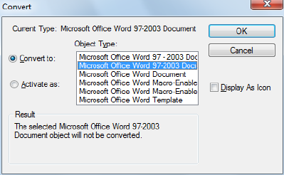
Convert Dialog Box
Quick Reference
See also:
■Link OLE Objects in Drawings
Specifies a different source application for an embedded object.
Access Methods
Shortcut menu: Right-click an embedded object and click OLE ➤ Convert.
List of Options
The following options are displayed,
Current Type Displays the type of object you are converting or activating.
Object Type Displays a list of available object types. If you select AutoCAD
LT Entities, text is converted to a multiline text (mtext) object, a spreadsheet
is converted to a table object, and a bitmap file is converted to an image object.
Convert To Converts the embedded object to the type specified under Object
Type.
Activate As Opens the embedded object as the type selected under Object
Type but returns the object to its current type after editing.
Display as Icon Displays the source application's icon in the drawing.
Double-clicking the icon displays the linked or embedded information.
Convert Dialog Box | 821
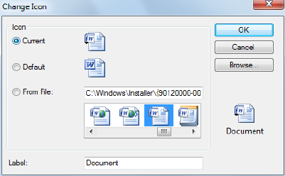
Change Icon Displays the Change Icon dialog box. This option is available
only if you select Display as Icon.
Result Describes the result of the selected options.
Change Icon Dialog Box
Quick Reference
See also:
■Link OLE Objects in Drawings
Changes the icon that represents an embedded or linked object in a drawing.
List of Options
The following options are displayed.
Icon
Specifies an icon to represent an embedded or linked object.
Current Specifies the currently selected icon.
Default Specifies the default icon for the source application.
From File Specifies an icon from a file (valid types include EXE, DLL, and
ICO).
Label
Specifies a caption for the icon. The file type is displayed unless you specify
otherwise.
822 | Chapter 15 O Commands

Browse
Displays the Browse dialog box (a standard file selection dialog box), in which
you can select an icon from a file.
OLESCALE
Quick Reference
See also:
■Edit OLE Objects in Drawings
Controls the size, scale, and other properties of a selected OLE object.
Access Methods
Shortcut menu: With an OLE object selected, right-click and click Text Size.
Summary
The OLE Text Size dialog box is displayed.
NOTE You must select an OLE object before entering the OLESCALE command.
OLE Text Size Dialog Box
Quick Reference
See also:
■Edit OLE Objects in Drawings
Maps the point size of one of the fonts in an OLE object to a text height in
the drawing.
OLESCALE | 823
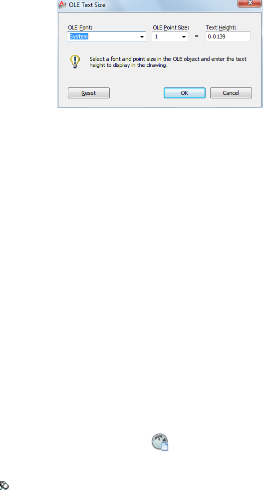
Summary
The OLE object is scaled automatically to accommodate the size of the text.
List of Options
The following options are displayed.
OLE Font Displays a list of the fonts used in the OLE object.
OLE Point Size Displays a list of the point sizes available for the selected font.
Text Height Sets a text height for the font at the selected point size.
Reset Restores the OLE object to its size when it was inserted in the drawing.
ONLINEDRAWINGS
Quick Reference
See also:
■Use AutoCAD WS for Drawing File Collaboration
Opens AutoCAD WS in a web browser and lists the available online files.
Access Methods
Button
Ribbon: Online tab ➤ Content panel ➤ Online Drawings
824 | Chapter 15 O Commands
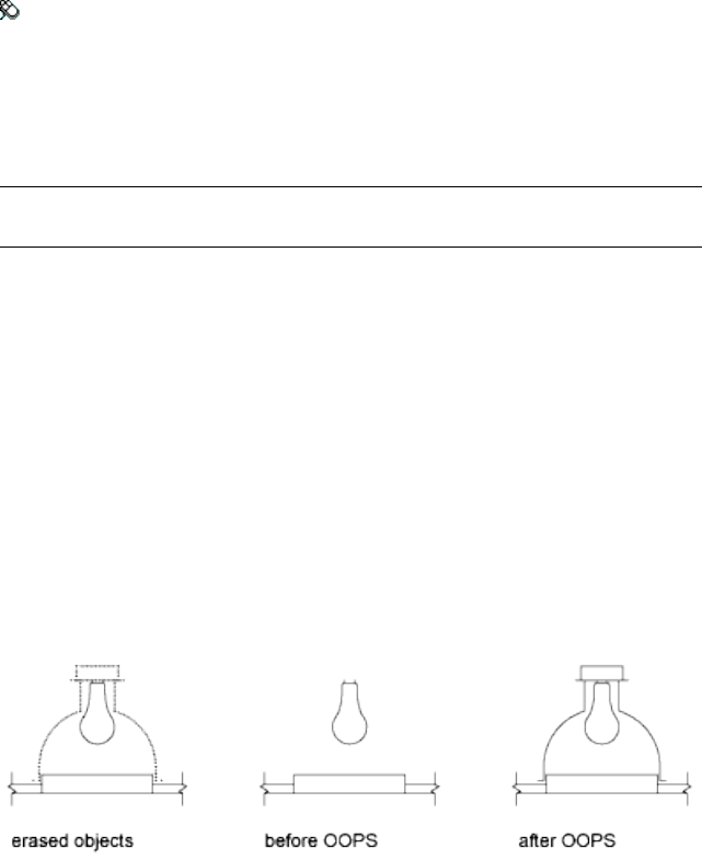
Menu: File ➤ AutoCAD WS ➤ Online Drawings
Summary
The Drawings section in AutoCAD WS displays your uploaded files and any
files that have been shared with you. Use the Drawings section to manage
your files and folders, and to edit, share, and download files.
NOTE You may first be prompted to log in to AutoCAD WS. If you do not have
an account, click Create an Account and follow the on-screen instructions.
OOPS
Quick Reference
See also:
■Erase Objects
Restores erased objects.
Summary
OOPS restores objects erased by the last ERASE command.
You can also use OOPS after BLOCK or WBLOCK because these commands
can erase the selected objects after creating a block.
You cannot use OOPS to restore objects on a layer that has been removed with
the PURGE command.
OOPS | 825
OPEN
Quick Reference
See also:
■Open a Drawing
Opens an existing drawing file.
Access Methods
Button
Menu: Application menu ➤ Open ➤ Drawing
Menu: File ➤ Open
Toolbar: Standard
Summary
The Select File dialog box (a standard file selection dialog box) is displayed.
When FILEDIA is set to 0 (zero), OPEN displays a Command prompt.
Standard File Selection Dialog Boxes
Quick Reference
See also:
■Save a Drawing
Several commands display standard file selection dialog boxes, in which you
can navigate through local and network drives and through FTP sites and Web
folders to select files. While each dialog box may vary slightly, following is a
list of the possible options.
826 | Chapter 15 O Commands
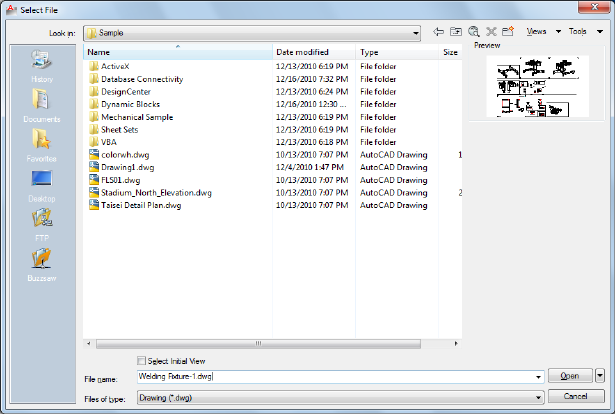
List of Options
The following options are displayed.
Places List
Provides quick access to predefined locations. Reorder the icons in the Places
list by dragging them to a new position. To add a new icon to Places, drag a
folder from the list. Changes to Places affect all standard file selection dialog
boxes.
History Displays shortcuts to the files most recently accessed from the dialog
box. It is recommended that you periodically remove unwanted shortcuts
from the History list. Select History, then select the unwanted shortcuts in
the Files list and click Delete. To sort the shortcuts by date, click Views ➤
Details, and then click the Modified column in the Files list.
Personal/My Documents Displays the contents of the Personal or My Documents
folder for the current user profile.
Favorites Displays the contents of the Favorites folder for the current user
profile. This folder consists of shortcuts to files or folders that you added to
Favorites using the Tools ➤ Add to Favorites option in the dialog box.
FTP Displays the FTP sites that are available for browsing in the standard file
selection dialog box. To add FTP locations to this list, or to modify an existing
FTP location, click Tools ➤ Add/Modify FTP Locations in the dialog box.
Standard File Selection Dialog Boxes | 827
Desktop Displays the contents of your desktop.
Buzzsaw Provides access to Buzzsaw projects. Buzzsaw is a secure Internet-based
collaboration and project management service that connects project teams in
different locations. To use Buzzsaw, you must already have a project hosting
account on Buzzsaw or be given access to a subscriber's Buzzsaw site. If you
do not yet have a project hosting account on Buzzsaw, clicking Buzzsaw
displays the Select Template dialog box where you can add a Buzzsaw location
shortcut. Double-clicking Add a Buzzsaw Location Shortcut opens the Log In
To Buzzsaw dialog box where you can register for a free 30-day trial subscription
to the service. Also, the first time you access Buzzsaw, your default web browser
opens with the project hosting page displayed. If you already have a project
hosting account, clicking Buzzsaw shows all of your project sites in the Site
list.
Look In/Save In
Displays the current folder or drive. Click the arrow to view the hierarchy of
the folder path and to navigate up the path tree or to other drives, network
connections, FTP locations, or web folders (either Web Folders or My Network
Places, depending on the version of your operating system). You can create
web folders in Windows Explorer. Consult your system administrator or
Windows Explorer Help for more information about web folders. To control
whether the last used paths in each particular standard file selection dialog
box are stored across sessions, use the REMEMBERFOLDERS system variable.
Back
Returns to the previous file location.
Up One Level
Navigates one level up in the current path tree.
Search the Web
Displays the Browse the Web dialog box, from which you can access and store
files on the Internet.
Delete
Deletes the selected file or folder.
Create New Folder
Creates a new folder in the current path using a name that you specify.
828 | Chapter 15 O Commands
Views
Controls the appearance of the Files list or Folders list and, for a Files list,
specifies whether to show a preview image when a file is selected.
List Displays a multi-column list.
Details Displays a single-column list with file details.
Thumbnail Displays each file in a thumbnail view.
Preview Displays a bitmap of the selected file. To save a bitmap with a drawing
file, use the Save a Thumbnail Preview Image option on the Open and Save
tab in the Options dialog box.
Tools
Provides tools to help with file selection and other actions available in file
selection dialog boxes.
Find Displays the Find dialog box, in which you can search for files using
name, location, and date-modified filters.
Locate
Uses the AutoCAD LT search path to locate the file specified in File Name.
You set the search path on the Files tab in the Options dialog box.
Add/Modify FTP Locations Displays the Add/Modify FTP Locations dialog
box, in which you can specify the FTP sites to make available for browsing.
To browse these sites, select FTP from the Places list.
Add Current Folder to Places Adds an icon for the selected folder to the
Places list, providing quick access to that folder from all standard file selection
dialog boxes. To remove the icon, right-click the icon and choose Remove.
Add to Favorites
Creates a shortcut to the current Look In location, or to the selected file or
folder. The shortcut is placed in the Favorites folder for the current user profile,
which you can access by choosing Favorites in the Places list.
Look in Favorites
Sets the Look In path to your system’s Favorites folder.
Options Provides additional options for certain standard file selection dialog
boxes.
Security Options Provides options for a digital signature and password that
are invoked when you save a file.
Standard File Selection Dialog Boxes | 829
Files List
Displays the files and folders in the current path and of the selected file type.
Use the Views menu in the dialog box to switch between List view and Details
view.
Preview
Displays a bitmap of the selected file when you choose Views ➤ Preview in
the dialog box. To save a bitmap with a drawing file, use the Save a Thumbnail
Preview Image option on the Open and Save tab in the Options dialog box.
File Name
Displays the name of the file you select in the Files list. If you select multiple
files, File Name displays each selected file within quotation marks. You must
use quotation marks when entering multiple file names. You can use wild-card
characters to filter files displayed in the Files list.
Files of Type
When you are saving files, Files of Type specifies the format in which the file
is saved.
Select Initial View
Displays the specified model space view when you open the drawing if the
drawing contains more than one named view.
Update Sheet and View Thumbnails Now
Reflects the current setting of the UPDATETHUMBNAIL system variable. This
option temporarily overrides that setting. This option does not change the
current setting of UPDATETHUMBNAIL.
Open/Save
Depending on the purpose of the specific file selection dialog box, opens or
saves the selected file or enters the path of the selected folder in the previous
dialog box. Certain file selection dialog boxes may include additional options,
accessed by clicking the arrow next to the Open button.
Open Read-Only Opens a file in read-only mode. You cannot save changes
to the file using the original file name.
830 | Chapter 15 O Commands
Buzzsaw Location Shortcuts Dialog Box
Quick Reference
See also:
■Open a Drawing
Creates, renames, modifies, and deletes Buzzsaw location shortcuts.
List of Options
The following options are displayed.
Buzzsaw Location Shortcuts Lists the location of existing Buzzsaw shortcuts.
New Opens the Log In to Buzzsaw Site dialog box.
Rename Renames the shortcuts you select.
Modify Opens the Log In to Buzzsaw Site dialog box, where you can change
settings for the selected shortcut.
Delete Removes the selected shortcut.
Close Closes the selected shortcut location.
Log In to Buzzsaw Dialog Box
Quick Reference
See also:
■Open a Drawing
Logs in to the Buzzsaw site in order to browse to a specific location
Buzzsaw Location Shortcuts Dialog Box | 831
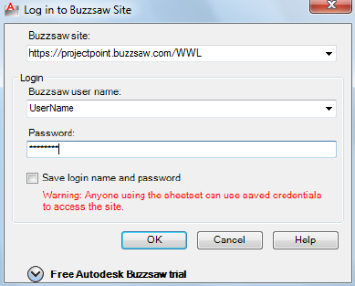
List of Options
The following options are displayed.
Buzzsaw Site Specifies the location of the most recently used Buzzsaw site.
Enter any existing address or site name.
Buzzsaw User Name Specifies the user name you use for the Buzzsaw site you
want to access.
Password Specifies your password for the Buzzsaw site.
Save Login Name and Password Saves your user and login name so that you
don't need to retype it the next time you access the site.
Click here to register for a free trial Registers you for a free trial of the
Buzzsaw site.
Create or Edit a Buzzsaw Location Shortcut Dialog Box
Quick Reference
See also:
■Open a Drawing
Sets a shortcut to a Buzzsaw location.
832 | Chapter 15 O Commands
Summary
Provides access to a new Autodesk Buzzsaw location that you specify. You can
open drawings or save drawings at this location. If a sheet set is open, the
Autodesk Buzzsaw location is associated with your current sheet set. The only
Buzzsaw locations displayed are those associated with the current sheet set.
List of Options
The following options are displayed.
Buzzsaw Site Displays the name of the current Buzzsaw site.
Select a Buzzsaw Site Project or Folder Lists the most recently opened projects
and folders in the site.
Browse Displays the Select a Buzzsaw Project or Folder dialog box, which you
can use to find and select a project or folder.
Enter a Name for this Buzzsaw Location Shortcut Specifies the name of the
shortcut.
Select a Buzzsaw Location Dialog Box
Quick Reference
See also:
■Open a Drawing
Specifies a Buzzsaw project or folder to save with a Buzzsaw location shortcut.
List of Options
The following option is displayed.
List of Buzzsaw Projects and Folders Specifies Buzzsaw projects or folders
that can be linked to the shortcut.
Select a Buzzsaw Location Dialog Box | 833
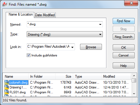
Find Dialog Box
Quick Reference
See also:
■Specify Search Paths and File Locations
Searches for files using name, location, and date modified filters.
Summary
To access the Find dialog box, in a standard file selection dialog box, click
Tools menu ➤ Find.
List of Options
The following options are displayed.
Name & Location Tab
Filters the file search based on file type, file name, and location.
Named
Specifies the full or partial file names to include in the search. When entering
multiple file names, enclose each name in quotation marks.
834 | Chapter 15 O Commands
Use the following wild-card characters to broaden your search:
■* (Asterisk): Matches any string and can be used anywhere in the search
string.
■? (Question mark): Matches any single character; for example, ?BC matches
ABC, 3BC, and so on.
The type of files to include in the search is determined by Type, so you don't
need to enter a file extension in Named. For example, to find house102.dwg,
enter house* and set Type to Drawing (*.dwg).
Type
Specifies the type of files to include in the search. Available file types are
limited to those supported by the specific standard file selection dialog box.
Look In
Specifies the location to search. Enter a location, choose a location from the
list, or choose Browse to navigate to a location. When entering multiple
locations, enclose each location in quotation marks.
Browse
Displays the Browse for Folder dialog box, in which you can navigate to a
location for the search.
Include Subfolders
Searches all subfolders within the Look In location.
Date Modified Tab
Filters the file search based on the file's creation or modified date.
All Files
Searches without a date filter.
Find All Files Created or Modified
Restricts the search to files created or modified within a specified time.
■Between: Searches for files created or modified between two dates. Enter
the dates or click the arrows to choose dates from a calendar. To navigate
the calendar, use the left and right arrows, or click the month and year.
■During the Previous N Months: Searches for files created or modified within
a specified number of months.
Find Dialog Box | 835
■During the Previous N Days: Searches for files created or modified within a
specified number of days.
Find Now
Searches for files using the criteria specified in both tabs.
Stop
Ends the search.
New Search
Clears the search results and resets the default values for all search options.
OK
When one or more files are selected in the search results, closes the Find dialog
box and enters the selected file names in the standard file selection dialog
box.
Search Results
Lists all files found by the search. To pass a file to the standard file selection
dialog box, select a file and choose OK. When used with a standard file
selection dialog box that allows multiple file selection, you can pass multiple
files from the Search Results.
Add/Modify FTP Locations Dialog Box
Quick Reference
See also:
■Open a Drawing
Defines the FTP sites that you can browse within standard file selection dialog
boxes.
836 | Chapter 15 O Commands
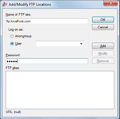
Summary
To browse the sites that you add, select FTP from the Places list in the standard
file selection dialog box.
List of Options
The following options are displayed.
Name of FTP Site
Specifies the site name for the FTP location (for example, ftp.autodesk.com).
Log On As
Specifies whether to log on to the FTP site anonymously or with a specific
user name.
Anonymous
Logs you on to the FTP site as an anonymous user. If the FTP site does not
allow anonymous logons, select User and enter a valid user name.
User
Logs you on to the FTP site using the specified user name.
Password
Specifies the password to use to log on to the FTP site.
Add/Modify FTP Locations Dialog Box | 837
Add
Adds a new FTP site to the list of FTP locations available from the standard
file selection dialog box.
Modify
Modifies the selected FTP site to use the specified site name, logon name, and
password.
Remove
Removes the selected FTP site from the list of FTP locations available from the
standard file selection dialog box.
FTP Sites
Lists the FTP sites that are available from the Places list in all standard file
selection dialog boxes.
URL
Displays the URL for the selected FTP site.
OPEN Command Prompt
Quick Reference
See also:
■Open a Drawing
Opens an existing drawing file.
WhenFILEDIA is set to 0 (zero), OPEN displays the following Command
prompt.
Enter name of drawing to open:
Enter ~ (tilde) at the prompt to ignore FILEDIA and display the Select File
dialog box, a standard file selection dialog box.
838 | Chapter 15 O Commands
OPENDWFMARKUP
Quick Reference
See also:
■Respond to Markups
Opens a DWF or DWFx file that contains markups.
Access Methods
Menu: File ➤ Load Markup Set
Summary
Displays the Open Markup DWF dialog box (a standard file selection dialog
box), in which you can select a DWF or DWFx file that contains markups to
load into the Markup Set Manager.
NOTE When opening a digitally signed DWFx file, a message box is displayed
that warns you about saving a new version of the file will invalidate the attached
digital signature.
OPENONLINE
Quick Reference
See also:
■Use AutoCAD WS for Drawing File Collaboration
Opens the AutoCAD WS Editor in a web browser and displays an online copy
of the current drawing for online editing and sharing.
Access Methods
Button
OPENDWFMARKUP | 839
Ribbon: Online tab ➤ Content panel ➤ Open Online
Menu: File ➤ AutoCAD WS ➤ Open Online
Toolbar: Online
Summary
If the drawing has never been uploaded to AutoCAD WS, or if the latest version
is not available in your online storage, the drawing and any supporting files
are automatically uploaded.
You must save the drawing before you can continue with this command.
NOTE You may first be prompted to log in to AutoCAD WS. If you do not have
an account, click Create an Account and follow the on-screen instructions.
OPENSHEETSET
Quick Reference
See also:
■Create and Manage a Sheet Set
Opens a selected sheet set.
Access Methods
Button
Menu: File ➤ Open Sheet Set
Summary
The Open Sheet Set dialog box (a standard file selection dialog box) is
displayed.
In this dialog box, you can select a sheet set data (DST) file to load sheet set
information into the Sheet Set Manager.
840 | Chapter 15 O Commands

OPTIONS
Quick Reference
See also:
■Set Up the Drawing Area
Customizes the program settings.
Access Methods
Menu: Application menu ➤ Options
Menu: Tools ➤ Options
Shortcut menu: With no commands active and no objects selected,
right-click in the drawing area. Click Options.
Shortcut menu: Right-click in the command window, and click Options.
Summary
The Options dialog box is displayed.
Options Dialog Box
Quick Reference
See also:
■Set Up the Drawing Area
Customizes the program settings.
List of Options
The following options are displayed.
Drawing Icon
Signifies that an option is saved with the drawing, and affects only the current
drawing. An option saved in the registry is not displayed with a drawing file
OPTIONS | 841
icon, and affects all drawings in a work session. Options that are saved in the
registry are saved in the current profile.
Current Drawing
Displays the name of the current drawing above the tabs. (DWGNAME system
variable)
List of Tabs
The Options dialog box includes the following tabs:
■Files on page 842
■Display on page 847
■Open and Save on page 850
■Plot and Publish on page 854
■System on page 859
■User Preferences on page 862
■Drafting on page 866
■Selection on page 869
Files Tab (Options Dialog Box)
Quick Reference
See also:
■Set Up the Drawing Area
Lists the folders in which the program searches for support, driver, menu, and
other files. Also lists optional, user-defined settings such as which dictionary
to use for checking spelling.
Paths are searched in the order that they are listed in the Options dialog box.
If the same file exists in different folders, then the first instance found is used.
List of Options
The following options are displayed.
842 | Chapter 15 O Commands

Browse
Displays the Browse for Folder or Select a File dialog box (a standard file
selection dialog box), in which you can specify a new location for the folder
or file selected in the list.
Support File Search Path
Specifies the folders in which the program should look for text fonts,
customization files, plug-ins, drawings to insert, linetypes, and hatch patterns
that are not in the current folder.
Device Driver File Search Path
Specifies the search path for device drivers for the video display, pointing
devices, printers, and plotters.
WARNING Do NOT remove DRV path and always add paths as secondary paths.
Customization Files
Specifies the names and locations of various types of files.
Main Customization File Specifies the default location of the main
customization file (acadlt.cuix).
Enterprise Customization File Specifies the location of an enterprise
customization file.
Custom Icon Location Specifies the location for custom icons used in
customization files.
Help and Miscellaneous File Names
Specifies the names and locations of various types of files.
Help File Specifies the location of the local Help file.
(HELPPREFIX on page 1532 system variable)
Default Internet Location Specifies the default Internet location used by
both the BROWSER command and the Browse the Web button on the Web
toolbar.
Text Editor, Dictionary, and Font File Names
Specifies a number of optional settings.
Text Editor Application Sets the application for editing multiline text objects.
(MTEXTED system variable)
Main Dictionary Displays the three letter keyword for the current main
spelling dictionary.
(DCTMAIN system variable)
Options Dialog Box | 843
Custom Dictionary File Displays the path and file name of the current custom
spelling dictionary.
(DCTCUST system variable)
Alternate Font File Specifies the alternate font to be used when the specified
font file cannot be located.
(FONTALT system variable)
If you click Browse, the Alternate Font dialog box is displayed, from which
you can choose an available font.
Font Mapping File Specifies the font mapping file to be used.
(FONTMAP system variable)
Print File, Spooler, and Prolog Section Names
Specifies settings related to plotting.
Plot File Name for Legacy Plotting Scripts Specifies a default name for the
temporary plot files used with plotting scripts created with AutoCAD Release
14 or earlier. The default name is the drawing name plus the .plt file extension.
The default name used with AutoCAD 2000 and later drawings is the drawing
name-layout name plus the .plt file name extension. Some plotting device drivers,
however, use a different plot file extension.
Print Spool Executable Specifies the application to use for print spooling.
You can enter the executable file name as well as any command line arguments
you want to use. For example, you can enter myspool.bat %s to spool plot
files to myspool.bat and have a unique plot file name automatically generated.
See “Use AutoSpool” in the Driver and Peripheral Guide.
PostScript Prolog Section Name Present for legacy reasons only. Autodesk
has dropped active support of PostScript and the PSIN, PSOUT, and PSPROLOG
commands.
Printer Support File Path
Specifies search path settings for printer support files. Settings with multiple
paths are searched in the specified order.
Print Spooler File Location Specifies the path for print spool files.
Printer Configuration Search Path Specifies the path for printer configuration
files (PC3 files).
Printer Description File Search Path Specifies the path for files with a .pmp
file extension, or printer description files.
844 | Chapter 15 O Commands
Plot Style Table Search Path Specifies the path for files with an .stb or .ctb
extension, or plot style table files (both named plot style tables and
color-dependent plot style tables).
Automatic Save File Location
Specifies the path for the file created when you select Automatic Save on the
Open and Save tab.
(SAVEFILEPATH system variable)
Color Book Locations
Specifies the path for color book files that can be used when specifying colors
in the Select Color dialog box. You can define multiple folders for each path
specified. This option is saved with the user profile.
Template Settings
Specifies the drawing template settings.
Drawing Template File Location Specifies the path to locate drawing template
files used by the Start Up wizard and New dialog box.
Sheet Set Template File Location Specifies the path to locate sheet set
template files used by the Create Sheet Set wizard.
Default Template File Name for QNEW Specifies the drawing template file
used by the QNEW command.
Default Template for Sheet Creation and Page Setup Overrides Specifies
the default template file that is used for creating new sheets and to store page
setup overrides that can be applied to Publish operations from the Sheet Set
Manager.
Tool Palettes File Locations
Specifies the path for tool palette support files.
Authoring Palette File Locations
Specifies the path for the Block Authoring Palettes support files. Block
Authoring Palettes are used in the Block Editor and provide tools for creating
dynamic blocks.
Log File Location
Specifies the path for the log file created when you select Maintain a Log File
on the Open and Save tab. (LOGFILEPATH system variable)
Action Recorder Settings
Specifies the locations used to store recorded action macros or where additional
action macros are located for playback.
Options Dialog Box | 845
Actions Recording File Location Specifies the path used to store new action
macros.
(ACTRECPATH system variable)
Additional Actions Reading File Locations Specifies the additional paths to
use when locating available action macros for playback.
(ACTPATH system variable)
Plot and Publish Log File Location
Specifies the path for the log file that is created if you select the Automatically
Save Plot and Publish Log option on the Plot and Publish tab.
Temporary Drawing File Location
Specifies the location to store temporary files. This program creates temporary
files and then deletes them when you exit the program. If you plan to run the
program from a write-protected folder (for example, if you are working on a
network or opening files from a CD), specify an alternate location for your
temporary files. The folder you specify must not be write-protected.
Windows has a character limit of 255 for the combined file name and path
length of temporary files. You can modify this limit from the Options dialog
box, Files tab, under Temporary Drawing File Location.
Temporary External Reference File Location
Creates a path for storing temporary copies of demand-loaded xref files.
(XLOADPATH system variable)
DGN Mapping Setups Location
Specifies the location of the dgnsetups.ini file where DGN mapping setups
are stored. This location must exist and have read/write permissions for DGN
commands to function normally.
Browse
Displays the Browse for Folder or Select a File dialog box, depending on what
you selected in the List of Folders and Files.
Add
Adds a search path for the selected folder.
Remove
Removes the selected search path or file.
Move Up
Moves the selected search path above the preceding search path.
846 | Chapter 15 O Commands
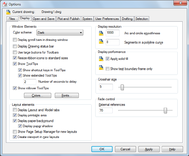
Move Down
Moves the selected search path below the following search path.
Set Current
Makes the selected project or spelling dictionary current.
Display Tab (Options Dialog Box)
Quick Reference
See also:
■Set Up the Drawing Area
Customizes the display.
Options Dialog Box | 847
List of Options
The following options are displayed.
Window Elements
Controls display settings specific to the drawing environment.
Color scheme
Controls color settings in a dark or light color for elements such as the status
bar, title bar, ribbon bar, and the application menu frame.
Display Scroll Bars in Drawing Window
Displays scroll bars at the bottom and right sides of the drawing area.
Display Drawing Status Bar
Displays the drawing status bar, which displays several tools for scaling
annotations.
When the drawing status bar is turned on it displays at the bottom of the
drawing area. When the drawing status bar is turned off, the tools found on
the drawing status bar are moved to the application status bar.
Use Large Buttons for Toolbars
Displays buttons in a larger format at 32 by 32 pixels.
Resize Ribbon Icons to Standard Sizes
Scales the small ribbon icons to 16 x 16 pixels and the large ribbon icons to
32 x 32 pixels when they do not match the standard icon sizes.
(RIBBONICONRESIZE on page 1643 system variable)
Show Tooltips
Controls the display of tooltips on the ribbon, toolbars, and other user interface
elements.
(TOOLTIPS on page 1689 system variable)
Show shortcut keys in Tooltips
Displays shortcut keys in the tooltip (Alt + Key) (Ctrl + Key).
Show extended Tooltips
Controls the display of extended tooltips.
Number of seconds to delay
Sets the delay time between the display of basic tooltips and extended tooltips.
848 | Chapter 15 O Commands
Show rollover Tooltips
Controls the display of rollover tooltips when the cursor hovers over an object.
(ROLLOVERTIPS on page 1646 system variable)
Colors
Displays the Color Options dialog box. Use this dialog box to specify colors
of elements in the main application window.
Fonts
Displays the Command Line Window Font dialog box. Use this dialog box to
specify the font for the command window text.
Layout Elements
Controls options for existing and new layouts. A layout is a paper space
environment in which you can set up drawings for plotting.
Display Layout and Model Tabs
Displays the layout and Model tabs at the bottom of the drawing area. When
this option is cleared, the tabs are replaced by buttons on the status bar.
Display Printable Area
Displays the printable area in a layout. The printable area is represented by
the area within the dashed line and is determined by the selected output
device.
Display Paper Background
Displays a representation of the specified paper size in a layout. The paper size
and plot scale determine the size of the paper background.
Display Paper Shadow
Displays a shadow around the paper background in layout. This option is not
available if the Display Paper Background option is cleared.
Show Page Setup Manager for New Layouts
Displays the Page Setup Manager the first time you click a layout tab. Use this
dialog box to set options related to paper and plot settings.
Create Viewport in New Layouts
Creates a single viewport automatically when you create a new layout.
Crosshair Size
Determines the size of the crosshairs as a percentage of the screen size.
Options Dialog Box | 849
(CURSORSIZE system variable)
Display Resolution
Controls the quality of the display of objects. If you set high values to improve
display quality, the impact on performance is significant.
Arc and Circle Smoothness
Sets the resolution for objects in the current viewport.
(VIEWRES command)
Segments in a Polyline Curve
Sets the number of line segments to be generated for each spline-fit polyline
generated by the Spline option of the PEDIT command.
(SPLINESEGS system variable)
Display Performance
Controls display settings that affect performance.
Apply Solid Fill
Specifies whether hatches and fills, 2D solids, and wide polylines are filled in.
(FILLMODE system variable)
Show Text Boundary Frame Only
Controls how text is displayed.
(QTEXTMODE system variable)
Fade Control
Controls the fading intensity value of DWG xrefs.
Xref Display
Controls the dimming for all DWG xref objects.
(XDWGFADECTL on page 1728 system variable)
This option only affects the display on the screen. It does not affect plotting
or plot preview.
Open and Save Tab (Options Dialog Box)
Quick Reference
See also:
■Set Up the Drawing Area
850 | Chapter 15 O Commands
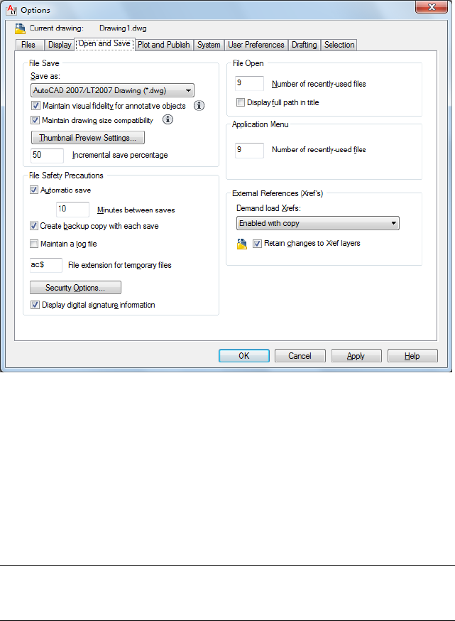
Controls options that relate to opening and saving files.
List of Options
The following options are displayed.
File Save
Controls settings related to saving a file.
Save As
Displays the valid file formats used when saving a file with SAVE, SAVEAS,
QSAVE, SHAREWITHSEEK on page 1118 and WBLOCK. The file format selected
for this option becomes the default format for saving drawings.
NOTE AutoCAD LT 2004 is the drawing file format used by the AutoCAD LT 2004,
AutoCAD LT 2005, and AutoCAD LT 2006 releases. AutoCAD LT 2007 is used by
AutoCAD LT 2007, AutoCAD LT 2008, and AutoCAD LT 2009 releases.
Maintain Visual Fidelity for Annotative Objects
Controls whether the drawing is saved with visual fidelity.
(SAVEFIDELITY on page 1647 system variable)
Options Dialog Box | 851

Annotative objects may have multiple . Annotative objects are decomposed
and scale representations are saved to separate layers, which are named based
on their original layer and appended with a number.
NOTE Enabling Maintain Visual Fidelity for Annotative Objects only impacts
drawings saved to a legacy drawing file format (AutoCAD LT 2007 and earlier).
Maintain Drawing Size Compatibility
Controls large object size limit support when you open and save drawings.
(LARGEOBJECTSUPPORT on page 1561 system variable)
Thumbnail Preview Settings
Displays the Thumbnail Preview Settings dialog box, which controls whether
thumbnail previews are updated when the drawing is saved.
Incremental Save Percentage
Sets the percentage of potentially wasted space in a drawing file. Full saves
eliminate wasted space. Incremental saves are faster, but they increase the size
of the drawing.
(ISAVEPERCENT system variable)
If you set Incremental Save Percentage to 0, every save is a full save. For
optimum performance, set the value to 50. If hard disk space becomes an
issue, set the value to 25. If you set the value to 20 or less, performance of the
SAVE and SAVEAS commands slows significantly.
File Safety Precautions
Assists in avoiding data loss and in detecting errors.
Automatic Save
Saves your drawing automatically at the intervals you specify. You can specify
the location of all Autosave files by using the SAVEFILEPATH system
variable.SAVEFILE (read-only) stores the name of the Autosave file.
Minutes Between Saves: When Automatic Save is on, specifies how often the
drawing is saved.
(SAVETIME system variable)
Create Backup Copy with Each Save
Improves the speed of incremental saves, especially for large drawings.
(ISAVEBAK system variable)
For information about using backup files, see Create and Restore Backup Files
in the User's Guide.
852 | Chapter 15 O Commands
Maintain a Log File
Writes the contents of the text window to a log file. (LOGFILEMODE on page
1571 system variable, see also LOGFILEPATH and LOGFILENAME)
File Extension for Temporary Files
Specifies a unique extension for temporary save files. The default extension
is .ac$.
Security Options
Provides options for a digital signature and password that are invoked when
you save a file.
Display Digital Signature Information
Presents digital signature information when a file with a valid digital signature
is opened. (SIGWARN on page 1658 system variable)
File Open
Controls settings that relate to recently used files and open files.
Number of Recently Used Files
Controls the number of recently used files that are listed in the File menu for
quick access. Valid values are 0 to 9.
Display Full Path In Title
Displays the full path of the active drawing in the drawing's title bar, or in
the application window title bar if the drawing is maximized.
Application Menu
Number of Recently Used Files
Controls the number of recently used files listed in the application menu’s
Recent Documents quick menu. Valid values are 0 to 50.
External References (Xrefs)
Controls the settings that relate to editing and loading external references.
Demand Load Xrefs
Turns xref demand-loading on and off, and controls whether it opens the
referenced drawing or a copy.
(XLOADCTL system variable)
■Disabled: Turns off demand loading.
Options Dialog Box | 853
■Enabled: Turns on demand loading and improves performance. Select the
Enabled setting to enhance the loading process when working with clipped
xrefs that contain a spatial or layer index. When this option is selected,
other users cannot edit the file while it is being referenced.
■Enabled with Copy: Turns on demand loading but uses a copy of the
referenced drawing. Other users can edit the original drawing.
Retain Changes to Xref Layers
Controls the properties of xref-dependent layers.
(VISRETAIN system variable)
Plot and Publish Tab (Options Dialog Box)
Quick Reference
See also:
■Set Up the Drawing Area
Controls options related to plotting and publishing.
854 | Chapter 15 O Commands
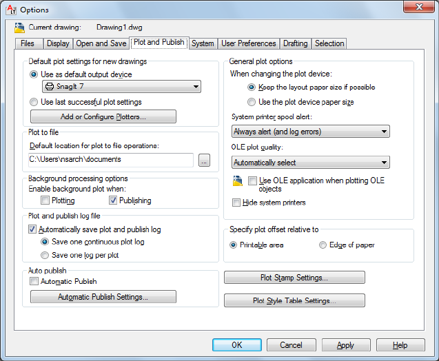
List of Options
The following options are displayed.
Default Plot Settings For New Drawings
Controls default plotting settings for new drawings or drawings created in
AutoCAD Release 14 or earlier that have never been saved in AutoCAD 2000
or later format.
Use As Default Output Device
Sets the default output device for new drawings and for drawings created in
AutoCAD Release 14 or earlier that have never been saved in AutoCAD 2000
or later format.
The list displays any plotter configuration files (PC3) found in the plotter
configuration search path and any system printers that are configured in the
system.
Use Last Successful Plot Settings
Sets the plotting settings to match those of the last successful plot.
Options Dialog Box | 855

Add or Configure Plotters
Displays the Plotter Manager (a Windows system window). You can add or
configure a plotter with the Plotter Manager.
Plot To File
Specifies the default location for plot to file operations.
Background Processing Options
Controls whether background plotting is turned on or off for plotting and
publishing.
You can use background plotting to start a job you are plotting or publishing
and immediately return to work on your drawing while your job is plotted or
published as you work. (BACKGROUNDPLOT system variable)
Background plot and publish details are available through the Plot and Publish
status bar icon shortcut menu.
Enable Background Plotting When
Plotting: Specifies that plot jobs are processed in the background. This setting
is also affected by the BACKGROUNDPLOT system variable.
Publishing: Specifies that published jobs are processed in the background. This
setting is also affected by the BACKGROUNDPLOT system variable.
NOTE When -PLOT, PLOT, -PUBLISH, and PUBLISH are used in a script (SCR file),
the BACKGROUNDPLOT system variable value is ignored, and -PLOT, PLOT,
-PUBLISH, and PUBLISH are processed in the foreground.
Plot and Publish Log File
Controls options for saving a plot and publish log file as a comma-separated
value (CSV) file that can be viewed in a spreadsheet program. To view or
change the location of the log file, see the Files tab in the Options dialog box
on page 842.
This log file contains information about plot and publish jobs such as:
■Job ID
■Job name
■Sheet set name
■Category name
■Date and time started and completed
■Sheet name
856 | Chapter 15 O Commands
■Full file path
■Selected layout name
■Page setup name
■Named page setup path
■Device name
■Paper size name
■Final status
Automatically Save Plot and Publish Log
Specifies that a log file that contains information about all plot and publish
jobs is automatically saved.
Save One Continuous Plot Log
Specifies that a single log file that contains information about all plot and
publish jobs is automatically saved.
Save One Log File Per Plot
Specifies that a separate log file is created for each plot and publish job.
Auto Publish
Specifies whether drawings are published automatically to DWF, DWFx, or
PDF files. You can also control options for automatic publishing.
Automatic Publish
When this options is selected, drawings are published to DWF, DWFx, or PDF
files automatically when you save or close a drawing file. (AUTOMATICPUB
on page 1393, AUTODWFPUBLISH system variables)
Automatic Publish Settings
Displays the Auto Publish Settings palette on page 89 where you can customize
the settings for publishing including when it occurs and the location to store
the published files.
General Plot Options
Keep the Layout Paper Size If Possible
Uses the paper size specified in the Page Setup dialog box as long as the selected
output device can plot to this paper size. (PAPERUPDATE system variable =
0)
Options Dialog Box | 857
If the selected output device cannot plot to this paper size, the program displays
a warning message and uses the paper size specified either in the plotter
configuration file (PC3) or in the default system settings if the output device
is a system printer.
Use the Plot Device Paper Size
Uses the paper size specified either in the plotter configuration file (PC3) or
in the default system settings if the output device is a system printer.
(PAPERUPDATE system variable = 1)
System Printer Spool Alert
Controls whether you are alerted when the plotted drawing is spooled through
a system printer because of an input or output port conflict.
■Always Alert (And Log Errors): Alerts you and always logs an error when the
plotted drawing spools through a system printer.
■Alert First Time Only (And Log Errors): Alerts you once and always logs an error
when the plotted drawing spools through a system printer.
■Never Alert (And Log First Error): Never alerts you and logs only the first error
when the plotted drawing spools through a system printer.
■Never Alert (Do Not Log Errors): Never alerts you or logs an error when the
plotted drawing spools through a system printer.
OLE Plot Quality
Sets the default plot quality for OLE objects.
(OLEQUALITY system variable)
Use OLE Application When Plotting OLE Objects
Controls whether the source application of an embedded OLE object loads
when plotting.
(OLESTARTUP system variable)
Hide System Printer
Controls whether Windows system printers are displayed in the Plot and Page
Setup dialog boxes. This option hides standard Windows system printers only.
It does not hide Windows system printers that have been configured using
the Add-a-Plotter wizard.
You can control the size of the list of devices in the Plot and Page Setup dialog
boxes by moving a device's PC3 file out of the Plotters folder and its subfolders.
858 | Chapter 15 O Commands
Specify Plot Offset Relative To
Controls whether the plot offset is relative to the printable area or to the edge
of the paper.
(PLOTOFFSET system variable).
Printable Area
Specifies that the plot offset is relative to the printable area.
Edge of Paper
Specifies that the plot offset is relative to the edge of the paper.
Plot Stamp Settings
Opens the Plot Stamp dialog box.
Plot Style Table Settings
Opens the Plot Style Table Settings dialog box.
System Tab (Options Dialog Box)
Quick Reference
See also:
■Set Up the Drawing Area
Controls system settings.
Options Dialog Box | 859
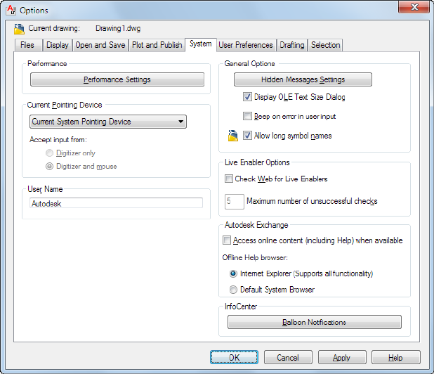
List of Options
The following options are displayed.
Controls settings that relate to configuration of the graphics display system.
Performance Settings
Current Pointing Device
Controls options that relate to the pointing device.
Current Pointing Device
Displays a list of the available pointing device drivers.
■Current System Pointing Device: Sets the system pointing device as current.
■Wintab Compatible Digitizer: Sets the Wintab-compatible digitizer as current.
Accept Input From
Specifies whether the program accepts input from both a mouse and a digitizer
or ignores mouse input when a digitizer is set.
860 | Chapter 15 O Commands
User Name
Changes the user name with the Windows login information.
This name is inserted when you use the time and date stamp (REVDATE) and
is useful if different people work on the same drawing.
Specifies how the display list is updated in the Model tab and layout tabs.
General Options
Hidden Messages Settings
Controls the display of previously hidden messages.
Displays the Hidden Message Settings dialog box on page 889.
Display OLE Text Size Dialog
Displays the OLE Text Size dialog box when OLE objects are inserted into
drawings.
Beep on Error in User Input
Sounds an alarm beep when an invalid entry is detected.
Allow Long Symbol Names
Sets the parameters for named object names (such as linetypes and layers)
stored in definition tables.
(EXTNAMES system variable)
Live Enabler Options
Specifies whether the program checks for object enablers.
Using object enablers, you can display and use custom objects in AutoCAD
drawings.
Check Web for Live Enablers
Specifies how the program checks for object enablers.
(PROXYWEBSEARCH system variable)
Maximum Number of Unsuccessful Checks
Specifies the number of times to check for object enablers if unsuccessful.
For more information, see “Work with Custom and Proxy Objects”.
Autodesk Exchange
Controls whether the source for Autodesk Exchange is online or local.
Access Online Content (including Help) When Available
Options Dialog Box | 861
Specifies whether information is accessed from the Autodesk website, or from
locally installed files.
When online, the latest Help information and other online resources are
accessible.
Offline Help Browser
Specifies whether to use Microsoft® Internet Explorer® or your default Web
browser for viewing Help.
InfoCenter
Balloon Notifications
Controls the content, frequency, and duration of balloon notifications in the
upper-right corner of the application window.
Displays the InfoCenter Settings dialog box on page 890.
User Preferences Tab (Options Dialog Box)
Quick Reference
See also:
■Set Up the Drawing Area
Controls options that optimize the way you work.
862 | Chapter 15 O Commands
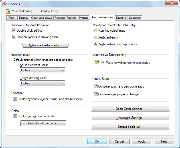
List of Options
The following options are displayed.
Windows Standard Behavior
Controls keystroke and right-click behavior.
Double-click Editing
Controls the double click editing behavior in the drawing area.
(DBLCLKEDIT system variable)
Shortcut Menus in Drawing Area
Controls whether Default, Edit, and Command mode shortcut menus are
available in the drawing area.
(SHORTCUTMENU system variable)
If this option is cleared, right-click is interpreted as Enter.
Right-Click Customization
Options Dialog Box | 863
Displays the Right-Click Customization dialog box. This dialog box provides
further definition for the Shortcut Menus in Drawing Area option.
(SHORTCUTMENU system variable)
Insertion Scale
Controls the default scale for inserting blocks and drawings into a drawing.
Source Content Units
Sets source content units value when INSUNITS is set to 0.
(INSUNITSDEFSOURCE system variable)
If Unspecified-Unitless is selected, the object is not scaled when inserted.
Target Drawing Units
Sets target drawing units value when INSUNITS is set to 0.
(INSUNITSDEFTARGET system variable)
Fields
Sets preferences related to fields.
Display Background of Fields
Controls whether fields are displayed with a gray background.
(FIELDDISPLAY system variable)
When this option is cleared, fields are displayed with the same background
as any text.
Field Update Settings
Displays the Field Update Settings dialog box. (FIELDEVAL system variable)
Priority for Coordinate Data Entry
Controls whether coordinates entered on the command line will override
running object snaps.
(OSNAPCOORD system variable)
Running Object Snap
Specifies that running object snaps override coordinate entry at all times.
(OSNAPCOORD system variable = 0)
Keyboard Entry
Specifies that coordinate entry overrides running object snaps at all times.
(OSNAPCOORD system variable = 1)
Keyboard Entry Except Scripts
864 | Chapter 15 O Commands

Specifies that coordinate entry overrides running object snaps, except in scripts.
(OSNAPCOORD system variable = 2)
Associative Dimensioning
Controls whether associative dimension objects or legacy-style, nonassociative
dimension objects are created.
Make New Dimensions Associative
Creates associative dimensions, which automatically adjust their locations,
orientations, and measurement values when the geometric objects associated
with them are modified. (DIMASSOC system variable)
Hyperlink
Controls settings that relate to the display properties of hyperlinks.
Display Hyperlink Cursor, Tooltip, and Shortcut Menu
Controls the display of the hyperlink cursor, tooltips, and shortcut menu.
(HYPERLINKOPTIONS on page 597 command)
The shortcut menu provides additional hyperlink options when you select an
object that contains a hyperlink and then right-click in the drawing area.
Undo/Redo
Controls Undo and Redo for Zoom and Pan.
Combine Zoom and Pan Commands
Groups multiple and consecutive zoom and pan commands as a single action
for undo and redo operations.
NOTE Pan and zoom commands that are started from the menu are not combined,
and always remain separate actions.
Combine Layer Property Changes
Groups layer property changes made from the Layer Properties Manager.
Block Editor Settings
Displays the Block Editor Settings dialog box on page 135. Use this dialog box
to control the environment settings of the Block Editor.
Lineweight Settings
Displays the Lineweight Settings dialog box. Use this dialog box to set
lineweight options, such as display properties and defaults, and also to set the
current lineweight.
Options Dialog Box | 865
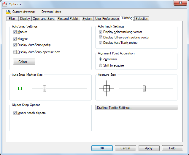
Default Scale List
Displays the Default Scale List dialog box to manage the default list of scales
displayed in several dialog boxes associated with layout viewports and plotting.
You can delete all custom scales and restore the default list of scales.
Drafting Tab (Options Dialog Box)
Quick Reference
See also:
■Set Up the Drawing Area
Sets options for several editing features, including AutoSnap and AutoTrack.
List of Options
The following options are displayed.
866 | Chapter 15 O Commands
AutoSnap Settings
Controls the display of the AutoSnap marker, tooltip, and magnet.
When the cursor, or aperture box, is on an object, you can press Tab to cycle
through all the snap points available for that object.
Marker
Controls the display of the AutoSnap marker. The marker is a geometric symbol
that is displayed when the crosshairs move over a snap point. (AUTOSNAP
system variable)
Magnet
Turns the AutoSnap magnet on or off. The magnet is an automatic movement
of the crosshairs that locks the crosshairs onto the nearest snap point.
(AUTOSNAP system variable)
Display AutoSnap Tooltip
Controls the display of the AutoSnap tooltip. The tooltip is a label that
describes which part of the object you are snapping to. (AUTOSNAP system
variable)
Display AutoSnap Aperture Box
Turns the display of the AutoSnap aperture box on or off.
(APBOX system variable)
The aperture box is a box that appears inside the crosshairs when you snap
to an object.
Colors
Displays the Drawing Window Colors dialog box.
AutoSnap Marker Size
Sets the display size for the AutoSnap marker.
Object Snap Options
Sets running object snap modes.
(OSNAP command)
Ignore Hatch Objects
Specifies options for object snaps. (OSOPTIONS system variable)
Options Dialog Box | 867
AutoTrack Settings
Controls the settings that relate to AutoTrack™ behavior, which is available
when polar tracking or object snap tracking is turned on (see DSETTINGS).
Display Polar Tracking Vector
Displays a vector along specified angles when polar tracking is on. With polar
tracking, you can draw lines along angles. Polar angles are 90-degree divisors,
such as 45, 30, and 15 degrees. (TRACKPATH system variable = 2)
Display Full-Screen Tracking Vector
Tracking vectors are lines from which you can draw objects at specific angles
or in specific relationships to other objects. If this option is selected, alignment
vectors are displayed as infinite lines. (TRACKPATH system variable = 1)
Display AutoTrack Tooltip
Controls the display of the AutoSnap marker, tooltip, and magnet.
(AUTOSNAP system variable)
Alignment Point Acquisition
Automatic
Displays tracking vectors automatically when the aperture moves over an
object snap.
Shift to Acquire
Displays tracking vectors when you press Shift and move the aperture over
an object snap.
Aperture Size
Sets the display size for the object snap target box, in pixels.
(APERTURE system variable)
When Display AutoSnap Aperture Box is selected (or when APBOX is set to
1), the aperture box is displayed in the center of the crosshairs when you snap
to an object. The aperture size determines how close to a snap point you can
be before the magnet locks the aperture box to the snap point. Values range
from 1 to 50 pixels.
Drafting Tooltip Appearance
Controls the color, size, and transparency of drafting tooltips.
Settings
Displays the Tooltip Appearance dialog box.
868 | Chapter 15 O Commands
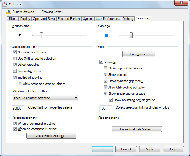
Selection Tab (Options Dialog Box)
Quick Reference
Sets options for selecting objects.
List of Options
The following options are displayed.
Pickbox Size
Sets the object selection target height, in pixels. (PICKBOX system variable)
The pickbox is the object selection tool that appears in editing commands.
Selection Modes
Controls settings that relate to object selection methods.
Noun/Verb Selection
Options Dialog Box | 869
Controls whether you select objects before (noun-verb selection) or after you
issue a command. (PICKFIRST system variable)
Many but not all editing and inquiry commands support noun/verb selection.
Use Shift to Add to Selection
Controls whether subsequent selections replace the current selection set or
add to it. (PICKADD system variable)
To clear a selection set quickly, draw a selection window in a blank area of
the drawing.
Object Grouping
Selects all objects in a group when you select one object in that group. With
GROUP on page 541 you can create and name a set of objects for selection.
(PICKSTYLE system variable)
Associative Hatch
Determines which objects are selected when you select an associative hatch.
If this option is selected, boundary objects are also selected when you select
an associative hatch. (PICKSTYLE system variable)
Implied Windowing
Initiates the drawing of a selection window when you select a point outside
an object. (PICKAUTO system variable)
Drawing the selection window from left to right selects objects that are entirely
inside the window's boundaries. Drawing from right to left selects objects
within and crossing the window's boundaries.
Allow Press Drag on Object
Controls the window selection method. (PICKAUTO on page 1610 system
variable)
If this option is cleared, you can draw a selection window by clicking two
separate points with the pointing device.
Window Selection Method
Use the dropdown list to change the PICKDRAG on page 1611 system variable
setting.
Object Limit for Properties Palette
870 | Chapter 15 O Commands

Determines the limit of the number of objects that can be changed at one
time with the Properties and Quick Properties palettes. (PROPOBJLIMIT system
variable)
Selection Preview
Highlights objects as the pickbox cursor rolls over them. (PREVIEWEFFECT
system variable)
When a Command Is Active
Displays selection previewing only when a command is active and the Select
Objects prompt is displayed. (SELECTIONPREVIEW system variable)
When No Command Is Active
Displays selection previewing when no commands are active.
(SELECTIONPREVIEW system variable)
Visual Effect Settings
Displays the Visual Effect Settings dialog box.
Grip Size
(GRIPSIZE system variable)
Grips
Grips are small squares displayed on an object after it has been selected.
Grip Colors
Displays the Grip Colors dialog box on page 873 where you can specify the
colors for different grip status and elements.
Show Grips
Controls the display of grips on selected objects. Displaying grips in a drawing
significantly affects performance. Clear this option to optimize performance.
(GRIPS system variable)
Show Grips within Blocks
Controls the display of grips in blocks. (GRIPBLOCK system variable)
Options Dialog Box | 871
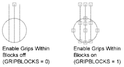
Show Grip Tips
Displays grip-specific tips when the cursor hovers over a grip on a custom
object that supports grip tips. This option has no effect on standard objects.
(GRIPTIPS system variable)
Show Dynamic Grip Menu
Controls the display of dynamic menu when pausing over a multi-functional
grip. (GRIPMULTIFUNCTIONAL on page 1526 system variable)
Allow Ctrl-cycling Behavior
Allows the Ctrl-cycling behavior for multi-functional grips.
(GRIPMULTIFUNCTIONAL on page 1526 system variable)
Show Single Grip on Groups
Displays a single grip for an object group. (GROUPDISPLAYMODE on page
1529 system variable)
Show Bounding Box on Groups
Displays a bounding box around the extents of grouped objects.
(GROUPDISPLAYMODE on page 1529 system variable)
Object Selection Limit for Display of Grips
Suppresses the display of grips when the selection set includes more than the
specified number of objects. (GRIPOBJLIMIT system variable)
The valid range is 1 to 32,767. The default setting is 100.
Ribbon Options
Contextual Tab States Button
The Ribbon Contextual Tab State Options dialog box on page 885 is displayed,
where you can set object selection settings for the display of ribbon contextual
tabs.
872 | Chapter 15 O Commands
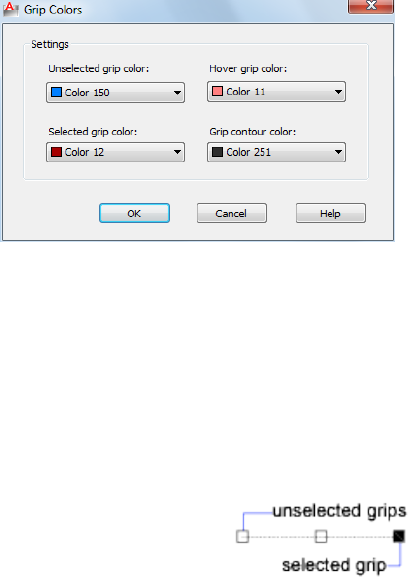
Grip Colors Dialog Box
Quick Reference
See also:
■Set Up the Drawing Area
Sets the color properties of the grip.
List of Options
The following options are displayed.
Settings
Controls the color settings of the grip.
Unselected Grip Color
Controls the color of unselected grips.
(GRIPCOLOR on page 1524 system variable)
Selected Grip Color
Controls the color of selected grips.
(GRIPHOT on page 1525 system variable)
Hover Grip Color
Controls the fill color of an unselected grip when the cursor pauses over it.
Options Dialog Box | 873
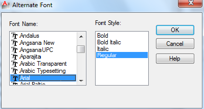
(GRIPHOVER on page 1525 system variable)
Grip Contour Color
Controls the color of the grip contour.
(GRIPCONTOUR on page 1524 system variable)
Alternate Font Dialog Box
Quick Reference
See also:
■Specify Application Fonts
Specifies the location of the font file to use if the original font cannot be
located and an alternate font is not specified in the font mapping file.
Access Methods
Pointing device: Options dialog box, Files tab
Summary
You can also set the location of Alternate Font File by using the FONTALT
system variable.
If you do not specify an alternate font, when you open a drawing containing
fonts that cannot be located, a dialog box is displayed in which you specify
a font to use for each missing font.
List of Options
The following options are displayed.
874 | Chapter 15 O Commands
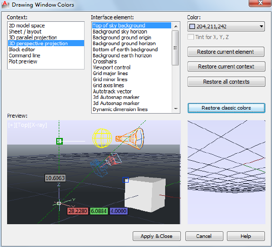
Font Name
Lists the font family name for all registered TrueType fonts and all SHX fonts
in the Fonts folder.
Font Style
Specifies font character formatting, such as italic, bold, or regular. If the missing
font is a Big Font, this option changes to Big Font and lists all available
Asian-language Big Font files.
Drawing Window Colors Dialog Box
Quick Reference
See also:
■Set Up the Drawing Area
Sets the display colors of the interface elements for each context in the
application.
Drawing Window Colors Dialog Box | 875
Access Methods
Pointing device: Options dialog box, Display tab
Summary
A context is an operating environment such as model space. An interface element
is an item that is visible in that context such as the crosshairs pointer or the
background color.
List of Options
The following options are displayed.
Context
A context is an environment such as model space. Interface elements can have
different colors assigned depending on the context. The context you select
displays a list of associated elements. Select a context, an interface element,
and then a color.
Interface Element
Lists the interface elements in a selected context. An interface element is an
item that is visible in a context such as the background color. Select an
interface element, and then a color.
Color
Lists the available color settings to apply to the selected interface element.
You can choose one of the colors in the color list or choose Select Color to
open the Select Color dialog box.
Color tinting applies pure red, blue and green hues using the luminance
(lightness) of the color you specify while increasing the color saturation by
50%.
Tint for X, Y Controls whether X- and Y-axis color tinting is applied to the
following interface elements: crosshairs pointer, Autotrack vectors, and drafting
tooltips.
Restore Current Element
Restores the currently selected interface element to its default color.
Restore Current Context
Restores all interface elements in the currently selected context to their default
colors.
Restore All Contexts
876 | Chapter 15 O Commands
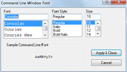
Restores all interface elements back to their default color settings.
Restore Classic Colors
Restores only the interface elements of 2D model space back to the AutoCAD
2008 classic color settings.
Preview
Displays a preview of the drawing based on defined settings.
Command Line Window Font Dialog Box
Quick Reference
See also:
■Specify Application Fonts
Sets the font displayed in the Command window.
Access Methods
Pointing device: Options dialog box, Display tab
Summary
The text font used in the Command window can be changed to suit your
preferences.
List of Options
The following options are displayed.
Command Line Window Font Dialog Box | 877
Font Lists the system fonts available for selection.
Font Style Lists the styles available to apply to the current font.
Size Lists the font sizes available for the current font.
Thumbnail Preview Settings Dialog Box
Quick Reference
See also:
■Set Up the Drawing Area
Controls whether thumbnail previews are updated when the drawing is saved.
Access Methods
Pointing device: Options dialog box, Open and Save tab
List of Options
The following options are displayed.
Drawing
Save a Thumbnail Preview Image
Controls whether BMP preview images are saved with the drawing.
(RASTERPREVIEW system variable)
Use the View when Drawing Last Saved
Uses the last saved view to generate the thumbnail preview for the drawing.
Use the Home View
Uses the Home view saved with the drawing to generate the thumbnail preview
for the drawing.
Home View
Set current View as Home
Defines the current view of the drawing as the Home view.
Reset Home to Default
Restores the default Home view.
878 | Chapter 15 O Commands
Sheets and Views
Generate Sheet, Sheet View and Model View Thumbnails
Controls updating of the thumbnail previews for views and layouts.
(UPDATETHUMBNAIL system variable)
Sheet thumbnails are displayed on the Sheet List tab, sheet view thumbnails
on the View List tab, and model space view thumbnails on the Resource
Drawings tab.
Performance-Accuracy Slider
Specifies when thumbnails are updated and which thumbnails are updated.
(UPDATETHUMBNAIL system variable)
Information Panel Displays information about the current position of the
slider.
Named Views
Sets the size for thumbnails created for named views.
Named views
Sets the maximum size of the named views.
Plot Style Table Settings Dialog Box
Quick Reference
See also:
■Set Up the Drawing Area
Specifies settings for plot style tables.
Access Methods
Pointing device: Options dialog box, Plot and Publish tab
List of Options
The following options are displayed.
Plot Style Table Settings Dialog Box | 879
Default Plot Style Behavior for New Drawings
Controls the plot style mode, Color-Dependent or Named, that is used when
opening a drawing that was created in a release prior to AutoCAD 2000 or
when creating a new drawing from scratch without using a drawing template.
A plot style is a collection of property settings defined in a plot style table and
applied when the drawing is plotted. Changing the default plot style setting
by using the Options dialog box does not affect the current drawing.
The default plot style setting is Use Color Dependent Plot Styles. The Plot Style
Control on the Properties toolbar is unavailable by default. The Plot Style
Control is available when you select the Use Named Plot Styles option and
open a new drawing. (PSTYLEPOLICY system variable)
Use Color Dependent Plot Styles
Uses color-dependent plot styles in both new drawings and drawings created
in AutoCAD Release 14 or earlier. (PSTYLEPOLICY system variable = 1)
Color-dependent plot styles use the numbers from the AutoCAD Color Index
to create a plot style table with a .ctb file extension. Each color is defined by
a name or number ranging from 1 to 255. You can assign each color number
to a different pen on a pen plotter to achieve different property settings in
the plotted drawing. If this option is selected, a plot style is created for each
color setting.
Once a drawing is saved with Use Color Dependent Plot Styles as the default,
you can convert it to Use Named Plot Styles using the CONVERTCTB and
CONVERTPSTYLES commands.
Use Named Plot Styles
Uses named plot styles in both new drawings and drawings created in earlier
versions of AutoCAD LT. The plot style is defined in the plot style table
attached to the layout. Named plot style tables are files with the file extension
.stb. ( PSTYLEPOLICY system variable = 0)
Once a drawing is saved with Use Named Plot Styles as the default, you can
convert it to Use Color Dependent Plot Styles using the CONVERTCTB and
CONVERTPSTYLES commands. However, once you use CONVERTPSTYLES to
convert a drawing from using a named plot style table to a color plot style
table, you cannot use CONVERTPSTYLES to convert it back to using a named
plot style table.
Current Plot Style Table Settings
Specifies the current plot style table settings that are applied to new drawings.
Default Plot Style Table
880 | Chapter 15 O Commands
Specifies the default plot style table to attach to new drawings. A plot style
table is a file with a .ctb or an .stb extension that includes and defines plot
styles.
If you are using color-dependent plot styles, this option lists all color dependent
plot style tables found in the search path as well as the value of None. If you
are using named plot styles, this option lists all named plot styles tables.
Default Plot Style for Layer 0
Specifies the default plot style for all layers in a drawing when opening a
drawing that was created in a release prior to AutoCAD 2000, or for Layer 0
when creating a new drawing from scratch without using a drawing template.
(DEFLPLSTYLE system variable)
Default Plot Style for Objects
Specifies the default plot style for new objects in a drawing when opening a
drawing that was created in a release prior to AutoCAD 2000, or when creating
a new drawing from scratch without using a drawing template.
(DEFPLSTYLE system variable)
Add or Edit Plot Style Tables
Displays the Plot Style Manager (a Windows Explorer window), where you
can create or edit plot style tables.
Right-Click Customization Dialog Box
Quick Reference
See also:
■Set Up the Drawing Area
Controls whether right-clicking in the drawing area displays a shortcut menu
or has the same effect as pressing Enter.
Access Methods
Pointing device: Options dialog box, User Preferences tab
Right-Click Customization Dialog Box | 881
Summary
If you are accustomed to using the right-click method for Enter while a
command is active, you might prefer to disable Command shortcut menus
from this dialog box. You can also control shortcut menus by using the
SHORTCUTMENU system variable.
List of Options
The following options are displayed.
Turn on Time-Sensitive Right-Click
Controls right-click behavior. A quick click is the same as pressing Enter. A
longer click displays a shortcut menu. You can set the duration of the longer
click in milliseconds.
Default Mode
Determines what happens when you right-click in the drawing area when no
objects are selected and no commands are in progress.
Repeat Last Command
Disables the Default shortcut menu. As a result, right-clicking in the drawing
area when no objects are selected and no commands are in progress is the
same as pressing Enter, which repeats the last issued command.
Shortcut Menu
Enables the Default shortcut menu.
Edit Mode
Determines what happens when you right-click in the drawing area when one
or more objects are selected and no commands are in progress.
Repeat Last Command
Disables the Edit shortcut menu. As a result, right-clicking in the drawing area
when one or more objects are selected and no commands are in progress is
the same as pressing Enter, which repeats the last issued command.
Shortcut Menu
Enables the Edit shortcut menu.
Command Mode
Determines what happens when you right-click in the drawing area when a
command is in progress.
Enter
882 | Chapter 15 O Commands

Disables the Command shortcut menu. As a result, right-clicking in the drawing
area when a command is in pro-gress is the same as pressing Enter.
Shortcut Menu: Always Enabled
Enables the Command shortcut menu.
Shortcut Menu: Enabled When Command Options Are Present
Enables the Command shortcut menu only when command options are
available at the Command prompt. If no options are available, a right-click is
the same as pressing Enter.
Field Update Settings Dialog Box
Quick Reference
See also:
■Set Up the Drawing Area
Access Methods
Menu: Options dialog box, User Preferences tab
Summary
Controls how fields are updated. (FIELDEVAL system variable)
List of Options
The following options are displayed
Open
Automatically updates fields when the file is opened.
Save
Automatically updates fields when the file is saved.
Plot
Automatically updates fields when the file is plotted.
eTransmit
Automatically updates fields when the file is sent using ETRANSMIT.
Field Update Settings Dialog Box | 883
Regen
Automatically updates fields when the file is regenerated.
Visual Effect Settings Dialog Box
Quick Reference
See also:
■Set Up the Drawing Area
Controls the appearance of selection previewing.
Access Methods
Pointing device: Options dialog box, Selection tab
List of Options
The following options are displayed.
Selection Preview Effect
Specifies the visual effect used for previewing selection of objects.
(PREVIEWEFFECT system variable)
Preview Area
Displays the effect of the current settings.
Face Highlighting Controls the face highlighting setting.
■Texture Fill. Highlights the face with texture fill effect.
Line Highlighting Controls the line highlighting settings.
■Dash. Displays dashed lines when the pickbox cursor rolls over an object.
This selection previewing indicates that the object would be selected if
you clicked. Dashed lines are the default display for selected objects.
(PREVIEWEFFECT system variable = 0)
■Thicken. Displays thickened lines when the pickbox cursor rolls over an
object. This selection previewing indicates that the object would be selected
if you clicked. (PREVIEWEFFECT system variable = 1)
884 | Chapter 15 O Commands
■Both. Displays thickened, dashed lines when the pickbox cursor rolls over
an object. This selection previewing indicates that the object would be
selected if you clicked. (PREVIEWEFFECT system variable = 2)
Advanced Options
Displays the Advanced Preview Options dialog box.
Selection Area Effect
Controls the appearance of selection areas during selection preview.
Preview Area
Displays the effect of the current settings.
Indicate Selection Area
Controls the display of effects for selection areas.
(SELECTIONAREA system variable)
Window Selection Color
Controls the color of the transparent selection area during window selection.
(WINDOWAREACOLOR system variable)
Crossing Selection Color
Controls the color of the selection area during crossing selection.
(CROSSINGAREACOLOR system variable)
Selection Area Opacity
Controls the transparency of the selection area during window and crossing
selection.
(SELECTIONAREAOPACITY system variable)
Ribbon Contextual Tab State Options Dialog Box
Quick Reference
See also:
■Set Up the Drawing Area
Sets object selection settings for the display of ribbon contextual tabs
Ribbon Contextual Tab State Options Dialog Box | 885
Access Methods
Pointing device: Options dialog box, Selection tab
List of Options
The following options are available in this dialog box.
Contextual Tab Display
Controls how ribbon contextual tabs are displayed when you single- or
double-click an object.
(RIBBONCONTEXTSELECT on page 1641 system variable)
Do Not Switch To Contextual Tab on Selection
When an object or selection set is single- or double-clicked, focus is not
automatically switched to ribbon contextual tabs. ( RIBBONSELECTMODE on
page 1643 system variable = 0)
Show On Single-click
When an object or selection set is single-clicked, focus is switched to the first
ribbon contextual tab. ( RIBBONSELECTMODE on page 1643 system variable =
1)
Show On Double-click
When an object or selection set is double-clicked, focus is switched to the first
ribbon contextual tab. ( RIBBONSELECTMODE on page 1643 system variable =
2)
Object Selection Options
Retain Pickfirst Selections When Commands Are Invoked From a
Contextual Tab
When checked, the pickfirst selection set remains selected after a command
is started from a ribbon contextual tab. (RIBBONSELECTMODE on page 1643
system variable = 1)
When cleared, the pickfirst selection set does not remain selected after a
command is started from a ribbon contextual tab.
Object Selection Maximum for Contextual Tab Display
Limits the number of objects that can be changed at one time with the ribbon
property controls or a contextual tab.
(RIBBONCONTEXTSELLIM on page 1642 system variable)
886 | Chapter 15 O Commands
Advanced Preview Options Dialog Box
Quick Reference
See also:
■Set Up the Drawing Area
Allows you to turn selection cycling on and off and configure selection cycling
display options.
Access Methods
Pointing device: Options dialog box, Selection tab
Summary
Excludes specified object types from selection previewing.
(PREVIEWFILTER system variable)
List of Options
The following options are displayed.
Exclude Objects on Locked Layers
Excludes specified object types from selection previewing.
( PREVIEWFILTER system variable)
Exclude
Turns off selection previewing for the selected object types. ( PREVIEWFILTER
system variable)
Xrefs
Excludes objects in xrefs from selection previewing. This option is on by
default. ( PREVIEWFILTER system variable)
Tables
Excludes tables from selection previewing. This option is on by default. (
PREVIEWFILTER system variable)
Groups
Excludes objects in groups from selection previewing. This option is off by
default. ( PREVIEWFILTER system variable)
Advanced Preview Options Dialog Box | 887

Multiline Text
Excludes multiline text objects from selection previewing. This option is off
by default. ( PREVIEWFILTER system variable)
Hatches
Excludes hatch objects from selection previewing. This option is off by default.
( PREVIEWFILTER system variable)
Transparency Dialog Box
Quick Reference
See also:
■Set Up the Drawing Area
Controls transparency for dockable windows.
Access Methods
Shortcut menu: Right-click the title bar on the dockable window and click
Transparency.
List of Options
The following options are displayed.
How transparent should the palette be? Sets the degree of transparency for
the palette. The palette has maximum transparency when the slider is at Clear.
With the slider at Solid, the palette is opaque.
(PALETTEOPAQUE on page 1603 system variable)
How transparent should the palette be on mouse-over? Sets the degree of
transparency for the palette on mouse-over. The palette has maximum
transparency when the slider is at Clear. When the palette is at Solid, it is
opaque on mouse-over.
(ROLLOVEROPACITY on page 1645 system variable)
NOTE The degree of transparency on mouse-over cannot be more than the degree
of transparency of the palette.
888 | Chapter 15 O Commands
Click to Preview Preview the palette mouse-over transparency value when
the button is held down. The palette returns to the default transparency set
when the button is released.
Apply these settings to all palettes Sets the degree of transparency for the
palette and mouse-over for all palettes.
(APPLYGLOBALOPACITIES on page 1384 system variable)
Disable all window transparency (global) Disables transparency for all
palettes.
(GLOBALOPACITY on page 1520 system variable)
Hidden Message Settings Dialog Box
Quick Reference
See also:
■Set Up the Drawing Area
Displays all dialog boxes that you marked to not display again or to always
use a specified option in them.
Access Methods
Pointing device: Options dialog box, System tab
List of Options
The following options are displayed.
Search Finds messages by using one or more keywords.
Check messages to show Displays the list of hidden messages.
Message preview Displays the currently checked message.
The tree view displays the dialog information in the form below.
■Application Name
■Category
■Dialog title
Hidden Message Settings Dialog Box | 889
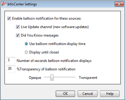
InfoCenter Settings Dialog Box
Quick Reference
See also:
■Overview of InfoCenter and Autodesk Exchange
Provides options for controlling the content and duration of balloon
notifications that display in the upper-right corner of the application window.
Access Methods
Pointing device: Options dialog box, System tab
List of Options
The following options are displayed.
Enable Balloon Notification for These Sources Controls whether the balloon
notification feature is turned on or off.
Live Update Channel (New Software Updates) Controls whether notices
regarding product software updates are displayed.
Did You Know Messages Controls whether helpful messages and tips are
displayed.
890 | Chapter 15 O Commands

Did You Know messages provide Knowledge Base information and general
instructional messages. Click the text or the Expand icon to view the detailed
information.
Use Balloon Notification Display Time Displays the balloon message for the
number of seconds that you specify below.
Number of Seconds Balloon Notification Displays Specify the length of
time that the balloon displays before automatically closing.
% Transparency of Balloon Notification Controls the display transparency
of the balloons from 0 (opaque) to 80 (nearly transparent).
Default Scale List Dialog Box
Quick Reference
See also:
■Scale Views in Layout Viewports
Controls the default list of scales stored in the registry.
Access Methods
Pointing device: Options dialog box, User Preferences tab
Summary
When the scale list in a drawing is reset, the list is restored to the default list
of scales defined in the Default Scale List dialog box.
NOTE To control the list of scales for the current drawing, use the SCALELISTEDIT
on page 1098 command. After you add a new scale to the default scale list in the
registry, you can use the Reset button in the Edit Drawing Scales dialog box to
add the new scale to your drawing.
List of Options
The following options are displayed.
Scale List
Metric Displays the default list of metric scales.
Imperial Displays the default list of imperial scales.
Default Scale List Dialog Box | 891

If a scale name is duplicated, but has a different value, a number is appended
to the name.
Add
Displays the Add Scale dialog box.
Edit
Displays the Edit Scale dialog box.
NOTE You cannot edit temporary scales.
Move Up
Moves the currently selected scale in the scale list up one position.
Move Down
Moves the currently selected scale in the scale list down one position.
Delete
Removes all unreferenced scales from the scale list and leaves the referenced
scale when multiple scales are selected.
Reset
Deletes all scales and restores the default list of scales defined in AutoCAD LT.
You must press Reset separately for imperial scales and for metric scales.
Edit Edits the selected scale in-place in the scale list.
Press Tab to move between the fields of the scale being edited.
Reset Deletes all custom scales and restores the default list of scales defined
in AutoCAD LT.
ORTHO
Quick Reference
See also:
■Use Orthogonal Locking (Ortho Mode)
Constrains cursor movement to the horizontal or vertical direction.
Access Methods
Menu: Tools ➤ Drafting Settings
892 | Chapter 15 O Commands
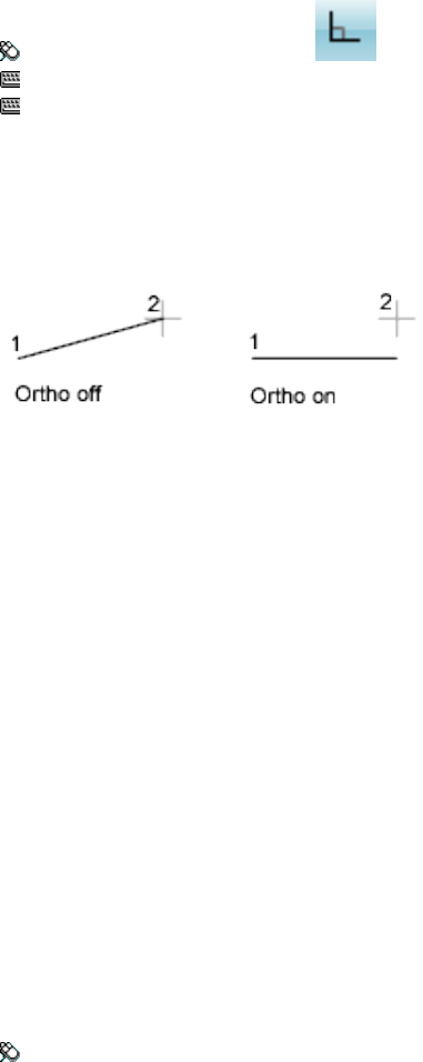
Toolbar: Status bar ➤ Ortho
Command entry: F8
Command entry: 'ortho for transparent use
Summary
In the illustration, a line is drawn using Ortho mode. Point 1 is the first point
specified, and point 2 is the position of the cursor when the second point is
specified.
Ortho mode is used when you specify an angle or distance by means of two
points using a pointing device. In Ortho mode, cursor movement is constrained
to the horizontal or vertical direction relative to the UCS.
Horizontal is defined as being parallel to the X axis of the UCS and vertical as
being parallel to the Y axis.
In a 3D view, ORTHO is additionally defined as being parallel to the Z axis of
the UCS, and the tooltip displays +Z or -Z for the angle depending on the
direction along the Z axis.
OSNAP
Quick Reference
See also:
■Use Object Snaps
Sets running object snap modes.
Access Methods
Menu: Tools ➤ Drafting Settings
OSNAP | 893

Toolbar: Status bar ➤ Osnap
Shortcut menu: Press Shift while right-clicking in the drawing area and
choose Osnap Settings.
Command entry: F3
Command entry: 'osnap for transparent use
Summary
The Object Snap tab of the Drafting Settings dialog box is displayed.
If you enter -osnap at the Command prompt, the following prompts are
displayed.
List of Prompts
The following prompts are displayed.
Current osnap modes: current
Enter list of object snap modes on page 894: Enter names of object snap modes
separated with commas, or enter none or off
Object Snap Modes
Specify one or more object snap modes by entering the first three characters
of the name. If you enter more than one name, separate the names with
commas.
TANgentCENterENDpoint
NEArestNODeMIDpoint
PARallelQUAdrantINTersection
INSertionEXTension
PERpendicularAPParent Intersection
For a description of each of these object snap modes, see the Object Snaps tab
of the Drafting Settings dialog box.
QUIck Snaps to the first snap point found. Quick must be used in conjunction
with other object snap modes.
NONe Turns off object snap modes.
894 | Chapter 15 O Commands
OVERKILL
Quick Reference
See also:
■Erase Objects
Removes duplicate or overlapping lines, arcs, and polylines. Also, combines
partially overlapping or contiguous ones.
Access Methods
Button
Ribbon: Home tab ➤ Modify panel ➤ Delete Duplicate Objects
Menu: Modify ➤ Delete Duplicate Objects
Toolbar: Modify II ➤ Delete Duplicate Objects
Summary
Displays the Delete Duplicate Objects dialog box on page 896.
Removes redundant geometry.
■Duplicate copies of objects are deleted
■Arcs drawn over portions of circles are deleted
■Lines, partially overlapping, drawn at the same angle are combined into
a single line
■Duplicate line or arc segments overlapping polyline segments are deleted
If you enter -overkill at the Command prompt, options are displayed.
OVERKILL | 895
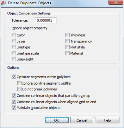
Delete Duplicate Objects Dialog Box
Quick Reference
See also:
■Erase Objects
Removes duplicate geometry as well as overlapping lines, arcs, and polylines.
Also, combines partially overlapping or contiguous ones.
List of Prompts
Object Comparison Settings
Tolerance Controls the precision with which OVERKILL makes numeric
comparisons. If this value is 0, the two objects being compared must match
before OVERKILL modifies or deletes one of them.
Ignore Object Property:
Use these settings to determine which object properties are ignored during
comparison.
Color Object color is ignored.
Layer Object layers are ignored.
896 | Chapter 15 O Commands
Linetype Object linetypes are ignored.
Linetype Scale Object linetype scale is ignored.
Lineweight Object lineweight is ignored.
Thickness Object thickness is ignored.
Transparency Object transparency is ignored.
Plot style Object plot style is ignored.
Material Object material is ignored.
Options
Use these settings to control how OVERKILL deals with lines, arcs, and
polylines.
Optimize segments within polylines When selected, individual line and
arc segments within selected polylines are examined. Duplicate vertices and
segments are removed.
Also, OVERKILL compares individual polyline segments with completely
separate line and arc segments. If a polyline segment duplicates a line or arc
object, one of them is deleted.
If this option is not selected, polylines are compared as discreet objects and
two sub-options are not selectable.
Ignore polyline segment width Ignores segment width, while optimizing
polyline segments.
Do not break polylines Polyline objects are unchanged.
Combine colinear objects that partially overlap Overlapping objects are
combined into single objects.
Combine colinear objects when aligned end to end Objects that have
common endpoints are combined into single objects.
Maintain associative objects Associative objects are not deleted or modified.
Delete Duplicate Objects Dialog Box | 897
-OVERKILL
Quick Reference
See also:
■Erase Objects
Removes duplicate or overlapping lines, arcs, and polylines. Also, combines
partially overlapping or contiguous ones.
List of Prompts
The following prompts are displayed.
Select objects: Use an object selection method
Enter an option to change [Ignore on page 898/tOlerance on page 899/optimize
Plines on page 899/combine parTial overlap on page 899/combine Endtoend
on page 899/Associativity on page 899] <done>:
List of Options
Ignore
Ignores one or more of the following properties during object comparison
■None
■All
■Color
■LAyer
■Ltype
■Ltscale
■LWeight
■Thickness
■TRansparency
■plotStyle
■Material
898 | Chapter 15 O Commands
Tolerance Defines the value within which OVERKILL makes numeric
comparisons for determining object duplication.
Optimize Polylines Optimize segments within plines [segment wiDth/Break
polyline/Yes/No] <Yes>:
■Segment Width: ignore polyline segment width
■Break Polyline: maintains polylines when optimizing polyline segments
■Yes: Enabled by default. Honors polylines as discreet objects and deletes
non-polyline objects that overlap polylines.
■No: Forces OVERKILL to examine polyline segments individually. Polyline
segments may be deleted as duplicates of non-polyline objects.
Combine Partial Overlap Overlapping objects area combined into single
objects.
Combine End to End Objects that have common endpoints are combined
into single objects.
Associativity Associative objects are not deleted or modified.
-OVERKILL | 899
900
P Commands
PAGESETUP
Quick Reference
See also:
■Specify Page Setup Settings
Controls the page layout, plotting device, paper size, and other settings for each
new layout.
Access Methods
Button
Ribbon: Output tab ➤ Plot panel ➤ Page Setup
Menu: Application menu ➤ Print ➤ Page Setup
Menu: File ➤ Page Setup Manager
Shortcut menu: Right-click the Model layout or a named (paper space) layout
and click Page Setup Manager.
Summary
The Page Setup Manager is displayed.
16
901
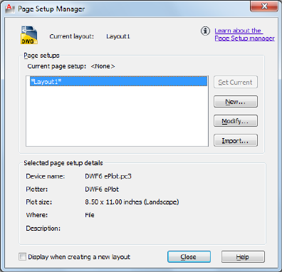
A page setup is a collection of plot device and other settings that determine
the appearance and format of your final output. These settings are stored in
the drawing file and can be modified and applied to other layouts.
Page Setup Manager
Quick Reference
See also:
■Specify Page Setup Settings
Specifies the page setup for the current layout.
Summary
You can also create named page setups, modify existing ones, or import page
setups from other drawings.
List of Options
The following options are displayed.
Current Layout
Lists the current layout to which the page setup will be applied.
902 | Chapter 16 P Commands
Page Setups
Displays the current page setup, sets a different page setup as current, creates
a new page setup, modifies an existing page setup, and imports page setups
from other drawings.
Current Page Setup
Displays the page setup that is applied to the current layout.
Page Setup List
Lists the page setups that are available to apply to the current layout.
The list includes the named page setups and layouts that are available in the
drawing. Layouts that have a named page setup applied to them are enclosed
in asterisks, with the named page setup in parentheses; for example, *Layout
1 (System Scale-to-fit)*. The current page setup is selected by default. You can
double-click a page setup in this list to set it as the current page setup for the
current layout.
The shortcut menu also provides options for removing and renaming page
setups.
Set Current
Sets the selected page setup as the current page setup for the current layout.
You cannot set the current layout as the current page setup.
New
Displays the New Page Setup dialog box, in which you can enter a name for
the new page setup and specify the page setup to use as a starting point.
Modify
Displays the Page Setup dialog box, in which you can edit the settings for the
selected page setup.
Selected Page Setup Details
Displays information about the selected page setup.
Device Name
Displays the name of the output device specified in the currently selected page
setup.
Plotter
Displays the type of output device specified in the currently selected page
setup.
Plot Size
Page Setup Manager | 903

Displays the paper size and orientation specified in the currently selected page
setup.
Where Displays the physical location of the output device specified in the
currently selected page setup.
Description
Displays descriptive text about the output device specified in the currently
selected page setup.
Display When Creating a New Layout
Specifies that the Page Setup dialog box is displayed when a new layout tab
is selected or a new layout is created.
You can reset this function by turning on the Show Page Setup Dialog for New
Layouts option on the Display tab of the Options dialog box.
New Page Setup Dialog Box
Quick Reference
See also:
■Specify Page Setup Settings
Specifies a name for the new page setup, as well as the page setup to use as a
starting point.
List of Options
The following options are displayed.
904 | Chapter 16 P Commands
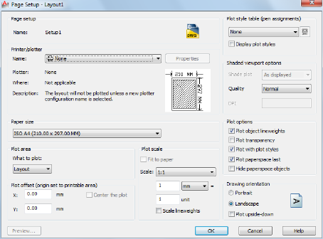
New Page Setup Name
Specifies the name for the new page setup.
Start With
Specifies a page setup to use as a starting point for the new page setup. When
you click OK, the Page Setup dialog box is displayed with the settings of the
selected page setup, which you can modify as necessary.
<None> Specifies that no page setup is used as a starting point. The default
settings that are displayed in the Page Setup dialog box can be modified.
<Default Output Device> Specifies that the default output device specified
in the Options dialog box, Plot and Publish tab, is set as the printer in the
new page setup.
<Previous Plot> Specifies that the new page setup uses the settings specified
in the last plot job.
Page Setup Dialog Box
Quick Reference
See also:
■Specify Page Setup Settings
Specifies page layout and plotting device settings.
Page Setup Dialog Box | 905
Summary
The Page Setup dialog box is displayed in the following cases:
■When you create a new page setup through the Page Setup Manager
■When you modify an existing page setup through the Page Setup Manager
The page setup settings that you specify are stored with the layout and can
be applied to other layouts or imported into other drawings.
List of Options
The following options are displayed.
Page Setup
Name Displays the name of the current page setup.
Icon
Indicates that the Page Setup dialog box was opened from a layout.
Printer/Plotter
Specifies a configured plotting device to use when plotting or publishing
layouts.
Name
Lists the available PC3 files or system printers from which you can select to
plot or publish the current layout. An icon in front of the device name
identifies it as a PC3 file or a system printer.
Properties
Displays the Plotter Configuration Editor (PC3 editor), in which you can view
or modify the current plotter configuration, ports, device, and media settings.
If you make changes to the PC3 file using the Plotter Configuration Editor,
the Changes to a Printer Configuration File dialog box is displayed.
Plotter
Displays the plot device specified in the currently selected page setup.
Where
Displays the physical location of the output device specified in the currently
selected page setup.
Description
906 | Chapter 16 P Commands
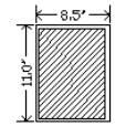
Displays descriptive text about the output device specified in the currently
selected page setup. You can edit this text in the Plotter Configuration Editor.
Partial Preview
Shows an accurate representation of the effective plot area relative to the paper
size and printable area. The tooltip displays the paper size and printable area.
Paper Size
Displays standard paper sizes that are available for the selected plotting device.
If the selected plotter does not support the layout's selected paper size, a
warning is displayed, and you can select the plotter's default paper size or a
custom paper size.
A default paper size is set for the plotting device when you create a PC3 file
with the Add-a-Plotter wizard. For information about this wizard, see “Set Up
Plotters and Printers” in the Driver and Peripheral Guide. The paper size that you
select in the Page Setup dialog box is saved with the layout and overrides the
PC3 file settings.
The actual printable area of the page, which is determined by the selected
plotting device and paper size, is indicated in the layout by a dashed line.
If you are plotting a raster image, such as a BMP or TIFF file, the size of the
plot is specified in pixels, not in inches or millimeters.
Plot Area
Specifies the area of the drawing to be plotted.
Layout/Limits When plotting a layout, plots everything within the printable
area of the specified paper size, with the origin calculated from 0,0 in the
layout.
When plotting from the Model layout, plots the entire drawing area that is
defined by the grid limits. If the current viewport does not display a plan view,
this option has the same effect as the Extents option.
Extents Plots the portion of the current space of the drawing that contains
objects. All geometry in the current layout is plotted. The drawing may be
regenerated to recalculate the extents before plotting.
Display Plots the view in the current viewport in the current layout.
Page Setup Dialog Box | 907

View Plots a view that was previously saved with the VIEW command.
Window
Plots any portion of the drawing that you specify. When you specify the two
corners of the area to plot, the Window button becomes available.
Click the Window button to use the pointing device to specify the two corners
of the area to be plotted, or enter coordinate values.
Plot Offset
Specifies an offset of the plot area relative to the lower-left corner of the
printable area or to the edge of the paper, depending on the setting made in
the Specify Plot Offset Relative To option (Options dialog box, Plot and Publish
tab). The Plot Offset area of the Page Setup dialog box displays the specified
plot offset option in parentheses.
The printable area of a drawing sheet is defined by the selected output device
and is represented by a dashed line in a layout. When you change to another
output device, the printable area may change.
You can offset the geometry on the paper by entering a positive or negative
value in the X and Y offset boxes. The plotter unit values are in inches or
millimeters on the paper.
Center the Plot
Automatically calculates the X and Y offset values to center the plot on the
paper.
X
Specifies the plot origin in the X direction relative to the setting of the Plot
Offset Definition option.
Y
Specifies the plot origin in the Y direction relative to the setting of the Plot
Offset Definition option.
Plot ScaleScale
Controls the relative size of drawing units to plotted units.
NOTE If the Layout option is specified in Plot Area, the layout is plotted at 1:1
regardless of the setting specified in Scale.
Fit to Paper
Scales the plot to fit within the selected paper size and displays the custom
scale factor in the Scale, Inch =, and Units boxes.
908 | Chapter 16 P Commands

Scale
Defines the exact scale for the output. Custom defines a user-defined scale. You
can create a custom scale by entering the number of inches (or millimeters)
equal to the number of drawing units.
NOTE You can modify the list of scales with SCALELISTEDIT.
Inch(es) =/mm =/Pixel(s) =
Specifies the number of inches, millimeters, or pixels equal to the specified
number of units.
Inch/mm/pixel
Specifies inches or mm for display of units. The default is based on the paper
size and changes each time a new paper size is selected.
Pixel is available only when a raster output is selected.
Unit
Specifies the number of units equal to the specified number of inches,
millimeters, or pixels.
Scale Lineweights
Scales lineweights in proportion to the plot scale. Lineweights normally specify
the linewidth of output objects and are output with the linewidth size
regardless of the scale.
Plot Style Table (Pen Assignments)
Sets the plot style table, edits the plot style table, or creates a new plot style
table.
Name (Unlabeled)
Displays the plot style table that is assigned to the current Model tab or layout
tab and provides a list of the currently available plot style tables.
If you select New, the Add Plot Style Table wizard is displayed, which you can
use to create a new plot style table. The wizard that is displayed is determined
by whether the current drawing is in color-dependent or named mode.
Edit
Displays the Plot Style Table Editor, in which you can view or modify plot
styles for the currently assigned plot style table.
Display Plot Styles
Page Setup Dialog Box | 909
Controls whether the properties of plot styles assigned to objects are displayed
on the screen.
Shaded Viewport Options
Specifies how shaded viewports are plotted and determines their resolution
levels and dots per inch (dpi).
Shade Plot
Specifies how views are plotted. To specify this setting for a viewport on a
layout tab, select the viewport and then, on the Tools menu, click Properties.
From the Model tab, you can select from the following options:
■As Displayed: Plots objects the way they are displayed on the screen.
■Wireframe: Plots objects in wireframe regardless of the way they are
displayed on the screen.
■Hidden: Plots objects with hidden lines removed regardless of the way they
are displayed on the screen.
Quality
Specifies the resolution at which shaded viewports are plotted.
You can select from the following options:
■Draft: Sets shaded model space views to be plotted as wireframe.
■Preview: Sets shaded model space views to be plotted at one quarter of the
current device resolution, to a maximum of 150 dpi.
■Normal: Sets shaded model space views to be plotted at one half of the
current device resolution, to a maximum of 300 dpi.
■Presentation: Sets shaded model space views to be plotted at the current
device resolution, to a maximum of 600 dpi.
■Maximum: Sets shaded model space views to be plotted at the current
device resolution with no maximum.
■Custom: Sets shaded model space views to be plotted at the resolution
setting that you specify in the DPI box, up to the current device resolution.
DPI
Specifies the dots per inch for shaded views, up to the maximum resolution
of the current plotting device.
910 | Chapter 16 P Commands

NOTE Shaded viewport plotting of rendered views is not supported.
Plot Options
Specifies options for lineweights, transparency, plot styles, shaded plots, and
the order in which objects are plotted.
Plot Object Lineweights
Specifies whether lineweights assigned to objects and layers are plotted.
Plot Transparency
Specifies whether object transparency is plotted. This option should only be
used when plotting drawings with transparent objects.
IMPORTANT For perfomance reasons, plotting transparency is disabled by default.
To plot transparent objects, check the Plot Transparency option. This setting can
be overridden by the PLOTTRANSPARENCYOVERRIDE on page 1617 system variable.
By default, the system variable honors the setting in the Page Setup and the Plot
dialog boxes.
Plot with Plot Styles
Specifies whether plot styles applied to objects and layers are plotted.
Plot Paper Space Last
Plots model space geometry first. Paper space geometry is usually plotted
before model space geometry.
Hide Paper Space Objects
Specifies whether the HIDE operation applies to objects in a paper space
viewport. This option is available only from a layout tab. This setting is
reflected in the plot preview, but not in the layout.
Drawing Orientation
Specifies the orientation of the drawing on the paper for plotters that support
landscape or portrait orientation.
Portrait
Orients and plots the drawing so that the short edge of the paper represents
the top of the page.
Landscape
Orients and plots the drawing so that the long edge of the paper represents
the top of the page.
Page Setup Dialog Box | 911
Plot Upside-Down
Orients and plots the drawing upside-down.
Icon
Indicates the media orientation of the selected paper and represents the
orientation of the drawing on the page as a letter on the paper.
NOTE The orientation of plots is also affected by the PLOTROTMODE system
variable.
Preview
Displays the drawing as it will appear when plotted on paper by executing
the PREVIEW command.
Changes to a Printer Configuration File Dialog Box (Page Setup)
Quick Reference
See also:
■Specify Page Setup Settings
Notifies you that you have made changes to an existing plotter configuration
(PC3) file.
Access Methods
Button
Ribbon: Output tab ➤ Plot panel ➤ Page Setup
Menu: Application menu ➤ Print ➤ Page Setup
Shortcut menu: Right-click the Model tab or a layout tab and click Page
Setup Manager.
Command entry: pagesetup
912 | Chapter 16 P Commands
Summary
You can cancel your changes, click OK to overwrite the PC3 file, or specify a
new file name for the modified PC3 file.
List of Options
The following options are displayed.
Save Changes to the Following File Specifies the path of the PC3 file that
you have changed. To preserve the original PC3 file, specify a new file name.
Import Page Setups Dialog Box
Quick Reference
See also:
■Specify Page Setup Settings
Displays the page setups in the selected drawing that are available to import.
Summary
List of Options
The following options are displayed.
Source Drawing
Displays the source drawing that contains the listed page setups that are
available to import.
Page Setups
Lists the page setups that are available to import and their location in the
source drawing. Selected page setups are imported into the current drawing
when you click OK.
Name Specifies the name of the page setup available to import.
Location Specifies the location (Model or named layout) of the page setup in
the drawing from which you are importing the page setup.
Details
Displays information about the selected page setup.
Device Name
Import Page Setups Dialog Box | 913

Displays the name of the plot device specified in the currently selected page
setup.
Plotter
Displays the type of output device specified in the currently selected page
setup.
Plot Size
Displays the paper size and orientation specified in the currently selected page
setup.
Where
Displays the physical location of the output device specified in the currently
selected page setup.
Description
Displays descriptive text about the output device specified in the currently
selected page setup.
PAN
Quick Reference
See also:
■Pan or Zoom a View
Moves the view planar to the screen.
Access Methods
Button
Ribbon: View tab ➤ Navigate panel ➤ Pan
Menu: View ➤ Pan ➤ Realtime
Toolbar: Standard
Shortcut menu: With no objects selected, right-click in the drawing area
and click Pan.
914 | Chapter 16 P Commands

Summary
You can pan the drawing display in real time.
List of Prompts
The following prompts are displayed.
Press Esc or Enter to exit, or right-click to display a shortcut menu.
If you enter -pan at the Command prompt, PAN displays command prompts,
and you can specify a displacement to pan the drawing display.
Position the cursor at the start location and press the mouse button down.
Drag the cursor to the new location. You can also press the mouse scroll wheel
or middle button down and drag the cursor to pan.
Panning in Real Time
Quick Reference
See also:
■Pan or Zoom a View
As a view is being panned, the cursor updates to let you know when you have
reached the extents of the drawing.
Summary
The cursor changes to a hand cursor. By holding down the pick button on
the pointing device, you lock the cursor to its current location relative to the
viewport coordinate system. The drawing display is moved in the same
direction as the cursor.
When you reach a logical extent (edge of the drawing space), a bar is displayed
on the hand cursor on that edge. Depending on whether the logical extent is
at the top, bottom, or side of the drawing, the bar is either horizontal (top or
bottom) or vertical (left or right side).
Panning in Real Time | 915
When you release the pick button, panning stops. You can release the pick
button, move the cursor to another location in the drawing, and then press
the pick button again to pan the display from that location.
To stop panning at any time, press Enter or Esc.
-PAN
Quick Reference
See also:
■Pan or Zoom a View
Moves the view planar to the screen by specifying a distance and direction
the view should be moveed in.
List of Prompts
The following prompts are displayed.
Specify base point or displacement: Specify a point
You can specify a single point, indicating the relative displacement of the
drawing with respect to the current location, or (more commonly) you can
specify two points, in which case the displacement is computed from the first
point to the second point.
If you press Enter, the drawing is moved by the amount you specified in the
Specify Base Point or Displacement prompt. For example, if you specify 2,2
at the first prompt and press Enter at the second prompt, the drawing is moved
2 units in the X direction and 2 units in the Y direction. If you specify a point
at the Specify Second Point prompt, the location of the first point is moved
to the location of the second point.
916 | Chapter 16 P Commands
You cannot use PAN transparently during VPOINT or while another ZOOM,
PAN, or VIEW command is in progress.
Pan Shortcut Menu
Quick Reference
See also:
■Pan or Zoom a View
Pan and Zoom shortcut menu allows for switching between navigation tools
and cancelling the current navigation tool.
To access the Pan shortcut menu, right-click in the drawing area while PAN
is active.
List of Options
The following options are displayed.
Exit Cancels PAN or ZOOM.
Pan Switches to PAN.
Zoom Switches to ZOOM in real time.
Zoom Window Zooms to display an area specified by a rectangular window.
Zoom Original Restores the original view.
Zoom Extents Zooms to display the drawing extents.
PARAMETERS
Quick Reference
See also:
■Add Constraints to Geometry
■Work With Constraint Parameters in Blocks
Pan Shortcut Menu | 917
Opens the Parameters Manager palette that includes all dimensional constraint
parameters, reference parameters, and user variables in the current drawing.
Access Methods
Button
Ribbon: Parametric tab ➤ Manage panel ➤ Parameters Manager
Menu: Parametric ➤ Parameters Manager
Toolbar: Parametric
Summary
The Parameters Manager palette displays relevant parametric information
based on whether you access it from within the drawing or from within the
Block Editor.
■Parameters Manager - Drawing Editor on page 918
■Parameters Manager - Block Editor on page 921
Parameters Manager - Drawing Editor
Quick Reference
See also:
■Work With Constraint Parameters in Blocks
Controls the associative parameters used in the drawing.
Summary
The Parameters Manager palette displays all associative variables (dimensional
constraint variables and user-defined variables) available in the drawing.
You can edit, rename, and delete associative variables.
918 | Chapter 16 P Commands
The Parameters Manager palette includes a grid control with three columns,
by default. You can also add two columns (Description, Type) using the
shortcut menu.
List of Options
The following options are displayed.
DescriptionColumn
Displays the variable nameName
Displays the real number or the equation
for the expression, for example, d1+d2
Expression
Displays the value of the expressionValue
Additional Columns
Displays the dimensional constraint type
or variable value
Type
Displays the comments or notes associated
with the user variable
Description
Edit a Dimensional Variable
You can edit the dimensional variable name and expression. To do so:
■Double-click the name or expression box.
■Select the row and press F2. Press the Tab key to edit the contiguous
columns.
You cannot edit the Value column.
When you rename a dimensional variable, all instances of the variable are
updated in the drawing and in the Parameters Manager palette.
TIP Use the shortcut menu for the Name and Expression cells when copying and
pasting values. The Expressions shortcut menu contains commonly used
mathematical functions.
Invalid expressions are displayed in red text.
Parameters Manager - Drawing Editor | 919
Delete a Dimensional Variable
When you delete a dimension variable:
■The associated dimensional constraint in the drawing is removed.
■The variables retain the value calculated by the expression as a constant.
This action is for variables referenced by other variables, and ensures that
the geometry does not change.
Filtering the Display of Variables
You can filter the display of variables to do the following:
■Display All Parameters- Displays all associative variables. No filter is applied.
■Display Parameters Used in Expressions - Displays all variables that contain
expressions to evaluate a value, and variables contained in expressions.
Sorting a Column
Click a column heading to sort the variables in the table in ascending or
descending order of the column property. When you sort by variable type,
the name column is second in order to be sorted.The sort order is persistent.
The sort order is not affected when you change a name or expression.
Defining a Parameter Group
The Parameters Manager allows you to define parameter groups in the drawing
editor. A parameter group is a collection of named parameters. It contains a
subset of all parameters defined for the current space, but the group can also
be empty.
Click the Filter icon to create a group, which displays a filter tree on the left
vertical panel of the palette where you can show, hide, or expand the group
filters. Drag and drop the parameters from the grid control into a parameter
group.
The Invert Filter check box displays all the parameters which do not belong
in the group.
You can filter the display of variables to do the following:
■All - Displays all associative variables. No filter is applied.
■All Used in Expressions - Displays all variables that contain expressions to
evaluate a value, and variables contained in expressions.
■Custom group filter - Displays all parameters added in the defined
parameter group.
920 | Chapter 16 P Commands
Searching a Parameter
An edit box allows you to search for parameters by name.
Highlighting Dimensional Constraints
When you select a dimensional constraint in the Parameters Manager palette,
the associated object is highlighted in the drawing.
If the parameter is a dynamic constraint that is hidden, the dynamic constraint
will be temporarily displayed and highlighted when you select the cell.
NOTE The object is not selected when highlighted; the highlighting is to visually
identify the dimensionally constrained object.
Parameters Manager - Block Editor
Quick Reference
See also:
■Work With Constraint Parameters in Blocks
Controls the associative parameters used in the Block Editor.
Summary
In the Block Editor, the Parameters Manager displays a consolidated view of
all parameters and user-defined properties for the block definition.
The Parameters Manager palette includes a grid control with three columns
(Name, Expression, Value) by default. You can add one or more additional
columns (Type, Order, Show, or Description) using the shortcut menu.
DescriptionColumn
Displays the variable nameName
Displays the real number or equation, for
example, d1+d2
Expression
Displays the value of the expressionValue
Additional Columns
Parameters Manager - Block Editor | 921

DescriptionColumn
Displays the dimensional constraint type
or variable value
Type
Controls the order properties are displayed
in the Properties palette
Order
Displays the parameter as a property of the
block reference
Show
Displays the comments or notes associated
with the user variable
Description
The Type column affects the formatting of the parameter in the Parameters
Manager and Properties palette. It also affects the value of the parameter when
the block is scaled.
Block Scale FactorPrecisionUnitsType
Scaled by scale factorLUPRECLUNITSDistance
No scaleAUPRECAUNITSAngle
No scaleLUPRECDecimalReal
Multiplied by square of
scale
LUPRECDecimalArea
Multiplied by cube of scaleLUPRECDecimalVolume
Not applicableNot applicableNot applicableString
The Type cell for User parameters displays a drop-down list of the value types.
The parameter can be sorted and can be set to Show or Hide in the Properties
palette. The value of the parameter resets to 1 when you change the type from
String to another type.
Parameters can be renamed; equations and values can be entered or modified.
Changes to a parameter name are immediately updated throughout the table
and in the Block Editor.
922 | Chapter 16 P Commands
The parameters for the block definition are organized in the following
categories:
■Action Parameters
■Dimensional Constraint Parameters
■Reference Parameters
■User Parameters
■Attributes
You can only add user parameters to the table. When you delete any item
from the table, the item is automatically deleted from the block definition.
Edit a Dimensional Variable
You can edit the dimensional variable name and expression. To do so:
■Double-click the name or expression box.
■Select the row and press F2. Press the Tab key to edit the contiguous
columns.
You cannot edit the Value column.
When you rename a dimensional variable, all instances of the variable are
updated in the drawing and in the Parameters Manager palette.
Invalid expressions are displayed in red text.
Delete a Dimensional Variable
The following are the current behavioral changes in the drawing when you
delete a dimension variable:
■The associated dimensional constraint in the drawing is removed.
■The variables retain the value calculated by the expression as a constant.
This action is for variables referenced by other variables, and ensures that
the geometry does not change.
Filtering the Display of Variables
You can filter the display of variables to do the following:
■Display All Parameters — Displays all associative variables. No filter is
applied.
Parameters Manager - Block Editor | 923

■Display Parameters Used in Expressions - Displays all variables that contain
expressions to evaluate a value, and variables contained in expressions.
Sorting a Column
The sort order is not affected when you change a cell value.
Searching a Parameter
An edit box in the upper-right corner of the Parameters Manager allows you
to search for parameters by name.
-PARAMETERS
Quick Reference
See also:
■Work With Constraint Parameters in Blocks
Opens the Parameters Manager palette that includes all dimensional constraint
parameters, reference parameters, and user variables in the current drawing.
List of Prompts
The following prompts are displayed.
Enter a parameter option [Edit on page 924/Rename on page 924/Delete on page
924/? on page 924]:
NOTE You cannot use the -PARAMETERS command in the Block Editor on page
127.
Edit Edits the expression of the specified user variable.
Rename Renames the user variable.
Delete Removes the user variable from the list.
? — List Parameters Lists available user variables in the drawing.
924 | Chapter 16 P Commands

PARAMETERSCLOSE
Quick Reference
See also:
■Work With Constraint Parameters in Blocks
Closes the Parameters Manager palette.
PASTEASHYPERLINK
Quick Reference
See also:
■Add Hyperlinks to a Drawing
Creates a hyperlink to a file, and associates it with a selected object.
Access Methods
Button
Ribbon: Home tab ➤ Clipboard panel ➤ Paste as Hyperlink
Menu: Edit ➤ Paste as Hyperlink
Summary
First, select a document, such as a text, spreadsheet, drawing, or image file,
and copy it to the Clipboard. Then, use this command to associate a hyperlink
to that document with any selected object.
PARAMETERSCLOSE | 925

PASTEBLOCK
Quick Reference
See also:
■Cut, Copy, and Paste with the Clipboard
Pastes objects from the Clipboard into the current drawing as a block.
Access Methods
Button
Ribbon: Home tab ➤ Clipboard panel ➤ Paste as Block
Menu: Edit ➤ Paste as Block
Shortcut menu: With no command active, right-click in the drawing area
and click Clipboard ➤ Paste as Block
Summary
The objects copied to the Clipboard are pasted into the drawing as a block at
the specified insertion point. The block is given a random name.
PASTECLIP
Quick Reference
See also:
■Cut, Copy, and Paste with the Clipboard
Pastes objects from the Clipboard into the current drawing.
926 | Chapter 16 P Commands
Access Methods
Button
Ribbon: Home tab ➤ Clipboard panel ➤ Paste
Menu: Edit ➤ Paste
Toolbar: Standard
Shortcut menu: With no command active, right-click in the drawing area,
and click Clipboard ➤ Paste
Command entry: Ctrl+V
Summary
If the Clipboard contains ASCII text, the text is inserted as a multiline text
(mtext) object using the MTEXT defaults. A spreadsheet is inserted as a table
object.
All other objects, except AutoCAD LT objects, are inserted as embedded or
linked (OLE) objects. You can edit these OLE objects by double-clicking them
in the drawing to open the application in which they were created.
When you copy objects to the Clipboard, information is stored in all available
formats. When you paste the Clipboard contents into a drawing, the format
that retains the most information is used. You can also use Copy and Paste
to transfer objects between drawings.
NOTE If the cursor is in the drawing area, PASTECLIP behaves as described. If the
cursor is at the Command prompt, text from the Clipboard is pasted at the current
prompt.
PASTEORIG
Quick Reference
See also:
■Cut, Copy, and Paste with the Clipboard
PASTEORIG | 927

Pastes objects from the Clipboard into the current drawing using the original
coordinates.
Access Methods
Button
Ribbon: Home tab ➤ Clipboard panel ➤ Paste to Original Coordinates
Menu: Edit ➤ Paste to Original Coordinates
Shortcut menu: With no command active, right-click in the drawing area,
and click Clipboard ➤ Paste to Original Coordinates
Summary
The objects copied to the Clipboard are pasted into the current drawing at
the same coordinates used in the original drawing. This command functions
only when the Clipboard contains AutoCAD LT data from a drawing other
than the current drawing.
PASTESPEC
Quick Reference
See also:
■Cut, Copy, and Paste with the Clipboard
Pastes objects from the Clipboard into the current drawing and controls the
format of the data.
Access Methods
Button
Ribbon: Home tab ➤ Clipboard panel ➤ Paste Special
Menu: Edit ➤ Paste Special
928 | Chapter 16 P Commands
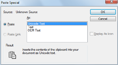
Summary
The Paste Special dialog box is displayed.
Paste Special Dialog Box
Quick Reference
See also:
■Cut, Copy, and Paste with the Clipboard
Sets file formats and linking options for data pasted from the Clipboard.
Summary
You can either embed file data or link file data. Linked data is updated when
you open the drawing.
When you copy objects to the Clipboard, information is stored in all available
formats. When you paste the Clipboard contents into a drawing, you can
choose from the available formats.
List of Options
The following options are displayed.
Source Displays the name of the document that contains the information
you copied. It may also show the specific section of the document you copied.
Paste Pastes the contents of the Clipboard into the current drawing as an
embedded object.
Paste Special Dialog Box | 929

Paste Link Pastes the contents of the Clipboard into the current drawing. If
the source application supports an OLE or data link, a link is created to the
original file.
As Displays applicable formats in which you can paste the contents of the
Clipboard into the current drawing.
Display as Icon Inserts a picture of the application icon instead of the data.
To view or edit the data, double-click the icon.
PCINWIZARD
Quick Reference
See also:
■Import PCP or PC2 Settings into a Layout
Displays a wizard to import PCP and PC2 configuration file plot settings into
the Model or current named (paper space) layout.
Access Methods
Menu: Tools ➤ Wizards ➤ Import Plot Settings
Summary
PCINWIZARD displays the Import PCP or PC2 Plot Settings wizard. Information
that can be imported from PCP or PC2 files includes plot area, rotation, plot
offset, plot optimization, plot to file, paper size, plot scale, and pen mapping.
The wizard prompts you for the name of the PCP or PC2 configuration file
from which you want to import settings. You can view and modify the plot
settings prior to importing them. The imported settings can be applied to the
Model or named (paper space) layout whichever is current.
930 | Chapter 16 P Commands

PDFADJUST
Quick Reference
See also:
■Adjust Underlay Contrast, Fade, Monochrome, and Colors for the
Background
Adjust the fade, contrast, and monochrome settings of a PDF underlay.
Access Methods
Button
Ribbon: PDF Underlay contextual tab ➤ Adjust panel
Summary
If you select a single PDF underlay, the default values for Fade, Contrast, and
Monochrome are the current property settings of the selected underlay. If you
select multiple underlays, the default values for Fade, Contrast, and
Monochrome remain as they were set the last time the command was used.
You can also use the ADJUST on page 20 command to change an underlay’s
fade, contrast, and monochrome settings.
To adjust the colors for the background, open the underlay’s Properties Palette.
List of Prompts
The following prompts are displayed.
Fade Controls the fade effect of the underlay. Values range from 0 through
100. The greater the value, the lighter the linework in the underlay appears.
Works indirectly with the contrast effect; a higher contrast value blends the
underlay in the background when fade is set to a higher value.
Contrast Controls the contrast, and indirectly the fading effect, of the
underlay. Values range from 0 through 100. The greater the value, the more
each pixel is forced to its primary or secondary color. Default=75.
PDFADJUST | 931
Monochrome Controls the color saturation of all linework while maintaining
the luminance. When turned on, the linework appears in varying shades of
gray starting at black if the background color luminance is 50 percent or more.
If the background color luminance is less than 50 percent, then the colors are
inverted, with the darkest linework displaying in white, and the lightest
linework displaying in black.
PDFATTACH
Quick Reference
See also:
■Attach Files as Underlays
Insert a PDF file as an underlay into the current drawing.
Access Methods
Button
Ribbon: Insert tab ➤ Reference panel ➤ Attach
Menu: Insert ➤ PDF Underlay
Toolbar: Insert
Summary
When you attach a PDF file as an underlay, you link that referenced file to
the current drawing. Any changes to the referenced file are displayed in the
current drawing when it is opened or reloaded.
The Select Reference File dialog box (a standard file selection dialog box) is
displayed. Once you select a PDF file, the Attach PDF Underlay dialog box on
page 934 is displayed. After the file is attached, you can adjust and clip the
underlay through the PDF Underlay Ribbon Contextual tab on page 936.
932 | Chapter 16 P Commands

-PDFATTACH
Quick Reference
See also:
■Attach Files as Underlays
Attach a PDF underlay from the command line.
Summary
When you attach a PDF file as an underlay, you link that referenced file to
the current drawing. Any changes to the referenced file are displayed in the
current drawing when it is opened or reloaded.
TIP You can drag a PDF file onto the drawing window to start the PDFATTACH
command.
List of Prompts
The following prompts are displayed.
Path to PDF File to Attach Enters the full path name to the PDF underlay
file.
Entering a tilde (~) displays the Select PDF File dialog box (a standard file
selection dialog box).
To avoid errors when entering a file name, it is recommended that you specify
both the PDF file and path as follows:
path name\filename.dgn
or
“path name\filename.dgn”
If you enter a valid PDF file name without a file extension, the program adds
the extension and searches for the file.
Enter Page Number Enter a page number. For a list of pages, enter ?.
Enter Page(s) to list <*> Lists the pages available in the PDF file in a separate
text window.
Insertion Point Specifies the insertion point for the selected PDF file.
-PDFATTACH | 933
Scale Factor Specifies the scale factor of the selected PDF underlay and the
scale factor units.
If INSUNITS is set to “unitless” or if the underlay does not contain resolution
information, the scale factor becomes the underlay width in AutoCAD units.
If INSUNITS has a value such as millimeters, centimeters, inches, or feet, and
the underlay has resolution information, the scale factor is applied after the
true width of the underlay in AutoCAD units is determined.
Rotation Specifies the rotation angle of the selected PDF underlay.
Attach PDF Underlay Dialog Box
Quick Reference
See also:
■Attach Files as Underlays
Names, locates, and defines the insertion point, scale, and rotation of attached
PDF underlays.
List of Options
The following options are displayed.
Name
Identifies the PDF file you have selected to attach.
Browse
Opens the Select Reference File dialog (a standard file selection dialog box on
page 826).
Select one of more pages from the PDF file
Displays all of the pages that are found in the PDF file. If the PDF file only
contains a single page, that page is listed. You can select multiple pages by
holding Shift or Ctrl and selecting the pages to attach.
Path Type
Select the full (absolute) path, the relative path to the PDF file, or No Path,
and the name of the PDF file. For the No Path option, the PDF file must be
located in the same folder as the current drawing file.
934 | Chapter 16 P Commands
Insertion Point
Specifies the insertion point for the selected PDF file.
Specify On-Screen
Directs input at the Command prompt or the pointing device.
X
Sets the X coordinate value.
Y
Sets the Y coordinate value.
Z
Sets the Z coordinate value.
Scale
Specifies the scale factor of the selected PDF underlay.
If INSUNITS is set to “unitless” or if the underlay does not contain resolution
information, the scale factor becomes the underlay width in AutoCAD units.
If INSUNITS has a value such as millimeters, centimeters, inches, or feet, and
the underlay has resolution information, the scale factor is applied after the
true width of the underlay in AutoCAD units is determined.
Specify On-screen
Inputs information at the Command prompt or with the pointing device. If
Specify On-Screen is cleared, enter a value for the scale factor.
Scale Factor Field
Enter a value for the scale factor.
Rotation
Specifies the rotation angle of the selected DWF underlay.
Specify on-screen
If Specify On-Screen is selected, you may wait until you exit the dialog box
to rotate the object with your pointing device or enter a rotation angle value
at the Command prompt.
Angle
If Specify On-Screen is cleared, enter the rotation angle value in the dialog
box. The default rotation angle is 0.
Attach PDF Underlay Dialog Box | 935
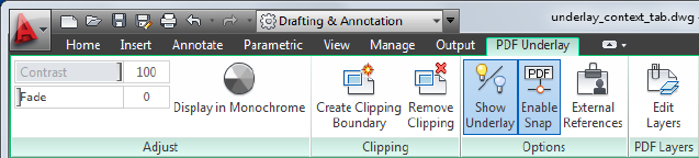
Show Details
Found In Displays the path to the PDF file.
Saved Path Displays the path that is saved with the drawing when the PDF
file is attached. The path is dependent upon the Path Type setting.
PDF Underlay Ribbon Contextual tab
Quick Reference
See also:
■Work with Underlays
Displays options for editing PDF underlays.
List of Options
The following options are displayed.
Summary
When you select a PDF underlay, the PDF Contextual tab is displayed on the
ribbon.
Adjust Panel
Contrast Controls the contrast and the fading effect of the underlay.
Fade Controls the appearance of the linework. The greater the value, the
lighter the linework in the underlay is displayed.
Display in Monochrome Displays the underlay in black and white.
Clipping Panel
Create Clipping Boundary Deletes the old clipping boundary (if one exists)
and create a new one.
Remove Clipping Deletes the clipping boundary.
936 | Chapter 16 P Commands

Options Panel
Show Underlay Hides or displays the underlay.
Enable Snap Determines whether object snapping is active for geometry in
the underlay.
External References (EXTERNALREFERENCES on page 504) Opens the
External References palette.
PDF Layers Panel
Edit Layers (ULAYERS on page 1281) Controls the display of layers in a DWF,
DWFx, PDF, or DGN underlay.
PDFCLIP
Quick Reference
See also:
■Clip Underlays
Crops the display of a selected PDF underlay to a specified boundary.
Access Methods
Button
Ribbon: PDF Underlay contextual tab ➤ Clipping panel ➤ Create
Clipping Boundary
Shortcut menu: Select a PDF underlay to clip, right-click and click PDF Clip
Summary
The clipping boundary determines the portion of an image outside the
boundary that is hidden. The visibility of the clipping boundary is controlled
by the FRAME system variable.
The boundary you specify must be in a plane parallel to the PDF underlay.
PDFCLIP | 937

TIP Use the generic CLIP on page 211 command to clip images, external references,
viewports, and underlays.
List of Prompts
The following prompts are displayed.
On
Turns on clipping and displays the PDF underlay clipped to the previously
defined boundary.
Off
Turns off clipping and displays the entire PDF underlay and frame.
If you re-clip the PDF underlay while clipping is turned off, clipping is
automatically turned back on. You are prompted to delete the old boundary
even when clipping is turned off and the clipping boundary is not visible.
Delete
Removes a predefined clipping boundary and displays the full original
underlay.
New Boundary
Defines a rectangular or polygonal clipping boundary, or generates a polygonal
clipping boundary from a polyline.
Select Polyline Defines the boundary with the selected polyline. The polyline
can be open but must consist of straight line segments and cannot intersect
itself.
Polygonal Defines a polygonal clipping boundary with three or more points
that you specify for the vertices of a polygon.
Rectangular Defines a rectangular boundary with the points that you specify
for opposite corners.
Invert Clip Inverts the mode of the clipping boundary: objects are clipped
either outside the boundary or inside the boundary.
NOTE You can only create a new clipping boundary for a selected PDF underlay
when the old boundary is deleted.
938 | Chapter 16 P Commands

PDFLAYERS
Quick Reference
See also:
■Control the Display of Layers in an Underlay
Controls the display of layers in a PDF underlay.
Access Methods
Button
Ribbon: Insert tab ➤ Reference panel ➤ Underlay Layers
Shortcut menu: Select a PDF underlay. Right-click in the drawing area and
click PDF Layers.
Summary
When you select a PDF underlay, the PDF Underlay ribbon contextual tab on
page 936 displays. From the contextual tab, you can click Edit Layers or enter
PDFLAYERS. The Underlay Layers dialog box on page 1282 displays.
The ULAYERS on page 1281 command manages the layers of all underlays in
the current document regardless of type: DWF, DWFx, PDF, and DGN.
PEDIT
Quick Reference
See also:
■Modify Polylines
Edits polylines.
PDFLAYERS | 939

Access Methods
Button
Ribbon: Home tab ➤ Modify panel ➤ Edit Polyline
Menu: Modify ➤ Object ➤ Polyline
Toolbar: Modify II
Shortcut menu: Select a polyline to edit. Right-click in the drawing area
and click Polyline Edit.
Summary
Common uses for PEDIT include joining 2D polylines, converting lines and
arcs into 2D polylines, and converting polylines into curves that approximate
B-splines (spline-fit polylines).
List of Prompts
The following prompts are displayed.
Select polyline or [MULTIPLE]: Use an object selection method or enter m
The remaining prompts depend on whether you have selected a 2D polylineor
a 3D polyline.
If the selected object is a line, arc, or a spline, the following prompt is
displayed:
Object selected is not a polyline.
Do you want it to turn into one? <Y>: Enter y or n, or press Enter
If you enter y, the object is converted into a single-segment 2D polyline that
you can edit. You can use this operation to join lines and arcs into a polyline.
Before the selected spline is converted to a polyline, the following prompt is
displayed:
Specify a precision <10>: Enter a new precision value or press Enter
The precision value determines how accurately the resulting polyline is to fit
to the source spline. Valid value is an integer between 0 and 99.
NOTE A high precision value may cause performance problems.
940 | Chapter 16 P Commands
The PLINECONVERTMODE on page 1613 system variable determines whether
the polylines are created with linear or arc segments. When the PEDITACCEPT
on page 1607system variable is set to 1, this prompt is suppressed, and the
selected object is automatically converted to a polyline.
The conversion in both PEDIT and SPLINEDIT will obey the DELOBJ on page
1433 system variable.
Multiple Selection (PEDIT)
Quick Reference
Enables selection for more than one object.
If the selection set includes lines, arcs, or splines, the following prompt is
displayed:
List of Prompts
The following prompts are displayed.
Convert Lines, Arcs and Splines to polylines [Yes/No]? <Y>: Enter y or n or press
Enter
Specify a precision for spline conversion <10>: Enter a new precision value or
press Enter
The entered precision value affects all splines in the selection set. The precision
value is an integer between 0 and 99.
2D Polyline Selection (PEDIT)
Quick Reference
If you select a 2D polyline, the following prompt is displayed:
List of Prompts
The following prompts are displayed.
Enter an option [Close/Join/Width/Edit vertex/Fit/Spline/Decurve/Ltype
gen/Reverse/Undo]: Enter an option or press Enter to end the command
Multiple Selection (PEDIT) | 941
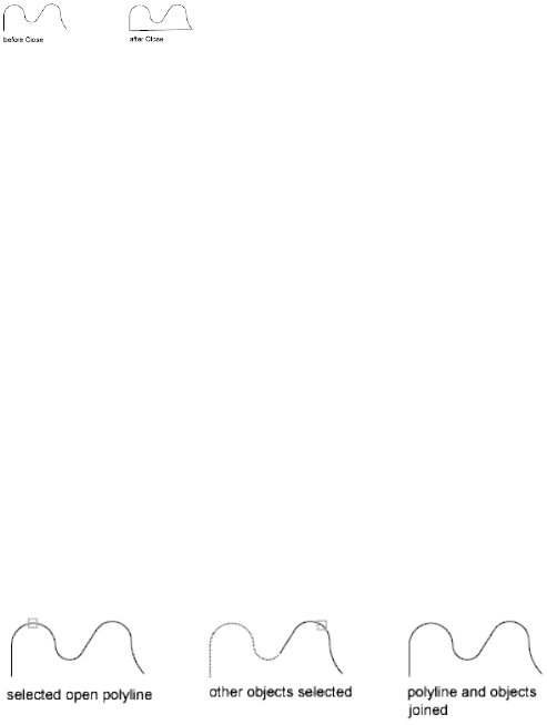
If the polyline you select is a closed polyline, Open replaces the Close option
in the prompt. You can edit a 2D polyline if its normal is parallel to and in
the same direction as the Z axis of the current UCS.
Close
Creates the closing segment of the polyline, connecting the last segment with
the first. The polyline is considered open unless you close it using the Close
option.
Open
Removes the closing segment of the polyline. The polyline is considered closed
unless you open it using the Open option.
Join
Adds lines, arcs, or polylines to the end of an open polyline and removes the
curve fitting from a curve-fit polyline. For objects to join the polyline, their
endpoints must touch unless you use the Multiple option at the first PEDIT
prompt. In this case, you can join polylines that do not touch if the fuzz
distance is set to a value large enough to include the endpoints.
Jointype
Sets the method of joining selected polylines.
Extend Joins the selected polylines by extending or trimming the segments
to the nearest endpoints.
Add Joins the selected polylines by adding a straight segment between the
nearest endpoints.
Both Joins the selected polylines by extending or trimming if possible.
Otherwise joins the selected polylines by adding a straight segment between
the nearest endpoints.
Width
Specifies a new uniform width for the entire polyline.
You can use the Width option of the Edit Vertex option to change the starting
and ending widths of a segment.
942 | Chapter 16 P Commands
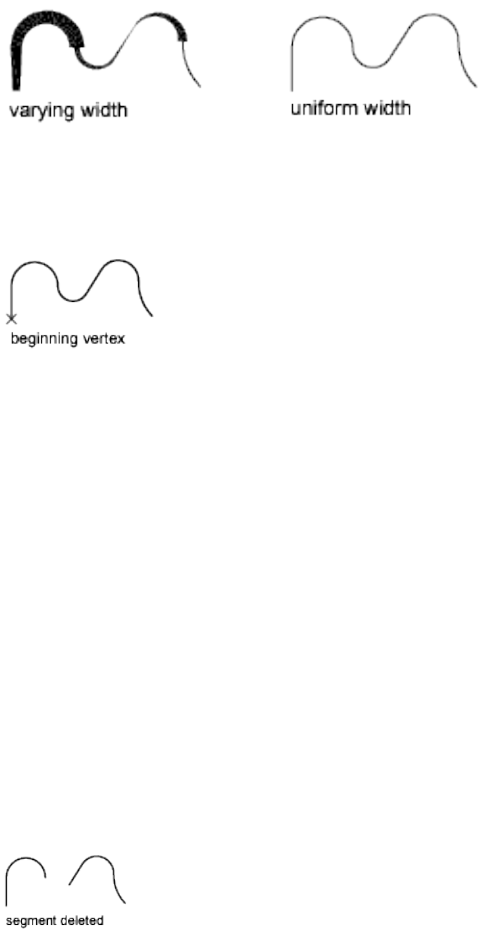
Edit Vertex
Marks the first vertex of the polyline by drawing an X on the screen. If you
have specified a tangent direction for this vertex, an arrow is also drawn in
that direction.
Next
Moves the X marker to the next vertex. The marker does not wrap around
from the end to the start of the polyline even if the polyline is closed.
Previous
Moves the X marker to the previous vertex. The marker does not wrap around
from the start to the end of the polyline even if the polyline is closed.
Break
Saves the location of the marked vertex while you move the X marker to any
other vertex.
If one of the specified vertices is at an end of the polyline, the result is one
truncated polyline. If both specified vertices are at endpoints of the polyline,
or if just one vertex is specified and it is at an endpoint, you cannot use Break.
■Next on page 943
■Previous on page 943
Go Deletes any segments and vertices between the two vertices you specify
and returns to Edit Vertex mode.
Exit Exits Break and returns to Edit Vertex mode.
2D Polyline Selection (PEDIT) | 943
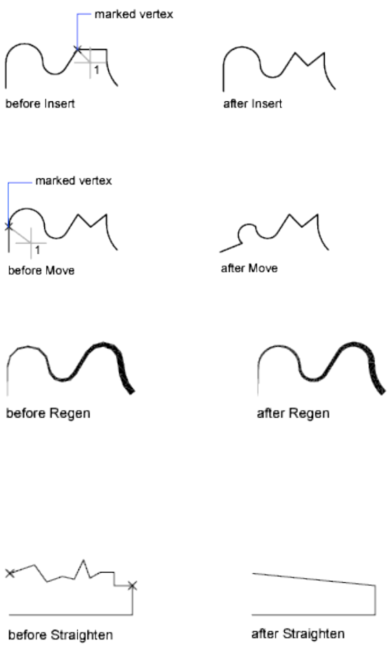
Insert
Adds a new vertex to the polyline after the marked vertex.
Move
Moves the marked vertex.
Regen
Regenerates the polyline.
Straighten
Saves the location of the marked vertex while you move the X marker to any
other vertex.
If you want to remove an arc segment that connects two straight segments of
a polyline and then extend the straight segments until they intersect, use the
FILLET command with a fillet radius of 0.
944 | Chapter 16 P Commands
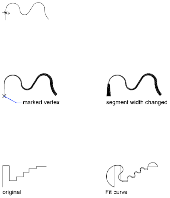
Next Moves the X marker to the next vertex.
Previous Moves the X marker to the previous vertex.
Go Deletes any segments and vertices between the two vertices you select,
replaces them with single straight line segments, and returns to Edit Vertex
mode. If you specify only one vertex by entering go without moving the X
marker, the segment following that vertex is straightened if it is an arc.
Exit Exits Straighten and returns to Edit Vertex mode.
Tangent
Attaches a tangent direction to the marked vertex for use later in curve fitting.
Width
Changes the starting and ending widths for the segment that immediately
follows the marked vertex.
You must regenerate the polyline to display the new width.
Exit
Exits Edit Vertex mode.
Fit
Creates an arc-fit polyline, a smooth curve consisting of arcs joining each pair
of vertices. The curve passes through all vertices of the polyline and uses any
tangent direction you specify.
2D Polyline Selection (PEDIT) | 945
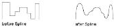
Spline
Uses the vertices of the selected polyline as the control points, or frame, of a
curve approximating a B-spline. This curve, called a spline-fit polyline, passes
through the first and last control points unless the original polyline was closed.
The curve is pulled toward the other points but does not necessarily pass
through them. The more control points you specify in a particular part of the
frame, the more pull they exert on the curve. Quadratic and cubic spline-fit
polylines can be generated.
Spline-fit polylines are very different from the curves produced by the Fit
option. Fit constructs pairs of arcs that pass through every control point. Both
of these curves are different from true B-splines produced with the SPLINE
command.
If the original polyline included arc segments, they are straightened when the
spline's frame is formed. If the frame has width, the resulting spline tapers
smoothly from the width of the first vertex to the width of the last vertex. All
intermediate width information is ignored. Once spline-fit, the frame, if
displayed, is shown with zero width and CONTINUOUS linetype. Tangent
specifications on control point vertices have no effect on spline-fitting.
When a spline-fit curve is fit to a polyline, the spline-fit curve's frame is stored
so that it can be recalled by a subsequent decurving. You can turn a spline-fit
curve back into its frame polyline by using the PEDIT Decurve option. This
option works on fit curves in the same manner as it does on splines.
Most editing commands act the same when applied to spline-fit polylines or
fit curves.
■MOVE, ERASE, COPY, MIRROR, ROTATE, and SCALE operate on both the
spline curve and its frame, whether the frame is visible or not.
■EXTEND changes the frame by adding a new vertex where the initial or
final line of the frame intersects the boundary geometry.
■BREAK and TRIM generate a polyline with only the fit spline, which is
consistent with fit curves, where the curve fitting is permanent.
■EXPLODE deletes the frame and generates lines and arcs to approximate
the spline-fit polyline.
■OFFSET generates a polyline with only the fit spline, which is consistent
with its behavior with fit curves.
946 | Chapter 16 P Commands
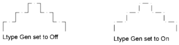
■DIVIDE, MEASURE, and the Object option of AREA and HATCH see only
the fit spline, not the frame.
■STRETCH refits the spline to the stretched frame after a spline is stretched.
The Join option of PEDIT decurves the spline and discards the spline
information of the original and any added polylines. Once the Join operation
is complete, you can fit a new spline to the resulting polyline.
The Edit Vertex options of PEDIT have the following effect:
■The Next and Previous options move the X marker only to points on the
frame of the spline, whether visible or not.
■The Break option discards the spline.
■The Insert, Move, Straighten, and Width options automatically refit the
spline.
■The Tangent option has no effect on splines.
Object snap uses only the spline-fit curve itself, not the frame. If you want to
snap to the frame control points, use PEDIT to recall the polyline frame first.
Decurve
Removes extra vertices inserted by a fit or spline curve and straightens all
segments of the polyline. Retains tangent information assigned to the polyline
vertices for use in subsequent fit curve requests. If you edit a spline-fit polyline
with a command such as BREAK or TRIM, you cannot use the Decurve option.
Ltype Gen
Generates the linetype in a continuous pattern through the vertices of the
polyline. When turned off, this option generates the linetype starting and
ending with a dash at each vertex. Ltype Gen does not apply to polylines with
tapered segments.
Reverse
Reverses the order of vertices of the polyline. Use this option to reverse the
direction of objects that use linetypes with included text. For example,
2D Polyline Selection (PEDIT) | 947
depending on the direction in which a polyline was created, the text in the
linetype might be displayed upside down.
Undo
Reverses operations as far back as the beginning of the PEDIT session.
3D Polyline Selection (PEDIT)
Quick Reference
If you select a 3D polyline, the following prompt is displayed:
List of Prompts
The following prompts are displayed.
Enter an option [Close/Join/Edit vertex/Spline curve/Decurve/Reverse/Undo]:
Enter an option or press Enter
If the polyline you select is closed, Open replaces the Close option in the
prompt.
Close
Creates the closing segment of the polyline, connecting the last segment with
the first. The polyline is considered open unless you close it with Close.
Open
Removes the closing segment of the polyline. The polyline is considered closed
unless you open it with Open.
Join
Joins an open curve to the 3D polyline. The curve can be on a different plane,
but must be contiguous with the 3D polyline.
Edit Vertex
Performs various editing tasks on one vertex of the polyline and segments
that follow it.
Next
Moves the X marker to the next vertex. The marker does not wrap around
from the end to the start of the polyline, even if the polyline is closed.
Previous
Moves the X marker to the previous vertex. The marker does not wrap around
from the start to the end of the polyline, even if the polyline is closed.
948 | Chapter 16 P Commands
Break
Saves the location of the marked vertex while you move the X marker to any
other vertex.
■Previous on page 948
■Previous on page 943
Go Deletes any segments and vertices between the two vertices you specify
and returns to Edit Vertex mode.
Exit Exits Break and returns to Edit Vertex mode.
If one of the specified vertices is at an end of the polyline, the polyline is
truncated. If both specified vertices are at endpoints of the polyline, or if just
one vertex is specified and it is at an endpoint, you cannot use Break mode.
Insert
Adds a new vertex to the polyline after the marked vertex.
Move
Moves the marked vertex.
Regen
Regenerates the polyline.
Straighten
Saves the location of the marked vertex while you move the X marker to any
other vertex.
Next Moves the X marker to the next vertex.
Previous Moves the X marker to the previous vertex.
Go Deletes any segments and vertices between the two vertices you select,
replaces them with single straight line segments, and returns to Edit Vertex
mode. If you specify only one vertex by entering go without moving the X
marker, the segment following that vertex is made straight if it is an arc.
Exit Exits Straighten and returns to Edit Vertex mode.
To remove an arc segment that connects two straight segments of a polyline
and then to extend the straight segments until they intersect, use the FILLET
command with a fillet radius of 0.
Exit
Exits Edit Vertex mode.
3D Polyline Selection (PEDIT) | 949

Spline Curve
Fits a 3D B-spline curve to its control points. The SPLFRAME system variable
controls the accuracy and display of the control points for the 3D B-spline,
whose curves can be approximated only by line segments. Negative values for
spline segments are ignored.
Decurve
Removes extra vertices inserted by a fit or spline curve and straightens all
segments of the polyline. Retains tangent information assigned to the polyline
vertices for use in subsequent fit curve requests. If you edit a spline-fit polyline
with a command such as BREAK or TRIM, you cannot use the Decurve option.
Reverse
Reverses the order of vertices of the polyline. Use this option to reverse the
direction of objects that use linetypes with included text. For example,
depending on the direction in which a polyline was created, the text in the
linetype might be displayed upside down.
Undo
Reverses operations as far back as the beginning of the PEDIT session.
PKFSTGROUP
Quick Reference
See also:
■Group Objects
Opens the legacy Group Manager.
950 | Chapter 16 P Commands

Access Methods
Ribbon: Home tab ➤ Groups panel ➤ Named Groups
Menu: Tools ➤ Group Manager
Toolbar: Group
Summary
Groups provide an easy way to combine drawing elements that you need to
manipulate as a unit.
List of Options
The following options are displayed.
Group Displays the names of existing groups. Group names can be up to 31
characters long and can include letters, numbers, and the special characters
dollar sign ($), hyphen (-), and underscore (_), but not spaces. The name is
converted to uppercase characters.
When Include Unnamed Groups is selected, this list includes default names
assigned to unnamed groups (*A1, *A2, and so on).
Selectable Specifies whether a group is selectable. When a group is selectable,
selecting one object in the group selects the whole group. Objects on locked
or frozen layers are not selected.
When a group is not selectable, the light bulb icon is unavailable and selecting
a single group member selects only that object. When thePICKSTYLE system
variable is set to 0, no groups are selectable.
Description Describes the selected group. You can enter descriptions at any
time. Select the group name, and then click in the Description column.
Include Unnamed Groups Specifies whether unnamed groups are listed.
When this option is cleared, only named groups are displayed.
Create Group Creates a new group composed of objects you have selected.
When you click Create Group, the cursor moves to the Group column, and
you can enter a group name.
Ungroup Removes the selected group from the list in the Group Manager and
removes the association of objects in the group.
Add to Group Adds selected objects to the group selected under Group.
Remove from Group Removes selected objects from the group selected under
Group. To use this option, selectability must be off.
PKFSTGROUP | 951
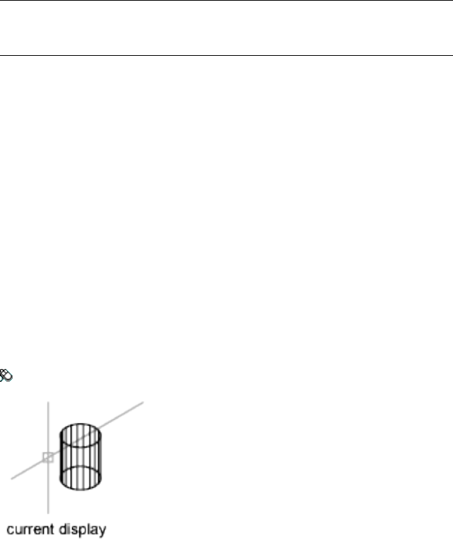
Details Displays the Group Manager—Details dialog box. This dialog box lists
any group names you have created under Group. Select a name to display the
number of objects in the group and the group description.
Select Group Selects all objects in the specified group. To select objects in a
group, select the group name under Group and click Select Group.
NOTE When the PICKADD system variable is set to 1, you can add and remove
objects from the current group selection set. When PICKADD is set to 0, the current
selection set is replaced with a new selection set.
Deselect Group Removes a specified group from a selection set. If multiple
groups are selected, you can remove a specific group from the selection set by
selecting the group name under Group.
PLAN
Quick Reference
See also:
■Change to a View of the XY Plane
Displays an orthographic view of the XY plane of a specified user coordinate
system.
Access Methods
Menu: View ➤ 3D Views ➤ Plan View ➤ World UCS
List of Options
The following options are displayed.
952 | Chapter 16 P Commands
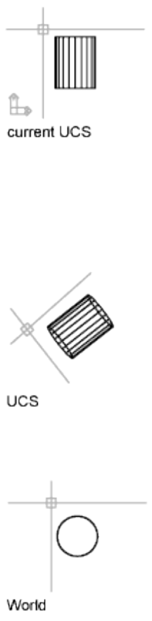
Current UCS Regenerates a plan view of the display so that the drawing extents
fit in the current viewport of the current UCS.
UCS Changes to a plan view of a previously saved UCS and regenerates the
display.
Enter name of UCS or [?]: Enter a name or enter ? to list all UCSs in the drawing
If you enter ? at the prompt, the following prompt is displayed:
Enter UCS name(s) to list <*>: Enter a name or enter * to list all UCSs in the drawing
World Regenerates a plan view of the display so that the drawing extents fit
on the screen of the world coordinate system.
PLAN | 953
PLINE
Quick Reference
See also:
■Draw Polylines
Creates a 2D polyline, a single object that is composed of line and arc segments.
Access Methods
Button
Ribbon: Home tab ➤ Draw panel ➤ Polyline
Menu: Draw ➤ Polyline
Toolbar: Draw
Summary
A 2D polyline is a connected sequence of segments created as a single planar
object. You can create straight line segments, arc segments, or a combination
of the two.
NOTE A temporary plus-shaped marker displays at the first point. This marker can
be useful when you create long and complicated polylines. It is removed when
you complete the polyline.
The PLINEGEN system variable controls the linetype pattern display around
and the smoothness of the vertices of a 2D polyline. Setting PLINEGEN to 1
generates new polylines in a continuous pattern around the vertices of the
completed polyline. Setting PLINEGEN to 0 starts and ends the polyline with
a dash at each vertex. PLINEGEN does not apply to polylines with tapered
segments.
954 | Chapter 16 P Commands
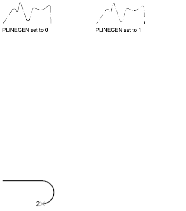
List of Prompts
The following prompts are displayed.
Specify start point: Specify a point
Current line-width is <current>
Specify next point on page 954 or [Arc on page 955/Close on page 959/Halfwidth
on page 959/Length on page 960/Undo on page 960/Width on page 960]: Specify
a point or enter an option
Next Point
Draws a line segment. The previous prompt is repeated.
Arc
Adds arc segments to the polyline.
Specify endpoint of arc or
[Angle/CEnter/CLose/Direction/Halfwidth/Line/Radius/Second
pt/Undo/Width]: Specify a point (2) or enter an option
NOTE For the Center option of the PLINE command, enter ce; for the Center
object snap, enter cen or center.
Endpoint of Arc
Draws an arc segment. The arc segment is tangent to the previous segment of
the polyline. The previous prompt is repeated.
Angle
Specifies the included angle of the arc segment from the start point.
Specify included angle:
PLINE | 955
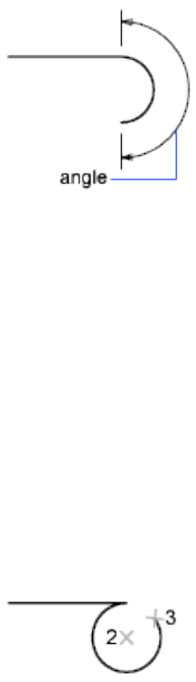
Entering a positive number creates counterclockwise arc segments. Entering
a negative number creates clockwise arc segments.
Specify endpoint of arc or [Center/Radius]: Specify a point or enter an option
Endpoint of Arc Specifies the endpoint and draws the arc segment.
Center Specifies the center of the arc segment.
Specify center point of arc:
Radius Specifies the radius of the arc segment.
Specify radius of arc: Specify a distance
Specify direction of chord for arc <current>: Specify a point or press ENTER
Center
Specifies the center of the arc segment.
Specify center point of arc: Specify a point (2)
Specify endpoint of arc or [Angle/Length]: Specify a point (3) or enter an option
Endpoint of Arc Specifies the endpoint and draws the arc segment.
Angle Specifies the included angle of the arc segment from the start point.
Specify included angle:
Length Specifies the chord length of the arc segment. If the previous segment
is an arc, the new arc segment is drawn tangent to the previous arc segment.
Specify length of chord:
956 | Chapter 16 P Commands
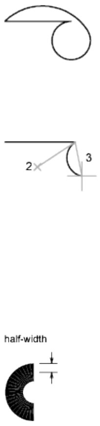
Close
Draws an arc segment from the last point specified to the starting point,
creating a closed polyline. At least two points must be specified to use this
option.
Direction
Specifies a starting direction for the arc segment.
Specify the tangent direction from the start point of arc: Specify a point (2)
Specify endpoint of arc: Specify a point (3)
Halfwidth
Specifies the width from the center of a wide polyline segment to one of its
edges.
Specify starting half-width <current>: Enter a value or press ENTER
Specify ending half-width <starting width>: Enter a value or press ENTER
The starting half-width becomes the default ending half-width. The ending
half-width becomes the uniform half-width for all subsequent segments until
you change the half-width again. The starting and ending points of wide line
segments are at the center of the line.
PLINE | 957
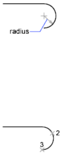
Typically, the intersections of adjacent wide polyline segments are beveled.
No beveling is performed for nontangent arc segments or very acute angles
or when a dot-dash linetype is used.
Line
Exits the Arc option and returns to the initial PLINE command prompts.
Radius
Specifies the radius of the arc segment.
Specify radius of arc: Specify a distance
Specify endpoint of arc or [Angle]: Specify a point or enter a
Endpoint of Arc Specifies the endpoint and draws the arc segment.
Angle Specifies the included angle for the arc segment.
Specify included angle:
Specify direction of chord for arc <current>: Specify an angle or press ENTER
Second Pt
Specifies the second point and endpoint of a three-point arc.
Specify second point on arc: Specify a point (2)
Specify end point of arc: Specify a point (3)
Undo
Removes the most recent arc segment added to the polyline.
Width
Specifies the width of the next arc segment.
Specify starting width <current>: Enter a value or press ENTER
Specify ending width <starting width>: Enter a value or press ENTER
958 | Chapter 16 P Commands
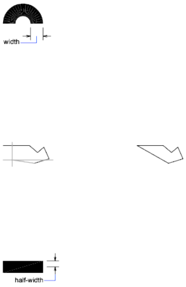
The starting width becomes the default ending width. The ending width
becomes the uniform width for all subsequent segments until you change the
width again. The starting and ending points of wide line segments are at the
center of the line.
Typically, the intersections of adjacent wide polyline segments are beveled.
No beveling is performed for nontangent arc segments, very acute angles, or
when a dot-dash linetype is used.
Close
Draws a line segment from the last point specified to the starting point,
creating a closed polyline. At least two points must be specified to use this
option.
Halfwidth
Specifies the width from the center of a wide polyline line segment to one of
its edges.
Specify starting half-width <current>: Enter a value or press ENTER
Specify ending half-width <current>: Enter a value or press ENTER
The starting half-width becomes the default ending half-width. The ending
half-width becomes the uniform half-width for all subsequent segments until
you change the half-width again. The starting and ending points of wide line
segments are at the center of the line.
PLINE | 959
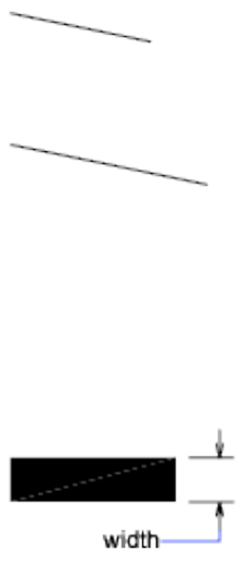
Typically, the intersections of adjacent wide polyline segments are beveled.
No beveling is performed for nontangent arc segments or very acute angles
or when a dot-dash linetype is used.
Length
Draws a line segment of a specified length at the same angle as the previous
segment. If the previous segment is an arc, the new line segment is drawn
tangent to that arc segment.
Specify length of line: Specify a distance
Undo
Removes the most recent line segment added to the polyline.
Width
Specifies the width of the next line segment.
Specify starting width <current>: Enter a value or press ENTER
Specify ending width <starting width>: Enter a value or press ENTER
The starting width becomes the default ending width. The ending width
becomes the uniform width for all subsequent segments until you change the
width again. The starting and ending points of wide line segments are at the
center of the line.
Typically, the intersections of adjacent wide polyline segments are beveled.
No beveling is performed for nontangent arc segments or very acute angles
or when a dot-dash linetype is used.
960 | Chapter 16 P Commands
PLOT
Quick Reference
See also:
■Overview of Plotting
Plots a drawing to a plotter, printer, or file.
Access Methods
Button
Ribbon: Output tab ➤ Plot panel ➤ Plot
Menu: Application menu ➤ Print ➤ Plot
Menu: File ➤ Plot
Toolbar: Standard
Shortcut menu: Right-click the Model tab or a layout tab and click Plot
Summary
The Plot dialog box is displayed. Click OK to begin plotting with the current
settings.
If you enter -plot at the Command prompt, options are displayed.
Plot Dialog Box
Quick Reference
See also:
■Overview of Plotting
Specifies device and media settings, and plots your drawing.
PLOT | 961
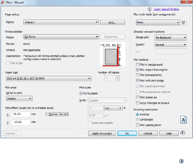
Summary
You can display more options by clicking the More Options button.
List of Options
The following options are displayed.
Page Setup
Displays a list of any named and saved page setups in the drawing. You can
base the current page setup on a named page setup saved in the drawing, or
you can create a new named page setup based on the current settings in the
Plot dialog box by clicking Add.
Name
Displays the name of the current page setup.
Add
Displays the Add Page Setup dialog box, in which you can save the current
settings in the Plot dialog box to a named page setup. You can modify this
page setup through the Page Setup Manager.
Printer/Plotter
Specifies a configured plotting device to use when plotting layouts.
962 | Chapter 16 P Commands

If the selected plotter doesn't support the layout's selected paper size, a warning
is displayed and you can select the plotter's default paper size or a custom
paper size.
Name
Lists the available PC3 files or system printers from which you can select to
plot the current layout. An icon in front of the device name identifies it as a
PC3 file or a system printer.
■PC3 file icon: Indicates a PC3 file.
■System printer icon: Indicates a system printer.
Properties
Displays the Plotter Configuration Editor (PC3 editor), in which you can view
or modify the current plotter configuration, ports, device, and media settings.
If you make changes to the PC3 file using the Plotter Configuration Editor,
the Changes to a Printer Configuration File dialog box is displayed.
Plotter
Displays the plot device specified in the currently selected page setup.
Where
Displays the physical location of the output device specified in the currently
selected page setup.
Description
Displays descriptive text about the output device specified in the currently
selected page setup. You can edit this text in the Plotter Configuration Editor.
Plot to File
Plots output to a file rather than to a plotter or printer. The default location
for plot files is specified in the Options dialog box, Plot and Publish tab, under
Default Location for Plot-to-File Operations.
Plot Dialog Box | 963
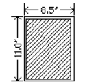
If the Plot to File option is turned on, when you click OK in the Plot dialog
box, the Plot to File dialog box (a standard file navigation dialog box) is
displayed.
Partial Preview
Shows an accurate representation of the effective plot area relative to the paper
size and printable area. The tooltip displays the paper size and printable area.
Paper Size
Displays standard paper sizes that are available for the selected plotting device.
If no plotter is selected, the full standard paper size list is displayed and
available for selection.
If the selected plotter doesn't support the layout's selected paper size, a warning
is displayed, and you can select the plotter's default paper size or a custom
paper size.
A default paper size is set for the plotting device when you create a PC3 file
with the Add-a-Plotter wizard. For information about this wizard, see “Set Up
Plotters and Printers” in the Driver and Peripheral Guide. The paper size that you
select in the Page Setup dialog box is saved with the layout and overrides the
PC3 file settings.
The actual printable area of the page, which is determined by the selected
plotting device and paper size, is indicated in the layout by a dashed line.
If you are plotting a raster image, such as a BMP or TIFF file, the size of the
plot is specified in pixels, not in inches or millimeters.
Number of Copies
Specifies the number of copies to plot. This option is not available when you
plot to file.
Plot Area
Specifies the portion of the drawing to be plotted. Under What to Plot, you
can select an area of the drawing to be plotted.
964 | Chapter 16 P Commands
Layout/Limits When plotting a layout, plots everything within the printable
area of the specified paper size, with the origin calculated from 0,0 in the
layout.
When plotting from the Model tab, plots the entire drawing area that is defined
by the grid limits. If the current viewport does not display a plan view, this
option has the same effect as the Extents option.
Extents Plots the portion of the current space of the drawing that contains
objects. All geometry in the current space is plotted. The drawing may be
regenerated to recalculate the extents before plotting.
Display Plots the view in the current viewport in the selected Model tab or
the current paper space view in the layout.
View Plots a view that was previously saved with the VIEW command. You
can select a named view from the list. If there are no saved views in the
drawing, this option is unavailable.
When the View option is selected, a View list is displayed that lists the named
views that are saved in the current drawing. You can select a view from this
list to plot.
Window
Plots any portion of the drawing that you specify. When you select Window,
the Window button becomes available. Click the Window button to use the
pointing device to specify the two corners of the area to be plotted, or enter
coordinate values.
Specify first corner: Specify a point
Specify other corner: Specify a point
Plot Offset
Specifies an offset of the plot area relative to the lower-left corner of the
printable area or to the edge of the paper, depending on the setting made in
the Specify Plot Offset Relative To option (Options dialog box, Plot and Publish
tab). The Plot Offset area of the Plot dialog box displays the specified plot
offset option in parentheses.
The printable area of a drawing sheet is defined by the selected output device
and is represented by a dashed line in a layout. When you change to another
output device, the printable area may change.
You can offset the geometry on the paper by entering a positive or negative
value in the X and Y offset boxes. The plotter unit values are in inches or
millimeters on the paper.
Center the Plot
Plot Dialog Box | 965

Automatically calculates the X and Y offset values to center the plot on the
paper. This option is not available when Plot Area is set to Layout.
X
Specifies the plot origin in the X direction relative to the setting of the Plot
Offset Definition option.
Y
Specifies the plot origin in the Y direction relative to the setting of the Plot
Offset Definition option.
Plot Scale
Controls the relative size of drawing units to plotted units. The default scale
setting is 1:1 when plotting a layout. The default setting is Fit to Paper when
plotting from the Model tab.
Fit to Paper
Scales the plot to fit within the selected paper size and displays the custom
scale factor in the Scale, Inch =, and Units boxes.
Scale
Defines the exact scale for the plot. Custom defines a user-defined scale. You
can create a custom scale by entering the number of inches (or millimeters)
equal to the number of drawing units.
NOTE You can modify the list of scales with SCALELISTEDIT.
Inch(es) =/mm =/Pixel(s) =
Specifies the number of inches, millimeters, or pixels equal to the specified
number of units.
Inch/mm/pixel
Specifies inches or mm for display of units in the Plot dialog box. The default
is based on the paper size and changes each time a new paper size is selected.
Pixel is available only when a raster output is selected.
Units
Specifies the number of units equal to the specified number of inches,
millimeters, or pixels.
Scale Lineweights
966 | Chapter 16 P Commands

Scales lineweights in proportion to the plot scale. Lineweights normally specify
the linewidth of plotted objects and are plotted with the linewidth size
regardless of the plot scale.
Preview
Displays the drawing as it will appear when plotted by starting the PREVIEW
command. To exit the preview and return to the Plot dialog box, press ESC,
press ENTER, or right-click and then click Exit on the shortcut menu.
Apply to Layout
Saves the current Plot dialog box settings to the current layout.
More Options
Controls display of additional options in the Plot dialog box.
■Plot Style Table (Pen Assignments)
■Shaded Viewport Options
■Plot Options
■Drawing Orientation
Plot Style Table (Pen Assignments)
Sets the plot style table, edits the plot style table, or creates a new plot style
table.
Name (Unlabeled)
Displays the plot style table that is assigned to the current Model tab or layout
tab and provides a list of the currently available plot style tables.
If you select New, the Add Plot Style Table wizard is displayed, which you can
use to create a new plot style table. The wizard that is displayed is determined
by whether the current drawing is in color-dependent or named mode.
Edit
Displays the Plot Style Table Editor, in which you can view or modify plot
styles for the currently assigned plot style table.
Plot Dialog Box | 967
Shaded Viewport Options
Specifies how shaded viewports are plotted and determines their resolution
level and dots per inch (dpi).
Shade Plot
Specifies how views are plotted. To specify this setting for a viewport on a
layout tab, select the viewport and then, on the Tools menu, click Properties.
From the Model tab, you can select from the following options:
■As Displayed. Plots objects the way they are displayed on the screen.
■Legacy Wireframe. Objects in wireframe regardless of the way they are
displayed on the screen, using the legacy SHADEMODE on page 1116
command.
■Legacy Hidden. Objects with hidden lines removed regardless of the way
the objects are displayed on the screen, using the legacy SHADEMODE on
page 1116 command.
■Wireframe. Plots objects in wireframe regardless of the way they are
displayed on the screen.
■Hidden. Plots objects with hidden lines removed regardless of the way the
objects are displayed on the screen.
■Shades of Gray. Plots objects with Shades of Gray visual style applied
regardless of the way the objects are displayed on the screen.
■Sketchy. Plots objects with Sketchy visual style applied regardless of the
way the objects are displayed on the screen.
■X-ray. Plots objects with x-ray visual style applied regardless of the way
the objects are displayed on the screen
■Shaded with Edges. Plots objects with Shded with Edges visual style applied
regardless of the way the objects are displayed on the screen
■Shaded. Plots objects with Shaded visual style applied regardless of the
way the objects are displayed on the screen
Quality
Specifies the resolution at which shaded viewports are plotted.
You can select from the following options:
■Draft: Sets shaded model space views to be plotted as wireframe.
968 | Chapter 16 P Commands

■Preview: Sets shaded model space views to be plotted at one quarter of the
current device resolution, to a maximum of 150 dpi.
■Normal: Sets shaded model space views to be plotted at one half of the
current device resolution, to a maximum of 300 dpi.
■Presentation: Sets shaded model space views to be plotted at the current
device resolution, to a maximum of 600 dpi.
■Maximum: Sets shaded model space views to be plotted at the current device
resolution with no maximum.
■Custom: Sets shaded model space views to be plotted at the resolution
setting that you specify in the DPI box, up to the current device resolution.
DPI
Specifies the dots per inch for shaded views, up to the maximum resolution
of the current plotting device. This option is available if you select Custom
in the Quality box.
NOTE Shaded viewport plotting of rendered views is not supported.
Plot Options
Specifies options for lineweights, transparency, plot styles, shaded plots, and
the order in which objects are plotted.
Plot in Background
Specifies that the plot is processed in the background. (BACKGROUNDPLOT
system variable)
Plot Object Lineweights
Specifies whether lineweights assigned to objects and layers are plotted. This
option is unavailable if Plot with Plot Styles is selected.
Plot Transparency
Specifies whether object transparency is plotted. This option should only be
used when plotting drawings with transparent objects.
IMPORTANT For perfomance reasons, plotting transparency is disabled by default.
To plot transparent objects, check the Plot Transparency option. This setting can
be overridden by the PLOTTRANSPARENCYOVERRIDE on page 1617 system variable.
By default, the system variable honors the setting in the Page Setup and the Plot
dialog boxes.
Plot Dialog Box | 969

Plot with Plot Styles
Specifies whether plot styles applied to objects and layers are plotted. When
you select this option, Plot Object Lineweights is automatically selected also.
Plot Paperspace Last
Plots model space geometry first. Paper space geometry is usually plotted
before model space geometry.
Hide Paperspace Objects
Specifies whether the HIDE operation applies to objects in the paper space
viewport. This option is available only from a layout tab. The effect of this
setting is reflected in the plot preview, but not in the layout.
Plot Stamp On
Turns on plot stamping. Places a plot stamp on a specified corner of each
drawing and/or logs it to a file.
Plot stamp settings are specified in the Plot Stamp dialog box, in which you
can specify the information that you want applied to the plot stamp, such as
drawing name, date and time, plot scale, and so on. To open the Plot Stamp
dialog box, select the Plot Stamp On option, and then click the Plot Stamp
Settings button that is displayed to the right of the option.
You can also open the Plot Stamp dialog box by clicking the Plot Stamp Settings
button on the Plot and Publish tab of the Options dialog box.
Plot Stamp Settings button
Displays the Plot Stamp dialog box when the Plot Stamp On option is selected
in the Plot dialog box.
Save Changes to Layout
Saves changes that you make in the Plot dialog box to the layout.
Drawing Orientation
Specifies the orientation of the drawing on the paper for plotters that support
landscape or portrait orientation. The paper icon represents the media
orientation of the selected paper. The letter icon represents the orientation of
the drawing on the page.
Portrait
970 | Chapter 16 P Commands
Orients and plots the drawing so that the short edge of the paper represents
the top of the page.
Landscape
Orients and plots the drawing so that the long edge of the paper represents
the top of the page.
Plot Upside-Down
Orients and plots the drawing upside down.
Icon
Indicates the media orientation of the selected paper and represents the
orientation of the drawing on the page as a letter on the paper.
NOTE Drawing orientation is also affected by the PLOTROTMODE system variable.
Less Options
Hides the following options in the Plot dialog box:
■Plot Style Table (Pen Assignments)
■Shaded Viewport Options
■Plot Options
■Drawing Orientation
Add Page Setup Dialog Box
Quick Reference
See also:
■Overview of Plotting
Saves the current settings in the Plot dialog box to a named page setup.
Summary
You can modify this page setup through the Page Setup Manager.
Add Page Setup Dialog Box | 971
List of Options
The following options are displayed.
New Page Setup Name
Specifies a name for the new page setup. You can modify the new named page
setup later through the Page Setup Manager.
Changes to a Printer Configuration File Dialog Box
Quick Reference
See also:
■Overview of Plotting
Notifies you that you have made changes to an existing plotter configuration
(PC3) file.
List of Options
The following options are displayed.
Apply Changes for the Current Plot Only
Uses the changes you've made to the PC3 file in the current plot but does not
save them in the PC3 file.
Save Changes to the Following File
Specifies the path of the PC3 file that you have changed. To preserve the
original PC3 file, specify a new file name.
Plot Job Progress Dialog Box
Quick Reference
See also:
■Overview of Plotting
Provides information about the status and progress of your plot job.
972 | Chapter 16 P Commands
List of Options
The following options are displayed.
Cancel Sheet Cancels the plot of the sheet currently being processed.
Cancel Job Cancels the plot job.
Update PC3 File with New Printer Dialog Box
Quick Reference
See also:
■Overview of Plotting
Displays the device driver name that is stored in the PC3 file.
Summary
A device can be a plotter or printer. With this dialog box, you can select a
valid plotter or printer and update the existing PC3 file; you can also save a
modified copy as a new PC3 file.
The dialog box is displayed in the PLOT or PAGESETUP command in a layout
configured for a PC3 file that contains an invalid or missing plotter or printer
name.
List of Options
The following options are displayed.
Device Needed
Displays the device specified in the PC3 file that is configured for the current
layout.
Printer Name
Lists the available plotters, printers, and PC3 files. Select a plotter, printer, or
PC3 file to be substituted for the missing printer specified in your PC3 file.
Select None if you don't want to make any substitution.
If you select None, the other settings for the current layout remain unchanged.
If you select a plotter or printer that uses a different driver than the one
Update PC3 File with New Printer Dialog Box | 973
specified in the original PC3 file, the following configuration information
may change when the PC3 file is saved:
■Plot quality
■Color depth
■Resolution
■Media source
■Media destination
■Media finishing options (such as folding or binding)
■Any custom settings of the previous device or driver
If the plotter or printer you select can't support the paper size specified in the
layout, the default paper size is used. A warning is displayed that allows you
to cancel this operation and return to the Plot or Page Setup dialog box with
the None device selected.
Device For each selection you make under Printer Name, the corresponding
device driver name is displayed in this column, as follows:
■For a selected plotter or printer, this column displays the device driver
name stored in the plotter or printer's PC3 file.
■For a selected PC3 file, this column displays the device driver name stored
in the PC3 file.
■For a selection of None, this column displays no device name. No device
will be substituted for the missing printer specified in the PC3 file.
Status Area
Displays information about the selected plotter, printer, or PC3 file.
Update and Save PC3 File
Displays the name of the PC3 file for the current layout. If you click OK
without changing the name of the PC3 file, the existing PC3 file is updated
with the new printer name. If you change the name of the PC3 file and click
OK, a copy of the PC3 file is saved with the new printer information.
974 | Chapter 16 P Commands
-PLOT
Quick Reference
See also:
■Overview of Plotting
Plots a drawing to a plotter, printer, or file in the command line.
If you enter -plot at the Command prompt, the following prompts are
displayed.
List of Prompts
The following prompts are displayed.
Detailed plot configuration [Yes on page 975/No on page 975] <No>: Enter y or
n or press ENTER
No
Indicates that you do not want a detailed plot configuration for this plot.
Enter a layout name or [?] <current>:
Enter a page setup name < >:
Enter an output device name or [?] <current>:
Write the plot to a file [Yes/No] <current>:
Enter file name: <dwgname-layoutname.plt>:
Save changes to layout [Yes/No] <No>:
Proceed with Plot [Yes/No] <Y>:
For information about these prompts, see the description for Yes.
Yes
Specifies detailed page settings for the Model tab or layout tab you are plotting.
Enter a layout name or [?] <current>: Specify the name of the layout tab you want
to plot
Enter an output device name or [?] <current>: Specify the name of the output
device to which you want to plot the Model tab or layout tab you selected
If you enter a new device name without an extension, the program assumes
that the device is a PC3 file (Autodesk® HDI plotter configuration file). If no
-PLOT | 975
PC3 file is found, the program searches for a Windows system printer with
that device name.
Enter paper size or [?] <current>: Specify the paper size to use for the plot or enter
? to view the actual list of paper sizes defined for the plotter driver
You must specify a paper size exactly as it is defined by the plotter driver.
Enter paper units [Inches/Millimeters] <current>:
The Enter Paper Units prompt is not displayed if you are plotting a raster
image, such as a BMP or TIFF file, because the size of the plot is assumed to
be in pixels.
Enter drawing orientation [Portrait/Landscape] <current>:
Portrait Orients and plots the drawing so that the short edge of the paper
represents the top of the page.
Landscape Orients and plots the drawing so that the long edge of the paper
represents the top of the page.
Plot upside down [Yes/No] <No>:
Orients and plots the drawing upside down.
Enter plot area [Display/Extents/Limits/Layout/View/Window] <current>:
Display Plots the view in the current viewport on the Model tab or the current
view in the layout, depending on which tab you select to plot.
Extents Plots all of the objects in the current viewport, except objects on
frozen layers. From a layout tab, plots all the geometry in paper space. The
drawing may be regenerated to recalculate the extents before plotting.
Limits Plots the drawing area defined by the grid limits. Available only when
the Model tab is selected.
Layout Plots everything within the printable area of the specified paper size,
with the origin calculated from 0,0 in the layout. Available only when a layout
tab is selected.
View Plots a view saved previously with the VIEW command. You can select
a named view from the list provided. If there are no saved views in the drawing,
this option is unavailable.
Window Plots any portion of the drawing you specify. This option prompts
you to specify the corners of the window.
Enter lower left corner of window: Specify a point
Enter upper right corner of window: Specify a point
976 | Chapter 16 P Commands

Enter plot scale (Plotted Inches = Drawing Units) or [Fit] <current>: Specify the
scale of the plot
Plotted Inches = Drawing Units Calculates the plot scale based on the inches
or millimeters to drawing units that you specify. You can also enter a real
number as a fraction (for example, you can enter 1=2 or .5).
Fit Calculates the scale to fit the area on the sheet of paper.
The default scale setting is 1:1 when you are plotting a layout, unless you
modified and saved the setting. The default setting is Fit when plotting a
Model tab.
Enter plot offset (x, y) or [Center] <current>: Specify the plot offset in either the X
or Y direction, or enter c to center the plot on the paper
Plot with plot styles [Yes/No] <current>: Specify whether to plot using the plot
styles applied to objects and defined in the plot style table
If you specify Yes to plot with plot styles, the following prompt is displayed:
Enter plot style table name or [?] (enter . for none) <current>: Enter a plot style
table name, ? to view plot style tables, or . (period) for none
All style definitions with different property characteristics are stored in the
current plot style table and can be attached to the geometry. This setting
replaces pen mapping in earlier versions of the program.
Plot with lineweights [Yes/No] <current>:
Scale lineweights with plot scale [Yes/No] <current>:
NOTE The Scale Lineweights with Plot Scale prompt is displayed only when you
plot from a layout tab. Settings for the shaded plotting type are available only
when you plot from the Model tab. To control shaded plotting settings of viewports
in a layout tab, use the Shadeplot option of the -vports command when you
create a viewport.
Enter shade plot setting [As displayed/Wireframe/Hidden] <As displayed>: Enter
a shade plot option
Specifies how model space views are plotted.
As Displayed Specifies that a model space view is plotted the same way it is
displayed.
Wireframe Specifies that a model space view is plotted in wireframe regardless
of display.
-PLOT | 977
Hidden Specifies that a model space view is plotted with hidden lines removed
regardless of display.
Write the plot to a file [Yes/No] <current>: Enter y if you want to write the plotted
drawing to a file, or press Enter to plot to an output device
If you specify Yes, the following prompt is displayed:
Enter file name: <dwgname-layoutname.plt>: Enter a file name
Save changes to page setup? Or set shade plot quality? [Yes/No/Quality] <No>:
If you enter y, the current settings in the Page Setup dialog box are saved. If
you enter q, you are prompted for the shaded plotting quality and are given
the option of providing a custom dpi. Then you are prompted to save the
page setup with the added quality settings.
Enter shade plot quality
[Draft/Preview/Normal/pResentation/Maximum/Custom] <Normal>: Enter c
if you want to specify a dpi, or to use a preset dpi, specify a different quality option
Enter custom dpi <150>:
Save changes to page setup [Yes/No]? <No>:
Plot paper space first [Yes/No] <current>:
Paper space geometry is usually plotted before model space geometry. If you
enter n, the model space geometry is plotted first, and paper space geometry
is plotted last. This option is available only if you are plotting from a layout
tab.
Hide paperspace objects? [Yes/No] <No>:
Specifies whether the Hide operation applies to objects in the paper space
viewport. This option is available only from a layout tab.
Proceed with plot [Yes/No] <Y>:
PLOTSTAMP
Quick Reference
See also:
■Set Options for Plotted Objects
978 | Chapter 16 P Commands

Places a plot stamp on a specified corner of each drawing and logs it to a file.
Summary
The Plot Stamp dialog box is displayed.
NOTE Plot stamp will always be drawn with pen number 7, or the highest
numbered available pen if the plotter does not hold seven pens. You must install
a suitable pen in that position. If you are using a non-pen (raster) device, color 7
is always used for plot stamping.
If you enter -plotstamp at the Command prompt, options are displayed.
Plot Stamp Dialog Box
Quick Reference
See also:
■Set Options for Plotted Objects
Specifies the information for the plot stamp.
List of Options
The following options are displayed.
Plot Stamp Fields
Specifies the drawing information you want applied to the plot stamp. The
selected fields are separated by commas and a space.
Drawing Name
Includes the drawing name and path in the plot stamp information.
Layout Name
Includes the name of the layout in the plot stamp information.
Date and Time
Includes the date and time in the plot stamp information.
NOTE A plot stamp uses the current date and time format setting of the operating
system. Plot stamp specifically uses the short date style for dates.
Plot Stamp Dialog Box | 979
Login Name
Includes the user login name in the plot stamp information.
Device Name
Includes the current plotting device name in the plot stamp information.
Paper Size
Includes the paper size for the currently configured plotting device in the plot
stamp information.
Plot Scale
Includes the plot scale in the plot stamp information.
Preview
Provides a visual display of the plot stamp location based on the location and
rotation values you have specified in the Advanced Options dialog box. You
cannot preview the plot stamp any other way. This is not a preview of the
plot stamp contents.
User Defined Fields
Provides text that can optionally be plotted, logged, or both plotted and logged
at plot time. The selected value in each user-defined list will be plotted.
For example, you might populate one list with media types or prices and the
other with job names. If the user-defined value is set to <none>, then no
user-defined information is plotted
Add/Edit
Displays the User Defined Fields dialog box, where you can add, edit, or delete
user-defined fields.
Plot Stamp Parameter File
Stores plot stamp information in a file with a .pss extension. Multiple users
can access the same file and stamp their plots based on company standard
settings.
Two PSS files are provided, Mm.pss and Inches.pss, which are located in the
Support folder. The initial default plot stamp parameter file name is determined
by the regional settings of the operating system when the program is installed.
Path
Specifies the location of the plot stamp parameter file.
Load
980 | Chapter 16 P Commands
Displays the Plotstamp Parameter File Name dialog box (a standard file
selection dialog box) in which you can specify the location of the parameter
file you want to use.
Save As
Saves the current plot stamp settings in a new parameter file.
Advanced
Displays the Advanced Options dialog box, in which you can set the location,
text properties, and units of the plot stamp. You can also create a log file, and
set its location.
User Defined Fields Dialog Box
Quick Reference
See also:
■Set Options for Plotted Objects
Create and mange user-defined fields.
Summary
User-defined fields are created and edited using the User Defined Fields dialog
box, which is displayed when you choose the Add/Edit button in the Plot
Stamp dialog box.
List of Options
The following options are displayed.
Name
Lists the available user-defined fields.
Add
Adds an editable user-defined field.
Edit
Allows editing of the selected user-defined field.
Delete
User Defined Fields Dialog Box | 981

Deletes the selected user-defined field.
Advanced Options Dialog Box
Quick Reference
See also:
■Set Options for Plotted Objects
Determines the location, text properties, and units of the plot stamp.
Access Methods
Command entry: plotstamp
Summary
You can also create a log file and set its location. The dialog box is displayed
when you choose the Advanced button in the Plot Stamp dialog box.
List of Options
The following options are displayed.
Location and Offset
Determines the plot stamp location, the orientation of the plot stamp, and
the offset you want to apply relative to either the printable area or the paper
border.
Location
Indicates the area where you want to place the plot stamp. Selections include
Top Left, Bottom Left (default), Bottom Right, and Top Right. The location is
relative to the image orientation of the drawing on the page.
Orientation
Indicates the rotation of the plot stamp in relation to the specified page. The
options are Horizontal and Vertical for each of the locations (for example,
Top Left Horizontal and Top Left Vertical).
Stamp Upside Down
Rotates the plot stamp upside down.
982 | Chapter 16 P Commands
X Offset
Determines the X offset value that is calculated from either the corner of the
paper or the corner of the printable area, depending on which setting you
specify. If you specify Offset Relative to Paper Border, the offset value is
calculated so that the plot stamp information fits within the designated paper
size. If the offset value positions the plot stamp information beyond the
printable area, the plot stamp text is cut off.
Y Offset
Determines the Y offset value that is calculated from either the corner of the
paper or the corner of the printable area, depending on which setting you
specify. If you specify Offset Relative to Paper Border, the offset value is
calculated so that the plot stamp information fits within the paper size.
Offset Relative to Printable Area
Calculates the offset values that you specify from the corner of the printable
area of the paper (not the corner of the paper).
Offset Relative to Paper Border
Calculates the offset values that you specify from the corner of the paper (not
the corner of the printable area of the paper).
Text Properties
Determines the font, height, and number of lines you want to apply to the
plot stamp text.
Font
Specifies the TrueType font you want to apply to the text used for the plot
stamp information.
Height
Specifies the text height you want to apply to the plot stamp information.
Single Line Plot Stamp
Places the plot stamp information in a single line of text. The plot stamp
information can consist of up to two lines of text, but the placement and
offset values you specify must accommodate text wrapping and text height.
If this option is cleared, plot stamp text is wrapped after the third field.
Plot Stamp Units
Specifies the units used to measure X offset, Y offset, and height. You can
define units using inches, millimeters, or pixels.
Advanced Options Dialog Box | 983
Two sets of values for the plot stamp size and location are saved in the PSS
file: one for the dimensionless file formats and the other for dimensional file
formats. If the units you select in the dialog box are dimensional, then the
dimensional values are displayed and modified. To access the dimensionless
values, you need to select pixels as the unit of measurement. Regardless of the
units selected in the dialog box, the correct set of values is applied at plot
time. In other words, changing the unit of measurement does not cause the
values to be recalculated.
Log File Location
Writes the plot stamp information to a log file instead of, or in addition to,
stamping the current plot. If plot stamping is turned off, the log file can still
be created.
Create a Log File
Writes the plot stamp information to a log file. The default log file is plot.log,
and it is located in the main application folder.
You can specify a different file name and path. After the initial plot.log file is
created, the plot stamp information in each succeeding plotted drawing is
added to this file. Each drawing's plot stamp information is a single line of
text. The plot stamp log file can be placed on a network drive and shared by
multiple users. Plot stamp information from each user is appended to the
plot.log file.
Log File Name
Specifies the file name for the log file you are creating. Enter a new file name
if you do not want to use the default file name, plot.log.
Browse
Lists the currently saved plot stamp log files. You can choose to overwrite an
existing plot stamp log file with the currently specified plot stamp information,
and then to save this file.
-PLOTSTAMP
Quick Reference
See also:
■Set Options for Plotted Objects
984 | Chapter 16 P Commands
Places a plot stamp on a specified corner of each drawing and logs it to a file.
If you enter -plotstamp at the Command prompt, the following prompts are
displayed. The settings in the PSS file are displayed as defaults for each prompt.
You can use -PLOTSTAMP as part of a plotting script to modify plot stamp
information for a drawing.
LIst of Prompts
The following prompts are displayed.
Enter an option [On/OFF/Fields/User fields/Log file/LOCation/Text
properties/UNits]:
On Turns on the plot stamp for the current drawing.
OFF Turns off the plot stamp for the current drawing.
Fields Specifies the plot stamp field information you want to apply to the
current plot stamp.
Stamp drawing name? [Yes/No] <Yes>:
Stamp layout name? [Yes/No] <Yes>:
Stamp date and time? [Yes/No] <Yes>:
Stamp login name? [Yes/No] <Yes>:
Stamp plot device name? [Yes/No] <Yes>:
Stamp paper size? [Yes/No] <Yes>:
Stamp plot scale? [Yes/No] <Yes>:
User Fields Specifies the user-defined fields you want to apply to the current
plot stamp.
Enter User field 1 <>: Enter any user-defined field
Enter User field 2 <>: Enter any user-defined field
Log File Specifies writing the current plot stamp information to a log file
rather than applying this information to the current plotted drawing. The
default log file is plot.log, unless you specify another file path.
Write plot stamp to log file? [Yes/No] <Yes>:
Enter log file path <plot.log>:
Location Determines the location of the plot stamp on the page based on
offset, orientation, and relationship to either the printable area or the border
of the paper.
Location selections include and are relative to the printable area or the border
of the paper, depending on what you specify at the prompt.
-PLOTSTAMP | 985
Enter stamp location [TL/TR/BL/BR] <BL>:
■TL: Top Left
■TR: Top Right
■BL: Bottom Left
■BR: Bottom Right
Text orientation indicates the rotation angle of the plot stamp in relation to
the page.
Enter text orientation [Horizontal/Vertical] <Horizontal>:
■Horizontal: Plot stamp will be horizontal relative to the page.
■Vertical: Plot stamp will be vertical relative to the page.
Stamp upside-down [Yes/No] <No>:
Specify plot stamp offset <0.1000,0.1000>:
Specifying an offset relative to the paper border calculates the offset values
that you specify from the corner of the paper. Specifying an offset relative to
the printable area calculates the offset values that you specify from the corner
of the printable area.
Specify offset relative to [paper Border/printable Area] <printable Area>:
Text Properties Determines the font name and text height for the current
plot stamp text. You can also specify to place the text on one line or to wrap
the text to two lines. The placement and offset values you specify for this plot
stamp must accommodate the text wrapping and the text height.
Enter font name <>: Enter a font name
Enter text height <0.1500>: Enter a value
Place plot stamp on single line? [Yes/No] <No >:
Units Specifies the units used to measure X offset, Y offset, and height. You
can define units using inches, millimeters, or pixels.
Enter measurement units [Inches/Millimeters/Pixels] <Inches>:
986 | Chapter 16 P Commands

PLOTSTYLE
Quick Reference
See also:
■Use Plot Styles to Control Plotted Objects
Controls the named plot styles that are attached to the current layout and
can be assigned to objects.
Access Methods
Button
Menu: Application menu ➤ Print ➤ Edit Plot Style Tables
Menu: Format ➤ Plot Style
Summary
To use the PLOTSTYLE command, the drawing must be configured to use
named plot styles.
■If a drawing is in Color-Dependent mode, you can convert it to use named
plot styles using the CONVERTPSTYLES command.
■To configure a new drawing to use named plot styles, set PSTYLEPOLICY
to 0 before creating the new drawing.
If no selection set exists, the Current Plot Style dialog box is displayed. If a
selection set exists, the Select Plot Style dialog box is displayed.
If you enter -plotstyle at the Command prompt, options are displayed on page
990.
PLOTSTYLE | 987
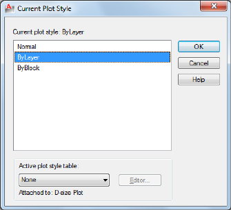
Current Plot Style Dialog Box
Quick Reference
See also:
■Use Plot Styles to Control Plotted Objects
Specifies the plot style for new objects.
List of Options
The following options are displayed.
Current Plot Style
Displays the current plot style.
Plot Style List
Displays the available plot styles that can be assigned to an object, including
the default plot style, NORMAL. A plot style is a collection of overrides for
color, dithering, gray scale, pen assignments, screening, linetype, lineweight,
end styles, join styles, and fill styles.
Active Plot Style Table
Sets the plot style table attached to the current layout. A plot style table is a
collection of plot style definitions.
Editor
988 | Chapter 16 P Commands
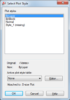
Displays the Plot Style Table Editor, in which you modify the plot styles in
the plot style table.
Attached To
Displays the tab (Model tab or layout tab) that the plot style table is attached
to.
Select Plot Style Dialog Box
Quick Reference
See also:
■Use Plot Styles to Control Plotted Objects
Specifies the plot style to be assigned.
List of Options
The following options are displayed.
Plot Styles
Displays the available plot styles, including the default plot style, NORMAL.
A plot style is a collection of property settings used in plotting.
Select Plot Style Dialog Box | 989
Original
Displays the originally assigned plot style.
New
Displays the new plot style to be assigned.
Active Plot Style Table
Sets the plot style table attached to the current drawing. A plot style table
defines plot styles.
Editor
Displays the Plot Style Table Editor.
Attached To
Displays the tab (Model tab or layout tab) that the plot style table is attached
to.
-PLOTSTYLE
Quick Reference
See also:
■Use Plot Styles to Control Plotted Objects
Lists all available plotstyles in the current drawing and to set a plotstyle current.
List of Prompts
The following prompts are displayed.
Current plot style is "current"
Enter an option [?/Current]:
?—List Plot Styles Lists the plot styles in the attached plot style table.
Current Specifies the plot style to use for new objects.
990 | Chapter 16 P Commands
PLOTTERMANAGER
Quick Reference
See also:
■Overview of Plotting
Displays the Plotter Manager, where you can add or edit a plotter configuration.
Access Methods
Button
Ribbon: Output tab ➤ Plot panel ➤ Manage Plotters
Menu: Application menu ➤ Print ➤ Manage Plotters
Menu: File ➤ Plotter Manager
Summary
In the folder, you can start the Add-a-Plotter wizard, or double-click a PC3 file
to open the Plotter Configuration Editor.
■Double-click the Add-a-Plotter wizard to add and configure plotters and
printers.
■Double-click a plotter configuration (PC3 file) to start the Plotter
Configuration Editor.
Add-a-Plotter Wizard
Quick Reference
See also:
■Overview of Plotting
PLOTTERMANAGER | 991
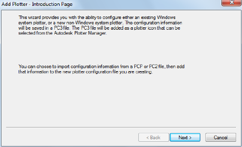
Adds new plotters and printers. The wizard produces a PC3 file that you can
edit in the Plotter Configuration Editor. Your configurations are stored in the
Plotters folder.
Plotter Configuration Editor
Quick Reference
See also:
■Overview of Plotting
Modifies a PC3 file's plotter port connections and output settings, including
media, graphics, physical pen configuration, custom properties, initialization
strings, calibration, and user-defined paper sizes. You can drag these
configuration options from one PC3 file to another.
Summary
You can start the Plotter Configuration Editor with any of the following
methods:
■Double-click a PC3 file in Microsoft® Windows® Explorer or right-click the
PC3 file and click Open. (By default, PC3 files are stored in the Plotters
folder. To find the location of your plotter files, on the Tools menu, click
Options. In the Options dialog box, Files tab, click the plus sign to the left
of Printer Support File Path. Click the plus sign to the left of the Printer
992 | Chapter 16 P Commands
Configuration Search Path file. Under Printer Configuration Search Path,
click the path name to view the location of your plotter files.)
■Choose Edit Plotter Configuration from within the Add-a-Plotter wizard.
■Choose Properties in the Page Setup dialog box.
■Choose Properties in the Plot dialog box.
Depending on your configured plotting device, additional options may be
available on the Device and Document Settings tab. For example, when you
configure a nonsystem plotter, you can modify the pen characteristics.
■General
■Ports on page 995
■Device and Document Settings on page 996
General Tab (Plotter Configuration Editor)
Quick Reference
See also:
■Overview of Plotting
Contains basic information about the plotter configuration (PC3) file. You
can add or modify the information in the Description area. The remainder of
the tab is read-only.
Plotter Configuration Editor | 993
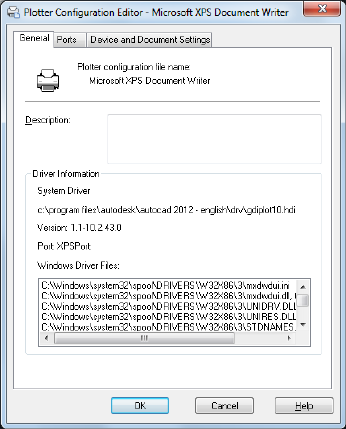
List of Options
The following options are displayed.
Plotter Configuration File Name Displays the file name you assigned in the
Add-a-Plotter wizard.
Description
Displays information you want to include about the plotter.
Driver Information Displays the following information:
■Plotter driver type (system or nonsystem), name, model, and location
■HDI driver file version number (AutoCAD LT specialized driver files)
■UNC name of the network server (if the plotter is connected to a network
server)
■I/O port (if the plotter is connected locally)
■Name of the system printer (if the configured plotter is the system printer)
■PMP (Plot Model Parameters) file name and location (if a PMP file is
attached to the PC3 file)
994 | Chapter 16 P Commands
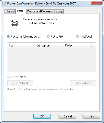
Ports Tab (Plotter Configuration Editor)
Quick Reference
See also:
■Overview of Plotting
Changes communication settings between the configured plotter and your
computer or network system. You can specify whether you want to plot
through a port, plot to a file, or use AutoSpool. See “Use AutoSpool” in the
Driver and Peripheral Guide.
If you plot through a parallel port, you can specify the timeout value. If you
plot through a serial port, you can change the baud rate, protocol, flow control,
and input and output timeout values.
List of Options
The following options are displayed.
Plot to the Following Port
Sends the drawing to the plotter through the selected port.
Plotter Configuration Editor | 995
Plot to File
Sends the drawing to the file specified in the Plot dialog box.
AutoSpool
Uses the AutoSpool utility to plot the drawing. AutoSpool is specified on the
Files tab in the Options dialog box.
Port List
Displays a list and description of available ports, both local and network. If
the port is a network port, the name of the network printer is also displayed.
Show All Ports
Shows all available ports on the computer regardless of the ports available on
the plotter.
Browse Network
Displays the network choices so you can connect to another instance of a
nonsystem plotter.
Configure Port
Displays either the Configure LPT Port dialog box or the Settings for COM
Port dialog box.
Device and Document Settings Tab (Plotter Configuration Editor)
Quick Reference
See also:
■Overview of Plotting
Controls many of the settings in the PC3 file. Click the icon for any of the
nodes to view and change the specific settings. When you change a setting,
your changes appear in angle brackets (< >) next to the setting name. A check
mark is also displayed over the icon of the node with a changed value.
996 | Chapter 16 P Commands
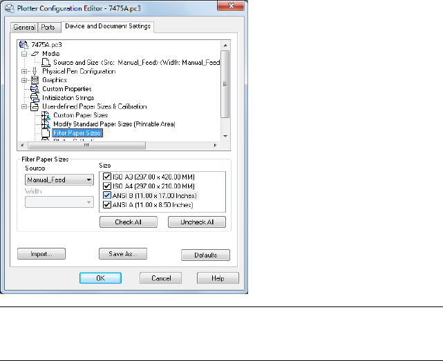
NOTE Only the settings available for the configured device are displayed in the
tree view. In addition, you might not be able to edit some settings if the device
handles the setting through Custom Properties or doesn't support the capability.
List of Options
The following options are displayed.
Media Node
Specifies a paper source, size, type, and destination. Available settings depend
on the supported features of your configured plotter. For Windows system
printers, you must configure the media settings using the Custom Properties
node.
Source and Size
Specifies the paper source and size.
■Source: Specifies the paper source; for example, sheet-fed or roll-fed. If you
specify a tray, you can select the type of tray.
■Width: Specifies the width of the paper roll for a roll-fed source.
■Automatic: Enables the printer to specify the appropriate paper source.
■Size: Displays a list of available paper sources and both standard and custom
paper sizes.
Plotter Configuration Editor | 997

■Printable Bounds: Displays the print boundaries.
Media Type
Displays a list of the media types supported by the plotter configuration.
Duplex Printing
Determines double-sided printing and binding margin. Binding margin options
are available only for plotters that support duplex printing.
■None: Indicates no double-sided printing.
■Short Side: Places the binding margin on the short side of the paper.
■Long Side: Places the binding margin on the long side of the paper.
Media Destination
Displays a list of available media destinations for the configured plotter, such
as collating, cutting, and stapling. These options are available only for plotters
that support this function.
Physical Pen Configuration Node (for Pen Plotters Only)
Controls the specific pens in the pen plotter. The lower pane of the Device
and Document Settings tab displays a table used to describe the color, width,
and speed of each pen in the plotter.
NOTE The physical pen information cannot be detected automatically; you must
provide this information for your pen plotter under Physical Pen Characteristics.
Pen Configuration Specifies settings for pen plotters.
■Prompt for Pen Swapping: Use more than one pen while plotting on a
single-pen plotter. Under Physical Pen Characteristics, you can specify
settings for as many pens as you want. You are prompted when you need
to change pens.
■Area Fill Correction: Enables the program to compensate for pen widths when
plotting filled areas and wide polylines. Each polygon is shrunk by half of
the width of the pen used to draw it. This option prevents the plotter from
oversizing the filled area when using a wide pen and ensures precision.
Use this option if the plot must be accurate to half the pen width, such as
in printed circuit artwork.
■Pen Optimization Level: Reduces plot time and increases the efficiency of the
pens by optimizing the pen motion. For example, you can prevent pens
from retracing duplicate lines. If your drawing uses many colors or widths,
998 | Chapter 16 P Commands

you can reduce the time needed to change pens by selecting Adds Pen
Sorting. Every object that uses a particular pen will be plotted before
switching to another pen. Each method in the list includes the optimization
methods preceding it in the list (except for No Optimization).
Physical Pen Characteristics To plot your drawing correctly on a pen plotter,
you need to provide information about the pens in your plotter. For each pen
in your plotter, specify a color and width. To optimize pen performance, you
can specify a speed.
NOTE This information is required; the physical pen information cannot be
detected automatically.
■Color: Specifies the colors of the pens in your plotter. The pen color that
closely matches the object's color is selected. You can assign colors to your
pens that correspond to each object's color. Use the Color list to select one
of the following settings: No Pen, Red, Yellow, Green, Cyan, Blue, Magenta,
Black, or Other. If you choose Other, the Select Color dialog box is
displayed, providing access to the full color palette. Use No Pen to indicate
that there is no pen in a particular position.
■Speed: Adjusts pen speed on a pen-by-pen basis. This feature is useful, for
example, for slowing down pens that are skipping. Each pen manufacturer
recommends a pen speed for each type of media. For best results, use those
values. You can specify a pen speed in millimeters or inches per second.
■Width: Specifies the width of your pens so the program can determine if
multiple pen strokes are needed to draw wide lines. You can specify the
pen width in inches or millimeters. Be sure to select the pen width to
match the actual width of the pen. The list provides a set of common pen
widths.
Specifying pen characteristics here doesn't replace the pen tables you might
have imported from PCP, PC2, or CFG files from AutoCAD Release 14,
AutoCAD LT® 98, or earlier releases. For more information about importing
these settings, see “Change Plot Style Settings” in the User's Guide.
Graphics Node
Specifies settings for printing vector graphics, raster graphics, and TrueType
text. Depending on the capabilities of the plotter, you can modify color depth,
resolution, and dithering. You can select either color or monochrome output
for vector drawings. When printing raster images on a plotter with limited
memory, you can improve performance by making some changes to the quality
of the printed output. If you use a nonsystem plotter that supports varying
Plotter Configuration Editor | 999
amounts of installed RAM, you can provide that information to improve
performance.
Installed Memory
Provides the program with the amount of total memory (RAM) installed on
a nonsystem plotter. This option is only available for nonWindows system
printers that accept optional memory. If your plotter has extra memory, specify
the total amount of memory.
■Total Installed Memory: Specifies the total installed memory in megabytes.
The plotter driver uses the memory information to determine whether
banding or image quality degradation is required to prevent the system
from running out of memory.
Vector Graphics
Provides options for specifying the color depth, resolution, and dithering of
vector output. Some of the Vector Graphics options are closely interrelated;
changing an option can affect other available options.
■Color Depth: Displays a list for choosing color depth for the configured
plotter. The color depth options change as you change the resolution and
dithering values. More color depth uses more memory and takes longer to
plot. You can specify either color or monochrome output.
■Resolution: Adjusts the DPI (dots per inch) resolution of the configured
plotter. Changing the DPI resolution changes the options available in the
Dithering list. A higher resolution setting uses more memory and takes
longer to plot than a lower resolution setting.
■Dithering: Specifies a dithering choice for non-pen-based plotters. Some
dithering choices cause slower plotting.
Raster Graphics (Non-Pen Plotters Only)
Specifies trade-offs between plotting speed and output quality when plotting
raster objects on raster devices. If you reduce the image quality, you increase
output speed. If your system resources are limited, reducing image quality can
reduce the chance of running out of memory while plotting.
■Raster and Shaded/Rendered Viewports: Specifies a position on the slider that
balances output quality with memory and plotting speed when plotting
raster images and shaded viewports. (Rendered viewport plotting is not
supported in AutoCAD LT Position the slider at None to disable raster
image printing. Degrading the image quality lets you plot in less time.
1000 | Chapter 16 P Commands

Position the slider at Best for the best output at the expense of memory
and plotting speed.
■OLE: Specifies a position on the slider that balances output quality with
memory use and plotting speed when plotting OLE objects. Position the
slider at None to disable OLE object printing. Degrading the image quality
lets you plot in less time. Position the slider at Best for the best output at
the expense of memory and plotting speed.
■Trade-off: Specifies where to compromise quality if you can't output at the
highest quality. Move the slider to diminish resolution and color.
TrueType Text
On Windows system printers, specifies whether to plot TrueType text as a
graphic image or as text.
Plotting as a graphic guarantees that the text is printed as displayed, at the
expense of slowing down the plotter and using more memory. Plotting as
TrueType text prints faster and uses less memory; the plotter may use a different
font for printing.
■TrueType as Text: Plots TrueType text as text.
■TrueType as Graphics: Plots TrueType text as graphics.
Merge Control
On raster plotters, controls the appearance of lines that cross. Merge control
is not effective if your plotter is configured to plot everything as black or if
you are using PostScript language.
■Lines Overwrite: Uses the last plotted line to obscure the lines under it. Only
the topmost line is visible at the intersection.
■Lines Merge: Merges the colors of crossing lines.
NOTE Merge control may appear as an option for system printers that do not
actually support the feature. Please check your printer's documentation to
determine if merge control is supported.
Custom Properties Node
Modifies the device-specific properties for the plotter configuration. The
settings for each plotter vary. If the plotter manufacturer has not included a
Custom Properties dialog box for the device driver, the Custom Properties
option is not available.
Plotter Configuration Editor | 1001
For some drivers, such as ePlot, this is the only tree view option that is
displayed. For Windows system printers, most of the device-specific settings
are made in this dialog box. For more information about the custom properties
settings for your device, choose Help in the Custom Properties dialog box.
Initialization Strings Node (for Non-System Plotters Only)
Sets pre-initialization, post-initialization, and termination ASCII text plotter
strings, which send commands to a plotting device before and after the
program initializes the device and after plotting is complete.
If you are plotting to an unsupported plotter in emulation mode, you can
specify ASCII text initialization strings that prepare the plotter for printing,
set device-specific options, and restore the plotter to its original state. You can
also use initialization strings to turn on or off a plotting device feature that
is not supported by the program.
The text string is sent literally, except for a back slash (\). Use a back slash
followed by a three-digit number (taken from the ASCII table), for example,
\027, to specify binary (unprintable) characters such as the escape character.
\027 is interpreted and sent as a single character whose value is 27. The number
27 is the escape character. For example, \27%-12345X PJL ENTER LANGUAGE
= PostScript\10 sends an HP PJL command to a dual-language laser printer
before it's initialized and switches the printer into PostScript mode. The \027
sends an escape character and the \010 sends a line feed character. The
remainder of the text string is sent literally. It is best to use three decimal
digits for binary characters, so you'll need to add leading zeros as necessary.
Initialization strings should be used by advanced users only.
Pre-Initialization
Forces a plotter to emulate another plotter by sending a pre-initialization
ASCII text string to the plotter before it is initialized.
Use a back slash followed by a three-digit number (taken from the ASCII table),
for example, \027, to specify binary (unprintable) characters such as the escape
character.
Post-Initialization
Sets a device-specific option that is not supported elsewhere in the program.
Specify a post-initialization ASCII text string that is sent to the plotter after it
is initialized.
Use a back slash followed by a three-digit number (taken from the ASCII table),
for example, \027, to specify binary (unprintable) characters such as the escape
character.
1002 | Chapter 16 P Commands
Termination
Restores the printer to its original state after plotting. Specify a termination
ASCII text string that is sent to the plotter after plotting is complete.
Use a back slash followed by a three-digit number (taken from the ASCII table),
for example, \027, to specify binary (unprintable) characters such as the escape
character.
User-Defined Paper Sizes & Calibration Node
Attaches a PMP file to the PC3 file, calibrates the plotter, and adds, deletes,
revises, or filters custom paper sizes. You can also modify standard paper sizes.
This node accesses the Plotter Calibration and Custom Paper Size wizards. If
the plotter you are using has been calibrated, a Plotter Model Parameter (PMP)
file contains that calibration information. If the PMP file is not already attached
to the PC3 file you are editing, you must create that association so you can
use the PMP file. If the plotter was calibrated from within the Add-a-Plotter
wizard while creating the current PC3 file, the PMP file is already attached.
Use the PMP File Name option under User-defined Paper Sizes & Calibration
to attach a PMP file to, or detach the PMP file from, the PC3 file you are
editing.
Custom Paper Sizes (Nonsystem Printers Only)
Creates a customized paper size or changes the printable area of a standard or
nonstandard paper size.
With the Custom Paper Size wizard you can create a new paper size, or select
from a list of available paper sizes (from a PMP file) if the plotter is not a
Windows system printer. If the plotter is a Windows system printer, use
Custom Properties.
Each plotter has a maximum printable area determined by where it grips the
paper and how far the pen shuttle can reach. If you are creating a paper size
that is larger than the paper sizes offered in the Plotter Configuration Editor,
verify that the plotter is capable of plotting the new dimensions.
■Add: Starts the Custom Paper Size wizard. When you add a paper size, you
can either create a new paper size from scratch or create a new one based
on the listing of available paper sizes for the selected configured plotter.
The new paper size is a user-defined size, not a standard size.
■Delete: Deletes the selected custom paper size from the list.
■Edit: Starts the Custom Paper Size wizard, where you can modify the selected
paper size. You can change any of the custom paper size settings.
Plotter Configuration Editor | 1003

NOTE For Windows system printers, you can change the paper size settings and
create custom paper sizes only in the Custom Properties dialog box.
Modify Standard Paper Sizes
Adjusts the printable area for standard paper sizes to match the printer's
capabilities. (You can't create custom paper sizes for Windows system printers
using the Plotter Configuration Editor.)
■List of Standard Paper Sizes: Displays the available set of standard paper sizes.
■Modify: Starts the Custom Paper Size wizard. You can modify Printable Area
and File Name. The new paper size is a user-defined size, not a standard
size.
Filter Paper Sizes
Filters the list of paper sizes displayed for the plotting device selected in the
Plot and Page Setup dialog boxes. The list of paper sizes is displayed on the
Plot Settings tab in the Plot dialog box and on the Layout Settings tab in the
Page Setup dialog box.
Select the paper sizes you want to display for this device.
■Check All: Hides all the paper sizes for the device.
■Uncheck All: Displays all the paper sizes for the device.
Plotter Calibration
Starts the Plotter Calibration wizard. If you need to correct scaling
discrepancies, you can adjust the plotter calibration using the Plotter
Calibration wizard. See “Calibrate Plotters and Work with Custom Paper Sizes”
in the Driver and Peripheral Guide.
NOTE You should perform a plotter calibration only if your drawings must be
exactly to scale and your plotter or printer produces inaccurate plots. Plotter
Calibration causes the program to rescale all plots sent to your plotter. If your
plotter provides a calibration utility, it is recommended that you use it instead of
the utility supplied with this program.
PMP File Attaches a PMP file to or detaches a PMP file from the PC3 file you
are editing. Use the Detach button to break the association between the PMP
file and the PC3 file.
■Attach: Attaches a PMP file to the PC3 file. You can reuse calibration and
custom paper size data stored in the PMP file.
1004 | Chapter 16 P Commands
■Save PMP: Saves a PMP file to a new file in the AutoCAD LT 2012\drv folder.
■Detach: Detaches the PMP file associated with the PC3 file you are editing.
Import
Imports file information from earlier versions of the program. If you have a
PCP or PC2 file from an earlier version, you can import some of the
information in those files into a PC3 file. PC3 files store plotter name, port
information, pen optimization level, paper size, and resolution.
Save As
Saves a PC3 File to a new file name.
Defaults
Restores the settings on the Device and Document Settings tab back to the
default settings.
Configure LPT Port Dialog Box
Quick Reference
See also:
■Overview of Plotting
Specifies the time that the program waits for the plotter buffer to empty before
sending more data.
Summary
You specify how much time you want to elapse before you are prompted to
cancel the plot. If your drawings are complex or your pen speed is very slow,
set the timeout value higher than the default (30 seconds). If you begin to
receive numerous timeout prompts, your timeout setting is probably too low.
List of Options
The following options are displayed.
Timeout
Specifies an amount of time to wait before retrying.
Configure LPT Port Dialog Box | 1005

Transmission Retry
Specifies the timeout value in milliseconds.
Settings for COM Port Dialog Box
Quick Reference
See also:
■Overview of Plotting
Specifies the baud rate, protocol, flow control, and hardware handshaking for
serial ports on plotters that support these settings.
NOTE The settings on your plotter must match the settings in the program or
you cannot plot.
List of Options
The following options are displayed.
Baud Rate
Specifies the baud rate. Use the fastest available baud rate.
Protocol
Displays the protocol settings available for your plotter. Use the protocol
recommended by your device manufacturer. For more information see the
documentation for your device.
Flow Control
Sets the flow control for your plotter. The default flow control setting is
XON/XOFF (software handshaking) for compatibility with previous versions
of the program.
If you select Hardware handshaking, you can specify additional settings in
the Advanced Settings for COM Port dialog box that correspond to different
pins on the RS232 connector.
1006 | Chapter 16 P Commands
Advanced Settings for COM Port Dialog Box
Quick Reference
See also:
■Overview of Plotting
Specifies additional hardware handshaking settings for serial ports.
List of Options
The following options are displayed.
CTS
Enables Clear To Send handshaking. This monitors pin 5 of a 25-pin serial
port or pin 8 of a 9-pin serial port. CTS is an input bit, monitored for an output
from the plotter or printer.
DSR
Enables Data Set Ready handshaking. This monitors pin 6 of a 25-pin serial
port, or pin 6 of a 9-pin serial port. DSR is an input bit, monitored for an
output from the printer or plotter.
RLSD
Enables Received Line Signal Detector handshaking. This is sometimes called
DCD or Data Carrier Detect. It is an input pin that can be monitored for an
output from the plotter. It is on pin 8 of a 25-pin serial port and on pin 1 of
a 9-pin serial port.
RTS
Controls the Request To Send output bit. This sends a signal to the printer or
plotter on pin 4 of a 25-pin serial port or on pin 7 of a 9-pin serial port.
Disabled
Disables the RTS line when the device is opened.
Enabled
Enables the RTS line when the device is opened.
Handshake
Advanced Settings for COM Port Dialog Box | 1007
Enables RTS handshaking. The driver raises the RTS line when the input buffer
is less than one-half full and lowers the RTS line when the buffer is more than
three-quarters full.
Toggle
Specifies that the RTS line is high if bytes are available for transmission. After
all buffered bytes have been sent, the RTS line is low.
DTR
Controls the Data Terminal Ready output pin. This sends a signal to the printer
or plotter on pin 20 of a 25-pin serial port or on pin 4 of a 9-pin serial port.
Disabled
Disables the DTR line when the device is opened.
Enabled
Enables the DTR line when the device is opened.
Handshake
Enables DTR handshaking.
PNGOUT
Quick Reference
See also:
■Export Raster Files
Saves selected objects to a file in a Portable Network Graphics format.
Summary
The Create Raster File dialog box (a standard file selection dialog box) is
displayed. Enter the file name in the dialog box.
List of Prompts
The following prompts are displayed.
Select objects or <all objects and viewports>: Press Enter to select all objects and
viewports or use an object selection method and press Enter
1008 | Chapter 16 P Commands
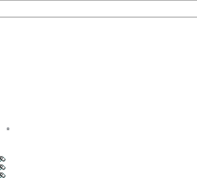
A Portable Network Graphics file is created that contains the objects you select.
The file reflects what is displayed on the screen. Light glyphs that are displayed
in the drawing appear in the new file, even if the Plot Glyph property of the
lights is set to No.
NOTE When the FILEDIA system variable is set to 0 (Off), prompts are displayed
at the Command prompt.
POINT
Quick Reference
See also:
■Draw Reference Points
Creates a point object.
Access Methods
Button
Ribbon: Home tab ➤ Draw panel ➤ Multiple Points
Menu: Draw ➤ Point ➤ Single
Toolbar: Draw
Summary
Points can act as nodes to which you can snap objects. You can specify a full
three-dimensional location for a point. The current elevation is assumed if
you omit the Z coordinate value.
The PDMODE and PDSIZE system variables control the appearance of point
objects. PDMODE values 0, 2, 3, and 4 specify a figure to draw through the
point. A value of 1 specifies that nothing is displayed.
POINT | 1009
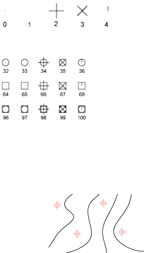
Specifying the value 32, 64, or 96 selects a shape to draw around the point,
in addition to the figure drawn through it:
PDSIZE controls the size of the point figures, except for PDMODE values 0
and 1. A setting of 0 generates the point at 5 percent of the drawing area
height. A positive PDSIZE value specifies an absolute size for the point figures.
A negative value is interpreted as a percentage of the viewport size.
After you change PDMODE and PDSIZE, the appearance of existing points
changes the next time the drawing is regenerated.
You can use MEASURE and DIVIDE to create points along an object. Use
DDPTYPE to specify point size and styles easily.
List of Prompts
Specify a point: Specify a point in the drawing
1010 | Chapter 16 P Commands
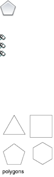
POLYGON
Quick Reference
See also:
■Draw Rectangles and Polygons
Creates an equilateral closed polyline.
Access Methods
Button
Ribbon: Home tab ➤ Draw panel ➤ Polygon
Menu: Draw ➤ Polygon
Toolbar: Draw
List of Prompts
The following prompts are displayed.
Enter number of sides <current>: Enter a value between 3 and 1024 or press Enter
Specify center of polygon on page 1011 or [Edge on page 1012]: Specify a point (1)
or enter e
Center of Polygon
Defines the center of the polygon.
Enter an option [Inscribed in circle/Circumscribed about circle] <current>: Enter
i or c or press Enter
POLYGON | 1011
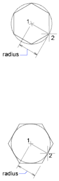
Inscribed in Circle Specifies the radius of a circle on which all vertices of the
polygon lie.
Specify radius of circle: Specify a point (2) or enter a value
Specifying the radius with your pointing device determines the rotation and
size of the polygon. Specifying the radius with a value draws the bottom edge
of the polygon at the current snap rotation angle.
Circumscribed about Circle Specifies the distance from the center of the
polygon to the midpoints of the edges of the polygon.
Specify radius of circle: Specify a distance
Specifying the radius with your pointing device determines the rotation and
size of the polygon. Specifying the radius with a value draws the bottom edge
of the polygon at the current snap rotation angle.
Edge
Defines a polygon by specifying the endpoints of the first edge.
Specify first endpoint of edge: Specify a point (1)
Specify second endpoint of edge: Specify a point (2)
1012 | Chapter 16 P Commands
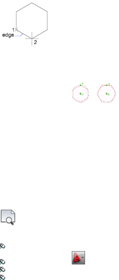
You can specify the different parameters of the polygon including the number
of sides. The difference between the inscribed and circumscribed options is
shown.
PREVIEW
Quick Reference
See also:
■Preview a Plot
Displays the drawing as it will be plotted.
Access Methods
Button
Ribbon: Output tab ➤ Plot panel ➤ Preview
Menu: Application menu ➤ Print ➤ Plot Preview
Menu: File ➤ Plot Preview
Toolbar: Standard
PREVIEW | 1013
Summary
The preview is based on the current plot configuration, as defined by the
settings in the Page Setup or Plot dialog box. It shows exactly how the drawing
will look when plotted, including lineweights, fill patterns, and other plot
style options.
The cursor changes to a magnifying glass with plus (+) and minus (-) signs.
Dragging the cursor toward the top of the screen while holding down the pick
button enlarges the preview image. Dragging toward the bottom of the screen
reduces the preview image.
PROPERTIES
Quick Reference
See also:
■Display and Change the Properties of Objects
Controls properties of existing objects.
Access Methods
Button
Ribbon: View tab ➤ Palettes panel ➤ Properties
Menu: Modify ➤ Properties
Toolbar: Standard
Shortcut menu: Select the objects whose properties you want to view or
modify, right-click in the drawing area, and click Properties.
Summary
The Properties palette is displayed and lists the properties of the selected
objects.
1014 | Chapter 16 P Commands

When more than one object is selected, only those properties common to all
selected objects are displayed.
When no objects are selected, only the current settings of general properties
are displayed.
There are several general properties common to all objects. All other object
properties are specific to the type of object.
Properties Palette
Quick Reference
See also:
■Display and Change the Properties of Objects
■Specify the Behavior of Dockable Windows
Displays the properties of the selected object or set of objects.
Summary
When more than one object is selected, only those properties common to all
selected objects are displayed. When no objects are selected, only the current
settings of general properties are displayed.
You can specify a new value to modify any property that can be changed.
Click the value and use one of the following methods:
■Enter a new value.
■Click the down arrow a the right and select a value from the list.
■Click the Pick Point button to use the pointing device to change a
coordinate value.
■Click the QuickCalc calculator button to calculate a new value.
■Click the left or right arrow to increase or decrease the value.
■Click the [ ] button and change the property value in a dialog box.
NOTE When you view properties of AutoCAD objects, some properties may be
unavailable.
Properties Palette | 1015
List of Options
The following options are displayed.
Object Type Displays the type of object that is selected.
Toggle Value of PICKADD Sysvar Turns the PICKADD system variable on
(1) and off (0). When PICKADD is on, each object selected, either individually
or by windowing, is added to the current selection set. When PICKADD is off,
selected objects replace the current selection set.
Select Objects Selects desired objects using any selection method. The
properties common to the selected objects are displayed in the Properties
palette. You can then modify the properties of the selected objects in the
Properties palette, or you can make other changes to the selected objects by
entering an editing command.
Quick Select Displays the Quick Select dialog box . Use Quick Select to create
selection sets based on filtering criteria.
Shortcut Menu
The following shortcut menu options are available when you right-click the
title bar.
Move Displays a four-headed arrow cursor that you can use to move the
palette. The palette does not dock.
Size Displays a four-headed arrow cursor that you can use to drag an edge or
a corner to make the palette smaller or larger.
Close Closes the Properties palette.
Allow Docking Toggles the ability to dock or anchor palette windows. If this
option is selected, a window can be docked when you drag it over a docking
area at the side of a drawing. A docked window adheres to the side of the
application window and causes the drawing area to be resized. Selecting this
option also makes Anchor Right and Anchor Left available.
Anchor Right/ Anchor Left Attaches the Properties palette to an anchor tab
base at the right or left side of the drawing area. The palette rolls open and
closed as the cursor moves across it. When an anchored palette is open, its
content overlaps the drawing area. An anchored palette cannot be set to stay
open.
Auto-hide Causes a floating palette to roll open and closed as the cursor
moves across it. When this option is cleared, the palette stays open.
Transparency Displays the Transparency dialog box on page 888.
1016 | Chapter 16 P Commands
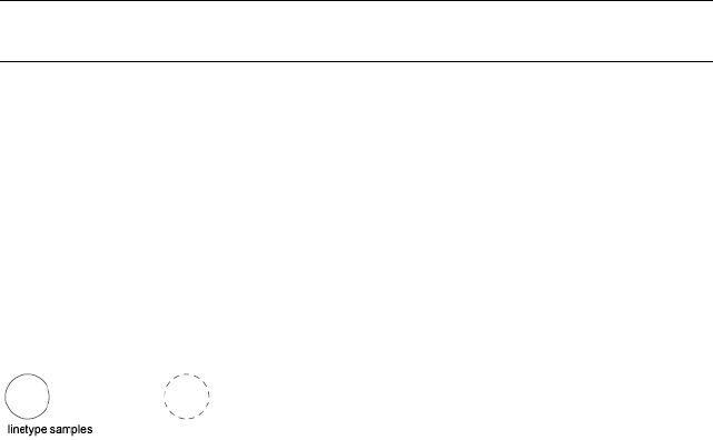
General Properties of Objects
Quick Reference
See also:
■Display and Change the Properties of Objects
Each graphical object in a drawing shares a common set of properties known
as the general properties.
Summary
The following general properties are common to most graphical objects.
NOTE Layers or objects that are assigned property overrides in viewports display
a ByLayer (VP) value and a background color for applicable properties.
List of Options
The following options are displayed.
Color Specifies the color for objects. Selecting Select Color in the color list
displays the Select Color dialog box (see COLOR).
Layer Specifies the current layer of the object. The list shows all layers in the
current drawing (see LAYER).
Linetype Specifies the current linetype of the object. The list shows all
linetypes in the current drawing (see LINETYPE).
Linetype Scale Specifies the linetype scale factor of the object (see LTSCALE).
Plot Style Lists NORMAL, BYLAYER, BYBLOCK, plus any plot styles contained
in the current plot style table (see PLOTSTYLE).
Lineweight Specifies the lineweight of the object. The list shows all available
lineweights in the current drawing (see LWEIGHT).
Hyperlink Attaches a hyperlink to a graphical object. If a description has been
assigned to the hyperlink, the description is displayed. If no description has
been assigned, the URL is displayed (see HYPERLINK).
General Properties of Objects | 1017
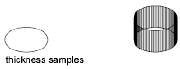
Transparency Specifies the transparency of the object (see TRANSPARENCY).
Thickness Sets the current 3D thickness. This property does not apply to all
objects (see CHPROP).
Cell Border Properties Dialog Box
Quick Reference
See also:
■Display and Change the Properties of Objects
Sets the properties of the borders of table cells.
Access Methods
Pointing device: With a table cell selected and the Properties palette open,
click in the value cell for Border Lineweight or Border Color, and click the [...]
button.
List of Options
The following options are displayed.
Border Properties
Controls the properties of the borders of the selected table cells.
Lineweight
Sets the lineweight to be used for borders that are displayed. If you use a heavy
lineweight, you may have to change the cell margins.
Linetype
Sets the linetype to be used for borders that are displayed.
Color
Sets the color to be used for borders that are displayed.
Double Line
1018 | Chapter 16 P Commands

When checked, a double line border will be added to the selected cells.
Spacing
Determines the spacing of double-line borders. The default value is .1800.
Preview
Displays a preview of how the borders of the selected table will look.
NOTE Linetypes will not display in the preview.
All Borders
Applies the border properties settings to all borders of the selected table cells.
Outside Borders
Applies the border properties settings to the outside borders of the selected
table cells.
Inside Borders
Applies the border properties settings to the inside borders of the selected
table cells.
No Borders
Applies the border properties settings to none of the borders of the selected
table cells.
Top Border Applies the border properties setting to the top borders of the
selected table cells.
Inside Horizontal Border Applies the border properties setting to the inside
horizontal borders of the selected table cells.
Bottom Border Applies the border properties setting to the bottom borders
of the selected table cells.
Left Border Applies the border properties setting to the left borders of the
selected table cells.
Inside Vertical Border Applies the border properties setting to the inside
vertical border of the selected table cells.
Right Border Applies the border properties setting to the right border of the
selected table cells.
Cell Border Properties Dialog Box | 1019
Add Distance or Angle Value Dialog Box
Quick Reference
See also:
■Display and Change the Properties of Objects
Adds distance or angle values to a parameter's value set in a dynamic block
definition.
List of Options
The following options are displayed.
Distances or Angle to Add
Specifies values (separated by commas) to add to the value set.
Distances or Angles List (Unlabeled)
Lists the distances or angles defined for the value set.
Add
Adds the values specified in the Distances or Angle to Add box.
Delete
Deletes the selected value.
PROPERTIESCLOSE
Quick Reference
See also:
■Display and Change the Properties of Objects
Closes the Properties palette.
Summary
The Properties palette closes.
1020 | Chapter 16 P Commands
PSETUPIN
Quick Reference
See also:
■Specify Page Setup Settings
Imports a user-defined page setup into a new drawing layout.
Summary
The Select Page Setup From File dialog box (a standard file selection dialog
box) is displayed in which you can select the drawing (.dwg), template (.dwt),
or drawing interchange format (.dxf) file whose page setups you want to import.
If FILEDIA is set to 0 (zero) and you enter -psetupin at the Command prompt,
PSETUPIN displays command prompts.
When you select the drawing file that you want to use, the Import Page Setups
dialog box is displayed.
-PSETUPIN
Quick Reference
See also:
■Specify Page Setup Settings
If you enter -psetupin at the Command prompt, the following prompts are
displayed.
Enter file name: Enter the name of the drawing file that contains the pagesetup to
import
Enter user defined page setup to import or [?]: Enter the name of the page setup
to import
PSETUPIN | 1021
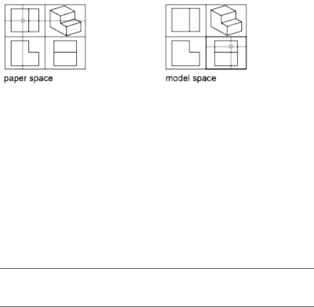
PSPACE
Quick Reference
See also:
■Work in Model Space
In a layout, switches from model space in a viewport to paper space.
Summary
The program switches from model space to paper space when you are working
on a named (paper space) layout.
On the named layout, use paper space to create a finished layout of a drawing
for printing. As part of designing your layout, you create layout viewports,
which are windows containing different views of the model. By switching
from paper space to model space (see MSPACE), you can edit the model and
views within the current layout viewport.
You can make a viewport current by double-clicking inside it. You can switch
to paper space by double-clicking an area of the paper space layout that is not
within a viewport.
When in paper space, you can also switch to model space by clicking Model
on the status bar. If you are in model space, you can switch to the last paper
space b clicking Paper on the status bar.
You can also switch between layout and model tabs at the bottom of the
drawing area.
NOTE The layout and Model tabs are only displayed if you have selected the
Display Layout and Model Tabs in the Display Tab (Options Dialog Box) on page
847.
1022 | Chapter 16 P Commands
PUBLISH
Quick Reference
See also:
■Publish Drawings
Publishes drawings to DWF, DWFx, and PDF files, or to plotters.
Access Methods
Button
Ribbon: Output tab ➤ Plot panel ➤ Batch Plot
Menu: File ➤ Publish
Toolbar: Standard
Summary
You can assemble a collection of drawings and create an electronic drawing
set. Electronic drawing sets are saved as DWF and DWFx files that can be
viewed or plotted using Autodesk Design Review. PDF files can be viewed with
a PDF viewer
Select an Exising Drawing Set Description
If you enter +publish at the Command prompt, you can select an existing
Drawing Set Descriptions (DSD) file from the Select List of Sheets dialog box
(a standard file selection dialog box on page 826). The Publish dialog box opens
and displays the drawing set saved in the DSD file under Sheets to Publish.
With the FILEDIA system variable set to 0, if you enter +publish at the
Command prompt, PUBLISH displays Command prompts.
PUBLISH | 1023
Publish Dialog Box
Quick Reference
See also:
■Overview of Publishing
Summary
Specifies drawing sheets that you can assemble, reorder, rename, copy, and
save for publishing as a multi-sheet drawing set. You can publish the drawing
set to a DWF, DWFx, or PDF file or send it to the plotter named in the page
setup for hardcopy output or as a plot file. You can save this list of drawing
sheets as a DSD (Drawing Set Descriptions) file. Saved drawing sets can replace
or be appended to the current list for republishing.
Specifies drawing sheets that you can assemble, reorder, rename, copy, and
save for publishing as a multisheet drawing set. You can publish the drawing
set to a DWF, DWFx, or PDF file or sent it to the plotter named in the page
setup for hardcopy output or as a plot file.
List of Options
The following options are displayed.
Sheet List
Displays the current drawing set (DSD) or batch plot (BP3) file.
Load Sheet List Button
Displays the Load Sheet List dialog box (a standard file selection dialog box
on page 826), in which you can select a DSD file to load. Displays the Replace
or Append dialog box if a list of drawing sheets is present in the Publish
Drawing Sheets dialog box. You can either replace the existing list of drawing
sheets with the new sheets or append the new sheets to the current list.
Save Sheet List Button
Displays the Save List As dialog box (a standard file selection dialog box on
page 826), in which you can save the current list of drawings as a DSD file. DSD
files are used to describe lists of drawing files and selected lists of layouts
within those drawing files.
1024 | Chapter 16 P Commands
Publish To:
Defines how to publish the list of sheets. You can publish to either a
multi-sheet DWF, DWFx, or PDF file (an electronic drawing set) or to the
plotter specified in the page setup (a paper drawing set or a set of plot files).
Plotter Named in Page Setup
Indicates that the output devices given for each drawing sheet in the page
setup will be used.
DWF, DWFx, and PDF
Selects the output file format: DWF, DWFx, or PDF.
Automatically Load All Open Drawings
When selected, the contents of all open documents (layouts and/or model
space) are automatically loaded in the publish list. When not selected, only
the current document’s contents are loaded in the publish list.
List of Sheets Buttons
Add Sheets Button
Displays the Select Drawings dialog box (a standard file selection dialog box
on page 826), in which you can select drawings to add to the list of drawing
sheets. The layout names from those files are extracted, and one sheet is added
to the list of drawing sheets for each layout and model.
The initial drawing sheet names are constructed from the base drawing name
and the layout name or the word Model separated by a dash (-).
Remove Sheets Button
Deletes the selected drawing sheets from the list of sheets.
Move Sheet Up Button
Moves the selected drawing sheets up one position in the list.
Move Sheet Down Button
Moves the selected drawing sheets down one position in the list.
Preview Button
Displays the drawing as it will appear when plotted on paper by executing
the PREVIEW command. To exit the print preview and return to the Publish
dialog box, press ESC, press ENTER, or right-click and then click Exit on the
shortcut menu.
Publish Dialog Box | 1025

Sheets to Publish
Contains the list of drawing sheets to be included for publishing. Click the
page setup column to change the sheet’s settings. Use the shortcut menu to
add sheets or make other changes to the list.
Sheet Name Combines the drawing name and the layout name with a dash
(-). Includes the Model tab only if the Include Model When Adding Sheets
option is selected. You can copy sheets by clicking Copy Selected Sheets on
the shortcut menu. You can change the name shown in Sheet Name by clicking
Rename Sheet on the shortcut menu. Drawing sheet names must be unique
within a single DWF, DWFx, or PDF file. The shortcut menu also provides an
option for removing all the sheets from the list.
NOTE The drawing sheets that populate the Sheets to Publish list are controlled
by the PUBLISHALLSHEETS system variable.
Page Setup Displays the named page setup for the sheet. You can change the
page setup by clicking the page setup name and selecting another page setup
from the list. Only Model tab page setups can be applied to Model tab sheets,
and only paper space page setups can be applied to paper space layouts. Select
Import to import page setups from another DWG file through the Import Page
Setups for Publishing dialog box (a standard file selection dialog box).
Status Displays the status of the sheet when it is loaded to the list of sheets.
Show Details
Displays and hides the Selected Sheet Information and Selected Page Setup
Information areas.
Selected Sheet Details
Displays the following information about the selected page setup: plot device,
plot size, plot scale, and details.
Publish Options Information
Publish Options
Opens the Publish Options dialog box, in which you can specify options for
publishing.
Publish Output
Number of Copies
Specifies the number of copies to publish. If the Publish to DWF, DWFx, or
PDF option is selected, the Number of Copies setting defaults to 1 and cannot
be changed. If a sheet's page setup specifies to plot to file, then the number
set in this option is ignored and a single plot file is created.
1026 | Chapter 16 P Commands

Precision Optimizes the dpi of DWF, DWFx, and PDF files for your field:
manufacturing, architecture or civil engineering. Or you can configure a
custom precision preset in the Precision Presets Manager on page 489.
This setting overrides the dpi setting in the .PC3 driver. This option is grayed
out if no file type is selected in the Publish to: drop-down list.
NOTE The precision override is applied to all sheets in the list.
Include Plot Stamp
Places a plot stamp on a specified corner of each drawing and logs it to a file.
The plot stamp data is specified in the Plot Stamp Dialog BoxPlot Stamp
Settings Dialog Box on page 979.
Plot Stamp Settings Displays the Plot Stamp Dialog BoxPlot Stamp Settings
Dialog Box on page 979, in which you can specify the information, such as
drawing name and plot scale, that you want applied to the plot stamp
Publish in Background
Toggles background publishing for the selected sheet/s.
You can also set the background publishing in the Plot and Publish tab (Tools
menu ➤ Options). Select the Publishing checkbox in the Background
processing options group.
Send the Sheets to the Plotter in Reverse Order When selected, sends sheets
to the plotter in reverse of default order. This option is available only if the
Plotter Named in Page Setup option is selected.
Open in Viewer when Done When publishing completes, the DWF, DWFx
or PDF file will open in a viewer application.
Publish
Starts the publishing operation. Creates one or more single-sheet DWF, DWFx,
or PDF files or a single multi-sheet DWF, DWFx, or PDF file, depending on
the contents in the list of drawing sheets and the settings in the Publish
Options dialog box.
To display information about the published drawing set, including any errors
or warnings, click the Plotting Details Report Available icon in the status tray
on the right side of the status bar. Clicking this icon displays the Plot and
Publish Details dialog box, which provides information about your completed
plot and publish jobs. This information is also saved to the Plot and Publish
log file. The shortcut menu for this icon also provides an option to view the
most recently published DWF, DWFx, or PDF file.
Publish Dialog Box | 1027
Publish Options Dialog Box
Quick Reference
See also:
■Overview of Publishing
Specifies options for publishing.
Summary
Specifies general options for the published DWF, DWFx, or PDF file such as
the file name, the save location, and layer information.
List of Options
Default Output Location (Plot to File)
Specifies the output folder location where DWF, DWFx, PDF, and plot files
are saved when you publish drawing sheets.
General DFW/PDF Options
Specifies options for creating a single-sheet DWF or DWFx file.
Type Specifies that a single-sheet DWF, DWFx, or PDF file or a single
multi-sheet DWF, DWFx, or PDF file is generated for all the sheets listed in
the Publish Dialog Box on page 1024.
Naming
■Prompt for Name - Indicates that you will be prompted for a name and
location to publish the multi-sheet DWF, DWFx, or PDF files.
■Specify Name - Prompts you for a name and location to publish the
multi-sheet DWF, DWFx, or PDF files.
Name Enables you to specify the data that you can optionally include in the
DWF, DWFx or PDF file.
Layer Information Specifies whether layer information is included in the
published DWF, DWFx or PDF file.
Merge Control Specifies whether overlapping lines merge (the colors of the
lines blend together into a third color) or overwrite (the last plotted line
obscures the line beneath it).
1028 | Chapter 16 P Commands

DWF Data Options
Lists and enables you to specify the data that you can optionally include in
the DWF or DWFx file.
Password Protection Specifies the following options for protecting DWF or
DWFx files with passwords:
■DisabledSpecifies that no password is required.
■Prompt for Password - Displays the DWF Password Dialog Box on page
1032 when you click Publish.
■Specify Password - Specifies that the password in the password box is
applied to the DWF or DWFx file. When you select this option, the
Password box becomes available, and you must enter a password.
NOTE If you lose or forget the password, it cannot be recovered. Keep a list
of passwords and their corresponding DWF or DWFx file names in a safe place.
Password Specifies that published DWF or DWFx files have a password applied
to them. A recipient of a DWF or DWFx file that has a password applied to it
must have the password to open the DWF or DWFx file.
Block Information Specifies whether block property and attribute information
is included in the published DWF or DWFx files.
NOTE You must set block information to Include in order for block template file
information to be available.
Block Template File Provides options for creating a new block template (DXE)
file, editing an existing block template file, or using the settings of a previously
created block template file.
Create opens the Publish Block Template dialog box on page 1030, in which
you can create a new block template.
Edit opens the Select Block Template dialog box (a standard file selection
dialog box on page 826), in which you can select an existing block template
to modify.
Publish Options Dialog Box | 1029
Publish Block Template Dialog Box (Publish)
Quick Reference
See also:
■Overview of Publishing
Summary
Specifies which blocks and their properties and attributes to include in the
published DWF or DWFx file.
List of Options
The following options are displayed.
Current Template
Displays the name of the current block template.
Block Source Drawings
Displays all block source drawings that have been loaded into the Publish
Block Template dialog box.
Add
Adds drawings to the list of block source drawings.
Remove
Removes selected drawings from the list of block source drawings.
Scan for Blocks
Scans block source drawings for unique definitions of blocks and their
properties and attributes.
Block Data to Publish
Displays block data to publish.
Unique Blocks from Source Drawings
Displays unique blocks found in block source drawings.
Check Blocks to Publish
Displays all scanned blocks found in block source drawings.
1030 | Chapter 16 P Commands
Exclude Blocks Without Attributes
Excludes blocks without attributes defined.
Properties of Selected Blocks
Displays properties of selected blocks found in block source drawings.
Check Properties to Publish
Displays the union of properties of the current selection of blocks.
Exclude General Block Properties
Excludes all general block properties from the list display.
Options
Opens the Block Template Options dialog box where you can specify additional
settings.
Save
Saves the block template file.
Block Template Options Dialog Box (Publish)
Quick Reference
See also:
■Overview of Publishing
Summary
Specifies optional settings to include blocks within blocks and to include
blocks within xrefs in the published DWF or DWFx file.
List of Options
The following options are displayed.
Include Nested Blocks Includes blocks within blocks in the published DWF
or DWFx file.
Include Blocks in Xrefs Includes blocks within xrefs in the published DWF
or DWFx file.
Block Template Options Dialog Box (Publish) | 1031

DWF Password Dialog Box
Quick Reference
See also:
■Overview of Publishing
Summary
Specifies the password to apply to the DWF or DWFx file. DWF or DWFx
passwords are case sensitive. The password or phrase can be made up of letters,
numbers, punctuation, or non-ASCII characters.
WARNING If you lose or forget the password, it cannot be recovered. Keep a list
of passwords and their corresponding DWF or DWFx file names in a safe place.
When you enter a password and click OK, the Confirm DWF Password dialog
box is displayed.
Confirm DWF Password Dialog Box
Quick Reference
See also:
■Overview of Publishing
Summary
Provides a space to confirm the password that you entered in the DWF
Password dialog box. If the two passwords do not match, you must click
Publish again to reenter the correct password.
1032 | Chapter 16 P Commands

Publish Job Progress Dialog Box
Quick Reference
See also:
■Overview of Publishing
Summary
Displays information about the status and progress of your publish job if
background publishing is turned off in the Options dialog box, Plot and Publish
tab.
List of Options
The following options are displayed.
Cancel Sheet Cancels publishing of the sheet currently being processed.
Cancel Job Cancels the publish job.
-PUBLISH
Quick Reference
See also:
■Overview of Publishing
Access Method
Command entry: +publish
Summary
The Command prompt version of PUBLISH provides an interface for publishing
drawing sheets that can be controlled by a script. It also provides a simplified
method for regenerating DWF or DWFx files or plotted output from existing
DSD files.
Publish Job Progress Dialog Box | 1033

With the FILEDIA system variable set to 0, enter +publish at the Command
prompt. The following prompt is displayed:
List of Prompts
The following prompts are displayed.
Enter name of sheet list <path file name.dsd>: Press ENTER for the current drawing
or enter the sheet list name
NOTE The bracketed text <DSD file name> contains the name of the DSD file
used when this command was last run. The bracketed text area is blank if no
previous name exists. If you enter a tilde (~) for the file name, the standard file
selection dialog box is displayed regardless of the FILEDEA setting.
The file name is validated and the list of sheets is loaded.
When -PLOT, PLOT, +PUBLISH, and PUBLISH are used in a script (SCR file),
the BACKGROUNDPLOT system variable value is ignored, and -PLOT, PLOT,
+PUBLISH, and PUBLISH are processed in the foreground.
Once the publish job starts, each drawing sheet name is listed along with an
appropriate message. Drawing sheets not found or not initialized are indicated
with an error message.
When the publish job is complete, the details can be viewed in the Plot and
Publish Details dialog box.
A log file is written during the publish operation. The log file contains the
drawing sheet name, layout name, full drawing name, path name, and status.
The log file name is derived from the name of the sheet list file with CSV
replacing the DSD file extension.
NOTE Any existing log file is overwritten by a new log file without any warning
message being displayed.
PUBLISHTOWEB
Quick Reference
See also:
■Use the Publish to Web Wizard to Create Web Pages
1034 | Chapter 16 P Commands

Creates HTML pages that include images of selected drawings.
Access Methods
Button
Menu: File ➤ Publish to Web
Summary
The Publish to Web wizard is displayed.
This wizard provides a simplified interface for creating formatted web pages
that include DWF, DWFx, JPEG, or PNG images of drawings. After creating a
web page, you can post it to an Internet or intranet location.
Publish to Web Wizard
Quick Reference
See also:
■Use the Publish to Web Wizard to Create Web Pages
Creates a formatted HTML page.
Summary
You can choose from a number of different formatting options that control
the layout of your completed HTML page. After creating an HTML page, you
can use the wizard to publish the page to an Internet or intranet location.
You can also use the wizard to modify existing HTML pages that were created
using the PUBLISHTOWEB command.
You can customize the template you use for your web page. For information
about customizing templates, see “Customize a Publish to Web Template” in
the Customization Guide.
Publish to Web Wizard | 1035
PURGE
Quick Reference
See also:
■Erase Objects
Removes unused items, such as block definitions and layers, from the drawing.
Access Methods
Button
Menu: Application menu ➤ Drawing Utilites ➤ Purge
Menu: File ➤ Drawing Utilities ➤ Purge
Summary
The Purge dialog box is displayed.
If you enter -purge at the Command prompt, options are displayed.
Unused named objects can be removed from the current drawing. These
include include block definitions, dimension styles, groups, layers, linetypes,
and text styles. Zero-length geometry and empty text objects can also be
removed.
NOTE The PURGE command will not remove unnamed objects (zero-length
geometry or empty text and mtext objects) from blocks or locked layers.
Purge Dialog Box
Quick Reference
See also:
■Erase Objects
1036 | Chapter 16 P Commands
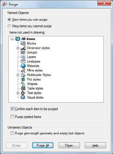
Removes unused items, such as block definitions and layers, from the drawing.
Summary
Displays items that can be purged.
List of Options
The following options are displayed.
Named Objects
View Items You Can Purge
Switches the tree view to display a summary of named objects in the current
drawing that you can purge.
Items Not Used in Drawing
Lists the named objects that are not used in the current drawing and that can
be purged.
You can list the items for any object type by clicking the plus sign or by
double-clicking the object type. You purge items by selecting the item to purge.
Purge Dialog Box | 1037

Purge Nested Items removes items only when you select one of the following
options:
■All Items or Blocks in the tree view
■The Purge All button
View Items You Cannot Purge
Switches the tree view to display a summary of named objects in the current
drawing that you can't purge.
Items Currently Used in Drawing
Lists named objects that cannot be removed from the drawing.
Most of these objects are currently used in the drawing or are default items
that cannot be removed.
When you select individual named objects, information about why you can't
purge the item is displayed below the tree view.
Confirm Each Item to Be Purged
Displays the Confirm Purge dialog box when you purge an item.
Purge Nested Items
Removes all unused named objects from the drawing even if they are contained
within or referenced by other unused named objects.
The Confirm Purge dialog box is displayed, and you can cancel or confirm
the items to be purged.
Tip
Displays information detailing why you can't purge the selected item.
Unnamed Objects
Purge zero-length geometry and empty text objects
Deletes geometry of zero length (lines, arcs, polylines and so on) in non-block
objects. Also deletes mtext and text that contains only spaces (no text) in
non-block objects.
NOTE The PURGE command will not remove zero-length geometry or empty text
and mtext objects from blocks or locked layers.
Purge
Purges the selected items.
1038 | Chapter 16 P Commands

Purge All
Purges all unused items.
-PURGE
Quick Reference
See also:
■Erase Objects
Removes unused named objects, such as block definitions and layers, from
the drawing at the Command prompt.
Summary
Allows you to remove unused named objects from a drawing at the Command
prompt. You can only remove one level of reference at a time. Repeat the
command until there are no unreferenced, named objects.
NOTE The PURGE command will not remove unnamed objects (zero-length
geometry or empty text and mtext objects) from blocks or locked layers.
List of Prompts
The following prompts are displayed.
Type of Unused Objects to Purge
Deletes unused applications from blocks, dimension styles, groups, layers,
linetypes, materials, multileader styles, plot styles, shapes, text styles, multiline
styles, table styles, visual styles, regapps, zero-length geometry, empty text
objects, or all.
Enter Name (s) to Purge Enter an object name of * to list the objects.
Verify Each Name to Be Purged? Enter y to verify each name.
-PURGE | 1039
1040
Q Commands
QCCLOSE
Quick Reference
See also:
■Overview of QuickCalc
Closes the QuickCalc calculator.
Summary
Closes the QuickCalc calculator.
QDIM
Quick Reference
See also:
■Overview of Dimensioning
Creates a series of dimensions quickly from selected objects.
17
1041
Access Methods
Button
Ribbon: Annotate tab ➤ Dimensions panel ➤ Quick Dimension
Menu: Dimension ➤ Quick Dimension
Toolbar: Dimension
Summary
This command is particularly useful for creating a series of baseline or
continued dimensions, or for dimensioning a series of circles and arcs.
List of Prompts
The following prompts are displayed.
Select geometry to dimension: Select the objects you want to dimension or the
dimensions you want to edit and press Enter
Specify dimension line position, or
[Continuous/Staggered/Baseline/Ordinate/Radius/Diameter/datumPoint/Edit/seTtings]
<current>: Enter an option or press Enter
Continuous Creates a series of continued dimensions.
Staggered Creates a series of staggered dimensions.
Baseline Creates a series of baseline dimensions.
Ordinate Creates a series of ordinate dimensions.
Radius Creates a series of radial dimensions.
Diameter Creates a series of diameter dimensions.
Datum Point Sets a new datum point for baseline and ordinate dimensions.
Edit Edits a series of dimensions. You are prompted to add or remove points
from existing dimensions.
Settings Sets the default object snap for specifying extension line origins.
1042 | Chapter 17 Q Commands

QKUNGROUP
Quick Reference
See also:
■Group Objects
■UNGROUP on page 1286
Removes a group definition from a drawing.
Access Methods
Command entry: qkungroup
Summary
The group definition is deleted; the group is split into its component objects.
QLEADER
Quick Reference
See also:
■Create Leaders
■Modify Leaders Using Grips
Creates a leader and leader annotation.
Summary
It is recommended that you use the workflow available through the MLEADER
on page 742 command to create leader objects.
You can use QLEADER to
■Specify leader annotation and annotation format
■Set the location where leaders attach to multiline text annotation
QKUNGROUP | 1043
■Limit the number of leader points
■Constrain the angle of the first and second leader segments
You can use the Leader Settings dialog box to customize the command so that
it prompts you for the number of leader points and the annotation type suited
to your drawing needs.
If associative dimensioning is turned on with DIMASSOC, the leader start
point can be associated with a location on an object. If the object is relocated,
the arrowhead remains attached to the object and the leader line stretches,
but the text or feature control frame remains in place.
List of Prompts
The following prompts are displayed.
Specify “first leader point”, or [“Settings”] <Settings>: Specify the first leader
point, or press Enter to specify leader settings
First Leader Point
The Number of Points setting on the Leader Line & Arrow tab of the Leader
Settings dialog box determines the number of leader points you are prompted
to specify.
Width If you set the text width value to 0.00, the width of the multiline text
is unlimited.
Tolerance If Tolerance is selected on the Annotation tab, the Geometric
Tolerance dialog box is displayed. Use the dialog box to create the tolerance
feature control frame.
Enter block name or [?]: Enter the name, or enter ? to display a list of blocks defined
in the drawing
Insertion Point For a description of the insertion options, see -INSERT on
page 624.
Settings
Displays the Leader Settings dialog box.
1044 | Chapter 17 Q Commands
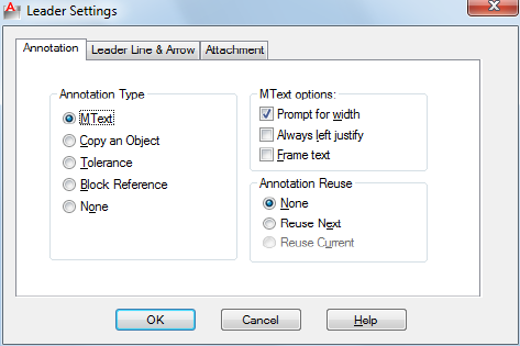
Leader Settings Dialog Box
Quick Reference
See also:
■Create Leaders
■Modify Leaders Using Grips
Creates a leader and leader annotation.
Summary
Customizes the QLEADER command and sets properties for leaders and leader
annotations.
List of Tabs
The following tabs are displayed.
Annotation Tab (Leader Settings Dialog Box)
Annotation Type
Sets the leader annotation type. The type you select changes the QLEADER
leader annotation prompt.
MText
Prompts you to create multiline text (mtext) annotation.
Leader Settings Dialog Box | 1045
Copy an Object
Prompts you to copy a multiline text, single-line text, tolerance, or block
reference object and connects the copy to the end of the leader line. The copy
is associated with the leader line, meaning that if the copied object moves,
the end of the leader line moves with it. The display of the hook line depends
on the object copied.
Tolerance
Displays the Tolerance dialog box, which you can use to create a feature control
frame to attach to the leader.
Block Reference
Prompts you to insert a block reference. The block reference is inserted at an
offset from the end of the leader line and is associated to the leader line,
meaning that if the block moves, the end of the leader line moves with it. No
hook line is displayed.
None
Creates a leader with no annotation.
MText Options
The options are available only when the multiline text annotation type is
selected.
Prompt for Width
Prompts you to specify the width of the multiline text annotation.
Always Left Justify
Left-justifies the multiline text annotation, regardless of leader location.
Frame Text
Places a frame around multiline text annotation.
Annotation Reuse
Sets options for reusing leader annotation.
None
Does not reuse leader annotation.
Reuse Next
Reuses the next annotation you create for all subsequent leaders.
1046 | Chapter 17 Q Commands
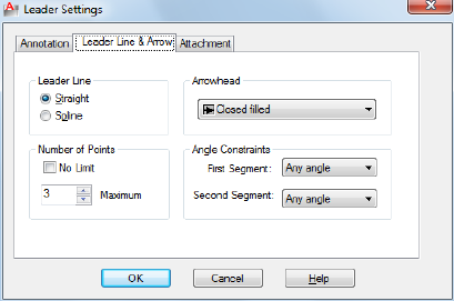
Reuse Current
Reuses current annotation. This option is automatically selected when you
reuse annotation after selecting Reuse Next.
Leader Line & Arrow Tab (Leader Settings Dialog Box)
Leader Line
Sets the leader line format.
Straight
Creates straight-line segments between the points you specify.
Spline
Creates a spline object using the leader points you specify as control points.
Arrowhead
Defines the leader arrowhead. The arrowheads are also available for dimension
lines (DIMSTYLE command). If you select User Arrow, a list of blocks in the
drawing is displayed.
Number of Points
Sets the number of leader points that QLEADER prompts you to specify before
prompting for the leader annotation. For example, if you set the points to 3,
QLEADER automatically prompts you to specify the annotation after you
specify two leader points. Set the number to one more than the number of
leader segments you want to create.
If you set the option to No Limit, QLEADER prompts for leader points until
you press Enter.
Leader Settings Dialog Box | 1047
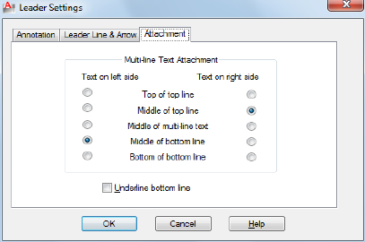
Angle Constraints
Sets angle constraints for the first and second leader lines.
First Segment
Sets the angle of the first leader segment.
Second Segment
Sets the angle of the second leader segment.
Attachment Tab (Leader Settings Dialog Box)
Sets the attachment location for leader lines and multiline text annotation.
This tab is available only when Mtext is selected on the Annotation tab.
Top of Top Line
Attaches the leader line at the top of the top multiline text line.
Middle of Top Line
Attaches the leader line at the middle of the top multiline text line.
Middle of Multiline Text
Attaches the leader line at the middle of the multiline text.
Middle of Bottom Line
Attaches the leader line at the middle of the bottom multiline text line.
Bottom of Bottom Line
Attaches the leader line at the bottom of the bottom multiline text line.
Underline Bottom Line
1048 | Chapter 17 Q Commands
Underlines the bottom multiline text line.
QNEW
Quick Reference
See also:
■Use a Drawing Template File
Starts a new drawing from a selected drawing template file.
Access Methods
Button
Menu: Application menu ➤ New ➤ Drawing
Toolbar: Standard
Summary
QNEW creates a new drawing from the default drawing template file and
folder path specified in Default Template File Name for QNEW on the File tab
of the Options dialog box.
When a default drawing template file is set to None or is not specified, QNEW
displays the Select Template File dialog box (a standard file selection dialog
box).
The behavior of the QNEW command is determined by the STARTUP system
variable.
■1: Displays the Create New Drawing dialog box.
■0: Displays the Select Template dialog box (a standard file selection dialog
box) or starts the new drawing using the default drawing template file.
QNEW | 1049
If the system variable, FILEDIA, is set to 0 instead of 1, a Command prompt
is displayed. If you set FILEDIA to 0, this prompt is displayed regardless of the
Startup setting.
QSAVE
Quick Reference
See also:
■Save a Drawing
Saves the current drawing using the specified default file format.
Access Methods
Button
Menu: File ➤ Save
Toolbar: Standard
Summary
If the drawing is named, the program saves the drawing and does not request
a new file name. Use the SAVEAS command if you need to save a drawing
with a different name. If the drawing is read-only, use the SAVEAS command
to save the changed file under a different name.
If the drawing is unnamed, the Save Drawing As dialog box (see SAVEAS) is
displayed and the drawing is saved with the file name and format you specify.
NOTE The file format specified on the Open and Save tab of the Options dialog
box is used when saving a drawing with this command.
1050 | Chapter 17 Q Commands
QSELECT
Quick Reference
See also:
■Select Objects by Properties
Creates a selection set based on filtering criteria.
Access Methods
Button
Ribbon: Home tab ➤ Utilities panel ➤ Quick Select
Menu: Tools ➤ Quick Select
Shortcut menu: End any active commands, right-click in the drawing area,
and choose Quick Select.
Summary
The Quick Select dialog box is displayed.
QSELECT filters selection sets by object type and property. For example, you
can select all of the multiline text objects in a drawing that use a specified
text style.
Quick Select Dialog Box
Quick Reference
See also:
■Select Objects by Properties
Specifies the filtering criteria and how you want to create the selection set
from that criteria.
QSELECT | 1051
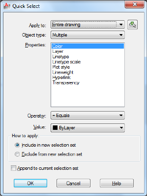
List of Options
The following options are displayed.
Apply To
Applies the filtering criteria to the entire drawing or to the current selection
set (if one exists).
If Append to Current Selection Set is selected, the filtering criteria is applied
to the entire drawing.
Select Objects
Temporarily closes the Quick Select dialog box so that you can select the
objects to which you want to apply the filter criteria.
Object Type
Specifies the type of objects to include in the filtering criteria. If the filtering
criteria are being applied to the entire drawing, the Object Type list includes
all object types, including custom. Otherwise, the list includes only the object
types of the selected objects.
If an application such as AutoCAD® Map 3D was used to add a feature
classification to an object, you can select a classification.
If you select an object type not supported by AutoCAD LT, it is greyed out in
the Properties palette and is not available for changes.
1052 | Chapter 17 Q Commands

Properties
Specifies the object property for the filter. This list includes all searchable
properties for the selected object type. The property you select determines the
options available in Operator and Value.
If an application such as AutoCAD® Map 3D was used to add a feature
classification to an object, you can select a classification property.
Operator
Controls the range of the filter. Depending on the selected property, options
can include Equals, Not Equal To, Greater Than, Less Than, and *Wildcard
Match. *Wildcard Match is available only for text fields that can be edited.
Use the Select All option to ignore all properties filters.
For more information, see “Filter and Sort the List of Layers”.
Value
Specifies the property value for the filter.
How to Apply
Specifies whether you want the new selection set to include or exclude objects
that match the specified filtering criteria. Select Include in New Selection Set
to create a new selection set composed only of objects that match the filtering
criteria. Select Exclude from New Selection Set to create a new selection set
composed only of objects that do not match the filtering criteria.
Append to Current Selection Set
Specifies whether the selection set created by QSELECT replaces or is appended
to the current selection set.
NOTE QSELECT supports custom objects (objects created by another application)
and their properties. If a custom object uses properties other than AutoCAD LT
properties, the custom object's source application must be running in order for
the properties to be available to QSELECT.
Quick Select Dialog Box | 1053
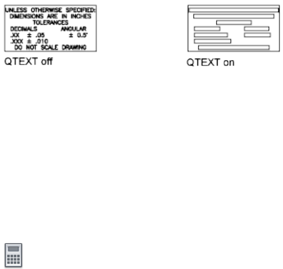
QTEXT
Quick Reference
See also:
■Control the Display of Polylines, Hatches, Gradient Fills, Lineweights, and
Text
Controls the display and plotting of text and attribute objects.
Summary
When QTEXT (Quick Text) is on, each text and attribute object is displayed
as a bounding box around the text object. Turning QTEXT mode on reduces
the time it takes the program to redraw and regenerate drawings that contain
many text objects.
QUICKCALC
Quick Reference
See also:
■Overview of QuickCalc
Opens the QuickCalc calculator.
Access Methods
Button
1054 | Chapter 17 Q Commands
Ribbon: View tab ➤ Palettes panel ➤ QuickCalc
Menu: Tools ➤ Palettes ➤ QuickCalc
Toolbar: Standard
Shortcut menu: Right-click and click QuickCalc.
Summary
The QuickCalc calculator performs a full range of mathematical, scientific,
and geometric calculations, creates and uses variables, and converts units of
measurement.
Displays the QuickCalc calculator on page 1055.
QuickCalc Calculator
Quick Reference
See also:
■Overview of QuickCalc
Performs a full range of mathematical, scientific, and geometric calculations,
creates and uses variables, and converts units of measurement.
List of Options
The following options are displayed.
Toolbar
Performs quick calculations of common functions.
Clear Clears the Input box.
Clear History Clears the history area.
Paste Value to Command Line Pastes the value in the Input box at the
Command prompt. When QuickCalc is used transparently during a command,
this button is replaced by the Apply button at the bottom of the calculator.
Get Coordinates Calculates the coordinates of a point.
Distance Between Two Points Calculates the distance between two points.
The calculated distance always displays as a unitless decimal value.
QuickCalc Calculator | 1055
Angle of Line Defined by Two Points Calculates the angle of two points.
Two Lines Defined by Four Points Calculates the intersection of four points.
History Area
Displays a running list of previously evaluated expressions. The History area
shortcut menu provides several options, including copying a selected
expression to the Clipboard.
Input Box
Provides a box where you enter and retrieve expressions.
More/Less Button
Hides or Displays all QuickCalc function areas. Right-click to select individual
function areas to hide or display.
Number Pad
Provides a standard calculator keypad where you enter numbers and symbols
for arithmetic expressions.
Scientific Area
Evaluates trigonometric, logarithmic, exponential, and other expressions
commonly associated with scientific and engineering applications.
Units Conversion Area
Converts units of measurement from one unit type to another unit type. The
units conversion area accepts only decimal values without units.
Units Type Select length, area, volume, and angular values from a list.
Convert From Lists the units of measurement from which to convert.
Convert To Lists the units of measurement to which to convert.
Value to Convert Provides a box to enter a value to convert.
Converted Value Converts the units entered and displays the converted value.
Calculator Icon Returns the converted value to the Input box.
Variables Area
Provides access to predefined constants and functions. You can use the
Variables area to define and store additional constants and functions.
Variables Tree Stores predefined shortcut functions and user-defined variables.
1056 | Chapter 17 Q Commands
Shortcut functions are common expressions that combine a function with an
object snap. The following table describes the predefined shortcut functions
in the list.
DescriptionShortcut ForShortcut Function
Distance between two end-
points
dist(end,end)dee
Intersection of two lines
defined by four endpoints
ill(end,end,end,end)ille
Midpoint between two en-
dpoints
(end+end)/2mee
Unit vector in the XY plane
and normal to two end-
points
nor(end,end)nee
Radius of a selected circle,
arc, or polyline arc
radrad
Vector from two endpointsvec(end,end)vee
Unit vector from two end-
points
vec1(end,end)vee1
New Variable Button Opens the Variable Definition dialog box on page 1057.
Edit Variable Button Opens the Variable Definition dialog box on page 1057
so you can make changes to the selected variable.
Delete Variable Button Deletes the selected variable.
Calculator Button Returns the selected variable to the Input box.
Variable Definition Dialog Box
Quick Reference
See also:
■Overview of QuickCalc
Variable Definition Dialog Box | 1057
Defines a variable to store in the variables tree.
List of Options
The following options are displayed.
Variable Type
Specifies the type of variable.
Constant
Stores the new variable as a constant.
Function
Stores the new variable as a function.
Variable Properties
Defines the properties of a new variable.
Name
Stores the name of the variable. Names of constants cannot include spaces.
Group With
Stores the named variable in the selected category. If New is selected, the
Category Definition dialog box on page 1059 opens, where you can define a
new category for the variable.
Value or Expression
Stores the value or expression for the variable.
Description
Stores a description for the variable.
OK
Closes the dialog box and applies the current settings to the variable.
Cancel
Closes the dialog box without applying the current settings.
Help
Displays Help.
1058 | Chapter 17 Q Commands
Settings
The following shortcut menu options are available when you right-click the
title bar.
Move Displays a four-headed arrow cursor that you can use to move the
dialog box. The dialog box does not dock.
Size Displays a four-headed arrow cursor that you can use to drag an edge or
a corner to make the smaller or larger.
Close Closes the Markup Set Manager.
Allow Docking Toggles the ability to dock or anchor the calculator.
Anchor Right/ Anchor Left Attaches the QuickCalc calculator to an anchor
tab base at the right or left side of the drawing area.
Auto-hide Causes a floating palette to roll open and closed as the cursor
moves across it. When this option is cleared, the palette stays open.
Transparency Displays the Transparency dialog box on page 888.
Category Definition Dialog Box
Quick Reference
See also:
■Overview of QuickCalc
Defines a category to organize the variables in the variables tree.
List of Options
The following options are displayed.
Category Properties
Defines the properties of the new category.
Name
Stores the name of the category.
Description
Stores a description for the category.
Category Definition Dialog Box | 1059
OK
Closes the dialog box and applies the current settings to the variable.
Cancel
Closes the dialog box without applying the current settings.
Help
Displays Help.
QUICKCUI
Quick Reference
See also:
■Create and Edit Toolbars
Displays the Customize User Interface Editor in a collapsed state.
Summary
The Customize User Interface Editor on page 242 is displayed in a collapsed
state. Only the Customizations In <filename> and Command List panes are
displayed. The Customizations In <filename> pane is shown collapsed and the
Command List pane is shown expanded.
For more information, see User Interface Customization.
QUICKPROPERTIES
Quick Reference
See also:
■Display and Change the Properties of Objects
Displays quick property data for selected objects.
1060 | Chapter 17 Q Commands

Summary
Displays the Quick Properties palette that displays a customizable list of object
properties for one or more selected objects.
The behavior of the Quick Propetries palette is controlled by settings on the
Quick Properties tab of the Drafting Settings dialog box (DSETTINGS on page
414). The QPMODE on page 1632 system variable controls whether the palette
is displayed automatically when objects are selected.
QUIT
Quick Reference
See also:
■Start a Drawing
Exits the program.
Access Methods
Menu: File ➤ Exit
Summary
Quits the program if there have been no changes since the drawing was last
saved. If the drawing has been modified, you are prompted to save or discard
the changes before quitting.
You can quit a file that has been opened in read-only mode if you have made
no modifications or if you are willing to discard them. To save modifications
to a read-only drawing, use the SAVEAS command to save the drawing under
another name.
QUIT | 1061

QVDRAWING
Quick Reference
See also:
■Switch Between Open Drawings
Displays open drawings and layouts in a drawing in preview images.
Access Methods
Button
Shortcut menu: Click on the status bar.
Summary
Displays a two-level structure of preview images at the bottom of the
application. The first level displays the images of open drawings and the second
level displays the images for model space and layouts in a drawing.
QVDRAWINGCLOSE
Quick Reference
See also:
■Switch Between Open Drawings
Closes preview images of open drawings and layouts in a drawing.
Access Methods
Button
Shortcut menu: Click on the Quick View drawings toolbar.
1062 | Chapter 17 Q Commands

Summary
Closes preview images of open drawings and layouts in a drawing.
QVLAYOUT
Quick Reference
See also:
■Switch Between Layouts in the Current Drawing
Displays preview images of model space and layouts in a drawing.
Access Methods
Button
Shortcut menu: Click on the status bar.
Summary
Displays preview images of model space and layouts in a drawing in a row at
the bottom of the application.
QVLAYOUTCLOSE
Quick Reference
See also:
■Switch Between Layouts in the Current Drawing
Closes preview images of model space and layouts in a drawing
QVLAYOUT | 1063

Access Methods
Button
Shortcut menu: Click on the Quick View drawings toolbar.
Summary
Closes preview images of model space and layouts in a drawings.
1064 | Chapter 17 Q Commands
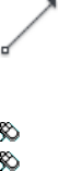
R Commands
RAY
Quick Reference
See also:
■Draw Construction Lines (and Rays)
Creates a line that starts at a point and continues to infinity.
Access Methods
Button
Ribbon: Home tab ➤ Draw panel ➤ Ray
Menu: Draw ➤ Ray
Summary
The ray is extended to the edge of the display in the direction defined by the
starting point and the through point. The prompt for a through point is
redisplayed so you can create multiple rays. Press Enter to end the command.
18
1065
Lines that extend to infinity in one direction, known as rays, can be used as
references for creating other objects.
List of Prompts
The following prompts are displayed.
Specify start point: Specify a point (1)
Specify through point: Specify a point for the ray to pass through (2)
RECOVER
Quick Reference
See also:
■Repair a Damaged Drawing File
Repairs and then opens a damaged drawing file.
Access Methods
Button
1066 | Chapter 18 R Commands

Menu: Application menu ➤ Drawing Utilities ➤ Recover ➤ Recover
Menu: File ➤ Drawing Utilities ➤ Recover
Summary
The program extracts as much material as it can from the damaged file. Files
that can be recovered include DWG, DWT, and DWS files. Performing a recover
on a DXF file will only open the file.
In the Select File dialog box (a standard file selection dialog box), enter the
drawing file name or select the damaged drawing file. Results are displayed
in the text window.
When FILEDIA is set to 0 (zero), RECOVER displays the following command
prompt.
Enter ~ (tilde) at the prompt to ignore FILEDIA and display the Select File
dialog box.
RECOVERALL
Quick Reference
See also:
■Repair a Damaged Drawing File
Repairs a damaged drawing file along with all attached xrefs.
Access Methods
Menu: Application menu ➤ Drawing Utilities ➤ Recover ➤ Recover
with Xrefs
Menu: File ➤ Drawing Utilities ➤ Recover Drawing and Xrefs
Summary
In the Select File dialog box (a standard file selection dialog box), enter the
drawing file name or select the damaged drawing file.
The selected drawing file and all attached xrefs, including all nested xrefs, are
opened, repaired, resaved, and closed.
■Drawing files are saved in the current drawing file format.
RECOVERALL | 1067
■Copies of the original drawing files are saved as BAK files.
■If the object enabler is present, custom objects are updated.
Results are displayed in the Drawing Recovery Log window. Each drawing file
checked includes a Drawing Recovery Log that can be expanded or collapsed.
The entire log can be copied to the Windows clipboard with the Copy to
Clipboard button.
When FILEDIA is set to 0 (zero), RECOVERALL displays the following command
prompt.
Enter ~ (tilde) at the prompt to ignore FILEDIA and display the Select File
dialog box.
NOTE The RECOVERALL command recovers or audits DWG, DWT, and DWS files.
RECTANG
Quick Reference
See also:
■Draw Rectangles and Polygons
Creates a rectangular polyline.
Access Methods
Button
Ribbon: Home tab ➤ Draw panel ➤ Rectangle
Menu: Draw ➤ Rectangle
Toolbar: Draw
Summary
With this command, you can specify the rectangle parameters (length, width,
rotation) and control the type of corners (fillet, chamfer, or square).
1068 | Chapter 18 R Commands
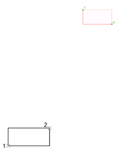
List of Prompts
The following prompts are displayed.
Current settings: Rotation = 0
Specify first corner point or [Chamfer/Elevation/Fillet/Thickness/Width]:
Specify a point or enter an option
First Corner Point
Specifies a corner point of the rectangle.
Other Corner Point Creates a rectangle using the specified points as diagonally
opposite corners.
Area Creates a rectangle using the area and either a length or a width. If the
Chamfer or Fillet option is active, the area includes the effect of the chamfers
or fillets on the corners of the rectangle.
Dimensions Creates a rectangle using length and width values.
Rotation Creates a rectangle at a specified rotation angle.
Chamfer
Sets the chamfer distances for the rectangle.
Elevation
Specifies the elevation of the rectangle.
Fillet
Specifies the fillet radius of the rectangle.
Thickness
Specifies the thickness of the rectangle.
Width
Specifies the polyline width of the rectangle to be drawn.
RECTANG | 1069

REDO
Quick Reference
See also:
■Correct Mistakes
Reverses the effects of previous UNDO or U command.
Access Methods
Button
Menu: Edit ➤ Redo
Toolbar: Standard
Shortcut menu: With no command active and no objects selected, right-click
in the drawing area and click Redo.
Command entry: Ctrl+Y
Summary
REDO reverses the effects of a single UNDO or U command. REDO must
immediately follow the U or UNDO command.
REDRAW
Quick Reference
See also:
■Erase Objects
Refreshes the display in the current viewport.
Access Methods
Menu: View ➤ Redraw
Command entry: 'redraw for transparent use
1070 | Chapter 18 R Commands

Summary
Removes temporary graphics left by VSLIDE and some operations from the
current viewport. To remove stray pixels, use the REGEN command.
REFCLOSE
Quick Reference
See also:
■Save Back Edited Referenced Drawings and Blocks
Saves back or discards changes made during in-place editing of a reference,
either an xref or a block definition.
Access Methods
Menu: Tools ➤ Xref and Block In-Place Editing ➤ Save Reference Edits
Menu: Tools ➤ Xref and Block In-Place Editing ➤ Close Reference
Shortcut menu: With no objects selected during in-place reference editing,
right-click in the drawing area and choose Close Refedit Session.
Summary
If you save or discard changes with REFCLOSE, you can still use the UNDO
command to return to the reference editing session. If you have made
unwanted changes to an xref and already saved back the changes, use UNDO
to undo the unwanted changes; then use REFCLOSE to save back changes and
restore the xref to its original state.
NOTE When you edit and save xrefs in place in a drawing, the preview image for
the original reference drawing is no longer available unless you open and save the
drawing again.
List of Prompts
The following prompts are displayed.
Enter option [Save/Discard reference changes] <Save>:
REFCLOSE | 1071
Save Saves back to the xref source drawing or to the block definition
in the current drawing all changes made to objects in the working set. If you
remove an object from the working set and save changes, the object is deleted
from the reference and added to the current drawing. The Save Back Changes
to Reference button on the Refedit toolbar automatically saves reference editing
changes.
NOTE If the file format of the xref source drawing is AutoCAD Release 14 or earlier,
the file is saved in AutoCAD 2010 file format. The file format is not changed for
xref source drawings in AutoCAD 2000 and 2004 format.
Discard Reference Changes Discards the working set; the source
drawing or block definition is returned to its original state. Any changes you
make to objects in the current drawing (not in the xref or block) are not
discarded. If you delete any object that is not in the working set, the object
is not restored even if you choose to discard changes. The Discard Changes
to Reference button on the Refedit toolbar automatically discards reference
editing changes without using REFCLOSE.
REFEDIT
Quick Reference
See also:
■Edit Selected Objects in Referenced Drawings and Blocks
Edits an xref or a block definition directly within the current drawing.
Access Methods
Button
Ribbon: Insert tab ➤ Reference panel ➤ Edit Reference
Menu: Tools ➤ Xref and Block In-place Editing ➤ Edit Reference In-Place
1072 | Chapter 18 R Commands

Toolbar: Refedit
Summary
The objects that you select from the selected xref or block are temporarily
extracted and made available for editing in the current drawing. The set of
extracted objects is called the working set, which can be modified and then
saved back to update the xref or block definition.
List of Prompts
The following prompts are displayed.
Select reference: Select an xref or a block in the current drawing
If you edit an xref when the ribbon is active, the Edit Reference ribbon
contextual tab displays.
If you enter -refedit at the Command prompt, options are displayed.
Edit Reference Ribbon Contextual Tab
Quick Reference
See also:
■Edit Selected Objects in Referenced Drawings and Blocks
Manages the working set of objects that are edited in a reference.
Reference Editing Panel
Save or Discard Changes (REFCLOSE on page 1071) Saves back or discards
changes made during in-place editing of a reference, either an xref or a block
definition.
Add to or Remove From Working Set (REFSET on page 1077) Adds or removes
objects from a working set during in-place editing of a reference, either an
xref or a block definition.
Edit Reference Ribbon Contextual Tab | 1073
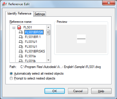
Reference Edit Dialog Box
Quick Reference
See also:
■Edit Selected Objects in Referenced Drawings and Blocks
Specifies the reference to edit.
Summary
To select a reference to edit, select an object in the reference. If you select an
object that is part of one or more nested references, the nested references are
displayed in the dialog box.
List of Tabs
■Identify Reference on page 1074
■Settings on page 1075
Identify Reference Tab (Reference Edit Dialog Box)
Provides visual aids for identifying the reference to edit and controls how the
reference is selected.
Reference Name
1074 | Chapter 18 R Commands
Displays the reference selected for in-place editing and any references nested
within the selected reference.
Nested references are displayed only if the selected object is part of a nested
reference. If multiple references are displayed, choose a specific xref or block
to modify. Only one reference can be edited in place at a time.
Preview
Displays a preview image of the currently selected reference.
The preview image displays the reference as it was last saved in the drawing.
The reference preview image is not updated when changes are saved back to
the reference.
Path
Displays the file location of the selected reference. If the selected reference is
a block, no path is displayed.
Automatically Select All Nested Objects
Controls whether nested objects are included automatically in the reference
editing session.
Prompt to Select Nested Objects
Controls whether nested objects must be selected individually in the reference
editing session.
If this option is checked, after you close the Reference Edit dialog box and
enter the reference edit state, you are prompted to select the specific objects
in the reference that you want to edit.
Select nested objects: Select objects within the reference that you want to edit
Settings Tab (Reference Edit Dialog Box)
Provides options for editing references.
Create Unique Layer, Style, and Block Names
Controls whether layers and other named objects extracted from the reference
are uniquely altered.
If selected, named objects in xrefs are altered (names are prefixed with $#$),
similar to the way they are altered when you bind xrefs. If cleared, the names
of layers and other named objects remain the same as in the reference drawing.
Named objects that are not altered to make them unique assume the properties
of those in the current host drawing that share the same name.
Display Attribute Definitions for Editing
Reference Edit Dialog Box | 1075
Controls whether all variable attribute definitions in block references are
extracted and displayed during reference editing.
If Display Attribute Definitions for Editing is selected, the attributes (except
constant attributes) are made invisible, and the attribute definitions are
available for editing along with the selected reference geometry. When changes
are saved back to the block reference, the attributes of the original reference
remain unchanged. The new or altered attribute definitions affect only
subsequent insertions of the block; the attributes in existing block instances
are not affected. Xrefs and block references without definitions are not affected
by this option.
Lock Objects Not in Working Set
Locks all objects not in the working set. This prevents you from accidentally
selecting and editing objects in the host drawing while in a reference editing
state.
The behavior of locked objects is similar to objects on a locked layer. If you
try to edit locked objects, they are filtered from the selection set.
-REFEDIT
Quick Reference
See also:
■Edit Selected Objects in Referenced Drawings and Blocks
Edits an xref or a block definition directly within the current drawing.
List of Prompts
The following prompts are displayed.
Select reference: Select an xref or block in the current drawing
Select nesting level [OK/Next] <Next>: Enter an option or press Enter
OK
Accepts the currently highlighted reference for in-place reference editing.
If you are editing a block reference with attributes, you can enter y to display
the attribute definitions and make them available for editing. The attributes
are made invisible, and the attribute definitions are available for editing along
with the selected reference geometry. When changes are saved back to the
1076 | Chapter 18 R Commands

block reference, the attributes of the original reference remain unchanged.
The new or altered attribute definitions affect only subsequent insertions of
the block; the attributes in existing block instances are not affected.
All Objects in the selected reference will be automatically included in the
reference editing session.
Nested After you close the Reference Edit dialog box and enter the reference
edit state, you are prompted to select the specific objects in the reference that
you want to edit.
Next
Advances through the reference and nested references available for selection.
The currently selected reference is highlighted.
A working set is formed with the objects you have selected for editing. The
working set includes objects that can be saved back to update the xref or block
definition. When you save back changes, changes made to the objects in the
reference file are saved without actually opening the reference drawing or
recreating the block. The working set is visually distinct from the rest of the
current drawing: all objects in the current drawing, except objects in the
working set, appear faded. The XFADECTL system variable controls the fading
of objects while you edit a reference in place.
You can select objects in xrefs for editing even if they are on a locked layer in
the reference file. When a reference object is part of the working set, you can
unlock the object's layer and make changes to the object. Only the changes
made to the object are saved back to the reference file; the xref layer remains
locked in the reference file.
NOTE Objects outside of the working set are not faded unless the visual style is
set to 2D Wireframe during in-place reference editing.
REFSET
Quick Reference
See also:
■Use the Working Set to Edit Referenced Drawings and Blocks
Adds or removes objects from a working set during in-place editing of a
reference, either an xref or a block definition.
REFSET | 1077

Access Methods
Menu: Tools ➤ Xref and Block In-place Editing ➤ Add to Working Set
Menu: Tools ➤ Xref and Block In-Place Editing ➤ Remove from Working
Set
Summary
Objects that are part of the working set are visually distinct from other objects
in the current drawing. All objects in the current drawing, except objects in
the working set, appear faded.
List of Prompts
The following prompts are displayed.
Transfer objects between the Refedit working set and host drawing...
Enter an option [Add/Remove] <Add>: Enter an option or press Enter
Add Adds objects to the working set.
An object that is part of the working set is added to the reference when changes
are saved back, and the object is removed from the current drawing. The Add
to Working Set button on the Refedit toolbar prompts you to add objects to
the working set without using REFCLOSE on page 1071.
Remove Removes objects from the working set.
An object that is removed from the working set is removed from the reference
when changes are saved back; the object is also removed from the current
drawing. The Remove from Working Set button on the Refedit toolbar prompts
you to remove objects from the working set without using REFCLOSE.
1078 | Chapter 18 R Commands

REGEN
Quick Reference
See also:
■Control the Display of Polylines, Hatches, Gradient Fills, Lineweights, and
Text
Regenerates the entire drawing from the current viewport.
Access Methods
Menu: View ➤ Regen
Summary
REGEN regenerates the entire drawing and recomputes the screen coordinates
for all objects in the current viewport. It also reindexes the drawing database
for optimum display and object selection performance.
REGENALL
Quick Reference
See also:
■Control the Display of Polylines, Hatches, Gradient Fills, Lineweights, and
Text
Regenerates the drawing and refreshes all viewports.
Access Methods
Menu: View ➤ Regen All
Summary
REGENALL regenerates the entire drawing and recomputes the screen
coordinates for all objects in all viewports. It also reindexes the drawing
database for optimum display and object selection performance.
REGEN | 1079

REGION
Quick Reference
See also:
■Create and Combine Areas (Regions)
Converts an object that encloses an area into a region object.
Access Methods
Button
Ribbon: Home tab ➤ Draw panel ➤ Region
Menu: Draw ➤ Region
Toolbar: Draw
Summary
Regions are two-dimensional areas you create from closed shapes or loops.
Closed polylines, lines, and curves are valid selections. Curves include circular
arcs, circles, elliptical arcs, ellipses, and splines.
You can combine several regions into a single, complex region.
Closed 2D and exploded planar 3D polylines in the selection set are converted
to separate regions and then converts polylines, lines, and curves to form
closed planar loops (outer boundaries and holes of a region). If more than two
curves share an endpoint, the resulting region might be arbitrary.
1080 | Chapter 18 R Commands
The boundary of the region consists of end-connected curves where each point
shares only two edges. All intersections and self-intersecting curves are rejected.
If a selected polyline has been smoothed by either the Spline or Fit option of
PEDIT, the resulting region contains the line or arc geometry of the smoothed
polyline. The polyline is not converted to a spline object.
REGION deletes the original objects after converting them to regions unless
the system variable DELOBJ is set to 0. If the original objects were hatched,
hatch associativity is lost. To restore associativity, rehatch the region.
REINIT
Quick Reference
See also:
■Digitizing Tablets
Reinitializes the digitizer, digitizer input/output port, and program parameters
file.
Summary
The Re-initialization dialog box is displayed.
Re-initialization Dialog Box
Quick Reference
See also:
■Digitizing Tablets
Defines the I/O port and the device file for reinitialization.
REINIT | 1081
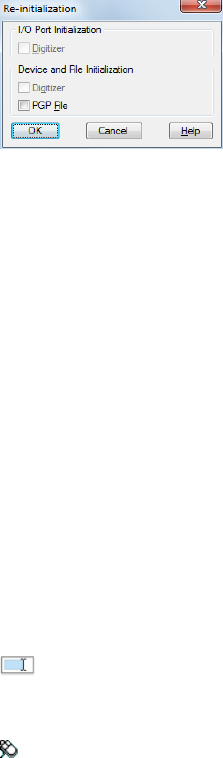
List of Options
The following options are displayed.
I/O Port Initialization Reinitializes the I/O port for the digitizer.
Device File Initialization Reinitializes the digitizer and the acaslt.pgp file.
RENAME
Quick Reference
See also:
■Resolve Name Conflicts in External References
Changes the names assigned to items such as layers and dimension styles.
Access Methods
Button
Menu: Format ➤ Rename
Summary
Named objects are categories of items such as layers, dimension styles, table
styles, text styles, and so on. It is strongly recommended that you create
standard naming conventions for them and save them in drawing template
files.
The Rename dialog box is displayed.
If you enter -rename at the Command prompt, options are displayed.
1082 | Chapter 18 R Commands
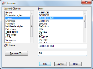
Rename Dialog Box
Quick Reference
See also:
■Resolve Name Conflicts in External References
Changes the names assigned to named objects such as layers and dimension
styles.
List of Options
The following options are displayed.
Named Objects
Lists named objects in a drawing by category.
Items
Displays items of the type specified in Named Objects.
Old Name
Specifies the item to be renamed. You can use the wild-card characters * and
? to rename groups of items. You can't rename some standard items, such as
layer 0 and the CONTINUOUS linetype.
Rename To
Specifies the new name you want to assign to the item.
Rename Dialog Box | 1083
-RENAME
Quick Reference
See also:
■Resolve Name Conflicts in External References
Changes the names assigned to named objects from the Command prompt.
List of Prompts
The following prompts are displayed.
Enter object type to rename
[Block/Dimstyle/LAyer/LType/Material/multileadeRstyle/Plotstyle/textStyle/Tablestyle/Ucs/VIew/VPort]:
Enter a named object type to rename an object
Enter old object name: Enter the old name
Enter new object name: Enter the new name
RESETBLOCK
Quick Reference
See also:
■Work with Dynamic Blocks in Drawings
Resets one or more dynamic block references to the default values of the block
definition.
Access Methods
Shortcut menu: Select a dynamic block reference in a drawing. Right-click
in the drawing area and click Reset Block.
1084 | Chapter 18 R Commands

RESUME
Quick Reference
See also:
■Run Slide Shows from Scripts
■Create Command Scripts
Continues an interrupted script.
Access Methods
Command entry: 'resume for transparent use
Summary
You can interrupt a macro script that is running by pressing Esc or Backspace.
Any error encountered while processing input from a script file causes the
script to be suspended. If a script is suspended while the program is active,
you can use RESUME to continue the script.
REVCLOUD
Quick Reference
See also:
■Create Revision Clouds
Creates a revision cloud using a polyline.
Access Methods
Button
Ribbon: Home tab ➤ Draw panel ➤ Revision Cloud
RESUME | 1085
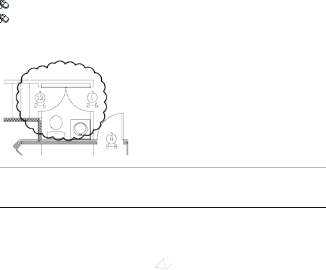
Menu: Draw ➤ Revision Cloud
Toolbar: Draw
Summary
NOTE REVCLOUD stores the last used arc length in the system registry. This value
is multiplied by DIMSCALE to provide consistency when the program is used with
drawings that have different scale factors.
You can create a new revision cloud by dragging your cursor, or you can
convert a closed object such as an ellipse or polyline into a revision cloud.
Use revision clouds to highlight parts of a drawing that are being reviewed.
The resulting object is a polyline.
List of Prompts
The following prompts are displayed.
Minimum arc length: 0.5000 Maximum arc length: 0.5000
Specify start point or [Arc length/Object/Style] <Object>: Drag to draw the
revision cloud, enter an option, or press Enter
Arc Length Specifies the length of the arcs in a revision cloud.
The maximum arc length cannot be set to more than three times the minimum
arc length.
Object Specifies an object to be converted to a revision cloud.
Style Specifies the style of the revision cloud.
1086 | Chapter 18 R Commands

REVDATE
Quick Reference
See also:
■Add Date and Time Stamps to Layouts
Inserts or updates a block containing user name, current time and date, and
drawing name.
Access Methods
Menu: Tools ➤ Time and Date Stamp
Summary
A revdate block is inserted, or an existing revdate block is updated.
You can explode the revdate block and place its contents in another location,
such as a title block.
REVERSE
Quick Reference
See also:
■Modify Polylines
Reverses the vertices of selected lines, polylines, splines, and helixes, which
is useful for linetypes with included text, or wide polylines with differing
beginning and ending widths.
Access Methods
Button
Ribbon: Home tab ➤ Modify panel ➤ Reverse
REVDATE | 1087

Summary
Vertices of selected objects are reversed.
For example, when a linetype with text is specified with relative rotation in
a LIN file, the text in the linetype might be displayed upside down. Reversing
the vertices of the object changes the orientation of the text.
The REVERSE command does not change the orientation of text where rotation
is specified as upright. For more information, see Text in Custom Linetypes.
RIBBON
Quick Reference
See also:
■Display and Organize the Ribbon
Opens the ribbon window.
RIBBONCLOSE
Quick Reference
See also:
■Display and Organize the Ribbon
Closes the ribbon window.
1088 | Chapter 18 R Commands
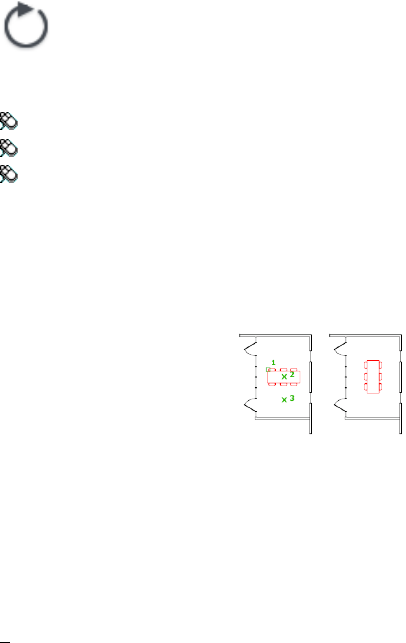
ROTATE
Quick Reference
See also:
■Rotate Objects
Rotates objects around a base point.
Access Methods
Button
Ribbon: Home tab ➤ Modify panel ➤ Rotate
Menu: Modify ➤ Rotate
Toolbar: Modify
Shortcut menu: Select the objects to rotate. Right-click in the drawing area
and click Rotate.
Summary
You can rotate selected objects around a base point to an absolute angle.
List of Prompts
The following prompts are displayed.
Current positive angle in UCS: ANGDIR=current ANGBASE=current
Select objects: Use an object selection method and press Enter when you finish
Specify base point: Specify a point
Specify rotation angle or [Copy/Reference]: Enter an angle, specify a point, enter
c, or enter r
Rotation Angle Determines how far an object rotates around the base point.
ROTATE | 1089

The axis of rotation passes through the specified base point and is parallel to
the Z axis of the current UCS.
Copy Creates a copy of the selected objects for rotation.
Reference Rotates objects from a specified angle to a new, absolute angle.
When you rotate a viewport object, the borders of the viewport remain parallel
to the edges of the drawing area.
RSCRIPT
Quick Reference
See also:
■Run Slide Shows from Scripts
■Create Command Scripts
Repeats a script file.
Summary
RSCRIPT is useful for demonstrations that repeat a script; for example, a script
that must run over and over during a trade show or in a showroom.
If RSCRIPT is the last line in a script file, the file runs continuously until
interrupted by Esc.
NOTE Consider turning off UNDO and any log files if you anticipate running the
script over a long period; otherwise, these log files continue to grow and take up
increasing amounts of disk space.
1090 | Chapter 18 R Commands
S Commands
SAVE
Quick Reference
See also:
■Save a Drawing
Saves the drawing under the current file name or a specified name.
Obsolete. The SAVE command is functionally identical to the QSAVE on page
1050 command. The Save option on the File menu, Standard toolbar, or Quick
Access toolbar is QSAVE.
Summary
If the drawing is read-only, use the SAVEAS on page 1091 command to save changes
under a different file name.
SAVEAS
Quick Reference
See also:
■Save a Drawing
19
1091

Saves a copy of the current drawing under a new file name.
Access Methods
Menu: File ➤ Save As
Summary
The Save Drawing As standard file selection dialog box is displayed. Enter a
file name and type. Saving a drawing to any DXF™ format affects performance.
See Save Drawings to Previous Drawing File Formats for a description of the
limitations that result from saving to an earlier version.
In the Save Drawing As dialog box, Tools ➤ Options displays the Saveas
Options dialog box, which controls various DWG and DXF settings.
The file is saved with the specified file name. If the drawing is already named,
the drawing is saved with the new file name. If you save the file as a drawing
template, the Template Options dialog box is displayed, where you can provide
a description for the template and set the units of measurement.
When FILEDIA is set to 0 (zero), SAVEAS displays command prompts.
Template Options Dialog Box
Quick Reference
See also:
■Save a Drawing
Sets drawing template options.
1092 | Chapter 19 S Commands
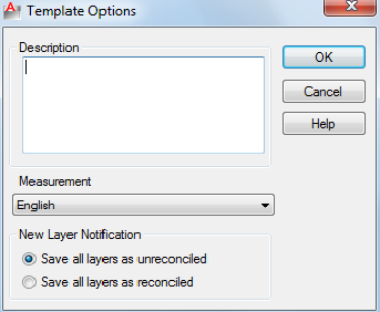
Summary
The Template Options dialog box displays automatically after you specify the
files of type as *.dwt, enter the template file name, and click Save.
List of Options
The following options are displayed.
Description
Specifies a description for the drawing template. This description is displayed
when you choose the template in the Startup dialog box or in the Create New
Drawing dialog box.
Measurement
Specifies whether the drawing template uses English (imperial) or metric units.
New Layer Notification
Save All Layers As Unreconciled
Saves the template file with its layers set as unreconciled, which means that
a layer baseline is not created.
See Reconcile New Layers for more information about unreconciled layers.
Save All Layers As Reconciled
Saves the template file with its layers set as reconciled, which results in creating
a layer baseline.
See Reconcile New Layers for more information about reconciled layers.
Template Options Dialog Box | 1093
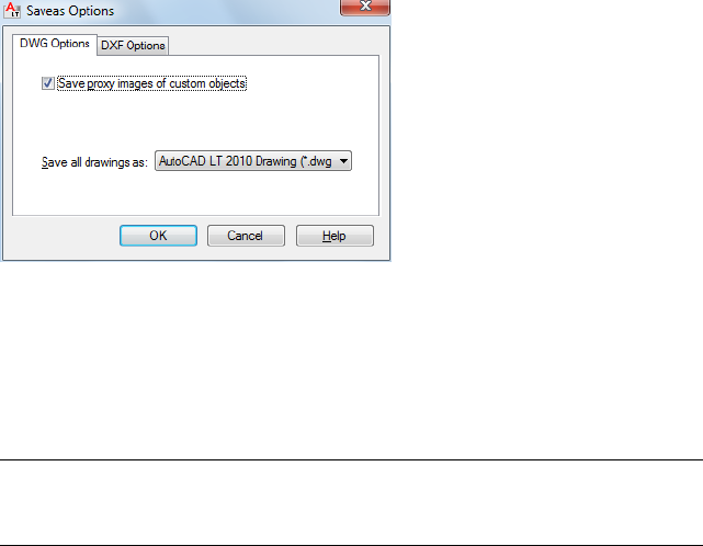
Saveas Options Dialog Box
Quick Reference
See also:
■Save a Drawing
Sets options for DWG files and for drawing interchange file output.
List of Options
The following options are displayed.
■DWG Options
■DXF Options
DWG Options Tab (Saveas Options Dialog Box)
Controls the display of custom objects and specifies the default file format
for saving drawings.
Save Proxy Images of Custom Objects
If you save to an earlier format, or the drawing contains custom objects from
another application, select Save Proxy Images of Custom Objects to save images
of the custom objects in the drawing file. (PROXYGRAPHICS system variable)
If you do not choose this option, a frame is saved for each custom object in
the drawing file.
NOTE If you are saving a drawing file that contains DWF references to an earlier
drawing format, this switch has no effect on DWF underlays as they will not appear
as proxy objects or as a frame.
1094 | Chapter 19 S Commands
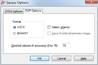
Save All Drawings As
Specifies the default file format that drawings are saved to. You can also set
this option on the Open and Save tab in the Options dialog box.
For more information, see OPTIONS.
DXF Options Tab (Saveas Options Dialog Box)
Sets drawing interchange file output options.
Format
Specifies whether to create an ASCII or a binary DXF file. ASCII-format DXF
files can be read with a text editor and are compatible with a wider range of
applications. Binary-format DXF files are more compact. Read and write
operations with binary-format files is faster than with ASCII-format files.
Select Objects
Controls whether the DXF file consists of selected objects or the entire drawing.
When the output file includes only selected objects, the block definitions of
only the selected block references are included.
Save Thumbnail Preview Image
Specifies whether an image of the drawing is displayed in the Preview area of
the Select File dialog box (RASTERPREVIEW system variable).
Decimal Places of Accuracy
Saves the file using the specified precision. The default precision is usually
adequate; however, you might need to increase this value for certain drawings
or applications. The advantage of lower precision is decreased file size, and,
in some cases, protecting intellectual property.
Saveas Options Dialog Box | 1095
SAVEAS Command Prompts
Quick Reference
See also:
■Save a Drawing
Saves a copy of the current drawing under a new file name.
List of Prompts
The following prompts are displayed.
Current file format: current
Enter file format
[R14(LT98<97)/2000(LT2000)/2004(LT2004)2007(LT2007)/2010(LT2010)/DXF/Template]
<2010>:
Enter an option or press Enter
Save drawing as <current>: Enter a name or press Enter
SCALE
Quick Reference
See also:
■Resize or Reshape Objects
Enlarges or reduces selected objects, keeping the proportions of the object the
same after scaling.
Access Methods
Button
Ribbon: Home tab ➤ Modify panel ➤ Scale
Menu: Modify ➤ Scale
1096 | Chapter 19 S Commands

Toolbar: Modify
Shortcut menu: Select the objects to scale. Right-click in the drawing area
and click Scale.
Summary
To scale an object, specify a base point and a scale factor. The base point acts
as the center of the scaling operation and remains stationary. A scale factor
greater than 1 enlarges the object. A scale factor between 0 and 1 shrinks the
object.
List of Prompts
The following prompts are displayed.
Select objects: Use an object selection method and press Enter when you finish
Specify base point: Specify a point
The base point you specify identifies the point that remains in the same
location as the selected objects change size (and thus move away from the
stationary base point).
NOTE When you use the SCALE command with objects, the position or location
of the object is scaled relative to the base point of the scale operation, but the size
of the object is not changed.
Specify scale factor or [Copy/Reference]: Specify a scale, enter c, or enter r
Scale Factor Multiplies the dimensions of the selected objects by the specified
scale. A scale factor greater than 1 enlarges the objects. A scale factor between
0 and 1 shrinks the objects. You can also drag the cursor to make the object
larger or smaller.
Copy Creates a copy of the selected objects for scaling.
Reference Scales the selected objects based on a reference length and a specified
new length.
SCALE | 1097

SCALELISTEDIT
Quick Reference
See also:
■Scale Views in Layout Viewports
Controls the list of scales available for layout viewports, page layouts, and
plotting.
Access Methods
Button
Ribbon: Annotate tab ➤ Annotation Scaling panel ➤ Scale List
Menu: Format ➤ Scale List
Command entry: 'scalelistedit for transparent use
Summary
Displays a list of predefined scales used throughout the program. This list can
be easily modified to display only the scales you need.
The Edit Scale List dialog box is displayed.
If you enter -scalelistedit at the Command prompt, options are displayed.
Edit Drawing Scales Dialog Box
Quick Reference
See also:
■Scale Views in Layout Viewports
Controls the list of scales available for layout viewports, page layouts, and
plotting.
1098 | Chapter 19 S Commands
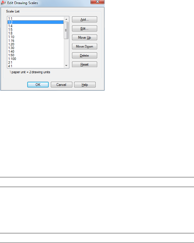
List of Options
The following options are displayed.
Scale List Displays the list of currently defined scales. Also displays temporary
scales that are imported when xrefs are attached. If a scale name is duplicated,
but has a different value, a number is appended to the name.
Add Displays the Add Scale dialog box.
Press Tab to move between the fields of the scale being edited.
Edit Displays the Edit Scale dialog box.
NOTE You cannot edit temporary scales.
Move Up Moves the currently selected scale in the scale list up one position.
Move Down Moves the currently selected scale in the scale list down one
position.
Delete Removes the selected scale from the scale list.
NOTE You cannot delete a scale that is referenced by an object.
Reset Deletes all custom scales and unused scales and restores the default list
of scales defined in the Default Scale List dialog box on page 891.
Edit Drawing Scales Dialog Box | 1099
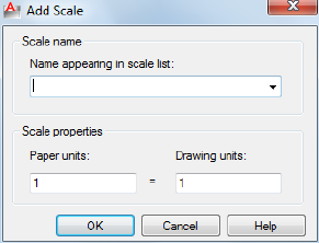
Add Scale Dialog Box
Quick Reference
See also:
■Scale Views in Layout Viewports
Adds a new scale to the scale list.
List of Options
The following options are displayed.
Scale Name
Name Appearing in Scale List Specifies the scale name to add to the scale
list.
Scale Properties
Sets the ratio of paper units to drawing units.
Paper Units When combined with the value of the drawing units, determines
the ratio that defines the scale for viewing or plotting.
Drawing Units When combined with the value of the paper units, determines
the ratio that defines the scale for viewing or plotting.
1100 | Chapter 19 S Commands
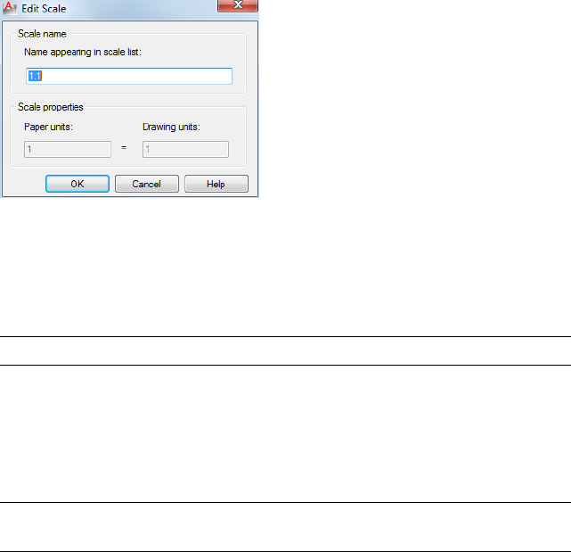
Edit Scale Dialog Box
Quick Reference
See also:
■Scale Views in Layout Viewports
Changes the existing scales listed in the Scale List area.
List of Options
The following options are displayed.
Scale Name
Lists the name of the currently selected scale in the Scale List area.
NOTE You cannot change the name of a scale that is referenced by an xref.
Name Appearing in Scale List Enter a descriptive or numeric name. For
example, in an architectural drawing that uses a typical imperial scale, you
can enter either 1"=4' or 1:48.
Scale Properties
Modifies the ratio of paper units to drawing units.
NOTE You cannot change the scale properties of a scale that is referenced by an
object in the drawing.
Paper Units When combined with the value of the drawing units, determines
the ratio that defines the scale for viewing or plotting.
Drawing Units When combined with the value of the paper units, determines
the ratio that defines the scale for viewing or plotting.
Edit Scale Dialog Box | 1101

-SCALELISTEDIT
Quick Reference
See also:
■Scale Views in Layout Viewports
Controls the list of scales available for layout viewports, page layouts, and
plotting.
List of Prompts
The following prompts are displayed.
Enter option [?/Add/Delete/Reset/Exit] <Add>: Enter an option or press Enter
?Displays a list of defined scales.
Add Adds a new scale to the scale list. Enter a ratio in the format n:m, where
n is the number of paper units and m is the number of drawing units
Delete Removes a specified scale. If a scale is current or supported by an object,
it cannot be deleted.
Reset Deletes all custom scales as a result and restores the default list of scales.
SCALETEXT
Quick Reference
See also:
■Change Text Scale and Justification
Enlarges or reduces selected text objects without changing their locations.
Access Methods
Button
1102 | Chapter 19 S Commands
Ribbon: Annotate tab ➤ Text panel ➤ Scale
Menu: Modify ➤ Object ➤ Text ➤ Scale
Toolbar: Text
List of Prompts
The following prompts are displayed.
Select objects: Use an object selection method, and press Enter when you finish
Enter a base point option for scaling
[Existing/Left/Center/Middle/Right/TL/TC/TR/ML/MC/MR/BL/BC/BR]<Existing>:
Specify a location to serve as a base point for resizing or scaling
The base point is a location relative to a text object that serves as a fixed point
for the resizing or scaling operation, which is applied individually to each
selected text object.
Specifying a base point for the operation does not change the insertion point
relative to the text.
The base point options shown above are described in the TEXT command.
The base point options for single line text are similar to those for multiline
text except that the Align, Fit, and Left text options are equivalent to the
bottom left (BL) multiline text attachment point.
Specify new model height or [Paper height/Match object/Scale factor]<0.5000>:
Specify a text height or enter an option
NOTE You can only specify a model height for non- objects.
Paper Height
Scales the text height depending on the annotative property.
NOTE You can only specify a paper height for annotative objects.
Match Object
Scales the text objects that you originally selected to match the size of a selected
text object.
NOTE This option only affects like objects (annotative or nonannotative).
Scale Factor
Scales the selected text objects based on a reference length and a specified
new length.
Reference Scales the selected text objects relative to a reference length and a
new length.
SCALETEXT | 1103
The selected text is scaled by a ratio of the values that you entered for the new
length and the reference length. If the new length is less than the reference
length, the selected text objects are reduced in size.
SCRIPT
Quick Reference
See also:
■Overview of Command Scripts
Executes a sequence of commands from a script file.
Access Methods
Button
Ribbon: Manage tab ➤ Applications panel ➤ Run Script
Menu: Tools ➤ Run Script
Command entry: 'script for transparent use
Summary
A script is a text file with an .scr file extension. Each line of the script file
contains a command that can be completed at the Command prompt,
including alternative versions of commands that normally display dialog
boxes.
The Select Script File dialog box (a standard file selection dialog box) is
displayed. Enter the file name of a script to run that script.
When FILEDIA is set to 0 (zero), SCRIPT displays the following command
prompt.
1104 | Chapter 19 S Commands
SECURITYOPTIONS
Quick Reference
See also:
■Protect and Sign Drawings
Specifies password or digital signature options for a drawing file.
Summary
The Security Options dialog box is displayed. You can add security settings
that are applied when you save the drawing.
Security Options Dialog Box
Quick Reference
See also:
■Protect and Sign Drawings
Specifies security settings to be used when your drawing is saved.
List of Options
The following options are displayed.
Digital Signature Tab (Security Options Dialog Box)
Adds a digital signature to a drawing when the drawing is saved.
Attach Digital Signatures After Saving Drawing Attaches a digital signature
to a drawing when the drawing is saved.
Select a Digital ID (Certificate) Displays a list of digital IDs that you can use
to sign files. Includes information about the organization or individual to
whom the digital ID was issued, the digital ID vendor who issued the digital
ID, and when the digital ID expires.
Signature Information Provides a list of time services you can use to add a
time stamp to your digital signature, the status of the time server connection,
SECURITYOPTIONS | 1105
and a Comments area (to include information relevant to the digital signature
or to the files you are signing).
Get Time Stamp From Provides a list of time servers you can use to time
stamp your digital signature.
NOTE The timesrvr.txt file contains the time servers that you can choose from.
Time Service Status Displays the connection status (Successfully Contacted
Time Server or Could Not Contact Time Server) of the time service.
Comment Provides a place for comments about the digital signature or the
files you are signing.
SEEK
Quick Reference
See also:
■Use Autodesk Seek to Add and Share Drawings
Opens a web browser and displays the Autodesk Seek home page.
Access Methods
Ribbon: Insert tab ➤ Content panel ➤ Autodesk Seek search box (enter
keywords)
Shortcut menu: Right-click on the Tool Palettes window, or a block, and
click Seek Design Content.
You can also access Autodesk Seek from DesignCenter (ADCENTER on page
10) and from Content Explorer (CONTENTEXPLORER on page 229).
Summary
Product design information that is available on Autodesk Seek depends on
what content providers, both corporate partners and individual contributors,
publish to Autodesk Seek.
This service is an online source for product information that is directly
accessible from your Autodesk software. From the Autodesk Seek search box,
you can access 3D models, 2D drawings, and product specifications from
product manufacturers, suppliers, and aggregators.
1106 | Chapter 19 S Commands
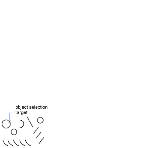
NOTE Autodesk Seek is currently available in US English only.
SELECT
Quick Reference
See also:
■Select Objects Individually
Places selected objects in the Previous selection set.
Summary
A small box, called the object selection target or pickbox, replaces the crosshairs
on the graphics cursor.
At the Select Objects prompt in a subsequent command, use the Previous
option to retrieve the previous selection set.
To view all options, enter ? at the Command prompt.
List of Prompts
The following prompts are displayed.
Select objects: Use an object selection method
Expects a point or
Window/Last/Crossing/BOX/ALL/Fence/WPolygon/CPolygon/Group/Add/Remove/Multiple/Previous/Undo/AUto/SIngle
Select objects: Specify a point or enter an option
Window Selects all objects completely inside a rectangle defined by two
points. Specifying the corners from left to right creates a window selection.
(Specifying the corners from right to left creates a crossing selection.)
SELECT | 1107
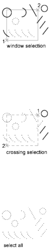
Last Selects the most recently created visible object. The object must be in
the current space, that is, model space or paper space, and its layer must not
be set to frozen or off.
Crossing Selects objects within and crossing an area defined by two points.
A crossing selection is displayed as dashed or otherwise highlighted to
differentiate it from window selection.
Box Selects all objects inside or crossing a rectangle specified by two points.
If the rectangle's points are specified from right to left, Box is equivalent to
Crossing. Otherwise, Box is equivalent to Window.
All Selects all objects in either model space or the current layout, except those
objects on frozen or on locked layers.
Fence Selects all objects crossing a selection fence. The Fence method is similar
to CPolygon except that that the fence is not closed, and a fence can cross
itself. Fence is not affected by the PICKADD system variable.
1108 | Chapter 19 S Commands
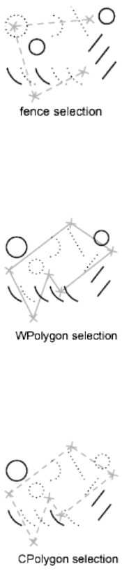
WPolygon Selects objects completely inside a polygon defined by points. The
polygon can be any shape but cannot cross or touch itself. The last segment
of the polygon is drawn so that it is closed at all times. WPolygon is not
affected by the PICKADD system variable.
CPolygon Selects objects within and crossing a polygon defined by specifying
points. The polygon can be any shape but cannot cross or touch itself. The
last segment of the polygon is drawn so that it is closed at all times. CPolygon
is not affected by the PICKADD system variable.
Group Selects all objects within one or more named or unnamed groups.
When you specify an unnamed group, be sure to include the asterisk (*). For
example, enter *a3.
Add Switches to the Add method: selected objects can be added to the selection
set by using any of the object selection methods. Auto and Add are the default
methods.
SELECT | 1109
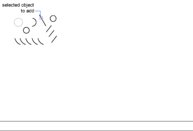
Remove Switches to the Remove method: objects can be removed from the
current selection set using any object selection method. An alternative to
Remove mode is to hold down Shift while selecting single objects or use the
Automatic option.
Multiple Selects objects individually without highlighting them during object
selection. This speeds up object selection for highly complex objects.
Previous Selects the most recent selection set. The Previous selection set is
cleared by operations that delete objects from the drawing.
NOTE The Previous selection set is ignored if you switch spaces.
Undo Cancels the selection of the object most recently added to the selection
set.
Auto Switches to automatic selection: pointing to an object selects the object.
Pointing to a blank area inside or outside an object forms the first corner of
a box defined by the Box method. Auto and Add are the default methods.
Single Switches to the Single method: selects the first object or set of objects
designated rather than continuing to prompt for further selections.
SELECTSIMILAR
Quick Reference
See also:
■Select Objects by Properties
Adds similar objects to the selection set based on selected objects.
1110 | Chapter 19 S Commands
Access Methods
Shortcut menu: Select the object that you want to use as the template object
to select similar objects. Right-click in the drawing area and click Select Similar.
Summary
Selects similar objects of the same type based on specified matching properties,
such as the color or block name.
List of Prompts
The following prompt is displayed.
Select objects or [SEttings]: Use an object selection method and press Enter
The Settings option displays the Select Similar Settings dialog box.
Select Similar Settings Dialog Box
Quick Reference
See also:
■Select Objects by Properties
Controls which properties must match for an object of the same type to be
selected.
List of Options
The following options are displayed.
Color Considers objects with matching colors to be similar.
Layer Considers objects on matching layers to be similar.
Linetype Considers objects with matching linetypes to be similar.
Linetype scale Considers objects with matching linetype scales to be similar.
Lineweight Considers objects with matching lineweights to be similar.
Plot style Considers objects with matching plot styles to be similar.
Object style Considers objects with matching styles (such as text styles,
dimension styles, and table styles) to be similar.
Select Similar Settings Dialog Box | 1111
Name Considers referenced objects (such as blocks, xrefs, and images) with
matching names to be similar.
SETBYLAYER
Quick Reference
See also:
■Display and Change the Properties of Objects
Changes the property overrides of selected objects to ByLayer.
Access Methods
Button
Ribbon: Home tab ➤ Modify panel ➤ Set to ByLayer
Menu: Modify ➤ Change to ByLayer
List of Prompts
The following prompts are displayed.
Current active settings: Color Linetype Lineweight Transparency Material Plot
Style
Select objects or [Settings]: Use an object selection method and press Enter when
you finish
If Settings is selected, the SetByLayer Settings dialog box is displayed, in which
you can specify which object properties are set to ByLayer.
If objects are selected, the Command prompt displays:
Change ByBlock to ByLayer? [Yes/No] <Yes>:
Include blocks? [Yes/No] <Yes>:
You can specify which properties are changed to ByLayer, including color,
linetype, lineweight, and materials.
1112 | Chapter 19 S Commands
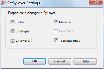
SetByLayer Settings Dialog Box
Quick Reference
See also:
■Display and Change the Properties of Objects
Changes property overrides for color, linetype, lineweight, material, plot style,
and transparency to ByLayer for selected objects and inserted blocks on
unlocked layers.
List of Options
The following options are displayed.
Color
Changes the color of selected objects to ByLayer. (SETBYLAYERMODE=1)
Linetype
Changes the linetype of selected objects to ByLayer. (SETBYLAYERMODE=2)
Lineweight
Changes the lineweight of selected objects to ByLayer. (SETBYLAYERMODE=4)
Plot Style
Changes the plot style of selected objects to ByLayer. This option is available
in named plot style drawings. (SETBYLAYERMODE=16)
Transparency
SetByLayer Settings Dialog Box | 1113

Changes the transparency value of selected objects to ByLayer.
(SETBYLAYERMODE=128)
SETENV
Quick Reference
See also:
■Overview of Hatch Patterns and Fills
Sets values of specified registry variables.
Summary
Use SETENV to view the registry settings of the MaxArray and MaxHatch
registry variables.
List of Prompts
The following prompts are displayed.
Enter variable name: Specify a name
Value: Enter a new value for the variable
NOTE SETENV is case sensitive.
SETVAR
Quick Reference
See also:
■Enter Commands on the Command Line
Lists or changes the values of system variables.
1114 | Chapter 19 S Commands

Access Methods
Button
Command entry: 'setvar for transparent use
List of Prompts
The following prompts are displayed.
Enter variable name or [?] <current>: Enter a variable name, enter ?, or press Enter
Variable Name Specifies the name of the system variable you want to set.
You can also change the value of system variables at the Command prompt
by entering the name of the variable and its new value.
?—List Variables Lists all system variables in the drawing and their current
settings.
SHADE
Quick Reference
See also:
■Add Simple Shading to 3D Objects
Displays a flat-shaded image of the drawing in the current viewport.
Summary
Hidden lines are removed and a shaded picture of the drawing is displayed.
The SHADE command uses the colors of the object being shaded. Shading is
calculated based on one light source from directly behind the eye. Subsequent
changes to the drawing are not reflected in the shaded object until you use
the SHADE command again.
The shaded image remains in the viewport until the viewport is regenerated.
The shaded image cannot be printed or plotted; however, you can output a
shaded image to a slide using the MSLIDE command.
SHADE | 1115
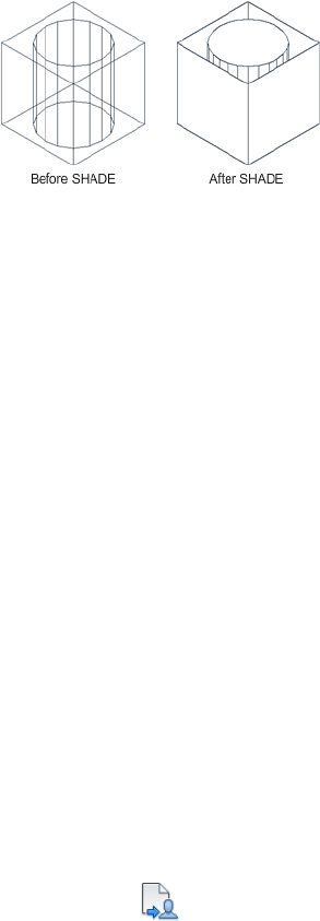
On systems that display fewer than 256 colors, SHADE produces an image
that removes hidden lines and displays the faces in their original color with
no lighting effect.
SHADEMODE
Quick Reference
See also:
■Add Simple Shading to 3D Objects
Controls the display of solid object shading in the current viewport.
SHARE
Quick Reference
See also:
■Use AutoCAD WS for Drawing File Collaboration
Shares the AutoCAD WS online copy of the current drawing with other users.
Access Methods
Button
1116 | Chapter 19 S Commands
Ribbon: Online tab ➤ Share panel ➤ Share Drawing
Menu: File ➤ AutoCAD WS ➤ Share Drawing
Toolbar: Online
Summary
The Share Drawing dialog box on page 1117 is displayed. You must save the
drawing before you can continue with this command.
NOTE You may first be prompted to log in to AutoCAD WS. If you do not have
an account, click Create an Account and follow the on-screen instructions.
Share Drawing Dialog Box
Quick Reference
See also:
■Use AutoCAD WS for Drawing File Collaboration
Shares the AutoCAD WS online copy of the current drawing with other users.
Summary
Sharing online drawings allows other users to view, edit, and download the
drawings.
Invite other users to simultaneously view and edit a shared drawing, allowing
participants to collaborate in real time.
Share Drawing Dialog Box | 1117
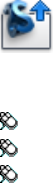
The permissions can be changed at any time in the Share Drawing dialog box;
new permissions take effect immediately.
List of Options
The following options are displayed.
Invite People Specifies recipients from your AutoCAD WS contacts. Enter
multiple email addresses to share a drawing with several users at once.
Share Sends email notifications to recipients with the link to the drawing, a
message, and a preview of the drawing.
Edit Allows recipients to edit any object in the shared drawing. When this
option is cleared, users can mark up and add to the drawing, but they cannot
change existing objects.
Download Allows recipients to download a copy of the drawing.
Open in AutoCAD WS Opens the shared drawing in the AutoCAD WS Editor.
SHAREWITHSEEK
Quick Reference
See also:
■Use Autodesk Seek to Add and Share Drawings
Uploads a selected block or the current drawing to the Autodesk Seek website.
Access Methods
Button
Ribbon: Output tab ➤ Autodesk Seek panel ➤ Share with Autodesk Seek
Menu: Application menu ➤ Publish ➤ Share with Autodesk Seek
Menu: File ➤ Share with Autodesk Seek
Shortcut menu: Right-click on a block and click Share with Autodesk Seek
1118 | Chapter 19 S Commands
Summary
Publishes single blocks or entire drawings to the Autodesk Seek website. You
must be a registered user on the Autodesk Seek website to upload content.
Currently, you can only upload a single drawing file at a time.
NOTE Autodesk Seek is currently available in US English only.
Share with Autodesk Seek Dialog Box
Quick Reference
See also:
■Use Autodesk Seek to Add and Share Drawings
Uploads the selected block or the current drawing file to the Autodesk Seek
website.
List of Options
The following options are displayed.
Share the Selected Block
Select a block to upload to the Autodesk Seek website. A DWG file is created
using the default Save as file format specified in the Options dialog.
List
Share with Autodesk Seek Dialog Box | 1119

Lists the blocks in the current drawing available for upload to the Autodesk
Seek website.
Share the Current Drawing
Selects the current drawing (not including external references) for upload to
the Autodesk Seek website. If you choose to use the last saved version of the
file, it uploads the file in its current file format.
Preview
Displays a preview image of the selected block or the current drawing (if
available).
SHEETSET
Quick Reference
See also:
■Quick Start for Sheet Sets
Opens the Sheet Set Manager.
Access Methods
Button
Ribbon: View tab ➤ Palettes panel ➤ Sheet Set Manager
Toolbar: Standard
Menu: Tools ➤ Palettes ➤ Sheet Set Manager
Summary
Displays the Sheet Set Manager.
The Sheet Set Manager organizes, displays, and manages sheet sets, a named
collection of drawing sheets. Each sheet in a sheet set is a layout in a drawing
(DWG) file.
1120 | Chapter 19 S Commands

Sheet Set Manager
Quick Reference
See also:
■Create a Sheet Set
Displays and organizes named collections of drawing sheets
Access Methods
Button
Ribbon: View tab ➤ Palettes panel ➤ Sheet Set Manager
Toolbar: Standard
Menu: Tools ➤ Palettes ➤ Sheet Set Manager
Summary
The Sheet Set Manager is not fully functional if
■The command is active;
■No drawing is open;
■The sheet set is locked by another user; or
■A lock icon displayed in front of the sheet set name in the Sheet Set
Manager indicates that the sheet set is locked. Hold your cursor over the
lock icon to view a tooltip that shows who has the sheet set locked.
List of Tabs
■Sheet List
■Sheet Views
■Model Views
Sheet Set Manager | 1121
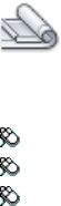
Sheet List Control
The Sheet List control displays the name of the current sheet set, or, if no
sheet sets are open, the Open option. The Sheet List control provides the
following options for all tabs:
Names of Open Sheet Sets Lists all open sheet sets, if any. A check is displayed
next to the current sheet set.
Recent Displays a list of recently opened sheet sets.
New Sheet Set Starts the Create Sheet Set wizard.
Open Displays the Open Sheet Set standard file selection dialog box.
Sheet List Tab
Quick Reference
See also:
■Create and Modify Sheets
Access Methods
Button
Ribbon: View tab ➤ Palettes panel ➤ Sheet Set Manager
Toolbar: Standard
Menu: Tools ➤ Palettes ➤ Sheet Set Manager
Summary
The Sheet List tab displays an ordered list of sheets. You can organize these
sheets under headings, called subsets, that you create.
List of Options
This tab has the following buttons:
1122 | Chapter 19 S Commands
Publish to DWF Publishes selected sheets or a sheet set to a specified DWF
file.
Publish to DWFx Publishes selected sheets or a sheet set to a specified DWFx
file.
Publish to PDF Publishes selected sheets or a sheet set to a specified DWFx
file.
Publish to Plotter Automatically publishes the selected sheets to the default
plotter or printer.
Publish Using Page Setup Override Automatically publishes the selected
sheets using the selected page setup override rather than the page setup
specified in each drawing. The page setup overrides are stored in a drawing
template (DWT) file designated to be the source of the page setup override
information.
Publish Displays a list of Publish options. The description for each option is
listed in alphabetical order under Shortcut Menu Options below.
Sheet Selections Displays a menu where you can save, manage, and restore
sheet selections by name. This makes it easy to specify a group of sheets for a
publish, transmit, or archive operation. The description for each option is
listed in alphabetical order under Shortcut Menu Options below.
Details (at bottom of window) Displays basic information about the currently
selected sheet or subset.
Preview (bottom of window) Displays a thumbnail preview of the currently
selected sheet.
Shortcut Menu Options
The following options are displayed on shortcut menus for the Sheet List tab.
For easier access, they are listed in alphabetical order. The options displayed
in each shortcut menu depend on context: in the tree view, if you right-click
the name of the sheet set, a different shortcut menu will display than if you
right-click the name of a subset or the name of a sheet.
Archive Displays the Archive a Sheet Set dialog box.
Close Sheet Set Closes the current sheet set, removing the sheet set
information displayed in the Sheet Set Manager window.
eTransmit Displays the Create Transmittal dialog box.
Edit Subset and Sheet Publish Settings Displays thePublish Sheets dialog
box.
Sheet Set Manager | 1123
Import Layout as Sheet Displays the Import Layouts as Sheets dialog box.
Include Plot Stamp Turns the plot stamp on or off for the selected sheet set,
subset, or sheet.
Include for Publish Includes the sheet for publishing.
Insert Sheet List Table Displays the Insert Sheet List Table dialog box.
Manage Page Setups Displays the Page Setup Manager dialog box.
New Sheet Displays the New Sheet dialog box.
New Subset Displays the Subset Properties dialog box, where you can create
a new sheet subset for organizing the sheets in a sheet set.
Open Opens the drawing file of the selected sheet and displays the layout.
Open Read-Only Opens the drawing file of the selected sheet in read-only
mode and displays the layout. You cannot save changes to the file using the
original file name.
Plot Stamp Settings Displays the Plot Stamp dialog box, in which you can
specify the information, such as drawing name and plot scale, that you want
applied to the plot stamp.
Properties (Sheet Set) When the sheet set node is selected, displays the Sheet
Set Properties dialog box.
Properties (Subset) When a subset node is selected, displays the Subset
Properties dialog box. See New Subset.
Properties (Sheet) When a sheet node is selected, displays the Sheet Properties
dialog box.
Publish Displays the Publish dialog box.
Publish in Reverse Order When checked, sends sheets to the plotter in reverse
of default order.
Publish Sheets in Subset Publishes the sheets in the subset.
When Do Not Publish Sheets is checked, all sheets in the subset is not
published.
Suspends all sheets in the subset from being published.
Publish Using Page Setup Override Automatically publishes the selected
sheets using the selected page setup override rather than the page setup
specified in each drawing. The page setup overrides are stored in a drawing
1124 | Chapter 19 S Commands

template (DWT) file designated to be the source of the page setup override
information.
Plot Stamp Settings Displays the Plot Stamp dialog box.
Publish to DWF Publishes the selected sheets or the sheet set to a specified
DWF file.
Publish to Plotter Automatically publishes the selected sheets to the default
plotter or printer.
Remove Subset Removes the currently selected subset from the organization
of the sheet set.
Rename & Renumber Displays the Rename & Renumber Sheet dialog box.
Resave All Sheets Updates the sheet set information saved with each drawing
in the current sheet set. Each drawing file in the current sheet set is opened
and resaved. Any changes that were made are updated in the sheet set data
(DST) file.
Drawing files saved in a previous DWG file format are resaved without
changing format.
NOTE In a network environment, make sure that all drawing files in the current
sheet set that are opened by other users are closed before performing this
operation.
Remove Sheet Removes the currently selected sheet from the sheet set.
Save Sheet Selection Displays the New Sheet Selection dialog box.
Sheet Set Publish Options Displays the Sheet Set Publish Options dialog box.
This is the same as the Publish Options dialog, but is specific to the current
sheet set.
Transmittal Setups Displays the Transmittal Setups dialog box.
Sheet Views Tab
Quick Reference
See also:
■Create and Modify Sheets
Sheet Set Manager | 1125
Access Methods
Button
Ribbon: View tab ➤ Palettes panel ➤ Sheet Set Manager
Toolbar: Standard
Menu: Tools ➤ Palettes ➤ Sheet Set Manager
Summary
The Sheet Views tab displays an ordered list of views used in the current sheet
set. You can organize these views under headings, called categories, that you
create.
NOTE Only sheet views created in AutoCAD 2005 or later are listed on the Sheet
Views tab.
List of Options
This tab has the following buttons:
New View Category Button Displays the View Category dialog box.
View by Category Displays the views in the current sheet set organized by
their categories.
View by Sheet Displays a list of views in the current sheet set organized by
the sheet on which they are located.
Shortcut Menu Options
The following options are displayed on shortcut menus for the Sheet Views
tab.
Display Displays the selected view in the sheet in which it was created. Opens
the drawing file containing the sheet, if the drawing file is not already open.
New View Category Displays the View Category dialog box, in which you
can create a new view category to organize the views in a sheet set.
Place Callout Block Specifies and places a callout block onto a sheet.
Place View Label Specifies and places a view label block onto a sheet.
Properties (Sheet Set) Displays the Sheet Set Properties dialog box.
1126 | Chapter 19 S Commands
Properties (View Category) Displays the View Category dialog box.
Rename Renames the selected sheet view category.
Rename & Renumber Displays the Rename and Renumber View dialog box
where you can renumber and retitle the selected sheet view.
Set Category Reassigns the selected sheet view to a category that you specify.
Model Views Tab
Quick Reference
See also:
■Create and Modify Sheets
Access Methods
Button
Ribbon: View tab ➤ Palettes panel ➤ Sheet Set Manager
Toolbar: Standard
Menu: Tools ➤ Palettes ➤ Sheet Set Manager
Summary
The Model Views tab displays a list of folders, drawing files, and model space
views available for the current sheet set. You can add and remove folder
locations to control which drawing files are associated with the current sheet
set.
NOTE After creating a named model space view, you must save the drawing to
add the view to the Model Views tab.
List of Options
Refresh Updates the list of drawing files listed in the tree view. The Refresh
button updates all information stored in the sheet set data (DST) file, checks
all folders in every resource location for new or removed drawing files, and
Sheet Set Manager | 1127
checks all drawing files that are expanded for new or removed model space
views.
Add New Location Displays the Browse for Folder standard file selection
dialog box, in which you can add a folder location to the sheet set.
Shortcut Menu Options
Add New Location Displays the Browse for Folder standard file selection
dialog box where you can add a folder location to the sheet set.
eTransmit Displays the Create Transmittal dialog box.
Open File Opens the selected drawing (DWG) file.
Place on Sheet Initiates a series of automated steps that creates and places a
view of the selected model onto the current layout of the current drawing.
These steps are
■You are prompted to place the view on the layout. Right-click to change
the scale of the view before placement
■The selected model is attached as an xref in the current drawing
■A layout viewport is created on the current layout
■A sheet view is created that corresponds with the newly created layout
viewport
Remove Location Removes the currently selected folder location from the
sheet set.
See Model Space Views Expands a list of named model space views.
Subset Properties Dialog Box
Quick Reference
See also:
■Organize a Sheet Set
Creates a new sheet subset in a sheet set.
1128 | Chapter 19 S Commands
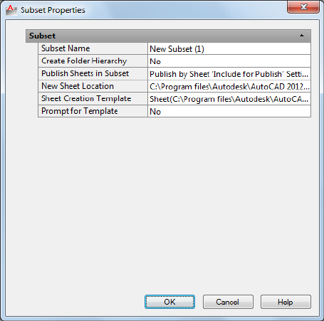
Summary
You can organize sheets by dragging them to different subsets.
List of Options
The following options are displayed.
Subset Name
Specifies the name of this subset and the name of the sheet storage folder for
this subset if Create Folders Relative to Parent Subset Storage Location is
selected.
Publish Sheets in Subset
Conforms to the current settings for sheet set publishing.
New Sheet Location
Specifies the folder location for all new drawing (DWG) files containing sheets
that are associated with this subset.
Sheet Creation Template
Specifies the drawing template (DWT) file and layout name that is used to
create new drawing files for this subset.
Subset Properties Dialog Box | 1129
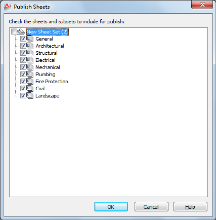
The syntax for this property is
layoutname [folderpath\]filename.dwt
Prompt for Template
When Yes is selected, prompts you to specify a drawing template file rather
than use the default drawing template file for creating new sheets.
Publish Sheets Dialog Box
Quick Reference
See also:
■Publish, Transmit, and Archive Sheet Sets
Specifies the sheets to be included for publishing.
Summary
When a sheet is selected, it is included for publishing.
1130 | Chapter 19 S Commands
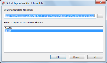
Select Layout as Sheet Template Dialog Box
Quick Reference
See also:
■Create and Modify Sheets
Specifies the folder path, drawing template (DWT) file, and layout name to
be used for creating new sheets.
List of Options
The following options are displayed.
Drawing Template File Name
Specifies the drawing template file path and name to be used for creating new
sheets.
Select a Layout to Create New Sheets
Lists and specifies the name of the layout in the drawing template file to be
used for new sheets.
Select Layout as Sheet Template Dialog Box | 1131
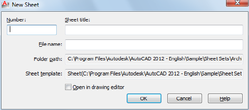
New Sheet Dialog Box
Quick Reference
See also:
■Create and Modify Sheets
Creates a new sheet in the current sheet set by creating a new drawing (DWG)
file that includes a layout tab with the same name as the drawing.
List of Options
The following options are displayed.
Number
Specifies the sheet number. It is recommended that you do not fill in the sheet
number when you first create a sheet. By default the drawing name and layout
name of the new sheet will be the sheet number together with sheet title.
You can remove the sheet number from the file name when you create the
new sheet, but the sheet number will still be in the layout name.
Sheet Title
Specifies the sheet title, which corresponds to an identically named layout
tab in the new drawing.
File Name
Specifies the name of the new drawing file containing the sheet. By default,
the name of the drawing file is the sheet number combined with the sheet
title. You can also change the drawing file name in this box.
Folder Path
1132 | Chapter 19 S Commands
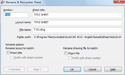
Displays the default folder for the new drawing file.
The default folder for a subset is specified in the Subset Properties dialog box;
and the default folder for a sheet set is specified in the Sheet Set Properties
dialog box.
Sheet Template
Displays the default sheet template file used for creating the new drawing file.
The default template file used for creating new drawings in a subset is specified
in the Subset Properties dialog box; the default template file for creating new
drawings in a sheet set is specified in the Sheet Set Properties dialog box.
Open in Drawing Editor
When checked, allows you to open the drawing after creation and edit directly
within the file.
Rename & Renumber Sheet Dialog Box
Quick Reference
See also:
■Create and Modify Sheets
Specifies a sheet number, sheet title, and other properties for a sheet in a sheet
set.
Rename & Renumber Sheet Dialog Box | 1133
List of Options
The following options are displayed.
Number
Specifies the sheet number of the selected sheet.
Sheet Title
Specifies the sheet title of the selected sheet.
Layout Name
Specifies the name of the layout associated with the selected sheet.
File Name
Specifies the name of the drawing file associated with the selected sheet.
Folder Path
Displays the folder path for the drawing file.
Rename Layout to match Sheet Title
When checked, changes the layout name to match the sheet title.
Prefix with Sheet Number
When checked, changes the layout name to a new name formed by adding
the sheet number to the beginning of the sheet title.
Rename Drawing File to match Sheet Title
When checked, changes the drawing file name to match the sheet title.
Prefix with Sheet Number
When checked, changes the drawing file name to a new name formed by
adding the sheet number to the beginning of the sheet title.
Next
Loads the next sheet into this dialog box. This provides a convenient method
for renumbering or retitling a series of sheets.
Previous
Loads the previous sheet into this dialog box.
1134 | Chapter 19 S Commands
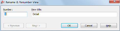
Rename & Renumber View Dialog Box
Quick Reference
See also:
■Create and Modify Sheets
Specifies a sheet number and view title for a view in a sheet set.
List of Options
The following options are displayed.
Number
Specifies the sheet number of the selected view.
View Title
Specifies the view title of the selected view.
Previous
Loads the previous view into this dialog box.
Next
Loads the next view into this dialog box.
Import Layouts as Sheets Dialog Box
Quick Reference
See also:
■Create and Modify Sheets
Rename & Renumber View Dialog Box | 1135
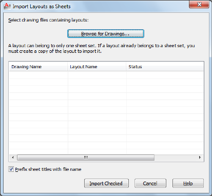
Provides a method for quickly importing layouts into a sheet set, and specifying
which layout tab is to be used as the sheet.
Summary
If a layout already belongs to a sheet set, you must create a copy of the drawing
containing the layout to import it.
List of Options
The following options are displayed.
Browse for Drawings
Displays the Select Drawing standard file selection dialog box.
List of Layouts in Selected Drawing
Lists all available layouts in the specified drawing file. Click a check box to
select a layout.
Prefix Sheet Titles with File Name
When checked, automatically adds the drawing file name to the beginning
of the sheet title.
Import Checked Imports a layout from the list only if it displays a check
mark.
1136 | Chapter 19 S Commands
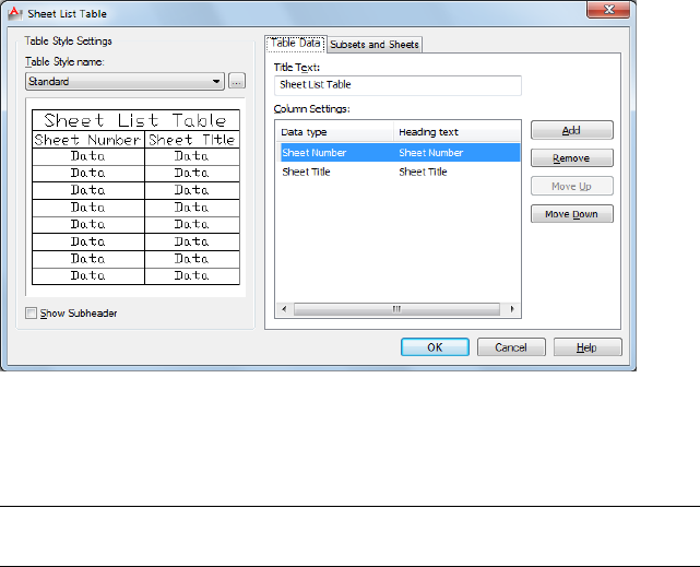
Insert Sheet List Table Dialog Box
Quick Reference
See also:
■Create and Modify Sheets
Creates a table listing the sheets in the sheet set.
Summary
This table can be added to any sheet in the current sheet set, but it is typically
added to the title sheet.
NOTE Insert Sheet List Table on the sheet set shortcut menu is not available if the
Model tab is active, or if the current layout is not a sheet in the current sheet set.
List of Tabs
This dialog box contains the following tabs.
■Table Data Tab
■Subsets and Sheets Tab
Insert Sheet List Table Dialog Box | 1137
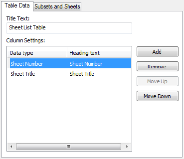
List of Options
The following options are displayed.
Table Style Name
Specifies the table style to be used for the table.
Table Style Preview
Displays a preview of the currently selected table style.
Include Subsets as Headers in Output
When checked, displays the names of the subsets, dividing the sheet list table
into sections.
Table Style Settings Displays options for the table style.
Table Data Tab
Quick Reference
See also:
■Create and Modify Sheets
Displays options for the table data.
1138 | Chapter 19 S Commands
List of Options
The following options are displayed.
Title Text
Specifies the name of the title of the sheet list table.
Column Settings Area
Displays a list of the column definitions in the sheet list table. Each line in
the list represents a column. The top-to-bottom order of the list represents
how the columns will be displayed in the table (left to right).
Data Type Column Selecting a column definition and then clicking on an
entry in the Data Type column displays a list. From this list, you can change
the type of information that is going to be displayed in the columns of the
sheet list table.
Heading Text Column Allows you to change the title text for each column
in the sheet list table.
Add
Adds a sheet number column to the sheet list table.
Remove
Removes the selected column from the sheet list table. If you accidentally
remove a column, you can add a Number column and then change its data
type from the data type list.
Move Up
Moves the selected column up in the column list and to the left in the sheet
list table.
Move Down
Moves the selected column down in the column list and to the right in the
sheet list table.
Insert Sheet List Table Dialog Box | 1139
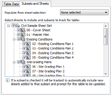
Subsets and Sheets Tab
Quick Reference
See also:
■Create and Modify Sheets
Displays options to control the sheet selection represented by the current
sheet list table
List of Options
The following options are displayed.
Populate From Sheet Selection Drop-Down Menu Sets the check state of
the items in the view based on a previous saved sheet selection.
Sheet Set Tree View Displays the sheet set subsets that are to be updated
automatically.
1140 | Chapter 19 S Commands
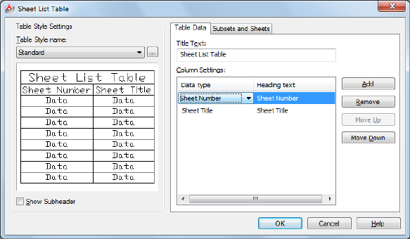
Edit Sheet List Table Settings Dialog Box
Quick Reference
See also:
■Create and Modify Sheets
Allows you to edit a sheet list table that exists in the current drawing.
Access Methods
Shortcut menu: Select any cell in Sheet List Table ➤ Right-click to open
the shortcut menu ➤ Edit Sheet List Table Settings
Summary
The Edit Sheet List Table Settings dialog box gives you access to all the settings
found on the Insert Sheet List Table dialog box.
List of Options
The following options are displayed.
Table Style Settings
Displays options for the table style.
Table Style Name
Edit Sheet List Table Settings Dialog Box | 1141
Specifies the table style to be used for the table. The Browse button displays
the Table Style dialog box.
Table Style Sample Area
Displays a sample of the currently selected table style.
Show Subheader
When checked, displays the names of the subsets, dividing the sheet list table
into sections.
Table Data Settings
Displays options for the table data.
Title Text
Specifies the name of the title of the sheet list table.
Column Settings Area
Displays a list of the column definitions in the sheet list table. Each line in
the list represents a column. The top-to-bottom order of the list represents
how the columns will be displayed in the table (left to right).
Data Type Column Selecting a column definition and then clicking on an
entry in the Data Type column displays a list. From the list, you can change
the type of information that is going to be displayed in the columns of the
sheet list table.
Heading Text Column Allows you to change the title text for each column
in the sheet list table.
Add
Adds a sheet number column to the sheet list table.
Remove
Removes the selected column from the sheet list table. If you accidentally
remove a column, you can add a new Sheet Number column and then change
its data type from the data type list.
Move Up
Moves the selected column up in the column list and to the left in the sheet
list table.
Move Down
Moves the selected column down in the column list and to the right in the
sheet list table.
1142 | Chapter 19 S Commands
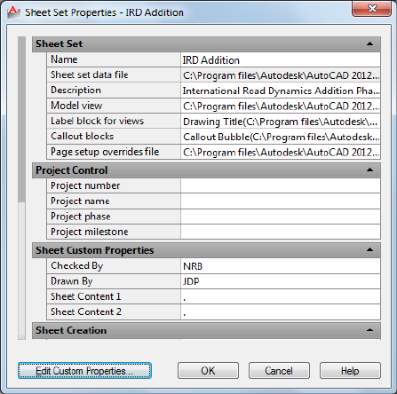
Sheet Set Properties Dialog Box
Quick Reference
See also:
■Create and Modify Sheets
Displays information that is specific to the selected sheet set.
Summary
You can click on each field to display a description at the bottom of the dialog
box.
This includes information such as the path and file name of the sheet set data
(DST) file, the paths of the folders that contain the drawing files associated
with the sheet set, and any custom properties associated with the sheet set
List of Options
The following options are displayed.
Name Displays the name of the sheet set.
Sheet Set Properties Dialog Box | 1143
Sheet Set Data File Displays the path and file name of the sheet set data (DST)
file.
Description Displays a description of the sheet set.
Model View Displays the paths and names of folders that contain drawings
used by the sheet set.
Label Block for Views Displays the path and file name of the DWT or DWG
file that contains the label blocks for the sheet set.
Callout Blocks Displays the path and file name of the DWT or DWG file that
contains the callout blocks for the sheet set.
Page Setup Overrides File Displays the path and file name for the drawing
template (DWT) file containing the page setup overrides for the sheet set.
Project Control Displays several fields commonly used in projects including
Project Number, Project Name, Project Phase, and Project Milestone.
Sheet Custom Properties Displays the user-defined custom properties
associated with each sheet in the sheet set.
Sheet Storage Location Displays the path and name of the folder where new
sheets are created.
Sheet Creation Template Displays the path and name of the DWG or DWT
file to be used when creating new sheets for the sheet set.
Prompt for Template Controls whether you will be prompted for a sheet
creation template every time you create a new sheet in a sheet set.
Sheet Set Custom Properties Displays the user-defined custom properties
associated with the sheet set.
Edit Custom Properties
Displays the Sheet Set Custom Properties dialog box.
Sheet Set Custom Properties Dialog Box
Quick Reference
See also:
■Include Information with Sheets and Sheet Sets
1144 | Chapter 19 S Commands
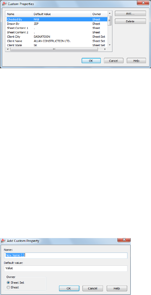
Lists the custom properties associated with the current sheet set.
List of Options
The following options are displayed.
Add
Displays the Add Custom Property dialog box.
Delete
Removes the selected custom property from the sheet set.
Add Custom Property Dialog Box
Quick Reference
See also:
■Include Information with Sheets and Sheet Sets
Creates a custom property to be associated with the current sheet set or with
each sheet.
Add Custom Property Dialog Box | 1145
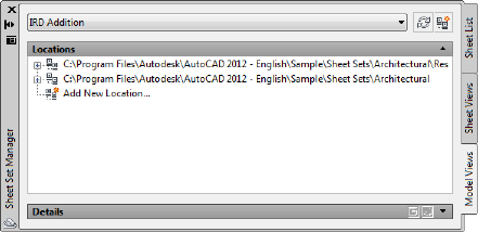
Summary
Custom properties can be used to store information such as a contract number,
the name of the designer, and the release date.
List of Options
The following options are displayed.
Name
Specifies the name of a new custom property.
Default Value
Specifies a value for the custom property.
Owner
Specifies whether the custom property belongs to the sheet set or to a sheet.
Resource Drawing Locations Dialog Box
Quick Reference
See also:
■Organize a Sheet Set
Displays a list of folders that are available for the current sheet set.
Summary
You can add and remove folder locations to control which drawing files are
available for the current sheet set.
1146 | Chapter 19 S Commands
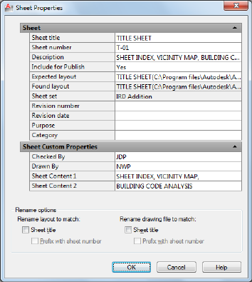
List of Options
The following options are displayed.
Add
Displays the Browse for Folder standard file selection dialog box, in which
you can add a folder location to the list.
Delete
Removes the selected folder from the list.
Sheet Properties Dialog Box
Quick Reference
See also:
■Create and Modify Sheets
Displays information that is specific to the selected sheet, such as the sheet
title, sheet number, and whether it will be included in publishing operations.
Also displays custom properties, if any.
Sheet Properties Dialog Box | 1147
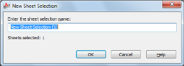
Summary
You can enter a new value to modify any available sheet property.
List of Options
The following options are displayed.
Sheet and Sheet Custom Properties Displays the properties of the selected
sheet. Also displays custom properties, if any. You can enter a new value to
modify any sheet property. The Expected Layout is the path and file name of
the drawing where the sheet was saved. The Found Layout is the path and file
name of the drawing where the sheet was found. If the paths are different,
you can modify the path and file name in Expected Layout. This operation
reassociates the sheet with the sheet set.
Rename Options Displays the options for renaming the selected sheet. These
settings are the same as those in Rename & Renumber Sheet dialog box on
page 1133.
New Sheet Selection Dialog Box
Quick Reference
See also:
■Publish, Transmit, and Archive Sheet Sets
Saves a named selection of sheets for future operations.
Summary
After you select several sheets and then save the selection, you can restore the
sheet selection by name. This makes it easy to specify a set of sheets for a
publish, transmit, or archive operation.
1148 | Chapter 19 S Commands
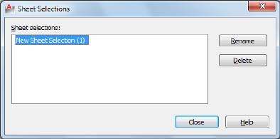
List of Options
The following options are displayed.
Enter the Sheet Selection Name
Specifies a name for the sheet selection.
Sheet Selections Dialog Box
Quick Reference
See also:
■Publish, Transmit, and Archive Sheet Sets
Renames or deletes saved sheet selections.
List of Options
The following options are displayed.
Sheet Selections
Specifies the sheet selection that you want to rename or delete.
Rename
Renames the selected sheet selection.
Delete
Deletes the selected sheet selection.
Sheet Selections Dialog Box | 1149
View Category Dialog Box
Quick Reference
See also:
■Organize a Sheet Set
Creates a new view category in a sheet set.
Summary
You can organize views by dragging them under different view categories.
List of Options
The following options are displayed.
Category Name
Specifies the name of a new view category.
Select the Callout Blocks to be Used in this Category
Provides a method for listing the callout blocks appropriate to the current
view category.
Add Blocks
Displays the List of Blocks dialog box.
List of Blocks Dialog Box
Quick Reference
See also:
■Create and Modify Sheets
Lists, adds, or deletes callout blocks for use in the current sheet set.
1150 | Chapter 19 S Commands
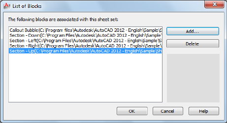
Summary
This dialog box is displayed by clicking the Add Blocks button in the View
Category dialog box, or by clicking the [...] button next to Callout blocks in
the Sheet Set Properties dialog box.
List of Options
The following options are displayed.
List of Blocks
Displays the list of blocks available for use with the current sheet set.
Add
Displays the Select Block dialog box.
Delete
Removes the selected block from the list of callout blocks.
Preview area Displays a preview image when a single block is selected.
Select Block Dialog Box
Quick Reference
See also:
■Create and Modify Sheets
Adds a new label block or callout blocks for use in the current sheet set.
Select Block Dialog Box | 1151
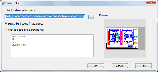
List of Options
The following options are displayed.
Enter the Drawing File Name
Specifies the path and name of a drawing (DWG) file or the name and path
of a drawing template (DWT) file to be used as the source of a block definition.
Select the Drawing File as a Block
Uses the entire specified drawing file or drawing template file as the block
definition.
Choose Blocks in the Drawing File
Uses a selected block definition from the specified drawing file or drawing
template file.
Preview
Displays a preview image when a single block is selected.
SHEETSETHIDE
Quick Reference
See also:
■Create a Sheet Set
Closes the Sheet Set Manager.
1152 | Chapter 19 S Commands
SHOWPALETTES
Quick Reference
See also:
■Specify the Behavior of Dockable Windows
Restores the display of hidden palettes.
Access Methods
Command entry: Ctrl+Shift+H
Summary
Restores the state of the display and position of palettes hidden by
HIDEPALETTES.
Press Ctrl+Shift+H to switch between HIDEPALETTES and SHOWPALETTES.
NOTE If a palette was manually turned back on, it is not affected by
SHOWPALETTES (even if it was manually closed again)
SIGVALIDATE
Quick Reference
See also:
■View Digital Signature Details
Displays information about the digital signature attached to a drawing file.
Summary
The Validate Digital Signatures dialog box is displayed. Review the information
displayed in the dialog box, and click Close to view the signed file.
SHOWPALETTES | 1153
Validate Digital Signatures Dialog Box
Quick Reference
See also:
■View Digital Signature Details
Displays information about a digital signature.
Summary
You can determine if a digital signature is valid and if the signed file has been
modified since it was signed.
List of Options
The following options are displayed.
Name
Displays the location and name of the file whose digital signature is being
viewed.
Digital Signature Status
Displays a Valid Signature icon if a digital signature is valid, and an Invalid
Signature icon if the digital signature is not valid.
File Status
Displays the status of the signed file.
View Base Signature
Displays the Digital Signature Contents dialog box. This option is available
only if the digital signature is valid and the file has not been modified since
it was signed.
Xref Drawings
Contains detailed information about any xrefs in the signed file.
View Xref Drawings
Displays the xref drawings contained in a file's base drawing.
View Xref List
1154 | Chapter 19 S Commands
Contains a list of the xref drawings in a signed file. This list is available only
if the current file contains xrefs and View Xref Drawings is selected.
View Xref Signature
Displays the Digital Signatures Contents dialog box for the selected xref. This
button is enabled only if the xref has a valid digital signature attached.
Digital Signature Contents Dialog Box
Quick Reference
See also:
■View Digital Signature Details
Displays information about a digital signature.
Summary
You can determine if a digital signature is valid and if the signed file has been
modified since it was signed.
List of Options
The following options are displayed.
Name
Displays the location and name of the file whose digital signature is being
viewed.
Digital Signature Status
Displays the status of the digital signature.
File Status
Displays the status of the signed file.
Signed By
Displays the name of the organization or individual who attached a digital
signature to the current file.
Digital Signature Contents Dialog Box | 1155
Other Fields
Displays the subject, issuer, valid from date, valid to date, or serial number in
the Values box.
Subject Displays information about the organization or individual who owns
the digital ID and attached the digital signature.
Issuer Displays the name of the certificate authority that originally issued the
digital ID.
Valid From Displays the day, month, year, and exact time from which the
digital ID can be first used and is considered valid.
Valid To Displays the day, month, year, and exact time at which the digital
ID ceases to be valid.
Serial Number Displays the serial number assigned to the digital ID.
Values
Displays information about a digital signature based on the item you select
in the Other Fields list.
Comment
Displays any comments about the digital signature that is attached to the
current file.
Signature Date and Time
Displays the date and time that the digital signature was attached to the current
file. The date and time are based on the time service used when the signature
was attached.
Time Service Used
Displays the time service used to add the time stamp to the current file.
Skip Xref Warnings
Determines if the Digital Signature Contents dialog box is displayed for signed
xrefs. This check box is displayed only in the Digital Signature Contents dialog
box when a signed drawing is opened.
1156 | Chapter 19 S Commands

SKETCH
Quick Reference
See also:
■Draw Freehand Sketches
Creates a series of freehand line segments.
Summary
Sketching is useful for creating irregular boundaries or for tracing with a
digitizer. Specify the object type (line, polyline, or spline), increment, and
tolerance before sketching.
List of Prompts
The following prompts are displayed.
Sketch on page 1157 or [Type on page 1157/Increment on page 1158/toLerance on
page 1158]:
Sketch Creates a sketch.
Type Specifies the object type for the sketch line. (SKPOLY on page 1659 system
variable)
■Line on page 702
■Polyline on page 954
■Spline on page 1169
SKETCH | 1157
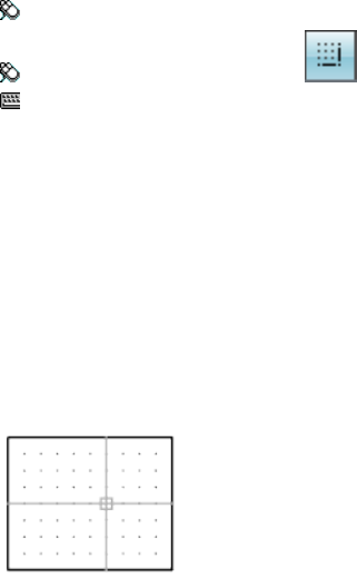
Increment Defines the length of each freehand line segment. You must move
the pointing device a distance greater than the increment value to generate
a line. (SKETCHINC on page 1659 system variable)
Tolerance For Splines, specifies how closely the spline’s curve fits to the
freehand sketch. (SKTOLERANCE on page 1660 system variable)
SNAP
Quick Reference
See also:
■Adjust Grid and Grid Snap
Restricts cursor movement to specified intervals.
Access Methods
Menu: Tools ➤ Drafting Settings
Toolbar: Status bar ➤ Snap
Command entry: snap or ‘snap for transparent use
List of Prompts
The following prompts are displayed.
Specify snap spacing on page 1158 or [ON on page 1158/OFF on page 1159/Aspect
on page 1159/Style on page 1159/Type on page 1159] <current>: Specify a distance,
enter an option, or press Enter
Snap Spacing
Activates Snap mode with the value you specify.
On
Activates Snap mode using the current settings of the snap grid.
1158 | Chapter 19 S Commands
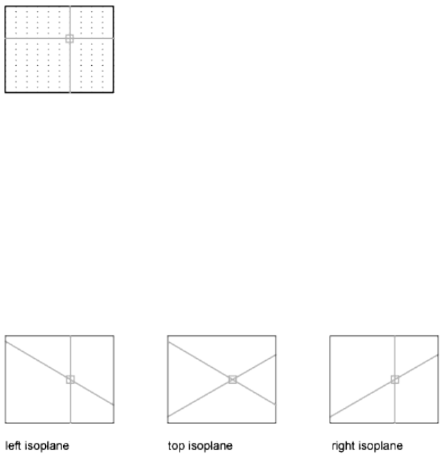
Off
Turns off Snap mode but retains the current settings.
Aspect
Specifies different spacing in the X and Y directions.
Style
Specifies the format of the snap grid, which is Standard or Isometric.
Standard
Sets a rectangular snap grid that is parallel to the XY plane of the current UCS.
X and Y spacing may differ.
Spacing Specifies the overall spacing of the snap grid.
Aspect Specifies the horizontal and vertical spacing of the snap grid separately.
Isometric
Sets an isometric snap grid, in which the snap locations are initially at
30-degree and 150-degree angles. Isometric snap cannot have different Aspect
values. The lined grid does not follow the isometric snap grid.
ISOPLANE determines whether the crosshairs lie in the top isometric plane
(30- and 150-degree angles), the left isoplane (90- and 150-degree angles), or
the right isoplane (30- and 90-degree angles).
Type
Specifies the snap type, polar or rectangular. This setting is also controlled by
the SNAPTYPE system variable.
Polar Sets the polar angle increment.
(POLARANG system variable)
SNAP | 1159
Grid Sets the snap to Grid. When you specify points, the cursor snaps along
vertical or horizontal grid points.
SOLID
Quick Reference
See also:
■Modify Hatch Properties
Creates solid-filled triangles and quadrilaterals.
Summary
2D solids are filled only when the FILLMODE system variable is on (1) and
the viewing direction is orthogonal to the 2D solid.
List of Prompts
The following prompts are displayed.
First point Sets the first point in the 2D solid.
Second point Sets the first edge of the 2D solid.
Third point Sets the corner that is opposite the second point.
Fourth point or <exit> The fourth point is diagonally opposite the first point.
Pressing Enter at the Fourth Point prompt creates a filled triangle. Specifying
a fifth point creates a quadrilateral area.
Specifying successive third and fourth points creates further connected triangles
and four-sided polygons in a single solid object.
1160 | Chapter 19 S Commands
SPACETRANS
Quick Reference
See also:
■Change Text Scale and Justification
Calculates equivalent model space and paper space lengths in a layout.
Access Methods
Button
Toolbar: Text
List of Prompts
In a layout, when in model space, the prompt is displayed as follows:
Specify paper space distance <1.000>: Enter a length in paper space to convert to
the equivalent length in model space
In a layout, when in paper space, the prompt is displayed as follows:
Select a viewport: Pick a layout viewport object (this prompt is displayed when more
than one viewport object is available in the layout)
Specify model space distance <1.000>: Enter a length in model space to convert
to the equivalent length in paper space
SPACETRANS converts lengths, typically text heights, from either model space
or paper space to its equivalent length in the other space. It is intended to be
invoked transparently at a prompt for text height or other length value. When
SPACETRANS | 1161
used at the Command prompt, SPACETRANS displays the computed length
equivalent at the Command prompt.
NOTE This command is not available from the Model tab or in a perspective view.
SPELL
Quick Reference
See also:
■Check Spelling
Checks spelling in a drawing.
Access Methods
Button
Ribbon: Annotate tab ➤ Text panel ➤ Check Spelling
Menu: Tools ➤ Spelling
Toolbar: Text
Command entry: 'spell for transparent use
Summary
When you enter spell at the Command prompt, the Check Spelling dialog
box is displayed. Select the Start button to begin the spelling check.
If Check Spelling is set to Entire Drawing, spelling is checked on the Model
layout, then on named (paper space) layouts. If a flagged word is identified,
the drawing area highlights and zooms to that word.
NOTE Invisible text such as text on hidden layers, and hidden block attributes is
not checked. Non-uniformly scaled blocks and objects not on the supported
annotation scale are also not checked.
1162 | Chapter 19 S Commands
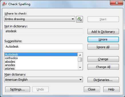
Check Spelling Dialog Box
Quick Reference
See also:
■Check Spelling
Displays the spelling checker dialog box that picks and displays the wrongly
spelt words and suggests alternate words.
Summary
Checks the spelling in single-line text, multiline text, multileader text, text
within block attributes, text within xrefs, and text added to dimensions.
In block attributes, only the attribute values are checked. The spelling in text
objects within block references and nested block references is checked, but
spell checking in block definitions is performed only if the associated block
reference has been selected.
List of Options
The following options are displayed.
Where to Check
Displays the areas you want checked for spelling.
Check Spelling Dialog Box | 1163
Select Text Objects
Limits the spelling check to the selected single-line text, multiline text,
dimension text, multileader text, text within block attributes, and text within
xrefs.
Not in Dictionary
Displays the word identified as misspelled.
Suggestions
Displays a list of suggested replacement words from the current dictionary.
You can select another replacement word from the list, or edit or enter a
replacement word in the top Suggestions text area.
Main Dictionary
Lists the main dictionary options. The default dictionary will depend on the
language setting.
Start
Starts checking text for spelling errors.
Ignore
Skips the current word.
Ignore All
Skips all remaining words that match the current word.
Add to Dictionary
Adds the current word to the current custom dictionary. The maximum word
length is 63 characters.
Change
Replaces the current word with the word in the Suggestions box.
Change All
Replaces the current word in all selected text objects in the spell check area.
Dictionaries
Displays the Dictionaries dialog box.
Settings
Displays the Check Spelling Settings dialog box.
1164 | Chapter 19 S Commands
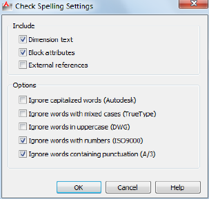
Undo
Reverses the previous check spelling action or series of actions, including
Ignore, Ignore All, Change, Change All, and Add to Dictionary.
Check Spelling Settings Dialog Box
Quick Reference
See also:
■Check Spelling
Provides options to change the way the default behavior of the spelling checker
dialog box.
Summary
Specifies specific text options that will be checked in your drawing.
List of Options
The following options are displayed.
Include
Dimension Text
Searches dimension text.
Block Attributes
Check Spelling Settings Dialog Box | 1165
Searches block attributes text for spelling errors.
External References
Specifies to search external references for spelling errors.
Options
Ignore Capitalized Words
Specifies to ignore capitalized words.
Ignore Words with Mix Cases
Specifies to ignore words that contain uppercase and lowercase letters.
Ignore Words in Uppercase
Specifies to ignore words that are in all uppercase.
Ignore Words with Numbers
Specifies to ignore words that include numbers.
Ignore Words Containing Punctuation
Specifies to ignore words that contain punctuation.
Dictionaries Dialog Box
Quick Reference
See also:
■Check Spelling
Displays the installed dictionaries and allows you to edit the custom dictionary.
1166 | Chapter 19 S Commands

Summary
Manages dictionaries. During a spelling check, the words in the drawing are
matched to the words in the current main and current custom dictionaries.
Any spelling exceptions that you identify with the Add option are stored in
the custom dictionary you are currently using.
If you want to check spelling in another language, you can change to a
different main dictionary. You can also create any number of custom
dictionaries and switch between them as needed.
List of Options
The following options are displayed.
Main Dictionary
Displays a list of language-specific dictionaries from which you can choose a
different main dictionary. This dictionary is used in conjunction with the
custom dictionary.
Custom Dictionary
Displays the name of the current custom dictionary. The .cus extension is used
for an AutoCAD custom dictionary.
Current Custom Dictionary
Displays a list from which you can select a custom dictionary file. The selected
dictionary file is used until another file is selected.
The list also includes a Manage custom dictionaries selection which brings up
the Manage Custom Dictionaries dialog box.
Dictionaries Dialog Box | 1167
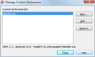
Content
Displays a list of the words that currently exist in the specified custom
dictionary.
You can add words to or delete words from the list below.
Add
Adds the word that you enter in the box to the current custom dictionary.
The maximum length is 63 characters.
Delete
Deletes a word from current custom dictionary content.
Import
Imports words from another dictionary or word list into your current custom
dictionary.
Manage Custom Dictionaries Dialog Box
Quick Reference
See also:
■Check Spelling
Manages your custom dictionaries allowing you to add or remove a dictionary.
List of Options
The following options are displayed.
1168 | Chapter 19 S Commands
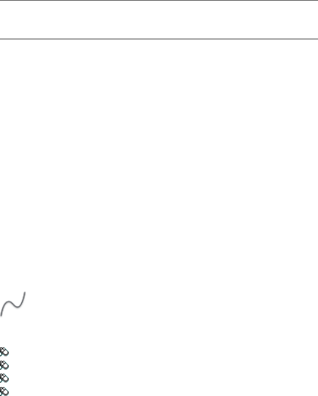
Custom Dictionaries List
Displays the custom dictionaries list. Only one dictionary can be selected at
a time.
New
Allows you to create a custom dictionary. The new dictionary is highlighted
as the current one.
NOTE The filename for a custom dictionary cannot use any non-current code
page characters in its name. If you are sharing a custom dictionary between
different locals or languages do not use non-ASCII characters.
Add
Allows you to add an existing custom dictionary from your file lists.
Remove
Allows you to delete a custom dictionary file from your list.
SPLINE
Quick Reference
See also:
■Draw Splines
Creates a smooth curve that passes through or near a set of fit points, or that
is defined by the vertices in a control frame.
Access Methods
Button
Ribbon: Home tab ➤ Draw panel ➤ Spline
Menu: Draw ➤ Spline ➤ Fit Points
Menu: Draw ➤ Spline ➤ Control Vertices
Toolbar: Draw
SPLINE | 1169
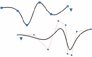
Summary
SPLINE creates curves called nonuniform rational B-splines (NURBS), referred to
as splines for simplicity.
Splines are defined either with fit points, or with control vertices. By default,
fit points coincide with the spline, while control vertices define a control frame.
Control frames provide a convenient method to shape the spline. Each method
has its advantages.
For splines created with control vertices, you can display the control frame
by selecting the spline.
List of Prompts
The prompts that display depend on whether you create a spline with fit
points or with control vertices.
For splines created with the fit point method:
Specify first point or [Method on page 1170/Degree on page 1173/Object on page
1171]:
For splines created with the control vertices method:
Specify first point or [Method on page 1170/Knots on page 1171/Object on page
1171]:
First Point
Specifies the first point of the spline, either the first fit point or the first control
vertex, depending on the current method.
Method
Controls whether the spline is created with fit points or with control vertices.
(SPLMETHOD on page 1667 system variable)
Fit Creates a degree 3 (cubic) B-spline by specifying fit points that the spline
must pass through. When the tolerance value is greater than 0, the spline
must be within the specified tolerance distance from each point.
Changing the Method updates the SPLMETHOD on page 1667 system variable.
1170 | Chapter 19 S Commands
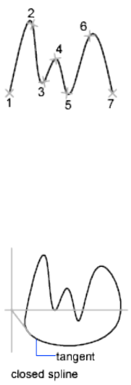
Control Vertices Creates a spline by specifying control vertices. Use this
method to create splines of degree 1 (linear), degree 2 (quadratic), degree 3
(cubic), and so on up to degree 10. Adjusting the shape of a spline by moving
control vertices often provides better results than moving fit points.
Object
Converts 2D or 3D quadratic or cubic spline-fit polylines to equivalent splines.
The original polyline is retained or discarded depending on the setting of the
DELOBJ system variable.
Next Point
Creates additional spline segments until you press Enter.
Undo
Removes the last specified point.
Close
Closes the spline by defining the last point to be coincident with the first. By
default, closed splines are periodic, maintaining curvature continuity (C2)
along the entire loop.
Options for Splines with Fit Points
The following options are specific to the fit point method.
Knots Specifies the knot parameterization, one of several computational methods
that determines how the component curves between successive fit points
within a spline are blended. (SPLKNOTS on page 1666 system variable)
SPLINE | 1171
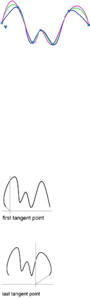
■Chord (or Chord-Length method). Spaces the knots connecting each
component curve to be proportional to the distances between each
associated pair of fit points. An example is the green curve in the
illustration.
■Square Root (or Centripetal method). Spaces the knots connecting each
component curve to be proportional to the square root of the distance
between each associated pair of fit points. This method usually produces
“gentler” curves. An example is the blue curve in the illustration.
■Uniform (or Equidistant method). Spaces the knots of each component
curve to be equal, regardless of the spacing of the fit points. This method
often produces curves that overshoot the fit points. An example is the
magenta curve in the illustration.
Start Tangency Specifies a tangent condition on the starting point of the
spline.
End Tangency Specifies a tangent condition on the ending point of the spline.
1172 | Chapter 19 S Commands
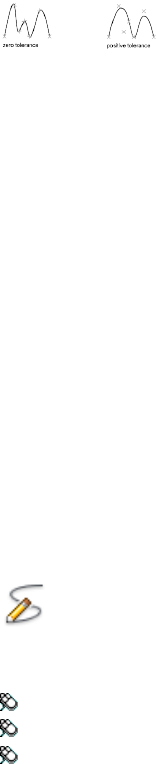
Tolerance Specifies the distance by which the spline is allowed to deviate
from the specified fit points. A tolerance value of 0 requires the resulting spline
to pass directly through the fit points. The tolerance value applies to all fit
points except the starting and ending fit points, which always have a tolerance
of 0.
Options for Splines with Control Vertices
The following option is specific to the control vertices (CV) method.
(SPLMETHOD on page 1667 system variable)
Degree Sets the polynomial degree of the resulting spline. Use this option to
create splines of degree 1 (linear), degree 2 (quadratic), degree 3 (cubic), and
so on up to degree 10.
SPLINEDIT
Quick Reference
See also:
■Modify Splines
Modifies the parameters of a spline or converts a spline-fit polyline to a spline.
Access Methods
Button
Ribbon: Home tab ➤ Modify panel ➤ Edit Spline
Menu: Modify ➤ Object ➤ Spline
Toolbar: Modify II
Shortcut menu: Select a spline to edit. Right-click in the drawing area and
click Spline.
SPLINEDIT | 1173

Summary
Modifies the data that defines a spline, such as the number and weight of
control vertices, the fit tolerance, and the starting and ending tangents.
NOTE SPLINEDIT automatically converts spline-fit polylines to splines even if you
immediately exit SPLINEDIT after selecting the spline-fit polyline.
The data that defines a spline is represented in one of two formats: as a control
frame or as fit points. The format can change depending on how the spline
was orginally created, the options selected from the grip menus, or the options
used in SPLINEDIT.
You can change any of following data:
■Control frame data consists of control vertices, the polynomial degree of
the spline, and the weights assigned to each control vertex.
■Fit data consists of fit points, knot parameterization, the fit tolerance, and
the tangents at the endpoints of the spline.
NOTE Switching from displaying control vertices to fit points automatically changes
the selected spline to degree 3. Splines originally created using higher-degree
equations will likely change shape as a result. In addition, if the spline was created
using a positive tolerance value, the fit points will be relocated to the knots on the
spline, and the tolerance value is reset to 0.
List of Prompts
The following prompts are displayed.
Select spline:
Enter an option [Close on page 1174/Join on page 1175/Fit data on page 1175/Edit
Vertex on page 1176/convert to Polyline on page 1177/Reverse on page 1178/Undo
on page 1178] <eXit>:
Close/Open
One of the following options displays, depending on whether the selected
spline is open or closed. An open spline has two endpoints, while a closed
spline forms a loop.
Close Closes an open spline by defining the last point to be coincident with
the first. By default, closed splines are periodic, maintaining curvature
continuity (C2) along the entire curve.
Open Opens a closed spline by removing the final curve segment between
the first and last points specified when the spline was originally created.
1174 | Chapter 19 S Commands
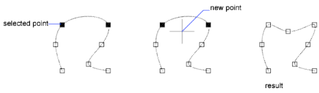
Join
Combines a selected spline with other splines, lines, polylines, and arcs at
coincident endpoints to form a larger spline. Objects are joined with kinks at
the points where they are joined (C0 continuity).
Fit Data
Edits fit point data using the following options:
Enter a fit data option [Add on page 1175/Close on page 1175Delete on page
1175/Kink on page 1176/Move on page 1176/Purge on page 1176/Tangents on page
1176/toLerance on page 1176/eXit on page 1176] <eXit>:
Add
Adds fit points to the spline.
After selecting a fit point, specify a new fit point to be added to the spline in
the direction of the next fit point, which is automatically highlighted.
If you select the last fit point on an open spline, the new fit point is added to
the end of the spline.
If you select the first fit point on an open spline, you have the option of
specifying whether the new fit point is added before or after the first point.
Close/Open
One of the following options displays, depending on whether the selected
spline is open or closed. An open spline has two endpoints, while a closed
spline forms a loop.
Close Closes an open spline by defining the last point to be coincident with
the first. By default, closed splines are periodic, maintaining curvature
continuity (C2) along the entire curve.
Open Opens a closed spline by removing the final curve segment between
the first and last points specified when the spline was originally created.
Delete
Removes selected fit points from a spline.
SPLINEDIT | 1175
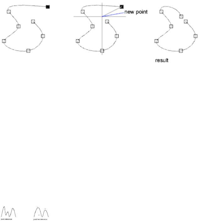
Kink
Adds a knot and fit point at the specified location on the spline, which does
not maintain tangent or curvature continuity at that point.
Move
Moves fit points to new locations.
New Location Moves the selected fit point to the specified location.
Next Selects the next fit point.
Previous Selects the previous fit point.
Select Point Select any fit point on the spline.
Purge
Replaces the fit data from the spline with control vertices.
Tangents
Changes the starting and ending tangents of a spline. Specify a point to
establish a tangent direction. You can use object snaps such as Perpendicular
or Parallel.
If the spline is closed, the prompt becomes Specify Tangent or [System
Default].
The System Default option calculates the default end tangents.
Tolerance
Refits the spline to the existing fit points using the new tolerance value.
Exit
Returns to the previous prompt.
Edit Vertex
Edits control frame data using the following options:
1176 | Chapter 19 S Commands
Enter a vertex editing option [Add on page 1177/Delete on page 1177/Elevate order
on page 1177/Move on page 1177/Weight on page 1177/eXit on page 1177] <eXit>:
Add
Adds a new control vertex at the point you specify that is located between
two existing control vertices.
Delete
Removes a selected control vertex.
Elevate Order
Increases the polynomial order (degree plus one) of the spline. This results in
increasing the number of control vertices across the spline.
The maximum value is 26.
Move
Relocates a selected control vertex.
■New Location on page 1176
■Next on page 1176
■Previous on page 1176
■Select Point on page 1176
Weight
Changes the weight of a specified control vertex.
New Weight Recalculates the spline based on the new weight value for the
specified control vertex. A larger value pulls the spline closer to the control
vertex.
■Next on page 1176
■Previous on page 1176
■Select Point on page 1176
Exit
Returns to the previous prompt.
Convert to Polyline
Converts the spline to a polyline.
The precision value determines how closely the resulting polyline matches
the spline. Valid values are any integer between 0 and 99.
SPLINEDIT | 1177
NOTE A high precision value will decrease performance.
The PLINECONVERTMODE system variable determines whether the polylines
are created with linear or arc segments.
The DELOBJ system variable determines whether the original spline is retained.
Reverse
Reverses the direction of the spline. This option is intended primarily for
third-party applications.
Undo
Cancels the last action.
Exit
Returns to the Command prompt.
STRETCH
Quick Reference
See also:
■Resize or Reshape Objects
Stretches objects crossed by a selection window or polygon.
Access Methods
Button
Ribbon: Home tab ➤ Modify panel ➤ Stretch
Menu: Modify ➤ Stretch
Toolbar: Modify
Summary
Objects that are partially enclosed by a crossing window are stretched. Objects
that are completely enclosed within the crossing window, or that are selected
individually, are moved rather than stretched. Several objects such as circles,
ellipses, and blocks, cannot be stretched.
1178 | Chapter 19 S Commands
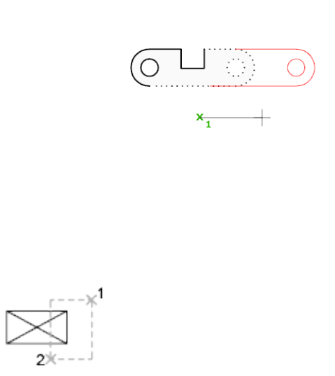
List of Prompts
The following prompts are displayed.
Select objects to stretch by crossing-window or crossing-polygon...
Select objects: Use the cpolygon option or the crossing object selection method, and
press Enter. Individually selected objects and objects that are completely enclosed by
the crossing selection are moved rather than stretched.
STRETCH moves only the vertices and endpoints that lie inside the crossing
selection, leaving those outside unchanged. STRETCH does not modify 3D
solids, polyline width, tangent, or curve-fitting information.
Base Point
Specify base point or [Displacement] <last displacement>: Specify a base point or
enter displacement coordinates
Specify second point or <use first point as displacement>: Specify a second point,
or press Enter to use the previous coordinates as a displacement
Displacement
Specify displacement <last value>: Enter displacement values for X,Y (and optionally
Z)
STRETCH | 1179
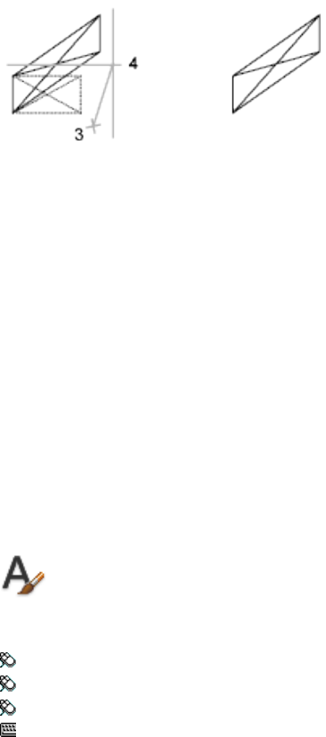
If you enter a second point, the objects are stretched the vector distance from
the base point to the second point. If you press Enter at the Specify Second
Point of Displacement prompt, the first point is treated as an X,Y,Z
displacement.
STYLE
Quick Reference
See also:
■Overview of Text Styles
Creates, modifies, or specifies text styles.
Access Methods
Button
Ribbon: Home tab ➤ Annotation panel ➤ Text Style
Menu: Format ➤ Text Style
Toolbar: Text
Command entry: 'style for transparent use
Summary
The Text Style dialog box is displayed.
If you enter -style at the Command prompt, options are displayed.
1180 | Chapter 19 S Commands
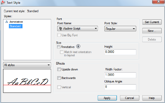
You can specify the current text style to determine the appearance of all new
text. A text style includes the font, size, obliquing angle, orientation, and
other text characteristics.
Text Style Dialog Box
Quick Reference
See also:
■Overview of Text Styles
Creates, modifies, or specifies text styles.
Summary
Creates, modifies, or sets named text styles.
List of Options
The following options are displayed.
Current Text Style
Lists the current text style.
Text Style Dialog Box | 1181

Styles
Displays the list of styles in the drawing. A icon before the style name
indicates that the style is .
Style names can be up to 255 characters long. They can contain letters,
numbers, and the special characters dollar sign ($), underscore (_), and hyphen
(-).
Style List Filter
The drop-down list specifies whether all styles or only the styles in use are
displayed in the styles list.
Preview
Displays sample text that changes dynamically as you change fonts and modify
the effects.
Font
Changes the style's font.
NOTE If you change the orientation or font file of an existing text style, all text
objects with that style use the new values when the drawing is regenerated.
Font Name
Lists the font family name for all registered TrueType fonts and all compiled
shape (SHX) fonts in the Fonts folder.
When you select a name from the list, the program reads the file for the
specified font. The file's character definitions are loaded automatically unless
the file is already in use by another text style. You can define several styles
that use the same font. For more information, see “Assign Text Fonts”.
Font Style
Specifies font character formatting, such as italic, bold, or regular. When Use
Big Font is selected, this option changes to Big Font Name and is used to select
a Big Font file name.
Use Big Font
Specifies an Asian-language Big Font file. Only SHX files are valid file types
for creating Big Fonts.
For more information, see “Use Text Fonts for International Work”.
1182 | Chapter 19 S Commands
Size
Changes the size of the text.
Annotative
Specifies that the text is . Click the information icon to learn more about the
annotative objects.
Match Text Orientation to Layout
Specifies that the orientation of the text in paper space viewports matches the
orientation of the layout. This option is unavailable if the option is cleared.
Height or Paper Text Height
Sets the text height based on the value you enter. Entering a height greater
than 0.0 sets the text height for this style automatically. If you enter 0.0, the
text height defaults to the last text height used, or the value stored in the
drawing template file.
TrueType fonts might be displayed at a smaller height than SHX fonts with
the same height setting.
If the annotative option is selected, the value entered sets the text height in
paper space.
See “Set Text Height” for more information.
Effects
Modifies characteristics of the font, such as its height, width factor, and
obliquing angle and whether it is displayed upside down, backwards, or
vertically aligned.
Upside Down
Displays the characters upside down.
Backwards
Displays the characters backwards.
Vertical
Displays the characters aligned vertically. Vertical is available only if the
selected font supports dual orientation. Vertical orientation is not available
for TrueType fonts.
Width Factor
Sets the character spacing. Entering a value less than 1.0 condenses the text.
Entering a value greater than 1.0 expands it.
Text Style Dialog Box | 1183

Oblique Angle
Sets the obliquing angle of the text. Entering a value between -85 and 85
italicizes the text.
NOTE TrueType fonts using the effects described in this section might appear
bold on the screen. Onscreen appearance has no effect on plotted output. Fonts
are plotted as specified by applied character formatting.
Set Current
Sets the style selected under Styles to current.
New
Displays the New Text Style dialog box and automatically supplies the name
“ stylen” (where n is the number of the supplied style) for the current settings.
You can accept the default or enter a name and choose OK to apply the current
style settings to the new style name.
Delete
Deletes unused text styles.
Apply
Applies style changes made in the dialog box to the current style and to the
text of the current style in the drawing.
-STYLE
Quick Reference
See also:
■Overview of Text Styles
Creates, modifies, or specifies text styles.
List of Prompts
The following prompts are displayed.
Enter name of text style or [?] <current>: Enter a style name, enter ?, or press Enter
1184 | Chapter 19 S Commands
Text Style Name Specifies the text style name. To define a style that uses Big
Fonts, you can use long file names that do not contain commas. Commas are
used to separate SHX files and Big Font files for defining a Big Font file.
Enter a TrueType font family name or an SHX font file name. If you do not
enter a file name extension, this program searches for an SHX file. If the file
is not located, Windows substitutes the first located registered TrueType font.
All long file names except those containing commas are accepted at the
prompt. The comma is reserved for the Big Font naming convention: an SHX
file followed by a comma (,), followed by the Big Font file name. A space is
interpreted as part of the font name, not as a carriage return.
If you enter annotative, you are prompted to create an text style.
Tilde (~) Displays the Select Font File dialog box.
In the Select Font File dialog box, valid types include SHX and TTF. The
character definitions of the selected font file are loaded automatically unless
the file is already in use by another text style. You can define several styles
that use the same font file.
Match Text Orientation to Layout If you enter yes the current text style
orientation in paper space viewports matches the layout.
Height of Text If you enter a height of 0.0, you are prompted for the text
height each time you enter text using this style. Entering a height greater than
0.0 sets the Text Height (Non annotative), entering a height greater than 0.0
sets the Paper Text Height (Annotative), for this style.
Width Factor Entering a value less than 1.0 condenses the text. Entering a
value greater than 1.0 expands it.
Obliquing Angle Entering a value between -85 and 85 obliques the text.
Vertical Vertical is available only if the selected font supports dual orientation.
?—List Text Styles Lists the text styles available in the drawing.
At the Enter Text Style(s) to List prompt, entering the name of a style displays
the name, font file, height, width factor, obliquing angle, and generation of
the style and exits the command. Entering an asterisk (*) or pressing Enter
displays the height, width factor, obliquing angle, and generation (whether
text is drawn backwards, upside-down, vertically, or normally) of each style,
and then exits the command.
-STYLE | 1185

STYLESMANAGER
Quick Reference
See also:
■Manage Plot Style Tables
Displays the Plot Style Manager, where you can revise plot style tables.
Access Methods
Button
Menu: Application menu ➤ Print ➤ Manage Plot Styles
Menu: File ➤ Plot Style Manager
Summary
In the folder, you can start the Add-a-Plot-Style-Table wizard, or double-click
an STB or CTB file to open the Plot Style Table Editor.
■Double-click the Add-a-Plot-Style-Table wizard to add plot style tables.
■Double-click a plot style table (STB or CTB file) to start the Plot Style Table
Editor.
Add-a-Plot-Style-Table Wizard
Quick Reference
See also:
■Choose a Type of Plot Style Table
Adds new plot style tables.
1186 | Chapter 19 S Commands
Summary
Plot style tables contain and define plot styles, which can be assigned to
objects. When complete, the wizard produces an STB or CTB file depending
on the type of table you are creating. You can edit these files in the Plot Style
Table Editor. To use your new plot style table, the selected options on the Plot
and Publish tab of the Options dialog box must be appropriate for the type
of plot style table (named or color-dependent) you created.
You can create a plot style table from scratch, use an existing plot style table
as a starting point, or use settings from a PCP, PC2, or CFG file.
You can create either a named plot style table or a color-dependent plot style
table. With a named plot style table, you can add and define plot styles as you
like; the file name has the extension .stb. A color-dependent plot style table
creates 255 plot styles based on color; the file name has the extension .ctb.
You can specify whether you want to use a plot style table for new drawings
or for pre-AutoCAD 2000 drawings when they are saved in a later format.
Plot Style Table Editor
Quick Reference
See also:
■Manage Plot Style Tables
Modifies the plot styles in a plot style table.
Summary
If the plot style table is attached to a layout or the Model tab, and you change
a plot style, any objects that use that plot style are affected. If the plot style
table is color-dependent, the file extension is CTB. If the plot style table is
named, the file extension is STB. For information, see “Use Plot Styles to
Control Plotted Objects”.
Open the Plot Style Table Editor with any of the following methods:
■Double-click a CTB or STB file in the Plot Style Manager.
■Right-click a CTB or STB file in the Plot Style Manager, and then choose
Open from the shortcut menu.
Plot Style Table Editor | 1187
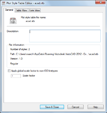
■Choose Plot Style Table Editor from the Finish screen in the Add Plot Style
Table wizard.
■In the Page Setup dialog box under Plot Style Table (Pen Assignments),
select a plot style and click the Edit button.
■In the Current Plot Style and Select Plot Style dialog boxes, choose Editor.
■General
■Table View and Form View
General Tab (Plot Style Table Editor)
Quick Reference
See also:
■Use Plot Styles to Control Plotted Objects
Lists the plot style table file name, description, version number, location (path
name), and table type.
1188 | Chapter 19 S Commands
List of Options
The following options are displayed.
Plot Style Table File Name Displays the name of the plot style table file you
are editing.
Description
Provides a description area for a plot style table.
File Information
Displays information about the plot style table you are editing: number of
plot styles, path, and version number of the Plot Style Table Editor.
Apply Global Scale Factor to Non-ISO Linetypes
Scales all the non-ISO linetypes and fill patterns in the plot styles of objects
controlled by this plot style table.
Scale Factor
Specifies the amount to scale non-ISO linetypes and fill patterns.
Table View and Form View Tabs (Plot Style Table Editor)
Quick Reference
See also:
■Use Plot Styles to Control Plotted Objects
Plot Style Table Editor | 1189
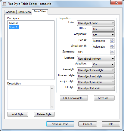
Summary
Lists all of the plot styles in the plot style table and their settings.
Plot styles are displayed in columns from left to right. In general, the Table
View tab is convenient if you have a small number of plot styles. If you have
a large number of plot styles, the Form view is more convenient because the
plot style names are listed at the left and the properties of the selected style
are displayed to the right. The first plot style in a named plot style table is
NORMAL and represents an object's default properties (no plot style applied).
You cannot modify or delete the NORMAL style.
List of Options
The following options are displayed.
Name Displays the names of plot styles in named plot style tables. Plot styles
in named plot style tables can be changed. Plot style names in color-dependent
plot style tables are tied to object color and cannot be changed. The program
accepts up to 255 characters for style names.
Description
Provides a description for each plot style.
Properties
1190 | Chapter 19 S Commands
Specifies the settings for the new plot style you are adding to the current plot
style table.
Color
Specifies the plotted color for an object. The default setting for plot style color
is Use Object Color. If you assign a plot style color, the color overrides the
object's color at plot time.
You can choose Select Color to display the Select Color dialog box and select
one of the 255 AutoCAD Color Index (ACI) colors. The color you specify is
displayed in the plot style color list as Custom Color. If the plot device does
not support the color you specify, it plots the nearest available color or, in
the case of monochrome devices, black.
Enable Dithering
Enables dithering. A plotter uses dithering to approximate colors with dot
patterns, giving the impression of plotting more colors than available in the
AutoCAD Color Index (ACI). If the plotter does not support dithering, the
dithering setting is ignored.
Dithering is usually turned off in order to avoid false line typing that results
from dithering of thin vectors. Turning off dithering also makes dim colors
more visible. When you turn off dithering, the program maps colors to the
nearest color, resulting in a smaller range of colors when plotting.
Convert to Grayscale
Converts the object's colors to grayscale if the plotter supports grayscale. If
you clear Convert to Grayscale, the RGB values are used for object colors.
Dithering is available whether you use the object's color or assign a plot style
color.
Use Assigned Pen Number (Pen Plotters Only)
Specifies a pen to use when plotting objects that use this plot style. Available
pens range from 1 to 32. If plot style color is set to Use Object Color, or you
are editing a plot style in a color-dependent plot style table, the value is set
to Automatic.
If you specify 0, the field updates to read Automatic. The program determines
the pen of the closest color to the object you are plotting using the information
you provided under Physical Pen Characteristics in the Plotter Configuration
Editor.
Virtual Pen Number
Plot Style Table Editor | 1191
Specifies a virtual pen number between 1 and 255. Many non-pen plotters
can simulate pen plotters using virtual pens. For many devices, you can
program the pen's width, fill pattern, end style, join style, and color/screening
from the front panel on the plotter.
Enter 0 or Automatic to specify that the program should make the virtual pen
assignment from the AutoCAD Color Index.
The virtual pen setting in a plot style is used only by non-pen plotters and
only if they are configured for virtual pens. If this is the case, all the other
style settings are ignored and only the virtual pen is used. If a non-pen plotter
is not configured for virtual pens, then the virtual and physical pen
information in the plot style is ignored and all the other settings are used.
You can configure your non-pen plotter for virtual pens under Vector Graphics
on the Device and Document Settings tab in the PC3 Editor. Under Color
Depth, select 255 Virtual Pens.
Screening
Specifies a color intensity setting that determines the amount of ink placed
on the paper while plotting. Selecting 0 reduces the color to white. Selecting
100 displays the color at its full intensity. The Enable Dithering option must
be selected for screening.
Linetype
Displays a list with a sample and a description of each linetype. If you assign
a plot style linetype, the linetype overrides the object's linetype at plot time.
Adaptive Adjustment
Adjusts the scale of the linetype to complete the linetype pattern.
If you do not select Adaptive Adjustment, the line might end in the middle
of a pattern. Turn off Adaptive Adjustment if linetype scale is important. Turn
on Adaptive Adjustment if complete linetype patterns are more important
than correct linetype scaling.
Lineweight
Displays a sample of the lineweight as well as its numeric value. You can
specify the numeric value of each lineweight in millimeters.
If you assign a plot style lineweight, the lineweight overrides the object's
lineweight when it is plotted.
Line End Style
If you assign a line end style, the line end style overrides the object's line end
style at plot time.
1192 | Chapter 19 S Commands
Line Join Style
If you assign a line join style, the line join style overrides the object's line join
style at plot time.
Fill Style
If you assign a fill style, the fill style overrides the object's fill style at plot
time.
Add Style
Adds a new plot style to a named plot style table.
The plot style is based on Normal, which uses an object's properties and doesn't
apply any overrides by default. You must specify the overrides you want to
apply after you create the new plot style. You cannot add a new plot style to
a color-dependent plot style table; a color-dependent plot style table has 255
plot styles mapped to color. You also cannot add a plot style to a named plot
style table that has a translation table.
Delete Style
Deletes the selected style from the plot style table.
Objects assigned this plot style retain the plot style assignment but plot as
Normal because the plot style is no longer defined in the plot style table. You
cannot delete a plot style from a named plot style table that has a translation
table, or from a color-dependent plot style table.
Edit Lineweights
Modifies the widths values of existing lineweights.
Displays the Edit Lineweights dialog box.
There are 28 lineweights available to apply to plot styles in plot style tables.
If the lineweight you need does not exist in the list of lineweights stored in
the plot style table, you can edit an existing lineweight. You cannot add or
delete lineweights from the list in the plot style table.
Save As
Displays the Save As dialog box and saves the plot style table to a new name.
Plot Style Table Editor | 1193

Edit Lineweights Dialog Box
Quick Reference
See also:
■Use Plot Styles to Control Plotted Objects
Modifies the width values of existing lineweights.
List of Options
The following options are displayed.
Lineweights
Lists the lineweights in the plot style table. You can modify existing
lineweights, but you can't add or delete them. If you change a lineweight
value, other plot styles that use the lineweight also change.
When you edit a lineweight value, it is rounded and displayed with a precision
of four places past the decimal point. Lineweight values must be zero or a
positive number. If you create a lineweight with a zero width, the line is plotted
as thin as the plotter can create it. The maximum possible lineweight value
is 100 millimeters (approximately four inches).
Units for Listing
Specifies the units in which to display the list of lineweights.
Edit Lineweight
Makes the selected lineweight available for editing.
Sort Lineweights
Sorts the list of lineweights by value. If you change lineweight values, choose
Sort Lineweights to resort the list.
1194 | Chapter 19 S Commands

SUBTRACT
Quick Reference
See also:
■Create and Combine Areas (Regions)
Combines selected regions by subtraction.
Access Methods
Button
Menu: Modify ➤ Region ➤ Subtract
Summary
With SUBTRACT, you can create a 2D region object by subtracting one set of
existing region objects from another, overlapping set. You can select only
regions for use with this command.
Select the objects that you want to keep, press Enter, then select the objects
that you want to subtract.
SUBTRACT | 1195
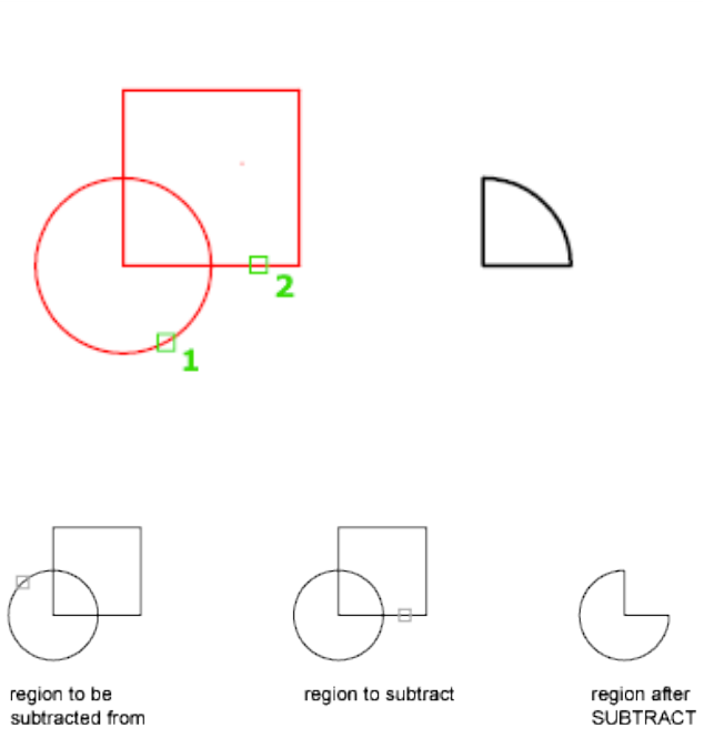
Objects in the second selection set are subtracted from objects in the first
selection set. A single new region is created.
You can only subtract regions from other regions that are on the same plane.
However, you can perform simultaneous SUBTRACT actions by selecting sets
of regions on different planes. The program then produces separate subtracted
regions on each plane. Regions for which there are no other selected coplanar
regions are rejected.
List of Prompts
The following prompts are displayed.
Select objects (to subtract from) Specifies the regions to be modified by
subtraction.
Select objects (to subtract) Specifies the regions to subtract.
1196 | Chapter 19 S Commands

SYSWINDOWS
Quick Reference
See also:
■Switch Between Open Drawings
Arranges windows and icons when the application window is shared with
external applications.
Access Methods
Button
Ribbon: View tab ➤ Window panel ➤ Tile Horizontally
Menu: Window ➤ Cascade
Menu: Window ➤ Tile Horizontally
Menu: Window ➤ Tile Vertically
Menu: Window ➤ Arrange Icons
List of Prompts
The following prompts are displayed.
Enter an option [Cascade on page 1197/tile Horizontal on page 1197/tile Vertical
on page 1197/Arrange icons on page 1198]: Enter an option
Cascade
Organizes a large number of windows by overlapping them for easier access.
Tile Horizontal Arranges open drawings in horizontal, nonoverlapping
windows.
When several drawings are open, you can view them in rows. Additional
columns are added only when there's not enough space.
Tile Vertical Arranges windows in vertical, nonoverlapping tiles.
When several drawings are open, you can view them in columns. Additional
rows are added only when there's not enough space.
SYSWINDOWS | 1197
Arrange Icons Arranges the window icons.
Arranges multiple open drawings, when minimized, in a line at the bottom
of the workspace.
1198 | Chapter 19 S Commands
T Commands
TABLE
Quick Reference
See also:
■Create and Modify Tables
Creates an empty table object.
Access Methods
Button
Ribbon: Home tab ➤ Annotation panel ➤ Insert Table
Menu: Draw ➤ Table
Toolbar: Draw
Summary
A table is a compound object that contains data in rows and columns. It can
be created from an empty table or a table style. A table can also be linked to
data in a Microsoft Excel spreadsheet.
20
1199
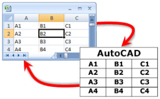
The Insert Table dialog box is displayed.
If you select a table cell when the ribbon is active, the Table ribbon contextual
tab displays.
If you enter -table at the Command prompt, options are displayed.
Insert Table Dialog Box
Quick Reference
See also:
■Create and Modify Tables
Creates an empty table object.
1200 | Chapter 20 T Commands
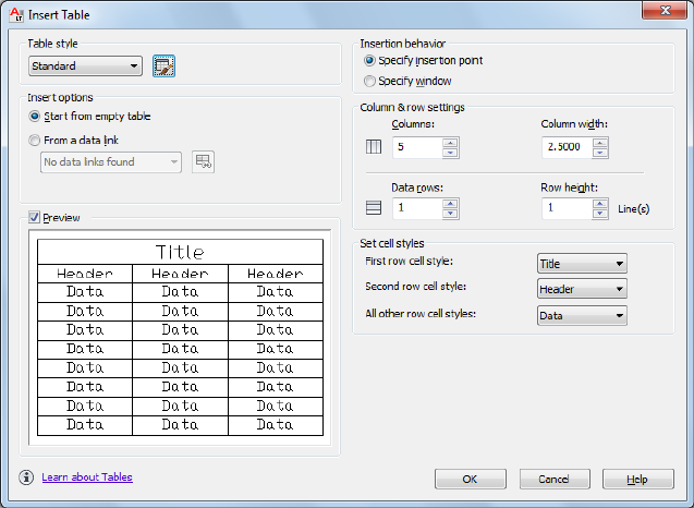
Summary
Inserts an empty table in the drawing.
List of Options
The following options are displayed.
Table Style
Choose a table style from within the current drawing from which to create a
table. You can create a new table style by clicking the button next to the
drop-down list.
Insert Options
Specifies the method for inserting your table.
Start from Empty Table
Creates an empty table that can be filled in with data manually.
Start from Data Link
Creates a table from data in an external spreadsheet.
Insert Table Dialog Box | 1201
Preview
Controls whether a preview displays. If you start from an empty table, the
preview displays an example of the table style. If you create a table link, the
preview displays the resulting table. Clear this option to improve performance
when working with large tables.
Insertion Behavior
Specifies the location of the table.
Specify Insertion Point
Specifies the location of the upper-left corner of the table. You can use the
pointing device or enter coordinate values at the Command prompt. If the
table style sets the direction of the table to read from the bottom up, the
insertion point is the lower-left corner of the table.
Specify Window
Specifies a size and a location for the table. You can use the pointing device
or enter coordinate values at the Command prompt. When this option is
selected, the number of columns and rows and the column width and row
height depend on the size of the window and the column and row settings.
Column & Row Settings
Set the number and size of columns and rows.
Columns Icon
Indicates columns.
Rows Icon
Indicates rows.
Columns
Specifies the number of columns. When the Specify Window option is selected
and you specify a column width, the Auto option is selected, and the number
of columns is controlled by the width of the table. If a table style containing
a starting table has been specified, then you can choose the number of
additional columns you would like added to that starting table.
Column Width
Specifies the width of the columns. When the Specify Window option is
selected and you specify the number of columns, the Auto option is selected,
and the column width is controlled by the width of the table. The minimum
column width is one character.
1202 | Chapter 20 T Commands
Data Rows
Specifies the number of rows. When the Specify Window option is selected
and you specify a row height, the Auto option is selected, and the number of
rows is controlled by the height of the table. A table style with a title row and
a header row has a minimum of three rows. The minimum row height is one
line. If a table style containing a starting table has been specified, then you
can choose the number of additional data rows you would like added to that
starting table.
Row Height
Specifies the height of the rows in number of lines. The height of a line is
based on the text height and the cell margin, which are both set in the table
style. When the Specify Window option is selected and you specify the number
of rows, the Auto option is selected, and the row height is controlled by the
height of the table.
Set Cell Styles
For table styles that do not contain a starting table, specifies a cell style for
rows in the new table.
First Row Cell Style
Specifies a cell style for the first row in the table. The Title cell style is used by
default.
Second Row Cell Style
Specifies a cell style for the second row in the table. The Header cell style is
used by default.
All Other Row Cell Styles
Specifies a cell style for all other rows in the table. The Data cell style is used
by default.
Table Options
For table styles that contain a starting table, specifies the table elements from
the starting table that are retained upon insertion.
Label Cell Text
Retains text from the Header or Title rows in the starting table in the
newly-inserted table.
Data Cell Text
Retains text from the Data rows in the starting table in the newly-inserted
table.
Insert Table Dialog Box | 1203
Blocks
Retains blocks from the starting table in the newly-inserted table.
Retain Cell Style Overrides
Retains cell style overrides from the starting table in the newly-inserted table.
Data Links
Retains data links from the starting table in the newly-inserted table.
Table Ribbon Contextual Tab
Quick Reference
See also:
■Create and Modify Tables
List of Options
The following options are displayed.
Rows/Columns Panel
Insert Row Above Inserts a row above the currently selected cell or row.
Insert Row Below Inserts a row below the currently selected cell or row
Delete Row(s) Deletes the currently selected row(s).
Insert Column Left Inserts a column to the left of the currently selected cell
or row.
Insert Column Right Inserts a column to the right of the currently selected
cell or row.
Delete Column(s) Deletes the currently selected column(s).
Merge Panel
Merge Cells Merges the selected cells into one large cell.
Unmerge Cells Unmerges cells that were previously merged.
Cell Styles Panel
Match Cell Applies the properties of a selected cell to other cells.
1204 | Chapter 20 T Commands
Cell Styles Lists all cell styles contained within the current table style. The
cell styles Title, Header, and Data are always contained within any table style,
and cannot be deleted or renamed.
Cell Borders Sets the properties of the borders of the selected table cells.
Alignment Specifies alignment for the content within cells. Content is middle-,
top-, or bottom-aligned with respect to the top and bottom borders of the
cell. Content is center-, left-, or right-aligned with respect to the left and right
borders of the cell.
Background Fill Specifies the fill color. Select None or a background color,
or click Select Color to display the Select Color dialog box.
Cell Format Panel
Cell Locking Locks or unlocks cell content and/or formatting from editing.
Data Format Displays a list of data types (Angle, Date, Decimal Number, and
so on) that you can format for table rows.
Preview Displays a preview of the option you selected in the Format list.
Format Depending on the data type you select, displays a list of relevant
format types. For example, if you selected Angle as the data type, options such
as Decimal Degrees, Grads, Radians, and so on are displayed.
Precision For Angle, Decimal Number and Points data types only, sets the
precision for applicable formats. For example, if you select Angle as the data
type and Radians as the format type, options such as Current Precision, 0.0r,
0.00r, 0.000r, and so on are displayed.
List Separator For a Point data type only, displays a list of options (comma,
semicolon, or colon) that you can use to separate list items.
Symbol For Currency data types only, displays a list of currency symbols that
you can use.
Append Symbol In Currency data types, places the currency symbol after the
number. In the Percentage data types, places the percent symbol after the
number.
Negative Numbers For Currency data types only, lists options for displaying
negative numbers.
X, Y, and Z For a Point data type only, filters X, Y, or Z coordinates.
Additional Format For Angle, Decimal Number, Point and Whole Number
data types only, opens the Additional Format dialog box, where you set
additional formatting options for table cells.
Table Ribbon Contextual Tab | 1205
Examples For the Date data type only, displays a list of date display options
for the date option you selected in the Format field. Click a date in the Format
field to see an example.
Insert Panel
Block The Insert dialog box is displayed, where you can insert a block into
the currently selected table cell.
Field The Field dialog box is displayed, where you can insert a field into the
currently selected table cell.
Formula Inserts a formula into the currently selected table cell. A formula
must start with an equal sign (=). The formulas for sum, average, and count
ignore empty cells and cells that do not resolve to a numeric value. Other
formulas display an error (#) if any cell in the arithmetic expression is empty
or contains nonnumeric data.
Manage Cell Contents Displays the content of the selected cell. You can
change the order of cell content as well as change the direction in which cell
content will appear.
Data Panel
Link Cell The New and Modify Excel Link dialog box is displayed, where you
can link data from a spreadsheet created in Microsoft Excel to a table within
your drawing.
Download from Source Updates data in the table cell that is referenced by
changed data in an established data link.
Manage Cell Content Dialog Box
Quick Reference
See also:
■Create and Modify Tables
Displays the content of the selected cell.
1206 | Chapter 20 T Commands

Access Methods
Toolbar: Table
Shortcut menu: Right-click while editing any single cell, and click Manage
Cell Content.
List of Options
The following options are displayed.
Cell Content List Box
Lists all text and/or blocks in the selected cell in order of appearance. Text is
indicated with the label Table Cell Text. Blocks are indicated with Block
preceding the name of the block.
Content Order Buttons
Move Up
Moves the selected list box content up in the display order.
Move Down
Moves the selected list box content down in the display order.
Delete
Removes the selected list box content from the table cell.
Manage Cell Content Dialog Box | 1207
Layout Mode Options
Changes the direction in which cell content will appear.
Flow
Places cell content based on the width of the cell.
Stacked Horizontal
Places cell content horizontally, regardless of cell width.
Stacked Vertical
Places cell content vertically, regardless of cell height.
Content Spacing
Determines the spacing between text and/or blocks within the cell.
-TABLE
Quick Reference
See also:
■Create and Modify Tables
Creates an empty table object.
List of Prompts
The following prompts are displayed.
Current table style: "Standard" Cell width: 2.5000 Cell height: 1 line(s)
Enter number of columns on page 1208 or [Auto/from Style/data Link] <5>:
Number of Columns
Specifies the number of columns.
Number of Rows
Specifies the number of rows.
Insertion Point Specifies the location of the upper-left corner of the table. If
the table style sets the direction of the table to read from the bottom up, the
insertion point is the lower-left corner of the table.
Width Specifies a width for the table columns.
1208 | Chapter 20 T Commands
Height Specifies a height for the table rows.
Style Specifies a table style for the table. The specified table style must contain
a starting table.
For more information, see Work with Table Styles.
Auto Specifies a size and a location for the table. When this option is selected,
you can set the number of columns or the column width, but not both. The
number of rows and the row height depend on the size of the window you
specify.
First Corner Specifies the location of the upper-left corner of the table. If the
table style sets the direction of the table to read from the bottom up, the
insertion point is the lower-left corner of the table.
Height Specifies a height for the table rows.
Auto
Specifies a size and a location for the table.
Number of Rows Specifies the number of rows.
From Style
Specifies a table style for creating the table. You can use the pointing device
or enter coordinate values at the Command prompt. The specified table style
must contain a starting table.
For more information about starting tables, see Work with Table Styles.
Insertion Point Specifies the location of the upper-left corner of the table. If
the table style sets the direction of the table to read from the bottom up, the
insertion point is the lower-left corner of the table.
Style Specifies a table style for the table.
Entering [?] displays a list of table styles available in your drawing.
Rows Specifies the number of rows you want to add to the table stored in the
specified table style. The rows are added to the rows already in the specified
table.
Columns Specifies the number of columns you want to add to the table stored
in the specified table style. The columns are added to the columns already in
the specified table.
Options
Specifies special formatting options that can be inserted in the table.
Label Text Retains rows with a cell type of Label found in the table style’s
starting table.
-TABLE | 1209
The cell type is set in the Properties palette. The Header and Title cell styles
use the Label cell type by default.
Data Text Retains rows with a cell type of Data found in the table style’s
starting table.
The cell type is set in the Properties palette. The Data cell style uses the Data
cell type property by default.
Data Links Retains data links found in the specified table style’s starting table.
For more information, see Link a Table to External Data.
Blocks Retains blocks found in the specified table style’s starting table.
Cell Style Overrides Retains cell style overrides found in the specified table
style’s starting table.
For more information, see Work with Table Styles.
Data Link
Specifies a data link from which a table is created.
Entering [?] displays a list of data links available in your drawing.
TABLEDIT
Quick Reference
See also:
■Add Text and Blocks to Tables
Edits text in a table cell.
Access Methods
Shortcut menu: With a table cell selected, right-click and click Edit Cell
Text.
Pointing device: Double-click inside a table cell.
Pick a table cell: Click inside a table cell, and enter text or use the Text Formatting
toolbar or the Options shortcut menu to make changes
1210 | Chapter 20 T Commands
TABLEEXPORT
Quick Reference
See also:
■Create and Modify Tables
Exports data from a table object in CSV file format.
Access Methods
Shortcut menu: With a table selected, right-click and click Export.
Summary
A standard file selection dialog box is displayed. Table data is exported in the
comma-separated (CSV) file format. All formatting of the table and its text is
lost.
TABLESTYLE
Quick Reference
See also:
■Work with Table Styles
Creates, modifies, or specifies table styles.
Access Methods
Button
Ribbon: Annotate tab ➤ Tables ➤ ➤ Table Style
Menu: Format ➤ Table Style
Toolbar: Styles
TABLEEXPORT | 1211
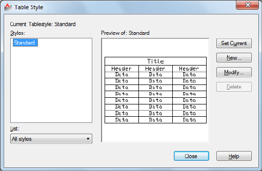
Summary
The Table Style dialog box is displayed.
You can specify the current table style to determine the appearance of all new
tables. A table style includes settings for background colors, margins, borders,
text, and other table characteristics.
Table Style Dialog Box
Quick Reference
See also:
■Work with Table Styles
Sets the current table style and creates, modifies, and deletes table styles.
List of Options
The following options are displayed.
Current Table Style
Displays the name of the table style that is applied to tables you create.
Styles
Displays a list of table styles. The current style is highlighted.
1212 | Chapter 20 T Commands
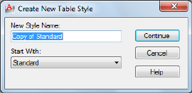
List
Controls the contents of the Styles list.
Preview Of
Displays a preview image of the style that is selected in the Styles list.
Set Current
Sets the table style selected in the Styles list as the current style. All new tables
are created using this table style.
New
Displays the Create New Table Style dialog box, in which you can define new
table styles.
Modify
Displays the Modify Table Style dialog box, in which you can modify table
styles.
Delete
Deletes the table style selected in the Styles list. A style that is being used in
the drawing cannot be deleted.
Create New Table Style Dialog Box
Quick Reference
See also:
■Work with Table Styles
Specifies a name for the new table style and specifies the existing table style
on which the new table style will be based.
Create New Table Style Dialog Box | 1213
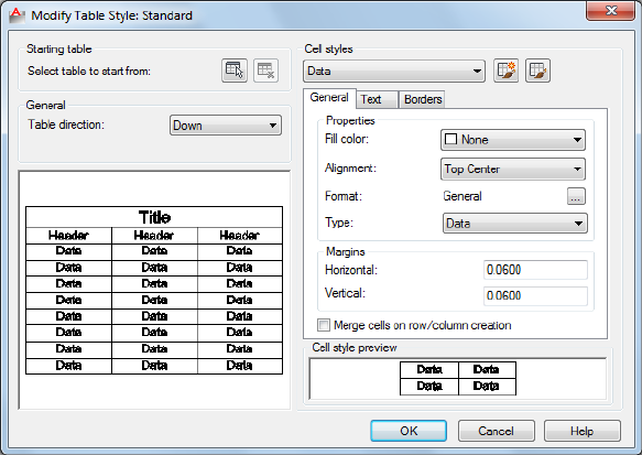
List of Options
The following options are displayed.
New Style Name
Names the new table style.
Start With
Specifies an existing table style whose settings are the default for the new table
style.
Continue Displays the New Table Style dialog box, in which you define the
new table style.
New and Modify Table Style Dialog Boxes
Quick Reference
See also:
■Work with Table Styles
Defines a new table style or modifies an existing table style.
1214 | Chapter 20 T Commands
List of Options
The following options are displayed.
Starting Table
Allows you to specify a table in your drawing to use as an example for
formatting this table style. Once you select a table, you can specify the structure
and contents you want copied from that table to the table style.
With the Remove Table icon, you can remove a table from the current specified
table style.
General
Table Direction
Sets the direction of a table. Down creates a table that reads from top to
bottom. Up creates a table that reads from bottom to top.
■Down: The title row and the column heads row are at the top of the table.
When you click Insert Rows and click Below, the new row is inserted below
the current row.
■Up: The title row and the column heads row are at the bottom of the table.
When you click Insert Rows and click Below, the new row is inserted above
the current row.
Preview
Displays an example of the effect of the current table style settings.
Cell Styles
Defines a new cell style or modifies an existing cell style. You can create any
number of cell styles.
Cell Style Menu
Displays cell styles already found within the table.
Create Cell Styles Button
Launches the Create New Cell Style dialog box.
Manage Cell Styles Button
Launches the Manage Cell Styles dialog box.
Cell Style Tabs
Set the appearance of the data cells, the cell text, and the cell borders.
New and Modify Table Style Dialog Boxes | 1215
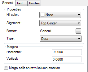
General Tab
Properties
Fill Color
Specifies the background color of the cell. The default is None.
You can choose Select Color to display the Select Color dialog box.
Alignment
Sets justification and alignment for the text in the table cell. Text is middle-,
top-, or bottom-aligned with respect to the top and bottom borders of the
cell. Text is center-justified, left-justified, or right-justified with respect to the
left and right borders of the cell.
See “Justify Multiline Text” in the User's Guide for an illustration of the nine
options.
Format
Sets data type and formatting for the Data, Column Heading, or Title rows in
a table. Clicking this button displays the Table Cell Format dialog box, where
you can further define formatting options.
Type
Specifies the cell style as either a label or data.
Margins
Controls the spacing between the border of the cell and the cell content. The
cell margin settings apply to all cells in the table. The default setting is 0.06
(imperial) and 1.5 (metric).
Horizontal
Sets the distance between the text or block in the cell and the left and right
cell borders.
1216 | Chapter 20 T Commands
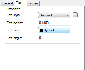
Vertical
Sets the distance between the text or block in the cell and the top and bottom
cell borders.
Merge cells on row/column creation
Merges any new row or column created with the current cell style into one
cell. You can use this option to create a title row at the top of your table.
Text Tab
Text Style
Lists the available text styles.
Text Style Button
Displays the Text Style Dialog Box where you can create or modify text styles.
(DIMTXSTY system variable)
Text Height
Sets the text height. The default text height for data and column head cells
is 0.1800. The default text height for the table title is 0.25.
Text Color
Specifies the color of the text. Choose Select Color at the bottom of the list
to display the Select Color dialog box.
Text Angle
Sets the text angle. The default text angle is 0 degrees. You can enter any angle
between -359 and +359 degrees.
New and Modify Table Style Dialog Boxes | 1217

Borders Tab
Lineweight
Sets the lineweight to be applied to the borders you specify by clicking a border
button. If you use a heavy lineweight, you may have to increase the cell
margins.
Linetype
Sets the linetype to be applied to the borders you specify. Choose Other to
load a custom linetype.
Color
Sets the color to be applied to the borders you specify by clicking a border
button. Choose Select Color to display the Select Color dialog box.
Double Line
Displays table borders as double lines.
Spacing
Determines the spacing for double line borders. The default spacing is 0.1800.
Border Buttons
Controls the appearance of the borders of the cells. The border properties are
lineweight and color of the gridlines.
All Borders
Applies the border properties settings to all borders.
Outside Border
Applies the border properties settings to the outside border.
Inside Border
1218 | Chapter 20 T Commands
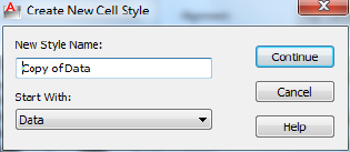
Applies the border properties settings to the inside border.
Bottom Border
Applies the border properties settings to the bottom borders.
Left Border
Applies the border properties settings to the left borders.
Top Border
Applies the border properties settings to the top borders.
Right Border
Applies the border properties settings to the right borders.
No Border
Hides borders.
Cell Style Preview
Displays an example of the effect of the current table style settings.
Create New Cell Style Dialog Box
Quick Reference
See also:
■Work with Table Styles
Specifies a name for the new cell style and specifies the existing cell style on
which the new cell style will be based.
List of Options
The following options are displayed.
Create New Cell Style Dialog Box | 1219
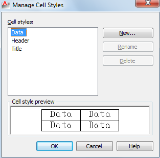
New Style Name
Names the new cell style.
Start With
Specifies an existing cell style whose settings are the default for the new cell
style.
Continue Returns you to the New Table Style dialog box, in which you define
the new cell style.
Manage Cell Styles Dialog Box
Quick Reference
See also:
■Work with Table Styles
Displays all cell styles within the current table style and allows you to create
or delete a cell style.
List of Options
The following options are displayed.
Cell Styles
1220 | Chapter 20 T Commands
Lists all cell styles contained within the current table style. The cell styles Title,
Header, and Data are always contained within any table style.
New
Displays the Create New Cell Style dialog box. From here, you can create a
new cell style to be contained within the current table style.
Rename
Allows you to give a new name to the selected cell style. The Title, Header,
and Data cell styles cannot be renamed.
Delete
Allows you to delete the selected cell style.
Cell Style Preview
Displays an example of the effect of the current cell style settings.
Table Cell Format Dialog Box
Quick Reference
See also:
■Work with Table Styles
The options displayed here change based on the selected data type and format
you select.
Table Cell Format Dialog Box | 1221
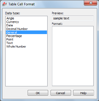
List of Options
The following options are displayed.
Data Type Displays a list of data types (Angle, Date, Decimal Number, and
so on) that you can format for table rows.
Preview Displays a preview of the option you selected in the Format list.
Format Depending on the data type you select, displays a list of relevant
format types. For example, if you selected Angle as the data type, options such
as Decimal Degrees, Grads, Radians, and so on are displayed.
Precision For Angle, Decimal Number, and Points data types only, sets the
precision for applicable formats. For example, if you select Angle as the data
type and Radians as the format type, options such as Current Precision, 0.0r,
0.00r, 0.000r, and so on are displayed.
List Separator For a Point data type only, displays a list of options (comma,
semicolon, or colon) that you can use to separate list items.
Symbol For Currency data types only, displays a list of currency symbols that
you can use.
Append Symbol In Currency data types, places the currency symbol after the
number. In the Percentage data types, places the percent symbol after the
number.
Negative Numbers For Currency data types only, lists options for displaying
negative numbers.
1222 | Chapter 20 T Commands
X, Y, and Z Coordinates For a Point data type only, filters X, Y, or Z
coordinates.
Additional Format For Angle, Decimal Number, Point, and Whole Number
data types only, opens the Additional Format dialog box, where you set
additional formatting options for table cells.
Examples For the Date data type only, displays a list of date display options
for the date option you selected in the Format field. Click a date in the Format
field to see an example.
Additional Format Dialog Box
Quick Reference
See also:
■Work with Table Styles
Provides additional formatting options for table cells.
List of Options
The following options are displayed.
Current Value
Displays the value in base drawing units.
Preview
Displays updates to the format as you change the conversion factor and other
settings.
Conversion Factor
Specifies the conversion factor to use on the current value. The default is 1
for no conversion.
Additional Text
Specifies a prefix or a suffix for the value.
Number Separators
Specifies a decimal separator and the formatting for numbers over 1000.
Decimal Specifies the separator for decimal values. Select a period, a comma,
or a space.
Thousands Inserts a comma to group thousands in a field value.
Additional Format Dialog Box | 1223

Zero Suppression
Controls the suppression of leading and trailing zeros, and of feet and inches
that have a value of zero.
Leading Suppresses leading zeros in all decimal values. For example, 0.5000
becomes .5000.
Trailing Suppresses trailing zeros in all decimal values. For example, 12.5000
becomes 12.5, and 30.0000 becomes 30.
0 Feet Suppresses the feet portion of a feet-and-inches value when the distance
is less than one foot. For example, 0'-6 1/2" becomes 6 1/2".
0 Inches Suppresses the inches portion of a feet-and-inches value when the
distance is an integral number of feet. For example, 1'-0" becomes 1'.
TABLET
Quick Reference
See also:
■Digitizing Tablets
Calibrates, configures, and turns on and off an attached digitizing tablet.
Access Methods
Menu: Tools ➤ Tablet
List of Options
The following options are displayed.
Enter an option [ON on page 1224/OFF on page 1224/CAL on page 1225/CFG on
page 1227]:
On
Turns on Tablet mode. Setting the TABMODE system variable to 1 also turns
on Tablet mode. Pressing Ctrl+T on some systems turns Tablet mode on and
off.
Off
Turns off Tablet mode. Setting the TABMODE system variable to 0 also turns
off Tablet mode. Pressing Ctrl+T on some systems turns Tablet mode on and
off.
1224 | Chapter 20 T Commands

Cal
Calibrates the digitizer with a paper drawing or photograph, creating the tablet
transformation, which is the mapping of points from the tablet to the
coordinate drawing system. Calibration is digitizing points on the drawing
and mapping them to their real coordinates.
Calibration can be performed in model space or paper space. The Cal option
turns on Tablet mode in the space in which the tablet is calibrated. When the
space is changed, the Cal option turns off Tablet mode.
The paper should be flat (with no bumps or wrinkles) and securely fastened
to the digitizing tablet. The paper can be oriented at any angle.
The points you enter cannot be duplicates. The points need not be the origin
on either axis, and you can enter as many points as you like. The more points
you enter, the more accurate the drawing will be.
If you enter only two points, the program automatically computes an
orthogonal transformation.
If you enter three or more points, the program computes the transformation
in each of the three transformation types (Orthogonal, Affine, and Projective)
to determine which best fits the calibration points. If you enter more than
four points, computing the best-fitting projective transformation can take a
long time. You can cancel the process by pressing Esc.
When the computations are complete, the program displays a table with the
number of calibration points and a column for each transformation type.
If there have been no failures of projection transformation, the program
prompts you to choose a transformation type.
Only transformation types for which the outcome was Success, Exact, or
Canceled are included in this prompt. A projective transformation can be
specified even if it was canceled. The program uses the result computed at the
time you canceled.
Orthogonal Specifies translation, uniform scaling, and rotation with two
calibration points.
Use Orthogonal for dimensionally accurate paper drawings and paper drawings
in which the portion to be digitized is long and narrow, with most points
confined to single lines.
NOTE You must specify the lower-left point location before specifying the
upper-right point location.
TABLET | 1225
Affine Specifies arbitrary linear transformation in two dimensions consisting
of translation, independent X- and Y-scaling, rotation, and skewing with three
calibration points.
Use Affine when horizontal dimensions in a paper drawing are stretched with
respect to vertical dimensions, and lines that are supposed to be parallel
actually are parallel.
The RMS (root mean square) error reported after calibration measures how
close the program has come to making a perfect fit. Affine should be used if
the RMS is small.
Projective Specifies a transformation equivalent to a perspective projection
of one plane in space onto another plane with four calibration points. A
projective transformation provides a limited form of what cartographers call
rubber sheeting, in which different portions of the tablet surface are stretched
by varying amounts. Straight lines map into straight lines. Parallel lines do
not necessarily stay parallel.
Projective transformation corrects parallel lines that appear to converge.
Repeat Table Redisplays the computed table, which rates the transformation
types.
Transformation Table
Reports the number of calibration points and provides information about
each transformation type.
Outcome of Fit
Reports the outcome of fit for each of the transformation types. If the outcome
of fit is not Success or Exact for any of the transformation types, the program
reports failure of the entire calibration process and ends the command. The
remaining entries in each column are blank unless Outcome of Fit is Success.
Exact Indicates the correct number of points for a valid transformation.
Success Indicates more than enough points. The program succeeded in fitting
a transformation to the data.
Impossible Indicates not enough points.
Failure Indicates enough points, but the program was unable to fit a
transformation to the points, usually because some points were colinear or
coincident.
Canceled Indicates that the fit process was canceled. This outcome occurs
only with the projective transformation.
1226 | Chapter 20 T Commands
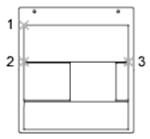
RMS Error
Reports the RMS (root mean square) error, which measures how close the
program has come to finding a perfect fit. The goal is the smallest RMS error.
Standard Deviation
Reports the standard deviation of the residuals. If it is near zero, the residual
at each calibration point is about the same.
Largest Residual/At Point
Reports the point at which the mapping is least accurate. The residual is the
distance between where the point was mapped during transformation and
where it would be mapped if the fit were perfect. The distance is given in the
current linear units.
Second-Largest Residual/At Point
Reports the point at which the mapping is second-least accurate. The residual
is the distance between where the point was mapped during transformation
and where it would be mapped if the fit were perfect. The distance is given in
the current linear units.
Cfg
Designates or realigns the tablet menu areas or designates a small portion of
a large tablet as a screen pointing area.
If tablet menus are in use and the same number of menus is selected, the
following prompts are displayed:
Do you want to realign tablet menus? [Yes/No] <N>: Enter y or n or press Enter
Digitize upper-left corner of menu area n: Digitize a point (1)
Digitize lower-left corner of menu area n: Digitize a point (2)
Digitize lower-right corner of menu area n: Digitize a point (3)
In the prompt, n is the menu number (1-4).
The printed menu form must be affixed to the tablet surface, and the requested
points must be digitized. The set of three points must form a 90-degree angle.
Tablet menu areas can be skewed at any angle.
TABLET | 1227
After all interaction concerning tablet menus is complete, the following prompt
is displayed:
Do you want to respecify the screen pointing area? [Yes/No] <N>: Enter y or n
or press Enter
If you enter y, the following prompts are displayed:
Digitize lower-left corner of the pointing area: Digitize a point
Digitize upper-right corner of the pointing area: Digitize a point
A small portion of the tablet's surface is designated as the fixed screen pointing
area.
Do you want to specify the Floating Screen Pointing area? [Yes/No] <N>: Enter
y or n or press Enter
If you responded y to the previous prompt, respond to the following prompt:
Do you want the Floating Screen Area to be the same size as the Fixed Screen
Pointing Area? [Yes/No] <Y>: Enter y or n or press Enter
If you responded n to the previous prompt, respond to the following prompts:
Digitize lower-left corner of the Floating Screen pointing area: Digitize a point
Digitize upper-right corner of the Floating Screen pointing area: Digitize a point
Respond to the following prompt:
Would you also like to specify a button to toggle the Floating Screen Area?
[Yes/No] <N>: Enter y or n or press Enter
If you responded y to the previous prompt, respond to the following prompt:
Press any non-pick button on the digitizer puck that you wish to designate as
the toggle for the Floating Screen Area
TASKBAR
Quick Reference
See also:
■Transfer Information between Open Drawings
1228 | Chapter 20 T Commands

Controls whether multiple open drawings are displayed separately or grouped
on the Windows taskbar.
List of Prompts
The following prompts are displayed.
Enter new value for Taskbar <varies>:
■On Windows 7 systems, the default value is 1.
■For all other Windows operating systems, the default value is 0.
When TASKBAR is set to 1, drawings are displayed separately on the Windows
taskbar. With Windows 7, preview images of each open drawing are displayed
when the cursor is over the AutoCAD taskbar button.
When TASKBAR is set to 0, only the name of the current drawing is displayed
on the Windows taskbar buttons.
TEXT
Quick Reference
See also:
■Create Single-Line Text
Creates a single-line text object.
Access Methods
Button
Ribbon: Home tab ➤ Annotation panel ➤ Single Line Text
Menu: Draw ➤ Text ➤ Single Line Text
Toolbar: Text
TEXT | 1229

Summary
You can use single-line text to create one or more lines of text, where each
text line is an independent object that you can move, format, or otherwise
modify. Right-click in the text box to select options on the shortcut menu.
If TEXT was the last command entered, pressing Enter at the Specify Start
Point of Text prompt skips the prompts for paper height and rotation angle.
The text that you enter in the text box is placed directly beneath the previous
line of text. The point that you specified at the prompt is also stored as the
insertion point of the text.
If the TEXTED system variable is set to 1, text created using TEXT displays the
Edit Text dialog box. If TEXTED is set to 2, the In-Place Text Editor is displayed.
When creating text, you can click anywhere in a drawing to create a new text
block. You can also use the keyboard to move among text blocks (for example:
for new text created using the TEXT command, you can navigate through text
groups by pressing Tab or Shift+Tab, or edit a group of text lines by pressing
Alt and clicking each text object.)
NOTE Text that would otherwise be difficult to read (if it is very small, very large,
or is rotated) is displayed at a legible size and is oriented horizontally so that you
can easily read and edit it.
You can enter special characters and format text by entering Unicode strings
and control codes.
List of Prompts
The following prompts are displayed.
Current text style: <current> Current text height: <current> Annotative: <current>
Specify start point on page 1230 of text or [Justify on page 1231/Style on page 1233]:
Specify a point or enter an option
Start Point
Specifies a start point for the text object. Enter text in the In-Place Text Editor
for single-line text.
The SpecifyHeight prompt is displayed only if the current text style is not and
does not have a fixed height.
The Specify Paper Text Height prompt is displayed only if the current text
style is annotative.
1230 | Chapter 20 T Commands
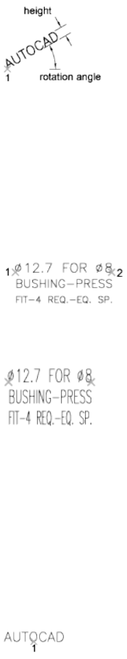
Justify
Controls justification of the text.
You can also enter any of these options at the Specify Start Point of Text
prompt.
Align Specifies both text height and text orientation by designating the
endpoints of the baseline.
The size of the characters adjusts in proportion to their height. The longer
the text string, the shorter the characters.
Fit Specifies that text fits within an area and at an orientation defined with
two points and a height. Available for horizontally oriented text only.
The height is the distance in drawing units that the uppercase letters extend
from the baseline. Designated text height is the distance between the start
point and a point you specify. The longer the text string, the narrower the
characters. The height of the characters remains constant.
Center Aligns text from the horizontal center of the baseline, which you
specify with a point.
The rotation angle specifies the orientation of the text baseline with respect
to the center point. You can designate the angle by specifying a point. The
text baseline runs from the start point toward the specified point. If you specify
a point to the left of the center point, the text is drawn upside down.
TEXT | 1231
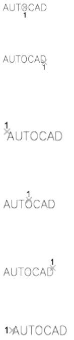
Middle Aligns text at the horizontal center of the baseline and the vertical
center of the height you specify. Middle-aligned text does not rest on the
baseline.
The Middle option differs from the MC option in that it uses the midpoint of
all text, including descenders. The MC option uses the midpoint of the height
of uppercase letters.
Right Right-justifies the text at the baseline, which you specify with a point.
TL (Top Left) Left-justifies text at a point specified for the top of the text.
Available for horizontally oriented text only.
TC (Top Center) Centers text at a point specified for the top of the text.
Available for horizontally oriented text only.
TR (Top Right) Right-justifies text at a point specified for the top of the text.
Available for horizontally oriented text only.
ML (Middle Left) Left-justifies text at a point specified for the middle of the
text. Available for horizontally oriented text only.
MC (Middle Center) Centers the text both horizontally and vertically at the
middle of the text. Available for horizontally oriented text only.
The MC option differs from the Middle option in that it uses the midpoint of
the height of uppercase letters. The Middle option uses the midpoint of all
text, including descenders.
1232 | Chapter 20 T Commands

MR (Middle Right) Right-justifies text at a point specified for the middle of
the text. Available for horizontally oriented text only.
BL (Bottom Left) Left-justifies text at a point specified for the baseline.
Available for horizontally oriented text only.
BC (Bottom Center) Centers text at a point specified for the baseline. Available
for horizontally oriented text only.
BR (Bottom Right) Right-justifies text at a point specified for the baseline.
Available for horizontally oriented text only.
Style
Specifies the text style, which determines the appearance of the text characters.
Text you create uses the current text style.
Entering ? lists the current text styles, associated font files, height, and other
parameters.
TEXT | 1233
Text Shortcut Menu
Quick Reference
See also:
■Create Single-Line Text
Displays options available for creating and modifying single-line text.
List of Options
The following options are displayed.
Opaque Background When checked, makes the background of the editor
opaque.
Find and Replace Displays the Replace dialog box.
Select All Selects all the text in the single-line text object.
Change Case Changes the case of selected text.
Special Unicode Characters
Quick Reference
See also:
■Create Single-Line Text
When entering text, you can create special characters, including the degree
symbol, plus/minus tolerance symbol, and the diameter symbol, by entering
the following Unicode character strings.
List of Options
The following options are displayed.
\U+00B0 Degrees symbol (°)
\U+00B1 Tolerance symbol ( )
1234 | Chapter 20 T Commands
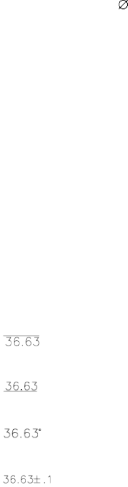
\U+2205 Diameter symbol ( )
Control Codes and Special Characters
Quick Reference
See also:
■Create Single-Line Text
Summary
In addition to using Unicode characters for entering special characters, you
can also overscore text, underscore text, or insert a special character by
including control information in the text string. Use a pair of percent signs
to introduce each control sequence.
You can use this control code with standard AutoCAD LT text fonts and Adobe
PostScript fonts.
List of Options
The following options are displayed.
%%nnn Draws character number nnn.
You can use these control codes with standard AutoCAD LT text fonts only:
%%o Toggles overscoring on and off.
%%u Toggles underscoring on and off.
%%d Draws degrees symbol (°).
%%p Draws plus/minus tolerance symbol ( ).
Control Codes and Special Characters | 1235
%%c Draws circle diameter dimensioning symbol (ý).
%%% Draws a single percent sign (%). This is valid for the TEXT command
only.
Overscoring and underscoring can be in effect at the same time. Both turn off
automatically at the end of the text string.
You can use the %%nnn control sequence to display special characters using
the PostScript fonts.
A sample drawing (truetype.dwg) showing the character map for each font is
provided in the sample folder.
The Euro Symbol
You can use the euro symbol with SHX fonts and their TrueType equivalent
fonts shipped with AutoCAD 2000 and later releases. If your keyboard does
not contain a euro symbol, hold down the Alt key and enter 0128 on the
numeric keypad.
TEXTEDIT
Quick Reference
See also:
■Change Text
Edits a selected multiline or single-line text object, or the text in a dimension
object.
Summary
Displays the in-place text editor, and accepts your changes to the selected
multiline text, single-line text, or dimension object.
1236 | Chapter 20 T Commands

List of Prompts
The following prompt is displayed.
Select an annotation object: Select a text, mtext, or dimension object
TEXTSCR
Quick Reference
See also:
■Navigate and Edit Within the Command Window
Opens the text window.
Access Methods
Button
Ribbon: Views tab ➤ Windows panel ➤ User Interface drop-down ➤
Text Window
Menu: View ➤ Display ➤ Text Window
Command entry: 'textscr for transparent use
Summary
The Command prompt is displayed in a separate window. You can press F2
to switch between the drawing area and the text window.
When the Command prompt is hidden, you can turn it back on by entering
commandline in the text window.
This command is ignored on dual-screen systems.
TEXTSCR | 1237
TEXTTOFRONT
Quick Reference
See also:
■Control How Overlapping Objects Are Displayed
Brings text and dimensions in front of all other objects in the drawing.
Access Methods
Ribbon: Home tab ➤ Modify panel (expanded) ➤ Draw Order
Drop-down ➤ Bring Text to Front
Ribbon: Home tab ➤ Modify panel (expanded) ➤ Draw Order
Drop-down ➤ Bring Dimensions to Front
Menu: Tools ➤ Draw Order ➤ Bring Text and Dimensions to Front ➤
Text and Dimension Objects
List of Prompts
The following prompts are displayed.
Bring to front: [Text/Dimensions/Both] <Both>: Enter an option or press Enter
Text Brings all text in front of all other objects in the drawing.
Dimensions Brings all dimensions in front of all other objects in the drawing.
Both Brings all text and dimensions in front of all other objects in the drawing.
NOTE Text and dimensions that are contained within blocks and xrefs cannot be
brought to the front apart from the containing object. Also, text in multileaders
and tables are not supported.
TIFOUT
Quick Reference
See also:
■Export Raster Files
1238 | Chapter 20 T Commands
Saves selected objects to a file in TIFF file format.
Summary
The Create Raster File dialog box (a standard file selection dialog box) is
displayed. Enter the file name in the dialog box.
List of Prompts
The following prompts are displayed.
Select objects or <all objects and viewports>: Press Enter to select all objects and
viewports or use an object selection method and press Enter
A TIFF file is created that contains the objects you select. The file reflects what
is displayed on the screen.
NOTE When the FILEDIA system variable is set to 0 (Off), command prompts are
displayed.
TIME
Quick Reference
See also:
■Obtain General Drawing Information
Displays the date and time statistics of a drawing.
Access Methods
Button
Menu: Tools ➤ Inquiry ➤ Time
Command entry: 'time for transparent use
TIME | 1239
Summary
List of Prompts
The following prompts are displayed.
Current time: Wednesday, December 31, 2003 9:54:51:406 AM
Times for this drawing:
Created: Friday, December 12, 2003 1:21:36:203 AM
Last Updated: Wednesday, December 31, 2003 9:49:19:208 AM
Total Editing Time: 0 days 06:44:10.520
Elapsed Timer (on): 0 days 00:07:05.312
Next Automatic Save In: 0 days 01:59:15.570
Enter option [Display/On/OFF/Reset]: Enter an option or press Enter
Current Time Displays the current date and time to the nearest millisecond
using a 24-hour clock.
Created Displays the date and time that the current drawing was created.
Last Updated Displays the date and time of the latest update of the current
drawing. This date and time is initially the drawing creation time. The time
is revised whenever the drawing file is saved.
Total Editing Time Displays the time spent editing the current drawing. This
timer is updated by the program and cannot be reset or stopped. Plotting time
is not included in the total editing time. If you quit the editing session without
saving the drawing, the time you spent in the editing session is not added to
the accumulated editing time.
Elapsed Timer Runs as another timer while the program is running. You can
turn it on and off or reset it whenever you like.
Next Automatic Save In Indicates the time remaining until the next automatic
save. You can set the time interval using OPTIONS or the SAVETIME system
variable.
Display Repeats the display with updated times.
On Starts the user elapsed timer if it was off.
Off Stops the user elapsed timer.
Reset Resets the user elapsed timer to 0 days 00:00:00.000.
1240 | Chapter 20 T Commands
TIMELINE
Quick Reference
See also:
■Use AutoCAD WS for Drawing File Collaboration
Provides access to previous versions of the AutoCAD WS online copy of the
current drawing.
Access Methods
Button
Ribbon: Online tab ➤ Content panel ➤ Timeline
Menu: File ➤ AutoCAD WS ➤ Timeline
Toolbar: Online
Summary
The Timeline dialog box on page 1241 is displayed. You must save the drawing
before you can continue with this command.
NOTE You may first be prompted to log in to AutoCAD WS. If you do not have
an account, click Create an Account and follow the on-screen instructions.
Timeline Dialog Box
Quick Reference
See also:
■Use AutoCAD WS for Drawing File Collaboration
Provides access to previous versions of the AutoCAD WS online copy of the
current drawing.
TIMELINE | 1241
Summary
The timeline presents a visual representation of the history of any drawing
uploaded to AutoCAD WS. A unique version is added to the timeline whenever
the drawing is uploaded from AutoCAD or online edits are saved in AutoCAD
WS, including changes resulting from collaboration sessions.
Use the timeline to refer to previous versions of the drawing and track all
changes. Users with whom you have shared the drawing can view the timeline.
List of Options
The following options are displayed.
View Online Opens the specified version in AutoCAD WS and displays the
timeline of the drawing.
Download Downloads the selected version as follows:
■Open. Downloads the drawing to a default location on the local computer
and opens it in AutoCAD.
■Save. Saves the drawing to a specified location.
1242 | Chapter 20 T Commands
TINSERT
Quick Reference
See also:
■Add Text and Blocks to Tables
Inserts a block in a table cell.
Access Methods
Shortcut menu: With a cell in a table selected, right-click and click Insert
Block on the shortcut menu.
Summary
The Insert a Block in a Table Cell dialog box is displayed.
Insert a Block in a Table Cell Dialog Box
Quick Reference
See also:
■Add Text and Blocks to Tables
Specifies options for inserting a block in a table cell.
List of Options
The following options are displayed.
Name Specifies the block reference to insert.
Browse Displays the Select Drawing File dialog box. Select the drawing file to
insert as a block reference.
Path Displays the location of the drawing file selected in the Select Drawing
File dialog box.
Scale
TINSERT | 1243
Specifies the scale for the block reference. Enter a value or select AutoFit to
scale the block to fit in the selected cell.
AutoFit Controls if the block reference should be scaled to fit in the select
table cell, or if the height and width of the table cell should be adjusted to fit
the block reference being inserted.
Rotation Angle
Specifies a rotation angle for the block.
Overall Cell Alignment
Specifies alignment for the block in the table cell. The block is middle-, top-,
or bottom-aligned with respect to the top and bottom borders of the cell. The
block is center-, left-, or right-aligned with respect to the left and right borders
of the cell.
TOLERANCE
Quick Reference
See also:
■Overview of Geometric Tolerances
Creates geometric tolerances contained in a feature control frame.
Access Methods
Button
Ribbon: Annotate tab ➤ Dimensions panel ➤ Tolerance
Menu: Dimension ➤ Tolerance
Toolbar: Dimension
Summary
The Geometric Tolerance dialog box is displayed.
1244 | Chapter 20 T Commands
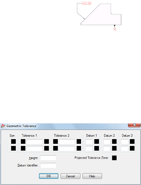
Geometric tolerances show acceptable deviations of form, profile, orientation,
location, and runout. Feature control frames can be created with leader lines
using TOLERANCE, LEADER, or QLEADER.
Geometric Tolerance Dialog Box
Quick Reference
See also:
■Overview of Geometric Tolerances
Specifies the symbols and values for a feature control frame.
Summary
After you select geometric characteristic symbols, the Geometric Tolerance
dialog box closes and the following prompt is displayed:
Enter tolerance location: Specify a location
The feature control frame is placed at the specified location.
List of Prompts
The following prompts are displayed.
Geometric Tolerance Dialog Box | 1245
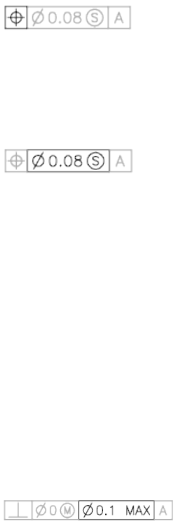
Sym
Displays the geometric characteristic symbol, which you select from the Symbol
dialog box. The dialog box is displayed when you select one of the Sym boxes.
Tolerance 1
Creates the first tolerance value in the feature control frame. The tolerance
value indicates the amount by which the geometric characteristic can deviate
from a perfect form. You can insert a diameter symbol before the tolerance
value and a material condition symbol after it.
First Box
Inserts a diameter symbol in front of the tolerance value. Click the box to
insert the diameter symbol.
Second Box
Creates the tolerance value. Enter a value in the box.
Third Box
Displays the Material Condition dialog box, in which you select a modifying
symbol. These symbols act as modifiers to the geometric characteristic and
the tolerance value of features that can vary in size.
The symbol is inserted into the MC box for the first tolerance value in the
Geometric Tolerance dialog box.
Tolerance 2
Creates the second tolerance value in the feature control frame. Specify the
second tolerance value in the same way as the first.
Datum 1
Creates the primary datum reference in the feature control frame. The datum
reference can consist of a value and a modifying symbol. A datum is a
theoretically exact geometric reference used to establish the tolerance zone
for a feature.
1246 | Chapter 20 T Commands
First Box
Creates the datum reference value.
Second Box
Displays the Material Condition dialog box, in which you select a modifying
symbol. These symbols act as modifiers to the datum reference.
The symbol is inserted into the MC box for the primary datum reference in
the Geometric Tolerance dialog box.
Datum 2
Creates the secondary datum reference in the feature control frame in the
same way as the primary datum reference.
Datum 3
Creates the tertiary datum reference in the feature control frame in the same
way as the primary datum reference.
Height
Creates a projected tolerance zone value in the feature control frame. A
projected tolerance zone controls the variation in height of the extended
portion of a fixed perpendicular part and refines the tolerance to that specified
by positional tolerances.
Projected Tolerance Zone
Inserts a projected tolerance zone symbol after the projected tolerance zone
value.
Geometric Tolerance Dialog Box | 1247
Datum Identifier
Creates a datum-identifying symbol consisting of a reference letter. A datum
is a theoretically exact geometric reference from which you can establish the
location and tolerance zones of other features. A point, line, plane, cylinder,
or other geometry can serve as a datum.
Symbol Dialog Box
Quick Reference
See also:
■Overview of Geometric Tolerances
Displays the geometric characteristic symbols for location, orientation, form,
profile, and runout.
Summary
The symbol is inserted into the Sym text box in the Geometric Tolerance
dialog box. The following table describes the symbols.
Geometric characteristic symbols
TypeCharacteristicSymbol
LocationPosition
1248 | Chapter 20 T Commands
Geometric characteristic symbols
TypeCharacteristicSymbol
LocationConcentricity or coaxiality
LocationSymmetry
OrientationParallelism
OrientationPerpendicularity
OrientationAngularity
FormCylindricility
FormFlatness
FormCircularity or roundness
FormStraightness
ProfileProfile of a surface
ProfileProfile of a line
RunoutCircular runout
RunoutTotal runout
Symbol Dialog Box | 1249
Material Condition Dialog Box
Quick Reference
See also:
■Overview of Geometric Tolerances
Specifies a modifying symbol. These symbols act as modifiers to the geometric
characteristic and the tolerance value of features that can vary in size.
Summary
The symbol is inserted into the MC box for the first or second tolerance value
in the Geometric Tolerance dialog box.
TOOLBAR
Quick Reference
See also:
■Toolbars
Displays, hides, and customizes toolbars.
Access Methods
Button
Ribbon: View tab ➤ Windows panel ➤ Toolbars
Menu: View ➤ Toolbars
Shortcut menu: Right-click any toolbar and choose Customize.
1250 | Chapter 20 T Commands
Summary
The Customize User Interface dialog box (see CUI) is displayed.
If you enter -toolbar at the Command prompt, options are displayed.
-TOOLBAR
Quick Reference
See also:
■Toolbars
List of Prompts
The following prompts are displayed.
Enter toolbar name on page 1251 or [ALL on page 1252]: Enter a name or enter all
Toolbar Name
Specifies a toolbar to display, close, or position.
Enter a valid toolbar name. If the default menu is loaded, the following names
are available:
ucs_iiparametricinsertarray_edit
viewpropertieslayersarray_toolbar
viewportsrefeditlayers_iidimension
webreferencelayoutsdraw
workspacesstandardmeasure-
ment_tools
draw_order
zoomstandard_annota-
tion
modifydraw_order,_an-
nota-
tion_to_front
stylesmodify_iifind_text
textmultileadergroup
-TOOLBAR | 1251

ucsobject_snapinquiry
Show Displays the specified toolbar.
Hide Closes the specified toolbar.
Left Docks the specified toolbar at the left side of the screen.
Right Docks the specified toolbar at the right side of the screen.
Top Docks the specified toolbar at the top of the screen.
Bottom Docks the specified toolbar at the bottom of the screen.
Enter New Position Sets the position of the toolbar in columns and rows
relative to a toolbar dock. The first value is horizontal. The second value is
vertical.
Float Changes the toolbar from docked to floating.
Enter Number of Rows Specifies the number of rows in the floating toolbar.
All
Displays or closes all toolbars.
Show Displays all toolbars.
Hide Closes all toolbars.
TOOLPALETTES
Quick Reference
See also:
■Create and Use Tools from Objects and Images
Opens the Tool Palettes window.
Button
Access Methods
Ribbon: View tab ➤ Palettes panel ➤ Tool Palettes
1252 | Chapter 20 T Commands

Menu: Tools ➤ Palettes ➤ Tool Palettes
Toolbar: Standard
Summary
Use tool palettes to organize blocks, hatches, and custom tools in a tabbed
window. Various options and settings are accessible from shortcut menus that
display when you right-click different areas of the Tool Palettes window.
NOTE Tool palettes can be used only in the version of the product in which they
were created. For example, you cannot use a tool palette that was created in
AutoCAD LT 2012 in AutoCAD LT 2007.
List of Options
The following options are displayed.
Add Text Inserts a text entry box at the cursor location, where you can add
a label that helps organize palette contents.
Add Separator Adds a tool palette separator line at the location of the cursor.
All Palettes Displays all tool palette tabs in the palette window.
Allow Docking Toggles the ability to dock or anchor palette windows. A
docked window adheres to the side of the application window and causes the
drawing area to be resized. Selecting this option also makes Anchor Right and
Anchor Left available. Clear this option to undock a docked tool palette.
Anchor Left/ Anchor Right Attaches the palette to an anchor tab base at the
left or right side of the drawing area. An anchored palette rolls open and closed
as the cursor moves across it. When an anchored palette is open, its content
overlaps the drawing area. An anchored palette cannot be set to stay open.
Auto-hide A setting that causes a floating window to roll open and closed as
the cursor moves across it. When this option is cleared, the full tool palette
stays open continuously.
Close Closes the tool palette window.
Copy Copies the selected tool to the Clipboard.
Customize Commands Displays the Customize User Interface Dialog Box.
Customize Palettes Displays the Customize dialog box.
Cut Removes the selected tool from the tool palette and places it on the
Clipboard.
TOOLPALETTES | 1253
Delete Removes the selected tool from the tool palette.
Delete Palette Removes the current palette.
Dynamic Blocks Displays the palette tabs containing dynamic blocks.
Move Changes the cursor to a four-direction arrow.
Move Up Moves the selected tool palette up one position.
Move Down Moves the selected tool palette down one position.
New Palette Creates a new palette. Enter a name or press Enter to use the
default name.
Paste Pastes a tool from the Clipboard to the current tab.
Properties Displays the Tool Properties dialog box, where you can change the
properties of the selected tool.
Rename Renames the selected tool.
Rename Palette Renames the current palette.
Samples Displays the Samples tool palette.
Sort By Specifies whether palette contents are sorted by name or by type.
Size Changes the cursor to a four-direction arrow.
Transparency Displays the Transparency dialog box.
View Options Displays the View Options dialog box, where you can control
how tools are displayed.
View Options Dialog Box
Quick Reference
See also:
■Change Tool Palette Settings
Controls the display of tools in the current tool palette or in all tool palettes.
1254 | Chapter 20 T Commands
Access Methods
Shortcut menu: Right-click a blank area or a tab on a tool palette and click
View Options.
List of Options
The following options are displayed.
Image Size
Controls the display size of the selected tool palette icon.
View Style
Controls the text displayed with a tool palette icon.
Icon Only
Displays the tool icon only.
Icon with Text
Displays the tool icon with the tool name below.
List View
Displays the tool icon with the tool name to the right.
Apply To
Controls whether the view options are applied to the current tool palette or
to all tool palettes in the Tool Palettes window.
Tool Properties Dialog Box
Quick Reference
See also:
■Customize Tool Palettes
Controls the properties associated with the selected tool.
Access Methods
Shortcut menu: Right-click a tool on a tool palette and click Properties.
Tool Properties Dialog Box | 1255

Summary
The types of properties that are displayed will vary depending on the type of
tool that is selected. In addition the following controls are displayed:
List of Options
The following options are displayed.
Image
Displays the icon of the selected tool.
Name
Displays the name of the selected tool. This can be edited.
Description
Displays a description of the selected tool.
TOOLPALETTESCLOSE
Quick Reference
See also:
■Create and Use Tools from Objects and Images
Closes the Tool Palettes window.
Access Methods
Ribbon: View tab ➤ Palettes panel ➤ Tool Palettes
Menu: Tools ➤ Palettes ➤ Tool Palettes
Toolbar: Standard
1256 | Chapter 20 T Commands

TPNAVIGATE
Quick Reference
See also:
■Organize Tool Palettes
Displays a specified tool palette or palette group.
List of Prompts
The following prompts are displayed.
Specify tool palette to display or [palette Group]: Enter a tool palette name, or
enter g
Tool Palette Name Displays the specified tool palette.
Specifying a tool palette that is not part of the current group displays the
specified palette and its palette group.
Palette Group Displays the specified tool palette group.
NOTE TPNAVIGATE opens the Tool Palettes window if closed.
TRANSPARENCY
Quick Reference
See also:
■Modify Color and Transparency for Bitonal Raster Images
Controls whether background pixels in an image are transparent or opaque.
Access Methods
Button
Menu: Modify ➤ Object ➤ Image ➤ Transparency
TPNAVIGATE | 1257
Toolbar: Reference
Shortcut menu: Select an image, right-click in the drawing area, and click
Image ➤ Transparency.
List of Prompts
The following prompts are displayed.
Select image(s):
Enter transparency mode [ON/OFF] <current>: Enter an option or press Enter
On Turns transparency on so that objects beneath the image are visible.
Off Turns transparency off so that objects beneath the image are not visible.
NOTE The PALETTEOPAQUE system variable controls whether dockable windows
can be made transparent.
TRAYSETTINGS
Quick Reference
See also:
■Application Status Bar
Controls the display of icons and notifications in the status bar tray.
Access Methods
Button
Shortcut menu: Right-click the status bar and click Tray Settings.
Summary
The Tray Settings dialog box is displayed.
1258 | Chapter 20 T Commands
Tray Settings Dialog Box
Quick Reference
See also:
■Application Status Bar
Controls the display of icons and notifications in the tray at the right end of
the status bar.
List of Options
The following options are displayed.
Display Icons from Services
Displays the tray at the right end of the status bar and displays icons from
services. When this option is cleared, the tray is not displayed.
Display Notifications from Services
Displays notifications from services.
Display Time
Sets the time in seconds that a notification is displayed.
Display Until Closed
Displays a notification until you click the Close button.
TRIM
Quick Reference
See also:
■Trim or Extend Objects
Trims objects to meet the edges of other objects.
Tray Settings Dialog Box | 1259
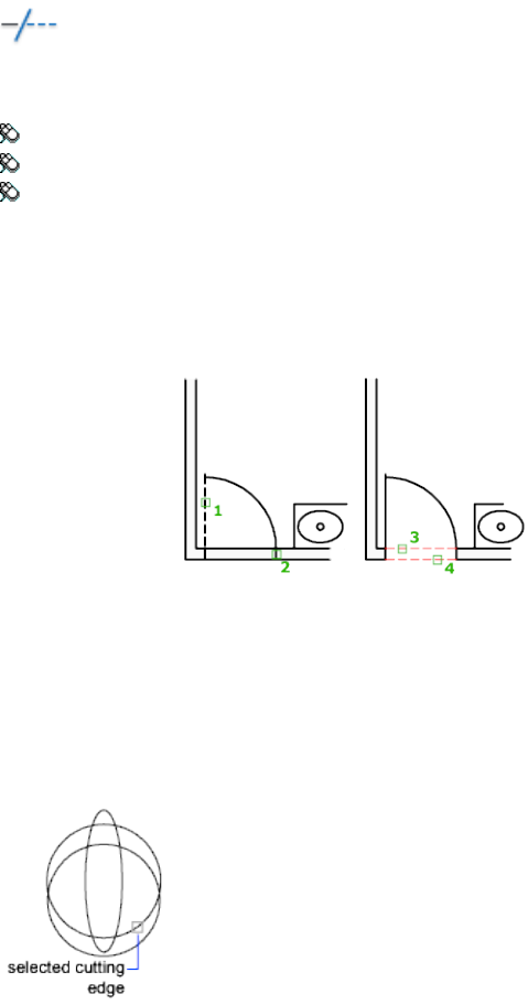
Access Methods
Button
Ribbon: Home tab ➤ Modify panel ➤ Trim
Menu: Modify ➤ Trim
Toolbar: Modify
Summary
To trim objects, select the boundaries. Then press Enter and select the objects
that you want to trim. To use all objects as boundaries, press Enter at the first
Select Objects prompt.
List of Prompts
The following prompts are displayed.
Current settings: Projection = current, Edge = current
Select cutting edges...
Select objects or <select all>: Select one or more objects and press Enter, or press
Enter to select all displayed objects
1260 | Chapter 20 T Commands
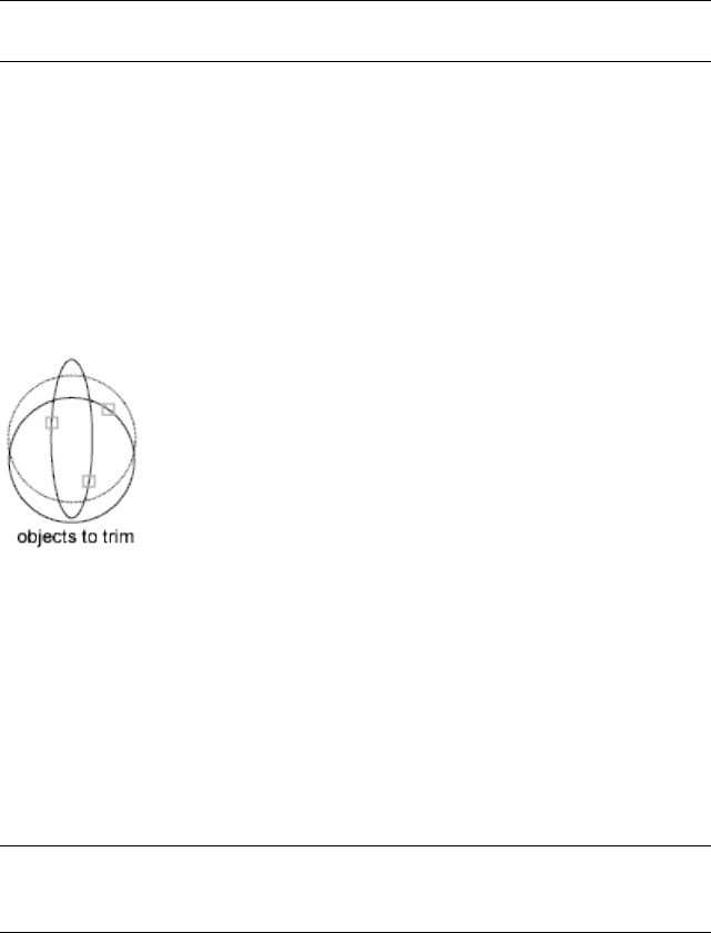
Select the objects that define the cutting edges to which you want to trim an
object, or press Enter to select all displayed objects as potential cutting edges.
TRIM projects the cutting edges and the objects to be trimmed onto the XY
plane of the current user coordinate system (UCS).
NOTE To select cutting edges that include blocks, you can use only the single
selection, Crossing, Fence, and Select All options.
Select object to trim on page 1261 or shift-select to extend on page 1261 or [Fence
on page 1261/Crossing on page 1261/Project on page 1261/Edge on page 1262/eRase
on page 1263/Undo on page 1263]: Select an object to trim, hold down SHIFT and
select an object to extend it instead, or enter an option
Specify an object selection method to select the objects to trim. If more than
one trim result is possible, the location of the first selection point determines
the result.
Object to Trim
Specifies the object to trim.
Shift-Select to Extend
Extends the selected objects rather than trimming them. This option provides
an easy method to switch between trimming and extending.
Fence
Selects all objects that cross the selection fence. The selection fence is a series
of temporary line segments that you specify with two or more fence points.
The selection fence does not form a closed loop.
Crossing
Selects objects within and crossing a rectangular area defined by two points.
NOTE Some crossing selections of objects to be trimmed are ambiguous. TRIM
resolves the selection by following along the rectangular crossing window in a
clockwise direction from the first point to the first object encountered.
Project
Specifies the projection method used when trimming objects.
TRIM | 1261
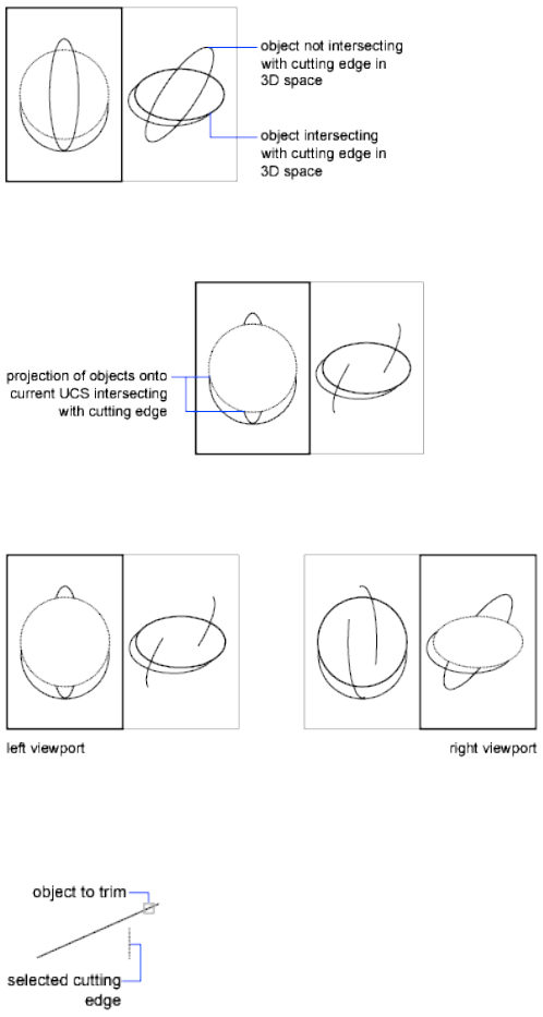
None Specifies no projection. The command trims only objects that intersect
with the cutting edge in 3D space.
UCS Specifies projection onto the XY plane of the current UCS. The command
trims objects that do not intersect with the cutting edge in 3D space.
View Specifies projection along the current view direction. The command
trims objects that intersect the boundary in the current view.
Edge
Determines whether an object is trimmed at another object's extrapolated
edge or only to an object that intersects it in 3D space.
1262 | Chapter 20 T Commands
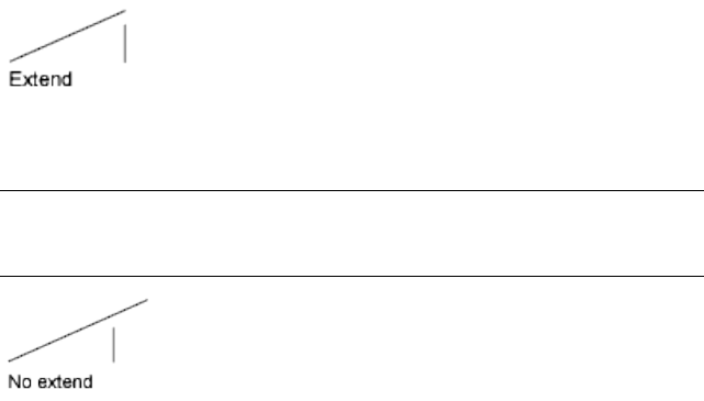
Extend Extends the cutting edge along its natural path to intersect an object
in 3D space.
No Extend Specifies that the object is trimmed only at a cutting edge that
intersects it in 3D space.
NOTE When trimming hatches, do not set Edge to Extend. If you do, gaps in the
trim boundaries will not be bridged when trimming hatches, even when the gap
tolerance is set to a correct value.
Erase
Deletes selected objects. This option provides a convenient method to erase
unneeded objects without leaving the TRIM command.
Undo
Reverses the most recent change made by TRIM.
TRIM | 1263
1264

U Commands
U
Quick Reference
See also:
■Correct Mistakes
Reverses the most recent operation.
Access Methods
Button
Menu: Edit ➤ Undo
Toolbar: Standard
Shortcut menu: With no command active and no objects selected, right-click
in the drawing area and click Undo.
Command entry: Ctrl+Z
Summary
You can enter u as many times as you wish, backing up one step at a time, until
the drawing is as it was when you began the current editing session.
21
1265
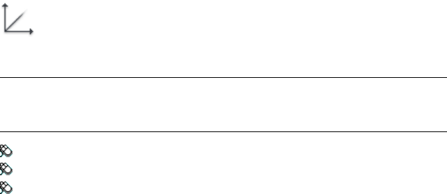
When an operation cannot be undone, the command name is displayed but
no action is performed. Operations external to the current drawing, such as
plotting or writing to a file, cannot be undone.
If you changed modes or used transparent commands during a command,
their effects are undone, along with the effects of the main command.
The U command is equivalent to entering undo 1.
UCS
Quick Reference
See also:
■Work with the User Coordinate System (UCS)
■UCSSELECTMODE
Sets the origin and orientation of the current UCS.
Access Methods
Button
NOTE By default, the Coordinates panel is hidden in the Drafting & Annotation
workspace. To display the Coordinates panel, click the View tab, then right-click
and choose Show Panels, and then click Coordinates.
Ribbon: View tab ➤ Coordinates panel ➤ UCS
Menu: Tools ➤ New UCS
Toolbar: UCS
Shortcut menu: Right-click the UCS icon and click an option.
Summary
The UCS is the active coordinate system that establishes the XY plane (work
plane) and Z-axis direction for drawing and modeling. Control the UCS origin
and orientation to make drawing more convenient as you specify points, enter
coordinates, and work with drawing aids, such as Ortho mode and the grid.
1266 | Chapter 21 U Commands
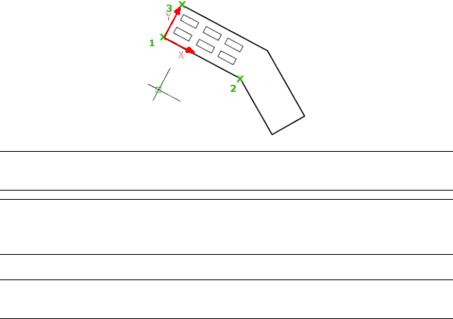
List of Prompts
The following prompts are displayed.
Specify Origin of UCS on page 1267 or [Face on page 1267/NAmed on page
1268/OBject on page 1269/Previous on page 1269/View on page 1269/World on page
1269/X/Y/Z on page 1269/ZAxis on page 1271] <World>:
Specify Origin of UCS
Defines a new UCS using one, two, or three points:
■If you specify a single point, the origin of the current UCS shifts without
changing the orientation of the X, Y, and Z axes.
■If you specify a second point, the UCS rotates to pass the positive X axis
through this point.
■If you specify a third point, the UCS rotates around the new X axis to
define the positive Y axis.
The three points specify an origin point, a point on the positive X axis, and a
point on the positive XY plane.
NOTE If you do not specify a Z coordinate value when entering a coordinate, the
current Z value is used.
TIP You can also select and drag the UCS icon origin grip directly to a new location,
or choose Move Origin Only from the origin grip menu. For more information,
see To define a new UCS origin using the origin grip.
Face
TIP You can also select and drag the UCS icon (or choose Move And Align from
the origin grip menu) to dynamically align the UCS with faces.
Dynamically aligns the UCS to a face on a 3D object.
Move the cursor over a face to see a preview of how the UCS will be aligned.
UCS | 1267
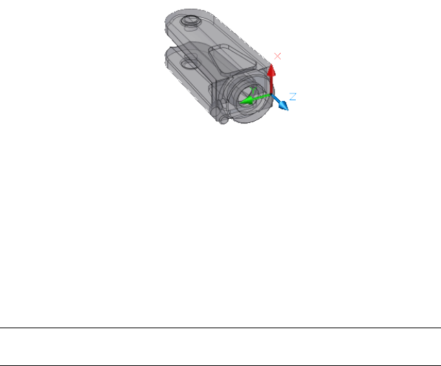
Next Locates the UCS on either the adjacent face or the back face of the
selected edge.
Xflip Rotates the UCS 180 degrees around the X axis.
Yflip Rotates the UCS 180 degrees around the Y axis.
Accept Accepts the changes and places the UCS.
3D objects can be created in AutoCAD.
Named
Saves or restores named UCS definitions.
TIP You can also right-click the UCS icon and click Named UCS to save or restore
named UCS definitions.
Restore
Restores a saved UCS definition so that it becomes the current UCS.
Name Specifies the name of the UCS definition to restore.
?—List UCS definitions Lists details about the specified UCS definitions.
Save
Saves the current UCS to a specified name.
Name Specifies the name for the UCS definition.
Delete
Removes the specified UCS definition from the list of saved definitions.
?—List UCS Definitions
Lists saved UCS definitions showing the origin and X, Y, and Z axes for each
saved UCS definition relative to the current UCS. Enter an asterisk to list all
UCS definitions. If the current UCS is the same as the WCS (World Coordinate
System), it is listed as WORLD. If it is custom, but unnamed, it is listed as NO
NAME.
1268 | Chapter 21 U Commands
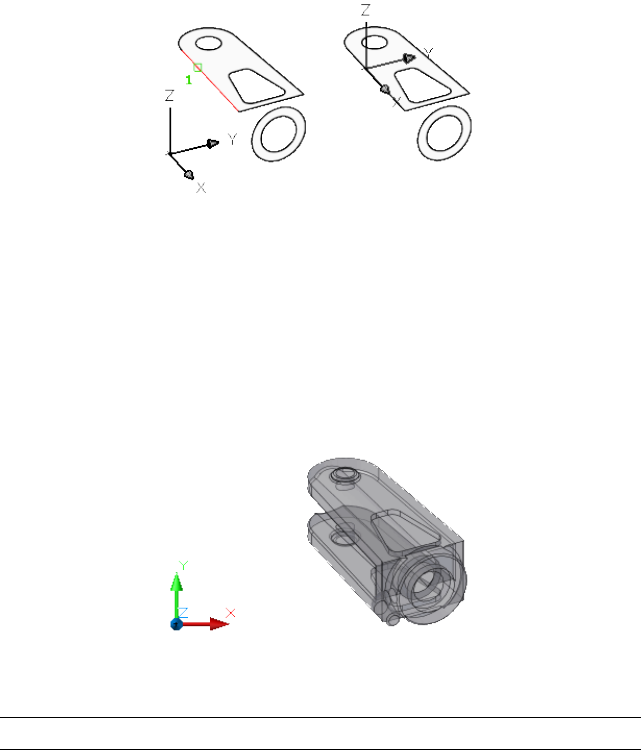
Object
Aligns the UCS to a selected 2D or 3D object. The UCS can be aligned with
any object type except xlines and 3D polylines.
Move the cursor over an object to see a preview of how the UCS will align,
and click to place the UCS. In most cases, the UCS origin will be located at
the endpoint that is nearest to the specified point, the X axis will align to an
edge or tangent to a curve, and the Z axis will align perpendicular to the object.
Previous
Restores the previous UCS.
You can steps back through the last 10 UCS settings in the current session.
UCS settings are stored independently for model space and paper space.
View
Aligns the XY plane of the UCS to a plane perpendicular to your viewing
direction. The origin point remains unchanged, but the X and Y axes become
horizontal and vertical.
World
Aligns the UCS with the world coordinate system (WCS).
TIP You can also click the UCS icon and choose World from the origin grip menu.
X, Y, Z
Rotates the current UCS about a specified axis.
UCS | 1269
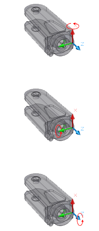
Point your right thumb in the positive direction of the X axis and curl your
fingers. Your fingers indicate the positive rotation direction about the axis.
Point your right thumb in the positive direction of the Y axis and curl your
fingers. Your fingers indicate the positive rotation direction about the axis.
Point your right thumb in the positive direction of the Z axis and curl your
fingers. Your fingers indicate the positive rotation direction about the axis.
You can define any UCS by specifying an origin and one or more rotations
around the X, Y, or Z axis.
1270 | Chapter 21 U Commands
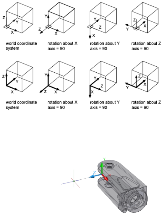
Z Axis
Aligns the UCS to a specified positive Z axis.
The UCS origin is moved to the first point and its positive Z axis passes through
the second point.
Object Aligns the Z axis tangent to the endpoint that is nearest to the specified
point. The positive Z axis points away from the object.
UCSICON
Quick Reference
See also:
■Control the Display of the User Coordinate System Icon
UCSICON | 1271
Controls the visibility, placement, appearance, and selectability of the UCS
icon.
Access Methods
Button
NOTE By default, the Coordinates panel is hidden in the Drafting & Annotation
workspace. To display the Coordinates panel, click the View tab, then right-click
and choose Show Panels, and then click Coordinates.
Ribbon: View tab ➤ Coordinates panel ➤ UCS Icon Properties
Menu: View ➤ Display ➤ UCS Icon ➤ Properties
Summary
The UCS icon indicates the location and orientation of the current UCS. You
can manipulate the UCS icon using grips. This is controlled by the
UCSSELECTMODE on page 1704 system variable.
NOTE If the location of the UCS origin is not visible in a viewport, the UCS icon
is displayed in the lower-left corner of the viewport instead.
Different coordinate system icons are displayed in paper space and model
space. In model space, you can choose between 2D and 3D icon display styles
(see the Properties on page 1273 option):
■2D. The letter W appears in the Y portion of the icon if the UCS is the same
as the WCS (world coordinate system). If the UCS is rotated so that the Z
axis lies in a plane parallel to the viewing plane—that is, if the XY plane
is edge-on to the viewer—the 2D UCS icon is replaced by a broken pencil
icon.
■3D. A square is displayed in the XY plane at the origin if the current UCS
is the same as the WCS, and you are viewing the UCS from above (the
positive Z direction). The square is missing if you are viewing the UCS
from below. The Z axis is solid when viewed from above the XY plane and
dashed when viewed from below the XY plane.
1272 | Chapter 21 U Commands
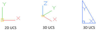
List of Prompts
The following prompts are displayed.
Enter an option [ON/OFF/All/Noorigin/ORigin/Selectable/Properties on page
1273]<current>: Enter an option or press Enter
On Displays the UCS icon.
Off Turns off display of the UCS icon.
All Applies changes to the icon in all active viewports. Otherwise, UCSICON
affects only the current viewport.
No Origin Displays the icon at the lower-left corner of the viewport regardless
of the location of the UCS origin.
Origin Displays the icon at the origin (0,0,0) of the current UCS. If the origin
is out of view, it is displayed at the lower-left corner of the viewport.
Selectable Controls whether the UCS icon is selectable and can be manipulated
with grips.
Properties Displays the UCS Icon dialog box, in which you can control the
style, visibility, and location of the UCS icon.
UCS Icon Dialog Box
Quick Reference
See also:
■Control the Display of the User Coordinate System Icon
Controls the style, visibility, and location of the UCS icon.
UCS Icon Dialog Box | 1273
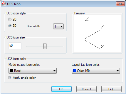
List of Options
The following options are displayed.
UCS Icon Style
Specifies display of either the 2D or the 3D UCS icon and its appearance.
2D
Displays a 2D icon without a representation of the Z axis.
3D
Displays a 3D icon.
Line Width
Controls the line width of the UCS icon if the 3D UCS icon is selected.
Preview
Displays a preview of the UCS icon in model space.
UCS Icon Size
Controls the size of the UCS icon as a percentage of viewport size. The default
value is 50, and the valid range is from 5 to 95. Note that the size of the UCS
icon is proportional to the size of the viewport in which it is displayed.
UCS Icon Color
Controls the colors of the UCS icon in model space viewports and in layout
tabs.
Model Space Icon Color
1274 | Chapter 21 U Commands
Controls the color of the UCS icon in model space viewports.
Layout Tab Icon Color
Controls the UCS icon color in layout tabs.
Apply Single Color Applies the selected Model space icon color to all axes of
the 2D UCS icon.
UCSMAN
Quick Reference
See also:
■Work with the User Coordinate System (UCS)
Manages UCS definitions.
Access Methods
Button
NOTE By default, the Coordinates panel is hidden in the Drafting & Annotation
workspace. To display the Coordinates panel, click the View tab, then right-click
and choose Show Panels, and then click Coordinates.
Ribbon: View tab ➤ Coordinates panel ➤ Named
Menu: Tools ➤ Named UCS
Toolbar: UCS
Summary
The UCS dialog box is displayed.
UCSMAN | 1275
UCS Dialog Box
Quick Reference
See also:
■Work with the User Coordinate System (UCS)
Controls the UCS and UCS icon settings for viewports.
Summary
Lists, renames, and restores user coordinate system (UCS) definitions, and
controls UCS and UCS icon settings for viewports.
List of Tabs
■Named UCSs on page 1276
■Orthographic UCSs on page 1277
■Settings on page 1279
Named UCSs Tab (UCS Dialog Box)
Lists UCS definitions and sets the current UCS.
Current UCS
Displays the name of the current UCS. If the UCS has not been saved and
named, it is listed as UNNAMED.
1276 | Chapter 21 U Commands
UCS Names List
UNNAMED is always the first entry if the current UCS is unnamed. World is
always listed and cannot be renamed or deleted. If you define other coordinate
systems for the active viewport during the current editing session, a Previous
entry is next. You can step back through these coordinate systems by selecting
Previous and Set Current repeatedly.
To add a UCS name to this list, use the Save option of the UCS command.
Set Current
Restores the selected coordinate system. You can also restore a selected
coordinate system by double-clicking its name in the list, or by right-clicking
the name and choosing Set Current.
Details
Displays the UCS Details dialog box, which displays UCS coordinate data. You
can also view the details about a selected coordinate system by right-clicking
the name and choosing Details.
Rename (Shortcut Menu Only) Renames a customized UCS. You cannot
rename the World UCS.
Delete (Shortcut Menu Only) Deletes a customized UCS. You cannot delete
the World UCS.
Orthographic UCSs Tab (UCS Dialog Box)
Changes the UCS to one of the orthographic UCS settings.
Current UCS
Displays the name of the current UCS. If the UCS has not been saved and
named, it is listed as UNNAMED.
UCS Dialog Box | 1277

Orthographic UCS Names
Lists the six orthographic coordinate systems defined in the current drawing.
The orthographic coordinate systems are defined relative to the UCS specified
in the Relative To list.
■Name. Specifies the name of the orthographic coordinate system.
■Depth. Specifies the distance between the XY plane of the orthographic
UCS and a parallel plane that passes through the origin of the coordinate
system specified by the UCSBASE system variable. The parallel plane of
the UCSBASE coordinate system can be an XY, YZ, or XZ plane.
NOTE You can specify the depth or a new origin for the selected orthographic
UCS. See Depth option.
Set Current
Restores the selected coordinate system.
Details
Displays the UCS Details dialog box, which displays UCS coordinate data. You
can also view the details about a selected coordinate system by right-clicking
the name and choosing Details.
Relative To
Specifies the base coordinate system for defining the orthographic UCSs. By
default, WCS is the base coordinate system.
Whenever you change the Relative To setting, the origin of the selected
orthographic UCS is restored to its default position.
If you save an orthographic coordinate system in a drawing as part of a
viewport configuration, or if you select a setting in Relative To other than
World, the orthographic coordinate system name changes to UNNAMED to
distinguish it from the predefined orthographic coordinate system.
Reset (Shortcut Menu Only) Restores the origin of the selected orthographic
coordinate system. The origin is restored to its default location (0,0,0) relative
to the specified base coordinate system.
Depth (Shortcut Menu or Double-Click) Specifies the distance between the
XY plane of the orthographic UCS and a parallel plane that passes through
the origin of the coordinate system. In the Orthographic UCS Depth dialog
box, enter a value or choose the Select New Origin button to use the pointing
device to specify a new depth or a new origin.
1278 | Chapter 21 U Commands
Settings Tab (UCS Dialog Box)
Displays and modifies UCS icon settings and UCS settings saved with a
viewport.
UCS Icon Settings
Specifies the UCS icon display settings for the current viewport.
On
Displays the UCS icon in the current viewport.
Display at UCS Origin Point
Displays the UCS icon at the origin of the current coordinate system in the
current viewport. If this option is cleared, or if the origin of the coordinate
system is not visible in the viewport, the UCS icon is displayed at the lower-left
corner of the viewport.
Apply to All Active Viewports
Applies the UCS icon settings to all active viewports in the current drawing.
Allow Selecting UCS Icon
Controls whether the UCS icon is highlighted when the cursor moves over it
and whether you can click to select it and access the UCS icon grips.
UCS Settings
Specifies UCS behavior when the UCS setting is updated.
Update View to Plan When UCS Is Changed
Restores Plan view when the coordinate system in the viewport is changed.
(UCSFOLLOW system variable)
UCS Dialog Box | 1279
Orthographic UCS Depth Dialog Box
Quick Reference
See also:
■Work with the User Coordinate System (UCS)
Specifies the depth for an orthographic UCS.
Access Methods
Shortcut menu: Right-click in the Orthographic UCSs list. Click Depth.
List of Options
The following options are displayed.
<Name> Depth
Specifies the distance between the XY plane of the orthographic UCS and a
parallel plane that passes through the origin of the coordinate system.
Select New Origin
Temporarily closes the dialog box so that you can use the pointing device to
specify a new depth location in the drawing.
To reset the origin of the selected orthographic UCSs to the default location
(0,0,0), right-click, and click Reset.
UCS Details Dialog Box
Quick Reference
See also:
■Work with the User Coordinate System (UCS)
Displays information about the origin and axes of the selected UCS.
1280 | Chapter 21 U Commands
Summary
By default, the origin and the values for the X, Y, and Z axes are calculated
relative to the world coordinate system.
List of Options
The following options are displayed.
Name
Displays the name of the current named UCS.
Origin
Displays the UCS origin relative to the UCS selected in Relative To.
X Axis
Displays the values for the X axis relative to the UCS selected in Relative To.
Y Axis
Displays the values for the Y axis relative to the UCS selected in Relative To.
Z Axis
Displays the values for the Z axis relative to the UCS selected in Relative To.
Relative To
Sets a base coordinate system for calculating the values for Origin, X Axis, Y
Axis, and Z Axis. (UCSBASE system variable)
ULAYERS
Quick Reference
See also:
■Control the Display of Layers in an Underlay
Controls the display of layers in a DWF, DWFx, PDF, or DGN underlay.
ULAYERS | 1281

Access Methods
Button
Ribbon: Insert tab ➤ Reference panel ➤ Layers
Shortcut menu: Select an underlay, right-click in the drawing area, and
choose DWF, PDF, or DGN Layers.
Summary
After selecting the underlay, the Underlay Layers dialog box is displayed.
Underlay Layers Dialog Box
Quick Reference
See also:
■Control the Display of Layers in an Underlay
Controls the display of layers in a DWF, DWFx, PDF, or DGN underlay.
Summary
You can turn layers on and off to filter which layers display in an underlay.
List of Options
The following options are available in this dialog box.
Reference Name Select the reference whose layers you want to manage.
Search for layer
Filters the layer list by name quickly as you enter characters. This filter is not
saved when you close the Underlay Layers dialog box. You can also search
using wild cards.
On
1282 | Chapter 21 U Commands
Turns the selected layers on and off. When a layer is on it is visible and
available for plotting. When a layer is off, it is invisible and not plotted, even
if Plot is on.
Name
Displays the name of the layer.
UNDO
Quick Reference
See also:
■Correct Mistakes
Reverses the effect of commands.
Access Methods
Button
Toolbar: Standard
Summary
UNDO displays the command or system variable name at the Command
prompt to indicate that you have stepped past the point where the command
was used.
NOTE UNDO has no effect on some commands and system variables, including
those that open, close, or save a window or a drawing, display information, change
the graphics display, regenerate the drawing, or export the drawing in a different
format.
List of Prompts
The following prompts are displayed.
UNDO | 1283

Enter the number on page 1284 of operations to undo or [Auto on page
1284/Control on page 1284/BEgin/End on page 1284/Mark/Back on page 1285]: Enter
a positive number, enter an option, or press Enter to undo a single operation
Number
Undoes the specified number of preceding operations. The effect is the same
as entering u multiple times.
Auto
Groups the commands in a macro, such as a menu macro, into a single action,
making them reversible by a single U command.
UNDO Auto is not available if the Control option has turned off or limited
the UNDO feature.
Control
Limits or turns off UNDO.
All Turns on the full UNDO command.
None Turns off the U and UNDO commands and discards any UNDO
command information saved earlier in the editing session. The Undo button
on the Standard toolbar is unavailable.
The Auto, Begin, and Mark options are not available when None or One is in
effect. If you attempt to use UNDO while it is turned off, the following prompt
is displayed:
Enter an UNDO control option [All/None/One/Combine/Layer] <All>:
One Limits UNDO to a single operation.
The Auto, Begin, and Mark options are not available when None or One is in
effect. The main prompt for the UNDO command changes to show that only
a Control option or a single step of the UNDO command is available when
the One option is in effect.
Combine Controls whether multiple, consecutive zoom and pan commands
are combined as a single operation for undo and redo operations.
NOTE Pan and zoom commands that are started from the menu are not combined,
and always remain separate actions.
Layer Controls whether the layer dialog operations are combined as a single
undo operation.
Begin, End
Groups a sequence of actions into a set. After you enter the Begin option, all
subsequent actions become part of this set until you use the End option.
Entering undo begin while a group is already active ends the current set and
begins a new one. UNDO and U treat grouped actions as a single action.
1284 | Chapter 21 U Commands
If you enter undo begin without undo end, using the Number option undoes
the specified number of commands but does not back up past the begin point.
If you want to go back to before the begin point, you must use the End option,
even if the set is empty. The same applies to the U command. A mark placed
by the Mark option disappears inside an UNDO group.
Mark, Back
Mark places a mark in the undo information. Back undoes all the work done
back to this mark. If you undo one operation at a time, you are informed when
you reach the mark.
You can place as many marks as necessary. Back moves back one mark at a
time, removing the mark. If no mark is found, Back displays the following
prompt:
This will undo everything. OK? <Y>: Enter y or n or press Enter
Enter y to undo all commands entered in the current session. Enter n to ignore
the Back option.
When you use the Number option to undo multiple actions, UNDO stops if
it encounters a mark.
Undocumented Command or System Variable
Quick Reference
This command or system variable is not documented in the Help system for
one of several reasons, including
■It is obsolete, but included in the product to maintain legacy script
compatibility
■It was included for testing purposes and has limited or no functionality
■It is a special case of a similar, documented command and is used in the
menu or the ribbon only
■It was included to maintain AutoCAD compatibility and has limited or no
functionality in AutoCAD LT
Use Search to find additional information about the feature in which you are
interested, and the documented commands and system variables associated
with it.
Undocumented Command or System Variable | 1285

UNGROUP
Quick Reference
See also:
■Edit Groups
Disassociates the objects from a group.
Access Methods
Button
Ribbon: Home tab ➤ Groups ➤ Ungroup
Menu: Tools ➤ Ungroup
Toolbar: Group
Summary
The following prompts are displayed.
Select group or [Name]:
If a group contains sub-groups, you are promted to Accept to ungroup the
current selection or choose Next to cycle through the groups in the selection
set.
UNION
Quick Reference
See also:
■Create and Combine Areas (Regions)
Combines selected regions by addition.
1286 | Chapter 21 U Commands
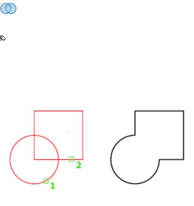
Access Methods
Button
Menu: Modify ➤ Region ➤ Union
Summary
You can combine two or more 2D regions into a single, composite region.
Regions combine only with other region objects that are located on the same
plane.
However, you can perform simultaneous UNION actions by selecting sets of
regions on different planes. UNION then produces separate, combined regions
on each plane.
List of Prompts
The following prompt is displayed.
Select objects Select the regions to be combined.
UNION | 1287

UNISOLATEOBJECTS
Quick Reference
See also:
■Control the Display of Objects
Displays previously hidden objects.
Access Methods
Menu: Tools ➤ Isolate ➤ End Object Isolation
Shortcut menu: Right-click in the drawing area and click Isolate ➤ End
Object Isolation.
Summary
Displays objects previously hidden with the ISOLATEOBJECTS on page 629 or
HIDEOBJECTS on page 586 command.
UNITS
Quick Reference
See also:
■Determine the Units of Measurement
Controls coordinate and angle display formats and precision.
Access Methods
Button
Menu: Application menu ➤ Drawing Utilities ➤ Units
Menu: Format ➤ Units
Command entry: 'units for transparent use
1288 | Chapter 21 U Commands
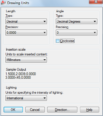
Summary
The format, precision, and other conventions to be used in displaying
coordinates, distances, and angles are set and saved in drawing template files.
These settings can also be changed in the current drawing file.
The Drawing Units dialog box is displayed.
If you enter -units at the Command prompt, options are displayed.
Drawing Units Dialog Box
Quick Reference
See also:
■Determine the Units of Measurement
Controls the displayed precision and format for coordinates and angles.
List of Options
The following options are displayed.
Drawing Units Dialog Box | 1289
Length
Specifies the current unit of measurement and the precision for the current
units.
Type
Sets the current format for units of measure. The values include Architectural,
Decimal, Engineering, Fractional, and Scientific. The Engineering and
Architectural formats produce feet-and-inches displays and assume that each
drawing unit represents one inch. The other formats can represent any
real-world unit.
Precision
Sets the number of decimal places or fractional size displayed for linear
measurements.
Angle
Specifies the current angle format and the precision for the current angle
display.
Type
Sets the current angle format.
Precision
Sets the precision for the current angle display.
The following conventions are used for the various angle measures: decimal
degrees appear as decimal numbers, grads appear with a lowercase g suffix,
and radians appear with a lowercase r suffix. The degrees/minutes/seconds
format uses d for degrees, ' for minutes, and " for seconds; for example:
123d45'56.7"
Surveyor's units show angles as bearings, using N or S for north or south,
degrees/minutes/seconds for how far east or west the angle is from direct north
or south, and E or W for east or west; for example:
N 45d0'0" E
The angle is always less than 90 degrees and is displayed in the
degrees/minutes/seconds format. If the angle is precisely north, south, east,
or west, only the single letter representing the compass point is displayed.
Clockwise
Calculates positive angles in the clockwise direction. The default direction for
positive angles is counterclockwise.
1290 | Chapter 21 U Commands

When prompted for an angle, you can point in the desired direction or enter
an angle regardless of the setting specified for Clockwise.
Insertion Scale
Controls the unit of measurement for blocks and drawings that are inserted
into the current drawing. A block or a drawing that is created with units that
are different from the units specified with this option is scaled when inserted.
The insertion scale is the ratio of the units used in the source block or drawing
and the units used in the target drawing. Select Unitless to insert the block
without scaling it to match the specified units.
NOTE In the Options dialog box, User Preferences tab, the Source Content Units
and Target Drawing Units settings are used when, either in the source block or
the target drawing, Insertion Scale is set to Unitless.
Sample Output
Displays an example of the current settings for units and angles.
Lighting
Controls the unit of measurement for the intensity of photometric lights in
the current drawing.
NOTE In order to create and use photometric lights, a unit other than Generic
must be specified from the list of options. If Insertion Scale is set to Unitless, a
warning message is displayed informing you that the rendered output might not
be as expected.
Direction
Displays the Direction Control dialog box.
Direction Control Dialog Box
Quick Reference
See also:
■Determine the Units of Measurement
Defines the angle for 0 degrees and specifies the direction in which angles are
measured.
Direction Control Dialog Box | 1291
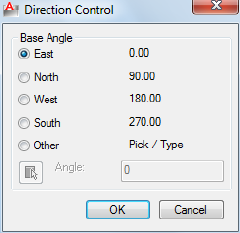
Summary
When prompted for an angle, you can locate a point in the desired direction
or enter an angle.
Base Angle
Sets the direction of the zero angle. The following options affect the entry of
angles, the display format, and the entry of polar, cylindrical, and spherical
coordinates.
East
Specifies the compass direction east (the default).
North
Specifies the compass direction north.
West
Specifies the compass direction west.
South
Specifies the compass direction south.
Other
Specifies a direction different from the points of the compass.
Angle
Specifies a value for the zero angle when Other is selected.
Pick an Angle Button
Defines the zero angle in the graphics area based on the angle of an imaginary
line that connects any two points you specify with the pointing device.
1292 | Chapter 21 U Commands
-UNITS
Quick Reference
See also:
■Determine the Units of Measurement
Controls coordinate and angle display formats and precision.
List of Prompts
The following prompts are displayed.
Report formats: (Examples)
1. Scientific 1.55E+01
2. Decimal 15.50
3. Engineering 1'-3.50"
4. Architectural 1'-3 1/2"
5. Fractional 15 1/2
Enter choice, 1 to 5 <current>: Enter a value (1-5) or press Enter
The following prompt for decimal precision is displayed if you specify the
scientific, decimal, or engineering format:
Enter number of digits to right of decimal point (0 to 8) <current>: Enter a value
(0-8) or press Enter
The following prompt for the denominator of the smallest fraction is displayed
if you specify the architectural or fractional format.
Enter denominator of smallest fraction to display
(1, 2, 4, 8, 16, 32, 64, 128, or 256) <current>: Enter a value (1, 2, 4, 8, 16, 32, 64,
128, or 256) or press Enter
The next prompt is for angle formats and precision:
Systems of angle measure: (Examples)
1. Decimal degrees 45.0000
2. Degrees/minutes/seconds 45d0'0"
3. Grads 50.0000g
4. Radians 0.7854r
5. Surveyor's units N 45d0'0" E
Enter choice, 1 to 5 <current>: Enter a value (1-5) or press Enter
Enter number of fractional places for display of angles (0 to 8) <current>: Enter
a value (0-8) or press Enter
-UNITS | 1293
The next prompt is for the direction for angle 0:
Direction for angle 0:
East 3 o'clock = 0
North 12 o'clock = 90
West 9 o'clock = 180
South 6 o'clock = 270
Enter direction for angle 0 <current>: Enter a value or press Enter
The default direction for 0 degrees is to the east quadrant, or 3 o'clock. The
default direction for positive angular measurement is counterclockwise.
Measure angles clockwise? [Yes/No] <current>: Enter y or n or press Enter
UPDATEFIELD
Quick Reference
See also:
■Update Fields
Manually updates fields in selected objects in the drawing.
Access Methods
Button
Ribbon: Insert tab ➤ Data panel ➤ Update Fields
Menu: Tools ➤ Update Fields
Shortcut menu: With any text command active and a field selected,
right-click and click Update Field.
Summary
You can update a field manually when you want to see the latest value. With
Date fields, you must update them manually, they never update automatically.
1294 | Chapter 21 U Commands
UPDATETHUMBSNOW
Quick Reference
See also:
■Switch Between Open Drawings
Manually updates thumbnail previews for named views, drawings, and layouts.
Summary
The UPDATETHUMBNAIL system variable controls how the thumbnail
previews are updated. The UPDATETHUMBSNOW command updates the
following:
■Sheets, sheet views, and model space views thumbnails in the Sheet Set
Manager
■Quick View images
NOTE The thumbnail previews displayed in the Sheet Set Manager is not available
in AutoCAD for Mac. This command is made available for use in mixed
environments.
UPLOAD
Quick Reference
See also:
■Use AutoCAD WS for Drawing File Collaboration
Uploads the current drawing to AutoCAD WS and controls whether to
automatically upload changes.
Access Methods
Button
UPDATETHUMBSNOW | 1295
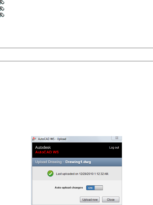
Ribbon: Online tab ➤ Upload panel ➤ Upload
Menu: File ➤ AutoCAD WS ➤ Upload
Toolbar: Online
Summary
The Upload Drawing dialog box on page 1296 is displayed. You must save the
drawing before you can continue with this command.
NOTE You may first be prompted to log in to AutoCAD WS. If you do not have
an account, click Create an Account and follow the on-screen instructions.
Upload Drawing Dialog Box
Quick Reference
See also:
■Use AutoCAD WS for Drawing File Collaboration
Uploads the current drawing to AutoCAD WS and controls whether to
automatically upload changes.
Summary
When you upload a drawing, you can indicate whether subsequent changes
to the local file are automatically uploaded each time the drawing is saved in
AutoCAD.
1296 | Chapter 21 U Commands

List of Options
The following options are displayed.
Auto-Upload Changes Controls whether to automatically upload the current
drawing every time it is saved.
Upload Now Uploads the current drawing. If the drawing has been previously
uploaded, the current drawing replaces the latest version of the online copy.
Hide Hides the dialog box. Use UPLOAD on page 1295 to redisplay the dialog
box.
Retry Reattempts to upload the drawing if previous attempt failed.
UPLOADFILES
Quick Reference
See also:
■Use AutoCAD WS for Drawing File Collaboration
Uploads selected files to AutoCAD WS.
Access Methods
Button
Ribbon: Online tab ➤ Upload panel ➤ Upload Multiple Files
Menu: File ➤ AutoCAD WS ➤ Upload Multiple Files
Toolbar: Online
Summary
The Choose Files to Upload dialog box on page 1298 is displayed.
NOTE You may first be prompted to log in to AutoCAD WS. If you do not have
an account, click Create an Account and follow the on-screen instructions.
UPLOADFILES | 1297
Choose Files to Upload Dialog Box
Quick Reference
See also:
■Use AutoCAD WS for Drawing File Collaboration
Uploads selected files to AutoCAD WS.
Summary
The Choose Files to Upload dialog box is a standard file selection dialog box
on page 826. Select up to 10 files from your local hard drive and network drives
to upload to AutoCAD WS without opening them in AutoCAD. You can upload
all types of files.
1298 | Chapter 21 U Commands
V Commands
VIEW
Quick Reference
See also:
■Save and Restore Views
Saves and restores named model space views, layout views, and preset views.
Access Methods
Button
Ribbon: View tab ➤ View panel ➤ Named Views
Menu: View ➤ Named Views
Toolbar: View
Summary
The View Manager on page 1300 is displayed.
If you enter -view at the Command prompt, options are displayed.
NOTE The VIEW command cannot be used transparently.
22
1299
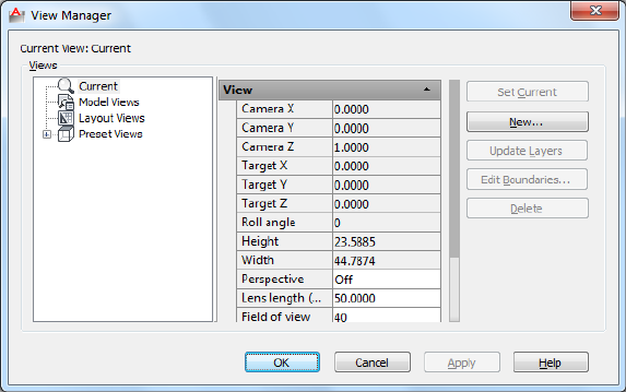
View Manager
Quick Reference
See also:
■Save and Restore Views
Creates, sets, renames, modifies, and deletes named views, including model
named views and camera views, layout views, and preset views.
Summary
List of Options
The following options are displayed.
Views
Displays a list of the available views. You can expand each node (except for
the Current node) to display its views.
■Current. Displays the current view and its View and Clipping properties
■Model Views. Displays a list of named views and cameras, and lists General,
View, and Clipping properties for a selected view.
1300 | Chapter 22 V Commands
■Layout Views. Displays a list of viewports on a layout that define a view,
and lists General and View properties for a selected view.
■Preset Views. Displays a list of orthogonal and isometric views, and lists
the General properties for a selected view.
General
The following properties are available:
Name Displays the name of a selected camera, model, or layout view.
UCS For model and layout views, displays the name of the user coordinate
system saved with the named view.
Restore Ortho UCS For preset views, restores the associated UCS when an
orthographic view is current. This option sets the UCSORTHO system variable.
Set Relative To For preset views, specifies the base coordinate system for
defining the orthographic view. The UCSBASE system variable controls the
orientation of orthographic UCSs relative to the WCS or to named UCSs.
Changing this setting also changes the orientation of the predefined
orthographic UCSs.
Layer Snapshot For model views and layout views, specifies whether the
current layer on/off settings are stored with the selected view.
Annotation Scale Specifies the annotation scale saved with the view.
Animation
View Type For model and layout views, displays the view type assigned to
the named view.
Transition Type For model and layout views, displays the transition type
assigned to the named view and is used when playing back the view.
Transition Duration For model and layout views, displays the length of time
for the transition that is assigned to the named view and is used when playing
back the view.
Movement For model views only, displays the movement assigned to a named
view that is assigned the Cinematic view type.
Playback Duration For model and layout views, displays the length of time
that the animation takes to play back.
Distance For model views only, displays the distance used for the Cinematic
view type.
View Manager | 1301
Distance Up For model views only, displays the distance the camera can move
upward. Applies to the Crane Up movement type.
Distance Down For model views only, displays the distance the camera can
move downward. Applies to the Crane Down movement type.
Distance Forward For model views only, displays the distance the camera
can move forward. Applies to the Crane Down movement type.
Distance Back For model views only, displays the distance the camera can
move backward. Applies to the Crane Up movement type.
Degrees Left / Right For model views only, displays the amount of rotation
around the Z axis. Applies to Look and Orbit movement types.
Degrees Up / Down For model views only, displays the amount of rotation
around the XY plane. Applies to Look and Orbit movement types.
Distance (Pan) Left / Right For layout views only, displays the distance the
camera can pan left and right. Applies to Pan + Zoom movement type.
Distance (Pan) Up / Down For layout views only, displays the distance the
camera can pan up and down. Applies to Pan + Zoom movement type.
Percentage In / Out For layout views only, displays the percentage the camera
can zoom in and out. Applies to Pan + Zoom movement type.
Current Position For model and layout views, displays the current position
of the camera.
Always Look at Pivot Point For model views only, displays if the view is
locked to the center-of-interest. Applies to Track and Crane movement types.
View
Camera X For current and model views only, displays the X coordinate of the
view’s camera.
Camera Y For current and model views only, displays the Y coordinate of the
view’s camera.
Camera Z For current and model views only, displays the Z coordinate of the
view’s camera.
Target X For current and model views only, displays the X coordinate of the
view's target.
Target Y For current and model views only, displays the Y coordinate of the
view’s target.
1302 | Chapter 22 V Commands
Target Z For current and model views only, displays the Z coordinate of the
view’s target.
Roll angle Displays the rotation angle of the view within your viewing plane,
which is a plane parallel to your monitor's screen.
Height Specifies the height of the view.
Width Specifies the width of the view.
Perspective For current and model views, specifies whether perspective view
is on.
Lens Length (mm) For all views except layouts, specifies the lens length (in
millimeters). Changing this value changes the Field of View setting accordingly.
Field of View For all views except layouts, specifies the horizontal field of
view (in current angle units). Changing this value changes the Lens Length
setting accordingly.
Clipping
Front Plane Specifies the offset value for the front clipping plane if front
clipping is enabled for the view.
Back Plane Specifies the offset value for the back clipping plane if back
clipping is enabled for the view.
Clipping Sets clipping options.
Set Current
Restores the selected view.
New
Displays the New View dialog box on page 1304.
Update Layers
Updates layer information saved with a selected view to match the layer
visibility in the current model space or layout viewport.
Edit Boundaries
Displays the selected view, with the rest of the drawing area displayed in a
lighter color to show the boundaries of the named view.
Delete
Deletes a selected view.
View Manager | 1303
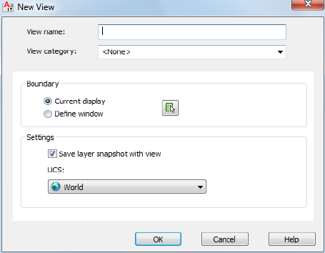
New View Dialog Box
Quick Reference
See also:
■Save and Restore Views
Creates a named view.
List of Options
The following options are displayed.
View Name
Specifies the view’s name.
View Category
Specifies a category for the named view.
View Type
Specifies the type of view for the named view. Recorded Walk is available for
model space views only.
Boundary
Defines the area of the drawing that is assigned to the named view.
Current Display
1304 | Chapter 22 V Commands
Uses the current display as the new view.
Define Window
Uses a window as the new view, which you define in the drawing area by
specifying two opposite corners.
Define View Window Button
Temporarily closes the New View and View Manager dialog boxes so that you
can use the pointing device to define the opposite corners of the New View
window.
Settings
Provides options for saving settings with the named view.
Save Layer Snapshot with View
Saves the current layer visibility settings with the new named view.
UCS
For model and layout views, specifies a UCS to save with the new view.
List of Tabs
The following tabs are displayed.
■View Properties tab
■Shot Properties tab
-VIEW
Quick Reference
See also:
■Save and Restore Views
List of Prompts
The following prompts are displayed.
Enter an option [?/Delete/Orthographic/Restore/Save/sEttings/Window]:
?—List Views Lists the named views in the drawing.
-VIEW | 1305
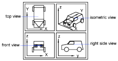
The list includes the name of each specified view and the space in which it
was defined. M designates model space, and P designates paper space.
Delete Deletes one or more named views.
Orthographic Restores the predefined orthographic view you specify to the
current viewport.
The view orientation of the specified orthographic view is based on the
UCSBASE system variable, which is set to the world coordinate system by
default. When one of the orthographic views is restored, the program zooms
to the extents in the current viewport.
Restore Restores the view you specify to the current viewport. If a UCS setting
was saved with the view, it is also restored.
The center point and magnification of the saved view are also restored. If you
restore a model space view while working in paper space, you are prompted
to select a viewport in which to restore that view.
Select the viewport by clicking its border. The viewport you select must be on
and active. The program switches to model space and restores the view in the
selected viewport.
If you restore a paper space view while working in model space in a layout
tab, the program switches to paper space and restores the view. You can't
restore a paper space view if you are working in the Model tab.
Save Saves the display in the current viewport using the name you supply.
The current value of the UCSVIEW system variable is displayed when you save
a view. To change the setting and turn this option on or off, use the UCS
option of VIEW.
Settings Specifies various settings for the VIEW command.
Layer Snapshot Saves the current layer visibility settings with the new named
view.
1306 | Chapter 22 V Commands
UCS Determines whether the current UCS and elevation settings are saved
when a view is saved. (UCSVIEW system variable)
Window Saves a portion of the current display as a view.
Restoring such a view may display objects outside the window you specified
because the shape of the window may differ from that of the viewport in
which you are restoring the view. However, plotting the view plots only the
objects inside the window, not the entire viewport display.
VIEWGO
Quick Reference
See also:
■Save and Restore Views
Restores a named view.
Summary
Restores the view you specify to the current viewport. If a layer state, UCS,
live section, visual style, or background setting was saved with the view, the
settings are also restored.
VIEWPLOTDETAILS
Quick Reference
See also:
■Overview of Plotting
Displays information about completed plot and publish jobs.
VIEWGO | 1307

Access Methods
Button
Ribbon: Output tab ➤ Plot panel ➤ View Details
Menu: File ➤ View Plot and Publish Details
Summary
The Plot and Publish Details dialog box is displayed.
You can view detailed information about all completed plot and publish jobs,
or just the errors that have occurred. You can also copy the information
displayed in the dialog box to the Clipboard.
Plot and Publish Details Dialog Box
Quick Reference
See also:
■Overview of Plotting
Displays information about plotting and publishing jobs that have been
completed in the current session.
1308 | Chapter 22 V Commands
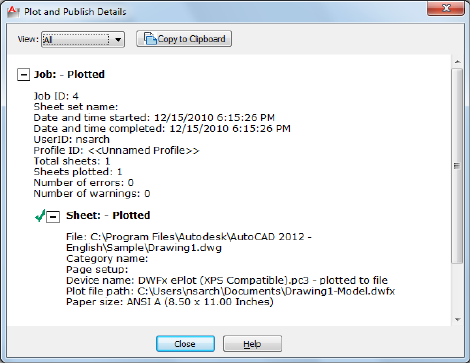
Summary
Plot and publish details are also available through the Plot and Publish status
bar icon shortcut menu.
List of Options
The following options are displayed.
View
Specifies what is displayed. You can also right-click in the details area and
click View Errors Only or View All to change this setting.
All Displays information about all completed plot and publish jobs and sheets
within those jobs.
Errors Lists errors that have occurred as jobs were plotted or published.
Copy to Clipboard
Copies all highlighted text to the Clipboard.
Details Area
Lists details of completed plot and publish jobs.
Plot and Publish Details Dialog Box | 1309
Plot and Publish Status Bar Icon Shortcut Menu
Quick Reference
See also:
■Overview of Plotting
Summary
When background plotting is enabled, provides options for cancelling the
sheet that is currently being plotted, cancelling the entire plot or publish job,
viewing the Plot and Publish Details dialog box, and viewing the most recently
created Design Web Format (DWF™) file. Right-click any of the plot and publish
icons in the tray on the right side of the status bar. These icons are described
in the following table.
A plot or publish job is currently being processed in the background
A plotting details report is available. No errors and warnings occurred.
A plotting details report is available. Errors and warnings occurred.
List of Options
The following options are displayed.
Cancel Sheet Cancels the sheet that is currently being plotted.
Cancel Entire Job Cancels the entire plot or publish job.
View Plot and Publish Details Displays Plot and Publish Details dialog box.
View <filename>.dwf Opens the most recently created DWF file.
Enable Balloon Notification Turns on balloon notification of the status of
jobs you have plotted and published.
1310 | Chapter 22 V Commands
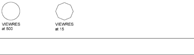
VIEWRES
Quick Reference
See also:
■Change Views
Sets the resolution for objects in the current viewport.
Summary
The model is regenerated.
VIEWRES controls the appearance of circles, arcs, splines, and arced polylines
using short vectors. The greater the number of vectors, the smoother the
appearance of the circle or arc. For example, if you create a very small circle
and then zoom in, it might appear to be a polygon. Using VIEWRES to increase
the zoom percentage and regenerate the drawing updates and smooths the
circle's appearance.
NOTE Increasing the zoom percentage in VIEWRES may increase the time it takes
to regenerate the drawing.
When a named (paper space) layout is made current for the first time and a
default viewport is created in the layout, the viewing resolution for this initial
viewport is the same as the viewing resolution for the Model layout viewport.
The VIEWRES setting is saved in the drawing. To change the default for new
drawings, consider specifying the VIEWRES setting in the template files on
which you base your new drawings.
VIEWRES | 1311
VPCLIP
Quick Reference
See also:
■Create and Modify Layout Viewports
Clips layout viewport objects and reshapes the viewport border.
Access Methods
Button
Ribbon: View tab ➤ Viewports panel ➤ Clip
Menu: Modify ➤ Clip ➤ Viewport
Toolbar: Viewports
Shortcut menu: Select the viewport to clip. Right-click in the drawing area
and choose Viewport Clip.
Summary
You can either select an existing object to designate as the new boundary, or
specify the points of a new boundary. The new boundary does not clip the
old boundary, it redefines it.
TIP Use the generic CLIP on page 211 command to clip images, external references,
viewports, and underlays.
List of Prompts
The following prompts are displayed.
Clipping Object Specifies an object to act as a clipping boundary. Objects
that are valid as clipping boundaries include closed poly-lines, circles, ellipses,
closed splines, and regions.
Polygonal Draws a clipping boundary. You can draw line segments or arc
segments by specifying points. The following prompt is displayed:
1312 | Chapter 22 V Commands
The descriptions of the Next Point, Arc, Close, Length, and Undo options
match the descriptions of the corresponding options in the PLINE command.
Delete Deletes the clipping boundary of a selected viewport. This option is
available only if the selected viewport has already been clipped. If you clip a
viewport that has been previously clipped, the original clipping boundary is
deleted, and the new clipping boundary is applied.
VPLAYER
Quick Reference
See also:
■Freeze Specified Layers in a Layout Viewport
Sets layer visibility within viewports.
List of Prompts
The following prompts are displayed.
Enter an option [? on page 1313/Color on page 1313/Ltype/LWeight/PStyle on
page 1314/TRansparency on page 1314/Freeze on page 1315/Thaw on page 1315/Reset
on page 1315/Newfrz on page 1315/Vpvisdflt on page 1315]:
In the Model layout, the VPLAYER command has two options.
Enter an option [Newfrz/Vpvisdflt]:
?—List Frozen Layers
Displays the names of frozen layers in a selected viewport.
Color
Changes the color associated with a layer.
True Color Specifies a true color to use for the selected object.
Color Book Specifies a color from a loaded color book to use for the selected
object.
All Applies the changes in all viewports.
Select Applies the changes in selected viewports.
Current Applies the changes in the current viewport only.
VPLAYER | 1313
Ltype
Changes the linetype associated with a layer.
■All on page 1313
■Select on page 1313
■Current on page 1313
Lweight
Changes the lineweight associated with a layer.
If you enter a lineweight that is not valid, the current lineweight is set to the
nearest fixed lineweight value.
If you want to plot an object with a custom width not found in the list of
fixed lineweight values, you can use the Plot Style Table Editor to customize
plotted lineweights.
■All on page 1313
■Select on page 1313
■Current on page 1313
Pstyle
Sets the plot style assigned to a layer. This option is not available if you are
using color-dependent plot styles in the current drawing (the PSTYLEPOLICY
on page 1627 system variable is set to 1). See Use Plot Styles to Control Plotted
Objects in the User’s Guide.
■All on page 1313
■Select on page 1313
■Current on page 1313
Transparency
Changes the transparency level associated with a layer.
■All on page 1313
■Select on page 1313
■Current on page 1313
1314 | Chapter 22 V Commands
Freeze
Freezes a layer or set of layers in one or more viewports. Objects on frozen
layers are not displayed, regenerated, or plotted.
■All on page 1313
■Select on page 1313
■Current on page 1313
■Except Current. Freezes specified layers in all viewports across all layouts,
except in the current viewport.
Thaw
Thaws layers in specific viewports.
■All on page 1313
■Select on page 1313
■Current on page 1313
Reset
Sets the visibility of layers in specified viewports to their current default setting.
■All on page 1313
■Select on page 1313
■Current on page 1313
Newfrz (New Freeze)
Creates new layers that are frozen in all viewports.
Vpvisdflt (Viewport Visibility Default)
Thaws or freezes the specified layers in subsequently created viewports.
VPMAX
Quick Reference
See also:
■Access Model Space from a Layout Viewport
VPMAX | 1315
Expands the current layout viewport for editing.
Access Methods
Toolbar: Status bar ➤ Maximize Viewport
Shortcut menu: Select a named layout viewport to mazimize. Right-click
and click Maximize Viewport.
Pointing device: Double-click a named layout viewport.
Summary
The viewport is expanded to fill the screen and switched to model space for
editing.
VPMIN
Quick Reference
See also:
■Access Model Space from a Layout Viewport
Restores the current layout viewport.
Access Methods
Toolbar: Status bar ➤ Minimize Viewport
Shortcut menu: Select a named layout viewport to mazimize. Right-click
and click Minimize Viewport.
Pointing device: Double-click outside of the maximized viewport.
Summary
The center point and magnification are returned to the settings that were in
effect before the viewport was maximized.
1316 | Chapter 22 V Commands
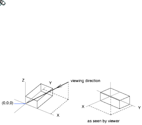
VPOINT
Quick Reference
See also:
■Define a 3D View with Coordinate Values or Angles
Sets the viewing direction for a 3D visualization of the drawing.
Access Methods
Menu: View ➤ 3D Views ➤ Viewpoint
List of Prompts
The following prompts are displayed.
Specify a view pointor [Rotate] <display compass and tripod>: Specify a point,
enter r, or press Enter to display a compass and axis tripod
View Point Creates a vector that defines a direction from which the drawing
can be viewed. The view defined is as if the viewer is looking from the point
back at the origin (0,0,0).
Rotate Specifies a new viewing direction using two angles.
■Enter angle in XY plane from X axis.
The first angle is specified with respect to the X axis, in the XY plane.
■Enter angle from XY plane.
The second angle is specified up or down from the XY plane.
VPOINT | 1317
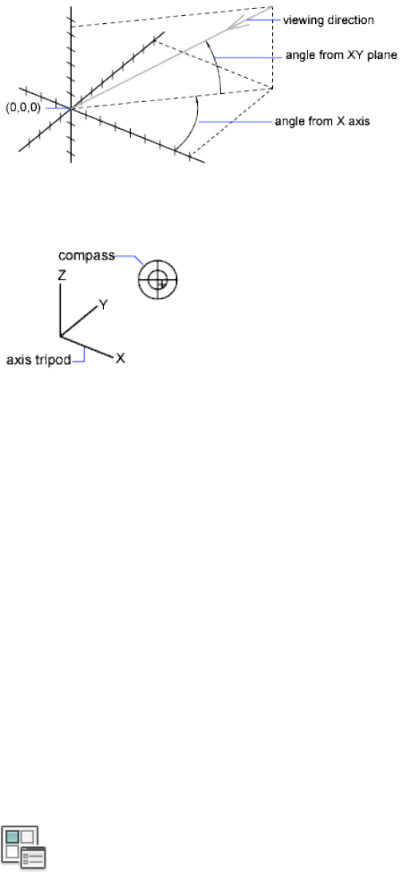
Compass and Axis Tripod Displays a compass and axis tripod, which you
use to define a viewing direction in the viewport.
The compass is a two-dimensional representation of a globe. The center point
is the north pole (0,0,n), the inner ring is the equator (n,n,0), and the entire
outer ring is the south pole (0,0,-n).
As you move the crosshairs, the axis tripod rotates to conform to the viewing
direction indicated on the compass. To select a viewing direction, move your
pointing device to a location on the globe and click.
VPORTS
Quick Reference
See also:
■Set Model Space Viewports
Creates multiple viewports in model space or paper space.
Access Methods
Button
1318 | Chapter 22 V Commands

Ribbon: View tab ➤ Viewports panel ➤ Named Viewports
Menu: View ➤ Viewports ➤ New Viewports, Named Viewports
Toolbar: Layouts
Summary
The Viewports dialog box is displayed.
If you enter -vports at the Command prompt, options are displayed.
Viewports Dialog Box
Quick Reference
See also:
■Set Model Space Viewports
Creates new viewport configurations, or names and saves a model space
viewport configuration.
Summary
The options available depend on whether you are configuring model space
viewports (on the Model layout) or layout viewports (on a named (paper space)
layout).
List of Options
The following options are displayed.
Viewports Dialog Box | 1319
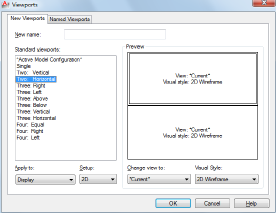
New Viewports Tab—Model Space (Viewports Dialog Box)
New Name
Specifies a name for the new model space viewport configuration. If you do
not enter a name, the viewport configuration is applied but not saved. If a
viewport configuration is not saved, it cannot be used in a layout.
Standard Viewports
Lists and sets the standard viewport configurations, including CURRENT,
which is the current configuration.
Preview
Displays a preview of the viewport configuration you select and the default
views assigned to each individual viewport in the configuration.
Apply To
Applies the model space viewport configuration to the entire display or to the
current viewport.
■Display: Applies the viewport configuration to the entire Model tab display.
■Current Viewport: Applies the viewport configuration to the current viewport
only.
1320 | Chapter 22 V Commands
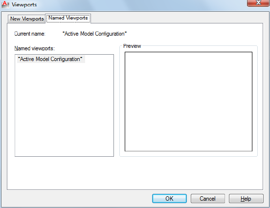
Setup
Specifies either a 2D or a 3D setup. When you select 2D, the new viewport
configuration is initially created with the current view in all of the viewports.
When you select 3D, a set of standard orthogonal 3D views is applied to the
viewports in the configuration.
Change View To
Replaces the view in the selected viewport with the view you select from the
list. You can choose a named view, or if you have selected 3D setup, you can
select from the list of standard views. Use the Preview area to see the choices.
Named Viewports Tab—Model Space (Viewports Dialog Box)
Lists all saved model viewport configurations in the drawing.
Current Name
Displays the name of the current viewport configuration.
New Viewports Tab—Layouts (Viewports Dialog Box)
Standard Viewports Displays a list of standard viewport configurations and
configures layout viewports.
Preview Displays a preview of the viewport configuration you select and the
default views assigned to each individual viewport in the configuration.
Viewports Dialog Box | 1321
Viewport Spacing
Specifies the spacing you want to apply between the layout viewports you are
configuring.
Setup Specifies either a 2D or a 3D setup. When you select 2D, the new
viewport configuration is initially created with the current view in all of the
viewports. When you select 3D, a set of standard orthogonal 3D views is
applied to the viewports in the configuration.
Change View To Replaces the view in the selected viewport with the view
you select from the list. You can choose a named view, or if you have selected
3D setup, you can select from the list of standard views.
Named Viewports Tab—Layouts (Viewports Dialog Box)
Displays any saved and named model space viewport configurations for you
to use in the current layout. You cannot save and name a layout viewport
configuration.
-VPORTS
Quick Reference
See also:
■Set Model Space Viewports
Creates multiple viewports in model space or paper space.
Summary
The command prompts available depend on whether you are configuring
model viewports (on the Model tab) or layout viewports (on a layout tab).
-VPORTS - Model Space Viewports
Quick Reference
See also:
■Set Model Space Viewports
1322 | Chapter 22 V Commands
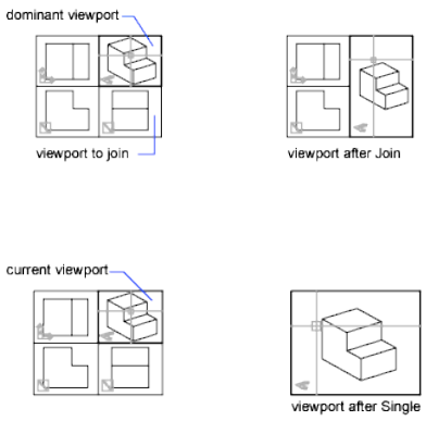
Creates multiple viewports in model space.
Summary
The number and layout of active viewports and their associated settings are
called viewport configurations.
List of Prompts
The following prompts are displayed.
Enter an option [Save/Restore/Delete/Join/Single/?/2/3/4] <3>: Enter an option
Save Saves the current viewport configuration using a specified name.
Restore Restores a previously saved viewport configuration.
Delete Deletes a named viewport configuration.
Join Combines two adjacent model viewports into one larger viewport.
The two model viewports must share a common edge of the same length. The
resulting viewport inherits the view of the dominant viewport.
Single Returns the drawing to a single viewport view, using the view from
the current viewport.
?—List Viewport Configurations Displays the identification numbers and
screen positions of the active viewports.
The lower-left and upper-right corners of the viewport define its location. For
these corners, values between 0.0,0.0 (for the lower-left corner of the drawing
area) and 1.0,1.0 (for the upper-right corner) are used. The current viewport
is listed first.
-VPORTS | 1323
2Divides the current viewport in half.
3Divides the current viewport into three viewports.
The Horizontal and Vertical options split the area into thirds. The Above,
Below, Left, and Right options specify where the larger viewport is placed.
4Divides the current viewport into four viewports of equal size.
-VPORTS - Layout Viewports
Quick Reference
See also:
■Create and Modify Layout Viewports
Creates multiple viewports in named (paper space) layouts.
Summary
The number and layout of active viewports and their associated settings are
called viewport configurations.
List of Prompts
The following prompts are displayed.
Specify corner of viewport or [ON/OFF/Fit/Shadeplot/Lock/Restore/Layer/2/3/4]
<Fit>: Specify a point or enter an option
On Turns on a viewport, making it active and making its objects visible.
Off Turns off a viewport. When a viewport is off, its objects are not displayed,
and you cannot make that viewport current.
Fit Creates one viewport that fills the available display area. The actual size
of the viewport depends on the dimensions of the paper space view.
Shadeplot Specifies how viewports in layouts are plotted.
■As Displayed: Plots the same way it is displayed
■Wireframe: Plots wireframe regardless of display
■Hidden: Plots with hidden lines removed regardless of display
1324 | Chapter 22 V Commands
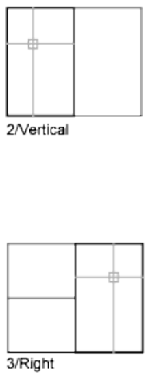
Lock Locks the current viewport. This is similar to layer locking.
Object Creates a nonrectangular layout viewport from a closed polyline,
ellipse, spline, region, or circle. The polyline you specify must be closed and
contain at least three vertices. It can be self-intersecting, and it can contain
arcs as well as line segments.
Polygonal Creates a nonrectangular layout viewport defined by a series of
line and arc segments.
The descriptions of the Next Point, Arc, Close, Length, and Undo options
match the descriptions of the corresponding options in the PLINE command.
Restore Restores a previously saved viewport configuration.
Layer Resets layer property overrides for the selected viewport to their global
layer properties.
2Divides the current viewport in half.
3Divides the current viewport into three viewports.
Horizontal and Vertical split the area into thirds. The other options create one
large viewport in half the available area and two smaller ones in the other
half. Above, Below, Left, and Right specify where the larger viewport is placed.
4Divides the current viewport into four viewports of equal size.
-VPORTS | 1325
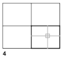
VSLIDE
Quick Reference
See also:
■View Slides
Displays an image slide file in the current viewport.
Summary
The Select Slide File dialog box, a standard file selection dialog box, is displayed.
To display a slide in a slide library (.slb extension), set FILEDIA to 0, enter
vslide, and then specify the slide library file name followed by the slide file
name enclosed in parentheses: slidelibrary (slide).
When you view slides of images shaded with the -SHADE command in a larger
window or a higher resolution than was used for creating the slide, black lines
may appear interspersed among the lines of the shaded image. To avoid this
situation, use a full screen that is set at the highest resolution when creating
the slides.
1326 | Chapter 22 V Commands
VTOPTIONS
Quick Reference
See also:
■Pan or Zoom a View
Displays a change in view as a smooth transition.
Summary
The View Transitions dialog box on page 1327 is displayed.
View Transitions Dialog Box
Quick Reference
See also:
■Pan or Zoom a View
Controls when smooth view transitions are used.
Summary
Sets the options for smooth view transitions.
List of Options
The following options are displayed.
Enable Animation for Pan and Zoom Makes a smooth view transition during
panning and zooming. (VTENABLE system variable)
Enable Animation When View Rotates Makes a smooth view transition
when the view angle is changed. (VTENABLE system variable)
Enable Animation During Scripts Makes smooth view transitions while a
script is running. (VTENABLE system variable)
Transition Speed Sets the speed of a smooth view transition in milliseconds.
VTOPTIONS | 1327
Performance
Set the minimum speed for a smooth view transition in frames per second.
When a smooth view transition cannot maintain this speed, an instant
transition is used to preserve performance.
1328 | Chapter 22 V Commands

W Commands
WBLOCK
Quick Reference
See also:
■Create Drawing Files for Use as Blocks
Saves selected objects or converts a block to a specified drawing file.
Access Methods
Button
Ribbon: Insert tab ➤ Block Definition panel ➤ Write Block
Summary
The Write Block dialog box is displayed.
Entering -wblock at the Command prompt displays a standard file selection
dialog box in which to specify a name for the new drawing file, followed by
command prompts. If FILEDIA is set to 0, the standard file selection dialog box
is suppressed.
23
1329
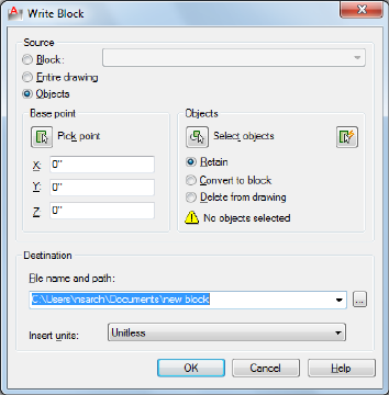
Write Block Dialog Box
Quick Reference
See also:
■Create Drawing Files for Use as Blocks
Saves selected objects or converts a block to a specified drawing file.
Summary
The Write Block dialog box provides a convenient method for saving part of
the current drawing to a different drawing file, or saving a specified block
definition as a separate drawing file.
List of Options
The following options are displayed.
Source
Specifies blocks and objects, saves them as a file, and specifies insertion points.
Block
Specifies an existing block to save as a file. Select a name from the list.
Entire Drawing
1330 | Chapter 23 W Commands
Selects current drawing to save as another file.
Objects
Selects objects to save as a file. Specify a base point and select objects below.
Base Point
Specifies a base point for the block. The default value is 0,0,0.
Pick Point
Temporarily closes the dialog box so that you can specify an insertion base
point in the current drawing.
X
Specifies the X coordinate value for the base point.
Y
Specifies the Y coordinate value for the base point.
Z
Specifies the Z coordinate value for the base point.
Objects
Sets the effect of block creation on objects used to create a block.
Retain
Retains the selected objects in the current drawing after saving them as a file.
Convert to Block
Converts the selected object or objects to a block in the current drawing after
saving them as a file.
Delete from Drawing
Deletes the selected objects from the current drawing after saving them as a
file.
Select Objects Button
Temporarily closes the dialog box so that you can select one or more objects
to save to the file.
Quick Select Button
Opens the Quick Select dialog box, which you can use to filter your selection
set.
Write Block Dialog Box | 1331
Objects Selected
Indicates the number of objects selected.
Destination
Specifies the new name and location of the file and the units of measurement
to be used when the block is inserted.
File Name and Path
Specifies a file name and path where the block or objects will be saved.
[...]
Displays a standard file selection dialog box.
Insert Units
Specifies the unit value to be used for automatic scaling when the new file is
dragged from DesignCenter™ or inserted as a block in a drawing that uses
different units. Select Unitless if you do not want to automatically scale the
drawing when you insert it. See INSUNITS.
-WBLOCK
Quick Reference
See also:
■Create Drawing Files for Use as Blocks
Saves selected objects or converts a block to a specified drawing file.
Summary
If FILEDIA is set to 1, entering -wblock at the Command prompt displays a
standard file selection dialog box in which to specify a name for the new
drawing file. If FILEDIA is set to 0, entering -wblock at the Command prompt
displays a prompt. The new drawing is saved in the file format that is specified
in Save As on the Open and Save tab in the Options dialog box.
After the file is created, the selected objects are deleted from the drawing. You
can use OOPS to restore the objects.
1332 | Chapter 23 W Commands
In the new drawing, the world coordinate system (WCS) is set parallel to the
user coordinate system (UCS).
List of Prompts
The following prompts are displayed.
Enter name of output file:
Enter name of existing block or
[= (block=output file)/* (whole drawing)] <define new drawing>:
Existing Block Writes that block to a file. You cannot enter the name of an
external reference (xref) or one of its dependent blocks.
=Specifies that the existing block and the output file have the same name.
*Writes the entire drawing to the new output file, except for unreferenced
symbols. Model space objects are written to model space, and paper space
objects are written to paper space.
WHOHAS
Quick Reference
See also:
■Open a Drawing
Displays ownership information for opened drawing files.
Summary
You can use WHOHAS to track which users have certain drawing files open.
After you select a file, the ownership information is displayed at the Command
prompt. The information includes the current user's computer name, login
ID, and full name (if available) and the date and time the drawing file was
opened.
NOTE Similar information is displayed automatically when you try to open a
drawing file that another user has already opened.
WHOHAS | 1333
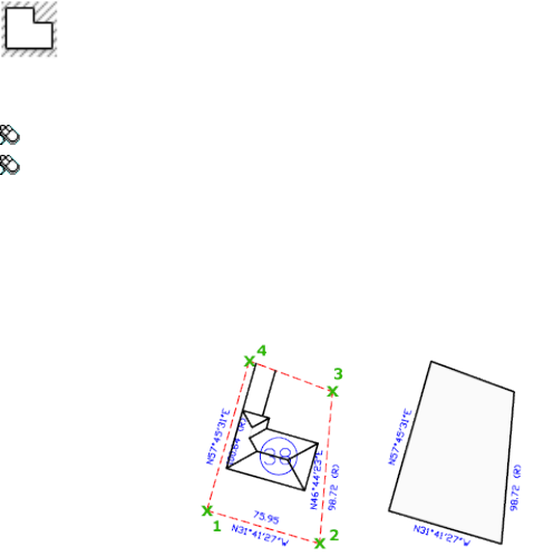
The information displayed by WHOHAS is stored in a temporary DWL (drawing
lock) file. A DWL file is deleted when the file is closed.
WIPEOUT
Quick Reference
See also:
■Create a Blank Area to Cover Objects
Creates a wipeout object, and controls whether wipeout frames are displayed
in the drawing.
Access Methods
Button
Ribbon: Home tab ➤ Draw panel ➤ Wipeout
Menu: Draw ➤ Wipeout
Summary
Creates a polygonal area that masks underlying objects with the current
background color. The wipeout area is bounded by a frame that you can turn
on for editing and turn off for plotting.
List of Prompts
The following prompts are displayed.
1334 | Chapter 23 W Commands
Specify first point on page 1335 or [Frames on page 1335/Polyline on page 1335]
<Polyline>.
First Point Determines the polygonal boundary of the wipeout object from
a series of points.
Frames Determines whether the edges of all wipeout objects are displayed or
hidden.
Polyline Determines the polygonal boundary of the wipeout objects from a
selected polyline.
Erase Polyline Enter y to erase the polyline that was used to create the wipeout
object. Enter n to retain the polyline.
WMFIN
Quick Reference
See also:
■Insert WMF Files
Imports a Windows metafile.
Access Methods
Button
Menu: Insert ➤ Windows Metafile
Summary
WMF files can contain both vector and raster information, however only the
vector information is imported. WMF files are inserted as a block reference
and can be resized and printed without losing resolution.
The Import WMF dialog box (a standard file selection dialog box) is displayed.
In the Import WMF dialog box, if you click Tools ➤ Options, the WMF In
Options dialog box is displayed. You can also open this dialog box directly
by using WMFOPTS.
WMFIN | 1335
List of Prompts
The following prompts are displayed.
Specify insertion point on page 1336 or [Scale on page 1336/X on page 1336/Y on
page 1336/Z on page 1336/Rotate on page 1336/PScale on page 1337/PX on page 1337/PY
on page 1337/PZ on page 1337/PRotate on page 1337]: Specify a point or enter an option
Insertion Point
Places a copy of the metafile with its base point at the specified insertion
point.
X Scale Factor Sets the X and Y scale factors.
All X and Y dimensions of the metafile are multiplied by the X and Y scale
factors supplied. The metafile is rotated by the angle specified, using the
insertion point as the center of rotation.
Corner Defines the X and Y scales at the same time, using the insertion point
and another point as the corners of a box. The X and Y dimensions of the box
become the X and Y scale factors. The insertion point is the first corner.
The rotation angle sets the angle of the WMF file.
XYZ Scales the metafile in all three dimensions.
If you enter c, you specify a corner point. The specified point and the insertion
point determine the X and Y scale factors for the WMF file.
The rotation angle sets the angle of the WMF file.
Scale
Sets the scale factor for the X, Y, and Z axes. The scale for the Z axis is the
absolute value of the specified scale factor.
X
Sets the X scale factor.
Y
Sets the Y scale factor.
Z
Sets the Z scale factor.
Rotate
Sets the angle of insertion for the WMF file.
■X Scale Factor on page 1336
■Corner on page 1336
■XYZ on page 1336
1336 | Chapter 23 W Commands
PScale
Sets the temporary scale factor for the X, Y, and Z axes to control the display
of the WMF file as it is dragged into position.
■X Scale Factor on page 1336
■Corner on page 1336
■XYZ on page 1336
PX
Sets the temporary scale factor for the X axis to control the display of the WMF
file as it is dragged into position.
■X Scale Factor on page 1336
■Corner on page 1336
■XYZ on page 1336
PY
Sets the temporary scale factor for the Y axis to control the display of the WMF
file as it is dragged into position.
■X Scale Factor on page 1336
■Corner on page 1336
■XYZ on page 1336
PZ
Sets the temporary scale factor for the Z axis to control the display of the WMF
file as it is dragged into position.
■X Scale Factor on page 1336
■Corner on page 1336
■XYZ on page 1336
PRotate
Sets the temporary rotation angle of the WMF file as it is dragged into position.
■X Scale Factor on page 1336
■Corner on page 1336
■XYZ on page 1336
WMFIN | 1337
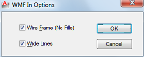
WMFOPTS
Quick Reference
See also:
■Insert WMF Files
Sets options for WMFIN.
Summary
The WMF In Options dialog box is displayed.
WMF In Options Dialog Box
Quick Reference
See also:
■Insert WMF Files
Controls whether metafiles maintain relative line widths and whether they
are imported as wireframes or solid objects.
List of Options
The following options are displayed.
Wire Frame (No Fills)
Imports objects as wireframes. If you clear this option, objects are imported
as filled objects.
Wide Lines
1338 | Chapter 23 W Commands
Maintains the relative line width of lines and borders. If you clear this option,
lines are imported with zero width.
WMFOUT
Quick Reference
See also:
■Export WMF Files
Saves objects to a Windows metafile.
Summary
The Create WMF standard file selection dialog box is displayed.
WORKSPACE
Quick Reference
See also:
■Create Task-Based Workspaces
Creates, modifies, and saves workspaces and makes a workspace current.
List of Prompts
The following prompts are displayed.
Enter Workspace option [setCurrent on page 1339/SAveas on page 1339/Edit on
page 1339/Rename on page 1257/Delete on page 1340/SEttings on page 1340/? on page
1340].
Set Current Sets a current workspace.
Save As Saves a current interface configuration as a workspace.
Edit Opens the Customize User Interface dialog box, Customize tab on page
242, where you can make modifications to a workspace.
Rename Renames a workspace.
WMFOUT | 1339
Delete Deletes a workspace.
Settings Opens the Workspace Settings dialog box on page 1341, which controls
the display, menu order, and Save settings of a workspace.
?—List Workspaces Lists all workspaces defined in the main and enterprise
CUIx files.
WSSAVE
Quick Reference
See also:
■Create Task-Based Workspaces
Saves a workspace.
Summary
If you enter -wssave at the Command prompt, WSSAVE displays prompts.
The Save Workspace dialog box is displayed.
Save Workspace Dialog Box
Quick Reference
See also:
■Create Task-Based Workspaces
Saves the current workspace scheme and settings of a workspace.
List of Options
The following option are displayed.
Name Displays a text box where you can specify a name for a newly saved
workspace and view a list of existing workspaces. These workspaces can be
overwritten if the CUIx file in which they are included is writable. Read-only
1340 | Chapter 23 W Commands
files, such as CUIx files that are shared across a network (called enterprise CUIx
files), are displayed with a “Read-Only” file name extension.
WSSETTINGS
Quick Reference
See also:
■Create Task-Based Workspaces
Sets options for workspaces.
Summary
The Workspace Settings dialog box is displayed.
Workspace Settings Dialog Box
Quick Reference
See also:
■Create Task-Based Workspaces
Controls the display, menu order, and Save settings of a workspace.
List of Options
The following options are displayed.
My Workspace
Displays a list of workspaces from which you can choose a workspace to assign
to the My Workspace toolbar button.
Menu Display and Order
Controls which workspace name you want to display in the Workspaces toolbar
and menu, the order of those workspace names, and whether a separator line
is added between each workspace name. The workspaces displayed here and
in the Workspaces toolbar and menu include the current workspace (displayed
WSSETTINGS | 1341
with a check mark in the toolbar and menu) and the workspace you've defined
in the My Workspace= option, regardless of the display settings.
Move Up
Moves workspace names up in the display order.
Move Down
Moves workspace names down in the display order.
Add Separator
Adds a separator between workspace names.
Do Not Save Changes to Workspace
Does not save changes you've made to a workspace when you switch to another
workspace
(WSAUTOSAVE on page 1725 system variable)
Automatically Save Workspace Changes
Saves changes you've made to a workspace when you switch to another
workspace.
(WSAUTOSAVE on page 1725 system variable)
1342 | Chapter 23 W Commands

X Commands
XATTACH
Quick Reference
See also:
■Attach Drawing References (Xrefs)
Inserts DWG files as an external reference (xref).
Access Methods
Button
Ribbon: Insert tab ➤ Reference panel ➤ Attach
Menu: Insert ➤ DWG Reference
Toolbar: Reference
Summary
When you attach a drawing file as an xref, you link that referenced drawing to
the current drawing. Any changes to the referenced drawing are displayed in
the current drawing when it is opened or reloaded.
The Select Reference File dialog box (a standard file selection dialog box) is
displayed. After you select the DWG files, the Attach External Reference dialog
box is displayed.
24
1343
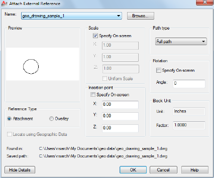
After the files are attached, you can adjust and clip the xref through the
External Reference ribbon contextual tab.
Attach External Reference Dialog Box
Quick Reference
See also:
■Attach Drawing References (Xrefs)
Attaches drawings as an external reference (xref).
Summary
If you attach a drawing that contains an attached xref, the attached xref
appears in the current drawing. You can select multiple DWG files to attach.
Like blocks, attached xrefs can be nested. If another person is currently editing
the xref, the attached drawing is based on the most recently saved version.
External references that have been clipped in AutoCAD® can be attached and
viewed in AutoCAD LT®.
List of Options
The following options are displayed.
1344 | Chapter 24 X Commands
Name
Identifies the DWG you have selected to attach.
Browse
Displays the Select Reference File dialog box (a standard file selection dialog
box), in which you can select a new external reference for the current drawing.
Preview
Displays the DWG you have selected to attach.
Reference Type
Specifies whether the external reference is an attachment or an overlay. Unlike
an xref that is an attachment, an overlay is ignored when the drawing to
which it is attached is then attached as an xref to another drawing.
Locate using Geographic Data
Attaches drawings using geographic data as the reference.
Scale
Specify On-screen
Allows you to input at the Command prompt or the pointing device.
X
Sets the X scale factor.
Y
Sets the Y scale factor.
Z
Sets the Z scale factor.
Uniform Scale
Sets the Y and X scale factors as the same as Z.
Insertion Point
Specify On-Screen
Allows you to input at the Command prompt or the pointing device.
X
Sets the X coordinate value.
Y
Attach External Reference Dialog Box | 1345
Sets the Y coordinate value.
Z
Sets the Z coordinate value.
Path Type
Select the full (absolute) path, the relative path to the external reference file,
or No Path, the name of the external reference (the file must be located in the
same folder as the current drawing file).
Rotation
Specify on-screen
If Specify On-Screen is selected, you may wait until you exit the dialog box
to rotate the object with your pointing device or at the Command prompt.
Angle
If Specify On-Screen is cleared, enter the rotation angle value in the dialog
box.
Block Unit
Displays information about the block units.
Block Name Displays the name of the block associated with the selected
external reference.
Unit Displays the specified INSUNITS value for the inserted block.
Factor Displays the unit scale factor, which is calculated based on the
INSUNITS value of the block and the drawing units.
Show Details
Displays the external reference file paths.
Found In Displays the path where the external reference file is located.
Saved Path Displays the path that is saved with the drawing when the external
reference is attached. The path is dependent upon the Path Type setting.
1346 | Chapter 24 X Commands
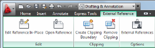
External Reference Ribbon Contextual Tab
Quick Reference
See also:
■Attach Drawing References (Xrefs)
Displays options for attaching external references.
Summary
The External Reference tab is displayed when you select an external reference.
List of Options
The following options are displayed.
Edit Panel
Edit Reference In-Place (REFEDIT on page 1072) Edits an xref or a block
definition directly within the current drawing.
Open Reference (XOPEN on page 1355) Opens a selected drawing reference
(xref) in a new window.
Clipping Panel
Create Clipping Boundary (XCLIP on page 1350) Crops the display of a selected
external reference or block reference to a specified boundary.
Remove Clipping (XCLIP on page 1350) Deletes the clipping boundary.
Options Panel
External References (EXTERNALREFERENCES on page 504) Opens the
External References palette.
External Reference Ribbon Contextual Tab | 1347
XBIND
Quick Reference
See also:
■Archive Drawings That Contain Referenced Drawings (Bind)
Binds one or more definitions of named objects in an xref to the current
drawing.
Access Methods
Button
Menu: Modify ➤ Object ➤ External Reference ➤ Bind
Toolbar: Reference
Summary
The Xbind dialog box is displayed.
If you enter -xbind at the Command prompt, options are displayed.
NOTE The Bind option of XREF binds the xref file. Use XBIND for individual
dependent definitions.
Xbind Dialog Box
Quick Reference
See also:
■Archive Drawings That Contain Referenced Drawings (Bind)
Adds xref-dependent named objects (such as blocks, dimension styles, layers,
linetypes, and text styles) to your drawing.
1348 | Chapter 24 X Commands
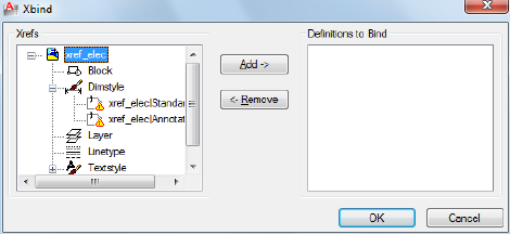
List of Options
The following options are displayed.
Xrefs
Lists the xrefs currently attached to the drawing. Selecting an xref
(double-clicking) displays the named object definitions in the attached xref.
Definitions to Bind
Lists the xref-dependent named object definitions to bind to the host drawing.
Add
Moves the named object definitions selected in the Xrefs list into the
Definitions to Bind list.
Remove
Moves the xref-dependent named object definition selected in the Definitions
to Bind list back to its xref-dependent definition table.
-XBIND
Quick Reference
See also:
■Archive Drawings That Contain Referenced Drawings (Bind)
Binds one or more definitions of named objects in an xref to the current
drawing.
-XBIND | 1349

List of Prompts
The following prompts are displayed.
Enter symbol type to bind [Block/Dimstyle/LAyer/LType/Style]: Enter an option
Depending on the option, you are prompted for a xref-dependent named
object (symbol) such as a block, dimension style, layer, linetype, or text style.
Enter dependent Symbol name(s): Enter a name list or * to bind all xref-dependent
named objects (symbols) from that definition table
The name you specify must be the full name, including the vertical bar
character ( | ).
The xref-dependent named objects you specify are added to your drawing.
You can manipulate them as you would any other named object. The vertical
bar character ( | ) from each xref-dependent named object is replaced with a
number (usually 0) between two dollar signs ($).
If you specify a layer whose associated linetype is not CONTINUOUS, XBIND
also binds the referenced linetype. If you apply XBIND to a block, any block,
dimension style, layer, linetype, or text style that's referenced by objects in
the block is also bound. If the block contains an xref, XBIND binds that xref
and all its dependent named objects.
XCLIP
Quick Reference
See also:
■Clip External References and Blocks
Crops the display of a selected external reference or block reference to a
specified boundary.
Access Methods
Button
1350 | Chapter 24 X Commands
Ribbon: Inset tab ➤ Reference panel ➤ Clip.
Menu: Modify ➤ Clip ➤ Xref
Toolbar: Reference
Shortcut menu: Select an xref. Right-click in the drawing area and click
Clip Xref.
Summary
The clipping boundary determines the portion of an xref or block instance
that is hidden, either outside or inside the boundary. The visibility of the
clipping boundary is controlled by the XCLIPFRAME system variable.
TIP Use the generic CLIP command to clip images, external references, viewports,
and underlays.
List of Options
The following options are displayed.
On
Displays the clipped portion of the external reference or block in the current
drawing.
Off
Displays all of the geometry of the external reference or block in the current
drawing, ignoring the clipping boundary.
Clipdepth
Sets the front and back clipping planes on an xref or block. Objects outside
the volume defined by the boundary and the specified depth are not displayed.
Regardless of the current UCS, the clip depth is applied parallel to the clipping
boundary.
Front Clip Point Creates a clipping plane passing through and perpendicular
to the clipping boundary.
Distance Creates a clipping plane the specified distance from and parallel to
the clipping boundary.
Remove Removes both the front and back clipping planes.
Delete
Removes a clipping boundary for the selected xref or block. To temporarily
turn off a clipping boundary, use the Off option. Delete erases the clipping
boundary and the clipdepth. The ERASE command cannot be used to delete
clipping boundaries.
XCLIP | 1351

Generate Polyline
Automatically draws a polyline coincident with the clipping boundary. The
polyline assumes the current layer, linetype, lineweight, and color settings.
Use this option when you want to modify the current clipping boundary using
PEDIT and then redefine the clipping boundary with the new polyline. To see
the entire xref while redefining the boundary, use the Off option.
New Boundary
Defines a rectangular or polygonal clipping boundary, or generates a polygonal
clipping boundary from a polyline.
Select Polyline Defines the boundary with the selected polyline. The polyline
can be open but must consist of straight line segments and cannot intersect
itself.
Polygonal Defines a polygonal clipping boundary with three or more points
that you specify for the vertices of a polygon.
Rectangular Defines a rectangular boundary with the points that you specify
for opposite corners.
Invert Clip Inverts the mode of the clipping boundary: objects are clipped
either outside the boundary or inside the boundary.
NOTE You can only create a new clipping boundary for a selected XREF underlay
when the old boundary is deleted.
XLINE
Quick Reference
See also:
■Draw Construction Lines (and Rays)
Creates a line of infinite length.
Access Methods
Button
1352 | Chapter 24 X Commands
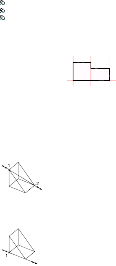
Ribbon: Home tab ➤ Draw panel ➤ Construction Line
Menu: Draw ➤ Construction Line
Toolbar: Draw
Summary
Lines that extend to infinity, such as xlines, can be used to create construction
and reference lines, and for trimming boundaries.
List of Prompts
The following prompts are displayed.
Specify a point on page 1353 or [Hor on page 1353/Ver on page 1353/Ang on page
1354/Bisect on page 1354/Offset on page 1354.
Point
Specifies the location of the infinite line using two points through which it
passes.
The xline is created through the specified point.
Hor
Creates a horizontal xline passing through a specified point.
The xline is created parallel to the X axis.
Ver
Creates a vertical xline passing through a specified point.
XLINE | 1353
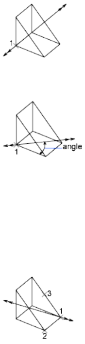
The xline is created parallel to the Y axis.
Ang
Creates an xline at a specified angle.
Angle of Xline Specifies the angle at which to place the line.
Reference Specifies the angle from a selected reference line. The angle is
measured counterclockwise from the reference line.
Bisect
Creates an xline that passes through the selected angle vertex and bisects the
angle between the first and second line.
The xline lies in the plane determined by the three points.
Offset
Creates an xline parallel to another object.
Offset Distance Specifies the distance the xline is offset from the selected
object.
Through Creates an xline offset from a line and passing through a specified
point.
1354 | Chapter 24 X Commands
XOPEN
Quick Reference
See also:
■Edit a Referenced Drawing in a Separate Window
Opens a selected drawing reference (xref) in a new window.
Summary
Opens a selected drawing reference in a separate window for editing.
If the selected reference contains nested xrefs, Open Reference Files dialog
box on page 1355 is displayed where you can specify which xref to open.
Open Reference Files Dialog Box
Quick Reference
See also:
■Edit a Referenced Drawing in a Separate Window
Opens a selected drawing reference (xref) in a new window.
XOPEN | 1355
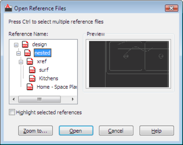
Summary
The Open Reference Files dialog box, displays a reference tree showing all
nested xrefs. The source file for the selected xref opens in a separate drawing
window, where you can edit, save, and then close the drawing.
List of Options
The following options are displayed.
Reference Name
Displays a reference tree of all nested xrefs for a specified reference.
Highlight Selected Reference
Highlights the selected xrefs in the drawing area.
Preview
Displays a preview of the selected reference.
Zoom To...
1356 | Chapter 24 X Commands
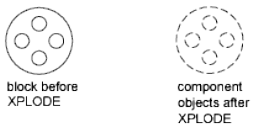
Temporarily closes the Open Reference Files dialog box and zooms the view
in the drawing area to the selected reference. Press Enter to redisplay the dialog
box.
Open
Opens the source file for the selected reference in a separate window.
XPLODE
Quick Reference
See also:
■Disassemble a Block Reference (Explode)
Breaks a compound object into its component objects.
Summary
Reports how many objects were selected and, of those, how many objects
cannot be exploded.
List of Prompts
The following prompts are displayed.
Enter an option [Individually on page 1357/Globally on page 1358].
Individually
Applies changes to the selected objects one at a time. The following prompt
is displayed for each object.
All Sets the color, linetype, lineweight, and layer of the component objects
after you explode them. The prompts associated with the Color, Linetype,
Lineweight, and Layer options are displayed.
XPLODE | 1357
Color Sets the color of the objects after you explode them.
■Enter bylayer to inherit the color of the exploded object's layer.
■Enter byblock to inherit the color of the exploded object.
■Enter t for a true color to be used for the selected object.
■Enter co for a color from a loaded color book to be used for the selected
object.
Layer Sets the layer of the component objects after you explode them. The
default option is to inherit the current layer rather than the layer of the
exploded object.
LType Sets the linetype of the component objects after you explode them.
Enter bylayer to inherit the linetype of the exploded object's layer.
Enter byblock to inherit the linetype of the exploded object.
LWeight Sets the lineweight of the component objects after you explode
them.
Inherit from Parent Block Sets the color, linetype, lineweight, and layer of
the component objects to that of the exploded object if the component objects'
color, linetype, and lineweight are BYBLOCK and the objects are drawn on
layer 0.
Explode Breaks a compound object into its component objects exactly as the
EXPLODE command does.
Globally
Applies changes to all the selected objects.
XREF
Quick Reference
See also:
■Attach and Detach Referenced Drawings
■ERHIGHLIGHT
Starts the EXTERNALREFERENCES command.
1358 | Chapter 24 X Commands
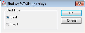
Summary
The External References palette is displayed.
If you enter -xref at the Command prompt, options are displayed.
Bind Xrefs/DGN Underlays Dialog Box
Quick Reference
See also:
■Attach and Detach Referenced Drawings
Converts DWG references (xrefs) and DGN Underlays to standard local block
definitions.
Summary
If you bind an xref into the current drawing, the xref and all its dependent
named objects become a part of the current drawing. Use XBIND to add
individual xref-dependent named objects, such as blocks, text styles, dimension
styles, layers, and linetypes, to the local definition table. The two methods of
binding xrefs to the current drawing are Bind and Insert. Bind alters the
definition table names of an xref when it is inserted. Insert does not alter the
definition table names of an xref when it is inserted. To bind a nested xref,
you must also select the parent xref.
List of Options
The following options are displayed.
Bind
Binds the selected DWG reference to the current drawing. Xref-dependent
named objects are changed from blockname|definitionname to
blockname$n$definitionname syntax. In this manner, unique named objects are
created for all xref-dependent definition tables bound to the current drawing.
Bind Xrefs/DGN Underlays Dialog Box | 1359
For example, if you have an xref named FLOOR1 containing a layer named
WALL, after binding the xref, the xref-dependent layer FLOOR1|WALL becomes
a locally defined layer named FLOOR1$0$WALL. The number in $n$ is
automatically increased if a local named object with the same name already
exists. In this example, if FLOOR1$0$WALL already existed in the drawing,
the xref-dependent layer FLOOR1|WALL would be renamed FLOOR1$1$WALL.
Insert
Binds the DWG reference to the current drawing in a way similar to detaching
and inserting the reference drawing. Rather than being renamed using
blockname$n$definitionname syntax, xref-dependent named objects are stripped
of the xref name. As with inserting drawings, no name-incrementing occurs
if a local named object shares the same name as a bound xref-dependent
named object. The bound xref-dependent named object assumes the properties
of the locally defined named object.
For example, if you have an xref named FLOOR1 containing a layer named
WALL, after binding with the Insert option, the xref-dependent layer
FLOOR1|WALL becomes the locally defined layer WALL.
-XREF
Quick Reference
See also:
■Attach and Detach Referenced Drawings
List of Prompts
The following prompts are displayed.
Enter an Option
?—List Xrefs Lists the DWG reference name, path, and type and the number
of DWG references currently attached to your drawing.
Bind Converts a specified DWG reference into a block, making it a permanent
part of the drawing.
The xref-dependent named objects, such as layer names, of the former xref
are added to your drawing. In each xref-dependent named object, the vertical
bar (|) is replaced with three new characters: a number (usually 0) between
1360 | Chapter 24 X Commands
two dollar signs ($). The number is increased if the same name already exists
in the current drawing.
Detach Detaches one or more DWG references from your drawing, erasing
all instances of a specified xref and marking the xref definition for deletion
from the definition table. Only the xrefs attached or overlaid directly to the
current drawing can be detached; nested xrefs cannot be detached.
Path Displays and edits the path name associated with a particular DWG
reference. This option is useful if you change the location of or rename the
drawing file associated with the xref.
Unload Unloads the selected DWG references.
A marker is left in place of the xref so that it can be reloaded later.
Reload Reloads one or more DWG references. This option reloads and displays
the most recently saved version of that drawing.
If the program encounters an error while reloading, it ends XREF and undoes
the entire reloading sequence.
Overlay Displays the Enter Name of File to Overlay dialog box (a standard
file selection dialog box). If you reference a drawing that contains an overlaid
xref, the overlaid xref does not appear in the current drawing.
Unlike blocks and attached xrefs, overlaid xrefs cannot be nested. If another
person is currently editing the xref file, the program overlays the most recently
saved version.
If the xref you specify is not already overlaid, a new xref is crated, using the
name of the referenced file.
If FILEDIA is set to 0, the following prompt is displayed:
Enter Name of File to Overlay.
You can enter a tilde (~) to display a dialog box.
Attach Displays the External Reference dialog box, if a DWG reference is
selected, or the Select Reference File dialog box, if no DWG reference is selected.
See XATTACH.
If you reference a drawing that contains an attached xref, the attached xref
appears in the current drawing. Like blocks, attached xrefs can be nested. If
another person is currently editing the xref file, the most recently saved version
is attached.
Specify Insertion Point
Specify a point or enter an option
-XREF | 1361
Scale Sets the scale factor. All X and Y dimensions of the xref are multiplied
by the X and Y scale factors. The xref is rotated by the specified angle, using
the insertion point as the center of rotation.
X, Y, and Z Sets X, Y, and Z scale factors.
■X Scale Factor. Defines X, Y, and Z scale factors for the xref.
■Corner. Defines the X and Y scales at the same time, using the insertion
point and another point as the corners of a box, and then defines the Z
scale.
Rotate Sets the angle of insertion for the xref.
PScale Sets the scale factor for the X, Y, and Z axes to control the display of
the xref as it is dragged into position.
PX, PY, and PZ Sets the X, Y, and Z axes to control the display of the xref as
it is dragged into position.
PRotate Sets the rotation angle of the xref as it is dragged into position.
1362 | Chapter 24 X Commands

Z Commands
ZOOM
Quick Reference
See also:
■Pan or Zoom a View
Increases or decreases the magnification of the view in the current viewport.
Access Methods
Button
Ribbon: View tab ➤ Navigate panel ➤ Realtime
Menu: View ➤ Zoom ➤ Realtime
Toolbar: Standard
Shortcut menu: With no objects selected, right-click in the drawing area and
choose Zoom to zoom in real time.
Summary
You can change the magnification of a view by zooming in and out, which is
similar to zooming in and out with a camera. Using ZOOM does not change
the absolute size of objects in the drawing. It changes only the magnification
of the view.
25
1363
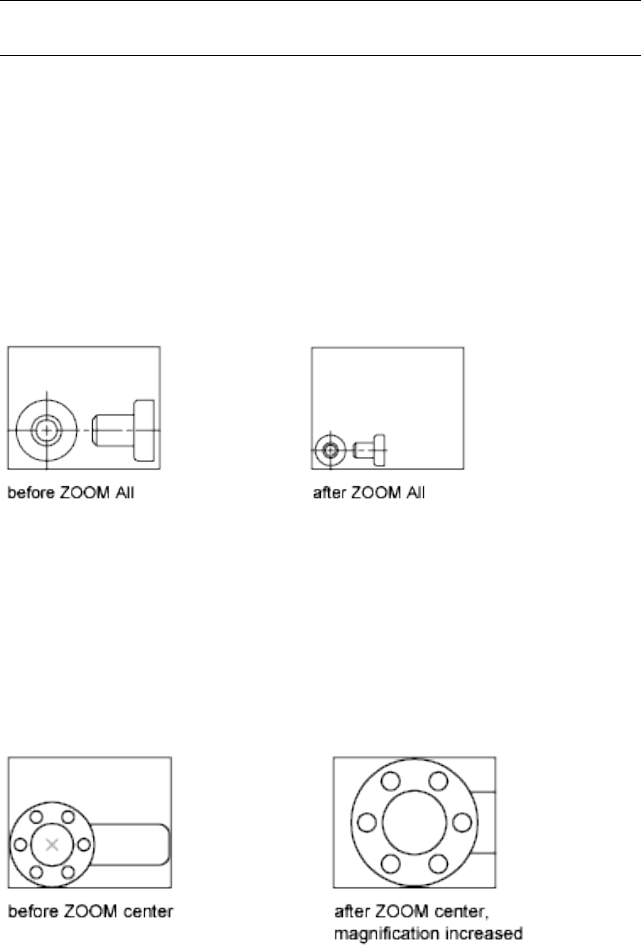
In a perspective view, ZOOM displays the 3DZOOM prompts.
NOTE You cannot use ZOOM transparently during VPOINT or while ZOOM, PAN,
or VIEW is in progress.
List of Prompts
The following prompts are displayed.
Specify corner of window, enter a scale factor (nX or nXP), or
[All on page 1364/Center/Dynamic/Extents on page
1365/Previous/Scale/Window/Object] <real time>
All Zooms to display all visible objects and visual aids.
Adjusts the magnification of the drawing area to accommodate the extents
of all visible objects in the drawing, or visual aids such as the grid limits (the
LIMITS command), whichever is larger.
In the illustration on the right, the grid limits are set to a larger area than the
extents of the drawing.
Because it always regenerates the drawing, you cannot use ZOOM All
transparently.
Center Zooms to display a view defined by a center point and a magnification
value or a height. A smaller value for the height increases the magnification.
A larger value decreases the magnification. Not available in perspective
projection.
1364 | Chapter 25 Z Commands
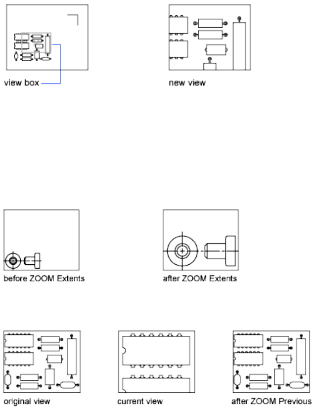
Dynamic Pans and zooms using a rectangular view box. The view box
represents your view, which you can shrink or enlarge and move around the
drawing. Positioning and sizing the view box pans or zooms to fill the viewport
with the view inside the view box. Not available in perspective projection.
■To change the size of the view box, click, resize it, and click again to accept
the new size of the view box.
■To pan with the view box, drag it to the location you want and press Enter.
Extents Zooms to display the maximum extents of all objects.
The extents of each object in the model are calculated and used to determine
how the model should fill the window.
Previous Zooms to display the previous view. You can restore up to 10 previous
views.
ZOOM | 1365
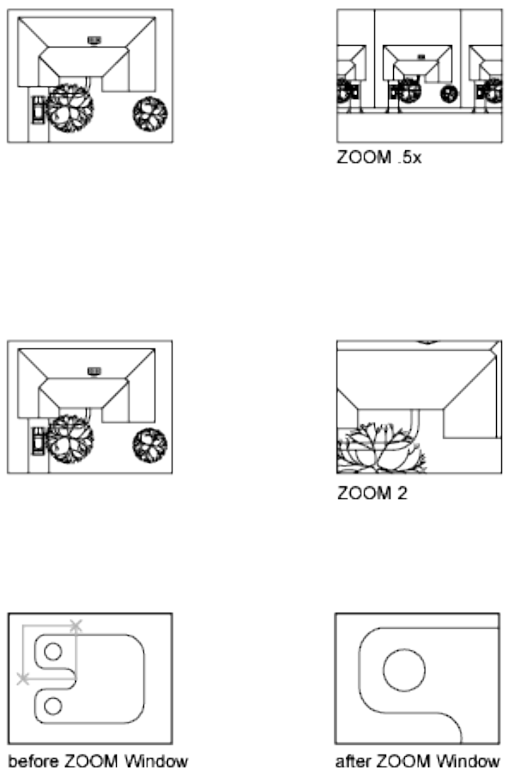
Scale Zooms to change the magnification of a view using a scale factor.
■Enter a value followed by x to specify the scale relative to the current view.
■Enter a value followed by xp to specify the scale relative to paper space
units.
For example, entering .5x causes each object to be displayed at half its current
size on the screen.
Entering .5xp displays model space at half the scale of paper space units. You
can create a layout with each viewport displaying objects at a different scale.
Enter a value to specify the scale relative to the grid limits of the drawing.
(This option is rarely used.) For example, entering 2 displays objects at twice
the size they would appear if you were zoomed to the limits of the drawing.
Window Zooms to display an area specified by a rectangular window.
With the cursor, you can define an area of the model to fill the entire window.
1366 | Chapter 25 Z Commands

Object Zooms to display one or more selected objects as large as possible and
in the center of the view. You can select objects before or after you start the
ZOOM command.
Real Time Zooms interactively to change the magnification of the view.
The cursor changes to a magnifying glass with plus (+) and minus (-) signs.
See Zoom Shortcut Menu on page 1367 for a description of the options that are
available while zooming in real time.
Holding down the pick button at the midpoint of the window and moving
vertically to the top of the window zooms in to 100%. Conversely, holding
the pick button down at the midpoint of the window and moving vertically
to the bottom of the window zooms out by 100%.
When you reach the zoom-in limit, the plus sign in the cursor disappears,
indicating that you can no longer zoom in. When you reach the zoom-out
limit, the minus sign in the cursor disappears, indicating that you can no
longer zoom out.
When you release the pick button, zooming stops. You can release the pick
button, move the cursor to another location in the drawing, and then press
the pick button again and continue to zoom the display from that location.
To exit zooming, press Enter or Esc.
Zoom Shortcut Menu
Quick Reference
See also:
■Pan or Zoom a View
Shortcut menu allows you to switch between pan and different zoom options.
Summary
When the ZOOM command is active, you can exit ZOOM or switch to PAN
using the options on the Zoom shortcut menu. To access the Zoom shortcut
menu, right-click in the drawing area while ZOOM is active.
Zoom Shortcut Menu | 1367
List of Options
The following options are displayed.
Exit Cancels ZOOM or PAN.
Pan Switches to PAN.
Zoom Switches to ZOOM in real time.
Zoom Window Zooms to display an area specified by a rectangular window.
Zoom Object Zooms to display one or more selected objects as large as possible
and in the center of the drawing area.
Zoom Original Restores the original view.
Zoom Extents Zooms to display the drawing extents.
1368 | Chapter 25 Z Commands

Command Modifiers
You can use command modifiers to help you locate points or select objects while a command
is in progress. Use the Coordinate Filter, Direct Distance Entry, From, MTP, and Tracking
command modifiers at any prompt that requires point specification. Use the Selection Mode
command modifiers at any prompt that requires object selection.
Coordinate Filters (Command Modifier)
Quick Reference
See also:
■Combine Coordinate Values (Coordinate Filters)
Combines X, Y, and Z values from different points to specify a single point
Command entry: Enter .x, .y, .xy, .xz, or .yz
At any prompt for locating a point, you can enter point filters to specify a single
coordinate by extracting the X, Y, and Z values of several points. In the following
example, the start point for the line has a coordinate constructed from the X
value of the midpoint of the first object you select, with the Y and Z values of
the midpoint of the second object you select.
Command: line
Specify first point: .x
of mid
of Select an object
of (need YZ) mid
of Select another object
To point: Specify a point
26
1369
Direct Distance Entry (Command Modifier)
Quick Reference
See also:
■Enter Direct Distances
Locates the next point at a specified distance in the direction of your cursor
Command entry: At a prompt to locate a point, enter a numeric value
With direct distance entry, you can quickly specify a point relative to the last
point you entered. At any prompt for a point location, you move the cursor
first to specify the direction, and then enter a numeric distance.
In the following example, the second point for the line will be located 5 units
toward the direction of the cursor. The direct distance that you enter is
measured along the path from the last point to the current location of the
cursor. This feature is usually used with Ortho or Snap mode turned on.
Command: line
Specify first point: Specify a point
Specify next point: Move the cursor in the desired direction and enter 5
NOTE The direct distance entry method is not available while you are using
temporary override keys for Ortho, object snap tracking, or polar tracking.
FROM (Command Modifier)
Quick Reference
See also:
■Offset from Temporary Reference Points
Locates a point offset from a reference point within a command.
Toolbar: Object Snap
Command entry: At a prompt to locate a point, enter from
Base Point: Specify a point to use as a base point
of <offset>: Enter a relative offset
1370 | Chapter 26 Command Modifiers
At a prompt for locating a point, enter from, and then enter a temporary
reference or base point from which you can specify an offset to locate the next
point. Enter the offset location from this base point as a relative coordinate,
or use direct distance entry.
NOTE You cannot use this method during dragging in commands such as MOVE
and COPY. Specifying an absolute coordinate, either by keyboard entry or with a
pointing device, cancels the FROM command.
MTP (Command Modifier)
Quick Reference
See also:
■Use Object Snaps
Locates the midpoint between two points.
Command entry: At a prompt to locate a point, enter mtp
The midpoint between two points (MTP) command modifier can be used with
running object snaps or object snap overrides. (OSNAP command)
At any Command prompt to locate a point, enter mtp or m2p.
First point of mid: Specify a point
Second point of mid: Specify a second point
TRACKING (Command Modifier)
Quick Reference
See also:
■Track to Offset Point Locations (Tracking)
Locates a point from a series of temporary points.
Command entry: At a prompt to locate a point, enter tracking
Tracking turns on Ortho mode and can be used with Snap mode.
MTP (Command Modifier) | 1371

At any prompt to locate a point, enter tracking, track, or tk.
First tracking point: Specify a location or distance
Next point (Press ENTER to end tracking): Specify a second location or distance
Tracking specifies a series of temporary points, each offset from the previous
one. Thus, you specify a new point location from a series of directions and
distances. To determine the location of each temporary point, you can use
direct distance entry. First move the cursor to specify the direction, and then
enter a numeric distance.
Alternatively, tracking can establish a new point by combining the X and Y
values of two specified points. You can specify these two points in any order,
depending on the cursor direction after the first point. Direct distance entry
specifies a distance in the direction of the current location of your cursor.
Coordinate filters combine X, Y, and Z values from different points into a
single point. Relative coordinate entry locates a point relative to the last point
entered.
You can also access tracking by holding down SHIFT and right-clicking to
display the object snap shortcut menu.
Object Snaps (Command Modifier)
Quick Reference
See also:
■Use Object Snaps
Specifies a precise point at a location on an object.
Command entry: Within a command, at a prompt to locate a point, specify
an object snap
When you specify an object snap, the cursor snaps to the specified point on
an object closest to the center of the cursor. By default, a marker and a tooltip
are displayed when you move the cursor over the object snap location on an
object.
Specify a Single Object Snap
If you specify a single object snap, it stays in effect only for the next point
you specify.
1372 | Chapter 26 Command Modifiers

You can specify an object snap with any of the following methods:
■Enter a object snap by typing its name. To see a list of valid object snaps,
refer to the OSNAP on page 893 command or the Drafting Settings Dialog
Box on page 414.
■Click an object snap from the Object Snap toolbar.
■Click an object snap from the Object Snap shortcut menu. You can diisplay
this shortcut menu by pressing SHIFT while you right-click.
Use Running Object Snaps
Using the OSNAP or DSETTINGS commands, you can specify a set of running
object snaps. Running object snaps are one or more object snaps that remain
in effect as you work.
■To turn running object snaps on and off, click the OSNAP button on the
status bar or press F3.
■Press TAB to cycle through the object snap possibilities before you specify
the point.
■To turn off running object snaps for the next point only, specify the None
object snap.
Selection Modes (Command Modifier)
Quick Reference
See also:
■Select Objects
Controls how you create selection sets
Command entry: At a prompt to select objects, enter one of the valid selection
modes described in the SELECT command
The selection mode you enter remains active only for the current Select Objects
prompt.
Selection Modes (Command Modifier) | 1373
1374
System Variables
AutoCAD LT® stores the values for its operating environment and some of its commands in
system variables. You can examine any system variable and change any writable system
variable directly at the command prompt by entering the system variable name or by using
the SETVAR command. Many system variables are also accessible through dialog box options.
To access a list of system variables, on the Contents tab of the Help window, click the + sign
next to System Variables.
1375
1376

3D System Variables
3DSELECTIONMODE
Quick Reference
See also:
■Select Objects Individually
IntegerType:
RegistrySaved in:
1Initial value:
Controls the selection precedence of both visually and physically overlapping
objects when using 3D visual styles.
Use legacy 3D selection precedence.0
Use line-of-sight 3D selection precedence for selecting 3D
solids and surfaces. Also, a defining object associated with
a surface is given selection precedence with this setting.
1
3DSELECTIONMODE has no effect when selecting 3D solids if they are displayed
as 2D or 3D wireframes.
27
1377
1378

A System Variables
ADCSTATE
Quick Reference
See also:
■Access Content with DesignCenter
(Read-only)
IntegerType:
Not-savedSaved in:
VariesInitial value:
Indicates whether the DesignCenter window is open or closed.
For developers who need to determine status through AutoLISP.
Closed0
Open1
28
1379
AFLAGS
Quick Reference
See also:
■Define Block Attributes
IntegerType:
Not-savedSaved in:
16Initial value:
Sets options for attributes.
The value is the sum of the following:
No attribute mode selected0
Invisible1
Constant2
Verify4
Preset8
Lock position in block16
Multiple lines32
ANGBASE
Quick Reference
See also:
■Create Angular Dimensions
RealType:
DrawingSaved in:
0.0000Initial value:
1380 | Chapter 28 A System Variables

Sets the base angle to 0 with respect to the current UCS.
ANGDIR
Quick Reference
See also:
■Create Angular Dimensions
IntegerType:
DrawingSaved in:
0Initial value:
Sets the direction of positive angles.
Angle values are measured from angle 0 relative to the orientation of the
current UCS.
Counterclockwise0
Clockwise1
ANNOALLVISIBLE
Quick Reference
See also:
■Display Annotative Objects
IntegerType:
DrawingSaved in:
1Initial value:
Hides or displays annotative objects that do not support the current annotation
scale.
Only annotative objects that support the current are dis-
played
0
ANGDIR | 1381
All annotative objects are displayed1
The ANNOALLVISIBLE setting is saved individually for model space and each
layout.
NOTE When ANNOALLVISIBLE is set to 1, annotative objects that support more
than one scale will only display one .
ANNOAUTOSCALE
Quick Reference
See also:
■Set Annotation Scale
IntegerType:
RegistrySaved in:
-4Initial value:
Updates annotative objects to support the annotation scale when the
annotation scale is changed.
When the value is negative, the autoscale functionality is turned off, but the
settings are maintained:
Newly set annotation scale is not added to annotative
objects.
0
Adds the newly set annotation scale to annotative objects
that support the current scale except for those on layers
1
that are turned off, frozen, locked or that are set to View-
port > Freeze.
Adds the newly set annotation scale to annotative objects
that support the current scale except for those on layers
2
that are turned off, frozen, or that are set to Viewport >
Freeze.
Adds the newly set annotation scale to annotative objects
that support the current scale except for those on layers
that are locked.
3
1382 | Chapter 28 A System Variables
Adds the newly set annotation scale to all annotative ob-
jects that support the current scale.
4
ANNOTATIVEDWG
Quick Reference
See also:
■Create Annotative Blocks and Attributes
IntegerType:
DrawingSaved in:
0Initial value:
Specifies whether or not the drawing will behave as an annotative block when
inserted into another drawing.
Nonannotative0
Annotative1
NOTE The ANNOTATIVEDWG system variable becomes read-only if the drawing
contains annotative objects.
APBOX
Quick Reference
See also:
■Set Visual Aids for Object Snaps (AutoSnap)
IntegerType:
RegistrySaved in:
0Initial value:
Turns the display of the AutoSnap aperture box on or off.
ANNOTATIVEDWG | 1383

The aperture box is displayed in the center of the crosshairs when you snap
to an object.
Off0
On1
APERTURE
Quick Reference
See also:
■Use Object Snaps
IntegerType:
RegistrySaved in:
10Initial value:
Sets the display size for the object snap target box, in pixels.
This system variable has the same name as a command. Use the SETVAR
command to access this system variable.
Enter a value (1-50). The higher the number, the larger the target box.
You can also change this setting in the Options dialog box, Drafting tab.
APERTURE controls the object snap target box, not the pickbox displayed at
the Select Objects prompt. The object selection pickbox is controlled by the
PICKBOX system variable.
APPLYGLOBALOPACITIES
Quick Reference
See also:
■Set Up the Drawing Area
■Transparency Dialog Box on page 888
1384 | Chapter 28 A System Variables
SwitchType:
RegistrySaved in:
0Initial value:
Applies transparency settings to all palettes.
Transparency settings off0
Transparency settings on1
This system variable determines the default setting for the Transparency dialog
box > Apply these settings to all palettes option on page 889.
APSTATE
Quick Reference
See also:
■Create Custom Block Authoring Tools
(Read-only)
IntegerType:
Not-savedSaved in:
0Initial value:
Indicates whether the Block Authoring Palettes window in the Block Editor
is open or closed.
Closed0
Open1
ARRAYEDITSTATE
Quick Reference
See also:
■Edit Associative Arrays
APSTATE | 1385

(Read-only)
IntegerType:
Not-savedSaved in:
0Initial value:
Indicates whether the drawing is in the array editing state, which is activated
while editing an associative array’s source objects.
Off0
On1
AREA
Quick Reference
See also:
■Obtain Area and Mass Properties Information
(Read-only)
RealType:
Not-savedSaved in:
0.0000Initial value:
Stores the last area computed by the AREA command.
This system variable has the same name as a command.
Use the GETVAR command to access this system variable.
ARRAYTYPE
Quick Reference
See also:
■Array Objects
IntegerType:
RegistrySaved in:
1386 | Chapter 28 A System Variables

0Initial value:
Specifies the default array type.
Rectangular array0
Path array1
Polar array2
ATTDIA
Quick Reference
See also:
■Insert Blocks
IntegerType:
RegistrySaved in:
0Initial value:
Controls whether the INSERT command uses a dialog box for attribute value
entry.
Issues Command prompts0
Uses a dialog box1
ATTIPE
Quick Reference
See also:
■Define Block Attributes
IntegerType:
RegistrySaved in:
0Initial value:
ATTDIA | 1387
Controls the which Text Formatting toolbar is used with the in-place editor
for modifying multiline attributes.
Displays the abbreviated Text Formatting toolbar with the
in-place editor
0
Displays the full Text Formatting toolbar with the in-place
editor
1
Use the abbreviated Text Formatting toolbar with the in-place editor when
modifying multiline attributes for best compatibility with releases prior to
AutoCAD LT 2008.
ATTMODE
Quick Reference
See also:
■Define Block Attributes
IntegerType:
DrawingSaved in:
1Initial value:
Controls display of attributes.
Off: Makes all attributes invisible0
Normal: Retains current visibility of each attribute; visible
attributes are displayed; invisible attributes are not
1
On: Makes all attributes visible2
1388 | Chapter 28 A System Variables
ATTMULTI
Quick Reference
See also:
■Define Block Attributes
IntegerType:
RegistrySaved in:
1Initial value:
Controls whether multiline attributes can be created.
Turns off all access methods for creating multiline attrib-
utes. They can still be viewed and edited.
0
Turns on all access methods for creating multiline attrib-
utes.
1
ATTREQ
Quick Reference
See also:
■Insert Blocks
IntegerType:
RegistrySaved in:
1Initial value:
Controls whether INSERT uses default attribute settings during insertion of
blocks.
Assumes the defaults for the values of all attributes0
Turns on prompts or a dialog box for attribute values, as
specified by ATTDIA
1
ATTMULTI | 1389
AUDITCTL
Quick Reference
See also:
■Repair a Damaged Drawing File
IntegerType:
RegistrySaved in:
0Initial value:
Controls whether AUDIT creates an audit report (ADT) file.
Prevents writing of ADT files0
Writes ADT files1
AUNITS
Quick Reference
See also:
■Set the Unit Format Conventions
IntegerType:
DrawingSaved in:
0Initial value:
Sets units for angles.
Decimal degrees0
Degrees/minutes/seconds1
Gradians2
Radians3
Surveyor's units4
1390 | Chapter 28 A System Variables
AUPREC
Quick Reference
See also:
■Set the Unit Format Conventions
IntegerType:
DrawingSaved in:
0Initial value:
Sets the display precision for angular units and coordinates.
However, the internal precision of angular values and and coordinates is always
maintained, regardless of the display precision. AUPREC does not affect the
display precision of dimension text (see DIMSTYLE on page 361).
Valid values are integers from 0 to 8.
AUTOCOMPLETEDELAY
Quick Reference
See also:
■The Command Line Window
IntegerType:
DrawingSaved in:
0.3Initial value:
Controls the amount of time that elapses before automated keyboard features
display at the Command prompt.
The time delay setting in the AUTOCOMPLETEMODE on page 1392 system
variable must be turned on for AUTOCOMPLETEDELAY to have an effect.
Valid values are real numbers from 0 to 10, which represent seconds.
AUPREC | 1391

AUTOCOMPLETEMODE
Quick Reference
See also:
■The Command Line Window
IntegerType:
DrawingSaved in:
15Initial value:
Controls what types of automated keyboard features are available at the
Command prompt.
The setting is stored as a bitcode using the sum of the following values:
Turns off all automated keyboard features when typing at
the Command prompt
0
Turns on any automated keyboard features when typing
at the Command prompt
1
Automatically appends suggestions as each keystroke is
entered after the third keystroke
2
Displays a list of suggestions as keystrokes are entered4
Displays the icon of the command or system variable, if
available
8
Excludes the display of system variables16
AUTODWFPUBLISH
Quick Reference
See also:
■Set Publish Options
1392 | Chapter 28 A System Variables
IntegerType:
RegistrySaved in:
0Initial value:
Controls whether DWF (Design Web Format) files are created automatically
when you save or close drawing (DWG) files.
Turns off automatic publishing to DWF files when a
drawing is saved or closed
0
Turns on automatic publishing to DWF files when a
drawing is saved or closed
1
The AUTOPUBLISH command controls additional options.
NOTE This command will be removed in a future release.
AUTOMATICPUB
Quick Reference
See also:
■Set Publish Options
IntegerType:
User-settingsSaved in:
0Initial value:
Controls whether electronic files (DWF/PDF) are created automatically when
you save or close drawing (DWG) files.
Turns off automatic publishing to DWF/PDF files when a
drawing is saved or closed
0
Turns on automatic publishing to DWF/PDF files when a
drawing is saved or closed
1
The AUTOPUBLISH command controls additional options.
AUTOMATICPUB | 1393

AUTOSNAP
Quick Reference
See also:
■Set Visual Aids for Object Snaps (AutoSnap)
IntegerType:
RegistrySaved in:
63Initial value:
Controls the display of the AutoSnap marker, tooltip, and magnet.
Also turns on polar and object snap tracking, and controls the display of polar
tracking, object snap tracking, and Ortho mode tooltips. The setting is stored
as a bitcode using the sum of the following values:
Turns off the AutoSnap marker, tooltips, and magnet. Also
turns off polar tracking, object snap tracking, and tooltips
for polar tracking, object snap tracking, and Ortho mode
0
Turns on the AutoSnap marker1
Turns on the AutoSnap tooltips2
Turns on the AutoSnap magnet4
Turns on polar tracking8
Turns on object snap tracking16
Turns on tooltips for polar tracking, object snap tracking,
and Ortho mode
32
1394 | Chapter 28 A System Variables
B System Variables
BACKGROUNDPLOT
Quick Reference
See also:
■Overview of Plotting
IntegerType:
RegistrySaved in:
2Initial value:
Controls whether background plotting is turned on or off for plotting and
publishing.
By default, background plotting is turned off for plotting and on for publishing.
PUBLISHPLOTValue
ForegroundForeground0
ForegroundBackground1
BackgroundForeground2
BackgroundBackground3
When -PLOT, PLOT, -PUBLISH, and PUBLISH are used in a script (SCR file), the
BACKGROUNDPLOT system variable value is ignored, and -PLOT, PLOT,
-PUBLISH, and PUBLISH are processed in the foreground.
29
1395
BACTIONBARMODE
Quick Reference
See also:
■Group Related Actions in Dynamic Blocks
IntegerType:
RegistrySaved in:
1Initial value:
Indicates whether the action bars or the legacy action objects are displayed
in the Block Editor.
Legacy action objects are displayed in the
Block Editor.
0
Action bars are displayed in the Block Edit-
or.
1
NOTE The BACTIONSET,BASSOCIATE, and BLOOKUPTABLE on page 142 commands
are disabled when the BACTIONBARMODE system variable is set to 1.
BACTIONCOLOR
Quick Reference
See also:
■Overview of Actions and Parameters
StringType:
RegistrySaved in:
7Initial value:
Sets the text color of actions in the Block Editor.
Valid values include BYLAYER, BYBLOCK, and an integer from 1 to 255.
1396 | Chapter 29 B System Variables

BCONSTATUSMODE
Quick Reference
See also:
■Work with AutoCAD Drawings in AutoCAD LT
IntegerType:
Not-savedSaved in:
0Initial value:
Turns the constraint display status on and off and controls the shading of
objects based on their constraint level.
When the display status is on, objects are shaded based on whether they are
partially constrained, fully constrained, over constrained, or not constrained.
Turns off the constraint display status0
Turns on the constraint display status1
You can turn the display status on or off using an icon in the drawing status
bar. The colors corresponding to the constraint status can also be modified
in the Block Editor Settings dialog box. When you enter the Block Editor, the
value is always set to 0.
BDEPENDENCYHIGHLIGHT
Quick Reference
See also:
■Overview of Actions and Parameters
IntegerType:
RegistrySaved in:
1Initial value:
BCONSTATUSMODE | 1397

Controls whether or not dependent objects are dependency highlighted when
a parameter, action, or grip is selected in the Block Editor.
Specifies that dependent objects are not highlighted0
Specifies that dependent objects are highlighted1
Dependency highlighting displays objects with a halo effect.
BGRIPOBJCOLOR
Quick Reference
See also:
■Overview of Actions and Parameters
StringType:
RegistrySaved in:
141Initial value:
Sets the color of grips in the Block Editor.
Valid values include BYLAYER, BYBLOCK, and an integer from 1 to 255.
BGRIPOBJSIZE
Quick Reference
See also:
■Overview of Actions and Parameters
IntegerType:
RegistrySaved in:
8Initial value:
Sets the display size of custom grips in the Block Editor relative to the screen
display.
Valid values are integers from 1 to 255.
1398 | Chapter 29 B System Variables

BLIPMODE
Quick Reference
See also:
■Erase Objects
IntegerType:
RegistrySaved in:
0Initial value:
Controls whether marker blips are visible.
Obsolete
Marker blips have been removed from the product.
This system variable has the same name as the BLIPMODE command. Use the
SETVAR command to access this system variable.
Turns off marker blips0
Turns on marker blips1
BLOCKEDITLOCK
Quick Reference
See also:
■Create and Edit Dynamic Blocks
IntegerType:
RegistrySaved in:
0Initial value:
Disallows opening of the Block Editor and editing of dynamic block definitions.
BLIPMODE | 1399
When BLOCKEDITLOCK is set to 1, double-clicking a dynamic block in a
drawing opens the Properties palette. Double-click actions can be customized
using the Double Click Actions.
Specifies that the Block Editor can be opened0
Specifies that the Block Editor cannot be opened1
BLOCKEDITOR
Quick Reference
See also:
■Create and Edit Dynamic Blocks
(Read-only)
IntegerType:
Not-savedSaved in:
0Initial value:
Indicates whether or not the Block Editor is open.
Indicates that the Block Editor is not open0
Indicates that the Block Editor is open1
BLOCKTESTWINDOW
Quick Reference
See also:
■Test Blocks Within the Block Editor
(Read-only)
IntegerType:
Not-savedSaved in:
0Initial value:
1400 | Chapter 29 B System Variables
Indicates whether or not a test block window is current.
The BLOCKTESTWINDOW system variable controls the display of the
contextual panel that is displayed when a test block window is current. When
the test block window is current, this system variable is set to 1, otherwise it
is set to 0.
BPARAMETERCOLOR
Quick Reference
See also:
■Overview of Actions and Parameters
StringType:
RegistrySaved in:
170Initial value:
Sets the color of parameters in the Block Editor.
Valid values include BYLAYER, BYBLOCK, and an integer from 1 to 255.
BPARAMETERFONT
Quick Reference
See also:
■Overview of Actions and Parameters
StringType:
RegistrySaved in:
Simplex.shxInitial value:
Sets the font used for parameters and actions in the Block Editor.
You can specify either a True Type font or a SHX font (for example, Verdana
or Verdana.ttf). You must add the .shx extension to specify an AutoCAD SHX
font. When specifying an Asian Big Font, use the following naming
convention: an SHX file followed by a comma (,), followed by the Big Font
file name (for example, Simplex.shx,Bigfont.shx).
BPARAMETERCOLOR | 1401

BPARAMETERSIZE
Quick Reference
See also:
■Overview of Actions and Parameters
IntegerType:
RegistrySaved in:
12Initial value:
Sets the size of parameter text and features in the Block Editor relative to the
screen display.
Valid values include an integer from 1 to 255.
BPTEXTHORIZONTAL
Quick Reference
See also:
■Overview of Actions and Parameters
IntegerType:
RegistrySaved in:
1Initial value:
Forces the text displayed for action parametes and constraint parameters in
the Block Editor to be horizontal.
Aligns text with the dimension line of the
parameter
0
Displays the text for action parameters and
constraint parameters in the Block Editor
horizontally
1
The BPTEXTHORIZONTAL system variable is applicable to the action
parameters and block constraint parameters.
1402 | Chapter 29 B System Variables

BTMARKDISPLAY
Quick Reference
See also:
■Overview of Actions and Parameters
IntegerType:
RegistrySaved in:
1Initial value:
Controls whether or not value set markers are displayed for dynamic block
references.
Specifies that value set markers are not displayed0
Specifies that value set markers are displayed1
BVMODE
Quick Reference
See also:
■Work With Action Parameters in Blocks
IntegerType:
Not-savedSaved in:
0Initial value:
Controls how objects that are made invisible for the current visibility state
are displayed in the Block Editor.
Specifies that hidden objects are not visible0
Specifies that hidden objects are visible but dimmed1
BTMARKDISPLAY | 1403
1404

C System Variables
CALCINPUT
Quick Reference
See also:
■Set Up the Drawing Area
IntegerType:
RegistrySaved in:
1Initial value:
Controls whether mathematical expressions and global constants are evaluated
in text and numeric entry boxes of windows and dialog boxes.
Expressions are not evaluated0
Expressions are evaluated after you press Alt+Enter1
CANNOSCALE
Quick Reference
See also:
■Set Annotation Scale
30
1405
StringType:
DrawingSaved in:
1:1Initial value:
Sets the name of the current annotation scale for the current space.
You can only enter a named scale that exists in the drawing’s named scale
list.
CANNOSCALEVALUE
Quick Reference
See also:
■Set Annotation Scale
(Read-only)
RealType:
DrawingSaved in:
1.0000Initial value:
Returns the value of the current annotation scale.
CBARTRANSPARENCY
Quick Reference
See also:
IntegerType:
RegistrySaved in:
50Initial value:
Controls the transparency of the constraint bars.
The valid CBARTRANSPARENCY system variable is between 10 and 90. The
higher value makes the constraint bars more opaque.
1406 | Chapter 30 C System Variables
CDATE
Quick Reference
See also:
■Obtain General Drawing Information
(Read-only)
RealType:
Not-savedSaved in:
VariesInitial value:
Stores the current date and time in decimal format.
The date and time displays in a decimal format starting with the year. After
the decimal point, CDATE displays the time using a 24-hour clock. For
example, the ninth day of February in the year 2006 at 3:05 pm displays as
20060209.150500.
CECOLOR
Quick Reference
See also:
■Change the Color of an Object
StringType:
DrawingSaved in:
BYLAYERInitial value:
Sets the color of new objects.
Valid values include the following:
■BYLAYER or BYBLOCK
■AutoCAD Color Index (ACI): integer values from 1 to 255, or a color name
from the first seven colors
■True Colors: RGB or HSL values from 000 to 255 in the form
"RGB:130,200,240"
CDATE | 1407
■Color Books: Text from standard PANTONE or custom color books, the
DIC color guide, or RAL color sets, for example "DIC COLOR GUIDE(R)$DIC
43"
CELTSCALE
Quick Reference
See also:
■Control Linetype Scale
RealType:
DrawingSaved in:
1.0000Initial value:
Sets the current object linetype scaling factor.
Sets the linetype scaling for new objects relative to the LTSCALE on page 712
command setting. A line created with CELTSCALE = 2 in a drawing with
LTSCALE set to 0.5 would appear the same as a line created with CELTSCALE
= 1 in a drawing with LTSCALE = 1.
CELTYPE
Quick Reference
See also:
■Set the Current Linetype
StringType:
DrawingSaved in:
BYLAYERInitial value:
Sets the linetype of new objects.
1408 | Chapter 30 C System Variables
CELWEIGHT
Quick Reference
See also:
■Set the Current Lineweight
IntegerType:
DrawingSaved in:
-1Initial value:
Sets the lineweight of new objects.
Sets the lineweight to "BYLAYER."-1
Sets the lineweight to "BYBLOCK."-2
Sets the lineweight to "DEFAULT." "DEFAULT" is controlled
by the LWDEFAULT system variable.
-3
Other valid values entered in hundredths of millimeters include 0, 5, 9, 13,
15, 18, 20, 25, 30, 35, 40, 50, 53, 60, 70, 80, 90, 100, 106, 120, 140, 158, 200,
and 211.
All values must be entered in hundredths of millimeters. (Multiply a value by
2540 to convert values from inches to hundredths of millimeters.)
CENTERMT
Quick Reference
See also:
■Change Multiline Text
IntegerType:
RegistrySaved in:
0Initial value:
Controls how grips stretch multiline text that is centered horizontally.
CELWEIGHT | 1409

CENTERMT does not apply to stretching multiline text by using the ruler in
the In-Place Text Editor.
When you move a corner grip in centered multiline text,
the center grip moves in the same direction, and the grip
on the opposite side remains in place
0
When you move a corner grip in centered multiline text,
the center grip stays in place, and both sets of side grips
move in the direction of the stretch
1
CETRANSPARENCY
Quick Reference
See also:
■Display and Change the Properties of Objects
StringType:
DrawingSaved in:
ByLayerInitial value:
Sets the transparency level for new objects.
Transparency value determined by layerByLayer
Transparency value determined by blockByBlock
Fully opaque (not transparent)0
Transparency value defined as a percentage1-90
To change the transparency of existing objects, use the Properties palette or
the Layer Properties Manager.
NOTE Transparency is limited to 90 percent to avoid confusion with layers that
are turned off or frozen.
The transparency level for new hatch objects is controlled by the
HPTRANSPARENCY system variable.
1410 | Chapter 30 C System Variables
CHAMFERA
Quick Reference
See also:
■Create Chamfers
RealType:
DrawingSaved in:
0.0000Initial value:
Sets the first chamfer distance when CHAMMODE is set to 0.
CHAMFERB
Quick Reference
See also:
■Create Chamfers
RealType:
DrawingSaved in:
0.0000Initial value:
Sets the second chamfer distance when CHAMMODE is set to 0.
CHAMFERC
Quick Reference
See also:
■Create Chamfers
RealType:
DrawingSaved in:
0.0000Initial value:
Sets the chamfer length when CHAMMODE is set to 1.
CHAMFERA | 1411

CHAMFERD
Quick Reference
See also:
■Create Chamfers
RealType:
DrawingSaved in:
0.0000Initial value:
Sets the chamfer angle when CHAMMODE is set to 1.
CHAMMODE
Quick Reference
See also:
■Create Chamfers
IntegerType:
Not-savedSaved in:
0Initial value:
Sets the input method for CHAMFER
Requires two chamfer distances0
Requires a chamfer length and an angle1
CIRCLERAD
Quick Reference
See also:
■Draw Circles
1412 | Chapter 30 C System Variables

RealType:
Not-savedSaved in:
0.0000Initial value:
Sets the default circle radius.
A zero indicates no default.
CLASSICKEYS
Quick Reference
See also:
■Set Interface Options
SwitchType:
RegistrySaved in:
0Initial value:
Sets the behavior of the AutoCAD LT shortcut keys.
To copy, press Ctrl+C0
To cancel, press Ctrl+C1
CLAYER
Quick Reference
See also:
■Change Layer Settings and Layer Properties
StringType:
DrawingSaved in:
0Initial value:
Sets the current layer.
CLASSICKEYS | 1413

CLEANSCREENSTATE
Quick Reference
See also:
■Control the Display of Toolbars
(Read-only)
IntegerType:
Not-savedSaved in:
0Initial value:
Indicates whether the clean screen state is on or off.
Off0
On1
CLISTATE
Quick Reference
See also:
■Dock, Resize, and Hide the Command Window
(Read-only)
IntegerType:
Not-savedSaved in:
1Initial value:
Indicates whether the Command Line is open or closed.
Closed0
Open1
1414 | Chapter 30 C System Variables

CLIPBOARD
Quick Reference
See also:
■Cut, Copy, and Paste with the Clipboard
(Read-only)
IntegerType:
Not-savedSaved in:
0Initial value:
Indicates the status of the Clipboard. The setting is stored as a bitcode using
the sum of the following values:
Nothing available0
ASCII text format available1
AutoCAD LT format available2
Windows metafile format available4
For information about using CLIPBOARD in a DIESEL expression, see DIESEL
Expressions in Macros in the Customization Guide.
CMDACTIVE
Quick Reference
See also:
■Enter Commands on the Command Line
(Read-only)
IntegerType:
Not-savedSaved in:
VariesInitial value:
Indicates whether an ordinary command, transparent command, script, or
dialog box is active.
CLIPBOARD | 1415
The setting is stored as a bitcode using the sum of the following values:
No active command0
Ordinary command is active1
Transparent command is active2
Script is active4
Dialog box is active8
DDE is active16
AutoLISP is active (only visible to an ObjectARX-defined
command)
32
ObjectARX command is active64
CMDDIA
Quick Reference
See also:
■Modify Leaders Using Grips
IntegerType:
RegistrySaved in:
1Initial value:
Controls the display of the In-Place Text Editor for the LEADER and QLEADER
commands.
Off0
On1
1416 | Chapter 30 C System Variables
CMDINPUTHISTORYMAX
Quick Reference
See also:
■Enter Commands on the Command Line
IntegerType:
RegistrySaved in:
20Initial value:
Sets the maximum number of previous input values that are stored for a
prompt in a command.
Display of the history of user input is controlled by the INPUTHISTORYMODE
system variable.
CMDNAMES
Quick Reference
See also:
■Enter Commands on the Command Line
(Read-only)
StringType:
Not-savedSaved in:
""Initial value:
Displays the names of the active and transparent commands.
For example, LINE'ZOOM indicates that the ZOOM command is being used
transparently during the LINE command.
The following is a simple example that demonstrates how to use DIESEL to
display the current command at the status line.
Command: modemacro
New value for MODEMACRO, or . for none <"">: $(getvar, cmdnames)
CMDINPUTHISTORYMAX | 1417
CMLEADERSTYLE
Quick Reference
See also:
■Work with Leader Styles
StringType:
DrawingSaved in:
StandardInitial value:
Sets the name of the current multileader style.
CONSTRAINTBARMODE
Quick Reference
See also:
■Apply or Remove Geometric Constraints
BitcodeType:
RegistrySaved in:
4095Initial value:
Controls the display of geometrical constraints on constraint bars.
Horizontal1
Vertical2
Perpendicular4
Parallel8
Tangent16
Smooth32
Coincident64
1418 | Chapter 30 C System Variables
Concentric128
Colinear256
Symmetric512
Equal1024
Fix2048
For example, set CONSTRAINTBARMODE to 12 (8+4) to display parallel and
perpendicular constraints on the constraint bars.
Set CONSTRAINTBARMODE to 4095 to display constraint bars for all constraint
types.
CONSTRAINTNAMEFORMAT
Quick Reference
See also:
■Apply Dimensional Constraints
IntegerType:
RegistrySaved in:
2Initial value:
Controls the text format for dimensional constraints.
Name (for example, Width)0
Value (for example, 4.0000)1
Expression (for example, width = 4.0000)2
NOTE The CONSTRAINTNAMEFORMAT system variable is also applicable to the
block constraint parameters in the Block Editor.
CONSTRAINTNAMEFORMAT | 1419
CONSTRAINTRELAX
Quick Reference
See also:
■Work with AutoCAD Drawings in AutoCAD LT
(Read-only)
IntegerType:
Not-savedSaved in:
0Initial value:
Indicates whether constraints are enforced or relaxed when editing an object.
Maintains constraints0
Relaxes constraints1
Use this system variable when you run scripts and want to relax any
constraints.
CONSTRAINTSOLVEMODE
Quick Reference
See also:
■Modify Objects with Geometric Constraints Applied
BitcodeType:
RegistrySaved in:
1Initial value:
Controls constraint behavior when applying or editing constraints.
Does not retain the size of the geometry
when a constraint is applied or modified
0
Retains the size of the geometry when a
constraint is applied or modified
1
1420 | Chapter 30 C System Variables

When the CONSTRAINTSOLVEMODE is set to 0, resizing a constrained line
may result in unpredictable behavior.
CONTENTEXPLORERSTATE
Quick Reference
See also:
■Content Explorer
■DesignCenter
(Read-only)
IntegerType:
Not-savedSaved in:
VariesInitial value:
Indicates whether the Content Explorer window is open or closed.
Closed0
Open1
COORDS
Quick Reference
See also:
■Overview of Coordinate Entry
IntegerType:
RegistrySaved in:
1Initial value:
Controls the format and update frequency of coordinates on the status line.
The absolute coordinates of your pointing device is up-
dated only when you specify points
0
CONTENTEXPLORERSTATE | 1421
The absolute coordinates of your pointing device is up-
dated continuously
1
The absolute coordinates of your pointing device is up-
dated continuously except when a point, distance, or
2
angle is requested. In that case, relative polar coordinates
are displayed instead of X and Y. The Z values always dis-
play as absolute coordinates.
The absolute coordinates (WCS) of your pointing device
is updated continuously with the latitude and longitude
coordinate values of the geographic location.
3
COPYMODE
Quick Reference
See also:
■Copy Objects
IntegerType:
RegistrySaved in:
0Initial value:
Controls whether the COPY command repeats automatically.
Sets the COPY command to repeat automatically0
Sets the COPY command to create a single copy1
CPLOTSTYLE
Quick Reference
See also:
■Overview of Plot Styles
1422 | Chapter 30 C System Variables
StringType:
DrawingSaved in:
ByColorInitial value:
Controls the current plot style for new objects.
If the current drawing you are working in is in color-dependent mode,
CPLOTSTYLE is read-only and has a value of BYCOLOR. If the current drawing
is in named plot styles mode, CPLOTSTYLE can be set to the following values
(BYLAYER is the default):
"BYLAYER"
"BYBLOCK"
"NORMAL"
"USER DEFINED"
To convert the current drawing to use named or color-dependent plot styles,
use CONVERTPSTYLES.
CROSSINGAREACOLOR
Quick Reference
See also:
■Customize Object Selection
IntegerType:
RegistrySaved in:
100Initial value:
Controls the color of the selection area during crossing selection.
The valid range is 1 to 255. The SELECTIONAREA on page 1650 system variable
must be on.
CROSSINGAREACOLOR | 1423
CTAB
Quick Reference
See also:
■Set Model Space Viewports
StringType:
DrawingSaved in:
ModelInitial value:
Returns the name of the current layout in the drawing.
Provides a means for the user to determine which layout is active.
CTABLESTYLE
Quick Reference
See also:
■Work with Table Styles
StringType:
DrawingSaved in:
StandardInitial value:
Sets the name of the current table style.
CURSORSIZE
Quick Reference
See also:
■Set Up the Drawing Area
IntegerType:
RegistrySaved in:
1424 | Chapter 30 C System Variables
5Initial value:
Determines the size of the crosshairs as a percentage of the screen size.
Valid settings range from 1 to 100 percent. When set to 100, the crosshairs
are full-screen and the ends of the crosshairs are never visible. When less than
100, the ends of the crosshairs may be visible when the cursor is moved to
one edge of the screen.
CVPORT
Quick Reference
See also:
■Select and Use the Current Viewport
IntegerType:
DrawingSaved in:
2Initial value:
Displays the identification number of the current viewport.
You can change this value, which changes the current viewport, if the
following conditions are met:
■The identification number you specify is that of an active viewport.
■A command in progress has not locked cursor movement to that viewport.
■Tablet mode is off.
CVPORT | 1425
1426

D System Variables
DATALINKNOTIFY
Quick Reference
See also:
■Link a Table to External Data
IntegerType:
RegistrySaved in:
2Initial value:
Controls the notification for updated or missing data links.
Disables data link update notification.0
Enables data link notification. Notifies you that external
data is linked to the current drawing by displaying the
1
data link icon in the lower-right corner of the application
window (the notification area of the status bar tray). Will
not display balloon message notifications.
Enables data link notification and balloon message notific-
ations. Notifies you that external data is linked to the
2
current drawing as in 1 above. Also displays a data link
file change notification in the area of the drawing where
the data link requires updating.
31
1427
DATE
Quick Reference
See also:
■Obtain General Drawing Information
(Read-only)
RealType:
Not-savedSaved in:
VariesInitial value:
Stores the current date and time in Modified Julian Date format.
This value is represented as a Modified Julian Date (MJD), which is the Julian
day number and decimal fraction of a day in the format:
<Julian day number>.<Decimal fraction of a day>
The Modified Julian Date, conventionally called UT1, is a worldwide scientific
standard that assigns day numbers beginning at an essentially arbitrary date
and time of 12:00 a.m. on 1 January 4713 B.C. (B.C.E.). With this system, 4
July 1997 at 2:29:58 p.m. corresponds to 2450634.60387736, and 1 January
1998 at 12:00 noon corresponds to 2450815.50000000.
You can compute differences in date and time by subtracting the numbers
returned by DATE. To compute the seconds since midnight from the value
returned by DATE, multiply the decimal fraction in DATE by 86400 seconds.
Because your computer clock provides the date and time, the DATE system
variable returns a true Julian date only if the system clock is set to UTC/Zulu
(Greenwich Mean Time). TDCREATE and TDUPDATE have the same format
as DATE, but their values represent the creation time and last update time of
the current drawing.
DBLCLKEDIT
Quick Reference
See also:
■Overview of Double Click Actions
1428 | Chapter 31 D System Variables

■Modify Objects
IntegerType:
RegistrySaved in:
1Initial value:
Controls the double click editing behavior in the drawing area.
Double click actions can be customized using the Customize User Interface
(CUI) Editor.
The system variable can accept the values of On and Off in place of 1 and 0.
Disabled0
Enabled1
DBMOD
Quick Reference
See also:
■Save a Drawing
(Read-only)
IntegerType:
Not-savedSaved in:
0Initial value:
Indicates the drawing modification status.
The setting is stored as a bitcode using the sum of the following values:
Object database modified1
Database variable modified4
Window modified8
View modified16
Field modified32
DBMOD | 1429

The DBMOD value is reset to 0 when you save the drawing.
DCTCUST
Quick Reference
See also:
■Check Spelling
StringType:
RegistrySaved in:
VariesInitial value:
Displays the path and file name of the current custom spelling dictionary.
DCTMAIN
Quick Reference
See also:
■Check Spelling
StringType:
RegistrySaved in:
Varies by country/regionInitial value:
Displays the three letter keyword for the current main spelling dictionary.
You can specify a default main spelling dictionary using the SETVAR command.
When prompted for a new value for DCTMAIN, you can enter one of the
keywords below. Depending on the language version of the program, not all
dictionaries may be available.
Language nameKeyword
American Englishenu
British English (ise)eng
1430 | Chapter 31 D System Variables
Canadian Englishenc
Catalancat
Czechcsy
Danishdan
Dutch (primary)nld
Finnishfin
French (accented capitals)fra
French (unaccented capitals)frc
German (post-reform)deu
German (pre-reform)deo
Italianita
Norwegian (Bokmal)nor
Portuguese (Brazilian)ptb
Portuguese (Iberian)ptg
Russianrus
Spanishesp
Swedishsve
DCTMAIN | 1431
DEFLPLSTYLE
Quick Reference
See also:
■Overview of Plot Styles
StringType:
RegistrySaved in:
ByColorInitial value:
Specifies the default plot style for all layers in a drawing when opening a
drawing that was created in a release prior to AutoCAD 2000, or for Layer 0
when creating a new drawing from scratch without using a drawing template.
When the drawing is opened and PSTYLEPOLICY is set to 1 (color-dependent
plot style mode), DEFLPLSTYLE is read-only and has a value of “BYCOLOR.”
If PSTYLEPOLICY is set to 0 (named plot style mode) when the drawing is
opened, DEFLPLSTYLE is writable and has a default value of “NORMAL.”
To convert the current drawing to use named or color-dependent plot styles,
use CONVERTPSTYLES.
DEFPLSTYLE
Quick Reference
See also:
■Overview of Plot Styles
StringType:
RegistrySaved in:
ByColorInitial value:
Specifies the default plot style for new objects in a drawing when opening a
drawing that was created in a release prior to AutoCAD 2000, or when creating
a new drawing from scratch without using a drawing template.
When the drawing is opened and PSTYLEPOLICY is set to 1 (color-dependent
plot style mode), DEFPLSTYLE is read-only and has a value of “BYCOLOR.” If
1432 | Chapter 31 D System Variables

PSTYLEPOLICY is set to 0 (named plot style mode), DEFPLSTYLE is writable
and has a default value of “BYLAYER.”
To convert the current drawing to use named or color-dependent plot styles,
use CONVERTPSTYLES.
DELOBJ
Quick Reference
See also:
■Create and Combine Areas (Regions)
IntegerType:
RegistrySaved in:
3Initial value:
Controls whether geometry used to create other objects is retained or deleted.
All defining geometry is retained.0
Deletes objects used to create other objects.Non-
zero in- This setting applies to options in commands such as RE-
GION, SPLINE, SPLINEDIT, and PEDIT. The range of non-
zero values is there to maintain AutoCAD compatibility.
teger val-
ues from
-3 to 3
DGNFRAME
Quick Reference
See also:
■Hide and Show Underlay Frames
IntegerType:
DrawingSaved in:
0Initial value:
DELOBJ | 1433

Determines whether DGN underlay frames are visible or plotted in the current
drawing.
The FRAME system variable overrides the DGNFRAME setting. Use the
DGNFRAME system variable after the FRAME system variable to reset the DGN
frame settings.
The DGN underlay frame is not displayed or plotted.0
The frame temporarily reappears during selection preview
or object selection.
The DGN underlay frame is displayed amd plotted.1
The DGN underlay frame is displayed but not plotted.2
DGNIMPORTMAX
Quick Reference
See also:
■Import MicroStation DGN Files
RealType:
RegistrySaved in:
10000000Initial value:
Sets the maximum number of elements that are translated when importing a
DGN file.
This limit prevents the program from running out of memory and suspending
when importing large DGN files.
Turns off the limit.0
Sets the limit for the number of elements.>0
1434 | Chapter 31 D System Variables

DGNIMPORTMODE
Quick Reference
See also:
■Import MicroStation DGN Files
IntegerType:
User-settingsSaved in:
0Initial value:
Controls the default behavior of the DGNIMPORT command.
Imports the DGN file in a new drawing file.0
Imports the DGN file into the currently open drawing and
ignores duplicate named objects.
1
Imports the DGN file into the currently open drawing2
and adds a prefix to all named objects with the DGN file-
name.
DGNMAPPINGPATH
Quick Reference
See also:
■Import MicroStation DGN Files
(Read-only)
StringType:
RegistrySaved in:
VariesInitial value:
Specifies the location of the dgnsetups.ini file where DGN mapping setups
are stored.
NOTE You can set the location of the dgnsetups.ini file in Files tab (Options dialog
box).
DGNIMPORTMODE | 1435
DGNOSNAP
Quick Reference
See also:
■Use Object Snaps with Underlays
IntegerType:
RegistrySaved in:
1Initial value:
Determines whether object snapping is active for geometry in DGN underlays
that are attached to the drawing.
The UOSNAP system variable overrides the DGNOSNAP setting.
Turns off object snapping for geometry in all DGN under-
lay attachments in the drawing
0
Turns on object snapping for geometry in all DGN under-
lay attachments in the drawing
1
DIASTAT
Quick Reference
See also:
■Switch Between Dialog Boxes and the Command Line
(Read-only)
IntegerType:
Not-savedSaved in:
0Initial value:
Stores the exit method of the most recently used dialog box.
Cancel0
OK1
1436 | Chapter 31 D System Variables

NOTE The DIASTAT system variable does not apply to standard file selection dialog
boxes, such as the Select File and the Save Drawing As dialog boxes.
DIGITIZER
Quick Reference
See also:
■Draw Freehand Sketches
(Read-only)
IntegerType:
RegistrySaved in:
0Initial value:
Identifies digitizers connected to the system.
Integrated touch1
External touch2
Integrated pen4
External pen8
Multiple input16
Input devices are ready128
DIMADEC
Quick Reference
See also:
■Create Angular Dimensions
IntegerType:
DIGITIZER | 1437

DrawingSaved in:
0Initial value:
Controls the number of precision places displayed in angular dimensions.
Angular dimensions display the number of decimal places
specified by DIMDEC.
-1
Specifies the number of decimal places displayed in angu-
lar dimensions (independent of DIMDEC)
0-8
DIMALT
Quick Reference
See also:
■Control the Display of Dimension Units
SwitchType:
DrawingSaved in:
OffInitial value:
Controls the display of alternate units in dimensions.
See also DIMALTD, DIMALTF, DIMALTTD, DIMALTTZ, DIMALTZ, and
DIMAPOST.
Disables alternate unitsOff
Enables alternate unitsOn
DIMALTD
Quick Reference
See also:
■Control the Display of Dimension Units
1438 | Chapter 31 D System Variables
IntegerType:
DrawingSaved in:
2 (imperial) or 3 (metric)Initial value:
Controls the number of decimal places in alternate units.
If DIMALT is turned on, DIMALTD sets the number of digits displayed to the
right of the decimal point in the alternate measurement.
DIMALTF
Quick Reference
See also:
■Control the Display of Dimension Units
RealType:
DrawingSaved in:
25.4000 (imperial) or 0.0394 (metric)Initial value:
Controls the multiplier for alternate units.
If DIMALT is turned on, DIMALTF multiplies linear dimensions by a factor to
produce a value in an alternate system of measurement. The initial value
represents the number of millimeters in an inch.
DIMALTRND
Quick Reference
See also:
■Control the Display of Dimension Units
RealType:
DrawingSaved in:
0.0000Initial value:
Rounds off the alternate dimension units.
DIMALTF | 1439
DIMALTTD
Quick Reference
See also:
■Control the Display of Dimension Units
IntegerType:
DrawingSaved in:
2 (imperial) or 3 (metric)Initial value:
Sets the number of decimal places for the tolerance values in the alternate
units of a dimension.
DIMALTTZ
Quick Reference
See also:
■Control the Display of Dimension Units
IntegerType:
DrawingSaved in:
0Initial value:
Controls suppression of zeros in tolerance values.
Suppresses zero feet and precisely zero inches0
Includes zero feet and precisely zero inches1
Includes zero feet and suppresses zero inches2
Includes zero inches and suppresses zero feet3
To suppress leading or trailing zeros, add the following values to one of the
preceding values:
Suppresses leading zeros4
1440 | Chapter 31 D System Variables

Suppresses trailing zeros8
DIMALTU
Quick Reference
See also:
■Control the Display of Dimension Units
IntegerType:
DrawingSaved in:
2Initial value:
Sets the units format for alternate units of all dimension substyles except
Angular.
Scientific1
Decimal2
Engineering3
Architectural (stacked)4
Fractional (stacked)5
Architectural6
Fractional7
Microsoft Windows Desktop (decimal format using Control
Panel settings for decimal separator and number grouping
symbols)
8
DIMALTU | 1441
DIMALTZ
Quick Reference
See also:
■Control the Display of Dimension Units
IntegerType:
DrawingSaved in:
0Initial value:
Controls the suppression of zeros for alternate unit dimension values.
DIMALTZ values 0-3 affect feet-and-inch dimensions only.
Suppresses zero feet and precisely zero inches0
Includes zero feet and precisely zero inches1
Includes zero feet and suppresses zero inches2
Includes zero inches and suppresses zero feet3
Suppresses leading zeros in decimal dimensions (for ex-
ample, 0.5000 becomes .5000)
4
Suppresses trailing zeros in decimal dimensions (for ex-
ample, 12.5000 becomes 12.5)
8
Suppresses both leading and trailing zeros (for example,
0.5000 becomes .5)
12
DIMANNO
Quick Reference
See also:
■Create Annotative Dimensions and Tolerances
1442 | Chapter 31 D System Variables

(Read-only)
IntegerType:
DrawingSaved in:
0Initial value:
Indicates whether or not the current dimension style is annotative.
Nonannotative0
Annotative1
DIMAPOST
Quick Reference
See also:
■Control the Display of Dimension Units
StringType:
DrawingSaved in:
""Initial value:
Specifies a text prefix or suffix (or both) to the alternate dimension
measurement for all types of dimensions except angular.
For instance, if the current units are Architectural, DIMALT is on, DIMALTF
is 25.4 (the number of millimeters per inch), DIMALTD is 2, and DIMAPOST
is set to "mm", a distance of 10 units would be displayed as 10"[254.00mm].
To turn off an established prefix or suffix (or both), set it to a single period
(.).
DIMARCSYM
Quick Reference
See also:
■Create Arc Length Dimensions
DIMAPOST | 1443

IntegerType:
DrawingSaved in:
0Initial value:
Controls display of the arc symbol in an arc length dimension.
Places arc length symbols before the dimension text0
Places arc length symbols above the dimension text1
Suppresses the display of arc length symbols2
DIMASSOC
Quick Reference
See also:
■Associative Dimensions
IntegerType:
DrawingSaved in:
2Initial value:
Controls the associativity of dimension objects and whether dimensions are
exploded.
Creates exploded dimensions. There is no association
between the various elements of the dimension. The lines,
0
arcs, arrowheads, and text of a dimension are drawn as
separate objects.
Creates non-associative dimension objects. The elements
of the dimension are formed into a single object. If one
1
of the definition points of the dimension moves, the di-
mension is updated.
Creates associative dimension objects. The elements of
the dimension are formed into a single object, and one
2
or more definition points of the dimension are coupled
with association points on geometric objects. If the asso-
1444 | Chapter 31 D System Variables

ciation point on the geometric object moves, the dimen-
sion location, orientation, and value are updated.
DIMASSOC is not stored in a dimension style.
Drawings saved in a format previous to AutoCAD 2002 retain the setting of
the DIMASSOC system variable. When the drawing is reopened in AutoCAD
2002 or later, the dimension associativity setting is restored.
DIMASZ
Quick Reference
See also:
■Customize Arrowheads
RealType:
DrawingSaved in:
0.1800 (imperial) or 2.5000 (metric)Initial value:
Controls the size of dimension line and leader line arrowheads. Also controls
the size of hook lines.
Multiples of the arrowhead size determine whether dimension lines and text
should fit between the extension lines. DIMASZ is also used to scale arrowhead
blocks if set by DIMBLK. DIMASZ has no effect when DIMTSZ is other than
zero.
DIMATFIT
Quick Reference
See also:
■Fit Dimension Text Within Extension Lines
IntegerType:
DrawingSaved in:
3Initial value:
DIMASZ | 1445
Determines how dimension text and arrows are arranged when space is not
sufficient to place both within the extension lines.
Places both text and arrows outside extension lines0
Moves arrows first, then text1
Moves text first, then arrows2
Moves either text or arrows, whichever fits best3
A leader is added to moved dimension text when DIMTMOVE is set to 1.
DIMAUNIT
Quick Reference
See also:
■Create Angular Dimensions
IntegerType:
DrawingSaved in:
0Initial value:
Sets the units format for angular dimensions.
Decimal degrees0
Degrees/minutes/seconds1
Gradians2
Radians3
1446 | Chapter 31 D System Variables

DIMAZIN
Quick Reference
See also:
■Suppress Zeros in Dimensions
IntegerType:
DrawingSaved in:
0Initial value:
Suppresses zeros for angular dimensions.
Displays all leading and trailing zeros0
Suppresses leading zeros in decimal dimensions (for ex-
ample, 0.5000 becomes .5000)
1
Suppresses trailing zeros in decimal dimensions (for ex-
ample, 12.5000 becomes 12.5)
2
Suppresses leading and trailing zeros (for example, 0.5000
becomes .5)
3
DIMBLK
Quick Reference
See also:
■Customize Arrowheads
StringType:
DrawingSaved in:
""Initial value:
Sets the arrowhead block displayed at the ends of dimension lines.
To return to the default, closed-filled arrowhead display, enter a single period
(.). Arrowhead block entries and the names used to select them in the New,
DIMAZIN | 1447
Modify, and Override Dimension Style dialog boxes are shown below. You
can also enter the names of user-defined arrowhead blocks.
NOTE Annotative blocks cannot be used as custom arrowheads for dimensions
or leaders.
closed filled""
dot"_DOT"
dot small"_DOTS-
MALL"
dot blank"_DOTB-
LANK"
origin indicator"_ORI-
GIN"
origin indicator 2"_ORI-
GIN2"
open"_OPEN"
right angle"_OPEN90"
open 30"_OPEN30"
closed"_CLOSED"
dot small blank"_SMALL"
none"_NONE"
oblique"_OB-
LIQUE"
box filled"_BOX-
FILLED"
box"_BOXB-
LANK"
1448 | Chapter 31 D System Variables
closed blank"_CLOSED-
BLANK"
datum triangle filled"_DATUM-
FILLED"
datum triangle"_DATUMB-
LANK"
integral"_INTEG-
RAL"
architectural tick"_ARCHTICK"
DIMBLK1
Quick Reference
See also:
■Customize Arrowheads
StringType:
DrawingSaved in:
""Initial value:
Sets the arrowhead for the first end of the dimension line when DIMSAH is
on.
To return to the default, closed-filled arrowhead display, enter a single period
(.). For a list of arrowheads, see DIMBLK.
NOTE Annotative blocks cannot be used as custom arrowheads for dimensions
or leaders.
DIMBLK1 | 1449
DIMBLK2
Quick Reference
See also:
■Customize Arrowheads
StringType:
DrawingSaved in:
""Initial value:
Sets the arrowhead for the second end of the dimension line when DIMSAH
is on.
To return to the default, closed-filled arrowhead display, enter a single period
(.). For a list of arrowhead entries, see DIMBLK.
NOTE Annotative blocks cannot be used as custom arrowheads for dimensions
or leaders.
DIMCEN
Quick Reference
See also:
■Create Radial Dimensions
RealType:
DrawingSaved in:
0.0900 (imperial) or 2.5000 (metric)Initial value:
Controls drawing of circle or arc center marks and centerlines by the
DIMCENTER, DIMDIAMETER, and DIMRADIUS commands.
For DIMDIAMETER and DIMRADIUS, the center mark is drawn only if you
place the dimension line outside the circle or arc.
No center marks or lines are drawn0
Centerlines are drawn<0
1450 | Chapter 31 D System Variables

Center marks are drawn>0
The absolute value specifies the size of the center mark or centerline.
The size of the centerline is the length of the centerline segment that extends
outside the circle or arc. It is also the size of the gap between the center mark
and the start of the centerline.
The size of the center mark is the distance from the center of the circle or arc
to the end of the center mark.
DIMCLRD
Quick Reference
See also:
■Control Dimension Lines
IntegerType:
DrawingSaved in:
0Initial value:
Assigns colors to dimension lines, arrowheads, and dimension leader lines.
Also controls the color of leader lines created with the LEADER command.
Color numbers are displayed in the Select Color dialog box. For BYBLOCK,
enter 0. For BYLAYER, enter 256.
DIMCLRE
Quick Reference
See also:
■Override a Dimension Style
IntegerType:
DrawingSaved in:
0Initial value:
Assigns colors to extension lines, center marks, and centerlines.
DIMCLRD | 1451

Color numbers are displayed in the Select Color dialog box. For BYBLOCK,
enter 0. For BYLAYER, enter 256.
DIMCLRT
Quick Reference
See also:
■Control the Appearance of Dimension Text
IntegerType:
DrawingSaved in:
0Initial value:
Assigns colors to dimension text.
The color can be any valid color number.
DIMCONSTRAINTICON
Quick Reference
BitcodeType:
RegistrySaved in:
3Initial value:
Displays the lock icon next to the text for dimensional constraints.
Does not display the lock icon next to the
text for dimensional constraints
0
Displays the icon for dynamic constraints1
Displays the icon for annotational con-
straints
2
Displays the icon for dynamic and annota-
tional constraints
3
1452 | Chapter 31 D System Variables
DIMDEC
Quick Reference
See also:
■Control the Display of Dimension Units
IntegerType:
DrawingSaved in:
4 (imperial) or 2 (metric)Initial value:
Sets the number of decimal places displayed for the primary units of a
dimension.
The precision is based on the units or angle format you have selected. Specified
value is applied to angular dimensions when DIMADEC on page 1437 is set to
-1.
DIMDLE
Quick Reference
See also:
■Control Dimension Lines
RealType:
DrawingSaved in:
0.0000Initial value:
Sets the distance the dimension line extends beyond the extension line when
oblique strokes are drawn instead of arrowheads.
DIMDEC | 1453
DIMDLI
Quick Reference
See also:
■Control Dimension Lines
RealType:
DrawingSaved in:
0.3800 (imperial) or 3.7500 (metric)Initial value:
Controls the spacing of the dimension lines in baseline dimensions.
Each dimension line is offset from the previous one by this amount, if
necessary, to avoid drawing over it. Changes made with DIMDLI are not
applied to existing dimensions.
DIMDSEP
Quick Reference
See also:
■Control the Display of Dimension Units
Single-characterType:
DrawingSaved in:
. (imperial) or , (metric)Initial value:
Specifies a single-character decimal separator to use when creating dimensions
whose unit format is decimal.
When prompted, enter a single character at the Command prompt. If
dimension units is set to Decimal, the DIMDSEP character is used instead of
the default decimal point. If DIMDSEP is set to NULL (default value, reset by
entering a period), the decimal point is used as the dimension separator.
1454 | Chapter 31 D System Variables
DIMEXE
Quick Reference
See also:
■Control Extension Lines
RealType:
DrawingSaved in:
0.1800 (imperial) or 1.2500 (metric)Initial value:
Specifies how far to extend the extension line beyond the dimension line.
DIMEXO
Quick Reference
See also:
■Control Extension Lines
RealType:
DrawingSaved in:
0.0625 (imperial) or 0.6250 (metric)Initial value:
Specifies how far extension lines are offset from origin points.
With fixed-length extension lines, this value determines the minimum offset.
DIMFRAC
Quick Reference
See also:
■Control the Display of Fractions
IntegerType:
DrawingSaved in:
DIMEXE | 1455
0Initial value:
Sets the fraction format when DIMLUNIT is set to 4 (Architectural) or 5
(Fractional).
Horizontal stacking0
Diagonal stacking1
Not stacked (for example, 1/2)2
DIMFXL
Quick Reference
See also:
■Control Extension Lines
RealType:
DrawingSaved in:
1.0000Initial value:
Sets the total length of the extension lines starting from the dimension line
toward the dimension origin.
DIMFXLON
Quick Reference
See also:
■Control Extension Lines
SwitchType:
DrawingSaved in:
OffInitial value:
Controls whether extension lines are set to a fixed length.
When DIMFXLON is on, extension lines are set to the length specified by
DIMFXL.
1456 | Chapter 31 D System Variables
DIMGAP
Quick Reference
See also:
■Control the Location of Dimension Text
RealType:
DrawingSaved in:
0.0900 (imperial) or 0.6250 (metric)Initial value:
Sets the distance around the dimension text when the dimension line breaks
to accommodate dimension text.
Also sets the gap between annotation and a hook line created with the LEADER
command. If you enter a negative value, DIMGAP places a box around the
dimension text.
DIMGAP is also used as the minimum length for pieces of the dimension line.
When the default position for the dimension text is calculated, text is
positioned inside the extension lines only if doing so breaks the dimension
lines into two segments at least as long as DIMGAP. Text placed above or
below the dimension line is moved inside only if there is room for the
arrowheads, dimension text, and a margin between them at least as large as
DIMGAP: 2 * (DIMASZ + DIMGAP).
DIMJOGANG
Quick Reference
See also:
■Create Radial Dimensions
RealType:
DrawingSaved in:
45Initial value:
Determines the angle of the transverse segment of the dimension line in a
jogged radius dimension.
DIMGAP | 1457

Jogged radius dimensions are often created when the center point is located
off the page. Valid settings range is 5 to 90.
DIMJUST
Quick Reference
See also:
■Control the Location of Dimension Text
IntegerType:
DrawingSaved in:
0Initial value:
Controls the horizontal positioning of dimension text.
Positions the text above the dimension line and center-
justifies it between the extension lines
0
Positions the text next to the first extension line1
Positions the text next to the second extension line2
Positions the text above and aligned with the first exten-
sion line
3
Positions the text above and aligned with the second ex-
tension line
4
DIMLDRBLK
Quick Reference
See also:
■Overview of Leader Objects
StringType:
1458 | Chapter 31 D System Variables

DrawingSaved in:
""Initial value:
Specifies the arrow type for leaders.
To return to the default, closed-filled arrowhead display, enter a single period
(.). For a list of arrowhead entries, see DIMBLK on page 1447.
NOTE Annotative blocks cannot be used as custom arrowheads for dimensions
or leaders.
DIMLFAC
Quick Reference
See also:
■Set the Scale for Dimensions
RealType:
DrawingSaved in:
1.0000Initial value:
Sets a scale factor for linear dimension measurements.
All linear dimension distances, including radii, diameters, and coordinates,
are multiplied by DIMLFAC before being converted to dimension text. Positive
values of DIMLFAC are applied to dimensions in both model space and paper
space; negative values are applied to paper space only.
DIMLFAC applies primarily to nonassociative dimensions (DIMASSOC set 0
or 1). For nonassociative dimensions in paper space, DIMLFAC must be set
individually for each layout viewport to accommodate viewport scaling.
DIMLFAC has no effect on angular dimensions, and is not applied to the
values held in DIMRND, DIMTM, or DIMTP.
DIMLFAC | 1459

DIMLIM
Quick Reference
See also:
■Display Lateral Tolerances
SwitchType:
DrawingSaved in:
OffInitial value:
Generates dimension limits as the default text.
Setting DIMLIM to On turns DIMTOL off.
Dimension limits are not generated as default textOff
Dimension limits are generated as default textOn
DIMLTEX1
Quick Reference
See also:
■Control Extension Lines
StringType:
DrawingSaved in:
""Initial value:
Sets the linetype of the first extension line.
The value is BYLAYER, BYBLOCK, or the name of a linetype.
1460 | Chapter 31 D System Variables
DIMLTEX2
Quick Reference
See also:
■Control Extension Lines
StringType:
DrawingSaved in:
""Initial value:
Sets the linetype of the second extension line.
The value is BYLAYER, BYBLOCK, or the name of a linetype.
DIMLTYPE
Quick Reference
See also:
■Control Dimension Lines
StringType:
DrawingSaved in:
""Initial value:
Sets the linetype of the dimension line.
The value is BYLAYER, BYBLOCK, or the name of a linetype.
DIMLUNIT
Quick Reference
See also:
■Control the Display of Dimension Units
IntegerType:
DIMLTEX2 | 1461
DrawingSaved in:
2Initial value:
Sets units for all dimension types except Angular.
Scientific1
Decimal2
Engineering3
Architectural (always displayed stacked)4
Fractional (always displayed stacked)5
Microsoft Windows Desktop (decimal format using Control
Panel settings for decimal separator and number grouping
symbols)
6
DIMLWD
Quick Reference
See also:
■Control Dimension Lines
EnumType:
DrawingSaved in:
-2Initial value:
Assigns lineweight to dimension lines.
Default (the LWDEFAULT value)-3
BYBLOCK-2
BYLAYER-1
The integer represents 1/100th of a mm.
1462 | Chapter 31 D System Variables

DIMLWE
Quick Reference
See also:
■Control Extension Lines
EnumType:
DrawingSaved in:
-2Initial value:
Assigns lineweight to extension lines.
Default (the LWDEFAULT value)-3
BYBLOCK-2
BYLAYER-1
The integer represents 1/100th of a mm.
DIMPOST
Quick Reference
See also:
■Control the Display of Dimension Units
StringType:
DrawingSaved in:
NoneInitial value:
Specifies a text prefix or suffix (or both) to the dimension measurement.
For example, to establish a suffix for millimeters, set DIMPOST to mm; a
distance of 19.2 units would be displayed as 19.2 mm.
If tolerances are turned on, the suffix is applied to the tolerances as well as to
the main dimension.
DIMLWE | 1463

Use <> to indicate placement of the text in relation to the dimension value.
For example, enter <>mm to display a 5.0 millimeter radial dimension as
"5.0mm". If you entered mm <>, the dimension would be displayed as "mm
5.0". Use the <> mechanism for angular dimensions.
DIMRND
Quick Reference
See also:
■Round Off Dimension Values
RealType:
DrawingSaved in:
0.0000Initial value:
Rounds all dimensioning distances to the specified value.
For instance, if DIMRND is set to 0.25, all distances round to the nearest 0.25
unit. If you set DIMRND to 1.0, all distances round to the nearest integer.
Note that the number of digits edited after the decimal point depends on the
precision set by DIMDEC. DIMRND does not apply to angular dimensions.
DIMSAH
Quick Reference
See also:
■Customize Arrowheads
SwitchType:
DrawingSaved in:
OffInitial value:
Controls the display of dimension line arrowhead blocks.
Use arrowhead blocks set by DIMBLKOff
Use arrowhead blocks set by DIMBLK1 and DIMBLK2On
1464 | Chapter 31 D System Variables

DIMSCALE
Quick Reference
See also:
■Set the Scale for Dimensions
RealType:
DrawingSaved in:
1.0000Initial value:
Sets the overall scale factor applied to dimensioning variables that specify
sizes, distances, or offsets.
Also affects the leader objects with the LEADER command.
Use MLEADERSCALE to scale multileader objects created with the MLEADER
command.
A reasonable default value is computed based on the
scaling between the current model space viewport and
0.0
paper space. If you are in paper space or model space and
not using the paper space feature, the scale factor is 1.0.
A scale factor is computed that leads text sizes, arrowhead
sizes, and other scaled distances to plot at their face values.
>0
DIMSCALE does not affect measured lengths, coordinates, or angles.
Use DIMSCALE to control the overall scale of dimensions. However, if the
current dimension style is , DIMSCALE is automatically set to zero and the
dimension scale is controlled by the CANNOSCALE system variable. DIMSCALE
cannot be set to a non-zero value when using annotative dimensions.
DIMSD1
Quick Reference
See also:
■Control Dimension Lines
DIMSCALE | 1465

SwitchType:
DrawingSaved in:
OffInitial value:
Controls suppression of the first dimension line and arrowhead.
When turned on, suppresses the display of the dimension line and arrowhead
between the first extension line and the text.
First dimension line is not suppressedOff
First dimension line is suppressedOn
DIMSD2
Quick Reference
See also:
■Control Dimension Lines
SwitchType:
DrawingSaved in:
OffInitial value:
Controls suppression of the second dimension line and arrowhead.
When turned on, suppresses the display of the dimension line and arrowhead
between the second extension line and the text.
Second dimension line is not suppressedOff
Second dimension line is suppressedOn
DIMSE1
Quick Reference
See also:
■Control Extension Lines
1466 | Chapter 31 D System Variables

SwitchType:
DrawingSaved in:
OffInitial value:
Suppresses display of the first extension line.
Extension line is not suppressedOff
Extension line is suppressedOn
DIMSE2
Quick Reference
See also:
■Control Extension Lines
SwitchType:
DrawingSaved in:
OffInitial value:
Suppresses display of the second extension line.
Extension line is not suppressedOff
Extension line is suppressedOn
DIMSOXD
Quick Reference
See also:
■Control Dimension Lines
SwitchType:
DrawingSaved in:
OffInitial value:
DIMSE2 | 1467

Suppresses arrowheads if not enough space is available inside the extension
lines.
Arrowheads are not suppressedOff
Arrowheads are suppressedOn
If not enough space is available inside the extension lines and DIMTIX is on,
setting DIMSOXD to On suppresses the arrowheads. If DIMTIX is off,
DIMSOXD has no effect.
DIMSTYLE
Quick Reference
See also:
■Apply a New Dimension Style to Existing Dimensions
(Read-only)
StringType:
DrawingSaved in:
Standard (imperial) or ISO-25 (metric)Initial value:
Stores the name of the current dimension style.
This system variable has the same name as a command. Use the SETVAR
command to access this system variable. The DIMSTYLE system variable is
read-only; to change the current dimension style, use the DIMSTYLE command.
DIMTAD
Quick Reference
See also:
■Control the Location of Dimension Text
IntegerType:
DrawingSaved in:
1468 | Chapter 31 D System Variables
0 (imperial) or 1 (metric)Initial value:
Controls the vertical position of text in relation to the dimension line.
Centers the dimension text between the extension lines.0
Places the dimension text above the dimension line except
when the dimension line is not horizontal and text inside
1
the extension lines is forced horizontal (DIMTIH = 1). The
distance from the dimension line to the baseline of the
lowest line of text is the current DIMGAP value.
Places the dimension text on the side of the dimension
line farthest away from the defining points.
2
Places the dimension text to conform to Japanese Industrial
Standards (JIS).
3
Places the dimension text below the dimension line.4
DIMTDEC
Quick Reference
See also:
■Display Lateral Tolerances
IntegerType:
DrawingSaved in:
4 (imperial) or 2 (metric)Initial value:
Sets the number of decimal places to display in tolerance values for the primary
units in a dimension.
This system variable has no effect unless DIMTOL is set to On. The default for
DIMTOL is Off.
DIMTDEC | 1469

DIMTFAC
Quick Reference
See also:
■Set the Scale for Dimensions
RealType:
DrawingSaved in:
1.0000Initial value:
Specifies a scale factor for the text height of fractions and tolerance values
relative to the dimension text height, as set by DIMTXT.
For example, if DIMTFAC is set to 1.0, the text height of fractions and
tolerances is the same height as the dimension text. If DIMTFAC is set to
0.7500, the text height of fractions and tolerances is three-quarters the size
of dimension text.
DIMTFILL
Quick Reference
See also:
■Control the Appearance of Dimension Text
IntegerType:
DrawingSaved in:
0Initial value:
Controls the background of dimension text.
No background0
The background color of the drawing1
The background specified by DIMTFILLCLR2
1470 | Chapter 31 D System Variables

DIMTFILLCLR
Quick Reference
See also:
■Control the Appearance of Dimension Text
IntegerType:
DrawingSaved in:
0Initial value:
Sets the color for the text background in dimensions.
Color numbers are displayed in the Select Color dialog box. For BYBLOCK,
enter 0. For BYLAYER, enter 256.
DIMTIH
Quick Reference
See also:
■Control the Location of Dimension Text
SwitchType:
DrawingSaved in:
On (imperial) or Off (metric)Initial value:
Controls the position of dimension text inside the extension lines for all
dimension types except Ordinate.
Aligns text with the dimension lineOff
Draws text horizontallyOn
DIMTFILLCLR | 1471

DIMTIX
Quick Reference
See also:
■Fit Dimension Text Within Extension Lines
SwitchType:
DrawingSaved in:
OffInitial value:
Draws text between extension lines.
For linear and angular dimensions, dimension text is placed
inside the extension lines if there is sufficient room.
Off
Draws dimension text between the extension lines even
if it would ordinarily be placed outside those lines. For ra-
On
dius and diameter dimensions, DIMTIX on always forces
the dimension text outside the circle or arc.
DIMTM
Quick Reference
See also:
■Display Lateral Tolerances
RealType:
DrawingSaved in:
0.0000Initial value:
Sets the minimum (or lower) tolerance limit for dimension text when DIMTOL
or DIMLIM is on.
DIMTM accepts signed values. If DIMTOL is on and DIMTP and DIMTM are
set to the same value, a tolerance value is drawn.
If DIMTM and DIMTP values differ, the upper tolerance is drawn above the
lower, and a plus sign is added to the DIMTP value if it is positive.
1472 | Chapter 31 D System Variables

For DIMTM, the program uses the negative of the value you enter (adding a
minus sign if you specify a positive number and a plus sign if you specify a
negative number).
DIMTMOVE
Quick Reference
See also:
■Modify Dimension Text
IntegerType:
DrawingSaved in:
0Initial value:
Sets dimension text movement rules.
Moves the dimension line with dimension text0
Adds a leader when dimension text is moved1
Allows text to be moved freely without a leader2
DIMTOFL
Quick Reference
See also:
■Fit Dimension Text Within Extension Lines
SwitchType:
DrawingSaved in:
Off (imperial) or On (metric)Initial value:
Controls whether a dimension line is drawn between the extension lines even
when the text is placed outside.
DIMTMOVE | 1473

For radius and diameter dimensions, a dimension line is drawn inside the
circle or arc when the text, arrowheads, and leader are placed outside.
Does not draw dimension lines between the measured
points when arrowheads are placed outside the measured
points
Off
Draws dimension lines between the measured points even
when arrowheads are placed outside the measured points
On
DIMTOH
Quick Reference
See also:
■Fit Dimension Text Within Extension Lines
SwitchType:
DrawingSaved in:
On (imperial) or Off (metric)Initial value:
Controls the position of dimension text outside the extension lines.
Aligns text with the dimension lineOff
Draws text horizontallyOn
DIMTOL
Quick Reference
See also:
■Display Lateral Tolerances
SwitchType:
DrawingSaved in:
OffInitial value:
1474 | Chapter 31 D System Variables

Appends tolerances to dimension text.
Setting DIMTOL to on turns DIMLIM off.
DIMTOLJ
Quick Reference
See also:
■Display Lateral Tolerances
IntegerType:
DrawingSaved in:
1 (imperial) or 0 (metric)Initial value:
Sets the vertical justification for tolerance values relative to the nominal
dimension text.
This system variable has no effect unless DIMTOL is set to On. The default for
DIMTOL is Off.
Bottom0
Middle1
Top2
DIMTP
Quick Reference
See also:
■Set the Scale for Dimensions
RealType:
DrawingSaved in:
0.0000Initial value:
DIMTOLJ | 1475

Sets the maximum (or upper) tolerance limit for dimension text when DIMTOL
or DIMLIM is on.
DIMTP accepts signed values. If DIMTOL is on and DIMTP and DIMTM are
set to the same value, a tolerance value is drawn.
If DIMTM and DIMTP values differ, the upper tolerance is drawn above the
lower and a plus sign is added to the DIMTP value if it is positive.
DIMTSZ
Quick Reference
See also:
■Customize Arrowheads
RealType:
DrawingSaved in:
0.0000Initial value:
Specifies the size of oblique strokes drawn instead of arrowheads for linear,
radius, and diameter dimensioning.
Draws arrowheads.0
Draws oblique strokes instead of arrowheads. The size of
the oblique strokes is determined by this value multiplied
by the DIMSCALE value.
>0
DIMTVP
Quick Reference
See also:
■Control the Location of Dimension Text
RealType:
DrawingSaved in:
1476 | Chapter 31 D System Variables
0.0000Initial value:
Controls the vertical position of dimension text above or below the dimension
line.
The DIMTVP value is used when DIMTAD is off. The magnitude of the vertical
offset of text is the product of the text height and DIMTVP. Setting DIMTVP
to 1.0 is equivalent to setting DIMTAD to on. The dimension line splits to
accommodate the text only if the absolute value of DIMTVP is less than 0.7.
DIMTXSTY
Quick Reference
See also:
■Control the Appearance of Dimension Text
StringType:
DrawingSaved in:
StandardInitial value:
Specifies the text style of the dimension.
DIMTXT
Quick Reference
See also:
■Control the Appearance of Dimension Text
RealType:
DrawingSaved in:
0.1800 (imperial) or 2.5000 (metric)Initial value:
Specifies the height of dimension text, unless the current text style has a fixed
height.
DIMTXSTY | 1477

DIMTXTDIRECTION
Quick Reference
See also:
■Control the Appearance of Dimension Text
IntegerType:
DrawingSaved in:
0Initial value:
Specifies the reading direction of the dimension text.
Displays dimension text in a Left-to-Right reading style0
Displays dimension text in a Right-to-Left reading style1
DIMTZIN
Quick Reference
See also:
■Display Lateral Tolerances
IntegerType:
DrawingSaved in:
0 (imperial) or 8 (metric)Initial value:
Controls the suppression of zeros in tolerance values.
Values 0-3 affect feet-and-inch dimensions only.
Suppresses zero feet and precisely zero inches0
Includes zero feet and precisely zero inches1
Includes zero feet and suppresses zero inches2
Includes zero inches and suppresses zero feet3
1478 | Chapter 31 D System Variables
Suppresses leading zeros in decimal dimensions (for ex-
ample, 0.5000 becomes .5000)
4
Suppresses trailing zeros in decimal dimensions (for ex-
ample, 12.5000 becomes 12.5)
8
Suppresses both leading and trailing zeros (for example,
0.5000 becomes .5)
12
DIMUPT
Quick Reference
See also:
■Control the Location of Dimension Text
SwitchType:
DrawingSaved in:
OffInitial value:
Controls options for user-positioned text.
Cursor controls only the dimension line locationOff
Cursor controls both the text position and the dimension
line location
On
DIMZIN
Quick Reference
See also:
■Suppress Zeros in Dimensions
IntegerType:
DrawingSaved in:
DIMUPT | 1479
0 (imperial) or 8 (metric)Initial value:
Controls the suppression of zeros in the primary unit value.
Values 0-3 affect feet-and-inch dimensions only:
Suppresses zero feet and precisely zero inches0
Includes zero feet and precisely zero inches1
Includes zero feet and suppresses zero inches2
Includes zero inches and suppresses zero feet3
Suppresses leading zeros in decimal dimensions (for ex-
ample, 0.5000 becomes .5000)
4
Suppresses trailing zeros in decimal dimensions (for ex-
ample, 12.5000 becomes 12.5)
8
Suppresses both leading and trailing zeros (for example,
0.5000 becomes .5)
12
DISPSILH
Quick Reference
See also:
■Hide Lines or Shade 3D Objects
IntegerType:
DrawingSaved in:
0Initial value:
Controls display of silhouette edges of 3D solid objects in a 2D Wireframe or
3D Wireframe visual style.
This system variable applies to displaying AutoCAD 3D solid objects in
AutoCAD LT.
Off. Do not display silhouette edges0
1480 | Chapter 31 D System Variables

On. Display silhouette edges1
When turned on, DISPSILH also suppresses the mesh displayed when using
the HIDE command with SHADEMODE set to 2D wireframe.
Use the REGEN command to display the results.
DISTANCE
Quick Reference
See also:
■Obtain Distances, Angles, and Point Locations
(Read-only)
RealType:
Not-savedSaved in:
0.0000Initial value:
Stores the distance computed by the DIST command.
DONUTID
Quick Reference
See also:
■Draw Donuts
RealType:
Not-savedSaved in:
0.5000Initial value:
Sets the default for the inside diameter of a donut.
DISTANCE | 1481

DONUTOD
Quick Reference
See also:
■Draw Donuts
RealType:
Not-savedSaved in:
1.0000Initial value:
Sets the default for the outside diameter of a donut.
The value must be nonzero. If DONUTID is larger than DONUTOD, the two
values are swapped by the next command.
DRAGMODE
Quick Reference
See also:
■Set Up the Drawing Area
IntegerType:
RegistrySaved in:
2Initial value:
Controls the display of objects being dragged.
This system variable has the same name as a command. Use the SETVAR
command to access this system variable.
When it is on, the image of an object is displayed as you drag it to another
location. With some computer configurations, dragging can be
time-consuming. Use DRAGMODE to suppress dragging.
Does not display an outline of the object as you drag it0
Displays the outline of the object as you drag it only if you
enter drag at the Command prompt after selecting the
object to drag
1
1482 | Chapter 31 D System Variables

Auto; always displays an outline of the object as you drag
it
2
DRAGP1
Quick Reference
See also:
■Set Up the Drawing Area
IntegerType:
RegistrySaved in:
5000Initial value:
When hardware acceleration is used, controls how many vectors the system
draws when you drag objects within a 2D viewport before it checks for a new
input sample from the mouse.
A larger number results in more graphical vectors being displayed as objects
are dragged. For best performance, it is recommended that you use hardware
acceleration rather than software acceleration. DRAGP1 has no effect when
dragging objects in a 3D viewport.
DRAGP2
Quick Reference
See also:
■Set Up the Drawing Area
IntegerType:
RegistrySaved in:
10Initial value:
When software acceleration is used, controls how many vectors the system
draws when you drag objects within a 2D viewport before it checks for a new
input sample from the mouse.
DRAGP1 | 1483

A larger number results in more graphical vectors being displayed as objects
are dragged. For best performance, it is recommended that you use hardware
acceleration rather than software acceleration. DRAGP2 has no effect when
dragging objects in a 3D viewport.
DRAWORDERCTL
Quick Reference
See also:
■Control How Overlapping Objects Are Displayed
IntegerType:
DrawingSaved in:
3Initial value:
Controls the default display behavior of overlapping objects when they are
created or edited.
Turns off the default draw order of overlapping objects:
after objects are edited, regardless of their draw order,
0
the objects are displayed on top until a drawing is regen-
erated (REGEN) or reopened. This setting also turns off
draw order inheritance: new objects that are created from
another object using the commands listed below are not
assigned the draw order of the original object. Use this
setting to improve the speed of editing operations in large
drawings. The commands that are affected by inheritance
are BREAK, FILLET, HATCH, HATCHEDIT, EXPLODE, TRIM,
JOIN, PEDIT, and OFFSET.
Turns on the default draw order of objects: after objects
are edited, they are automatically displayed according to
the correct draw order.
1
Turns on draw order inheritance: new objects created
from another object using the commands listed above are
assigned the draw order of the original object.
2
Provides full draw order display. Turns on the correct draw
order of objects, and turns on draw order inheritance.
3
1484 | Chapter 31 D System Variables

NOTE Full draw order display may slow some editing operations.
DRSTATE
Quick Reference
See also:
■Recover from a System Failure
(Read-only)
IntegerType:
Not-savedSaved in:
VariesInitial value:
Indicates whether the Drawing Recovery Manager window is open or closed.
Closed0
Open1
DTEXTED
Quick Reference
See also:
■Create Single-Line Text
IntegerType:
RegistrySaved in:
2Initial value:
Specifies the user interface displayed for editing single-line text.
Obsolete command. Replaced by the TEXTED on page 1681 system variable.
DRSTATE | 1485

DWFFRAME
Quick Reference
See also:
■Hide and Show Underlay Frames
IntegerType:
DrawingSaved in:
2Initial value:
Determines whether DWF or DWFx underlay frames are visible or plotted in
the current drawing.
The FRAME system variable overrides the DWFFRAME setting. Use the
DWFFRAME system variable after the FRAME system variable to reset the DWF
frame settings
The DWF or DWFx underlay frame is not visible and it is
not plotted.
0
The frame temporarily reappears during selection preview
or object selection.
Displays and plots the DWF or DWFx underlay frame.1
Displays but does not plot the DWF or DWFx underlay
frame.
2
DWFOSNAP
Quick Reference
See also:
■Use Object Snaps with Underlays
IntegerType:
RegistrySaved in:
1Initial value:
1486 | Chapter 31 D System Variables
Determines whether object snapping is active for geometry in DWF or DWFx
underlays that are attached to the drawing.
The UOSNAP system variable overrides the DWFOSNAP setting.
Object snapping is disabled for geometry in all DWF or
DWFx underlay attachments in the drawing
0
Object snapping is enabled for geometry in all DWF or
DWFx underlay attachments in the drawing
1
DWGCHECK
Quick Reference
See also:
■Open a Drawing
IntegerType:
RegistrySaved in:
1Initial value:
Checks drawings for potential problems when opening them.
If a drawing that you try to open has a potential problem,
you are warned before the drawing is opened.
0
If a drawing that you try to open has a potential problem,
or if it was saved by an application other than one released
1
by Autodesk or based on RealDWG, you are warned before
the drawing is opened.
If a drawing that you try to open has a potential problem,
you are notified at the Command prompt.
2
If a drawing that you try to open has a potential problem,
you are notified at the Command prompt. If the drawing
3
has a potential problem and the drawing was saved by
an application other than one released by Autodesk or
based on RealDWG, you are warned before the drawing
is opened.
DWGCHECK | 1487
DWGCODEPAGE
Quick Reference
See also:
■Use Text Fonts for International Work
(Read-only)
StringType:
Not-savedSaved in:
VariesInitial value:
Stores the same value as SYSCODEPAGE (for compatibility reasons).
DWGNAME
Quick Reference
See also:
■Save a Drawing
(Read-only)
StringType:
Not-savedSaved in:
Drawing1.dwgInitial value:
Stores the name of the current drawing.
If a new drawing has not been saved yet, DWGNAME defaults to Drawing1.dwg.
Additional new drawings are named Drawing2.dwg, Drawing3.dwg, and so on.
The location of the saved drawing file is stored in DWGPREFIX on page 1489.
1488 | Chapter 31 D System Variables

DWGPREFIX
Quick Reference
See also:
■Save a Drawing
(Read-only)
StringType:
Not-savedSaved in:
VariesInitial value:
Stores the drive and folder prefix for the drawing.
DWGTITLED
Quick Reference
See also:
■Save a Drawing
(Read-only)
IntegerType:
Not-savedSaved in:
0Initial value:
Indicates whether the current drawing has been named.
Drawing has not been named0
Drawing has been named1
DYNCONSTRAINTMODE
Quick Reference
IntegerType:
DWGPREFIX | 1489
RegistrySaved in:
1Initial value:
Displays hidden dimensional constraints when constrained objects are selected.
Keeps constraints hidden when an object
is selected
0
Displays hidden constraints when dimen-
sionally constrained objects are selected
1
NOTE This system variable takes effect when dynamic constraints are hidden (see
DCDISPLAY on page 271).
DYNDIGRIP
Quick Reference
See also:
■Use Dynamic Input
BitcodeType:
RegistrySaved in:
31Initial value:
Controls which dynamic dimensions are displayed during grip stretch editing.
The DYNDIVIS system variable must be set to 2, which displays all dynamic
dimensions.
The setting is stored as a bitcode using the sum of the following values:
None0
Resulting dimension1
Length change dimension2
Absolute angle dimension4
Angle change dimension8
1490 | Chapter 31 D System Variables
Arc radius dimension16
The DYNMODE system variable turns Dynamic Input features on and off.
DYNDIVIS
Quick Reference
See also:
■Use Dynamic Input
IntegerType:
RegistrySaved in:
1Initial value:
Controls how many dynamic dimensions are displayed during grip stretch
editing.
DYNDIGRIP controls which dynamic dimensions are displayed during grip
stretch editing.
Only the first dynamic dimension in the cycle order0
Only the first two dynamic dimensions in the cycle order1
All dynamic dimensions, as controlled by the DYNDIGRIP
system variable
2
The DYNMODE system variable turns Dynamic Input features on and off.
DYNINFOTIPS
Quick Reference
See also:
■Use Object Grips
IntegerType:
DYNDIVIS | 1491
RegistrySaved in:
1Initial value:
Controls whether tips are displayed for using Shift and Ctrl when editing with
grips.
When dynamic input is turned on and you select a grip, a tip at the cursor
lists the available grip options that you can cycle through using Shift or Ctrl..
Hide the Shift and Ctrl tips0
Display the Shift and Ctrl tips1
This setting is on the Dynamic Input tab in the Drafting Settings dialog box.
DYNMODE
Quick Reference
See also:
■Use Dynamic Input
IntegerType:
RegistrySaved in:
3Initial value:
Turns Dynamic Input features on and off.
When all features are on, the context governs what is displayed.
When DYNMODE is set to a negative value, the Dynamic Input features are
not turned on, but the setting is stored. Press the Dynamic Input button in
the status bar to set DYNMODE to the corresponding positive value.
All Dynamic Input features, including dynamic prompts,
off
0
Pointer input on1
Dimensional input on2
Both pointer input and dimensional input on3
1492 | Chapter 31 D System Variables

If dynamic prompts are on (DYNPROMPT is set to 1), they are displayed when
DYNMODE is set to 1, 2, or 3.
When dimensional input is turned on (DYNMODE = 2 or 3), the program
switches to pointer input when you enter a comma or an angle bracket (<),
or when you select multiple grip points.
When DYNMODE is set to 1, 2, or 3, you can turn off all features temporarily
by holding down the temporary override key, F12.
Settings are on the Dynamic Input tab in the Drafting Settings dialog box.
DYNPICOORDS
Quick Reference
See also:
■Use Dynamic Input
SwitchType:
RegistrySaved in:
0Initial value:
Controls whether pointer input uses relative or absolute format for coordinates.
Relative0
Absolute1
The DYNMODE system variable turns Dynamic Input features on and off.
DYNPIFORMAT
Quick Reference
See also:
■Use Dynamic Input
SwitchType:
DYNPICOORDS | 1493
RegistrySaved in:
0Initial value:
Controls whether pointer input uses polar or Cartesian format for coordinates.
This setting applies only to a second or next point.
Polar0
Cartesian1
The DYNMODE system variable turns Dynamic Input features on and off.
DYNPIVIS
Quick Reference
See also:
■Use Dynamic Input
IntegerType:
RegistrySaved in:
1Initial value:
Controls when pointer input is displayed.
Only when you type at a prompt for a point0
Automatically at a prompt for a point1
Always2
The DYNMODE system variable turns Dynamic Input features on and off.
1494 | Chapter 31 D System Variables

DYNPROMPT
Quick Reference
See also:
■Use Dynamic Input
IntegerType:
RegistrySaved in:
1Initial value:
Controls display of prompts in Dynamic Input tooltips.
Off0
On1
The DYNMODE system variable turns Dynamic Input features on and off.
When DYNMODE is set to 0 (off), prompts are not displayed regardless of the
DYNPROMPT setting.
DYNTOOLTIPS
Quick Reference
See also:
■Use Dynamic Input
SwitchType:
RegistrySaved in:
1Initial value:
Controls which tooltips are affected by tooltip appearance settings.
Only Dynamic Input value fields0
All drafting tooltips1
DYNPROMPT | 1495
1496

E System Variables
EDGEMODE
Quick Reference
See also:
■Trim or Extend Objects
IntegerType:
RegistrySaved in:
0Initial value:
Controls how the TRIM and EXTEND commands determine cutting and
boundary edges.
Uses the selected edge without any extensions0
Extends or trims the selected object to an imaginary ex-
tension of the cutting or boundary edge
1
Lines, arcs, elliptical arcs, rays, and polylines are objects eligible for natural
extension. The natural extension of a line or ray is an unbounded line (xline),
an arc is a circle, and an elliptical arc is an ellipse. A polyline is broken down
into its line and arc components, which are extended to their natural boundaries.
32
1497

ELEVATION
Quick Reference
See also:
■Overview of the User Coordinate System (UCS)
RealType:
DrawingSaved in:
0.0000Initial value:
Stores the current elevation of new objects relative to the current UCS.
ERHIGHLIGHT
Quick Reference
See also:
■Attach Drawing References (Xrefs)
IntegerType:
RegistrySaved in:
1Initial value:
Controls whether reference names or reference objects are highlighted when
their counterparts are selected in the External References palette or in the
drawing window.
Referenced objects are not highlighted.0
Referenced objects are highlighted.1
1498 | Chapter 32 E System Variables

ERSTATE
Quick Reference
See also:
■Attach Drawing References (Xrefs)
(Read-only)
IntegerType:
Not-savedSaved in:
VariesInitial value:
Indicates whether the External References palette is open or closed.
Closed0
Open1
EXEDIR
Quick Reference
See also:
■Set Interface Options
(Read-only)
StringType:
Not-savedSaved in:
VariesInitial value:
Displays the folder path of the AutoCAD LT executable file.
ERSTATE | 1499
EXPERT
Quick Reference
See also:
■Switch Between Dialog Boxes and the Command Line
IntegerType:
Not-savedSaved in:
0Initial value:
Controls whether certain prompts are issued.
Issues all prompts normally.0
Suppresses “About to regen, proceed?” and “Really want
to turn the current layer off?” (-LAYER)
1
Suppresses the preceding prompts and “Block already
defined. Redefine it?” (-BLOCK) and “A drawing with this
name already exists. Overwrite it?” (SAVE or WBLOCK).
2
Suppresses the preceding prompts and those issued by
the LINETYPE Command prompt (-LINETYPE) if you try to
3
load a linetype that's already loaded or create a new line-
type in a file that already defines that linetype.
Suppresses the preceding prompts and those issued by
UCS Save and VPORTS Save if the name you supply already
exists.
4
Suppresses the prompt, “That name is already in Use, re-
define it?” issued by the -DIMSTYLE Save option when
you supply the name of an existing dimension style.
5
Suppresses the same prompt issued by the -SCALELISTEDIT
Add option.
1500 | Chapter 32 E System Variables

EXPLMODE
Quick Reference
See also:
■Disassemble a Block Reference (Explode)
IntegerType:
Not-savedSaved in:
1Initial value:
Controls whether the EXPLODE command supports nonuniformly scaled
(NUS) blocks.
Does not explode NUS blocks0
Explodes NUS blocks1
EXPORTEPLOTFORMAT
Quick Reference
See also:
■Export DWF and DWFx Files
IntegerType:
User-settingsSaved in:
2Initial value:
Sets the default electronic file output type: PDF, DWF, or DWFx.
PDF0
DWF1
DWFx2
EXPLMODE | 1501
EXPORTMODELSPACE
Quick Reference
See also:
■Work with Model Space and Paper Space
IntegerType:
DrawingSaved in:
0Initial value:
Specifies what part of the drawing to export to a DWF, DWFx, or PDF file from
Model space
Display0
Extents1
Window2
EXPORTPAPERSPACE
Quick Reference
See also:
■Work with Model Space and Paper Space
IntegerType:
DrawingSaved in:
0Initial value:
Specifies what part of the drawing to export to a DWF, DWFx, or PDF file from
paper space.
Current Layout0
All Layouts1
1502 | Chapter 32 E System Variables

EXPORTPAGESETUP
Quick Reference
See also:
■Export DWF and DWFx Files
IntegerType:
DrawingSaved in:
0Initial value:
Specifies whether to export to a DWF, DWFx, or PDF file with the current page
setup.
Current - Exports the file using the DWG’s current page
setup. When this is set to 0, the Page Setup combo box
0
in the Export to DWF/PDF panel of the Ribbon’s Output
tab displays Current.
Override - Exports the file and allows you to override the
DWG’s current page setup. When this is set to 1, the Page
1
Setup combo box in the Export to DWF/PDF panel of the
Ribbon’s Output tab displays Override.
You can override plot options such as page size and orient-
ation in the Page Setup Override dialog box.
EXTMAX
Quick Reference
See also:
■Pan or Zoom a View
(Read-only)
3D-pointType:
DrawingSaved in:
VariesInitial value:
Stores the upper-right point of the drawing extents.
EXPORTPAGESETUP | 1503

Expands outward as new objects are drawn; shrinks only with ZOOM All or
ZOOM Extents. Reported in world coordinates for the current space.
EXTMIN
Quick Reference
See also:
■Pan or Zoom a View
(Read-only)
3D-pointType:
DrawingSaved in:
VariesInitial value:
Stores the lower-left point of the drawing extents.
Expands outward as new objects are drawn; shrinks only with ZOOM All or
ZOOM Extents. Reported in world coordinates for the current space.
EXTNAMES
Quick Reference
See also:
■Resolve Name Conflicts in External References
IntegerType:
DrawingSaved in:
1Initial value:
Sets the parameters for named object names (such as linetypes and layers)
stored in definition tables.
Uses AutoCAD LT Release 14 parameters, which limit
names to 31 characters in length. Names can include the
0
letters A to Z, the numerals 0 to 9, and the special charac-
ters dollar sign ($), underscore (_), and hyphen (-).
1504 | Chapter 32 E System Variables

Uses AutoCAD 2000 (and later releases) parameters.
Names can be up to 255 characters in length, and can
1
include the letters A to Z, the numerals 0 to 9, spaces, and
any special characters not used by the operating system
and AutoCAD LT for other purposes.
EXTNAMES | 1505
1506
F System Variables
FACETRES
Quick Reference
See also:
■Add Simple Shading to 3D Objects
RealType:
DrawingSaved in:
0.5000Initial value:
Adjusts the smoothness of shaded objects and objects with hidden lines removed.
Valid values are from 0.01 to 10.0.
When you use the 3DPRINT command, the FACTRES system variable is set to
10.
FIELDDISPLAY
Quick Reference
See also:
■Work with AutoCAD Drawings in AutoCAD LT
IntegerType:
33
1507
RegistrySaved in:
1Initial value:
Controls whether fields are displayed with a gray background.
The background is not plotted.
Fields are displayed with no background0
Fields are displayed with a gray background1
FIELDEVAL
Quick Reference
See also:
■Update Fields
IntegerType:
DrawingSaved in:
31Initial value:
Controls how fields are updated.
The setting is stored as a bitcode using the sum of the following values:
Not updated0
Updated on open1
Updated on save2
Updated on plot4
Updated on use of ETRANSMIT8
Updated on regeneration16
NOTE The Date field is updated by UPDATEFIELD, but it is not updated
automatically based on the setting of the FIELDEVAL system variable.
1508 | Chapter 33 F System Variables

FILEDIA
Quick Reference
See also:
■Switch Between Dialog Boxes and the Command Line
IntegerType:
RegistrySaved in:
1Initial value:
Suppresses display of file navigation dialog boxes.
Does not display dialog boxes. You can still request a file
dialog box to appear by entering a tilde (~) in response
to the command's prompt.
0
Displays dialog boxes. However, if a script is active, an
ordinary prompt is displayed.
1
FILLETRAD
Quick Reference
See also:
■Create Fillets
RealType:
DrawingSaved in:
0.0000Initial value:
Stores the current fillet radius for 2D objects.
If you use the FILLET on page 518 command to change the radius of a 2D fillet,
the value of this system variable changes to match.
FILEDIA | 1509

FILLETRAD3D
Quick Reference
See also:
■Fillet a Surface
■Modify Edges on 3D Objects
RealType:
DrawingSaved in:
1.0000Initial value:
Stores the current fillet radius for 3D objects.
Stores the default radius for 3D solid and surface fillets created with the
FILLETEDGE and SURFFILLET commands. If you change the radius while
using the FILLETEDGE or SURFFILLET commands, the FILLETRAD system
variable does not update to this new value.
FILLMODE
Quick Reference
See also:
■Control the Display of Polylines, Hatches, Gradient Fills, Lineweights, and
Text
IntegerType:
DrawingSaved in:
1Initial value:
Specifies whether hatches and fills, 2D solids, and wide polylines are filled in.
Objects are not filled0
Objects are filled1
1510 | Chapter 33 F System Variables
FONTALT
Quick Reference
See also:
■Substitute Fonts
StringType:
RegistrySaved in:
simplex.shxInitial value:
Specifies the alternate font to be used when the specified font file cannot be
located.
When a drawing file with a defined text style is opened and an alternate font
is not specified, the Alternate Font dialog box is displayed.
FONTMAP
Quick Reference
See also:
■Substitute Fonts
StringType:
RegistrySaved in:
acadlt.fmpInitial value:
Specifies the font mapping file to be used.
A font mapping file contains one font mapping per line; the original font used
in the drawing and the font to be substituted for it are separated by a semicolon
(;). For example, to substitute the Times TrueType font for the Roman font,
the line in the mapping file would read as follows:
romanc.shx;times.ttf
If FONTMAP does not point to a font mapping file, if the FMP file is not found,
or if the font file name specified in the FMP file is not found, the font defined
in the style is used. If the font in the style is not found, a font is substituted
according to the substitution rules.
FONTALT | 1511
FONTMAP only works with text created through the MTEXT command.
FRAME
Quick Reference
See also:
■Hide and Show Underlay Frames
■Show and Hide Raster Image Boundaries
■Update Referenced Drawing Attachments
IntegerType:
DrawingSaved in:
3Initial value:
Controls the display of frames for all images, underlays, and clipped xrefs.
The FRAME setting overrides the individual IMAGEFRAME, DWFFRAME,
PDFFRAME, DGNFRAME, and XCLIPFRAME settings.
The frame is not visible and it is not plotted.0
The frame temporarily reappears during selection preview
or object selection.
Displays and plots the frame.1
Displays but does not plot the frame.2
The individual setting varies for all external references in
the current drawing (images, underlays, and clipped xrefs
all have different frame settings).
3
1512 | Chapter 33 F System Variables
FRAMESELECTION
Quick Reference
See also:
■Clip External References and Blocks
■Hide and Show Underlay Frames
■Show and Hide Raster Image Boundaries
IntegerType:
RegistrySaved in:
1Initial value:
Controls whether the frame of an image, underlay, or clipped xref can be
selected.
Hidden frames cannot be selected.0
Hidden frames can be selected.1
NOTE The PREVIEWFILTER on page 1622 system variable may prevent the frame
from redisplaying during selection preview, but the frame can still be selected.
FULLPLOTPATH
Quick Reference
See also:
■Print or Plot Drawings
IntegerType:
RegistrySaved in:
1Initial value:
Controls whether the full path of the drawing file is sent to the plot spooler.
Sends the drawing file name only0
FRAMESELECTION | 1513

Sends the full path of the drawing file1
1514 | Chapter 33 F System Variables

G System Variables
GEOLATLONGFORMAT
Quick Reference
See also:
■Specify the Geographic Location of a Drawing
IntegerType:
RegistrySaved in:
0Initial value:
Controls the format of the latitude or longitude values in the Geographic
Location dialog box, and the coordinate status bar in Geographic mode.
Latitude and longitude format is decimal
degrees (DD)
0
Latitude and longitude format is degrees
minutes seconds (DMS)
1
34
1515

GEOMARKERVISIBILITY
Quick Reference
See also:
■Specify the Geographic Location of a Drawing
IntegerType:
DrawingSaved in:
1Initial value:
Controls the visibility of geographic markers.
Geographic marker is not visible0
Geographic marker is visible1
GFANG
Quick Reference
See also:
■Choose a Hatch Pattern or Fill
RealType:
Not-savedSaved in:
0Initial value:
Specifies the angle of a gradient fill.
Valid values range from 0 to less than 360 (degrees). Negative values and values
equal to or greater than 360 are accepted, but they are converted to the
equivalent value between 0 and 360.
1516 | Chapter 34 G System Variables
GFCLR1
Quick Reference
See also:
■Choose a Hatch Pattern or Fill
StringType:
Not-savedSaved in:
"Blue"Initial value:
Specifies the color for a one-color gradient fill or the first color for a two-color
gradient fill.
Valid values include the following:
■AutoCAD Color Index (ACI): integer values from 1 to 255, or a color name
from the first seven colors
■True Colors: RGB or HSL values from 000 to 255 in the form
"RGB:130,200,240"
■Color Books: Text from standard color books, guides, or sets, for example
"DIC COLOR GUIDE(R)$DIC 43"
GFCLR2
Quick Reference
See also:
■Choose a Hatch Pattern or Fill
StringType:
Not-savedSaved in:
"Yellow"Initial value:
Specifies the second color for a two-color gradient fill.
Valid values include the following:
■AutoCAD Color Index (ACI): integer values from 1 to 255, or a color name
from the first seven colors
GFCLR1 | 1517

■True Colors: RGB or HSL values from 000 to 255 in the form
"RGB:130,200,240"
■Color Books: Text from standard color books, guides, or sets, for example
"DIC COLOR GUIDE(R)$DIC 43"
GFCLRLUM
Quick Reference
See also:
■Choose a Hatch Pattern or Fill
RealType:
Not-savedSaved in:
1.0000Initial value:
Controls the tint or shade level in a one-color gradient fill.
A tint gradient transitions toward white and a shade gradient transitions
toward black. Valid values range from 0.0 (darkest) to 1.0 (lightest).
GFCLRSTATE
Quick Reference
See also:
■Choose a Hatch Pattern or Fill
IntegerType:
Not-savedSaved in:
0Initial value:
Specifies whether a gradient fill uses one color or two colors.
Two-color gradient fill0
One-color gradient fill1
1518 | Chapter 34 G System Variables

GFNAME
Quick Reference
See also:
■Choose a Hatch Pattern or Fill
IntegerType:
Not-savedSaved in:
1Initial value:
Specifies the pattern of a gradient fill.
Linear1
Cylindrical2
Inverted cylindrical3
Spherical4
Hemispherical5
Curved6
Inverted spherical7
Inverted hemispherical8
Inverted curved9
GFSHIFT
Quick Reference
See also:
■Choose a Hatch Pattern or Fill
GFNAME | 1519
IntegerType:
Not-savedSaved in:
0Initial value:
Specifies whether the pattern in a gradient fill is centered or is shifted up and
to the left.
Centered0
Shifted up and to the left1
GLOBALOPACITY
Quick Reference
See also:
■Set Up the Drawing Area
■Transparency Dialog Box on page 888
IntegerType:
RegistrySaved in:
100Initial value:
Controls transparency level for all palettes.
Fully transparent0
Fully opaque100
Enter a value from 0-100 to set the transparency level.
This system variable determines the default setting for the Transparency dialog
box > Disable all window transparency (global) option on page 889.
1520 | Chapter 34 G System Variables
GRIDDISPLAY
Quick Reference
See also:
■Adjust Grid and Grid Snap
BitcodeType:
DrawingSaved in:
2Initial value:
Controls the display limits of the grid.
The setting is stored as a bitcode using the sum of the following values:
Restricts the grid to the area specified by the LIMITS
command
0
Does not restrict the grid to the area specified by the
LIMITS command
1
Turns on adaptive grid display, which limits the density
of the grid when zoomed out
2
If the grid is set to adaptive display and when zoomed in,
generates additional, more closely spaced grid lines in the
same proportion as the intervals of the major grid lines
4
NOTE Setting 4 is ignored unless setting 2 is specified.
GRIDMAJOR
Quick Reference
See also:
■Adjust Grid and Grid Snap
IntegerType:
DrawingSaved in:
GRIDDISPLAY | 1521

5Initial value:
Controls the frequency of major grid lines compared to minor grid lines.
Valid values range from 1 to 100.
Grid lines are displayed when SHADEMODE is set to Hidden.
GRIDMODE
Quick Reference
See also:
■Adjust Grid and Grid Snap
IntegerType:
DrawingSaved in:
1Initial value:
Specifies whether the grid is turned on or off.
Turns the grid off0
Turns the grid on1
GRIDSTYLE
Quick Reference
See also:
■Adjust Grid and Grid Snap
IntegerType:
RegistrySaved in:
0Initial value:
Controls the style of grid displayed for 2D model space, Block Editor, 3D
parallel projection, 3D perspective projection, and Sheet and Layout tabs.
1522 | Chapter 34 G System Variables
The setting is stored as an integer using the sum of the following values:
Displays lined grid for 2D model space, Block Editor, 3D
parallel projection, 3D perspective projection, and Sheet
and Layout.
0
Displays dotted grid for 2D model space.1
Displays dotted grid for Block Editor.2
Displays dotted grid for Sheet and Layout.4
GRIDUNIT
Quick Reference
See also:
■Adjust Grid and Grid Snap
2D-pointType:
DrawingSaved in:
0.5000,0.5000 (imperial) or 10,10 (metric)Initial value:
Specifies the grid spacing (X and Y) for the current viewport.
GRIPBLOCK
Quick Reference
See also:
■Control Grips in Blocks
■Selection Tab (Options Dialog Box) on page 869
IntegerType:
RegistrySaved in:
0Initial value:
GRIDUNIT | 1523

Controls the display of grips in blocks.
Assigns a grip only to the insertion point of the block0
Assigns grips to objects within the block1
GRIPCOLOR
Quick Reference
See also:
■Use Object Grips
■Selection Tab (Options Dialog Box) on page 869
IntegerType:
RegistrySaved in:
150Initial value:
Controls the color of unselected grips.
The valid range is 1 to 255.
GRIPCONTOUR
Quick Reference
See also:
■Use Object Grips
IntegerType:
RegistrySaved in:
251Initial value:
Controls the color of the grip contour.
The valid range is 1 to 255.
1524 | Chapter 34 G System Variables
GRIPDYNCOLOR
Quick Reference
See also:
■Work with Dynamic Blocks in Drawings
IntegerType:
RegistrySaved in:
140Initial value:
Controls the color of custom grips for dynamic blocks.
The valid range is 1 to 255.
GRIPHOT
Quick Reference
See also:
■Use Object Grips
■Selection Tab (Options Dialog Box) on page 869
IntegerType:
RegistrySaved in:
12Initial value:
Controls the color of selected grips.
The valid range is 1 to 255.
GRIPHOVER
Quick Reference
See also:
■Use Object Grips
GRIPDYNCOLOR | 1525
■Selection Tab (Options Dialog Box) on page 869
IntegerType:
RegistrySaved in:
11Initial value:
Controls the fill color of an unselected grip when the cursor pauses over it.
The valid range is 1 to 255.
GRIPMULTIFUNCTIONAL
Quick Reference
See also:
■Choose a Method to Modify Objects
■Modify Objects Using Grips
BitcodeType:
RegistrySaved in:
3Initial value:
Specifies the access methods for multi-functional grip options.
Multi-functional grip options are not available0
Multi-functional grip options can be accessed by pressing
Ctrl to change grip behavior (Ctrl-cycling)
1
Multi-functional grip options can be accessed via the grip
menu displayed when you hover over a grip
2
Multi-functional grip options can be accessed with both
Ctrl-cycling and the grip menu
3
1526 | Chapter 34 G System Variables
GRIPOBJLIMIT
Quick Reference
See also:
■Use Object Grips
■Selection Tab (Options Dialog Box) on page 869
IntegerType:
RegistrySaved in:
100Initial value:
Suppresses the display of grips when the selection set includes more than the
specified number of objects.
The valid range is 0 to 32,767. For example, when set to 1, grips are suppressed
when more than one object is selected. When set to 0, grips are always
displayed.
GRIPS
Quick Reference
See also:
■Use Object Grips
■Selection Tab (Options Dialog Box) on page 869
IntegerType:
RegistrySaved in:
2Initial value:
Controls the display of grips on selected objects.
Hides grips0
Displays grips1
Displays additional midpoint grips on polyline segments2
GRIPOBJLIMIT | 1527

To adjust the size of the grips and the effective selection area used by the
cursor when you snap to a grip, use GRIPSIZE.
GRIPSIZE
Quick Reference
See also:
■Use Object Grips
■Selection Tab (Options Dialog Box) on page 869
IntegerType:
RegistrySaved in:
5Initial value:
Sets the size of the grip box in pixels.
The valid range is 1 to 255.
GRIPTIPS
Quick Reference
See also:
■Use Object Grips
■Selection Tab (Options Dialog Box) on page 869
■Choose a Method to Modify Objects
■Modify Objects with Multi-functional Grips
IntegerType:
RegistrySaved in:
1Initial value:
Controls the display of grip tips when the cursor hovers over grips on dynamic
blocks and custom objects that support grip tips.
Turns off the display of grip tips.0
1528 | Chapter 34 G System Variables
Turns on the display of grip tips.1
GROUPDISPLAYMODE
Quick Reference
See also:
■Select Objects in Groups
IntegerType:
RegistrySaved in:
2Initial value:
Controls the display and grips on groups, when group selection is on.
Displays grips on all objects in the selected group0
Displays a single grip at the center of the grouped objects1
Displays the group bounding box with a single grip at the
center
2
Group selection is enabled by setting the PICKSTYLE on page 1612 system
variable to 1 or 3.
GROUPDISPLAYMODE | 1529
1530
H System Variables
HALOGAP
Quick Reference
See also:
■Add Simple Shading to 3D Objects
IntegerType:
DrawingSaved in:
0Initial value:
Specifies a gap to be displayed where an object is hidden by another object.
The value is specified as a percent of one unit and is independent of the zoom
level.
A haloed line is shortened at the point where it is hidden when HIDE or the
Hidden option of SHADEMODE are used. The halo gap can also be set in the
Hidden Line Settings dialog box, Halo Gap Percentage area.
HANDLES
Quick Reference
See also:
■Overview of Command Scripts
35
1531
(Read-only)
IntegerType:
DrawingSaved in:
OnInitial value:
Reports whether object handles can be accessed by applications.
Because handles can no longer be turned off, has no effect except to preserve
the integrity of scripts.
HELPPREFIX
Quick Reference
See also:
■Set Up the Drawing Area
■Files Tab (Options Dialog Box) on page 842
StringType:
RegistrySaved in:
VariesInitial value:
Sets the file path for the Help system.
This system variable determines the default setting in the Options dialog box
> Files tab > Help and Miscellaneous File Names option > Help Location option
on page 843.
HIDEPRECISION
Quick Reference
See also:
■Hide Lines or Shade 3D Objects
IntegerType:
Not-savedSaved in:
0Initial value:
Controls the accuracy of hides and shades.
1532 | Chapter 35 H System Variables

Hides can be calculated in double precision or single precision. Setting
HIDEPRECISION to 1 produces more accurate hides by using double precision,
but this setting also uses more memory and can affect performance, especially
when hiding solids.
Single precision; uses less memory0
Double precision; uses more memory1
The HIDEPRECISION setting can also be set in the Hidden Line Settings dialog
box, Hide Precision area.
HIDETEXT
Quick Reference
See also:
■Hide Lines in 3D Objects
SwitchType:
DrawingSaved in:
OnInitial value:
Specifies whether text objects created by the TEXT or MTEXT command are
processed during a HIDE command.
Text is not hidden and does not hide other objectsOff
Text is hidden but does not hide other objectsOn
HIDETEXT can also be set in the Hidden Line Settings dialog box.
HIGHLIGHT
Quick Reference
See also:
■Customize Object Selection
HIDETEXT | 1533
IntegerType:
Not-savedSaved in:
1Initial value:
Controls object highlighting; does not affect objects selected with grips.
Turns off object selection highlighting0
Turns on object selection highlighting1
HPANG
Quick Reference
See also:
■Overview of Hatch Patterns and Fills
RealType:
Not-savedSaved in:
0.0000Initial value:
Sets the angle for new hatch patterns.
HPANNOTATIVE
Quick Reference
See also:
■Overview of Scaling Annotations
IntegerType:
DrawingSaved in:
0Initial value:
Controls whether a new hatch pattern is annotative.
Nonannotative0
Annotative1
1534 | Chapter 35 H System Variables

HPASSOC
Quick Reference
See also:
■Specify Hatch and Fill Areas
IntegerType:
RegistrySaved in:
1Initial value:
Controls whether hatches and fills are associative.
Hatches and fills are not associated with their defining
boundary objects
0
Hatches and fills are associated with their defining
boundary objects and are updated when the boundary
objects change
1
HPBACKGROUNDCOLOR
Quick Reference
See also:
■Set Property Overrides for Hatches and Fills
StringType:
DrawingSaved in:
NoneInitial value:
Controls the background color for hatch patterns.
Valid values include the following:
■“None” or “.” for no background color
■AutoCAD Color Index (ACI): integer values from 1 to 255, or a color name
from the first seven colors
HPASSOC | 1535
■True Colors: RGB or HSL values from 000 to 255 in the form
"RGB:130,200,240"
■Color Books: Text from standard color books, guides, or sets, for example
"DIC COLOR GUIDE(R)$DIC 43"
HPBOUND
Quick Reference
See also:
■Specify Hatch and Fill Areas
IntegerType:
Not-savedSaved in:
1Initial value:
Controls the object type created by HATCH and BOUNDARY.
Creates a region0
Creates a polyline1
A polyline or region object is created only if the HPBOUNDRETAIN system
variable is turned on.
HPBOUNDRETAIN
Quick Reference
See also:
■Specify Hatch and Fill Areas
IntegerType:
DrawingSaved in:
0Initial value:
1536 | Chapter 35 H System Variables
Controls whether boundary objects are created for new hatches and fills.
Does not create boundary objects0
Creates boundary objects according to the HPBOUND
system variable
1
HPCOLOR
Quick Reference
See also:
■Set Property Overrides for Hatches and Fills
StringType:
DrawingSaved in:
use currentInitial value:
Sets a default color for new hatches.
Valid values include the following:
■“.” to use the current color set in the CECOLOR system variable
■ByLayer or ByBlock
■AutoCAD Color Index (ACI): integer values from 1 to 255, or a color name
from the first seven colors
■True Colors: RGB or HSL values from 000 to 255 in the form
"RGB:130,200,240"
■Color Books: Text from standard color books, guides, or sets, for example
"DIC COLOR GUIDE(R)$DIC 43"
Values other than the “.” (use current) value override the current color
(CECOLOR).
HPCOLOR | 1537

HPDLGMODE
Quick Reference
See also:
■Overview of Hatch Patterns and Fills
IntegerType:
User-settingsSaved in:
2Initial value:
Controls the display of the Hatch and Gradient dialog box and the Hatch Edit
dialog box.
Hatch and Gradient dialog box is not displayed for HATCH
and GRADIENT unless Settings is entered at the Command
prompt
0
Hatch and Gradient dialog box is displayed for HATCH
and GRADIENT
1
Hatch and Gradient dialog box is not displayed for HATCH
and GRADIENT when the ribbon is active (RIBBONSTATE
2
= 1). When the ribbon is inactive (RIBBONSTATE = 0), the
Hatch and Gradient dialog box is displayed.
HPDOUBLE
Quick Reference
See also:
■Choose a Hatch Pattern or Fill
IntegerType:
Not-savedSaved in:
0Initial value:
Specifies hatch pattern doubling for user-defined patterns.
1538 | Chapter 35 H System Variables
Doubling specifies a second set of lines drawn at 90 degrees to the original
lines.
Turns off hatch pattern doubling0
Turns on hatch pattern doubling1
HPDRAWORDER
Quick Reference
See also:
■Set Property Overrides for Hatches and Fills
IntegerType:
Not-savedSaved in:
3Initial value:
Controls the draw order of hatches and fills.
Controls whether hatch and fill objects are displayed in front or behind all
other objects, or in front or behind their associated boundaries.
None. The hatch or fill is not assigned a draw order.0
Send to back. The hatch or fill is sent to the back of all
other objects.
1
Bring to front. The hatch or fill is brought to the front of
all other objects.
2
Send behind boundary. The hatch or fill is sent behind
the hatch’s boundary objects.
3
Bring in front of boundary. The hatch or fill is brought in
front of the hatch’s boundary objects.
4
HPDRAWORDER | 1539

HPGAPTOL
Quick Reference
See also:
■Specify Hatch and Fill Areas
RealType:
RegistrySaved in:
0.0000Initial value:
Treats a set of objects that almost enclose an area as a closed hatch boundary.
The default value, 0, specifies that the objects enclose the area, with no gaps.
Enter a value, in drawing units, from 0 to 5000 to set the maximum size of
gaps that can be ignored when the objects serve as a hatch boundary.
HPINHERIT
Quick Reference
See also:
■Modify Hatch Alignment, Scale, and Rotation
IntegerType:
DrawingSaved in:
0Initial value:
Controls whether to inherit the hatch origin when using the Inherit Properties
option in HATCH and HATCHEDIT.
The hatch origin is taken from HPORIGIN0
The hatch origin is taken from the source hatch object1
1540 | Chapter 35 H System Variables
HPISLANDDETECTION
Quick Reference
See also:
■Specify Hatch and Fill Areas
IntegerType:
DrawingSaved in:
1Initial value:
Controls how islands within the hatch boundary are treated.
Normal. Hatches islands within islands.0
Outer. Hatches only areas outside of islands.1
Ignore. Hatches everything within the boundaries.2
An island is an enclosed area within the area to be hatched.
HPISLANDDETECTIONMODE
Quick Reference
See also:
■Specify Hatch and Fill Areas
IntegerType:
DrawingSaved in:
1Initial value:
Controls whether internal closed boundaries, called islands, are detected.
Off0
.
On (recommended). Hatches or ignores islands according
to HPISLANDDETECTION.
1
HPISLANDDETECTION | 1541
HPLAYER
Quick Reference
See also:
■Set Property Overrides for Hatches and Fills
StringType:
DrawingSaved in:
use currentInitial value:
Specifies a default layer for new hatches and fills.
Values other than the “.” (use current) value override the current layer
(CELAYER).
HPMAXAREAS
Quick Reference
See also:
■Control the Scale of Hatch Patterns
RealType:
RegistrySaved in:
100Initial value:
Sets the maximum number of enclosed areas that a single hatch object can
have and still automatically switch between solid and pattern hatches during
zoom operations.
Valid values are from 0 to10,000,000.
1542 | Chapter 35 H System Variables
HPMAXLINES
Quick Reference
See also:
■Control the Scale of Hatch Patterns
RealType:
RegistrySaved in:
1000000Initial value:
Sets the maximum number of hatch lines that are generated in a hatch
operation.
Valid values are from 100 to10,000,000.
HPNAME
Quick Reference
See also:
■Choose a Hatch Pattern or Fill
StringType:
Not-savedSaved in:
ANSI31 (imperial) or ANGLE (metric)Initial value:
Sets the default hatch pattern name.
Valid names can contain up to 34 characters without spaces. The value ""
indicates that there is no default. Enter a period (.) to reset HPNAME to the
default value.
HPMAXLINES | 1543
HPOBJWARNING
Quick Reference
See also:
■Control the Scale of Hatch Patterns
IntegerType:
RegistrySaved in:
10000Initial value:
Sets the number of hatch boundary objects that can be selected before
displaying a warning message.
The maximum value can vary, but is significantly larger than 100000000 (one
hundred million).
HPORIGIN
Quick Reference
See also:
■Control the Hatch Origin Point
2D-pointType:
DrawingSaved in:
0.0000,0.0000Initial value:
Sets the hatch origin point for new hatch patterns relative to the current user
coordinate system.
HPORIGINMODE
Quick Reference
See also:
■Control the Hatch Origin Point
1544 | Chapter 35 H System Variables
IntegerType:
RegistrySaved in:
0Initial value:
Controls how the default hatch origin point is determined.
Uses HPORIGIN0
Uses the bottom-left corner of the rectangular extents of
the hatch boundaries
1
Uses the bottom-right corner of the rectangular extents
of the hatch boundaries
2
Uses the top-right corner of the rectangular extents of the
hatch boundaries
3
Uses the top-left corner of the rectangular extents of the
hatch boundaries
4
Uses the center of the rectangular extents of the hatch
boundaries
5
HPQUICKPREVIEW
Quick Reference
See also:
■Specify Hatch and Fill Areas
SwitchType:
User-settingsSaved in:
1Initial value:
Controls whether a hatch preview is displayed when specifying a hatch area.
No preview0 or OFF
Quick preview1 or ON
HPQUICKPREVIEW | 1545

HPQUICKPREVTIMEOUT
Quick Reference
See also:
■Specify Hatch and Fill Areas
IntegerType:
RegistrySaved in:
2Initial value:
Sets the maximum time for a hatch preview to generate before the preview is
automatically cancelled.
If the specified duration is reached, and the preview is not complete, the
preview is cancelled, but the command remains active.
The duration is measured in seconds. Valid values range from 1 to 300.
NOTE The HPQUICKPREVIEW on page 1545 system variable controls whether a
preview is generated when using the HATCH on page 545 command.
HPSCALE
Quick Reference
See also:
■Control the Scale of Hatch Patterns
RealType:
Not-savedSaved in:
1.0000Initial value:
Sets the hatch pattern scale factor.
1546 | Chapter 35 H System Variables

HPSEPARATE
Quick Reference
See also:
■Specify Hatch and Fill Areas
IntegerType:
RegistrySaved in:
0Initial value:
Controls whether a single hatch object or separate hatch objects are created
when operating on several closed boundaries.
A single hatch object is created0
Separate hatch objects are created1
HPSPACE
Quick Reference
See also:
■Control the Scale of Hatch Patterns
RealType:
Not-savedSaved in:
1.0000Initial value:
Sets the hatch pattern line spacing for user-defined patterns.
HPSEPARATE | 1547
HPTRANSPARENCY
Quick Reference
See also:
■Set Property Overrides for Hatches and Fills
StringType:
DrawingSaved in:
use currentInitial value:
Sets the default transparency for new hatches and fills.
Valid values include “use current” (or “.”), ByLayer, ByBlock, and integer values
from 0 to 90. The higher the value, the more transparent the hatch.
Values other than “use current” or “.” override the current transparency
(CETRANSPARENCY on page 1410).
Changing this value does not affect existing hatch objects.
HYPERLINKBASE
Quick Reference
See also:
■Use a Hyperlink to Access a File or a Web Page
StringType:
DrawingSaved in:
""Initial value:
Specifies the path used for all relative hyperlinks in the drawing.
If no value is specified, the drawing path is used for all relative hyperlinks.
1548 | Chapter 35 H System Variables

I System Variables
IMAGEFRAME
Quick Reference
See also:
■Show and Hide Raster Image Boundaries
IntegerType:
DrawingSaved in:
1Initial value:
Controls whether image frames are displayed and plotted.
The FRAME system variable overrides the IMAGEFRAME setting. Use the
IMAGEFRAME system variable after the FRAME system variable to reset the
image frame settings.
The image frame is not diplayed or plotted.0
The frame temporarily reappears during selection preview
or object selection.
Displays and plots the image frame.1
Displays but does not plot the image frame.2
36
1549

IMAGEHLT
Quick Reference
See also:
■Improve the Display Speed of Raster Images
IntegerType:
RegistrySaved in:
0Initial value:
Controls whether the entire raster image or only the raster image frame is
highlighted.
Highlights only the raster image frame0
Highlights the entire raster image1
INDEXCTL
Quick Reference
See also:
■Work with Layer and Spatial Indexes
IntegerType:
DrawingSaved in:
0Initial value:
Controls whether layer and spatial indexes are created and saved in drawing
files.
To receive the maximum benefit of demand loading, it is recommended that
you save any drawings that are used as xrefs with layer and spatial indexes
No indexes are created0
Layer index is created1
1550 | Chapter 36 I System Variables

Spatial index is created2
Layer and spatial indexes are created3
INETLOCATION
Quick Reference
See also:
■Get Started with Internet Access
StringType:
RegistrySaved in:
http://www.autodesk.com/acltuserInitial value:
Stores the Internet location used by the BROWSER command and the Browse
the Web dialog box.
INPUTHISTORYMODE
Quick Reference
See also:
■Shortcut Menus
■The Command Line Window
BitcodeType:
RegistrySaved in:
15Initial value:
Controls the content and location of the user input history.
The setting is stored as a bitcode using the sum of the following values:
No history of recent input is displayed.0
History of recent input is displayed at the command line
or in a dynamic prompt tooltip. Access with the Up Arrow
1
INETLOCATION | 1551

and Down Arrow keys at the Command prompt, or at an
input prompt.
History of recent input for the current command is dis-
played in the shortcut menu under Recent Input.
2
History of recent input for all commands in the current
session is displayed in the shortcut menu under Recent
Input.
4
Markers for recent input of point locations are displayed.
Use the arrow keys at the Command prompt for specifying
a point location.
8
INSBASE
Quick Reference
See also:
■Insert Blocks
3D-pointType:
DrawingSaved in:
0.0000,0.0000,0.0000Initial value:
Stores the insertion base point set by BASE, which gets expressed as a UCS
coordinate for the current space.
INSNAME
Quick Reference
See also:
■Insert Blocks
StringType:
Not-savedSaved in:
1552 | Chapter 36 I System Variables
""Initial value:
Sets a default block name for the INSERT command.
The name must conform to symbol naming conventions. Returns "" if no
default is set. Enter a period (.) to set no default.
INSUNITS
Quick Reference
See also:
■Insert Blocks
IntegerType:
DrawingSaved in:
1 (imperial) or 4 (metric)Initial value:
Specifies a drawing-units value for automatic scaling of blocks, images, or xrefs
when inserted or attached to a drawing.
NOTE The INSUNITS setting is ignored when inserting blocks into a drawing.
Unspecified (No units)0
Inches1
Feet2
Miles3
Millimeters4
Centimeters5
Meters6
Kilometers7
Microinches8
Mils9
INSUNITS | 1553
Yards10
Angstroms11
Nanometers12
Microns13
Decimeters14
Dekameters15
Hectometers16
Gigameters17
Astronomical Units18
Light Years19
Parsecs20
INSUNITSDEFSOURCE
Quick Reference
See also:
■Insert Blocks
IntegerType:
RegistrySaved in:
1Initial value:
Sets source content units value when INSUNITS is set to 0.
Valid range is 0 to 20.
Unspecified (No units)0
Inches1
1554 | Chapter 36 I System Variables
Feet2
Miles3
Millimeters4
Centimeters5
Meters6
Kilometers7
Microinches8
Mils9
Yards10
Angstroms11
Nanometers12
Microns13
Decimeters14
Dekameters15
Hectometers16
Gigameters17
Astronomical Units18
Light Years19
Parsecs20
INSUNITSDEFSOURCE | 1555
INSUNITSDEFTARGET
Quick Reference
See also:
■Insert Blocks
IntegerType:
RegistrySaved in:
1Initial value:
Sets target drawing units value when INSUNITS is set to 0.
Valid range is 0 to 20.
Unspecified (No units)0
Inches1
Feet2
Miles3
Millimeters4
Centimeters5
Meters6
Kilometers7
Microinches8
Mils9
Yards10
Angstroms11
Nanometers12
Microns13
1556 | Chapter 36 I System Variables
Decimeters14
Dekameters15
Hectometers16
Gigameters17
Astronomical Units18
Light Years19
Parsecs20
INTELLIGENTUPDATE
Quick Reference
See also:
■Set Interface Options
IntegerType:
RegistrySaved in:
20Initial value:
Controls the graphics refresh rate.
The default value is 20 frames per second. If you encounter problems related
to graphics generation or timing, turn off the variable by setting it to 0.
INTELLIGENTUPDATE works by suppressing the graphics update until the
timer expires. Subsequent updates reset the timer.
INTERSECTIONCOLOR
Quick Reference
See also:
■Add Simple Shading to 3D Objects
INTELLIGENTUPDATE | 1557

Controls the color of polylines at the intersection of 3D surfaces when the
visual style is set to 2D Wireframe.
Value 0 designates entity color ByBlock, value 256 designates entity color
ByLayer, and value 257 designates entity color ByEntity. Values 1-255 designate
an AutoCAD Color Index (ACI) color.
An intersection polyline is what displays as the face-to-face intersection of 3D
surfaces when the HIDE command is used or the SHADEMODE command is
set to Hidden.
The INTERSECTIONCOLOR setting is visible only if INTERSECTIONDISPLAY
is turned on and if the HIDE on page 584 command is used.
The INTERSECTIONCOLOR setting can also be specified in the Hidden Line
Settings dialog box, Face Intersections area, Color control.
INTERSECTIONDISPLAY
Quick Reference
See also:
■Add Simple Shading to 3D Objects
SwitchType:
DrawingSaved in:
OffInitial value:
Controls the display of polylines at the intersection of 3D surfaces when the
visual style is set to 2D Wireframe.
Turns off the display of intersection polylinesOff
Turns on the display of intersection polylinesOn
An intersection polyline displays at the face-to-face intersection of 3D surfaces
when the HIDE command is used or the SHADEMODE command is set to
Hidden.
The INTERSECTIONDISPLAY setting can also be set in the Hidden Line Settings
dialog box, Face Intersections area, Display Intersections check box.
1558 | Chapter 36 I System Variables
ISAVEBAK
Quick Reference
See also:
■Set Interface Options
IntegerType:
RegistrySaved in:
1Initial value:
Improves the speed of incremental saves, especially for large drawings.
ISAVEBAK controls the creation of a backup file (BAK). In the operating system,
copying the file data to create a BAK file for large drawings takes a major
portion of the incremental save time.
No BAK file is created (even for a full save)0
A BAK file is created1
WARNING In some cases (such as a power failure in the middle of a save), it's
possible that drawing data can be lost.
ISAVEPERCENT
Quick Reference
See also:
■Set Up the Drawing Area
IntegerType:
RegistrySaved in:
50Initial value:
Determines the amount of wasted space tolerated in a drawing file.
The value of ISAVEPERCENT is an integer between 0 and 100. The default
value of 50 means that the estimate of wasted space within the file does not
exceed 50 percent of the total file size. Wasted space is eliminated by periodic
ISAVEBAK | 1559
full saves. When the estimate exceeds 50 percent, the next save will be a full
save. This resets the wasted space estimate to 0. If ISAVEPERCENT is set to 0,
every save is a full save.
ISOLINES
Quick Reference
See also:
■Create Solids
IntegerType:
DrawingSaved in:
4Initial value:
Specifies the number of contour lines displayed on the curved surfaces of 3D
solids.
Valid settings range from 0 to 2047.
1560 | Chapter 36 I System Variables

L System Variables
LARGEOBJECTSUPPORT
Quick Reference
See also:
■Save a Drawing
IntegerType:
RegistrySaved in:
0Initial value:
Controls large object size limit support when you open and save drawings.
Use legacy object size limits from AutoCAD LT 2009 and
prior
0
Use AutoCAD LT 2010 object size limits1
LASTANGLE
Quick Reference
See also:
■Draw Arcs
37
1561
(Read-only)
RealType:
Not-savedSaved in:
0.0000Initial value:
Stores the end angle of the last arc entered relative to the XY plane of the
current UCS for the current space.
LASTPOINT
Quick Reference
See also:
■Overview of Coordinate Entry
3D-pointType:
Not-savedSaved in:
0.0000,0.0000,0.0000Initial value:
Stores the last point specified, expressed as UCS coordinates for the current
space.
You can reference the last point specified by entering the @ symbol at a point
prompt. This is equivalent to entering @0,0,0.
LATITUDE
Quick Reference
See also:
■Specify the Geographic Location of a Drawing
RealType:
DrawingSaved in:
37.7950Initial value:
Specifies the latitude of the drawing model in decimal format.
The default is the latitude of San Francisco, California. The valid range is -90
to +90. Positive values represent north latitudes.
This value is affected by the settings of the LUPREC system variable.
1562 | Chapter 37 L System Variables

This value is not affected by the settings of the AUNITS and AUPREC system
variables.
LAYEREVAL
Quick Reference
See also:
■Use New Layer Notification
■LAYEREVALCTL on page 1564
■LAYERNOTIFY on page 1566
IntegerType:
DrawingSaved in:
0Initial value:
Specifies whether the layer list is evaluated for new layers when added to the
drawing or to attached xrefs.
The setting is stored in an integer using one of the following values:
Off0
Detects when new xref layers have been added in the
drawing
1
Detects when new layers have been added in the drawing
and xrefs
2
NOTE LAYEREVALCTL overrides the LAYEREVAL and LAYERNOTIFY setvars when
LAYEREVALCTL = 0. It acts like a global off (but not a global on). There is no effect
even if LAYEREVALCTL is turned on if LAYERNOTIFY = 0 or LAYEREVAL = 0.
LAYEREVALCTL must be set to 1 for LAYERNOTIFY and LAYEREVAL to function
correctly.
LAYEREVAL | 1563

LAYEREVALCTL
Quick Reference
See also:
■Use New Layer Notification
■LAYEREVAL on page 1563
■LAYERNOTIFY on page 1566
IntegerType:
User-settingsSaved in:
1Initial value:
Controls the overall Unreconciled New Layer filter list in Layer Properties
Manager which is evaluated for new layers.
This system variable also affects whether the new layer notification is displayed
or not.
Disables the evaluation and notification of new layers0
Enables the evaluation of new layers on LAYEREVAL settings
in DWG file
1
NOTE LAYEREVALCTL overrides the LAYEREVAL and LAYERNOTIFY setvars when
LAYEREVALCTL = 0. It acts like a global off (but not a global on). There is no effect
even if LAYEREVALCTL is turned on if LAYERNOTIFY = 0 or LAYEREVAL = 0.
LAYEREVALCTL must be set to 1 for LAYERNOTIFY and LAYEREVAL to function
correctly.
LAYERFILTERALERT
Quick Reference
See also:
■Filter and Sort the List of Layers
1564 | Chapter 37 L System Variables
IntegerType:
RegistrySaved in:
2Initial value:
Deletes excessive layer filters to improve performance.
When a drawing has 100 or more layer filters, and the number of layer filters
exceeds the number of layers, LAYERFILTERALERT provides a method for
deleting layer filters to improve performance.
Off0
When the Layer Manager is opened, deletes all layer filters;
no message is displayed
1
When the Layer Manager is opened, displays a message
that states the problem, recommends deleting all filters,
2
and offers a choice: “Do you want to delete all layer filters
now?”
When the drawing is opened, displays a message that
states the problem and offers to display a dialog box where
you can choose which filters to delete
3
LAYERMANAGERSTATE
Quick Reference
See also:
■Change Layer Settings and Layer Properties
(Read-only)
IntegerType:
Not-savedSaved in:
VariesInitial value:
Indicates whether the Layer Properties Manager is open or closed.
Closed0
Open1
LAYERMANAGERSTATE | 1565
LAYERNOTIFY
Quick Reference
See also:
■Use New Layer Notification
■LAYEREVAL on page 1563
■LAYERNOTIFY on page 1566
BitcodeType:
DrawingSaved in:
0Initial value:
Specifies when an alert displays when unreconciled new layers are found.
Off0
Plot1
Open2
Load/Reload/Attach for xrefs4
Restore layer state8
Save16
Insert32
NOTE LAYEREVALCTL overrides the LAYEREVAL and LAYERNOTIFY setvars when
LAYEREVALCTL = 0. It acts like a global off (but not a global on). There is no effect
even if LAYEREVALCTL is turned on if LAYERNOTIFY = 0 or LAYEREVAL = 0.
LAYEREVALCTL must be set to 1 for LAYERNOTIFY and LAYEREVAL to function
correctly.
1566 | Chapter 37 L System Variables
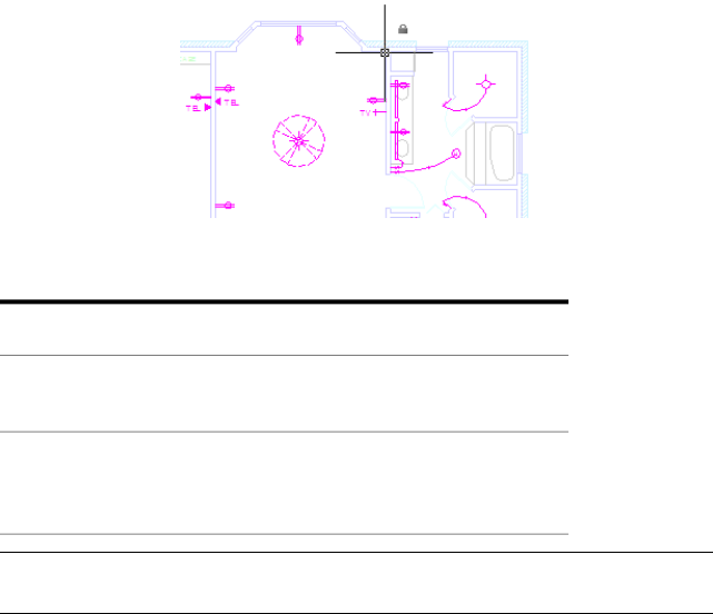
LAYLOCKFADECTL
Quick Reference
See also:
■Use Layers to Manage Complexity
IntegerType:
RegistrySaved in:
50Initial value:
Controls the amount of fading for objects on locked layers.
Fades the objects on locked layers to contrast them with objects on unlocked
layers and reduces the visual complexity of a drawing. Objects on locked layers
are still visible for reference and for object snapping.
The range for controlling the fading for objects on locked layers is from -90
to 90.
Locked layers are not faded0
When the value is positive, controls the percent of fading
up to 90 percent
>0
When the value is negative, locked layers are not faded,
but the value is saved for switching to that value by
changing the sign
<0
NOTE The fading value is limited to 90 percent to avoid confusion with layers
that are turned off or frozen.
LAYLOCKFADECTL | 1567

LAYOUTCREATEVIEWPORT
Quick Reference
See also:
■Work on a Named Layout
IntegerType:
RegistrySaved in:
1Initial value:
Controls whether a viewport is created automatically on each new layout
added to a drawing.
Newly created layouts do not include any viewports.0
A single layout viewport is created with each new layout.1
LIMCHECK
Quick Reference
See also:
■Adjust Grid and Grid Snap
IntegerType:
DrawingSaved in:
0Initial value:
Controls the creation of objects outside the grid limits.
Objects can be created outside the limits0
Objects cannot be created outside the limits1
1568 | Chapter 37 L System Variables
LIMMAX
Quick Reference
See also:
■Adjust Grid and Grid Snap
2D-pointType:
DrawingSaved in:
12.0000,9.0000 (imperial) or 420.0000,297.0000 (metric)Initial value:
Stores the upper-right grid limits for the current space, expressed as world
coordinates.
LIMMAX is read-only when paper space is active and the paper background
or printable area is displayed.
LIMMIN
Quick Reference
See also:
■Adjust Grid and Grid Snap
2D-pointType:
DrawingSaved in:
0.0000,0.0000Initial value:
Stores the lower-left grid limits for the current space, expressed as a world
coordinate.
LIMMIN is read-only when paper space is active and the paper background
or printable area is displayed.
LIMMAX | 1569
LOCALE
Quick Reference
See also:
■Specify Search Paths and File Locations
■Organize Program and Support Files
(Read-only)
StringType:
Not-savedSaved in:
Varies by country/regionInitial value:
Displays a code that indicates the current locale.
This code appears as a three-letter abbreviation returned by the Windows
GetLocaleInfo function using the LOCALE_SABBREVLANGNAME constant.
LOCALROOTPREFIX
Quick Reference
See also:
■Overview of File Organization
(Read-only)
StringType:
RegistrySaved in:
VariesInitial value:
Stores the full path to the root folder where local customizable files were
installed.
The Template and Textures folders are in this location, and you can add any
customizable files that you do not want to roam on the network. See
ROAMABLEROOTPREFIX on page 1644 for the location of the roamable files.
1570 | Chapter 37 L System Variables

LOCKUI
Quick Reference
See also:
■Specify the Behavior of Dockable Windows
BitcodeType:
RegistrySaved in:
0Initial value:
Locks the position and size of toolbars and dockable windows such as
DesignCenter and the Properties palette.
Locked toolbars and windows can still be opened and closed and items can
be added and deleted. To unlock them temporarily, hold down Ctrl.
A lock icon in the status bar tray indicates whether toolbars and windows are
locked. Right-click the icon to display locking options.
The setting is stored as a bitcode using the sum of the following values:
Toolbars and windows not locked0
Docked toolbars locked1
Docked or anchored windows locked2
Floating toolbars locked4
Floating windows locked8
LOGFILEMODE
Quick Reference
See also:
■Set Interface Options
IntegerType:
LOCKUI | 1571

RegistrySaved in:
0Initial value:
Specifies whether the contents of the command history are written to a log
file.
Log file is not maintained0
Log file is maintained1
LOGFILENAME
Quick Reference
See also:
■Set Interface Options
(Read-only)
StringType:
DrawingSaved in:
VariesInitial value:
Specifies the path and name of the command history log file for the current
drawing.
The initial value varies depending on the name of the current drawing and
the installation folder.
LOGFILEPATH
Quick Reference
See also:
■Set Interface Options
StringType:
RegistrySaved in:
VariesInitial value:
1572 | Chapter 37 L System Variables
Specifies the path for the command history log files for all drawings in a
session.
You can also specify the path by using the OPTIONS command. The initial
value is based on the installation folder.
LONGITUDE
Quick Reference
See also:
■Specify the Geographic Location of a Drawing
RealType:
DrawingSaved in:
-122.3940Initial value:
Specifies the longitude of the drawing model in decimal format.
The default is the longitude of San Francisco, California. The valid range is
-180 to +180. Positive values represent east longitudes.
This value is affected by the settings of the LUPREC system variable.
This value is not affected by the settings of the AUNITS and AUPREC system
variables.
LTSCALE
Quick Reference
See also:
■Control Linetype Scale
RealType:
DrawingSaved in:
1.0000Initial value:
Sets the global linetype scale factor.
LONGITUDE | 1573
The linetype scale factor cannot equal zero. This system variable has the same
name as a command. Use the SETVAR command to access this system variable.
LUNITS
Quick Reference
See also:
■Set the Unit Format Conventions
IntegerType:
DrawingSaved in:
2Initial value:
Sets linear units.
Scientific1
Decimal2
Engineering3
Architectural4
Fractional5
LUPREC
Quick Reference
See also:
■Set the Unit Format Conventions
IntegerType:
DrawingSaved in:
4Initial value:
Sets the display precision for linear units and coordinates.
1574 | Chapter 37 L System Variables
However, the internal precision of distance, area, and volume values, and
linear coordinates is always maintained, regardless of the display precision.
LUPREC does not affect the display precision of dimension text (see DIMSTYLE
on page 361).
Valid values are integers from 0 to 8.
LWDEFAULT
Quick Reference
See also:
■Overview of Lineweights
EnumType:
RegistrySaved in:
25Initial value:
Sets the value for the default lineweight.
The default lineweight can be set to any valid lineweight value in hundredths
of millimeters, including: 0, 5, 9, 13, 15, 18, 20, 25, 30, 35, 40, 50, 53, 60, 70,
80, 90, 100, 106, 120, 140, 158, 200, and 211.
All values must be entered in hundredths of millimeters. (Multiply a value by
2540 to convert values from inches to hundredths of millimeters.)
LWDISPLAY
Quick Reference
See also:
■Display Lineweights
IntegerType:
DrawingSaved in:
OFFInitial value:
Controls whether the lineweights of objects are displayed.
LWDEFAULT | 1575

This setting is controlled separately for model space and for all paper space
layouts.
Lineweights are not displayedOFF
Lineweights are displayedON
LWUNITS
Quick Reference
See also:
■Display Lineweights
IntegerType:
RegistrySaved in:
1Initial value:
Controls whether lineweight units are displayed in inches or millimeters.
Inches0
Millimeters1
1576 | Chapter 37 L System Variables
M System Variables
MAXACTVP
Quick Reference
See also:
■Turn Layout Viewports On or Off
IntegerType:
DrawingSaved in:
64Initial value:
Sets the maximum number of viewports that can be active at one time in a
layout.
MAXACTVP has no effect on the number of viewports that are plotted.
MAXSORT
Quick Reference
See also:
■Work with Blocks
IntegerType:
RegistrySaved in:
1000Initial value:
38
1577

Sets the maximum number of symbol names or block names sorted by listing
commands.
If the total number of items exceeds this value, no items are sorted.
The value of MAXSORT is an integer between 0 and 32767.
MAXTOUCHES
Quick Reference
See also:
■Draw Freehand Sketches
(Read-only)
IntegerType:
Not-savedSaved in:
0Initial value:
Identifies the number of touch points supported by connected digitizers.
MBUTTONPAN
Quick Reference
See also:
■Pointing Device Buttons
IntegerType:
RegistrySaved in:
1Initial value:
Controls the behavior of the third button or wheel on the pointing device.
Supports the action defined in the customization file0
Supports panning when you hold and drag the button or
wheel
1
1578 | Chapter 38 M System Variables

MEASUREINIT
Quick Reference
See also:
■Overview of Starting a New Drawing
IntegerType:
RegistrySaved in:
Varies by country/regionInitial value:
Controls whether a drawing you start from scratch uses imperial or metric
default settings.
Specifically, MEASUREINIT controls which hatch pattern and linetype files
are used. The Drawing1.dwg that opens when you start the program is a drawing
that is started from scratch.
Imperial; uses the hatch pattern file and linetype file des-
ignated by the ANSIHatch and ANSILinetype registry set-
tings
0
Metric; uses the hatch pattern file and linetype file desig-
nated by the ISOHatch and ISOLinetype registry settings
1
MEASUREMENT
Quick Reference
See also:
■Overview of Starting a New Drawing
IntegerType:
DrawingSaved in:
0 (imperial) or 1 (metric)Initial value:
MEASUREINIT | 1579

Controls whether the current drawing uses imperial or metric hatch pattern
and linetype files.
Imperial; uses the hatch pattern file and linetype file des-
ignated by the ANSIHatch and ANSILinetype registry set-
tings
0
Metric; uses the hatch pattern file and linetype file desig-
nated by the ISOHatch and ISOLinetype registry settings
1
MENUBAR
Quick Reference
See also:
■Access the Classic Menu Bar
Controls the display of the menu bar.
Hides the menu bar0
Displays the menu bar1
MENUECHO
Quick Reference
See also:
■Create Macros
IntegerType:
Not-savedSaved in:
0Initial value:
Sets menu echo and prompt control bits.
1580 | Chapter 38 M System Variables
The value is the sum of the following:
Suppresses echo of menu items (^P in a menu item toggles
echoing)
1
Suppresses display of system prompts during menu2
Disables ^P toggle of menu echoing4
Displays input/output strings; debugging aid for DIESEL
macros
8
MIRRHATCH
Quick Reference
See also:
■Mirror Objects
IntegerType:
DrawingSaved in:
0Initial value:
Controls how MIRROR reflects hatch patterns.
Retains hatch pattern direction0
Mirrors the hatch pattern direction1
MIRRTEXT
Quick Reference
See also:
■Mirror Objects
IntegerType:
MIRRHATCH | 1581
DrawingSaved in:
0Initial value:
Controls how MIRROR reflects text.
Retains text direction0
Mirrors the text1
MLEADERSCALE
Quick Reference
See also:
■Modify Leaders Using Grips
RealType:
DrawingSaved in:
1.0000Initial value:
Sets the overall scale factor applied to multileader objects.
Use DIMSCALE to scale leader objects created with the LEADER command.
A reasonable default value is computed based on the
scaling between the current model space viewport and
0.0
paper space. If you are in paper space or model space and
not using the paper space feature, the scale factor is 1.0.
A scale factor is computed that leads text sizes, arrowhead
sizes, and other scaled distances to plot at their face values.
>0
MLEADERSCALE does not affect measured lengths, coordinates, or angles.
When MLEADERSCALE is set to 0, and the current multileader style is not ,
the overall multileader scale of multileader objects created in paper space
viewports is determined by the viewport scale. When the current multileader
style is annotative, the MLEADERSCALE value is set to 0. Changes to the
MLEADERSCALE value are ignored and the value is reset to 0.
1582 | Chapter 38 M System Variables
MODEMACRO
Quick Reference
See also:
■Overview of the MODEMACRO System Variable
StringType:
Not-savedSaved in:
""Initial value:
Displays a text string on the status line, such as the name of the current
drawing, time/date stamp, or special modes.
Use MODEMACRO to display a string of text, or use special text strings written
in the DIESEL macro language to have the macro evaluated from time to time
and base the status line on user-selected conditions.
MSLTSCALE
Quick Reference
See also:
■Display Annotative Objects
IntegerType:
DrawingSaved in:
1Initial value:
Scales linetypes displayed on the model tab by the
Linetypes displayed on the Model tab are not scaled by
the annotation scale
0
Linetypes displayed on the Model tab are scaled by the
annotation scale
1
NOTE MSLTSCALE is set to 0 when you open drawings created in AutoCAD LT
2007 and earlier.
MODEMACRO | 1583

MSMSTATE
Quick Reference
See also:
■Overview of Using Markups for Design Review
(Read-only)
IntegerType:
Not-savedSaved in:
VariesInitial value:
Indicates whether the Markup Set Manager is open or closed.
Closed0
Open1
MSOLESCALE
Quick Reference
See also:
■Overview of Importing OLE Objects into Drawings
RealType:
DrawingSaved in:
1.0000Initial value:
Controls the size of an OLE object with text that is pasted into model space.
MSOLESCALE controls only the initial size. If the scale factor value is changed,
existing OLE objects in the drawing are not affected.
A positive number scales by value. Zero (0) scales by the DIMSCALE value.
1584 | Chapter 38 M System Variables

MTEXTCOLUMN
Quick Reference
See also:
■Create and Edit Columns in Multiline Text
IntegerType:
DrawingSaved in:
2Initial value:
Sets the default column setting for an mtext object.
No column.0
Dynamic columns with auto height.1
Dynamic column with manual height.2
MTEXTED
Quick Reference
See also:
■Overview of Using an Alternate Text Editor
StringType:
RegistrySaved in:
"Internal"Initial value:
Sets the application for editing multiline text objects.
You can specify a different text editor for the MTEXT command. If you set
MTEXTED to internal or to null (.), the In-Place Text Editor is displayed. If
you set MTEXTED to “OldEditor”, the Multiline Text Editor is displayed. If
you specify a path and the name of the executable file for another text editor
or word processor, that path and file name instead are displayed instead.
Text editors other than the internal one show the formatting codes in
paragraph text.
MTEXTCOLUMN | 1585

MTEXTFIXED
Quick Reference
See also:
■Overview of Multiline Text
IntegerType:
RegistrySaved in:
2Initial value:
Sets the display size and orientation of multiline text in a specified text editor.
If MTEXTED is set to “Internal”, multiline text is displayed in the In-Place
Text Editor, and the setting of MTEXTFIXED has the following results:
Displays the In-Place Text Editor and the text within it at
the size, position, and rotation of the multiline text object
in the drawing.
0 or 1
Displays the In-Place Text Editor and the text within it at
the size, position, and rotation of the multiline text object
in the drawing.
2
Text that would otherwise be difficult to read (if it is very
small, very large, or is rotated) is displayed at a legible size
and is oriented horizontally so that you can easily read
and edit it.
MTEXTTOOLBAR
Quick Reference
See also:
■Overview of Multiline Text
IntegerType:
User-settingsSaved in:
2Initial value:
1586 | Chapter 38 M System Variables

Controls the display of the Text Formatting toolbar.
The Text Formatting toolbar is never displayed.0
The Text Formatting toolbar is displayed upon selection
of an MTEXT object.
1
The Text Formatting toolbar does not display when the
ribbon is on.
2
MTJIGSTRING
Quick Reference
See also:
■Overview of Multiline Text
StringType:
RegistrySaved in:
"abc"Initial value:
Sets the content of the sample text displayed at the cursor location when the
MTEXT command is started.
The text string is displayed in the current text size and font. You can enter
any string of up to ten letters or numbers or enter a period (.) to display no
sample text.
MYDOCUMENTSPREFIX
Quick Reference
See also:
■Specify Search Paths and File Locations
(Read-only)
StringType:
RegistrySaved in:
MTJIGSTRING | 1587
VariesInitial value:
Stores the full path to the My Documents folder for the user currently logged
on.
1588 | Chapter 38 M System Variables

N System Variables
NAVBARDISPLAY
Quick Reference
See also:
■Use Navigation Bar
IntegerType:
RegistrySaved in:
1Initial value:
Controls the display of the navigation bar in all viewports.
Navigation bar is not displayed0
Navigation bar is displayed1
39
1589
1590

O System Variables
OBJECTISOLATIONMODE
Quick Reference
See also:
■Control the Display of Objects
IntegerType:
User-settingsSaved in:
0Initial value:
Controls whether hidden objects remain hidden between drawing sessions.
OJBECTISOLATIONMODE controls whether objects that are hidden using the
ISOLATEOBJECTS on page 629 or HIDEOBJECTS on page 586 command remain
hidden after saving and reopening the drawing.
Isolated/hidden objects are temporary for current drawing
session
0
Isolated/hidden objects persist between drawing sessions1
40
1591
OBSCUREDCOLOR
Quick Reference
See also:
■Add Simple Shading to 3D Objects
IntegerType:
DrawingSaved in:
257Initial value:
Specifies the color of obscured lines.
Value 0 designates ByBlock, value 256 designates ByLayer, and value 257
designates ByEntity. Values 1-255 designate an AutoCAD Color Index (ACI).
An obscured line is a hidden line made visible by changing its color and
linetype and is visible only when the HIDE or SHADEMODE commands are
used.
The OBSCUREDCOLOR setting is visible only if the OBSCUREDLTYPE system
variable is turned on by setting it to a value other than 0.
The obscured color can also be set in the Hidden Line Settings dialog box,
Obscured Lines area, Color pull-down menu.
OBSCUREDLTYPE
Quick Reference
See also:
■Add Simple Shading to 3D Objects
IntegerType:
DrawingSaved in:
0Initial value:
Specifies the linetype of obscured lines.
The obscured linetype can also be set in the Hidden Line Settings dialog box,
Obscured Lines area, Linetype pull-down menu.
1592 | Chapter 40 O System Variables

An obscured line is a hidden line made visible by changing its color and
linetype and is visible only when the HIDE or SHADEMODE commands are
used.
Obscured linetypes are independent of zoom level, unlike regular linetypes.
The linetype values are defined as follows:
Off0
Solid1
Dashed2
Dotted3
Short Dash4
Medium Dash5
Long Dash6
Double Short Dash7
Double Medium Dash8
Double Long Dash9
Medium Long Dash10
Sparse Dot11
OBSCUREDLTYPE | 1593
OFFSETDIST
Quick Reference
See also:
■Offset an Object
RealType:
Not-savedSaved in:
-1.0000Initial value:
Sets the default offset distance.
Offsets an object through a specified point<0
Sets the default offset distance
0
OFFSETGAPTYPE
Quick Reference
See also:
■Offset an Object
IntegerType:
RegistrySaved in:
0Initial value:
Controls how potential gaps between segments are treated when polylines
are offset.
Extends line segments to their projected intersections.0
Fillets line segments at their projected intersections. The
radius of each arc segment is equal to the offset distance.
1
Chamfers line segments at their projected intersections.
The perpendicular distance from each chamfer to its cor-
2
1594 | Chapter 40 O System Variables
responding vertex on the original object is equal to the
offset distance.
OLEFRAME
Quick Reference
See also:
■Edit OLE Objects in Drawings
IntegerType:
DrawingSaved in:
2Initial value:
Controls whether a frame is displayed and plotted on all OLE objects in the
drawing.
The frame on an OLE object must be displayed in order for grips to be visible.
Frame is not displayed and not plotted0
Frame is displayed and is plotted1
Frame is displayed but is not plotted2
OLEHIDE
Quick Reference
See also:
■Overview of Importing OLE Objects into Drawings
IntegerType:
RegistrySaved in:
0Initial value:
OLEFRAME | 1595

Controls the display and plotting of OLE objects.
All OLE objects are visible and plot0
OLE objects are visible and plot in paper space only1
OLE objects are visible and plot in model space only2
No OLE objects are visible or plot3
OLEQUALITY
Quick Reference
See also:
■Overview of Importing OLE Objects into Drawings
IntegerType:
RegistrySaved in:
3Initial value:
Sets the default plot quality for OLE objects.
With OLEQUALITY, you can assign the plot quality for OLE objects to 0
(monochrome), 1 (low graphics), or 2 (high graphics).
When OLEQUALITY is set to 3, the quality level is assigned automatically
based on the type of object. For example, spreadsheets and tables are set to
monochrome, color text and pie charts are set to low graphics, and
photographs are set to high graphics.
The following table define the value of the plot quality for OLE objects.
Monochrome0
Low graphics1
High graphics2
Automatically Select3
1596 | Chapter 40 O System Variables
OLESTARTUP
Quick Reference
See also:
■Overview of Importing OLE Objects into Drawings
IntegerType:
DrawingSaved in:
0Initial value:
Controls whether the source application of an embedded OLE object loads
when plotting.
Loading the OLE source application may improve the plot quality.
Does not load the OLE source application0
Loads the OLE source application when plotting1
OPENPARTIAL
Quick Reference
See also:
■Open a Drawing
IntegerType:
RegistrySaved in:
1Initial value:
Controls whether a drawing file can be worked on before it is fully open.
Two conditions must be met for this system variable to have an effect. The
drawing must have been saved with paper space displayed (TILEMODE is set
to 0), and the INDEXCTL system variable must be set to a non-zero value.
Legacy behavior: A drawing must be fully opened before
work can begin on it
0
OLESTARTUP | 1597

Work can begin on the visible portions of a drawing before
it is fully open
1
OPMSTATE
Quick Reference
See also:
■Display and Change the Properties of Objects
(Read-only)
IntegerType:
Not-savedSaved in:
0Initial value:
Indicates whether the Properties palette is open, closed, or hidden.
Closed0
Open1
Auto-hide: Open but only the title bar is displayed when
the cursor moves off the palette
2
ORTHOMODE
Quick Reference
See also:
■Use Orthogonal Locking (Ortho Mode)
IntegerType:
DrawingSaved in:
0Initial value:
Constrains cursor movement to the perpendicular.
1598 | Chapter 40 O System Variables
When ORTHOMODE is turned on, the cursor can move only horizontally or
vertically relative to the UCS and the current grid rotation angle
Turns off Ortho mode0
Turns on Ortho mode1
OSMODE
Quick Reference
See also:
■Use Object Snaps
IntegerType:
RegistrySaved in:
4133Initial value:
Sets running object snaps
The setting is stored as a bitcode using the sum of the following values:
NONe0
ENDpoint1
MIDpoint2
CENter4
NODe8
QUAdrant16
INTersection32
INSertion64
PERpendicular128
TANgent256
OSMODE | 1599
NEArest512
Clears all object snaps1024
APParent Intersection2048
EXTension4096
PARallel8192
To specify more than one object snap, enter the sum of their values. For
example, entering 3 specifies the Endpoint (bitcode 1) and Midpoint (bitcode
2) object snaps. Entering 16383 specifies all object snaps.
OSNAPCOORD
Quick Reference
See also:
■Set Visual Aids for Object Snaps (AutoSnap)
IntegerType:
RegistrySaved in:
2Initial value:
Controls whether coordinates entered on the command line will override
running object snaps.
Running object snap settings override keyboard coordinate
entry
0
Keyboard entry overrides object snap settings1
Keyboard entry overrides object snap settings except in
scripts
2
1600 | Chapter 40 O System Variables
OSNAPNODELEGACY
Quick Reference
See also:
■Change Multiline Text
IntegerType:
RegistrySaved in:
0Initial value:
Controls whether the Node object snap can be used to snap to multiline text
objects.
The number and location of nodes on a multiline text object snap depends
on the vertical and horizontal justification of the multiline text object.
Node object snap can be used with multiline text objects0
Node object snap ignores multiline text objects1
OSOPTIONS
Quick Reference
See also:
■Use Object Snaps
BitcodeType:
RegistrySaved in:
1Initial value:
Automatically suppresses object snaps on hatch objects.
Object snaps operate on hatch objects, and on geometry
with negative Z values when using a dynamic UCS
0
Object snaps ignore hatch objects1
OSNAPNODELEGACY | 1601
1602

P System Variables
PALETTEOPAQUE
Quick Reference
See also:
■Set Up the Drawing Area
■Transparency Dialog Box on page 888
IntegerType:
RegistrySaved in:
0Initial value:
Controls whether palettes can be made transparent.
When transparency is available and turned on, you can use the Transparency
option on the shortcut menu to set a different degree of transparency for the
current palette or for all palettes.
When transparency is unavailable or turned off, all palettes are opaque.
Transparency is unavailable when palettes or windows are docked, when
transparency is not supported by the current operating system, or when a
hardware accelerator is enabled.
Transparency is turned off0
Transparency is turned on1
41
1603

Transparency is turned off and is not supported by the
hardware and/or operating system
2
Transparency is turned on, but is not supported by the
hardware and/or operating system
3
Available settings depend whether hardware acceleration is enabled. When
hardware acceleration is enabled, setting 2 and 3 are available; when disabled,
setting 0 and 1 are available.
This system variable determines the default setting in the Transparency dialog
box > General section > How transparent should the palette be? option on
page 888.
PAPERUPDATE
Quick Reference
See also:
■Set Paper Size
IntegerType:
RegistrySaved in:
0Initial value:
Controls the display of a warning dialog box when attempting to print a layout
with a paper size different from the paper size specified by the default for the
plotter configuration file.
Displays a warning dialog box if the paper size specified
in the layout is not supported by the plotter
0
Sets paper size to the configured paper size of the plotter
configuration file
1
1604 | Chapter 41 P System Variables
PDFFRAME
Quick Reference
See also:
■Hide and Show Underlay Frames
IntegerType:
DrawingSaved in:
1Initial value:
Determines whether the PDF underlay frame is visible.
The FRAME system variable overrides the PDFFRAME setting. Use the
PDFFRAME system variable after the FRAME system variable to reset the PDF
frame settings.
The PDF underlay frame is not displayed or plotted.0
The frame temporarily reappears during selection preview
or object selection.
Displays and plots the PDF underlay frame.1
Displays but does not plot the PDF underlay frame.2
PDFOSNAP
Quick Reference
See also:
■Use Object Snaps with Underlays
IntegerType:
RegistrySaved in:
1Initial value:
Determines whether object snapping is active for geometry in PDF underlays
that are attached to the drawing.
PDFFRAME | 1605
The UOSNAP system variable overrides the PDFOSNAP setting.
Object snapping is disabled for geometry in all PDF under-
lay attachments in the drawing
0
Object snapping is enabled for geometry in all PDF under-
lay attachments in the drawing
1
PDMODE
Quick Reference
See also:
■Divide an Object into Equal Segments
IntegerType:
DrawingSaved in:
0Initial value:
Controls how point objects are displayed.
For information about values to enter, see the POINT on page 1009 command.
PDSIZE
Quick Reference
See also:
■Divide an Object into Equal Segments
RealType:
DrawingSaved in:
0.0000Initial value:
Sets the display size for point objects.
Creates a point at 5 percent of the drawing area height0
Specifies an absolute size>0
1606 | Chapter 41 P System Variables
Specifies a percentage of the viewport size<0
PEDITACCEPT
Quick Reference
See also:
■Modify Polylines
IntegerType:
RegistrySaved in:
0Initial value:
Suppresses display of the Object Selected Is Not a Polyline prompt in PEDIT.
The prompt is followed by “Do you want it to turn into one?” Entering y
converts the selected object to a polyline. When the prompt is suppressed,
the selected object is automatically converted to a polyline.
The prompt is displayed0
The prompt is suppressed1
PELLIPSE
Quick Reference
See also:
■Draw Ellipses
IntegerType:
DrawingSaved in:
0Initial value:
Controls the ellipse type created with ELLIPSE.
Creates a true ellipse object.0
PEDITACCEPT | 1607

Creates a polyline representation of an ellipse1
PERIMETER
Quick Reference
See also:
■Obtain Area and Mass Properties Information
(Read-only)
RealType:
Not-savedSaved in:
0.0000Initial value:
Stores the last perimeter value computed by the AREA or LIST command.
PERSPECTIVE
Quick Reference
See also:
■Work with AutoCAD Drawings in AutoCAD LT
IntegerType:
DrawingSaved in:
VariesInitial value:
Specifies whether the current viewport displays a perspective view.
In AutoCAD LT, you can only turn off perspective in a drawing created with
an AutoCAD-based application; you cannot turn perspective back on.
NOTE PERSPECTIVE is set to 0 when the drawing file or DXF file is saved to a file
format earlier than AutoCAD LT 2007.
1608 | Chapter 41 P System Variables

PERSPECTIVECLIP
Quick Reference
See also:
■Define a Perspective Projection (DVIEW)
RealType:
RegistrySaved in:
5.0000Initial value:
Determines the location of eyepoint clipping.
The value determines where the eye point clipping occurs as a percentage.
Values can range between 0.01 and 10.0. If you select a small value, the z-values
of objects will be compressed at the target view and beyond. If you select a
value such as 0.5%, the clipping will appear very close to the eyepoint of the
view. In some extreme cases it might be appropriate to use 0.1%, but it is
recommended to change the setting to a higher value such as 5%.
PICKADD
Quick Reference
See also:
■Select Multiple Objects
IntegerType:
User-settingsSaved in:
2Initial value:
Controls whether subsequent selections replace the current selection set or
add to it.
Turns off PICKADD. The objects most recently selected
become the selection set. Previously selected objects are
0
removed from the selection set. Add more objects to the
selection set by pressing SHIFT while selecting.
PERSPECTIVECLIP | 1609
Turns on PICKADD. Each object selected, either individually
or by windowing, is added to the current selection set.
1
To remove objects from the set, press SHIFT while select-
ing.
Turns on PICKADD. Each object selected, either individually
or by windowing, is added to the current selection set.
2
To remove objects from the set, press SHIFT while select-
ing. Keeps objects selected after the SELECT on page 1107
command ends.
PICKAUTO
Quick Reference
See also:
■Select Multiple Objects
IntegerType:
RegistrySaved in:
1Initial value:
Controls automatic windowing for object selection.
Window selection is disabled.0
Selects a clicked object or begins a selection window (for
either a window or crossing selection) when the cursor is
not on an object.
1
Selects a clicked object or begins a selection window
whether the cursor is on an object or not.
2
For PICKAUTO settings 0 and 1, object selection occurs when the mouse
button is pressed. For PICKAUTO setting 2, object selection occurs when the
mouse button is released.
1610 | Chapter 41 P System Variables
PICKBOX
Quick Reference
See also:
■Select Objects Individually
IntegerType:
RegistrySaved in:
3Initial value:
Sets the object selection target height, in pixels.
NOTE When PICKBOX is set to 0, selection previewing of objects is not available.
PICKDRAG
Quick Reference
See also:
■Select Multiple Objects
IntegerType:
RegistrySaved in:
2Initial value:
Controls the method of drawing a selection window.
Create a selection window using two points. Click once
to begin a selecton window, click again to complete the
selection.
0
Create a selection window clicking and dragging. Release
the mouse button to complete the selection.
1
Create a selection window using either of the methods
above.
2
PICKBOX | 1611
PICKFIRST
Quick Reference
See also:
■Customize Object Selection
IntegerType:
RegistrySaved in:
1Initial value:
Controls whether you select objects before (noun-verb selection) or after you
issue a command.
Turns off PICKFIRST; you select objects after you issue a
command
0
Turns on PICKFIRST; you select objects before you issue a
command
1
PICKSTYLE
Quick Reference
See also:
■Select Objects in Groups
IntegerType:
RegistrySaved in:
1Initial value:
Controls the use of group selection and associative hatch selection.
No group selection or associative hatch selection0
Group selection1
Associative hatch selection2
1612 | Chapter 41 P System Variables

Group selection and associative hatch selection3
PLATFORM
Quick Reference
See also:
■Set Interface Options
(Read-only)
StringType:
Not-savedSaved in:
VariesInitial value:
Indicates which platform is in use.
PLINECONVERTMODE
Quick Reference
See also:
■Modify Splines
IntegerType:
RegistrySaved in:
0Initial value:
Specifies the fit method used in converting splines to polylines.
Polylines are created with linear segments0
Polylines are created with arc segments1
PLATFORM | 1613
PLINEGEN
Quick Reference
See also:
■Display Linetypes on Short Segments and Polylines
IntegerType:
DrawingSaved in:
0Initial value:
Sets how linetype patterns generate around the vertices of a 2D polyline.
Does not apply to polylines with tapered segments.
Generates polylines to start and end with a dash at each
vertex
0
Generates the linetype in a continuous pattern around the
vertices of the polyline
1
PLINETYPE
Quick Reference
See also:
■Draw Polylines
IntegerType:
RegistrySaved in:
2Initial value:
Specifies whether optimized 2D polylines are used.
PLINETYPE controls both the creation of new polylines with the PLINE
command and the conversion of existing polylines in drawings from previous
releases.
Polylines in older drawings are not converted when
opened; PLINE creates old-format polylines
0
1614 | Chapter 41 P System Variables

Polylines in older drawings are not converted when
opened; PLINE creates optimized polylines
1
Polylines in AutoCAD Release 14 or older drawings are
converted when opened; PLINE creates optimized polylines
2
For more information on the two formats, see the CONVERT command.
PLINETYPE also controls the polyline type created with the following
commands: BOUNDARY (when object type is set to Polyline), DONUT, PEDIT
(when selecting a line or arc), and POLYGON.
PLINEWID
Quick Reference
See also:
■Draw Polylines
RealType:
DrawingSaved in:
0.0000Initial value:
Stores the default polyline width.
PLOTOFFSET
Quick Reference
See also:
■Adjust the Plot Offset of a Layout
IntegerType:
RegistrySaved in:
0Initial value:
PLINEWID | 1615
Controls whether the plot offset is relative to the printable area or to the edge
of the paper.
Sets the plot offset relative to the printable area.0
Sets the plot offset relative to the edge of the paper1
PLOTROTMODE
Quick Reference
See also:
■Select a Printer or Plotter
IntegerType:
RegistrySaved in:
2Initial value:
Controls the orientation of plots.
Rotates the effective plotting area so the corner with the
Rotation icon aligns with the paper at the lower left for 0,
0
top left for 90, top right for 180, and lower right for 270.
X and Y origin offsets are calculated relative to the lower-
left corner.
Aligns the lower-left corner of the effective plotting area
with the lower-left corner of the paper.
1
Works the same as 0 value except that the X and Y origin
offsets are calculated relative to the rotated origin position.
2
1616 | Chapter 41 P System Variables

PLOTTRANSPARENCYOVERRIDE
Quick Reference
See also:
■Work with Object Properties
IntegerType:
User-settingsSaved in:
1Initial value:
Controls whether object transparency is plotted.
Does not plot object transparency0
Uses the setting specified in the Page Setup or the Plot
dialog boxes
1
Plots object transparency2
Setting the PLOTTRANSPARENCYOVERRIDE system variable to 0 or 2 overrides
the Plot Transparency option in the Page Setup or the Plot dialog boxes.
WARNING Because this system variable can affect global plot performance, it is
strongly advised that you leave the value set to 1 and manage plot transparency
when plotting.
POINTCLOUDDENSITY
Quick Reference
See also:
■Work with AutoCAD Drawings in AutoCAD LT
IntegerType:
DrawingSaved in:
15Initial value:
PLOTTRANSPARENCYOVERRIDE | 1617
Controls the number of points displayed at once for all point clouds in the
drawing view.
The system variable value is a percentage of 1,500,000, which is the maximum
number of points that can exist in a drawing, regardless of the number of
point clouds attached to a single drawing.
For example, if the system variable is set to 1, a maximum of 15,000 points
is displayed at one time, even if there are multiple point clouds displayed on
the screen. The 15,000 points are evenly distributed between the viewable
point clouds.
POLARADDANG
Quick Reference
See also:
■Use Polar Tracking and PolarSnap
StringType:
RegistrySaved in:
""Initial value:
Stores additional angles for polar tracking and polar snap.
You can add up to 10 angles. Each angle can be separated with semicolons (;).
The AUNITS system variable sets the format for display of angles.Unlike
POLARANG, POLARADDANG angles do not result in multiples of their values.
The bit value for the POLARMODE system variable must have 4 turned on for
POLARADDANG to have an effect.
When using fractions of an angle, set the AUPREC system variable (angular
precision) to a higher value. Otherwise, the POLARADDANG value will be
rounded off.
1618 | Chapter 41 P System Variables
POLARANG
Quick Reference
See also:
■Use Polar Tracking and PolarSnap
RealType:
RegistrySaved in:
90Initial value:
Sets the polar angle increment.
Values are 90, 45, 30, 22.5, 18, 15,10, and 5.
POLARDIST
Quick Reference
See also:
■Use Polar Tracking and PolarSnap
RealType:
RegistrySaved in:
0.0000Initial value:
Sets the snap increment when the SNAPTYPE is set to 1 (PolarSnap).
POLARMODE
Quick Reference
See also:
■Use Polar Tracking and PolarSnap
IntegerType:
RegistrySaved in:
POLARANG | 1619
0Initial value:
Controls settings for polar and object snap tracking.
The setting is stored as a bitcode using the sum of the following values:
Polar angle measurements
Measure polar angles based on current UCS (absolute)0
Measure polar angles from selected objects (relative)1
Object snap tracking
Track orthogonally only0
Use polar tracking settings in object snap tracking2
Use additional polar tracking angles
No0
Yes4
Acquire object snap tracking points
Acquire automatically0
Press SHIFT to acquire8
POLYSIDES
Quick Reference
See also:
■Draw Rectangles and Polygons
IntegerType:
Not-savedSaved in:
4Initial value:
Sets the default number of sides for the POLYGON command.
1620 | Chapter 41 P System Variables
The range is 3 to 1024.
PREVIEWEFFECT
Quick Reference
See also:
■Customize Object Selection
IntegerType:
RegistrySaved in:
2Initial value:
Specifies the visual effect used for previewing selection of objects.
Dashed lines (the default display for selected objects)0
Thickened lines1
Dashed and thickened lines2
PREVIEWFACEEFFECT
Quick Reference
See also:
■Customize Object Selection
IntegerType:
RegistrySaved in:
1Initial value:
Specifies the visual effect used for previewing selection of face subobjects.
No highlight effect for face0
Highlight face with texture fill1
PREVIEWEFFECT | 1621

PREVIEWFILTER
Quick Reference
See also:
■Customize Object Selection
BitcodeType:
RegistrySaved in:
7Initial value:
Excludes specified object types from selection previewing.
The setting is stored as a bitcode using the sum of the following values:
Excludes nothing0
Excludes objects on locked layers1
Excludes objects in xrefs2
Excludes tables4
Excludes multiline text objects8
Excludes hatch objects16
Excludes objects in groups32
PROJMODE
Quick Reference
See also:
■Trim or Extend Objects
IntegerType:
RegistrySaved in:
1Initial value:
1622 | Chapter 41 P System Variables
Sets the current Projection mode for trimming or extending.
True 3D mode (no projection)0
Project to the XY plane of the current UCS1
Project to the current view plane2
PROPOBJLIMIT
Quick Reference
See also:
■Display and Change the Properties of Objects
IntegerType:
User-settingsSaved in:
25000Initial value:
Limits the number of objects that can be changed at one time with the
Properties and Quick Properties palettes.
The valid range is 0 - 32767. If the limit is exceeded, the property fields in the
palettes will be grayed out.
NOTE A similar limit on ribbon property controls and ribbon contextual tabs is
stored independently by the RIBBONCONTEXTSELLIM on page 1642 system variable.
PROXYGRAPHICS
Quick Reference
See also:
■Work with Custom and Proxy Objects
IntegerType:
DrawingSaved in:
1Initial value:
PROPOBJLIMIT | 1623
Specifies whether images of proxy objects are saved in the drawing.
Does not save image with the drawing; a bounding box
is displayed instead
0
Saves image with the drawing1
PROXYNOTICE
Quick Reference
See also:
■Work with Custom and Proxy Objects
IntegerType:
RegistrySaved in:
1Initial value:
Displays a notice when a proxy is created.
A proxy is created when you open a drawing containing custom objects created
by an application that is not present. A proxy is also created when you issue
a command that unloads a custom object's parent application.
No proxy warning is displayed0
Proxy warning is displayed1
PROXYSHOW
Quick Reference
See also:
■Work with Custom and Proxy Objects
IntegerType:
RegistrySaved in:
1624 | Chapter 41 P System Variables

1Initial value:
Controls the display of proxy objects in a drawing.
Proxy objects are not displayed0
Graphic images are displayed for all proxy objects
1
Only the bounding box is displayed for all proxy
objects
2
PROXYWEBSEARCH
Quick Reference
See also:
■Work with Custom and Proxy Objects
IntegerType:
RegistrySaved in:
0Initial value:
Specifies how the program checks for object enablers.
Object enablers allow you to display and use custom objects.
PROXYWEBSEARCH is also controlled with the Live Enabler options on the
System tab of the Options dialog box.
Prevents checking for object enablers0
Checks for object enablers only if a live Internet connection
is present
1
PROXYWEBSEARCH | 1625

PSLTSCALE
Quick Reference
See also:
■Scale Linetypes in Layout Viewports
IntegerType:
DrawingSaved in:
1Initial value:
Controls the linetype scaling of objects displayed in paper space viewports.
No special linetype scaling. Linetype dash lengths are
based on the drawing units of the space (model or paper)
0
in which the objects were created. Scaled by the global
LTSCALE factor.
Viewport scaling governs linetype scaling. If TILEMODE is
set to 0, dash lengths are based on paper space drawing
1
units, even for objects in model space. In this mode,
viewports can have varying magnifications, yet display
linetypes identically. For a specific linetype, the dash
lengths of a line in a viewport are the same as the dash
lengths of a line in paper space. You can still control the
dash lengths with LTSCALE
When you change PSLTSCALE or use a command such as ZOOM with
PSLTSCALE set to 1, objects in viewports are not automatically regenerated
with the new linetype scale. Use the REGEN or REGENALL command to update
the linetype scales in each viewport.
PSTYLEMODE
Quick Reference
See also:
■Overview of Plot Styles
1626 | Chapter 41 P System Variables
(Read-only)
IntegerType:
DrawingSaved in:
1Initial value:
Indicates whether the current drawing is in a Color-Dependent or Named Plot
Style mode.
Uses named plot style tables in the current drawing0
Uses color-dependent plot style tables in the current
drawing
1
PSTYLEPOLICY
Quick Reference
See also:
■Overview of Plot Styles
IntegerType:
RegistrySaved in:
1Initial value:
Controls the plot style mode, Color-Dependent or Named, that is used when
opening a drawing that was created in a release prior to AutoCAD 2000 or
when creating a new drawing from scratch without using a drawing template.
Drawing is set to use named plot styles. The plot style for
new objects is set to the default defined in DEFPLSTYLE.
0
The plot style for new layers is set to the default defined
in DEFLPLSTYLE.
Drawing is set to use color-dependent plot styles. The plot
style for an object is based on the object’s color.
1
PSTYLEPOLICY | 1627

PUBLISHALLSHEETS
Quick Reference
See also:
■Overview of Publishing
IntegerType:
User-settingsSaved in:
1Initial value:
Specifies whether to load the contents of the active document or of all open
documents in the Publish dialog box.
Only the current document's contents (layouts and/or
model space) are automatically loaded in the publish list
0
The contents (layouts and/or model space) of all open
AutoCAD documents are automatically loaded in the
publish list
1
PUBLISHCOLLATE
Quick Reference
See also:
■Publish, Transmit, and Archive Sheet Sets
IntegerType:
User-settingsSaved in:
1Initial value:
Controls whether plotting a sheet set, multi-sheet plot file, or plot spool file
can be interrupted by other plot jobs.
1628 | Chapter 41 P System Variables
Publishing sheets as a single job requires a plot driver that supports the
multi-sheet plotting or printing option.
A published sheet set is processed one sheet at a time.
Separate PLT files are created for each sheet. If the sheet
0
set is published, the sheets might be interleaved with
other plot jobs.
A published sheet set is processed as a single job. A multi-
sheet PLT file is created. If the sheet set is published, it is
never interleaved with other plot jobs.
1
PUBLISHHATCH
Quick Reference
See also:
■Publish an Electronic Drawing Set
IntegerType:
RegistrySaved in:
1Initial value:
Controls whether hatch patterns published to DWF or DWFx format are treated
as a single object when they are opened in Autodesk Impression.
Treats hatch pattern components as separate objects when
published to a DWF or DWFx format
0
Treats hatch pattern components as a single object when
published to a DWF or DWFx format
1
NOTE Autodesk Impression uses this information to improve performance when
handling DWF or DWFx files that contain hatches. This variable only affects
drawings published to the DWF or DWFx format. It does not affect drawings
plotted to the DWF or DWFx format.
PUBLISHHATCH | 1629
PUCSBASE
Quick Reference
See also:
■Overview of the User Coordinate System (UCS)
StringType:
DrawingSaved in:
""Initial value:
Stores the name of the UCS that defines the origin and orientation of
orthographic UCS settings in paper space only.
1630 | Chapter 41 P System Variables

Q System Variables
QCSTATE
Quick Reference
See also:
■Overview of QuickCalc
IntegerType:
DrawingSaved in:
VariesInitial value:
Indicates whether the QuickCalc calculator is open or closed.
Closed0
Open1
QPLOCATION
Quick Reference
See also:
■Display and Change the Properties of Objects
IntegerType:
42
1631
RegistrySaved in:
0Initial value:
Sets the location for the Quick Properties palette.
The Quick Properties palette is displayed relative to the
location of the cursor
0
The Quick Properties palette is displayed in a fixed location
that is independent of the cursor
1
QPMODE
Quick Reference
See also:
■Display and Change the Properties of Objects
IntegerType:
RegistrySaved in:
-1Initial value:
Controls whether the Quick Properties palette is displayed when objects are
selected.
Turns off the display of the Quick Properties palette for all
objects when they are selected in the drawing area
0
Turns on the display of the Quick Properties palette for all
objects when they are selected in the drawing area
1
Turns on the display of Quick Properties palette, but only
for objects that are supported in the Customize User Inter-
2
face (CUI) editor for displaying quick properties when they
are selected in the drawing area
NOTE When this system variable is set to a negative number, the feature is turned
off but the value is retained. To use this feature, the PICKFIRST system variable
must be set to 1 (on).
1632 | Chapter 42 Q System Variables
QTEXTMODE
Quick Reference
See also:
■Control the Display of Polylines, Hatches, Gradient Fills, Lineweights, and
Text
IntegerType:
DrawingSaved in:
0Initial value:
Controls how text is displayed.
Turns off Quick Text mode; displays characters0
Turns on Quick Text mode; displays a box in place of text1
QVDRAWINGPIN
Quick Reference
See also:
■Switch Between Open Drawings
IntegerType:
RegistrySaved in:
0Initial value:
Controls the default display state of preview images of drawings.
Displays preview images of drawings in an unpinned state0
Displays preview images of drawings in a pinned state1
QTEXTMODE | 1633

QVLAYOUTPIN
Quick Reference
See also:
■Switch Between Layouts in the Current Drawing
IntegerType:
RegistrySaved in:
0Initial value:
Controls the default display state of preview images of model space and layouts
in a drawing.
Displays preview images of model space and layouts in a
drawing in an unpinned state
0
Displays preview images of model space and layouts in a
drawing in a pinned state
1
1634 | Chapter 42 Q System Variables
R System Variables
RASTERDPI
Quick Reference
See also:
■Plot to Raster File Formats
IntegerType:
RegistrySaved in:
300Initial value:
Controls paper size and plot scaling when changing from dimensional to
dimensionless output devices, or vice versa.
Converts millimeters or inches to pixels, or vice versa. Accepts an integer between
100 and 32,767 as a valid value.
RASTERPERCENT
Quick Reference
See also:
■Plot to Raster File Formats
IntegerType:
RegistrySaved in:
43
1635

20Initial value:
Sets the maximum percentage of available virtual memory that is allowed for
plotting a raster image.
RASTERPREVIEW
Quick Reference
See also:
■Save a Drawing
IntegerType:
RegistrySaved in:
1Initial value:
Controls whether BMP preview images are saved with the drawing.
No preview image is created0
Preview image created1
RASTERTHRESHOLD
Quick Reference
See also:
■Plot to Raster File Formats
IntegerType:
RegistrySaved in:
20Initial value:
Specifies a raster threshold in megabytes.
If the plotted raster image exceeds this threshold, the availability of system
memory is checked. The plot is aborted if the image is too big for the available
memory.
1636 | Chapter 43 R System Variables

RECOVERAUTO
Quick Reference
See also:
■Repair a Damaged Drawing File
BitcodeType:
RegistrySaved in:
0Initial value:
Controls the display of recovery notifications before or after opening a
damaged drawing file.
Displays a task dialog to recover damaged files while
opening a drawing that needs recovery. The task dialog
interrupts any running scripts.
0
Automatically recovers the damaged files, opens the
drawing, and displays a task dialog with the information
1
of the recovered files. If a script is running, the task dialog
is suppressed.
Automatically recovers the damaged files and opens the
drawing without displaying any task dialog. The informa-
2
tion of the recovered files is displayed at the command
prompt.
RECOVERYMODE
Quick Reference
See also:
■Recover from a System Failure
IntegerType:
RegistrySaved in:
2Initial value:
RECOVERAUTO | 1637

Controls whether drawing recovery information is recorded after a system
failure.
Recovery information is not recorded, the Drawing Recov-
ery window does not display automatically after a system
0
failure, and any recovery information in the system registry
is removed
Recovery information is recorded, but the Drawing Recov-
ery window does not display automatically after a system
failure
1
Recovery information is recorded, and the Drawing Recov-
ery window displays automatically in the next session after
a system failure
2
REFEDITNAME
Quick Reference
See also:
■Edit Selected Objects in Referenced Drawings and Blocks
(Read-only)
StringType:
Not-savedSaved in:
""Initial value:
Displays the name of the reference being edited.
REGENMODE
Quick Reference
See also:
■Control the Display of Polylines, Hatches, Gradient Fills, Lineweights, and
Text
1638 | Chapter 43 R System Variables
IntegerType:
DrawingSaved in:
1Initial value:
Controls automatic regeneration of the drawing.
Prevents automatic regeneration for commands such as
DRAWORDER
0
Allows automatic regeneration for certain commands1
REMEMBERFOLDERS
Quick Reference
See also:
■Open a Drawing
IntegerType:
RegistrySaved in:
1Initial value:
Controls the default path displayed in standard file selection dialog boxes.
Restores the behavior of AutoCAD 2000 and previous re-
leases. When you start the program by double-clicking a
0
shortcut icon, if a Start In path is specified in the icon
properties, that path is used as the default for all standard
file selection dialog boxes.
The default path in each standard file selection dialog box
is the last path used in that dialog box. The Start In folder
specified for the AutoCAD shortcut icon is not used.
1
REMEMBERFOLDERS | 1639

REPORTERROR
Quick Reference
See also:
■Recover from a System Failure
IntegerType:
RegistrySaved in:
1Initial value:
Controls whether an error report can be sent to Autodesk if the program closes
unexpectedly.
Error reports help Autodesk diagnose problems with the software.
The Error Report message is not displayed, and no report
can be sent to Autodesk.
0
The Error Report message is displayed, and an error report
can be sent to Autodesk.
1
An error report can be sent through the operating system if REPORTERROR
is set to 0 and the operating system supports error reporting.
RIBBONBGLOAD
Quick Reference
See also:
■Display and Organize the Ribbon
IntegerType:
RegistrySaved in:
1Initial value:
Controls whether ribbon tabs are loaded into memory by a background process
during idle processor time.
1640 | Chapter 43 R System Variables

Loading the contents of all ribbon tabs in a workspace into memory
significantly improves the speed in which ribbon tabs display when you click
on them. The memory used is no more than if you opened each tab in the
workspace individually.
Loads the contents of ribbon tabs into memory only when
needed.
0
Loads the contents of ribbon tabs into memory during
idle processor time.
1
RIBBONCONTEXTSELECT
Quick Reference
See also:
■Display and Organize the Ribbon
IntegerType:
User-settingsSaved in:
1Initial value:
Controls how ribbon contextual tabs are displayed when you single- or
double-click an object.
When an object or selection set is single- or double-clicked,
focus is not automatically switched to ribbon contextual
tabs defined in contextual tab states.
0
When an object or selection set is single-clicked, focus is
switched to the first ribbon contextual tab defined in
contextual tab states.
1
When an object or selection set is double-clicked, focus is
switched to the first ribbon contextual tab defined in
contextual tab states.
2
RIBBONCONTEXTSELECT | 1641

RIBBONCONTEXTSELLIM
Quick Reference
See also:
■Display and Organize the Ribbon
IntegerType:
User-settingsSaved in:
2500Initial value:
Limits the number of objects that can be changed at one time with the ribbon
property controls or a contextual tab.
The valid range is 0 to 32767. When set to 0, the limit is turned off. If the
limit is exceeded, the ribbon property controls and panels will be grayed out.
Selecting a large number of objects and changing them with the Properties
panel or a contextual tab on the ribbon can result in slow response time. This
system variable prevents such an occurrence, especially on a computer with
limited memory.
NOTE The Properties and Quick Properties palettes are not affected by this system
variable, but are limited by the PROPOBJLIMIT on page 1623 system variable.
RIBBONDOCKEDHEIGHT
Quick Reference
See also:
■Display and Organize the Ribbon
IntegerType:
RegistrySaved in:
100Initial value:
Determines whether the horizontally docked ribbon is set to the height of the
current tab or a predetermined height.
1642 | Chapter 43 R System Variables

The valid range is from 0 to 500. When set to 0, the ribbon will always size
itself to the height of the selected tab. When set to any value between 1 to
500, the ribbon will always be that number of pixels high.
RIBBONICONRESIZE
Quick Reference
See also:
■Display and Organize the Ribbon
■Create Custom Images for Commands
IntegerType:
RegistrySaved in:
1Initial value:
Controls whether to resize icons on the ribbon to standard sizes.
Images are not resized; they are displayed based on their
actual dimensions
0
Images are resized to fit; small images are resized to 16x16
pixels and large images are resized to 32x32 pixels
1
RIBBONSELECTMODE
Quick Reference
See also:
■Display and Organize the Ribbon
IntegerType:
User-settingsSaved in:
1Initial value:
RIBBONICONRESIZE | 1643
Determines whether a pickfirst selection set remains selected after a ribbon
contextual tab is invoked and the command is completed.
The pickfirst selection set does not remain selected0
after a command is executed from a ribbon contextual
tab.
NOTE There may be exceptions for some commands.
The pickfirst selection set remains selected after a com-
mand is executed from a ribbon contextual tab.
1
RIBBONSTATE
Quick Reference
See also:
■Overview of the Ribbon
(Read-only)
IntegerType:
Not-savedSaved in:
1Initial value:
Indicates whether the ribbon palette is open or closed.
Closed0
Open1
ROAMABLEROOTPREFIX
Quick Reference
See also:
■Overview of File Organization
1644 | Chapter 43 R System Variables
(Read-only)
StringType:
RegistrySaved in:
VariesInitial value:
Stores the full path to the root folder where roamable customizable files were
installed.
If you are working on a network that supports roaming, when you customize
files that are in your roaming profile they are available to you regardless of
which machine you are currently using.
These files are stored in the product folder under the Application Data folder;
for example, "c:\Documents and Settings\username\Application
Data\productname\version\language".
ROLLOVEROPACITY
Quick Reference
See also:
■Set Up the Drawing Area
■Transparency Dialog Box on page 888
IntegerType:
RegistrySaved in:
100Initial value:
Controls the transparency of a palette while the cursor moves over the palette.
Fully transparent0
Fully opaque100
Enter a value from 0-100 to set the transparency level.
This system variable determines the default setting in the Transparency dialog
box > Rollover section > How transparent should the palette be on mouse-over?
option on page 888.
ROLLOVEROPACITY | 1645

ROLLOVERTIPS
Quick Reference
See also:
■Set Interface Options
IntegerType:
RegistrySaved in:
1Initial value:
Controls the display of rollover tooltips when the cursor hovers over an object.
The content in tooltips can be customized in the Customize User Interface
(CUI) Editor.
Object rollover tooltips are not displayed0
Object rollover tooltips are displayed1
RTDISPLAY
Quick Reference
See also:
■Pan or Zoom a View
IntegerType:
RegistrySaved in:
1Initial value:
Controls the display of raster images and OLE objects during Realtime ZOOM
or PAN.
Displays raster image and OLE content0
Displays outline only1
1646 | Chapter 43 R System Variables
S System Variables
SAVEFIDELITY
Quick Reference
See also:
■Save a Drawing
■Save with Visual Fidelity for Annotative Objects
BitcodeType:
RegistrySaved in:
1Initial value:
Controls whether the drawing is saved with visual fidelity.
The setting is stored as a bitcode using the sum of the following values:
Saved without visual fidelity.0
Annotation objects assigned annotative scales are saved
to separate layers for each scale used. Only affects draw-
1
ings when saving to AutoCAD LT 2007 or earlier file
formats.
44
1647
SAVEFILE
Quick Reference
See also:
■Set Up the Drawing Area
(Read-only)
StringType:
RegistrySaved in:
VariesInitial value:
Stores the current automatic save file name.
SAVEFILEPATH
Quick Reference
See also:
■Set Up the Drawing Area
StringType:
RegistrySaved in:
VariesInitial value:
Specifies the path to the directory for all automatic save files for the current
session.
You can also change the path in the Options dialog box.
SAVENAME
Quick Reference
See also:
■Obtain General Drawing Information
1648 | Chapter 44 S System Variables

(Read-only)
StringType:
Not-savedSaved in:
""Initial value:
Displays the file name and directory path of the most recently saved drawing.
SAVETIME
Quick Reference
See also:
■Set Up the Drawing Area
IntegerType:
RegistrySaved in:
10Initial value:
Sets the automatic save interval, in minutes.
Turns off automatic saving.0
Saves the drawing at intervals specified by the nonzero
integer automatically
>0
The value of SAVETIME is an integer between 0 and 600.
The SAVETIME timer starts as soon as you make a change to a drawing. It is
reset and restarted by a manual QSAVE, SAVE, or SAVEAS. The current drawing
is saved to the path specified by the SAVEFILEPATH system variable. The file
name is stored in the SAVEFILE system variable.
SCREENSIZE
Quick Reference
See also:
■Switch Between Model and Named Layouts
SAVETIME | 1649

(Read-only)
2D-pointType:
Not-savedSaved in:
VariesInitial value:
Stores current viewport size in pixels (X and Y).
SELECTIONANNODISPLAY
Quick Reference
See also:
■Display Annotative Objects
IntegerType:
RegistrySaved in:
1Initial value:
Controls whether alternate scale representations are temporarily displayed in
a dimmed state when an annotative object is selected.
Off0
On1
The dimming intensity is controlled by the XFADECTL system variable.
SELECTIONAREA
Quick Reference
See also:
■Customize Object Selection
IntegerType:
RegistrySaved in:
1Initial value:
Controls the display of effects for selection areas.
1650 | Chapter 44 S System Variables

Selection areas are created by the Window, Crossing, WPolygon, and CPolygon
options of SELECT on page 1107.
Off0
On1
SELECTIONAREAOPACITY
Quick Reference
See also:
■Customize Object Selection
IntegerType:
RegistrySaved in:
25Initial value:
Controls the transparency of the selection area during window and crossing
selection.
The valid range is 0 to 100. The lower the setting, the more transparent the
area. A value of 100 makes the area opaque. The SELECTIONAREA on page
1650 system variable must be on.
SELECTIONCYCLING
Quick Reference
See also:
■Select Objects Individually
■Use 3D Subobject Grips
■Modify 3D Subobjects
IntegerType:
RegistrySaved in:
2Initial value:
SELECTIONAREAOPACITY | 1651

Turns selection cycling on and off.
Off0
On (the list dialog does not display)1
On (the list dialog displays the selected objects that you
can cycle through)
2
SELECTIONPREVIEW
Quick Reference
See also:
■Customize Object Selection
BitcodeType:
RegistrySaved in:
3Initial value:
Controls the display of selection previewing.
Objects are highlighted when the pickbox cursor rolls over them. This selection
previewing indicates that the object would be selected if you clicked. The
setting is stored as a bitcode using the sum of the following values:
Off0
On when no commands are active1
On when a command prompts for object selection2
1652 | Chapter 44 S System Variables
SELECTSIMILARMODE
Quick Reference
See also:
■Select Objects by Properties
BitcodeType:
User-settingsSaved in:
130Initial value:
Controls which properties must match for an object of the same type to be
selected with SELECTSIMILAR.
The default value is 130. Objects of the same type are considered similar if
they are on the same layer, and, for referenced objects, have the same name.
The setting is stored as a bitcode using the sum of the following values:
Object type0
Color1
Layer2
Linetype4
Linetype scale8
Lineweight16
Plot style32
Object style (such as text styles, dimension styles, and
table styles)
64
Name (for referenced objects, such as blocks, xrefs, and
images)
128
SELECTSIMILARMODE | 1653

SETBYLAYERMODE
Quick Reference
See also:
■Display and Change the Properties of Objects
IntegerType:
RegistrySaved in:
255Initial value:
Controls which properties are selected for the SETBYLAYER command.
The setting is stored as an integer using the sum of the following values:
No properties are selected0
Color property1
Linetype property2
Lineweight property4
Material property8
Plot Style property16
Changes ByBlock to ByLayer32
Includes blocks when changing ByBlock to ByLayer64
Transparency property128
SHADEDGE
Quick Reference
See also:
■Add Simple Shading to 3D Objects
1654 | Chapter 44 S System Variables

IntegerType:
DrawingSaved in:
3Initial value:
Controls the shading of edges.
Faces shaded, edges not highlighted0
Faces shaded, edges drawn in background color1
Faces not filled, edges in object color2
Faces in object color, edges in background color3
SHADEDIF
Quick Reference
See also:
■Add Simple Shading to 3D Objects
IntegerType:
DrawingSaved in:
70Initial value:
Sets the ratio of diffuse reflective light to ambient light.
The ratio is a percentage of diffuse reflective light when SHADEDGE on page
1654 is set to 0 or 1.
SHORTCUTMENU
Quick Reference
See also:
■Set Up the Drawing Area
IntegerType:
RegistrySaved in:
SHADEDIF | 1655

11Initial value:
Controls whether Default, Edit, and Command mode shortcut menus are
available in the drawing area.
The setting is stored as a bitcode using the sum of the following values:
Disables all Default, Edit, and Command mode shortcut
menus.
0
Enables Default mode shortcut menus.1
Enables Edit mode shortcut menus.2
Enables Command mode shortcut menus whenever a
command is active.
4
Enables Command mode shortcut menus only when
command options are currently available at the Command
prompt.
8
Enables the display of a shortcut menu when the right
button on the pointing device is held down long enough
16
NOTE When this system variable is set to a value greater than 15, the
SHORTCUTMENUDURATION on page 1656 system variable determines the length
of time that the right button on the pointing device must be held down to display
a shortcut menu.
SHORTCUTMENUDURATION
Quick Reference
See also:
■Set Up the Drawing Area
IntegerType:
RegistrySaved in:
250Initial value:
Specifies how long the right button on a pointing device must be pressed to
display a shortcut menu in the drawing area.
1656 | Chapter 44 S System Variables

The value is expressed in milliseconds, and the valid range is 100 to 10,000.
If the right button is held down for the same or longer duration than the value
of this system variable, a shortcut menu is displayed.
If the right button is held down for a shorter duration, the result is the same
as if you press the Enter or Return key.
NOTE The SHORTCUTMENU on page 1655 system variable must be set to a value
greater than 15 for this system variable to take effect.
SHOWLAYERUSAGE
Quick Reference
See also:
■Overview of Layers
IntegerType:
RegistrySaved in:
0Initial value:
Displays icons in the Layer Properties Manager to indicate whether layers are
in use.
Setting this system variable to Off improves performance in the Layer Properties
Manager.
Off0
On1
SHOWPAGESETUPFORNEWLAYOUTS
Quick Reference
See also:
■Use a Page Setup to Specify Plot Settings
SHOWLAYERUSAGE | 1657

IntegerType:
RegistrySaved in:
0Initial value:
Specifies whether the Page Setup Manager is displayed when a new layout is
created.
Do not display the Page Setup Manager when a new lay-
out is created
0
Display the Page setup Manager when a new layout is
created
1
SIGWARN
Quick Reference
See also:
■View Digital Signature Details
IntegerType:
RegistrySaved in:
1Initial value:
Controls whether a warning is presented when a file with an attached digital
signature is opened.
If the system variable is on and you open a file with a valid signature, the
digital signature status is displayed. If the variable is off and you open a file,
the digital signature status is displayed only if a signature is invalid. You can
set the variable using the Display Digital Signature Information option on the
Open and Save tab of the Options dialog box.
Warning is not presented if a file has a valid signature0
Warning is presented1
1658 | Chapter 44 S System Variables

SKETCHINC
Quick Reference
See also:
■Draw Freehand Sketches
RealType:
DrawingSaved in:
0.1000 (imperial) or 1.0000 (metric)Initial value:
Sets the record increment for the SKETCH command.
SKPOLY
Quick Reference
See also:
■Draw Freehand Sketches
IntegerType:
DrawingSaved in:
0Initial value:
Determines whether the SKETCH command generates lines, polylines, or
splines.
Generates lines0
Generates polylines1
Generates splines2
SKETCHINC | 1659
SKTOLERANCE
Quick Reference
See also:
■Draw Freehand Sketches
RealType:
DrawingSaved in:
0.5Initial value:
Determines how closely the spline fits to the freehand sketch.
Valid values are between 0 and 1.
SNAPANG
Quick Reference
See also:
■Adjust Grid and Grid Snap
RealType:
DrawingSaved in:
0.0000Initial value:
Sets the snap and grid rotation angle for the current viewport relative to the
current UCS.
When SNAPANG is set to a value other than 0, the lined grid will not display.
SNAPBASE
Quick Reference
See also:
■Adjust Grid and Grid Snap
1660 | Chapter 44 S System Variables

2D-pointType:
DrawingSaved in:
0.0000,0.0000Initial value:
Sets the snap and grid origin point for the current viewport relative to the
current UCS.
SNAPISOPAIR
Quick Reference
See also:
■Set Isometric Grid and Snap
IntegerType:
DrawingSaved in:
0Initial value:
Controls the isometric plane for the current viewport.
Left0
Top1
Right2
SNAPMODE
Quick Reference
See also:
■Adjust Grid and Grid Snap
IntegerType:
DrawingSaved in:
0Initial value:
SNAPISOPAIR | 1661

Turns the Snap mode on and off.
Snap off0
Snap on for the current viewport1
SNAPSTYL
Quick Reference
See also:
■Adjust Grid and Grid Snap
IntegerType:
DrawingSaved in:
0Initial value:
Sets the snap style for the current viewport.
Standard (rectangular snap)0
Isometric snap1
SNAPTYPE
Quick Reference
See also:
■Adjust Grid and Grid Snap
IntegerType:
RegistrySaved in:
0Initial value:
Sets the type of snap for the current viewport.
Grid, or standard snap.0
1662 | Chapter 44 S System Variables

PolarSnap. Snaps along polar angle increments. Use Po-
larSnap with polar and object snap tracking.
1
SNAPUNIT
Quick Reference
See also:
■Adjust Grid and Grid Snap
2D-pointType:
DrawingSaved in:
0.5000,0.5000 (imperial) or 10.0000,10.0000 (metric)Initial value:
Sets the snap spacing for the current viewport.
If SNAPSTYL is set to 1, the X value of SNAPUNIT is adjusted automatically
to accommodate the isometric snap.
Changes to this system variable are not reflected in the grid until the display
is refreshed.
SORTENTS
Quick Reference
See also:
■Control How Overlapping Objects Are Displayed
IntegerType:
DrawingSaved in:
127Initial value:
Controls object sorting in support of draw order for several operations.
The setting is stored as a bitcode using the sum of the following values:
Turns off all object sorting0
SNAPUNIT | 1663
Sorts for object selection1
Sorts for object snaps2
Obsolete, has no effect4
Obsolete, has no effect8
Sorts for REGEN commands16
Sorts for plotting32
Obsolete, has no effect64
SPLDEGREE
Quick Reference
See also:
■Modify Polylines
(Read-only)
IntegerType:
Not-savedSaved in:
3Initial value:
Stores the last-used degree setting for splines and sets the default degree setting
for the SPLINE command when specifying control vertices.
Enter a value from 1 to 5.
NOTE SPLDEGREE defaults to 3 when AutoCAD LT starts.
1664 | Chapter 44 S System Variables

SPLFRAME
Quick Reference
See also:
■Overview of Creating Meshes
IntegerType:
DrawingSaved in:
0Initial value:
Controls the display of helixes and smoothed mesh objects.
0■Does not display the control polygon for helixes.
■Displays smoothed mesh objects if they have been smoothed.
■Does not display the invisible edges of 3D faces or polyface meshes.
1■Displays the control polygon for helixes.
■Displays unsmoothed mesh objects, even if they have been smoothed.
■Displays the edges of 3D faces and polyface meshes.
SPLINESEGS
Quick Reference
See also:
■Modify Polylines
IntegerType:
DrawingSaved in:
8Initial value:
Sets the number of line segments to be generated for each spline-fit polyline
generated by the Spline option of the PEDIT command.
Enter a non-zero integer between -32768 to 32767. If you set SPLINESEGS to
a negative value, segments are generated using the absolute value of the setting
SPLFRAME | 1665

and then a fit-type curve is applied to those segments. Fit-type curves use arcs
as the approximating segments. Using arcs yields a smoother generated curve
when few segments are specified, but the curve can take longer to generate.
SPLINETYPE
Quick Reference
See also:
■Modify Polylines
IntegerType:
DrawingSaved in:
6Initial value:
Sets the type of curve generated by the Spline option of the PEDIT command.
Quadratic B-spline5
Cubic B-spline6
SPLKNOTS
Quick Reference
See also:
■Modify Splines
IntegerType:
Not-savedSaved in:
0Initial value:
Stores the default knot option for the SPLINE command when specifying fit
points.
Chord distance0
Square root of chord distance1
1666 | Chapter 44 S System Variables

Uniform distance2
NOTE SPLKNOTS always defaults to 0 when AutoCAD LT starts.
SPLMETHOD
Quick Reference
See also:
■Draw Splines
IntegerType:
Not-savedSaved in:
0Initial value:
Stores whether the default method used for the SPLINE command is fit points
or control vertices.
Create splines using fit points0
Create splines using control vertices1
NOTE SPLMETHOD always defaults to 0 when AutoCAD LT starts.
SPLPERIODIC
Quick Reference
See also:
■Draw Splines
IntegerType:
User-settingsSaved in:
1Initial value:
SPLMETHOD | 1667

Controls whether closed splines and NURBS surfaces are generated with
periodic properties to maintain the smoothest continuity at the closure point
or seam.
Creates closed splines and NURBS surfaces with the
method used in AutoCAD LT 2011 and earlier releases.
0
Creates periodic closed splines and closed NURBS surfaces,
for the smoothest (C2) continuity. (Recommended)
1
SSFOUND
Quick Reference
See also:
■Publish, Transmit, and Archive Sheet Sets
(Read-only)
StringType:
Not-savedSaved in:
""Initial value:
Displays the sheet set path and file name if a search for a sheet set is successful.
SSLOCATE must be set to 1 and the drawing file must be open for a successful
search.
SSLOCATE
Quick Reference
See also:
■Create and Modify Sheets
IntegerType:
User-settingsSaved in:
1Initial value:
1668 | Chapter 44 S System Variables

Controls whether the sheet set associated with a drawing is located and opened
when the drawing is opened.
Does not open a drawing's sheet set with the drawing0
Opens a drawing's sheet set with the drawing1
SSMAUTOOPEN and SSLOCATE must both be set to 1 to open a sheet set
automatically in the Sheet Set Manager.
SSMAUTOOPEN
Quick Reference
See also:
■Create and Modify Sheets
IntegerType:
User-settingsSaved in:
1Initial value:
Controls the display behavior of the Sheet Set Manager when a drawing
associated with a sheet is opened.
Does not open the Sheet Set Manager automatically0
Opens the Sheet Set Manager automatically1
SSMAUTOOPEN and SSLOCATE must both be set to 1 to open a sheet set
automatically in the Sheet Set Manager.
SSMPOLLTIME
Quick Reference
See also:
■Create and Modify Sheets
SSMAUTOOPEN | 1669

IntegerType:
RegistrySaved in:
60Initial value:
Controls the time interval between automatic refreshes of the status data in
a sheet set.
The SSMPOLLTIME timer sets the time in seconds between automatic refreshes
of the status data of sheets in a sheet set. Valid values are 20-600. The
SSMSHEETSTATUS system variable must be set to 2 for the timer to operate.
SSMSHEETSTATUS
Quick Reference
See also:
■Create and Modify Sheets
IntegerType:
RegistrySaved in:
2Initial value:
Controls how the status data in a sheet set is refreshed.
The status data for sheets in the current sheet set includes whether a sheet is
locked and whether a sheet is missing (or found in an unexpected location).
This status data can be updated automatically for all sheets.
To refresh the sheet set manually, use the Refresh Sheet Status button on the
Sheet List tab of the Sheet Set Manager.
Do not automatically refresh the status data in a sheet set0
Refresh the status data when the sheet set is loaded or
updated
1
Refresh the status data when the sheet set is loaded or
updated, or at a time interval set by SSMPOLLTIME
2
1670 | Chapter 44 S System Variables

SSMSTATE
Quick Reference
See also:
■Create a Sheet Set
(Read-only)
IntegerType:
Not-savedSaved in:
VariesInitial value:
Indicates whether the Sheet Set Manager window is open or closed.
Closed0
Open1
STARTUP
Quick Reference
See also:
■Overview of Starting a New Drawing
IntegerType:
RegistrySaved in:
0Initial value:
Controls what displays when the application is started, or when a new drawing
is opened.
Controls whether the Create New Drawing dialog box is displayed when a
new drawing is started with NEW or QNEW. Also controls whether the Startup
dialog box is displayed when the application is started.
SSMSTATE | 1671
If the FILEDIA system variable is set to 0, file dialog boxes are not displayed.
Displays the Select Template dialog box, or uses a default
drawing template file set in the Options dialog box, on
the Files tab.
0
Starts without opening a drawing template file, and dis-
plays the Startup or the Create New Drawing dialog box.
1
Starts without opening a drawing template file. If available
in the application a custom dialog box is displayed.
2
STATUSBAR
Quick Reference
See also:
■Status Bars
IntegerType:
RegistrySaved in:
1Initial value:
Controls the display of the application and drawing status bars.
Hides both the application and drawing status bars0
Displays only the application status bar1
Displays both the application and drawing status bars2
Displays only the drawing status bar3
1672 | Chapter 44 S System Variables
SYSCODEPAGE
Quick Reference
See also:
■Use Text Fonts for International Work
(Read-only)
StringType:
Not-savedSaved in:
VariesInitial value:
Indicates the system code page, which is determined by the operating system.
To change the code page, see Help for your operating system.
SYSCODEPAGE | 1673
1674

T System Variables
TABLEINDICATOR
Quick Reference
See also:
■Create and Modify Tables
IntegerType:
RegistrySaved in:
1Initial value:
Controls the display of row numbers and column letters when the In-Place Text
Editor is open for editing a table cell.
Off0
On1
TABLETOOLBAR
Quick Reference
See also:
■Create and Modify Tables
45
1675
IntegerType:
RegistrySaved in:
2Initial value:
Controls the display of the Table toolbar.
The Table toolbar is never displayed.0
The Table toolbar is displayed upon selection of a table
cell.
1
The Table toolbar is not displayed when the ribbon is
turned on.
2
TABMODE
Quick Reference
See also:
■Digitizing Tablets
IntegerType:
Not-savedSaved in:
0Initial value:
Controls the use of the tablet.
For more information on using and configuring a tablet, see the TABLET
command.
Off0
On1
1676 | Chapter 45 T System Variables

TARGET
Quick Reference
See also:
■Define a 3D View with Coordinate Values or Angles
(Read-only)
3D-pointType:
DrawingSaved in:
0.0000,0.0000,0.0000Initial value:
Stores the location (as a UCS coordinate) of the target point for the current
viewport.
TBSHOWSHORTCUTS
Quick Reference
See also:
■Toolbars
StringType:
RegistrySaved in:
yesInitial value:
Specifies whether shortcuts that use the Ctrl and Alt keys are displayed in the
tooltips on toolbars.
Display shortcut keysno
Do not display shortcut keysyes
TARGET | 1677
TDCREATE
Quick Reference
See also:
■Add Identifying Information to Drawings
(Read-only)
RealType:
DrawingSaved in:
VariesInitial value:
Stores the local time and date the drawing was created.
TDINDWG
Quick Reference
See also:
■Add Identifying Information to Drawings
(Read-only)
RealType:
DrawingSaved in:
VariesInitial value:
Stores the total editing time, which is the total elapsed time between saves of
the current drawing.
The format is:
<number of days>.<decimal fraction of a day>
To compute the number of seconds, multiply the decimal fraction in
TDINDWG by 86400 seconds.
1678 | Chapter 45 T System Variables
TDUCREATE
Quick Reference
See also:
■Add Identifying Information to Drawings
(Read-only)
RealType:
DrawingSaved in:
VariesInitial value:
Stores the universal time and date that the drawing was created.
TDUPDATE
Quick Reference
See also:
■Add Identifying Information to Drawings
(Read-only)
RealType:
DrawingSaved in:
VariesInitial value:
Stores the local time and date of the last update/save.
TDUSRTIMER
Quick Reference
See also:
■Add Identifying Information to Drawings
(Read-only)
RealType:
TDUCREATE | 1679

DrawingSaved in:
VariesInitial value:
Stores the user-elapsed timer.
TDUUPDATE
Quick Reference
See also:
■Add Identifying Information to Drawings
(Read-only)
RealType:
DrawingSaved in:
VariesInitial value:
Stores the universal time and date of the last update or save.
TEMPOVERRIDES
Quick Reference
See also:
■Override Object Snap Settings
IntegerType:
RegistrySaved in:
1Initial value:
Turns temporary override keys on and off.
A temporary override key is a key that you can hold down to temporarily turn
on or turn off one of the drawing aids that are set in the Drafting Settings
dialog box; for example, Ortho mode, object snaps, or Polar mode.
Off0
On1
1680 | Chapter 45 T System Variables
TEXTED
Quick Reference
See also:
■Change Single-Line Text
IntegerType:
RegistrySaved in:
2Initial value:
Specifies the user interface displayed for editing single-line text.
Displays the In-Place Text Editor when creating or editing
single-line text.
0
Displays the Edit Text dialog box when editing single-line
text.
1
Displays the In-Place Text Editor when creating or editing
single-line text. Repeats the command automatically.
2
TEXTFILL
Quick Reference
See also:
■Use TrueType Fonts
IntegerType:
RegistrySaved in:
1Initial value:
Controls the filling of TrueType fonts while plotting.
Displays text as outlines0
Displays text as filled images1
TEXTED | 1681
TEXTOUTPUTFILEFORMAT
Quick Reference
See also:
■Share Drawing Files Internationally
IntegerType:
DrawingSaved in:
0Initial value:
Provides Unicode options for log files.
ANSI format0
UTF-8 (Unicode)1
UTF-16LE (Unicode)2
UTF-16BE (Unicode)3
TEXTQLTY
Quick Reference
See also:
■Use TrueType Fonts
Sets the resolution tessellation fineness of text outlines.
IntegerType:
Not-savedSaved in:
50Initial value:
Sets the resolution tessellation fineness of text outlines for TrueType fonts
while plotting. 0 represents no effort to refine the smoothness of the text; 100
represents a maximum effort to smooth text characters. Lower values decrease
resolution and increase plotting speed. Higher values increase resolution and
decrease plotting speed.
1682 | Chapter 45 T System Variables
Sets the resolution of TrueType fonts while plotting. Use integer values from
0 to 100. Lower values decrease resolution and increase plotting speed. Higher
values increase resolution and decrease plotting speed.
TEXTSIZE
Quick Reference
See also:
■Set Text Height
RealType:
DrawingSaved in:
0.2000 (imperial) or 2.5000 (metric)Initial value:
Sets the default height for new text objects drawn with the current text style.
TEXTSIZE has no effect if the current text style has a fixed height.
TEXTSTYLE
Quick Reference
See also:
■Overview of Text Styles
StringType:
DrawingSaved in:
StandardInitial value:
Sets the name of the current text style.
TEXTSIZE | 1683

THICKNESS
Quick Reference
See also:
■Add 3D Thickness to Objects
RealType:
DrawingSaved in:
0.0000Initial value:
Sets the current 3D thickness.
TILEMODE
Quick Reference
See also:
■Set Model Space Viewports
IntegerType:
DrawingSaved in:
1Initial value:
Makes the Model tab or the last layout tab current.
Makes the last active layout tab (paper space) active0
Makes the Model tab active1
TIMEZONE
Quick Reference
See also:
■Overview of Geographic Location
1684 | Chapter 45 T System Variables
EnumType:
DrawingSaved in:
-8000Initial value:
Sets the time zone for the sun in the drawing.
The values in the table are expressed as hours and minutes away from
Greenwich Mean Time. The geographic location you set also sets the time
zone. If the time zone is not accurate, you can correct it in the Geographic
Location dialog box or set the TIMEZONE system variable.
International Date Line West-12000
Midway Island, Samoa-11000
Hawaii-10000
Alaska-9000
Pacific Time (US & Canada), Tijuana-8000
Arizona-7000
Chihuahua, La Paz, Mazatlan-7000
Mountain Time (US & Canada)-7000
Arizona-7001
Mazatlan-7002
Central America-6000
Central Time (US & Canada)-6001
Guadalajara, Mexico City, Monterrey-6002
Saskatchewan-6003
Eastern Time (US & Canada)-5000
Indiana (East)-5001
Bogota, Lima, Quito-5002
TIMEZONE | 1685

Atlantic Time (Canada)-4000
Caracas, La Paz-4001
Santiago-4002
Newfoundland-3300
Brasilia-3000
Buenos Aires, Georgetown-3001
Greenland-3002
Mid-Atlantic-2000
Azores-1000
Cape Verde Is.-1001
Universal Coordinated Time0
Greenwich Mean Time1
Casablanca, Monrovia2
Amsterdam, Berlin, Bern, Rome, Stockholm+1000
Brussels, Madrid, Copenhagen, Paris+1001
Belgrade, Bratislava, Budapest, Ljubljana, Prague+1002
Sarajevo, Skopje, Warsaw, Zagreb+1003
West Central Africa+1004
Athens, Beirut, Istanbul, Minsk+2000
Bucharest+2001
Cairo+2002
Harare, Pretoria+2003
1686 | Chapter 45 T System Variables
Helsinki, Kyiv, Sofia, Talinn, Vilnius+2004
Jerusalem+2005
Moscow, St. Petersburg, Volograd+3000
Kuwait, Riyadh+3001
Baghdad+3002
Nairobi+3003
Tehran+3300
Abu Dhabi, Muscat+4000
Baku, Tbilisi, Yerevan+4001
Kabul+4300
Ekaterinburg+5000
Islamabad, Karachi, Tashkent+5001
Chennai, Kolkata, Mumbai, New Delhi+5300
Kathmandu+5450
Almaty, Novosibirsk+6000
Astana, Dhaka+6001
Sri Jayawardenepura+6002
Rangoon+6300
Bangkok, Hanoi, Jakarta+7000
Krasnoyarsk+7001
Beijing, Chongqing, Hong Kong, Urumqi+8000
Kuala Lumpur, Singapore+8001
TIMEZONE | 1687

Taipei+8002
Irkutsk, Ulaan Bataar+8003
Perth+8004
Osaka, Sapporo, Tokyo+9000
Seoul+9001
Yakutsk+9002
Adelaide+9300
Darwin+9301
Canberra, Melbourne, Sydney+10000
Guam, Port Moresby+10001
Brisbane+10002
Hobart+10003
Vladivostok+10004
Magadan, Solomon Is., New Caledonia+11000
Auckland, Wellington+12000
Fiji, Kamchatka, Marshall Is.+12001
Nuku’alofa+13000
1688 | Chapter 45 T System Variables

TOOLTIPMERGE
Quick Reference
See also:
■Set Interface Options
SwitchType:
RegistrySaved in:
0Initial value:
Combines drafting tooltips into a single tooltip.
The appearance of the merged tooltip is controlled by the settings in the
Tooltip Appearance dialog box.
Off0
On1
TOOLTIPS
Quick Reference
See also:
■Set Interface Options
IntegerType:
RegistrySaved in:
1Initial value:
Controls the display of tooltips on the ribbon, toolbars, and other user interface
elements.
Turns off the display of tooltips0
Turns on the display of tooltips1
TOOLTIPMERGE | 1689
TOOLTIPSIZE
Quick Reference
See also:
■Other Tool Locations
IntegerType:
RegistrySaved in:
0Initial value:
Sets the display size for drafting tooltips, and for automatic completion text
at the Command prompt.
Valid range is -3 to 6. Greater values result in larger drafting tooltips, and
larger automatic completion text at the Command prompt. Negative values
represent smaller sizes than the default.
TOOLTIPTRANSPARENCY
Quick Reference
See also:
■Other Tool Locations
IntegerType:
RegistrySaved in:
0Initial value:
Sets the transparency for drafting tooltips.
Valid range is 0 to 100. When a value of 0 is used, the drafting tooltip is fully
opaque. The greater the value entered, the more transparent the drafting
tooltip will appear.
1690 | Chapter 45 T System Variables

TPSTATE
Quick Reference
See also:
■Customize Tool Palettes
(Read-only)
IntegerType:
Not-savedSaved in:
VariesInitial value:
Indicates whether the Tool Palettes window is open or closed.
Closed0
Open1
TRACEWID
Quick Reference
See also:
■Draw Lines
RealType:
DrawingSaved in:
0.0500 (imperial) or 1.0000 (metric)Initial value:
Sets the default trace width.
Obsolete
The TRACE command and TRACEWID system variable have been removed
from the product.
TPSTATE | 1691

TRACKPATH
Quick Reference
See also:
■Use Polar Tracking and PolarSnap
IntegerType:
RegistrySaved in:
0Initial value:
Controls the display of polar and object snap tracking alignment paths.
Displays full-screen polar and object snap tracking paths0
Displays full-screen polar tracking path; displays object
snap tracking path only between the alignment point and
the From point to the cursor location
1
Displays full-screen object snap tracking path; does not
display polar tracking path
2
Does not display polar tracking path; displays object snap
tracking path only between the alignment point and the
From point to the cursor location
3
TRANSPARENCYDISPLAY
Quick Reference
See also:
■Control the Display Properties of Certain Objects
IntegerType:
RegistrySaved in:
1Initial value:
1692 | Chapter 45 T System Variables
Controls whether the object transparency is displayed.
Object transparency is not displayed0
Object transparency is displayed1
TRAYICONS
Quick Reference
See also:
■Update Referenced Drawing Attachments
IntegerType:
RegistrySaved in:
1Initial value:
Controls whether a tray is displayed on the status bar.
Does not display a tray0
Displays a tray1
TRAYNOTIFY
Quick Reference
See also:
■Update Referenced Drawing Attachments
IntegerType:
RegistrySaved in:
1Initial value:
Controls whether service notifications are displayed in the status bar tray.
Does not display notifications0
TRAYICONS | 1693

Displays notifications1
TRAYTIMEOUT
Quick Reference
See also:
■Update Referenced Drawing Attachments
IntegerType:
RegistrySaved in:
0Initial value:
Controls the length of time (in seconds) that service notifications are displayed.
Valid values are 0 to 10.
TREEDEPTH
Quick Reference
See also:
■Work with Layer and Spatial Indexes
IntegerType:
DrawingSaved in:
3020Initial value:
Specifies the maximum depth, that is, the number of times the tree-structured
spatial index can divide into branches.
Suppresses the spatial index entirely, eliminating the per-
formance improvements it provides in working with large
0
drawings. This setting assures that objects are always
processed in database order.
1694 | Chapter 45 T System Variables

Turns on spatial indexing. An integer of up to five digits
is valid. The first three digits refer to model space, and the
remaining two digits refer to paper space.
>0
Treats model space objects as 2D (Z coordinates are ig-
nored), as is always the case with paper space objects.
<0
Such a setting is appropriate for 2D drawings and makes
more efficient use of memory without loss of performance
NOTE You cannot use TREEDEPTH transparently.
TREEMAX
Quick Reference
See also:
■Work with Layer and Spatial Indexes
IntegerType:
RegistrySaved in:
10000000Initial value:
Limits memory consumption during drawing regeneration by limiting the
number of nodes in the spatial index (oct-tree).
By imposing a fixed limit with TREEMAX, you can load drawings created on
systems with more memory than your system and with a larger TREEDEPTH
than your system can handle. These drawings, if left unchecked, have an
oct-tree large enough to eventually consume more memory than is available
to your computer. TREEMAX also provides a safeguard against experimentation
with inappropriately high TREEDEPTH values.
The initial default for TREEMAX is 10000000 (10 million), a value high enough
to effectively disable TREEMAX as a control for TREEDEPTH. The value to
which you should set TREEMAX depends on your system's available RAM.
You get about 15,000 oct-tree nodes per megabyte of RAM.
If you want an oct-tree to use up to, but no more than, 2 megabytes of RAM,
set TREEMAX to 30000 (2 x 15,000). If the program runs out of memory
allocating oct-tree nodes, restart, set TREEMAX to a smaller number, and try
loading the drawing again.
TREEMAX | 1695

The program might occasionally run into the limit you set with TREEMAX.
Follow the resulting prompt instructions. Your ability to increase TREEMAX
depends on your computer's available memory.
TRIMMODE
Quick Reference
See also:
■Create Chamfers
IntegerType:
RegistrySaved in:
1Initial value:
Controls whether selected edges for chamfers and fillets are trimmed.
Leaves selected edges intact0
Trims selected edges to the endpoints of chamfer lines
and fillet arcs
1
TSPACEFAC
Quick Reference
See also:
■Specify the Line Spacing Within Multiline Text
RealType:
Not-savedSaved in:
1.0000Initial value:
Controls the multiline text line-spacing distance measured as a factor of text
height.
Valid values are 0.25 to 4.0.
1696 | Chapter 45 T System Variables
TSPACETYPE
Quick Reference
See also:
■Specify the Line Spacing Within Multiline Text
IntegerType:
RegistrySaved in:
1Initial value:
Controls the type of line spacing used in multiline text.
At Least adjusts line spacing based on the tallest characters in a line. Exactly
uses the specified line spacing, regardless of individual character sizes.
At Least1
Exactly2
TSTACKALIGN
Quick Reference
See also:
■Create Stacked Characters Within Multiline Text
IntegerType:
DrawingSaved in:
1Initial value:
Controls the vertical alignment of stacked text.
Bottom aligned0
Center aligned1
Top aligned2
TSPACETYPE | 1697
TSTACKSIZE
Quick Reference
See also:
■Create Stacked Characters Within Multiline Text
IntegerType:
DrawingSaved in:
70Initial value:
Controls the percentage of stacked text fraction height relative to selected
text's current height.
Valid values are from 25 to 125.
1698 | Chapter 45 T System Variables

U System Variables
UCS2DDISPLAYSETTING
Quick Reference
See also:
■The UCS Icon
■Use Coordinates and Coordinate Systems (UCS)
IntegerType:
RegistrySaved in:
1Initial value:
Displays the UCS icon when the 2D Wireframe visual style is current.
Off. The UCS icon is not displayed when the 2D Wireframe
visual style is current.
0
On. The UCS icon is displayed when the 2D Wireframe
visual style is current.
1
NOTE The UCSICON on page 1271 command must also be set to ON to display the
UCS icon.
46
1699
UCSAXISANG
Quick Reference
See also:
■Work with the User Coordinate System (UCS)
IntegerType:
RegistrySaved in:
90Initial value:
Stores the default angle when rotating the UCS around one of its axes using
the X, Y, or Z option of the UCS command.
Its value must be entered as an angle in degrees (valid values are: 5, 10, 15,
18, 22.5, 30, 45, 90, 180).
UCSBASE
Quick Reference
See also:
■Overview of the User Coordinate System (UCS)
StringType:
DrawingSaved in:
""Initial value:
Stores the name of the UCS that defines the origin and orientation of
orthographic UCS settings.
Valid values include any named UCS.
1700 | Chapter 46 U System Variables

UCSFOLLOW
Quick Reference
See also:
■Overview of the User Coordinate System (UCS)
IntegerType:
DrawingSaved in:
0Initial value:
Generates a plan view whenever you change from one UCS to another.
The UCSFOLLOW setting is saved separately for each viewport. If UCSFOLLOW
is on for a particular viewport, a plan view is generated in that viewport
whenever you change coordinate systems.
Once the new UCS has been established, you can use PLAN, VIEW, or VPOINT
to change the view of the drawing. It will change to a plan view again the
next time you change coordinate systems.
UCS does not affect the view0
Any UCS change causes a change to the plan view of the
new UCS in the current viewport
1
The setting of UCSFOLLOW is maintained separately for paper space and
model space and can be accessed in either, but the setting is ignored while in
paper space (it is always treated as if set to 0). Although you can define a
non-world UCS in paper space, the view remains in plan view to the world
coordinate system.
UCSICON
Quick Reference
See also:
■Control the Display of the User Coordinate System Icon
UCSFOLLOW | 1701

IntegerType:
DrawingSaved in:
3Initial value:
Displays the UCS icon for the current viewport or layout.
This system variable has the same name as a command. Use the SETVAR
command to access this system variable.
The setting is stored as a bitcode using the sum of the following values:
No icon is displayed0
On; the icon is displayed in the lower-left corner of the
current viewport or layout
1
Origin; if the icon is on, the icon is displayed at the UCS
origin, if possible
2
The setting of this system variable is viewport and layout specific.
UCSNAME
Quick Reference
See also:
■Overview of the User Coordinate System (UCS)
(Read-only)
StringType:
DrawingSaved in:
Stores the name of the current coordinate system for the current viewport in
the current space.
Returns a null string if the current UCS is unnamed.
1702 | Chapter 46 U System Variables

UCSORG
Quick Reference
See also:
■Overview of the User Coordinate System (UCS)
(Read-only)
3D-pointType:
DrawingSaved in:
0.0000,0.0000,0.0000Initial value:
Stores the origin point of the current coordinate system for the current
viewport in the current space.
This value is always stored as a world coordinate.
UCSORTHO
Quick Reference
See also:
■Overview of the User Coordinate System (UCS)
IntegerType:
RegistrySaved in:
1Initial value:
Determines whether the related orthographic UCS setting is restored
automatically when an orthographic view is restored.
Specifies that the UCS setting remains unchanged when
an orthographic view is restored
0
Specifies that the related orthographic UCS setting is re-
stored automatically when an orthographic view is restored
1
UCSORG | 1703

UCSSELECTMODE
Quick Reference
See also:
■Overview of the User Coordinate System (UCS)
IntegerType:
RegistrySaved in:
1Initial value:
Controls whether the UCS icon can be selected and manipulated with grips.
The UCS icon is not selectable.0
The UCS icon is selectable.1
UCSVIEW
Quick Reference
See also:
■Save and Restore Views
IntegerType:
RegistrySaved in:
1Initial value:
Determines whether the current UCS is saved with a named view.
Does not save current UCS with a named view0
Saves current UCS whenever a named view is created1
1704 | Chapter 46 U System Variables
UCSXDIR
Quick Reference
See also:
■Overview of the User Coordinate System (UCS)
(Read-only)
3D-pointType:
DrawingSaved in:
1.0000,0.0000,0.0000Initial value:
Stores the X direction of the current UCS for the current viewport in the
current space.
The setting of this system variable is viewport specific.
UCSYDIR
Quick Reference
See also:
■Overview of the User Coordinate System (UCS)
(Read-only)
3D-pointType:
DrawingSaved in:
0.0000,1.0000,0.0000Initial value:
Stores the Y direction of the current UCS for the current viewport in the current
space.
The setting of this system variable is viewport specific.
UCSXDIR | 1705

UNDOCTL
Quick Reference
See also:
■Correct Mistakes
(Read-only)
IntegerType:
Not-savedSaved in:
53Initial value:
Indicates the state of the Auto, Control, and Group options of the UNDO
command.
The setting is stored as a bitcode using the sum of the following values:
UNDO is turned off0
UNDO is turned on1
Only one command can be undone2
Auto is turned on4
A group is currently active8
Zoom and pan operations are grouped as a single action16
Layer property operations are grouped as a single action32
UNDOMARKS
Quick Reference
See also:
■Correct Mistakes
(Read-only)
1706 | Chapter 46 U System Variables

IntegerType:
Not-savedSaved in:
0Initial value:
Stores the number of marks placed in the UNDO control stream by the Mark
option.
The Mark and Back options are not available if a group is currently active.
UNITMODE
Quick Reference
See also:
■Specify Units and Unit Formats
IntegerType:
DrawingSaved in:
0Initial value:
Controls the display format for units.
By default, the format for displaying measured values differs slightly from the
format used for entering them. (You cannot include spaces when entering
measured values.)
Displays fractional, feet-and-inches, and surveyor's angles
in “report” format using spaces as delimiters
0
Displays fractional, feet-and-inches, and surveyor's angles
in “input” format without including spaces and, in some
cases, substituting dashes for spaces
1
UOSNAP
Quick Reference
See also:
■Use Object Snaps with Underlays
UNITMODE | 1707
IntegerType:
RegistrySaved in:
1Initial value:
Determines whether object snapping is active for geometry in DWF, DWFx,
PDF, and DGN underlays that are attached to the drawing.
UOSNAP overrides the DWFOSNAP, PDFOSNAP, and DGNOSNAP settings.
Conversely, you can override the UOSNAP setting for DWF, DWFx, PDF, and
DGN underlays by issuing the necessary DWFOSNAP, PDFOSNAP, or
DGNOSNAP system variables.
Object snapping is disabled for geometry in all underlay
attachments in the drawing
0
Object snapping is enabled for geometry in all underlay
attachments in the drawing
1
The individual setting varies for all underlays in the current
drawing: DWF, DWFx and DGN.
2
UPDATETHUMBNAIL
Quick Reference
See also:
■Set Interface Options
BitcodeType:
DrawingSaved in:
15Initial value:
Controls updating of the thumbnail previews for views and layouts.
The setting is stored as a bitcode using the sum of the following values:
Does not update previews0
Updates previews for model space views1
Updates previews for layout views2
1708 | Chapter 46 U System Variables

Updates previews for layouts4
Updates previews when layouts or views are created,
modified, or restored
8
Updates previews when the drawing is saved16
USERI1-5
Quick Reference
See also:
■DIESEL Expressions in Macros
IntegerType:
DrawingSaved in:
0Initial value:
Provides storage and retrieval of integer values.
There are five system variables: USERI1, USERI2, USERI3, USERI4, and USERI5.
USERNAME
Quick Reference
See also:
■Set Interface Options
StringType:
RegistrySaved in:
VariesInitial value:
Specifies the user name.
This system variable is initially set by the Windows login information.
USERI1-5 | 1709
USERR1-5
Quick Reference
See also:
■DIESEL Expressions in Macros
RealType:
DrawingSaved in:
0.0000Initial value:
Provides storage and retrieval of real numbers.
There are five system variables: USERR1, USERR2, USERR3, USERR4, and
USERR5.
1710 | Chapter 46 U System Variables
V System Variables
VERSION
Quick Reference
See also:
■Set Interface Options
(Read-only)
StringType:
RegistrySaved in:
VariesInitial value:
Stores the AutoCAD LT version.
VIEWCTR
Quick Reference
See also:
■Pan or Zoom a View
(Read-only)
3D-pointType:
DrawingSaved in:
VariesInitial value:
47
1711

Stores the center of view in the current viewport.
Expressed as a UCS coordinate.
VIEWDIR
Quick Reference
See also:
■Change to a View of the XY Plane
(Read-only)
3D-vectorType:
DrawingSaved in:
0.0000,0.0000,1.0000Initial value:
Stores the viewing direction in the current viewport, expressed in UCS
coordinates.
This describes the camera point as a 3D offset from the target point.
VIEWMODE
Quick Reference
See also:
■Save and Restore Views
(Read-only)
IntegerType:
DrawingSaved in:
0Initial value:
Stores the View mode for the current viewport.
The setting is stored as a bitcode using the sum of the following values:
Turned off.0
Perspective view active.1
1712 | Chapter 47 V System Variables
Front clipping on2
Back clipping on.4
UCS Follow mode on.8
Front clip not at eye. If on, the front clip distance
(FRONTZ) determines the front clipping plane. If off,
16
FRONTZ is ignored, and the front clipping plane is set to
pass through the camera point (vectors behind the camera
are not displayed). This flag is ignored if the front-clipping
bit (2) is off.
VIEWSIZE
Quick Reference
See also:
■Save and Restore Views
(Read-only)
RealType:
DrawingSaved in:
VariesInitial value:
Stores the height of the view displayed in the current viewport, measured in
drawing units.
VIEWTWIST
Quick Reference
See also:
■Rotate Views in Layout Viewports
(Read-only)
RealType:
VIEWSIZE | 1713

DrawingSaved in:
0.0000Initial value:
Stores the view rotation angle for the current viewport measured relative to
the WCS.
VISRETAIN
Quick Reference
See also:
■Attach Drawing References (Xrefs)
IntegerType:
DrawingSaved in:
1Initial value:
Controls the properties of xref-dependent layers.
Controls visibility, color, linetype, lineweight, and plot styles.
The layer table, as stored in the reference drawing (xref),
takes precedence. Changes made to xref-dependent layers
0
in the current drawing are valid in the current session only
and are not saved with the drawing. When the current
drawing is reopened, the layer table is reloaded from the
reference drawing, and the current drawing reflects all of
those layer property settings.
Xref-dependent layer changes made in the current drawing
take precedence. Layer settings are saved with the current
drawing's layer table and persist from session to session.
1
VPLAYEROVERRIDES
Quick Reference
See also:
■Override Layer Properties in Viewports
1714 | Chapter 47 V System Variables
(Read-only)
IntegerType:
DrawingSaved in:
0Initial value:
Indicates if there are any layers with viewport (VP) property overrides for the
current layout viewport.
Current viewport does not have any associated layer
property overrides
0
Current viewport has associated layer property overrides1
VPLAYEROVERRIDESMODE
Quick Reference
See also:
■Override Layer Properties in Viewports
IntegerType:
RegistrySaved in:
1Initial value:
Controls whether layer property overrides for layout viewports are displayed
and plotted.
Layer property overrides are not displayed in layout view-
ports or plotted
0
Layer property overrides are displayed in layout viewports
and plotted
1
VPLAYEROVERRIDESMODE | 1715
VPMAXIMIZEDSTATE
Quick Reference
See also:
■Access Model Space from a Layout Viewport
(Read-only)
IntegerType:
Not-savedSaved in:
0Initial value:
Indicates whether the viewport is maximized or not.
The maximized viewport state is canceled if you start the PLOT command.
Not maximized0
Maximized1
VPROTATEASSOC
Quick Reference
See also:
■Rotate Views in Layout Viewports
IntegerType:
RegistrySaved in:
1Initial value:
Controls whether the view within a viewport is rotated with the viewport
when the viewport is rotated.
When a viewport is rotated, the view inside is not rotated.0
When a viewport is rotated, the view inside is rotated to
match the rotation of the viewport.
1
1716 | Chapter 47 V System Variables

NOTE After rotating a viewport, VPROTATEASSOC is set to 0 for a new viewport
created in the same layout.
VSMAX
Quick Reference
See also:
■Save and Restore Model Layout Viewport Arrangements
(Read-only)
3D-pointType:
DrawingSaved in:
VariesInitial value:
Stores the upper-right corner of the current viewport's virtual screen.
Expressed as a UCS coordinate.
VSMIN
Quick Reference
See also:
■Save and Restore Model Layout Viewport Arrangements
(Read-only)
3D-pointType:
DrawingSaved in:
VariesInitial value:
Stores the lower-left corner of the current viewport's virtual screen.
Expressed as a UCS coordinate.
VSMAX | 1717

VTDURATION
Quick Reference
See also:
■Set Interface Options
IntegerType:
RegistrySaved in:
750Initial value:
Sets the duration of a smooth view transition, in milliseconds.
The valid range is 0 to 5000.
VTENABLE
Quick Reference
See also:
■Set Interface Options
IntegerType:
RegistrySaved in:
3Initial value:
Controls when smooth view transitions are used.
Smooth view transitions can be on or off for panning and zooming, for changes
of view angle, or for scripts. The valid range is 0 to 7.
For scriptsFor rotationFor pan/zoomSetting
OffOffOff0
OffOffOn1
OffOnOff2
OffOnOn3
1718 | Chapter 47 V System Variables
For scriptsFor rotationFor pan/zoomSetting
OnOffOff4
OnOffOn5
OnOnOff6
OnOnOn7
VTFPS
Quick Reference
See also:
■Set Interface Options
IntegerType:
RegistrySaved in:
7Initial value:
Sets the minimum speed of a smooth view transition, in frames per second.
When a smooth view transition cannot maintain this speed, an instant
transition is used. The valid range is 1 to 30.
VTFPS | 1719
1720

W System Variables
WHIPARC
Quick Reference
See also:
■Draw Curved Objects
IntegerType:
RegistrySaved in:
0Initial value:
Controls whether the display of circles and arcs is smooth.
Circles and arcs are not smooth, but rather are displayed
as a series of vectors
0
Circles and arcs are smooth, displayed as true circles and
arcs
1
WINDOWAREACOLOR
Quick Reference
See also:
■Customize Object Selection
48
1721
IntegerType:
RegistrySaved in:
150Initial value:
Controls the color of the transparent selection area during window selection.
The valid range is 1 to 255. SELECTIONAREA on page 1650 must be on.
WMFBKGND
Quick Reference
See also:
■Edit Referenced Drawings
IntegerType:
Not-savedSaved in:
OffInitial value:
Controls the background display when objects are inserted in Windows
metafile (WMF) format.
The objects may be inserted using any of the following methods:
■Output to a Windows metafile using WMFOUT
■Copied to the Clipboard and pasted as a Windows metafile
■Dragged as a Windows metafile
The background color is transparent. The foreground
color depends on the setting of WMFFOREGND.
Off
The background color is the same as the current back-
ground color in the drawing, whether in model space or
in a layout. The foreground color remains unchanged.
On
1722 | Chapter 48 W System Variables
WMFFOREGND
Quick Reference
See also:
■Edit Referenced Drawings
IntegerType:
Not-savedSaved in:
OffInitial value:
Controls the assignment of the foreground color when objects are inserted in
Windows metafile (WMF) format.
The objects may be inserted using any of the following methods:
■Output to a Windows metafile using WMFOUT
■Copied to the Clipboard and pasted as a Windows metafile
■Dragged as a Windows metafile
WMFFOREGND applies only when WMFBKGND is set to Off.
The foreground and background colors are swapped if
necessary to ensure that the foreground color is darker
than the background color
Off
The foreground and background colors are swapped if
necessary to ensure that the foreground color is lighter
than the background color
On
WORKSPACELABEL
Quick Reference
See also:
■Application Status Bar
IntegerType:
WMFFOREGND | 1723

RegistrySaved in:
0Initial value:
Controls whether to display the name of the current workspace in the status
bar.
Hides the workspace name0
Displays the workspace name1
WORLDUCS
Quick Reference
See also:
■Overview of the User Coordinate System (UCS)
(Read-only)
IntegerType:
Not-savedSaved in:
1Initial value:
Indicates whether the UCS is the same as the WCS.
UCS differs from the WCS0
UCS matches the WCS1
WORLDVIEW
Quick Reference
See also:
■Define a 3D View with Coordinate Values or Angles
IntegerType:
DrawingSaved in:
1Initial value:
1724 | Chapter 48 W System Variables

Determines whether input to the DVIEW and VPOINT commands is relative
to the WCS (default) or the current UCS.
UCS remains unchanged0
UCS changes to the WCS for the duration of the com-
mand; the command input is relative to the current UCS
1
WSAUTOSAVE
Quick Reference
See also:
■Create Task-Based Workspaces
■Workspace Settings Dialog Box on page 1341
SwitchType:
RegistrySaved in:
0Initial value:
Saves changes you made to a workspace when you switch to another work
space.
Autosave on0
Autosave off1
This system variable determines the default setting in the Workspace Settings
dialog box > When Switching Workspaces section on page 1342.
WSCURRENT
Quick Reference
See also:
■Create Task-Based Workspaces
WSAUTOSAVE | 1725
StringType:
Not-savedSaved in:
VariesInitial value:
Returns the current workspace name at the Command prompt and sets a
workspace to current.
1726 | Chapter 48 W System Variables

X System Variables
XCLIPFRAME
Quick Reference
See also:
■Update Referenced Drawing Attachments
IntegerType:
DrawingSaved in:
2Initial value:
Determines whether xref clipping boundaries are visible or plotted in the current
drawing.
The FRAME system variable overrides the XCLIPFRAME setting.Use the
XCLIPFRAME system variable after the FRAME system variable to reset the
clipped xref frame settings
The frame is not visible and it is not plotted.0
The frame temporarily reappears during selection preview
or object selection.
The clipped xref frame is displayed and plotted1
The clipped xref frame is displayed but not plotted2
49
1727

XDWGFADECTL
Quick Reference
See also:
■Attach Drawing References (Xrefs)
IntegerType:
RegistrySaved in:
70Initial value:
Controls the dimming for all DWG xref objects.
The valid XDWGFADECTL system variable value is between -90 and 90. When
XDWGFADECTL is set to a negative value, the Xref Fading feature is not turned
on, but the setting is stored.
DWG xref objects are not faded.0
When the value is positive, controls the percent of fading
up to 90 percent.
>0
When the value is negative, xref objects are not faded,
but the value is saved for switching to that value by
changing the sign.
<0
XEDIT
Quick Reference
See also:
■Update Referenced Drawing Attachments
IntegerType:
DrawingSaved in:
1Initial value:
1728 | Chapter 49 X System Variables

Controls whether the current drawing can be edited in-place when being
referenced by another drawing.
Can't use in-place reference editing0
Can use in-place reference editing1
XFADECTL
Quick Reference
See also:
■Attach Drawing References (Xrefs)
IntegerType:
RegistrySaved in:
50Initial value:
Controls the amount of fading within a reference being edited in place. This
setting affects only the objects that are not being edited in the reference.
Valid values are from 0 to 90.
Also controls the fading intensity percentage of alternate object representations
that display in a dimmed state, such as alternate scale representations of
objects.
SELECTIONANNODISPLAY controls whether or not alternate scale
representations of annotative objects are displayed.
XLOADCTL
Quick Reference
See also:
■Work with Demand Loading in Large Drawings
IntegerType:
RegistrySaved in:
XFADECTL | 1729
2Initial value:
Turns xref demand-loading on and off, and controls whether it opens the
referenced drawing or a copy.
Turns off demand-loading; the entire drawing is loaded.0
Turns on demand-loading. Referenced drawings are kept
open and locked.
1
Turns on demand-loading. Copies of referenced drawings
are opened and locked; referenced drawings are not
locked
2
When XLOADCTL is set to 2, a copy of each referenced drawing file is stored
in the folder specified by the XLOADPATH system variable or the temporary
files folder (set in the Options dialog box).
Additionally, xrefs load faster when you work across a network: the
performance enhancement is most pronounced when you open drawings
with many xrefs.
XLOADPATH
Quick Reference
See also:
■Set Paths for Temporary Xref File Copies
StringType:
RegistrySaved in:
VariesInitial value:
Creates a path for storing temporary copies of demand-loaded xref files.
For more information, see XLOADCTL on page 1729.
1730 | Chapter 49 X System Variables
XREFCTL
Quick Reference
See also:
■Track External Reference Operations (Log File)
IntegerType:
RegistrySaved in:
0Initial value:
Controls whether external reference log (XLG) files are created.
Does not write log files0
Writes log files1
XREFNOTIFY
Quick Reference
See also:
■Update Referenced Drawing Attachments
IntegerType:
RegistrySaved in:
2Initial value:
Controls the notification for updated or missing xrefs.
Disables xref notification0
Enables xref notification. Notifies you that xrefs are at-
tached to the current drawing by displaying the xref icon
1
in the status bar tray. When you open a drawing, alerts
you to missing xrefs by displaying the xref icon with a
yellow alert symbol (!).
XREFCTL | 1731

Enables xref notification and balloon messages. Displays
the xref icon as in 1 above. Also displays balloon messages
2
in the same area when xrefs are modified. The number of
minutes between checking for modified xrefs is controlled
by the environment variable XNOTIFYTIME.
XREFTYPE
Quick Reference
See also:
■Nest and Overlay Referenced Drawings
IntegerType:
RegistrySaved in:
0Initial value:
Controls the default reference type when attaching or overlaying an external
reference.
Attachment is the default0
Overlay is the default1
1732 | Chapter 49 X System Variables
Z System Variables
ZOOMFACTOR
Quick Reference
See also:
■Pointing Device Buttons
IntegerType:
RegistrySaved in:
60Initial value:
Controls how much the magnification changes when the mouse wheel moves
forward or backward.
Accepts an integer between 3 and 100 as a valid value. The higher the number,
the more the change.
ZOOMWHEEL
Quick Reference
See also:
■Pointing Device Buttons
IntegerType:
RegistrySaved in:
50
1733
0Initial value:
Toggles the direction of transparent zoom operations when you scroll the
middle mouse wheel.
Moves wheel forward zooms in; moving wheel backwards
zooms out.
0
Move wheel forward zooms out; moving wheel backwards
zooms in.
1
1734 | Chapter 50 Z System Variables

Utilities
Attach Digital Signatures
Quick Reference
See also:
■Overview of Digital Signatures
Attaches a digital signature to files.
Menu: Start menu (Windows) ➤ Programs ➤ Autodesk ➤ AutoCAD LT
➤ Attach Digital Signatures
The Attach Digital Signatures dialog box is displayed.
Attach Digital Signatures Dialog Box
Quick Reference
See also:
■Overview of Digital Signatures
Selects the files for attachment of digital signatures.
51
1735
Files to Be Signed
Lists the names of the files to be signed, the folder in which each file resides,
and the current status of the file.
Add Files
Opens the Select File dialog box, where you select the files for digital signature.
Search Folders
Opens the Search Folders dialog box, where you can search for files in the
folder you specify.
Remove
Removes selected files from the Files to Be Signed list.
Clear List
Removes all files from the Files to Be Signed list.
Number of Files to Sign
Displays the number of files that the Attach Digital Signatures program will
attempt to sign.
Select a Digital ID (Certificate)
Displays a list of digital IDs that you can use to sign files. Includes information
about the organization or individual to whom the digital ID was issued, the
digital ID vendor who issued the digital ID, and when the digital ID expires.
Signature Information
Provides a list of time services you can use to add a time stamp to your digital
signature, the status of the time server connection, and a Comments area (to
include information relevant to the digital signature or to the files you are
signing).
Get Time Stamp From
Provides a list of time servers you can use to time stamp your digital signature
and includes the connection status of the time server.
1736 | Chapter 51 Utilities
Time Service Status
Displays the connection status (Successfully Contacted Time Server or Could
Not Contact Time Server) of the time service.
Comment
Provides a place to include information relevant to the digital signature or to
the files you are signing.
Sign Files
Attaches a digital signature to every file listed in this dialog box.
Search Folders Dialog Box
Quick Reference
See also:
■Overview of Digital Signatures
Searches for folders that contain files you want to digitally sign.
Start in Folder
Enters the name of the folder where you want to begin the search for files you
want to sign.
Include Subfolders
Searches subfolders of the folder in the Start in Folder box.
Browse
Opens the Browse for Folder dialog box, where you can choose a folder to
search.
Search for Files Named
Searches for the file type you specify.
You can specify DWG and DWT files, as well as EXE and ZIP files generated
by eTransmit.
Search Folders Dialog Box | 1737

SLIDELIB
Quick Reference
See also:
■Create and View Slide Libraries
Compiles slide files listed in an ASCII file into a slide library file.
You can construct slide library (SLB) files from slide (SLD) files by using the
SLIDELIB utility program supplied in the main program folder. The following
operating system command prompt syntax constructs a slide library:
slidelib library [ < slidelist ]
where
library specifies the slide library file (extension .slb) into which the slide files
(extension .sld) are added. slidelist specifies a list of slide files. If you want to
specify a file extension, it must be .sld.
SLIDELIB reads a list of slide file names. This list is normally supplied by
redirecting a list of files (one per line in another file created using a text editor
or a user-supplied utility program) to standard input.
The operating system commands shown below will create a slidelist file that
can be used with SLIDELIB. All the slide files you want to compile into a slide
library should be placed in a single directory. At a DOS prompt (version 5.0
or newer), enter the following:
dir *.sld /b > mylist
This creates the mylist file, which you can pass to SLIDELIB. You can also create
the mylist file with a text editor by listing the slide file names (and paths, if
necessary), such as lobby, d:\slides\office, and \aec\slides\stairs. The slide file
name, but not the drive and directory information, is saved in the library file.
Because only the file name is included, a library can contain slides with the
same name from different directories, but only one of the slides can be
accessed.
To generate the slide library mlib from mylist, enter the following:
slidelib mlib < mylist
This entry creates the file mlib.slb, which contains the names and definitions
of the slides listed in mylist.
1738 | Chapter 51 Utilities

WARNING Do not delete your original slides. SLIDELIB has no provision for
updating a slide library once it is created. If you want to add or delete a slide,
update the slidelist file and re-create the library with SLIDELIB. All the original slides
must be present in order to do this.
SLIDELIB | 1739
1740
Index
3DCONFIG command
about 3
Performance Tuner Log 5
Performance Tuning dialog box 4
3Dconnexion Settings dialog box
3DPOLY command 7
3DSELECTIONMODE system
variable 1377
A
ABOUT command 9
Actions tab (Block Authoring Palettes
window) 131
ADCCLOSE command 10
ADCENTER command
about
DesignCenter window 11
Search dialog box 15
ADCNAVIGATE command 18
ADCSTATE system variable 1380
Add Angle Value dialog box 1020
Add Custom Property dialog box 458,
1146
Add Distance Value dialog box 1020
Add Page Setup dialog box 971
Add Parameter Properties dialog
box 144, 169
Add Scale dialog box 1100
Add Scales to Object dialog box 815
Add-a-Plot-Style-Table wizard 1187
Add-a-Plotter wizard 992
Add/Modify FTP Locations dialog
box 837
Additional Format dialog box 1223
ADDSELECTED command 19
ADJUST command 21
Advanced Options dialog box 982
Advanced Preview Options dialog
box 887
Advanced Settings for COM Port dialog
box 1007
Advanced Setup wizard 810
Advanced tab (Search dialog box) 17
AFLAGS system variable 1380
ALIGN command 22
Alternate Font dialog box 874
Alternate Units tab (New Dimension Style
dialog box) 389
ANGBASE system variable 1381
ANGDIR system variable 1381
ANNOALLVISIBLE system variable 1382
ANNOAUTOSCALE system variable 1383
ANNORESET command 24
Annotation tab (Leader Settings dialog
box) 1045
Annotative Object Scale dialog box 814
ANNOTATIVEDWG system
variable 1383
ANNOUPDATE command 25
APBOX system variable 1384
APERTURE command 25
APERTURE system variable 1384
APPLYGLOBALOPACITIES system
variable 1385
APSTATE system variable 1385
ARC command 26
Archive - Set Password dialog box 38
Archive a Sheet Set dialog box 31
ARCHIVE command
about 31
Archive - Set Password dialog box 38
Archive a Sheet Set dialog box 31
Modify Archive Setup dialog box 35
AREA command 40
AREA system variable 1386
ARRAY command 43
Array Editor ribbon contextual tab 52
ARRAYCLOSE command 47
ARRAYEDIT command 48
ARRAYEDITSTATE system variable 1386
ARRAYPATH command 54
1741 | Index
ARRAYPOLAR command 57
ARRAYRECT command 60
ARRAYTYPE system variable 1387
ATTACH command 63
Attach DGN Underlay dialog box 282
Attach Digital Signatures dialog
box 1735
Attach Digital Signatures utility 1735
Attach DWF Underlay dialog box 435
Attach External Reference dialog
box 1344
Attach Image dialog box 613
Attach PDF Underlay dialog box 934
Attachment tab (Leader Settings dialog
box) 1048
ATTACHURL command 66
ATTDEF command 67
ATTDIA system variable 1387
ATTEDIT command 75
ATTEXT command 81
ATTIPE system variable 1388
ATTIPEDIT command 84
ATTMODE system variable 1389
ATTMULTI system variable 1389
ATTREQ system variable 1390
Attribute Definition dialog box 68
Attribute Extraction dialog box 82
Attribute Order dialog box 114
Attribute tab (Edit Attribute dialog
box) 109
Attribute tab (Enhanced Attribute
Editor) 461
ATTSYNC command 85
AUDIT command
AUDITCTL system variable 1390
AUNITS system variable 1391
AUPREC system variable 1391
Auto Publish Options dialog box 89
AUTOCOMPLETE command 87
AUTOCOMPLETEDELAY system
variable 1392
AUTOCOMPLETEMODE system
variable 1392
AUTODWFPUBLISH system
variable 1393
AUTOMATICPUB system variable 1393
AUTOPUBLISH command 88
AUTOSNAP system variable 1394
AutoStack Properties dialog box 786
B
Background Mask dialog box 782
BACKGROUNDPLOT system
variable 1396
BACTION command 91
BACTIONBAR command 96
BACTIONBARMODE system
variable 1396
BACTIONCOLOR system variable 1397
BACTIONSET command 97
BACTIONTOOL command 98
Balloon Notification dialog box 890
BASE command 104
BASSOCIATE command 105
BATTMAN command
about 106
Block Attribute Manager 106
Block Attribute Settings dialog
box 113
Edit Attribute dialog box 108
BATTORDER command 114
BAUTHORPALETTE command 115
BAUTHORPALETTECLOSE
command 116
BCLOSE command 117
BCONSTATUSMODE system
variable 1397
BCONSTRUCTION command 117
BCYCLEORDER command 118
BDEPENDENCYHIGHLIGHT system
variable 1398
BEDIT command
about 120
Block Editor 127
Block Editor ribbon contextual
tab 122
Edit Block Definition dialog box 121
BESETTINGS command 135
BGRIPOBJCOLOR system variable 1398
BGRIPOBJSIZE system variable 1399
BGRIPSET command 138
1742 | Index
BHATCH command 139
Bind Xrefs/DGN Underlays dialog
box 1359
BLEND command 139
BLIPMODE command 140
BLIPMODE system variable 1399
Block Attribute Manager
about 106
Block Attribute Settings dialog box 113
Block Authoring Palettes window 127
BLOCK command 145
Block Definition dialog box 146
Block Editor
about 127
Parameters Manager 921
Block Editor ribbon contextual tab (Block
Editor) 122
Block Editor Settings dialog box 136
Block Editor toolbar 128
Block Properties Table dialog box 168
Block Template Options dialog box 1031
BLOCKEDITLOCK system variable 1400
BLOCKEDITOR system variable 1400
BLOCKICON command 141
BLOCKTESTWINDOW system
variable 1401
BLOOKUPTABLE command
about 142
Add Parameter Properties dialog
box 144
Property Lookup Table dialog
box 143
BMPOUT command 151
BOUNDARY command 151
Boundary Creation dialog box 152
BPARAMETER command 154
BPARAMETERCOLOR system
variable 1401
BPARAMETERFONT system
variable 1402
BPARAMETERSIZE system variable 1402
BPTEXTHORIZONTAL system
variable 1403
BREAK command 161
BROWSER command 164
BSAVE command 164
BSAVEAS command 165
BTABLE command
about 166
Add Parameter Properties dialog
box 169
Block Properties Table dialog
box 168
BTESTBLOCK command 170
BTMARKDISPLAY system variable 1403
Button Editor dialog box 252
Buzzsaw Location Shortcuts dialog
box 831
BVHIDE command 171
BVMODE system variable 1403
BVSHOW command 172
BVSTATE command
about 173
New Visibility State dialog box 174
Visibility States dialog box 173
C
CAL command 177
CALCINPUT system variable 1405
CANNOSCALE system variable 1406
CANNOSCALEVALUE system
variable 1406
Category Definition dialog box 1059
CBARTRANSPARENCY system
variable 1407
CDATE system variable 1407
CECOLOR system variable 1408
Cell Border Properties dialog box 1018
CELTSCALE system variable 1408
CELTYPE system variable 1409
CELWEIGHT system variable 1409
CENTERMT system variable 1410
CETRANSPARENCY system
variable 1411
CHAMFER command 198
CHAMFERA system variable 1411
CHAMFERB system variable 1411
CHAMFERC system variable 1412
CHAMFERD system variable 1412
CHAMMODE system variable 1412
CHANGE command 200
Index | 1743
Change Icon dialog box 822
Change to Layer dialog box 679
Changes to a Printer Configuration File
dialog box 913, 972
Check Spelling dialog box 1163
Check Spelling Settings dialog box 1165
Choose Files to Upload dialog box 1298
CHPROP command 203
CHSPACE command 205
CIRCLE command 206
CIRCLERAD system variable 1413
CLASSICIMAGE command 208
CLASSICKEYS system variable 1413
CLASSICLAYER command 209
CLASSICXREF command 209
CLAYER system variable 1414
CLEANSCREENOFF command 211
CLEANSCREENON command 210
CLEANSCREENSTATE system
variable 1414
CLIP command 211
CLIPBOARD system variable 1415
CLISTATE system variable 1415
CLOSE command 214
CLOSEALL command 215
CMDACTIVE system variable 1416
CMDDIA system variable 1417
CMDINPUTHISTORYMAX system
variable 1417
CMDNAMES system variable 1418
CMLEADERSTYLE system variable 1418
Color Books tab (Select Color dialog
box) 221
COLOR command 215
Color tab (Modify DGN Mapping Setup
dialog box) 317
Column Label shortcut menu 650
Column Settings dialog box 781
Columns menu 780
Command Line Window Font dialog
box 877
COMMANDLINE command 223
COMMANDLINEHIDE command 224
Compare Dimension Styles dialog
box 396
Configure LPT Port dialog box 1005
Confirm DWF Password dialog box 1032
Constraint Settings dialog box 227
CONSTRAINTBAR command
CONSTRAINTBARMODE system
variable 1419
CONSTRAINTNAMEFORMAT system
variable 1420
CONSTRAINTRELAX system
variable 1420
CONSTRAINTSETTINGS command 226
CONSTRAINTSOLVEMODE system
variable 1421
Content tab (Modify Multileader Style
dialog box) 754
CONTENTEXPLORER command 229
CONTENTEXPLORERCLOSE
command 230
CONTENTEXPLORERSTATE system
variable 1421
Conversion Setups dialog box 446
Convert dialog box 821
CONVERTCTB command 231
CONVERTPSTYLES command 232
Coordinate Filters command
modifier 1369
Coordinate System Already Defined dialog
box 531
COORDS system variable 1422
COPY command 235
Copy To Layer dialog box 240
COPYBASE command 236
COPYCLIP command 237
COPYHIST command 238
COPYLINK command 238
COPYMODE system variable 1422
COPYTOLAYER command 239
CPLOTSTYLE system variable 1423
Create a Buzzsaw Location Shortcut dialog
box 833
Create New Cell Style dialog box 1219
Create New Dimension Style dialog
box 365
Create New Drawing dialog box 804
Create New Multileader Style dialog
box 757
Create New Table Style dialog box 1214
1744 | Index
Create Transmittal dialog box
about 471
Files Table tab 472
Files Tree tab 471
CROSSINGAREACOLOR system
variable 1424
CTAB system variable 1424
CTABLESTYLE system variable 1424
CUI command
about 241
Button Editor dialog box 252
Find and Replace dialog box 255
Image Manager dialog box 254
CUIEXPORT command 257
CUIIMPORT command 257
CUILOAD command 258
CUIUNLOAD command 260
Current Plot Style dialog box 988
CURSORSIZE system variable 1425
Custom tab (Drawing Properties dialog
box) 457
CUSTOMIZE command 261
Customize dialog box
CUSTOMIZE command 262
Customize Layer Columns dialog
box 662
Customize tab (Customize User Interface
dialog box) 243
Customize User Interface dialog box
Customize tab 243
Transfer tab 251
CUTCLIP command 264
CVPORT system variable 1425
D
Data Link Manager 266
DATALINK command
about 265
Data Link Manager 266
New Excel Data Link dialog box 267
DATALINKNOTIFY system variable 1428
DATALINKUPDATE command 270
Date Modified tab (Find dialog box) 835
Date Modified tab (Search dialog box) 17
DATE system variable 1428
DBLCLKEDIT system variable 1429
DBMOD system variable 1430
DCDISPLAY command 271
DCTCUST system variable 1430
DCTMAIN system variable 1432
DDEDIT command
about 272
Edit Attribure Definition dialog
box 273
Edit Text dialog box 273
DDPTYPE command 274
DDVPOINT command 276
Default Scale List dialog box 891
Define Geographic Location dialog
box 530
DEFLPLSTYLE system variable 1432
DEFPLSTYLE system variable 1433
DELAY command 278
DELCONSTRAINT command 279
Delete Duplicate Objects dialog box 896
Delete Layers dialog box 641
DELOBJ system variable 1433
DesignCenter window 11
DETACHURL command 279
Device and Document Settings tab (Plotter
Configuration Editor) 996
DGN Mapping Setups dialog box 311
DGN Underlay ribbon contextual
tab 284
DGNADJUST command 280
DGNATTACH command
about 281
Attach DGN Underlay dialog
box 282
DGN Underlay Ribbon contextual
tab 284
DGNCLIP command 288
DGNEXPORT command 289
DGNFRAME system variable 1434
DGNIMPORT command 298
DGNIMPORTMAX system variable 1435
DGNIMPORTMODE system
variable 1435
DGNLAYERS command 309
DGNMAPPING command
about 310
Index | 1745
DGN Mapping Setups dialog
box 311
Modify DGN Mapping Setup dialog
box 314
New Mapping Setup dialog box 313
DGNMAPPINGPATH system
variable 1436
DGNOSNAP system variable 1436
DIASTAT system variable 1437
Dictionaries dialog box 1167
Digital Signature Contents dialog
box 1155
Digital Signature tab (Security Options
dialog box) 1105
DIGITIZER system variable 1437
DIM and DIM1 commands 320
DIMADEC system variable 1438
DIMALIGNED command 323
DIMALT system variable 1438
DIMALTD system variable 1439
DIMALTF system variable 1439
DIMALTRND system variable 1440
DIMALTTD system variable 1440
DIMALTTZ system variable 1441
DIMALTU system variable 1442
DIMALTZ system variable 1442
DIMANGULAR command 326
DIMANNO system variable 1443
DIMAPOST system variable 1443
DIMARC command 329
DIMARCSYM system variable 1444
DIMASSOC system variable 1445
DIMASZ system variable 1445
DIMATFIT system variable 1446
DIMAUNIT system variable 1447
DIMAZIN system variable 1447
DIMBASELINE command 331
DIMBLK system variable 1449
DIMBLK1 system variable 1450
DIMBLK2 system variable 1450
DIMBREAK command 333
DIMCEN system variable 1451
DIMCENTER command 334
DIMCLRD system variable 1451
DIMCLRE system variable 1452
DIMCLRT system variable 1452
DIMCONSTRAINTICON system
variable 1453
DIMCONTINUE command 335
DIMDEC system variable 1453
DIMDIAMETER command 337
DIMDISASSOCIATE command 339
DIMDLE system variable 1454
DIMDLI system variable 1454
DIMDSEP system variable 1455
DIMEDIT command 339
Dimension Input Settings dialog
box 431
Dimension Style Manager
about 363
Dimensional tab (Constraint Settings
dialog box) 228
DIMEXE system variable 1455
DIMEXO system variable 1455
DIMFRAC system variable 1456
DIMFXL system variable 1456
DIMFXLON system variable 1457
DIMGAP system variable 1457
DIMINSPECT command 341
DIMJOGANG system variable 1458
DIMJOGGED command 345
DIMJOGLINE command 347
DIMJUST system variable 1458
DIMLDRBLK system variable 1459
DIMLFAC system variable 1460
DIMLIM system variable 1460
DIMLINEAR command 348
DIMLTEX1 system variable 1461
DIMLTEX2 system variable 1461
DIMLTYPE system variable 1461
DIMLUNIT system variable 1462
DIMLWD system variable 1463
DIMLWE system variable 1463
DIMORDINATE command 352
DIMOVERRIDE command 354
DIMPOST system variable 1464
DIMRADIUS command 355
DIMREASSOCIATE command 356
DIMREGEN command 358
DIMRND system variable 1464
DIMROTATED command 359
DIMSAH system variable 1465
1746 | Index
DIMSCALE system variable 1465
DIMSD1 system variable 1466
DIMSD2 system variable 1466
DIMSE1 system variable 1467
DIMSE2 system variable 1467
DIMSOXD system variable 1468
DIMSPACE command 361
DIMSTYLE command
about 362
Compare Dimension Styles dialog
box 396
Create New Dimension Style dialog
box 365
Dimension Style Manager 363
Modify Dimension Style dialog
box 366
New Dimension Style dialog
box 366
Override Dimension Style dialog
box 366
DIMSTYLE system variable 1468
DIMTAD system variable 1469
DIMTDEC system variable 1470
DIMTEDIT command 400
DIMTFAC system variable 1470
DIMTFILL system variable 1471
DIMTFILLCLR system variable 1471
DIMTIH system variable 1472
DIMTIX system variable 1472
DIMTM system variable 1473
DIMTMOVE system variable 1473
DIMTOFL system variable 1474
DIMTOH system variable 1474
DIMTOL system variable 1475
DIMTOLJ system variable 1475
DIMTP system variable 1476
DIMTSZ system variable 1476
DIMTVP system variable 1477
DIMTXSTY system variable 1477
DIMTXT system variable 1478
DIMTXTDIRECTION system
variable 1478
DIMTZIN system variable 1479
DIMUPT system variable 1479
DIMZIN system variable 1480
Direct Distance command modifier 1370
Direction Control dialog box 1292
Display tab (Options dialog box) 848
DISPSILH system variable 1481
DIST command 403
DISTANCE system variable 1481
DIVIDE command 404
DLINE command 406
DONUT command 407
DONUTID system variable 1482
DONUTOD system variable 1482
DOWNLOADMANAGER command 408
Drafting tab (Options dialog box) 866
DRAGMODE command 409
DRAGMODE system variable 1483
DRAGP1 system variable 1483
DRAGP2 system variable 1484
Drawing Properties dialog box 452
Drawing Recovery Manager
about 411
Drawing Units dialog box 1289
Drawing Window Colors dialog box 876
DRAWINGRECOVERY command
about 410
Drawing Recovery Manager 411
DRAWINGRECOVERYHIDE
command 412
DRAWORDER command 413
DRAWORDERCTL system variable 1485
DRSTATE system variable 1485
DSETTINGS command
about 414
Dimension Input Settings dialog
box 431
Pointer Input Settings dialog
box 430
Tooltip Appearance dialog box 432
DWF Password dialog box 1032
DWF Underlay ribbon contextual
tab 438
DWFADJUST command 21, 434
DWFATTACH command
about 435
Attach DWF Underlay dialog
box 435
DWF Underlay ribbon contextual
tab 438
Index | 1747
Substitute DWF Name dialog
box 437
DWFCLIP command 441
DWFFORMAT command 442
DWFFRAME system variable 1486
DWFLAYERS command 443
DWFOSNAP system variable 1487
DWG Convert dialog box 444
DWGCHECK system variable 1488
DWGCODEPAGE system variable 1488
DWGCONVERT command
about 443
Conversion Setups dialog box 446
DWG Convert dialog box 444
Modify Conversion Setup dialog
box 448
New Conversion Setup dialog
box 447
DWGNAME system variable 1489
DWGPREFIX system variable 1489
DWGPROPS command
about 451
Add Custom Property dialog
box 458
Drawing Properties dialog box 452
DWGTITLED system variable 1489
DXF Options tab (Saveas Options dialog
box) 1095
Dynamic Input tab (Drafting Settings
dialog box) 424
DYNCONSTRAINMODE system
variable 1490
DYNDIGRIP system variable 1491
DYNDIVIS system variable 1491
DYNINFOTIPS system variable 1492
DYNMODE system variable 1493
DYNPICOORDS system variable 1493
DYNPIFORMAT system variable 1494
DYNPIVIS system variable 1495
DYNPROMPT system variable 1495
DYNTOOLTIPS system variable 1495
E
E-mail Address tab (Insert Hyperlink dialog
box) 593
EATTEDIT command 459
EDGEMODE system variable 1498
Edit a Buzzsaw Location Shortcut dialog
box 833
Edit Attribute Definition dialog box 273
Edit Attribute dialog box 108
Edit Attributes dialog box 76
Edit Block Definition dialog box 121
Edit Drawing Scales dialog box 1099
Edit Hyperlink dialog box 594
Edit Layer State dialog box 672
Edit Lineweights dialog box 1194
EDIT PGP command 464
Edit Reference ribbon contextual
tab 1074
Edit Scale dialog box 1101
Edit Sheet List Table Settings dialog
box 1141
Edit Text dialog box 273
ELEV command 465
ELEVATION system variable 1498
ELLIPSE command 466
Enhanced Attribute Editor
about 460
ERASE command 470
ERHIGHLIGHT system variable 1499
ERSTATE system variable 1499
ETRANSMIT command
about 471
Create Transmittal dialog box 471
Modify Transmittal dialog box 474
Transmittal - Set Password dialog
box 479
Transmittal Setups dialog box 473
EXEDIR system variable 1500
Existing File or Web Page tab (Insert
Hyperlink dialog box) 591
EXPERT system variable 1501
EXPLMODE system variable 1501
EXPLODE command 480
EXPORT command 482
Export DGN Settings dialog box 290
Export Layout to Model Space Drawing
dialog box 495
Export to DWF/PDF Options palette 486
Export to DWF/PDF ribbon panel 491
1748 | Index
EXPORTDWF command
about 485
Export to DWF/PDF Options
palette 486
Export to DWF/PDF ribbon
panel 491
Import Precision Preset dialog
box 491
New Precision Preset dialog box 491
Page Setup Override dialog box 488
Precision Presets Manager 489
Save as DWF dialog box 485
EXPORTDWFX command
about 493
Save as DWFx dialog box 493
EXPORTEPLOTFORMAT system
variable 1502
EXPORTLAYOUT command 495
EXPORTMODELSPACE system
variable 1502
EXPORTPAGESETUP system
variable 1503
EXPORTPAPERSPACE system
variable 1503
EXPORTPDF command
about 496
Save as PDF dialog box 497
EXPORTSETTINGS command 498
EXPORTTOAUTOCAD command 499
EXTEND command 501
External Reference ribbon contextual
tab 1347
External References palette
about 505
EXTERNALREFERENCES command 504
EXTERNALREFERENCESCLOSE
command 512
EXTMAX system variable 1504
EXTMIN system variable 1504
EXTNAMES system variable 1505
F
FACETRES system variable 1507
FIELD command 513
Field dialog box 514
Field Update Settings dialog box 883
FIELDDISPLAY system variable 1508
FIELDEVAL system variable 1509
FILEDIA system variable 1509
Files tab (Options dialog box) 842
Files Table tab (Archive a Sheet Set dialog
box) 33
Files Table tab (Create Transmittal dialog
box) 472
Files Tree tab (Archive a Sheet Set dialog
box) 32
Files Tree tab (Create Transmittal dialog
box) 471
FILL command 517
FILLET command 519
FILLETRAD system variable 1510
FILLETRAD3D system variable 1510
FILLMODE system variable 1511
FILTER command 521
Find and Replace dialog box
(commands) 255
Find and Replace dialog box (mtext) 783
Find and Replace dialog box (text) 525
FIND command 525
Find dialog box (OPEN) 834
Fit tab (New Dimension Style dialog
box) 380
FONTALT system variable 1511
FONTMAP system variable 1512
Form View tab (Plot Style Table
Editor) 1190
FRAME system variable 1513
FRAMESELECTION system variable 1513
FROM command modifier 1371
FULLPLOTPATH system variable 1514
G
General tab (Drawing Properties dialog
box) 453
General tab (Plot Style Table
Editor) 1189
General tab (Plotter Configuration
Editor) 993
Geographic Location dialog box 532
Index | 1749
GEOGRAPHICLOCATION command
Coordinate System Already Defined
dialog box 531
Define Geographic Location dialog
box 530
Geographic Location dialog box 532
Location Already Exists dialog
box 531
Location Picker dialog box 535
GEOLATLONGFORMAT system
variable 1516
GEOMARKERVISIBILITY system
variable 1516
Geometric tab (Constraint Settings dialog
box) 227
Geometric Tolerance dialog box 1245
Get Link dialog box 537
GETENV command 536
GETLINK command 537
GFANG system variable 1517
GFCLR1 system variable 1517
GFCLR2 system variable 1518
GFCLRLUM system variable 1518
GFCLRSTATE system variable 1519
GFNAME system variable 1519
GFSHIFT system variable 1520
GLOBALOPACITY system variable 1521
GOTOURL command 538
GRADIENT command 539
Gradient tab (Hatch and Gradient dialog
box) 553
GRAPHSCR command 540
GRID command 540
GRIDDISPLAY system variable 1521
GRIDMAJOR system variable 1522
GRIDMODE system variable 1522
GRIDSTYLE system variable 1523
GRIDUNIT system variable 1523
Grip Colors dialog box 873
GRIPBLOCK system variable 1524
GRIPCOLOR system variable 1524
GRIPCONTOUR system variable 1525
GRIPDYNCOLOR system variable 1525
GRIPHOT system variable 1525
GRIPHOVER system variable 1526
GRIPMULTIFUNCTIONAL system
variable 1527
GRIPOBJLIMIT system variable 1527
GRIPS system variable 1528
GRIPSIZE system variable 1528
GRIPTIPS system variable 1529
GROUP command 541
GROUPDISPLAYMODE system
variable 1529
GROUPEDIT command
about 543
H
HALOGAP system variable 1531
HANDLES system variable 1532
HATCH command
about 546
Hatch Creation ribbon contextual
tab 558
Hatch Pattern Palette dialog
box 564
Hatch Creation ribbon contextual
tab 558
Hatch Edit dialog box 573
Hatch Editor ribbon contextual tab 573
Hatch Pattern Palette dialog box 564
Hatch tab (Hatch and Gradient dialog
box) 551
HATCHEDIT command 572
HATCHGENERATEBOUNDARY
command 581
HATCHSETBOUNDARY command 582
HATCHSETORIGIN command 583
HATCHTOBACK command 583
HELP command 584
HELPPREFIX system variable 1532
Hidden Line Settings dialog box 587
Hidden Message Settings dialog box 889
HIDEOBJECTS command 586
HIDEPALETTES command 587
HIDEPRECISION system variable 1533
HIDETEXT system variable 1533
HIGHLIGHT system variable 1534
HPANG system variable 1534
HPANNOTATIVE system variable 1535
1750 | Index
HPASSOC system variable 1535
HPBACKGROUNDCOLOR system
variable 1536
HPBOUND system variable 1536
HPBOUNDRETAIN system variable 1537
HPCOLOR system variable 1538
HPDLGMODE system variable 1538
HPDOUBLE system variable 1539
HPDRAWORDER system variable 1540
HPGAPTOL system variable 1540
HPINHERIT system variable 1541
HPISLANDDETECTION system
variable 1541
HPISLANDDETECTIONMODE system
variable 1542
HPLAYER system variable 1542
HPMAXAREAS system variable 1543
HPMAXLINES system variable 1543
HPNAME system variable 1544
HPOBJWARNING system variable 1544
HPORIGIN system variable 1544
HPORIGINMODE system variable 1545
HPQUICKPREVIEW system
variable 1546
HPQUICKPREVTIMEOUT system
variable 1546
HPSCALE system variable 1547
HPSEPARATE system variable 1547
HPSPACE system variable 1548
HPTRANSPARENCY system
variable 1548
HYPERLINK command
about 590
Edit Hyperlink dialog box 594
Insert Hyperlink dialog box 591
Select Place in Document dialog
box 595
HYPERLINKBASE system variable 1548
HYPERLINKOPTIONS command 597
I
ID command 599
Identity Reference tab (Reference Edit
dialog box) 1074
IGESIMPORT command 603
IGSEXPORT command 600
Image Adjust dialog box 610
IMAGE command 607
Image Manager dialog box 254
Image ribbon contextual tab 615
IMAGEADJUST command 610
IMAGEATTACH command
about 613
Attach Image dialog box 613
Image ribbon contextual tab 615
IMAGECLIP command 617
IMAGEFRAME system variable 1550
IMAGEHLT system variable 1550
IMAGEQUALITY command 619
IMPORT command 619
Import DGN Settings dialog box 299
Import Layouts as Sheets dialog
box 1136
Import Page Setups dialog box 913
Import Precision Preset dialog box 491
In-Place Text Editor
about 763
Index Color tab (Select Color dialog
box) 217
INDEXCTL system variable 1551
INETLOCATION system variable 1551
InfoCenter Settings dialog box 890
INPUTHISTORYMODE system
variable 1552
INSBASE system variable 1552
Insert a Block in a Table Cell dialog
box 1243
INSERT command 621
Insert dialog box 622
Insert Hyperlink dialog box 591
INSERT Object dialog box 627
Insert Sheet List Table dialog box 1137
Insert Table dialog box 1201
Insertion Cycling Order dialog box 119
INSERTOBJ command 627
INSNAME system variable 1553
Inspection Dimension dialog box 342
INSUNITS system variable 1554
INSUNITSDEFSOURCE system
variable 1556
Index | 1751
INSUNITSDEFTARGET system
variable 1557
INTELLIGENTUPDATE system
variable 1557
INTERSECTIONCOLOR system
variable 1558
INTERSECTIONDISPLAY system
variable 1559
ISAVEBAK system variable 1559
ISAVEPERCENT system variable 1560
ISOLATEOBJECTS command 629
ISOLINES system variable 1560
ISOPLANE command 630
J
JOIN command 633
JPGOUT command 635
JUSTIFYTEXT command 636
L
LARGEOBJECTSUPPORT system
variable 1561
LASTANGLE system variable 1562
LASTPOINT system variable 1562
LATITUDE system variable 1563
LAYCUR command 639
LAYDEL command 640
LAYER command
about 642
Customize Layer Columns dialog
box 662
Edit Layer State dialog box 672
Layer Filter Properties dialog
box 652
Layer Properties Manager 643
Layer Settings dialog box 659
Layer Transparency dialog box 658
Lineweight dialog box 657
New Layer State to Save dialog
box 671
Select Layer States dialog box 674
Select Layers to Add to Layer State
dialog box 673
Select Linetype dialog box 656
Layer Filter Properties dialog box 652
Layer Properties Manager
about 643
Layer Settings dialog box 659
Layer shortcut menu 651
Layer States Manager
about 669
Layer tab (Modify DGN Mapping Setup
dialog box) 315
Layer Transparency dialog box 658
LAYERCLOSE command 666
LAYEREVAL system variable 1564
LAYEREVALCTL system variable 1564
LAYERFILTERALERT system
variable 1565
LAYERMANAGERSTATE system
variable 1566
LAYERNOTIFY system variable 1567
LAYERPMODE command 667
LAYERSTATE command
about 668
Layer States Manager 669
LayerWalk dialog box 694
LAYFRZ command 675
LAYISO command 677
LAYLCK command 678
LAYLOCKFADECTL system
variable 1568
LAYMCH command 679
LAYMCUR command 681
LAYMRG command
about 682
Merge Layers dialog box 682
Merge to Layer dialog box 683
LAYOFF command 684
LAYON command 686
LAYOUT command 686
Layout Wizard
about 688
LAYOUTCREATEVIEWPORT system
variable 1568
LAYOUTWIZARD command 688
LAYTHW command 689
LAYULK command 690
LAYUNISO command 691
LAYVPI command 692
1752 | Index
LAYWALK command 693
LEADER command 696
Leader Format tab (Modify Multileader
Style dialog box) 752
Leader Line & Arrow tab (Leader Settings
dialog box) 1047
Leader Settings dialog box 1045
Leader Structure tab (Modify Multileader
Style dialog box) 753
LENGTHEN command 699
LIMCHECK system variable 1569
LIMITS command 701
LIMMAX system variable 1569
LIMMIN system variable 1570
LINE command 703
Lines and Arrows tab (New Dimension
Style dialog box) 367
LINETYPE command
about 705
Linetype Manager 705
Load or Reload Linetypes dialog
box 708
Linetype Manager
about 705
Linetype tab (Modify DGN Mapping Setup
dialog box) 315
Lineweight dialog box 657
Lineweight Settings dialog box 714
Lineweight tab (Modify DGN Mapping
Setup dialog box) 316
Links dialog box 820
LIST command 710
List of Blocks dialog box 1151
List View shortcut menu 650
Load or Reload Linetypes dialog box 708
Load/Unload Customizations dialog
box 259
LOCALE system variable 1570
LOCALROOTPREFIX system
variable 1571
Location Already Exists dialog box 531
Location Picker dialog box 535
LOCKUI system variable 1571
Log In to Buzzsaw dialog box 832
LOGFILEMODE system variable 1572
LOGFILENAME system variable 1572
LOGFILEOFF command 711
LOGFILEON command 712
LOGFILEPATH system variable 1573
LONGITUDE system variable 1573
LTSCALE command 712
LTSCALE system variable 1574
LUNITS system variable 1574
LUPREC system variable 1575
LWDEFAULT system variable 1575
LWDISPLAY system variable 1576
LWEIGHT command 713
LWUNITS system variable 1576
M
Manage Cell Content dialog box 1207
Manage Cell Styles dialog box 1220
Manage Custom Dictionaries dialog
box 1168
Manage Uploads dialog box 718
MANAGEUPLOADS command 717
MARKUP command 719
Markup Set Manager
about 720
Markup shortcut menu 721
MARKUPCLOSE command 725
MASSPROP command 726
MATCHCELL command 729
MATCHPROP command 730
Material Condition dialog box 1250
MAXACTVP system variable 1577
MAXSORT system variable 1578
MAXTOUCHES system variable 1578
MBUTTONPAN system variable 1579
MEASURE command 734
MEASUREGEOM command 736
MEASUREINIT system variable 1579
MEASUREMENT system variable 1580
MENUBAR system variable 1580
MENUECHO system variable 1581
Merge Layers dialog box 682
Merge to Layer dialog box 683
MESSAGES command 740
MIRRHATCH system variable 1581
MIRROR command 741
MIRRTEXT system variable 1582
Index | 1753
MLEADER command 743
MLEADERALIGN command 745
MLEADERCOLLECT command 746
MLEADEREDIT command 748
MLEADERSCALE system variable 1583
MLEADERSTYLE command
about 749
Create New Multileader Style dialog
box 757
Modify Multileader Style dialog
box 752
Multileader Style Manager 750
MODEL command 758
Model Views tab (Sheet Set
Manager) 1127
MODEMACRO system variable 1583
Modify Archive Setup dialog box 35
Modify Conversion Setup dialog box 448
Modify DGN Mapping Setup dialog
box 314
Modify Dimension Style dialog box 366
Modify FTP Locations dialog box 837
Modify Multileader Style dialog box 752
Modify Table Style dialog box 1215
Modify Transmittal dialog box 474
More Options tab (Hatch and Gradient
dialog box) 555
MOVE command 759
MREDO command 760
MSLIDE command 760
MSLTSCALE system variable 1584
MSMSTATE system variable 1584
MSOLESCALE system variable 1585
MSPACE command 761
MTEDIT command 762
MTEXT command
about 762
AutoStack Properties dialog box 786
Background Mask dialog box 782
Column Settings dialog box 781
Columns menu 780
Find and Replace dialog box 783
In-Place Text Editor 763
Paragraph dialog box 778
Stack Properties dialog box 784
Text Editor ribbon contextual
tab 773
Text Formatting toolbar 768
MTEXTCOLUMN system variable 1585
MTEXTED system variable 1586
MTEXTFIXED system variable 1586
MTEXTTOOLBAR system variable 1587
MTJIGSTRING system variable 1587
MTP command modifier 1371
Multileader Style Manager 750
MULTIPLE command 794
MVIEW command 794
MYDOCUMENTSPREFIX system
variable 1588
N
Name and Location tab (Find dialog
box) 834
Named UCSs tab (UCS dialog box) 1276
Named Viewports tab (Viewports dialog
box) 1321
NAVBAR command 799
NAVBARDISPLAY system variable 1589
NAVSWHEEL command 801
NCOPY command 802
NEW command
about 804
Advanced Setup wizard 810
Create New Drawing dialog box 804
Quick Setup wizard 808
New Conversion Setup dialog box 447
New Dimension Style dialog box 366
New Excel Data Link dialog box 267
New Layer State to Save dialog box 671
New Mapping Setup dialog box 313
New Page Setup dialog box 904
New Precision Preset dialog box 491
New Sheet dialog box 1132
New Sheet Selection dialog box 1148
New Table Style dialog box 1215
New View dialog box
about 1304
View Properties tab 1304
New Viewports tab (Viewports dialog
box)
1754 | Index
New Visibility State dialog box 174
NEWSHEETSET command 812
O
Object Selection Filters dialog box 522
Object Snap tab (Drafting Settings dialog
box) 420
Object Snaps command modifier 1372
OBJECTISOLATIONMODE system
variable 1592
OBJECTSCALE command
about 813
Add Scales to Object dialog box 815
Annotative Object Scale dialog
box 814
OBSCUREDCOLOR system variable 1592
OBSCUREDLTYPE system variable 1594
OFFSET command 817
OFFSETDIST system variable 1594
OFFSETGAPTYPE system variable 1595
OLE Text Size dialog box 824
OLEFRAME system variable 1595
OLEHIDE system variable 1596
OLELINKS command
about 819
Change Icon dialog box 822
Convert dialog box 821
Links dialog box 820
OLEQUALITY system variable 1597
OLESCALE command 823
OLESTARTUP system variable 1597
ONLINEDRAWINGS command 825
OOPS command 825
Open and Save tab (Options dialog
box) 851
OPEN command
about 826
Add/Modify FTP Locations dialog
box 837
Buzzsaw Location Shortcuts dialog
box 831
Create a Buzzsaw Location Shortcut
dialog box 833
Edit a Buzzsaw Location Shortcut
dialog box 833
Find dialog box 834
Log In to Buzzsaw dialog box 832
Select a Buzzsaw Location dialog
box 833
Standard File Selection dialog
boxes 827
Open Reference Files dialog box 1356
OPENDWFMARKUP command 839
OPENONLINE command 840
OPENPARTIAL system variable 1598
OPENSHEETSET command 840
OPMSTATE system variable 1598
OPTIONS command
about 841
Advanced Preview Options dialog
box 887
Alternate Font dialog box 874
Command Line Window Font dialog
box 877
Default Scale List dialog box 891
Drawing Window Colors dialog
box 876
Field Update Settings dialog box 883
Grip Colors dialog box 873
Hidden Message Settings dialog
box 889
InfoCenter Settings dialog box 890
Options dialog box 841
Plot Style Table Settings dialog
box 879
Ribbon Contextual Tab State Options
dialog box 886
Right-Click Customization dialog
box 882
Thumbnail Preview Settings dialog
box 878
Transparency dialog box 888
Visual Effect Settings dialog box 884
Options dialog box 841
ORTHO command 893
Orthographic UCS Depth dialog
box 1280
Orthographic UCSs tab (UCS dialog
box) 1277
ORTHOMODE system variable 1599
OSMODE system variable 1600
Index | 1755
OSNAP command 894
OSNAPCOORD system variable 1601
OSNAPNODELEGACY system
variable 1601
OSOPTIONS system variable 1602
OVERKILL command 895
Override Dimension Style dialog
box 366
P
Page Setup dialog box 906
Page Setup Manager
about 902
Page Setup dialog box 906
Page Setup Override dialog box 488
PAGESETUP command
about 901
Changes to a Printer Configuration
File dialog box 913
Import Page Setups dialog box 913
New Page Setup dialog box 904
Page Setup dialog box 906
Page Setup Manager 902
PALETTEOPAQUE system variable 1604
PAN command 915
Pan shortcut menu 917
PAPERUPDATE system variable 1605
Paragraph dialog box 778
Parameter Sets tab (Block Authoring
Palettes window) 132
PARAMETERS command
about 918
Parameters Manager (Block
Editor) 921
Parameters Manager (Drawing
Editor) 918
Parameters Manager (Block Editor) 921
Parameters Manager (Drawing
Editor) 918
Parameters tab (Block Authoring Palette
window) 129
PARAMETERSCLOSE command 925
Paste Special dialog box 929
PASTEASHYPERLINK command 925
PASTEBLOCK command 926
PASTECLIP command 927
PASTEORIG command 928
PASTESPEC command 929
PCINWIZARD command 930
PDF Underlay ribbon contextual tab 936
PDFADJUST command 931
PDFATTACH command
about 932
Attach PDF Underlay dialog box 934
PDF Underlay ribbon contextual
tab 936
PDFCLIP command 937
PDFFRAME system variable 1605
PDFLAYERS command 939
PDFOSNAP system variable 1606
PDMODE system variable 1606
PDSIZE system variable 1607
PEDIT command 940
PEDITACCEPT system variable 1607
PELLIPSE system variable 1608
Performance Tuner Log 5
Performance Tuning dialog box 4
PERIMETER system variable 1608
PERSPECTIVE system variable 1609
PERSPECTIVECLIP system variable 1609
PICKADD system variable 1610
PICKAUTO system variable 1611
PICKBOX system variable 1611
PICKDRAG system variable 1612
PICKFIRST system variable 1612
PICKSTYLE system variable 1613
PKFSTGROUP command 951
PLAN command 952
PLATFORM system variable 1613
PLINE command 954
PLINECONVERTMODE system
variable 1614
PLINEGEN system variable 1614
PLINETYPE system variable 1615
PLINEWID system variable 1615
Plot and Publish Details dialog box 1309
Plot and Publish Status Bar Icon shortcut
menu 1310
Plot and Publish tab (Options dialog
box) 855
1756 | Index
PLOT command
about 961
Add Page Setup dialog box 971
Changes to a Printer Configuration
File dialog box 972
Plot dialog box 962
Plot Job Progress dialog box 973
Update PC3 File with New Printer
dialog box 973
Plot dialog box 962
Plot Job Progress dialog box 973
Plot Stamp dialog box 979
Plot Style Table Editor
about 1187
Form View tab 1190
General tab 1189
Table View tab 1190
Plot Style Table Settings dialog box 879
PLOTOFFSET system variable 1616
PLOTROTMODE system variable 1617
PLOTSTAMP command
about 979
Advanced Options dialog box 982
Plot Stamp dialog box 979
User Defined Fields dialog box 981
PLOTSTYLE command
about 987
Current Plot Style dialog box 988
Select Plot Style dialog box 989
Plotter Configuration Editor 992
PLOTTERMANAGER command
about 991
Add-a-Plotter wizard 992
Advanced Settings for COM dialog
box 1007
Configure LPT Port dialog box 1005
Plotter Configuration Editor 992
Settings for COM Port dialog
box 1006
PLOTTRANSPARENCYOVERRIDE system
variable 1617
PNGOUT command 1008
POINT command 1009
Point Style dialog box 275
POINTCLOUDDENSITY system
variable 1618
Pointer Input Settings dialog box 430
Polar Tracking tab (Drafting Settings dialog
box) 418
POLARADDANG system variable 1619
POLARANG system variable 1619
POLARDIST system variable 1619
POLARMODE system variable 1620
POLYGON command 1011
POLYSIDES system variable 1621
Ports tab (Plotter Configuration
Editor) 995
Precision Presets Manager 489
PREVIEW command 1014
PREVIEWEFFECT system variable 1621
PREVIEWFACEEFFECT system
variable 1622
PREVIEWFILTER system variable 1622
Primary Units tab (New Dimension Style
dialog box) 385
PROJMODE system variable 1623
PROPERTIES command
about 1014
Add Angle Value dialog box 1020
Add Distance Value dialog box 1020
Cell Border Properties dialog
box 1018
Properties palette 1015
Properties palette
about 1015–1016
general properties 1017
Properties tab (Edit Attribute dialog
box) 112
Properties tab (Enhanced Attribute
Editor) 463
PROPERTIESCLOSE command 1021
Property Lookup Table dialog box 143
Property Settings dialog box 731
PROPOBJLIMIT system variable 1623
PROXYGRAPHICS system variable 1624
PROXYNOTICE system variable 1624
PROXYSHOW system variable 1625
PROXYWEBSEARCH system
variable 1626
PSETUPIN command 1021
PSLTSCALE system variable 1626
PSPACE command 1022
Index | 1757
PSTYLEMODE system variable 1627
PSTYLEPOLICY system variable 1628
Publish Block Template dialog box 1030
PUBLISH command
Block Template Options dialog
box 1031
Confirm DWF Password dialog
box 1032
DWF Password dialog box 1032
Publish Block Template dialog
box 1030
Publish dialog box 1024
Publish Job Progress dialog
box 1033
Publish Options dialog box 1028
Publish dialog box 1024
Publish Job Progress dialog box 1033
Publish Options dialog box 1028
Publish Sheets dialog box 1130
Publish to Web wizard 1035
PUBLISHALLSHEETS system
variable 1628
PUBLISHCOLLATE system variable 1629
PUBLISHHATCH system variable 1630
PUBLISHTOWEB command 1035
PUCSBASE system variable 1630
PURGE command 1036
Purge dialog box 1037
Q
QCCLOSE command 1041
QCSTATE system variable 1631
QDIM command 1042
QKUNGROUP command 1043
QLEADER command
about 1043
Leader Settings dialog box 1045
QNEW command 1050
QPLOCATION system variable 1632
QPMODE system variable 1633
QSAVE command 1050
QSELECT command 1051
QTEXT command 1054
QTEXTMODE system variable 1633
Quick Properties tab (Drafting Settings
dialog box) 426
Quick Select dialog box 1052
Quick Setup wizard 808
QuickCalc calculator
about 1055
Category Definition dialog
box 1059
Variable Definition dialog box 1058
QUICKCALC command 1055
QUICKCUI command 1060
QUICKPROPERTIES command 1061
QUIT command 1061
QVDRAWING command 1062
QVDRAWINGCLOSE command 1063
QVDRAWINGPIN system variable 1634
QVLAYOUT command 1063
QVLAYOUTCLOSE command 1064
QVLAYOUTPIN system variable 1634
R
RASTERDPI system variable 1635
RASTERPERCENT system variable 1636
RASTERPREVIEW system variable 1636
RASTERTHRESHOLD system
variable 1637
RAY command 1065
Re-initialization dialog box 1082
RECOVER command 1067
RECOVERALL command
RECOVERAUTO system variable 1637
RECOVERYMODE system variable 1638
RECTANG command 1068
REDO command 1070
REDRAW command 1071
REFCLOSE command 1071
REFEDIT command
about 1073
Edit Reference ribbon contextual
tab 1074
Reference Edit dialog box 1074
REFEDITNAME system variable 1638
Reference Edit dialog box 1074
REFSET command 1078
REGEN command 1079
1758 | Index
REGENALL command 1079
REGENMODE system variable 1639
REGION command 1080
REINIT command 1081
Reload Linetypes dialog box 708
REMEMBERFOLDERS system
variable 1640
Rename & Renumber Sheet dialog
box 1134
Rename & Renumber View dialog
box 1135
RENAME command 1082
Rename dialog box 1083
Replace tab (Find and Replace dialog
box) 255
REPORTERROR system variable 1640
RESETBLOCK command 1085
Resource Drawing Locations dialog
box 1146
RESUME command 1085
REVCLOUD command 1086
REVDATE command 1087
REVERSE command 1088
RIBBON command 1088
Ribbon Contextual Tab State Options
dialog box 886
RIBBONBGLOAD system variable 1641
RIBBONCLOSE command 1089
RIBBONCONTEXTSELECT system
variable 1642
RIBBONCONTEXTSELLIM system
variable 1642
RIBBONDOCKEDHEIGHT system
variable 1643
RIBBONICONRESIZE system
variable 1643
RIBBONSELECTMODE system
variable 1644
RIBBONSTATE system variable 1644
Right-Click Customization dialog
box 882
ROAMABLEROOTPREFIX system
variable 1645
ROLLOVEROPACITY system
variable 1646
ROLLOVERTIPS system variable 1646
ROTATE command 1089
RSCRIPT command 1090
RTDISPLAY system variable 1646
S
Save as DWF dialog box 485
Save as DWFx dialog box 493
Save as PDF dialog box 497
Save Block As dialog box 165
Save Workspace dialog box 1340
SAVEAS command
about 1092
Saveas Options dialog box 1094
Template Options dialog box 1093
Saveas Options dialog box 1094
SAVEFIDELITY system variable 1648
SAVEFILE system variable 1648
SAVEFILEPATH system variable 1648
SAVENAME system variable 1649
SAVETIME system variable 1649
SCALE command 1097
SCALELISTEDIT command
about 1098
Add Scale dialog box 1100
Edit Drawing Scales dialog box 1099
Edit Scale dialog box 1101
SCALETEXT command 1103
SCREENSIZE system variable 1650
SCRIPT command 1104
Search dialog box 15
Search Folders dialog box 1737
Search tabs (Search dialog box) 16
Security Options dialog box 1105
SECURITYOPTIONS command
about 1105
Security Options dialog box 1105
SEEK command 1106
Select a Buzzsaw Location dialog
box 833
Select Block dialog box 1152
Select Color dialog box
about 216
Color Books tab 221
Index Color tab 217
True Color tab 219
Index | 1759
SELECT command 1107
Select Layer States dialog box 674
Select Layers to Add to Layer State dialog
box 673
Select Layout as Sheet Template dialog
box 1131
Select Linetype dialog box 656
Select Place in Document dialog box 595
Select Plot Style dialog box 989
Select Similar Settings dialog box 1111
Selection Cycling tab (Draft settings dialog
box) 428
Selection Modes command
modifier 1373
Selection tab (Options dialog box) 869
SELECTIONANNODISPLAY system
variable 1650
SELECTIONAREA system variable 1651
SELECTIONAREAOPACITY system
variable 1651
SELECTIONCYCLING system
variable 1652
SELECTIONPREVIEW system
variable 1653
SELECTSIMILAR command 1111
SELECTSIMILARMODE system
variable 1654
SETBYLAYER command 1112
SetByLayer Settings dialog box 1113
SETBYLAYERMODE system
variable 1654
SETENV command 1114
Settings for COM Port dialog box 1006
Settings tab (Reference Edit dialog
box) 1075
Settings tab (UCS dialog box) 1279
SETVAR command 1115
SHADE command 1115
SHADEDGE system variable 1655
SHADEDIF system variable 1655
SHADEMODE command 1116
SHARE command 1117
Share Drawing dialog box 1117
Share with Autodesk Seek dialog
box 1119
SHAREWITHSEEK command 1119
Sheet List tab (Sheet Set Manager) 1122
Sheet Properties dialog box 1148
Sheet Selections dialog box 1149
Sheet Set Custom Properties dialog
box 1145
Sheet Set Manager
about 1121
Model Views tab 1127
Sheet List tab 1122
Sheet Views tab 1126
Sheet Set Properties dialog box 1143
Sheet Views tab (Sheet Set
Manager) 1126
Sheets tab (Archive a Sheet Set dialog
box) 31
SHEETSET command
about 1120
Add Custom Property dialog
box 1146
Edit Sheet List Table Settings dialog
box 1141
Import Layouts as Sheets dialog
box 1136
Insert Sheet List Table dialog
box 1137
List of Blocks dialog box 1151
New Sheet dialog box 1132
New Sheet Selection dialog
box 1148
Publish Sheets dialog box 1130
Rename & Renumber Sheet dialog
box 1134
Rename & Renumber View dialog
box 1135
Resource Drawing Locations dialog
box 1146
Select Block dialog box 1152
Select Layout as Sheet Template dialog
box 1131
Sheet Properties dialog box 1148
Sheet Selections dialog box 1149
Sheet Set Custom Properties dialog
box 1145
Sheet Set Manager 1121
Sheet Set Properties dialog box 1143
Subset Properties dialog box 1129
1760 | Index
View Category dialog box 1150
SHEETSETHIDE command 1153
SHORTCUTMENU system variable 1656
SHORTCUTMENUDURATION system
variable 1657
SHOWLAYERUSAGE system
variable 1657
SHOWPAGESETUPFORNEWLAYOUTS
system variable 1658
SHOWPALETTES command 1153
SIGVALIDATE command
about 1153
Digital Signature Contents dialog
box 1155
Validate Digital Signatures dialog
box 1154
SIGWARN system variable 1659
SKETCH command 1157
SKETCHINC system variable 1659
SKPOLY system variable 1660
SKTOLERANCE system variable 1660
SLIDELIB utility 1738
Snap and Grid tab (Drafting Settings dialog
box) 415
SNAP command 1158
SNAPANG system variable 1660
SNAPBASE system variable 1661
SNAPISOPAIR system variable 1661
SNAPMODE system variable 1662
SNAPSTYL system variable 1662
SNAPTYPE system variable 1663
SNAPUNIT system variable 1663
SOLID command
SORTENTS system variable 1664
SPACETRANS command 1161
SPELL command
about 1162
Check Spelling dialog box 1163
Check Spelling Settings dialog
box 1165
Dictionaries dialog box 1167
Manage Custom Dictionaries dialog
box 1168
SPLDEGREE system variable 1665
SPLFRAME system variable 1665
SPLINE command 1170
SPLINEDIT command 1174
SPLINESEGS system variable 1666
SPLINETYPE system variable 1666
SPLKNOTS system variable 1667
SPLMETHOD system variable 1667
SPLPERIODIC system variable 1668
SSFOUND system variable 1668
SSLOCATE system variable 1669
SSMAUTOOPEN system variable 1669
SSMPOLLTIME system variable 1670
SSMSHEETSTATUS system variable 1671
SSMSTATE system variable 1671
Stack Properties dialog box 784
Standard File Selection dialog boxes 827
STARTUP system variable 1672
Statistics tab (Drawing Properties dialog
box) 456
STATUSBAR system variable 1673
STRETCH command 1178
STYLE command 1180
STYLESMANAGER command
about 1186
Add-a-Plot-Style-Table wizard 1187
Edit Lineweights dialog box 1194
Plot Style Table Editor 1187
Subset Properties dialog box 1129
Subsets and Sheets tab (Insert Sheet List
Table Dialog Box) 1140
Substitute DWF Name dialog box 437
Summary tab (Drawing Properties dialog
box) 454
Symbol dialog box 1248
Symbols and Arrows tab (New Dimension
Style dialog box) 371
SYSCODEPAGE system variable 1673
System tab (Options dialog box) 860
SYSWINDOWS command 1197
T
Table Cell Format dialog box 1222
TABLE command
about 1200
Insert Table dialog box 1201
Manage Cell Content dialog
box 1207
Index | 1761
Table ribbon contextual tab 1204
Table Data tab (Insert Sheet List Table
Dialog Box) 1139
Table ribbon contextual tab 1204
Table Style dialog box 1212
Table View tab (Plot Style Table
Editor) 1190
TABLEDIT command 1211
TABLEEXPORT command 1211
TABLEINDICATOR system variable 1675
TABLESTYLE command
about 1212
Additional Format dialog box 1223
Create New Cell Style dialog
box 1219
Create New Table Style dialog
box 1214
Manage Cell Styles dialog box 1220
Modify Table Style dialog box 1215
New Table Style dialog box 1215
Table Cell Format dialog box 1222
Table Style dialog box 1212
TABLET command 1224
TABLETOOLBAR system variable 1676
TABMODE system variable 1677
TARGET system variable 1677
TASKBAR command 1229
TBSHOWSHORTCUTS system
variable 1678
TDCREATE system variable 1678
TDINDWG system variable 1679
TDUCREATE system variable 1679
TDUPDATE system variable 1679
TDUSRTIMER system variable 1680
TDUUPDATE system variable 1680
Template Options dialog box 1093
TEMPOVERRIDES system variable 1681
TEXT command 1230
Text Editor ribbon contextual tab 773
Text Editor shortcut menu 764
Text Formatting toolbar 768
Text Options tab (Edit Attribute dialog
box) 110
Text Options tab (Enhanced Attribute
Editor) 461
Text shortcut menu 1234
Text Style dialog box 1181
Text tab (New Dimension Style dialog
box) 375
TEXTED system variable 1681
TEXTEDIT command 1236
TEXTFILL system variable 1682
TEXTOUTPUTFILEFORMAT system
variable 1682
TEXTQLTY system variable 1683
TEXTSCR command 1237
TEXTSIZE system variable 1683
TEXTSTYLE system variable 1684
TEXTTOFRONT command 1238
THICKNESS system variable 1684
Thumbnail Preview Settings dialog
box 878
TIFOUT command 1239
TILEMODE system variable 1684
TIME command 1241
Timeline dialog box 1242
TIMEZONE system variable 1689
TINSERT command 1243
TOLERANCE command
about 1244
Geometric Tolerance dialog
box 1245
Material Condition dialog box 1250
Symbol dialog box 1248
Tolerances tab (New Dimension Style
dialog box) 392
Tool Properties dialog box 1256
TOOLBAR command 1251
TOOLPALETTES command
about 1253
Tool Properties dialog box 1256
View Options dialog box 1255
TOOLPALETTESCLOSE command 1257
Tooltip Appearance dialog box 432
TOOLTIPMERGE system variable 1689
TOOLTIPS system variable 1690
TOOLTIPSIZE system variable 1690
TOOLTIPTRANSPARENCY system
variable 1691
TPNAVIGATE command 1257
TPSTATE system variable 1691
Tracking command modifier 1372
1762 | Index
TRACKPATH system variable 1692
Transfer tab (Customize User Interface
dialog box) 251
Transmittal - Set Password dialog
box 479
Transmittal Setups dialog box 473
TRANSPARENCY command 1258
Transparency dialog box 888
TRANSPARENCYDISPLAY system
variable 1693
Tray Settings dialog box 1259
TRAYICONS system variable 1693
TRAYNOTIFY system variable 1694
TRAYSETTINGS command 1258
TRAYTIMEOUT system variable 1694
Tree View shortcut menu 646
TREEDEPTH system variable 1695
TREEMAX system variable 1696
TRIM command 1260
TRIMMODE system variable 1696
True Color tab (Select Color dialog
box) 219
TSPACEFAC system variable 1697
TSPACETYPE system variable 1697
TSTACKALIGN system variable 1698
TSTACKSIZE system variable 1698
U
U command 1265
UCS command 1266
UCS Details dialog box 1281
UCS dialog box 1276
UCS Icon dialog box 1274
UCS2DDISPLAYSETTING system
variable 1700
UCSAXISANG system variable 1700
UCSBASE system variable 1701
UCSFOLLOW system variable 1701
UCSICON command 1272
UCSICON system variable 1702
UCSMAN command
about 1275
Orthographic UCS Depth dialog
box 1280
UCS Details dialog box 1281
UCS dialog box 1276
UCSNAME system variable 1703
UCSORG system variable 1703
UCSORTHO system variable 1704
UCSSELECTMODE system variable 1704
UCSVIEW system variable 1705
UCSXDIR system variable 1705
UCSYDIR system variable 1706
ULAYERS command 1282
Underlay Layers dialog box 1282
UNDO command 1283
UNDOCTL system variable 1706
UNDOMARKS system variable 1707
UNISOLATEOBJECTS command 1288
UNITMODE system variable 1707
UNITS command
about 1289
Direction Control dialog box 1292
Drawing Units dialog box 1289
Unload Customizations dialog box 259
UOSNAP system variable 1708
Update PC3 File with New Printer dialog
box 973
UPDATEFIELD command 1294
UPDATETHUMBNAIL system
variable 1709
UPDATETHUMBSNOW command 1295
UPLOAD command 1296
Upload Drawing dialog box 1296
UPLOADFILES dialog box 1297
User Defined Fields dialog box 981
User Preferences tab (Options dialog
box) 863
USERI1-5 system variable 1709
USERNAME system variable 1710
USERR1-5 system variable 1710
V
Validate Digital Signatures dialog
box 1154
Variable Definition dialog box 1058
VERSION system variable 1711
View Category dialog box 1150
VIEW command
about 1300
Index | 1763
New View dialog box 1304
View of This Drawing tab (Insert Hyperlink
dialog box) 593
View Options dialog box 1255
View Properties tab (New View dialog
box) 1304
View Transitions dialog box 1327
VIEWCTR system variable 1712
VIEWDIR system variable 1712
VIEWGO command 1307
VIEWMODE system variable 1713
VIEWPLOTDETAILS command
about 1308
Plot and Publish Details dialog
box 1309
Plot and Publish Status Bar Icon
shortcut menu 1310
Viewpoint Presets dialog box 277
Viewports dialog box 1319
VIEWRES command 1311
VIEWSIZE system variable 1713
VIEWTWIST system variable 1714
Visibility States dialog box 173
VISRETAIN system variable 1714
Visual Effect Settings dialog box 884
VPCLIP command 1312
VPLAYER command 1313
VPLAYEROVERRIDES system
variable 1715
VPLAYEROVERRIDESMODE system
variable 1716
VPMAX command 1316
VPMAXIMIZEDSTATE system
variable 1716
VPMIN command 1316
VPOINT command 1317
VPORTS command 1319
VPROTATEASSOC system variable 1717
VSLIDE command 1326
VSMAX system variable 1717
VSMIN system variable 1718
VTDURATION system variable 1718
VTENABLE system variable 1719
VTFPS system variable 1719
VTOPTIONS command 1327
W
WBLOCK command 1329
WHIPARC system variable 1721
WHOHAS command 1333
WINDOWAREACOLOR system
variable 1722
WIPEOUT command 1334
WMF In Options dialog box 1338
WMFBKGND system variable 1723
WMFFOREGND system variable 1723
WMFIN command 1335
WMFOPTS command 1338
WMFOUT command 1339
WORKSPACE command 1339
Workspace Settings dialog box 1341
WORKSPACELABEL system
variable 1724
WORLDUCS system variable 1724
WORLDVIEW system variable 1725
Write Block dialog box 1330
WSAUTOSAVE system variable 1725
WSCURRENT system variable 1726
WSSAVE command 1340
WSSETTINGS command 1341
X
XATTACH command
about 1343
Attach External Reference dialog
box 1344
External Reference ribbon contextual
tab 1347
XBIND command 1348
Xbind dialog box 1349
XCLIP command 1351
XCLIPFRAME system variable 1728
XDWGFADECTL system variable 1728
XEDIT system variable 1729
XFADECTL system variable 1729
XLINE command 1353
XLOADCTL system variable 1730
XLOADPATH system variable 1731
XOPEN command 1355
XPLODE command 1357
1764 | Index
1766
