Autodesk Auto CAD Mechanical 2009 Getting Started Qsg
User Manual: autodesk AutoCAD Mechanical - 2009 - Getting Started Free User Guide for Autodesk AutoCAD Software, Manual
Open the PDF directly: View PDF ![]() .
.
Page Count: 94
- Contents
- 1 Introduction
- 2 Get Familiar with the Work Area
- 3 Drawing Commands in AutoCAD Mechanical
- 4 Modify Drawings with Power Commands
- 5 Generate Standard Parts
- 6 Organize Objects with Layers
- 7 Create Hidden Lines
- 8 Reusable Detailing Tools
- 9 Power Dimensions
- 10 Add Part Lists and Balloons
- 11 International Drafting Standards
- Index

AutoCAD Mechanical 2009
Getting Started
January 2008Part No. 206A1-050000-PM01A
©2008 Autodesk, Inc. All Rights Reserved. Except as otherwise permitted by Autodesk, Inc., this publication, or parts thereof, may not be
reproduced in any form, by any method, for any purpose.
Certain materials included in this publication are reprinted with the permission of the copyright holder.
Trademarks
The following are registered trademarks or trademarks of Autodesk, Inc., in the USA and other countries: 3DEC (design/logo), 3December,
3December.com, 3ds Max, ActiveShapes, Actrix, ADI, Alias, Alias (swirl design/logo), AliasStudio, Alias|Wavefront (design/logo), ATC, AUGI,
AutoCAD, AutoCAD Learning Assistance, AutoCAD LT, AutoCAD Simulator, AutoCAD SQL Extension, AutoCAD SQL Interface, Autodesk, Autodesk
Envision, Autodesk Insight, Autodesk Intent, Autodesk Inventor, Autodesk Map, Autodesk MapGuide, Autodesk Streamline, AutoLISP, AutoSnap,
AutoSketch, AutoTrack, Backdraft, Built with ObjectARX (logo), Burn, Buzzsaw, CAiCE, Can You Imagine, Character Studio, Cinestream, Civil
3D, Cleaner, Cleaner Central, ClearScale, Colour Warper, Combustion, Communication Specification, Constructware, Content Explorer,
Create>what's>Next> (design/logo), Dancing Baby (image), DesignCenter, Design Doctor, Designer's Toolkit, DesignKids, DesignProf, DesignServer,
DesignStudio, Design|Studio (design/logo), Design Your World, Design Your World (design/logo), DWF, DWG, DWG (logo), DWG TrueConvert,
DWG TrueView, DXF, EditDV, Education by Design, Exposure, Extending the Design Team, FBX, Filmbox, FMDesktop, Freewheel, GDX Driver,
Gmax, Heads-up Design, Heidi, HOOPS, HumanIK, i-drop, iMOUT, Incinerator, IntroDV, Inventor, Inventor LT, Kaydara, Kaydara (design/logo),
LocationLogic, Lustre, Maya, Mechanical Desktop, MotionBuilder, Mudbox, NavisWorks, ObjectARX, ObjectDBX, Open Reality, Opticore,
Opticore Opus, PolarSnap, PortfolioWall, Powered with Autodesk Technology, Productstream, ProjectPoint, ProMaterials, Reactor, RealDWG,
Real-time Roto, Recognize, Render Queue, Reveal, Revit, Showcase, ShowMotion, SketchBook, SteeringWheels, StudioTools, Topobase, Toxik,
ViewCube, Visual, Visual Bridge, Visual Construction, Visual Drainage, Visual Hydro, Visual Landscape, Visual Roads, Visual Survey, Visual Syllabus,
Visual Toolbox, Visual Tugboat, Visual LISP, Voice Reality, Volo, Wiretap, and WiretapCentral
The following are registered trademarks or trademarks of Autodesk Canada Co. in the USA and/or Canada and other countries: Backburner,
Discreet, Fire, Flame, Flint, Frost, Inferno, Multi-Master Editing, River, Smoke, Sparks, Stone, and Wire
All other brand names, product names or trademarks belong to their respective holders.
Disclaimer
THIS PUBLICATION AND THE INFORMATION CONTAINED HEREIN IS MADE AVAILABLE BY AUTODESK, INC. "AS IS." AUTODESK, INC. DISCLAIMS
ALL WARRANTIES, EITHER EXPRESS OR IMPLIED, INCLUDING BUT NOT LIMITED TO ANY IMPLIED WARRANTIES OF MERCHANTABILITY OR
FITNESS FOR A PARTICULAR PURPOSE REGARDING THESE MATERIALS.
Published by:
Autodesk, Inc.
111 Mclnnis Parkway
San Rafael, CA 94903, USA
Contents
Chapter 1 Introduction . . . . . . . . . . . . . . . . . . . . . . . . . . . . 1
Why You Should Use this Guide . . . . . . . . . . . . . . . . . . . . . . 1
Additional Resources . . . . . . . . . . . . . . . . . . . . . . . . . . . . 1
Before You Begin . . . . . . . . . . . . . . . . . . . . . . . . . . . . . . 2
Chapter 2 Get Familiar with the Work Area . . . . . . . . . . . . . . . . . . 3
AutoCAD Mechanical User Interface . . . . . . . . . . . . . . . . . . . . 3
Workspace Settings . . . . . . . . . . . . . . . . . . . . . . . . . . . . . 5
Drawing File Types . . . . . . . . . . . . . . . . . . . . . . . . . . . . . 9
Chapter 3 Drawing Commands in AutoCAD Mechanical . . . . . . . . . . 11
Drawing Commands . . . . . . . . . . . . . . . . . . . . . . . . . . . 11
Draw Construction Lines . . . . . . . . . . . . . . . . . . . . . . . . . 12
Create Holes . . . . . . . . . . . . . . . . . . . . . . . . . . . . . . . . 14
Create Countersink Holes . . . . . . . . . . . . . . . . . . . . . . . . . 17
Create Hatch Patterns . . . . . . . . . . . . . . . . . . . . . . . . . . . 19
Draw a Rectangle . . . . . . . . . . . . . . . . . . . . . . . . . . . . . 21
Draw a Centerline Pattern . . . . . . . . . . . . . . . . . . . . . . . . . 23
Draw Section Lines . . . . . . . . . . . . . . . . . . . . . . . . . . . . 24
Create Chamfers . . . . . . . . . . . . . . . . . . . . . . . . . . . . . . 24
Chapter 4 Modify Drawings with Power Commands . . . . . . . . . . . . 27
iii
Power Commands . . . . . . . . . . . . . . . . . . . . . . . . . . . . . 27
Chapter 5 Generate Standard Parts . . . . . . . . . . . . . . . . . . . . . 31
Standard Parts Content . . . . . . . . . . . . . . . . . . . . . . . . . . 31
Parts Library Navigation . . . . . . . . . . . . . . . . . . . . . . 32
Resize the Panels . . . . . . . . . . . . . . . . . . . . . . . . . . 35
Insert Screw Components . . . . . . . . . . . . . . . . . . . . . . 36
Insert Fasteners . . . . . . . . . . . . . . . . . . . . . . . . . . . 39
Edit Standard Parts . . . . . . . . . . . . . . . . . . . . . . . . . . . . 40
Projected Views of Standard Parts . . . . . . . . . . . . . . . . . . . . . 41
Change Representations . . . . . . . . . . . . . . . . . . . . . . . . . . 43
Chapter 6 Organize Objects with Layers . . . . . . . . . . . . . . . . . . . 45
Predefined Mechanical Layers . . . . . . . . . . . . . . . . . . . . . . . 45
Mechanical Layer Manager . . . . . . . . . . . . . . . . . . . . . . . . 48
Predefined Object Properties . . . . . . . . . . . . . . . . . . . . . . . 50
Object Property Settings . . . . . . . . . . . . . . . . . . . . . . . . . . 52
Chapter 7 Create Hidden Lines . . . . . . . . . . . . . . . . . . . . . . . . 57
Associative Hidden Lines . . . . . . . . . . . . . . . . . . . . . . . . . 57
Chapter 8 Reusable Detailing Tools . . . . . . . . . . . . . . . . . . . . . 61
Chamfers . . . . . . . . . . . . . . . . . . . . . . . . . . . . . . . . . 61
Title Block . . . . . . . . . . . . . . . . . . . . . . . . . . . . . . . . . 62
Associative Detail View . . . . . . . . . . . . . . . . . . . . . . . . . . 63
Chapter 9 Power Dimensions . . . . . . . . . . . . . . . . . . . . . . . . 67
Create Mechanical Dimensions . . . . . . . . . . . . . . . . . . . . . . 67
Multiple Dimensions . . . . . . . . . . . . . . . . . . . . . . . . . . . 71
Edit Dimensions . . . . . . . . . . . . . . . . . . . . . . . . . . . . . . 73
Chapter 10 Add Part Lists and Balloons . . . . . . . . . . . . . . . . . . . . 75
Create Part References . . . . . . . . . . . . . . . . . . . . . . . . . . . 75
About Bills of Materials (BOMs) . . . . . . . . . . . . . . . . . . . . . . 77
Create Balloons . . . . . . . . . . . . . . . . . . . . . . . . . . . . . . 79
Create a Parts List . . . . . . . . . . . . . . . . . . . . . . . . . . . . . 80
Chapter 11 International Drafting Standards . . . . . . . . . . . . . . . . . 81
Set the Drafting Standard . . . . . . . . . . . . . . . . . . . . . . . . . 81
Create a Custom Standard . . . . . . . . . . . . . . . . . . . . . . . . 82
Scale for Text and Symbols . . . . . . . . . . . . . . . . . . . . . . . . 84
Standard-based Annotations . . . . . . . . . . . . . . . . . . . . . . . 86
iv | Contents
vi
Introduction
AutoCAD® Mechanical software extends the capabilities of AutoCAD® so that you can quickly
create and manage mechanical drawings.
This Getting Started guide provides concepts and short exercises to help you get started with
AutoCAD Mechanical.
Why You Should Use this Guide
As you make the transition from AutoCAD to AutoCAD Mechanical, this Getting
Started Guide provides an introduction to the most commonly used features of
AutoCAD Mechanical. Use it to learn the basic features that enable you to begin
working quickly.
This guide focuses on the following:
■Important concepts to get started working with AutoCAD Mechanical.
■How to use mechanical features to draw, modify, organize, and annotate
your drawings efficiently.
If you are new to AutoCAD Mechanical, we recommend that you follow the
lessons in this guide from start to finish.
Additional Resources
From the Help menu, you can access the following resources:
■Help provides detailed concepts, procedures, and reference information for
all features. To access the Help topics, select Help ➤ Mechanical Help Topics
1
1

on the menu bar. You can also press F1 at the Command prompt, in a
dialog box, or at a prompt within a command to display Help information.
■Mechanical Feature Workshop demonstrates the top ten most important
features in AutoCAD Mechanical.
■Learning Resources link to additional resources about AutoCAD Mechanical.
Before You Begin
Before you begin, we recommend that you have a working knowledge of
Microsoft® operation systems and how to use basic AutoCAD commands.
You must have AutoCAD Mechanical installed and licensed on your computer
system to complete the lessons in this guide.
The exercise files are in the Getting_Started folder.
NOTE The path to the folder containing Getting_Started files is:
■Windows Vista™: C:\Users\Public\Documents\Autodesk\ACADM
2009\Acadm\Getting_Started
■Windows®XP: C:\Documents and Settings\All
Users\Documents\Autodesk\ACADM 2009\Acadm\Getting_Started
NOTE All AutoCAD commands and features are available while working on your
drawings in AutoCAD Mechanical.
2 | Chapter 1 Introduction
Get Familiar with the
Work Area
This chapter shows how you can quickly get acquainted with the AutoCAD® Mechanical
work area. It also shows you how to work with the AutoCAD Mechanical user interface,
workspaces, and drawing file types.
AutoCAD Mechanical User Interface
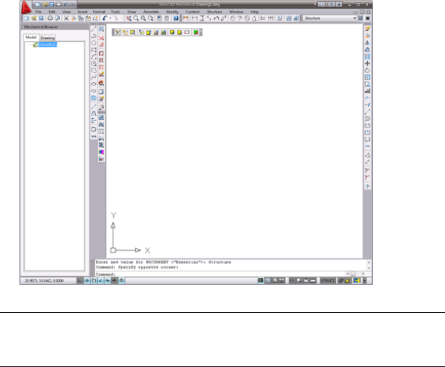
When you launch AutoCAD Mechanical, the Classic workspace appears as the
current work area. Use this workspace to learn to use AutoCAD Mechanical.
Refer to the following image.
2
3
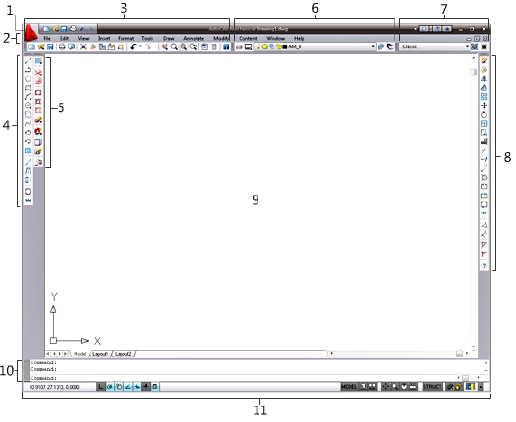
About the Work Area
The work area consists of the following components:
1 Menu Browser button
Click this button to access a complete list of commands in the menu bar,
and to search for Help information.
2 Menu bar
The menu bar contains menus and commands for performing tasks. It is
a mix of AutoCAD® and AutoCAD Mechanical commands. The first four
drop-down menus contain AutoCAD commands; the fifth menu through
the last menu contain both AutoCAD and AutoCAD Mechanical
commands.
3 Mechanical Main toolbar
This standard toolbar contains the New, Open, Save, Save as, and Print
commands, and a set of viewing tools.
4 Draw toolbar
The Draw toolbar holds all of the mechanical drawing tools.
5 Design toolbar
4 | Chapter 2 Get Familiar with the Work Area

This toolbar contains a set of design tools such as hatch, construction
lines, contour, create/edit associative hide, user configuration, and
detailing tools.
6 Mechanical Layer toolbar
This toolbar contains the current layer state and a set of layer tools to
help you work efficiently on your drawing.
7 Workspaces toolbar
This toolbar shows the current selection of workspaces. You can also
switch to other workspaces while working on your drawings.
8 Modify toolbar
This toolbar contains a set of tools for modifying objects and drawings.
9 Drawing area
The drawing area is where you create and place your drawing objects.
10 Command line
The command line shows the command that is executing, if any, and
prompts or messages from that command. You can view and select options
while running commands to create or edit objects in your drawing.
11 Status bar
Contains the application and drawing status bars for you to view and
toggle drawing settings, helping you to work efficiently on your design.
NOTE Whether you are running AutoCAD Mechanical in Microsoft® Windows®
XP or Vista™, 32-bit or 64-bit versions, AutoCAD Mechanical shows a similar work
area.
Workspace Settings
Selecting a workspace controls the display of the pre-defined menus, toolbars,
palettes, and dashboards for quick and easy access to commands. You can
choose a convenient workspace to start working on your drawing, or customize
and save your own workspaces according to your project requirements.
The predefined workspaces built into AutoCAD Mechanical are:
■Classic
Workspace Settings | 5
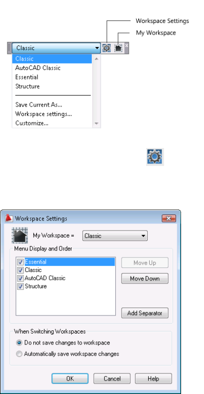
■AutoCAD Classic
■Essential
■Structure
To set the current workspace, click and select your workspace from the
drop-down list under My Workspace. You can then conveniently switch back
to your workspace by clicking the My Workspace icon in the Workspaces
toolbar.
6 | Chapter 2 Get Familiar with the Work Area
NOTE AutoCAD Mechanical automatically launches the last workspace you used
but not your workspace (My Workspace) the next time you launch the application.
To use your workspace, click on the drawing Workspace toolbar.
NOTE If you add or remove any toolbars on the predefined workspace, these
changes do not appear in the active workspace the next time you use that
workspace. The changes appear when you select Automatically save workspace
changes in the Workspace Settings dialog box.
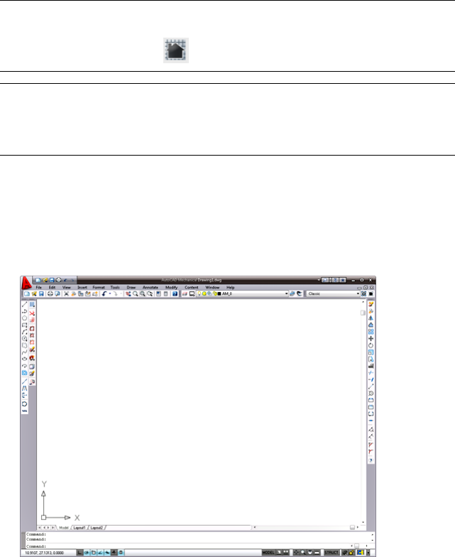
Switch Workspaces
You can switch between predefined and custom workspaces.
■Classic Workspace
This workspace consists a minimal set of mechanical toolbars for a beginner
using AutoCAD Mechanical.
■AutoCAD Classic Workspace
The typical AutoCAD workspace that contains relevant AutoCAD toolbars
such as Standard, Draw, Draw Order, Layers, Modify, Properties, Styles,
and Workspaces.
Workspace Settings | 7
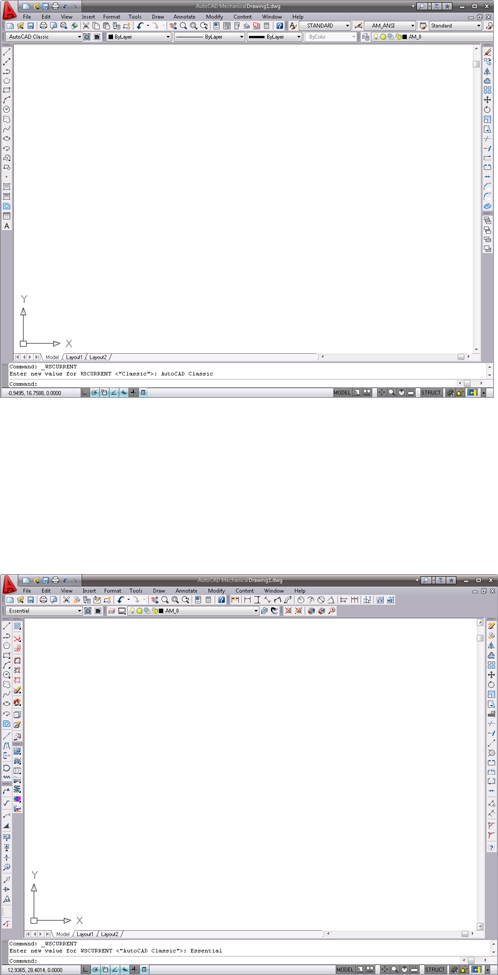
■Essential Workspace
The Essential workspace contains the most commonly used mechanical
toolbars such as Mechanical Main, Draw, Modify, Design Tools, Mechanical
Layer, Dimension, Standard Content, Symbols, and Bill of Materials for
you to create, organize, edit, and annotate your drawings in AutoCAD
Mechanical.
8 | Chapter 2 Get Familiar with the Work Area
■Structure Workspace
Select the Structure workspace when you create structured objects in
AutoCAD Mechanical. The program groups structured objects into parts,
subassemblies, and assemblies for quick selection and modification.
The mechanical browser in the left pane appears when you select the
structure workspace. Other relevant toolbars for structured objects appear
when you work on structured objects.
NOTE To use the Structure workspace, it is important to understand how
mechanical structure works for your design. Learn more about mechanical structure
from Mechanical Help, or the built-in Learning Mechanical Structure tutorial.
Drawing File Types
AutoCAD Mechanical includes the complete installation of AutoCAD reinforced
with a complete suite of 2D mechanical features.
You can use drawings created in AutoCAD in AutoCAD Mechanical. The
program retains all entities when moving AutoCAD drawings to AutoCAD
Mechanical. It maintains visual fidelity when exchanging drawings with older
or 2009 versions of AutoCAD to AutoCAD Mechanical.
Drawing File Types | 9
You can also save AutoCAD Mechanical drawings to formats from AutoCAD
2009 or earlier.
10 | Chapter 2 Get Familiar with the Work Area
Drawing Commands in
AutoCAD Mechanical
Mechanical drawings consist of commonly used parts connected to other parts or features in
a design. AutoCAD® Mechanical drawing commands provide more flexibility for creating
these parts.
This chapter shows you how to create a part of an assembly efficiently using the primary
AutoCAD commands together with the extended AutoCAD Mechanical drawing commands.
Drawing Commands
AutoCAD Mechanical provides several options for drawing commands. You can
create specialty lines, circles, arcs, automatic centerlines, and other elements in
your drawing. The Draw toolbar includes more options for rectangles, arcs, and
circles.
3
11
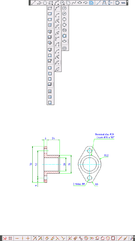
This chapter shows you how to create a part (a gland) using AutoCAD
Mechanical drawing commands. Use the measurements in the following image
for the exercises.
Draw Construction Lines
AutoCAD Mechanical includes a full complement of construction lines for
aligning drafting views.
12 | Chapter 3 Drawing Commands in AutoCAD Mechanical
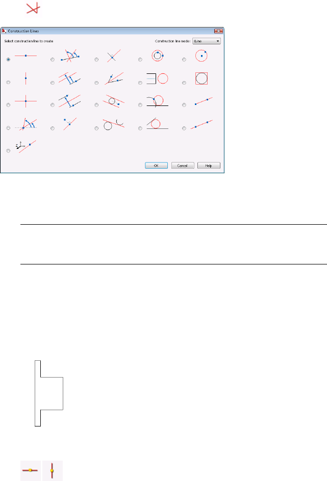
Click to open the Construction Lines dialog box.
Draw Construction Lines
1Begin a New drawing based on the am_iso template.
NOTE AutoCAD Mechanical includes eight drafting standard templates that
control drafting elements such as layer settings, object properties, text heights
and colors, and symbology formats. This lesson uses the ISO drafting standard.
2Select the Essential workspace for this exercise.
3Use the command Zoom ➤ All to show the entire page.
4Based on the dimensions in the earlier image of the gland, use the Line
command to create the front view of the gland.
5 Create horizontal construction lines aligned to the front view
using the AMCONSTHOR command. Create a vertical construction line
Draw Construction Lines | 13
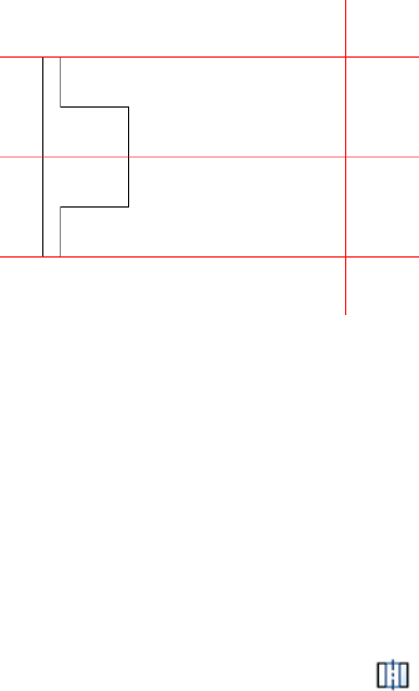
for the position of the side view using the AMCONSTVER command. See
the following image.
The program creates horizontal and vertical construction lines.
Create Holes
In AutoCAD, you create holes using Line, Circle, Trim, and Modify commands.
In AutoCAD Mechanical, the hole is a Power Object or mechanical object with
attributes or internal information. Use the AMTHOLE2D command to create
the hole.
Create Holes
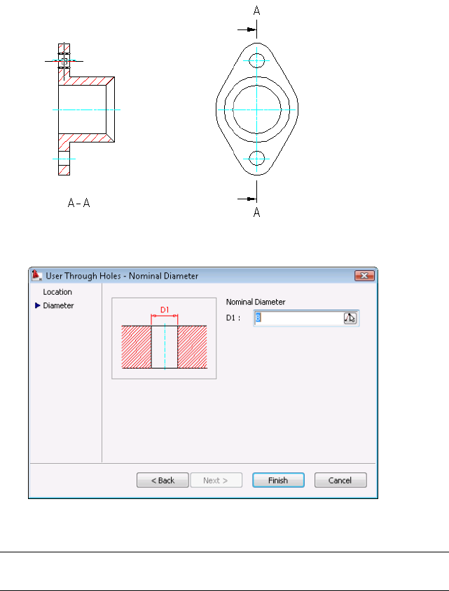
1From the Content menu, click Holes ➤ to create a through hole.
2Scroll to the bottom of the Details list, and select User Through Holes.
3Select Front View.
4Place a through hole with the diameter 8 mm, as specified.
14 | Chapter 3 Drawing Commands in AutoCAD Mechanical
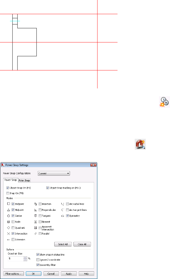
5To create another, similar hole, from the Modify menu, click the
Power Copy command. The Power Copy command remembers the
attributes of the Power Object and creates another hole of the same size,
symmetrical to the first hole.
Use the Symmetry Power Snap selection in the Power Snap Settings dialog
box to create a hole symmetrical to the first hole. Click to open the
Power Snap Settings dialog box, and then select the Symmetry checkbox.
Create Holes | 15
When inserting the hole, select the construction line at the center of the
part for its symmetry point.
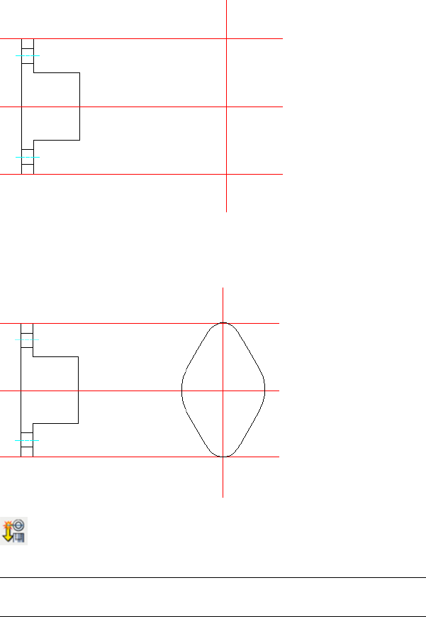
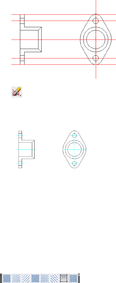
6Use the Circle, Line, and Trim commands to draw the side view of the
gland as shown in the following image. Draw the side view to full scale
using the dimensions on the first page of this lesson.
7 From the Modify menu, click the Power View command to create
a projected top view of the holes from the front view.
NOTE You can create two horizontal construction lines aligned from the
front view for the positions of the holes on the side view.
8Create the top view of the holes based on the front view (parent).
16 | Chapter 3 Drawing Commands in AutoCAD Mechanical
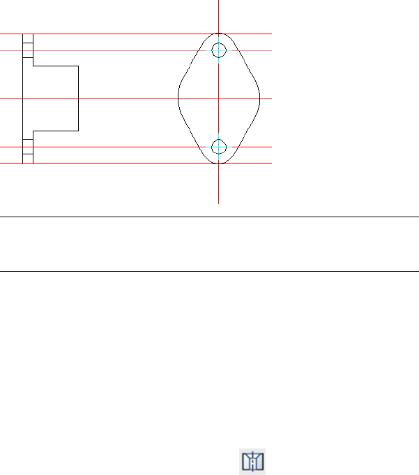
9The program creates the top view of the holes.
NOTE You can use Power View to create projected views of standard parts
such as screws, bolts, and nuts. It quickly creates a top view from a side view,
or a side view from a top view.
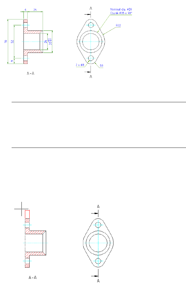
Create Countersink Holes
Countersink holes are Power Objects or mechanical objects. Use the
AMCOUNTS2D command to create a countersink hole. You can quickly change
the size of countersink holes by using the Power Edit command.
Create a Countersink Hole
1From the Content menu, click Holes ➤ Countersinks
2Create a countersink hole with nominal diameter 26 mm, countersink
diameter 35 mm, and angle 90 degrees.
3Specify its insertion point as shown in the following image.
Create Countersink Holes | 17
4Enter 30 for the hole length and 180 degrees for the rotation angle.
5Enter 26 for the nominal diameter, 35 for the countersink diameter, and
90 degrees for the angle, and then click Finish.
6The program creates a countersink hole.
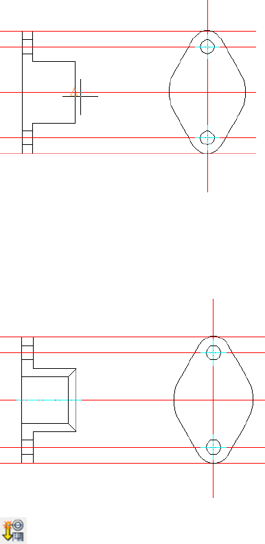
7 From the Modify menu, click the Power View command to create
the projected top view of the countersink hole from the front view.
18 | Chapter 3 Drawing Commands in AutoCAD Mechanical
8 Click the AMERASEALLCL command to remove all construction
lines.
9The program creates the part (a gland).
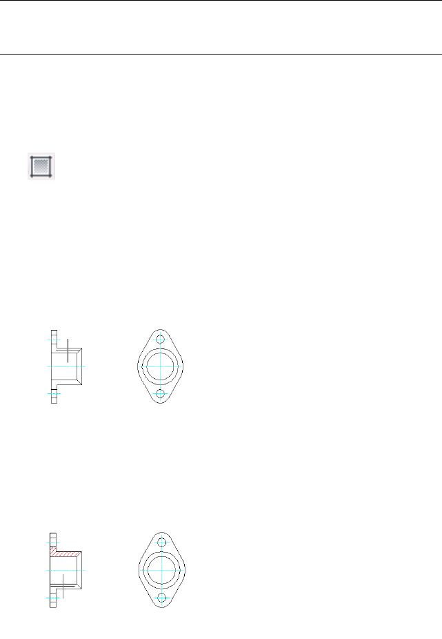
Create Hatch Patterns
Hatches enable people using your mechanical drawings to distinguish between
parts in the section or breakout views more easily. In AutoCAD Mechanical,
there are three types of hatches: associative hatch, user-defined hatch, and
predefined hatch.
Predefined hatches are for manufacturing drawings with parts of different
sizes and shapes in an assembly. The program includes six predefined hatch
patterns with left and right directions, at 45-degree and 135-degree angles,
three hatch pattern widths, and one double-hatch pattern.
Create Hatch Patterns | 19
NOTE User-defined and predefined hatches are non-associative by default. To
change both to be associative, select the Make Predefined Hatches Associative
checkbox on the AM:Preferences tab of the Options dialog box.
Create Hatch Patterns
For many parts in an assembly, you can apply predefined hatches quickly by
selecting the part and using a Hatch menu command. For this exercise, select
the User-defined hatch command.
1 From the Draw toolbar, click Hatch ➤ User-defined hatch.
2Select User-defined pattern in the Pattern Type list. Set 45 degrees for
angle and 2.50 mm for Spacing in the Pattern properties list.
3Click OK.
4Click a point within the boundary area of the part to add the hatch
pattern.
5Press ENTER.
6Click a point within the next boundary area to add the hatch pattern.
See the following image.
20 | Chapter 3 Drawing Commands in AutoCAD Mechanical
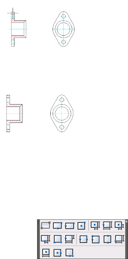
7Press ENTER to repeat the command. Clear the Adapt hatch distance at
less than five hatchlines checkbox in the Hatch dialog box. Doing so
ensures consistent hatch spacing on the part.
8Press ENTER to repeat the command. Continue to add hatch patterns to
the parts.
The program creates the hatch patterns.
Draw a Rectangle
You can create rectangles and squares with the Rectangle command in
AutoCAD Mechanical. This function gives you a convenient and flexible way
to place rectangles at the specific positions with no further modification to
your design.
Draw a Rectangle | 21
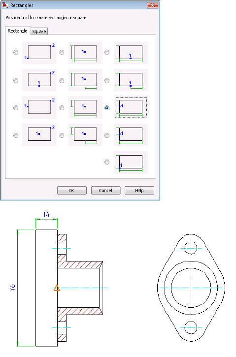
Try It: Draw a Rectangle
You can select the rectangle from the Rectangle toolbar or press ENTER at the
Rectangle command options to open the Rectangles dialog box.
For this exercise, attach a circular plate beside the gland you created. Select
the rectangle with the height-middle insertion point. Locate its middle point,
and specify its full base as 14 mm and its full height as 76 mm.
The program creates the rectangle and places it at the specified location.
22 | Chapter 3 Drawing Commands in AutoCAD Mechanical
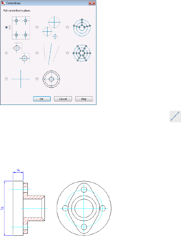
Draw a Centerline Pattern
Mechanical drawings often require centerlines and centerline crosses with or
without holes, countersink holes, or counterbore holes. The Centerlines dialog
box provides you with multiple ways to create centerlines and holes quickly.
You can access centerlines command from the Draw menu, or click on
the Draw toolbar, and then press ENTER to display the Centerlines dialog box.
Try It: Draw a Centerline Cross
Refer to the following image. Draw a centerline cross with holes on a full circle
on its side view.
Draw a Centerline Pattern | 23
Draw Section Lines
To draw section lines in AutoCAD Mechanical, use the AMSECTIONLINE
command. The layer, color, linetype, and lineweight properties are predefined
for the section line.
Create Chamfers
Create chamfers in AutoCAD Mechanical with the AMCHAM2D
command. As with AutoCAD, you can choose to trim or not to trim the
geometry when you chamfer. Unlike AutoCAD, you can include dimensions
when you chamfer. You can also configure the list of chamfer sizes for your
drawings.
24 | Chapter 3 Drawing Commands in AutoCAD Mechanical
Create Chamfers | 25
26
Modify Drawings with
Power Commands
Power Objects or mechanical objects in AutoCAD® Mechanical are objects that contain
attributes. They include standard parts, symbol libraries, Power Dimensions, holes, hole charts,
title blocks, balloons, part lists, and all objects created with AutoCAD Mechanical commands.
This chapter shows you how to create or modify Power Objects quickly with Power Commands.
Power Commands
In AutoCAD Mechanical, a Power Object is an object with attributes. It contains
relevant parameters that makes the object intelligent. For example, a screw has
its screw size stored in its geometry, and a chamfer has its chamfer sizes stored
in it.
Power Commands use this information to create, copy, and edit Power Objects
quickly.
The Modify menu contains the Power Edit, Power Copy, Power
Erase, Power Recall, and Power View commands.
NOTE You can double-click any Power Object to activate the Power Edit command
for modification. It automatically opens a dialog box enabling you to make changes.
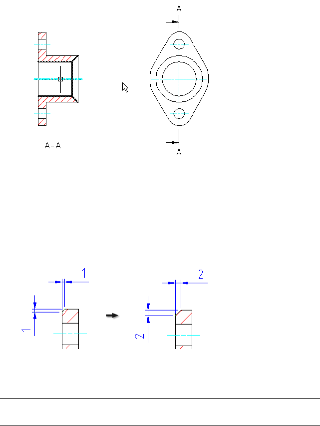
Edit the Hole
1Double-click the existing hole (diameter 8 mm).
4
27
2The User Through Holes - Nominal Diameter dialog box appears.
3Change the diameter of the hole to 6 mm.
NOTE Changing the hole size of the front view does not automatically update
the hole size of its related side view.
The geometry and its hole size change accordingly.
Edit the Countersink Hole
1Double-click the countersink hole. The User Countersinks - Parameter
for Countersinks dialog box appears.
28 | Chapter 4 Modify Drawings with Power Commands
2Change the countersink hole diameter to 30 and its nominal diameter
to 20. Click OK to see the changes update automatically.
3Undo the previous change.
Edit the Chamfer
1Double-click the chamfer. The Chamfer dialog box appears.
2Change the chamfer length to 2 and click OK. Notice the chamfer and
its dimension update to the new length.
NOTE You can use the Power Recall command to create another hole with the
same parameters as the existing hole.
Try using the Power Recall, Power Copy, and Power View commands on this
drawing.
Power Commands | 29
30
Generate Standard Parts
Manufacturing designs often include standard parts and features. These standard parts can
include screws, nuts, washers, pins, rivets, bushings, and others. It is typically to find standard
parts collected and published in libraries, and AutoCAD® Mechanical includes several such
libraries. With AutoCAD Mechanical, you can insert standard parts from installed parts libraries
directly into your drawings. If you cannot find any industry-standard part in the parts library
for your design requirements, you can create custom parts and add them to your libraries as
well.
AutoCAD Mechanical also includes many commonly used features such as undercuts, keyways,
pre-drawn holes, blind holes, oblong holes, countersink holes, and counterbore holes. As
with standard parts, you can add these elements easily into your designs.
This chapter describes how to generate standard parts for a sealed shaft unit.
Standard Parts Content
This lesson shows you how to select and use industry-standard parts for your
design. AutoCAD Mechanical includes standard part libraries from 18
manufacturers (AFNOR, ANSI, AS, BSI, CNS, CSN, DIN, GB, GOST, IS, ISO, JIS,
KS, PN, SFS, SS, STN, and UNI). To use standard parts from a manufacturer,
select that manufacturer during installation.
Selected Standards
■From the Content menu, click Parts Library, or enter AMSTDPLIB at the
Command prompt.
■The Standard Part Library panel appears. You can see the installed standards
in the Standard Parts pane.
5
31
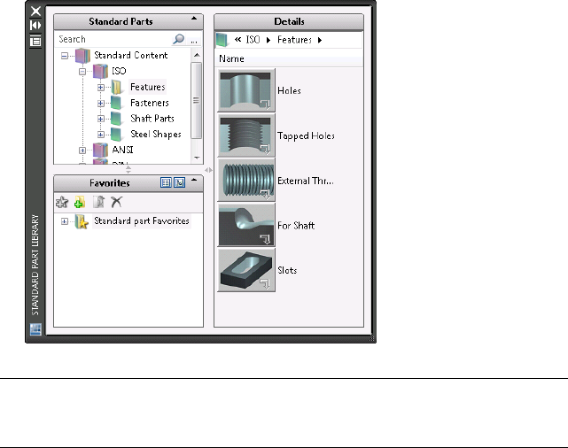
■Use this Standard Part Library to search for your required standard parts.
You can also move the commonly used standard parts to the Favorites
pane for easy access.
NOTE If you require standard parts from other manufacturers in your drawings,
install the parts libraries from the installation CD or DVD. It is important to make
all required selections during the initial installation of AutoCAD Mechanical.
Parts Library Navigation
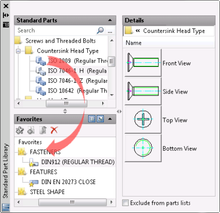
The Standard Part Library dialog box includes three panes: Standard Parts,
Favorites, and Details. You can use any of the following methods to move the
selected standard parts to the Favorites list for easy access and reuse in other
drawings.
Method 1:
Drag the part family node from the Standard Parts pane to Favorites.
32 | Chapter 5 Generate Standard Parts
Method 2:
Right-click the part family node and select Add to Favorites from the context
menu.
View Favorites Lists
When you have a long list of favorites, you can organize the list with the
buttons marked 1 and 2 in the following image.
Parts Library Navigation | 33
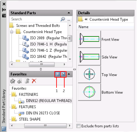
1To show a list of available views in the Favorites panel.
2To show the available views in a tree structure.
Select a Projected View in Favorites
From the View column, click the current view to open a drop-down list of
available views for that part.
34 | Chapter 5 Generate Standard Parts
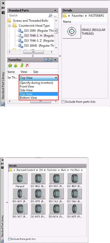
Resize the Panels
You can resize the panels by dragging the left-right arrows between the panels.
You can open and close the panels with the up and down arrows (chevrons)
in the upper right corners of the panels. The following image shows selected
standard parts in the Details panel.
Resize the Panels | 35
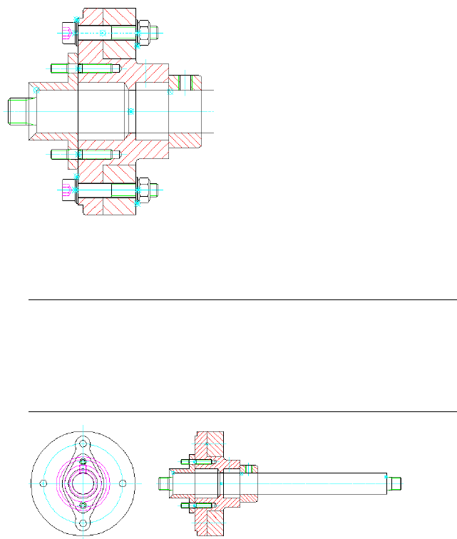
Insert Screw Components
You can create screw connection assemblies that consist of screws, nuts,
washers, and holes with the Screw Connection wizard. When you insert screw
connections, you indicate corresponding hole locations for the screws.
Insert Screw Components
1Open the gs_sealed_shaft_assy drawing in the Getting_Started folder.
NOTE The path to the folder containing Getting_Started files is:
■Windows Vista™: C:\Users\Public\Documents\Autodesk\ACADM
2009\Acadm\Getting_Started
■Windows®XP: C:\Documents and Settings\All
Users\Documents\Autodesk\ACADM 2009\Acadm\Getting_Started
2From the Content menu, click Screw Connection. The Screw Connection
- Front View dialog box appears.
36 | Chapter 5 Generate Standard Parts
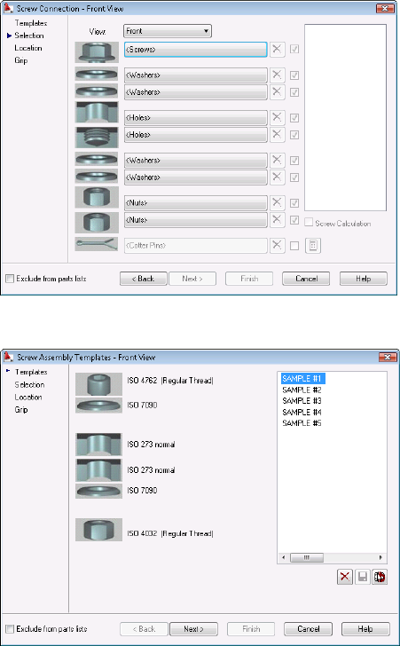
3Click the Back button to select a screw connection template.
4Double-click SAMPLE #1 and select the M 8 screw from the list.
Insert Screw Components | 37
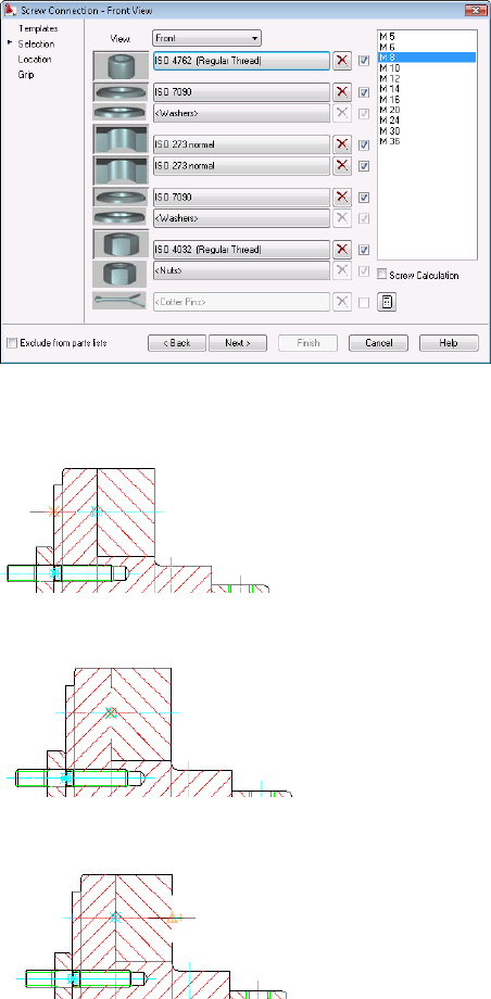
5Click Next and specify the insertion point of first hole as shown in the
following image.
6Specify the endpoint of first hole as shown in the following image.
7Specify the endpoint of second hole as shown in the following image.
8Click Next on the Screw Assembly Location - Front View dialog box.
38 | Chapter 5 Generate Standard Parts
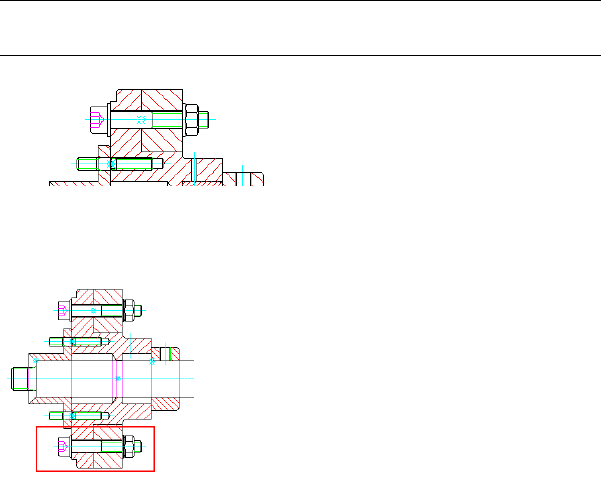
9Select the Normal representation in the Screw Assembly Grip
Representation - Front View dialog box. Click Finish.
The program adds a screw connection to fasten the two plates. Notice
that AutoCAD Mechanical automatically removes and cleans up excess
materials when you insert the screw components.
NOTE If there are holes on both the bracket and plate, it is not necessary to
select and create holes in the Screw Connection - Front View dialog box.
10 Use the AMPOWERCOPY command to copy the screw connection and
place it at the bottom of the assembly.
Insert Fasteners
In the standard part libraries, you can also find the most commonly used
fasteners for your assemblies. In this exercise, you insert a cylindrical pin into
the pin hole on the bracket.
Insert a Cylindrical Pin
1From the Content menu, click Fasteners ➤ Cylindrical Pins.
2Select the ISO 2338 pin.
3Select the Front View.
Insert Fasteners | 39
4Specify the insertion point as shown in the following image.
5Enter 270 degrees for its rotation angle.
6Select 3 mm for its diameter.
7Click Finish.
8Drag its length to approximately 12 mm on the bushing.
9Select the standard size - 3m6 x 12-A pin in the Select Part Size dialog
box.
The program inserts the cylindrical pin.
Edit Standard Parts
All standard parts and features in AutoCAD Mechanical are Power Objects.
You can modify them using Power Commands. AutoCAD Mechanical
automatically heals and cleans up affected areas after you modify an object
with a Power Command.
Erase the Pin
1From the Modify menu, click Power Erase.
2Select the Pin to erase.
3Press ENTER.
40 | Chapter 5 Generate Standard Parts
4Notice that the pin hole on the bushing cleans up automatically and the
geometry heals itself.
5Undo the previous step.
NOTE Do not use the Erase command from AutoCAD® on any Power Object.
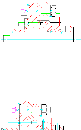
Edit the Screw Components
1Double-click the centerline of the screw components.
2Select M 6 in the list.
3Click Finish.
Notice that all screw components change to the new size.
4
Select the other screw connection instances to change to size M 6.
Both screw components change to size M 6.
Projected Views of Standard Parts
You can generate the projected view of a standard part from its existing view
(parent view) using Power View command. Depending on the first-angle or
third-angle projection for the drawings your company uses, it prompts you
Projected Views of Standard Parts | 41
to select a view (top, bottom, front, or side) of the standard part to draw as
you generate the projected view.
NOTE The projected views are associative. If there is any change to the parent or
child view, the program updates associated views automatically.
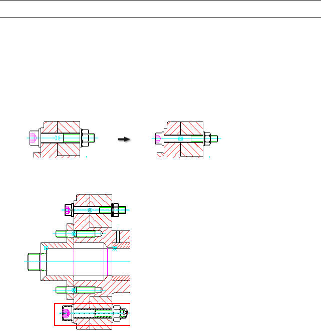
Generate the Projected View for Screw Components
1From the Modify menu, click Power view.
2Select the screw components (Front View) on the right.
3Click Top in AutoCAD Mechanical dialog box.
4Specify the insertion point as shown in the following image.
The program creates the top view of screw components.
Try it: Edit the Screw Components
Double-click the screw component front view and change its size to M 6.
Notice that its associated top-view update accordingly.
42 | Chapter 5 Generate Standard Parts
Change Representations
Your conceptual designs do not need full representations of standard parts.
They can use draft representations: symbolic and simplified views. In AutoCAD
Mechanical, you can change the representation type by using the Change
Representation command.
You can change the representation in the Options dialog box on the
AM:Standard Parts tab.
2D RepresentationsTypes
Symbolic
Simplified
Standard
NOTE Changing the default setting in the Options dialog box does not affect
standard parts already placed in the drawing. It affects only the newly created
standard parts.
Change Representations | 43
44
Organize Objects with
Layers
With the predefined mechanical layers in AutoCAD® Mechanical, the program automatically
organizes the layers for all mechanical parts. Automated organization helps to speed up and
simplify your work.
This chapter demonstrates how organizing objects with layers in AutoCAD Mechanical
compares to AutoCAD®, and how to convert AutoCAD layers to AutoCAD Mechanical layers.
Predefined Mechanical Layers
Layers work differently in the AutoCAD Mechanical than they do in AutoCAD.
What are the differences?
In AutoCAD, you define layers with properties such as color, linetype, lineweight
and other properties manually in the Layer Properties Manager dialog box. You
then create objects on the current layer.
AutoCAD Mechanical does not require you to set up layers for mechanical
objects because they are already predefined and fully automated.
When you access a mechanical command, the current layer changes to the layer
defined for the objects on which the command executes. The program sets the
layer automatically to on or off, locked or unlocked, and plot or non-plottable
based on its defined properties.
What is the benefit of predefined mechanical object properties and layers?
In mechanical drawings, there are many standard features and parts like through
holes, countersink and counterbore holes, screws, washers, nuts, pins, springs,
6
45
shafts, and mechanical standards for drafting geometries, annotations, and
symbols.
AutoCAD Mechanical manages these objects automatically with predefined
layers based on the properties of the mechanical objects. Because of this
functionality, you spend less time defining layers on your own.
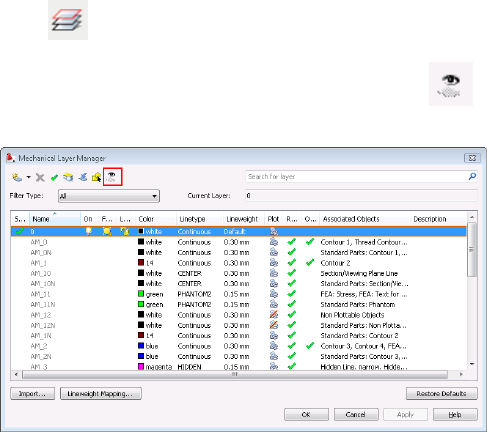
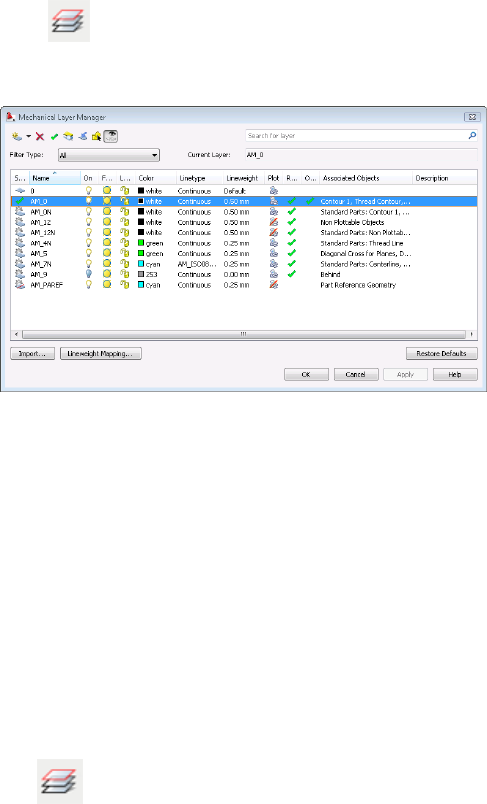
View the Predefined Layers
All predefined layers begin with the prefix AM_.
1Click
2In the Mechanical Layer Manager dialog box, click to show the
predefined mechanical layers.
3In the AutoCAD Mechanical Layers dialog box, click the drop-down arrow
in the Filter Type and select Part List. Notice that the layer AM_6 associates
with Text and the layer AM_BOR associates with Drawing Border.
4Select other mechanical objects in the Filter Type list. Observe their layers
and associated objects.
Use Predefined Layers
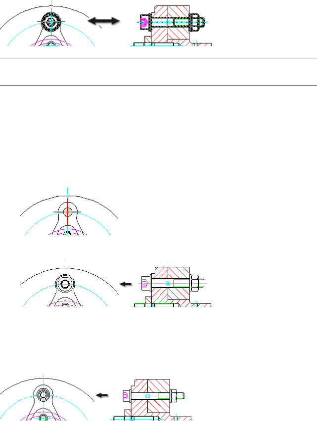
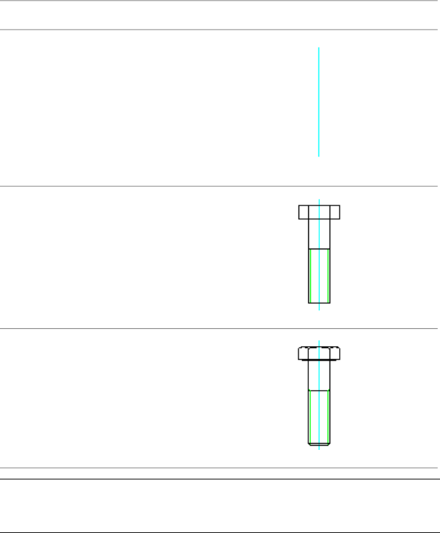
In this exercise, you create a standard part (a screw) and review the predefined
layers automatically generated in the drawing.
1Begin a new drawing based on the am_iso template. AutoCAD always
starts with Layer 0 by default. AutoCAD Mechanical starts with Layer
AM_0.
46 | Chapter 6 Organize Objects with Layers
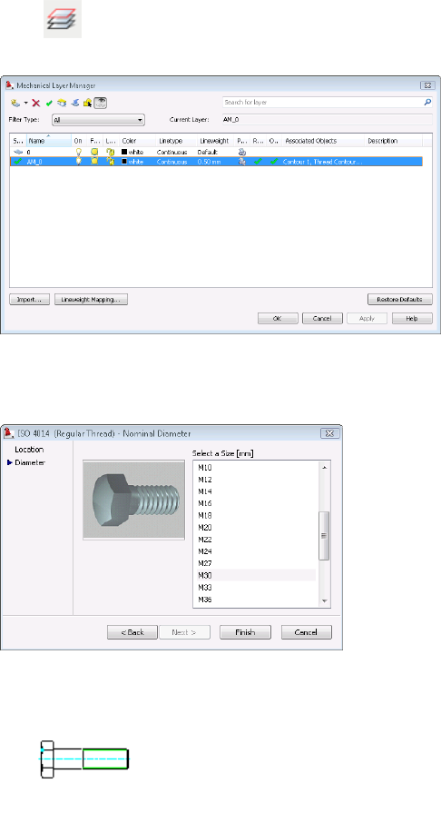
2Click to review the existing layers on the new drawing. Only two
layers appear in the Mechanical Layer Manager dialog box.
3From the Content menu, click Fasteners ➤ Screws.
4Click Hex Head Types ➤ ISO 4014 (Regular Thread) ➤ Front View.
5Insert the screw, size M 30 x 110.
Predefined Mechanical Layers | 47
6Click to review the automatically generated layers for the screw.
Notice the Standard part - screw appears on Layer AM_0N. See other layers
and associated objects used for the screw.
7Save and close the drawing.
Mechanical Layer Manager
In AutoCAD Mechanical, you use Mechanical Layer Manager dialog box to
organize and manage objects with layers. There are two methods to show this
dialog box.
■Method 1:
At the Command prompt, enter AMLAYER.
■Method 2:
Click
48 | Chapter 6 Organize Objects with Layers
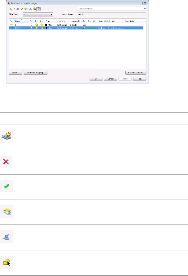
The following table shows the tool buttons and descriptions in the Mechanical
Layer Manager dialog box.
DescriptionButton
Create new layers.
New Layer
Delete layers.
Delete
Set a layer to be current.
Set Current
Check layers from existing objects.
Check Layer
Move objects into a selected layer.
Move Into
Highlight the selected layers.
Highlight
Mechanical Layer Manager | 49

DescriptionButton
To show or hide layer definitions.
Show\Hide Layer Definitions
Can I use the AutoCAD Layer Properties Manager dialog box to manage all layers
including the predefined mechanical layers instead of Mechanical Layer Manager dialog
box?
We do not recommend this approach, because no changes you make in the
AutoCAD Layer Properties Manager dialog box carry over for mechanical
object definitions.
For legacy AutoCAD drawings in AutoCAD Mechanical, can I change the properties for
AutoCAD layers in the Mechanical Layer Manager dialog box?
Yes. You can change the properties for AutoCAD layers in the Mechanical
Layer Manager - AMLAYER dialog box. Your changes overwrite any changes
made in the Layer dialog box.
In other words, in the Mechanical Layer Manager dialog box you can control
all layers including changes from AutoCAD and AutoCAD Mechanical. You
can also clearly define mechanical layers and associated objects.
Can you rename the AM_ layers?
Yes. You can rename these layers according to your company standard naming
convention. We recommend that you configure the layers and the properties
for all objects in the Object Property Settings dialog box before you start
working on any drawings.
Predefined Object Properties
You can configure the predefined properties of objects you create in AutoCAD
Mechanical with the Object Properties dialog box.
1Enter OP (hotkey for Options) at the Command prompt.
2Click the AM:Standards tab.
3Double-click to open the Standard Settings dialog box.
4Click the Settings button in the Object Properties list.
50 | Chapter 6 Organize Objects with Layers
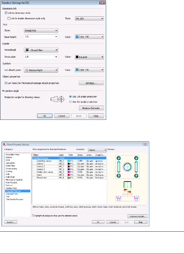
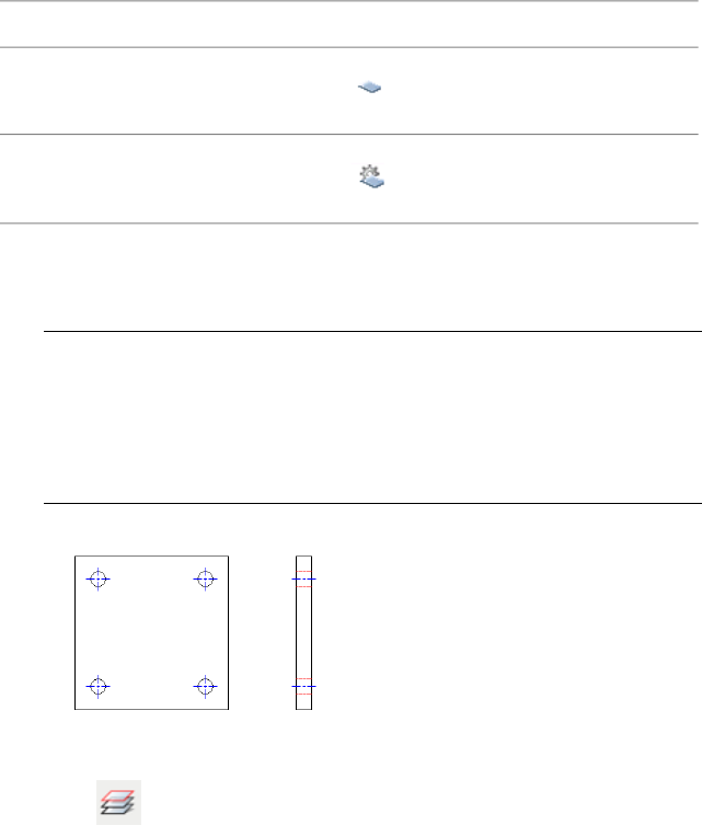
The Object Property Settings dialog box appears, as shown in the following
image.
NOTE For information on how to configure AutoCAD Mechanical object properties,
refer to the Configure Automatic Property Management section in the
Configuration and Setup Guide in AutoCAD Mechanical.
Predefined Object Properties | 51
Object Property Settings
When you open AutoCAD drawings in AutoCAD Mechanical, all layers created
in AutoCAD automatically appear in the AutoCAD Mechanical Layer dialog
box. They remain AutoCAD layers until you change them to AutoCAD
Mechanical layers in the Object Property Settings dialog box.
RepresentativeDescription
AutoCAD Layer
Mechanical Layer
Convert AutoCAD layers to Mechanical layers
1Open the gs_acad_layers drawing from the Getting_Started folder.
NOTE The path to the folder containing Getting_Started files is:
■Windows Vista™:C:\Users\Public\Documents\Autodesk\ACADM
2009\Acadm\Getting_Started
■Windows®XP: C:\Documents and Settings\All
Users\Documents\Autodesk\ACADM 2009\Acadm\Getting_Started
2Click to open the Mechanical Layer Manager dialog box. Notice
that AutoCAD layers appear in it.
52 | Chapter 6 Organize Objects with Layers
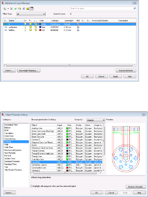
3To convert the AutoCAD layer - Centerline to a mechanical layer, change
the layer for Centerline in the category Drafting to Layer - Centerline in
the Object Property Settings dialog box.
4Click the layer AM_7 on the object, Centerline. Object Property Settings
- Select Layer dialog box displays. Scroll down to the bottom of the list
to select the layer centerline.
Object Property Settings | 53
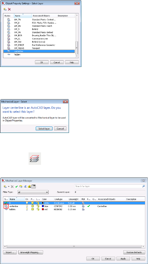
5The Mechanical Layer - Select dialog box appears, informing you that
the program is converting an AutoCAD layer to an AutoCAD Mechanical
layer.
6Click OK three times to close all dialog boxes.
7Next, click . Notice that the Centerline layer is now an AutoCAD
Mechanical layer.
8Next, change the layer for the object - Centerline, narrow in the Standard
Features category on the Object Property Settings dialog box to centerline.
54 | Chapter 6 Organize Objects with Layers
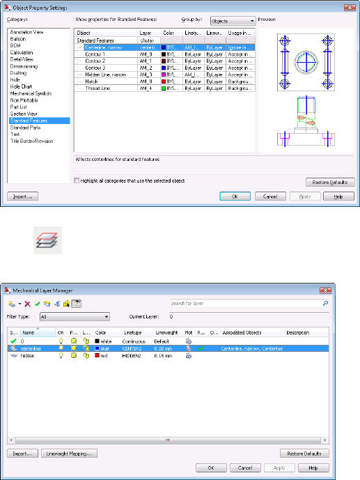
9Click . Notice the Mechanical layer -centerline now associated to
two mechanical objects: Centerline and Centerline, narrow.
10 From the Content menu, click Holes ➤ Through Holes.
11 Select the ISO 273 normal icon, and click Top View to insert an M 30
hole at the center of the plate. Notice the mechanical object, through
hole now uses the Layer - centerline for its centerline.
Object Property Settings | 55
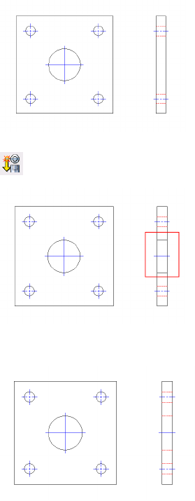
12 Create the front view of the hole using the Powerview command.
13 Change the Hole - front view to hidden lines type.
Tip
■Use Mechanical Layer Manager dialog box to work with all layers in the
drawing instead of the AutoCAD Layer Properties Manager dialog box.
■To ensure layer consistency across all drawings, set up the layers in the
Object Property Settings dialog box and save them as templates for reuse.
56 | Chapter 6 Organize Objects with Layers
Create Hidden Lines
In assembly or conceptual drawings, it is common to hide background objects to show objects
obscured behind connected front objects. AutoCAD® Mechanical represents background
objects with hidden lines.
This chapter shows you how to create associative hidden lines by specifying which objects
lie in front of others. Any changes to the front or back objects automatically update the
associated hidden lines.
Associative Hidden Lines
In AutoCAD®, converting geometrical lines to hidden lines on mechanical
drawings can be a time-consuming task. The process includes breaking each
line into multiple segments, changing the linetype to Hidden, and changing
the line color properties to the required color. In AutoCAD Mechanical, the
process is simpler. You can create hidden lines without breaking the lines into
segments, and hidden lines automatically reflect predefined layers and properties.
When working on multiple projects with the same objects and subassemblies,
designers frequently have to convert lines between hidden lines and geometrical
lines. In AutoCAD Mechanical, the AMSHIDEEDIT command manages that
process.
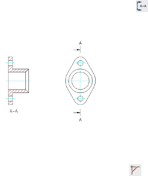
Create Associative Hidden Lines
Use the AMSHIDE command to create associative hidden lines. After you select
foreground objects, overlapped areas of objects that lie behind those objects are
drawn as associative hidden lines.
1Open the gs_hidden_lines drawing from the Getting_Started folder.
7
57
NOTE The path to the folder containing Getting_Started files is:
■Windows Vista™:C:\Users\Public\Documents\Autodesk\ACADM
2009\Acadm\Getting_Started
■Windows®XP: C:\Documents and Settings\All
Users\Documents\Autodesk\ACADM 2009\Acadm\Getting_Started
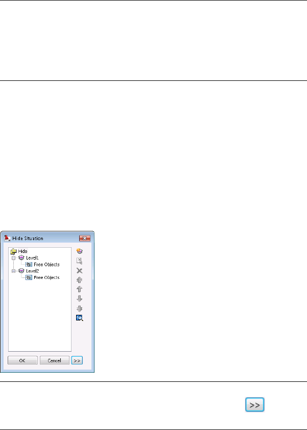
2From the Modify menu, click Associative Hide, then click Create
Associative Hide Situations.
3Select the shaft for the foreground object. Notice that AutoCAD
Mechanical automatically places all obscured objects behind the shaft
on Level 2 as background objects. In this case, Level 1 refers to the shaft
- front object. All other objects behind the shaft are at Level 2.
4There is no limit to the number of levels allowed with the AMSHIDE
command. You can place one object or several objects on a level. You
can also rename levels, including Level 1, for easy identification and
searching.
NOTE If you are working on the mechanical structure environment for
structured object, expand the Hide Situation dialog box. Click to expand
the dialog box.
5Click OK. Notice that the program hides background objects behind the
shaft.
58 | Chapter 7 Create Hidden Lines
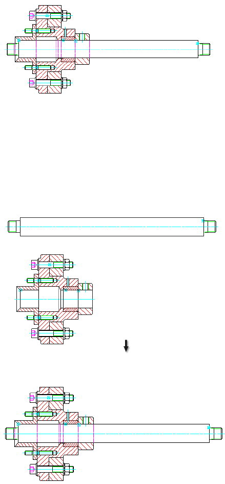
Try It: Associative Hidden Lines
In this exercise, you move the shaft away from the assembly to see how hidden
lines heal and change to solid lines. Move the shaft back into place to see the
hidden lines return to the previous state.
Any changes to the foreground or background objects update the resulting
hidden lines automatically.
Associative Hidden Lines | 59

NOTE You can use AMSHIDE command on structured or non-structured drawings.
For more information on mechanical structure, refer to Mechanical Help or the
Learning Mechanical Structure tutorial.
Tip
■To revert all hidden lines to geometrical lines for reuse, use the
AMSHIDEEDIT command to open the Hide Situation dialog box. Remove
the elemental geometry from the levels.
■You can also use the AMSHIDEEDIT command to modify or update the
hide situations in the drawing.
60 | Chapter 7 Create Hidden Lines
Reusable Detailing Tools
In AutoCAD® Mechanical, the drafting tools have intelligence built-in that help you edit the
features easily without having to remove and recreate the original features.
This lesson demonstrates some reusable tools such as chamfers, title blocks, and associative
detail views.
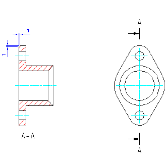
Chamfers
You can resize chamfers created in AutoCAD Mechanical using the Chamfer
dialog box. Because the chamfer has built-in intelligence, you simply double-click
the chamfer to make changes.
Try It: Edit a chamfer
Open the completed part drawing (the gland) you created. Double-click the
chamfer and change its size to 2 mm. See that the dimensions change to the
new chamfer size. You can double-click a fillet to change its size.
8
61
Title Block
You can scale and center your drawing within the title block using the Title
Block (AMTITLE) command. After you place the title block, you can make
edits, such as changing the title block style, without erasing and reinserting
the title block. Double-click the title block to change its size in the dialog box.
Insert a Title Block
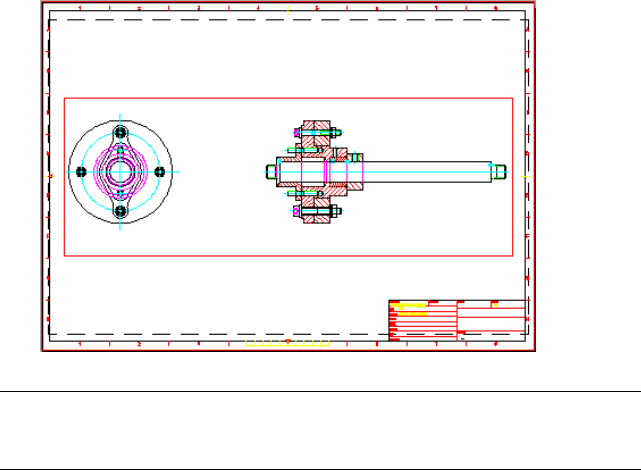
In this lesson, you place the assembly in the layout, and then insert the title
block.
1Open the completed gs_hidden_lines drawing from the previous lesson.
2 From the View menu, click Viewports ➤ Viewport/Scale Area.
3Select the entire drawing.
4Select the check box for Automatic view creation in Layout1.
5Click OK and place the viewport on the layout.
6From the Annotate menu, click Drawing Title and Revision ➤ Drawing
Title/Borders.
7 In the Drawing Border with Title Block dialog box, select A2
(420x594mm) in the paper format list. Click OK.
8Click Close in the Page Setup Manager dialog box.
9Locate and place the title block in Layout1.
10 Enter drawing information in the Change Title Block Entry dialog box.
Click OK.
11 Select the viewport outline and press Enter when the program prompts
for a new location for the object.
62 | Chapter 8 Reusable Detailing Tools
NOTE Use the Viewport/Scale Area command to control the length and text
scaling when creating viewports. For more details, refer to the AutoCAD Mechanical
Help.
Associative Detail View
Detail views show an enlarged area of geometry or a dimensioned part that
is not clearly visible in the original view. Use the Detail command to create
linked views at different scales and place them in model space or in the layout.
The geometry in the detail view is associative to the original view. If you
change the original view, the program updates the associative detail view; if
you change the associative detail view, the program updates the original view.
In the following image, a detail view shows its geometry two times larger than
its original view. Continuing from the previous title block insertion, use the
AMDETAIL command to create a detail view and place it on the Layout tab.
Associative Detail View | 63

Create a Detail View
1From the Design toolbar, click .
2Enclose the screw connection as shown in the following image.
3Toggle to the viewport of the original layout in the Detail view list to
place the detail in the layout tab.
64 | Chapter 8 Reusable Detailing Tools
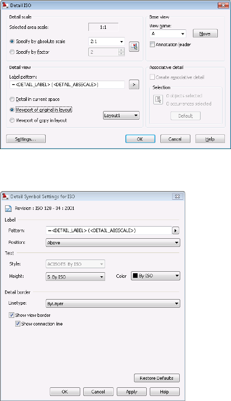
4Click the Settings button in the Detail ISO dialog box. Select the Show
view border checkbox.
5Click OK and place the enlarged detail view on the drawing.
Try It: Edit a Detail View
Double-click the centerline of the screw connection and change its size from
M 8 to M 6. Notice that the associated detail view changes accordingly.
Associative Detail View | 65
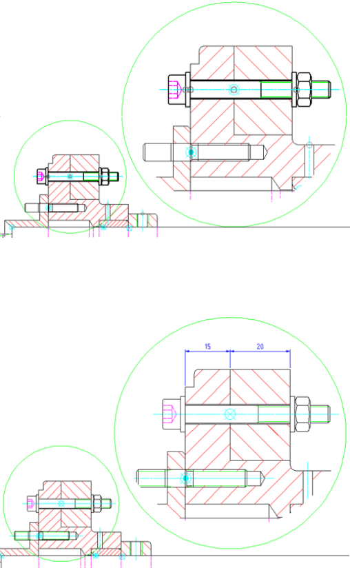
Try It: Dimension a Detail View
Use the Power Dimension command (AMPOWERDIM) to add dimensions in
the detail view.
66 | Chapter 8 Reusable Detailing Tools
Power Dimensions
Unlike AutoCAD®, AutoCAD® Mechanical does not use several dimension commands to
create linear, angular, baseline, and chain dimensions. In AutoCAD Mechanical, the power
dimension command, AMPOWERDIM, saves you time in creating multiple dimension types
on your drawings.
This lesson describes how to use the Power Dimensioning and automatic dimensioning tools
to add dimensions on your drawings. It also shows you how to edit dimensions quickly with
a set of editing tools.
Create Mechanical Dimensions
You create dimensions on a drawing to communicate the required sizes of parts
to the production team for fabrication purposes.
Use the Power Dimension command to create horizontal, vertical, aligned,
rotated, angular, radial, baseline, and chain dimensions. Power Dimensions give
you the flexibility to define the appearance and content of the dimensions.
You can create dimensions in model space or layout. Power Dimensions
automatically adjust based on the scale factors of the scaled area in model space.
In the layout, dimensions added automatically based on the points or geometry
selected.
Add Dimensions by using Power Dimensioning
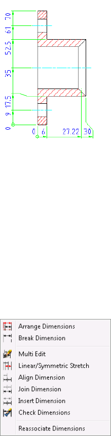
In the following image shows the completed dimensioning on the two views
of a gland.
9
67
1Open the gs_dimensions drawing in the Getting_Started folder.
NOTE The path to the folder containing Getting_Started files is;
■Windows Vista™:C:\Users\Public\Documents\Autodesk\ACADM
2009\Acadm\Getting_Started
■Windows®XP: C:\Documents and Settings\All
Users\Documents\Autodesk\ACADM 2009\Acadm\Getting_Started
2From the Annotate menu, click Power Dimensioning.
3Insert the 6 mm dimension for the flange of the part.
4Locate the dimension line location. Click at the location when the
dimension line appears in red. This location is the preset dimension line
location from the geometry contour.
68 | Chapter 9 Power Dimensions
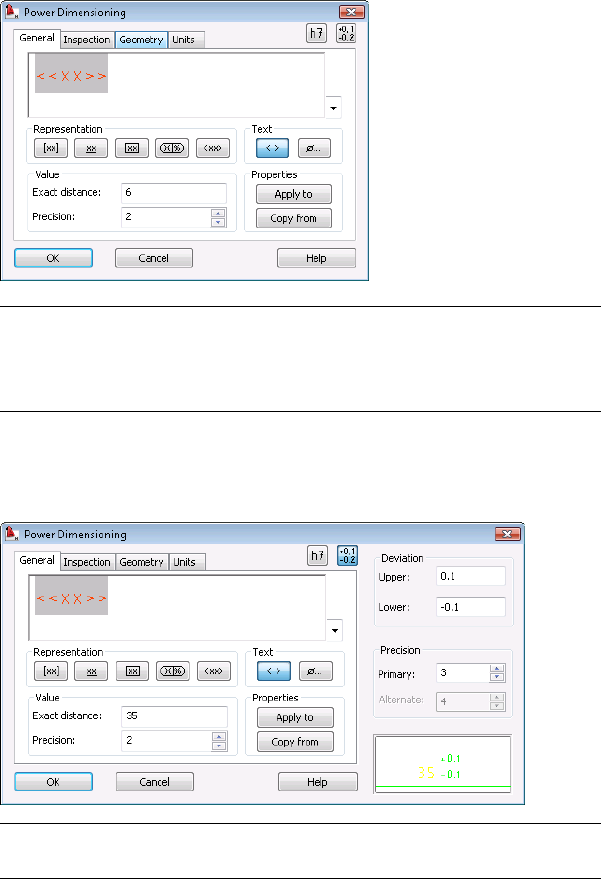
5The Power Dimensioning dialog box appears showing the dimension
value. Click OK.
6 NOTE By default, the Power Dimensioning dialog box appears for the first
set of dimensions and not for subsequent dimensions when working on the
Power Dimension. To change this behavior, go to Options ➤ AM:Standards
➤ and double-click the Dimension in the Standard elements list.
7Enter C (for Chain) in the command line. Insert the 24mm dimension.
Notice you are still in the Power Dimensioning command.
NOTE When adding the dimension, you can set its options, add tolerances
and fits to the dimensions.
Create Mechanical Dimensions | 69
8Press Enter twice to reactivate the Power Dimensioning command to
create the 26 mm dimension.
9Type S to select the line for the 35 mm dimension. Type O to open the
Power Dimensioning dialog box and create its tolerance.
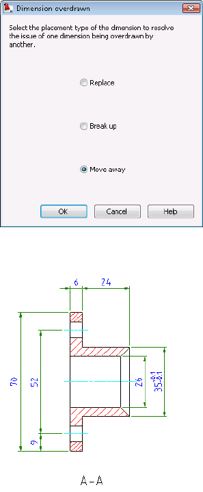
10 If the 70 mm dimension overlaps the 52 mm dimension, a Dimension
Overdrawn dialog box appears enabling you to move the overlapping
dimension away from the other automatically.
11 Create all dimensions for the front view.
12 Continue to add the radial dimensions for the side view.
70 | Chapter 9 Power Dimensions
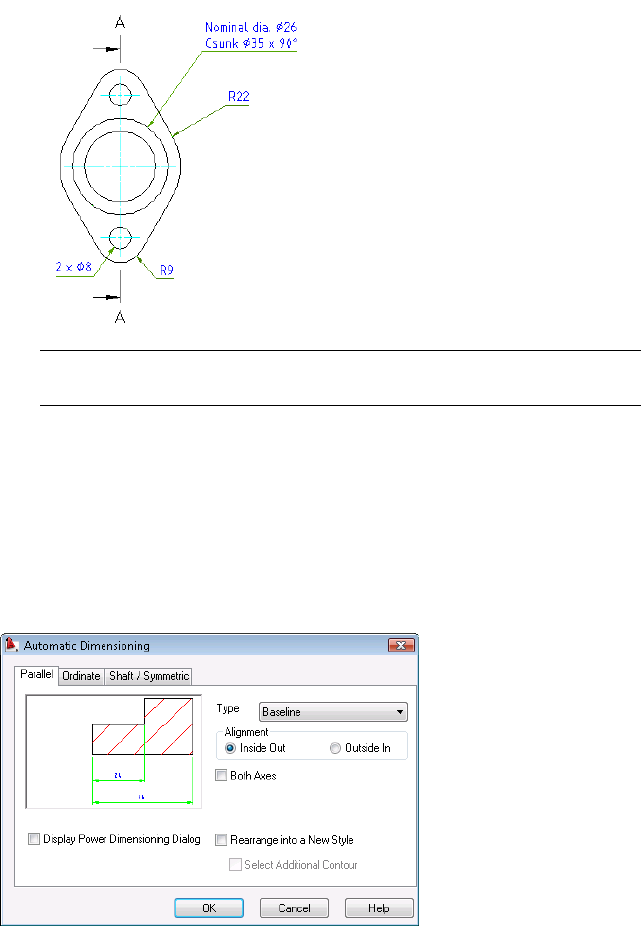
NOTE When placing dimensions, you can switch between radial dimensions
and diameter dimensions.
Multiple Dimensions
It is often necessary to create ordinate dimensions on semiconductor or
automation drawings. In AutoCAD Mechanical, you can create a group of
parallel, ordinate, shaft, and symmetrical dimensions all at the same time by
using the Multiple dimensioning command.
Multiple Dimensions | 71
Filtering is enabled automatically to prevent you from dimensioning hidden
lines, auxiliary lines, text, phantom lines, section lines, hatches, or other
dimension lines.
Multiple dimensioning commands use the current drawing standard and
drawing scale. The program places them on layer AM_5.
Try It: Create Multiple Dimensions
In the following exercise, you specify the datum point at the lower left corner
of the flange and create automatic dimensions along its x-y axis. Notice that
the program ignores hatching lines when dimensioning.
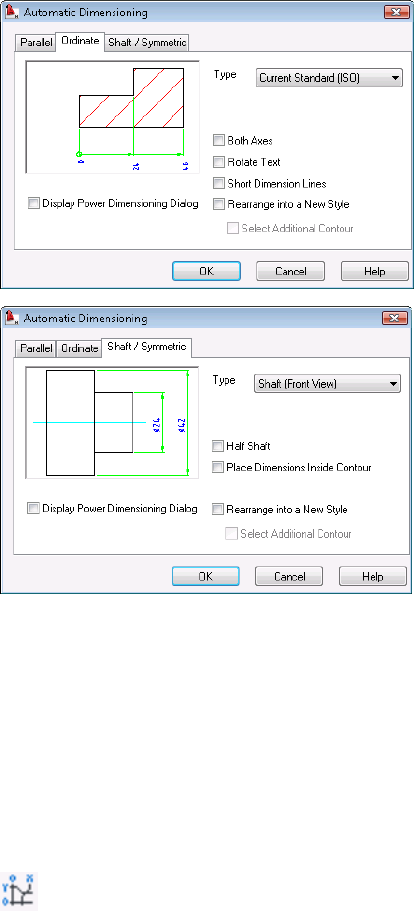
On the Annotate tab, select the Multiple Dimensioning command. Select
the Ordinate tab, and select the checkboxes for Both Axes and Rotate Text.
Generate the dimensions as shown in the following illustration.
72 | Chapter 9 Power Dimensions
Edit Dimensions
To open the Power Dimensioning or Automatic Dimensioning dialog boxes
for editing, double-click the existing dimensions. Dimensions change instantly
when you select new options or enter new parameters in these dialog boxes.
You can break, rearrange, stretch, and join dimensions with dimension editing
tools in AutoCAD Mechanical.
Try It: Edit Dimensions
Edit several dimensions at your own pace. From the Annotate menu, click
Edit Dimensions, and select the editing tools shown in the following image.
Edit Dimensions | 73
74
Add Part Lists and
Balloons
Adding part lists and balloons in AutoCAD® Mechanical is easier than the manual method
in AutoCAD®. You can also ensure an accurate count of item quantities as you add or remove
objects in an assembly drawing.
This lesson describes the role of part references for objects and how they relate to a bill of
materials (BOM) in an assembly drawing. It also shows you how to create and edit a bill of
materials (BOM), and to add a part list and balloons to a drawing.
Create Part References
In this lesson, you identify and itemize each part or component with attributes
in the part reference.
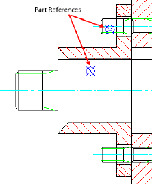
All standard parts including screws, nuts, steel shapes, and others have part
references automatically generated from the manufacturer catalogs. See the
10
75
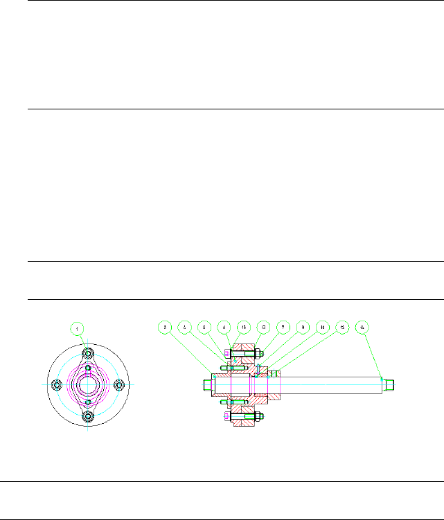
following illustration. Notice the representation of nodes used for standard
parts is different from the designed components as shown previously.
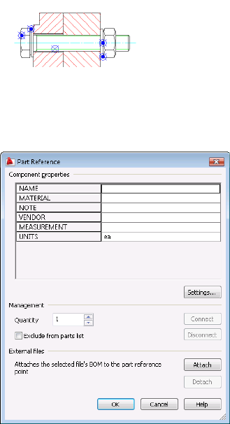
The part reference contains component properties such as material, note,
vendor, measurement, and units. You can also add and include the component
properties from the bill of materials. Click the Settings button on the Part
Reference dialog box.
The program captures component properties to the bill of materials (BOM)
for use in part lists and balloons.
76 | Chapter 10 Add Part Lists and Balloons
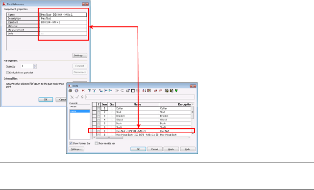
NOTE If you add or remove part references, the quantity value for the changed
component updates automatically in the bill of materials.
Try It: Create a part reference
Create a part reference for a component on your own. From the Annotate
menu, click Part Reference, and then click the component to locate the node
and open the Part Reference dialog box. Enter the component properties and
click OK.
About Bills of Materials (BOMs)
The BOM is the database of all parts and subassembly components in the
assembly. It captures all part references and information for parts you use in
an assembly drawing. You can view and edit the BOM information in the
BOM dialog box.
You can add, delete, and edit component properties in the BOM dialog box.
A drawing file can have more than one BOM. You can add or remove columns
or rows of information, change the order of the information shown in the
dialog box (like in an Excel spreadsheet), and insert part lists or balloons into
the drawing. See the BOM dialog box in the following image.
About Bills of Materials (BOMs) | 77
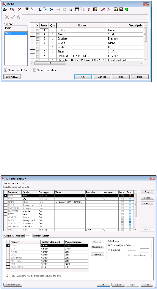
BOM Settings
To manage the BOM settings, open the Options dialog box. Right-click an
empty place on the drawing area to show the context menu ➤ Options ➤
AM:Standards tab ➤ double-click BOM in the Standard elements list in the
right pane. BOM settings for the active standard dialog box appears.
In the BOM Settings dialog box, you can add component properties from the
available component properties list to the four tabs: Component Properties,
BOM, Parts List, and Balloon. Select an entire row, and then click Add.
You can also add custom component properties to the Available component
properties list. To add a component property, double-click the last row and
enter your custom property.
78 | Chapter 10 Add Part Lists and Balloons
Create Balloons
You use balloons in mechanical drawing to itemize the parts in an assembly.
Create Balloons
1Open the gs_balloons drawing from the Getting_Started folder.
NOTE The path to the folder containing Getting_Started files is:
■Windows Vista™:C:\Users\Public\Documents\Autodesk\ACADM
2009\Acadm\Getting_Started
■Windows®XP: C:\Documents and Settings\All
Users\Documents\Autodesk\ACADM 2009\Acadm\Getting_Started
2From the Annotate menu, click Balloons.
3Enter T (auto) to create balloons automatically for the selected part
references.
4Enclose the whole assembly - front view. Make sure that you do not miss
any part references.
5Press ENTER to place the balloons.
NOTE Press F8 to turn off the orthogonal mode for easy placement of
balloons.
NOTE Use the option -reorganize in the AMBALLOON command to rearrange
balloons into a straight line.
Create Balloons | 79
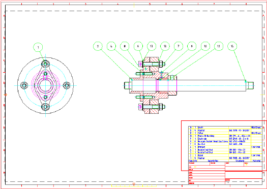
Create a Parts List
You create a part list to show a list of detail information for parts used in an
assembly drawing.
Create a Parts List
1Continue from the previous exercise.
2From the Annotate menu, click Parts List.
3Press ENTER to create a parts list from the main BOM.
4Click OK and place the parts list at the bottom right of the title block.
80 | Chapter 10 Add Part Lists and Balloons
International Drafting
Standards
Setting a standard based on industry standards or a custom company standard helps to
maintain a common form of communication for consistent productions results. AutoCAD
Mechanical supports ANSI, BSI, CSN, DIN, GB, GOST, ISO, and JIS industry standards. You
can also create a custom standard based on one of the industry standards and change some
or all of the settings according to your company standard.
In this lesson, you use the annotating tools in AutoCAD Mechanical to create standards-based
tolerances, fits, datum identifiers, feature control frames, surface texture symbols, welding
symbols, and leader notes to meet these standards.
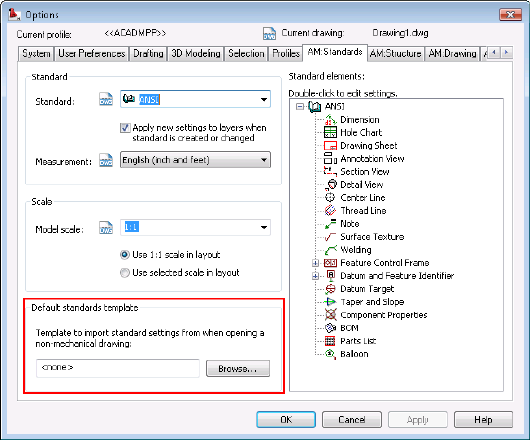
Set the Drafting Standard
In mechanical drawings, the standard controls all geometry, symbols, and texts
sizes. You select an industry standard, or a custom company standard, when
you start working on a drawing. You can also import a standard template from
your project team or another company.
To set the standard, activate or modify a standard in the standards list of the
AM:Standards tab in the Options dialog box. You can also edit multiple elements
to match the settings specific to your company or industry standard in the right
pane of the AM:Standards tab. The active standard appears with an open book
icon at its left. See the following image.
11
81
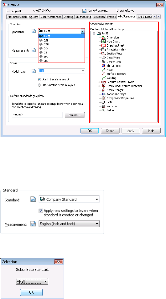
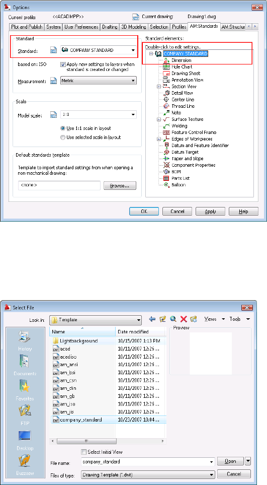
Create a Custom Standard
In the Options dialog box, double-click the active standard and type a new
standard name, for example “Company Standard.”
Press ENTER. The Selection dialog box appears, enabling you to select a base
standard. Select a base standard from the drop-down list and Click OK.
The program creates a custom standard, Company Standard.
82 | Chapter 11 International Drafting Standards
Best Practice
Set up a default template file with your selected standard to start every new
drawings and make it available to everyone in the project team. By doing so,
you save time configuring your requirements and ensure consistency with all
team members using the company standards.
Create a Custom Standard | 83
Save your default standards template in DWT format. To use this template for
non-AutoCAD Mechanical drawings, import this template into the drawings
when you open them.
Scale for Text and Symbols
For many large components or assemblies, it is necessary to scale down text
and symbols to fit them on standard paper sizes (A4, A3, A2, A1, or A0 size).
Annotations, including dimensions, symbols, and notes, can become illegible
when you view them in the model space. This session shows how you can set
the scale for the text and symbols.
84 | Chapter 11 International Drafting Standards
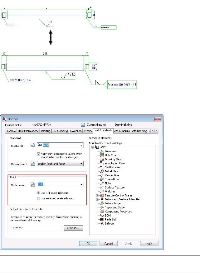
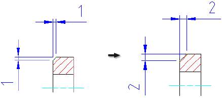
To set the size of symbols and text to the required sizes for viewing and printing
purposes, set the scale factor in the Model scale list in the Options dialog box.
NOTE When you change the model scale factor to 1:2, the annotations are
automatically two times larger than they are at scale factor 1:1.
Scale for Text and Symbols | 85
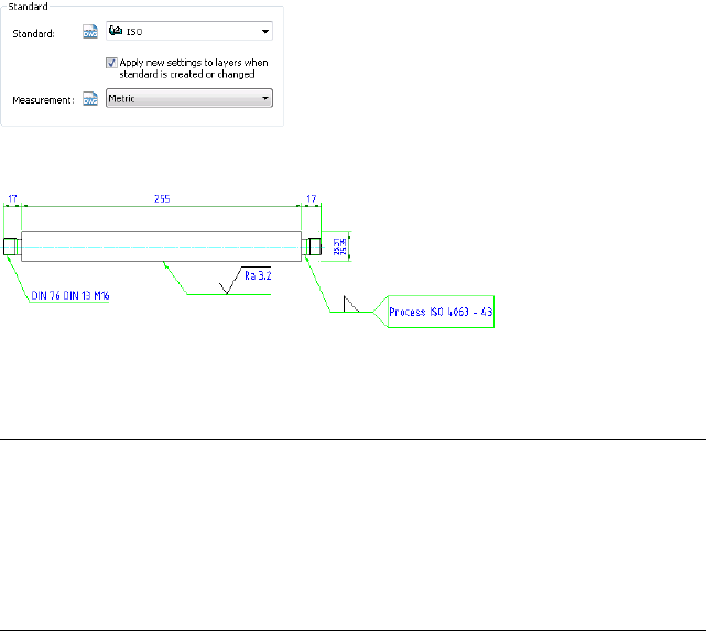
Standard-based Annotations
In the following exercise, you create the symbols for the front view of a shaft
used in a sealed shaft assembly based on the ISO standard with metric
measurements.
The following image shows a detailed shaft with the annotations.
Try It: Standard-based Annotations
Open the gs_shaft drawing in the Getting_Started folder.
NOTE The path to the folder containing Getting_Started files is:
■Windows Vista™:C:\Users\Public\Documents\Autodesk\ACADM
2009\Acadm\Getting_Started
■Windows®XP: C:\Documents and Settings\All
Users\Documents\Autodesk\ACADM 2009\Acadm\Getting_Started
From the Annotate menu, click Symbols. Use the annotating tools to add the
feature control frame, tolerance, surface texture, and welding symbol as shown
in the previous image.
Change the scale factor in the model scale list, and then rescale all the symbols
and dimensions to view the new size.
Add a custom standard in the AM:Standards tab of the Options dialog box.
Modify some of the elements such as the color of the arrow for welding
symbols. You can also save the current settings to a default template, a DWT
file, for reuse.
86 | Chapter 11 International Drafting Standards
Index
A
additional resources 1
associative hatch 19
associative hidden lines 57
automatic dimensioning 71
B
balloons 79
bill of materials 77
bom 77
C
center line 23
center line pattern 23
chamfer 61
construction line 12
Convert AutoCAD Layers to Mechanical
Layers 52
countersink hole 17
custom standard 82
D
detail view 63
dimensions 67
drafting standard 81
drawing file type 9
F
fastener 39
H
hatch 19
hidden lines 57
hole 14
M
mechanical dimensions 67
modify dimensions 73
O
object properties 50
P
part list 80
part reference 75
power commands 27
predefined layers 45
projected view 41
R
rectangle 21
resources 1
additional 1
S
screw connections 36
section line 24
standard for symbols 81
standard parts 31
standard parts library 31
T
title block 62
U
user interface 3
Index | 87
