Autodesk Inventor Routed Systems 2010 Getting Started Qsg
User Manual: autodesk Inventor Routed Systems - 2010 - Getting Started Free User Guide for Autodesk Inventor Software, Manual
Open the PDF directly: View PDF ![]() .
.
Page Count: 398 [warning: Documents this large are best viewed by clicking the View PDF Link!]
- Contents
- Part 1 Tubes and Pipes
- 1 Get Started with Tube & Pipe
- 2 Route Basics
- 3 Set Styles
- 4 Create Rigid Routes and Runs
- Workflow for Rigid Routes
- Create Auto Route Regions
- Manually Create Parametric Regions
- Automatically Dimension Route Sketches
- Create Segments With Precise Values
- Define Parallel and Perpendicular Segments
- Snap Route Points to Existing Geometry
- Place Constraints On Route Sketches
- Create Bends Between Existing Pipe Segments
- Create Pipe Routes With Custom Bends
- Create Bent Tube Routes
- Realign 3D Orthogonal Route Tool
- Control Dimension Visibility
- Populated Routes
- 5 Create and Edit Flexible Hose Routes
- 6 Edit Rigid Routes and Runs
- 7 Use Content Center Libraries
- 8 Author and Publish
- 9 Document Routes and Runs
- Part 2 Cable and Harness
- 10 Get Started with Cable and Harness
- 11 Work With Harness Assemblies
- 12 Use the Cable and Harness Library
- 13 Work with Wires and Cables
- 14 Work with Segments
- 15 Route Wires and Cables
- 16 Work with Splices
- 17 Work with Ribbon Cables
- 18 Generate Reports
- 19 Work With Nailboards and Drawings
- Part 3 IDF Translator
- Index

Autodesk Inventor Routed Systems 2010
Getting Started
January 2009Part No. 464B1-050000-PM01A
©2009 Autodesk, Inc. All Rights Reserved. Except as otherwise permitted by Autodesk, Inc., this publication, or parts thereof, may not be
reproduced in any form, by any method, for any purpose.
Certain materials included in this publication are reprinted with the permission of the copyright holder.
Trademarks
The following are registered trademarks or trademarks of Autodesk, Inc., in the USA and other countries: 3DEC (design/logo), 3December,
3December.com, 3ds Max, ADI, Alias, Alias (swirl design/logo), AliasStudio, Alias|Wavefront (design/logo), ATC, AUGI, AutoCAD, AutoCAD
Learning Assistance, AutoCAD LT, AutoCAD Simulator, AutoCAD SQL Extension, AutoCAD SQL Interface, Autodesk, Autodesk Envision, Autodesk
Insight, Autodesk Intent, Autodesk Inventor, Autodesk Map, Autodesk MapGuide, Autodesk Streamline, AutoLISP, AutoSnap, AutoSketch,
AutoTrack, Backdraft, Built with ObjectARX (logo), Burn, Buzzsaw, CAiCE, Can You Imagine, Character Studio, Cinestream, Civil 3D, Cleaner,
Cleaner Central, ClearScale, Colour Warper, Combustion, Communication Specification, Constructware, Content Explorer, Create>what's>Next>
(design/logo), Dancing Baby (image), DesignCenter, Design Doctor, Designer's Toolkit, DesignKids, DesignProf, DesignServer, DesignStudio,
Design|Studio (design/logo), Design Web Format, Discreet, DWF, DWG, DWG (logo), DWG Extreme, DWG TrueConvert, DWG TrueView, DXF,
Ecotect, Exposure, Extending the Design Team, Face Robot, FBX, Filmbox, Fire, Flame, Flint, FMDesktop, Freewheel, Frost, GDX Driver, Gmax,
Green Building Studio, Heads-up Design, Heidi, HumanIK, IDEA Server, i-drop, ImageModeler, iMOUT, Incinerator, Inferno, Inventor, Inventor
LT, Kaydara, Kaydara (design/logo), Kynapse, Kynogon, LandXplorer, LocationLogic, Lustre, Matchmover, Maya, Mechanical Desktop, Moonbox,
MotionBuilder, Movimento, Mudbox, NavisWorks, ObjectARX, ObjectDBX, Open Reality, Opticore, Opticore Opus, PolarSnap, PortfolioWall,
Powered with Autodesk Technology, Productstream, ProjectPoint, ProMaterials, RasterDWG, Reactor, RealDWG, Real-time Roto, REALVIZ,
Recognize, Render Queue, Retimer,Reveal, Revit, Showcase, ShowMotion, SketchBook, Smoke, Softimage, Softimage|XSI (design/logo),
SteeringWheels, Stitcher, Stone, StudioTools, Topobase, Toxik, TrustedDWG, ViewCube, Visual, Visual Construction, Visual Drainage, Visual
Landscape, Visual Survey, Visual Toolbox, Visual LISP, Voice Reality, Volo, Vtour, Wire, Wiretap, WiretapCentral, XSI, and XSI (design/logo).
The following are registered trademarks or trademarks of Autodesk Canada Co. in the USA and/or Canada and other countries:
Backburner,Multi-Master Editing, River, and Sparks.
The following are registered trademarks or trademarks of MoldflowCorp. in the USA and/or other countries: Moldflow, MPA, MPA
(design/logo),Moldflow Plastics Advisers, MPI, MPI (design/logo), Moldflow Plastics Insight,MPX, MPX (design/logo), Moldflow Plastics Xpert.
All other brand names, product names or trademarks belong to their respective holders.
Disclaimer
THIS PUBLICATION AND THE INFORMATION CONTAINED HEREIN IS MADE AVAILABLE BY AUTODESK, INC. "AS IS." AUTODESK, INC. DISCLAIMS
ALL WARRANTIES, EITHER EXPRESS OR IMPLIED, INCLUDING BUT NOT LIMITED TO ANY IMPLIED WARRANTIES OF MERCHANTABILITY OR
FITNESS FOR A PARTICULAR PURPOSE REGARDING THESE MATERIALS.
Published by:
Autodesk, Inc.
111 Mclnnis Parkway
San Rafael, CA 94903, USA
Contents
Tubes and Pipes . . . . . . . . . . . . . . . . . . . . . . . . . . . 1
Chapter 1 Get Started with Tube & Pipe . . . . . . . . . . . . . . . . . . . 3
About Tube & Pipe . . . . . . . . . . . . . . . . . . . . . . . . . . . . . 3
Tube & Pipe Features . . . . . . . . . . . . . . . . . . . . . . . . . 3
Tube & Pipe Environment . . . . . . . . . . . . . . . . . . . . . . 4
Tube & Pipe Browser . . . . . . . . . . . . . . . . . . . . . . . . . 6
Work in Autodesk Inventor Installations . . . . . . . . . . . . . . . . . 7
Prerequisites . . . . . . . . . . . . . . . . . . . . . . . . . . . . . . . . 8
Back Up Tutorial Data Files . . . . . . . . . . . . . . . . . . . . . . . . . 9
Workflow for Tube and Pipe Assemblies . . . . . . . . . . . . . . . . . . 9
Set Up Projects For Exercises . . . . . . . . . . . . . . . . . . . . . . . 11
Define the Master Runs Assembly . . . . . . . . . . . . . . . . . . . . . 11
Create Master Runs Assemblies . . . . . . . . . . . . . . . . . . . 12
Add Individual Runs . . . . . . . . . . . . . . . . . . . . . . . . 15
Specify Global Settings . . . . . . . . . . . . . . . . . . . . . . . 16
Chapter 2 Route Basics . . . . . . . . . . . . . . . . . . . . . . . . . . . . 19
About Rigid Routes . . . . . . . . . . . . . . . . . . . . . . . . . . . . 19
Auto Route Cycling . . . . . . . . . . . . . . . . . . . . . . . . . 20
Parametric Regions . . . . . . . . . . . . . . . . . . . . . . . . . 21
About Flexible Hose Routes . . . . . . . . . . . . . . . . . . . . . . . . 21
Route Points . . . . . . . . . . . . . . . . . . . . . . . . . . . . . . . . 22
iii
Rigid Route Points . . . . . . . . . . . . . . . . . . . . . . . . . . 22
Hose Route Points . . . . . . . . . . . . . . . . . . . . . . . . . . 23
3D Orthogonal Route Tool . . . . . . . . . . . . . . . . . . . . . . . . 23
Tool Elements for Pipe Routing . . . . . . . . . . . . . . . . . . . 23
Tool Elements for Tube Routing . . . . . . . . . . . . . . . . . . 24
Change Tool Displays . . . . . . . . . . . . . . . . . . . . . . . . 25
Define Angular Position and Rotation Snap . . . . . . . . . . . . 25
Define 45-degree Angles . . . . . . . . . . . . . . . . . . . . . . . 26
Define Bent Tubes Angles . . . . . . . . . . . . . . . . . . . . . . 27
Use Point Snap to Define Points . . . . . . . . . . . . . . . . . . 28
Enter Precise Values . . . . . . . . . . . . . . . . . . . . . . . . . 29
Route Tools . . . . . . . . . . . . . . . . . . . . . . . . . . . . . . . . 31
Basic Tools . . . . . . . . . . . . . . . . . . . . . . . . . . . . . . 31
Bend Tools . . . . . . . . . . . . . . . . . . . . . . . . . . . . . . 32
Dimension Tools . . . . . . . . . . . . . . . . . . . . . . . . . . 33
Parallel and Perpendicular Tools . . . . . . . . . . . . . . . . . . 34
Other Tools . . . . . . . . . . . . . . . . . . . . . . . . . . . . . 34
Chapter 3 Set Styles . . . . . . . . . . . . . . . . . . . . . . . . . . . . . 37
About Tube and Pipe Styles . . . . . . . . . . . . . . . . . . . . . . . . 37
Access Tube and Pipe Styles . . . . . . . . . . . . . . . . . . . . . . . . 38
View and Select Styles . . . . . . . . . . . . . . . . . . . . . . . . . . . 40
Set Style Options . . . . . . . . . . . . . . . . . . . . . . . . . . . . . 41
General Tab . . . . . . . . . . . . . . . . . . . . . . . . . . . . . 42
Rules Tab . . . . . . . . . . . . . . . . . . . . . . . . . . . . . . 43
Work with Styles . . . . . . . . . . . . . . . . . . . . . . . . . . . . . . 44
Create Rigid Pipe with Fittings Styles . . . . . . . . . . . . . . . . 45
Tubing with Bends Style . . . . . . . . . . . . . . . . . . . . . . 47
Flexible Hose Styles . . . . . . . . . . . . . . . . . . . . . . . . . 47
Create Flexible Hose Styles . . . . . . . . . . . . . . . . . . . . . 48
Change Styles for Existing Routes . . . . . . . . . . . . . . . . . 49
Change Active Styles for New Routes . . . . . . . . . . . . . . . . 50
Add Styles to Assembly Templates . . . . . . . . . . . . . . . . . . . . 50
Chapter 4 Create Rigid Routes and Runs . . . . . . . . . . . . . . . . . . . 53
Workflow for Rigid Routes . . . . . . . . . . . . . . . . . . . . . . . . 53
Create Auto Route Regions . . . . . . . . . . . . . . . . . . . . . . . . 55
Manually Create Parametric Regions . . . . . . . . . . . . . . . . . . . 58
Automatically Dimension Route Sketches . . . . . . . . . . . . . 59
Create Segments With Precise Values . . . . . . . . . . . . . . . . 60
Define Parallel and Perpendicular Segments . . . . . . . . . . . . 61
Snap Route Points to Existing Geometry . . . . . . . . . . . . . . 65
Place Constraints On Route Sketches . . . . . . . . . . . . . . . . 67
Create Bends Between Existing Pipe Segments . . . . . . . . . . . 70
Create Pipe Routes With Custom Bends . . . . . . . . . . . . . . 71
iv | Contents
Create Bent Tube Routes . . . . . . . . . . . . . . . . . . . . . . 78
Realign 3D Orthogonal Route Tool . . . . . . . . . . . . . . . . . 82
Control Dimension Visibility . . . . . . . . . . . . . . . . . . . . 87
Populated Routes . . . . . . . . . . . . . . . . . . . . . . . . . . . . . 88
Chapter 5 Create and Edit Flexible Hose Routes . . . . . . . . . . . . . . . 91
Workflow for Flexible Hose Routes . . . . . . . . . . . . . . . . . . . . 91
Create Flexible Hose Routes . . . . . . . . . . . . . . . . . . . . . . . . 92
Create Hose Routes with Both Fittings . . . . . . . . . . . . . . . 93
Change Nominal Diameters . . . . . . . . . . . . . . . . . . . . 96
Create Hose Routes With One Fitting . . . . . . . . . . . . . . . . 97
Edit Flexible Hose Routes . . . . . . . . . . . . . . . . . . . . . . . . 101
Hose Nodes . . . . . . . . . . . . . . . . . . . . . . . . . . . . . 102
Hose Length . . . . . . . . . . . . . . . . . . . . . . . . . . . . 104
Start Fitting and End Fitting . . . . . . . . . . . . . . . . . . . . 105
Bend Radius Check . . . . . . . . . . . . . . . . . . . . . . . . . 106
Delete Flexible Hose Routes . . . . . . . . . . . . . . . . . . . . . . . 107
Practice Your Skills . . . . . . . . . . . . . . . . . . . . . . . . . . . . 108
Chapter 6 Edit Rigid Routes and Runs . . . . . . . . . . . . . . . . . . . 111
About Editing Rigid Routes and Runs . . . . . . . . . . . . . . . . . . 111
Auto Regions . . . . . . . . . . . . . . . . . . . . . . . . . . . . 111
Parametric Regions . . . . . . . . . . . . . . . . . . . . . . . . . 112
Options for Editing . . . . . . . . . . . . . . . . . . . . . . . . . . . 113
Route Tab . . . . . . . . . . . . . . . . . . . . . . . . . . . . . . 113
Pipe Run Tab . . . . . . . . . . . . . . . . . . . . . . . . . . . . 113
Context Menus . . . . . . . . . . . . . . . . . . . . . . . . . . . 114
Control Individual Settings . . . . . . . . . . . . . . . . . . . . . . . 117
Route Points . . . . . . . . . . . . . . . . . . . . . . . . . . . . . . . 118
Add to Finished Routes . . . . . . . . . . . . . . . . . . . . . . 118
Insert Intermediate Route Points . . . . . . . . . . . . . . . . . 119
Delete Route Points . . . . . . . . . . . . . . . . . . . . . . . . 120
Auto Regions . . . . . . . . . . . . . . . . . . . . . . . . . . . . . . . 120
Move Auto Route Segments Approximately . . . . . . . . . . . . 121
Move Auto Route Segments Accurately . . . . . . . . . . . . . . 123
Remove Unwanted Segments or Route Points . . . . . . . . . . 124
Convert Auto Region to Parametric Sketch . . . . . . . . . . . . 125
Dimensions . . . . . . . . . . . . . . . . . . . . . . . . . . . . . . . 128
Fittings . . . . . . . . . . . . . . . . . . . . . . . . . . . . . . . . . . 130
Place Fittings in the Active Project Workspace . . . . . . . . . . 131
Insert Library Parts Using AutoDrop . . . . . . . . . . . . . . . . 132
Adjust Fitting Position and Orientation . . . . . . . . . . . . . . 135
Restore Default Fittings . . . . . . . . . . . . . . . . . . . . . . 135
Replace Existing Fittings . . . . . . . . . . . . . . . . . . . . . . 136
Connections . . . . . . . . . . . . . . . . . . . . . . . . . . . . . . . 138
Contents | v
Delete Fitting Connections . . . . . . . . . . . . . . . . . . . . 138
Connect Fittings and Components . . . . . . . . . . . . . . . . 140
Edit Bent Tube Routes . . . . . . . . . . . . . . . . . . . . . . . . . . 144
Change Bend Radius . . . . . . . . . . . . . . . . . . . . . . . . 145
Move Coupling Nodes . . . . . . . . . . . . . . . . . . . . . . . 146
Delete Routes and Runs . . . . . . . . . . . . . . . . . . . . . . . . . 146
Chapter 7 Use Content Center Libraries . . . . . . . . . . . . . . . . . . 149
About Content Center . . . . . . . . . . . . . . . . . . . . . . . . . . 149
Content Center Libraries . . . . . . . . . . . . . . . . . . . . . . . . . 150
Manage Libraries . . . . . . . . . . . . . . . . . . . . . . . . . . . . . 151
Configure Libraries . . . . . . . . . . . . . . . . . . . . . . . . . 152
Place Tube and Pipe Parts . . . . . . . . . . . . . . . . . . . . . . . . 154
Chapter 8 Author and Publish . . . . . . . . . . . . . . . . . . . . . . . 155
About Authoring and Publishing . . . . . . . . . . . . . . . . . . . . 155
Author Tube and Pipe Parts . . . . . . . . . . . . . . . . . . . . . . . 155
Access Tube & Pipe Authoring Tool . . . . . . . . . . . . . . . . 156
Author Parameters . . . . . . . . . . . . . . . . . . . . . . . . . 158
Prepare iParts . . . . . . . . . . . . . . . . . . . . . . . . . . . . 163
Author iParts . . . . . . . . . . . . . . . . . . . . . . . . . . . . 166
Practice Your Skills . . . . . . . . . . . . . . . . . . . . . . . . . 173
Publish to Content Center . . . . . . . . . . . . . . . . . . . . . . . . 173
Set Up the Library and Subcategories . . . . . . . . . . . . . . . 174
Publish Authored Parts . . . . . . . . . . . . . . . . . . . . . . 175
Create Styles Using Published Parts . . . . . . . . . . . . . . . . . . . 181
Chapter 9 Document Routes and Runs . . . . . . . . . . . . . . . . . . . 183
About Documenting Routes and Runs . . . . . . . . . . . . . . . . . 183
Workflow for Documenting Pipe Runs . . . . . . . . . . . . . . 184
Use Drawing Templates . . . . . . . . . . . . . . . . . . . . . . . . . 185
Prepare Design View Representations . . . . . . . . . . . . . . . . . . 185
Create Drawing Views . . . . . . . . . . . . . . . . . . . . . . . . . . 187
Create Base Views . . . . . . . . . . . . . . . . . . . . . . . . . 188
Create Projected Views . . . . . . . . . . . . . . . . . . . . . . . 190
Create Detail Views . . . . . . . . . . . . . . . . . . . . . . . . 191
Practice Your Skills . . . . . . . . . . . . . . . . . . . . . . . . . 195
Recover Route Centerlines . . . . . . . . . . . . . . . . . . . . . . . . 195
Dimension Drawing Views . . . . . . . . . . . . . . . . . . . . . . . . 196
Create and Export Bills of Material . . . . . . . . . . . . . . . . . . . 198
Enable the Parts Only View . . . . . . . . . . . . . . . . . . . . 199
Add Base QTY and Stock Number . . . . . . . . . . . . . . . . . 200
Create and Export Bill of Materials . . . . . . . . . . . . . . . . 201
Create Parts Lists . . . . . . . . . . . . . . . . . . . . . . . . . . . . . 202
vi | Contents
Annotate Drawings with Piping Styles . . . . . . . . . . . . . . . . . 204
Cable and Harness . . . . . . . . . . . . . . . . . . . . . . . . 207
Chapter 10 Get Started with Cable and Harness . . . . . . . . . . . . . . 209
About Cable and Harness . . . . . . . . . . . . . . . . . . . . . . . . 209
Prerequisites . . . . . . . . . . . . . . . . . . . . . . . . . . . . 209
Back Up Tutorial Data Files . . . . . . . . . . . . . . . . . . . . . . . 210
Set Up Projects For Exercises . . . . . . . . . . . . . . . . . . . . . . . 211
Help . . . . . . . . . . . . . . . . . . . . . . . . . . . . . . . . . . . 211
Work in Autodesk Inventor Installations . . . . . . . . . . . . . . . . 212
About Electrical Parts . . . . . . . . . . . . . . . . . . . . . . . . . . 213
Workflow for Electrical Parts . . . . . . . . . . . . . . . . . . . . 213
Create Electrical Parts . . . . . . . . . . . . . . . . . . . . . . . . . . 214
Place Pins and Define Pin-level Properties . . . . . . . . . . . . 214
Set Part Properties . . . . . . . . . . . . . . . . . . . . . . . . . 219
Add RefDes Placeholders . . . . . . . . . . . . . . . . . . . . . . 219
Practice Your Skills . . . . . . . . . . . . . . . . . . . . . . . . . 220
Modify Pinned Parts . . . . . . . . . . . . . . . . . . . . . . . . . . . 221
Add Custom Properties to Parts . . . . . . . . . . . . . . . . . . . . . 222
Place Electrical Parts . . . . . . . . . . . . . . . . . . . . . . . . . . . 222
Chapter 11 Work With Harness Assemblies . . . . . . . . . . . . . . . . . 225
About Working in Harness Assemblies . . . . . . . . . . . . . . . . . 225
Cable and Harness Environment . . . . . . . . . . . . . . . . . 226
Create Harness Assemblies . . . . . . . . . . . . . . . . . . . . . . . . 227
Workflow for Harness Components . . . . . . . . . . . . . . . . 227
Use the Cable and Harness Browser . . . . . . . . . . . . . . . . . . . 231
Set Properties for Harness Components . . . . . . . . . . . . . . . . . 231
Customize Properties . . . . . . . . . . . . . . . . . . . . . . . 232
Set Occurrence Properties . . . . . . . . . . . . . . . . . . . . . 232
Assign Occurrence Reference Designators . . . . . . . . . . . . . 233
Chapter 12 Use the Cable and Harness Library . . . . . . . . . . . . . . . 235
About the Cable and Harness Library . . . . . . . . . . . . . . . . . . 235
Locate the Cable and Harness Library File . . . . . . . . . . . . 236
Display the Library Dialog Box . . . . . . . . . . . . . . . . . . . . . 238
Adding Library Definitions . . . . . . . . . . . . . . . . . . . . . . . 240
Create New Library Definitions . . . . . . . . . . . . . . . . . . 240
Modify Library Wire and Cable Definitions . . . . . . . . . . . . . . . 242
Copy Library Definitions . . . . . . . . . . . . . . . . . . . . . 242
Edit Library Definitions . . . . . . . . . . . . . . . . . . . . . . 242
Delete Library Definitions . . . . . . . . . . . . . . . . . . . . . 243
Add Properties to Library Definitions . . . . . . . . . . . . . . . 244
Contents | vii
Import and Export Library Data . . . . . . . . . . . . . . . . . . . . . 245
Import into the Cable and Harness Library . . . . . . . . . . . . 245
Export Library Data . . . . . . . . . . . . . . . . . . . . . . . . 247
Practice Your Skills . . . . . . . . . . . . . . . . . . . . . . . . . . . . 248
Chapter 13 Work with Wires and Cables . . . . . . . . . . . . . . . . . . . 251
About Wires and Cables . . . . . . . . . . . . . . . . . . . . . . . . . 251
Set Modeling and Curvature Behavior . . . . . . . . . . . . . . . . . . 252
Insert Wires and Cables Manually . . . . . . . . . . . . . . . . . . . . 253
Insert Wires Manually . . . . . . . . . . . . . . . . . . . . . . . 253
Insert Cables Manually . . . . . . . . . . . . . . . . . . . . . . 257
Move Wires and Cables . . . . . . . . . . . . . . . . . . . . . . . . . 259
Move Wires . . . . . . . . . . . . . . . . . . . . . . . . . . . . 260
Move Cables . . . . . . . . . . . . . . . . . . . . . . . . . . . . 261
Delete Wires and Cables . . . . . . . . . . . . . . . . . . . . . . . . . 261
Delete Wires . . . . . . . . . . . . . . . . . . . . . . . . . . . . 262
Remove Cables and Cable Wires . . . . . . . . . . . . . . . . . . 262
Replace Wires . . . . . . . . . . . . . . . . . . . . . . . . . . . . . . 263
Assign Virtual Parts . . . . . . . . . . . . . . . . . . . . . . . . . . . 264
Import Harness Data . . . . . . . . . . . . . . . . . . . . . . . . . . . 265
Configuration File Formats . . . . . . . . . . . . . . . . . . . . 266
Comma Separated Value Data File Formats . . . . . . . . . . . . 267
XML File Formats . . . . . . . . . . . . . . . . . . . . . . . . . 268
Review Harness Data . . . . . . . . . . . . . . . . . . . . . . . . 268
Import Harness Data . . . . . . . . . . . . . . . . . . . . . . . . 269
Add Shape to Wires and Cable Wires . . . . . . . . . . . . . . . . . . 271
Add Wire Points . . . . . . . . . . . . . . . . . . . . . . . . . . 271
Redefine and Move Wire Points . . . . . . . . . . . . . . . . . . 273
Delete Wire Work Points . . . . . . . . . . . . . . . . . . . . . . 274
Set Occurrence Properties . . . . . . . . . . . . . . . . . . . . . . . . 274
Wire Occurrence Properties . . . . . . . . . . . . . . . . . . . . 275
Cable Occurrence Properties . . . . . . . . . . . . . . . . . . . . 276
Override Library-level Properties . . . . . . . . . . . . . . . . . 276
Restore Library-Level Properties . . . . . . . . . . . . . . . . . . 277
Change Wire and Cable Displays . . . . . . . . . . . . . . . . . . . . 277
Chapter 14 Work with Segments . . . . . . . . . . . . . . . . . . . . . . . 279
About Segments . . . . . . . . . . . . . . . . . . . . . . . . . . . . . 279
Define Segments . . . . . . . . . . . . . . . . . . . . . . . . . . 279
Select Work Points for Segments . . . . . . . . . . . . . . . . . . . . . 280
Plan Segment Start Points and Endpoints . . . . . . . . . . . . . 280
Apply Offset Distances . . . . . . . . . . . . . . . . . . . . . . . 281
Create Segments . . . . . . . . . . . . . . . . . . . . . . . . . . . . . 281
Add Segment Branches . . . . . . . . . . . . . . . . . . . . . . 286
Manipulate Segments . . . . . . . . . . . . . . . . . . . . . . . . . . 287
viii | Contents
Redefine or Move Segment Work Points . . . . . . . . . . . . . 288
Insert Segment Work Points . . . . . . . . . . . . . . . . . . . . 289
Delete Harness Segment Work Points . . . . . . . . . . . . . . . 290
Delete Harness Segments . . . . . . . . . . . . . . . . . . . . . 290
Set Segment Properties . . . . . . . . . . . . . . . . . . . . . . . . . . 291
Set Diameter Behavior in Segments . . . . . . . . . . . . . . . . . . . 292
Change Displays of Segments . . . . . . . . . . . . . . . . . . . . . . 293
Set Segment Defaults . . . . . . . . . . . . . . . . . . . . . . . . . . . 293
Chapter 15 Route Wires and Cables . . . . . . . . . . . . . . . . . . . . . 295
About Routing and Unrouting . . . . . . . . . . . . . . . . . . . . . . 295
Define Manual Routes . . . . . . . . . . . . . . . . . . . . . . . . . . 296
Define Semi-automatic Routes . . . . . . . . . . . . . . . . . . . . . . 297
Route Wires . . . . . . . . . . . . . . . . . . . . . . . . . . . . 297
Define Automatic Routes . . . . . . . . . . . . . . . . . . . . . . . . 299
View Wire and Cable Paths . . . . . . . . . . . . . . . . . . . . 300
Unroute . . . . . . . . . . . . . . . . . . . . . . . . . . . . . . . . . 301
Unroute Wires . . . . . . . . . . . . . . . . . . . . . . . . . . . 301
Unroute Cables . . . . . . . . . . . . . . . . . . . . . . . . . . . 302
Unroute All Wires or Cables from All Segments . . . . . . . . . . 303
Practice Your Skills . . . . . . . . . . . . . . . . . . . . . . . . . 303
Chapter 16 Work with Splices . . . . . . . . . . . . . . . . . . . . . . . . 305
About Splices . . . . . . . . . . . . . . . . . . . . . . . . . . . . . . . 305
Recommended Workflow . . . . . . . . . . . . . . . . . . . . . 305
Create Splices . . . . . . . . . . . . . . . . . . . . . . . . . . . . . . . 306
Insert Splices . . . . . . . . . . . . . . . . . . . . . . . . . . . . 307
Modify Splices . . . . . . . . . . . . . . . . . . . . . . . . . . . . . . 308
Splice Wires or Add Wires to the Splice . . . . . . . . . . . . . . 308
Redefine the Splice . . . . . . . . . . . . . . . . . . . . . . . . 309
Splice Properties . . . . . . . . . . . . . . . . . . . . . . . . . . . . . 313
Access Properties for Splices and Splice Pins . . . . . . . . . . . 313
Control Length for Splices . . . . . . . . . . . . . . . . . . . . . 313
Delete Splices . . . . . . . . . . . . . . . . . . . . . . . . . . . . 314
Practice Your Skills . . . . . . . . . . . . . . . . . . . . . . . . . 314
Chapter 17 Work with Ribbon Cables . . . . . . . . . . . . . . . . . . . . 315
About Ribbon Cables . . . . . . . . . . . . . . . . . . . . . . . . . . . 315
Define Raw Ribbon Cables . . . . . . . . . . . . . . . . . . . . . . . . 315
Place Connectors from Content Center . . . . . . . . . . . . . . . . . 316
Create Ribbon Cables . . . . . . . . . . . . . . . . . . . . . . . . . . 321
Adjust Ribbon Cable Orientation and Shape . . . . . . . . . . . 324
Chapter 18 Generate Reports . . . . . . . . . . . . . . . . . . . . . . . . 329
Contents | ix
About Generating Reports . . . . . . . . . . . . . . . . . . . . . . . . 329
Workflow for Harness Reports . . . . . . . . . . . . . . . . . . . 329
Use the Report Generator Dialog Box . . . . . . . . . . . . . . . . . . 330
Format Reports . . . . . . . . . . . . . . . . . . . . . . . . . . . . . . 331
Use Sample Configuration Files . . . . . . . . . . . . . . . . . . 331
Edit Configuration Files . . . . . . . . . . . . . . . . . . . . . . 333
Generate Reports . . . . . . . . . . . . . . . . . . . . . . . . . . . . . 336
Create Part and Wire Bills of Material . . . . . . . . . . . . . . . 337
Create Wire Run List Reports . . . . . . . . . . . . . . . . . . . 338
Create Custom Reports . . . . . . . . . . . . . . . . . . . . . . 339
Chapter 19 Work With Nailboards and Drawings . . . . . . . . . . . . . . 341
About Nailboards and Drawings . . . . . . . . . . . . . . . . . . . . . 341
Nailboard Features . . . . . . . . . . . . . . . . . . . . . . . . . 342
Nailboard Environment . . . . . . . . . . . . . . . . . . . . . . . . . 342
Nailboard Browser . . . . . . . . . . . . . . . . . . . . . . . . . 344
Create Nailboards . . . . . . . . . . . . . . . . . . . . . . . . . . . . 344
Set Display Behavior . . . . . . . . . . . . . . . . . . . . . . . . 345
Manipulate the Harness . . . . . . . . . . . . . . . . . . . . . . . . . 346
Move the Harness . . . . . . . . . . . . . . . . . . . . . . . . . 346
Arrange the Harness Segments . . . . . . . . . . . . . . . . . . . 347
Arrange the Wire Stubs . . . . . . . . . . . . . . . . . . . . . . 348
Arrange the Label . . . . . . . . . . . . . . . . . . . . . . . . . 350
Change Nailboard Displays . . . . . . . . . . . . . . . . . . . . . . . 351
Change Segment and Wire Line Display . . . . . . . . . . . . . 351
Change Fan State and Displays . . . . . . . . . . . . . . . . . . 352
Annotate Nailboard Drawings . . . . . . . . . . . . . . . . . . . . . . 354
Dimension the Nailboard . . . . . . . . . . . . . . . . . . . . . 354
Add Properties . . . . . . . . . . . . . . . . . . . . . . . . . . . 355
Add Tables . . . . . . . . . . . . . . . . . . . . . . . . . . . . . 358
Placing Connector Views . . . . . . . . . . . . . . . . . . . . . . . . 360
Create an Assembly Drawing . . . . . . . . . . . . . . . . . . . . . . 361
Print Nailboards and Drawings . . . . . . . . . . . . . . . . . . . . . 363
Practice Your Skills . . . . . . . . . . . . . . . . . . . . . . . . . 364
IDF Translator . . . . . . . . . . . . . . . . . . . . . . . . . . 365
Chapter 20 Use the IDF Translator . . . . . . . . . . . . . . . . . . . . . . 367
About the IDF Translator . . . . . . . . . . . . . . . . . . . . . . . . . 367
Exchange Data . . . . . . . . . . . . . . . . . . . . . . . . . . . . . . 368
Understand Import IDF Options . . . . . . . . . . . . . . . . . . . . . 369
General Information . . . . . . . . . . . . . . . . . . . . . . . . 370
Select document type to create . . . . . . . . . . . . . . . . . . 370
Select items to import . . . . . . . . . . . . . . . . . . . . . . . 371
x | Contents
Item color . . . . . . . . . . . . . . . . . . . . . . . . . . . . . 371
Import IDF Board Files . . . . . . . . . . . . . . . . . . . . . . . . . . 371
Use IDF Board Data . . . . . . . . . . . . . . . . . . . . . . . . . . . 375
Index . . . . . . . . . . . . . . . . . . . . . . . . . . . . . . . 377
Contents | xi
xii
Tubes and Pipes
Part 1 of this manual presents the getting started information for Tube and Pipe in Autodesk
Inventor® Routed Systems. This add-in to the Autodesk Inventor assembly environment
provides the capability to create complete tube and pipe systems in mechanical assembly
designs.
1
2
Get Started with Tube &
Pipe
This chapter provides basic information to help you get started using Tube & Pipe in Autodesk
Inventor® Routed Systems and the exercises in this manual.
It also provides information about the tube and pipe environment, how to get started with
a tube and pipe assembly, and how to use tube and pipe data.
About Tube & Pipe
Tube & Pipe provides features for setting tube and pipe styles, adding runs and
routes to mechanical assemblies or product designs, adding initial fittings to
create route branches, and populating selected routes. When a tube and pipe
assembly is complete, the tube and pipe information can be represented in
drawings and presentations, and output to different data formats.
Tube & Pipe Features
With the tube and pipe tools you can:
■Create tube and pipe assembly files.
■Define, view, modify, copy, delete, and share tube and pipe styles that
conform to industry standards.
■Create tube, pipe, or hose routes using automatic solutions the system
calculates based on the style criteria.
■Create derived routes and edit the underlying base sketch.
1
3
■Use sketched tools to create parametric regions in rigid piping and bent
tubing routes.
■Utilize the existing geometry and drawn construction lines to navigate the
rigid piping and bent tubing routes.
■Defer updates on automatic routing for the tube and pipe runs assembly,
pipe run, and individual routes.
■Modify both routes and runs by placing dimensions and geometric
constraints.
■Access and use the Content Center to place conduit parts and fittings in
tube and pipe assemblies. Fittings can be used to initiate route branches.
■Author custom tube and pipe iParts and standard parts for publishing to
the Content Center Library.
■Populate selected routes with library components.
■Suppress memory-costly tube and pipe components in Level of Detail
representations, especially in large tube and pipe assemblies.
■Place non-adaptive occurrences of master runs assemblies, runs, hose
assemblies, and routes and make them adaptive for reuse.
■Swap in the needed master runs assembly member in the tube and pipe
interchangeability set when a tube and pipe iAssembly factory is created.
■Recover the route centerlines in tube and pipe drawings.
■Use the bill of materials to document routes and runs.
■Move pipe runs rigidly and edit hose routes in positional representations.
■Save tube and pipe data to ISOGEN .pcf files or ASCII bend tables.
■Use the browser to edit tube and pipe runs and to change visibility for
routes, runs, and components.
Tube & Pipe Environment
Tube & Pipe provides the familiar Autodesk Inventor® assembly environment
in addition to commands for adding and editing routes and runs.
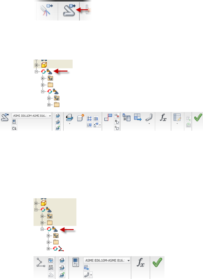
When you open an assembly in Autodesk Inventor Tube & Pipe, a command
appears on the Assembly tab for adding piping runs to your design.
4 | Chapter 1 Get Started with Tube & Pipe
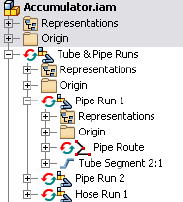
Once you add your first run, the commands specific to creating tube and pipe
runs in an assembly are displayed.
The Tube and Pipe panel is active when the top-level (master) run is active as
shown in the following image.
Tube and Pipe
Use the Tube and Pipe panel to add new individual runs to the master runs
assembly, define tube and pipe styles, set Gravity, and output the ISOGEN
data.
Use the tabs to switch between the Tube & Pipe and the Assembly panel bars.
The Pipe Run tab is active when an individual run is active as shown in the
following image.
Pipe Run
Tube & Pipe Environment | 5

Use the Pipe Run tab to add new routes, place and connect fittings, define
tube and pipe styles, and output the ISOGEN data.
The Route panel is available when the tube, pipe, or hose route environment
is active.
Route
Use the Route panel to create new routes, create a derived route, add or move
sketch nodes and segments, define tube and pipe styles, and dimension or
constrain the route.
There are several ways to enter the route environment, such as creating new
routes in a pipe run, double-clicking an existing route, and right-clicking a
route and selecting Edit.
There are additional tube and pipe commands contained here:
Enables switching between the Model browser, Content
Center Favorites, and Representations.
Browser toolbar
Contains the content of the tube and pipe assembly
in a hierarchy, along with the main Tube & Pipe Runs
Model browser
subassembly. The main run acts as a container for all
routes and runs and the components created or placed
in the routed system.
Contains the Tube & Pipe Authoring command to au-
thor tube and pipe iParts and normal parts for publish-
ing to the Content Center.
Part Features panel
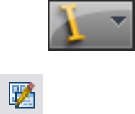
Tube & Pipe Browser
All tube and pipe components added to an assembly are contained in the
main runs subassembly. The components include individual runs and their
associated routes, fittings, segments, and route points.
Each run contains an Origin folder, one or more routes, and any segments or
fittings that are populated or manually inserted.
Routes contain the designated route points. To become familiar with the
various components in the browser, open a sample tube and pipe assembly.
6 | Chapter 1 Get Started with Tube & Pipe
Use the Tube & Pipe Browser
1Open the tube and pipe assembly, Accumulator. By default, it is located
at: Windows®XP C:\Program Files\Autodesk\Inventor<version>\Tutorial
Files\Tube & Pipe\Accumulator
Windows Vista®
C:\Users\Public\Documents\Autodesk\Inventor<version>\Tutorial Files\Tube
& Pipe\Accumulator
2Activate and expand the master runs assembly Tube & Pipe Runs.
Pipe Run 1 contains components for a bent tubing style run.
3Expand Hose Run 1 to view components for a flexible hose style run.
4Continue to expand folders in the hierarchy until you are familiar with
the contents, and then close the assembly.
5To view components for a rigid pipe run, open the sample, Buffer Prep
Skid. By default, it is located at: Windows XP C:\Program
Files\Autodesk\Inventor<version>\Samples\Models\Tube & Pipe\Buffer Prep
Skid
Windows Vista
C:\Users\Public\Documents\Autodesk\Inventor<version>\Samples\Models\Tube
& Pipe\Buffer Prep Skid
6Expand the folders in the hierarchy until you are familiar with the
contents, and then close the assembly.
Work in Autodesk Inventor Installations
If Autodesk Inventor Tube & Pipe is not installed on the system viewing the
tube and pipe data, the master runs assembly and all that it contains is
read-only. This means that the outline of the tube and pipe component is
Work in Autodesk Inventor Installations | 7
visible through Autodesk Inventor, but the component cannot be edited, and
new tube and pipe components cannot be added.
When the Tube & Pipe add-in is not installed, the tasks you can perform with
the tube and pipe data include:
■Open a Tube & Pipe Runs subassembly.
■Determine interferences with tube and pipe components in populated
routes by selecting the entire tube and pipe runs subassembly in the
browser.
■View the outline of tube and pipe run data within the context of an open
assembly file.
■Turn visibility off to completely hide the Tube & Pipe Runs component
in the graphics window.
■Create detailed drawings of populated routes within any file.
Prerequisites
It is assumed that you have a working knowledge of the Autodesk Inventor
interface and tools. If you do not, use the integrated Help for access to online
documentation and tutorials.
At a minimum, you should understand how to:
■Use the assembly, part modeling, sketch, and drawing environments, and
browsers.
■Edit a component in place.
■Create, constrain, and manipulate work points and work features.
■Set color styles.
■Use Content Center.
Be more productive with Autodesk® software. Get trained at an Autodesk
Authorized Training Center (ATC®) with hands-on, instructor-led classes to
help you get the most from your Autodesk products. Enhance your productivity
with proven training from over 1,400 ATC sites in more than 75 countries.
For more information about training centers, contact atc.program@autodesk.com
or visit the online ATC locator at www.autodesk.com/atc.
8 | Chapter 1 Get Started with Tube & Pipe
It is also recommended that you have a working knowledge of Windows XP,
or Windows Vista, and a working knowledge of concepts for routing tube and
pipe through mechanical assembly designs.
Back Up Tutorial Data Files
For each exercise in this section, you use files that contain the example
geometry or parts for that task. These files are included in the Tutorial Files
directory for the application. For Tube & Pipe, the files are located in the
installation path of Autodesk Inventor Tube & Pipe by default:
■Windows XP C:\Program Files\Autodesk\Inventor <version>\Tutorial
Files\Tube & Pipe
■Windows Vista C:\Users\Public\Documents\ Autodesk\Inventor
<version>\Tutorial Files\Tube & Pipe
Before you begin the exercises, back up the files so the originals are always
available. You can revert to these files if you make any mistakes during the
exercises, or if you would like to repeat an exercise.
Back up the tutorial files
1Go to the Tube & Pipe directory and create a new folder called
Exercise_Backup.
2From within the Tutorial Files directory, copy the exercise data into your
new folder.
Now you can use the files in the Tutorial Files directory as you work through
the exercises in this book. Keep any files you create for an exercise in the
Tutorial Files directory to avoid the possibility of file resolution problems.
Workflow for Tube and Pipe Assemblies
The first step in creating a tube and pipe system is to open an assembly file.
The assembly file can be empty or contain an assembly model. You can then
create the first pipe run and begin adding bent tubing, rigid piping, and flexible
hose routes.
Back Up Tutorial Data Files | 9
Create a tube and pipe runs assembly
1Set up the project environment such as project type, workspace, and
permissions to the style library. Content Center configuration is also
especially important.
2Optionally, customize your own master runs assembly template.
3Within a normal Inventor assembly, create a master runs assembly.
4Use the Tube & Pipe Styles tool to set style options.
5Select a tube, pipe, or hose style, and then create a new route using
automatic solutions and parametric regions to guide your selections.
6Adjust the route to design changes.
7Populate the route or insert additional fittings into the tube and pipe
assembly or directly onto a route. Fittings can be used to initiate new
routes.
8Add additional routes and runs.
9Make final adjustments to each route and run. Change the active style
or add, remove, reposition, and replace fittings, route points, and
segments.
10 Populate selected route(s).
11 Optionally:
■To reuse the master runs assembly, runs, routes, or flexible hose
assemblies, place secondary occurrences and use the Make Adaptive
tool to transition them to new primary occurrences.
■Create Level of Detail representations to save memory if you are
working with a large assembly.
■Create drawing views based on specific representations and
configurations, create and export bill of material tables for routes and
runs, and annotate drawings using parts lists, piping styles, and so
on.
■Save the file in a different format such as ISOGEN or bend table to
import to other drawing applications.
10 | Chapter 1 Get Started with Tube & Pipe
Set Up Projects For Exercises
For the exercises, browse to and select the project file in the Tutorial Files
directory.
Set up the project for Tube & Pipe exercises
1Click ➤ Manage ➤ Projects.
2 Use the Configure Content Center Libraries tool to configure
libraries. If required, ensure that you have logged in to your Autodesk
Vault server and the needed libraries are ready on the server.
3Select the AirSystemAssy.ipj as the active project.
4Optionally, in the Edit Project pane, right-click Use Styles Library, and
then select Yes or Read Only.
5Optionally, expand the Folder Options, right-click Content Center Files,
select Edit, and then enter CC.
The CC folder is under the root path of the project work space. You can
specify any other location you need to store the Content Center library
content. You can also use the default Content Center Files location.
6When you have completed all settings for the project, click Save.
7Ensure the project is active. If it is not, double-click the project.
8Click Done.
Define the Master Runs Assembly
When an assembly file is first opened, the assembly environment is displayed
and you can begin adding pipe runs. For the first pipe run added, the system
creates the master runs assembly along with an individual run. The master
runs assembly is a container for all pipe runs added to the assembly. The
number of runs you include depends on your design and manufacturing
documentation needs.
Each run can include one or more individual routes. All routes in a run can
use the same or different styles. With the capability to assign unique styles,
it is possible to have all three route types, each with different size diameters
Set Up Projects For Exercises | 11
in a single run. Routes can start and end on assembly model geometry or an
initial fitting dropped on the route to create a branch or fork.
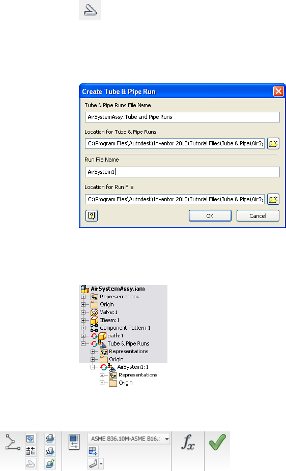
Create Master Runs Assemblies
To create the master runs assembly, you click Environments tab ➤ Begin
panel ➤ Tube and Pipe on the ribbon. On the Create Tube & Pipe Run dialog
box that appears you provide a unique name and location for the master runs
assembly and individual run respectively. By default, the files are saved to the
workspace of the active project.
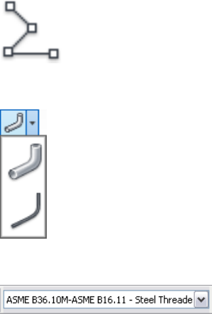
The Tube & Pipe Runs assembly is added to the browser along with other
placed components and is arranged in the order it was added to the assembly.
In the following exercise, you open an existing assembly and prepare to add
tubing and piping in the context of that assembly. You also become familiar
with the components included in the tube and pipe design environment
including the Tube and Pipe tab, Pipe Run tab, Route tab, and Model browser.
Create a tube and pipe assembly
1Click ➤ Open.
2Open the AirSystemAssy.iam assembly.
12 | Chapter 1 Get Started with Tube & Pipe
3 On the ribbon, click Environments tab ➤ Begin panel ➤ Tube
and Pipe.
4On the Create Tube & Pipe Run dialog box, enter AirSystem1 as the name
for the first run and accept the other defaults. Verify the default path in
the project workspace.
5Click OK.
The individual run is automatically added and activated so you can begin
defining a route and adding components.
6Examine the available tools on the Pipe Run tab, as shown in the
following image.
7Examine the Pipe Run tab to see the New Route tool, the Display All
Objects/Display Route Only tool, and the Active Style list.
Create Master Runs Assemblies | 13
New Route
Display All Objects/Display Route Only
Active Style list
8Click Help ➤ Help Topics to access Help, and then click the Contents
tab to display the table of contents if it is not already displayed.
9Click Tube and Pipe to display and examine the related Help topics.
14 | Chapter 1 Get Started with Tube & Pipe
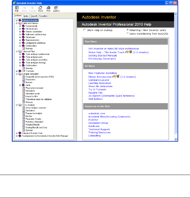
10 Close the Help window.
11 Activate the top-level assembly and save the file.
NOTE It is recommended that you save the top assembly regularly. Tube and Pipe
components are not stored in your project workspace until the top assembly is
saved.
Add Individual Runs
Each time you use the Create Pipe Run tool after the Tube & Pipe Runs
assembly is created, an individual run is added to this container run. Individual
runs are arranged in the order they are added to the tube and pipe assembly.
You can name and locate each run file as it is added.
The following image shows the default settings when you create the second
run:
Add Individual Runs | 15
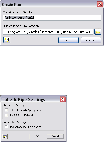
Specify Global Settings
With the top assembly active, right-click Tube & Pipe Runs in the Model
browser and use the Tube & Pipe Settings dialog box to specify the global
document and application settings for the master runs assembly.
Defer All Tube & Pipe Updates
Defer all tube and pipe updates when you are editing normal parts in a standard
Autodesk Inventor assembly or editing positional representations.
After the Defer All Tube & Pipe Updates check box is selected, most commands
specific to Tube & Pipe are disabled. The tube and pipe runs assembly is not
visible. Neither the tube and pipe runs assembly nor the associated parts in
drawings automatically update. You cannot create new pipe routes and runs
in the tube and pipe runs assembly.
When the Defer All Tube & Pipe Updates check box is cleared, you can defer
updates for individual runs and individual routes. For detailed instructions,
see Control Individual Settings on page 117 in Chapter 6.
Specify the setting for defer all tube and pipe updates
1Activate the top assembly.
2Right-click Tube & Pipe Runs, and select Tube & Pipe Settings.
16 | Chapter 1 Get Started with Tube & Pipe

3In the Tube & Pipe Settings dialog box, ensure the Defer All Tube & Pipe
Updates check box is cleared.
You can view automatic responses to edits on the tube and pipe assembly.
4Click OK.
Use of Bill of Materials
The drawing manager uses the current bill of materials (BOM) to create tube
and pipe drawings. When you migrate R9 or earlier tube and pipe drawings,
you can specify whether to continue using the R9 BOM (default) or to use the
current BOM.
The BOMs mainly differ in how they store the raw material description for
library parts:
■In the current BOM, the raw material description for conduit parts is stored
in the new stock number property. All BOM items with the same part
number are automatically merged in parts lists. If the part number is blank,
parts do not merge.
■In the R9 BOM, the raw material description for conduit parts was stored
in the part number property. You had control over the merging of rows
in the parts list. Even if two pipes had the same part number, you could
choose not to merge them.
In the exercises that follow you use the current version of Autodesk Inventor
Tube and Pipe to create tube and pipe assemblies, so the Use R9 Bill of Materials
check box is cleared by default.
NOTE For more information about how to migrate legacy tube and pipe drawings
to the current version, see the Help.
Prompt for Conduit File Names
When conduit parts are saved to your project workspace the first time, the
default file names are used, with a suffix of a 13-digit number that is generated
randomly based on your system time. The conduit file naming convention
can be customized when you enable the Prompt for Conduit File Names option.
Specify Global Settings | 17
Specify the prompt for conduit file names
1Activate the top assembly or master runs assembly.
2In the Model browser, right-click the Tube & Pipe Runs and select Tube
& Pipe Settings.
3In the Tube & Pipe Settings dialog box, Application Settings pane, to
accept the default conduit part file names, clear the Prompt for Conduit
File Names check box. Otherwise, select the check box.
4In the exercises that follow you do not need to customize the conduit
file names, clear the check box.
5Click OK.
18 | Chapter 1 Get Started with Tube & Pipe
Route Basics
A run is a collection of one or more routes with the same or unique styles that work together
to make up a complete flow system. A route is the path that determines the shape of the flow
system within the assembly and the intelligent placement of library components for the run
along that path.
Some routes contained in a run start and end on the assembly model geometry. Other routes
branch off a primary route to create a network of interconnecting rigid pipes, bent tubes, and
flexible hoses required to represent a single flow system.
Once you have a route, you can populate it with the Content Center library content based
on the tube and pipe style and the defined route path through the assembly.
About Rigid Routes
There are two types of rigid routes: rigid piping and bent tubing. The rigid route
styles, Rigid Pipe with Fittings and Tubing with Bends, contain the rules for
conduit parts and elbows. A pipe route can comprise pipe segments, couplings,
45-degree and 90-degree elbows, gaskets, gaps for groove welds, and custom
bends. A tube route comprises tubing segments and tubing bends. Couplings
connect straight segments and elbows or bends connect each directional change
point. If a butt weld style is active and gaps are set to display, straight segments
and directional change points have gaps between them for groove welds instead
of fittings.
A rigid route can be a series of auto regions and parametric regions:
■An auto region is created by selecting circular openings and work points as
the start and end route points and can have any number of segments that
are automatically created by the system. As you select two circular openings,
vertices, and work points, the system automatically generates the needed
segments and route points. If more than one routing solution exists based
2
19
on the points selected, you can cycle through the solutions and select the
one that best fits your needs.
■A parametric region is created using the 3D Orthogonal Route tool along
with the 3D sketch route tools, such as Point Snap, Rotation Snap, Parallel
With Edge, Perpendicular To Face, Bend, and General Dimension.
Auto regions are created where geometric constraints are not important.
Parametric regions are created to constrain the route to existing geometry or
dimensions. An auto region can be converted to a series of continuous sketched
segments at a later time.
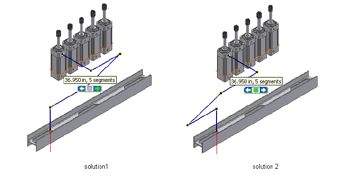
Auto Route Cycling
As you select existing valid geometry, the system may calculate more than
one auto region solution based on the points selected and display the Select
Other tool. You can cycle through the solutions upon route creation or later
edits, and select the one that best fits your needs.
Click the arrows to cycle through available solutions. Click the middle green
button to make your selection. If there are multiple auto-route solutions in a
single route, the Select Other tool cycles through the solutions in each section
before advancing to the next section.
20 | Chapter 2 Route Basics

Solutions are evaluated and prioritized based on length and number of
segments. The length and segment information is included in a tooltip as you
consider the available solutions.
If you must switch to a new auto region solution in later edits, activate the
route environment. The Alternate Auto Solution tool is available when
right-clicking the auto region in the Model browser.
Parametric Regions
Along with the 3D Orthogonal Route tool, you can use geometric constraints,
dimensions, custom bends, point snap, and rotation snap to manually define
sketched route points.
If existing geometry such as a vertex, linear geometry, planar faces, and work
features (including work points, work axes, and work planes) can help navigate
through the route system, include them as reference geometry. You can then
apply appropriate geometric constraints and dimension constraints to define
the design.
In addition, you can draw construction lines from sketched route points and
then use the General Dimension tool to position the coplanar segment
accurately.
NOTE It is best to plan for route constraints before starting the design.
About Flexible Hose Routes
Flexible hose routes can contain up to three parts: a start fitting, a hose
segment, and an end fitting. The start fitting and end fitting for a flexible hose
must have two connection points. Flexible hose routes can also consist of only
the hose, with both fittings suppressed, or a hose with one fitting suppressed.
To provide more control over hose shape, you can insert intermediate route
points in the hose route as you create it. As you make your selections, a preview
line appears between the selected points to help you visualize the route.
Flexible hose routes can be created between standard assembly geometry or
initiated from fittings dropped onto existing routes to create a branch.
Parametric Regions | 21
Route Points
Routes are created by selecting at least two route points. Route points can be
manually defined. In rigid routes, the system may also automatically generate
route points in auto regions.
A route typically starts from:
■Circular geometry such as a face, a hole, and cylindrical cuts
■Work points that reside in the assembly
■Vertices on any assembly component
■Existing free terminal route points in the active route
■Existing fittings
When you select circular geometry or work points, the route remains associative
to these points. If the model geometry changes, the route automatically
updates.
A variety of edit tools are available for route points on the Route tab and the
right-click context menu, depending on the specific route creation mechanism
and route type. For instance, when you are editing a rigid route, the 3D
Move/Rotate tool, Constraints tool, and General Dimension tool are applicable
to sketched route points. However, only the Move Node tool, Move Segment
tool, and Edit Position tool are applicable to auto regions where appropriate.
Rigid Route Points
Each route point in rigid routes is typically associated to a fitting with an
exception of free terminal route points. Rigid routes with a butt weld style are
also an exception. In this case, gaps can be displayed between route
components. Valid point selections are controlled by styles, connection data,
and the action being performed.
To better control the direction of a route, you can manually define any number
of intermediate route points using the 3D sketch route tools. Appropriate tools
are available to edit route points in both auto regions and parametric regions.
System-generated route points always automatically update to changes made
to the route during editing. Sketched route points in the parametric region
may also dynamically update unless they are fully constrained.
22 | Chapter 2 Route Basics
Hose Route Points
In hose routes, intermediate route points are used to control the shape of the
splines. They are not associated to any fittings. Depending on how the hose
route style defines the start fitting and end fitting, intermediate route points
can be inserted at an appropriate time.
To reposition the hose route points, you can place geometric constraints or
adjust the offset distances from existing geometry using the Redefine tool.
Editing the hose length does not impact the position of the adjacent hose
route points.
3D Orthogonal Route Tool
The 3D Orthogonal Route tool appears as soon as you begin selecting route
points in the graphics window. It contains several elements that guide selection
of valid route points.
When the 3D Orthogonal Route tool first appears, only the line extender is
displayed. With the line extender you can select points that are offset from a
selected edge. Once you select a point along the line, other elements of the
3D Orthogonal Route tool appear at the selected point.
The elements displayed are dependent on what is selected, the connection
geometry, and set styles. For example, the 3D Orthogonal Route tool includes
different elements depending on whether you are creating a pipe route with
fittings or a tube route with bends. Some elements are common to both styles.
Valid points, those that will make a connection of the allowable length, are
highlighted with a green dot as you move the cursor over the lines in the tool.
Points that do not fall within the range set by the style criteria are displayed
as a yellow x. The size of the tool can be increased if the line is not long
enough.
Tool Elements for Pipe Routing
When a rigid piping style is active and all elements are displayed on the 3D
Orthogonal Route tool, you can:
■Rotate freely around the local axis.
■Change direction in 90- or 45-degree increments.
■Create points from referenced geometry.
Hose Route Points | 23
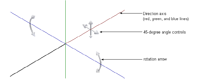
■Select points offset from selected edges.
The different elements in the 3D Orthogonal Route tool for rigid pipes with
fittings include:
Shows valid direction for the next route point. Click
the line to add a node in that direction. Together with
Direction axes
the Point Snap tool, you can define a work point on
the axis direction from referenced geometry.
Shows the rotation possibilities for the next route point
and enables the free rotation. Together with the Rota-
Rotation arrows
tion Snap tool, you can rotate the direction axis to an
orientation from referenced geometry.
Changes direction in 45-degree increments. This is
available only when 45-degree route direction is set for
the active style.
45-degree angle con-
trol
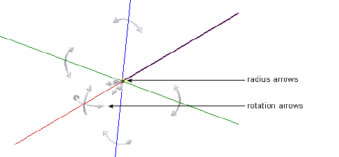
Tool Elements for Tube Routing
When a Tubing with Bends style type is active the line extender, direction
axes, and rotation arrows display along with the elements specific to creating
bent tube runs. In addition to the ability to rotate freely around the local axis,
create points from referenced geometry, and select points offset from selected
edges, you can also:
■Change direction at any angle between 0 and 180 degrees.
■Make precise adjustments to the included angle using the rotation arrows.
■Change the bend radius using the radius arrows.
24 | Chapter 2 Route Basics
Change Tool Displays
Both tool color and size can be changed. Tool size is changed using the plus
(+) or minus (-) keys on the keypad. Use plus (+) to increase the size, and minus
(-) to reduce it. To adjust the colors in which the direction axes, line extender,
or tooltip are displayed, set the colors as you would other color format styles.
Set colors in the display of the 3D Orthogonal Route tool
1Open a tube and pipe assembly file containing at least one route. You
can use the Tube & Pipe sample files, which are installed in
Autodesk\Inventor <version>\Samples\Models\Tube & Pipe by default.
2Activate the top-level assembly or Tube & Pipe Runs subassembly.
3On the ribbon, click Manage tab ➤ Styles and Standards panel ➤ Styles
Editor .
4In the Styles and Standards Editor dialog box, expand Color in the left
pane and select a Route_UI_Tool_(toolname) color style.
5Set the appropriate color attributes.
6Click Save to apply color changes immediately. Otherwise, colors become
effective when you click Done to close the dialog box.
Define Angular Position and Rotation Snap
The rotation arrows and direction axes can be displayed when defining routes
and placing fittings, and then again when editing and repositioning routes
Change Tool Displays | 25
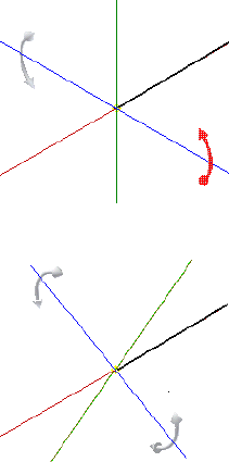
and fittings. With the Rotation Arrows and Direction Axes displayed, you can
view the rotation possibilities for the current selection.
To rotate freely around the axis, click and drag the Rotation Arrow as needed.
To snap the rotation in 90-degree increments, click on a line of the Direction
Axis.
The tool snaps to all four quadrant border angles as you rotate. The tool also
snaps to edge or face geometry. In this case, a dashed line and preview point
show how the snap is applied.
Click and drag a rotation arrow.
Release the cursor in the new location.
Define 45-degree Angles
When the 45-degree route direction is set in the active style, the Angle Control
can be displayed in the 3D Orthogonal Route tool. When it is displayed, you
can rotate the route position in 45-degree increments.
To use the Angle Control, click the arrow pointing in the angular position
you need. When you are satisfied with the position, select a point on the line
to create a segment at the new angular position.
Click an arrow to direct the path to the angle you want.
26 | Chapter 2 Route Basics
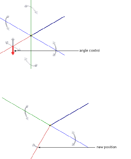
The route path changes to the new angular position. If you select the wrong
direction, click the single arrow displayed on the selected axis to revert to the
previous angular position.
Define Bent Tubes Angles
When a tubing with bends style is active, the Rotation Handles are displayed
on the 3D Orthogonal Route tool. When they are displayed you can create a
bend at any angle.
To use the Rotation Handles click the arrow pointing in the angular position
you need, and drag to the required position. The tool snaps in regular
increments based on the 3D Angle Snap value. This value is set on the Tools
tab ➤ Options panel ➤ Document Settings ➤ Modeling tab.
Define Bent Tubes Angles | 27
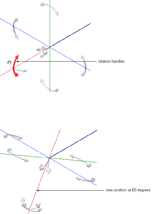
When you are satisfied with the new position, select a point on the line to
create a segment at the new location. The route path changes to the new
angular position. Using the Rotation Handles, you can also create a series of
bends to achieve a compound bend.
Use Point Snap to Define Points
When the 3D Orthogonal Route tool is active and Point Snap is checked in
the context menu, you can define points by snapping to other model geometry.
Pause your cursor over faces, edges, or work points, a dashed line and preview
point are displayed at the intersection of the line and the plane of the
highlighted edge or face.
The dashed line represents the snap point in relation to the highlighted
geometry. When the preview point is displayed at the needed location, click
the selected geometry and the point is created.
28 | Chapter 2 Route Basics
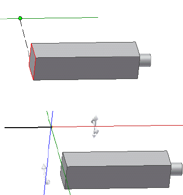
A dashed line shows the point snapped from the face.
Click the face to create the route point at the intersection with the tool.
Enter Precise Values
Although all route points can be selected interactively, sometimes exact values
are needed to create the required route. You can enter precise values for both
angles and distances. The values entered are the distance or angle from the
active position to the current node. If a point was snapped onto a line of the
3D Orthogonal Route tool, the value entered is the distance from the snap
point to the desired node to add. The entered values must comply with set
rules for segment length; otherwise, you are prompted to reenter the value.
For tubing with bends styles, you can also enter a precise bend radius.
To enter an exact distance, start typing the value while your cursor pauses
over the direction axis of the 3D Orthogonal Route tool. You can also
right-click and select Enter Distance to enter a value.
Entering angles is very similar. To enter an angle, start typing the needed value
while your cursor pauses over a rotation arrow or bent tube rotation arrow.
You can also right-click and select Enter Angle to enter an angle.
Enter exact distances while your cursor pauses over the rotation arrows,
rotation arrows, or direction axes of the 3D Orthogonal Route tool.
Enter the value for the distance.
Enter Precise Values | 29
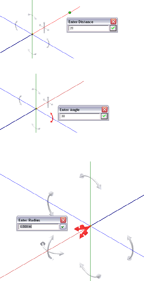
Enter the value for the angle.
To view the current bend radius, pause your cursor over the radius arrow.
Click the tool to enter a different value for the bend radius. You can also start
typing the new value while your cursor pauses over the radius arrow.
30 | Chapter 2 Route Basics

The new radius affects only the next bend. All subsequent bends use the default
radius set on the Tube & Pipe Styles dialog box.
Route Tools
To start creating routes, you must activate an individual pipe run, and then
enter the route environment. Along with the 3D Orthogonal Route tool, a
variety of sketched route tools are available and can assist in the route design.
You can create a route by connecting two or more points and directing the
route through circular openings and around existing geometry in its path.
Basic Tools
To enter the route environment, use the Pipe Run tab ➤ Route panel ➤
New Route tool.
New Route tool
In Route mode, the Route tab displays and you can begin creating a path for
your route. Use the Route tool to add new routes or continue existing ones.
Route tool
As you select points for a route, Autodesk Inventor® Routed Systems gives you
visual feedback about what is happening in the graphics window and text
messages on the status bar. The messages change based on what is selected
and the action you are performing.
When deciding on the design of your route, you can:
■Decide whether you must manually define the route direction or allow
the system to automatically calculate solutions.
Route Tools | 31
■Identify the circular geometry (or work points) that are used as the start
and endpoints.
■Analyze where directional change points are needed to route through or
around existing geometry.
■Create in-line work features, such as a work point at the intersection of
work planes, to guide the route path.
■Place constraints or dimensions to sketched segments.
■Convert auto regions to parametric regions so that you can make more
edits.
You can define your routes as close to the appropriate results as possible, and
then adjust them later, or you can develop them using precise distances and
dimensions as you go. To speed creation and plan for dynamic editing and
updating, allow the system to automatically create route points whenever
geometric constraints are not important. Define route points manually where
it is critical for a route to navigate through a particular direction and constrain
to existing geometry.
If using in-line work features, consider simplifying the route display by
selecting the Auto-hide in-line features option on the Tools tab ➤ Options
panel ➤ Application Options ➤ Part tab. In-line work features are hidden
as soon as they are consumed by a feature. The auto-hide option is enabled
by default.
Bend Tools
Use bent tubing and flexible hosing styles to create curved routes conforming
to the minimum bend radius. Typically, use the following tools to manually
create bends in the rigid route:
■Custom Bend tool on the right-click context menu when the 3D
Orthogonal Route tool is active. It is applicable when creating a pipe route.
■Bend tool on the Route tab. It is applicable when editing parametric regions
in a finished route.
32 | Chapter 2 Route Basics
Bend tool
In pipe routes, when a bend is required where it has not been manually
defined, the default bend radius of two times the pipe nominal diameter is
used. For instance, applying the Parallel With Edge tool to a certain linear
geometry may also require a bend if directional fittings in the Content Center
such as 45-degree or 90-degree elbow are not appropriate.
NOTE When an existing bend is deleted by mistake, use the Bend tool to create
a new bend where appropriate.
Dimension Tools
In rigid routes, there are three typical types of dimensions pertaining to the
route sketch:
■Linear dimension, such as the length of route segments
■Radial dimension, such as bend radius for custom bends in piping routes
and normal bends in tubing routes
■Angular dimension, such as angles between directional turns
Dimensions only apply to the route sketch in parametric regions. Auto regions
always dynamically update to assembly changes so the number of segments
typically varies from the new solution. They do not involve dimensions until
the Convert to Sketch command is applied.
The Auto-Dimension tool on the right-click context menu enables you to
switch whether to automatically dimension the subsequent route sketch. To
place and edit dimensions manually, click Route tab ➤ Constrain panel ➤
Dimension or double-click an existing dimension in place.
General Dimension tool
Dimension Tools | 33

Similar to Autodesk Inventor, dimensions on the route sketch can be
categorized into two types: normal sketched dimension (driving dimension)
and driven dimension. Normal sketched dimensions are used to drive the
route geometry. For instance, sketched route segments are manually created
using a specified dimension. Driven dimensions are enclosed in parentheses
as displayed in the graphics window and allow route geometry to dynamically
respond to associated changes.
NOTE The General Dimension tool cannot create a bend. After you use the Bend
tool to create a bend between two coplanar segments, you can edit the bend
radius using the General Dimension tool.
Parallel and Perpendicular Tools
During forward creation of sketched route segments, use the Parallel With
Edge and Perpendicular To Face tools to reorient the axis of the 3D Orthogonal
Route tool against existing geometry. When the next route point is defined
on this axis, a parallel or perpendicular constraint is added to the resultant
route segment. You can also pick up route points in the other two axes.
Applying the two tools may request an irregular angle (neither 45-degree nor
90-degree) at the preceding route point. Consequently, a custom bend is
created. Radius arrow and rotation arrow are available on the 3D Orthogonal
Route tool. Edit the bend radius and rotation angle as needed.
Other Tools
In addition to the 3D Orthogonal Route tool, Point Snap, Rotation Snap,
Custom Bend, Bend, General Dimension, Parallel With Edge, and Perpendicular
To Face tools that are discussed in the preceding sections, Tube & Pipe in
Autodesk Inventor Routed Systems Suite provides the following tools to define
the route sketch manually:
Applies the 3D sketch constraints between route points,
segments, and included reference geometry, such as
Constraints tool
Perpendicular, Parallel, Tangent, Coincident, Collinear,
and Fix.
Includes the reference geometry from the source geo-
metry to constrain the route sketch, such as vertices,
Include Geometry
tool
linear edges, planar faces, and work features (work
points, work axes, and work planes).
34 | Chapter 2 Route Basics
Creates any number of construction lines from the
sketched route point and places dimensions, typically
Draw Construction
Line tool
the included angle between the construction line and
the adjacent segment.
For detailed instructions on how to use these tools, see the Help.
Other Tools | 35
36

Set Styles
Tube and pipe styles describe the characteristics for tube, pipe, and hose routes. These styles
are key to controlling the design of the routed system as it evolves from prototype to
manufacturing.
This chapter provides basic information about the available options, how to set them, how
to modify and change them, and how to add them to a template.
About Tube and Pipe Styles
Tube and pipe styles affect most aspects of route design from route creation and
editing to populating the route. They are used to ensure consistent application
of tube and pipe components. For example, conduit parts and fittings in a pipe
run often have certain requirements for size, route direction, and materials.
With tube and pipe styles, you can set these requirements once, and then apply
them to the design.
When defining a style, you are specifying the conduit part and fittings from
the Content Center libraries that make up the pipe run and establishing rules
to be followed during routing.
There is a list of system-supplied tube and pipe styles in Autodesk Inventor®
Routed Systems. You can use one of these styles, create your own style based
on one of them, or create your own style based on published conduit parts and
fittings.
NOTE It is possible to define a style with which you are unable to create a route,
such as if you select fittings that do not have compatible end treatments. While the
Tube & Pipe Styles tool allows styles to be defined in this way, routes cannot be
created using such a style.
3
37
To correctly define new materials for tube and pipe styles, you must enable
the Use Styles Library setting for your project. For detailed instructions, see
Set Up Projects For Exercises on page 11 in Chapter 1.
WARNING Do not confuse tube and pipe styles with styles and style libraries in
Autodesk Inventor®. They are two separate, unrelated entities.
Access Tube and Pipe Styles
Before you begin working with routes and runs, examine the style settings,
and then select the style you need.
To work with styles, activate the tube and pipe environment and start the
Tube & Pipe Styles tool to display the Tube & Pipe Styles dialog box. The Tube
& Pipe Styles tool can be accessed on the ribbon or right-click menu when
you activate:
■The master runs assembly
■A run
■A route
Tube & Pipe Styles tool
Existing styles are also available from the Active Style list on the ribbon.
38 | Chapter 3 Set Styles
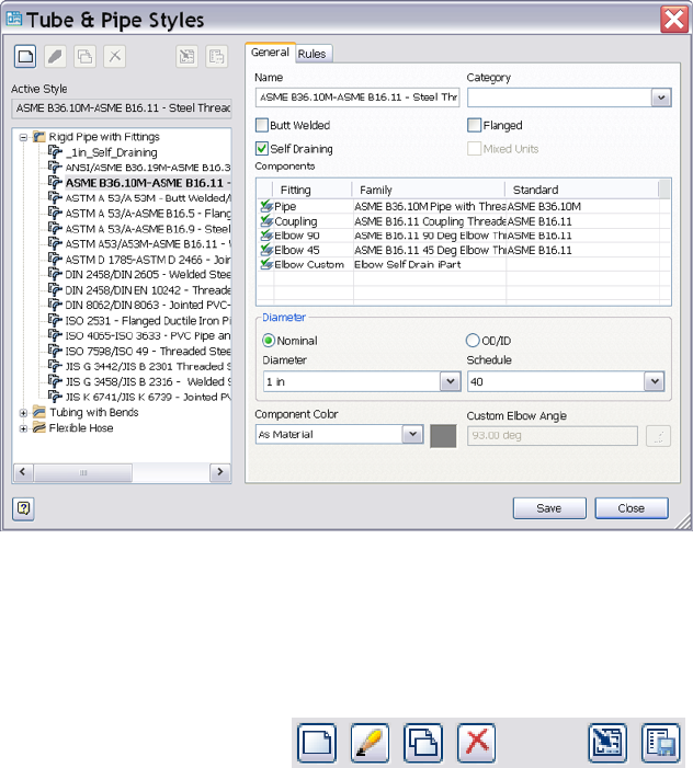
The features in the Tube & Pipe Styles dialog box include:
The tool set for the library that you use to create, edit,
copy, and delete one or more defined styles. Import
Toolbar
and export functions are also provided to bring style
definitions in and out of the local or master runs tem-
plates. Pause your cursor over the toolbar to view the
tooltips.
Displays the style used when automatically creating a
tube or pipe route and when populating a route with
Active Style
library content. The style displayed is based on the
active tube and pipe environment.
Displays the list of available style types, categories, and
individual styles. By default, the browser is expanded
Styles browser
to the location of the active style. Expand the list to
view and select other style types, categories, and style
definitions.
Sets or displays the name and category, style type, de-
fault components, and other general characteristics of
General tab
Access Tube and Pipe Styles | 39
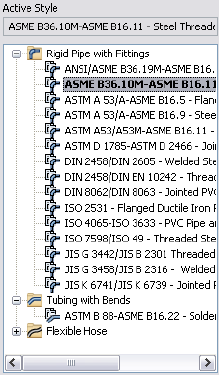
how routes are created for new or existing style defini-
tions.
Sets the parameters that specify the size range for cre-
ating route segments between identified route points.
Rules tab
For butt welded styles it also sets gap size and display.
For flanged and butt welded styles, it indicates the type
of coupling to use.
View and Select Styles
When you first open the Tube & Pipe Styles dialog box, the browser list
automatically expands to the location of the active style. The active style
displayed is dependent on the current tube and pipe environment. The active
style is displayed above the styles browser in a read-only input box. It is also
highlighted in bold in the browser list.
There are three types of styles in the list:
Creates a series of straight pipe segments connected
with specified fittings. The required and optional fit-
Rigid Pipe with Fit-
tings
tings vary depending on the type of rigid pipe style
being created.
Creates a single route with bends instead of fittings at
the directional change points.
Tubing with Bends
40 | Chapter 3 Set Styles
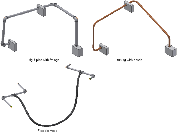
Creates a route consisting of a single hose segment that
can connect up to two fittings
Flexible Hose
An example of each is shown in the following image.
The style browser also provides access to the list of all defined styles. You can
use this list to select one or more styles, and then click a tool on the toolbar
to perform various operations. You can also right-click a node to display a
context menu with additional options.
Set Style Options
The Tube & Pipe Styles dialog box has two tabs. The nodes you select in the
browser list and certain selections you make on the General tab act as filters
to drive not only the available nominal diameter values and the rules, but
also the components from which you can choose.
The parameters on each tab are described in this section.
Set Style Options | 41
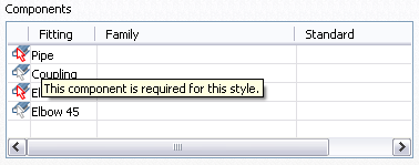
General Tab
On the General tab you can set a new, unique name for a style or modify and
rename an existing one. You also specify the general characteristics of how
routes are created and select components to include in the style definition.
The components table lists a basic set of components for the style being viewed
or created. Symbols indicate whether the component is optional or required
and if there are any issues with the component. Pause the cursor over the
symbol for a description.
Right-click a row in the table to clear existing components, suppress or
unsuppress fittings, or browse for components. When browsing for
components, the Library Browser dialog box is displayed. The parts available
for selection on the Library Browser dialog box are filtered from the Content
Center based on the node selected in the styles browser and the style criteria
set on the General tab.
42 | Chapter 3 Set Styles
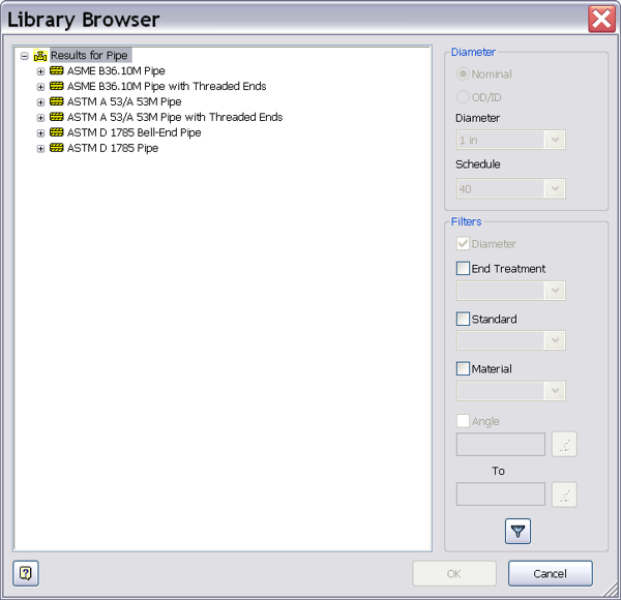
You can also set additional filtering, such as material and industry standard
to further refine the list. The standards and materials of published parts are
listed. Use the lists to make your selections. Once the standard is selected, the
available materials for the standard are listed. When an asterisk is displayed,
the system returns all content for that setting. For example, the system allows
all (*/any) materials to appear in the results.
Rules Tab
The Rules tab sets parameters that specify the size range for creating route
segments between identified route points. It includes the minimum and
maximum values, as well as the increment round-off value. Other settings are
specific to the type of style being created:
■For bent tube routes, you can set the default bend radius for the bends.
Rules Tab | 43

■For flexible hose routes, you can set a hose length round-up value and
minimum bend radius.
■For butt welded styles, you can set the gap size for the groove welds and
whether to display the gaps in the graphics window and drawings.
■For a combination butt welded and flanged style, indicate the style to use
at coupling points. The fitting connections are determined by the end
treatment that is set for the fitting. All other end treatment types use a gap
to join segments and fittings.
WARNING It is recommended that the minimum segment length is at least 1.5
times Nominal Diameter. Otherwise, it is more likely to cause a minimum segment
length violation if conduit segments are too small compared to Nominal Diameter.
Work with Styles
Although it is best to set styles before creating routes or placing fittings, styles
can be created at any time and style changes can be applied to new and existing
routes throughout the design process. With styles you can:
■Set style defaults for all new routes you create.
■Change the active style for the tube and pipe assembly.
■Change the style for the active route.
■Modify settings for all routes that use the same style.
NOTE You cannot apply a rigid type style to an existing flexible hose route and
vice versa. To change between a rigid style and flexible hose style, you must delete
the route and create a new one using the flexible hose style.
Before creating a new style, author necessary conduit parts and fittings and
publish them to the Content Center. They are not created automatically. Once
custom parts are authored and published, define the new style to match the
properties of published parts. For detailed instructions about authoring and
publishing, see Author and Publish on page 155.
You can modify any of the available style definitions including those that are
provided with the system. The change is saved with the style. The style change
is also applied to any route currently using that style. In the following exercises
you create new styles based on existing ones.
44 | Chapter 3 Set Styles

NOTE Before you make changes to a system style, make a copy and give it a new
name. You can then select the system style from the browser and make the
modifications.
To create a new style from a blank one, select the style type to create, and
then click New. This leaves the basic requirements for the style type as a guide,
but clears all values.
Create Rigid Pipe with Fittings Styles
When creating rigid pipe styles, the required components depend on the type
of rigid style being created.
■Typically three compatible parts are required: a pipe, a coupling, and an
elbow. If you require both 45-degree and 90-degree elbows, four parts are
required.
■Self Draining styles require five components: a pipe, a coupling, a 45-degree
elbow, a 90-degree elbow, and a previously published custom elbow or tee
that matches the slope angle.
■Welded tube and pipe styles typically need two part types: a pipe and a
90-degree elbow. Butt welded styles require you to set a gap size for the
groove welds and determine whether to display the gaps in the graphics
window and drawings.
■Flanged styles require: a pipe, an elbow, a flange instead of a coupling, and
an optional gasket.
In this exercise, you create two new rigid piping styles using existing styles as
the base.
NOTE When you switch between styles or create new styles during edits, you are
prompted whether or not to save edits. Click Yes to save edits to the current style
before proceeding or click No to proceed without saving changes to the current
style.
Create rigid piping styles
1With the AirSystemAssy.iam assembly open, activate the master runs
assembly Tube & Pipe Runs or the AirSystem1:1 run.
Create Rigid Pipe with Fittings Styles | 45
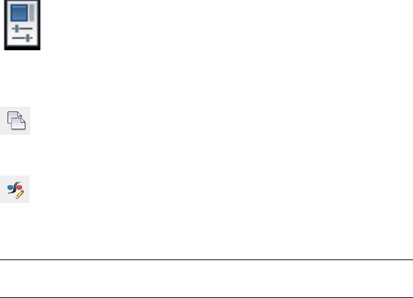
2 On the ribbon, click the Tube & Pipe Styles tool.
3In the style browser, select ASTM A53/A53M - ASME B16.11 Welded Steel
Pipe as the basis for the new style.
4 Click Copy.
5From the styles browser, select the copy you just created.
6 Click Edit.
7On the General tab, enter Welded Steel Pipe - ASTM A53/A53M - ASME B16.11
(1/4 ND) in the Name input box.
NOTE As you create new style definitions, you can also create categories in
which to organize them. Categories are optional.
8Under Components, notice that there are 4 components included in this
style that have all been successfully selected.
9Under Diameter, click the arrow to select a nominal diameter of 1/4 in.
from the list.
10 If desired, click the Rules tab to view the settings for minimum and
maximum values and the increment round-off.
11 Click Save.
The new style is added to the browser list, but is not set as the active style
for forward route creation.
12 To set the style as active, right-click the style in the browser list and select
Active.
13 To define the second style, make a copy of ISO 7598/ISO 49 Threaded
Steel Pipe with Iron Fittings.
14 Select and then edit the copy you just created.
15 Name the new style: Threaded Steel Pipe with Iron Fittings (1/2 ND, 90 Only).
16 Under Components, right-click the Elbow 45 row and select Clear.
17 Under Diameter, select a nominal diameter of 1/2 in.
46 | Chapter 3 Set Styles
18 Click Save.
Tubing with Bends Style
1In the style browser, expand the Tubing with Bends style type.
2Select ASTM B 88-ASME B16.22 Soldered Copper Tubing as the base for
the new style.
3Copy and edit the style as you did for the previous styles.
4Name the style: Soldered Copper Tube (1/2 ND,.5 Bend).
5Click the Rules tab and enter a bend radius of 0.500 in.
6Click Save.
Flexible Hose Styles
Flexible hose styles have some additional options that the other styles do not.
You can set the Use subassembly option to determine how the flexible hose
route is structured. It can be created in a flat structure, or with route
components grouped in a subassembly under the pipe run (default). Once
you create a flexible hose route, the route structure cannot be changed.
As with rigid route types, one of the first things you must do before creating
a route is to select a flexible hose style using the Tube & Pipe Styles tool. You
can create your own flexible hose style using custom fittings published to the
Content Center or select a predefined style.
Flexible Hose Style Parameters
A flexible hose style includes several parameters that are common to all three
route types. The parameters specific to a flexible hose style include:
(On the Rules tab) Rounds the hose length up to the
first larger value, based on the specified increment. For
Hose Round Up Value
example, if the Hose Round Up Value is set to 0.5 in.,
the hose length of 1.4 in. is rounded up to 1.5 in.
(On the General tab under Components) Includes a
hose part, a start fitting, and an end fitting. The start
Fitting Types
and end fittings can be suppressed using the context
Tubing with Bends Style | 47

menu from the appropriate rows in the components
table. Suppressed fittings are not included in the flex-
ible hose route. If you suppress the start fitting, the
end fitting is automatically suppressed.
Determines the structure of the hose as either a flat
structure or a subassembly.
Use subassembly
For more information about parameters, see Set Style Options on page 41 in
this chapter.
NOTE You cannot apply a rigid type style to an existing flexible hose route and
vice versa. To change between a rigid style and flexible hose style, you must delete
the route and create a new one using the flexible hose style.
Structure Flexible Hose Routes
When defining the flexible hose style you must decide if you want the fittings
placed into either a flat structure or a subassembly.
All parts are independent components placed along
with all other components under the pipe run. There
is no subassembly.
Flat structure
All parts are grouped into a subassembly under the
pipe run.
Subassembly struc-
ture
The route structure used for your design is typically determined by how the
hose route parts are purchased, assembled, and represented in manufacturing
documentation such as Parts Lists and Bills of Materials (BOM).
Create Flexible Hose Styles
In the following exercises, you create several hose styles based on the
predefined Hydraulic Hose - Female Thread - Swivel style.
Create a Flexible Hose style with both fittings
1In the style browser, select Hydraulic Hose - Female Thread - Swivel.
2Copy and edit the style as you did previously.
3Enter the new style name, Hydraulic Hose- Female Thread - Swivel (1/2 ND
2) to indicate the nominal size and two hose fittings, and click Save.
48 | Chapter 3 Set Styles
4On the General tab, select 1/2 in from the Diameter list.
5On the Rules tab, verify that .125 in is the Hose Round Up value.
6Click Save.
Create a Flexible Hose style with start fitting only
1Create another style based on Hydraulic Hose - Female Thread - Swivel
and save it as Hydraulic Hose- Female Thread - Swivel (1/2 ND 1).
2Under Components, select the End Fitting row, right-click and select
Suppress Fitting.
3Select 1/2 in from the Diameter list.
4Accept the other default settings.
5Click Save.
Create a new Flexible Hose type style with no fittings
1Create a third style based on Hydraulic Hose - Female Thread - Swivel
and save it as Hydraulic Hose- Female Thread - Swivel (1/2 ND 0).
2Right-click the copy and select Edit.
3Under Components, right-click the Start Fitting row and select Suppress
Fitting.
If the end fitting is not suppressed, you are prompted that the end fitting
will also be suppressed. Click Yes.
4Select 1/2 in from the Diameter list.
5Accept the other default settings.
6Click Save.
Change Styles for Existing Routes
Design needs change as the routed system evolves. With styles, you can make
subtle or dramatic changes quickly and efficiently.
For example, it is common to create routed systems using less expensive
manufacturing methods at the early design stages, then switch to the actual,
more expensive manufacturing methods at the end.
Change Styles for Existing Routes | 49

Change the style of an existing route
1Activate the route for which you want to change the style. If desired,
open a tube and pipe assembly from the Samples directory to perform
this operation.
2On the Route tab, Manage panel, select a new style from the Active Style
list.
The model is updated to conform to the new style. The changes are also
reflected in the browser.
NOTE When switching a route from a Tubing with Bends style to a Rigid Pipe
with Fittings style, the results may be unpredictable. You cannot switch an existing
route between the rigid piping and flexible hose styles.
Change Active Styles for New Routes
Routes in the same system often have different uses and different requirements.
To accommodate these changes, you can select a new style with the settings
needed for each different route. If you change or edit a style that is in use by
one or more routes, the style change or edits will affect all routes that use that
style.
Change the active style for new routes
1Activate the master runs assembly or an individual pipe run.
2On the Tube and Pipe or Pipe Run tab, Active Style list, select Welded
Steel Pipe - ASTM A53/A53M - ASME B16.11 (1/4 ND).
Add Styles to Assembly Templates
Within an Autodesk Inventor assembly, the tube and pipe runs subassembly
is created from the master tube and pipe runs assembly template, piping
runs.iam. This file is stored in the installation path of Autodesk Inventor
Professional Tube & Pipe, by default, Windows®XP C:\Program
Files\Autodesk\Inventor <version>\Design Data\Tube & Pipe and
C:\Users\Public\Documents\Autodesk\Inventor <version>\Design Data\Tube &
Pipe for Windows Vista®.
As with Autodesk Inventor assembly templates, Autodesk Inventor Professional
Tube & Pipe provides two types of units for the template: English and Metric.
50 | Chapter 3 Set Styles
When you install Autodesk Inventor Professional, your selection of default
units of measurement sets the default template used to create standard Inventor
assemblies and the default template used to create tube and pipe runs
subassemblies. For example, if you set English (Inches) as the default unit of
measurement during installation, the template in the English subdirectory is
copied to the Design Data\Tube & Pipe directory.
When you customize a set of tube and pipe styles, they are saved in the local
piping runs assembly that you name and locate when you first start your tube
and pipe assembly. To reuse them in future tube and pipe assemblies, you can
export the styles from the local piping runs assembly, and then import them
into a (blank) master runs assembly template. Once added to the master runs
assembly template, your styles can be used in other tube and pipe assemblies.
NOTE You must check the Use Styles Library option for the project. If it is set to
No, you may receive a warning message in this exercise. You must set the option
to either Yes or Read Only. Otherwise, you cannot continue defining tube and
pipe styles and populate routes in the exercises that follow.
Add custom styles to an assembly template
1Create a new, empty assembly file.
2 On the ribbon, click Environments tab ➤ Begin panel ➤ Tube
and Pipe.
3When prompted, save the assembly file. On the Create Tube and Pipe
Run dialog box, click OK to save the file using the defaults.
The main tube and pipe runs assembly is automatically named and
located, and the first run is activated.
4 With the master runs assembly or the first run active, click the
Tube & Pipe Styles tool. Create new styles, modify existing styles, or
import styles as required. Save the changes and then click OK.
5Right-click and select Finish Edit.
6Activate the master runs assembly, right-click the individual run Run01,
and then select Delete Run.
7Click OK to confirm.
Add Styles to Assembly Templates | 51
8With the top assembly active, save the file.
9In the graphics window right-click and select Generate Tube & Pipe
Template.
The piping runs.iam file is created in the Design Data\Tube & Pipe directory
along with a backup of the original template. The file name for the backup
is piping runs-old(1).iam where 1 is an incremental number starting with
1. The default installation location for Windows XP is C:\Program
Files\Autodesk\Inventor <version>\Design Data\Tube & Pipe. The default
installation location for Windows Vista is
C:\Users\Public\Documents\Autodesk\Inventor <version>\Design Data\Tube
& Pipe.
52 | Chapter 3 Set Styles

Create Rigid Routes and
Runs
Rigid routes are defined by selected route points. The rigid route styles, Rigid Pipe with Fittings
and Tubing with Bends, contain the rules for route components such as conduit parts and
elbows. Couplings, welds, or flanges connect straight segments. Elbows, bends, welds, or
flanges connect each directional change point. A populated route is created based on the tube
and pipe style and the defined route path through the assembly.
In this chapter, you learn about the methods and tools for creating rigid piping and bent
tubing routes with auto regions and parametric regions, and populating selected routes with
library components.
Workflow for Rigid Routes
The following is a typical workflow of creating a rigid route with a mixed set of
auto regions and parametric regions.
Create a rigid route
1Start with a tube and pipe assembly.
2With the top assembly or master runs assembly active, right-click the master
runs assembly, Tube & Pipe Runs by default and select Tube & Pipe Settings
to set the global document settings and application settings for all routes
and runs.
3 On the ribbon, click Environments tab ➤ Begin panel ➤ Tube
and Pipe to add new runs.
4
53

4If pipe run is not activated, right-click the pipe run and select Edit.
5 Select an active tube and pipe style. Optionally, you can create
new styles, modify existing styles, and import styles from other routes
or tube and pipe assemblies using the Tube & Pipe Styles tool.
6 With the pipe run active, click Pipe Run tab ➤ Route panel
➤ New Route. Enter a new file name or modify the default file name
and location.
7 On the ribbon, click Route tab ➤ Create panel ➤ Route to
start defining the start point on valid geometry.
8Use the 3D Orthogonal Route tool to continue selecting valid geometry
to create auto route regions, or use geometry constraints, point snap, or
specific dimensions to create sketched route segments.
9Right-click and select Finish Edit.
10 Populate the route, and set the conduit part file names if you have enabled
the Prompt for Conduit File Names option on the Tube & Pipe Settings
dialog box in Step 2.
11 To continue editing the route, if you are working with a large tube and
pipe assembly, use the Display/Update Settings and Defer All Updates
tools to prevent automatic updates and save memory cost.
12 Optionally:
■Add additional route points as you create or edit a route.
■Adjust route points and segments dynamically or by placing geometric
constraints and dimensional constraints.
■Change the active tube and pipe style.
■Place fittings and conduit parts from the Content Center using
AutoDrop or from the active project workspace.
54 | Chapter 4 Create Rigid Routes and Runs
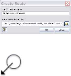
■Connect fittings, routes, runs, tube and pipe subassembly, and
Autodesk Inventor® components.
■Use the Model browser to visualize the tube and pipe run structure
or change visibility for conduit parts and fittings.
13 Save the top assembly.
It is recommended that you save the top assembly regularly. Tube and
pipe components are not stored in your project workspace until the top
assembly is saved.
Create Auto Route Regions
In this exercise, you quickly define a route by selecting points using circular
geometry and allowing the system to generate the rest.
Create an auto region
1In the AirSystemAssy.iam assembly, activate AirSystem1:1.
2On the Pipe Run tab active style list, verify that Welded Steel Pipe - ASTM
A53/A53M - ASME B16.11 (1/4 ND) is the active style.
3On the ribbon, click Pipe Run tab ➤ Route panel ➤ New Route.
4On the Create New Route dialog box, accept the default route file name
and location, and then click OK.
A pipe route is added to the active run and activated in place. The Route
tab is displayed.
5 On the ribbon, click Route tab ➤ Create panel ➤ Route.
Create Auto Route Regions | 55
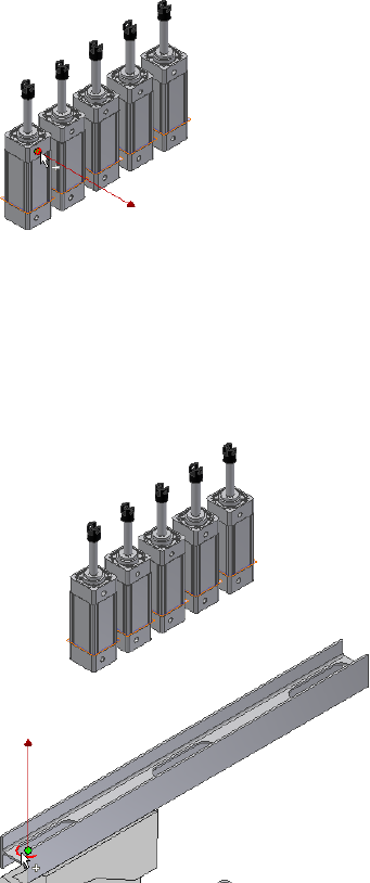
6In the graphics window, pause the cursor over the circular geometry as
shown in the following image. Zoom in and use the Select Other Direction
tool if needed to make your selection.
Once preselected, the circular geometry highlights and the line extender
displays, showing the direction of the route so you can create valid points
along the line. Press the spacebar to change the direction of the line
extender if needed.
7Click the circular geometry to select it as the start point.
This point is associated with the component that contains the selected
circular edge. A work point is added to the piping route.
8For the second route point, you can select a point on the line extender
or existing geometry. To route through the IBeam, pause the cursor over
the left arc of the IBeam opening.
56 | Chapter 4 Create Rigid Routes and Runs
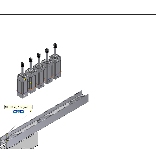
Rotate and zoom in to view the arc. Make sure the line is pointing to the
approach direction of the route.
NOTE To flip the direction of a displayed axis, press the spacebar or use the
Select Other tool.
9Click the geometry to select it as the second point.
As soon as you make your selection, the route generates to that point
and the Select Other tool appears indicating that multiple solutions exist.
10 Click the arrows to cycle through the solutions. Click the green middle
button to select the first solution as shown in Step 9.
11 In the Model browser, verify that the Autoroute browser node is added
and contains the indented auto route points.
Create Auto Route Regions | 57
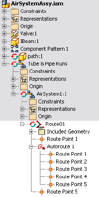
12 Right-click the Autoroute browser node and select Alternate Route
Solution.
You can use the Select Other tool to switch the auto region solution as
needed.
13 Ensure that you click the green middle button on the Select Other tool
to go back to the previously-set solution before you continue.
Manually Create Parametric Regions
Many runs involve more complex routing, which requires the creation of
additional route points. Tube & Pipe in Autodesk Inventor® Routed Systems
provides a variety of route tools to dimension or constrain the route against
existing geometry and construction lines.
In this chapter, you learn about how to use the General Dimension tool,
Parallel With Edge, Perpendicular To Face, Point Snap and Rotation Snap,
Bend and Custom Bend, and 3D Orthogonal Route tool.
For detailed instructions about other parametric route tools, refer to the Help.
58 | Chapter 4 Create Rigid Routes and Runs
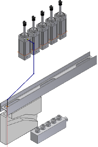
Automatically Dimension Route Sketches
When you manually define the next route point, the system automatically
adds dimensions to the route sketch by default. You can disable the
Auto-Dimension option on the right-click menu.
In the exercises that follow, you allow the system to automatically dimension
the route sketch in parametric regions so you accept the default setting.
Automatically dimension the parametric route sketch
1In the Route1 environment, ensure the 3D Orthogonal Route tool is
active for forward creation. If the line extender is not displayed, right-click
the last route point, and click the Route tool.
2Right-click in the graphics window and verify that Auto-Dimension is
enabled.
Automatically Dimension Route Sketches | 59
Create Segments With Precise Values
When the 3D Orthogonal Route tool is active, you can define the segments
with precise values using any of the following ways:
■Move the cursor over the direction axis of the 3D Orthogonal Route tool,
right-click, and then select Enter Distance.
■Pause the cursor over the direction axis, and then directly type the value
from the keyboard. The Enter Distance dialog box is automatically
displayed.
When you manually define the next route point, the system automatically
adds dimensions to the route sketch by default. You can disable the
Auto-Dimension option on the right-click context menu.
In the exercises that follow, you allow the system to automatically dimension
the route sketch in parametric regions so you accept the default setting.
Create segments using precise values
1Ensure the 3D Orthogonal Route tool is active on the last route point.
2Pause the cursor over the line extender, right-click and select Enter
Distance.
3Enter a distance of 3.4 inches for the next point, and then click the green
check mark.
The point is created on the screen, and the 3D Orthogonal Route tool is
displayed again at the new point. This time, since the new point is an
arbitrary point in space, all directions are enabled and selectable, except
backwards.
60 | Chapter 4 Create Rigid Routes and Runs
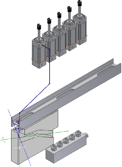
Define Parallel and Perpendicular Segments
In this exercise, you reorient the direction axes of the 3D Orthogonal Route
tool parallel and perpendicular to the edges and faces on the concave path
part. The next segments can then fit in the path part.
Applying the Parallel With Edge tool to a certain linear geometry may require
a bend if directional fittings in the Content Center such as 45-degree or
90-degree elbow are not appropriate.
Create segments using existing geometry
1Rotate your view to look at the front of the assembly.
2Pause the cursor over the red direction axis of the 3D Orthogonal Route
tool, right-click and select Parallel With Edge.
Define Parallel and Perpendicular Segments | 61
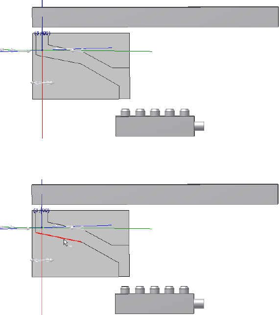
The system prompts you to select a linear edge.
3Select the linear edge on the path part as shown in the following image,
and click to set the selection.
The red direction axis is reoriented to the direction of the selected edge.
The included reference geometry is added to the Included Geometry
folder in the Model browser.
62 | Chapter 4 Create Rigid Routes and Runs
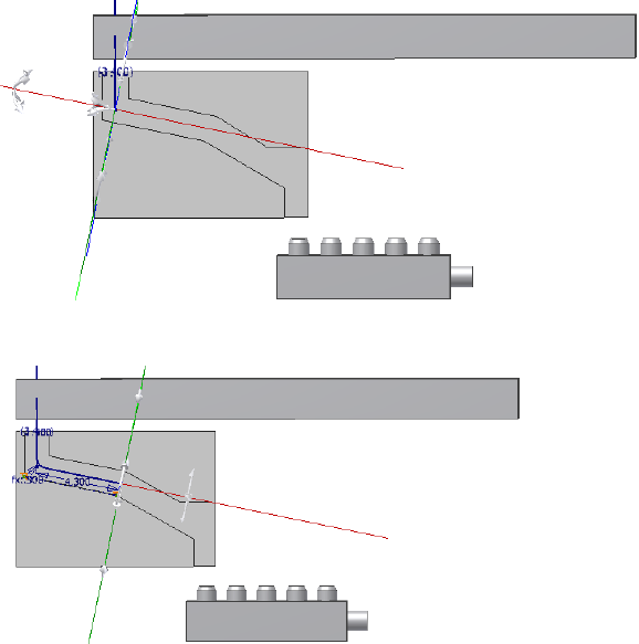
4Pause the cursor over the red axis, and then enter 4.3.
5Verify that a bend is automatically added between the new segment and
the preceding segment.
6For the next point, right-click the red direction axis again and select
Parallel With Edge.
7Select the other linear edge on the path part as shown in the following
image.
Define Parallel and Perpendicular Segments | 63
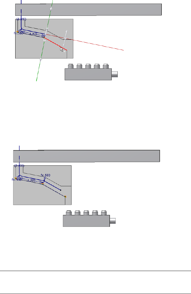
8Before creating the next route point, right-click in the graphics window
and clear the Auto-Dimension check mark.
9Click anywhere in the forward direction on the red direction axis. The
segment length is not important.
10 Right-click in the graphics window and select Done.
11 Verify that the new segment is not dimensioned.
In the exercise that follows, you make the last route point coincident with a
newly created route point. The last segment must not be dimensioned so that
it can dynamically update to a new segment length. Otherwise, the route
sketch may be over-constrained.
NOTE If you did not turn off the Auto-Dimension option, the last segment is
dimensioned. To dynamically update to later edits, you can also manually delete
the linear dimension. Right-click the dimension, and select Delete.
64 | Chapter 4 Create Rigid Routes and Runs
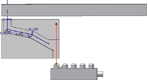
Snap Route Points to Existing Geometry
The Point Snap tool helps you to create route points by snapping to faces,
edges, work points, or vertices.
In this exercise, you continue defining the route point by snapping to the
path part.
Snap route points to existing geometry
1On the ribbon, click Route tab ➤ Create panel ➤ Route.
2Click the left circular opening on the valve part.
3Right-click in the graphics window and select Point Snap.
4Move the cursor over the last segment you just created in the preceding
exercise.
A dashed line representing the snap point is displayed from the cursor
to the preview point. A preview point is displayed at the intersection of
the line and the axis.
Snap Route Points to Existing Geometry | 65
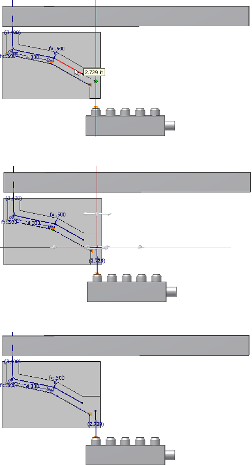
5When the lines appear, click the segment to set the snapped route point.
6Right-click and select Done.
66 | Chapter 4 Create Rigid Routes and Runs
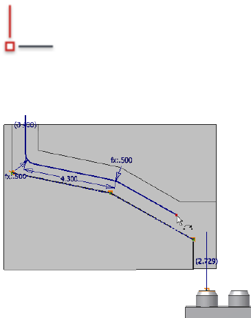
Place Constraints On Route Sketches
As with the 3D sketch in Autodesk Inventor, you can place geometric
constraints on the route sketch to constrain route points and segments.
Available 3D sketch constraints include Perpendicular, Parallel, Tangent,
Coincident, Collinear, and Fix. They help create your tube and pipe system
in the appropriate direction and orientation and constrain it to assembly
changes, join route points, and make route points fixed where dynamic updates
are not allowed.
In this exercise, you place a coincident constraint on the two separate route
points to join two route segments.
Join separate route points with the coincident constraint
1 On the ribbon, click Route tab ➤ Constrain panel ➤
Coincident.
2Select the two separate route points as shown in the following images.
First point to select
Place Constraints On Route Sketches | 67

Second point to select
The separate sketches form a closed route.
3Right-click in the graphics window and select Done.
4Right-click again and select Finish Edit.
68 | Chapter 4 Create Rigid Routes and Runs
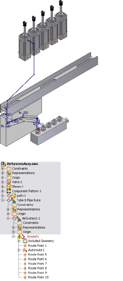
Notice that an error icon displays beside the route.
Place Constraints On Route Sketches | 69
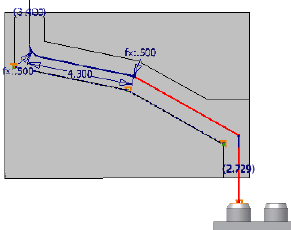
Placing the coincident constraint causes an odd (not 90-degree, 45-degree
or combined135-degree) angle between the two segments so the route is
in error. In the exercise that follows, you create a bend to fix the violation.
Create Bends Between Existing Pipe Segments
The rigid piping styles allow only the 90-degree, and 45-degree angles (when
45-degree is allowed in the style) and also the combined angles of 135-degrees.
When the Parallel With Edge or Perpendicular To Face tool is applied, bends
are automatically created where an odd angle is required.
When an odd angle exists between the two joint pipe segments, violations
occur. Use the Bend tool to create a bend so that the route is valid.
You can manually define the bends using the Custom Bend tool. It is applied
before you create the next segment.
In this exercise, you use the Bend tool to fix the invalid angle violation in the
preceding exercise.
Join separate route points with the coincident constraint
1To verify the errors in Route01, right-click the route in the Model browser
and select Show Violations.
2To identify the route part in error, click an error on the Show Violations
dialog box, and then view the error in the graphic window.
The invalid angle is between the two segments as highlighted in the
following image.
3Click OK to close the Show Violations dialog box.
70 | Chapter 4 Create Rigid Routes and Runs
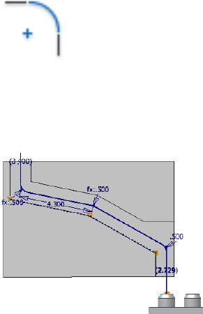
4 On the ribbon, click Route tab ➤ Create panel ➤ Bends.
5Accept the default settings on the Bend dialog box, and then select the
two segments that include the invalid angle.
The bend is created with a radius value of 0.5 inch. The error icon in the
Model browser disappears.
6Close the Bend dialog box.
7To end the route, right-click again and select Finish Edit.
Create Pipe Routes With Custom Bends
Rigid pipe routes with fittings may require a custom bend to satisfy special
manufacturing situations. To add a custom bend, use the Custom Bend option
in the right-click context menu while creating a pipe route. The 3D Orthogonal
Route tool changes to include the tube routing tools so you can create a bend
with the radius and angle you need. You can create multiple custom bends
in any given route.
In this exercise, you add a second route in the AirSystem1 run, change the
active style, and then create a route that is offset from the circular edge. You
also use the 3D Orthogonal Route tool to create additional points, including
custom bends.
Add custom bends
1In the AirSystemAssy.iam assembly, activate the AirSystem1:1 run.
Create Pipe Routes With Custom Bends | 71
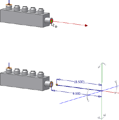
2On the Pipe Run tab, Manage panel, Active Style list, set the Active Style
to Threaded Steel Pipe with Iron Fittings (1/2, 90 Only).
3On the ribbon, click Pipe Run tab ➤ Route panel ➤ New Route, and
then accept the default route file name and location to continue.
4On the ribbon, click Route tab ➤ Create panel ➤ Route to start defining
the start point on valid geometry.
5Pause the cursor over the circular edge as shown in the following image,
enter a distance of 1 inch, and then click the green check mark.
The point is created offset from the circular edge by that distance.
6Move the cursor along the line extender and enter 8.5.
You can enlarge or reduce the 3D Orthogonal Route tool by pressing plus
(Shift and +) and minus (-) on the keypad.
7Enlarge the 3D Orthogonal Route tool until the line reaches the top of
the model.
8Make sure Point Snap is on, and then move the cursor over the work
plane to snap the point onto the 3D Orthogonal Route tool. Click to
create the point.
72 | Chapter 4 Create Rigid Routes and Runs
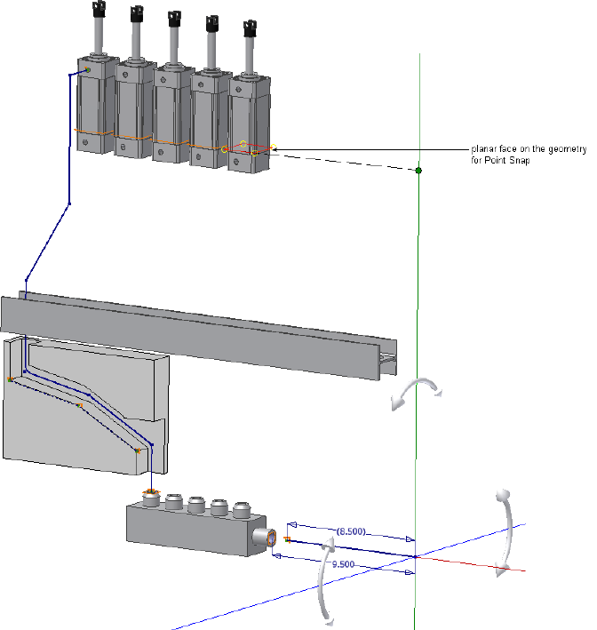
9Rotate the view to the front of the assembly.
Create Pipe Routes With Custom Bends | 73
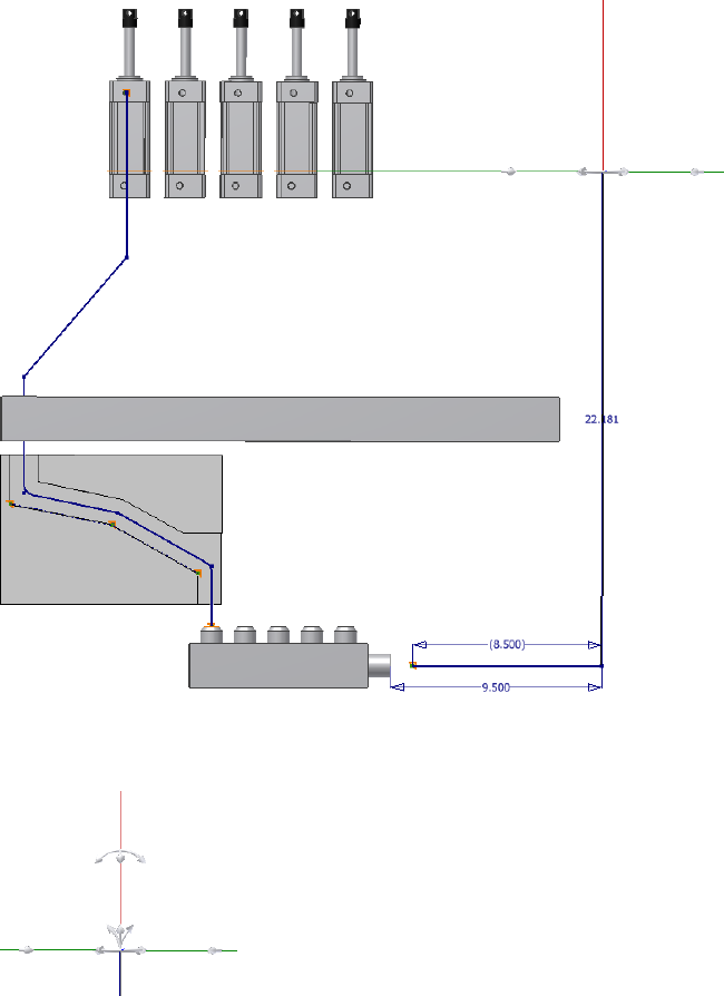
10 Right-click in the graphics window, and select Custom Bend.
The 3D Orthogonal Route tool now displays the tube routing elements.
11 Click the rotation handle on the red axis and drag in the direction shown
until the tooltip displays an angle of 30 degrees. You can also enter 30
when you move the cursor over the rotation handle.
74 | Chapter 4 Create Rigid Routes and Runs
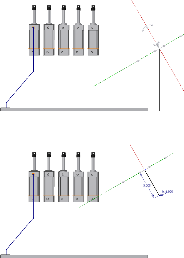
12 Pause the cursor over the red axis, and then enter a distance of 5 inches.
The 3D Orthogonal Route tool reverts to displaying the pipe routing
elements.
13 Right-click and select Custom Bend. Add a bend of 60 degrees in the other
direction, as shown in the following image.
Create Pipe Routes With Custom Bends | 75
14 Pause the cursor over the red axis, and then enter a distance of 5 inches.
15 Right-click, select Custom Bend, and then create a bend of 30 degrees as
shown in the following image.
76 | Chapter 4 Create Rigid Routes and Runs
16 Pause the cursor over the red axis, and enter 8 inches.
17 Right-click and select Done.
18 Right-click and select Finish Edit.
The linear segments adjacent to the custom bend sequence are joined
with the bend to create a single pipe segment with bends, rather than
custom elbows.
Create Pipe Routes With Custom Bends | 77
Create Bent Tube Routes
Bent tube type routes can be created at any angle and using any bend radius.
For this exercise you select the Soldered Copper Tube (1/2 ND,.5 Bend) style
you created earlier, and then create a bent tube route by directing it along the
IBeam and over to the threaded steel route to the right of the model.
Create a bent tube route
1In the AirSystemAssy.iam assembly, activate the AirSystem1:1 run.
2On the Pipe Run tab, Manage panel, Active Style list, select Soldered
Copper Tubing (1/2 ND,.5 Bend).
78 | Chapter 4 Create Rigid Routes and Runs
3On the ribbon, click Pipe Run tab ➤ Route panel ➤ New Route, and
then accept the default route file name and location to continue.
4On the ribbon, click Route tab ➤ Create panel ➤ Route to start defining
the start point on valid geometry.
5Select the start point of the route.
6Enter a distance of 5 inches for the first segment.
The 3D Orthogonal Route tool is displayed with the tube routing elements.
7Click the Radius handle and enter a bend radius of 1 inch.
8Rotate to get a better view of the tool, select the Rotation handle, and
then drag up by 30 degrees.
9Pause the cursor over the red axis, and enter a distance of 3 inches.
10 Select the Rotation handle, and drag down 140 degrees.
11 Pause the cursor over the red axis, and enter a distance of 3 inches.
Create Bent Tube Routes | 79
12 Click and drag the rotation handle 15 degrees to the right, and then
create two segments of 5 inches along the red axis.
13 Rotate the view to look at the front of the model. Move the cursor over
the Rotation handle, and then enter 50 degrees to drag to the right.
14 Pause the cursor over the red axis, and then enter a distance of 21 inches
for the next route point.
80 | Chapter 4 Create Rigid Routes and Runs
15 Enter a bend radius of 2 inches, click and drag the rotation handles up
by 40 degrees, and then enter a distance of 5 inches along the red axis.
Create Bent Tube Routes | 81
16 Right-click and select Done.
17 Right-click and select Finish Edit.
Realign 3D Orthogonal Route Tool
The Rotation Snap tool assists you to reorient a specified direction axis of the
3D Orthogonal Route tool by snapping to available linear edges and planar
faces. A custom bend is automatically created at the current route point when
the next segment is defined. It is useful when the direction axes of the 3D
Orthogonal Route tool does not align with the needed geometry.
In this exercise, you create a new route with the Welded Steel Pipe - ASTM
A53/A53M - ASME B16.11 (1/4 ND) style, and then review the skills you have
learned about the Point Snap tool to create route points. Finally, use the
82 | Chapter 4 Create Rigid Routes and Runs
Rotation Snap tool on the right-click context menu to reorient the direction
axes of the 3D Orthogonal Route tool by snapping to the valve opening.
Snap the axis rotation to existing geometry
1In the AirSystemAssy.iam assembly, activate the AirSystem1:1 run.
2On the Pipe Run tab, Manage panel, Active Style list, select Welded Steel
Pipe - ASTM A53/A53M - ASME B16.11 (1/4 ND).
3On the ribbon, click Pipe Run tab ➤ Route panel ➤ New Route, and
then accept the default route file name and location.
AirSystemAssy.Route04 is added to the Model browser.
4On the ribbon, click Route tab ➤ Create panel ➤ Route to start defining
the start point on valid geometry.
5Select the start point as shown in the following image.
6Click the right circular edge on the IBeam to allow the system to generate
an auto region. Use the Select Other tool to cycle through all solutions
as needed, and then select the first solution.
7Right-click in the graphics window and select Point Snap.
8Move the cursor over the upper face on the path part as shown in the
following image, and then click to snap the new route point.
Rotate the view to get a better view as needed.
Realign 3D Orthogonal Route Tool | 83
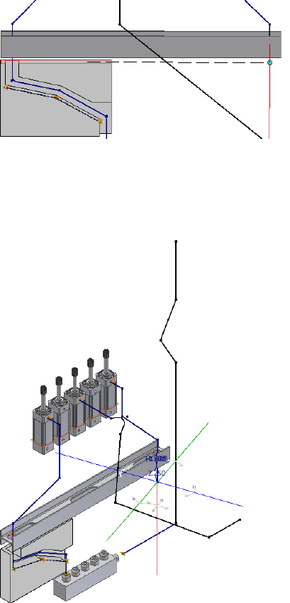
9Pause the cursor over the line extender, and then enter a distance of 2.25
inches for the next point.
10 Rotate to the isometric view. Notice that the green axis does not align
parallel to the valve part.
11 In this exercise, the green axis should be parallel to the valve part for the
rest of the route. Right-click in the graphics window, and select Rotation
Snap.
84 | Chapter 4 Create Rigid Routes and Runs
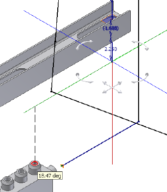
12 Click the Rotation handle on the green axis, and drag the cursor over the
valve opening. Release the cursor.
The green axis changes to the new orientation. It is parallel to the valve
part.
13 Right-click in the graphics window to ensure that Point Snap is enabled
on the context menu. Highlight the circular edge in the valve opening
as shown in the following image. Right-click and choose Select Other
Snap.
A preview point displays at the intersection of the line and the axis. A
dashed line representing the snap point displays from the cursor to the
preview point.
14 When the lines appear, click the green button to set the snapped route
point.
Realign 3D Orthogonal Route Tool | 85
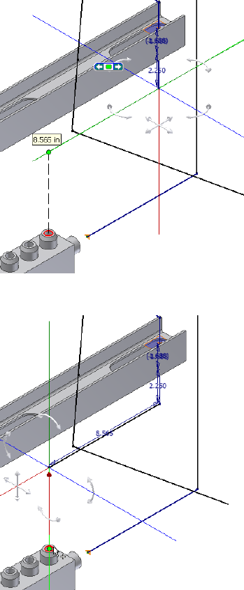
15 For the last point, click the circular geometry.
16 Right-click and select Done.
17 Right-click again and select Finish Edit.
86 | Chapter 4 Create Rigid Routes and Runs
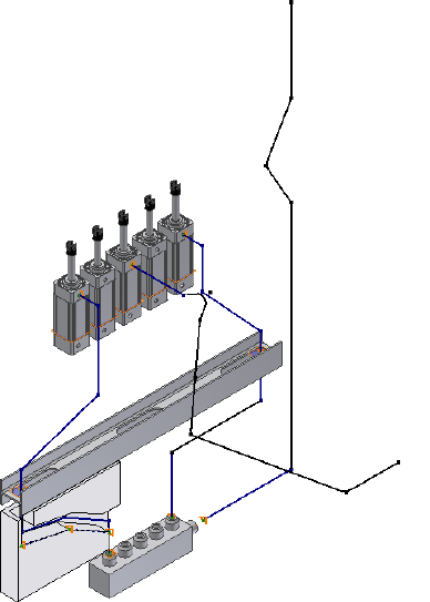
Control Dimension Visibility
In the route environment, dimensions in parametric regions remain visible
by default. Auto regions do not involve dimensions so no associated
dimensions are displayed.
Too many dimensions may block the view of the design window. In the
exercise that follows, you practice controlling the dimension visibility on the
route sketch using the Dimension Visibility tool.
Hide or display the route dimensions
1Activate Route01.
2Right-click the route in the Model browser, and then clear the Dimension
Visibility check mark.
All dimensions become invisible.
Control Dimension Visibility | 87
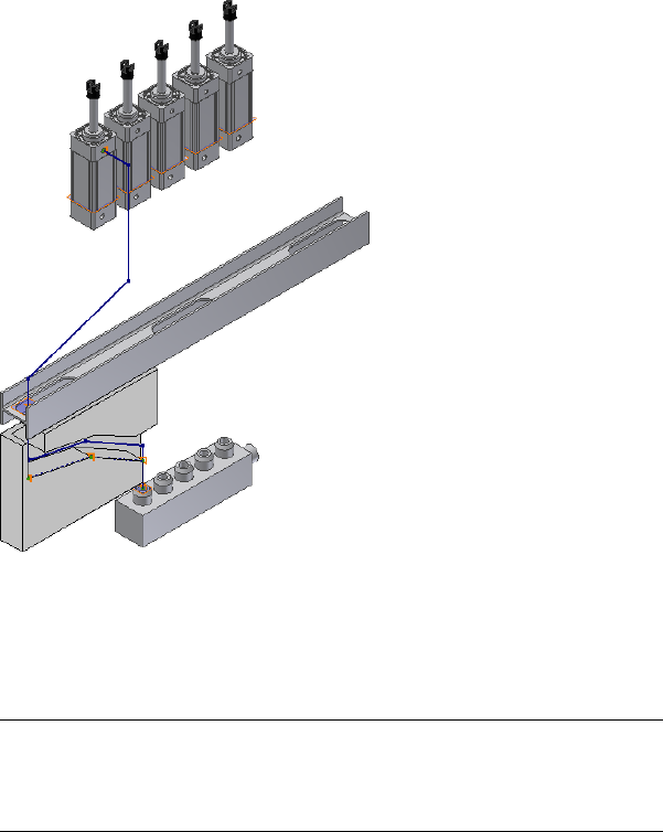
3To display the route dimensions, select Dimension Visibility on the
right-click menu.
4Right-click in the graphics window and select Finish Edit.
The run environment is activated.
NOTE In the run environment, the route dimensions are always invisible
regardless of the Dimension Visibility setting by default. To display route
dimensions in the run environment, right-click the route and select the
Dimension Visibility check mark.
Populated Routes
A populated route is a solid, three-dimensional representation of the pipes
and fittings. A route starts with a defined path, which you can populate with
library components to complete the route. You can place fittings to the
populated routes from the Content Center tool using AutoDrop.
88 | Chapter 4 Create Rigid Routes and Runs
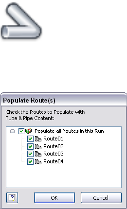
Tube and pipe information is treated like other parts and subassemblies and
can be detailed using drawing manager methods and tools. You can document
both populated and unpopulated routes. However, routes must be populated
before being saved to the ISOGEN or bending machine formats.
Populate one or multiple routes
1With the AirSystemAssy.iam assembly open, activate the AirSystem1:1
run.
2 On the ribbon, click Pipe Run tab ➤ Route panel ➤ Populate
Route.
3In the Populate Route(s) dialog box, select the check boxes for the routes
you need to populate. In this exercise, you populate all routes in the run.
Routes are populated using the styles you set. Each time a route is
populated all segments and fittings created are added to the associated
run folder.
4Click OK. It will take a moment to populate the routes.
Populated Routes | 89
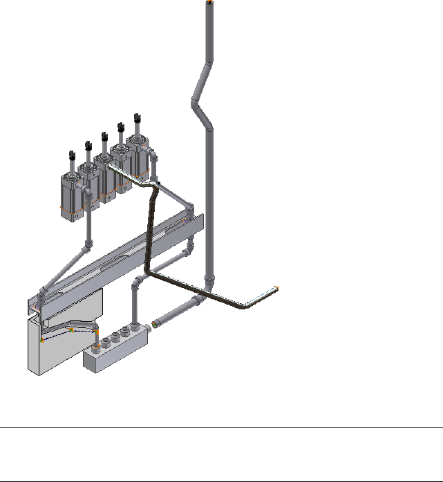
5Right-click and select Finish Edit.
NOTE To populate a single route in a pipe run, you must activate the run and
then click the Populate Route tool on the Pipe Run tab or right-click the route in
the Model browser.
90 | Chapter 4 Create Rigid Routes and Runs

Create and Edit Flexible
Hose Routes
Flexible hose routes in a tube and pipe assembly are commonly used in machine construction
to transmit dynamic power, such as hydraulic and pneumatic power. They are defined by
placing fittings and hose nodes that determine the shape and appearance of the route in the
assembly. The flexible hose style controls which fittings are used and the structure of the
flexible hose in the assembly.
In this chapter, you learn how to create a flexible hose style, and then use the styles to create
flexible hose routes both in a flat structure and in a subassembly structure. You also learn to
populate, edit, and delete the routes.
Workflow for Flexible Hose Routes
The workflow for creating a flexible hose route is as follows:
1Create a tube and pipe assembly.
2Optionally, drop fittings on appropriate pipe segments or assembly
geometry to use as the start or end connection points for hose routes.
NOTE You can also start and end the hose route from any existing compatible
geometry or component.
3Define and select a flexible hose style, indicating the route structure and
fittings to use.
4Create a flexible hose route to connect the geometry or fittings in the tube
and pipe assembly.
5
91

5The workflow differs depending on the hose fitting definition that is
specified in the flexible hose style. If the route contains:
■Both start and end fittings, connect the start fitting and end fitting,
and then add optional intermediate hose nodes.
■A start fitting, connect the start fitting first, add optional intermediate
hose nodes, and then select the end geometry or component.
■No fittings (both are suppressed), select the start geometry or
component, add optional intermediate hose nodes, and then select
the end geometry or component.
6Optionally, edit hose nodes and hose length.
7Finish the edit and populate the route.
Create Flexible Hose Routes
With a flexible hose style active, click Pipe Run tab ➤ Route panel ➤ New
Route to define a new hose assembly.
Many tools and guides used for creating hose routes are the same as those
used for piping and tubing routes, such as the 3D Orthogonal Route tool and
direction axes. For more information, see 3D Orthogonal Route Tool on page
23 in Chapter 2.
You can insert intermediate nodes in the 3D hose spline. Valid points for
intermediate flexible hose nodes are the same as those for rigid routes. In
addition, you can select points offset from a face. For more information, see
Route Points on page 22 in Chapter 2. Route points created by selecting
arbitrary points offset from a face are not associative and do not update to
changes in the model geometry.
NOTE Once a 3D hose spline is finished by right-clicking and selecting Done, you
can only insert intermediate nodes onto the spline.
Although flexible route fittings are typically connected to other fittings in the
active route or an adjacent route, several types of points are available for
selection. Valid fitting connection points include:
■A connection on other tube and pipe fittings
92 | Chapter 5 Create and Edit Flexible Hose Routes
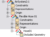
■A connection on a standard Autodesk Inventor® part that has been
authored using the Tube & Pipe Authoring tool and published to the
Content Center
■The end of a tube, pipe, or hose segment
■A circular edge on any component
Create Hose Routes with Both Fittings
In this exercise you create a new run, and then use a flexible hose style you
created earlier to create a hose route. The style specifies a subassembly structure
that contains both a start and end fitting.
Create a hose route subassembly with both start and end fittings
1Activate the master runs assembly, click Tube and Pipe tab ➤ Run panel
➤ Create Pipe Run. Enter AirSystem2 for the run file name and accept
the default file location.
The new run is activated.
2On the Pipe Run tab, Manage panel, select the Hydraulic Hose- Female
Thread - Swivel (1/2 ND 2) style from the Active Style list.
3On the ribbon, click Pipe Run tab ➤ Route panel ➤ New Route.
The Create Hose dialog box appears with the default file name and file
location.
4Accept the default hose assembly file name and location.
The Flexible Hose 01 subassembly is added under the AirSystem2:1run.
The Hose1 route is activated by default.
5On the ribbon, click Route tab ➤ Create panel ➤ Route.
The start fitting specified by the hose style is attached to the cursor and
ready for placement.
Create Hose Routes with Both Fittings | 93
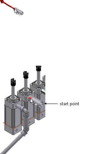
6Move the cursor to the start route point on the geometry as shown in
the following image, and then click to set the start fitting. The direction
axis on the part should point in the direction of the route.
7Change the direction for the fitting connection. Right-click and select
Next Connection, or press the spacebar.
The end fitting appears and is attached to the cursor.
Notice that the start fitting and end fitting reference the same part file
in the Content Center in this style.
8Move the cursor to the circular opening on the valve part, and click to
set the end fitting.
94 | Chapter 5 Create and Edit Flexible Hose Routes
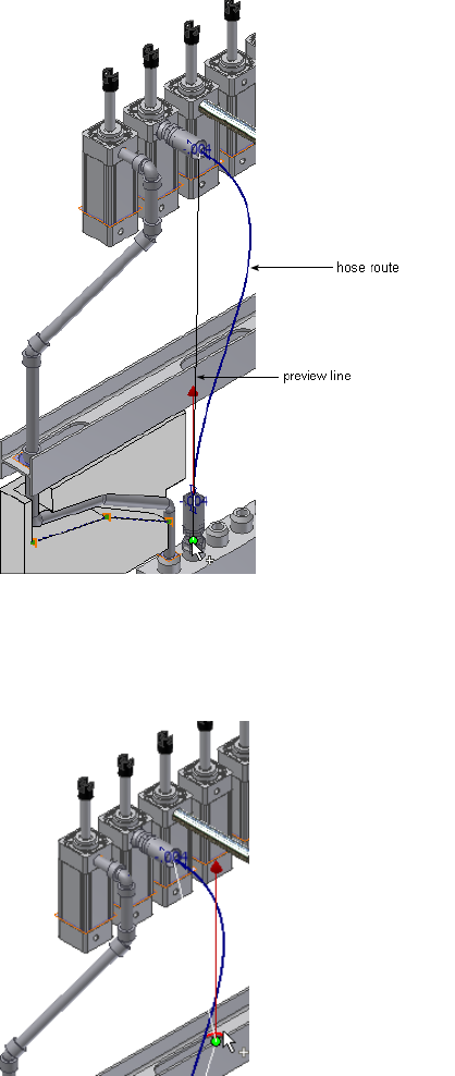
9To add an intermediate node tangent to a circular edge on IBeam, move
the cursor close to the circular edge, and then click to set the hose node.
When the associated center node is selected, the circular edge is
highlighted.
Create Hose Routes with Both Fittings | 95
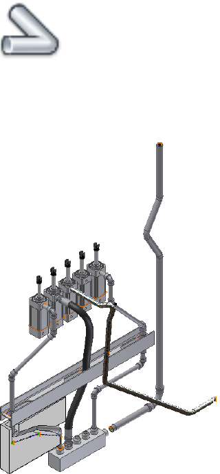
10 Right-click and select Done.
11 Right-click and select Finish Edit.
The run environment is activated.
12 To populate the hose route, click Pipe Run tab ➤ Route panel
➤ Populate Route.
After the route is populated, a Flexible Hose part, start fitting, and end
fitting are added to the Model browser at the bottom of the flexible hose
assembly.
Change Nominal Diameters
The diameters of all components in a flexible hose route are controlled by the
flexible hose style. You cannot modify those components directly using the
Model browser.
96 | Chapter 5 Create and Edit Flexible Hose Routes
When modifying the nominal diameter in the style:
■If the part family (hose, start fitting, and end fitting) contains the member
with the desired nominal diameter, Tube & Pipe automatically locates the
member listed under Components in the Tube & Pipe Styles dialog box.
■If the part family does not contain the member with the desired nominal
diameter, you must search for and locate them. Under Components,
right-click the appropriate row and select Browse to start the Library Browser
tool, and then select one from the compatible parts list.
Change nominal diameters of hose route components
1Activate the Hose 01 route in the AirSystem2:1 run.
2On the ribbon, click Route tab ➤ Manage panel ➤ Tube and Pipe Styles.
Verify that the Hydraulic Hose- Female Thread - Swivel (1/2 ND 2) style
is active.
3On the General tab, change the Diameter from 1/2 in to 5/16 inches.
4Verify the list in the Components table. If Pipe, Start Fitting, or End
Fitting is empty, click Browse, and then search for and locate a part from
the compatible parts list.
5Click Save.
6Click Close.
7Right-click and select Finish Edit.
The new diameter applies to the start fitting, hose segment, and end
fitting in the hose route. Autodesk Inventor Tube & Pipe recomputes the
hose route.
Create Hose Routes With One Fitting
In this exercise, you place a threaded tee onto the threaded steel pipe you
previously created, and create a hose route using the Hydraulic Hose- Female
Thread - Swivel (1/2 ND 1) style. This flexible hose style suppresses the end
fitting so the hose route ends at the tee. The fitting is set as suppressed in the
style definition.
Create a hose route
1Activate the AirSystem1:1 run.
Create Hose Routes With One Fitting | 97
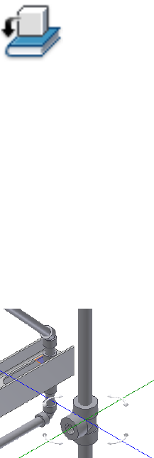
2 On the ribbon, click Pipe Run tab ➤ Content panel ➤ Place.
3In the Place from Content Center dialog box, navigate to and double-click
Tube & Pipe ➤ Fittings ➤ Tees ➤ ASME B16.11 Tee Threaded - Class
3000 to open the part family. Select a nominal diameter of 1/2 inch, and
then place the tee on the downward pipe segment in the threaded steel
route you previously created.
For detailed instructions on placing fittings from the Content Center
using AutoDrop, see Insert Library Parts Using AutoDrop on page 132 in
Chapter 6.
4Use the 3D Orthogonal Route tool to rotate the tee to the orientation as
shown in the following image. If the 3D Orthogonal tool is not displayed,
right-click the tee, and select Edit Fitting Orientation.
5Right-click and select Done.
6On the Pipe Run tab, Manage panel, select the Hydraulic Hose- Female
Thread - Swivel (1/2 ND 1) style from the Active Style list.
7On the ribbon, click Pipe Run tab ➤ Route panel ➤ New Route. Accept
the default hose assembly file name and location in the Create Hose
dialog box.
The Flexible Hose 02 subassembly is added to the AirSystem1:1 run. The
Hose02 route environment is activated.
8Click the Route tool.
9Select the start route point on the same geometry as shown in the
following image.
98 | Chapter 5 Create and Edit Flexible Hose Routes
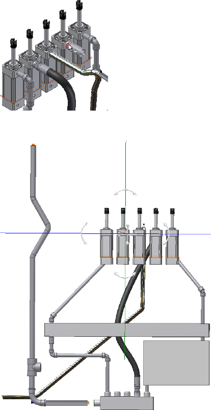
10 Rotate the assembly as shown in the following image.
11 Pause the cursor over the planar face of the IBeam, right-click and select
Edit Offset. The default offset distance is half the size of the outside
diameter (OD) of the hose part, 0.440 inch for this style.
Create Hose Routes With One Fitting | 99
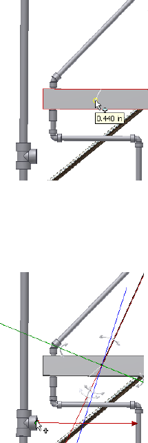
12 In the Edit Offset dialog box, enter 3 inches, and click OK.
13 Click the IBeam.
14 Select the tee to set the final node.
15 Right-click and select Done.
16 Right-click and select Finish Edit.
Look for the corresponding flexible hose subassembly under the
AirSystem1:1 run.
17 Populate the hose route.
Your assembly should look like the following image.
100 | Chapter 5 Create and Edit Flexible Hose Routes
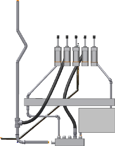
Edit Flexible Hose Routes
You can edit both populated and unpopulated hose routes in several ways.
In this exercise, you use the hose subassembly you just created to:
■Edit hose nodes and hose length.
■Edit the active style to change the start fitting and end fitting.
■Change the diameters of all components in the hose route. For detailed
instructions, see Change Nominal Diameters on page 96 in this chapter.
■Check the bend radius and clear violations.
Edit Flexible Hose Routes | 101
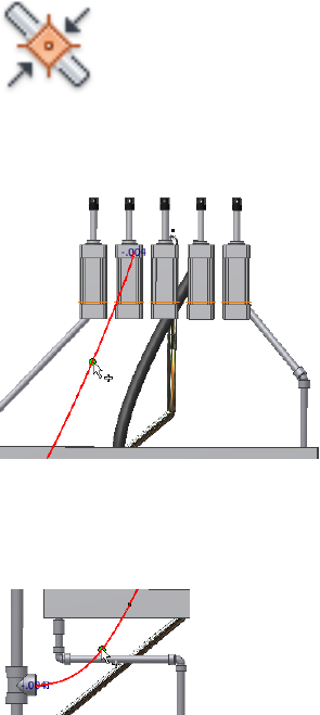
Hose Nodes
After you finish editing a hose route and before it is populated, you can use
the Insert Node tool to insert new hose nodes. The route recomputes with
each new hose node.
You can also adjust the hose node position and orientation using the 3D
Move/Rotate tool, redefine the hose nodes, and delete nodes.
Add a hose node
1In the AirSystem1:1 run, activate Hose02 in the Flexible Hose 02
subassembly.
2 On the ribbon, click Route tab ➤ Create panel ➤ Insert
Node, and then move the cursor over the hose spline.
The spline segment is highlighted with a green point indicating the
intermediate node position is valid.
3Click to insert the first node.
4Right-click the spline below the IBeam, and select Insert Node to add
another hose node.
102 | Chapter 5 Create and Edit Flexible Hose Routes

5Click to insert the second node.
Move a hose node
1Right-click the new route point, and select 3D Move/Rotate.
2Drag the triad in any direction. You can also enter a precise value along
the X, Y, or Z axes.
3Click Apply or OK.
NOTE If you want to move the hose node that is tangent to the circular edge of
the IBeam, you must right-click the node and clear the Associative check mark.
Redefine a hose node
1To change the position of the new node, right-click the route point and
select Redefine.
When you move the cursor over planar surfaces or existing work geometry,
the Edit Offset tool appears.
2Move the cursor to the planar face of the I-Beam.
The offset guide indicates the offset value. By default it is the last selected
offset value or the system default value of 0.440 in for this style.
3Do either of the following:
■To use the default offset value, click to set the node.
■To change the offset value, pause the cursor at an appropriate point,
right-click and select Edit Offset, and then enter a precise value.
The route is recomputed.
4Right-click and select Done.
Delete a hose node
1To delete the new route point that you just redefined, right-click the node
and select Delete.
2Repeat to delete the other inserted route point.
3After deleting both route points, save the top-level assembly file.
Hose Nodes | 103
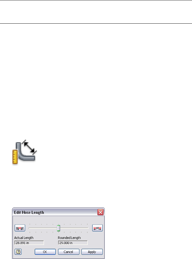
NOTE You can delete the start or end hose node only when the flexible hose style
suppresses both fittings or the end fitting respectively. Deleting such hose nodes
enables you to redefine hose nodes using the Route tool.
Hose Length
When the hose is too slack or too tight, you can use the 3D Move/Rotate tool
to adjust specific nodes and change the hose length closer to the desired
length.
You can modify the length of a hose route precisely using the Hose Length
tool. When adjusting the hose length, there are two types of length values
displayed: Actual Length and Rounded Length. You can choose which one to
display when documenting hose routes.
Adjust the length of a hose route
1In the AirSystem1:1 run, activate Hose02 in the Flexible Hose 02
subassembly.
2 On the ribbon, click Route tab ➤ Manage panel ➤ Hose
Length.
The Edit Hose Length dialog box displays the actual length and the
rounded length. The rounded length is calculated from the hose round
up value specified in the style. The values specific to your own exercise
may be a bit different since positions of hose nodes may be different.
3Drag the slider to the left and right to see the effects of the movement
on the spline.
A thinner green preview spline represents the hose that results.
104 | Chapter 5 Create and Edit Flexible Hose Routes

4Click the Decrease the Scale tool or the Increase the Scale tool to change
the length range.
5Once you are satisfied with the hose length, click OK.
Start Fitting and End Fitting
Use the style to modify fittings in flexible hose routes. You can change existing
fittings, remove a fitting, or restore a suppressed fitting.
In this exercise, the hose style in use has specified the start fitting only and
suppressed the end fitting. You must do the following:
■Change the start fitting.
■Add a new end fitting.
■Suppress the newly added end fitting.
NOTE If you want to remove both start fitting and end fitting, you can choose to
suppress the start fitting and the end fitting is suppressed automatically.
Replace the start fitting
1In the AirSystem1:1 run, activate Hose02 in the Flexible Hose 02
subassembly.
2On the ribbon, click Route tab ➤ Manage panel ➤ Tube and Pipe Styles.
3Under Components, look at the Start Fitting used in the style.
4Click Edit.
5Right-click the Start Fitting row and select Browse to access the Content
Center. The Library Browser filters out all the hose family and fittings in
compatible standards.
6Select Parker Male Taper Thread - Swivel from the list.
7Click OK.
8In the Tube & Pipe Styles dialog box, click Save, and then click Close.
9Right-click and select Finish Edit.
The start fitting in the graphics window and in the Model browser is
changed.
Start Fitting and End Fitting | 105
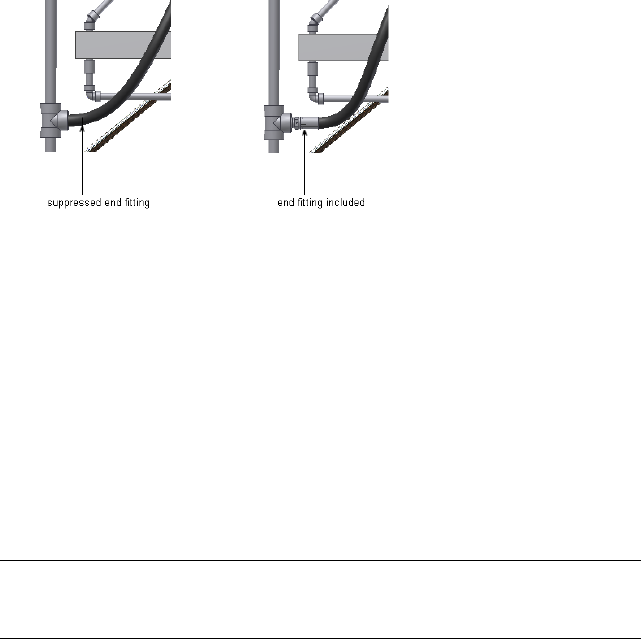
Add and suppress an end fitting
1Open the Tube & Pipe Styles dialog box and ensure the hose route style
to receive the new end fitting, Hydraulic Hose- Female Thread - Swivel
(1/2 ND 1) is the active style.
2Click Edit.
3Under Components, right-click the End Fitting row and clear the Suppress
Fitting check mark.
4Click Save, and then click Close.
A new end fitting for the hose route connects the hose segment and the
tee. You can verify this in the graphics window and Model browser.
Bend Radius Check
The Flexible Hose style determines the minimum bend radius. Before
populating, use the Bend Radius Check tool to verify a single hose route or
all hose routes under the pipe run. If any bend radius in a hose route is smaller
than the minimum value or the route is self-intersecting, a yellow error icon
is displayed after bend radius check.
When violations are corrected, check the bend radius again or click Return
on the Quick Access toolbar to update the hose route. In this case, the error
icon automatically disappears.
NOTE You can use the Clear Violation tool to remove the error icon from the
Model browser at any time, but violations still exist in the hose route until you
manually correct them.
106 | Chapter 5 Create and Edit Flexible Hose Routes
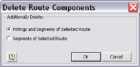
Check the bend radius
1Activate the hose route.
2Right-click the hose route in the browser, and select Bend Radius ➤
Check.
3If the Error dialog box displays the violations against the minimum bend
radius, click OK.
Optionally, right-click the hose route or the pipe run in the browser, and
select Bend Radius ➤ Clear Violation.
4Edit the hose route.
5Repeat Steps 2 through 4 until no violations occur.
Delete Flexible Hose Routes
You can delete both populated and unpopulated hose routes. When deleting,
you are prompted to indicate whether to delete all segments and fittings in
the route or only the segments. If only segments are deleted, the fittings are
moved to the top of the browser and are available for future use. For this
exercise, it is recommended that you delete both the hose segments and the
fittings.
Delete a hose route
1Activate the AirSystem2:1 run.
2If the Flexible Hose 01 subassembly is collapsed, click to expand it.
3Right-click Hose1 and select Delete Route.
4In the Delete Route Components dialog box, make sure Fittings and
Segments of Selected Route is selected, and then click OK.
The Flexible Hose subassembly is deleted completely.
5Save the top-level assembly. This run becomes empty.
Delete Flexible Hose Routes | 107
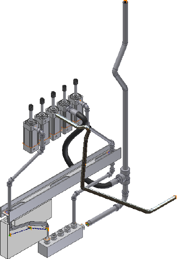
Your assembly should look like the following image.
Practice Your Skills
Using the skills you have learned from the previous exercises, try the following
in the AirSystem2:1 run:
1Activate the AirSystem2:1 run.
2Create a new hose style with a flat structure that is based on the Hydraulic
Hose - Female Thread - Swivel style with the following settings:
New style name: Flat Hose with Female Swivel (1/2 ND 2)
Diameter: 1/2 inch
Clear the Use subassembly check mark
3Create a route using the new style. Note the flexible hose and hose
components in the browser.
108 | Chapter 5 Create and Edit Flexible Hose Routes
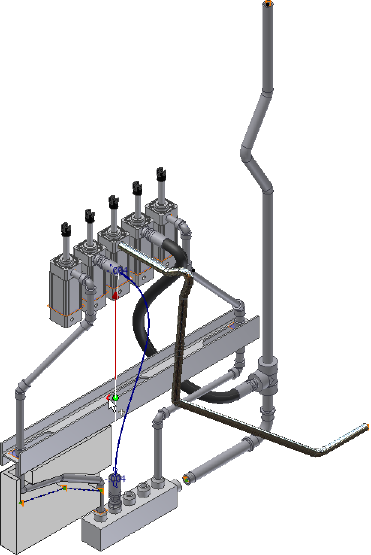
4On the ribbon, click Pipe Run tab ➤ Route panel ➤ New Route.
The Create Route dialog box displays. Note that it is not the Create Hose
dialog as displayed in the preceding exercises.
5Accept the default hose route file name and location and click OK.
A new route node is added to the run in the Model browser. Note that
there is no flexible hose assembly node.
6Create a new hose route using the new style. To define the route, select
the start, end, and then intermediate geometry as shown in the following
image.
7Right-click in the graphics window and select Finish Edit.
8Populate the hose route and save the top assembly.
Practice Your Skills | 109
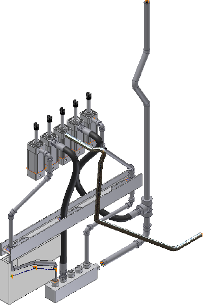
110 | Chapter 5 Create and Edit Flexible Hose Routes

Edit Rigid Routes and Runs
Autodesk Inventor® Routed Systems provides varied methods for updating and modifying
each component of a tube and pipe system to accommodate changes in design criteria and
in the assembly model.
In this chapter, you learn how to use various tab and context menu options to edit routes
and runs.
About Editing Rigid Routes and Runs
After finishing the initial definition of a route or run, you can continue to make
changes. Available edit tools may vary depending on the edit context, such as
auto regions and parametric regions.
Using Undo reverses the last action taken during the current editing session,
and exits the current command.
NOTE Consider the affect of changes to assembly model geometry on which the
routes and runs depend. For example, deleting parts or editing geometry in the
model that affects associative route points may require you to delete the run and
redefine the route.
Modifying or changing the style is another way of modifying routes and runs.
For detailed instructions, see Change Styles for Existing Routes on page 49 in
Chapter 3.
Auto Regions
The following edit options are available for auto regions:
■Add interior route points.
6
111
■Insert, replace, delete, and restore placed fittings.
■Change the active tube and pipe style.
■Change fitting diameters.
■Use the Edit Position or Move Segment tool to reposition route segments.
■Use the Edit Position or Move Node tool to reposition the intermediate
route points that are associated with a default coupling.
■Switch to an alternative solution if multiple solutions exist.
■Convert an auto region to a series of continuous sketched route segments.
■Delete auto regions.
■Remove client constraints to convert a segment or point in an autoroute
region to a parametric region.
Parametric Regions
The following edit options are available for parametric regions:
■Insert, reposition, or delete segments and route points.
■Insert, replace, delete, and restore placed fittings.
■Change the active route style.
■Change fitting diameters.
■Reposition a placed fitting by editing segment dimensions or using the 3D
Move/Rotate tool.
■Use the 3D Move/Rotate tool to move route points in three dimensions.
■Create bends using the Bend tool.
■Edit the dimensions (linear, angular, and radial) using the General
Dimension tool.
■Switch between driven dimension and normal sketched dimension.
■Show, edit, and delete geometric constraints.
■Delete route segments. It is also the way of deleting the free terminal route
point.
112 | Chapter 6 Edit Rigid Routes and Runs
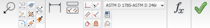
Options for Editing
You can edit both populated and unpopulated routes. If the route is populated,
activate the route to edit it in place. Library components populating the route
are temporarily set as not visible and the underlying 3D sketch of the route
is displayed.
Route Tab
When you are in the route environment, the Route tab is displayed.
Appropriate tools are available in the specific edit context. Pause the cursor
over the images to view the tooltip.
Pipe Run Tab
When you are in the run environment, the Tube & Pipe tab is displayed. You
can place fittings from the Content Center or your project workspace, and
connect fittings and components.
In the exercises that follow, you learn the basic Connect fitting tools:
Connects two components relative to one another in
a tube and pipe assembly. The components need not
Connect Fittings
be collinear. You can connect a fitting, a conduit part,
or a normal Autodesk Inventor® part that already exists
in the assembly to another base component. You can
also connect fittings when placing or dropping them
in the graphics window.
Inserts and connects a new fitting between two connec-
ted fittings in a tube and pipe assembly. The new fitting
Insert Fittings
must be collinear to make the connection. Using this
feature you can build a series of connected fittings, or
insert fittings between fitting groups such as flanges
created during population of a route.
Options for Editing | 113

Context Menus
Many edit actions start by selecting from the context menu. The context menu
varies depending on the edit context and the selected item.
In the exercises that follow, you learn the following basic editing tools:
Interactively positions route points in the parametric
regions by dragging the triad in a planar mode, axial
3D Move/Rotate
move or rotate, free movement, or entering values
along X, Y, or Z axes. You can also reposition route
points by editing the segment dimensions.
By default, the triad axes relate logically to the world
coordinate system but may vary from the route direc-
tion. To accurately define the X, Y, Z distances relative
to the route direction, you can redefine the axis align-
ment to the route segment.
Changes the diameter for one or more placed fittings
and routed fittings that are used by a style to populate
Change Fitting Dia-
meter
routes and runs. The system finds the diameters that
are common to all selected fittings and displays them
in a list.
NOTE Change Size performs the same action.
114 | Chapter 6 Edit Rigid Routes and Runs
Delete ■For route segments in parametric regions, deletes
the selected route segment.
■For pipe or tube parts, deletes the selected conduit
part and the underlying route segment.
■For route points, deletes the selected node from the
route and re-evaluates automatic routing against
the style settings, and then updates the route. You
can delete manually placed route points, but not
start and end points and route points that are inser-
ted during automatic routing.
■For client constraints on the auto region, deletes
the client constraint so that you can then edit indi-
vidual route points and segments.
■For groups of fittings, when removing the base fit-
ting that owns the route point, you must indicate
how to handle the remaining fittings in the group.
Removes the route, plus fittings and segments, or seg-
ments only in the selected route.
Delete Route
Removes the selected pipe run from the browser and
the graphics window. All routes and components in
the pipe run are deleted.
Delete Run
Prevents or allows automatic populating of tube and
pipe components in an individual route, pipe run, or
Display/Update Set-
tings
master runs assembly by selecting Route Objects Only
or All Tube & Pipe Objects.
Deletes or edits the engagement for fitting connections
between two fittings or between a tube, pipe, or hose
Edit Fitting Connec-
tions
part or a standard Inventor part and a fitting that was
manually inserted from the Content Center Library
using the Insert tool or from the active project work-
space using the Place Fitting tool.
Activates the selected fitting and provides the 3D Or-
thogonal Route tool for rotational changes. It is avail-
able only for placed fittings.
Edit Fitting Orienta-
tion
Activates the selected auto route segment or route point
that is associated with a default coupling in an auto
Edit Position
region, and provides the 3D Orthogonal Route Tool
for translational edits.
Context Menus | 115
Turns the appearance of a fitting (coupling) on and off
for route points associated to geometry. When cleared,
Fitting
the fitting is not created, the pipe remains a single
segment, and the route points remain associative to
the selected geometry.
Edits the hose and adjusts the length by changing the
weight of the tangency or tension of the hose segment.
Hose Length
Inserts a route point in the selected route. By default,
this new node adds a coupling, weld gap, or flange at
Insert Node
the selected route location. Available on the Route tab
or in the context menu of the graphics window when
a route is activated.
Moves a route point that is associated with a default
coupling in an auto region to a new position. The sys-
Move Node
tem recalculates the automatic routing based on the
new position of the selected route point.
Note that such route points are generated when the
linear distance between two points is larger than the
maximum segment length that you have specified in
the rigid piping or bent tubing styles.
To reposition route points in parametric regions, you
can edit the segment dimensions or apply the 3D Move
Rotate tool
Moves a route segment in an auto region to a new po-
sition. The system recalculates the automatic routing
based on the new position of the selected segment.
Move Segment
Replaces a placed fitting with the default fitting (elbow
or coupling) for the set style or replaces a placed fitting
Restore Fitting
with a coupling no matter how many connection
points the original placed fitting has.
Continues adding route points to the specified route.
Also available on the context menu for free terminal
Route
route points that are not used in any other routes or
fittings.
For more information about commands on the context menu, see the Help
index.
116 | Chapter 6 Edit Rigid Routes and Runs
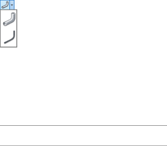
Control Individual Settings
When changes are made to a standard Autodesk Inventor assembly, routes
and runs, and positional representations, the tube and pipe assembly defaults
to automatically update. To save time for updating the whole tube and pipe
assembly, you can defer automatic updates of tube, pipe, and hose components
for individual runs and routes. You can see the effect a change has on an
individual route before repopulating.
You can also disable automatic updates for the entire tube and pipe runs
subassembly. The following image shows the Display/Update Settings list you
can access on the Pipe Run tab when a pipe run is activated.
Allows the entire pipe run or specified routes to fully
update. When the All Tube & Pipe Objects option is
All Tube & Pipe Ob-
jects
selected, the associated routes and runs are displayed
as populated and automatically respond to changes.
This is the default setting when new routes and runs
are added to a master runs assembly.
Defers automatic updates for the entire pipe run or
specified routes. When the Route Objects Only option
Route Objects Only
is selected, the associated routes and runs are displayed
as centerlines, underlying components are hidden and
do not respond to changes.
NOTE When a new route is created and populated, it always displays as populated
and not as centerlines. This is true even when the pipe run is set to Route Object
Only.
Control the display and update setting for individual runs and routes
1In the AirSystemAssy.iam assembly, activate the top assembly or master
runs assembly.
Control Individual Settings | 117

2Right-click Tube & Pipe Runs, and then select Tube & Pipe Settings. Ensure
the Defer All Tube & Pipe Updates check box is cleared in the Tube &
Pipe Settings dialog box. These settings are only available when the check
box is cleared.
3Activate the pipe run.
4Right-click the pipe run or a specific route, and then select Display/Update
Settings, or click the pipe run or a specific route, and then select the
Display/Update Settings tool on the tab.
5Select the display and update setting you need.
6Use the default setting, All Tube & Pipe Objects, so that you can view
automatic responses to edits on routes and runs.
Route Points
A route is considered finished when you select Finish Edit. You can also use
the Route tool to repair disjointed routes.
A disjoint route can occur when segments are deleted from a route. While
deleting segments, you can use the Route tool to close the gap between disjoint
segments.
Add to Finished Routes
New route points can be added to a previously finished route by activating
the route to edit, and then using the Route tool on the end route point.
Add a point to an existing route
1Activate Route03 in the AirSystem1:1 run.
2 In the graphics window or Model browser, do either of the
following:
■Click the last route point, and select the Route tool on the Route tab.
■Right-click the last route point, and select the Route tool.
The route resumes at the last selected route point.
118 | Chapter 6 Edit Rigid Routes and Runs
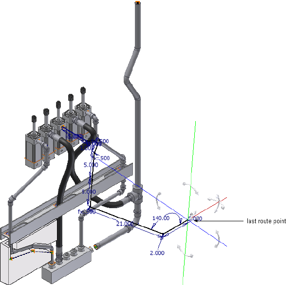
3Add one more point to the route in a location and orientation of your
choice, for instance, 8 inches along the red axis.
4Right-click and select Done.
5Right-click and select Finish Edit.
The new route point becomes the current last route point. A coupling is
added to the route point from which you continued the routing.
Insert Intermediate Route Points
Intermediate route points can be added to any route or run as long as they
comply with styles.
Insert Intermediate Route Points | 119

Insert intermediate route points
1Activate a tube or pipe route.
2 Click Route tab ➤ Create panel ➤ Insert Node.
3Click the segment to insert a route point.
4Right-click and select Finish Edit.
A coupling is added to the route in that location.
Delete Route Points
You can delete the manually created route points when the resultant route
complies with the style criteria. Tube and Pipe automatically closes Gaps left
by deleted route points between collinear segments are automatically closed.
Segments adjoining the deleted route points reposition or resize to adjust to
the change.
To delete the free terminal route point, you must delete the last segment.
Delete manually created route points
1Activate Route03 in the AirSystem1:1 run.
2In the graphics window or Model browser, right-click the intermediate
route point you just inserted manually, and then select Delete.
The last two segments automatically heal to one single segment.
3Right-click and select Finish Edit.
NOTE After the manually inserted route point populates as a coupling fitting,
delete the fitting in the run environment and the underlying route point.
Auto Regions
Intermediate segments in an auto region can be repositioned dynamically by
using the Move Segment tool and clicking and dragging or by using the precise
distances. The movement allowed follows the conditions established by the
120 | Chapter 6 Edit Rigid Routes and Runs

current style and connection data. It also depends on the geometry adjacent
to the point you select for the operation.
As you drag the selected geometry, the system re-evaluates and updates
adjacent route components. Route points that are automatically generated
between points on selected geometry update when changes are made to a
route.
Move Auto Route Segments Approximately
Using the Move Segment tool on the Route tab, you can move segments in
an auto region approximately. The direction arrows appear on the geometry
indicating the directions allowed for the move. Click anywhere on the segment
near the direction arrow you need, or click and drag the arrow directly. The
arrow changes to red indicating that it is the direction being dragged.
If the minimum length setting for the style is violated during a drag, the
segment or segments in violation turn red. A tooltip also displays the segment
length and the message <Min Pipe Length> in red text.
If alternate solutions are available, the Select Other tool appears for you to
cycle through and select the solution you need.
Move segments in an auto region approximately
1Activate Route01 in the AirSystem1:1 run.
2 On the ribbon, click Route tab ➤ Create panel ➤ Move
Segment.
3Pause the cursor over the right end of the segment as shown in the
following image, until the arrow changes to red.
The movement allowed depends on the geometry closest to the point
you select for the drag operation. If the point is a coupling or an associated
route point, the movement is restricted.
Move Auto Route Segments Approximately | 121
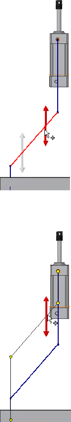
4Click and drag the segment upward as shown in the following image. To
end the drag operation, release the cursor.
5Right-click and select Done.
6Right-click and select Finish Edit.
122 | Chapter 6 Edit Rigid Routes and Runs
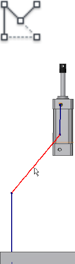
Move Auto Route Segments Accurately
By entering precise values, the Edit Position tool not only applies to the route
points that are associated with a default coupling fitting in an auto region,
but can also move the intermediate segments in an auto region.
Move segments in an auto region accurately
1Activate Route01 in the AirSystem1:1 run.
2 In the graphics window, right-click the segment as shown in
the following image and select the Edit Position tool.
The 3D Orthogonal Route tool is displayed with available direction to
reposition the segment.
Move Auto Route Segments Accurately | 123
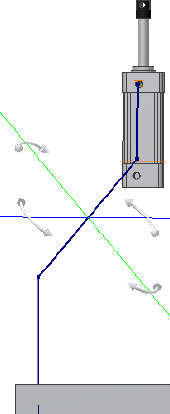
3Pause the cursor over the direction axis, and then enter a specific value.
4If alternative solutions are available, the Select Other tool appears for you
to cycle through and select the solution you need.
5Use Undo to reverse the last action and exit from the current command.
6Right-click and select Done.
7Right-click and select Finish Edit.
Remove Unwanted Segments or Route Points
In an auto region, when adjacent segments are coplanar and perpendicular
to each other, you can use the Move Segment tool to remove the unwanted
segment and the route point involved.
To remove them, drag the geometry until the route points are coincident with
adjacent route points.
124 | Chapter 6 Edit Rigid Routes and Runs
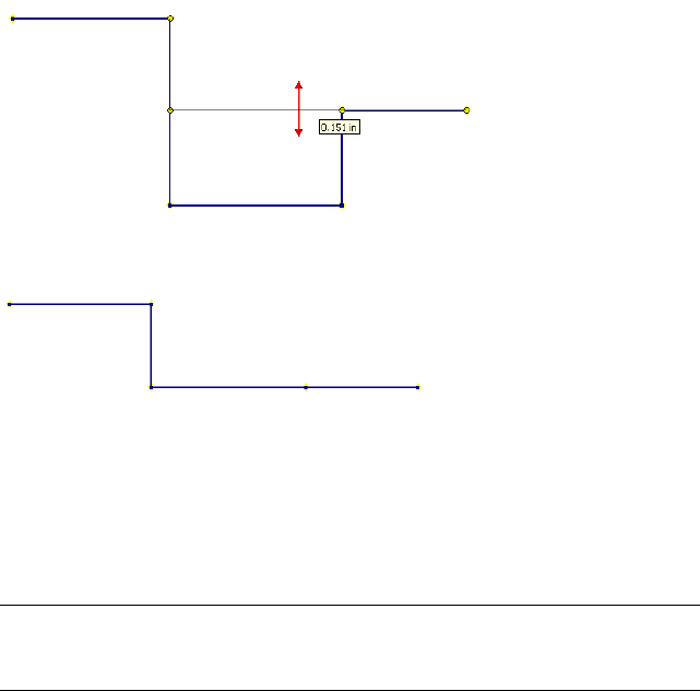
Release the cursor to stop the drag. The unwanted segment is removed.
You can then delete the extra route points using Delete from the context
menu, or by dragging the unwanted route points until they are coincident
with an adjacent one. When they are coincident, release the cursor to end the
drag and remove the route point.
While you are dragging the segment, use the ESC key to cancel the drag and
return to regular editing.
NOTE Ensure that the segment being moved does not attempt to overlap any
other existing segment. Otherwise, the system will automatically calculate a route
shape.
Convert Auto Region to Parametric Sketch
If you need to have more control over the segments in an auto region, use
the Convert to Sketch tool to convert it to a series of continuous sketched
segments. The Model browser reflects the deletion of the auto region and new
sketched route points.
All client constraints in the auto region are then deleted so more edit options
are available to adjust the route. It is equivalent to deleting all client constraints
within the auto region manually.
Convert Auto Region to Parametric Sketch | 125
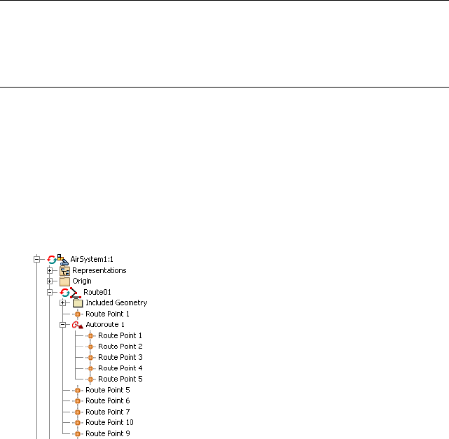
TIP If you need to convert only one segment from within an auto region, right-click
the segment, select Show All Constraints, select the client constraint for the
segment, and right-click and delete the client constraint symbol. If you want to
break an auto region at one route point, you can choose to delete the client
constraint symbol for the route point.
In this exercise, before you convert the auto region in the
AirSystemAssy.Route1:1 you should route to the parametric region.
Convert an auto region to parametric sketch
1Activate Route01 in the AirSystem1:1 run.
2In the Model browser, expand the Autoroute 1 node and review the nodes
in the Model browser. You can then compare the browser behavior with
the new parametric region.
3Right-click in the graphics window and select Show All Constraints.
Review the client constraints on the segments in the auto region.
126 | Chapter 6 Edit Rigid Routes and Runs
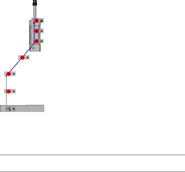
4In the Model browser, right-click the Autoroute 1 node and select Convert
to Sketch.
The auto region changes to a series of continuous sketched segments.
Dimensions are added to the route sketch where appropriate.
NOTE If Auto-Dimension is not enabled during route creation, dimensions
will not be added here.
5Press F8 to verify that all client constraints are deleted so edit options for
parametric regions are available to adjust the route points and segments.
To hide all constraints, press F9.
Convert Auto Region to Parametric Sketch | 127
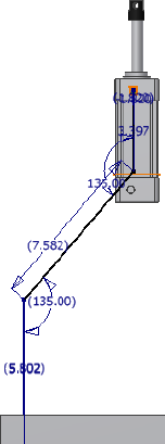
6In the Model browser, verify that the Autoroute1 node disappears.
7Right-click and select Finish Edit.
Dimensions
Auto regions always dynamically update to assembly changes and the shape
of the route may vary from the original auto route solution. They do not
involve dimensions until you convert them to parametric regions.
For parametric regions, there are three typical types of dimensions pertaining
to the route sketch:
■Linear dimension, such as the segment length.
■Radial dimension, such as the bend radius.
■Angular dimension, such as the included angle at the direction turn.
Similar to Autodesk Inventor, dimensions on the route sketch can be
categorized into two types:
It is used to drive the route geometry. For instance,
sketched route segments are manually created using a
specified normal sketched dimension.
Normal sketched di-
mension (driving di-
mension)
128 | Chapter 6 Edit Rigid Routes and Runs
It is enclosed in parentheses as displayed in the
graphics window and allows route geometry to dynam-
Driven dimension
ically respond to associated changes. It typically occurs
on the route sketch that relates to the assembly geo-
metry or when an auto region is converted to a para-
metric region.
You can switch between the driven dimension and the normal sketched
dimension using the Drive Dimension tool. Once a driven dimension is
switched to a normal sketched dimension, you can edit the value. If converting
the driven dimension to a driving dimension will over-constrain the geometry,
the conversion is not allowed.
Driven Dimension tool
In the route environment, normal sketched dimensions can be manually set
using the General Dimension or edits in place. If you want to place dimensions
based on geometry outside of the active route, you must first include it in the
route sketch using the Include Geometry tool.
General Dimension tool
NOTE Placing dimensions may over-constrain the route sketch. You may also fail
to switch the dimension type. You can identify the geometric constraints as needed.
In this exercise, you edit the segment length in place. For more information
about how to place and edit dimensions on the route sketch (3D sketch), refer
to the Help.
Edit the route dimension
1Activate Route03 in the AirSystem1:1 run.
2Double-click the dimension on the last segment as shown in the following
image.
Dimensions | 129
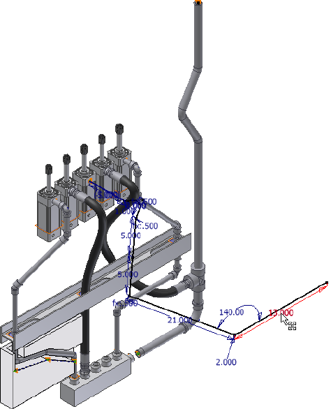
3On the Edit Dimension dialog box, enter 5 inches.
4Right-click and select Finish Edit.
Fittings
You can place fittings from either the Content Center or the active project
work space. They can be placed onto tube and pipe route segments, free
terminal route points, adjacent to existing fittings, between connected fittings,
or in the background of the graphics window.
Segment length must comply with the minimum segment length style once
the fitting is placed. If the fitting is not compatible with the route in some
other way, such as size and material differences, the insertion is allowed, but
you are alerted to the incompatible conditions. The fitting being dropped
130 | Chapter 6 Edit Rigid Routes and Runs
must also be appropriate for the drop point selected. For example, elbows may
not be dropped on straight segments.
For a placed fitting or a routed fitting for which you have changed the fitting
diameter, you can:
■Change its orientation, as well as connection point.
■Change the fitting route point position on straight rigid segments.
■Replace existing fittings.
■Restore original fittings, typically elbows and couplings.
■Delete placed fittings and default couplings. You cannot delete the default
directional fittings.
Place Fittings in the Active Project Workspace
Fittings from the active project workspace are added to the design using the
Place Fitting tool on the Pipe Run tab.
NOTE You cannot place conduit parts using this tool.
Place a fitting from your project workspace
1Activate the pipe run to receive the fitting.
2 On the ribbon, click Pipe Run tab ➤ Route panel ➤ Place
Fitting.
3In the Open dialog box, browse to and select the component to place,
and then click Open.
The selected component is placed in the graphics window, attached to
the cursor.
4Click a point of your choice for insertion.
■To insert an elbow, select a direction change route point.
■To insert other types of components, select any point along an existing
run segment.
Place Fittings in the Active Project Workspace | 131
5To place additional occurrences of the same part, move the cursor to a
different location and click. Continue until all occurrences are placed.
6Right-click and select Done.
7Right-click and select Finish Edit.
TIP For consumed fittings in a tube and pipe run assembly, click to highlight the
fitting in the Model browser or the graphics window, and then click the Place
Fitting tool to place more occurrences of the highlighted fitting quickly. Using the
Model browser, you can insert any compatible fitting from another pipe run into
the target pipe run. Using the graphics window, you can only select fittings within
the target pipe run.
Insert Library Parts Using AutoDrop
Both library fittings and conduit parts can be placed into a tube and pipe
assembly from the Content Center using AutoDrop.
Conduit parts can be placed only in the background of the graphics window.
You can connect the placed conduit parts to other components using the
Connect Fittings tool. Hose routes do not accommodate placed fittings.
To locate tube and pipe library parts, start the Place from Content Center or
Replace from Content Center tool.
In this exercise, you activate a run, locate a standard fitting, select the nominal
diameter, and then use AutoDrop to insert it into the run.
For more information about the Content Center libraries, see Use Content
Center Libraries on page 149.
NOTE If you have changes to the default parameters for the library part and it is
the first time for AutoDrop, you must save it as a custom part before completing
the placement. This typically occurs when placing conduit parts.
Insert a library fitting using AutoDrop
1Activate the AirSystem1:1 run.
2 On the ribbon, click Pipe Run tab ➤ Content panel ➤ Place.
You can also right-click in the graphics window to access the tool.
132 | Chapter 6 Edit Rigid Routes and Runs
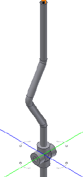
3In the Place from Content Center dialog box, go to Tube & Pipe ➤
Fittings ➤ Crosses.
4In the Crosses pane, click ASME B16.11 Cross Threaded - Class 3000.
All family members are listed in the pane below.
5Click OK to select the part family and close the Place from Content Center
dialog box.
The ASME B16.11 Cross Threaded - Class 3000 Part Family dialog box is
displayed with a list of all available nominal diameters.
6On the Table tab, select:
ND: 1/2
As Standard
To verify the detailed information of the selected cross family, click and
go through the Select, Table View, and Family Information tabs.
7Click OK to complete the part member selection.
The cross is attached to the cursor in the graphics window.
8Move the cursor over the pipe segment, and then click to set the cross
fitting.
9Optionally, use the 3D Orthogonal Route tool to edit the orientation of
the placed cross.
10 Right-click and select Done.
Insert Library Parts Using AutoDrop | 133

11 When quitting the AutoDrop, you can right-click the placed fitting and
select Edit Fitting Orientation to display the 3D Orthogonal Route tool
again.
12 Right-click and select Finish Edit.
Practice Your Skills
In this exercise, you use the skills you just learned to insert a pipe part from
the Content Center Library into the background of the graphics window. Note
that you cannot drop the conduit part onto route segments.
In addition to ND (Nominal Diameter), you must specify the SN (Schedule
Number) and PL (Pipe Length) parameters.
Insert a library pipe part
1Activate the AirSystem1:1 run.
2Right-click in the graphics window and select the Place from Content
Center tool.
3In the Place from Content Center dialog box, navigate to and select Tube
& Pipe ➤ Conduits ➤ Pipes ➤ ASTM A 53/A 53M Pipe.
4In the Content Center Part Family dialog box, specify:
ND: 1/4
SN: 40
PL: 10
5Click OK.
6In the Save As dialog box, use the default location and file name.
7Place the pipe part anywhere in the background of the graphics window.
8Right-click and select Done.
TIP You can use the Connect Fittings tool to connect the placed tube or pipe
part to another component in the run.
134 | Chapter 6 Edit Rigid Routes and Runs
Adjust Fitting Position and Orientation
Fittings are associated with the underlying route points on the route sketch,
with the exception groups of connected fittings. In this case, the first fitting
placed is associated with an underlying route point and all adjacent fittings
are associated to that first fitting. Repositioning the route point simultaneously
changes the position of the fitting or fitting group. You can activate the route
environment, and then reposition the route point using the 3D Move/Rotate
or General Dimension tool and reposition the default coupling fitting using
the Edit Position or Move Node tool.
You can also use the Edit Fitting Orientation tool to redefine the fitting
orientation and change the connection point.
In this exercise, you change the orientation and connection points on the
fitting you placed in the preceding exercise.
Change fitting orientation and connection point
1Activate the AirSystem1:1 run.
2In the graphics window, right-click the cross, and then select Edit Fitting
Orientation.
The 3D Orthogonal Route tool is displayed at the fitting.
3Use the rotation axes to reorient the fitting.
■For exact rotation, right-click the rotation arrow, and then select Enter
Angle.
■For exact position, right-click on the direction axis parallel to the
segment, and then select Enter Distance.
4Optionally, to change the connection point, right-click in the graphics
window, and then use Select Orientation to set the new connection point.
5Right-click and select Done.
6Right-click and select Finish Edit.
Restore Default Fittings
Using the Restore Fitting tool, you can restore the placed fitting to a coupling
or an elbow no matter how many connection points the placed fitting has.
Adjust Fitting Position and Orientation | 135
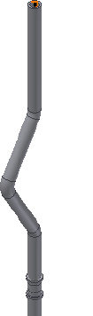
The placed fitting to restore must be within the tube or pipe segment or it
cannot be placed at the free terminal of the run.
Restore a default fitting
1Activate the AirSystem1:1 run.
2Right-click the placed cross and select Restore Fitting.
The placed fitting changes to a coupling fitting at the same position.
Replace Existing Fittings
You can replace one occurrence of a selected fitting instance with a new fitting
instance from the Content Center or all occurrences at once. The replacement
fittings can be inserted at previously defined route points.
Replaced fittings use the route information of the previous part. Orientation
and position can be adjusted if the part type and connection information
allows.
In this exercise, you place a tee from the Content Center to replace the
coupling you just restored from the placed cross. In addition, you can also
place a non-library replacement fitting using the Place Fitting tool.
Replace existing fittings with library fittings
1Activate the AirSystem1:1 run.
136 | Chapter 6 Edit Rigid Routes and Runs

2 In the Model browser or graphics window, click the coupling,
and then click Pipe Run tab ➤ Content panel ➤ Place.
The Replace from Content Center dialog box is displayed.
3Navigate to Tube & Pipe ➤ Fittings ➤ Tee ➤ ASME B16.11 Tee
Threaded - Class 3000 and double-click to open the part family.
The ASME B16.11 Tee Threaded - Class 3000 Part Family dialog box is
displayed.
4Optionally, to replace all occurrences in the highlighted fitting type,
select the Replace All check mark.
In this exercise, you only have one occurrence of the cross fitting so you
see no difference.
5In the dialog box, select:
ND: 1/2
As Standard
Click OK.
The cross fitting is replaced with the tee fitting.
6Optionally, to edit the orientation of the placed tee, right-click the tee
and select Edit Fitting Orientation. To end the edit, right-click and select
Done.
Replace Existing Fittings | 137
7Right-click and select Finish Edit.
Connections
Fitting connections are used to maintain the fixed relationship between
components in a tube and pipe assembly. You can connect fittings or normal
Autodesk Inventor components that already exist in the tube and pipe assembly
to other components including connected fittings. You can also connect
fittings being dropped from the Content Center or being placed using the
Place Fitting tool to another component. After the connection is created, use
the Edit Fitting Orientation tool to rotate the free fitting or component to a
new orientation. Select multiple fittings to rotate them as a group.
You can break connections to edit the fitting connections independently and
accommodate more changes to the tube and pipe run assembly. You cannot
break connections between fittings placed during populate route.
In this exercise, you delete the connection between the tee fitting and the
hose route, and then adjust the hose route and connect to another tee fitting
you placed on the upper segment of Route03 in the AirSystem1:1 run.
Delete Fitting Connections
You can delete fitting connections and edit the engagement when they are
formed:
■By using the Connect Fittings tool.
■By dropping a fitting on the end of a pipe segment or adjacent to other
fittings.
Delete fitting connections
1Activate the AirSystem1:1 run.
2Rotate the graphics window to get a better view.
138 | Chapter 6 Edit Rigid Routes and Runs
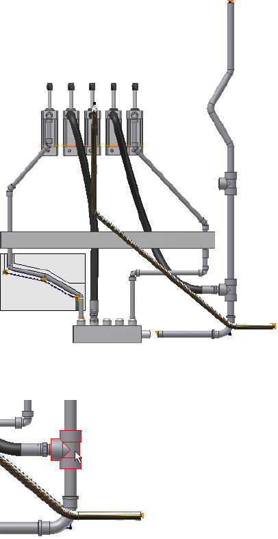
3Right-click the tee fitting as shown in the following image, and select
Edit Fitting Connections.
The Edit Connections dialog box displays with all existing connections
on the tee fitting, including two pipe segments and one hose fitting.
Delete Fitting Connections | 139
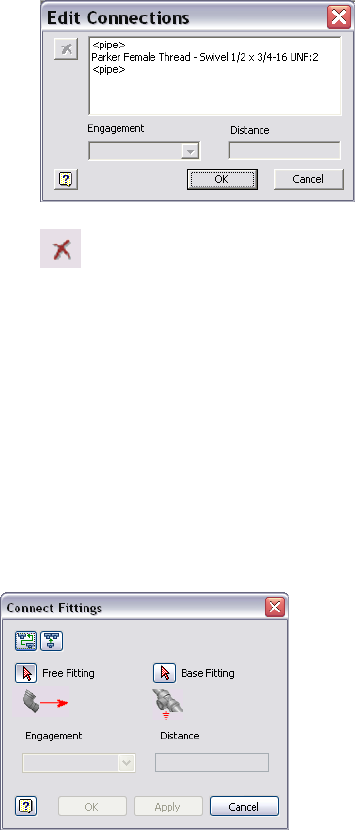
4 In the connections list, select Parker Female Thread - Swivel 1/2 x
3/4-16 UNF:2, and click the Delete button.
The connection with the hose fitting changes to no connection.
5Click OK.
Connect Fittings and Components
Use the Connect Fittings tool to connect two components relative to one
another in a tube and pipe assembly. You can connect a fitting, a conduit
part, or a normal Autodesk Inventor part that already exists in the assembly
to another base component. You can also connect fittings before placing them
in the graphics window.
You can also insert and connect a collinear fitting between existing fittings.
The dialog box changes depending on the operation you have selected.
140 | Chapter 6 Edit Rigid Routes and Runs
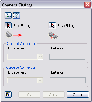
To complete the connection, you must have one free fitting and a base fitting
or fittings as specified in the following images. You also specify the engagement
type, as well as the engagement distance when User Defined is selected from
the Engagement list.
Can be a fitting or a normal Autodesk Inventor part in
the active pipe run assembly that is not driven by a
Free fitting
node in a route or by any other fitting. When inserting
a fitting between an existing fitting connection, the
fitting must be collinear. Once the free fitting is con-
nected to the base component, it is always positioned
relative to the base fitting during updates and other
operations.
Can be a fitting, a conduit part, or a normal Inventor
part that is located anywhere within the assembly.
Base Fitting(s)
When inserting a fitting, the base fittings are restricted
to connected collinear fittings. In both cases the base
fitting specifies the connection that constrains the
position and routing of the free fitting.
Available only when you select a connection between
two fittings or between a component and a fitting that
Engagement
was inserted using the Connect Fitting tool. It includes
three engagement types:
■Free Fitting: Uses the free fitting engagement type
for the selected connection.
■Base Fitting: Uses the base fitting engagement type
for the selected connection.
Connect Fittings and Components | 141
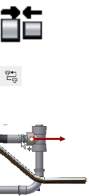
■User Defined: A positive number moves the free
fitting or component away from the connected base
fitting or component. A negative number moves
the free fitting or component toward the connected
base fitting or component.
Indicates the engagement distance used for the connec-
tion between fittings and components. Read-write only
when the User Defined engagement type is used.
Distance
In this exercise, you connect the hose route to the upper tee you manually
placed. The hose route is flexible and acts as the free fitting.
Connect fittings and components
1Activate the AirSystem1:1 run.
2Expand the Flexible Hose 02 assembly, and then activate the hose route.
3In the graphics window, right-click the intermediate Route Point 2, and
select Delete.
The hose route recalculates the hose length.
4Right-click and select Finish Edit.
The AirSystem1:1 run is activated.
5 On the ribbon, click Pipe Run tab ➤ Route panel ➤ Connect
Fittings.
6 In the Connect Fittings dialog box, ensure the Connect Fittings
tool is enabled.
7Ensure the Free Fitting tool is selected and click the hose fitting.
142 | Chapter 6 Edit Rigid Routes and Runs
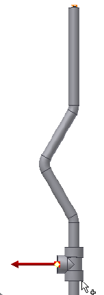
8Click the Base Fitting tool, and then click the tee fitting on the upper
segment.
9Select Female Fitting as the engagement type.
10 Click Apply or OK.
The hose route is recomputed. Right-click in the graphics window and
select Isometric View. Your assembly should look like the following image.
Connect Fittings and Components | 143
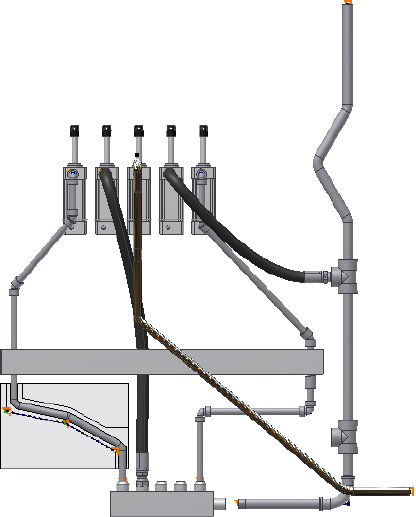
11 In the graphics window or Model browser, right-click the unconnected
tee on the downward segment, and select Delete.
The tee fitting is no longer needed so you delete it. The pipe segment
automatically heals.
Edit Bent Tube Routes
All editing options work for bent tube runs. Edit position, however, behaves
differently for tube runs. When moving a tube segment, both adjacent points
are moved by the same distance and direction. The adjoining bends change
their included angle to make the new route possible. No new segments are
introduced. In addition, you can also edit the bend radius and move coupling
nodes.
144 | Chapter 6 Edit Rigid Routes and Runs
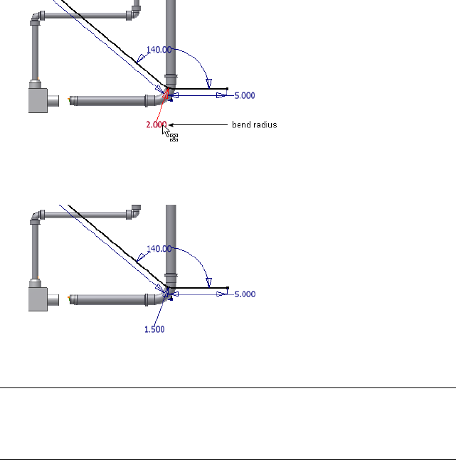
Change Bend Radius
The radius dimension is displayed for each bend in a tube run by default. You
can change the bend radius for selected nodes in the active route. To edit the
bend radius on individual nodes, you edit dimensions.
Change bend radius on individual nodes
1Activate Route03 in the AirSystem1:1 run.
2Double-click the bend radius dimension as shown in the following image.
3Enter 1.5 inch as the new value, and then click the green check mark.
The radius changes for that node only.
4Right-click and select Finish Edit.
NOTE Alternatively, you can choose Select Sketch Features from the Select tool
on the Quick Access toolbar while the top-level assembly is activated, and then
double-click the bend radius dimension. Enter the new bend radius, and click
Update.
Change Bend Radius | 145

Move Coupling Nodes
In tube routes you can move coupling nodes in three dimensions when the
route points are not fully constrained. The system then dynamically updates
the route sketch and the collinear constraints on the adjacent segments remain.
You can also reposition coupling route points by editing the segment
dimensions.
NOTE To remove a coupling, you must delete the associated route point in the
route environment.
In this exercise, you use the 3D Move/Rotate tool.
Move the coupling node
1Activate Route03 in the AirSystem1:1 run.
2Right-click the intermediate route point on the segment, and select 3D
Move/Rotate.
3Drag the triad axes or enter the X, Y, or Z values to move the point as
needed.
4Click OK.
Delete Routes and Runs
You can delete a selected run or any individual routes that it contains. You
can also delete one or more selected routes.
When you delete a populated route, you must also indicate whether to delete
the segments and fittings that it contains or to save the fittings for future
routing. Fittings that are not deleted are placed above the first route in the
active run.
Delete a run
1Activate Tube & Pipe Runs in a tube and pipe assembly.
2Right-click the pipe run to delete, and select Delete Run.
Delete a route and its components
1Activate the run containing the route to delete.
146 | Chapter 6 Edit Rigid Routes and Runs
2In the Model browser, right-click the route and select Delete.
If the routes to delete are populated, the Delete Route Components dialog
box displays.
3Do either of the following:
■To delete both segments and fittings, click the button beside Fittings
and Segments of Selected Route.
■To delete segments and keep the fittings, click the button beside
Segments of Selected Route.
4Right-click and select Finish Edit.
Delete Routes and Runs | 147
148
Use Content Center
Libraries
The Autodesk Inventor® Content Center provides standard Autodesk Inventor parts, as well
as conduit parts and tube and pipe fittings. The components comply with industry standards.
In this chapter, you learn the basics about the Content Center.
About Content Center
The Content Center is an Autodesk Inventor tool used for accessing and
maintaining the libraries. You can create as many libraries as you need on the
Autodesk® Vault server, and attach them to the Content Center using the
Configure Content Center Libraries tool.
Autodesk Inventor® Routed Systems provides three tools to manage libraries,
configure libraries, and edit library content with varied functions:
To use libraries in the Content Center, the server must
be installed. You can create new libraries on the server
Autodesk Vault server
and then use the Configure Content Center Libraries
tool to attach it to the Content Center. You can perman-
ently delete a library from the server after you detach it
from the Content Center.
You can attach the libraries on the server to the Content
Center.
Configure Content
Center Libraries tool
You can edit library parts from within the Content
Center.
Content Center Editor
tool
7
149

In this chapter, you learn the basics about the Content Center. For more
information about managing, configuring, and using the Content Center,
refer to the Help.
To manage and configure libraries, you must have read/write permissions to
the Content Center and libraries. Otherwise, go to the system administrator
to request permissions.
NOTE In the exercises that follow, you must have read/write permissions to the
Content Center.
Content Center Libraries
The Content Center Library contains libraries of standard and custom Autodesk
Inventor parts (fasteners, steel shapes, shaft parts) and features that can be
placed into assemblies using AutoDrop. It also includes conduit parts (hoses,
pipes, tubes) and tube and pipe fittings (couplings, elbows, flanges, tees, and
so on) that are standard for creating tube and pipe systems.
Libraries from several different industry standards are provided. You access
the library parts using the Place from Content Center and Replace from
Content Center tools. Once you locate the part you need in a library, you set
parameters for the part, and then use AutoDrop to insert the part in the
assembly file or directly onto a run. When a library part is dropped into an
assembly, an .ipt file is created for the inserted part and is added to the Model
browser.
For Tube & Pipe specific libraries, you can manage them the same as you do
with Inventor-specific libraries. For example, to reuse custom library parts that
you published in earlier versions of Autodesk Inventor Routed Systems, you
can import the appropriate library database files. Using the Publish Part tool,
you can add your own tube and pipe parts that have been authored to the
Content Center libraries for standard use.
NOTE When a tube and pipe style uses the conduit part or fittings in a library that
is currently not available, you must configure the library before you can continue
modifying this style and populating routes that use this style.
150 | Chapter 7 Use Content Center Libraries

Manage Libraries
To manage libraries on the server, click Start ➤ Programs ➤ Autodesk ➤
Autodesk Vault server ➤ Console. Log in to the server, and click OK. Once
the console is open, you can perform several operations.
Create a new library on the Autodesk Vault server
1Start the Vault server Console.
2In the console navigation pane, expand the appropriate server.
3Right-click Libraries and select Create Library.
If the library has not been attached to the Autodesk Vault server, you must
attach it first.
Attach a library to the Content Center
1In the Vault server Console navigation pane, expand the appropriate
server.
2Right-click Libraries and select Attach Library.
3Select the library to attach from the list, and click OK. The .mdf and .ldf
file of the library must be placed under the data folder of your SQL server
path.
Edit read/write permission to a library
1In the Vault server Console navigation pane, expand the appropriate
server.
2Right-click a library in the list and select or clear the Read Only check
mark.
NOTE For default libraries you cannot clear the Read Only check mark.
Detach a library
1In the Vault server Console navigation pane, expand the appropriate
server.
2Expand the Libraries folder.
3Right-click a library in the list and select Detach.
Manage Libraries | 151

This removes the library from the server, but does not permanently delete
it.
Export a library
1In the Vault server Console navigation pane, expand the appropriate
server.
2Expand the Libraries folder.
3Right-click a library in the list and select Export.
Delete a library permanently
1In the Vault server Console navigation pane, expand the appropriate
server.
2Expand the Libraries folder.
3Right-click a library in the list and select Delete.
4Click OK.
Configure Libraries
To configure Content Center Libraries for use in a project, open Autodesk
Inventor Routed Systems and click ➤ Manage ➤ Projects.
Using the Configure Content Center Libraries tool you can:
■Add new libraries.
■Import Inventor libraries and the Tube & Pipe Library from previous
versions.
■Edit or remove existing custom libraries in the Libraries list.
■Update the libraries in the list.
152 | Chapter 7 Use Content Center Libraries
Typically the prerequisite for configuring libraries in the Content Center is
that the libraries must exist on the server. Importing libraries to the Content
Center is an exception:
■If the target library is a pair of .mdf and .ldf files, start the Autodesk Vault
Manager. Right-click Libraries in the Admin Tools browser and select Import
Library.
■If the target library is .mdb file, start the Configure Content Center Libraries
tool. Click the Import Library tool.
Workflow: Configure libraries in Content Center
1Open Autodesk Inventor Routed Systems.
2Click ➤ Manage ➤ Projects.
3 In the Projects dialog box, set the desired active project and click
the Configure Content Center Libraries tool on the bottom right corner.
Workflow: Edit library contents in the Content Center
1Open Autodesk Inventor Routed Systems.
2 On the ribbon, click Manage tab ➤ Content Center panel
➤ Editor.
Retrieve the most current library data
1Open Autodesk Inventor Routed Systems.
2Click ➤ Manage ➤ Projects.
3 In the Projects dialog box, click the Configure Content Center
Libraries tool on the bottom right corner.
4Select one or multiple libraries and click the Update Library tool.
Configure Libraries | 153

Edit category properties and part families
1 On the ribbon, click Manage tab ➤ Content Center panel
➤ Editor.
2Use appropriate tools to make edits.
Place Tube and Pipe Parts
Both conduit parts and fittings can be placed into a tube and pipe assembly
from the Content Center using AutoDrop.
The following tools are available to locate tube and pipe library parts:
■Use the Place from Content Center tool to directly place library parts. For
detailed instructions, see Insert Library Parts Using AutoDrop on page 132
in Chapter 6.
■To replace an existing fitting or all instances in the same fitting type,
right-click the fitting to replace and start the Replace from Content Center
tool. For detailed instructions, see Replace Existing Fittings on page 136 in
Chapter 6.
154 | Chapter 7 Use Content Center Libraries
Author and Publish
To take advantage of the Content Center functionality, such as queries and dropping conduit
parts and fittings, you must publish custom tube and pipe iParts and normal parts to the
Content Center. For example, custom parts in the Content Center can be shared in multiple
projects so you do not need to save the same custom parts for each project workspace.
In this chapter, you learn how to use the Tube & Pipe Authoring tool to author tube and pipe
iParts, and use the Publish Part tool to publish authored parts to the Content Center for future
use in tube and pipe assemblies. You also learn how to publish normal parts as fittings.
About Authoring and Publishing
You must publish parts to a library to which you have read/write permissions.
Otherwise, go to your system administrator to request permissions.
Publishing parts automatically points to the default category in which they
must be published in the active library. If you click into another category, click
the default category in the library tree again to continue the publishing.
The task of authoring and publishing is performed using two tools in sequence:
■Autodesk Inventor® Tube & Pipe Authoring tool
■Autodesk Inventor Publish Part tool
Author Tube and Pipe Parts
After you create a custom fitting or component and transform it to an iPart
factory, you can use the Tube & Pipe Authoring tool to prepare the part for
publishing to the Content Center. You can also author and publish a normal
part (not an iPart) as a fitting.
8
155

You can author and publish tube and pipe iParts as either pipes or fittings,
but can only author and publish normal parts as fittings.
When authoring tube and pipe iParts, you specify:
■Part type
■Connection number
■End treatment of each connection
■Parameter and iPart table mapping
■Connection point and connection axis
■Gender (female, male, or neutral)
■Engagement of each connection
■ISOGEN properties for fittings
■Mating point and pipe axis (for branch fitting only)
■Cut options (for branch fitting only)
When authoring normal parts, you specify all of the previous items, with the
exception of the Parameter and iPart table mapping. In its place, you specify
a fixed nominal size.
Access Tube & Pipe Authoring Tool
The Tube & Pipe Authoring tool is available as soon as you have an iPart or a
normal part file open.
Access the Tube & Pipe Authoring tool
1Open a normal part or an iPart file.
2 On the ribbon, click Manage tab ➤ Author panel ➤ Tube
and Pipe.
TIP You may need to expand the drop-down menu to select the Tube and
Pipe author as shown in the following image.
156 | Chapter 8 Author and Publish
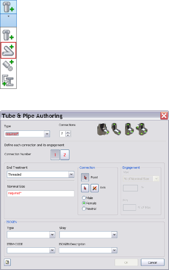
The Tube & Pipe Authoring dialog box displays. The following image is
an example of authoring a pipe iPart.
For information on preparing tube and pipe iParts, see the Help.
Access Tube & Pipe Authoring Tool | 157
Author Parameters
Use the Tube & Pipe Authoring dialog box to specify the part type, number
of connections, end treatment, required part parameters, engagement, and
optional ISOGEN properties for tube and pipe iParts or normal parts being
authored.
Once authored, you can publish them to the Content Center. If you do not
want to make the part available from the library, you can save the part to a
different location.
Type
Specifies the part type to author from the available list. The selected type
determines the root category to which you can publish the part in the Content
Center.
■To author a standard, two-connection segment, select Tube, Pipe, or Hose.
These three part types are not available when you are authoring a normal
part.
■To author a standard fitting, select any of the available fitting types.
■If it does not fit into any available fitting types, select Other.
All standard part types such as tubes, pipes, hoses, adapters, crosses, elbows,
flanges, branched fittings, gaskets, and so on are available for authoring and
publishing.
Connections
Specifies the number of connections for the part being authored. Each part
type defaults to a connection number. If you do not use the default number
of connections, set a new value in the Connections list. If you are authoring
a cap, elbow, tee, or cross, click the appropriate fitting image.
Connection Number
Specifies the connection to define. The number of connections changes
dynamically depending on the quantity specified for the part being authored.
158 | Chapter 8 Author and Publish
Click the connection number button representing the connection to set. The
button changes from red to black when required connection criteria is satisfied.
Continue to click buttons and set parameters until all connections are defined.
■Red buttons indicate that the connection criteria have not been satisfied.
■Black buttons indicate the connection has the necessary information for
authoring and publishing.
Angle
Read-only display of the angle value between the two primary connections
in a self draining elbow or tee. This area of the dialog box does not appear
unless the fitting being authored has an angle value greater than 45 and less
than 90 degrees.
End Treatment
Specifies the end treatment used for each connection number. The End
Engagement list filters out all possible end treatments for the current
connection point.
Click the arrow to select an end treatment from the list.
Parameter
Specifies parameters for each connection number. All listed parameters must
be mapped. This setting is available only when you are authoring a tube and
pipe iPart.
Click the arrow to select a parameter from the list, and then map each one to
the appropriate iPart table column. Once set, parameter mappings are
automatically populated for all other connections. You can reset them if the
connection is a different size.
Typically fitting iParts must contain the nominal diameter (ND). For butt
welded branched fittings, the schedule number (SN) is also required.
Conduit iParts must contain:
■Nominal diameter (ND)
■Schedule number (SN)
Author Parameters | 159
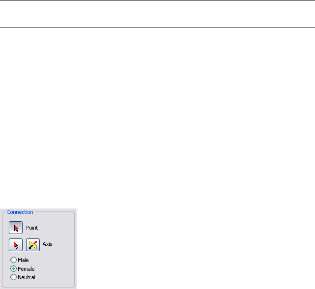
■Outside diameter (OD)
■Inside diameter (ID)
■Pipe length (PL)
NOTE Pipe Length is only required on the first connection number. You do not
need to map the iPart column to Pipe Length for all other connection numbers.
Nominal Size
Specifies the fixed nominal size of the normal part being authored. Normal
parts can only be authored and published as fittings. This setting is available
only when you are authoring a normal part.
Connection Point, Connection Axis, Gender
Connection settings determine the connection geometry, type, and direction
of the axis. In this case, set and map the parameter before you continue.
This section typically has the following options with an exception of the last
connection number on a branched fitting:
Sets the point at which the fitting connects with exist-
ing geometry. Click the icon, and then select either a
Connection Point
tool
circular edge or existing work point for the connection
in the graphics window. For gasket parts and butt weld
components, select a point on the connection face. A
work point is displayed at the center of the circular
edge.
Sets the direction in which to connect the part being
published. Click the icon, and then select either a cir-
Connection Axis tool
cular edge or existing work axis for the connection. An
arrow in the graphics window shows the set axis direc-
160 | Chapter 8 Author and Publish

tion. The axis direction should point outside of the
part, not inside. To flip the arrow in the opposite dir-
ection, click the Flip Direction button.
Changes the axis to the opposite direction.Flip direction
Select the appropriate gender for the connections. For
example, gaskets and butt weld components are typic-
ally neutral gender.
Male, Female, Neutral
NOTE For more information about the connection information for authoring
branched fittings, refer to the Help.
Engagement
Before a custom fitting can be placed in a tube and pipe assembly, engagement
information must be set. Library parts from the Content Center already include
this information.
Pipe engagement determines the range (minimum and maximum engagement
position values) for how a pipe is inserted into a fitting. The maximum
engagement position (Max) is defined by a work point on the connection
axis.
The Max work point can be an existing work point or it can be created by the
intersection of a selected planar face and the connection axis:
■The actual Max distance is the distance from the connection point to the
Max point along the connection axis.
■The minimum engagement position (Min) is the distance from the
connection point to the Min.
The set engagement range displays in the graphics window, and updates
dynamically as changes are made to the Max and Min settings.
Author Parameters | 161
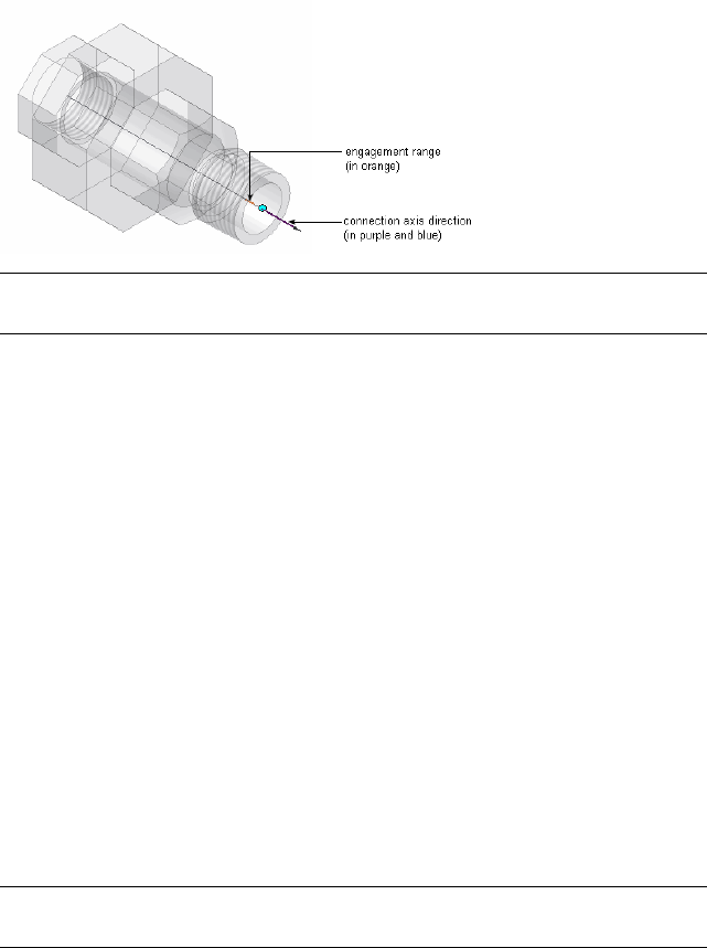
NOTE The Engagement section of the dialog box is not enabled until the required
settings in the previous sections are set.
There are three types of engagement that you can set:
The Max is a percentage of the nominal size value (NS).
This engagement type automatically adjusts to changes
% of Nominal Size
in the nominal size. Gaskets and butt weld components
have 0% engagement.
Establishes an association between the connection
point and a work point representing the maximum
To Plane/Point (Asso-
ciated)
engagement position. The point can be an existing
work point or work point that is created by the inter-
section of a selected planar face and the work axis.
The actual maximum engagement position distance.
You can enter the distance in the dialog box.
Distance
The minimum engagement position is always specified as a percentage of the
Max distance.
When a pipe is inserted into a fitting, the pipe fitting procedure applies the
defined minimum and maximum to ensure the engagement position is within
the specified range. Depending on the minimum increment set in the style,
the end of the pipe falls between the Min and the Max.
NOTE For more information about setting the different types of engagement,
refer to the Help.
ISOGEN Properties
To support the optional ISOGEN output format, you must add certain
properties to the published fittings. The ISOGEN properties you must add are:
162 | Chapter 8 Author and Publish
Specifies the piping component type property required
by ISOGEN .pcf files.
Type
Four-character symbol keys that consist of the two-
character pairs for part type and their valid end types.
SKEY
The SKEY is used as part of ISOGEN end point input.
Wild card values of **, @, or + may also be included in
the SKEY. The wild card values are replaced by addition-
al information such as a range of integer values denot-
ing bend radius or number of segments.
Specifies the parameter to use for the manufacturer's
item-code for the selected part. For iparts, it selects the
Item-Code
ITEMCODE column in the family table and maps it to
the item-code property. For non-iparts, enter the
needed code based on the manufacturer's data. You
can also click the arrow to map the item code to other
parameters.
Provides a manufacturing description of the selected
part. Click the arrow to select from the list, or enter
the needed description.
ISOGEN Description
Prepare iParts
When creating the iPart, make sure the necessary values are included in the
iPart table. It is recommended that you learn what parameters are required to
author tube and pipe parts. You can then create appropriate parameters and
features when transforming the part to an iPart factory.
For more information about preparing an iPart, see:
■Autodesk Inventor Skill Builders: Authoring, Publishing, and Styles - Part
1. It is available at: http://www.autodesk.com/inventorpro-skillbuilder.
■Help system.
In this exercise, you use sample iParts to learn how to author and publish to
the Content Center.
When a sample tube and pipe iPart is open:
■Use the Parameters tool to verify the model parameters and user parameters
that are used in the iPart. It is recommended that you use model equations
to define the part parameters so that multiple part occurrences specified
in the iPart Authoring table can dynamically update in proportion.
Prepare iParts | 163
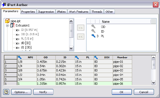
■Double-click Table in the Model browser to open the iPart Author table.
Verify all part occurrences that are defined for the iPart. Each row in the
iPart Author table represents a part occurrence for the part family to publish
to the Content Center.
■If you must customize the pipe length of the part when placed from the
Content Center at a later time, specify it as Custom Parameter Column in
the iPart Author table before authoring. Click the column head to select
the entire column, right-click, and then select Custom Parameter Column.
■Each row in the iPart Author table can have its own material style. When
needed materials for an iPart are not available in the Styles Library, routes
and runs using this material cannot be properly populated. To add new
materials to the Styles Library, you must enable the Styles Library for your
project. For detailed instructions on how to enable the Styles Library, see
Set Up Projects For Exercises on page 11. For detailed instructions on how
to add and modify material styles, see the Index entry “material styles” in
the Help.
Set Default Rows in iPart Author Tables
Each iPart Author table has a default row. The default row determines the
library part that displays when you open a part family in the Content Center.
For instance, open the sample pipe iPart Autodesk\Inventor Professional
<version>\Tutorial Files\Tube & Pipe\Example_iparts\pipe.ipt. In the Model
browser, double-click Table to open the iPart Author dialog box:
164 | Chapter 8 Author and Publish

The row highlighted in green is the default row. To change the default row,
right-click the appropriate row number, such as 1/2, and select Set As Default
Row. Click OK and the pipe part in the graphics window automatically updates.
Once this pipe iPart is published to the Content Center, when opening the
part family, the preview image shows the part with parameters in the default
row.
You can open 90-degree elbow and 45-degree elbow to verify their default
rows on the iPart Author dialog box.
NOTE Do not change the default row for sample iParts.
Set iPart Family Key Columns
An iPart can have up to 9 keys used to define criteria for AutoDrop and filtering
out the iPart for tube and pipe styles.
Pipe iParts typically have 3 family key columns: nominal size, schedule number,
and pipe length. For the sample pipe iPart:
■On the Other tab, NPS is primary key {1} and SCH is secondary key {2}.
■On the Parameters tab, PL is tertiary key {3}.
Fitting iParts typically have 1 family key column: nominal size. For the sample
elbow iParts, on the Other tab, NPS is primary key {1}.
The following image illustrates the relationship between iPart family key
columns and part family thumbnail page in the Content Center.
Prepare iParts | 165
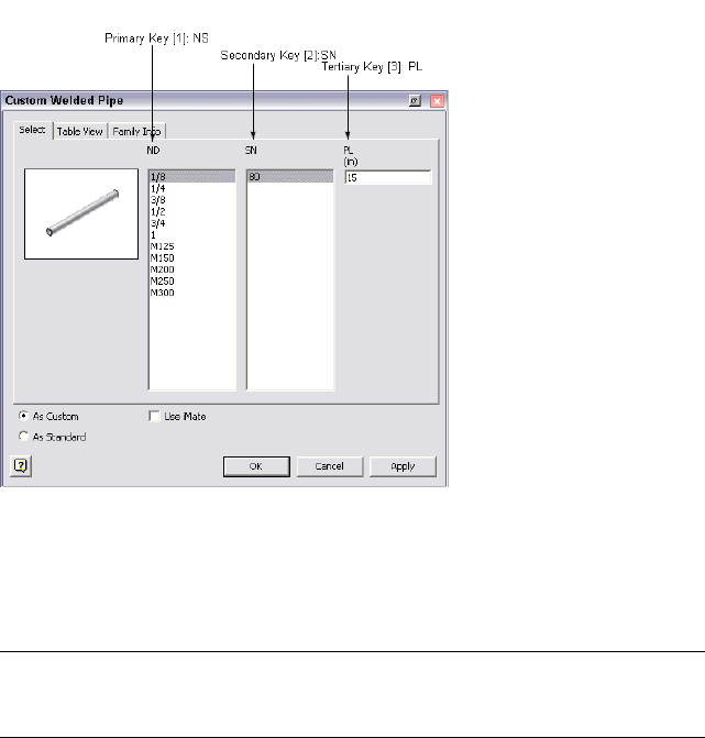
Family key columns play an important role in the file naming schema for part
families in the Content Center. After authoring and publishing, the sequential
combination of hierarchical keys form the value of the pre-defined property
{DESIGNATION} in the Content Center. In this case, {DESIGNATION} is pipe
{NS} {SN} {PL}, in which pipe indicates the conduit part type.
TIP When you publish authored parts to the Content Center, you can also set and
modify family key columns on the Publish Guide. For more information, see Publish
Authored Parts on page 175.
Author iParts
The Tube & Pipe Authoring tool predefines a list of available part types to
author, such as Tubes, Pipes, Hoses, Couplings, Elbows, and Tees. When no
category is appropriate for the fitting part being authored, select Other.
In this exercise, you use the Tube & Pipe Authoring tool to standardize three
sample iParts that are stored in Autodesk\Inventor Professional <version>\Tube
& Pipe\Tutorial Files\Tube & Pipe\Example_iparts: pipe iPart, 45-degree and
90-degree elbow iParts.
166 | Chapter 8 Author and Publish
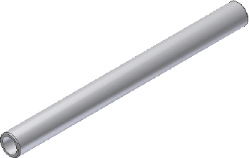
Keep in mind that you cannot select an edge adjacent to a torus or spline face
to define connection points and connection axes.
■In the exercises of authoring the pipe iPart, you learn to define connection
points and connection axes using valid circular edges.
■In the exercises of authoring the 45-degree and 90-degree elbow iParts,
you learn to define connection points and connection axes using existing
work points and work axes that were prepared for the exercises.
In addition, you can use the skills learned from authoring tube and pipe iParts
to author normal parts.
Pipe iPart
In this exercise, you define connection points and connection axes through
valid edges on the sample pipe iPart.
Author a pipe iPart
1Open the pipe.ipt iPart file.
2In the Model browser, right-click Table and select Edit via Spread Sheet
or Edit Table to verify the iPart authoring parameters. Close the file.
3On the ribbon, click Manage tab ➤ Author panel ➤ Tube and Pipe.
4In the Type list, select Pipe. The default value in the Connections list is
2 and cannot be modified.
5Verify that connection number button 1 is selected to indicate that you
are setting the information for Connection 1.
6In the End Treatment list, select Welded for Connection 1.
Author iParts | 167
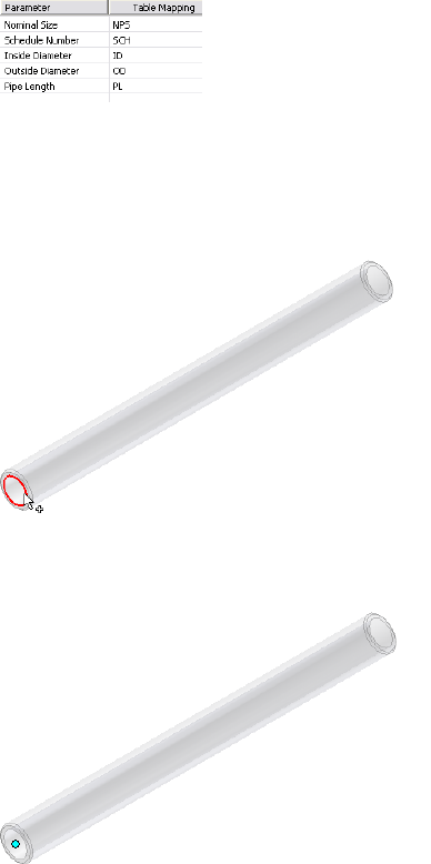
7Click the red required field and complete the mapping as shown in the
following image.
The Parameter list represents the attributes for the published part and it
determines the controlling parameters for styles. The Table Mapping list
represents the attributes for the pipe iPart. Parameter and table mapping
are always selected as a pair.
8Click the Connection Point tool, and then select the connection point
in the graphics window.
9Pause the cursor over the geometry until the circular edge is highlighted
as shown.
10 Click to select the highlighted edge.
A connection point is displayed at the center of the circular edge.
168 | Chapter 8 Author and Publish
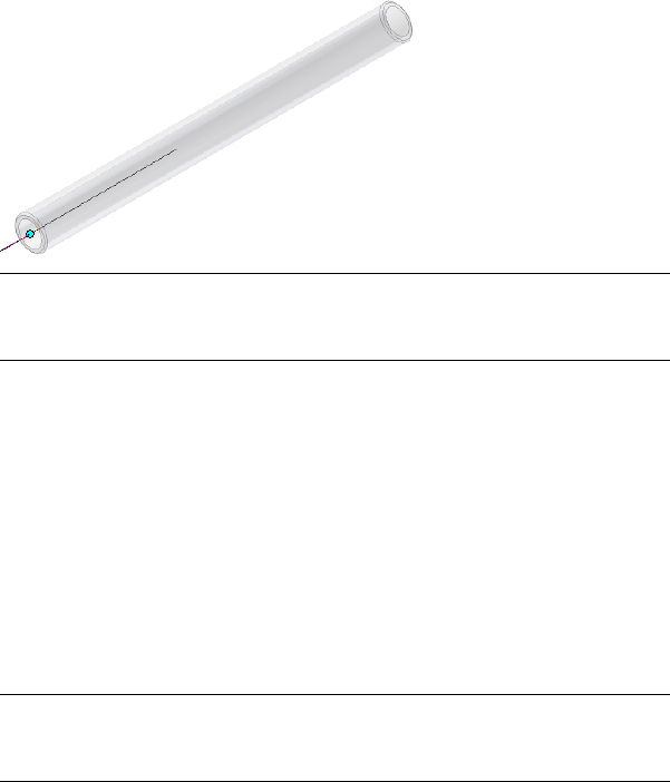
11 Click the Connection Axis tool, and then define the connection axis in
the graphics window.
12 Pause the cursor over the same circular edge that you selected for the
work point, and click to select. An arrow shows the axis direction.
TIP If the axis points toward the inside of the part, click the Flip Direction
tool. The connection direction must point toward the engaging fitting, so it
often points outward.
13 Ensure the Neutral check box is enabled. Neutral is automatically selected
when the Welded end treatment is set.
14 Specify the Engagement setting. For pipe parts, when connecting to the
adjacent fittings, the connection only applies to the engagement
definition of the adjacent fittings by default. Because any engagement
parameters specified for a pipe iPart are ignored by default for the
connection to the adjacent fittings, it is recommended that you set a
fixed value of 0 in such cases.
Max: Distance: 0 inch
Min % of Max: 0
NOTE If the engagement section is dimmed, a required setting, such as the
connection axis, was not yet set. You must complete all previous settings
before you can set engagement values.
The connection number button 1 should now be black, indicating that
all connection criteria are satisfied for Connection 1.
15 Click the connection number button 2 to begin defining the second
connection.
The parameter mapping is populated with information set for Connection
1. Since the nominal sizes are the same, you do not need to set it again.
Author iParts | 169
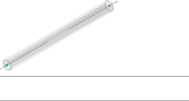
16 Use the same settings as Connection 1 and be sure to set End Treatment
to Welded.
To define the connection information, click the circular edge on the other
pipe end to set the connection point and connect axis.
NOTE For the Tubes, Pipes, and Hoses part types being authored, you do
not need to specify the Pipe Length parameter for connections other than
Connection 1. The Pipe Length parameter is unique for a conduit part.
17 Verify that each connection number button changes from red to black
so all required connection criteria are set.
18 Click OK.
19 On the Authoring Result dialog box, click OK.
20 Save the authored pipe iPart and close the part file.
All authoring changes are saved for the next time you want to author
the iPart again. You can publish the authored pipe to the Content Center
at a later time.
Elbow iPart
In this exercise, you define connection points and connection axes using
existing work points and work axes that were created before authoring.
Author the 45-degree elbow iPart
1Open the 45elbow.ipt iPart file.
In the following image, work points and work axes that were created to
define connection points and axes are displayed in the Model browser.
170 | Chapter 8 Author and Publish
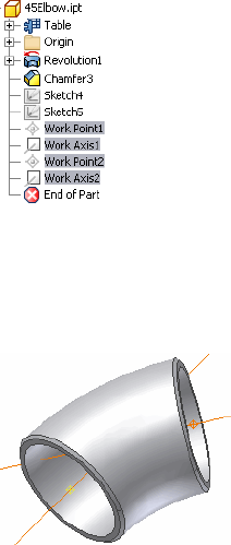
2Press CTRL or SHIFT to select all predefined work points and work axes in
the browser, right-click and select Visibility.
Click the browser icon to highlight the corresponding work point or work
axis in the graphics window.
3On the ribbon, click Manage tab ➤ Author panel ➤ Tube and Pipe.
4On the Tube & Pipe Authoring dialog box, specify:
Type: Elbows
Connections: 2
5Click connection number button 1.
6Set the following:
End Treatment: Welded
Parameter and Table Mapping: Nominal Size: NPS
Connection Point and Connection Axis: See the following images
Connection: Female
Engagement
Max: Distance: 0 inch
Min % of Max: 0
Author iParts | 171
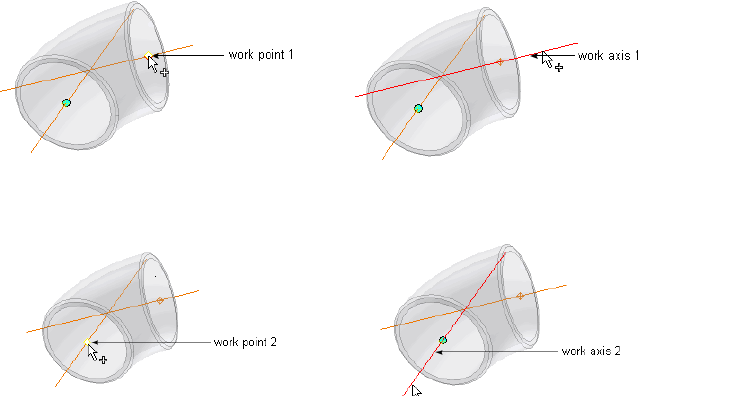
7Click connection number button 2, and then repeat Step 6 using the
following image to set the Connection Point and Connection Axis.
8Specify the following ISOGEN properties:
Type: ELBOW
SKey: ELBW - Elbow - Butt Weld (90 degree and 45 degree)
ITEM-CODE: 90 45 LLR
Description: ELBOW 90 45 DEGREE BW ASTM A043 WPF316 SCH.40
9Click OK.
10 On the Authoring Result dialog box, click OK.
11 Save the authored 45-degree elbow iPart, and close the part file.
Author the 90-degree elbow iPart
1Open the 90LongElbow.ipt part file.
2Repeat the previous steps using the same settings and connection points
as for the 45-degree elbow iPart.
3Save the authored 90-degree elbow iPart, and close the part file.
172 | Chapter 8 Author and Publish
Practice Your Skills
Use the skills you have learned from the previous exercises and try to author
a normal part. Keep in mind that you can only:
■Author a normal part as a fitting.
■Enter a fixed nominal size.
1Prepare a normal part using Autodesk Inventor.
2Click the Tube and Pipe Authoring tool.
3On the Tube & Pipe Authoring dialog box:
■Select one fitting type.
■Use the default number of connections or set the connections you
need.
■Select an appropriate End Treatment option depending on the part
feature.
■Enter a value for the nominal size.
■Define the connection point and connection axis using geometry on
the part or predefined work points and work axes.
■Specify the gender as female or male for each connection.
■Specify the Max and Min Engagement settings using the Fixed option
or the interactive method.
■Optionally set ISOGEN properties, such as Type, SKey, and
ITEM-CODE.
4Click OK.
5Save the authored normal part.
Publish to Content Center
The Content Center setting defines the library where you want the part to
belong. Parts can only be published to libraries that have Read/Write
permission. Otherwise, go to your system administrator to request permissions.
Practice Your Skills | 173

When publishing parts, iParts, or features, the Content Center automatically
points to the default root category where you must publish the part. Create
appropriate subcategories as needed, and then specify the family properties
and category parameters so the published parts or features can be queried at
a later time.
NOTE Do not change the default root category Autodesk Inventor matches in the
Content Center; otherwise, the publishing functionality is disabled for the category
that was changed to. To continue the publishing process, click to restore the
default category in the library tree.
Set Up the Library and Subcategories
You cannot add a new library to the Content Center while you are in the
process of publishing. Use the Autodesk Vault server and Configure Content
Center Libraries tool to create and attach the library to the Content Center
beforehand.
In addition, you cannot create new categories in the Content Center while in
the process of publishing. Use the Content Center Editor tool to set up the
categories beforehand.
To publish authored parts in the exercise that follows, you first set up the
library. You use the default category to publish at a later time.
Set up a new library
1Log in to the Vault server Console.
2Expand the appropriate server.
3Right-click Libraries and select Create Library. Create a new library named
CustomLibrary. Click OK.
By default, the new library is attached to the server and you have the
read/write permission.
4Exit the console.
5Ensure that the Internet Information Server (IIS) is started. Otherwise,
libraries on the server cannot be accessed. This is not required for
standalone installations.
6Start Autodesk Inventor Tube & Pipe.
174 | Chapter 8 Author and Publish

7Click ➤ Manage ➤ Projects.
The Projects dialog box displays the project configuration information.
8On the Project pane, ensure that the Tube & Pipe Tutorial Files project
is active and use the Configure Content Center Libraries tool ➤ Add
Library tool to attach CustomLibrary to the Content Center.
For detailed instructions, see Set Up Projects For Exercises on page 11 in
Chapter 1.
9Save the changes for the project and close the Projects dialog box.
10 On the ribbon, click Tools tab ➤ Content Center panel ➤ Editor and
update the libraries in the Content Center as needed.
11 Optionally, you can create subcategories to publish parts.
For detailed instructions, refer to the Help.
In the exercises that follow, you publish the authored parts to the default
category that the system automatically matches. You do not need to create
subcategories in this step.
Publish Authored Parts
When publishing authored parts, you must map the part parameters to the
category parameters. The information you provide to define the part sets the
structure for its location in Content Center, provides a base for the part file
name, and makes the part attributes available for future queries.
In the exercises that follow, you use the Publish Part tool to add authored
pipe, 45-degree elbow, and 90-degree elbow iParts to CustomLibrary that you
created in the previous exercise.
NOTE If you need to use published parts to define tube and pipe styles, you must
specify the Standards Organization and Standard family properties during
publishing. They are the key style criteria to filter out library parts on the Tube &
Pipe Styles dialog box.
Pipe iPart
In this exercise, you publish the authored pipe iPart to CustomLibrary.
Publish Authored Parts | 175
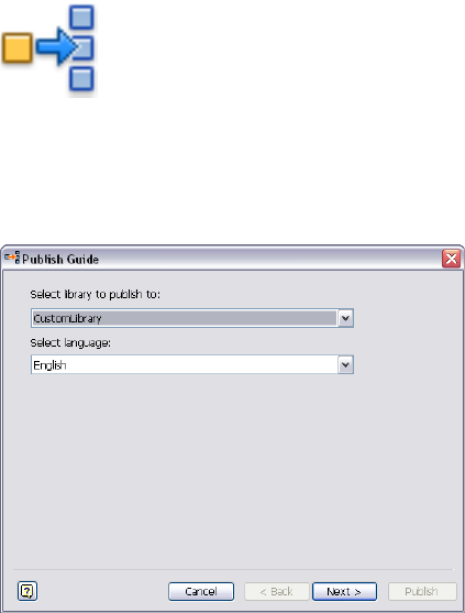
Publish an iPart
1Open the pipe.ipt part you previously authored.
2 On the ribbon, click Manage tab ➤ Content Center panel
➤ Publish Part.
The Publish Guide dialog box displays.
3Select CustomLibrary from the list and accept the default language, and
then click Next.
4Select Pipes from the list and click Next.
176 | Chapter 8 Author and Publish
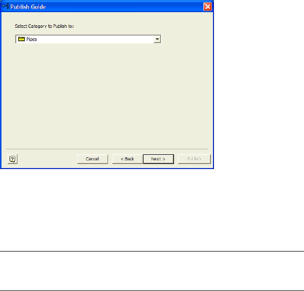
5Accept the default mapping between the iPart family columns and
category parameters and click Next.
The mapping has been done during authoring. You do not need to do
anything for tube and pipe parts publishing unless you need to change
the default mapping.
NOTE In the mapping table, required family columns and category
parameters represent a different background color from optional properties
that follow.
6Optionally, define the family key columns if you have not set the family
key columns during iPart preparation or that do not satisfy the design.
In this exercise, ensure that you have the three family key columns for
the pipe part in the order of NPS, SCH, and PL. Click Next.
Publish Authored Parts | 177
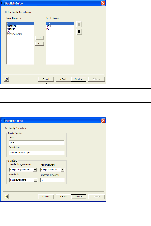
NOTE For detailed instructions on how to set the family key columns when
preparing a tube and pipe iPart, see Prepare iParts on page 163 in this chapter.
7Specify the pipe part family properties as shown in the following image:
NOTE Multiple styles can be used in a single tube and pipe run and different
styles may use different standards, so the Standards Organization and Standard
information is required if you plan to use a differing standard part in a style.
8Click Next.
The preview image of the published part is displayed. You can change
the thumbnail image for future use in the Content Center.
178 | Chapter 8 Author and Publish
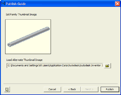
9Click Finish.
10 On the Publish Guide dialog box, click Publish.
11 When the Publish Result dialog box prompts about the successful publish,
click OK.
When processing is complete, the part is added to Custom Library ➤
Tube & Pipe ➤ Conduits ➤ Pipes category. You can use the Content
Center Editor tool to verify the published pipe part family.
Once published, the Standard information is available in the lists on the Tube
& Pipe Styles dialog box. The part materials are available when the appropriate
standard specification is selected.
You can also navigate to the published union part family using the Content
Center tool and practice using the AutoDrop functionality to place it in a
sample model or model of your choice.
Elbow iPart
Use the skills you just learned to publish the 45-degree and 90-degree elbow
iParts to Custom Library ➤ Tube & Pipe ➤ Fittings ➤ Elbows category.
Publish the 45-degree elbow iPart
1Repeat the previous steps to publish the 45-degree elbow iPart to
CustomLibrary.
Publish Authored Parts | 179
Use Tube & Pipe ➤ Fittings ➤ Elbows as the category path.
Click Next to go to the next wizard.
2Accept the default mapping between the iPart family columns and
category parameters and click Next.
3Accept the default family key columns and click Next.
4Specify the following family properties and click Next.
Family Naming:
Name: 45Elbow
Description: Butt Weld 45 Elbow
Standard:
Standard Organization: SampleOrganization
Manufacturer: SampleCompany
Standard: SampleStandard
Standard and Revision: 1
5Review the published elbow information and go back to the preceding
wizards to make appropriate changes as needed. Click Next until you
reach the final screen of the wizard, and then click Finish.
6Click Publish, and then OK.
Publish the 90-degree elbow iPart
1Repeat the steps above to publish the 90-degree elbow iPart to
CustomLibrary.
Use Tube & Pipe ➤ Fittings ➤ Elbows as the category path.
Click Next to go to the next wizard.
2Accept the default mapping between the iPart family columns and
category parameters and click Next.
3Accept the default family key columns and click Next.
4Specify the following family properties and click Next.
Family Naming:
Name: 90LongElbow
Description: Butt Weld 90 Long Elbow
Standard:
180 | Chapter 8 Author and Publish
Standard Organization: SampleOrganization
Manufacturer: SampleCompany
Standard: SampleStandard
Standard and Revision: 1
5Review the published elbow information and go back to the preceding
wizards to make appropriate changes as needed. Click next until you
reach the final screen of the wizard, and then click Finish.
6Click Publish, and then OK.
Create Styles Using Published Parts
Once you successfully publish custom conduit parts and fittings to the Content
Center, you can create new styles based on those published parts.
Most styles require a pipe, elbows, and a coupling. Welded styles, such as the
style in this exercise, do not require a coupling.
In this exercise, you create a welded Rigid Pipe with Fittings style using the
published pipe and 90-degree elbow. Only two parts are required by this style,
since it is a welded style with 90-degree elbows only.
Set a new style with published parts
1With a tube and pipe runs assembly open, open the Tube & Pipe Styles
dialog box.
2On the Tube & Pipe Styles dialog box, select ASTM A53/A53M-ASME
B16.11 - Welded Steel Pipe from the Style list as the base.
3Click New to create a new style named Custom Welded Pipe (1/4, 90) and
clear the values.
4In the Components table, right-click the Pipe row and select Browse.
5In the Library Browser, click the Standard check box and select
SampleStandard.
6Click the Filter tool, so the custom pipe you created is the only item
listed.
7Select the pipe, and then click OK.
8On the General tab under Diameter, set the following options:
Create Styles Using Published Parts | 181

Nominal Diameter: 1/4 inch
Schedule: 80
Keep in mind:
■SampleStandard is the Standard parameter (not Standard Organization)
you manually set for the part family standard properties during
publishing.
■When SampleStandard is selected in the Standard list, enable the
materials filter to display all available materials in the list. If the desired
material is not displayed, use the Content Center tool to verify the
part family does own this material. Use the Styles Editor tool to ensure
this material is added to the Styles Library.
9Accept the other general settings.
10 On the Tube & Pipe Styles dialog box, Rules tab, specify:
Min: 1.000 inch
Max: 200.000 inch
Inc.: 0.1 inch
11 Repeat steps 4 through 9 to select the 90-degree elbow part.
TIP Notice that the couplings are not required for welded routes, so they
are listed as optional. Pause the cursor over the symbol to view the tooltip.
12 Click Save.
13 Click Close.
The new style Custom Welded Pipe (1/4, 90) is created and available for
creating new rigid pipe routes.
182 | Chapter 8 Author and Publish
Document Routes and Runs
Drawing views, parts lists, and the Bill of Materials table specific to the Tube & Pipe Add-in
are used to describe individual pipe runs and components.
In this chapter, you learn how to create design views for drawings, create varied drawing
views, recover route centerlines, dimension routes and runs, and create and export the bill
of materials, create parts lists, and annotate drawings with piping style data.
About Documenting Routes and Runs
In drawings, tube and pipe information is treated like other parts and
subassemblies. You can describe the individual pipe runs and components and
detail them using normal drawing manager methods and tools unless noted
otherwise.
The two drawing properties are typically used to roll up conduit parts in the
parts lists correctly. You can add them to either specific drawing documents or
drawing templates:
■Conduit segment length. With an internal name of Base QTY. It specifies
the length of conduit parts.
■Raw material description. With an internal name of Stock Number. It stores
the raw material descriptions for conduit parts.
To create tube and pipe drawings correctly, you may need to do the following:
■If you are migrating R9 or earlier tube and pipe drawing documents to the
current version of Autodesk Inventor®, determine the BOM to use. In this
exercise, you use the new BOM.
9
183
■To document individual routes and runs, create design view representations
in which you turn off the visibility of unnecessary components, and then
apply them to appropriate drawing views.
■Use broken views to fit long nondescript sections of pipe on a drawing.
■Use detail views to show selected fittings.
■To dimension routes and runs correctly, recover route centerlines. To
dimension unpopulated routes, you can recover route centerlines.
■Add the Pipe Length and Stock Number properties to parts lists and a Bill
of Materials table.
■To create BOMs for specific routes and runs, set their BOM Structure
property to Reference.
Workflow for Documenting Pipe Runs
To document a tube and pipe assembly, you may need to use the following
workflow.
Document a tube and pipe assembly
1Create a tube and pipe assembly containing populated or unpopulated
routes.
2Edit design views for the drawing file if you want to output specific views,
especially in some complicated assemblies.
3Optionally, edit drawing templates.
4Create one or more base views.
5Create other required views from the base view or any available parent
views.
6Recover route centerlines and dimension routes and runs.
7Create and export the BOMs.
8Create parts lists.
9Add balloons to the pipe run components and annotate drawings with
the piping style data.
184 | Chapter 9 Document Routes and Runs

NOTE The results in your exercise may differ from figures illustrated in this chapter,
depending on specific working environment, original assembly, and workflow
used.
Use Drawing Templates
When documenting a tube and pipe assembly, each new drawing file uses a
drawing template. You can update existing templates or create and add new
ones into the Templates folder. For Windows®XP this located under Program
Files\Autodesk\Inventor<version>\Design Data\Tube & Pipe by default. For
Windows Vista® this located under
Users\Public\Documents\Autodesk\Inventor<version>\Design Data\Tube & Pipe
by default.
For more information about customizing drawing templates, refer to the Help.
Prepare Design View Representations
A Design View is created in the assembly environment and preserves a
designated representation view of assembly components. It can be mapped
to drawing views of the assembly file.
In cases where only specific pipe runs in a complicated assembly need to be
documented, you can define a specific design view in which components that
are contained in the top-level assembly but not within the pipe runs are
hidden. Thus, components with Visibility off are not displayed in the drawing
view when the relevant design view is selected for the drawing file.
Before creating drawing views for pipe runs, you can customize specific design
views for the assembly environment using the Design View Representations
tool.
In this exercise, you create a design view in which you turn off the visibility
of IBeam in the tube and pipe assembly, AirSystemAssy.iam.
Create a new design view
1Open the AirSystemAssy.iam assembly.
2 At the top of the Model browser, click the Design View
Representations tool.
Use Drawing Templates | 185
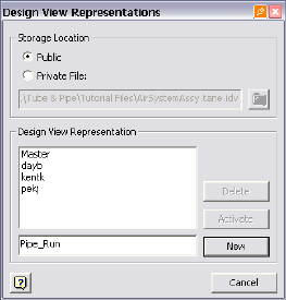
3In the Design View Representations dialog box, accept the default public
storage location, or select Private and specify your own storage location.
4Enter a Design View name, Pipe_Run, and click New.
The new Pipe_Run design view is active by default. In this case, Pipe_Run
is used to create drawing views for the tube and pipe assembly in later
exercises.
5Close the dialog box.
6In the Model browser, right-click the IBeam:1, and then clear the Visibility
check mark. You can also define any other assembly viewing
characteristics.
7Turn off the visibility of the AirSystem2:1 run.
8Save the top-level assembly.
186 | Chapter 9 Document Routes and Runs
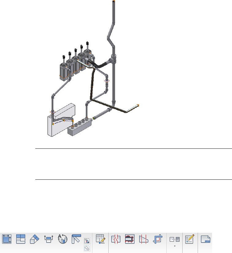
NOTE You can set the association with the design view when creating a drawing
view. The association with the design view can be changed after the drawing view
is created. When associations are set, it is possible to update the drawing view
automatically when changes are made to the assembly in the selected design view.
Create Drawing Views
In this exercise, use the Place Views tab to create a base view, projected view,
and detail view for a tube and pipe assembly you previously created. Pause
the cursor over the images to view the tooltip.
The following figure shows the completed drawing views:
Create Drawing Views | 187
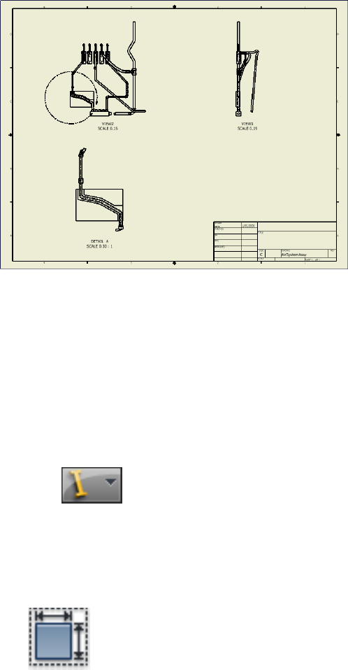
Create Base Views
Before creating other drawing views, such as projected views and detail views,
you must first create at least one base view.
Create a base view for a tube and pipe assembly
1Open the AirSystemAssy.iam assembly. Make sure you have the Pipe_Run
design view active for the tube and pipe assembly in which the IBeam
and AirSystem2 are not visible.
2Click ➤ New.
3In the New File dialog box select Standard_AIP.idw and then click OK.
The Drawing environment is activated. Examine the Model browser. The
IBeam and Pipe Run 2 have visibility turned off.
4Save the drawing document as AirSystemAssy.idw.
5 On the ribbon, click Place Views tab ➤ Create panel ➤ Base.
The Drawing View dialog box displays.
188 | Chapter 9 Document Routes and Runs
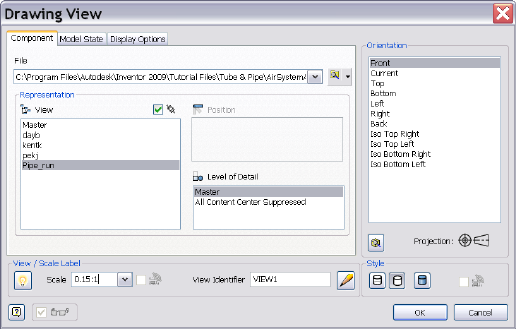
6In the Drawing View dialog box, Component tab, specify:
File Windows XP: C:\Program Files\Autodesk\Inventor<version>\Design
Data\Tutorial Files\Tube & Pipe\AirSystemAssy.iam. File Windows Vista:
C:\Users\Public\Documents\Autodesk\Inventor<version>\Design
Data\Tutorial Files\Tube & Pipe\AirSystemAssy.iam
If an assembly is already opened, it is selected by default. You can click
Browse to locate the assembly that you need.
Representation: Pipe_Run, Associative
The active design view for the assembly is selected by default. The drawing
view automatically updates when the component visibility in the
associated design view changes.
View / Scale Label: 0.15:1, Visible
View Identifier: VIEW1
Orientation: Front
Style: Hidden Line
7In the Drawing View dialog box, Display Options tab, use the defaults.
8Move the preview to the upper-right quadrant of the drawing sheet, and
then click to place the view.
Create Base Views | 189

NOTE If you click OK on the dialog box instead, the view may be placed in
a random location. You can move the view by clicking inside the blank area
and dragging the rectangular border of the view.
9Save the drawing document.
Create Projected Views
Projected views can be created on any drawing views. When a projected view
is placed in the drawing sheet, you can edit the projected view properties using
the Edit View tool on the context menu.
Now, project a right view from the base view you just created.
Create a projected view
1 On the ribbon, click Place Views tab ➤ Create panel ➤
Projected.
2Click inside VIEW1 that is used as the parent view.
3Move the preview to the upper-left quadrant of the drawing sheet, and
then click to set the view location.
A black rectangular border appears.
4Right-click and select Create.
190 | Chapter 9 Document Routes and Runs
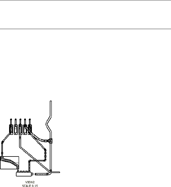
The back projected view is in place now.
5To edit the projected view properties, right-click inside the projected
view, and select Edit View.
NOTE n the Drawing View dialog box that is displayed, some drawing view
settings, such as File and Style, are disabled because the projected view
respects the parent view. You can change its default inherited relationship
with the parent view to activate more settings.
6In the Drawing View dialog box, specify:
Representation: Pipe_Run, Associative
Scale: Scale from Base, Visible
Label: VIEW2, Visible
Style: Style from Base
7Click OK.
The projected view updates to new settings.
8Save the drawing document.
Create Detail Views
Detail views do not respect the drawing view settings from the parent view.
They can be placed anywhere in the drawing sheet.
Create Detail Views | 191
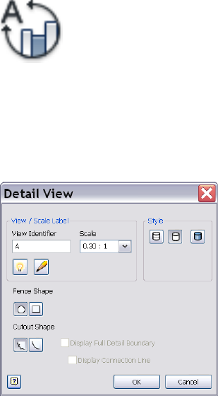
Add a detail view
1 On the ribbon, click Place Views tab ➤ Create panel ➤
Detail.
2Click inside VIEW2 that is used as the parent view.
The Detail View dialog box displays.
3In the Detail View dialog box, specify the settings as shown in the
following image:
4Click OK.
The circular selection symbol is attached to the cursor.
192 | Chapter 9 Document Routes and Runs
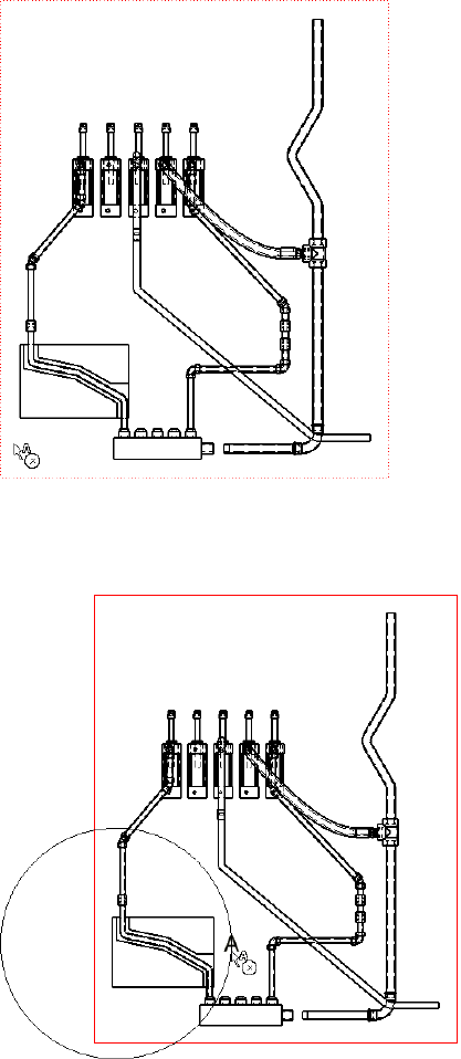
5Place the cursor inside the projected view as shown in the preceding
image. Click and drag the cursor to include the part of
AirSystemAssy.Route1:1 as shown in the following image.
Create Detail Views | 193
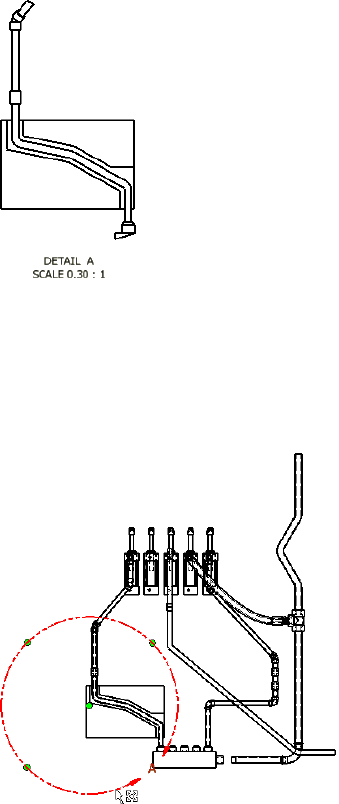
6Click to set the portion of the projected view.
The cursor changes to a plus symbol. The detail view preview is displayed.
7Move the cursor to the appropriate position, and then click to set the
detail view.
8If the portion in the detail view is not as desired, you can use the circular
selection tool to adjust the portion. Move the cursor over the circular
selection tool in VIEW2 as shown in the following image, click to activate
it. To move the circular selection tool, click and drag the green center
point. To change the portion, click and drag the circular edge outward
or inward.
9Save the drawing document.
194 | Chapter 9 Document Routes and Runs

Practice Your Skills
In this exercise, you learn to recognize the three drawing views you just created.
This will make it easier to recover route centerlines in later exercises.
Move the cursor over the Model browser to highlight each drawing view.
Examine the drawing view structure in the Model browser:
■The base view (VIEW1) is the parent view of the projected view (VIEW2).
■The projected view (VIEW2) is the parent view of the detail view (A).
Recover Route Centerlines
By default, the drawing manager hides the centerlines of tube, pipe, and hose
routes in drawing views. Centerline recovery is used to control the availability
of the route centerlines in active tube and pipe drawing views for
dimensioning.
You can control the centerline recovery at the tube and pipe runs assembly,
individual run, or individual route levels in the active drawing view, depending
on the amount of dimensioning you need. For example, when dimensioning
all or most of the routes and runs in a tube and pipe assembly, include route
centerlines for the entire tube and pipe runs assembly, and then hide the
centerlines for the individual runs and routes you do not need.
You must dimension routes to the centerlines in drawing views. Otherwise,
the dimensions may be incorrect. When the specified route centerlines are
recovered, you can dimension routes to the centerlines. If you change the
centerline recovery back, all recovered centerlines in the active drawing views
are deleted so associated dimensions may disappear or become incorrect.
NOTE When a new route or run is created, the route centerline in drawing views
has the same centerline recovery setting as the parent. To add or remove centerlines
for other Autodesk Inventor components in a standard assembly, change the
Automated Centerline Settings on the Tools tab ➤ Options panel ➤ Document
Settings ➤ Drawing tab.
In drawing views that are created from the base view, the route centerline
visibility respects the setting in the base view. For example, if you have
recovered route centerlines in the base view, the relevant route centerlines
are automatically recovered in all associated drawing views that are
subsequently created. When route centerlines are not recovered in the base
view, you can manually recover them for drawing views you need.
Practice Your Skills | 195
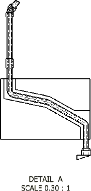
Recover route centerlines in the detailed view (DETAIL: A)
1In the Model browser, under Sheet 1, navigate to
VIEW1:AirSystemAssy.iam ➤ VIEW1:AirSystemAssy.iam ➤
AirSystemAssy.iam ➤ Tube & Pipe Runs ➤ AirSystem1:1.
2Expand AirSystem1:1, right-click Route01, and select Include Route
Centerlines.
The route centerlines are recovered in both the base view and associated
drawing views. Verify the detail view as highlighted in the following
image.
Dimension Drawing Views
There are two types of dimensions for documenting the drawing views of the
tube and pipe assemblies:
Controls the features that are applied during sketching
or creation of the feature. Autodesk Inventor Tube &
Model dimension
Pipe can access the model dimensions of components
and place them in a drawing view. You can then re-
trieve them to display the overall dimensions of pipe
runs.
Added in the drawing view for further documentation
using the General Dimension tool on the Annotate
Drawing dimension
196 | Chapter 9 Document Routes and Runs
tab. It does not affect features or parts. You can add
general dimensions, baseline dimensions, ordinate di-
mensions, and so on.
The following image shows the Annotate tab on which you can use tools to
add dimensions. Pause the cursor over the images to view the tooltip.
Dimension tools include:
■General Dimension
■Baseline Dimension Set
■Baseline Dimension
■Ordinate Dimension Set
■Ordinate Dimension
In the following exercises, you learn to add general dimensions in the detail
view DETAIL A. For more information on dimensioning, refer to the Help.
Add general drawing dimensions
1In the AirSystemAssy.idw drawing document, click the Annotate tab.
2 On the ribbon, click Annotate tab ➤ Dimension panel ➤
Dimension.
3Click the intersection point of two route centerlines and the point on
the valve as shown in the following images, and then drag to set the
dimension.
Dimension Drawing Views | 197
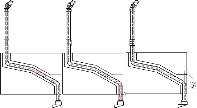
4Press ESC to exit the command.
5Save the drawing document.
Create and Export Bills of Material
In a tube and pipe bill of materials (BOM), conduit parts and fittings from the
Content Center that make up routes and runs are set to Purchased. Master
runs assembly, rigid route sketches, hose splines, and hose assemblies are not
distinct line items in the bill of materials so they are set to Phantom.
You can override the default BOM structure to meet your design needs. For
instance, if you want to create and export the BOM information for specific
routes and runs, set all other routes or runs to the Reference BOM structure.
In addition, using the BOM Editor, you can:
■Edit materials.
■Add custom iProperties.
■Enable structured and parts-only BOMs and set view properties accordingly.
■Enable the part number merging and set the merging criteria.
■Set quantity overrides for components.
■Control whether different components with the same part number can be
merged into one row. If the merging is enabled, you can create your own
list of values to exclude from being merged into one row. The blank part
198 | Chapter 9 Document Routes and Runs
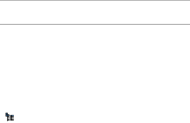
number is permanently excluded so different components with the blank
part number do not merge.
NOTE If you are migrating tube and pipe drawings from R9 or earlier versions,
ensure the stock number (Stock Number) and conduit segment length (Base
QTY) properties are selected into the BOM table.
Enable the Parts Only View
In this exercise, you create a bill of materials table for the tube and pipe
assembly and enable the Parts Only view for the exercises that follow.
Create and export bill of materials for specific runs
1In the AirSystemAssy.idw drawing window, expand
VIEW1:AirSystemAssy.iam in the Model browser.
2 Right-click AirSystemAssy.iam and select the Bill of Materials tool.
The Bill of Materials dialog box displays. By default, the Structured view
is enabled and the Parts Only view is disabled.
Enable the Parts Only View | 199
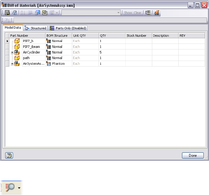
3In the Bill of Materials dialog box, click the Parts Only (Disabled) tab.
4 On the toolbar, click the arrow next to the View Options tool,
and then select Enable BOM View.
All components in the tube and pipe assembly are shown in a flat list.
Subassemblies are not displayed.
Add Base QTY and Stock Number
In this exercise, you add the Base QTY and Stock Number properties to the
Bill of Materials table so that conduit parts are rolled up correctly.
Add Tube & Pipe-specific properties to the Bill of Materials table
1In the Bill of Materials dialog box, verify on the Model Data tab whether
the Base QTY and Stock Number columns are included.
200 | Chapter 9 Document Routes and Runs

If they are not included, click the Choose Columns tool on the
toolbar. In the Customization dialog box, click and drag the needed
columns to the table.
NOTE You can also remove unwanted columns using the Customization
dialog box.
2Close the Customization dialog box.
3Click Done.
4Save the drawing document.
Create and Export Bill of Materials
As with bill of materials (BOM) in drawing documents, the BOM Structure
property defines the status of each component in the BOM table: Normal,
Phantom, Reference, Purchased, and Inseparable. Tube and pipe components
typically follow the default BOM structure. Conduit parts and fittings from
the Content Center that make up routes and runs are set to Purchased. The
master runs assembly, rigid route sketches, hose splines, and hose assemblies
do not have distinct line items in the bill of materials so they are set to
Phantom.
However, you can override the default BOM structure to meet specific design
needs. For instance, you can modify the BOM structures so that you can create
and export the BOM information for specific routes and runs. When a
component has a BOM Structure of Reference, the BOM treats the component
and all its direct and indirect children as if they do not exist. All child
components, that are a part of a Reference component, are excluded from
quantity, mass, or volume calculations, regardless of their own BOM Structure
value.
The AirSystemAssy.iam assembly contains two runs. In this exercise, you export
the bill of materials information for the AirSystem1:1 run.
NOTE The visibility setting that is specified in the design views does not impact
the bill of materials. The components with the visibility off are calculated in the
bill of materials table.
Create and Export Bill of Materials | 201

Create and export bill of materials for specific runs
1In the Bill of Materials dialog box, Model Data tab, expand
AirSystemAssy.Tube and Pipe Runs in the Part Number list.
Verify that both runs are displayed on the Structured tab and all tube
and pipe components are displayed on the Parts Only tab. (BOM view
must be enabled to view this tab.)
2Click the AirSystem2:1 row, and then select Reference from the BOM
Structure list.
3Click the Structured and Parts Only tab to verify the result.
Only the AirSystem1:1 run is displayed on the Structured tab. On the
Parts Only tab, the hose part and associated parker fittings in the
AirSystem2:1 run disappear.
4 To export the bill of materials, click the Export Bill of Materials tool
on the toolbar.
5Select either the Structured or Parts Only view to export, and then save
the file to your local disk.
6In the Bill of Materials dialog box, click Done.
7Save the drawing document.
Create Parts Lists
If Base QTY and Stock Number properties are not selected into the parts lists,
parts lists do not include those properties the first time you create them.
Keep in mind that the drawing manager always groups parts using the Part
Number property even if you remove it from the parts list. Each conduit part
in the current version of Autodesk Inventor has a unique part number:
In this exercise, you create a parts list for the base view (VIEW1), use the
Column Chooser tool to add the Base QTY property to the parts lists. The
Stock Number property is already included in the default parts list style.
Add Base QTY and Stock Number to a parts list
1 On the ribbon, click Annotate tab ➤ Table panel ➤ Parts List tool
to create a Parts Only parts list for the base view (VIEW1).
202 | Chapter 9 Document Routes and Runs
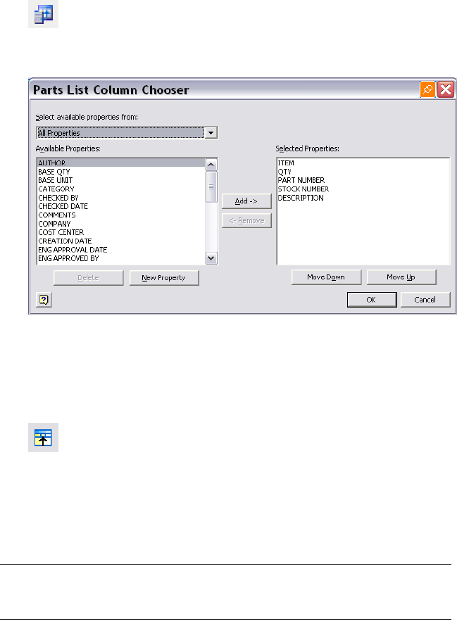
2In the graphics window or Model browser, right-click the parts list and
select Edit Parts List.
3 In the Edit Parts List dialog box, click the Column Chooser tool.
The Parts List Column Chooser dialog box displays. By default, the STOCK
NUMBER property is in the Selected Properties list.
4In the Available Properties list, select BASE QTY, and then click Add.
5Click OK.
Both BASE QTY and STOCK NUMBER columns are displayed in the Edit
Parts List dialog box.
6 Optionally, use the Group Settings tool to group parts list rows
based on the BASE QTY and STOCK NUMBER.
7In the Edit Parts List dialog box, click OK
The parts list automatically updates.
8Save the drawing document.
NOTE Using the Style Editor tool, you can add the BASE QTY and STOCK NUMBER
properties to the parts list style. For detailed instructions on how to use the Style
Editor tool, refer to the Help.
Create Parts Lists | 203
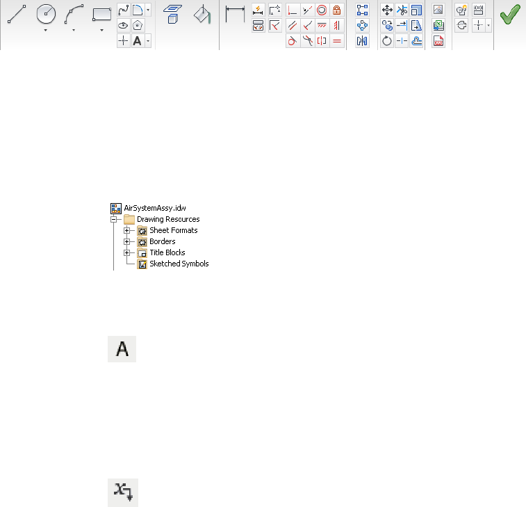
Annotate Drawings with Piping Styles
You may want to use information that is defined in tube and pipe styles to
annotate tube and pipe drawings. You can start to define sketched symbols,
and then use the Text tool (highlighted below) on the Sketch tab to insert
property references in text. When property values change, text that contains
the property updates with the new values. Pause the cursor over the images
to view the tooltip.
Drawing Sketch panel bar
In this exercise, you create a parts list for the base view (VIEW1), use the
Column Chooser tool to add the Base QTY property to the parts lists. The
Stock Number property is already included in the default parts list style.
Create sketched symbols with piping style data and annotate drawings
1In the AirSystemAssy.idw drawing window, expand Drawing Resources.
2Right-click Sketched Symbols and select Define New Symbol.
The drawing sketch environment is activated.
3 On the ribbon, click Sketch tab ➤ Draw panel ➤ Text, and then
click a location in the graphics window to place the first property.
The Format Text dialog box is displayed.
4Use the default text style and select _Piping Style from the Type list.
The Property option is activated. All piping style properties available in
the Property list are from tube and pipe styles.
5 Select a specific piping style property from the Property list and
click the Add Text Parameter tool, for instance, Standard.
204 | Chapter 9 Document Routes and Runs
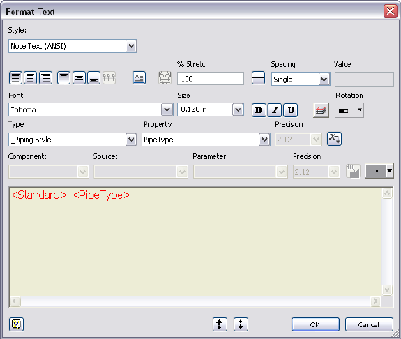
6Repeat this step to add more piping style properties to define the text
symbol. To separate properties, type the needed separator from the
keyboard before adding a new property.
In this exercise, you select the Standard and PipeType properties with a
separator as shown in the following image.
7Accept the other defaults and click OK.
A string of all selected piping style properties is previewed in the location
you clicked in Step 3.
8Right-click in the graphics window and select Done.
9Optionally, to edit the property set, move your cursor over the preview
string, right-click and select Edit Text.
10 Right-click again and select Save Sketched Symbol. Enter the name in the
Sketched Symbol dialog box and click Save. In this exercise, enter the
name Conduit_Standard_Type.
The new sketched symbol is added to the Model browser, Drawing
Resources, Sketched Symbol list. The drawing annotation environment
is activated.
Annotate Drawings with Piping Styles | 205
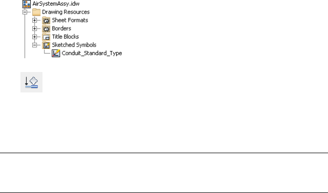
11 To place the symbol to annotate tube and pipe parts, click Annotate
tab ➤ Symbols panel ➤ User, pick the desired symbol, and then pick
an edge on a tube or pipe part.
12 Save the drawing document.
NOTE When placing symbols to annotate drawings, ensure that you pick an edge
on the conduit part or fitting while placing a custom piping style sketched symbol.
To end, right-click and select Continue. Right-click again and select Done.
206 | Chapter 9 Document Routes and Runs
Cable and Harness
Part 2 of this manual presents the getting started information for Cable and Harness in
Autodesk Inventor® Routed Systems. This add-in provides tools for creating and manipulating
three-dimensional wire harnesses in the context of a standard Autodesk Inventor® assembly.
207
208
Get Started with Cable and
Harness
This chapter provides basic information and exercises to help you get started with Cable and
Harness.
You also learn how to identify and label connection points on an electrical component and
set properties for the pins and the part.
About Cable and Harness
Cable and Harness provides tools for creating and manipulating
three-dimensional wire harnesses in a standard Autodesk Inventor® assembly.
Prerequisites
We assume that you have a working knowledge of the Autodesk Inventor
interface and tools. If you do not, use the integrated Help system for access to
online documentation including advanced topics, tutorials, and skill builders,
and complete the exercises in the Autodesk Inventor Getting Started manual.
At a minimum, we recommend that you understand how to:
■Use the assembly, part modeling, sketch, and drawing environments and
browsers.
■Place and constrain parts in an assembly.
■Edit a component in place.
■Create, constrain, and manipulate work points and work features.
10
209
■Create and annotate basic drawings.
■Set color styles and use the Style Editor.
■Use Content Center.
Be more productive with Autodesk® software. Get trained at an Autodesk
Authorized Training Center (ATC®) with hands-on, instructor-led classes to
help you get the most from your Autodesk products. Enhance your productivity
with proven training from over 1,400 ATC sites in more than 75 countries.
For more information about training centers, visit the online ATC locator at
www.autodesk.com/atc.
We also recommend that you have a working knowledge of Microsoft®
Windows NT® 4.0, Windows® 2000, Windows® XP, or Windows Vista® and
a working knowledge of concepts for setting up, connecting, and routing wires
through mechanical assembly designs.
Back Up Tutorial Data Files
For each exercise in this section, you use files that contain the example
geometry or parts for that task. These files are included in the Tutorial Files
directory for each application. For Cable and Harness, the files are located in
the Tutorial Files\Cable & Harness folder where you installed Autodesk Inventor.
Before you begin the exercises, back up the files so the originals are always
available. You can revert to these files if you make any mistakes during the
exercises, or if you would like to repeat an exercise.
Back up the tutorial files
1In the folder where Autodesk Inventor is installed, go to the Cable &
Harness directory and create a folder called Exercise_Backup.
The default installation location is:
Microsoft Windows XP operating system:
■Program Files\Autodesk\Inventor <version>\Tutorial Files\
Microsoft Vista operating system:
■Users\login-name\AppData\Local\Autodesk\Inventor <version>\Tutorial
Files\
210 | Chapter 10 Get Started with Cable and Harness

2Select the Cable & Harness folder and copy the exercise data into your
new folder.
Now you can use the tutorial files as you work through the exercises in this
book.
Keep any files you create for an exercise in the Tutorial Files\Cable & Harness
directory to avoid the possibility of file resolution problems.
Set Up Projects For Exercises
For the exercises, click ➤ Manage ➤ Projects and then browse
to and select the EnclosureAssembly.ipj as the active project. The default
installation location for this project is:
Microsoft Windows XP operating system:
■Program Files\Autodesk\Inventor <version>\Tutorial Files\Cable & Harness
Windows Vista operating system:
■Users\login-name\AppData\Local\Autodesk\Inventor <version>\Tutorial
Files\Cable & Harness
To add connectors from the Content Center, use the Configure Content Center
Libraries tool to configure libraries. Ensure that you have logged into the
Autodesk Vault server and the needed libraries are ready on the server. The
connector content is included in the Routed Systems library.
Help
The Help system provides information about every feature in Cable and Harness
as well as standard features.
1 To access Help, click the Help button in the InfoCenter above the
Ribbon. Then, click the Contents tab to display the table of contents if
it is not already displayed.
Set Up Projects For Exercises | 211
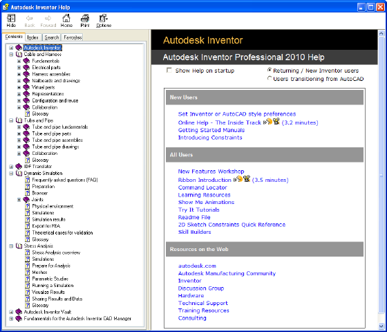
The Help home page provides quick access to various help components
such as: Skill Builders, Show Me animations, Advanced Productivity topics,
and Index and Search functions.
2Under the Contents tab, expand Cable and Harness to display and
examine the related Help topics.
Work in Autodesk Inventor Installations
If Cable & Harness is not installed on the system, viewing the harness data,
the harness subassembly, and the data it contains is read-only. The geometry
of the harness components is visible through Autodesk Inventor, but the
components cannot be edited, and new cable and harness components cannot
be added. However, you can edit electrical parts, and move pins, but electrical
part properties are not available.
212 | Chapter 10 Get Started with Cable and Harness
About Electrical Parts
Electrical parts are normal Autodesk Inventor parts or iParts with extended
properties and one or more defined connection points, known as pins.
Electrical parts are the only harness components that are not created in the
context of a harness assembly. Instead, electrical parts are created by editing
normal Autodesk Inventor parts. While editing the parts you identify the
special work points called pins, provide required properties, and optionally
add additional custom properties. You can define and edit the pins individually
or as a group. Once defined, the electrical part is placed in an assembly.
The part used can be fully modeled or a simple representation of the part, as
long as there is some geometry to designate the connection points, or pins.
For example, the part could be a simple plane with work points representing
the pins. For a group of pins, the part could be a simple plane with a single
point representing the start location for the group. These pins are the attach
points for the wires in the harness assembly.
You can also create, author, and publish your own connectors or place generic
connectors from the Cable and Harness ➤ Connectors category of the Content
Center.
Workflow for Electrical Parts
The harness workflow begins with electrical parts. The following are the basic
steps to create an electrical part and place it in an assembly.
Create an electrical part and place it in an assembly
1Edit an Autodesk Inventor part.
2Add individual or group pin definitions, each with a unique name and
additional properties, if appropriate.
3Optionally, author and publish the connector part to Content Center.
4Optionally, provide a placeholder reference designator (RefDes) or generic
value for that electrical part type in the part file.
Do it once for each electrical part.
5Place the part in an assembly.
6Assign the reference designator for an individual occurrence or group.
The reference designator for the individual occurrence or group is required
About Electrical Parts | 213
in each harness assembly that uses the electrical part, not once on each
part occurrence.
Create Electrical Parts
Use the Harness panel on the Model tab to add pins and the reference
designator placeholder. The reference designator and pins are specified while
editing the part file or editing the part in place. Pause the cursor over the
commands to view the tooltips.
Place Pins and Define Pin-level Properties
A connector can contain one or more pins. Valid geometry for pin selections
includes both associative and non associative points. The points you select
determine whether the pins are updated if the geometry to which they are
associated changes.
Non-associative points are arbitrary points on any face. They do not update
if the geometry changes. Associative points, which update as the geometry is
changed, include any one of the following:
■Existing work points
■Center points on any circular component such as a face, a hole, and
cylindrical cuts or arc edges
■Existing sketch points
■Model vertices
Each pin must have a unique name. By default, each individual pin name is
a sequential number starting with 1. For pin groups, you provide a prefix letter
and start number, and then select the naming scheme that you need. Each
pin name within a part must be unique. When the browser name changes for
an individual pin, the pin name updates. The reverse is also true. To change
naming for a pin group, delete the pin group and recreate it with the naming
you need.
In this exercise, you edit the part in place to add individual pins and a
placeholder reference designator to a part. For your convenience, the
connectors are already placed in the assembly.
Start by opening an assembly in the default project.
214 | Chapter 10 Get Started with Cable and Harness
Open the assembly
1Open Autodesk Inventor if it is not already open, and click
➤ Manage ➤ Projects.
2On the Projects dialog box, verify the Enclosure_Assembly.ipj project is the
active project, and then click Done.
If needed, browse to the project. The default location is:
Microsoft Windows XP operating system:
■Program Files\Autodesk\Inventor <version>\Tutorial Files\Cable & Harness
Windows Vista operating system:
■Users\login-name\AppData\Local\Autodesk\Inventor <version>\Tutorial
Files\Cable & Harness
3Click ➤ Open.
4Select the file named Enclosure_Assembly.iam and click Open.
The assembly looks like the following image.
Place Pins and Define Pin-level Properties | 215
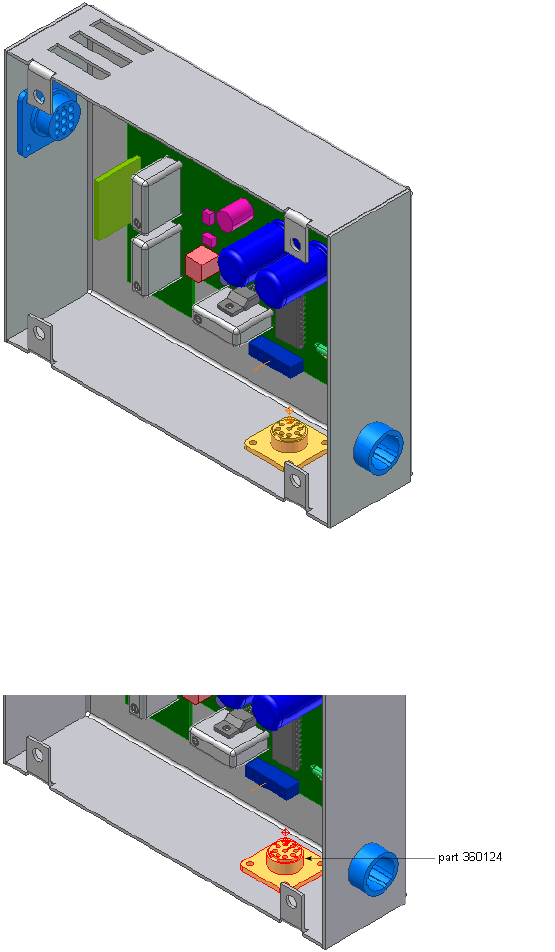
Add pins in the assembly
1In the browser, pause the cursor over the part named 360124.
The part highlights in the graphics window so that you can see the part
to edit.
2In the browser, double-click the part name to select the part for editing.
216 | Chapter 10 Get Started with Cable and Harness
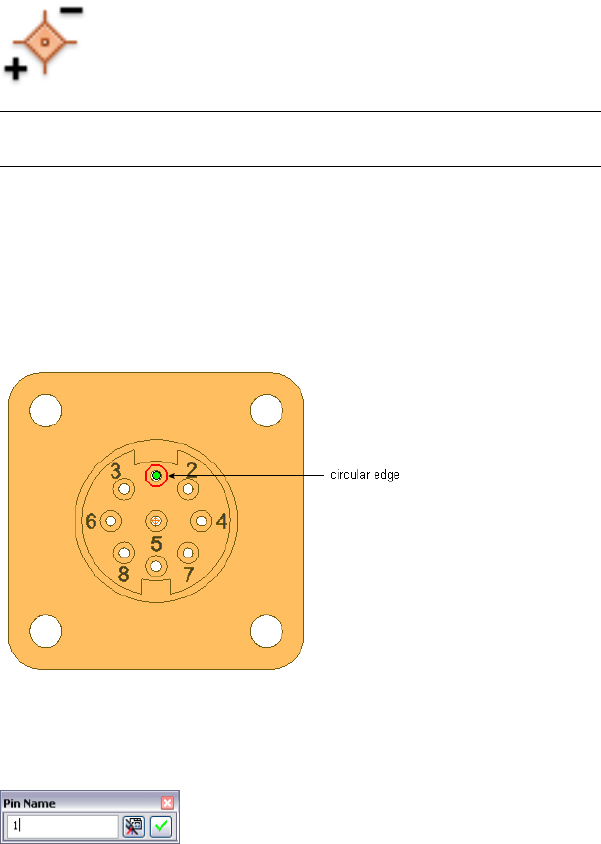
3In the Model browser, delete work points 1 through 9. You re-create these
points in the next steps.
4 On the ribbon, click Model tab ➤ Harness panel ➤ Pin.
NOTE If the Harness panel is not visible, right-click on the Ribbon, click Panels,
and select Harness.
5Rotate and zoom the view to see the part as shown in the following image.
Turn visibility off for any parts obstructing your view.
6In the graphics window, move the cursor over the part geometry to
highlight valid points for your selection.
7Highlight the circular edge shown, and then click to select the center
point.
8On the Pin Name dialog box, use the default pin name of 1.
9Click the Harness Properties button to display the entire Pin Properties
dialog box.
10 Click the Custom tab to see where custom properties are added.
For this exercise, do not add any additional properties for the pin.
Place Pins and Define Pin-level Properties | 217
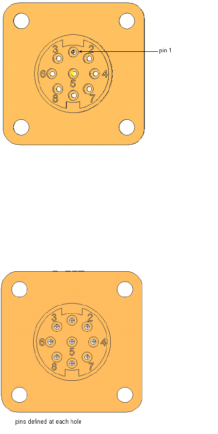
11 Click OK.
The work point representing the pin appears for pin 1.
12 Define a pin for hole 2:
■Highlight the circular edge.
■Accept the Pin Name of 2.
■Click the check mark button.
13 Repeat the steps to define a pin at each hole. Name the pins to match
their number label. For example, enter a Pin Name of 3 for the hole
labeled as 3, and so on.
14 Right-click, and then select Done to exit Place Pin mode.
218 | Chapter 10 Get Started with Cable and Harness
Note that each pin name within the selected part is unique. The pin name
specified is also the name of the special work point feature listed in the browser.
Set Part Properties
Specific property data must be added to a part to provide a complete electrical
definition. These properties are also visible on the part occurrence in the
assembly.
The part name and part number are automatically set based on the part file
name and the Autodesk Inventor part number. If appropriate, you can set a
value for the placeholder reference designator property.
The reference designator, or RefDes, is a unique identifier that maps the part
to the schematic design. Typically a placeholder identifier, such as U? is added
in the part environment, and then a specific identifier is added for each
occurrence of the part in the context of the assembly. For example, if a certain
RS232 connector occurs in an assembly multiple times, each occurrence must
have a unique identifier, such as U1, U2, and U3.
Additional custom properties can also be added to the part. Custom properties
provide specific information to downstream processes such as reporting.
Custom properties such as the vendor and vendor part number, often come
from the data book for the component.
To save time on data entry and reduce entry errors, consider creating a template
for electrical parts that contains placeholders for commonly used properties.
Add RefDes Placeholders
In this exercise, you add a placeholder RefDes to the electrical part.
Add a RefDes placeholder
1With nothing selected, select Model tab ➤ Harness panel ➤ Properties.
Alternatively, right-click the part in the browser, and then select Harness
Properties from the context menu.
2On the General tab of the Part properties dialog box, enter a reference
designator (RefDes). In this case, enter the placeholder U?.
3Click OK on the dialog box, and click OK on the message box if it appears.
If the message box does appear, select to not show the message box again.
Set Part Properties | 219
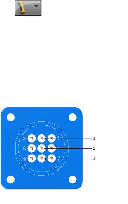
You also need to click OK on the dialog box again after the message box
closes.
4Click ➤ Save and click OK in the dialog box.
5Right-click and select Finish Edit.
In a later exercise, you set the RefDes value for the occurrences.
Practice Your Skills
Use the skills you just learned to add pins and a RefDes placeholder to the
other electrical parts.
1Edit the part 360575:1, and add pins at each hole. Name the pins to
match their number label.
2Add the reference designator U?.
3Right-click and select Finish Edit. Alternatively, click Return on the
Ribbon.
4In the browser, expand the PCB subassembly to locate and edit part LTP.
5Add the pins as shown. Pin 1 is the pin closest to part 360124.
220 | Chapter 10 Get Started with Cable and Harness
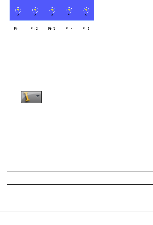
6Specify the reference designator J?.
7Right-click and select Finish Edit. Alternatively, click Return on the
Ribbon.
8In the browser, edit part 360575:2 and notice how this occurrence inherits
the pins set in 360575:1. You only need to pin the part once and all
occurrences inherit the pins.
9Return to the assembly.
10 Click ➤ Save and click OK.
Modify Pinned Parts
Once an electrical part is defined, you can modify it in several ways.
■Add or modify electrical properties on both the parts and pins.
■Modify pins or a pin group using standard Autodesk Inventor work point
operations (Ground, 3D Move/Rotate, Redefine Feature).
■Delete selected pins or a group of pins.
NOTE Any wires attached to a deleted pin dangle. To reattach a dangling wire
move the wire to another pin using Edit Wire from the context menu.
■Change the start location, orientation, and spacing of a group of pins.
■Rename individual pins.
NOTE Delete the pin group and make a new one to change naming or pin or
row number for a group.
When modifying pins using Redefine Feature, you create the geometry used
to define the individual pin or the start location for a group of pins. You can
Modify Pinned Parts | 221
place or project work points onto part faces, linear edges, or an arc or circle.
Work points can also be constrained to the center points of arcs, circles, and
ellipses.
To modify library parts ensure that you have edit and publish permission to
the Content Center.
Add Custom Properties to Parts
In this exercise, you add a custom property to a part. Each custom property
requires a data type. Each data type, except for text, has a default unit
associated with it.
Add custom properties to a part
1In-place edit part 360124.
2In the browser, select 360124:1, right-click, and then select Harness
Properties from the context menu.
3Click the Custom tab, and enter the values as follows:
Name: Vendor
Type: Text
Value: AMP
4Click the Add button, and then click OK.
The property is added to the list, and the dialog box is closed.
5Save the part file and return to the assembly.
6Repeat the steps to add the same Vendor properties to the electrical parts
LTP and 360575:1.
Place Electrical Parts
You place and constrain electrical parts in an assembly just as you place and
constrain standard Autodesk Inventor parts. Once placed, with a harness
assembly added, you set a specific reference designator for each occurrence of
that part in the context of each harness assembly.
Electrical parts can be placed anywhere below a harness assembly or parent
assembly. They can be placed outside of the harness assembly or demoted
into the harness assembly, depending on how you prefer to document the
222 | Chapter 10 Get Started with Cable and Harness
harness assembly. Connectors that already reside within subassemblies can
remain there.
If the connector is physically part of the harness, like a mating connector,
consider adding it directly to the appropriate harness assembly. An object
such as a terminal block that is not part of the harness, may not belong in
the harness assembly.
If reusing a top-level assembly that contains a harness assembly, we recommend
that you demote the electrical parts into the harness assembly. From within
Cable and Harness, use Save Copy As to copy the top-level assembly and its
contents (the harness assembly, other subassemblies, and so on) and reuse it
in another assembly.
In this assembly, the four electrical parts you created earlier were placed for
you. You set the reference designator for each part occurrence after the harness
assembly is added in the next chapter.
When placing and constraining mating connectors for a harness assembly,
remember the following information:
■When the connectors reside in the harness assembly, they can be
constrained to objects in the top-level assembly only while editing the
top-level assembly. The connectors cannot be constrained while in-place
editing the harness assembly.
■If you are unsure whether to place mating connectors as children of the
top-level assembly or in the harness assembly in your initial design, it is
good practice to place the connectors in the top-level assembly without
constraints. Using this method, you can demote the connectors into the
harness assembly before the harness is created without losing constraints.
Any RefDes information added to a connector at the time they are demoted
is lost and must be edited to reassign the RefDes in the harness. Any wires
or cables attached to connectors at the time they are demoted dangle and
must be edited to reassign the wires to the connector pins.
■Constraints placed in the harness assembly provide more flexibility for
individual components within the harness to adapt to assembly changes.
They do not adapt to changes as a rigid body. For example, with a top-level
assembly, if you constrain to a subassembly, all the parts in the subassembly
move as one rigid body. With a harness assembly, you can constrain all
connectors in the subassembly to different locations and they adapt
independently of one another. They do not move as a rigid body.
Place Electrical Parts | 223
224
Work With Harness
Assemblies
This chapter provides basic information about the tools added by the cable and harness
environment. It also tells how to create a harness assembly and set properties.
About Working in Harness Assemblies
The Cable and Harness software includes features for defining electrical parts,
inserting wires, cables, and ribbon cables from a library, routing wires through
segment paths, inserting splices, and attaching virtual parts. You can generate
reports for several common report types, or configure them to your specific
needs. The harness assembly information can also be represented in drawings
or nailboard drawings. It can also be saved to an .xml format.
With the cable and harness tools you can:
■Create or edit harness assembly files.
■Create electrical parts.
■Author and publish connector parts to the Content Center.
■Retrieve generic or published connector parts from the Content Center.
■Edit and retrieve harness object definitions from a library.
■Import electrical connectivity wire lists (including cable wires) using either
.csv or .xml file formats.
■Allocate space by defining possible wire, cable, and ribbon cable paths
through the assembly.
11
225

■Route wires and cables through harness segments and automatically
calculate lengths and bundle diameters.
■Configure and generate reports of the harness assembly.
■Insert and arrange splices, attach virtual parts, and make other
modifications to the harness design.
■Create accurate 2D harness documentation with intelligent properties and
dimensions that automatically update as the 3D design changes.
■Use the browser to organize and edit electrical parts, pins, wires, cables,
ribbon cables, splices, virtual parts, and segments. You can also change
visibility on all harness objects through the browser, except for virtual
parts.
■Optionally, copy and reuse the completed harness in another location.
WARNING Do not perform operations specific to Autodesk Inventor® on segments,
wires, cables, and ribbon cables. It can cause problems with operations in cable
and harness. For example, do not use Autodesk Inventor operations such as
extrusions, sweeps, and so on, to change harness objects.
Cable and Harness Environment
To access the Cable and Harness environment, you create or edit a harness
assembly. Features specific to Cable and Harness are available only in this
environment. Other features, such as a Nailboard, are only available once a
valid harness assembly is created.
Some of the features specific to the Cable and Harness environment include:
Panels and commands for the cable and harness envir-
onment.
Cable and Harness
tab
Contained in the Model browser, the Cable and Har-
ness browser items include the contents of one or more
Cable and Harness
browser items
harness assemblies in a hierarchy. The harness assem-
blies act as containers for all the objects created or
placed in that particular harness.
Switches between rendered and centerline display for
wires, segments, and ribbon cables.
Segment, wire, rib-
bon cable display
tools
226 | Chapter 11 Work With Harness Assemblies
Activated by editing normal Autodesk Inventor parts,
this panel contains the command set for creating
electrical parts.
Harness panel
Activated by editing normal Autodesk Inventor parts,
use this command to author connectors.
Connector command
Activated by selecting the Nailboard command from
the Cable and Harness tab. This tab contains the com-
Nailboard tab
mand set for manipulating and annotating a 2D repres-
entation of the 3D harness.
Use the Nailboard View command, in the standard
Drawing environment, to create a nailboard from an
open drawing.
Nailboard View com-
mand
Use the Connector View command to add connectors
to your nailboard drawing.
Connector View
command
Cable and Harness also adds electrical data types and units unique to the
electrical domain, and makes connectors available from the Content Center
Library.
Create Harness Assemblies
When an assembly file is first opened in Autodesk Inventor, the assembly
environment is displayed. To begin designing a harness in your assembly
model, create the harness assembly.
A standard Autodesk Inventor assembly can contain multiple harness
assemblies.
Workflow for Harness Components
The following are the basic steps to place and create harness objects such as
wires, cables, ribbon cables, and segments in an assembly:
Place and create harness objects
1Create electrical (pinned) parts, adding properties as needed.
2Open the Autodesk Inventor assembly file in which the harness will be
created or exists.
3Optionally, author and publish electrical parts to the Content Center.
4Place and constrain electrical parts in the assembly.
Create Harness Assemblies | 227

5Create the harness assembly.
6Insert wires, cables, and ribbon cables into the harness assembly, and
then add properties as needed.
7Create segments that define the possible wire and cable paths through
the assembly.
8Add properties to the segments as needed.
9Route wires and cables through selected segments.
10 Insert splices, add wire and cable points, add ribbon cable points and
folds, adjust ribbon cable twist, attach virtual parts, and make other
modifications to the harness.
11 Create a nailboard of the harness assembly and generate parts list and
bill of materials information.
To create the Harness assembly, click Assemble tab ➤ Begin panel ➤ Cable
and Harness.
Create Harness command
In the Create Harness dialog box, provide a unique name and location for the
harness subassembly. By default, the file is named <top level
assembly>.Harness<number>.iam (where number is a sequential number that
increments with each harness assembly) and is saved to the location of the
open assembly file, along with the corresponding harness part. You can provide
a different name and location if appropriate. You can also change the name
to something harness specific or descriptive.
Once you provide the name and location, the system adds a harness assembly
to the browser. It is added to the browser along with other placed components
and is arranged in the order it is added to the assembly. You can locate the
harness anywhere in the assembly hierarchy, except in another harness
assembly. For example, you can nest the harness assembly in another standard
Autodesk Inventor assembly, but not in another harness assembly. When you
edit a harness assembly, you can connect only to harness objects that share
the same parent assembly as that harness assembly.
In this exercise, you open an existing assembly and prepare to wire it. You
also become familiar with the features included in the cable and harness design
228 | Chapter 11 Work With Harness Assemblies
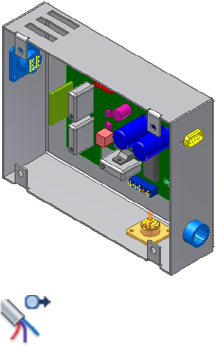
environment, including the tab, display tools, and browser. A ribbon cable
harness assembly was already added for you.
Create a harness assembly
1If not already open, navigate to and select the file Enclosure_Assembly.iam.
The assembly is displayed as shown.
2 On the ribbon, click Assemble tab ➤ Begin panel ➤ Cable and
Harness.
3On the Create Harness dialog box, enter the name for the harness
assembly as shown, and accept the default location (example is for
Windows® XP)
Harness Assembly File Name: Harness Assembly1.iam
Harness Assembly File Location: Program Files\Autodesk\Inventor
<version>\Cable & Harness\Tutorial Files\Enclosure_Assembly\AIP\Cable
and Harness
4Click OK.
The system adds the harness assembly to the browser and activates the
cable and harness environment. The following illustration shows the
Cable & Harness tab. Pause the cursor over the images to view the tooltips.
Workflow for Harness Components | 229
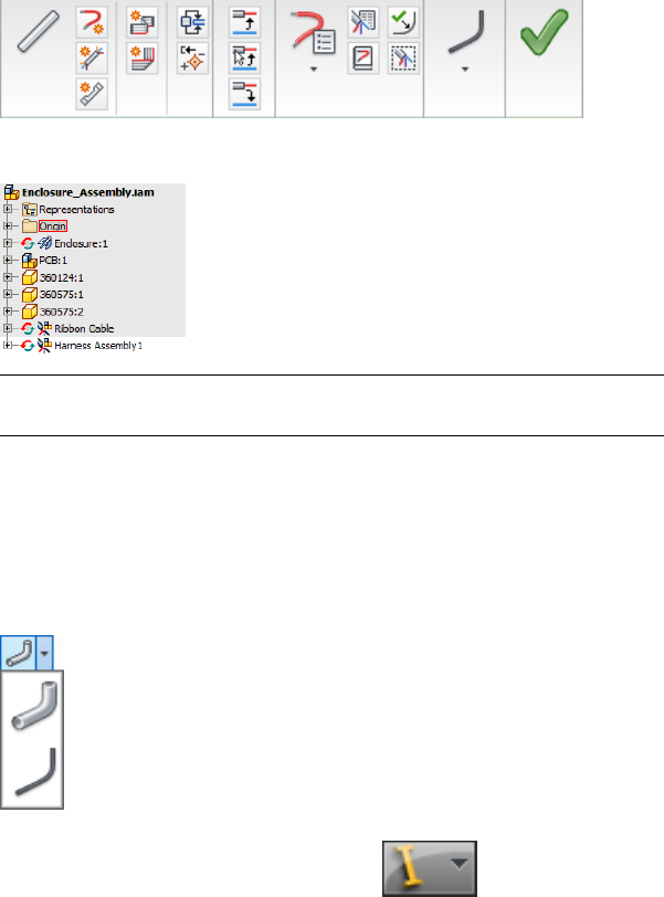
5Locate the new harness assembly in the browser hierarchy.
NOTE Clicking the Create Harness tool again adds a second harness assembly
after the existing one at the same level.
6Examine the Visibility panel of the Cable and Harness tab to see the
display settings for wires, cables, ribbon cables, and segments. Click the
arrow to display the list.
The display for these harness objects can be changed at any time. The
display for all objects of a selected type in a selected harness assembly
can also be changed.
7Activate the top-level assembly and click ➤ Save.
8Click OK.
The harness assembly is saved using the name and location indicated
previously.
230 | Chapter 11 Work With Harness Assemblies

Use the Cable and Harness Browser
All harness objects added to an assembly file are automatically contained in
the harness assembly. The objects include wires, cables, cable wires, ribbon
cables, segments, splices, virtual parts, and optionally electrical parts and pins.
Each harness assembly contains an Origin and a Representations folder and
a single harness part. Although harness assemblies respond to representations
in the parent assembly, they do not respond as expected to representations
created at the harness assembly. For best results, create representations at the
parent assembly level only.
The harness part contains one folder for each of the harness objects that make
up the harness. Each segment has a work point for every point used to shape
the segment. Ribbon cables contain work points and folds used to shape the
ribbon cable. The Virtual Parts folder contains a folder for each type of virtual
part in the harness.
NOTE Promoting a harness part from its parent assembly corrupts the cable and
harness data. In this case, close the assembly without saving. Demoting the harness
back to the subassembly does not fix the data.
Set Properties for Harness Components
Every harness component contains a set of properties. These properties are
used for the documentation you produce, such as reports and drawings.
Properties are also used to check specific aspects of the design, such as bend
radius and bundle diameters.
Properties are added at different levels within the assembly. They can be added
to the source component in the library as well as to any occurrences of that
component within the assembly.
When you create a harness object, some properties are required, such as the
Pin Name for an electrical part occurrence, or the Wire ID for a wire. You can
decide on which other properties to set.
The documentation you produce for downstream consumers drives the
properties you set. Some properties, such as length or adjusted length for a
harness segment are derived from the placement or settings of the related
component. These properties cannot be changed, but can be viewed and used
in the documentation.
You can set and view properties when the component is active in Cable and
Harness. Some properties can also be accessed from other objects. For example,
Use the Cable and Harness Browser | 231
from the Wire Properties dialog box, you can view and modify properties on
the parts and pins to which it is connected.
You can also use the property dialog boxes to add and remove virtual parts.
Search for “virtual parts” in the Help index for more details.
Customize Properties
The Custom tab of the Properties dialog box may contain predefined properties.
These properties are available in the property Name list, and have a preset
name and data type. You can add them to the object individually and set the
value.
If you need a property for a harness component that is not predefined by
Cable and Harness, you can create a custom property. To create a custom
property, you name the property and set its data type and value. Once the
property is fully defined, it is added to the property Name list on the Custom
tab. The property is also available in the Name list within the same part file
or harness assembly for use on other harness objects.
For more information about setting data types for custom properties, refer to
the Help.
Set Occurrence Properties
Harness objects have general properties that are stored in their source files,
and unique occurrence properties that are stored within the assembly in which
they are placed. Harness component occurrences get their properties from the
source component. For example, when an electrical (pinned) part is placed in
the harness assembly, its properties come from the part definition. When
specific properties are needed for an occurrence, you can override certain
component-level property values with an occurrence property value.
In the property list on the Custom tab, properties added to an occurrence are
represented with white backgrounds. Properties listed with a dark background
indicate a source-level property. For example, on the Wire Properties dialog
box, for an occurrence wire, the properties added at the library level are
displayed with a dark background.
232 | Chapter 11 Work With Harness Assemblies
Assign Occurrence Reference Designators
Now that the harness assembly is added, set a specific reference designator
for each electrical part occurrence.
NOTE Add occurrence properties to electrical parts only after they are in their
proper assembly location. Occurrence properties are lost when electrical parts are
promoted or demoted, and must be reassigned.
Set a reference designator for an electrical part occurrence
1In the browser, double-click Harness Assembly1, if not already active.
2Right-click the part name 360124, and then select Harness Properties
from the context menu.
NOTE You can select the parts, but the browser has a gray background.
3On the Part Properties dialog box, set a RefDes of U3 for the occurrence,
and then click OK.
4Repeat the steps to set a RefDes of U7 for part 360575:1.
5Set a RefDes of U8 for part 360575:2.
6In the browser, expand the PCB subassembly to locate part LTP, and then
set a RefDes of J12.
The generic placeholder RefDes for each part is overridden at the
occurrence level with the unique value. The RefDes on each part
occurrence is required.
NOTE Once the harness assembly is added, you can also assign terminals,
seals, and plugs to electrical part pins.
7Activate the top-level assembly and click ➤ Save.
8Click OK.
Assign Occurrence Reference Designators | 233
234
Use the Cable and Harness
Library
All harness objects in Cable & Harness come from a single library. In this chapter, you learn
how to navigate in the library and use the Cable and Harness Library tool.
About the Cable and Harness Library
The cable and harness library contains the list of standard library definitions
used to create occurrences in a harness assembly. It contains definitions for the
following types:
■Wire
■Cable
■Splice
■Raw ribbon cable
■Virtual parts: Label, Loom, Plug, Seal, Terminal, and custom types
These definitions do not have a physical representation, and exist only in the
cable and harness library file. You select occurrences from this library list to
insert them in the harness assembly.
You can use any standard definition in the library or add your own definitions.
You can also modify and remove existing definitions and add new object types.
To add a large number of definitions, import the harness objects using an import
file.
12
235

With the cable and harness library tools you can:
■Add new definitions and object types.
■Modify, copy, and delete existing definitions.
■Import and export definitions.
■Explore the harness objects in the list.
■View the basic properties for a selected harness object such as a wire or
cable.
■View the total number of a certain harness object type in the library.
NOTE If a cable and harness assembly that was created in Version 8 of Cable and
Harness is opened in the current version, the data format of the library must be
migrated to the current version which includes cables. Outdated wire definitions
must also be removed from the existing library. If needed, see “migration, Cable
and Harness Library” in the Help index for more details about migration options.
Locate the Cable and Harness Library File
The cable and harness library file contains all the library data. By default, the
file is named Cable&HarnessDefaultLibrary.iwl and is located in the Design
Data\Cable & Harness directory as set for the project. You can change this
location using the File Locations tab on the Harness Settings dialog box.
Typically, one cable and harness library file is created and stored on a server
for all harness assemblies to reference. If the Cable and Harness Library is
accessed by multiple users, it must be placed in a shared location. You can set
a different cable and harness library file and location for each harness assembly,
although only one is recommended.
The first person to open the Cable and Harness Library can add, edit, and
remove harness objects. All others attempting to access the Cable and Harness
Library, are notified that the library is being edited and it cannot be accessed.
In this case, the Cable and Harness library is read-only, but you can still insert
any harness object listed in the Cable and Harness Library into the harness
assembly. For all harness objects but cables and raw ribbon cables, the default
library definition is used when the cable and harness library cannot be found.
The default library definitions cannot be modified.
236 | Chapter 12 Use the Cable and Harness Library
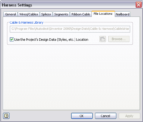
Each time you open the Cable and Harness Library, the system determines if
changes were made to the library data that require an update. If updates are
required, the changes are immediately available in the active harness assembly.
In this exercise, you access and view the name and location for the current
cable and harness library file.
View the location of the Cable&HarnessDefaultLibrary.iwl file
1In the browser, double-click Harness Assembly1, if not already active.
2In the browser, right-click Harness Assembly1, and then select Harness
Settings from the context menu.
3On the Harness Settings dialog box, click the File Locations tab.
This harness assembly references the default cable and harness library
file as set for the Design Data of the project. The default file and location
is:
Microsoft®Windows®XP operating system:
■Program Files\Autodesk\Inventor <version>\Design Data\Cable &
Harness\Cable&HarnessDefaultLibrary.iwl
Windows Vista®operating system:
■Users\Public\Documents\Autodesk\Inventor <version>\Design Data\Cable
& Harness\Cable&HarnessDefaultLibrary.iwl
Locate the Cable and Harness Library File | 237
NOTE Set the location for the Design Data of the project by clicking the
Tools tab ➤ Options panel ➤ Application Options ➤ File tab, and entering
the path under Design Data (Styles, etc.).
4To set the library file to a location other than the default location, clear
the Use the Project’s Design Data (Styles, etc.) Location and click the
Browse button to navigate to and select the file in the needed location.
NOTE To create a new, empty Cable and Harness Library, enter a new file
name. If a new name is entered, the cable and harness library file is created
in the specified directory.
5If the file location or name is changed, click Update , then click
Apply or OK on the dialog box to load the library.
6For this exercise, leave the library in the default location.
Display the Library Dialog Box
Click Cable and Harness tab ➤ Manage panel ➤ Library to display the Cable
& Harness Library dialog box.
Cable & Harness Library command
The following illustration shows the Cable & Harness Library dialog box with
the Wire object type and Default Library Wire selected.
238 | Chapter 12 Use the Cable and Harness Library
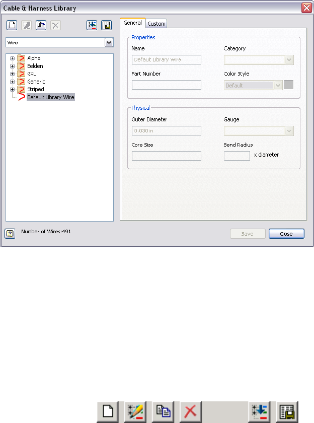
The features on the Cable & Harness Library dialog box include a drop-down
list that includes the harness object types available in the library. The data
and format displayed for each object type is similar. You select the object type
for the library data to view and use, and then features specific to that object
type are displayed.
The Cable & Harness Library includes:
The tool set for the library that you use to create, edit,
copy, and delete individual library wire or library cable
Cable and Harness
Library toolbar
definitions. Import and export functions are also
provided to bring library data in and out of the library.
Pause your cursor over the toolbar to view the tooltips.
Lists available harness object types. Click the arrow to
select from the list. The individual objects of that type
List of harness object
types
are displayed in the list of individual harness objects.
For User-defined harness objects, select Add New Type
and enter a unique type.
Display the Library Dialog Box | 239
Lists the contents of the cable and harness library. The
library contents include individual harness objects and
harness objects in specified categories.
Categories and list of
harness objects
The definition used by default when the associated
library cannot be found. This definition cannot be de-
Default library defini-
tions
leted or modified. There is no default cable or raw rib-
bon cable.
The total number of individual objects in the selected
library.
Number of harness
objects
Displays properties for the selected definition and the
category in which the selected object is organized. For
Object Properties tabs
example, displayed wire properties include color style,
part number, outer diameter, gauge, and core size.
Displayed cable properties include category, part
number, outer diameter, and number of wires.
Adding Library Definitions
You can add library definitions to the library individually or load multiple
definitions into the library at one time by importing from a spreadsheet or
other list.
Create New Library Definitions
To create new library definitions, specify the required properties. For example,
specify the wire name, color, and outer diameter for a new library wire
definition. Typically, these required properties are listed on the General tab.
If appropriate, organize new definitions into new or existing categories, assign
a part number, and add additional physical properties. Any number of custom
properties may also be added.
For example, the library Wire object type has two tabs:
Sets required, physical, and optional properties for new
definitions such as bend radius.
General
Sets new or edits existing custom properties. All custom
properties must have a data type.
Custom
The library Cable Wire dialog box includes a Wires tab in addition to the
General and Custom tabs listed previously:
240 | Chapter 12 Use the Cable and Harness Library

Lists the wires that make up the cable so you can
change the Conductor ID.
Wires
In this exercise, you create a library wire and label definition.
Create new library wire and library label definitions
1 With the Enclosure_Assembly.iam still open, and the harness
assembly active, click Cable and Harness tab ➤ Manage panel ➤ Library
.
2 On the Cable & Harness Library dialog box, ensure that Wire is the
selected object type, and then click the New tool.
3On the Library Wire dialog box, General tab, in Properties, specify:
Name: BLU_EE_22
Category: Alpha
Part Number: 60820
Color Style: Blue
4In Physical, enter the following values related to the physical parameters
of the wire:
Outer Diameter: 0.0540
Gauge: 22
5Leave Core Size and Bend Radius blank.
6You can click the Custom tab to add additional properties to the wire
definition, but it is not required for this exercise.
7Click Save to save the wire to the referenced library.
The BLU_EE_22 wire is added to the Alpha list, and is saved for use in
any harness assembly that references the library file.
8Click the arrow and select Label from the object type list.
9Click the New tool.
10 On the General tab under Properties, specify:
Name: Wire ID Label
Create New Library Definitions | 241

11 Accept all other settings under Properties and Physical.
12 Under Default Contents, click the arrow to select Wire ID from the
Property list, and then click Insert Property.
13 Click Save and do not close the dialog box.
Modify Library Wire and Cable Definitions
Using the object types, the listed categories, the lists of individual objects, and
the tools in the library, you can select harness objects to copy, modify, or
remove.
Copy Library Definitions
In this exercise, you copy a wire that you created.
Copy a library wire definition
1With the Cable & Harness Library dialog box still open, go to the list of
wires, and then select the BLU_EE_22 wire that you created.
2 Click the Copy tool.
A copy of the wire BLU_EE_22 is added to the wire list under the original
wire. The default name of the copied wire is BLU_EE_22 Copy. You can
make up to 9 copies of the same wire before renaming it.
Edit Library Definitions
You can edit any definition in the library except the Default Library definitions
such as the Default Library Wire or Default Library Loom. For all harness object
types, you can edit the general and custom properties. For cables, you can also
add and remove wires from the cable.
Edit a wire definition in the library
1 On the Cable & Harness Library dialog box, select the wire
BLU_EE_22_Copy in the list, and then click the Edit tool.
242 | Chapter 12 Use the Cable and Harness Library
As an alternative, you can right-click the wire in the list, and then select
Edit from the context menu.
2Change the settings as follows:
Name: BLU_EE_22A
Category: Generic
NOTE Invalid names, such as those that duplicate an existing name, are
indicated in red.
3Click Save.
The list of wires automatically updates to show the renamed wire in the
Generic category.
Delete Library Definitions
You can delete a library definition using the Cable & Harness Library dialog
box. If a harness object that is deleted from the library was already added to
a harness assembly, any occurrences of that object in the assembly are not
deleted. You cannot delete wires used by a cable.
NOTE If a wire or cable with the same name as the deleted one is added back
into the Cable and Harness Library before a harness assembly is opened, any
occurrences of the wire automatically update with the new definition the next
time the harness assembly is updated.
In this exercise, you delete the wire definition you added previously.
Delete a wire definition
1On the Cable & Harness Library dialog box, select the wire to delete:
BLU_EE_22A.
2 Click the Delete tool, and then click Yes to confirm the deletion.
Alternatively, you can right-click the wire, and then select Delete from
the context menu.
3Look at the list to verify that the wire was deleted.
Delete Library Definitions | 243

Add Properties to Library Definitions
Use the Edit tool from the Cable & Harness Library dialog box to view, add,
or modify library-level properties.
In this exercise, you add custom properties that further define a wire. Use a
color property to represent a textured wire. Although textured color styles are
supported, they cannot be viewed on wires displayed in the default centerline
display mode.
In this exercise, you select a single color wire, and then add the wire color as
a property.
Add custom properties to a wire
1On the Cable & Harness Library dialog box, expand the Generic category,
and then select the wire named 22AWG-GRN.
2Click the Edit tool.
3Click the Custom tab, and then enter two properties with the values
shown. Click Add after entering each property:
Name: Vendor
Type: Text
Value: 5876
Name: Volt
Type: Voltage
Value: 300V
4To modify the existing color property, click the property in the list, and
then enter the following values:
Name: Color
Type: Text
Value: Green/Yellow
NOTE In the Help index, go to “wires, striped” for complete directions on
creating a two-color, striped wire.
5Click Modify, and then click Save.
6Close the Cable & Harness Library dialog box.
244 | Chapter 12 Use the Cable and Harness Library

Import and Export Library Data
Cable and Harness Library data can be imported into the library, as well as
exported out of the library by specifying two files. A comma-separated value
(.csv) data file and a configuration file (.cfg) are used for both processes.
The configuration file describes the input parameters, their associated data
types, and corresponding units. The data file contains the library data, which
is a description of each harness object imported into or exported from a library.
A blank value is entered by using two consecutive list separators, such as two
consecutive commas. Only one list separator is required if the entry is the last
one in the row. If the color styles for a harness object are not defined, the
default color style is used. Refer to the Help for details on the format and
contents of these files.
NOTE You cannot update existing harness objects by importing library data.
Import into the Cable and Harness Library
The workflow for importing definitions into the Cable and Harness Library is
the same for all object types, except you must do the import with the
appropriate object type selected. The data provided in the files is also different
depending on the object you are importing.
Sample import configuration file for library wires:
libwires
C:\libwires.log
Wire Name,Color Style,Outer Diameter,Category,Part Number,Gauge
text,text,length,text,text,text
none,none,inch,none,none,none
Sample import configuration file for library cables:
libcables
C:\libcables.log
Cable Name,Category,Part Number,Outer Diameter,Conductor ID,Wire Name
text,text,text,length,text,text
none,none,none,inch,none,none
Import and Export Library Data | 245

Sample import configuration file for library seals:
libseal
C:\libvirtualparts-seals.log
Name,Category,Part Number,Min Outer Diameter,Max Outer Diameter,Diameter Type
text, text, text, thickness, thickness,text
none, none, none, inch, inch, none
Sample import configuration for library splice:
libsplice
C:\libsplice.log
Name, Category,PartNumber,Embedded Length, MyCustom
Splice_L, Size, SP_L_001, 0.3in, 1s
Splice_M, Size, SP_LM001, 0.32in, 12
Splice_LS Size, SP_S_001, 0.31in, 13
Sample import configuration file for library raw ribbon cables.
libribboncables
C:\librawribboncables.log
Name,Category, Part Number, Conductor One Color Style, Ribbon Body Color Style,
Number of Conductors,Pitch,Height,Width,Gauge,Core Size
text,text,text,text,text,text,length,length,length,text,length
none,none,none,none,none,none,inch,inch,inch,none,inch
For this exercise, you import wires. The configuration and data files were
already created for you.
Import wires into the library
1Ensure Harness Assembly1 is still active.
2On the Ribbon, click Cable and Harness tab ➤ Manage panel ➤ Library.
3Ensure that the Wire object type is selected.
4On the Cable & Harness Library dialog box toolbar, click Import Library
Objects .
246 | Chapter 12 Use the Cable and Harness Library

The Cable & Harness Library dialog box remains open during the import.
5On the Import Library Wires dialog box, click the Browse buttons to
navigate to the Tutorial Files\Cable & Harness\Wire Library folder where
you installed Autodesk Inventor, and then open the following files:
Data File (.csv): LibraryGXLWires.csv
Configuration File (.cfg): WireLibrary.cfg
NOTE The files listed previously use the comma delimiter, which is commonly
used in the United States to separate values. Other locales may use a
semi-colon. Versions of the files that use the semi-colon delimiter are also
provided. For this example use the listed files. Typically you use the file version
with the delimiter specified in the Microsoft Windows regional or language
settings for your locale.
6Click OK to add the wire data to the open library.
A dialog box appears indicating the status of the import and confirms
the name and location of the log file. The log file contains details of the
import, including updates to wires, and errors associated with the import.
7Click Close on the confirmation dialog box.
The Cable & Harness Library dialog box is updated with the GXL data
after the import.
8On the Cable & Harness Library dialog box, click Close.
Export Library Data
When exporting data from a library, you set the name and location for the
output file, and then the system writes the data to the comma-separated data
file as specified. The data file includes information for each wire or cable
contained in the library, and respects the locale-specific list separator for the
column delimiter. The configuration file specifies which properties to export.
All property values are exported using the unit preference settings. The same
data file (.csv) used for export (along with the corresponding configuration
file) can be used for import, which constitutes a complete round trip from
and to the library.
Export Library Data | 247

Export wire data from the library
1Ensure that the harness assembly is active and the Cable & Harness Library
dialog box still displayed.
2On the Cable & Harness Library dialog box toolbar, ensure that the Wire
object type is selected, then click Export Library Object .
3Enter the name and location for the Data File (.csv) that is output, or
select an existing file.
4On the Export Library Wires dialog box, select the needed Configuration
File (.cfg), WireLibrary.cfg.
5Click OK on the Export Library Wires dialog box.
6Click Close on the confirmation dialog box.
7Click Close on the Cable & Harness Library dialog box.
Practice Your Skills
For additional practice, you can:
■Create additional wires
■Copy a cable definition
■Delete a cable definition
■Add properties to a cable definition
Use the skills you just learned along with the following steps to create a library
cable definition.
Create a library cable definition
1Select the Cable object type on the Cable & Harness Library dialog box.
2Select the New tool.
3Click the General tab, and then enter a unique cable Name.
4Optionally, provide a Part Number and Category.
5Select the needed Outer Diameter setting:
■For a fixed diameter, clear the check box and enter a diameter value.
248 | Chapter 12 Use the Cable and Harness Library

■For a variable diameter, select the Calculate from Wires check box.
6Click the Wires tab, and then click Add to add wires to the cable
definition.
7On the Add Wires dialog box, select a wire from the list of library wires,
and then click Add. You must add at least one wire.
8Continue adding wires until all wires that make up the cable are added,
and then click OK.
9If appropriate, click the Custom tab and add additional properties to the
library cable definition, such as vendor and jacket color.
10 Click OK.
11 Click Save and then click Close.
NOTE The wires referred to by a cable definition must exist in the library before
they can be added to the cable. This requirement includes the library cable import.
The import file must reference existing wire definitions.
Practice Your Skills | 249
250
Work with Wires and
Cables
In this chapter, you learn how to add wires and cables to an assembly and modify them.
About Wires and Cables
Wires and cables are retrieved from the Cable and Harness Library and placed
in the assembly using manual or automatic methods. To insert wires manually,
you select the wire to insert, and then identify the two pins on the electrical
parts or splices. To insert cables manually, you select the cable to insert, and
then identify the pins for each wire in the cable. To insert multiple wires or
cables automatically, you import a wire list in .xml or .csv/.cfg format. When
using an .xml import file, you can also generate virtual parts and bring in
additional data such as properties.
To check for and correct missing RefDes information and to verify that the
required electrical parts are placed in the harness assembly before importing
the file, you can use the Review Harness Data tool from the Cable and Harness
tab.
Once the wires and cables are in the assembly you can diagnose and correct
certain data errors. You can also add points to control shape and edit, delete,
and move wires and cables, and replace wires. The system automatically
calculates lengths based on placement in the assembly. To help complete the
design, you can also add virtual parts, such as looms, to wires and cable wires
if needed. You can also add labels to wire pins and cable wire pins.
13
251
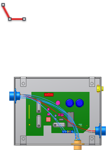
Set Modeling and Curvature Behavior
Before you begin creating harness objects such as wires and cables, you can
set several default configuration options for forward creation. The defaults are
set on the Harness Settings dialog box.
To view and examine the current settings
1Activate Harness Assembly1, right-click, and select Harness Settings.
2On the General tab examine the settings of interest, and then ensure the
Use Surfaces for All Segments and Wires is selected. It is the default.
Use this setting for faster processing times while creating and editing.
Clear the check box to use solids.
3Click the Wires/Cables tab and examine the settings of interest.
4 Under Natural Curvature click Without Natural Curvature .
■With Natural Curvature creates wires and cables that are tangent to
the outward direction assigned to the associated connector. Wires
and cables created with tangency are displayed in a more natural
shape that curves as the wires and cables approach the connector pins.
Including this natural curve makes the length of the cable more
realistic. It is the default.
■Without Natural Curvature creates wires and cables that are not
tangent to the outward direction assigned to the associated connector.
Wires and cables created without tangency are displayed as straight
lines that go from point-to-point.
252 | Chapter 13 Work with Wires and Cables
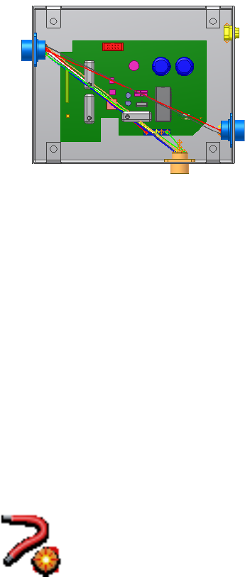
5Click the other tabs and examine the settings of interest.
6Click OK.
Insert Wires and Cables Manually
To insert individual wires or cables into an assembly, use the Create Wire or
Create Cable tool.
Insert Wires Manually
To insert wires, you provide a wire ID, select the wire to connect, and then
select the pins for each end of the wire.
Insert a wire manually
1In the browser, double-click Harness Assembly1, if it is not already active.
2 On the ribbon, click Cable and Harness tab ➤ Create panel
➤ Create Wire .
3On the Create Wire dialog box, accept the default Wire ID (Wire1).
The Wire ID is “Wire” plus an incremental number starting with 1.
4From the list of wires, select the wire to insert. Use the arrows to select
the following category and wire name from the lists.
Insert Wires and Cables Manually | 253
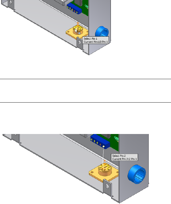
Category: Generic
Name: 22AWG-GRN
5Verify that the Pin 1 button is depressed. If it is not, click the button.
6In the graphics window, move the cursor over the pins in part 360124.
As you select points for a wire, the application displays tooltips and
dynamic prompts to instruct you on the next step. When the tooltip is
displayed as U3 Pin1, click the work point representing the start pin for
the wire.
The pin changes color when selected. The Pin 1 button changes from red
to white, and the Pin 2 button is activated (depressed).
NOTE To turn off dynamic prompts, click Tools tab ➤ Options panel ➤
Application Options ➤ General tab and clear the Show command prompting
(Dynamic Prompts) check box.
7Pause the cursor over the first pin on part LTP.
As you select the second pin for a wire, a preview wire is displayed along
with the tooltips and dynamic prompts.
254 | Chapter 13 Work with Wires and Cables
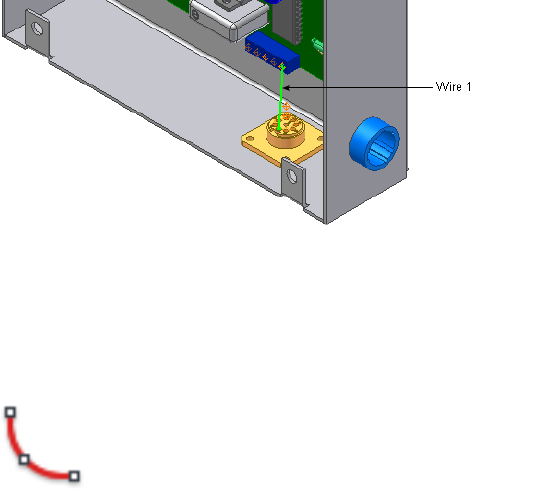
8When the tooltip is displayed as J12 Pin 1, click the point to select the
second pin.
9To create the wire, click Apply on the dialog box.
The wire is created as centerline or rendered, depending on the display
setting. Display is set to centerline for wires and cables by default.
10 While the dialog box is still open, click the Properties button to view the
properties for the library wire. Click OK.
The wire that is placed is an occurrence wire. The occurrence inherits the
properties from the library wire.
11 On the Create Wire dialog box, click Cancel.
12 Before adding the second wire, use the skills you learned
previously to change the natural curvature setting for wires and cables
back to With Natural Curvature .
13 For the wires to display natural curvature, the associated connectors must
be authored
Double-click 360124:1.
14 Click Manage tab ➤ Author panel ➤ Connector.
15 Click on the top face of 360124:1to define the outward normal direction.
16 Click OK to author the connector.
17 Click OK to close the message box. Return to the harness assembly.
18 You need to author the other connectors to display natural curvature.
Follow the steps to author connectors for LTP and 360575.
Insert Wires Manually | 255
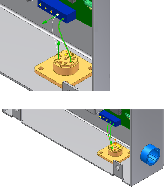
Note how natural curvature is displayed once you author the associated
connectors.
19 Add one more wire connecting U3 Pin 2 to J12 Pin 2.
As you select points for the wire, the application gives you visual feedback
on the outward direction for each point you select along with the preview
wire and prompt.
20 Right-click, and then select Apply from the context menu.
21 Click Cancel.
22 In the browser, right-click, and then select Finish Edit.
23 In the browser, expand the Harness Assembly1 part and the Wires folder
to view the added wires in the hierarchy.
24 Save your files.
256 | Chapter 13 Work with Wires and Cables

Insert Cables Manually
To insert cables, you provide a cable ID, select the cable to connect, and then
select the pins for each wire, or conductor, in the cable. The system
automatically advances through the cable wires in sequence, starting with the
first cable wire. If needed, you can also manually select the order in which to
connect the cable wires.
In this exercise, you add a second harness assembly so that the cable harness
can be documented in a separate nailboard drawing, and then you add the
cable wires.
Insert a cable manually
1Ensure that nothing is selected in the browser.
2On the ribbon, click Environments tab ➤ Begin panel ➤ Cable and
Harness, enter the name for the harness assembly and the location as
shown, and then click OK (example for Windows® XP):
Harness Assembly File Name: Harness Assembly2.iam
Harness Assembly File Location: Enter the path, or browse to Program
Files\ Autodesk\Inventor <version>\Tutorial Files\Cable &
Harness\Enclosure_Assembly\AIP\Cable & Harness
3Add the following reference designators for the connectors:
For part 360575:1 add RefDes U7
For part 360575:2 add RefDes U8
4 On the ribbon, click Cable and Harness tab ➤ Create panel
➤ Create Cable .
5On the Create Cable dialog box, accept the default Cable ID (Cable1).
By default, the Cable ID is “Cable” plus an incremental number starting
with 1.
6From the list of cables, select the cable to insert. Select the category and
cable name shown. Use the arrows to select from the list:
Category: Belden
Name: 8441
This cable contains two wires to connect in the assembly.
Insert Cables Manually | 257
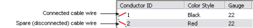
7Verify that the Pin 1 button is depressed. If it is not, click the button.
8By default, the first cable wire is automatically selected for connection.
If it is not, select the first cable wire in the list.
9In the graphics window, move the cursor over the pins in part 36575:2,
rotating as needed to see the part. When the tooltip is displayed as U8
Pin 1, click the work point.
Cable wires are automatically assigned Wire IDs as they are connected.
By default, the Wire ID is the Cable ID plus the Conductor ID.
10 Connect the other end of the cable wire to part 36575:1. When the tooltip
is displayed as U7 Pin 1, click the work point. The status of the cable wire
in the list changes to connected, and then the system automatically
advances to the next cable wire.
11 Connect the second cable wire from Pin 2 on part 36575:2 (tooltip U8
Pin 2) to Pin 2 on part 36575:1 (tooltip U7 Pin 2).
12 If appropriate, click the Properties button to view the properties for the
cable.
13 Click OK.
258 | Chapter 13 Work with Wires and Cables
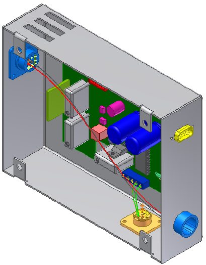
14 In the browser, expand the harness assembly and the Cables folder to
view the added cable and cable wires in the hierarchy.
In the browser, cable wires are named with the Cable ID followed by the
conductor ID, and the conductor ID in parentheses. Cable wire names
are changed by modifying the Wire ID in the Cable Wire Properties dialog
box. You cannot remove the conductor ID in parentheses.
Move Wires and Cables
From within a harness assembly, a wire or cable can have one or both of its
ends moved and reconnected to different pins. Both routed and unrouted
wires and cables can be changed.
A dangling wire can also be moved to reattach detached ends to existing pins.
Spare cable wires, cable wires that have no connections, can also be attached
to pins, including splice pins.
Move Wires and Cables | 259
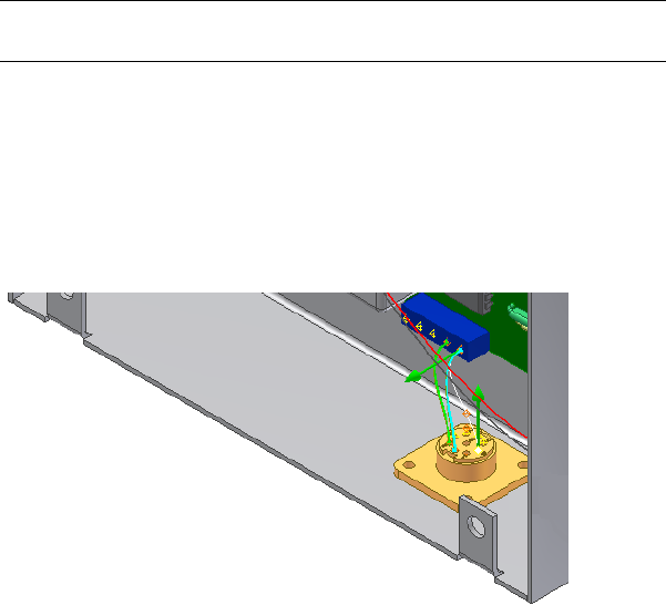
Move Wires
To move a wire, choose the wire to move, select Edit Wire from the context
menu, click the selection button representing the pin connection to change,
and then select the new pin connection. In this exercise, you move Pin 2 of
the wire you added previously to another pin on the same connector.
Move a wire
1Activate Harness Assembly1.
2In the browser or graphics window, right-click Wire1, and then select
Edit Wire from the context menu.
NOTE To select the pin in the graphics window, you may need to set the
Select tool to Select sketch features.
3On the Edit Wire dialog box, verify the Pin 1 button is selected.
4In the graphics window, move the cursor over the pins to preview the
wire connection possibilities before making a selection.
The preview wire is a straight white line drawn between the two pins.
5When the tooltip is displayed as U3 Pin 6, click the pin as shown in the
following illustration.
6To create the wire in the new location, right-click, and then select Apply
from the context menu.
The wire is redrawn using the new pin, and the wire length is updated
as needed.
260 | Chapter 13 Work with Wires and Cables
7Click Cancel.
Move Cables
Moving cables and wires is similar. To move a cable, however, you move the
wires it contains.
Workflow: Moving a cable
1Select the cable containing the cable wires to move.
2Select Edit Cable from the context menu.
3On the Edit Cable dialog box, click the wire to move.
4Click the selection button representing the pin connection to change.
5Select the new pin connection.
6Continue selecting cable wires and changing pin connections as needed
until the desired cable wires are moved.
7Click Cancel.
Delete Wires and Cables
Wires and cables you no longer need in your design can be deleted at any
time. Any virtual parts attached to the wire or cable are also deleted.
Move Cables | 261
Delete Wires
To remove a wire, select the wire to remove, and then delete it using the
context menu.
Delete a wire
1Activate Harness Assembly1, if not already active.
2In the browser or graphics window, select Wire2.
NOTE To select the wire in the graphics window, you may need to set the
Select tool to Select Sketch Features.
3Right-click and select Delete from the context menu.
The wire is deleted.
Remove Cables and Cable Wires
There are several ways you can remove cables from your design. You can:
■Delete an entire cable.
■Disconnect a selected cable wire from its current connection.
■Delete a selected cable wire from the cable definition.
Like wires, you can delete cables that are no longer used at any time. To delete
a cable, use the same workflow used for deleting wires.
To remove a cable wire from a cable, edit the cable definition in the Cable
and Harness Library and then delete the cable wire. Removing a cable wire
262 | Chapter 13 Work with Wires and Cables
from a cable definition does not remove the cable from the library. It does
remove the wire from any occurrences of that cable in the harness.
Wires that make up a cable can also be disconnected. You can disconnect a
wire to reterminate it to different pins, or to leave it as a spare. Disconnected
wires are also removed from the graphics window. Each time a cable wire is
disconnected, all properties on the cable wire are reset to the library-level
property values.
Disconnect a cable wire
1In the browser, activate Harness Assembly2, and then expand the harness
part to see the Cables folder.
2Expand the Cables folder and the Cable, and then select Cable1:1(1).
3Right-click and select Edit Cable.
4On the Edit Cable dialog box, select a cable wire to disconnect.
5Click Disconnect, and then click Apply.
Notice how the cable wire termination status updates, and the cable wire
is removed from the graphics window.
6Reconnect the wire to Pin 1 on both connectors as you did earlier, and
then click OK.
Replace Wires
To change or replace a wire definition, you select the wire to change, and then
select the new library wire definition. The wire is redrawn using the new
definition. The wire occurrence property values, including the Wire ID, remain
the same and the library-level wire properties are added to the occurrence wire
immediately.
Wire color changes take effect immediately. To see the effect of changes to
outer diameter values, click the Update tool.
Replace a wire
1Activate Harness Assembly1.
2In the browser or graphics window, select Wire1, right-click, and then
select Edit Wire.
Replace Wires | 263

NOTE To select the wire in the graphics window, you may need to set the
Select tool to Select sketch elements.
3On the Edit Wire dialog box select:
Category: Belden
Name: 9916-V10
4If necessary, click Properties to view the properties for the library wire.
5To redraw the wire using the new definition, click Apply, and then Cancel.
The wire in the graphics window is redrawn in violet.
6Return the wire to the original, green wire definition. On the Edit Wire
dialog box, select:
Category: Generic
Name: 22AWG-GRN
7Click OK.
NOTE Cables cannot be replaced. Delete them and add them again with
the appropriate cable chosen from the library list.
Assign Virtual Parts
You can assign virtual parts to various objects in a harness assembly using the
Assign Virtual Parts tool on the Cable and Harness tab. You can also assign
virtual parts to individual objects through the Property dialog box of an object.
You can use one of the virtual parts in the Cable and Harness Library, or you
can create and use your own. Refer to the Help for information on types of
virtual parts that may be assigned to various harness object types.
For this exercise, you assign the Wire ID label you created previously to a wire
pin.
Assign a label to a wire pin
1Activate Harness Assembly1, expand the harness part in the browser to
see the Wires folder.
2Right-click Pin 6 (6 RefDes U3) and select Wire Pin Properties from the
context menu.
264 | Chapter 13 Work with Wires and Cables

3On the Wire Pin Properties dialog box, click the Virtual Parts tab and set
the following:
Type: Label
Category: None
Name: Wire ID Label
4Click Add, and then OK.
Import Harness Data
Use Import Harness Data on the Cable and Harness tab to add (connect)
multiple wires or cables in the harness assembly automatically. You can create
these files yourself using a text editor or spreadsheet, or you can import this
data from other applications, such as AutoCAD® Electrical. You can import
The import many times with the same or different import files.
NOTE When importing from AutoCAD Electrical, refer to the Help for tips on
preparing your data for use in Cable and Harness.
Import Harness Data command
To import the wires and cables, select the import files to use. The import files
include a configuration (.cfg) file and a comma separated (.csv) data file or an
.xml file. The data in these files specifies the point-to-point connectivity of
each wire and cable wire. Ribbon cables cannot be included in import files.
The configuration file, which respects the locale-specific list separator, describes
the format of the input .csv data file. An .xml data file combines the
information provided in both the .cfg and .csv file. It can also include
information on properties and virtual parts that the .csv file cannot. Neither
format supports the import of a connector, splice, or pin.
Once the wires and cables are imported, the system indicates the status of the
import, displays the Imported Harness Data dialog box, and writes a log file
containing the details of the import.
The import checks for duplicates, missing, and changed wires or cable wires.
If a new wire or cable has the same ID as an existing one, it is not added. A
Import Harness Data | 265
warning message is displayed if the duplicate entry has different data or
connectivity.
To ensure that the import is not interrupted due to missing parts, use Review
Harness Data on the Cable and Harness tab to parse the harness data in a
harness data import file and generate a list of all the electrical parts defined
in that file. The list includes all connectors and splices and their defined
properties. An error condition icon is displayed for any electrical part that
does not have a RefDes in the assembly.
Use this list to check for and correct missing RefDes information and to verify
that the required electrical parts are placed in the harness assembly before
importing the file. Refer to the online Help for more details.
Once the harness data is imported, you can use the Imported Harness Data
dialog box to:
■View the imported data.
■Identify and correct any issues with the data.
■Add additional information to provide a complete definition.
Configuration File Formats
The configuration file must contain the following information to accommodate
both wires and cables. Previous file formats that contain only wires still work
for wire import. Cable occurrences must use the format listed:
Type of object contained in the input file. For cable
and wire occurrences, the object is cablesandwires. It
is not case sensitive.
OBJECT
The output log file path and name. For example,
C:\WireListImport\wirelist.log. If no path is listed, the
log file is created in the same directory as the .csv file.
LOGFILE
Specifies the order, data type, and units of the input
parameters. There must be a Wire ID, Cable ID, Library
HEADER1 (Property
Name)
Name, Conductor ID, REFDES1, Pin1, REFDES2, and
Pin2. The REFDES can be from splices or connectors.
The Cable and Conductor IDs are required only when
importing cable wires. The custom properties and re-
quired properties can be in any order, as long as the
minimum required subset is present.
266 | Chapter 13 Work with Wires and Cables

Specifies the data type associated with the property
name in the same column.
HEADER2 (Data
Type)
Specifies the unit of measure associated with the data
type in the same column.
HEADER3 (Unit)
The wire connectivity parameters in the comma-separated data file must have
the exact data types and units specified in the configuration file. Units must
be appropriate for the data type specified for the given property name.
See the Help for more details on data types and unit handling.
NOTE Configuration files are used for importing wire connectivity data and cable
and harness library data, and for producing reports. Each configuration file performs
a different task, and requires information specific to that task.
Comma Separated Value Data File Formats
Any number of wires or cables can be included in the comma-separated data
(.csv) file. The separator recognized in a .csv file is not always a comma. It is
determined by regional settings in Microsoft® Windows®. For example, in
another country the separator could be a semicolon.
For each cable and wire included in the file, the following information is
required:
A unique identifier for each wire.Wire ID
(Cables only.) A unique identifier for each cable. Leave
this column blank for wires.
Cable ID
A wire or cable name in the library.Library Name
(Cables only.) A unique identifier for each cable wire.
Leave this column blank for wires.
Conductor ID
A unique identifier for the first connector or splice oc-
currence.
REFDES1
A unique pin name on the first pin.PIN1
A unique identifier on the second connector or splice
occurrence.
REFDES2
A unique pin name on the second pin.PIN2
Additional wire or cable occurrence properties can be imported on an
object-by-object basis after the required input parameters. The corresponding
data type and unit for each custom property added must be listed in the
associated configuration file.
Comma Separated Value Data File Formats | 267

NOTE The electrical part RefDes value is only recognized by the Import Harness
Data function when it is set at the occurrence level. Any RefDes values set in the
part file are not used.
XML File Formats
An XML schema is used to describe the format of .xml files used to import and
export data for a harness. The schema describes most of the data model of the
Cable & Harness application for a single harness. Ribbon cables are not
included.
See the Help for more details on the .xml schema. In the Index, search for and
select XML files, and then select “Harness data XML file schema reference.”
Review Harness Data
Electrical parts and pins and their RefDes must exist in the assembly before
importing harness data. To ensure that the import is not interrupted due to
missing parts, use Review Electrical Parts from the Cable and Harness tab to
generate a list of all the electrical parts that are defined in the import file,
along with any missing RefDes information. An error condition icon is
displayed for any electrical part that does not have a RefDes in the assembly.
NOTE If file or format errors exist that prevent the file from importing, the Import
Harness Data message dialog box is displayed with a description of the issue. If
errors exist, but the file still imports, click View Log for details.
Ensure that electrical data is complete before import
1In the browser, double-click Harness Assembly1 as the assembly to receive
the imported wires.
2 With Harness Assembly1 still active, click the arrow beside
Import Harness Data and select Review Harness Data .
3Click Browse to locate and open the import files listed in the following
list. They are located in the Tutorial Files\Cable & Harness\Wire List Import
folder where you installed Autodesk Inventor.
Data File (.csv): WireListImport.csv
268 | Chapter 13 Work with Wires and Cables
Configuration File (.cfg): WireListConfiguration.cfg
4Click OK to review the data.
5On the Review Harness data dialog box, you see error-free information
on the three connectors.
NOTE If errors exist, use this list to correct the RefDes or other errors.
Import Harness Data
In this exercise, you import seven discrete wires into the harness assembly
using import files that were already created for you. The cable columns, cable
ID, and Conductor ID, are left blank. To view the file contents, open the file
in a text editor.
Import a wire list to a harness assembly
1 With Harness Assembly1 still active, click the arrow beside
Review Harness Data and select Import Harness Data .
2Click Browse to locate and open the import files listed in the following
list. They are located in the Tutorial Files\Cable & Harness\Wire List Import
folder where you installed Autodesk Inventor.
Data File (.csv): WireListImport.csv
Configuration File (.cfg): WireListConfiguration.cfg
3To add the wires to the active harness assembly, click OK.
The Imported Harness Data dialog box is displayed and lists the items
that were imported. For this example, there should be no errors. If errors
exist, you can right click the items in question for more information on
the issue and how to fix it.
4Optionally, expand the folders on the Import Harness Data dialog box
to view details on the import.
5Click OK.
Import Harness Data | 269
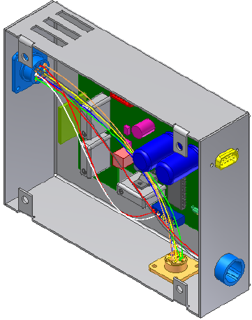
A message box displays the status of the import. The message indicates
that seven wires imported successfully. You can check the log file for
details on the import, including any associated errors or warnings.
6Click Close on the message dialog box. The wires are added to the harness
assembly.
7Exit Harness Assembly1 and save the files.
The following is an example of a wire list in the .csv format that contains both
wires and cables. There are three discrete wires and two cables:
//Wire ID,Cable ID,Library Name,Conductor ID,REFDES 1,Pin 1,REFDES 2,Pin 2
1001,CA1,Belden 4C 22AWG,1,J1,2,J5,6,
1002,CA1,Belden 4C 22AWG,2,J1,3,J5,7,
1003,CA1,Belden 4C 22AWG,3,J1,11,J5,8,
1004,CA1,Belden 4C 22AWG,4,J1,12,J5,9,
1005,,18 AWG BLU,J3,2,J6,1,,
1006,,18 AWG BLK,J3,3,J6,3,,
270 | Chapter 13 Work with Wires and Cables

1007,,18 AWG RED,J3,4,J6,2,,
1008,CA2,Belden 4C 22AWG1,J2,1,J8,3,,
1009,CA2,Belden 4C 22AWG2,J2,2,J8,4,,
1010,CA2,Belden 4C 22AWG3,J2,3,J8,5,,
1011,CA2,Belden 4C 22AWG4,J2,4,J8,6,,
Add Shape to Wires and Cable Wires
By default, a wire or cable wire is initially created with natural curvature
between the pins to which it is attached. If this curvature is not appropriate
or if the wires or cables wires were created without natural curvature, you can
control the shape by adding and adjusting wire work points on:
■Unrouted wires and cable wires
■Wire stubs and cable wire stubs
You cannot add work points to cables or spare cable wires.
NOTE Because all wire and cable wire work points are deleted when routed, we
recommend that you add work points only after routing the wire or cable wire for
the first time.
Once work points are added, you can adjust their location and offset value to
achieve the shape you need.
In the following exercises, you add points on a wire, adjust the points to
change the shape of the wire, and then delete them.
Add Wire Points
1Rotate the view until it looks like the following image.
Add Shape to Wires and Cable Wires | 271
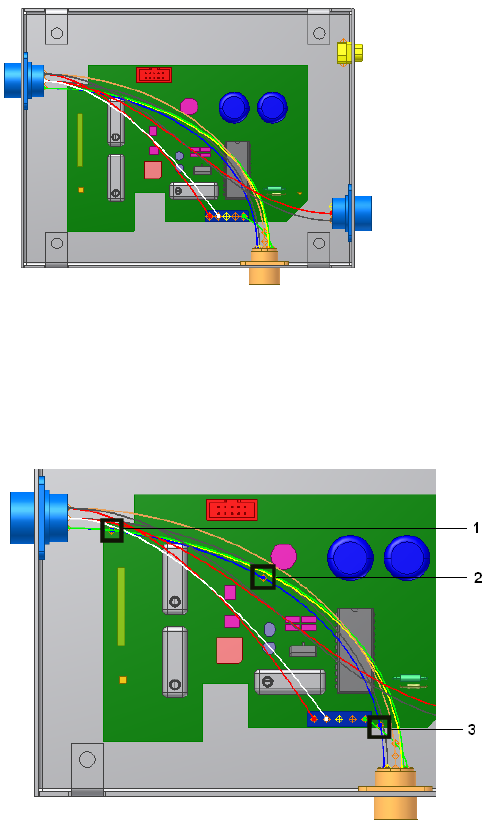
2Double-click Harness Assembly1.
3In the browser, right-click wire 2207, and then select Add Points on the
context menu.
4Move the cursor over the wire in the graphics window, and then click
the wire to create the three points in the order shown.
A grounded work point is created at each pick location, and the wire
recomputes, changing shape slightly after each point is added.
5Right-click and select Finish.
272 | Chapter 13 Work with Wires and Cables
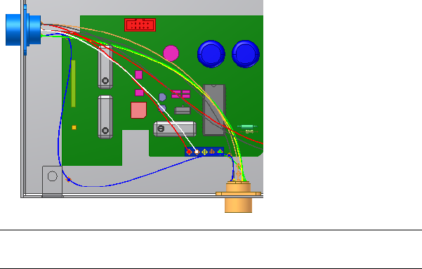
Redefine and Move Wire Points
Once the points are added you can redefine the points to an arbitrary location
or feature to achieve the shape you need. Wire points based on an arbitrary
point on a face are offset a specified distance and does not update to changes
in the model, including changes from positional representations. Like the
points used to define pins on parts, points based on existing geometry are not
offset and update to changes in the model.
You can also reposition wire work points dynamically or by precise coordinates
with the 3D Move/Rotate tool.
Manipulate wire points
1In the browser, expand wire 2207, right-click the second work point you
created and then select Redefine Point from the context menu.
2In the graphics window, pause the cursor near the tab on the enclosure
as shown. Notice the tooltip that shows the offset value for the point.
3In the graphics window, right-click (not on the point), select Edit Offset
from the context menu, and then enter .200 to change the offset.
4Click the point in the location shown to create a point that is offset from
the face of the enclosure. The wire recomputes.
NOTE To create a point that would update to changes in the model, click
the circular edge of the tab.
5If appropriate, rotate the view to see the increased offset.
Redefine and Move Wire Points | 273
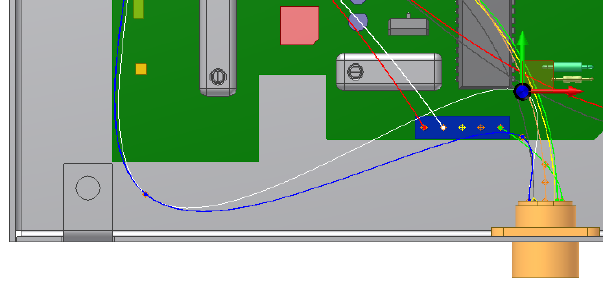
6In the browser or graphics window, right-click the third work point
created, and then select 3D Move/Rotate.
7Select or drag a triad segment to move the point to the location shown.
The position of the wire is previewed and any bend radius violations
noted before applying the move.
8Click OK and the wire recomputes to the new location.
Delete Wire Work Points
You can delete individual wire work points or all points at once.
1In the browser, right-click the first work point created, and then select
Delete Point on the context menu. The wire recomputes.
2To remove all points from the wire, right-click Wire 2207, and then select
Delete All Points on the context menu.
The wire returns to its original state and the length of the wire is
recomputed.
Set Occurrence Properties
Wire and cable occurrences inherit the general properties that were created
at the library level. Occurrence properties can be stored within the assembly
in which the wires and cables are placed. You can override certain library-level
property values with an occurrence property value.
274 | Chapter 13 Work with Wires and Cables

Wire Occurrence Properties
To access the Wire Properties dialog box, right-click on a wire and select
Harness Properties. The Wire Properties dialog box for wire occurrences has
several tabs.
Displays the Wire ID property that can be edited on
the occurrence. It also includes length information,
bend radius, and display options.
NOTE We recommend that you define the bend radius
at the library level so that it appears on all occurrences.
Occurrence
Lists properties related to the display of wires and any
attached looms. It also enables you to view and modify
the order of multiple, attached looms.
Display
Displays the library-level properties for the selected
wire occurrence. These properties cannot be edited at
the occurrence level.
General
Lists the RefDes and pin name for each end of the wire
and provides links to the properties for those pins and
connectors.
From/To
Enables you to add and remove looms and custom
virtual parts for the selected wire. It also lists any virtual
parts attached to the selected wire.
Virtual Parts
Lists and sets the custom properties for the selected
wire.
Custom
The Custom tab of the properties dialog box for wire occurrences contains
several predefined, or recommended, properties. These properties are available
in the property Name list and have a preset name and type. You can add them
to the occurrences individually and set the value. The recommended properties
for wire occurrences are:
Categorizes wires into types or categories for comparis-
on.
Separation Code
Categorizes wires and segments into class groupings
for comparison.
Class
The maximum allowable length for wire.Max Length
Wire Occurrence Properties | 275
Cable Occurrence Properties
To access the Cable Properties dialog box, right-click on a cable and select
Harness Properties. The Cable Properties dialog box for cable occurrences also
has four tabs.
Displays the Cable ID property that can be edited on
the occurrence. It also includes length, bend radius
information, and display options.
Occurrence
Displays the library-level properties for the selected
cable occurrence. These properties cannot be edited at
the occurrence level.
General
Lists the wires in the cable and enables you to connect
and disconnect cable wires from the cable.
Wires
Lists and sets the custom properties for the selected
cable.
Custom
The Custom tab of the properties dialog box for wire occurrences contains
several predefined, or recommended, properties. These properties are available
in the property Name list and have a preset name and type. You can add them
to the occurrences individually and set the value. The recommended properties
for cable occurrences are the same properties listed for wires.
Override Library-level Properties
In this exercise, you change the value of the custom Volt property for a wire.
Override a library-level property
1Double-click Harness Assembly1 if it is not already active.
2In the browser or graphics window, expand the Harness Assembly1 part
and the Wires folder.
3Right-click Wire1, and select Harness Properties on the context menu.
4Click the Custom tab. Notice that the custom properties added at the
library level are displayed with a dark background.
5Click the Volt property in the table.
6Select the property Value of 300 volts and change it to 200 volts.
7Click Modify to override the property in the table, and then click Apply.
276 | Chapter 13 Work with Wires and Cables
Restore Library-Level Properties
To restore a property value to its original library-level value, position the cursor
anywhere in the selected table row, right-click, and then select Restore.
In this exercise, you restore the library-level property value for the custom
Volt property with the value override.
Restore a library-level property value
1With the Wire Properties dialog box still open, click the Volt row in the
custom property table to select it.
Notice that the library-level property name, and value appear in the
bottom left of the dialog box.
2Right-click anywhere in the row, and then select Restore on the context
menu.
The wire library replaces the occurrence value with the library value.
3Click OK.
Change Wire and Cable Displays
Wires and cables can be displayed as either rendered or centerline. Centerline
display is the default and should be used for optimal performance while
creating and routing wires and cables.
If Rendered Display is selected, the harness object is drawn as a
three-dimensional shaded solid with the diameter as set in the library
definition, which is similar to the physical object appears. With centerline
display the objects are drawn as lines, making it easier to see and work on
existing model geometry.
Restore Library-Level Properties | 277
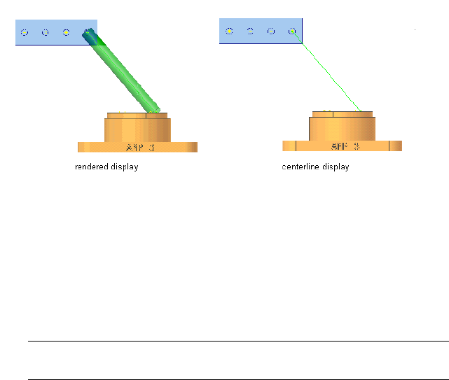
The rendered and centerline display options can be set for individual wires or
cables or for all wires or cables in a selected harness assembly as shown in the
exercise that follows.
Change the display for wires
1Double-click Harness Assembly1 if it is not already active.
2In the browser or graphics window, select any wire from the list of wires.
NOTE To select the wire in the graphics window, you may need to set the
Select tool to Select Sketch Features.
3Right-click and select Display as Rendered on the context menu.
4To change the display for all wires, select the Wires folder in the browser,
right-click, and select Display All as Rendered on the context menu.
All wires in the selected harness assembly are displayed as rendered.
5On the Cable and Harness tab, Visibility panel, select Centerline Display
to return the wires to the default centerline display mode.
278 | Chapter 13 Work with Wires and Cables

Work with Segments
Segments define virtual paths used for routing wires and cables through assemblies.
In this chapter, you learn how to define and manipulate a segment, how to branch a segment,
and how to change the segment display characteristics.
About Segments
Segments define the possible paths a wire or cable can take through an assembly.
Each click in the graphic window creates a work point on the segment. Work
points are used to manipulate the segment into its desired position and shape.
The segment is created with a default diameter, and is offset a specified distance
from selected geometry.
Once a path is defined, it can be modified in several ways, including inserting
splices or creating segment branches.
Define Segments
Use the Create Segment tool on the Cable and Harness tab to create a path for
routing wires and cables.
Create Segment command
To create a segment you define at least two points, a start point and an endpoint.
As you design, you can add additional segment work points where it is critical
for the segment to adapt to changes in the assembly, or to control the direction
14
279

of the segment around or through existing assembly geometry. Use as few
work points as possible, since additional work points slow performance and
make relocating work points more difficult.
NOTE You can also use segment points to assign labels and custom virtual parts.
For more precise placement of segment work points, define work features at
critical locations before inserting the segment. Work features, such as work
points and work axes, are especially useful for directing segments through
tie-downs, clips, or other geometry. Segment work points associated to work
features update when the model changes. They also react to positional
representations. Work features can also help create a more accurate approach
to the connectors, or direct the segment around geometry to avoid.
Feedback is provided throughout the creation process to highlight valid points
and show the offset for your selections.
Select Work Points for Segments
Like the points used to define pins and wire points, the points you select for
segments determine whether certain work points are updated when changes
are made to the associated geometry. Segment work points created by selecting
arbitrary points on a face are not updated to changes in the model geometry.
Segment work points based on the following geometry, do update when
changes are made:
■Existing work points
■Center points on any circular component such as a face, a hole, and
cylindrical cuts or arc edges
■Existing sketch points
■Model vertices
Select Undo or press ESC while creating a segment to remove the last segment
point created and end the create segment operation.
Plan Segment Start Points and Endpoints
When multiple segments exist in an assembly, the placement of the start and
endpoints of the segment in relation to the wire or cable connection points
is an important consideration. When automatically routing wires and cables,
280 | Chapter 14 Work with Segments
the system checks for the harness segment ends closest to each end of the
wire or cable, and then searches for the shortest path through the identified
contiguous segments. Whenever possible, place the harness segments so there
is no confusion as to which segment is closest to the connection points.
See Define Automatic Routes on page 299 for details about how the system
automatically routes wires and cables.
Apply Offset Distances
Arbitrary points selected on a face are offset a set distance from the selected
geometry. Segment points based on existing geometry are not offset. A segment
can require several different offset distances throughout its length. To adjust
the segment offset as you move through the assembly, right-click in the
graphics window, and select Edit Offset.
NOTE The offset distance is applied only while you create segments. It is not
applied when wires or cables are routed through the segment and cause the
update of the diameter.
Create Segments
You can define segment paths as close to the appropriate results as possible,
and then adjust them later. You can also develop them using work features
you set when planning the segment path.
In the following exercises, you define a harness segment between two circular
connectors and around the PCB board in the enclosure. You adjust the offset
while you work. You define a second harness segment between two circular
connectors and around the PCB board on the opposite side of the first segment.
A work point is defined to control the approach to the first connector.
Start a segment
1In the browser, double-click Harness Assembly1 if it is not already selected.
2 On the ribbon, click Cable and Harness tab ➤ Create panel
➤ Create Segment.
Apply Offset Distances | 281
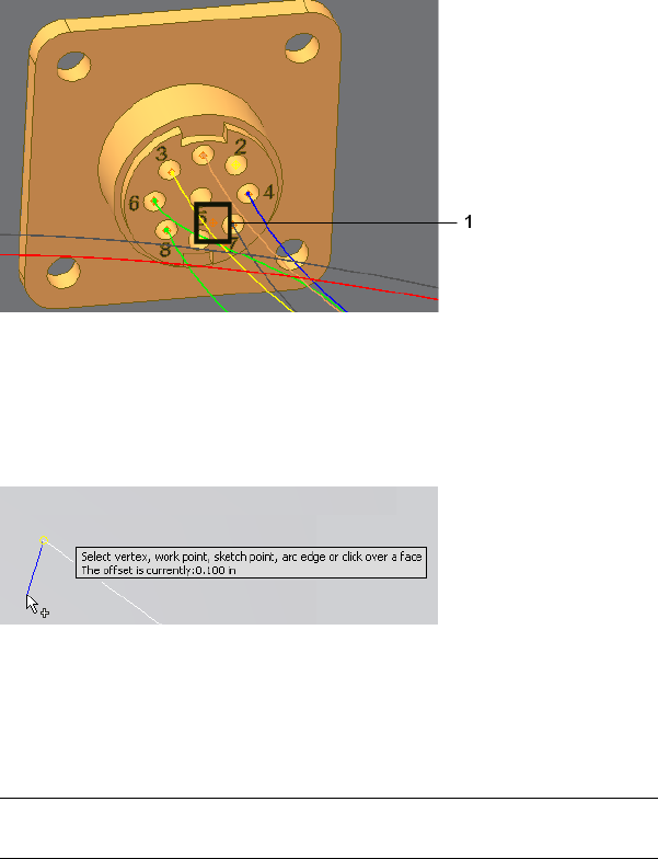
3In the graphics window, orient and zoom the view as shown in the
following illustration, and then select point 1.
A segment work point is created at the selected point.
4Move the cursor over the bottom of the enclosure until the tooltip and
offset symbol appear. The tooltip displays the offset value as 0.100 in,
and the symbol shows the actual offset distance as a guide for your
selections.
Close-up of offset symbol
5Before you select the second point, increase the offset to prepare for a
branch that is created in a later exercise. To increase the offset, right-click,
select Edit Offset from the context menu, and then enter 0.270.
NOTE Units are not required when entering offset values. If no unit is specified
the default unit setting is used.
6For the second point orient and zoom the view as shown, and then select
a point based on the bottom of the enclosure.
As you make your selections, a straight line appears from the selected
point to the current cursor position. The system draws the line between
the points as selections are made.
282 | Chapter 14 Work with Segments
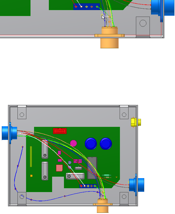
7Continue selecting points around the printed circuit board (PCB) and
toward the other connector to create the segment shape like the following
image.
The following image shows several additional point selections. Exact
placement of the work points is not important. You can adjust the work
points once the segment is complete.
8For the last point, pause the cursor over the connector face near the center
hole.
9Right-click, select Edit Offset, and then enter .200.
10 Click to select the point as shown in the illustration.
Create Segments | 283
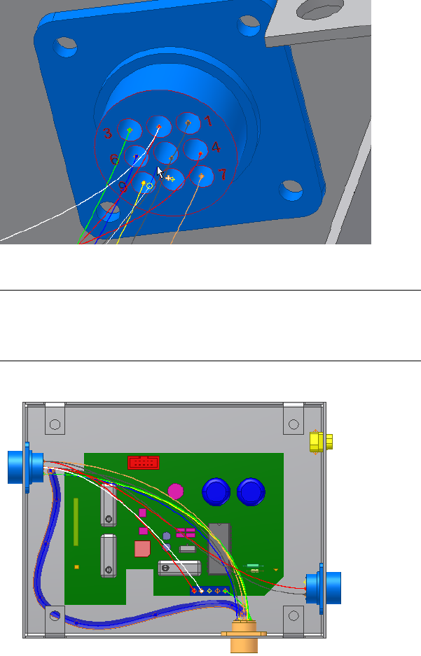
11 Right-click and select Finish to complete the segment.
NOTE If an error message is displayed and the sweep cannot be generated,
adjust the work points in areas of highest curvature to reduce the curve. See
Redefine or Move Segment Work Points on page 288 for details about adjusting
segment work points.
The system generates the segment, as shown in the following illustration.
12 Save the harness assembly.
284 | Chapter 14 Work with Segments
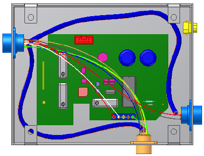
Start another segment
1Activate Harness Assembly2.
2Create a segment from connector 360575:2 to connector 360575:1
Click Cable and Harness tab ➤ Create panel ➤ Create Segment.
3Change the offset to 0.200.
4Click the face of connector 360575:2 near pin 5.
5Continue selecting points as shown to create a segment like the one
shown in the following illustration.
6Before you select the last point on the connector face, change the offset
to .270.
7Click the bottom of the connector face near pins 7 and 8.
The new segment is positioned like the following illustration.
Create Segments | 285
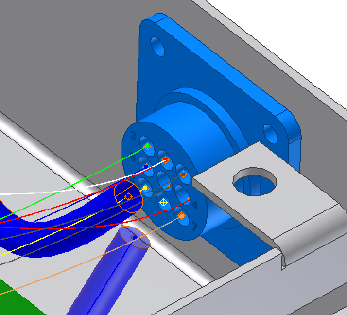
8Right-click and select Finish to complete the segment.
9Save the harness assembly.
Add Segment Branches
Segment branches are made by starting or ending a new segment on an existing
segment. Once completed, there are three segments sharing a common
endpoint. The original segment is broken into two separate segments. No
tangent constraint is formed between the branch and the two original
segments.
As wires and cables are routed, each of the three segments behave as separate
entities and can assume different diameters.
Add a segment branch
1In the browser, double-click Harness Assembly1.
2On the ribbon, click Cable and Harness tab ➤ Create panel ➤ Create
Segment.
3Pause the cursor over the harness segment to branch, and then click the
segment work point shown as the branch start point.
286 | Chapter 14 Work with Segments
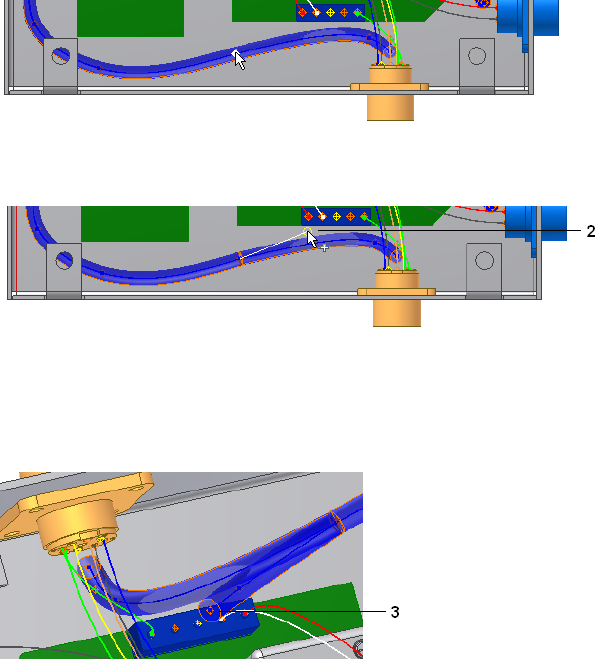
4Change the offset to 0.470, and then select one point (2) between the
segment and the LTP:1 connector.
5For the final point (3), change the offset to .270, and then select the face
of the connector LTP:1 near pin 3.
6Right-click and select Finish to complete the branch with a shape like
the one in the image.
Manipulate Segments
Once a segment path is defined, it can be modified in several ways. You can:
■Add additional work points.
■Delete work points.
■Move and redefine work points.
Manipulate Segments | 287

Redefine or Move Segment Work Points
You move and redefine segment work points just as you would move and
redefine other work points. To modify grounded and ungrounded work points,
right-click the work point in the browser or graphics window, select the
Redefine Point option, and then select the new location. The work point
becomes associative to new geometry that you select. Changes to the geometry
reposition the associated work point.
Grounded work points can also be modified using the 3D Move/Rotate option.
To use 3D Move/Rotate, select the 3D Move/Rotate option, and then drag the
work point to the desired location. The work point remains grounded.
For more information about working with work points in Autodesk Inventor®,
search for work points in the Help index.
NOTE When the location of a segment changes dramatically, delete the existing
segment and create a new one, rather than try to adjust existing segment work
points to accommodate the changes.
In this exercise, you use 3D Move/Rotate to adjust a work point for the segment
branch.
Move the work point
1To get a better view of your data, turn off the visibility for any geometry
obstructing your view.
You can create design views that include only the components necessary
to wire the assembly. Creating a view that shows only the harnesses or
a specific harness assembly can also be useful.
2Double-click Harness Assembly1 if it is not already active.
3In the graphics window, right-click the second branch work point (2) as
shown in the following illustration.
4Right-click and select 3D/Move Rotate from the context menu.
5Drag the point vertically until the preview looks similar to the following
shape, right-click, and select Apply.
288 | Chapter 14 Work with Segments
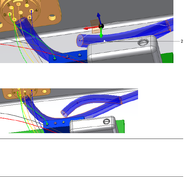
6Continue adjusting until you are satisfied with the shape, right-click, and
select OK.
NOTE Once a segment is created, you can select it in the browser, and then
select Bend Radius ➤ Check from the context menu to verify whether any
points along the segment violate the bend radius value. Make sure the bend
radius multiplier is set before checking the points. Select “bend radius, check”
in the Help index for more details on bend radius checking.
7Save the harness assembly.
Insert Segment Work Points
If the design changes so that you need more control over the segment shape
in certain areas, you can insert additional points.
Add a segment work point
1Double-click Harness Assembly1 to activate it in place, if it is not already
active.
2In the browser or graphics window, right-click Segment2, and then select
Add Points from the context menu.
3Pause the cursor over the area of the segment shown in the illustration.
Insert Segment Work Points | 289
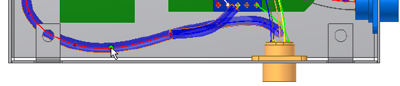
The path and work points highlight as you move the cursor over the
segment.
4Click the path to add the point.
The point is added and the segment recomputes.
5Right-click and select Finish.
Delete Harness Segment Work Points
To delete a work point from a harness segment, activate the harness assembly,
right-click the point to remove, and then select Delete Point from the context
menu. The point is removed and the segment recomputes. Any splice or virtual
part attached to a deleted segment point is also deleted.
If the point is a common endpoint of two segments, they merge into a single
segment. If the point is the common endpoint of three or more segments
(branches), no merging occurs. Instead, each segment has a unique work point
at its end, and can be manipulated independently.
Delete a work point from a single segment
1With the harness assembly still active, right-click the point you just added.
2Select Delete Point.
The point is removed and the segment recomputes.
Delete Harness Segments
Before you delete an entire segment, you can choose whether you want the
points from the deleted segment to remain on the wires that were routed
through it, thus keeping the shape of the segment after the segment is gone.
To keep the points, click the Wires/Cables tab on the Harness Settings dialog
box and click Inherit Segment Points on Segment Delete. Any virtual parts
attached to the segment are also deleted.
290 | Chapter 14 Work with Segments
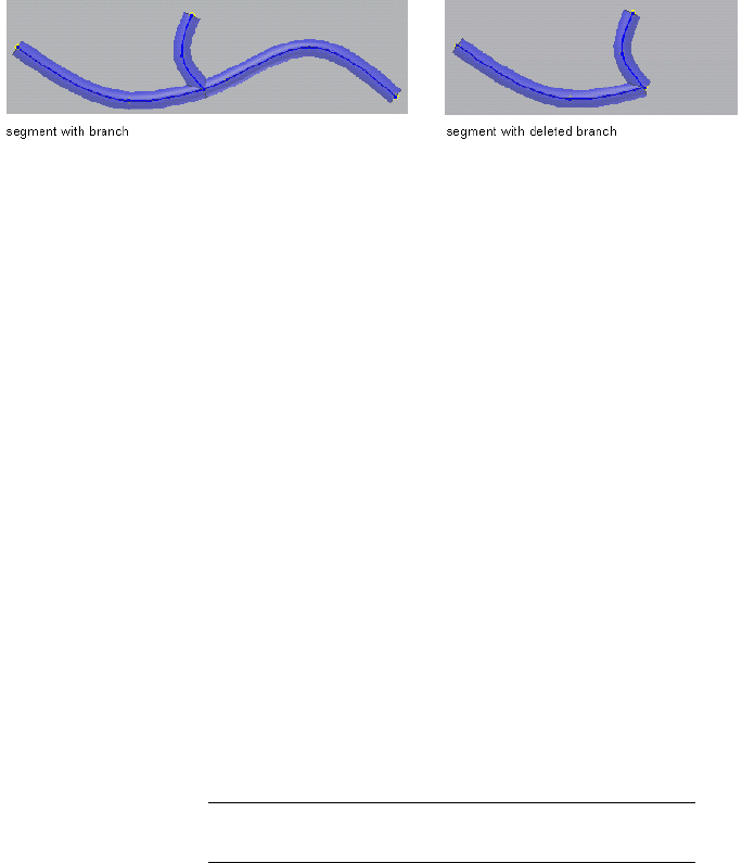
To delete a segment, select the segment from the browser or graphics window,
right-click and select Delete from the context menu. If the segment deleted
is a branch, the two remaining segments are not merged.
When a segment is deleted, any wires or cables routed through that segment
unroute from that segment only. If the wire or cable was routed through the
deleted segment only, the object returns to an unrouted state. If the wire or
cable was routed through more than one segment, then it remains routed
through the other segments.
Set Segment Properties
Like wires and cables, segments contain a set of properties that provide a
complete definition of the segment in the assembly. Unlike wires and cables,
segments do not exist in the context of a library and do not contain
library-level properties. They contain only occurrence-level properties.
The Segment Properties dialog box has five tabs.
Lists properties related to the physical aspects of the
segment, including segment display and bend radius.
Occurrence
Lists properties related to the display of segments and
any attached looms. It also enables you to view and
modify the order of multiple, attached looms.
Display
Lists properties for wires and cables routed through
the segment. Double-click any row to display the
Wires/Cables
properties dialog box for that wire or cable wire occur-
rence.
NOTE You can also attach virtual parts using the Assign
Virtual Parts tool on the Cable and Harness tab.
Use to add and remove looms and custom virtual parts
for the selected segment. It also lists any virtual parts
attached to the selected segment.
Virtual Parts
Lists custom properties added to the segment.Custom
Set Segment Properties | 291
On the custom tab there are several preset, or reserved, properties available
from the Name list. See the Help for details about these properties.
Access segment properties
1Double-click the harness assembly.
2In the browser or graphics window, right-click a segment, and then select
Harness Properties from the context menu.
3Click the various tabs to view and set the desired properties.
4Click the Virtual Parts tab to add and remove looms and custom virtual
parts.
5Click the Display tab to change order and color of multiple attached
looms.
For more details on virtual parts search for “virtual parts” in the Help
index.
Set Diameter Behavior in Segments
Segments can be configured as fixed diameter segments or as variable diameter
segments. Fixed diameter segments, such as semi-rigid tubing, do not change
as wires and cables are routed, unrouted, or deleted. The diameter of variable
segments is automatically updated as wires and cables are added or removed.
By default, segment diameters are updated automatically as wires and cables
are routed, unrouted, or deleted from the segment.
Change the segment diameter behavior workflow
1Double-click the harness assembly containing the segments to change.
2In the browser or graphics window, right-click the segment to change,
and then select Harness Properties from the context menu.
3On the Occurrence tab of the Segment Properties dialog box, select the
appropriate diameter setting.
■For a variable diameter, select the Calculate Size from Wires check
box.
■For a fixed diameter, clear the check box and enter a diameter value.
4Click OK.
292 | Chapter 14 Work with Segments

The segments are updated accordingly.
Change Displays of Segments
Segments can be displayed as rendered or centerlines. Rendered display
provides a three-dimensional appearance, while centerline display provides
an unobstructed view of the work points and path.
Like wires, the display options can be set for individual segments or for all
segments in a selected harness assembly. The display preference can be set in
different ways, either with the context menu for the segment occurrence or
the Segments folder, the Segment Properties dialog box, or the Display Settings
tool on the Cable and Harness tab. The occurrence level display settings always
override the current display state.
Change the display for a selected segment
1Double-click Harness Assembly1 if it is not already active.
2In the browser or graphics window, right-click a segment and select
Harness Properties.
3 On the Segment Properties dialog box, Display tab, click the tool
for the Centerline display option.
4To change the display setting for all segments, select the Segments folder
in the browser, right-click, and select Display All As Rendered from the
context menu.
You can also change the display of a single segment by selecting the
Display As Rendered option from the Display Settings tool on the Visibility
panel of the Cable and Harness tab or by right-clicking a segment and
selecting Display As Rendered from the context menu.
Set Segment Defaults
Several default settings are available for harness segments. With Harness
Assembly1 still active, do the following:
Change Displays of Segments | 293

Set the segment defaults
1In the browser, right-click the harness assembly, and then select Harness
Settings from the context menu.
2On the Occurrence tab of the Segment Properties dialog box, set the
diameter behavior.
3If appropriate, set a bend radius value.
NOTE The bend radius multiplier must be set for the bend radius check to
operate.
4Set the segment color.
5Select the display setting, including the color style for any assigned looms.
These settings are used when creating segments.
6Set the distance to offset segment work points from the selected face
during selection.
7Click OK.
294 | Chapter 14 Work with Segments
Route Wires and Cables
When wires and cables are routed, they are inserted into selected segments using manual,
automatic, or semi-automatic methods. Unrouting wires and cables removes them from the
selected segments.
In this chapter, you learn how to use the different routing and unrouting methods.
About Routing and Unrouting
By default, when wires and cables are routed, or placed into segments, the wire
and cable lengths and segment diameters are automatically calculated. All work
points on a wire or cable wire are deleted when routed from a point-to-point
state. Wire and cable lengths and segment diameters are also calculated
automatically when unrouting or removing wires and cables from segments.
When routing and unrouting individual wires, each wire is independent and
can take a different path through the assembly. When routing and unrouting
cables all cable wires that make up the cable must follow the same path. If a
change is made to the routing or unrouting of one cable wire, all associated
cable wires also change.
Wires and cables can be routed only into segments that are in the active harness
assembly. To route wires and cables, you can use one of three methods:
Inserts individual wires and cables into selected segments
one at a time. Segments can be discontinuous.
manual
Inserts selected wires and cables into continuous seg-
ments.
semi-automatic
Automatically inserts all unrouted wires or cables into
the segment that is closest to the wire connect points
(pins) and also represents the shortest path.
automatic
15
295
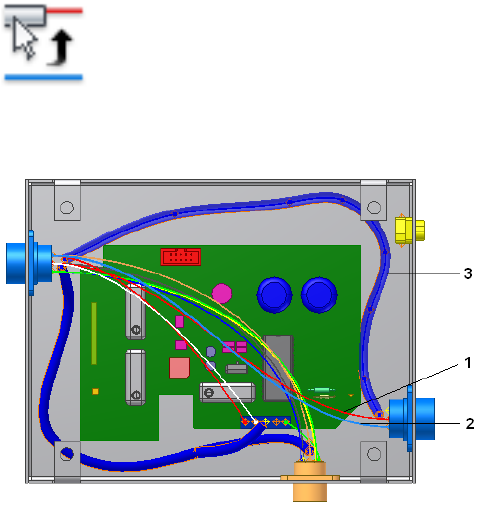
When routing or unrouting you can select the object to use before opening
the dialog box, or you can select the objects using the dialog box tools.
Define Manual Routes
Use the Route tool to route individual wires or cables manually into a single
segment. The segments can be discontinuous and can be used for incremental
routing to create networks with gaps.
The workflow for manually routing cables and wires is the same. The difference
is that when you select a wire, it is routed independently of all other wires.
When you select a single cable wire, all cable wires associated with the same
cable are routed and unrouted together.
Route a Belden cable into a single segment
1Activate Harness Assembly2.
2 On the ribbon, click Cable and Harness tab ➤ Route panel
➤ Route.
3In the graphics window, select a cable wire (1 or 2) to route.
4Select the Single Segment check box.
296 | Chapter 15 Route Wires and Cables
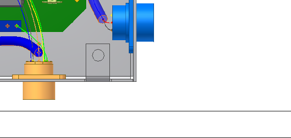
5Select the First Segment button, select the segment (3) in the graphics
window as shown previously, and then click OK.
Both cable wires are routed at once, and the cable lengths and bundle
diameters are updated automatically.
NOTE All cable wires are routed or unrouted together and must take the
same path (routed through the same segments) in the harness assembly.
6Save the harness assembly.
Define Semi-automatic Routes
When creating a semi-automatic route, use the Route tool to select one or
more wires or cables, and the first and last segment within the desired network.
The system looks for the shortest continuous path connecting the two
segments.
If more than one path exists between the two segments selected, a dialog box
is displayed for you to cycle through the possibilities, from shortest to longest.
The corresponding paths are highlighted in the graphics window.
Route Wires
In this exercise, you select a wire and route it manually.
Route a wire into multiple segments
1Double-click Harness Assembly1 if it is not already active.
2Click Cable and Harness tab ➤ Route panel ➤ Route.
3On the Route Wires dialog box, verify that the Wires button is selected.
Define Semi-automatic Routes | 297
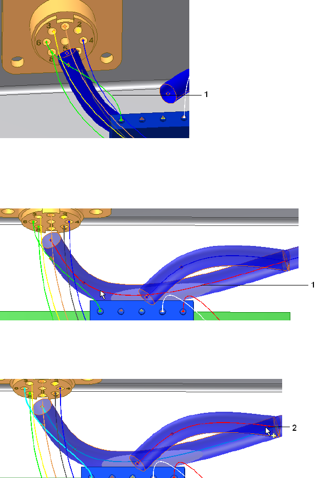
4In the graphics window, click the wire (1) as shown in the illustration.
In the browser, this wire is named Wire1.
On the Route Wires dialog box, the Wires button changes from red to
white to indicate that the wire selection is complete.
5Click the First Segment button, and then click the first segment (1) as
shown in the following illustration.
The First Segment button changes color, and the Last Segment button is
depressed.
6In the graphics window, click the branch segment (2), and then click OK.
298 | Chapter 15 Route Wires and Cables
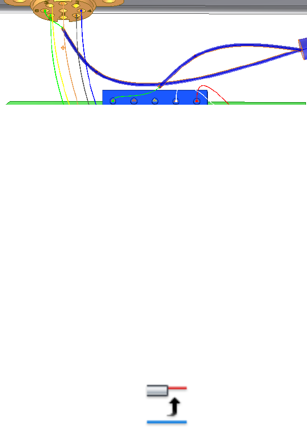
The wire is routed into the main segment and out the branch. The
segment diameter and wire length are calculated automatically.
Define Automatic Routes
You can route all unrouted wires and cable automatically, or you can route
selected wires and cables. When automatically routing, the system checks for
the harness segment ends closest to each end of the object being routed. When
the segment ends are identified, the system examines all segments found, and
then looks for the shortest path. After finding the shortest path, the objects
are routed.
If the harness segment endpoints found are within 0.005 meters of one
another, they are considered to be the same distance. If there is no connection
between any of the identified start and end segment points, such as when the
endpoints identified are from different harness segments, or when the same
segment point is identified for both the start and endpoints, the route fails.
In this case, you can route the objects using manual methods.
In this exercise, you route any remaining unrouted wires and cable wires into
the segments.
Automatically route all wires and cable wires
1With Harness Assembly1 still active, click Cable and Harness tab ➤
Route panel ➤ Automatic Route .
2On the Automatic Route dialog box, select All Unrouted Wires.
The dialog box indicates that there are seven unrouted wires selected for
routing.
Define Automatic Routes | 299
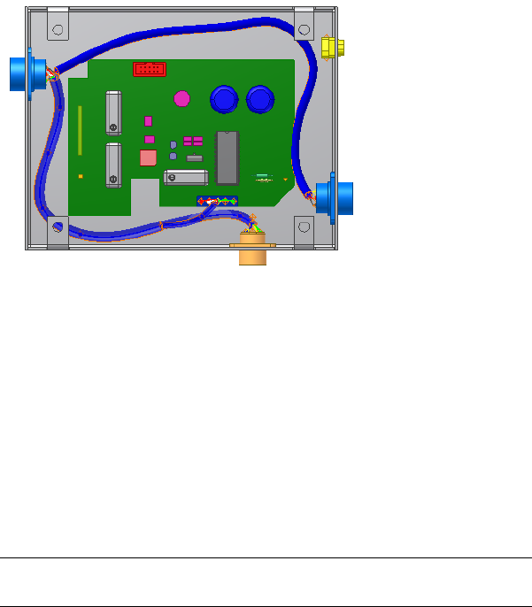
3Click OK.
The remaining wires are routed into the segments, and the dialog box is
closed.
View Wire and Cable Paths
As a result of routing and unrouting wires and cables in a complex assembly,
the path a wire or cable takes is not always easy to see. To highlight all of the
segments a routed object passes through, select View Path from the context
menu.
View a wire path
1With Harness Assembly1 still active, select Wire1. You can select the wire
from the graphics window or browser.
NOTE To select the wires from the graphics window, set the Select tool to
Select Sketch Features.
2With the wire selected, right-click and select View Path from the context
menu.
The wire stub (the exposed portions of the wires from the end segment
to the pin), and the path of the segment the wire passes through are
highlighted in the graphics window.
300 | Chapter 15 Route Wires and Cables

Unroute
Using a combination of tools on the Unroute Wires dialog box, there are
several options for unrouting wires and cables. You can unroute:
■Selected wires or cables from all segments (default)
■Selected wires or cables from selected segments
■All wires or cables from all segments
When wires or cables are unrouted from the specified segments, the wires
behave as if the segment was deleted, and return to their point-to-point
connection position.
All work points on wires or cable wires are deleted when the wires are unrouted
from all segments. The work points remain when a wire or cable wire is
unrouted from selected segments only.
When the last object is unrouted from a segment that is set to calculate size
from wires (including cable wires), the segment diameter does not change
from the diameter it had with that last object in it. The current segment is
not resized when all wires and cables are unrouted at once.
Rather than unroute an object entirely, it is often necessary to unroute it from
one or more individual segments. In the following exercises you unroute a
selected wire, and then unroute all remaining wires. You also unroute a cable.
Unroute Wires
Individual, or discrete, wires are unrouted independent of one another.
Unroute selected wires from selected segments
1With Harness Assembly1 active, click Cable and Harness tab ➤ Route
panel ➤ Unroute .
2Verify the All Wires check box is not selected. In the graphics window,
select Wire1 (1) as the wire to unroute.
Unroute | 301
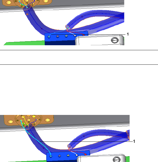
NOTE To select the wires in the graphics window, set the Select tool to Select
Sketch features.
The Wires button changes color and the Segments button is depressed.
3Clear the All Segments check box.
4In the graphics window, click the segment closest to connector 360124.
5Click the segment branch, and then click OK.
Wire1 (1) returns to its unrouted state.
Unroute Cables
To unroute a cable, you select a single cable wire, and then all cable wires
associated to the same cable are unrouted together.
1Activate Harness Assembly2.
2Click Cable and Harness tab ➤ Route panel ➤ Unroute, if the Unroute
dialog box is not already open.
3Verify the All Wires and All segments check boxes are cleared.
4Make sure that the Wires button is selected, and then in the graphics
window, select the black cable wire (1), as the cable wire to unroute.
The cable wire is labeled as Cable1:1 in the browser.
302 | Chapter 15 Route Wires and Cables
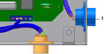
5Click the Segments button, and then, in the graphics window, click the
segment between the two blue connectors (parts 360575:1 and 360575:2).
6Click OK.
Both wires in the cable return to their unrouted state.
Unroute All Wires or Cables from All Segments
In this exercise, you unroute the remaining wires. If the dialog box is not still
open from the previous exercise, select the Unroute command.
Unroute all wires
1Activate Harness Assembly1.
2On the Unroute dialog box, verify that both the All Wires and All
Segments check boxes are selected.
3Click OK.
The wires are unrouted and wire lengths update to reflect the change.
Practice Your Skills
Use the skills and tools learned in the previous examples:
1Reroute the wires and cables you just unrouted.
2Save your work.
The data files with routed wires and cables are required to create the
nailboard in Work With Nailboards and Drawings on page 341.
Unroute All Wires or Cables from All Segments | 303
304
Work with Splices
In Cable and Harness, splices are a virtual representation of the splice location and the wires
that are joined together to make a path for electricity to flow.
In this chapter you learn how to create and manipulate splices, add properties to the splice
or splice pins, and set embedded length to indicate splice type.
About Splices
Each splice contains two pins, is created with a default size, and is offset a
specified distance from selected face geometry. It can also be associated to
selected geometry. Splices are typically placed on segments with little or no
bending at the splice location. The embedded length is set on splices or splice
pins.
A default splice is provided in the Cable and Harness Library. You cannot change
settings on the default splice, but you can define your own splice, and then set
different defaults as needed. To change settings on splice occurrences, right-click,
select Harness properties from the context menu and change settings on the
Splice Properties dialog box.
Once a splice is positioned in the harness assembly, it can be included in
standard assembly drawings and nailboard drawings. In the nailboard drawing
the splice is represented with a unique color and symbol. Splice information is
also included in reports and when saving data to the XML format.
Recommended Workflow
■Add a splice definition to the Cable and Harness Library.
■Activate the harness assembly.
16
305

■Create a splice.
■Accept or change the splice Refdes and the selected splice.
■Optionally, click the Properties button to view the properties on the selected
splice.
■Locate the splice offset from a face.
■Optionally, add or modify custom properties on the splice.
■Import the wires onto the connectors.
■Splice the wires.
■Redefine the splice onto the segment.
■Route the wires.
■Optionally, add virtual parts.
If you prefer, you can create the splice on a segment, import wires onto the
splice, and then route the wires. You can also connect wires to splices manually.
Create Splices
Use the Create Splice tool on the Cable and Harness tab to add a splice to a
harness assembly. Valid geometry for creating a splice includes:
■An arbitrary point offset from a face
■A wire, including wire work points
■A segment, including the segment endpoints and work points
■Wire stubs (the portion of the wire from the end segment to the pin),
exposed wire pieces (sections of wires displayed between gaps in segments),
unrouted wires
Like segments, you can also associate a splice to other model geometry such
as a vertices, sketch points, or center points.
NOTE You cannot place splices on cable wires, ribbon cables, connector pins,
another splice, or dangling wires. We recommend that you do not place splices
at segment junctions.
306 | Chapter 16 Work with Splices
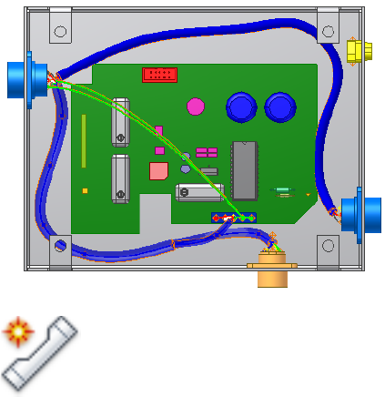
Insert Splices
In this exercise you create the splice at an arbitrary location, and then add
two wires to the splice.
Insert a splice
1In the browser, double-click Harness Assembly1.
2Create a Generic 22AWG-GRN wire from U7 Pin 3 on Connector 360575:1
to J12 Pin 2 on LTP:1.
3Create another Generic 22AWG-GRN wire from U7 Pin 5 on connector
360575:1 to J12 Pin 2 on LTP:1, and then click OK. The new wires are
shown in the following image.
4 On the ribbon, click Cable and Harness tab ➤ Create panel
➤ Create Splice .
5On the Create Splice dialog box, accept the defaults.
You can accept or change the default RefDes, accept the default splice,
or select a custom splice from the library. You can also click Properties
to view and change existing custom properties or add your own.
6Click the Select Location tool, if not already selected.
A green circle that represents the splice is attached to the cursor. A line
representing the offset distance extends from the splice object.
Insert Splices | 307
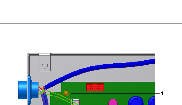
NOTE To change the offset right-click again, select Edit Offset, and then
enter a value. The default offset is set on the Splice tab of the Harness Settings
dialog box.
7Click in the graphics window to place the splice.
The splice (1) is shown in the following image.
8Click OK.
Modify Splices
After you place the splice, you can:
■Add wires to the splice manually or by importing a wire list.
■Add or modify Custom properties on the splice occurrence or splice pins.
You cannot change splice pin names or default properties on the splice.
Default properties must be changed on the splice definition in the library.
■Redefine the splice location.
■Delete the splice.
Splice Wires or Add Wires to the Splice
To visualize the best placement of the splice in the harness, place the splice
on the wires before redefining the splice onto the segment.
1In the browser or graphics window click the splice, right-click, and then
select Splice Wire on the context menu.
2Click Wire 2, the wire to splice.
308 | Chapter 16 Work with Splices
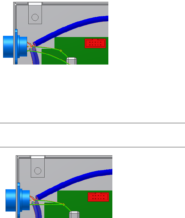
The wire is split and added to the browser with the unique name, Wire
2_1.
3Click Wire3, right-click, and then select Splice on the context menu.
4Click the splice.
5Click OK on the confirmation dialog box to remove redundant wires.
Redundant wires (wires that share a common point when spliced) are
deleted.
NOTE Redundant wires are only removed when manually splicing wires.
Importing wires or placing wires on splices using Create Wire or Edit Wire
does not remove redundant wires.
Redefine the Splice
After visualizing the splice on the wires, you can redefine the splice to a new
location. You can redefine a splice on a wire:
■Onto another wire.
■Onto a segment
Redefine the Splice | 309
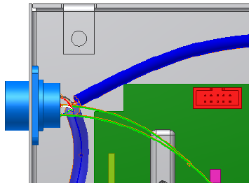
■At another location, including another location along the same wire
You cannot redefine the splice to a location off of the wire, because the wires
connected to the splice move with the splice. You can only delete the splice.
You can also redefine a splice on a segment:
■To a location off of the segment.
■Onto another segment.
■At another location along the same segment.
If the new location is on a different wire or segment:
■The new wire or segment is split, and each object gets a unique name. For
example, Segment1 becomes Segment1 and Segment1_1.
■If the initial location was on a segment, the existing segment is healed and
any wires attached to the splice are unrouted.
■If the initial location was on a wire, the wires move with the splice to the
new location.
■Any work points on the spliced wires are retained.
Redefine a splice along the wire or to an arbitrary location
1Right-click the splice, and then select Redefine Splice on the context
menu.
2Click a new location along the same wire.
310 | Chapter 16 Work with Splices
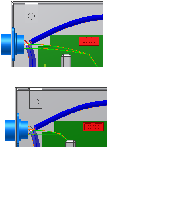
3Right-click the Splice again, select Redefine Splice, and then select a new
location in the enclosure.
Notice how the wires move with the splice.
4Use Undo twice to return the splice to the original location.
Redefine the splice onto a segment
1Right-click the splice in the graphics window, and then select Redefine
Splice on the context menu.
NOTE We recommend that you place splices on segments. In this exercise,
you redefine the splice onto a segment, and then route the wires.
2Click the segment to locate the splice (1). Click directly on the spline at
the center of the segment or click a segment work point.
Redefine the Splice | 311
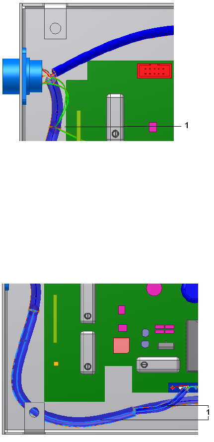
3On the ribbon, click Cable and Harness tab ➤ Route panel ➤ Automatic
Route.
4Make sure that All Unrouted Wires is selected, and then click OK.
The wires are routed into the spliced segment and out the branched
segment.
5In the browser, right click Wire2_1, and then select View Path to make
sure that the wires were routed as intended.
The wire path (1) is highlighted to and from the splice along with the
segments that the wire is routed through.
6Save the harness assembly.
312 | Chapter 16 Work with Splices
Splice Properties
Like all other harness objects, splices and splice pins contain a set of properties
that provide a complete description of the splice. Splice occurrences inherit
the default properties that are set on the library definition and the general
properties set at the part level. Default settings can only be changed on the
definition in the library. When unique properties are needed for the splice
definition, you can create and add a new splice definition to the library. When
unique properties are needed for the splice occurrence in an assembly you
can add custom properties.
Access Properties for Splices and Splice Pins
1In the browser or graphics window, right-click the splice, and select
Harness Properties. The Splice Properties dialog box displays.
2Examine the properties. Notice that there is an embedded length value
of 0. Also notice that you can assign Virtual Parts to the splice through
this dialog box. Click OK.
3In the browser under the Splices folder, expand the splice to view the
splice pins. Right-click a splice point, and then select Harness Properties
to see the Splice Pin Properties dialog box.
4Examine the properties, and then click OK.
Control Length for Splices
The embedded length property is key for splices, because it indicates the
different splice types. There are two types of splices:
A physical object where the wires are inserted into the
body of the splice to form the electrical connection.
Butt splices
Wires do not overlap, thus the embedded length is zero
or a negative number.
Wires are either soldered or ultrasonically welded to-
gether. The embedded length value is the amount that
the wires overlap.
Overlapping splices
For both splice types, the splice pins are located in the center of the splice.
All wire lengths are calculated to the splice pins and the embedded length of
the splice is added to the wire length to determine its adjusted length value.
Splice Properties | 313
This ensures that the proper wire length is added to each wire connecting to
the splice.
To change the embedded length for a splice, create a splice in the Cable and
Harness library, and then enter the needed embedded length value. You cannot
change the embedded length on the Default Library Splice.
Search for “length, control in splices” in the Help index for more information
and examples on setting embedded length and negative length conditions.
Delete Splices
If you delete a splice with two wires attached, the wires heal. If there are three
or more wires, redundant wires are deleted along with their associated
properties. The logical connection of the signal carried by the wires is
maintained.
If you delete a splice from a segment, the segment heals and all routed wires
remain routed. If a segment or wire that has a splice on it is deleted, the splice
remains. Any custom virtual parts assigned to the splice are also deleted.
Practice Your Skills
1Create a splice.
2Import wires onto the splice.
3Manually attach a wire to the splice.
4Delete a splice from a segment.
5Delete a splice from a wire.
314 | Chapter 16 Work with Splices
Work with Ribbon Cables
In this chapter you learn how to add a raw ribbon cable definition to the Cable and Harness
Library, create a ribbon cable between start and end connectors, and then modify it to control
the shape and direction through the assembly.
About Ribbon Cables
Like wires and cables, ribbon cables are retrieved from the Cable and Harness
library and placed in the harness assembly. To insert a ribbon cable, you select
the ribbon cable to insert, identify the start and end connectors, specify how
the ribbon cable engages with the connector, and then add intermediate work
points to control shape or indicate the location for a fold.
Once the ribbon cable is in the assembly, there are many ways to modify it.
■Change connectivity: select different connectors, change direction in which
the ribbon cable attaches to the connectors, move conductor one to a
different pin, change the orientation.
■Add, delete, move, and redefine work points.
■Add single and double folds.
■Adjust twist at selected points.
In the following exercises, you create a ribbon cable with a single fold between
D-Sub Ribbon on the enclosure and RC Male Connector on the PCB board.
Define Raw Ribbon Cables
Like traditional cables, there is no default ribbon cable. Before creating a ribbon
cable in the harness assembly, the definition for the raw ribbon cable must exist
17
315
in the Cable and Harness Library. You add raw ribbon cable definitions to the
library the same way you add other harness objects.
1Activate the Ribbon Cable harness assembly.
2Click the Cable & Harness Library tool.
3Select Raw Ribbon Cable as the harness object type.
4Click the New tool and examine the properties that are unique to ribbon
cables such as the ability to set different colors for conductor one and
the ribbon cable body.
5On the General tab, enter the manufacturing information for the ribbon
cable:
Name: 28-AWG-9-Conductor
Category: Tutorial
Part Number: 28-AWG-9-Conductor
Conductor One: Red
Ribbon Body: Gray Light
Number of Conductors: 9
Pitch: .05 in.
Height: .035 in.
Width: .450 in.
Gauge: 28
(Core size is optional. Leave it blank.)
6Optionally, click the Custom tab to add additional properties.
7Click Save and the new raw ribbon cable is added to the library in the
Tutorial category.
8Click Close.
Place Connectors from Content Center
The Content Center contains some generic connectors for your use. You can
use these connectors or create custom connectors that you author and publish
to Content Center for reuse.
316 | Chapter 17 Work with Ribbon Cables

For more information on authoring and publishing connectors and using
Content Center, see the Help.
In this exercise, you use a 10-pin ribbon cable connector from Content Center.
Locate and place the connector
1Activate the Ribbon Cable harness assembly, if not already active.
2 On the ribbon, click Assemble tab ➤ Component panel ➤
Place from Content Center .
3On the Place from Content Center, Category View pane, navigate to
Cable & Harness ➤ Connectors ➤ Ribbon Cable.
4 Click Family Preview to view the family members for the ribbon
cable connector.
5In the preview table, note the Member name for the 10-pin connector.
In this case, it is the first member in the list.
6Double-click the image of the ribbon cable connector to select it.
7On the Ribbon Cable Connector dialog box, ensure that the following
are selected:
■Ribbon Cable Connector-01
■As Standard
8Click OK.
In the graphics window, the part is attached to the cursor.
9Rotate the enclosure to get a better view of the RC Male Connector (1).
10 Click in the background of the graphics window to place the part (2).
Exact placement is not important.
Place Connectors from Content Center | 317
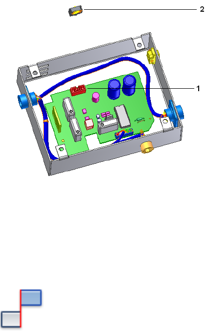
11 Right-click and select Done.
In this exercise, you place three mate constraints to constrain the ribbon cable
connector in place.
Constrain the connector
1Activate the top-level assembly, Enclosure_Assembly.iam.
2 On the ribbon, click Assemble tab ➤ Position panel ➤
Constrain.
3Ensure the Show Preview check box is enabled.
4Ensure the Mate constraint tool and the first selection button is selected,
and then click the face of the ribbon cable connector.
318 | Chapter 17 Work with Ribbon Cables
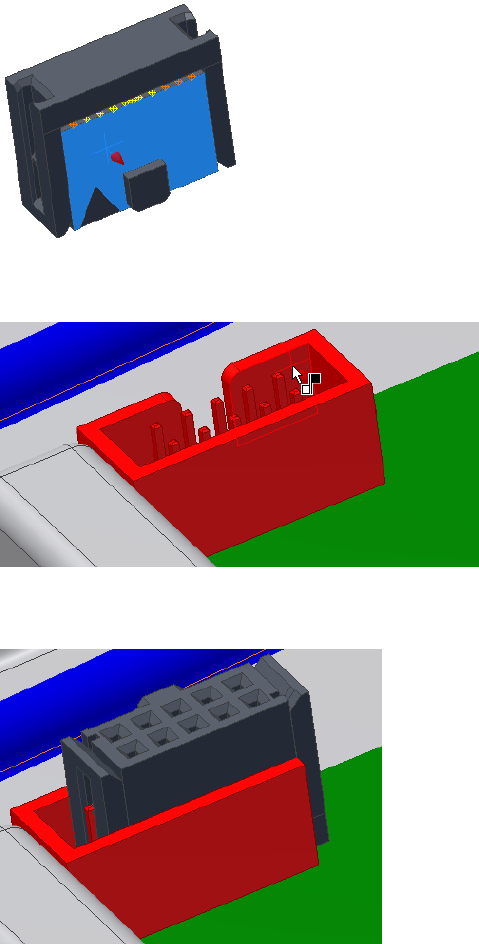
5The second selection tool is now active. Click the wall of the RC Male
Connector as the geometry to mate to.
6When the preview shows the connector has moved into place, click Apply
to create the first mate constraint.
Place Connectors from Content Center | 319
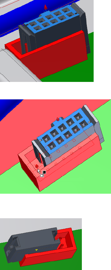
7For the second mate constraint, click the top face of the ribbon cable
connector.
8Click the bottom face of the RC Male Connector.
9When the preview shows the connector has moved into place, click Apply
to create the second mate constraint.
320 | Chapter 17 Work with Ribbon Cables
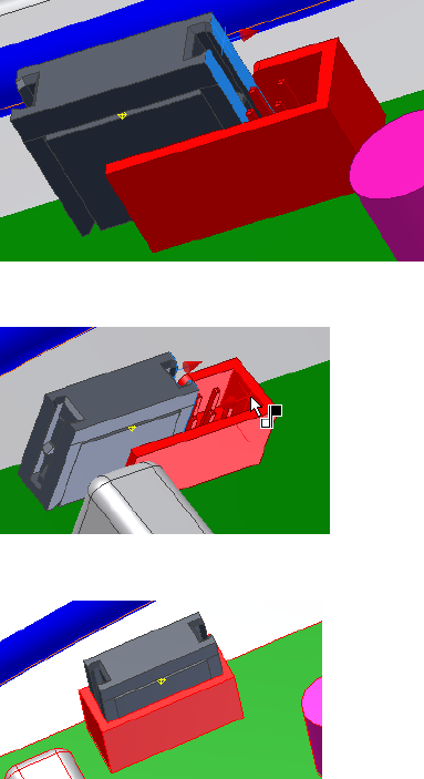
10 For the final mate constraint, click the right side of the ribbon cable
connector.
11 Click the inside face of the RC Male Connector.
12 When the connector moves into place, click OK.
Create Ribbon Cables
You create a ribbon cable between a start and end connector. When selecting
the connectors for a ribbon cable, only valid (authored) ribbon cable
connectors highlight. Once you select the connectors, each mouse click in
the graphics window creates a work point on the ribbon cable. As with other
harness objects, you can offset work points from a face and adjust the offset
Create Ribbon Cables | 321
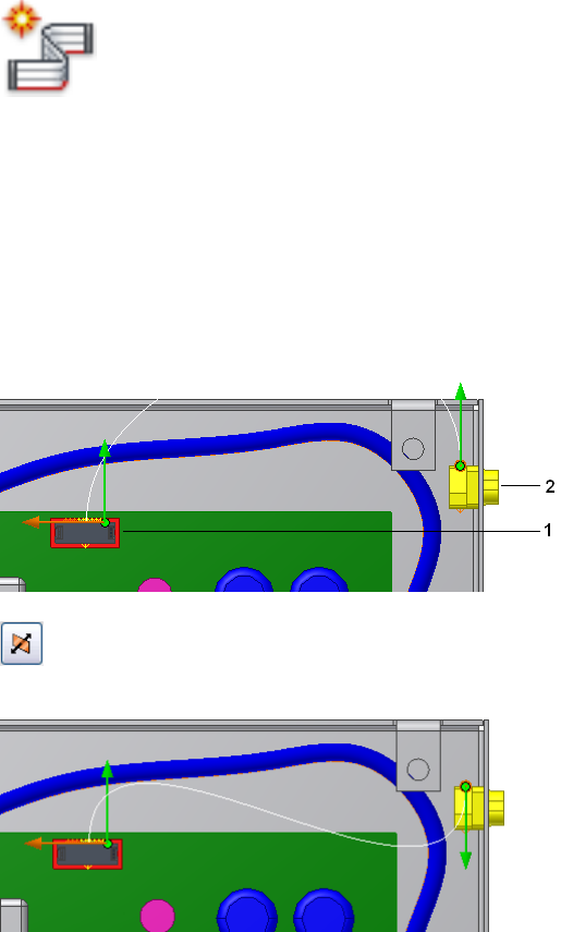
as you work. Or you can associate work points with existing geometry for
more precise placement.
Create the ribbon cable
1Activate the Ribbon Cable assembly.
2 On the ribbon, click Cable and Harness tab ➤ Create panel
➤ Create Ribbon Cable.
3Ensure that the raw ribbon cable definition you created earlier is the
ribbon cable that is selected in the dialog box.
4In the graphics window, select the start connector (1) and the end
connector (2).
Notice the directional arrows and the spline that appear. The green arrow
indicates the outward direction of the connector. The orange arrow shows
the orientation for the width of the ribbon cable body. The spline
indicates the initial shape of the ribbon cable.
5 The outward direction on the end connector is not correct. Click
the outward direction tool for the end connector to change the direction.
322 | Chapter 17 Work with Ribbon Cables
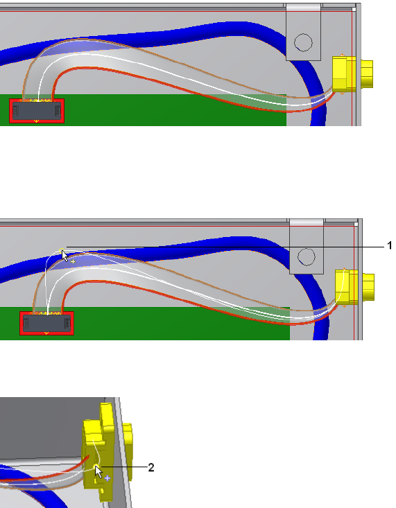
6Click OK.
You are still in ribbon creation mode and can add intermediate points
to change the current shape. Add the points in sequence from the start
connector to the end connector.
7Right-click, select Edit Offset, and enter .500 in.
8Click in the graphics window to add an intermediate point (1) to control
how the ribbon cable approaches the start connector.
9Click in the graphics window to control the approach for the end
connector. This time, click an existing work point (2).
10 Right-click and select Finish.
Create Ribbon Cables | 323
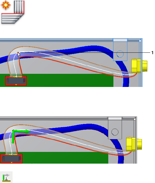
Adjust Ribbon Cable Orientation and Shape
The ribbon cable must align with the slot at connector D-Sub Ribbon. To
control the orientation of the ribbon cable, you can add single or double
90-degree folds at work points that exist along the ribbon cable.
A ribbon cable with a fold is a single piece of raw ribbon cable. For modeling
purposes, the ribbon cable is not continuous through the fold. When you add
a fold, three separate entities are created: the fold entity and the ribbon cable
piece to each side. Each entity is represented as a node in the browser.
For this exercise, you add a single fold and then adjust the twist.
Add a fold
1 Click the Cable and Harness tab ➤ Create panel ➤ Create
Foldl, and then click the first point (1) you created.
An arrow appears at the fold point indicating the direction of the next
work point on the path of the ribbon cable, which is the correct direction
for this fold.
2 Under Alignment in the dialog box, click the Shaft tool, and then
click the face of the enclosure (1).
324 | Chapter 17 Work with Ribbon Cables
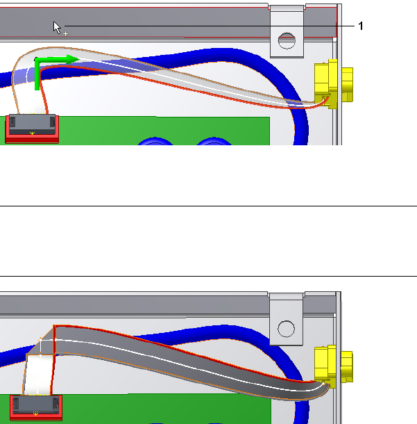
This action aligns the shaft perpendicular to the selected face. To align
the shaft parallel to existing geometry, select an edge.
3Click OK and the fold is created with the specified direction and
alignment.
NOTE Like editing other harness objects, you can right-click ribbon cable
work points and use Redefine Point and 3D Move/Rotate to move route
points. Ribbon cable work points cannot be rotated. For folds, only the work
point used to create the fold can be manipulated.
4In the browser, expand the Ribbon Cables folder and the ribbon cable.
You should see Ribbon1, Fold1, and Ribbon2.
Adjust twist
The ribbon cable body aligns parallel to the slot in the D-Sub Ribbon Cable
connector. To adjust the ribbon cable at a selected point, use Twist Control.
Adjust Ribbon Cable Orientation and Shape | 325
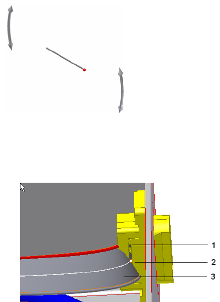
1With the ribbon cable harness assembly still active, zoom into the D-Sub
Ribbon cable and notice how the cable body (3) is twisted in relation to
the slot (1) on the connector.
2Right-click the point you selected earlier (2) and select Edit Twist.
3The Twist Control appears at the selected point.
The rotation handles (1) enable you to change the current orientation.
The red ball (2) is the conductor one indicator. The orientation bar (2)
represents the orientation of the surface on the ribbon cable at the selected
location.
326 | Chapter 17 Work with Ribbon Cables
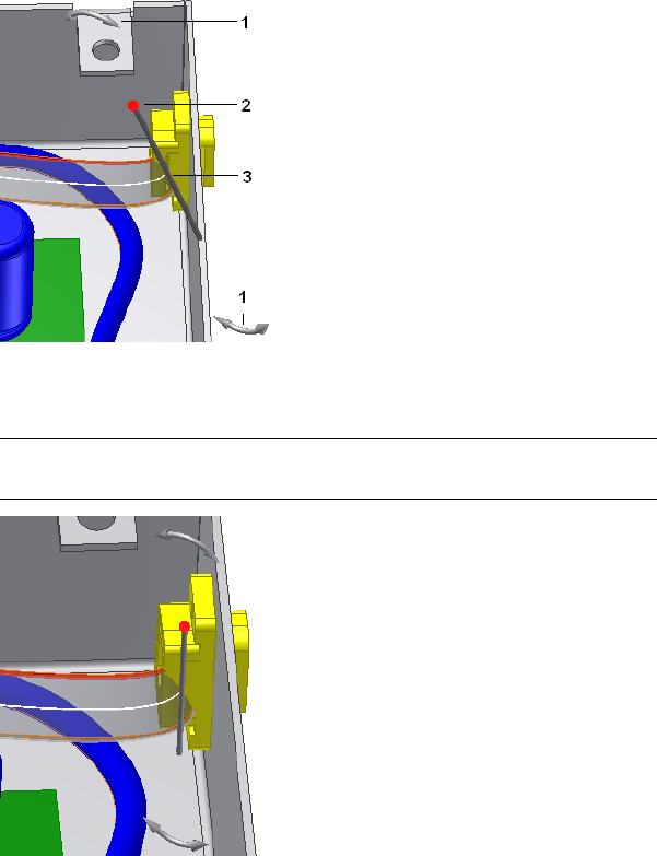
4Click and drag a rotation handle until the ribbon body is aligned with
the slot, and release the mouse button.
NOTE Click the minus (-) and plus (+) on the keypad to decrease and increase
the size of the Twist Control, if appropriate.
5Right-click and select Apply.
The ribbon cable body recomputes to the new location.
Adjust Ribbon Cable Orientation and Shape | 327
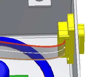
6Save the assembly.
Practice Your Skills
1Edit the ribbon cable and change the orientation and direction of the
ribbon cable as they attach to the connectors.
2Edit the fold. Change the fold type, experiment with the direction and
alignment.
3Add and modify the work points on the ribbon cable.
328 | Chapter 17 Work with Ribbon Cables

Generate Reports
Harness assemblies can be documented in reports. These reports are dependent on specified
properties and can be configured to meet your needs.
In this chapter, you learn about the Report Generator user interface, and how to format and
generate reports.
About Generating Reports
Several standard report types, such as wire run lists, bills of material, and
connector tables, can be run for a harness assembly. The information that is
processed is based on the property set for each harness component.
When a report is generated, the output file is saved to a specified location, and
one or more reports are displayed in the Report Generator document window
for viewing. Report output files can be imported into an Excel® spreadsheet or
similar application. Reports can also be added as table annotations in a nailboard
drawing.
A set of sample configuration files is installed with the application. You can
rename and customize the sample configuration files to produce reports that
meet your needs. You can also create your own configuration file from a blank
file.
NOTE The Report Generator can only view report configuration and .csv files that
are created in the Report Generator.
Workflow for Harness Reports
The following are the basic steps to create and generate a harness report.
18
329
Workflow: Generate reports
1Activate the harness assembly to report on.
2Select Report from the Cable and Harness tab.
3Specify a configuration file (.cfg) to format and process the data.
4Modify the configuration file to meet your needs.
5Select the files to generate.
6Generate the reports.
Use the Report Generator Dialog Box
Before you begin processing reports, explore the commands on the Report
Generator dialog box. To display the Report Generator dialog box, click Cable
and Harness tab ➤ Manage panel ➤ Report.
Report
The Report Generator user interface consists of a menu bar, toolbar, and
document window. When the dialog box is first displayed, the document
window is empty. After a report is generated, the text files containing the
output from generated reports are displayed. The toolbar and menu bar contain
features for generating and modifying reports, and several standard Windows
features.
The following commands are available on the Report Generator toolbar. Pause
your cursor over the toolbar to view the tooltips.
Creates a new, blank text file.New Text File
Opens an existing text file.Open Text File
Saves the selected text file using the name and location
specified.
Save Text File
Cuts, copies, or pastes the selected text.Cut, Copy, Paste
Sends the selected text files to print.Print
330 | Chapter 18 Generate Reports
Sets the files to use for processing reports on the active
harness assembly, and creates a report output file. Also
Create Report
removes reports from the list, and can rename and re-
locate the output file.
Selects the configuration file to edit, and then displays
the configuration file dialog box with options to
Edit a configuration
(.cfg) file
modify the format and specify information to include
for the selected file.
Arranges text files in the document window to overlap
slightly.
Cascade Text Files
Arranges text files in the document window to display
with no overlap.
Tile Text Files
Closes all files displayed in the document window.Close Text Files
Format Reports
Each report type requires a configuration (.cfg) file to process the information
from the harness assembly and create a report. To create a configuration file
or modify an existing configuration file, use the Edit configuration file
command on the Report Generator toolbar.
Sample .cfg files for each of the main report types are provided in the Tutorial
Files\Cable & Harness\Report Generator folder where you installed the Autodesk
Inventor® software. We recommend that you use these files whenever possible
to reduce input time and errors.
You can also create a new blank configuration file.
Use Sample Configuration Files
The easiest way to create a report is to use one of the sample configuration
files installed with the application. If the sample file does not meet your needs,
use the sample file as a base, modify, and organize the data to include the
information you need, and then save the file using a unique name.
All sample report types are set to print as comma-separated files. To view the
settings while reading the descriptions, select the required configuration file,
and then click each tab.
The following are sample files and their output:
Format Reports | 331

PartsList.cfg
Lists the electrical parts attached by a wire or cable wire in the harness
assembly. The format is set to include a placeholder for repeated part names,
and to print the column headers and the text displayed in the Info tab.
Part_Splice_Wire_Cable_BOM.cfg
Outputs the quantity of each part type that is attached by a wire or cable wire
in the harness assembly. The report also includes a total length calculation
for each library wire type used in the harness. The filter is set to exclude objects
from the BOM (denoted by a specific property BOM=FALSE name/value pair),
and to use the Part Number to total the number of like objects. Although
length is required to total the amount of wire in the harness assembly, the
column is not printed. The total amount of each wire and cable is included
in the Quantity column.
To create a full electrical bill of materials (BOM) for a harness assembly, you
can use the Report Generator or the Autodesk Inventor bill of materials. The
Autodesk Inventor parts list includes only the harness assembly, and none of
its contents. To include harness parts in a BOM, add them as virtual
components in the Cable and Harness assembly.
NOTE Virtual parts and ribbon cables are not included in bill of material reports
created with the Report Generator. All harness objects, however, are included in
bill of materials and parts lists created using standard Autodesk Inventor features.
Wire Run List.cfg
Outputs a from/to list for each wire, including cable wires, in the design. It
includes the connection, RefDes, and pin name at both ends of each wire, as
well as the length of the wire in the specified units. The table uses several link
types to get the RefDes and pin name information for each wire end. The wire
lengths include a round-off value that is used before converting the wires to
feet. The format is set to sort multiple columns.
Connector.cfg
Creates one file for each electrical component or splice with a RefDes value,
and wires or cables wires attached to them in the selected harness assembly.
332 | Chapter 18 Generate Reports
The output file lists the pin name, Wire ID, and wire color. The filter is set to
query only the parts with a part number property. The table is set to include,
but not print, the RefDes property. The format is set to output a file for each
RefDes and <RefDes>.txt is used as the default output name. If multiple wires
or cable wires connect to the same pin, each wire appears on a new line, but
the pin name is not repeated.
Segment Table.cfg
Creates a table with information about the physical characteristics of each
segment in a harness.
Edit Configuration Files
To modify an existing configuration file, click the Edit configuration (.cfg) file
command, select the file to modify, and then change the format and other
aspects of the report using the configuration file dialog box.
Before editing a configuration file, click each tab of the dialog box to explore
the available options. The following tabs are available:
Displays and sets the header information for the con-
figuration file.
Info
Sets the columns and information to use for the report.Table
Controls the types of harness components to include
in the report.
Filter
Refines the report output format including sorting, file
format, and file print options.
Format
Configuration File Options
The parameters on each of the four tabs in the Edit Configuration file dialog
box are described in this section. Click each tab to view the parameters being
described.
Info Tab
On the Info tab, view and set the information to appear as the file header.
The file header often provides a brief description of the report. Other
Edit Configuration Files | 333

information such as the name of the project or model used, and a date can
also be included. Use the scroll bar to view all the information, if necessary.
Table Tab
On the table tab, set the columns and properties to use for parsing the report.
Click the buttons to add and remove columns, and click the input boxes to
add property values to each field. If an arrow is displayed, click the arrow to
select from a list.
Keywords are used to perform certain functions, such as counting the number
of like objects based on a specified property name.
See the Help for details about key words.
In the Table tab on the Edit Configuration dialog box, link types are used to
obtain information on an object type, such as a pin or part, when running a
report on a different object type, such as a wire. The following table shows
the link types you can use for the different harness component object types.
SplicesCable
Wire
PartPinWireSegmentLink Types
XXXXXXNone
XGETPART
XXGETPART1, GETPART2
XXGETSEGMENTS
XGETWIRES
XXGETPINS
XXGETPIN1,GETPIN2
XXGETPINSGETWIRES
XXGETPINSGETWIRESGETPIN2
XXGETPINSGETWIRESGETPART2
The rows of the table are defined as follows:
334 | Chapter 18 Generate Reports

Sets the text for column headings. Enter any string.Column header
Specifies whether to derive a property value from the
main object or an associated object. When set to a link
Link type
type, the property value is derived from an associated
object.
Sets the name of a single property whose value is
written to the report. You can enter a property such as
Name
Color Style or Gauge, or a keyword. Keywords enable
functions within the report generator. See the Help for
details on keywords.
Sets the width of the column.Column width
Sets the value to place in the last row.Subtotal function
Specifies whether the data displayed in this column is
a harness property. “No” means that the property is a
constant or special keyword.
Property data?
Specifies the units to use for that column. Autodesk
Inventor unit settings are used by default. When the
Units
data type is a length type, round-off values are
presented in the Round Off Row.
Indicates the round up value used for wire and segment
lengths. Values are dependent on the Unit setting.
NOTE We recommend that you do not adjust the Unit
and Round-up settings from the default. If adjusted, the
lengths in harness assembly and nailboard could be differ-
ent from the generated reports.
Round Up
Sets whether to print a units suffix in the report.Print units suffix?
Sets whether to print this column in the report.Print column?
Filter Tab
The Filter tab options determine the harness objects and property name value
pairs used to process data for the report.
Sets one or more harness component objects to include
in the report.
Select objects to re-
port
Sets the property name and value pairs to include or
exclude from the report. Also specifies the property
value used to group and calculate like objects.
Object filters
Edit Configuration Files | 335

Format Tab
On the format tab, you set options that fine tune the report output. There are
several options.
Enables a single report to output multiple files, and
determines how to handle them. You can specify a
Multiple files
property to use as the naming convention for created
files. Valid properties include any property that appears
as a column in the Table tab.
Specifies, in descending order of importance, columns
used to sort the report data. Valid column numbers are
Sort by column
dependent on the columns that appear on the Table
tab. Enter at least one column number.
Specifies a placeholder when blank or repeated values
are used consecutively in a single column. You set the
Placeholder
text or character string to use as a placeholder in the
report.
There are also several print options listed:
Writes the options selected in the Filter tab to the re-
port.
Print filter informa-
tion
Writes the name of the .cfg file and the directory in-
formation to the report. Clear the box to exclude this
information from the report.
Print header
Writes the text in the Info Tab to the report. Clear the
box to exclude the Info Tab text from the report.
Print information
Includes the column headers as defined on the Table
Tab in the report. Clear the box to exclude the column
headers from the report.
Print column headers
NOTE We do not recommend that you enable the Print filter information, Print
header, or Print information options when you create reports for tables on the
nailboard drawing since they affect the parsing of the data when the table is
created.
Generate Reports
To generate a report, you select one or more configuration files to use, and
then click OK to generate the report. The output file is saved to the specified
336 | Chapter 18 Generate Reports

location, and one or more reports are displayed in the Report Generator
document window for viewing.
A data type consistency check is performed as the reports are processed, and
a log file is generated. The consistency check is performed for all properties
on all harness objects associated with the selected harness assembly. For each
property used on an object in a harness assembly, only one data type can be
associated with the property name. For example, an inconsistency can occur
if a connector part with a specific property and data type is placed into a
harness assembly that contains a wire or segment with the same property
name, but a different data type.
The log file details any properties with conflicting data types. If there is a
failure in the data type consistency check, the location of the log file is listed,
and you are prompted whether to continue.
Create Part and Wire Bills of Material
In this exercise, you generate a simple bill of materials report for the parts and
wires in the harness design using the sample file
Part_Splice_Wire_Cable_BOM.cfg.
Before you begin, verify that the harness assembly is saved and fully up to
date (Update button is not active).
NOTE You can also create a complete bill of materials and parts lists using standard
Autodesk Inventor features.
Create a BOM for parts and wires in a harness design
1 Double-click Harness Assembly1, and then click Cable and
Harness tab ➤ Manage panel ➤ Report.
2On the Report Generator dialog box, click Create Report.
3On the Create Reports dialog box, click Add File to List, navigate to
Tutorial Files\Cable & Harness\Report
Generator\Part_Splice_Wire_Cable_BOM.cfg, and then click Open.
An output file Harness Assembly1_Part_Splice_Wire_Cable_BOM.csv is added
to the list at the same time as the selected configuration file. It is located
in the same directory as the associated harness assembly by default.
Create Part and Wire Bills of Material | 337

4To rename the file, double-click the output file name in the list, and then
enter Part_Splice_WireCable_BOM1.
Click Open.
5Click OK.
The report is processed and the output file is generated with the specified
name and location, and then displayed in the Report Generator document
window.
The path of the last selected configuration file is used as the default for
subsequent file add operations.
Create Wire Run List Reports
A wire run list is a from/to list for each wire and cable wire in the design. It
typically includes the reference designator and pin name or number for each
end of the wire, and the wire part number and length information.
In this exercise, you modify the sample wire run list report to include more
information, including link types.
Before you begin, verify that the harness assembly is saved and fully up to
date (Update button not active).
Modify a wire run list
1Make sure Harness Assembly 1 is still active.
2On the ribbon, click Cable and Harness tab ➤ Manage panel ➤ Report,
if Report Generator is not already open.
3Click the Edit a configuration (.cfg) file command on the Report Generator
toolbar, select Tutorial Files\Cable & Harness\Report Generator\Wire Run
List.cfg , and then click Open.
4On the Info tab, click in the input area before the existing text, and then
enter Modified at the beginning of the text.
NOTE This information is included in the report only if Print header is selected
on the Format tab.
5Click the Filter tab, and then select the items to process for the report.
Verify that Wire and Cable Wire are selected as the object types.
338 | Chapter 18 Generate Reports
6Click the Table tab. Scroll to the right and notice how columns 5 - 10 use
link types to get the RefDes and pin name for each wire end.
7Leave the Format settings as they are, and then click OK to display the
Save As dialog box. Name the file Modified_Wire Run List.cfg and then click
Save.
8On the Report Generator toolbar, click Create Report.
9On the Create Reports dialog box, click Add File to List, navigate to the
Modified_Wire Run List.cfg file in the Report Generator directory, and then
click Open.
10 Click OK.
Create Custom Reports
In this exercise, you create a new, custom report by first creating a
configuration file from a blank configuration file.
Create a custom report
1Double-click Harness Assembly1, and then click Cable and Harness tab
➤ Manage panel ➤ Report.
2Click the Edit a configuration (.cfg) file command on the Report Generator
toolbar.
3Browse to the appropriate file location.
4Enter the name of the new configuration file as custom_partbom.cfg and
click Open.
5On the Info tab, enter Customized Part Bill of Material, no quantity.
6Click the Filter tab, and then in Select Objects, select Part.
7In Object Filters on the same tab, select All for both the Property Name
and Property Value.
8Click the Table tab, and then click Insert Column to add two columns.
Insert each column before column 1.
9Enter the values in the columns, as indicated previously. To enter data,
click in the input box, and then enter the value. If an arrow is displayed,
click the arrow and select from the list.
Create Custom Reports | 339

The first column lists the reference designator for the part, followed by
the part number.
Each column can be configured, and any property name can be displayed.
Column2Column1
PartNumberREFDESColumn header
NONENONELink type
PARTNUMBERREFDESName
1515Column width
NONECOUNTSubtotal function
YESYESProperty data?
DEFAULTNONEUnits
NONENONERound up
YESNOPrint units suffix?
YESYESPrint column?
10 On the Format tab, enter two as the first column to sort.
11 Select the following print options if they are not already selected:
Print filter information
Print header
Print information
Print column headers
12 Click OK to save the new configuration file.
Using the skills learned earlier, generate the report using this configuration
file to view the resulting output. Each of the parts in the design display
in an individual row.
340 | Chapter 18 Generate Reports
Work With Nailboards and
Drawings
You can document a harness assembly in a nailboard drawing or a standard Autodesk Inventor®
assembly drawing.
In this chapter, you learn how to create a nailboard drawing, manipulate the harness shape,
annotate the drawing with dimensions, and add connectors and other key information. You
also learn to create a simple assembly drawing with the harness objects represented as
centerlines.
About Nailboards and Drawings
A nailboard is a 2D flattened representation of the harness assembly that is used
in the manufacture of a wire harness, cable, or ribbon cable. In a nailboard all
harness wires, cables, and segments are flattened and drawn as straight lines in
their original display colors. Ribbon cables are flattened and drawn as rectangles
with appropriate lines indicating any folds. The work points defined in 3D,
translate to 2D points that can be used to arrange the harness shape. The relative
positions of the work points from 3D to 2D are maintained, including the
distance between any of the two points.
Along with the 2D view, the drawing often contains annotations such as a bill
of materials, parts list, a wire list, views of connectors, dimensions, pin numbers,
and other attribute data.
Any changes made to the harness are automatically reflected in the nailboard
the next time it is opened within the harness assembly, unless the assembly is
set to defer updates.
You can also document the cable and harness assembly in a standard assembly
drawing and either sweep the harness objects or include them as centerlines.
19
341
Nailboard Features
With the nailboard tools, you can:
■Create an accurate, associative 2D representation of a 3D harness.
■Set default display for segments.
■Set default display and distribution for cable wire stubs and wire stubs.
■Set default style, offset, orientation, and scale for connector views.
■Set whether to show or hide looms and labels. (If looms are shown, wires,
cables, and segments to which a loom is attached are displayed in the loom
color by default.)
■Rearrange the harness, segment, wire and cable wire stubs, ribbon cables,
and labels (if displayed).
■Create base views.
■Create connector base views.
■Annotate the drawing with pin, wire, splice, ribbon cable, and connector
properties.
■Add dimensions to actual wire and bundle lengths.
■Add dimensions to actual ribbon cable lengths and various points that
identify a fold in a ribbon cable.
■Add other data needed for manufacturing.
Nailboard Environment
There are three ways to enter the nailboard environment:
■Click Nailboard on the Cable and Harness tab in an active harness assembly.
■Click Nailboard View on the Place Views tab in an open drawing.
■Open an existing nailboard.
In the nailboard environment, the Nailboard tab and browser are displayed
and you can begin manipulating and annotating harness data.
342 | Chapter 19 Work With Nailboards and Drawings
To provide for maximum flexibility, the standard Autodesk Inventor Annotate
and Place Views tabs are available from the nailboard environment. Using
these features, however, is not recommended. We recommend that you create
another view and make annotations as needed until the view contains the
entities you require.
Pause your cursor over the commands to view the tooltips.
The commands on the Nailboard panels include:
Enters edit mode allowing easy access to the nailboard
sketch.
Edit Nailboard Sketch
Fixes a point as a pivot point for the purpose of arran-
ging the wires, segments, and ribbon cables.
Pivot
Equally distributes wire or cable wire stubs about the
endpoint of the segment based on the specified angle
and sorting direction.
Fan Out
Collapses all wires or cable wires onto each other to
form one entity that emerges from the endpoint of the
Fan In
segment. It is displayed using the characteristics of the
longest wire or the segment.
Removes the specified length from the selected wire
or segment to shorten the object to fit in the drawing.
Broken Sketch Entity
Like the standard General Dimension command,
however, the dimension values on the wires, segments,
Harness Dimension
and ribbon cables are overridden by the adjusted length
values from the harness assembly.
Inserts the harness properties onto the nailboard.Property Display
Accesses the report generator from within the nailboard
for creation of report files that can be used for annot-
ating the drawing.
Report
Places one, some, or all connector views. You can spe-
cify the display characteristics for placement.
Place Connector
Views
Accesses the standard Autodesk Inventor Drawing
Manager command within the nailboard environment
for placement of connectors.
Base View
Nailboard Environment | 343

Inserts a table onto the nailboard drawing. Not avail-
able in nailboard sketch.
Create Table
Nailboard Browser
The Cable & Harness and Model browsers in the nailboard environment
contain the same items, except for the nailboard sketch, which exists only in
the model browser.
Create Nailboards
By default, when you create a nailboard drawing:
■The nailboard view (or draft view) is created and placed in the nailboard
sketch.
■The harness is placed in the center of the drawing.
■The wires, cables, segments, and ribbon cables are drawn with their original
display color.
■The title block and border are placed on the nailboard based on the selected
template.
■Splices are represented with a unique symbol and color.
■Wire and cable wire stubs are equally distributed (fanned out) in a clockwise
direction about the segment endpoint at a 90 degree angle.
■No automatic scaling is done, which means that the harness objects are
placed on the drawing even if they exceed the border size. It causes the
nailboard to be a true one-to-one harness drawing.
■Looms and labels are not shown.
NOTE If needed, use the standard Autodesk Inventor Edit command on the draft
view to scale the nailboard view.
The Enclosure Assembly contains three harness assemblies. You can create a
nailboard drawing for each.
344 | Chapter 19 Work With Nailboards and Drawings
Set Display Behavior
Before you create a nailboard, you can verify or change the defaults that
control:
■Lines for segments and wires, including cable wires
■Fan state (fan in or fan out)
■Display behavior for fanned in wire stubs and cable wire stubs
■Sorting direction and angle for fanned out wire stubs and cable wire stubs
■Color style for looms assigned to segments and wires/cable wires.
■Offset, orientation, display style, and scale for connector base views.
■NOTE Once the nailboard is created, you can control the display state for
looms and labels. Right-click the harness assembly in the Cable & Harness
browser and select Nailboard Settings, Display tab.
Defaults for new nailboards are set using either the Harness Settings or
Nailboard View dialog boxes, depending on how you create the nailboard.
In this exercise, you view the default display settings for the active assembly
and create a nailboard drawing.
Create a nailboard for the first harness assembly
1Double-click Harness Assembly1 as the assembly to document.
2To view the default settings, right-click Harness Assembly1 in the browser,
select Harness Settings from the context menu, and then click the
Nailboard tab.
3Review the loom color style settings on the Wires/Cables and Segments
tabs, and then click OK or Cancel.
4 On the ribbon, click Cable and Harness tab ➤ Manage panel
➤ Nailboard.
5On the Open Template dialog box, select the default template,
Standard.idw, and then click OK.
Set Display Behavior | 345
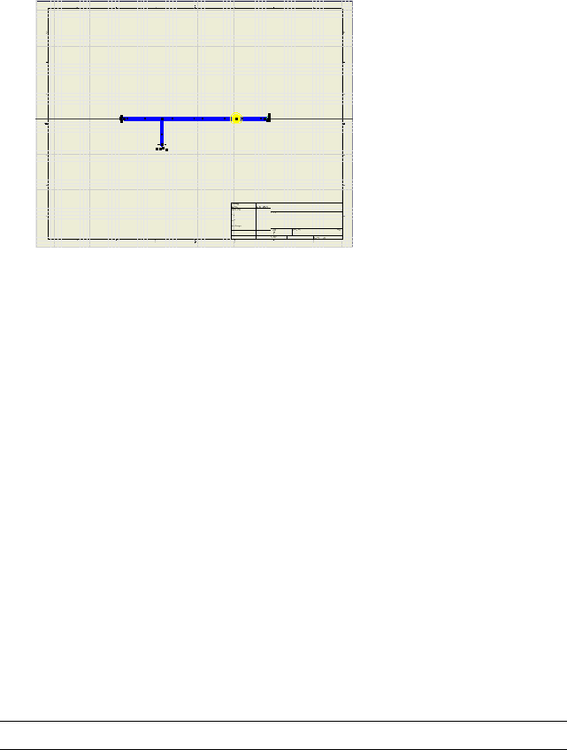
The nailboard drawing view is created and the nailboard sketch is active.
The harness is placed in the drawing as shown.
6Right-click in the graphics window, and select Finish Sketch.
7Save your work using the file name, Harness Assembly1.idw.
Manipulate the Harness
Although the default arrangement of the harness and harness objects require
little manipulation after initial placement, options are provided to rearrange
the harness objects.
For example, in a nailboard drawing, you can move the entire harness and
rearrange segments or wire or cable wire stubs to position them for ease in
annotating and viewing in the drawing. Any displayed labels are initially
centered on the pin or point to which they are associated. You can also
rearrange them for ease in viewing in the drawing.
Move the Harness
You can move the entire harness to a new location on the drawing. You can
move the harness in the drawing view or the nailboard sketch.
NOTE For a move to occur, no pivot points can exist.
346 | Chapter 19 Work With Nailboards and Drawings
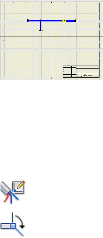
Move the harness assembly in the drawing view.
1Click the harness segment, and then drag the cursor to the location shown
in the illustration.
2Release the mouse to complete the move.
The harness is moved and redrawn in the selected location.
3Undo to return the harness to its original position in the center of the
drawing.
Arrange the Harness Segments
To arrange segments use Pivot to fix segment points, and then click and drag
the ends of the segments around that pivot point.
In this exercise, you arrange the harness segments in vertical and horizontal
directions using grid snap for precision placement.
Arrange the harness segments
1 On the ribbon, click Nailboard tab ➤ Edit panel ➤ Edit.
2 In the active nailboard drawing sketch, click Nailboard tab
➤ Edit panel ➤ Pivot.
Arrange the Harness Segments | 347
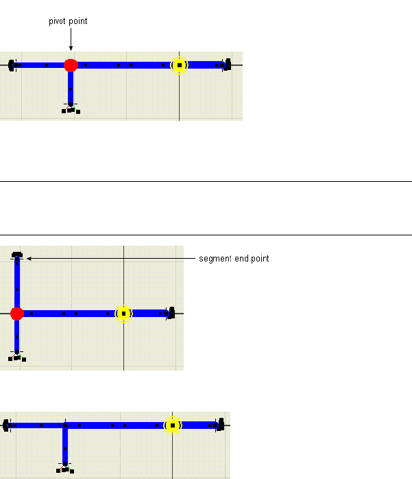
3In the graphics window, click the junction point for the harness branch.
4Click the point at the left end of the segment, and then drag until the
segment snaps to the vertical position.
NOTE Snap is enabled by default. To disable snap, in the graphics window,
right-click in the background, and then select Disable Snap from the context
menu.
5Return the segment to its original position.
6Right-click and select Finish from the context menu to remove the pivot
point.
Arrange the Wire Stubs
In a nailboard drawing, you can manually rearrange individual wires and cable
wires by dragging them. You can also arrange multiple wire stubs automatically
using Fan In and Fan Out. Exposed wires and wires ending on splices cannot
be fanned in or out.
348 | Chapter 19 Work With Nailboards and Drawings
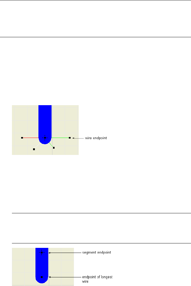
NOTE The wire stubs in this harness are short. If the wire stubs are important in
your nailboard drawings, you can return to the harness assembly and move the
final segment point farther from the connectors. Longer wire stubs are more visible
in the drawing. The drawing updates automatically the next time it is opened or
activated for editing.
Manually arrange individual wire stubs
1Zoom in on the end of the branched segment to see the distribution of
the wire stubs.
2Click and drag each of the wire endpoints to change their positions as
shown.
A pivot point is not required when rotating wires about a segment
endpoint.
Automatically arrange multiple wire stubs (fan in and fan out)
1Right-click the segment endpoint or any of the four wire endpoints, and
then select Fan In/Out ➤ Fan In.
The wires are displayed using the color and diameter of the segment and
the length of the longest wire.
NOTE If a loom is assigned to a wire or segment, they can display using the
color of the loom or the wire. Color style must be set using the Wires/Cables
and Segments tabs of the Harness Settings dialog box before creating the
nailboard.
Arrange the Wire Stubs | 349
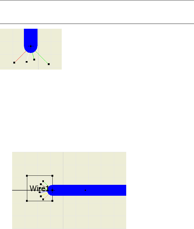
2Right-click the segment point or end point of longest wire, and then
select Fan In/Out ➤ Fan Out.
3In the Fan Out Wires dialog box, click OK.
NOTE Right-click a wire in the fanned out state, and then select Fan Out from the
context menu to change the sorting direction or angle between the outermost
wires.
Arrange the Label
To arrange the label, first set the label to show in the nailboard. Once labels
are set to show, you can manually rearrange individual labels by dragging.
1In the browser, right-click Harness Assembly 1, and then select Nailboard
Settings.
2On the Nailboard Settings dialog box under Virtual Parts, click the Show
Labels check box, and then click OK.
3Click and drag the text box to change its position as shown.
350 | Chapter 19 Work With Nailboards and Drawings
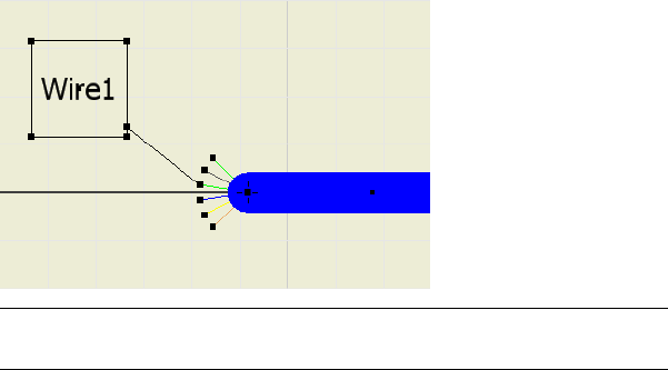
NOTE Label and font size can be adjusted on the label definition in the Cable
and Harness Library.
4For the purpose of this exercise, change the default label display setting
back to hide. (Right click the harness assembly, select Nailboard Settings,
click the Display tab, and clear the Show Labels check box.)
Change Nailboard Displays
Once the nailboard is created and the harness is placed, you can change the
display for segments, wires, cable wires, wire stubs, and cable wire stubs using
the context menu, and tools on the Cable and Harness tab. You can also
change the display for connector base views.
Change Segment and Wire Line Display
By default, nailboard wires and cable wires are set to display as thin lines.
Segments are set to display as actual diameter. You can switch the display for
an individual object in the nailboard drawing or all harness objects of one
type.
To change the segment, wire, or cable wire display once the nailboard is
created, right-click and use the display options on the context menu.
Change segment display
1In the active nailboard drawing sketch, select the segment to change.
2Right-click and clear the Display as Actual Diameter check box.
Change Nailboard Displays | 351
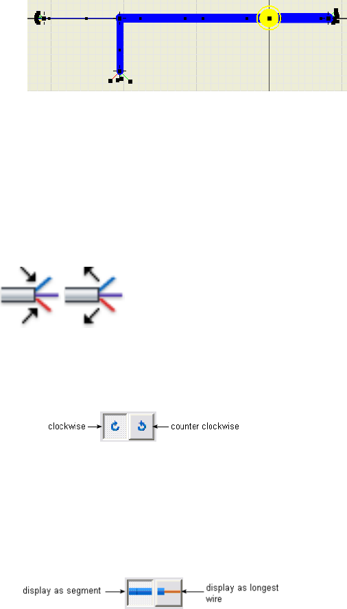
Notice how the segment has changed.
3Right-click again, and click the Display as Actual Diameter check box to
return the display to the actual diameter.
Change Fan State and Displays
You can change the fan state of wire stubs and cable wire stubs using Fan In
and Fan Out on the Nailboard tab, Edit panel, or right-click to use the context
menu.
Fanned out wire stubs are always displayed using the current wire display
setting. Once the nailboard is created, you can change the sorting direction
and angle using Fan Out on the Nailboard tab, or right-click and use the
context menu.
There are two options for displaying wire and cable wire stubs that are fanned
in:
■Display as segment - use the diameter and color of the associated segment
and the length of the longest wire.
■Display as longest wire - use the diameter, color, and length of the longest
wire.
352 | Chapter 19 Work With Nailboards and Drawings
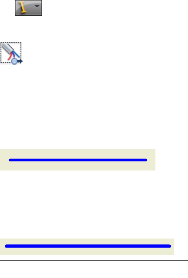
In this exercise, you create a nailboard view of the harness assembly from an
open drawing and change the fan state and display behavior.
Fan in wires and change display settings
1Click ➤ New.
2In the New File template dialog box, select the default template,
Standard.idw, and then click OK.
3 On the ribbon, click Place Views tab ➤ Create panel ➤
Nailboard.
4On the Nailboard View dialog box, ensure that the Nailboard View is
Harness Assembly 2.iam.
5Click the Display tab and click Fan In.
6Under Appearance, click Display as Longest Wire.
7Click OK and close the dialog box.
8Right-click and select Finish Sketch for a better view of the cable wire
stubs.
9On the ribbon, click Nailboard tab ➤ Edit panel ➤ Edit.
10 In the browser, right-click Harness Assembly2, and select Nailboard
Settings.
11 On the Nailboard Settings dialog box, click the Display tab, and then
click Display as Segment.
12 Click OK.
NOTE This technique is the only way to change the fan in the display once
the nailboard drawing is created.
Change Fan State and Displays | 353
Annotate Nailboard Drawings
Add annotations to the nailboard drawing to provide the needed
manufacturing information. You can add dimensions and selected properties
on the designated harness objects. You can also add tables including
information such as a wire run list, or harness bill of materials.
Dimension the Nailboard
Nailboard dimensions are like driven dimensions where the values update
when the harness segments and wire lengths update, but they do not affect
the harness geometry. Unlike standard Autodesk Inventor dimensions, the
nailboard dimension values show an adjusted length. The adjusted length is
the actual calculated wire and segment length that factors in such things as
service loop, global slack, and embedded length.
NOTE Search for and select “adjusted length” in the Help index to learn more
about adjusting the length in a harness assembly.
You can place dimensions between two selected points on segments, wire or
cable stubs, or splices. The dimensions can span wires and segments if needed.
Dimensions can be moved and deleted in the nailboard sketch, but they cannot
be edited.
Dimension Styles control the text style, format, and display properties of the
dimensions. All nailboard dimensions are aligned and parallel to the selected
geometry.
When you exit the nailboard sketch, the parentheses are removed from the
dimension and automatically retrieved into the view.
Add some dimensions to the harness segments
1Activate the nailboard for Harness Assembly1.
2 On the ribbon, click Nailboard tab ➤ Dimension panel ➤
Harness Dimension.
3In the graphics window, click the point at the right end of the horizontal
segment, and then click the segment point at the branch.
354 | Chapter 19 Work With Nailboards and Drawings
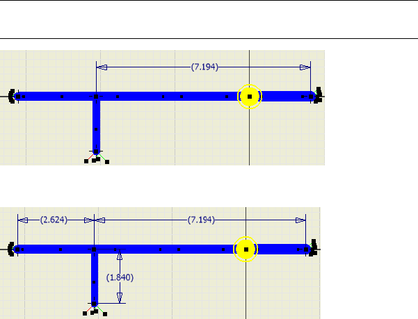
4Drag to display the dimension, and then click to place as shown.
NOTE Your dimensions may differ depending on your placement of the
segment and segment points.
5Dimension the other two segments as shown, right-click and select Done.
Add Properties
Use the Property Display tool to view and display harness properties for wires,
cable wires, pins, splices, and segments displayed on the drawing. You can
select individual or multiple objects for display.
To place the properties in the drawing, you select the location for the first
item in the selection set. The system automatically places all other properties
offset from the associated harness object based on this initial selection.
Once placed you can delete them, or move and adjust the displayed properties
to their desired position by right-clicking and rotating 90 degrees in the
clockwise or counterclockwise directions. You can also edit the text to change
the font. If the harness object to which a property is associated is moved, the
property is also moved.
Add properties to pins, parts, and a selected wire
1In the graphics window, zoom in on the harness.
Add Properties | 355
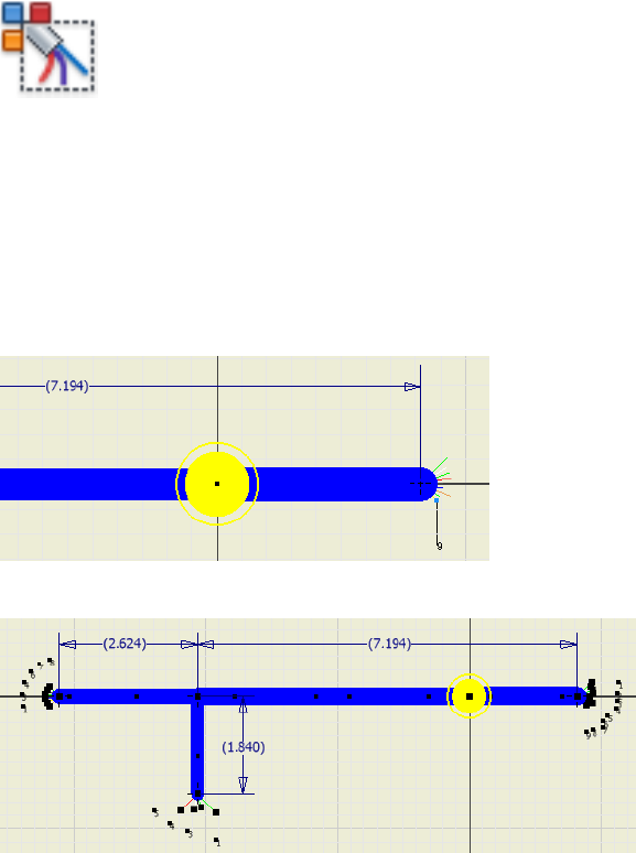
2 On the ribbon, click Nailboard tab ➤ Manage panel ➤
Property Display.
3On the Property Display dialog box under Select Filters, click All Pins.
4In the Property Name list, select Pin Name.
5Under Display Options, select Value Only, and then click Apply.
6In the graphics window a rubberband line appears from the property text
box, which is attaches the cursor to the associated object. Click to place
the property as shown.
All properties are automatically placed based on this selection.
7To place the part properties, select All Parts, select RefDes and Part
Number, select Value Only, and then click Apply.
Use CTRL + click to select multiple items in the list.
8In the graphics window, click to place the part properties.
356 | Chapter 19 Work With Nailboards and Drawings
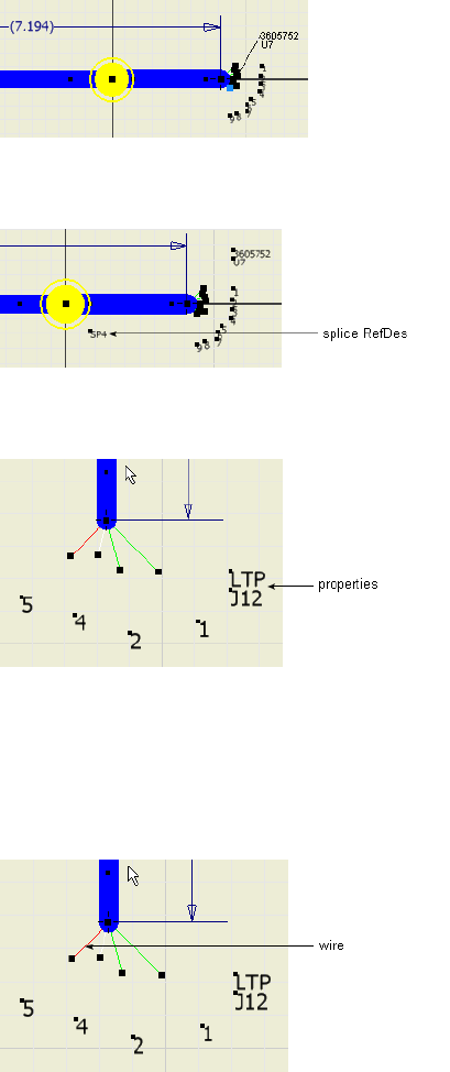
9To place the splice properties, select All Splices, select RefDes and Value
Only, and then click OK.
10 Use CTRL + Click to select the LTP, J12 properties and drag them closer
to the end of the branched segment.
Place a property for a single object
1On the ribbon, click Nailboard tab ➤ Manage panel ➤ Property Display.
2On the dialog box, select Object, and then click the wire shown in the
following image.
Add Properties | 357
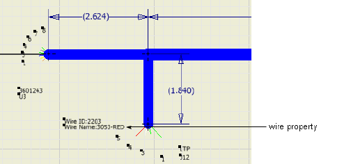
3On the dialog box, scroll in the property list to select Wire ID and Wire
Name.
4Click Name and Value, and then click Apply.
In the graphics window, notice that the property appears on the opposite
end of the segment, and not on the branch segment where the wire was
selected.
5Press the spacebar to switch the property to the branch end of the
segment, and then click to place.
6To see the associativity between the harness objects and the associated
properties, drag the wire to a horizontal position.
When the wire moves, the properties associated to the wire also moves,
keeping their original offset and relative position.
7Return the wire to the previous position.
Add Tables
To add a table with additional manufacturing information you first generate
a report or a standard Autodesk Inventor bill of materials or parts list with the
required information.
If a report is not generated before entering the nailboard environment, use
the Report tool to generate it. For details on generating a parts list, search for
“bill of materials, in nailboard” in the Help index. Once the report is generated,
you use the Table tool to select the report output file and place the table in
the drawing. You place parts lists and tables in nailboard just as you place
parts lists and tables in other drawings.
358 | Chapter 19 Work With Nailboards and Drawings
Once the table is placed, you can move or resize the table by dragging the
edges. You can also edit the table to change:
■Cell justification and size
■Cell and grid line weights and color
■Title position
■Text style
NOTE You cannot edit report data within the table. The external file controls the
data so you cannot insert, delete, or change the order of rows or columns.
Typically, tables include wire run list, bill of material, or connector
information. In this exercise, you place a cable and harness bill of materials
that was created using the Report Generator in the nailboard drawing. The
cable and harness bill of materials is unique to the harness assembly and may
not contain standard Inventor parts list information. It does not include virtual
part or ribbon cable information.
If changes are made to the external report file while the drawing is open,
right-click the table in the browser, and then select Update to update the table
data. The location and filename must be the same for the update to work.
Add a table to the nailboard drawing
1If the nailboard sketch is active, right-click in the graphics window and
select Finish Sketch.
2 On the ribbon, click Nailboard tab ➤ Create panel ➤ Create
Table.
3On the Table dialog box, under Select View, click the Browse button.
4On the Open dialog box, browse to and select the Harness
Assembly1_Part_WireCable_BOM1.csv file, click Open and then OK. The
default location is: Program Files\Autodesk\Inventor <version>\Tutorial
Files\Cable & Harness\Report Generator.
5Click in the upper left corner of the drawing to place the table.
6To modify the physical characteristics of the table, select the table in the
browser or graphics window, right-click, and then select Edit.
Add Tables | 359
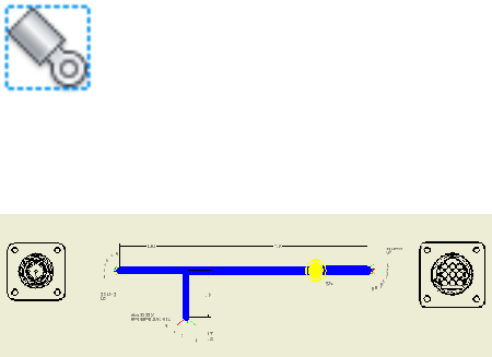
7Click Table Layout, and then use the Table Layout dialog box to change
the title of the table to Enclosure Harness Assembly BOM. If appropriate,
make additional changes to the table, and then select OK.
Placing Connector Views
You can also add connectors to complete the harness information using the
Place Connector Views tool. You can set the default display characteristics
before placing the connectors, or you can override the defaults on selected
connectors while placing them.
For this exercise, you place two connector views using default display settings
and then override the default display settings for the other connector.
1 In the drawing view, click Nailboard tab ➤ Create panel ➤
Place Connector Views.
2In the connector list, clear the check box for LTP:1, and then click OK.
The selected connectors are placed using the default display settings.
3Click the Place Connector Views tool again.
4Under Orientation, click the arrow to select ISO Top Right from the list,
and then Click OK.
360 | Chapter 19 Work With Nailboards and Drawings
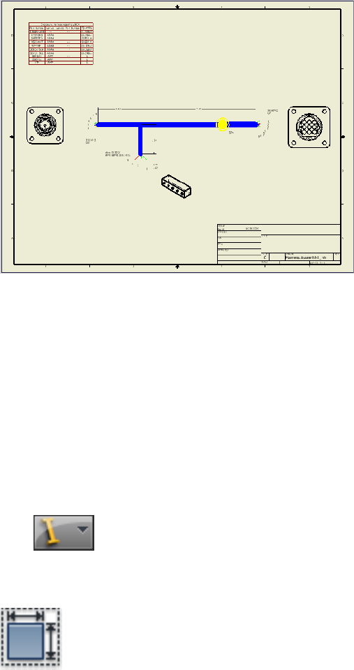
5Save your work.
To change the views after placement, right click the view to change and select
Edit View or Edit View orientation. To delete a connector base view, right-click
the view and select Delete.
Create an Assembly Drawing
In a standard assembly drawing, cable and harness information is treated like
other parts and subassemblies. You use normal drawing and manager methods
and tools to detail it. You can sweep or recover harness objects into the drawing
as centerlines.
1Click ➤ New.
2On the Open template dialog box, select the default template,
Standard.idw, and then click OK.
3 In the drawing view, click Place Views tab ➤ Create panel ➤
Base.
Create an Assembly Drawing | 361
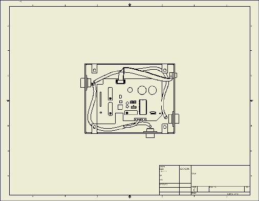
4On the Drawing View dialog box, ensure that Enclosure_assembly.iam is
selected. The default location is:
Microsoft®Windows®XP operating system
■Program Files\Autodesk\Inventor <version>\Tutorial Files\Cable & Harness
Windows Vista®operating system
■Users\login-name\AppData\Local\Autodesk\Inventor <version>\Tutorial
Files\Cable & Harness
Click to place the view as shown.
5In the browser, expand VIEW 1 and Enclosure_assembly.iam.
6Right-click Harness_Assembly1, and then select Include Centerlines ➤
Wires.
The centerlines for both the wire and segment are displayed.
7Right-click Harness_Assembly2, and then select Include Centerlines ➤
Cables.
362 | Chapter 19 Work With Nailboards and Drawings
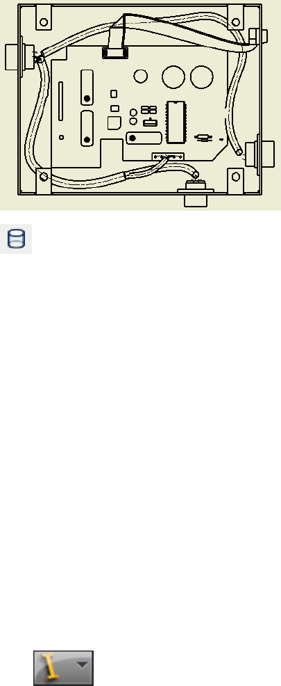
To display the portion of the splice that is hidden by other
geometry, right-click the view in the graphics window, select Edit View,
and then select the Hidden Line tool in the Drawing View dialog box.
8Optionally, add dimensions and other annotations.
9Save your work.
Print Nailboards and Drawings
You print nailboards and standard drawings that include harness assemblies
using Autodesk Inventor printing capabilities. When printing nailboards and
other large drawings, use the tiling capability to:
■Print a single drawing across multiple pages.
■Print registration marks on page corners for alignment of printed pages.
■Include page identifiers that contain the drawing and sheet name and a
table cell number to help keep pages in order.
You can print or plot a single sheet, a range of sheets, or all of the sheets in
the active drawing.
Workflow: Print a nailboard or drawing
1Click ➤ Print.
Print Nailboards and Drawings | 363

2In the Print Drawing dialog box, set the print range, scale, and number
of copies. If necessary, you can click Properties to open the Print Setup
dialog box, and then change the paper size and orientation.
3If the drawing is too large to fit on one sheet, in the Scale box, select
Model 1:1, and then select the Tiling Enabled check box.
4Click the Preview button to confirm your expected prints.
5Click OK.
NOTE Check the All colors as black option to print the drawing in black and white.
Embedded images and shaded views are still printed in color.
Refer to Help for details on other printing options.
Practice Your Skills
Create a nailboard drawing of the ribbon cable.
■Add dimensions for: conductor one, length of the ribbon cable, fold angle,
internal work points.
■Place connector base views.
■Edit the ribbon cable harness assembly and change the fold to a double
fold. Return to the nailboard and see the results of the change.
■Add properties.
Create a nailboard view from an open drawing, and then:
■Generate reports or a parts list and place additional tables.
■Update the external report file, and then update the table data.
■Move and adjust the table settings.
■Display additional properties.
■Create and place a parts list with roll-up.
■Experiment with angle and sorting direction for fanned out wire stubs and
cable wire stubs.
■Change the orientation and font size of existing properties.
364 | Chapter 19 Work With Nailboards and Drawings
IDF Translator
Part 3 of this manual provides information about the Intermediate Data Format (IDF) translator
for the exchange of printed circuit assembly (PCA) data between mechanical design and
printed circuit board (PCB) layout in Autodesk Inventor® Routed Systems.
365
366

Use the IDF Translator
The Intermediate Data Format (IDF) is an industry-standard specification designed specifically
for the exchange of printed circuit assembly (PCA) data between mechanical design and
printed circuit board (PCB) layout.
In this chapter, you learn about the IDF, what types of IDF data are supported by the translator,
how to import IDF data using the translator, and how the data can be used.
About the IDF Translator
The Autodesk Inventor® IDF Translator uses the IDF format to read files
containing printed circuit assembly data and create an assembly or part file in
Autodesk Inventor® containing the PCB and all of its components.
The IDF Translator enables the transfer of PCA data between PCB layout and
mechanical design within Autodesk Inventor.
When you first open an IDF board file using the translator, general information
about the file being opened is displayed. The items on the board are summarized
so you can import all items or a subset that you select. You can import the data
as a new Autodesk Inventor assembly or part file, or place the IDF data as a
component in an existing assembly.
Once the data is imported, the board appears with basic board and component
geometry information, along with design constraint information, such as keep
in and keep out regions. Assigned component colors provide a visually correct
representation of the PCB. The browser and BOM are updated with the IDF data.
NOTE The IDF does not provide a full design representation of a PCA, such as full
functional or electrical descriptions, and should not be used as such.
20
367

With the Autodesk Inventor IDF Translator you can:
■Import industry standard files (.brd, .emn, .bdf, .idb) in the Intermediate
Data Format (IDF) as new part or assembly files, or as subassemblies in
existing assemblies.
■Display a summary of board items before importing.
■Automatically place all or selected board items, such as drilled holes,
keepouts, outlines (including cutouts), and components on the PCB.
■Automatically group outlines, keepouts, and components based on board
side (top, bottom, inner), when imported as an assembly.
NOTE Via keepouts are not grouped since they travel through the board.
■Assigns colors on import for an accurate board representation. You can
change the colors for the entire board, other outlines, and all or selected
components.
Exchange Data
The Autodesk Inventor IDF Translator supports IDF versions 2.0 and 3.0, and
PCB design files with the extensions .brd, .emn, .bdf and .idb.
The following table summarizes and describes the types of IDF entities
supported by the Autodesk Inventor IDF Translator.
DescriptionBoard entity type
Each of the four outline types provides a different function,
such as communicating board shape and cutouts, or regions
Outlines:
■Board and Panel
for routing and placing components. When imported as an
■Other assembly, outlines are represented in the browser as parts
■Routing with single or multiple sketches. If multiple sketches exist,
■Placement you can expand the part to view them. When imported as
a part, outlines are represented as sketches.
Each keepout specifies a region of the board where a type
of item is not allowed. If multiple placement keepouts exist,
Keepouts:
■Routing
a sketch is created for each one. All routing keepouts on the
■Via same side of the board (Top, Bottom, or Inner) are stored
■Placement together in a single sketch. Only one sketch is created for
via keepouts, since only through vias are supported. When
368 | Chapter 20 Use the IDF Translator

DescriptionBoard entity type
imported as an assembly, all sketches for each type of keep-
out are stored in a part. Expand the part to view the
sketches.
Specifies an area where a group of related components are
to be placed. If a group area exists on both sides of the
Group Areas
board, a sketch is created for each side. When imported as
an assembly, all sketches are stored in a part. Expand the
part to view the sketches.
Drilled holes are distinguished from circular cutouts and are
placed onto the same sketch as the board outline.
Drilled Holes
Board components such as connectors, switches, and dis-
plays are listed with their package name and part number.
Components (Compon-
ent Placement)
Each component contains placement information that spe-
cifies its location on the board. The display name for com-
ponent occurrences is the placement reference designator.
When imported as a part, each instance of a component is
represented as a sketch. When imported as an assembly,
each component is represented as a part, and there are
multiple occurrences of that part instance for each compon-
ent.
Notes added in the IDF data are created and stored with
the file, but are not displayed.
Annotations
The entities created by the IDF Translator are not only graphical representations
of design entities. They are normal Autodesk Inventor parts with additional
attributes that are applied to the created sketch. Attributes for reference
designators defined in the IDF file are stored with the component
representation.
All part files and sketches are named automatically, based on the board name
and other existing board information.
Understand Import IDF Options
Once you select a file to import, the IDF data is read into Autodesk Inventor
and the Import IDF Options dialog box is displayed. It provides basic
Understand Import IDF Options | 369
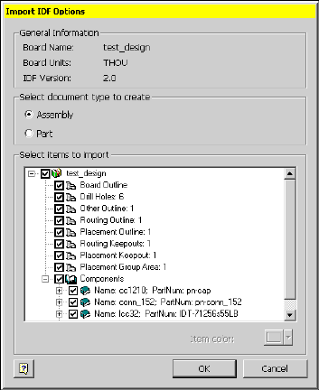
information about the board being imported, options for how to create the
data, and a summary of all board items.
You can click Cancel to exit the dialog box without importing any data. Click
OK to import all checked items.
General Information
Displays the board name, the units used, and the IDF Version for the selected
board data.
Select document type to create
Sets the type of document (or file) type to create.
Select to create a new assembly file containing multiple
part files that represent the imported data.
Assembly
Select to create a single part file for the imported data,
which reduces the number of files to manage.
Part
370 | Chapter 20 Use the IDF Translator

Select items to import
Lists the items contained on the board. Use this list to determine whether to
import all items or a selected set. To prevent an item from being imported,
clear the check box before that item.
Item color
Shows the color for a selected item in the list so you can assign new colors.
You can assign a color to the entire board, other outlines, and all or individual
components.
To select a new color, click the item name in the list, and then select a color
from the palette.
Import IDF Board Files
In the typical design process, a PCB designer lays out the components on a
board, and then the completed board assembly is passed through the IDF to
the mechanical designer to verify fit (size, shape, height) in the context of an
existing assembly.
Another common workflow involves the design of PCB boards to be used as
standard components in other assemblies, or as stand-alone parts or assemblies.
To accommodate these common workflows, the IDF Translator provides two
ways to import IDF data. You can:
■Import the data as a new part or assembly file.
■Place the data as a component in an existing assembly in Autodesk
Inventor.
Import IDF data into an existing assembly
1Open a destination Autodesk Inventor assembly file of your choice.
2 On the ribbon, click Assemble tab ➤ Component panel ➤ Place.
3On the Open dialog box, in Files of type, select IDF Board File (.brd, .emn,
.bdf, .idb), and then select the file to import.
4Click Open to begin reading IDF data.
Select items to import | 371
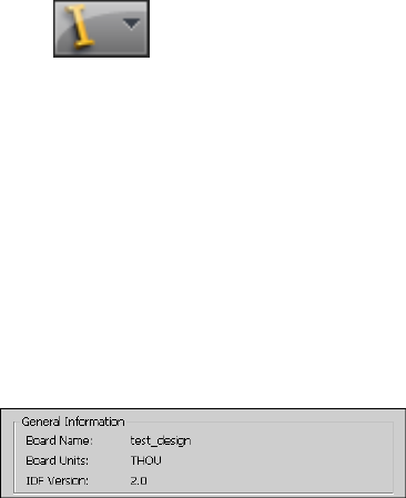
5On the Import IDF Options dialog box, view the summary data, and then
select part or assembly as the type of file to create.
6Select the items to import.
All items are imported by default. Clear the check mark from the items
you do not want to import.
7To import other outlines, components, or reference designators in a
different color, click the component name, and then select a color from
the palette
8Click OK.
To exit the dialog box without importing any data, click Cancel.
The assembly or part document for the imported IDF data is displayed,
with the IDF board components. The browser and BOM are populated
with the IDF data.
9Return to the destination assembly to place the component as usual.
In this exercise, you import a board as a new assembly.
Import an IDF board file as an assembly
1Click ➤ Open.
2On the Open dialog box, change the file type to IDF Board File (.brd, .emn,
.bdf, .idb).
3Navigate to the Autodesk\Inventor
<version>\Samples\Models\Translation\IDFTranslator folder, and then
select idf.brd.
4Click Open to start reading data.
The status bar is displayed indicating the progress as files are being read.
5On the Import IDF Options dialog box, review the general information
displayed about the data being imported.
The information is displayed as shown in the following illustration.
372 | Chapter 20 Use the IDF Translator
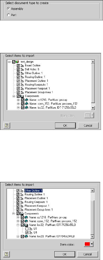
6Select Assembly as the type of document you want to create.
7Review the summary of board items to import to get an idea of the items
included on the board.
The summary of items is displayed, as shown in the following illustration:
8Click the plus (+) sign before the component named
Icc32;Partnumber:IDT-71256s55LB to expand it.
9Clear the check box before U1 so that it is not imported.
10 Select Other Outline so the name is highlighted, and then verify that the
assigned item color is red.
If multiple other outlines exist, all are displayed in the same color. Colors
can be assigned to group components visually or to call attention to a
Import IDF Board Files | 373
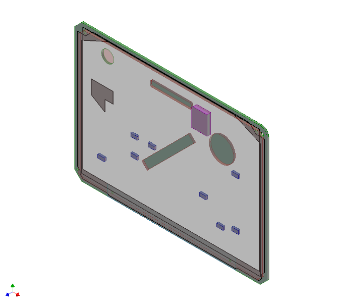
particular item. To assign a new color, click the arrow beside Item Color
and select from the palette.
11 Click OK.
To exit the dialog box without importing any data, click Cancel.
When the selected data is imported, a standard .iam file with the IDF
board components is created, as shown in the following illustration.
The browser and BOM are updated with the IDF information.
12 Look at the browser to see the results of the import.
When imported as an assembly document, the board components are
translated into multiple parts that are contained in the new assembly.
Each part file contains the data for one or more component instance.
The following illustration shows the results of importing the idf.brd file
in the browser.
374 | Chapter 20 Use the IDF Translator
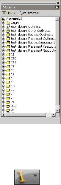
When imported as a part document, the board components are translated
into the sketches and extrusions that make up the part model in a
hierarchy. Importing IDF data as a single part simplifies file management
and reduces the number of files that must be opened to display an accurate
representation of the PCB assembly.
13 Click ➤ Save, and accept the defaults.
For additional practice, try importing the same file as a part to see the
differences in the browser information.
Use IDF Board Data
Once IDF data is imported, you can treat it as you would treat normal Autodesk
Inventor parts, assemblies, and subassemblies. With the PCB data you can:
■Verify important features of the board including mounting locations, major
components, connector locations, and keepout areas.
■Verify the fit and shape of the board in the context of the assembly, when
placed in an existing assembly.
■Edit design constraints (keepouts) as 2D sketches.
Use IDF Board Data | 375

■Create drawings, presentations, and design views.
■Manually define reference designators on individual components and pins.
■Use 3D measure between board items.
NOTE If the Autodesk Inventor IDF Translator is not installed on the system viewing
the imported data, new IDF data cannot be imported. There are no other
restrictions on interaction with the IDF data.
376 | Chapter 20 Use the IDF Translator
Index
3D Move/Rotate tool 114
3D Orthogonal Route tool 23, 82
defining angles 26
defining points 28
precise values 29
A
Active Style list, tube and pipe 38
Add Parameter tool 204
assemblies
base views 188
multiple segments, defining 280
pins, placing 216
placing parts from Content
Center 154
workflows, tube and pipe 9
assembly drawings 361
associative points for pins 214
authored parts
publishing 175
authoring parts 155, 158
defining connections 158
ISOGEN properties 162
preparing iParts 163
types 158
auto regions
converting to sketches 125
intermediate segments, move 121
Autodesk Inventor Professional
IDF board data 375
IDF Translator, using 368
AutoDrop in tube and pipe 132, 154
automatic dimensions in route
sketches 59
Automatic Route tool 299
B
Base View tool 188
base views 188
Bend Radius Check tool 106
Bend tool 32
bends
between pipe segments 70–71
editing tube routes 144
tube routes 78
Bill of Materials dialog box 199
Bill of Materials tool 199
bills of material
parts and wires 337
parts, wires, and cables 332
tube and pipe 17
bills of materials
adding specific properties 200
exporting for specific runs 199
exporting in tube and pipe 201
tube and pipe 198
board components 369, 371
board entities 369
branch segments 286
browsers
cable and harness 226, 231
IDF data displays 374
nailboard 344
tube and pipe 6
C
cable and harness
browser displays 231
component properties 231
drawings 341
features 225
interface features 226
panel bar 229
Cable and Harness Library tool 238
cable and wire displays, changing 277
cable ID naming conventions 257
Cable Properties dialog box 276
cable wires
adding points 271
Index | 377
removing 262
cables
deleting 262
displaying 277
naming 257
removing wires 262
unrouting 302
centerlines
displays 277, 293
including in drawings 362
recovering 195
Change Fitting Diameter tool 114
Choose Columns tool 201
Clockwise option 352
color settings
IDF data 371
raw ribbon cables 316
conduit parts in tube and pipe 17, 132
conduit parts, placing in tube and
pipe 154
configuration files 265
editing 333
reports 331
sample 331
Configure Libraries tool 152
Connect Fittings dialog box 141
Connect Fittings tool 113, 141–142
connection number parameters 159
connections
setting number values 158
connectors
pins 214, 220
placing 223, 317
reports 332
constraints on route sketches 67
Constraints tool 34
Content Center 149
conduit parts and fittings,
placing 154
managing libraries 151
placing components with
AutoDrop 132
publishing authored parts 175
publishing parts 155
setting up libraries 174
Content Center dialog box 137
Content Center Editor tool 153
Content Center tool 132
context menus in tube and pipe 114
Convert Sketch tool 125
Copy Library Wire tool 242
Counter clockwise option 352
coupling nodes, moving 146
Create Cable tool 253
Create Fold tool 324
Create Harness dialog box 229
Create Harness tool 228
Create New Route dialog box 55
Create Pipe Run tool 13, 53
Create Segment tool 279
Create Tube & Pipe Run dialog box 13
Create Wire tool 253
Custom Bend tool 70
Custom tab 291
customizing
part properties 219, 222
reports 339
wire properties 244
D
data
cable and harness library, importing
and exporting 245
exchanging 368
exporting from wire library 247
review for importing 268
wire library file, locating 236
data (.csv) files
formatting 267
wires, importing 265
defer updates
tube and pipe 16
Delete Library Wire tool 243
Delete Route tool 115
Delete Run tool 115
Delete tool 115
Design View Representations dialog
box 186
Design View Representations tool 185
design views
views, design 185
378 | Index
Detail View dialog box 192
Detail View tool 192
detail views 191
dialog boxes
Bill of Materials 199
Cable Properties 276
Connect Fittings 141
Content Center, tube and pipe 137
Create Harness 229
Create New Route 55
Create Tube & Pipe Run 13
Design View Representations 186
Detail View 192
Edit Hose Length 104
Edit Parts List 202
Harness Settings 237
Import IDF Options 370
Pin Properties 217
Populate Route(s), tube and pipe 89
Properties 232
Publish Guide 176
Report Generator 330
Segment Properties 291
Tube & Pipe Authoring 158
Tube & Pipe Settings 16
Tube & Pipe Styles 39
Wire Library 238
Wire Properties 275
diameter behaviors 292
dimensions
automatic in route sketches 59
control visibility, tube and pipe 87
drawing views 196
parametric regions 128
Display as longest wire option 352
Display as segment option 352
display tools, cable and harness 226
Display/Update Settings list 117
Display/Update Settings tool 115
displays
nailboard 345
segments 293
documenting drawing views
model and drawing dimensions 196
documenting routes and runs 183
Draw Construction Line tool 34
Drawing Sketch panel bar 204
drawing views
base 188
design view representations 185
detail 191
in tube and pipe 187
model and drawing dimensions 196
projected 190
drawings
annotating with piping styles 204
assembly 361
IDF data 375
including centerlines 362
migrating tube and pipe 17
printing 363
wire harness 341, 345
drilled holes board entity 368
Drive Dimension tool 129
E
Edit Configuration File dialog box 333
Edit Configuration File tool 333
Edit Fitting Connections tool 115
Edit Fitting Orientation tool 115
Edit Hose Length dialog box 104
Edit Library Wire tool 243
Edit Parts List dialog box 202
Edit Position tool 115, 123
electrical parts 213
modifying 221
pins, placing 214
placing 222
review before importing 268
workflows 213
end treatments for connections 159
engagement information, pipe
pipe engagement information 161
environments
nailboard 342
tube and pipe 4
exercises
backing up tutorial files 9, 210
prerequisites, cable and harness 209
prerequisites, tube and pipe 8
setting up projects 11
Index | 379
Export Bill of Materials tool 202
Export Wire Library tool 247
F
Fan In tool 352
Fan Out tool 352
features
cable and harness 225
tube and pipe 3
files
backing up for exercises 210
IDF, importing 371
printing 363
review for importing 268
wire library, locating 235
wire_library.iwl file 236
Filter tab 335
Fitting tool 116
fittings
adjusting positions 135
connecting with components 138
deleting connections 138
editing flexilble hose 105
inserting 113
inserting with AutoDrop 132
placing 130
placing in tube and pipe 154
restoring defaults 135
flexible hose styles 47
flexible hoses
changing nominal diameters 96
deleting routes 107
editing 101, 105
routes in tube and pipe 21, 23, 91
folds
adding 324
aligning 324
Format tab 335
G
General Dimension tool 33, 197
group areas board entity 368
Group Settings tool 203
H
harness assemblies 229
nesting 228
segment diameter settings 292
workflows 213
harness components
demoting and promoting 231
occurrence properties 232
placing in assemblies 227
properties, customizing 231
Harness Part Features panel bar 214, 227
Harness Properties tool 214, 217
Harness Settings dialog box
File Locations tab 237
Help, tube and pipe 14, 211
Hose Length tool 104, 116
hose nodes 102
hose routes
adjusting lengths 104
I
IDF (Intermediate Data Format)
in Autodesk Inventor
Professional 375
translator 367
translator, supported IDF
versions 368
IDF data
annotations for IDF data 369
browser representations 374
drawings and presentations 375
import options 370
importing as assemblies 371
importing as parts 371
setting colors 371
Import IDF Options dialog box 370
Import Wire Library tool 246
Import Wire List tool 269
importing data 268
Include Geometry tool 34, 129
individual runs, tube and pipe 15
Info tab 333
insert fittings 113
Insert Node tool 102, 116, 120
380 | Index
iPart Author table 164
iParts
authoring 166
in tube and pipe 163
pipe, publishing 176
publishing elbow 179
ISOGEN properties 162
K
keepouts board entity 368
key words 334
L
labels, assigning 264
lengths of hose routes 104
libraries, Content Center 151
setting up 174
Library Browser dialog box 42
library wires
definitions 240, 243–244
editing 242
importing and exporting 245
link types 334
M
master runs assemblies
settings 16
tube and pipe 11
Mode Node tool 116
Move Segment tool 116, 121
N
nailboard environment 342
Nailboard panel bar 227
Nailboard tool 342
Nailboard View tool 227, 342
nailboards 344
browser 344
printing 363
setting display behavior 345
New Library Wire tool 241
New Route tool 31, 54
nominal diameters, flexible hoses 96
non associative points for pins 214
notes for IDF data 369
O
occurrence properties 232
outlines board entity 368
P
panel bars
Cable and Harness 227, 229
Drawing Sketch 204
Drawing views
Drawing Views panel bar 187
Route 113
Tube & Pipe 13, 113
Parallel tool 34
parameters, connection number 159
parametric regions 58
parts
customizing properties 222
electrical 213, 222
harness, demoting and
promoting 231
pinned, modifying and deleting 221
preparing iParts 163
properties 219
publishing authored 175
publishing to Content Center 155
specifying types for authoring 158
styles from published 181
Parts List tool 202
parts lists, generating 202
PCB file extensions 368
Perpendicular tool 34
Pin Properties dialog box 217
pins
modifying 221
placing 216, 220
pipe routes 23
Place Component tool 371
Place Constraint tool 318
Place Fitting tool 131
Index | 381
Place from Content Center tool 98, 132,
317
Place Pin tool 214
placeholder reference designators 219–
220
Point Snap tool 65
points
adding to wires and cable wires 271
moving in tube routes 146
moving on wires 273
moving segments 287
routes for hoses 23
routes in tube and pipe 21–22
Populate Route tool 89, 96
Populate Route(s) dialog box 89
populated routes 88
practice your skills
author parts 173
create routes 108
insert parts from libraries 134
reorganize drawing views 195
precise values for routes 29, 123
prerequisites for exercises
cable and harness 209
tube and pipe 8
presentations, IDF data 375
printing nailboards and drawings 363
Projected View tool 190
projected views 190
projects
fittings in work spaces 131
setting up 11
properties
cable occurrences 276
custom harness 232
customizing 219
harness components 231
library wire definitions 244
library-level 276
occurrence 232
parts 219
segments 291
wire occurrences 275
Properties dialog box 232
Publish Guide dialog box 176
Publish Part tool 176
publishing parts to Content Center 155,
158
R
raw ribbon cable definitions 316
reference designators 219
assigning occurrences 233
placeholders 219–220
rendered displays 277, 293
Replace from Content Center tool 137
Report Generator dialog box 330
Report Generator toolbar 330
Report tool 330
reports 329
configuration files 331, 333
connector tables 332
customizing 339
formatting 331
generating 329, 337
part and wire bills of material 332,
337
parts lists 332
print options 336
wire run lists 332, 338
workflows 330
Restore Fitting tool 116
ribbon cable connectors 317
ribbon cables 322
adding folds 324
adding points 323
adjust twist 325
outward direction 322
rigid pipe with fittings styles 45
Rotation Snap tool 82
Route panel bar 113
Route tool 54, 116, 296
routes 295
automatic 299
manual 296
multiple segments 297
semi-automatic 297
single segments 296
routes in tube and pipe
3D Orthogonal Route tool 23
add to finished 118
382 | Index
adding bent tube routes 78
auto route regions 55
auto route solutions 20
constraining points on sketches 67
custom bends 71
defining angles 26
defining points 21, 28
defining route points 22
delete flexible hose 107
deleting 146
deleting points 120
documenting 183
editing 129
editing bent tube 144
editing flexible hose 101
flexible hose 21, 23, 91
hoses, one fitting 97
options for auto regions 111
options for parametric regions 111
populating routes 88
precise values 29, 123
recovering centerlines 195
rigid 19
rigid, editing 111
segments, removing 124
snapping points to faces 65
tool elements for pipes 23
tool elements for tubes 24
updating 117
with start and end fittings 93
runs
deleting 146
documenting 183
individual, tube and pipe 15
rigid, editing 111
updating tube and pipe 117
S
Segment Properties dialog box 291
segment work points, inserting 289
segments 279, 292
adding branches 286
changing displays 293
changing offsets 281
defining 279–280
deleting 290
deleting work points 290
displaying 226, 230
editing in tube and pipe 129
modifying 287
routing wires through 295
setting diameters 292
unrouting wires 301
sorting direction 352
spare wires
connecting 262
Splice tool 306
splices
creating 306
deleting 314
workflow 305
styles
adding to templates 50
annotating drawings in tube and
pipe 204
changing active 50
changing existing 49
selecting components 42
types of 40
Styles dialog box
General tab 42
Rules tab 43
styles, tube and pipe
Active Style list 38
from published parts 181
setting options 41
setting parameters 38
Symbols tool 206
T
Table tab 333
templates
add style information 50
tools
3D Move/Rotate, tube and pipe 114
3D Orthogonal Route, tube and
pipe 82
Add Parameter 204
Automatic Route 299
Base View 188
Index | 383
Bend Radius Check 106
Bend, tube and pipe 32
Bill of Materials 199
Cable and Harness Library 235, 238
Change Fitting Diameter, tube and
pipe 114
Choose columns 201
Configure Libraries 152
Connect Fittings 113
Connect Fittings, tube and
pipe 141–142
Constraints, tube and pipe 34
Construction Line, tube and pipe 34
Content Center Editor 153
Content Center, tube and pipe 132
Convert sketch, tube and pipe 125
Copy Library Wire 242
Create Harness 228
Create Pipe Run 53
Create Pipe Run, tube and pipe 13
Custom Bend, tube and pipe 70
Delete Library Wire 243
Delete Route, tube and pipe 115
Delete Run, tube and pipe 115
Delete, tube and pipe 115
Design View Representations 185
Detail View 192
Display/Update Settings, tube and
pipe 115
Drive Dimension, tube and pipe 129
Edit Fitting Connections, tube and
pipe 115
Edit Fitting Orientation, tube and
pipe 115
Edit Library Wire 243
Edit Position 123
Edit Position, tube and pipe 115
Export Bills of Material 202
Export Wire Library 247
Fitting, tube and pipe 116
General Dimension 197
General Dimension, tube and
pipe 33
Group Settings 203
Hose Length, tube and pipe 104,
116
Import Wire Library 246
Include Geometry, tube and
pipe 34, 129
Insert Node, tube and pipe 102,
116, 120
Mode Node, tube and pipe 116
Move Segment 121
Move Segment, tube and pipe 116
New Library Wire 241
New Route, tube and pipe 31, 54
Parallel, tube and pipe 34
Parts Lists 202
Perpendicular, tube and pipe 34
Place Component 371
Place Fitting 131
Place from Content Center 98, 132
Point Snap, tube and pipe 65
Populate Route tool, tube and
pipe 96
Populate Route, tube and pipe 89
Projected View 190
publish part 176
Replace from Content Center 137
Report 330
Report Generator 330
Restore Fitting, tube and pipe 116
Rotation Snap, tube and pipe 82
Route 296
Route, tube and pipe 54, 116
Symbols 206
Tube & Pipe Authoring 155, 166
Tube & Pipe Styles 54
View Properties 200
translator, Intermediate Data Format
(IDF) 367
Tube & Pipe Authoring dialog box 158
Tube & Pipe Authoring tool 155, 166
Tube & Pipe Settings dialog box 16
Tube & Pipe Styles dialog box 39
Tube & Pipe Styles tool 54
tube and pipe 8
browser 6
context menus 114
environment 4
features 3
panel bar 13
384 | Index
settings 16
Tube and Pipe panel bar 113
tube routes 24
tubing with bends styles 47
tutorial files 9
locating 215
Twist Control tool 325
changing size 327
conductor one indicator 326
orientation bar 326
rotation handles 326
U
Unroute tool 301–302
Unroute Wires dialog box 301
V
View Properties tool 200
views
base for assemblies 188
projected 190
virtual parts, assigning 264
W
wire and cable displays 277
wire data libraries 235
wire ID naming conventions 253
wire libraries 238
data, importing and exporting 245
definitions 240
locating 235
viewing files 237
Wire Library dialog box 238
wire lists 265
importing 269
Wire Properties dialog box 275
wire work points
adding 271
deleting 274
moving 273
redefining 273
wires
adding points 271
assemblies, inserting in 251
automatic routing 299
delete points 274
deleting 262
displaying 226, 230, 277
importing 265
library definitions 240, 242–243
library files, locating 236
lists, importing 269
manual routes 297
moving 259
moving points 273
naming 253
properties, customizing 244
redefining 273
replacing 263
routing 295
run lists 332, 338
unrouting 295, 301
unrouting all 303
Wires tab 291
work points
grounded and ungrounded 287
harness segments 290
moving segments 287
segments 279
workflows
add detail views 192
add general drawing
dimensions 197
add information to parts lists 202
add points to routes 118
add properties to BOMs 200
adjusting lengths of routes 104
annotate drawings with piping style
data 204
assembly components 227
author elbow iParts 170
author pipe iParts 167
auto route regions, tube and pipe 55
base views for assemblies 188
change bend radii of nodes 145
change nominal diameters of
components 97
Index | 385
check bend radii 107
connect fittings and
components 142
control dimension visibility 87
control update settings 117
convert auto regions to sketches 126
create design views 185
create rigid routes 53
defer updates, tube and pipe 16
delete fitting connections 138
delete hose routes 107
delete points 120
delete routes and components 146
document assemblies 184
edit route dimensions 129
export BOMs for specific runs 202
flexible hose routes 91
insert fittings with AutoDrop 132
insert intermediate route points 120
insert library pipe parts 134
libraries in Content Center 151
manage conduit file names 18
modify fittings 135
modify hose route fittings 105
move coupling nodes 146
move segments in auto
regions 121, 123
parts electrical 213
place fittings in project
workspaces 131
populate routes in tube and pipe 89
projected views 190
projects for tube and pipe 11
publish elbow iParts 179
publish iParts 176
recover route centerlines 196
replace fittings with library
fittings 136
restore default fittings 136
routes with one fitting 97
routes with start and end fittings 93
segments with existing geometry 61
segments with precise values 60
set styles with published parts 181
setting up libraries 174
snapping points to existing
geometry 65
tube and pipe assemblies 9, 12
working with hose nodes 102
386 | Index
