Autodesk Navis Works Review 2010 User Guide Navisworks
User Manual: autodesk NavisWorks Review - 2010 - User Guide Free User Guide for Autodesk NavisWorks Software, Manual
Open the PDF directly: View PDF ![]() .
.
Page Count: 336 [warning: Documents this large are best viewed by clicking the View PDF Link!]
- Contents
- Welcome to Autodesk Navisworks Review 2010
- Installation
- Quick Start to Stand-Alone Installation
- Prepare for Installation
- Install and Run Autodesk Navisworks Review 2010
- Move to Autodesk Navisworks from a Previous Release
- Install Autodesk Navisworks for Multiple Users
- Quick Start to Network Administration and Deployment
- Set Up a Deployment
- Installation Troubleshooting
- General Installation Issues
- How can I check my graphics card driver to see if it needs to be updated?
- When performing a Typical installation, what gets installed?
- Why should I specify the Project Folder and Site Folder?
- How do I share the Autodesk Navisworks settings on a site and project basis?
- Where are my product manuals?
- How do I register and activate Autodesk Navisworks?
- Deployment Issues
- Licensing Issues
- Networking Issues
- Uninstall and Maintenance Issues
- When adding or removing features, how can I tell what features get installed by default?
- Is it possible to change the installation folder when adding or removing features?
- When should I reinstall the product instead of a repair?
- Do I need my original disk to reinstall my software?
- When I uninstall my software, what files are left on my system?
- General Installation Issues
- Quick Start to Stand-Alone Installation
- Quick Start
- Get a Whole-Project View
- Work with Files
- Native File Formats
- Compatible CAD Applications
- Use File Readers
- 3DS File Reader
- ASCII Laser Scan File Reader
- Bentley AutoPLANT File Reader
- CIS2 File Reader
- DWG/DXF/SAT File Reader
- DWF File Reader
- DGN File Reader
- Faro Scan File Reader
- IFC File Reader
- IGES File Reader
- Inventor File Reader
- JTOpen File Reader
- Leica Scan File Reader
- MAN File Reader
- PDS File Reader
- Riegl Scan File Reader
- RVM File Reader
- SketchUp SKP File Reader
- STEP File Reader
- STL File Reader
- VRML File Reader
- Z+F Scan File Reader
- Use File Exporters
- Manage Files
- Explore Your Model
- Control Model Appearance and Render Quality
- Review Your Model
- Use Viewpoints and Sectioning Modes
- Record and Play Animations
- Work Within a Team
- Share Data
- Work with Files
- TimeLiner Playback
- Autodesk Navisworks Reference
- File Options Dialog Box
- File Units and Transform Dialog Box
- New Link Dialog Box
- Edit Link Dialog Box
- Edit Viewpoint Dialog Box
- Options Editor
- Default Collision Dialog Box
- Collision Dialog Box
- Convert Object Properties Dialog Box
- Culling Options Dialog Box
- Customize Dialog Box
- Customize Keyboard Dialog Box
- Publish Dialog Box
- Background Settings Dialog Box
- Image Export Dialog Box
- Animation Export Dialog Box
- Glossary
- Index

Autodesk Navisworks Review 2010
User Guide
March 2009
©2009 Autodesk, Inc. All Rights Reserved. Except as otherwise permitted by Autodesk, Inc., this publication, or parts thereof, may not be
reproduced in any form, by any method, for any purpose.
Certain materials included in this publication are reprinted with the permission of the copyright holder.
Trademarks
The following are registered trademarks or trademarks of Autodesk, Inc., in the USA and other countries: 3DEC (design/logo), 3December,
3December.com, 3ds Max, ADI, Alias, Alias (swirl design/logo), AliasStudio, Alias|Wavefront (design/logo), ATC, AUGI, AutoCAD, AutoCAD
Learning Assistance, AutoCAD LT, AutoCAD Simulator, AutoCAD SQL Extension, AutoCAD SQL Interface, Autodesk, Autodesk Envision, Autodesk
Insight, Autodesk Intent, Autodesk Inventor, Autodesk Map, Autodesk MapGuide, Autodesk Streamline, AutoLISP, AutoSnap, AutoSketch,
AutoTrack, Backdraft, Built with ObjectARX (logo), Burn, Buzzsaw, CAiCE, Can You Imagine, Character Studio, Cinestream, Civil 3D, Cleaner,
Cleaner Central, ClearScale, Colour Warper, Combustion, Communication Specification, Constructware, Content Explorer, Create>what's>Next>
(design/logo), Dancing Baby (image), DesignCenter, Design Doctor, Designer's Toolkit, DesignKids, DesignProf, DesignServer, DesignStudio,
Design|Studio (design/logo), Design Web Format, Discreet, DWF, DWG, DWG (logo), DWG Extreme, DWG TrueConvert, DWG TrueView, DXF,
Ecotect, Exposure, Extending the Design Team, Face Robot, FBX, Filmbox, Fire, Flame, Flint, FMDesktop, Freewheel, Frost, GDX Driver, Gmax,
Green Building Studio, Heads-up Design, Heidi, HumanIK, IDEA Server, i-drop, ImageModeler, iMOUT, Incinerator, Inferno, Inventor, Inventor
LT, Kaydara, Kaydara (design/logo), Kynapse, Kynogon, LandXplorer, LocationLogic, Lustre, Matchmover, Maya, Mechanical Desktop, Moonbox,
MotionBuilder, Movimento, Mudbox, NavisWorks, ObjectARX, ObjectDBX, Open Reality, Opticore, Opticore Opus, PolarSnap, PortfolioWall,
Powered with Autodesk Technology, Productstream, ProjectPoint, ProMaterials, RasterDWG, Reactor, RealDWG, Real-time Roto, REALVIZ,
Recognize, Render Queue, Retimer,Reveal, Revit, Showcase, ShowMotion, SketchBook, Smoke, Softimage, Softimage|XSI (design/logo),
SteeringWheels, Stitcher, Stone, StudioTools, Topobase, Toxik, TrustedDWG, ViewCube, Visual, Visual Construction, Visual Drainage, Visual
Landscape, Visual Survey, Visual Toolbox, Visual LISP, Voice Reality, Volo, Vtour, Wire, Wiretap, WiretapCentral, XSI, and XSI (design/logo).
The following are registered trademarks or trademarks of Autodesk Canada Co. in the USA and/or Canada and other countries:
Backburner,Multi-Master Editing, River, and Sparks.
The following are registered trademarks or trademarks of MoldflowCorp. in the USA and/or other countries: Moldflow, MPA, MPA
(design/logo),Moldflow Plastics Advisers, MPI, MPI (design/logo), Moldflow Plastics Insight,MPX, MPX (design/logo), Moldflow Plastics Xpert.
LightWorks, the LightWorks logo, LWA and LWA-Enabled are registered trademarks of LightWork Design Ltd. The LWA-Enabled logo, Interactive
Image Regeneration, IIR, A-Cubed, Feature-Following Anti-Aliasing and FFAA are all trademarks of LightWork Design Ltd. All other trademarks,
images and logos remain the property of their respective owners. Copyright of LightWork Design Ltd. 1990-2007, 2008.
This software is based in part on the work of the Independent JPEG Group.
Contains a modified version of Open CASCADE libraries. See the license file "OpenCascadeLicense.txt" in the Navisworks installation directory.
Source code is available from download.autodesk.com/us/navisworks/OpenCascade.zip.
Disclaimer
THIS PUBLICATION AND THE INFORMATION CONTAINED HEREIN IS MADE AVAILABLE BY AUTODESK, INC. "AS IS." AUTODESK, INC. DISCLAIMS
ALL WARRANTIES, EITHER EXPRESS OR IMPLIED, INCLUDING BUT NOT LIMITED TO ANY IMPLIED WARRANTIES OF MERCHANTABILITY OR
FITNESS FOR A PARTICULAR PURPOSE REGARDING THESE MATERIALS.
Contents
Welcome to Autodesk Navisworks Review 2010 . . . . . . . . . . . . . . . . . . . . . . . . . . 1
Chapter 1 What Is New in This Release? . . . . . . . . . . . . . . . . . . . . . . . . . . . . . . . . . . . . 3
Chapter 2 How to Get Assistance . . . . . . . . . . . . . . . . . . . . . . . . . . . . . . . . . . . . . . . . 7
Use Communication Center . . . . . . . . . . . . . . . . . . . . . . . . . . . . . . . . . . . . . . . . . . . 7
Overview of Communication Center . . . . . . . . . . . . . . . . . . . . . . . . . . . . . . . . . . . 7
Specify Communication Center Settings . . . . . . . . . . . . . . . . . . . . . . . . . . . . . . . . . 8
Use the Help System . . . . . . . . . . . . . . . . . . . . . . . . . . . . . . . . . . . . . . . . . . . . . . . 9
Find Information in Help . . . . . . . . . . . . . . . . . . . . . . . . . . . . . . . . . . . . . . . . . 9
Use Searches . . . . . . . . . . . . . . . . . . . . . . . . . . . . . . . . . . . . . . . . . . . . . . . 10
How Help Topics Are Organized . . . . . . . . . . . . . . . . . . . . . . . . . . . . . . . . . . . . . 11
Print Help Topics . . . . . . . . . . . . . . . . . . . . . . . . . . . . . . . . . . . . . . . . . . . . . 11
Show and Hide the Contents Pane . . . . . . . . . . . . . . . . . . . . . . . . . . . . . . . . . . . . 12
Get More Help . . . . . . . . . . . . . . . . . . . . . . . . . . . . . . . . . . . . . . . . . . . . . . . . . 12
Learn the Product . . . . . . . . . . . . . . . . . . . . . . . . . . . . . . . . . . . . . . . . . . . . . . . . 12
Access Subscription Center . . . . . . . . . . . . . . . . . . . . . . . . . . . . . . . . . . . . . . . . . . . 13
About Subscription Center . . . . . . . . . . . . . . . . . . . . . . . . . . . . . . . . . . . . . . . . 14
Manage Files with Autodesk Vault . . . . . . . . . . . . . . . . . . . . . . . . . . . . . . . . . . . . 14
View the Product Readme . . . . . . . . . . . . . . . . . . . . . . . . . . . . . . . . . . . . . . . . . . . 15
Join the Customer Involvement Program . . . . . . . . . . . . . . . . . . . . . . . . . . . . . . . . . . . 15
Chapter 3 Installation . . . . . . . . . . . . . . . . . . . . . . . . . . . . . . . . . . . . . . . . . . . . . 17
Quick Start to Stand-Alone Installation . . . . . . . . . . . . . . . . . . . . . . . . . . . . . . . . . . . . 17
Prepare for Installation . . . . . . . . . . . . . . . . . . . . . . . . . . . . . . . . . . . . . . . . . . 17
System Requirements for Stand-Alone Installation . . . . . . . . . . . . . . . . . . . . . . . . 17
Understand Administrative Permission Requirements . . . . . . . . . . . . . . . . . . . . . . 19
Locate Your Autodesk Navisworks Serial Number and Product Key . . . . . . . . . . . . . . . . 19
Avoid Data Loss During Installation . . . . . . . . . . . . . . . . . . . . . . . . . . . . . . . . 19
Choose a Language . . . . . . . . . . . . . . . . . . . . . . . . . . . . . . . . . . . . . . . . . 19
Configure Button . . . . . . . . . . . . . . . . . . . . . . . . . . . . . . . . . . . . . . . . . . 20
Install Multiple or Bundled Products . . . . . . . . . . . . . . . . . . . . . . . . . . . . . . . 20
Install and Run Autodesk Navisworks Review 2010 . . . . . . . . . . . . . . . . . . . . . . . . . . . 21
Install Autodesk Navisworks . . . . . . . . . . . . . . . . . . . . . . . . . . . . . . . . . . . . 21
Launch Autodesk Navisworks . . . . . . . . . . . . . . . . . . . . . . . . . . . . . . . . . . . 25
How to Launch Autodesk Navisworks in Another Language . . . . . . . . . . . . . . . . . . . 25
Add or Remove Features . . . . . . . . . . . . . . . . . . . . . . . . . . . . . . . . . . . . . . 26
Reinstall or Repair Autodesk Navisworks Review 2010 . . . . . . . . . . . . . . . . . . . . . . 27
Uninstall Autodesk Autodesk Navisworks Review 2010 . . . . . . . . . . . . . . . . . . . . . . 27
Move to Autodesk Navisworks from a Previous Release . . . . . . . . . . . . . . . . . . . . . . . . . 27
Contents | iii
Install Autodesk Navisworks for Multiple Users . . . . . . . . . . . . . . . . . . . . . . . . . . . . . . . . 28
Quick Start to Network Administration and Deployment . . . . . . . . . . . . . . . . . . . . . . . . 28
Deployment Preparation . . . . . . . . . . . . . . . . . . . . . . . . . . . . . . . . . . . . . . 28
Set Up Network Tools and Your License Server . . . . . . . . . . . . . . . . . . . . . . . . . . 31
Distribute the Program . . . . . . . . . . . . . . . . . . . . . . . . . . . . . . . . . . . . . . . 33
Distribute an Autodesk Navisworks Product . . . . . . . . . . . . . . . . . . . . . . . . . . . . 33
Set Up a Deployment . . . . . . . . . . . . . . . . . . . . . . . . . . . . . . . . . . . . . . . . . . . 34
Preliminary Tasks for a Network Deployment . . . . . . . . . . . . . . . . . . . . . . . . . . . 34
Configure Button . . . . . . . . . . . . . . . . . . . . . . . . . . . . . . . . . . . . . . . . . . 35
Your Deployment Choices . . . . . . . . . . . . . . . . . . . . . . . . . . . . . . . . . . . . . 36
Choose a Language . . . . . . . . . . . . . . . . . . . . . . . . . . . . . . . . . . . . . . . . . 40
Create a Deployment . . . . . . . . . . . . . . . . . . . . . . . . . . . . . . . . . . . . . . . . 41
Final Review and Complete Setup . . . . . . . . . . . . . . . . . . . . . . . . . . . . . . . . . 44
Modify a Deployment (optional) . . . . . . . . . . . . . . . . . . . . . . . . . . . . . . . . . 44
Point Users to the Administrative Image . . . . . . . . . . . . . . . . . . . . . . . . . . . . . 44
Uninstall an Autodesk Product . . . . . . . . . . . . . . . . . . . . . . . . . . . . . . . . . . . 45
Installation Troubleshooting . . . . . . . . . . . . . . . . . . . . . . . . . . . . . . . . . . . . . . . . . . 45
General Installation Issues . . . . . . . . . . . . . . . . . . . . . . . . . . . . . . . . . . . . . . . . 45
How can I check my graphics card driver to see if it needs to be updated? . . . . . . . . . . . . 45
When performing a Typical installation, what gets installed? . . . . . . . . . . . . . . . . . . 46
Why should I specify the Project Folder and Site Folder? . . . . . . . . . . . . . . . . . . . . . 46
How do I share the Autodesk Navisworks settings on a site and project basis? . . . . . . . . . . 46
Where are my product manuals? . . . . . . . . . . . . . . . . . . . . . . . . . . . . . . . . . 47
How do I register and activate Autodesk Navisworks? . . . . . . . . . . . . . . . . . . . . . . . 47
Deployment Issues . . . . . . . . . . . . . . . . . . . . . . . . . . . . . . . . . . . . . . . . . . . . 48
Is there a checklist I can refer to when performing a deployment? . . . . . . . . . . . . . . . . 48
Where should deployments be located? . . . . . . . . . . . . . . . . . . . . . . . . . . . . . . 48
Where can I check if service packs are available for my software? . . . . . . . . . . . . . . . . 48
How do I choose between 32-bit and 64-bit deployments? . . . . . . . . . . . . . . . . . . . . 48
What are information channels? . . . . . . . . . . . . . . . . . . . . . . . . . . . . . . . . . 48
Licensing Issues . . . . . . . . . . . . . . . . . . . . . . . . . . . . . . . . . . . . . . . . . . . . . . 49
What is the difference between a stand-alone license and a network license? . . . . . . . . . . 49
What is the benefit to using a network licensed version of the software? . . . . . . . . . . . . 49
What is Internet Explorer used for? . . . . . . . . . . . . . . . . . . . . . . . . . . . . . . . . 49
Networking Issues . . . . . . . . . . . . . . . . . . . . . . . . . . . . . . . . . . . . . . . . . . . . 49
Where do I find my server name? . . . . . . . . . . . . . . . . . . . . . . . . . . . . . . . . . 49
If I choose to create a log file, what kind of information does the log file contain? . . . . . . . 50
What is an administrative image (MSI) file? . . . . . . . . . . . . . . . . . . . . . . . . . . . . 50
What is the impact of selecting all products to be included in the administrative image? . . . . 50
Uninstall and Maintenance Issues . . . . . . . . . . . . . . . . . . . . . . . . . . . . . . . . . . . . 50
When adding or removing features, how can I tell what features get installed by default? . . . 50
Is it possible to change the installation folder when adding or removing features? . . . . . . . 50
When should I reinstall the product instead of a repair? . . . . . . . . . . . . . . . . . . . . . 50
Do I need my original disk to reinstall my software? . . . . . . . . . . . . . . . . . . . . . . . 51
When I uninstall my software, what files are left on my system? . . . . . . . . . . . . . . . . . 51
Chapter 4 Quick Start . . . . . . . . . . . . . . . . . . . . . . . . . . . . . . . . . . . . . . . . . . . . . 53
Start and Quit Autodesk Navisworks . . . . . . . . . . . . . . . . . . . . . . . . . . . . . . . . . . . . . . 53
Automatically Save and Recover Navisworks Files . . . . . . . . . . . . . . . . . . . . . . . . . . . . . . . 53
Command Line Options . . . . . . . . . . . . . . . . . . . . . . . . . . . . . . . . . . . . . . . . . . . . 55
The User Interface . . . . . . . . . . . . . . . . . . . . . . . . . . . . . . . . . . . . . . . . . . . . . . . 57
Parts of Autodesk Navisworks Interface . . . . . . . . . . . . . . . . . . . . . . . . . . . . . . . . . 57
Menu Bar . . . . . . . . . . . . . . . . . . . . . . . . . . . . . . . . . . . . . . . . . . . . . . 57
Toolbars . . . . . . . . . . . . . . . . . . . . . . . . . . . . . . . . . . . . . . . . . . . . . . . 61
Scene Area . . . . . . . . . . . . . . . . . . . . . . . . . . . . . . . . . . . . . . . . . . . . . 68
Dockable Windows . . . . . . . . . . . . . . . . . . . . . . . . . . . . . . . . . . . . . . . . . 70
Status Bar . . . . . . . . . . . . . . . . . . . . . . . . . . . . . . . . . . . . . . . . . . . . . . 71
Undo/Redo Commands . . . . . . . . . . . . . . . . . . . . . . . . . . . . . . . . . . . . . . . . . 72
Autodesk Navisworks Workspaces . . . . . . . . . . . . . . . . . . . . . . . . . . . . . . . . . . . . 72
Default Keyboard Shortcuts . . . . . . . . . . . . . . . . . . . . . . . . . . . . . . . . . . . . . . . 73
Customize the Toolbars . . . . . . . . . . . . . . . . . . . . . . . . . . . . . . . . . . . . . . . . . 76
Autodesk Navisworks Options . . . . . . . . . . . . . . . . . . . . . . . . . . . . . . . . . . . . . . . . . 78
Environment Options . . . . . . . . . . . . . . . . . . . . . . . . . . . . . . . . . . . . . . . . . . . . . 81
Location Options . . . . . . . . . . . . . . . . . . . . . . . . . . . . . . . . . . . . . . . . . . . . . . . . 81
iv | Contents
Display Units . . . . . . . . . . . . . . . . . . . . . . . . . . . . . . . . . . . . . . . . . . . . . . . . . . 82
Profiles . . . . . . . . . . . . . . . . . . . . . . . . . . . . . . . . . . . . . . . . . . . . . . . . . . . . . 83
Search Directories . . . . . . . . . . . . . . . . . . . . . . . . . . . . . . . . . . . . . . . . . . . . . . . . 84
Get a Whole-Project View . . . . . . . . . . . . . . . . . . . . . . . . . . . . . . . . . . . . . 85
Chapter 5 Work with Files . . . . . . . . . . . . . . . . . . . . . . . . . . . . . . . . . . . . . . . . . . . 87
Native File Formats . . . . . . . . . . . . . . . . . . . . . . . . . . . . . . . . . . . . . . . . . . . . . . . 87
Compatible CAD Applications . . . . . . . . . . . . . . . . . . . . . . . . . . . . . . . . . . . . . . . . . 88
Supported CAD File Formats . . . . . . . . . . . . . . . . . . . . . . . . . . . . . . . . . . . . . . . 90
Supported Laser Scan File Formats . . . . . . . . . . . . . . . . . . . . . . . . . . . . . . . . . . . . 91
Use File Readers . . . . . . . . . . . . . . . . . . . . . . . . . . . . . . . . . . . . . . . . . . . . . . . . . 91
3DS File Reader . . . . . . . . . . . . . . . . . . . . . . . . . . . . . . . . . . . . . . . . . . . . . . 91
ASCII Laser Scan File Reader . . . . . . . . . . . . . . . . . . . . . . . . . . . . . . . . . . . . . . . 92
Bentley AutoPLANT File Reader . . . . . . . . . . . . . . . . . . . . . . . . . . . . . . . . . . . . . 92
CIS2 File Reader . . . . . . . . . . . . . . . . . . . . . . . . . . . . . . . . . . . . . . . . . . . . . 93
DWG/DXF/SAT File Reader . . . . . . . . . . . . . . . . . . . . . . . . . . . . . . . . . . . . . . . . 95
DWF File Reader . . . . . . . . . . . . . . . . . . . . . . . . . . . . . . . . . . . . . . . . . . . . . 97
DGN File Reader . . . . . . . . . . . . . . . . . . . . . . . . . . . . . . . . . . . . . . . . . . . . . 98
Faro Scan File Reader . . . . . . . . . . . . . . . . . . . . . . . . . . . . . . . . . . . . . . . . . . . 99
IFC File Reader . . . . . . . . . . . . . . . . . . . . . . . . . . . . . . . . . . . . . . . . . . . . . . 99
IGES File Reader . . . . . . . . . . . . . . . . . . . . . . . . . . . . . . . . . . . . . . . . . . . . . 99
Inventor File Reader . . . . . . . . . . . . . . . . . . . . . . . . . . . . . . . . . . . . . . . . . . . 100
JTOpen File Reader . . . . . . . . . . . . . . . . . . . . . . . . . . . . . . . . . . . . . . . . . . . 100
Leica Scan File Reader . . . . . . . . . . . . . . . . . . . . . . . . . . . . . . . . . . . . . . . . . . 101
MAN File Reader . . . . . . . . . . . . . . . . . . . . . . . . . . . . . . . . . . . . . . . . . . . . 102
PDS File Reader . . . . . . . . . . . . . . . . . . . . . . . . . . . . . . . . . . . . . . . . . . . . . 103
Riegl Scan File Reader . . . . . . . . . . . . . . . . . . . . . . . . . . . . . . . . . . . . . . . . . . 103
RVM File Reader . . . . . . . . . . . . . . . . . . . . . . . . . . . . . . . . . . . . . . . . . . . . . 103
SketchUp SKP File Reader . . . . . . . . . . . . . . . . . . . . . . . . . . . . . . . . . . . . . . . . 104
STEP File Reader . . . . . . . . . . . . . . . . . . . . . . . . . . . . . . . . . . . . . . . . . . . . . 104
STL File Reader . . . . . . . . . . . . . . . . . . . . . . . . . . . . . . . . . . . . . . . . . . . . . 105
VRML File Reader . . . . . . . . . . . . . . . . . . . . . . . . . . . . . . . . . . . . . . . . . . . . 105
Z+F Scan File Reader . . . . . . . . . . . . . . . . . . . . . . . . . . . . . . . . . . . . . . . . . . . 106
Use File Exporters . . . . . . . . . . . . . . . . . . . . . . . . . . . . . . . . . . . . . . . . . . . . . . . 106
AutoCAD File Exporter . . . . . . . . . . . . . . . . . . . . . . . . . . . . . . . . . . . . . . . . . 106
Revit File Exporter . . . . . . . . . . . . . . . . . . . . . . . . . . . . . . . . . . . . . . . . . . . . 111
MicroStation File Exporter . . . . . . . . . . . . . . . . . . . . . . . . . . . . . . . . . . . . . . . 112
Viz and Max File Exporter . . . . . . . . . . . . . . . . . . . . . . . . . . . . . . . . . . . . . . . 114
ArchiCAD File Exporter . . . . . . . . . . . . . . . . . . . . . . . . . . . . . . . . . . . . . . . . . 115
Manage Files . . . . . . . . . . . . . . . . . . . . . . . . . . . . . . . . . . . . . . . . . . . . . . . . . . 117
Open Files . . . . . . . . . . . . . . . . . . . . . . . . . . . . . . . . . . . . . . . . . . . . . . . . 117
Create Files . . . . . . . . . . . . . . . . . . . . . . . . . . . . . . . . . . . . . . . . . . . . . . . 117
Save and Rename Files . . . . . . . . . . . . . . . . . . . . . . . . . . . . . . . . . . . . . . . . . 117
Complex Models . . . . . . . . . . . . . . . . . . . . . . . . . . . . . . . . . . . . . . . . . . . . 120
Refresh Files . . . . . . . . . . . . . . . . . . . . . . . . . . . . . . . . . . . . . . . . . . . . . . . 122
Merge Files . . . . . . . . . . . . . . . . . . . . . . . . . . . . . . . . . . . . . . . . . . . . . . . 122
Email Files . . . . . . . . . . . . . . . . . . . . . . . . . . . . . . . . . . . . . . . . . . . . . . . . 123
Receive 3D Mail . . . . . . . . . . . . . . . . . . . . . . . . . . . . . . . . . . . . . . . . . . . . . 123
Chapter 6 Explore Your Model . . . . . . . . . . . . . . . . . . . . . . . . . . . . . . . . . . . . . . . . 125
View Scene Statistics . . . . . . . . . . . . . . . . . . . . . . . . . . . . . . . . . . . . . . . . . . . . . 125
Navigate a Scene . . . . . . . . . . . . . . . . . . . . . . . . . . . . . . . . . . . . . . . . . . . . . . . 125
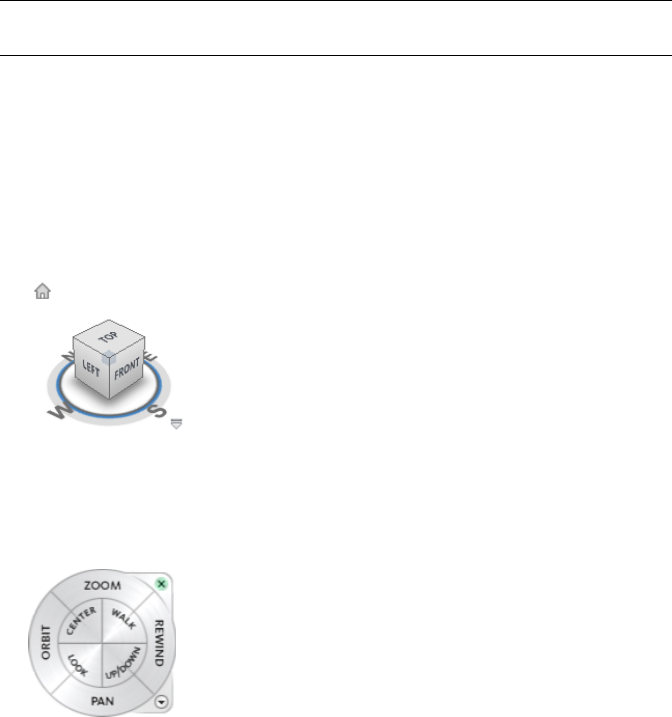
Orientation in 3D Space . . . . . . . . . . . . . . . . . . . . . . . . . . . . . . . . . . . . . . . . 126
Navigation Modes . . . . . . . . . . . . . . . . . . . . . . . . . . . . . . . . . . . . . . . . . . . . 127
SteeringWheels . . . . . . . . . . . . . . . . . . . . . . . . . . . . . . . . . . . . . . . . . . . . . 133
Camera . . . . . . . . . . . . . . . . . . . . . . . . . . . . . . . . . . . . . . . . . . . . . . . . . 150
ViewCube . . . . . . . . . . . . . . . . . . . . . . . . . . . . . . . . . . . . . . . . . . . . . . . . 152
Navigation Aids . . . . . . . . . . . . . . . . . . . . . . . . . . . . . . . . . . . . . . . . . . . . . 159
View All . . . . . . . . . . . . . . . . . . . . . . . . . . . . . . . . . . . . . . . . . . . . . . . . . 161
View Selected . . . . . . . . . . . . . . . . . . . . . . . . . . . . . . . . . . . . . . . . . . . . . . 161
Focus . . . . . . . . . . . . . . . . . . . . . . . . . . . . . . . . . . . . . . . . . . . . . . . . . . 162
Hold . . . . . . . . . . . . . . . . . . . . . . . . . . . . . . . . . . . . . . . . . . . . . . . . . . . 162
Contents | v
Control the Realism of Your Navigation . . . . . . . . . . . . . . . . . . . . . . . . . . . . . . . . . . . 162
Gravity . . . . . . . . . . . . . . . . . . . . . . . . . . . . . . . . . . . . . . . . . . . . . . . . . 162
Crouching . . . . . . . . . . . . . . . . . . . . . . . . . . . . . . . . . . . . . . . . . . . . . . . . 163
Collision . . . . . . . . . . . . . . . . . . . . . . . . . . . . . . . . . . . . . . . . . . . . . . . . . 163
Third Person View . . . . . . . . . . . . . . . . . . . . . . . . . . . . . . . . . . . . . . . . . . . . 164
Head-Up Display . . . . . . . . . . . . . . . . . . . . . . . . . . . . . . . . . . . . . . . . . . . . . . . 165
Chapter 7 Control Model Appearance and Render Quality . . . . . . . . . . . . . . . . . . . . . . . . . 167
Control Model Appearance . . . . . . . . . . . . . . . . . . . . . . . . . . . . . . . . . . . . . . . . . . 167
Select Render Mode . . . . . . . . . . . . . . . . . . . . . . . . . . . . . . . . . . . . . . . . . . . 167
Add Lighting . . . . . . . . . . . . . . . . . . . . . . . . . . . . . . . . . . . . . . . . . . . . . . 168
Select Background Effect . . . . . . . . . . . . . . . . . . . . . . . . . . . . . . . . . . . . . . . . 170
Adjust Displaying of Primitives . . . . . . . . . . . . . . . . . . . . . . . . . . . . . . . . . . . . . 172
Control Render Quality . . . . . . . . . . . . . . . . . . . . . . . . . . . . . . . . . . . . . . . . . . . . 174
Use Culling . . . . . . . . . . . . . . . . . . . . . . . . . . . . . . . . . . . . . . . . . . . . . . . 174
Control Rendering of Objects . . . . . . . . . . . . . . . . . . . . . . . . . . . . . . . . . . . . . . 176
Adjust Presenter Materials . . . . . . . . . . . . . . . . . . . . . . . . . . . . . . . . . . . . . . . 177
Stereo Rendering . . . . . . . . . . . . . . . . . . . . . . . . . . . . . . . . . . . . . . . . . . . . 178
Chapter 8 Review Your Model . . . . . . . . . . . . . . . . . . . . . . . . . . . . . . . . . . . . . . . . 179
Select Objects . . . . . . . . . . . . . . . . . . . . . . . . . . . . . . . . . . . . . . . . . . . . . . . . . 179
Interactive Geometry Selection . . . . . . . . . . . . . . . . . . . . . . . . . . . . . . . . . . . . . 179
Set Selection Resolution . . . . . . . . . . . . . . . . . . . . . . . . . . . . . . . . . . . . . . . . . 183
Set Highlighting Method . . . . . . . . . . . . . . . . . . . . . . . . . . . . . . . . . . . . . . . . 184
Hide Objects . . . . . . . . . . . . . . . . . . . . . . . . . . . . . . . . . . . . . . . . . . . . . . . 185
Find Objects . . . . . . . . . . . . . . . . . . . . . . . . . . . . . . . . . . . . . . . . . . . . . . . . . . 186
Find Items Window . . . . . . . . . . . . . . . . . . . . . . . . . . . . . . . . . . . . . . . . . . . 186
Quick Find . . . . . . . . . . . . . . . . . . . . . . . . . . . . . . . . . . . . . . . . . . . . . . . 190
Create and Use Sets of Objects . . . . . . . . . . . . . . . . . . . . . . . . . . . . . . . . . . . . . . . . 190
Selection Sets Window . . . . . . . . . . . . . . . . . . . . . . . . . . . . . . . . . . . . . . . . . 191
Create and Manage Selection and Search Sets . . . . . . . . . . . . . . . . . . . . . . . . . . . . . 192
Compare Objects . . . . . . . . . . . . . . . . . . . . . . . . . . . . . . . . . . . . . . . . . . . . . . . 194
Object Properties . . . . . . . . . . . . . . . . . . . . . . . . . . . . . . . . . . . . . . . . . . . . . . . 195
Properties Window . . . . . . . . . . . . . . . . . . . . . . . . . . . . . . . . . . . . . . . . . . . 195
Custom Properties . . . . . . . . . . . . . . . . . . . . . . . . . . . . . . . . . . . . . . . . . . . . 196
External Database Links . . . . . . . . . . . . . . . . . . . . . . . . . . . . . . . . . . . . . . . . . 198
Manipulate Object Attributes . . . . . . . . . . . . . . . . . . . . . . . . . . . . . . . . . . . . . . . . . 205
Transform Objects . . . . . . . . . . . . . . . . . . . . . . . . . . . . . . . . . . . . . . . . . . . . 205
Change Color and Transparency . . . . . . . . . . . . . . . . . . . . . . . . . . . . . . . . . . . . 209
Snapping . . . . . . . . . . . . . . . . . . . . . . . . . . . . . . . . . . . . . . . . . . . . . . . . 209
Reset to Original Values . . . . . . . . . . . . . . . . . . . . . . . . . . . . . . . . . . . . . . . . . 210
Measure Tools . . . . . . . . . . . . . . . . . . . . . . . . . . . . . . . . . . . . . . . . . . . . . . . . . 211
Measure Tools Window . . . . . . . . . . . . . . . . . . . . . . . . . . . . . . . . . . . . . . . . . 211
Measuring . . . . . . . . . . . . . . . . . . . . . . . . . . . . . . . . . . . . . . . . . . . . . . . . 212
Comments and Redlines . . . . . . . . . . . . . . . . . . . . . . . . . . . . . . . . . . . . . . . . . . . 216
Add Comments and Redlines . . . . . . . . . . . . . . . . . . . . . . . . . . . . . . . . . . . . . . 216
Review Comments and Redline Tags . . . . . . . . . . . . . . . . . . . . . . . . . . . . . . . . . . 222
Links . . . . . . . . . . . . . . . . . . . . . . . . . . . . . . . . . . . . . . . . . . . . . . . . . . . . . . 226
Link Categories . . . . . . . . . . . . . . . . . . . . . . . . . . . . . . . . . . . . . . . . . . . . . 226
Display Links . . . . . . . . . . . . . . . . . . . . . . . . . . . . . . . . . . . . . . . . . . . . . . 227
Customize Links . . . . . . . . . . . . . . . . . . . . . . . . . . . . . . . . . . . . . . . . . . . . . 228
Add Links . . . . . . . . . . . . . . . . . . . . . . . . . . . . . . . . . . . . . . . . . . . . . . . . 230
Find and Follow Links . . . . . . . . . . . . . . . . . . . . . . . . . . . . . . . . . . . . . . . . . 231
Manage Links . . . . . . . . . . . . . . . . . . . . . . . . . . . . . . . . . . . . . . . . . . . . . . 232
Smart Tags . . . . . . . . . . . . . . . . . . . . . . . . . . . . . . . . . . . . . . . . . . . . . . . . . . . 233
SwitchBack to AutoCAD and MicroStation . . . . . . . . . . . . . . . . . . . . . . . . . . . . . . . . . . 234
Chapter 9 Use Viewpoints and Sectioning Modes . . . . . . . . . . . . . . . . . . . . . . . . . . . . . . 237
Create and Modify Viewpoints . . . . . . . . . . . . . . . . . . . . . . . . . . . . . . . . . . . . . . . . 237
Overview of Viewpoints . . . . . . . . . . . . . . . . . . . . . . . . . . . . . . . . . . . . . . . . 237
Saved Viewpoints Window . . . . . . . . . . . . . . . . . . . . . . . . . . . . . . . . . . . . . . . 237
Save Viewpoints . . . . . . . . . . . . . . . . . . . . . . . . . . . . . . . . . . . . . . . . . . . . . 240
Recall Viewpoints . . . . . . . . . . . . . . . . . . . . . . . . . . . . . . . . . . . . . . . . . . . . 241
vi | Contents
Organize Viewpoints . . . . . . . . . . . . . . . . . . . . . . . . . . . . . . . . . . . . . . . . . . 241
Edit Viewpoints . . . . . . . . . . . . . . . . . . . . . . . . . . . . . . . . . . . . . . . . . . . . . 241
Default Viewpoint Options . . . . . . . . . . . . . . . . . . . . . . . . . . . . . . . . . . . . . . . 242
Share Viewpoints . . . . . . . . . . . . . . . . . . . . . . . . . . . . . . . . . . . . . . . . . . . . 244
Sectioning . . . . . . . . . . . . . . . . . . . . . . . . . . . . . . . . . . . . . . . . . . . . . . . . . . . 244
Enable Section Planes . . . . . . . . . . . . . . . . . . . . . . . . . . . . . . . . . . . . . . . . . . 245
Position and Use Section Planes . . . . . . . . . . . . . . . . . . . . . . . . . . . . . . . . . . . . 245
Link Section Planes . . . . . . . . . . . . . . . . . . . . . . . . . . . . . . . . . . . . . . . . . . . 248
Enable and Use Section Boxes . . . . . . . . . . . . . . . . . . . . . . . . . . . . . . . . . . . . . 248
Chapter 10 Record and Play Animations . . . . . . . . . . . . . . . . . . . . . . . . . . . . . . . . . . . 251
Create and Edit Viewpoint Animations . . . . . . . . . . . . . . . . . . . . . . . . . . . . . . . . . . . . 251
Play Animations . . . . . . . . . . . . . . . . . . . . . . . . . . . . . . . . . . . . . . . . . . . . . . . . 254
Chapter 11 Work Within a Team . . . . . . . . . . . . . . . . . . . . . . . . . . . . . . . . . . . . . . . . 255
Collaborate Toolbar . . . . . . . . . . . . . . . . . . . . . . . . . . . . . . . . . . . . . . . . . . . . . . 255
Collaboration Session . . . . . . . . . . . . . . . . . . . . . . . . . . . . . . . . . . . . . . . . . . . . . 255
Chapter 12 Share Data . . . . . . . . . . . . . . . . . . . . . . . . . . . . . . . . . . . . . . . . . . . . . 259
Print . . . . . . . . . . . . . . . . . . . . . . . . . . . . . . . . . . . . . . . . . . . . . . . . . . . . . . 259
Print Preview . . . . . . . . . . . . . . . . . . . . . . . . . . . . . . . . . . . . . . . . . . . . . . 259
Print Setup . . . . . . . . . . . . . . . . . . . . . . . . . . . . . . . . . . . . . . . . . . . . . . . 259
Print Current Viewpoint . . . . . . . . . . . . . . . . . . . . . . . . . . . . . . . . . . . . . . . . 260
Import Files . . . . . . . . . . . . . . . . . . . . . . . . . . . . . . . . . . . . . . . . . . . . . . . . . . 260
PDS Tag Files . . . . . . . . . . . . . . . . . . . . . . . . . . . . . . . . . . . . . . . . . . . . . . 260
PDS Display Set Files . . . . . . . . . . . . . . . . . . . . . . . . . . . . . . . . . . . . . . . . . . 261
Viewpoints Files . . . . . . . . . . . . . . . . . . . . . . . . . . . . . . . . . . . . . . . . . . . . . 261
Search Criteria Files . . . . . . . . . . . . . . . . . . . . . . . . . . . . . . . . . . . . . . . . . . . 262
Search Set Files . . . . . . . . . . . . . . . . . . . . . . . . . . . . . . . . . . . . . . . . . . . . . 262
Export Files . . . . . . . . . . . . . . . . . . . . . . . . . . . . . . . . . . . . . . . . . . . . . . . . . . 263
Piranesi EPix Format . . . . . . . . . . . . . . . . . . . . . . . . . . . . . . . . . . . . . . . . . . 263
PDS Tag Files . . . . . . . . . . . . . . . . . . . . . . . . . . . . . . . . . . . . . . . . . . . . . . 264
Autodesk DWF Format . . . . . . . . . . . . . . . . . . . . . . . . . . . . . . . . . . . . . . . . . 264
Google Earth KML Format . . . . . . . . . . . . . . . . . . . . . . . . . . . . . . . . . . . . . . . 264
Export Images . . . . . . . . . . . . . . . . . . . . . . . . . . . . . . . . . . . . . . . . . . . . . . 266
Viewpoints Files . . . . . . . . . . . . . . . . . . . . . . . . . . . . . . . . . . . . . . . . . . . . . 268
Current Search Criteria . . . . . . . . . . . . . . . . . . . . . . . . . . . . . . . . . . . . . . . . . 268
Search Set Files . . . . . . . . . . . . . . . . . . . . . . . . . . . . . . . . . . . . . . . . . . . . . 268
Viewpoints Report . . . . . . . . . . . . . . . . . . . . . . . . . . . . . . . . . . . . . . . . . . . 268
Chapter 13 TimeLiner Playback . . . . . . . . . . . . . . . . . . . . . . . . . . . . . . . . . . . . . . . . 269
Overview of TimeLiner Tool . . . . . . . . . . . . . . . . . . . . . . . . . . . . . . . . . . . . . . . . . 269
TimeLiner Playback Window . . . . . . . . . . . . . . . . . . . . . . . . . . . . . . . . . . . . . . 269
Simulate Tab . . . . . . . . . . . . . . . . . . . . . . . . . . . . . . . . . . . . . . . . . . . 269
Play Simulations . . . . . . . . . . . . . . . . . . . . . . . . . . . . . . . . . . . . . . . . . . . . . . . . 271
Chapter 14 Autodesk Navisworks Reference . . . . . . . . . . . . . . . . . . . . . . . . . . . . . . . . . 273
File Options Dialog Box . . . . . . . . . . . . . . . . . . . . . . . . . . . . . . . . . . . . . . . . . . . . 273
Culling Tab . . . . . . . . . . . . . . . . . . . . . . . . . . . . . . . . . . . . . . . . . . . . . . . 273
Orientation Tab . . . . . . . . . . . . . . . . . . . . . . . . . . . . . . . . . . . . . . . . . . . . . 274
Speed Tab . . . . . . . . . . . . . . . . . . . . . . . . . . . . . . . . . . . . . . . . . . . . . . . . 274
Head Light Tab . . . . . . . . . . . . . . . . . . . . . . . . . . . . . . . . . . . . . . . . . . . . . 275
Scene Lights Tab . . . . . . . . . . . . . . . . . . . . . . . . . . . . . . . . . . . . . . . . . . . . . 275
DataTools Tab . . . . . . . . . . . . . . . . . . . . . . . . . . . . . . . . . . . . . . . . . . . . . . 275
File Units and Transform Dialog Box . . . . . . . . . . . . . . . . . . . . . . . . . . . . . . . . . . . . . 275
New Link Dialog Box . . . . . . . . . . . . . . . . . . . . . . . . . . . . . . . . . . . . . . . . . . . . . 276
Edit Link Dialog Box . . . . . . . . . . . . . . . . . . . . . . . . . . . . . . . . . . . . . . . . . . . . . 276
Edit Viewpoint Dialog Box . . . . . . . . . . . . . . . . . . . . . . . . . . . . . . . . . . . . . . . . . . 276
Options Editor . . . . . . . . . . . . . . . . . . . . . . . . . . . . . . . . . . . . . . . . . . . . . . . . . 277
General Node . . . . . . . . . . . . . . . . . . . . . . . . . . . . . . . . . . . . . . . . . . . . . . 278
Undo Page . . . . . . . . . . . . . . . . . . . . . . . . . . . . . . . . . . . . . . . . . . . . . 278
Contents | vii
Locations Page . . . . . . . . . . . . . . . . . . . . . . . . . . . . . . . . . . . . . . . . . . 278
Environment Page . . . . . . . . . . . . . . . . . . . . . . . . . . . . . . . . . . . . . . . . 278
Communication Center Page . . . . . . . . . . . . . . . . . . . . . . . . . . . . . . . . . . . 278
Auto-Save Page . . . . . . . . . . . . . . . . . . . . . . . . . . . . . . . . . . . . . . . . . . 279
Model Node . . . . . . . . . . . . . . . . . . . . . . . . . . . . . . . . . . . . . . . . . . . . . . . 279
Performance Page . . . . . . . . . . . . . . . . . . . . . . . . . . . . . . . . . . . . . . . . . 279
NWD Page . . . . . . . . . . . . . . . . . . . . . . . . . . . . . . . . . . . . . . . . . . . . . 281
NWC Page . . . . . . . . . . . . . . . . . . . . . . . . . . . . . . . . . . . . . . . . . . . . . 281
Interface Node . . . . . . . . . . . . . . . . . . . . . . . . . . . . . . . . . . . . . . . . . . . . . . 282
Display Units Page . . . . . . . . . . . . . . . . . . . . . . . . . . . . . . . . . . . . . . . . 282
Selection Page . . . . . . . . . . . . . . . . . . . . . . . . . . . . . . . . . . . . . . . . . . . 282
Measure Page . . . . . . . . . . . . . . . . . . . . . . . . . . . . . . . . . . . . . . . . . . . 283
Snapping Page . . . . . . . . . . . . . . . . . . . . . . . . . . . . . . . . . . . . . . . . . . . 283
Viewpoint Defaults Page . . . . . . . . . . . . . . . . . . . . . . . . . . . . . . . . . . . . . 283
Hyperlinks Page . . . . . . . . . . . . . . . . . . . . . . . . . . . . . . . . . . . . . . . . . . 284
Smart Tags Page . . . . . . . . . . . . . . . . . . . . . . . . . . . . . . . . . . . . . . . . . . 286
Developer Page . . . . . . . . . . . . . . . . . . . . . . . . . . . . . . . . . . . . . . . . . . 287
Display Page . . . . . . . . . . . . . . . . . . . . . . . . . . . . . . . . . . . . . . . . . . . . 287
SpaceBall Page . . . . . . . . . . . . . . . . . . . . . . . . . . . . . . . . . . . . . . . . . . . 288
ViewCube Page . . . . . . . . . . . . . . . . . . . . . . . . . . . . . . . . . . . . . . . . . . 288
SteeringWheels . . . . . . . . . . . . . . . . . . . . . . . . . . . . . . . . . . . . . . . . . . 289
File Readers Node . . . . . . . . . . . . . . . . . . . . . . . . . . . . . . . . . . . . . . . . . . . . 290
3DS Page . . . . . . . . . . . . . . . . . . . . . . . . . . . . . . . . . . . . . . . . . . . . . 291
ASCII Laser Page . . . . . . . . . . . . . . . . . . . . . . . . . . . . . . . . . . . . . . . . . . 291
CIS2 Page . . . . . . . . . . . . . . . . . . . . . . . . . . . . . . . . . . . . . . . . . . . . . 291
DGN Page . . . . . . . . . . . . . . . . . . . . . . . . . . . . . . . . . . . . . . . . . . . . . 292
DWF Page . . . . . . . . . . . . . . . . . . . . . . . . . . . . . . . . . . . . . . . . . . . . . 293
DWG/DXF/SAT Page . . . . . . . . . . . . . . . . . . . . . . . . . . . . . . . . . . . . . . . 293
Faro Page . . . . . . . . . . . . . . . . . . . . . . . . . . . . . . . . . . . . . . . . . . . . . 295
IFC Page . . . . . . . . . . . . . . . . . . . . . . . . . . . . . . . . . . . . . . . . . . . . . . 296
IGES Page . . . . . . . . . . . . . . . . . . . . . . . . . . . . . . . . . . . . . . . . . . . . . 296
Inventor Page . . . . . . . . . . . . . . . . . . . . . . . . . . . . . . . . . . . . . . . . . . . 297
JTOpen Page . . . . . . . . . . . . . . . . . . . . . . . . . . . . . . . . . . . . . . . . . . . . 297
Leica Page . . . . . . . . . . . . . . . . . . . . . . . . . . . . . . . . . . . . . . . . . . . . . 297
MAN Page . . . . . . . . . . . . . . . . . . . . . . . . . . . . . . . . . . . . . . . . . . . . . 298
PDS Page . . . . . . . . . . . . . . . . . . . . . . . . . . . . . . . . . . . . . . . . . . . . . 298
Riegl Page . . . . . . . . . . . . . . . . . . . . . . . . . . . . . . . . . . . . . . . . . . . . . 298
RVM Page . . . . . . . . . . . . . . . . . . . . . . . . . . . . . . . . . . . . . . . . . . . . . 299
SKP Page . . . . . . . . . . . . . . . . . . . . . . . . . . . . . . . . . . . . . . . . . . . . . . 300
STEP Page . . . . . . . . . . . . . . . . . . . . . . . . . . . . . . . . . . . . . . . . . . . . . 300
STL Page . . . . . . . . . . . . . . . . . . . . . . . . . . . . . . . . . . . . . . . . . . . . . . 301
VRML Page . . . . . . . . . . . . . . . . . . . . . . . . . . . . . . . . . . . . . . . . . . . . 301
Z + F Page . . . . . . . . . . . . . . . . . . . . . . . . . . . . . . . . . . . . . . . . . . . . . 302
File Exporters Node . . . . . . . . . . . . . . . . . . . . . . . . . . . . . . . . . . . . . . . . . . . 302
DWG Page . . . . . . . . . . . . . . . . . . . . . . . . . . . . . . . . . . . . . . . . . . . . . 302
Revit Page . . . . . . . . . . . . . . . . . . . . . . . . . . . . . . . . . . . . . . . . . . . . . 304
DGN Page . . . . . . . . . . . . . . . . . . . . . . . . . . . . . . . . . . . . . . . . . . . . . 305
Viz/Max Page . . . . . . . . . . . . . . . . . . . . . . . . . . . . . . . . . . . . . . . . . . . 306
Tools Node . . . . . . . . . . . . . . . . . . . . . . . . . . . . . . . . . . . . . . . . . . . . . . . 306
Presenter Page . . . . . . . . . . . . . . . . . . . . . . . . . . . . . . . . . . . . . . . . . . . 306
Scripter Page . . . . . . . . . . . . . . . . . . . . . . . . . . . . . . . . . . . . . . . . . . . . 308
Animator Page . . . . . . . . . . . . . . . . . . . . . . . . . . . . . . . . . . . . . . . . . . 308
Default Collision Dialog Box . . . . . . . . . . . . . . . . . . . . . . . . . . . . . . . . . . . . . . . . . 308
Collision Dialog Box . . . . . . . . . . . . . . . . . . . . . . . . . . . . . . . . . . . . . . . . . . . . . 309
Convert Object Properties Dialog Box . . . . . . . . . . . . . . . . . . . . . . . . . . . . . . . . . . . . 310
Culling Options Dialog Box . . . . . . . . . . . . . . . . . . . . . . . . . . . . . . . . . . . . . . . . . . 310
Customize Dialog Box . . . . . . . . . . . . . . . . . . . . . . . . . . . . . . . . . . . . . . . . . . . . . 310
Toolbars Tab . . . . . . . . . . . . . . . . . . . . . . . . . . . . . . . . . . . . . . . . . . . . . . . 311
Commands Tab . . . . . . . . . . . . . . . . . . . . . . . . . . . . . . . . . . . . . . . . . . . . . 311
Options Tab . . . . . . . . . . . . . . . . . . . . . . . . . . . . . . . . . . . . . . . . . . . . . . . 311
Customize Keyboard Dialog Box . . . . . . . . . . . . . . . . . . . . . . . . . . . . . . . . . . . . . . . 312
Publish Dialog Box . . . . . . . . . . . . . . . . . . . . . . . . . . . . . . . . . . . . . . . . . . . . . . 312
Background Settings Dialog Box . . . . . . . . . . . . . . . . . . . . . . . . . . . . . . . . . . . . . . . 313
Image Export Dialog Box . . . . . . . . . . . . . . . . . . . . . . . . . . . . . . . . . . . . . . . . . . . 314
Animation Export Dialog Box . . . . . . . . . . . . . . . . . . . . . . . . . . . . . . . . . . . . . . . . 314
viii | Contents
x | Contents
Welcome to Autodesk
Navisworks Review 2010
Autodesk Navisworks Review 2010 software extends access to existing design data
for real-time visualization to experience design projects before they are real. Project
quality improves by combining and sharing of 3D design data and information,
regardless of file size or format. Easy-to-use design review tools improve insight
and understanding of design intent. Entire project models can be published and
freely viewed in NWD and 3D DWF™ formats to provide valuable digital assets
during and after construction.
1
2 | Part 1 Welcome to Autodesk Navisworks Review 2010
What Is New in This
Release?
Autodesk Navisworks Review 2010 contains many new features and enhancements.
Installation
The installation screen provides links to the installation options, deployment
options, installation tools and utilities, documentation and language settings.
When installing the product you can select to install either the 32-bit or 64-bit
version. You also have the option of selecting the DWG file readers that require
installation, plus the exporter plugins that you require.
NOTE If you are installing the product on a 32-bit operating system the 64-bit install
options are inaccessible.
User Interface
Changes to the Autodesk Navisworks Review 2010 interface more closely align
the product with Autodesk standard interface and navigation toolsets.
■ViewCube. The ViewCube is an on-screen widget, shaped like a cube, that
rotates as you orbit your 3D scene and provides you with feedback about your
current camera viewing angle in relation to the model world. See “ViewCube”
on page 152.
■SteeringWheels. SteeringWheels are task-based floating tool palettes that travel
with the cursor to minimize tool access time. SteeringWheels provide access
to different navigation tools grouped into various wheels depending on the
navigation task and user skill level. See “SteeringWheels” on page 133.
1
3
■Button menus. In Autodesk Navisworks, some toolbar buttons exist in mutually-exclusive groups of which only one at a
time can be selected. These buttons are now grouped under drop-down menus to improve accessibility and decrease screen
clutter.
■Artificial horizon. You can now place your model against a fixed artificial horizon so that it appears more realistic and does
not float in mid air. The background of the 3D scene is split across the horizontal plane giving the effect of a sky and the
ground. The resulting artificial horizon gives you an indication of your orientation in the 3D world. See “Select Background
Effect” on page 170.
Measurement
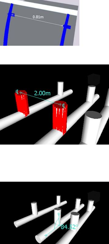
Numerous improvements to the measurement tools allow greater accuracy when calculating dimensions and distances between
objects in your Autodesk Navisworks model.
■Measure Shortest Distance. When measuring the distance between two objects, Autodesk Navisworks can now calculate
and display the shortest distance between the selected objects.
■Measure distance between center lines of parametric objects.
■When measuring distances you now have the option of converting measurements into redlines. The end markers, lines,
and dimension labels of your current measurement are converted into a redline and stored in the current viewpoint.
■When measuring an angle, Autodesk Navisworks now displays a measurement arc.
■When measuring an area, Autodesk Navisworks now displays a dotted line to indicate the closure path for the area.
See “Measuring” on page 212.
Sectioning
Improved support for quick and accurate analysis of models using the sectioning toolset.
■Create a user-defined section box to display only geometry within the defined section box.
4 | Chapter 1 What Is New in This Release?

■Align section planes to specific faces of an object or line.
See “Sectioning” on page 244.
Auto-Save
You now have the option of automatically saving your work at regular intervals.
See “Automatically Save and Recover Files” on page 53.
Communication Center
The Communication Center allows the Autodesk Navisworks and Autodesk team to notify you of product-related updates
and announcements.
See “Use Communication Center” on page 7.
File Format Support
■Support for JT file format, supporting most geometry types and object attributes. See “JTOpen File Reader” on page 100.
■Support for CIMSteel Integration Standards (CIS/2). See “CIS2 File Reader” on page 93.
Miscellaneous Enhancements
■Autodesk Navisworks Review 2010 is available for full 64-bit installation.
■Manual override option allows you to specify the distance of Near and Far Clipping Planes. See “Use Culling” on page 174.
■When entering invalid values in the Options Editor, you are notified of the error.
■You can now configure site and project folders at install time, making deployment across an organization easier. See “Select
the Project and Site Folder Paths (optional)” on page 40.
■Upgrades to the Autodesk Navisworks rendering engine (LADS) provide improved support for PNG transparencies and
improved rendering consistency.
■Improved Revit support for: shared coordinates, rebars, True North, views, and viewpoints exported from Revit 9 and later.
| 5
6 | Chapter 1 What Is New in This Release?
How to Get Assistance
There are various ways to find information about how to use this program, and
multiple resources are available.
Use Communication Center
Communication Center provides up-to-date product information,
software updates, product support announcements, and other
product-related announcements.
Overview of Communication Center
Communication Center provides up-to-date product information,
software updates, product support announcements, and other
product-related announcements.
Communication Center is an interactive feature that must be
connected to the Internet in order to deliver content and
information.
Each time Communication Center is connected, it sends your
information to Autodesk so that you receive the correct information.
All information is sent anonymously to Autodesk to maintain your
privacy.
The following information is sent to Autodesk:
■Product name (in which you are using Communication Center)
■Product release number
■Product language
■Country/region (specified in the Communication Center settings)
■Your subscription contract number (if you’re a subscription
customer)
Autodesk compiles statistics using the information sent from
Communication Center to monitor how it is being used and how
it can be improved. Autodesk maintains information provided by
or collected from you in accordance with the company's published
privacy policy, which is available on http://www.autodesk.com/privacy.
Whenever new information is available, Communication Center
notifies you by displaying a balloon message below the
Communication Center button on the InfoCenter box.
2
7
Communication Center provides the following kinds of announcements:
■Product Support Information. Get breaking news from the Product Support team at Autodesk, including
when Live Update maintenance patches are released.
■Subscription Announcements. Receive subscription announcements and subscription program news, as well
as links to e-Learning Lessons, if you are an Autodesk subscription member (available in countries/regions
where Autodesk subscriptions are offered).
For more information about Autodesk Subscription, see “Access Subscription Center” on page 13.
■Articles and Tips. Be notified when new articles and tips are available on Autodesk websites.
■Live Update Maintenance Patches. Receive automatic notifications whenever new maintenance patches are
released from Autodesk.
■Featured Technologies and Content. Learn more about third-party developer applications and content.
You can customize the items that display on the Communication Center panel. For more information, see
“Specify Communication Center Settings” on page 8.
To open Communication Center
■Click the Communication Center button on the Standard toolbar in the upper right-side of the application.
Menu: Help ➤ Communication Center
To receive new information notifications
■Click the link in the balloon message below the notification icon on the Status bar.
To turn off Balloon Notifications
■Right-click the notification icon on the Status bar, and click Disable Balloon Notifications.
Specify Communication Center Settings
You can specify Communication Center settings in the Options Editor.
In the Options Editor, you can specify the following settings:
■General. Your current locations, how often to check for new online content, and maximum age of the
displayed articles.
■Autodesk Channels. Channels to display in the Communication Center panel as well as the number of articles
to display for each channel.
■Balloon Notification. Notifications for new product information, software updates, and product support
announcements. Also, you can customize the display time of the balloon.
To specify general settings for Communication Center
1Open the Communication Center panel, and click Options.
2In the Options Editor, expand the General node, and click the Communication Center option.
3On the Communication Center page, select the country in which you are working. This is used for tailoring
location-specific Communication Center content.
4Use the Check for New Online Content drop-down list to specify the desired frequency. By default,
Communication Center checks for new content every 4 hours.
5To remove old content, select the Hide Old Content check box, and use the After box to set the number of
days after which old content is hidden. The default value is 14 days.
8 | Chapter 2 How to Get Assistance
6Click OK.
To specify the channels to display in the Communication Center panel
1Open the Communication Center panel, and click Options.
2In the Options Editor, expand the General node, expand the Communication Center node, and click the
Autodesk Channels option.
3On the Autodesk Channels page, select the Subscribed check boxes for all channels you want to display.
4Click OK.
To specify balloon notification settings
1Open the Communication Center panel, and click Options.
2In the Options Editor, expand the General node, expand the Communication Center node, and click the
Balloon Notifications option.
3On the Balloon Notifications page, use the Enable Balloon Notifications check box to turn balloon notification
on/off.
4In the Display Duration box, enter the number of seconds to set the length of time for balloon notifications
to display.
The default value for the balloon display time is 5 seconds.
5Click OK.
Use the Help System
You can get much more benefit from the Help system when you learn how to use it efficiently.
The Help system contains complete information about using this program. In the Help window, you use the left
pane to locate information. The tabs above the left pane give you several ways for finding the topics you want
to view. The right pane displays the topics you select.
Find Information in Help
The tabs on the left side of the Help window provide different methods for finding information.
To locate a specific word or phrase in the current topic, click in the topic text and press the CTRL+F keys.
Contents Tab
■Presents an overview of the available documentation in a list of topics and subtopics.
■Allows you to browse by selecting and expanding topics.
■Provides a structure so you can always see where you are in Help and quickly jump to other topics.
Index Tab
■Displays an alphabetical list of keywords related to the topics listed on the Contents tab.
■Accesses information quickly when you already know the name of a feature, command, or operation, or
when you know what action you want the program to perform.
Search Tab
■Provides a keyword search of all the topics listed on the Contents tab.
■Accepts the Boolean operators AND (+), OR, NOT (-), and NEAR.
■Accepts the wild cards *, ?, and ~.
Use the Help System | 9
■Allows you to perform a search for a phrase when the phrase is enclosed in double quotes.
■Displays a ranked list of topics that contain the word or words entered in the keyword field.
■Arranges the results alphabetically by title or by location if you click on the Title and Location column
headings.
Use Searches
Use the Search tab to find relevant topics based on keywords that you enter.
The basic search rules are as follows:
■Type your keywords in uppercase or lowercase characters; searches are not case-sensitive.
■Search for any combination of letters (a-z) and numbers (0-9).
■Do not use punctuation marks such as a period, colon, semicolon, comma, hyphen, and single quotation
marks; they are ignored during a search.
■Group the elements of your search using double quotation marks or parentheses to set each element apart.
Use Wild Card Characters
You can use the following wild card characters in any keyword:
DescriptionSymbol
Replaces one or more characters when
used at the beginning, middle, or end of
*
a word. For example, “*lish”, “p*lish”, and
“pub*” will all find “publish”. Also, “an-
no*” will find “annotative”, “annotation”,
“annoupdate”, “annoreset”, and so on.
Replaces a single character. For example,
“cop?” will find “copy”, but not “copy-
base”.
?
Expands the tense of the word at the be-
ginning or end of a word. For example,
~
“plotting~” will find “plots”, “plotted”,
and so on. Also, “~plot” will find “preplot”,
“replot”, and so on.
Search for Phrases
When searching for a phrase, use double quotation marks (" ") to enclose words that must appear next to each
other in the specified sequence. For example, enter "specifying units of measurement" to find only topics with
all those words in that order. If you don't use the quotation marks around that text, Help finds all topics containing
any one of the listed words, that is, all topics containing "specifying", all topics containing "units", all topics
containing "of", and all topics containing "measurement".
TIP If you can’t find the information you need through a search, try using the Contents tab.
Use Boolean Operators
With the AND, OR, NOT, and NEAR operators, you can precisely define your search by creating a relationship
between search terms. The following table shows how you can use each of these operators. If no operator is
10 | Chapter 2 How to Get Assistance
specified, AND is used. For example, the query spacing border printing is equivalent to spacing AND border AND
printing.
ResultsExampleSearch for
Topics containing both the
words "tree view" and "palette"
"tree view" AND “palette”Both terms in the same
topic
Topics containing either the
word "viewpoint" or the word
"animation" or both
viewpoint OR animationEither term in a topic
Topics containing the word
"NWD," but not the word "NWC"
nwd NOT nwcThe first term without
the second term
Topics containing the word
"user" within eight words of the
word "menu"
user NEAR menuBoth terms in the same
topic, close together
NOTE The |, &, and ! characters do not work as Boolean operators. You must use AND (also +), OR, and NOT (also
-).
How Help Topics Are Organized
Most topics in this Help system have three tabs above the right pane of the Help window. The tabs display
different types of information.
■Concept tab. Describes a feature or function. When you click the Concept tab, the Help Contents list in the
left pane of the Help window expands and highlights the current topic. The Contents tab displays the structure
of the Help on that topic. You can easily display nearby topics by clicking them in the list.
■Procedure tab. Provides step-by-step instructions for common procedures related to the current topic. After
displaying a procedure, you can click the Procedure tab to redisplay the current list of procedures.
■Quick Reference tab. Lists reference information related to the current topic.
When you click a different tab, the topic remains the same. Only the type of information displayed—concept,
procedures, or quick reference links—is different.
Concept Tab Organization
In a Concept tab, there are two types of information that may be displayed: navigation text and destination text.
Navigation text displays links with short descriptions. The purpose of navigation text is to guide you step-by-step
to the information that you need. The links on navigation pages lead to additional navigation pages deeper in
the Help structure until you come to a destination page. Each link is designed to provide you with more detailed
information.
Procedure Tab and Quick Reference Tab Organization
As you navigate deeper into the Help structure on the Contents tab, the corresponding information on the
Procedure tab and on the Quick Reference tab becomes more specific, and the number of entries displayed on
each of these two tabs decreases.
Print Help Topics
The quickest way to print the current topic is to right-click within the topic and click Print.
The Print button on the Help toolbar provides these print options:
■Print the selected topic (recommended)
■Print the selected heading and all subtopics
How Help Topics Are Organized | 11
NOTE When you select the second option, you may get numerous printed pages, depending on how many subtopics
the currently selected topic contains.
To print a Help topic
1Display the topic you want to print.
2Right-click in the topic pane. Click Print.
3In the Print dialog box, click Print.
To print a selected heading and all subtopics
1Display the topic you want to print and make sure that the Contents tab is displayed.
2On the Help toolbar, click Print.
3In the Print Topics dialog box, click Print the Selected Heading and All Subtopics.
4Click OK.
Show and Hide the Contents Pane
Use the Hide button on the Help toolbar to shrink the Help window to a compact size by hiding the pane that
contains the Contents, Index, and Search tabs.
The compact window size is best for displaying procedures while you work.
Use the Show button to expand the Help window to display the pane that contains Contents, Index, and Search
tabs. The expanded window size is best for locating and displaying conceptual and reference information.
Get More Help
You can access several additional sources of help.
■On the Standard toolbar, use Communication Center. Display the Communication Center panel for product
updates and announcements.
■Press F1. Displays context-sensitive reference information.
■Click the Help button in many dialog boxes. Displays reference information for the dialog box.
■View the product Readme. Displays late-breaking information about this product.
Other resources help you get information about Autodesk products and assistance with your questions about
this program.
■Autodesk website. Access http://www.autodesk.com.
■Local support. Check with your dealer or Autodesk country/region office.
Learn the Product
Training programs and products from Autodesk help you learn the key technical features and improve your
productivity. For the latest information about Autodesk training, visit http://www.autodesk.com/training or contact
your local Autodesk office.
12 | Chapter 2 How to Get Assistance

Autodesk Authorized Training Centers
The Autodesk® Authorized Training Center (ATC®) network delivers Autodesk-authorized, instructor-led training
to design professionals who use Autodesk software. Autodesk Authorized Training Centers use experienced and
knowledgeable instructors. More than 1,200 ATC sites are available worldwide to meet your needs for
discipline-specific, locally based training.
To find a training center near you, contact your local Autodesk office or visit http://www.autodesk.com/atc.
Autodesk Official Training Courseware
Autodesk Official Training Courseware (AOTC) is technical training material developed by Autodesk. Designed
for traditional 1/2-day to 5-day, instructor-led classroom training and used by Authorized Training Centers and
other Autodesk partners, AOTC is well-suited for self-paced, stand-alone learning. The manuals cover key concepts
and software functionality with hands-on, step-by-step, real-world exercises. You can purchase AOTC from your
local reseller or distributor, or you can order it online from the Autodesk Store at http://www.autodesk.com/aotc.
e-Learning
Autodesk e-Learning for Autodesk Subscription customers features interactive lessons organized into product
catalogs. Each lesson is 20-40 minutes in length and features hands-on exercises, with an option to use a simulation
of the product or the actual application. You can also use an online evaluation tool that identifies gaps in skills,
determines what lessons will be most helpful, and gauges learning progress.
If you are a member of Autodesk subscription, you can access e-Learning and other subscription services from
within your Autodesk product.
For more information about how to access e-Learning in the product, see “Access Subscription Center” on page
13.
For more information about Autodesk subscription resources, visit http://www.autodesk.com/subscriptioncenter.
Autodesk Developer Network
The Autodesk Developer (ADN) program for ADN members provides support for full-time, professional developers
who want to build software based on Autodesk products. As an ADN member, you will receive the business,
software, support, and training you need to be successful. If you are a developer, visit http://www.autodesk.com/adn.
Autodesk Consulting
Autodesk Consulting provides services that help set up processes and provide critical training that will help
increase productivity so you can capitalize on the power of your products. For more information on general
consulting, systems integration, or custom training services, visit http://www.autodesk.com/consulting.
Partner Products and Services
Autodesk works together with thousands of software partners around the world. These partners provide products
and services that enhance Autodesk products for design professionals. Visit the Partner Products & Services page
at http://www.autodesk.com/partnerproducts for a list of resources available for your Autodesk product and your
industry.
Access Subscription Center
The Subscription Center is available to subscription members from within the product.
If you are a subscription member, you can access subscription services by clicking the Communication Center
button on the Standard toolbar, and then clicking a Subscription Center link. To learn more about Autodesk
subscription membership, visit http://www.autodesk.com/subscriptioncenter.
Access Subscription Center | 13
About Subscription Center
With Autodesk Subscription, you get the latest releases of Autodesk software, incremental product enhancements,
personalized web support from Autodesk technical experts, and self paced e-Learning. Subscription services are
available to subscription members only.
By clicking the Communication Center button on the Standard toolbar, members have access to the following
options (under Subscription Center):
■Subscription status. Checks your subscription status.
■Create support request. Provides direct one-to-one communication with Autodesk support technicians. You
receive fast, complete answers to your installation, configuration, and troubleshooting questions.
■View support requests. Tracks and manage your questions and responses through Autodesk's state-of-the-art
support system.
■Edit Subscription Center profile. Sets up and maintains your subscription account.
■View e-Learning catalog. Features interactive lessons organized into product catalogs.
■e-Learning Lessons. (For subscription members only.) Each lesson is 15-30 minutes and features hands-on
exercises, with an option to use a simulation instead of the software application. You can use an online
evaluation tool that identifies gaps in skills, determines what lessons will be most helpful, and gauges learning
progress.
Subscription Resources and Privacy
Subscription resources provide interactive product features over the Internet. Each time you access subscription
resources (such as e-Learning or Create Support Request) from Communication Center in an Autodesk product,
product information (such as the serial number, version, language, and the subscription contract ID) is sent to
Autodesk for verification that your product is on subscription.
Autodesk compiles statistics using the information sent to subscription resources to monitor how they are being
used and how they can be improved. Autodesk maintains the information provided by or collected from you in
accordance with Autodesk's published privacy policy, which is available at http://www.autodesk.com/privacy.
To access the Subscription Center in the program
1Click the Communication Center button on the Standard toolbar.
2On the Communication Center panel, under Subscription Center, click the subscription resource you want
to access.
NOTE Subscription Center is not available to all product users. If subscription resources are not available in your
product, your product is not entitled to subscription benefits.
Manage Files with Autodesk Vault
If you are a subscription customer, you have access to Autodesk Vault, a file management tool that provides a
repository where documents and files are stored and managed.
Autodesk Vault gives you more power to manage files and track changes. Versioned copies of master files are
maintained, allowing you to easily revert to earlier versions of files. You can check files out for editing and later
check them back in. The master copy is never directly edited.
Autodesk Vault consists of two required components: the Autodesk Data Management Server and the Vault
Client. Optionally, you can also install the Vault Office Add-in.
For information about using the Vault, refer to the Vault Help system.
TIP The main components for the Autodesk Vault can be downloaded from the Autodesk Subscription site.
14 | Chapter 2 How to Get Assistance

View the Product Readme
You can find late-breaking information about this software in the Readme.
It is suggested that you read through the Autodesk Navisworks Readme for information about recommended
hardware, updated installation instructions, and known software problems.
Join the Customer Involvement Program
You are invited to participate in helping guide the direction of Autodesk design software.
If you participate in the Customer Involvement Program (CIP), specific information about how you use AutoCAD
is forwarded to Autodesk. This information includes what features you use the most, problems that you encounter,
and other information helpful to the future direction of the product.
Here is a list of the information that is automatically sent to Autodesk:
■Name and version of the Autodesk product
■Number of minutes you are running the software
■Number of sessions that end due to stability issues
■Menu actions triggered
■Error conditions encountered, fatal, and non-fatal
■Import/export actions (including file extension used)
■Scene statistics after a load or import (number of objects, faces, vertices etc.)
■Operating system name and version
■System configuration information such as processor, amount of memory, and graphics card
■Other Autodesk products installed
■Plug-in (DLLS) installed with Autodesk Navisworks
■IP address, used to identify your country or region
What the Customer Involvement Program Cannot Do
The Customer Involvement Program is committed to protecting your privacy. It cannot do any of the following:
■Collect any drawing or design data
■Collect any identity information such as name, address, or phone number
■Send you email or contact you in any other way
For additional information, click the links in the Customer Involvement Program dialog box.
Why You Should Consider Participating
The Customer Involvement Program involves you directly in telling Autodesk
■The commands and features that Autodesk should focus on
■The commands and features that are hardly ever used
■The most common problem areas
■The hardware typically used with Autodesk Navisworks
NOTE You can start or stop your participation in this program at any time. Access to the controls is available from the
Autodesk Navisworks Help menu. In network installations, your system administrator can choose whether to make the
CIP program available or not.
View the Product Readme | 15
To turn the CIP on or off
1Click Help ➤ Customer Involvement Program.
2In the Customer Involvement Program dialog box, click a level of participation, and then click OK.
16 | Chapter 2 How to Get Assistance

Installation
This chapter provides information about installing and activating Autodesk
Navisworks on a workstation, as well as deploying Autodesk Navisworks from a
network location.
Quick Start to Stand-Alone Installation
This section provides step-by-step instructions about how to prepare,
and then install Autodesk Navisworks.
If you have never installed the product before, you should familiarize
yourself with the entire installation process and options before
beginning.
For information about installing network-licensed or multi-seat
stand-alone versions of the program, see “Install Autodesk
Navisworks for Multiple Users” on page 28.
Prepare for Installation
To prepare for installation, you should review the system
requirements, understand administrative permission requirements,
locate your Autodesk Navisworks Review 2010 serial number and
product key, and close all running applications.
Complete these tasks, and you are ready to begin installing Autodesk
Navisworks Review 2010.
System Requirements for Stand-Alone
Installation
The first task you need to complete is to make sure that your
computer meets the minimum system requirements. If your system
does not meet these requirements, problems can occur, both within
Autodesk Navisworks and at the operating system level.
Whether your Windows operating system is the 32-bit or the 64-bit
version, the version is automatically detected during installation.
NOTE Both the 32-bit version and 64-bit version of Autodesk Navisworks
Review 2010 can be installed on a 64-bit version of Windows, but the
64-bit version of Autodesk Navisworks Review 2010 cannot be installed
on a 32-bit version of Windows.
3
17
See the following table for hardware and software requirements.
Hardware and software requirements
RequirementHardware/Software
32-BitOperating system
Windows© XP© Professional, SP 2 or SP 3;
Windows XP Home, SP 2 or SP 3; Windows
Vista Ultimate, SP 1; Windows Vista Enter-
prise, SP 1; Windows Vista Business, SP 1;
Windows Vista Home Premium, SP 1;
Windows Vista Home Basic, SP 1
64-Bit
Windows© XP© Professional, SP 1; Win-
dows Vista Enterprise, SP 1; Windows Vista
Business, SP 1; Windows Vista Ultimate, SP
1; Windows Vista Home Premium, SP 1
32-BitWeb browser
Microsoft© Internet Explorer 6.0, SP 1 or
later
64-Bit
Internet Explorer 7.0 or later
32-BitProcessor
AMD© Athlon©, 3.0 GHz or faster (minim-
um); Intel© Pentium© IV, 3.0 GHz or faster
(recommended)
64-Bit
AMD or Intel EM64T
32-BitRAM
512 MB (minimum) 2 GB or greater (re-
commended)
64-Bit
2 GB
128 MB, 1024 x 768 VGA, True Color
(minimum); 256 MB or greater - 1280 x
Graphics card
1024 32-bit color video display adapter,
True Color (recommended)
Installation 800 MBHard disk
MS-Mouse compliantPointing device
Any speed (for installation only)DVD-ROM
18 | Chapter 3 Installation
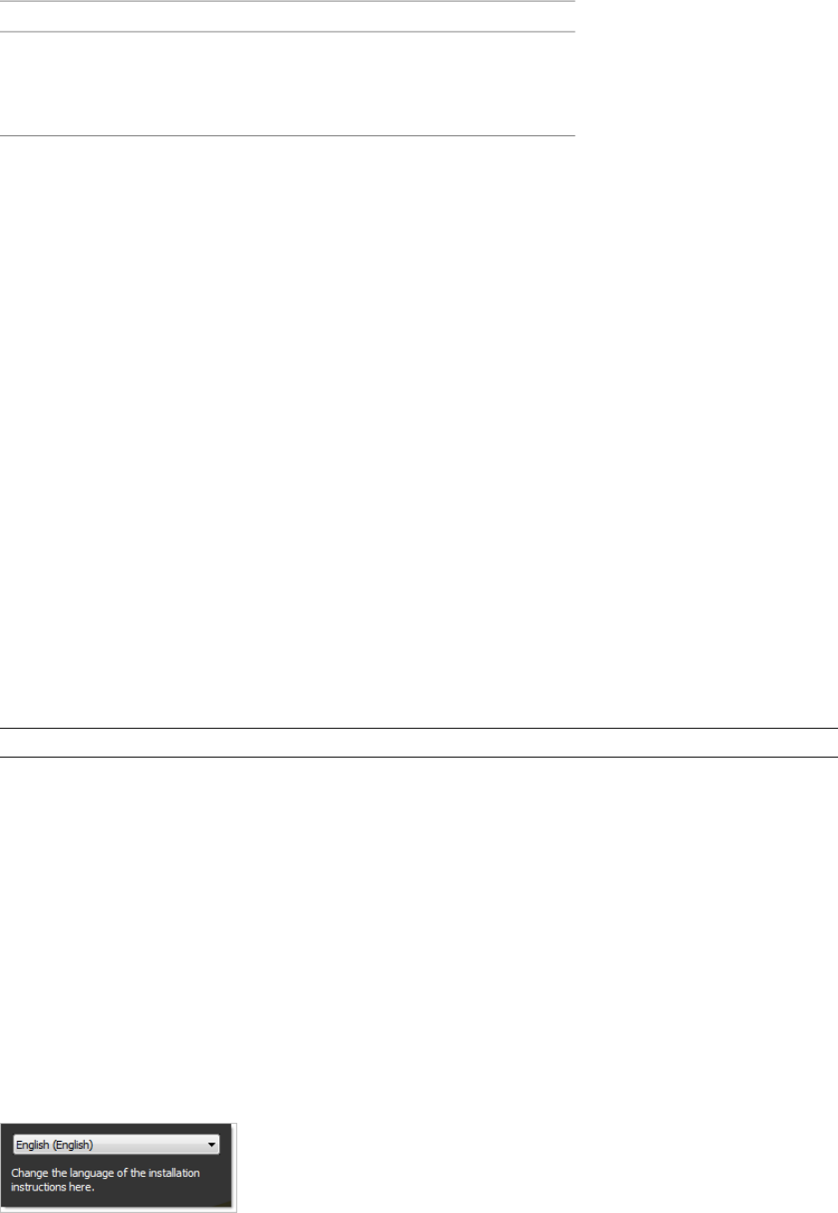
Hardware and software requirements
Open GL©-compatible 3D video card;
Printer or plotter; Modem or access to an
Optional hardware
Internet connection; Network interface
card
Understand Administrative Permission Requirements
To install Autodesk Navisworks, you must have administrator permissions.
You do not need to have domain administrative permissions. See your system administrator for information
about administrative permissions.
To run Autodesk Navisworks, you do not need administrator permissions. You can run the program as a limited
user.
Locate Your Autodesk Navisworks Serial Number and Product Key
When you install Autodesk Navisworks, you are prompted for your serial number and product key in the Product
and User Information page.
The serial number must contain a three-digit prefix followed by an eight-digit number. The product key consists
of five digits.
The serial number and product key are located on the outside of the product packaging, or in the email you
received if you downloaded your product. Make sure to have these available before you install the program so
that you don't have to stop in the middle of the installation.
Make sure to have this number available before you activate the program so that you don't have to stop in the
middle of the installation.
The information you enter is permanently retained with the product. Because you can't change this information
later without uninstalling, take care when entering the information. To review this product information later,
click Help ➤ About.
NOTE If you have lost your serial number or product key, contact your local Autodesk office for assistance.
Avoid Data Loss During Installation
The Autodesk Navisworks installation process may stop if some applications (such as Microsoft® Outlook® or
virus-checking programs) are running.
Close all running applications to avoid possible data loss.
Choose a Language
You can select a different language for installation instructions, and a language for individual product installations
in the same install process.
When you start the installation process, the installer automatically determines your operating system language.
If a supported language is detected, your install pages are displayed in that language. If you want to change that
language, you select a different one from the Installer Language list on the first page of the Installation wizard.
Prepare for Installation | 19
NOTE Some products may not have multi-language support at the time of product release. Additional language
support may be available later. Check http://autodesk.com/servicesandsupport for the availability of additional language
packs.
Using Language Packs
Language packs (.msi) support use of different languages in each Autodesk Navisworks product, including
exporters. Pack names start with NAVFREE_, NAVREV_, NAVSIM_, NAVMAN_, and exporters_ respectively.
NOTE You must install at least one language pack for each product.
It is possible to add additional language packs to Autodesk Navisworks products later. You can manually install
the required language packs by double-clicking on the language pack .msi file.
Language packs are located on the installation DVD and unpacked downloaded media under the x86 folder for
32-bit products and under the x64 folder for 64-bit products.
■Language packs for specific products are included in the NAVFREE, NAVREV, NAVSIM, NAVMAN, and
NWEXPORT subfolders of x86 and x64 folders.
■Language packs for specific languages are included in the en-US (English), de-DE (German), es-ES (Spanish),
fr-FR (French), it-IT (Italian), ja-JP (Japanese), ko-KR (Korean), pt-BR (Brazilian Portuguese), ru-RU (Russian)
and zh-CN (Chinese PRC) subfolders of the product folders.
So, for example, to install the 32-bit French language pack for Autodesk Navisworks Review, double-click
x86/NAVREV/fr-FR/NAVREV_LP.msi.
Configure Button
During the installation process, you choose either a typical installation (install the product with default settings),
or a customized installation. If you choose to customize, you start that process in the Review - Configure - Install
dialog box. Select the appropriate product from the drop-down list, and click the Configure button.
After you click the Configure button, the following dialog boxes and options are displayed:
■Select the License Type - Stand-Alone license or Network license. If you choose Network license, you also need
to select the license server model - Single, Distributed, or Redundant.
■Project and Site Folders - These settings can be shared across an entire project site, or across a specific project
group depending on the required level of granularity. Refer to “Why should I specify the Project Folder and
Site Folder?” on page 46.
■Select the Installation Type - Typical or Custom. If you choose a Typical installation (default settings), the
product installs the most common application features. To see which features are included in a Typical
installation, refer to “When performing a Typical installation, what gets installed?” on page 46. If you choose
Custom, you select specific features to install.
■Include a Service Pack - If a service pack is available for your installation, you can include it.
When you have completed your choices, click the Configuration Complete button. This takes you back to the
Review - Configure - Create dialog box, where you can review your selections and complete the installation
process.
If you do not wish to make configuration changes on the Review - Configure - Install page, click Install.
Install Multiple or Bundled Products
Some Autodesk packages are comprised of multiple products or are part of multi-product bundles.
20 | Chapter 3 Installation

The Installation wizard for packages that are comprised of multiple products gives you the option to choose
which products you want to install.
In the Installation wizard, for packages containing multiple products, you can choose which products and
languages you want to install. During the install process, you are informed whether a copy of the software is
already installed. You are also warned if your system does not meet the minimum system requirements for the
product. Each product name is displayed on its own tabbed panel; you can configure them individually.
If you purchased a package that is a multi-product bundle, such as an educational or institutional package, you
may have a package that includes several Autodesk products. For these bundled packages, an Installer disc contains
information for all the products in the package. The Installer disc helps you install all of the products.
Install and Run Autodesk Navisworks Review 2010
To use the product, you must install the product, register and activate it, and then launch it.
You must have administrative permissions to install Autodesk Navisworks.
This section provides instructions for installing and activating Autodesk Navisworks for an individual user on a
stand-alone computer.
For information about installing network-licensed or multi-seat stand-alone versions of the program, see “Install
Autodesk Navisworks for Multiple Users” on page 28.
When you have successfully installed Autodesk Navisworks Review 2010, you are ready to register your product
and start using the program. To register the product, start Autodesk Navisworks Review 2010 and follow the
on-screen instructions. For more information, see “How do I register and activate Autodesk Navisworks?” on
page 47
NOTE Autodesk does not recommend or support the distribution of an Autodesk product using imaging software.
Install Autodesk Navisworks
The Autodesk Navisworks Installation wizard contains all installation-related material in one place.
From the Installation wizard, you can access user documentation, change the installer language, select a
language-specific product, install supplemental tools, view support solutions, and learn about deploying your
product on a network.
NOTE Autodesk Navisworks Review 2010 ships on a single DVD. Insert the Autodesk Navisworks DVD in your DVD
drive to start the installation process. Follow the prompts to complete the installation. As long as the DVD is in the
drive, you can access documentation by clicking the documentation link.
■Review installation documentation before you install. It is recommended that you take the time to familiarize
yourself with the complete installation process before you install Autodesk Navisworks. You can access PDF
versions of the licensing manuals and CHM versions of the installation manuals from the product's Installation
wizard by selecting the Read this Documentation selection, or the Documentation link at the bottom, left
pane of the install pages.
You can also access PDFs from the product disc. For late-breaking information, it is also recommended that
you review the product Readme.
NOTE To view or print PDF (.pdf) files, Adobe® Reader must be installed on your computer. If you do not have
Adobe Reader, you can download the latest version at http://www.adobe.com.
■Install Autodesk Navisworks Review 2010. From the Installation wizard, click Install Products. Follow the
on-screen instructions to complete the installation.
Install Autodesk Navisworks Using Default Values
This is the fastest means of installing Autodesk Navisworks on your system.
Install and Run Autodesk Navisworks Review 2010 | 21
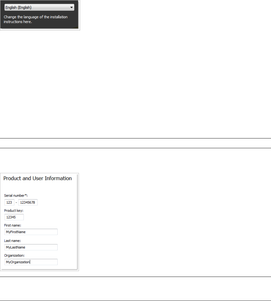
Only default values are used which means it is a typical installation being installed to C:\Program
Files\Autodesk\Navisworks Review 2010.
To install Autodesk Navisworks using default values on a stand-alone computer
1Insert the Autodesk Navisworks Review 2010 DVD into your computer's DVD drive.
The Autodesk Navisworks Review 2010 Installation wizard launches in the language that best matches the
settings on your computer.
If the Installation wizard does not start automatically, double-click Setup.exe at the root of the Autodesk
Navisworks DVD.
2In the Installation wizard, select a language for the install instructions or accept the default language. Click
Install Products.
3Select the products and the languages for the products you want to install:
■On a 64-bit version of Windows, you can install both 32-bit and 64-bit versions of Autodesk Navisworks,
64-bit version of Autodesk Navisworks Freedom, and both 32-bit and 64-bit versions of exporter plugins.
■On a 32-bit version of Windows, you can install 32-bit version of Autodesk Navisworks, 32-bit version
of Autodesk Navisworks Freedom, and 32-bit version of exporter plugins.
Click Next.
In order to choose a language for an individual product, you first must click the Select Language for Individual
Products check box, then select the language from the drop-down list. In some cases, additional languages
may not be available for the products you choose to install.
4Review the Autodesk software license agreement for your country or region. You must accept this agreement
to proceed with the installation. Choose your country or region, click I Accept, and then click Next.
NOTE If you do not agree to the terms of the license and want to terminate the installation, click Cancel.
5On the Product and User Information page, enter your serial number, product key, and user information.
Review the Privacy Policy from the link at the bottom of the dialog box. After reviewing, click Next.
IMPORTANT The information you enter here is permanent and is displayed in the Autodesk Navisworks Review
2010 window (accessed by Help ➤ About) on your computer. Because you can't change this information later
without uninstalling the product, make sure you enter the correct information now.
6On the Review - Configure - Install page, click Install to begin installing.
22 | Chapter 3 Installation

The wizard does the following:
■Uses a Typical installation, which installs the most common application features. To see which features
are included in a Typical installation, refer to “Typically Installed Features” on page 46.
■Installs Autodesk Navisworks to the default install path of C:\Program Files\Autodesk\Navisworks
Review 2010.
■Installs the products you selected in Step 3.
NOTE By default, the Installation wizard automatically enables the exporter plugins for all 3rd party products
already installed on your PC.
7On the Installation Complete page, choose from the following:
■View the installation log file - to view the installation log file.
■View the Autodesk Navisworks Review 2010 Readme - to open the Readme file with the information that
was not available when the Autodesk Navisworks Review 2010 documentation was prepared.
■View the Autodesk Navisworks Freedom 2010 Readme - to open the Readme file with the information
that was not available when the Autodesk Navisworks Freedom 2010 documentation was prepared.
NOTE If you do not want to view the Readme files now, clear the check boxes.
8Click Finish.
Install Autodesk Navisworks Using Configured Values
With this installation method, you can fine-tune exactly what gets installed by using the Configure option.
You can alter the installation type, the install path, the license type, and specify the location of the Project and
Site folders.
To install Autodesk Navisworks using configured values on a stand-alone computer
1Insert the Autodesk Navisworks Review 2010 DVD into your computer's DVD drive.
The Autodesk Navisworks Review 2010 Installation wizard launches in the language that best matches the
settings on your computer.
If the Installation wizard does not start automatically, double-click Setup.exe at the root of the Autodesk
Navisworks DVD.
2In the Installation wizard, select a language for the install instructions or accept the default language. Click
Install Products.
3Select the products and the languages for the products you want to install:
■On a 64-bit version of Windows, you can install both 32-bit and 64-bit versions of Autodesk Navisworks,
64-bit version of Autodesk Navisworks Freedom, and both 32-bit and 64-bit versions of exporter plugins.
■On a 32-bit version of Windows, you can install 32-bit version of Autodesk Navisworks, 32-bit version
of Autodesk Navisworks Freedom, and 32-bit version of exporter plugins.
Click Next.
In order to choose a language for an individual product, you first must click the Select Language for Individual
Products check box, then select the language from the drop-down list. In some cases, additional languages
may not be available for the products you choose to install.
4Review the Autodesk software license agreement for your country or region. You must accept this agreement
to proceed with the installation. Choose your country or region, click I Accept, and then click Next.
NOTE If you do not agree to the terms of the license and want to terminate the installation, click Cancel.
Install and Run Autodesk Navisworks Review 2010 | 23
5On the Products and User Information page, enter your serial number, product key, and user information.
Review the Privacy Policy from the link at the bottom of the dialog box. After reviewing, click Next.
IMPORTANT The information you enter here is permanent and is displayed in the Autodesk Navisworks Review
2010 window (accessed by Help ➤ About) on your computer. Because you can't change this information later
without uninstalling the product, make sure you enter the correct information now.
6On the Products and User Information page, enter your user information. Review the Privacy Policy from the
link at the bottom of the dialog box. After reviewing, click Next.
IMPORTANT The information you enter here is permanent and is displayed in the Autodesk Navisworks Review
2010 window (accessed by Help ➤ About) on your computer. Because you can't change this information later
without uninstalling the product, make sure you enter the correct information now.
7On the Review - Configure - Install page, click Configure to make configuration changes. Each of the products
you selected in Step 3 has its own tab:
■For each of the selected products you can change the license type, installation type, installation path,
and the project and site folder paths.
■For Navisworks exporter plugins, you can change which plugins are installed.
NOTE At any time you can click Next and then Configuration Complete to return to the Review-Configure-Install
page.
8To configure a product installation:
aOn the Select License Type page, you can choose to install a Stand-Alone License or Network license.
Click Next.
bOn the Project and Site Folder Paths page, you can specify:
■Project Folder - use the Browse button to select the directory that contains the product settings
specific to a project group.
■Site Folder - use the Browse button to select the directory that contains the product settings standard
across the entire project site.
cOn the Select the Installation Type page, you can choose to make the following configuration changes:
■Typical - installs the most common application features.
■Custom - installs only the application features that you select from the Select Features To Install
list:
Contains Navisworks ActiveX Lite control.ActiveX Lite Control
Contains the Component Object Model
interface for customizing and extending
the Navisworks functionality.
API
Contains various feature sample files.Example NWD files
Contains the Autodesk Navisworks User
Guide in PDF format.
PDF Manual
Contains full set of Autodesk Navisworks
files.
Product
Contains several Rich Photorealistic Con-
tent files.
Sample RPCs
■Product Install Path - use the Browse button to select the drive and location where product will be
installed. Click Next.
24 | Chapter 3 Installation

9To configure Navisworks exporter plugins, click the product tab. The Select the Installation Type page, shows
a list of all exporter plugins:
■ - indicates plugins with the 3rd party software already installed on your PC.
■ - indicates plugins for the 3rd party software, which is either not installed on your PC or has not been
detected by the Installation wizard.
Select the check boxes next to all required plugins. If the 3rd party software has not been detected by the
wizard, you can manually enable the plugins for it. Selecting the check box automatically opens the dialog
box, which enables you to browse for the correct software installation directory.
10 Click another product tab to configure another product, or click Next and then Configuration Complete
to return to the Review-Configure-Install page. Then, click Install.
NOTE If you want a copy of your configuration summary information, click the Copy to Clipboard button.
11 On the Installation Complete page, choose from the following:
■View the installation log file - to view the installation log file.
■View the Autodesk Navisworks Review 2010 Readme - to open the Readme file with the information that
was not available when the Autodesk Navisworks Review 2010 documentation was prepared.
■View the Autodesk Navisworks Freedom 2010 Readme - to open the Readme file with the information
that was not available when the Autodesk Navisworks Freedom 2010 documentation was prepared.
NOTE If you do not want to view the Readme files now, clear the check boxes.
12 Click Finish.
Launch Autodesk Navisworks
Assuming that you've followed all of the previous steps outlined in this Quick Start section, you can launch
Autodesk Navisworks and start taking advantage of its new and updated features.
You can start Autodesk Navisworks in the following ways:
■Desktop shortcut icon. When you install Autodesk Navisworks, a shortcut icon is placed on your desktop.
Double-click the Autodesk Navisworks icon to start the program.
■Start menu. On the Start menu, click All Programs (or Programs) ➤ Autodesk ➤ Navisworks Review 2010 ➤
Autodesk Navisworks Review 2010.
■Location where Autodesk Navisworks is installed. If you have administrative permissions, you can run Autodesk
Navisworks in the location where you installed it. If you are a limited-rights user, you must run Autodesk
Navisworks from the Start menu or from the desktop shortcut icon. If you want to create a custom shortcut,
make sure that the Start In directory for the shortcut points to a directory where you have write permissions.
NOTE When the product is started, by default, it uses the language that best matches the settings on your computer.
You can also launch Autodesk Navisworks in another of the supported languages.
How to Launch Autodesk Navisworks in Another Language
To run Autodesk Navisworks in another of the installed languages, you need to add one of the language selector
arguments to the desktop shortcut.
To run Autodesk Navisworks in another language
1Right-click the Autodesk Navisworks desktop shortcut, and click Properties on the shortcut menu to open
the Autodesk Navisworks Properties dialog box.
Install and Run Autodesk Navisworks Review 2010 | 25
2On the Shortcut tab, enter a space in the Target field after ..\roamer.exe, and then enter one of the following
arguments:
-lang en-US for English localization
-lang de-DE for German localization
-lang es-ES for Spanish localization
-lang fr-FR for French localization
-lang it-IT for Italian localization
-lang ja-JP for Japanese localization
-lang ko-KR for Korean localization
-lang pt-BR for Brazilian Portuguese localization
-lang ru-RU for Russian localization
-lang zh-CN for Chinese (PRC) localization
3Click OK to save the changes.
Add or Remove Features
You can add or remove Autodesk Navisworks Review 2010 features at any time. For example, you may have
chosen a Custom installation option when you first installed Autodesk Navisworks, but now you want to add
features that you did not install originally. Or you may no longer need to use all of the features that were installed
originally.
You can add or remove features by using the Add or Remove Programs dialog box.
To add or remove features
1In the Control Panel, double-click Add or Remove Programs.
2In the Add or Remove Programs dialog box, click Autodesk Navisworks Review 2010, and then click
Change/Remove in Windows XP or Uninstall/Change in Vista.
The Autodesk Navisworks Review 2010 Installation wizard re-opens in Maintenance Mode.
3Click Add or Remove Features. On the Add/Remove Features page, select a feature to install or uninstall.
The icons to the left of the selections give you an indication of the action that will be taken.
Indicates a feature that was marked for installation will be in a typical installation.
Indicates a feature that is not currently scheduled for installation.
Indicates a feature that was not originally marked for installation, but was added to the installed feature
list.
Indicates an installed feature that is chosen for removal.
NOTE If you need to revert to the Autodesk Navisworks Review 2010 features that you selected in your original
installation, click Cancel.
Click Next.
4On the Update Autodesk Navisworks Review 2010 Installation page, click Next.
5On the Update Complete page, you are informed when the updates have been performed. Click Finish.
26 | Chapter 3 Installation

Reinstall or Repair Autodesk Navisworks Review 2010
If you accidentally delete or alter files that are required by Autodesk Navisworks Review 2010, Autodesk Navisworks
might not perform correctly, and you might receive error messages when you try to execute a command or find
a file. You can attempt to fix this problem by reinstalling or repairing Autodesk Navisworks Review 2010.
The reinstallation or repair uses the features that were part of the installation type you chose when you initially
installed the program.
To reinstall or repair Autodesk Navisworks Review 2010
1In the Control Panel, double-click Add or Remove Programs.
2In the Add or Remove Programs dialog box, click Autodesk Navisworks Review 2010, and then click
Change/Remove in Windows XP or Uninstall/Change in Vista.
The Autodesk Navisworks Review 2010 Installation wizard re-opens in Maintenance Mode.
3Click Repair Autodesk Navisworks Review 2010.
4On the Select Repair or Reinstall page, click one of the following, and then click Next.
■Repair My Autodesk Navisworks Review 2010 Installation. This option replaces all registry entries that
Autodesk Navisworks initially installed and restores Autodesk Navisworks Review 2010 to its default
state.
■Reinstall My Autodesk Navisworks Review 2010 Installation. This option repairs the registry and reinstalls
all files from the original installation. Use this option if the Repair My Autodesk Navisworks Review
2010 Installation option does not solve the problem.
5On the Repair Autodesk Navisworks Review 2010 page, click Next to start the process.
6On the Repair Complete page, you are informed when the repairs have been performed. Click Finish.
Uninstall Autodesk Autodesk Navisworks Review 2010
When you uninstall Autodesk Navisworks Review 2010, all components are removed. This means that even if
you've previously added or removed components, or if you've reinstalled or repaired Autodesk Navisworks Review
2010, the uninstall removes all Autodesk Navisworks installation files from your system.
To uninstall Autodesk Navisworks Review 2010
1In the Control Panel, double-click Add or Remove Programs.
2In the Add or Remove Programs dialog box, click Autodesk Navisworks Review 2010, and then click
Change/Remove in Windows XP or Uninstall/Change in Vista.
The Autodesk Navisworks Review 2010 Installation wizard re-opens in Maintenance Mode.
3Click Uninstall.
4On the Autodesk Navisworks Review 2010 page, click Next to remove Autodesk Navisworks from the system.
5When informed that the product has been successfully uninstalled, click Finish.
NOTE Even though Autodesk Navisworks Review 2010 is removed from your system, the software license remains.
If you reinstall Autodesk Navisworks Review 2010 at some future time, you will not have to register and re-activate
the program.
Move to Autodesk Navisworks from a Previous Release
If you have a previous version of Autodesk Navisworks installed on your system, you can install Autodesk
Navisworks Review 2010 and keep other versions of the program on the same system. This is called a side-by-side
installation.
Move to Autodesk Navisworks from a Previous Release | 27
If you've purchased an upgrade version of Autodesk Navisworks Review 2010, you are required to uninstall the
previous version within 120 days of installing Autodesk Navisworks Review 2010. See your license agreement
for more information.
Install Autodesk Navisworks for Multiple Users
This section provides step-by-step instructions for installing network-licensed or multi-seat stand-alone versions
of the Autodesk Navisworks Review 2010.
Quick Start to Network Administration and Deployment
Network deployment of this program requires careful planning and execution.
If you are not familiar with network administration and deployment, you should familiarize yourself with the
following topics before you attempt to deploy and administer the program over a network.
Deployment Preparation
To prepare for a deployment, you should take the time to review the following requirements and options.
System Requirements for a Deployment
This section contains the system requirements for the location of the administrative image that you create, the
network license server, and the client workstation.
Before you begin installing the program on a network, make sure that your servers and client workstations meet
the minimum recommended hardware and software requirements for a deployment.
Whether the Windows operating system is the 32-bit or the 64-bit version is automatically detected when
installing Autodesk Navisworks. You can choose which versions of Navisworks will be installed.
NOTE Both the 32-bit version and 64-bit version of Autodesk Navisworks Review 2010 can be installed on a 64-bit
version of Windows, but the 64-bit version of Autodesk Navisworks Review 2010 cannot be installed on a 32-bit version
of Windows.
See the following tables for administrative image, license server, and client workstation system requirements.
Hardware and software requirements for the location of the administrative
image
RequirementHardware/Software
1.5 GB (recommended)Hard disk
Hardware and software requirements for the network license server
RequirementHardware/Software
Windows Vista 32-bitOperating system
Windows XP 32-bit
Windows 2003 Server Edition
AMD® Athlon®, 3.0 GHz or faster (minim-
um)
Computer/processor
Intel® Pentium® IV, 3.0 GHz or faster (re-
commended)
28 | Chapter 3 Installation
Hardware and software requirements for the network license server
Compatible with existing Ethernet network
infrastructure
Network interface card
TCP/IPCommunication protocol
Hardware and software requirements for client machine
RequirementHardware/Software
32-BitOperating system
Windows©XP© Professional, SP 2 or SP 3;
Windows XP Home, and Professional, SP
2 or SP 3; Windows Vista Ultimate, SP 1;
Windows Vista Enterprise, SP 1; Windows
Vista Business SP 1; Windows Vista Home
Premium, SP 1; Windows Vista Home Basic,
SP 1
64-Bit
Windows Vista Enterprise, SP 1; Windows
Vista Business, SP 1; Windows Vista Ulti-
mate, SP 1; Windows Vista Home Premium,
SP 1; Windows XP Professional, SP 1
32-BitWeb browser
Internet Explorer 6.0, SP 1 (or later)
64-Bit
Internet Explorer 7.0 or later
32-BitProcessor
AMD® Athlon®, 3.0 GHz or faster (minim-
um); Intel® Pentium® IV, 3.0 GHz or faster
(recommended)
64-Bit
AMD 64 or Intel EM64T
32-BitMemory (RAM)
512 MB (minimum); 2 GB or greater (re-
commended)
64-Bit
2 GB
128 MB, 1024 x 768 VGA, True Color
(minimum)
Graphics card
Quick Start to Network Administration and Deployment | 29

Hardware and software requirements for client machine
256 MB or greater - 1280 x 1024 32-bit
color video display adapter, True Color
(recommended)
Installation 800 MBHard disk
MS-Mouse compliantPointing device
Any speed (for installation only)DVD-ROM
Open Open GL®-compatible 3D video cardOptional hardware
Printer or plotter
Modem or access to an Internet connec-
tion
Network interface card
Choose an Installation Type
When you set up your deployment, you need to choose the type of installation to deploy.
In the Autodesk Navisworks Review 2010 Deployment wizard, you specify one of the following installation types:
■Network License installation. With this type of installation, you install the program to workstations with the
files and registry entries that allow the program to communicate with the Network License Manager. You
also define the configuration of the Network License Manager so that the licenses can be accessed. Workstations
running the program based on a network installation do not require individual activation. Licensing of this
program is managed by at least one license server.
The main advantage is that you can install Autodesk Navisworks Review 2010 on more systems than the
number of licenses you have purchased (for example, purchasing 25 licenses but installing on 40 workstations).
At any one time, Autodesk Navisworks Review 2010 runs on the maximum number of systems for which you
have licenses. This means you get a true floating license.
■Multi-Seat Stand-Alone installation (Stand-Alone option). Choose this type of installation for stand-alone
installations where a single serial number and product key are used for multiple seats. Multi-seat stand-alone
installations do not rely upon a Network License Manager to manage product licenses; however, you can still
use the Autodesk Navisworks Review 2010 Installation wizard to create administrative images and create
deployments. Registration and activation is more automated for multi-seat stand-alone installations. After
the first activation using the multi-seat stand-alone serial number, activation occurs automatically for all
workstations based on this deployment, as long as your systems are connected to the Internet.
■Stand-Alone installation (Stand-Alone option). Choose this type of installation for stand-alone installations
where a single serial number and product key are used for a single seat. Like a multi-seat stand-alone
installation, you do not use the Network License Manager to manage product licensing, but installation,
registration, and activation occurs on each workstation.
If you choose one of the Stand-Alone installation types, you can proceed to the section “Distribute the Program”
on page 33.
Choose a License Server Model
If you chose the Network License option, you need to decide which license server model to use to distribute the
product licenses.
TIP If you are deploying a stand-alone or multi-seat stand-alone installation type, you do not use a license server model.
Proceed to the section “Distribute the Program” on page 33.
30 | Chapter 3 Installation

For the network installation, use one of the following license server models:
■Single license server model. The Network License Manager is installed on a single server, so license management
and activity is restricted to this server. A single license file represents the total number of licenses available
on the server.
■Distributed license server model. Licenses are distributed across more than one server. A unique license file
is required for each server. To create a distributed license server, you must run the Network License Manager
on each server that is part of the distributed server pool.
■Redundant license server model. You use three servers to authenticate a single license file. One server acts as
the master, while the other two provide backup if the master server fails. With this configuration, licenses
continue to be monitored and issued as long as at least two servers are still functional. The license file on all
three servers is the same. You must install the Network License Manager on each server.
Each of these license server models is described in detail in the Network Licensing Guide. It is strongly recommended
that you read that guide before you deploy the program. You can find the Network Licensing Guide by clicking
the Documentation link at the lower left corner of the Autodesk Navisworks Review 2010 Deployment wizard.
Set Up Network Tools and Your License Server
If you are planning to have users run the program using network licenses, you need to use the Network License
Manager.
The Network License Manager helps you configure and manage license servers.
Install the Network License Manager
The Network License Manager is used to configure and manage the license servers.
To install your Network License Manager
1In the Autodesk Navisworks Review 2010 Installation wizard, click Install Tools and Utilities.
2On the Select the Products to Install page, select Autodesk Network License Manager and click Next.
3Review the Autodesk software license agreement for your country or region. You must accept this agreement
to proceed with the installation. Choose your country or region, click I Accept, and then click Next.
NOTE If you do not agree to the terms of the license and want to terminate the installation, click Cancel.
4On the Review - Configure - Install page, review your product selection and the current settings. If you don't
want to make any changes, click Install. If you want to change the install type or installation path, click
Configure.
5On the Select the Installation Type page, accept the default installation path (C:\Program Files\Autodesk
Network License Manager\) or Browse to specify a different path. If you enter a path that does not exist, a
new folder is created using the name and location you provide. Click Next.
WARNING Do not install the Network License Manager on a remote drive. When you install the Network License
Manager files, you must provide a path to a local drive. You must specify the drive letter; the universal naming
convention (UNC) is not supported.
6On the Configuration Complete page, click Configuration Complete to return to the confirmation page.
7On the Review - Configure - Install page, click Install.
8When the Installation Complete page displays, click Finish.
Quick Start to Network Administration and Deployment | 31

To Activate a Network License Through Autodesk.com
If your product does not include the Network License Activation Utility, you can activate your license by going
to https://registeronce.autodesk.com, and following the on-screen instructions.
Configure Your License Server
You configure a license server so that you can manage the Autodesk Navisworks product licenses.
You can configure the license server with the lmtools.exe utility.
You should be logged in with Administrator rights when working with the LMTOOLS utility.
To configure your license server
1Do one of the following:
■Click Start menu ➤ All Programs (or Programs) ➤ Autodesk ➤ Network License Manager ➤ LMTOOLS.
■(Windows Vista) Double-click the LMTOOLS icon on the desktop.
2In the Lmtools program, on the Service/License File tab, select the Configure Using Services option.
3Click the Config Services tab.
4In the Service Name list, select the service name you want to use to manage licenses.
By default, the service name is FLEXnet Service 1. If FLEXnet® is managing other software on your computer
in addition to Autodesk, you can change the service name to avoid confusion, for example, you can rename
FLEXnet Service 1 to Autodesk Server1.
NOTE If you have more than one software vendor using FLEXnet for license management, the Service Name list
contains more than one option. Make sure that only one Autodesk service is listed.
5In the Path to Lmgrd.exe File field, enter the path to the Network License Manager daemon (lmgrd.exe), or
click Browse to locate the file.
By default, this daemon is installed in the C:\Program Files\Autodesk Network License Manager folder.
6In the Path to the License File box, enter the path to your license file, or click Browse to locate the file.
7In the Path to the Debug Log File box, enter a path to create a debug log, or click Browse to locate an existing
log file.
It is recommended that you save to the \Program Files\Autodesk Network License Manager folder. The log file
must have a .log file extension. For new log files, you must enter the .log extension manually.
8To run lmgrd.exe as a service, select Use Services.
9To automatically start lmgrd.exe when the system starts, select Start Server at Power Up.
10 Click Save Service to save the new configuration under the service name you selected in step 4. Click Yes
when prompted if you would like to save the settings to the service.
11 Click the Start/Stop/Reread tab and do one of the following:
■If a service has not yet been defined for Autodesk, click Start Server to start the license server.
■If a service for Autodesk is already defined and running, click ReRead License File to refresh the Network
License Manager with any changes made to the license file or Options file.
The license server starts running and is ready to respond to client requests.
12 Close lmtools.exe.
32 | Chapter 3 Installation
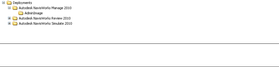
Distribute the Program
Once you have fully prepared for creating a deployment, you are ready to set up and distribute Autodesk
Navisworks by using the Deployment wizard and choosing a deployment method.
Create a Network Share
A network share is an installation folder that you make available to users' computers on a network. You point
users to this location to install the program. Create a network share that will be used by the Autodesk Navisworks
Deployment wizard during the creation of a client deployment.
A shared folder is required for network license and multi-seat stand-alone methods of installation.
It is recommended that you name the network share folder Deployments on the desktop of the system where you
want deployments stored. You can then add subfolders inside the shared Deployments folder that clearly convey
the name of product you plan to deploy. This is also beneficial if you plan to deploy multiple products.
Any subfolders that are placed inside a shared folder are automatically shared.
TIP You must have Full Control permissions set for your shared folder when you are creating your deployment images.
Read permissions are necessary to access the network share and administrative permissions on the workstation where
the program is deployed.
To create your network share
1On the desktop of a network server, create a folder named Deployments.
2Right-click the Deployments folder and click Share and Security (or Sharing).
3In the [folder name] Properties dialog box, Sharing tab, select Share This Folder.
4Specify a Share Name, such as Deployments, if necessary.
5Click the Permissions button. In the Permissions dialog box make sure Full Control is active. Click OK.
In Vista, right-click the Deployments folder and then click Share. In the Properties dialog box select Sharing
and then Advanced Sharing to share the folder. Click the Permissions button to make sure Full Control is
active. Click OK.
These steps are important when creating your deployment images.
6Click OK or Close to close the Properties dialog box.
7For each product you plan to install, create a subfolder in the Deployments folder. Name each folder with
the pertinent product name.
Minimize the Chances of Installation Failure
The Navisworks installation process may stop if some applications, such as Microsoft Outlook or virus checking
programs, are running when you are creating a deployment. Close all running applications and temporarily
disable virus checking utilities.
Distribute an Autodesk Navisworks Product
You can choose from several methods of distributing an Autodesk program. Network sharing is the default
method.
■Network Share. Users launch the program with the shortcut icon that you created with the Deployment
wizard. The program is installed on users' local computers, and a product icon appears on their desktop.
Quick Start to Network Administration and Deployment | 33
NOTE Users must have Read permissions to access the network share and administrative permissions on the
workstation where this program is installed.
■Scripting. A script executes a command or a set of commands. Scripts are similar to batch files but are more
flexible. Installation scripts are most useful for stand-alone installation of programs on computers that are
connected to a network. Scripts are also useful for installing service packs, extensions, and object enablers
on a network.
■Group Policy Objects (GPOs). With group policy objects, this program can be advertised to any Windows XP
or Windows Vista computer that is part of a Windows 2003 Server Active Directory environment.
Autodesk products are designed to be installed on a computer so that any user who logs on to the computer
can run the software. If you attempt to assign this program for a specific user rather than a computer, you
may encounter problems when a second specified user tries to install or uninstall a copy of the program.
■Microsoft SystemCenter Configuration Manager (SCCM). You can deploy Autodesk software using Microsoft®
System Center Configuration Manager (SCCM).
When you use SCCM to deploy Autodesk software, you set up the source directory using the Deployment
wizard. The Deployment wizard creates an administrative image that is used by SCCM to distribute the
Autodesk software to the target systems. The location where you perform the administrative installation
becomes the location of the package source directory.
■Imaging Software. You can use imaging software, such as Norton Ghost, to create a master image to distribute
Autodesk products. Once created, the master image is then replicated to other computers throughout your
facility.
Care needs to be taken since the use of imaging software can result in conflicts with the product licensing,
incomplete installations, and problems with activation.
Set Up a Deployment
The deployment process provides you with numerous options for creating, and customizing your deployments,
so you should set aside ample time to complete the process in one sitting.
To be successful it is recommended that your review the following checklist and information before you begin.
The deployment process is initiated from the Deployment wizard. Once a deployment is created, users then
access the deployment to install products to their computers.
Preliminary Tasks for a Network Deployment
The deployment checklist gives you a quick summary of the type of information you should be familiar with
before begin. When you have completed these tasks, you are ready to create a deployment.
Deployment Checklist
You have reviewed the system requirements. You must
make sure that your network, servers, and client work-
stations meet the system requirements.
You understand the type of license you’ve purchased.
If you plan a network license deployment, you should
also be familiar with the type of license server model
you want to use and the license server names.
You have installed and activated any supporting tools
and utilities.
You have located your product serial number and
product key. The serial number and product key are
located on the outside of the product packaging, or in
the email you received if you downloaded your product.
34 | Chapter 3 Installation
Deployment Checklist
You know how you’re going to personalize the pro-
grams during registration. Using consistent registration
data is very important.
You have identified the location (such as a shared folder)
where deployments will reside for each program you
plan to deploy.
You have closed all other programs and disabled anti-
virus software.
You have decided what languages you will include in
your administrative image, and what languages you will
use for your deployment package.
You have determined if your deployment plan involves
using imaging software to distribute your programs to
client workstations.
You have specified whether you want to create log files
that contain deployment and installation data, run silent
mode, and participate in the Customer Involvement
Program.
You know which type of installation you’ll perform -
typical or custom.
You have chosen the installation folder option.
You have decided if you want to include centralized
product settings with your deployment, such as global
options, workspaces, datatools, avatars, Clash Detective
rules, Presenter archives, custom Clash Detective tests,
object animation scripts, and so on.
You have set up access and participation in features like
the Customer Involvement Program.
Configure Button
During the deployment process, you can create a deployment that uses the default settings, or you can create a
customized deployment. To customize, you begin in the Review - Configure - Create Deployments dialog box.
Select the appropriate product from the drop-down list, and click the Configure button.
The following options are available after you click the Configure button. See “Your Deployment Choices” on
page 36 for more details about deployment options.
■Select the License Type - Stand-alone or Network license
■Select the Installation Type - Typical or Custom
■Select the Project and Site Folder Paths
■Select Installation Folder
When you finish selecting options for your customization, click the Configuration Complete button. The Review
- Configure - Create Deployments dialog box is displayed again, and you can review your selections. Once you
have confirmed your selections, click Create Deployment.
Set Up a Deployment | 35
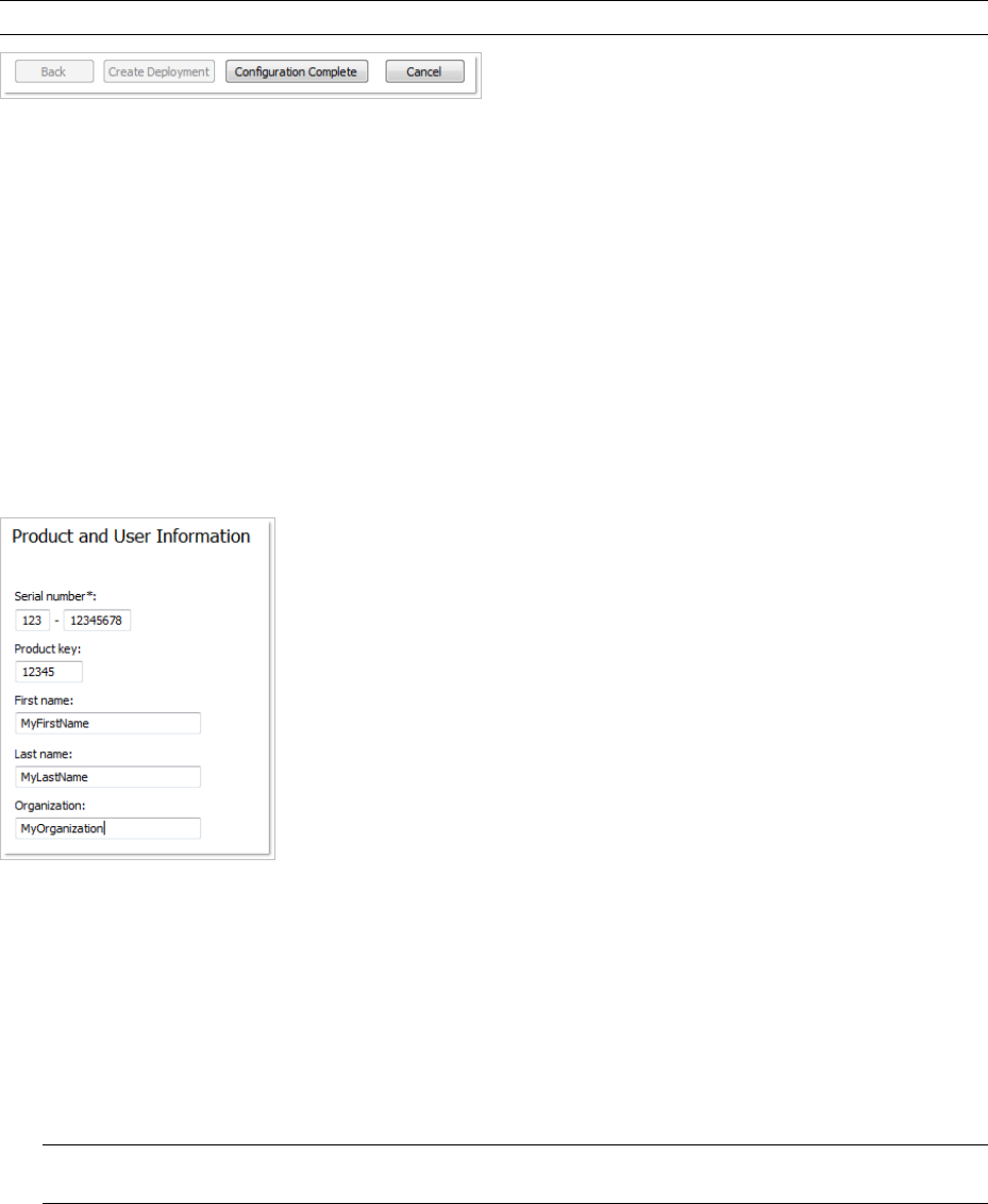
NOTE To get a copy of your settings, select the Copy to Clipboard button.
If you do not wish to make configuration changes on the Review - Configure - Create Deployments page, click
Create Deployment.
Your Deployment Choices
When you create a deployment, you will make several choices during the process to create various client
deployment images and deployment types. The following sections outline your choices in more detail.
Enter Product and User Information
The Product and User Information page is used to personalize the program for your environment.
The information you enter is permanently retained with the product and is displayed in the Help menu on all
workstations. Because you can't change this information later without uninstalling, take care when entering the
information.
You must also enter the product serial number and product key in order to run the product. The product serial
number and product key are located on the product packaging, or in the electronic fulfillment messaging. The
serial number must contain a three-digit prefix followed by an eight-digit number. The product key consists of
five digits.
Your client’s can review this product information later, by clicking Help ➤ About.
To enter your serial number and personal information
1When creating a deployment, on the Product and User Information page, enter your product serial number
and the required personalization data.
NOTE Although it is required that you enter information in each box on this page, you can enter any information
that you want to convey to users who install the deployment.
2Click Next.
Specify Log File Locations
The program has two types of log files with which you can monitor information about deployments and
installations.
■Network log. The network log file keeps a record of all workstations that run the deployment. On the General
Deployment Settings page of the deployment process, you choose whether or not to create a network log
36 | Chapter 3 Installation
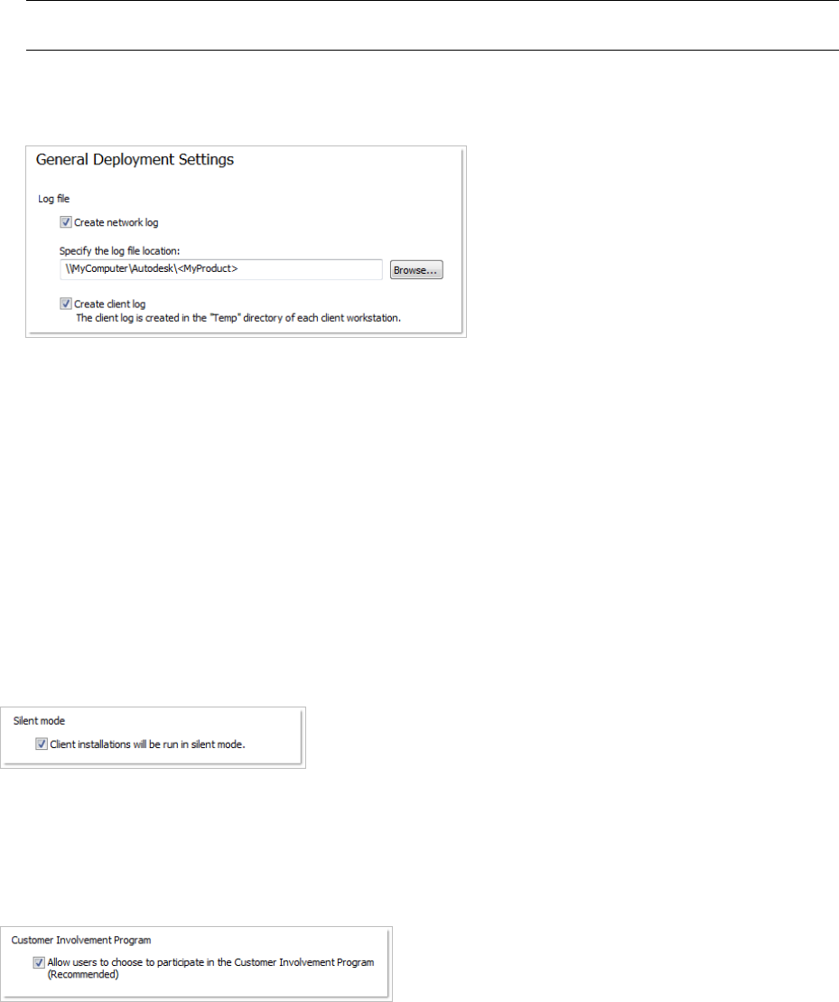
file. The log lists the user name, workstation name, and the status of the installation. Refer to this file for
status information and details about problems that users encountered during installation (for example, low
disc space or inadequate permissions).
The network log is named with the same name you chose for your deployment. You can specify where the
log file is created by entering either a valid UNC (universal naming convention) path or hard-coded path on
your network, for example \\MyComputer\Autodesk\<Autodesk product>. Users should use their actual computer
name in place of MyComputer.
NOTE The folder where the network log resides must be a shared folder where users who install the program have
Change permissions. Otherwise, successes or failures for user installations cannot be written to the log file.
■Client log. The client log contains detailed installation information for each workstation. This information
may be useful in diagnosing installation problems. The client log is located in the %Temp% directory of each
client workstation.
To specify a log file location
1While creating a deployment, on the General Deployment Settings page, select the check box next to the
Create Network Log box. Enter the name of the folder where you want the network log to be located.
2If you want to create a client log, select the Create Client Log option.
3Click Next.
What Is Silent Mode?
When silent mode is active and a user initiates the deployment, the installation proceeds without any explicit
user input.
No dialog boxes are presented that require interaction from the user. This includes all error and warning dialog
boxes. Check the log file for errors that may occur in the event of installation problems.
Customer Involvement Program (CIP)
If you choose to have your clients participate in the Customer Involvement Program, Autodesk Navisworks
Review 2010 will automatically send Autodesk information about system configuration, what features you use
most, any problems that you encounter, and other information helpful to the future direction of the product.
Set Up a Deployment | 37
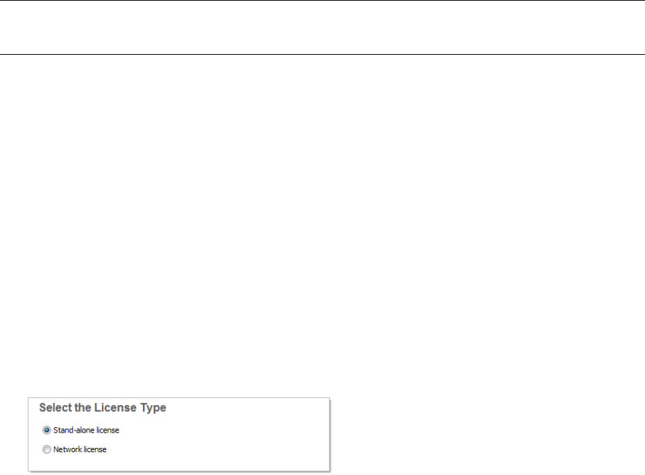
Select a License Type (optional)
When you set up your deployment, you choose the type of installation to deploy based on the type of software
license you purchased: stand-alone or network. You also select the network license server model you want to
use to distribute product licenses.
IMPORTANT Depending on the type of option you choose on the configuration page, network or stand-alone license,
note that you must use the same type of installation for all those products in your deployment session. If you select
products that do not support the type of license you purchased, you will not be able to activate those products.
Specify the license type to use during deployment
■Stand-Alone license (a single serial number for a single seat). For a stand-alone license, you install, register,
and activate the program on each workstation.
■Network license. With this type of installation, you install the program to workstations with the files and
registry entries that allow the program to communicate with the Network License Manager. You also define
the configuration of the Network License Manager so that the licenses can be accessed. Workstations running
the program based on a network installation do not require individual activation. Licensing of this program
is managed by at least one license server.
Specify the license server model during deployment
If you choose the Network license option, you need to decide which license server model to use to distribute
your product licenses - single, distributed or redundant license server model.
If you are deploying a stand-alone or multi-seat stand-alone installation type, you do not use a license server
model. For more information on server models, see “Choose a License Server Model” on page 30.
To deploy a stand-alone license
1While creating a deployment, on the Select the License Type page, select Stand-alone license.
2Click Next.
To deploy a network license using a single license server model
1While creating a deployment, on the Select the License Type page, select the Network License option.
2Select Single License Server as the license server model you want to use with the Network License Manager.
If you have already used the Network License Manager to create a license server model, you must select the
same license server model in this step. If you have not yet used the Network License Manager to create a
license server model, make sure that you select the same settings in the Network License Manager that you
choose here.
3Enter the server name of the server that will run the Network License Manager, or click the Browse button
to locate the server. Click Next.
For more information about license server models and setting up your license server, see “Choose a License Server
Model” on page 30 or “Configure Your License Server” on page 32
To deploy a network license using a distributed license server model
1While creating a deployment, on the Select the License Type page, select the Network License option.
2Select Distributed License Server as the license server model you want to use with the Network License
Manager.
38 | Chapter 3 Installation

If you have already used the Network License Manager to create a license server model, you must select the
same license server model in this step. If you have not yet used the Network License Manager to create a
license server model, make sure that you select the same settings in the Network License Manager that you
choose here.
3Enter the name of one of the servers that will run the Network License Manager, or click the Browse button
to locate the server. Click Add to add the server to the Server Pool. Once all the servers are added to the
Server Pool list, use the Move Up and Move Down buttons to arrange the servers in the order you want
them to be searched by a user's workstation. You must enter at least two servers. Click Next.
For more information about license server models and setting up your license server, see “Choose a License Server
Model” on page 30 or “Configure Your License Server” on page 32
To deploy a network license using a redundant license server model
1While creating a deployment, on the Select the License Type page, select the Network License option.
2Select Redundant License Server as the license server model you want to use with the Network License
Manager.
If you have already used the Network License Manager to create a license server model, you must select the
same license server model in this step. If you have not yet used the Network License Manager to create a
license server model, make sure that you select the same settings in the Network License Manager that you
choose here.
3In the First Server Name field, enter a server name of one server that will run the Network License Manager,
or click the Browse button to locate the server. Enter the server names for the remaining two servers that
you will use in the redundant server pool. Click Next.
NOTE If you are not sure how to obtain the server host name, see Plan Your License Server Configuration in the
Network Licensing Guide, located on the Documentation link of the Installation wizard.
For more information about license server models and setting up your license server, see “Choose a License Server
Model” on page 30 or “Configure Your License Server” on page 32
Select the Installation Type and Location (optional)
As part of making your deployment choices, you can select the type of installation that users receive when they
install the program, choose which optional features are included, and specify a product location.
■Typical. Installs the most common application features. This option is recommended for most users.
■Custom. Installs only the application features that you select.
To deploy a typical installation, and specify a product location
1During the deployment, on the Select the Installation Type page, select Typical as the type of installation
that you want.
2Enter the path on the client workstation where you want to install the program, for example C:\Program
Files\<Autodesk product>.
The Disc Space Requirements chart lets you review available drives and disc space.
3Click Next.
To deploy a custom installation, choose optional features, and specify a product location
1During the deployment, on the Select the Installation Type page, select the Custom option as the type of
installation that you want.
2From the Select Features to Install list, select the features that you want to install.
Set Up a Deployment | 39

Your choices are as follows:
Contains Navisworks ActiveX Lite control.ActiveX Lite Control
Contains the Component Object Model
interface for customizing and extending
the Navisworks functionality.
API
Contains various feature sample files.Example NWD files
Contains the Autodesk Navisworks User
Guide in PDF format.
PDF Manual
Contains full set of Navisworks files.Autodesk Navisworks Review 2010
Contains several Rich Photorealistic Con-
tent files.
Sample RPCs
If, after making feature changes, you decide you want the original selections, click the Restore Defaults
button on the Select the Installation Type page.
3Enter the path on the client workstation where you want to install the program, for example C:\Program
Files\<Autodesk product>.
The Disc Space Requirements chart lets you review available drives and disc space.
Select the Project and Site Folder Paths (optional)
When you set up your deployment, you can share various Autodesk Navisworks settings across entire project
site, or across a specific project group depending on the required level of granularity.
See also:
■“How do I share the Autodesk Navisworks settings on a site and project basis?” on page 46
To select the Project and Site folder paths
1On the Project and Site Folder Paths page, Project Folder box, click the Browse button to select the directory
that contains the Autodesk Navisworks settings specific to a project group.
2In the Site Folder box, click the Browse button to select the directory that contains the Autodesk Navisworks
settings standard across the entire project site.
Choose a Language
You can select a different language for deployment instructions, and a language for product installations in the
same deployment process.
For example, if you need to provide Autodesk Navisworks to users in one or more languages different than your
own, you can download language packs from the installer that will allow you to deploy the product in the
languages you need to support.
NOTE Language packs can only be included in an administrative image during the creation of the deployment and
not during modification.
When you start the deployment process, the installer automatically determines your operating system language.
If a supported language is detected, your deployment pages are displayed in that language. If you want to change
that language, you can choose a different one from the installer language list on the opening page of the
Installation wizard.
40 | Chapter 3 Installation
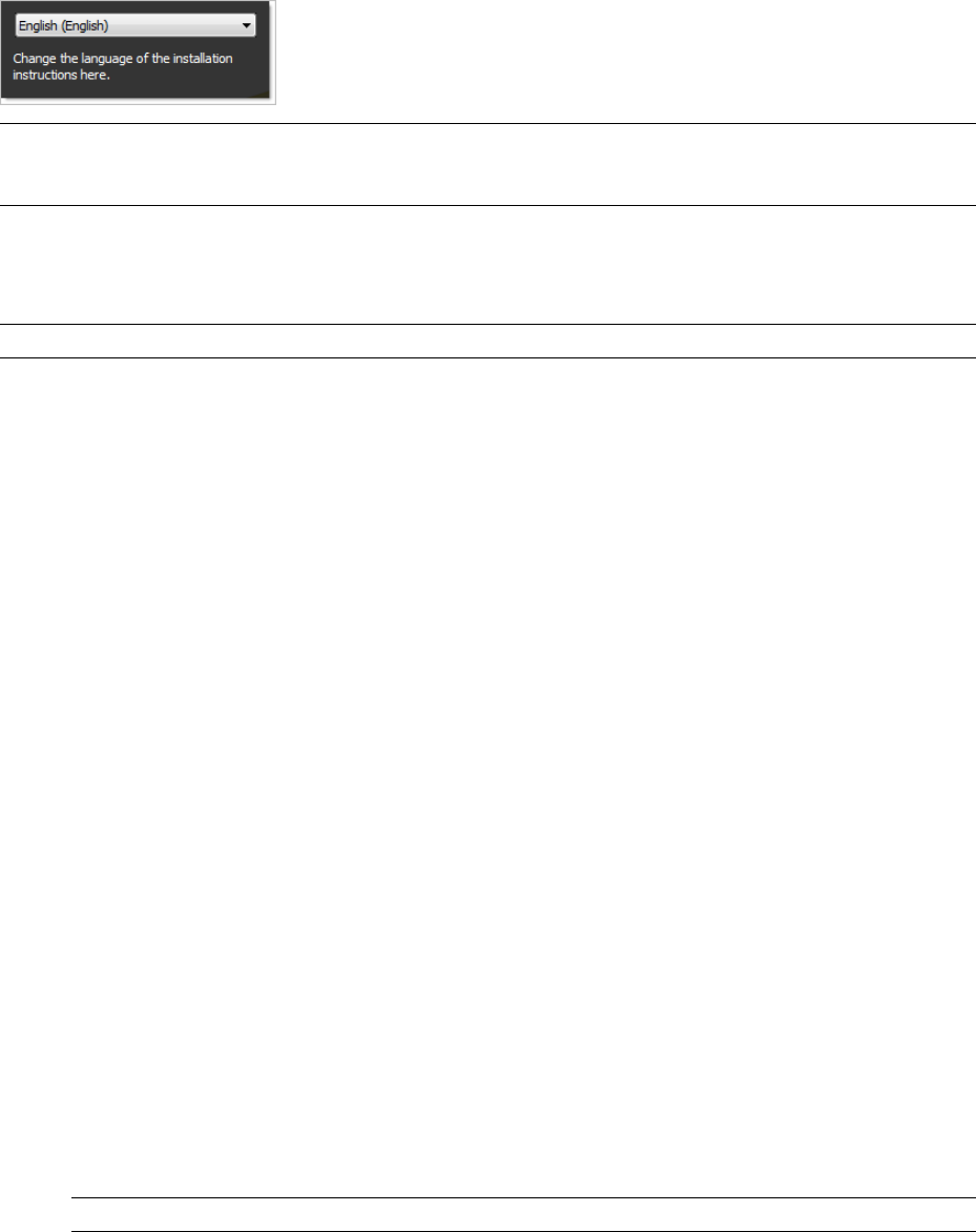
NOTE Some products may not have multi-language support at the time of product release. Additional language
support may be available later. Check http://autodesk.com/servicesandsupport for the availability of additional language
packs.
Using Language Packs
Language packs (.msi) support use of different languages in each Autodesk Navisworks product, including
exporters. Pack names start with NAVFREE_, NAVREV_, NAVSIM_, NAVMAN_, and exporters_ respectively.
NOTE You can only select one language pack for each product for deployment.
It is possible to manually add additional language packs to Autodesk Navisworks products later by double-clicking
on the language pack .msi file. Alternatively, you can set up and run scripts to install additional language packs.
Language packs are located on the installation DVD and unpacked downloaded media under the x86 folder for
32-bit products and under the x64 folder for 64-bit products.
■Language packs for specific products are included in the NAVFREE, NAVREV, NAVSIM, NAVMAN, and
NWEXPORT subfolders of x86 and x64 folders.
■Language packs for specific languages are included in the en-US (English), de-DE (German), es-ES (Spanish),
fr-FR (French), it-IT (Italian), ja-JP (Japanese), ko-KR (Korean), pt-BR (Brazilian Portuguese), ru-RU (Russian)
and zh-CN (Chinese PRC) subfolders of the product folders.
Create a Deployment
A deployment contains a Microsoft Transform (MST) file that modifies the default behavior of the installation
program.
As you begin a deployment, you need to select the location of your Administrative image, a deployment name,
and if your target systems are 32 or 64-bit operating systems.
Create a Deployment Using Default Values
This is the fastest means of creating client deployment images.
To create a default deployment
1In the Deployment wizard, click Create Deployments.
2On the Begin Deployment page, specify the following: administrative image location, deployment name,
and if your target system is 32 or 64-bit.
■In the Administrative Image field, enter the path to your existing shared network location, or use the
Browse button to navigate to that location. This area is where you create and store your administrative
image. Users install the program from this location.
NOTE If you do not know how to create a network share, see “Create a Network Share” on page 33.
■In the Deployment Name field, enter the new deployment's name. The name you enter here is the name
of the shortcut users will access to install the product.
■Under This is to be a:, select either 32-bit or 64-bit for your target operating system. This selection does
not identify the system your deployment was created on; it identifies your target system.
Click Next.
Set Up a Deployment | 41
3On the Select the Products to Include in the Deployment page, select the products you want to include, the
languages to include in your administrative image, and the language of your deployment:
aFor a 64-bit version of Windows, you can install both 32-bit and 64-bit versions of Autodesk Navisworks,
64-bit version of Autodesk Navisworks Freedom, and both 32-bit and 64-bit versions of exporter plugins.
bOn a 32-bit version of Windows, you can install 32-bit version of Autodesk Navisworks, 32-bit version
of Autodesk Navisworks Freedom, and 32-bit version of exporter plugins.
After making your choices, click Next.
4Review the Autodesk software license agreement for your country or region. You must accept this agreement
to proceed with the deployment. Choose your country or region, click I Accept, and then click Next.
NOTE If you do not agree to the terms of the license and want to terminate the installation, click Cancel.
5On the Product and User Information page, enter your serial number, product key, and user information.
Review the Privacy Policy, and then click Next.
NOTE The information you enter here is permanent and is displayed in the Help menu on users’ computers.
Because you can't change this information later without uninstalling the product, make sure you enter the
information carefully.
6On the General Deployment Settings page, choose whether or not you want to create network log and/or
a client log, if you want to run the client installation in silent mode, and if you want users to participate in
the Customer Involvement Program.
■When you choose to create a network log file, you also have to specify where the log file is created by
entering either a valid UNC (universal naming convention) path or hard-coded path on your network.
The network log file is optional.
NOTE The folder where the network log resides must be a shared folder where users who install the program
have Change permissions. Otherwise, successes or failures for user installations cannot be written to the log
file.
■Choose whether you want a client log file created.
■If you want to prevent users from changing installation settings when they install, select Silent mode.
■If you choose participation in the Customer Involvement Program, Autodesk sends helpful information
about the product.
For more information regarding log files, refer to “Specify Log File Locations” on page 36.
Click Next.
7On the Review - Configure - Create Deployments page, click Create Deployment.
By clicking Create Deployment, an administrative image is created in your shared folder using the deployment
options listed in the Current Settings field. If you would like a summary of your deployment settings, click
the Copy to Clipboard button.
8On the Deployment Complete page, click Finish.
Create a Deployment Using Configured or Customized Values
If you plan on altering your deployment by removing features or restricting access to online resources you can
create a configured or customized deployment.
To create a custom deployment
1In the Deployment wizard, click Create Deployments.
42 | Chapter 3 Installation
2On the Begin Deployment page, specify the following: administrative image location, deployment name,
and if your target system is 32 or 64-bit.
■In the Administrative Image field, enter the path to your existing shared network location, or use the
Browse button to navigate to that location. This area is where you create and store your administrative
image. Users install the program from this location.
NOTE If you do not know how to create a network share, see “Create a Network Share” on page 33.
■In the Deployment Name field, enter the new deployment's name. The name you enter here is the name
of the shortcut users will access to install the product.
■Under This is to be a:, select either 32-bit or 64-bit for your target operating system. This selection does
not identify the system your deployment was created on; it identifies your target system.
Click Next.
3On the Select the Products to Include in the Deployment page, select the products you want to include, the
languages to include in your administrative image, and the language of your deployment:
aFor a 64-bit version of Windows, you can install both 32-bit and 64-bit versions of Navisworks, 64-bit
version of Autodesk Navisworks Freedom, and both 32-bit and 64-bit versions of exporter plugins.
bOn a 32-bit version of Windows, you can install 32-bit version of Navisworks, 32-bit version of Autodesk
Navisworks Freedom, and 32-bit version of exporter plugins.
After making your choices, click Next.
4Review the Autodesk software license agreement for your country or region. You must accept this agreement
to proceed with the deployment. Choose your country or region, click I Accept, and then click Next.
NOTE If you do not agree to the terms of the license and want to terminate the installation, click Cancel.
5On the Product and User Information page, enter your serial number, product key, and user information.
Review the Privacy Policy, and then click Next.
NOTE The information you enter here is permanent and is displayed in the Help menu on users’ computers.
Because you can't change this information later without uninstalling the product, make sure you enter the
information carefully.
6On the General Deployment Settings page, choose whether or not you want to create network log and/or
a client log, if you want to run the client installation in silent mode, and if you want users to participate in
the Customer Involvement Program.
■When you choose to create a network log file, you also have to specify where the log file is created by
entering either a valid UNC (universal naming convention) path or hard-coded path on your network.
The network log file is optional.
NOTE The folder where the network log resides must be a shared folder where users who install the program
have Change permissions. Otherwise, successes or failures for user installations cannot be written to the log
file.
■Choose whether you want a client log file created.
■If you want to prevent users from changing installation settings when they install, select Silent mode.
■If you choose participation in the Customer Involvement Program, Autodesk sends helpful information
about the product.
For more information regarding log files, refer to “Specify Log File Locations” on page 36.
Click Next.
Set Up a Deployment | 43
7On the Review - Configure - Create Deployments page, click the Configure button to make changes to the
administrative image. Each of the products you selected to install, has its own configuration tab:
■For Autodesk Navisworks Freedom 2010 you can change the installation path.
■For Autodesk Navisworks Manage 2010, you can change the license type, installation type, installation
path, and the project and site folder paths.
■For Navisworks exporter plugins, currently you cannot change which plugins are installed. By default,
the exporter plugins for all 3rd party products installed on a client PC will be automatically enabled.
Make your selections, and then click Next.
8On the Configuration Complete page, select a different product tab to configure another product, or click
Configuration Complete to review your choices.
9On the Review-Configure-Create Deployments page, click Create Deployment. If you want a summary of
your deployment settings, click the Copy to Clipboard button.
10 On the Deployment Complete page, click Finish.
Final Review and Complete Setup
To complete your deployment setup, confirm the settings you selected.
You have created an Autodesk product deployment with precise options that are specific to your group of users.
You can now use this deployment to install the program.
To confirm and complete the setup of a network deployment
1On the Review - Configure - Create Deployments page, scroll the list of current settings and verify your
installation selections.
2Click the Configure button, if you need to change any selections.
3Click the Copy to Clipboard button, if you want a copy of the installation information.
4Click Create Deployment.
5On the Deployment Complete page, click Finish.
Modify a Deployment (optional)
After a deployment is created, it may be necessary to modify the deployment for some client workstations.
You can apply a patch or select various custom files that are not part of the base administrative image. You can
also perform modifications such as changing the installation directory from drive C to drive D.
To modify a deployment
1Open the shared network folder where you originally chose to place your product deployment.
2In the Tools folder, double-click the Create and Modify a Deployment shortcut.
This re-opens the Deployment wizard.
3Click through the deployment pages and make the necessary changes.
4After all the modifications have been made, click Create Deployment.
Point Users to the Administrative Image
When you have completed the deployment process, you are ready to have users install the newly created or
modified deployment.
44 | Chapter 3 Installation

You need to notify your users of the shortcut that was created in the administrative image. The shortcut is the
same name that you chose when you created a deployment.
To point users to the administrative image
■The simplest method of notifying users how to install the deployment is to email them with instructions
about using the shortcut. At a minimum, the instructions need to include the location of the deployment
and instructions about double-clicking the shortcut to the deployment.
Uninstall an Autodesk Product
When you uninstall an Autodesk product, all components are removed in the process.
This means that even if you have previously added or removed components, or if you have reinstalled or repaired
an Autodesk product, uninstalling removes all Autodesk product installation files from your system.
To uninstall the program
1Do one of the following:
■(Windows XP) Click Start menu ➤ Settings ➤ Control Panel ➤ Add or Remove Programs.
■(Windows Vista) Click Start menu ➤ Control Panel ➤ Programs and Features ➤ Uninstall or change
a program.
2In the Add/Remove Programs window, select Autodesk Navisworks Review 2010, and then click
Change/Remove or Uninstall/Change.
3Click Uninstall.
4On the Uninstall Autodesk Navisworks Review 2010 page, click Next to remove Autodesk Navisworks from
the system.
5When informed that the product has been successfully uninstalled, click Finish.
NOTE Even though Autodesk Navisworks is removed from your system, the software license remains. If you reinstall
Autodesk Navisworks at some future time, you will not have to register and re-activate the program.
Installation Troubleshooting
This section provides solutions to installation issues and answers to commonly asked questions that may arise
while installing your products.
Additional troubleshooting information and support is also available at http://autodesk.com/support.
General Installation Issues
This section provides solutions to installation issues and answers to commonly asked questions that may arise
while installing your products.
How can I check my graphics card driver to see if it needs to be updated?
It is recommended that you verify and update your graphics card driver to optimize your program. Use the
following procedure to identify your current graphics card driver.
To identify your graphics card driver
1Start Autodesk Navisworks Review 2010.
2Click Help ➤ System Info.
The Autodesk Navisworks Review 2010 information dialog box opens.
Installation Troubleshooting | 45
3Review the information about your system including the graphics card driver and driver version, and click
OK to close the dialog.
When performing a Typical installation, what gets installed?
A Typical installation includes the following features:
Contains full set of Autodesk Navisworks
Review 2010 files
Autodesk Navisworks Review 2010
Contains the Component Object Model
interface for customizing and extending
the Autodesk Navisworks functionality
API
Contains several Rich Photorealistic Con-
tent files for the Presenter tool
Sample RPC's
Contains various feature sample filesExample NWD files
Contains the Autodesk Navisworks Review
2010 user guide in PDF format
PDF manual
Why should I specify the Project Folder and Site Folder?
You can share global Autodesk Navisworks settings, workspaces, datatools, avatars, Clash Detective rules, Presenter
archives, custom Clash Detective tests, object animation scripts, and so on, with other users.
These settings can be shared across an entire project site, or across a specific project group depending on the
required level of granularity.
Autodesk Navisworks examines the current user profile and the all users profile on the local machine, and then
checks the settings in the Project Directory and the Site Directory. The files in the Project Directory take precedence.
How do I share the Autodesk Navisworks settings on a site and project basis?
To install Autodesk Navisworks with the pre-configured settings, such as a site-wide set of global options or
project-specific set of workspaces, you need to:
1Configure and export required settings (such as workspaces, global options, clash tests and so on) in an
XML file format.
When you configure global options, you can lock some of the options to prevent users from editing them
later on local machines.
TIP If you want to create a locked global options file, run the stand-alone Options Editor from the command line
by typing “drive:pathname\OptionsEditor.exe” -l. The Options Editor opens with the locking facility.
2Set up the Site and Project directory structure.
Typically, you need to place the Site and Project directories on a central server, so that they can be used for
centralized access by Autodesk Navisworks users.
The Site and Project Directories should contain the following subfolders:
46 | Chapter 3 Installation
3Place the exported settings inside the appropriate subfolders.
The centralized workspace files should go into the Workspaces subfolder, the centralized global options files
should go into the global_options subfolder, and so on.
Where are my product manuals?
All documentation created for Autodesk products are built in two different formats: PDF and CHM.
■CHM files are made available during installation; click the Documentation link in the Installation wizard.
To access CHM files after the product is installed, use the Help system in the product.
■PDF files are available after the product is installed; they are located in the Autodesk\Autodesk Navisworks
2010\<locale>\Manuals folder.
CHM files are installed to the \Autodesk\Autodesk Navisworks 2010\<locale> folder.
How do I register and activate Autodesk Navisworks?
The first time you start Autodesk Navisworks Review 2010, the Product Activation wizard is displayed. You can
either activate Autodesk Navisworks at that time or run Autodesk Navisworks and activate it later.
Until you register and enter a valid activation code for Autodesk Navisworks Review 2010, you are operating the
program in trial mode and the Product Activation wizard is displayed for 30 days from the first time that you
run the program. If after 30 days of running Autodesk Navisworks Review 2010 in trial mode you have not
registered and provided a valid activation code, your only option is to register and activate Autodesk Navisworks
Review 2010. You will not be able to run in trial mode after the 30 days expires. Once you register and activate
Autodesk Navisworks Review 2010, the Product Activation wizard is no longer displayed.
TIP The fastest and most reliable way to register and activate your product is by using the Internet. Simply enter your
registration information and send it to Autodesk over the Internet. Once you submit your information, registration and
activation occur almost instantly.
To register and activate Autodesk Navisworks Review 2010
1Click Start menu ➤ All Programs (or Programs) ➤ Autodesk ➤ Autodesk Navisworks Review 2010 ➤ Autodesk
Navisworks Review 2010.
2In the Autodesk Navisworks Review 2010 Product Activation wizard, select Activate the Product, and then
click Next.
This starts the Register Today process.
3Click Register and Activate (Get an Activation Code).
4Click Next and follow the on-screen instructions.
If you do not have Internet access, or if you want to use another method of registration, you can register
and activate Autodesk Navisworks Review 2010 in one of the following ways:
■Email. Create an email message with your registration information and send it to Autodesk.
■Fax or Post/Mail. Enter your registration information, and fax or mail the information to Autodesk.
General Installation Issues | 47
Deployment Issues
This section outlines common issues and their solutions with regards to software deployments.
Is there a checklist I can refer to when performing a deployment?
The Installation chapter contains a complete section that describes preliminary actions and the entire deployment
process. See “Preliminary Tasks for a Network Deployment” on page 34.
Where should deployments be located?
Shared folders are required for both network license and multi-seat stand-alone methods of installation.
The shared folder (network share) is created before you run the Installation wizard and is where product
deployments are stored. It is recommended that you name the network share folder Deployments on the desktop
of the system where you want deployments stored. You can then add subfolders inside the shared Deployments
folder that clearly convey the names of products you plan to deploy. For example:
Any subfolders that are placed inside a shared folder are automatically shared.
NOTE You must have Full Control permissions set for your shared folder when you are creating your deployment
images. Read permissions are necessary to access the network share and administrative permissions on the workstation
where the program is deployed.
Where can I check if service packs are available for my software?
To find out if a patch or Service Pack is available for your product, visit the Autodesk Product Support page at
http://support.autodesk.com.
How do I choose between 32-bit and 64-bit deployments?
You have a choice of selecting 32-bit or 64-bit deployment. This choice controls which operating system the
deployment is targeted at, NOT what sort of products to include in the deployment.
■Selecting 32-bit deployment gives you a choice of 32-bit products, and will only install on 32-bit operating
systems.
■Selecting 64-bit deployment gives you a choice of 32-bit and 64-bit products, and will only install on 64-bit
operating systems.
So, for example, if you want to install 32-bit products on a 64-bit operating system, you need to choose 64-bit
deployment.
NOTE You can make either type of deployment from either type of operating system.
What are information channels?
The Communication Center allows you to receive announcements from various information channels. Through
information channels, you can receive the following:
■Product Support information, including maintenance patch notifications.
48 | Chapter 3 Installation
■Subscription Center announcements and subscription program news, as well as links to e-Learning Lessons,
if you are an Autodesk subscription member.
■Notifications of new articles and tips posted on Autodesk websites.
Licensing Issues
This section outlines common issues and their solutions with regards to software licenses and licensing your
products.
What is the difference between a stand-alone license and a network license?
Stand-alone licensed products are registered and activated to an individual workstation.
While the software can be installed on multiple systems in your facility, the license only allows one system to
be operational. The Portable License Utility can be used if a license needs to be transferred to another system. If
you need to run more systems, you need to purchase more stand-alone licensed products, or consider converting
to network licenses.
Network licensed products rely on the Network License Manager to keep track of software licenses.
The software can be installed and run on multiple systems, up to the maximum number of licenses you’ve
purchased. The Network License Manager "checks out" licenses until they are all in use. No further systems can
run the program until a license is "checked in." If you need to run more systems, you can purchase additional
licenses for the Network License Manager to maintain.
What is the benefit to using a network licensed version of the software?
Network licensed products are recommended for large drafting/design facilities, classrooms, and lab environments.
The main advantage is that you can install products on more systems than the number of licenses you have
purchased (for example, purchasing 25 licenses but installing on 40 workstations). At any one time, products
will run on the maximum number of systems for which you have licenses. This means you get a true floating
license. If software needs to be run on more systems, additional licenses can be purchased.
Registration and activation occurs only once and the licenses are maintained on your Network License Server.
What is Internet Explorer used for?
After installing your product, you can operate in trial mode for a given number of days. Whenever you launch
the program, you are prompted to activate the software.
When you choose to activate the software, Internet Explorer makes this process much faster.
Once you entered your registration data and submit it to Autodesk, an activation code is returned and you are
not prompted again during startup.
Networking Issues
This section outlines common issues and their solutions with regards to performing a network installation or
configuring your network license servers.
Where do I find my server name?
When installing a network licensed product, you must specify the name of the server that will run the Network
License Manager.
If you don’t know the server name, you can quickly find it by opening a Windows command prompt on the
system that will be the Network License Manager. At the prompt, enter ipconfig /all and note the Host Name
entry.
Licensing Issues | 49
If I choose to create a log file, what kind of information does the log file contain?
There are two types of log files that can be generated that monitor information about deployments and
installations.
■The Network log file keeps a record of all workstations that run the deployment. The log lists the user name,
workstation name, and the status of the installation. Refer to this file for status information and details about
problems that users may have encountered during installation.
■The Client log file contains detailed installation information for each workstation. This information may be
useful in diagnosing installation problems. The client log is located in the \Temp directory of each client
workstation.
What is an administrative image (MSI) file?
An administrative image is a collection of shared file resources created during the deployment process and is used
by deployments to install the program to networked workstations. An.msi file is a Microsoft Installer file.
What is the impact of selecting all products to be included in the administrative
image?
If you elect to include all products in your deployment, the administrative image will be larger.
You should select all products only when you create multiple deployments from this image and prefer not to
use the installation disk. If there are products you rarely or never use, and you do not expect to create additional
deployments, you should only select a subset of products.
You can still create a deployment at a later date, and include additional products, but you need to create a new
administrative image. You need the installation media to do so.
Uninstall and Maintenance Issues
This section outlines common issues and their solutions with regards to adding and removing features, reinstalling
or repairing your installation, and uninstalling products.
When adding or removing features, how can I tell what features get installed
by default?
To quickly see what gets installed during a typical, default installation, click the Restore Defaults button on the
Add/Remove Features page.
Is it possible to change the installation folder when adding or removing
features?
Once your product is installed, you cannot change the installation path from the Add/Remove Features page.
Changing the path while adding features results in program corruption, so it is not an option.
When should I reinstall the product instead of a repair?
You should reinstall your product if you accidentally delete or alter files that are required by the program. Missing
or altered files adversely affect the performance of your product and cause error messages when you try to execute
a command or find a file.
If an attempt to repair an installation fails, reinstalling is the next best option.
50 | Chapter 3 Installation
Do I need my original disk to reinstall my software?
When performing a reinstall of the product, you do not need to have the original DVD on hand.
Installation data is cached locally on your drive and that data is reused when reinstalling.
When I uninstall my software, what files are left on my system?
If you uninstall the product, some files remain on your system such as files you created or edited.
Your license file also stays on your workstation when you uninstall your product. If you reinstall on the same
workstation, the license information remains valid and you do not have to reactivate the product.
Uninstall and Maintenance Issues | 51
52 | Chapter 3 Installation

Quick Start
This chapter helps you get up-to-speed with the Autodesk Navisworks interface.
Start and Quit Autodesk Navisworks
Once you've installed Autodesk Navisworks Review 2010, you can
start it from the Windows desktop or from the command line.
To start Autodesk Navisworks, do one of the following from the
Windows desktop:
■Double-click the Autodesk Navisworks icon, or
■Go to Start ➤ All Programs (or Programs) ➤ Autodesk ➤
Navisworks Review 2010 ➤ Autodesk Navisworks Review 2010.
Autodesk Navisworks starts in the language that best matches the
settings on your computer. You can also start Autodesk Navisworks
in another of the installed languages.
NOTE You can add command line switches to specify different startup
routines for the program. See “Command Line Options” on page 55.
To quit Autodesk Navisworks, on the File menu, click Exit.
If the model has been changed since opening it, Autodesk
Navisworks asks you whether you want to save any changes. Respond
appropriately and Autodesk Navisworks will close.
Automatically Save and Recover Navisworks
Files
Power cuts, system and software failures can cause Autodesk
Navisworks to close before you can save changes to your file.
Autodesk Navisworks can automatically save backup versions of a
file you are working on, enabling you to recover your work if
Autodesk Navisworks closes abnormally.
Auto-saved files have an .nwf format, and named as
<FileName>.AutoSave<x> where <FileName> is the name of the
current Navisworks file, and <x> is a number that increments with
each auto-save. So, for example, if you work with a file called
Enviro-Dome.nwd, the first auto-saved file is called
4
53
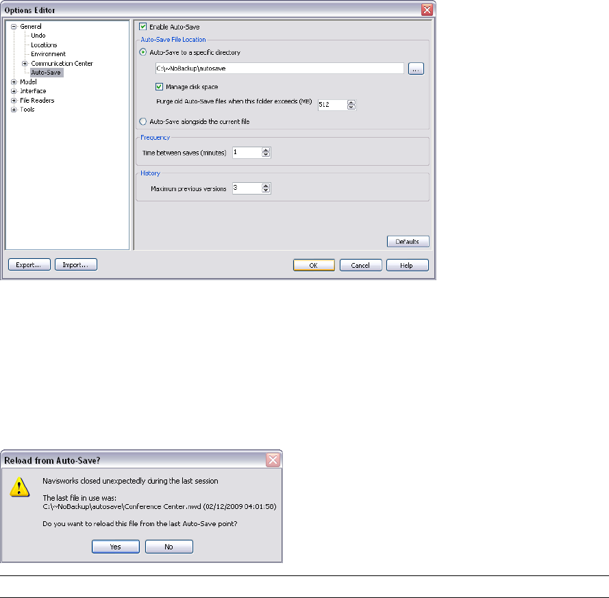
Enviro-Dome.Autosave0.nwf, the second auto-saved file is called Enviro-Dome.Autosave1.nwf and so on.
You can control a number of auto-save options, such as how often Navisworks saves your work, the location of
backup files, and the maximum number of backup files you want to keep.
To customize the auto-save options
1Click Tools ➤ Global Options.
2In the Options Editor, expand the General node, and click Auto-Save.
3Adjust the auto-save options, as required. For example, if you want Navisworks to save a backup file every
20 minutes from a significant file change, enter 20 into the Time Between Saves (minutes) box.
4Click OK.
To recover your work
1Start Autodesk Navisworks. You are automatically prompted to reload the last file you were working on.
2Click Yes to open the most recent saved version of the file.
NOTE Click No, if you don’t want to recover your work, or if you want to manually load a different backup file.
To manually load a backup file into Navisworks
1Start Autodesk Navisworks. If you are prompted to reload the last file you were working on, click No.
2Click File ➤ Open.
3In the Open dialog box, browse to the folder that contains the backup files. By default, it’s <USERPROFILE>\
Application Data\<PRODUCTFOLDER>\AutoSave.
4Click Open.
5When you are prompted to save a file with a different name, click Save As.
54 | Chapter 4 Quick Start
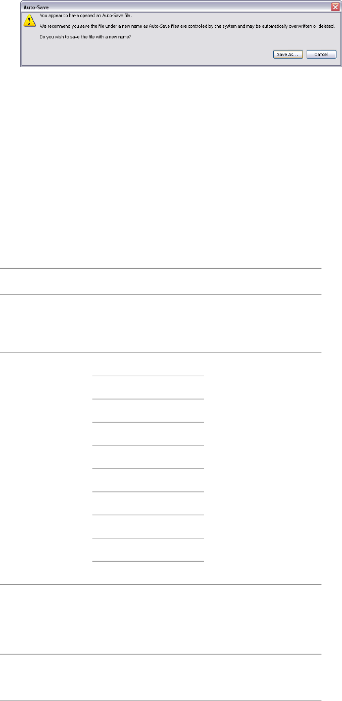
6In the Save As dialog box, enter a new file name, and browse to the desired location.
7Click Save.
Command Line Options
Command line switches can specify different startup routines for Navisworks.
You can use command line switches to specify several options when you start the program. For example, you
can run Autodesk Navisworks in another language, perform additional memory checks, load and append files,
output error reports. With command line switches, you can also set up several program icons, each with different
start-up options.
Command line switches are parameters you can add to the roamer.exe command line associated with a Microsoft®
Windows® shortcut icon or the Windows Run dialog box. You can include several switches within a single
command line. Valid switches are listed in the following table.
DescriptionArgumentCommand Line
Switch
Outputs an error report to the
specified file. You must
[file_name.dmp]-dump
provide the file name and file
path within quotation marks.
Launches Autodesk Navis-
works in the specified lan-
en-US = English-lang
de-DE = German guage. It is possible to run
Autodesk Navisworks in a lan-
es-ES = Spanish guage other than the default
locale (for example, you can
fr-FR = French run a Japanese version of
Autodesk Navisworks with
English default locale).
it-IT = Italian
ja-JP = Japanese
ko-KR = Korean
pt-BR = Brazilian Portuguese
ru-RU = Russian
zh-CN = Chinese (PRC)
Outputs log to the specified
file. You must provide the full
[filename.txt]-log
file path within quotation
marks. For example,
“C:\temp\log.txt"
Runs Autodesk Navisworks
with additional checks for
memory errors.
-memcheck
Command Line Options | 55

DescriptionArgumentCommand Line
Switch
Autodesk Navisworks converts
an input file into the NWC
[outputfile.nwc] [inputfile]-nwc
format in the background, and
places it into the specified dir-
ectory. You must provide the
full file paths within quotation
marks. For example,
“C:\temp\a.dwg"
Autodesk Navisworks converts
an input file into the NWD
[outputfile.nwd] [input file]-nwd
format in the background, and
places it into the specified dir-
ectory. You must provide the
full file paths within quotation
marks. For example,
“C:\temp\b.dwg"
Starts Autodesk Navisworks,
and imports the global op-
[filename.xml]-options
tions from the specified global
options file. You must provide
the full file path within quota-
tion marks. For example,
"C:\temp\my_global_op-
tions.xml"
Registers roamer.exe with
COM.
-regserver
The syntax for using command line switches is:
“drive:pathname\roamer.exe” [switches] [“file1”] [“file2”] [“fileN”], where [switches] are the valid
command line switches in any order, and [file1]...[fileN] are the files to be loaded and appended together, if
required. You must provide the full file paths within quotation marks.
For example, the following entry starts the program from a folder named Autodesk Navisworks in Russian language,
loads the global options file options.xml, and creates a log file log.txt.
"C:\Autodesk Navisworks\roamer.exe" -options "C:\temp\options.xml" -lang ru-ru -log
"C:\temp\file.log"
To start the program with a command line switch
1Right-click the program icon on the Windows desktop. Click Properties.
2In the Autodesk Navisworks Properties dialog box, Shortcut tab, in the Target box, edit the parameters for
the switch using the following syntax:
“drive:pathname\roamer.exe” [switches] [“file”] [“file2”] [“fileN”], where [switches] are the valid
command line switches in any order, and [file1]...[fileN] are the files to be loaded and appended together,
if required. You must provide the full file paths within quotation marks.
For example, enter: “D:\Autodesk Navisworks\roamer.exe" -log "D:\temp\nw_log.txt" "D:\temp\a.nwd"
"D:\temp\b.dwg".
3Click OK.
56 | Chapter 4 Quick Start
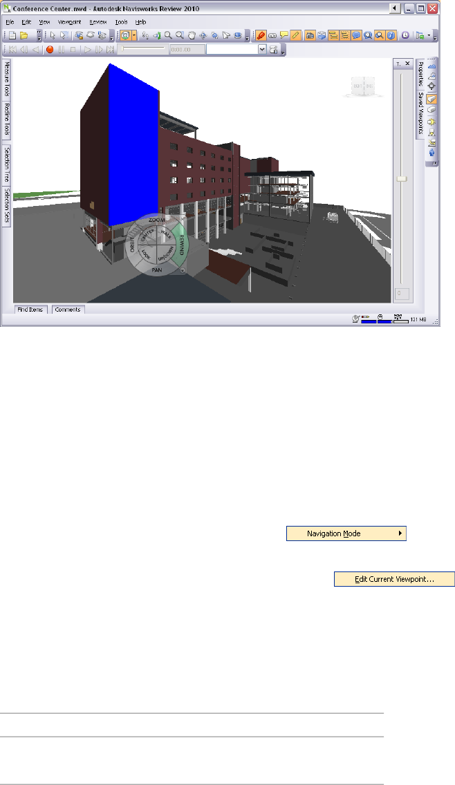
The User Interface
The Autodesk Navisworks interface contains a number of traditional Windows elements, such as toolbars, dockable
windows, dialog boxes and shortcut menus in which you complete tasks.
Parts of Autodesk Navisworks Interface
This section briefly describes the main interface components.
The Autodesk Navisworks interface is intuitive and easy to learn and use. You can adjust the application interface
to match the way you work. For example, you can hide toolbars that you rarely use, so they do not clutter the
interface. You can add and remove buttons from toolbars. You can also create your own toolbars.
Menu Bar
The Menu bar contains all commands available in Autodesk Navisworks, grouped together by similar or 'like'
functionality.
For example, all commands related to review functionality are located under the Review menu, all commands
related to user assistance are located under the Help menu and so on.
When a menu has a right-pointing arrow, such as , there is a submenu associated with that
choice.
When a menu item is followed by a series of dots, such as , there is a dialog box associated
with that choice.
Quick Reference
File Menu
This menu contains commands for managing files.
DescriptionOption
Resets the program, and closes the cur-
rently open Navisworks file.
New
The User Interface | 57
DescriptionOption
Refreshes your scene with the latest ver-
sions of currently loaded model files.
Refresh
Displays the Open dialog box.Open
Displays the Open URL dialog box.Open URL
Displays the Append dialog box.Append
Displays the Merge dialog box.Merge
Saves the currently open Navisworks file.Save
Displays the Save As dialog box.Save As
Displays the Publish dialog box.Publish
Displays the Print dialog box.Print
Enables print preview mode.Print Preview
Displays the Print Setup dialog box.Print Setup
Deletes the selected files. You can only
delete appended files.
Delete
Saves the currently open Navisworks file,
accesses your email program, and adds the
saved file as an email attachment.
Send
Displays the Import dialog box, and en-
ables you to import Intergraph PDS review
data, and various Navisworks data.
Import
Displays the Export dialog box, and en-
ables you to export data from Navisworks.
Export
Displays shortcuts to the most recently
opened files.
Recent Files
Exits the program.Exit
Edit Menu
This menu contains commands for locating, selecting and editing geometry in your model.
DescriptionOption
Reverses the last performed operation.Undo
Reverses the last operation performed by
the Undo command.
Redo
Gives you access to selection functionality.Select
Displays the Quick Find dialog box.Quick Find
Repeats the previously run quick find
search.
Quick Find Next
58 | Chapter 4 Quick Start
DescriptionOption
Toggles the Find Items control bar.Find Items
Toggles the Find Comments dialog box.Find Comments
Toggles hidden mode for selected items.Hidden
Toggles required mode for selected items.Required
Toggles hidden mode for unselected items.Unselected Hidden
Enables you to override color, transpar-
ency, and transform for selected items.
Override Item
Enables you to reset selected items back
to their original state.
Reset Item
Enables you to reset all overridden items
back to their original state.
Reset All
Enables you to sort the items in the Selec-
tion Tree alphabetically.
Sort
Displays the File Units and Transform dia-
log box.
File Units an Transform
View Menu
This menu contains commands that control the Navisworks interface.
DescriptionOption
Enables you to toggle the display of control
bars.
Control Bars
Enables you to control workspaces.Workspaces
Enable you to control the views in the
Scene Area.
Scene View
Enables you to control the Head-Up Display
elements.
Head-Up Display
Enables you to control the SteeringWheels.SteeringWheels
Puts the video output into stereo mode.Stereo
Displays the Stereo Options dialog box.Stereo Options
Displays useful scene statistics.Scene Statistics
Viewpoint Menu
This menu contains a set of commands that affect the current viewpoint, including model appearance, navigation
and sectioning.
DescriptionOption
Enables you to use saved viewpoints.Saved Viewpoints
Parts of Autodesk Navisworks Interface | 59
DescriptionOption
Enables you to look from a preset view-
point.
Look From
Sets the viewpoint up vector to align with
the selected orientation.
Set Viewpoint Up
Enables you to select rendering mode.Rendering
Enables you to select lighting mode.Lighting
Enables you to display primitives.Display
Enables you to select navigation mode.Navigation Mode
Enables you to control the camera during
interactive navigation.
Navigation Tools
Enables you to create a limited volume of
your model.
Sectioning
Displays the Edit Viewpoint dialog box for
the current viewpoint.
Edit Current Viewpoint
Review Menu
This menu contains commands for reviewing and markup.
DescriptionOption
Enables you to add and manage com-
ments.
Comments
Enables you to add and manage annota-
tions.
Redline
Enables you to use the measure tools.Measure
Enables you to add and manage hyperlinks.Hyperlinks
Enables you to locate review tags.Tags
Sends the current view of the currently
loaded file back to AutoCAD or MicroSta-
tion-based program.
SwitchBack
Renumbers all comment IDs, making them
unique to the scene.
Renumber Comment IDs
Renumbers all tag IDs, making them
unique to the scene.
Renumber Tag IDs
Tools Menu
This menu contains commands for advanced model analysis and reviewing, and also commands for customizing
Autodesk Navisworks.
DescriptionOption
Toggles the TimeLiner Playback window.TimeLiner Playback
60 | Chapter 4 Quick Start
DescriptionOption
Displays the DataTools dialog box.DataTools
Displays the Compare dialog box.Compare
Toggles the Redline Tools tool window.Redline
Toggles the display of hyperlinks.Hyperlinks
Toggles the display of smart tags.Smart Tags
Toggles the Measure Tools tool window.Measure
Enables you to control animation playback,
and record viewpoint animations.
Animation
Enables you to select a background color
for the Scene Area.
Background
Displays the File Options dialog box.File Options
Displays the Customize dialog box.Customize
Displays the Options Editor.Global Options
Help Menu
This menu provides access to the Autodesk Navisworks online reference system.
DescriptionOption
Opens the Help system.Help Topics
Opens the Communication Center
dockable window.
Communication Center
Opens the context-sensitive help.What’s This
Displays the Autodesk Navisworks
product page.
Navisworks on the Web
Displays the Customer Involvement dia-
log box.
Customer Involvement Program
Displays detailed information about your
system.
System Info
Displays copyright and license informa-
tion about your copy of Autodesk Navis-
About Autodesk Navisworks Re-
view 2010
works, and enables you to access the
Product Information dialog box.
Toolbars
Autodesk Navisworks toolbars provide quick access to frequently used commands.
Every button on a toolbar includes a tooltip, which describes the function the button activates. Placing the
mouse over a button displays a brief instruction on how to use this feature in the Status bar.
Parts of Autodesk Navisworks Interface | 61
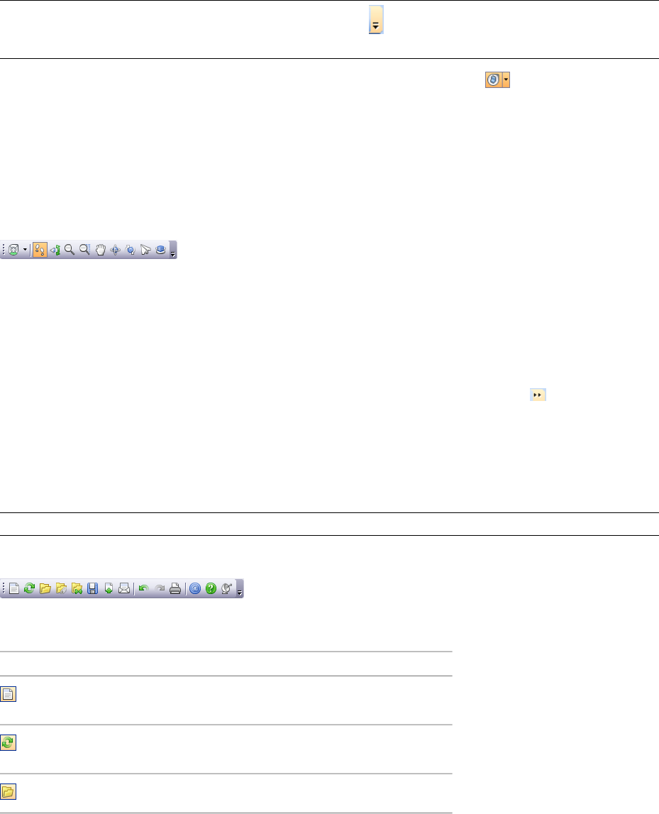
You can rearrange, open and close toolbars:
■To move a toolbar, click the dotted line at the edge of the toolbar, and drag it to a different location.
■To open or close toolbars, right-click an empty area next to the last toolbar on the screen, and choose from
the list of available toolbars on the shortcut menu.
In addition to rearranging the existing Autodesk Navisworks toolbars, you can customize their appearance and
content, and create your own toolbars.
NOTE To quickly personalize a toolbar, click the Toolbar Options button on the right, and click Add or Remove
Buttons on the shortcut menu.
When a Autodesk Navisworks toolbar button has a down-pointing arrow, such as , a submenu toolbar is
associated with that choice. Click the triangle to open the menu, and select a specific option. As you move
through the menu, additional help is displayed in the Status bar. When the option is selected, it becomes the
current command and is displayed as a button in the toolbar. To repeat the command, click the button in the
toolbar. To choose a different command, click the triangle again.
Some toolbar buttons enable you to choose a program mode. For example, to look around your model, you need
to be in look around mode. To rotate the model, you need to be in examine mode and so on. Autodesk Navisworks
remains in the selected mode until instructed otherwise. To identify the mode you are in, look at the buttons.
If a button is highlighted and has a dark blue boarder around it, the corresponding mode is currently active.
To leave the mode, either click the same button again or choose a different mode.
Some buttons are used to toggle the display of dialog boxes, and dockable windows (for example, the Presenter
window, the Animator window etc.). Again, if a button is highlighted and has a dark blue boarder around it, it
means that the corresponding display element is currently open.
As you open more toolbars on the screen, or resize the Autodesk Navisworks window, the toolbars may get
overlapped with each other to reduce the screen clutter. When this happens, some buttons will be hidden under
the overlaps. To quickly access the entire set of commands on a toolbar, click the chevron button at the right
end of the toolbar. The remaining commands available for that toolbar will appear.
Quick Reference
In this section, you will find a complete list of Navisworks toolbars and associated buttons.
NOTE The actual toolbar content can differ from this reference depending on the workspace you use.
Standard Toolbar
This toolbar provides quick access to file management commands. It also enables you to undo/redo your actions,
and open the Help system.
DescriptionButton
Resets the program, and closes the cur-
rently open Navisworks file.
Refreshes your scene with the latest ver-
sions of currently loaded model files.
Displays the Open dialog box.
62 | Chapter 4 Quick Start
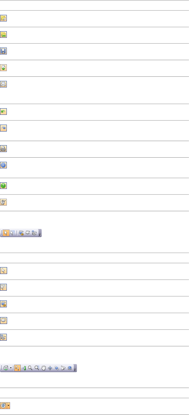
DescriptionButton
Displays the Open URL dialog box.
Displays the Merge dialog box.
Saves the currently open Navisworks file.
Displays the Publish dialog box.
Saves the currently open Navisworks file,
accesses your email program, and adds the
saved file as an email attachment.
Reverses the last performed operation.
Reverses the last operation performed by
the Undo command.
Displays the Print dialog box.
Displays copyright and license information
about your copy of Autodesk Navisworks.
Opens the Help system.
Opens the Communication Center.
Selection Tools Toolbar
This toolbar provides access to the selection commands, plus enables you to hide geometry objects.
DescriptionButton
Turns on select mode.
Turns on select box mode.
Toggles required mode for selected items.
Toggles hidden mode for selected items.
Toggles hidden mode for unselected items.
Navigation Mode Toolbar
This toolbar includes nine modes and six SteeringWheels for interactive navigation around your 3D models.
DescriptionButton
Selects the wheel.
Parts of Autodesk Navisworks Interface | 63
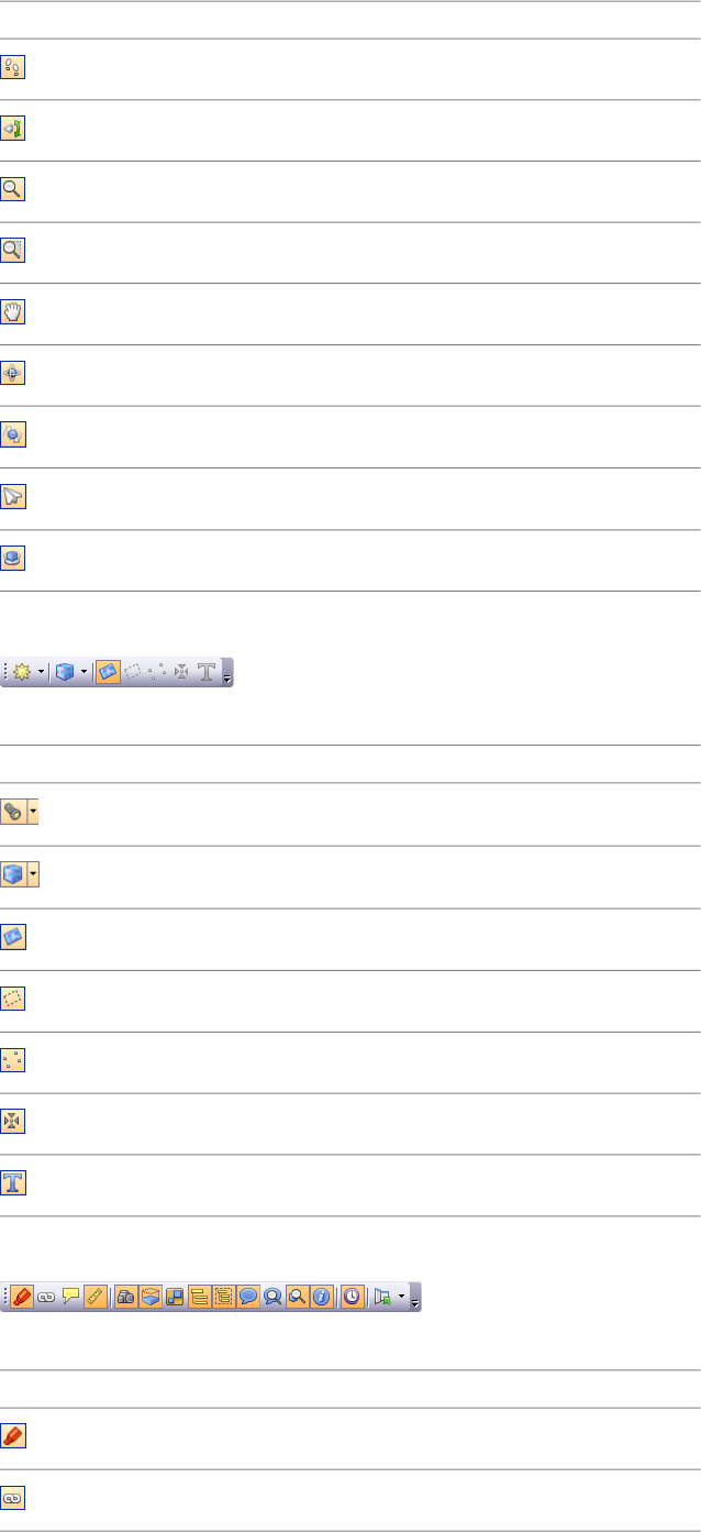
DescriptionButton
Turns on walk mode.
Turns on look around mode.
Turns on zoom mode.
Turns on zoom box mode.
Turns on pan mode.
Turns on orbit mode.
Turns on examine mode.
Turns on fly mode.
Turns on turntable mode.
Rendering Style Toolbar
This toolbar controls the model appearance in Navisworks.
DescriptionButton
Selects lighting mode.
Selects rendering mode.
Toggles the rendering of surfaces.
Toggles the rendering of lines.
Toggles the rendering of points.
Toggles the rendering of snap points.
Toggles the rendering of 3D text.
Workspace Toolbar
This toolbar gives you quick access to the Navisworks review and analysis tools.
DescriptionButton
Toggles the Redline Tools tool window.
Toggles the display of hyperlinks.
64 | Chapter 4 Quick Start
DescriptionButton
Toggles the display of smart tags.
Toggles the Measure Tools tool window.
Toggles the Viewpoints control bar.
Toggles the Sectioning toolbar.
Toggles the Plan Thumbnail control bar.
Toggles the Section Thumbnail control bar.
Toggles the Selection Tree control bar.
Toggles the Selection Sets control bar.
Toggles the Comments control bar.
Toggles the Find Comments dialog box.
Toggles the Find Items control bar.
Toggles the Properties control bar.
Toggles the TimeLiner Playback window.
Controls workspaces.
Model Views Toolbar
This toolbar controls the views in the Scene Area.
DescriptionButton
Splits your active scene view vertically.
Splits your active scene view horizontally.
Adds title bars to all custom scene views.
Sectioning Toolbar
This toolbar enables you to create a limited volume of your model.
DescriptionButton
Enables you to link two opposing section
planes together.
Parts of Autodesk Navisworks Interface | 65
DescriptionButton
Displays the Set Sectioning Box Size dialog
box.
Restricts the section distance to the
bounding box limits of the objects selected
in the Scene Area
Displays the Sectioning Plane dialog box.
Enables/disables the current section plane
or box.
Deletes the current section plane.
Enables you to choose the alignment
method.
Animation Toolbar
This toolbar allows you to record viewpoint animations, play back object and viewpoint animations, and toggle
the scripting functionality.
DescriptionButton
Rewinds the current animation back to the
beginning.
Steps back a single animation frame or
keyframe.
Plays the current animation backwards.
Records the viewpoint animation.
Pauses the animation.
Stops playing the current animation, and
rewinds it back to the beginning.
Plays the currently selected animation.
Steps one frame or keyframe forwards.
Fast forwards the current animation to the
end.
Toggles the Scripter engine on and off in
the Navisworks file.
Collaborate Bar Toolbar
66 | Chapter 4 Quick Start
This toolbar enables you to participate in design review sessions across a Local Area Network (LAN).
DescriptionButton
Starts Windows™ NetMeeting.
Enables you to rtake control of the session,
and become the ‘driver’.
Refreshes Navisworks data on all attendees
machines.
Object Manipulation Toolbar
This toolbar enables you to edit geometry in your model.
DescriptionButton
Toggles the display of the translation
gizmo.
Toggles the display of the rotation gizmo.
Toggles the display of the scale gizmo.
Enables you to apply color override.
Enables you to apply transparency override.
Enables/disables snapping.
Navigation Tools Toolbar
This toolbar enables you to control the camera during interactive navigation.
DescriptionButton
Dollies and pans the camera so that the
entire model is in the Scene View.
Zooms the camera so that the selected
item fills the Scene View.
Puts the Scene View into focus mode.
Holds the selected items. As you move
around the model, these objects will move
with you.
Uses a perspective camera.
Uses an orthographic camera.
Toggles collision.
Parts of Autodesk Navisworks Interface | 67
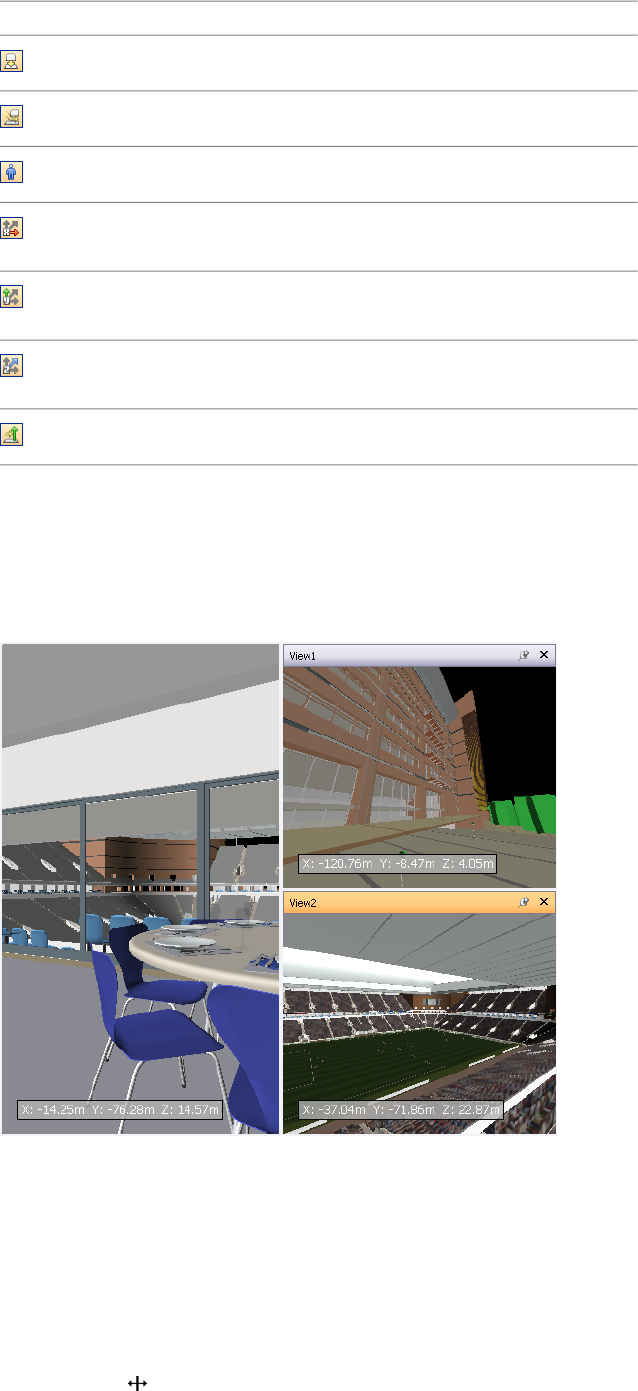
DescriptionButton
Toggles gravity.
Toggles crouching.
Toggles third person view.
Aligns the current viewpoint with the X
axis.
Aligns the current viewpoint with the Y
axis.
Aligns the current viewpoint with the Z
axis.
Straightens the camera.
Scene Area
This is the area where you view and interact with your 3D models.
When you start Navisworks, the Scene Area contains only one scene view, but you can add more scene views,
if needed. Custom scene views are named "ViewX" where 'X' is the next available number.
Looking at several views of your model simultaneously is useful when you compare lighting and rendering styles,
animate different parts of your model, and so on.
Only one scene view can be active at a time. A scene view becomes active as you work in it. If you left-click a
scene view, the scene view is activated and whatever you click is selected, or, if you click an empty area, everything
is deselected. Right-clicking a scene view activates it, and opens a shortcut menu.
Each scene view remembers the navigation mode being used. The recording and playback of animations only
occurs in the currently active view.
Each scene view can be resized. To resize scene views, move the cursor over the scene view intersection and drag
the splitter bar .
68 | Chapter 4 Quick Start
You can make custom scene views dockable. Dockable scene views have title bars, and can be moved, docked,
tiled, and auto hidden the same way as dockable windows. If you want to use several custom scene views, but
don't want to have any splits in the Scene Area, you can move them elsewhere. For instance, you can tile your
scene views on the Viewpoints control bar.
NOTE You cannot undock the default scene view.
Full Screen Mode
In full screen mode your current scene view takes up the full screen, and no interface controls are shown.
To interact with the model in the scene view, use the keyboard shortcuts and the shortcut menu.
TIP If you use two monitors, your default scene view is automatically placed on the primary display, and the interface
can be placed on the secondary display to control the interaction.
Scene View Content
Navisworks enables you to change the size of content displayed in a scene view. This can be of particular use if
you are composing a scene for image or animation export. By setting the content size to the same proportions
as your intended output, you can visualize exactly how it will look.
To create a custom scene view
■To split your active scene view horizontally, click View ➤ Scene View ➤ Split Horizontal.
■To split your active scene view vertically, click View ➤ Scene View ➤ Split Vertical.
Toolbar: Model Views ➤ Split Horizontal and Model Views ➤ Split Vertical
To make custom scene views dockable
■Click View ➤ Scene View ➤ Toggle Title Bars.
All of your custom scene views now have title bars.
Toolbar: Model Views ➤ Toggle Title Bars
To delete a custom scene view
1If your scene view is not dockable, click View ➤ Scene View ➤ Toggle Title Bars.
2Click to close the scene view.
NOTE You cannot delete the default scene view.
To toggle full screen mode
■Click View ➤ Scene View ➤ Full Screen.
Command entry: F11
Shortcut menu: Viewpoint ➤ Full Screen
To resize the content of the active scene view
1Click View ➤ Scene View ➤ Window Size.
2In the Window Size dialog box, Type drop-down list, select the sizing type.
Parts of Autodesk Navisworks Interface | 69
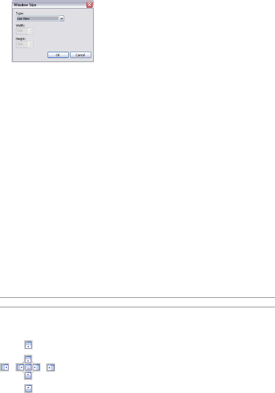
■Use View - makes the content fill the currently active scene view.
■Explicit - defines the exact width and height for the content.
■Use Aspect Ratio - uses the aspect ratio of the current scene view to automatically calculate the width
of the content when the height is entered, or the height of the content when the width is entered.
3If you selected the Explicit option, enter the width and height for your content in pixels.
If you selected the Use Aspect Ratio, enter the width or height for your content in pixels.
4Click OK.
Dockable Windows
Most Navisworks features are accessible from the dockable windows.
There are two types of dockable windows:
■Control bars
■Tool windows
To display a control bar, click View ➤ Control Bars on the Menu bar, and then choose from the list of available
control bars.
To display a tool window, click Tools on the Menu bar, and then choose from the list of available tool windows.
Alternatively, click the desired button on the Workspace toolbar.
Both types of windows can be moved and resized, and either floated in the Scene Area or docked. A docked
window shares one or more edges with adjacent windows and toolbars. If a shared edge is moved, the windows
change shape to compensate. You can also float windows anywhere on the screen, if necessary.
To undock and relocate a window, click and drag the title bars at the top or side of the window.
To prevent a window from automatically docking while you drag it, hold down the CTRL key.
NOTE You can quickly dock and undock a window by double-clicking the window's title bar.
Use the Docking Tool
When you drag a dockable window from its current location towards a new destination on the interface, a
docking tool appears.
The docking stickers point towards the four edges of the interface.
70 | Chapter 4 Quick Start
When the window you are dragging is close to the place where you want it to dock, move the mouse over the
corresponding area of the docking tool. You will see an outline of the window appear on the interface. To dock
the window there, release the mouse button.
Tile Windows
You can tile dockable windows on the interface. To do this, drag a window you want to tile over the window
where you want it to be placed. When a rectangular outline appears, release the mouse button.
Auto Hide Windows
You can auto hide dockable windows; this keeps the windows active while maximizing the amount of available
screen space. If auto-hide is active, the body of the window disappears when you move the cursor out of it,
leaving only the title bar visible. Move the cursor over the title bar to display the entire window again.
To switch auto-hide on, click on the title bar. To switch auto-hide off, click on the title bar.
The Shortcut Menu
Right-clicking a dockable window displays a shortcut menu of available commands. If you right-click a single
item, or select one or more items and right-click, this menu contains commands related to the items. If you
right-click an area that contains no items or data, the menu contains commands related to the dockable window,
if appropriate.
Status Bar
The Status bar appears at the bottom of the Autodesk Navisworks screen. As this is not a toolbar, it cannot be
customized or moved around.
The left-hand corner of the Status bar is used to display short instructions on how to use the Autodesk Navisworks
features.
In the right-hand corner of the Status bar there are four performance indicators that give you constant feedback
as to how well Autodesk Navisworks is performing on your machine, and the notification icon.
Notification Icon
Notification icon indicates whether any new information is available. Balloon notifications appear over this icon
whenever new Communication Center content is available. You can right-click this icon to turn off the
notifications, or to customize the Communication Center options.
Pencil Progress Bar
The progress bar under the left hand icon (pencil) indicates how much of the current view is drawn, that is how
much drop-out there is in the current viewpoint. When the progress bar is at 100%, the scene is completely
drawn, with no drop-out. The icon changes color when a redraw is in progress. Whilst the scene is being drawn,
the pencil will change to yellow. If there is too much data to handle and your machine cannot process this
quickly enough for Autodesk Navisworks, then the pencil changes to red, indicating a bottleneck.
Disk Progress Bar
The progress bar under the central icon (disk) indicates how much of the current model is loaded from disk, that
is how much is loaded into memory. When the progress bar is at 100%, the entire model, including geometry
and property information, is loaded into memory. The icon changes color when a file load is in progress. Whilst
data is being read, the disk changes to yellow. If there is too much data to handle and your machine cannot
process this quickly enough for Autodesk Navisworks, then the disk changes to red, indicating a bottleneck.
Web Server Progress Bar
The progress bar under the right hand icon (web server) indicates how much of the current model is downloaded,
that is how much has been downloaded from a web server. When the progress bar is at 100%, the entire model
has been downloaded. The icon changes color when a file load is in progress. Whilst data is being downloaded,
the web server changes to yellow. If there is too much data to handle and your machine cannot process this
quickly enough for Autodesk Navisworks, then the web server changes to red, indicating a bottleneck.
Parts of Autodesk Navisworks Interface | 71
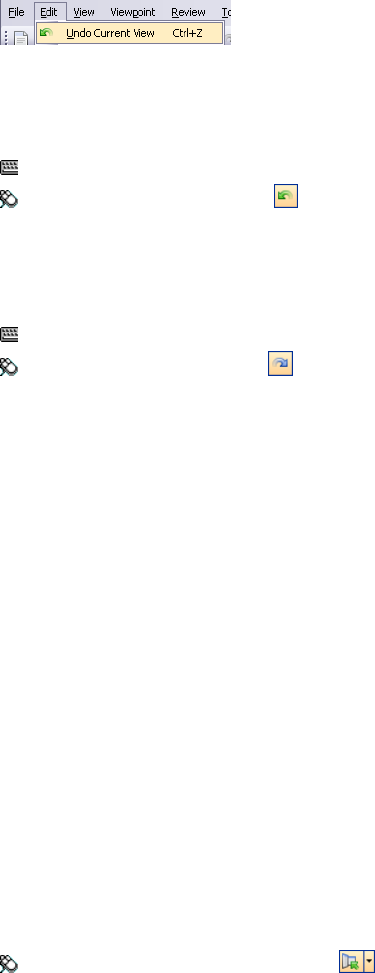
Memory Bar
The field to the right of the icons reports the amount of memory currently being used by Autodesk Navisworks.
This is reported in Megabytes (MB).
Undo/Redo Commands
You can undo or redo your actions in Autodesk Navisworks.
The default settings are adequate for regular Autodesk Navisworks usage, but you can adjust the amount of space
allocated to the undo/redo buffer, if necessary.
The Edit ➤ Undo and Edit ➤ Redo menu items state what type of action you can undo/redo.
To undo an action
■Click Edit ➤ Undo on the Menu bar.
Command entry: CTRL + Z
Toolbar: Standard ➤ Undo
To redo an action
■Click Edit ➤ Redo on the Menu bar.
Command entry: CTRL+Y
Toolbar: Standard ➤ Redo
Autodesk Navisworks Workspaces
Workspaces are sets of toolbars and dockable windows that are grouped and organized so that you can work in
a custom, task-oriented design review environment.
Each workspace contains sets of toolbars and dockable windows with the tools required to perform a certain job,
making it easy to switch between design review layouts as necessary. For example, 'file aggregation', 'project
review', 'object animation' and 'interference detection' workspaces could be set up, saved and used as appropriate.
The workspaces can also be shared with other users. You could, for example, create separate workspaces for
occasional and power Navisworks users, or setup your own corporate standard.
Autodesk Navisworks comes with several pre-configured workspaces:
■Safe Mode - selects the design review layout with the minimum features.
■Extended - selects the design review layout recommended for advanced users.
■Default - selects the design review layout recommended for users new to the program.
■Classic - selects the design review layout used in Navisworks v5 and earlier.
You can use these workspaces as-is or modify them in accordance to your requirements. When you first start
Navisworks, the default workspace is used. You can choose a different workspace at any time by clicking View
➤ Workspaces, and then selecting the required workspace from the list.
Toolbar: Workspace ➤ Workspaces
To save current layout to a new workspace
1Set up your design review layout. For example, you can close all toolbars except the Standard, Selection
Tools, Navigation Mode, and Workspace.
72 | Chapter 4 Quick Start
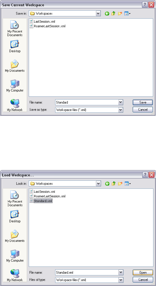
2On the View menu, click Workspaces ➤ Save Workspace.
3In the Save Current Workspace dialog box, enter a name for the new workspace. You can also select the
name of an existing workspace to overwrite it with your modified configuration.
4Click Save.
To load a saved workspace into Navisworks
1On the View menu, click Workspaces ➤ Load Workspace.
2In the Load Workspace dialog box, browse to the folder containing the desired workspace, and select it.
3Click Open.
Default Keyboard Shortcuts
Keyboard shortcuts are keyboard alternatives you can use to initiate commands normally accessed with the
mouse.
For example, to open the Selection Tree, you can press CTRL + F12, to open the Find Comments dialog box, you
can press SHIFT + F4, and so on. Keyboard shortcuts offer a means to let you work faster and more efficiently.
Some dialog boxes or dockable windows can be closed with the same command used to open it.
Default Keyboard Shortcuts | 73
Many keyboard shortcuts are already set for most commonly used actions. You can modify the default shortcuts
or add new shortcuts, if necessary.
Quick Reference
DescriptionDefault Keyboard Shortcut
Closes the currently active dockable win-
dow when it is undocked, or exits the ap-
ALT + F4
plication if the main application window
is active.
Switches between the dockable windows
when they are undocked.
ALT + F6
Turns on turntable mode.CTRL + 0
Turns on select mode.CTRL + 1
Turns on walk mode.CTRL + 2
Turns on look around mode.CTRL + 3
Turns on zoom mode.CTRL + 4
Turns on zoom box mode.CTRL + 5
Turns on pan mode.CTRL + 6
Turns on orbit mode.CTRL + 7
Turns on examine mode.CTRL + 8
Turns on fly mode.CTRL + 9
Displays the Append dialog box.CTRL + A
Toggles collision mode. You must be in
appropriate navigation mode (that is, Walk
or Fly) for this keyboard shortcut to work.
CTRL + D
Displays the Quick Find dialog box.CTRL + F
Toggles gravity mode.CTRL + G
Toggles hidden mode for selected items.CTRL + H
Displays the Merge dialog box.CTRL + M
Resets the program, and closes the cur-
rently open Navisworks file.
CTRL + N
Displays the Open dialog box.CTRL + O
Displays the Print dialog box.CTRL + P
Toggles required mode for selected items.CTRL + R
Saves the currently open Navisworks file.CTRL + S
74 | Chapter 4 Quick Start

DescriptionDefault Keyboard Shortcut
Toggles third person mode.CTRL + T
Reverses the last operation performed by
the Undo command.
CTRL + Y
Reverses the last performed operation.CTRL + Z
Opens the Help system.CTRL + F1
Toggles the Camera Tilt control bar.CTRL + F7
Toggles the Sectioning toolbar.CTRL + F8
Toggles the Plan Thumbnail control bar.CTRL + F9
Toggles the Section Thumbnail control bar.CTRL + F10
Toggles the Viewpoints control bar.CTRL + F11
Toggles the Selection Tree control bar.CTRL + F12
Dollies and pans the camera so that the
entire model is in view.
CTRL + HOME
Takes you to the next redline tag.CTRL + SHIFT + N
Takes you to the previous redline tag.CTRL + SHIFT + P
Enables view selected mode. This keyboard
shortcut only applies to the Scene Area
HOME
windows. This means it will only work
when this window has focus.
Deselects everything.ESC
Opens the Help system.F1
Renames the selected item, when appropri-
ate.
F2
Repeats the previously run quick find
search.
F3
Refreshes your scene with the latest ver-
sions of currently loaded model files.
F5
Toggles full screen mode.F11
Opens the last used SteeringWheel.Shift + W
Enables you to get context-sensitive help.SHIFT + F1
Toggles the Selection Sets control bar.SHIFT + F2
Toggles the Find Items control bar.SHIFT + F3
Toggles the Find Comments dialog box.SHIFT + F4
Default Keyboard Shortcuts | 75
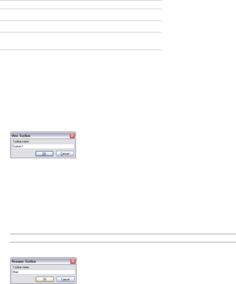
DescriptionDefault Keyboard Shortcut
Toggles the Comments control bar.SHIFT + F6
Toggles the Properties control bar.SHIFT + F7
Opens a shortcut menu for the active
dockable window.
SHIFT + F10
Customize the Toolbars
You can customize the appearance and contents of the Autodesk Navisworks toolbars by using the Customize
dialog box.
To add a custom toolbar
1Click Tools ➤ Customize.
2In the Customize dialog box, Toolbars tab, click the New button.
3Enter a name for the toolbar in the Toolbar Name box. By default, new toolbars are named "Custom X"
where 'X' is the next available number added to the list.
4Click OK.
The new toolbar appears in the toolbar area.
5Close the Customize dialog box.
To rename a custom toolbar
1Click Tools ➤ Customize.
2In the Customize dialog box, Toolbars tab, click your toolbar.
3Click Rename.
NOTE You can only rename custom toolbars.
4Enter the new name for your toolbar.
5Click OK.
6Close the Customize dialog box.
To delete a custom toolbar
1Click Tools ➤ Customize.
2In the Customize dialog box, Toolbars tab, click the toolbar you don’t need.
3Click Delete.
76 | Chapter 4 Quick Start
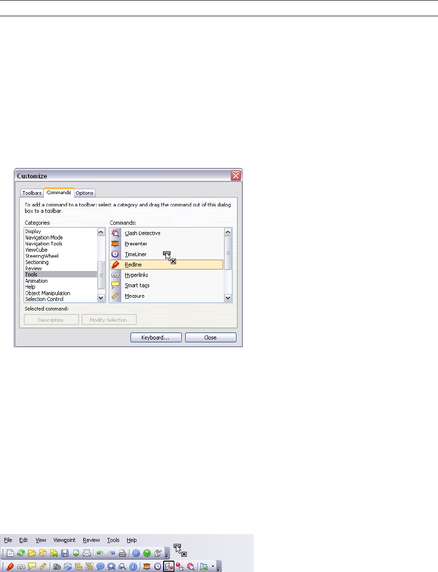
NOTE You can only delete custom toolbars.
4Close the Customize dialog box.
To add commands
1Click Tools ➤ Customize. This opens the Customize dialog box.
2There are several ways to add commands to a toolbar or a menu:
■In the Customize dialog box, Commands tab, click the desired category, and drag the command from
the commands list on to the toolbar. If the command has a default icon assigned to it (it is shown next
to the command in the command list), the icon will appear as a button on your toolbar. If no icon is
assigned to the command, the name of the command will appear as a button on the toolbar. For menus,
the command will appear exactly as it is shown in the command list.
■Drag the command from another menu or toolbar onto your toolbar or menu. This moves the command
from its original location into a new place.
■Hold CTRL and drag the command from another menu or toolbar onto your toolbar or menu. This
creates a copy of the command, and does not remove the command from its original location.
3If you want to edit the command’s appearance, right-click it on the toolbar or menu, and use options on
the shortcut menu.
4Close the Customize dialog box.
To delete commands
1Click Tools ➤ Customize. This opens the Customize dialog box.
2Drag the command away from the menu or toolbar, until a cursor displays a small cross.
3Release the left mouse button to delete the command.
4Close the Customize dialog box.
To customize keyboard shortcuts
1Click Tools ➤ Customize.
2In the Customize dialog box, click the Keyboard button.
Customize the Toolbars | 77
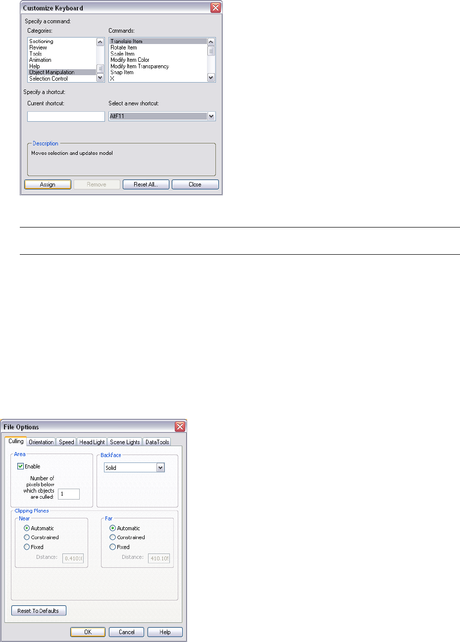
3In the Customize Keyboard dialog box, use the Categories and Commands lists to find desired command.
4Click the command, and choose a shortcut in the Select a New Shortcut drop-down list.
5Click Assign.
NOTE Clicking Remove removes the shortcut assignment for the selected command, and clicking Reset All restores
the default shortcut assignments.
6Close the dialog boxes.
Autodesk Navisworks Options
There are two types of options: File Options and Global Options.
File Options
For each Autodesk Navisworks file (.NWF and .NWD), you can adjust the model appearance and the speed of
navigation around it. File options are stored with Autodesk Navisworks files (.nwf or .nwd), and reloaded each
time you open these files.
The File Options dialog box is used to customize various file options, and can be accessed from the Tools menu.
78 | Chapter 4 Quick Start
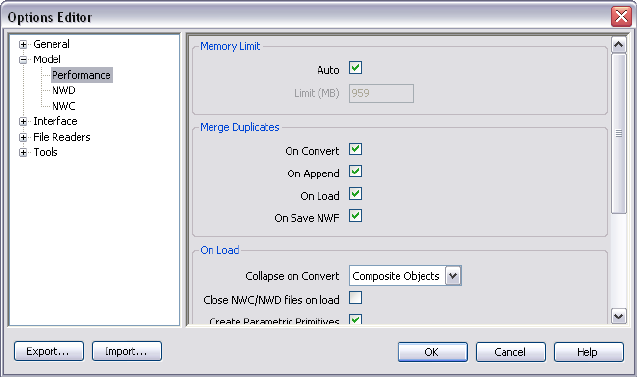
Global Options
Global options, on the other hand, are set for all Autodesk Navisworks sessions. The Options Editor can be
accessed from the Tools menu, or it can be launched as a separate application. To do this, click Start ➤ Programs
➤ Autodesk ➤ Navisworks Review 2010 ➤ Options Editor. The options are grouped together, and presented
in a tree structure, making it quicker to find and change them.
Global options can be exported and imported, making it quick and easy for project managers, or systems
administrators, to ensure the Autodesk Navisworks settings on all machines are identical.
To configure file options
1Click Tools ➤ File Options.
2Use the File Options dialog box to customize various file settings.
3Click OK to save the changes.
See also:
■“File Options Dialog Box” on page 273
To configure global options
1Click Tools ➤ Global Options.
2In the Options Editor, expand the desired node, and click the option you want to configure.
3Click OK to save the changes.
See also:
■“Options Editor” on page 277
To export global options
1Click Tools ➤ Global Options.
2In the Options Editor, click the Export button.
3In the Select Options to Export dialog box, select the check boxes for all options you want to be exported
(or 'serialized'). If an option cannot be exported, it is greyed out.
Autodesk Navisworks Options | 79
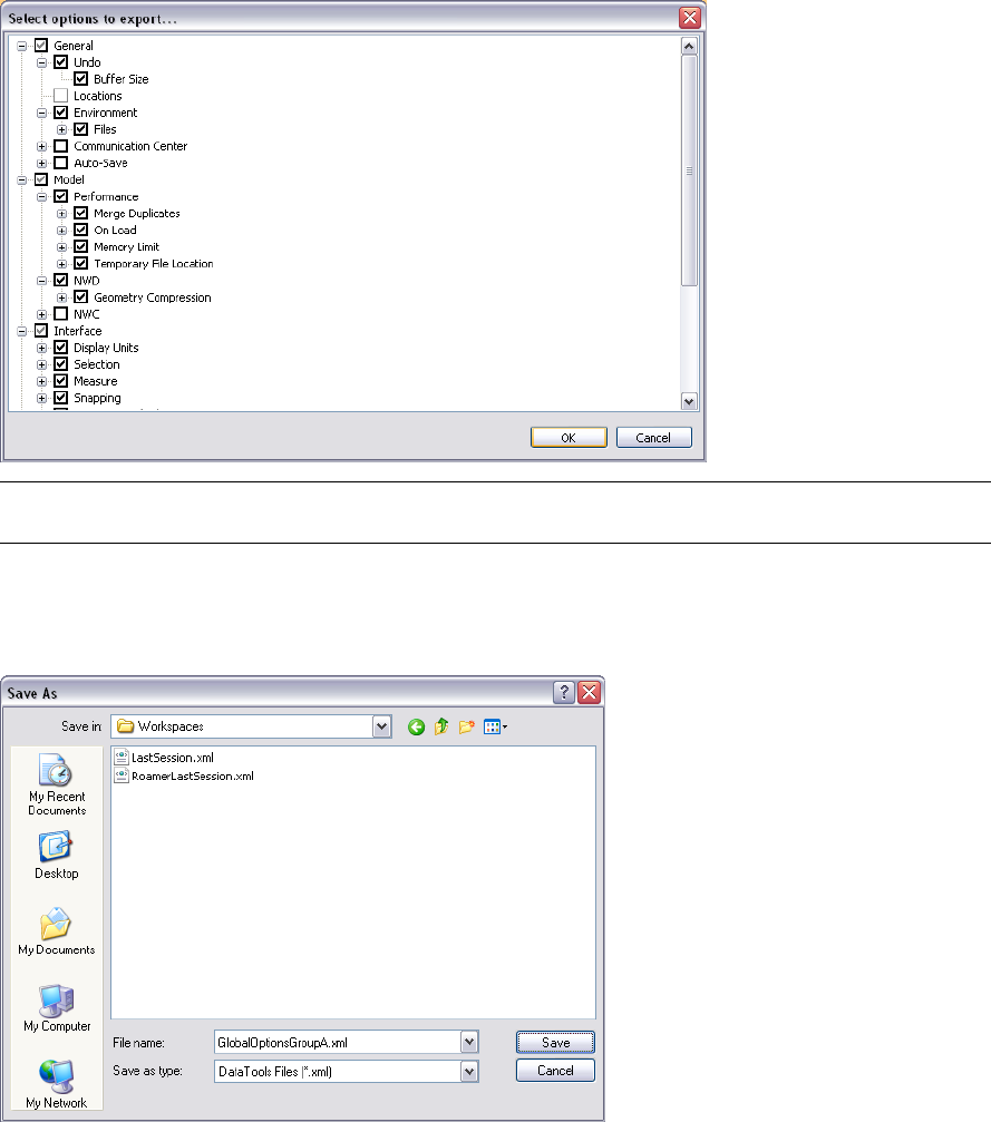
TIP To quickly select/deselect all options for a given category, use the top-level check boxes. For example, selecting
the General check box, instantly selects all options under this node.
4Click OK to export the selected settings.
5In the Save As dialog box, enter a name for the settings file. You can also select the name of an existing
settings file to overwrite it with your modified configuration.
6Click Save.
7Click OK to close the Options Editor.
To import global options
1Click Tools ➤ Global Options.
2In the Options Editor, click the Import button.
3In the Open dialog box, browse to the folder containing the settings file, select it, and click Open.
80 | Chapter 4 Quick Start
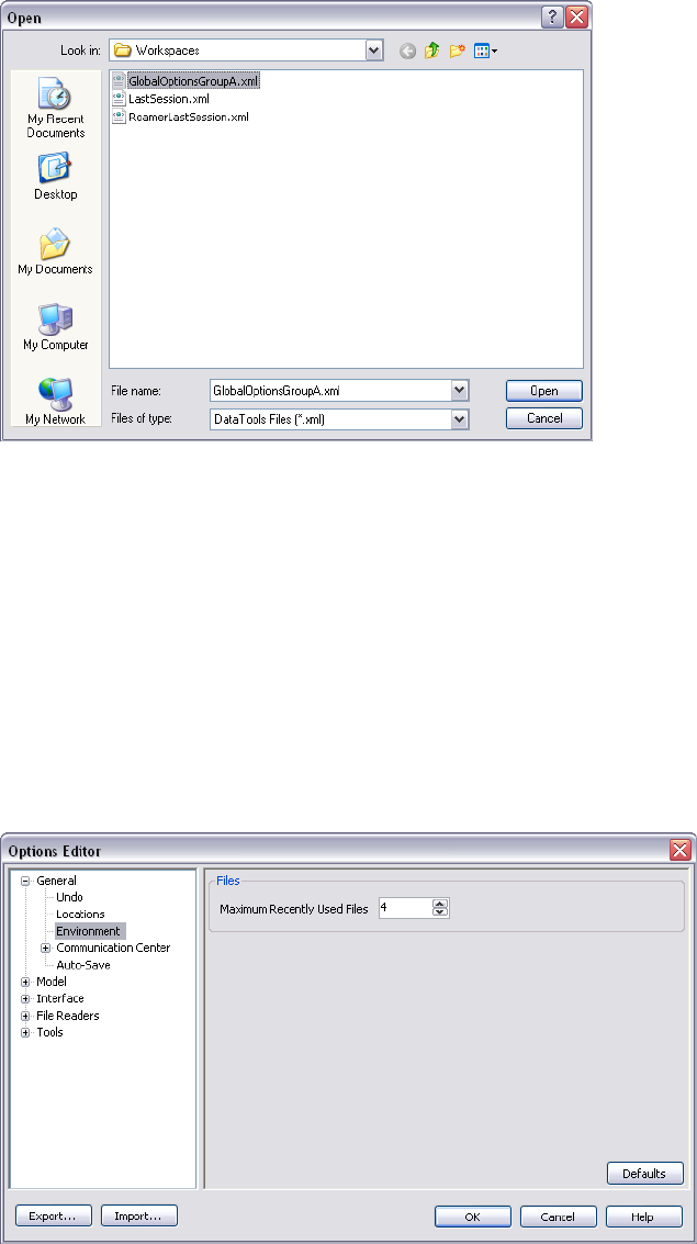
4Click OK to close the Options Editor.
Environment Options
You can adjust the number of recent file shortcuts stored by Autodesk Navisworks.
To configure environment options
1Click Tools ➤ Global Options.
2In the Options Editor, expand the General node, and click the Environment option.
3On the Environment page, enter the desired number into the Maximum Recently Used Files box. By default,
shortcuts to the four most recently opened files can be displayed.
4Click OK.
Location Options
These options enable centralized sharing of global Autodesk Navisworks settings, workspaces, datatools, avatars,
Clash Detective rules, Presenter archives, custom Clash Detective tests, object animation scripts, and so on, with
other users.
The settings can be shared across an entire project site, or across a specific project group depending on the
required level of granularity.
Environment Options | 81
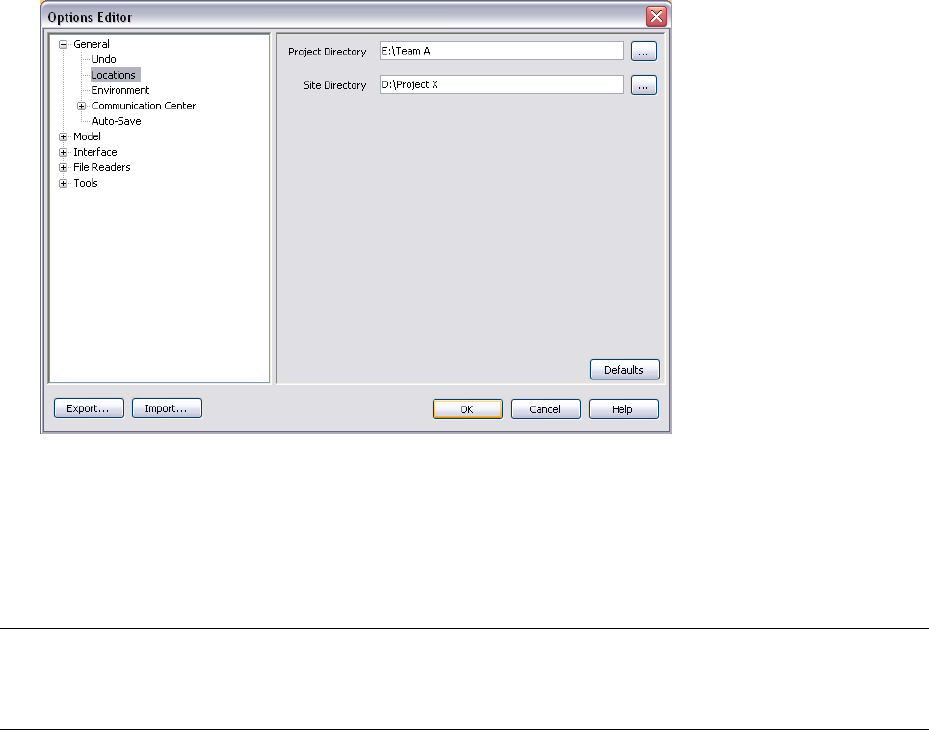
To configure location options
1Click Tools ➤ Global Options.
2Expand the General node in the Options Editor, and click the Locations option.
3In the Project Directory box, browse to the directory that contains the Autodesk Navisworks settings specific
to your project group.
4In the Site Directory box, browse to the directory that contains the Autodesk Navisworks settings standard
across the entire project site.
5Click OK.
NOTE When you run Autodesk Navisworks for the first time, the settings are picked up from the installation directory.
Subsequently, Autodesk Navisworks examines the current user profile and the all users profile on the local machine,
and then checks the settings in the Project Directory and the Site Directory. The files in the Project Directory take
precedence.
Display Units
Display units determine the scale of your model in Navisworks.
Display units are used to measure geometry in your scene, align appended models, set tolerances for clash
detection, set texture sizes and so on.
When you open CAD and laser scan files, Autodesk Navisworks reads the file units directly from the files. If this
is not possible (for example, the file is unitless), Autodesk Navisworks uses the default file units configured for
that file type in the Global Options whenever possible. Loaded files are scaled appropriately to the configured
display units.
It is possible to rescale the file units, if they are found to be incorrect for the scene.
To customize display units
1Click Tools ➤ Global Options.
2Expand the Interface node in the Options Editor, and click the Display Units option.
82 | Chapter 4 Quick Start
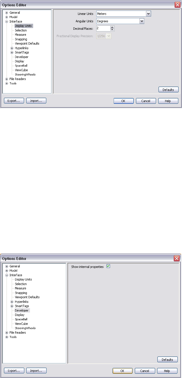
3Select the Linear Units from the drop-down list. Be sure to choose the exact format required.
4Select the Angular Units from the drop-down list.
5Enter the number of decimal places you want to see throughout the interface for your units in the Decimal
Places box. If the unit chosen is a fractional unit, rather than a decimal unit, then you have the choice of
what level of fraction to display the units from the Fractional Display Precision drop-down list.
6Click OK.
Profiles
Autodesk Navisworks can be adjusted to your level of CAD technical knowledge.
By default, a standard profile is used. If necessary, you can use a developer profile to display additional object
properties.
To use a developer profile
1Click Tools ➤ Global Options.
2Expand the Interface node, and click the Developer option.
3Select the Show Internal Properties check box to add additional object properties to the Properties control
bar.
Profiles | 83
4Click OK.
Search Directories
Autodesk Navisworks searches for a variety of configuration files in subdirectories of three standard directories.
These files can be overridden on a per user, all users or per installation basis. The search directories are:
■Application Data\Autodesk Navisworks Review 2010 within the current user profile. For example, C:\Documents
and Settings\user\Application Data\Autodesk Navisworks Review 2010 where user is the name of the current
user.
■Application Data\Autodesk Navisworks Review 2010 within the all users default profile. For example, C:\Documents
and Settings\All Users\Application Data\Autodesk Navisworks Review 2010.
■Within the Navisworks install directory. For example, C:\Program Files\Autodesk Navisworks Review 2010.
84 | Chapter 4 Quick Start
Get a Whole-Project View
85
86 | Part 2 Get a Whole-Project View
Work with Files
In Autodesk Navisworks you can open files originated from a variety of CAD
applications.
You can combine these files together, and create a single Autodesk Navisworks
file with a whole-project view of your model. This file brings together geometry
and data created by multi-disciplinary teams, and enables you to explore and
review complex models in real-time.
Native File Formats
Autodesk Navisworks has three native file formats: NWD, NWF, and
NWC.
NWD File Format
An NWD file contains all model geometry together with review
markups. You can think of an NWD file as a snapshot of the current
state of the model.
NWD files are very small, as they compress the CAD data by up to
80% of the original size.
NWF File Format
An NWF file contains links to the original native files (as listed on
the Selection Tree) together with review markups. No model
geometry is saved with this file format; this makes an NWF
considerably smaller in size than an NWD.
NWC File Format (Cache Files)
By default, when you open or append any native CAD or laser scan
files in Autodesk Navisworks, a cache file is created in the same
directory and with the same name as the original file, but with an
.nwc extension.
NWC files are smaller than the original files, and speed up your
access to commonly used files. When you next open file or append
file in Autodesk Navisworks, the data is read from the corresponding
cache file if it is newer than the original file. If the cache file is older,
which means the original file has changed, Autodesk Navisworks
converts the updated file, and creates a new cache file for it.
See also:
■“NWC File Options” on page 281
5
87

■“NWD File Options” on page 281
Compatible CAD Applications
The table below is provided as a quick reference only, and does not contain an exhaustive list of compatible
CAD applications. For additional information, please refer to the Features and Specifications section on our
website http://www.autodesk.com/navisworks.
File FormatsApplication
DWG, DXF, 3DSAutodesk AutoCAD
DWG, DXF, 3DSAutodesk ADT/AutoCAD Architecture
DWG, DXF, 3DSAutodesk Building Systems/AutoCAD MEP
IPT, IAM, IPJ, IGES, STEPAutodesk Inventor
DWG, DXF, 3DSAutodesk AutoCAD Civil 3D
DWG, DXF, 3DS, VRMLAutodesk MDT
DWG, DXF, DGNAutodesk Revit
DWG, DXF, DGNAutodesk Revit Building/Revit Architecture
DWG, DXF, DGN, CIS/2Autodesk Revit Structure
DWG, DXF, DGNAutodesk Revit Systems/Revit MEP
DWG, DXF, 3DS, IGESAutodesk 3DS MAX
DWG, DXF, 3DSAutodesk VIZ
DXF, IGES, VRMLAutodesk Maya
DGN, DWG, DXFBentley AutoPLANT
DGN, DWG, DXF, IGES, VRMLBentley MicroStation SE
DGN, DWG, DXF, IGES, STEP, VRMLBentley MicroStation J
DGN, DWG, DXF, IGES, STEP, VRMLBentley MicroStation
DGN, DWG, DXF, IGES, STEP, VRMLBentley Triforma J
DGN, DWG, DXF, IGES, STEP, VRMLBentley Triforma
DWG, DXF, DGN, IFCGraphisoft ArchiCAD
DWG, DXF, DGNGraphisoft Constructor
DXFAceCad StruCad
DWG, DXF, 3DS, IGES, STL, VRMLauto.des.sys form.z
DWG, DXF, 3DSAEC CADPIPE
RVMAVEVA PDMS
88 | Chapter 5 Work with Files

File FormatsApplication
DWG, DXFCADopia IntelliCAD
DWG, DGNCEA Technology Plant-4D
DWG, DXF, 3DSCOADE CADWorx Plant
DWG, DXF, 3DSCOADE CADWorx Pipe
DWG, DXF, 3DSCOADE CADWorx Steel
DWG, DXF, 3DSCOINS BSLink
DWG, DXF, 3DSCOINS Framing
DWGCSC 3D+
DXF, IGES, STEPDassault Systemes CATIA
SKP, DWG, 3DSGoogle SketchUp
DWG, DXF, 3DSHannappel Software GmbH elcoCAD R4
DRI, DRV, DWG, DXF, DGN, IGES,
STEP
Integraph PDS
MANInformatix MicroGDS
DWG, DXF, 3DSITandFactory CADISON
VRMLITandFactory TRICAD MS
DWG, DXF, 3DSKiwi Software GmbH ProSteel 3D
DWG, DXF, IGES, STEPKubotek USA CADKEY
DWG, DXF, 3DSM.A.P. CAD-Duct
DWG, DXF, 3DS, IGES, STEPMcNeel North America Rhino
DWG, DXF, 3DSMensch und Maschine RoCAD
DWG, DXF, 3DSMultiSUITE MultiSTEEL
DWG, DXF, DGN, IFCNemetschek Allplan
DWG, DXF, 3DSPROCAD 3DSMART
IGES, STEP, VRMLPTC Pro/ENGINEER
IGES, STEPPTC CADDS 5
DWG, DXF, 3DSQuickPen PipeDesigner 3D
DWG, DXF, 3DSQuickPen DuctDesigner 3D
DWG, DXF, 3DSRAM International CADstudio
DWG, DXF, IGES, STEP, VRMLSolidWorks
Compatible CAD Applications | 89
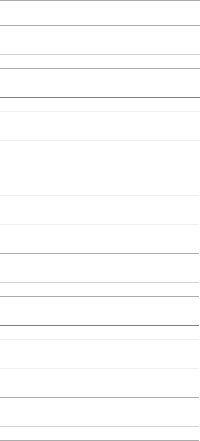
File FormatsApplication
DGN, VRML, CIS/2Tekla Structures
DGNTekla Xsteel
DWG, DXF, IGES, STEPthink3 thinkdesign
DXF, IGES, STEPUGS I-deas
IGES, STEPUGS Solid Edge
DXF, IGES, STEPUGS NX (Unigraphics)
DWG, DXF, 3DSUGS Factory CAD
DWG, DXF, 3DSUHP Process Piping FabPro Pipe
DWG, DXF, 3DSUHP Process Piping x-plant
Supported CAD File Formats
See the following table for the native CAD file formats you can open in Autodesk Navisworks without having
the CAD applications installed on your machine.
ExtensionFormat
.nwd, .nwf, .nwcAutodesk Navisworks
.dwg, .dxfAutoCAD
.satACIS SAT
.stp, .stepCIS/2
.dwfDWF
.ifcIFC
.igs, .igesIGES
.man, .cv7Informatix MicroGDS
.ipt, .iam,. ipjInventor
.jtJTOpen
.dgn, .prp, .prwMicroStation (SE, J, V8, XM)
.driPDS Design Review
.rvmRVM
.skpSketchUp
.stp, .stepSTEP
.stlSTL
.wrl, .wrzVRML
90 | Chapter 5 Work with Files
ExtensionFormat
.3ds, .prjv3D Studio
IMPORTANT The DWG/DXF/SAT file formats are supported when you run the 64-bit version of Autodesk Navisworks
on a 64-bit version of Windows, or when you run the 32-bit version of Autodesk Navisworks on a 32-bit version of
Windows. They are not supported when you run the 32-bit Autodesk Navisworks on a 64-bit version of Windows.
Supported Laser Scan File Formats
See the following table for the laser scan file formats you can open in Autodesk Navisworks.
ExtensionFormat
.asc, .txtASCII Laser File
.fls, .fws, .iQscan, .iQmod, .iQwspFaro
.pts, .ptxLeica
.3ddRiegl
.zfc, .zfsZ+F
NOTE Native Trimble file format is NOT supported. To open your file in Autodesk Navisworks, convert it into ASCII
laser file format first.
Use File Readers
Autodesk Navisworks provides file readers to support a variety of CAD file formats and laser scan file formats.
When you open a CAD file in Autodesk Navisworks, an appropriate file reader is automatically used. If necessary,
you can adjust the default file reader settings to improve the conversion quality.
3DS File Reader
3DS is a common file format supported by many CAD applications.
The Autodesk Navisworks file reader reads all 2D and 3D geometry, as well as texture maps. The hierarchy defined
by the keyframe data from keyframe 0 is preserved, including instancing. Entities are positioned based on keyframe
0.
Supported Entities
■All 2D and 3D geometry
■Cameras
■Groups
■Texture maps in the formats: 8-bit color-mapped, 16-bit and 24-bit true color, uncompressed or Run Length
Encoded .tga, .bmp, .jpg, .lwi (LightWork Image).
NOTE Textures from 3DS files come through as Presenter materials, though you should bear in mind that 3DS
files contain file names in the 8.3 DOS format only and that various formats are not yet supported in Presenter.
■Colors (from material color, not wireframe color - ambient, diffuse, shininess, transparency and self
illumination).
Supported Laser Scan File Formats | 91
Unsupported Entities
■Keyframes (objects are currently taken from keyframe 0)
■Texture maps in the formats: gray-scale .tga, .tif, .gif, .png.
■Other maps (e.g. opacity maps, reflections etc.)
■Wireframe meshes
■Lines, splines
■Points
■Background images
See also:
■“3DS File Reader Options” on page 291
ASCII Laser Scan File Reader
Most scanner software support exporting the point data in an ASCII text file. Providing that the data is saved in
the correct format, this data can be read by Autodesk Navisworks.
Supported formats for ASCII laser scan data are listed below. The data must be separated using one of the following
characters: comma, tab or space. The character used to signify a decimal must be a point (period).
■X, Y, Z
■X, Y, Z, Intensity
■X, Y, Z, Red, Green, Blue
■X, Y, Z, Intensity, Red, Green, Blue
Intensity, Red, Green, and Blue values are integers in the range 0-255. Intensities are not gamma corrected.
Supported Entities
■Points
Unsupported Entities
■No other entities are supported.
See also:
■“ASCII Laser Scan File Reader Options” on page 291
Bentley AutoPLANT File Reader
Bentley AutoPLANT is based on AutoCAD and as such uses the DWG file format to store model geometry. Any
settings related to the DWG file format also affect files from AutoPLANT.
AutoPLANT Object Properties can be stored in external database MDB files. By default, Autodesk Navisworks also
supports these files through the DataTools functionality, and looks for Equipment, Nozzle and Piping datatools
links.
See also:
■“DWG/DXF/SAT File Reader Options” on page 293
92 | Chapter 5 Work with Files
CIS2 File Reader
The CIS2 file reader supports CIMSteel Integration Standards (CIS/2) adopted by the American Institute of Steel
Construction (AISC) as their format for data exchange between steel related CAD software.
Supported Entities
■Assembly_design
■Assembly_design_child
■Assembly_manufacturing
■Analysis_model_3d
■Part_derived
■Part_prismatic_simple
■Part_sheet_bounded_complex
■Part_sheet_bounded_simple
■Section_profile_compound
■Section_profile_derived
■Section_profile_edge_defined
■Section_profile_angle
■Section_profile_channel
■Section_profile_circle
■Section_profile_circle_hollow
■Section_profile_i_type
■Section_profile_i_type_asymmetric
■Section_profile_i_type_rail
■Section_profile_rectangle
■Section_profile_rectangle_hollow
■Section_profile_t_type
■feature_volume_prismatic_chamfer
■feature_volume_prismatic_flange_notch
■feature_volume_prismatic_flange_chamfer
■feature_volume_prismatic_notch
■feature_volume_prismatic_skewed_end
■Element_curve_simple
■Element_node_connectivity
■Element_eccentricity
■Located_joint_system
■Design_joint_system
■Joint_system_mechanical
■Fastener_mechanism
CIS2 File Reader | 93
■Fastener_simple_bolt
■Fastener_simple_shear_connector
Unsupported Entities
■Part_complex
■Part_prismatic_complex
■Part_sheet_profiled
■Section_profile_centreline
■feature_cutting_plane
■feature_edge_chamfer
■feature_surface
■feature_thread
■feature_volume_complex
■feature_volume_curved
■feature_volume_hole
■Element_volume
■Element_surface
■Element_point
■Element_curve_complex
■Element_with_material
■Joint_system_amorphous
■Joint_system_chemical
■Joint_system_welded
■Weld_mechanism
■Joint_system_complex
■Fastener_simple_nut
■Fastener_simple_washer
■Fastener_simple_stud
■Fastener_simple_pin
■Fastener_simple_nail
■Fastener_simple_screw
■Fastener_simple_countersunk
■Fastener_simple_curve
■Fastener_simple_complex
Supported Basic Section Profile Types
The file reader supports the following basic section profile types:
■I-Beam
94 | Chapter 5 Work with Files

■Tee
■Angle
■Channel
■Circle
■Rectangle
■Double Angle
■Joist
Supported AISC Section Profile Types
The reader supports all AISC defined section profile types and maps them to the basic section profile types:
■I-Beam: HP, M, S, W
■Tee: MT, ST, WT
■Angle: L, LP
■Channel: C, MC
■Circle: HSRO, P, PX, PXX, RB
■Rectangle: HSRE, HSSQ, SB, TS
■Double Angle: DL, DLL, DLS
See also:
■“CIS2 File Reader Options” on page 291
DWG/DXF/SAT File Reader
The DWG/DXF/SAT file reader uses Autodesk's ObjectDBX™ technology and so is guaranteed to read all object
geometry and information for those third party applications that utilize the ObjectDBX Framework.
The structure of the drawing is preserved including xrefs, blocks, inserts, AutoCAD color index, layers, views and
active viewpoint. Entities are colored using the AutoCAD Color Index (ACI), so will match those in an AutoCAD
‘shaded’ view.
NOTE The file reader supports files from all products based on AutoCAD 2010 and earlier.
IMPORTANT The DWG/DXF/SAT file reader is not supported when you run the 32-bit Autodesk Navisworks on a
64-bit version of Windows.
Supported Entities
■All 2D and 3D geometry, including arcs, lines, polylines with non-zero thickness, ACIS objects (regions and
solids), polygon and polyface meshes, 3D faces and surfaces.
■Points and snap points.
■Lines, polylines, circles, arcs with zero thickness.
■Named views
■Layers
■Colors
■Blocks, inserts and multiple inserts
DWG/DXF/SAT File Reader | 95

■Groups
■External references (xrefs)
■Hyperlinks
■Text or multi-line text
■Entity handles
■Attributes
■Textures
■File properties
Unsupported Entities
■Lights
■Splines
■Multi-lines
■Linetypes
■Dimensions and leaders
■Raster bitmaps
■Construction lines (xlines and rays)
■Hatching
See also:
■“DWG/DXF/SAT File Reader Options” on page 293
Overview of Object Enablers
Object Enablers (OEs) can be thought of as a ‘translator’ for custom objects. Applications based on the AutoCAD®
platform, (including Autodesk products like AutoCAD® Architecture, and non-Autodesk products like Bentley
AutoPlant) generate custom objects that are saved into the DWG file format. These custom objects are typically
found in content libraries that are built into these applications.
Many applications have the ability to read DWG files; however, outside of the authoring application any custom
objects cannot be interpreted. As a result, DWG file readers display such custom objects incorrectly, as proxy
graphics (wireframe geometry), unless the required OE is installed on the machine reading the DWG file.
NOTE Autodesk Navisworks contains versions of RealDWG™ for 2004, 2005, 2006, 2007, 2008, 2009, and 2010. This
means you can use OE between 2004 and 2010 with Navisworks. You cannot use any OEs older than 2004. However,
OEs are backwards compatible, and you can install a later OE to support reading of older versions of DWG files.
To check if an OE is required
1In Autodesk Navisworks, open a DWG file.
2If you can only see wireframe geometry, click View ➤ Scene Statistics. The Scene Statistics dialog box
contains the report listing any missing, or failed to load OEs. You need to install all missing OEs to open
the file correctly in Autodesk Navisworks.
NOTE Occasionally, an OE is already installed, but does not support non-AutoCAD-based applications, like
Autodesk Navisworks. In such cases, the OE is reported as missing in the Scene Statistics dialog box.
96 | Chapter 5 Work with Files

To install and use an OE with Navisworks
1Obtain the required OE, and run the installer.
2On the OE Setup page, select the check box for the relevant Autodesk Navisworks products.
NOTE Some OEs have dependencies on other OEs, and, therefore, must be installed in a specific order. For
example, the AutoCAD MEP 2009 OE has a dependency on the AutoCAD Architecture 2009 OE. As a result, the
AutoCAD MEP 2009 OE must be installed after the AutoCAD Architecture OE.
3Click Install. When the OE is installed, click Finish.
4Run Autodesk Navisworks.
5Click Tools ➤ Global Options.
6In the Options Editor, expand the File Readers node, and click DWG/DXF/SAT.
7Ensure the value in the DWG Loader Version field is the same as the version of the installed OE, and close
the dialog box. For example, if you’ve installed OE for AutoCAD Architecture 2007, you must set the DWG
Loader Version to ‘2007’.
When you open a DWG file in Autodesk Navisworks, the file reader uses the configured OE.
How do I know if I need to use an Object Enabler with Autodesk Navisworks 2010?
When a DWG file is opened in Autodesk Navisworks 2010, and the objects are displayed as wireframe geometry,
it usually means that an Object Enabler is missing.
Additionally, the Scene Statistics dialog box reports any missing or failed to load OEs.
Where do I obtain Object Enablers from?
The recommended way to obtain OEs is to request them from the persons authoring the DWG file. This ensures
that the correct version of OE is used.
TIP You can also download many OEs from the vendor websites for the authoring applications. For example, you can
download Autodesk OEs from http://www.autodesk.com/oe.
What do I do when Object Enablers are not reported as missing but I can only see wireframe geometry?
1Click Tools ➤ Global Options.
2In the Options Editor, expand the File Readers node, and click DWG/DXF/SAT.
3Select ‘Shaded’ in the Render Type field.
4Ensure the Use ADT Standard Configuration check box is selected.
5Click OK to save the changes and close the dialog box.
6Click File ➤ New, and then open the DWG file again.
DWF File Reader
Autodesk DWF was specifically developed by Autodesk as a file format for architects, engineers, and GIS
professionals to share design data. The DWF file reader reads all 3D geometry, as well as textures and properties.
Supported Entities
■All 3D geometry
■Texture maps
■Texture coordinates
■Colors (per-vertex, per-face)
■Property fields
■Categories
DWF File Reader | 97

Unsupported Entities
■2D lines/plot sections
■Thumbnails
■Marked-up sketches
■More than one 3D section per file (any others are ignored)
■NURBS surfaces
■Cameras
See also:
■“DWF File Reader Options” on page 293
DGN File Reader
Autodesk Navisworks can read 3D DGN and PRP files from Bentley's MicroStation, but does not support CEL
files or 2D DGNfiles. Referenced files and instances of cells are respected, and the Selection Tree reflects this file
structure.
NOTE The file reader supports files from MicroStation 95, SE and /J. It does not support MicroStation Modeller and
any versions of MicroStation before 95.
Supported Entities
■All 2D and 3D geometry including shapes, complex shapes, meshes, cones, surfaces, B-spline boundaries,
solids, SmartSolids and Feature Solids, lines, arcs and ellipses.
■Splines and B-spline curves
■Lights
■Levels
■Cells, shared cells, and their instancing
■Colors and ambient, diffuse, and shininess properties of materials from .pal and .mat palette and material
files
■Texture maps
■Referenced files including aliases
■Dynamic drawing of parametric models when loading/exporting DGN and PRP files.
■3D text used for notes and labels is now converted and displayed by default.
■Family, part and texture information from TriForma, and PDS object information from DRV files.
■Family, part and texture information from TriForma, and PDS object information from DRV files
Unsupported Entities
■Raster bitmaps
■Dimensions and leaders
See also:
■“DGN File Reader Options” on page 292
98 | Chapter 5 Work with Files
Faro Scan File Reader
The file reader supports files from all Faro™ scanners. Combined iQscan files must be located in a folder called
‘Scans’ in the same directory as the associated iQmod and iQwsp workspace files.
See also:
■“Faro Scan File Reader Options” on page 295
IFC File Reader
The file reader supports stand-alone IF files.
Supported Entities
■Faceted BReps
■Extruded area solids
■Geometric sets
■Face-based and surface-based models
■Simple, trimmed, and composite curves
■Simple surfaces
■Simple parametric, arbitrary and derived profiles
■Boolean clipping results and element-level voiding and projection CSG operations
■Basic styled and mapped items
■Property sets, including simple and complex properties
Unsupported Entities
■Voided BReps
■Bounded half-space solids
■Complex parametric profiles
■BSpline curves
■Curve styles
■Swept surfaces
■Textures and complex lighting
■Loading of server-based IFC models
See also:
■“IFC File Reader Options” on page 296
IGES File Reader
The file reader uses the Open CASCADE libraries to read and tessellate IGS and IGES files up to and including
IGES 5.3.
Supported Entities
■Groups
Faro Scan File Reader | 99
■Colors
■Planes
■Parametric spline, ruled, B-spline, offset, bounded, trimmed and plane surfaces and surfaces of revolution.
■Tabulated cylinders
■Solids and manifold solids
■Shells
■Faces
Unsupported Entities
■Points
■Lines
■Circular or conic arcs
■Composite, parametric spline, B-spline, or offset curves
■Boundaries
■Attributes
See also:
■“IGES File Reader Options” on page 296
Inventor File Reader
The file reader supports IPT (part), IAM (assembly) and IPJ (project) file formats. IDW (drawing) file format cannot
be read.
The reader supports files from Autodesk Inventor 2010™ and earlier. Later versions should also work, but haven't
been tested. Autodesk Inventor 5™ (or higher) or Autodesk Inventor Design Tracking 5™ (or higher) must be
installed. Autodesk Inventor Design Tracking™ can be downloaded from http://support.autodesk.com.
See also:
■“Inventor File Reader Options” on page 297
JTOpen File Reader
The file reader supports 3D JT data format developed by Siemens PLM Software (formerly UGS Corp.).
Supported Entities
■Tri-strip set shape
■Polyline set shape
■Box primitive shape
■Cylinder primitive shape
■Sphere primitive shape
■Models with vertex-based color and normal
■General JT B-Rep
100 | Chapter 5 Work with Files
■Geometric transform attribute
■Material attribute
■XT B-Rep segment
■Properties
Unsupported Entities
■Point set shape
■Polygon set shape
■Wire harness set shape
■Pyramid primitive shape
■Tri-prism primitive shape
■PMI manager meta data
■Models with facet-based or primitive-based color and normal
■Texture
■HSV color model
■B-Rep CAD tag
■Line style attribute
■Point style attribute
■Shader effects attribute
■Vertex shader attribute
■Fragment shader attribute
■Infinite light attribute
■Point light attribute
■Wireframe segment
■LOD
See also:
■“JTOpen File Reader Options” on page 297
Leica Scan File Reader
The file reader supports files from all Leica™ HDS scanners.
Supported Entities
■Points
Unsupported Entities
■No other entities are supported
See also:
■“Leica File Reader Options” on page 297
Leica Scan File Reader | 101
MAN File Reader
The file reader supports MAN files from Informatix's MicroGDS™ version 6.0 or later. MicroGDS™ projects are
not supported. The workaround is to export the desired project window with a .man extension.
In Autodesk Navisworks, MicroGDS renderer materials are shown in their flat-shaded colors in shaded mode. In
full render mode, or with Presenter rendering, the full shaders are used. Only the standard LightWorks shaders
are available. The shaders which are unique to MicroGDS are not available inside Autodesk Navisworks, and are
converted as follows:
■Height band color shader is treated as plain grey
■Wrapped random color shader is treated as a plain color using the flat-shaded color from MicroGDS
■Wrapped stencil transparency is ignored
■Undulate, wrapped brick, wrapped grid and wrapped ripple displacement shaders are ignored
■Object axis texture space is equivalent to the Autodesk Navisworks box texture space
■Auto axis and object XY axis texture spaces are treated as the Autodesk Navisworks box texture space
■Grid background is treated as a plain background using the background color, that is grid lines are not shown
■Foreground and environment shaders are ignored
NOTE All other shaders, as of MicroGDS 7.2, are correctly imported into Autodesk Navisworks.
MicroGDS materials are specified in millimeters, and are converted into metres to make Autodesk Navisworks
materials, dividing distance parameters by 1000.
Windows with Perspective Views are converted as viewpoints.
Supported Entities
■Clump primitives
■Line primitives.
NOTE The color of line primitives is determined by the first phase in which they appear in the Principal window
of the MAN file. If they are not included in the Principal window, the color is determined by their style.
■Light styles.
NOTE Projector lights are treated as a spot light without the transparent image.
■Material styles, both plain and most LightWorks Renderer materials.
NOTE For materials using wrapped images, you must specify the texture paths.
■Layers.
NOTE All layers are read, and made visible according to their status in the Principal window of the MAN file.
■Instances
■Object data structure
Unsupported Entities
■Text primitives
■Photo primitives
See also:
■“MAN File Reader Options” on page 298
102 | Chapter 5 Work with Files
PDS File Reader
The file reader supports DRI files from the PDS Design Review package.
See also:
■“PDS File Reader Options” on page 298
Riegl Scan File Reader
The file reader supports files from all Riegl™ LMS scanners.
Supported Entities
■Points
■Triangles
Unsupported Entities
■No other entities are supported
See also:
■“Riegl File Reader Options” on page 298
RVM File Reader
The file reader supports the following file formats:
■Binary and ASCII RVM files exported from AVEVA's PDMS™ product
■Dump Attributes and Datal (also called ‘OUTPUT’) attribute files, with the .att, .attrib, and .txt file extensions.
■RVS files
Supported Entities
■All geometry
■Attributes stored on groups
■Textures (via RVS file)
■Cameras and camera tracks (via RVS file)
■Clip planes (via RVS file)
■Signs (via RVS file)
■Tags (via RVS file)
■Labels (via RVS file)
■Translucency (via RVS file)
■PDMS origin points
Unsupported Entities
■Attributes stored on primitives
■Lights
PDS File Reader | 103
■Object Animation
■Smooth Animation
■Groups
■Autotags
See also:
■“RVM File Reader Options” on page 299
SketchUp SKP File Reader
The file reader supports native SKP file format.
Supported Entities
■Geometry
■Materials (face front material only)
■Transparency
■Groups
■Components
■Layers
■Imported images
■Transparency
Unsupported Entities
■Text
■Dimensions
■Section planes
See also:
■“Sketchup SKP File Reader Options” on page 300
STEP File Reader
The file reader uses the Open CASCADE libraries to read and tessellate STP and STEP files up to and including
AP214 CC2 and AP203.
Supported Entities
■Assemblies
■Colors
■Planes
■B-spline and rational B-spline, Bezier, conical, cylindrical, offset, rectangular trimmed, linear extrusion,
bounded, manifold, spherical, toroidal, uniform and quasi-uniform, surfaces.
■Shells
■Advanced and facetted boundary representations (BReps)
104 | Chapter 5 Work with Files
Unsupported Entities
■Points
■PCurves, B-spline, rational B-spline, Bezier, trimmed, uniform or quasi-uniform curves.
■Circles or ellipses
■Hyperbola
See also:
■“STEP File Reader Options” on page 300
STL File Reader
The file reader only supports binary STL files. ASCII versions are not supported.
Supported Entities
■Triangles
Unsupported Entities
■No other entities are supported
See also:
■“STL File Reader Options” on page 301
VRML File Reader
The file reader supports files in both VRML1 and VRML2 file formats.
Supported Entities
■All 3D geometry including cuboids, cylinders, cones, spheres, elevation grids, extrusions, face and line sets,
and points.
■All grouping nodes, but with the following limitations:
VRML2 Billboard nodes - children are loaded but no billboarding takes place.
VRML2 Collision nodes - children are loaded but no specification of collision detection occurs.
VRML1 WWWAnchor and VRML2 Anchor nodes - children are loaded but clicking objects does not load
any referenced VRML world.
VRML1 and VRML2 LOD nodes - the most detailed (that is, first) child is always loaded.
Unsupported Entities
■All ROUTE definitions
■All sensor nodes
■All interpolator nodes
■Textures specified within the VRML file (VRML2 PixelTexture nodes and the image component of VRML1
Texture2 nodes).
■VRML2 Script nodes
■VRML2 MovieTexture nodes
STL File Reader | 105

■VRML2 Fog nodes
■VRML2 AudioClip and Sound nodes
■All text-related nodes (VRML1 ASCII Text, VRML2 Text, and FontStyle nodes).
See also:
■“VRML File Reader Options” on page 301
Z+F Scan File Reader
The file reader supports files from all Z+F™ IMAGER scanners.
Supported Entities
■Points
Unsupported Entities
■No other entities are supported
See also:
■“Z+F File Reader Options” on page 302
Use File Exporters
Autodesk Navisworks provides file exporters to create native Navisworks files directly in CAD applications.
Currently, you can export NWC files from AutoCAD, MicroStation, Revit, ArchiCAD, and Viz/Max applications.
You can use file exporters:
■If Autodesk Navisworks cannot read the native CAD file format. Currently, the following native file formats
are not supported: VIZ, MAX, ArchiCAD, Revit.
■If Autodesk Navisworks has converted the native CAD file, but some geometry is missing, for example, and
you want to improve the file quality.
AutoCAD File Exporter
Autodesk Navisworks comes with ARX plugins for any AutoCAD™ based product, such as Architectural Desktop™,
and enables you to export files into NWC file format.
The file exporter is available for any AutoCAD-based product between AutoCAD 2004 and 2010 releases.
NOTE If you installed the Autodesk Navisworks software with exporter plugins, and you install any AutoCAD-based
software after Autodesk Navisworks is installed, you need to update your exporter plugins installation with the appropriate
ARX plugins before you can use them.
See also:
■“DWG File Exporter Options” on page 302
Add the ARX Plugin
You can either add the ARX plugin to Exporter Plugins installation, or load it manually in AutoCAD-based
software.
106 | Chapter 5 Work with Files

To add the ARX plugin to Exporter Plugins installation
1In the Control Panel, double-click Add or Remove Programs.
2In the Add or Remove Programs dialog box, click Autodesk Navisworks Review 2010 Exporter Plugins, and
then click Change/Remove in Windows XP or Uninstall/Change in Vista.
3In the Installation wizard, click Add or Remove Features.
4On the Select Exporters to Install page, the Export From Other Applications node, select the check box next
to the required plugin.
5Click Next.
6On the Update Autodesk Navisworks Review 2010 Exporter Plugins page, click Next.
7On the Update Complete page, you are informed when the updates have been performed. Click Finish.
To load the ARX plugin in an AutoCAD-based application
1Type ARX at the command line.
2Press Return.
3Type the letter L (for ‘Load’) at the command line.
4Press Return.
5In the Select ARX/DBX File dialog box, browse to the ARX plugin.
NOTE For AutoCAD 20xx based applications, the plugin is located under C:\Program Files\Common Files\Autodesk
Shared\Navisworks\2010\NWExport20xx\nwexport20xx.arx.. So, for example, for AutoCAD 2004 based applications,
the plugin is located under C:\Program Files\Common Files\Autodesk Shared\Autodesk
Navisworks\2010\NWExport2004\nwexport2004.arx, and so on.
6Click OK to load the ARX plugin.
Use the ARX Plugin
You can export files from AutoCAD-based applications either from the command line, or by using the Navisworks
menu.
Before you can use the Navisworks menu, you need to load it first. By default, the Navisworks menu is added to
the menu browser. In some programs, it can also be added to the menu bar.
To use the command line to export files
1To export an NWC file, type NWCOUT at the command line.
2Press Return.
3In the Save As dialog box, enter the name for the Navisworks file, and browse to the desired storage location.
4Click OK to export the file, or Cancel to return to the application without exporting it.
To load the Autodesk Navisworks export menu
1At the command line, type MENULOAD.
2Press Return.
3In the Load/Unload Customizations dialog box, click Browse.
4In the Select Customization File dialog box, change the Files of Type to Legacy Menu Template (*.mnu),
and browse to the Autodesk Navisworks menu file.
AutoCAD File Exporter | 107
NOTE For AutoCAD 20xx based applications, this file is located under C:\Program Files\Common Files\Autodesk
Shared\Navisworks\2010\NWExport20xx\lwnw_export.mnu. So, for example, for AutoCAD 2004 based applications,
this file is located under C:\Program Files\Common Files\Autodesk
Shared\Navisworks\2010\NWExport2004\lwnw_export.mnu, and so on.
5Click Open.
6In the Load/Unload Customizations dialog box, click Load.
The loaded menu is shown in the Loaded Customization Groups.
7Click Close.
To use Navisworks menu to export files
1Click the menu browser button located at the top-left corner of the application window.
2To export an NWC file, click Navisworks Cache on the Navisworks menu.
3In the Save As dialog box, enter the name for the Navisworks file, and browse to the desired storage location.
4Click OK to export the file, or Cancel to return to the application without exporting it.
To adjust the options for the DWG file exporter
1Click the menu browser button located at the top-left corner of the application window.
2Click Navisworks Export Option on the Navisworks menu.
3Expand the File Exporters node in the Options Editor, and click the DWG page. Use the options on this
page to adjust the settings for future exports of NWC files from AutoCAD-based applications.
4Click OK to save the changes.
Command entry: NWOPT
CAD Preview
The ARX plugin also enables you to walk through your model in real time inside a dockable Navigator window
directly in the AutoCAD interface.
You can easily import and export viewpoints between Navigator and AutoCAD, and explore the models that
you are building.
NOTE The Navisworks Navigator is provided for products based on AutoCAD 2004™ and above.
To navigate AutoCAD models in real time
1Type NWNAVIGATOR at the command line.
2Use the Navigator window to explore your model.
Quick Reference
Buttons
The Navigator toolbar contains the following buttons.
DescriptionButton
Synchronizes the model in the Navigator
window with the AutoCAD model. The
Navigator window is not updated automat-
108 | Chapter 5 Work with Files
DescriptionButton
ically. Click this button every time you
want to navigate around the latest model.
Changes the current AutoCAD view to the
view in the Navigator window.
Changes the view in the Navigator window
to the current AutoCAD view.
Selects walk mode and enables you to walk
through the model on a horizontal plane.
Selects look around mode and enables you
to look around the model from the current
camera position.
Selects zoom mode. Dragging the left
mouse button up and down or using the
UP and DOWN ARROW keys zooms in and
out respectively.
Selects zoom-to-a-box mode. Dragging a
box with the left mouse button over the
model fills the view with the contents of
the box. Holding down the SHIFT or CTRL
keys or spinning the mouse wheel, tempor-
arily switches this mode to zoom mode.
Selects pan mode. Dragging the left mouse
pans the model up, down, left and right.
Holding down the SHIFT or CTRL keys or
spinning the mouse wheel, temporarily
switches this mode to zoom mode.
Selects orbit mode. Dragging the left
mouse button or using the UP, DOWN,
LEFT ARROW, and RIGHT ARROW keys ro-
tates the camera around the model. Hold-
ing down the SHIFT key or spinning the
mouse wheel, temporarily switches this
mode to zoom mode. Holding down the
CTRL key temporarily pans the camera.
Selects examine mode. Dragging the left
mouse button or using the UP, DOWN,
LEFT ARROW, and RIGHT ARROW keys ro-
tates the model about. Holding down the
SHIFT key or spinning the mouse wheel,
temporarily switches this mode to zoom
mode. Holding down the CTRL key tempor-
arily switches this mode to pan mode.
Selects fly mode. Holding down the left
mouse button moves the camera forward.
As in a flight simulator, the left mouse
button banks left/right when dragged left
or right and tilts up/down when dragged
up or down. The UP and DOWN cursor
keys zoom in and out respectively, and the
AutoCAD File Exporter | 109
DescriptionButton
LEFT ARROW and RIGHT ARROW keys spin
the camera left and right respectively.
Holding down the SHIFT key speeds up
this movement. Holding down the CTRL
key rotates the camera around its viewing
axis, while still moving forward.
Selects turntable mode. Dragging the left
mouse button left and right, or using the
LEFT ARROW and RIGHT ARROW keys spins
the turntable left and right respectively.
Holding down the SHIFT key or spinning
the mouse wheel, temporarily switches this
mode to zoom mode. Holding down the
CTRL key temporarily switches this mode
to pan mode.
Shows all model. Clicking this button dol-
lies and pans the camera so that the entire
model is displayed.
Selects perspective camera view.
Selects orthographic camera view.
Opens the Help system.
The Shortcut Menu
Right-clicking in the Navigator window opens a shortcut menu.
Focus on Item Focuses the camera on the selected item. The point you click becomes the focal point for examine,
orbit, and turntable navigation modes.
Speed
Frame Rate Specifies the number of frames per second (FPS) that are rendered in the Navigator window.
The default setting is 6. You can set the frame rate from 1 through 20 frames per second. Reducing the value
reduces drop-out, but can cause jerky movement during navigation. Increasing the value ensures a smoother
navigation, but increases drop-out.
Hardware Acceleration Select this option to utilize any available OpenGL hardware acceleration on your video
card.
NOTE If your video card does not support OpenGL hardware acceleration, this option is not available.
Viewpoint
Rendering Selects rendering mode for your model. Choose from:
■Shaded - renders the model with smooth shading and without textures. This is the default option.
■Wireframe - renders the model in wireframe; all triangle edges are visible in this mode.
■Hidden Line - renders the model in hidden line; this is equivalent to rendering model as shaded and wireframe
at the same time. The output is low quality as all the facet edges in the model are visible.
Lighting Selects lighting mode for your model. Choose from:
■No Lights - turns off lighting. The model is shaded with flat rendering.
110 | Chapter 5 Work with Files

■Head Light - uses a single directional light located at the camera that always points in the same direction as
the camera. This is the default option.
■Scene Lights - uses any lights defined in the model, or two default opposing lights, if none are available.
Navigation Mode Selects navigation mode. The options available here are the same as on the Navigator toolbar,
with one exception. The Select option enables you to select items in your model. You can select multiple items
by holding down the CTRL key while selecting items.
Navigation Tools Select View All to display the entire model.
Perspective Camera Selects perspective camera view.
Orthographic Camera Selects orthographic camera view.
Options
Culling Options Opens the Culling Options dialog box.
Close Files on Open Indicates whether NWC file created for the model is closed once it has been loaded into
memory.
Selecting this option unlocks NWC files for editing by other users.
Max Image Texture Size Specifies the maximum size for texture images in pixels.
The higher the value, the higher the load on your graphics card, as more MB in memory is required to render
textures.
Revit File Exporter
Autodesk Navisworks cannot read native Revit files directly. Use the file exporter to save your files in NWC
format, which can be open in Navisworks.
See also:
■“Revit File Exporter Options” on page 304
To export NWC files from Revit
1In Revit, click Tools ➤ External Tools ➤ Navisworks 2010.
NOTE This option is not available in Demo/Viewer mode. If you are not in demo mode, but do not have access
to the Navisworks menu, check if editing view is set to normal, and the modify tool is selected (Edit ➤ Modify).
2In the Export Scene As dialog box, enter the name for the Navisworks file, and browse to the desired storage
location.
3Click Save to export the file, or Cancel to return to the application without exporting it.
To adjust the options for the Revit file exporter
1In Revit, click Tools ➤ External Tools ➤ Navisworks 2010.
2In the Export Scene As dialog box, click the Navisworks Settings button.
3Expand the File Exporters node in the Options Editor, and click the Revit page. Use the options on this page
to adjust the settings for future exports of NWC files from Revit.
4Click OK to save the changes and return to the Export Scene As dialog box.
5Click Cancel to close the dialog box.
Revit File Exporter | 111

MicroStation File Exporter
Autodesk Navisworks comes with MDL plugins for MicroStation™ 95, SE, /J and v8 , and enables you to export
files into NWC file format.
NOTE If you installed the Autodesk Navisworks software with exporter plugins, and you install MicroStation software
after Autodesk Navisworks is installed, you need to update your exporter plugins installation with the appropriate ARX
plugins before you can use them.
See also:
■“DGN File Exporter Options” on page 305
To add the MDL plugin to Autodesk Navisworks Exporter Plugins installation
1In the Control Panel, double-click Add or Remove Programs.
2In the Add or Remove Programs dialog box, click Autodesk Navisworks Review 2010 Exporter Plugins, and
then click Change/Remove in Windows XP or Uninstall/Change in Vista.
3In the Installation wizard, click Add or Remove Features.
4On the Select Exporters to Install page, the Export From Other Applications node, select the check box next
to the required plugin.
5Click Next.
6On the Update Autodesk Navisworks Review 2010 Exporter Plugins page, click Next.
7On the Update Complete page, you are informed when the updates have been performed. Click Finish.
Load the MDL Plugin
Before you can use the MDL plugin, you need to load it first.
You can either do it for the current session only, or you can add the plugin to your default configuration, in
which case, it is loaded for all future sessions.
To load the MDL plugin for the current session only
1Click Utilities ➤ Key-In.
2In the Key-In dialog box, type mdl load nwexport7.
3Press Return.
To load the MDL plugin for all future sessions
1Click Workspace ➤ Configuration.
2In the Configuration dialog box, Category field, click Design Applications.
3Click NWEXPORT7 in the Available Applications field.
4Click the Add button.
5Click OK, and confirm that you want to add NWEXPORT MDL plugin to your default configuration.
Export Files from the Key-In Command Line
You can export files from the key-in command line individually or in batches.
You can also add the commands to the Key-In menu to speed up the process.
112 | Chapter 5 Work with Files

To use the key-in command line to export files
1Click Utilities ➤ Key-In to open the Key-In dialog box.
2To export an NWC file, type nwcout.
NOTE To export the current design file quickly, you can use the batchnwcout command. The exporter replaces
the design file extension (usually .dgn) with .nwc when exporting the file. When you use this commands, you
are not prompted to overwrite any existing files, and no export dialog box is shown.
3In the Export Navisworks file dialog box, browse to the desired storage location.
The exporter automatically provides a filename, and a view number, which you can modify, if necessary.
The chosen view number determines the initial model view in Navisworks.
4Click OK to export the file.
To add Navisworks export commands to the Key-In menu
1Click Workspace ➤ Customize.
2In the Customize dialog box, the Menu Bar tab, expand the Utilities option in the Edit Menu Bar field.
3Click the Key-In option, and click the Insert button.
4In the Insert Menu Item dialog box, enter the Label, for example, ‘Export Navisworks Cache File’.
5In the Key-In field, type the appropriate command, for example, ‘nwcout’.
6Click OK.
7Add as many menu items as necessary, and click Save.
The added options are now available from the Utilities ➤ Key-In menu.
Export Files from the Command Line
You can also export files from the command line by using the msbatch.bat file. This is useful when you want to
set up an automated script for file export.
NOTE To export a file from the command line, you must first add the MicroStation program directory to the Path
environment variable.
The format of the command line exporter is
msbatch nwexport7 [-f] FILE [OUTPUT]
FILE is the name of the MicroStation file you want to export. This is the only required option. The OUTPUT
argument enables you to specify the name of the output file.
By default, the exporter only converts files that have been changed since the last time you exported them. This
is useful for speeding up exporting a large number of files. If you want to force the exporter to convert all files,
use the -f option.
NOTE If the exporter encounters any problems, it produces an error log in a file called nwdout.err.
To modify the Path environment variable
1In the Control Panel, double-click System.
2In the System Properties dialog box, Advanced tab, click the Environment Variables button.
3In the Environment Variables dialog box, double-click Path under System Variables.
4In the Edit System Variable dialog box, add the path to the MicroStation application to the Variable Value
field.
MicroStation File Exporter | 113

NOTE Paths must be separated with a semicolon (;).
5Click OK to save the changes and close the dialog boxes.
To use the command line to export files
1On the Start menu, click Run in Windows XP or press Windows + R on the keyboard in Vista.
2Enter the file export command with appropriate arguments, for example msbatch nwexport7 file.
3Press Enter.
4In the MicroStation Manager dialog box, select the files you want to export, file extension (.nwc), and
storage location.
5Click OK.
Customize the DGN File Exporter Options
The file exporter only exports from 3D DGN files - 2D files are not supported.
Navisworks colors are derived from either MicroStation cell colors or MicroStation materials, depending on the
chosen export options. The appearance of objects in Publisher matches the appearance of a MicroStation shaded
render.
To adjust the options for the DGN file exporter
1Click Utilities ➤ Key-In to open the Key-In dialog box.
2Type nwopt, and press Enter.
3Expand the File Exporters node in the Options Editor, and click the DGN page. Use the options on this page
to adjust the settings for future exports of NWC files from MicroStation.
4Click OK to save the changes.
Viz and Max File Exporter
Autodesk Navisworks cannot read native Viz/Max files directly. Use the file exporter to save your files in NWC
format, which can be open in Navisworks.
The file exporter is available for Viz versions 4 to 2008 and Max versions from 5 to 2010.
NOTE If you installed the Autodesk Navisworks software with exporter plugins, and you install Viz or Max software
after Autodesk Navisworks is installed, you need to update your exporter plugins installation with the appropriate ARX
plugins before you can use them.
See also:
■“Viz/Max File Exporter Options” on page 306
Export NWC files from Viz or Max
1Click File ➤ Export.
2In the Select File to Export dialog box, select Navisworks 7 Cache (*.NWC) in the Save as Type field.
3Enter the name for the Navisworks file, and browse to the desired storage location.
4Click Save to export the file, or Cancel to return to the application without exporting it.
114 | Chapter 5 Work with Files

NOTE Any textures applied to the Viz or Max model are saved in a directory with the same name as the exported
file, but with a _presenter_maps suffix. All textures are converted into .bmp files and saved into this directory
for use with Navisworks.
Add the Navisworks utility menu
1Click the More button on the Utilities panel.
2In the Utilities dialog box, select Navisworks 2010 option, and click OK.
Customize the 3DS file exporter options
1Click the Options Editor button on the Navisworks menu on the Utilities panel.
2Expand the File Exporters node in the Options Editor, and click the Viz/Max page. Use the options on this
page to adjust the settings for future exports of NWC files from Viz and Max applications.
ArchiCAD File Exporter
Autodesk Navisworks cannot read native ArchiCAD files directly. Use the file exporter to save your files in NWC
format, which can be open in Navisworks.
The file exporter is available for ArchiCAD v8 through to v12.
The export add-on for ArchiCAD is available from both the 2D and 3D windows. All standard ArchiCAD elements
and library parts can be exported provided they have a 3D representation, and any others are ignored.The file
exporter saves both standard materials and custom GDL script materials.
NOTE Only visible layers are exported.
ArchiCAD cutaway plane settings does not set the Navisworks section plane; it is used to export items that are
physically reduced by the plane.
Supported Entities
■Global Unique Identifiers (GUIDs)
■Custom parameters for library parts defined by GDL scripts
■Storeys
■Library part instances
■Cameras
■Hotlinks
■Sun attributes
■Materials
Unsupported Entities
■Section planes
■Points
■Lines
■Textures
Export from 2D window
1Click File ➤ Save As.
ArchiCAD File Exporter | 115

2In the Save As dialog box, select Navisworks 7 (*nwc) in the Save As Type field.
3Enter the name for the Navisworks file, and browse to the desired storage location.
4Click Save to begin the export process.
5In the Export dialog box adjust the file exporter options:
■Export GUIDs - select this check box to attach a Globally Unique IDentifier as a property to each item
in the model. In Navisworks, GUIDs are used by the Clash Detective to track clashes.
■Enable Library Part Instancing - select this check box to make instances of library parts rather than
creating new items. This is only possible when multiple library part elements within the ArchiCAD
model have exactly the same properties. Instancing these parts means a smaller NWC file, and shorter
export times.
NOTE In sectioned models, when this check box is selected all instances show the same sectioning as the
original item (usually, the first library part in the file). If you get some unexpected effects, clear this check box.
■Export Library Part Parameters - select this check box to save library part parameters (including the
user-defined custom parameters) as item properties in Navisworks.
■Export Current Story Only - select this check box to export the current story only.
Clear this check box to export the whole model. The default view is determined from the bounding box
of the model.
6Click OK.
Export from 3D window
1Click File ➤ Save As.
2In the Save As dialog box, select Navisworks 7 (*nwc) in the Save As Type field.
3Enter the name for the Navisworks file, and browse to the desired storage location.
4Click Save to begin the export process.
5In the Export dialog box adjust the file exporter options:
■Export GUIDs - select this check box to attach a Globally Unique IDentifier as a property to each item
in the model. In Navisworks, GUIDs are used by the Clash Detective to track clashes.
■Enable Library Part Instancing - select this check box to make instances of library parts rather than
creating new items. This is only possible when multiple library part elements within the ArchiCAD
model have exactly the same properties. Instancing these parts means a smaller NWC file, and shorter
export times.
NOTE In sectioned models, when this check box is selected all instances show the same sectioning as the
original item (usually, the first library part in the file). If you get some unexpected effects, clear this check box.
■Export Library Part Parameters - select this check box to save library part parameters (including the
user-defined custom parameters) as item properties in Navisworks.
■Export Current Story Only - this option is not used; everything contained within the view is exported.
When saving from the 3D window, the view becomes the default Navisworks view (including window
settings, such as cutaway planes.
6Click OK.
116 | Chapter 5 Work with Files
Manage Files
Open Files
To open files in Autodesk Navisworks, you can either use a standard Open dialog box or drag and drop files
directly to the Selection Tree control bar.
NOTE If the chosen file is a CAD or laser scan file, Autodesk Navisworks automatically uses an appropriate file reader
to open it, provided this file format is supported.
Autodesk Navisworks keeps a list of recently opened files (by default, up to 4 files are shown). You can open any
of these files by clicking Files ➤ Recent Files. If you want to modify the size of this list, use the Options Editor.
You can use the SHIFT and CTRL keys to open several files at the same time. This automatically creates a new
‘Untitled’ Navisworks file with the selected files appended together.
For NWD files, it is possible to publish them to a web server, and then open them directly from within Navisworks.
You can start navigating the model even before the file has been fully downloaded. 10 - 50% is usually sufficient
for this. The greater the hierarchical structure of the model, the closer to 50% download is required. Similarly,
the lesser the hierarchical structure of the model, the sooner you can begin the navigation.
To open a file
1Click File ➤ Open.
2In the Open dialog box, use the Files of Type box to select the appropriate file type, and navigate to the
folder where your file is located.
3Select the file, and click Open.
Toolbar: Standard ➤ Open
Command entry: CTRL + O
To open NWD files located on a web server
1Click File ➤ Open URL.
2Enter the file address, and click OK.
Create Files
When you start Autodesk Navisworks, a new ‘Untitled’ Navisworks file is automatically created for you. The new
file uses default settings defined in the Options Editor, and in the File Options dialog box. You can customize
these settings, as necessary.
If you have a Navisworks file already open, and want to close it and create another file, click File ➤ New.
Toolbar: Standard ➤ New
Save and Rename Files
When you save a Navisworks file, you have a choice between an NWD and NWF file formats.
As a rule of thumb, use an NWF file format to save the scene you created by bringing all model files together,
and an NWD file format when you simply want a snapshot of your current work.
Both formats store the review markups, but NWD file stores the file geometry, while NWF file stores the links
to original files. This makes NWF files considerably smaller in size. Also when you open an NWF file, Autodesk
Navisworks automatically reloads all modified referenced files, which means the geometry is always up-to-date,
even for the most complex models.
Manage Files | 117
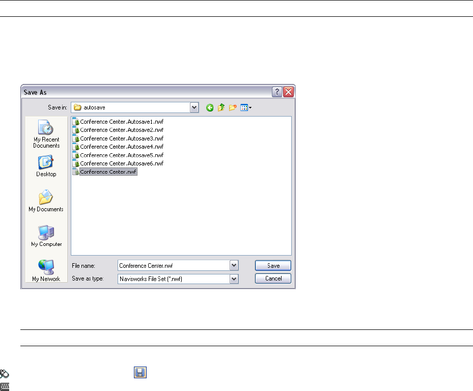
On the other hand, whenever you need to share the scene you created and review markups with others, it is best
to distribute a published NWD file, which includes additional features such as password protection and file
expiration date. The published files can be viewed in both Autodesk Navisworks Review 2010 and Autodesk
Navisworks Freedom 2010 (a free viewer).
IMPORTANT When you publish an NWD file, you cannot include any RPCs added to your scene.
To save a file
1Click File ➤ Save. If your file has been saved previously, Navisworks overwrites the file with the new data.
2If you file has not been previously saved, the Save As dialog box opens.
Enter the file name, use the Files of Type box to select one of the native Navisworks formats (NWF or NWD),
select the location for the file, and click Save.
TIP If you need to open your file with an earlier versions of Autodesk Navisworks, save it as that version type.
Toolbar: Standard ➤ Save
Command entry: CTRL + S
To rename a file
1Click File ➤ Save As.
2In the Save As dialog box, enter the new name for your file.
118 | Chapter 5 Work with Files
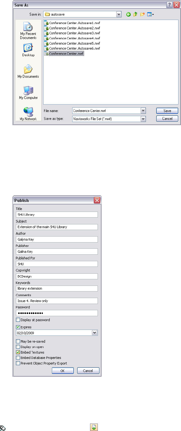
3Click Save.
To publish an NWD file
1Open the file that you want to publish (NWD or NWF).
2Click File ➤ Publish.
3Use the Publish dialog box to enter the document information, and specify the required document protection.
4Click OK.
5In the Save As dialog box, enter the file name, and specify the file location.
6Click Save. Your file is now published.
Toolbar: Standard ➤ Publish
Save and Rename Files | 119
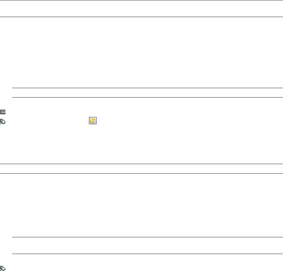
Complex Models
You can use Navisworks files to build complex models.
When you bring files from different sources into the same scene, Autodesk Navisworks automatically aligns
rotation and origin of models, and rescales the units in each file to match display units.
If the rotation, origin, or file units are incorrect for the scene, you can manually adjust them for each of the
opened files.
Append Files
To add more models to an existing scene, you need to append model files.
NOTE If you try to drag and drop files directly to the Selection Tree control bar or to use the Open dialog box, you
will create a new Navisworks file instead.
To append model files
1Open a Navisworks file.
2Click File ➤ Append.
3In the Append dialog box, use the Files of Type box to select the appropriate file type, and navigate to the
folder where the files you want to add is located.
4Select the required files, and click Open.
TIP To select multiple files, use SHIFT and CTRL keys.
Command entry: CTRL + A
Toolbar: Standard ➤ Append
Delete Files
You can delete files appended to your Navisworks file.
NOTE You cannot delete any files from a published NWD file.
To delete a file
1Open a Navisworks file.
2Right-click the file you want to delete in the Selection Tree.
3Click Delete.
4Click Yes to confirm your command.
NOTE The Undo command is not available; therefore, if you make a mistake, you will need to append your file
back manually.
Menu: File ➤ Delete
Adjust File Units and Transform
For each appended file, you can change the file units, and modify the model’s rotation, origin, and scale.
It is recommended to adjust file units first, before attempting to fix the problems with model alignment.
120 | Chapter 5 Work with Files
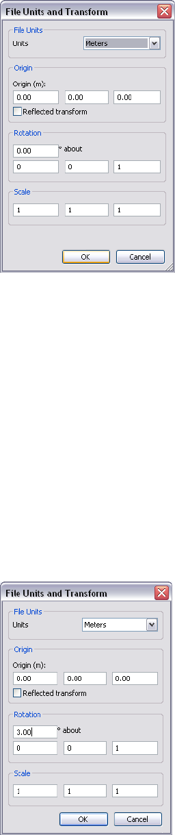
To change file units in a loaded file
1Click the desired file in the Selection Tree.
2Click Edit ➤ File Units and Transform.
3In the File Units and Transform dialog box, select the required format in the Units drop-down list.
4Click OK.
To change a file transform in a loaded file
1Click the desired file in the Selection Tree.
2Click Edit ➤ File Units and Transform.
3To move the model’s location, in the File Units and Transform dialog box, the Origin area, enter values for
the X, Y and Z axis.
If you use a negative scale, select the Reflected Transform check box.
4To change the model’s rotation, in the File Units and Transform dialog box, the Rotation area, enter an
angle of rotation, and selecting the axis to rotate about (by typing a value greater than 0). This will rotate
the model about its origin point.
5To change the model’s scale, in the File Units and Transform dialog box, the Scale area, enter values for the
X, Y and Z axis. To proportionally scale an object, ensure the X, Y, and Z values are equal.
Entering a negative value flips the model inside out.
Complex Models | 121
6Click OK.
Refresh Files
When working in Autodesk Navisworks, it is possible that others may be working on the CAD files you are
currently reviewing. For example, if you are coordinating various disciplines on a project, then you may have
an NWF file referencing numerous design files. During the iterative stages of the project, any member of the
design team could potentially be modifying their CAD files.
To ensure the data you are reviewing is current, Autodesk Navisworks provides a refresh function to reopen the
files that have been modified on the disk since commencing the review session.
To refresh currently open files
➤ Click File ➤ Refresh.
Toolbar: Standard ➤ Refresh
Merge Files
Autodesk Navisworks is a collaborative solution, and although users may be reviewing the model in different
ways, their resultant files can be merged into a single Navisworks file, with any duplicate geometry and markup
automatically removed.
When merging multiple NWF files that each comprise the same referenced files, Autodesk Navisworks only loads
a single set of the combined models, along with all review markup (such as tags, viewpoints or comments) from
each NWF file. Any duplicate geometry or markup is removed when merged.
Merging Timeliner Data
For files that contain TimeLiner data, merging is done as follows:
■if two TimeLiner data sets are identical, all duplicate data is removed.
■if two TimeLiner data sets contain the same Primary link, then the data set with the most recent link (that
is, the newest file date) is chosen over the other. If the Primary links are different, then the data set with the
highest number of tasks will be used, and links are re-attached wherever possible.
■if two TimeLiner data sets are completely unrelated, no data merging is performed.
To merge files
1Click File ➤ New.
2Open the first of the files with the review markup.
3Click File ➤ Merge.
4In the Merge dialog box, use the Files of Type box to select the appropriate file type (NWD or NWF), and
navigate to the folder where your files you want to merge are located.
5Select the required files, and click Open.
TIP To select multiple files, use SHIFT and CTRL keys.
Command entry: CTRL + M
Toolbar: Standard ➤ Merge
122 | Chapter 5 Work with Files
Email Files
You can send and receive Navisworks files by email.
To send an open Autodesk Navisworks file, click File ➤ Send.
Autodesk Navisworks saves your file first, and then opens the available mail software and attaches your file to a
blank email message.
You can email both NWD and NWF files, although the size of an NWD file will be considerably larger.
Toolbar: Standard ➤ Send
Receive 3D Mail
To open a received file, save the attachment on your disk, and then double-click it.
If it’s an NWF file, Autodesk Navisworks searches for the referenced files first using the absolute path that the
sender originally saved the file with. This is useful if a team is on a local network and the files can be found using
the Universal Naming Convention (UNC).
TIP A team not sharing a server can organize a project using the same file hierarchy and drive letter, and Autodesk
Navisworks can find the files this way.
If Autodesk Navisworks is unable to find the referenced files, then you need to save the attached NWF file in a
directory where all referenced files are located. Autodesk Navisworks can then search for the files relative to the
master NWF location.
TIP
You can use the same method to move a whole sub-directory from your projects directory to a completely new
location. Save the master NWF file in this new place, and Autodesk Navisworks will be able to search for the
referenced files from there.
Email Files | 123
124 | Chapter 5 Work with Files
Explore Your Model
Autodesk Navisworks Review 2010 enables you to walk through a scene in real
time.
View Scene Statistics
Scene statistics display information about the current scene.
Scene statistics list all files contributing to the scene, and the
different graphic elements that make up the scene, along with which
of these have been processed or ignored when loaded.
Other useful statistics are the bounding box of the entire scene and
the total number of primitives (triangles, lines, points) in the scene.
Quick Reference
To view scene statistics
■Click View ➤ Scene Statistics.
Navigate a Scene
In Autodesk Navisworks, you have a variety of options for navigating
your scene.
You can directly manipulate your position in 3D space with nine
navigation modes on the Navigation Modes toolbar. You can also
use StreeringWheels that travel with the cursor, and can save you
time by combining many of the common navigation tools into a
single interface.
You can change the orientation and view of your model by using
the preset views available from the Viewpoint ➤ Navigation Tools
menu. Alternatively, you can use the ViewCube, a 3D navigational
tool that enables you to reorient the view of a model by clicking
predefined areas on the cube. For example, clicking the front of the
ViewCube turns the view until the camera is facing the front of the
scene. You can also click the ViewCube and drag it to rotate the
view freely.
You can use the options on the Navigation Tools toolbar to control
the realism of your navigation. So, for example, you can walk down
stairs or follow terrain, crouch under objects, use an avatar to
represent yourself within the 3D model.
6
125

Animating Navigation
As you navigate in Autodesk Navisworks, you can record viewpoint animations, and then play them back. For
more information, see “Record and Play Animations” on page 251.
Orientation in 3D Space
Although Autodesk Navisworks uses the X, Y, Z coordinate system, there is no hard-and-fast rule as to which
way each of these particular axes actually 'points'.
Autodesk Navisworks reads the data necessary to map which way is ‘up’ and which way is ‘north’ directly from
the files loaded into your scene. If this is not possible, by default, Z is treated as ‘up’ and Y is treated as ‘north’.
It is possible to change the ‘up’ and ‘north’ directions for the entire model (world orientation), and the ‘up’
direction for the current viewpoint (viewpoint up vector).
NOTE Changing the viewpoint up vector affects navigation in modes that rely on the ‘up’ direction of the current
viewpoint, such as walk, turntable, and orbit. It also has an impact on section views.
To align the viewpoint up vector to the current view
➤ Click Viewpoint ➤ Set Viewpoint Up ➤ Set Up.
To align the viewpoint up vector to one of the preset axes
1Click Viewpoint ➤ Set Viewpoint Up.
2Click one of the preset axis. Choose from:
■Set Up + X
■Set Up - X
■Set Up + Y
■Set Up - Y
■Set Up + Z
■Set Up -Z
To change the world orientation
1Click Tools ➤ File Options.
2In the File Options dialog box, Orientation tab, enter the required values to adjust the model orientation.
126 | Chapter 6 Explore Your Model
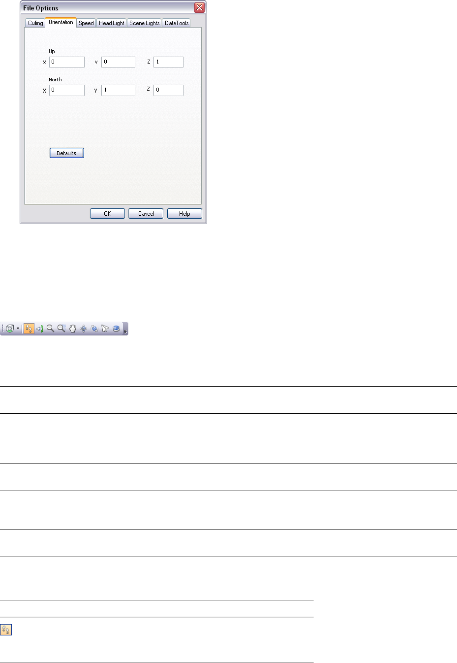
3Click OK.
Navigation Modes
There are nine navigation modes available from the Navigation Mode toolbar to control how you move around
the Scene Area- six camera-centric modes and three model-centric modes.
In a camera-centric mode, the camera moves within the scene, whereas in a model-centric mode, model moves
inside the scene. For example, orbit and examine modes essentially do the same thing, except that orbit mode
moves the camera around the focal point and examine mode moves the model around the focal point.
NOTE Navigation modes and SteeringWheels are mutually exclusive, so activating navigation mode deactivates the
current SteeringWheel menu.
Movement in each mode is based on the keyboard arrow keys, the Shift and Control keys, and mouse drags. The
mouse wheel is also supported, allowing quick and easy zooming or tilting, depending on the current navigation
mode.
TIP Dragging with the left mouse button while holding down the Control key performs the same actions as dragging
with the middle mouse button, which is useful if you only have a two-button mouse.
The Shift and Control keys modify the movement, for example holding down Shift in walk mode speeds up
movement, and holding down Control in this mode, glides the camera left/right and up/down.
NOTE Gliding the camera is opposite to panning the model. Gliding is a camera-centric motion and panning is a
model-centric motion.
Quick Reference
DescriptionMode
Walk. Enables you to walk through the
model on a horizontal plane ensuring that
“up” is always “up”.
Navigation Modes | 127
DescriptionMode
Look Around. Enables you to look around
the model from the current camera posi-
tion and gives the effect that you are
moving your head around.
Zoom. Enables you to zoom into and out
of the model. Cursor up zooms in and
cursor down zooms out.
Zoom to a Box. Enables you to drag a box
so that the contents of the box fill the view.
Pan. Enables you to pan the model rather
than the camera.
Orbit. Enables you to orbit the camera
around the model, ensuring that “up” is
always “up”. The camera always orbits
around the focal point of the model.
Examine. Enables you to rotate the model
about.
Fly. Enables you to fly around the model
like in a flight simulator.
Turntable. Enables you to spin the model
around the up vector. This navigation
mode behaves as though the model is sit-
ting on a turntable, ensuring that “up” is
always “up”.
Walk Mode
In walk mode, you can navigate through a model as if you were walking through it. In this mode, the up direction
is always maintained.
Once you start walk mode, the cursor changes to the walk cursor. To walk through the model, you drag in the
direction in which you want to move in.
To use walk mode to move through the model
1Click Walk on the Navigation Mode toolbar.
2To move, hold down the left mouse button as you drag in the direction you want to walk, or use the cursor
keys. The camera spins left and right, and moves forwards and backwards.
NOTE Holding down the SHIFT key speeds up this movement.
128 | Chapter 6 Explore Your Model
3To glide, hold down the CTRL key as you drag the mouse. The camera glides left and right and up and
down.
As walk mode is camera-centric, this mode differs from the normal pan mode in that the camera is moved
rather than the model.
4To tilt the camera up and down, spin the mouse wheel.
Menu: Viewpoint ➤ Navigation Mode ➤ Walk
Command entry: CTRL + 2
Look Around Mode
In look around mode, you can rotate the current view vertically and horizontally. When rotating the view, your
line of sight rotates about the current eye position, like turning your head.
To look around a view
1Click Look Around on the Navigation Mode toolbar.
2To look around, drag the left mouse button, or use the cursor keys. The camera looks left, right, up or down.
NOTE Holding down the SHIFT key speeds up this movement.
3To rotate the camera around its viewing axis, hold down the CTRL key.
Menu: Viewpoint ➤ Navigation Mode ➤ Look Around
Command entry: CTRL + 3
Zoom Mode
In zoom mode, you can zoom into and out of the model.
To zoom the view
1Click Zoom on the Navigation Mode toolbar.
2Drag the left mouse button up and down, or use the up and down cursor keys, to zoom in and out
respectively.
Menu: Viewpoint ➤ Navigation Mode ➤ Zoom
Command entry: CTRL + 4
Navigation Modes | 129
Zoom Box Mode
In zoom box mode, you can zoom in to an area of the model by dragging a rectangular box around the area you
want to fit in the Scene Area.
To zoom in to an area of the model by specifying box
1Click Zoom Box on the Navigation Mode toolbar.
2Drag a box with the left mouse button over the Scene Area to fill the view with the contents of the box.
NOTE Holding down the Shift or Control keys, or spinning the mouse wheel, temporarily enables normal zoom
mode.
Menu: Viewpoint ➤ Navigation Mode ➤ Zoom Box
Command entry: CTRL + 5
Pan Mode
In pan mode, you can move the model, rather than the camera. For example, dragging upward moves the model
up while dragging downward moves the model down.
To pan a model
1Click Pan on the Navigation Mode toolbar.
2Drag the left mouse button to pan the model up, down, left and right.
NOTE Holding down the SHIFT or CTRL keys, or spinning the mouse wheel, temporarily enables normal zoom
mode.
Menu: Viewpoint ➤ Navigation Mode ➤ Pan
Command entry: CTRL + 6
Orbit Mode
In orbit mode, the camera moves around the focal point of the model. In this mode, the up direction is always
maintained.
130 | Chapter 6 Explore Your Model
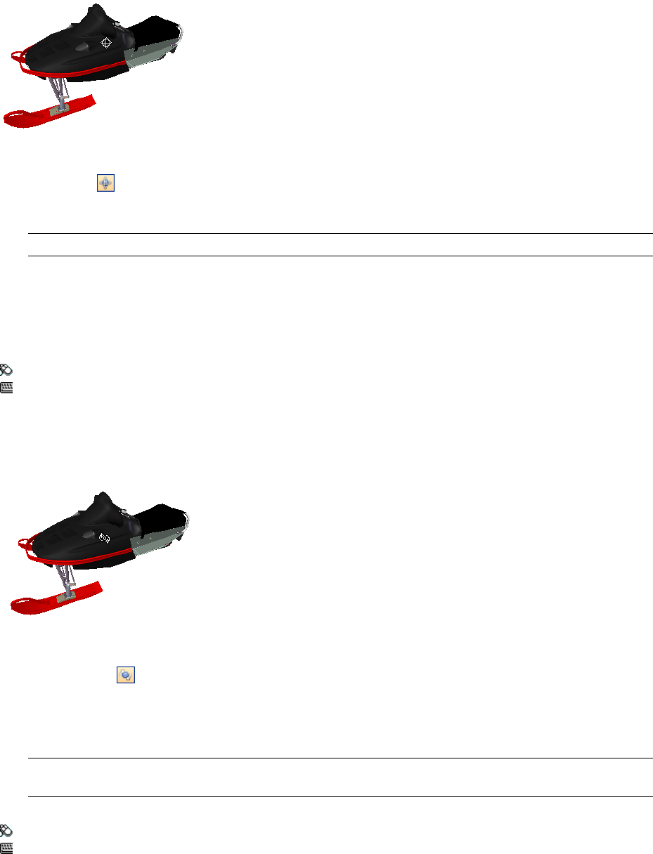
To orbit a model
1Click Orbit on the Navigation Mode toolbar.
2To rotate the camera around the model, drag the left mouse button, or using the cursor keys.
NOTE Holding down the SHIFT key, or spinning the mouse wheel, temporarily enables normal zoom mode.
3To glide the camera, hold down the CTRL key as you drag the mouse. The camera glides left and right and
up and down.
As orbit mode is camera-centric, this mode differs from normal pan mode in that the camera is moved
rather than the model.
Menu: Viewpoint ➤ Navigation Mode ➤ Orbit
Command entry: CTRL + 7
Examine Mode
In examine mode, you can rotate the model around the focal point.
To examine a model
1Click Examine on the Navigation Mode toolbar.
2To rotate the model around the focal point, drag the left mouse button, or using the cursor keys. If the
mouse is moving when you let go of the button, the model keeps spinning. Clicking on the model stops
this.
NOTE Holding down the Shift key, or spinning the mouse wheel, temporarily enables normal zoom mode. Holding
down the CTRL key, temporarily enables normal pan mode.
Menu: Viewpoint ➤ Navigation Mode ➤ Examine
Command entry: CTRL + 8
Fly Mode
In fly mode, you can move around the model like in a flight simulator.
Navigation Modes | 131
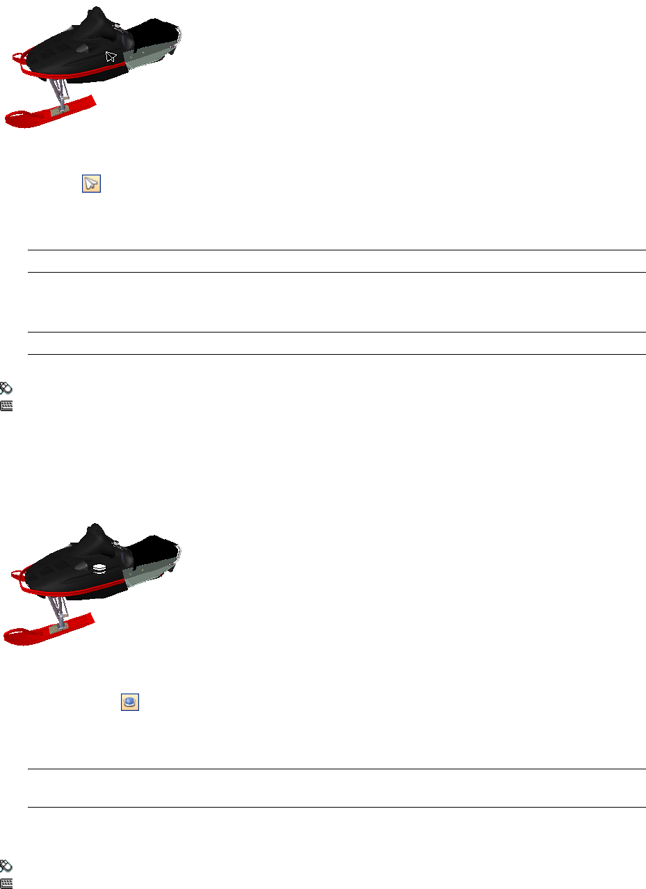
To use fly mode to move through the model
1Click Fly on the Navigation Mode toolbar.
2Hold down the left mouse button to move the camera forward. As in a flight simulator, the left mouse
button banks left/right when dragged left or right and tilts up/down when dragged up or down.
NOTE Holding down the SHIFT key speeds up this movement.
3Use the up and down cursor keys to zoom the camera in and out respectively; use the left and right cursor
keys to spin the camera left and right respectively.
NOTE Holding down the CTRL key rotates the camera around its viewing axis, while still moving forward.
Menu: Viewpoint ➤ Navigation Mode ➤ Fly
Command entry: CTRL + 9
Turntable Mode
In turntable mode, you can spin the model around the up vector as though the model is sitting on a turntable.
In this mode, the up direction is always maintained.
To spin model on a turntable
1Click Turntable on the Navigation Mode toolbar.
2Drag the left mouse button left and right, or use the left and right cursor keys, to spin the turntable left and
right respectively.
NOTE Holding down the SHIFT key or spinning the mouse wheel, temporarily enables normal zoom mode.
Holding down the CTRL key, temporarily enables normal pan mode.
3To tilt the the turntable up and down, spin the mouse wheel, or use the up and down cursor keys.
Menu: Viewpoint ➤ Navigation Mode ➤ Turntable
Command entry: CTRL + 0
132 | Chapter 6 Explore Your Model
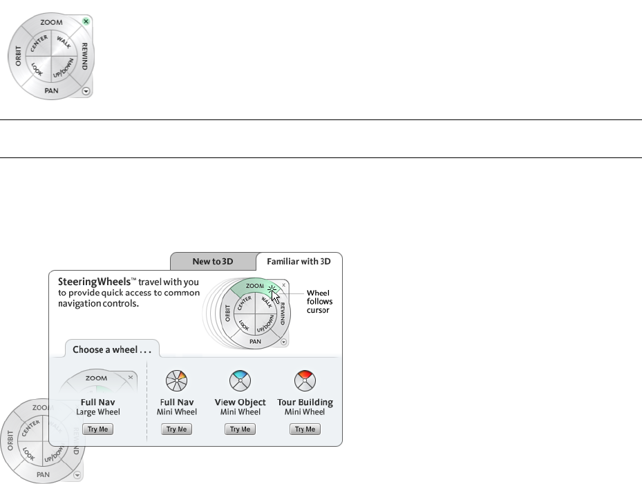
SteeringWheels
SteeringWheels™ are tracking menus that follow your cursor, and from which you can access diferent 3D
navigation tools from a single tool.
Overview of SteeringWheels
SteeringWheels, also known as wheels, can save you time by combining many of the common navigation tools
into a single interface. Wheels are specific to the context from which a model is being viewed.
NOTE SteeringWheels and navigation modes are mutually exclusive, so activating a SteeringWheel deactivates the
currently selected navigation mode.
First Contact Balloon
At startup, the SteeringWheel is pinned. When you move the cursor over the SteeringWheel, the First Contact
balloon is displayed. The First Contact balloon serves as an introduction to the purpose of the wheels and how
you can use them.
Display and Use Wheels
Pressing and dragging on a wedge of a wheel is the primary mode of interaction. After a wheel is displayed, click
one of the wedges and hold down the button on the pointing device to activate the navigation tool. Drag to
reorient the current view. Releasing the button returns you to the wheel.
Control the Appearance of Wheels
You can control the appearance of the wheels by switching between the different styles of wheels that are
available, or by adjusting the size and opacity. Wheels are available in two different styles: big and mini. The
SteeringWheels | 133
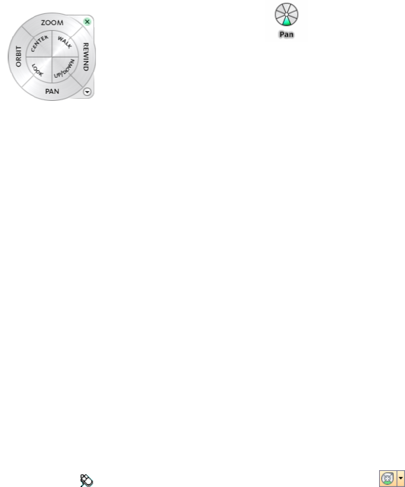
big wheel is larger than the cursor, and labels are shown on the wheel wedges. The mini wheel is about the same
size as the cursor, and labels are not displayed on the wheel wedges.
Mini
Full
Big Full Naviga-
tion Wheel
Navig-
ation
Wheel
The size of a wheel controls how large or small the wedges and labels appear on the wheel; the opacity level
controls the visibility of the objects in the model behind the wheel.
Control Tooltips for Wheels and Messages for Tools
Tooltips are displayed for each button on a wheel as the cursor is moved over them. The tooltips appear below
the wheel and identify what action will be performed if the wedge or button is clicked.
Similar to tooltips, tool messages and cursor text are displayed when you use one of the navigation tools from
a wheel. Tool messages are displayed when a navigation tool is active; they provide basic instructions about
using the tool. Tool cursor text displays the name of the active navigation tool near the cursor. Disabling tool
messages and cursor text only affects the messages that are displayed when using the mini wheels or the big Full
Navigation wheel.
To display a wheel
1Click View ➤ SteeringWheels.
2Click the wheel you want to display, for example Full Navigation Wheel.
Toolbar: Navigation Mode ➤ SteeringWheels
To close a wheel
Use one of the following methods to close a wheel:
■Press SHIFT+W
■Click the Close button.
■Right-click the wheel, and click Close Wheel.
To change the size of a wheel
1Display a wheel.
2Right-click the wheel, and click SteeringWheels Options.
3In the Options Editor, the SteeringWheels page under the Interface node, select an option from the Size
drop-down list in the Big Wheels or Mini Wheels area.
4Click OK.
To change the opacity of a wheel
1Display a wheel.
2Right-click the wheel, and click SteeringWheels Options.
3In the Options Editor, the SteeringWheels page under the Interface node, select an option from the Opacity
drop-down list in the Big Wheels or Mini Wheels area.
134 | Chapter 6 Explore Your Model
4Click OK.
To control the startup placement of a wheel
1Display a wheel.
2Right-click the wheel, and click SteeringWheels Options.
3In the Options Editor, the SteeringWheels page under the Interface node, select the Always Show the Pinned
Wheel on Startup check box.
When this option is selected, the wheel is pinned to the window at startup. When this check box is clear,
the wheel follows the position of the cursor at startup.
4Click OK.
To enable tooltips for wheels
1Display a wheel.
2Right-click the wheel, and click SteeringWheels Options.
3In the Options Editor, the SteeringWheels page under the Interface node, select the Show Tooltips check
box.
Tooltips are displayed for each wedge and button on a wheel when the cursor moves over the wheel.
4Click OK.
To enable tool messages for wheels
1Display a wheel.
2Right-click the wheel, and click SteeringWheels Options.
3In the Options Editor, the SteeringWheels page under the Interface node, select the Show Tool Messages
check box.
Messages are displayed when you use the navigation tools.
4Click OK.
To enable tool cursor text for wheels
1Display a wheel.
2Right-click the wheel, and click SteeringWheels Options.
3In the Options Editor, the SteeringWheels page under the Interface node, select the Show Tool Cursor Text
check box.
The name of the active tool is displayed near the cursor when the tool is in use.
4Click OK.
Wheel Menu
From the Wheel menu, you can switch between different wheels and change the behavior of some of the
navigation tools on the current wheel.
Use the Wheel menu to switch between the big and mini wheels that are available, go to the Home view, change
the preferences of the current wheel, and control the behavior of the orbit, look, and walk 3D navigation tools.
The menu items available on the Wheel menu are dependent on the current wheel and program.
To display the Wheel menu
■Click the down arrow in the lower-right corner of the wheel or right-click on the wheel.
SteeringWheels | 135
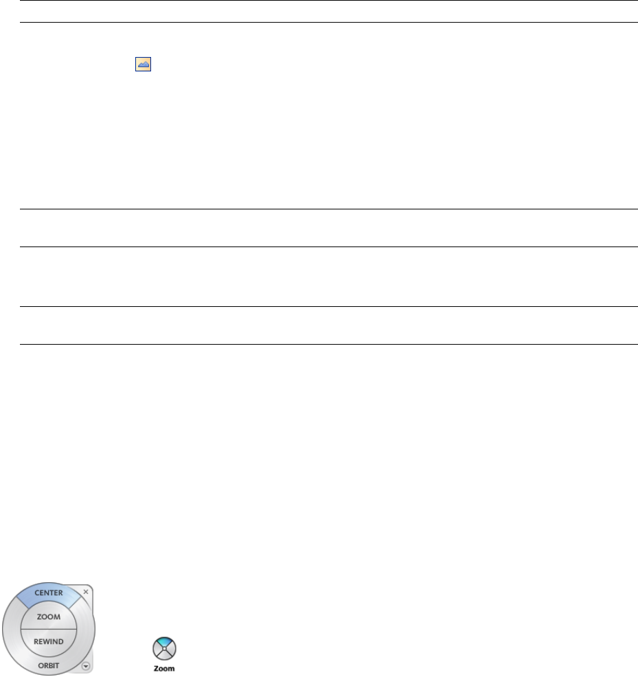
Quick Reference
The Wheel menu has the following options:
■View Object Wheel. Displays the big View Object wheel.
■Tour Building Wheel. Displays the big Tour Building wheel.
■Full Navigation Wheel. Displays the big Full Navigation wheel.
■Advanced Wheels. Displays the mini View Object, Tour Building, or Full Navigation wheel.
■Go Home. Goes to the Home view saved with the model.
NOTE This is the Home view as set using the ViewCube.
■Fit to Window. Resizes and centers the current view to display all objects in the Scene Area. This is equivallent
to clicking View All on the Navigation Tools toolbar.
■Restore Original Center. Restores the center point of the view to the extents of the model.
■Level Camera. Orients the camera such that it is level with the 'ground'. That is to say, resets the camera 'up'
vector to the world up vector as set in File Options ➤ Orientation, and sets the roll of the camera to 0.
■Increase Walk Speed. Increases the walk speed for the Walk tool to double its current setting in the Options
Editor.
NOTE This does not affect the viewpoint linear speed for Navisworks walk navigation mode. The navigation tool
used by SteeringWheels and Navisworks navigation modes are independent.
■Decrease Walk Speed. Decreases the walk speed for the Walk tool to half its current setting in the Options
Editor.
NOTE This does not affect the viewpoint linear speed for Navisworks walk navigation mode. The navigation tool
used by SteeringWheels and Navisworks navigation modes are independent.
■SteeringWheels Options. Displays the Options Editor where you can adjust the appearance and behavior of
SteeringWheels.
■Help. Launches the online Help system and displays the topic for SteeringWheels.
■Close Wheel. Closes the wheel.
View Object Wheels
With the View Object wheels (big and mini), you can view individual objects or features in a model. The big
View Object wheel is optimized for new 3D users while the mini View Object wheel is optimized for experienced
3D users.
136 | Chapter 6 Explore Your Model
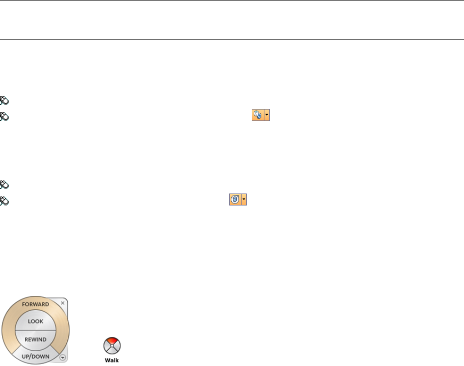
Big View Object Wheel
The big View Object wheel wedges have the following options:
■
Center
. Specifies a point on a model to adjust the center of the current view or change the target point used
for some of the navigation tools.
■
Zoom
. Adjusts the magnification of the current view.
■
Rewind
. Restores the most recent view orientation. You can move backward or forward by clicking and
dragging left or right.
■
Orbit
. Rotates the current view around a fixed pivot point.
Mini View Object Wheel
The mini View Object wheel wedges have the following options:
■
Zoom (Top wedge)
. Adjusts the magnification of the current view.
■
Rewind (Right wedge)
. Restores the most recent view. You can move backward or forward by clicking and
dragging left or right.
■
Pan (Bottom wedge)
. Repositions the current view by panning.
■
Orbit (Left wedge)
. Rotates the current view around a fixed pivot point.
NOTE When the mini wheel is displayed, you can press and hold the middle mouse button to pan, scroll the wheel
button to zoom in and out, and hold the SHIFT key while pressing and holding the middle mouse button to orbit the
model.
To switch to the mini View Object wheel
■Right-click the wheel, and click Advanced Wheels ➤ Mini View Object Wheel.
Menu: View ➤ SteeringWheels ➤ Mini View Object Wheel
Toolbar: Navigation Mode ➤ Mini View Object Wheel
To switch to the big View Object wheel
■Right-click the wheel, and click View Object Wheel.
Menu: View ➤ SteeringWheels ➤ View Object Wheel
Toolbar: Navigation Mode ➤ View Object Wheel
Tour Building Wheels
With the Tour Building wheels (big and mini), you can move through a model, such as a building, an assembly
line, ship, or oil rig. You can also walk through and navigate around a model. The big Tour Building wheel is
optimized for new 3D users while the mini Tour Building wheel is optimized for experienced 3D users.
SteeringWheels | 137
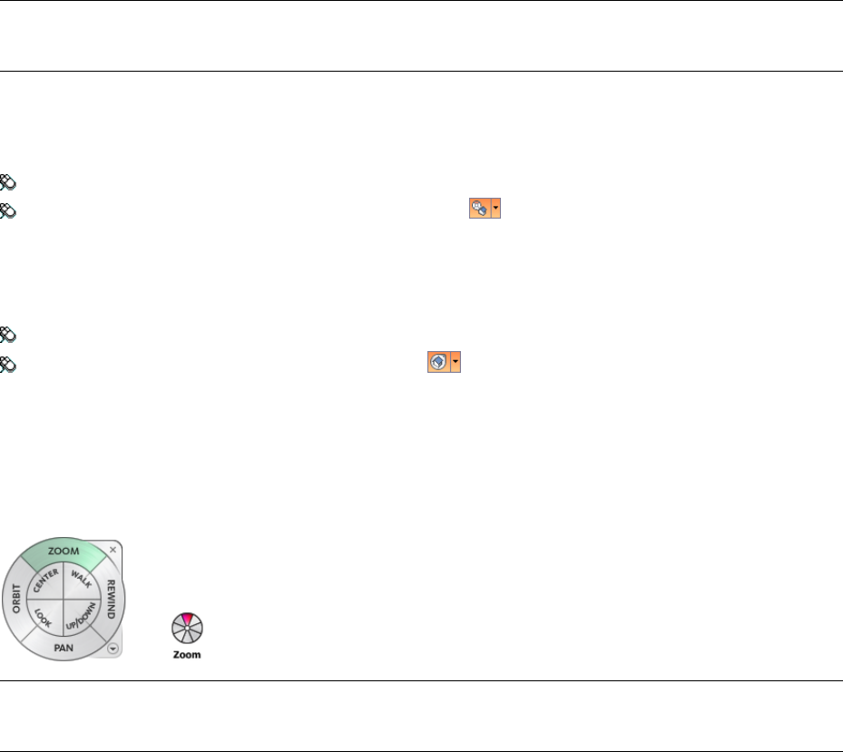
Big Tour Building Wheel
The big Tour Building wheel wedges have the following options:
■
Forward
. Adjusts the distance between the current point of view and the defined pivot point of the model.
Clicking once moves forward half the distance as far as the object you clicked.
■
Look
. Swivels the current view.
■
Rewind
. Restores the most recent view. You can move backward or forward by clicking and dragging left or
right.
■
Up/DownTool
. Slides the current view of a model along the Z axis of the model.
Mini Tour Building Wheel
The mini Tour Building wheel wedges have the following options:
■
Walk (Top wedge)
. Simulates walking through a model.
■
Rewind (Right wedge)
. Restores the most recent view. You can move backward or forward by clicking and
dragging left or right.
■
Up/Down (Bottom wedge)
. Slides the current view of a model along the Z axis of the model.
■
Look (Left wedge)
. Swivels the current view.
NOTE When the mini wheel is displayed, you can press and hold the middle mouse button to pan, scroll the wheel
button to zoom in and out, and hold the SHIFT key while pressing and holding the middle mouse button to orbit the
model.
To switch to the mini Tour Building wheel
■Right-click the wheel, and click Advanced Wheels ➤ Mini Tour Building Wheel.
Menu: View ➤ SteeringWheels ➤ Mini Tour Building Wheel
Toolbar: Navigation Mode ➤ Mini Tour Building Wheel
To switch to the big Tour Building wheel
■Right-click the wheel, and click Tour Building Wheel.
Menu: View ➤ SteeringWheels ➤ Tour Building Wheel
Toolbar: Navigation Mode ➤ Tour Building Wheel
Full Navigation Wheels
The Full Navigation wheels (big and mini) combine the 3D navigation tools found on the View Object and Tour
Building wheels. You can view individual objects, and walk through and around a model. The big and mini Full
Navigation wheels are optimized for experienced 3D users.
NOTE When one of the Full Navigation wheels is displayed, you can press and hold the middle mouse button to pan,
scroll the wheel button to zoom in and out, and hold the SHIFT key while pressing and holding the middle mouse
button to orbit the model.
138 | Chapter 6 Explore Your Model
Big Full Navigation Wheel
The big Full Navigation wheel wedges have the following options:
■
Zoom
. Adjusts the magnification of the current view.
■
Rewind
. Restores the most recent view. You can move backward or forward by clicking and dragging left or
right.
■
Pan
. Repositions the current view by panning.
■
Orbit
. Rotates the current view around a fixed pivot point.
■
Center
. Specifies a point on a model to adjust the center of the current view or change the target point used
for some of the navigation tools.
■
Walk
. Simulates walking through a model.
■
Look
. Swivels the current view.
■
Up/Down
. Slides the current view of a model along the Z axis of the model.
Mini Full Navigation Wheel
The mini Full Navigation wheel wedges have the following options:
■
Zoom (Top wedge)
. Adjusts the magnification of the current view.
■
Walk (Upper right wedge)
. Simulates walking through a model.
■
Rewind (Right wedge)
. Restores the most recent view. You can move backward or forward by clicking and
dragging left or right.
■
Up/Down (Lower right wedge)
. Slides the current view of a model along the Z axis of the model.
■
Pan (Bottom wedge)
. Repositions the current view by panning.
■
Look (Lower left wedge)
. Swivels the current view.
■
Orbit (Left wedge)
. Rotates the current view around a fixed pivot point.
■
Center (Upper left wedge)
. Specifies a point on a model to adjust the center of the current view or change
the target point used for some of the navigation tools.
To switch to the mini Full Navigation wheel
■Right-click the wheel, and click Advanced Wheels ➤ Mini Full Navigation Wheel.
Menu: View ➤ SteeringWheels ➤ Mini Full Navigation Wheel
Toolbar: Navigation Mode ➤ Mini Full Navigation Wheel
To switch to the big Full Navigation wheel
■Right-click the wheel, and click Full Navigation Wheel.
Menu: View ➤ SteeringWheels ➤ Full Navigation Wheel
Toolbar: Navigation Mode ➤ Full Navigation Wheel
Navigation Tools
Each wheel is divided into different wedges. Each wedge contains a navigation tool that you can be uses to
reorient the current view of a model. Which navigation tools are available depends on which wheel is active.
SteeringWheels | 139
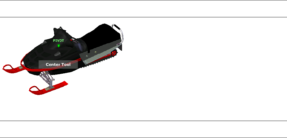
Control Navigation Realism
You can use collision, gravity, and crouching with the Walk tool. This allows you, for example, to walk up and
down stairs and walk under low objects.
You can also use the third person view with SteeringWheels to enhance your navigation experience. However,
the avatar is only shown when you use the Walk tool, and the Pan tool to prevent cluttering of the screen.
Center Tool
With the Center tool, you can define the center of the current view of a model. To define the center, you drag
the cursor over your model. A sphere is displayed in addition to the cursor. The sphere indicates that the point
below the cursor in the model will be the center of the current view when you release the mouse button, the
model is centered on the sphere.
NOTE If a center point on a model cannot be identified, then a prohibited icon (a circle with a diagonal line) is displayed
instead of the sphere.
The point defined by the Center tool provides a focal point for the Zoom tool and a pivot point for the Orbit
tool.
NOTE If you want to zoom from the Full Navigation wheels from your defined center point, hold down CTRL before
zooming.
To specify a point on a model as the center of a view
1Display one of the Full Navigation wheels or the big View Object wheel.
2Click and hold down the Center wedge.
3Drag the cursor to the desired location of the model.
4Release the button on your pointing device when the sphere is displayed.
The model is panned until the sphere is centered.
To specify the target point for the Zoom and Orbit tools
1Display one of the Full Navigation wheels or the big View Object wheel.
2Click and hold down the Center wedge.
3Drag the cursor over the desired location of the model.
4Release the button on your pointing device when the sphere is displayed.
The model is panned until the sphere is centered.
5Use the Zoom or Orbit tool to reorient the view of the model.
If you are using one of the Full Navigation wheels, hold down the CTRL key before using the Zoom tool.
140 | Chapter 6 Explore Your Model
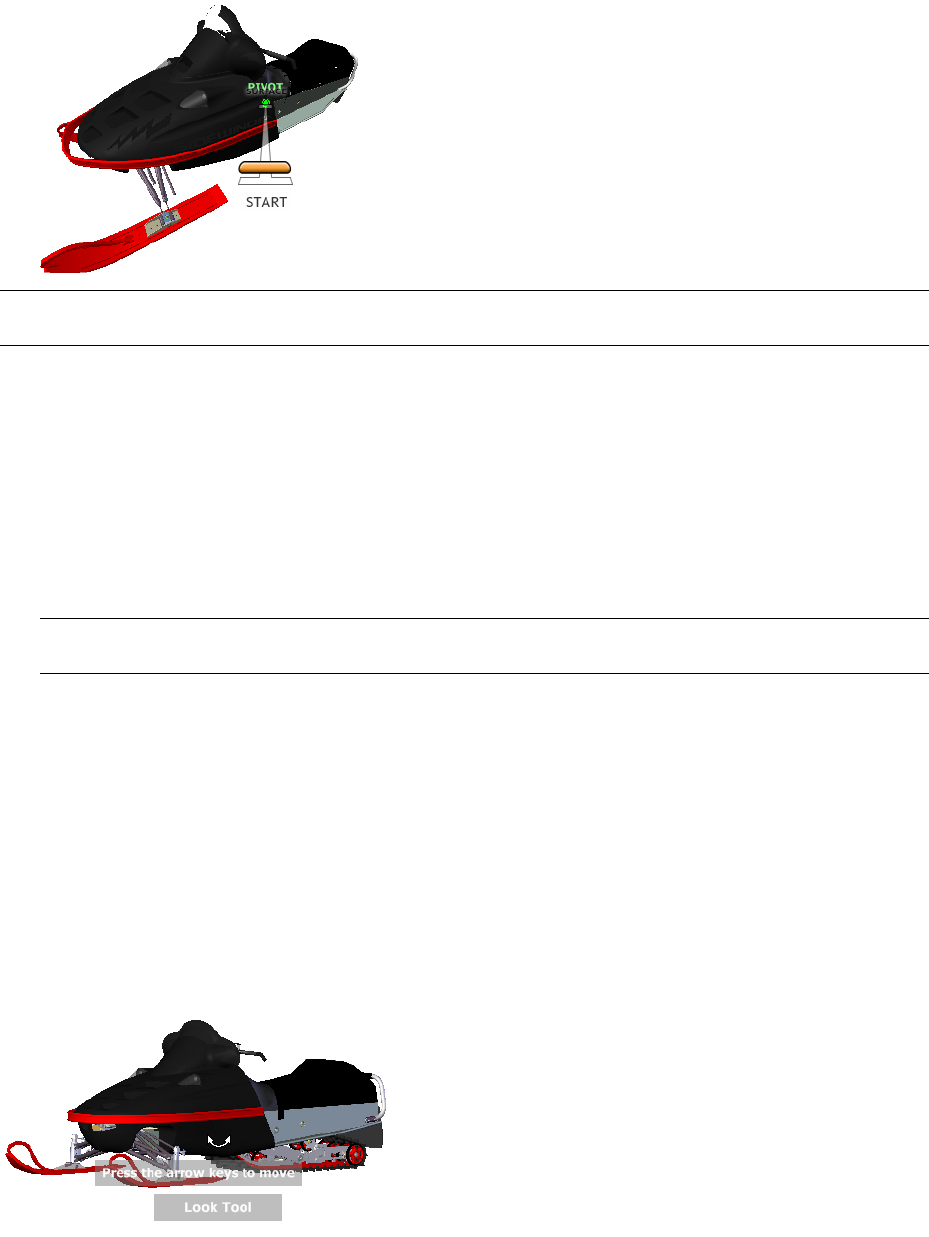
Forward Tool
You use the Forward tool to change the magnification of the model by increasing or decreasing the distance
between the current point of view and the pivot point. The distance that you can move forward or backward is
limited by the position of the pivot point.
NOTE In orthographic views, the Forward tool is limited to the distance between the current position and the pivot
point. In perspective views, it is not limited, so you can move the cursor through the pivot point.
To adjust the distance between the current point of view and the pivot point you use the Drag Distance indicator.
The Drag Distance indicator has two marks on it that show the start and destination distances from the current
point of view. The current traveled distance is shown by the orange position indicator. Slide the indicator forward
or backwards to decrease or increase the distance towards the pivot point.
To reorient a view by moving towards or away from the model
1Display the big Tour Building wheel.
2Click and hold down the Forward wedge.
The Drag Distance indicator is displayed.
NOTE If you click the Forward wedge once, the model moves forward 50% of the distance between the current
location and the pivot point.
3Drag the cursor up or down to change the distance from which you view the model.
4Release the button on your pointing device to return to the wheel.
Look Tool
With the Look tool, you can rotate the current view vertically and horizontally. When rotating the view, your
line of sight rotates about the current eye position, like turning your head. The Look tool can be compared to
you standing in a fixed location, and looking up or down while turning your head left or right.
When using the Look tool, you adjust the view of the model by dragging the cursor. As you drag, the cursor
changes to the Look cursor and the model rotates around the location of the current view.
SteeringWheels | 141
In addition to using the Look tool to look around a model, you can also use the tool to pan the current view to
a specific face on the model. Press and hold the SHIFT key before selecting the Look tool on one of the Full
Navigation wheels.
Walking Through a Model
When using the Look tool from the big Full Navigation wheel, you can walk through a model by using the arrow
keys on the keyboard. To adjust the walk speed, use the Options Editor.
Invert Vertical Axis
When you drag the cursor upward, the target point of the view raises; dragging the cursor downward lowers the
target point of the view. To invert the vertical axis for the Look tool, use the Options Editor.
To look around a view with the Look tool
1Display one of the Full Navigation wheels or the mini Tour Building wheel.
2Click and hold down the Look wedge.
The cursor changes to the Look cursor.
3Drag the pointing device to change the direction in which you are looking.
4Release the button on your pointing device to return to the wheel.
To look at a face in the model with the Look tool
1Display one of the Full Navigation wheels.
2Press and hold down the SHIFT key.
3Click and hold down the Look wedge.
The cursor changes to the Look At cursor.
4Drag over the objects in the model until the face highlights that you want to look at.
5Release the button on your pointing device to return to the wheel.
To look around and walk through a model with the Look tool
1Display the big Full Navigation wheel.
2Click and hold down the Look wedge.
The cursor changes to the Look cursor.
3Drag to change the direction in which you are looking.
4While holding down the button on your pointing device, press the arrow keys to walk in the model.
5Release the button on your pointing device to return to the wheel.
6Click Close to exit the wheel.
To invert the vertical axis for the Look tool
1Display a wheel.
2Right-click the wheel, and click SteeringWheels Options.
3In the Options Editor, the SteeringWheels page under the Interface node, select the Invert Vertical Axis
check box.
Dragging downward and upward lowers and raises the target point of the current view.
4Click OK.
142 | Chapter 6 Explore Your Model
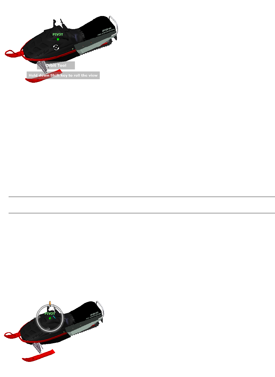
Orbit Tool
You use the Orbit tool to change the orientation of a model. The cursor changes to the Orbit cursor. As you drag
the cursor, the model rotates around a pivot point while the view remains fixed.
Specify the Pivot Point
The pivot point is the base point used when rotating the model with the Orbit tool. You can specify the pivot
point in the following ways:
■Default pivot point. When you first open a model, the target point of the current view is used as the pivot
point for orbiting the model.
■Select objects. You can select objects before the Orbit tool is used to calculate the pivot point. The pivot
point is calculated based on the center of the extents of the selected objects.
■Center tool. You can specify a point on the model to use as the pivot point for orbiting with the Center tool.
■CTRL+Click and drag. Press and hold down the CTRL key before clicking the Orbit wedge or while the Orbit
tool is active; then drag to the point on the model you want to use as the pivot point. This option is only
available when using the big and mini Full Navigation wheels or the mini View Object wheel.
NOTE While the Orbit tool is active, you can be press and hold the CTRL key at anytime to move the pivot point
used by the Orbit tool.
Maintain Up Direction
You can control how the model orbits around the pivot point by choosing to maintain the up direction of the
model. When the up direction is maintained, orbiting is constrained along the XY axis and in the Z direction. If
you drag horizontally, the camera moves parallel to the XY plane. If you drag vertically, the camera moves along
the Z axis.
If the up direction is not maintained, you can roll the model using the roll ring which is centered around the
pivot point. Use the properties dialog box for the SteeringWheels to control whether the up direction is maintained
or not for the Orbit tool.
SteeringWheels | 143

To orbit a model with the Orbit tool
1Display one of the View Object or Full Navigation wheels.
2Click and hold down the Orbit wedge.
The cursor changes to the Orbit cursor.
3Drag to rotate the model.
NOTE Use the Center tool to re-center the model in the current view, if you are using one of the Full Navigation
or View Object wheels.
4Release the button on your pointing device to return to the wheel.
To orbit around an object with the Orbit tool
1Press ESC to make sure no commands are active and to clear any previously selected objects.
2Select the objects in the model for which you want to define the pivot point.
3Display one of the View Object or Full Navigation wheels.
4Click and hold down the Orbit wedge.
The cursor changes to the Orbit cursor.
5Drag to rotate the model.
6Release the button on your pointing device to return to the wheel.
To turn on selection sensitivity for the Orbit tool
1Display one of the View Object or Full Navigation wheels.
2Right-click the wheel, and click SteeringWheels Options.
3In the Options Editor, the SteeringWheels page under the Interface node, select the Enable Selection
Sensitivity check box.
4Click OK.
The extents of any objects that are selected before the wheel is displayed are used to define the pivot point
for the Orbit tool. If no objects are selected, the pivot point used by the Orbit is the one defined by the
Center tool.
To maintain the up direction for the Orbit tool
1Display the mini View Object wheel or one of the Full Navigation wheels.
2Right-click the wheel, and click SteeringWheels Options.
3In the Options Editor, the SteeringWheels page under the Interface node, select the Keep Scene Upright
check box.
4Click OK.
Orbiting the model is constrained along the XY plane and Z directions.
To roll the model around the pivot point with the Orbit tool
1Display the mini View Object Wheel or one of the Full Navigation wheels.
2Right-click the wheel, and click SteeringWheels Options.
3In the Options Editor, the SteeringWheels page under the Interface node, clear the Keep Scene Upright
check box.
4Click OK.
144 | Chapter 6 Explore Your Model
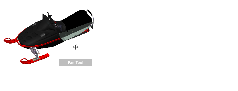
5Click and hold the Orbit wedge.
The cursor changes to the Orbit cursor.
6Press and hold the SHIFT key to display the roll ring. Drag to roll the model.
7Release the button on your pointing device to return to the wheel.
To start the Orbit tool with the middle mouse button
1Display one of the wheels other than the big View Object or Tour Building wheels.
2Press and hold down the SHIFT key.
3Press and hold down the scroll wheel or middle button on your pointing device and drag to orbit the model.
4Release the button on your pointing device to return to the wheel.
Pan Tool
When the pan tool is active, the Pan cursor (a four-sided arrow) is displayed. Dragging the pointing device moves
the model in the same direction. For example, dragging upward moves the model up while dragging downward
moves the model down.
TIP If the cursor reaches the edge of the screen, you can continue panning by dragging further to force it to wrap
around the screen.
To pan the view with the Pan tool
1Display one of the Full Navigation wheels, or the mini View Object wheel.
2Click and hold the Pan wedge.
The cursor changes to the Pan cursor.
3Drag to reposition the model.
4Release the button on your pointing device to return to the wheel.
To start the Pan tool with the middle mouse button
1Display one of the Full Navigation wheels, or the mini View Object wheel.
2Press and hold down the scroll wheel or middle button.
The cursor changes to the Pan cursor.
3Drag to reposition the model.
4Release the wheel or button on your pointing device to return to the wheel.
SteeringWheels | 145
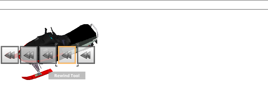
Rewind Tool
As you use the navigation tools to reorient the view of a model, the previous view is saved to the navigation
history. The navigation history holds a representation of the previous views of the model along with a thumbnail.
A separate navigation history is maintained for each window; it is not maintained after the window is closed.
Rewind navigation history is view-specific.
With the Rewind tool, you can retrieve previous views from the navigation history. From the navigation history,
you can restore a previous view or scroll through all of the saved views.
When you hold down the button on the pointing device over the Rewind tool on the wheel, the Rewind History
panel is displayed. You can scroll through the navigation history. To restore one of the previous views in the
navigation history, drag the bracket to the left in the Rewind History panel.
NOTE Rewind history is not saved between sessions.
To restore the previous view
1Display a wheel.
2Click the Rewind wedge.
To restore a previous view with the Rewind History panel
1Display a wheel.
2Click and hold the Rewind wedge.
The Rewind History panel is displayed.
3While holding down the button on your pointing device, drag to the left or to the right to restore a previous
view.
Dragging to the left restores an older previous view. Dragging to the right restores a view that is newer than
the one you are currently viewing. You must have previously used the Rewind tool to see views available
on the right. The current position in the navigation history is indicated by the orange box that is dragged
along the Rewind History panel.
Up/Down Tool
Unlike the Pan tool, you use the UP/Down tool to adjust the height of the current viewpoint along the model's
Z axis. To adjust the vertical elevation of the current view, you drag up or down. As you drag, the current elevation
and the allowed range of motion is displayed on a graphical element called the Vertical Distance indicator.
The Vertical Distance indicator has two marks that show the highest (Top) and lowest (Bottom) elevation the
view can have. While changing the elevation with the Vertical Distance indicator, the current elevation is shown
by the bright orange indicator, while the previous elevation is shown by the dim orange indicator.
146 | Chapter 6 Explore Your Model
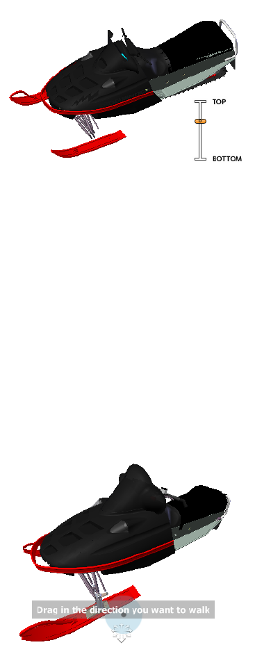
To change the elevation of a view
1Display one of the Full Navigation wheels or the Tour Building wheels.
2Click and hold down the Up/Down wedge.
The Vertical Distance indicator is displayed.
3Drag up or down to change the elevation of the view.
4Release the button on your pointing device to return to the wheel.
Walk Tool
With the Walk tool, you can navigate through a model as if you were walking through it. Once you start the
Walk tool, the Center Circle icon is displayed near the center of the view and the cursor changes to display a
series of arrows. To walk through the model, you drag in the direction in which you want to move in.
Constrain the Walk Angle
When walking through a model, you can constrain the movement angle to the world up vector. If the Constrain
Walk Angle option is enabled, you can freely walk around while maintaining a constant camera viewpoint
elevation; if the walk angle is not constrained, you will “fly” in the direction you are looking. Use the Options
Editor to constrain the movement angle to the world up vector for the Walk tool.
Movement Speed
As you walk or “fly” through a model, you can control the movement speed. Movement speed is controlled by
the distance in which the cursor is moved from the Center Circle icon and the current movement speed setting.
You can adjust the movement speed setting permanently and temporarily as you use the Walk tool. To
permanently adjust the movement speed, use the Options Editor or the < and > keys when the Walk tool is
active. To temporarily increase movement speed, press and hold the + (plus) key while using the Walk tool.
Change the Elevation
As you use the Walk tool, you can adjust the camera elevation by holding down the SHIFT key. This temporarily
activates the Up/Down tool. With the Up/Down tool active, drag up or down to adjust the elevation of the
camera. You can also use the UP ARROW and DOWN ARROW keys as you walk to adjust the height of the view.
SteeringWheels | 147

To use the Walk tool to move through the model
1Display one of the Full Navigation wheels or the mini Tour Building wheel.
2Click and hold down the Walk wedge.
The cursor changes to the Walk cursor and the Center Circle icon is displayed.
3Drag in the direction you want to walk.
NOTE While walking, press and hold down the + (plus) key to temporarily increase your movement speed.
4Release the button on your pointing device to return to the wheel.
To change the movement speed for the Walk tool
1Display a wheel.
2Right-click the wheel, and click SteeringWheels Options.
3In the Options Editor, the SteeringWheels page under the Interface node, use the Walk Speed slider.
Dragging the slider to the left decreases the walking speed; dragging the slider to the right increases the
walking speed.
4Click OK.
To constraint the Walk tool to the world up vector
1Display a wheel.
2Right-click the wheel, and click SteeringWheels Options.
3In the Options Editor, the SteeringWheels page under the Interface node, select the Constrain Walk Angle
check box.
4Click OK.
Movement when walking is done parallel to the world up of the model.
To adjust the height of the current view from the Walk tool
1Display one of the Full Navigation wheels or the mini Tour Building wheel.
2Click and hold down the Walk wedge.
The cursor changes to the Walk cursor and the Center Circle icon is displayed.
3Do one of the following:
■Press and hold down the SHIFT key to enable the Up/Down tool; drag up or down.
■Press and hold down the UP ARROW or DOWN ARROW key.
4Release the button on your pointing device to return to the wheel.
Zoom Tool
You use the Zoom tool to change the zoom magnification of a model.
148 | Chapter 6 Explore Your Model
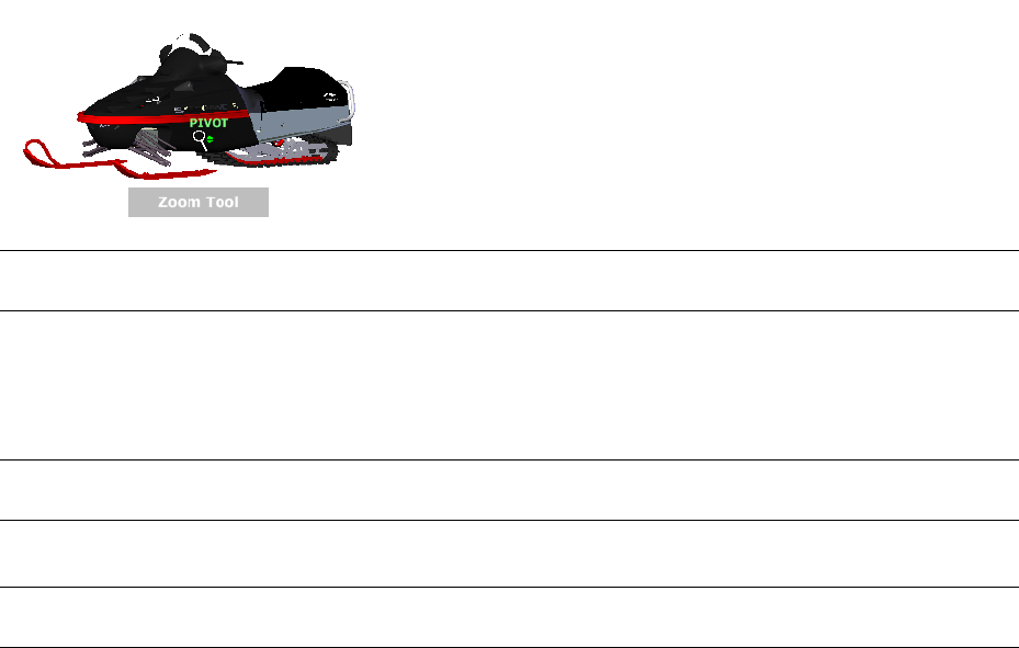
NOTE When you start the Zoom tool from the Full Navigation wheel, incremental zooming must be enabled in the
Options Editor in order to use CTRL+click and SHIFT+click.
Zoom Constraints
When changing the magnification of a model with the Zoom tool, you cannot zoom in any further than the
focus point or out past the extents of the model. The direction you can zoom in and out is controlled by the
center point set by the Center tool.
NOTE Unlike the Zoom tool on the big View Object wheel, the Zoom tool on the mini View Object wheel and the
Full Navigation wheels are not constrained.
To zoom the view with a single click
NOTE You must enable incremental zoom when using the Full Navigation wheels, or a mini View Object wheel. For
the big View Object wheel, the incremental zoom is always enabled.
1Do the following to make sure the Enable Single-Click Incremental Zoom In option is selected:
aDisplay the Full Navigation Wheel.
bRight-click the wheel, and click SteeringWheel Options.
cIn the Options Editor, the SteeringWheels page under the Interface node, select the Enable Single-Click
Incremental Zoom In check box.
dClick OK.
2Display a wheel that has the Zoom tool.
3Click the Zoom wedge.
The magnification of the model is increased and you are zoomed in closer to the model. If you hold down
the SHIFT key while clicking the Zoom wedge, the model is zoomed out; you can hold down the CTRL key
to zoom in.
To zoom a view in and out by dragging
1Display one of the Full Navigation wheels, or one of the View Object wheels.
2Click and hold down the Zoom wedge.
The cursor changes to the Zoom cursor.
3Drag vertically to zoom in or out.
4Release the button on your pointing device to return to the wheel.
To zoom in to an area of the model by specifying window
1Display one of the Full Navigation wheels or the mini View Object wheel.
2Press and hold down the SHIFT key.
3Click and hold down the Zoom wedge.
The cursor changes to the Zoom cursor.
SteeringWheels | 149

4Drag the pointing device to define the opposite corner of the window that defines the area in which you
want to zoom.
NOTE Holding down the CTRL key while defining the second point of the window determines if the first point
of the window is used as the corner or center of the window being dragged. When the CTRL key is held down,
the first point defines the center of the window.
5Release the button on your pointing device to return to the wheel.
To zoom in and out by scrolling the mouse wheel when a SteeringWheel is displayed
1Display one of the wheels other than the big Tour Building wheel.
2Scroll the wheel forward or backward to zoom in or out.
3Release the button on your pointing device to return to the wheel.
Quick Reference
You use the Zoom tool to change the zoom magnification of a model. The following mouse click and key
combinations are available to control how the Zoom tool behaves:
■Click. If you click the Zoom tool on a wheel, the current view is zoomed in by a factor of 25 percent. If you
are using the Full Navigation wheel, incremental zoom must be enabled in the Options Editor.
■SHIFT+click. If you hold down the SHIFT key before you click the Zoom tool on a wheel, the current view is
zoomed in by a factor of 25 percent. Zooming is performed from the current pivot point, and not the location
of the cursor.
■CTRL+click. If you hold down the CTRL key before you click the Zoom tool on a wheel, the current view is
zoomed in by a factor of 25 percent. Zooming is performed from the current pivot point, and not the location
of the cursor.
■Click and drag. If you click the Zoom tool and hold down the button on your pointing device, you can adjust
the magnification of the model by dragging up and down.
■CTRL+click and drag. When using the Full Navigation wheels or the mini View Object wheel, you can control
the target point used by the Zoom tool. By holding down the CTRL key, the Zoom tool uses the location of
the previous pivot point defined by the Zoom, Orbit, or Center tool.
■SHIFT+click and drag. When using the Full Navigation wheels or the mini View Object wheel, you can zoom
in to an area of the model by dragging a rectangular window around the area you want to fit in the window.
Hold down the SHIFT key and then click and drag a window around the area in which you want to zoom.
NOTE If you hold down the CTRL key along with the SHIFT key, you can zoom in to an area of a model using a
center-based window instead of one defined by opposite corners.
■Mouse wheel. When a wheel is displayed, scroll the mouse wheel up or down to zoom the view of the model
in or out.
NOTE When you use the Zoom tool from the Full Navigation wheel or the View Object wheel, the point in the view
where you click to zoom becomes the Center point for future Orbit operations until you either use the Zoom tool again
or use the Center tool. If you press CTRL before you click the Zoom wedge, the Center point does not change.
Camera
Autodesk Navisworks offers you a number of prefixed options to control the camera position and orientation
during navigation.
150 | Chapter 6 Explore Your Model
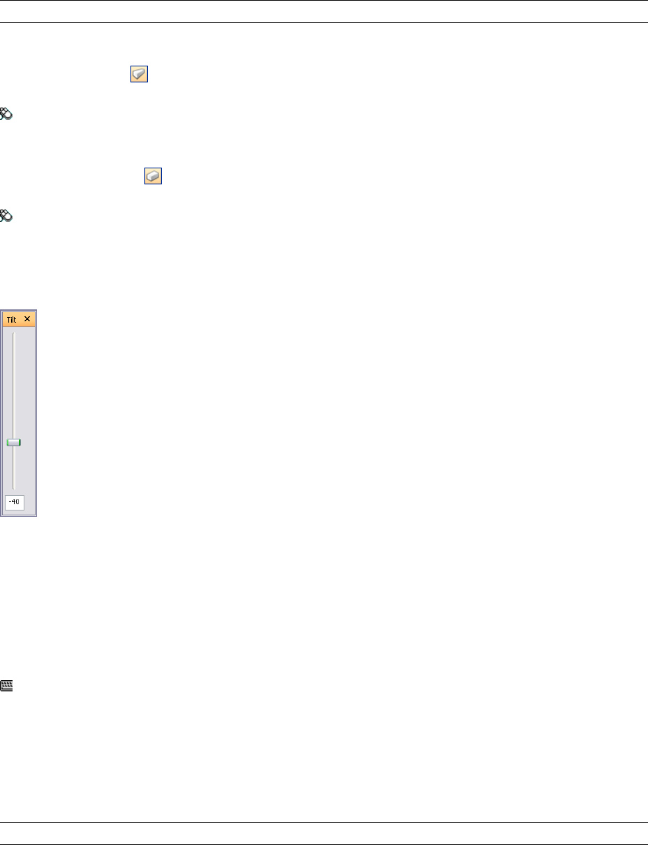
Camera Projection
You can choose to use a perspective camera or an orthographic camera during navigation.
NOTE Orthographic cameras are not available with walk and fly navigation modes.
To use a perspective camera
➤ Click Perspective on the Navigation Tools toolbar.
Menu: Viewpoint ➤ Navigation Tools ➤ Perspective
To use an orthographic camera
➤ Click Orthographic on the Navigation Tools toolbar.
Menu: Viewpoint ➤ Navigation Tools ➤ Orthographic
Camera Tilt
You can adjust the tilt angle of the camera during navigation by using the slider on the Camera Tilt control bar.
The tilt angle is indicated in the scene's units below (negative) or above (positive) horizontal (0) at the base of
the control bar.
This is particularly useful in walk mode to look up and down. If your mouse has a wheel, you can use it to adjust
the tilt angle.
To toggle the Camera Tilt control bar
➤ Click View ➤ Control Bars ➤ Camera Tilt.
Command entry: CTRL + F7
Straighten Camera
You can straighten the camera to align with the viewpoint up vector.
When the camera position is close to the viewpoint up vector (within 13 degrees), you can use this function to
snap the camera to the appropriate axis.
TIP The same effect can be achieved by typing 0 at the base of the Camera Tilt control bar.
To straighten camera
➤ Click Viewpoint ➤ Navigation Tools ➤ Straighten.
Camera | 151
Predefined Camera Views
In Autodesk Navisworks, you can align a camera to one of the axis, or select one of six predefined face views to
instantly change the camera’s position and orientation in the scene.
When you align the camera position along one of the axis:
■Aligning with X axis toggles between front and back face views.
■Aligning with Y axis toggles between left and right face views.
■Aligning with Z axis toggles between top and bottom face views.
NOTE In previous versions of Autodesk Navisworks, the front face view was fixed and linked to the ‘up’ direction of
the current viewpoint by default. In Autodesk Navisworks Review 2010 you can customize the location of the front
face by using the ViewCube. This change is global, and affects all viewpoints.
To align with X-axis
➤ Click Align X on the Navigation Tools toolbar.
Menu: Viewpoint ➤ Navigation Tools ➤ Align X
To align with Y-axis
➤ Click Align Y on the Navigation Tools toolbar.
Menu: Viewpoint ➤ Navigation Tools ➤ Align Y
To align with Z-axis
➤ Click Align Z on the Navigation Tools toolbar.
Menu: Viewpoint ➤ Navigation Tools ➤ Align Z
To look from a preset face view
1Click Viewpoint ➤ Look From.
2Click one of the face views. Choose from:
■Top
■Bottom
■Front
■Back
■Left
■Right
ViewCube
Autodesk® ViewCube® navigation tool provides visual feedback of the current orientation of a model. You can
use the ViewCube tool to adjust the viewpoint of your model.
Overview of the ViewCube
The ViewCube tool is a persistent, clickable, and draggable interface that you use to switch between views of
your model.
152 | Chapter 6 Explore Your Model
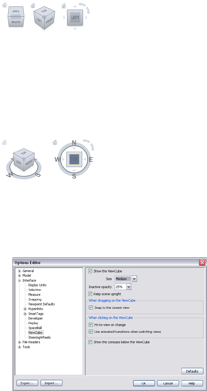
When you display the ViewCube, it is shown in the top- right corner of the Scene Area over the model in an
inactive state. While the ViewCube tool is inactive, it provides visual feedback about the current viewpoint of
the model as view changes occur. When the cursor is positioned over the ViewCube tool, it becomes active; you
can switch to one of the available preset views, roll the current view, or change to the Home view of the model.
Control the Appearance of the ViewCube
The ViewCube tool is displayed in one of two states: inactive and active. When the ViewCube tool is inactive,
it appears partially transparent by default so that it does not obscure the view of the model. When active, it is
opaque and may obscure the view of the objects in the current view of the model.
In addition to controlling the opacity level of the ViewCube when it is inactive, you can also control its size,
and the display of the compass. The settings used to control the appearance of the ViewCube are located in the
Options Editor.
Use the Compass
The compass is displayed below the ViewCube tool and indicates which direction North is defined for the model.
You can click a cardinal direction letter on the compass to rotate the model, or you can click and drag one of
the cardinal direction letters or the compass ring to interactively rotate the model around the center of the view.
To display or hide the ViewCube
■Click View ➤ Head-Up Display ➤ ViewCube.
To control the size of the ViewCube
1Right-click the ViewCube tool, and click ViewCube Options.
2In the Options Editor, the ViewCube page under the Interface node, select an option from the Size drop-down
list.
ViewCube | 153
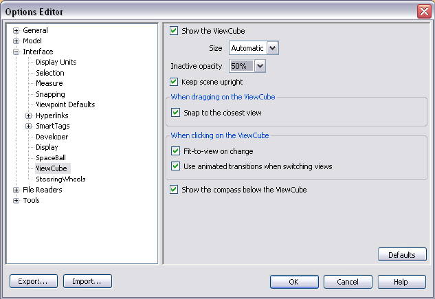
3Click OK.
To control the inactive opacity of the ViewCube
1Right-click the ViewCube tool, and click ViewCube Options.
2In the Options Editor, the ViewCube page under the Interface node, select an option from the Inactive
Opacity drop-down list.
3Click OK.
To display the compass for the ViewCube
1Right-click the ViewCube tool, and click ViewCube Options.
2In the Options Editor, the ViewCube page under the Interface node, select Show Compass Below the
ViewCube.
3Click OK.
The compass is displayed below the ViewCube tool and indicates the direction of North for the model.
ViewCube Menu
Use the ViewCube menu to restore and define the Home view of a model, switch between view projection modes,
and change the interactive behavior and appearance of the ViewCube tool.
To display the ViewCube menu
To display the ViewCube menu, do one of the following:
■Right-click on the compass, Home icon, or the main area of the ViewCube tool.
■Click the context menu button located below the ViewCube tool.
Quick Reference
The ViewCube menu has the following options:
■Home. Restores the Home view saved with the model.
■Orthographic. Switches the current view to orthographic projection.
154 | Chapter 6 Explore Your Model
■Perspective. Switches the current view to perspective projection.
■Lock to Selection. Uses the selected objects to define the center of the view when a view orientation change
occurs with the ViewCube tool.
NOTE If you click Home on the ViewCube tool, the view returns to the Home view even if Lock to Current Selection
is selected.
■Set Current View as Home. Defines the Home view of the model based on the current view.
■Set Current View as Front. Defines the Front view of the model based on the current view.
■Reset Front. Resets the Front view of the model to its default orientation.
■ViewCube Options. Displays the Options Editor where you can adjust the appearance and behavior of the
ViewCube tool.
■Help. Launches the online Help system and displays the topic for the ViewCube tool.
Reorient the Current View
ViewCube is used to reorient the current view of a model. You can reorient the view of a model with the ViewCube
tool by clicking pre-defined areas to set a preset view current, click and drag to freely change the view angle of
the model, and define and restore the Home view.
TIP When the cursor is over one of the clickable areas of the ViewCube tool, the cursor changes to an arrow with a
small cube to indicate that it is over the ViewCube tool.
You use the other twenty defined areas to access angled views of a model. Clicking one of the corners on the
ViewCube tool reorients the current view of the model to a three-quarter view, based on a viewpoint defined by
three sides of the model. Clicking one of the edges reorients the view of the model to a half view based on two
sides of the model.
You can also click and drag the ViewCube tool to reorient the view of a model to a custom viewpoint other than
one of the twenty-six predefined viewpoints. As you drag, the cursor changes to indicate that you are reorienting
the current view of the model. If you drag the ViewCube tool close to one of the preset orientations and it is set
to snap to the closest view, the ViewCube tool rotates to the closest preset orientation.
The outline of the ViewCube tool helps you identify the form of orientation it is in: freeform or constrained.
When the ViewCube tool is in freeform orientation, not orientated to one of the twenty-six predefined views,
its outline is displayed as dashed. The ViewCube tool is outlined in a solid continuous line when it is constrained
to one of the predefined views.
Roll a Face View
When you view a model from one of the face views, two roll arrow buttons are displayed near the ViewCube
tool. Use the roll arrows to rotate the current view 90 degrees clockwise or counterclockwise around the center
of the view.
ViewCube | 155
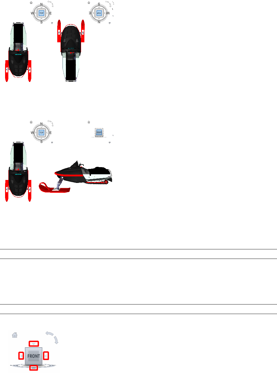
Switch to an Adjacent Face
When the ViewCube tool is active while viewing a model from one of the face views, four orthogonal triangles
are displayed near the ViewCube tool. You use these triangles to switch to one of the adjacent face views.
Front View
You can define the Front view of a model to define the direction of the face views on the ViewCube tool. Along
with the Front view, the up direction of a model is also used to define the direction of the face views on the
ViewCube tool.
NOTE Front view is a global setting and will be the same for viewpoints.
To reorient the current view to a preset orientation
■Click one of the faces, edges, or corners on the ViewCube tool.
To view an adjacent face
NOTE Make sure a face view is current.
■Click one of the triangles displayed near the edges of the ViewCube tool.
To interactively reorient the view
■Click the ViewCube tool, hold down the left mouse button, and drag in the direction that you want to orbit
the model.
156 | Chapter 6 Explore Your Model
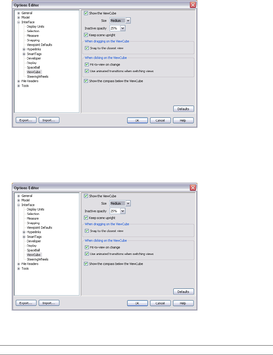
To use animated transitions when reorienting a view to a preset orientation
1Right-click the ViewCube tool, and click ViewCube Options.
2In the Options Editor, the ViewCube page under the Interface node, select Use Animated Transitions When
Switching Views.
3Click OK.
To automatically fit the model after a view orientation
1Right-click the ViewCube tool, and click ViewCube Options.
2In the Options Editor, the ViewCube page under the Interface node, select Fit-to-View on Change.
3Click OK.
To roll a face view
NOTE Make sure a face view is displayed.
■Click one of the roll arrows displayed above and to the right of the ViewCube tool.
ViewCube | 157
The left roll arrow rotates the view 90 degrees counterclockwise; the right roll arrow rotates the view 90
degrees clockwise.
To define the front view
■Right-click the ViewCube tool, and click Set Current View as Front.
To restore the Front view
■Right-click the ViewCube tool, and click Reset Front.
Set the View Projection Mode
The ViewCube tool supports two different view projections: perspective and orthographic. Orthographic projection
is also referred to as parallel projection. Perspective projected views are calculated based on the distance from a
theoretical camera and target point. The shorter the distance between the camera and the target point, the more
distorted the perspective effect appears; greater distances produce less distorted affects on the model. Orthographic
projected views display all the points of a model being projected parallel to the screen.
Orthographic projection mode makes it easier to work with a model due to all the edges of the model appearing
as the same size, regardless of the distance from the camera. Orthographic projection mode though, is not how
you commonly see objects in the real world. Objects in the real world are seen in perspective projection. So when
you want to generate a rendering or hidden line view of a model, using perspective projection will give the model
a more realistic look.
The following illustration shows the same model viewed from the same viewing direction, but with different
view projections.
Perspective
Orthographic
To change the view projection mode
■Right-click the ViewCube tool, and click one of the following options:
■Orthographic
■Perspective
Home View
The Home view is a special view stored with a model that makes it easy to return to a known or familiar view.
You can define any view of the model as the Home view. The saved Home view can be applied to the current
view by clicking the Home button above the ViewCube tool or from the ViewCube menu.
To define the Home view
■Right-click the ViewCube tool, and click Set Current View as Home.
158 | Chapter 6 Explore Your Model

To reorient the model to the Home view
■Click the Home button ( ) located near the ViewCube tool.
Examine Individual Objects with ViewCube
You can lock the ViewCube tool to a set of selected objects. Locking a selection of objects to the ViewCube tool
defines the center of the current view and the distance from center for the view based on the selected objects.
Selecting and deselecting objects after Lock to Selection is turned on has no effect on the center or distance from
the center of the view when a view orientation changes. You cannot zoom to the extents of a model when Lock
to Selection is on, even if the ViewCube tool is set to zoom to extents after each view orientation change.
To lock to the current selection
■Right-click the ViewCube tool, and click Lock to Selection.
If Lock to Selection is checked when a view orientation change occurs, the selected objects are used to calculate
the center of the view and the view zooms to the extents of the selected objects. When cleared, the selected
objects are used to calculate the center of the view and the view zooms to the extents of the model.
To examine an individual object with ViewCube
1In the model, select one or more objects to define the centerpoint of the view.
2Click one of the preset locations on the ViewCube tool, or click and drag the ViewCube tool to reorient the
view of the model.
The ViewCube tool reorients the view of the model based on the centerpoint of the selected objects.
Navigation Aids
SpaceBall
NOTE The term SpaceBall is used as a generic term for all 3D motion controllers from 3Dconnexion™, including the
SpaceBall, SpaceMouse and SpaceTraveler.
A SpaceBall can be used as an alternative to the mouse to move around the Scene Area.
The behavior of the SpaceBall corresponds to the currently selected navigation mode. This enables you to navigate
with the SpaceBall whilst performing other operations with the mouse.
If no mode is selected on the Navigation Mode toolbar or if the selected mode is not a valid mode for the SpaceBall,
then a default navigation mode will be used.
The speed of navigation is sensitive to the amount of force applied to the SpaceBall. You can adjust the SpaceBall
settings by using the Control Panel for the device which is supplied by the SpaceBall manufacturer with the
installation.
The default navigation mode and the speed of translation and rotation can be adjusted in the Options Editor.
Thumbnail Views
Thumbnails are useful to get an overall view of where you are in the whole scene and to quickly move the camera
to a location in a large model.
There are two types of thumbnail views available in Autodesk Navisworks:
■Section thumbnail
■Plan thumbnail
Navigation Aids | 159
The thumbnails show a fixed view of the model. By default, the section thumbnail shows the view from the
front of the model and the plan thumbnail shows a top view of the model.
Thumbnail views are displayed inside the control bars. A triangular marker represents your current viewpoint.
This marker moves as you navigate, showing the direction of your view. The marker may also be dragged by
holding the left mouse button over it and dragging to move the camera in the Scene Area.
NOTE The marker changes to a small dot when the thumbnail view is in the same plane as the camera view.
To use the Plan Thumbnail
1Click View ➤ Control Bars ➤ Plan Thumbnail.
The Plan View control bar opens with the thumbnail view of the model.
2Drag the triangular marker on the thumbnail into a new location. The camera in the Scene Area changes
its position to match the position of the marker in the thumbnail.
Alternatively, navigate to a different location in the Scene Area. The triangular marker in the thumbnail
changes its position to match the camera position in the Scene Area.
3To manipulate a thumbnail view, right-click anywhere in the Plan View control bar. Use the shortcut menu
to adjust the view as desired.
Command entry: CTRL + F9
To use the Section Thumbnail
1Click View ➤ Control Bars ➤ Sectiion Thumbnail.
The Section View control bar opens with the thumbnail view of the model.
2Drag the triangular marker on the thumbnail into a new location. The camera in the Scene Area changes
its position to match the position of the marker in the thumbnail.
Alternatively, navigate to a different location in the Scene Area. The triangular marker in the thumbnail
changes its position to match the camera position in the Scene Area.
3To manipulate a thumbnail view, right-click anywhere in the Section View control bar. Use the shortcut
menu to adjust the view as desired.
Command entry: CTRL + F10
160 | Chapter 6 Explore Your Model
Quick Reference
Right-clicking the Section View or the Plan View control bar opens the shortcut menu with the following options.
DescriptionOption
Enables you to set the thumbnail view to
one of the preset viewpoints. Choose from:
Look From
Top, Bottom, Front, Back, Left, Right, or
Current Viewpoint. Selecting the Current
Viewpoint option sets view in the thumb-
nail to the active navigation viewpoint.
Sets the active navigation viewpoint to the
view in the thumbnail.
Update Current Viewpoint
Opens the Edit Viewpoint dialog box, and
enables you to modify the settings for the
thumbnail viewpoint.
Edit Viewpoint
Instructs Autodesk Navisworks to match
aspect ratio of the thumbnail to that of the
Lock Aspect Ratio
current viewpoint in the Scene Area. The
matching is done even when you resize
the control bar with the thumbnail. This
will usually give gray strips either to the
top and bottom, or to either side of the
thumbnail view.
Redraws the thumbnail based on the cur-
rent setting. Thumbnail drawing uses soft-
Refresh
ware OpenGL and so can take a couple of
seconds for large models.
Opens context-sensitive help.Help
View All
Makes the complete model fit into the Scene Area.
Using this function dollies and pans the camera so that the entire model is shown in the current view, which is
very useful if you get lost inside a model or lose it completely.
Occasionally, you may get a blank view. This is usually because there are items that are very small in comparison
to the main model, or items that are located a long way away from the main model. In these cases, right-click
an item in the Selection Tree and click View Selected to find your way back to the model before trying to figure
out which items are "lost".
To view everything
➤ Click View All on the Navigation Tools toolbar.
Menu: Viewpoint ➤ Navigation Tools ➤ View All
Shortcut menu: Scene ➤ View All
View Selected
Zooms the camera so that the selected items fill the Scene Area.
View All | 161
To view selected items
➤ Click View Selected on the Navigation Tools toolbar.
Menu: Viewpoint ➤ Navigation Tools ➤ View Selected
Shortcut menu: Scene ➤ View Selected
Focus
You can put the Scene View into focus mode until the next click.
When you are in focus mode, clicking on an item swivels the camera so that the point clicked is in the center
of the view. This point becomes the focal point for examine, orbit, and turntable navigation modes.
To focus
➤ Click Focus on the Navigation Tools toolbar.
Menu: Viewpoint ➤ Navigation Tools ➤ Focus
Shortcut menu: Scene ➤ Focus
Hold
When you navigate around a model in Autodesk Navisworks, it is possible to "pick up" or hold selected items
and move around with them in the model.
For example you may be viewing a plan for a factory and would like to see different configurations of machine
layouts.
To hold and release objects
1Select the objects you want to hold either in the Scene Area or in the Selection Tree.
2Click Hold on the Navigation Tools toolbar.
The selected objects are now held and will move with you through the model when you use navigation
modes, such as walk, pan and so on.
3To release the held objects, click Hold on the Navigation Tools toolbar again.
4If you want to reset the objects to their original position, click Edit ➤ Reset All ➤ Reset Transforms.
Menu: Viewpoint ➤ Navigation Tools ➤ Hold
Control the Realism of Your Navigation
Gravity
NOTE This function only works in connection with collision.
Where collision gives you mass, gravity gives you weight. As such, you (as the collision volume) will be pulled
downwards whilst walking through the scene.
NOTE Gravity can only be used in walk navigation mode, and with the Walk tool for SteeringWheels.
This allows you to walk down stairs, for example, or follow terrain.
162 | Chapter 6 Explore Your Model
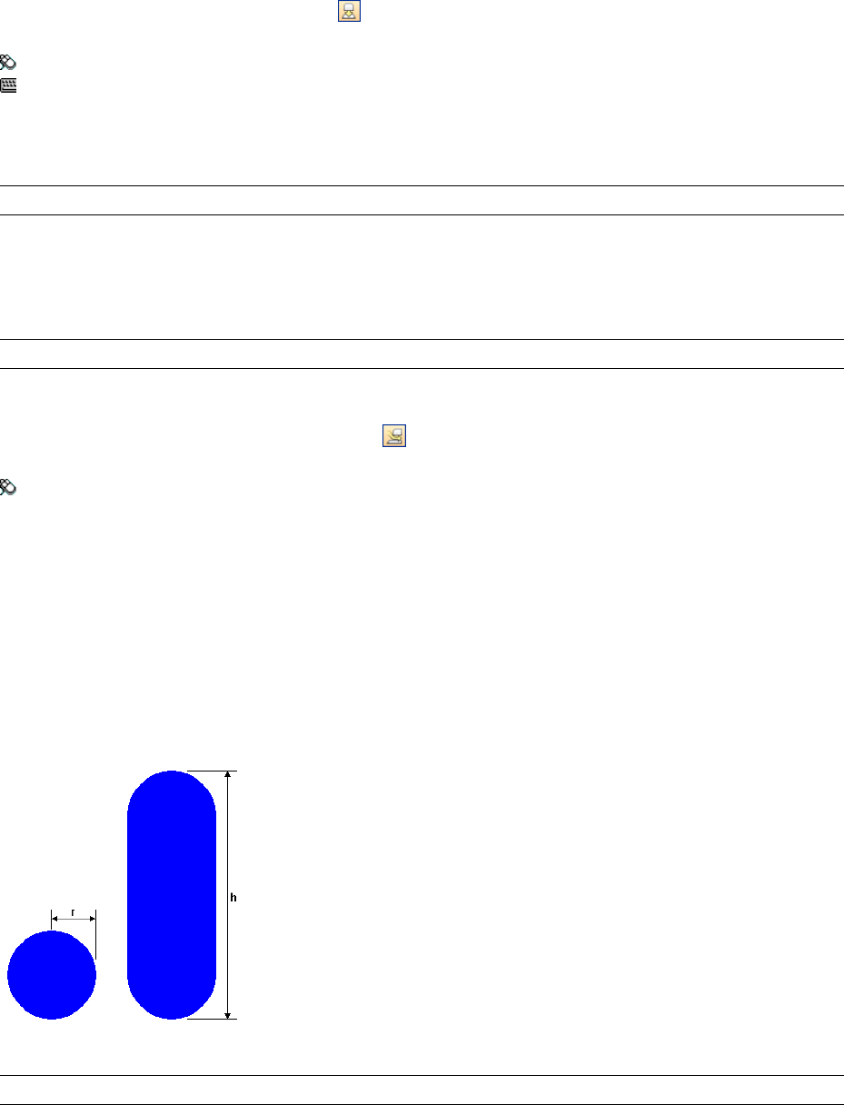
To toggle gravity
➤ In walk navigation mode, click Gravity on the Navigation Tools toolbar.
Menu: Viewpoint ➤ Navigation Tools ➤ Gravity
Command entry: CTRL + G
Crouching
NOTE This function only works in connection with collision.
When walking or flying around the model with collision activated, you may encounter object that are too low
to walk under, a low pipe for example. This function enables you to crouch under any such objects.
With crouching activated, you will automatically crouch under any objects that you cannot walk under at your
specified height, thereby not impeding your navigation around the model.
TIP To temporarily crouch under a low object, hold down the Space bar to allow navigation to proceed.
To toggle crouching
➤ In walk or fly navigation mode, click Crouch on the Navigation Tools toolbar.
Menu: Viewpoint ➤ Navigation Tools ➤ Crouch
Collision
This function defines you as a collision volume - a 3D object that can navigate around and interact with the
model, obeying certain physical rules that confine you within the model itself. In other words, you have a mass
and as such, cannot pass through other objects, points or lines in the scene.
You can walk over, or climb over objects in the scene that are up to half the height of the collision volume, thus
allowing you to walk up stairs, for example.
The collision volume, in its basic form, is a sphere (with radius = r), that can be extruded to give it height (with
height = h >= r). See diagram below:
The dimensions of the collision volume can be customized for the current viewpoint or as a global option.
NOTE Collision can only be used in walk and fly navigation modes, and with the Walk tool for SteeringWheels.
When collision is turned on, rendering prioritization is changed so that objects around the camera or avatar are
displayed with much higher detail than normal. The size of the region of high detail is based on collision volume
radius and speed of movement (needing to see what is about to be walked into).
Crouching | 163
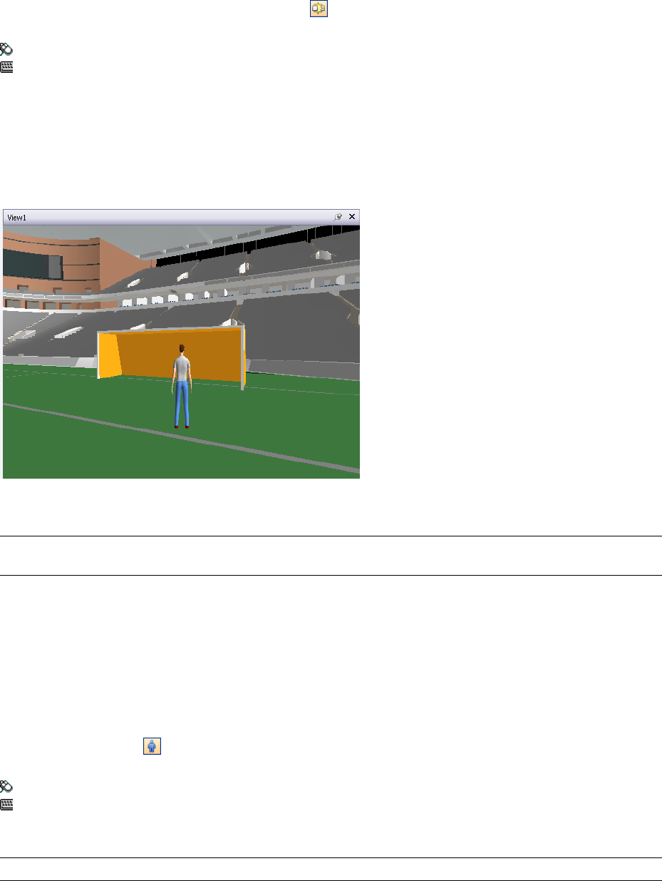
To toggle collision
➤ In walk or fly navigation mode, click Collision on the Navigation Tools toolbar.
Menu: Viewpoint ➤ Navigation Tools ➤ Collision
Command entry: CTRL + D
Third Person View
This function allows you to navigate scene from a third person perspective.
When third person is activated, you will be able to see an avatar which is a representation of yourself within the
3D model. Whilst navigating you will be controlling the avatar's interaction with the current scene.
Using third person in connection with collision and gravity makes this a very powerful function, allowing you
to visualize exactly how a person would interact with the intended design.
NOTE When you use third person with SteeringWheels, the avatar is only shown with the Walk and Pan tools, to
prevent the screen clatter.
You can customize settings, such as avatar selection, dimention, and positioning, for the current viewpoint or
as a global option.
When third person view is turned on, rendering prioritization is changed so that objects around the camera or
avatar are displayed with much higher detail than normal. The size of the region of high detail is based on
collision volume radius, speed of movement (needing to see what is about to be walked into) and the distance
of the camera behind the avatar (in order to see what the avatar is interacting with).
To toggle third person view
➤ Click Third Person on the Navigation Tools toolbar.
Menu: Viewpoint ➤ Navigation Tools ➤ Third Person
Command entry: CTRL + T
To add and use a custom avatar
IMPORTANT Autodesk does not recommend or support usage of the custom avatars.
1Open the file you want to use as your avatar (.dwg, .skp etc.) in Autodesk Navisworks.
2Click File ➤ Save As.
3In the Save As dialog box, select .nwd in the Save as Type box.
164 | Chapter 6 Explore Your Model
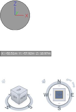
4Browse to the Autodesk Navisworks installation directory, for example: C:\Program
Files\Autodesk\Navisworks Review 2010\avatars\my_new_folder_name.
5Type in the new name for your avatar file, and click Save.
6Restart Autodesk Navisworks, and open any file.
7Click Tools ➤ Global Options.
8In the Options Editor, expand the Interface node, and click the Viewpoint Defaults option.
9Click the Settings button.
10 In the Default Collision dialog box, slect the Enable check box in the Third Person area.
11 Select your avatar in the Avatar drop-down list.
12 Click OK to return to the Options Editor.
13 You can also change the size of the avatar by changing the Height and the Radius values in the Viewer area.
14 Click OK.
15 Restart Autodesk Navisworks.
Head-Up Display
Head-up display elements are on-screen displays that provide information about your location and orientation
in the 3D world.
In Autodesk Navisworks, you can use the following head-up display (HUD) elements:
■XYZ Axes - shows the X, Y, Z orientation of the camera (or the avatar’s eye if the avatar is visible). The XYZ
Axes indicator is located at the bottom-left of the Scene Area.
■Position Readout - shows the absolute X, Y, Z position of the camera (or the avatar's eye position if the avatar
is visible). The Position Readout is located at the bottom-left of the Scene Area.
■ViewCube - provides visual feedback about the current camera viewing angle in relation to the model world.
The ViewCube is located at the top-right of the Scene Area.
To toggle XYZ Axes
➤ Click View ➤ Head-Up Display ➤ XYZ Axes.
To toggle Position Readout
➤ Click View ➤ Head-Up Display ➤ Position Readout.
Head-Up Display | 165
To toggle ViewCube
➤ Click View ➤ Head-Up Display ➤ ViewCube.
166 | Chapter 6 Explore Your Model
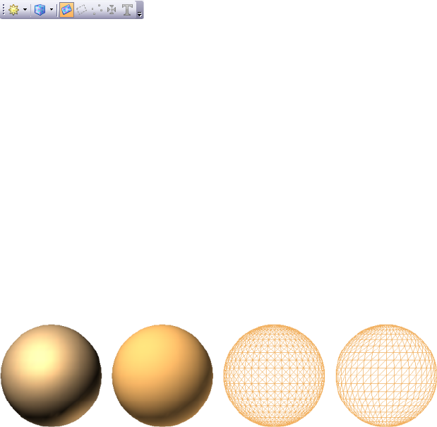
Control Model Appearance
and Render Quality
You can control both the appearance of the model in the Scene Area and the
quality of rendering in real time.
Control Model Appearance
You can use the Rendering Styles toolbar to control how your model
is displayed in the Scene Area.
You have a choice of one of four interactive lighting modes (full
lights, scene lights, head light, or no lights), four rendering modes
(full render, shaded render, wireframe or hidden line) and you can
individually turn each of the five primitive types (surfaces, lines,
points, snap points and text) on and off.
Select Render Mode
Rendering shades the scene's geometry using the lighting you've set
up, and the materials and environmental settings (such as
background) you've applied.
In Autodesk Navisworks, you can use four render modes to control
how the items are rendered in the Scene Area. The spheres below
demonstrate the effect that the render modes have on model
appearance. In order from the left, these are full render, shaded,
wireframe and hidden line.
7
167
Full Render
In full render mode, the model is rendered with smooth shading including any materials that have been applied
using the Presenter tool, or have been brought through from the native CAD file.
NOTE Autodesk Navisworks does not convert all native CAD file's textures. For more details, see “Use File Readers” on
page 91 and “Use File Exporters” on page 106.
To select full render mode
■Click Full Render on the Rendering Style toolbar.
Menu: Viewpoint ➤ Rendering ➤ Full Render
Shaded
In shaded mode, the model is rendered with smooth shading and without textures.
To select shaded mode
■Click Shaded on the Rendering Style toolbar.
Menu: Viewpoint ➤ Rendering ➤ Shaded
Wireframe
In wireframe mode, the model is rendered in wireframe. As Autodesk Navisworks uses triangles to represent
surfaces and solids, all triangle edges are visible in this mode.
To select wireframe mode
■Click Wireframe on the Rendering Style toolbar.
Menu: Viewpoint ➤ Rendering ➤ Wireframe
Hidden Line
In hidden line mode, the model is rendered in wireframe, but only the outline and facet edges of surfaces that
are visible to the camera are displayed.
NOTE Unlike wireframe mode, where surfaces are rendered transparent, hidden line mode renders surfaces opaque.
To select hidden line mode
■Click Hidden Line on the Rendering Style toolbar.
Menu: Viewpoint ➤ Rendering ➤ Hidden Line
Add Lighting
In Autodesk Navisworks, you can use four lighting modes to control how the 3D scene is lit.
The spheres below demonstrate the effect the lighting styles have on them. In order from the left, these are full
lights, scene lights, head light and no lights.
168 | Chapter 7 Control Model Appearance and Render Quality
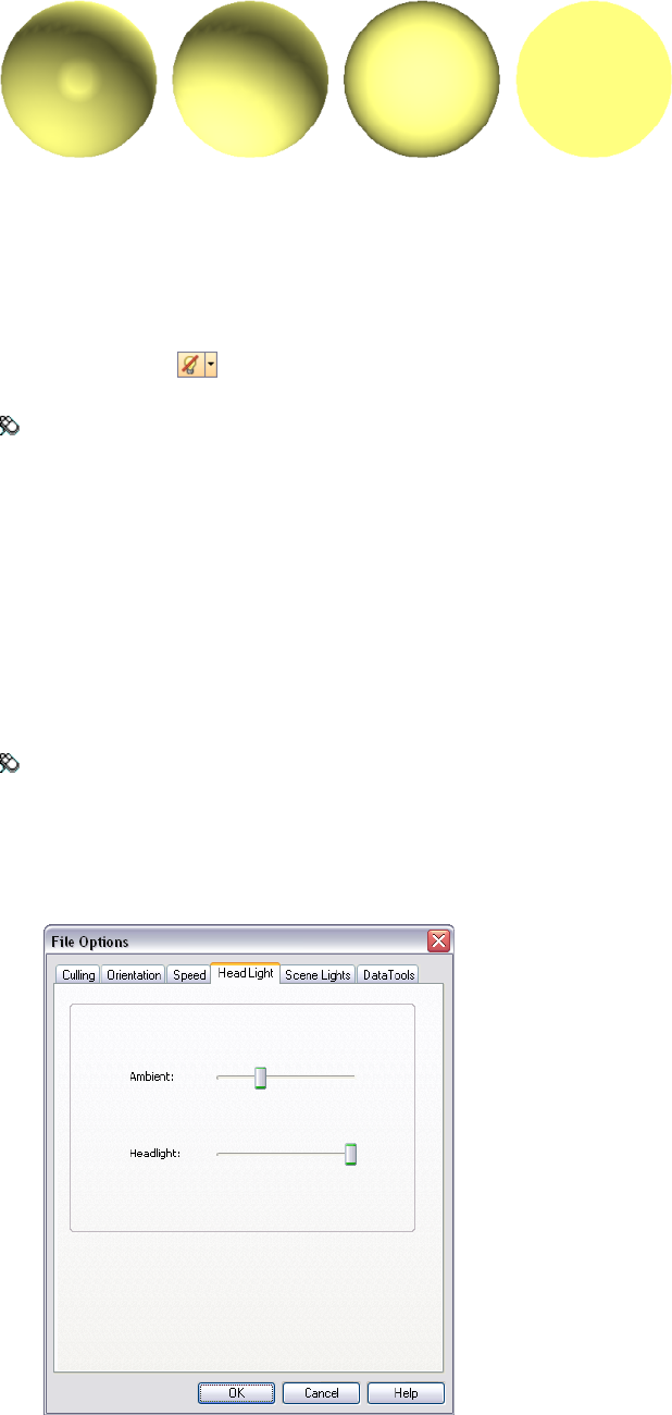
No Lights
This mode switches off all lights. The scene is shaded with flat rendering.
To turn off all lights
■Click No Lights on the Rendering Style toolbar.
Menu: Viewpoint ➤ Lighting ➤ No Lights
Head Light
This mode uses a single directional light located at the camera that always points in the same direction as the
camera.
You can customize the head light properties in the File Options dialog box.
To use head light mode
■Click Head Light on the Rendering Style toolbar.
Menu: Viewpoint ➤ Lighting ➤ Head Light
To adjust head light intensity
1Click Tools ➤ File Options.
2In the File Options dialog box, click the Headlight tab.
3Move the Ambient slider to adjust the brightness of the scene, and the Headlight slider to adjust the brightness
of the directional light.
Add Lighting | 169
TIP Turning on head light mode before following this procedure lets you instantly see the effect your changes
have on the scene rendering.
4Click OK.
Scene Lights
This mode uses the lights that have been brought through from the native CAD file. If no lights are available,
two default opposing lights are used instead.
You can customize the intensity of scene lights in the File Options dialog box.
To use lights defined with the model
■Click Scene Lights on the Rendering Style toolbar.
Menu: Viewpoint ➤ Lighting ➤ Scene Lights
To adjust scene lights intensity
1Click Tools ➤ File Options.
2In the File Options dialog box, click the Scene Lights tab.
3Move the Ambient slider to adjust the brightness of the scene.
TIP Turning on scene lights mode before following this procedure lets you instantly see the effect your changes
have on the scene rendering.
4Click OK.
Full Lights
This mode uses lights that have been defined with the Presenter tool.
To use lights defined with the Presenter tool
■Click Full Lights on the Rendering Style toolbar.
Menu: Viewpoint ➤ Lighting ➤ Full Lights
Select Background Effect
In Autodesk Navisworks, you can choose a background effect to use in the Scene Area.
Currently, the following options are available:
■Plain - the background of the 3D scene is filled with the selected color. This is the default background style.
170 | Chapter 7 Control Model Appearance and Render Quality
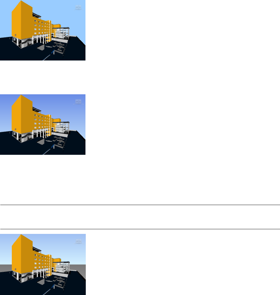
Plain background
■Graduated - the background of the 3D scene is filled with a smooth gradient between the two selected colors.
Graduated background
■Horizon - the background of the 3D scene is split across the horizontal plane giving the effect of a sky and
the ground. The resulting artificial horizon gives you an indication of your orientation in the 3D world. By
default, the artificial horizon respects the world up vector as set in File Options ➤ Orientation.
NOTE The artificial horizon is a background effect, and does not include a physical ground plane. So, for example,
if you navigate ‘under the ground’ and look up, you will not see the back of a ground plane, instead you will see
the model from beneath, and a background filled with the sky color.
Horizon background
To set a plain background
1Click Tools ➤ Background.
2In the Background Settings dialog box, select Plain in the Mode drop-down list.
3Select the required color from the Color palette.
4Review the new background effect in the preview box, and click OK.
To set a graduated background
1Click Tools ➤ Background.
2In the Background Settings dialog box, select Graduated in the Mode drop-down list.
3Select the first color from the Top Color palette.
Select Background Effect | 171
4Select the second color from the Bottom Color palette.
5Review the new background effect in the preview box, and click OK.
To set an artificial horizon background
1Click Tools ➤ Background.
2In the Background Settings dialog box, select Horizon in the Mode drop-down list.
3To set a graduated sky color, use the Sky Color and Horizon Sky Color palettes.
4To set a graduated ground color, use the Horizon Ground Color and Ground Color palettes.
5Review the new background effect in the preview box, and click OK.
Adjust Displaying of Primitives
You can enable and disable the drawing of surfaces, lines, points, snap points, and 3D text in the Scene Area.
Points are ‘real’ points in the model, whereas snap points mark locations on other primitives, for example the
center of a circle, and are useful for snapping to when measuring.
Surfaces
Surfaces are the triangles that make up the 2D and 3D items in the scene. You can toggle the rendering of surfaces
in the model.
To toggle the rendering of surfaces
■Click Surfaces on the Rendering Style toolbar.
Menu: Viewpoint ➤ Display ➤ Surfaces
Lines
You can toggle the rendering of lines in the model. You can also change the width of the drawn lines by using
the Options Editor.
To toggle the rendering of lines
■Click Lines on the Rendering Style toolbar.
Menu: Viewpoint ➤ Display ➤ Lines
To change the line width
1Click Tools ➤ Global Options.
2In the Options Editor, expand the Interface node, and click the Display options.
3On the Display page, Primitives area, enter a number between 1 and 9 in the Line Size box.
This sets the width in pixels for lines drawn in the Scene Area.
4Click OK.
172 | Chapter 7 Control Model Appearance and Render Quality
Points
Points are real points in the model, for example, the points in a point cloud in a laser scan file. You can toggle
the rendering of points in the model. You can also change the size of drawn points by using the Options Editor.
To toggle the rendering of points
■Click Points on the Rendering Style toolbar.
Menu: Viewpoint ➤ Display ➤ Points
To change the size of points
1Click Tools ➤ Global Options.
2In the Options Editor, expand the Interface node, and click the Display option.
3On the Display page, Primitives area, enter a number between 1 and 9 in the Point Size box.
This sets the size in pixels for points drawn in the Scene Area.
4Click OK.
Snap Points
Snap points are implied points in the model, for example, the center point of a sphere or end points of a pipe.
You can toggle the rendering of snap point in the model. You can also change the size of the drawn snap points
by using the Options Editor.
To toggle the rendering of snap points
■Click Snap Points on the Rendering Style toolbar.
To change the size of snap points
1Click Tools ➤ Global Options.
2In the Options Editor, expand the Interface node, and click the Display option.
3On the Display page, Primitives area, enter a number between 1 and 9 in the Snap Size box.
This sets the size in pixels of snap points drawn in the Scene Area.
4Click OK.
Text
You can toggle the rendering of 3D text in the model.
To toggle the rendering of 3D text
■Click Text on the Rendering Style toolbar.
Menu: Viewpoint ➤ Display ➤ Text
Adjust Displaying of Primitives | 173
Control Render Quality
Use Culling
Culling lets you navigate and manipulate large and complex scenes at interactive rates by intelligently hiding
less-important objects as you work.
In Autodesk Navisworks, you can use the following methods of culling objects:
■Area - the objects’ size in pixels determines whether the objects are rendered or not. By default, any objects
smaller than 1x1 pixels in size are discarded.
■Backface - by default, only the front face of every polygon is drawn in Autodesk Navisworks. Sometimes,
during the conversion process the front and back face of polygons get mixed, in which case, you need to
adjust the Backface option.
■Near and Far Clipping Planes (frustum culling) - objects closer to the camera than the near clipping plane or
beyond the far clipping plane are not drawn. You can let Autodesk Navisworks automatically constrain the
location of the clipping planes, or you can constrain their location manually.
To set area culling
1Click Tools ➤ File Options.
2In the File Options dialog box, Culling tab, select the Enable check box in the Area section.
3Enter a value for the screen area in pixels below which geometry objects are culled. For example, setting
this value to 100 pixels means that any object within the model that would be drawn less than 10x10 pixels
in size are discarded.
4Click OK.
To turn on backface culling for all objects
1Click Tools ➤ File Options.
2In the File Options dialog box, Culling tab, select On in the Backface area.
3Click OK.
To turn off backface culling for all objects
1Click Tools ➤ File Options.
2In the File Options dialog box, Culling tab, select Off in the Backface area.
3Click OK.
To turn on backface culling only for solid objects
1Click Tools ➤ File Options.
2In the File Options dialog box, Culling tab, select Solid in the Backface area.
3Click OK.
To constrain the position of the clipping planes automatically
1Click Tools ➤ File Options.
2In the File Options dialog box, click the Culling tab.
3Select Automatic for the Near clipping plane.
4Select Automatic for the Far clipping plane.
174 | Chapter 7 Control Model Appearance and Render Quality
5Click OK.
Autodesk Navisworks automatically controls the position of near and far clipping planes to give you the
best view of the model.
To constrain the position of the clipping planes manually
1Click Tools ➤ File Options.
2In the File Options dialog box, click the Culling tab.
3Select Constrained for the Near clipping plane, and enter the desired value in the Distance box.
4Select Constrained for the Far clipping plane, and enter the desired value in the Distance box.
5Click OK.
Autodesk Navisworks uses the provided values unless doing so affects the system performance (for example,
makes the whole model invisible), in which case it adjusts the position of the clipping planes as necessary.
To fix the position of the clipping planes
1Click Tools ➤ File Options.
2In the File Options dialog box, click the Culling tab.
3Select Fixed for the Near clipping plane, and enter the desired value in the Distance box.
4Select Fixed for the Far clipping plane, and enter the desired value in the Distance box.
5Click OK.
IMPORTANT Autodesk Navisworks uses the provided values even if doing so affects the system performance (for
example, makes the whole model invisible).
Make Objects Required
Although Autodesk Navisworks intelligently prioritizes objects for culling in the scene, sometimes it drops out
geometry that needs to remain visible while navigating.
You can make sure the objects are always rendered during interactive navigation by making them required.
To make objects required
1Select geometry items that you want to remain visible during navigation in the Selection Tree.
2Click Required on the Selection Tools toolbar.
In the Selection Tree, the object appear red when required.
TIP Clicking Required again makes the selected objects unrequired.
Menu: Edit ➤ Required
Command entry: CTRL + R
Shortcut menu: Required
To make all objects unrequired
■Click Edit ➤ Reset All ➤ Unrequire All.
Shortcut menu: Scene ➤ Reset All ➤ Unrequire All
Use Culling | 175
Control Rendering of Objects
Adjust Scene Rendering During Navigation
Your models can range in size from small models to complex supermodels. As you navigate a scene in real time,
Autodesk Navisworks automatically calculates which items to render first, based on the size of items, distance
from the camera, and the specified frame rate. This customizable frame rate is guaranteed by default, but can be
turned off, if necessary. Items that Autodesk Navisworks does not have time to render are dropped out. These
dropped items are rendered when navigation stops.
The amount of drop-out depends on several factors, such as your hardware performance (graphics card and
driver), the size of the Scene Area, and the size of the model. When working with truly large supermodels in
Autodesk Navisworks, you will require a sufficient amount of RAM to load and review the data.
Autodesk Navisworks employs JetStream technology which optimizes the usage of the available RAM. Before
running out of memory, Autodesk Navisworks pages unnecessary data to the hard disk, freeing up space for
loading to continue. JetStream technology also enables you to start navigating the supermodel, before it has
been completely loaded into memory. Autodesk Navisworks is large address aware, and utilizes any additional
memory assignment following the 3GB switch available on Windows XP systems.
TIP You can reduce the amount of drop-out during navigation by reducing frame rate, or switching off the Guarantee
Frame Rate option.
To set the target frame rate
1Click Tools ➤ File Options.
2In the File Options dialog box, Speed tab, select the number of frames per second to be applied to the
rendered display of the model.
3Click OK.
To set the level of detail
1Click Tools ➤ Global Options.
2In the Options Editor, expand the Interface node, and click the Display option.
3On the Display page, Detail area, select the Guarantee Frame Rate check box to maintain the target frame
rate during navigation. If this check box is clear, the complete model is rendered during navigation, no
matter how long it takes.
4Select the Fill in Detail check box to render a complete model when navigation stops. If this check box is
clear, the items dropped out during navigation are not filled in when it stops.
5Select the Batch Fill check box if you want the dropped out items to be rendered in chunks rather than
gradually.
NOTE This check box is clear by default, as gradual rendering gives better results for most video cards.
6Click OK.
To render transparent items
NOTE If your video card supports hardware accelerated OpenGL, you can turn on the rendering of transparent items
during interactive navigation. By default, transparent items are only drawn when interaction has ceased to prevent
problems with display performance.
1Click Tools ➤ Global Options.
2In the Options Editor, expand the Interface node, and click the Display option.
3On the Display page, Transparency area, select the Interactive Transparency check box.
176 | Chapter 7 Control Model Appearance and Render Quality

4Click OK.
To render parametric primitives
NOTE Modifying this option requires a restart of Autodesk Navisworks to take effect.
1Click Tools ➤ Global Options.
2In the Options Editor, expand the Interface node, and click the Display option.
3On the Display page, Primitives area, select the Enable Parametric Primitives check box. The level of detail
changes during navigation depending on the distance from the camera.
If you want to use the default representations of primitives, clear this check box. The level of detail stays
the same during navigation.
Click OK.
Accelerate Display Performance
If your video card supports OpenGL, you can improve the graphical performance by turning on hardware
acceleration and occlusion culling.
Using the hardware acceleration usually gives you better and faster rendering. However, some graphics cards
may not function well in this mode in which case switching this option off is recommended.
Occlusion culling can significantly improve performance in situations when much of the model is not visible.
For example, when you walk down the corridor of a building, the walls occlude most geometry outside the
corridor. Other rooms are only visible through doorways or windows. Turning on occlusion culling dramatically
reduces the rendering load in such cases.
To use hardware acceleration
NOTE If your video card does not support OpenGL hardware acceleration, this option is not available.
1Click Tools ➤ Global Options.
2In the Options Editor, expand the Interface node, and click the Display option.
3On the Display page, Acceleration area, select the Hardware Acceleration check box. This allows Autodesk
Navisworks to utilize any available OpenGL hardware acceleration on your video card.
NOTE If your video card drivers do not function well with Autodesk Navisworks, clear this check box.
4Click OK.
To use occlusion culling
1Click Tools ➤ Global Options.
2In the Options Editor, expand the Interface node, and click the Display option.
3On the Display page, Acceleration area, select the Occlusion Culling check box.
4Click OK.
NOTE Occlusion culling can only be used on a machine with an OpenGL 1.5 compliant graphics card.
Adjust Presenter Materials
You can adjust the appearance of Presenter materials in the Scene Area to get optimum performance from your
graphics card when navigating around heavily textured scenes.
Adjust Presenter Materials | 177
See also:
■“Presenter Page” on page 306
Stereo Rendering
Stereoscopic viewing in Autodesk Navisworks allows the viewing of the 3D model through stereo-enabled
hardware, including active and passive stereo viewing glasses in conjunction with both CRT screens and dedicated
projectors.
IMPORTANT Using stereo rendering requires the host computer have an OpenGL graphics card with stereo support.
Additionally, some drivers require stereo to be explicitly enabled in the driver and may require lower color or resolution
settings before the stereo rendering becomes available.
When the video output is in stereo mode, the view looks blurred without the correct glasses being worn. If the
camera is in orthographic mode, it needs to be set to perspective for the effect to work correctly.
NOTE As the view for each eye has to be rendered separately it is not possible to support incremental filling in of detail
in stereo mode. The detail appears when rendering is complete. Progress can be seen using the bar in the status area,
and it is still possible to interrupt and start interacting again at any time.
In focal point-based navigation modes (such as examine, orbit, and turntable) the model is positioned so that
parts closer than the focal point appear in front of the screen, with the rest behind. In other navigation modes
(such as walk and fly), the focal point is set so that any avatar will be level with the screen. Objects between you
and the avatar will appear in front of the screen. You can adjust the out of screen effect in the Stereo Options
dialog box.
To enable stereo rendering
■Click View ➤ Stereo.
NOTE This option is only available if you have the required hardware, and the correct driver and display settings.
To adjust the stereo effects
1Click View ➤ Stereo Options.
2In the Stereo Options dialog box, move the Magnitude slider to vary the strength of the effect.
3To adjust the out of screen effect, select the Enable check box, and then move the slider to control how
much of the scene appears out of the screen during navigation.
4If you need to swap the left and right eyes over, select the Swap Eyes check box. This can be useful when
moving from CRT to a large screen projector and back.
5Click OK.
178 | Chapter 7 Control Model Appearance and Render Quality

Review Your Model
Select Objects
With large models it is potentially a very time-consuming process
to select items of interest. Autodesk Navisworks makes this a much
simpler task by providing a range of functions for quickly selecting
geometry both interactively and by searching the model manually
and automatically.
Interactive Geometry Selection
In Autodesk Navisworks, there is a concept of an active selection
set (the currently selected items, or the current selection) and saved
selections sets. Selecting and finding items makes them part of the
current selection, so you can hide them or override their colors. At
any time, the current selection can be saved and named for retrieval
in later sessions.
Selecting items makes them part of the current selection, so you
can hide them or override their colors.
You can use several methods to interactively select items into the
current selection. You can use the tabs in the Selection Tree, select
items directly in the Scene Area with select and select box modes,
and you can select other items with similar properties to an existing
selection using the selection commands.
NOTE Right-clicking any item in the Selection Tree or Scene Area opens
a shortcut menu.
You can also customize the level at which you select items (selection
resolution), and modify the highlighting method for the items
selected in the Scene Area.
Selection Tree Window
The Selection Tree is a dockable window, which displays a variety
of hierarchical views of the structure of the model, as defined by
the CAD application in which the model was created.
8
179
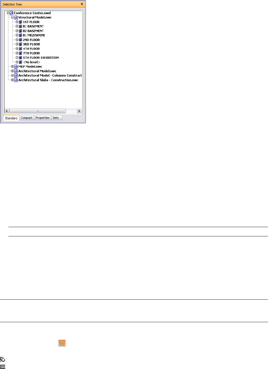
Autodesk Navisworks uses this hierarchical structure to identify object-specific paths (from the file name down
to a particular object).
By default there are four tabs:
■Standard. Displays the default tree hierarchy, including all instancing. The contents of this tab can be sorted
alphabetically.
■Compact. Displays a simplified version of the hierarchy on the Standard tab, omitting various items. You
can customize the level of complexity of this tree in the Options Editor.
■Properties. Displays the hierarchy based on the items' properties. This enables simple manual searching of
the model by item property.
■Sets. Displays a list of selection and search sets. If no selection and search sets have been created, this tab is
not shown.
NOTE The list of the items on the Sets tab is exactly the same as the list on the Selection Sets dockable window.
■Sets. Displays a list of selection and search sets. If no selection and search sets have been created, this tab is
not shown.
Additional customized Selection Tree tabs can be added by using the Autodesk Navisworks API.
Naming of items reflects the names from the original CAD application, wherever possible. There are different
tree icons representing the types of geometry making up the structure of the model. Each of these item types
can be marked as hidden (gray), unhidden (dark blue) or required (red).
NOTE If a group is marked as hidden or required, then all instances of that group are marked as hidden or required.
If you want to operate on a single occurrence of an item, then you should mark the instanced group (the level above,
or the “parent”, in the hierarchy) hidden or required.
To toggle the Selection Tree
■Click Selection Tree on the Workspace toolbar.
Menu: View ➤ Control Bars ➤ Selection Tree
Command entry: CTRL + F12
To use the Selection Tree to select objects
1Open the Selection Tree, and click the Standard tab.
180 | Chapter 8 Review Your Model
2Click an object in the Selection tree to select the corresponding geometry in the Scene Area.
NOTE When you select an item in the tree, individual geometry or a group of geometry is selected in the Scene
Area depending on chosen selection resolution.
3To select several items at the same time, use the SHIFT and CTRL keys. CTRL allows multiple selection item
by item, and SHIFT allows multiple selection between the first and last items selected.
4To remove selection from an object in the Selection Tree press ESC.
To change the sort order on the Standard tab
1Open the Selection Tree, and click the Standard tab.
2Right-click any item in the tree and click Scene ➤ Sort. The contents of the tab is now ordered alphabetically.
NOTE You cannot use the Undo option to reverse this action.
To customize the contents of the Compact tab
1Click Tools ➤ Global Options.
2In the Options Editor, expand the Interface node, and click the Selection option.
3On the Selection page, select the required level of detail in the Compact Tree box. Choose from the following
options:
■Models - the tree is restricted to displaying model files only.
■Layers - the tree can be expanded down to the layer level.
■Objects - can be expanded down to the objects level, but without the levels of instancing shown on the
Standard tab.
4Click OK.
Quick Reference
DescriptionIcon
A model, such as a drawing file or design
file.
A layer or level.
A group, such as a block definition from
AutoCAD or cell definition from MicroSta-
tion.
An instanced group, such as an inserted
block from AutoCAD or cell from MicroSta-
tion. If in the imported file the instance
was unnamed, Autodesk Navisworks names
the instance to match its child's name.
An item of geometry, such as a polygon.
An instanced item of geometry, such as an
instance from 3D Studio.
Interactive Geometry Selection | 181
DescriptionIcon
A composite object. A single CAD object
that is represented in Autodesk Navisworks
by a group of geometry items.
Saved selection set.
Saved search set.
Selection Modes
There are two selection modes available from the Selection Tools toolbar to control how you select geometry.
As standard, selection modes are mutually exclusive to navigation modes, and SteeringWheels, so that when
you are selecting you cannot navigate and vice versa.
NOTE When using a SpaceBall in conjunction with the standard mouse control, the SpaceBall can be configured for
navigation and the mouse for selecting. See “SpaceBall” on page 159 for more information.
Selecting geometry in the Scene Area automatically selects the corresponding objects in the Selection Tree.
Holding the SHIFT key whilst selecting items in the Scene Area cycles through the selection resolution, allowing
you to get more specific with your selections.
You can use the Options Editor to customize the distance from an item you have to be for it to be selected (pick
radius). This is useful when you select lines and points.
Select Mode
In select mode, you can click an item in the Scene Area to select it. Once a single item is selected, its properties
are shown in the Properties window.
Select Box Mode
In select box mode, you can select multiple items in the model by dragging a rectangular box around the area
you want to make your current selection.
To use select mode to select geometry
1Click on the Selection Tools toolbar.
2Click an item in the Scene Area to select it.
3To select multiple geometry, press and hold down the CTRL key while clicking items in the scene.
4To remove items from the current selection, hold down the CTRL key while clicking them again. Alternatively,
press the ESC key to to remove all items from the current selection.
Menu: Edit ➤ Select ➤ Select
Command entry: CTRL + 1
To use select box mode to select geometry
1Click on the Selection Tools toolbar.
2Drag a box with the left mouse button over the Scene Area to select all items within the box.
TIP Holding down the SHIFT key while dragging the box selects all items within and that intersect the box.
3To select multiple geometry, press and hold down the CTRL key while dragging a box in the scene.
182 | Chapter 8 Review Your Model

4To remove items from the current selection, press the ESC key.
To set the pick radius
1Click Tools ➤ Global Options.
2In the Options Editor, expand the Interface node, and click the Selection option.
3On the Selection page, enter the radius in pixels that an item has to be within in order to be selected. The
valid values are between 1 and 9.
4Click OK.
Selection Commands
Selection commands enable you to quickly alter the current selection using logic. You can select multiple items
based on the currently selected items' properties, or quickly invert the set, select everything or nothing.
To select items with selection commands
1Click Edit ➤ Select.
2Click the required selection command.
Quick Reference
The selection commands are as follows:
■Select All. Selects all items contained within the model.
■Select None. Deselects everything in the model.
■Invert Selection. Currently selected items become deselected and vice versa.
■Selection Sets. Provides you with options to save and recall selection and search sets.
■Select Multiple Instances. Selects all instances (sometimes called insertions) of the currently selected geometry
group that occur in the model.
■Select Same Name. Selects all items in the model that have the same name as the currently selected item.
■Select Same Type. Selects all items in the model that have the same type as the currently selected item.
■Select Same <Property>. Selects all items with the same property as the currently selected item. This property
can be any searchable property currently attached to the item, for example material or hyperlink.
NOTE Using the Select Same <Property> command works by comparing items' properties. If you have multiple
items selected when you perform a selection command of same name or type and so on, all the types, names and
properties of the items in the current selection are compared with all items’ properties in the scene. The items with
properties matching any properties of the currently selected items are selected.
Set Selection Resolution
When you click an item in the Scene View, Autodesk Navisworks doesn't know what level of item to start selecting
at - do you mean the whole model, or the layer, or the instance, or group, or just the geometry? The default
selection resolution specifies a starting point for the object path in the Selection Tree so that Autodesk Navisworks
can locate and select the item.
You can customize the default selection resolution in the Options Editor. Or you can use a quicker way, by
right-clicking any item in the Selection Tree and clicking Set Selection Resolution to X, where X is one of the
available selection resolutions.
Set Selection Resolution | 183
If you find you have selected the wrong level of item, you can interactively cycle through the selection resolution,
without having to go to the Options Editor or the Selection Tree. You can do this by holding down the SHIFT
key when clicking an item. This selects an item one level more specific each time you click the item until the
resolution gets to "geometry", at which point it reverts back to "model". Clicking on a different item reverts the
selection resolution back to default (as set in the Options Editor).
To set the default selection resolution
1Click Tools ➤ Global Options.
2In the Options Editor, expand the Interface node, and click the Selection option.
3On the Selection page, select the required starting point for the object path in the Resolution box.
4Click OK.
Quick Reference
The available options for selection resolution are as follows:
■Model. Makes the object path start at the model node; as a result, all objects in the model are selected.
■Layer. Makes the object path start at the layer node; as a result all objects within a layer are selected.
■First Object. Makes the object path start at the highest level of objects below the layer node, if applicable.
■Last Object. Makes the object path start at the lowest level of objects in the Selection Tree. Autodesk Navisworks
looks for composite objects first, and if none are found, the geometry level is used instead. This is the default
option.
■Last Unique. Makes the object path start at the first unique level of objects (not multiple-instanced) in the
Selection Tree.
■Geometry. Makes the object path start from the geometry level in the Selection Tree.
Set Highlighting Method
You can use the Options Editor to customize color and method of highlighting geometry selected in the Scene
Area.
There are three types of highlighting:
■Shaded
■Wireframe
184 | Chapter 8 Review Your Model
■Tinted
To toggle highlighting of selected objects
1Click Tools ➤ Global Options.
2In the Options Editor, expand the Interface node, and click the Selection option.
3On the Selection page, Highlight area, select the Enabled check box, if you want the selected items to be
highlighed in the Scene Area. Clear this check box, if you don’t want any highlighting.
4Click OK.
To customize the way objects are highlighted
1Click Tools ➤ Global Options.
2In the Options Editor, expand the Interface node, and click the Selection option.
3Make sure the Enabled check box is selected.
4Use the Method drop-down list to select the type of highlighting you want (Shaded, Wireframe or Tinted).
5Click the Color palette to select the highlight color.
6If you selected Tinted in the Method box, use the slider to adjust the Tint Level.
7Click OK.
Hide Objects
Autodesk Navisworks provides tools that can be used to hide and display objects or groups of objects. Hidden
objects are not drawn in the Scene Area.
Hide Selected Objects
You can hide the objects in the current selection so that they are not drawn in the Scene Area. This is useful
when you want to remove specific parts of the model. For example, when you walk down the corridow of
building, you may want to hide a wall that occlude your view of the next room.
Hide Unselected Objects
You can hide all items except those currently selected so that they are not drawn in the Scene Area. This is useful
when you only want to see specific parts of the model.
Hide Objects | 185
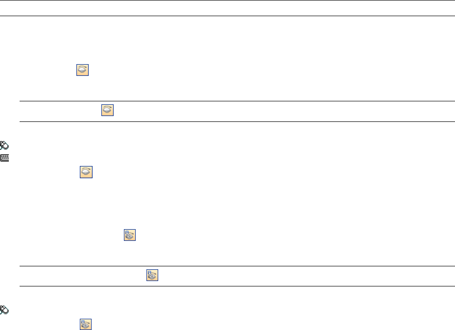
NOTE In the Selection Tree, the items appear gray when marked as hidden.
To make selected objects hidden
1In the Scene Area, select all items you want to hide.
2Click Hidden on the Selection Tools toolbar.
The selected objects are now invisible.
TIP Clicking Hidden again displays the invisible objects.
Menu: Edit ➤ Hidden
Command entry: CTRL + H
Shortcut menu: Hidden
To make unselected items hidden
1In the Scene Area, select all items you want to review.
2Click Unselected Hidden on the Selection Tools toolbar.
Only the selected geometry remains visible.
TIP Clicking Unselected Hidden again displays the invisible objects.
Menu: Edit ➤ Unselected Hidden
Shortcut menu: Unselected Hidden
To reveal all hidden objects
■Click Edit ➤ Reset All ➤ Unhide All.
Shortcut menu: Scene ➤ Reset All ➤ Unhide All
Find Objects
Finding is a quick and powerful way of selecting items into the current selection based on items' properties.
You can use the Find Items window to set up and run a search, which can then be saved and re-run in later
sessions or shared with other users.
You can also use Quick Find, which is a faster way of searching. It simply looks for the specified string in all
property names and values attached to items in the scene.
Find Items Window
The Find Items window is a floating window that enables you to search for items having a common property or
combination of properties.
186 | Chapter 8 Review Your Model
The left pane contains the Find Selection Tree with several tabs at the bottom, and enables you to select the level
of item to start searching at; this can be a file, a layer, an instance, a selection set, and so on.
The tabs are the same as on the Selection Tree window:
■Standard. Displays the default tree hierarchy, including all instancing.
■Compact. Displays a simplified version of the tree hierarchy.
■Properties. Displays the hierarchy based on the items' properties.
■Sets. Displays a list of selection and search sets. If no selection and search sets have been created, this tab is
not shown.
NOTE The list of the items on the Sets tab is exactly the same as the list on the Selection Sets window.
The right pane enables you to add the search statements (or conditions). And the buttons enable you to find
the qualifying items in your scene.
Defining Search Statements
A search statement contains a property (a combination of category name and property name), a condition
operator, and a value to be tested against the selected property. For example, you can search for Material that
Contains Chrome.
By default, all items that match your statement criteria are found (for example, all objects that use chrome
material). You can also negate a statement, in which case, all items that do not match your statement criteria
are found instead (for example, all objects that do not use chrome material).
Each category and property name has two parts - a user string which is shown in the Autodesk Navisworks
interface, and an internal string which is not shown, and is mainly used by the API. By default, the items are
matched on both parts, but you can instruct Autodesk Navisworks to match only on one part, if necessary. For
example, you can ignore user names in searches, and match items on their internal names only. This can be
useful when you plan on sharing your saved searches with other users who may be running localized versions
of Autodesk Navisworks.
The statements that do not use default settings are identified by this icon: . It appears, for example, when you
negate a statement, or choose to ignore the upper and lower cases in property values.
Combining Search Statements
Search statements are read from left to right. By default, all statements are ANDed. For example: "A AND B", "A
AND B AND C".
You can arrange your statements into groups. For example, "(A AND B) OR (C AND D)". ORed statements are
identified by a plus icon: . All statements preceding the ORed statement are ANDed, and all statements following
the ORed statement are ANDed. So to create two groups in the previous example, you need to mark statement
C as ORed.
There are no parentheses to visually show you the way the statements are read. Simple statements such as "A
OR B" will not be misinterpreted. For complex searches, the order and groupings of the statements is more
Find Items Window | 187
important, especially if you choose to negate some statements. For example, "(A AND B) OR (C AND NOT D)".
When search conditions are evaluated, NOT is applied before AND, and AND is applied before OR.
To toggle the Find Items window
■Click Find Items on the Workspace toolbar.
Menu: View ➤ Control Bars ➤ Find Items
Command entry: SHIFT + F3
To find objects
1Open the Find Items window.
2On the Find Selection Tree, click the items where you want to start searching from. For example, if you
want to search the whole model, click the Standard tab, press and hold CTRL, and click all files that comprise
the model. If you want to limit your search to a selection set, click the Sets tab, and click the required set.
3Define a search statement:
aClick the Category column, and select the property category name from the drop-down list, for example,
‘Item’.
bIn the Property column, select the property name from the drop-down list, for example, ‘Material’.
cIn the Condition column, select the condition operator, for example, ‘Contains’.
dIn the Value column, type in the property value to search for, for example, ‘Chrome’.
eIf you want to make your search statement case-insensitive, right-click it, and click Ignore String Value
Case.
4Define more search statements, if required.
By default, all statements are ANDed. This means that they all need to be true for an item to be selected.
You can make a statement use OR logic, by right-clicking it and clicking Or Condition. If you are using two
statements, and marked the second one as ORed, this means that an item will be selected if either of these
statements is true.
5Click the Find All button. The search results are highlighted in the Scene Area and the Selection Tree.
To save current search
1Open the Selection Sets window.
2Right-click anywhere in the window, and click Add Current Search.
3Type a name for your search set, and press ENTER.
Menu: Edit ➤ Select ➤ Selection Sets ➤ Add Current Search
To export a current search
1Click File ➤ Export ➤ Current Search XML.
2In the Export dialog box, browse to the desired folder.
3Enter a name for your file, and click Save.
To import a saved search
1Click File ➤ Import Search XML.
2In the Import dialog box, brose to the folder containing the file with the save search criteria, and select it.
3Click Open.
188 | Chapter 8 Review Your Model
Quick Reference
Search Options
Category Selects the category name. Only the categories that are contained in the scene are available in the
drop-down list.
Property Selects the property name. Only the properties in the scene within the category chosen are available
in the drop-down list.
Condition Selects a condition operator for your search. You can use the following operators depending on the
property you are searching for:
■=. Equals; can be used to evaluate any type of property. To qualify for the search, a property must match the
specified value exactly.
■Not Equals . Can be used to evaluate any type of property.
■< - Greater Than; can be used to evalueate numerical property types only.
■<= - Greater Than or Equals; can be used to evaluate numerical property types only.
■> - Less Than; can be used to evaluate numerical property types only.
■>= - Less Than or Equals; can be used to evaluate numerical property types only.
■Contains. To qualify for the search, a property must contain the specified value (for example, series of letters
within a string).
■Wildcard. Enables you to use wildcards in the Value field to allow matching against any character (?) or an
arbitrary sequence of characters (*).
■Defined. To qualify for the search, a property must have some value defined.
■Undefined. To qualify for the search, a property must not have any defined value.
Value You can either type in a value freely in this box, or choose a pre-defined value from the drop-down list
which shows all values in the scene available within the category and property you defined earlier. If you used
Wildcard as the condition operator, you can type a value with wildcards. To match one single unspecified
character use the symbol ? (question mark). To match any number of unspecified characters, use the symbol *
(asterisk). For example, "b??k" will match "brick" and "block"; "b*k" will match "bench kiosk", "brick", and "block";
and "*b*k*" will match "bench kiosk", "brick" and "block" and also "Coarse bricks" and "block 2".
This box is not available if you used Defined or Undefined as the condition operator.
Match Case Select this check box to respect the upper and lower case letters of the values tested during the
search. This affects all statements in your search. It’s also possible to set case sensitivity for individual search
statements by using the Search Conditions shortcut menu.
Prune Below Result Select this check box if you want to stop searching a branch of the Fnd Selection Tree as
soon as the first qualifying object is found.
Search Specifies the type of the search to run. Choose from:
■Default. Searches all items selected in the Find Selection Tree, along with the paths below these items, for
qualifying objects.
■Below Selected Paths. Only searches below the items selected in the Find Selection Tree for qualifying objects.
■Selected Paths Only. Only searches within the items selected in the Find Selection Tree for qualifying items.
Find Selection Tree Shortcut Menu
Select Changes the selection you made in the Scene Area to the current selection in the Find Selection Tree.
Import Current Selection Changes the selection in the Find Selection Tree to your current selection the Scene
Area.
Find Items Window | 189
Search Conditions Shortcut Menu
Ignore String Value Case Makes the selected search statement case-insensitive (for example, both ‘Chrome’ and
‘chrome’ materials are treated as qualifying).
Ignore Category User Name Instructs Autodesk Navisworks to use internal category names and ignore the user
category names for the selected search statement.
Ignore Category Internal Name Instructs Autodesk Navisworks to use user category names and ignore the
internal category names for the selected search statement.
Ignore Property User Name Instructs Autodesk Navisworks to use internal property names and ignore the user
property names for the selected search statement.
Ignore Property Internal Name Instructs Autodesk Navisworks to use user property names and ignore the
internal category names for the selected search statement.
Or Condition Chooses OR condition for the selected search statement.
Negate Condition Negates the selected search statement, so that all items that do not match the statement
criteria are found.
Delete Condition Deletes the selected search statement.
Delete All Conditions Deletes all search statements.
Buttons
Find First Finds the first qualifying item, and selects it in the Scene Area and the Selection Tree.
Find Next Finds the next qualifying item, and selects it in the Scene Area and the Selection Tree.
Find All Finds all qualifying items, and highlights them in the Scene Area and the Selection Tree.
TIP Click Unselected Hidden on the Selection Tools toolbar to display only the search results in the Scene Area.
Quick Find
To locate and select the objects quickly, use the Quick Find feature.
To quickly find items
1Click Edit ➤ Quick Find.
2In the Quick Find dialog box, type in the text to search for in all item’s properties. This can be a word or a
few words. The search is not case-sensitive.
3Click Find Next. Autodesk Navisworks finds and selects the first item in the Selection Tree that matches the
entered text, selects it in the Scene Area, and stops the search.
4To repeat the search, click Edit ➤ Quick Find Next. If there are any more items that match the entered text,
Autodesk Navisworks selects the next one in the Selection Tree, selects it in the Scene Area, and stops the
search.
Command entry: To use Quick Find: CTRL + F. To Find Next: F3
Create and Use Sets of Objects
In Autodesk Navisworks, you can create and use sets of like objects. This makes it easier to review and analyze
your model.
Selection Sets
Selection sets are static groups of items, and are useful for saving a group of objects that you want to regularly
perform some action on, such as hiding them, changing transparency and so on. They simply store a group of
190 | Chapter 8 Review Your Model
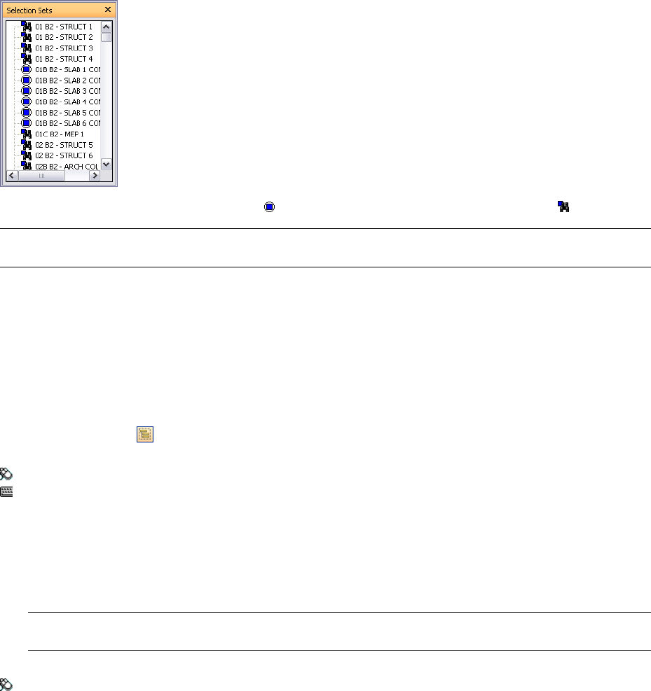
items for later retrieval. There is no intelligence behind this set - if the model changes at all, the same items are
selected (assuming they are still available in the model) when recalling the selection set.
Search Sets
Search sets are dynamic groups of items, and work in a similar way to selection sets, except that they save search
criteria instead of the results of a selection, so that you can re-run the search at a later date as and when the
model changes. Search sets are much more powerful and can save you time, especially if your CAD files are
continuing to be updated and revised. It is also possible to export search sets, and share them with other users.
Selection Sets Window
The Selection Sets is a dockable window, which displays both selection sets and search sets available in your
Navisworks file.
The selection sets are identified by this icon: , and the search sets are identified by this icon: .
NOTE The list of the items on the Selection Sets window is exactly the same as the list on the Sets tab of the Selection
Tree.
You can customize the names of selection and search sets, and add comments. You can also show the selection
and search sets as links in the Scene Area. These links are created automatically by Navisworks. Clicking on a
link restores the geometry within the corresponding selection or search set to the active selection, and highlights
it in the Scene Area and on the Selection Tree.
You can use the Selection Set shortcut menu to create and manage selection and search sets in the Navisworks
file.
To toggle the Selection Sets window
■Click Selection Sets on the Workspace toolbar.
Menu: View ➤ Control Bars ➤ Selection Sets
Command entry: SHIFT + F2
To use the Selection Sets window to select objects
1Open the Selection Sets window.
2Click the desired set in the list. The geometry in this set is selected in the Scene Area and in the Selection
Tree.
NOTE If you clicked on a search set, the search is performed on the current model, looking for all geometry that
meets the search criteria, including any additional geometry that could have been added to the file.
Menu: Edit ➤ Select ➤ Selection Sets ➤ <Saved Set>
Selection Sets Window | 191

To change the sort order on the Selection Sets window
1Open the Selection Sets window.
2Right-click any item in the list, and click Sort. The contents of the tab is now ordered alphabetically.
Quick Reference
The Selection Set shortcut menu has the following options:
■New Folder. Creates a folder above the selected item.
■Add Current Selection. Saves the current selection as a new selection set in the list. This set contains all
currently selected geometry.
■Add Current Search. Saves the current search as a search set in the list. This set contains the current search
criteria.
■Make Visible. If the geometry in the selected search or selection set is hidden, you can use this option to
make it visible.
■Add Copy. Creates a copy of the search or selection set highlighted in the list. The copy has the same name
as the original set, but with a (X) suffix, where X is the next available number.
■Add Comment. Opens the Add Comment dialog box for the selected item.
■Edit Comment. Opens the Edit Comment dialog box for the selected item.
■Update. Updates the selected search set with the current search criteria, or updates the selected selection set
with the currently selected geometry.
■Delete. Deletes the selected search or selection set.
■Rename. Renames the selected search or selection set. By default, new selection sets aare named Selection
SetX, and search sets are named Search SetX, where X is the next available number added to the list.
■Sort. Orders the contents of the Search Sets window alphabetically.
■Help. Launches the online Help system and displays the topic for selection and search sets.
Create and Manage Selection and Search Sets
You can add, move and delete selection and search sets, and organize them into folders.
Search and selection sets can be updated. You can modify your current selection in the Scene Area, or the current
search criteria, and change the contents of your set to reflect this.
You can also export search sets and reuse them. For example, if models contain the same components, such as
steel structure, ventilation ductwork, and so on, you can define generic search sets, export them as an XML file,
and share with other users.
To save a selection set
1Open the Selection Sets window.
2Select all the items that you want to save in the Scene Area or on the Selection Tree.
3Right-click the Selection Sets window, and click Add Current Selection.
4Type a name for your selection set, and press ENTER.
Menu: Edit ➤ Select ➤ Selection Sets ➤ Add Current Selection
To save a search set
1Open the Find Items window, and set up the desired search criteria.
192 | Chapter 8 Review Your Model
2Click the Find All button to run the search. All items that satisfy your criteria are now selected in the Scene
Area and the Selection Tree.
3Open the Selection Sets window, right-click, and click Add Current Search.
4Type a name for your search set, and press ENTER
Menu: Edit ➤ Select ➤ Selection Sets ➤ Add Current Search
To rename a search or selection set
1Open the Selection Sets window.
2Right-click the desired search or selection set, and click Rename.
3Type a new name for your set, and press ENTER.
Command entry: F2
To delete a search or selection set
1Open the Selection Sets window.
2Right-click the search or selection set you want to remove, and click Delete.
To organize selection and search sets into folders
1Open the Selection Sets window.
2Right-click, and click New Folder on the shortcut menu. The folder is added to the list.
If, when you right-click, the item selected is a folder, then the new folder is created inside it, otherwise it
is added above the selected item. You can have as many folders as you like.
3Type a name for your folder, and press ENTER.
TIP Use names that can help you to identify your sets in future.
4Click the set that you want to add to your new folder. Hold down the left mouse button and drag the mouse
to the folder name. Release the mouse button to drop the set into the folder.
TIP You can also drag the folders themselves, together with their contents.
To update a selection set
1Select the desired geometry in the Scene Area or on the Selection Tree.
2Open the Selection Sets window.
3Right-click the selection set you want to modify, and click Update.
To update a search set
1Open the Find Items window, and run a new search.
2Open the Selection Sets window.
3Right-click the search set you want to modify, and click Update.
To export search sets
1Click File ➤ Export ➤ Search Sets XML.
2In the Export dialog box, browse to the desired folder.
3Enter a name for your file, and click Save.
Create and Manage Selection and Search Sets | 193

To import search sets
1Click File ➤ Import ➤ Search Sets XML.
2In the Import dialog box, brose to the folder containing the file with the search sets, and select it.
3Click Open.
Compare Objects
You can look for differences between any two selected items in the scene. These items can be files, layers, instances,
groups, or just geometry.
You can also use this feature to investigate the differences between two versions of the same model.
During the comparison, Autodesk Navisworks starts at the level of each item, and recursively travels down each
path on the Selection Tree, comparing each item it comes across in terms of the criteria you requested.
When the comparison is finished, the results can be highlighted in the Scene Area. The following color-coding
is used by default:
■White. Matching items.
■Red. Items with differences.
■Yellow. The first item contains things not found in the second item.
■Cyan. The second item contains things not found in the first item.
You can save the comparison results as selection sets with automatic comments describing the found differences
in more detail.
To compare two versions of the model
1Open the first file that you want to compare in Autodesk Navisworks.
2Click File ➤ Append, locate the second file, and click Open.
3Hold down CTRL key, and select both files.
4Click Tools ➤ Compare.
5In the Compare dialog box, the Find Differences In area, select the check boxes for all required options.
NOTE The Overridden Material and Overridden Transform check boxes relate to changing the color and
transparency in Autodesk Navisworks, and changing a file's origin, scale or rotation since loading into Autodesk
Navisworks, respectively. These check boxes are clear by default. All the other criteria relate to properties of items
from the original CAD model.
6In the Results area, select the check boxes to control how the comparison results are displayed:
■Save as Selection Sets. Saves the items that you are comparing as a selection set. You can then use this
set for later comparisons between the same items.
■Save Each Difference As Set. Saves the resulting differences found in the comparison between the two
items as a selection set for later analysis. The selection set will also have a comment attached detailing
the differences in more depth.
■Remove Old Results.Removes any selection sets resulting from a previous comparison, in order to reduce
confusion when looking at the results.
■Hide Matches. Hides all items that turn out to be the same in the comparison, when the comparison
finishes.
■Highlight Results. Highlights each resulting difference with a color override, when the comparison
finishes. You can reset the colors back by clicking Edit ➤ Reset All ➤ Colors and Transparencies.
194 | Chapter 8 Review Your Model
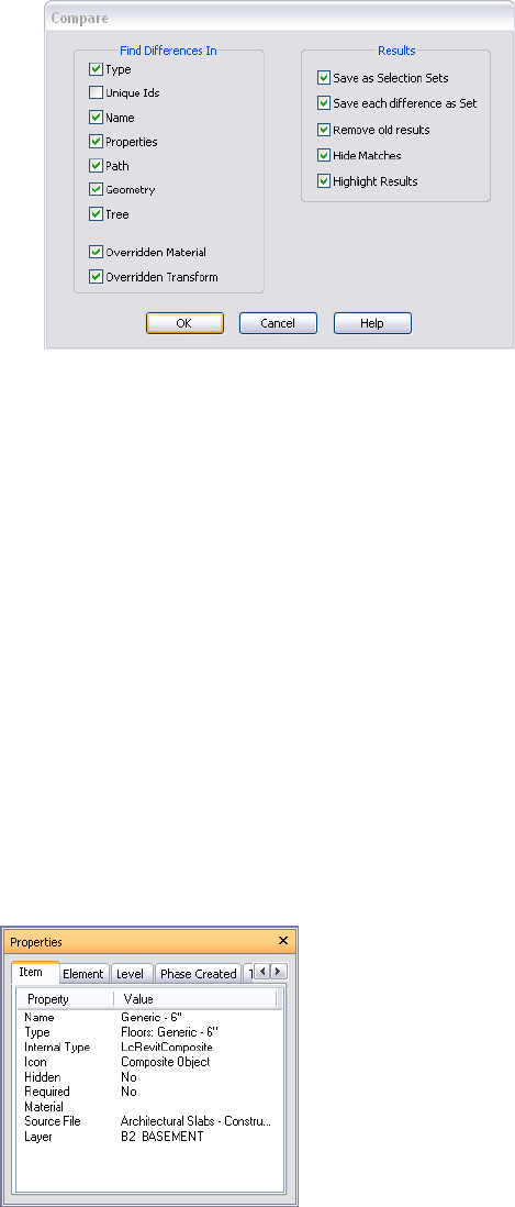
7Click OK.
To compare two items in the model
1Select exactly two items in the scene.
2Click Tools ➤ Compare.
3Use the Compare dialog box to set up the comparison search.
4Click OK.
Object Properties
Autodesk Navisworks supports the conversion of object properties for many file formats. For more details on
supported/unsupported entities, see “Use File Readers” on page 91.
Properties Window
Once brought into Autodesk Navisworks, the object properties can be examined in the Properties window.
This is a floating window, which has a dedicated tab for each property category associated with the currently
selected object.
Internal file properties, such as transform and geometry properties, are not shown by default. The Options Editor
enables you to switch this on.
You can use the Properties shortcut menu to create and manage custom object properties, and links.
You can also bring more object properties into Autodesk Navisworks from external databases, and show on the
database-specific tabs in the Properties window.
Object Properties | 195
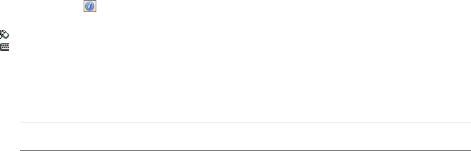
To toggle the Properties window
■Click Properties on the Workspace toolbar.
Menu: View ➤ Control Bars ➤ Properties
Command entry: SHIFT + F7
To examine object’s properties
1Select the object of interest in the Selection Tree, or in the Scene Area.
2Open the Properties window, and use the tabs to navigate between the available property categories.
NOTE If more than one object is selected, the Properties window only shows the number of selected items, and
doesn’t show any property information.
To add tabs with internal properties to the Properties window
1Click Tools ➤ Global Options.
2In the Options Editor, expand the Interface node, and click the Developer option.
3On the Developer page, select the Show Internal Properties check box.
4Click OK.
Quick Reference
The Properties shortcut menu has the following options:
■Copy Value Copies the selected value.
■Copy Row Copies the selected row.
■Copy All Copies all on the tab.
■Edit Hyperlinks. Opens the Edit Hyperlinks dialog box.
■Add New User Data Tab. Adds a custom property tab to the Properties window.
■Delete New User Data Tab. Deletes the currently selected custom property tab from the Properties window.
■Insert New Property. Adds a custom property.
■Delete Property. Deletes the currently selected custom property.
■Edit Property Value. Enables you to edit the value for all property types except Boolean.
■Set Value. Enables you to edit the value for Boolean property type.
■Rename Property. Renames the currently selected custom property.
■Rename Tab. Renames the currently selected custom property tab on the Properties window.
Custom Properties
Property information brought into Autodesk Navisworks from a CAD application cannot be edited, with the
exception of color, transparency and links. You can, however, add your own custom information to any item
in the model scene.
To add a custom property tab
1Open the Properties window.
196 | Chapter 8 Review Your Model

2Select the object of interest in the Scene Area or on the Selection Tree.
3Right-click the Properties window, and click Add New User Data Tab. The new property category is added
for the currently selected object. By default, the tab is called User Data.
To rename a custom property tab
1Open the Properties window.
2Click the custom tab you want to rename.
3Right-click the properties area, and click Rename Tab.
4Enter a new name for the tab in the box provided.
5Click OK.
To delete a custom property tab
1Open the Properties window.
2Click the custom tab you want to delete.
3Right-click the properties area, and click Delete User Data Tab.
To add a custom property
1Open the Properties window.
2Click the custom tab where you want to add a property.
3Right-click the properties area, click Insert New Property, and click the property type you want to add.
Choose:
■String - if the property value is a string
■Boolean - if the property value is Yes or No
■Float - if the property value is a decimal value, for example: 1.234
■Integer - if the property value is a positive whole number (1, 2, 3,...), a negative whole number (-1, -2,
-3,...), or zero (0)
4Enter the name for the property in the Property box, and press ENTER.
5Double-click the Value box, enter the value associated with your property into the box provided, and click
OK.
NOTE For Boolean properties, double-clicking the Value box toggles between Yes and No values.
To edit a custom property
1Open the Properties window.
2Click the custom tab where the property you want to edit is located.
3To rename the property, right-click it, click Rename Property, and enter the new name in the box provided.
Click OK.
4To edit the property value, right-click it, click Edit Property Value, and enter the new value in the box
provided. Click OK.
NOTE For Boolean properties, click Set Value on the shortcut menu, and choose Yes or No.
To delete a custom property
1Open the Properties window.
Custom Properties | 197
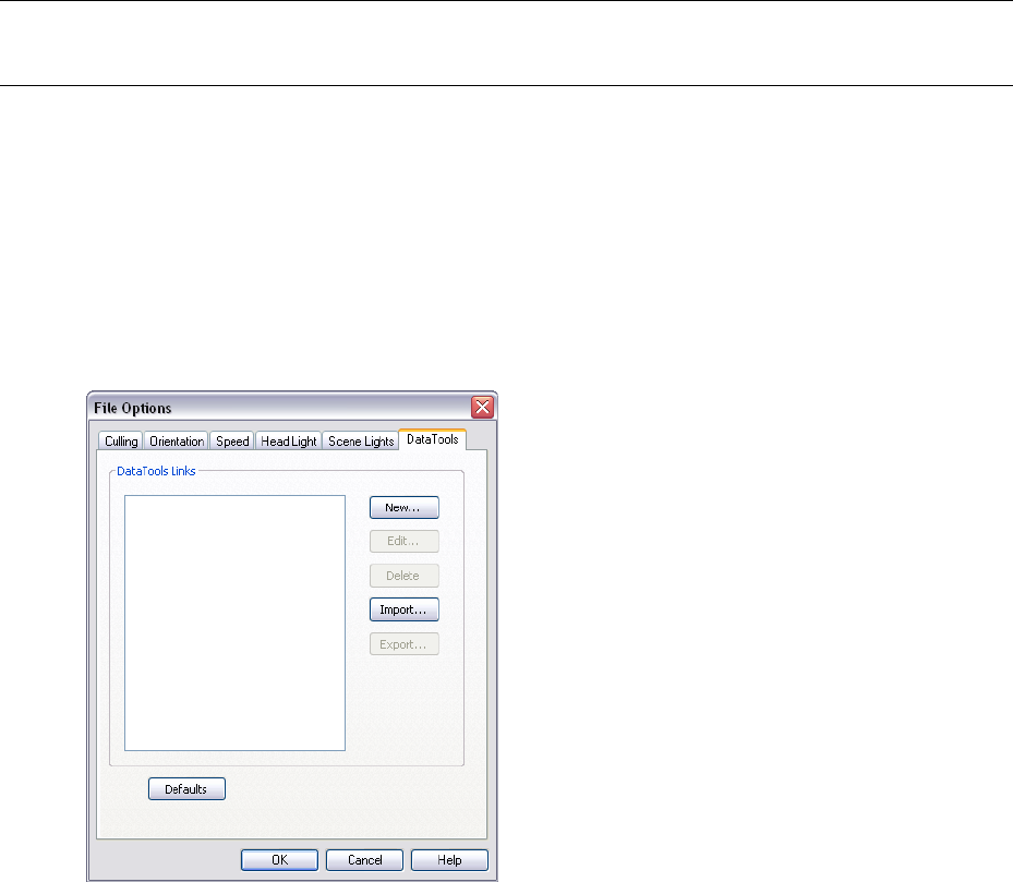
2Click the custom tab where the property you want to delete is located.
3Right-click the property, and click Delete Property.
External Database Links
Databases are commonly used to store large amount of data, such as equipment specifications, catalogue data,
and maintenance manuals.
You can connect to external databases directly from your Navisworks files, and create links between objects in
the scene and fields in the database tables to bring through extra properties.
Any database with a suitable ODBC driver is supported, but the properties for the objects in the model must
include unique identifiers to the data in the database. For example, for AutoCAD-based files, entity handles can
be used.
You can have as many database links as you want, but they all should have unique names. To use a database
link, you need to activate it first.
Database links can be saved inside Navisworks files (NWF and NWD). You can also save database links globally,
making them persistent across all Autodesk Navisworks sessions. The global connection information is saved on
the local machine. If the associated database is available on loading the NWF/NWD file, the link automatically
establishes itself when an object is selected. On selecting an object, if the database is available, and there is data
associated with the object, Autodesk Navisworks adds an appropriate database tab to the Properties window, and
displays the appropriate data.
NOTE To be able to display the data, you need to configure the connection details. You may need a database
administrator to do this, as a knowldege of the database being connected to is required. You can use Navisworks tags
in connection strings and SQL statements.
Data linked from a database connection can be extracted and embedded as static data within the published NWD
file. It also can also be included in object searches, and can be used with the Clash Detective tool as part of the
clash criteria.
You can export database links, and share them with other users.
To add a database link
1If you want to add a database link to the Navisworks file:
aClick Tools ➤ File Options.
bIn the File Options dialog box, DataTools tab, click the New button.
198 | Chapter 8 Review Your Model
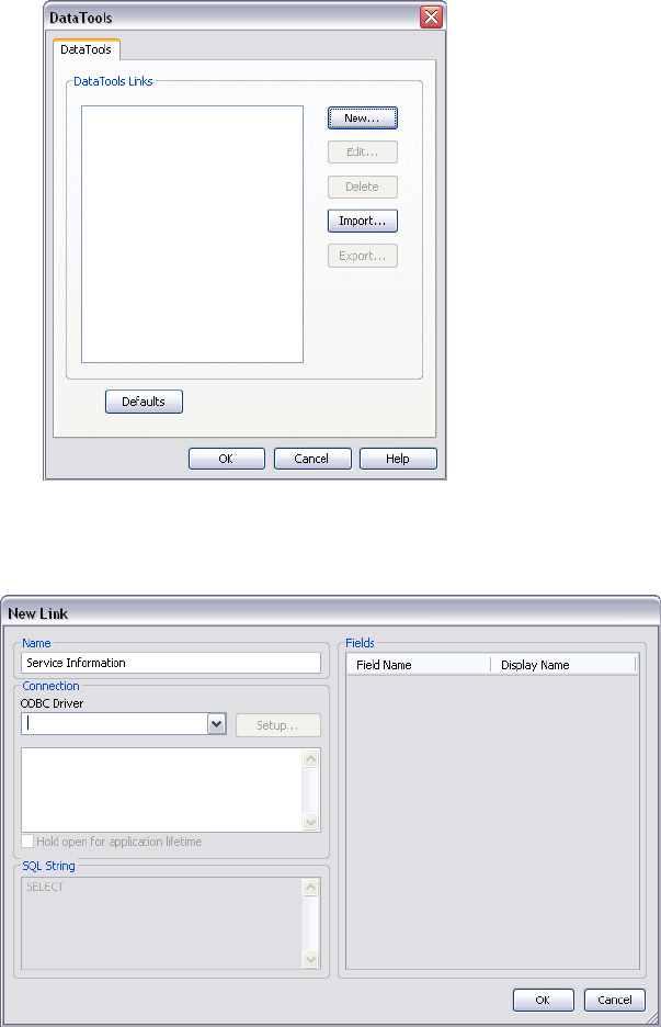
2If you want to add a database link globally:
aClick Tools ➤ DataTools.
bIn the DataTools dialog box, click the New button.
3In the New Link dialog box, enter a Name for the new link, for example, 'Service Information'. This is the
name of the tab that will appear on the Properties window.
You are now ready to configure the database link.
4Click OK to save the link and return to the previous dialog box.
To configure a database link
1To configure a file-based database link:
aClick Tools ➤ File Options.
bIn the File Options dialog box, DataTools tab, click the link you want to configure in the DataTools
Links area, and click the Edit button.
External Database Links | 199
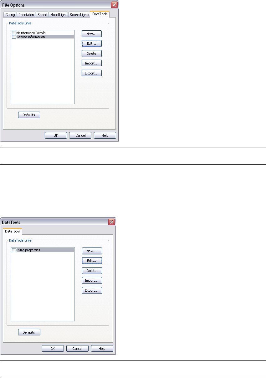
NOTE If you haven't added any links yet, click the New button, and follow the procedure for adding database
links first.
2To configure a global database link:
aClick Tools ➤ DataTools
bIn the DataTools dialog box, click the link you want to configure in the DataTools Links area, and click
the Edit button.
NOTE If you haven't added any links yet, click the New button, and follow the procedure for adding database
links first.
3Configure the ODBC Driver:
aIn the Edit Link dialog box, select the appropriate ODBC Driver to define the type of the database to
link to, for example 'Microsoft Access Driver (*.mdb).
200 | Chapter 8 Review Your Model
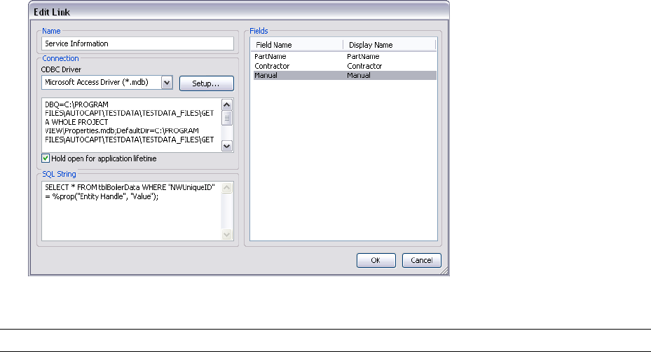
bClick the Setup button. The driver wizard opens, and guides you through the setup options. If you
have difficulties setting up your connection details, contact your database administrator. When you
finish, the box underneath will show the connection string. This string can be modified, if necessary.
For example, if you want to select a database with a certain name (say, test.mdb) that is always next
to the model file (as in the resultant NWD/NWF not the original), type in:
DBQ=%pushpath(%poppath(%currentpath),"test.mdb"); DRIVER={Microsoft Access Driver (*.mdb)};
If you want to select a database with the same name as the original model file (say, AutoPlant), type
in: DBQ=%join(%removeext(%removepath(%sourcepath)),".mdb"); DRIVER={Microsoft Access Driver
(*.mdb)};
4Select the Hold Open for Application Lifetime check box, if you want to keep the database link open until
you exit Autodesk Navisworks.
5Specify which table in the database to query:
In the SQL String field, click after SELECT, and enter the selection statement, for example: SELECT * FROM
tblBoilerData WHERE "NWUniqueID" = %prop("Entity Handle", "Value");
This statement instructs Autodesk Navisworks to select all columns from the tblBoilerData table, whilst
requiring that the column called NWUniqueID matches a category/property pair called Entity Handle/Value.
6Select which columns you want to display as link categories on the Properties window:
aDouble-click the Fields Name field, and type the exact name of the database column, for example:
“Part-time”.
bPress ENTER.
The Display Name is automatically completed for you, but you can click it, and enter a different name,
if you want. The text entered here is the category name shown on the link tab of the Properties window.
cRepeat the above process to list all required categories in the Fields area of the dialog box.
7Click OK.
IMPORTANT The model is not linked to the external data source until you have activated the database link.
To delete a database link
1To delete a file-based database link:
aClick Tools ➤ File Options.
bIn the File Options dialog box, DataTools tab, click the link you want to remove in the DataTools Links
area, and click the Delete button.
External Database Links | 201
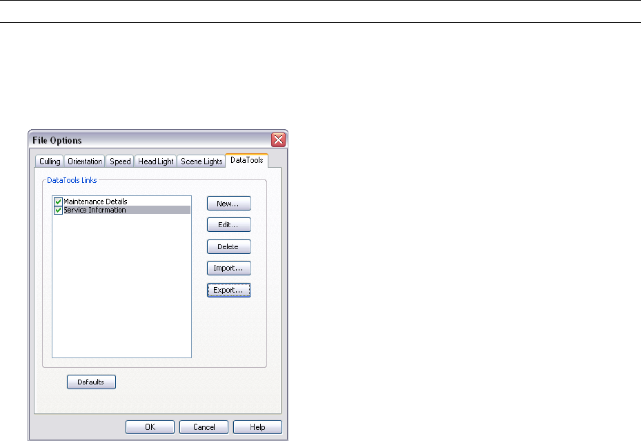
2To delete a global database link:
➤ Click Tools ➤ DataTools.
3In the DataTools dialog box, click the link you want to remove in the DataTools Links area, and click the
Delete button.
4Click OK.
To activate a database link
1To activate a file-based database link:
aClick Tools ➤ File Options.
bIn the File Options dialog box, DataTools tab, select the check boxes for all links you want to activate
in the DataTools Links area.
2To activate a global database link:
aClick Tools ➤ DataTools.
bIn the DataTools dialog box, select the check boxes for all links you want to activate in the DataTools
Links area.
3Click OK.
IMPORTANT You cannot activate links with insufficient or invalid configuration information.
To export a database link
1Click Tools ➤ File Options.
2In the File Options dialog box, DataTools tab, click the link you want to export in the DataTools Links area,
and click the Export button.
3In the Save As dialog box, browse to the desired folder, and enter a name for the datatools file. You can also
select the name of an existing datatools file to overwrite it with your modified configuration.
202 | Chapter 8 Review Your Model
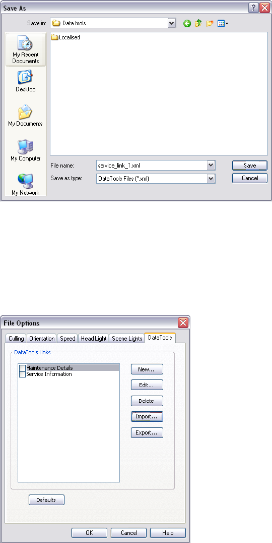
4Click Save.
5Click OK to close the File Options dialog box.
To import a database link
1Click Tools ➤ File Options.
2In the File Options dialog box, DataTools tab, click the Import button.
3In the Open dialog box, browse to the folder containing the required datatools file, select it, and click Open.
External Database Links | 203
4Click OK to close the File Options dialog box.
Quick Reference
You can use the following Navisworks tags with SQL queries:
Property Tags
%prop("category","property") Property of the currently selected object. Category is the name of the tab in the
property windows (for example, Item or Entity Handle) and property is the name of the property in that tab (for
example, Value or Layer).
%intprop("category","property") Property of the currently selected object. This is the same as the previous tag
except instead of using the publicly visible category and property name use the internal Navisworks names. The
benefit of using internal names is that they are not language dependent. This is advanced tag suitable for users
familiar with the Autodesk Navisworks API.
File and Path Tags
%sourcepath This tag represents the full path and filename that the currently selected object comes from. Even
when a collection of model files have been combined into a single NWD file this tag still remembers the path
and filename of the original model file.
%currentpath This tag represents the full path and filename of the currently loaded model. If you currently
have an NWF or NWD loaded that contains many other models it will just return the path and filename of the
top level NWF/NWD.
File and Path Manipulation Tags
%removeext("text") If the provided text includes a filename with an extension, this tag removes the extension.
%removepath("text") If the provided text includes a path and filename, this tag remove the paths and just
returns the filename.
%poppath("text") If the provided text includes a path, this tag removes the top level. If it the text also includes
a filename, it counts as the top level and is removed. For example, %poppath(“c:\temp”) becomes c:\ and
%popath(c:\temp\readme.txt”) becomes c:\temp.
%pushpath("text1","text2") If text1 is a path and text2 is a file or folder name, then text2 is added onto the
path in text1. For example, %pushpath(“c:\test”,”model.nwd”) becomes c:\test\model.nwd.
String Manipulation Tags
%join("text","text") This tag simply joins the two pieces of text together. For example, %join(“c:\”,”model.nwd”)
returns c:\model.nwd.
204 | Chapter 8 Review Your Model
Query Examples
The examples below illustrate how tags could be used with SQL queries.
■Selecting all columns from table Test whilst requiring that the column called Entity Handles matches a
category/property pair called Entity Handle/Value and the column called File Name matches the original
filename of the drawing:
SELECT * FROM Test WHERE "Entity Handle" = %prop("Entity Handle","Value") AND “File Name” =
$removeext(%removepath(%sourcepath));
Here the path and the extension of the file name are being stripped, so a file like c:\model\3rdFloorDucts.dwg
would come out as 3rdFloorDucts.
■Selecting two columns from table Test whilst requiring that the column called Entity Handle matches a
category/property pair called Entity Handle/Value:
SELECT Name,Part FROM Test WHERE "Entity Handle" = %prop("Entity Handle","Value");
■Selecting all columns from table Test whilst requiring that the column called Value is within a certain range
given by two category/property pairs:
SELECT * FROM Test WHERE Value BETWEEN %prop("Pressure","Minimum") AND
%prop("Pressure","Maximum");
NOTE Tags must not contain white space between the brackets (unless enclosed by quote marks), so
%prop("EntityHandle","Value") works, but %prop("EntityHandle", "Value") does not.
Manipulate Object Attributes
In Autodesk Navisworks, you can manipulate objects’ transforms (translation, rotation, and scale), and also
change color and transparency of objects. All object manipulation is carried out in the Scene Area.
Any changes that you make to object attributes are considered to be global, (as if they’d been changed in the
original CAD model), and can be saved with Navisworks files. You have an option of resetting object attributes
back to the state they were in when imported from the original CAD files.
Manipulating Object Attributes During Object Animation
You can temporarily modify position, rotation, size, color and transparency of geometry objects for animation
purposes. These changes are not global, and can only be saved (or captured) as animation keyframes.
Transform Objects
To transform objects, you can use three visual manipulation tools, or gizmos, available from the Object
Manipulation toolbar. You can also transform objects numerically.
To get a clearer view of objects as you manipulate them, you can use the Options Editor to adjust the way in
which the current selection is highlighted. For more information, see “Set Highlighting Method” on page 184.
Using Gizmos
Each gizmo displays three colored axes at the correct angles relevant to the current camera position. Gizmos act
like 3D objects in that the axis rotate with the viewpoint. However, they are overlaid over the top of the 3D
scene, and can’t be obscured by other objects. When you hover over a grabable part of the gizmo, the cursor
changes to a hand icon.
Scale GizmoRotation GizmoTranslation Gizmo
Manipulate Object Attributes | 205
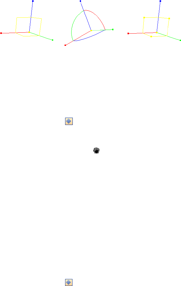
When you use gizmos, you can adjust snapping to control the precision of your operations.
Using Measure Tools to Transform Objects
You can use the Measure Tools functionality to move and rotate the currently selected objects.
To move an object with the translation gizmo
1Select the object you want to move in the Scene Area.
2Click Translate Item on the Object Manipulation toolbar.
3Use the translation gizmo to adjust the position of the currently selected object:
■To move all currently selected objects, place the mouse over the square at the end of the desired axis.
When the cursor changes to , drag the square on the screen to increase/decrease the translation along
that axis.
■To move the objects along several axes at the same time, drag the square frame between the desired axes.
Dragging the yellow square in the middle of the translation gizmo enables you to snap this center point
to other geometry in the model.
■To move the translation gizmo itself rather than the selected objects, hold down the CTRL key while
dragging the square at the end of the desired axis.
■To snap the translation gizmo to other objects, hold down the CTRL key while dragging the yellow
square in the middle of the gizmo.
■For the point-to-point translation, hold down the CTRL key, and use the center square to drag the gizmo
to the start point. Then, with CTRL released, drag the square again to move the objects to the end point.
To move an object numerically
1Select the object you want to move in the Scene Area.
2Click Translate Item on the Object Manipulation toolbar.
3On the Object Manipulation toolbar, type in numerical values into the manual entry boxes to move the
object by the amount entered:
■X, Y, Z represent translation distance in the current model unit.
■cX, cY, cZ represent the translation center point.
To move an object by overriding its transform
1Select the object you want to move in the Scene Area.
2Click Edit ➤ Override Item ➤ Override Transform.
3In the Override Transform dialog box, enter the XYZ values of the transform to be aplied to the currently
selected object. For example, a transform of (0, 0, 1) repositions an object by one unit in the Z direction.
206 | Chapter 8 Review Your Model
4Click OK.
To move an object with a measure tool
1Select the object you want to move.
2Open the Measure Tools window, and click Point Line .
3Click the selected object to create the first point. This is the start point from which the repositioning will
be calculated.
4Click the second point in the scene. This is the point where the object will be moved to. There is now a line
connecting the start point and the end point in the Scene Area.
5If you want to be able to move the object several times, create more points in the scene.
NOTE You can only select a point on another object in the scene. Selecting a point in 'space' is not a valid option.
To reposition an object into 'space', you can either use a translation gizmo or, if you know the distance by which
the object is to be moved, by overriding its transform.
6Click Transform Objects to move the object to the second point. If you have multiple points in the
scene, each time you click Transform Objects the selected object is moved to the next point.
To rotate an object with the rotation gizmo
1Select the object you want to rotate in the Scene Area.
2Click Rotate Item on the Object Manipulation toolbar.
3Use the rotation gizmo to rotate the currently selected object:
■Before you can rotate the currently selected objects, you need to position the origin (center point) of
the rotation. To do this, place the mouse over the square at the end of the desired axis. When the cursor
changes to , drag the square on the screen to increase/decrease the translation along that axis. This
will move the rotation gizmo itself.
Dragging the yellow square in the middle of the rotation gizmo enables you to move it around, and
snap it to points on other geometry objects.
Transform Objects | 207
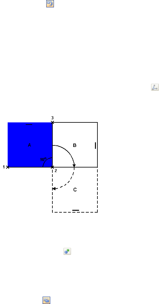
■Once the rotation gizmo is positioned correctly, place the mouse over one of the curves in the middle,
and drag it on the screen to rotate the selected objects. The curves are color-coded, and match the color
of the axis used to rotate the object around. So, for example, dragging the blue curve between the X and
Y axes, rotates the objects around the blue Z axis.
■To rotate the orientation of the rotation gizmo to an arbitrary position, hold down the CTRL key while
dragging one of the three curves in the middle.
■To snap the gizmo to other objects, hold the CTRL key while dragging the yellow square in the middle
of the gizmo.
To rotate an object numerically
1Select the object you want to rotate in the Scene Area.
2Click Rotate Item on the Object Manipulation toolbar.
3On the Object Manipulation toolbar, type in numerical values into the manual entry boxes to move the
object by the amount entered:
■X, Y, Z represent degrees of rotation in the current model unit.
■cX, cY, cZ represent the rotation center point.
To rotate an object with a measure tool
1Select the object you want to move.
2Open the Measure Tools window, and click Measure Angle .
3To rotate the object, click three points on the selected object to determine how the object is to be rotated
(refer to the diagram below).
This diagram illustrates how the selected object (position A) is rotated. Lines from the first to the second
point (1 to 2) and from the second to third point (2 to 3) define the angle by which the object is rotated
(for example, 90 degrees). The second point (2) is used as the rotation center point.
4Click Transform Objects . This rotates the selected object from postion A into position B (as shown in
the previous diagram). Clicking this button again, rotates the object from position B into position C.
To resize an object with the scale gizmo
1Select the object you want to resize in the Scene Area.
2Click Scale Item on the Object Manipulation toolbar.
208 | Chapter 8 Review Your Model
3Use the scale gizmo to resize the currently selected object:
■To resize all currently selected objects, place the mouse over one of seven squares. When the cursor
changes to , drag the square on the screen to modify the size of the objects. Typically, dragging a
square up or right increases the size, dragging it down or left decreases the size.
■To resize the objects across a single axis only, use colored squares at the end of the axes. To resize the
objects across two axes at the same time, use yellow squares in the middle of the axes. Finally, to resize
the objects across all three axes at the same time, use the square in the center of the gizmo.
■You can modify the center of scaling. To do this, place the mouse over the square in the middle of the
gizmo, and hold down the CTRL key while dragging the square on the screen.
To resize an object numerically
1Select the object you want to resize in the Scene Area.
2Click Scale Item on the Object Manipulation toolbar.
3On the Object Manipulation toolbar, type in numerical values into the manual entry boxes to move the
object by the amount entered:
■X, Y, Z represent a scaling factor (1 being the current size, 0.5 half, 2 being double, and so on).
■cX, cY, cZ represent the scaling center point.
Change Color and Transparency
You can apply custom colors and transparencies to geometry in the scene.
For example, when you are dealing with models with unsupported materials and textures, all geometry is displayed
in its wireframe color. You can change (or overrided) the color and transparency of objects in the scene for more
realistic presentation.
You can also choose to use Presenter tool to apply texture materials to objects in the scene to obtain even better
results.
NOTE Any materials applied with the Presenter tool supersede any color and transparency changes.
To change color
1Select the object you want to modify in the Scene Area.
2Click Modify Item Color on the Object Manipulation toolbar, and choose the desired color.
Menu: Edit ➤ Override Item ➤ Override Color
To change transparency
1Select the object you want to modify in the Scene Area.
2Click Modify Item Transparency on the Object Manipulation toolbar.
3Use the slider to adjust how transparent or opaque the selected object is.
Menu: Edit ➤ Override Item ➤ Override Transparency
Snapping
Snapping gives you control when measuring, moving, rotating, and scaling objects in Autodesk Navisworks.
Change Color and Transparency | 209
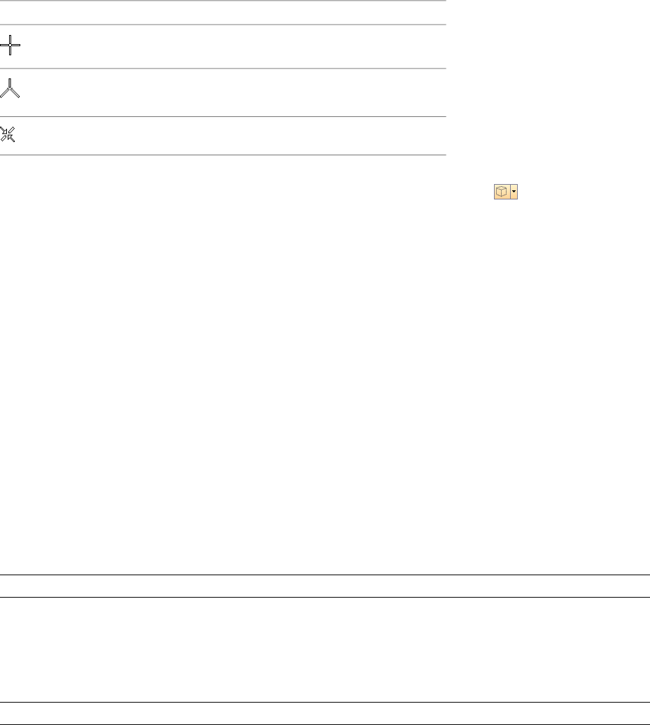
Points and snap points are automatically snapped to. You can set the cursor to snap to the nearest vertex, edge,
or line when you pick geometry. You can also adjust the snapping angle and the snapping tolerance that are
used when you rotate geometry.
Different cursors feed back what is being snapped to:
DescriptionCursor
No snap, but a point on a surface is found.
A vertex, point, snap point or line end is
found to snap to.
An edge is found to snap to.
Geometry in Autodesk Navisworks is tessellated with triangles, and therefore, the cursor snaps to edges that may
appear to be in the middle of a face. Consider viewing the model in hidden line mode to clarify which vertex
or edge the cursor is snapping to.
To customize snap settings
1Click Tools ➤ Global Options.
2In the Options Editor, expand the Interface node, and click the Snapping option.
3On the Snapping page, Picking area, select the check boxes for all required snaps, and enter the snapping
Tolerance. The smaller the value, the closer the cursor must be to a feature in the model before it snaps to
it.
4In the Rotation area, enter the multiplier for the snapping angle into the Angles box, and the snapping
tolerance into the Angle Sensitivity box. The smaller the value, the closer to the snapping angle the cursor
must be for snap to take effect.
5Click OK.
Reset to Original Values
In Autodesk Navisworks, you can reset object attributes back to the values in the original CAD files.
To restore original colors and transparencies for an object or a group of objects in your scene
NOTE You cannot restore colors separately from transparencies.
1Select the required objects in the Scene Area.
2Click Edit ➤ Reset Item ➤ Colors and Transparencies.
To reset colors and transparencies for all objects in your scene
NOTE You cannot restore colors separately from transparencies.
■Click Edit ➤ Reset All ➤ Colors and Transparencies.
To reset transform for an object or a group of objects in your scene
1Select the required objects in the Scene Area.
2Click Edit ➤ Reset Item ➤ Reset Transforms.
210 | Chapter 8 Review Your Model
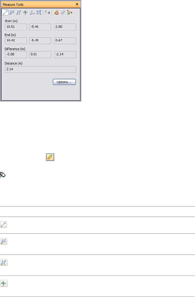
To reset transform for all objects in your scene
■Click Edit ➤ Reset All ➤ Reset Transforms.
Measure Tools
Measure tools enable you to measure between points on items in the model. All measurements are made in
display units.
Using measure tools is mutually exclusive to using navigation modes and SteeringWheels, so that when you are
measuring you cannot navigate and vice versa.
Measure Tools Window
The Measure Tools window is a dockable window, which contains a number of buttons at the top enabling you
to select the type of measurement you want to do.
For all measurements, the X, Y, and Z coordinates of the Start point and End point are displayed in the text
boxes underneath the buttons, together with the Difference and the absolute Distance. If you use accumulative
measure, such as Point Line or Accumulate, Distance shows the accumulated distance for all points registered
in the measurement.
To toggle the Measure Tools window
■Click Measure on the Workspace toolbar.
Menu: Tools ➤ Measure
Quick Reference
DescriptionButton
Measures the distance between two points.
Measures the distance between a base
point and various other points.
Measures a total distance between multiple
points along a route.
Calculates the sum total of several point-
to-point measurements.
Measure Tools | 211
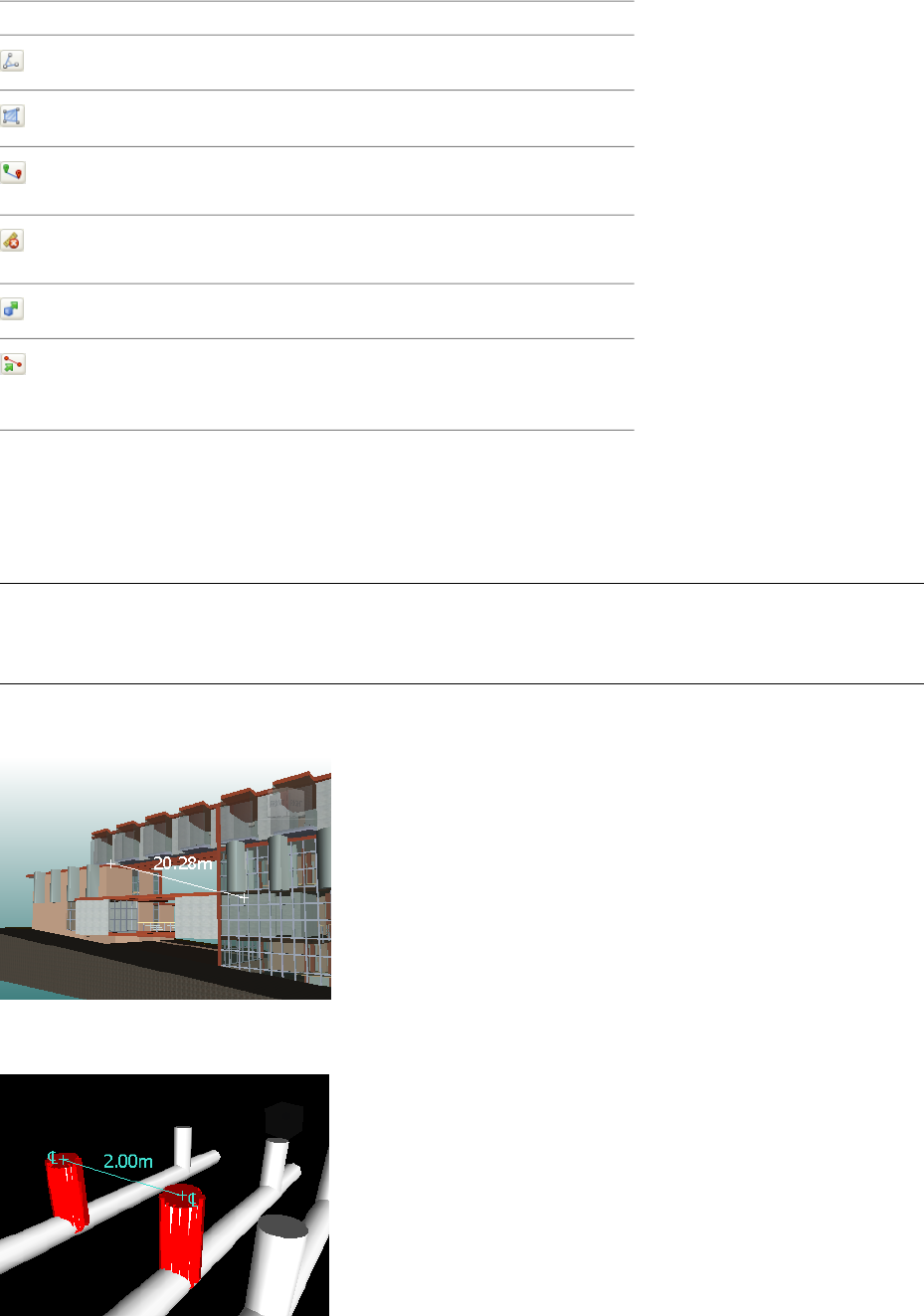
DescriptionButton
Calculates an angle between two lines.
Calculates an area on a plane.
Measures the shortest distance between
two selected objects.
Clears all measuring lines in the Scene
Area.
Enables you to move or rotate an object.
Converts the endpoint markers, the lines,
and any displayed measurement values
into redlines.
Measuring
You can use measuring tools to make linear, angular, and area measurements, and to automatically measure the
shortest distance between two selected objects.
NOTE When you measure, you must click on a point on an item to register a point - clicking on the background will
not register anything. You can reset a measure command at any time by right-clicking instead of left-clicking in the
Scene Area. This starts the measure command again with no points registered, just as if you had chosen a new
measurement type.
Endpoints of standard measuring lines are represented as small cross symbols in the Scene Area, and all lines
being measured by a simple line between registered points.
Endpoints of measuring lines that are snapped to center lines are represented as cross symbols with additional
CL markers.
You can change the color and thickness of measuring lines, and toggle the display of dimension label in the
Scene Area.
212 | Chapter 8 Review Your Model
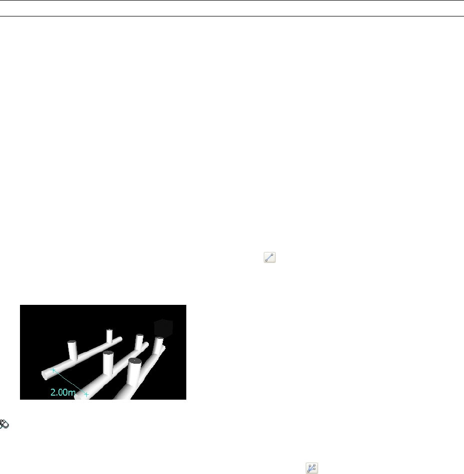
Dimension Labels
For distance-based measurements, the dimension label is drawn for each line segment. For accumulative
measurements, the dimension label shows the totals, and is drawn for the last line segment. The text is positioned
relative to the center point of the line.
For anglular measurements, an arc indicator is shown inside the angle, with the centre of the text positioned on
the invisible line bisecting the angle. If an angle is too accute, the label is drawn outside the angle. This label is
fixed, and does not resize when you zoom in or out, unless the measuring lines become too short on screen to
accommodate the arc, in which case it will be adjusted.
The Options Editor enables you to toggle the dimension labels on and off.
For area measurements, the dimension label is positioned at the centre of the area being measured.
Converting Measurements to Redlines
You can convert measurements to redlines. The measurement itself is cleared when it is converted to a redline,
and the redline takes the color and line thickness that is currently set for redlining.
NOTE When you convert measurements to redlines, the lines and text are stored in the current viewpoint.
To change the thickness and color of measuring lines
1Open the Measure Tools window, and click Options.
2In the Options Editor, the Measure page under the Interface node, enter the desired number into the Line
Thickness box.
3Select the required color from the Color palette. By default, measuring lines are white.
4Click OK.
To toggle the dimension labels
1Open the Measure Tools window, and click Options.
2In the Options Editor, the Measure page under the Interface node, select the Show Measurement Values in
Scene View check box.
3Click OK.
To measure a distance between two points
1Open the Measure Tools window, and click Point to Point .
2Click the start and end point of the distance to be measured in the Scene Area.
The Distance box, and the optional dimension label display the measured distance.
Menu: Review ➤ Measure ➤ Point to Point
To keep the same start point as you measure a distance between two points
1Open the Measure Tools window, and click Point to Multiple Points .
Measuring | 213
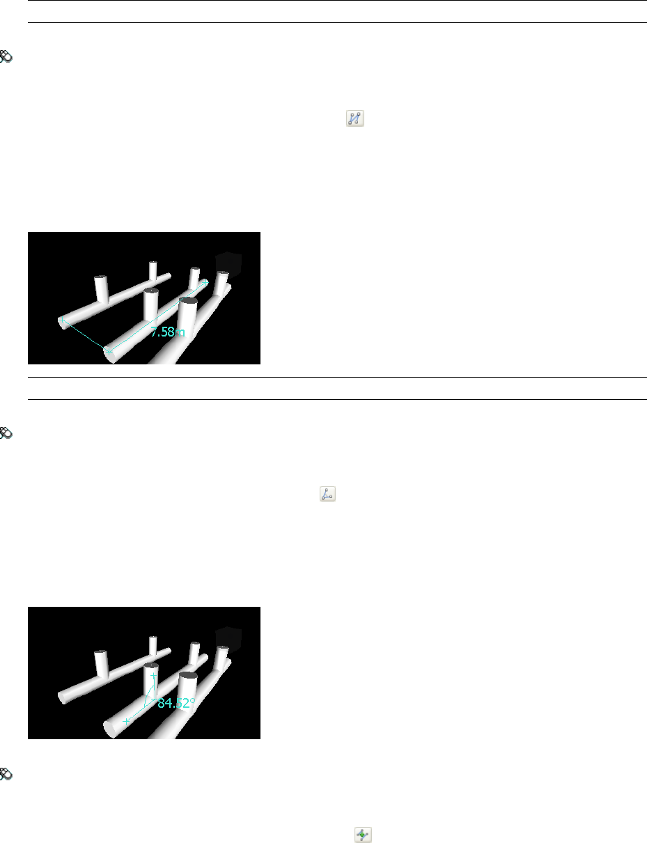
2Click the start point, and the first end point to be measured. A measuring line is displayed between two
points.
3Click to register the next end point to be measured.
4Repeat this to measure additional end points if required. The Distance box, and the optional dimension
label always display the last measured distance. Your start point stays the same throughout.
TIP If you want to change the start point, right-click in the Scene Area, and select a new start point.
Menu: Review ➤ Measure ➤ Point to Multiple Points
To measure a total distance along a route
1Open the Measure Tools window, and click Point Line .
2Click the start and the second point to be measured.
3Click the next point along the route.
4Repeat this to measure the entire route. The Distance box, and the optional dimension label display the
total distance along the selected route.
TIP If you want to change the start point, right-click in the Scene Area, and select a new start point.
Menu: Review ➤ Measure ➤ Point Line
To calculate an angle between two lines
1Open the Measure Tools window, and click Angle .
2Click a point on the first line.
3Click the first line at the point where it intersects the second line.
4Click a point on the second line. The Angle box and the optional dimension label display the calculated
angle between the two lines.
Menu: Review ➤ Measure ➤ Measure Angle
To calculate the sum total of several point-to-point measurements
1Open the Measure Tools window, and click Accumulate .
214 | Chapter 8 Review Your Model
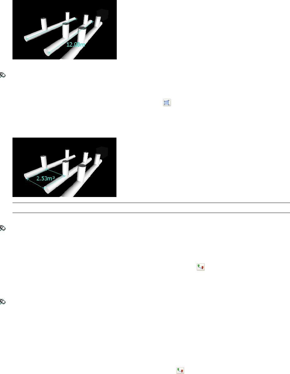
2Click the start and end points of the first distance to be measured.
3Click the start and end points of the next distance to be measured.
4Repeat to measure more distances if necessary. The Distance box, and the optional dimension label display
the sum of all point-to-point measurements.
Menu: Review ➤ Measure ➤ Accumulate
To calculate an area on a plane
1Open the Measure Tools window, and click Measure Area .
2Click to register a series of points to describe tthe perimter of the area you want to calculate. The Area box,
and the optional dimension label display the area of the perimeter described since the first point, as projected
onto the plane of the viewpoint.
NOTE For your calculation to be accurate, all added points must be on the same plane.
Menu: Review ➤ Measure ➤ Measure Area
To measure the shortest distance between two objects
1Press and hold the CTRL key and select two objects in the Scene Area.
2Open the Measure Tools window, and click Measure Shortest Distance .
The Distance box, and the optional dimension label display the shortest distance between the selected
objects.
Menu: Review ➤ Measure ➤ Measure Shortest Distance
To measure the shortest distance between two parametric objects
1Press and hold the CTRL key and select two parametric objects in the Scene Area.
2Open the Measure Tools window, and click Options.
3In the Options Editor, the Measure page under the Interface node, select the Use Center Lines check box,
and click OK.
4In the Measure Tools window, click Measure Shortest Distance .
The Distance box, and the optional dimension label display the shortest distance between the center lines
of the selected parametric objects.
Measuring | 215
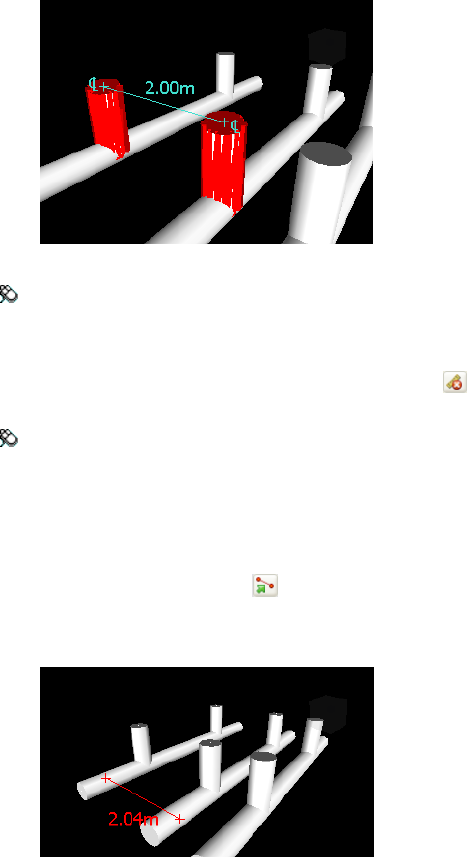
Menu: Review ➤ Measure ➤ Measure Shortest Distance
To clear measuring lines
■Open the Measure Tools window, and click Clear .
Menu: Review ➤ Measure ➤ Clear
To convert measurements into redlines
1Open the Measure Tools window, and take the desired measurements, for example, distance between two
points.
2Click Convert to Redline in the Measure Tools window.
The end markers, lines, and dimension label (if any) of your current measurement are now converted to a
redline, and stored in the current viewpoint.
Comments and Redlines
Add Comments and Redlines
You can add comments to viewpoints, viewpoint animations, selection and search sets, clash results, and timeliner
tasks.
Redline tools enable you to add review annotations to viewpoints, and clash detection results.
Using redline tools is mutually exclusive to using navigation modes and SteeringWheels, so that when you are
redlining you cannot navigate and vice versa.
Redline Tags
Redline tags combine the features of redlining, viewpoints and comments into a single, easy to use review tool.
This allows you to tag anything you want to identify in the model scene. A viewpoint is automatically created
for you, and you can add a comment and status to the tag.
For example, during a review session, you locate an item in the scene that is incorrectly sized or positioned. You
can tag this item, stating the problem, save your review results as an NWF file, and pass the file to the design
team. The design team can search the file, for any tags of status 'new', and locate your review comments. Once
216 | Chapter 8 Review Your Model
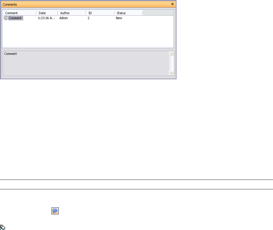
any necessary modifications are made to the drawing files, these can be reloaded into the *.nwf file, and the tag
status can be changed accordingly. You can review this latest version of the NWF file, ensure all tags have been
resolved and finally 'approve' them.
Comments Window
The Comments window is a dockable window that enables you to view and manage comments.
The Comments window shows the name, time and date, author, ID, status, and subject (or first line) of each
comment. There are different icons helping you to identify the source of each comment at a glance.
The Comment shortcut menu has the following options:
■Add Comment. Opens the Add Comment dialog box.
■Edit Comment. Opens the Edit Comment dialog box for the selected item.
■Delete Comment. Deletes the selected comment.
■Help. Launches the online Help system and displays the topic for comments.
You can add as many comments as you wish to a source, either from the Comments window, or from the source
itself.
TIP To add a comment to a specific object in the Scene Area, use redline tags.
To toggle the Comments window
■Click Comments on the Workspace toolbar.
Menu: View ➤ Control Bars ➤ Comments
To add a comment to a viewpoint
1Open the Viewpoints window.
2Right-click the desired viewpoint, and click Add Comment.
3In the Comments window, type in your comment. By default, it is assigned New status.
4Click OK.
To add a comment to a viewpoint animation
1Open the Viewpoints window.
2Right-click the desired viewpoint animation, and click Add Comment.
3In the Comments window, type in your comment. By default, it is assigned New status.
4Click OK.
Add Comments and Redlines | 217
To add a comment to a selection or search set
1Open the Selection Sets window.
2Right-click the desired selection or search set, and click Add Comment.
3In the Comments window, type in your comment. By default, it is assigned New status.
4Click OK.
To view comments
1Open the Comments window.
2Go the source of your comments. For example, open the Saved Viewpoints window.
3As you click the source items, for example, viewpoints, the associated comments are displayed in the
Comments window.
Quick Reference
DescriptionIcon
Selection set
Search set
Viewpoint (orthographic camera)
Viewpoint (perspective camera)
Viewpoint animation
Viewpoint animation cut
Redline tag
Redline Tools Window
The Redline Tools window is a dockable window with a number of buttons at the top enabling you to mark up
viewpoints with redline annotations.
The Thickness and Color controls enable you to modify the redline settings. These changes do not affect already
drawn redlines. Also, thickness only applies to lines; it does not affect redline text, which has a default size and
weight and cannot be modified.
All redlines (with an exception of redline tags) can only be added to a saved viewpoint or to a clash result which
has a saved viewpoint. If you don’t have any saved viewpoints, adding a redline tag will automatically create
and save a viewpoint for you.
You can also convert measurements to redlines. For more information, see “Measuring” on page 212.
218 | Chapter 8 Review Your Model
To toggle the Redline Tools window
■Click Redline on the Workspace toolbar.
Menu: Tools ➤ Redline
To add a redline tag
1Open the Redline Tools window, and click Tag .
2In the Scene Area, click the object you want to tag.
3Click the area where you want the tag label to be located. The redline tag is now added, and both points
arejoined by a leader line.
If the current viewpoint is not already saved, then it will be saved automatically and named 'Tag View X',
where X is the tag ID.
4In the Add Comments dialog box, enter the text to be associated with the tag, set the tag Status from the
drop-down list, and click OK.
Menu: Review ➤ Redline ➤ Tag
To add text
1Open the Viewpoints window, and click the viewpoint that you want to review.
2Open the Redline Tools window, and click Text .
3In the Scene Area, click the location where you want to place the text.
4Enter your annotation into the box provided, and click OK. The redline is added to the selected viewpoint.
NOTE Text can only be added in a single line with this redline tool. To display text on multiple lines, write each
line individually.
5If you want to move the annotation, right-click the redline, and click Move. Clicking a different location
in the Scene Area moves the text there.
6If you want to edit the annotation, right-click the redline, and click Edit.
Menu: Review ➤ Redline ➤ Text
Add Comments and Redlines | 219
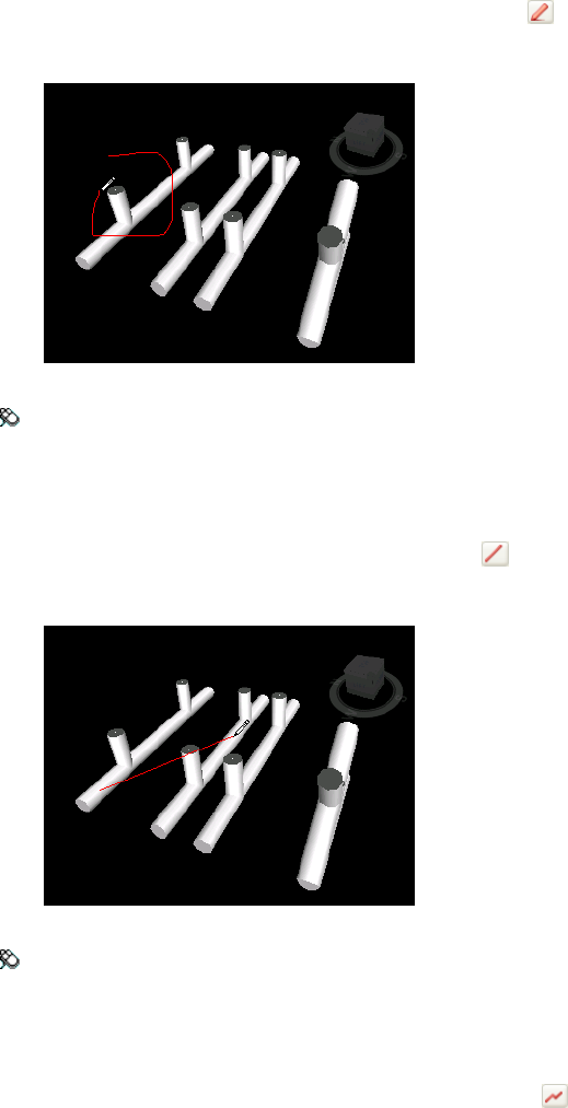
To draw freehand
1Open the Viewpoints window, and click the viewpoint that you want to review.
2Open the Redline Tools window, and click Freehand .
3Drag the mouse to draw in the viewpoint.
Menu: Review ➤ Redline ➤ Freehand
To draw a line
1Open the Viewpoints window, and click the viewpoint that you want to review.
2Open the Redline Tools window, and click Line .
3Click in the viewpoint at line start and end points.
Menu: Review ➤ Redline ➤ Line
To draw a string of lines
1Open the Viewpoints window, and click the viewpoint that you want to review.
2Open the Redline Tools window, and click Line String .
3Click in the viewpoint to begin. Each time you click, a new point is added to the line string. When the
string is complete, click the right mouse button to end the line, and you can then start a new line string.
220 | Chapter 8 Review Your Model
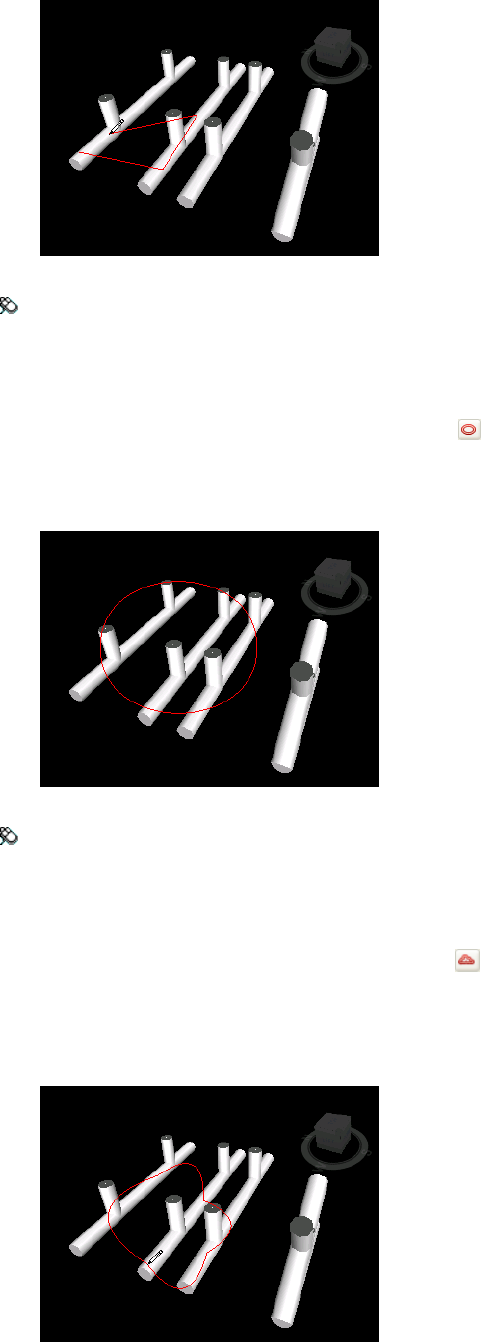
Menu: Review ➤ Redline ➤ Line String
To draw an ellipse
1Open the Viewpoints window, and click the viewpoint that you want to review.
2Open the Redline Tools window, and click Ellipse .
3Click and drag a box in the viewpoint to outline the ellipse.
4Release the mouse to place the ellipse in the viewpoint.
Menu: Review ➤ Redline ➤ Ellipse
To draw a cloud
1Open the Viewpoints window, and click the viewpoint that you want to review.
2Open the Redline Tools window, and click Cloud .
3Click in the viewpoint to begin drawing the arcs of the cloud. Each time you click, a new point is added.
Clicking clockwise draws regular arcs, clicking counterclockwise, draws inverted arcs.
4To automatically close the cloud, right-click.
Add Comments and Redlines | 221
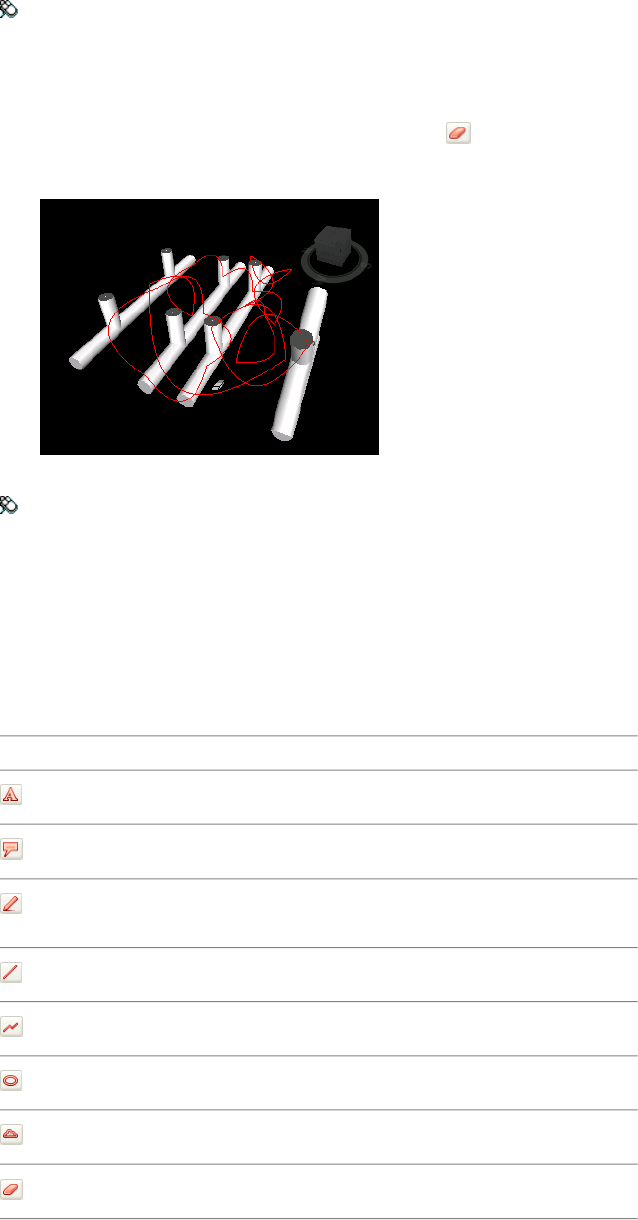
Menu: Review ➤ Redline ➤ Cloud
To erase redlines
1Open the Viewpoints window, and click the viewpoint that you want to review.
2Open the Redline Tools window, and click Erase .
3Drag a box over the redline you want to delete, and release the mouse.
Menu: Review ➤ Redline ➤ Erase
To view redlines
1Open the Viewpoints window.
2Click the desired viewpoint. All attached redlines (if any) are displayed in the Scene Area.
Quick Reference
DescriptionButton
Adds text to a viewpoint.
Adds a redline tag to a viewpoint.
Enables you to draw freehand in a view-
point.
Draws a line in a viewpoint.
Draws a string of lines in a view point.
Draws an ellipse in a viewpoint.
Draws a cloud in a viewpoint.
Erases redlines.
Review Comments and Redline Tags
You can use the Find Comments window to set up and run a search for redline tags and comments. You can
also use a quick find feature to locate redline tags.
222 | Chapter 8 Review Your Model
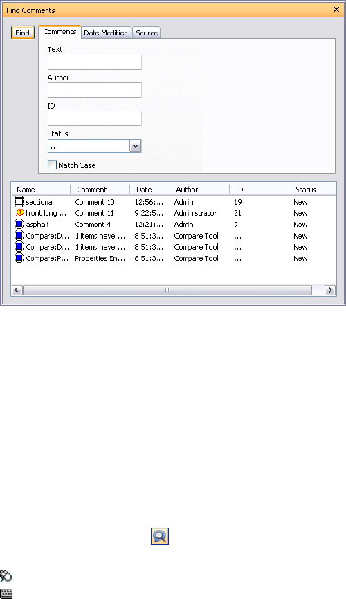
During a review session, you can edit text, change status assigned to comments and redline tags, and delete
comments and tags. You can also renumber tag and comments IDs, if necessary.
Find Comments Window
The Find Comments window is a floating window that enables you to search for comments and redline tags
based on the comment data (text, author, ID, status), comment modification date, and the source of comment.
Three tabs on the top enables you to set up the search criteria. Pressing the Find button runs the search. Any
found results are displayed in a multi-column table at the bottom of the window. You can use the scroll bars at
the right and at the bottom of the tab to move through the comments. There are different icons helping you to
identify the source of each comment at a glance. These icons are the same as the ones used in the Comments
window.
Selecting a comment in the list also selects the source of the comment. For example, selecting a comment which
originated from a saved viewpoint selects that viewpoint.
You can change the sort order of the items in the list by clicking a column head.
If new comments are added, or any of the existing comments are modified, the results list is cleared.
To toggle the Find Comments window
■Click Find Comments on the Workspace toolbar.
Menu: Edit ➤ Find Comments or Review ➤ Comments ➤ Find Comments
Command entry: SHIFT + F4
To find comments
1Open the Find Comments window.
2Set up the search criteria:
aUse the Comments tab if you want to search for a specific text, author, ID, or status.
bUse the Date Modified tab to only search for comments created within the specified timeframe.
cUse the Source tab to only search for comments attached to the selected sources.
3Click Find.
Review Comments and Redline Tags | 223
To find redline tags
1Open the Find Comments window.
2Click the Source tab, select the Redline Tags check box, and clear the rest of the check boxes.
3Use the Comments and Date Modified tabs to restrict your search further, if required.
4Click Find.
Quick Reference
Comments Tab
Use this tab to restrict your search based on the comment data. If the boxes on this tab are left empty, the search
returns all comments within the criteria set on the Date Modified and Source tabs.
Text The exact text to search for in all comments. This can be a word or a few words. So for, example, typing
redline, and running a search, returns only the comments that contain a single “redline” word.
If you don’t know the exact content of the comment, you can use the wildcards. To match one single unspecified
character use the symbol ? (question mark). To match any number of unspecified characters either before or
after the text, use the symbol * (asterisk). For example, if you want to find all comments that contain some text
before and after the word redline, type *redline* in the Text box.
Author The exact author name to search for in all comments. Use the wildcards if you don’t know the exact
author name.
ID The exact comment ID to search for. You can only use numbers here.
Status Selects the comment status to search for.
Match Case Select this check box if you want the search to respect lower and upper case characters in the search.
Date Modified Tab
Use this tab to specify a date range within which the comments must have been made.
All Comments The search returns all comments. This is the default option.
Between Select this radio button if you want to search for all comments modified between the specified dates.
During the Previous Months Select this radio button to locate all comments modified in the last X number of
months.
During the Previous Days Select this radio button to locate all comments modified in the last X number of
days.
Source Tab
Use this tab to restrict the search by the source that the comment is attached to. By default all check boxes are
selected.
Clash Detective Select this check box if you want to find the comments attached to Clash Detective results.
Clearing this check box excludes the comments related to clashes from the search results.
TimeLiner Select this check box if you want to find the comments attached to TimeLiner tasks. Clearing this
check box excludes the comments related to TimeLiner from the search results.
Viewpoints Select this check box if you want to find the comments attached to viewpoints. Clearing this check
box excludes the comments related to viewpoints from the search results.
Redline Tags Select this check box if you want to find the comments attached to redline tags. Clearing this
check box excludes the comments related to redline tags from the search results.
Selection Sets Select this check box if you want to find the comments attached to selection and search sets.
Clearing this check box excludes the comments related to selection and search sets from the search results.
224 | Chapter 8 Review Your Model
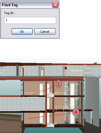
Find Redline Tags
You can search for redline tags the same way as you search for comments. You can also use a quick find
functionality specifically designed to work with redline tags.
To find redline tag
1Click Review ➤ Tags ➤ Find Tag by ID.
2In the Find Tag dialog enter the tag ID.
3Click OK. You are automatically taken to the appropriate viewpoint.
To navigate through redline tags
1Open the Comments window.
2Click Review ➤ First Tag. The tag comment is shown in the Comments window, and the Scene View
displays the viewpoint with the first redline tag.
3To navigate through the tags in your scene:
■Click Review ➤ Tags ➤ Next Tag to find the tag following the current tag.
■Click Review ➤ Tags ➤ Previous Tag to find the tag preceding the current tag.
■Click Review ➤ Tags ➤ Last Tag to find the last tag in the scene.
4Click Review ➤ Tags ➤ Current Tag to select the current tag.
Edit Comments and Redlines
Once a comment is saved, you can edit it either from the Comments window, or from the source itself. Editing
redline tags is the same as editing comments.
To change content and status of a comment or redline tag
1View the comment or redline tag you want to edit in the Comments window.
2Right-click the comment or tag, and click Edit Comment.
3Modify the comment text as necessary.
4Use the Status box to change the status.
Review Comments and Redline Tags | 225
5Click OK.
Menu: Review ➤ Comments ➤ Edit Comment
To delete a comment or redline tag
1View the comment or redline tag you want to delete in the Comments window.
2Right-click the comment or tag, and click Delete Comment.
Menu: Review ➤ Comments ➤ Delete Comment
Manage IDs
When you add a redline tag or comment to your scene, it is automatically assigned a unique ID. If, however,
you are appending or merging multiple Navisworks files together, then there is a possibility for the same ID to
be used more than once. Consider the following example. Three users reviewed and added comments and redlines
to same model file, each saving their work as an NWF file. If you merge the resulting NWF files together, only
one copy of the geometry would be loaded and any tag viewpoints of the same name would be suffixed with
the .nwf filename in brackets. All tag ID's, however, would be retained. In such cases, you can renumber all the
IDs, making them unique to the scene once again.
NOTE There may be a situation, where two sessions are merged that contain identically numbered tags and
corresponding viewpoints (Tag Views). In this situation, when you renumber tag IDs, Autodesk Navisworks will also
attempts, wherever possible, to rename the associated Tag Views in line with the new tag numbers.
To renumber comment IDs
■Click Review ➤ Renumber Comment IDs.
To renumber tag IDs
■Click Review ➤ Renumber Tag IDs.
Links
There are several sources of links in Autodesk Navisworks: original links that have been converted from the native
CAD files, links that have been added by Autodesk Navisworks users, and links that have been automatically
generated by the program (for example, selection set links, viewpoint links, TimeLiner task links and so on).
The links converted from the native CAD files, and the links added by Autodesk Navisworks users are treated as
object properties. This means, you can examine them in the Properties window.
You can also use the Find Items window to search for them.
All links are saved with Autodesk Navisworks files so that as the model changes, the links remain there for you
and others to view.
Link Categories
There are two types of links: standard and user-defined.
Standard links are split into the following categories:
■Hyperlink
■Tag
■Viewpoints
■TimeLiner
226 | Chapter 8 Review Your Model
■Selection sets
■Redline tags
By default, all links except tags, are drawn as icons in the Scene Area. Tags are drawn as text.
User-defined links enable you to customize the link categories to suit your workflow. By default, user-defined
links are drawn as icons in the Scene Area.
You can use the Options Editor to toggle the display of each of the link categories, and also to control their
appearance.
When you add a link, you can assign a user-defined category, hyperlinks category, or tag category to it. The rest
of the categories are automatically assigned by Autodesk Navisworks when it generates correponding links.
Display Links
You can switch links in the Scene Area on and off. You can also toggle the display of each of the link categories.
When links are switched on, you can reduce the screen clutter by restricting a number of links can be shown in
the Scene Area, hiding colliding icons, and using culling. Finally, as some standard link categories can have
comments associated with them, you can choose to only draw links with attached comments.
To toggle the display of links
■Click Hyperlinks on the Workspace toolbar.
Menu: Tools ➤ Hyperlinks
To control the display of standard links
1Click Tools ➤ Global Options.
2In the Options Editor, expand the Interface node, expand the Hyperlinks node, and click the Standard
Categories option.
3On the Standard Categories page, select the Visible check box to display the corresponding link category.
Clearing the check box hides the corresponding link category in the Scene Area.
By default, all standard link categories are visible.
4Click OK.
To control the display of user-defined links
1Click Tools ➤ Global Options.
2In the Options Editor, expand the Interface node, expand the Hyperlinks node, and click the User-Defined
Categories option.
3On the User-Defined Categories page, select the Visible check box to display the corresponding link category.
Clearing the check box hides the corresponding link category in the Scene Area.
By default, all user-defined link categories are visible.
NOTE If no user-defined categories have been added, this page is empty.
4Click OK.
To reduce the screen clutter
1Click Tools ➤ Global Options.
2In the Options Editor, expand the Interface node, and click the Hyperlinks option.
Display Links | 227

3On the Hyperlinks page, enter the number of links into the Max Icons box. By default, up to 25 links can
be visible.
4To hide links that appear overlapped in the Scene Area, select the Hide Colliding Icons check box.
5In the Cull Radius box enter the desired value. Only the links located within the specified distance from
the camera are drawn in the Scene Area. The default value of 0 means that all links are drawn.
6Click OK.
To hide links without comments
1Click Tools ➤ Global Options.
2In the Options Editor, expand the Interface node, expand the Hyperlinks node, and click the Standard
Categories option.
3On the Standard Categories page, select the Hide Icons Without Comments check box for all required link
categories.
By default, links without comments are also displayed.
4Click OK.
Customize Links
You can customize the default appearance of links in Autodesk Navisworks. In particular, you can draw them in
3D, and you can add leader lines (arrows) pointing to the attachment point on the items. You can also choose
how to represent each link category (as an icon or as text).
Attachment Points
By default, links are attached to the default center of the item's bounding box.
You can override this with more convenient attachment points. If you add more than one attachment point,
the link is displayed attached to the closest attachment point to the camera during navigation. This allows you
to set up links so that they are always available for following when drawn in 3D mode during navigation, and
do not disappear behind objects.
To draw links in 3D mode
NOTE In 3D mode links can become hidden by other objects in the scene when you are navigating.
1Click Tools ➤ Global Options.
2In the Options Editor, expand the Interface node, and click the Hyperlinks option.
3On the Hyperlinks page, select the In 3D check box.
Links now float in 3D space just in front of their attachment points to the items.
4Click OK.
To show leader lines
1Click Tools ➤ Global Options.
2In the Options Editor, expand the Interface node, and click the Hyperlinks option.
3On the Hyperlinks page, Enter the X- and Y- distance in Leader Offset for the number of pixels to the right
and up that these leader lines will use. The default angle is 0. The recommended angle is 45.
Links in the Scene Area have now leader lines pointing to the attachment point on the items.
228 | Chapter 8 Review Your Model
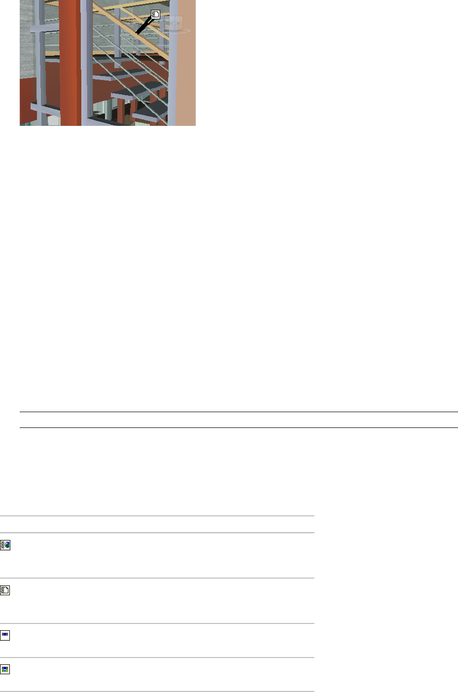
4Click OK.
To customize appearance of standard links
1Click Tools ➤ Global Options.
2In the Options Editor, expand the Interface node, expand the Hyperlinks node, and click the Standard
Categories option.
3On the Standard Categories page, use the Icon Type box to specify how you want a link to be drawn for
each of the available categories. You can choose between an icon and text.
By default, tag links are shown as text, and the rest of the link categories are shown as icons.
4Click OK.
To customize appearance of user-defined links
1Click Tools ➤ Global Options.
2In the Options Editor, expand the Interface node, expand the Hyperlinks node, and click the User-Defined
Categories option.
3On the User-Defined Categories page, use the Icon Type box to specify how you want a link to be drawn
for each of the available categories. You can choose between an icon and text. By default, links with
user-defined categories are shown as icons.
NOTE If no user-defined categories have been added, this page is empty.
4Click OK.
Quick Reference
The table below shows the icons that can be used to represent different link categories in the Scene Area.
DescriptionIcon
Represents links that have hyperlink, tag,
or any user-defined category (and points
to a web address).
Represents links that have hyperlink, tag,
or any user-defined category (and points
to an external file).
Represent links with TimeLiner category
(task with attached items).
Represent links with TimeLiner category
(task with valid links).
Customize Links | 229
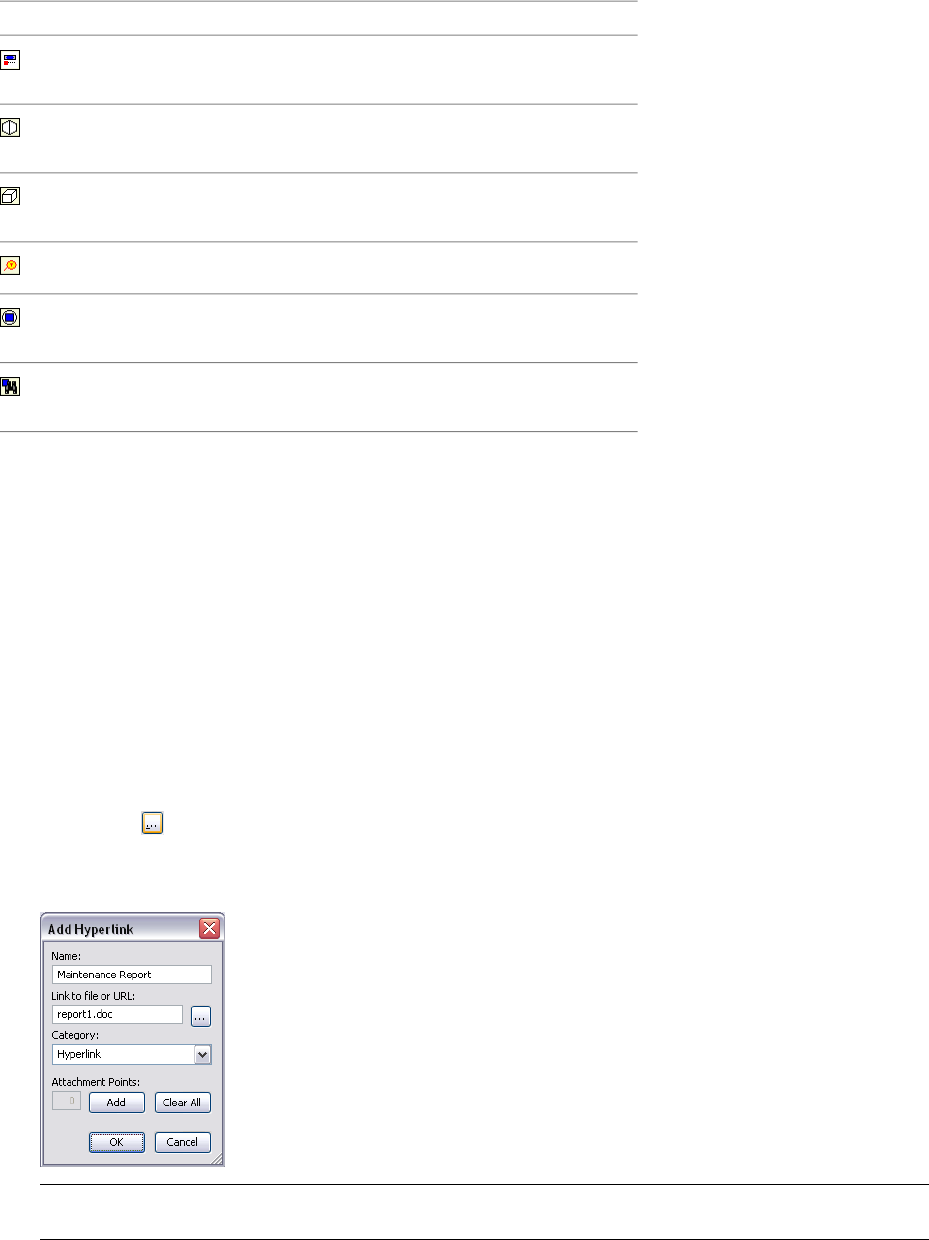
DescriptionIcon
Represent links with TimeLiner category
(tasks with broken links).
Represents links with viewpoints category
(perspective camera mode).
Represents links with viewpoints category
(orthographic camera mode).
Represents links with redline tags category.
Represents links with selection sets cat-
egory (selection sets).
Represents links with selection sets cat-
egory (search sets).
Add Links
Your can add links that point to various data sources, such as spreadsheets, webpages, scripts, graphics, audio
and video files and so on. An object can have muliple links attached to it, although, only one link, called default,
is shown in the Scene Area. The default link is the link that you add first, but you can mark a different link as
default, if necessary.
To add a link to an object
1In the Scene Area, select the desired geometry item.
2Click Review ➤ Hyperlinks ➤ Add Hyperlink.
3In the Add Hyperlink dialog box, enter the name for the link in the Name box.
4In the Link to File or URL box, type in the full path to the required data source or the URL address. You can
also browse to the folder containing the desired external file.
5Choose the category for your link from the Category drop-down list. by default, your link has hyperlink
category.
TIP To create a custom category type, type its name directly into the Category box. when you save your hyperlink,
the corresponding user-defined category is automatically created.
6 Optional:By default, your link is attached to the default center of the item’s bounding box. If you want to
attach your link to a specific point on the selected item, click the Add button. A cross-hair cursor appears
in the Scene Area, allowing you to select a point on the item where the link will be attached to.
230 | Chapter 8 Review Your Model
NOTE If you made a mistake, clicking the Clear All button deletes all attachment points associated with this link
and reverts to the link being attached to the center of the item's bounding box.
7Click OK.
To add several links to the same object
1In the Scene Area, select the desired geometry item.
2Right-click and click Hyperlinks ➤ Add Hyperlinks.
3Use the Add Hyperlinks dialog box to add the first link. This is the default link, and it’s the only link that
will be visible in the Scene Area. You can choose a different default link later, if necessary.
4Right-click the object again, and repeat the previous steps to add all required links.
Find and Follow Links
Links are an extremely useful review tool to allow you to access non-graphical information through the graphical
interface of Autodesk Navisworks.
The links converted from the native CAD files, and the links added by Autodesk Navisworks users are treated as
object properties. This means, you can examine them in the Properties window.
You can also use the Find Items window to search for them.
To follow a default link
1Make sure links are switched on. If not, click Hyperlinks on the Workspace toolbar.
2Click the desired link in the Scene Area to open the attached data source.
Shortcut menu: Follow Link
To follow one of the non-default links
1Make sure links are switched on. If not, click Hyperlinks on the Workspace toolbar.
2Right-click the default link, and click the Select Item Containing Hyperlink option. This option is only
available for multiple hyperlinks attached to the same item.
3Click Review ➤ Hyperlinks, and click the link that you want to follow.
To follow a default link from the Properties window
NOTE You can use this procedure to follow links from original CAD files, or links that you have added yourself.
1In the Scene Area, select the object with a link.
2Open the Properties window, right-click any tab, and click Follow Default Hyperlink.
To find links
1Click Find Items on the Workspace toolbar.
2In the Find Items window, click the Standard tab, press and hold CTRL, and click all files that comprise the
model.
3Click the Category column, and select Hyperlinks from the drop-down list.
4In the Property column, select the property name from the drop-down list, for example, ‘Category’.
5In the Condition column, select the condition operator, for example, ‘=’.
Find and Follow Links | 231
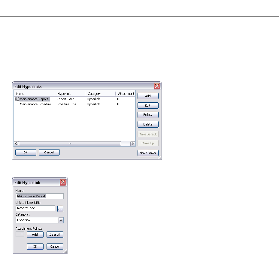
6In the Value column, type in the property value to search for, for example, ‘Hyperlink’.
7Click the Find All button. The search results are highlighted in the Scene Area and the Selection Tree.
Manage Links
You can edit original links that have been converted from the native CAD files. If you do this, then save the
changes in an .nwf file, then change the hyperlink in the original CAD file, and reopen the .nwf file in Autodesk
Navisworks, then your edit ‘overrides’ will remain. If you haven't edited the hyperlinks in Autodesk Navisworks,
however, the updated links from the CAD file will appear.
You can reset all links on an object to those that were originally converted from the CAD file. You can also reset
all links on all objects in the scene to their original state.
NOTE You cannot edit automatically generated links, such as the links that point to clash results, TimeLiner tasks and
so on.
You can delete any links that have been added to your file by Autodesk Navisworks users, and the links that
have been converted from original CAD files. You cannot delete automatically generated links, but you can turn
them off, so they don’t clutter the Scene Area.
To edit a link
1In the Scene Area, right-click the link you want to edit, and click Edit Hyperlink.
2In the Edit Hyperlinks dialog box, click the link you want to change, and click the Edit button.
3Use the Edit Hyperlink dialog box to modify the link details, and click OK.
4Click OK to close the Edit Hyperlinks dialog box.
To change the default link
1In the Scene Area, right-click the default link, and click Edit Hyperlink.
2In the Edit Hyperlink dialog box, select the link that you want to be shown in the Scene Area, and click the
Make Default button.
232 | Chapter 8 Review Your Model
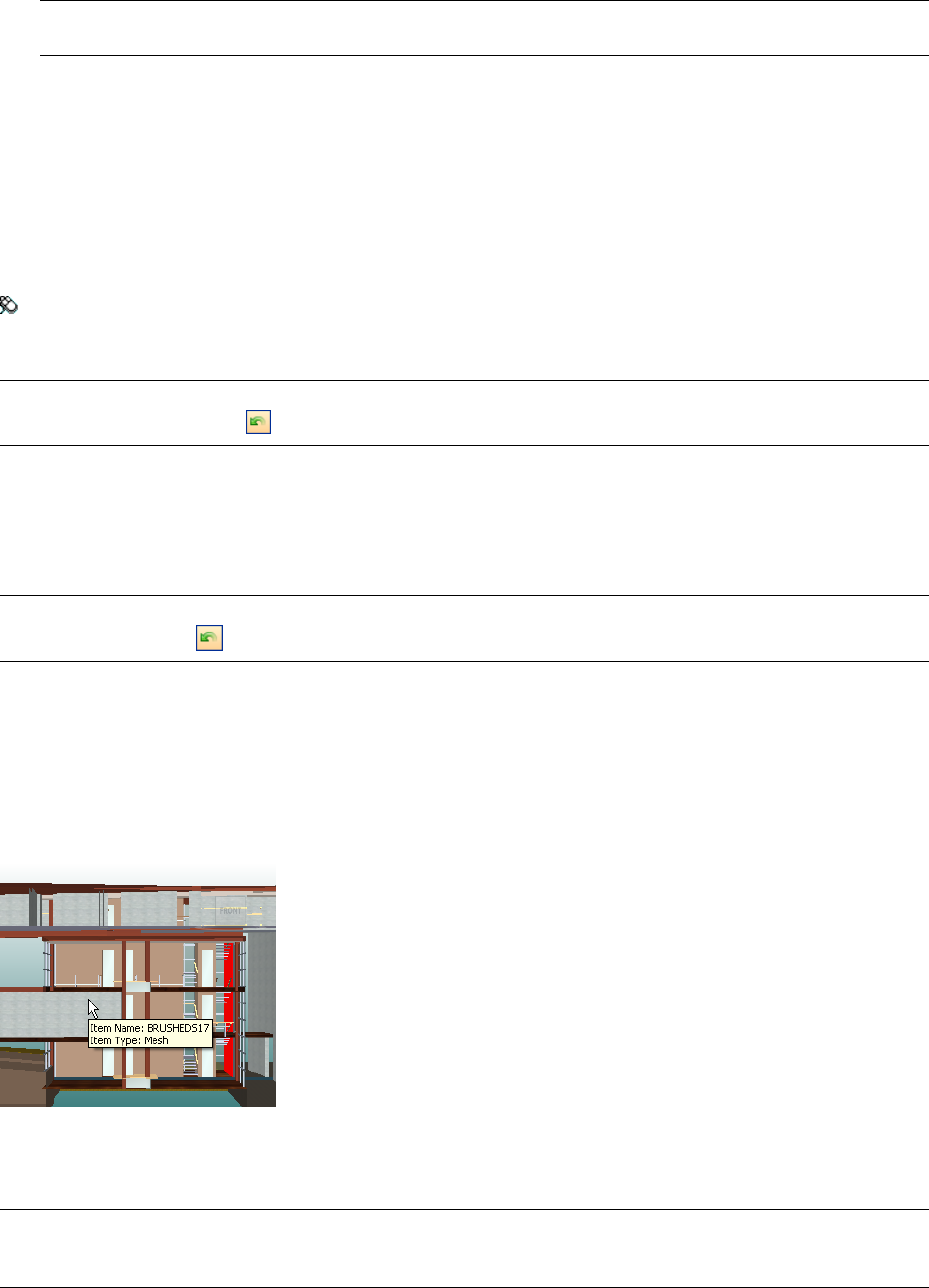
NOTE You can also move links up and down the list using the Move Up and Move Down buttons, or by dragging
them to their new position in the list. The link at the top of the list is the default link.
3Click OK.
To delete a link
1In the Scene Area, right-click the default link, and click Edit Hyperlink.
2In the Edit Hyperlinks dialog box, click the link you want to delete, and click the Delete button.
3Click OK.
Menu: Review ➤ Hyperlinks ➤ Edit Hyperlinks
To reset all links for an object
IMPORTANT Resetting links for an object also removes any links manually added to it by Navisworks users. If you
made a mistake, use the Undo button on the Standard toolbar.
1In the Scene Area, select the object with the links that you want to reset to their original state.
2Click Edit ➤ Reset Item ➤ Reset Hyperlinks.
To reset all links in a scene
IMPORTANT Resetting links in a scene also removes all links manually added to it by Navisworks users. If you made
a mistake, use the Undo button on the Standard toolbar.
■Click Edit ➤ Reset All ➤ Reset Hyperlinks
Smart Tags
Smart tags display property information in a tooltip style window as you move your cursor over objects in the
Scene Area. You don’t need to select objects first. The smart tags disappear after a few seconds.
By default, smart tags show the name and type of the object, but you can use the Options Editor to define which
properties are shown. Each definition that you configure enables you to display an additional category/property
combination in smart tags. You can choose whether to hide caterory names in smart tags or not.
NOTE When you move your mouse over an object that doesn't have the requested property, Autodesk Navisworks
searches up the selection tree for a parent object that contains that information, and displays it instead, thus maximising
the useful information you get.
To toggle the display of smart tags
■Click Smart Tags on the Workspace toolbar.
Smart Tags | 233
Menu: Tools ➤ Smart Tags
To add a smart tag definition
1Click Tools ➤ Global Options.
2In the Options Editor, expand the Interface node, expand the SmartTags node, and click the Definitions
option.
3On the Definitions page, click Grid View to display smart tag definitions as table rows.
4Click Add Element . A new row is added to the top of the table.
5Click the Category column, and select the property category from the drop-down list, for example ‘Item.’
The options available depend on the property categories in your model.
6Click the Property column, and select the property name from the drop-down list, for example, ‘Material’.
The options available depend on the selected property category.
7Click OK.
NOTE You can add as many definitions to your smart tags as you like.
To delete a smart tag definition
1Click Tools ➤ Global Options.
2In the Options Editor, expand the Interface node, expand the SmartTags node, and click the Definitions
option.
3On the Definitions page, click Grid View to display smart tag definitions as table rows.
4Click the Category or Property for the definition that you want to delete.
5Click Remove Element .
6Click OK.
To hide category names
1Click Tools ➤ Global Options.
2In the Options Editor, expand the Interface node, and click the SmartTags option.
3Select the Hide Category check box.
4Click OK.
SwitchBack to AutoCAD and MicroStation
You can use the SwitchBack functionality to send the current view of the currently loaded file back to AutoCAD
(version 2004 or later) or MicroStation-based CAD products (/J and v8).
IMPORTANT The native CAD package must be installed on the same machine as Autodesk Navisworks for SwitchBack
to work.
To use SwitchBack with AutoCAD
1For AutoCAD (version 2004 or later) or products based on it, first open the product in the usual manner,
and type: nwload in the command line to load the nwexport plugin.
NOTE If SwitchBack needs to be available every time AutoCAD is run, nwexport can be added to the set of startup
applications in AutoCAD.
234 | Chapter 8 Review Your Model
2Once the CAD package is running, and nwexport has been started, return to Autodesk Navisworks.
3Click Tools ➤ Global Options.
4In the Options Editor, expand the File Readers node, and click the DWG/DXF/SAT option.
5On the DWG/DXF/SAT page, check that the Convert Entity Handles option is selected.
6Select an object in the Scene Area, and click Review ➤ SwitchBack.
The current Autodesk Navisworks camera view is taken back to the CAD package, and the same object is
selected. Selection of objects is done by entity handle.
NOTE If a Clash Detective tool is available, you can click the SwitchBack button on the Results tab.
7Make the changes in AutoCAD, then save the changes.
8Return to Autodesk Navisworks, and click Refresh on the Standard toolbar to view the modified object.
NOTE Some objects cannot be selected in AutoCAD (for example, blocks) which may mean that running SwitchBack
may be unsuccessful with a given selected object. If this is the case, try selecting further up the object tree and trying
again.
Shortcut menu: SwitchBack
To use SwitchBack with MicroStation
1For MicroStation (/J and v8) or products based on it, open the product in the usual manner.
2Click Utilities ➤ Key In.
3In the Key-In dialog box, type mdl load nwexport6 to load the nwexport plugin.
NOTE If SwitchBack needs to be available every time MicroStation is run, nwexport6 can be added to the list of
MDL plugins in MicroStation.
4Once the MicroStation package is running, and nwexport has been started, return to Autodesk Navisworks.
5Select an object in the Scene Area, and click Review ➤ SwitchBack.
The current Autodesk Navisworks camera view is taken back to first visible view in MicroStation, and the
same object is selected. Selection of objects is done by element ID (MicroStation v8) or DMRS value
(MicroStation /J).
NOTE If a Clash Detective tool is available, you can click the SwitchBack button on the Results tab.
6If you want to override the view used by SwitchBack, use the nwview <view number> key-in where view
number is the visible window in MicroStation. This view setting is not saved between sessions.
7Make the changes in MicroStation, then save the changes.
8Return to 2010, and click Refresh on the Standard toolbar to view the modified object.
Shortcut menu: SwitchBack
SwitchBack to AutoCAD and MicroStation | 235
236 | Chapter 8 Review Your Model
Use Viewpoints and
Sectioning Modes
Viewpoints are an important feature of Autodesk Navisworks. They not only allow
you to save and return to views of the model which are of importance, but they
can also be used for design review audit trails, and for setting up animations of
the model.
Create and Modify Viewpoints
Overview of Viewpoints
Viewpoints contain more than just the camera information - each
viewpoint can also contain redlines and comments. In fact, you can
use viewpoints as a design review audit trail. They can be used as
hyperlinks in the Scene Area to click on and zoom to the viewpoint,
which will also bring up the redline and comments associated with
it. The viewpoints, redlines and comments are all saved into an .nwf
file from Autodesk Navisworks, and are independent of the model
geometry. So, if the native CAD files are changing, the saved
viewpoints remain the same, appearing as an overlay on top of the
base layer of model geometry. This enables you to see how the design
has evolved. See “Review Your Model” on page 179 for more
information on hyperlinks, comments and redlines and “Native File
Formats” on page 87 for more information on the .nwf file format.
Viewpoints also retain the section planes active at the time of
viewpoint creation, which can be useful in animating sliding
sections. See “Sectioning” on page 244 for more information on
sections. Viewpoints can optionally retain saved attributes too, so
that on returning to a viewpoint, overridden colors, transparencies
and hidden items are reinstated. This can be used to great effect to
create animations where items appear and disappear from the scene
in time. See “Default Viewpoint Options” on page 242 for more
information on options, and “Record and Play Animations” on page
251 for more information on viewpoint animations.
Saved Viewpoints Window
The Saved Viewpoints window is a floating window that enables
you to create and manage different views of your model so that you
9
237
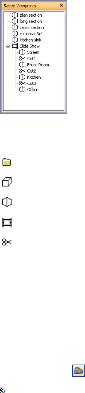
can jump to preset viewpoints without having to navigate each time to reach an item.
The Saved Viewpoints window is a floating window that enables you to jump to preset viewpoints without
having to navigate each time to reach an item.
Viewpoint animations are also saved with the viewpoints, as they are simply a list of viewpoints treated as
keyframes. In fact, viewpoint animations can be made by simply dragging preset viewpoints onto an empty
viewpoint animation. You can organize your viewpoints and viewpoint animations using folders.
Icons are used to represent different elements:
represents a folder which may contain all other elements (including other folders).
represents a viewpoint saved in orthographic mode.
represents a viewpoint saved in perspective mode.
represents a viewpoint animation clip.
represents a cut inserted into a viewpoint animation clip.
You can select more than one viewpoint by either holding down the Control key and left-clicking, or by
left-clicking the first item, and then clicking the last item while holding down the Shift key.
You can drag viewpoints around the Saved Viewpoints window, and reorganize them into folders or animations.
There are no buttons on this window, and commands are actioned through shortcut menus.
Through these menus, you can save and update viewpoints, create and manage viewpoint animations, and create
folders to organize these viewpoints and viewpoint animations. You can also drag and drop viewpoints or
viewpoint animations onto viewpoint animations or folders. Holding down the Control key during this operation
will copy the element being dragged. This allows fairly complex hierarchies of viewpoint animations and folders
to be easily composed.
Viewpoints, folders and viewpoint animations can all be renamed by slow clicking (clicking and pausing without
moving the mouse) the element, or clicking it and pressing F2.
To toggle the Saved Viewpoints window
➤ Click Saved Viewpoints on the Workspace toolbar.
Menu: View ➤ Control Bars ➤ Saved Viewpoints
238 | Chapter 9 Use Viewpoints and Sectioning Modes

Command entry: CTRL + F11
Quick Reference
You get a different shortcut menu, depending on what element you right-click in the Saved Viewpoints window.
All shortcut menus share the Sort option, which sorts the contents of the window alphabetically, including
folders and their contents.
IMPORTANT Any changes that you make cannot be saved, and will apply for the duration of your Autodesk Navisworks
session.
Blank Space
Save Viewpoint Saves the current viewpoint, and adds it to the Saved Viewpoints window.
New Folder Adds a folder to the Saved Viewpoints window.
Add Animation Adds a new empty viewpoint animation, ready for dragging viewpoints onto.
Add Cut Adds an animation cut. Cuts are used as pauses in the viewpoint animations, and are 1 second long
by default.
Sort Sorts the contents of the Saved Viewpoints window alphabetically.
Help Opens the Help system.
Saved Viewpoint
Save Viewpoint Creates a copy of the selected viewpoint in the Saved Viewpoints window.
New Folder Adds a folder above the selected viewpoint.
Add Animation Adds a new empty viewpoint animation above the selected viewpoint.
Add Cut Adds an animation cut above the selected viewpoint. Cuts are used as pauses in the viewpoint animations,
and are 1 second long by default.
Add Copy Creates a copy of the selected viewpoint in the Saved Viewpoints window. The copy is named the
same as the selected viewpoint, but includes the version number in brackets. For example, View1(1), View1(2)
and so on.
Add Comment Adds a comment regarding the selected viewpoint. See “Comments and Redlines” on page 216
for more information on comments.
Edit Comment When available, opens the Edit Comment dialog box.
Edit Opens the Edit Viewpoint dialog box, and enables you to manually edit the viewpoint’s attributes.
Update Makes the selected viewpoint the same as the current viewpoint in the Scene Area.
Transform Opens the Transform dialog box. It enables you to transform the camera position.
Delete Deletes the selected viewpoint from the Saved Viewpoints window.
Rename Enables you to rename the selected viewpoint.
Sort Sorts the contents of the Saved Viewpoints window alphabetically.
Help Opens the Help system.
Viewpoint Animation
Save Viewpoint Saves the current viewpoint, and adds it as the last keyframe in the selected viewpoint animation.
New Folder Adds a folder as the last keyframe in the selected viewpoint animation.
Add Animation Adds a new empty viewpoint animation as the last keyframe in the selected viewpoint animation.
Add Cut Adds an animation cut to the end of viewpoint animation. Cuts are used as pauses in the viewpoint
animations, and are 1 second long by default. You can drag the created cut into a different position.
Saved Viewpoints Window | 239

Add Copy Creates a copy of the selected viewpoint animation in the Saved Viewpoints window. The copy is
named the same as the selected viewpoint animation, but includes the version number in brackets. For example,
View1(1), View1(2) and so on.
Add Comment Adds a comment regarding the selected viewpoint animation. See “Comments and Redlines”
on page 216 for more information on comments.
Edit Comment When available, opens the Edit Comment dialog box.
Edit Opens the Edit Animation dialog box, and enables you to set the duration of the selected viewpoint
animation, the type of smoothing, and whether it loops or not.
NOTE Clicking Edit over an animation keyframe, opens the Edit Viewpoint dialog box; and clicking Edit over an
animation cut, opens the Edit Animation Cut dialog box.
Update Updates all keyframes in the viewpoint animation with the current render style, lighting, and navigation
mode.
NOTE Clicking Update over a single keyframe will only update that frame with the current modes.
Delete Deletes the selected viewpoint animation from the Saved Viewpoints window.
NOTE Clicking Delete over a keyframe or a cut, removes the keyframe or cut from the viewpoint animation.
Rename Enables you to rename the selected viewpoint animation, keyframe, or cut.
Sort Sorts the contents of the Saved Viewpoints window alphabetically.
Help Opens the Help system.
Folder
Save Viewpoint Saves the current viewpoint, and adds it to the selected folder.
New Folder Adds a subfolder to the selected folder.
Add Animation Adds a new empty viewpoint animation to the selected folder.
Add Cut Adds an animation cut to the selected folder. Cuts are used as pauses in the viewpoint animations, and
are 1 second long by default. You can drag the created cut into a different position.
Add Copy Creates a copy of the selected folder in the Saved Viewpoints window. The copy is named the same
as the selected folder, but includes the version number in brackets. For example, View1(1), View1(2) and so on.
Add Comment Adds a comment regarding the selected folder. See “Comments and Redlines” on page 216 for
more information on comments.
Edit Comment When available, opens the Edit Comment dialog box.
Update Updates all viewpoints in the folder with the current render style, lighting and navigation mode. Choosing
Update for a single viewpoint will only update that viewpoint with the current modes.
Delete Removes the selected folder and all of its contents from the Saved Viewpoints window.
Rename Enables you to rename the selected folder.
Sort Sorts the contents of the Saved Viewpoints window alphabetically.
Help Opens the Help system.
Save Viewpoints
New viewpoints are named "ViewX" where 'X' is the next available number added to the list. This new viewpoint
takes all the attributes of the current viewpoint in the Scene Area.
To save a viewpoint
1If the Saved Viewpoints window is not displayed, click Saved Viewpoints on the Workspace toolbar.
240 | Chapter 9 Use Viewpoints and Sectioning Modes
2Right-click an empty space in the Saved Viewpoints window, and click Save Viewpoint.
3Type a new name for your viewpoint, and press Enter.
Toolbar: Viewpoint ➤ Saved Viewpoints ➤ Save Viewpoint
Recall Viewpoints
You can return to any of previously saved viewpoints. On recalling viewpoints the navigation mode that was
active when the viewpoint was created will be re-selected. Any redlines and comments associated with the
viewpoint will also be reinstated.
To recall a viewpoint from the menu
➤ Click Viewpoint ➤ Saved Viewpoints, and choose the saved viewpoint from the list.
It is now displayed in the Scene Area.
NOTE Up to 19 viewpoints can be shown on the Viewpoint menu. Also, if a viewpoint is located inside a folder, it will
not be shown on this menu.
To recall a viewpoint from the Saved Viewpoints window
1If the Saved Viewpoints window is not displayed, click Saved Viewpoints on the Workspace toolbar.
2Click the desired viewpoint in the list. It is now displayed in the Scene Area.
Organize Viewpoints
Viewpoints can be organized into folders, if necessary.
IMPORTANT The viewpoints stored inside folders cannot be recalled by using the Viewpoint ➤ Saved Viewpoints
menu.
To organize viewpoints into folders
1If the Saved Viewpoints window is not displayed, click Saved Viewpoints on the Workspace toolbar.
2Right-click an empty space in the Saved Viewpoints window, and click New Folder.
3Type in a new name, and press Enter.
TIP Use names that can help you identify your viewpoints in future.
4Drag the required viewpoints into your new folder.
Edit Viewpoints
You can edit any viewpoints attributes, including camera position, field of view, speed of motion and saved
attributes. All entries are measured in Display Units.
To edit a viewpoint
1If the Saved Viewpoints window is not displayed, click Saved Viewpoints on the Workspace toolbar.
2Right-click the viewpoint you want to modify, and click Edit.
Recall Viewpoints | 241
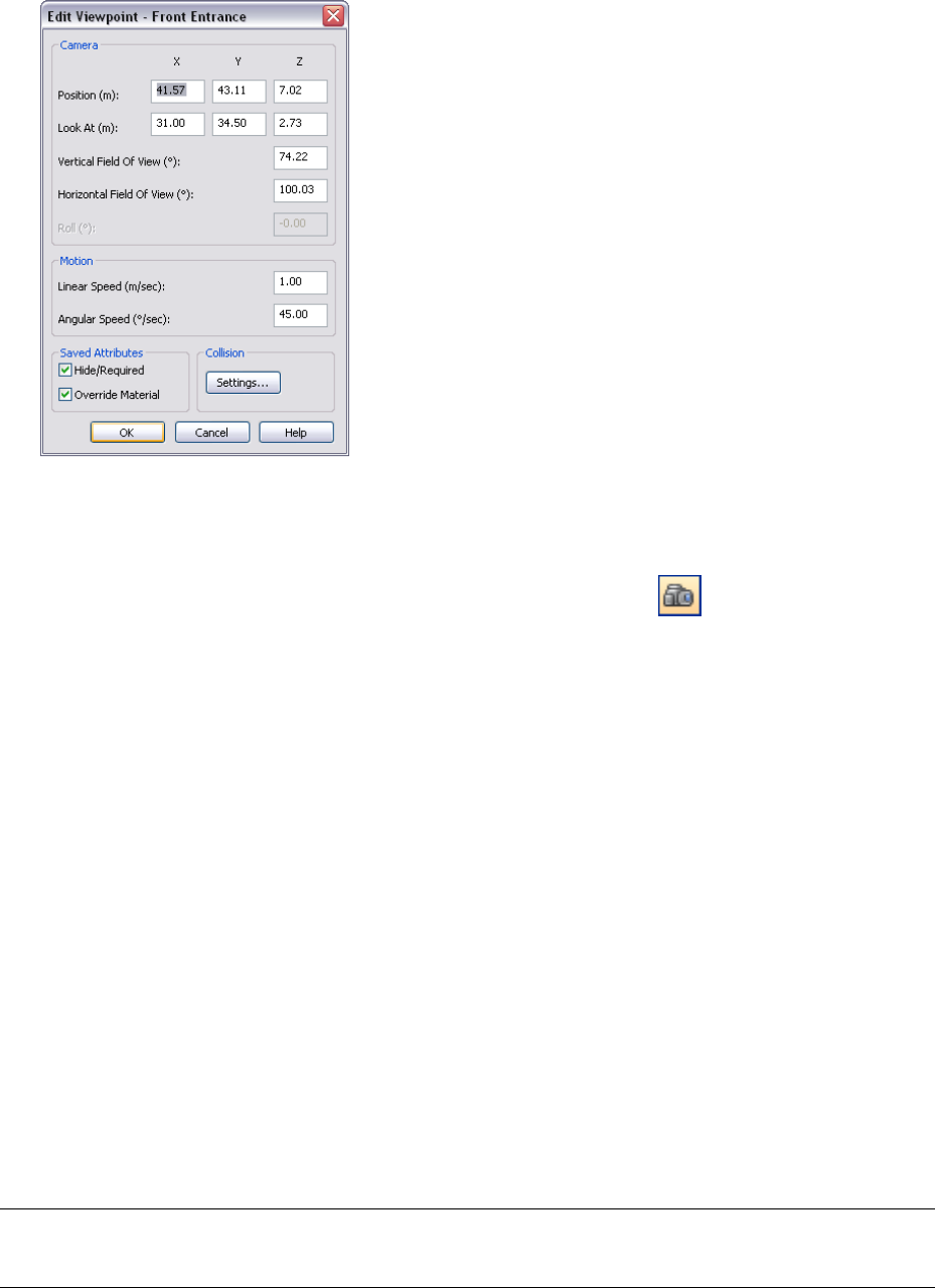
3Use the Edit Viewpoint dialog box to adjust the viewpoint’s attributes.
4Click OK.
To delete a viewpoint
1If the Saved Viewpoints window is not displayed, click Saved Viewpoints on the Workspace toolbar.
2Right-click the viewpoint you want to remove, and click Delete.
Default Viewpoint Options
Two view attributes can be saved with a viewpoint:
■Hide/Required - whether items are hidden or required.
■Override Materials - the color and transparency of items.
You can set a viewpoint to save either attribute by editing the viewpoint. To update changes to overridden
material or hide/required, use the Update option on the viewpoints shortcut menu. Be careful, though, as this
also updates the point of view as well, which may disrupt any redline information stored with the viewpoint.
By default these attributes are not stored with new saved viewpoints. If you do wish them to be saved by default,
then this can be set in the Options Editor.
Default collision settings can also be saved with a viewpoint, including whether collision, gravity, crouching,
and third person view are enabled.
You can set a viewpoint to save any of these settings by editing the viewpoint, in the same way as the view
attributes.
By default, all of the collision settings are disabled. If you want to save your preferred collision setting defaults,
use the Options Editor.
NOTE When you modify the default viewpoint settings, your changes do not affect the currently opened Autodesk
Navisworks file. They are used as soon as you open a new Autodesk Navisworks file, or start a new Autodesk Navisworks
session.
To set the default view attributes
1Click Tools ➤ Global Options.
242 | Chapter 9 Use Viewpoints and Sectioning Modes
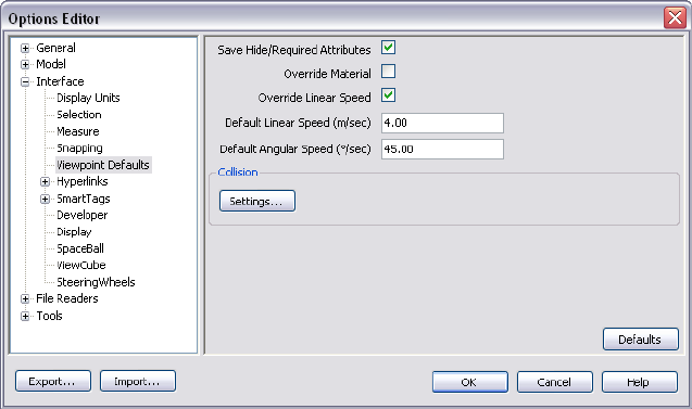
2In the Options Editor, expand the Interface node, and click the Viewpoint Defaults option.
3Select the Save Hide/Required Attributes check box if you want to save the hidden and required items with
the viewpoints you save. This means that when returning to those viewpoints, the items that were hidden
when the viewpoint was saved will be hidden again and those that were drawn will be drawn again. By
default, this check box is clear, as it requires a relatively large amount of memory to save this state information
with each viewpoint.
See “Hide Objects” on page 185 for more information on hidden items, and “Make Objects Required” on
page 175 for more information on making items required.
4Select the Override Material check box if you want to save the material overrides with the viewpoints you
save. This means that when returning to those viewpoints, the material overrides set when the viewpoint
was saved will be reinstated. By default, this check box is clear as it requires a relatively large amount of
memory to save this state information with each viewpoint.
See “Manipulate Object Attributes” on page 205 for more information on overriding materials.
5Select the Override Model Linear Speed check box to be able to set a specific speed to navigate on loading
a model. Without this selected, the linear navigation speed is directly related to the size of the model loaded.
6The Default Angular Speed can be set to any number of degrees per second. This affects the speed at which
the camera turns.
7Click OK.
To set the default collision options
1Click Tools ➤ Global Options.
2In the Options Editor, expand the Interface node, and click the Viewpoint Defaults option.
3On the Viewpoint Defaults page, click the Settings button.
4In the Default Collision dialog box, select the default options you want Autodesk Navisworks to initialize
with.
Default Viewpoint Options | 243
5Click OK to return to the Options Editor.
6Click OK to save the changes.
Share Viewpoints
You can export saved viewpoints from Autodesk Navisworks into an .xml file, and share them with other users.
For more information, see “Export Viewpoints” on page 268 and “Import Viewpoints” on page 261.
Sectioning
There are two sectioning modes available from the Sectioning toolbar: planes and box.
Planes mode allows you to make up to six sectional cuts in any plane while still being able to navigate around
the scene, enabling you to see inside models without hiding any item.
Section planes are stored inside viewpoints and so can also be used within viewpoint animations and object
animations to show a dynamically sectioned model. See “Saved Viewpoints Window” on page 237 for more
information on viewpoints, and “Record and Play Animations” on page 251 for more information on animations.
Slices can also be created using two opposing section planes and linking them. In this way you can move a slice
through the scene in real time and can again link this to viewpoint animations, object animations, and viewpoints.
Box mode enables you to define a section box to focus your review on specific and limited areas of the model.
As you move the box around, only the geometry within the defined section box is displayed in the Scene Area.
244 | Chapter 9 Use Viewpoints and Sectioning Modes
To open the Sectioning toolbar
➤ Right-click anywhere in the toolbar area of the screen, and click Sectioning on the shortcut menu.
Toolbar: Workspace ➤ Sectioning
Enable Section Planes
To view cross-sectional cuts of your model, you can enable up to six section planes. Only one plane is active at
a time, but it is possible to link two section planes together to form slices.
The section plane that is active is numbered in the drop-down box on the Sectioning toolbar.
To enable a section plane
1Select the Planes mode on the Sectioning toolbar.
2Select the plane you want to enable in the drop-down box. In this box, there will always be one more than
the number of enabled section planes in the scene, up to a maximum of 6.
3Click the Enable/Disable button.
Position and Use Section Planes
Once you have enabled at least one section plane, you can align it, and then use the slider to control how the
section plane moves through the model.
Each section plane remembers its settings (alignment, slider position, step size and so on).
If you have more than one section plane enabled, you can delete the currently active plane using the Delete
button. The next enabled plane will then become the active plane.
Alignment Modes
By default, section planes are aligned to the top of your model. This means using the section plane enables you
to view top-down into your model. You can use the Sectioning toolbar to select a different mode of alignment:
■Align Top - aligns section plane with top of model. This is the default option.
■Align Bottom - aligns section plane with bottom of model.
Enable Section Planes | 245
■Align Front - aligns section plane with front of model.
■Align Back - aligns section plane with back of model.
■Align Left - aligns section plane with left of model.
■Align Right - aligns section plane with right of model.
■Align To Line - enables you to pick a line, and place the section plane ‘on’ that line, at the point where
you clicked, and aligned so that its normal is on the line itself, facing towards the camera.
■Align To Surface - enables you to pick a surface, and place the section plane ‘on’ that surface, with its
normal aligned to the normal of the triangle picked.
■Align To View - aligns section plane with camera view plane.
Slider Behavior
The slider behavior depends on the selected mode of section alignment. By default, the range of slider represents
the entire extents of the model in the selected direction. For example, for section planes aligned to top, moving
the slider moves the plane from the very top to the very bottom of the model; for section planes aligned to
bottom, moving the slider moves the plane from the very bottom to the very top of the mode, and so on.
It is possible to restrict the range of the slider movement, and set a finer resolution for sectioning large models.
The Set Range button enables you to limit the range of the section planes to the bounding box limits of
the currently selected items. Clicking this button with nothing selected resets the range back to default.
You can also control the Step Size of the slider; it dictates the incremental value by which the slider moves when
you single-click rather than drag on it.
If the Step Size in not enabled, the slider will move at percentage intervals when you single-click on it.
To align a section plane to one of the pre-fixed directions
1On the Sectioning toolbar, select the plane you want to align in the drop-down box.
2If it’s not already enabled, click .
3Select one of the six pre-fixed directions from the alignment button menu, for example, Align Right
.
Autodesk Navisworks updates the position and alignment of the section plane.
To align a section plane to line
1On the Sectioning toolbar, select the plane you want to align in the drop-down box.
2If it’s not already enabled, click .
3Select Align To Line from the alignment button menu.
The cursor changes to a target .
4In the Scene Area, click somewhere on the line you want to align to.
246 | Chapter 9 Use Viewpoints and Sectioning Modes
Autodesk Navisworks updates the position and alignment of the section plane, so that it is placed at the
point you clicked.
To align a section plane to surface
1On the Sectioning toolbar, select the plane you want to align in the drop-down box.
2If it’s not already enabled, click .
3Select Align To Surface from the alignment button menu.
The cursor changes to a crosshair .
4In the Scene Area, click somewhere on an object you want to align to.
Autodesk Navisworks updates the position and alignment of the section plane so that it is placed ‘on’ the
surface of the selected object.
To align a section plane to view
1On the Sectioning toolbar, select the plane you want to align in the drop-down box.
2If it’s not already enabled, click .
To set the slider step size
1On the Sectioning toolbar, select the required section plane in the drop-down box.
2If it’s not already enabled, click .
3Click the Step Size button.
4In the Sectioning Plane dialog box, select the Enable check box, enter the desired value into the text box
below, and click OK.
To move a section plane through the model
1On the Sectioning toolbar, select the required section plane in the drop-down box.
2If it’s not already enabled, click .
3If necessary, change the alignment of the section plane, and set up the slider step size.
4Move the slider to interactively position the section plane to the required location. Clicking the slider causes
it to move incrementally. The distance shown in the edit box is the distance from the 'base point' that is
set by the alignment. So if you chose 'Top' alignment, it is the distance from the top of the model, if you
chose 'Left' alignment, it's the distance from the left, and so on. You can type the distance value directly
into the edit box (instead of using the slider).
TIP You can also use the cursor keys and mouse wheel for simple sliding of the section plane through the model.
5If you want to restrict the range of the section plane movement to specific items, select them in the Scene
Area, and click the Set Range button.
Position and Use Section Planes | 247
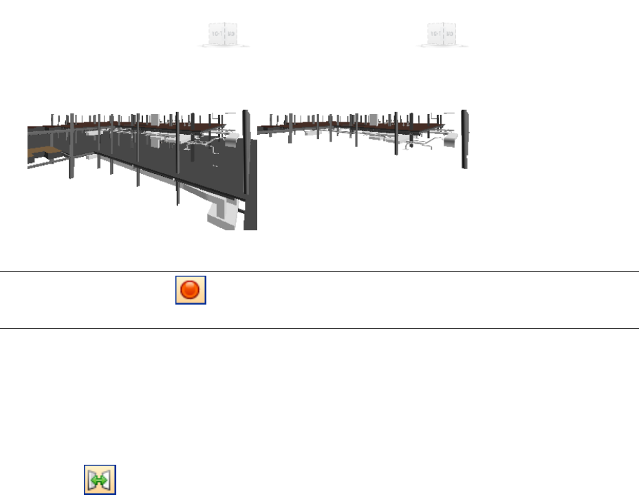
Link Section Planes
In Autodesk Navisworks, you can link any two section planes together, so they move as one. Doing this enables
you to quickly slice your model in real time. The slices can be used in viewpoints, viewpoint animations, and
object animations.
In practice, you should only link parallel planes together, such as top and bottom, left and right, front and back.
This is because linking together section planes that are at right angles to each other, and then moving them will
have no visible effect on the model.
Also, you may have unpredictable results if you try to link section planes that are aligned to lines, surfaces, or
view.
To link two parallel planes together
1Begin by setting up two parallel section planes, for example, the first one aligned to Top, and the second
one aligned to Bottom. You can use the slider to adjust the position of each of the planes (that is how far
you want them separated in the slice).
2Click the Link button.
3Move the slider. Now when you move one of the section planes, the other one moves with it, effectively,
creating a slice through the model.
NOTE You can click the Record button on the Animation toolbar, and record a viewpoint animation showing
the model as it is sliced. You can also save the configured slice as a viewpoint, and return to it later.
Enable and Use Section Boxes
You can define a section box to focus your review on specific and limited areas of the model. Once you’ve set
the box size, you can use the X, Y, Z boxes on the Sectioning toolbar to move the box around the model. By
default, the range of box movement covers the entire extents of the model.
It is possible to restrict the range of the box movement, and set a finer resolution for sectioning large models.
The Set Range button enables you to limit the range of the section box to the bounding box limits of the
currently selected items. Clicking this button with nothing selected resets the range back to default.
You can also specify the Step Size used to control the X, Y, Z boxes; it dictates the incremental value by which
the box moves when you single-click on the up/down arrows next to each box.
If the Step Size in not enabled, the box will move at percentage intervals when you single-click on the up/down
arrows.
Once defined, the box remembers its settings.
248 | Chapter 9 Use Viewpoints and Sectioning Modes
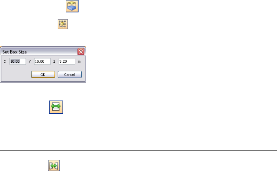
To enable and use a section box
1Select the Box mode on the Sectioning toolbar.
2Click the Enable/Disable button.
3Click the Set Box Size button.
4In the Set Box Size dialog box, enter the X, Y, Z values to define the box, and click OK.
Autodesk Navisworks creates the sectioning box in the center of the model.
5Click the Step Size button.
6In the Sectioning Plane dialog box, select the Enable check box, enter the desired value into the text box
below, and click OK.
7Use the X, Y, and Z numeric steppers to move the sectioning box around the model.
TIP If you want to restrict the range of the box movement to specific items, select them in the Scene Area, and
click the Set Range button.
Enable and Use Section Boxes | 249
250 | Chapter 9 Use Viewpoints and Sectioning Modes
Record and Play
Animations
In Autodesk Navisworks there are two types of animation: viewpoint animation
and object animation.
Viewpoint Animation
Viewpoint animation is a quick and efficient way of recording both your
movement through the model and views of the model. There are two ways to
produce a viewpoint animation in Autodesk Navisworks:
■By recording interactive navigation
■By creating animated transitions between saved views
You can also create slide show animations, which are, essentially, viewpoint
transitions with a number of cuts (pauses) added between viewpoints.
Object Animation
In addition to viewpoint animation, you can also animate and interact with 3D
geometry in your model. Although the ability to record animations and produce
scripts necessary to interact with animated objects is limited to users with access
to the Animator and Scripter functionality, any user can actually play them back
once they have been recorded.
Create and Edit Viewpoint Animations
There are two ways to create viewpoint animations in Autodesk
Navisworks. You can either simply record your real-time walk
through, or you can assemble specific viewpoints for Autodesk
Navisworks to interpolate into a viewpoint animation later.
Viewpoint animation is controlled through the Tools ➤ Animation
menu, the Saved Viewpoints dockable window, and the Animation
toolbar.
It is worth remembering that you can hide items in viewpoints,
override colors and transparencies and set multiple section planes
and these will all be respected by a viewpoint animation. This way
you can easily create powerful viewpoint animations.
Once a viewpoint animation is recorded, you can edit it to set the
duration, the type of smoothing and whether it loops or not.
10
251
There is also nothing to stop you copying viewpoint animations (hold down the CTRL key when dragging an
animation on the Saved Viewpoints window), dragging frames off the animation into a blank space on the Saved
Viewpoints window to remove them from the viewpoint animation, editing individual frames attributes, inserting
cuts or dragging other viewpoints or viewpoint animations onto the existing one, to continue developing your
animations.
Animation Cuts (Pauses)
Cuts in a viewpoint animation are simply points where the camera pauses for a while. They are inserted
automatically when you click Pause during the interactive recording of a viewpoint animation, or you can insert
them manually into an existing viewpoint animation.
To create a viewpoint animation in real time
1If the Animation toolbar is not displayed, right-click anywhere in the toolbar area of the screen, and click
Animation on the shortcut menu.
2Click the Record button on the Animation toolbar.
3Navigate around in the Scene Area while Autodesk Navisworks records your movement. You can even move
the section planes through the model during your navigation, and this will be recorded into the viewpoint
animation too.
4At any point during the navigation, you can click the Pause button . This will pause the recording while
you maneuver into a new position. Click the Pause button again to continue recording the viewpoint
animation. The resulting viewpoint animation will contain a “cut” on page 252 for the duration of the pause.
5When finished, click the Stop button .
6If the Saved Viewpoints window is not displayed, click View ➤ Control Bars ➤ Saved Viewpoints. This is
where your new viewpoint animation called "AnimationX", where 'X' is the latest available number, is added
to. The name will be editable at this point if you want to name it yourself. This viewpoint animation will
also become the current active animation in the Available Animations drop-down box on the Animation
toolbar.
While the above method is useful for creating quick viewpoint animations on the fly, sometimes you need more
control over the viewpoint camera. To do this in Autodesk Navisworks, you need to set up several viewpoints
and add them to an empty viewpoint animation. When playing back the animation, Autodesk Navisworks will
then interpolate between these viewpoints.
To create an animation frame by frame
1If the Saved Viewpoints window is not already displayed, click View ➤ Control Bars ➤ Saved Viewpoints.
2Right-click the Saved Viewpoints window, and click Add Animation on the shortcut menu.
A new viewpoint animation called "AnimationX", where 'X' is the latest available number, will be added to
the Saved Viewpoints window. The name will be editable at this point if you want to name it yourself. There
will be no plus sign next to the viewpoint animation, showing that the viewpoint animation is indeed
empty.
3Create the viewpoints where you want the camera to move through during the animation and save these
on the Saved Viewpoints window. They will become the frames for the animation. The more frames you
have, the smoother and more predictable the viewpoint animation will be. See “Save Viewpoints” on page
240 for more information on creating viewpoints.
4When you have all required viewpoints, simply drag them onto the empty viewpoint animation you just
created. You can drag them on one-by-one, or you can select multiple viewpoints using the CTRL and SHIFT
keyboard keys and drag several on at once. If you drop them onto the viewpoint animation icon itself, then
the viewpoints will become frames at the end of the animation, but you can drop the viewpoints anywhere
on the expanded animation to put them where you wish.
252 | Chapter 10 Record and Play Animations
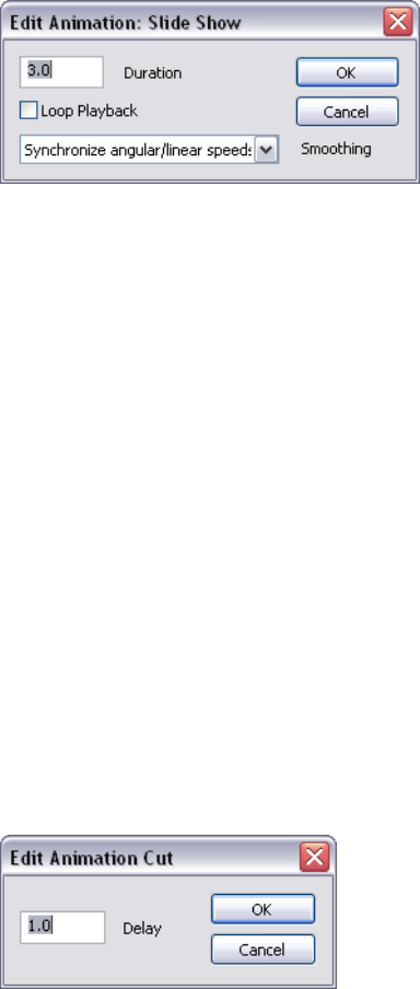
5At this point, you can use the Animation Position slider on the Animation toolbar to move backward and
forward through the viewpoint animation to see how it looks.
6You can edit any of the viewpoints inside the viewpoint animation (see “Edit Viewpoints” on page 241 for
details on this), or you can add more viewpoints, delete them, move them around, add cuts, and edit the
animation itself until you are happy with the viewpoint animation.
7Once you have several viewpoint animations, you can drag and drop them onto a master viewpoint animation
to compose more complex combinations of animations, just like dragging and dropping viewpoints onto
an animation as a frame.
To edit a viewpoint animation
1If the Saved Viewpoints window is not already displayed, click View ➤ Control Bars ➤ Saved Viewpoints.
2Right-click the viewpoint animation you want to modify on the Saved Viewpoints window, and click Edit
on the shortcut menu.
3In the Edit Animation dialog box, type in the duration in seconds in the Duration box.
4If you want the viewpoint animation to play back continuously, select the Loop Playback check box.
5From the Smoothing drop-down list, select the type of smoothing you want the viewpoint animation to
use.
None means that the camera will move from one frame to the next without any attempt at smoothing out
the corners.
The speed of movement between frames of an animation is dictated by the angular and linear speeds of the
individual frames and so choosing Synchronize Angular/Linear Speeds will smooth the differences between
the speeds of each frame in the animation, resulting in a less jerky animation.
6Click OK.
To insert cuts (pauses) into a viewpoint animation
1If the Saved Viewpoints window is not already displayed, click View ➤ Control Bars ➤ Saved Viewpoints.
2Right-click the animation frame below where you want to insert the cut, and click Add Cut on the shortcut
menu.
3Type in the name of the cut, or press Enter to accept the default name, which will be "CutX", where 'X' is
the next available number.
4The default duration of a cut is 1 second. To alter the duration of this pause, right-click the cut, and click
Edit on the shortcut menu.
5In the Edit Animation Cut dialog box, type in the duration of the pause in seconds.
6Click OK.
Create and Edit Viewpoint Animations | 253

Play Animations
You can play back both pre-recorded object animation and viewpoint animation in the Scene Area.
The viewpoint animations play in real time; this means that the Autodesk Navisworks engine is still attempting
to maintain the guaranteed frame rate so some drop-out may still occur, just as in real-time navigation.
To play back an animation
1If the Saved Viewpoints window is not already displayed, click View ➤ Control Bars ➤ Saved Viewpoints.
2Select the animation you want to play back from either the Saved Viewpoints window, or from the Available
Animations drop-down list on the Animation toolbar.
3You can use the Animation Position slider to quickly move forwards and backwards through the animation.
Full left is at the beginning and full right is at the end. The text box next to the slider shows the point in
time (in seconds) through the animation that the camera is. You can type a number into this box to set the
camera at a certain point in the animation and play back from that point.
4For viewpoint animations, you may notice that the frame in the animation in the Saved Viewpoints window
is highlighted when the animation is playing. You can click on any frame to set the camera to that point
in time in the viewpoint animation and continue playing back from there.
5Use the VCR buttons on the “Animation Toolbar” on page 66 to step and play forwards and backwards
through the animation.
To enable scripting
➤ To enable animation scripts in your file, click the Toggle Scripts button on the Animation toolbar.
You can now interact with your model. For example, if there is a script to open a door on pressing a specific
key on the keyboard, pressing this key will open the door.
254 | Chapter 10 Record and Play Animations
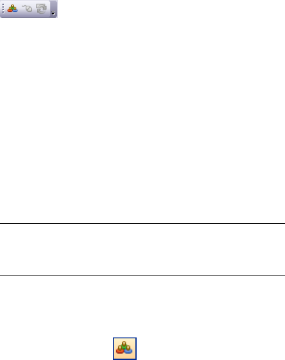
Work Within a Team
Autodesk Navisworks Review 2010 enables multiple users to participate in a single
design review session across a Local Area Network (LAN). This utilizes the shared
program features of Windows NetMeeting, available to all Windows users.
Collaborate Toolbar
The Collaborate toolbar contains the collaboration tools necessary
to run collaboration sessions.
If the Collaborate toolbar is not displayed, right-click anywhere in
the toolbar area of the screen, and click Collaborate Bar on the
shortcut menu.
Collaboration Session
All meeting participants require access to a Autodesk Navisworks
.nwf or .nwd file, in a shared location. One of the participants will
'host' the meeting and place a call to invite the others to join the
meeting. Any of the participants who have joined the meeting can
take control and drive the session. All navigation performed by the
driver will be displayed in the Scene Area on each of the participants’
machines. Any viewpoints or redlines (for example) added during
the session can be updated on all participants’ machines at the click
of a button.
NOTE If a collaborative review session, as outlined here, is not
conducted in single room, then additional teleconferencing provisions
could be necessary. This may be using the NetMeeting Whiteboard, or
your own telephone system.
To start a collaboration session
1Open the Autodesk Navisworks file that you want to collaborate
on from a shared directory.
2Click the Collaborate button on the Collaborate toolbar.
This initializes Windows NetMeeting.
11
255
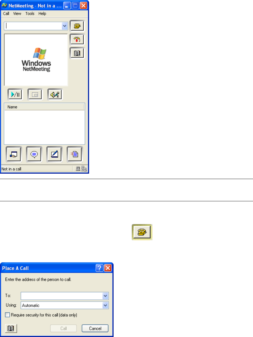
NOTE The first time Windows NetMeeting initializes, a Setup wizard will take you through the setup process.
You will need to enter your name and email address. When using NetMeeting on a LAN you do not need to log
onto a directory server, as these will not be available to you.
To place a call, inviting attendees to join
1Having initialized Windows NetMeeting, click the Call button in the NetMeeting dialog box.
2In the Place a Call dialog box, enter the machine name or IP address of the machine you wish to join the
meeting into the To box.
3Click the Call button to send the invite.
Once the person receiving the invite accepts this, both their name and yours will be listed in the NetMeeting
dialog box.
4Repeat this procedure to invite all required participants.
256 | Chapter 11 Work Within a Team
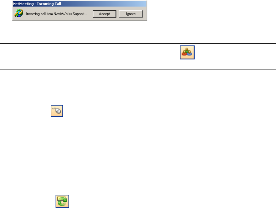
To accept an invitation
1When you are invited to join a meeting, the Incoming Call dialog box is displayed.
2Click the Accept button to join the meeting, or Ignore to decline the invitation.
NOTE Once you have accepted a call, you will need to click the Collaborate button on the Collaborate toolbar
to start your own collaboration session.
To become the driver
During a collaboration meeting, anyone in the call can take control of the session and become the 'driver'. The
driver will control navigation of the shared model on all machines in the call.
1Click the Drive button on the Collaborate toolbar.
2Upon clicking the drive button, all other users in the call will receive a message advising that you are
requesting control. They will have to answer Yes to this message if you are to drive Autodesk Navisworks
on their machine.
To refresh all attendees machines
Although real-time navigation in Autodesk Navisworks can be performed on all machines in a call by one user,
it is not possible for review data such as saved viewpoints, comments and redlines, to be automatically updated
on all users' machines. This information can, however, be updated on their machines by refreshing the model.
This refresh process can be performed on one users machine and refresh all machines in the call.
➤ Click the Refresh button on the Collaborate toolbar.
Collaboration Session | 257
258 | Chapter 11 Work Within a Team
Share Data
Print
You can print a hard copy of the current viewpoint to any printer
or plotter.
Print Preview
Before you print out a copy of the model you are working on, you
may wish to see how it will appear.
To preview model before printing
1Click File ➤ Print Preview.
2Use the Zoom In and Zoom Out buttons to do just that with
the preview image.
3Click Print.
4In the Print dialog box, click OK.
Print Setup
This option enables you to the set up paper size and orientation
options.
To change the print setup
1Click File ➤ Print Setup.
2In the Print Setup dialog box, make changes as required to the
paper and orientation.
3Click the Properties button if you want to change
printer-specific settings.
4Return to the Print dialog box, and click OK to print the image.
12
259
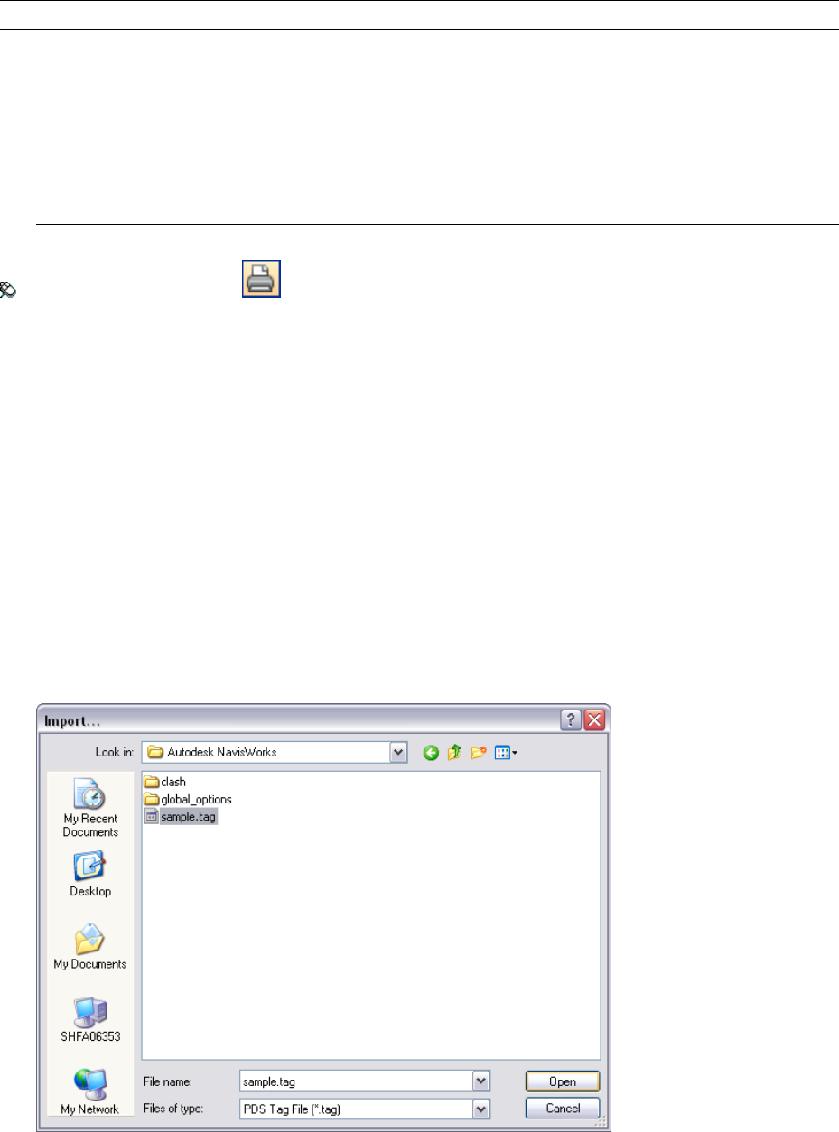
Print Current Viewpoint
When the print option is selected, Autodesk Navisworks prints the current viewpoint scaled to fit and centered
on the page.
NOTE If you would prefer to export an image for printing, see “Export an Image” on page 266 for more information.
To print the current viewpoint
1Click File ➤ Print.
2Check the printer settings are as required, and click OK.
NOTE The maximum image size is 2048x2048 pixels.
The Properties button controls printer-specific ink and paper settings.
Toolbar: Standard ➤ Print
Import Files
The import option inputs Intergraph PDS review data, including: PDS Tags (.tag) and PDS Display Sets (.dst).
It is also possible to import various data that has been exported from previous Autodesk Navisworks sessions.
PDS Tag Files
Tag information from Intergraph PDS contains a unique ID, saved viewpoint and corresponding comments. Tag
information created in Autodesk Navisworks may also be exported to be used in Intergraph PDS. See “PDS Tag
Files” on page 264.
To import a PDS tag file
1Click File ➤ Import ➤ PDS Tags.
2Use the Import dialog box to locate the desired .tag file.
260 | Chapter 12 Share Data
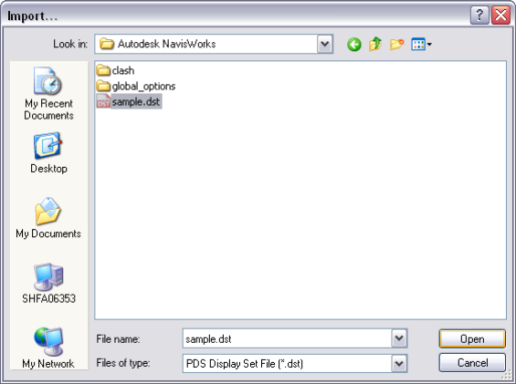
3Click Open to import the PDS data.
PDS Display Set Files
Display sets from Intergraph PDS contain detailed criteria, defining item selections. When imported into Autodesk
Navisworks, .dst files create Search Sets in the Selection Sets window.
See also:
■“Selection Sets Window” on page 191
To import PDS display sets
1Click File ➤ Import ➤ PDS Display Sets.
2Use the Import dialog box to locate the desired .dst file.
3Click Open to import the PDS display sets.
Viewpoints Files
Viewpoints can be imported into Autodesk Navisworks via an .xml file, enabling you to bring viewpoints into
the current scene from another model file. For example, if you are working on different versions of the same
model, you can save viewpoints in one version of the file, export them and then import them into the other
version. See “Save Viewpoints” on page 240 for more information on saving viewpoints, and “Export Viewpoints
Files” on page 268 for more information on exporting viewpoints to an .xml file.
To import viewpoints and associated data
1Click File ➤ Import ➤ Viewpoints XML.
2In the Import dialog box, locate the desired viewpoints .xml file.
PDS Display Set Files | 261
3Click Open.
Search Criteria Files
Search criteria can be imported into Autodesk Navisworks. This will populate the Find Items window. The search
can then be run on the current model, finding any items that match the specific criteria. See “Find Items Window”
on page 186 for more information on searching the model for items based on their properties.
To import saved search criteria
1Click File ➤ Import ➤ Search XML.
2In the Import dialog box, locate the desired search .xml file.
3Click Open.
Search Set Files
Search sets can be imported into Autodesk Navisworks. This will populate the Selection Sets window with
pre-defined search sets. Selecting an imported Search Set will define the current Find Items criteria and search
262 | Chapter 12 Share Data
the current model accordingly. See “Find Items Window” on page 186 for more information on searching the
model for items based on their properties.
To import saved search sets
1Click File ➤ Import ➤ Search Sets XML.
2In the Import dialog box, locate the desired search sets .xml file.
3Click Open.
Export Files
Piranesi EPix Format
To export an .epx file for rendering in Informatix’s Piranesi
1File ➤ Export ➤ Piranesi EPix
2In the Piranesi EPix dialog box, click the Browse button to locate a destination and enter a new filename
to export, if you want to change from the existing filename and location.
3Select the sizing options for the file to be exported:
■Type - sets the size of the exported image as follows:
Explicit. Gives you full control of the width and height (the dimensions are in pixels).
Use Aspect Ratio. Enables you to specify the height. The width is automatically calculated from the
aspect ratio of your current view.
Use View. Uses the width and height of your current view.
■Width - enables you to enter the width in pixels, when available.
■Height - enables you to enter the height in pixels, when available.
4Select the desired value in the Anti-Aliasing box. This option applies to OpenGL renderer only. Anti-aliasing
is used to smooth the edges of the exported images. The higher the number, the smoother the image, but
the longer they take to export. 4x is adequate for most situations.
5Click Save.
Export Files | 263
PDS Tag Files
To export PDS tags
1Click File ➤ Export ➤ PDS Tags.
2In the Export dialog box, enter a new filename and location, if you want to change from those suggested.
3Click Save.
Autodesk DWF Format
Autodesk DWF files can be exported from Autodesk Navisworks. The file exporter creates a .dwf file containing:
■All geometry
■All materials
■Per-vertex colors
■Properties (where available)
To export a DWF file
1Click File ➤ Export ➤ Autodesk DWF.
2In the Export dialog box, enter a new filename and location, if you want to change from those suggested.
3Click Save.
Google Earth KML Format
Google Earth KML files can be exported from Autodesk Navisworks. The exporter creates a compressed KML file
with the extension .kmz and supports the export of:
■Triangles
■Lines
■Materials (color and flat transparency only)
■Viewpoints (adjustments may occur due to Google Earth limitations)
■Model Hierarchy
■Hyperlinks (currently only URLs work correctly in Google Earth)
To export to Google Earth KML files
1Click File ➤ Export ➤ Google Earth KML
2In the KML Options dialog box, select the Export Model Relative to Terrain Height check box to put Google
Earth in a mode where all heights are measured from the surface of the ground. When this is check box is
clear all heights are measured from sea-level.
264 | Chapter 12 Share Data
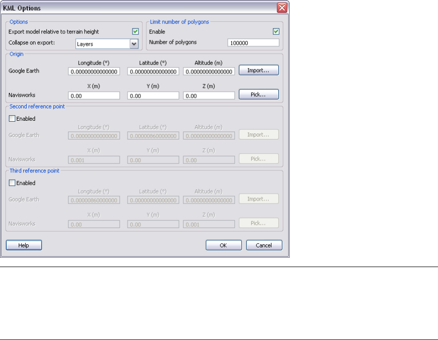
NOTE When positioning a model relative to sea level, the height of the Google Earth reference points must also
be measured relative to sea level. When positioning a model relative to the ground, the Google Earth reference
points must be measured relative to the ground.
Google Earth always places new placemarks at an altitude of zero, irrespective of whether that is relative or
absolute.
3The Collapse on Export drop-down list allows different levels of collapsing parts of the model hierarchy in
the exported file. Choose from:
■None - ensures the whole hierarchy is exported
■All Objects - collapses everything into one node
■Files - collapses each file into one node
■Layers - collapses each layer into one node
4Select the Enable check box in the Limit Number of Polygons area to restrict the amount of geometry
exported into the output file. Geometry is selected on the basis of taking the most obvious objects in
preference to the fine detail. If the exported file is too large for Google Earth to display, try enabling this
and reducing the number of polygons. Clicking View ➤ Scene Statistics in Autodesk Navisworks shows
the number of triangles and/or lines in the current project. By setting a polygon limit you are choosing to
export only some of these items.
5The Origin position values are the first pair of reference points on the Google Earth surface, and must always
be defined. The Autodesk Navisworks reference point will always be positioned to exactly overlay the Google
Earth reference point.
Second and Third reference points can be used, and if enabled then the position and orientation of the
model can be more accurately defined.
6Use the Import buttons to read-in saved placemark locations from KML files exported from Google Earth.
The Origin Import button differs slightly from the other two; if the KML file contains multiple placemarks,
this button will offer the user the choice of importing second and third reference points if available. The
other two buttons will only import a single reference point.
7The Pick buttons allow the reference point locations to be selected in the Scene Area.
Google Earth KML Format | 265
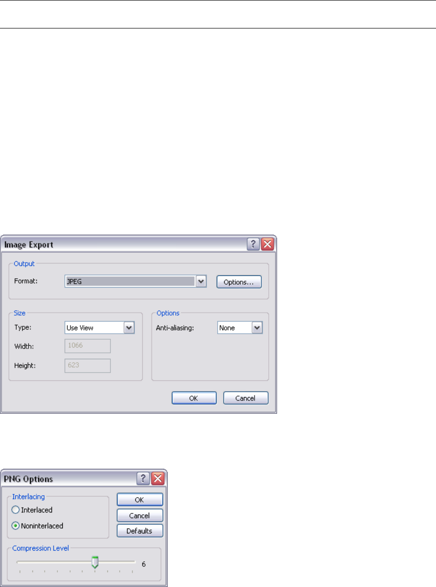
These points must be visible in the Scene Area prior to exporting, as once the KML Options dialog box is
open you will not be able to navigate before picking.
TIP You can use View ➤ Scene View ➤ Split Vertical or Split Horizontal to split the Scene Area into separate
views of each reference point.
8Click OK.
9In the Export dialog box, enter a new filename and location, if you want to change from those suggested.
10 Click Save.
Export Images
Export an Image
To export an image as a bitmap, .png, or .jpeg file
1Display the view you want to export in the Scene Area, and click File ➤ Export ➤ Image.
2In the Image Export dialog box, select the Format of the image you want to export.
3Use the Size and Options area to set the image size. See “Image Export Dialog Box” on page 314.
For .png file format, click the Options button, and use the PNG Options dialog box to specify the Interlacing
and Compression settings.
For .jpeg file format, click the Options button, and use the JPEG Options dialog box to specify the
Compression and Smoothing settings.
266 | Chapter 12 Share Data
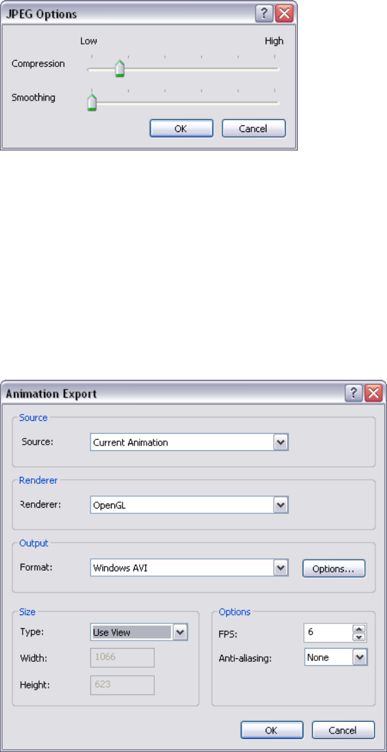
4Click OK.
5In the Save As dialog box, enter a new filename and location, if you want to change from those suggested.
6Click Save.
Export an Animation
To export an animation to an .avi file, or a sequence of image files
1Click File ➤ Export ➤ Animation.
The Animation Export dialog box opens.
2To export the currently selected viewpoint animation, select Current Animation in the Source box.
To export the currently selected object animation, select Current Animator Scene in the Source box.
3Set up the rest of the boxes in the Animation Export dialog box, and click OK. For more information, see
“Animation Export Dialog Box” on page 314.
4In the Save As dialog box, enter a new filename and location, if you want to change from those suggested.
5Click Save.
Export Images | 267

Viewpoints Files
Viewpoints can be exported from Autodesk Navisworks to an .xml file.
These viewpoints contain all associated data, including camera positions, sections, hidden items and material
overrides, redlines, comments, tags and collision detection settings.
Once the viewpoint data is exported to this text-based file format, it can either be imported into other Autodesk
Navisworks sessions, or it can be accessed and used in other applications. For example, you may want to set up
the same viewpoints in your CAD application.
To export viewpoints
1Click File ➤ Export ➤ Viewpoints XML.
2In the Export dialog box, enter a new filename and location, if you want to change from those suggested.
3Click Save.
Current Search Criteria
The search criteria specified in the Find Items window can be exported to an .xml file. This can then be imported
into other Autodesk Navisworks sessions. For example, if you have specified a complicated search criteria,
containing various logic statements, that relates to all projects you work on, then this feature allows you to
specify it once and use it on all projects.
For more information, see “Find Items Window” on page 186.
To export current search criteria
1Click File ➤ Export ➤ Current Search XML.
2In the Export dialog box, enter a new filename and location, if you want to change from those suggested.
3Click Save.
Search Set Files
Saved search sets can be exported from Autodesk Navisworks as an .xml file. These can then be imported into
other Autodesk Navisworks sessions and re-used. For example, if you have a number of generic searches that you
perform on all of your projects, this feature allows you to specify the searches once and use them on all projects.
For more information see, “Create and Manage Selection and Search Sets” on page 192.
To export search sets
1Click File ➤ Export ➤ Search Sets XML.
2In the Export dialog box, enter a new filename and location, if you want to change from those suggested.
3Click Save.
Viewpoints Report
An .html file can be exported containing a JPEG of all of the saved viewpoints and associated data, including
camera position and comments.
NOTE To customize the appearance or layout of the html file, you will need to edit the viewpoints_report_lang.xsl
file, where lang is a code representing your language. The installed file is located in the stylesheets subdirectory of the
Autodesk Navisworks install directory. You can copy the edited file to the stylesheets subdirectory of any of the Autodesk
Navisworks search directories. For more information, see “Search Directories” on page 84.
268 | Chapter 12 Share Data
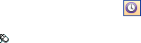
TimeLiner Playback
TimeLiner playback enables you to play back a TimeLiner construction sequence.
In this section, you will learn how to simulate your TimeLiner sequence throughout
the duration of the project schedule.
Overview of TimeLiner Tool
The TimeLiner tool adds 4D schedule simulation to Autodesk
Navisworks files.
In Autodesk Navisworks Review 2010, TimeLiner has a playback-only
option, allowing any externally created project data to be simulated,
but no changes to be made to that data.
TimeLiner Playback Window
The TimeLiner dockable window enables you to to set up and play
simulations.
To toggle the TimeLiner Playback window
■Click TimeLiner Playback on the Workspace toolbar.
Menu: Tools ➤ TimeLiner Playback
Simulate Tab
The Simulate tab enables you to simulate your TimeLiner sequence
throughout the duration of the project schedule.
13
269
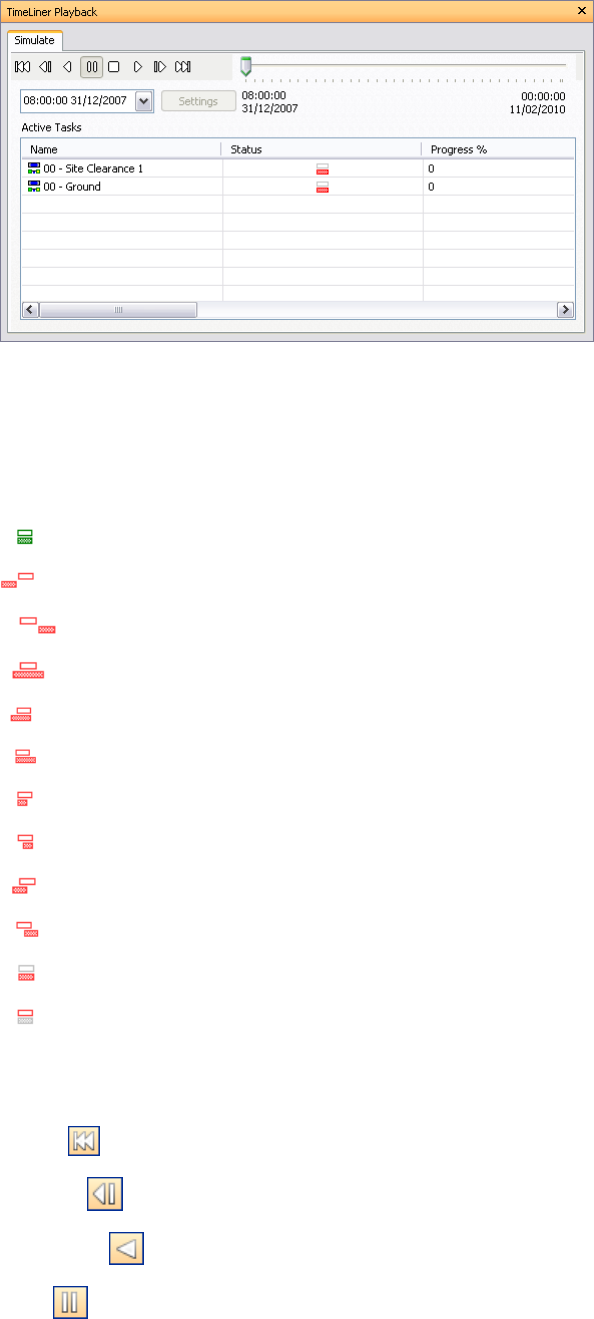
The Status Icons
Each task has its own Status identified by an icon, representing planned against actual relationships. Each icon
shows two bars. The top bar represents the Planned dates, and the bottom bar represents the Actual dates. If the
Actual Start and Finish dates are the same as the Planned Start and Finish dates, the bars are displayed in green.
Any variations between Planned and Actual dates are displayed in red. Missing Planned or Actual dates are shown
in grey.
Actual Start and End dates equal Planned Start and End dates.
Actual End date before Planned Start date.
Actual Start date after Planned End date.
Actual Start date before Planned Start date and Actual End date after Planned End date.
Actual Start date before Planned Start date and Actual End date equals Planned End date.
Actual Start date equals Planned Start date and Actual End date after Planned End date.
Actual Start date equals Planned Start date and Actual End date before Planned End date.
Actual Start date after Planned Start date and Actual End date equals Planned End date.
Actual Start date before Planned Start date and Actual End date before Planned End date.
Actual Start date after Planned Start date and Actual End date after Planned End date.
Actual Start and End dates only.
Planned Start and End dates only.
The Playback Controls
Use the standard VCR buttons to step and play forwards and backwards through the simulation:
Rewind will rewind the simulation back to the beginning.
Step Back will step back a single step size.
Reverse Play will play the simulation backwards.
Pause will pause the simulation at the time you press it at. You can then look around and interrogate the
model, or step forwards and backwards through the simulation. To continue playing from where you paused,
just press Play again.
270 | Chapter 13 TimeLiner Playback
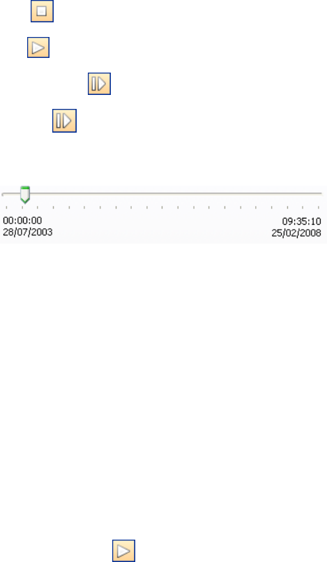
Stop will stop the simulation playing and rewind back to the beginning.
Play will play the simulation from the currently selected time.
Step Forwards will step forwards a single step size.
Forward will fast forward the simulation to the end.
You can use the Simulation Position slider to quickly move forwards and backwards through the simulation. Full
left is at the beginning and full right is at the end.
The Date/Time box below the VCR buttons shows the point in time through the simulation. You can click on
the drop-down icon to the right of the date to display a calendar, from which you can select a date to 'jump' to.
The Active Tasks
All Active Tasks are show in a multi-column table. You can move and resize table columns, if necessary.
You can view the current simulation time for each of the active tasks, and how close to completion they are
(Progress is displayed as a percentage). The Status of each active task is also displayed as an icon. For simulations
where Planned and Actual dates are available, the status provides a visual representation as to whether there is
any variance between the planned and actual dates. See “The Status Icons” on page 270 for more information.
Play Simulations
To play a simulation
1If the TimeLiner Playback window is not already open, click Tools ➤ TimeLiner Playback.
2Click the Play button on the Simulate tab.
The TimeLiner Playback window displays the tasks as they are carried out, and the Scene Area shows the
sections of the model added or removed over time, in accordance with the task types.
Play Simulations | 271
272 | Chapter 13 TimeLiner Playback

Autodesk Navisworks
Reference
File Options Dialog Box
Use this dialog box to control the appearance of the model and the
speed of navigation around it, and also to create and configure links
to external databases.
When you modify any of the options in this dialog box, your
changes are saved in the currently opened Autodesk Navisworks
file, and apply to this file only.
Menu: Tools ➤ File Options.
Culling Tab
Use this tab to adjust geometry culling in the opened Autodesk
Navisworks file.
Area
Enable Specifies whether area culling is used.
Number of Pixels Below Which Objects are Culled Specifies a
value for the screen area in pixels below which objects are culled.
For example, setting the value to 100 pixels means that any object
within the model that would be drawn less than 10x10 pixels in
size are discarded.
Clipping Planes
Near
Automatic Select this radio button to make Autodesk Navisworks
automatically control the near clip plane position to give you the
best view of the model. The Distance box becomes unavailable.
Constrained Select this radio button to constrain the near clipping
plane to the value set in the Distance box.
Autodesk Navisworks uses the provided value unless doing so affects
performance (for example, makes the whole model invisible), in
which case it adjusts the near clip plane position as necessary.
Fixed Select this radio button to set the near clipping plane to the
value provided in the Distance box.
14
273
Distance Specifies the farthest distance between the camera and the near clipping plane position in constrained
mode.
Specifies the exact distance between the camera and the near clipping plane position in fixed mode.
NOTE Nothing is drawn between the camera and the near clipping plane; when you override automatic mode, make
this value small enough to display your data. Also, overriding automatic mode with values under 1 can produce
unpredictable results.
Far
Automatic Select this radio button to make Autodesk Navisworks automatically control the far clipping plane
position to give you the best view of the model. The Distance box becomes unavailable.
Constrained Select this radio button to constrain the far clipping plane to the value set in the Distance box.
Autodesk Navisworks uses the provided value unless doing so affects performance (for example, makes the whole
model invisible), in which case it adjusts the far clip plane position as necessary.
Fixed Select this radio button to set the far clipping plane to the value provided in the Distance box.
Distance Specifies the closest distance between the camera and the far clipping plane position in constrained
mode.
Specifies the exact distance between the camera and the far clipping plane position in fixed mode.
NOTE Nothing is drawn beyond this plane; when you override automatic mode, make this value large enough to
include your data. Additionally, using the ratio of the far clipping plane to near clipping plane in excess of 10000 can
produce unwanted effects.
Backface
Turns on backface culling for all objects. Select from the following options:
■On - turns on backface culling for all objects.
■Off - turns off backface culling
■Solid - turns on backface culling for solid objects only. This is the default option.
TIP If you can see through some objects, or some object parts are missing, turn off backface culling.
TIP If you want to restore the default values, click the Defaults button.
Orientation Tab
Use this tab to adjust the real-world orientation of your model.
Up
X, Y, Z Specify the X, Y, and Z coordinate values. By default, Autodesk Navisworks takes the positive Z-axis as
Up.
North
X, Y, Z Specify the X, Y, and Z coordinate values. By default, Autodesk Navisworks takes the positive Y-axis as
North.
TIP If you want to restore the default values, click the Defaults button.
Speed Tab
Use this tab to adjust the frame rate speed to reduce the amount of drop-out during navigation.
TIP If this does not improve navigation, try switching off the Guarantee Frame Rate option.
Frame Rate Specifies the number of frames per second (FPS) that are rendered in the Scene View.
274 | Chapter 14 Autodesk Navisworks Reference
The default setting is 6. You can set the frame rate from 1 through 60 frames per second. Reducing the value
reduces drop-out, but can cause jerky movement during navigation. Increasing the value ensures a smoother
navigation, but increases drop-out.
TIP If you want to restore the default values, click the Defaults button.
Head Light Tab
Use this tab to change the intensity of the scene's ambient light and headlight for Head Light mode.
Ambient Use the slider to control the overall brightness of the scene.
Headlight Use the slider to control the brightness of the light located at the camera.
NOTE To see the effect your changes have on the model in the Scene View, apply Head Light mode.
Scene Lights Tab
Use this tab to change the intensity of the scene's ambient light for Scene Lights mode.
Ambient Use the slider to control the overall brightness of the scene.
NOTE To see the effect your changes have on the model in the Scene View, apply Scene Lights mode
DataTools Tab
Use this tab to create and manage links between the opened Autodesk Navisworks file and external databases.
DataTools Links Displays all database links in Autodesk Navisworks file. Select the check box next to the link
to activate it.
IMPORTANT You cannot activate links with insufficient or invalid configuration information.
Buttons
New Opens the New Link dialog box where you can specify the link parameters.
Edit Opens the Edit Link dialog box where you can modify the parameters for the selected database link.
Delete Deletes the selected database link.
Import Lets you select and open previously saved datatools files.
Export Saves the selected database link as a datatools file.
NOTE If you want to restore the default values, click the Defaults button.
File Units and Transform Dialog Box
Use this dialog box to adjust the file units and file transforms for the file selected in the Selection Tree.
NOTE You can only adjust file units and transforms for one file at a time.
Menu: Edit ➤ File Units and Transform
Shortcut menu: File Units and Transform
File Units
Units Lets you choose the units for the loaded file.
Origin
Origin Enter the X, Y, and Z coordinate values to move the file geometry into this position.
Head Light Tab | 275

Reflected Transform Select this check box if you use a negative scale for your transform.
Rotation
Enter the rotation angle.
Select the rotation axis by entering values greater than 0. The file geometry rotates about its origin point.
Scale
Enter the scaling factor around X, Y, and Z axis for the file geometry; 1 being the current size, 0.5 half, 2 being
double and so on. To scale proportionally, ensure the X, Y and Z scale values are equal. Entering negative values
flips the file geometry inside out.
New Link Dialog Box
Use this dialog box to add a database link to the opened Autodesk Navisworks file.
Pointing device: File Options dialog box ➤ DataTools tab ➤ New button
Name Specifies the name of the database link. This name appears as a tab on the Properties control bar. Each
link name must be unique.
Connection
ODBC Driver Defines the type of database for the link. Use the drop-down list to select the appropriate ODBC
Driver.
Setup Opens the Database Setup wizard. Use it to enter the connection options. If you have problems setting
up your connection details, contact your database administrator.
When you finish, the box underneath shows the connection string.
Hold Open for Application Lifetime Specifies whether the database link is open until you exit Autodesk
Navisworks.
SQL String Defines which table in the database to query. If you are not familiar with SQL, you may need to ask
your database administrator to set the SQL statement for you.
Fields
Defines which columns to display as link categories on the Properties control bar.
Field Name Specifies the name of the column in the selected database table. You must enter the exact name
Display Name Specifies the link category name shown on the Properties control bar. This name is automatically
completed for you, but you can modify it, if necessary.
Edit Link Dialog Box
Use this dialog box to modify the selected database link.
For information about the settings on this dialog box, see the “New Link dialog box” on page 276.
Pointing device: File Options dialog box ➤ DataTools tab ➤ Edit button
Edit Viewpoint Dialog Box
Use this dialog box to edit viewpoint atributes.
Menu: Viewpoint ➤ Edit Current Viewpoint
Camera
Position Enter the X, Y, and Z coordinate values to move the camera into this position.
Look At Enter the X, Y, and Z coordinate values to change the focal point for the camera.
276 | Chapter 14 Autodesk Navisworks Reference
Vertical Field of View, Horizontal Field of View Defines the area of the scene that can be viewed through the
camera. You can adjust the values for both vertical and horizontal angles of view. If the display units are set to
degrees, then these numbers should be between 0.1 and 90; and if in radians, between 0.002 and 3.124.
A larger value produces a wider angle of view and a smaller value produces a narrower, or more tightly focused,
angle of view.
NOTE When you modify the Vertical Field of View, the Horizontal Field of View is automatically adjusted, and vice
versa to match the aspect ratio in Autodesk Navisworks.
Roll Rotates the camera around its front-to-back axis. A positive value rotates the camera anticlockwise, and a
negative value rotates it clockwise.
NOTE This value is not editable where the viewpoint up vector stays upright (that is, in walk, orbit and turntable
modes).
Motion
Linear Speed The speed of motion in a straight line for the viewpoint. The minimum value is 0 and the maximum
is based on the size of the scene's bounding box.
Angular Speed The speed at which the camera turns.
Saved Attributes
This area applies to saved viewpoints only. If you are editing a current viewpoint, this area is not greyed out.
Hide/Required Select this check box to save hidden/required markup information about objects in your model
with the viewpoint. When you use a viewpoint again, the hidden/required markups set when the viewpoint was
saved are reapplied.
NOTE Saving the state information with each viewpoint requires a relatively large amount of memory.
Override Material Select this check box to save material override information with the viewpoint. When you
use a viewpoint again, the material overrides set when the viewpoint was saved are reapplied.
NOTE Saving the state information with each viewpoint requires a relatively large amount of memory.
Collision
Settings Opens the Collision dialog box.
Options Editor
Use the Options Editor to adjust program settings for Autodesk Navisworks sessions.
The settings that you set up in the Options Editor are persistent across all Autodesk Navisworks sessions. You
also share the modified settings with other members of your team.
The options are presented in a hierarchical tree structure. Clicking expands the nodes, clicking collapses
the nodes.
Menu: Tools ➤ Global Options
Shortcut menu: Global Options
Buttons
Export Displays the Select Options to Export dialog box, where you can select the global options you want to
export (or ‘serialize’). If an option cannot be exported, it is grayed out.
Import Displays the Open dialog box, where you can browse to the file with the required global option settings.
OK Saves the changes, and closes the Options Editor.
Cancel Discards the changes, and closes the Options Editor.
Help Displays the context-sensitive help.
Options Editor | 277
General Node
Use the settings in this node to adjust the buffer size, file locations, number of recent file shortcuts you want
Autodesk Navisworks to store, and the auto-save options.
TIP If you want to restore the default values, click the Defaults button.
Undo Page
Use the settings on this page to adjust the buffer size.
Buffer Size (kB) Specifies the amount of space Autodesk Navisworks allocates for saving undo/redo actions.
Locations Page
Use the options on this page to share global Autodesk Navisworks settings, workspaces, datatools, avatars, Clash
Detective rules, Presenter archives, custom Clash Detective tests, object animation scripts, and so on, with other
users.
The settings can be shared across an entire project site, or across a specific project group depending on the
required level of granularity.
When you run Autodesk Navisworks for the first time, the settings are picked up from the installation directory.
Subsequently, Autodesk Navisworks examines the current user profile and the all users profile on the local
machine, and then checks the settings in the Project Directory and the Site Directory. The files in the Project
Directory take precedence.
Project Directory Click to open the Browse for Folder dialog box, and locate the directory that contains
the Autodesk Navisworks settings specific to a project group.
Site Directory Click to open the Browse for Folder dialog box, and locate the directory that contains the
Autodesk Navisworks settings standard across the entire project site.
Environment Page
Use the settings on this page to adjust the number of recent file shortcuts stored by Autodesk Navisworks.
Maximum Recently Used Files Specifies how many file shortcuts Autodesk Navisworks can remember. By
default, shortcuts to the four most recently opened files can be displayed.
Communication Center Page
Use the settings on this page to adjust the settings for Communication Center.
Please Indicate the Country/Region Nearest to Your Current Location Set the country in which Autodesk
Navisworks users work. This is used for tailoring location-specific Communication Center content.
Check for New Online Content Specifies how often Communication Center checks for new content.
Content Filtering
Hide Old Content Indicates whether old content in Communication Center is hidden from view.
After Sets the number of days after which content is considered to be old.
Autodesk Channels Page
Use the settings on this page to select which channels you want to display in the Communication Center list.
By default, all available channels are selected. You cannot add or remove channels from the grid, and you cannot
edit data in the grid.
278 | Chapter 14 Autodesk Navisworks Reference
Balloon Notifications Page
Use the settings on this page to adjust balloon notifications.
Enable Balloon Notifications Indicates whether balloon notifications are turned on.
Display Duration Sets the length of time (in seconds) the balloon notifications are shown in the Status bar
before automatically disappearing.
Auto-Save Page
Use the setting on this page to adjust the auto-save options.
Enable Auto-Save Indicates whether Autodesk Navisworks automatically saves Navisworks files. By default, this
check box is selected.
Clear this check box if you do not want to save Navisworks files automatically.
Auto-Save File Location Specifies how the backup files are saved. Select from the following options:
■Auto-Save to a Specific Directory - this is the default option.
Directory
The default directory for auto-save is: <USERPROFILE>\ Application Data\<PRODUCTFOLDER>\AutoSave
Click to open the Browse for Folder dialog box, and select the desired location for auto-save.
Manage Disk Space
Indicates whether the size of the disk space restricts the creation of backup files. This check box is selected
by default.
Purge Old Auto-Save Files When This Folder Exceeds (MB)
Active when the Manage Disk Space check box is selected. Specifies the maximum directory size for backup
files. The default value is 512 MB. When the size of the auto-save folder exceeds the specified value, Autodesk
Navisworks deletes the oldest backup file (based on the date modified).
■Auto-Save Alongside the Current File
Frequency
Time Between Saves (minutes) Defines the time interval between auto-saves of significant file changes.
By default, a backup file is saved every 15 minutes following a significant change to a Navisworks file.
History
Maximum Previous Versions Determines how many backup files are stored. By default, it’s three files. When
the number of auto-saved files exceeds the specified value, Autodesk Navisworks deletes the oldest backup file
(based on the date modified).
Model Node
Use the settings in this node to optimize Autodesk Navisworks performance, and customize parameters for NWD
and NWC files.
TIP If you want to restore the default values, click the Defaults button.
Performance Page
Use the options on this page to optimize Autodesk Navisworks performance.
Memory Limit
Auto Indicates whether Autodesk Navisworks automatically determines the maximum memory that can be used.
Selecting this check box sets the memory limit to the lowest of your available physical memory or address space,
less that required for your operating system.
Model Node | 279
Limit (MB) Specifies the maximum memory that Autodesk Navisworks can use.
Merge Duplicates
These options improve performance by multiply instancing matching items. Rather than storing every item in
memory, if any items are the same, Autodesk Navisworks can store one instance of them and 'copy' that instance
into other positions. This is of particular benefit on larger models, where there are significant numbers of these
duplicate geometries.
On Convert Select this check box to merge duplicates when a CAD file is converted into the Autodesk Navisworks
format.
On Append Select this check box to merge duplicates when a new file is appended to the currently opened
Autodesk Navisworks file.
On Load Select this check box to merge duplicates when a file is loaded into Autodesk Navisworks.
On Save NWF Select this check box to merge duplicates when the current scene is saved in the NWF file format.
On Load
Collapse on Convert Collapses the tree structure on the Selection Tree to the specified level when native CAD
files are converted into Autodesk Navisworks. Select from the following options:
■None - the tree is fully expanded.
■Composite Objects - the tree is collapsed up to the level of composite objects.
■All Objects - the tree is collapsed up to the level of objects.
■Layers - the tree is collapsed up to the level of layers.
■Files - the tree is collapsed up to the level of files.
This enables performance to be prioritized over structure/properties and has the added benefit of improving
streaming by cutting down the logical structure.
NOTE Although Autodesk Navisworks tries to collapse items to the fewest number possible, it may be necessary to
prevent collapsing in some cases to preserve model fidelity. For example, if an item has properties or materials unique
to itself, then collapsing would endanger this information, and therefore it will not be collapsed.
Close NWC/NWD files on Load Indicates whether NWC and NWD files are closed once they’ve been loaded
into memory.
When you open NWC/NWD files, Autodesk Navisworks locks them for editing. By selecting this check box, you
instruct Autodesk Navisworks to close NWC or NWD files as soon as they’ve been loaded into memory. This
means that the files can be opened and edited by other users while you are viewing them.
Create Parametric Primitives Select this check box to enable creation of parametric models (models described
by formulae not vertices).
Using this option allows you to get better looking visuals, faster rendering, smaller memory footprint (especially,
when loading DGN and RVM files with significant amounts of parametric data that no longer need to be converted
into vertices in Autodesk Navisworks).
NOTE Modifying this option takes effect when you next load or refresh file.
Create Presenter Materials Select this check box to enable creation of Presenter materials when NWC files are
loaded.
Clearing this check box turns off creation of Presenter materials. Use this option if you’ve only got Autodesk
Navisworks Review installed.
Temporary File Location
Auto Indicates whether Autodesk Navisworks automatically selects your user Temp folder.
Location Click to open the Browse for Folder dialog box, and select the desired Temp folder.
280 | Chapter 14 Autodesk Navisworks Reference
NWD Page
Use the options on this page to enable and disable geometry compression and select whether the precision of
certain options is reduced when saving or publishing NWD files.
Geometry Compression
Enable Select this check box to enable geometry compression when NWD files are saved.
Geometry compression results in less memory being required and therefore smaller NWD files.
Reduce Precision
Coordinates Select this check box to reduce the precision of coordinates.
Precision Specifies the precision value for coordinates. The larger the value, the less precise coordinates are.
Normals Select this check box to reduce the precision of normals.
Colors Select this check box to reduce the precision of colors.
Texture Coordinates Select this check box to reduce the precision of texture coordinates.
See also:
■“Native File Formats” on page 87
NWC Page
Use the options on this page to manage reading and writing of cache files (NWC).
By default, when Autodesk Navisworks opens a native CAD file (for example, AutoCAD or MicroStation), it first
checks in the same directory whether there is a cache file present with the same name as the CAD file but with
an .nwc extension. If there is, and this cache file is newer than the native CAD file, then Autodesk Navisworks
opens this file instead as it has already been converted to Autodesk Navisworks format and, therefore, opens
much quicker. If, however, there is no cache file present, or the cache file is older than the native CAD file, then
Autodesk Navisworks has to open the CAD file and convert it. By default, it writes a cache file in the same
directory and with the same name as the CAD file, but with the .nwc extension, for speeding up the opening of
this file in future.
Caching
Read Cache Select this check box to use cache files when Autodesk Navisworks opens native CAD files.
Clear this check box if you don’t want to use cache files. This ensures that Autodesk Navisworks converts native
CAD files each time they are opened.
Write Cache Select this check box to save cache files when native CAD files are converted. Generally, cache files
are much smaller than original CAD files, therefore, selecting this option does not take up too much disk space.
Clear this check box if you don’t want to save cache files.
Geometry Compression
Enable Select this check box to enable geometry compression when NWC files are saved.
Geometry compression results in less memory being required and therefore smaller NWC files.
Reduce Precision
Coordinates Select this check box to reduce the precision of coordinates.
Precision Specifies the precision value for coordinates. The larger the value, the less precise coordinates are.
Normals Select this check box to reduce the precision of normals.
Colors Select this check box to reduce the precision of colors.
Texture Coordinates Select this check box to reduce the precision of texture coordinates.
Model Node | 281

See also:
■“Native File Formats” on page 87
Interface Node
Use the settings in this node to customize Autodesk Navisworks interface.
TIP If you want to restore the default values, click the Defaults button.
Display Units Page
Use this page to customize the units used by Autodesk Navisworks.
Linear Units Use the drop-down list to select the desired linear value. Meters are used by default.
Angular Units Use the drop-down list to select the desired angular value. Degrees are used by default.
Decimal Places Specifies the number of decimal places used by units.
Fractional Display Precision Specifies the level of fraction used by units. This box is enabled for fractional units
only.
Selection Page
Use the options on this page to configure the way geometry objects are selected, and highlighted.
Pick Radius Specifies the radius, in pixels, that an item has to be within in order for it to be selected.
Resolution Specifies the level of selection used by default.
When you click in the Scene View, Autodesk Navisworks requires a starting point for the object path in the
Selection Tree box to identify the selected item. You can choose one of the following options:
■Model - the object path starts at the model node; as a result, all objects in the model are selected.
■Layer - the object path starts at the layer node; as a result all objects within a layer are selected.
■First Object - the object path starts at the highest level of objects below the layer node, if applicable.
■Last Object - the object path starts at the lowest level of objects in the Selection Tree. Autodesk Navisworks
looks for composite objects first, and if none are found, the geometry level is used instead. This is the default
option.
■Last Unique - the object path starts at the first unique level of objects (not multiple-instanced) in the Selection
Tree.
■Geometry - the object path starts from the geometry level in the Selection Tree.
Compact Tree Specifies the level of detail shown on the Compact tab of the Selection Tree.
Use one of the following options:
■Models - the tree is restricted to displaying model files only.
■Layers - the tree can be expanded down to the layer level.
■Objects - can be expanded down to the objects level, but without the levels of instancing shown on the
Standard tab.
Highlight
Enabled Indicates whether Autodesk Navisworks highlights the selected items in the Scene View.
Clear this check box if you don’t want to highlight selected items.
282 | Chapter 14 Autodesk Navisworks Reference
Method Specifies how the objects are highlighted. Select one of the following options:
■Shaded
■Wireframe
■Tinted
Color Click to specify the highlight color.
Tint Level (%) Use the slider to adjust the tint level.
Measure Page
Use the options on this page to adjust the appearance and style of the measure lines.
Line Thickness Specifies the thickness of the measure lines.
Color Click to specify the color of the measure lines.
In 3D Select this check box to draw the measure lines in 3D.
If the measure lines become obscured by other geometry, clear this check box to draw the lines in 2D over the
top of geometry.
Show Measurement Values in Scene View Select this check box if you want to display the dimension labels in
the Scene Area.
Use Center Lines When this check box is selected, the shortest distance measurements snap to the center lines
of parametric objects.
When this check box is clear, the surface of the parametric objects is used for the shortest distance measurement
instead.
NOTE Changing this option does not affect any measurement currently in place. To see any changes, clear the
measurement, and start again.
Snapping Page
Use the options on this page to adjust the cursor snapping.
Picking
Snap to Vertex Select this check box to snap the cursor to the nearest vertex.
Snap to Edge Select this check box to snap the cursor to the nearest triangle edge.
Snap to Line Vertex Select this check box to snap the cursor to the nearest line end.
Tolerance Defines the snapping tolerance. The smaller the value, the closer the cursor must be to a feature in
the model before it snaps to it.
Rotation
Angles Specifies the multiplier for the snapping angle.
Angle Sensitivity Defines the snapping tolerance. The value you enter here determines how close to the snapping
angle the cursor must be for snap to take effect.
Viewpoint Defaults Page
Use the options on this page to define attributes that are saved with viewpoints when you create them.
Interface Node | 283
When you modify default viewpoint settings, your changes do not affect the currently opened Autodesk
Navisworks file. They are used as soon as you open a new Autodesk Navisworks file, or start a new Autodesk
Navisworks session.
Save Hide/Required Attributes Select this check box to save viewpoints with hidden/required markup information
about objects in your model. When you use a viewpoint again, the hidden/required markups set when the
viewpoint was saved are reapplied.
By default, this check box is clear, as saving the state information with each viewpoint requires a relatively large
amount of memory.
Override Material Select this check box to save viewpoints with material override information. When you use
a viewpoint again, the material overrides set when the viewpoint was saved are reapplied.
By default, this check box is clear, as saving the state information with each viewpoint requires a relatively large
amount of memory.
Override Linear Speed By default, the linear navigation speed is directly related to the size of your model. Select
this check box, if you want to set a specific navigation speed manually.
Default Linear Speed Specifies the default linear speed value.
Default Angular Speed Specifies the default speed at which the camera turns.
Collision
Settings Opens the Default Collision dialog box where you can adjust the collision, gravity, crouching and third
person view settings.
Hyperlinks Page
Use the options on this page to customize the way hyperlinks are displayed in the Scene View.
TIP If you want to restore the default values, click the Defaults button.
In 3D Indicates whether the hyperlink icons are drawn in 3D in the Scene View.
Select this box if you want the hyperlink items to float in 3D space just in front of their attachment points to
the geometry.
If the hyperlink items become obscured by other geometry, clear this check box to draw the hyperlink icons in
2D over the top of geometry.
Max Icons Specifies the maximum number of icons to draw in the Scene View.
Hide Colliding Icons Select this check box to hide the hyperlink icons that appear overlapped in the Scene
View.
Cull Radius Specifies how close to the camera hyperlinks have to be before they are drawn in the Scene View.
Any hyperlinks further away than this distance are not drawn. The default value of 0 means that all hyperlinks
are drawn.
X Leader Offset, Y Leader Offset Hyperlinks can be drawn with leader lines (arrows) pointing to the attachment
point on the geometry that the hyperlink is attached to. Enter the X- and Y- values to specify the number of
pixels to the right and up that these leader lines use.
Standard Categories Page
Use the settings on this page to switch the displaying of hyperlinks based on their categories.
Hyperlink
Icon Type Specifies how to display this hyperlink category.
Select one of the following options:
■Icon - hyperlinks are represented by default icons and in the Scene View.
284 | Chapter 14 Autodesk Navisworks Reference
■Text - hyperlinks are represented by text boxes with hyperlink descriptions in the Scene View.
Visible Select this check box to display this hyperlink category in the Scene View.
Tag
Icon Type Specifies how to display this hyperlink category.
Select one of the following options:
■Icon - hyperlinks are represented by default icons and in the Scene View.
■Text - hyperlinks are represented by text boxes with hyperlink descriptions in the Scene View.
Visible Select this check box to display this hyperlink category in the Scene View.
Viewpoints
Icon Type Specifies how to display this hyperlink category.
Select one of the following options:
■Icon - hyperlinks are represented by default icons in the Scene View:
- hyperlinks to viewpoints saved in perspective mode
- hyperlinks to viewpoints saved in orthographic mode
■Text - hyperlinks are represented by text boxes with hyperlink descriptions in the Scene View.
Visible Select this check box to display this hyperlink category in the Scene View.
Hide Icons without Comments Select this check box to display only the hyperlinks that have comments in
the Scene View.
Redline Tags
Icon Type Specifies how to display this hyperlink category.
Select one of the following options:
■Icon - hyperlinks are represented by default icons in the Scene View.
■Text - hyperlinks are represented by text boxes with hyperlink descriptions in the Scene View.
Visible Select this check box to display this hyperlink category in the Scene View.
Hide Icons without Comments Select this check box to display only the hyperlinks that have comments in
the Scene View.
Selection Sets
Icon Type Specifies how to display this hyperlink category.
Select one of the following options:
■Icon - hyperlinks are represented by default icons in the Scene View:
■ - hyperlinks to selection sets
■ - hyperlinks to search sets
■Text - hyperlinks are represented by text boxes with hyperlink descriptions in the Scene View.
Interface Node | 285
Visible Select this check box to display this hyperlink category in the Scene View.
Hide Icons without Comments Select this check box to display only the hyperlinks that have attached comments
in the Scene View.
User-Defined Categories Page
Use this page to view custom hyperlink categories.
The padlock icon indicates that you cannot add or remove categories directly from here.
Buttons
Grid View Click to display custom hyperlink categories in a tabular format.
List View Click to display custom hyperlink categories in a list format (the same way as the standard
hyperlink categories are shown).
Records View Click to display hyperlink categories as records.
Previous and Next Element Use and to navigate between hyperlink categories. If you clicked the Records
View button, this is the only way to move between the records.
Visible Select this check box to display the corresponding hyperlink category in the Scene View.
Icon Type Select one of the following options:
■Icon - hyperlinks are represented by default icons and in the Scene View.
■Text - hyperlinks are represented by text boxes with hyperlink descriptions in the Scene View.
Smart Tags Page
Use the options on this page to customize the way smart tags are displayed in the Scene View.
TIP If you want to restore the default values, click the Defaults button.
Hide Category Clear this check box to include category names in the smart tag tooltips.
If you don’t want to see category names in the smart tag tooltips, select this check box.
Definitions Page
Use the options on this page to set up the smart tag categories.
Buttons
Add Element Click to add a smart tag definition.
Remove Element Click to delete the selected smart tag definitions.
Grid View Click to display smart tag definitions in a tabular format.
List View Click to display smart tag definitions in a list format.
286 | Chapter 14 Autodesk Navisworks Reference
Records View Click to display smart tag definitions as records.
Previous and Next Element Use and to navigate between smart tag definitions.
If you clicked the Records View button, this is the only way to move between the records.
Category Specifies the smart tag category that you want to customize.
Property Specifies the property that is displayed in the tooltips for the selected category.
Developer Page
Use the options on this page to adjust the display of object properties.
Show Internal Properties Indicates whether additional object properties are displayed in Autodesk Navisworks.
Select this check box if you want to get access to the Geometry tab and the Transform tab in the Properties
control bar.
Display Page
Use the options on this page to adjust the display performance.
Acceleration
Hardware Acceleration Select this check box to utilize any available OpenGL hardware acceleration on your
video card.
If your video card drivers do not function well with Autodesk Navisworks, clear this check box.
NOTE If your video card does not support OpenGL hardware acceleration, this check box is not available.
Occlusion Culling Select this check box to enable occlusion culling. This means that Autodesk Navisworks only
draws visible objects and ignores any objects located behind other objects.
Selecting this check box improves the display performance when much of the model is not visible. For example,
when you're walking down the corridor of a building.
IMPORTANT Occlusion culling can only be used on a machine with an OpenGL 1.5 compliant graphics card.
Transparency
Interactive Transparency Select this check box to render transparent items dynamically during interactive
navigation.
By default, this check box is clear, therefore, transparent items are only drawn when interaction has stopped.
NOTE If your video card does not support hardware accelerated OpenGL, selecting this check box can affect display
performance.
Detail
Guarantee Frame Rate Indicates whether the Autodesk Navisworks engine maintains the frame rate specified
on the Speed tab of the File Options dialog box.
By default, this check box is selected, and the target rate is maintained while moving. When movement stops
the complete model is rendered.
If this check box is clear, the complete model is always rendered during navigation, no matter how long it takes.
Fill In Detail Indicates whether Autodesk Navisworks fills in any discarded detail when navigation has stopped.
Batch Fill Select this check box to render detail in chunks (batches) rather than gradually.
NOTE This check box is clear by default, as gradual rendering gives better results for most video cards.
Primitives
Point Size Enter a number from 1 through 9 to set the size (in pixels) of points drawn in the Scene View.
Interface Node | 287

Line Size Enter a number from 1 through 9 to set the width (in pixels) of lines drawn in the Scene View.
Snap Size Enter a number from 1 through 9 to set the size (in pixels) of snap points drawn in the Scene View.
Enable Parametric Primitives Indicates whether Autodesk Navisworks dynamically renders parametric primitives
during interactive navigation.
Selecting this check box means the level of detail changes during navigation depending on the distance from
the camera.
Clear this check box to use the default representations of primitives; the level of detail stays the same during
navigation.
SpaceBall Page
Use the options on this page to customize the SpaceBall behavior.
These options are offered in addition to the adjustments that can be made using the Control Panel for the device
which is supplied by the SpaceBall manufacturer with the installation.
Scale Translation By Enter the value that is used to adjust the speed of translation.
Scale Rotation By Enter the value that is used to adjust the speed of rotation.
Navigation Mode Use the drop-down list to specify a default navigation mode for the SpaceBall. It is used when
no valid navigation mode is currently selected.
ViewCube Page
Use the options on this page to customize the ViewCube behavior.
Show the ViewCube Indicates whether or not the ViewCube is displayed in the top-right corner of the Scene
Area.
TIP You can also toggle the ViewCube by clicking View ➤ Head-Up Display ➤ ViewCube.
Size Specifies the size of the ViewCube. You can choose from the following options:
■Automatic
■Tiny
■Small
■Medium
■Large
NOTE In automatic mode, the size of the ViewCube is relative to the size of the Scene Area, and ranges between
medium and tiny.
Inactive Opacity When the ViewCube is inactive, that is your cursor is distant from the ViewCube, it appears
transparent. To control the opacity level, choose from the following options:
■0%
■25%
■50%
■75%
■100%
Keep Scene Upright Indicates whether the upside-down orientations of the scene is allowed when you use the
ViewCube.
When this check box is selected, dragging the ViewCube produces a turntable effect.
288 | Chapter 14 Autodesk Navisworks Reference

When Dragging on the ViewCube
While being dragged, the ViewCube and the scene rotate in an arcball like fashion, unless the Keep Scene Upright
check box is selected.
Snap to the Closest View Indicates whether the ViewCube snaps to one of the fixed views when it is angularly
close to one of the fixed views.
When Clicking on the ViewCube
Fit-to-View on Change When this check box is selected, clicking the ViewCube rotates around the center of
the scene and zooms out to fit the scene into the Scene Area. When dragging the ViewCube, prior to the drag,
the view changes to look at the scene center (but does not zoom) and continues to use that as the pivot point
while dragging.
If this check box is clear, clicking or dragging the ViewCube rotates around the current pivot point and does not
zoom in or out.
Use Animated Transitions When Switching Views If this check box is selected, an animated transition displays
when you click on a section of the ViewCube to help you visualize the spatial relationship between the current
viewpoint and the selected viewpoint.
NOTE When navigating about 3D scenes that contain vast amounts of geometry, the application frame rate may drop
and make it difficult for the system to smoothly animate a viewpoint transition.
Show the Compass Below the ViewCube Indicates whether the compass is displayed below the ViewCube tool.
SteeringWheels
Use the options on this page to customize the SteeringWheels menus.
Big Wheels
Size Specifies the size of big wheels. You can choose from the following options:
■Small (64x64)
■Normal (128x128)
■Large (256x256).
Normal is the default option.
Opacity Controls the opacity level of big wheels. The default value is 50%. You can choose from the following
options:
■25% (mostly transparent)
■50%
■75%
■90% (mostly opaque)
Mini Wheels
Size Specifies the size of mini wheels. You can choose from the following options:
■Small (16x16)
■Normal (32x32)
■Large (64x64).
■Extra Large (256x256)
Normal is the default option.
Interface Node | 289

Opacity Controls the opacity level of mini wheels. The default value is 50%. You can choose from the following
options:
■25% (mostly transparent)
■50%
■75%
■90% (mostly opaque)
Always Show the Pinned Wheel on Startup When this check box is selected, the ‘pinned’ SteeringWheel and
the First Contact dialog box are always shown when Autodesk Navisworks is started.
On-Screen Messages
Show Tool Messages Toggles the display of tooltips for navigation tools. When this check box is selected, the
tooltips are shown below the cursor as you use the tools.
NOTE This setting is always on for View Object and Tour Building wheels, and cannot be turned off.
Show Tooltips Toggles the display of wheel tooltips. When this check box is selected, the tooltips are shown
when you hover over wedges on the wheels.
NOTE This setting is always on for View Object and Tour Building wheels, and cannot be turned off.
Show Tool Cursor Text Toggles the display of tool label below the cursor.
NOTE This setting is always on for View Object and Tour Building wheels, and cannot be turned off.
Look Tool
Invert Vertical Axis Selecting this check box swaps the up-down axis for the Look tool; that is pushing the
mouse forward looks down, and pulling the mouse backward looks up.
Walk Tool
Constrain Walk Angle Selecting this check box makes the Walk Tool respect the world up vector (as set in File
Options ➤ Orientation). As a result, using the Walk tool causes the camera to snap to the current up vector.
When this check box is clear, the Walk tool disregards the world up vector, and the camera is walked with its
current up orientation unaffected.
Walk Speed Sets the speed of the Walk tool from 0.1 (very slow) to 10 (very fast).
Zoom Tool
Enable Single-Click Incremental Zoom In When this check box is selected, single clicking over the Zoom
wedge increases the magnification of the model. When this check box is clear, nothing happens when you single
click over the Zoom wedge.
Orbit Tool
Keep Scene Upright When this check box is selected, the Orbit tool behaves similarly to orbit navigation mode,
with orbiting constrained along the XY axis and in the Z direction.
When this check box is clear, the Orbit tool behaves similarly to examine navigation mode, and you can roll
the model around the pivot point.
Enable Selection Sensitivity When this check box is selected, the objects selected before the Orbit tool are used
to calculate the pivot point to use for orbiting. The pivot point is calculated based on the center of the extents
of the selected objects.
File Readers Node
Use the settings in this node to configure the file readers required to open native CAD and scanning applications
file formats in Autodesk Navisworks.
TIP If you want to restore the default values, click the Defaults button.
290 | Chapter 14 Autodesk Navisworks Reference

3DS Page
Use this page to adjust the options for the 3DS file reader.
Convert Hidden Select this check box if you want Autodesk Navisworks to convert hidden entities in 3DS files.
They are automatically marked as hidden by Autodesk Navisworks.
When this check box is clear, the file reader ignores hidden items.
Bitmap File Search Paths The paths of texture map files are not stored with the texture maps in the model.
Enter the required paths into this box, separating them with semi-columns.
Default Units Specifies the type of units Autodesk Navisworks uses when opening 3DS files.
TIP If the chosen units type turns out to be wrong, you can rescale the model by using the File Units and Transform
option.
See also:
■“3DS File Reader” on page 91
ASCII Laser Page
Use this page to adjust the options for the ASCII laser scan file reader.
Sample Rate Specifies the frequency of points extracted from the input file.
Increasing the sample rate, reduces the number of points extracted. This has the effect of reducing the image
resolution, but increasing the speed with which the file is loaded.
Use Point Intensity Values Select the check box to extract intensity values from the input file.
When this check box is clear, the file reader ignores intensity values.
Use Point Color Values Select the check box to extract color values from the input file.
When this check box is clear, the file reader ignores color values.
See also:
■“ASCII Laser Scan File Reader” on page 92
CIS2 Page
Use this page to adjust the options for the CIS2 file reader.
Convert Features Indicates whether features are converted.
NOTE Converting a large number of features may have a negative impact on the loading performance.
Convert Unknown Section into Rectangle Select this check box to convert unknown sections profiles into
rectangles with estimated parameters, but the scale may not be appropriate.
When this check box is clear, the file reader ignores unknown sections profiles.
Faceting Factor Enter the required value to control the level of faceting that takes place.
The faceting factor must be greater or equal to 0, where 0 results in the faceting factor being turned off. The
default value is 1. To get twice the number of facets, double this value. To get half as many facets, halve this
value. Larger faceting factors result in more polygons to a model and larger Autodesk Navisworks files.
Max Facet Deviation This setting controls the greatest distance between the edge of a facet and the actual
geometry. If this distance is greater than the Max Facet Deviation value, Autodesk Navisworks adds more facets.
If the Max Facet Deviation is set to 0, then this function is ignored.
File Readers Node | 291

DGN Page
Use this page to adjust the options for the 3D DGN and PROP file reader.
Faceting Factor Enter the required value to control the level of faceting that takes place.
The faceting factor must be greater or equal to 0, where 0 results in the faceting factor being turned off. The
default value is 1. To get twice the number of facets, double this value. To get half as many facets, halve this
value. Larger faceting factors result in more polygons to a model and larger Autodesk Navisworks files.
Max Facet Deviation This setting controls the greatest distance between the edge of a facet and the actual
geometry.
If this distance is greater than the Max Facet Deviation value, Autodesk Navisworks adds more facets.
If the Max Facet Deviation is set to 0, then this function is ignored.
Convert Hidden Items Select this check box to convert hidden entities in DGN files. They are automatically
marked as hidden by Autodesk Navisworks.
When this check box is clear, the file reader ignores hidden items.
Show Hidden Items Select this check box, if you want to display all entities in converted DGN files, irrespective
of whether they are hidden or not.
NOTE To use this option, you must select the Convert Hidden Items check box.
Convert Lines and Arcs Select this check box to convert lines, splines, curves, arcs, circles, or ellipses in DGN
files.
Merge Lines and Arcs Select this check box if you want to reduce the complexity of the model in the Selection
Tree by interpreting adjoining lines with the same color, level, and parent as a single item.
Clear this check box if you want to leave these elements as separate items in Autodesk Navisworks.
Convert Text Select this check box to convert text into smart tags in Autodesk Navisworks.
When this check box is clear, the file reader ignores text in DGN files.
Shape Merge Threshold Specifies the number of vertices for MicroStation shapes.
If the number of vertices is less than or equal to the Shape Merge Threshold value, Autodesk Navisworks merges
all shapes on the same level or in the same cell and with the same color into a "Shape Set".
Convert References Select this check box to convert reference files in DGN files.
When this check box is clear, the file reader ignores reference files.
Ignore Unres. References Select this check box to ignore unresolved reference files in DGN files.
If this check box is clear, the file reader attempts to convert all reference files, and presents you with a dialog
box to find any unresolved reference files at a run time.
Use Level Symbology Select this check box to enable the level symbology from MicroStation. This makes items
in Autodesk Navisworks take their color from level rather than use the default element color in MicroStation.
Align Global Origins Indicates whether Autodesk Navisworks aligns global origins in referenced DGN files to
the origin of the master DGN file.
When DGN files are appended together with this check box selected, their global origins are positioned in the
same place.
Use Materials Indicates whether MicroStation's materials are exported and assigned to elements.
Select this check box to assign the same textures, diffuse, ambient, and specular colors to the elements as in the
MicroStation scene.
Clear this check box to assign the same colors to the elements as in the MicroStation scene.
Material Search Paths Enter a semi-colon separated list of paths to the MicroStation palette (.pal) and material
(.mat) files. These paths are used by the file reader to convert MicroStation materials.
Convert PDS Data Select this check box to read object information from Intergraph's Plant Design System™
while converting the DGN files.
292 | Chapter 14 Autodesk Navisworks Reference

PDS information is read from Intergraph's DRV files. The file reader looks for a DRV file with the same base name
as the DGN file in the same directory.
When this check box is clear, the file reader ignores PDS data.
Convert TriCAD Data Select this check box to read object information from Triplan's TriCAD™ while converting
DGN files.
When this check box is clear, the file reader ignores TriCAD data.
Convert TriForma Data Select this check box to read object information from Bentley's TriForma™ while
converting DGN files.
When this check box is clear, the file reader ignores Tri-Forma data.
TriForma Dataset Search Paths Enter a semi-colon separated list of paths that the file reader uses to locate
Triforma data set files. You must include the paths to user-defined datasets.
View Number Enter the required value to selects a specific view for loading. The file reader uses the level visibility
of this view when converting items.
For example, enter 0 to use the first active view.
See also:
■“DGN File Reader” on page 98
DWF Page
Use this page to adjust the options for the DWF file reader.
Faceting Factor Enter the required value to control the level of faceting that takes place.
The faceting factor must be greater or equal to 0, where 0 results in the faceting factor being turned off. The
default value is 1. To get twice the number of facets, double the value. To get half as many facets, halve the value.
Larger faceting factors result in more polygons to a model and larger Autodesk Navisworks files.
Max Facet Deviation This setting controls the greatest distance between the edge of a facet and the actual
geometry.
If this distance is greater than the Max Facet Deviation value, Autodesk Navisworks adds more facets.
If the Max Facet Deviation is set to 0, then this function is ignored.
Extract Textures Select this check box to extract textures and environment maps associated with the file.
NOTE Environment maps are not set in the scene by default, and must be configured in Presenter manually.
When this check box is clear, the file reader ignores maps and textures.
See also:
■“DWF File Reader” on page 97
DWG/DXF/SAT Page
Use this page to adjust the options for the DWG/ DFX/SAT file reader.
Faceting Factor Enter the required value to control the level of faceting that takes place.
The faceting factor must be greater or equal to 0, where 0 results in the faceting factor being turned off. The
default value is 1. To get twice the number of facets, double the value. To get half as many facets, halve the value.
Larger faceting factors result in more polygons to a model and larger Autodesk Navisworks files.
Max Facet Deviation This setting controls the greatest distance between the edge of a facet and the actual
geometry.
If this distance is greater than the Max Facet Deviation value, Autodesk Navisworks adds more facets.
If the Max Facet Deviation is set to 0, then this function is ignored.
File Readers Node | 293

Split by Color Compound objects can be split into parts based on their color. Select this check box if you want
to use this functionality.
For example, a window object from Architectural Desktop can be split into a frame and a pane. If this check box
is clear, you can only select the window object as a whole, whereas if you select this check box, you can select
the individual pane and frame.
NOTE Autodesk Navisworks names parts of compound objects after their color.
Default Decimal Units Selects the types of units Autodesk Navisworks uses to open DWG and DXF files that
were created with decimal drawing units.
NOTE DWG and DXF files do not specify the units they were created in. To adjust the units in Autodesk Navisworks,
use the File Units and Transform option.
Merge 3D Faces Indicates whether the file reader interprets adjoining faces with the same color, layer, and parent
as a single item in the Selection Tree.
Clear this check box to keep the entities as separate items in the Selection Tree.
Merge Lines Indicates whether the file reader interprets joining lines with the same color, layer, and parent as
a single item in the Selection Tree.
Clear this check box to keep the entities as separate items in the Selection Tree.
Convert Off Select this check box to convert layers that are switched off in DWG and DXF files. They are
automatically marked as hidden in Autodesk Navisworks.
When this check box is clear, the file reader ignores switched off layers.
Convert Frozen Select this check box to convert layers that are frozen in DWG and DXF files. They are
automatically marked as hidden in Autodesk Navisworks.
When this check box is clear, the file reader ignores frozen layers.
Convert Entity Handles Select this check box to convert entity handles, and attach them to object properties
in Autodesk Navisworks.
When this check box is clear, the file reader ignores entity handles.
Convert Groups Select this check box to retain groups in DWG and DXF files; this adds another selection level
to the Selection Tree.
When this check box is clear, the file reader ignores groups.
Convert XRefs Select this check box to convert any external reference files contained within the DWG file
automatically.
Clear this check box if you want to append files in Autodesk Navisworks later yourself.
Merge XRef Layers Select this check box to merge the layers in external reference files with layers in the main
DWG file in the Selection Tree.
Clear this check box to keep the external reference files separate from the main DWG file in the Selection Tree.
Convert Views Select this check box to convert the named views into Autodesk Navisworks viewpoints.
When this check box is clear, the file reader ignores views.
Convert Points Select this check box to convert points in DWG and DXF files.
When this check box is clear, the file reader ignores points.
Convert Lines Select this check box to convert lines and arcs in DWG and DXF files.
When this check box is clear, the file reader ignores lines.
Convert Snap Points Select this check box to convert snap points in DWG and DXF files.
When this check box is clear, the file reader ignores snap points.
Convert Text Select this check box to convert text in DWG and DXF files.
When this check box is clear, the file reader ignores text.
294 | Chapter 14 Autodesk Navisworks Reference

DWG Loader Version Specifies which version of ObjectDBX to use when loading AutoCAD files. This option
enables you to select support for the correct version of object enablers that can be used within the file.
NOTE When you modify this setting, restart Autodesk Navisworks to apply the changes. This is because once any
particular version of ObjectDBX is loaded during reading of a DWG or DXF file, the version in use does not change
until the program is restarted.
Load Material Definitions Select this check box to extract material definitions from DWG files.
When this check box is clear, the file reader ignores material definitions.
Use ADT Standard Configuration Select this check box to convert geometry and materials in DWG files using
the Standard display configuration.
Clear this check box to convert geometry and materials accordingly to whether they are displayed in the currently
saved display configuration.
Convert Hidden ADT Spaces Indicates whether space objects that lack any visible 3D geometry in DWG files
are converted (for example, objects that lack floor or ceiling thicknesses).
Selecting this check box results in corresponding hidden objects appearing in Autodesk Navisworks.
NOTE This option does not affect the normal behavior of space objects that have visible 3D geometry in DWG files.
Material Search Paths Autodesk Navisworks automatically searches the default Autodesk material paths.
Use this box to specify additional paths to texture files used in Autodesk Architectural Desktop materials. Separate
the paths with semi-columns.
Render Type Specifies the render style used for objects when loading DWG files.
Selecting Automatic means Autodesk Navisworks uses the render style saved in DWG files.
If geometry is not correctly displayed, adjust the render style with one of the following options: Rendered,
Shaded, or Wireframe.
Buttons
Defaults Restores the default values.
Advanced Opens the “Convert Object Properties dialog box” on page 310 where you can select third-party
applications to read object information from.
See also:
■“DWG/DXF/SAT File Reader” on page 95
Faro Page
Use this page to adjust the options for the Faro Scan file reader.
Point Colors Specifies how points are extracted from the input file.
Select from the following options:
■None - the points come through as white.
■Intensity - the points use the intensity values stored in the file.
■Color - the points use the color values stored in the file.
NOTE If the selected option is not available, then the file reader defaults to the values used in the file. For example, if
you set Point Colors to Color, but only intensities are available in the file, then the file reader uses the intensities.
See also:
■“Faro Scan File Reader” on page 99
File Readers Node | 295

IFC Page
Use this page to adjust the options for the IFC file reader.
Convert Bounding Boxes Select this check box to bring through and visualize bounding boxes.
When this check box is clear, the file reader ignores bounding boxes.
Convert Spaces Select this check box to bring through and visualize spaces.
When this check box is clear, the file reader ignores spaces.
Faceting Factor Enter the required value to control the level of faceting that takes place.
The faceting factor must be greater or equal to 0, where 0 results in the faceting factor being turned off. The
default value is 1. When you double the value, you get twice the number of facets. When you halve the value
you get half as many facets. Larger faceting factors result in more polygons to a model and larger Autodesk
Navisworks files.
Max Facet Deviation This setting controls the greatest distance between the edge of a facet and the actual
geometry.
If this distance is greater than the Max Facet Deviation value, Autodesk Navisworks adds more facets.
If the Max Facet Deviation is set to 0, then this function is ignored.
Representation Detail Specifies the level of visual representation of IFC elements.
IFC elements can have multiple visual representations, such as bounding boxes (simplest), lines, styled lines,
polygons, and styled polygons (most complex). Loading and showing all of these representations can lead to
cluttered visuals and memory overheads.
Select from the following options:
■Highest Only - to load and show the most complex level of detail available while ignoring simpler ones.
■Show Highest - to load all representations, but only show the highest level of detail available.
■Show All - to load and show everything available.
Show Spatial Hierarchy Select this check box to show IFC model as a tree structure in the Selection Tree.
Clear this check box to show IFC model as a simple list of elements in the Selection Tree.
Use Property-Based Colors Select this check box to converts and use property-based colors.
TIP If an IFC file is predominantly black when loaded, clear this check box to revert back to using IFC-standard colors.
See also:
■“IFC File Reader” on page 99
IGES Page
Use this page to adjust the options for the IGES file reader.
Faceting Factor Enter the required value to control the level of faceting that takes place.
The faceting factor must be greater or equal to 0, where 0 results in the faceting factor being turned off. The
default value is 1. To get twice the number of facets, double the value. To get half as many facets, halve the value.
Larger faceting factors result in more polygons to a model and larger Autodesk Navisworks files.
Max Facet Deviation This setting controls the greatest distance between the edge of a facet and the actual
geometry.
If this distance is greater than the Max Facet Deviation value, Autodesk Navisworks adds more facets.
If the Max Facet Deviation is set to 0, then this function is ignored.
See also:
■“IGES File Reader” on page 99
296 | Chapter 14 Autodesk Navisworks Reference

Inventor Page
Use this page to adjust the options for the Inventor file reader.
Active Project Specifies the path of the current Inventor project.
See also:
■“Inventor File Reader” on page 100
JTOpen Page
Use this page to adjust the options for the JTOpen file reader.
Faceting Factor Enter the required value to control the level of faceting that takes place.
The faceting factor must be greater or equal to 0, where 0 results in the faceting factor being turned off. The
default value is 1. To get twice the number of facets, double this value. To get half as many facets, halve this
value. Larger faceting factors result in more polygons to a model and larger Autodesk Navisworks files.
Max Facet Deviation This setting controls the greatest distance between the edge of a facet and the actual
geometry.
If this distance is greater than the Max Facet Deviation value, Autodesk Navisworks adds more facets.
If the Max Facet Deviation is set to 0, then this function is ignored.
Retriangulate JT Brep Models Select this check box to use BREP entities to create geometry.
Clear this check box to use tri-strips to create geometry.
See also:
■“JTOpen File Reader” on page 100
Leica Page
Use this page to adjust the options for the Leica Scan file reader.
Sample Rate Specifies the frequency of points extracted from the input file.
Increasing the sample rate, reduces the number of points extracted. As a result, the image resolution is reduced,
and the file is converted faster.
Point Colors Specifies how points are extracted from the input file.
Select from the following options:
■None - the points come through as white.
■Raw Intensity - the points use the intensity values stored in the file.
■Color - the points use the color values stored in the file.
■Color-Mapped Intensity - the points use a spectrum of RGB colors.
■Gamma Correction Intensity - the points use gamma-corrected raw intensity values stored in the file.
Gamma Correction Level Specifies a gamma correction value used to adjust the normalized point intensity
values obtained from the file, and results in lighter or darker images depending on the setting.
A gamma correction value in the range between 0.1 and 0.99 adjusts the weighting of intensity values at the
lower end of the intensity range, so that the image appears lighter.
A gamma correction level above 1.0 has the effect of darkening the image.
NOTE A gamma correction of 1 means no changes.
File Readers Node | 297
See also:
■“Leica Scan File Reader” on page 101
MAN Page
Use this page to adjust the options for the MAN file reader.
Include Line-Geometry Select this check box to convert MicroGDS line-primitives.
When this check box is clear, the file reader ignores line-geometry.
Set Facet Circle Specifies the number of facets for arcs.
Enter the number of straight line segments required to facet a whole circle. This option corresponds to the
MicroGDS Set Facet preference.
Texture Path Specifies the path to the folder containing images used in MicroGDS Materials. This path is used
as the base for relative paths for materials that use image files.
This option corresponds to the MicroGDS Renderer Textures preference.
Define Presenter Materials Select this check box to define MicroGDS material-styles as Presenter materials in
Autodesk Navisworks.
When this check box is clear, the file reader ignores MicroGDS material-styles.
See also:
■“MAN File Reader” on page 102
PDS Page
Use this page to adjust the options for the PDS file reader.
Load Tags Select this check box if you want Autodesk Navisworks to read associated TAG files together with the
DRI file.
When this check box is clear, the file reader ignores TAG files.
Load Display Sets Select this check box if you want Autodesk Navisworks to read associated Display Set DST
files with the DRI file.
When this check box is clear, the file reader ignores Display Set DST files.
Input Files Selects the input file type.
Select from the following options:
■DGN Files - to convert the original DGN files.
■NWC Files - to open the NWC cache versions of the files.
This option is useful if you routinely perform a batch conversion of the DGN files into NWC files, and would
like to open the NWC files when reading a DRI file.
See also:
■“PDS File Reader” on page 103
Riegl Page
Use this page to adjust the options for the Riegl Scan file reader.
Use Point Color Values Select this check box to extract color values from the input file.
When this check box is clear, the file reader ignores color values.
Use Point Intensity Values Select this check box to extract intensity values from the input file.
When this check box is clear, the file reader ignores intensity values.
298 | Chapter 14 Autodesk Navisworks Reference

Triangulate Point Data Select this check box to extract triangles from the input file.
Selecting this check box slows down the speed of file conversion.
Apply Scanner Transformation Select this check box to display the image in local coordinates relative to the
scanner.
Clear this check box to display the image in global coordinates. Use this option when the file contains more
than one frame.
See also:
■“Riegl Scan File Reader” on page 103
RVM Page
Use this page to adjust the options for the RVM file reader.
Faceting Factor Enter the required value to control the level of faceting that takes place.
The faceting factor must be greater or equal to 0, where 0 results in the faceting factor being turned off. The
default value is 1. When you double the value, you get twice the number of facets. When you halve the value
you get half as many facets. Larger faceting factors result in more polygons to a model and larger Autodesk
Navisworks files.
Max Facet Deviation This setting controls the greatest distance between the edge of a facet and the actual
geometry.
If this distance is greater than the Max Facet Deviation value, Autodesk Navisworks adds more facets.
If the Max Facet Deviation is set to 0, then this function is ignored.
Convert Attributes Select this check box to convert attribute files. All files located by the file reader are considered
in the same order they were found. Attributes are matched to elements in the scene by name. Any attributes
that were not found are counted, and the number reported in the scene statistics.
When this check box is clear, the file reader ignores attribute files.
Search All Attribute Files Controls the way the file reader locates attribute files. The file extensions are specified
in the Attribute File Extensions box.
When this check box is clear (the default option), the file reader checks the directory where the RVM file is
located for an attribute file with the same name. If it cannot find an attribute file, then it looks in a subdirectory
with the same name as the RVM file for all files with the specified file extensions.
When this check box is selected, the file reader first uses the default search method. If it cannot find any attribute
files, it returns to the directory where the RVM reader is located, and looks for all files with the specified file
extensions.
Attribute File Extensions Specifies the file extensions that the file reader uses to recognize attribute files. The
default extensions are *.ATT, *.ATTRIB, and *.TXT. Separate the values in the list with semi-colons.
Generate Texture Coordinates Select this check box to create texture coordinates for each point in the model.
When this check box is clear, the file reader ignores texture coordinates.
Keep Empty Groups Select this check box to convert groups that do not contain any geometry. Use this option
when, for example, these groups contain attributes.
When this check box is clear, the file reader ignores empty groups. This is the default option.
Load RVS File Select this check box to read an RVS file at the same time as the corresponding RVM file. This is
the default option.
NOTE To work correctly, the RVS file must have the same name, and path as the associated RVM file, but with an .rvs
extension.
When this check box is clear, the file reader ignores RVS files.
File Readers Node | 299

RVS Transparencies as Materials Select this check box to attach transparent materials to the objects. Use this
option, for example, when large objects in the scene are permanently transparent, and you want to convert them
as such.
When this check box is clear (the default option), the file reader ignores RVS transparency settings. Use this
option, for example, when you want to override transparency settings in the RVS file.
NOTE You can also override object transparency directly in Autodesk Navisworks.
Convert Origins Select this check box to convert component origin points into Autodesk Navisworks snap
points.
When this check box is clear, origin points are discarded.
Convert Zero-Thickness Solids Select this check box to convert 3D solids with a zero thickness into 2D geometry.
When this check box is clear, 3D solids with a zero thickness are discarded.
See also:
■“RVM File Reader” on page 103
SKP Page
Use this page to adjust the options for the SketchUp SKP file reader.
Convert Hidden Items Select this check box to convert hidden entities in SKP files. They are automatically
marked as hidden in Autodesk Navisworks.
When this check box is clear, the file reader ignores hidden items.
Merge Faces Indicates whether the file reader interprets adjoining faces with the same color, layer, and parent
as a single item in the Selection Tree.
Clear this check box to keep the faces as separate items in the Selection Tree.
Merge Lines Indicates whether the file reader interprets joining lines with the same color, layer, and parent as
a single item in the Selection Tree.
Clear this check box to keep the lines as separate items in the Selection Tree.
See also:
■“SketchUp SKP File Reader” on page 104
STEP Page
Use this page to adjust the options for the STEP file reader.
Faceting Factor Enter the required value to control the level of faceting that takes place.
The faceting factor must be greater or equal to 0, where 0 results in the faceting factor being turned off. The
default value is 1. To get twice the number of facets, double the value. To get half as many facets, halve the value.
Larger faceting factors result in more polygons to a model and larger Autodesk Navisworks files.
Max Facet Deviation This setting controls the greatest distance between the edge of a facet and the actual
geometry.
If this distance is greater than the Max Facet Deviation value, Autodesk Navisworks adds more facets.
If the Max Facet Deviation is set to 0, then this function is ignored.
See also:
■“STEP File Reader” on page 104
300 | Chapter 14 Autodesk Navisworks Reference

STL Page
Use this page to adjust the options for the STL file reader.
Default Units Specifies the type of units Autodesk Navisworks uses when opening STL files.
TIP If the chosen units type turns out to be wrong, you can rescale the model by using the File Units and Transform
option.
Override Normals Normals control how objects appears when lit. By default, this check box is clear, and the
file reader uses the data provided in the STL file, giving the most accurate visible results.
Select this check box if you want Autodesk Navisworks to ignore the normals, and generate the lighting data
instead, for example when the supplied model contains invalid lighting data.
NOTE Using this option is less accurate than using real lighting data in STL files.
See also:
■“STL File Reader” on page 105
VRML Page
Use this page to adjust the options for the VRML file reader.
Default Units Specifies the type of units Autodesk Navisworks uses when opening VRML world files.
Faceting Factor Enter the required value to control the level of faceting that takes place.
The faceting factor must be greater or equal to 0, where 0 results in the faceting factor being turned off. The
default value is 1. When you double the value, you get twice the number of facets. When you halve the value
you get half as many facets. Larger faceting factors result in more polygons to a model and larger Autodesk
Navisworks files.
Max Facet Deviation This setting controls the greatest distance between the edge of a facet and the actual
geometry.
If this distance is greater than the Max Facet Deviation value, Autodesk Navisworks adds more facets.
If the Max Facet Deviation is set to 0, then this function is ignored.
Override Normals Normals control how objects appears when lit. By default, this check box is clear, and the
file reader uses the data provided in the VRML file, giving the most accurate visible results.
Select this check box if you want Autodesk Navisworks to ignore the normals, and generate the lighting data
instead, for example when the supplied model contains invalid lighting data.
NOTE Using this option is less accurate than using real lighting data in VRML files.
Override Orientation By default, this check box is clear, and the file reader processes the geometry information
in order indicated in VRML files, which can be clockwise or counter-clockwise.
When this check box is selected, the file reader ignores the order in VRML files, and processes the geometry
information counter-clockwise. This option is useful, if your model, when viewed in Autodesk Navisworks, has
holes or black areas in it.
Override Switch Statements By default, this check box is clear. This means, the file reader uses the default
behavior of the switch statements in VRML files.
For switch statements that are used in VRML scripting, related geometry is only converted if the corresponding
switch is turned on. As a result, you can get a mostly empty model in Autodesk Navisworks.
When this check box is selected, the file reader processes all switch statements, and brings through extra geometry.
NOTE Overriding Switch Statements can result, for example, in creating duplicate geometry if the switch statement
contains several ways to represent the same object.
File Readers Node | 301

See also:
■“VRML File Reader” on page 105
Z + F Page
Use this page to adjust the options for the Z+F Scan file reader.
Sample Rate Specifies the frequency of points extracted from the input file.
Increasing the sample rate, reduces the number of points extracted. As a result, the image resolution is reduced,
and the file is converted faster.
Remove Spurious Points Select this check box to ignore spurious points in the input file.
When this check box is clear, the file reader extracts spurious points.
Point Intensity Specifies how points are extracted from the input file.
Select from the following options:
■None - the points come through as white.
■Raw Intensity - the points use the intensity values stored in the file.
■Color-Mapped Intensity - the points use a spectrum of RGB colors.
■Gamma Correction Intensity - the points use gamma-corrected raw intensity values stored in the file.
Gamma Correction Level Specifies a gamma correction value used to adjust the normalized point intensity
values obtained from the file, and results in lighter or darker images depending on the setting.
A gamma correction value in the range between 0.1 and 0.99 adjusts the weighting of intensity values at the
lower end of the intensity range, so that the image appears lighter.
A gamma correction level above 1.0 has the effect of darkening the image.
NOTE A gamma correction of 1 means no changes.
See also:
■“Z+F Scan File Reader” on page 106
File Exporters Node
Use the settings in this node to configure the file exporters required to export native Navisworks files directly
from CAD applications.
TIP If you want to restore the default values, click the Defaults button.
DWG Page
Use this page to adjust the options for the DWG file exporter.
Convert Entity Handles Select this check box to convert entity handles, and attach them to object properties
in Autodesk Navisworks.
When this check box is clear, the file exporter ignores entity handles.
Convert Frozen Select this check box to convert layers that are frozen in DWG and DXF files. They are
automatically marked as hidden in Autodesk Navisworks.
When this check box is clear, the file exporter ignores frozen layers.
Convert Groups Select this check box to retain groups in DWG and DXF files; this adds another selection level
to the Selection Tree.
When this check box is clear, the file exporter ignores groups.
302 | Chapter 14 Autodesk Navisworks Reference

Convert Hidden ADT Spaces Indicates whether space objects that lack any visible 3D geometry in DWG files
are converted (for example, objects that lack floor or ceiling thicknesses).
Selecting this check box results in corresponding hidden objects appearing in Autodesk Navisworks.
NOTE This option does not affect the normal behavior of space objects that have visible 3D geometry in DWG files.
Convert Lines Select this check box to convert lines and arcs in DWG and DXF files.
When this check box is clear, the file exporter ignores lines.
Convert Off Select this check box to convert layers that are switched off in DWG and DXF files. They are
automatically marked as hidden in Autodesk Navisworks.
When this check box is clear, the file exporter ignores switched off layers.
Convert Points Select this check box to convert points in DWG and DXF files.
When this check box is clear, the file exporter ignores points.
Convert Snap Points Select this check box to convert snap points in DWG and DXF files.
When this check box is clear, the file exporter ignores snap points.
Convert Text Select this check box to convert text in DWG and DXF files.
When this check box is clear, the file exporter ignores text.
Convert Views Select this check box to convert the named views into Autodesk Navisworks viewpoints.
When this check box is clear, the file exporter ignores views.
Convert XRefs Select this check box to convert any external reference files contained within the DWG file
automatically.
Clear this check box if you want to append files in Autodesk Navisworks later yourself.
Default Decimal Units Selects the types of units Autodesk Navisworks uses to open DWG and DXF files that
were created with decimal drawing units.
NOTE DWG and DXF files do not specify the units they were created in. To adjust the units in Autodesk Navisworks,
use the File Units and Transform option.
Default Font Specifies default font used to display converted text in Autodesk Navisworks.
DWG Loader Version Specifies which version of ObjectDBX to use when loading AutoCAD files.
Faceting Factor Enter the required value to control the level of faceting that takes place.
The faceting factor must be greater or equal to 0, where 0 results in the faceting factor being turned off. The
default value is 1. To get twice the number of facets, double the value. To get half as many facets, halve the value.
Larger faceting factors result in more polygons to a model and larger Autodesk Navisworks files.
Load Material Definitions Select this check box to extract material definitions from DWG files.
When this check box is clear, the file exporter ignores material definitions.
Material Search Paths Autodesk Navisworks automatically searches the default Autodesk material paths.
Use this box to specify additional paths to texture files used in Autodesk Architectural Desktop materials. Separate
the paths with semi-columns.
Max Facet Deviation This setting controls the greatest distance between the edge of a facet and the actual
geometry.
If this distance is greater than the Max Facet Deviation value, Autodesk Navisworks adds more facets.
If the Max Facet Deviation is set to 0, then this function is ignored.
Merge 3D Faces Indicates whether the file exporter interprets adjoining faces with the same color, layer, and
parent as a single item in the Selection Tree.
Clear this check box to keep the entities as separate items in the Selection Tree.
Merge Lines Indicates whether the file exporter interprets joining lines with the same color, layer, and parent
as a single item in the Selection Tree.
File Exporters Node | 303

Clear this check box to keep the entities as separate items in the Selection Tree.
Merge XRef Layers Select this check box to merge the layers in external reference files with layers in the main
DWG file in the Selection Tree.
Clear this check box to keep the external reference files separate from the main DWG file in the Selection Tree.
Render Type Specifies the render style used for objects when loading DWG files.
Selecting Automatic means Autodesk Navisworks uses the render style saved in DWG files.
If geometry is not correctly displayed, adjust the render style with one of the following options: Rendered,
Shaded, or Wireframe.
Split by Color Compound objects can be split into parts based on their color. Select this check box if you want
to use this functionality.
For example, a window object from Architectural Desktop can be split into a frame and a pane. If this check box
is clear, you can only select the window object as a whole, whereas if you select this check box, you can select
the individual pane and frame.
NOTE Autodesk Navisworks names parts of compound objects after their color.
Use ADT Standard Configuration Select this check box to convert geometry and materials in DWG files using
the Standard display configuration.
Clear this check box to convert geometry and materials accordingly to whether they are displayed in the currently
saved display configuration.
See also:
■“AutoCAD File Exporter” on page 106
Revit Page
This page enables you to adjust the NWC export options for the Revit file exporter.
Convert Element Ids Select this check box to export the ID numbers for each Revit element.
When this check box is clear, the file exporter ignores IDs.
Convert Element Parameters Specifies how Revit parameters are read. Select from the following options:
■None - the file exporter does not convert parameters.
■Elements - the file exporter converts parameters for all found elements.
■All - the file exporter converts parameters for all found elements, including the referenced elements. As a
result, extra property tabs are available in Autodesk Navisworks.
Export Specifies how geometry is exported. Select from the following options:
■Entire Project - all geometry in the project is exported.
■Current View - everything that is currently visible is exported.
■Selection - only the currently selected geometry is exported.
Try and Find Missing Materials When this check box is selected (the default option), the file exporter looks
for a match for the materials missing from the export.
NOTE If any inappropriate materials are applied to the model geometry as a result, clear this check box to fix the
problem.
World Units Selects the type of units Autodesk Navisworks uses to open the exported NWC files.
NOTE To adjust the units in Autodesk Navisworks, use the File Units and Transform option.
304 | Chapter 14 Autodesk Navisworks Reference
See also:
■“Revit File Exporter” on page 111
DGN Page
Use this page to adjust the options for the 3D DGN file exporter.
Align Global Origins Indicates whether Autodesk Navisworks aligns global origins in referenced DGN files to
the origin of the master DGN file.
When DGN files are appended together with this check box selected, their global origins are positioned in the
same place.
Convert Hidden Items Select this check box to convert hidden entities in DGN files. They are automatically
marked as hidden by Autodesk Navisworks.
When this check box is clear, the file exporter ignores hidden items.
Convert Lines and Arcs Select this check box to convert lines, splines, curves, arcs, circles, or ellipses in DGN
files.
Convert PDS Data Select this check box to read object information from Intergraph's Plant Design System™
while converting the DGN files.
PDS information is read from Intergraph's DRV files. The file exporter looks for a DRV file with the same base
name as the DGN file in the same directory.
When this check box is clear, the file exporter ignores PDS data.
Convert References Select this check box to convert reference files in DGN files.
When this check box is clear, the file exporter ignores reference files.
Convert Text Select this check box to convert text into smart tags in Autodesk Navisworks.
When this check box is clear, the file exporter ignores text in DGN files.
Convert TriCAD Data Select this check box to read object information from Triplan's TriCAD™ while converting
DGN files.
When this check box is clear, the file exporter ignores TriCAD data.
Convert TriForma Data Select this check box to read object information from Bentley's TriForma™ while
converting DGN files.
When this check box is clear, the file exporter ignores Tri-Forma data.
Default Font Specifies default font used to display converted text in Autodesk Navisworks.
Faceting Factor Enter the required value to control the level of faceting that takes place.
The faceting factor must be greater or equal to 0, where 0 results in the faceting factor being turned off. The
default value is 1. To get twice the number of facets, double this value. To get half as many facets, halve this
value. Larger faceting factors result in more polygons to a model and larger Autodesk Navisworks files.
Ignore Unres. References Select this check box to ignore unresolved reference files in DGN files.
If this check box is clear, the file exporter attempts to convert all reference files, and presents you with a dialog
box to find any unresolved reference files at a run time.
Material Search Paths Enter a semi-colon separated list of paths to the MicroStation palette (.pal) and material
(.mat) files. These paths are used by the file exporter to convert MicroStation materials.
Max Facet Deviation This setting controls the greatest distance between the edge of a facet and the actual
geometry.
If this distance is greater than the Max Facet Deviation value, Autodesk Navisworks adds more facets.
If the Max Facet Deviation is set to 0, then this function is ignored.
Merge Lines and Arcs Select this check box if you want to reduce the complexity of the model in the Selection
Tree by interpreting adjoining lines with the same color, level, and parent as a single item.
Clear this check box if you want to leave these elements as separate items in Autodesk Navisworks.
File Exporters Node | 305

Shape Merge Threshold Specifies the number of vertices for MicroStation shapes.
If the number of vertices is less than or equal to the Shape Merge Threshold value, Autodesk Navisworks merges
all shapes on the same level or in the same cell and with the same color into a ‘Shape Set’.
Show Hidden Items Select this check box, if you want to display all entities in converted DGN files, irrespective
of whether they are hidden or not.
NOTE To use this option, you must select the Convert Hidden Items check box.
TriForma Dataset Search Paths Enter a semi-colon separated list of paths that the file reader uses to locate
Triforma data set files. You must include the paths to user-defined datasets.
Use Level Symbology Select this check box to enable the level symbology from MicroStation. This makes items
in Autodesk Navisworks take their color from level rather than use the default element color in MicroStation.
Use Materials Indicates whether MicroStation's materials are exported and assigned to elements.
Select this check box to assign the same textures, diffuse, ambient, and specular colors to the elements as in the
MicroStation scene.
Clear this check box to assign the same colors to the elements as in the MicroStation scene.
View Number Enter the required value to selects a specific view for loading. The file exporter uses the level
visibility of this view when converting items.
For example, enter 0 to use the first active view.
See also:
■“MicroStation File Exporter” on page 112
Viz/Max Page
Use this page to adjust the options for the 3DS file exporter.
Convert Hidden Items Select this check box to convert hidden entities in 3DS files. They are automatically
marked as hidden by Autodesk Navisworks.
When this check box is clear, the file exporter ignores hidden items.
Convert User Properties Select this check box to attach any user properties you have defined in Viz or Max to
the converted Navisworks items.
When this check box is clear, the file exporter ignores user properties.
Pre-Render Scene By default, this check box is clear.
Select this check box if the exported file misses some texture maps. This forces Viz/Max to do an internal render,
and cache all texture maps. As a result, all texture maps are exported with the model.
See also:
■“Viz and Max File Exporter” on page 114
Tools Node
Use the settings in this node to adjust the options for Presenter, Scripter, and Animator.
Presenter Page
Use this page to adjust the Presenter options.
Profile You can adjust Presenter to your level of knowledge.
306 | Chapter 14 Autodesk Navisworks Reference

Select from the following options:
■Basic - gives you access to the basic Presenter features, with a limited editing functionality. This is the default
option.
■Standard - gives you access to some of the advanced Presenter features.
■Advanced - gives you access to the advanced Presenter features, such as extra materials, lights, render styles.
Smoothed Textures Select this check box if you want textures to look smooth; this takes longer to render.
When this check box is clear, the textures render faster, but appear pixelated.
Filtered Textures Select this check box to turn on mipmapping. Using this option improves the appearance of
textures in the distance.
Interactive Materials Indicates whether the applied Presenter materials are shown during navigation. By default,
this check box is selected.
When this check box is clear, textures are not displayed during navigation. Using this option reduces the load
on graphics cards, and gives less drop-out in heavily textured scenes. The materials reappear automatically when
navigation stops, provided Autodesk Navisworks uses full render mode.
Interactive Lighting Indicates whether the applied Presenter lights are shown during navigation. By default,
this check box is selected.
When this check box is clear, lights are not displayed during navigation. Using this option reduces the load on
graphics cards, and gives less drop-out in heavily lit scenes. The lights reappear automatically when navigation
stops, provided Autodesk Navisworks uses full lights mode.
Max Texture Size This option affects the visual details of the textures applied to geometry. Enter the desired
value in pixels. For example, a value of 128 means the maximum texture size of 128 pixels x 128 pixels.
The higher the value, the higher the load on your graphics card, as more MB in memory is required to render
textures.
Max Image Texture Size Specifies the maximum size for texture images in pixels. For example, a value of 256
means the maximum texture size of 256 pixels x 256 pixels.
The higher the value, the higher the load on your graphics card, as more MB in memory is required to render
textures.
Max Background Texture Specifies the maximum size for background textures in pixels. For example, a value
of 256 means the maximum texture size of 256 pixels x 256 pixels.
The higher the value, the higher the load on your graphics card, as more MB in memory is required to render
textures.
Blend Transparent Textures Select this check box to use partially transparent objects. This option improves
overall quality, but takes longer to render.
When this check box is clear, items with transparency of more than 50% are treated as completely transparent,
and are not rendered.
Use Texture Anti-Aliasing Indicates whether antialiasing is used for procedural textures. Selecting this check
box improves quality, but takes longer to render.
A procedural texture is a mathematically- generated image that represents natural elements such as wood, marble,
granite, metal, stone, and so on. In Presenter, procedural textures have ball-style preview icons.
Hardware Shading Selects the hardware-accelerated shading.
NOTE This option can only be used on machines with OpenGL 1.5 compliant graphics cards.
Choose from the following options:
■Off - turns off hardware-accelerated shading.
■Lighting - only lights are shown.
■Passive Shadows - both lights and shadows are turned off during navigation, and automatically reappear
when navigation stops.
Tools Node | 307

■Interactive Shadows - both lights and shadows are shown during navigation.
Hardware Bump Maps Select this check box to display bump map textures during navigation. To use this option,
enable Hardware Shading first.
NOTE This option can only be used on machines with OpenGL 1.5 compliant graphics cards.
Hardware Marble Select this check box to display hardware-rendered marble materials during navigation. To
use this option, enable Hardware Shading first.
NOTE This option can only be used on machines with OpenGL 1.5 compliant graphics cards.
Scripter Page
Use the settings in this node to customize the Scripter options.
Message Level Selects the contents of the message file.
Choose from the following options:
■User - the message file only contains user messages (that is, messages generated by message actions in scripts).
■Debug - the message file contains both user messages and debug messages (that is, messages generated
internally by Scripter). Debugging enables you to see what is going on in more complex scripts.
Path to Message File Use this box to enter the location of the message file. If a message file doesn't exist yet,
Autodesk Navisworks attempts to create one for you.
NOTE You can't use variables in the file path.
Animator Page
Use the settings in this node to customize the Animator options.
Display Manual Entry Indicates whether the Manual Entry bar is shown in the Animator window. By default,
this check box is selected.
Default Collision Dialog Box
Use this dialog box to specify and save your preferred collision settings.
By default, collision, gravity, crouching, and third person view are switched off. When you modify default
collision settings, your changes do not affect the currently opened Autodesk Navisworks file. They are used as
soon as you open a new Autodesk Navisworks file, or start a new Autodesk Navisworks session.
TIP If you want to restore the default values, click the Defaults button.
Pointing device: Global Options dialog box ➤ Interface node ➤ Viewpoint Defaults option ➤ Settings
button
Collision Select this check box to define a viewer as a collision volume in walk and fly modes. As a result, a
viewer acquires some mass, and cannot pass through other objects, points, or lines in the Scene View.
NOTE Selecting this check box changes the rendering prioritization so that objects around the viewer are displayed
with much higher detail than normal. The size of the region of high detail is based on collision volume radius and
speed of movement.
Gravity Select this check box to give a viewer some weight in walk mode. This option works in conjunction
with Collision.
Auto Crouch Select this check box to enable a viewer crouch under objects that are too low to pass under in
walk mode. This option works in conjunction with Collision.
308 | Chapter 14 Autodesk Navisworks Reference

Viewer
Radius Specifies the radius of the collision volume.
Height Specifies the height of the collision volume.
Eye Offset Specifies the distance below the top of the collision volume, where the camera will focus upon if
Auto Zoom check box is selected.
Third Person
Enable Select this check box to use third person view. In third person view, an avatar is shown in the Scene
View to represent the viewer.
Selecting this check box changes rendering prioritization so that objects around the avatar are displayed with
much higher detail than normal. The size of the region of high detail is based on collision volume radius, speed
of movement, and the distance of the camera behind the avatar.
Auto Zoom Select this check box to automatically switch from third person view to first person view whenever
the line of vision becomes obscured by an item.
Avatar Specifies the avatar that is used in third person view.
Angle Specifies the angle at which the camera looks at the avatar.
For example, zero degrees positions the camera directly behind the avatar; 15 degrees makes the camera look
down on the avatar at a 15 degree angle.
Distance Specifies the distance between the camera and the avatar.
Collision Dialog Box
Use this dialog box to adjust the collision settings for the selected viewpoint.
By default, collision, gravity, crouching, and third person view are switched off.
TIP If you want to restore the default values, click the Defaults button.
Pointing device: Edit Viewpoint dialog box ➤ Settings button
Collision Select this check box to define a viewer as a collision volume in walk and fly modes. As a result, a
viewer acquires some mass, and cannot pass through other objects, points, or lines in the Scene View.
NOTE Selecting this check box changes the rendering prioritization so that objects around the viewer are displayed
with much higher detail than normal. The size of the region of high detail is based on collision volume radius and
speed of movement.
Gravity Select this check box to give a viewer some weight in walk mode. This option works in conjunction
with Collision.
Auto Crouch Select this check box to enable a viewer crouch under objects that are too low to pass under in
walk mode. This option works in conjunction with Collision.
Viewer
Radius Specifies the radius of the collision volume.
Height Specifies the height of the collision volume.
Eye Offset Specifies the distance below the top of the collision volume, where the camera will focus upon if
Auto Zoom check box is selected.
Third Person
Enable Select this check box to use third person view. In third person view, an avatar is shown in the Scene
View to represent the viewer.
Selecting this check box changes rendering prioritization so that objects around the avatar are displayed with
much higher detail than normal. The size of the region of high detail is based on collision volume radius, speed
of movement, and the distance of the camera behind the avatar.
Collision Dialog Box | 309

Auto Zoom Select this check box to automatically switch from third person view to first person view whenever
the line of vision becomes obscured by an item.
Avatar Specifies the avatar that is used in third person view.
Angle Specifies the angle at which the camera looks at the avatar.
For example, zero degrees positions the camera directly behind the avatar; 15 degrees makes the camera look
down on the avatar at a 15 degree angle.
Distance Specifies the distance between the camera and the avatar.
Convert Object Properties Dialog Box
Use this dialog box to select third-party applications for the DWG and DXF file reader to read object information
from.
The DWG and DXF file reader can convert object information from a number of third-party applications that
are built on AutoCAD.
Pointing device: Global Options ➤ File Readers node ➤ DWG/DXF/SAT option ➤ Advanced button
Select the check boxes for all required applications.
Culling Options Dialog Box
This dialog box is shown when you access the culling options from the Navigator window. It enables you to
adjust geometry culling when you navigate a model in an AutoCAD application.
Area
Enable Specifies whether area culling is used.
Number of Pixels Below Which Objects are Culled Specifies a value for the screen area in pixels below which
objects are culled. For example, setting the value to 100 pixels means that any object within the model that
would be drawn less than 10x10 pixels in size are discarded.
Backface
Turns on backface culling for all objects. Select from the following options:
■On - turns on backface culling for all objects.
■Off - turns off backface culling.
■Solid - turns on backface culling for solid objects only. This is the default option.
Near Clip Plane
Furthest Distance Specifies the farthest distance between the camera and the near clip plane position.
Automatically Generated Specifies whether Autodesk Navisworks automatically controls the near clip plane
position to give you the best view of the model.
Far Clip Plane
Closest Distance Specifies the closest distance between the camera and the far clip plane position.
Automatically Generated Specifies whether Autodesk Navisworks automatically controls the far clip plane
position to give you the best view of the model.
TIP If you want to restore the default values, click the Defaults button.
Customize Dialog Box
Use this dialog box to customize the appearance and contents of the Navisworks toolbars.
310 | Chapter 14 Autodesk Navisworks Reference

Menu: Tools ➤ Customize
Shortcut menu: Customize
Buttons
Keyboard Opens the Customize Keyboard dialog box and enables you to customize keyboard shortcuts.
Toolbars Tab
Use this tab to specify which toolbars should appear and which should be hidden, and to add and manage your
own toolbars.
Toolbars Select the check box to display the corresponding toolbar. Clear the check box to hide the corresponding
toolbar.
Buttons
New Creates a new custom toolbar. By default, new toolbars are named "Custom X" where 'X' is the next available
number added to the list.
Rename Enables you to rename a custom toolbar.
Delete Enables you to delete a custom toolbar.
Commands Tab
Use this tab to add and remove commands from the Menu bar and the toolbars.
NOTE You cannot add and remove commands from shortcut menus.
Categories Contains the groups of commands that can be customized.
Commands Contains all available commands for the selected category.
Selected Command
Description Activates when you’ve dropped the command onto a toolbar or a menu. Clicking this button gives
you more information about the command.
Modify Selection Activates when you’ve dropped the command onto a toolbar or a menu. Clicking this button
enables you to edit the command’s appearance.
■Reset - resets the selected command to its default appearance.
■Delete - deletes the selected command.
■Name - specifies the name of the command. Place & (ampersand) in front of a letter you want to use as a
keyboard shortcut. Pressing ALT together with this letter activates the command.
■Default Style - uses the default style for the command.
■Text Only - the command is shown as text (as it's entered in the Name box).
■Image and Text - the command is show as both text and image.
■Begin a Group - adds a separator to the left of the command if it's added to a toolbar, or above the command,
if it's added to a menu.
Options Tab
Use this tab to personalize appearance of toolbars and menus, and to customize keyboard shortcuts.
Personalized Menus and Toolbars
Always Show Full Menus Indicates whether the Menu bar contains all commands. By default, this check box
is selected.
Toolbars Tab | 311
If you want to show only basic and frequently used commands on short versions of the menus, clear this check
box.
Show Full Menus After a Short Delay Activates when the Always Show Full Menus check box is clear. Select
this check box if you want to show all commands on the menu after a brief delay when you rest the mouse
pointer on an open menu.
Reset Menu and Toolbar Usage Data Resets any changes you’ve made to the appearance of toolbars and menus
to default settings.
Other
Large Icons Toggles the size of the toolbar buttons. This does not affect icons used on the menus.
List Font Names in Their Font Toggles the way the font names are shown in font lists.
Show ScreenTips on Toolbars Toggles the display of tooltips when the mouse is over a toolbar button.
Show Shortcut Keys in ScreenTips Activates when the Show ScreenTips on Toolbars check box is selected.
Toggles the display of shortcut keys in tooltips.
Menu Animations Defines the way menus are animated.
Customize Keyboard Dialog Box
Use this dialog box to assign keyboard shortcuts to the Navisworks commands.
Pointing device: Customize dialog box ➤ Keyboard button
Specify a Command
Categories Contains the groups of commands that can be customized.
Commands Contains all available commands for the selected category.
Specify a Shortcut
Current Shortcut Displays the current keyboard shortcut for the selected command, if assigned.
Select a New Shortcut Select the shortcut you want to assign to the selected command from the drop-down list
of valid shortcuts.
Currently Assigned To
Displays the command a shortcut is assigned to if the shortcut you've entered is already assigned.
Description
A description of the selected command, if defined.
Buttons
Assign Activates when you select a value from the Select a New Shortcut drop-down list. When you click Assign,
it transfers the shortcut information to the Current Shortcut box.
Remove Removes the shortcut selected in the Current Shortcut box.
Reset All Resets any changes you’ve made to the shortcuts to the default settings.
Pointing device: Click the Keyboard button in the Customize dialog box.
Publish Dialog Box
Use this dialog box to adjust security settings for a published NWD file.
Menu: File ➤ Publish
Toolbar: Standard ➤ Publish
312 | Chapter 14 Autodesk Navisworks Reference
Title Displays the document title. The title doesn’t have to be the same as the file name.
Subject Displays the document subject.
Author Displays the author of the document.
Publisher Displays the publisher of the document.
Published For Displays the party the document is published for.
Copyright Displays copyright information.
Keywords List of keywords that can be used to search for this document.
Comments Displays additional information about the document.
Password You can limit access to an NWD file by entering a password into this box. You are asked to confirm
the password later, when you click OK in this dialog box.
Now anybody who wants to open this NWD file must type in the password you specified.
IMPORTANT If you forget your password, you cannot recover it from the published NWD file.
Display at password This check box indicates whether the Publish dialog box is shown to users who are trying
to open password-protected NWD files.
Selecting this check box gives the users a read-only access to document properties, and enables them to find out
the details of the person they can request a password from.
Clear this check box if you don’t want to provide the document information to users.
Expires Select this check box to set an expiration date for the published file. This activates the Calendar box,
where you can pick the required date. After the selected date is passed, the file cannot be opened.
NOTE Evaluation copies of Autodesk Navisworks Review 2010 can publish NWD files, however, these files have the
same expiry date as the evaluation software. To remove the expiry date from an NWD file created by an evaluation
copy, you must re-publish the file with a full Autodesk Navisworks Review 2010 license.
May be Re-saved This check box controls whether users can republish this file as an NWD.
If this check box is clear, the review changes made to the published file can only be saved as an NWF file.
Display on Open This check box indicates whether the Publish dialog box is shown to the users as soon as they
open the file.
If the file is password-protected, the dialog box is shown after the users have entered the correct password.
Embed Textures Select this check box if you want to embed all textures into the published file. This enables
you to password-protect textures, including any custom or imported textures.
By default, this check box is clear, and textures are saved separately.
Embed Database Properties Select this check box if you want to embed all properties accessed via external
databases in the published file.
By default, this check box is clear, and only the database links are stored in the published file.
Prevent Object Property Export Select this check box if you don’t want to include object properties that come
from native CAD packages in the published file. This enables you to protect intellectual property.
Background Settings Dialog Box
Use this dialog box to choose a background effect to use in the Scene Area.
Menu: Tools ➤ Background
Mode Selects the type of background effect. Choose from:
■Plain
■Graduated
■Horizon
Background Settings Dialog Box | 313

Color Sets the color for a plain background.
Top Color Sets the top color in a graduated background.
Bottom Color Sets the bottom color in the graduated background.
Sky Color Sets the sky color (top) in a horizon background.
Horizon Sky Color Sets the sky color (bottom) in a horizon background.
Horizon Ground Color Sets the ground color (top) in a horizon background.
Ground Color Sets the ground color (bottom) in a horizon background.
Image Export Dialog Box
Use this dialog box to export the current viewpoint into one of the file types supported by Autodesk Navisworks.
Menu: File ➤ Export ➤ Image
Type Use the drop-down list to select one of the image types supported by Autodesk Navisworks.
Choose from:
■JPEG
■Windows Bitmap
■PNG
Options Enables you to specify the options for .png and .jpg file formats. For PNG images, you can select the
Interlacing and Compression levels, and for the JPEG images you can select Compression and Smoothing levels.
Size
Type Use the drop-down list to specify how to set the size of the exported image.
Choose from:
■Explicit. Gives you full control of the width and height (the dimensions are in pixels).
■Use Aspect Ratio. Enables you to specify the height. The width is automatically calculated from the aspect
ratio of your current view.
■Use View. Uses the width and height of your current view.
Width Enables you to enter the width in pixels, when available.
Height Enables you to enter the height in pixels, when available.
Options
Anti-Aliasing This option applies to OpenGL renderer only. Anit-aliasing is used to smooth the edges of the
exported images. Select the appropriate value from the drop-down list. The higher the number, the smoother
the image, but the longer they take to export. 4x is adequate for most situations.
Animation Export Dialog Box
Use this dialog box to export an animation to an AVI file or a sequence of image files.
Menu: File ➤ Export ➤ Animation
Source
Source Selects the source from which to export the animation. Choose from:
■Current Animation. The currently selected viewpoint animation.
■TimeLiner Simulation. The currently selected TimeLiner sequence.
314 | Chapter 14 Autodesk Navisworks Reference
■Current Animator Scene. The currently selected object animation.
Renderer
Renderer Selects the animation renderer. Choose from:
■OpenGL. Quickly renders your animation; this option is also ideal for previewing animations.
Output
Format Select the output format. Choose from:
■Windows AVI. Exports animation as a commonly readable AVI file. Use the Options button to select the
video compressor from the drop-down list, and adjust the output settings.
NOTE If a video compressor is not available on your computer, the Configure button may be greyed out.
■JPEG. Exports a sequence of static images, which are taken from individual frames in the animation. Use the
Options button to select Compression and Smoothing levels.
■PNG. Exports a sequence of static images, taken from individual frames in the animation. Use the Options
button to select Interlacing and Compression levels.
■Windows Bitmap. Exports a sequence of static images, which are taken from individual frames in the animation.
There are no Options for this format.
Options Enables you to configure the options for the selected output format.
Size
Type Use the drop-down list to specify how to set the size of the exported animation.
TIP For animations, a much lower resolution can be used than for static images, for example, 640x480.
Choose from:
■Explicit. Gives you full control of the width and height (the dimensions are in pixels).
■Use Aspect Ratio. Enables you to specify the height. The width is automatically calculated from the aspect
ratio of your current view.
■Use View. Uses the width and height of your current view.
Width Enables you to enter the width in pixels, when available.
Height Enables you to enter the height in pixels, when available.
NOTE There is a maximum size of 2048 x 2048 pixels, for Autodesk Navisworks OpenGL output.
Options
FPS Specifies the number of frames per second; this setting is relevant for AVI files.
NOTE The higher the FPS, the smoother the animation will be. However, using a high FPS will considerably increase
the rendering time. It is, usually, acceptable to use between 10 to 15 FPS.
Anti-Aliasing This option applies to OpenGL renderer only. Anti-aliasing is used to smooth the edges of the
exported images. Select the appropriate value from the drop-down list. The higher the number, the smoother
the image, but the longer they take to export. 4x is adequate for most situations.
Animation Export Dialog Box | 315
316 | Chapter 14 Autodesk Navisworks Reference
Glossary
Glossary of technical terms relating to Autodesk Navisworks Review 2010.
Display Terminology
average frame rate This shows the current measured frame rate, averaged over the last second.
average frame time This shows the time taken to render the last frame.
average triangle rate This shows the rate at which triangles are being rendered and is a measure of how well
your graphics card is working.
culling Culling is a process for determining items not to draw during the render of a scene. Autodesk Navisworks
does a level of prioritized culling with the drop-out method of rendering interactive scenes, but you have a
certain level of control over other aspects of culling such as backface, near and far planes.
drop-out In order to maintain interactivity and guarantee a user-defined frame rate, Autodesk Navisworks only
renders what it can in the fraction of a second it has. The remainder is "dropped out", or not rendered.
Autodesk Navisworks prioritizes what is rendered and what is dropped out based on size of the item's bounding
box, distance from viewer and size on screen, so only the less significant items in the scene are dropped out.
Once navigation has ceased, the scene continues rendering until all items are visible.
frame rate The frame rate is the number of frames per second (FPS) that are rendered in the main navigation
window. Autodesk Navisworks guarantees a user-defined frame rate in order to maintain interactivity.
Export Terminology
These are terms specific to Autodesk Navisworks that are used in relation to exporting.
codec Codec stands for "COmpression-DECompression" and is a program that compresses and decompresses
animations when creating and playing back .avi files. Codecs are installed independently of Autodesk Navisworks
and are available when installed on your Windows™ system and the same codec that was used to create an .avi
file is required to play it back.
File Terminology
cache files (.nwc) When any native CAD file file is opened or appended, Autodesk Navisworks creates a cache
file (.nwc) if the write cache option is set. When the file is next opened or appended, Autodesk Navisworks will
read data from the corresponding cache file rather than re-converting the original data if the cache is newer than
the original file. If the original file is altered, Autodesk Navisworks will re-create the cache file when it is next
loaded. Cache files speed up access to commonly used files. They are particularly useful for models made up of
many files of which only a few are changed between viewing sessions. Cache files can also be exported from
some CAD applications where a native file reader is not available with Autodesk Navisworks. Cache options can
be edited in the Options Editor (Tools ➤ Global Options ➤ Model node).
external references External references (sometimes called reference files or "XRefs") are shown in Autodesk
Navisworks Selection Tree as an inserted group. Autodesk Navisworks looks for the externally referenced files in
the same place as AutoCAD or MicroStation would.
If the Unresolved XRef dialog box is shown, then this link has somehow been broken and the referenced files
need to be relocated to where AutoCAD or MicroStation would expect them to be.
317
If these XRefs are not important for the current session, then you can Ignore the reference and the file will load
without that XRef inserted. Similarly, Ignore All will load the file without any unresolved XRefs.
You can also customize the options for the DWG/DXF/SAT and DGN file readers in the Options Editor (Tools
➤ Global Options ➤ File Readers node) to set whether external references are loaded or not. This gives you
more control over file appending into Autodesk Navisworks.
faceting factor During an export from a CAD package to .nwc format, or while Autodesk Navisworks is reading
a native CAD file, decisions must be made as how a curved surface is reduced to flat facets. For most applications
and file formats, you have control over the level of faceting that takes place.
All items, no matter what their size, will use the same faceting factor and so have the same number of sides to
curved entities. Therefore, you need to experiment a little with different values to account for the size that these
items will appear on screen.
The faceting factor must be greater or equal to 0, where 0 results in the faceting factor being turned off. The
default value is 1, if you double the value you get twice the number of facets, if you halve the value you get half
as many facets. Larger faceting factors will result in more polygons to a model and larger Autodesk Navisworks
files. There is little point having a large faceting factor if these curved entities are golf balls viewed from 200
yards!
For AutoCAD exports, the faceting factor is set from the NWCOPT command. MicroStation's faceting factor is
set from Options, which is available from the NWCOUT export dialog. To set the faceting factor on reading CAD
files go to the Options Editor (click Tools ➤ Global Options, expand the File Readers node, and choose the
relevant file reader page).
max facet deviation Maximum facet deviation is used in conjunction with faceting factor to ensure that larger
objects, with too large a deviation from the original, have additional facets added. If a difference greater than
the entered value is found in a model it adds more facets. The values are measured in the model units.
Where d is greater than the maximum faceting deviation value, more facets are added to the object.
If the max faceting deviation is set to 0, then this function is ignored and just the faceting factor is used.
published data files (.nwd ) Published NWD files are useful when wanting to take a snapshot of the model at
a certain time. All the geometry and review information is saved into the .nwd file and cannot then be changed.
Published NWD files can also contain information about the file, as well as being able to be password protected
and time-bombed for security. These files are also very small, compressing the CAD data by up to 80% of the
original size.
Published NWD files are useful when issuing models for viewing by others with the Autodesk Navisworks Freedom
2010 free viewer, as well as being appendable themselves into Autodesk Navisworks to build up a larger scene.
review files (.nwf) Review files are useful when using the native CAD files appended into Autodesk Navisworks.
They store the location of the appended files, along with any design reviews made in Autodesk Navisworks, such
as comments, redlines, viewpoints, animations and so on.
If a group of files is appended into a Autodesk Navisworks scene, and saved as an NWF file, then on re-opening
this .nwf file later, once the original CAD files have been changed, the updated CAD files will be loaded into the
scene for review.
shape merge threshold MicroStation shapes are polygons that can have 3 or more vertices. They're often used
to model more complex objects which can waste memory. So, Autodesk Navisworks merges all shapes on the
same level or in the same cell and with the same color into a "Shape Set" if these shapes have less than or equal
to the number of vertices given by the Shape Merge Threshold.
318 | Glossary
Selection Terminology
These are terms specific to Autodesk Navisworks that are used in relation to selecting items.
composite objects A composite object is a group of geometry that is considered a single object in the selection
tree. For example, a window object might be made up of a frame and a pane. If a composite object, the window
object would be both the frame and the pane and be selected all at once.
instances An instance is a single object, which is referred to several times within a model, for example a tree.
This has the advantage of cutting down on file size by not unnecessarily repeating an object.
item name The original CAD or Autodesk Navisworks assigned identifier. Any item can have a name and this
name will usually come from the original CAD package that the model was created in.
item type Every item in Autodesk Navisworks has a type. Examples of types are reference files, layers, instances
(sometimes called inserts) and groups. Every CAD package also has a number of geometry types, for example,
polygons, 3D Solids and so on.
selection resolution The selection resolution is the level in the selection tree you start selecting at. You can
cycle through items in the tree by holding down the shift key during a selection.
user name and internal name Each category and property name has two parts - a user visible string which is
localized and an internal string which isn't and is mainly used by the API. By default when matching names in
the Smart Tags and Find Items dialog boxes, both parts must be the same, but you can use the flags to match
only on one part. You might use Ignore User Name if you wanted to match something irrespective of which
localized version was being used.
Viewpoint Terminology
angular speed The speed that the camera moves when turning right and left in any navigation mode.
anti-aliasing Anti-aliasing improves image quality by softening the jagged edge appearance of sharp lines. 2x
to 64x refers to the extra number of frames that are required for the anti-aliasing process. The greater the number
of frames, the finer the effect, (with the consequent increase in rendering time).
aspect ratio Aspect ratio is the proportion of X-axis to Y-axis size. For example, in exporting a bitmap of a
viewpoint, maintaining the aspect ratio would keep the proportion of the view even if the number of pixels was
different.
camera-centric Navigation modes in which the camera is moved around the model.
field of view The field of view of a camera is the angle that the camera can see. A large field of view will fit more
into the view, but will look distorted and a small field of view will tend to make the view more flat, tending
towards an orthographic view. There are two fields of view in Autodesk Navisworks - vertical and horizontal.
Editing one will change the other and the two are related by the viewpoint's aspect ratio.
focal point The focal point is the position in 3D space that the camera will rotate around or zoom into in
examine, orbit, turntable and zoom modes.
model centric Navigation modes in which the model is moved in front of the camera.
roll The roll of the camera is its angle around the viewing axis. This cannot be edited in a navigation mode
where the world up vector stays upright (walk, orbit and turntable).
saved attributes Each viewpoint can optionally save the state of its hidden and "required" items, as well as any
material (color and transparency) overrides. Then, on recalling the viewpoint, those same items are re-hidden,
re-made required, and the materials reinstated. This can be useful in the creation of animations when dragging
on viewpoints onto an empty animation.
tilt angle This is indicated in the scene's units below (negative) or above (positive) horizontal (0) at the base of
the tilt bar.
viewpoint up vector The direction that Autodesk Navisworks considers "up" is called the "viewpoint up vector".
This is maintained in the walk, orbit and turntable modes. This may be also referred to as ‘world up vector’.
Glossary | 319
320 | Glossary
Index
3D space 126
A
ADN 13
align viewpoint 126
animation
cut 252
cuts 252
edit 251
enable scripts 254
object 251
play 254
record 251
viewpoint 251
Animation Export 314
Animation toolbar 66
annotations 216
append model 120
ARX plugin 106
Auto-Save 53
Autodesk Developer Network 13
B
background effects 170
Background Settings 313
backup 53
C
CAD preview 108
cameras 151
align 152
orthographic 151
perspective 151
straighten 151
tilt 151
CIP (Customer Involvement Program) 15
close toolbars 61
collaborate
drive 255
refresh 255
session 255
start 255
Windows NetMeeting 255
Collaborate Bar toolbar 67
collision 163
Collision 309
auto crouch 309
gravity 309
third person 309
viewer 309
color 209
command line 55
comments 216
clash result 216
edit 225
find 223
IDs 226
review 222
search set 216
selection set 216
status 225
TimeLiner task 216
view 216
viewpoint 216
viewpoint animation 216
Communication Center 7
settings 8
Subscription Center 13
compare
items 194
models 194
compatible CAD applications 88
configuration files 84
Convert Object Properties 310
create 117
crouching 163
culling 174
area 174
backface 174
near and far clipping planes 174
require objects 175
Culling Options 310
area 310
backface 310
far clip plane 310
near clip plane 310
custom properties 196
custom scene views 69
Customer Involvement Program 15
Customize 311
commands 311
keyboard shortcuts 312
options 311
toolbars 311
customize keyboard 76
customize toolbars 76
cuts 252
D
database links 198
Default Collision 308
auto crouch 308
gravity 308
third person 308
viewer 308
delete files 120
Display Units 82
dockable windows 70
E
edit
comments 225
redlines 225
Index | 321
edit animations 251
Edit Link 276
Edit menu 58
Edit Viewpoint 276
email 123
enable scripts 254
enhancements 3
exit 53
export
animations 266
DWF 264
images 266
KLM 264
PDS tags 264
Piranesi EPix 263
search criteria 268
search sets 268
viewpoints 268
viewpoints report 268
Export Image 314
F
file exporters 106
ArchiCAD 115
AutoCAD 106
DGN 114
Max 114
MicroStation 112
Revit 111
Viz 114
file formats
NWC 87
NWD 87
NWF 87
supported CAD 90
supported laser scan 91
File menu 57
File Options 78, 273
culling 273
DataTools 273
head light 273
orientation 273
scene lights 273
speed 273
file readers 91
3DS 91
ASCII laser scan 92
Bentley AutoPLANT 92
CIS2 93
DGN 98
DWF 97
DWG/DXF/SAT 95
Faro Scan 99
IFC 99
IGES 99
Inventor 100
JTOpen 100
Leica Scan 101
MAN 102
PDS 103
Riegl 103
RVM 103
SketchUp SKP 104
STEP 104
STL 105
VRML 105
Z+F Scan 106
file units 120
File Units and Transform 275
file units 275
origin 275
rotation 275
scale 275
find 186
comments 223
links 231
redline tags 225
First Contact balloon 133
fly 131
focal point 131
frame rate 273
frustum culling 174
Full Navigation Wheels 133
full screen mode 69
G
gizmos 205
Global Options 78
Developer 83
Display Units 82
Environment 81
export 79
import 79
Location 81
graduated background 170
gravity 162
H
hardware accelearation 177
head-up display 165
Help 9
access more information 12
concepts 11
print 11
procedures 11
quick reference 11
search 10
training 12
Help menu 61
hide objects 185
highlighting 184
horizon background 170
HUD 165
hyperlinks 226
I
import
PDS display sets 261
PDS tags 260
search criteria 262
search sets 262
viewpoints 261
installation 17, 21
deployment 28
322 | Index
deployment issues 48
general issues 45
languages 19
licensing issues 49
maintenance issues 50
multiple users 28
networking issues 49
side-by-side 28
stand-alone 17
troubleshooting 45
K
keyboard shortcuts 73
L
launch 53
lighting 168
full lights 170
head light 169
no lights 169
scene lights 170
links 226
add 230
attachment points 228
categories 226
control display 227
customize 228
default 232
delete 232
edit 232
external database 198
find 231
follow 231
reset 232
section plane 248
standard 226
user-defined 226
load backup 53
Locations 81
look around 129
M
markups 216
MDL plugin 112
measure
angle between two lines 212
area 212
clear measuring lines 212
cumulative distance 212
distance between two points 212
point to multiple points 212
shortest distance 212
shortest distance between paramentric objects 212
total distance along path 212
measurements
convert to redlines 213
dimension labels 213
formatting 212
Menu bar 57
menus 57
Edit 58
File 57
Help 61
Review 60
Tools 60
View 59
Viewpoint 59
merge
files 122
TimeLiner data 122
Model Views toolbar 65
move objects 205
move toolbars 61
multiple-user installation 28
N
navigation 125
Navigation Mode toolbar 63
navigation modes 127
Examine 131
Fly 131
Look Around 129
Orbit 130
Pan 130
Turntable 132
Walk 128
Zoom 129
Zoom Box 130
Navigation Tools toolbar 67
NetMeeting 255
network deployment 28
Network License Activation 31
Network License Manager 31
network licenses 31
network share 33
new 117
new features 3
New Link 276
connection 276
fields 276
notification icon 71
notifications 7
NWC 87
NWD 87
NWF 87
O
object attrbutes 205
during animation 205
move 205
resize 205
rotate 205
object attributes
color 209
snapping 209
transparency 209
Object Enablers 96
Object Manipulation toolbar 67
open 117
open toolbars 61
Options Editor 277
file exporters 277
file readers 277
Index | 323
general 277
interface 277
model 277
tools 277
orbit 130
orientation 126
P
pan 130
pauses 252
pick radius 182
plain background 170
Presenter materials 177
preview 259
primitives 172
lines 172
points 173
snap points 173
surfaces 172
text 173
print 259
current viewpoint 260
preview 259
setup 259
product news 7
progress bar
disk 71
memory 72
pencil 71
web server 71
Project Directory 81
properties
custom 196
publish 117
Publish 313
Q
Quick Find 190
quit 53
R
Readme 15
receive files 123
recently used files 81
record animations 251
recover 53
redlines
cloud 218
color 218
edit 225
erase 218
find tags 225
freehand 218
line 218
line string 218
review 222
status 225
tag 218
tag IDs 226
tags 216
text 218
thickness 218
view 218
Redo 72
refresh files 122
rename 117
rendering 167
accelerate 177
control 176
full 168
hidden line 168
shaded 168
stereo 178
wireframe 168
Rendering Style toolbar 64
reset 210
resize objects 205
restore 210
review 216
Review menu 60
rotate objects 205
S
save 117
automatically 53
search sets 192
selection sets 192
viewpoints 240
Scene Area 68
scene statistics 125
scene views 68
content 69
custom 69
resize 68
search directories 84
search sets 191
delete 192
export 192
import 192
rename 192
save 192
update 192
section planes
align 245
disable 245
enable 245
link 248
move 245
slider step size 245
sectioning 244
box attributes 248
boxes 248
planes 245
Sectioning toolbar 65
selection 179
commands 183
pick radius 182
resolution 183
sets 190
selection sets
delete 192
rename 192
save 192
update 192
324 | Index
Selection Tools toolbar 63
Selection Tree 179
sort 179
send 123
share 123
export files 263
import files 260
print 259
viewpoints 244
shortcuts 73
Show Internal Properties 83
side-by-side installation 28
Site Directory 81
smart tags 233
control display 233
definition 233
hide category name 233
snapping 209
SpaceBall 159
stand-alone installation 17
Standard toolbar 62
start 53
status 225
Status bar 71
SteeringWheels 133
stereo 178
straighten 151
Subscription Center 14
SwitchBack
AutoCAD 234
MicroStation 234
switches 55
system requirements
network deployment 28
stand-alone installation 17
T
tag IDs 226
thumbnails 159
tilt 151
Toolbar Options 61
toolbars 61
Animation 66
Collaborate Bar 67, 255
customize 76
delete 76
Model Views 65
Navigation Mode 63
Navigation Tools 67
new 76
Object Manipulation 67
Rendering Style 64
Sectioning 65
Selection Tools 63
Standard 62
Workspace 64
Tools menu 60
tooltips 133
Tour Building Wheels 133
transform 120
transparency 209
turntable 132
U
UI 57
Undo 72
unhide objects 185
updates 7
upgrade 28
user interface 57
V
view
fit model to Scene Area 161
fit selection to Scene Area 161
hold items 162
set focal point 162
third person perspective 164
View menu 59
View Object Wheels 133
ViewCube 153
appearance 153
compass 153
lock to selection 159
Viewpoint menu 59
viewpoints 237
default collision options 242
default view attributes 242
delete 241
edit 241
export 244
folders 241
organize 241
save 240
use 241
W
walk 128
wheels 133
window
Comments 217
Edit Viewpoint 241
Find Comments 223
Find Items 186
Measure Tools 211
Properties 195
Redline Tools 218
Saved Viewpoints 237
Selection Sets 191
windows
auto-hide 70
dock 70
tile 70
undock 70
Workspace toolbar 64
workspaces 72
create 72
load 72
save 72
shared 72
world orientation 126
Index | 325
