Autodesk Navis Works Freedom 2012 User Guide Navisworks En
User Manual: autodesk NavisWorks Freedom - 2012 - User Guide Free User Guide for Autodesk NavisWorks Software, Manual
Open the PDF directly: View PDF ![]() .
.
Page Count: 324 [warning: Documents this large are best viewed by clicking the View PDF Link!]
- Contents
- Welcome to Autodesk Navisworks Freedom 2012
- What Is New in This Release?
- How to Get Assistance
- Installation
- Quick Start to Stand-Alone Installation
- Installation Troubleshooting
- General Installation Issues
- How can I check my graphics card driver to see if it needs to be updated?
- How do I switch my license from stand-alone to network or network to stand-alone?
- When performing a Typical installation, what gets installed?
- Why should I specify the Project Folder and Site Folder?
- How do I share the Autodesk Navisworks settings on a site and project basis?
- When should I reinstall the product instead of repairing it?
- When I uninstall my software, what files are left on my system?
- Uninstall and Maintenance Issues
- General Installation Issues
- Quick Start
- Work with Files
- Explore Your Model
- Control Model Appearance and Render Quality
- Review Your Model
- Use Viewpoints
- Play Back Animations
- Work Within a Team
- Share Data
- TimeLiner Playback
- Reference
- Background Settings Dialog Box
- Collision Dialog Box
- Default Collision Dialog Box
- Edit Viewpoint Dialog Box
- File Options Dialog Box
- InfoCenter Settings Dialog Box
- Options Editor Dialog Box
- Glossary
- Index

Autodesk Navisworks Freedom 2012
User Guide
April 2011
©2011 Autodesk, Inc. All Rights Reserved. Except as otherwise permitted by Autodesk, Inc., this publication, or parts thereof, may not
be reproduced in any form, by any method, for any purpose.
Certain materials included in this publication are reprinted with the permission of the copyright holder.
Trademarks
The following are registered trademarks or trademarks of Autodesk, Inc., and/or its subsidiaries and/or affiliates in the USA and other countries:
3DEC (design/logo), 3December, 3December.com, 3ds Max, Algor, Alias, Alias (swirl design/logo), AliasStudio, Alias|Wavefront (design/logo),
ATC, AUGI, AutoCAD, AutoCAD Learning Assistance, AutoCAD LT, AutoCAD Simulator, AutoCAD SQL Extension, AutoCAD SQL Interface,
Autodesk, Autodesk Envision, Autodesk Intent, Autodesk Inventor, Autodesk Map, Autodesk MapGuide, Autodesk Streamline, AutoLISP, AutoSnap,
AutoSketch, AutoTrack, Backburner, Backdraft, Built with ObjectARX (logo), Burn, Buzzsaw, CAiCE, Civil 3D, Cleaner, Cleaner Central, ClearScale,
Colour Warper, Combustion, Communication Specification, Constructware, Content Explorer, Dancing Baby (image), DesignCenter, Design
Doctor, Designer's Toolkit, DesignKids, DesignProf, DesignServer, DesignStudio, Design Web Format, Discreet, DWF, DWG, DWG (logo), DWG
Extreme, DWG TrueConvert, DWG TrueView, DXF, Ecotect, Exposure, Extending the Design Team, Face Robot, FBX, Fempro, Fire, Flame, Flare,
Flint, FMDesktop, Freewheel, GDX Driver, Green Building Studio, Heads-up Design, Heidi, HumanIK, IDEA Server, i-drop, ImageModeler, iMOUT,
Incinerator, Inferno, Inventor, Inventor LT, Kaydara, Kaydara (design/logo), Kynapse, Kynogon, LandXplorer, Lustre, MatchMover, Maya,
Mechanical Desktop, Moldflow, Moonbox, MotionBuilder, Movimento, MPA, MPA (design/logo), Moldflow Plastics Advisers, MPI, Moldflow
Plastics Insight, MPX, MPX (design/logo), Moldflow Plastics Xpert, Mudbox, Multi-Master Editing, Navisworks, ObjectARX, ObjectDBX, Open
Reality, Opticore, Opticore Opus, Pipeplus, PolarSnap, PortfolioWall, Powered with Autodesk Technology, Productstream, ProjectPoint, ProMaterials,
RasterDWG, RealDWG, Real-time Roto, Recognize, Render Queue, Retimer,Reveal, Revit, Showcase, ShowMotion, SketchBook, Smoke, Softimage,
Softimage|XSI (design/logo), Sparks, SteeringWheels, Stitcher, Stone, StudioTools, ToolClip, Topobase, Toxik, TrustedDWG, ViewCube, Visual,
Visual LISP, Volo, Vtour, Wire, Wiretap, WiretapCentral, XSI, and XSI (design/logo).
LightWorks, the LightWorks logo, LWA and LWA-Enabled are registered trademarks of LightWork Design Ltd. The LWA-Enabled logo, Interactive
Image Regeneration, IIR, A-Cubed, Feature-Following Anti-Aliasing and FFAA are all trademarks of LightWork Design Ltd. All other trademarks,
images and logos remain the property of their respective owners. Copyright of LightWork Design Ltd. 1990-2007, 2008.
This software is based in part on the work of the Independent JPEG Group.
Disclaimer
THIS PUBLICATION AND THE INFORMATION CONTAINED HEREIN IS MADE AVAILABLE BY AUTODESK, INC. "AS IS." AUTODESK, INC. DISCLAIMS
ALL WARRANTIES, EITHER EXPRESS OR IMPLIED, INCLUDING BUT NOT LIMITED TO ANY IMPLIED WARRANTIES OF MERCHANTABILITY OR
FITNESS FOR A PARTICULAR PURPOSE REGARDING THESE MATERIALS.
This User Guide was last updated on 11 April 2011.
Contents
Chapter 1 Welcome to Autodesk Navisworks Freedom 2012 . . . . . . . . . 1
What Is New in This Release? . . . . . . . . . . . . . . . . . . . . . . . 1
How to Get Assistance . . . . . . . . . . . . . . . . . . . . . . . . . . . 4
Find Information Using InfoCenter . . . . . . . . . . . . . . . . . 4
Overview of InfoCenter . . . . . . . . . . . . . . . . . . . . 4
Search for Information . . . . . . . . . . . . . . . . . . . . . 5
Access Subscription Center . . . . . . . . . . . . . . . . . . . 7
Use Communication Center . . . . . . . . . . . . . . . . . . 9
Save and Access Favorite Topics . . . . . . . . . . . . . . . . 10
Use the Help System . . . . . . . . . . . . . . . . . . . . . 11
Specify InfoCenter Settings . . . . . . . . . . . . . . . . . . 16
Get More Help . . . . . . . . . . . . . . . . . . . . . . . . . . . . 19
View the Product Readme . . . . . . . . . . . . . . . . . . . . . . 19
Join the Customer Involvement Program . . . . . . . . . . . . . 19
Chapter 2 Installation . . . . . . . . . . . . . . . . . . . . . . . . . . . . . 21
Quick Start to Stand-Alone Installation . . . . . . . . . . . . . . . . . . 21
Prepare for Installation . . . . . . . . . . . . . . . . . . . . . . . 21
System Requirements for Stand-Alone Installation . . . . . . 21
Install Microsoft .Net Framework 4.0 . . . . . . . . . . . . . 23
Understand Administrative Permission
Requirements . . . . . . . . . . . . . . . . . . . . . . . . 24
Avoid Data Loss During Installation . . . . . . . . . . . . . 24
iii
Choose a Language . . . . . . . . . . . . . . . . . . . . . . 24
Configuration . . . . . . . . . . . . . . . . . . . . . . . . . 25
Install Multiple or Bundled Products . . . . . . . . . . . . . 26
Install and Run Autodesk Navisworks Freedom 2012 . . . . . . . 27
Install Autodesk Navisworks . . . . . . . . . . . . . . . . . 27
Launch Autodesk Navisworks . . . . . . . . . . . . . . . . . 29
How to Launch Autodesk Navisworks in Another
Language . . . . . . . . . . . . . . . . . . . . . . . . . . 30
Repair Autodesk Navisworks Freedom 2012 . . . . . . . . . 31
Uninstall Autodesk Navisworks Freedom 2012 . . . . . . . . 31
Installation Troubleshooting . . . . . . . . . . . . . . . . . . . . . . . 32
General Installation Issues . . . . . . . . . . . . . . . . . . . . . 33
How can I check my graphics card driver to see if it needs
to be updated? . . . . . . . . . . . . . . . . . . . . . . . . 33
How do I switch my license from stand-alone to network
or network to stand-alone? . . . . . . . . . . . . . . . . . 34
When performing a Typical installation, what gets
installed? . . . . . . . . . . . . . . . . . . . . . . . . . . 34
Why should I specify the Project Folder and Site
Folder? . . . . . . . . . . . . . . . . . . . . . . . . . . . . 34
How do I share the Autodesk Navisworks settings on a
site and project basis? . . . . . . . . . . . . . . . . . . . . 35
When should I reinstall the product instead of repairing
it? . . . . . . . . . . . . . . . . . . . . . . . . . . . . . . 36
When I uninstall my software, what files are left on my
system? . . . . . . . . . . . . . . . . . . . . . . . . . . . 36
Uninstall and Maintenance Issues . . . . . . . . . . . . . . . . . 36
When should I reinstall the product instead of a
repair? . . . . . . . . . . . . . . . . . . . . . . . . . . . . 37
When I uninstall my software, what files are left on my
system? . . . . . . . . . . . . . . . . . . . . . . . . . . . 37
Chapter 3 Quick Start . . . . . . . . . . . . . . . . . . . . . . . . . . . . . 39
Start and Quit Autodesk Navisworks . . . . . . . . . . . . . . . . . . . 39
The User Interface . . . . . . . . . . . . . . . . . . . . . . . . . . . . . 39
Parts of Autodesk Navisworks Interface . . . . . . . . . . . . . . . 40
Application Button and Menu . . . . . . . . . . . . . . . . 41
Quick Access Toolbar . . . . . . . . . . . . . . . . . . . . . 44
Ribbon . . . . . . . . . . . . . . . . . . . . . . . . . . . . . 46
Tooltips . . . . . . . . . . . . . . . . . . . . . . . . . . . . 52
Keytips . . . . . . . . . . . . . . . . . . . . . . . . . . . . . 53
Navigation Tools . . . . . . . . . . . . . . . . . . . . . . . 54
The Classic User Interface . . . . . . . . . . . . . . . . . . . 54
Scene View . . . . . . . . . . . . . . . . . . . . . . . . . . 67
Dockable Windows . . . . . . . . . . . . . . . . . . . . . . 70
Status Bar . . . . . . . . . . . . . . . . . . . . . . . . . . . 75
iv | Contents
Undo/Redo Commands . . . . . . . . . . . . . . . . . . . . . . . 76
Autodesk Navisworks Workspaces . . . . . . . . . . . . . . . . . 77
Default Keyboard Shortcuts . . . . . . . . . . . . . . . . . . . . . 79
Navigation with the Wheel Button . . . . . . . . . . . . . . . . . . . . 83
Autodesk Navisworks Options . . . . . . . . . . . . . . . . . . . . . . 85
Location Options . . . . . . . . . . . . . . . . . . . . . . . . . . . . . 90
Display Units . . . . . . . . . . . . . . . . . . . . . . . . . . . . . . . 91
Profiles . . . . . . . . . . . . . . . . . . . . . . . . . . . . . . . . . . . 93
Search Directories . . . . . . . . . . . . . . . . . . . . . . . . . . . . . 94
Gizmos . . . . . . . . . . . . . . . . . . . . . . . . . . . . . . . . . . . 94
Chapter 4 Work with Files . . . . . . . . . . . . . . . . . . . . . . . . . . 97
Use File Readers . . . . . . . . . . . . . . . . . . . . . . . . . . . . . . 97
NWD Files . . . . . . . . . . . . . . . . . . . . . . . . . . . . . . 97
DWF/DWFx Files . . . . . . . . . . . . . . . . . . . . . . . . . . 97
Manage Files . . . . . . . . . . . . . . . . . . . . . . . . . . . . . . . . 98
Open Files . . . . . . . . . . . . . . . . . . . . . . . . . . . . . . 98
Create Files . . . . . . . . . . . . . . . . . . . . . . . . . . . . . 99
2D and Multi-Sheet Files . . . . . . . . . . . . . . . . . . . . . . 100
Project Browser Window . . . . . . . . . . . . . . . . . . . 100
Chapter 5 Explore Your Model . . . . . . . . . . . . . . . . . . . . . . . 105
Navigate a Scene . . . . . . . . . . . . . . . . . . . . . . . . . . . . . 105
Orientation in a 3D Workspace . . . . . . . . . . . . . . . . . . 106
Product-Specific Navigation Tools . . . . . . . . . . . . . . . . . 107
Navigation Bar Tools . . . . . . . . . . . . . . . . . . . . . 108
SteeringWheels Tools . . . . . . . . . . . . . . . . . . . . 113
Classic Navigation Modes and Tools . . . . . . . . . . . . 130
ViewCube . . . . . . . . . . . . . . . . . . . . . . . . . . . . . 139
Overview of ViewCube . . . . . . . . . . . . . . . . . . . 139
ViewCube Menu . . . . . . . . . . . . . . . . . . . . . . . 142
Reorient the View of a Model with ViewCube . . . . . . . 143
Set the View Projection Mode . . . . . . . . . . . . . . . . 147
Home View . . . . . . . . . . . . . . . . . . . . . . . . . . 148
Examine Individual Objects with ViewCube . . . . . . . . 149
Navigation Bar . . . . . . . . . . . . . . . . . . . . . . . . . . . 149
Overview of Navigation Bar . . . . . . . . . . . . . . . . . 150
Reposition and Reorient the Navigation Bar . . . . . . . . 151
Control the Display of Navigation Tools on the Navigation
Bar . . . . . . . . . . . . . . . . . . . . . . . . . . . . . 152
SteeringWheels . . . . . . . . . . . . . . . . . . . . . . . . . . . 153
Overview of SteeringWheels . . . . . . . . . . . . . . . . . 153
Wheel Menu . . . . . . . . . . . . . . . . . . . . . . . . . 157
View Object Wheels . . . . . . . . . . . . . . . . . . . . . 158
Tour Building Wheels . . . . . . . . . . . . . . . . . . . . 160
Contents | v
Full Navigation Wheels . . . . . . . . . . . . . . . . . . . 162
2D Navigation Wheel . . . . . . . . . . . . . . . . . . . . 164
3Dconnexion 3D Mouse . . . . . . . . . . . . . . . . . . . . . . 164
Camera . . . . . . . . . . . . . . . . . . . . . . . . . . . . . . . 167
Set Camera Projection . . . . . . . . . . . . . . . . . . . . 167
Control the Field of View . . . . . . . . . . . . . . . . . . 168
Position and Focus Camera . . . . . . . . . . . . . . . . . 168
Navigation Aids . . . . . . . . . . . . . . . . . . . . . . . . . . 172
Head-Up Display . . . . . . . . . . . . . . . . . . . . . . . 172
Reference Views . . . . . . . . . . . . . . . . . . . . . . . 173
Focus . . . . . . . . . . . . . . . . . . . . . . . . . . . . . . . . 175
Hold . . . . . . . . . . . . . . . . . . . . . . . . . . . . . . . . 175
Control the Realism of Your Navigation . . . . . . . . . . . . . . . . . 176
Gravity . . . . . . . . . . . . . . . . . . . . . . . . . . . . . . . 176
Crouching . . . . . . . . . . . . . . . . . . . . . . . . . . . . . 177
Collision . . . . . . . . . . . . . . . . . . . . . . . . . . . . . . 177
Third Person View . . . . . . . . . . . . . . . . . . . . . . . . . 178
Chapter 6 Control Model Appearance and Render Quality . . . . . . . . 181
Control Model Appearance . . . . . . . . . . . . . . . . . . . . . . . 181
Select Render Mode . . . . . . . . . . . . . . . . . . . . . . . . 181
Full Render . . . . . . . . . . . . . . . . . . . . . . . . . . 182
Shaded . . . . . . . . . . . . . . . . . . . . . . . . . . . . 182
Wireframe . . . . . . . . . . . . . . . . . . . . . . . . . . 182
Hidden Line . . . . . . . . . . . . . . . . . . . . . . . . . 183
Add Lighting . . . . . . . . . . . . . . . . . . . . . . . . . . . . 183
Full Lights . . . . . . . . . . . . . . . . . . . . . . . . . . 184
Scene Lights . . . . . . . . . . . . . . . . . . . . . . . . . 184
Head Light . . . . . . . . . . . . . . . . . . . . . . . . . . 185
No Lights . . . . . . . . . . . . . . . . . . . . . . . . . . . 186
Select Background Effect . . . . . . . . . . . . . . . . . . . . . . 186
Adjust Displaying of Primitives . . . . . . . . . . . . . . . . . . 188
Surfaces . . . . . . . . . . . . . . . . . . . . . . . . . . . 188
Lines . . . . . . . . . . . . . . . . . . . . . . . . . . . . . 189
Points . . . . . . . . . . . . . . . . . . . . . . . . . . . . 189
Snap Points . . . . . . . . . . . . . . . . . . . . . . . . . 190
Text . . . . . . . . . . . . . . . . . . . . . . . . . . . . . . 191
Control Render Quality . . . . . . . . . . . . . . . . . . . . . . . . . 191
Use Culling . . . . . . . . . . . . . . . . . . . . . . . . . . . . . 191
Make Objects Required . . . . . . . . . . . . . . . . . . . 193
Control Rendering of Objects . . . . . . . . . . . . . . . . . . . 194
Adjust Scene Rendering During Navigation . . . . . . . . . 194
Accelerate Display Performance . . . . . . . . . . . . . . . 196
Adjust Presenter Materials . . . . . . . . . . . . . . . . . . . . . 197
Stereo Rendering . . . . . . . . . . . . . . . . . . . . . . . . . . 198
vi | Contents
Chapter 7 Review Your Model . . . . . . . . . . . . . . . . . . . . . . . 201
Select Objects . . . . . . . . . . . . . . . . . . . . . . . . . . . . . . . 201
Interactive Geometry Selection . . . . . . . . . . . . . . . . . . 201
Selection Tree Window . . . . . . . . . . . . . . . . . . . 202
Selection Tools . . . . . . . . . . . . . . . . . . . . . . . . 205
Selection Commands . . . . . . . . . . . . . . . . . . . . 206
Set Highlighting Method . . . . . . . . . . . . . . . . . . . . . 208
Hide Objects . . . . . . . . . . . . . . . . . . . . . . . . . . . . 210
Find Objects . . . . . . . . . . . . . . . . . . . . . . . . . . . . . . . 211
Quick Find . . . . . . . . . . . . . . . . . . . . . . . . . . . . . 211
Find All Sheets and Models Containing the Selected Object . . . . . . 212
Find Items in Other Sheets and Models Window . . . . . . . . . 213
Use Sets of Objects . . . . . . . . . . . . . . . . . . . . . . . . . . . 216
Object Properties . . . . . . . . . . . . . . . . . . . . . . . . . . . . . 216
Properties Window . . . . . . . . . . . . . . . . . . . . . . . . . 216
Reset Object Attributes . . . . . . . . . . . . . . . . . . . . . . . . . 218
Reset to Original Values . . . . . . . . . . . . . . . . . . . . . . 218
Measure Tools . . . . . . . . . . . . . . . . . . . . . . . . . . . . . . 219
Measure Tools Window . . . . . . . . . . . . . . . . . . . . . . 219
Measuring . . . . . . . . . . . . . . . . . . . . . . . . . . . . . 220
Comments and Annotations . . . . . . . . . . . . . . . . . . . . . . 228
View Comments and Annotations . . . . . . . . . . . . . . . . 228
Comments Window . . . . . . . . . . . . . . . . . . . . . 228
View Redlines and Tags . . . . . . . . . . . . . . . . . . . 229
Links . . . . . . . . . . . . . . . . . . . . . . . . . . . . . . . . . . . 230
Link Categories . . . . . . . . . . . . . . . . . . . . . . . . . . . 231
Display Links . . . . . . . . . . . . . . . . . . . . . . . . . . . . 231
Customize Links . . . . . . . . . . . . . . . . . . . . . . . . . . 233
Find and Follow Links . . . . . . . . . . . . . . . . . . . . . . . 235
Reset Links . . . . . . . . . . . . . . . . . . . . . . . . . . . . . 236
Quick Properties . . . . . . . . . . . . . . . . . . . . . . . . . . . . . 236
Chapter 8 Use Viewpoints . . . . . . . . . . . . . . . . . . . . . . . . . 239
Modify Viewpoints . . . . . . . . . . . . . . . . . . . . . . . . . . . 239
Saved Viewpoints Window . . . . . . . . . . . . . . . . . . . . 239
Recall Viewpoints . . . . . . . . . . . . . . . . . . . . . . . . . 242
Organize Viewpoints . . . . . . . . . . . . . . . . . . . . . . . . 243
Edit Viewpoints . . . . . . . . . . . . . . . . . . . . . . . . . . 244
Chapter 9 Play Back Animations . . . . . . . . . . . . . . . . . . . . . . 247
Play Animations and Scripts . . . . . . . . . . . . . . . . . . . . . . . 247
Chapter 10 Work Within a Team . . . . . . . . . . . . . . . . . . . . . . . 251
Collaborate Panel . . . . . . . . . . . . . . . . . . . . . . . . . . . . 251
Contents | vii
Collaboration Session . . . . . . . . . . . . . . . . . . . . . . . . . . 251
Chapter 11 Share Data . . . . . . . . . . . . . . . . . . . . . . . . . . . . 255
Print . . . . . . . . . . . . . . . . . . . . . . . . . . . . . . . . . . . 255
Print Preview . . . . . . . . . . . . . . . . . . . . . . . . . . . . 255
Print Setup . . . . . . . . . . . . . . . . . . . . . . . . . . . . . 255
Print Current Viewpoint . . . . . . . . . . . . . . . . . . . . . . 256
Chapter 12 TimeLiner Playback . . . . . . . . . . . . . . . . . . . . . . . 257
Overview of TimeLiner Tool . . . . . . . . . . . . . . . . . . . . . . . 257
TimeLiner Playback Window . . . . . . . . . . . . . . . . . . . 257
Simulate Tab . . . . . . . . . . . . . . . . . . . . . . . . . 257
Play Simulations . . . . . . . . . . . . . . . . . . . . . . . . . . 260
Simulation Settings Dialog Box . . . . . . . . . . . . . . . . . . 261
Overlay Text Dialog Box . . . . . . . . . . . . . . . . . . . . . . 266
Chapter 13 Reference . . . . . . . . . . . . . . . . . . . . . . . . . . . . . 269
Background Settings Dialog Box . . . . . . . . . . . . . . . . . . . . . 269
Collision Dialog Box . . . . . . . . . . . . . . . . . . . . . . . . . . . 270
Default Collision Dialog Box . . . . . . . . . . . . . . . . . . . . . . 271
Edit Viewpoint Dialog Box . . . . . . . . . . . . . . . . . . . . . . . . 272
File Options Dialog Box . . . . . . . . . . . . . . . . . . . . . . . . . 274
Culling Tab . . . . . . . . . . . . . . . . . . . . . . . . . . . . . 274
Orientation Tab . . . . . . . . . . . . . . . . . . . . . . . . . . 276
Speed Tab . . . . . . . . . . . . . . . . . . . . . . . . . . . . . . 277
Headlight Tab . . . . . . . . . . . . . . . . . . . . . . . . . . . 277
Scene Lights Tab . . . . . . . . . . . . . . . . . . . . . . . . . . 277
InfoCenter Settings Dialog Box . . . . . . . . . . . . . . . . . . . . . 278
General Node . . . . . . . . . . . . . . . . . . . . . . . . . . . 278
Communication Center Node . . . . . . . . . . . . . . . . . . . 278
Autodesk Channels Page . . . . . . . . . . . . . . . . . . . 279
Balloon Notification Page . . . . . . . . . . . . . . . . . . 279
RSS Feeds Page . . . . . . . . . . . . . . . . . . . . . . . . 280
Options Editor Dialog Box . . . . . . . . . . . . . . . . . . . . . . . . 280
General Node . . . . . . . . . . . . . . . . . . . . . . . . . . . 281
Undo Page . . . . . . . . . . . . . . . . . . . . . . . . . . 281
Locations Page . . . . . . . . . . . . . . . . . . . . . . . . 281
Interface Node . . . . . . . . . . . . . . . . . . . . . . . . . . . 282
Display Units Page . . . . . . . . . . . . . . . . . . . . . . 282
Selection Page . . . . . . . . . . . . . . . . . . . . . . . . 282
Measure Page . . . . . . . . . . . . . . . . . . . . . . . . . 284
Snapping Page . . . . . . . . . . . . . . . . . . . . . . . . 284
Viewpoint Defaults Page . . . . . . . . . . . . . . . . . . . 285
Links Page . . . . . . . . . . . . . . . . . . . . . . . . . . 286
viii | Contents
Quick Properties Page . . . . . . . . . . . . . . . . . . . . 288
Developer Page . . . . . . . . . . . . . . . . . . . . . . . . 288
Display Page . . . . . . . . . . . . . . . . . . . . . . . . . 288
3Dconnexion Page . . . . . . . . . . . . . . . . . . . . . . 293
Navigation Bar Page . . . . . . . . . . . . . . . . . . . . . 293
ViewCube Page . . . . . . . . . . . . . . . . . . . . . . . . 294
SteeringWheels . . . . . . . . . . . . . . . . . . . . . . . . 296
User Interface Page . . . . . . . . . . . . . . . . . . . . . . 298
Model Node . . . . . . . . . . . . . . . . . . . . . . . . . . . . 299
Performance Page . . . . . . . . . . . . . . . . . . . . . . 299
NWD Page . . . . . . . . . . . . . . . . . . . . . . . . . . 301
NWC Page . . . . . . . . . . . . . . . . . . . . . . . . . . 302
Chapter 14 Glossary . . . . . . . . . . . . . . . . . . . . . . . . . . . . . 305
Index . . . . . . . . . . . . . . . . . . . . . . . . . . . . . . . 309
Contents | ix
x
Welcome to Autodesk
Navisworks Freedom
2012
Autodesk Navisworks Freedom 2012 software is the free viewer for NWD and DWF™
files. Use Navisworks Freedom to extend the whole-project view to all project
stakeholders, helping to improve communication and collaboration.
Multi-disciplinary models created in building information modeling (BIM), digital
prototype (DP), and process plant design applications can be combined into a single
integrated project model and published into the NWD format using Autodesk
Navisworks Manage or Autodesk Navisworks Simulate software. The published file
provides access to model hierarchy, object properties, and embedded review data,
including viewpoints, animations, redlines, and comments.
What Is New in This Release?
Autodesk Navisworks Freedom 2012 contains many new features and
enhancements.
User Interface
Easy access to commonly used review and navigation tools to increase review
productivity.
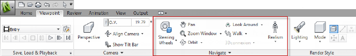
■The Viewpoint tab now includes the Navigate pane, providing access to
tools such as walk, pan, zoom, and orbit; SteeringWheels tracking menus,
3Dconnexion 3D mouse, and the realism settings.
1
1
Autodesk File Format Support
Autodesk Navisworks now offers 2D DWF and multi-sheet DWF support,
allowing you to open, review and explore your 2D datasets alongside your 3D
models. Importantly, the 2D view is integrated with the 3D environment -
this enables you to select a component in the 3D model and then to find and
review the same component in a 2D representation (such as a floor plan or
section) providing you with the most appropriate view of the data for the task
that you are undertaking. When working with the FBX visualization file format
you can now achieve an accurate transfer of materials, textures and lights
when importing or exporting data between Autodesk Navisworks and other
FBX compatible applications.
■Support for opening 2D/3D DWF and DWFx files. See DWF File Reader.
■Support for exporting 3D DWF and DWFx files. See Export 3D DWF/DWFx
Files.
■Multi-sheet file support. See 2D and Multi-Sheet Files (page 100).
■2D/3D Object Association support. See Find All Sheets and Models Con-
taining the Selected Object (page 212).
■FBX consistent material support for lights, materials, and textures. See FBX
File Reader.
Autodesk Navisworks Freedom 2012 Enhancements
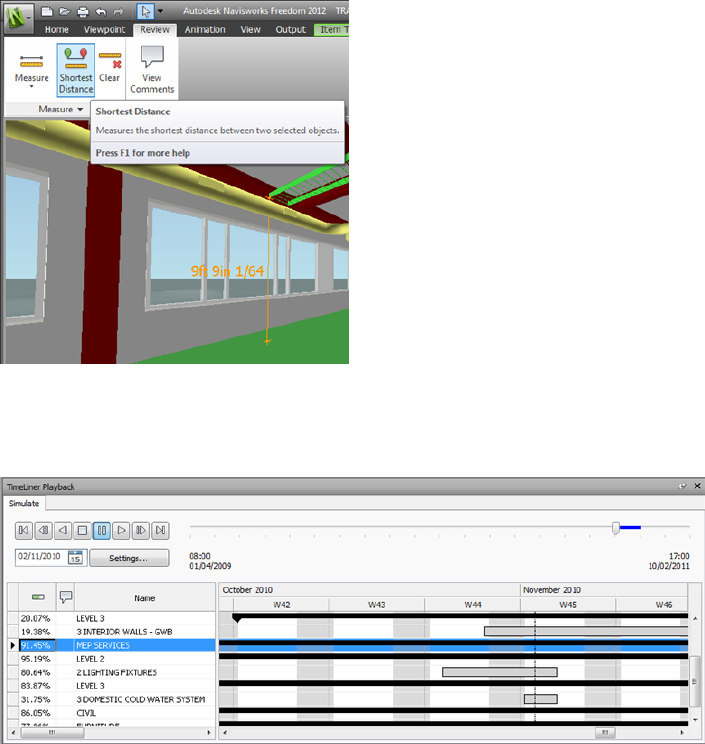
■The Review tab now contains Measure tools supporting field access to
dimensioning and area calculation.
2 | Chapter 1 Welcome to Autodesk Navisworks Freedom 2012
■You can now open 2D DWF, and multi-sheet DWF files, as well as NWD
files.
■A Gantt View is now available during 4D TimeLiner simulations.
Miscellaneous Enhancements
■Enhanced support for the
■3D mouse through an extended interface. See 3Dconnexion 3D Mouse
(page 164).
■Communication Centre now supports live updates.
■New avatars to be used in a variety of roles ranging from construction
workers and safety professionals, to office workers. Since avatars can vary
What Is New in This Release? | 3
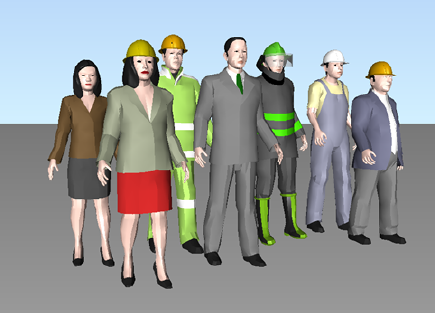
per viewpoint, you can easily show how project stakeholders will interact
with a specific phase of the project in the relevant context.
How to Get Assistance
There are various ways to find information about how to use this program,
and multiple resources are available.
Find Information Using InfoCenter
You can use InfoCenter to search Autodesk Navisworks help file for
information. You can also easily access product updates and announcements.
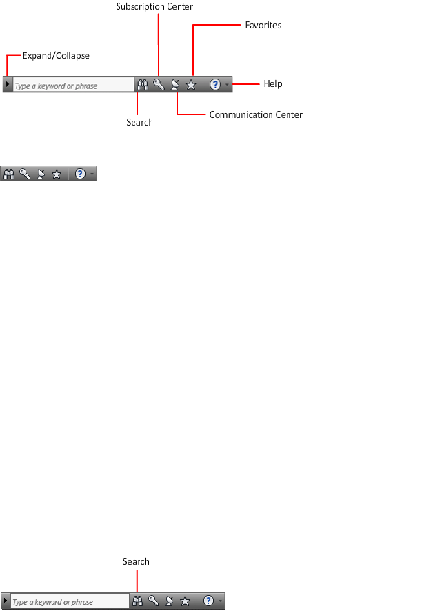
Overview of InfoCenter
You can use InfoCenter to search for product-related help, display the
Subscription Center panel for subscription services, display the Communication
Center panel for product updates and announcements, and display the
Favorites panel to access saved topics.
You can use InfoCenter to:
■Search for information in the main product Help through keywords (or
by entering a phrase)
■Access subscription services through Subscription Center panel
4 | Chapter 1 Welcome to Autodesk Navisworks Freedom 2012
■Access to product-related updates and announcements through
Communication Center panel
■Access saved topics through Favorites panel
To display the InfoCenter box in a collapsed state, click the arrow to its left.
To rearrange the topics displayed on a panel
1Display a panel by doing one of the following:
■In the InfoCenter box, click the Subscription Center button.
■In the InfoCenter box, click the Communication Center button.
■In the InfoCenter box, click the Favorites button.
2Click and drag a category or group header to the desired position.
TIP To keep the Subscription Center, Communication Center, and the
Favorites panel expanded, click the push pin icon in the bottom-right corner
of the panel.
NOTE You can rearrange categories within a group, but you cannot move them
into other groups.
Search for Information
You can enter keywords or a phrase in the InfoCenter box to search for
information.
How to Get Assistance | 5

When you enter keywords or a phrase in the InfoCenter box, you search the
contents of the main Autodesk Navisworks Help file.
Keyword searches produce better results. The results are listed on the Help
Search tab. Click a topic to display it in help.
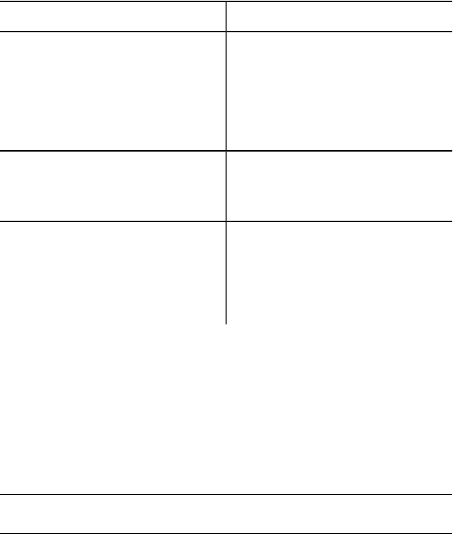
When you use InfoCenter to search for information, you can use the following
special symbols in your query to refine or expand it. These symbols can be
used alone or can be combined.
DescriptionSymbol
Replaces one or more characters when used at the beginning,
middle, or end of a word. For example, “*lish”, “p*lish”, and “pub*”
*
will find “publish”. Also, “anno*” will find “annotative”, “annota-
tion”, “annoupdate”, “annoreset”, and so on.
Replaces a single character. For example, “cop?” will find “copy”,
but not “copybase”.
?
Adds grammatical form variations to a keyword when added at the
beginning or end of a word. For example, “plotting~” will find
~
“plots”, “plotted”, and so on. Also, “~plot” will find “preplot”,
“replot”, and so on.
When performing the exact phrase search, use double quotation marks (" ")
to enclose words that must appear next to each other in the specified text
string. For example, enter "specify units of measurement" to find only
topics with all those words in that order. You can also use the previously
mentioned symbols in a text string that is enclosed in double quotation marks.
To search the main Help file for information
1In the InfoCenter box, enter a keyword or phrase.
2Click the Search button.
The main Help file opens, and the search results are listed on the Help Search
tab.
6 | Chapter 1 Welcome to Autodesk Navisworks Freedom 2012
Access Subscription Center
Subscription Center displays links to information about subscription services
such as product enhancements, personalized web support from Autodesk
technical experts, and self-paced e-Learning.
If you are a subscription member, you can access subscription services by
clicking the Communication Center button in the InfoCenter box,
and then clicking a Subscription Center link. To learn more about Autodesk
subscription membership, visit http://www.autodesk.com/subscriptioncenter.
About Subscription Center
With Autodesk Subscription, you get the latest releases of Autodesk software,
incremental product enhancements, personalized web support from Autodesk
technical experts, and self paced e-Learning. Subscription services are available
to subscription members only.
By clicking the Communication Center button in the InfoCenter box,
members have access to the following options (under Subscription Center):
■Subscription status. Checks your subscription status.
■Create support request. Provides direct one-to-one communication
with Autodesk support technicians. You receive fast, complete answers to
your installation, configuration, and troubleshooting questions.
■View support requests. Tracks and manages your questions and
responses through Autodesk's state-of-the-art support system.
■Edit Subscription Center profile. Sets up and maintains your
subscription account.
■View e-Learning catalog. Features interactive lessons organized into
product catalogs.
■e-Learning Lessons. (For subscription members only.) Each lesson is
15-30 minutes and features hands-on exercises, with an option to use a
simulation instead of the software application. You can use an online
evaluation tool that identifies gaps in skills, determines what lessons will
be most helpful, and gauges learning progress.
How to Get Assistance | 7

Subscription Resources and Privacy
Subscription resources provide interactive product features over the Internet.
Each time you access subscription resources (such as e-Learning or Create
Support Request) from Communication Center in an Autodesk product,
product information (such as the serial number, version, language, and the
subscription contract ID) is sent to Autodesk for verification that your product
is on subscription.
Autodesk compiles statistics using the information sent to subscription
resources to monitor how they are being used and how they can be improved.
Autodesk maintains the information provided by or collected from you in
accordance with Autodesk's published privacy policy, which is available at
http://www.autodesk.com/privacy.
To open the Subscription Center
1Click the Communication Center button in the InfoCenter box.
2On the Communication Center panel, under Subscription Center,
click the subscription resource you want to access.
NOTE Subscription Center is not available to all product users. If subscription
resources are not available in your product, your product is not entitled to
subscription benefits.
Manage Files with Autodesk Vault
If you are a subscription customer, you have access to Autodesk Vault, a file
management tool that provides a repository where documents and files are
stored and managed.
Autodesk Vault gives you more power to manage files and track changes.
Versioned copies of master files are maintained, allowing you to easily revert
to earlier versions of files. You can check files out for editing and later check
them back in. The master copy is never directly edited.
Autodesk Vault consists of two required components: the Autodesk Data
Management Server and the Vault Client. Optionally, you can also install the
Vault Office Add-in.
For information about using the Vault, refer to the Vault Help system.
8 | Chapter 1 Welcome to Autodesk Navisworks Freedom 2012

TIP The main components for the Autodesk Vault can be downloaded from the
Autodesk Subscription site.
Use Communication Center
Communication Center provides up-to-date product information, software
updates, product support announcements, and other product-related
announcements.
Overview of Communication Center
You can click the Communication Center button to display links to
information about product updates and announcements, and may include
links to RSS feeds.
Whenever new information is available, Communication Center notifies
you by displaying a balloon message below the Communication Center
button in the InfoCenter box.
Communication Center provides the following types of announcements:
■Autodesk Channels: Receive support information, product updates, and
other announcements (including articles and tips).
■RSS Feeds. Receive information from RSS feeds to which you subscribe.
RSS feeds generally notify you when new content is posted. You are
automatically subscribed to several default RSS feeds when you install the
program.
■Product Support Information. Get breaking news from the Product
Support team at Autodesk, including when Live Update maintenance
patches are released.
■Subscription Announcements. Receive subscription announcements
and subscription program news, as well as links to e-Learning Lessons, if
you are an Autodesk subscription member (available in countries/regions
where Autodesk subscriptions are offered).
■Articles and Tips. Be notified when new articles and tips are available
on Autodesk websites.
■Live Update Maintenance Patches. Receive automatic notifications
whenever new maintenance patches are released from Autodesk.
■Featured Technologies and Content. Learn more about third-party
developer applications and content.
How to Get Assistance | 9
You can customize the items that display on the Communication Center
panel. For more information, see Specify InfoCenter Settings (page 16).
Communication Center Online Policy
Communication Center is an interactive feature that must be connected to
the Internet in order to deliver content and information. Each time
Communication Center is connected, it sends your information to Autodesk
so that you receive the correct information. All information is sent
anonymously to Autodesk to maintain your privacy.
Communication Center sends the following information to Autodesk:
■Product name (in which you are using Communication Center)
■Product release number
■Product language
■Country/region (specified in the Communication Center settings)
■Your unique Customer Involvement Program (CIP) ID if you are
participating in the CIP program
Autodesk compiles statistics using the information sent from
Communication Center to monitor how it is being used and how it can
be improved. Autodesk maintains information provided by or collected from
you in accordance with the company's published privacy policy, which is
available at http://www.autodesk.com/privacy.
To open Communication Center
■In the InfoCenter box, click the Communication Center button.
To receive new information notifications
■Click the link in the balloon message to open the article or announcement.
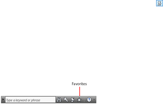
Save and Access Favorite Topics
You can click the Favorites button to display saved links to topics or web
locations.
10 | Chapter 1 Welcome to Autodesk Navisworks Freedom 2012
Any link that displays on the Subscription Center or Communication
Center panel can be marked as a favorite.
A link marked as a favorite displays a star icon on the Subscription Center
panel or the Communication Center panel.
To display the InfoCenter Favorites panel
■In the InfoCenter box, click the Favorites button.
NOTE The links displayed on the Favorites panel are organized into the same
groups or categories from which they were added.
To save a link in InfoCenter as a favorite
1Display a panel by doing one of the following:
■In the InfoCenter box, click the Subscription Center button.
■In the InfoCenter box, click the Communication Center button.
2Click the star icon that is displayed next to the link that you want to
save as a favorite.
To remove a favorite link from the InfoCenter Favorites panel
1In the InfoCenter box, click the Favorites button to display the Favorites
panel.
2Click the star icon that is displayed next to the link that you want to
remove from the Favorites panel.
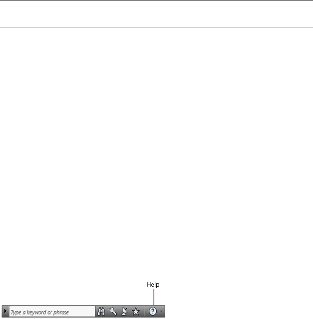
Use the Help System
You can click the Help button to display topics in Help.
You can get much more benefit from the Help system when you learn how
to use it efficiently. You can quickly find general descriptions, procedures,
details about dialog boxes and palettes, or definitions of terms.
The Help system contains complete information about using this program.
In the Help window, you use the left pane to locate information. The tabs
How to Get Assistance | 11
above the left pane give you several ways for finding the topics you want to
view. The right pane displays the topics you select.
To display topics in Help
■In the InfoCenter box, click the Help button.
How Help Topics Are Organized
Most topics in this Help system have three tabs above the right pane of the
Help window. The tabs display different types of information.
■Concept tab. Describes a feature or function. When you click the
Concept tab, the Help Contents list in the left pane of the Help window
expands and highlights the current topic. The Contents tab displays the
structure of the Help on that topic. You can easily display nearby topics
by clicking them in the list.
■Procedure tab. Provides step-by-step instructions for common procedures
related to the current topic. After displaying a procedure, you can click the
Procedure tab to redisplay the current list of procedures.
■Quick Reference tab. Lists reference information related to the current
topic.
When you click a different tab, the topic remains the same. Only the type of
information displayed—concept, procedures, or quick reference links—is
different.
Search in Help
Use the Help Search tab to find relevant topics based on keywords that you
enter.
The basic search rules are as follows:
■Type your keywords in uppercase or lowercase characters; searches are not
case-sensitive.
■Search for any combination of letters (a-z) and numbers (0-9).
■Do not use punctuation marks such as a period, colon, semicolon, comma,
hyphen, and single quotation marks; they are ignored during a search.
■Group the elements of your search using double quotation marks or
parentheses to set each element apart.
12 | Chapter 1 Welcome to Autodesk Navisworks Freedom 2012
Use Wild Card Characters
You can use the following wild card characters in any keyword:
DescriptionSymbol
Replaces one or more characters when used
at the beginning, middle, or end of a word.
*
For example, “*lish”, “p*lish”, and “pub*”
will all find “publish”. Also, “anno*” will
find “annotative”, “annotation”, “annoup-
date”, “annoreset”, and so on.
Replaces a single character. For example,
“cop?” will find “copy”, but not “copy-
base”.
?
Expands the tense of the word at the begin-
ning or end of a word. For example, “plot-
~
ting~” will find “plots”, “plotted”, and so
on. Also, “~plot” will find “preplot”,
“replot”, and so on.
Search for Phrases
When searching for a phrase, use double quotation marks (“ ”) to enclose
words that must appear next to each other in the specified sequence. For
example, enter “specifying units of measurement” to find only topics with all
those words in that order. If you don’t use the quotation marks around that
text, Help finds all topics containing any one of the listed words, that is, all
topics containing “specifying”, all topics containing “units”, all topics
containing “of”, and all topics containing “measurement”.
TIP If you can’t find the information you need through a search, try using the
Contents tab.
Use Boolean Operators
With the AND, OR, NOT, and NEAR operators, you can precisely define your
search by creating a relationship between search terms. The following table
shows how you can use each of these operators. If no operator is specified,
How to Get Assistance | 13
AND is used. For example, the query spacing border printing is equivalent to
spacing AND border AND printing.
ResultsExampleSearch for
Topics containing both the words
“tree view” and “palette”
“tree view” AND “palette”Both terms in the same
topic
Topics containing either the word
“viewpoint” or the word “anima-
tion” or both
viewpoint OR animationEither term in a topic
Topics containing the word
“NWD”, but not the word
“NWC”
nwd NOT nwcThe first term without
the second term
Topics containing the word
“user” within eight words of the
word “menu”
user NEAR menuBoth terms in the same
topic, close together
NOTE The |, &, and ! characters do not work as Boolean operators. You must use
AND (also +), OR, and NOT (also -).
Find Information in Help Topics
The tabs on the left side of the Help window provide different methods for
finding information.
Contents Tab
■Presents an overview of the available documentation in a list of topics and
subtopics.
■Allows you to browse by selecting and expanding topics.
■Provides a structure so you can always see where you are in Help and
quickly jump to other topics.
14 | Chapter 1 Welcome to Autodesk Navisworks Freedom 2012

Index Tab
■Displays an alphabetical list of keywords related to the topics listed on the
Contents tab.
■Accesses information quickly when you already know the name of a feature,
command, or operation, or when you know what action you want the
program to perform.
Search Tab
■Provides a keyword search of all the topics listed on the Contents tab.
■Accepts the Boolean operators AND (+), OR, NOT (-), and NEAR.
■Accepts the wild cards *, ?, and ~.
■Allows you to perform a search for a phrase when the phrase is enclosed
in double quotes.
■Displays a ranked list of topics that contain the word or words entered in
the keyword field.
■Arranges the results alphabetically by title or by location if you click on
the Title and Location column headings.
To find a specific word or phrase in the currently displayed Help topic
1Click in the topic text and press CTRL+F.
2In the Find text box, enter a keyword or phrase.
3Click Next. If the keyword or phrase is located, the topic scrolls to display
the result.
Print Help Topics
The quickest way to print the current topic is to right-click within the topic
and click Print.
The Print button on the Help toolbar provides these print options:
■Print the selected topic (recommended)
■Print the selected heading and all subtopics
NOTE When you select the second option, you may get numerous printed pages,
depending on how many subtopics the currently selected topic contains.
How to Get Assistance | 15
To print a Help topic
1Display the topic you want to print.
2Right-click in the topic pane. Click Print.
3In the Print dialog box, click Print.
To print a selected heading and all subtopics
1Display the topic you want to print and make sure that the Contents
tab is displayed.
2On the Help toolbar, click Print.
3In the Print Topics dialog box, click Print the Selected Heading
and All Subtopics.
4Click OK.
Show and Hide the Contents Pane
You can control the size of the Help window.
Use the Hide button on the Help toolbar to shrink the Help window
to a compact size by hiding the pane that contains the Contents, Index,
and Search tabs. The compact window size is best for displaying procedures
while you work.
Use the Show button to expand the Help window to display the pane
that contains Contents, Index, and Search tabs. The expanded window
size is best for locating and displaying conceptual and reference information.
Specify InfoCenter Settings
You can specify general and Communication Center settings in the
InfoCenter Settings dialog box.
In the InfoCenter Settings dialog box, you can specify the following settings:
■General. Your current location, frequency for checking new online content
and option to turn on or off animated transition effects for the InfoCenter
panels.
16 | Chapter 1 Welcome to Autodesk Navisworks Freedom 2012

■Communication Center. Set the maximum age of the articles displayed
on the Communication Center panel.
■Autodesk Channels. Channels to display in the Communication Center
panel as well as the number of articles to display for each channel.
■Balloon Notification. Notifications for new product information,
software updates, and product support announcements. Also, you can
customize the transparency and the display time of the balloon.
■RSS Feeds. RSS feed subscriptions. You can add or remove RSS feeds. RSS
feeds generally notify you when new content is posted.
To specify the channels to display in the Communication Center panel
1Display a panel by doing one of the following:
■In the InfoCenter box, click the Subscription Center button.
■In the InfoCenter box, click the Communication Center button.
■In the InfoCenter box, click the Favorites button.
2Click the InfoCenter Settings button.
3In the InfoCenter Settings dialog box, in the left pane, click Autodesk
Channels.
4In the right pane, select or clear the channels you want to display in the
Communication Center panel.
5Click OK.
To specify InfoCenter balloon notification settings
1Display a panel by doing one of the following:
■In the InfoCenter box, click the Subscription Center button.
■In the InfoCenter box, click the Communication Center button.
■In the InfoCenter box, click the Favorites button.
2Click the InfoCenter Settings button.
3In the InfoCenter Settings dialog box, in the left pane, click Balloon
Notification.
4In the right pane, select or clear the options to turn balloon notification
on or off.
5Enter the number of seconds to set the length of time for balloon
notifications to display.
How to Get Assistance | 17
6Enter the transparency value of the balloon or set the value using the
slider.
7Click OK.
To add an RSS feed to Communication Center
1Display a panel by doing one of the following:
■In the InfoCenter box, click the Subscription Center button.
■In the InfoCenter box, click the Communication Center button.
2Click the InfoCenter Settings button .
3In the InfoCenter Settings dialog box, in the left pane, click RSS Feeds.
4In the right pane, do one of the following:
■Click Add.
■Right-click anywhere in the right pane. Click Add.
5In the Add RSS Feed dialog box, enter the location of the RSS feed you
want to add. Click Add.
6In the InfoCenter - RSS Feed Confirmation dialog box, click Close.
7Click OK.
To remove an RSS feed from Communication Center
1Display a panel by doing one of the following:
■In the InfoCenter box, click the Subscription Center button.
■In the InfoCenter box, click the Communication Center button.
■In the InfoCenter box, click the Favorites button.
2Click the InfoCenter Settings button.
3In the InfoCenter Settings dialog box, in the left pane, click RSS Feeds.
4In the right pane, do one of the following:
■Click Remove.
■Right-click an RSS feed. Click Remove.
5In the InfoCenter - Remove RSS Feed dialog box, click Yes.
6Click OK.
18 | Chapter 1 Welcome to Autodesk Navisworks Freedom 2012
Get More Help
You can access several additional sources of help.
■Use Communication Center. Display the Communication Center
panel for product updates and announcements.
■Press F1. Displays context-sensitive reference information.
■Click the Help button in many dialog boxes. Displays reference
information for the dialog box.
■View the product Readme. Displays late-breaking information about
this product.
Other resources help you get information about Autodesk products and
assistance with your questions about this program.
■Autodesk website. Access http://www.autodesk.com.
■Local support. Check with your dealer or Autodesk country/region office.
View the Product Readme
You can find late-breaking information about this software in the Readme.
It is suggested that you read through the Autodesk Navisworks Readme for
information about recommended hardware, updated installation instructions,
and known software problems. The Readme file is available from the product’s
program group on the Windows Start menu.
Join the Customer Involvement Program
You are invited to help guide the direction of Autodesk design software.
If you participate in the Customer Involvement Program (CIP), specific
information about how you use Autodesk Navisworks is forwarded to Autodesk.
This information includes what features you use the most, problems that you
encounter, and other information helpful to the future direction of the
product.
See the following links for more information.
■Learn more about the Autodesk Customer Involvement Program: ht-
tp://www.autodesk.com/cip
How to Get Assistance | 19
■Read the Autodesk Privacy Statement: http://www.autodesk.com/cipprivacy
When you join, you will be able to view reports that can help you optimize
your use of Autodesk Navisworks.
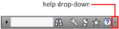
To turn the CIP on or off
1On the InfoCenter toolbar, to the right of the Help button, click the
drop-down arrow.
2Click Customer Involvement Program.
3In the Customer Involvement Program dialog box, select to start or stop
participating.
4Click OK.
20 | Chapter 1 Welcome to Autodesk Navisworks Freedom 2012

Installation
Quick Start to Stand-Alone Installation
This section provides step-by-step instructions about how to prepare, and then
install Autodesk Navisworks.
Stand-alone installation is recommended for individual users or small groups.
The key point is that you will repeat the installation process on each computer.
For a stand-alone license this is the only valid installation type, but it can also
be used with a multi-seat stand-alone or network license.
Prepare for Installation
To prepare for installation, you should review the system requirements,
understand administrative permission requirements, and close all running
applications.
Complete these tasks, and you are ready to begin installing Autodesk Navisworks
Freedom 2012.
NOTE It is also recommended that you install Microsoft .Net Framework 4.0 before
installing the product. See Install Microsoft .Net Framework 4.0 (page 23).
System Requirements for Stand-Alone Installation
The first task you need to complete is to make sure that your computer meets
the minimum system requirements. If your system does not meet these
requirements, problems can occur, both within Autodesk Navisworks and at
the operating system level.
2
21
Whether your Windows operating system is the 32-bit or the 64-bit version,
the version is automatically detected during installation.
See the following table for hardware and software requirements.
Hardware and software requirements for client machine
RequirementHardware/Software
Microsoft® Windows 7 (32-bit or 64-bit) Home Ba-
sic, Home Premium, Professional, Enterprise, or Ul-
timate (recommended)
Operating System
Microsoft® Windows Vista® SP2 (32-bit or 64-bit)
Home Premium, Business, Enterprise, or Ultimate
Microsoft® Windows XP SP3 (32-bit) Home, or
Professional
Microsoft® Windows XP SP2 (64-bit) Professional
Microsoft® Internet Explorer® 7.0 or later
Web browser
AMD Athlon™, 3.0 GHz or faster (minimum); Intel®
Pentium® 4, 3.0 GHz or faster (recommended) -
with SSE2 technology
Processor
512 MB (minimum); 2 GB or more (recommended)Memory (RAM)
1024 x 768 with true color (minimum)VGA Display
1280 x 1024 32-bit color video display adapter with
true color (recommended)
Direct3D 9® and OpenGL® capable graphics card
with Shader Model 2 (minimum)
Graphics Card
11 GB free disk space for installationHard disk
22 | Chapter 2 Installation

Hardware and software requirements for client machine
Microsoft® Mouse-compliant pointing device
Pointing device
Any speed (for installation only)DVD-ROM
Printer or plotterOptional hardware
Modem or access to an Internet connection
Network interface card
Install Microsoft .Net Framework 4.0
Autodesk Navisworks Freedom 2012 requires Microsoft .Net 4.0 to be installed
prior to product installation.
Most Windows updates should include Microsoft .NET Framework 4, however,
for old versions of Windows, you can download and install Microsoft .NET
Framework 4 redistributables from: http://www.microsoft.com/downloads/en/de-
tails.aspx?FamilyID=0a391abd-25c1-4fc0-919f-b21f31ab88b7 or install Microsoft
.Net Framework 4 from the following directory in the installation media:
\3rdParty\NET\4\wcu\dotNetFramework\.
The Installation wizard will install Microsoft .Net Framework 4 if it detects
that required updates have not been installed.
NOTE If the Installation wizard prompts you to install the Microsoft .NET 4.0
Framework, the .NET 4.0 Framework installer may prompt you to first install the
Windows Imaging Component (WIC). This can occur if you do not have the latest
Microsoft Windows updates or service packs. You are most likely to need WIC if
you are running Windows XP SP2 without certain Windows Updates installed. If
required, the Microsoft WIC installers are available at the following locations:
■32-bit installer: http://www.microsoft.com/downloads/en/details.aspx?Family-
ID=8e011506-6307-445b-b950-215def45ddd8&displaylang=en
■64-bit installer: http://www.microsoft.com/downloads/en/details.aspx?Family-
ID=f64654ac-6e26-41d9-a90a-0e7783b864ee
Quick Start to Stand-Alone Installation | 23
Understand Administrative Permission
Requirements
To install Autodesk Navisworks, you must have administrator permissions.
You do not need to have domain administrative permissions. See your system
administrator for information about administrative permissions.
To run Autodesk Navisworks, you do not need administrator permissions. You
can run the program as a limited user.
Avoid Data Loss During Installation
The Autodesk Navisworks installation process may stop if some applications
(such as Microsoft® Outlook® or virus-checking programs) are running.
Close all running applications to avoid possible data loss.
Choose a Language
You can select a different language for installation instructions, and a language
for individual product installations in the same install process.
When you start the installation process, the installer automatically determines
your operating system language. If a supported language is detected, your
install pages are displayed in that language. If you want to change that
language, you select a different one from the Installer Language list on the
first page of the Installation wizard.
NOTE Some products may not have multi-language support at the time of product
release. Additional language support may be available later. Check http://sup-
port.autodesk.com for the availability of additional language packs.
Using Language Packs
Language packs support use of different languages in each Autodesk Navisworks
product, including exporters. Pack names start with NAVFREE_, NAVSIM_,
NAVMAN_, and exporters_ respectively.
24 | Chapter 2 Installation
NOTE You must install at least one language pack for each product.
It is possible to install additional language packs to Autodesk Navisworks
products later. You can manually install the required language packs by
double-clicking on the language pack MSI file.
Language packs are located on the installation DVD and unpacked downloaded
media under the x86 folder for 32-bit products and under the x64 folder for
64-bit products.
■Language packs for specific products are included in the NAVFREE,
NAVSIM, NAVMAN, and NWEXPORT subfolders of x86 and x64 folders.
■Language packs for specific languages are included in the en-US (English),
de-DE (German), es-ES (Spanish), fr-FR (French), it-IT (Italian), ja-JP
(Japanese), ko-KR (Korean), pt-BR (Brazilian Portuguese), ru-RU (Russian)
and zh-CN (Chinese PRC) subfolders of the product folders.
So, for example, to install the 32-bit French language pack for Autodesk
Navisworks Freedom, double-click x86/NAVFREE/fr-FR/NAVFREE_LP.msi.
Configuration
During the installation process, you choose either a typical installation (install
the product with default settings), or a customized installation. On the Install
➤ Configure Installation page, for any product you have selected to install,
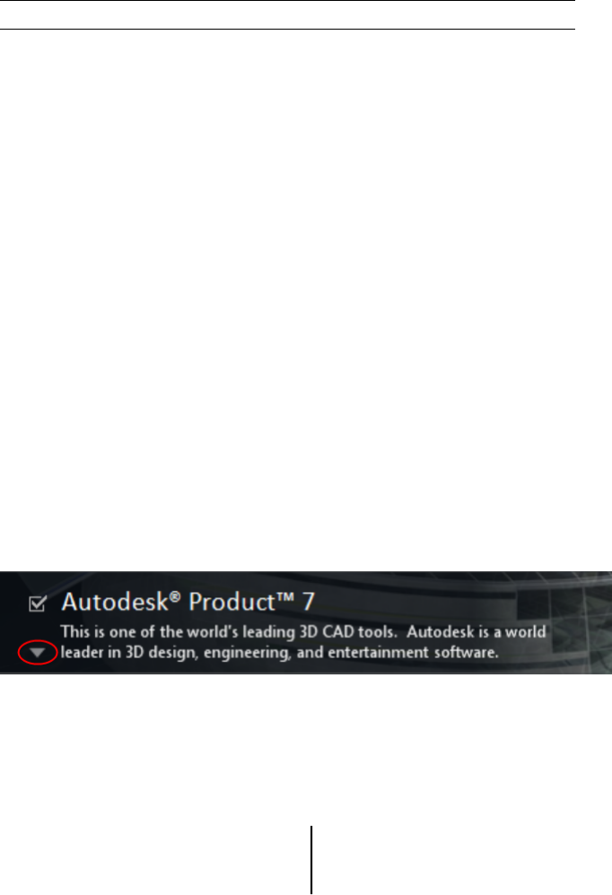
you will see a triangular control for access to a configuration panel.
Click anywhere in the product box to open the configuration panel:
■Installation Type. If you choose a Typical installation (default settings)
the product installs the most common application features. A Custom
installation installs only the application features that you select from the
Select Features To Install list. The available features will depend upon
the product you are installing:
Contains Autodesk Navisworks Redistribut-
able ActiveX control.
Redistributable ActiveX Control
Quick Start to Stand-Alone Installation | 25

Contains full set of Autodesk Navisworks
files.
Program
■Create the Desktop Shortcut. Select the check box to create the desktop
shortcut for Autodesk Navisworks.
■Project and Site Folders. Use the Browse buttons to select the
directories that will contain Autodesk Navisworks settings that can be
shared across an entire project site, or across a specific project group (see
Select the Project and Site Folders).
■Service Packs. If a service pack is available for your installation, you can
include it in the installation.
After you have configured the settings as required, click the product name to
close the configuration panel.
Install Multiple or Bundled Products
Some Autodesk packages are comprised of multiple products or are part of
multi-product bundles.
The Installation wizard for packages that are comprised of multiple products
gives you the option to choose which products you want to install.
In the Installation wizard, for packages containing multiple products, you can
choose which products and languages you want to install. During the install
process, you are informed whether a copy of the software is already installed.
You are also warned if your system does not meet the minimum system
requirements for the product. Each product name is displayed on its own
tabbed panel; you can configure them individually.
If you purchased a package that is a multi-product bundle, such as an
educational or institutional package, you may have a package that includes
several Autodesk products. For these bundled packages, an Installer disc
contains information for all the products in the package. The Installer disc
helps you install all of the products.
26 | Chapter 2 Installation
Install and Run Autodesk Navisworks
Freedom 2012
You must have administrative permissions to install Autodesk Navisworks.
This section provides instructions for installing and activating Autodesk
Navisworks for an individual user on a stand-alone computer.
NOTE Autodesk does not recommend or support the distribution of an Autodesk
product using imaging software.
Install Autodesk Navisworks
The Autodesk NavisworksInstallation wizard contains all installation-related
material in one place.
From the Installation wizard, you can access user documentation, change
the installer language, select a language-specific product, install supplemental
tools, view support solutions, and learn about deploying your product on a
network.
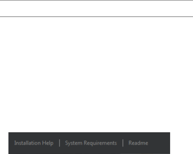
■Review installation documentation before you install. It is
recommended that you take the time to familiarize yourself with the
complete installation process before you install Autodesk Navisworks.
Documentation is accessible from links on the lower left corner of the
installer.
■Install Autodesk Navisworks Freedom 2012. From the Installation
wizard, click Install. Follow the on-screen instructions to complete the
installation.
Install Autodesk Navisworks Using Default Values
This is the fastest means of installing Autodesk Navisworks on your system.
Only default values are used which means it is a typical installation being
installed to C:\Program Files\Autodesk\Navisworks Freedom 2012.
Quick Start to Stand-Alone Installation | 27
To install Autodesk Navisworks using default values on a stand-alone computer
1Close all running applications on your computer and start the
Installation wizard.
2On the Installation wizard, if required, select an alternate language
for the Installation wizard from the Installation Instructions
drop-down, and then click Install.
3Review the Autodesk software license agreement for your country or
region. You must accept this agreement to proceed with the installation.
Choose your country or region, click I Accept, and then click Next.
NOTE If you do not agree to the terms of the license and want to terminate
the installation, click Cancel.
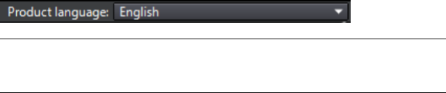
4On the Configure Installation page, select the products to install,
and if required add a language pack(s) from the Product Language
drop-down (see Choose a Language (page 24)).
5If required, use the Installation PathBrowse button to select the
drive and location where product will be installed.
6Click Install. The wizard installs the products you selected using a
Typical installation, which installs the most common application
features. To see which features are included in a Typical installation,
refer to Typically Installed Features (page 34).
NOTE By default, the Installation wizard automatically enables the exporter
plugins for all third-party products already installed on your computer.
7Click Finish.
Install Autodesk Navisworks Using Configured
Values
With this installation method, you can fine-tune exactly what gets installed.
You can alter the license type, the installation type, the install path, and
specify the location of the Project and Site folders.
To install Autodesk Navisworks using configured values on a stand-alone
computer
1Close all running applications on your computer and start the
Installation wizard.
28 | Chapter 2 Installation
2On the Installation wizard, if required, select an alternate language
for the Installation wizard from the Installation Instructions
drop-down, and then click Install.
3Review the Autodesk software license agreement for your country or
region. You must accept this agreement to proceed with the installation.
Choose your country or region, click I Accept, and then click Next.
NOTE If you do not agree to the terms of the license and want to terminate
the installation, click Cancel.
4On the Configure Installation page, select the products to install,
and if required add a language pack(s) from the Product Language
drop-down (see Choose a Language (page 24)).
5Click the product name to open the configuration panel where you can
review and change settings. See Configuration (page 25). After you have
configured the settings as required, click the product name to close the
configuration panel.
6If required, use the Installation PathBrowse button to select the
drive and location where product will be installed.
7Click Install. The wizard installs the products you selected using your
Custom installation settings.
8Click Finish.
Launch Autodesk Navisworks
Assuming that you’ve followed all of the previous steps outlined in this Quick
Start section, you can launch Autodesk Navisworks and start taking advantage
of its new and updated features.
You can start Autodesk Navisworks in the following ways:
■Desktop shortcut icon. When you install Autodesk Navisworks, a
shortcut icon is placed on your desktop. Double-click the Autodesk
Navisworks icon to start the program.
■Start button. Click Start ➤ All Programs ➤ Autodesk ➤ Navisworks
Freedom 2012 ➤ Autodesk Navisworks Freedom 2012.
■Location where Autodesk Navisworks is installed. If you have
administrative permissions, you can run Autodesk Navisworks in the
location where you installed it. If you are a limited-rights user, you must
run Autodesk Navisworks from the Start button or from the desktop
shortcut icon. If you want to create a custom shortcut, make sure that the
Quick Start to Stand-Alone Installation | 29

Start In directory for the shortcut points to a directory where you have
write permissions.
NOTE When the product is started, by default, it uses the language that best
matches the settings on your computer. You can also launch Autodesk Navisworks
in another of the supported languages.
How to Launch Autodesk Navisworks in Another
Language
To run Autodesk Navisworks in another of the installed languages, you need
to add one of the language selector arguments to the desktop shortcut.
To run Autodesk Navisworks in another language
1Right-click the Autodesk Navisworks desktop shortcut, and click
Properties on the shortcut menu to open the Autodesk
NavisworksProperties dialog box.
2On the Shortcut tab, enter a space in the Target field after
..\roamer.exe, and then enter one of the following arguments:
■-lang en-US for English localization
■-lang de-DE for German localization
■-lang es-ES for Spanish localization
■-lang fr-FR for French localization
■-lang it-IT for Italian localization
■-lang ja-JP for Japanese localization
■-lang ko-KR for Korean localization
■-lang pt-BR for Brazilian Portuguese localization
■-lang ru-RU for Russian localization
■-lang zh-CN for Chinese (PRC) localization
3Click OK to save the changes.
30 | Chapter 2 Installation
Repair Autodesk Navisworks Freedom 2012
If you accidentally delete or alter files that are required by Autodesk Navisworks
Freedom 2012, Autodesk Navisworks might not perform correctly, and you
might receive error messages when you try to execute a command or find a
file. You can attempt to fix this problem by repairing Autodesk Navisworks
Freedom 2012.
Repairing uses the features that were part of the installation type you chose
when you initially installed the program.
To repair Autodesk Navisworks Freedom 2012
1Do one of the following:
■(Windows XP) Click Start ➤ Settings ➤ Control Panel ➤ Add
or Remove Programs.
■(Windows Vista and Windows 7) Click Start ➤ Control
Panel ➤ Programs and Features.
2From the list of programs, click Autodesk Navisworks Freedom 2012,
and then click Change/Remove (Windows XP) or Uninstall/Change
(Windows Vista and Windows 7).
The Autodesk Navisworks Freedom 2012Installation wizard re-opens
in Maintenance Mode.
3Click Repair or Reinstall.
4On the Repair or Reinstall page, click RepairAutodesk Navisworks
Freedom 2012. This option replaces all registry entries that Autodesk
Navisworks initially installed and restores Autodesk Navisworks Freedom
2012 to its default state. Click Repair.
NOTE ReinstallAutodesk Navisworks Freedom 2012 repairs the registry
and reinstalls all files from the original installation. Use this option if the
RepairAutodesk Navisworks Freedom 2012 option does not solve the
problem.
5On the Repair Complete page, click Finish.
Uninstall Autodesk Navisworks Freedom 2012
When you uninstall Autodesk Navisworks Freedom 2012, all components are
removed. This means that even if you've previously added or removed
Quick Start to Stand-Alone Installation | 31

components, or if you've reinstalled or repaired Autodesk Navisworks Freedom
2012, the uninstall removes all Autodesk Navisworks installation files from
your system.
IMPORTANT Do not use registry cleaning programs or attempt to modify the
registry entries yourself to uninstall Autodesk Navisworks Freedom 2012. Failure
to follow the official uninstall procedure will result in the inability to re-install the
software .
To uninstall Autodesk Navisworks Freedom 2012
1Do one of the following:
■(Windows XP) Click Start ➤ Settings ➤ Control Panel ➤ Add
or Remove Programs.
■(Windows Vista and Windows 7) Click Start ➤ Control
Panel ➤ Programs and Features.
2From the list of programs, click Autodesk Navisworks Freedom 2012,
and then click Change/Remove (Windows XP) or Uninstall/Change
(Windows Vista and Windows 7).
The Autodesk Navisworks Freedom 2012Installation wizard re-opens
in Maintenance Mode.
3Click Uninstall.
4When informed that the product has been successfully uninstalled, click
Finish.
NOTE Even though Autodesk Navisworks Freedom 2012 is removed from
your system, the software license remains. If you reinstall Autodesk Navisworks
Freedom 2012 at some future time, you will not have to register and
re-activate the program.
Installation Troubleshooting
This section provides solutions to installation issues and answers to commonly
asked questions that may arise while installing your products.
Additional troubleshooting information and support is also available at ht-
tp://support.autodesk.com.
32 | Chapter 2 Installation
General Installation Issues
This section provides solutions to installation issues and answers to commonly
asked questions that may arise while installing your products.
How can I check my graphics card driver to see if
it needs to be updated?
It is recommended that you ensure your computer has the most current
graphics card driver for the best possible display performance.
To identify your graphics card driver
1Start Autodesk Navisworks Freedom 2012.
2In the InfoCenter box, click the down arrow next to the Help button
➤ System Info.
The Autodesk Navisworks Freedom 2012 information dialog box opens.
3Review the information about your system including the graphics card
driver and driver version, and click OK to close the dialog.
To check the Web for an updated graphics card driver
■Use Windows Update. If a more recent graphics card driver is available,
select it to have Windows Update download and install it.
■Search the graphics card manufacturer’s website for the type of installed
graphics card. If a more recent graphics card driver is available, install it
following the instructions provided by the manufacturer.
To install an updated graphics card driver
1Check the Web for to see if an updated driver is available.
■Use Windows Update.
■Search the graphics card manufacturer’s website for the type of
installed graphics card.
2If a more recent graphics card driver is available, follow the instructions
from the website to download and install it.
Installation Troubleshooting | 33
How do I switch my license from stand-alone to
network or network to stand-alone?
If you simply entered the wrong license type by mistake, and are still running
the installer, use the Back button to return to the Product Information
page, and change the License Type.
If you want to change the license type for an installed product, contact your
Autodesk reseller or license supplier to obtain the new license and serial
number. Then uninstall your product and run a new install to change the
license type and enter the new serial number.
When performing a Typical installation, what gets
installed?
A Typical installation includes the following features:
Contains Autodesk Navisworks Redistribut-
able ActiveX control.
Redistributable ActiveX Control
Contains full set of Autodesk Navisworks
files.
Program
Why should I specify the Project Folder and Site
Folder?
You can share global Autodesk Navisworks settings, workspaces, datatools,
avatars, Clash Detective rules and custom tests, Presenter archives, object
animation scripts, and so on, with other users.
These settings can be shared across an entire project site, or across a specific
project group depending on the required level of granularity.
Autodesk Navisworks examines the current user profile and the all users profile
on the local machine, and then checks the settings in the Project Directory
and the Site Directory. The files in the Project Directory take precedence.
34 | Chapter 2 Installation
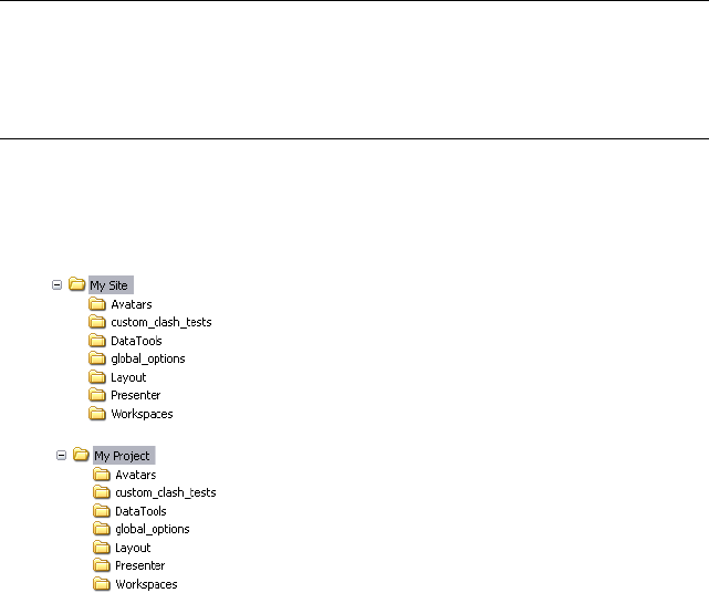
How do I share the Autodesk Navisworks settings
on a site and project basis?
Sharing Autodesk Navisworks settings requires you to export the desired
settings as an XML file to the appropriate Site or Project directory’s
global_options folder. The name of the XML file is not significant. However it
must be stored in the global_options folder.
TIP When you configure global options, you can lock some of the options to
prevent users from editing them later on local machines. To create a locked global
options file, run the stand-alone Options Editor from the command line by
typing “drive:pathname\OptionsEditor.exe” -l. The Options Editor opens
with the locking facility.
To share settings on a site and project basis
1Create appropriate Site and Project directories and subfolders in a central
location to be accessed by other Navisworks users.
2In Autodesk Navisworks, click the application button ➤ Options
Editor.
3Click Export.
4In the Select Options to Export dialog box, check all options you
want to export and click OK.
5In the Save As dialog box, name the XML file as desired and save it to
the global_options folder in the appropriate Site or Project directory.
Installation Troubleshooting | 35
See also:
Location Options (page 90)
Autodesk Navisworks Options (page 85)
NO LABEL
Run the installer again from the original media, and click Install Tools &
Utilities on the first screen. The installer guides you through the process of
selection, configuration and installation of tools and utilities.
When should I reinstall the product instead of
repairing it?
Reinstall your product if you accidentally delete or alter files that are required
by the program.
Missing or altered files adversely affect the performance of your product and
cause error messages when you try to execute a command or find a file.
If an attempt to repair an installation fails, reinstalling is the next best option.
When I uninstall my software, what files are left
on my system?
If you uninstall the product, some files remain on your computer such as files
you created or edited (for example, drawings or custom menus).
Your license file also stays on your computer when you uninstall your product.
If you reinstall on the same computer, the license information remains valid;
you do not have to reactivate the product.
Uninstall and Maintenance Issues
This section outlines common issues and their solutions with regards to adding
and removing features, reinstalling or repairing your installation, and
uninstalling products.
36 | Chapter 2 Installation

IMPORTANT Do not use registry cleaning programs or attempt to modify the
registry entries yourself to uninstall Autodesk Navisworks Freedom 2012. Failure
to follow the official uninstall procedure will result in the inability to re-install the
software.
When should I reinstall the product instead of a
repair?
You should reinstall your product if you accidentally delete or alter files that
are required by the program. Missing or altered files adversely affect the
performance of your product and cause error messages when you try to execute
a command or find a file.
If an attempt to repair an installation fails, reinstalling is the next best option.
Installation data is cached locally on your drive and that data is reused when
reinstalling. If any files cannot be located when reinstalling a product, you
are prompted to load the original media. If the product was installed from a
network deployment, you need access to the original deployment, unaltered
by later changes such as the addition of a service pack.
When I uninstall my software, what files are left
on my system?
If you uninstall the product, some files remain on your system such as files
you created or edited.
Your license file also stays on your workstation when you uninstall your
product. If you reinstall on the same workstation, the license information
remains valid and you do not have to reactivate the product.
Installation Troubleshooting | 37
38

Quick Start
Start and Quit Autodesk Navisworks
Once you’ve installed (page 21)Autodesk Navisworks Freedom 2012, you can
start it from the Windows desktop or from the command line.
To start Autodesk Navisworks, do one of the following from the Windows
desktop:
■Double-click the Autodesk Navisworks icon, or
■Click Start ➤ All Programs ➤ Autodesk ➤ Navisworks Freedom
2012 ➤ Freedom 2012.
Autodesk Navisworks starts in the language that best matches the settings on
your computer. You can also start Autodesk Navisworks in another of the in-
stalled languages (page 30).
To quit Autodesk Navisworks, click the application button . At the
bottom of the application menu, click Exit Autodesk Navisworks.
The User Interface
The Autodesk Navisworks interface contains a number of traditional Windows
elements, such as the application menu, Quick Access toolbar, ribbon, dockable
windows, dialog boxes and shortcut menus in which you complete tasks.
3
39
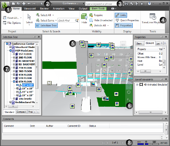
Parts of Autodesk Navisworks Interface
This section briefly describes the main components of the standard Autodesk
Navisworks interface.
The Autodesk Navisworks interface is intuitive and easy to learn and use. You
can adjust the application interface to match the way you work. For example,
you can hide docking windows that you rarely use, so they do not clutter the
interface. You can add and remove buttons from the ribbon and the Quick
Access toolbar.
You can apply a different theme to the standard interface. You can also switch
back to the classic Autodesk Navisworks interface with old-style menu and
toolbars.
5. Scene View1. Application button and menu
6. Navigation bar2. Quick Access toolbar
7. Dockable windows3. InfoCenter
40 | Chapter 3 Quick Start
8. Status bar4. Ribbon
See also:
Overview of InfoCenter (page 4)
To change theme of the standard user interface
1Click the application button ➤ Options.
2In the Options Editor, expand the Interface node, and click the User
Interface option.
3On the User Interface page, select the required theme type from the
Theme drop-down list.
4Click OK.
Application Button and Menu
The application menu enables you to access common tools.
It provides access to many common file actions, and also allows you to manage
your files using more advanced tools, such as Import, Export, and Publish.
Some application menu choices have additional menus that show related
commands.
To open the application menu, click the application button . Clicking
it again closes the application menu.
The User Interface | 41
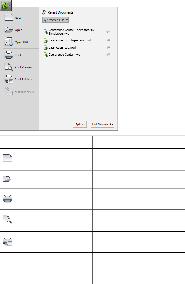
DescriptionOption
Closes the currently open file, and creates
a new file.
(New)
Opens files.
(Open)
Prints the scene.
(Print)
Shows a preview of how the document will
print.
(Print Preview)
Specifies print settings.
(Print Settings)
Opens the Options Editor.Options
Exits the program.Exit Navisworks
42 | Chapter 3 Quick Start

Recent Documents List
You can view, sort, and access supported files that you have recently opened.
The most recent files are shown in the Recent Documents list. The list is
ordered with the most recently used file at the top.
By default, up to four files are shown. If you want to modify the size of this
list, use the Options Editor.
You can pin the files by using the push pin button to the right. Pinning enables
you to keep a file in the list until you turn off the push pin button.
Sort and Group Files
Use the drop-down list at the top of the Recent Documents list to sort or
group files by:
■By Ordered List
■By Access Date
■By Size
■By Type
Preview Documents
When you mouse over a file in the Recent Documents list, the following
information is displayed:
■Path where the file is stored
■Date the file was last modified
■Name of the person who is currently working with the file
To change the number of recent documents listed
1Click the application button ➤ Options.
2In the Options Editor, expand the General node, and click the
Environment option.
3On the Environment page, enter the number of recent documents to
be listed into the Maximum Recently Used Files box.
The User Interface | 43
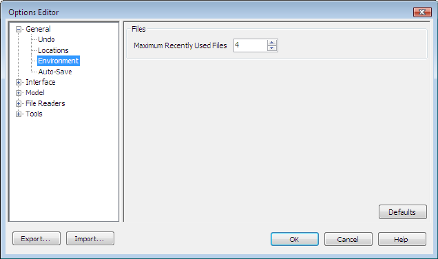
4Click OK.
To keep a document in the Recent Documents list
■Click the push pin button to the right of the document.
To view the Recent Documents list by access date
■In the top-left corner of the Recent Documents list, in the By Ordered
List drop-down list, select By Access Date.
To view the Recent Documents list by size
■In the top-left corner of the Recent Documents list, in the By Ordered
List drop-down list, select By Size.
To view the Recent Documents list by type
■In the top-left corner of the Recent Documents list, in the By Ordered
List drop-down list, select By Type.
Quick Access Toolbar
At the top of the application window, the Quick Access toolbar displays
frequently used commands.
44 | Chapter 3 Quick Start
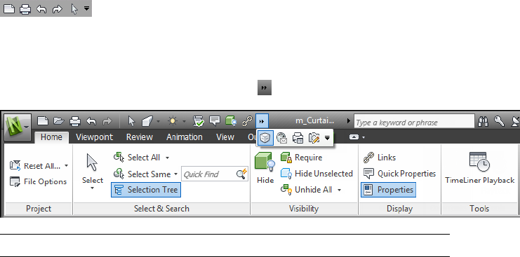
You can add unlimited number of buttons to the Quick Access toolbar.
Buttons are added to the right of the default commands. You can add separators
between the buttons. Commands that extend past the maximum length of
the toolbar are displayed in a flyout button .
NOTE Only ribbon commands can be added to the Quick Access toolbar.
You can move the Quick Access toolbar either above or below the ribbon.
To add a ribbon button to the Quick Access toolbar
1Display the tab and panel that contains the button you want to add to
the Quick Access toolbar.
2Right-click the button on the ribbon, and click Add to Quick Access
Toolbar.
To remove a ribbon button from the Quick Access toolbar
1Right-click the button on the Quick Access toolbar
2Click Remove from Quick Access toolbar.
To display the Quick Access toolbar below the ribbon
■Click the Customize Quick Access Toolbar drop-down button, and
click Show Below the Ribbon.
Shortcut menu: Right-click any button on the Quick Access toolbar. Click
Show Quick Access Toolbar below the Ribbon.
To display the Quick Access toolbar above the ribbon
■Click the Customize Quick Access Toolbar drop-down button, and
click Show Above the Ribbon.
The User Interface | 45
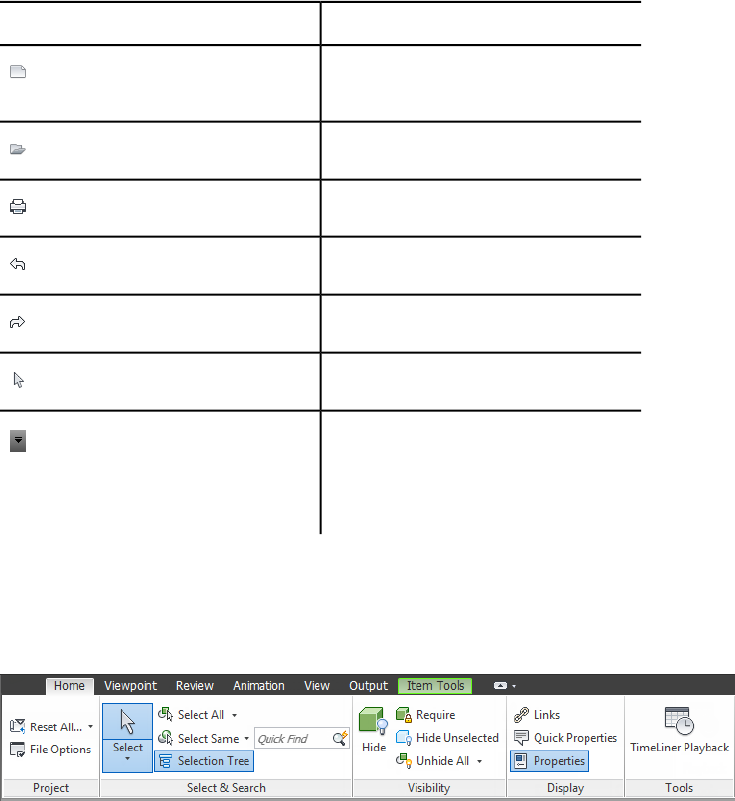
Shortcut menu: Right-click any button on the Quick Access toolbar. Click
Show Quick Access Toolbar above the Ribbon.
By default, it contains the following tools:
DescriptionOption
Closes the currently open file, and creates
a new file.
(New)
Opens files.
(Open)
Prints the current viewpoint.
(Print)
Cancels the most recent action.
(Undo)
Reinstates the most recent action.
(Redo)
Selects items with a mouse click.
(Select)
Customizes the items displayed on the
Quick Access toolbar. To enable or disable
(Customize Quick Access Toolbar)
an item, click next to it on the Customize
Quick Access Toolbar drop-down.
Ribbon
The ribbon is a palette that displays task-based tools and controls.
The ribbon is divided into tabs, with each tab is supporting a specific activity.
Within each tab, tools are grouped together into a task-based series of panels.
46 | Chapter 3 Quick Start
To specify which ribbon tabs and panels are displayed, right-click the ribbon
and, on the shortcut menu, click or clear the names of tabs or panels.
You can customize the ribbon depending on your needs in the following ways:
■Change the order of ribbon tabs. Click the tab you want to move, drag it
to the desired position, and release.
■Change the order of ribbon panels in a tab. Click the panel you want to
move, drag it to the desired position, and release.
You can control the amount of space the ribbon takes in the application
window. There are two buttons to the right of the ribbon tabs, that allow you
to choose the ribbon toggle and ribbon minimize states.
■The first button toggles between the full ribbon state and the minimize
ribbon state .
■The second drop-down button allows you to select one of four minimize
ribbon states:
■Minimize to Tabs: Minimizes the ribbon so that only tab titles are
displayed.
■Minimize to Panel Titles: Minimizes the ribbon so that only tab
and panel titles are displayed.
■Minimize to Panel Buttons: Minimizes the ribbon so that only tab
titles and panel buttons are displayed.
■Cycle Through All: Cycles through all four ribbon states in the order,
full ribbon, minimize to panel buttons, minimize to panel titles,
minimize to tabs.
Contextual Tabs
Some of the tabs are contextual. When you execute some commands, a special
contextual ribbon tab is displayed instead of a toolbar or dialog box. For
example, as soon as you start selecting items in the Scene View, the previously
hidden Item Tools tab appears. When nothing is selected, it becomes hidden
again.
Slideout Panels
A down arrow to the right of a panel title indicates that you can slide out
the panel to display additional tools and controls. By default, an expanded
panel closes automatically when you click another panel. To keep a panel
The User Interface | 47
expanded, click the push pin icon in the bottom-left corner of the slideout
panel.
Floating Panels
If you pull a panel off of a ribbon tab and into a different area in the
application window or the desktop, that panel floats where you placed it. The
floating panel remains open until you return it to the ribbon, even if you
switch ribbon tabs.
Tool Launcher
Some ribbon panels display a dialog box or a dockable window related to that
panel. A tool launcher arrow in the lower-right corner of the panel indicates
that you can display a related tool. Click the icon to display the associated
dialog box or dockable window.
Check Boxes
Check boxes allow you to toggle an option on or off.
Sliders
When an option can be executed with varying intensity, the slider allows you
to control the setting from lower to higher, or reverse.
To display the ribbon
If you use the Classic user interface, you can switch back to the ribbon.
1Click the application button ➤ Options.
2In the Options Editor, expand the Interface node, and click the User
Interface option.
3On the User Interface page, select Standard (Recommended) from
the User Interface drop-down list.
4Click OK.
To hide or show a ribbon tab
1Right-click anywhere inside the ribbon.
2Under Show Tabs, click or clear the name of a tab.
48 | Chapter 3 Quick Start
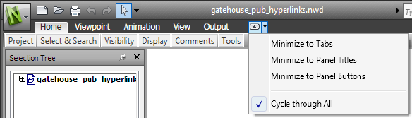
To hide or show a ribbon panel
1Click the ribbon tab that you want to organize.
2Right-click the ribbon tab.
3Under Show Panels, click or clear the name of a panel.
To show or hide text labels on ribbon panels
■Right-click a ribbon tab, and click or clear Show Panel Titles.
To return a floating panel to the ribbon
■Mouse over the right side of the floating panel and click the Return
Panels to Ribbon icon.
To toggle the ribbon size
1Click the drop-down arrow in the ribbon tab bar, and select the desired
minimize ribbon state.
2Double-click the name of the active ribbon tab or anywhere in the ribbon
tab bar.
The ribbon toggles between the selected minimize ribbon state and the
full ribbon state.
To reset the ribbon and the Quick Access toolbar
1Right-click anywhere inside the ribbon.
2Click Restore Default Ribbon.
The User Interface | 49
Home Tab
Contains tools to...Panel
control the whole scene.Project
select items and save selections in the scene
via a range of methods, including using
searches.
Select & Search
show and hide items of model geometry.Visibility
show and hide information including
properties and links.
Display
launch TimeLiner Playback tool.Tools
Viewpoint Tab
Contains tools to...Panel
load and playback saved viewpoints and
viewpoint animations.
Save, Load & Playback
apply various settings to the camera.Camera
set the linear and angular speed of motion,
select navigational tools and 3D mouse
Navigate
settings, and apply realism settings such as
gravity and collisions.
control the lighting and rendering settings.Render Style
Review Tab
Contains tools to...Panel
measure distances, angles, and areas.Measure
50 | Chapter 3 Quick Start
Contains tools to...Panel
view and locate comments in the scene.Comments
Animation Tab
Contains tools to...Panel
select and play back animations.Playback
enable scripts.Script
View Tab
Contains tools to...Panel
enable stereoscopic vision provided suitable
hardware is available.
Stereo
set the linear and angular speed of motion,
select navigational tools and 3D mouse
Navigate
settings, and apply realism settings such as
gravity and collisions. This panel is hidden
by default.
toggle navigation controls, such as the
Navigation Bar, ViewCube, HUD elements,
and reference views.
Navigation Aids
control the Scene View window including
going full screen, splitting the window and
setting the background style/colors.
Scene View
control which floating windows are shown,
and load/save workspace configurations.
Workspace
The User Interface | 51
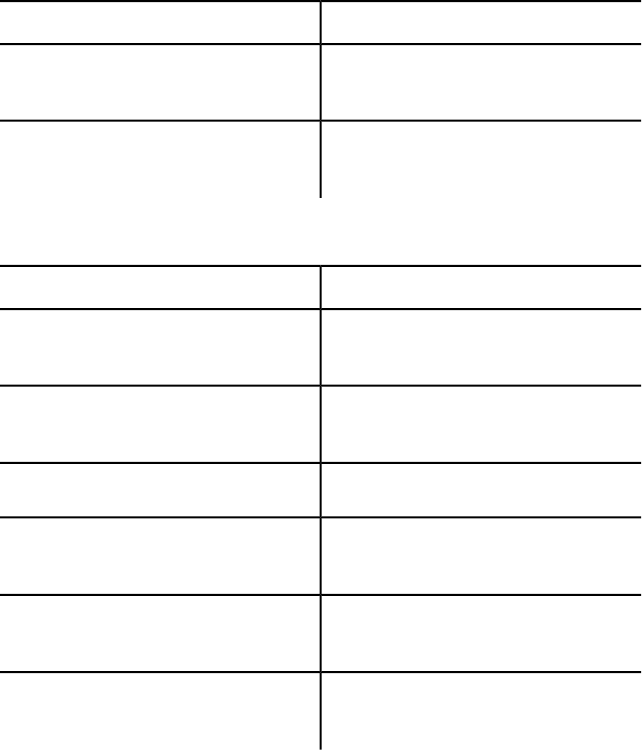
Output Tab
Contains tools to...Panel
print and preview the current viewpoint,
and set print settings.
Print
send an email with the current file as an
attachment.
Send
Item Tools Tab
Contains tools to...Panel
hold the selected items so that they move
with you as you navigate around the scene.
Hold
focus and zoom the current view onto the
selected items.
Look At
control the visibility of the selected items.Visibility
reset the position, rotation, and scale of the
selected items back to their original values.
Transform
reset the color and transparency of the se-
lected items back to their original values.
Appearance
reset the links on the selected items back
to their original values.
Links
Tooltips
Placing the mouse pointer over a menu choice or a button shows a tooltip
containing the name of the tool, a keyboard shortcut (if applicable), and a
brief description of the tool.
52 | Chapter 3 Quick Start
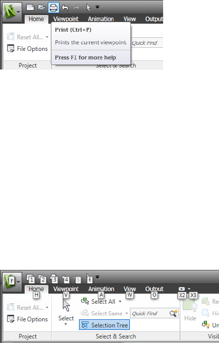
Some tooltips on the application menu, Quick Access toolbar, and ribbon
are progressive. If you leave the cursor over the menu choice or a button for
another moment, the tooltip may expand to show additional information.
While the tooltip is visible, you can press F1 for context-sensitive help that
provides more information about that tool.
Keytips
Autodesk Navisworks provides accelerator keys, or keytips, to enable you to
use the keyboard, rather than the mouse, to interact with the application
window.
Keytips are provided for the application menu, Quick Access toolbar, and
ribbon. You can still use ‘old style’ keyboard shortcuts, such as CTRL + N to
open a new file, and CTRL + P to print the current file.
To display keytips, press ALT. The keytips (letters or numbers) are shown on
the screen next to the corresponding command or user interface element.
Press the displayed accelerator key to immediately invoke the desired command
or to show the user interface element. For example, pressing ALT, and then
pressing 1 creates a new file.
To hide the keytips, press ALT again.
See also:
Default Keyboard Shortcuts (page 79)
The User Interface | 53
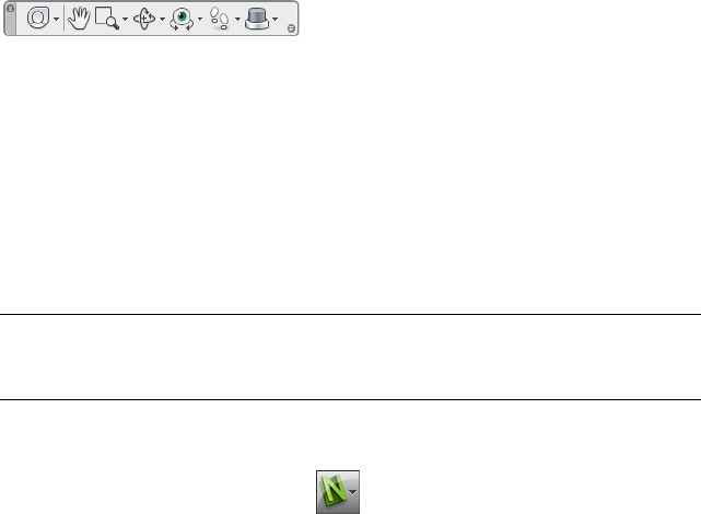
Navigation Tools
The navigation bar provides access to tools related to interactive navigation
and orientation in the model including Autodesk® ViewCube®,
SteeringWheels®, and 3Dconnexion® 3D mouse.
You can customize the navigation bar based on what you consider important
to show. You can also change the docking position of the navigation bar in
the Scene View.
The Classic User Interface
If you prefer, you can switch back to the Classic user interface, and use the
toolbars and pull-down menus from the menu bar instead of the ribbon.
NOTE The Classic user interface is no longer being updated with enhancements
to Autodesk Navisworks. It is recommended that you work using the standard
Autodesk Navisworks interface.
To switch to the classic user interface
1Click the application button ➤ Options.
2In the Options Editor, expand the Interface node, and click the User
Interface option.
3On the User Interface page, select Classic from the User Interface
drop-down list.
4Click OK.
Menu Bar
The Menu bar contains all commands available in Autodesk Navisworks,
grouped together by similar or 'like' functionality.
For example, all commands related to review functionality are located under
the Review menu, all commands related to user assistance are located under
the Help menu and so on.
54 | Chapter 3 Quick Start
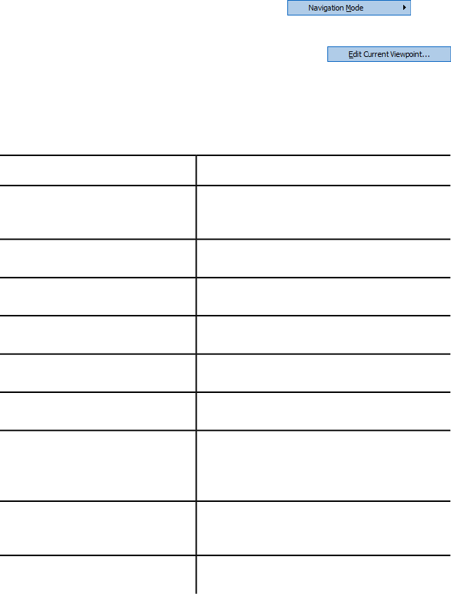
When a menu has a right-pointing arrow, such as , there
is a submenu associated with that choice.
When a menu item is followed by a series of dots, such as
, there is a dialog box associated with that choice.
File Menu
This menu contains commands for managing files.
DescriptionOption
Resets the program, and closes the currently open
Autodesk Navisworks file.
New
Displays the Open dialog box.Open
Displays the Open URL dialog box.Open URL
Displays the Print dialog box.Print
Enables print preview mode.Print Preview
Displays the Print Setup dialog box.Print Settings
Saves the currently open Autodesk Navisworks
file, accesses your email program, and adds the
saved file as an email attachment.
Send by Email
Displays shortcuts to the most recently opened
files.
Recent Files
Exits the program.Exit
The User Interface | 55

Edit Menu
This menu contains commands for locating, selecting and editing geometry
in your model.
DescriptionOption
Reverses the last performed operation.Undo
Reverses the last operation performed by the
Undo command.
Redo
Gives you access to selection functionality.Select
Displays the Quick Find dialog box.Quick Find
Repeats the previously run quick find search.Quick Find Next
Toggles hidden mode for selected items.Hidden
Toggles required mode for selected items.Required
Toggles hidden mode for unselected items.Hide Unselected
Enables you to reset selected items back to their
original state.
Reset Item
Enables you to reset all overridden items back to
their original state.
Reset All
Enables you to sort the items in the Selection
Tree alphabetically.
Sort
Displays the File Units and Transform dialog
box.
File Units an Transform
56 | Chapter 3 Quick Start
View Menu
This menu contains commands that control the Autodesk Navisworks interface.
DescriptionOption
Enables you to toggle the display of control bars.Control Bars
Enables you to control workspaces.Workspaces
Enable you to control the views in the Scene
View.
Scene View
Enables you to toggle navigation controls, such
as ViewCube, Navigation Bar, and HUD elements.
Head-Up Display
Enables you to control the SteeringWheels.SteeringWheels
Puts the video output into stereo mode.Enable Stereo
Displays the Stereo Options dialog box.Stereo Options
Displays useful scene statistics.Scene Statistics
Viewpoint Menu
This menu contains a set of commands that affect the current viewpoint,
including model appearance and navigation.
DescriptionOption
Enables you to look from a preset viewpoint.Look From
Sets the viewpoint up vector to align with the
selected orientation.
Set Viewpoint Up
Enables you to select rendering mode.Rendering
Enables you to select lighting mode.Lighting
The User Interface | 57
DescriptionOption
Enables you to display primitives.Display
Enables you to select navigation mode.Navigation Mode
Enables you to control the camera during inter-
active navigation.
Navigation Tools
Displays the Edit Viewpoint dialog box for the
current viewpoint.
Edit Current Viewpoint
Tools Menu
This menu contains commands for advanced model analysis and reviewing,
and also commands for customizing Autodesk Navisworks.
DescriptionOption
Toggles the TimeLiner Playback window.TimeLiner Playback
Toggles the display of links.Links
Toggles the display of quick properties.Quick Properties
Enables you to control animation playback, and
toggle scripts.
Animation
Enables you to select a background color for the
Scene View.
Background
Displays the File Options dialog box.File Options
Displays the Options Editor.Global Options
58 | Chapter 3 Quick Start
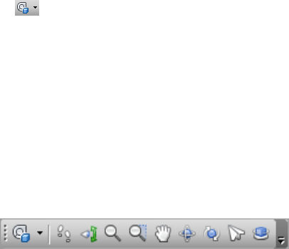
Toolbars
Autodesk Navisworks toolbars provide quick access to frequently used
commands.
Every button on a toolbar includes a tooltip, which describes the function the
button activates. Placing the mouse over a button displays a brief instruction
on how to use this feature in the Status bar.
You can rearrange, open and close toolbars:
■To move a toolbar, click the dotted line at the edge of the toolbar, and
drag it to a different location.
■To open or close toolbars, right-click an empty area next to the last toolbar
on the screen, and choose from the list of available toolbars on the shortcut
menu.
When a Autodesk Navisworks toolbar button has a down-pointing arrow, such
as , a submenu toolbar is associated with that choice. Click the triangle
to open the menu, and select a specific option. As you move through the
menu, additional help is displayed in the Status bar. When the option is
selected, it becomes the current command and is displayed as a button in the
toolbar. To repeat the command, click the button in the toolbar. To choose
a different command, click the triangle again.
Some toolbar buttons enable you to choose a program mode. For example, to
look around your model, you need to be in look around mode. To rotate the
model, you need to be in Free Orbit mode and so on. Autodesk Navisworks
remains in the selected mode until instructed otherwise. To identify the mode
you are in, look at the buttons. If a button is highlighted and has a dark blue
boarder around it, the corresponding mode is currently active.
To leave the mode, either click the same button again or choose a different
mode.
Some buttons are used to toggle the display of dialog boxes, and dockable
windows (for example, the Presenter window, the Animator window etc.).
Again, if a button is highlighted and has a dark blue boarder around it, it
means that the corresponding display element is currently open.
As you open more toolbars on the screen, or resize the Autodesk Navisworks
window, the toolbars may get overlapped with each other to reduce the screen
clutter. When this happens, some buttons will be hidden under the overlaps.
The User Interface | 59
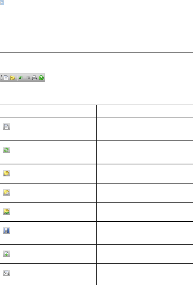
To quickly access the entire set of commands on a toolbar, click the chevron
button at the right end of the toolbar. The remaining commands available
for that toolbar will appear.
In this section, you will find a complete list of Autodesk Navisworks toolbars
and associated buttons.
NOTE The actual toolbar content can differ from this reference depending on the
workspace you use.
Standard Toolbar
This toolbar provides quick access to file management commands. It also
enables you to undo/redo your actions, and open the Help system.
DescriptionButton
Resets the program, and closes the currently
open Autodesk Navisworks file.
Refreshes your scene with the latest versions
of currently loaded model files.
Displays the Open dialog box.
Displays the Append dialog box.
Displays the Merge dialog box.
Saves the currently open Autodesk Navis-
works file.
Displays the Publish dialog box.
Saves the currently open Autodesk Navis-
works file, accesses your email program,
60 | Chapter 3 Quick Start
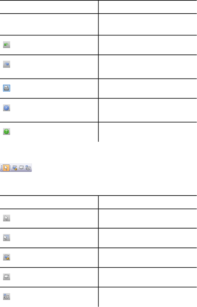
DescriptionButton
and adds the saved file as an email attach-
ment.
Reverses the last performed operation.
Reverses the last operation performed by
the Undo command.
Displays the Print dialog box.
Displays copyright and license information
about your copy of Autodesk Navisworks.
Opens the Help system.
Selection Tools Toolbar
This toolbar provides access to the selection commands, plus enables you to
hide geometry objects.
DescriptionButton
Turns on Select mode.
Turns on Select Box mode.
Toggles required mode for selected items.
Toggles hidden mode for selected items.
Toggles hidden mode for unselected items.
The User Interface | 61
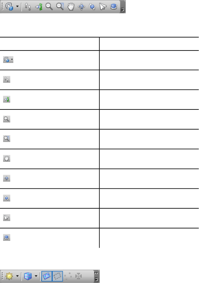
Navigation Mode Toolbar
This toolbar includes nine modes and six SteeringWheels for interactive
navigation around your 3D models.
DescriptionButton
Selects the wheel.
Turns on Walk mode.
Turns on Look Around mode.
Turns on Zoom mode.
Turns on Zoom Box mode.
Turns on Pan mode.
Turns on Orbit mode.
Turns on Free Orbit mode.
Turns on Fly mode.
Turns on Constrained Orbit mode.
Rendering Style Toolbar
62 | Chapter 3 Quick Start
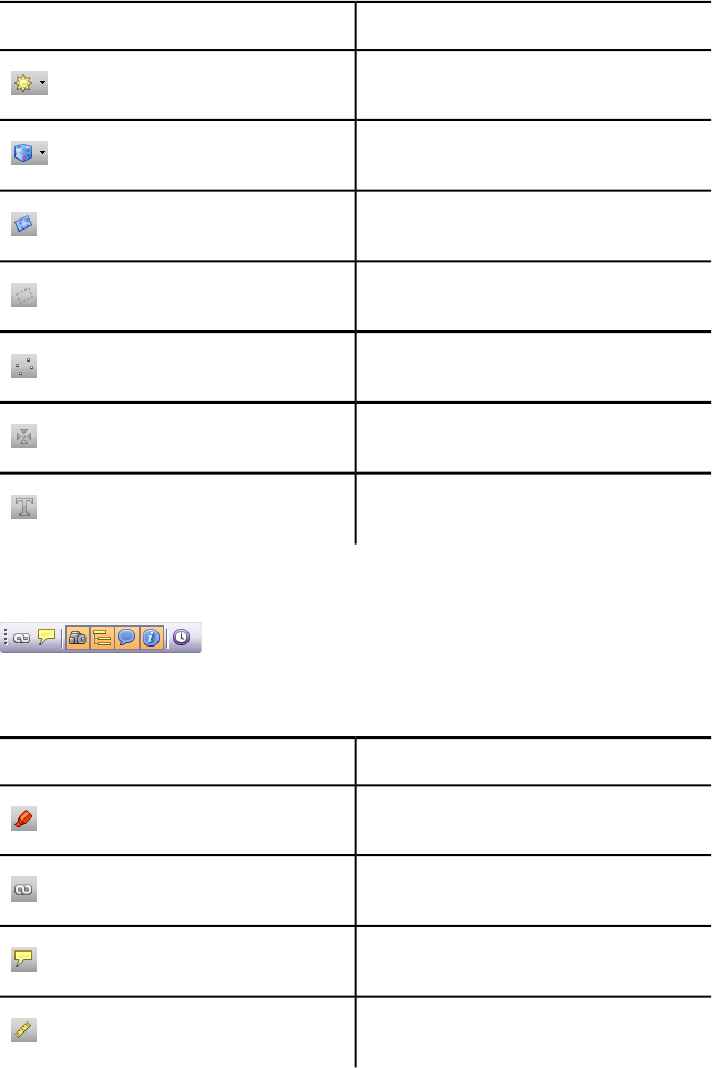
This toolbar controls the model appearance in Autodesk Navisworks.
DescriptionButton
Selects Lighting mode.
Selects Rendering mode.
Toggles the rendering of surfaces.
Toggles the rendering of lines.
Toggles the rendering of points.
Toggles the rendering of snap points.
Toggles the rendering of 3D text.
Workspace Toolbar
This toolbar gives you quick access to the Autodesk Navisworks review and
analysis tools.
DescriptionButton
Toggles the Redline Tools tool window.
Toggles the display of links.
Toggles the display of quick properties.
Toggles the Measure Tools tool window.
The User Interface | 63
DescriptionButton
Toggles the Viewpoints control bar.
Toggles the Sectioning toolbar.
Toggles the Plan View control bar.
Toggles the Section View control bar.
Toggles the Selection Tree control bar.
Toggles the Sets control bar.
Toggles the Comments control bar.
Toggles the Find Comments dialog box.
Toggles the Find Items control bar.
Toggles the Properties control bar.
Toggles the Clash Detective tool window.
Toggles the Presenter tool window.
Toggles the TimeLiner tool window.
Toggles the TimeLiner Playback window.
Toggles the Animator tool window.
64 | Chapter 3 Quick Start
DescriptionButton
Toggles the Scripter tool window.
Controls workspaces.
Animation Toolbar
This toolbar allows you to play back object and viewpoint animations, and
toggle the scripting functionality.
DescriptionButton
Rewinds the current animation back to the
beginning.
Steps back a single animation frame or
keyframe.
Plays the current animation backwards.
Records the viewpoint animation.
Pauses the animation.
Stops playing the current animation, and
rewinds it back to the beginning.
Plays the currently selected animation.
Steps one frame or keyframe forwards.
Fast forwards the current animation to the
end.
The User Interface | 65
DescriptionButton
Toggles the Scripter engine on and off in
the Autodesk Navisworks file.
Navigation Tools Toolbar
This toolbar enables you to control the camera during interactive navigation.
DescriptionButton
Dollies and pans the camera so that the
entire model is in the Scene View.
Zooms the camera so that the selected item
fills the Scene View.
Puts the Scene View into focus mode.
Holds the selected items. As you move
around the model, these objects will move
with you.
Uses a perspective camera.
Uses an orthographic camera.
Toggles collision.
Toggles gravity.
Toggles crouching.
66 | Chapter 3 Quick Start
DescriptionButton
Toggles third person view.
Aligns the current viewpoint with the X axis.
Aligns the current viewpoint with the Y axis.
Aligns the current viewpoint with the Z axis.
Scene View
This is the area where you view and interact with your 3D models.
When you start Autodesk Navisworks, the Scene View contains only one
scene view, but you can add more scene views, if needed. Custom scene views
are named “ViewX” where “X” is the next available number. The default scene
view cannot be moved.
The User Interface | 67
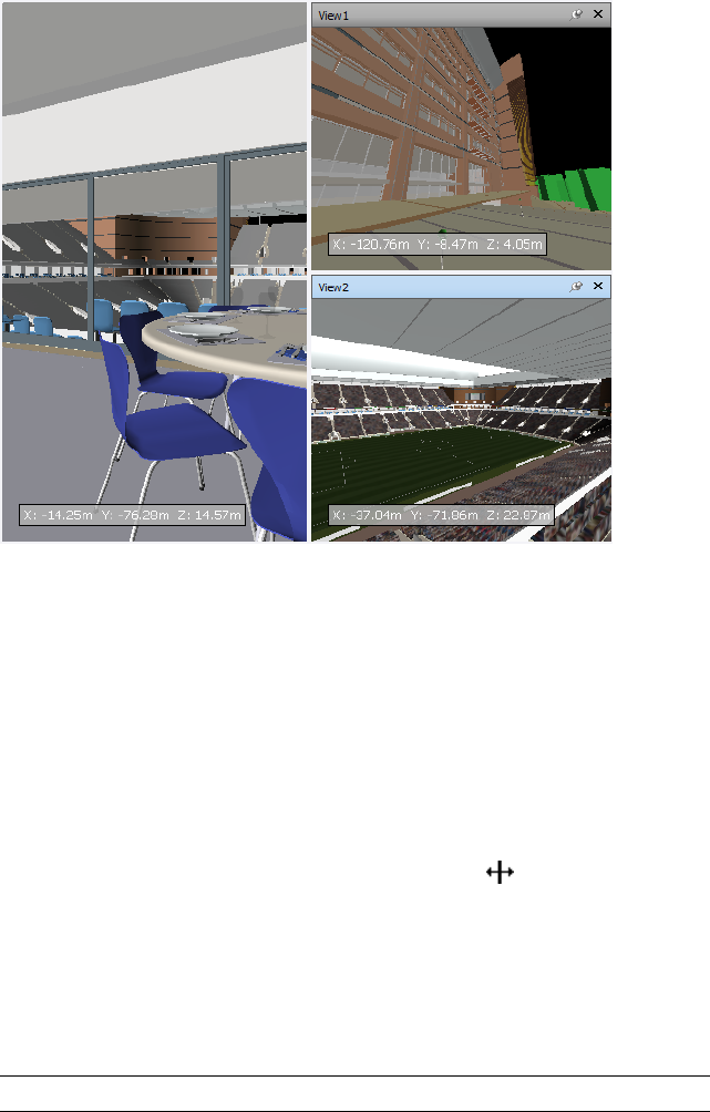
Looking at several views of your model simultaneously is useful when you
compare lighting and rendering styles, animate different parts of your model,
and so on.
Only one scene view can be active at a time. A scene view becomes active as
you work in it. If you left-click a scene view, the scene view is activated and
whatever you click is selected, or, if you click an empty area, everything is
deselected. Right-clicking a scene view activates it, and opens a shortcut menu.
Each scene view remembers the navigation mode being used. The recording
and playback of animations only occurs in the currently active view.
Each scene view can be resized. To resize scene views, move the cursor over
the scene view intersection and drag the splitter bar .
You can make custom scene views dockable. Dockable scene views have title
bars, and can be moved, docked, tiled, and auto hidden the same way as
dockable windows (page 70). If you want to use several custom scene views,
but don't want to have any splits in the Scene View, you can move them
elsewhere. For instance, you can tile your scene views on the Viewpoints
control bar.
NOTE You cannot undock the default scene view.
68 | Chapter 3 Quick Start
Full Screen Mode
In Full Screen mode your current scene view takes up the full screen.
To interact with the model in the scene view, you can use the ViewCube, the
Navigation Bar, the keyboard shortcuts, and the shortcut menu.
TIP If you use two monitors, your default scene view is automatically placed on
the primary display, and the interface can be placed on the secondary display to
control the interaction.
To create a custom scene view
■To split your active scene view horizontally, click View tab ➤ Scene View
panel ➤ Split View ➤ Split Horizontal .
■To split your active scene view vertically, click View tab ➤ Scene View
panel ➤ Split View ➤ Split Vertical .
Toolbar: Classic user interface: Model Views ➤ Split Horizontal
and Model Views ➤ Split Vertical
To make a custom scene views dockable
■Click View tab ➤ Scene View panel ➤ Show Title Bars.
All of your custom scene views now have title bars.
Toolbar: Classic user interface: Model Views ➤ Toggle Title Bars
To delete a custom scene view
1If your scene view is not dockable, click View tab ➤ Scene View panel
➤ Show Title Bars.
2Click to close the scene view.
NOTE You cannot delete the default scene view.
To toggle Full Screen mode
■Click View tab ➤ Scene View panel ➤ Full Screen .
The User Interface | 69
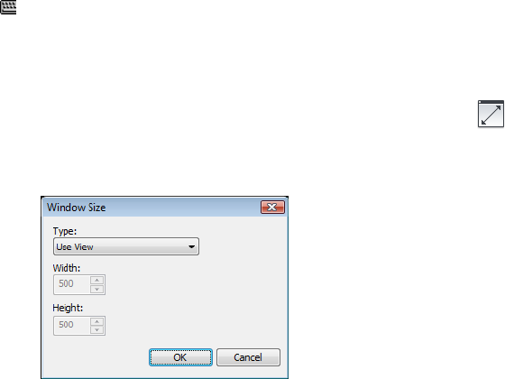
Command entry: F11
Shortcut menu: Viewpoint ➤ Full Screen
To resize the content of the active scene view
1Click View tab ➤ Scene View panel ➤ Window Size .
2In the Window Size dialog box, Type drop-down list, select the sizing
type.
■Use View - makes the content fill the currently active scene view.
■Explicit - defines the exact width and height for the content.
■Use Aspect Ratio - uses the aspect ratio of the current scene view
to automatically calculate the width of the content when the height
is entered, or the height of the content when the width is entered.
3If you selected the Explicit option, enter the width and height for your
content in pixels.
If you selected the Use Aspect Ratio, enter the width or height for
your content in pixels.
4Click OK.
Dockable Windows
Most Autodesk Navisworks features are accessible from dockable windows.
There are several windows to choose from, which are grouped into several
functional areas:
70 | Chapter 3 Quick Start

Main Tools Windows
These windows give you access to the core Autodesk Navisworks functionality:
■TimeLiner Playback
Review Windows
These windows contain tools required to perform select/search/review
operations:
■Selection Tree
■Properties
■Comments
■Measure Tools
Viewpoint Windows
These windows contain tools necessary to set up and use viewpoints:
■Saved Viewpoints
■Tilt - 3D workspace only.
■Plan View - 3D workspace only.
■Section View - 3D workspace only.
Multi-Sheet Windows
These window enable you to work with multi-sheet files:
■Project Browser
■Find Item in Other Sheets and Models
Windows can be moved and resized, and either floated in the Scene View
or docked (pinned or auto-hidden).
TIP You can quickly dock and undock a window by double-clicking the window’s
title bar.
A docked window shares one or more edges with adjacent windows and
toolbars. If a shared edge is moved, the windows change shape to compensate.
You can also float windows anywhere on the screen, if necessary.
The User Interface | 71

NOTE The Tilt window can only be docked vertically on the left or right, taking
up the full height of the canvas, or be floating.
By default, a docked window is pinned, meaning that the window remains
displayed at its current size and can be moved. When you auto hide a window
and move the mouse pointer away from it, the window is reduced to a tab
displaying the window name. Moving the mouse pointer over the tab displays
the window fully, but temporarily, over the canvas. Auto-hiding a window
can show more of the canvas while still keeping the window available.
Auto-hiding a window also prevents it from being undocked, grouped, or
ungrouped.
NOTE When you dock windows inside the default scene view, you do not get pin
and auto-hide functionality.
An undocked window is one that has been separated from the program
window. Each undocked window can be moved around the screen or screens
as desired. Although undocked windows cannot be pinned, they can be resized
and grouped.
A window group is a way to have more than one window occupy the same
amount of space on the screen. When windows are grouped, each window is
represented by a tab at the bottom of the group. In a group, click a tab to
display that window. You can group or ungroup window as necessary and
save custom workspaces. After changing window positions, you can save your
settings as a custom workspace.
Auto Hide Position
When you auto hide a window, it collapses against a specific side of the canvas
- Top, Left, Right, or Bottom. The side to which it collapses is determined by
the docking position. So, for example, if you dock a window to the left of
canvas, it collapses to the left.
The Shortcut Menu
Right-clicking a dockable window displays a shortcut menu of available
commands. If you right-click a single item, or select one or more items and
right-click, this menu contains commands related to the items. If you
right-click an area that contains no items or data, the menu contains
commands related to the dockable window, if appropriate.
72 | Chapter 3 Quick Start
To show a dockable window
1Click View tab ➤ Workspace panel ➤ Windows .
2Select the check box next to the desired window in the drop-down list.
To move a dockable window
1Click and drag the title bar at the top or side of the window.
2Optional: to prevent a window from automatically docking while you
drag it, hold down the CTRL key.
TIP The docking tool allows you to place windows in a specific relationship to the
canvas areas.
To group dockable windows
1Click and drag the title bar of the window to be added to another window
or group.
2Drop the window on the title bar of the receiving window or group. A
tab with the name of the dragged window is added to the bottom of the
receiving window.
To ungroup dockable windows
1Within the group, click the tab for the window you want to remove.
2Click and drag the window tab out of the group.
3Drop the window to ungroup it.
To auto hide dockable windows
1On a window title bar, click .
The window continues to be displayed until you move the mouse pointer
away from it. When you move the mouse pointer, the window is
collapsed until you place the mouse pointer over the window tab on the
side of the canvas where its docked.
NOTE To move or group windows, you need to pin them first.
To pin dockable windows
1Move the mouse cursor over the title bar to display the hidden window.
The User Interface | 73
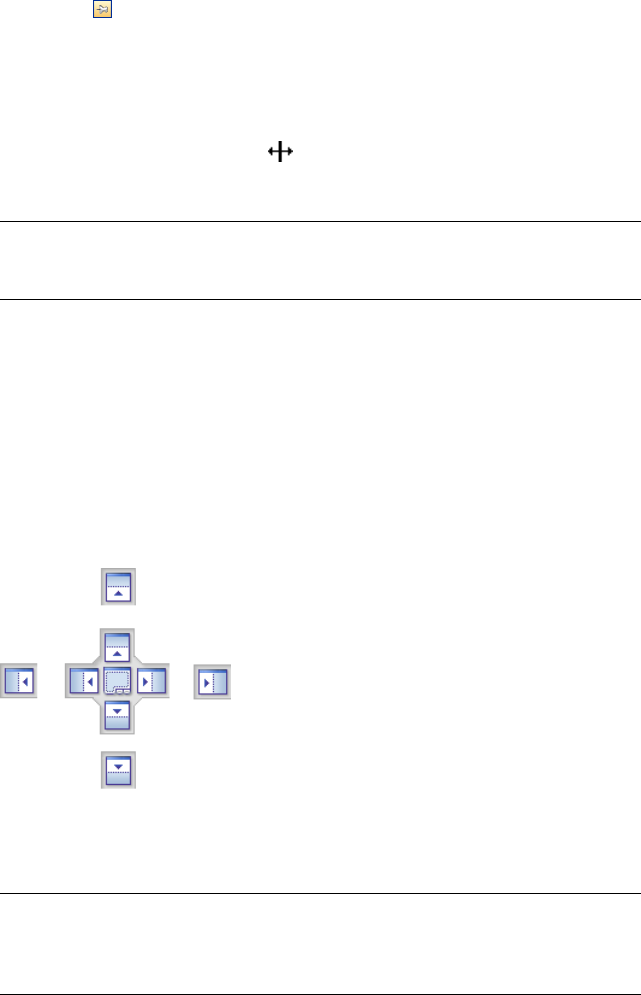
2Click on the title bar. The window is now pinned, and can be moved
and grouped.
To resize a dockable window or a group of windows
1Place the mouse pointer over a window border until the mouse pointer
changes to the splitter bar .
2Click and drag the boarder to the desired size.
TIP You can resize both pinned and auto hidden windows. In an auto-hidden
group, each window can be resized separately from other windows. In a pinned
group, resizing one window resizes the rest of the windows.
Docking Tool
The docking tool indicates the relationship of a dragged window to the rest
of the canvas, and enables you to pinpoint drag and drop destinations.
The tool contains an inner zone and outer zone of controls representing the
drop destination. Five stickers of the inner zone are used to dock windows
relative to the closest suitable area on the canvas, while four stickers of the
outer zone are used to dock windows relative to the canvas itself.
The docking tool also provides visual previews of what space will be occupied
by a window. These previews are shown when you are moving a window and
while your mouse is over one of the stickers.
TIP To quickly create a window group, use the sticker at the center of the docking
tool when you drag a window to its location. This works anywhere on the canvas
excluding the default scene view and the Tilt window. Custom scene views can
be grouped with other windows.
74 | Chapter 3 Quick Start
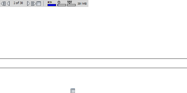
To move a window with the docking tool
1Click and drag the title bar at the top or side of the window towards the
place where you want it to dock. This activates the docking tool.
2Drag the window over the sticker on the docking tool that represents
the area you want the window to occupy.
3Release the mouse button to dock the window there. The window is
automatically resized to fill the area.
Status Bar
The Status bar appears at the bottom of the Autodesk Navisworks screen. It
cannot be customized or moved around.
The left-hand corner of the Status bar is used to display short instructions
on how to use the Autodesk Navisworks features (applies to the Classic user
interface only).
The right-hand corner of the Status bar includes four performance indicators
that give you constant feedback as to how well Autodesk Navisworks is
performing on your machine, a button to toggle the Project Browser
window, and controls to navigate between sheets/models in multi-sheet files.
Multi-Sheet Navigation Controls
Click the previous/next and first/last arrows to open the desired sheet/model
in the Scene View. This is equivalent to double-clicking the sheet/model in
the Project Browser window. The sheet/model will be automatically prepared
for use in Autodesk Navisworks, if applicable.
NOTE These controls are only available for multi-sheet files.
Project Browser Button
Click the Project Browser button to toggle the Project Browser window
(page 100).
Pencil Progress Bar
The progress bar under the left hand icon (pencil) indicates how much of the
current view is drawn, that is how much drop-out there is in the current
The User Interface | 75
viewpoint. When the progress bar is at 100%, the scene is completely drawn,
with no drop-out. The icon changes color when a redraw is in progress. Whilst
the scene is being drawn, the pencil will change to yellow. If there is too much
data to handle and your machine cannot process this quickly enough for
Autodesk Navisworks, then the pencil changes to red, indicating a bottleneck.
Disk Progress Bar
The progress bar under the central icon (disk) indicates how much of the
current model is loaded from disk, that is how much is loaded into memory.
When the progress bar is at 100%, the entire model, including geometry and
property information, is loaded into memory. The icon changes color when
a file load is in progress. Whilst data is being read, the disk changes to yellow.
If there is too much data to handle and your machine cannot process this
quickly enough for Autodesk Navisworks, then the disk changes to red,
indicating a bottleneck.
Web Server Progress Bar
The progress bar under the right hand icon (web server) indicates how much
of the current model is downloaded, that is how much has been downloaded
from a web server. When the progress bar is at 100%, the entire model has
been downloaded. The icon changes color when a file load is in progress.
Whilst data is being downloaded, the web server changes to yellow. If there
is too much data to handle and your machine cannot process this quickly
enough for Autodesk Navisworks, then the web server changes to red,
indicating a bottleneck.
Memory Bar
The field to the right of the icons reports the amount of memory currently
being used by Autodesk Navisworks. This is reported in Megabytes (MB).
Undo/Redo Commands
You can undo or redo your actions in Autodesk Navisworks.
The default settings are adequate for regular Autodesk Navisworks usage, but
you can adjust (page 281) the amount of space allocated to the undo/redo
buffer, if necessary.
76 | Chapter 3 Quick Start
To undo an action
■Click Undo on the Quick Access toolbar.
Command entry: CTRL + Z
Toolbar: Classic user interface: Standard ➤ Undo
To redo an action
■Click Redo on the Quick Access toolbar.
Command entry: CTRL + Y
Toolbar: Classic user interface: Standard ➤ Redo
Autodesk Navisworks Workspaces
Workspaces retain information about which windows are open, their positions,
and the size of the application window.
Workspaces retain changes made to the ribbon but not to the Quick Access
toolbar.
NOTE In the Classic user interface mode (that is, the ribbon is turned off),
workspaces retain information about the dockable windows and the toolbars.
The workspaces can be shared with other users. You could, for example, create
separate workspaces for occasional and power Autodesk Navisworks users, or
setup your own corporate standard.
Autodesk Navisworks comes with several pre-configured workspaces:
■Safe Mode - selects the layout with the minimum features.
■Navisworks Standard - selects the layout with commonly-used windows
auto-hidden as tabs.
■Navisworks Minimal - selects the layout giving the most space to the
Scene View.
You can use these workspaces as-is or modify them in accordance to your
requirements. When you first start Autodesk Navisworks, the Navisworks
Minimal workspace is used. You can choose a different workspace at any
time by clicking View tab ➤ Workspace panel ➤ Load Workspace ,
and then selecting the required workspace from the list.
Toolbar: Classic user interface: Workspace ➤ Workspaces
The User Interface | 77
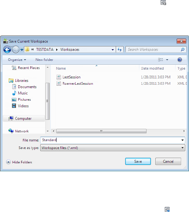
To save current layout to a new workspace
1Set up your design review layout. For example, you can group together
the Properties and Saved Viewpoints windows.
If you use the Classic user interface mode, for example, you can close
all toolbars except the Standard, Selection Tools, Navigation Mode,
and Workspace.
2Click View tab ➤ Workspace panel ➤ Save Workspace .
3In the Save Current Workspace dialog box, enter a name for the new
workspace. You can also select the name of an existing workspace to
overwrite it with your modified configuration.
4Click Save.
To load a saved workspace into Autodesk Navisworks
1Click View tab ➤ Workspaces panel ➤ Load Workspace .
2In the Load Workspace dialog box, browse to the folder containing
the desired workspace, and select it.
78 | Chapter 3 Quick Start
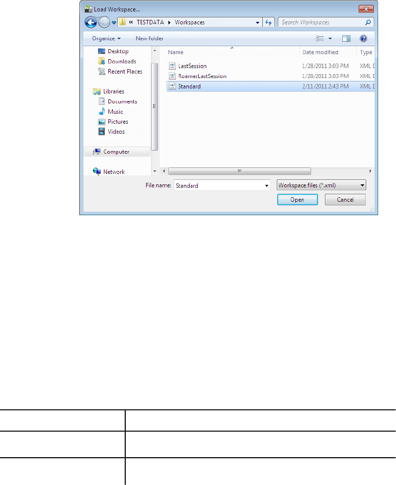
3Click Open.
Default Keyboard Shortcuts
Keyboard shortcuts are keyboard alternatives you can use to initiate commands
normally accessed with the mouse.
For example, to open the Selection Tree, window you can press CTRL + F12,
to open the Comments window, you can press SHIFT + F6, and so on.
Keyboard shortcuts offer a means to let you work faster and more efficiently.
Some dialog boxes or dockable windows can be closed with the same command
used to open it.
Many keyboard shortcuts are already set for most commonly used actions.
You can modify the default shortcuts or add new shortcuts, if necessary.
DescriptionDefault Keyboard Shortcut
Zooms to view all objects in the Scene View.PgUp
Zooms to magnify all selected objects in the Scene View.PgDn
The User Interface | 79
DescriptionDefault Keyboard Shortcut
Takes you to Home view. This keyboard shortcut only applies to the Scene
View windows. This means it will only work when this window has focus.
HOME
Deselects everything.ESC
Used to modify the middle mouse button actions.SHIFT
Used to modify the middle mouse button actions.CTRL
Turns the keytips on or off.ALT
Closes the currently active dockable window when it is undocked, or exits
the application if the main application window is active.
ALT + F4
Turns on Turntable mode.CTRL + 0
Turns on Select mode.CTRL + 1
Turns on Walk mode.CTRL + 2
Turns on Look Around mode.CTRL + 3
Turns on Zoom mode.CTRL + 4
Turns on Zoom Window mode.CTRL + 5
Turns on Pan mode.CTRL + 6
Turns on Orbit mode.CTRL + 7
Turns on Free Orbit mode.CTRL + 8
Turns on Fly mode.CTRL + 9
80 | Chapter 3 Quick Start
DescriptionDefault Keyboard Shortcut
Toggles Collision mode. You must be in appropriate navigation mode (that
is, Walk or Fly) for this keyboard shortcut to work.
CTRL + D
Displays the Quick Find dialog box.CTRL + F
Toggles Gravity mode.CTRL + G
Toggles Hidden mode for selected items.CTRL + H
Displays the Insert File dialog box.CTRL + I
Resets the program, closes the currently open Autodesk Navisworks file,
and creates a new file.
CTRL + N
Displays the Open dialog box.CTRL + O
Displays the Print dialog box.CTRL + P
Toggles Require mode for selected items.CTRL + R
Toggles Third Person mode.CTRL + T
Reverses the last operation performed by the Undo command.CTRL + Y
Reverses the last performed operation.CTRL + Z
Displays the previous sheet.CTRL + PgUp
Displays the next sheet.CTRL + PgDn
Opens the Help system.CTRL + F1
Toggles the TimeLiner Playback window.CTRL + F3
Toggles the Tilt window.CTRL + F7
The User Interface | 81
DescriptionDefault Keyboard Shortcut
Toggles the Plan View window.CTRL + F9
Toggles the Section View window.CTRL + F10
Toggles the Saved Viewpoints window.CTRL + F11
Toggles the Selection Tree window.CTRL + F12
Dollies and pans the camera so that the entire model is in view.CTRL + HOME
Play selected animation.CTRL + Right Arrow
Reverse Play selected animation.CTRL + Left Arrow
Sets current view as Home.CTRL + SHIFT + HOME
Sets current view as Front.CTRL + SHIFT + END
Takes you to the previous redline tag.CTRL + SHIFT + Left Arrow
Takes you to the next redline tag.CTRL + SHIFT + Right Arrow
Takes you to the first redline tag.CTRL + SHIFT + Up Arrow
Takes you to the last redline tag.CTRL + SHIFT + Down Arrow
Opens the Help system.F1
Renames the selected item, when appropriate.F2
Repeats the previously run Quick Find search.F3
Toggles Full Screen mode.F11
82 | Chapter 3 Quick Start
DescriptionDefault Keyboard Shortcut
Opens the Options Editor.F12
Opens the last used SteeringWheel.SHIFT + W
Enables you to get context-sensitive help.SHIFT + F1
Toggles the Comments window.SHIFT + F6
Toggles the Properties window.SHIFT + F7
Opens a shortcut menu.SHIFT + F10
Opens the File Options dialog box.SHIFT + F11
Navigation with the Wheel Button
If you have a wheel mouse, you can use the middle mouse button to zoom,
pan, and orbit.
Do this...To
scroll the wheel button forward.Zoom in
scroll the mouse wheel backward.Zoom out
hold down the middle mouse button, and
then move the mouse to pan.
Pan
press and hold SHIFT and hold down the
middle mouse button, and then move the
Orbit
mouse to orbit about the currently defined
pivot point. This function is not available in
a 2D workspace.
Navigation with the Wheel Button | 83
Do this...To
press and hold the SHIFT and CTRL keys
and hold down the middle mouse button,
Change the pivot point
then drag to the point on the model you
want to use as the pivot point. This function
is not available in a 2D workspace.
NOTE The above does not apply when using Walk, Fly, or any of the classic
navigation modes, all of which have their own wheel/middle button behaviors.
Mouse Wheel / Middle Button Navigation
NOTE In a 2D workspace you can only pan and zoom. Also, the Shift+ Middle
Button function is only available in a 3D workspace.
SHIFT + Middle
Button
Middle But-
ton
Wheel
Non-Navigational Tools
OrbitPanZoom In/Out
Select
Classic Navigation Modes
Glide Camera (Faster)Glide CameraLook Up/DownWalk
OrbitPanZoom In/OutLook Around
-Zoom (Drag)Zoom (Roll)Zoom
-Zoom (Drag)Zoom (Roll)Zoom Box
-Zoom (Drag)Zoom (Roll)Pan
-Glide CameraZoom (Roll)Orbit
-PanZoom (Roll)Examine
84 | Chapter 3 Quick Start

SHIFT + Middle
Button
Middle But-
ton
Wheel
-Roll-Fly
-PanTilt Up/DownTurntable
Standard Navigation Modes
OrbitPanZoom In/OutPan
OrbitPanZoom In/OutZoom Window
OrbitPanZoom In/OutZoom
OrbitPanZoom In/OutOrbit
OrbitPanZoom In/OutFree Orbit
OrbitPanZoom In/OutConstrained Orbit
OrbitPanZoom In/OutLook At
OrbitPanZoom In/OutSteeringWheels
Autodesk Navisworks Options
There are two types of options: File Options and Global Options.
File Options
For each Autodesk Navisworks file (NWF and NWD), you can adjust the model
appearance and the speed of navigation around it. Viewing options are stored
with Autodesk Navisworks files (NWF or NWD), and reloaded each time you
open these files.
Autodesk Navisworks Options | 85
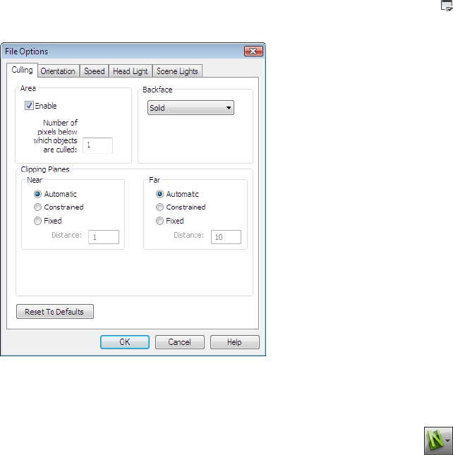
The File Options dialog box is used to customize various file options, and
can be accessed by clicking Home tab ➤ Project panel ➤ File Options
.
Global Options
Global options, on the other hand, are set for all Autodesk Navisworks sessions.
The Options Editor can be accessed by clicking the application button
➤ Options, or it can be launched as a separate application. To do this, click
Start ➤ All Programs ➤ Autodesk ➤ Navisworks Freedom 2012 ➤ Options
Editor. The options are grouped together, and presented in a tree structure,
making it quicker to find and change them.
86 | Chapter 3 Quick Start
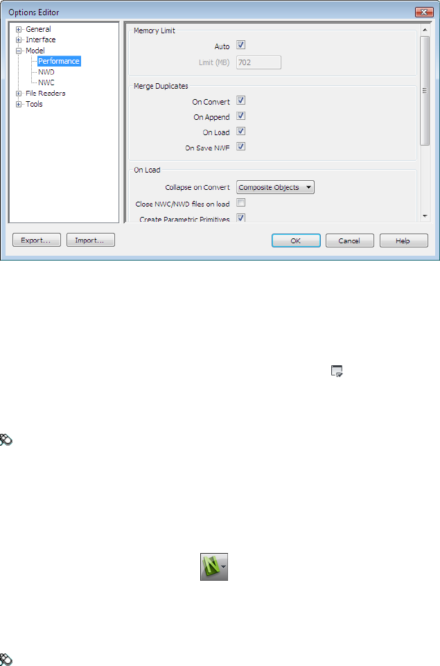
Global options can be exported and imported, making it quick and easy for
project managers, or systems administrators, to ensure the Autodesk Navisworks
settings on all machines are identical.
To configure file options
1Click Home tab ➤ Project panel ➤ File Options .
2Use the File Options dialog box to customize various file settings.
3Click OK to save the changes.
Menu: Classic user interface: Tools ➤ File Options
See also:
File Options Dialog Box (page 274)
To configure global options
1Click the application button ➤ Options.
2In the Options Editor, expand the desired node, and click the option
you want to configure.
3Click OK to save the changes.
Menu: Classic user interface: Tools ➤ Global Options
Autodesk Navisworks Options | 87
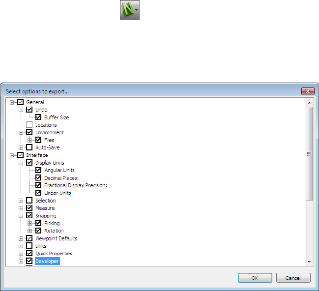
See also:
Options Editor Dialog Box (page 280)
To export global options
1Click the application button ➤ Options.
2In the Options Editor, click the Export button.
3In the Select Options to Export dialog box, select the check boxes
for all options you want to be exported (or “serialized”). If an option
cannot be exported, it is greyed out.
TIP To quickly select/deselect all options for a given category, use the
top-level check boxes. For example, selecting the General check box,
instantly selects all options under this node.
4Click OK to export the selected settings.
5In the Save As dialog box, enter a name for the settings file. You can
also select the name of an existing settings file to overwrite it with your
modified configuration.
88 | Chapter 3 Quick Start
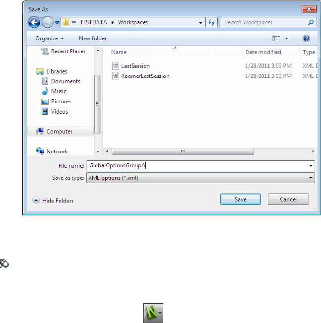
6Click Save.
7Click OK to close the Options Editor.
Menu: Classic user interface: Tools ➤ Global Options
To import global options
1Click the application button ➤ Options.
2In the Options Editor, click the Import button.
3In the Open dialog box, browse to the folder containing the settings
file, select it, and click Open.
Autodesk Navisworks Options | 89
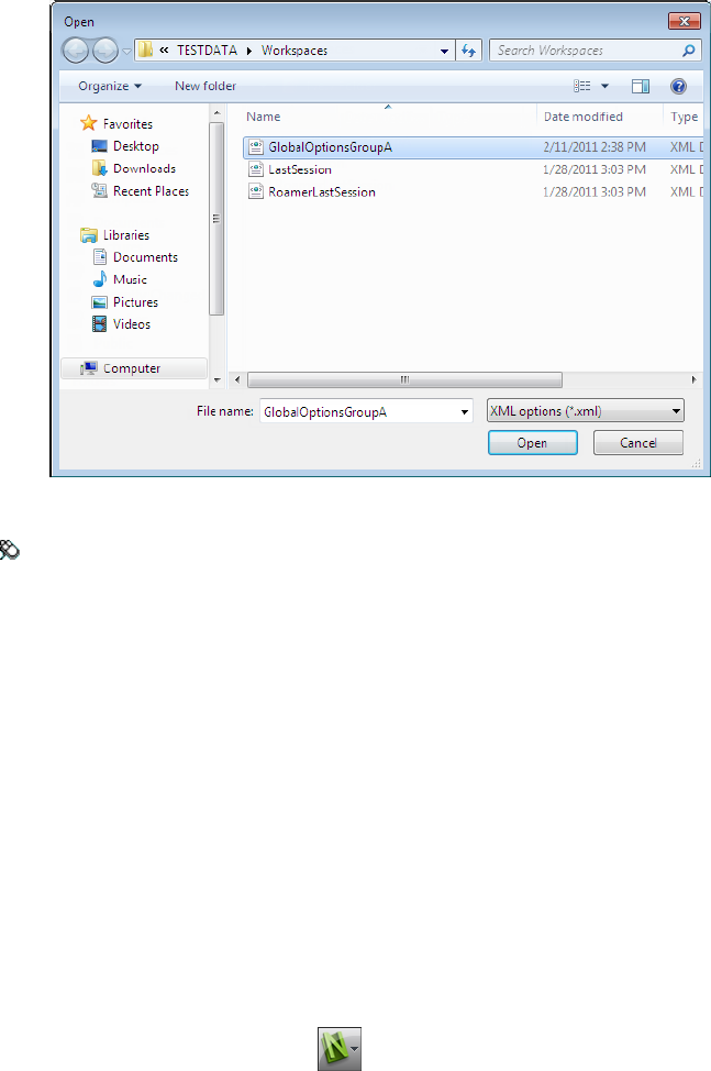
4Click OK to close the Options Editor.
Menu: Classic user interface: Tools ➤ Global Options
Location Options
These options enable centralized sharing of global Autodesk Navisworks
settings, workspaces, datatools, avatars, Clash Detective rules, Presenter
archives, custom Clash Detective tests, object animation scripts, and so on,
with other users.
The settings can be shared across an entire project site, or across a specific
project group depending on the required level of granularity.
See also:
How do I share the Autodesk Navisworks settings on a site and project
basis? (page 35)
To configure location options
1Click the application button ➤ Options.
90 | Chapter 3 Quick Start
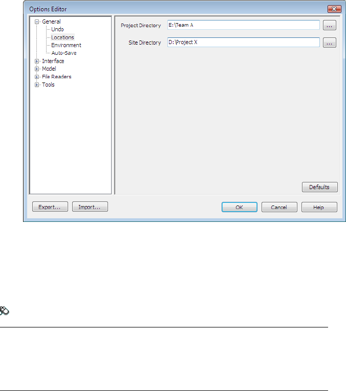
2Expand the General node in the Options Editor, and click the
Locations option.
3In the Project Directory box, browse to the directory that contains
the Autodesk Navisworks settings specific to your project group.
4In the Site Directory box, browse to the directory that contains the
Autodesk Navisworks settings standard across the entire project site.
5Click OK.
Menu: Classic user interface: Tools ➤ Global Options
NOTE When you run Autodesk Navisworks for the first time, the settings are picked
up from the installation directory. Subsequently, Autodesk Navisworks examines
the current user profile and the all users profile on the local machine, and then
checks the settings in the Project Directory and the Site Directory. The files
in the Project Directory take precedence.
Display Units
Display units determine the scale of your model in Autodesk Navisworks.
Display units are used to measure geometry in your scene, align appended
models, set tolerances for clash detection, set texture sizes and so on.
Display Units | 91

When you open CAD and laser scan files, Autodesk Navisworks reads the units
directly from the files. If this is not possible (for example, the file is unitless),
Autodesk Navisworks uses the default units configured for that file type in the
Options Editor whenever possible. Loaded files are scaled appropriately to
the configured display units.
It is possible to rescale the file units, if they are found to be incorrect for the
scene.
To customize display units
1Click the application button ➤ Options.
2Expand the Interface node in the Options Editor, and click the
Display Units option.
3Select the Linear Units from the drop-down list. Be sure to choose the
exact format required.
4Select the Angular Units from the drop-down list.
5Enter the number of decimal places you want to see throughout the
interface for your units in the Decimal Places box. If the unit chosen
is a fractional unit, rather than a decimal unit, then you have the choice
of what level of fraction to display the units from the Fractional
Display Precision drop-down list.
6Click OK.
92 | Chapter 3 Quick Start
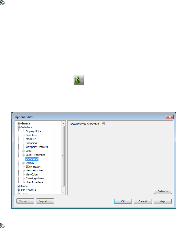
Menu: Classic user interface: Tools ➤ Global Options
Profiles
Autodesk Navisworks can be adjusted to your level of CAD technical
knowledge.
By default, a standard profile is used. If necessary, you can use a developer
profile to display additional object properties.
To use a developer profile
1Click the application button ➤ Options.
2Expand the Interface node, and click the Developer option.
3Select the Show Internal Properties check box to add additional
object properties to the Properties window.
4Click OK.
Menu: Classic user interface: Tools ➤ Global Options
Profiles | 93

Search Directories
Autodesk Navisworks searches for a variety of configuration files in
subdirectories of three standard directories.
These files can be overridden on a per user, all users or per installation basis.
The search directories are:
■Application Data\Autodesk Navisworks Freedom 2012 within the current user
profile. For example, C:\Documents and Settings\user\Application
Data\Autodesk Navisworks Freedom 2012 where user is the name of the
current user.
■Application Data\Autodesk Navisworks Freedom 2012 within the all users
default profile. For example, C:\Documents and Settings\All Users\Application
Data\Autodesk Navisworks Freedom 2012.
■Within the Autodesk Navisworks install directory. For example, C:\Program
Files\Autodesk Navisworks Freedom 2012.
NOTE If you are using Windows 7 then the search directory paths are different.
Instead of \Users\Application Data\Autodesk Navisworks Freedom 2012, the path
will be \Users\AppData\Roaming\Autodesk Navisworks Freedom 2012.
Two additional directories, Site and Project, may be used to share various
configuration settings with other users. When you run Autodesk Navisworks
for the first time, the settings are picked up from the installation directory.
Subsequently, Autodesk Navisworks examines the current user profile and the
all users profile on the local machine, and then checks the settings in the
Project Directory and the Site Directory. The files in the Project Directory take
precedence.
See also:
Location Options (page 90)
Gizmos
Autodesk Navisworks provides you with gizmo-based tools to interact with
3D objects. The following types of gizmos are used:
■Transform gizmos. Manipulate objects’ transforms (translation, rotation,
and scale) globally (as if they’d been changed in the original CAD model).
■Animation gizmos. Manipulate objects’ transforms temporarily for
animation purposes.
94 | Chapter 3 Quick Start
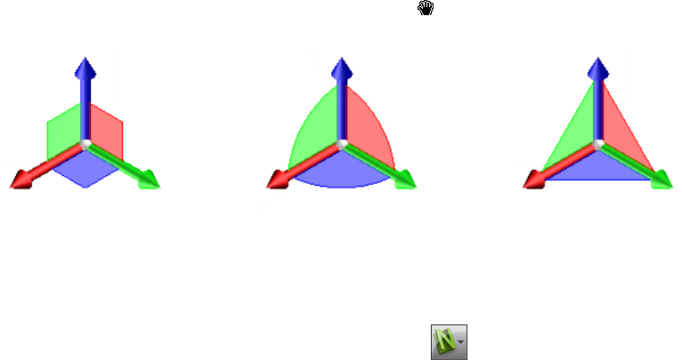
■Sectioning gizmos. Manipulate section planes and section box.
Each gizmo displays three colored axes at the correct angles relevant to the
current camera position. Gizmos act like 3D objects in that the axis rotate
with the viewpoint. However, they are overlaid over the top of the 3D scene,
and can’t be obscured by other objects. When you mouse over a grabable part
of the gizmo, the cursor changes to a hand icon.
Scale GizmoRotate GizmoMove Gizmo
When you use gizmos, you can adjust snapping to control the precision of
your operations (click the application button ➤ Options ➤ Interface
node ➤ Snapping page.
Gizmos | 95
96
Work with Files
Use File Readers
NWD Files
An NWD file is a file created with Autodesk Navisworks publisher tool, and
contains all model geometry together with review markups. You can think of
an NWD file as a snapshot of the current state of the model.
NWD files are very small, as they compress the CAD data by up to 80% of the
original size.
DWF/DWFx Files
Autodesk DWF was specifically developed by Autodesk as a file format for
architects, engineers, and GIS professionals to share 2D- and 3D- design data.
DWF files are highly compressed and retain detailed design information and
scale. The newest version of the DWF file format, DWFx, is based on the XML
Paper Specification (XPS) from Microsoft. DWFx files can be opened and printed
instantly using the free Microsoft XPS Viewer, which comes pre-installed on
computers using the Microsoft Windows Vista® operating system. (For the
Windows XP operating system, the Microsoft XPS Viewer can be downloaded
directly from Microsoft.) Unlike DWF files, DWFx files include additional
information to display design data in the Microsoft XPS Viewer. As such, DWFx
files are larger than corresponding DWF files.
4
97

Supported Entities
■All 3D geometry
■Texture maps
■Texture coordinates
■Colors (per-vertex, per-face)
■Property fields
■Categories
■2D lines/plot sections
■Thumbnails (for 2012 files or later)
■Sheet property (for 2012 files or later)
■More than one 3D section per file (multi-sheet file support)
Unsupported Entities
■Marked-up sketches
■NURBS surfaces
■Cameras
See also:
DWF File Reader Options
Manage Files
Open Files
To open files in Autodesk Navisworks, you can either use a standard Open
dialog box or drag and drop files directly into the Selection Tree window.
NOTE If the chosen file is a CAD or laser scan file, Autodesk Navisworks
automatically uses an appropriate file reader to open it, provided this file format
is supported.
Autodesk Navisworks keeps a list of recently opened files (by default, up to 4
files are shown). You can open any of these files by clicking the application
98 | Chapter 4 Work with Files
button . If you want to modify the size of this list, use the Options
Editor (General node ➤ Environment page).
You can use the SHIFT and CTRL keys to open several files at the same time.
This automatically creates a new “Untitled” Autodesk Navisworks file with
the selected files appended together.
For NWD files, it is possible to publish them to a web server, and then open
them directly from within Autodesk Navisworks. You can start navigating the
model even before the file has been fully downloaded. For this, 10 - 50% is
usually sufficient. The greater the hierarchical structure of the model, the
closer to 50% download is required. Similarly, the lesser the hierarchical
structure of the model, the sooner you can begin the navigation.
NOTE Encrypted DWF files, such as files with Password, and Print/Measure
protected files are not currently supported.
To open a file
1Click the application button ➤ Open ➤ Open .
2In the Open dialog box, use the Files of Type box to select the
appropriate file type, and navigate to the folder where your file is located.
3Select the file, and click Open.
Toolbar: Classic user interface: Standard ➤ Open
Command entry: CTRL + O
To open NWD files located on a web server
1Click the application button ➤ Open URL .
2Enter the file address, and click OK.
Create Files
When you start Autodesk Navisworks, a new “Untitled” Autodesk Navisworks
file is automatically created for you. The new file uses default settings defined
in the Options Editor, and in the File Options dialog box. You can
customize these settings, as necessary.
Manage Files | 99

If you have a Autodesk Navisworks file already open, and want to close it and
create another file, click New on the Quick Access toolbar.
Toolbar: Classic user interface: Standard ➤ New
2D and Multi-Sheet Files
You can now work with 2D files and files containing multiple sheets/models.
Whilst multi-disciplinary models provide a real-world likeness of what a
finished project should look like, various project stakeholders and field workers
are more familiar with 2D plans and elevations. Autodesk Navisworks Freedom
2012 supports 2D and multi-sheet files that can be reviewed, or combined
with models to provide multiple representations of project data.
The supported 2D and multi-sheet file formats are: DWF, DWF(x), and NWD.
When you open a supported file, which contains multiple sheets/models, the
default sheet/model is displayed in the Scene View, and all of the file's
sheets/models are listed in the Project Browser window. If a file contains
both 3D models and 2D sheets, the 3D model is loaded and displayed in the
Scene View by default. If you do not require 2D capabilities, simply close
the Project Browser window and continue working in a 3D workspace.
Project Browser Window
The Project Browser is a dockable window, which lists all sheets/models
in the currently opened file.
100 | Chapter 4 Work with Files
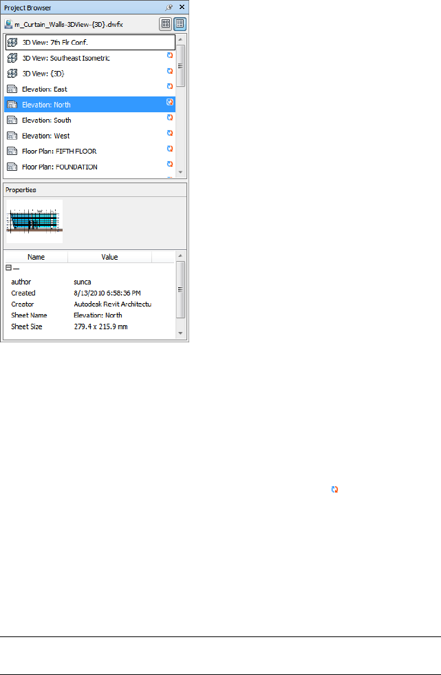
The Sheets/Models palette lists all sheets and models in the multi-sheet file.
The label at the top of the palette indicates the file currently open in Autodesk
Navisworks. The sheets/models can be represented as a list view or a thumbnail
view. By default, the display order is the same as in the original file. The
currently selected model/sheet is indicated with a shaded background, and
the model/sheet currently opened in the Scene View is indicated with a
black graphic border. When you open a multi-sheet file, not all sheets/models
may have been prepared to be used in Autodesk Navisworks. The sheets/models
which require preparation are indicated with the Prepare icon.
You can select several sheets/models at the same time with the SHIFT and
CTRL keys, but you cannot open more than one sheet/model in the Scene
View.
The Properties palette is used to examine properties for the sheet/model
selected in the Sheets/Models palette. You can also view the properties for the
currently opened file by clicking on its name. The properties are grouped by
category, are read-only, and can be expanded/collapsed.
NOTE If more than one sheet/model is selected, the Properties palette only
shows the number of selected items, and doesn't show any property information.
Manage Files | 101
To toggle the Project Browser window
■Click View tab ➤ Workspace panel ➤ Windows drop-down, and
select or clear the Project Browser check box.
Pointing device: Status bar ➤ Project Browser
To view sheets/models as a list
■Click the List View button in the top-right corner of the Project
Browser window.
To view sheets/models as thumbnails
■Click the Thumbnail View button in the top-right corner of the
Project Browser window.
To examine sheet/model properties
1Open a multi-sheet file.
2Click the 2D sheet or 3D model in the Project Browser. The
Properties palette shows the available information.
NOTE If more than one sheet/model is selected, the Properties palette
only shows the number of selected sheets/models, and doesn't show any
property information.
To open a sheet or model in the Scene View
1Open the Project Browser window.
2Double-click the sheet or model that you want to open.
TIP You can also use the multi-sheet navigation controls on the Status bar to
quickly open sheets/models.
To prepare a sheet/model for use
1Open the Project Browser window.
2Right-click the sheet or model you want to prepare, and click Prepare
Sheet/Model on the shortcut menu.
102 | Chapter 4 Work with Files
To prepare all sheets/models for use
1Open the Project Browser window.
2Right-click the sheet or model you want to prepare, and click Prepare
All Sheets/Models on the shortcut menu.
To print a sheet/model
NOTE You can only print the current viewpoint.
1Open the Project Browser window.
2Double-click the sheet or model you want to print, to make it current
(that is to open it in the Scene View).
3Click Output tab ➤ Print panel ➤ Print .
4Check the printer settings are as required, and click OK.
NOTE The maximum image size is 2048 x 2048 pixels.
The Properties button controls printer-specific ink and paper settings.
Sheets/Models Palette Shortcut Menu
Open Opens the selected sheet/model in the Scene View.
Prepare Sheet/Model Prepares all sheets/models selected in the list for use in
Autodesk Navisworks. To select multiple sheets/models, use SHIFT and CTRL
keys. If the selected sheets/models are ready, this option is not available.
Prepare All Sheets/Models Prepares all sheets/models in the multi-sheet file
for use in Autodesk Navisworks. If the sheets/models are ready for use, this
option is not available.
Print Prints the sheet/model currently opened in the Scene View.
Buttons
Thumbnail View Displays sheets/models as the thumbnail images in the
Sheets/Models palette.
List View Displays sheets/models as the list items in the Sheets/Models
palette.
Manage Files | 103
104

Explore Your Model
Navigate a Scene
In Autodesk Navisworks, you have a variety of options for navigating your scene.
You can directly manipulate your position in the Scene View with navigation
tools on the navigation bar, such as the pan and zoom. You can also use
SteeringWheels® that travel with the cursor, and can save you time by
combining many of the common navigation tools into a single interface.
You can use the ViewCube®, a 3D navigational tool that enables you to reorient
the view of a model by clicking predefined areas on the cube. For example,
clicking the front of the ViewCube turns the view until the camera is facing the
front of the scene. You can also click the ViewCube and drag it to rotate the
view freely. The ViewCube is not available in a 2D workspace.
TIP Use a 3Dconnexion 3D mouse as an alternative to the mouse to navigate and
change the orientation of your model in a 3D workspace. There is a 2D mode you
can use to navigate in a 2D workspace.
When you navigate a 3D model, you can use the realism tools on the
Viewpoint tab ➤ Navigate panel to control the speed and realism of your
navigation. So, for example, you can walk down stairs or follow terrain, crouch
under objects, and use an avatar to represent yourself within the 3D model. The
realism tools are not available in a 2D workspace.
Animating Navigation
As you navigate in Autodesk Navisworks, you can record viewpoint animations,
and then play them back. For more information, see Play Back Animations (page
247).
5
105
Orientation in a 3D Workspace
Although Autodesk Navisworks uses the X, Y, Z coordinate system, there is
no hard-and-fast rule as to which way each of these particular axes actually
“points”.
Autodesk Navisworks reads the data necessary to map which way is “up” and
which way is “north” directly from the files loaded into your scene. If this is
not possible, by default, Z is treated as “up” and Y is treated as “north”.
It is possible to change the “up” and “north” directions for the entire model
(world orientation), and the “up” direction for the current viewpoint
(viewpoint up vector).
NOTE Changing the viewpoint up vector affects navigation in modes that rely on
the “up” direction of the current viewpoint, such as Walk, Constrained Orbit,
and Orbit. It also has an impact on section views.
To align the viewpoint up vector to the current view
■In Scene View, right-click and click Viewpoint ➤ Set Viewpoint
Up ➤ Set Up on the shortcut menu.
To align the viewpoint up vector to one of the preset axes
1In Scene View, right-click and click Viewpoint ➤ Set Viewpoint
Up.
2Click one of the preset axis. Choose from:
■Set Up + X
■Set Up - X
■Set Up + Y
■Set Up - Y
■Set Up + Z
■Set Up - Z
To change the world orientation
1Click Home tab ➤ Project panel ➤ File Options .
2In the File Options dialog box, Orientation tab, enter the required
values to adjust the model orientation.
106 | Chapter 5 Explore Your Model
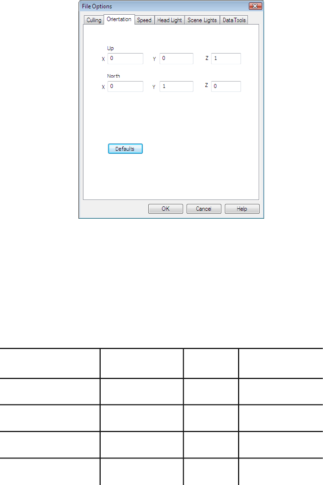
3Click OK.
Product-Specific Navigation Tools
The navigation bar and SteeringWheels provide you with access to a set of
product-specific navigation tools in 2D and 3D workspaces.
In Autodesk Navisworks Freedom 2012, some classic navigation tools have
been replaced with new navigation tools. See the table below for more details.
Can be switched
back to classic?
2D?Replaced byClassic tool
NoYesPanPan
NoYesZoomZoom
NoYesZoom AllView All
NoYesZoom SelectedView Selected
Navigate a Scene | 107
Can be switched
back to classic?
2D?Replaced byClassic tool
NoYesZoom WindowZoom Box
YesNoOrbitOrbit
YesNoFree OrbitExamine
YesNoConstrained OrbitTurntable
NoNoLookLook Around
---Focus
YesNoWalkWalk
-No-Fly
Customizing Tools Behavior
For the navigation bar, you can use Options Editor to toggle between
standard and classic modes for Orbit and Walk tools.
Control Navigation Realism
You can use Collision (page 177), Gravity (page 176), Crouch (page 177), and
Third Person View (page 178) to enhance your navigation experience in a 3D
workspace.
TIP Use a combination of Collision, Gravity, and Crouch with the Walk tool.
This allows you, for example, to walk up and down stairs and walk under low
objects.
Navigation Bar Tools
The navigation bar contains a set of product-specific navigation tools.
108 | Chapter 5 Explore Your Model
Pan Tool
The pan tool moves the view parallel to the screen.
The tool is activated by clicking Pan on the navigation bar. Pan behaves
the same way as the pan tool available on the SteeringWheels.
Zoom Tools
Set of navigation tools for increasing or decreasing the magnification of the
current view of the model.
The following zoom tools are available:
■Zoom Window . Allows you to draw a box and zoom into that area.
■Zoom . Standard click/drag zoom.
■Zoom Selected . Zooms in/out to show the selected geometry.
■Zoom All . Zooms out to show the whole scene.
Zoom Window
The tool is activated by clicking Zoom Window in the Zoom drop-down
on the navigation bar. It behaves the same way as the classic Zoom Box
mode.
Zoom
The tool is activated by clicking Zoom in the Zoom drop-down on the
navigation bar. It behaves the same way as the Zoom tool available on the
SteeringWheels.
Zoom Selected
The tool is activated by clicking Zoom Selected in the Zoom drop-down on
the navigation bar. Alternatively, you can click Item Tools tab ➤ Look At
panel ➤ Zoom on the ribbon. It behaves the same way as the classic
View Selected tool.
Navigate a Scene | 109
Zoom All
The tool is activated by clicking Zoom All in the Zoom drop-down on the
navigation bar. It behaves the same way as the classic View All tool.
Orbit Tools
Set of navigation tools for rotating the model around a pivot point while the
view remains fixed.These tools are not available in a 2D workspace.
The following orbit tools are available:
■Orbit . Moves the camera around the focal point of the model. The
up direction is always maintained, and no camera rolling is possible.
■Free Orbit . Rotates the model around the focal point in any direction.
■Constrained Orbit . Spins the model around the up vector as though
the model is sitting on a turntable. The up direction is always maintained.
Orbit
The tool is activated by clicking Orbit in the Orbit drop-down on the
navigation bar. It behaves the same way as the Orbit tool on the
SteeringWheels. You can use the Options Editor to switch back to the classic
Orbit mode.
Free Orbit
The tool is activated by clicking Free Orbit in the Orbit drop-down on the
navigation bar. It behaves similarly to the classic Examine mode. You can
use the Options Editor to switch back to the classic Examine mode.
Constrained Orbit
The tool is activated by clicking Constrained Orbit in the Orbit drop-down
on the navigation bar. It behaves similarly to the classic Turntable mode.
You can use the Options Editor to switch back to the classic Turntable
mode.
To use the classic Orbit tool with the navigation bar
1On the navigation bar, click Customize ➤ Navigation Bar Options.
110 | Chapter 5 Explore Your Model
2In the Options Editor, the Navigation Bar page under the Interface
node, select the Use Classic Orbit check box in the Orbit Tools area.
3Click OK.
To use the classic Examine tool with the navigation bar
1On the navigation bar, click Customize ➤ Navigation Bar Options.
2In the Options Editor, the Navigation Bar page under the Interface
node, select the Use Classic Free Orbit (Examine) check box in the
Orbit Tools area.
3Click OK.
To use the classic Turntable tool with the navigation bar
1On the navigation bar, click Customize ➤ Navigation Bar Options.
2In the Options Editor, the Navigation Bar page under the Interface
node, select the Use Classic Constrained Orbit (Turntable) check
box in the Orbit Tools area.
3Click OK.
Look Tools
Set of navigation tools for rotating the current view vertically and horizontally.
These tools are not available in a 2D workspace.
The following look tools are available:
■Look Around . Looks around the scene from the current camera
location.
■Look At . Looks at a particular point in the scene. The camera moves
to align with that point.
■Focus . Looks at a particular point in the scene. The camera stays where
it is.
Look Around
The tool is activated by clicking Look Around in the Look drop-down on
the navigation bar. It behaves the same way as the Look tool available on the
SteeringWheels.
Navigate a Scene | 111

Look At
The tool is activated by clicking Look At in the Look drop-down on the
navigation bar. It behaves the same way as the SteeringWheels Look tool
when you press and hold the SHIFT key.
Focus
The tool is activated by clicking Focus in the Look drop-down on the
navigation bar. See Focus (page 175) for more details.
Walk and Fly Tools
Set of navigation tools for moving around the model and controlling realism
settings. These tools are not available in a 2D workspace.
The following tools are available:
■Walk . Moves through a model as if you were walking through it.
■Fly . Moves through a model like in a flight simulator.
Walk
The tool is activated by clicking Walk in the Walk/Fly drop-down on the
navigation bar. By default, the tool behaves like the Walk tool on the
SteeringWheels. You can customize the tool options in the Options Editor.
You can also switch back to the classic Walk mode.
Fly
The tool is activated by clicking Fly in the Walk/Fly drop-down on the
navigation bar. It behaves the same way as the classic Fly mode.
See also:
Control the Realism of Your Navigation (page 176)
To use classic Walk tool with the navigation bar
1On the navigation bar, click Customize ➤ Navigation Bar Options.
2In the Options Editor, the Navigation Bar page under the Interface
node, select the Use Classic Walk check box in the Walk Tool area.
112 | Chapter 5 Explore Your Model
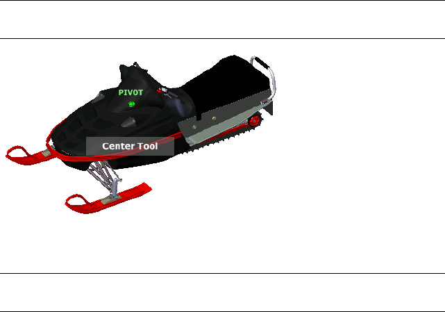
3Click OK.
SteeringWheels Tools
Each wheel is divided into different wedges. Each wedge contains a navigation
tool used to reorient the current view of a model. Which navigation tools are
available depends on which wheel is active.
Center Tool
With the Center tool, you can define the center of the current view of a model.
To define the center, drag the cursor over your model. A sphere (pivot point)
is displayed in addition to the cursor. The sphere indicates that the point
below the cursor in the model will be the center of the current view when
you release the mouse button. The model is centered on the sphere.
NOTE If the cursor is not over the model, the center cannot be set and a prohibited
cursor is displayed.
The point defined by the Center tool provides a focal point for the Zoom tool
and a pivot point for the Orbit tool.
NOTE If you want to zoom from the Full Navigation wheels from your defined
center point, hold down CTRL before zooming.
To specify a point on a model as the center of a view
1Display one of the Full Navigation wheels or the big View Object wheel.
2Click and hold down the Center wedge.
Navigate a Scene | 113
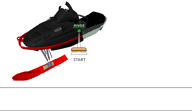
3Drag the cursor to the desired location of the model.
4Release the button on your pointing device when the sphere is displayed.
The model is panned until the sphere is centered.
To specify the target point for the Zoom and Orbit tools
1Display one of the Full Navigation wheels or the big View Object wheel.
2Click and hold down the Center wedge.
3Drag the cursor over the desired location of the model.
4Release the button on your pointing device when the sphere is displayed.
The model is panned until the sphere is centered.
5Use the Zoom or Orbit tool to reorient the view of the model.
If you are using one of the Full Navigation wheels, hold down the CTRL
key before using the Zoom tool.
Forward Tool
You use the Forward tool to change the magnification of the model by
increasing or decreasing the distance between the current point of view and
the pivot point. The distance that you can move forward or backward is limited
by the position of the pivot point.
NOTE In orthographic views, the Forward tool is limited to the distance between
the current position and the pivot point. In perspective views, it is not limited, so
you can move the cursor through the pivot point.
114 | Chapter 5 Explore Your Model
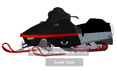
To adjust the distance between the current point of view and the pivot point
you use the Drag Distance indicator. The Drag Distance indicator has two
marks on it that show the start and destination distances from the current
point of view. The current traveled distance is shown by the orange position
indicator. Slide the indicator forward or backwards to decrease or increase the
distance towards the pivot point.
To reorient a view by moving towards or away from the model
1Display the big Tour Building wheel.
2Click and hold down the Forward wedge.
The Drag Distance indicator is displayed.
NOTE If you click the Forward wedge once, the model moves forward 50%
of the distance between the current location and the pivot point.
3Drag the cursor up or down to change the distance from which you view
the model.
4Release the button on your pointing device to return to the wheel.
Look Tool
With the Look tool, you can rotate the current view vertically and horizontally.
When rotating the view, your line of sight rotates about the current eye
position, like turning your head. The Look tool can be compared to standing
in a fixed location, and looking up, down, left or right.
When using the Look tool, you adjust the view of the model by dragging the
cursor. As you drag, the cursor changes to the Look cursor and the model
rotates around the location of the current view.
Navigate a Scene | 115
In addition to using the Look tool to look around a model, you can also use
the tool to transition the current view to a specific face on the model. Press
and hold the Shift key before selecting the Look tool on one of the Full
Navigation wheels.
Walking Through a Model
When using the Look tool from the big Full Navigation wheel, you can
walk through a model by using the arrow keys on the keyboard. To adjust the
walk speed, use the Options Editor.
Invert Vertical Axis
When you drag the cursor upward, the target point of the view raises; dragging
the cursor downward lowers the target point of the view. To invert the vertical
axis for the Look tool, use the Options Editor.
To look around a view with the Look tool
1Display one of the Full Navigation wheels or the mini Tour Building
wheel.
2Click and hold down the Look wedge.
The cursor changes to the Look cursor.
3Drag the pointing device to change the direction in which you are
looking.
4Release the button on your pointing device to return to the wheel.
To look at a face in the model with the Look tool
1Display one of the Full Navigation wheels.
2Press and hold down the SHIFT key.
3Click and hold down the Look wedge.
The cursor changes to the Look At cursor.
4Drag over the objects in the model until the face highlights that you
want to look at.
5Release the button on your pointing device to return to the wheel.
To look around and walk through a model with the Look tool
1Display the big Full Navigation wheel.
2Click and hold down the Look wedge.
116 | Chapter 5 Explore Your Model
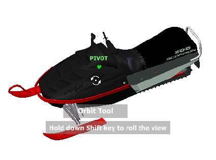
The cursor changes to the Look cursor.
3Drag to change the direction in which you are looking.
4While holding down the button on your pointing device, press the arrow
keys to walk in the model.
5Release the button on your pointing device to return to the wheel.
6Click Close to exit the wheel.
To invert the vertical axis for the Look tool
1Display a wheel.
2Right-click the wheel, and click SteeringWheels Options.
3In the Options Editor, the SteeringWheels page under the Interface
node, select the Invert Vertical Axis check box in the Look Tool
area.
Dragging downward and upward lowers and raises the target point of
the current view.
4Click OK.
Orbit Tool
You use the Orbit tool to change the orientation of a model. The cursor changes
to the Orbit cursor. As you drag the cursor, the model rotates around a pivot
point while the view remains fixed.
Navigate a Scene | 117
Specify the Pivot Point
The pivot point is the base point used when rotating the model with the Orbit
tool. You can specify the pivot point in the following ways:
■Default pivot point. When you first open a model, the target point of
the current view is used as the pivot point for orbiting the model.
■Select objects. You can select objects before the Orbit tool is used to
calculate the pivot point. The pivot point is calculated based on the center
of the extents of the selected objects.
■Center tool. You can specify a point on the model to use as the pivot
point for orbiting with the Center tool (page 113).
■CTRL+Click and drag. Press and hold down the CTRL key before clicking
the Orbit wedge or while the Orbit tool is active; then drag to the point
on the model you want to use as the pivot point. This option is only
available when using the big and mini Full Navigation wheels or the mini
View Object wheel.
NOTE While the Orbit tool is active, you can press and hold the CTRL key at
anytime to move the pivot point used by the Orbit tool.This pivot point is used
for subsequent navigation until it is moved.
Maintain Up Direction
You can control how the model orbits around the pivot point by choosing to
maintain the up direction of the model. When the up direction is maintained,
orbiting is constrained along the XY axis and in the Z direction. If you drag
horizontally, the camera moves parallel to the XY plane. If you drag vertically,
the camera moves along the Z axis.
If the up direction is not maintained, you can roll the model using the roll
ring which is centered around the pivot point. Use the properties dialog box
for the SteeringWheels to control whether the up direction is maintained or
not for the Orbit tool.
118 | Chapter 5 Explore Your Model
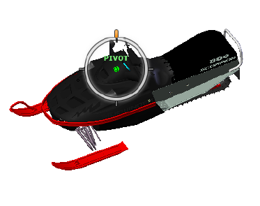
To orbit a model with the Orbit tool
1Display one of the View Object or Full Navigation wheels.
2Click and hold down the Orbit wedge.
The cursor changes to the Orbit cursor.
3Drag to rotate the model.
NOTE Use the Center tool to re-center the model in the current view, if you
are using one of the Full Navigation or View Object wheels.
4Release the button on your pointing device to return to the wheel.
To orbit around an object with the Orbit tool
1Press ESC to make sure no commands are active and to clear any
previously selected objects.
2Select the objects in the model for which you want to define the pivot
point.
3Display one of the View Object or Full Navigation wheels.
4Click and hold down the Orbit wedge.
The cursor changes to the Orbit cursor.
5Drag to rotate the model.
6Release the button on your pointing device to return to the wheel.
To turn on selection sensitivity for the Orbit tool
1Display one of the View Object or Full Navigation wheels.
Navigate a Scene | 119
2Right-click the wheel, and click SteeringWheels Options.
3In the Options Editor, the SteeringWheels page under the Interface
node, select the Center Pivot on Selection check box in the Orbit
Tool section.
4Click OK.
The extents of any objects that are selected before the wheel is displayed
are used to define the pivot point for the Orbit tool. If no objects are
selected, the pivot point used by the Orbit is the one defined by the
Center tool.
To maintain the up direction for the Orbit tool
1Display the mini View Object wheel or one of the Full Navigation
wheels.
2Right-click the wheel, and click SteeringWheels Options.
3In the Options Editor, the SteeringWheels page under the Interface
node, select the Keep Scene Upright check box in the Orbit Tool
area.
4Click OK.
Orbiting the model is constrained along the XY plane and Z directions.
To roll the model around the pivot point with the Orbit tool
1Display the mini View Object Wheel or one of the Full Navigation
wheels.
2Right-click the wheel, and click SteeringWheels Options.
3In the Options Editor, the SteeringWheels page under the Interface
node, clear the Keep Scene Upright check box.
4Click OK.
5Click and hold the Orbit wedge.
The cursor changes to the Orbit cursor.
6Press and hold the SHIFT key to display the roll ring. Drag to roll the
model.
7Release the button on your pointing device to return to the wheel.
To start the Orbit tool with the middle mouse button
1Display one of the wheels other than the big View Object or Tour
Building wheels.
120 | Chapter 5 Explore Your Model
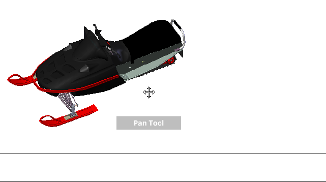
2Press and hold down the SHIFT key.
3Press and hold down the scroll wheel or middle button on your pointing
device and drag to orbit the model.
4Release the button on your pointing device to return to the wheel.
Pan Tool
When the pan tool is active, the Pan cursor (a four-sided arrow) is displayed.
Dragging the pointing device moves the model in the same direction. For
example, dragging upward moves the model up while dragging downward
moves the model down.
TIP If the cursor reaches the edge of the screen, you can continue panning by
dragging further to force it to wrap around the screen.
To pan the view with the Pan tool
1Display one of the Full Navigation wheels, or the mini View Object
wheel.
2Click and hold the Pan wedge.
The cursor changes to the Pan cursor.
3Drag to reposition the model.
4Release the button on your pointing device to return to the wheel.
Navigate a Scene | 121
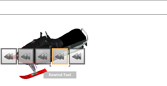
To start the Pan tool with the middle mouse button
1Display one of the Full Navigation wheels, or the mini View Object
wheel.
2Press and hold down the scroll wheel or middle button.
The cursor changes to the Pan cursor.
3Drag to reposition the model.
4Release the wheel or button on your pointing device to return to the
wheel.
Rewind Tool
As you use the navigation tools to reorient the view of a model, the previous
view is saved to the navigation history. The navigation history holds a
representation of the previous views of the model along with a thumbnail. A
separate navigation history is maintained for each window; it is not maintained
after the window is closed. Rewind navigation history is view-specific.
With the Rewind tool, you can retrieve previous views from the navigation
history. From the navigation history, you can restore a previous view or scroll
through all of the saved views.
NOTE When you rewind and record a new navigation history, the rewound views
are replaced by new views. The navigation history is not saved between sessions.
To restore the previous view
1Display a wheel.
2Click the Rewind wedge.
122 | Chapter 5 Explore Your Model
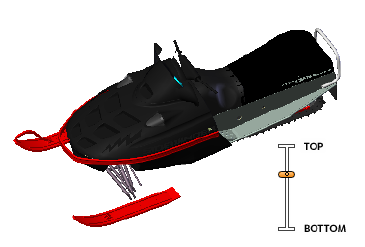
To restore a previous view with the Rewind History panel
1Display a wheel.
2Click and hold the Rewind wedge.
The Rewind History panel is displayed.
3While holding down the button on your pointing device, drag to the
left or to the right to restore a previous view.
Dragging to the left restores an older previous view. Dragging to the
right restores a view that is newer than the one you are currently viewing.
You must have previously used the Rewind tool to see views available
on the right. The current position in the navigation history is indicated
by the orange box that is dragged along the Rewind History panel.
Up/Down Tool
Unlike the Pan tool, you use the Up/Down tool to adjust the height of the
current viewpoint along the model's Z axis. To adjust the vertical elevation
of the current view, you drag up or down. As you drag, the current elevation
and the allowed range of motion is displayed on a graphical element called
the Vertical Distance indicator.
The Vertical Distance indicator has two marks that show the highest (Top)
and lowest (Bottom) elevation the view can have. While changing the elevation
with the Vertical Distance indicator, the current elevation is shown by the
bright orange indicator, while the previous elevation is shown by the dim
orange indicator.
To change the elevation of a view
1Display one of the Full Navigation wheels or the Tour Building wheels.
Navigate a Scene | 123
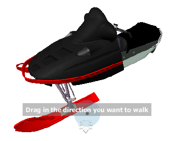
2Click and hold down the Up/Down wedge.
The Vertical Distance indicator is displayed.
3Drag up or down to change the elevation of the view.
4Release the button on your pointing device to return to the wheel.
Walk Tool
With the Walk tool, you can navigate through a model as if you were walking
through it. Once you start the Walk tool, the Center Circle icon is displayed
near the base of the view and the cursor changes to display a series of arrows.
To walk through the model, you drag in the direction in which you want to
move in.
Constrain the Walk Angle
When walking through a model, you can constrain the movement angle to
the world up vector. If the Constrain Walk Angle option is enabled, you
can freely walk around while maintaining a constant camera viewpoint
elevation; if the walk angle is not constrained, you will “fly” in the direction
you are looking. Use the Options Editor to constrain the movement angle
to the world up vector for the Walk tool.
Use Viewpoint Linear Speed
By default, the linear navigation speed in viewpoints is directly related to the
size of your model. You can set a specific speed of motion for all viewpoints
(Options Editor ➤ Interface ➤ Viewpoint Defaults) or for the current
124 | Chapter 5 Explore Your Model
viewpoint (Viewpoint tab ➤ Save, Load & Playback panel ➤ Edit
Current Viewpoint). Use the Options Editor to make the Walk tool Use
Viewpoint Linear Speed settings.
Movement Speed
As you walk or “fly” through a model, you can control the movement speed.
Movement speed is controlled by the distance in which the cursor is moved
from the Center Circle icon and the current movement speed setting. You
can adjust the movement speed setting permanently and temporarily as you
use the Walk tool. To permanently adjust the movement speed, use the
Options Editor or the < and > keys when the Walk tool is active. To
temporarily increase movement speed, press and hold the + (plus) key while
using the Walk tool.
Change the Elevation
As you use the Walk tool, you can adjust the camera elevation by holding
down the SHIFT key. This temporarily activates the Up/Down tool. With the
Up/Down tool active, drag up or down to adjust the elevation of the camera.
You can also use the UP ARROW and DOWN ARROW keys as you walk to adjust
the height of the view.
To use the Walk tool to move through the model
1Display one of the Full Navigation wheels or the mini Tour Building
wheel.
2Click and hold down the Walk wedge.
The cursor changes to the Walk cursor and the Center Circle icon is
displayed.
3Drag in the direction you want to walk.
NOTE While walking, press and hold down the + (plus) key to temporarily
increase your movement speed.
4Release the button on your pointing device to return to the wheel.
To change the movement speed for the Walk tool
1Display a wheel.
2Right-click the wheel, and click SteeringWheels Options.
3In the Options Editor, the SteeringWheels page under the Interface
node, use the Walk Speed slider in the Walk Tool area.
Navigate a Scene | 125
Dragging the slider to the left decreases the walking speed; dragging the
slider to the right increases the walking speed.
4Click OK.
To constraint the Walk tool to the world up vector
1Display a wheel.
2Right-click the wheel, and click SteeringWheels Options.
3In the Options Editor, the SteeringWheels page under the Interface
node, select the Constrain Walk Angle check box in the Walk Tool
area.
4Click OK.
Movement when walking is done parallel to the world up of the model.
To make the Walk tool use the viewpoint linear speed
1Display a wheel.
2Right-click the wheel, and click SteeringWheels Options.
3In the Options Editor, the SteeringWheels page under the Interface
node, select the Use Viewpoint Linear Speed check box in the Walk
Tool area.
4Click OK.
To adjust the height of the current view from the Walk tool
1Display one of the Full Navigation wheels or the mini Tour Building
wheel.
2Click and hold down the Walk wedge.
The cursor changes to the Walk cursor and the Center Circle icon is
displayed.
3Do one of the following:
■Press and hold down the SHIFT key to enable the Up/Down tool;
drag up or down.
■Press and hold down the UP ARROW or DOWN ARROW key.
4Release the button on your pointing device to return to the wheel.
126 | Chapter 5 Explore Your Model
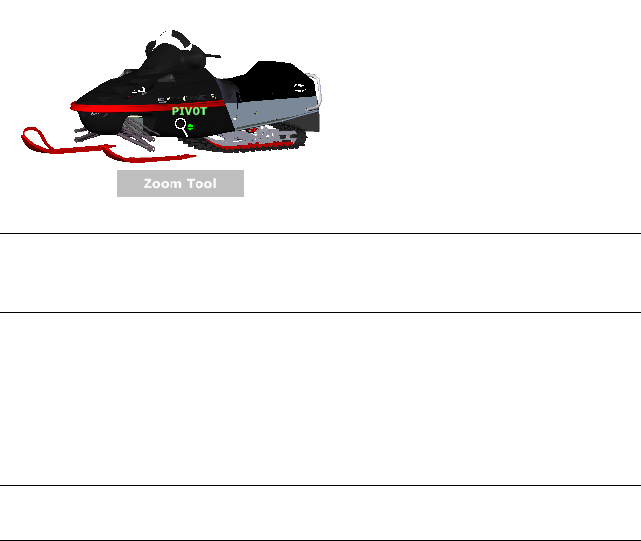
Zoom Tool
You use the Zoom tool to change the zoom magnification of a model.
NOTE When you start the Zoom tool from the Full Navigation wheel,
incremental zooming must be enabled in the Options Editor in order to use
CTRL+click and SHIFT+click.
Zoom Constraints
When changing the magnification of a model with the Zoom tool, you cannot
zoom in any further than the focus point or out past the extents of the model.
The direction you can zoom in and out is controlled by the center point set
by the Center tool.
NOTE Unlike the Zoom tool on the big View Object wheel, the Zoom tool on the
mini View Object wheel and the Full Navigation wheels are not constrained.
To zoom the view with a single click
Note:You must enable incremental zoom when using the Full Navigation
wheels, or a mini View Object wheel. For the big View Object wheel, the
incremental zoom is always enabled.
1Do the following to make sure the Enable Single-Click Incremental
Zoom-In option is selected:
1Display the Full Navigation wheel.
2Right-click the wheel, and click SteeringWheel Options.
3In the Options Editor, the SteeringWheels page under the
Interface node, select the Enable Single-Click Incremental
Zoom-In check box in the Zoom Tool area.
Navigate a Scene | 127
4Click OK.
2Display a wheel that has the Zoom tool.
3Click the Zoom wedge.
The magnification of the model is increased and you are zoomed in
closer to the model. If you hold down the SHIFT key while clicking the
Zoom wedge, the model is zoomed out; you can hold down the CTRL
key to zoom in.
To zoom a view in and out by dragging
1Display one of the Full Navigation wheels, or one of the View Object
wheels.
2Click and hold down the Zoom wedge.
The cursor changes to the Zoom cursor.
3Drag vertically to zoom in or out.
4Release the button on your pointing device to return to the wheel.
To zoom into an area of the model by specifying window
1Display one of the Full Navigation wheels or the mini View Object wheel.
2Press and hold down the SHIFT key.
3Click and hold down the Zoom wedge.
The cursor changes to the Zoom cursor.
4Drag the pointing device to define the opposite corner of the window
that defines the area in which you want to zoom.
NOTE Holding down the CTRL key while defining the second point of the
window determines if the first point of the window is used as the corner or
center of the window being dragged. When the CTRL key is held down, the
first point defines the center of the window.
5Release the button on your pointing device to return to the wheel.
To zoom in and out by scrolling the mouse wheel when the SteeringWheels
is displayed
1Display one of the wheels other than the big Tour Building wheel.
2Scroll the wheel forward or backward to zoom in or out.
3Release the button on your pointing device to return to the wheel.
128 | Chapter 5 Explore Your Model

You use the Zoom tool to change the zoom magnification of a model. The
following mouse click and key combinations are available to control how the
Zoom tool behaves:
■Click. If you click the Zoom tool on a wheel, the current view is zoomed
in by a factor of 25 percent. If you are using the Full Navigation wheel,
incremental zoom must be enabled in the Options Editor.
■SHIFT+click. If you hold down the SHIFT key before you click the Zoom
tool on a wheel, the current view is zoomed out by a factor of 25 percent.
Zooming is performed from the location of the cursor, and not the current
pivot point.
■CTRL+click. If you hold down the CTRL key before you click the Zoom
tool on a wheel, the current view is zoomed in by a factor of 25 percent.
Zooming is performed from the location of the cursor, and not the current
pivot point.
■Click and drag. If you click the Zoom tool and hold down the button
on your pointing device, you can adjust the magnification of the model
by dragging up and down.
■CTRL+click and drag. When using the Full Navigation wheels or the
mini View Object wheel, you can control the target point used by the
Zoom tool. By holding down the CTRL key, the Zoom tool uses the location
of the previous pivot point defined by the Zoom, Orbit, or Center tool.
■SHIFT+click and drag. When using the Full Navigation wheels or the
mini View Object wheel, you can zoom in to an area of the model by
dragging a rectangular window around the area you want to fit in the
window. Hold down the SHIFT key and then click and drag a window
around the area in which you want to zoom.
NOTE If you hold down the CTRL key along with the SHIFT key, you can
zoom in to an area of a model using a center-based window instead of one
defined by opposite corners.
■Mouse wheel. When a wheel is displayed, scroll the mouse wheel up or
down to zoom the view of the model in or out.
NOTE When you use the Zoom tool from the Full Navigation wheel or the View
Object wheel, the point in the view where you click to zoom becomes the Center
point for future Orbit operations until you either use the Zoom tool again or use
the Center tool. If you press CTRL before you click the Zoom wedge, the Center
point does not change.
Navigate a Scene | 129
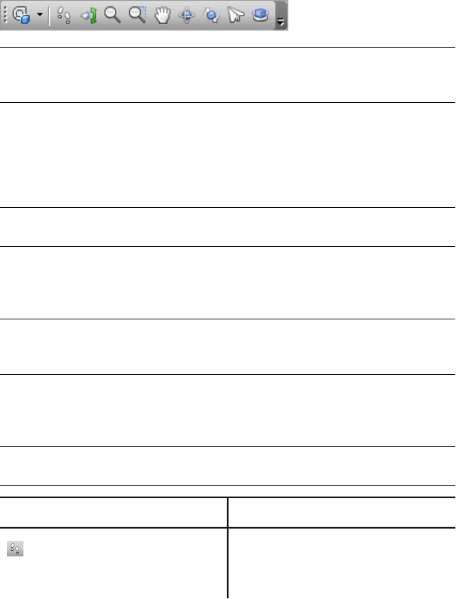
Classic Navigation Modes and Tools
In the Classic user interface, there are nine navigation modes available from
the Navigation Mode toolbar to control how you move around the Scene
View: six camera-centric modes and three model-centric modes.
TIP You can use some of these classic navigation modes with the standard (ribbon)
user interface. The Options Editor allows you to select between old and new
modes.
In a camera-centric mode, the camera moves within the scene, whereas in a
model-centric mode, model moves inside the scene. For example, orbit and
examine modes essentially do the same thing, except that orbit mode moves
the camera around the focal point and examine mode moves the model around
the focal point.
NOTE Navigation modes and SteeringWheels (page 153) are mutually exclusive,
so activating navigation mode deactivates the current SteeringWheel menu.
Movement in each mode is based on the keyboard arrow keys, the SHIFT and
CTRL keys, and mouse drags. The mouse wheel is also supported, allowing
quick and easy zooming or tilting, depending on the current navigation mode.
TIP Dragging with the left mouse button while holding down the CTRL key
performs the same actions as dragging with the middle mouse button, which is
useful if you only have a two-button mouse.
The SHIFT and CONTROL keys modify the movement, for example holding
down SHIFT in walk mode speeds up movement, and holding down CTRL in
this mode, glides the camera left/right and up/down.
NOTE Gliding the camera is opposite to panning the model. Gliding is a
camera-centric motion and panning is a model-centric motion.
DescriptionMode
Walk. Enables you to walk through the
model on a horizontal plane ensuring that
“up” is always “up”.
130 | Chapter 5 Explore Your Model
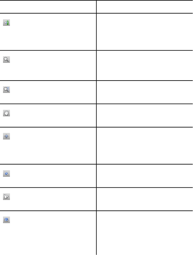
DescriptionMode
Look Around. Enables you to look around
the model from the current camera position
and gives the effect that you are moving
your head around.
Zoom. Enables you to zoom into and out
of the model. Cursor up zooms in and
cursor down zooms out.
Zoom to a Box. Enables you to drag a box
so that the contents of the box fill the view.
Pan. Enables you to pan the model rather
than the camera.
Orbit. Enables you to orbit the camera
around the model, ensuring that “up” is
always “up”. The camera always orbits
around the focal point of the model.
Examine. Enables you to rotate the model
about.
Fly. Enables you to fly around the model
like in a flight simulator.
Turntable. Enables you to spin the model
around the up vector. This navigation mode
behaves as though the model is sitting on
a turntable, ensuring that “up” is always
“up”.
Walk Mode
In Walk mode, you can navigate through a model as if you were walking
through it. In this mode, the up direction is always maintained.
Navigate a Scene | 131
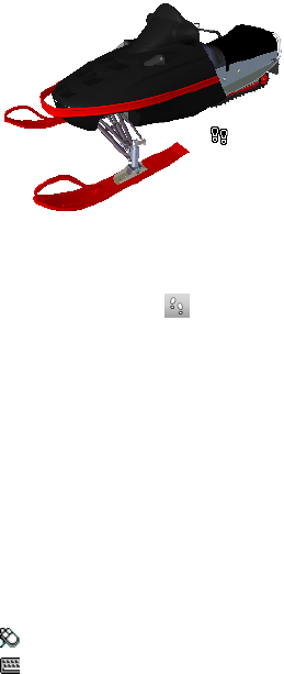
Once you start walk mode, the cursor changes to the walk cursor. To walk
through the model, you drag in the direction in which you want to move in.
To use walk mode to move through the model
1Click Walk on the Navigation Mode toolbar.
2To move, hold down the left mouse button as you drag in the direction
you want to walk, or use the cursor keys. The camera spins left and right,
and moves forwards and backwards.
NOTE Holding down the SHIFT key speeds up this movement.
3To glide, hold down the CTRL key as you drag the mouse. The camera
glides left and right and up and down.
As walk mode is camera-centric, this mode differs from the normal pan
mode in that the camera is moved rather than the model.
4To tilt the camera up and down, spin the mouse wheel.
Menu: Classic user interface: Viewpoint ➤ Navigation Mode ➤ Walk
Command entry: CTRL + 2
Look Around Mode
In Look Around mode, you can rotate the current view vertically and
horizontally. When rotating the view, your line of sight rotates about the
current eye position, like turning your head.
132 | Chapter 5 Explore Your Model
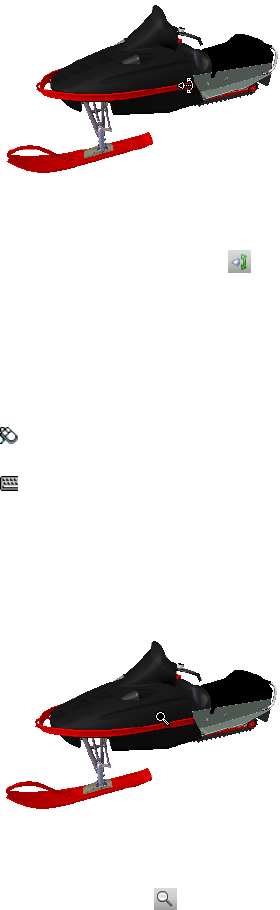
To look around a view
1Click Look Around on the Navigation Mode toolbar.
2To look around, drag the left mouse button, or use the cursor keys. The
camera looks left, right, up or down.
NOTE Holding down the SHIFT key speeds up this movement.
3To rotate the camera around its viewing axis, hold down the CTRL key.
Menu: Classic user interface: Viewpoint ➤ Navigation Mode ➤ Look
Around
Command entry: CTRL + 3
Zoom Mode
In Zoom mode, you can zoom into and out of the model.
To zoom the view
1Click Zoom on the Navigation Mode toolbar.
2Drag the left mouse button up and down, or use the up and down cursor
keys, to zoom in and out respectively.
Navigate a Scene | 133
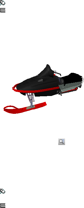
Menu: Classic user interface: Viewpoint ➤ Navigation Mode ➤ Zoom
Command entry: CTRL + 4
Zoom Box Mode
In Zoom Box mode, you can zoom into an area of the model by dragging a
rectangular box around the area you want to fit in the Scene View.
To zoom in to an area of the model by specifying box
1Click Zoom Box on the Navigation Mode toolbar.
2Drag a box with the left mouse button over the Scene View to fill the
view with the contents of the box.
NOTE Holding down the SHIFT or CTRL keys, or spinning the mouse wheel,
temporarily enables normal Zoom mode.
Menu: Classic user interface: Viewpoint ➤ Navigation Mode ➤ Zoom
Window
Command entry: CTRL + 5
Pan Mode
In Pan mode, you can move the model, rather than the camera. For example,
dragging upward moves the model up while dragging downward moves the
model down.
134 | Chapter 5 Explore Your Model
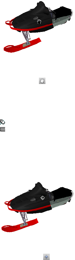
To pan a model
1Click Pan on the Navigation Mode toolbar.
2Drag the left mouse button to pan the model up, down, left and right.
NOTE Holding down the SHIFT or CTRL keys, or spinning the mouse wheel,
temporarily enables normal Zoom mode.
Menu: Classic user interface: Viewpoint ➤ Navigation Mode ➤ Pan
Command entry: CTRL + 6
Orbit Mode
In Orbit mode, the camera moves around the focal point of the model. In
this mode, the up direction is always maintained.
To orbit a model
1Click Orbit on the Navigation Mode toolbar.
2To rotate the camera around the model, drag the left mouse button, or
using the cursor keys.
Navigate a Scene | 135
NOTE Holding down the SHIFT key, or spinning the mouse wheel,
temporarily enables normal Zoom mode.
3To glide the camera, hold down the CTRL key as you drag the mouse.
The camera glides left and right and up and down.
As orbit mode is camera-centric, this mode differs from normal pan mode
in that the camera is moved rather than the model.
Menu: Classic user interface: Viewpoint ➤ Navigation Mode ➤ Orbit
Command entry: CTRL + 7
Examine Mode
In Free Orbit mode, you can rotate the model around the focal point.
To examine a model
1Click Examine on the Navigation Mode toolbar.
2To rotate the model around the focal point, drag the left mouse button,
or using the cursor keys. If the mouse is moving when you let go of the
button, the model keeps spinning. Clicking on the model stops this.
NOTE Holding down the SHIFT key, or spinning the mouse wheel,
temporarily enables normal Zoom mode. Holding down the CTRL key,
temporarily enables normal Pan mode.
Menu: Classic user interface: Viewpoint ➤ Navigation
Mode ➤ Examine
Command entry: CTRL + 8
136 | Chapter 5 Explore Your Model
Fly Mode
In Fly mode, you can move around the model like in a flight simulator.
To use Fly mode to move through the model
1Click Fly on the Navigation Mode toolbar.
2Hold down the left mouse button to move the camera forward. As in a
flight simulator, the left mouse button banks left/right when dragged
left or right and tilts up/down when dragged up or down.
NOTE Holding down the SHIFT key speeds up this movement.
3Use the up and down cursor keys to zoom the camera in and out
respectively; use the left and right cursor keys to spin the camera left
and right respectively.
NOTE Holding down the CTRL key rotates the camera around its viewing
axis, while still moving forward.
Menu: Classic user interface: Viewpoint ➤ Navigation Mode ➤ Fly
Command entry: CTRL + 9
Turntable Mode
In Turntable mode, you can spin the model around the up vector as though
the model is sitting on a turntable. In this mode, the up direction is always
maintained.
Navigate a Scene | 137
To spin model on a turntable
1On the navigation bar, click Turntable on the Navigation Mode
toolbar.
2Drag the left mouse button left and right, or use the left and right cursor
keys, to spin the turntable left and right respectively.
NOTE Holding down the SHIFT key or spinning the mouse wheel, temporarily
enables normal Zoom mode. Holding down the CTRL key, temporarily
enables normal Pan mode.
3To tilt the turntable up and down, spin the mouse wheel, or use the up
and down cursor keys.
Menu: Classic user interface: Viewpoint ➤ Navigation
Mode ➤ Turntable
Command entry: CTRL + 0
View All Tool
Makes the complete model fit into the Scene View.
Using this function dollies and pans the camera so that the entire model is
shown in the current view, which is very useful if you get lost inside a model
or lose it completely.
Occasionally, you may get a blank view. This is usually because there are items
that are very small in comparison to the main model, or items that are located
a long way away from the main model. In these cases, right-click an item in
the Selection Tree and click Zoom Selected to find your way back to the
model before trying to figure out which items are “lost”.
138 | Chapter 5 Explore Your Model
To view everything
1Click View All on the Navigation Tools toolbar.
Menu: Classic user interface: Viewpoint ➤ Navigation Tools ➤ View
All
Shortcut menu: Scene ➤ View All
Zoom Selected Tool
Zooms the camera so that the selected items fill the Scene View.
To view selected items
1Click Zoom Selected on the Navigation Tools toolbar.
Menu: Classic user interface: Viewpoint ➤ Navigation Tools ➤ Zoom
Selected
Shortcut menu: Scene ➤ Zoom Selected
ViewCube
Autodesk® ViewCube® navigation tool provides visual feedback of the current
orientation of a model. You can use the ViewCube tool to adjust the viewpoint
of your model. The ViewCube is not available in a 2D workspace.
Overview of ViewCube
The ViewCube tool is a persistent, clickable, and draggable interface that you
use to switch between views of your model.
When you display the ViewCube tool, by default it is shown in the top-right
corner of the Scene View over the model in an inactive state. The ViewCube
tool provides visual feedback about the current viewpoint of the model as
view changes occur. When the cursor is positioned over the ViewCube tool,
it becomes active. You can drag or click the ViewCube, switch to one of the
available preset views, roll the current view, or change to the Home view of
the model.
Navigate a Scene | 139
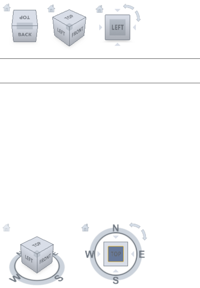
TIP When the navigation bar is linked to the ViewCube, both can be moved around
the Scene View. See Reposition and Reorient the Navigation Bar (page 151) for
more information.
Control the Appearance of ViewCube
The ViewCube tool is displayed in one of two states: inactive and active. When
the ViewCube tool is inactive, it appears partially transparent by default so
that it does not obscure the view of the model. When active, it is opaque and
may obscure the view of the objects in the current view of the model.
In addition to controlling the opacity level of the ViewCube when it is inactive,
you can also control its size, and the display of the compass. The settings used
to control the appearance of the ViewCube are located in the Options Editor.
Use the Compass
The compass is displayed below the ViewCube tool and indicates which
direction North is defined for the model. You can click a cardinal direction
letter on the compass to rotate the model, or you can click and drag one of
the cardinal direction letters or the compass ring to interactively rotate the
model around the pivot point.
140 | Chapter 5 Explore Your Model
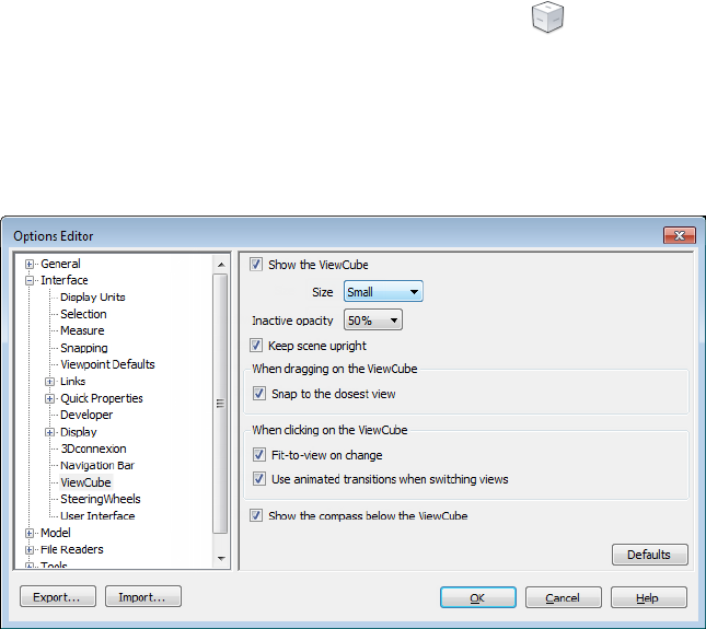
Drag or Click ViewCube
When you drag or click the ViewCube tool, the view of the model reorients
around a pivot point. The pivot point is displayed at the center of the object
that was last selected before using the ViewCube tool.
To display or hide the ViewCube
■Click View tab ➤ Navigation Aids panel ➤ ViewCube .
To control the size of the ViewCube
1Right-click the ViewCube tool, and click ViewCube Options.
2In the Options Editor, the ViewCube page under the Interface
node, select an option from the Size drop-down list.
3Click OK.
To control the inactive opacity of the ViewCube
1Right-click the ViewCube tool, and click ViewCube Options.
2In the Options Editor, the ViewCube page under the Interface
node, select an option from the Inactive Opacity drop-down list.
Navigate a Scene | 141
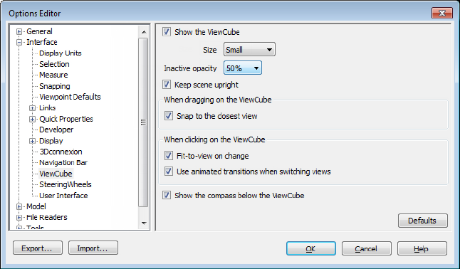
3Click OK.
To display the compass for the ViewCube
1Right-click the ViewCube tool, and click ViewCube Options.
2In the Options Editor, the ViewCube page under the Interface
node, select Show Compass Below the ViewCube.
3Click OK.
The compass is displayed below the ViewCube tool and indicates the
direction of north for the model.
ViewCube Menu
Use the ViewCube menu to restore and define the Home view of a model,
switch between view projection modes, and change the interactive behavior
and appearance of the ViewCube tool.
To display the ViewCube menu
To display the ViewCube menu, do one of the following:
■Right-click on the compass, Home icon, or the main area of the ViewCube
tool.
■Click the context menu button located below the ViewCube tool.
142 | Chapter 5 Explore Your Model
The ViewCube menu has the following options:
■Home. Restores the Home view saved with the model. This view is in
synchronization with the Go Home view option in the SteeringWheels
menu.
■Perspective. Switches the current view to perspective projection.
■Orthographic. Switches the current view to orthographic projection.
■Lock to Selection. Uses the selected objects to define the center of the
view when a view orientation change occurs with the ViewCube tool.
NOTE If you click Home on the ViewCube tool, the view returns to the Home
view even if Lock to Current Selection is selected.
■Set Current View as Home. Defines the Home view of the model based
on the current view.
■Set Current View as Front. Defines the Front view of the model.
■Reset Front. Resets the Front view of the model to its default orientation.
■ViewCube Options. Displays the Options Editor where you can adjust
the appearance and behavior of the ViewCube tool.
■Help. Launches the online Help system and displays the topic for the
ViewCube tool.
Reorient the View of a Model with ViewCube
ViewCube is used to reorient the current view of a model. You can reorient
the view of a model with the ViewCube tool by clicking pre-defined areas to
set a preset view current, click and drag to freely change the view angle of the
model, and define and restore the Home view.
Reorient the Current View
The ViewCube tool provides twenty-six defined parts to click and change the
current view of a model. The twenty-six defined parts are categorized into
three groups: corner, edge, and face. Of the twenty-six defined parts, six of
the parts represent standard orthogonal views of a model: top, bottom, front,
back, left, and right. Orthogonal views are set by clicking one of the faces on
the ViewCube tool.
Navigate a Scene | 143
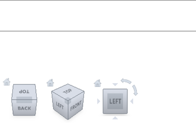
NOTE When the cursor is over one of the clickable areas of the ViewCube tool,
the cursor changes to an arrow with a small cube to indicate that it is over the
ViewCube tool. A tooltip is also displayed. The tooltip describes the action that
you can perform based on the location of the cursor over the ViewCube tool.
You use the other twenty defined parts to access angled views of a model.
Clicking one of the corners on the ViewCube tool reorients the current view
of the model to a three-quarter view, based on a viewpoint defined by three
sides of the model. Clicking one of the edges reorients the view of the model
to a half view based on two sides of the model.
You can also click and drag the ViewCube tool to reorient the view of a model
to a custom view other than one of the twenty-six predefined parts. As you
drag, the cursor changes to indicate that you are reorienting the current view
of the model. If you drag the ViewCube tool close to one of the preset
orientations and it is set to snap to the closest view, the ViewCube tool rotates
to the closest preset orientation.
The outline of the ViewCube tool helps you identify the form of orientation
it is in: standard or fixed. When the ViewCube tool is in standard orientation,
not orientated to one of the twenty-six predefined parts, its outline is displayed
as dashed. The ViewCube tool is outlined in a solid continuous line when it
is constrained to one of the predefined views.
Roll a Face View
When you view a model from one of the face views, two roll arrow buttons
are displayed near the ViewCube tool. Use the roll arrows to rotate the current
view 90 degrees clockwise or counterclockwise around the center of the view.
144 | Chapter 5 Explore Your Model
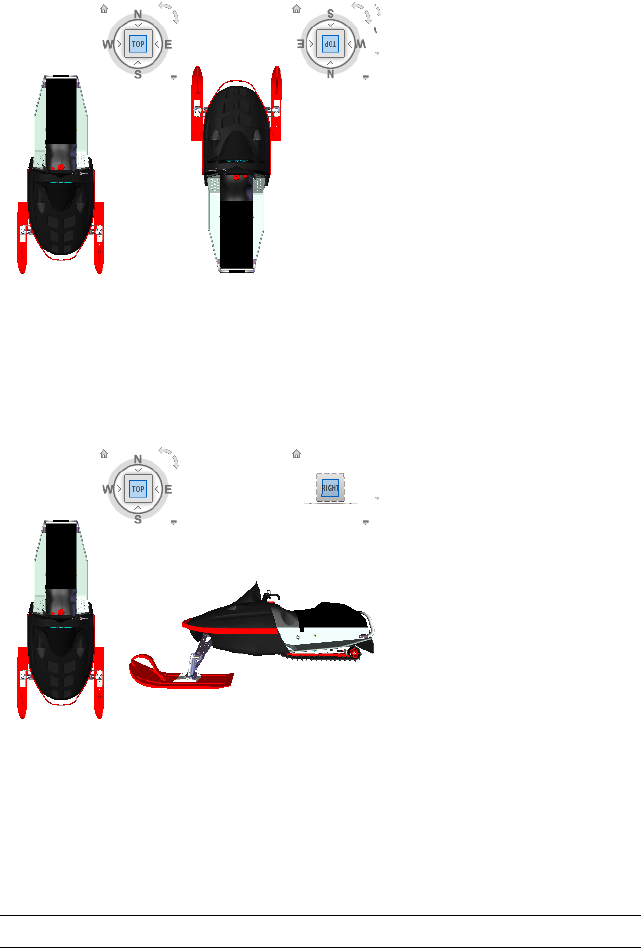
Switch to an Adjacent Face
When the ViewCube tool is active while viewing a model from one of the face
views, four orthogonal triangles are displayed near the ViewCube tool. You
use these triangles to switch to one of the adjacent face views.
Front View
You can define the Front view of a model to define the direction of the face
views on the ViewCube tool. Along with the Front view, the up direction of
a model is also used to define the direction of the face views on the ViewCube
tool.
NOTE Front view is a global setting and will be the same for viewpoints.
Navigate a Scene | 145
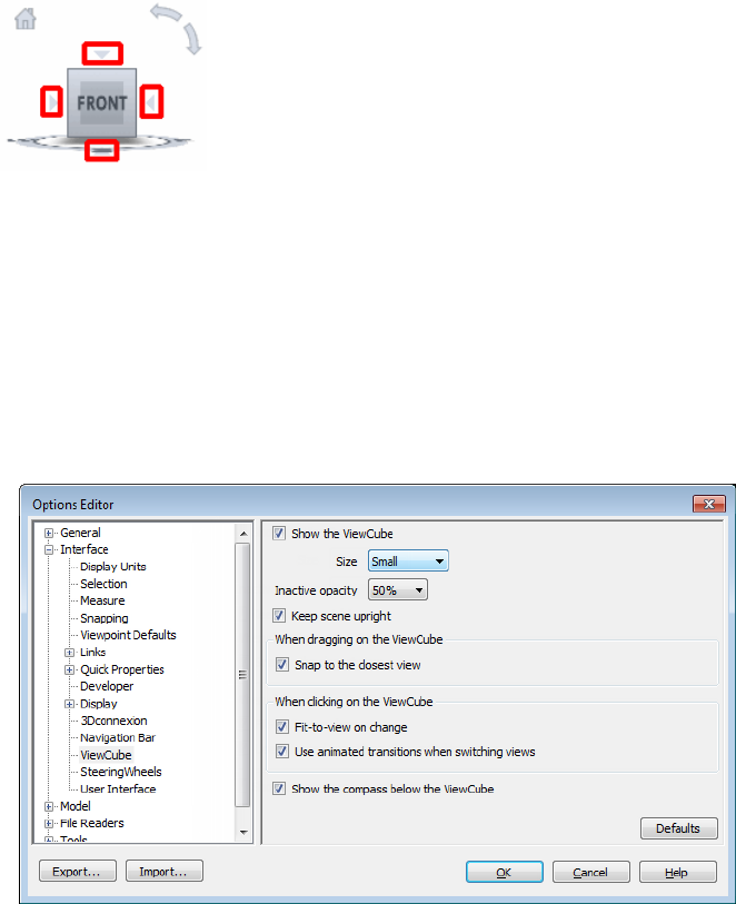
To reorient the current view to a preset orientation
■Click one of the faces, edges, or corners on the ViewCube tool.
To view an adjacent face
NOTE: Make sure a face view is current.
■Click one of the triangles displayed near the edges of the ViewCube tool.
To interactively reorient the view
■Click the ViewCube tool, hold down the left mouse button, and drag in
the direction that you want to orbit the model.
To use animated transitions when reorienting a view to a preset orientation
1Right-click the ViewCube tool, and click ViewCube Options.
2In the Options Editor, the ViewCube page under the Interface
node, select Use Animated Transitions When Switching Views.
146 | Chapter 5 Explore Your Model
When checked, transitions from one view to another appear animated
when clicking a predefined area on the ViewCube tool.
3Click OK.
To automatically fit the model after a view orientation
1Right-click the ViewCube tool, and click ViewCube Options.
2In the Options Editor, the ViewCube page under the Interface
node, select Fit-to-View on Change.
3Click OK.
To roll a face view
NOTE: Make sure a face view is displayed.
■Click one of the roll arrows displayed above and to the right of the
ViewCube tool.
The left roll arrow rotates the view 90 degrees counterclockwise; the right
roll arrow rotates the view 90 degrees clockwise.
To define the front view
■Right-click the ViewCube tool, and click Set Current View as Front.
To restore the Front view
■Right-click the ViewCube tool, and click Reset Front.
Set the View Projection Mode
The ViewCube tool supports two view projection modes (Perspective and
Orthographic). Orthographic projection is also referred to as parallel
projection. Perspective projected views are calculated based on the distance
from a theoretical camera and target point. The shorter the distance between
the camera and the target point, the more distorted the perspective effect
appears; greater distances produce less distorted affects on the model.
Orthographic projected views display all the points of a model being
projected parallel to the screen.
Orthographic projection mode makes it easier to work with a model due to
all the edges of the model appearing as the same size, regardless of the distance
from the camera. Orthographic projection mode though, is not how you
commonly see objects in the real world. Objects in the real world are seen in
Navigate a Scene | 147
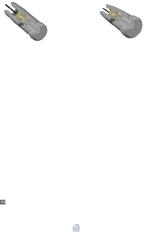
perspective projection. So when you want to generate a rendering or hidden
line view of a model, using perspective projection will give the model a more
realistic look.
The following illustration shows the same model viewed from the same viewing
direction, but with different view projections.
PerspectiveOrthographic
To change the view projection mode
■Right-click the ViewCube tool, and click one of the following options:
■Orthographic
■Perspective
Home View
The Home view is a special view stored with a model that makes it easy to
return to a known or familiar view. You can define any view of the model as
the Home view. The saved Home view can be applied to the current view by
clicking the Home button above the ViewCube tool or from the ViewCube
menu.
To define the Home view
■Right-click the ViewCube tool, and click Set Current View as Home.
Command entry: CTRL+SHIFT+Home
To reorient the model to the Home view
■Click the Home button ( ) located near the ViewCube tool.
■Right-click the ViewCube tool, and click Home.
148 | Chapter 5 Explore Your Model

Examine Individual Objects with ViewCube
You can lock the ViewCube tool to a set of selected objects. Locking a selection
of objects to the ViewCube tool defines the center of the current view and the
distance from center for the view based on the selected objects. To turn off
Lock to Selection, you can click the Lock to Selection button next to
the Home view button.
Selecting and deselecting objects after Lock to Selection is turned on has no
effect on the center or distance from the center of the view when a view
orientation changes. You cannot zoom fit to view a model when Lock to
Selection is on, even if the ViewCube tool is set to zoom fit to view after each
view orientation change.
To lock to the current selection
■Right-click the ViewCube tool, and click Lock to Selection.
If Lock to Selection is checked when a view orientation change occurs, the
selected objects are used to calculate the center of the view and the view
zooms to the extents of the selected objects. When cleared, the selected
objects are used to calculate the center of the view and the view zooms to
the extents of the model.
To examine an individual object with ViewCube
1In the model, select one or more objects to define the centerpoint of the
view.
2Click one of the preset locations on the ViewCube tool, or click and drag
the ViewCube tool to reorient the view of the model.
The ViewCube tool reorients the view of the model based on the
centerpoint of the selected objects.
Navigation Bar
Unified and product-specific navigation tools can be accessed from the
navigation bar.
Navigate a Scene | 149
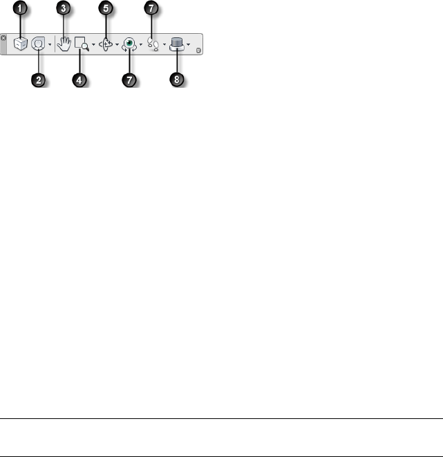
Overview of Navigation Bar
The navigation bar is a user interface element where you can access both
unified and product-specific navigation tools.
Unified navigation tools (such as Autodesk® ViewCube®, 3Dconnexion®, and
SteeringWheels®) are those that can be found across many Autodesk products.
Product-specific navigation tools are unique to a product. The navigation bar
floats over and along one of the sides of the Scene View.
You start navigation tools by clicking one of the buttons on the navigation
bar or selecting one of the tools from a list that is displayed when you click
the smaller portion of a split button.
5. Orbit tools (page 110). Set of navigation
tools for rotating the model around a pivot
point while the view remains fixed.
1. ViewCube (page 139) Indicates the current
orientation of a model, and is used to reori-
ent the current view of a model. Clicking
this button displays the ViewCube in the
Scene View when it’s not visible.
6. Look tools (page 111). Set of navigation
tools for rotating the current view vertically
and horizontally.
2. SteeringWheels (page 153) Collection of
wheels that offer rapid switching between
specialized navigation tools.
7. Walk and Fly tools (page 112). Set of
navigation tools for moving around the
model and controlling realism settings.
3. Pan tool (page 109). Activates the pan
tool and moves the view parallel to the
screen.
8. 3Dconnexion (page 164)Set of navigation
tools used to reorient the current view of a
model with a 3Dconnexion 3D mouse.
4. Zoom tools (page 109). Set of navigation
tools for increasing or decreasing the mag-
nification of the current view of the model.
NOTE In a 2D workspace, only the 2D navigation tools (such as 2D SteeringWheels,
Pan, Zoom, and the 2D Mode 3Dconnexion tools) are accessible.
150 | Chapter 5 Explore Your Model
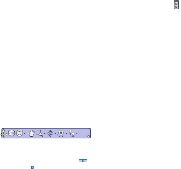
To display or hide the navigation bar
■Click View tab ➤ Navigation Aids panel ➤ Navigation Bar .
Reposition and Reorient the Navigation Bar
The position and orientation of the navigation bar can be adjusted by linking
it to the ViewCube tool, docking it when the ViewCube tool is not displayed,
or freely positioning it along one of the edges of the current window.
When linked to the ViewCube tool, the navigation bar is positioned below
the ViewCube tool and in a vertical orientation. When not linked or docked,
the navigation bar can be freely aligned along one of the edges of the Scene
View.
You can specify how the navigation bar can be repositioned from the
Customize menu. When the navigation bar is not linked to the ViewCube
tool or docked, a grip handle is displayed. Drag the grip handle on the
navigation bar to reposition it along one of the sides of the Scene View.
If the side of the Scene View that the navigation bar is aligned to is not long
enough to show the entire navigation bar, it is truncated to fit. When
truncated, the More Controls button is displayed and replaces the
Customize button. When you click the More Controls button, a menu
is displayed that contains the navigation tools that are not currently being
displayed.
To reposition the navigation bar and ViewCube
1On the navigation bar, click Customize.
2Click Customize menu ➤ Docking Positions ➤ check Link to
ViewCube.
When Link to ViewCube is checked, both the navigation bar and
ViewCube are repositioned together around the current window. When
ViewCube is not displayed, the navigation bar is docked in the same
location in which ViewCube would be instead.
3Click Customize menu ➤ Docking Positions ➤ and then a docking
position.
The navigation bar and ViewCube are repositioned.
Navigate a Scene | 151

To link the position of the navigation bar to ViewCube
1On the navigation bar, click Customize.
2Click Customize menu ➤ Docking Positions ➤ check Link to
ViewCube.
When Link to ViewCube is checked, both the navigation bar and
ViewCube are repositioned together around the current window.
To freely reposition the navigation bar along the edge of the current window
TIP In a 2D workspace, click the grip handle and drag the navigation bar to
reposition it.
1On the navigation bar, click Customize.
2Click Customize menu ➤ Docking Positions ➤ uncheck Link to
ViewCube.
The grip handle for the navigation bar is displayed along the top of the
navigation bar.
3Click the grip handle and drag the navigation bar along the edge of the
window where you want it displayed. Release the button on the pointing
device to orient the navigation bar along the edge of the window.
4Drag the navigation bar along the window’s edge to adjust its position
along the window’s edge.
Control the Display of Navigation Tools on the
Navigation Bar
You can control which unified and product-specific navigation tools are
displayed on the navigation bar with the Customize menu.
The Customize menu is displayed by clicking the Customize button on the
lower-right side of the navigation bar. From the Customize menus, you click
the navigation tools that you want displayed on the navigation bar. The
position of the navigation tools on the navigation bar is predefined and cannot
be changed.
NOTE In a 3D workspace, the ViewCube button is displayed on the navigation
bar only when the ViewCube tool is hidden in the Scene View. In a 2D workspace,
the ViewCube button is not available.
152 | Chapter 5 Explore Your Model
To customize the navigation bar
1On the navigation bar, click Customize.
2On the Customize menu, click the navigation tool you want to display
on the navigation bar.
A check mark next to a navigation tool’s name indicates it is displayed
on the navigation bar. Uncheck the navigation tool to remove it from
the navigation bar.
You can display a shortcut menu for tools on the navigation bar by
right-clicking them. The following commands are available on the shortcut
menu whenever they are applicable:
PurposeCommand
Removes the tool from the navigation bar.
This is equivalent to unchecking the relevant
check box in the Customize menu.
Remove from Navigation Bar
Hides the navigation bar.Close Navigation Bar
SteeringWheels
SteeringWheels™ are tracking menus that follow your cursor, and from which
you can access different 2D and 3D navigation tools from a single tool.
Overview of SteeringWheels
SteeringWheels, also known as wheels, can save you time by combining many
of the common navigation tools into a single interface. Wheels are specific
to the context from which a model is being viewed.
Navigate a Scene | 153
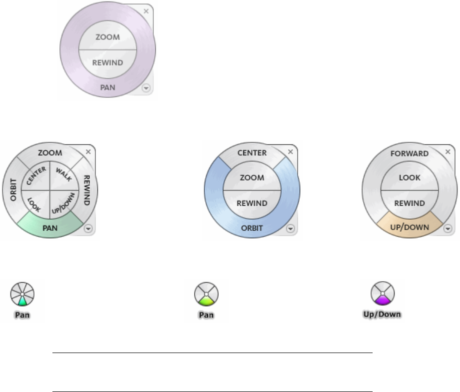
The following illustrations show the different wheels available:
2D Navigation Wheel
Tour Building Wheel (Basic Wheel)View Object Wheel (Basic Wheel)Full Navigation Wheel
Mini Tour Building WheelMini View Object WheelMini Full Navigation Wheel
NOTE SteeringWheels and classic navigation modes (page 130) are mutually
exclusive, so activating a SteeringWheel deactivates the currently selected Classic
navigation mode.
Display and Use Wheels
Pressing and dragging on a wedge of a wheel is the primary mode of
interaction. After a wheel is displayed, click one of the wedges and hold down
the button on the pointing device to activate the navigation tool. Drag to
reorient the current view. Releasing the button returns you to the wheel.
154 | Chapter 5 Explore Your Model
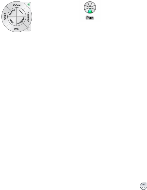
Control the Appearance of Wheels
You can control the appearance of the wheels by switching between the
different styles of wheels that are available, or by adjusting the size and opacity.
Wheels are available in two different styles: big and mini. The big wheel is
larger than the cursor, and labels are shown on the wheel wedges. The mini
wheel is about the same size as the cursor, and labels are not displayed on the
wheel wedges.
Mini Full Navigation WheelBig Full Navigation Wheel
The size of a wheel controls how large or small the wedges and labels appear
on the wheel; the opacity level controls the visibility of the objects in the
model behind the wheel.
Control Tooltips for Wheels and Messages for Tools
Tooltips are displayed for each button on a wheel as the cursor is moved over
them. The tooltips appear below the wheel and identify what action will be
performed if the wedge or button is clicked.
Similar to tooltips, tool messages and cursor text are displayed when you use
one of the navigation tools from a wheel. Tool messages are displayed when
a navigation tool is active; they provide basic instructions about using the
tool. Tool cursor text displays the name of the active navigation tool near the
cursor. Disabling tool messages and cursor text only affects the messages that
are displayed when using the mini wheels or the big Full Navigation wheel.
To display a wheel
1On the navigation bar, click the arrow below the SteeringWheels button.
2Click the wheel you want to display, for example Full Navigation
Wheel.
Ribbon: Viewpoint tab ➤ Navigate panel ➤ SteeringWheels
Navigate a Scene | 155

Toolbar: Classic user interface: Navigation Mode ➤ SteeringWheels
To close a wheel
■Press SHIFT+W
To change the size of a wheel
1Display a wheel.
2Right-click the wheel, and click SteeringWheels Options.
3In the Options Editor, the SteeringWheels page under the Interface
node, select an option from the Size drop-down list in the Big Wheels
or Mini Wheels area.
4Click OK.
To change the opacity of a wheel
1Display a wheel.
2Right-click the wheel, and click SteeringWheels Options.
3In the Options Editor, the SteeringWheels page under the Interface
node, select an option from the Opacity drop-down list in the Big
Wheels or Mini Wheels area.
4Click OK.
To enable tooltips for wheels
1Display a wheel.
2Right-click the wheel, and click SteeringWheels Options.
3In the Options Editor, the SteeringWheels page under the Interface
node, select the Show Tooltips check box in the On-Screen Messages
area.
Tooltips are displayed for each wedge and button on a wheel when the
cursor moves over the wheel.
4Click OK.
To enable tool messages for wheels
1Display a wheel.
2Right-click the wheel, and click SteeringWheels Options.
156 | Chapter 5 Explore Your Model
3In the Options Editor, the SteeringWheels page under the Interface
node, select the Show Tool Messages check box in the On-Screen
Messages area.
Messages are displayed when you use the navigation tools.
4Click OK.
To enable tool cursor text for wheels
1Display a wheel.
2Right-click the wheel, and click SteeringWheels Options.
3In the Options Editor, the SteeringWheels page under the Interface
node, select the Show Tool Cursor Text check box in the On-Screen
Messages area.
The name of the active tool is displayed near the cursor when the tool
is in use.
4Click OK.
Wheel Menu
From the Wheel menu, you can switch between different wheels and change
the behavior of some of the navigation tools on the current wheel.
Use the Wheel menu to switch between the big and mini wheels that are
available, go to the Home view, change the preferences of the current wheel,
and control the behavior of the orbit, look, and walk 3D navigation tools. The
menu items available on the Wheel menu are dependent on the current wheel
and program.
To display the Wheel menu
■Click the down arrow in the lower-right corner of the wheel or right-click
on the wheel.
The Wheel menu has the following options:
■Basic View Object Wheel. Displays the big View Object wheel.
■Basic Tour Building Wheel. Displays the big Tour Building wheel.
■Full Navigation Wheel. Displays the big Full Navigation wheel.
Navigate a Scene | 157
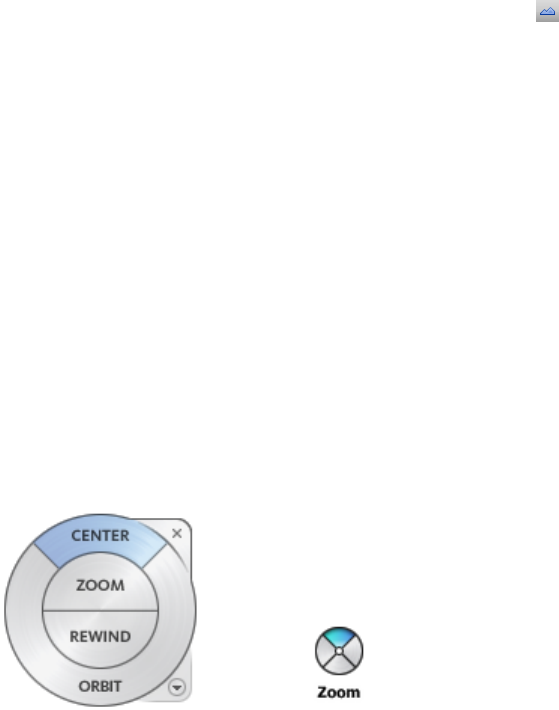
■Advanced Wheels. Displays the mini View Object, Tour Building, or
Full Navigation wheel.
■Home. Goes to the Home view saved with the model.
NOTE This is the Home view as set using the ViewCube.
■Fit to Window. Resizes and centers the current view to display all objects
in the Scene View. This is equivalent to clicking View All on the
Navigation Tools toolbar in the Classic user interface.
■Restore Original Center. Restores the center point of the view to the
extents of the model.
■Level Camera. Rotates the current view so it is relative to the XY ground
plane.
■SteeringWheels Options. Displays the Options Editor where you can
adjust the appearance and behavior of SteeringWheels.
■Help. Launches the online Help system and displays the topic for
SteeringWheels.
■Close Wheel. Closes the wheel.
View Object Wheels
With the View Object wheels (big and mini), you can view individual objects
or features in a model. The big View Object wheel is optimized for new 3D
users while the mini View Object wheel is optimized for experienced 3D users.
158 | Chapter 5 Explore Your Model
Big View Object Wheel
The big View Object wheel wedges have the following options:
■Center (page 113). Specifies a point on a model to adjust the center of
the current view or change the target point used for some of the navigation
tools.
■Zoom (page 127) . Adjusts the magnification of the current view.
■Rewind (page 122). Restores the most recent view orientation. You can
move backward or forward by clicking and dragging left or right.
■Orbit (page 117). Rotates the current view around a fixed pivot point at
the view’s center.
Mini View Object Wheel
The mini View Object wheel wedges have the following options:
■Zoom (Top wedge) (page 127) . Adjusts the magnification of the current
view.
■Rewind (Right wedge) (page 122). Restores the most recent view. You
can move backward or forward by clicking and dragging left or right.
■Pan (Bottom wedge) (page 109). Repositions the current view by
panning.
■Orbit (Left wedge) (page 117). Rotates the current view around a fixed
pivot point.
NOTE When the mini wheel is displayed, you can press and hold the middle
mouse button to pan, scroll the wheel button to zoom in and out, and hold the
SHIFT key while pressing and holding the middle mouse button to orbit the model.
To switch to the mini View Object wheel
■Right-click the wheel, and click Advanced Wheels ➤ Mini View Object
Wheel.
Toolbar: Navigation bar ➤ SteeringWheels ➤ Mini View Object Wheel
Ribbon: Viewpoint tab ➤ Navigate panel ➤ Steering WheelsMini
View Object
Menu: Classic user interface: View ➤ SteeringWheels ➤ Mini View
Object Wheel
Navigate a Scene | 159
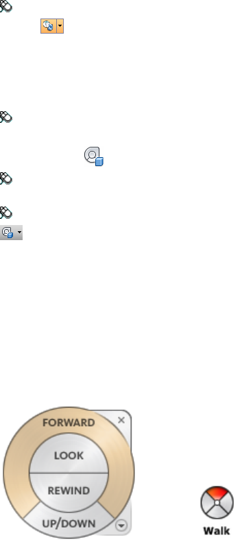
Toolbar: Classic user interface: Navigation Mode ➤ Mini View Object
Wheel
To switch to the big View Object wheel
■Right-click the wheel, and click Basic View Object Wheel.
Toolbar: Navigation bar ➤ SteeringWheels ➤ Basic View Object Wheel
Ribbon: Viewpoint tab ➤ Navigate panel ➤ Steering WheelsBasic
View Object
Menu: Classic user interface: View ➤ SteeringWheels ➤ View Object
Wheel
Toolbar: Classic user interface: Navigation Mode ➤ View Object Wheel
Tour Building Wheels
With the Tour Building wheels (big and mini), you can move through a model,
such as a building, an assembly line, ship, or oil rig. You can also walk through
and navigate around a model. The big Tour Building wheel is optimized for
new 3D users while the mini Tour Building wheel is optimized for experienced
3D users.
Big Tour Building Wheel
The big Tour Building wheel wedges have the following options:
■Forward (page 114). Adjusts the distance between the current point of
view and the defined pivot point of the model. Clicking once moves
forward half the distance as far as the object you clicked.
■Look. Swivels the current view.
160 | Chapter 5 Explore Your Model
■Rewind. Restores the most recent view. You can move backward or
forward by clicking and dragging left or right.
■Up/DownTool. Slides the current view of a model along the Z axis of
the model.
Mini Tour Building Wheel
The mini Tour Building wheel wedges have the following options:
■Walk (Top wedge). Simulates walking through a model.
■Rewind (Right wedge). Restores the most recent view. You can move
backward or forward by clicking and dragging left or right.
■Up/Down (Bottom wedge). Slides the current view of a model along
the Z axis of the model.
■Look (Left wedge). Swivels the current view.
NOTE When the mini wheel is displayed, you can press and hold the middle
mouse button to pan, scroll the wheel button to zoom in and out, and hold the
SHIFT key while pressing and holding the middle mouse button to orbit the model.
To switch to the mini Tour Building wheel
■Right-click the wheel, and click Advanced Wheels ➤ Mini Tour
Building Wheel.
Toolbar: Navigation bar ➤ SteeringWheels ➤ Mini Tour Building Wheel
Ribbon: Viewpoint tab ➤ Navigate panel ➤ Steering WheelsMini
Tour Building
Menu: Classic user interface: View ➤ SteeringWheels ➤ Mini Tour
Building Wheel
Toolbar: Classic user interface: Navigation Mode ➤ Mini Tour Building
Wheel
To switch to the big Tour Building wheel
■Right-click the wheel, and click Basic Tour Building Wheel.
Toolbar: Navigation bar ➤ SteeringWheels ➤ Basic Tour Building Wheel
Ribbon: Viewpoint tab ➤ Navigate panel ➤ Steering WheelsBasic
Tour Building
Navigate a Scene | 161
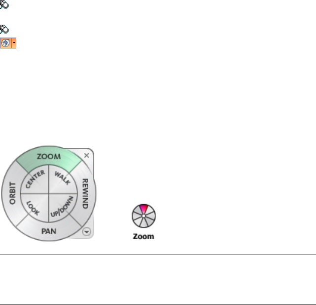
Menu: Classic user interface: View ➤ SteeringWheels ➤ Tour Building
Wheel
Toolbar: Classic user interface: Navigation Mode ➤ Tour Building Wheel
Full Navigation Wheels
The Full Navigation wheels (big and mini) contain common 3D navigation
tools used for both viewing an object and touring a building. The big and
mini Full Navigation wheels are optimized for experienced 3D users.
NOTE When one of the Full Navigation wheels is displayed, you can press and
hold the middle mouse button to pan, scroll the wheel button to zoom in and
out, and hold the SHIFT key while pressing and holding the middle mouse button
to orbit the model.
Big Full Navigation Wheel
The big Full Navigation wheel wedges have the following options:
■Zoom. Adjusts the magnification of the current view.
■Rewind. Restores the most recent view. You can move backward or
forward by clicking and dragging left or right.
■Pan. Repositions the current view by panning.
■Orbit. Rotates the current view around a fixed pivot point.
■Center. Specifies a point on a model to adjust the center of the current
view or change the target point used for some of the navigation tools.
■Walk. Simulates walking through a model.
■Look. Swivels the current view.
162 | Chapter 5 Explore Your Model
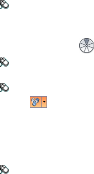
■Up/Down. Slides the current view of a model along the Z axis of the
model.
Mini Full Navigation Wheel
The mini Full Navigation wheel wedges have the following options:
■Zoom (Top wedge). Adjusts the magnification of the current view.
■Walk (Upper right wedge). Simulates walking through a model.
■Rewind (Right wedge). Restores the most recent view. You can move
backward or forward by clicking and dragging left or right.
■Up/Down (Lower right wedge). Slides the current view of a model
along the Z axis of the model.
■Pan (Bottom wedge). Repositions the current view by panning.
■Look (Lower left wedge). Swivels the current view.
■Orbit (Left wedge). Rotates the current view around a fixed pivot point.
■Center (Upper left wedge). Specifies a point on a model to adjust the
center of the current view or change the target point used for some of the
navigation tools.
To switch to the mini Full Navigation wheel
■Right-click the wheel, and click Advanced Wheels ➤ Mini Full
Navigation Wheel.
Toolbar: Navigation bar ➤ SteeringWheels ➤ Mini Full Navigation
Wheel
Ribbon: Viewpoint tab ➤ Navigate panel ➤ Steering WheelsMini
Full Navigation
Menu: Classic user interface: View ➤ SteeringWheels ➤ Mini Full
Navigation Wheel
Toolbar: Classic user interface: Navigation Mode ➤ Mini Full Navigation
Wheel
To switch to the big Full Navigation wheel
■Right-click the wheel, and click Full Navigation Wheel.
Toolbar: Navigation bar ➤ SteeringWheels ➤ Full Navigation Wheel
Navigate a Scene | 163
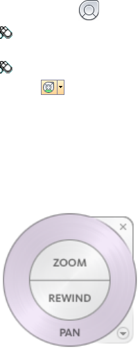
Ribbon: Viewpoint tab ➤ Navigate panel ➤ Steering WheelsFull
Navigation
Menu: Classic user interface: View ➤ SteeringWheels ➤ Full Navigation
Wheel
Toolbar: Classic user interface: Navigation Mode ➤ Full Navigation
Wheel
2D Navigation Wheel
With this wheel you can access basic 2D navigation tools; it is particularly
useful when you do not have a pointing device with a scroll wheel.
The 2D Navigation wheel wedges have the following options:
■Pan. Repositions the current view by panning.
■Zoom. Adjusts the magnification of the current view.
■Rewind. Restores the most recent view orientation. You can move
backward or forward by clicking and dragging left or right.
3Dconnexion 3D Mouse
A 3Dconnexion 3D mouse can be used as an alternative to the mouse to move
around the Scene View.
The device has a pressure sensitive controller cap designed to flex in all
directions. Push, pull, twist, or tilt the cap to pan, zoom, and rotate the current
view. The speed of navigation is sensitive to the amount of force applied to
the 3Dconnexion device. You can adjust the device settings by using the
Control Panel for the device which is supplied by the manufacturer with the
installation.
164 | Chapter 5 Explore Your Model
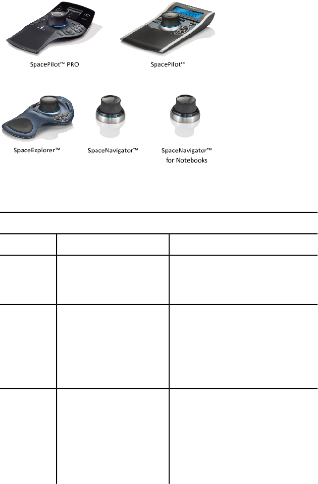
When a view change occurs with the 3Dconnexion 3D mouse, the ViewCube
tool is reoriented to reflect the current view. You can change the behavior of
the 3Dconnexion 3D mouse from the navigation bar.
3Dconnexion options on the navigation bar
ExampleDescriptionOption
Move the controller cap right to pan the
view to the right.
Navigates and reorients the
view in the direction of the
controller cap.
Object Mode
Move the controller cap forward to walk
towards the model.
Simulates walking through a
model. The view of the model
is moved in the opposite direc-
Walk Mode
tion of the controller cap. The
orientation and height of the
current view is maintained.
Move the controller cap up to elevate
the view. This makes the model appear
to move down.
Simulates flying through a
model. The view of the model
is moved in the opposite direc-
tion of the controller cap. The
Fly Mode
orientation and height of the
current view is not main-
tained.
Navigate a Scene | 165

3Dconnexion options on the navigation bar
ExampleDescriptionOption
Move the controller cap to pan and
zoom the view.
Navigates the view using only
2D navigation options. The
view moves in the direction of
the controller cap.
2D Mode
Click in the model. The view is centered
on the model based on the specified
point.
Specifies a point to define the
pivot point and centers the
model on that point. This
pivot point is used by sub-
Center Tool
sequent navigation tools until
it is moved.
Adjust the speed of translation and rota-
tion.
Controls the default naviga-
tion mode and the speed of
translation and rotation of the
3Dconnexion
Settings
3Dconnexion 3D mouse in
the Options Editor (page 293)
If you are using the Classic user interface, the behavior of the 3Dconnexion
device corresponds to the currently selected navigation bar tool (page 108) or
navigation mode (page 130). This enables you to navigate with the 3Dconnexion
device whilst performing other operations with the mouse. If no navigation
tool or mode is selected or if the selected tool or mode is not a valid mode for
the 3Dconnexion device, then a default navigation mode will be used.
Use View Management Keys in 3Dconnexion 3D Mouse
You can access different views (such as Top, Front, Left, Right, or Home) with
buttons available on some 3Dconnexion 3D mouse models. Use the Button
Configuration Editor to customize the operations of these buttons. When you
click any of these buttons on the device, you can
■Fit the view to the model extents. Rotates the view of the object
around the center of the scene and zooms out to fit the scene into the
viewport.
■Reorient the current view to a preset view. Returns the view of the
object to a predetermined view.
166 | Chapter 5 Explore Your Model
■Maintain selection sensitivity. Reorients the model around a defined
pivot point based on the current selection.
■Maintain lock to selection. When Lock to Selection option is activated
in the ViewCube tool, the view of the object reorients around the
predefined center of the selected object.
Camera
Autodesk Navisworks offers you a number of prefixed options to control the
camera projection, position, and orientation during navigation.
Set Camera Projection
You can choose to use a perspective camera or an orthographic camera during
navigation in a 3D workspace only. In a 2D workspace an orthographic camera
is always used.
NOTE Orthographic cameras are not available with Walk and Fly navigation
tools.
To use a perspective camera
■Click Viewpoint tab ➤ Camera panel ➤ Perspective .
Menu: Classic user interface: Viewpoint ➤ Navigation
Tools ➤ Perspective
To use an orthographic camera
■Click Viewpoint tab ➤ Camera panel ➤ Orthographic .
Menu: Classic user interface: Viewpoint ➤ Navigation
Tools ➤ Orthographic
Navigate a Scene | 167

Control the Field of View
You can define the area of the scene that can be viewed through the camera
in a 3D workspace only.
For the current viewpoint, you can move the FOV slider on the ribbon to
adjust the Horizontal Field of View. For previously saved viewpoints, you can
use the Edit Viewpoint dialog box (page 272) to adjust the values for both
vertical and horizontal angles of view.
NOTE When you modify the Horizontal Field of View, the Vertical Field of View is
automatically adjusted, and vice versa to match the aspect ratio in Autodesk
Navisworks.
To control the horizontal field of view
■Click Viewpoint tab ➤ Camera panel, and move the FOV slider to
control the camera’s angle of view.
Moving the slider to the right produces a wider angle of view, and moving
the slider to the left produces a narrower, or more tightly focused, angle
of view.
Position and Focus Camera
You can adjust the camera’s position and orientation in the scene.
Move Camera
For the current viewpoint, you can use the Position entry boxes on the ribbon
to move the camera position. For previously saved viewpoints, you can use
the Edit Viewpoint dialog box (page 272) to adjust the camera values.
NOTE The Z coordinate values are not available in a 2D workspace.
To move camera numerically
1Click the Viewpoint tab, and slide out the Camera panel.
2Type in numerical values into the Position entry boxes to move the
camera by the amount entered.
168 | Chapter 5 Explore Your Model
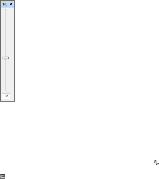
Rotate Camera
You can adjust the angle of the camera during navigation in a 3D workspace
only.
For the current viewpoint, use the Tilt window to rotate the camera up/down,
and the Roll entry box on the ribbon to rotate the camera left/right. For saved
viewpoints, you can use the Edit Viewpoint dialog box (page 272) to adjust the
camera values.
Tilt Window
The tilt angle is indicated in the scene's units below (negative) or above
(positive) horizontal (0) at the base of the window.
You can use the Tilt window with the Walk tool on the navigation bar to
look up and down. If your mouse has a wheel, you can use it to adjust the tilt
angle.
To toggle the Tilt window
■Click Viewpoint tab ➤ Camera panel ➤ Show Tilt Bar .
Command entry: CTRL + F7
To roll camera up/down
■Drag the slider up or down on the Tilt window to roll the camera.
Navigate a Scene | 169

You can also type values directly the entry box at the base of the Tilt
window. A positive value rotates the camera upwards, and a negative value
rotates camera downwards. Typing 0 straightens the camera.
To roll camera left/right
■Click the Viewpoint tab, and slide out the Camera panel.
■Type in a value into the Roll entry box to rotate the camera around its
front-to-back axis.
A positive value rotates the camera counterclockwise, and a negative value
rotates it clockwise.
NOTE This value is not editable when the viewpoint up vector stays upright
(that is, when you use Walk, Orbit and Constrained Orbit navigation tools).
Move Focal Point
You can change the focal point for the camera. For the current viewpoint, use
the Look At entry boxes on the ribbon. For saved viewpoints, you can use
the Edit Viewpoint dialog box (page 272) to adjust the camera values.
NOTE The Z coordinate values are not available in a 2D workspace.
In a 3D workspace, you can also put the Scene View into focus mode, which
effectively swivels the camera so that the point clicked is in the center of the
view. See Focus (page 175).
To move the camera focal point
1Click the Viewpoint tab, and slide out the Camera panel.
2Type in numerical values into the Look At entry boxes to move the
camera focal point by the amount entered.
Straighten Camera
You can straighten the camera to align with the viewpoint up vector in a 3D
workspace only.
When the camera position is close to the viewpoint up vector (within 13
degrees), you can use this function to snap the camera to the appropriate axis.
170 | Chapter 5 Explore Your Model
TIP The same effect can be achieved by typing 0 at the base of the Tilt window.
To straighten camera
■Click Viewpoint tab ➤ Camera panel ➤ Align Camera drop-down
➤ Straighten .
Predefined Camera Views
In Autodesk Navisworks, you can align a camera to one of the axis, or select
one of six predefined face views to instantly change the camera’s position and
orientation in the scene. This functionality is available in a 3D workspace
only.
When you align the camera position along one of the axis:
■Aligning with X axis toggles between front and back face views.
■Aligning with Y axis toggles between left and right face views.
■Aligning with Z axis toggles between top and bottom face views.
NOTE You can customize the location of the front face by using the ViewCube
tool. This change is global, and affects all viewpoints.
To align with X-axis
■Click Viewpoint tab ➤ Camera panel ➤ Align Camera drop-down
➤ Align X .
Menu: Classic user interface: Viewpoint ➤ Navigation Tools ➤ Align
X
To align with Y-axis
■Click Viewpoint tab ➤ Camera panel ➤ Align Camera drop-down
➤ Align Y .
Menu: Classic user interface: Viewpoint ➤ Navigation Tools ➤ Align
Y
To align with Z-axis
■Click Viewpoint tab ➤ Camera panel ➤ Align Camera drop-down
➤ Align Z .
Navigate a Scene | 171
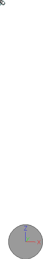
Menu: Classic user interface: Viewpoint ➤ Navigation Tools ➤ Align
Z
To look from a preset face view
■Right-click the Scene View, and click Viewpoint ➤ Look From.
■Click one of the face views. Choose from:
■Top
■Bottom
■Front
■Back
■Left
■Right
Navigation Aids
Head-Up Display
Head-up display elements are on-screen displays that provide information
about your location and orientation in a 3D workspace. This functionality is
not available in a 2D workspace.
In Autodesk Navisworks, you can use the following head-up display (HUD)
elements:
■XYZ Axes. Shows the X, Y, Z orientation of the camera (or the avatar’s
eye if the avatar is visible). The XYZ Axes indicator is located at the
bottom-left of the Scene View.
■Position Readout. Shows the absolute X, Y, Z position of the camera
(or the avatar's eye position if the avatar is visible). The Position Readout
is located at the bottom-left of the Scene View.
172 | Chapter 5 Explore Your Model

To toggle XYZ Axes
1Click View tab ➤ Navigation Aids panel ➤ HUD drop-down.
2Select or clear the XYZ Axes check box.
To toggle Position Readout
1Click View tab ➤ Navigation Aids panel ➤ HUD drop-down.
2Select or clear the Position Readout check box.
Reference Views
Reference views are useful to get an overall view of where you are in the whole
scene and to quickly move the camera to a location in a large model. This
functionality is available in a 3D workspace.
There are two types of reference views available in Autodesk Navisworks:
■Section View
■Plan View
The reference views show a fixed view of the model. By default, the section
view shows the view from the front of the model and the plan view shows a
top view of the model.
Reference views are displayed inside the dockable windows. A triangular marker
represents your current viewpoint. This marker moves as you navigate, showing
the direction of your view. The marker may also be dragged by holding the
left mouse button over it and dragging to move the camera in the Scene
View.
NOTE The marker changes to a small dot when the reference view is in the same
plane as the camera view.
To use the Plan View
1Click View tab ➤ Navigation Aids panel ➤ Reference Views
drop-down ➤ Plan View check box.
The Plan View window opens with the reference view of the model.
Navigate a Scene | 173
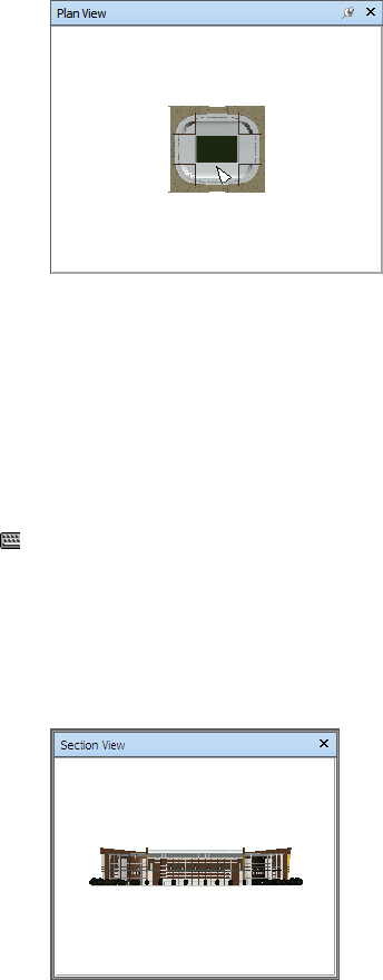
2Drag the triangular marker on the reference view into a new location.
The camera in the Scene View changes its position to match the
position of the marker in the view.
Alternatively, navigate to a different location in the Scene View. The
triangular marker in the reference view changes its position to match
the camera position in the Scene View.
3To manipulate a reference view, right-click anywhere in the Plan View
window. Use the shortcut menu to adjust the view as desired.
Command entry: CTRL + F9
To use the Section View
1Click View tab ➤ Navigation Aids panel ➤ Reference Views
drop-down ➤ Section View check box.
The Section View window opens with the reference view of the model.
2Drag the triangular marker on the reference view into a new location.
The camera in the Scene View changes its position to match the
position of the marker in the view.
174 | Chapter 5 Explore Your Model

Alternatively, navigate to a different location in the Scene View. The
triangular marker in the reference view changes its position to match
the camera position in the Scene View.
3To manipulate a reference view, right-click anywhere in the Section
View window. Use the shortcut menu to adjust the view as desired.
Command entry: CTRL + F10
Focus
You can put the Scene View into focus mode until the next click.
When you are in focus mode, clicking on an item swivels the camera so that
the point clicked is in the center of the view. This point becomes the focal
point for the Orbit tools (SteeringWheels and navigation bar) in a 3D workspace
only.
In the Classic user interface, 3D workspace, this point becomes the focal
point for examine, orbit, and turntable classic navigation modes (page 130).
In a 2D workspace, the camera is moved to the center of the box of focused
item while the z value remains the same.
To focus on an item
■Click Item Tools tab ➤ Look At panel ➤ Focus on Item .
Toolbar: Navigation bar ➤ Look tools ➤ Focus
Menu: Classic user interface: Viewpoint ➤ Navigation Tools ➤ Focus
Shortcut menu: Scene ➤ Focus
Hold
When you navigate around a model in Autodesk Navisworks, it is possible to
“pick up” or hold selected items and move around with them in the model.
For example you may be viewing a plan for a factory and would like to see
different configurations of machine layouts.
Navigate a Scene | 175
To hold and release objects
1Select the objects you want to hold either in the Scene View or in the
Selection Tree.
2Click Item Tools tab ➤ Hold panel ➤ Hold .
The selected objects are now held and will move with you through the
model when you use navigation tools, such as Walk, Pan and so on.
3To release the held objects, click Hold on the ribbon again.
4If you want to reset the objects to their original position, click Item
Tools tab ➤ Transform panel ➤ Reset Transform .
Menu: Classic user interface: Viewpoint ➤ Navigation Tools ➤ Hold
Control the Realism of Your Navigation
When you navigate a 3D model, you can use the realism tools on the
Viewpoint tab ➤ Navigate panel to control the speed and realism of your
navigation. The realism tools are not available in a 2D workspace.
Gravity
NOTE This function only works in connection with collision.
Where collision gives you mass, gravity gives you weight. As such, you (as the
collision volume) will be pulled downwards whilst walking through the scene.
NOTE Gravity can only be used with the Walk navigation tool.
This allows you to walk down stairs, for example, or follow terrain.
To toggle gravity
■When using the Walk tool, click Viewpoint tab ➤ Navigate panel
➤ Realism drop-down ➤ Gravity check box.
Menu: Classic user interface: Viewpoint ➤ Navigation Tools ➤ Gravity
Command entry: CTRL + G
176 | Chapter 5 Explore Your Model
Crouching
NOTE This function only works in connection with collision.
When walking or flying around the model with collision activated, you may
encounter object that are too low to walk under, a low pipe for example. This
function enables you to crouch under any such objects.
With crouching activated, you will automatically crouch under any objects
that you cannot walk under at your specified height, thereby not impeding
your navigation around the model.
TIP To temporarily crouch under a low object, hold down the Space bar to allow
navigation to proceed.
To toggle crouching
1When using the Walk or Fly tool, click Viewpoint tab ➤ Navigate
panel ➤ Realism drop-down ➤ Crouch check box.
Menu: Classic user interface: Viewpoint ➤ Navigation Tools ➤ Crouch
Collision
This function defines you as a collision volume - a 3D object that can navigate
around and interact with the model, obeying certain physical rules that confine
you within the model itself. In other words, you have a mass and as such,
cannot pass through other objects, points or lines in the scene.
You can walk over, or climb over objects in the scene that are up to half the
height of the collision volume, thus allowing you to walk up stairs, for
example.
The collision volume, in its basic form, is a sphere (with radius = r), that can
be extruded to give it height (with height = h >= 2r). See diagram below:
Control the Realism of Your Navigation | 177
The dimensions of the collision volume can be customized for the current
viewpoint or as a global option.
NOTE Collision can only be used with the Walk and Fly navigation tools.
When collision is turned on, rendering prioritization is changed so that objects
around the camera or avatar are displayed with much higher detail than
normal. The size of the region of high detail is based on collision volume
radius and speed of movement (needing to see what is about to be walked
into).
To toggle collision
1When using the Walk or Fly tool, click Viewpoint tab ➤ Navigate
panel ➤ Realism drop-down ➤ Collision check box.
Menu: Classic user interface: Viewpoint ➤ Navigation Tools ➤ Collision
Command entry: CTRL + D
Third Person View
This function allows you to navigate scene from a third person perspective.
When third person is activated, you will be able to see an avatar which is a
representation of yourself within the 3D model. Whilst navigating you will
be controlling the avatar's interaction with the current scene.
178 | Chapter 5 Explore Your Model
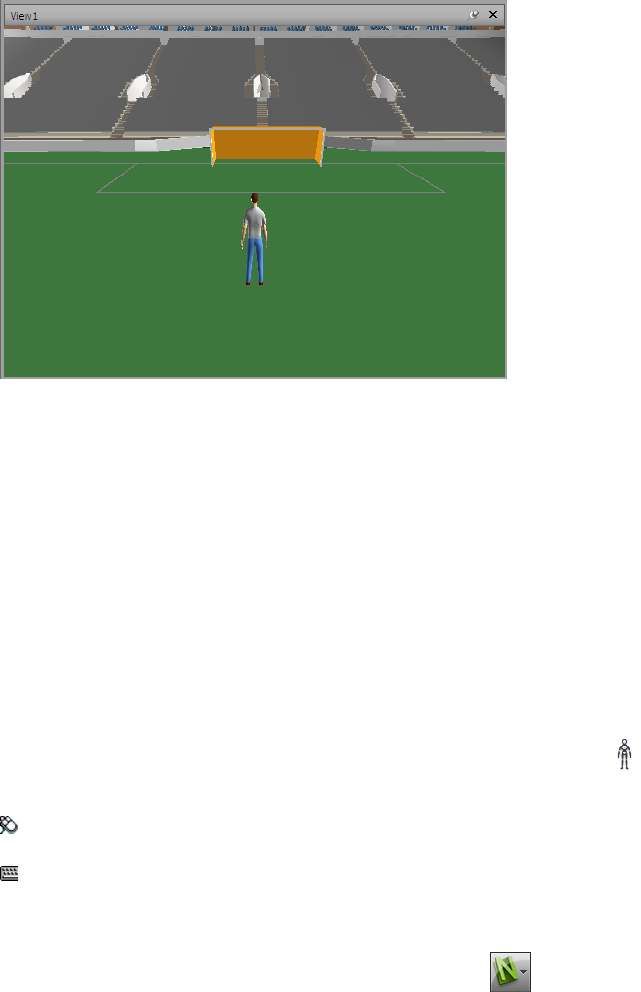
Using third person in connection with collision and gravity makes this a very
powerful function, allowing you to visualize exactly how a person would
interact with the intended design.
You can customize settings, such as avatar selection, dimension, and
positioning, for the current viewpoint or as a global option.
When third person view is turned on, rendering prioritization is changed so
that objects around the camera or avatar are displayed with much higher detail
than normal. The size of the region of high detail is based on collision volume
radius, speed of movement (needing to see what is about to be walked into)
and the distance of the camera behind the avatar (in order to see what the
avatar is interacting with).
To toggle third person view
1Click Viewpoint tab ➤ Navigate panel ➤ Realism drop-down
➤ Third Person check box.
Menu: Classic user interface: Viewpoint ➤ Navigation Tools ➤ Third
Person
Command entry: CTRL + T
To change the default avatar
1In Autodesk Navisworks, click the application button ➤ Options.
Control the Realism of Your Navigation | 179

2In the Options Editor, expand the Interface node, and click the
Viewpoint Defaults option.
3Click the Settings button in the Collision area.
4In the Default Collision dialog box, select the Enable check box in
the Third Person area.
5Click OK to return to the Options Editor.
6Click OK.
7Restart Autodesk Navisworks
To change an avatar for the current viewpoint
1In Autodesk Navisworks, click Viewpoint tab ➤ Save, Load &
Playback panel ➤ Edit Current Viewpoint on the ribbon.
2In the Edit Viewpoint dialog box, click the Settings button in the
Collision area.
3In the Collision dialog box, select the Enable check box in the Third
Person area.
4Select a new avatar in the Avatar drop-down list.
5Click OK to return to the Edit Viewpoint dialog box.
6Click OK.
180 | Chapter 5 Explore Your Model

Control Model
Appearance and
Render Quality
Control Model Appearance
You can use the tools on the Render Style panel on the Viewpoint tab to
control how your model is displayed in the Scene View.
You have a choice of one of four interactive lighting modes (Full Lights, Scene
Lights, Head Light, or No Lights), four rendering modes (Full Render,
Shaded, Wireframe, or Hidden Line) and you can individually turn each
of the five primitive types (Surfaces, Lines, Points, Snap Points, and Text)
on and off.
NOTE Render and Lighting modes are not available in a 2D workspace.
Select Render Mode
Rendering shades the scene’s geometry using the lighting you’ve set up, and
the materials and environmental settings (such as background) you’ve applied.
In Autodesk Navisworks, you can use four render modes to control how the
items are rendered in the Scene View. The spheres below demonstrate the
effect that the render modes have on model appearance. In order from the left,
these are Full Render, Shaded, Wireframe, and Hidden Line.
6
181
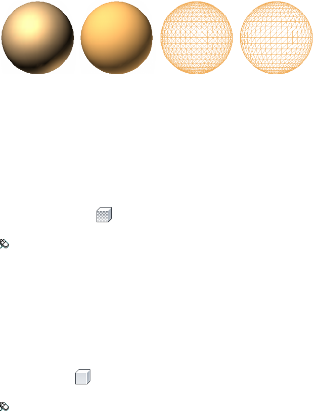
Full Render
In Full Render mode, the model is rendered with smooth shading including
any materials that have been applied using the Presenter tool, or have been
brought through from the native CAD file.
To select Full Render mode
■Click Viewpoint tab ➤ Render Style panel ➤ Mode drop-down, and
click Full Render .
Menu: Classic user interface: Viewpoint ➤ Rendering ➤ Full Render
Shaded
In Shaded mode, the model is rendered with smooth shading and without
textures.
To select Shaded mode
■Click Viewpoint tab ➤ Render Style panel ➤ Mode drop-down, and
click Shaded .
Menu: Classic user interface: Viewpoint ➤ Rendering ➤ Shaded
Wireframe
In Wireframe mode, the model is rendered in wireframe. As Autodesk
Navisworks uses triangles to represent surfaces and solids, all triangle edges
are visible in this mode.
182 | Chapter 6 Control Model Appearance and Render Quality
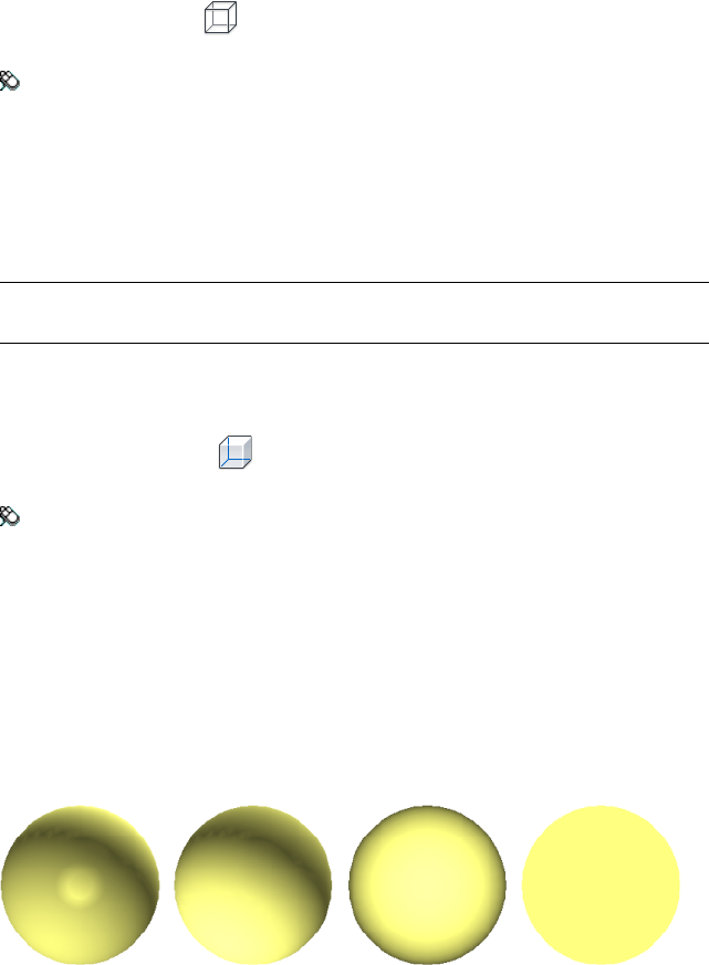
To select Wireframe mode
■Click Viewpoint tab ➤ Render Style panel ➤ Mode drop-down, and
click Wireframe .
Menu: Classic user interface: Viewpoint ➤ Rendering ➤ Wireframe
Hidden Line
In Hidden Line mode, the model is rendered in wireframe, but only the
outline and facet edges of surfaces that are visible to the camera are displayed.
NOTE Unlike wireframe mode, where surfaces are rendered transparent, hidden
line mode renders surfaces opaque.
To select Hidden Line mode
■Click Viewpoint tab ➤ Render Style panel ➤ Mode drop-down, and
click Hidden Line .
Menu: Classic user interface: Viewpoint ➤ Rendering ➤ Hidden Line
Add Lighting
In Autodesk Navisworks, you can use four lighting modes to control how the
3D scene is lit.
The spheres below demonstrate the effect the lighting styles have on them.
In order from the left, these are Full Lights, Scene Lights, Head Light,
and No Lights.
Control Model Appearance | 183
Full Lights
This mode uses lights that have been defined with the Presenter tool.
To use lights defined with the Presenter tool
■Viewpoint tab ➤ Render Style panel ➤ Lighting drop-down, and
click Full Lights .
Menu: Classic user interface: Viewpoint ➤ Lighting ➤ Full Lights
Scene Lights
This mode uses the lights that have been brought through from the native
CAD file. If no lights are available, two default opposing lights are used instead.
You can customize the intensity of scene lights in the File Options dialog
box.
To use lights defined with the model
■Click Viewpoint tab ➤ Render Style panel ➤ Lighting drop-down,
and click Scene Lights .
Menu: Classic user interface: Viewpoint ➤ Lighting ➤ Scene Lights
To adjust scene lights intensity
1Click Home tab ➤ Project panel ➤ File Options .
2In the File Options dialog box, click the Scene Lights tab.
3Move the Ambient slider to adjust the brightness of the scene.
TIP Turning on scene lights mode before following this procedure lets you
instantly see the effect your changes have on the scene rendering.
4Click OK.
184 | Chapter 6 Control Model Appearance and Render Quality
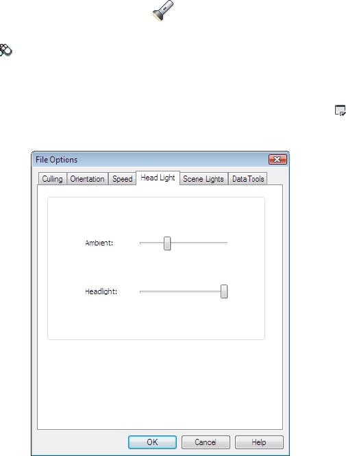
Head Light
This mode uses a single directional light located at the camera that always
points in the same direction as the camera.
You can customize the Head Light properties in the File Options dialog
box (Home tab ➤ Project panel).
To use Head Light mode
■Click Viewpoint tab ➤ Render Style panel ➤ Lighting drop-down,
and click Head Light .
Menu: Classic user interface: Viewpoint ➤ Lighting ➤ Head Light
To adjust Head Light intensity
1Click Home tab ➤ Project panel ➤ File Options .
2In the File Options dialog box, click the Headlight tab.
3Move the Ambient slider to adjust the brightness of the scene, and the
Headlight slider to adjust the brightness of the directional light.
Control Model Appearance | 185
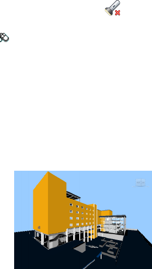
TIP Turning on Head Light mode before following this procedure lets you
instantly see the effect your changes have on the scene rendering.
4Click OK.
No Lights
This mode switches off all lights. The scene is shaded with flat rendering.
To turn off all lights
■Click Viewpoint tab ➤ Render Style panel ➤ Lighting drop-down,
and click No Lights .
Menu: Classic user interface: Viewpoint ➤ Lighting ➤ No Lights
Select Background Effect
In Autodesk Navisworks, you can choose a background effect to use in the
Scene View.
Currently, the following options are available:
■Plain - the background of the scene is filled with the selected color. This
is the default background style. It can be used for 3D models and 2D sheets.
Plain background
■Graduated - the background of the scene is filled with a smooth gradient
between the two selected colors. This background can be used for 3D
models and 2D sheets.
186 | Chapter 6 Control Model Appearance and Render Quality
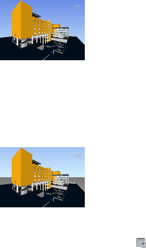
Graduated background
■Horizon - the background of the 3D scene is split across the horizontal
plane giving the effect of a sky and the ground. The resulting artificial
horizon gives you an indication of your orientation in the 3D world. By
default, the artificial horizon respects the world up vector as set in File
Options ➤ Orientation. This background is not supported for 2D sheets.
NOTE The artificial horizon is a background effect, and does not include a
physical ground plane. So, for example, if you navigate “under the ground”
and look up, you will not see the back of a ground plane, instead you will see
the model from beneath, and a background filled with the sky color.
Horizon background
To set a plain background
1Click View tab ➤ Scene View ➤ Background .
2In the Background Settings dialog box, select Plain in the Mode
drop-down list.
3Select the required color from the Color palette.
4Review the new background effect in the preview box, and click OK.
Control Model Appearance | 187
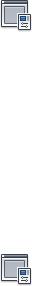
To set a graduated background
1Click View tab ➤ Scene View ➤ Background .
2In the Background Settings dialog box, select Graduated in the
Mode drop-down list.
3Select the first color from the Top Color palette.
4Select the second color from the Bottom Color palette.
5Review the new background effect in the preview box, and click OK.
To set an artificial horizon background for a 3D model
1Click View tab ➤ Scene View ➤ Background .
2In the Background Settings dialog box, select Horizon in the Mode
drop-down list.
3To set a graduated sky color, use the Sky Color and Horizon Sky
Color palettes.
4To set a graduated ground color, use the Horizon Ground Color and
Ground Color palettes.
5Review the new background effect in the preview box, and click OK.
Adjust Displaying of Primitives
You can enable and disable the drawing of Surfaces, Lines, Points, Snap
Points, and 3D Text in the Scene View.
Points are “real” points in the model, whereas Snap Points mark locations
on other primitives, for example the center of a circle, and are useful for
snapping to when measuring.
Surfaces
Surfaces are the triangles that make up the 2D and 3D items in the scene. You
can toggle the rendering of surfaces in the model.
188 | Chapter 6 Control Model Appearance and Render Quality
To toggle the rendering of surfaces
■Click Viewpoint tab ➤ Render Style panel ➤ Mode drop-down, and
click Surfaces .
Menu: Classic user interface: Viewpoint ➤ Display ➤ Surfaces
Lines
You can toggle the rendering of lines in the model. You can also change the
width of the drawn lines by using the Options Editor.
To toggle the rendering of lines
■Click Viewpoint tab ➤ Render Style panel ➤ Lines .
Menu: Classic user interface: Viewpoint ➤ Display ➤ Lines
To change the line width
1Click the application button ➤ Options.
2In the Options Editor, expand the Interface node, and click the
Display options.
3On the Display page, Primitives area, enter a number between 1 and
9 in the Line Size box.
This sets the width in pixels for lines drawn in the Scene View.
4Click OK.
Points
Points are real points in the model, for example, the points in a point cloud
in a laser scan file. You can toggle the rendering of points in the model. You
can also change the size of drawn points by using the Options Editor.
To toggle the rendering of points
■Click Viewpoint tab ➤ Render Style panel ➤ Points .
Control Model Appearance | 189
Menu: Classic user interface: Viewpoint ➤ Display ➤ Points
To change the size of points
1Click the application button ➤ Options.
2In the Options Editor, expand the Interface node, and click the
Display option.
3On the Display page, Primitives area, enter a number between 1 and
9 in the Point Size box.
This sets the size in pixels for points drawn in the Scene View.
4Click OK.
Snap Points
Snap points are implied points in the model, for example, the center point of
a sphere or end points of a pipe. You can toggle the rendering of snap point
in the 3D model. You can also change the size of the drawn snap points by
using the Options Editor.
NOTE You cannot toggle the rendering of snap points for 2D sheets.
To toggle the rendering of snap points
■Click Viewpoint tab ➤ Render Style panel ➤ Snap Points .
To change the size of snap points
1Click the application button ➤ Options.
2In the Options Editor, expand the Interface node, and click the
Display option.
3On the Display page, Primitives area, enter a number between 1 and
9 in the Snap Size box.
This sets the size in pixels of snap points drawn in the Scene View.
4Click OK.
190 | Chapter 6 Control Model Appearance and Render Quality
Text
You can toggle the rendering of text in 3D models. This functionality is not
supported for 2D sheets.
To toggle the rendering of 3D text
■Click Viewpoint tab ➤ Render Style panel ➤ Text .
Menu: Classic user interface: Viewpoint ➤ Display ➤ Text
Control Render Quality
Use Culling
Culling lets you navigate and manipulate large and complex scenes at
interactive rates by intelligently hiding less-important objects as you work.
In Autodesk Navisworks, you can use the following methods of culling objects:
■Area - the objects’ size in pixels determines whether the objects are
rendered or not. By default, any objects smaller than 1x1 pixels in size are
discarded.
■Backface - by default, only the front face of every polygon is drawn in
Autodesk Navisworks. Sometimes, during the conversion process the front
and back face of polygons get mixed, in which case, you need to adjust
the Backface option.
■Near and Far Clipping Planes (frustum culling) - objects closer to the
camera than the near clipping plane or beyond the far clipping plane are
not drawn. You can let Autodesk Navisworks automatically constrain the
location of the clipping planes, or you can constrain their location
manually.
NOTE Backface and Clipping Planes are not used in a 2D workspace.
To set area culling
1Click Home tab ➤ Project panel ➤ File Options .
2In the File Options dialog box, Culling tab, select the Enable check
box in the Area section.
Control Render Quality | 191

3Enter a value for the screen area in pixels below which geometry objects
are culled. For example, setting this value to 100 pixels means that any
object within the model that would be drawn less than 10x10 pixels in
size are discarded.
4Click OK.
To turn on backface culling for all objects in a 3D workspace
1Click Home tab ➤ Project panel ➤ File Options .
2In the File Options dialog box, Culling tab, select On in the Backface
area.
3Click OK.
To turn off backface culling for all objects in a 3D workspace
1Click Home tab ➤ Project panel ➤ File Options .
2In the File Options dialog box, Culling tab, select Off in the Backface
area.
3Click OK.
To turn on backface culling only for solid objects in a 3D workspace
1Click Home tab ➤ Project panel ➤ File Options .
2In the File Options dialog box, Culling tab, select Solid in the
Backface area.
3Click OK.
To constrain the position of the clipping planes automatically in a 3D
workspace
1Click Home tab ➤ Project panel ➤ File Options .
2In the File Options dialog box, click the Culling tab.
3Select Automatic for the Near clipping plane.
4Select Automatic for the Far clipping plane.
5Click OK.
Autodesk Navisworks automatically controls the position of near and
far clipping planes to give you the best view of the model.
192 | Chapter 6 Control Model Appearance and Render Quality

To constrain the position of the clipping planes manually in a 3D workspace
1Click Home tab ➤ Project panel ➤ File Options .
2In the File Options dialog box, click the Culling tab.
3Select Constrained for the Near clipping plane, and enter the desired
value in the Distance box.
4Select Constrained for the Far clipping plane, and enter the desired
value in the Distance box.
5Click OK.
Autodesk Navisworks uses the provided values unless doing so affects
the system performance (for example, makes the whole model invisible),
in which case it adjusts the position of the clipping planes as necessary.
To fix the position of the clipping planes in a 3D workspace
1Click Home tab ➤ Project panel ➤ File Options .
2In the File Options dialog box, click the Culling tab.
3Select Fixed for the Near clipping plane, and enter the desired value in
the Distance box.
4Select Fixed for the Far clipping plane, and enter the desired value in
the Distance box.
5Click OK.
IMPORTANT Autodesk Navisworks uses the provided values even if doing
so affects the system performance (for example, makes the whole model
invisible).
Make Objects Required
Although Autodesk Navisworks intelligently prioritizes objects for culling in
the scene, sometimes it drops out geometry that needs to remain visible while
navigating.
You can make sure the objects are always rendered during interactive
navigation by making them required.
Control Render Quality | 193
To make objects required
1Select geometry items that you want to remain visible during navigation
in the Selection Tree.
2Click Home tab ➤ Visibility panel ➤ Require .
In the Selection Tree, the object appear red when required.
TIP Clicking Require again makes the selected objects unrequired.
Menu: Classic user interface: Edit ➤ Required
Command entry: CTRL + R
Ribbon: Item Tools tab ➤ Visibility panel ➤ Require
To make all objects unrequired
■Click Home tab ➤ Visibility panel ➤ Unhide All drop-down
➤ Unrequire All .
Shortcut menu: Scene ➤ Reset All ➤ Unrequire All
Control Rendering of Objects
Adjust Scene Rendering During Navigation
Your models can range in size from small models to complex supermodels.
As you navigate a scene in real time, Autodesk Navisworks automatically
calculates which items to render first, based on the size of items, distance from
the camera, and the specified frame rate. This customizable frame rate is
guaranteed by default, but can be turned off, if necessary. Items that Autodesk
Navisworks does not have time to render are dropped out. These dropped
items are rendered when navigation stops.
The amount of drop-out depends on several factors, such as your hardware
performance (graphics card and driver), the size of the Scene View, and the
size of the model. When working with truly large supermodels in Autodesk
Navisworks, you will require a sufficient amount of RAM to load and review
the data.
Autodesk Navisworks employs JetStream technology which optimizes the
usage of the available RAM. Before running out of memory, Autodesk
194 | Chapter 6 Control Model Appearance and Render Quality
Navisworks pages unnecessary data to the hard disk, freeing up space for
loading to continue. JetStream technology also enables you to start navigating
the supermodel, before it has been completely loaded into memory. Autodesk
Navisworks is large address aware, and utilizes any additional memory
assignment following the 3GB switch available on Windows XP systems.
TIP You can reduce the amount of drop-out during navigation by reducing frame
rate, or switching off the Guarantee Frame Rate option.
To set the target frame rate
1Click Home tab ➤ Project panel ➤ File Options .
2In the File Options dialog box, Speed tab, select the number of frames
per second to be applied to the rendered display of the model.
3Click OK.
To set the level of detail
1Click the application button ➤ Options.
2In the Options Editor, expand the Interface node, and click the
Display option.
3On the Display page, Detail area, select the Guarantee Frame Rate
check box to maintain the target frame rate during navigation. If this
check box is clear, the complete model is rendered during navigation,
no matter how long it takes.
4Select the Fill in Detail check box to render a complete model when
navigation stops. If this check box is clear, the items dropped out during
navigation are not filled in when it stops.
5Click OK.
To render transparent items
NOTE: If your video card supports hardware accelerated OpenGL, you can
turn on the rendering of transparent items during interactive navigation. By
default, transparent items are only drawn when interaction has ceased to
prevent problems with display performance.
1Click the application button ➤ Options.
Control Render Quality | 195

2In the Options Editor, expand the Interface node, and click the
Display option.
3On the Display page, Transparency area, select the Interactive
Transparency check box.
4Click OK.
To render parametric primitives
NOTE: Modifying this option requires a restart of Autodesk Navisworks to
take effect.
1Click the application button ➤ Options.
2In the Options Editor, expand the Interface node, and click the
Display option.
3On the Display page, Primitives area, select the Enable Parametric
Primitives check box. The level of detail changes during navigation
depending on the distance from the camera.
If you want to use the default representations of primitives, clear this
check box. The level of detail stays the same during navigation.
Click OK.
Accelerate Display Performance
If your video card supports OpenGL, you can improve the graphical
performance by turning on hardware acceleration and occlusion culling.
Using the hardware acceleration usually gives you better and faster rendering.
However, some graphics cards may not function well in this mode in which
case switching this option off is recommended.
Occlusion culling can significantly improve performance in situations when
much of the model is not visible. For example, when you walk down the
corridor of a building, the walls occlude most geometry outside the corridor.
Other rooms are only visible through doorways or windows. Turning on
occlusion culling dramatically reduces the rendering load in such cases.
196 | Chapter 6 Control Model Appearance and Render Quality
To use hardware acceleration
NOTE: If your video card does not support OpenGL hardware acceleration,
this option is not available.
1Click the application button ➤ Options.
2In the Options Editor, expand the Interface node, and click the
Display option.
3On the Display page, Acceleration area, select the Hardware
Acceleration check box. This allows Autodesk Navisworks to utilize
any available OpenGL hardware acceleration on your video card.
NOTE If your video card drivers do not function well with Autodesk
Navisworks, clear this check box.
4Click OK.
To use occlusion culling
1Click the application button ➤ Options.
2In the Options Editor, expand the Interface node, and click the
Display option.
3On the Display page, Acceleration area, select the Occlusion Culling
check box.
4Click OK.
NOTE Occlusion culling can only be used on a machine with an OpenGL 1.5
compliant graphics card. Also, occlusion culling is not used in a 2D workspace.
Adjust Presenter Materials
You can adjust the appearance of Presenter materials in the Scene View to
get optimum performance from your graphics card when navigating around
heavily textured scenes.
See also:
Presenter Page
Control Render Quality | 197
Stereo Rendering
Stereoscopic viewing in Autodesk Navisworks allows the viewing of the 3D
model through stereo-enabled hardware, including active and passive stereo
viewing glasses in conjunction with both CRT screens and dedicated projectors.
IMPORTANT Using stereo rendering requires the host computer have an OpenGL
graphics card with stereo support. Additionally, some drivers require stereo to be
explicitly enabled in the driver and may require lower color or resolution settings
before the stereo rendering becomes available.
When the video output is in stereo mode, the view looks blurred without the
correct glasses being worn. If the camera is in orthographic mode, it needs to
be set to perspective for the effect to work correctly.
NOTE As the view for each eye has to be rendered separately it is not possible to
support incremental filling in of detail in stereo mode. The detail appears when
rendering is complete. Progress can be seen using the bar in the status area, and
it is still possible to interrupt and start interacting again at any time.
In focal point-based navigation modes (such as orbit, free orbit and constrained
orbit) the model is positioned so that parts closer than the focal point appear
in front of the screen, with the rest behind. In other navigation modes (such
as walk and fly), the focal point is set so that any avatar will be level with the
screen. Objects between you and the avatar will appear in front of the screen.
You can adjust the out of screen effect in the Stereo Options dialog box.
To enable stereo rendering
■Click View tab ➤ Stereo panel ➤ Enable Stereo .
NOTE This option is only available if you have the required hardware, and the
correct driver and display settings.
To adjust the stereo effects
1Click View tab ➤ Stereo panel ➤ Stereo Options tool launcher .
2In the Stereo Options dialog box, move the Magnitude slider to vary
the strength of the effect.
3To adjust the out of screen effect, select the Enable check box, and then
move the slider to control how much of the scene appears out of the
screen during navigation.
198 | Chapter 6 Control Model Appearance and Render Quality
4If you need to swap the left and right eyes over, select the Swap Eyes
check box. This can be useful when moving from CRT to a large screen
projector and back.
5Click OK.
Control Render Quality | 199
200

Review Your Model
Select Objects
Autodesk Navisworks provides several methods to interactively select items.
Interactive Geometry Selection
In Autodesk Navisworks, there is a concept of an active selection set (the
currently selected items, or the current selection) and saved selections sets. You
cannot save any selection or search sets yourself, but you can use the selection
or search sets saved in the model (the Sets tab on the Selection Tree).
Selecting items makes them part of the current selection, so you can hide them
or override their colors.
You can use several methods to interactively select items into the current
selection. You can use the tabs in the Selection Tree, select items directly in
the Scene View with the Select and Select Box tools, and you can select
other items with similar properties to an existing selection using the selection
commands.
NOTE Right-clicking any item in the Selection Tree or Scene View opens a
shortcut menu.
7
201
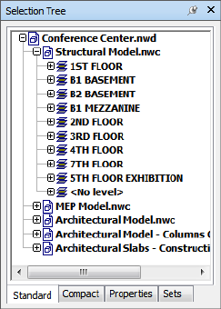
Selection Tree Window
The Selection Tree is a dockable window, which displays a variety of
hierarchical views of the structure of the model, as defined by the CAD
application in which the model was created.
Autodesk Navisworks uses this hierarchical structure to identify object-specific
paths (from the file name down to a particular object).
By default there are four tabs:
■Standard. Displays the default tree hierarchy, including all instancing.
■Compact. Displays a simplified version of the hierarchy on the Standard
tab, omitting various items. You can customize the level of complexity of
this tree in the Options Editor.
■Properties. Displays the hierarchy based on the items' properties. This
enables simple manual searching of the model by item property.
■Sets. Displays a list of selection and search sets. If no selection and search
sets have been created, this tab is not shown.
Naming of items reflects the names from the original CAD application,
wherever possible. You can copy and paste names from the Selection Tree.
To do this, right-click an item in the Selection Tree, and click Copy Name
on the context menu. Alternatively, you can click an item in the Selection
Tree, and press CTRL + C. The name is now copied to the clipboard.
202 | Chapter 7 Review Your Model
There are different tree icons representing the types of geometry making up
the structure of the model. Each of these item types can be marked as hidden
(gray), unhidden (dark blue) or required (red).
NOTE If a group is marked as hidden or required, then all instances of that group
are marked as hidden or required. If you want to operate on a single occurrence
of an item, then you should mark the instanced group (the level above, or the
“parent”, in the hierarchy) hidden or required.
To toggle the Selection Tree
■Click Home tab ➤ Select & Search panel ➤ Selection Tree .
Menu: Classic user interface: View ➤ Control Bars ➤ Selection Tree
Command entry: CTRL + F12
To use the Selection Tree to select objects
1Open the Selection Tree, and click the Standard tab.
2Click an object in the Selection tree to select the corresponding
geometry in the Scene View.
NOTE When you select an item in the tree, individual geometry or a group
of geometry is selected in the Scene View depending on chosen selection
resolution.
3To select several items at the same time, use the SHIFT and CTRL keys.
CTRL allows multiple selection item by item, and SHIFT allows multiple
selection between the first and last items selected.
4To remove selection from an object in the Selection Tree press ESC.
To customize the contents of the Compact tab
1Click the application button ➤ Options.
2In the Options Editor, expand the Interface node, and click the
Selection option.
3On the Selection page, select the required level of detail in the
Compact Tree box. Choose from the following options:
■Models - the tree is restricted to displaying model files only.
■Layers - the tree can be expanded down to the layer level.
Select Objects | 203
■Objects - can be expanded down to the objects level, but without
the levels of instancing shown on the Standard tab.
4Click OK.
DescriptionIcon
A model, such as a drawing file or design
file.
A layer or level.
A group, such as a block definition from
AutoCAD or cell definition from MicroSta-
tion.
An instanced group, such as an inserted
block from AutoCAD or cell from MicroSta-
tion. If in the imported file the instance was
unnamed, Autodesk Navisworks names the
instance to match its child's name.
An item of geometry, such as a polygon.
An instanced item of geometry, such as an
instance from 3D Studio.
A composite object. A single CAD object
that is represented in Autodesk Navisworks
by a group of geometry items.
Saved selection set.
Saved search set.
204 | Chapter 7 Review Your Model
Selection Tools
There are two selection tools (Select and Select Box ) available from
Home tab ➤ Select & Search panel to control the way you select geometry.
Typically, using selection tools is mutually exclusive to using navigation tools
(see Product-Specific Navigation Tools (page 107), so that when you are selecting
you cannot navigate and vice versa.
NOTE When using a 3Dconnexion 3D mouse in conjunction with the standard
mouse control, the 3Dconnexion device can be configured for navigation and the
mouse for selecting. See 3Dconnexion 3D Mouse (page 164) for more information.
Selecting geometry in the Scene View automatically selects the corresponding
objects in the Selection Tree.
Holding the SHIFT key whilst selecting items in the Scene View cycles
through the selection resolution, allowing you to get more specific with your
selections.
You can use the Options Editor to customize the distance from an item you
have to be for it to be selected (pick radius). This is useful when you select
lines and points.
Select Tool
The Select tool lets you select items in the Scene View with a mouse click.
The tool is activated by clicking Home tab ➤ Select & Search panel
➤ Select drop-down ➤ Select . Once a single item is selected, its
properties are shown in the Properties window.
Select Box Tool
In select box mode, you can select multiple items in the model by dragging
a rectangular box around the area you want to make your current selection.
To select geometry with the Select tool
1Click Home tab ➤ Select & Search panel ➤ Select drop-down
➤ Select .
2Click an item in the Scene View to select it.
Select Objects | 205
3To select multiple geometry, press and hold down the CTRL key while
clicking items in the scene.
4To remove items from the current selection, hold down the CTRL key
while clicking them again. Alternatively, press the ESC key to remove
all items from the current selection.
Menu: Classic user interface: Edit ➤ Select ➤ Select
Command entry: CTRL + 1
To select geometry with the Select Box tool
1Click Home tab ➤ Select & Search panel ➤ Select drop-down
➤ Select Box .
2Drag a box with the left mouse button over the Scene View to select
all items within the box.
TIP Holding down the SHIFT key while dragging the box selects all items
within and that intersect the box.
3To select multiple geometry, press and hold down the CTRL key while
dragging a box in the scene.
4To remove items from the current selection, press the ESC key.
To set the pick radius
1Click the application button ➤ Options.
2In the Options Editor, expand the Interface node, and click the
Selection option.
3On the Selection page, enter the radius in pixels that an item has to
be within in order to be selected. The valid values are between 1 and 9.
4Click OK.
Selection Commands
Selection commands enable you to quickly alter the current selection using
logic. You can select multiple items based on the currently selected items’
properties, or quickly invert the set, select everything or nothing.
206 | Chapter 7 Review Your Model

To select all items within the model
■Click Home tab ➤ Select & Search panel ➤ Select All drop-down
➤ Select All .
To deselect all items
■Click Home tab ➤ Select & Search panel ➤ Select All drop-down
➤ Select None .
To invert your current selection
■Click Home tab ➤ Select & Search panel ➤ Select All drop-down
➤ Invert Selection .
Currently selected items become deselected, and currently deselected items
become selected.
To select all instances of the selected geometry group
■Click Home tab ➤ Select & Search panel ➤ Select Same drop-down
➤ Select Multiple Instances .
To select all items with the same name as the currently selected item
1Click Home tab ➤ Select & Search panel ➤ Select Same drop-down
➤ Same Name .
To select all items with the same type as the currently selected item
■Click Home tab ➤ Select & Search panel ➤ Select Same drop-down
➤ Same Type .
To select all items with the same property as the currently selected item
■Click Home tab ➤ Select & Search panel ➤ Select Same drop-down
➤ Same <Property>.
To use a saved selection or search set
■Open the Selection Tree window, and click the Sets tab.
Select Objects | 207
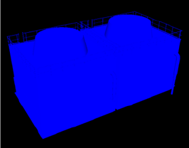
The selection commands are as follows:
■Select All. Selects all items contained within the model.
■Select None. Deselects everything in the model.
■Invert Selection. Currently selected items become deselected and vice
versa.
■Select Multiple Instances. Selects all instances (sometimes called
insertions) of the currently selected geometry group that occur in the
model.
■Select Same Name. Selects all items in the model that have the same
name as the currently selected item.
■Select Same Type. Selects all items in the model that have the same type
as the currently selected item.
■Select Same <Property>. Selects all items with the same property as the
currently selected item. This property can be any searchable property
currently attached to the item, for example material or link.
NOTE Using the Select Same <Property> command works by comparing
items' properties. If you have multiple items selected when you perform a
selection command of same name or type and so on, all the types, names and
properties of the items in the current selection are compared with all items’
properties in the scene. The items with properties matching any properties of
the currently selected items are selected.
Set Highlighting Method
You can use the Options Editor to customize color and method of
highlighting geometry selected in the Scene View.
There are three types of highlighting:
■Shaded
208 | Chapter 7 Review Your Model
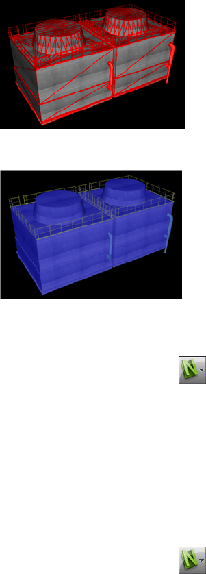
■Wireframe
■Tinted
To toggle highlighting of selected objects
1Click the application button ➤ Options.
2In the Options Editor, expand the Interface node, and click the
Selection option.
3On the Selection page, Highlight area, select the Enabled check box,
if you want the selected items to be highlighted in the Scene View.
Clear this check box, if you don’t want any highlighting.
4Click OK.
To customize the way objects are highlighted
1Click the application button ➤ Options.
2In the Options Editor, expand the Interface node, and click the
Selection option.
3Make sure the Enabled check box is selected.
Select Objects | 209
4Use the Method drop-down list to select the type of highlighting you
want (Shaded, Wireframe or Tinted).
5Click the Color palette to select the highlight color.
6If you selected Tinted in the Method box, use the slider to adjust the
Tint Level.
7Click OK.
Hide Objects
Autodesk Navisworks provides tools that can be used to hide and display
objects or groups of objects. Hidden objects are not drawn in the Scene View.
Hide Selected Objects
You can hide the objects in the current selection so that they are not drawn
in the Scene View. This is useful when you want to remove specific parts of
the model. For example, when you walk down the corridor of building, you
may want to hide a wall that occlude your view of the next room.
Hide Unselected Objects
You can hide all items except those currently selected so that they are not
drawn in the Scene View. This is useful when you only want to see specific
parts of the model.
NOTE In the Selection Tree, the items appear gray when marked as hidden.
To hide selected objects
1In the Scene View, select all items you want to hide.
2Click Home tab ➤ Visibility panel ➤ Hide .
The selected objects are now invisible.
TIP Clicking Hide again displays the invisible objects.
Menu: Classic user interface: Edit ➤ Hidden
Command entry: CTRL + H
Shortcut menu: Hide
210 | Chapter 7 Review Your Model
To make unselected items hidden
1In the Scene View, select all items you want to review.
2Click Home tab ➤ Visibility panel ➤ Hide Unselected .
Only the selected geometry remains visible.
TIP Clicking Hide Unselected again displays the invisible objects.
Menu: Classic user interface: Edit ➤ Hide Unselected
Shortcut menu: Hide Unselected
To reveal all hidden objects
■Click Home tab ➤ Visibility panel ➤ Unhide All drop-down
➤ Unhide All .
Shortcut menu: Scene ➤ Reset All ➤ Unhide All
Find Objects
You can run simple manual searches of the model by item property. To do
this:
■On the Selection Tree, click the Properties tab, and click the saved
property search in the list.
The corresponding model geometry is selected in the Scene View.
Quick Find
To locate and select the objects quickly, use the Quick Find feature.
To quickly find items
1Click Home tab ➤ Select & Search panel.
2In the Quick Find text box, type in the string to search for in all item’s
properties. This can be a word or a few words. The search is not
case-sensitive.
3Click Quick Find . Autodesk Navisworks finds and selects the first
item in the Selection Tree that matches the entered text, selects it in
the Scene View, and stops the search.
Find Objects | 211
4To find more items, click Quick Find again. If there are any more
items that match the entered text, Autodesk Navisworks selects the next
one in the Selection Tree, selects it in the Scene View, and stops the
search. Subsequent clicks find next instances.
Command entry: To open the Quick Find dialog box: CTRL + F. To
Find Next: F3
Find All Sheets and Models Containing the
Selected Object
You can search for an object across all prepared sheets/models in the Project
Browser.
Models exported into Autodesk Navisworks can be integrated with 2D sheets
exported from the same design application to form a multi-sheet file. For
example models exported from Autodesk Revit to the NWC, DWF or DWF(x)
file format can be integrated with any 2D sheets exported to DWF/DWF(x)
files from the same Revit project. This allows you to select a model component
in the 3D environment, and then to find and review the same component in
a 2D representation (such as a floor plan or section). Similarly, you can select
an item in your 2D sheet and find it in the 3D model and other 2D sheets.
Preparing Sheets/Models for Searching
When you open a multi-sheet file, not all sheets/models may have been
prepared to be used in Autodesk Navisworks. All sheets/models which require
preparation are indicated with the Prepare icon in the Project Browser
window. You can use the Project Browser shortcut menu to prepare one
or more sheets/models (see Project Browser Window (page 100), or you can
prepare all sheets/models directly in the Find Items in Other Sheets and
Models window. Autodesk Navisworks only searches prepared sheets/models.
So if some sheets/models in your file have not been prepared, they will not
be included in the search.
212 | Chapter 7 Review Your Model
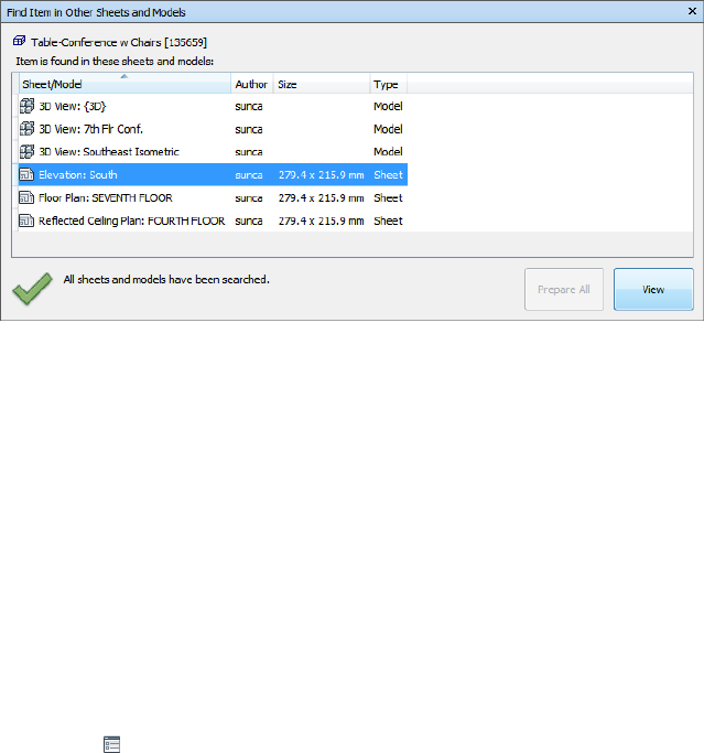
Find Items in Other Sheets and Models
Window
The Find Items in Other Sheets and Models is a dockable window that
enables you to search for an object across all prepared sheets/models in the
Project Browser.
The label at the top of the window indicates the object currently selected in
the Scene View. The geometry type is represented with an icon (page 204)
next to the object's name. The icons are the same as the icons used on the
Selection Tree window. The search results are displayed in the Sheets/Models
list, and contain all sheets/models in the currently open file where the selected
object has been found. You can sort the results by clicking the heading of the
desired column. This alternates the sort order between ascending and
descending.
To toggle the Find Item in Other Sheets and Models window
■Click View tab ➤ Workspace panel ➤ Windows drop-down, and
select or clear the Find Item in Other Sheets and Models check box.
To find all sheets and models containing the selected object
1Click on the Status bar to open the Project Browser window.
2Double-click the sheet or model with the object you want to locate in
other sheets and models, and select it in the Scene View .
Find All Sheets and Models Containing the Selected Object | 213
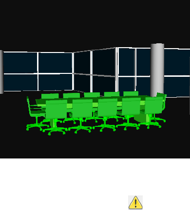
3Right-click the object, and click Find Item in Other Sheets and
Models on the shortcut menu.
4If you see a warning status icon in the Find Item in Other Sheets
and Models window, click the Prepare All button. Once all
sheets/models have been prepared, you will see a list of all sheets/models
that contain the object.
5Select the sheet/model in the list, and click View to open it. Autodesk
Navisworks zooms you to the selected object.
214 | Chapter 7 Review Your Model
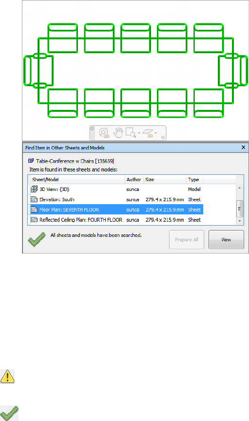
Buttons
Prepare All Prepares all unprepared sheets and models in the currently open
multi-sheet file.
View Opens the currently selected sheet or model in the Scene View.
Status Icons
Not all sheets/models can be searched in the currently open multi-sheet
file; at least one sheet or model has not yet been prepared.
All sheets/models in the currently open multi-sheet file have been
searched, and the results are up-to-date.
Find All Sheets and Models Containing the Selected Object | 215
Use Sets of Objects
In Autodesk Navisworks, you cannot save any selection or search sets yourself,
but you can use the selection or search sets saved in the model.
Selection sets store a group of items for later retrieval. There is no intelligence
behind this set - if the model changes at all, the same items will be selected
(assuming they are still available in the model) when recalling the selection
set.
Search sets work in a similar way, except that they save search criteria instead
of the results of a selection. So, if there are any search sets saved in the model,
then you use them in Autodesk Navisworks to run the search and select the
resulting objects.
Selection and search sets can be named and contain comments. They can also
be highlighted with icons in the Scene View, so that when you click on one,
the selection set is restored to the active set and all the items within it are
re-selected.
To select items from a selection or search set
1Open the Selection Tree window, and click the Sets tab.
2Click the saved selection or search set from the list.
On recalling a selection set, all the items that were selected when the
set was saved are re-selected into the current selection.
On recalling a search set, the search that was saved into the set is re-run
and any items matching the specification are selected into the current
selection.
Object Properties
Properties Window
The Properties window is a dockable window, which has a dedicated tab for
each property category associated with the currently selected object.
216 | Chapter 7 Review Your Model
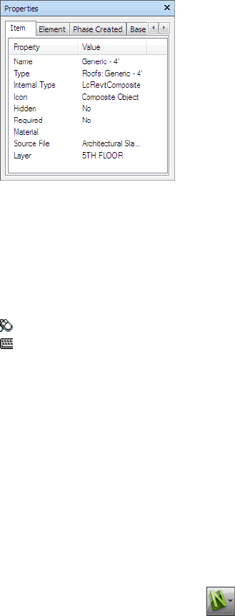
Internal file properties, such as transform and geometry properties, are not
shown by default. The Options Editor enables you to switch this on.
To toggle the Properties window
■Click View tab ➤ Workspace panel ➤ Windows drop-down, and
select or clear the Properties check box.
Menu: Classic user interface: View ➤ Control Bars ➤ Properties
Command entry: SHIFT + F7
To examine object properties
1Select the object of interest in the Selection Tree, or in the Scene
View.
2Open the Properties window, and use the tabs to navigate between
the available property categories.
NOTE If more than one object is selected, the Properties window only
shows the number of selected items, and doesn’t show any property
information.
To add tabs with internal properties to the Properties window
1Click the application button ➤ Options.
2In the Options Editor, expand the Interface node, and click the
Developer option.
3On the Developer page, select the Show Internal Properties check
box.
Object Properties | 217
4Click OK.
Reset Object Attributes
In Navisworks Freedom 2012, you have an option of resetting object attributes
back to the state they were in when imported from the original CAD files.
This will remove any color, transparency and transform overrides that may
have been applied in Navisworks Manage or Navisworks Simulate.
Reset to Original Values
In Autodesk Navisworks, you can reset object attributes back to the values in
the original CAD files.
To restore original appearance of an object or a group of objects in your scene
Note: You cannot restore colors separately from transparencies.
1Select the required objects in the Scene View.
2Click Item Tools tab ➤ Appearance panel ➤ Reset Appearance .
To reset appearance of all objects in your scene
Note: You cannot restore colors separately from transparencies.
■Click Home tab ➤ Project panel ➤ Reset All drop-down ➤ Appearances
.
To reset transform for an object or a group of objects in your scene
1Select the required objects in the Scene View.
2Click Item Tools tab ➤ Transform panel ➤ Reset Transform .
To reset transform for all objects in your scene
■Click Home tab ➤ Project panel ➤ Reset All drop-down ➤ Transforms
.
218 | Chapter 7 Review Your Model
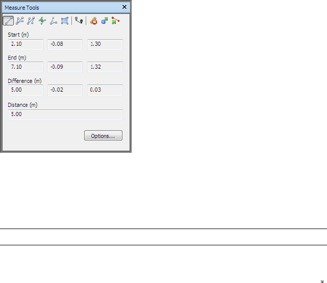
Measure Tools
Measure tools enable you to measure between points on items in the model.
All measurements are made in display units (page 91).
Using measure tools is mutually exclusive to using navigation tools (see
Product-Specific Navigation Tools (page 107)), so that when you are measuring
you cannot navigate and vice versa.
Measure Tools Window
The Measure Tools window is a dockable window, which contains a number
of buttons at the top enabling you to select the type of measurement you
want to do.
For all measurements, the X, Y, and Z coordinates of the Start point and End
point are displayed in the text boxes underneath the buttons, together with
the Difference and the absolute Distance. If you use accumulative measure,
such as Point Line or Accumulate, Distance shows the accumulated distance
for all points registered in the measurement.
NOTE Z coordinate values are not available for 2D sheeets.
To toggle the Measure Tools window
■Click Review tab ➤ Measure panel ➤ Measure Options tool launcher
.
Measure Tools | 219
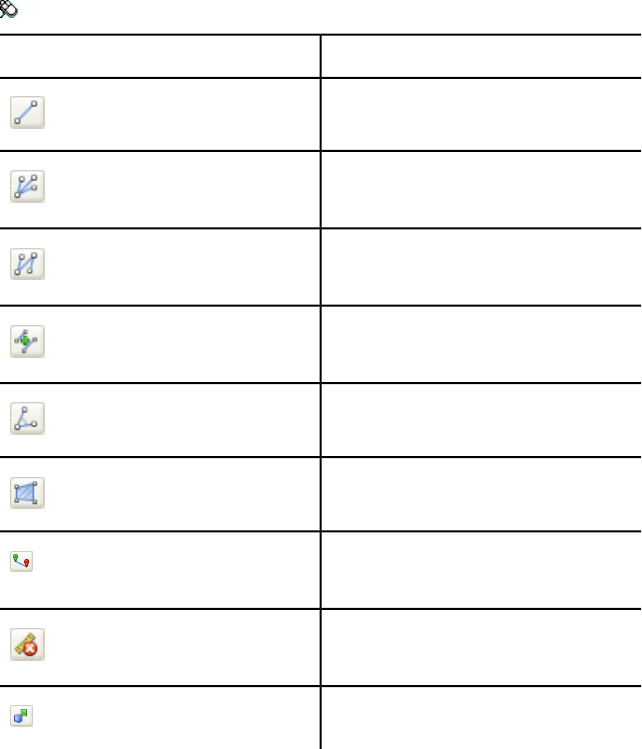
Menu: Classic user interface: Tools ➤ Measure
DescriptionButton
Measures the distance between two points.
Measures the distance between a base point
and various other points.
Measures a total distance between multiple
points along a route.
Calculates the sum total of several point-to-
point measurements.
Calculates an angle between two lines.
Calculates an area on a plane.
Measures the shortest distance between
two selected objects.
Clears all measuring lines in the Scene
View.
Enables you to move or rotate an object.
Measuring
You can use measuring tools to make linear, angular, and area measurements,
and to automatically measure the shortest distance between two selected
objects.
220 | Chapter 7 Review Your Model
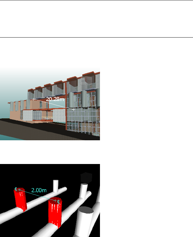
NOTE When you measure, you must click on a point on an item to register a point
- clicking on the background will not register anything. You can reset a measure
command at any time by right-clicking instead of left-clicking in the Scene View.
This starts the measure command again with no points registered, just as if you
had chosen a new measurement type.
Endpoints of standard measuring lines are represented as small cross symbols
in the Scene View, and all lines being measured by a simple line between
registered points.
Endpoints of measuring lines that are snapped to center lines are represented
as cross symbols with additional CL markers.
You can change the color and thickness of measuring lines, and toggle the
display of dimension label in the Scene View.
Dimension Labels
For distance-based measurements, the dimension label is drawn for each line
segment. For accumulative measurements, the dimension label shows the
Measure Tools | 221

totals, and is drawn for the last line segment. The text is positioned relative
to the center point of the line.
For angular measurements, an arc indicator is shown inside the angle, with
the centre of the text positioned on the invisible line bisecting the angle. If
an angle is too acute, the label is drawn outside the angle. This label is fixed,
and does not resize when you zoom in or out, unless the measuring lines
become too short on screen to accommodate the arc, in which case it will be
adjusted.
The Options Editor enables you to toggle the dimension labels on and off.
For area measurements, the dimension label is positioned at the centre of the
area being measured.
Using Measure Tools to Transform Objects
You can use measure tools to move and rotate the currently selected objects.
To change the thickness and color of measuring lines
1Open the Measure Tools window, and click Options.
2In the Options Editor, the Measure page under the Interface node,
enter the desired number into the Line Thickness box.
3Select the required color from the Color palette. By default, measuring
lines are white.
4Click OK.
To toggle the dimension labels
1Open the Measure Tools window, and click Options.
2In the Options Editor, the Measure page under the Interface node,
select the Show Measurement Values in Scene View check box.
3Click OK.
To measure a distance between two points
1Click Review tab ➤ Measure panel ➤ Measure drop-down ➤ Point
to Point .
2Click the start and end point of the distance to be measured in the Scene
View.
The optional dimension label displays the measured distance.
222 | Chapter 7 Review Your Model
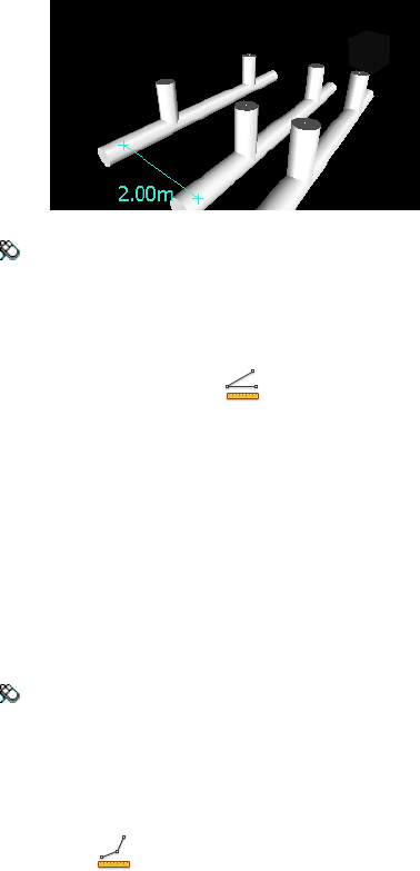
Menu: Classic user interface: Review ➤ Measure ➤ Point to Point
To keep the same start point as you measure a distance between two points
1Click Review tab ➤ Measure panel ➤ Measure drop-down ➤ Point
to Multiple Points .
2Click the start point, and the first end point to be measured. A measuring
line is displayed between two points.
3Click to register the next end point to be measured.
4Repeat this to measure additional end points if required. The optional
dimension label always displays the last measured distance. Your start
point stays the same throughout.
TIP If you want to change the start point, right-click in the Scene View,
and select a new start point.
Menu: Classic user interface: Review ➤ Measure ➤ Point to Multiple
Points
To measure a total distance along a route
1Click Review tab ➤ Measure panel ➤ Measure drop-down ➤ Point
Line .
2Click the start and the second point to be measured.
3Click the next point along the route.
4Repeat this to measure the entire route. The optional dimension label
displays the total distance along the selected route.
Measure Tools | 223
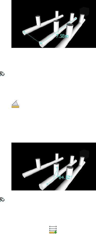
TIP If you want to change the start point, right-click in the Scene View,
and select a new start point.
Menu: Classic user interface: Review ➤ Measure ➤ Point Line
To calculate an angle between two lines
1Click Review tab ➤ Measure panel ➤ Measure drop-down ➤ Angle
.
2Click a point on the first line.
3Click the first line at the point where it intersects the second line.
4Click a point on the second line. The optional dimension label displays
the calculated angle between the two lines.
Menu: Classic user interface: Review ➤ Measure ➤ Measure Angle
To calculate the sum total of several point-to-point measurements
1Click Review tab ➤ Measure panel ➤ Measure drop-down
➤ Accumulate .
2Click the start and end points of the first distance to be measured.
3Click the start and end points of the next distance to be measured.
224 | Chapter 7 Review Your Model
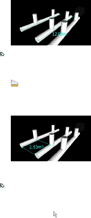
4Repeat to measure more distances if necessary. The optional dimension
label displays the sum of all point-to-point measurements.
Menu: Classic user interface: Review ➤ Measure ➤ Accumulate
To calculate an area on a plane
1Click Review tab ➤ Measure panel ➤ Measure drop-down ➤ Area
.
2Click to register a series of points to describe the perimeter of the area
you want to calculate. The optional dimension label displays the area
of the perimeter described since the first point, as projected onto the
plane of the viewpoint.
NOTE For your calculation to be accurate, all added points must be on the
same plane.
Menu: Classic user interface: Review ➤ Measure ➤ Measure Area
To measure the shortest distance between two objects
1Press and hold the CTRL key, and select two objects in the Scene View
with the Select tool .
Measure Tools | 225
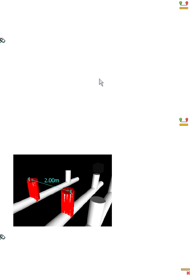
2Click Review tab ➤ Measure panel ➤ Measure Shortest Distance
.
The optional dimension label displays the shortest distance between the
selected objects.
Menu: Classic user interface: Review ➤ Measure ➤ Measure Shortest
Distance
To measure the shortest distance between two parametric objects
1Press and hold the CTRL key and select two parametric objects in the
Scene View with the Select tool .
2Open the Measure Tools window, and click Options.
3In the Options Editor, the Measure page under the Interface node,
select the Use Center Lines check box, and click OK.
4Click Review tab ➤ Measure panel ➤ Measure Shortest Distance
.
The Distance box, and the optional dimension label display the shortest
distance between the center lines of the selected parametric objects.
Menu: Classic user interface: Review ➤ Measure ➤ Measure Shortest
Distance
To clear measuring lines
■Click Review tab ➤ Measure panel ➤ Measure drop-down ➤ Clear
.
226 | Chapter 7 Review Your Model
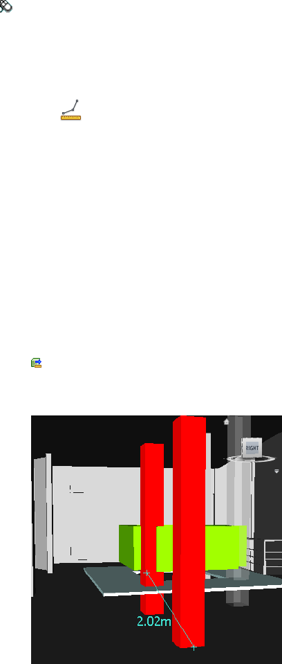
Menu: Classic user interface: Review ➤ Measure ➤ Clear
To move an object with a measure tool
1Select the object you want to move.
2Click Review tab ➤ Measure panel ➤ Measure drop-down ➤ Point
Line .
3Click the selected object to create the first point. This is the start point
from which the repositioning will be calculated.
4Click the second point in the scene. This is the point where the object
will be moved to. There is now a line connecting the start point and the
end point in the Scene View.
5If you want to be able to move the object several times, create more
points in the scene.
NOTE You can only select a point on another object in the scene. Selecting
a point in 'space' is not a valid option. To reposition an object into 'space',
you can either use a translation gizmo or, if you know the distance by which
the object is to be moved, by overriding its transform.
6Slide out the Measure panel, and click Transform Selected Items
to move the object to the second point. If you have multiple points
in the scene, each time you click Transform Objects the selected object
is moved to the next point.
Measure Tools | 227
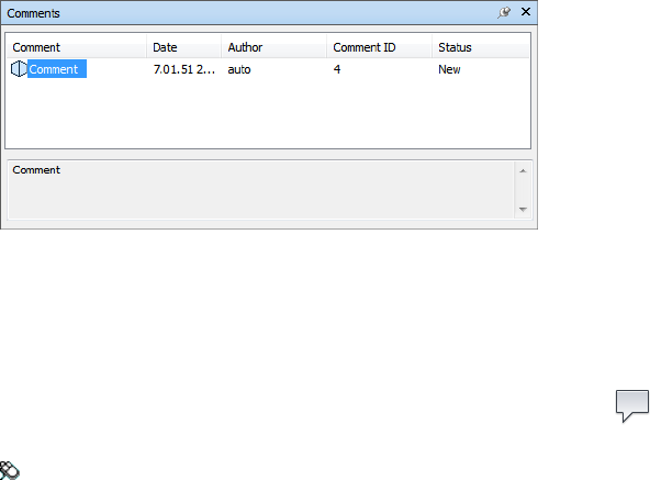
Comments and Annotations
View Comments and Annotations
You cannot add any comments, redline annotations or tags in Autodesk
Navisworks, but you can view comments, redlines, and tags attached to
viewpoints.
Comments Window
The Comments window is a dockable window that enables you to view
comments.
The Comments window shows the name, time and date, author, ID, status,
and subject (or first line) of each comment. There are different icons helping
you to identify the source of each comment at a glance.
To toggle the Comments window
■Click Review tab ➤ Comments panel ➤ View Comments .
Menu: Classic user interface: View ➤ Control Bars ➤ Comments
To view comments
1Open the Comments window.
2Go the source of your comments. For example, open the Saved
Viewpoints window.
228 | Chapter 7 Review Your Model
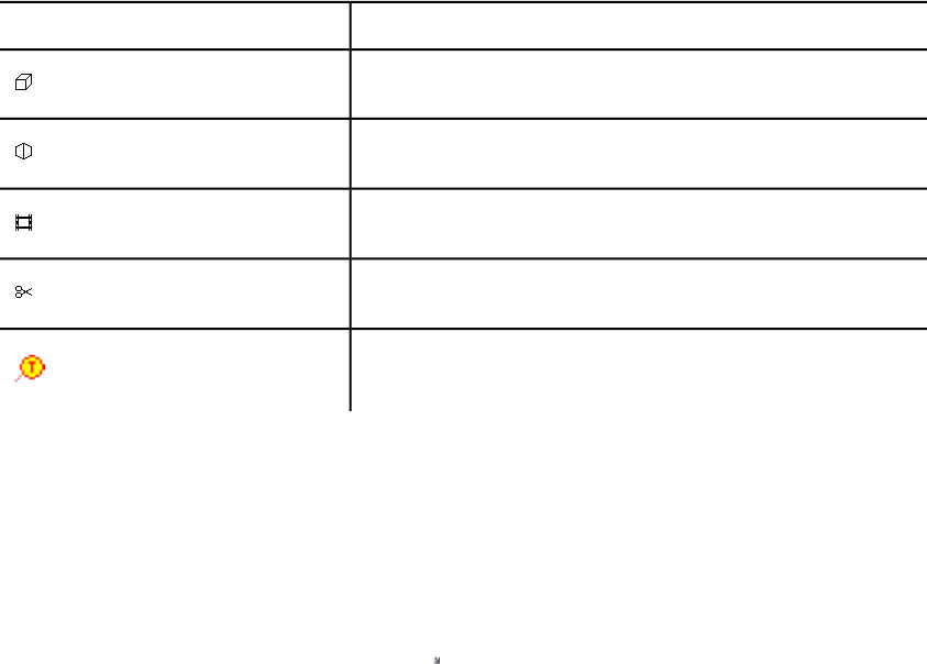
3As you click the source items, for example, viewpoints, the associated
comments are displayed in the Comments window.
DescriptionIcon
Viewpoint (orthographic camera)
Viewpoint (perspective camera)
Viewpoint animation
Viewpoint animation cut
Tag
View Redlines and Tags
To view redlines and tags you need to recall the viewpoint that contains them.
To view redlines
1Click Viewpoint tab ➤ Save, Load & Playback panel ➤ Saved
Viewpoints tool launcher .
2Click the desired viewpoint in the Saved Viewpoints window. All
attached redlines (if any) are displayed in the Scene View.
To view redlines and tags
■Click Viewpoint tab ➤ Save, Load & Playback panel ➤ Saved
Viewpoints drop-down, and choose the viewpoint that you want to
recall.
Comments and Annotations | 229
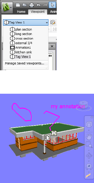
The viewpoint is displayed in the Scene View together with any redline
annotations and tags.
Links
There are several sources of links in Autodesk Navisworks: original links that
have been converted from the native CAD files, links that have been added
by Autodesk Navisworks users, and links that have been automatically
generated by the program (for example, viewpoint links).
The links converted from the native CAD files, and the links added by Autodesk
Navisworks users are treated as object properties. This means, you can examine
them in the Properties window.
All links are saved with Autodesk Navisworks files so that as the model changes,
the links remain there for you and others to view.
230 | Chapter 7 Review Your Model
Link Categories
There are two types of links: standard and user-defined.
Standard links are split into the following categories:
■Hyperlink
■Label
■Viewpoints
■Redline tags
By default, all links except labels, are drawn as icons in the Scene View.
Labels are drawn as text.
If available, user-defined links are drawn as icons in the Scene View by
default.
You can use the Options Editor to toggle the display of each of the link
categories, and also to control their appearance.
Display Links
You can switch links in the Scene View on and off. You can also toggle the
display of each of the link categories. Autodesk Navisworks remembers the
selected visibility setting between sessions.
When links are switched on, you can reduce the screen clutter by restricting
a number of links can be shown in the Scene View, hiding colliding icons,
and using culling. Finally, as some standard link categories can have comments
associated with them, you can choose to only draw links with attached
comments.
To toggle the display of links
■Click Home tab ➤ Display panel ➤ Links .
Menu: Classic user interface: Tools ➤ Links
To control the display of standard links
1Click the application button ➤ Options.
Links | 231

2In the Options Editor, expand the Interface node, expand the Links
node, and click the Standard Categories option.
3On the Standard Categories page, select the Visible check box to
display the corresponding link category. Clearing the check box hides
the corresponding link category in the Scene View.
By default, all standard link categories are visible.
4Click OK.
To control the display of user-defined links
1Click the application button ➤ Options.
2In the Options Editor, expand the Interface node, expand the Links
node, and click the User-Defined Categories option.
3On the User-Defined Categories page, select the Visible check box
to display the corresponding link category. Clearing the check box hides
the corresponding link category in the Scene View.
By default, all user-defined link categories are visible.
NOTE If no user-defined categories have been added, this page is empty.
4Click OK.
To reduce the screen clutter
1Click the application button ➤ Options.
2In the Options Editor, expand the Interface node, and click the
Links option.
3On the Links page, enter the number of links into the Max Icons box.
By default, 25 links can be visible.
4To hide links that appear overlapped in the Scene View, select the Hide
Colliding Icons check box.
5In the Cull Radius box enter the desired value. Only the links located
within the specified distance from the camera are drawn in the Scene
View. The default value of 0 means that all links are drawn.
6Click OK.
232 | Chapter 7 Review Your Model

To hide links without comments
1Click the application button ➤ Options.
2In the Options Editor, expand the Interface node, expand the Links
node, and click the Standard Categories option.
3On the Standard Categories page, select the Hide Icons Without
Comments check box for all required link categories.
By default, links without comments are also displayed.
4Click OK.
Customize Links
You can customize the default appearance of links in Autodesk Navisworks.
In particular, you can draw them in 3D, and you can add leader lines (arrows)
pointing to the attachment point on the items. You can also choose how to
represent each link category (as an icon or as text).
To draw links in 3D mode
Note: In 3D mode links can become hidden by other objects in the scene
when you are navigating.
1Click the application button ➤ Options.
2In the Options Editor, expand the Interface node, and click the
Links option.
3On the Links page, select the In 3D check box.
Links now float in 3D space just in front of their attachment points to
the items.
4Click OK.
To show leader lines
1Click the application button ➤ Options.
2In the Options Editor, expand the Interface node, and click the
Links option.
Links | 233
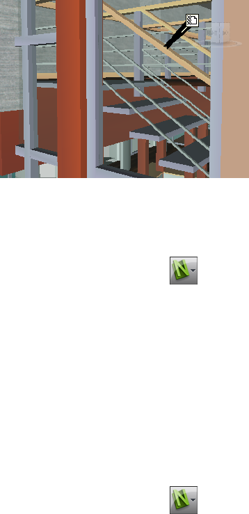
3On the Links page, Enter the X- and Y- distance in Leader Offset for
the number of pixels to the right and up that these leader lines will use.
The default angle is 0. The recommended angle is 45.
Links in the Scene View have now leader lines pointing to the
attachment point on the items.
4Click OK.
To customize appearance of standard links
1Click the application button ➤ Options.
2In the Options Editor, expand the Interface node, expand the Links
node, and click the Standard Categories option.
3On the Standard Categories page, use the Icon Type box to specify
how you want a link to be drawn for each of the available categories.
You can choose between an icon and text.
By default, label links are shown as text, and the rest of the link categories
are shown as icons.
4Click OK.
To customize appearance of user-defined links
1Click the application button ➤ Options.
2In the Options Editor, expand the Interface node, expand the Links
node, and click the User-Defined Categories option.
3On the User-Defined Categories page, use the Icon Type box to
specify how you want a link to be drawn for each of the available
234 | Chapter 7 Review Your Model

categories. You can choose between an icon and text. By default, links
with user-defined categories are shown as icons.
NOTE If no user-defined categories have been added, this page is empty.
4Click OK.
The table below shows the icons that can be used to represent different link
categories in the Scene View.
DescriptionIcon
Represents links that have hyperlink, label, or any user-defined category (and
points to a web address).
Represents links that have hyperlink, label, or any user-defined category (and
points to an external file).
Represents links with viewpoints category (perspective camera mode).
Represents links with viewpoints category (orthographic camera mode).
Represents links with tags category.
Find and Follow Links
Links are an extremely useful review tool to allow you to access non-graphical
information through the graphical interface of Autodesk Navisworks.
The links converted from the native CAD files, and the links added by Autodesk
Navisworks users are treated as object properties. This means, you can examine
them in the Properties window.
To follow a link
1Make sure links are switched on. If not, click Home tab ➤ Display
panel ➤ Links .
2Click the desired link in the Scene View to open the attached data
source.
Links | 235
Shortcut menu: Follow Link
Reset Links
You can reset all links on an object to those that were originally converted
from the CAD file. You can also reset all links on all objects in the scene to
their original state.
To reset all links for an object
Attention: Resetting links for an object also removes any links manually
added to it by Autodesk Navisworks users. If you made a mistake, use the
Undo button on the Quick Access toolbar.
1In the Scene View, select the object with the links that you want to
reset to their original state.
2Click Item Tools tab ➤ Links panel ➤ Reset Links .
To reset all links in a scene
Attention: Resetting links in a scene also removes all links manually added
to it by Autodesk Navisworks users. If you made a mistake, use the Undo
button on the Quick Access toolbar.
■Click Home tab ➤ Project panel ➤ Reset All drop-down ➤ Links
.
Quick Properties
You can switch quick properties in the Scene View on and off. Autodesk
Navisworks remembers the selected visibility setting between sessions.
When Quick Properties are switched on, you can view property information
in a tooltip style window as you move your cursor over objects in the Scene
View. You don’t need to select objects first. The quick properties tooltip
disappears after a few seconds.
236 | Chapter 7 Review Your Model
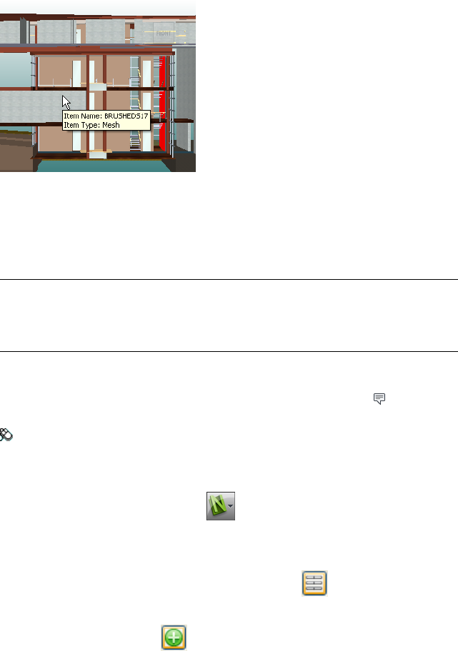
By default, quick properties show the name and type of the object, but you
can use the Options Editor to define which properties are shown. Each
definition that you configure enables you to display an additional
category/property combination in quick properties. You can choose whether
to hide category names in quick properties or not.
NOTE When you move your mouse over an object that doesn't have the requested
property, Autodesk Navisworks searches up the selection tree for a parent object
that contains that information, and displays it instead, thus maximizing the useful
information you get.
To toggle the display of quick properties
■Click Home tab ➤ Display panel ➤ Quick Properties .
Menu: Classic user interface: Tools ➤ Quick Properties
To add quick properties definition
1Click the application button ➤ Options.
2In the Options Editor, expand the Interface node, expand the Quick
Properties node, and click the Definitions option.
3On the Definitions page, click Grid View to display quick
properties definitions as table rows.
4Click Add Element . A new row is added to the top of the table.
5Click the Category column, and select the property category from the
drop-down list, for example ‘Item.’ The options available depend on the
property categories in your model.
Quick Properties | 237
6Click the Property column, and select the property name from the
drop-down list, for example, ‘Material’. The options available depend
on the selected property category.
7Click OK.
NOTE You can add as many definitions to your quick properties as you like.
To delete quick properties definition
1Click the application button ➤ Options.
2In the Options Editor, expand the Interface node, expand the Quick
Properties node, and click the Definitions option.
3On the Definitions page, click Grid View to display quick
properties definitions as table rows.
4Click the Category or Property for the definition that you want to
delete.
5Click Remove Element .
6Click OK.
To hide category names
1Click the application button ➤ Options.
2In the Options Editor, expand the Interface node, and click the
Quick Properties option.
3Select the Hide Category check box.
4Click OK.
238 | Chapter 7 Review Your Model
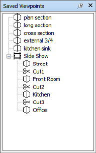
Use Viewpoints
Viewpoints are snapshots taken of the model as it is displayed in the Scene View.
Viewpoints may include a variety of comments and redline tags, which have been
previously added to a viewpoint. You cannot create viewpoints in Autodesk
Navisworks, but you can use any of the viewpoints and viewpoint animations saved
in the model. Viewpoint animation typically contains both the user movement
through the model and views of the model.
Modify Viewpoints
Saved Viewpoints Window
The Saved Viewpoints window is a dockable window that enables you to
jump to preset viewpoints without having to navigate each time to reach an
item.
8
239
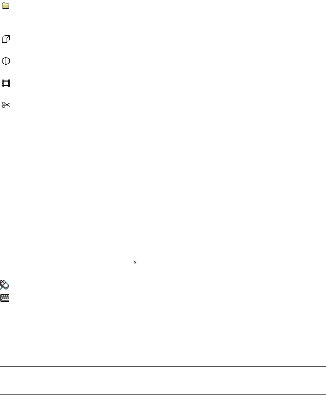
Viewpoint animations are also saved with the viewpoints, as they are simply
a list of viewpoints treated as keyframes.
Icons are used to represent different elements:
represents a folder which may contain all other elements (including other
folders).
represents a viewpoint saved in orthographic mode.
represents a viewpoint saved in perspective mode.
represents a viewpoint animation clip.
represents a cut inserted into a viewpoint animation clip.
You can select more than one viewpoint by either holding down the CTRL
key and left-clicking, or by left-clicking the first item, and then clicking the
last item while holding down the SHIFT key.
You can drag viewpoints around the Saved Viewpoints window, but you
cannot save any changes.
There are no buttons on this window, and commands are invoked through
shortcut menus.
To toggle the Saved Viewpoints window
■Click Viewpoint tab ➤ Save, Load & Playback panel ➤ Saved
Viewpoints tool launcher .
Menu: Classic user interface: View ➤ Control Bars ➤ Saved Viewpoints
Command entry: CTRL + F11
You get a different shortcut menu, depending on what element you right-click
in the Saved Viewpoints window. All shortcut menus share the Sort option,
which sorts the contents of the window alphabetically, including folders and
their contents.
IMPORTANT Any changes that you make cannot be saved, and will apply for the
duration of your Autodesk Navisworks session.
Blank Space
Sort Sorts the contents of the Saved Viewpoints window alphabetically.
Help Opens the Help system.
240 | Chapter 8 Use Viewpoints

Saved Viewpoint
Add Copy Creates a copy of the selected viewpoint in the Saved Viewpoints
window. The copy is named the same as the selected viewpoint, but includes
the version number in brackets. For example, View1(1), View1(2) and so on.
Edit Opens the Edit Viewpoint dialog box, and enables you to manually
edit the viewpoint’s attributes.
Update Makes the selected viewpoint the same as the current viewpoint in
the Scene View.
Transform Opens the Transform dialog box. It enables you to transform
the camera position. This option is not available in a 2D workspace.
Delete Deletes the selected viewpoint from the Saved Viewpoints window.
Rename Enables you to rename the selected viewpoint.
Copy Name Copies the name of the selected viewpoint to the Clipboard.
Sort Sorts the contents of the Saved Viewpoints window alphabetically.
Help Opens the Help system.
Viewpoint Animation
Add Copy Creates a copy of the selected viewpoint animation in the Saved
Viewpoints window. The copy is named the same as the selected viewpoint
animation, but includes the version number in brackets. For example, View1(1),
View1(2) and so on.
Edit Opens the Edit Animation dialog box, and enables you to set the
duration of the selected viewpoint animation, the type of smoothing, and
whether it loops or not.
NOTE Clicking Edit over an animation keyframe, opens the Edit Viewpoint
dialog box; and clicking Edit over an animation cut, opens the Edit Animation
Cut dialog box.
Update Updates all keyframes in the viewpoint animation with the current
render style, lighting, and navigation tool or mode.
NOTE Clicking Update over a single keyframe will only update that frame with
the current modes.
Transform Opens the Transform dialog box. It enables you to transform
the camera position. This option is not available in a 2D workspace.
Modify Viewpoints | 241

Delete Deletes the selected viewpoint animation from the Saved Viewpoints
window.
NOTE Clicking Delete over a keyframe or a cut, removes the keyframe or cut
from the viewpoint animation.
Rename Enables you to rename the selected viewpoint animation, keyframe,
or cut.
Copy Name Copies the name of the selected viewpoint animation, keyframe,
or cut to the Clipboard.
Sort Sorts the contents of the Saved Viewpoints window alphabetically.
Help Opens the Help system.
Folder
Add Copy Creates a copy of the selected folder in the Saved Viewpoints
window. The copy is named the same as the selected folder, but includes the
version number in brackets. For example, Folder1(1), Folder1(2) and so on.
Update Updates all viewpoints in the folder with the current render style,
lighting and navigation tool or mode. Choosing Update for a single viewpoint
will only update that viewpoint with the current modes.
Transform Opens the Transform dialog box. It enables you to transform
the camera position. This option is not available in a 2D workspace.
Delete Removes the selected folder and all of its contents from the Saved
Viewpoints window.
Rename Enables you to rename the selected folder.
Copy Name Copies the name of the selected folder to the Clipboard.
Sort Sorts the contents of the Saved Viewpoints window alphabetically.
Help Opens the Help system.
Recall Viewpoints
You can return to any of previously saved viewpoints. On recalling viewpoints
the navigation mode that was active when the viewpoint was created will be
re-selected. Any redlines and comments associated with the viewpoint will
also be reinstated.
242 | Chapter 8 Use Viewpoints
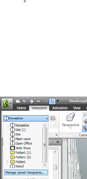
To recall a viewpoint from the Saved Viewpoints window
1If the Saved Viewpoints window is not displayed, click Viewpoint
tab ➤ Save, Load & Playback panel ➤ Saved Viewpoints tool
launcher .
2Click the desired viewpoint in the list. It is now displayed in the Scene
View.
Organize Viewpoints
Viewpoints can be organized into folders, as necessary.
To organize viewpoints into folders
1Click Viewpoint tab ➤ Save, Load & Playback panel ➤ Current
Viewpoint drop-down ➤ Manage Saved Viewpoints.
This opens the Saved Viewpoints window, and makes it the active
window.
2Right-click an empty space in the Saved Viewpoints window, and
click New Folder.
3Type in a new name, and press Enter.
4Drag the required viewpoints into your new folder.
Modify Viewpoints | 243
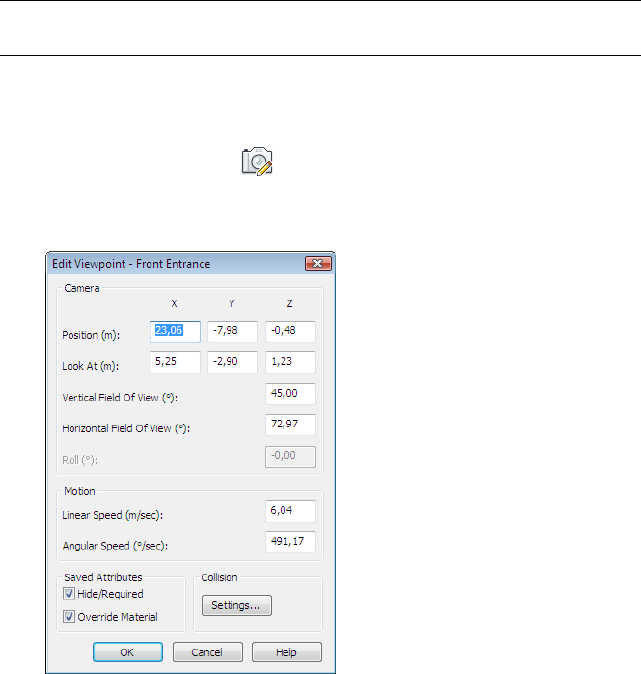
Edit Viewpoints
Depending on whether you work in a 2D or 3D workspace you can edit all or
some of the following viewpoints attributes, including camera position, field
of view, speed of motion and saved attributes. All entries are measured in
Display Units (page 91).
TIP Click Viewpoint tab and slide out of the Navigate panel to quickly adjust
linear and angular speed of motion for your current viewpoint in a 3D workspace.
To edit current viewpoint
1Click Viewpoint tab ➤ Save, Load & Playback panel ➤ Edit
Current Viewpoint .
2Use the Edit Viewpoint dialog box (page 272) to adjust the viewpoint’s
attributes.
3Click OK.
To edit a viewpoint
1Click Viewpoint tab ➤ Save, Load & Playback panel ➤ Current
Viewpoint drop-down ➤ Manage Saved Viewpoints.
244 | Chapter 8 Use Viewpoints
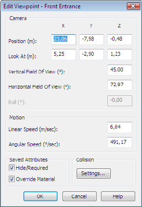
2In the Saved Viewpoints window, right-click the viewpoint you want
to modify, and click Edit.
3Use the Edit Viewpoint dialog box (page 272) to adjust the viewpoint’s
attributes.
4Click OK.
To delete a viewpoint
1Click Viewpoint tab ➤ Save, Load & Playback panel ➤ Current
Viewpoint drop-down ➤ Manage Saved Viewpoints.
2In the Saved Viewpoints window, right-click the viewpoint you want
to remove, and click Delete.
Modify Viewpoints | 245
246
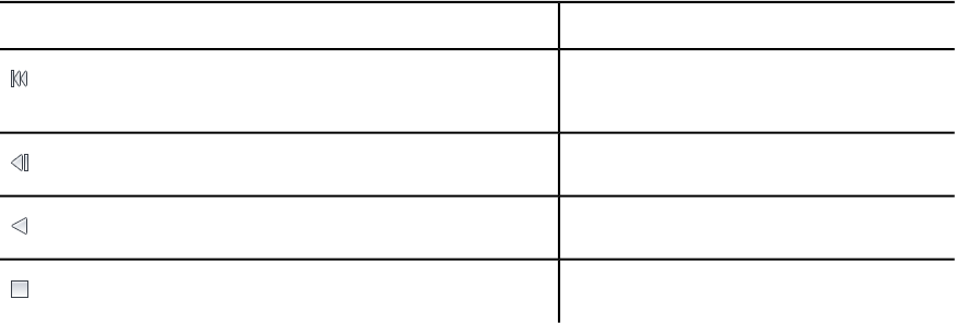
Play Back Animations
In Autodesk Navisworks there are two types of animation: viewpoint animation and
object animation.
Viewpoint animation contains pre-recorded user and camera movements in the
model. Object animation contains pre-recorded object movements in the model.
You cannot record any animation in Autodesk Navisworks, but you can play back
animations saved with the model. If there are any animation scripts, you can switch
them on and interact with animated objects.
Play Animations and Scripts
You can play back both pre-recorded object animation and viewpoint animation
in the Scene View.
The viewpoint animations play in real time; this means that the Autodesk
Navisworks engine is still attempting to maintain the guaranteed frame rate so
some drop-out may still occur, just as in real-time navigation.
PurposeControl
Rewinds the current animation back to the begin-
ning.
Steps back a single animation frame or keyframe.
Plays the current animation backwards.
Stops animation playback.
9
247
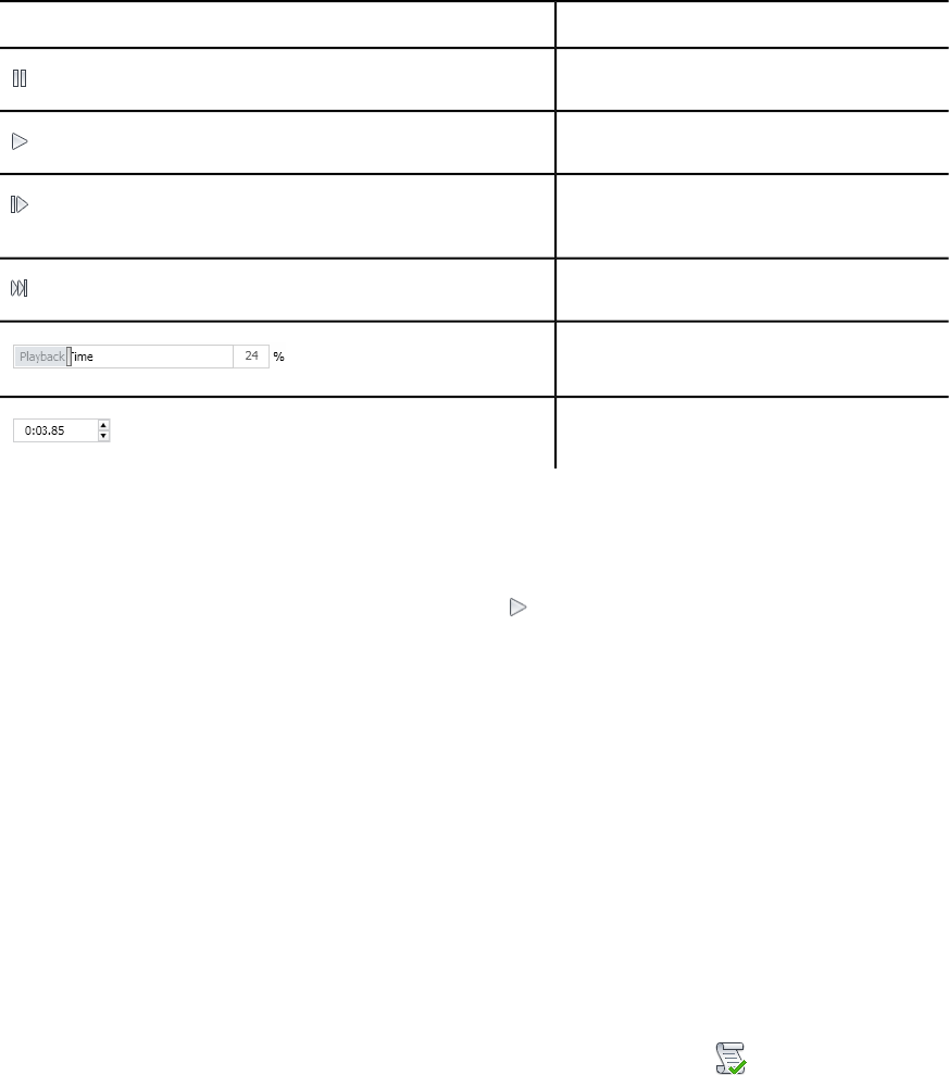
PurposeControl
Pauses animation playback.
Plays the currently selected animation.
Steps forwards one frame or keyframe in the an-
imation.
Moves forward to the end of animation.
The playback time slider.
The playback time spinner.
To play an animation
1Click Animation tab ➤ Playback panel ➤ Available Animations
drop-down list and select the animation you want to play back.
2On the Playback panel, click Play .
Use the VCR buttons on the Playback panel to control the animation.
The Playback Position slider enables you to quickly move forward
and backward through the animation. Full left is at the beginning and
full right is at the end.
To the right of the Playback Position slider, there are two animation
progress indicators: percentage and time (in seconds). You can type a
number into either box to set the camera at a certain point.
3For viewpoint animations, you may notice that the frame in the
animation in the Saved Viewpoints window (click View tab
➤ Workspace panel ➤ Windows drop-down ➤ Saved Viewpoints)
is highlighted when the animation is playing. Click any frame to set the
camera to that point in time in the viewpoint animation and continue
playing back from there.
To enable animation scripts
■Click Animation tab ➤ Scripts panel ➤ Enable Scripts .
248 | Chapter 9 Play Back Animations
You can now interact with your model. For example, if there is a script to
open a door on pressing a specific key on the keyboard, pressing this key
will open the door.
Play Animations and Scripts | 249
250
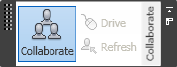
Work Within a Team
Autodesk Navisworks Freedom 2012 enables multiple users to participate in a single
design review session across a Local Area Network (LAN).
The Collaborate tool has two noteworthy limitations.
■Collaboration between different versions of Autodesk Navisworks is not supported.
■This feature is only available for Windows XP users, as it utilizes the shared program
features of Windows NetMeeting, which is unavailable in the Vista and Windows 7
operating systems.
Collaborate Panel
The collaboration tools necessary to run collaboration sessions are located on
the Review tab ➤ Collaborate panel.
By default, the Collaborate panel is not displayed. To display it, right-click
the Review tab, and click Show Panels ➤ Collaborate on the shortcut
menu.
Collaboration Session
All meeting participants require access to a Autodesk Navisworks NWF or NWD
file, in a shared location. One of the participants will host the meeting and
place a call to invite the others to join the meeting. Any of the participants who
have joined the meeting can take control and drive the session. All navigation
performed by the driver will be displayed in the Scene View on each of the
10
251
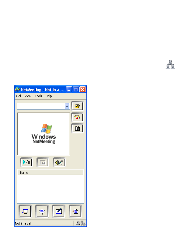
participants’ machines. Any viewpoints or redlines, for example, added during
the session can be updated on all participants’ machines at the click of a
button.
NOTE If a collaborative review session, as outlined here, is not conducted in single
room, then additional teleconferencing provisions could be necessary. This may
be using the NetMeeting Whiteboard, or your own telephone system.
To start a collaboration session
1Open the Autodesk Navisworks file that you want to collaborate on from
a shared directory.
2Click Review tab ➤ Collaborate panel ➤ Collaborate .
This initializes Windows® NetMeeting®.
NOTE The first time Windows NetMeeting initializes, a Setup wizard will
take you through the setup process. You will need to enter your name and
email address. When using NetMeeting on a LAN you do not need to log
onto a directory server, as these will not be available to you.
252 | Chapter 10 Work Within a Team
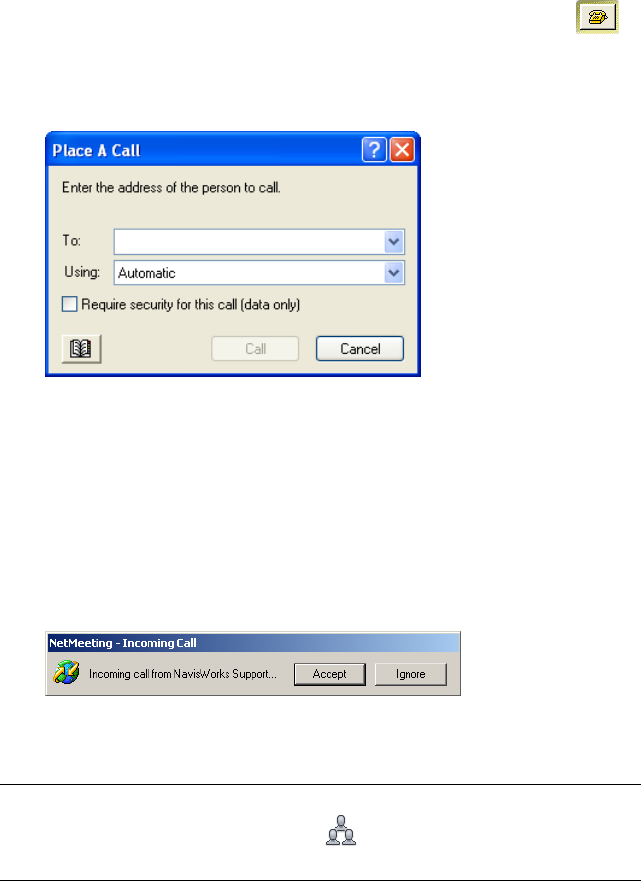
To place a call, inviting attendees to join
1Having initialized Windows NetMeeting, click the Call button in
the NetMeeting dialog box.
2In the Place a Call dialog box, enter the machine name or IP address
of the machine you wish to join the meeting into the To box.
3Click the Call button to send the invite.
Once the person receiving the invite accepts this, both their name and
yours will be listed in the NetMeeting dialog box.
4Repeat this procedure to invite all required participants.
To accept an invitation
1When you are invited to join a meeting, the Incoming Call dialog box
is displayed.
2Click the Accept button to join the meeting, or Ignore to decline the
invitation.
NOTE Once you have accepted a call, you will need to click Review tab
➤ Collaborate panel ➤ Collaborate to start your own collaboration
session.
Collaboration Session | 253

To become the driver
During a collaboration meeting, anyone in the call can take control of the
session and become the driver. The driver will control navigation of the shared
model on all machines in the call.
1Click Review tab ➤ Collaborate panel ➤ Drive .
2Upon clicking the drive button, all other users in the call will receive a
message advising that you are requesting control. They will have to
answer Yes to this message if you are to drive Autodesk Navisworks on
their machine.
To refresh all attendees machines
Although real-time navigation in Autodesk Navisworks can be performed on
all machines in a call by one user, it is not possible for review data such as
saved viewpoints, comments and redlines, to be automatically updated on all
users' machines. This information can, however, be updated on their machines
by refreshing the model. This refresh process can be performed on one users
machine and refresh all machines in the call.
■Click Review tab ➤ Collaborate panel ➤ Refresh .
254 | Chapter 10 Work Within a Team

Share Data
Print
You can print a hard copy of the current viewpoint to any printer or plotter.
Print Preview
Before you print out a copy of the model or sheet you are working on, you may
wish to see how it will appear.
To preview model/sheet before printing
1Click Output tab ➤ Print panel ➤ Print Preview .
2Use the Zoom In and Zoom Out buttons to do just that with the preview
image.
3Click Print.
4In the Print dialog box, click OK.
Print Setup
This option enables you to the set up paper size and orientation options.
To change the print setup
1Click Output tab ➤ Print panel ➤ Print Settings .
11
255
2In the Print Setup dialog box, make changes as required to the paper
and orientation.
3Click the Properties button if you want to change printer-specific
settings.
4Return to the Print dialog box, and click OK.
Print Current Viewpoint
When the print option is selected, Autodesk Navisworks prints the current
viewpoint scaled to fit and centered on the page.
To print the current viewpoint
1Click Output tab ➤ Print panel ➤ Print .
2Check the printer settings are as required, and click OK.
NOTE The maximum image size is 2048x2048 pixels.
The Properties button controls printer-specific ink and paper settings.
Toolbar: Classic user interface: Standard ➤ Print
256 | Chapter 11 Share Data
TimeLiner Playback
TimeLiner Playback enables you to view a TimeLiner construction sequence.
In this section, you will learn how to simulate your TimeLiner sequence throughout
the duration of the project schedule.
Overview of TimeLiner Tool
The TimeLiner tool adds 4D schedule simulation to Autodesk Navisworks files.
In Autodesk Navisworks Freedom 2012, TimeLiner has a playback-only option,
allowing any externally created project data to be simulated, but no changes to
be made to that data.
TimeLiner Playback Window
The TimeLiner Playback dockable window enables you to set up and play
simulations.
To toggle the TimeLiner Playback window
■Click Home tab ➤ Tools panel ➤ TimeLiner Playback
Menu: Classic user interface: Tools ➤ TimeLiner Playback
Simulate Tab
In the TimeLiner Playback window, the Simulate tab enables you to
simulate your TimeLiner sequence throughout the duration of the project
schedule.
12
257
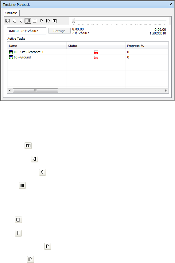
The Playback Controls
Use the standard VCR buttons to step and play forwards and backwards
through the simulation:
Rewind will rewind the simulation back to the beginning.
Step Back will step back a single step size.
Reverse Play will play the simulation backwards.
Pause will pause the simulation at the time you press it at. You can then
look around and interrogate the model, or step forwards and backwards
through the simulation. To continue playing from where you paused, just
press Play again.
Stop will stop the simulation playing and rewind back to the beginning.
Play will play the simulation from the currently selected time.
Step Forwards will step forwards a single step size.
Forward will fast forward the simulation to the end.
You can use the Simulation Position slider to quickly move forwards and
backwards through the simulation. Full left is at the beginning and full right
is at the end.
258 | Chapter 12 TimeLiner Playback
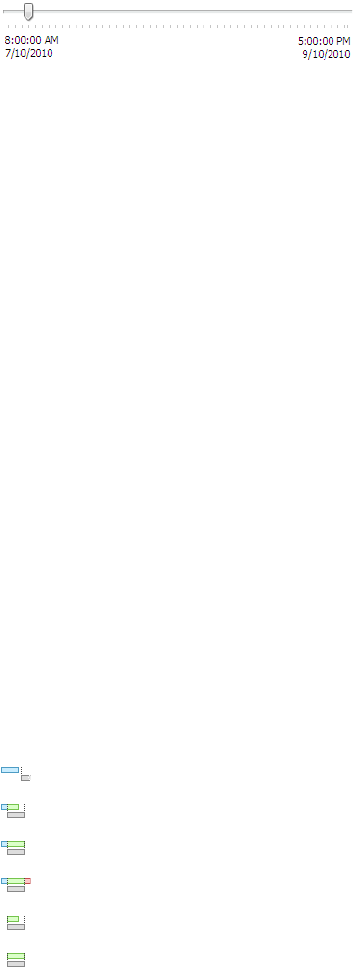
The Date/Time box next to the VCR buttons shows the point in time through
the simulation. You can click on the drop-down icon to the right of the date
to display a calendar, from which you can select a date to 'jump' to.
The Settings Button
The Settings button opens the Simulation Settings Dialog Box (page 261) that
enables you to define how the schedule is simulated.
The Task View
All active tasks are show in a multi-column table. You can move and resize
table columns, if necessary.
You can view the current simulation time for each of the active tasks, and
how close to completion they are (Progress is displayed as a percentage). The
Status of each active task is also displayed as an icon. For simulations where
Planned and Actual dates are available, the status provides a visual
representation as to whether there is any variance between the planned and
actual dates. See The Status Icons for more information.
The Status Icons
Each task has its own status identified by an icon. Two separate bars are drawn
for each task, showing planned against actual relationships. The color is used
to differentiate the early (blue), on-time (green), late (red), and planned (grey)
portions of the task. Dots mark the planned start and end dates.
Placing the mouse pointer over a Status icon shows a tooltip explaining the
task status.
Finished before planned start.
Early start, early finish.
Early start, on-time finish.
Early start, late finish.
On-time start, early finish.
On-time start, on-time finish.
Overview of TimeLiner Tool | 259
On-time start, late finish.
Late start, early finish.
Late start, on-time finish.
Late start, late finish.
Started after planned finish.
No comparison.
The Gantt Chart View
The Gantt Chart displays a colored bar chart illustrating your project status.
Each task takes up one row. The horizontal axis represents the time span of
the project, broken down into increments (such as days, weeks, months, and
years) and the vertical axis represents the project tasks. Tasks can run
sequentially, in parallel, or overlapping.
Play Simulations
To play a simulation
1If the TimeLiner Playback window is not already open, Click Home
tab ➤ Tools panel ➤ TimeLiner Playback .
2Click the Play button on the Simulate tab.
The TimeLiner Playback window displays the tasks as they are carried
out, and the Scene View shows the sections of the model added or
removed over time, in accordance with the task types.
To adjust a simulation playback
1If the TimeLiner window is not already open, click Home tab ➤ Tools
panel ➤ TimeLiner .
2Click the Simulation tab, and click the Settings button.
3When the Simulation Settings Dialog Box (page 261) opens, modify the
playback settings, and click OK.
260 | Chapter 12 TimeLiner Playback
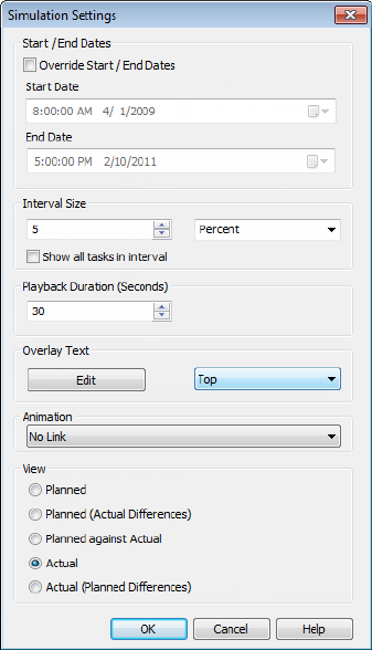
Simulation Settings Dialog Box
The Settings button on the Simulate tab provides access to the Simulation
Settings dialog box.
It is possible to override the Start and End dates that the simulation runs
between. Selecting the Override Start/End Dates check box enables the
date boxes and allows you to choose the start and end dates. By doing this,
you can simulate a small sub-section of the overall project. The dates will be
shown on the Simulate tab. These dates will also be used when exporting
animations.
You can define the Interval Size to use when stepping through the simulation
using the playback controls. The interval size can be set either as a percentage
of the overall simulation duration or to an absolute number of days or weeks,
and so on.
Overview of TimeLiner Tool | 261
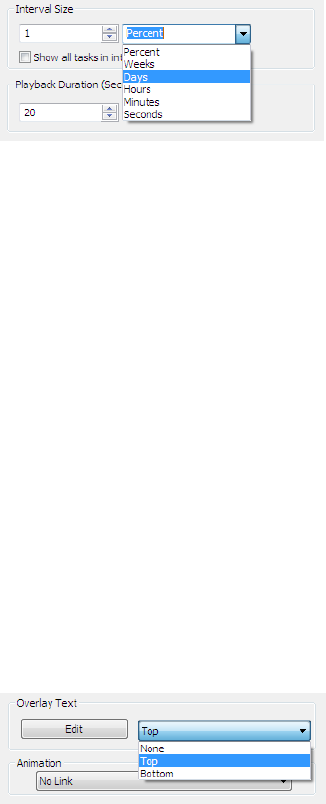
Use the drop-down list to select the interval unit, then use the Up and Down
arrow buttons to increase or decrease the interval size.
It is also possible to highlight all the tasks that are being worked on during
the interval. By selecting the Show All Tasks in Interval check box, and,
for example, setting the Interval Size to 5 Days, all tasks being worked on
during those 5 days will be set to their Start Appearance in the Scene
View, including those that begin and end within the bounds of the interval.
The Simulation slider will show this by drawing a blue line under the slider.
If this check box is clear, tasks that begin and end within the bounds of the
interval will not be highlighted in this manner, and will need to overlap with
the current date in order to be highlighted in the Scene View.
You can define the overall Playback Duration for the complete simulation
(the time needed to play it through from start to finish). Use the Up and
Down arrow buttons to increase or decrease the duration (in seconds). You
may also enter a duration directly into this field.
You can define whether the current simulation date should be overlaid in the
Scene View, and if so whether it should appear at the top or bottom of the
screen. From the drop-down, choose from None (to display no overlay text),
Top (to display the text at the top of the window), or Bottom (to display
the text at the bottom of the window).
You can Edit the information displayed in the overlay text using the Overlay
Text Dialog Box (page 266). This dialog box also makes it possible to alter the
Font Type, Style and Size by clicking on the contained Font button.
You can add animation to an entire schedule, so that during the TimeLiner
sequence playback, Autodesk Navisworks will also play the specified viewpoint
animation or camera.
262 | Chapter 12 TimeLiner Playback
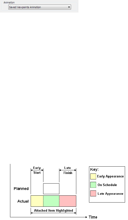
The following options can be selected in the Animation field:
■No Link - no viewpoint animation or camera animation will be played.
■Saved Viewpoints Animation - links your schedule to the currently
selected viewpoint or viewpoint animation.
■Scene X - ➤ Camera - links your schedule to a camera animation in the
selected animation scene.
You can view pre-recorded animations with the TimeLiner simulation (see
Play Animations and Scripts (page 247) ).
View area. Each view will playback the schedule depicting Planned and
Actual relationships:
■Actual. Choose this view to simulate the Actual schedule only (that is,
only use the Actual Start and Actual End dates).
■Actual (Planned Differences). Choose this view to simulate the Actual
schedule against the Planned schedule. This view will only highlight the
items attached to the task over the Actual date range (that is, between
Actual Start and Actual End. See diagram below for graphical
representation). For time periods where the Actual dates are within the
Planned dates (on schedule), the items attached to the task will be
displayed in the Task Type Start Appearance. For time periods where
the Actual dates are early, or late in comparison to the Planned dates
(there is a variance), then the items attached to the task will be displayed
in the Task TypeEarly or Late Appearance, respectively.
Overview of TimeLiner Tool | 263
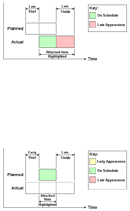
■Planned. Choose this view to simulate the Planned schedule only (that
is, only use the Planned Start and Planned End dates).
■Planned (Actual Differences). Choose this view to simulate the Actual
schedule against the Planned schedule. This view will only highlight the
items attached to the task over the Planned date range (that is, between
PlannedStart and Planned End. See diagram below for graphical
representation). For time periods where the Actual dates are within the
Planned dates (on schedule), the items attached to the task will be
displayed in the Task TypeStart Appearance. For time periods where
the Actual dates are early, or late in comparison to the Planned dates
(there is a variance), then the items attached to the task will be displayed
in the Task TypeEarly or Late Appearance, respectively.
264 | Chapter 12 TimeLiner Playback
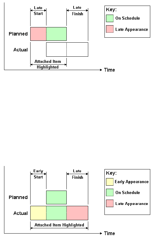
■Planned Against Actual. Choose this view to simulate the Actual
schedule against the Planned schedule. This will highlight the items
attached to the task over the entire Planned and Actual date range (that
is, between the earliest of Actual and PlannedStart dates and the latest
of Actual and PlannedEnd dates. See diagrams below for graphical
representation). For time periods where the Actual dates are within the
Planned dates (on schedule), the items attached to the task will be
displayed in the Task TypeStart Appearance. For time periods where
the Actual dates are early, or late in comparison to the Planned dates
(there is a variance), then the items attached to the task will be displayed
in the Task TypeEarly or Late Appearance, respectively.
Overview of TimeLiner Tool | 265
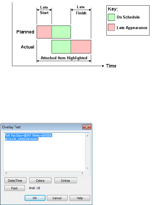
Overlay Text Dialog Box
You have the option to define the text overlaid in the Scene View during
simulation, by clicking Edit in the Simulation Settings Dialog Box (page 261).
By default the date and time are displayed using the format specified in
Control Panel ➤ Regional Settings. You can specify the exact format to
use by entering text into the text box. Most text will appear as entered, except
that words prefixed with a “%” or “$” character act as keywords and are
replaced with various values. The Date/Time and Extras buttons can be
used to select and insert all possible keywords. The Colors button can be used
to define the color of the overlay text.
The Font button brings up the standard Microsoft Windows font picker dialog
box. Once the correct font, font style and point size have been selected, press
OK to return to the Overlay Text dialog box. The current font selection is
266 | Chapter 12 TimeLiner Playback
shown next to the Font button, and during the TimeLiner simulation, all
text on the overlay will be shown using this font.
Date/Time Keywords
%a Abbreviated weekday name.
%A Full weekday name.
%b Abbreviated month name.
%B Full month name.
%c Date and time representation appropriate for locale.
%d Day of month as decimal number (01 - 31).
%H Hour in 24-hour format (00 - 23).
%I Hour in 12-hour format (01 - 12).
%j Day of year as decimal number (001 - 366).
%m Month as decimal number (01 - 12).
%M Minute as decimal number (00 - 59).
%p Current locale's A.M./P.M. indicator for 12-hour clock.
%S Second as decimal number (00 - 59).
%U Week of year as decimal number, with Sunday as first day of week (00 -
53).
%w Weekday as decimal number (0 - 6; Sunday is 0).
%W Week of year as decimal number, with Monday as first day of week (00
- 53).
%x Date representation for current locale.
%X Time representation for current locale.
%y Year without century, as decimal number (00 - 99).
%Y Year with century, as decimal number.
%z Time-zone abbreviation; no characters if time zone is unknown.
%Z Time-zone name; no characters if time zone is unknown.
Overview of TimeLiner Tool | 267
Color Keywords
$COLOR_RED Sets the overlay display text color to be red.
$COLOR_BLUE Sets the overlay display text color to be blue.
$COLOR_GREEN Sets the overlay display text color to be green.
$COLOR_WHITE Sets the overlay display text color to be white.
$COLOR_BLACK Sets the overlay display text color to be black.
$RGBr,g,b$RGB Sets the overlay display text to any color specified using
explicit RGB values between 0 and 255. For example, “$RGB127,127,127$RGB”
sets the color to grey.
Extra Keywords
$TASKS Adds the name of each currently active task to the overlay display
text. Each task is displayed on a new line.
$DAY Days since start of first task in project (starting from 1).
$WEEK Weeks since start of first task in project (starting from 1).
CTRL + Enter Type CTRL + Enter to insert a new line into the overlay display
text.
%% Percent sign.
268 | Chapter 12 TimeLiner Playback

Reference
Background Settings Dialog Box
Use this dialog box to choose a background effect to use in the Scene View.
Mode Selects the type of background effect. Choose from:
■Plain
■Graduated
■Horizon
NOTE Horizon mode and the associated colors are only available for 3D models.
Color Sets the color for a plain background.
Top Color Sets the top color in a graduated background.
Bottom Color Sets the bottom color in the graduated background.
Sky Color Sets the sky color (top) in a horizon background. This option is
available for 3D models only.
Horizon Sky Color Sets the sky color (bottom) in a horizon background. This
option is available for 3D models only.
Horizon Ground Color Sets the ground color (top) in a horizon background.
This option is available for 3D models only.
Ground Color Sets the ground color (bottom) in a horizon background. This
option is available for 3D models only.
Ribbon: View tab ➤ Scene View panel ➤ Background
13
269
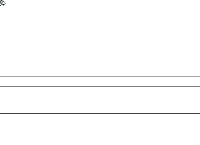
Shortcut menu: Right-click a blank area in the scene, and click Background
on the shortcut menu.
Menu: Classic user interface: Tools ➤ Background
Collision Dialog Box
Use this dialog box to adjust the collision settings for the selected viewpoint
in a 3D workspace.
By default, Collision, Gravity, Auto Crouch, and Third Person view are
switched off.
NOTE This dialog box is only available for 3D models.
Collision Select this check box to define a viewer as a collision volume in
Walk and Fly modes. As a result, a viewer acquires some mass, and cannot
pass through other objects, points, or lines in the Scene View.
NOTE Selecting this check box changes the rendering prioritization so that objects
around the viewer are displayed with much higher detail than normal. The size of
the region of high detail is based on collision volume radius and speed of
movement.
Gravity Select this check box to give a viewer some weight in Walk mode.
This option works in conjunction with Collision.
Auto Crouch Select this check box to enable a viewer to crouch under objects
that are too low to pass under in Walk mode. This option works in
conjunction with Collision.
Viewer
Radius Specifies the radius of the collision volume.
Height Specifies the height of the collision volume.
Eye Offset Specifies the distance below the top of the collision volume, where
the camera will focus upon if Auto Zoom check box is selected.
Third Person
Enable Select this check box to use Third Person view. In Third Person
view, an avatar is shown in the Scene View to represent the viewer.
Selecting this check box changes rendering prioritization so that objects around
the avatar are displayed with much higher detail than normal. The size of the
270 | Chapter 13 Reference

region of high detail is based on collision volume radius, speed of movement,
and the distance of the camera behind the avatar.
Auto Zoom Select this check box to automatically switch from Third Person
view to first person view whenever the line of vision becomes obscured by an
item.
Avatar Specifies the avatar that is used in Third Person view.
Angle Specifies the angle at which the camera looks at the avatar.
For example, 0° positions the camera directly behind the avatar; 15° makes
the camera look down on the avatar at a 15° angle.
Distance Specifies the distance between the camera and the avatar.
TIP If you want to restore the default values, click the Defaults button.
Pointing device: Edit Viewpoint dialog box ➤ Settings
Default Collision Dialog Box
Use this dialog box to specify and save your preferred collision settings in a
3D workspace.
By default, Collision, Gravity, Auto Crouch, and Third Person view are
switched off. When you modify default collision settings, your changes do
not affect the currently opened Autodesk Navisworks file. They are used as
soon as you open a new Autodesk Navisworks file, or start a new Autodesk
Navisworks session.
Collision Select this check box to define a viewer as a collision volume in
Walk and Fly modes. As a result, a viewer acquires some mass, and cannot
pass through other objects, points, or lines in the Scene View.
NOTE Selecting this check box changes the rendering prioritization so that objects
around the viewer are displayed with much higher detail than normal. The size of
the region of high detail is based on collision volume radius and speed of
movement.
Gravity Select this check box to give a viewer some weight in Walk mode.
This option works in conjunction with Collision.
Auto Crouch Select this check box to enable a viewer to crouch under objects
that are too low to pass under in Walk mode. This option works in
conjunction with Collision.
Default Collision Dialog Box | 271

Viewer
Radius Specifies the radius of the collision volume.
Height Specifies the height of the collision volume.
Eye Offset Specifies the distance below the top of the collision volume, where
the camera will focus upon if Auto Zoom check box is selected.
Third Person
Enable Select this check box to use Third Person view. In Third Person
view, an avatar is shown in the Scene View to represent the viewer.
Selecting this check box changes rendering prioritization so that objects around
the avatar are displayed with much higher detail than normal. The size of the
region of high detail is based on collision volume radius, speed of movement,
and the distance of the camera behind the avatar.
Auto Zoom Select this check box to automatically switch from Third Person
view to first person view whenever the line of vision becomes obscured by an
item.
Avatar Specifies the avatar that is used in Third Person view.
Angle Specifies the angle at which the camera looks at the avatar.
For example, 0° positions the camera directly behind the avatar; 15° makes
the camera look down on the avatar at a 15° angle.
Distance Specifies the distance between the camera and the avatar.
TIP If you want to restore the default values, click the Defaults button.
Pointing device: Options Editor dialog box ➤ Interface node
➤ Viewpoint Defaults page ➤ Settings
Edit Viewpoint Dialog Box
Use this dialog box to edit viewpoint attributes.
Camera
Position Enter the X, Y, and Z coordinate values to move the camera into
this position. The Z coordinate values are not available in a 2D workspace.
272 | Chapter 13 Reference
Look At Enter the X, Y, and Z coordinate values to change the focal point
for the camera. The Z coordinate values are not available in a 2D workspace.
Vertical Field of View, Horizontal Field of View Defines the area of the
scene that can be viewed through the camera in a 3D workspace only. You
can adjust the values for both vertical and horizontal angles of view.
A larger value produces a wider angle of view and a smaller value produces a
narrower, or more tightly focused, angle of view.
NOTE When you modify the Vertical Field of View, the Horizontal Field of
View is automatically adjusted, and vice versa to match the aspect ratio in Autodesk
Navisworks.
Roll Rotates the camera around its front-to-back axis. A positive value rotates
the camera counterclockwise, and a negative value rotates it clockwise.
NOTE This value is not editable when the viewpoint up vector stays upright (that
is, when you use Walk, Orbit and Constrained Orbit navigation tools).
Motion
Linear Speed The speed of motion in a straight line for the viewpoint in a
3D workspace. The minimum value is 0 and the maximum is based on the
size of the scene’s bounding box.
Angular Speed The speed at which the camera turns in a 3D workspace.
Saved Attributes
This area applies to saved viewpoints only. If you are editing a current
viewpoint, this area is greyed out.
Hide/Required Select this check box to save hidden/required markup
information about objects in your model with the viewpoint. When you use
a viewpoint again, the hidden/required markups set when the viewpoint was
saved are reapplied.
NOTE Saving the state information with each viewpoint requires a relatively large
amount of memory.
Override Material Select this check box to save material override information
with the viewpoint. When you use a viewpoint again, the material overrides
set when the viewpoint was saved are reapplied.
NOTE Saving the state information with each viewpoint requires a relatively large
amount of memory.
Edit Viewpoint Dialog Box | 273
Collision
Settings Opens the Collision dialog box (page 270). This functionality is
available in a 3D workspace only.
Ribbon: Viewpoint tab ➤ Save, Load & Playback panel ➤ Edit
Current Viewpoint
Menu: Classic user interface: Viewpoint ➤ Edit Current Viewpoint
File Options Dialog Box
Use this dialog box to control the appearance of the model and the speed of
navigation around it.
NOTE Some of the tabs are only available when working with 3D models.
When you modify any of the options in this dialog box, your changes are
saved in the currently opened Autodesk Navisworks file, and apply to this file
only.
Ribbon: Home panel ➤ Project tab ➤ File Options
Menu: Classic user interface: Tools ➤ File Options.
Culling Tab
Use this tab to adjust geometry culling in the opened Autodesk Navisworks
file.
NOTE The Clipping Planes and Backface options are only available for 3D models.
Area
Enable Specifies whether or not area culling is used.
Number of Pixels Below Which Objects Are Culled Specifies a value for the
screen area in pixels below which objects are culled. For example, setting the
value to 100 pixels means that any object within the model that would be
drawn less than 10x10 pixels in size are discarded.
274 | Chapter 13 Reference

Clipping Planes
Near
Automatic Select this radio button to make Autodesk Navisworks automatically
control the near clip plane position to give you the best view of the model.
The Distance box becomes unavailable.
Constrained Select this radio button to constrain the near clipping plane to
the value set in the Distance box.
Autodesk Navisworks uses the provided value unless doing so affects
performance (for example, makes the whole model invisible), in which case
it adjusts the near clip plane position as necessary.
Fixed Select this radio button to set the near clipping plane to the value
provided in the Distance box.
Distance Specifies the farthest distance between the camera and the near
clipping plane position in constrained mode.
Specifies the exact distance between the camera and the near clipping plane
position in fixed mode.
NOTE Nothing is drawn between the camera and the near clipping plane; when
you override automatic mode, make this value small enough to display your data.
Also, overriding automatic mode with values under 1 can produce unpredictable
results.
Far
Automatic Select this radio button to make Autodesk Navisworks automatically
control the far clipping plane position to give you the best view of the model.
The Distance box becomes unavailable.
Constrained Select this radio button to constrain the far clipping plane to
the value set in the Distance box.
Autodesk Navisworks uses the provided value unless doing so affects
performance (for example, makes the whole model invisible), in which case
it adjusts the far clip plane position as necessary.
Fixed Select this radio button to set the far clipping plane to the value provided
in the Distance box.
Distance Specifies the closest distance between the camera and the far clipping
plane position in constrained mode.
Specifies the exact distance between the camera and the far clipping plane
position in fixed mode.
File Options Dialog Box | 275
NOTE Nothing is drawn beyond this plane; when you override automatic mode,
make this value large enough to include your data. Additionally, using the ratio
of the far clipping plane to near clipping plane in excess of 10000 can produce
unwanted effects.
Backface
Turns on backface culling for all objects. Select from the following options:
■Off. Turns off backface culling.
■Solid. Turns on backface culling for solid objects only. This is the default
option.
■On. Turns on backface culling for all objects.
TIP If you can see through some objects, or some object parts are missing, turn
off backface culling.
TIP If you want to restore the default values, click the Reset to Defaults button.
Orientation Tab
Use this tab to adjust the real-world orientation of your model.
NOTE This tab is only available for 3D models.
Up
X, Y, Z Specify the X, Y, and Z coordinate values. By default, Autodesk
Navisworks takes the positive Z-axis as Up.
North
X, Y, Z Specify the X, Y, and Z coordinate values. By default, Autodesk
Navisworks takes the positive Y-axis as North.
TIP If you want to restore the default values, click the Defaults button.
276 | Chapter 13 Reference

Speed Tab
Use this tab to adjust the frame rate speed to reduce the amount of drop-out
during navigation.
TIP If this does not improve navigation, try switching off the Guarantee Frame
Rate option.
Frame Rate Specifies the number of frames per second (FPS) that are rendered
in the Scene View.
The default setting is 6. You can set the frame rate from 1 through 60 frames
per second. Reducing the value reduces drop-out, but can cause jerky
movement during navigation. Increasing the value ensures a smoother
navigation, but increases drop-out.
TIP If you want to restore the default values, click the Defaults button.
Headlight Tab
Use this tab to change the intensity of the scene's ambient light and headlight
for Head Light mode.
NOTE This tab is only available for 3D models.
Ambient Use the slider to control the overall brightness of the scene.
Headlight Use the slider to control the brightness of the light located at the
camera.
NOTE To see the effect your changes have on the model in the Scene View,
apply Head Light mode in the ribbon.
Scene Lights Tab
Use this tab to change the intensity of the scene’s ambient light for Scene
Lights mode.
NOTE This tab is only available for 3D models.
Ambient Use the slider to control the overall brightness of the scene.
File Options Dialog Box | 277
NOTE To see the effect your changes have on the model in the Scene View,
apply Scene Lights mode in the ribbon.
InfoCenter Settings Dialog Box
Use this dialog box to specify InfoCenter and Communication Center
settings.
Buttons
OK Saves changes and closes the InfoCenter Settings dialog box.
Cancel Discards changes and closes the InfoCenter Settings dialog box.
Help Displays the context-sensitive help.
Pointing device: In the InfoCenter box, click the Subscription Center
button/Communication Center button/Favorites button ➤ InfoCenter
Settings button
General Node
Use the General node to select your current location, frequency for checking
new online content and option to turn on or off animated transition effects
for the InfoCenter panels.
Please Indicate the Country/Region Nearest to Your Current Location Set
the country in which Autodesk Navisworks users work. This is used for tailoring
location-specific Communication Center content.
Check for New Online Content Specifies how often Communication
Center checks for new content.
Use Animated Transition Effects for Panels Check to animate panel
transitions.
Pointing device: InfoCenter Settings dialog box ➤ General node
Communication Center Node
Use the Communication Center node to set the maximum age of the
articles displayed on the Communication Center panel.
278 | Chapter 13 Reference
Hide Results Which Are More Than X Days Old Select this check box to
have InfoCenter hide search results older than the numeric value you specify.
CAD Manager Channel Used by other Autodesk products to specify the RSS
feeds published by a CAD manager, the CAD Manager Channel is not
enabled in Autodesk Navisworks.
Display Name Type the name to be displayed in the Search Results panel.
Pointing device: InfoCenter Settings dialog box ➤ Communication
Center node
Autodesk Channels Page
Use the settings on this page to adjust the settings for Communication
Center.
By default, all available channels are selected. You cannot add or remove
channels from the grid, and you cannot edit data in the grid.
Select Channels to Display in the Communication Center Panel Select the
channels and the number of articles you want to display in the
Communication Center panel.
Pointing device: InfoCenter Settings dialog box ➤ Communication
Center node ➤ Autodesk Channels page
Balloon Notification Page
Use the settings on this page to adjust balloon notifications.
Enable Balloon Notification for These Sources Select this check box to enable
balloon notifications in the product. Balloon notifications appear over the
InfoCenter box when any new information is available from the selected
sources.
Live Update Channel (New Software Updates) Select this check box to
receive balloon notification of available software updates.
Product Support Information Channel Select this check box to receive
balloon notification of new product information.
CAD Manager Channel The CAD Manager Channel is not enabled in
Autodesk Navisworks.
InfoCenter Settings Dialog Box | 279

RSS Feeds Select this check box to receive balloon notification of new RSS
feeds.
Number of Seconds Balloon Notification Displays Enter a numeric value
to indicate the amount of time to display balloon notifications.
% Transparency of Balloon Notification Enter a numeric value to indicate
the transparency of balloon notifications.
Alternatively, drag the slider toward Opaque to decrease the balloon
notification transparency percentage or toward Transparent to increase the
transparency percentage.
Pointing device: InfoCenter Settings dialog box ➤ Communication
Center node ➤ Balloon Notification page
RSS Feeds Page
Use the settings on this page to RSS feeds.
RSS Subscription Add. Specify the path for the RSS feed you want to add.
After the RSS feed has been added to the RSS Subscription list, under Items
to Display enter a numeric value to indicate the number of items to display.
Remove. Remove a selected RSS feed from the RSS Subscription list.
Pointing device: InfoCenter Settings dialog box ➤ Communication
Center node ➤ RSS Feeds page
Options Editor Dialog Box
Use the Options Editor to adjust program settings for Autodesk Navisworks
sessions.
The settings that you set up in the Options Editor are persistent across all
Autodesk Navisworks sessions. You also share the modified settings with other
members of your team.
The options are presented in a hierarchical tree structure. Clicking expands
the nodes, clicking collapses the nodes.
Ribbon: Application button ➤ Options
280 | Chapter 13 Reference

Buttons
Export Displays the Select Options to Export dialog box, where you can
select the global options you want to export (or “serialize”). If an option cannot
be exported, it is unavailable.
Import Displays the Open dialog box, where you can browse to the file with
the required global option settings.
OK Saves the changes, and closes the Options Editor.
Cancel Discards the changes, and closes the Options Editor.
Help Displays the context-sensitive help.
General Node
TIP If you want to restore the default values, click the Defaults button.
Pointing device: Options Editor dialog box ➤ General node
Undo Page
Use the settings on this page to adjust the buffer size.
Pointing device: Options Editor dialog box ➤ General node ➤ Undo
page
Buffer Size (KB) Specifies the amount of space Autodesk Navisworks allocates
for saving undo/redo actions.
Locations Page
Use the options on this page to share global Autodesk Navisworks settings,
workspaces, datatools, avatars, Clash Detective rules, Presenter archives, custom
Clash Detective tests, object animation scripts, and so on, with other users.
The settings can be shared across an entire project site, or across a specific
project group depending on the required level of granularity.
When you run Autodesk Navisworks for the first time, the settings are picked
up from the installation directory. Subsequently, Autodesk Navisworks
examines the current user profile and the all users profile on the local machine,
Options Editor Dialog Box | 281
and then checks the settings in the Project Directory and the Site
Directory. The files in the Project Directory take precedence.
Project Directory Click to open the Browse for Folder dialog box, and
locate the directory that contains the Autodesk Navisworks settings specific
to a project group.
Site Directory Click to open the Browse for Folder dialog box, and
locate the directory that contains the Autodesk Navisworks settings standard
across the entire project site.
Interface Node
Use the settings in this node to customize Autodesk Navisworks interface.
TIP If you want to restore the default values, click the Defaults button.
Display Units Page
Use this page to customize the units used by Autodesk Navisworks.
Linear Units Use the drop-down list to select the desired linear value. Meters
are used by default.
Angular Units Use the drop-down list to select the desired angular value.
Degrees are used by default.
Decimal Places Specifies the number of decimal places used by units.
Fractional Display Precision Specifies the level of fraction used by units. This
box is enabled for fractional units only.
Selection Page
Use the options on this page to configure the way geometry objects are selected,
and highlighted.
Pick Radius Specifies the radius, in pixels, that an item has to be within in
order for it to be selected.
Resolution Specifies the level of selection used by default.
282 | Chapter 13 Reference

When you click in the Scene View, Autodesk Navisworks requires a starting
point for the object path in the Selection Tree box to identify the selected
item. You can choose one of the following options:
■Model - the object path starts at the model node; as a result, all objects
in the model are selected.
■Layer - the object path starts at the layer node; as a result all objects within
a layer are selected.
■First Object - the object path starts at the highest level of objects below
the layer node, if applicable.
■Last Object - the object path starts at the lowest level of objects in the
Selection Tree. Autodesk Navisworks looks for composite objects first,
and if none are found, the geometry level is used instead. This is the default
option.
■Last Unique - the object path starts at the first unique level of objects
(not multiple-instanced) in the Selection Tree.
■Geometry - the object path starts from the geometry level in the
Selection Tree.
Compact Tree Specifies the level of detail shown on the Compact tab of the
Selection Tree.
Use one of the following options:
■Models - the tree is restricted to displaying model files only.
■Layers - the tree can be expanded down to the layer level.
■Objects - can be expanded down to the objects level, but without the
levels of instancing shown on the Standard tab.
Highlight
Enabled Indicates whether Autodesk Navisworks highlights the selected items
in the Scene View.
Clear this check box if you don’t want to highlight selected items.
Method Specifies how the objects are highlighted. Select one of the following
options:
■Shaded
■Wireframe
■Tinted
Color Click to specify the highlight color.
Options Editor Dialog Box | 283
Tint Level (%) Use the slider to adjust the tint level.
Measure Page
Use the options on this page to adjust the appearance and style of the measure
lines.
Line Thickness Specifies the thickness of the measure lines.
Color Click to specify the color of the measure lines.
In 3D Select this check box to draw the measure lines in 3D.
If the measure lines become obscured by other geometry, clear this check box
to draw the lines in 2D over the top of geometry.
Show Measurement Values in Scene View Select this check box if you want
to display the dimension labels in the Scene View.
Use Center Lines When this check box is selected, the shortest distance
measurements snap to the center lines of parametric objects.
When this check box is clear, the surface of the parametric objects is used for
the shortest distance measurement instead.
NOTE Changing this option does not affect any measurement currently in place.
To see any changes, clear the measurement, and start again.
Snapping Page
Use the options on this page to adjust the cursor snapping.
Picking
Snap to Vertex Select this check box to snap the cursor to the nearest vertex.
Snap to Edge Select this check box to snap the cursor to the nearest triangle
edge.
Snap to Line Vertex Select this check box to snap the cursor to the nearest
line end.
Tolerance Defines the snapping tolerance. The smaller the value, the closer
the cursor must be to a feature in the model before it snaps to it.
284 | Chapter 13 Reference
Rotation
Angles Specifies the multiplier for the snapping angle.
Angle Sensitivity Defines the snapping tolerance. The value you enter here
determines how close to the snapping angle the cursor must be for snap to
take effect.
Viewpoint Defaults Page
Use the options on this page to define attributes that are saved with viewpoints
when you create them.
When you modify default viewpoint settings, your changes do not affect the
currently opened Autodesk Navisworks file. They are used as soon as you open
a new Autodesk Navisworks file, or start a new Autodesk Navisworks session.
Save Hide/Required Attributes Select this check box to save viewpoints with
hidden/required markup information about objects in your model. When you
use a viewpoint again, the hidden/required markups set when the viewpoint
was saved are reapplied.
By default, this check box is clear, as saving the state information with each
viewpoint requires a relatively large amount of memory.
Override Material Select this check box to save viewpoints with material
override information. When you use a viewpoint again, the material overrides
set when the viewpoint was saved are reapplied.
By default, this check box is clear, as saving the state information with each
viewpoint requires a relatively large amount of memory.
Override Linear Speed By default, the linear navigation speed is directly
related to the size of your model. Select this check box, if you want to set a
specific navigation speed manually. This option is used in a 3D workspace
only.
Default Linear Speed Specifies the default linear speed value. This option is
used in a 3D workspace only.
Default Angular Speed Specifies the default speed at which the camera turns.
This option is used in a 3D workspace only.
Options Editor Dialog Box | 285
Links Page
Use the options on this page to customize the way links are displayed in the
Scene View.
TIP If you want to restore the default values, click the Defaults button.
Show Links Toggles the display of links in the Scene View.
In 3D Indicates whether the link icons are drawn in 3D in the Scene View.
Select this box if you want the links to float in 3D space just in front of their
attachment points to the geometry.
If the links become obscured by other geometry, clear this check box to draw
the link icons in 2D over the top of geometry.
Max Icons Specifies the maximum number of icons to draw in the Scene
View.
Hide Colliding Icons Select this check box to hide the link icons that appear
overlapped in the Scene View.
Cull Radius Specifies how close to the camera links have to be before they
are drawn in the Scene View. Any links further away than this distance are
not drawn. The default value of 0 means that all links are drawn.
X Leader Offset, Y Leader Offset Links can be drawn with leader lines (arrows)
pointing to the attachment point on the geometry that the link is attached
to. Enter the X- and Y- values to specify the number of pixels to the right and
up that these leader lines use.
Standard Categories Page
Use the settings on this page to switch the displaying of links based on their
categories.
Hyperlink
Icon Type Specifies how to display this link category.
Select one of the following options:
■Icon - links are represented by default icons and in the Scene View.
■Text - links are represented by text boxes with link descriptions in the
Scene View.
286 | Chapter 13 Reference
Visible Select this check box to display this link category in the Scene View.
Label
Icon Type Specifies how to display this link category.
Select one of the following options:
■Icon - links are represented by default icons and in the Scene View.
■Text - links are represented by text boxes with link descriptions in the
Scene View.
Visible Select this check box to display this link category in the Scene View.
TimeLiner Playback
Icon Type Specifies how to display this link category.
Select one of the following options:
■Icon - links are represented by default icons in the Scene View:
- links to manually created tasks■
■ - links to tasks with valid links
■ - links to tasks with broken links
■Text - links are represented by text boxes with link descriptions in the
Scene View.
Visible Select this check box to display this link category in the Scene View.
Hide Icons Without Comments Select this check box to display only the
links that have comments in the Scene View.
User-Defined Categories Page
Use this page to view custom link categories.
The padlock icon indicates that you cannot add or remove categories
directly from here.
Options Editor Dialog Box | 287

Quick Properties Page
Use the options on this page to customize the way quick properties are
displayed in the Scene View.
TIP If you want to restore the default values, click the Defaults button.
Show Quick Properties Toggles the display of quick properties in the Scene
View.
Hide Category Clear this check box to include category names in the quick
properties tooltips.
If you don’t want to see category names in the quick properties tooltips, select
this check box.
Definitions Page
Developer Page
Use the options on this page to adjust the display of object properties.
Show Internal Properties Indicates whether additional object properties are
displayed in Autodesk Navisworks.
Select this check box if you want to get access to the Geometry tab and the
Transform tab in the Properties control bar.
Display Page
Use the options on this page to adjust the display performance.
2D Graphics
Level of Detail You can adjust the level of detail of your 2D graphics, which
means you can trade off between the rendering performance and 2D fidelity.
Select from the following options:
■Low - gives you lower 2D fidelity, but better rendering performance.
■Medium - gives you medium 2D fidelity, and medium rendering
performance; this is the default option.
288 | Chapter 13 Reference

■High - gives you higher 2D fidelity, but lower rendering performance.
Detail
Guarantee Frame Rate By default, this check box is selected, and the target
rate is maintained while moving. When movement stops the complete model
is rendered.
If this check box is clear, the complete model is always rendered during
navigation, no matter how long it takes.
Fill In Detail Indicates whether Autodesk Navisworks fills in any discarded
detail when navigation has stopped.
Graphics System
Auto-Select Autodesk Navisworks supports two graphics systems: Presenter
Graphics and Autodesk Graphics. By default, this check box is selected and
Autodesk Navisworks controls which graphics system to use. Clear this check
box if you want to select the system yourself. This enables the System
drop-down box.
Hardware Acceleration Select this check box to utilize any available OpenGL
hardware acceleration on your video card.
If your video card drivers do not function well with Autodesk Navisworks,
clear this check box.
NOTE If your video card does not support OpenGL hardware acceleration, this
check box is not available.
System This drop-down box is available when you clear the Auto-Select
check box. Select from the following options:
■Presenter - supports the display of Presenter materials and uses Hardware
or Software OpenGL.
■Autodesk - supports the display of Autodesk materials and uses Direct3D
or Hardware OpenGL.
NOTE 3D models can use either graphics system, Presenter system is the default
option. 2D sheets can only use Autodesk Graphics, and will not render without a
Direct 3D/OpenGL supported graphics card.
Occlusion Culling Select this check box to enable occlusion culling. This
means that Autodesk Navisworks only draws visible objects and ignores any
objects located behind other objects.
Options Editor Dialog Box | 289

Selecting this check box improves the display performance when much of the
model is not visible. For example, when you’re walking down the corridor of
a building.
IMPORTANT Occlusion culling can only be used on a machine with an OpenGL
1.5 compliant graphics card. Also, occlusion culling is not used in a 2D workspace.
Heads Up
XYZ Axes Indicates whether the XYZ Axes indicator is displayed in the Scene
View.
Show Position Indicates whether the Position Readout is displayed in the
Scene View.
Primitives
Point Size Enter a number from 1 through 9 to set the size (in pixels) of points
drawn in the Scene View.
Line Size Enter a number from 1 through 9 to set the width (in pixels) of lines
drawn in the Scene View.
Snap Size Enter a number from 1 through 9 to set the size (in pixels) of snap
points drawn in the Scene View.
Enable Parametric Primitives Indicates whether Autodesk Navisworks
dynamically renders parametric primitives during interactive navigation.
Selecting this check box means the level of detail changes during navigation
depending on the distance from the camera.
Clear this check box to use the default representations of primitives; the level
of detail stays the same during navigation.
Transparency
Interactive Transparency Select this check box to render transparent items
dynamically during interactive navigation.
By default, this check box is clear, therefore, transparent items are only drawn
when interaction has stopped.
NOTE If your video card does not support hardware accelerated OpenGL, selecting
this check box can affect display performance.
290 | Chapter 13 Reference
Drivers Page
Use the options on this page to enable/disable available display drivers.
Available Drivers
This is a list of all drivers that Autodesk Navisworks can support. By default,
all drivers are selected.
Software (OpenGL) This is a legacy driver, which only works on 3D
geometries. If the check box is clear, Autodesk Navisworks will ignore this
driver when rendering geometries.
Presenter (OpenGL) This driver supports Presenter graphics system and only
works on 3D geometries. If the check box is clear, Autodesk Navisworks will
ignore this driver when rendering geometries.
Autodesk (DirectX 9) This driver supports Autodesk graphics system, and
works with both 2D and 3D geometries. If the check box is clear, Autodesk
Navisworks will ignore this driver when rendering geometries.
Autodesk (DirectX 10) This driver supports Autodesk graphics system, and
works with both 2D and 3D geometries. If the check box is clear, Autodesk
Navisworks will ignore this driver when rendering geometries.
Autodesk (DirectX 11) This driver supports Autodesk graphics system, and
works with both 2D and 3D geometries. If the check box is clear, Autodesk
Navisworks will ignore this driver when rendering geometries.
Autodesk (OpenGL) This driver supports Autodesk graphics system, and works
with both 2D and 3D geometries. If the check box is clear, Autodesk Navisworks
will ignore this driver when rendering geometries.
Autodesk Page
Use the options on this page to adjust effects and materials used in Autodesk
Graphics mode.
Autodesk Effects
Shader Style Defines Autodesk shading style on faces. Select from the following
options:
■Basic Material - realistic display of faces, close to how they would appear
in the real world. This is the default option.
Options Editor Dialog Box | 291
■Gooch - uses cool and warm colors instead of dark and light to enhance
the display of faces that might be shadowed and difficult to see in a realistic
display.
Autodesk Materials
Use Fall Back This option gives you control of forcing to use Basic Material
instead of Autodesk consistent material. If your graphics card does not function
well with Autodesk consistent material, this option will automatically be used.
Use Lod Texture Select this check box if you want to use LOD textures.
Reflection Enabled Select this check box to enable the reflection color for
Autodesk consistent material.
Highlight Enabled Select this check box to enable the specular color for
Autodesk consistent material.
Bump Enabled Select this option if you want to use a bump map, which
makes a rendered object appear to have a bumpy or irregular surface. For
example, when you render an object with a bump-mapped material, lighter
(whiter) areas of the map appear to be raised and darker (blacker) areas appear
to be low. If the image is in color, the gray-scale value of each color is used.
Bump mapping increases rendering time significantly but adds to the realism.
Image Library Selects Autodesk consistent material library based on the
texture resolution. Choose from the following options:
■Base Resolution - basic material library, with resolution of approximately
256 x 256 pixels. This library is installed by default, and is required by
Autodesk Navisworks to support a full range of visual style and color style
functionality.
■Low Resolution - low resolution images, approximately 512 x 512 pixels.
■Medium Resolution - medium resolution images, approximately 1024
x 1024 pixels.
■High Resolution - high resolution images. This option is not currently
supported.
Max Texture Dimensions This option affects the visual details of the textures
applied to geometry. Enter the desired value in pixels. For example, a value
of '128' means the maximum texture size of 128 pixels x 128 pixels. The higher
the value, the higher the load on your graphics card, as more MB in memory
is required to render textures.
Procedural Texture Size This option gives the size of textures generated from
procedural maps. For example, a value of '256' means the texture size of 256
292 | Chapter 13 Reference

x 256 pixels generated from procedural maps. The higher the value, the higher
the load on your graphics card, as more MB in memory is required to render
textures.
Multi Sample Anti Aliasing
MSAA Level Defines the value of anti-aliasing to render in Autodesk Graphics
mode. Anti-aliasing is used to smooth the edges of the geometry. The higher
the number, the smoother the geometry, but the longer the rendering will
take. 2x is the default option.
NOTE If your video card does not support higher MSAA, use lower MSAA that
your video card can support automatically.
3Dconnexion Page
Use the options on this page to customize the behavior of 3Dconnexion
devices.
NOTE All options are selected by default. If you make any changes you can click
the Default button to reset to the original settings.
These options are offered in addition to the adjustments that can be made
using the Control Panel for the device which is supplied by the device
manufacturer with the installation.
Speed Use the slider to adjust the sensitivity of the controller.
Keep Scene Upright Select this check box to disable the rolling axis. When
selected you will not be able to roll the model sideways.
Center Pivot on Selection Select this check box to move the pivot point to
the center of any selections you make.
Pan/Zoom Select this check box to turn on pan and zoom functionality for
the 3Dconnexion device.
Tilt/Spin/Roll Select this check box to turn on tilt, spin and roll functionality
for the 3Dconnexion device.
Navigation Bar Page
Use the options on this page to customize the behavior of tools on the
navigation bar.
Options Editor Dialog Box | 293

Orbit Tools
Use Classic Orbit Select this check box if you want to switch from the standard
Orbit tool to the classic Autodesk Navisworks Orbit mode on the navigation
bar.
Use Classic Free Orbit (Examine) Select this check box if you want to switch
from the standard Free Orbit tool to the classic Autodesk Navisworks Examine
mode on the navigation bar.
Use Classic Constrained Orbit (Turntable) Select this check box if you want
to switch from the standard Constrained Orbit tool to the classic Autodesk
Navisworks Turntable mode on the navigation bar.
Walk Tool
Use Classic Walk Select this check box if you want to switch from the standard
Walk tool to the classic Autodesk Navisworks Walk mode on the navigation
bar.
Constrain Walk Angle When this check box is selected, the Walk tool will
keep the camera upright while navigating. If this check box is clear, the tool
will allow the camera to roll while navigating (resulting in behavior almost
like the Fly tool).
Use Viewpoint Linear Speed When this check box is selected, the Walk tool
will respect the Viewpoint Linear Speed setting. In this case, the Walk speed
slider will act like a multiplier.
When this check box is clear, the Walk tool will work independently of the
Viewpoint Linear Speed setting, using a fixed value set with the slider.
Walk Speed Sets the speed of the Walk tool from 0.1 (very slow) to 10 (very
fast).
ViewCube Page
Use the options on this page to customize the ViewCube behavior.
Show the ViewCube Indicates whether or not the ViewCube is displayed in
the Scene View.
TIP You can also toggle the ViewCube by clicking View tab ➤ Navigation Aids
panel ➤ ViewCube .
294 | Chapter 13 Reference

Size Specifies the size of the ViewCube. You can choose from the following
options:
■Automatic
■Tiny
■Small
■Medium
■Large
NOTE In automatic mode, the size of the ViewCube is relative to the size of the
Scene View, and ranges between medium and tiny.
Inactive Opacity When the ViewCube is inactive, that is your cursor is distant
from the ViewCube, it appears transparent. To control the opacity level, choose
from the following options:
■0%
■25%
■50%
■75%
■100%
Keep Scene Upright Indicates whether the upside-down orientations of the
scene is allowed when you use the ViewCube.
When this check box is selected, dragging the ViewCube produces a turntable
effect.
When Dragging on the ViewCube
While being dragged, the ViewCube and the scene rotate in an arcball like
fashion, unless the Keep Scene Upright check box is selected.
Snap to the Closest View Indicates whether the ViewCube snaps to one of
the fixed views when it is angularly close to one of the fixed views.
When Clicking on the ViewCube
Fit-to-View on Change When this check box is selected, clicking the ViewCube
rotates around the center of the scene and zooms out to fit the scene into the
Scene View. When dragging the ViewCube, prior to the drag, the view changes
to look at the scene center (but does not zoom) and continues to use that as
the pivot point while dragging.
Options Editor Dialog Box | 295

If this check box is clear, clicking or dragging the ViewCube rotates around
the current pivot point and does not zoom in or out.
Use Animated Transitions When Switching Views If this check box is
selected, an animated transition displays when you click on a section of the
ViewCube to help you visualize the spatial relationship between the current
viewpoint and the selected viewpoint.
NOTE When navigating about 3D scenes that contain vast amounts of geometry,
the application frame rate may drop and make it difficult for the system to smoothly
animate a viewpoint transition.
Show the Compass Below the ViewCube Indicates whether the compass is
displayed below the ViewCube tool.
SteeringWheels
Use the options on this page to customize the SteeringWheels menus.
Big Wheels
Size Specifies the size of big wheels. You can choose from the following
options:
■Small (64x64)
■Normal (128x128)
■Large (256x256).
Normal is the default option.
Opacity Controls the opacity level of big wheels. The default value is 50%.
You can choose from the following options:
■25% (mostly transparent)
■50%
■75%
■90% (mostly opaque)
Mini Wheels
Size Specifies the size of mini wheels. You can choose from the following
options:
■Small (16x16)
296 | Chapter 13 Reference

■Normal (32x32)
■Large (64x64).
■Extra Large (256x256)
Normal is the default option.
Opacity Controls the opacity level of mini wheels. The default value is 50%.
You can choose from the following options:
■25% (mostly transparent)
■50%
■75%
■90% (mostly opaque)
On-Screen Messages
Show Tool Messages Toggles the display of tooltips for navigation tools.
When this check box is selected, the tooltips are shown below the cursor as
you use the tools.
NOTE This setting is always on for View Object and Tour Building wheels, and
cannot be turned off.
Show Tooltips Toggles the display of wheel tooltips. When this check box is
selected, the tooltips are shown when you hover over wedges on the wheels.
NOTE This setting is always on for View Object and Tour Building wheels, and
cannot be turned off.
Show Tool Cursor Text Toggles the display of tool label below the cursor.
NOTE This setting is always on for View Object and Tour Building wheels, and
cannot be turned off.
Look Tool
Invert Vertical Axis Selecting this check box swaps the up-down axis for the
Look tool; that is pushing the mouse forward looks down, and pulling the
mouse backward looks up.
Walk Tool
Constrain Walk Angle Selecting this check box makes the Walk Tool respect
the world up vector (as set in File Options ➤ Orientation). As a result, using
the Walk tool causes the camera to snap to the current up vector.
Options Editor Dialog Box | 297
When this check box is clear, the Walk tool disregards the world up vector,
and the camera is walked with its current up orientation unaffected.
Use Viewpoint Linear Speed When this check box is selected, the Walk tool
will respect the Viewpoint Linear Speed setting. In this case, the Walk speed
slider will act like a multiplier.
When this check box is clear, the Walk tool will work independently of the
Viewpoint Linear Speed setting, using a fixed value set with the slider.
Walk Speed Sets the speed of the Walk tool from 0.1 (very slow) to 10 (very
fast).
Zoom Tool
Enable Single-Click Incremental Zoom In When this check box is selected,
single clicking over the Zoom wedge increases the magnification of the model.
When this check box is clear, nothing happens when you single click over
the Zoom wedge.
Orbit Tool
Keep Scene Upright When this check box is selected, the Orbit tool behaves
similarly to the classic Orbit mode, with orbiting constrained along the XY
axis and in the Z direction.
When this check box is clear, the Orbit tool behaves similarly to the classic
Examine mode, and you can roll the model around the pivot point.
Center Pivot on Selection When this check box is selected, the objects
selected before the Orbit tool are used to calculate the pivot point to use for
orbiting. The pivot point is calculated based on the center of the extents of
the selected objects.
User Interface Page
Use the options on this page to choose the user interface (standard or classic),
and select the color theme.
User Interface Choose between the following options:
■Classic. Switches over to the classic Autodesk Navisworks interface with
old-style menu and toolbars.
■Standard (Recommended). Switches over to the new interface with a
ribbon tool palette. This is the default option.
298 | Chapter 13 Reference

Theme Use the drop-down list to apply one of the preset interface themes.
Model Node
Use the settings in this node to optimize Autodesk Navisworks performance,
and customize parameters for NWD and NWC files.
TIP If you want to restore the default values, click the Defaults button.
Performance Page
Use the options on this page to optimize Autodesk Navisworks performance.
Memory Limit
Auto Indicates whether Autodesk Navisworks automatically determines the
maximum memory that can be used. Selecting this check box sets the memory
limit to the lowest of your available physical memory or address space, less
that required for your operating system.
Limit (MB) Specifies the maximum memory that Autodesk Navisworks can
use.
Merge Duplicates
These options improve performance by multiply instancing matching items.
Rather than storing every item in memory, if any items are the same, Autodesk
Navisworks can store one instance of them and 'copy' that instance into other
positions. This is of particular benefit on larger models, where there are
significant numbers of these duplicate geometries.
On Convert Select this check box to merge duplicates when a CAD file is
converted into the Autodesk Navisworks format.
On Append Select this check box to merge duplicates when a new file is
appended to the currently opened Autodesk Navisworks file.
On Load Select this check box to merge duplicates when a file is loaded into
Autodesk Navisworks.
On Save NWF Select this check box to merge duplicates when the current
scene is saved in the NWF file format.
Options Editor Dialog Box | 299

On Load
Collapse on Convert Collapses the tree structure on the Selection Tree to
the specified level when native CAD files are converted into Autodesk
Navisworks. Select from the following options:
■None - the tree is fully expanded. Use this option to enable splitting
polylines into individual segments when importing DWGs and DGNs to
support multiple clash intersections. For DGN files, you also need to select
File Readers ➤ DGN ➤ Split Lines check box, and deselect File
Readers ➤ DGN ➤ Merge Lines and Arcs check box. For DWG files,
you also need to set File Readers ➤ DWG/DXF ➤ Line Processing
drop-down to Separate All Lines.
■Composite Objects - the tree is collapsed up to the level of composite
objects.
■All Objects - the tree is collapsed up to the level of objects.
■Layers - the tree is collapsed up to the level of layers.
■Files - the tree is collapsed up to the level of files.
This enables performance to be prioritized over structure/properties and has
the added benefit of improving streaming by cutting down the logical structure.
NOTE Although Autodesk Navisworks tries to collapse items to the fewest number
possible, it may be necessary to prevent collapsing in some cases to preserve model
fidelity. For example, if an item has properties or materials unique to itself, then
collapsing would endanger this information, and therefore it will not be collapsed.
Close NWC/NWD files on Load Indicates whether NWC and NWD files are
closed once they’ve been loaded into memory.
When you open NWC/NWD files, Autodesk Navisworks locks them for editing.
By selecting this check box, you instruct Autodesk Navisworks to close NWC
or NWD files as soon as they’ve been loaded into memory. This means that
the files can be opened and edited by other users while you are viewing them.
Create Parametric Primitives Select this check box to enable creation of
parametric models (models described by formulae not vertices).
Using this option allows you to get better looking visuals, faster rendering,
smaller memory footprint (especially, when loading DGN and RVM files with
significant amounts of parametric data that no longer need to be converted
into vertices in Autodesk Navisworks).
NOTE Modifying this option takes effect when you next load or refresh file.
300 | Chapter 13 Reference

Create Presenter Materials Select this check box to enable creation of
Presenter materials when NWC files are loaded.
Clearing this check box turns off creation of Presenter materials.
Temporary File Location
Auto Indicates whether Autodesk Navisworks automatically selects your user
Temp folder.
Location Click to open the Browse for Folder dialog box, and select
the desired Temp folder.
NWD Page
Use the options on this page to enable and disable geometry compression and
select whether the precision of certain options is reduced when saving or
publishing NWD files.
Geometry Compression
Enable Select this check box to enable geometry compression when NWD
files are saved.
Geometry compression results in less memory being required and therefore
smaller NWD files.
Reduce Precision
Coordinates Select this check box to reduce the precision of coordinates.
Precision Specifies the precision value for coordinates. The larger the value,
the less precise coordinates are.
Normals Select this check box to reduce the precision of normals.
Colors Select this check box to reduce the precision of colors.
Texture Coordinates Select this check box to reduce the precision of texture
coordinates.
Options Editor Dialog Box | 301
NWC Page
Use the options on this page to manage reading and writing of cache files
(NWC).
By default, when Autodesk Navisworks opens a native CAD file (for example,
AutoCAD or MicroStation), it first checks in the same directory whether there
is a cache file present with the same name as the CAD file but with an .nwc
extension. If there is, and this cache file is newer than the native CAD file,
then Autodesk Navisworks opens this file instead as it has already been
converted to Autodesk Navisworks format and, therefore, opens much quicker.
If, however, there is no cache file present, or the cache file is older than the
native CAD file, then Autodesk Navisworks has to open the CAD file and
convert it. By default, it writes a cache file in the same directory and with the
same name as the CAD file, but with the .nwc extension, for speeding up the
opening of this file in future.
Caching
Read Cache Select this check box to use cache files when Autodesk Navisworks
opens native CAD files.
Clear this check box if you don’t want to use cache files. This ensures that
Autodesk Navisworks converts native CAD files each time they are opened.
Write Cache Select this check box to save cache files when native CAD files
are converted. Generally, cache files are much smaller than original CAD files,
therefore, selecting this option does not take up too much disk space.
Clear this check box if you don’t want to save cache files.
Geometry Compression
Enable Select this check box to enable geometry compression when NWC
files are saved.
Geometry compression results in less memory being required and therefore
smaller NWC files.
Reduce Precision
Coordinates Select this check box to reduce the precision of coordinates.
Precision Specifies the precision value for coordinates. The larger the value,
the less precise coordinates are.
Normals Select this check box to reduce the precision of normals.
302 | Chapter 13 Reference
Colors Select this check box to reduce the precision of colors.
Texture Coordinates Select this check box to reduce the precision of texture
coordinates.
Options Editor Dialog Box | 303
304
Glossary
Glossary of technical terms relating to Autodesk Navisworks Freedom 2012.
Display Terminology
average frame rate This shows the current measured frame rate, averaged over the last second.
average frame time This shows the time taken to render the last frame.
average triangle rate This shows the rate at which triangles are being rendered and is a
measure of how well your graphics card is working.
culling Culling is a process for determining items not to draw during the render of a scene.
Autodesk Navisworks does a level of prioritized culling with the drop-out (page 305) method
of rendering interactive scenes, but you have a certain level of control over other aspects of
culling such as backface, near and far planes.
drop-out In order to maintain interactivity and guarantee a user-defined frame rate (page
305), Autodesk Navisworks only renders what it can in the fraction of a second it has. The
remainder is “dropped out”, or not rendered.
Autodesk Navisworks prioritizes what is rendered and what is dropped out based on size of
the item's bounding box, distance from viewer and size on screen, so only the less significant
items in the scene are dropped out.
Once navigation has ceased, the scene continues rendering until all items are visible.
frame rate The frame rate is the number of frames per second (FPS) that are rendered in the
main navigation window. Autodesk Navisworks guarantees a user-defined frame rate in order
to maintain interactivity.
File Terminology
published data files (NWD) Published NWD files are useful when wanting to take a snapshot
of the model at a certain time. All the geometry and review information is saved into the
NWD file and cannot then be changed. Published NWD files can also contain information
about the file, as well as being able to be password protected and time-bombed for security.
These files are also very small, compressing the CAD data by up to 80% of the original size.
14
305
Published NWD files are useful when issuing models for viewing by others with the Autodesk
Navisworks Freedom 2012 free viewer, as well as being appendable themselves into Autodesk
Navisworks to build up a larger scene.
Selection Terminology
These are terms specific to Autodesk Navisworks that are used in relation to selecting items.
composite objects A composite object is a group of geometry that is considered a single
object in the selection tree. For example, a window object might be made up of a frame and
a pane. If a composite object, the window object would be both the frame and the pane
and be selected all at once.
instances An instance is a single object, which is referred to several times within a model,
for example a tree. This has the advantage of cutting down on file size by not unnecessarily
repeating an object.
item name The original CAD or Autodesk Navisworks assigned identifier. Any item can
have a name and this name will usually come from the original CAD package that the model
was created in.
item type Every item in Autodesk Navisworks has a type. Examples of types are reference
files, layers, instances (sometimes called inserts), and groups. Every CAD package also has
a number of geometry types, for example, polygons, 3D Solids, and so on.
selection resolution The selection resolution is the level in the selection tree you start
selecting at. You can cycle through items in the tree by holding down the SHIFT key during
a selection.
user name and internal name Each category and property name has two parts - a user
visible string which is localized and an internal string which isn’t and is mainly used by the
API. By default when matching names in the Smart Tags and Find Items dialog boxes,
both parts must be the same, but you can use the flags to match only on one part. You
might use Ignore User Name if you wanted to match something irrespective of which
localized version was being used.
Viewpoint Terminology
angular speed The speed that the camera moves when turning right and left in any
navigation mode.
anti-aliasing Anti-aliasing improves image quality by softening the jagged edge appearance
of sharp lines. 2x to 64x refers to the extra number of frames that are required for the
anti-aliasing process. The greater the number of frames, the finer the effect, (with the
consequent increase in rendering time).
306 | Chapter 14 Glossary
aspect ratio Aspect ratio is the proportion of X-axis to Y-axis size. For example, in exporting
a bitmap of a viewpoint, maintaining the aspect ratio would keep the proportion of the
view even if the number of pixels was different.
camera-centric Navigation modes in which the camera is moved around the model.
field of view The field of view of a camera is the angle that the camera can see. A large field
of view will fit more into the view, but will look distorted and a small field of view will tend
to make the view more flat, tending towards an orthographic view. There are two fields of
view in Autodesk Navisworks - vertical and horizontal. Editing one will change the other
and the two are related by the viewpoint’s aspect ratio (page 307).
focal point The focal point is the position in 3D space that the camera will rotate around
or zoom into in examine, orbit, turntable and zoom modes.
model centric Navigation modes in which the model is moved in front of the camera.
roll The roll of the camera is its angle around the viewing axis. This cannot be edited in a
navigation mode where the world up vector stays upright (walk, orbit and turntable).
saved attributes Each viewpoint can optionally save the state of its hidden and “required”
items, as well as any material (color and transparency) overrides. Then, on recalling the
viewpoint, those same items are re-hidden, re-made required, and the materials reinstated.
This can be useful in the creation of animations when dragging on viewpoints onto an
empty animation.
tilt angle This is indicated in the scene’s units below (negative) or above (positive) horizontal
(0) at the base of the Tilt window.
viewpoint up vector The direction that Autodesk Navisworks considers “up” is called the
“viewpoint up vector”. This is maintained in the walk, orbit and turntable modes. This may
be also referred to as “world up vector”.
Glossary | 307
308
Index
2D 100
2D Navigation wheel 164
2D/3D object associations 212
3D mouse devices 165
3D workspace 106
3Dconnexion
options 293
3Dconnexion 3D mouse 165
A
align viewpoint 106
animation
enable scripts 247
play 247
Animation toolbar 65
annotations 228
Autodesk Channels 16
B
background effects 186
settings 269
C
cameras 167
align 171
orthographic 167
perspective 167
straighten 170
tilt 169
Center tool 113
CIP (Customer Involvement Program) 19
close toolbars 59
collaborate
drive 251
refresh 251
session 251
start 251
Windows NetMeeting 251
collision 177
options 270
comments 228
clash result 228
search set 228
selection set 228
TimeLiner task 228
view 228
viewpoint 228
viewpoint animation 228
Communication Center 9
settings 16
Subscription Center 7
compass (ViewCube) 140
configuration files 94
constrained orbit 137
create files 100
crouching 177
culling 191
area 191
backface 191
near and far clipping planes 191
require objects 193
Customer Involvement Program 19
customize
navigation bar 152
D
default collision 271
developer options 288
display options 288
display units 91
Display Units options 282
dockable windows 70
E
edit
viewpoint options 272
Edit menu 56
309 | Index
enable scripts 247
exit 39
F
face views 144
favorites links (InfoCenter) 11
File menu 55
file options 85, 274
culling 274
headlight 277
orientation 276
scene lights 277
speed 277
file readers
DWF/DWFx 97
find 211
InfoCenter information 6
links 235
objects in multi-sheet files 212
fly 137
focal point 136
Forward tool 114
frame rate 277
Front view 145
frustum culling 191
Full Navigation wheels 162
full screen mode 69
G
gizmos 94, 95
global options 85
developer 93
display units 91
environment 43
export 86
import 86
location 90
graduated background 186
gravity 176
H
hardware acceleration 196
head-up display 172
Help
access more information 19
concepts 12
displaying 11
print 15
procedures 12
quick reference 12
search 12
searching 6
hide objects 210
highlighting 208
Home view 148
horizon background 186
HUD 172
hyperlinks 230
I
InfoCenter
about 4
favorite links 11
searching 6
settings 16
Subscription Center 7
InfoCenter Settings 278
Autodesk Channels 279
Balloon Notifications 279
Communication Center 279
RSS Feeds 280
installation 27
general issues 33
languages 24
maintenance issues 36
stand-alone 21
troubleshooting 32
K
keyboard shortcuts 79
L
launch 39
310 | Index
lighting 183
full lights 184
head light 185
no lights 186
scene lights 184
links 230
categories 231
control display 231
customize 233
find 235
follow 235
options 286
reset 236
standard 231
user-defined 231
locations 90
option settings 281
look around 132
Look tool 115
M
markups 228
measuring 220
options 284
Menu bar 54
menus 54, 55
mouse devices 165
move toolbars 59
multi-sheet files 100
find objects 212
navigation controls 75
prepare 101
Project Browser 101
N
navigation 105
navigation bar 150
Navigation Bar options 293
Navigation Mode toolbar 62
navigation modes 130
Constrained Orbit 137
Fly 137
Free Orbit 136
Look Around 132
Orbit 135
Pan 134
Turntable 137
Walk 131
Zoom 133
Zoom Box 134
Navigation Tools toolbar 66
NetMeeting 251
new files 100
notifications 9
NWC
options 302
NWD
options 301
O
open 98
open toolbars 59
Options Editor 280
Interface 282
Model 299
orbit 135
Orbit tool 117
orientation 106
overlay text 266
P
pan 134
Pan tool 121
performance options 299
pick radius 205
pivot points 118
plain background 186
Presenter
adjust materials 197
preview 255
primitives 188
lines 189
points 189
snap points 190
surfaces 188
text 191
print 255
current viewpoint 256
Index | 311
preview 255
setup 255
privacy 10
product news 9
progress bar 75
project directory 90
Q
Quick Find 211
quick properties 236
options 288
quit 39
R
Readme 19
recently used files 43
redo 76
reference views 173
rendering 181
accelerate 196
control 194
full 182
hidden line 183
shaded 182
stereo 198
wireframe 182
Rendering Style toolbar 63
reset 218
restore 218
review 228
Rewind tool 122
ribbon 46
RSS feeds 16
S
scene view 67
search
InfoCenter 6
search directories 94
selection 201
commands 208
options 282
pick radius 205
Selection Tools toolbar 61
Selection Tree 202
sort 202
share
print 255
shortcuts 79
show internal properties 93
simulation settings 261
site directory 90
snapping
options 284
stand-alone installation 21
Standard toolbar 60
start 39
status bar 75
SteeringWheels 153
options 296
stereo 198
straighten 170
Subscription Center 7
system requirements
stand-alone installation 22
T
tilt 169
TimeLiner
simulation playback 258
TimeLiner Playback 257
simulate 257
toolbar options 59
toolbars 59
Animation 65
Navigation Mode 62
Navigation Tools 66
Rendering Style 63
Selection Tools 61
Standard 60
Workspace 63
Tools menu 58
Tour Building wheels 160
turntable 137
312 | Index
U
UI 40
undo 76
options 281
unhide objects 210
up direction 118
Up/Down tool 123
updates 9
user interface 40
user Interface
options 298
V
view
fit model to scene area 138
fit selection to scene area 139
hold items 175
set focal point 175
third person perspective 178
View menu 57
View Object wheels 158
ViewCube 139
appearance 139
compass 139
lock to selection 149
options 294
viewing options 274
viewpoint defaults options 285
Viewpoint menu 57
viewpoints 239
delete 244
edit 244
folders 243
organize 243
use 242
views
ViewCube orientation 143
W
walk 131
Walk tool 124
wheels 153
window
Comments 228
Edit Viewpoint 244
Find Items in Other Sheets and
Models 213
Measure Tools 219
Project Browser 101
Properties 216
Saved Viewpoints 239
TimeLiner Playback 257
windows
auto-hide 70
dock 70
tile 70
undock 70
Workspace toolbar 63
workspaces 77
create 77
load 77
save 77
shared 77
world orientation 106
Z
zoom 133
zoom area 134
Zoom tool 129
Index | 313
314
