Autodesk Auto CAD For Macintosh 2013 Customization Guide Acdmac En
User Manual: autodesk AutoCAD for Macintosh - 2013 - Customization Guide Free User Guide for Autodesk AutoCAD Software, Manual
Open the PDF directly: View PDF ![]() .
.
Page Count: 194 [warning: Documents this large are best viewed by clicking the View PDF Link!]
- Contents
- Basic Customization
- Custom Linetypes
- Custom Hatch Patterns
- User Interface Customization
- DIESEL
- Command Scripts
- Introduction to Programming Interfaces
- Shapes and Shape Fonts
- Overview of Shape Files
- Create Shape Definition Files
- Shape Descriptions
- Vector Length and Direction Code
- Special Codes
- Use Special Codes
- Codes 0, 1, and 2: End of Shape and Draw Mode Control
- Codes 3 and 4: Size Control
- Codes 5 and 6: Location Save/Restore
- Code 7: Subshape
- Codes 8 and 9: X-Y Displacements
- Code 00A: Octant Arc
- Code 00B: Fractional Arc
- Codes 00C and 00D: Bulge-Specified Arcs
- Code 00E: Flag Vertical Text Command
- Text Font Descriptions
- Sample Files
- Big Font Descriptions
- Unicode Font Descriptions
- Superscripts and Subscripts in SHX Files
- Index

AutoCAD 2013
Customization Guide
January 2012
©2012 Autodesk, Inc. All Rights Reserved. Except as otherwise permitted by Autodesk, Inc., this publication, or parts thereof, may not
be reproduced in any form, by any method, for any purpose.
Certain materials included in this publication are reprinted with the permission of the copyright holder.
Trademarks
The following are registered trademarks or trademarks of Autodesk, Inc., and/or its subsidiaries and/or affiliates in the USA and other countries:
123D, 3ds Max, Algor, Alias, Alias (swirl design/logo), AliasStudio, ATC, AUGI, AutoCAD, AutoCAD Learning Assistance, AutoCAD LT, AutoCAD
Simulator, AutoCAD SQL Extension, AutoCAD SQL Interface, Autodesk, Autodesk Homestyler, Autodesk Intent, Autodesk Inventor, Autodesk
MapGuide, Autodesk Streamline, AutoLISP, AutoSketch, AutoSnap, AutoTrack, Backburner, Backdraft, Beast, Beast (design/logo) Built with
ObjectARX (design/logo), Burn, Buzzsaw, CAiCE, CFdesign, Civil 3D, Cleaner, Cleaner Central, ClearScale, Colour Warper, Combustion,
Communication Specification, Constructware, Content Explorer, Creative Bridge, Dancing Baby (image), DesignCenter, Design Doctor, Designer's
Toolkit, DesignKids, DesignProf, DesignServer, DesignStudio, Design Web Format, Discreet, DWF, DWG, DWG (design/logo), DWG Extreme,
DWG TrueConvert, DWG TrueView, DWFX, DXF, Ecotect, Evolver, Exposure, Extending the Design Team, Face Robot, FBX, Fempro, Fire, Flame,
Flare, Flint, FMDesktop, Freewheel, GDX Driver, Green Building Studio, Heads-up Design, Heidi, Homestyler, HumanIK, IDEA Server, i-drop,
Illuminate Labs AB (design/logo), ImageModeler, iMOUT, Incinerator, Inferno, Instructables, Instructables (stylized robot design/logo),Inventor,
Inventor LT, Kynapse, Kynogon, LandXplorer, LiquidLight, LiquidLight (design/logo), Lustre, MatchMover, Maya, Mechanical Desktop, Moldflow,
Moldflow Plastics Advisers, Moldflow Plastics Insight, Moldflow Plastics Xpert, Moondust, MotionBuilder, Movimento, MPA, MPA (design/logo),
MPI, MPI (design/logo), MPX, MPX (design/logo), Mudbox, Multi-Master Editing, Navisworks, ObjectARX, ObjectDBX, Opticore, Pipeplus, Pixlr,
Pixlr-o-matic, PolarSnap, PortfolioWall, Powered with Autodesk Technology, Productstream, ProMaterials, RasterDWG, RealDWG, Real-time
Roto, Recognize, Render Queue, Retimer, Reveal, Revit, RiverCAD, Robot, Scaleform, Scaleform GFx, Showcase, Show Me, ShowMotion,
SketchBook, Smoke, Softimage, Softimage|XSI (design/logo), Sparks, SteeringWheels, Stitcher, Stone, StormNET, Tinkerbox, ToolClip, Topobase,
Toxik, TrustedDWG, U-Vis, ViewCube, Visual, Visual LISP, Voice Reality, Volo, Vtour, WaterNetworks, Wire, Wiretap, WiretapCentral, XSI.
All other brand names, product names or trademarks belong to their respective holders.
Disclaimer
THIS PUBLICATION AND THE INFORMATION CONTAINED HEREIN IS MADE AVAILABLE BY AUTODESK, INC. "AS IS." AUTODESK, INC. DISCLAIMS
ALL WARRANTIES, EITHER EXPRESS OR IMPLIED, INCLUDING BUT NOT LIMITED TO ANY IMPLIED WARRANTIES OF MERCHANTABILITY OR
FITNESS FOR A PARTICULAR PURPOSE REGARDING THESE MATERIALS.
Contents
Chapter 1 Basic Customization . . . . . . . . . . . . . . . . . . . . . . . . 1
Overview of Customization . . . . . . . . . . . . . . . . . . . . . . . . 1
Organize Program and Support Files . . . . . . . . . . . . . . . . . . . . 3
Overview of File Organization . . . . . . . . . . . . . . . . . . . . 3
Multiple Drawing Folders . . . . . . . . . . . . . . . . . . . . . . 5
Locate Customized Files . . . . . . . . . . . . . . . . . . . . . . . 7
Locate Plot Style Files . . . . . . . . . . . . . . . . . . . . . . 8
Locate Plotter Files . . . . . . . . . . . . . . . . . . . . . . . 8
Locate Support Files . . . . . . . . . . . . . . . . . . . . . . 9
Locate Drawing Template Files . . . . . . . . . . . . . . . . 12
Locate Texture Files . . . . . . . . . . . . . . . . . . . . . . 13
Create Command Aliases . . . . . . . . . . . . . . . . . . . . . . . . . 14
Create Command Aliases . . . . . . . . . . . . . . . . . . . . . . 15
Chapter 2 Custom Linetypes . . . . . . . . . . . . . . . . . . . . . . . . . 17
Overview of Linetype Definitions . . . . . . . . . . . . . . . . . . . . . 17
Simple Custom Linetypes . . . . . . . . . . . . . . . . . . . . . . . . . 18
Simple Custom Linetypes . . . . . . . . . . . . . . . . . . . . . . 20
Text in Custom Linetypes . . . . . . . . . . . . . . . . . . . . . . . . . 21
Text in Custom Linetypes . . . . . . . . . . . . . . . . . . . . . . 23
Shapes in Custom Linetypes . . . . . . . . . . . . . . . . . . . . . . . 24
Chapter 3 Custom Hatch Patterns . . . . . . . . . . . . . . . . . . . . . . 27
iii
Overview of Hatch Pattern Definitions . . . . . . . . . . . . . . . . . . 27
Overview of Hatch Pattern Definitions . . . . . . . . . . . . . . . 29
Hatch Patterns with Dashed Lines . . . . . . . . . . . . . . . . . . . . 29
Hatch Patterns with Dashed Lines . . . . . . . . . . . . . . . . . 31
Hatch Patterns with Multiple Lines . . . . . . . . . . . . . . . . . . . . 31
Hatch Patterns with Multiple Lines . . . . . . . . . . . . . . . . . 33
Chapter 4 User Interface Customization . . . . . . . . . . . . . . . . . . . 35
Understand User Interface Customization . . . . . . . . . . . . . . . . 35
Overview of the Customization . . . . . . . . . . . . . . . . . . . 35
Customization Glossary . . . . . . . . . . . . . . . . . . . . . . . 36
Customize Commands . . . . . . . . . . . . . . . . . . . . . . . . . . 36
Overview of Commands . . . . . . . . . . . . . . . . . . . . . . 36
Create, Edit, and Reuse Commands . . . . . . . . . . . . . . . . . 37
Create, Edit, and Reuse Commands . . . . . . . . . . . . . 38
Create Macros . . . . . . . . . . . . . . . . . . . . . . . . . . . . 40
Overview of Macros . . . . . . . . . . . . . . . . . . . . . . 40
Use Special Control Characters in Macros . . . . . . . . . . 42
Pause for User Input in Macros . . . . . . . . . . . . . . . . 44
Provide International Support in Macros . . . . . . . . . . . 46
Use Built-in Commands in Macros . . . . . . . . . . . . . . 46
Repeat Commands in Macros . . . . . . . . . . . . . . . . . 46
Use Single Object Selection Mode in Macros . . . . . . . . . 47
Use Conditional Expressions in Macros . . . . . . . . . . . 47
Use AutoLISP in Macros . . . . . . . . . . . . . . . . . . . . 48
Control the Display of Command Items . . . . . . . . . . . . . . 50
Create Tooltips for Commands . . . . . . . . . . . . . . . . . . . 51
Create and Manage Images for Commands . . . . . . . . . . . . . 51
Assign Images to a Command . . . . . . . . . . . . . . . . 52
Customize User Interface Elements . . . . . . . . . . . . . . . . . . . . 52
Menus . . . . . . . . . . . . . . . . . . . . . . . . . . . . . . . . 52
Overview of Menus . . . . . . . . . . . . . . . . . . . . . . 52
Create and Manage Pull-down Menus . . . . . . . . . . . . 53
Tool Sets . . . . . . . . . . . . . . . . . . . . . . . . . . . . . . . 56
Overview of Tool Sets and Tool Groups . . . . . . . . . . . 56
Create and Manage Tool Sets . . . . . . . . . . . . . . . . . 57
Chapter 5 DIESEL . . . . . . . . . . . . . . . . . . . . . . . . . . . . . . . 63
DIESEL Expressions in Macros . . . . . . . . . . . . . . . . . . . . . . 63
Catalog of DIESEL Functions . . . . . . . . . . . . . . . . . . . . . . . 66
+ (addition) . . . . . . . . . . . . . . . . . . . . . . . . . . . . . 66
- (subtraction) . . . . . . . . . . . . . . . . . . . . . . . . . . . . 67
* (multiplication) . . . . . . . . . . . . . . . . . . . . . . . . . . 67
/ (division) . . . . . . . . . . . . . . . . . . . . . . . . . . . . . . 67
= (equal to) . . . . . . . . . . . . . . . . . . . . . . . . . . . . . 67
iv | Contents
< (less than) . . . . . . . . . . . . . . . . . . . . . . . . . . . . . 67
> (greater than) . . . . . . . . . . . . . . . . . . . . . . . . . . . 68
!= (not equal to) . . . . . . . . . . . . . . . . . . . . . . . . . . . 68
<= (less than or equal to) . . . . . . . . . . . . . . . . . . . . . . 68
>= (greater than or equal to) . . . . . . . . . . . . . . . . . . . . 68
and . . . . . . . . . . . . . . . . . . . . . . . . . . . . . . . . . 69
angtos . . . . . . . . . . . . . . . . . . . . . . . . . . . . . . . . 69
edtime . . . . . . . . . . . . . . . . . . . . . . . . . . . . . . . . 69
eq . . . . . . . . . . . . . . . . . . . . . . . . . . . . . . . . . . 71
eval . . . . . . . . . . . . . . . . . . . . . . . . . . . . . . . . . 71
fix . . . . . . . . . . . . . . . . . . . . . . . . . . . . . . . . . . 71
getenv . . . . . . . . . . . . . . . . . . . . . . . . . . . . . . . . 71
getvar . . . . . . . . . . . . . . . . . . . . . . . . . . . . . . . . 72
if . . . . . . . . . . . . . . . . . . . . . . . . . . . . . . . . . . . 72
index . . . . . . . . . . . . . . . . . . . . . . . . . . . . . . . . 72
nth . . . . . . . . . . . . . . . . . . . . . . . . . . . . . . . . . . 72
or . . . . . . . . . . . . . . . . . . . . . . . . . . . . . . . . . . 73
rtos . . . . . . . . . . . . . . . . . . . . . . . . . . . . . . . . . . 73
strlen . . . . . . . . . . . . . . . . . . . . . . . . . . . . . . . . . 73
substr . . . . . . . . . . . . . . . . . . . . . . . . . . . . . . . . 73
upper . . . . . . . . . . . . . . . . . . . . . . . . . . . . . . . . 74
xor . . . . . . . . . . . . . . . . . . . . . . . . . . . . . . . . . . 74
DIESEL Error Messages . . . . . . . . . . . . . . . . . . . . . . . . . . 74
Chapter 6 Command Scripts . . . . . . . . . . . . . . . . . . . . . . . . . 75
Create Command Scripts . . . . . . . . . . . . . . . . . . . . . . . . . 75
Overview of Command Scripts . . . . . . . . . . . . . . . . . . . 75
Overview of Command Scripts . . . . . . . . . . . . . . . . 76
Run Scripts at Startup . . . . . . . . . . . . . . . . . . . . . . . . 77
Run Scripts at Startup . . . . . . . . . . . . . . . . . . . . . 78
Chapter 7 Introduction to Programming Interfaces . . . . . . . . . . . . . 79
AutoLISP . . . . . . . . . . . . . . . . . . . . . . . . . . . . . . . . . . 79
Overview of AutoLISP . . . . . . . . . . . . . . . . . . . . . . . . 79
Use AutoLISP Applications . . . . . . . . . . . . . . . . . . . . . 80
Automatically Load and Run AutoLISP Routines . . . . . . . . . . 82
Overview of AutoLISP Automatic Loading . . . . . . . . . . 82
The ACAD.LSP File . . . . . . . . . . . . . . . . . . . . . . 83
The ACADDOC.LSP File . . . . . . . . . . . . . . . . . . . . 84
The MNL File for an AutoLISP Menu . . . . . . . . . . . . . 85
Prevent AutoLISP Errors When Loading Startup Files . . . . 85
S::STARTUP Function: Postinitialization Execution . . . . . 86
ObjectARX . . . . . . . . . . . . . . . . . . . . . . . . . . . . . . . . . 87
Overview of ObjectARX . . . . . . . . . . . . . . . . . . . . . . . 88
Use ObjectARX Applications . . . . . . . . . . . . . . . . . . . . 88
Contents | v
Install and Uninstall Plug-In Applications . . . . . . . . . . . . . . . . 89
PackageContents.xml Format . . . . . . . . . . . . . . . . . . . . 90
ApplicationPackage Element . . . . . . . . . . . . . . . . . 93
CompanyDetails Element . . . . . . . . . . . . . . . . . . . 95
Components Element . . . . . . . . . . . . . . . . . . . . . 96
Supported Locale Codes . . . . . . . . . . . . . . . . . . . 103
Example of Basic .bundle Folder Structure . . . . . . . . . . . . 104
Example of Using Folders to Organize Components . . . . . . . 105
Chapter 8 Shapes and Shape Fonts . . . . . . . . . . . . . . . . . . . . . 109
Overview of Shape Files . . . . . . . . . . . . . . . . . . . . . . . . . 109
Overview of Shape Files . . . . . . . . . . . . . . . . . . . . . . 110
Create Shape Definition Files . . . . . . . . . . . . . . . . . . . . . . 110
Shape Descriptions . . . . . . . . . . . . . . . . . . . . . . . . . 111
Vector Length and Direction Code . . . . . . . . . . . . . . . . 112
Special Codes . . . . . . . . . . . . . . . . . . . . . . . . . . . . 113
Use Special Codes . . . . . . . . . . . . . . . . . . . . . . 114
Codes 0, 1, and 2: End of Shape and Draw Mode
Control . . . . . . . . . . . . . . . . . . . . . . . . . . . 115
Codes 3 and 4: Size Control . . . . . . . . . . . . . . . . . 115
Codes 5 and 6: Location Save/Restore . . . . . . . . . . . . 115
Code 7: Subshape . . . . . . . . . . . . . . . . . . . . . . 116
Codes 8 and 9: X-Y Displacements . . . . . . . . . . . . . 116
Code 00A: Octant Arc . . . . . . . . . . . . . . . . . . . . 117
Code 00B: Fractional Arc . . . . . . . . . . . . . . . . . . 118
Codes 00C and 00D: Bulge-Specified Arcs . . . . . . . . . . 119
Code 00E: Flag Vertical Text Command . . . . . . . . . . . 120
Text Font Descriptions . . . . . . . . . . . . . . . . . . . . . . . 121
Sample Files . . . . . . . . . . . . . . . . . . . . . . . . . . . . 122
Extended Simplex Roman . . . . . . . . . . . . . . . . . . 123
Extended Standard Font for UNICODE . . . . . . . . . . . 151
Big Font Descriptions . . . . . . . . . . . . . . . . . . . . . . . 171
Define a Big Font . . . . . . . . . . . . . . . . . . . . . . 171
Define an Extended Big Font File . . . . . . . . . . . . . . 172
Use Big Font Text in a Drawing . . . . . . . . . . . . . . . 178
Use a Big Font to Extend a Font . . . . . . . . . . . . . . . 179
Unicode Font Descriptions . . . . . . . . . . . . . . . . . . . . 180
Superscripts and Subscripts in SHX Files . . . . . . . . . . . . . 181
Superscripts and Subscripts in SHX Files . . . . . . . . . . 181
Index . . . . . . . . . . . . . . . . . . . . . . . . . . . . . . . 183
vi | Contents
Basic Customization
AutoCAD® is a general-purpose drafting system designed with an open architecture so you
can customize and extend its many features. As a result, you can expand and shape AutoCAD
according to your needs.
Overview of Customization
AutoCAD can be customized in simple ways. For example, you can change the
directory structure or create a custom title block to use on a layout. If you want
to change the interface further, you can edit the Tool Sets palette or menu bar,
and use DIESEL statements to create custom commands.
You can also use a number of powerful application programming interfaces
(APIs) to add to and modify AutoCAD to suit your needs.
The list that follows is arranged from least to most complex:
■Organize files. You can organize program, support, and drawing files. For
example, you can make a separate folder for each project that includes only
the support files that project needs.
■Create custom drawing templates (DWTs). You can create custom
drawing templates to use when creating a new drawing. Drawing templates
are used to store the layers, blocks, and styles that you might use across all
your drawings.
■Run external programs and utilities from within AutoCAD. You
can, for example, copy a disk or delete a file from within AutoCAD by adding
the appropriate external command to the program parameters (PGP) file,
acad.pgp.
■Define command aliases. You can define simple abbreviations, or aliases,
for frequently used commands from within AutoCAD by adding the
command to the PGP file acad.pgp. For example, you might want to start
the BLOCK command by entering b.
1
1
■Create custom linetypes, hatch patterns, shapes, and text fonts.
You can create linetypes, hatch patterns, shapes, and text fonts that
conform to your company standards and working methods.
■Customize the user interface. You can control many aspects of the
user interface, including the functionality and appearance of the Tool Sets
palette and menu bar. You use the CUI command to create and edit
commands, and assign them to a menu on the menu bar or a tab on the
Tool Sets palette.
■Customize the status line. You can toggle the display of the controls
on the status bar. Right-click an empty area of the status bar and choose
which controls to turn on or off.
■Automate repetitive tasks by writing scripts. A script is an ASCII
text file containing commands that are processed like a batch file when
you run the script. For example, if a set of drawings needs to be plotted a
certain way, you can write a script that opens each drawing, hides and
displays various layers, and issues PLOT commands.
■Redefine or disable selected AutoCAD commands, either at the
command prompt or as part of an AutoLISP or ObjectARX®
program. You can redefine certain AutoCAD commands to issue
supplementary messages and instructions or, for example, to create a
drawing management system in which the QUIT command is redefined
to write billing information to a log file before ending the editing session.
In addition to the methods described in the Customization Guide, there are
application programming interfaces (APIs) available for customizing AutoCAD.
Introduction to Programming Interfaces (page 79) briefly describes these APIs
and provides cross-references to more information.
See also:
Organize Program and Support Files (page 3)
Create Command Aliases (page 14)
Custom Linetypes (page 17)
Custom Hatch Patterns (page 27)
DIESEL (page 63)
Introduction to Programming Interfaces (page 79)
Command Scripts (page 75)
2 | Chapter 1 Basic Customization
Organize Program and Support Files
You can change the default directory structure for the program and support
files to suit your needs.
Overview of File Organization
AutoCAD uses support files for purposes such as storing customization
definitions, loading AutoLISP and ObjectARX applications, and describing
text fonts.
The default directory structure for the AutoCAD program and support files is
designed to efficiently organize those files into logical groups. If this
organization does not suit your needs, you can change it. However, some
applications look for certain files in specific locations, and you should verify
that your modifications do not conflict with the requirements of those
applications. Without the full path, including drive and directory, AutoCAD
can locate only those files that are found in the library search path.
The location of local customizable files is stored in the LOCALROOTPREFIX
system variable. The location of roamable customizable files is stored in the
ROAMABLEROOTPREFIX system variable. If a network supports roaming,
customizable files in the user's roaming profile are available on the machine
the user is logged onto.
Library Search Path
The library search path specifies where the program searches for files when
you do not specify a full path name, as follows:
■Current directory.
■Directory that contains the current drawing file.
■Directories listed in the search path specified on the Applications tab in
OPTIONS. (See Specify Search Paths and File Locations in the User's Guide.)
■Directory that contains the AutoCAD program files.
Depending on the current environment, two or more directories may be the
same.
If a file is not in this search path, you must specify both its path name and
file name before AutoCAD can find it. For example, if you want to insert the
part5.dwg drawing into your current drawing and it is not in the library search
path, you must specify its full path name, as shown here:
Organize Program and Support Files | 3
Command: insert
Enter block name or [?]: /files2/olddwgs/part5
If the drawing exists in that location, AutoCAD prompts you to finish the
INSERT command in the usual manner.
Directory Structure
AutoCAD uses tree-structured directories and subdirectories. It is recommended
that you keep supplemental files (such as AutoLISP applications and
customization files) separate from the AutoCAD program and support files.
This makes it easier to track possible conflicts and to upgrade each application
without affecting the others.
The default location for AutoCAD is in the Applications folder. You can create
a new directory on the same level (for example, /AcadApps) and store your
custom AutoLISP and ObjectARX application files, custom linetypes and hatch
pattern files, and other third-party applications in subdirectories on the next
level. If you want to maintain multiple drawing directories (for separate job
files), you can create a directory such as /AcadJobs with subdirectories for each
job.
Command Search Procedure
When you enter a command, AutoCAD goes through a series of steps to
evaluate the validity of the command name. A command can be a built-in
command or system variable, an external command or alias defined in the
acad.pgp file, or a user-defined AutoLISP command. Commands can also be
defined by ObjectARX applications or a device driver command. You can enter
a command on the command prompt or choose a command from the
appropriate menu. Commands can also be entered from a script file or by an
AutoLISP or ObjectARX application.
The following list describes the search order AutoCAD uses to validate a
command name.
1If the input is a null response (Spacebar or Enter), AutoCAD uses the
name of the last command issued.
2AutoCAD checks the command name against the list of built-in
commands. If the command is in the list and is not preceded by a period
(.), AutoCAD then checks the command against a list of undefined
commands. If the command is undefined, the search continues.
Otherwise, the command is run, unless another reason prevents it from
4 | Chapter 1 Basic Customization
doing so. Running it transparently or in Perspective mode might be
impossible.
3AutoCAD checks the command name against the names of commands
defined by a device driver, and then by those defined by the display
driver.
4AutoCAD checks the command name against the external commands
defined in the program parameters file (acad.pgp). If the command name
corresponds to a defined external command, that command runs, and
the search is complete.
5AutoCAD checks the command name against the list of commands
defined by AutoLISP or ObjectARX applications. At this point, an
autoloaded command is loaded.
6AutoCAD checks the command name against the list of system variables.
If the command name is in the list, AutoCAD executes the SETVAR
command, using the input as the variable name.
7If the command name corresponds to a command alias defined in the
program parameters file, AutoCAD uses the expanded command name
and continues the search, starting a new search against the list of built-in
commands.
8If all the preceding steps fail, the search terminates with a warning
message about illegal command names.
See also:
Overview of AutoLISP Automatic Loading (page 82)
Specify Search Paths and File Locations in the User's Guide
Multiple Drawing Folders
Keeping your drawing and other associated files in separate directories makes
it easier to perform basic file maintenance.
Keeping your drawing files and other associated files in separate directories
makes it easier to perform basic file maintenance. The scenario described in
this topic is based on the sample directory structure described in Overview of
File Organization (page 3), but you can expand or alter it to meet your needs.
You can set up the /AcadJobs directory to contain your drawing subdirectories.
The drawing subdirectories can contain other subdirectories that hold related
support files for a particular drawing type or job. The /AcadJobs/Job1/Support
directory can contain blocks and AutoLISP files specific to the drawing files
Organize Program and Support Files | 5
in /AcadJobs/Job1. Specifying support (with no path prefix) in the Support
path adds the support directory within the current directory to the Support
path.
To make sure that the required drawing directory is the current directory when
you start AutoCAD, and that all files and subdirectories in that directory are
easily accessible, you can create a program icon or a Start menu item that
specifies the correct working directory for each job. This functionality works
only if you set the AutoCAD system variable REMEMBERFOLDERS to 0.
You can use a batch program to create new job directories automatically. The
following batch program verifies that a specified directory exists, sets that
directory to be current, and then runs AutoCAD.
#!/bin/sh
prj="$1"
#Switch to the project folder and start AutoCAD
function startACAD() {
cd /AcadJobs/Jobs/$prj
echo "Starting AutoCAD"
"/Applications/Autodesk/AutoCAD 2013/AutoCAD
2013.app/Contents/MacOS/AutoCAD 2013"
}
#Clear Terminal and check for the existence of the folder
clear
cd .
if [ -d /AcadJobs/Jobs/$prj ]
then
startACAD
fi
#Prompt to create folder
echo .
echo Creating /AcadJobs/Jobs/$prj
echo 'Press Y to continue (or A to abort)'
echo .
cont="True"
answer=""while [ "$cont" = "True" ]
do
read -n1 -t10 answer
echo
if [ "$answer" = "y" ] || [ "$answer" = "Y" ] || [
"$answer" = "a" ] || [ "$answer" = "A" ]
then
cont="False"
fi
6 | Chapter 1 Basic Customization
done
#Check to see if the user requested to abort or continue
if [ "$answer" = "a" ] || [ "$answer" = "A" ]
then
exit 1
else
mkdir -p /AcadJobs/Jobs/$prj
fi
#Switch to the project folder and start AutoCAD
startACAD
Using an ASCII text editor (such as TextEdit), save the batch program to a file
named acad.sh. Be sure to change the drive and directory names to match
those on your system.
Place this file in your home directory or a shared location that is on your
system. You can run this shell script program using the Terminal window in
/Applications/Utilities on the drive the operating system is installed. If you
saved the file as acad.sh, use the following syntax:
./acad.sh jobname
where jobname is the name of the job directory to make current.
Locate Customized Files
AutoCAD supports a wide range of files that can be customized. The program
stores files that can be customized by user profile, as well as allow you to add
your own customized file locations. The following locations are defined by
the program:
■Local profiles. Local profiles are used to log on a computer and they
store settings and files that are not available when roaming. Some files,
such as materials and drawing templates are stored under your local profile
because of their size, they do not follow you from computer to computer.
■Roaming profiles. Roaming profiles allow you to log on to any computer
within a network and retain your user settings. Some files, such as your
personal settings and documents, follow you from computer to computer.
If roaming profiles are allowed on your network, your “roamable” files are
located in the <user>/Library/Application Support/Autodesk/Roaming/<Product
Version> folder, and your “nonroamable” files are located in the
<user>/Application Support/Autodesk/Local/<Product Version> folder.
Organize Program and Support Files | 7

Locate Plot Style Files
The location AutoCAD uses for plot style files defines on how the program
was installed and configured. You can use the OPTIONS command to locate
which folder is being used to store your plot styles.
To locate your plot style files
1From the Finder menu bar, click Go ➤ Applications.
2In the Applications window, double-click Autodesk ➤ AutoCAD
2013 ➤ AutoCAD.
3From the Mac OS menu bar, click AutoCAD ➤ Preferences.
NOTE
A drawing must be open to see the Preferences menu item.
4In the Application Preferences dialog box, Application tab, click the
arrow to the left of Printer Support File Path.
5Click the arrow to the left of the Plot Style Table Search Path file.
6Under Plot Style Table Search Path, click the path name to view the
location of your plot style files.
NOTE You can also locate your plot style files by entering stylesmanager on
the AutoCAD command line.
Locate Plotter Files
The location AutoCAD looks in for custom printer settings is stored in the
Application Preferences dialog box. You can use the OPTIONS command to
locate which folder is being used to store your plot configuration files.
To locate your plotter files
1From the Finder menu bar, click Go ➤ Applications.
2In the Applications window, double-click Autodesk ➤ AutoCAD
2013 ➤ AutoCAD.
3From the Mac OS menu bar, click AutoCAD ➤ Preferences.
8 | Chapter 1 Basic Customization

NOTE
A drawing must be open to see the Preferences menu item.
4In the Application Preferences dialog box, Application tab, click the
arrow to the left of Printer Support File Path.
5Click the arrow to the left of Printer Configuration Search Path.
6Under Printer Configuration Search Path, click the path name to view
the location of your plotter files.
NOTE You can also locate your plotter files by entering plottermanager on
the AutoCAD command line.
Locate Support Files
Support files include the following:
■Configuration file (acad.cfg)
■Custom icon files
■Help and miscellaneous files
■Font mapping file (acad.fmp)
■Alternate font file (simplex.shx)
■Support path files (acad.lin, acad.mln, acad.mnl,acad.pat, acad.pgp, acad.psf,
acad.unt, acadiso.lin, acadiso.pat, gdt.shx, inches.pss, and mm.pss)
Locate Support Files
To find the default location of the configuration file
1From the Finder menu bar, click Go ➤ Applications.
2In the Applications window, double-click Autodesk ➤ AutoCAD
2013 ➤ AutoCAD.
3From the Mac OS menu bar, click AutoCAD ➤ Preferences.
NOTE
A drawing must be open to see the Preferences menu item.
Organize Program and Support Files | 9
4In the Application Preferences dialog box, Application tab, click the
arrow to the left of Help and Miscellaneous File Names.
5Click the arrow to the left of Configuration File.
6Under Configuration File, click the path name to view the location of
your configuration file.
To find the default location of the customization files
1From the Finder menu bar, click Go ➤ Applications.
2In the Applications window, double-click Autodesk ➤ AutoCAD
2013 ➤ AutoCAD.
3From the Mac OS menu bar, click AutoCAD ➤ Preferences.
NOTE
A drawing must be open to see the Preferences menu item.
4In the Application Preferences dialog box, Application tab, click the
arrow to the left of Customization Files.
5Click the arrow to the left of Main Customization File.
6Under Main Customization File, click the path name to view the location
of your main customization file.
To find the default location of the custom icon files
1From the Finder menu bar, click Go ➤ Applications.
2In the Applications window, double-click Autodesk ➤ AutoCAD
2013 ➤ AutoCAD.
3From the Mac OS menu bar, click AutoCAD ➤ Preferences.
NOTE
A drawing must be open to see the Preferences menu item.
4In the Application Preferences dialog box, Application tab, click the
arrow to the left of Customization Files.
5Under Custom Icon Location, click the path name to view the location
for the custom button image files used with your customization files.
10 | Chapter 1 Basic Customization
To find the default location of the Help and miscellaneous files
1From the Finder menu bar, click Go ➤ Applications.
2In the Applications window, double-click Autodesk ➤ AutoCAD
2013 ➤ AutoCAD.
3From the Mac OS menu bar, click AutoCAD ➤ Preferences.
NOTE
A drawing must be open to see the Preferences menu item.
4In the Application Preferences dialog box, Application tab, click the
arrow to the left of Help and Miscellaneous File Names.
5Click the arrow to the left of the file you want to locate, and then click
the path name to view the location of the files.
To find the default location of the font mapping file
1From the Finder menu bar, click Go ➤ Applications.
2In the Applications window, double-click Autodesk ➤ AutoCAD
2013 ➤ AutoCAD.
3From the Mac OS menu bar, click AutoCAD ➤ Preferences.
NOTE
A drawing must be open to see the Preferences menu item.
4In the Application Preferences dialog box, Application tab, click the
arrow to the left of Text Editor, Dictionary, and Font File Names.
5Click the arrow to the left of Font Mapping File.
6Under Font Mapping File, click the path name to view the location of
your font mapping file.
To find the default location of the alternate font file
1From the Finder menu bar, click Go ➤ Applications.
2In the Applications window, double-click Autodesk ➤ AutoCAD
2013 ➤ AutoCAD.
3From the Mac OS menu bar, click AutoCAD ➤ Preferences.
Organize Program and Support Files | 11
NOTE
A drawing must be open to see the Preferences menu item.
4In the Application Preferences dialog box, Application tab, click the
arrow to the left of Text Editor, Dictionary, and Font File Names.
5Click the arrow to the left of Alternate Font File.
6Under Alternate Font File, click the path name to view the location of
your alternate font file.
To find the default location of the support path files
1From the Finder menu bar, click Go ➤ Applications.
2In the Applications window, double-click Autodesk ➤ AutoCAD
2013 ➤ AutoCAD.
3From the Mac OS menu bar, click AutoCAD ➤ Preferences.
NOTE
A drawing must be open to see the Preferences menu item.
4In the Application Preferences dialog box, Application tab, click the
arrow to the left of Support File Search Path.
5Under Support File Search Path, click a path name to view the location
of your support files.
Locate Drawing Template Files
The location AutoCAD looks in for drawing templates is stored in the
Application Preferences dialog box. You can use the OPTIONS command to
locate which folder is being used to store your drawing templates.
Locate Drawing Template Files
To locate your drawing template files
1From the Finder menu bar, click Go ➤ Applications.
2In the Applications window, double-click Autodesk ➤ AutoCAD
2013 ➤ AutoCAD.
12 | Chapter 1 Basic Customization
3From the Mac OS menu bar, click AutoCAD ➤ Preferences.
NOTE
A drawing must be open to see the Preferences menu item.
4In the Application Preferences dialog box, Application tab, click the
arrow to the left of Template Settings.
5Under Template Settings, click the arrow sign (+) to the left of Drawing
Template File Location.
6Under Drawing Template File Location, click the path name to view the
location of your drawing template files.
Locate Texture Files
The locations AutoCAD looks in for material texture files are stored in the
Application Preferences dialog box. You can use the OPTIONS command to
locate which folders are being used to store your material texture files.
Locate Texture Files
To locate your texture files
1From the Finder menu bar, click Go ➤ Applications.
2In the Applications window, double-click Autodesk ➤ AutoCAD
2013 ➤ AutoCAD.
3From the Mac OS menu bar, click AutoCAD ➤ Preferences.
NOTE
A drawing must be open to see the Preferences menu item.
4In the Application Preferences dialog box, Application tab, click the
arrow to the left of Texture Maps Search Path.
5Under Texture Maps Search Path, click the path name to view the location
of your texture files.
Organize Program and Support Files | 13

Create Command Aliases
A command alias is an abbreviation that you enter at the command prompt
instead of entering the entire command name.
For example, you can enter c instead of circle to start the CIRCLE command.
An alias is not the same as a keyboard shortcut, which is a combination of
keystrokes, such as Ctrl-S for SAVE.
The acad.pgp file defines command aliases. You can change existing aliases or
add new ones by editing acad.pgp in an ASCII text editor. In addition to
command aliases in acad.pgp, you will also find comment lines which are
preceded by a semicolon (;). Comment lines allow you to add textual
information to acad.pgp, such as when or who revised the file last.
NOTE Before you edit acad.pgp, create a backup so that you can restore it later,
if necessary.
To define a command alias, add a line to the acad.pgp file using the following
syntax:
abbreviation,*command
abbreviation is the command alias that you enter at the command prompt and
command is the command being abbreviated. You must enter an asterisk (*)
before the command name to identify the line as a command alias definition.
If you can enter a command transparently, you can also enter its alias
transparently. When you enter the command alias, the full command name
is displayed at the command prompt and the command is executed.
You can create command aliases that include the special hyphen (-) prefix,
such as those listed here, that accesses the version of a command that displays
command prompts instead of a dialog box.
BH, *-BHATCH
BD, *-BOUNDARY
NOTE You cannot use command aliases in command scripts. Using command
aliases in custom commands is not recommended.
Restarting AutoCAD automatically reloads the file.
14 | Chapter 1 Basic Customization
Create Command Aliases
To open the program parameters file (acad.pgp)
1From the Finder menu bar, click Go ➤ Home.
2In the Finder window, double-click Library. Continue to navigate to
Application Support/Autodesk/Roaming/AutoCAD
2013/<version>/<language>/Support and double-click acad.pgp. If prompted
for an application to use, select TextEdit.
Create Command Aliases | 15
16

Custom Linetypes
AutoCAD® provides a library of standard linetypes in the acad.lin and acadiso.lin files. You
can use the linetypes as they are, modify them, or create your own custom linetypes.
Overview of Linetype Definitions
Linetypes are defined in one or more linetype definition files that have a .lin
file extension.
The linetype name and definition determine the particular dash-dot sequence,
the relative lengths of dashes and blank spaces, and the characteristics of any
included text or shapes. You can use any of the standard linetypes that AutoCAD
provides, or you can create your own linetypes.
Examples of linetypes
A LIN file can contain definitions of many simple and complex linetypes. You
can add new linetypes to an existing LIN file, or you can create your own LIN
file. To create or modify linetype definitions, edit the LIN file using a text editor
or word processor or use LINETYPE at the command prompt.
When you create a linetype, you must load the linetype before you can use it.
The LIN files included in AutoCAD are acad.lin and acadiso.lin. You can display
or print these text files to better understand how to construct linetypes.
2
17
Simple Custom Linetypes
Each linetype is defined on two lines in a linetype definition file. The first
line contains the linetype name and an optional description. The second line
is the code that defines the actual linetype pattern.
The second line must begin with the letter A (alignment), followed by a list
of pattern descriptors that define pen-up lengths (spaces), pen-down lengths
(dashes), and dots. You can include comments in an LIN file by beginning
the line with a semicolon (;).
Linetype Definition Format
The format of the linetype definition is
*linetype_name,description
A,descriptor1,descriptor2, ...
For example, a linetype called DASHDOT is defined as
*DASHDOT,Dash dot __ . __ . __ . __ . __ . __ . __ . __
A,.5,-.25,0,-.25
This indicates a repeating pattern starting with a dash 0.5 drawing units long,
a space 0.25 drawing units long, a dot, and another space 0.25 drawing units
long. This pattern continues for the length of the line, ending with a dash 0.5
drawing units long. The linetype would be displayed as shown below.
__ . __ . __ . __ . __ . __ . __ . __
LIN files must be saved in ASCII format and use an .lin file extension.
Additional information about each field in a linetype definition follows.
Linetype Name
The linetype name field begins with an asterisk (*) and should provide a
unique, descriptive name for the linetype.
Description
The description of the linetype should help you visualize the linetype when
you edit the LIN file. The description is also displayed in the Linetype Manager
and in the Load or Reload Linetypes dialog box.
The description is optional and can include
■A simple representation of the linetype pattern using ASCII text
18 | Chapter 2 Custom Linetypes
■An expanded description of the linetype
■A comment such as "Use this linetype for hidden lines"
If you omit the description, do not insert a comma after the linetype name.
A description cannot exceed 47 characters.
Alignment Field (A)
The alignment field specifies the action for pattern alignment at the ends of
individual lines, circles, and arcs. Currently, AutoCAD supports only A-type
alignment, which guarantees that the endpoints of lines and arcs start and
stop with a dash.
For example, suppose you create a linetype called CENTRAL that displays the
repeating dash-dot sequence commonly used as a centerline. AutoCAD adjusts
the dash-dot sequence on an individual line so that dashes and line endpoints
coincide. The pattern fits the line so that at least half of the first dash begins
and ends the line. If necessary, the first and last dashes are lengthened. If a
line is too short to hold even one dash-dot sequence, AutoCAD draws a
continuous line between the endpoints. For arcs also, the pattern is adjusted
so that dashes are drawn at the endpoints. Circles do not have endpoints, but
AutoCAD adjusts the dash-dot sequence to provide a reasonable display.
You must specify A-type alignment by entering a in the alignment field.
Pattern Descriptors
Each pattern descriptor field specifies the length of segments making up the
linetype, separated by commas (no spaces are allowed):
■A positive decimal number denotes a pen-down (dash) segment of that
length.
■A negative decimal number denotes a pen-up (space) segment of that
length.
■A dash length of 0 draws a dot.
You can enter up to 12 dash-length specifications per linetype, provided they
fit on one 80-character line in the LIN file. You need to include only one
complete repetition of the linetype pattern defined by pattern descriptors.
When the linetype is drawn, AutoCAD uses the first pattern descriptor for the
starting and ending dashes. Between the starting and ending dashes, the
pattern dash specifications are drawn sequentially, beginning with the second
dash specification and restarting the pattern with the first dash specification
when required.
Simple Custom Linetypes | 19
A-type alignment requires that the first dash length be 0 or greater (a pen-down
segment). The second dash length should be less than 0 if you need a pen-up
segment and more than 0 if you are creating a continuous linetype. You must
have at least two dash specifications for A-type alignment.
Simple Custom Linetypes
To create a simple linetype from the Command prompt
1At the command prompt, enter -linetype.
2Enter c (Create).
3Enter a name for the linetype and press Enter.
The linetype name can include up to 255 characters. Linetype names
can contain letters, digits, and the special characters dollar sign ($),
hyphen (-), and underscore (_). Linetype names cannot include blank
spaces.
4In the Create or Append Linetype File dialog box, select a location from
the Where drop-down list and specify a LIN linetype library file. Click
Save.
If you select an existing file, the new linetype name is added to the
linetype names in the file.
5Enter text that describes the new linetype (optional).
6At the Enter Pattern prompt, specify the pattern of the line. Follow these
guidelines:
■All linetypes must begin with a dash.
■Enter zeros for dots.
■Enter negative real numbers for spaces. The value defines the length
of the space in drawing units.
■Enter positive real numbers for dashes. The value defines the length
of the dash in drawing units.
■Separate each dot, dash, or space value from the next with a comma.
■Use a space between a dot and a dash.
7Press Enter to end the command.
20 | Chapter 2 Custom Linetypes

NOTE
When you create a linetype, it is not loaded into your drawing automatically.
Use the Load option of LINETYPE.
To add a simple linetype to a LIN file
1Open the acad.lin or acadiso.lin file in a text editor that saves in ASCII
format.
2Create a header line that includes an asterisk and a linetype pattern
name. The name of the linetype pattern is limited to 31 characters.
3(Optional) To include a description in the header line, follow the linetype
pattern name with a comma and description text.
4Create a descriptor line that includes:
■All linetypes must begin with a dash.
■Enter zeros for dots.
■Enter negative real numbers for spaces. The value defines the length
of the space in drawing units.
■Enter positive real numbers for dashes. The value defines the length
of the dash in drawing units.
■Separate each dot, dash, or space value from the next with a comma.
■Use a space between a dot and a dash.
Text in Custom Linetypes
Characters from text fonts can be included in linetypes.
Characters from text fonts can be included in linetypes. Linetypes with
embedded characters can denote utilities, boundaries, contours, and so on.
As with simple linetypes, lines are dynamically drawn as you specify the
vertices. Characters embedded in lines are always displayed completely; they
are never trimmed.
Embedded text characters are associated with a text style in the drawing. Any
text styles associated with a linetype must exist in the drawing before you
load the linetype.
The format for linetypes that include embedded characters is similar to that
for simple linetypes in that it is a list of pattern descriptors separated by
commas.
Text in Custom Linetypes | 21
Character Descriptor Format
The format for adding text characters in a linetype description is as follows:
["text",textstylename,scale,rotation,xoffset,yoffset]
This format is added as a descriptor to a simple linetype. For example, a
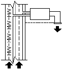
linetype called HOT_WATER_SUPPLY is defined as
*HOT_WATER_SUPPLY,---- HW ---- HW ---- HW ---- HW ---- HW
----
A,.5,-.2,["HW",STANDARD,S=.1,U=0.0,X=-0.1,Y=-.05],-.2
This indicates a repeating pattern starting with a dash 0.5 drawing units long,
a space 0.2 drawing units long, the characters HW with some scale and
placement parameters, and another space 0.2 drawing units long. The text
characters come from the text font assigned to the STANDARD text style at a
scale of 0.1, an upright rotation of 0 degrees, an X offset of -0.1, and a Y offset
of -0.05. This pattern continues for the length of the line, ending with a dash
0.5 drawing units long. The linetype would be displayed as shown below.
Notice that the total upstroke length is 0.2 + 0.2 = 0.4 and that the text origin
is offset -.01 units in the X direction from the end of the first upstroke. An
equivalent linetype would be
*HOT_WATER_SUPPLY,---- HW ---- HW ---- HW ---- HW ---- HW
----
A,.5,-.1,["HW",STANDARD,S=.1,U=0.0,X=0.0,Y=-.05],-.3
The total upstroke is still 0.1 + 0.3 = 0.4, but the text origin is not offset in the
X direction.
Additional information about each field in the character descriptor follows.
The values to be used are signed decimal numbers such as 1, -17, and 0.01.
text The characters to be used in the linetype.
text style name The name of the text style to be used. If no text style is
specified, AutoCAD uses the currently defined style.
22 | Chapter 2 Custom Linetypes

scale S=value. The scale factor to be used for the text style relative to the scale
of the linetype. The height of the text style is multiplied by the scale factor.
If the height is 0, the value for S=value alone is used as the height.
rotation U=value, R=value, or A=value. U= specifies upright or easy-to-read
text. R= specifies relative or tangential rotation with respect to the line. A=
specifies absolute rotation of the text with respect to the origin; that is, all
text has the same rotation regardless of its position relative to the line. The
value can be appended with a d for degrees (degrees is the default value), r for
radians, or g for grads. If rotation is omitted, 0 relative rotation is used.
Rotation is centered between the baseline and the nominal cap height.
NOTE Drawings containing legacy linetypes that do not use the U (upright) rotation
flag can be updated to the latest linetype definition by reloading the linetype from
the LIN files. Custom linetypes can be updated by changing the R (rotation) flag
to the U (upright) flag prior to reloading a linetype definition. For information on
loading a linetype, see Load Linetypes.
xoffset X=value. The shift of the text on the X axis of the linetype, which is
along the line. If xoffset is omitted or is 0, the text is elaborated with no
offset. Use this field to control the distance between the text and the previous
pen-up or pen-down stroke. This value is not scaled by the scale factor defined
by S=value, but it is scaled to the linetype.
yoffset Y=value. The shift of the text in the Y axis of the linetype, which is
at a 90-degree angle to the line. If yoffset is omitted or is 0, the text is
elaborated with no offset. Use this field to control the vertical alignment of
the text with respect to the line. This value is not scaled by the scale factor
defined by S=value, but it is scaled to the linetype.
Text in Custom Linetypes
To include text characters in linetypes
1Create a simple linetype, as described in To add a simple linetype to a
LIN file (page 21).
2Add the text character descriptor within the linetype pattern, using the
following format:
["text",textstylename,scale,rotation,xoffset,yoffset]
Text in Custom Linetypes | 23
Shapes in Custom Linetypes
A complex linetype can contain embedded shapes that are saved in shape
files. Complex linetypes can denote utilities, boundaries, contours, and so on.
As with simple linetypes, complex lines are dynamically drawn as the user
specifies vertices. Shapes and text objects embedded in lines are always
displayed completely; they are never trimmed.
The syntax for complex linetypes is similar to that of simple linetypes in that
it is a comma-delimited list of pattern descriptors. Complex linetypes can
include shape and text objects as pattern descriptors, as well as dash-dot
descriptors.
The syntax for shape object descriptors in a linetype description is as follows:
[shapename,shxfilename] or [shapename,shxfilename,transform]
where transform is optional and can be any series of the following (each preceded
by a comma):
R=## Relative rotation
A=## Absolute rotation
U=## Upright rotation
S=## Scale
X=## X offset
Y=## Y offset
In this syntax, ## is a signed decimal number (1, -17, 0.01, and so on), the
rotation is in degrees, and the remaining options are in linetype-scaled drawing
units. The preceding transform letters, if they are used, must be followed by an
equal sign and a number.
The following linetype definition defines a linetype named CON1LINE that
is composed of a repeating pattern of a line segment, a space, and the
embedded shape CON1 from the ep.shx file. (Note that the ep.shx file must be
in the support path for the following example to work properly.)
*CON1LINE, --- [CON1] --- [CON1] --- [CON1]
A,1.0,-0.25,[CON1,ep.shx],-1.0
Except for the code enclosed in square brackets, everything is consistent with
the definition of a simple linetype.
24 | Chapter 2 Custom Linetypes
As previously described, a total of six fields can be used to define a shape as
part of a linetype. The first two are mandatory and position-dependent; the
next four are optional and can be ordered arbitrarily. The following two
examples demonstrate various entries in the shape definition field.
[CAP,ep.shx,S=2,R=10,X=0.5]
The code above draws the CAP shape defined in the ep.shx shape file with a
scale of two times the unit scale of the linetype, a tangential rotation of 10
degrees in a counterclockwise direction, and an X offset of 0.5 drawing units
before shape elaboration takes place.
[DIP8,pd.shx,X=0.5,Y=1,R=0,S=1]
The code above draws the DIP8 shape defined in the pd.shx shape file with an
X offset of 0.5 drawing units before shape drawing takes place, and a Y offset
of one drawing unit above the linetype, with 0 rotation and a scale equal to
the unit scale of the linetype.
The following syntax defines a shape as part of a complex linetype.
[shapename,shapefilename,scale,rotate,xoffset,yoffset]
The definitions of the fields in the syntax follow.
shapename The name of the shape to be drawn. This field must be included.
If it is omitted, linetype definition fails. If shapename does not exist in the
specified shape file, continue drawing the linetype but without the embedded
shape.
shapefilename The name of a compiled shape definition file (SHX). If it is
omitted, linetype definition fails. If shapefilename is unqualified (that is, no
path is specified), search the library path for the file. If shapefilename is fully
qualified and not found at that location, remove the prefix and search the
library path for the file. If it is not found, continue drawing the linetype but
without the embedded shape.
scale S=value. The scale of the shape is used as a scale factor by which the
shape's internally defined scale is multiplied. If the shape's internally defined
scale is 0, the S=value alone is used as the scale.
rotate U=value, R=value or A=value. R= signifies relative or tangential rotation
with respect to the line's elaboration. A= signifies absolute rotation of the
shape with respect to the origin; all shapes have the same rotation regardless
of their relative position to the line. The value can be appended with a d for
degrees (if omitted, degree is the default), r for radians, or g for grads. If
rotation is omitted, 0 relative rotation is used.
Shapes in Custom Linetypes | 25

NOTE Drawings containing legacy linetypes that do not use the U (upright) rotation
flag can be updated to the latest linetype definition by reloading the linetype from
the LIN files. Custom linetypes can be updated by changing the R (rotation) flag
to the U (upright) flag prior to reloading a linetype definition. For information on
loading a linetype, see Load Linetypes.
xoffset X=value. The shift of the shape in the X axis of the linetype computed
from the end of the linetype definition vertex. If xoffset is omitted or is 0, the
shape is elaborated with no offset. Include this field if you want a continuous
line with shapes. This value is not scaled by the scale factor defined by S=.
yoffset Y=value. The shift of the shape in the Y axis of the linetype computed
from the end of the linetype definition vertex. If yoffset is omitted or 0, the
shape is elaborated with no offset. This value is not scaled by the scale factor
defined by S=.
See also:
Shapes and Shape Fonts (page 109)
26 | Chapter 2 Custom Linetypes

Custom Hatch Patterns
AutoCAD® provides a library of standard hatch patterns in the acad.pat and acadiso.pat files.
You can use the hatch patterns as they are, modify them, or create your own custom hatch
patterns.
Overview of Hatch Pattern Definitions
In addition to using the predefined hatch patterns that are supplied, you can
design and create your own custom hatch patterns.
Developing a hatch pattern definition requires knowledge, practice, and patience.
Because customizing hatches requires familiarity with hatch patterns, it is not
recommended for new users.
The hatch patterns supplied by AutoCAD are stored in the acad.pat and
acadiso.pat text files. You can add hatch pattern definitions to this file or create
your own files.
Regardless of where the definition is stored, a custom hatch pattern has the
same format. It has a header line with a name, which begins with an asterisk
and is no more than 31 characters long, and an optional description:
*pattern-name,description
It also has one or more line descriptors of the following form:
angle,x-origin,y-origin,delta-x,delta-y,dash-1,dash-2, …
The default hatch pattern ANSI31 shown in the Boundary Hatch and Fill dialog
box looks like this:
and is defined as follows:
3
27

*ANSI31, ANSI Iron, Brick, Stone masonry
45, 0,0, 0,.125
The pattern name on the first line, *ANSI31, is followed by a description: ANSI
Iron, Brick, Stone masonry. This simple pattern definition specifies a line
drawn at an angle of 45 degrees, that the first line of the family of hatch lines
is to pass through the drawing origin (0,0), and that the spacing between
hatch lines of the family is to be 0.125 drawing units.
Hatch pattern definitions follow these rules:
■Each line in a pattern definition can contain up to 80 characters. You can
include letters, numbers, and the special characters underline (_), hyphen
(-), and dollar sign ($). However, you must begin a pattern definition with
a letter or number, not a special character.
■AutoCAD ignores both blank lines and text to the right of a semicolon.
■Each pattern line is considered to be the first member of a line family,
created by applying the delta offsets in both directions to generate an
infinite family of parallel lines.
■The delta-x value indicates the displacement between members of the family
in the direction of the line. It is used only for dashed lines.
■The delta-y value indicates the spacing between members of the family;
that is, it is measured perpendicular to the lines.
■A line is considered to be of infinite length. A dash pattern is superimposed
on the line.
NOTE A blank line must be placed after the last hatch pattern definition in a PAT
file. If a blank line is not placed after the last hatch pattern definition, the last hatch
pattern definition will not be accessible when creating a hatch fill.
The process of hatching consists of expanding each line in the pattern
definition to its infinite family of parallel lines. All selected objects are checked
for intersections with any of these lines; any intersections cause the hatch
lines to be turned on and off as governed by the hatching style. Each family
of hatch lines is generated parallel to an initial line with an absolute origin
to guarantee proper alignment.
If you create a very dense hatch, AutoCAD may reject the hatch and display
a message indicating that the hatch scale is too small or its dash length too
short. You can change the maximum number of hatch lines by setting the
MaxHatch environment variable using (setenv “MaxHatch” “n”) where n is
a number between 100 and 10000000 (ten million).
28 | Chapter 3 Custom Hatch Patterns

NOTE When changing the value of MaxHatch, you must enter MaxHatch with
the capitalization as shown.
Overview of Hatch Pattern Definitions
To create a simple hatch pattern
1Open the acad.pat or acadiso.pat file in a text editor that saves in ASCII
format.
2Create a header line that includes an asterisk and a pattern name. The
name of the hatch pattern is limited to 31 characters.
3(Optional) To include a description in the header line, follow the pattern
name with a comma and description text.
4Create a descriptor line that includes
■An angle at which the line is drawn
■An X,Y origin point
■A delta-x of 0
■A delta-y of any value
Hatch Patterns with Dashed Lines
To define dashed-line patterns, you append dash-length items to the end of
the line definition item.
To define dashed-line patterns, you append dash-length items to the end of
the line definition item. Each dash-length item specifies the length of a
segment making up the line. If the length is positive, a pen-down segment is
drawn. If the length is negative, the segment is pen-up, and it is not drawn.
The pattern starts at the origin point with the first segment and cycles through
the segments in circular fashion. A dash length of 0 draws a dot. You can
specify up to six dash lengths per pattern line.
The hatch pattern ANSI33, looks like this:
and is defined as follows:
Hatch Patterns with Dashed Lines | 29
*ANSI33, ANSI Bronze, Brass, Copper
45, .176776695,0, 0,.25, .125,-.0625
For example, to modify a pattern for 45-degree lines to draw dashed lines with
a dash length of 0.5 units and a space between dashes of 0.5 units, the line
definition would be
*DASH45, Dashed lines at 45 degrees
45, 0,0, 0,.5, .5,-.5
This is the same as the 45-degree pattern shown in Overview of Hatch Pattern
Definitions (page 27), but with a dash specification added to the end. The
pen-down length is 0.5 units, and the pen-up length is 0.5, meeting the stated
objectives. If you wanted to draw a 0.5-unit dash, a 0.25-unit space, a dot, and
a 0.25-unit space before the next dash, the definition would be
*DDOT45,Dash-dot-dash pattern: 45 degrees
45, 0,0, 0,.5, .5,-.25, 0,-.25
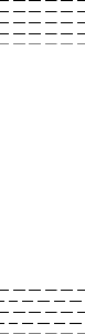
The following example shows the effect of delta-x specifications on dashed-line
families. First, consider the following definition:
*GOSTAK
0, 0,0, 0,.5, .5,-.5
This draws a family of lines separated by 0.5, with each line broken equally
into dashes and spaces. Because delta-x is zero, the dashes in each family
member line up. An area hatched with this pattern would look like this:
Now change the pattern to
*SKEWED
0, 0,0, .5,.5, .5,-.5
It is the same, except that you have set delta-x to 0.5. This offsets each successive
family member by 0.5 in the direction of the line (in this case, parallel to the
X axis). Because the lines are infinite, the dash pattern slides down the specified
amount. The hatched area would look like this:
30 | Chapter 3 Custom Hatch Patterns

Hatch Patterns with Dashed Lines
To create a hatch pattern with dashed lines
1Open the acad.pat or acadiso.pat file in a text editor that saves in ASCII
format.
2Create a header line that includes an asterisk and a pattern name. The
name of the hatch pattern is limited to 31 characters.
3(Optional) To include a description in the header line, follow the pattern
name with a comma and description text.
4Create a descriptor line that includes
■An angle at which the line is drawn
■An X,Y origin point
■A delta-x of any value if you want to offset alternating lines in the line
family
■A delta-y of any value
■A value for a dash length
■A value for a dot length
■An optional second value for a different dash length
■An optional second value for a different dot length
Hatch Patterns with Multiple Lines
Complex hatch patterns can have an origin that passes through offsets from
the origin and can have multiple members in the line family.
Not all hatch patterns use origin points of 0,0. Complex hatch patterns can
have an origin that passes through offsets from the origin and can have
multiple members in the line family. In composing more complex patterns,
you need to carefully specify the starting point, offsets, and dash pattern of
each line family to form the hatch pattern correctly.
The hatch pattern AR-B816 looks like this:
and is defined as follows with multiple lines describing the pattern:
Hatch Patterns with Multiple Lines | 31
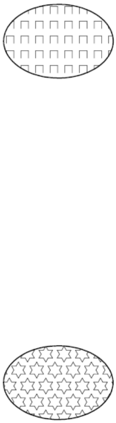
*AR-B816, 8x16 Block elevation stretcher bond
0, 0,0, 0,8
90, 0,0, 8,8, 8,-8
The following figure illustrates a squared-off, inverted-U pattern (one line up,
one over, and one down). The pattern repeats every one unit, and each unit
is 0.5 high and wide.
This pattern would be defined as follows:
*IUS,Inverted U's
90, 0,0, 0,1, .5,-.5
0, 0,.5, 0,1, .5,-.5
270, .5,.5, 0,1, .5,-.5
The first line (the up bar) is a simple dashed line with 0,0 origin. The second
line (the top bar) should begin at the end of the up bar, so its origin is 0,.5.
The third line (the down bar) must start at the end of the top bar, which is at
.5,.5 for the first instance of the pattern, so its origin is at this point. The third
line of the pattern could be the following:
90, .5,0, 0,1, .5,-.5
or
270, .5,1, 0,1, -.5,.5
The dashed pattern starts at the origin points and continues in the vector
direction given by the angle specification. Therefore, two dashed-line families
that are opposed 180 degrees are not alike. Two solid-line families are alike.
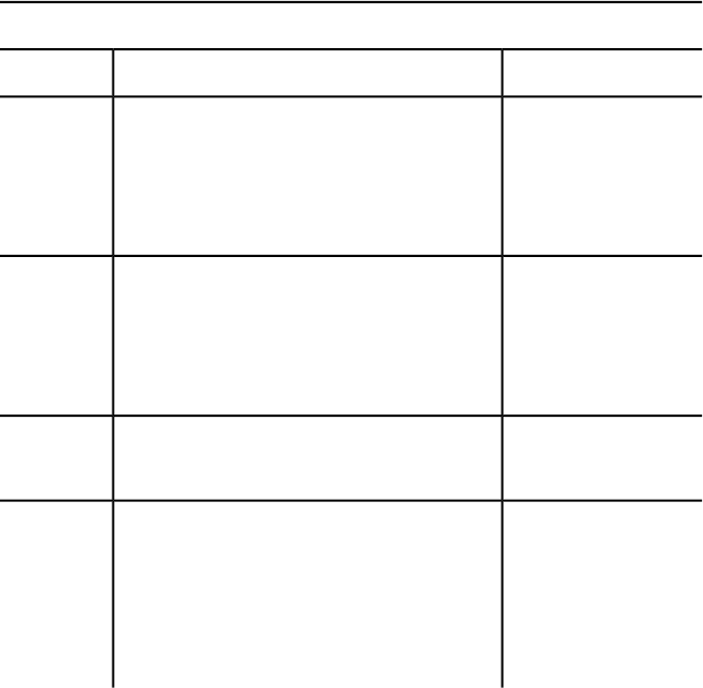
The following pattern creates six-pointed stars.
32 | Chapter 3 Custom Hatch Patterns
This example can help you refine your skills at pattern definition. (Hint: 0.866
is the sine of 60 degrees.)
The following is the AutoCAD definition of this pattern:
*STARS,Star of David
0, 0,0, 0,.866, .5,-.5
60, 0,0, 0,.866, .5,-.5
120, .25,.433, 0,.866, .5,-.5
Hatch Patterns with Multiple Lines
To create a hatch pattern with multiple lines
1Open the acad.pat or acadiso.pat file in a text editor that saves in ASCII
format.
2Create a header line that includes an asterisk and a pattern name. The
name of the hatch pattern is limited to 31 characters.
3(Optional) To include a description in the header line, follow the pattern
name with a comma and description text.
4Create a descriptor line that includes
■An angle at which the line is drawn
■An X,Y origin point
■A delta-x of any value if you want to offset alternating lines in the
line family
■A delta-y of any value
■A value for a dash length
■A value for a dot length
■An optional second value for a different dash length
■An optional second value for a different dot length
5Create a second line including all the parameters in the previous step.
6(Optional) Create additional lines to complete the multiple-line hatch
pattern.
Hatch Patterns with Multiple Lines | 33
34
User Interface Customiz-
ation
When you work in the program, you use a variety of menus, tool sets, and shortcut menus
to help you accomplish your tasks efficiently. You can also streamline your environment by
customizing these elements.
Understand User Interface Customization
Using the customization tools of AutoCAD, you can tailor your drawing
environment to suit your needs. The Customize dialog box helps you to easily
create and modify the menus and tool sets that make up the user interface.
Overview of the Customization
Customization of the user interface is done with the Customize dialog box.
From the Customize dialog box, you can
■Create new custom commands or modify existing commands
■Assign commands to various user interface elements
■Add or change menus that are displayed on the Mac OS menu bar
■Add or change tool sets that are displayed on the Tool Sets palette
Customizable User Interface Elements
The Customize dialog box allows you to create and manage commands that are
used by the user interface. Along with commands, you are able to customize
the following user interface elements
■Menu bar menus
4
35
■Tool sets
Customization Glossary
You should know several terms for customizing AutoCAD 2013.
Interface element An object that can be customized, such as a menu or tool
set.
Interface item The individual parts of a user interface element, such as a
menu item or tool set tool.
Macro A series of commands that are run in a defined sequence to accomplish
a drawing task.
Palette A modeless interface element that can be docked or floating outside
of the drawing area. Palettes include the Properties Inspector, Reference
Manager, Command Line, and so on.
Tool set An interface element that displays tool groups made up of commands
and flyouts (or drop-downs) that are displayed vertically outside the drawing
area.
Tool group An organizational structure used to lay out commands and flyouts
(or drop-downs) for display on the Tool Sets palette.
Customize Commands
Commands in the Customize dialog box are used to define custom macros
which are used to start standard and custom commands which can be executed
from the command prompt in AutoCAD.
Overview of Commands
You can easily create, edit, and reuse commands. The Commands tab of the
Customize dialog box allows you to create and modify existing commands
that can then be added to a user interface element.
When you change the properties of a command in the Commands list, the
properties of the command are changed everywhere the command is
referenced. Each property of a command in the Commands list controls which
36 | Chapter 4 User Interface Customization
actions are taken when the command is used and how the command looks
when added to a user interface element.
The following table shows the properties of the Scale command as they appear
in the Properties section.
Properties for the Scale command in the Commands list
ExampleDescriptionProperty
ScaleString displayed as the caption of a menu item
or as a tooltip on the Tool Sets palette. The string
Name
must include alphanumeric characters with no
punctuation other than a hyphen (-) or an under-
score (_).
Enlarges or reduces se-
lected objects, keeping
String displayed as a tooltip when the cursor
hovers over the tool on the Tool Sets palette.
Description
the proportions of the
object the same after
scaling
^C^C_scaleThe command macro. It follows the standard
macro syntax.
Macro
RCDATA_16_SCALEID string of the small-image resource (16 × 16
bitmap). The string must include alphanumeric
Image
characters with no punctuation other than a
hyphen (-) or an underscore (_). It can also be
a user-defined raster image file. Click the […]
button to open the Select Image File dialog box.
Create, Edit, and Reuse Commands
You can create a new command from scratch, copy an existing command to
create a new command, or edit the properties of an existing command.
When you change the properties of a command in the Commands list, the
command is updated for all user interface elements that reference the
command.
Customize Commands | 37
See also:
Create Macros (page 40)
Create, Edit, and Reuse Commands
To create a custom command
1At the Command prompt, enter cui and press Enter.
2In the Customize dialog box, Commands tab, click Create New Command
(+).
A new command (named Command1) is added to the Commands list
and properties for the new command are displayed in the Properties
section.
3In the Properties section, do the following:
■In the Name box, enter a name for the command.
The name is displayed in a tooltip on the Tool Sets palette and used
as the caption for a menu item.
■In the Description box, enter a description for the command.
The description is displayed in a tooltip on the Tool Sets palette.
■In the Macro box, enter a macro for the command.
■In the Image box, click the […] button to display the Select an Image
File dialog box. Select the raster image you want to assign to the
command, it should be 16x16 pixels
To edit a command
1At the Command prompt, enter cui and press Enter.
2In the Customize dialog box, Commands tab, Commands list, select the
command to edit.
NOTE
When you make a change to a command, the change is applied to all
instances of the command in all menus and tool sets.
3In the Properties section, do any of the following to edit the command:
■In the Name box, enter a name for the command.
38 | Chapter 4 User Interface Customization
The name is displayed in a tooltip on the Tool Sets palette and used
as the caption for a menu item.
■In the Description box, enter a description for the command.
The description is displayed in a tooltip on the Tool Sets palette.
■In the Macro box, enter a macro for the command.
■In the Image box, click the […] button to display the Select an Image
File dialog box. Select the raster image you want to assign to the
command, it should be 16x16 pixels
To delete a command
1At the Command prompt, enter cui and press Enter.
2In the Customize dialog box, Commands tab, Commands list, select the
command to delete.
NOTE
Commands assigned to a menu, tool set, shortcut key, or accelerator
cannot be deleted.
3Click the Options action menu below the Commands list, Gear icon,
and click Delete.
To duplicate a command
1At the Command prompt, enter cui and press Enter.
2In the Customize dialog box, Commands tab, Commands list, select the
command to duplicate.
3Click the Options action menu below the Commands list, Gear icon,
and click Duplicate.
Make the desired changes to the new copy of the command.
To use a command
1At the Command prompt, enter cui and press Enter.
2In the Customize dialog box, click the Menus or Tool Sets tab.
3In the Commands list, locate the command you want to use and drag
it to the menu or tool set you want to add the command to.
Customize Commands | 39
Create Macros
A macro defines the action that results when an interface element is selected.
A macro accomplishes a drawing task that would otherwise take a series of
actions by a user.
Overview of Macros
A macro can contain commands, special characters, DIESEL (Direct
Interpretively Evaluated String Expression Language) or AutoLISP programming
code.
NOTE
As AutoCAD is revised and enhanced, the sequence of prompts for various
commands (and sometimes command names) might change. Therefore, your
custom macros might require minor changes when you upgrade to a new
release of AutoCAD.
You add macros to interface elements by using the Customize dialog box.
Select an existing command or create a new command in the Commands list
on the Commands tab. Enter a macro in the Macros text box under the
Properties section. There are no length limitations for macros. However, you
do need to know how specific characters are used in macros and be aware of
other considerations or limitations.
Macro Basics
A macro in a user interface element can be as simple as a command (such as
circle) and some special characters (such as ^C^C).
For example, the macro ^C^C_circle \1, draws a circle with a radius of 1 unit.
The components that define this macro are explained in the table below.
Components in CIRCLE macro
ResultComponent typeComponent
Cancels any running commandsSpecial control charac-
ter
^C^C
40 | Chapter 4 User Interface Customization
Components in CIRCLE macro
Automatically translates the command
that follows into other languages
Special control charac-
ter
_
Starts the CIRCLE commandCommandCIRCLE
Creates a pause for the user to specify the
center point
Special control charac-
ter
\
Responds to the prompt for the circle's
radius (1)
Special control charac-
ter
1
For a list of special control characters that you can use in macros, see Use
Special Control Characters in Macros (page 42).
Cancel Running Commands
Make sure that you have no AutoCAD commands in progress before you
execute a macro. To automatically cancel a command before executing a
macro, enter ^C^C at the beginning of the macro (which is the same as pressing
ESC twice). Although a single ^C cancels most commands, ^C^C is required to
return to the command prompt from a dimensioning command and ^C^C^C
is required based on the current option of the -LAYER command. ^C^C handles
canceling out of most command sequences and therefore is the recommended
sequence used to ensure no command is active before the macro is started.
Verify Macro Characters
Every character in a macro is significant, even a blank space.
When you place a space at the end of the macro, AutoCAD processes the
macro as though you had entered a command (circle, for example) and then
pressed the Spacebar to complete the command.
Terminate Macros
Some macros require special terminators. Some commands (TEXT, for example)
require you to press Enter rather than Spacebar to terminate the command.
Some commands require more than one space (or Enter) to complete, but
some text editors cannot create a line with trailing blanks.
Customize Commands | 41
Two special conventions resolve these problems.
■A semicolon (;) in a macro automatically issues Enter at the Command
prompt.
■If a line ends with a control character, a backslash (\), a plus sign (+), or a
semicolon (;), AutoCAD does not add a blank space after it.
An item that ends with a backslash (\) pauses a macro for user input.
Compare the following macros:
ucs
ucs ;
The first example enters ucs at the command prompt and presses Spacebar.
The following prompt is displayed.
Specify origin of UCS or
[Face/NAmed/OBject/Previous/View/World/X/Y/Z/ZAxis] <World>:
The second example enters ucs, presses Spacebar, and presses Enter, which
accepts the default value (World).
Suppress Echoes and Prompts in Macros
Characters in a macro appear at the command line as though you had typed
the characters on the keyboard. This display duplication is called “echoing”.
You can suppress the “echoed” displays with the MENUECHO system variable.
If echoes and prompts from item input are turned off, a ^P in the item turns
them off.
Use Special Control Characters in Macros
You can use special characters, including control characters, in macros. In a
macro, the caret (^) is equivalent to pressing the Command key on the
keyboard. You can combine the caret with another character to construct
macros that do such things as turn the grid on and off (^G) or cancel a
command (^C).
The macro for the Address command below uses the backslash (\) to pause
for user input and the semicolon (;) for Enter.
text \.4 0 DRAFT Inc;;;Main St.;;;City, State;
42 | Chapter 4 User Interface Customization
The macro starts the TEXT command, pauses for the user to specify a start
point, and then enters the address on three lines. In the triple semicolon (;;;),
the first semicolon ends the text string, the second repeats TEXT, and the
third accepts the default placement below the previous line.
Macros use the special characters listed in the following table.
Special characters used in macros
DescriptionCharacter
Issues Enter;
Issues Enter^M
Issues Tab^I
Enters a space; a blank space between command sequences in a com-
mand is equivalent to pressing the Spacebar
[blank space]
Pauses for user input (cannot be used with accelerators)\
Allows you to access a built-in AutoCAD command even if it was un-
defined using the UNDEFINE command.
.
Translates AutoCAD commands and options that follow_
Repeats a command until another command is chosen*^C^C
Introduces a conditional DIESEL macro expression ($M=)$
Turns Snap on or off (equivalent to Command-B)^B
Cancels the active command or command option (equivalent to Esc)^C
Turns Dynamic UCS on or off (equivalent to Control-D)^D
Sets the next isometric plane^E
Customize Commands | 43
Special characters used in macros
DescriptionCharacter
Turns Grid on or off (equivalent to Control-G)^G
Issues Backspace^H
Turns Ortho on or off^O
Turns MENUECHO on or off^P
Echoes all prompts, status listings, and input to the printer^Q
Turns command versioning on or off. Command versioning is required
for some commands to ensure command macros written in an older
release work properly in the latest release.
^R
Changes the current viewport^V
Null character that suppresses the automatic addition of Spacebar at
the end of a command
^Z
Pause for User Input in Macros
To accept input from the keyboard or pointing device in the middle of a
command, place a backslash (\) in the macro at the point where you want
input.
circle \1
In the circle example, \1 pauses for the user to specify the center point and
then reads a radius of 1. Note that there is no space after the backslash.
-layer off \;
44 | Chapter 4 User Interface Customization

In this example, the macro starts -LAYER at the Command prompt, enters the
Off option (off), and then pauses for the user to enter a layer name (\). The
macro then turns that layer off and exits the -LAYER command (;).
NOTE
LAYER normally prompts for another operation and exits only if you press
Spacebar or Enter. In the macro, the semicolon (;) is the equivalent of pressing
Enter.
A macro typically resumes after one user input, such as a single point location.
Therefore, you cannot construct a macro that accepts a variable number of
inputs (as in object selection) and then continues. However, an exception is
made for SELECT: a backslash (\) suspends the SELECT command until object
selection has been completed. Consider the following example:
select \change previous ;properties color red ;
In this macro, SELECT creates a selection set of one or more objects (select \).
The macro then starts CHANGE (change), references the selection set using
the Previous option (previous;), and changes the color of all selected objects
to red (properties color red ;).
NOTE
The backslash character (\) causes a macro to pause for user input. You cannot
use a backslash for any other purpose in a macro. When you need to specify
a file directory path, use a forward slash (/) as the path delimiter: for example,
/direct/file.
The following circumstances delay resumption of a macro after a pause:
■If input of a point location is expected, object snap modes may be used
before the point is specified.
■If X/Y/Z point filters are used, the command remains suspended until the
entire point has been accumulated.
■For SELECT only, the macro does not resume until object selection has
been completed.
■If the user responds with a transparent command, the suspended macro
remains suspended until the transparent command is completed and the
originally requested input is received.
■If the user responds by choosing another command (to supply options or
to execute a transparent command), the original macro is suspended, and
Customize Commands | 45

the newly selected item is processed to completion. Then, the suspended
macro is resumed.
NOTE When command input comes from a command, the settings of the PICKADD
and PICKAUTO system variables are assumed to be 1 and 0, respectively. This
preserves compatibility with previous releases of AutoCAD and makes customization
easier because you are not required to check the settings of these variables.
Provide International Support in Macros
To develop menus that can be used with a non-English-language version of
AutoCAD, precede each command or option with the underscore character
(_). The underscore character allows the standard commands and options to
be translated automatically.
Use Built-in Commands in Macros
To develop macros that use built-in commands that are part of AutoCAD,
precede each command with the period character (.). The period character
allows the built-in command to be used even if it has been undefined with
the UNDEFINE command making the macro predicable when it is used on
other systems that share the same customization file.
Repeat Commands in Macros
You can use a leading asterisk (*) to repeat a command in a macro until you
choose another command.
Once you have selected a command, you might want to use it several times
before moving on to another command. In a macro, you can repeat a command
until you choose another command. You cannot use this feature to choose
options.
If a macro begins with *^C^C, the command is repeated until you terminate
by pressing Esc on the keyboard or by selecting another command.
NOTE
Do not use ^C (Cancel) within a macro that begins with the string *^C^C;
this cancels the repetition.
46 | Chapter 4 User Interface Customization

The macros in the following examples repeat the commands:
*^C^Cmove Single
*^C^Ccopy Single
*^C^Cerase Single
*^C^Cstretch Single Crossing
*^C^Crotate Single
*^C^Cscale Single
Each macro in the example starts a command and then prompts you to select
an object. Any other prompts necessary to complete the command are
displayed, and then the command ends and starts again.
NOTE
Command repetition cannot be used in macros for image tile menus.
Use Single Object Selection Mode in Macros
Single Object Selection mode cancels the normal repetition of the Select
Objects prompt in editing commands. After you select one object and respond
to any other prompts, the command ends.
Consider the macro in the following example:
*^C^Cerase single
This macro terminates the current command and starts ERASE in Single Object
Selection mode. After you choose this command, you either select a single
object to be erased or click a blank area in the drawing and specify window
selection. Any objects selected in this way are erased, and the command is
repeated (due to the leading asterisk) so that you can erase additional objects.
Press Esc to exit this mode.
Use Conditional Expressions in Macros
You can add conditional expressions to a macro by using a command that
introduces macro expressions written in DIESEL (Direct Interpretively Evaluated
String Expression Language).
The format is:
Customize Commands | 47
$M=expression
Introducing the macro with $M= tells AutoCAD to evaluate a string as a DIESEL
expression, and that expression is the DIESEL expression. The following example
defines a conditional expression in a macro:
FILLMODE $M=$(-,1,$(getvar,fillmode))
The macro switches the FILLMODE system variable on and off by subtracting
the current value of FILLMODE from 1 and returning the resulting value to
the FILLMODE system variable. You can use this method to toggle system
variables whose valid values are 1 or 0.
Termination of Macros That Contain Conditional Expressions
If you use the DIESEL string language to perform “if-then” tests, conditions
might exist where you do not want the normal terminating space or semicolon
(resulting in Enter). If you add ^Z to the end of the macro, AutoCAD does not
automatically add a space (Enter) to the end of the macro expression.
As with other control characters in commands, the ^Z used here is a string
composed of ^ (a caret) and Z and is not equivalent to pressing Cmd-Z.
In the following examples, ^Z is used as a macro terminator.
^C^C$M=$(if,$(=,$(getvar,tilemode),0),$S=mview _mspace )^Z
^C^C$M=$(if,$(=,$(getvar,tilemode),0),$S=mview _pspace )^Z
If these macros did not end with ^Z, AutoCAD would automatically add a
space (Enter), repeating the last command entered.
See also:
Use Special Control Characters in Macros (page 42)
DIESEL (page 63)
Use AutoLISP in Macros
Creating commands that use AutoLISP is a more advanced way to use the
AutoCAD customization feature.
You can use AutoLISP variables and expressions to create macros that perform
complex tasks. To use AutoLISP efficiently in macros, place AutoLISP code in
48 | Chapter 4 User Interface Customization
a separate MNL file. AutoCAD loads the MNL file when it loads a customization
file with the same name and in the same location.
Creating commands that use AutoLISP is a more advanced way to use the
AutoCAD customization feature. Carefully study the following examples and
the information in the AutoLISP Reference and the AutoLISP Developer's Guide.
Preset Values
An application that uses block insertion presets could provide commands like
these: [Set WINWID][Set WALLTHK][Insert Window]
^C^C^P(setq WINWID (getreal "Enter window width: ")) ^P
^C^C^P(setq WALLTHK (getreal "Enter wall thickness: ")) ^P
^C^C_INSERT window XScale !WINWID YScale !WALLTHK
This code inserts the block named “window,” scaling its X axis to the current
window width and its Y axis to the current wall thickness. In this example,
the actual values come from the user-defined AutoLISP symbols WINWID and
WALLTHK. The rotation is up to the user to decide so that the window can
be rotated in the wall.
Resize Grips
With the following commands, grip size adjustment can be done on the fly:
^P(setvar "gripsize"(1+ (getvar "gripsize")))(redraw)(princ)
^P(setvar "gripsize"(1- (getvar "gripsize")))(redraw)(princ)
To add validity checking to these commands, values less than 0 and greater
than 255 cannot be used for the GRIPSIZE system variable.
Prompt for User Input
The following item prompts for two points and draws a rectangular polyline
with the specified points as its corners.
^P(setq a (getpoint "Enter first corner: "));\+
(setq b (getpoint "Enter opposite corner: "));\+
pline !a (list (car a)(cadr b)) !b (list (car b)(cadr a))
c;^P
Customize Commands | 49
Control the Display of Command Items
The way a menu item is displayed indicates its availability in the program.
A menu item can be displayed as:
■Grayed out (disabled)
■Marked with a check marker or border
■Both grayed out and marked
Gray Out (Disable) Menu Items
You gray out a menu item by doing one of the following:
■Beginning a name with a tilde (~)
■Using a DIESEL string expression
For more information about using DIESEL expressions, see DIESEL Expressions
in Macros. When grayed out, the macro and submenus associated with the
menu item are made inaccessible.
DIESEL string expressions are used to conditionally disable or enable a menu
item each time they are displayed. For example, the DIESEL string expression
in the Macro text box in the Properties section disables the MOVE command
while any other command is active.
$(if,$(getvar,cmdactive),~)MOVE^C^C_move
Mark Menu Items
You can mark a menu item by doing one of the following:
■Beginning a command name with an exclamation point and a period (!.)
■Using a DIESEL string expression
A menu item is marked with or without a check mark.
Menu items can contain DIESEL string expressions to conditionally mark them
each time they are displayed. When the following DIESEL string is added to
the Macro text box for the applicable command in the Properties section on
the Commands tab, a check mark is placed to the left of the menu item whose
related system variable is currently enabled.
$(if,$(getvar,orthomode),!.)Ortho^O
50 | Chapter 4 User Interface Customization
$(if,$(getvar,snapmode),!.)Snap^B
$(if,$(getvar,gridmode),!.)Grid^G
Simultaneously Disable and Mark Command Items
You can mark and disable commands at the same time using either of the
following formats:
~!.labeltext
!.~labeltext
The tilde (~) is the special character code to disable a command and an
exclamation point and period (!.) is the special character code to mark a
command.
See also:
DIESEL Expressions in Macros (page 63)
Create Tooltips for Commands
Tooltips are descriptive messages that are displayed near the cursor when it
hovers over a tool set tool.
The Description property associated to a command provides a simple
description for what the command does. The value of the Description property
is displayed as part of a basic tooltip that is displayed when the cursor hovers
over a tool set tool. Along with the description, the name of the command is
also displayed.
See also:
Customize Commands (page 36)
Create and Manage Images for Commands
Images can be assigned to commands, and can be of two different types:
standard and custom. Standard images come with AutoCAD in a library, while
external raster images can be assigned to commands in the Customize dialog
box.
Customize Commands | 51
Assign Images to a Command
Standard and custom images can be assigned to a command.
When a command is added to a tool set, the assigned image is displayed on
the tool.
AutoCAD comes with a library of standard images that are used for the standard
commands; these can be assigned to your own custom commands. You can
create your own custom commands using an external image editor.
See also:
Customize Commands (page 36)
Customize User Interface Elements
User interface elements in the Customize dialog box are used to control how
commands can be started.
Menus
Menus are displayed on the Mac OS menu bar and are used to organize
commands by general task.
Overview of Menus
Each menu can contain both standard and custom commands. Commands
can be grouped with separators and sub-menus. If a menu is longer than the
current display resolution in the vertical direction, it is truncated to fit.
When a menu is truncated, two arrows are added to the menu; one is added
at the top and another to the bottom. With the arrows, you can scroll through
the list of menu items. Sub-menus areindicated on a menu by an arrow that
points to the right. When using a sub-menu, it appears to the right of its
associated menu item normally. If a sub-menu reaches the edge of the display,
additional nested sub-menus will be displayed to the left of the menu item.
Menu items on the Mac OS menu bar are executed by clicking it. Unlike a
menu item, you do not need to click a sub-menu to access the assigned menu
52 | Chapter 4 User Interface Customization
items. Position the cursor over the sub-menu to expand it and then click the
menu item you want to use.
Create and Manage Pull-down Menus
You can create pull-down menus, and add commands and sub-menus for
display on the Mac OS menu bar.
You can create and modify menus to display and organize the commands to
best match the way you work. Commands are added to a menu from the
Commands list in the Customize dialog box. Once commands are added to a
menu, you can reposition commands, and organize commands using separators
and sub-menus.
Sub-menus and Separators
Sub-menus are used to organize and group similar commands together. You
create sub-menus in much the same way that you create a menu. Separators
can also be inserted to group similar commands without adding an additional
navigation level. There is no clear decision that can be made as to when you
might use a sub-menu over a separator. Some possible reason why you might
consider to use a sub-menu over a separator is the current length of the menu
and how frequently a command might be used.
See also:
Customize Commands (page 36)
Create and Manage Pull-down Menus
To create a pull-down menu
1At the Command prompt, enter cui and press Enter.
2In the Customize dialog box, Menus tab, Menus List, select the menu
in which you want to create the new menu after.
3Click the Create Menu Element (+) button below the Menus list and
click Add Menu.
A new menu (named Menu1) is created. The default name changes based
on the number of menus you previously created.
4Enter a name for the new menu.
Customize User Interface Elements | 53
The name entered is what will appear on the Mac OS menu bar. Click a
menu name twice to rename it.
5In the Commands list, drag a command to the new menu.
6Release the button on the pointer device when the menu or sub-menu
is highlighted, or the desired location for the command is indicated by
a horizontal line.
For information about creating a command, see Create, Edit, and Reuse
Commands (page 37).
To create a sub-menu
1At the Command prompt, enter cui and press Enter.
2In the Customize dialog box, Menus tab, Menus list, expand the menu
you want to add a sub-menu to.
3Select the menu item you want to insert the new sub-menu after.
4Click the Create Menu Element (+) button below the Menus list and
click Add Sub-menu.
A new sub-menu (named Sub-menu1) is created. The default name
changes based on the number of sub-menus you previously created.
5Enter a name for the new menu.
The name entered is what will appear on the Mac OS menu bar. Click a
sub-menu name twice to rename it.
6In the Commands list, drag a command to the new sub-menu.
7Release the button on the pointer device when the menu or sub-menu
is highlighted, or the desired location for the command is indicated by
a horizontal line.
For information about creating a command, see Create, Edit, and Reuse
Commands (page 37).
To add a command to a pull-down menu or sub-menu
1At the Command prompt, enter cui and press Enter.
2In the Customize dialog box, click Menus tab.
3In the Commands list, drag a command to the menu or sub-menu which
you want to add a command.
54 | Chapter 4 User Interface Customization
NOTE
If you hold the cursor over a menu or sub-menu, it will expand over a
short interval of time.
4Release the button on the pointer device when a menu or sub-menu is
highlighted, or the desired location for the command is indicated by a
horizontal line.
For information about creating a command, see Create, Edit, and Reuse
Commands (page 37).
To change the display name for a pull-down menu, sub-menu, or command
1At the Command prompt, enter cui and press Enter.
2In the Customize dialog box, Menus tab, Menus list, select a menu,
sub-menu, or menu item so it is highlighted.
3You need to click in the Display Name column to edit the name displayed
for a menu item.
4Click the menu or menu item again to edit its name or display name.
5Enter the new name and press Enter.
To insert a separator
1At the Command prompt, enter cui and press Enter.
2In the Customize dialog box, Menus tab, Menus list, select a sub-menu
or menu item to insert a separator after.
3Click the Options action menu below the Menus list, Gear icon, and
click Insert Separator.
To duplicate a pull-down menu, sub-menu, command, or separator
1At the Command prompt, enter cui and press Enter.
2In the Customize dialog box, Menus tab, Menus list, select a menu,
sub-menu, command, or separator item to duplicate.
3Click the Options action menu below the Menus list, Gear icon, and
click Duplicate.
4Enter a new name for the duplicated item.
Customize User Interface Elements | 55
To delete a pull-down menu, sub-menu, command, or separator
1At the Command prompt, enter cui and press Enter.
2In the Customize dialog box, Menus tab, Menus list, select a menu,
sub-menu, command, or separator item to delete.
3Click the Options action menu below the Menus list, Gear icon, and
click Delete.
NOTE
Be careful which item is selected because you cannot undo the deletion
of the item. Click Cancel to abort the changes you made.
To reposition a pull-down menu, sub-menu, command, or separator
1At the Command prompt, enter cui and press Enter.
2In the Customize dialog box, Menus tab, Menus list, select a menu,
sub-menu, command, or separator item to reposition.
3Click and drag the selected item to its new location in the Menus list.
4Release the button on the pointer device when the menu or sub-menu
is highlighted, or the desired location for the command is indicated by
a horizontal line.
Tool Sets
You can customize the Tool Sets palette by creating and modifying tool sets
and tool groups.
Overview of Tool Sets and Tool Groups
Tool Sets are made up of tool groups that contain tools. A tool can be either
a command or flytout (also known as a drop-down). Tool sets are accessed
from the Tool Sets palette. Each tool group is a maximum of two tools wide
and has two different display states: collapsed and expanded.
Position the cursor over a tool on the Tool Sets palette and click to use it. If
the tool is a flyout (or drop-down), click and hold the button on the pointer
device, and release over the tool you want to use.
56 | Chapter 4 User Interface Customization
Tools are not the only interactions that you will interact on the Tool Sets
palette. When the cursor is positioned over a tool group, a disclosure triangle
might appear that indicates the tool group can be expanded. Click the
disclosure triangle to expand the panel to access additional tools. After a tool
group is expanded, click the Lock icon to keep the tool group from collapsing.
See also:
Customize Commands (page 36)
Create and Manage Tool Sets
Tool sets are created to organize tool groups on the Tool Sets palette. AutoCAD
comes with three tool sets that are used to organize drafting, annotation, and
modeling tools. You create and manage tool sets on the Tool Sets tab of the
Customize dialog box. After a tool set is created, you click the Tool Sets button
near the top of the Tool Sets palette to set it current and use the commands
and flyouts (drop-downs) assigned to it.
Tool Groups
Tool sets are often made up of multiple tool groups which are used to organize
commands and flyouts (drop-downs). Each tool group is divided into two
different parts, commands that are displayed by default and those that are
displayed when the tool group is expanded.
You insert a separator to divide a tool group into the two parts, by default a
tool group is not divided. Tools above the separator are those displayed by
default. When using the Tool Sets palette, click the disclosure triangle to
expand a tool group so you can access the tools that are hidden by default.
Click the Lock icon when the tool group is expanded to keep the tool group
from collapsing.
The order tool groups are displayed on the Tool Sets palette are controlled by
the Customize dialog box. Drag a tool set up or down on the Tool Sets tab to
change the order it appears on the Tool Sets palette.
Flyouts and Separators
Flyouts (or drop-downs) are used to help reduce the amount of space that
related commands take up. Commands on a flyout are displayed by pressing
and holding the button to display a menu with all the commands assigned
Customize User Interface Elements | 57
to the flyout. Release the button over a tool from the flyout to execute the
associated macro.
Separators can be added to a flyout to help provide an additional level of
organize. When a separator is added to a flyout, a solid horizontal line is
created across the flyout when it is displayed. A separator can be added to a
tool group, but it is used to control which commands and flyouts are displayed
by default and those that are available only when the tool group is expanded.
See also:
Customize Commands (page 36)
Create and Manage Tool Sets
To create a tool set
1At the Command prompt, enter cui and press Enter.
2In the Customize dialog box, Tool Sets tab, Tool Sets list, select the tool
set in which you want to create the new tool set after.
3Click the Create Tool Set Element (+) button below the Tool Sets list and
click Add Tool Set.
A new tool set (named Tool Set1) is created. The default name changes
based on the number of tool sets you previously created.
4Enter a name for the new tool set.
The name entered is what will appear on drop-down menu when the
Tool Sets button is clicked near the top of the Tool Sets palette. Click a
tool set name twice to rename it.
5Expand the new tool set.
6In the Commands list, drag a command to the default tool group under
the new tool set.
7Release the button on the pointer device when the tool group or flyout
is highlighted, or the desired location for the command is indicated by
a horizontal line.
For information about creating a command, see Create, Edit, and Reuse
Commands (page 37).
To create a tool group
1At the Command prompt, enter cui and press Enter.
58 | Chapter 4 User Interface Customization
2In the Customize dialog box, Tool Sets tab, Tool Sets list, expand the
tool set you want to add a tool group to.
3Select the tool group you want to insert the new tool group after.
4Click the Create Tool Set Element (+) button below the Tool Sets list and
click Add Tool Group.
A new panel (named Panel1) is created. The default name changes based
on the number of panels you previously created.
5Enter a name for the new tool group.
The name entered is displayed on the title bar of the tool group when
it is expanded.
6In the Commands list, drag a command to the new tool group.
7Release the button on the pointer device when the tool group or flyout
is highlighted, or the desired location is indicated by a horizontal line.
For information about creating a command, see Create, Edit, and Reuse
Commands (page 37).
To create a flyout
1At the Command prompt, enter cui and press Enter.
2In the Customize dialog box, Tool Sets tab, Tool Sets list, expand the
tool set and then the tool group you want to add a flyout to.
3Select the command or flyout you want to insert the new flyout after.
4Click the Create Tool Set Element (+) button below the Tool Sets list and
click Add Drop-down.
A new flyout (named Drop-down1) is created. The default name changes
based on the number of flyouts you previously created.
5Enter a name for the new flyout.
The name entered is not displayed on the Tool Sets palette.
6In the Commands list, drag a command to the new flyout.
7Release the button on the pointer device when the flyout is highlighted,
or the desired location is indicated by a horizontal line.
For information about creating a command, see Create, Edit, and Reuse
Commands (page 37).
To add a command to a tool group or flyout
1At the Command prompt, enter cui and press Enter.
Customize User Interface Elements | 59
2In the Customize dialog box, click Tool Sets tab.
3In the Commands list, drag a command to the tool group or flyout which
you want to add a command.
NOTE
If you hold the cursor over a tool group or flyout, it will expand after a
short interval of time.
4Release the button on the pointer device when a tool group or flyout is
highlighted, or the desired location is indicated by a horizontal line.
For information about creating a command, see Create, Edit, and Reuse
Commands (page 37).
To insert a separator
1At the Command prompt, enter cui and press Enter.
2In the Customize dialog box, Tool Sets tab, Tool Sets list, select a tool
group, flyout, or command to insert a separator after.
3Click the Options action menu below the Tool Sets list, Gear icon, and
click Insert Separator.
To duplicate a tool group, flyout, command, or separator
1At the Command prompt, enter cui and press Enter.
2In the Customize dialog box, Tool Sets tab, Tool Sets list, select a tool
group, flyout, command, or separator to duplicate.
3Click the Options action menu below the Tool Sets list, Gear icon, and
click Duplicate.
4Enter a new name for the duplicated item.
To delete a tool group, flyout, command, or separator
1At the Command prompt, enter cui and press Enter.
2In the Customize dialog box, Tool Sets tab, Tool Sets list, select a tool
group, flyout, command, or separator to delete.
3Click the Options action menu below the Tool Sets list, Gear icon, and
click Delete.
60 | Chapter 4 User Interface Customization
NOTE
Be careful which item is selected because you cannot undo the deletion
of the item. Click Cancel to abort the changes you made.
To reposition a tool group, flyout, command, or separator
1At the Command prompt, enter cui and press Enter.
2In the Customize dialog box, Tool Sets tab, Tool Sets list, select a tool
group, flyout, command, or separator to reposition.
3Click and drag the selected item to its new location in the Tool Sets list.
4Release the button on the pointer device when the tool group or flyout
is highlighted, or the desired location is indicated by a horizontal line.
Customize User Interface Elements | 61
62
DIESEL
Expressions in DIESEL (Direct Interpretively Evaluated String Expression Language) take strings
as input and generate string results. DIESEL can be used in menu macros to make complex
decisions.
You can also use DIESEL in menu items as a macro language instead of AutoLISP®.
DIESEL expressions accept strings and generate string results.
Because DIESEL expressions handle strings exclusively, the USERS1-5 system variables
are useful for passing information from an AutoLISP routine to a DIESEL expression.
DIESEL expressions are evaluated by AutoLISP routines through the use of the
AutoLISP menucmd function.
DIESEL Expressions in Macros
You can use DIESEL string expressions in customization (CUIx) files as an
additional method of creating macros.
These expressions can return string values (text strings) in response to standard
AutoCAD commands, AutoLISP and ObjectARX® routines, and other macros.
They can also return string values to the menu itself, thereby altering the
appearance or content of a menu label.
A DIESEL expression that you use in a menu item must follow the
$section=submenu format where the section name is M and the submenu is the
DIESEL expression you want. Frequently, you can implement a macro more
easily with AutoLISP.
The following examples show two menu items that produce the same result;
one uses DIESEL, and the other uses AutoLISP.
This menu item uses the DIESEL expression:
^C^C^P$M=$(if,$(=,$(getvar,cvport),1),mspace,pspace)
5
63
This menu item uses the AutoLISP expression:
^C^C^P(if (= (getvar "cvport") 1)(command "mspace")+
(command "pspace"))(princ) ^P
Both menu items provide a way to switch between paper space and model
space (if TILEMODE is set to 0), but the DIESEL expression is shorter and is
evaluated transparently, not requiring the call to the AutoLISP princ function.
If the special character ^P (which switches MENUECHO on and off) is omitted
in both cases, the DIESEL expression displays only the issued command,
whereas the AutoLISP expression displays the entire line of code.
Because the value returned by a DIESEL expression is a text string, it can be
used in response to an AutoLISP getxxx function call. This functionality enables
menu items to evaluate current drawing conditions and to return a value to
an AutoLISP routine.
The next example is based on these assumptions:
■The AutoLISP routine is loaded into memory.
■The CUIx excerpt is included in the current customization file.
■The symbols to insert are one unit high by one unit wide.
■The DIMSCALE variable is set to the drawing's scale factor (that is, a drawing
to be plotted at a scale of 1" = 10' would have a scale factor of 120, or a
1/4" = 1' scale drawing would have a scale factor of 48).
If you load and execute the sample AutoLISP routine, AutoCAD inserts the
symbol at the size and location you have specified. When plotted, the symbols
are the specified size (if the drawing is plotted at the same scale as that specified
by DIMSCALE).
The following is a sample AutoLISP routine.
(defun C:SYMIN ( )
(setq sym
(getstring
"\nEnter symbol name: ") ; Prompts for a symbol name
)
; Display the custom toolbar named Symsize
(command "._-toolbar" "SymSize" "_show")
(setq
siz (getreal
"\nSelect symbol size: ") ; Prompts for a symbol
size
p1 (getpoint
"\nInsertion point: ") ; Prompts for insertion
64 | Chapter 5 DIESEL

point
)
(command "._insert" ; Issues the INSERT command
sym ; using the desired symbol
p1 siz siz 0) ; insertion point, and size
; Hide the custom toolbar named Symsize
(command "._-toolbar" "SymSize" "_hide")
(princ) ; Exits quietly
)
NOTE
An AutoLISP routine that you use regularly should include error checking to
verify the validity of user input.
The DIESEL expressions in the following example multiply the current value
of DIMSCALE by the specified value, and return an appropriate scale factor.
This cannot be done with similar AutoLISP code; a value returned by an
AutoLISP expression cannot typically be used as a response to a getxxx function
call (such as, the getreal function in the preceding sample).
$M=$(*,$(getvar,dimscale),0.375)
$M=$(*,$(getvar,dimscale),0.5)
$M=$(*,$(getvar,dimscale),0.625)
DIESEL expressions can also return string values to pull-down menu item
labels, so that you can make menus unavailable or otherwise alter the way
they are displayed. To use a DIESEL expression in a pull-down menu label,
make sure that the first character is the $ character.
In the next example, the current layer is set to BASE and the following DIESEL
expression is used as the label.
$(eval,"Current layer: " $(getvar,clayer))
The result is that the appropriate pull-down menu is displayed and updated
whenever the current layer changes.
Current Layer: BASE
You can also use this method to interactively change the text displayed in a
pull-down menu. You use an AutoLISP routine that sets the USERS1-5 system
variables to the selected text, which can be retrieved by a DIESEL macro in a
menu label.
DIESEL Expressions in Macros | 65

NOTE The width of pull-down and shortcut menus is determined when the
customization file is being loaded. Menu labels generated or changed by DIESEL
expressions after a menu is loaded are truncated to fit within the existing menu
width.
If you anticipate that a DIESEL-generated menu label will be too wide, you
can use the following example to ensure that the menu width will
accommodate your labels. This example displays the first 10 characters of the
current value of the USERS3 (USERS1-5) system variable.
$(eval,"Current value: " $(getvar,users3))+
$(if, $(eq,$(getvar,users3),""), 10 spaces )^C^Cusers3
You cannot use trailing spaces in a menu label to increase the menu width,
because trailing spaces are ignored while the menu is being loaded. Any spaces
you use to increase the width of a menu label must be within a DIESEL
expression.
The next example uses the same DIESEL expression as the label and a portion
of the menu item. It provides a practical way to enter the current day and
date into a drawing.
$(edtime,$(getvar,date),DDD", "D MON YYYY)^C^Ctext +
\\\ $M=$(edtime,$(getvar,date),DDD", "D MON YYYY);
Also, you can use a DIESEL macro to mark pull-down menu labels or make
them unavailable. The following pull-down menu label displays an unavailable
ERASE while a command is active. The text is displayed normally when a
command is not active.
$(if,$(getvar,cmdactive),~)ERASE
You can use a similar approach to place a mark beside a pull-down menu item
or to interactively change the character used for the mark.
Catalog of DIESEL Functions
Status retrieval, computation, and display are performed by DIESEL functions.
All functions have a limit of 10 parameters, including the function name itself.
If this limit is exceeded, you get a DIESEL error message.
+ (addition)
Returns the sum of the numbers val1, val2, …, val9.
66 | Chapter 5 DIESEL
$(+, val1 [, val2, …, val9])
If the current thickness is set to 5, the following DIESEL string returns 15.
$(+, $(getvar,thickness),10)
- (subtraction)
Returns the result of subtracting the numbers val2 through val9 from val1.
$(-, val1 [, val2 , …, val9])
* (multiplication)
Returns the result of multiplying the numbers val1, val2, …, val9.
$(*, val1 [, val2, …, val9])
/ (division)
Returns the result of dividing the number val1 by val2, …, val9.
$(/, val1 [, val2, …, val9])
= (equal to)
If the numbers val1 and val2 are equal, the string returns 1; otherwise, it returns
0.
$(=, val1, val2)
< (less than)
If the number val1 is less than val2, the string returns 1; otherwise, it returns
0.
$(<, val1, val2)
Catalog of DIESEL Functions | 67
The following expression gets the current value of HPANG; if the value is less
than the value stored in the system variable USERR1, it returns 1. If the value
10.0 is stored in USERR1 and the current setting of HPANG is 15.5, the
following string returns 0.
$(<, $(getvar,hpang),$(getvar,userr1))
> (greater than)
If the number val1 is greater than val2, the string returns 1; otherwise, it returns
0.
$(>, val1, val2)
!= (not equal to)
If the numbers val1 and val2 are not equal, the string returns 1; otherwise, it
returns 0.
$(!=, val1, val2)
<= (less than or equal to)
If the number val1 is less than or equal to val2 , the string returns 1; otherwise,
it returns 0.
$(<=, val1, val2)
>= (greater than or equal to)
If the number val1 is greater than or equal to val2, the string returns 1;
otherwise, it returns 0.
$(>=, val1, val2)
68 | Chapter 5 DIESEL
and
Returns the bitwise logical AND of the integers val1 through val9.
$(and, val1 [, val2,…, val9])
angtos
Returns the angular value in the format and precision specified.
$(angtos, value [, mode,precision])
Edits the given value as an angle in the format specified by the mode and precision
as defined for the analogous AutoLISP function. (The values for mode are shown
in the following table.) If mode and precision are omitted, it uses the current
values chosen by the UNITS command.
Angular units values
String formatMode value
Degrees0
Degrees/minutes/seconds1
Grads2
Radians3
Surveyor's units4
edtime
Returns a formatted date and time based on a given picture.
$(edtime, time, picture)
Edits the AutoCAD Julian date given by time (obtained, for example, from
$(getvar,date) according to the given picture). The picture consists of format
Catalog of DIESEL Functions | 69
phrases replaced by specific representations of the date and time. Characters
not interpretable as format phrases are copied literally into the result of
$(edtime). Format phrases are defined as shown in the following table. Assume
that the date and time are Saturday, 5 September 1998 4:53:17.506.
edtime format phrases
OutputFormatOutputFormat
4H5D
04HH05DD
53MMSatDDD
17SSSaturdayDDDD
506MSEC9M
AMAM/PM09MO
amam/pmSepMON
AA/PSeptemberMONTH
aa/p98YY
1998YYYY
Enter the entire AM/PM phrase as shown in the preceding table; if AM is used
alone, the A will be read literally and the M will return the current month.
If any AM/PM phrases appear in the picture, the H and HH phrases edit the time
according to the 12-hour civil clock (12:00-12:59 1:00-11:59) instead of the
24-hour clock (00:00-23:59).
The following example uses the date and time from the preceding table. Notice
that the comma must be enclosed in quotation marks because it is read as an
argument separator.
$(edtime, $(getvar,date),DDD"," DD MON YYYY - H:MMam/pm)
70 | Chapter 5 DIESEL
It returns the following:
Sat, 5 Sep 1998 - 4:53am
If time is 0, the time and date at the moment that the outermost macro was
executed is used. This avoids lengthy and time-consuming multiple calls on
$(getvar,date) and guarantees that strings composed with multiple $(edtime)
macros all use the same time.
eq
If the strings val1 and val2 are identical, the string returns 1; otherwise, it
returns 0.
$(eq, val1, val2)
The following expression gets the name of the current layer; if the name
matches the string value, it returns 1.
$(eq,"PART12",$(getvar,clayer))
Returns 1
eval
Passes the string str to the DIESEL evaluator and returns the result of evaluating
it.
$(eval, str)
fix
Truncates the real number value to an integer by discarding any fractional part.
$(fix, value)
getenv
Returns the value of the environment variable varname.
$(getenv, varname)
Catalog of DIESEL Functions | 71
If no variable with that name is defined, it returns the null string.
getvar
Returns the value of the system variable with the given varname.
$(getvar, varname)
if
Conditionally evaluates expressions.
$(if, expr, dotrue [, dofalse])
If expr is nonzero, it evaluates and returns dotrue. Otherwise, it evaluates and
returns dofalse. Note that the branch not chosen by expr is not evaluated.
index
Returns the specified member of a comma-delimited string.
$(index, which, string)
Assumes that the string argument contains one or more values delimited by
the macro argument separator character, the comma. The which argument
selects one of these values to be extracted, with the first item numbered 0.
This function is most frequently used to extract X, Y, or Z coordinate values
from point coordinates returned by $(getvar).
Applications can use this function to retrieve values stored as comma-delimited
strings from the USERS1-5 system variables.
nth
Evaluates and returns the argument selected by which.
$(nth, which, arg0 [, arg1,…, arg7])
72 | Chapter 5 DIESEL
If which is 0, nth returns arg0, and so on. Note the difference between $(nth)
and $(index); $(nth)returns one of a series of arguments to the function, while
$(index) extracts a value from a comma-delimited string passed as a single
argument. Arguments not selected by which are not evaluated.
or
Returns the bitwise logical OR of the integers val1 through val9.
$(or, val1 [, val2,…, val9])
rtos
Returns the real value in the format and precision specified.
$(rtos, value [, mode, precision])
Edits the given value as a real number in the format specified by the mode and
precision as defined by the analogous AutoLISP function. If mode and precision
are omitted, it uses the current values selected with the UNITS command.
strlen
Returns the length of string in characters.
$(strlen, string)
substr
Returns the substring of string, starting at character start and extending for
length characters.
$(substr, string, start [, length])
Characters in the string are numbered from 1. If length is omitted, it returns
the entire remaining length of the string.
Catalog of DIESEL Functions | 73
upper
Returns the string converted to uppercase according to the rules of the current
locale.
$(upper, string)
xor
Returns the bitwise logical XOR of the integers val1 through val9.
$(xor, val1 [, val2,…, val9])
DIESEL Error Messages
Generally, if you make a mistake in a DIESEL expression, what went wrong
will be obvious. Depending on the nature of the error, DIESEL embeds an
error indication in the output stream.
DIESEL error messages
DescriptionError message
Syntax error (usually a missing right parenthesis or a runaway
string)
$?
Incorrect arguments to func$(func,??)
Unknown function func$(func)??
Output string too long—evaluation truncated$(++)
74 | Chapter 5 DIESEL

Command Scripts
A script reads and executes commands from a text file.
You can run a script when you start AutoCAD®, or you can run a script from within
AutoCAD using the SCRIPT command.
Create Command Scripts
A script is a text file that contains a series of commands. Common uses for
scripts are to customize startup and to automate repetitive tasks.
Overview of Command Scripts
A script is a text file with one command on each line.
You can invoke a script at startup, or you can run a script during a work session
by using the SCRIPT command. A script also provides an easy way to create
continuously running displays for product demonstrations and trade shows.
You create script files outside the program using a text editor (such as TextEdit)
that can save the file in ASCII format. The file extension must be .scr.
Each line of the script file contains a command. Each blank space in a script
file is significant because Spacebar is accepted as a command or data field
terminator. You must be very familiar with the sequence of prompts to provide
an appropriate sequence of responses in the script file.
NOTE Keep in mind that prompts and command names may change in future
releases, so you may need to revise your scripts when you upgrade to a later version
of this program. For similar reasons, avoid the use of abbreviations; future command
additions might create ambiguities.
6
75
A script can execute any command at the command prompt except a command
that displays a dialog box. In most cases, a command that displays a dialog
box has an alternative version of the command that displays command
prompts instead of a dialog box.
Script files can contain comments. Any line that begins with a semicolon (;)
is considered a comment, and it is ignored while the script file is being
processed. The last line of the file must be blank.
All references to long file names that contain embedded spaces must be
enclosed in double quotes. For example, to open the drawing my house.dwg
from a script, you must use the following syntax:
open "my house"
The following commands are useful in scripts:
'DELAY Provides a timed pause within a script (in milliseconds)
RESUME Continues an interrupted script
RSCRIPT Repeats a script file
When command input comes from a script, it is assumed that the settings of
the PICKADD and PICKAUTO system variables are 1 and 0, respectively;
therefore, you do not have to check the settings of these variables.
A script is treated as a group, a unit of commands, reversible by a single U
command. However, each command in the script causes an entry in the undo
log, which can slow script processing. If you like, you can use UNDO Control
None to turn off the undo feature before running the script, or you can write
it at the beginning of the script itself. Remember to turn it back on (UNDO
Control All) when the script is finished.
The script that is running stops when another script command is invoked.
Overview of Command Scripts
To create a script that changes settings in a drawing
This script turns on the grid, sets the global linetype scale to 3.0, and sets layer
0 as the current layer with red as the color.
1In a text editor, enter grid on.
2On the next line, enter ltscale 3.0.
3On the next line, enter layer set 0 color red 0.
76 | Chapter 6 Command Scripts
4Add a blank line.
5Save the file as ASCII text (TXT file), with a file extension of .scr.
The script file may contain comments, as follows:
; Turn grid on
grid on
; Set scale for linetypes
ltscale 3.0
; Set current layer and its color
layer set 0 color red 0
; Blank line above to end LAYER command
Run Scripts at Startup
A script that runs at startup can open a drawing and change its settings.
Suppose that every time you begin a new drawing, you turn on the grid, set
the global linetype scale to 3.0, and set layer 0 as your current layer, with red
as the color. You can do this using a drawing template, but you could do it
instead with the following script and store it in a text file called setup.scr.
grid on
ltscale 3.0
layer set 0 color red 0
The first line turns on the grid. The second line sets the global scale for
linetypes. The third line sets the current layer to layer 0 and sets its default
color to red. AutoCAD assumes that in a script you want to use the version of
LAYER command that displays command prompts rather than the palette
version. The result is equivalent to entering -layer at the command prompt.
The fourth line is blank, ending LAYER.
You could run a script at startup to open a drawing by using the following
syntax in a Terminal window:
AutoCAD drawing_name -b setup
All file names that contain embedded spaces must be enclosed in double
quotes, for example, “guest house”.
Including the file extensions .app, .dwg, .dwt, and .scr is optional. If AutoCAD
cannot find the script file, AutoCAD reports that it cannot open the file.
Create Command Scripts | 77
To run the same script at startup but create a new drawing using the
MyTemplate.dwt file as the template, enter the following in a Terminal window:
AutoCAD -t MyTemplate -b setup
This command creates a new drawing and issues a sequence of setup commands
from the setup.scr file. When the script has finished running, the command
prompt is displayed.
If you want to use the default template for the new drawing, you can omit
the -t switch and the template file name.
Run Scripts at Startup
To run a script at startup
1Click local drive ➤ Applications ➤ Utilities ➤ Terminal.
2In the Terminal window, enter AutoCAD drawing_name -b
script_name.
NOTE AutoCAD listed above is the path to the AutoCAD executable. By
default it is located at:
/Applications/Autodesk/<release>/AutoCAD.app/Contents/MacOS/AutoCAD
To start a new file, instead of a drawing file name, enter the -t switch
and the name of a template file: -t template_drawing.
The name of the script file must be the last parameter listed. The file
extensions are optional.
3Press Enter.
AutoCAD opens the drawing and executes the commands in the script
file. When the script has been completed, the Command prompt is
displayed.
78 | Chapter 6 Command Scripts
Introduction to Program-
ming Interfaces
AutoLISP
AutoLISP is based on the LISP programming language, which is simple to learn
and very powerful. Because AutoCAD has a built-in LISP interpreter, you can
enter AutoLISP code at the command prompt or load AutoLISP code from
external files.
Overview of AutoLISP
AutoLISP is an application interface in AutoCAD that automating of design
tasks. When an AutoLISP application or routine is loaded, it functions in its
own namespace for each drawing that is open. A namespace is an insulated
environment keeping AutoLISP routines that are specific to one drawing from
having symbol or variable name and value conflicts with those in another
drawing. For example, the following line of code sets a different value to the
symbol a for different documents.
(setq a (getvar "DWGNAME"))
AutoLISP applications or routines can interact with AutoCAD in many ways.
These routines can prompt the user for input, access built-in AutoCAD
commands directly, and modify or create objects in the drawing database. By
creating AutoLISP routines you can add discipline-specific commands to
AutoCAD. Some of the standard AutoCAD commands are actually AutoLISP
applications.
7
79

AutoLISP provides two file formats for applications:
■Reading an LSP file (.lsp)—an ASCII text file that contains AutoLISP program
code.
■Reading an FAS file (.fas)—a binary, compiled version of a single LSP
program file.
NOTE
Like-named AutoLISP application files are loaded based on their Modified time
stamp; the LSP or FAS file with the most recent time stamp is loaded unless
you specify the full file name (including the file name extension).
Because AutoCAD can read AutoLISP code directly, no compiling is required.
This makes AutoLISP an easy language to experiment with, regardless of your
programming experience.
Even if you are not interested in writing AutoLISP applications, your AutoCAD
package includes many useful routines. Routines are also available as shareware
through third-party developers. Knowing how to load and use these routines
can enhance your productivity.
NOTE When command input comes from the AutoLISP command function, the
settings of the PICKADD and PICKAUTO system variables are assumed to be 1 and
0, respectively. This preserves compatibility with previous releases of AutoCAD
and makes customization easier (because you don't have to check the settings of
these variables).
For information about AutoLISP programming, see the AutoLISP Developer's
Guide, and for information about AutoLISP, see the AutoLISP Reference in the
Help system.
Use AutoLISP Applications
AutoLISP applications are stored in ASCII text files that you can edit. Before
you can use an AutoLISP application, it must first be loaded.
AutoLISP applications are stored in ASCII text files with the .lsp extension.
These files generally have a header portion that describes a routine, its use,
and any specific instructions. This header might also include comments that
document the author and the legal information regarding the use of the
routine. Comments are preceded by a semicolon (;). You can view and edit
these files with a text editor or word processor that can produce an ASCII text
file.
80 | Chapter 7 Introduction to Programming Interfaces

Before you can use an AutoLISP application, it must first be loaded. You can
use the APPLOAD command or the AutoLISP load function to load an
application. Loading an AutoLISP application loads the AutoLISP code from
the LSP file into your system's memory.
Loading an application with the load function involves entering AutoLISP
code at the command prompt. If the load function is successful, it displays
the value of the last expression in the file at the command prompt. This is
usually the name of the last function defined in the file or instructions on
using the newly loaded function. If load fails, it returns an AutoLISP error
message. A load failure can be caused by incorrect coding in the file or by
entering the wrong file name at the command prompt. The syntax for the
load function is
(load
filename
[onfailure]
)
This syntax shows that the load function has two arguments: filename, which
is required, and onfailure, which is optional. When loading an AutoLISP file at
the command prompt, you typically supply only the filename argument. The
following example loads the AutoLISP file newfile.lsp.
Command: (load "newfile")
The .lsp extension is not required. This format works for any LSP file in the
current library path.
To load an AutoLISP file that is not in the library path, you must provide the
full path and file name as the filename argument.
Command: (load "/files/morelisp/newfile")
NOTE When specifying a directory path, you must use a slash (/) or two backslashes
(\\) as the separator, because a single backslash has a special meaning in AutoLISP.
See also:
Overview of File Organization (page 3)
AutoLISP | 81
Automatically Load and Run AutoLISP Routines
You can load AutoLISP routines each time you run AutoCAD. You can also
execute certain commands or functions at specific times during a drawing
session.
Overview of AutoLISP Automatic Loading
AutoCAD loads the contents of two user-definable files automatically: acad.lsp
and acaddoc.lsp.
By default, the acad.lsp file is loaded only once, when AutoCAD starts, whereas
acaddoc.lsp is loaded with each individual document (or drawing). This lets
you associate the loading of the acad.lsp file with application startup, and the
acaddoc.lsp file with document (or drawing) startup. The default method for
loading these startup files can be modified by changing the setting of the
ACADLSPASDOC system variable.
If one of these files defines a function of the special type S::STARTUP, this
routine runs immediately after the drawing is fully initialized. The S::STARTUP
function is described in S::STARTUP Function: Postinitialization Execution
(page 86). As an alternative, the APPLOAD command provides a Startup Suite
option that loads the specified applications without the need to edit any files.
The acad.lsp and acaddoc.lsp startup files are not provided with AutoCAD. It
is up to the user to create and maintain these files.
Command Autoloader
When you load an AutoLISP file, the command definitions in the file take up
memory whether or not you actually use the commands. The AutoLISP
autoload function makes a command available without loading the entire
routine into memory. Adding the following code to your acaddoc.lsp file
automatically loads the commands CMD1, CMD2, and CMD3 from the
cmds.lsp file and the NEWCMD command from the newcmd.lsp file.
(autoload "CMDS" '("CMD1" "CMD2" "CMD3"))
(autoload "NEWCMD" '("NEWCMD"))
The first time you enter an automatically loaded command at the command
prompt, AutoLISP loads the entire command definition from the associated
82 | Chapter 7 Introduction to Programming Interfaces

file. AutoLISP also provides the autoarxload function for ObjectARX
applications. See autoload and autoarxload in the AutoLISP Reference.
NOTE
Like-named AutoLISP startup files are loaded based on their Modified time
stamp; the LSP file with the most recent time stamp is loaded unless you
specify the full file name (including the file name extension).
See also:
S::STARTUP Function: Postinitialization Execution (page 86)
The ACAD.LSP File
You can create an acad.lsp file if you regularly use specific AutoLISP routines.
When you start AutoCAD, it searches the support file search path for an acad.lsp
file. If an acad.lsp file is found, it is loaded into memory.
The acad.lsp file is loaded at each drawing session startup when AutoCAD is
launched. Because the acad.lsp file is intended to be used for application-specific
startup routines, all functions and variables defined in an acad.lsp file are only
available in the first drawing. You will probably want to move routines that
should be available in all documents from your acad.lsp file into the acaddoc.lsp
file.
The recommended functionality of acad.lsp and acaddoc.lsp can be overridden
with the ACADLSPASDOC system variable. If the ACADLSPASDOC system
variable is set to 0 (the default setting), the acad.lsp file is loaded just once:
upon application startup. If ACADLSPASDOC is set to 1, the acad.lsp file is
reloaded with each new drawing.
The acad.lsp file can contain AutoLISP code for one or more routines, or just
a series of load function calls. The latter method is preferable, because
modification is easier. If you save the following code as an acad.lsp file, the
files mysessionapp1.lsp, databasesynch.lsp, and drawingmanager.lsp are loaded
every time you start AutoCAD.
(load "mysessionapp1")
(load "databasesynch")
(load "drawingmanager")
AutoLISP | 83

WARNING Do not modify the reserved acad2012.lsp file. Autodesk provides the
acad2012.lsp file, which contains AutoLISP defined functions that are required by
AutoCAD. This file is loaded into memory immediately before the acad.lsp file is
loaded.
See also:
Overview of File Organization (page 3)
Prevent AutoLISP Errors When Loading Startup Files (page 85)
The ACADDOC.LSP File
The acaddoc.lsp file is intended to be associated with each document (or
drawing) initialization. This file is useful if you want to load a library of
AutoLISP routines to be available every time you start a new drawing (or open
an existing drawing).
Each time a drawing opens, AutoCAD searches the library path for an
acaddoc.lsp file. If it finds one, it loads the file into memory. The acaddoc.lsp
file is always loaded with each drawing regardless of the settings of
ACADLSPASDOC.
Most users will have a single acaddoc.lsp file for all document-based AutoLISP
routines. AutoCAD searches for an acaddoc.lsp file in the order defined by the
library path; therefore, with this feature, you can have a different acaddoc.lsp
file in each drawing directory, which would load specific AutoLISP routines
for certain types of drawings or jobs.
The acaddoc.lsp file can contain AutoLISP code for one or more routines, or
just a series of load function calls. The latter method is preferable, because
modification is easier. If you save the following code as an acaddoc.lsp file, the
files mydocumentapp1.lsp, build.lsp, and counter.lsp are loaded every time a new
document is opened.
(load "mydocumentapp1")
(load "build")
(load "counter")
WARNING Do not modify the reserved acad2012doc.lsp file. Autodesk provides
the acad2012doc.lsp file, which contains AutoLISP-defined functions that are
required by AutoCAD. This file is loaded into memory immediately before the
acaddoc.lsp file is loaded.
84 | Chapter 7 Introduction to Programming Interfaces
See also:
Overview of File Organization (page 3)
Prevent AutoLISP Errors When Loading Startup Files (page 85)
The MNL File for an AutoLISP Menu
When AutoCAD loads a customization file, it searches for an MNL file with a
matching file name. If it finds the file, it loads the file into memory. This
function ensures that AutoCAD loads the AutoLISP functions that are needed
for proper operation of a menu.
This function ensures that AutoCAD loads the AutoLISP functions that are
needed for proper operation of a menu. For example, the default AutoCAD
customization file, acad.cuix, relies on the file acad.mnl. This file defines
numerous AutoLISP functions used by the menu. The MNL file is loaded after
the acaddoc.lsp file.
Prevent AutoLISP Errors When Loading Startup Files
If an AutoLISP error occurs while you are loading a startup file, the remainder
of the file is ignored and is not loaded.
Files specified in a startup file that do not exist or that are not in the AutoCAD
library path generally cause errors. Therefore, you may want to use the onfailure
argument with the load function. The following example uses the onfailure
argument:
(princ (load "mydocapp1" "\nMYDOCAPP1.LSP file not
loaded."))
(princ (load "build" "\nBUILD.LSP file not loaded."))
(princ (load "counter" "\nCOUNTER.LSP file not loaded."))
(princ)
If a call to the load function is successful, it returns the value of the last
expression in the file (usually the name of the last defined function or a
message regarding the use of the function). If the call fails, it returns the value
of the onfailure argument. In the preceding example, the value returned by the
load function is passed to the princ function, causing that value to be displayed
at the command prompt.
AutoLISP | 85
For example, if an error occurs while AutoCAD loads the mydocapp1.lsp file,
the princ function displays the following message and AutoCAD continues
to load the two remaining files:
MYDOCAPP1.LSP file not loaded.
If you use the command function in an acad.lsp or acaddoc.lsp, it should be
called only from within a defun statement. Use the S::STARTUP function to
define commands that need to be issued immediately when you begin a
drawing session.
See also:
S::STARTUP Function: Postinitialization Execution (page 86)
S::STARTUP Function: Postinitialization Execution
You can define an S::STARTUP function to perform any needed setup
operations after the drawing is initialized.
The startup LISP files (acad.lsp, acaddoc.lsp, and MNL) are all loaded into
memory before the drawing is completely initialized. Typically, this does not
pose a problem, unless you want to use the command function, which is not
guaranteed to work until after a drawing is initialized.
If the user-defined function S::STARTUP is included in an acad.lsp, acaddoc.lsp,
or MNL file, it is called when you enter a new drawing or open an existing
drawing. Thus, you can include a definition of S::STARTUP in the AutoLISP
startup file to perform any setup operations.
For example, if you want to override the standard HATCH command by adding
a message and then switching to the BHATCH command, use an acaddoc.lsp
file that contains the following:
(defun C:HATCH ( )
(alert "Using the BHATCH command!")
(princ "\nEnter OLDHATCH to get to real HATCH command.\n")
(command "BHATCH")
(princ)
)
(defun C:OLDHATCH ( )
(command ".HATCH")
(princ)
86 | Chapter 7 Introduction to Programming Interfaces

)
(defun-q S::STARTUP ( )
(command "undefine" "hatch")
(princ "\nRedefined HATCH to BHATCH!\n")
)
Before the drawing is initialized, new definitions for HATCH and OLDHATCH
are defined with the defun function. After the drawing is initialized, the
S::STARTUP function is called and the standard definition of HATCH is
undefined.
NOTE To be appended, the S::STARTUP function must have been defined with
the defun-q function rather than defun.
Because an S::STARTUP function can be defined in many places (an acad.lsp,
acaddoc.lsp, or MNL file or any other AutoLISP file loaded from any of these),
it's possible to overwrite a previously defined S::STARTUP function.
The following example shows one method of ensuring that your startup
function works with other functions.
(defun-q MYSTARTUP ( )
... your startup function ...
)
(setq S::STARTUP (append S::STARTUP MYSTARTUP))
The previous code appends your startup function to that of an existing
S::STARTUP function and then redefines the S::STARTUP function to include
your startup code. This works properly regardless of the prior existence of an
S::STARTUP function.
ObjectARX
ObjectARX technology provides the foundation for design software applications
to share intelligent object data. You can run third-party ObjectARX application
programs or write your own.
ObjectARX | 87
Overview of ObjectARX
ObjectARX® (AutoCAD Runtime Extension) is a compiled-language
programming environment for developing AutoCAD applications. The
ObjectARX programming environment allows you to load and run your
compiled projects in the same address space as AutoCAD. This allows your
programs to operate directly with core AutoCAD data structures and code.
The ObjectARX libraries allow you to take advantage of the AutoCAD open
architecture, providing direct access to the AutoCAD database structures,
graphics system, and AutoCAD geometry engine to extend AutoCAD classes
and capabilities at runtime. Additionally, you can define new commands that
operate exactly the same way as native AutoCAD commands.
You can use ObjectARX libraries in conjunction with AutoLISP, enabling
cross-API integration.
The ObjectARX programming environment is described in the ObjectARX
Developer's Guide. The documentation is part of the ObjectARX Software
Development Kit (SDK), which can be downloaded from the Development
Tools section of the Autodesk website.
Use ObjectARX Applications
To load an ObjectARX application, you use the Load option of the ARX
command. After loading, all commands defined by this application are
available at the command prompt.
Some ObjectARX applications use large amounts of system memory. If you
are finished using an application and want to remove it from memory, use
the Unload option of ARX.
You can also load an ObjectARX application with the arxload AutoLISP
function. The syntax for the arxloadfunction is almost identical to that of
the load function used with AutoLISP files. If the arxload function loads the
ObjectARX program successfully, it returns the program name. The syntax for
the arxload function is as follows:
(arxload
filename [onfailure]
)
88 | Chapter 7 Introduction to Programming Interfaces

The two arguments for the arxload function are filename and onfailure. As with
the load function, the filename argument is required and must be the complete
path name description of the ObjectARX program file to load. The onfailure
argument is optional and typically not used when you load ObjectARX
programs from the command prompt. The following example loads the
ObjectARX application myapp.arx.
(arxload "myapp")
As with AutoLISP files, AutoCAD searches the library path for the specified
file. If you need to load a file that is not in the library path, you must provide
the full path name description of the file.
NOTE
When specifying a directory path, you must use a slash (/) or two backslashes
(\\) as the separator, because a single backslash has a special meaning in
AutoLISP.
Attempting to load an application that has previously been loaded results in
an error. Before using arxload you should use the arx function to check the
currently loaded applications.
To unload an application with AutoLISP, use the arxunload function. The
following example unloads the myapp application.
(arxunload "myapp")
Using the arxunload function not only removes the application from memory
but also removes the command definitions associated with that application.
See also:
Overview of File Organization (page 3)
Install and Uninstall Plug-In Applications
The plug-in auto loader mechanism allows for the easy deployment of custom
applications using a package format.
The package format is a common folder structure that has the extension .bundle
in its name and has an XML file that defines the various components of the
plug-in. By deploying custom applications as a BUNDLE, it makes it easier to
Install and Uninstall Plug-In Applications | 89
target multiple operating systems and product releases since the parameters
of your plug-in are defined in the XML file of the package. A BUNDLE can be
used as a replacement to creating complex installer scripts when deploying a
plug-in.
The plug-in defined by each package is loaded into AutoCAD by placing it in
the /Applications/Autodesk/ApplicationAddins folder on your local drive. When
AutoCAD starts, the ApplicationAddins folder is checked for plug-in applications.
The packages found are automatically registered and loaded based on the
metadata in the XML file of each package.
Install Plug-in Packages
A package can be deployed using an installer or manually copying the files
and folder structure to the ApplicationAddins folder.
Loading Plug-ins
By default, plug-ins are automatically registered with AutoCAD and when a
new plug-in is installed during the current session. The load behavior for
plug-ins is controlled with the APPAUTOLOAD system variable. When
APPAUTOLOAD is set to 0, no plug-ins are loaded.
Uninstall Plug-in Packages
A package can be uninstalled by removing the appropriate folder with a .bundle
extension from the ApplicationAddins folder.
PackageContents.xml Format
The PackageContents.xml file contains information about the application
package, including information about the developer that authored it.
The information contained in the file can be used to specify which
AutoCAD-based products and releases the plug-in can be loaded into, their
supported Operating System, and how the application should be loaded, such
as load on startup or when a command is invoked.
The following elements are used to define and describe the plug-in:
■ApplicationPackage (page 93)
■CompanyDetails (page 95)
■Components (page 96)
90 | Chapter 7 Introduction to Programming Interfaces
PackageContents.xml for Download versus Local Deployment
How you plan to deploy your plug-in determines what should be in the
PackageContents.xml file. You need to supply more information when providing
a plug-in for download versus a local deployment. The following table explains
which elements and attributes are required, optional, or recommended for
the deployment you want to use.
For Local DeploymentFor Distributed Apps
ApplicationPackage element
RequiredRequired
SchemaVersion
RequiredRequiredAppVersion
OptionalRequiredAuthor
RecommendedRequiredName
RecommendedRequiredDescription
RecommendedRequiredIcon
RecommendedRequiredHelpfile
RequiredRequiredProductCode
OptionalRequiredUpgradeCode
CompanyDetails element
OptionalRequiredName
OptionalOptionalPhone
OptionalOptionalURL
Install and Uninstall Plug-In Applications | 91

For Local DeploymentFor Distributed Apps
OptionalRequiredEmail
RuntimeRequirements element – Required, if Components element present
OptionalOptionalOS
OptionalOptionalPlatform
OptionalOptionalSeriesMin
OptionalOptionalSeriesMax
OptionalOptionalSupportPath
ComponentEntry element – Required, if Components element present
RequiredRequiredAppName
OptionalOptionalAppDescription
OptionalOptionalAppType
RequiredRequiredModuleName
OptionalOptionalPerDocument
OptionalOptionalLoadReasons
Commands element
OptionalRequiredGroupName
Command element – Required, if Commands element present
92 | Chapter 7 Introduction to Programming Interfaces
For Local DeploymentFor Distributed Apps
RequiredRequiredGlobal
RequiredRequiredLocal
OptionalOptionalHelpTopic
OptionalOptionalStartupCommand
ApplicationPackage Element
Each PackageContents.xml file must contain an ApplicationPackage element.
The ApplicationPackage element, in the form of XML attributes, contains
general information about the plug-in. It also encapsulates other the element
types that help to define the contents of the plug-in.
An ApplicationPackage element can have any of the following attributes
attached to it:
DescriptionAttribute
PackageContents.xml format version number. The value
should always be 1.0 until a newer version of the schema
is introduced.
SchemaVersion
Application version number. AutoCAD uses this value to
determine if the installed version is the latest version. If
AppVersion
an updated version is available, the user is informed and
able to download and install the latest version. It is re-
commended to use an application version that includes
major and minor values, such as “1.0.0.0”.
Name of the plug-in author.Author
Plug-in name.Name
A localized plug-in name can be specified by combining
Name with a locale code. See Supported Locale Codes
(page 103) for a full list of supported locale codes.
Install and Uninstall Plug-In Applications | 93
DescriptionAttribute
Short description of the plug-in.Description
Localized descriptions can be specified by combining
Description with a locale code. See Supported Locale
Codes (page 103) for a full list of supported locale codes.
Icon for the plug-in; used in the installer and the Apps
section on Autodesk Exchange. The icon should be 32x32
Icon
pixels in size and support 32-bit (Truecolor) color depth.
Recommend using a BMP or ICO file format.
NOTE All path specifiers are '/' and not '\', and paths
are relative to the root .bundle folder.
Help file that explains how to use the plug-in and
provides additional information about the plug-in.
Helpfile
It is recommended to place a How To section that ex-
plains how to use the plug-in. The file can be an ASCII
text file, an HTML document, or PDF that contains all
the full documentation for the plug-in or contains a set
of redirects to where the content might be located on-
line.
Localized help files can be specified by combining Help-
file with a locale code. See Supported Locale Codes (page
103) for a full list of supported locale codes.
NOTE All path specifiers are '/' and not '\', and paths
are relative to the root .bundle folder.
Unique GUID for the plug-in. A GUID must be generated
for each unique plug-in, and is used for first run notifica-
ProductCode
tions and as the installer ID for Add/Remove Programs
in Windows when installed from the Apps tab on
Autodesk Exchange.
ProductCode should be updated if the AppVersion is
changed. This is so upgrade installs work properly and
a notification is displayed for the upgrade when loaded
into AutoCAD.
On Windows, you can use the MSI installer ProductCode
or generate a GUID using an application such as
94 | Chapter 7 Introduction to Programming Interfaces
DescriptionAttribute
GuidGen.exe. There are also websites that allow you to
generate a GUID.
Unique GUID for the plug-in that must never be
changed. The GUID is used by the Apps section on
UpgradeCode
Autodesk Exchange to allow for upgrading from an old
version to a newer version of a plug-in without the need
to uninstall the plug-in first.
NOTE You must increment AppVersion in order to allow
for proper upgrading of a plug-in.
An ApplicationPackage element can contain, or encapsulate, the following
elements:
■CompanyDetails (page 95)
■Components (page 96)
CompanyDetails Element
The CompanyDetails element is used to specify information about the
company that created the plug-in.
NOTE The CompanyDetails element is required when releasing a plug-in through
the Apps section on Autodesk Exchange. You must also populate each of the
attributes for the CompanyDetails element.
A CompanyDetails element can have any of the following attributes attached
to it:
DescriptionAttribute
Name of the developer or company that authored the
plug-in.
Name
Phone number of the developer or company of the plug-
in.
Phone
Install and Uninstall Plug-In Applications | 95
DescriptionAttribute
International phone numbers can be specified by com-
bining Phone with a locale code. See Supported Locale
Codes (page 103) for a full list of supported locale codes.
Web site for the developer or company of the plug-in.URL
Localized Web site can be specified by combining URL
with a locale code. See Supported Locale Codes (page
103) for a full list of supported locale codes.
Developer or company contact email address for the
plug-in.
Email
An international contact email address can be specified
by combining Email with a locale code. See Supported
Locale Codes (page 103) for a full list of supported locale
codes.
Components Element
The Components element is used to specify the components that make up
one version of the plug-in.
More than one Components elements can be used to identify the components
for a plug-in; each Components element can identify one or more components.
Platform and product information for a Components element is defined by
the RuntimeRequirements element (page 97).
For example, one Components element might define the 32-bit version of the
plug-in, while another might define the 64-bit Windows or Mac OS X version.
Along with the RuntimeRequirements element, the Components element
might contain one or more ComponentEntry elements. The ComponentEntry
element (page 99) is used to define the individual files that need to be loaded
by AutoCAD when the plug-in is ran.
96 | Chapter 7 Introduction to Programming Interfaces
RuntimeRequirements Element
The RuntimeRequirements element is recommended and is used to control
which operating systems, platforms, releases, and languages the components
can be used with.
It is also used to define AutoCAD support paths that are required for
components in that Components section. You can specify as may sets of
components as needed. If not included, it is assumed that all components are
compatible with all AutoCAD and AutoCAD-based products, releases, and
operating systems.
NOTE Although this element is optional, it is possible that the plug-in might be
installed on Mac OS X or another system that the plug-in was not originally tested
on. Therefore, it is recommended that the element is used to control when the
plug-in can be loaded.
A RuntimeRequirements element can have any of the following attributes
attached to it:
DescriptionAttribute
Target operating system.OS
Supported values are ‘Mac’, ‘Win32’, or ‘Win64’. If
omitted, it is assumed the plug-in supports all operating
systems. Multiple operating systems can be specified by
separating the values with the '|' symbol. (e.g.
OS="Win32|Win64")
NOTE AutoLISP applications can be used across multiple
operating systems.
Target AutoCAD or AutoCAD-based products.Platform
Should be used when using APIs specific to one of the
AutoCAD-based products that might not available in
AutoCAD or other AutoCAD-based products. Multiple
AutoCAD platforms can be specified by separating the
values with the '|' symbol.
Valid values are:
■ACADE - AutoCAD Electrical
■ACADM - AutoCAD Mechanical
■ACLT - AutoCAD LT
Install and Uninstall Plug-In Applications | 97
DescriptionAttribute
■ADT - Architectural Desktop
■AIP - Inventor Professional
■AIPRS - Inventor Professional for Routed Systems
■AIPSIM - Inventor Professional for Simulation
■AIS - Inventor Series
■AOEM - AutoCAD OEM
■AutoCAD - AutoCAD
■AutoCAD* - All AutoCAD-based products
■Civil - Autodesk Civil
■Civil3D - Autodesk Civil 3D
■LDT - Land Desktop
■Map - AutoCAD Map 3D
■MEP - AutoCAD MEP
■Plant3D - AutoCAD Plant 3D
■PNID - AutoCAD P & ID - 2D
Defines the minimum AutoCAD release number the set
of components supports.
SeriesMin
The value can be a major version number (R19) or a
specific version (R18.2). The AutoCAD version number
can be found in the Windows Registry or obtained with
the ACADVER system variable.
If this attribute and SeriesMax are not specified, it is as-
sumed all components are compatible with all AutoCAD
releases. If you omit this value, any version before that
specified by the SeriesMax attribute is allowed.
Defines the maximum AutoCAD release number the set
of components supports.
SeriesMax
If you omit this value, any version after that specified by
the SeriesMin attribute is allowed.
98 | Chapter 7 Introduction to Programming Interfaces
DescriptionAttribute
List of support paths used by this set of components
separated by a semicolon. The support paths should be
relative to the plug-in bundle.
SupportPath
Localized support paths can be specified by combining
SupportPath with a locale code. See Supported Locale
Codes (page 103) for a full list of supported locale codes.
ComponentEntry Element
The ComponentEntry element is required and is used to specify details about
each individual component in the Components element.
You can specify as many ComponentEntry elements as needed. Component
types can be one of the following file formats:
■AutoLISP (LSP)
■AutoLISP Fastload (FAS)
■ObjectARX (ARX)
■ObjectDBX (DBX)
A ComponentEntry element may contain a Commands element (page 102) if
the LoadReasons attribute is set to LoadOnCommandInvocation.
NOTE ComponentEntry elements are loaded in the order they are listed, but from
the bottom up. Therefore, any files that other components are dependent on must
be lower down the list. For example, if an ObjectARX module is dependent on an
ObjectDBX module, then the ObjectARX module will need to appear above the
ObjectDBX module in the list.
A ComponentEntry element can have any of the following attributes attached
to it:
DescriptionAttribute
Optional for AutoLISP; Required for ObjectARX - Com-
ponent name; same as AppName in the ObjectARX API
AcadAppInfo class.
AppName
Install and Uninstall Plug-In Applications | 99
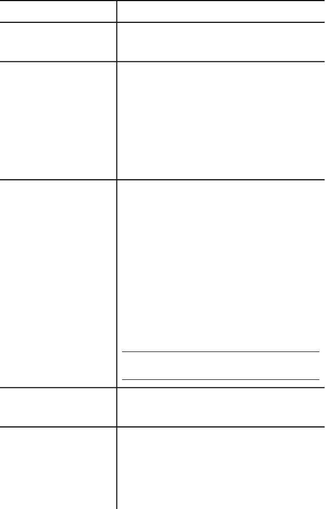
DescriptionAttribute
Component description; same as AppDescription in the
ObjectARX API AcadAppInfo class.
AppDescription
Component type; overrides the type derived from the
file extension provided in the ModuleName attribute.
AppType
The component type can be one of the following:
■Arx – ObjectARX
■Dbx – ObjectDBX
■Lisp or CompiledLisp – AutoLISP
■Bundle – Bundle package
Relative path to the component within the bundle; same
as ModuleName in the ObjectARX API AcadAppInfo class.
ModuleName
The component type is determined from the file exten-
sion:
■.arx – ObjectARX
■.dbx – ObjectDBX
■.lsp, .fas, or – AutoLISP
If your application will handle multiple languages, differ-
ent versions of a specific component can be specified by
combining ModuleName with a locale code. See Suppor-
ted Locale Codes (page 103) for a full list of supported
locale codes.
NOTE All path specifiers are '/' and not '\', and paths
are relative to the root .bundle folder.
AutoLISP only - When True, the AutoLISP file is loaded
once per document. Default is True.
PerDocument
Multiple values can be specified - Defines the load beha-
vior parameters for the component with LoadReasons
Loadreasons
and the exception of the LoadOnCommandInvocation
parameter.
By default, LoadOnAutoCADStartup, LoadOnAppearance,
and LoadOnProxy are enabled (set to True) if LoadReas-
100 | Chapter 7 Introduction to Programming Interfaces

DescriptionAttribute
ons is not specified. If parameters need to be disabled
(set to False), the LoadReasons element must be specified
along with the parameters set to False.
By default, LoadOnCommandInvocation is disabled, en-
abling it will disable LoadOnAutoCADStartup and
LoadOnAppearance unless they are explicitly enabled.
See the ObjectARX Reference Guide for full details on
AcadAppInfo LoadReasons.
Valid parameter values:
■True – Parameter is enabled
■False – Parameter is disabled
The following parameters are available:
■LoadOnCommandInvocation. Load only when
a custom commands is invoked. When using this
parameter, a ‘Commands’ element must be included.
If LoadOnCommandInvocation is enabled, LoadO-
nAutoCADStartup and LoadOnAppearance are as-
sumed to be disabled unless explicitly enabled. Only
applies to ObjectARX and AutoLISP.
NOTE For AutoCAD startup performance reasons,
it is very important to use this option when your
components define commands.
■LoadOnAutoCADStartup. Load when AutoCAD
starts up. When specified, this parameter has preced-
ence over all other parameters. It is recommended
only to use LoadOnAutoCADStartup when none of
the other parameters are suitable, disable it (set it to
False) whenever possible. If the LoadOnAutoCADStar-
tup parameter is omitted, then it defaults to enabled
(set to True) unless LoadOnCommandInvocation is
enabled, in which case LoadOnAutoCADStartup de-
faults to False. Only applies to ObjectARX.
■LoadOnProxyDetection. Load when a proxy
for a custom entity is detected. By default, this
parameter is enabled unless explicitly disabled (set
to False). When enabled (set to True), LoadOnAuto-
Install and Uninstall Plug-In Applications | 101
DescriptionAttribute
CADStartup should be disabled. Only applies to
ObjectDBX files.
■LoadOnAppearance. Load when the product
detects the application bundle in one of the Applic-
ationPlugins folders, thereby supporting instant load
on installation with no need to restart AutoCAD. The
parameter behaves the same way as LoadOnAuto-
CADStartup except the load context is relevant to
when an application is installed while the product is
running.
Commands and Command Element
The Commands element is optional unless the LoadOnCommandInvocation
parameter is enabled for the LoadReasons attribute. Used to specify which
commands to register for LoadOnCommandInvocation.
You can specify more than one Command element as needed.
A Commands element can have the following attribute attached to it:
DescriptionAttribute
Name used to organize related commands.GroupName
Command Element
Specifies the global and local names for each command.
A Command element can have any of the following attributes attached to it:
DescriptionAttribute
Global command name.Global
Local command name.Local
Commands can be defined for multiple languages by
combining Local with a locale code. See Supported
102 | Chapter 7 Introduction to Programming Interfaces
DescriptionAttribute
Locale Codes (page 103) for a full list of supported locale
codes.
Help topic to open when the command is active and F1
is pressed.
HelpTopic
NOTE To display the help topic, a help file must be as-
signed to the plug-in. The help file location for the plug-
in is specified with the HelpFile attribute under the Ap-
plicationPackage element.
Executes the command at startup when True.StartupCommand
Supported Locale Codes
AutoCAD is localized in a wide range of languages and the structure of the
PackageContents.xml file supports these different languages with locale codes.
Many of the attributes in the PackageContents.xml file support localized
languages. Append a locale code to the end of an attribute name to define a
localized version of the attribute.
For example, to define a Spanish version of a description in the
ApplicationPackage element you would create an attribute named
DescriptionEsp.
The following is a full list of all supported locale codes:
■Chs - Chinese (PRC)
■Cht - Chinese (Taiwan)
■Csy - Czech
■Deu - German
■Enu - English
■Esp - Spanish
■Fra - French
■Hun - Hungarian
■Ita - Italian
■Jpn - Japanese
Install and Uninstall Plug-In Applications | 103
■Kor - Korean
■Plk - Polish
■Rus - Russian
Example of Basic .bundle Folder Structure
Basic example of what a package for a plug-in might contain and how it is
structured on disk.
.bundle is not a file, but a folder name with a BUNDLE extension. The following
is an example of a plug-in that contains a LSP file as the main program and a
DWG support file. The following plug-in example is named OfficeSymbols
and its folder structure might look something like; folders are in bold:
OfficeSymbols.bundle
|- PackageContents.xml
|- Contents
|- OfficeSymbolsUtilities.lsp
|- Resources
|- OfficeSymbols.dwg
|- OfficeSymbols.htm
DescriptionFile name
The folder containing the files for a plug-in
and has the BUNDLE extension.
OfficeSymbols.bundle
XML file that contains metadata about the
plug-in.
PackageContents.xml
Example of a custom application file that
might define the behavior of the plug-in.
OfficeSymbolsUtilities.lsp
An application file can be an AutoLISP or
ObjectARX file.
104 | Chapter 7 Introduction to Programming Interfaces

DescriptionFile name
DWG file that contains symbols used by the
functionality defined in OfficeSymbolsUtilit-
ies.lsp.
OfficeSymbols.dwg
Help documentation for the plug-in. Can
be a redirect to where the documentation
OfficeSymbols.htm
might be stored on the local drive or an
online location.
Definition of the PackageContents.xml
<?xml version="1.0" encoding="utf-8" ?>
<ApplicationPackage SchemaVersion="1.0" AppVersion="1.0"
ProductCode="[Add Unique Plug-in GUID Here]"
Name="Office Symbols"
Helpfile="./Contents/Resources/OfficeSymbols.htm"
>
<CompanyDetails
Name="ABC Indoor CAD, Inc."
Email="support@abcindoorcad.com"
/>
<Components>
<ComponentEntry
ModuleName="./Contents/LISP/OfficeSymbolsUtilities.lsp"
/>
</Components>
</ApplicationPackage>
Example of Using Folders to Organize Compon-
ents
Example of what a package for a plug-in might look like using folders to
organize components.
Install and Uninstall Plug-In Applications | 105
It is recommended to use an organized folder structure for larger applications
as this can significantly speed up load times. The following is an example of
a plug-in that contains multiple LSP files and resource files. The plug-in in
this example is named OfficeSymbols and its folder structure might look
something like:
OfficeSymbols.bundle
|- PackageContents.xml
|- Contents
|- OfficeSymbolsMain.lsp
|- OfficeSymbolsUtilities.lsp
|- Resources
|- OfficeSymbols.dwg
|- OfficeSymbols.cuix
|- OfficeSymbols.ico
|- Help
|- OfficeSymbols.htm
Definition of the PackageContents.xml
<?xml version="1.0" encoding="utf-8" ?>
<ApplicationPackage
SchemaVersion="1.0"
AppVersion="1.0"
Author="ABC Indoor CAD, Inc."
ProductCode="[Add Unique Plug-in GUID Here]"
Name="Office Symbols (contains Full version)"
Icon="./Contents/Resources/OfficeSymbols.ico"
Helpfile="./Contents/Help/OfficeSymbols.htm"
>
<CompanyDetails
Name="ABC Indoor CAD, Inc."
Phone="1 (555)-415-1234"
PhoneEsp="34 5554 151234"
Url="www.abcindoorcad.com"
UrlEsp="www.abcindoorcad.es"
Email="support@abcindoorcad.com"
106 | Chapter 7 Introduction to Programming Interfaces
/>
<Components>
<RuntimeRequirements SupportPath="./Contents/Support"/>
<ComponentEntry
AppName="MainLISP"
ModuleName="./Contents/OfficeSymbolsMain.lsp"
/>
<ComponentEntry
AppName="UtilitiesLISP"
ModuleName="./Contents/OfficeSymbolsUtilities.lsp"
/>
<ComponentEntry
ModuleName="./Contents/Resources/OfficeSymbols.cuix"
/>
</Components>
</ApplicationPackage>
Install and Uninstall Plug-In Applications | 107
108
Shapes and Shape Fonts
With AutoCAD®, you can define shapes to use as drawing symbols and text fonts. This appendix
explains how to create and compile your own shape and font files.
Overview of Shape Files
Shapes are objects that you use like blocks. First you use the LOAD command
to load the compiled shape file containing the shape definition. Then you use
the SHAPE command to insert shapes from the file into your drawing. You can
specify the scale and rotation to use for each shape as you add it. AutoCAD SHP
fonts are a special type of shape file, and are defined in the same way as shape
files.
Blocks are more versatile and easier to use and apply than shapes. However,
shapes are more efficient for AutoCAD to store and draw. User-defined shapes
are helpful when you must insert a simple part many times and when speed is
important.
Compile Shape/Font Files
You enter the description of shapes in a specially formatted text file with a file
extension of .shp. To create the file, use a text editor or word processor that
enables you to save in ASCII format, and then compile the ASCII file. Compiling
a shape definition file (SHP) generates a compiled shape file (SHX).
The compiled file has the same name as the shape definition file but with a file
type of SHX. If the shape definition file defines a font, you use the STYLE
command to define a text style. Then, you use one of the text placement
commands (TEXT or MTEXT) to place the characters in the drawing. If the shape
definition file defines shapes, you use the LOAD command to load the shape
file into the drawing. Then, you use the SHAPE command to place the individual
shapes in the drawing (similar in concept to the INSERT command).
8
109

Compile PostScript Fonts
To use a Type 1 PostScript font in AutoCAD, you must first compile it into an
AutoCAD shape file. The COMPILE command accepts both SHP and PFB files
as input and generates an SHX file. Compiled versions of PostScript fonts can
take a lot of disk space, so compile only those fonts you use frequently.
AutoCAD cannot compile and load every Type 1 font. The PostScript font
facilities in AutoCAD are intended to process a subset of Adobe fonts. If you
receive an error while compiling a PostScript font, the resulting SHX file (if
one is generated) may not load into AutoCAD.
For more information on the Adobe Type 1 font format, refer to Adobe Type1
Font Format Version 1.1. When you've purchased and installed these fonts, you
can begin using them with AutoCAD.
NOTE Make sure you understand any copyright that accompanies the PostScript
fonts you use. The same copyright restrictions generally apply to the SHX form of
fonts you've compiled.
Overview of Shape Files
To compile a shape or font file
■At the Command prompt, enter compile and press Enter.
In the Select Shape or Font File dialog box, you can select a shape definition
file (SHP) or PostScript font file (PFB). After you select the file name, compiling
begins. If AutoCAD finds an error in the shape descriptions, a message is
displayed telling you the type of error and the line number. When compiling
is complete, the following messages are displayed:
Compilation successful.
Output file name.shx contains nnn bytes.
Create Shape Definition Files
AutoCAD font and shape files (SHX) are compiled from shape definition files
(SHP). You can create or modify shape definition files with a text editor or
word processor that saves files in ASCII format.
110 | Chapter 8 Shapes and Shape Fonts
Shape Descriptions
AutoCAD font and shape files (SHX) are compiled from shape definition files
(SHP). You can create or modify shape definition files with a text editor or
word processor that saves files in ASCII format.
The syntax of the shape description for each shape or character is the same
regardless of the final use (shape or font) for that shape description. If a shape
definition file is to be used as a font file, the first entry in the file describes
the font itself rather than a shape within the file. If this initial entry describes
a shape, the file is used as a shape file.
Being able to create your own shape definitions is a valuable skill. Keep in
mind, however, that this is a very complex subject to learn and requires
patience.
Each line in a shape definition file can contain up to 128 characters. Longer
lines cannot be compiled. Because AutoCAD ignores blank lines and text to
the right of a semicolon, you can embed comments in shape definition files.
Each shape description has a header line of the following form and is followed
by one or more lines containing specification bytes, separated by commas and
terminated by a 0.
*shapenumber,defbytes,shapename
specbyte1,specbyte2,specbyte3,...,0
The following list describes the fields of a shape description:
shapenumber A number, unique to the file, between 1 and 258 (and up to
32768 for Unicode fonts), and preceded by an asterisk (*). Non-Unicode font
files use the shape numbers 256, 257, and 258 for the symbolic identifiers
Degree_Sign, Plus_Or_Minus_Sign, and Diameter_Symbol. For Unicode fonts
these glyphs appear at the U+00B0, U+00B1, and U+2205 shape numbers and
are part of the “Latin Extended-A” subset.
Text fonts (files containing shape definitions for each character) require specific
numbers corresponding to the value of each character in the ASCII code; other
shapes can be assigned any numbers.
defbytes The number of data bytes (specbytes) required to describe the shape,
including the terminating 0. The limit is 2,000 bytes per shape.
shapename The shape name. Shape names must be uppercase to be recognized.
Names with lowercase characters are ignored and are usually used to label
font shape definitions.
Create Shape Definition Files | 111
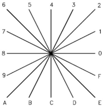
specbyte A shape specification byte. Each specification byte is a code that
defines either a vector length and direction or one of a number of special
codes. A specification byte can be expressed in the shape definition file as
either a decimal or hexadecimal value. This section uses both decimal and
hexadecimal specification byte values for its examples (as do many of the
shape definition files). If the first character of a specification byte is a 0 (zero),
the two characters that follow are interpreted as hexadecimal values.
Vector Length and Direction Code
A simple shape specification byte contains vector length and direction encoded
into one specification byte.
A simple shape specification byte contains vector length and direction encoded
into one specification byte (one specbyte field). Each vector length and direction
code is a string of three characters. The first character must be a 0, which
indicates to AutoCAD that the next two characters are interpreted as
hexadecimal values. The second character specifies the length of the vector
in units. Valid hexadecimal values range from 1 (one unit long) through F (15
units long). The third character specifies the direction of the vector. The
following figure illustrates the direction codes.
Vector direction codes
All the vectors in the preceding figure were drawn with the same length
specification. Diagonal vectors stretch to match the X or Y displacement of
112 | Chapter 8 Shapes and Shape Fonts
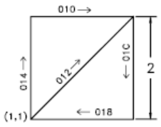
the closest orthogonal vector. This is similar to the action of the snap grid in
AutoCAD.
The following example constructs a shape named DBOX with an arbitrarily
assigned shape number of 230.
*230,6,DBOX
014,010,01C,018,012,0
The preceding sequence of specification bytes defines a box one unit high
byone unit wide, with a diagonal line running from the lower left to the upper
right. After saving the file as dbox.shp, use the COMPILE command to generate
the dbox.shx file. Use the LOAD command to load the shape file containing
this definition, and then use the SHAPE command as follows:
Command: shape
Enter shape name or [?]: dbox
Specify insertion point: 1,1
Specify height <current>: 2
Specify rotation angle <current>: 0
The resulting shape is shown in the following illustration.
Special Codes
Special codes can be used to create additional geometric forms and specify
certain actions.
Create Shape Definition Files | 113
Use Special Codes
The second character of the three-character string (the vector length
specification) must be 0, or you can specify the special code number. For
example, 008 and 8 are both valid specifications.
Specification byte codes
DescriptionCode
End of shape definition000
Activate Draw mode (pen down)001
Deactivate Draw mode (pen up)002
Divide vector lengths by next byte003
Multiply vector lengths by next byte004
Push current location onto stack005
Pop current location from stack006
Draw subshape number given by next byte007
X-Y displacement given by next two bytes008
Multiple X-Y displacements, terminated (0,0)009
Octant arc defined by next two bytes00A
Fractional arc defined by next five bytes00B
Arc defined by X-Y displacement and bulge00C
Multiple bulge-specified arcs00D
114 | Chapter 8 Shapes and Shape Fonts
Specification byte codes
DescriptionCode
Process next command only if vertical text00E
Codes 0, 1, and 2: End of Shape and Draw Mode Control
Code 0 marks the end of the shape definition, and Codes 1 and 2 control
Draw mode.
Draw is activated at the start of each shape. When Draw mode is turned on
(code 1), the vectors cause lines to be drawn. When Draw mode is turned off
(code 2), the vectors move to a new location without drawing.
Codes 3 and 4: Size Control
Codes 3 and 4 control the relative size of each vector.
The height specified with the SHAPE command is initially considered the
length of a single orthogonal vector (direction 0, 4, 8, or C). Code 3 divides
vector lengths by the next byte. Code 4 multiplies vector lengths by the next
byte. Codes 3 and 4 are followed by a specification byte containing an integer
scale factor (1 through 255).
If you want the shape height to specify the size of the entire shape, and you
use 10 vector lengths to draw it, you can use 3,10 to scale the height
specification. The scale factor is cumulative within a shape; that is, multiplying
by 2 and again by 6 results in a scale factor of 12. Usually, you should reverse
the effect of your scale factors at the end of the shape, especially for subshapes
and text font shapes. AutoCAD does not reset the scale factor for you.
Codes 5 and 6: Location Save/Restore
Code 5 pushes (saves) and code 6 pops (restores) the current coordinate
position while drawing a shape so that you can return to it from a later point
in the shape.
Create Shape Definition Files | 115
You must pop everything you push. The position stack is only four locations
deep. If the stack overflows because of too many pushes or too many missing
pops, the following message is displayed when the shape is drawn.
Position stack overflow in shape nnn
Similarly, if you try to pop more locations than have been pushed onto the
stack, the following message is displayed when the shape is drawn.
Position stack underflow in shape nnn
Code 7: Subshape
Code 7 draws the subshape number given by the next byte.
For a non-Unicode font the specification byte following code 7 is a shape
number from 1 to 255. For a Unicode font, code 7 is followed by a Unicode
shape number from 1 to 65535. Unicode shape numbers should be counted
as two bytes (for specific information about the differences between Unicode
and non-Unicode fonts, see Unicode Font Descriptions (page 180)).
The shape with that number (in the same shape file) is drawn at this time.
Draw mode is not reset for the new shape. When the subshape is complete,
drawing the current shape resumes.
Codes 8 and 9: X-Y Displacements
With codes 8 and 9 you can draw nonstandard vectors using X-Y
displacements.
Normal vector specification bytes draw only in the 16 predefined directions,
and the longest length is 15. These restrictions help make shape definitions
efficient but are sometimes limiting. Code 8 specifies the X-Y displacement
given by the next two bytes. Code 8 must be followed by two specification
bytes in the format:
8,X-displacement,Y-displacement
The X-Y displacements can range from -128 to +127. A leading + is optional,
and you can use parentheses to improve readability. The following example
results in a vector that draws (or moves) 10 units to the left and three units
up.
8,(-10,3)
116 | Chapter 8 Shapes and Shape Fonts
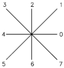
Following the two displacement specification bytes, the shape returns to
Normal Vector mode.
You can use code 9 to draw a sequence of nonstandard vectors. Code 9 specifies
any number of X-Y displacement pairs. The code sequence is terminated by
a (0,0) pair. The following example draws three nonstandard vectors and
returns to Normal Vector mode.
9,(3,1),(3,2),(2,-3),(0,0)
You must terminate the sequence of X-Y displacement pairs with a (0,0) pair
in order for AutoCAD to recognize any Normal Vectors or special codes that
follow.
Code 00A: Octant Arc
Special code 00A (or 10) uses the next two specification bytes to define an arc.
This is called an octant arc because it spans one or more 45-degree octants,
starting and ending on an octant boundary. Octants are numbered
counterclockwise from the 3 o'clock position, as shown in the following
illustration.
The arc specification is
10,radius,(-)0SC
The radius can be any value from 1 through 255. The second specification
byte indicates the direction of the arc (counterclockwise if positive, and
clockwise if negative), its starting octant (s, a value from 0 through 7), and
the number of octants it spans (c, a value from 0 through 7, in which 0 equals
eight octants, or a full circle). You can use parentheses to improve readability.
For example, consider the following fragment of a shape definition:
...012,10,(1,-032),01E,...
Create Shape Definition Files | 117
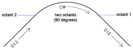
This code draws a one-unit vector up and to the right, a clockwise arc from
octant 3 (with a radius of one unit for two octants), and then a one-unit vector
down and to the right, as shown in the following illustration.
Code 00B: Fractional Arc
Special code 00B (11) draws an arc that doesn't necessarily start and end on
an octant boundary.
The definition uses five specification bytes.
11,start_offset,end_offset,high_radius,radius,(-)0SC
The start_offset and end_offset represent how far from an octant boundary the
arc begins or ends. The high_radius represents the most significant eight bits of
the radius; the high radius will be 0 unless the radius is greater than 255 units.
Multiply the high_radius value by 256 and add that value to the radius value to
generate an arc radius greater than 255. The radius and ending specification
byte are the same as for the octant arc specification (code 00A, described
previously).
You determine the startoffset by calculating the difference in degrees
between the starting octant's boundary (a multiple of 45 degrees) and the start
of the arc. Then, you multiply this difference by 256 and divide by 45. If the
arc starts on an octant boundary, its start offset is 0.
The end offset is calculated in a similar fashion, but you use the number of
degrees from the last octant boundary crossed to the end of the arc. If the arc
ends on an octant boundary, its end offset is 0.
For example, a fractional arc from 55 degrees to 95 degrees with a 3 unit radius
would be coded as follows:
11,(56,28,0,3,012)
Here is the explanation:
118 | Chapter 8 Shapes and Shape Fonts
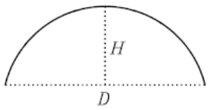
start_offset = 56 because ((55 - 45) * 256 / 45) = 56
end_offset = 28 because ((95 - 90) * 256 / 45) = 28
high_radius = 0 because (radius < 255)
radius = 3
starting octant = 1 because arc starts in the 45 degree
octant
ending octant = 2 because arc ends in the 90 degree octant
Codes 00C and 00D: Bulge-Specified Arcs
Special codes 00C and 00D (12 and 13) provide another mechanism for
including arc segments in shape descriptions.
They are similar to codes 8 and 9 in that you can use them to specify X-Y
displacements. However, codes 00C and 00D draw arcs by applying a bulge
factor to the displacement vector. Code 00C draws one arc segment, while
code 00D draws multiple arc segments (polyarcs) until it is terminated by a
(0,0) displacement.
Code 00C must be followed by three bytes describing the arc:
0C,X-displacement,Y-displacement,Bulge
Both the X and Y displacement and the bulge, which specifies the curvature
of the arc, can range from -127 to +127. If the line segment specified by the
displacement has length D, and the perpendicular distance from the midpoint
of that segment has height H, the magnitude of the bulge is ((2* H / D) * 127).
The sign is negative if the arc from the current location to the new location
is clockwise.
A semicircle has bulge 127 (or -127) and is the greatest arc that can be
represented as a single-arc segment using these codes (use two consecutive
arc segments for larger arcs). A bulge specification of 0 is valid and represents
a straight-line segment. Note, however, that using code 8 for a straight-line
segment saves a byte in the shape description.
Create Shape Definition Files | 119
The polyarc code (00D, or 13) is followed by 0 or by more arc segment triples,
and is terminated by a (0,0) displacement. Note that no bulge is specified after
the final displacement. For example, the letter S might be defined by the
following sequence:
13,(0,5,127),(0,5,-127),(0,0)
Zero bulge segments are useful within polyarcs to represent straight segments;
they are more efficient than terminating the polyarc, inserting one straight
segment, and then starting another polyarc.
The number -128 cannot be used in arc segment and polyarc definitions.
Code 00E: Flag Vertical Text Command
Special code 00E (14) is used only in dual-orientation text font descriptions,
where the font is used in both horizontal and vertical orientations.
When this special code is encountered in a character definition, the next code
is either processed or skipped, depending on orientation. If the orientation is
vertical, the next code is processed; if it is horizontal, the next code is skipped.
In horizontal text, the start point for each character is the left end of the
baseline. In vertical text, the start point is assumed to be the top center of the
character. At the end of each character, a pen-up segment is normally drawn
to position to the next character's start point. For horizontal text, it is to the
right; for vertical text, it is downward. The special 00E (14) code is used
primarily to adjust for differences in start points and endpoints, permitting
the same character shape definition to be used both horizontally and vertically.
For instance, the following definition of an uppercase D could be used in
either horizontal or vertical text.
*68,22,ucd
2,14,8,(-2, 6),1,030,012,044,016,038,2,010,1,06C,2,050,
14,8,(-4,-3),0
120 | Chapter 8 Shapes and Shape Fonts
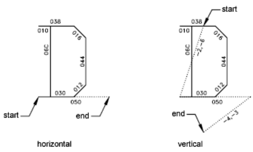
Text Font Descriptions
Text fonts must include a special shape number 0 that conveys information
about the font itself.
AutoCAD is packaged with numerous text fonts. You can use the STYLE
command to apply expansion, compression, or obliquing to any of these fonts,
thereby tailoring the characters to your needs. You can draw text of any height,
at any baseline angle, and with either horizontal or vertical orientation using
these fonts.
AutoCAD text fonts are files of shape definitions with shape numbers
corresponding to the ASCII code for each character. Codes 1 through 31 are
for control characters, only one of which is used in AutoCAD text fonts:
10 (LF) The line feed (LF) must drop down one line without drawing. This is
used for repeated TEXT commands, to place succeeding lines below the first
one.
*10,5,lf
2,8,(0,-10),0
You can modify the spacing of lines by adjusting the downward movement
specified by the LF shape definition.
Text fonts must include a special shape number 0 that conveys information
about the font itself. The format has the following syntax:
*0,4,font-name
above,below,modes,0
Create Shape Definition Files | 121

The above value specifies the number of vector lengths above the baseline
that the uppercase letters extend, and below indicates how far the lowercase
letters descend below the baseline. The baseline is similar in concept to the
lines on writing paper. These values define the basic character size and are
used as scale factors for the height specified in the TEXT command.
The modes byte should be 0 for a horizontally oriented font and 2 for a
dual-orientation (horizontal or vertical) font. The special 00E (14) command
code is honored only when modes is set to 2.
The standard fonts supplied with AutoCAD include a few additional characters
required for the AutoCAD dimensioning feature.
%%d Degree symbol (°)
%%p Plus/minus tolerance symbol ( )
%%c Circle diameter dimensioning symbol
You can use these and the %%nnn control sequences, as described under TEXT
in the Command Reference.
NOTE AutoCAD draws text characters by their ASCII codes (shape numbers) and
not by name. To save memory, specify the shape name portion of each text shape
definition in lowercase as shown in the following example. (Lowercase names are
not saved in memory.)
*65,11,uca
024,043,04d,02c,2,047,1,040,2,02e,0
Because the shape name uca contains lowercase letters, AutoCAD does not
save the name in memory. However, you can use the name for reference when
editing the font definition file. In this example, uca stands for uppercase
A.
Sample Files
This topic contains sample files that help extend the font characters provided
with AutoCAD.
122 | Chapter 8 Shapes and Shape Fonts
Extended Simplex Roman
;;
;; romans.shp - Extended Simplex Roman
;;
;; Copyright 1997 by Autodesk, Inc.
;;
;; Permission to use, copy, modify, and distribute this
software for
;; any purpose and without fee is hereby granted, provided
that the
;; above copyright notice appears in all copies and that
the restricted
;; rights notice below appear in all supporting
documentation.
;;
;; Use, duplication, or disclosure by the U.S. Government
is subject
;; to restrictions set forth in FAR 52.227-19 (Commercial
Computer
;; Software - Restricted Rights) and DFAR
252.227-7013(c)(1)(ii)
;; (Rights in Technical Data and Computer Software), as
applicable.
;;
*UNIFONT,6,ROMANS Copyright 1997 by Autodesk, Inc.
21,7,2,0,0,0
*0000A,9,lf
2,8,(0,-34),14,8,(30,34),0
*00020,9,spc
2,8,(21,0),14,8,(-21,-30),0
*00021,30,kexc
2,14,8,(-5,-21),14,5,8,(5,21),1,0EC,2,05C,1,01A,01E,012,016,2,
8,(5,-2),14,6,14,8,(5,-9),0
*00022,41,kdblqt
2,14,8,(-8,-25),14,5,8,(6,24),1,01A,016,012,01E,02C,02B,01A,2,
8,(8,5),1,01A,016,012,01E,02C,02B,01A,2,8,(4,-19),14,6,
14,8,(8,-9),0
*00023,57,kns
2,14,3,2,14,8,(-21,-50),14,4,2,14,5,8,(11,25),1,8,(-7,-32),2,
8,(13,32),1,8,(-7,-32),2,8,(-6,19),1,0E0,2,8,(-15,-6),1,0E0,2,
8,(4,-6),14,6,14,3,2,14,8,(21,-32),14,4,2,0
Create Shape Definition Files | 123
*00024,67,kds
2,14,8,(-10,-25),14,5,8,(8,25),1,8,(0,-29),2,8,(4,29),1,
8,(0,-29),2,8,(5,22),1,026,8,(-3,1),048,8,(-3,-1),02A,02C,02D,
01E,02F,8,(6,-2),02F,01E,02D,03C,02A,8,(-3,-1),048,8,(-3,1),026,
2,8,(17,-3),14,6,14,8,(10,-13),0
*00025,64,kpc
2,14,8,(-12,-21),14,5,8,(21,21),1,8,(-18,-21),2,8,(5,21),1,02E,
02C,02B,029,028,026,024,023,021,020,02F,8,(3,-1),030,8,(3,1),021,
2,8,(-4,-14),1,029,02B,02C,02E,020,021,023,024,026,028,2,
8,(7,-7),14,6,14,8,(12,-9),0
*00026,67,kand
2,14,8,(-13,-21),14,5,8,(23,12),1,014,016,018,01A,02B,8,(-2,-5),
8,(-2,-3),02A,029,048,027,016,025,024,023,012,8,(7,4),012,023,
024,025,027,029,02B,02C,8,(1,-3),8,(2,-3),8,(5,-7),02E,02F,020,
012,014,2,8,(3,-2),14,6,14,8,(13,-9),0
*00027,29,kapos
2,14,8,(-5,-25),14,5,8,(6,24),1,01A,016,012,01E,02C,02B,01A,2,
8,(6,-19),14,6,14,8,(5,-9),0
*00028,39,klp
2,14,8,(-7,-25),14,5,8,(11,25),1,02A,8,(-2,-3),04B,8,(-1,-5),04C,
8,(1,-5),04D,8,(2,-3),02E,2,8,(3,7),14,6,14,8,(7,-16),0
*00029,39,krp
2,14,8,(-7,-25),14,5,8,(3,25),1,02E,8,(2,-3),04D,8,(1,-5),04C,
8,(-1,-5),04B,8,(-2,-3),02A,2,8,(11,7),14,6,14,8,(7,-16),0
*0002A,37,kas
2,14,8,(-8,-21),14,5,8,(8,21),1,0CC,2,8,(-5,9),1,8,(10,-6),2,064,
1,8,(-10,-6),2,8,(13,-12),14,6,14,8,(8,-9),0
*0002B,31,kpls
2,14,8,(-13,-18),14,5,8,(13,18),1,8,(0,-18),2,096,1,8,(18,0),2,
8,(4,-9),14,6,14,8,(13,-9),0
*0002C,29,kcma
2,14,8,(-5,-2),14,5,8,(6,1),1,01A,016,012,01E,02C,02B,01A,2,
8,(6,4),14,6,14,8,(5,-13),0
*0002D,25,ksub
2,14,8,(-13,-9),14,5,8,(4,9),1,8,(18,0),2,8,(4,-9),14,6,
14,8,(13,-9),0
*0002E,26,kper
2,14,8,(-5,-2),14,5,8,(5,2),1,01A,01E,012,016,2,8,(5,-2),14,6,
14,8,(5,-9),0
*0002F,25,kdiv
2,14,8,(-11,-25),14,5,8,(20,25),1,8,(-18,-32),2,8,(20,7),14,6,
124 | Chapter 8 Shapes and Shape Fonts
14,8,(11,-16),0
*00030,62,n0
2,14,8,(-10,-21),14,5,8,(9,21),1,8,(-3,-1),8,(-2,-3),8,(-1,-5),
03C,8,(1,-5),8,(2,-3),8,(3,-1),020,8,(3,1),8,(2,3),8,(1,5),034,
8,(-1,5),8,(-2,3),8,(-3,1),028,2,8,(11,-21),14,6,14,8,(10,-9),0
*00031,27,n1
2,14,8,(-10,-21),14,5,8,(6,17),1,021,032,8,(0,-21),2,8,(9,0),
14,6,14,8,(10,-9),0
*00032,37,n2
2,14,8,(-10,-21),14,5,8,(4,16),1,014,023,012,021,040,02F,01E,02D,
02C,02B,8,(-2,-3),0AA,0E0,2,8,(3,0),14,6,14,8,(10,-9),0
*00033,46,n3
2,14,8,(-10,-21),14,5,8,(5,21),1,0B0,8,(-6,-8),030,02F,01E,
8,(1,-3),02C,8,(-1,-3),02A,8,(-3,-1),038,8,(-3,1),016,025,2,
8,(17,-4),14,6,14,8,(10,-9),0
*00034,34,n4
2,14,8,(-10,-21),14,5,8,(13,21),1,8,(-10,-14),0F0,2,8,(-5,14),1,
8,(0,-21),2,8,(7,0),14,6,14,8,(10,-9),0
*00035,52,n5
2,14,8,(-10,-21),14,5,8,(15,21),1,0A8,8,(-1,-9),012,8,(3,1),030,
8,(3,-1),02E,8,(1,-3),02C,8,(-1,-3),02A,8,(-3,-1),038,8,(-3,1),
016,025,2,8,(17,-4),14,6,14,8,(10,-9),0
*00036,68,n6
2,14,8,(-10,-21),14,5,8,(16,18),1,025,8,(-3,1),028,8,(-3,-1),
8,(-2,-3),8,(-1,-5),05C,8,(1,-4),02E,8,(3,-1),010,8,(3,1),022,
8,(1,3),014,8,(-1,3),026,8,(-3,1),018,8,(-3,-1),02A,8,(-1,-3),2,
8,(16,-7),14,6,14,8,(10,-9),0
*00037,31,n7
2,14,8,(-10,-21),14,5,8,(17,21),1,8,(-10,-21),2,8,(-4,21),1,0E0,
2,8,(3,-21),14,6,14,8,(10,-9),0
*00038,66,n8
2,14,8,(-10,-21),14,5,8,(8,21),1,8,(-3,-1),02B,02C,02D,02F,
8,(4,-1),8,(3,-1),02E,02D,03C,02B,01A,8,(-3,-1),048,8,(-3,1),016,
025,034,023,022,8,(3,1),8,(4,1),021,023,024,025,8,(-3,1),048,2,
8,(12,-21),14,6,14,8,(10,-9),0
*00039,68,n9
2,14,8,(-10,-21),14,5,8,(16,14),1,8,(-1,-3),02A,8,(-3,-1),018,
8,(-3,1),026,8,(-1,3),014,8,(1,3),022,8,(3,1),010,8,(3,-1),02E,
8,(1,-4),05C,8,(-1,-5),8,(-2,-3),8,(-3,-1),028,8,(-3,1),025,2,
8,(16,-3),14,6,14,8,(10,-9),0
Create Shape Definition Files | 125
*0003A,33,kcol
2,14,8,(-5,-14),14,5,8,(5,14),1,01A,01E,012,016,2,0CC,1,01A,01E,
012,016,2,8,(5,-2),14,6,14,8,(5,-9),0
*0003B,38,ksmc
2,14,8,(-5,-14),14,5,8,(5,14),1,01A,01E,012,016,2,8,(1,-13),1,
01A,016,012,01E,02C,02B,01A,2,8,(6,4),14,6,14,8,(5,-13),0
*0003C,28,klt
2,14,8,(-12,-18),14,5,8,(20,18),1,8,(-16,-9),8,(16,-9),2,8,(4,0),
14,6,14,8,(12,-9),0
*0003D,33,keq
2,14,8,(-13,-12),14,5,8,(4,12),1,8,(18,0),2,8,(-18,-6),1,
8,(18,0),2,8,(4,-6),14,6,14,8,(13,-9),0
*0003E,28,kgt
2,14,8,(-12,-18),14,5,8,(4,18),1,8,(16,-9),8,(-16,-9),2,8,(20,0),
14,6,14,8,(12,-9),0
*0003F,42,kqm
2,14,8,(-9,-21),14,5,8,(3,16),1,014,023,012,021,040,02F,01E,02D,
02C,02B,01A,049,03C,2,05C,1,01A,01E,012,016,2,8,(9,-2),14,6,
14,8,(9,-9),0
*00040,93,kea
2,14,3,2,14,8,(-27,-42),14,4,2,14,5,8,(18,13),1,025,027,038,029,
01A,02B,03C,02D,01E,02F,030,021,023,2,084,1,0AC,01E,020,022,
8,(1,3),024,8,(-1,3),025,026,027,8,(-3,1),038,8,(-3,-1),029,02A,
02B,8,(-1,-3),03C,8,(1,-3),02D,02E,02F,8,(3,-1),030,8,(3,1),021,
012,2,8,(6,-3),14,6,14,3,2,14,8,(27,-18),14,4,2,0
*00041,39,uca
2,14,8,(-9,-21),14,5,8,(9,21),1,8,(-8,-21),2,8,(8,21),1,
8,(8,-21),2,8,(-13,7),1,0A0,2,8,(4,-7),14,6,14,8,(9,-9),0
*00042,70,ucb
2,14,3,2,14,8,(-21,-42),14,4,2,14,5,8,(4,21),1,8,(0,-21),2,
8,(0,21),1,090,8,(3,-1),01E,02D,02C,02B,01A,8,(-3,-1),2,098,1,
090,8,(3,-1),01E,02D,03C,02B,01A,8,(-3,-1),098,2,8,(17,0),14,6,
14,3,2,14,8,(21,-18),14,4,2,0
*00043,55,ucc
2,14,3,2,14,8,(-21,-42),14,4,2,14,5,8,(18,16),1,025,026,027,048,
029,02A,02B,8,(-1,-3),05C,8,(1,-3),02D,02E,02F,040,021,022,023,2,
8,(3,-5),14,6,14,3,2,14,8,(21,-18),14,4,2,0
*00044,61,ucd
2,14,3,2,14,8,(-21,-42),14,4,2,14,5,8,(4,21),1,8,(0,-21),2,
8,(0,21),1,070,8,(3,-1),02E,02D,8,(1,-3),05C,8,(-1,-3),02B,02A,
126 | Chapter 8 Shapes and Shape Fonts
8,(-3,-1),078,2,8,(17,0),14,6,14,3,2,14,8,(21,-18),14,4,2,0
*00045,55,uce
2,14,3,2,14,8,(-19,-42),14,4,2,14,5,8,(4,21),1,8,(0,-21),2,
8,(0,21),1,0D0,2,8,(-13,-10),1,080,2,8,(-8,-11),1,0D0,2,8,(2,0),
14,6,14,3,2,14,8,(19,-18),14,4,2,0
*00046,37,ucf
2,14,8,(-9,-21),14,5,8,(4,21),1,8,(0,-21),2,8,(0,21),1,0D0,2,
8,(-13,-10),1,080,2,8,(6,-11),14,6,14,8,(9,-9),0
*00047,60,ucg
2,14,3,2,14,8,(-21,-42),14,4,2,14,5,8,(18,16),1,025,026,027,048,
029,02A,02B,8,(-1,-3),05C,8,(1,-3),02D,02E,02F,040,021,022,023,
034,2,058,1,050,2,8,(3,-8),14,6,14,3,2,14,8,(21,-18),14,4,2,0
*00048,39,uch
2,14,8,(-11,-21),14,5,8,(4,21),1,8,(0,-21),2,8,(14,21),1,
8,(0,-21),2,8,(-14,11),1,0E0,2,8,(4,-11),14,6,14,8,(11,-9),0
*00049,25,uci
2,14,8,(-4,-21),14,5,8,(4,21),1,8,(0,-21),2,8,(4,0),14,6,
14,8,(4,-9),0
*0004A,37,ucj
2,14,8,(-8,-21),14,5,8,(12,21),1,8,(0,-16),8,(-1,-3),01A,029,028,
027,016,8,(-1,3),024,2,8,(14,-7),14,6,14,8,(8,-9),0
*0004B,49,uck
2,14,3,2,14,8,(-21,-42),14,4,2,14,5,8,(4,21),1,8,(0,-21),2,
8,(14,21),1,0EA,2,052,1,8,(9,-12),2,8,(3,0),14,6,14,3,2,
14,8,(21,-18),14,4,2,0
*0004C,43,ucl
2,14,3,2,14,8,(-17,-42),14,4,2,14,5,8,(4,21),1,8,(0,-21),2,
8,(0,0),1,0C0,2,8,(1,0),14,6,14,3,2,14,8,(17,-18),14,4,2,0
*0004D,49,ucm
2,14,8,(-12,-21),14,5,8,(4,21),1,8,(0,-21),2,8,(0,21),1,
8,(8,-21),2,8,(8,21),1,8,(-8,-21),2,8,(8,21),1,8,(0,-21),2,
8,(4,0),14,6,14,8,(12,-9),0
*0004E,41,ucn
2,14,8,(-11,-21),14,5,8,(4,21),1,8,(0,-21),2,8,(0,21),1,
8,(14,-21),2,8,(0,21),1,8,(0,-21),2,8,(4,0),14,6,14,8,(11,-9),0
*0004F,50,uco
Create Shape Definition Files | 127
2,14,8,(-11,-21),14,5,8,(9,21),1,029,02A,02B,8,(-1,-3),05C,
8,(1,-3),02D,02E,02F,040,021,022,023,8,(1,3),054,8,(-1,3),025,
026,027,048,2,8,(13,-21),14,6,14,8,(11,-9),0
*00050,55,ucp
2,14,3,2,14,8,(-21,-42),14,4,2,14,5,8,(4,21),1,8,(0,-21),2,
8,(0,21),1,090,8,(3,-1),01E,02D,03C,02B,01A,8,(-3,-1),098,2,
8,(17,-10),14,6,14,3,2,14,8,(21,-18),14,4,2,0
*00051,56,ucq
2,14,8,(-11,-21),14,5,8,(9,21),1,029,02A,02B,8,(-1,-3),05C,
8,(1,-3),02D,02E,02F,040,021,022,023,8,(1,3),054,8,(-1,3),025,
026,027,048,2,8,(3,-17),1,06E,2,8,(4,2),14,6,14,8,(11,-11),0
*00052,61,ucr
2,14,3,2,14,8,(-21,-42),14,4,2,14,5,8,(4,21),1,8,(0,-21),2,
8,(0,21),1,090,8,(3,-1),01E,02D,02C,02B,01A,8,(-3,-1),098,2,070,
1,8,(7,-11),2,8,(3,0),14,6,14,3,2,14,8,(21,-18),14,4,2,0
*00053,51,ucs
2,14,8,(-10,-21),14,5,8,(17,18),1,026,8,(-3,1),048,8,(-3,-1),02A,
02C,02D,01E,02F,8,(6,-2),02F,01E,02D,03C,02A,8,(-3,-1),048,
8,(-3,1),026,2,8,(17,-3),14,6,14,8,(10,-9),0
*00054,31,uct
2,14,8,(-8,-21),14,5,8,(8,21),1,8,(0,-21),2,8,(-7,21),1,0E0,2,
8,(1,-21),14,6,14,8,(8,-9),0
*00055,39,ucu
2,14,8,(-11,-21),14,5,8,(4,21),1,0FC,8,(1,-3),02E,8,(3,-1),020,
8,(3,1),022,8,(1,3),0F4,2,8,(4,-21),14,6,14,8,(11,-9),0
*00056,33,ucv
2,14,8,(-9,-21),14,5,8,(1,21),1,8,(8,-21),2,8,(8,21),1,
8,(-8,-21),2,8,(9,0),14,6,14,8,(9,-9),0
*00057,49,ucw
2,14,8,(-12,-21),14,5,8,(2,21),1,8,(5,-21),2,8,(5,21),1,
8,(-5,-21),2,8,(5,21),1,8,(5,-21),2,8,(5,21),1,8,(-5,-21),2,
8,(7,0),14,6,14,8,(12,-9),0
*00058,33,ucx
2,14,8,(-10,-21),14,5,8,(3,21),1,8,(14,-21),2,8,(0,21),1,
8,(-14,-21),2,8,(17,0),14,6,14,8,(10,-9),0
*00059,34,ucy
2,14,8,(-9,-21),14,5,8,(1,21),1,8,(8,-10),0BC,2,8,(8,21),1,
8,(-8,-10),2,8,(9,-11),14,6,14,8,(9,-9),0
*0005A,37,ucz
2,14,8,(-10,-21),14,5,8,(17,21),1,8,(-14,-21),2,8,(0,21),1,0E0,2,
128 | Chapter 8 Shapes and Shape Fonts
8,(-14,-21),1,0E0,2,8,(3,0),14,6,14,8,(10,-9),0
*0005B,37,klb
2,14,8,(-7,-25),14,5,8,(4,25),1,8,(0,-32),2,8,(0,32),1,070,2,
8,(-7,-32),1,070,2,8,(3,7),14,6,14,8,(7,-16),0
*0005C,25,kbkslsh
2,14,8,(-11,-25),14,5,8,(2,25),1,8,(18,-32),2,8,(2,7),14,6,
14,8,(11,-16),0
*0005D,37,krb
2,14,8,(-7,-25),14,5,8,(9,25),1,8,(0,-32),2,8,(-7,32),1,070,2,
8,(-7,-32),1,070,2,8,(4,7),14,6,14,8,(7,-16),0
*0005E,28,kcaret
2,14,8,(-11,-25),14,5,8,(3,20),1,8,(8,5),8,(8,-5),2,8,(3,-20),
14,6,14,8,(11,-9),0
*0005F,21,kundrl
2,14,8,(-12,-14),14,5,02E,1,8,(20,0),2,022,14,6,14,8,(12,-11),0
*00060,29,krvap
2,14,8,(-5,-25),14,5,8,(4,24),1,01E,012,016,01A,02C,02D,01E,2,
8,(6,-19),14,6,14,8,(5,-9),0
*00061,55,lca
2,14,3,2,14,8,(-19,-28),14,4,2,14,5,8,(15,14),1,0EC,2,0B4,1,026,
027,038,029,02A,8,(-1,-3),02C,8,(1,-3),02E,02F,030,021,022,2,
8,(4,-3),14,6,14,3,2,14,8,(19,-18),14,4,2,0
*00062,57,lcb
2,14,3,2,14,8,(-19,-42),14,4,2,14,5,8,(4,21),1,8,(0,-21),2,0B4,1,
022,021,030,02F,02E,8,(1,-3),02C,8,(-1,-3),02A,029,038,027,026,2,
8,(15,-3),14,6,14,3,2,14,8,(19,-18),14,4,2,0
*00063,39,lcc
2,14,8,(-9,-14),14,5,8,(15,11),1,026,027,038,029,02A,8,(-1,-3),
02C,8,(1,-3),02E,02F,030,021,022,2,8,(3,-3),14,6,14,8,(9,-9),0
*00064,57,lcd
2,14,3,2,14,8,(-19,-42),14,4,2,14,5,8,(15,21),1,8,(0,-21),2,0B4,
1,026,027,038,029,02A,8,(-1,-3),02C,8,(1,-3),02E,02F,030,021,022,
2,8,(4,-3),14,6,14,3,2,14,8,(19,-18),14,4,2,0
*00065,42,lce
2,14,8,(-9,-14),14,5,8,(3,8),1,0C0,024,025,016,027,038,029,02A,
8,(-1,-3),02C,8,(1,-3),02E,02F,030,021,022,2,8,(3,-3),14,6,
14,8,(9,-9),0
*00066,36,lcf
2,14,8,(-6,-21),14,5,8,(10,21),1,028,029,8,(-1,-3),8,(0,-17),2,
Create Shape Definition Files | 129
8,(-3,14),1,070,2,8,(3,-14),14,6,14,8,(6,-9),0
*00067,66,lcg
2,14,3,2,14,8,(-19,-28),14,4,2,14,5,8,(15,14),1,8,(0,-16),
8,(-1,-3),01A,029,038,027,2,8,(9,17),1,026,027,038,029,02A,
8,(-1,-3),02C,8,(1,-3),02E,02F,030,021,022,2,8,(4,-3),14,6,14,3,
2,14,8,(19,-32),14,4,2,0
*00068,48,lch
2,14,3,2,14,8,(-19,-42),14,4,2,14,5,8,(4,21),1,8,(0,-21),2,0A4,1,
032,021,030,02F,8,(1,-3),0AC,2,8,(4,0),14,6,14,3,2,14,8,(19,-18),
14,4,2,0
*00069,32,lci
2,14,8,(-4,-21),14,5,8,(3,20),1,01E,012,016,01A,2,8,(1,-7),1,0DC,
2,8,(4,0),14,6,14,8,(4,-9),0
*0006A,39,lcj
2,14,8,(-5,-21),14,5,8,(5,20),1,01E,012,016,01A,2,8,(1,-7),1,
8,(0,-16),8,(-1,-3),029,028,2,8,(9,7),14,6,14,8,(5,-16),0
*0006B,49,lck
2,14,3,2,14,8,(-17,-42),14,4,2,14,5,8,(4,21),1,8,(0,-21),2,
8,(10,14),1,0AA,2,042,1,8,(7,-8),2,8,(2,0),14,6,14,3,2,
14,8,(17,-18),14,4,2,0
*0006C,25,lcl
2,14,8,(-4,-21),14,5,8,(4,21),1,8,(0,-21),2,8,(4,0),14,6,
14,8,(4,-9),0
*0006D,45,lcm
2,14,8,(-15,-14),14,5,8,(4,14),1,0EC,2,0A4,1,032,021,030,02F,
8,(1,-3),0AC,2,0A4,1,032,021,030,02F,8,(1,-3),0AC,2,8,(4,0),14,6,
14,8,(15,-9),0
*0006E,46,lcn
2,14,3,2,14,8,(-19,-28),14,4,2,14,5,8,(4,14),1,0EC,2,0A4,1,032,
021,030,02F,8,(1,-3),0AC,2,8,(4,0),14,6,14,3,2,14,8,(19,-18),
14,4,2,0
*0006F,58,lco
2,14,3,2,14,8,(-19,-28),14,4,2,14,5,8,(8,14),1,029,02A,8,(-1,-3),
02C,8,(1,-3),02E,02F,030,021,022,8,(1,3),024,8,(-1,3),026,027,
038,2,8,(11,-14),14,6,14,3,2,14,8,(19,-18),14,4,2,0
*00070,59,lcp
2,14,3,2,14,8,(-19,-28),14,4,2,14,5,8,(4,14),1,8,(0,-21),2,
8,(0,18),1,022,021,030,02F,02E,8,(1,-3),02C,8,(-1,-3),02A,029,
038,027,026,2,8,(15,-3),14,6,14,3,2,14,8,(19,-32),14,4,2,0
130 | Chapter 8 Shapes and Shape Fonts
*00071,59,lcq
2,14,3,2,14,8,(-19,-28),14,4,2,14,5,8,(15,14),1,8,(0,-21),2,
8,(0,18),1,026,027,038,029,02A,8,(-1,-3),02C,8,(1,-3),02E,02F,
030,021,022,2,8,(4,-3),14,6,14,3,2,14,8,(19,-32),14,4,2,0
*00072,44,lcr
2,14,3,2,14,8,(-13,-28),14,4,2,14,5,8,(4,14),1,0EC,2,084,1,
8,(1,3),022,021,030,2,8,(1,-14),14,6,14,3,2,14,8,(13,-18),14,4,2,
0
*00073,60,lcs
2,14,3,2,14,8,(-17,-28),14,4,2,14,5,8,(14,11),1,025,8,(-3,1),038,
8,(-3,-1),02B,02D,02F,8,(5,-1),02F,02D,01C,02B,8,(-3,-1),038,
8,(-3,1),025,2,8,(14,-3),14,6,14,3,2,14,8,(17,-18),14,4,2,0
*00074,36,lct
2,14,8,(-6,-21),14,5,8,(5,21),1,8,(0,-17),8,(1,-3),02F,020,2,
8,(-8,14),1,070,2,8,(3,-14),14,6,14,8,(6,-9),0
*00075,46,lcu
2,14,3,2,14,8,(-19,-28),14,4,2,14,5,8,(4,14),1,0AC,8,(1,-3),02F,
030,021,032,2,0A4,1,0EC,2,8,(4,0),14,6,14,3,2,14,8,(19,-18),14,4,
2,0
*00076,33,lcv
2,14,8,(-8,-14),14,5,8,(2,14),1,8,(6,-14),2,8,(6,14),1,
8,(-6,-14),2,8,(8,0),14,6,14,8,(8,-9),0
*00077,49,lcw
2,14,8,(-11,-14),14,5,8,(3,14),1,8,(4,-14),2,8,(4,14),1,
8,(-4,-14),2,8,(4,14),1,8,(4,-14),2,8,(4,14),1,8,(-4,-14),2,
8,(7,0),14,6,14,8,(11,-9),0
*00078,43,lcx
2,14,3,2,14,8,(-17,-28),14,4,2,14,5,8,(3,14),1,8,(11,-14),2,0E4,
1,8,(-11,-14),2,8,(14,0),14,6,14,3,2,14,8,(17,-18),14,4,2,0
*00079,37,lcy
2,14,8,(-8,-14),14,5,8,(2,14),1,8,(6,-14),2,8,(6,14),1,
8,(-6,-14),04B,02A,029,018,2,8,(15,7),14,6,14,8,(8,-16),0
*0007A,47,lcz
2,14,3,2,14,8,(-17,-28),14,4,2,14,5,8,(14,14),1,8,(-11,-14),2,
0E4,1,0B0,2,8,(-11,-14),1,0B0,2,8,(3,0),14,6,14,3,2,
14,8,(17,-18),14,4,2,0
Create Shape Definition Files | 131
*0007B,54,klbr
2,14,3,2,14,8,(-13,-50),14,4,2,14,5,8,(9,25),1,029,01A,02B,02C,
02D,01E,02D,02C,02A,029,02F,02E,02C,02B,01A,02B,02C,02D,01E,02F,
2,8,(5,7),14,6,14,3,2,14,8,(13,-32),14,4,2,0
*0007C,25,kvbar
2,14,8,(-4,-25),14,5,8,(4,25),1,8,(0,-32),2,8,(4,7),14,6,
14,8,(4,-16),0
*0007D,54,krbr
2,14,3,2,14,8,(-15,-50),14,4,2,14,5,8,(5,25),1,02F,01E,02D,02C,
02B,01A,02B,02C,02E,02F,029,02A,02C,02D,01E,02D,02C,02B,01A,029,
2,8,(9,7),14,6,14,3,2,14,8,(15,-32),14,4,2,0
*0007E,37,ktlde
2,14,8,(-13,-14),14,5,8,(4,6),1,024,8,(1,3),021,020,02F,8,(4,-3),
02F,020,021,023,024,2,8,(4,-12),14,6,14,8,(13,-9),0
*00080,4,keuroRef
7,020AC,0
*000A0,9,spc
2,8,(21,0),14,8,(-21,-30),0
*000A1,28,kiexc
2,14,8,(-5,-21),14,5,050,1,0E4,2,054,1,012,016,01A,01E,2,
8,(8,-19),14,6,14,8,(5,-9),0
*000A2,43,kcent
2,14,8,(-9,-17),14,5,03E,1,8,(12,20),2,06C,1,026,027,038,029,02A,
8,(-1,-3),02C,8,(1,-3),02E,02F,030,021,022,2,8,(3,-3),14,6,
14,8,(9,-9),0
*000A3,37,kpound
2,14,8,(-10,-21),14,5,8,(12,18),1,025,027,029,02B,0FC,03A,0E0,2,
8,(-8,10),1,068,014,060,2,8,(9,-11),14,6,14,8,(10,-9),0
*000A5,44,kyen
2,14,8,(-12,-21),14,5,8,(1,21),1,8,(8,-10),0BC,2,8,(8,21),1,
8,(-8,-10),2,078,1,0E0,2,8,(-14,-3),1,0E0,2,8,(6,-8),14,6,
14,8,(12,-9),0
*000A7,78,kpar
2,14,8,(-10,-25),14,5,060,1,012,016,01A,01C,02D,01E,02F,020,021,
012,023,014,025,016,8,(-8,4),016,025,014,023,012,021,010,
8,(8,-4),2,094,028,1,01A,01E,012,014,025,016,027,028,029,01A,02B,
01C,02D,01E,8,(8,-4),01E,02D,01C,02B,01A,029,018,8,(-8,4),2,
8,(16,-9),14,6,14,8,(10,-13),0
*000AA,51,lcau
2,14,8,-7,-21,14,5,8,4,14,3,2,1,0A0,2,054,1,02A,029,028,027,016,
8,-1,3,024,8,1,3,012,021,020,02F,02E,2,034,1,0CC,2,4,2,8,4,-15,
132 | Chapter 8 Shapes and Shape Fonts
14,6,14,8,7,-9,0
*000AB,25,kfrew
2,14,8,(-9,-14),14,5,0A0,1,076,072,2,050,1,07A,07E,2,030,14,6,
14,8,(9,-9),0
*000B0,25,kdeg
2,14,8,(-3,-21),14,5,8,(1,19),1,10,(2,64),2,8,(8,-19),14,6,
14,8,(3,-9),0
*000B1,39,kpls-min
2,14,8,(-13,-21),14,5,8,(13,21),1,8,(0,-18),2,096,1,8,(18,0),2,
8,(-18,-11),1,8,(18,0),2,8,(4,-1),14,6,14,8,(13,-9),0
*000B5,48,kmicro
2,14,3,2,14,8,(-19,-28),14,4,2,14,5,07C,1,022,8,(3,19),0AC,
8,(1,-3),02F,030,021,032,2,0A4,1,0EC,2,8,(4,0),14,6,14,3,2,
14,8,(19,-32),14,4,2,0
*000BA,56,lcou
2,14,8,-7,-21,14,5,8,4,14,3,2,1,0A0,2,8,-4,14,1,028,029,01A,8,-1,
-3,02C,8,1,-3,01E,02F,020,021,012,8,1,3,024,8,-1,3,016,027,2,4,2,
8,6,-21,14,6,14,8,7,-9,0
*000BB,25,kffrw
2,14,8,(-9,-14),14,5,030,1,072,076,2,050,1,07E,07A,2,0A0,14,6,
14,8,(9,-9),0
*000BC,43,kquart
2,14,8,(-14,-25),14,5,8,(4,21),1,021,022,0EC,2,8,(-2,-14),1,
8,(16,29),2,8,(2,-23),1,0A8,8,(7,9),0EC,2,8,(7,3),14,6,
14,8,(14,-13),0
*000BD,50,khalf
2,14,8,(-14,-25),14,5,8,(4,21),1,021,022,0EC,2,8,(-2,-14),1,
8,(16,29),2,8,(-6,-18),1,014,023,021,020,02F,02D,01C,02B,
8,(-7,-8),080,2,8,(4,3),14,6,14,8,(14,-13),0
*000BF,47,kiqm
2,14,8,(-9,-21),14,5,8,(13,4),1,016,012,01E,01C,02B,01A,029,038,
8,(-3,1),025,024,023,012,021,022,034,2,054,1,012,016,01A,01E,2,
8,(8,-19),14,6,14,8,(9,-9),0
*000C0,43,uc^
2,14,8,(-9,-25),14,5,8,(9,23),1,047,2,04E,1,8,(-8,-21),2,
8,(8,21),1,8,(8,-21),2,8,(-13,7),1,0A0,2,8,(4,-7),14,6,
14,8,(9,-9),0
*000C1,43,uc^
2,14,8,(-9,-25),14,5,8,(9,23),1,041,2,04A,1,8,(-8,-21),2,
8,(8,21),1,8,(8,-21),2,8,(-13,7),1,0A0,2,8,(4,-7),14,6,
Create Shape Definition Files | 133
14,8,(9,-9),0
*000C2,44,uc
2,14,8,(-9,-25),14,5,8,(5,23),1,041,04F,2,049,1,8,(-8,-21),2,
8,(8,21),1,8,(8,-21),2,8,(-13,7),1,0A0,2,8,(4,-7),14,6,
14,8,(9,-9),0
*000C3,55,uc^
2,14,8,(-9,-25),14,5,8,(4,22),5,1,023,10,(2,-50),01E,10,(2,82),
023,2,6,8,(5,-1),1,8,(-8,-21),2,8,(8,21),1,8,(8,-21),2,8,(-13,7),
1,0A0,2,8,(4,-7),14,6,14,8,(9,-9),0
*000C4,53,uc„
2,14,8,(-9,-25),14,5,8,(4,24),1,01E,012,016,01A,2,080,1,01E,012,
016,01A,2,03A,1,8,(-8,-21),2,8,(8,21),1,8,(8,-21),2,8,(-13,7),1,
0A0,2,8,(4,-7),14,6,14,8,(9,-9),0
*000C5,45,uc^
2,14,8,(-9,-25),14,5,8,(7,23),1,10,(2,64),2,02E,1,8,(-8,-21),2,
8,(8,21),1,8,(8,-21),2,8,(-13,7),1,0A0,2,8,(4,-7),14,6,
14,8,(9,-9),0
*000C6,45,uc^
2,14,8,(-9,-21),14,5,010,1,8,(8,21),8,(0,-21),080,2,8,(-8,7),1,
058,2,8,(5,4),1,050,2,8,(-5,10),1,080,2,8,(2,-21),14,6,
14,8,(9,-9),0
*000C7,65,uc‡
2,14,3,2,14,8,(-21,-42),14,4,2,14,5,8,(18,16),1,025,026,027,048,
029,02A,02B,8,(-1,-3),05C,8,(1,-3),02D,02E,02F,040,021,022,023,2,
8,(-9,-11),1,01E,030,012,024,016,028,034,2,0A0,14,6,14,3,2,
14,8,(21,-32),14,4,2,0
*000C8,53,uc^
2,14,3,2,14,8,(-19,-50),14,4,2,14,5,8,(6,25),1,8,(9,-4),2,
8,(2,-2),1,0D8,8,(0,-19),0D0,2,8,(-13,10),1,080,2,8,(7,-10),14,6,
14,3,2,14,8,(19,-18),14,4,2,0
*000C9,53,uc^
2,14,3,2,14,8,(-19,-50),14,4,2,14,5,8,(6,21),1,8,(9,4),2,
8,(2,-6),1,0D8,8,(0,-19),0D0,2,8,(-13,10),1,080,2,8,(7,-10),14,6,
14,3,2,14,8,(19,-18),14,4,2,0
*000CA,53,uc^
2,14,3,2,14,8,(-19,-50),14,4,2,14,5,8,(6,23),1,041,010,04F,2,
8,(2,-2),1,0D8,8,(0,-21),0D0,2,8,(-13,11),1,080,2,8,(7,-11),14,6,
14,3,2,14,8,(19,-18),14,4,2,0
*000CB,61,uc^
2,14,3,2,14,8,(-19,-50),14,4,2,14,5,8,(6,24),1,01E,012,016,01A,2,
070,1,01E,012,016,01A,2,8,(4,-3),1,0D8,8,(0,-21),0D0,2,
134 | Chapter 8 Shapes and Shape Fonts
8,(-13,11),1,080,2,8,(7,-11),14,6,14,3,2,14,8,(19,-18),14,4,2,0
*000CC,29,uc^
2,14,8,(-4,-25),14,5,8,(4,23),1,026,2,04D,1,8,(0,-21),2,8,(4,0),
14,6,14,8,(4,-9),0
*000CD,29,uc^
2,14,8,(-4,-25),14,5,8,(4,23),1,022,2,04B,1,8,(0,-21),2,8,(4,0),
14,6,14,8,(4,-9),0
*000CE,30,uc^
2,14,8,(-4,-25),14,5,8,(2,23),1,022,02E,2,02A,1,8,(0,-21),2,
8,(4,0),14,6,14,8,(4,-9),0
*000CF,41,uc^
2,14,8,(-4,-25),14,5,8,(1,24),1,01E,012,016,01A,2,040,1,01E,012,
016,01A,2,8,(-1,-3),1,8,(0,-21),2,8,(4,0),14,6,14,8,(4,-9),0
*000D1,41,uc
2,14,8,(-11,-25),14,5,040,1,8,(0,19),8,(14,-19),8,(0,19),2,
8,(-13,3),1,032,010,8,(4,-3),010,032,2,8,(5,-25),14,6,
14,8,(11,-9),0
*000D2,44,uc^
2,14,8,(-11,-25),14,5,8,(6,25),1,08F,2,8,(-6,-2),1,029,02A,04B,
05C,04D,02E,02F,040,021,022,043,054,045,026,027,048,2,8,(13,-19),
14,6,14,8,(11,-9),0
*000D3,42,uc^
2,14,8,(-11,-25),14,5,8,(6,21),1,081,2,06A,1,029,02A,04B,05C,04D,
02E,02F,040,021,022,043,054,045,026,027,048,2,8,(13,-19),14,6,
14,8,(11,-9),0
*000D4,57,uc^
2,14,8,(-11,-25),14,5,8,(6,23),1,041,04F,2,8,(-6,-2),1,029,02A,
02B,8,(-1,-3),05C,8,(1,-3),02D,02E,02F,040,021,022,023,8,(1,3),
054,8,(-1,3),025,026,027,048,2,8,(13,-21),14,6,14,8,(11,-9),0
*000D5,66,uc^
2,14,8,(-11,-25),14,5,8,(6,22),5,1,023,10,(2,-50),01E,10,(2,82),
023,2,6,8,(3,-1),1,029,02A,02B,8,(-1,-3),05C,8,(1,-3),02D,02E,
02F,040,021,022,023,8,(1,3),054,8,(-1,3),025,026,027,048,2,
8,(13,-21),14,6,14,8,(11,-9),0
*000D6,66,uc^
2,14,8,(-11,-25),14,5,8,(6,24),1,01E,012,016,01A,2,080,1,01E,012,
016,01A,2,8,(-5,-3),1,029,02A,02B,8,(-1,-3),05C,8,(1,-3),02D,02E,
02F,040,021,022,023,8,(1,3),054,8,(-1,3),025,026,027,048,2,
Create Shape Definition Files | 135
8,(13,-21),14,6,14,8,(11,-9),0
*000D8,54,uc›
2,14,8,(-11,-21),8,(9,21),1,029,02A,02B,8,(-1,-3),05C,8,(1,-3),
02D,02E,02F,040,021,022,023,8,(1,3),054,8,(-1,3),025,026,027,048,
2,8,(-6,-21),1,8,(16,21),2,8,(3,-21),14,8,(-11,-9),0
*000D9,43,uc^
2,14,8,(-11,-25),14,5,8,(15,21),1,087,2,06B,1,0DC,8,(1,-3),02E,
8,(3,-1),020,8,(3,1),022,8,(1,3),0D4,2,8,(4,-19),14,6,
14,8,(11,-9),0
*000DA,45,uc^
2,14,8,(-11,-25),14,5,8,(15,25),1,089,2,8,(-3,-2),1,0DC,8,(1,-3),
02E,8,(3,-1),020,8,(3,1),022,8,(1,3),0D4,2,8,(4,-19),14,6,
14,8,(11,-9),0
*000DB,46,uc^
2,14,8,(-11,-25),14,5,8,(15,23),1,047,049,2,8,(-3,-2),1,0FC,
8,(1,-3),02E,8,(3,-1),020,8,(3,1),022,8,(1,3),0F4,2,8,(4,-21),
14,6,14,8,(11,-9),0
*000DC,55,uc^
2,14,8,(-11,-25),14,5,8,(14,24),1,01E,012,016,01A,2,088,1,01E,
012,016,01A,2,8,(-2,-3),1,0FC,8,(1,-3),02E,8,(3,-1),020,8,(3,1),
022,8,(1,3),0F4,2,8,(4,-21),14,6,14,8,(11,-9),0
*000DD,38,uc^
2,14,8,(-9,-25),14,5,8,(13,25),1,089,2,049,1,8,(8,-9),0AC,2,
8,(8,19),1,8,(-8,-9),2,8,(9,-10),14,6,14,8,(9,-9),0
*000DF,53,kgers
2,14,8,(-9,-21),14,5,030,1,012,8,(0,16),023,012,021,020,02F,01E,
02D,02C,02B,01A,029,028,2,020,1,8,(3,-1),01E,02D,03C,02B,01A,029,
028,027,016,012,01E,2,8,(10,-2),14,6,14,8,(9,-9),0
*000E0,63,lc…
2,14,3,2,14,8,(-19,-42),14,4,2,14,5,8,(5,21),1,8,(8,-4),2,
8,(2,-3),1,0EC,2,0B4,1,026,027,038,029,02A,8,(-1,-3),02C,
8,(1,-3),02E,02F,030,021,022,2,8,(4,-3),14,6,14,3,2,
14,8,(19,-18),14,4,2,0
*000E1,63,lc
2,14,3,2,14,8,(-19,-42),14,4,2,14,5,8,(5,17),1,8,(8,4),2,
8,(2,-7),1,0EC,2,0B4,1,026,027,038,029,02A,8,(-1,-3),02C,
8,(1,-3),02E,02F,030,021,022,2,8,(4,-3),14,6,14,3,2,
14,8,(19,-18),14,4,2,0
*000E2,64,lc^
2,14,3,2,14,8,(-19,-42),14,4,2,14,5,8,(5,18),1,8,(4,3),8,(4,-3),
2,04D,1,0EC,2,0B4,1,026,027,038,029,02A,8,(-1,-3),02C,8,(1,-3),
136 | Chapter 8 Shapes and Shape Fonts
02E,02F,030,021,022,2,8,(4,-3),14,6,14,3,2,14,8,(19,-18),14,4,2,0
*000E3,63,lcƒ
2,14,3,2,14,8,(-19,-42),14,4,2,14,5,8,(4,18),1,032,010,03E,010,
032,2,07C,1,0EC,2,0B4,1,026,027,038,029,02A,8,(-1,-3),02C,
8,(1,-3),02E,02F,030,021,022,2,8,(4,-3),14,6,14,3,2,
14,8,(19,-18),14,4,2,0
*000E4,71,lc„
2,14,3,2,14,8,(-19,-42),14,4,2,14,5,8,(4,20),1,01E,012,016,01A,2,
090,1,01E,012,016,01A,2,8,(2,-6),1,0EC,2,0B4,1,026,027,038,029,
02A,8,(-1,-3),02C,8,(1,-3),02E,02F,030,021,022,2,8,(4,-3),14,6,
14,3,2,14,8,(19,-18),14,4,2,0
*000E5,63,lc†
2,14,3,2,14,8,(-19,-42),14,4,2,14,5,8,(7,19),1,10,(2,64),2,
8,(8,-5),1,0EC,2,0B4,1,026,027,038,029,02A,8,(-1,-3),02C,
8,(1,-3),02E,02F,030,021,022,2,8,(4,-3),14,6,14,3,2,
14,8,(19,-18),14,4,2,0
*000E6,51,lc
2,14,8,(-10,-14),14,5,8,(10,8),1,070,014,8,(-1,3),026,028,02A,
026,028,02A,8,(-1,-3),04C,8,(1,-3),02E,020,022,02E,020,021,023,2,
8,(-7,11),1,0EC,2,0A0,14,6,14,8,(10,-9),0
*000E7,49,lc‡
2,14,8,(-9,-14),14,5,8,(15,11),1,026,027,038,029,02A,8,(-1,-3),
02C,8,(1,-3),02E,02F,030,021,022,2,8,(-8,-9),1,01E,030,012,024,
016,028,034,2,090,14,6,14,8,(9,-16),0
*000E8,48,lcŠ
2,14,8,(-9,-21),14,5,8,(5,21),1,08F,2,8,(-10,-9),1,0C0,024,025,
016,027,038,029,02A,8,(-1,-3),02C,8,(1,-3),02E,02F,030,021,022,2,
8,(3,-3),14,6,14,8,(9,-9),0
*000E9,48,lc‚
2,14,8,(-9,-21),14,5,8,(5,17),1,081,2,8,(-10,-13),1,0C0,024,025,
016,027,038,029,02A,8,(-1,-3),02C,8,(1,-3),02E,02F,030,021,022,2,
8,(3,-3),14,6,14,8,(9,-9),0
*000EA,51,lcˆ
2,14,8,(-9,-21),14,5,8,(5,18),1,8,(4,3),8,(4,-3),2,0AA,1,0C0,024,
025,016,027,038,029,02A,8,(-1,-3),02C,8,(1,-3),02E,02F,030,021,
022,2,8,(3,-3),14,6,14,8,(9,-9),0
*000EB,58,lc‰
2,14,8,(-9,-21),14,5,8,(4,20),1,01E,012,016,01A,2,080,1,01E,012,
016,01A,2,8,(-9,-12),1,0C0,024,025,016,027,038,029,02A,8,(-1,-3),
Create Shape Definition Files | 137
02C,8,(1,-3),02E,02F,030,021,022,2,8,(3,-3),14,6,14,8,(9,-9),0
*000EC,27,lc_
2,14,8,(-7,-21),14,5,8,(3,21),1,08F,2,04A,1,0DC,2,8,(4,0),14,6,
14,8,(7,-9),0
*000ED,27,lc
2,14,8,(-7,-21),14,5,8,(3,17),1,081,2,08B,1,0DC,2,8,(4,0),14,6,
14,8,(7,-9),0
*000EE,34,lcŒ
2,14,8,(-7,-21),14,5,8,(3,18),1,8,(4,3),8,(4,-3),2,8,(-4,-5),1,
0DC,2,8,(4,0),14,6,14,8,(7,-9),0
*000EF,39,lc‹
2,14,8,(-7,-21),14,5,8,(3,20),1,01E,012,016,01A,2,060,1,01E,012,
016,01A,2,8,(-2,-7),1,0DC,2,8,(4,0),14,6,14,8,(7,-9),0
*000F1,56,lc
2,14,3,2,14,8,(-19,-42),14,4,2,14,5,8,(4,18),1,032,010,03E,010,
032,2,8,(-11,-7),1,0EC,2,0A4,1,032,021,030,02F,8,(1,-3),0AC,2,
8,(4,0),14,6,14,3,2,14,8,(19,-18),14,4,2,0
*000F2,64,lc•
2,14,3,2,14,8,(-19,-42),14,4,2,14,5,8,(5,21),1,8,(9,-4),2,069,1,
029,02A,8,(-1,-3),02C,8,(1,-3),02E,02F,030,021,022,8,(1,3),024,
8,(-1,3),026,027,038,2,8,(11,-14),14,6,14,3,2,14,8,(19,-18),14,4,
2,0
*000F3,66,lc
2,14,3,2,14,8,(-19,-42),14,4,2,14,5,8,(5,17),1,8,(9,4),2,
8,(-6,-7),1,029,02A,8,(-1,-3),02C,8,(1,-3),02E,02F,030,021,022,
8,(1,3),024,8,(-1,3),026,027,038,2,8,(11,-14),14,6,14,3,2,
14,8,(19,-18),14,4,2,0
*000F4,73,lc“
2,14,3,2,14,8,(-19,-42),14,4,2,14,5,8,(5,18),3,2,1,8,(9,6),
8,(9,-6),2,4,2,8,(-6,-4),1,029,02A,8,(-1,-3),02C,8,(1,-3),02E,
02F,030,021,022,8,(1,3),024,8,(-1,3),026,027,038,2,8,(11,-14),
14,6,14,3,2,14,8,(19,-18),14,4,2,0
*000F5,68,lc^
2,14,3,2,14,8,(-19,-42),14,4,2,14,5,8,(4,18),1,032,010,03E,010,
032,2,8,(-7,-7),1,029,02A,8,(-1,-3),02C,8,(1,-3),02E,02F,030,021,
022,8,(1,3),024,8,(-1,3),026,027,038,2,8,(11,-14),14,6,14,3,2,
14,8,(19,-18),14,4,2,0
*000F6,74,lc”
2,14,3,2,14,8,(-19,-42),14,4,2,14,5,8,(4,20),1,01E,012,016,01A,2,
090,1,01E,012,016,01A,2,8,(-5,-6),1,029,02A,8,(-1,-3),02C,
138 | Chapter 8 Shapes and Shape Fonts
8,(1,-3),02E,02F,030,021,022,8,(1,3),024,8,(-1,3),026,027,038,2,
8,(11,-14),14,6,14,3,2,14,8,(19,-18),14,4,2,0
*000F7,41,kto
2,14,8,(-9,-14),14,5,8,(8,13),1,01E,012,016,01A,2,8,(-5,-6),1,
0C0,2,8,(-7,-6),1,01E,012,016,01A,2,8,(10,-1),14,6,14,8,(9,-9),0
*000F8,24,lc›
7,06F,2,8,(-3,14),14,8,(9,9),1,8,(-13,-14),2,8,(17,0),
14,8,(-10,-9),0
*000F9,54,lc—
2,14,3,2,14,8,(-19,-42),14,4,2,14,5,8,(5,21),1,8,(9,-4),2,
8,(-10,-3),1,0AC,8,(1,-3),02F,030,021,032,2,0A4,1,0EC,2,8,(4,0),
14,6,14,3,2,14,8,(19,-18),14,4,2,0
*000FA,54,lc
2,14,3,2,14,8,(-19,-42),14,4,2,14,5,8,(5,17),1,8,(9,4),2,
8,(-10,-7),1,0AC,8,(1,-3),02F,030,021,032,2,0A4,1,0EC,2,8,(4,0),
14,6,14,3,2,14,8,(19,-18),14,4,2,0
*000FB,61,lc-
2,14,3,2,14,8,(-19,-42),14,4,2,14,5,8,(5,18),3,2,1,8,(9,6),
8,(9,-6),4,2,2,8,(-10,-4),1,0AC,8,(1,-3),02F,030,021,032,2,0A4,1,
0EC,2,8,(4,0),14,6,14,3,2,14,8,(19,-18),14,4,2,0
*000FC,62,lc_
2,14,3,2,14,8,(-19,-42),14,4,2,14,5,8,(4,20),1,01E,012,016,01A,2,
090,1,01E,012,016,01A,2,8,(-9,-6),1,0AC,8,(1,-3),02F,030,021,032,
2,0A4,1,0EC,2,8,(4,0),14,6,14,3,2,14,8,(19,-18),14,4,2,0
*000FD,43,lc^
2,14,8,(-8,-14),14,5,8,(2,14),5,032,1,8,(9,4),6,8,(6,-14),2,
8,(6,14),1,8,(-6,-14),04B,02A,029,018,2,8,(15,7),14,6,
14,8,(8,-16),0
*000FF,53,lc˜
2,14,8,(-8,-21),14,5,8,(3,20),1,01E,012,016,01A,2,080,1,01E,012,
016,01A,2,8,(-9,-6),1,8,(6,-14),2,8,(6,14),1,8,(-6,-14),04B,02A,
029,018,2,8,(15,7),14,6,14,8,(8,-16),0
*00104,50,c164
2,14,8,(-9,-21),14,5,8,(9,21),1,8,(-8,-21),2,8,(8,21),1,
8,(8,-21),3,2,10,(5,36),1,10,(5,-100),4,2,2,8,(-13,7),1,0A0,2,
8,(4,-7),14,6,14,8,(9,-9),0
*00105,66,c165
2,14,3,2,14,8,(-19,-28),14,4,2,14,5,8,(15,14),1,0EC,3,2,10,
Create Shape Definition Files | 139
(5,36),2,10,(5,-100),4,2,2,0B4,1,026,027,038,029,02A,8,(-1,-3),
02C,8,(1,-3),02E,02F,030,021,022,2,8,(4,-3),14,6,14,3,2,
14,8,(19,-18),14,4,2,0
*00106,71,c143
2,14,3,2,14,8,(-21,-42),14,4,2,14,5,3,2,2,8,(18,48),1,8,(8,6),2,
8,(-26,-54),4,2,8,(18,16),1,025,026,027,048,029,02A,02B,
8,(-1,-3),05C,8,(1,-3),02D,02E,02F,040,021,022,023,2,8,(3,-5),
14,6,14,3,2,14,8,(21,-18),14,4,2,0
*00107,54,c134
2,14,8,(-9,-14),14,5,8,(15,11),3,2,8,(-15,10),1,8,(6,4),2,
8,(9,-14),4,2,1,026,027,038,029,02A,8,(-1,-3),02C,8,(1,-3),02E,
02F,030,021,022,2,8,(3,-3),14,6,14,8,(9,-9),0
*0010C,49,c172
2,14,8,(-11,-27),8,(18,16),1,025,026,027,048,029,02A,02B,
8,(-1,-3),05C,8,(1,-3),02D,02E,02F,040,021,022,023,2,8,(-7,18),1,
042,2,04A,1,046,2,8,(14,-27),14,8,(-10,-9),0
*0010D,41,c159
2,14,8,(-9,-20),0F0,0B4,1,026,027,038,029,02A,8,(-1,-3),02C,
8,(1,-3),02E,02F,030,021,022,2,068,0D4,1,042,2,04A,1,046,2,
8,(13,-20),14,09A,0
*0010E,53,c210
2,14,8,(-11,-27),8,(4,21),1,0FC,06C,2,0F4,064,1,070,8,(3,-1),02E,
02D,8,(1,-3),05C,8,(-1,-3),02B,02A,8,(-3,-1),078,2,8,(7,23),1,
042,2,04A,1,046,2,8,(14,-27),14,8,(-10,-9),0
*0010F,46,c212
2,14,8,(-10,-21),8,(15,21),1,0FC,06C,2,0B4,1,026,027,038,029,02A,
8,(-1,-3),02C,8,(1,-3),02E,02F,030,021,022,2,8,(4,18),1,
8,(-3,-4),2,8,(3,-17),14,09A,0
*00118,66,c168
2,14,3,2,14,8,(-19,-42),14,4,2,14,5,8,(4,21),1,8,(0,-21),2,
8,(0,21),1,0D0,2,8,(-13,-10),1,080,2,8,(-8,-11),1,0D0,3,2,10,
(5,36),1,10,(5,-100),4,2,2,8,(2,0),14,6,14,3,2,14,8,(19,-18),
14,4,2,0
*00119,66,c169
2,14,8,(-9,-14),14,5,8,(3,8),1,0C0,024,025,016,027,038,029,02A,
8,(-1,-3),02C,8,(1,-3),02E,02F,030,3,2,10,(5,36),2,10,(5,-100),1,
4,2,021,022,2,3,2,10,(5,36),2,10,(5,-100),4,2,2,8,(3,-3),14,6,
14,8,(9,-9),0
*0011A,43,c183
2,14,8,(-10,-27),8,(4,21),1,0FC,06C,2,0F4,064,1,0D0,2,0D8,0AC,1,
140 | Chapter 8 Shapes and Shape Fonts
080,2,088,0BC,1,0D0,2,8,(-7,23),1,042,2,04A,1,046,2,8,(13,-27),
14,09A,0
*0011B,44,c216
2,14,8,(-9,-20),030,084,1,0C0,024,025,016,027,038,029,02A,
8,(-1,-3),02C,8,(1,-3),02E,02F,030,021,022,2,068,0D4,1,042,2,04A,
1,046,2,8,(13,-20),14,09A,0
*00141,51,c157
2,14,3,2,14,8,(-17,-42),14,4,2,14,5,8,(3,21),1,8,(0,-21),2,
8,(-1,11),1,8,(7,8),2,8,(-6,-19),1,0C0,2,8,(3,0),14,6,14,3,2,
14,8,(17,-18),14,4,2,0
*00142,33,c136
2,14,8,(-4,-21),14,5,8,(5,21),1,8,(0,-21),2,8,(-1,10),1,8,(4,6),
2,8,(3,-16),14,6,14,8,(4,-9),0
*00143,52,c227
2,14,8,(-11,-21),14,5,8,(4,21),8,(5,3),1,8,(4,3),2,8,(-9,-6),1,
8,(0,-21),2,8,(0,21),1,8,(14,-21),2,8,(0,21),1,8,(0,-21),2,
8,(4,0),14,6,14,8,(11,-9),0
*00144,57,c228
2,14,3,2,14,8,(-19,-28),14,4,2,14,5,8,(4,14),8,(4,2),1,8,(3,2),2,
8,(-7,-4),1,0EC,2,0A4,1,032,021,030,02F,8,(1,-3),0AC,2,8,(4,0),
14,6,14,3,2,14,8,(19,-18),14,4,2,0
*00147,38,c213
2,14,8,(-11,-27),8,(4,21),1,0FC,06C,2,0F4,064,1,8,(14,-21),0F4,
064,2,078,024,1,042,2,04A,1,046,2,8,(15,-27),14,8,(-11,-9),0
*00148,37,c229
2,14,8,(-10,-20),040,0E4,1,0EC,2,0A4,1,032,021,030,02F,8,(1,-3),
0AC,2,8,(-5,16),1,042,2,04A,1,046,2,8,(13,-20),14,09A,0
*00150,58,c138
2,14,8,(-11,-21),14,5,8,(9,21),1,029,02A,02B,8,(-1,-3),05C,
8,(1,-3),02D,02E,02F,040,021,022,023,8,(1,3),054,8,(-1,3),025,
026,027,048,2,034,1,044,2,040,1,04C,2,8,(9,-24),14,6,
14,8,(11,-9),0
*00151,68,c139
2,14,3,2,14,8,(-19,-28),14,4,2,14,5,8,(8,14),1,029,02A,8,(-1,-3),
02C,8,(1,-3),02E,02F,030,021,022,8,(1,3),024,8,(-1,3),026,027,
038,2,8,(4,4),1,044,2,058,1,04C,2,8,(12,-18),14,6,14,3,2,
14,8,(19,-18),14,4,2,0
*00158,53,c252
2,14,8,(-11,-27),8,(4,21),1,0FC,06C,2,0F4,064,1,090,8,(3,-1),01E,
02D,02C,02B,01A,8,(-3,-1),098,2,070,1,8,(7,-11),2,8,(-7,23),1,
Create Shape Definition Files | 141
042,2,04A,1,046,2,8,(14,-27),14,8,(-10,-9),0
*00159,35,c253
2,14,8,(-7,-20),040,0E4,1,0EC,2,084,1,8,(1,3),022,021,030,2,058,
024,1,042,2,04A,1,046,2,0FD,05D,14,8,(-6,-9),0
*0015A,62,c151
2,14,8,(-10,-21),14,5,8,(17,18),8,(-9,6),1,8,(4,3),2,8,(5,-9),1,
026,8,(-3,1),048,8,(-3,-1),02A,02C,02D,01E,02F,8,(6,-2),02F,01E,
02D,03C,02A,8,(-3,-1),048,8,(-3,1),026,2,8,(17,-3),14,6,
14,8,(10,-9),0
*0015B,71,c152
2,14,3,2,14,8,(-17,-28),14,4,2,14,5,8,(14,11),8,(-7,5),1,8,(3,2),
2,8,(4,-7),1,025,8,(-3,1),038,8,(-3,-1),02B,02D,02F,8,(5,-1),02F,
02D,01C,02B,8,(-3,-1),038,8,(-3,1),025,2,8,(14,-3),14,6,14,3,2,
14,8,(17,-18),14,4,2,0
*00160,57,c230
2,14,8,(-10,-27),8,(17,18),1,026,8,(-3,1),048,8,(-3,-1),02A,02C,
02D,01E,02F,8,(6,-2),02F,01E,02D,03C,02A,8,(-3,-1),048,8,(-3,1),
026,2,8,(7,20),1,042,2,04A,1,046,2,8,(14,-27),14,8,(-10,-9),0
*00161,52,c231
2,14,8,(-9,-20),0E0,0B4,1,025,8,(-3,1),038,8,(-3,-1),02B,02D,02F,
8,(5,-1),02F,02D,01C,02B,8,(-3,-1),038,8,(-3,1),025,2,060,0D4,1,
042,2,04A,1,046,2,8,(12,-20),14,8,(-8,-9),0
*00164,35,c155
2,14,8,(-8,-27),8,(8,21),1,0FC,06C,2,8,(-7,21),1,0E0,2,078,024,1,
042,2,04A,1,046,2,8,(12,-27),14,8,(-8,-9),0
*00165,36,c156
2,14,8,(-6,-21),8,(5,21),1,0FC,02C,8,(1,-3),02F,020,2,088,0E4,1,
070,2,074,1,8,(-3,-4),2,8,(6,-17),14,8,(-6,-9),0
*0016E,45,c222
2,14,8,(-11,-27),8,(4,21),1,0FC,8,(1,-3),02E,8,(3,-1),020,
8,(3,1),022,8,(1,3),0F4,2,078,024,1,021,024,027,029,02C,02F,2,
8,(11,-23),14,8,(-11,-9),0
*0016F,38,c133
2,14,8,(-10,-20),040,0E4,1,0AC,8,(1,-3),02F,030,021,032,2,0A4,1,
0EC,2,8,(-5,16),1,021,024,027,029,02C,02F,2,8,(9,-16),14,09A,0
*00170,52,c235
2,14,8,(-11,-21),14,5,8,(4,21),1,0FC,8,(1,-3),02E,8,(3,-1),020,
8,(3,1),022,8,(1,3),0F4,2,058,034,1,044,2,048,1,04C,2,8,(9,-2),2,
8,(4,-22),14,6,14,8,(11,-9),0
142 | Chapter 8 Shapes and Shape Fonts
*00171,60,c251
2,14,3,2,14,8,(-19,-28),14,4,2,14,5,8,(4,14),1,0AC,8,(1,-3),02F,
030,021,032,2,0A4,1,0EC,2,8,(-8,18),1,044,2,050,1,04C,2,
8,(3,-18),2,8,(4,0),14,6,14,3,2,14,8,(19,-20),14,4,2,0
*00179,45,c141
2,14,8,(-10,-21),14,5,8,(17,21),1,8,(-14,-21),2,8,(5,24),1,
8,(4,3),2,8,(-9,-6),1,0E0,2,8,(-14,-21),1,0E0,2,8,(3,0),14,6,
14,8,(10,-9),0
*0017A,58,c171
2,14,3,2,14,8,(-17,-28),14,4,2,14,5,8,(14,14),8,(-7,2),1,8,(3,2),
2,8,(4,-4),1,8,(-11,-14),2,0E4,1,0B0,2,8,(-11,-14),1,0B0,2,
8,(3,0),14,6,14,3,2,14,8,(17,-18),14,4,2,0
*0017B,45,c189
2,14,8,(-10,-21),14,5,8,(17,21),5,3,2,8,(-13,6),1,10,(2,96),4,2,
6,1,8,(-14,-21),0E0,2,8,(-14,21),1,0E0,2,8,(3,-21),14,6,
14,8,(10,-9),0
*0017C,59,c190
2,14,3,2,14,8,(-17,-28),14,4,2,14,5,8,(14,14),5,3,2,8,(-11,5),1,
10,(1,96),4,2,6,8,(-11,-14),2,0E4,1,0B0,2,8,(-11,-14),1,0B0,2,
8,(3,0),14,6,14,3,2,14,8,(17,-18),14,4,2,0
*0017D,42,c166
2,14,8,(-10,-27),8,(17,21),1,8,(-14,-21),2,0F4,064,1,0E0,2,
8,(-14,-21),1,0E0,2,8,(-7,23),1,042,2,04A,1,046,2,8,(14,-27),
14,8,(-10,-9),0
*0017E,38,c167
2,14,8,(-9,-20),0E2,1,8,(-11,-14),2,0E4,1,0B0,2,0B8,0EC,1,0B0,2,
8,(-5,16),1,042,2,04A,1,046,2,8,(12,-20),14,8,(-8,-9),0
*00410,38,_
2,14,8,(-9,-21),2,8,(4,7),1,9,(10,0),(0,0),2,8,(-13,-7),1,9,
(8,21),(8,-21),(0,0),2,8,(1,0),1,2,14,8,(-9,-9),0
*00411,46,_
2,14,8,(-10,-21),2,8,(15,21),1,9,(-11,0),(0,-21),(9,0),(3,1),
(1,1),(1,2),(0,3),(-1,2),(-1,1),(-3,1),(-9,0),(0,0),2,8,(17,-11),
1,2,14,8,(-11,-9),0
*00412,68,‚
2,14,8,(-11,-21),2,8,(13,21),1,9,(-9,0),(0,-21),(9,0),(3,1),
(1,1),(1,2),(0,3),(-1,2),(-1,1),(-3,1),(-9,0),(0,0),2,8,(9,10),1,
9,(3,-1),(1,-1),(1,-2),(0,-2),(-1,-2),(-1,-1),(-3,-1),(0,0),2,
8,(9,-11),1,2,14,8,(-11,-9),0
*00413,28,ƒ
Create Shape Definition Files | 143
2,14,8,(-8,-21),2,8,(16,21),1,9,(-12,0),(0,-21),(0,0),2,8,(13,0),
1,2,14,8,(-9,-9),0
*00414,50,„
2,14,8,(-12,-21),2,8,(22,-4),1,9,(0,4),(-20,0),(0,-4),(0,0),2,
8,(2,4),1,9,(3,3),(1,2),(1,4),(0,12),(11,0),(0,-21),(0,0),2,
8,(4,0),1,2,14,8,(-12,-13),0
*00415,40,…
2,14,8,(-9,-21),2,8,(17,21),1,9,(-13,0),(0,-21),(13,0),(0,0),2,
8,(-1,11),1,9,(-12,0),(0,0),2,8,(15,-11),1,2,14,8,(-10,-9),0
*00416,66,†
2,14,8,(-12,-21),2,8,(1,0),1,9,(9,12),(0,0),2,8,(2,9),1,9,
(0,-21),(0,0),2,8,(11,21),1,9,(-11,-11),(0,0),2,8,(-11,11),1,9,
(11,-11),(0,0),2,8,(11,-10),1,9,(-9,12),(0,0),2,8,(10,-12),1,2,
14,8,(-12,-9),0
*00417,68,‡
2,14,8,(-9,-21),2,8,(3,20),1,9,(4,1),(3,0),(3,-1),(1,-2),(0,-2),
(-1,-2),(-3,-2),(3,-1),(2,-2),(1,-2),(0,-2),(-1,-2),(-2,-2),
(-3,-1),(-3,0),(-3,1),(-3,2),(0,0),2,8,(9,9),1,9,(-4,0),(0,0),2,
8,(12,-12),1,2,14,8,(-9,-9),0
*00418,30,ˆ
2,14,8,(-11,-21),2,8,(4,21),1,9,(0,-21),(14,21),(0,-21),(0,0),2,
8,(4,0),1,2,14,8,(-11,-9),0
*00419,48,‰
2,14,8,(-11,-21),2,8,(4,21),1,9,(0,-21),(14,21),(0,-21),(0,0),2,
8,(-11,26),1,9,(1,-1),(2,-1),(2,0),(2,1),(1,1),(0,0),2,8,(7,-26),
1,2,14,8,(-11,-9),0
*0041A,46,Š
2,14,8,(-10,-21),2,8,(18,0),1,9,(-9,12),(0,0),2,8,(9,9),1,9,
(-14,-14),(0,0),2,8,(0,14),1,9,(0,-21),(0,0),2,8,(16,0),1,2,
14,8,(-10,-9),0
*0041B,36,‹
2,14,8,(-10,-21),2,8,(16,0),1,9,(0,21),(-11,0),(0,-17),(-1,-2),
(-1,-1),(-2,-1),(0,0),2,8,(19,0),1,2,14,8,(-10,-9),0
*0041C,32,Œ
2,14,8,(-12,-21),2,8,(20,0),1,9,(0,21),(-8,-15),(-8,15),(0,-21),
(0,0),2,8,(20,0),1,2,14,8,(-12,-9),0
*0041D,46,_
2,14,8,(-11,-21),2,8,(4,21),1,9,(0,-21),(0,0),2,8,(0,11),1,9,
(14,0),(0,0),2,8,(0,-11),1,9,(0,21),(0,0),2,8,(4,-21),1,2,
14,8,(-11,-9),0
*0041E,64,_
144 | Chapter 8 Shapes and Shape Fonts
2,14,8,(-11,-21),2,8,(9,21),1,9,(4,0),(2,-1),(2,-2),(1,-2),
(1,-3),(0,-5),(-1,-3),(-1,-2),(-2,-2),(-2,-1),(-4,0),(-2,1),
(-2,2),(-1,2),(-1,3),(0,5),(1,3),(1,2),(2,2),(2,1),(0,0),2,
8,(13,-21),1,2,14,8,(-11,-9),0
*0041F,30,_
2,14,8,(-11,-21),2,8,(4,0),1,9,(0,21),(14,0),(0,-21),(0,0),2,
8,(4,0),1,2,14,8,(-11,-9),0
*00420,44,_
2,14,8,(-10,-21),2,8,(4,0),1,9,(0,21),(9,0),(3,-1),(1,-1),(1,-2),
(0,-3),(-1,-2),(-1,-1),(-3,-1),(-9,0),(0,0),2,8,(16,-10),1,2,
14,8,(-10,-9),0
*00421,62,'
2,14,8,(-10,-21),2,8,(18,16),1,9,(-1,2),(-1,1),(-1,1),(-2,1),
(-4,0),(-2,-1),(-1,-1),(-1,-1),(-1,-2),(-1,-3),(0,-5),(1,-3),
(1,-2),(2,-2),(2,-1),(4,0),(2,1),(2,2),(1,2),(0,0),2,8,(2,-5),1,
2,14,8,(-10,-9),0
*00422,36,'
2,14,8,(-8,-21),2,8,(8,21),1,9,(0,-21),(0,0),2,8,(-7,21),1,9,
(14,0),(0,0),2,8,(1,-21),1,2,14,8,(-8,-9),0
*00423,44,“
2,14,8,(-8,-21),2,8,(15,21),1,9,(-7,-17),(-1,-2),(-1,-1),(-2,-1),
(-1,0),(0,0),2,8,(-2,21),1,9,(7,-17),(0,0),2,8,(8,-4),1,2,
14,8,(-8,-9),0
*00424,74,”
2,14,8,(-13,-21),2,8,(11,19),1,9,(4,0),(3,-1),(2,-1),(2,-2),
(1,-2),(0,-4),(-1,-2),(-2,-2),(-2,-1),(-3,-1),(-4,0),(-3,1),
(-2,1),(-2,2),(-1,2),(0,4),(1,2),(2,2),(2,1),(3,1),(0,0),2,
8,(2,2),1,9,(0,-21),(0,0),2,8,(13,0),1,2,14,8,(-13,-9),0
*00425,36,•
2,14,8,(-8,-21),2,8,(15,21),1,9,(-14,-21),(0,0),2,8,(0,21),1,9,
(14,-21),(0,0),2,8,(1,0),1,2,14,8,(-8,-9),0
*00426,40,-
2,14,8,(-11,-21),2,8,(4,21),1,9,(0,-21),(16,0),(0,-4),(0,0),2,
8,(-2,25),1,9,(0,-21),(0,0),2,8,(4,0),1,2,14,8,(-11,-13),0
*00427,44,—
2,14,8,(-10,-21),2,8,(3,21),1,9,(0,-8),(1,-3),(1,-1),(3,-1),
(9,0),(0,0),2,8,(0,13),1,9,(0,-21),(0,0),2,8,(4,0),1,2,
14,8,(-11,-9),0
*00428,40,˜
Create Shape Definition Files | 145
2,14,8,(-14,-21),2,8,(4,21),1,9,(0,-21),(21,0),(0,21),(0,0),2,
8,(-10,0),1,9,(0,-21),(0,0),2,8,(14,0),1,2,14,8,(-15,-9),0
*00429,50,™
2,14,8,(-14,-21),2,8,(4,21),1,9,(0,-21),(23,0),(0,-4),(0,0),2,
8,(-12,25),1,9,(0,-21),(0,0),2,8,(10,21),1,9,(0,-21),(0,0),2,
8,(4,0),1,2,14,8,(-15,-13),0
*0042A,48,š
2,14,8,(-10,-21),2,8,(1,21),1,9,(4,0),(0,-21),(8,0),(2,0),(2,1),
(1,1),(1,2),(0,4),(-1,2),(-1,1),(-2,1),(-10,0),(0,0),2,
8,(16,-12),1,2,14,8,(-11,-9),0
*0042B,54,›
2,14,8,(-12,-21),2,8,(4,21),1,9,(0,-21),(9,0),(2,1),(1,1),(1,2),
(0,4),(-1,2),(-1,1),(-2,1),(-9,0),(0,0),2,8,(16,9),1,9,(0,-21),
(0,0),2,8,(4,0),1,2,14,8,(-12,-9),0
*0042C,44,œ
2,14,8,(-10,-21),2,8,(4,21),1,9,(0,-21),(10,0),(2,1),(1,1),(1,2),
(0,4),(-1,2),(-1,1),(-2,1),(-10,0),(0,0),2,8,(16,-12),1,2,
14,8,(-10,-9),0
*0042D,64,_
2,14,8,(-9,-21),2,8,(6,11),1,9,(10,0),(0,0),2,8,(-14,7),1,9,
(2,2),(2,1),(4,0),(2,-1),(2,-2),(1,-2),(1,-3),(0,-5),(-1,-3),
(-1,-2),(-2,-2),(-2,-1),(-4,0),(-2,1),(-2,2),(0,0),2,8,(17,-3),1,
2,14,8,(-10,-9),0
*0042E,76,_
2,14,8,(-13,-21),2,8,(14,21),1,9,(4,0),(2,-1),(2,-3),(1,-4),
(0,-5),(-1,-4),(-2,-3),(-2,-1),(-4,0),(-2,1),(-2,3),(-1,4),(0,5),
(1,4),(2,3),(2,1),(0,0),2,8,(-5,-10),1,9,(-5,0),(0,0),2,8,(0,10),
1,9,(0,-21),(0,0),2,8,(22,0),1,2,14,8,(-13,-9),0
*0042F,54,Ÿ
2,14,8,(-10,-21),2,8,(2,0),1,9,(7,11),(0,0),2,8,(7,-11),1,9,
(0,21),(-9,0),(-3,-1),(-1,-1),(-1,-2),(0,-2),(1,-2),(1,-1),
(3,-1),(9,0),(0,0),2,8,(4,-11),1,2,14,8,(-10,-9),0
*00430,62,
2,14,8,(-9,-14),2,8,(15,3),1,9,(-2,-2),(-2,-1),(-3,0),(-2,1),
(-1,1),(-1,1),(-1,3),(0,2),(1,3),(2,2),(2,1),(3,0),(2,-1),(2,-2),
(0,0),2,8,(0,3),1,9,(0,-14),(0,0),2,8,(4,0),1,2,14,8,(-10,-9),0
*00431,64,
2,14,8,(-9,-21),2,8,(14,21),1,9,(-2,-1),(-5,-1),(-2,-1),(-1,-2),
(0,-12),(1,-2),(1,-1),(2,-1),(3,0),(2,1),(2,2),(1,3),(0,2),
146 | Chapter 8 Shapes and Shape Fonts
(-1,3),(-1,1),(-1,1),(-2,1),(-3,0),(-2,-1),(-2,-2),(0,0),2,
8,(15,-11),1,2,14,8,(-10,-9),0
*00432,68,
2,14,8,(-9,-21),2,8,(4,11),1,9,(2,2),(2,1),(3,2),(1,2),(-1,2),
(-1,1),(-3,0),(-2,-1),(-1,-1),(0,-15),(1,-2),(1,-1),(2,-1),(3,0),
(2,1),(2,2),(1,3),(0,2),(-1,3),(-2,2),(-2,1),(-3,0),(0,0),2,
8,(11,-14),1,2,14,8,(-10,-9),0
*00433,56,
2,14,8,(-8,-14),2,8,(3,11),1,9,(1,2),(3,1),(3,0),(3,-1),(1,-2),
(-1,-2),(-2,-1),(-5,-1),(-2,-1),(-1,-2),(0,-1),(1,-2),(3,-1),
(3,0),(3,1),(1,2),(0,0),2,8,(3,-3),1,2,14,8,(-9,-9),0
*00434,72,
2,14,8,(-9,-14),2,8,(15,11),1,9,(-1,1),(-1,1),(-2,1),(-3,0),
(-2,-1),(-2,-2),(-1,-3),(0,-2),(1,-3),(2,-2),(2,-1),(3,0),(2,1),
(2,2),(0,0),2,8,(0,11),1,9,(0,-16),(-1,-3),(-1,-1),(-2,-1),
(-3,0),(-2,1),(0,0),2,8,(13,6),1,2,14,8,(-10,-16),0
*00435,56,
2,14,8,(-9,-14),2,8,(3,8),1,9,(12,0),(0,2),(-1,2),(-1,1),(-2,1),
(-3,0),(-2,-1),(-2,-2),(-1,-3),(0,-2),(1,-3),(2,-2),(2,-1),(3,0),
(2,1),(2,2),(0,0),2,8,(3,-3),1,2,14,8,(-9,-9),0
*00436,58,
2,14,8,(-11,-14),2,8,(1,0),1,9,(7,8),(0,0),2,8,(12,6),1,9,
(-9,-9),(-9,9),(0,0),2,8,(9,0),1,9,(0,-14),(0,0),2,8,(3,8),1,9,
(7,-8),(0,0),2,8,(1,0),1,2,14,8,(-11,-9),0
*00437,62,
2,14,8,(-7,-14),2,8,(8,8),1,9,(2,-1),(1,-1),(1,-2),(-1,-2),
(-1,-1),(-2,-1),(-4,0),(-3,1),(0,0),2,8,(0,12),1,9,(3,1),(3,0),
(3,-1),(1,-2),(-1,-2),(-2,-1),(-3,0),(0,0),2,8,(9,-8),1,2,
14,8,(-7,-9),0
*00438,46,
2,14,8,(-9,-14),2,8,(4,14),1,9,(0,-10),(1,-3),(2,-1),(3,0),(2,1),
(3,3),(0,0),2,8,(0,10),1,9,(0,-14),(0,0),2,8,(4,0),1,2,
14,8,(-10,-9),0
*00439,64,
2,14,8,(-9,-14),2,8,(4,14),1,9,(0,-10),(1,-3),(2,-1),(3,0),(2,1),
(3,3),(0,0),2,8,(0,10),1,9,(0,-14),(0,0),2,8,(-9,18),1,9,(1,-1),
(2,-1),(2,0),(2,1),(1,1),(0,0),2,8,(5,-18),1,2,14,8,(-10,-9),0
*0043A,46,
2,14,8,(-8,-14),2,8,(4,14),1,9,(0,-14),(0,0),2,8,(4,8),1,9,
Create Shape Definition Files | 147
(7,-8),(0,0),2,8,(-1,14),1,9,(-10,-10),(0,0),2,8,(12,-4),1,2,
14,8,(-8,-9),0
*0043B,44,
2,14,8,(-9,-14),2,8,(14,14),1,9,(-6,0),(0,-10),(-1,-3),(-2,-1),
(-2,0),(0,0),2,8,(11,14),1,9,(0,-14),(0,0),2,8,(4,0),1,2,
14,8,(-9,-9),0
*0043C,32,
2,14,8,(-11,-14),2,8,(18,0),1,9,(0,14),(-7,-11),(-7,11),(0,-14),
(0,0),2,8,(18,0),1,2,14,8,(-11,-9),0
*0043D,46,-
2,14,8,(-9,-14),2,8,(4,7),1,9,(11,0),(0,0),2,8,(0,7),1,9,(0,-14),
(0,0),2,8,(-11,14),1,9,(0,-14),(0,0),2,8,(15,0),1,2,
14,8,(-10,-9),0
*0043E,56,
2,14,8,(-9,-14),2,8,(8,14),1,9,(3,0),(2,-1),(2,-2),(1,-3),(0,-2),
(-1,-3),(-2,-2),(-2,-1),(-3,0),(-2,1),(-2,2),(-1,3),(0,2),(1,3),
(2,2),(2,1),(0,0),2,8,(11,-14),1,2,14,8,(-10,-9),0
*0043F,46,
2,14,8,(-9,-14),2,8,(4,14),1,9,(0,-14),(0,0),2,8,(0,10),1,9,
(3,3),(2,1),(3,0),(2,-1),(1,-2),(0,-11),(0,0),2,8,(4,0),1,2,
14,8,(-10,-9),0
*00440,60,
2,14,8,(-9,-14),2,8,(4,14),1,9,(0,-21),(0,0),2,8,(0,18),1,9,
(2,2),(2,1),(3,0),(2,-1),(2,-2),(1,-3),(0,-2),(-1,-3),(-2,-2),
(-2,-1),(-3,0),(-2,1),(-2,2),(0,0),2,8,(15,-3),1,2,
14,8,(-10,-16),0
*00441,50,
2,14,8,(-8,-14),2,8,(15,11),1,9,(-2,2),(-2,1),(-3,0),(-2,-1),
(-2,-2),(-1,-3),(0,-2),(1,-3),(2,-2),(2,-1),(3,0),(2,1),(2,2),
(0,0),2,8,(2,-3),1,2,14,8,(-9,-9),0
*00442,66,
2,14,8,(-14,-14),2,8,(4,14),1,9,(0,-14),(0,0),2,8,(0,10),1,9,
(3,3),(2,1),(2,0),(2,-1),(1,-3),(0,-10),(0,0),2,8,(0,10),1,9,
(3,3),(2,1),(2,0),(2,-1),(1,-3),(0,-10),(0,0),2,8,(4,0),1,2,
14,8,(-14,-9),0
*00443,44,
2,14,8,(-7,-14),2,8,(1,14),1,9,(6,-14),(0,0),2,8,(6,14),1,9,
(-6,-14),(-2,-4),(-2,-2),(-2,-1),(-1,0),(0,0),2,8,(14,7),1,2,
14,8,(-7,-16),0
*00444,66,
148 | Chapter 8 Shapes and Shape Fonts
2,14,8,(-11,-14),2,8,(14,14),1,9,(-6,0),(-2,-1),(-2,-2),(-1,-3),
(0,-2),(1,-3),(2,-2),(2,-1),(6,0),(2,1),(2,2),(1,3),(0,2),(-1,3),
(-2,2),(-2,1),(0,0),2,8,(-3,0),1,9,(0,-21),(0,0),2,8,(11,7),1,2,
14,8,(-11,-16),0
*00445,36,
2,14,8,(-6,-14),2,8,(1,14),1,9,(11,-14),(0,0),2,8,(0,14),1,9,
(-11,-14),(0,0),2,8,(12,0),1,2,14,8,(-7,-9),0
*00446,50,
2,14,8,(-9,-14),2,8,(4,14),1,9,(0,-10),(1,-3),(2,-1),(3,0),(2,1),
(3,3),(0,0),2,8,(0,10),1,9,(0,-14),(2,0),(0,-3),(0,0),2,8,(2,3),
1,2,14,8,(-10,-12),0
*00447,46,
2,14,8,(-9,-14),2,8,(3,14),1,9,(0,-5),(1,-3),(2,-1),(3,0),(2,1),
(3,3),(0,0),2,8,(0,5),1,9,(0,-14),(0,0),2,8,(4,0),1,2,
14,8,(-9,-9),0
*00448,66,
2,14,8,(-14,-14),2,8,(24,0),1,9,(0,14),(0,0),2,8,(0,-10),1,9,
(-3,-3),(-2,-1),(-2,0),(-2,1),(-1,3),(0,10),(0,0),2,8,(0,-10),1,
9,(-3,-3),(-2,-1),(-2,0),(-2,1),(-1,3),(0,10),(0,0),2,8,(24,-14),
1,2,14,8,(-14,-9),0
*00449,70,
2,14,8,(-14,-14),2,8,(14,4),1,9,(-3,-3),(-2,-1),(-2,0),(-2,1),
(-1,3),(0,10),(0,0),2,8,(20,-10),1,9,(-3,-3),(-2,-1),(-2,0),
(-2,1),(-1,3),(0,10),(0,0),2,8,(10,0),1,9,(0,-14),(2,0),(0,-3),
(0,0),2,8,(2,3),1,2,14,8,(-14,-12),0
*0044A,64,
2,14,8,(-9,-14),2,8,(4,8),1,9,(1,1),(2,1),(3,0),(1,0),(2,-1),
(1,-1),(1,-2),(0,-2),(-1,-2),(-1,-1),(-2,-1),(-4,0),(-2,1),
(-1,1),(0,0),2,8,(-3,12),1,9,(3,0),(0,-14),(0,0),2,8,(14,0),1,2,
14,8,(-9,-9),0
*0044B,72,
2,14,8,(-10,-14),2,8,(4,8),1,9,(1,1),(2,1),(3,0),(1,0),(2,-1),
(1,-1),(1,-2),(0,-2),(-1,-2),(-1,-1),(-2,-1),(-4,0),(-2,1),
(-1,1),(0,0),2,8,(0,12),1,9,(0,-14),(0,0),2,8,(13,14),1,9,
(0,-14),(0,0),2,8,(4,0),1,2,14,8,(-11,-9),0
*0044C,62,
2,14,8,(-9,-14),2,8,(4,8),1,9,(1,1),(2,1),(3,0),(1,0),(2,-1),
(1,-1),(1,-2),(0,-2),(-1,-2),(-1,-1),(-2,-1),(-4,0),(-2,1),
(-1,1),(0,0),2,8,(0,12),1,9,(0,-14),(0,0),2,8,(14,0),1,2,
14,8,(-9,-9),0
Create Shape Definition Files | 149
*0044D,60,
2,14,8,(-8,-14),2,8,(2,11),1,9,(2,2),(2,1),(3,0),(2,-1),(2,-2),
(1,-3),(0,-2),(-1,-3),(-2,-2),(-2,-1),(-3,0),(-2,1),(-2,2),(0,0),
2,8,(12,4),1,9,(-6,0),(0,0),2,8,(9,-7),1,2,14,8,(-9,-9),0
*0044E,70,
2,14,8,(-12,-14),2,8,(4,14),1,9,(0,-14),(0,0),2,8,(0,7),1,9,
(5,0),(0,1),(1,3),(2,2),(2,1),(2,0),(2,-1),(2,-2),(1,-3),(0,-2),
(-1,-3),(-2,-2),(-2,-1),(-2,0),(-2,1),(-2,2),(-1,3),(0,1),(0,0),
2,8,(15,-7),1,2,14,8,(-12,-9),0
*0044F,54,
2,14,8,(-8,-14),2,8,(3,0),1,9,(4,5),(0,0),2,8,(6,-5),1,9,(0,14),
(-6,0),(-2,-1),(-1,-1),(-1,-2),(0,-1),(1,-2),(1,-1),(2,-1),(6,0),
(0,0),2,8,(4,-5),1,2,14,8,(-9,-9),0
*020A0,4,keuroRef2
7,0020AC,0
*020A7,49,kpes
2,14,8,(-11,-21),14,5,030,1,8,(0,21),050,02F,01E,02D,05C,02B,01A,
029,058,2,8,(12,13),1,8,(0,-18),02D,02F,010,2,8,(-6,14),1,060,2,
8,(3,-14),14,6,14,8,(11,-9),0
*020AC,45,keuro
2,14,8,(-10,-21),8,(2,10),5,1,014,00A,(9,-043),2,6,5,1,01C,00A,(9,043),
2,6,8,(-1,2),5,1,8,(13,0),2,6,04C,1,0B0,2,08C,080,14,8,(-10,-9),0
*02126,53,komega
2,14,8,(-11,-21),14,5,8,(3,1),1,01E,040,014,036,025,8,(-1,3),044,
8,(1,3),023,022,021,040,02F,02E,02D,8,(1,-3),04C,8,(-1,-3),02B,
03A,01C,040,012,2,8,(3,-1),14,6,14,8,(11,-9),0
*02205,64,kdiam
2,14,3,2,14,8,(-19,-40),14,4,2,14,5,8,(8,17),1,029,02A,8,(-1,-3),
02C,8,(1,-3),02E,02F,030,021,022,8,(1,3),024,8,(-1,3),026,027,
038,2,061,1,8,(-9,-20),2,8,(14,0),14,6,14,3,2,14,8,(19,-18),14,4,
2,0
*0221E,45,kinfin
2,14,8,(-11,-14),14,5,8,(11,11),1,025,027,028,029,02B,01C,02D,
02F,020,021,023,014,023,021,020,02F,02D,01C,02B,029,028,027,025,
2,8,(11,-10),14,6,14,8,(11,-9),0
*02264,36,kleq
2,14,8,(-13,-21),14,5,8,(22,21),1,8,(-18,-9),8,(18,-9),2,
8,(-18,-2),1,8,(18,0),2,8,(4,-1),14,6,14,8,(13,-9),0
150 | Chapter 8 Shapes and Shape Fonts
*02302,25,ktria
2,14,8,(-10,-21),14,5,040,1,0C0,084,066,06A,08C,2,8,(16,0),14,6,
14,8,(10,-9),0
Extended Standard Font for UNICODE
;;
;; txt.shp - Extended Standard Font for UNICODE
;;
;; Copyright 1997 by Autodesk, Inc.
;;
;; Permission to use, copy, modify, and distribute this
software for
;; any purpose and without fee is hereby granted, provided
that the
;; above copyright notice appears in all copies and that
the restricted
;; rights notice below appear in all supporting
documentation.
;;
;; Use, duplication, or disclosure by the U.S. Government
is subject
;; to restrictions set forth in FAR 52.227-19 (Commercial
Computer
;; Software - Restricted Rights) and DFAR
252.227-7013(c)(1)(ii)
;; (Rights in Technical Data and Computer Software), as
applicable.
;;
*UNIFONT,6,TXT Copyright 1997 by Autodesk, Inc.
6,2,2,0,0,0
*0000A,7,lf
2,0AC,14,8,(9,10),0
*00020,7,spc
2,060,14,8,(-6,-8),0
*00021,17,kexc
2,14,06C,1,014,2,014,1,044,2,020,06C,14,8,(-2,-3),0
*00022,20,kdblqt
2,14,8,(-1,-6),044,1,023,2,010,1,02B,2,04C,030,14,8,(-3,1),0
*00023,27,kns
2,14,8,(-2,-6),024,1,040,2,024,1,048,2,023,1,06C,2,020,1,064,2,
Create Shape Definition Files | 151
06D,14,8,(-4,-3),0
*00024,25,kds
2,14,8,(-2,-6),014,1,030,012,016,028,016,012,030,2,027,1,06C,2,
040,14,8,(-4,-3),0
*00025,31,kpc
2,14,8,(-2,-6),064,1,01C,010,014,018,2,040,1,8,(-4,-6),2,040,1,
018,014,010,01C,2,020,14,8,(-4,-3),0
*00026,24,kand
2,14,8,(-2,-6),041,1,02A,018,016,014,022,014,016,01A,01C,04E,2,
020,14,8,(-4,-3),0
*00027,28,kapos
2,14,3,2,14,8,(-1,-12),14,4,2,044,1,023,2,06C,020,14,3,2,
14,8,(-5,2),14,4,2,0
*00028,16,klp
2,14,8,(-1,-6),064,020,1,02A,02C,02E,2,020,14,03A,0
*00029,15,krp
2,14,8,(-1,-6),064,1,02E,02C,02A,2,040,14,03A,0
*0002A,27,kas
2,14,8,(-2,-5),021,1,044,2,02E,1,048,2,041,1,04A,2,044,1,04E,2,
02F,14,8,(-4,-3),0
*0002B,19,kpls
2,14,8,(-2,-5),021,1,044,2,02E,1,048,2,06F,14,8,(-4,-3),0
*0002C,28,kcma
2,14,3,2,14,02B,14,4,2,014,010,1,01C,01A,2,012,020,14,3,2,
14,8,(-3,-8),14,4,2,0
*0002D,14,ksub
2,14,8,(-2,-3),034,1,040,2,020,03C,14,048,0
*0002E,12,kper
2,14,01C,1,014,2,02F,14,8,(-2,-3),0
*0002F,17,kdiv
2,14,8,(-2,-6),1,8,(4,6),2,020,06C,14,8,(-4,-3),0
*00030,34,n0
2,14,3,2,14,8,(-3,-12),14,4,2,010,1,016,044,012,010,01E,04C,01A,
018,2,040,14,3,2,14,8,(-7,-6),14,4,2,0
*00031,18,n1
2,14,8,(-1,-6),054,1,012,06C,2,018,1,020,2,020,14,03A,0
*00032,23,n2
2,14,8,(-2,-6),054,1,012,020,01E,01C,01A,028,01A,02C,040,2,020,
14,8,(-4,-3),0
*00033,29,n3
2,14,8,(-2,-6),054,1,012,020,01E,01C,01A,018,2,010,1,01E,01C,01A,
152 | Chapter 8 Shapes and Shape Fonts
028,016,2,01C,060,14,8,(-4,-3),0
*00034,19,n4
2,14,8,(-2,-6),041,1,048,8,(3,4),06C,2,030,14,8,(-4,-3),0
*00035,23,n5
2,14,8,(-2,-6),014,1,01E,020,012,024,016,038,024,040,2,020,06C,
14,8,(-4,-3),0
*00036,24,n6
2,14,8,(-2,-6),034,1,030,01E,01C,01A,028,016,034,022,010,2,030,
06C,14,8,(-4,-3),0
*00037,16,n7
2,14,8,(-2,-6),064,1,040,06B,2,050,14,8,(-4,-3),0
*00038,32,n8
2,14,8,(-2,-6),010,1,016,014,012,020,012,014,016,028,01A,01C,01E,
2,020,1,01E,01C,01A,028,2,050,14,8,(-4,-3),0
*00039,24,n9
2,14,8,(-2,-6),010,1,010,022,034,016,028,01A,01C,01E,030,2,020,
03C,14,8,(-4,-3),0
*0003A,17,kcol
2,14,04C,044,1,01C,2,01C,1,01C,2,02F,14,8,(-2,-3),0
*0003B,34,ksmc
2,14,3,2,14,8,(-1,-8),14,4,2,010,044,1,01C,2,01C,1,02C,01A,2,012,
020,14,3,2,14,8,(-5,-8),14,4,2,0
*0003C,29,klt
2,14,3,2,14,8,(-3,-12),14,4,2,064,030,1,03A,03E,2,020,14,3,2,
14,8,(-5,-6),14,4,2,0
*0003D,18,keq
2,14,04B,044,1,040,2,02C,1,048,2,060,02C,14,8,(-4,-1),0
*0003E,28,kgt
2,14,3,2,14,8,(-3,-12),14,4,2,064,1,03E,03A,2,050,14,3,2,
14,8,(-7,-6),14,4,2,0
*0003F,36,kqm
2,14,3,2,14,8,(-3,-12),14,4,2,054,1,012,010,01E,01C,01A,01C,2,
01C,1,01C,2,030,14,3,2,14,8,(-7,-6),14,4,2,0
*00040,28,kea
2,14,8,(-2,-6),032,1,01A,018,014,012,010,02C,012,024,016,028,01A,
04C,01E,030,2,020,14,8,(-4,-3),0
*00041,21,uca
2,14,8,(-2,-6),1,024,043,04D,02C,2,047,1,040,2,02E,14,8,(-4,-3),0
*00042,29,ucb
2,14,8,(-2,-6),1,030,012,014,016,028,2,020,1,012,014,016,038,2,
010,1,06C,2,050,14,8,(-4,-3),0
Create Shape Definition Files | 153
*00043,23,ucc
2,14,8,(-2,-6),040,014,1,01A,028,016,044,012,020,01E,2,02E,03C,
14,8,(-4,-3),0
*00044,22,ucd
2,14,8,(-2,-6),1,030,012,044,016,038,2,010,1,06C,2,050,
14,8,(-4,-3),0
*00045,25,uce
2,14,8,(-2,-6),1,064,040,2,048,03C,1,020,2,028,03C,1,040,2,020,
14,8,(-4,-3),0
*00046,21,ucf
2,14,8,(-2,-6),1,064,040,2,048,03C,1,020,2,03C,040,14,8,(-4,-3),0
*00047,22,ucg
2,14,8,(-2,-6),032,1,010,03C,038,016,044,012,030,2,020,06C,
14,8,(-4,-3),0
*00048,22,uch
2,14,8,(-2,-6),1,064,2,03C,1,040,2,034,1,06C,2,020,14,8,(-4,-3),0
*00049,21,uci
2,14,8,(-1,-6),064,1,020,2,018,1,06C,2,018,1,020,2,020,14,03A,0
*0004A,19,ucj
2,14,8,(-2,-6),014,1,01E,020,012,054,2,020,06C,14,8,(-4,-3),0
*0004B,23,uck
2,14,8,(-2,-6),1,064,2,040,1,03A,018,2,010,1,03E,2,020,
14,8,(-4,-3),0
*0004C,16,ucl
2,14,8,(-2,-6),064,1,06C,040,2,020,14,8,(-4,-3),0
*0004D,17,ucm
2,14,8,(-2,-6),1,064,04D,043,06C,2,020,14,8,(-4,-3),0
*0004E,19,ucn
2,14,8,(-2,-6),1,064,8,(4,-6),064,2,06C,020,14,8,(-4,-3),0
*0004F,17,uco
2,14,8,(-2,-6),1,064,040,06C,048,2,060,14,8,(-4,-3),0
*00050,19,ucp
2,14,8,(-2,-6),1,064,030,01E,01C,01A,038,2,06F,14,8,(-4,-3),0
*00051,25,ucq
2,14,8,(-2,-6),022,1,01E,01A,018,016,044,012,020,01E,03C,01A,01E,
2,020,14,8,(-4,-3),0
154 | Chapter 8 Shapes and Shape Fonts
*00052,23,ucr
2,14,8,(-2,-6),1,064,030,01E,01C,01A,038,2,010,1,03E,2,020,
14,8,(-4,-3),0
*00053,22,ucs
2,14,8,(-2,-6),014,1,01E,020,012,046,012,020,01E,2,020,05C,
14,8,(-4,-3),0
*00054,19,uct
2,14,8,(-2,-6),064,1,040,2,028,1,06C,2,040,14,8,(-4,-3),0
*00055,20,ucu
2,14,8,(-2,-6),064,1,05C,01E,020,012,054,2,020,06C,14,8,(-4,-3),0
*00056,15,ucv
2,14,06B,064,1,06D,063,2,020,06C,14,8,(-5,-3),0
*00057,24,ucw
2,14,06B,064,1,9,(2,-6),(1,3),(1,-3),(2,6),(0,0),2,020,06C,
14,8,(-5,-3),0
*00058,22,ucx
2,14,8,(-2,-6),1,8,(4,6),2,048,1,8,(4,-6),2,020,14,8,(-4,-3),0
*00059,25,ucy
2,14,8,(-2,-6),064,1,8,(2,-3),03C,2,034,1,8,(2,3),2,020,06C,
14,8,(-4,-3),0
*0005A,19,ucz
2,14,8,(-2,-6),064,1,040,8,(-4,-6),040,2,020,14,8,(-4,-3),0
*0005B,17,klb
2,14,8,(-1,-6),1,064,020,2,06C,1,028,2,040,14,03A,0
*0005C,17,kbkslsh
2,14,8,(-2,-6),064,1,8,(4,-6),2,020,14,8,(-4,-3),0
*0005D,15,krb
2,14,8,(-1,-6),064,1,020,06C,028,2,040,14,03A,0
*0005E,16,kcaret
2,14,8,(-2,-6),044,1,022,02E,2,04D,14,8,(-4,1),0
*0005F,11,kundrl
2,14,028,01C,1,040,2,021,14,04A,0
*00060,27,krvap
2,14,3,2,14,8,(-1,-12),14,4,2,064,1,02D,2,04D,14,3,2,14,8,(-5,2),
14,4,2,0
*00061,24,lca
2,14,04B,020,1,018,016,024,012,010,01E,02C,01A,2,012,1,01E,2,020,
14,8,(-4,-3),0
*00062,25,lcb
Create Shape Definition Files | 155
2,14,8,(-2,-6),1,064,2,04C,1,022,010,01E,02C,01A,018,026,2,02C,
060,14,8,(-4,-3),0
*00063,17,lcc
2,14,04B,042,1,038,01A,02C,01E,030,2,020,14,8,(-4,-3),0
*00064,25,lcd
2,14,8,(-2,-6),041,1,02A,018,016,024,012,010,02E,2,044,1,06C,2,
020,14,8,(-4,-3),0
*00065,20,lce
2,14,04B,024,1,030,012,016,028,01A,02C,01E,020,2,030,
14,8,(-4,-3),0
*00066,22,lcf
2,14,8,(-2,-6),034,1,030,2,023,1,016,018,01A,05C,2,050,
14,8,(-4,-3),0
*00067,22,lcg
2,14,04B,01C,1,01E,020,012,044,016,028,01A,02C,01E,030,2,020,
14,8,(-4,-5),0
*00068,21,lch
2,14,8,(-2,-6),1,064,2,04C,1,022,010,01E,03C,2,020,14,8,(-4,-3),0
*00069,17,lci
2,14,06C,1,044,2,014,1,014,2,020,06C,14,8,(-2,-3),0
*0006A,35,lcj
2,14,3,2,14,8,(-3,-12),14,4,2,01C,1,01E,010,012,054,2,014,1,014,
2,020,06C,14,3,2,14,8,(-7,-10),14,4,2,0
*0006B,23,lck
2,14,8,(-2,-6),1,064,2,04C,1,020,022,2,02A,1,02E,2,020,
14,8,(-4,-3),0
*0006C,28,lcl
2,14,3,2,14,8,(-1,-12),14,4,2,064,1,05C,01E,2,020,14,3,2,
14,8,(-5,-6),14,4,2,0
*0006D,24,lcm
2,14,04B,1,044,2,01C,1,012,01E,01C,2,014,1,012,01E,03C,2,020,
14,8,(-4,-3),0
*0006E,21,lcn
2,14,8,(-2,-6),1,044,2,02C,1,022,010,01E,03C,2,020,14,8,(-4,-3),0
*0006F,20,lco
2,14,04B,030,1,028,016,024,012,020,01E,02C,01A,2,030,
14,8,(-4,-3),0
*00070,22,lcp
2,14,04B,02C,1,064,2,01C,1,012,020,01E,02C,01A,038,2,060,
14,8,(-4,-5),0,
156 | Chapter 8 Shapes and Shape Fonts
*00071,22,lcq
2,14,04B,04F,1,064,2,01C,1,016,028,01A,02C,01E,030,2,020,
14,8,(-4,-5),0,
*00072,19,lcr
2,14,04B,1,044,2,02C,1,022,010,01E,2,020,03C,14,8,(-4,-3),0
*00073,18,lcs
2,14,04B,1,030,012,016,028,016,012,030,2,04D,14,8,(-4,-3),0
*00074,21,lct
2,14,8,(-2,-6),044,1,040,2,026,1,05C,01E,012,2,02F,14,8,(-4,-3),0
*00075,20,lcu
2,14,04B,044,1,03C,01E,010,022,2,024,1,04C,2,020,14,8,(-4,-3),0
*00076,14,lcv
2,14,04B,044,1,04D,043,2,04D,14,8,(-4,-3),0
*00077,23,lcw
2,14,04B,044,1,9,(1,-4),(1,4),(1,-4),(1,4),(0,0),2,04D,
14,8,(-4,-3),0
*00078,16,lcx
2,14,04B,1,042,2,048,1,04E,2,020,14,8,(-4,-3),0
*00079,19,lcy
2,14,04B,044,1,04D,2,043,1,06B,018,2,024,060,14,8,(-4,-5),0
*0007A,15,lcz
2,14,04B,044,1,040,04A,040,2,020,14,8,(-4,-3),0
*0007B,19,klbr
2,14,8,(-1,-6),064,020,1,01A,01C,01A,01E,01C,01E,2,020,14,03A,0
*0007C,13,kvbar
2,14,06C,1,064,2,06C,020,14,8,(-2,-3),0
*0007D,18,krbr
2,14,8,(-1,-6),1,012,014,012,016,014,016,2,06C,040,14,03A,0
*0007E,15,ktlde
2,14,04B,034,1,012,02F,012,2,04D,14,8,(-4,-2),0
*00080,4,keuroRef
7,020AC,0
*000A0,7,NoBrkSpc
2,060,14,8,(-6,-8),0
*000A1,18,kiexc
2,14,06C,1,044,2,014,1,014,2,8,(2,-6),14,8,(-2,-3),0
Create Shape Definition Files | 157
*000A2,23,kcent
2,14,8,(-2,-5),01E,1,8,(2,6),2,01E,1,038,01A,02C,01E,030,2,020,
14,04A,0,
*000A3,23,kpound
2,14,8,(-2,-6),040,1,048,012,044,012,01E,2,02B,1,028,2,06F,
14,8,(-4,-3),0
*000A5,34,kyen
2,14,8,(-2,-6),064,1,8,(2,-3),03C,2,025,1,020,2,027,1,020,2,018,
1,8,(2,3),2,8,(2,-6),14,8,(-4,-3),0
*000A7,45,kpar
2,14,3,2,14,8,(-3,-12),14,4,2,014,1,01E,010,012,016,018,016,012,
2,021,1,016,018,01A,01E,010,01E,01A,2,8,(3,-2),14,3,2,
14,8,(-7,-6),14,4,2,0
*000AA,36,lcau
2,14,8,(-1,-6),2,3,2,8,3,9,1,01A,018,016,024,012,010,01E,02C,01E,
2,049,1,040,2,4,2,8,2,-3,14,8,(-3,1),0
*000AB,21,kfrew
2,14,8,(-2,-5),021,1,026,022,2,020,1,02A,02E,2,02F,14,8,(-4,-2),0
*000B0,19,kdeg
2,14,8,(-1,-6),054,1,012,01E,01A,016,2,05C,040,14,8,(-3,2),0
*000B1,23,kpls-min
2,14,8,(-2,-6),014,1,040,2,027,1,044,2,02A,1,040,2,04D,
14,8,(-4,-2),0
*000B5,24,kmicro
2,14,04B,02C,1,8,(1,6),1,03C,01E,010,023,2,024,1,04C,2,020,
14,8,(-4,-5),0
*000BA,35,lcou
2,14,8,(-1,-6),3,2,2,8,3,12,1,028,01A,02C,01E,020,012,024,016,2,
06B,1,040,2,4,2,8,2,-3,14,8,(-3,1),0
*000BB,22,kffrw
2,14,8,(-2,-5),014,1,022,026,2,020,1,02E,02A,2,040,01C,
14,8,(-4,-2),0
*000BC,41,kquart
2,3,2,14,8,(-5,-12),1,8,(10,12),2,8,(-8,-6),1,064,01A,2,05C,1,
020,2,8,(6,-4),1,048,8,(3,4),06C,2,060,14,8,(-9,-6),4,2,0
*000BD,45,khalf
2,3,2,14,8,(-5,-12),1,8,(10,12),2,8,(-8,-6),1,064,01A,2,05C,1,
020,2,8,(3,-1),1,012,020,01E,01C,01A,028,01A,02C,040,2,040,
158 | Chapter 8 Shapes and Shape Fonts
14,8,(-9,-6),4,2,0
*000BF,32,kiqm
2,3,2,14,8,(-3,-12),8,(6,2),1,02A,028,026,024,022,024,2,024,1,
024,2,8,(8,-12),14,8,(-7,-6),4,2,0
*000C0,31,uc^
2,14,8,(-2,-6),1,024,022,02E,02C,2,8,(-4,1),1,040,2,8,(-2,4),1,
027,2,8,(6,-6),14,8,(-4,-3),0
*000C1,31,uc^
2,14,8,(-2,-6),1,024,022,02E,02C,2,8,(-4,1),1,040,2,8,(-2,4),1,
021,2,8,(2,-6),14,8,(-4,-3),0
*000C2,32,uc^
2,14,8,(-2,-6),1,024,022,02E,02C,2,8,(-4,1),1,040,2,8,(-4,3),1,
022,02E,2,8,(2,-4),14,8,(-4,-3),0
*000C3,33,uc^
2,14,8,(-2,-6),1,024,022,02E,02C,2,8,(-4,1),1,040,2,8,(-4,4),1,
012,02F,012,2,8,(2,-6),14,8,(-4,-3),0
*000C4,32,uc„
2,14,8,(-2,-6),1,024,043,2,029,1,014,2,040,1,01C,2,027,1,04D,02C,
2,047,1,040,2,02E,14,8,(-4,-3),0
*000C5,25,uc^
2,14,8,(-2,-6),1,024,032,016,01A,03E,02C,2,8,(-4,1),1,040,2,02F,
14,8,(-4,-3),0
*000C6,33,uc^
2,14,8,(-2,-6),1,034,8,(2,3),020,2,8,(-2,-3),1,020,2,03C,1,028,
064,2,04B,1,020,2,04F,14,8,(-4,-3),0
*000C7,29,uc‡
2,14,8,(-2,-6),02E,1,010,014,018,014,2,021,1,01A,028,016,044,012,
020,01E,2,02E,03C,14,8,(-4,-5),0
*000C8,28,uc^
2,14,8,(-2,-6),1,044,040,2,016,1,027,2,04C,018,1,020,2,02A,1,040,
2,020,14,8,(-4,-3),0
*000C9,28,uc^
2,14,8,(-2,-6),1,044,040,2,025,1,029,2,03C,018,1,020,2,02A,1,040,
2,020,14,8,(-4,-3),0
*000CA,29,uc^
2,14,8,(-2,-6),1,044,040,2,016,1,016,01A,2,03C,018,1,020,2,02A,1,
040,2,020,14,8,(-4,-3),0
*000CB,32,uc^
2,14,8,(-2,-6),1,044,040,2,016,1,014,2,028,1,01C,2,03C,018,1,020,
2,02A,1,040,2,020,14,8,(-4,-3),0
*000CC,25,uc^
2,14,8,(-1,-6),044,1,020,2,014,1,027,2,02D,1,04C,2,018,1,020,2,
Create Shape Definition Files | 159
020,14,03A,0
*000CD,25,uc^
2,14,8,(-1,-6),044,1,020,2,024,1,029,2,01E,1,04C,2,018,1,020,2,
020,14,03A,0
*000CE,26,uc^
2,14,8,(-1,-6),044,1,020,2,014,1,016,01A,2,01E,1,04C,2,018,1,020,
2,020,14,03A,0
*000CF,29,uc^
2,14,8,(-1,-6),044,1,020,2,014,1,014,2,028,1,01C,2,01E,1,04C,2,
018,1,020,2,020,14,03A,0
*000D0,25,uc
2,14,8,(-2,-6),1,064,030,01E,04C,01A,038,2,024,015,1,020,2,01D,
04F,14,8,(-4,-3),0
*000D1,25,uc
2,14,8,(-2,-6),1,044,04E,044,2,048,014,1,012,02F,012,2,8,(2,-6),
14,8,(-4,-3),0
*000D2,25,uc^
2,14,8,(-2,-6),1,044,040,2,016,1,027,2,02C,030,1,04C,048,2,060,
14,8,(-4,-3),0
*000D3,25,uc^
2,14,8,(-2,-6),1,044,040,2,025,1,029,2,01C,030,1,04C,048,2,060,
14,8,(-4,-3),0
*000D4,26,uc^
2,14,8,(-2,-6),1,044,040,2,016,1,016,01A,2,01C,030,1,04C,048,2,
060,14,8,(-4,-3),0
*000D5,27,uc^
2,14,8,(-2,-6),1,044,040,2,024,1,01A,027,01A,2,01C,040,1,04C,048,
2,060,14,8,(-4,-3),0
*000D6,31,uc^
2,14,8,(-2,-6),1,044,2,012,1,014,2,02B,1,040,2,016,1,014,2,02D,1,
04C,048,2,060,14,8,(-4,-3),0
*000D8,29,ucd”
2,14,8,(-2,-6),1,8,(4,6),2,018,1,01E,04C,01A,028,016,044,012,020,
2,8,(3,-6),14,8,(-4,-3),0
*000D9,24,uc^
2,14,8,(-2,-6),064,1,05C,01E,020,012,054,2,01A,1,027,2,050,06C,
14,8,(-4,-3),0
*000DA,24,uc^
2,14,8,(-2,-6),064,1,05C,01E,020,012,054,2,018,1,029,2,050,05C,
14,8,(-4,-3),0
*000DB,25,uc^
160 | Chapter 8 Shapes and Shape Fonts
2,14,8,(-2,-6),064,1,05C,01E,020,012,054,2,01A,1,016,01A,2,050,
05C,14,8,(-4,-3),0
*000DC,27,uc^
2,14,8,(-2,-6),064,1,05C,01E,020,012,054,2,01A,1,014,2,028,1,01C,
2,05E,14,8,(-4,-3),0
*000DD,25,uc^
2,14,8,(-2,-6),044,1,02E,02C,2,024,1,022,2,025,1,029,2,050,05C,
14,8,(-4,-3),0
*000DE,27,lc
2,14,8,(-2,-6),02C,1,084,2,03C,1,012,020,01E,02C,01A,028,016,2,
8,(6,-1),14,8,(-4,-5),0
*000DF,24,kgers
2,14,8,(-2,-6),1,012,044,012,010,01E,01C,01A,01E,01C,01A,018,2,
040,14,8,(-4,-3),0
*000E0,39,lc…
2,14,8,(-2,-6),020,1,018,016,024,012,010,01E,02C,01A,2,012,1,01E,
2,2,3,2,8,(-3,10),1,047,2,8,(11,-12),4,2,14,8,(-4,-3),0
*000E1,39,lc
2,14,8,(-2,-6),020,1,018,016,024,012,010,01E,02C,01A,2,012,1,01E,
2,2,3,2,8,(-3,12),1,049,2,8,(11,-10),4,2,14,8,(-4,-3),0
*000E2,40,lcƒ
2,14,8,(-2,-6),020,1,018,016,024,012,010,01E,02C,01A,2,012,1,01E,
2,2,3,2,8,(-3,10),1,026,02A,2,8,(11,-10),4,2,14,8,(-4,-3),0
*000E3,40,lcƒ
2,14,8,(-2,-6),020,1,018,016,024,012,010,01E,02C,01A,2,012,1,01E,
2,3,2,8,(-7,10),1,012,02F,012,2,8,(7,-11),4,2,14,8,(-4,-3),0
*000E4,37,lc„
2,14,8,(-2,-6),020,1,018,016,024,2,034,1,01C,2,030,1,014,2,03A,1,
012,010,01E,02C,01A,2,012,1,01E,2,020,14,8,(-4,-3),0
*000E5,38,lc†
2,14,8,(-2,-6),3,2,8,(3,8),1,022,026,02A,02E,2,8,(3,-6),4,2,1,
01A,018,016,024,012,010,01E,02C,01E,2,020,14,8,(-4,-3),0
*000E6,30,lc
2,14,04B,021,1,01A,016,024,012,01E,03C,2,034,1,012,01E,01C,028,2,
01C,1,01E,010,2,020,14,8,(-4,-3),0
*000E7,24,lc‡
2,14,04B,042,1,038,01A,02C,01E,030,2,028,1,01C,010,01C,018,2,041,
14,8,(-4,-5),0
Create Shape Definition Files | 161
*000E8,27,lcŠ
2,14,8,(-2,-6),024,1,030,012,016,028,01A,02C,01E,020,2,054,1,027,
2,050,06C,14,8,(-4,-3),0
*000E9,26,lc‚
2,14,8,(-2,-6),024,1,030,012,016,028,01A,02C,01E,020,2,064,1,029,
2,05E,14,8,(-4,-3),0
*000EA,27,lcˆ
2,14,8,(-2,-6),024,1,030,012,016,028,01A,02C,01E,020,2,054,1,016,
01A,2,05E,14,8,(-4,-3),0
*000EB,31,lc‰
2,14,8,(-2,-6),024,1,030,012,016,028,01A,02C,01E,020,2,064,010,1,
01C,2,048,1,014,2,06E,14,8,(-4,-3),0
*000EC,18,lc_
2,14,8,(-1,-6),010,1,044,2,025,1,02F,2,020,05C,14,03A,0
*000ED,18,lc
2,14,8,(-1,-6),010,1,044,2,016,1,021,2,020,06C,14,03A,0
*000EE,19,lcŒ
2,14,8,(-1,-6),010,1,044,2,016,1,012,01E,2,020,05C,14,03A,0
*000EF,22,lc‹
2,14,8,(-1,-6),010,1,044,2,016,1,014,2,020,1,01C,2,020,05C,
14,03A,0
*000F0,30,lc
2,14,8,(-2,-6),8,(3,4),1,028,01A,02C,01E,020,012,024,036,2,01C,1,
021,2,8,(3,-6),14,8,(-4,-3),0
*000F1,27,lc
2,14,8,(-2,-6),1,044,2,014,1,012,02F,012,2,04A,1,022,010,01E,03C,
2,020,14,8,(-4,-3),0
*000F2,27,lc•
2,14,8,(-2,-6),030,1,028,016,024,012,020,01E,02C,01A,2,054,1,027,
2,050,06C,14,8,(-4,-3),0
*000F3,26,lc
2,14,8,(-2,-6),030,1,028,016,024,012,020,01E,02C,01A,2,064,1,029,
2,05E,14,8,(-4,-3),0
*000F4,27,lc“
2,14,8,(-2,-6),030,1,028,016,024,012,020,01E,02C,01A,2,054,1,016,
01A,2,05E,14,8,(-4,-3),0
*000F5,32,lc^
2,14,8,(-2,-6),030,1,028,016,024,012,020,01E,02C,01A,2,8,(-3,5),
1,012,02F,012,2,8,(2,-6),14,8,(-4,-3),0
*000F6,35,lc”
2,14,8,(-2,-6),030,1,028,016,024,2,034,1,01C,2,040,1,014,2,
162 | Chapter 8 Shapes and Shape Fonts
8,(-4,-3),1,012,020,01E,02C,01A,2,030,14,8,(-4,-3),0
*000F7,23,kto
2,14,8,(-2,-5),021,1,014,2,021,1,048,2,022,1,01C,2,04E,
14,8,(-4,-2),0
*000F8,24,lcd”
2,14,04B,010,1,020,012,024,016,028,01A,02C,01E,2,018,1,042,2,04D,
14,8,(-4,-3),0
*000F9,27,lc—
2,14,8,(-2,-6),044,1,03C,01E,010,022,2,038,044,1,02F,2,01E,1,04C,
2,020,14,8,(-4,-3),0
*000FA,26,lc
2,14,8,(-2,-6),044,1,03C,01E,010,022,2,036,1,021,2,02D,1,04C,2,
020,14,8,(-4,-3),0
*000FB,27,lc-
2,14,8,(-2,-6),044,1,03C,01E,010,022,2,036,1,012,01E,2,01E,1,04C,
2,020,14,8,(-4,-3),0
*000FC,32,lc_
2,14,8,(-2,-6),064,010,1,01C,2,01A,1,03C,01E,010,022,2,044,018,1,
01C,2,01E,1,04C,2,020,14,8,(-4,-3),0
*000FD,27,lc^
2,14,8,(-2,-6),044,1,04D,2,8,(-1,5),1,021,2,02D,1,06B,018,2,024,
060,14,8,(-4,-3),0
*000FE,25,uc
2,14,8,(-2,-6),1,064,2,01E,019,1,030,01E,01C,01A,038,2,01F,01C,
050,14,8,(-4,-3),0
*000FF,30,lc˜
2,14,8,(-2,-6),044,1,04D,2,054,018,1,014,2,020,1,01C,2,01E,1,06B,
018,2,024,060,14,8,(-4,-5),0
*00104,26,c164
2,14,8,(-2,-6),1,024,043,04D,02C,2,047,1,040,2,02C,1,01A,01E,2,
022,14,8,(-4,-3),0
*00105,30,c165
2,14,04B,020,1,018,016,024,012,010,01E,02C,01A,2,012,1,01E,3,2,
01A,01E,4,2,2,021,14,8,(-4,-3),0
*00106,28,c143
2,14,8,(-2,-6),040,014,1,01A,028,016,044,012,020,01E,2,038,024,1,
021,2,08C,030,14,8,(-4,-3),0
*00107,30,c134
2,14,04B,042,1,038,01A,02C,01E,030,2,3,2,8,(-5,10),1,021,2,029,
8,(9,-10),4,2,14,8,(-4,-3),0
*0010C,31,c172
Create Shape Definition Files | 163
2,14,8,(-2,-8),040,014,1,01A,028,016,044,012,020,01E,2,026,1,012,
2,01A,1,016,2,050,08C,14,8,(-4,-3),0
*0010D,29,c159
2,14,8,(-2,-6),042,1,038,01A,02C,01E,030,2,028,054,1,012,2,01A,1,
016,2,050,06C,14,8,(-4,-3),0
*0010E,32,c210
2,14,8,(-2,-8),1,030,012,044,016,038,2,010,1,06C,2,010,074,1,012,
2,01A,1,016,2,050,08C,14,8,(-4,-3),0
*0010F,31,c212
2,14,8,(-2,-6),041,1,02A,018,016,024,012,010,02E,2,044,1,06C,2,
020,064,1,01A,2,010,05C,14,8,(-4,-3),0
*00118,28,c168
2,14,8,(-2,-6),1,064,040,2,048,03C,1,020,2,028,03C,1,040,1,01A,
01E,2,022,14,8,(-4,-3),0
*00119,27,c169
2,14,04B,024,1,030,012,016,028,01A,02C,01E,020,3,2,01A,01E,4,2,2,
014,030,14,8,(-4,-3),0
*0011A,35,c183
2,14,8,(-2,-8),1,064,040,2,048,03C,1,020,2,028,03C,1,040,2,028,
074,1,012,2,01A,1,016,2,050,08C,14,8,(-4,-3),0
*0011B,32,c216
2,14,8,(-2,-6),024,1,030,012,016,028,01A,02C,01E,020,2,018,054,1,
012,2,01A,1,016,2,050,06C,14,8,(-4,-3),0
*00141,29,c157
2,14,8,(-2,-6),064,1,06C,040,2,048,034,1,3,2,8,(4,5),2,8,(8,-11),
4,2,14,8,(-4,-3),0
*00142,47,c136
2,14,3,2,14,8,(-1,-12),14,4,2,064,3,2,010,4,2,1,05C,01E,2,3,2,
8,(-3,5),1,8,(3,4),2,8,(4,-9),4,2,14,3,2,14,8,(-5,-6),14,4,2,0
*00143,24,c227
2,14,8,(-2,-6),1,064,8,(4,-6),064,2,038,014,1,021,2,08C,030,
14,8,(-4,-3),0
*00144,42,c228
2,14,3,2,14,8,(-3,-8),14,4,2,1,044,2,01C,1,012,010,01E,03C,2,
8,(-2,5),1,011,2,019,8,(4,-5),14,3,2,14,8,(-7,-6),14,4,2,0
*00147,27,c213
2,14,8,(-2,-8),1,064,8,(4,-6),064,2,027,1,012,2,01A,1,016,2,050,
08C,14,8,(-4,-3),0
*00148,29,c229
2,14,8,(-2,-6),1,044,2,01C,1,012,010,01E,03C,2,018,054,1,012,2,
01A,1,016,2,040,06C,14,03A,0
164 | Chapter 8 Shapes and Shape Fonts
*00150,27,c138
2,14,8,(-2,-6),1,064,040,06C,048,2,074,010,1,03C,2,020,1,034,2,
07C,030,14,8,(-4,-3),0
*00151,29,c139
2,14,04B,030,1,028,016,024,012,020,01E,02C,01A,2,074,1,02C,2,028,
1,024,2,07C,050,14,8,(-4,-3),0
*00158,33,c252
2,14,8,(-2,-8),1,064,030,01E,01C,01A,038,2,010,1,03E,2,028,074,1,
012,2,01A,1,016,2,050,08C,14,8,(-4,-3),0
*00159,29,c253
2,14,8,(-2,-6),1,044,2,02C,1,022,010,01E,2,026,1,012,2,01A,1,016,
2,050,06C,14,8,(-4,-3),0
*0015A,27,c151
2,14,8,(-2,-6),014,1,01E,020,012,046,012,020,01E,2,024,038,1,021,
2,08C,030,14,8,(-4,-3),0
*0015B,31,c152
2,14,04B,1,030,012,016,028,016,012,030,2,3,2,8,(-5,2),1,021,2,
029,8,(9,-10),4,2,14,8,(-4,-3),0
*00160,30,c230
2,14,8,(-2,-8),014,1,01E,020,012,046,012,020,01E,2,026,1,012,2,
01A,1,016,2,050,08C,14,8,(-4,-3),0
*00161,29,c231
2,14,8,(-2,-6),1,030,012,016,028,016,012,030,2,027,1,012,2,01A,1,
016,2,050,06C,14,8,(-4,-3),0
*00164,28,c155
2,14,8,(-2,-8),064,1,040,2,028,1,06C,2,074,1,012,2,01A,1,016,2,
050,08C,14,8,(-4,-3),0
*00165,26,c156
2,14,8,(-2,-6),044,1,040,2,026,1,05C,01E,012,2,054,1,01A,2,030,
05C,14,8,(-4,-3),0
*0016E,27,c222
2,14,8,(-2,-9),064,1,05C,01E,020,012,054,2,027,1,012,016,01A,01E,
2,040,07C,14,8,(-4,-3),0
*0016F,31,c133
2,14,8,(-2,-7),044,1,03C,01E,010,022,2,024,1,04C,2,028,054,1,012,
016,01A,01E,2,040,05C,14,8,(-4,-3),0
*00170,28,c235
2,14,8,(-2,-6),064,1,05C,01E,020,012,054,2,016,1,03C,2,028,1,034,
2,07C,050,14,8,(-4,-3),0
*00171,30,uue
2,14,04B,044,1,03C,01E,010,022,2,024,1,04C,2,074,018,1,02C,2,028,
Create Shape Definition Files | 165
1,024,2,07C,050,14,8,(-4,-3),0
*00179,25,c141
2,14,8,(-2,-6),064,1,040,8,(-4,-6),040,2,038,074,1,021,2,08C,030,
14,8,(-4,-3),0
*0017A,28,c171
2,14,04B,044,1,040,04A,040,2,3,2,8,(-5,10),1,021,2,029,8,(9,-10),
4,2,14,8,(-4,-3),0
*0017B,32,c189
2,14,8,(-2,-6),064,1,040,8,(-4,-6),040,2,084,028,1,3,4,01A,01E,
012,016,4,4,2,040,08C,14,8,(-4,-3),0
*0017C,34,c190
2,14,04B,044,1,040,04A,040,2,3,2,8,(-4,11),3,4,1,01A,01E,012,016,
4,4,2,8,(8,-11),4,2,14,8,(-4,-3),0
*0017D,29,c166
2,14,8,(-2,-8),064,1,040,8,(-4,-6),040,2,028,074,1,012,2,01A,1,
016,2,050,08C,14,8,(-4,-3),0
*0017E,27,c167
2,14,8,(-2,-6),044,1,040,04A,040,2,028,054,1,012,2,01A,1,016,2,
050,06C,14,8,(-4,-3),0
*00410,21,ucra
2,14,8,(-2,-6),1,024,043,04D,02C,2,047,1,040,2,02E,14,8,(-4,-3),0
*00411,24,ucrb
2,14,8,(-2,-6),1,064,030,01C,014,038,03C,030,01E,01C,01A,038,2,
060,14,8,(-4,-3),0
*00412,29,ucrv
2,14,8,(-2,-6),1,030,012,014,016,028,2,020,1,012,014,016,038,2,
010,1,06C,2,050,14,8,(-4,-3),0
*00413,17,ucrg
2,14,8,(-2,-6),1,064,040,01C,2,05C,020,14,8,(-4,-3),0
*00414,23,ucrd
2,14,8,(-2,-6),01C,1,014,050,064,028,04B,02C,050,01C,2,014,020,
14,8,(-6,-3),0
*00415,25,ucre
2,14,8,(-2,-6),1,064,040,2,048,03C,1,020,2,028,03C,1,040,2,020,
14,8,(-4,-3),0
*00416,22,ucr!
2,14,8,(-2,-6),062,2,038,1,06C,2,038,064,1,06E,2,020,
14,8,(-6,-3),0
*00417,27,ucr!
2,14,8,(-2,-6),014,1,01E,020,012,014,016,018,010,012,014,016,028,
01A,2,060,05C,14,8,(-4,-3),0
*00418,20,ucri
166 | Chapter 8 Shapes and Shape Fonts
2,14,8,(-2,-6),1,042,04C,064,2,048,1,06C,2,060,14,8,(-4,-3),0
*00419,24,ucrikr
2,14,8,(-2,-6),1,042,04C,064,2,018,1,028,2,018,1,06C,2,060,
14,8,(-4,-3),0
*0041A,23,ucrk
2,14,8,(-2,-6),1,064,2,040,1,03A,018,2,010,1,03E,2,020,
14,8,(-4,-3),0
*0041B,17,ukrl
2,14,8,(-2,-6),1,010,063,010,06C,2,020,14,8,(-5,-3),0
*0041C,17,ucrm
2,14,8,(-2,-6),1,064,04D,043,06C,2,020,14,8,(-4,-3),0
*0041D,22,ucrn
2,14,8,(-2,-6),1,064,2,03C,1,040,2,034,1,06C,2,020,14,8,(-4,-3),0
*0041E,23,ucro
2,14,8,(-2,-6),014,1,044,012,020,01E,04C,01A,028,016,2,060,01C,
14,8,(-4,-3),0
*0041F,16,ucrp
2,14,8,(-2,-6),1,064,040,06C,2,020,14,8,(-4,-3),0
*00420,19,ucrr
2,14,8,(-2,-6),1,064,030,01E,01C,01A,038,2,06F,14,8,(-4,-3),0
*00421,23,ucrs
2,14,8,(-2,-6),040,014,1,01A,028,016,044,012,020,01E,2,02E,03C,
14,8,(-4,-3),0
*00422,19,ucrt
2,14,8,(-2,-6),064,1,040,2,028,1,06C,2,040,14,8,(-4,-3),0
*00423,23,ucru
2,14,8,(-2,-6),014,1,01E,020,012,054,04C,038,016,034,2,060,06C,
14,8,(-4,-3),0
*00424,25,ucrf
2,14,8,(-2,-6),020,1,064,018,01A,02C,01E,020,012,024,016,018,2,
040,06C,14,8,(-4,-3),0
*00425,22,ucrx
2,14,8,(-2,-6),1,8,(4,6),2,048,1,8,(4,-6),2,020,14,8,(-4,-3),0
*00426,21,ucr!
2,14,8,(-2,-6),1,064,06C,040,064,06C,010,01C,2,014,020,
14,8,(-5,-3),0
*00427,19,ucrch
2,14,8,(-2,-6),064,1,03C,01E,030,044,06C,2,020,14,8,(-4,-3),0
Create Shape Definition Files | 167
*00428,21,ucrsh
2,14,8,(-2,-6),1,064,06C,030,044,04C,030,064,06C,2,020,
14,8,(-6,-3),0
*00429,24,ucr!
2,14,8,(-2,-6),1,064,06C,030,044,04C,030,064,06C,010,01C,014,2,
020,14,8,(-7,-3),0
*0042A,23,ucr'
2,14,8,(-2,-6),054,1,014,010,06C,030,012,014,016,038,2,060,03C,
14,8,(-5,-3),0
*0042B,24,ucrs
2,14,8,(-2,-6),1,030,012,014,016,038,03C,064,2,050,1,06C,2,020,
14,8,(-5,-3),0
*0042C,21,ucr]
2,14,8,(-2,-6),1,030,012,014,016,038,03C,064,2,060,06C,
14,8,(-4,-3),0
*0042D,25,ucr'
2,14,8,(-2,-6),014,1,01E,020,012,024,028,020,024,016,028,01A,2,
060,05C,14,8,(-4,-3),00,
*0042E,26,ucr!
2,14,8,(-2,-6),1,064,03C,010,024,012,010,01E,04C,01A,018,016,024,
2,050,03C,14,8,(-4,-3),0
*0042F,22,ucrya
2,14,8,(-2,-6),1,022,020,044,038,01A,02C,01E,030,02C,2,020,
14,8,(-4,-3),0
*00430,25,lcra
2,14,8,(-2,-6),014,1,024,012,020,01E,014,04C,014,01A,028,016,2,
060,01C,14,8,(-4,-3),0
*00431,22,lcrb
2,14,8,(-2,-6),044,030,1,038,04C,030,012,016,038,2,02C,060,
14,8,(-4,-3),0
*00432,24,lcrv
2,14,8,(-2,-6),1,044,020,10,(1,-36),028,030,10,(1,-36),038,2,060,
14,8,(-4,-3),0
*00433,16,lcrg
2,14,8,(-2,-6),1,044,030,2,04C,020,14,8,(-3,-3),0
*00434,24,lcrd
2,14,8,(-2,-6),01C,1,014,010,034,012,010,04C,028,030,01C,2,014,
020,14,8,(-4,-3),00,
*00435,20,lcre
2,14,04B,024,1,030,012,016,028,01A,02C,01E,020,2,030,
14,8,(-4,-3),0
168 | Chapter 8 Shapes and Shape Fonts
*00436,23,lcrg
2,14,8,(-2,-6),1,042,2,048,1,04E,2,028,1,044,2,040,04C,
14,8,(-4,-3),0
*00437,25,lcrz
2,14,8,(-2,-6),034,1,012,020,01E,01A,018,010,01E,01A,028,016,2,
060,01C,14,8,(-4,-3),0
*00438,17,lcri
2,14,8,(-2,-6),044,1,04C,042,04C,2,020,14,8,(-4,-3),0
*00439,23,lcrii
2,14,8,(-2,-6),044,1,04C,042,04C,2,044,018,1,028,2,050,04C,
14,8,(-4,-3),0
*0043A,19,lcrk
2,14,8,(-2,-6),1,044,02C,020,022,02A,02E,2,020,14,8,(-4,-3),0
*0043B,16,lcrl
2,14,8,(-2,-6),1,043,020,04C,2,020,14,8,(-4,-3),0
*0043C,17,lcrm
2,14,8,(-2,-6),1,044,02E,022,04C,2,020,14,8,(-4,-3),0
*0043D,18,lcrn
2,14,8,(-2,-6),1,044,02C,040,024,04C,2,020,14,8,(-4,-3),0
*0043E,25,lcro
2,14,04B,14,8,(0,-2),014,1,024,012,020,01E,02C,01A,028,016,2,060,
01C,14,8,(-4,-3),0
*0043F,16,lcrp
2,14,8,(-2,-6),1,044,040,04C,2,020,14,8,(-4,-3),0
*00440,20,lcrr
2,14,8,(-2,-6),1,044,030,01E,01C,01A,038,2,060,01C,14,8,(-4,-3),0
*00441,23,lcrs
2,14,8,(-2,-6),040,014,1,01A,028,016,024,012,020,01E,2,020,03C,
14,8,(-4,-3),0
*00442,18,lcrt
2,14,8,(-2,-6),020,1,044,028,040,2,020,04C,14,8,(-4,-3),0
*00443,22,lcru
2,14,8,(-2,-6),014,1,01E,020,012,034,02C,028,026,2,060,04C,
14,8,(-4,-3),0
*00444,25,lcrf
2,14,8,(-2,-6),020,1,044,018,01A,01C,01E,020,012,014,016,018,2,
040,04C,14,8,(-4,-3),0
*00445,20,lcrh
Create Shape Definition Files | 169
2,14,04B,14,8,(0,-2),1,042,2,048,1,04E,2,020,14,8,(-4,-3),0
*00446,21,lcrc
2,14,8,(-2,-6),044,1,04C,030,044,04C,010,01C,2,014,020,
14,8,(-4,-3),0
*00447,18,lcrch
2,14,8,(-2,-6),044,1,03C,030,034,04C,2,020,14,8,(-3,-3),0
*00448,21,lcrsh
2,14,8,(-2,-6),1,044,04C,020,024,02C,020,044,2,04C,020,
14,8,(-4,-3),0
*00449,24,lcrshch
2,14,8,(-2,-6),1,044,04C,020,024,02C,020,044,04C,010,01C,2,014,
020,14,8,(-5,-3),0
*0044A,21,lcrtvznak
2,14,8,(-2,-6),044,1,010,04C,020,012,016,028,2,050,02C,
14,8,(-4,-3),0
*0044B,24,lcryyy
2,14,8,(-2,-6),1,044,02C,020,01E,01A,028,2,040,1,044,2,04C,020,
14,8,(-4,-3),0
*0044C,19,lcrmznak
2,14,8,(-2,-6),1,044,02C,020,01E,01A,028,2,050,14,8,(-3,-3),0
*0044D,25,lcreee
2,14,8,(-2,-6),014,1,01E,020,012,014,028,020,014,016,028,01A,2,
060,03C,14,8,(-4,-3),0
*0044E,26,lcryu
2,14,8,(-2,-6),1,044,02C,010,014,012,010,01E,02C,01A,018,016,014,
2,050,02C,14,8,(-4,-3),0
*0044F,22,lcrya
2,14,8,(-2,-6),1,022,018,016,012,030,02C,028,020,02C,2,020,
14,8,(-4,-3),0
*020A0,4,keuroRef2
7,0020AC,0
*020A7,32,kpes
2,14,06B,14,010,1,064,020,01E,01C,01A,028,2,8,(4,3),1,05C,01E,
012,2,025,1,028,2,03E,020,14,8,(-6,-3),0
*020AC,45,keuro
3,2,2,14,8,(-4,-12),080,024,1,01C,01A,048,026,044,5,044,022,040,01E,01C
6,2,8,(-1,-1),5,1,050,6,2,024,1,060,2,8,(6,-7),14,8,(-8,-6),4,2,0
*02126,24,komega
2,14,8,(-2,-6),1,010,014,025,024,012,020,01E,02C,02B,01C,010,2,
170 | Chapter 8 Shapes and Shape Fonts
020,14,8,(-4,-3),0
*02205,28,kdiam
2,14,8,(-2,-6),012,1,016,024,012,020,01E,02C,01A,028,2,01B,1,063,
2,010,03D,03C,14,8,(-4,-3),0
*0221E,18,kinfin
2,14,04B,034,1,01E,022,01E,01A,026,01A,2,06F,14,8,(-4,-1),0
*02264,20,kleq
2,14,8,(-2,-6),014,1,040,2,054,1,049,04F,2,02E,14,8,(-4,-2),0
*02302,16,ktri
2,14,04B,1,024,022,02E,02C,048,2,060,14,8,(-4,-3),0
Big Font Descriptions
Some languages, such as Japanese, use text fonts with thousands of non-ASCII
characters. In order for drawings to contain such text, AutoCAD supports a
special form of shape definition file called a Big Font file.
Define a Big Font
Special codes in the first line of a Big Font file specify how to read two-byte
hexidecimal codes.
A font with hundreds or thousands of characters must be handled differently
from a font containing the ASCII set of up to 256 characters. In addition to
using more complicated techniques for searching the file, AutoCAD needs a
way to represent characters with two-byte codes as well as one-byte codes.
Both situations are addressed by the use of special codes at the beginning of
a Big Font file.
The first line of a Big Font shape definition file must be as follows:
*BIGFONT nchars,nranges,b1,e1,b2,e2,...
where nchars is the approximate number of character definitions in this set; if
it is off by more than about 10 percent, either speed or file size suffers. You
can use the rest of the line to name special character codes (escape codes) that
signify the start of a two-byte code. For example, on Japanese computers, Kanji
characters start with hexadecimal codes in the range 90-AF or E0-FF. When
the operating system sees one of these codes, it reads the next byte and
combines the two bytes into a code for one Kanji character. In the *BIGFONT
Create Shape Definition Files | 171
line, nranges tells how many contiguous ranges of numbers are used as escape
codes; b1, e1, b2, e2, and so on, define the beginning and ending codes in each
range. Therefore, the header for a Japanese Big Font file might look like this:
*BIGFONT 4000,2,090,0AF,0E0,0FF
After the *BIGFONT line, the font definition is just like a regular AutoCAD text
font, except that character codes (shape numbers) can have values up to 65535.
Define an Extended Big Font File
To reduce the size of composite Kanji characters, you can define an extended
Big Font file. Extended big fonts use the subshape code, followed immediately
by a 0.
The first line of an extended Big Font file is the same as the regular Big Font
file. This is the format for the remaining lines of the file:
*0,5,font-namecharacter-height, 0, modes,character-width,0
.
.
.
*shape-number,defbytes,shape-name
.
code,0,primitive#,basepoint-x,basepoint-y,width,height,
.
.
code,0,primitive#,basepoint-x,basepoint-y,width,height,
.
terminator
The following list describes the fields of a Big Font definition file:
character height Used along with character width to indicate the number of
units that define the font characters.
character width Used along with character height to indicate the number of
units that define the font characters. The character-height and
character-width values are used to scale the primitives of the font. In this
context, primitives are the points, lines, polygons, or character strings of the
font geometrically oriented in two-dimensional space. A Kanji character
consists of several primitives used repeatedly in different scales and
combinations.
172 | Chapter 8 Shapes and Shape Fonts
modes The modes byte should be 0 for a horizontally oriented font and 2 for
a dual-orientation (horizontal or vertical) font. The special 00E (14) command
code is honored only when modes is set to 2.
shape-number Character code.
defbytes Byte size. It is always 2 bytes, consisting of a hexadecimal or a
combination of decimal and hexadecimal codes.
shape-name Character name.
code Shape description special code. It is always 7 so that it can use the
subshape feature.
primitive# Reference to the subshape number. It is always 2 bytes.
basepoint-x X origin of the primitive.
basepoint-y Y origin of the primitive.
width Scale of the width of the primitive.
height Scale of the height of the primitive.
terminator End-of-file indicator for the shape definition. It is always 0.
To arrive at the scale factor, AutoCAD scales down the primitive to a square
unit and then multiplies it by the height and width to get the shape of the
character. Character codes (shape numbers) in the Big Font shape definition
file can have values up to 65535. The following table describes the fields of
the extended Big Font file.
Fields of the extended Big Font file
DescriptionByte sizeValueVariable
Character code2 bytesxxxx
shape-number
Extended font definition2 bytes7,0
code
Refer to subshape number2 bytesxxxx
primitive#
Primitive X origin1 byte
basepoint-x
Primitive Y origin1 byte
basepoint-y
Create Shape Definition Files | 173
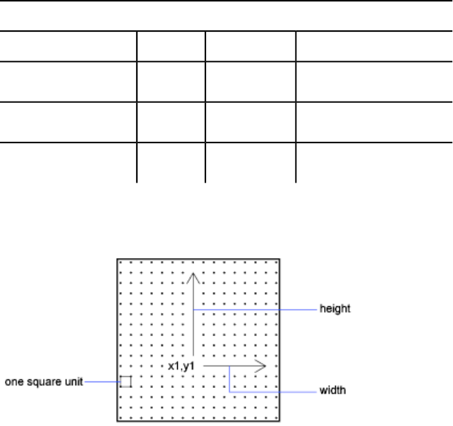
Fields of the extended Big Font file
DescriptionByte sizeValueVariable
Scale of primitive width1 byte
width
Scale of primitive height1 byte
height
End of shape definition1 byte0
terminator
The following figure is an example of a 16 x 16 dot matrix that you could use
to design an extended Big Font, such as a Kanji character. In the example, the
distance between each dot is one unit. The callout points to a square unit.
A square matrix for a Kanji character
The following figure shows examples of Kanji characters. Each character
occupies an M×N matrix (matrices don't have to be square), similar to the one
shown in the previous figure. The numbers above each figure are the associated
shape numbers.
174 | Chapter 8 Shapes and Shape Fonts
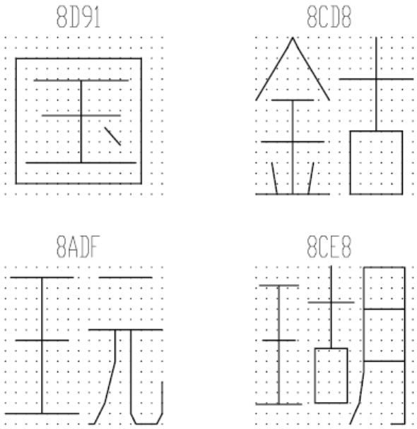
Examples of Kanji characters
The following figure shows Kanji primitives.
Create Shape Definition Files | 175
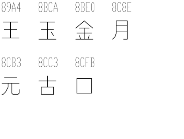
Examples of Kanji primitives
NOTE
Not all fonts are defined in a square matrix; some are defined in rectangular
matrices.
Example: Shape Definition File for an Extended Big Font
*BIGFONT 50,1,080,09e
*0,5,Extended Font
15,0,2,15,0
*08D91,31,unspecified
2,0e,8,-7,-15,
7,0,08cfb,0,0,16,16,7,0,08bca,2,3,12,9,
2,8,18,0,2,0e,8,-11,-3,0
*08CD8,31,unspecified
2,0e,8,-7,-15,
7,0,08be0,0,0,8,16,7,0,08cc3,8,0,8,16,
2,8,18,0,2,0e,8,-11,-3,0
*08ADF,31,unspecified
2,0e,8,-7,-15,
7,0,089a4,0,0,8,16,7,0,08cb3,8,0,8,16,
2,8,18,0,2,0e,8,-11,-3,0
*08CE8,39,unspecified
2,0e,8,-7,-15,
7,0,089a4,0,1,5,14,7,0,08cc3,5,2,5,14,7,0,08c8e,9,0,7,
16,2,8,18,0,2,0e,8,-11,-3,0
176 | Chapter 8 Shapes and Shape Fonts
*089A4,39,primitive
2,0e,8,-7,-15,2,8,1,14,1,0c0,
2,8,-11,-6,1,0a0,2,8,-12,-7,1,
0e0,2,8,-7,13,1,0dc,2,8,11,-1,
2,0e,8,-11,-3,0
*08BCA,41,primitive
2,0e,8,-7,-15,2,8,1,14,1,0c0,
2,8,-11,-6,1,0a0,2,8,-12,-8,1,
0e0,2,0e5,1,0ec,2,063,1,8,
2,-3,2,06f,2,0e,8,-11,-3,0
*08BE0,81,primitive
2,0e,8,-7,-15,2,8,3,9,1,080,
2,8,-10,-4,1,0c0,2,8,-13,-5,1,
0e0,2,8,-7,9,1,09c,2,8,-1,14,
1,8,-6,-5,2,8,8,5,1,8,6,-5,
2,8,-11,-6,1,8,1,-3,2,8,7,3,
1,8,-1,-3,2,8,-3,15,1,01a,2,
012,1,01e,2,8,10,-14,2,0e,8,
-11,-3,0
*08C8E,44,primitive
2,0e,8,-7,-15,2,8,3,15,1,090,0fc,038,
2,8,-6,11,1,090,2,8,-9,-5,1,
090,2,096,1,0ac,8,-1,-3,01a,01a,2,8,
18,0,2,0e,8,-11,-3,0
*08CB3,61,primitive
2,0e,8,-7,-15,2,042,1,02b,02a,018,2,
0d0,1,012,034,2,069,1,01e,040,2,8,
-8,6,1,02b,2,8,4,5,1,08c,2,8,
-3,8,1,03c,2,8,-5,3,1,0e0,2,8,
-12,5,1,0a0,2,8,6,-14,2,0e,8,
-11,-3,0
*08CC3,34,primitive
2,0e,8,-7,-15,2,0c1,1,06c,0a8,064,0a0,2,8,
-5,9,1,09c,2,8,-7,5,1,0e0,2,8,
4,-11,2,0e,8,-11,-3,0
*08CFB,22,primitive
2,0e,8,-7,-15,2,0d2,1,0cc,0c8,0c4,0c0,2,8,
5,-13,2,0e,8,-11,-3,0
Create Shape Definition Files | 177
Use Big Font Text in a Drawing
To use a Big Font for drawing text, you set up a text style and then specify the
name of the Big Font file.
To use a Big Font for drawing text, you must set up a text style by using the
STYLE command and then specify the name of the Big Font file. The same
text style can use a normal ASCII font as well; enter only the two file names,
separated by a comma. The following example uses the command prompt
version of the STYLE command.
Command: -style
Enter name of text style or [?] <current>: style_name
Specify full font name or font file name (TTF or SHX):
txt,greek
AutoCAD assumes that the first name is the normal font and that the second
is the big font.
If you enter only one name, AutoCAD assumes it is the normal font and
removes any associated Big Font.
By using leading or trailing commas when specifying the font file names, you
can change one font without affecting the other, as shown in the following
table.
Input for changing fonts
ResultInput
Both normal and Big Font specifiednormal, big
Normal font only (Big Font unchanged)normal,
Big Font only (normal font unchanged),big
Normal font only (if necessary, Big Font removed)normal
No changeENTER (null response)
When you use the -STYLE command to list styles or to revise an existing style,
AutoCAD displays the normal font file, a comma, and the Big Font file. If the
style has only a Big Font file, it is displayed with a leading comma: ,greek.
178 | Chapter 8 Shapes and Shape Fonts
For each character in a text string, AutoCAD searches the Big Font file first. If
the character is not found there, the normal font file is searched.
To enable Big Fonts from the Text Style dialog box, choose the Big Font file
you want to use from the Asian Set list.
Use a Big Font to Extend a Font
To include special symbols in text strings, you can use a Big Font instead of
extending a standard text font.
In some drafting disciplines, many special symbols can appear in text strings.
The AutoCAD standard text fonts can be extended to include special symbols.
However, extending standard text fonts has several limitations:
■The number of shapes is 255 per font file.
■Standard character set uses almost half the available shape numbers. Only
codes 1 through 9, 11 through 31, and 130 through 255 are available.
■Multiple text fonts require duplication of the symbol definitions in each
font.
■Special symbols require that you enter %%nnn, where nnn is the symbol's
shape number.
The Big Font mechanism avoids these problems. You can select one or more
seldom-used characters, such as the tilde (˜) or the vertical bar (|), as an escape
code, and use the next character to select the appropriate special symbol. For
instance, you can use the following Big Font file to draw Greek letters by
entering a vertical bar (|, ASCII code 124) followed by the equivalent Roman
letter. Because the first byte of each character is 124, the character codes are
biased by 124 x 256, or 31744.
*BIGFONT 60,1,124,124
*0,4,Greek
above, below, modes, 0
*31809,n,uca
...
uppercase Alpha definition, invoked by "|A"
*31810,n,ucb
...
uppercase Beta definition, invoked by "|B"
*31841,n,lca
...
lowercase Alpha definition, invoked by "|a"
Create Shape Definition Files | 179
*31842,n,lcb
...
lowercase Beta definition, invoked by "|b"
*31868,n,vbar
...
vertical bar definition, invoked by "||"
...
Unicode Font Descriptions
A single Unicode font, due to its large character set, is capable of supporting
all languages and platforms. Unicode shape definition files are virtually
identical in format and syntax to regular AutoCAD shape definition files.
The main difference is in the syntax of the font header as shown in the
following code:
*UNIFONT,6,font-name
above,below,modes,encoding,type,0
The font-name , above , below , and modes parameters are the same as
in regular fonts. The remaining two parameters are defined as follows:
encoding Font encoding. Uses one of the following integer values.
0 Unicode
1 Packed multibyte 1
2 Shape file
type Font embedding information. Specifies whether the font is licensed.
Licensed fonts must not be modified or exchanged. Bitcoded values can be
added.
0 Font can be embedded
1 Font cannot be embedded
2 Embedding is read-only
Another important difference is the handling of the code 7 subshape reference.
If a shape description includes a code 7 subshape reference, the data following
the code 7 is interpreted as a two-byte value. This affects the total number of
data bytes ( defbytes ) in the shape description header. For example, the
following shape description is found in the romans.shp file:
*00080,4,keuroRef
7,020AC,0
180 | Chapter 8 Shapes and Shape Fonts
The second field in the header represents the total number of bytes in the
shape description. If you are not used to working with Unicode font
descriptions, you may be inclined to use three bytes rather than four, but this
would cause an error during the compiling of the SHP file. This is true even
if the shape number you are referencing is not in the two-byte range (below
255); the compiler always uses two bytes for this value, so you must account
for that in the header.
The only other difference between Unifont shape definitions and regular shape
definitions is the shape numbers. The Unifont shape definitions that AutoCAD
provides use hexadecimal shape numbers as opposed to decimal values.
Although hexadecimal numbers are not required, their use makes it easier to
cross-reference the shape numbers with the \U+ control character values.
Superscripts and Subscripts in SHX Files
You can modify shape definition files to improve their ability to display
superscripts and subscripts.
The AutoCAD SHX fonts have limited superscript and subscript capabilities.
However, it is relatively easy to modify shape definition files to improve
superscript and subscript capability.
Creating superscripts and subscripts requires two steps. First, the “imaginary
pen” that is creating the text, vector by vector, on your screen needs to be
shifted up or down. Then, the font “scale” needs to be reduced. In addition,
the reverse process has to take place to return to the normal font. The font
needs to recognize four new keys: two for superscripts and two for subscripts.
To avoid altering the existing font definitions, you can access these with the
numeric keypad on your keyboard.
Superscripts and Subscripts in SHX Files
To add superscript and subscript definitions to a font
This example procedure is based on the AutoCAD Romans font file, although
a similar method applies to any AutoCAD font. This procedure adds four new
shape definitions to a font: super_on, super_off, sub_on, and sub_off, which
control the position and size of the characters that follow. For simplicity, this
example replaces the left- and right-bracket characters ([and]) and the left and
right curly brace characters ({and}) with the new characters. You may choose
to replace other characters or use a shape number in the extended range (ASCII
Create Shape Definition Files | 181
codes 128 through 256). If you use an extended shape number, you need to
use the %%nnn method (where nnn is the ASCII value of the character) for
placing the new characters.
1Edit your SHP file with an ASCII text editor.
2Search for the shape definitions of the characters you are replacing. To
comment out those definitions so the new definitions can take their
place, insert a semicolon in front of each line of the shape definition.
The shape definition may continue for a number of lines.
The left- and right-bracket characters have ASCII values of 91 and 93
(05B and 05D hex values, if the font is Unicode). The left and right curly
brace characters have ASCII values of 123 and 125 (07B and 07D hex).
3Add the first and second values on the second line of the definition, and
divide the total by 2 as shown in the following example:
*UNIFONT,6,Extended Simplex Roman for UNICODE
21,7,2,0 21 + 7 = 28, then 28 / 2 = 14. This number is
used later.
4Add the following lines to the end of the SHP file:
*91,8,super_on
2,8,(0,14),003,2,1,0
*93,8,super_off
2,004,2,8,(0,-14),1,0
*123,8,sub_on
2,8,(0,-14),003,2,1,0
*125,8,sub_off
2,004,2,8,(0,14),1,0
Notice the 14 and -14 values in the preceding lines. They are Y axis offsets
for the imaginary pen. The value 14 is half the maximum height of a
character in this font, which is the correct approximation for superscripts
and subscripts. This value needs to be calculated for each font file, but
you can modify it any way you want.
5Save the file.
6Use the COMPILE command to compile the SHP file.
Once the shape is compiled and an appropriate style is defined, you can
access the new pen-up and pen-down commands by entering the [, ], {,
and } characters. The [ character initiates superscript and the ] character
returns from superscript to normal. The { character initiates subscript
and the } character returns from subscript to normal.
182 | Chapter 8 Shapes and Shape Fonts
Index
A
acad.lsp file 83
acaddoc.lsp file 84
addition DIESEL function 66
aliases
creating for commands 14
alignment
linetype patterns 19
alternate font mapping files 9
and DIESEL function 69
angtos DIESEL function 69
ApplicationPackage element 93
applications
AutoLISP 80
ObjectARX 88
plug-in applications 89
Visual LISP 80
AutoCAD Runtime Extension 88
AutoLISP (LSP) applications
about 80
acad.lsp file 83
acaddoc.lsp file 84
DIESEL expressions and 64
errors when loading 85
loading 80, 82
loading ObjectARX applications
with 88
macros and 40, 48, 63
MNL files 85
S STARTUP function 86
system variables and 80
B
batch files 6
Big Fonts
about 171
defining 171
examples 174
extended Big Font files 172
extending text fonts with 179
text styles and 178
borders (menu items) 50
BUNDLE packages 89, 104
C
canceling commands 41
caret syntax in macros 42
CFG files 9
characters
Big Fonts 171
including in linetypes 21
macro control characters 40, 42
shape fonts 109
codes (shape specification bytes) 114
Command element 102
command line
switches 77
command line switches
running scripts and 77
command scripts 75
commands
about 36
aliases 14
canceling 41
creating 37
customizing 36
editing 37
Help topics about 51
images for 52
macros and 40, 41, 46
menus 52
name validity 4
pausing for input 44
properties 36
repeating 46
reusing 37
scripts 75
submenus and 53
tool sets and tool groups 56
183 | Index
tooltips 51
transparent commands 44
Commands element 102
comments
AutoLISP commenting 80
script commenting 76
CompanyDetails element 95
compiling shape or font files 109
ComponentEntry element 99
Components element 96
conditional expressions in macros 47
configuration files (plotters)
locating 9
configuration files (pointing devices)
locating 9
control characters in macros 42
copyright restrictions on fonts 110
custom icon files 9
customization
about 1
customization files (CUI)
DIESEL expressions in 63
directory structure and 4
Customize dialog box
about 35
customizing
about customization 35
commands 36
Customize dialog box 35
functions and features 1
glossary of terms for 36
hatch patterns 27
hatches 27
linetypes 17
menus 52
tool groups 56
tool sets 56
user interface 35
D
dashes
hatch pattern definitions 29
linetype definitions 18
dates
edtime DIESEL function 69
DCL files (dialog control language) 9,
80
DIESEL expressions
about 63
error messages 74
macros and 40, 47, 63
pull-down menu labels 65
DIESEL functions
addition 66
and 69
angtos 69
catalog 66
division 67
edtime 69
eq 71
equal to 67
eval 71
fix 71
getenv 71
getvar 72
greater than 68
greater than or equal to 68
if 72
index 72
less than 67
less than or equal to 68
multiplication 67
not equal to 68
nth 72
or 73
rtos 73
strlen 73
substr 73
subtraction 67
upper 74
xor 74
dimensions
font characters for 122
direction
shape specification codes 112
directories 3
directory paths
AutoLISP files 81
program and support files 3
division DIESEL function 67
dots in linetype definitions 18
184 | Index
drawing files (DWG)
folders and maintenance 5
drawing templates
locating files 12
drop-downs
tool groups 57
DWT files
locating 12
E
echoes in macros 42
editing
commands 37
edtime DIESEL function 69
eq DIESEL function 71
equal to DIESEL function 67
error messages
AutoLISP 86
DIESEL 74
errors
AutoLISP errors 85
eval DIESEL function 71
extended Big Font files 172
extended help 51
F
FAS files 80
fields (font definition files)
Big Font files 172
shape font files 111
files
locations 3
maintenance 5
roaming profiles and 7
fix DIESEL functions 71
flyouts
tool groups 57
FMP files (font mapping) 9
folders
BUNDLE packages 104
file locations 3
plug-in application
organization 106
font mapping files 9
fonts
compiling 109
creating 121
dimensioning characters in 122
including in linetypes 21
shape fonts 109
special symbols in 179
superscripts and subscripts in 181
G
getenv DIESEL function 71
getvar DIESEL function 72
graphics for commands 52
graying out menu item labels 50
greater than DIESEL function 68
greater than or equal to DIESEL
function 68
H
hatch patterns
about 27
creating 27
examples 27, 29, 31
multiple lines 31
hatches
creating 27
customizing 27
Help
locating Help files 9
tooltip command Help 51
I
icons
customizations 9
if DIESEL function 72
images for commands 52
index DIESEL function 72
input
pausing macros for 44
prompting for 49
installation
plug-in applications 89
Index | 185
interface
Customize dialog box 35
customizing 35
terminology 36
interface elements
defined 36
interface items 36
international character sets 46, 171, 172
J
Japanese fonts 171, 172
K
Kanji fonts 171, 172
keyboard input in macros 44
L
languages
Big Fonts 172
macro translations 46
special character codes 171
less than DIESEL function 67
less than or equal to DIESEL function 68
library search path 3
LIN files (linetype library) 9, 17
linetypes
about 17
complex 24
creating 18
customizing 17
examples 18
including shapes in 24
simple 18
text characters in 21
loading
AutoLISP applications 80, 82, 83,
84, 85
ObjectARX applications 88
plug-in applications 90
localization 103
LSP files (AutoLISP) 80
M
macros
about 40
AutoLISP expressions in 48, 63
commands in 46
conditional expressions in 47
defined 36
DIESEL expressions in 47, 63
international language support 46
pausing for user input 42, 44
prompting for user input 49
repeating commands 46
scripts 75
selecting objects with 47
special character codes for
commands 42
suppressing echoes and prompts 42
syntax 40
terminating 41
MDE (Multiple Design Environment) 80
menu items
DIESEL expressions and 65
disabling 50
graying out 50
menus
AutoLISP MNL files 85
creating 52, 53
creating sub-menu 53
customizing 52
international language support 46
menu bar 53
submenus 53
MNL files (menu LISP)
loading 82, 85
macros and 48
modifying
commands 37
Multiple Design Environment 80
multiple-line hatch patterns 31
multiplication DIESEL function 67
N
namespaces in Visual LISP 80
186 | Index
naming
linetypes 18
shapes 111
not equal to DIESEL function 68
nth DIESEL function 72
O
ObjectARX applications
about 88
loading 88
or DIESEL function 73
P
package folder structure 104
package installation 89
PackageContents.xml file 90
palettes
defined 36
PAT files 9
patterns
linetypes 19
pausing macros 42, 44
PFB files (printer font binary) 110
PGP files (program parameters) 9
plot styles
locating files 8
plotter configuration files
locating files 8
plug-in applications 89
PostScript fonts 110
prefixes for commands 14
profiles 7
program file locations 3
programming applications
AutoLISP 80
ObjectARX 88
plug-in applications 89
Visual LISP 80
prompts
suppressing 42
user input in macros 49
properties
commands 36
PSF files 9
R
rearranging
tools 57
repeating commands 46
ribbon
command images 52
roaming profiles 7
rtos DIESEL function 73
RuntimeRequirements element 97
S
S STARTUP AutoLISP function 86
SCR files (scripts) 75
scripts
about 75
file names and 76, 77
running at startup 77
switches and 77
search paths
default file locations 3
selecting
objects with macros 47
shape definition files
about 109
Big Font files 171
creating 109, 110
samples 122, 151
superscripts and subscripts 181
text fonts 121
Unicode fonts and 180
shape fonts
about 109
Big Fonts 171
sample files 122, 151
superscripts and subscripts 181
Unicode shape definition files 180
shape specification bytes 114
shapes
about 109
descriptions 111
including in linetypes 24
shape specification bytes 112
special codes 114
SHP fonts (shape definition) 109, 110
Index | 187
SHX fonts 9, 109, 110, 181
spaces in linetypes 18
special characters
commands and 53
macros and 40, 42, 53
shape fonts 109
startup AutoLISP errors 85
startup scripts 77
strlen DIESEL function 73
submenus 53
subscripts in fonts 181
substr DIESEL function 73
subtraction DIESEL function 67
superscripts in fonts 181
support files
locations 3
suppressing echoes and prompts 42
switches
running scripts and 77
symbols
commands and 53
macros and 40, 42, 53
shape fonts 109
syntax
macros 40
shape fonts 111
Unicode shape definition files 180
system variables
AutoLISP functions and 80
toggling values with macros 48
T
templates
locating files 12
terminating macros 41
text
including in linetypes 21
shape fonts 109
text styles
Big Fonts and 178
textures
locating files 13
time
edtime DIESEL function 69
tool groups
customizing 56
defined 36
drop-downs on 57
expanding 57
flyouts on 57
tool sets
creating 57
customizing 56
defined 36
drop-downs 57
flyouts 57
Tool Sets palette 56
toolbars
command images 52
tooltips
command Help in 51
translating macros 46
translating plug-in applications 103
transparent commands 44
Type 1 PostScript fonts 110
U
Unicode fonts 151, 180
Unicode shape definition files 180
UNT files 9
upper DIESEL function 74
user input
pausing macros 44
user interface
Customize dialog box 35
customizing 35
terminology 36
V
vectors in shape specifications 112
Visual LISP 80
VLISP (Visual LISP) 80
X
xor DIESEL function 74
188 | Index
